The theme for this month’s post could also be “hubris”. Over the years, I’ve collected a lot of tricks and procedures, and I rely on them. Turns out what I thought was a Fortress of Knowledge ™ turned out to be a sandcastle built at water’s edge at low tide. This month the tide came in and the sandcastle crumbled (along with a part or two) (okay…I’m being dramatic with the whole “crumble” thing but still…this month was a massive ass pain).
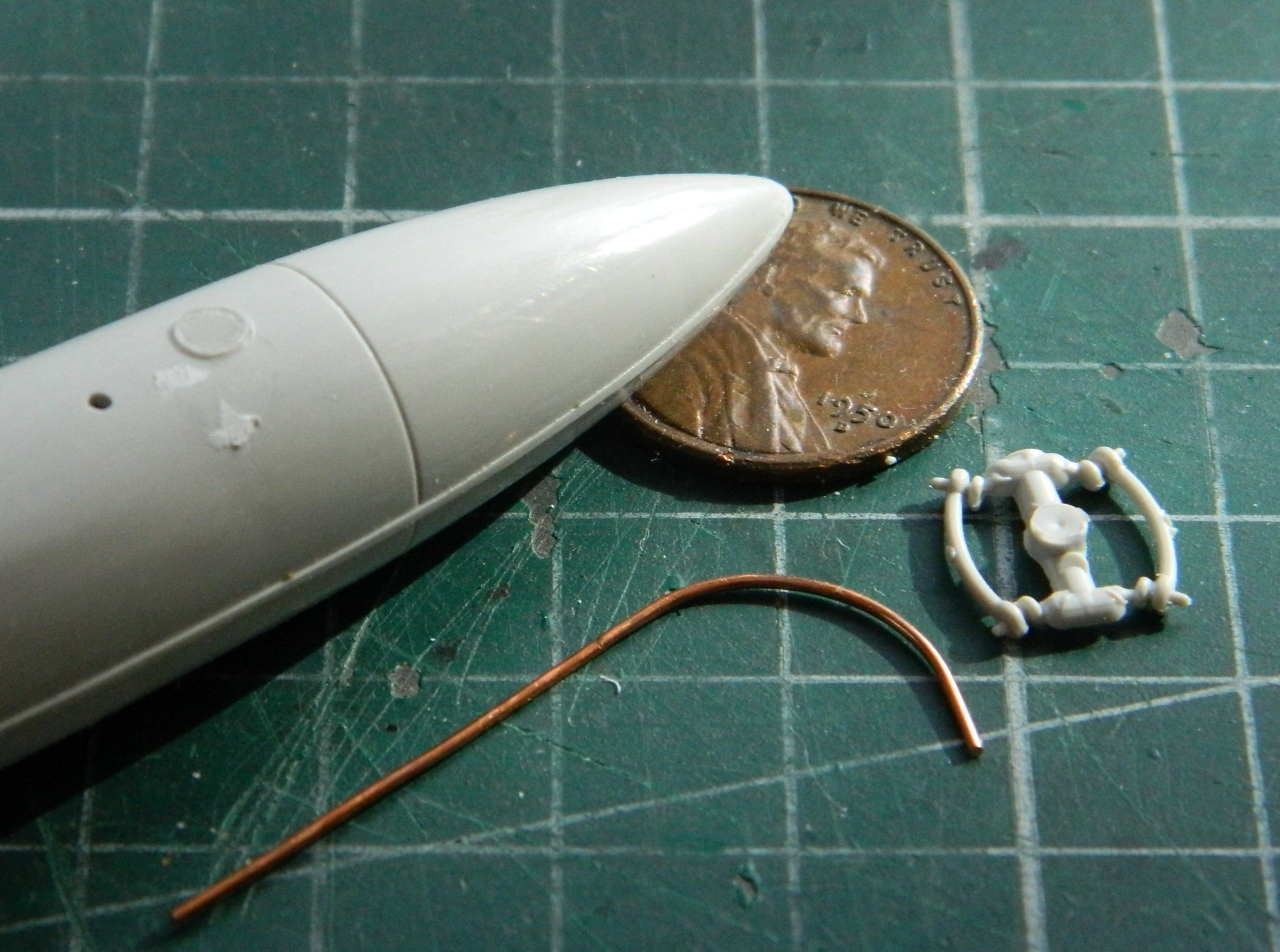
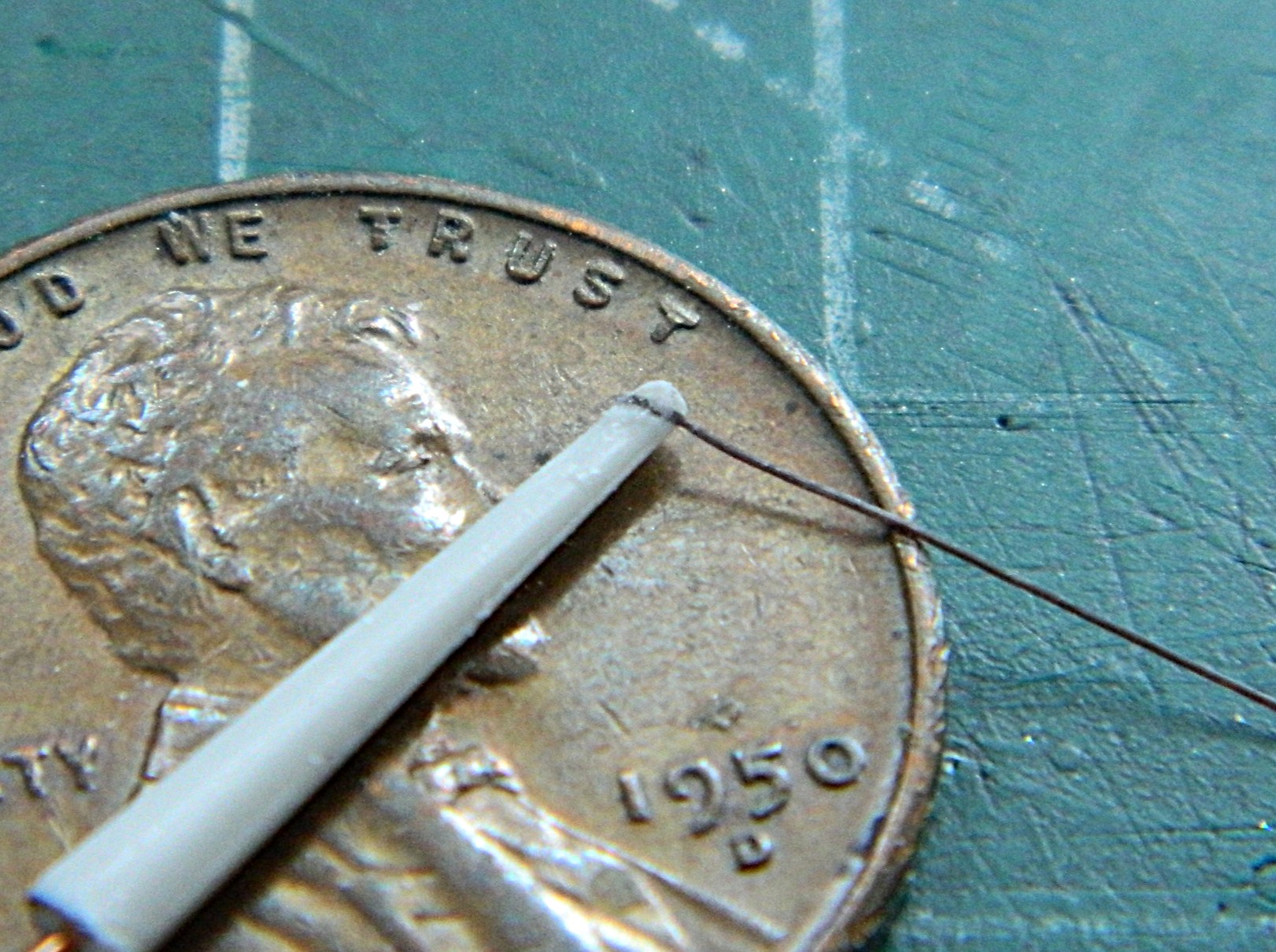
The opening salvo for hammering my hubris flat came when I left the brass tubing that I used to replace the kit’s offering for the 20mm cannons in the blackening solution overnight and went to bed so that I could get an early start on laying there for a couple (or three) (or more) of hours before getting some sleep. As I planted myself into the chair the following morning, my eyes (at least one of them) saw this:
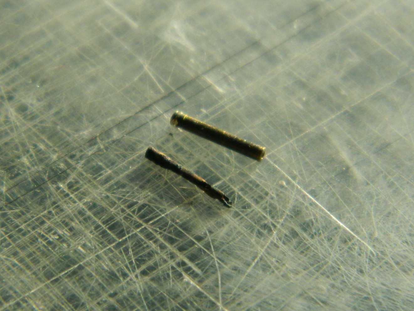
The tube at the top hasn’t been immersed yet in the Brass Black. The…remnant…at the bottom is what happens to brass after it’s been immersed in Brass Black overnight. Okay…now I know.
I worked on attaching the wings. Fit is vague, allowing the dihedral to be flat (wingtips at equal height from the ground) to almost U-shaped. I wasn’t taken aback by this because dry-fitting had shown that this would be a problem as the gaps at the wing-roots would be as well. I did the best that I could with getting the first one, my reference as it turned out, glued on with the correct(ish) angle to the fuselage (not that easily seen because I was clever enough to have something behind it that would obscure vision):
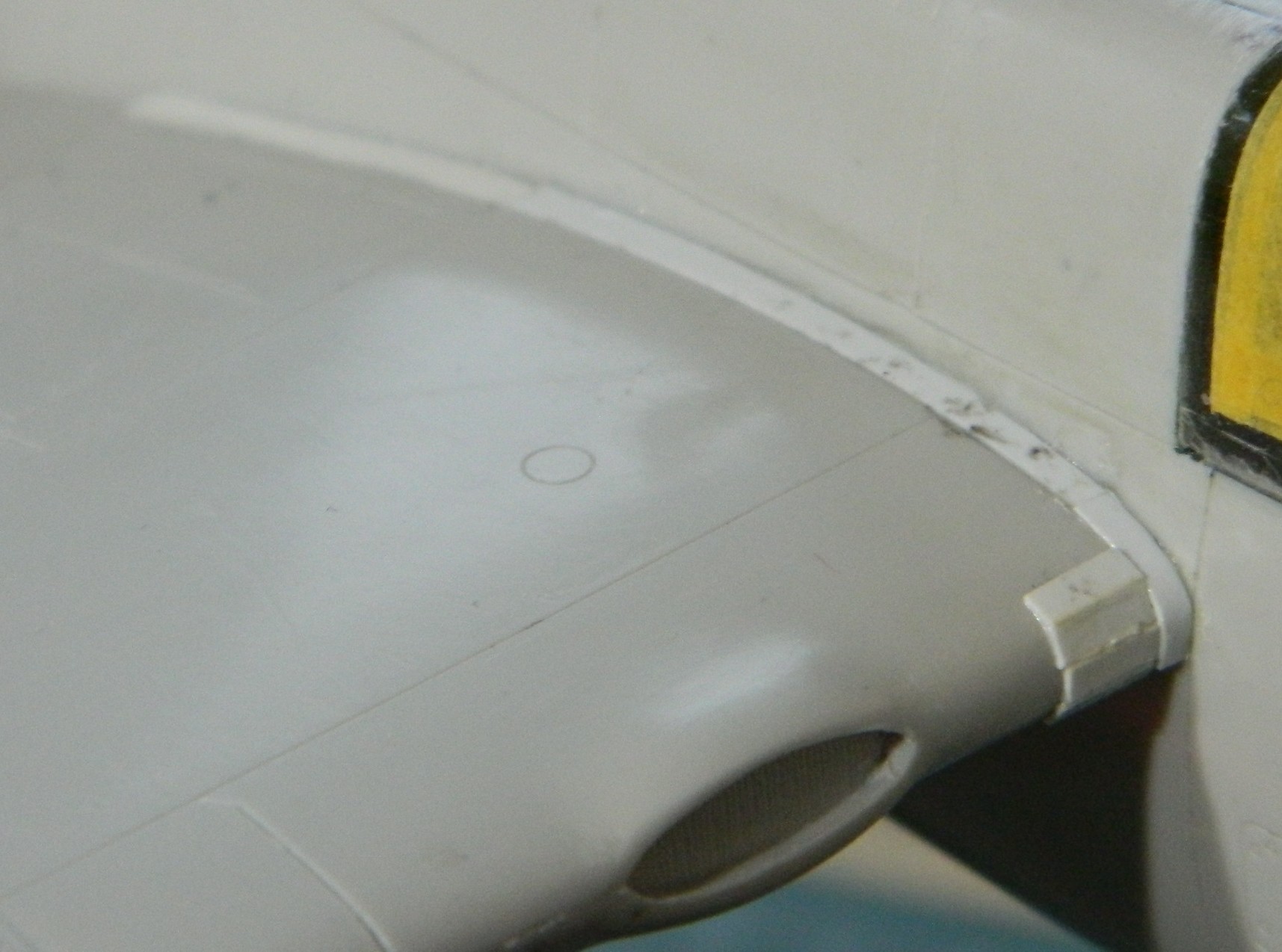
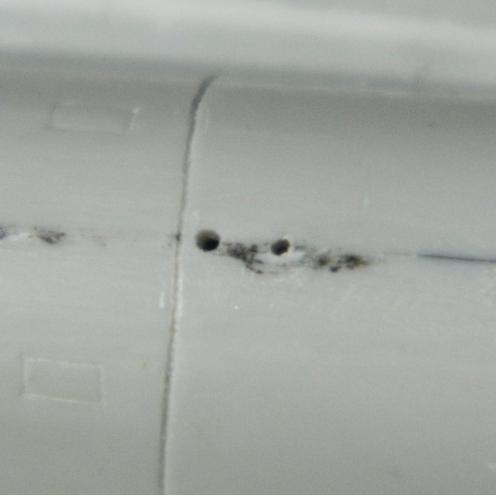
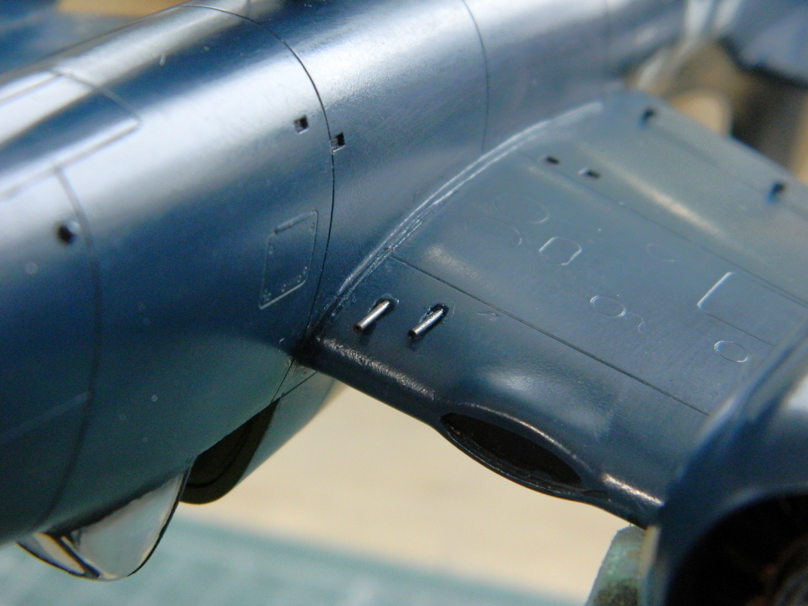
At this point I realized that there was a task I wanted to do that would be much easier to accomplish before the wings were attached. Shell ejection ports for both the .50 caliber machine guns and the 20mm cannons. The kit didn’t mold them in so I had to excavate a bit. Step one was to mark where they should go:

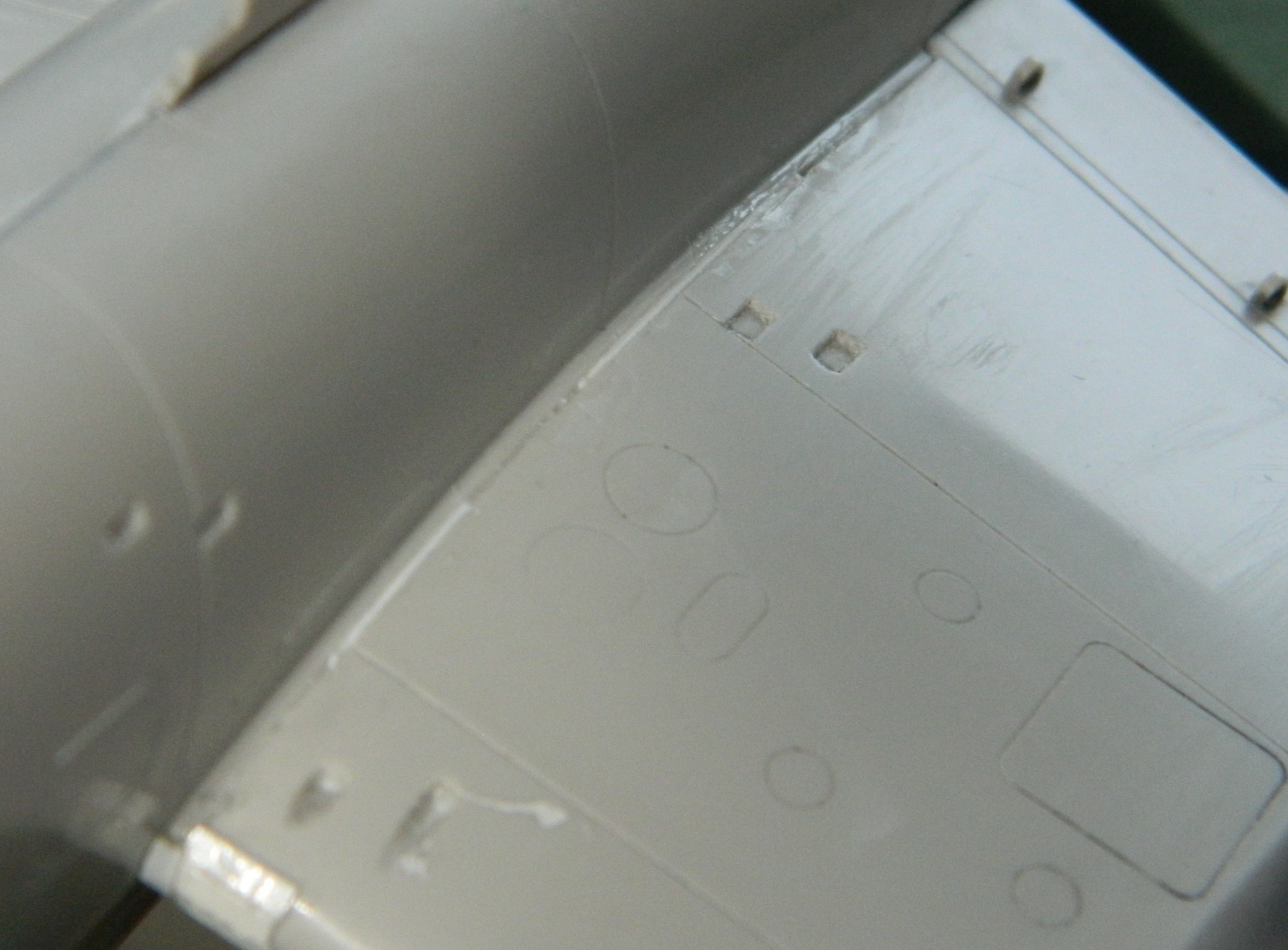
Then I started digging (using a sewing needle converted to a chisel point because everything else I had was much too large):

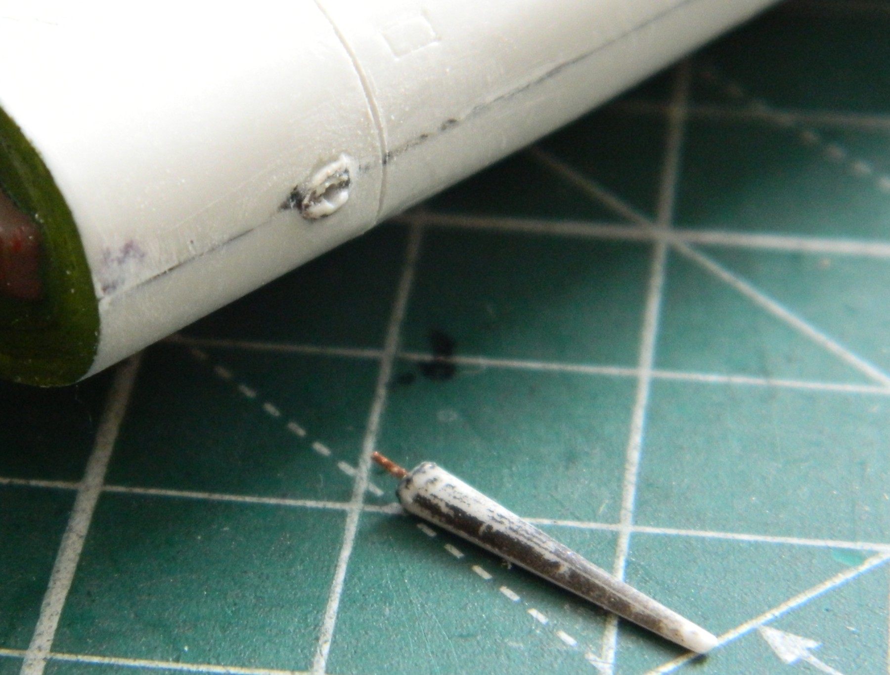
During the process of excavating the ejection ports, I managed to snap off the radio antenna mast that had been molded as part of one of the fuselage halves. I was waiting for that to happen (because some things I can see coming…sometimes) so I added a pin to the mast and drilled out the hole where I thought it should go (I found out otherwise later) and set it aside for later addition:

Then I glued the port (left, if I’m not trying to impress) wing and its space/filler added 0.010″ (.254mm) styrene as filler to position the wing to (what I hope is) the correct angle:

Then I added the other wing and used more styrene as a gap filling spacer:
I diddled with the dihedral until my eyeballs dried out. At some point, one must accept that this is the best that they can do. Plastic can only be worked so many times before things break and/or wear out (including, or perhaps especially, my nerves). So the trigger was pulled and things were glued on. Then both 0.010″ (.254mm) strip styrene and 3M Acrylic Putty added to get things to meet and join as they’re supposed to (or, more accurately, as I want them to…and hopefully “supposed to” and “as I want them to” are the same thing):

That followed up with filing, sanding, and cursing until the wings looked the way they were supposed to look all along (perhaps):

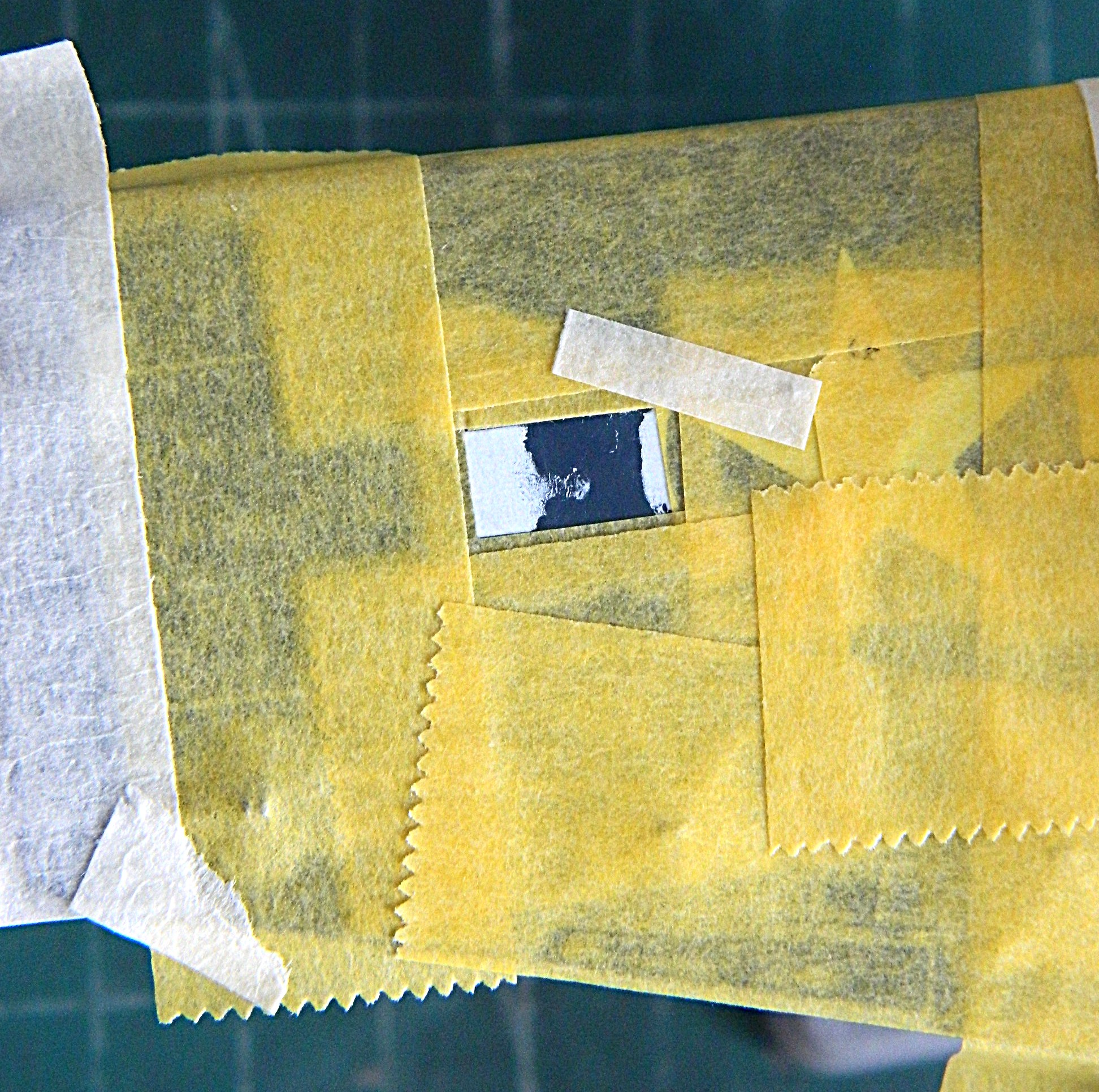
I had to reapply more putty, as one frequently must, to get the spots that were missed. I masked off the recessed lines to cut down on the amount of recovery those recessions would need had I not masked them off:
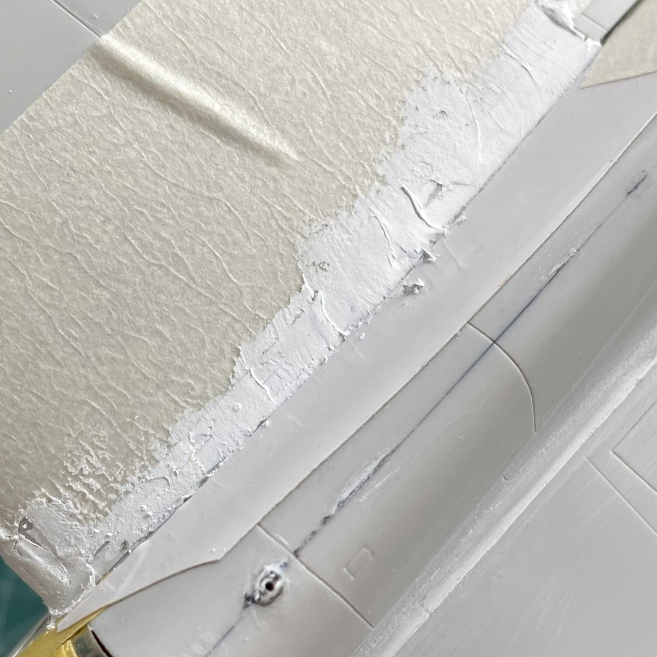
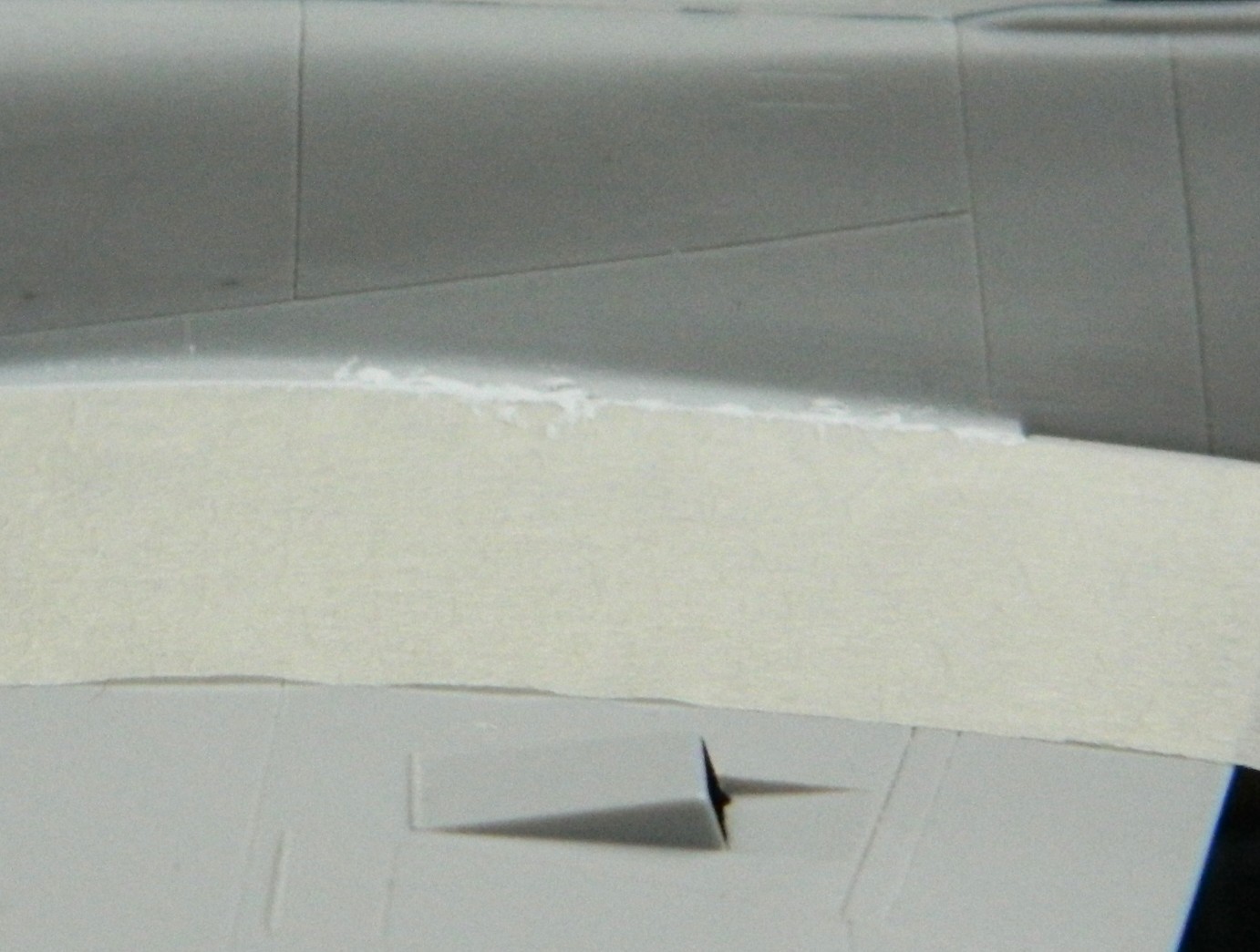
A word about masking… In the uppermost of the above photos, to the lower right of the white putty is a strip of white tape. I used electrical tape to do that because it will stretch. I used its stretching property to curve the tape to match the curve of where the top of the wing meets the fuselage. Handy trick to know as the electrical tape can be cut into narrower strips if you need it that way.
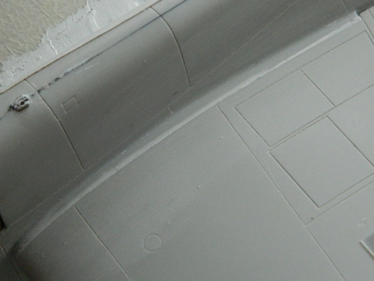
At this point I decided to recheck the fit of the vacu-formed canopy and I decided that it sat too far forward because the radio mast was too far forward. Well…how fortuitous that the bastid already snapped off! I figured out where I wanted the mast to mount and drilled its mounting hole for later attention and attachment (the hole to the left in the photo below is the new mounting location):
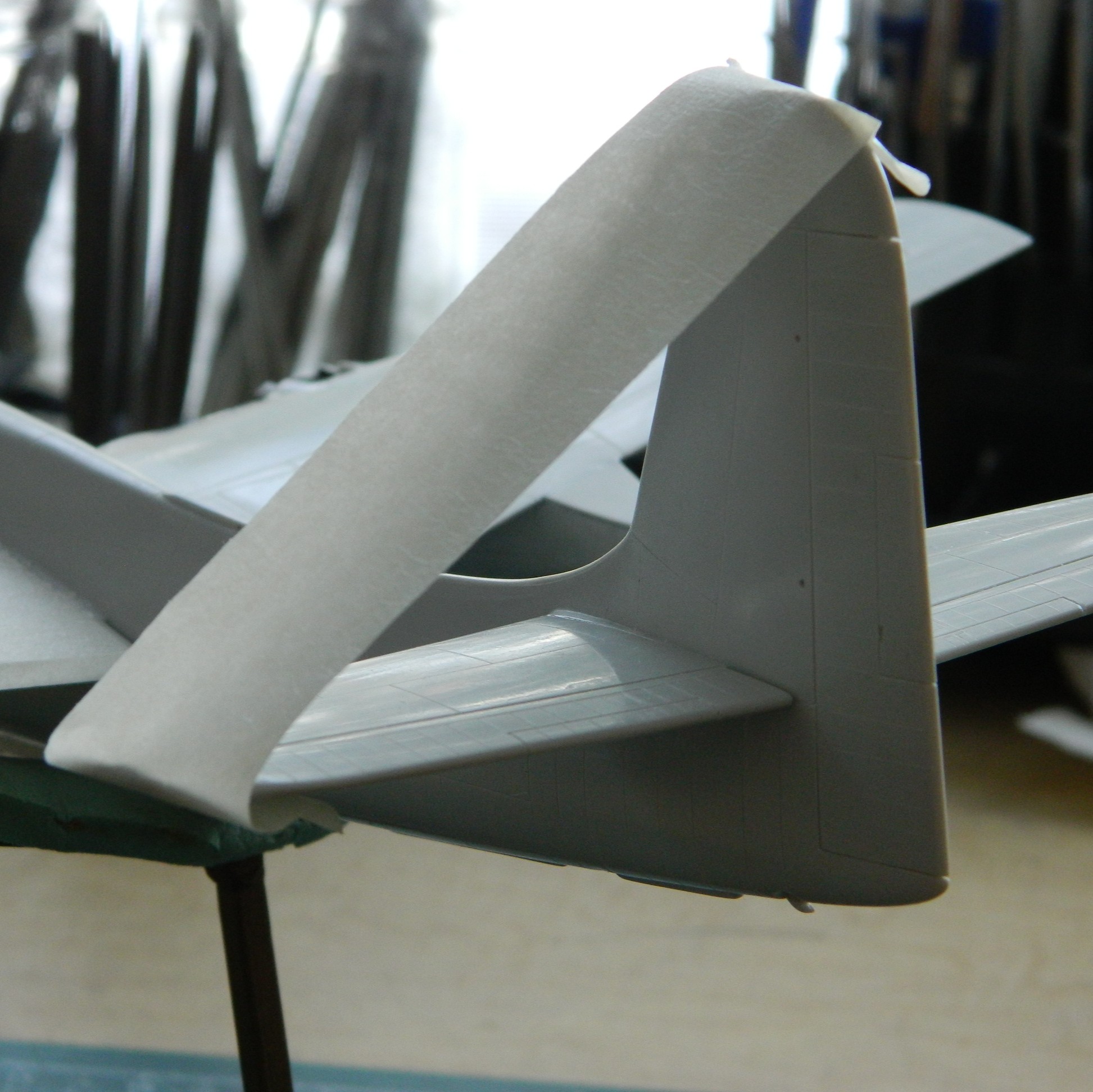
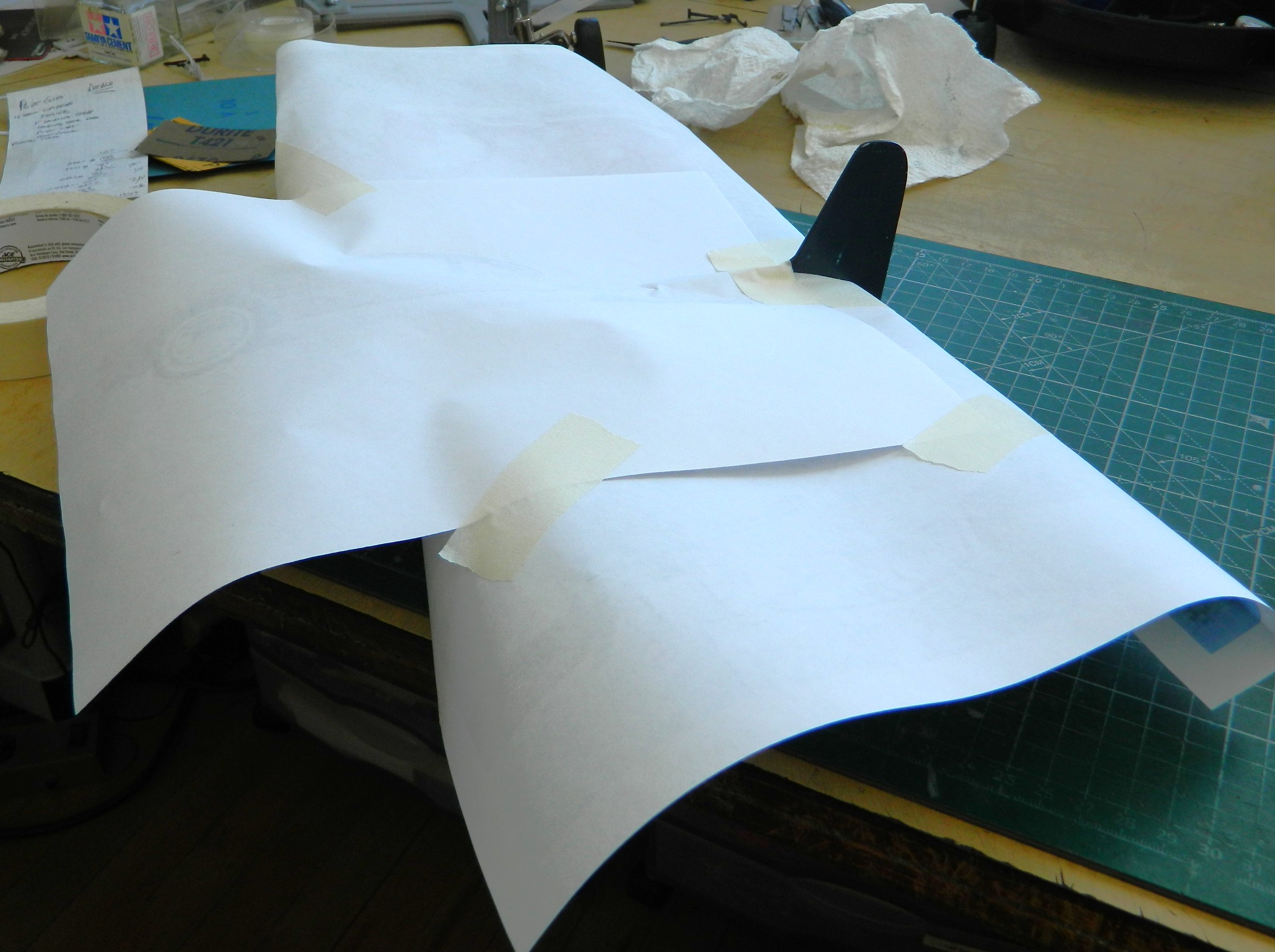
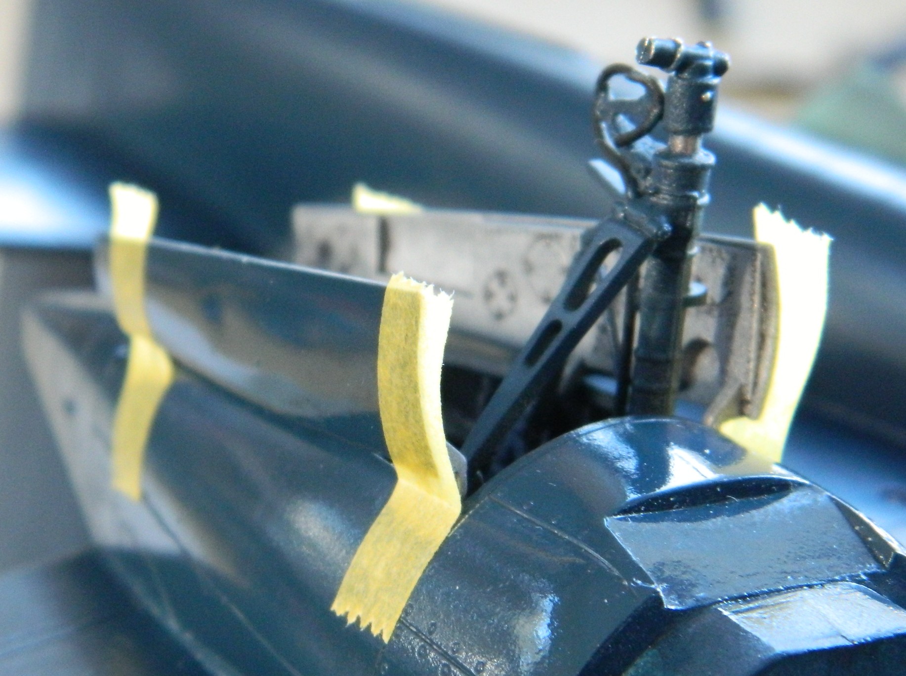
The empennage didn’t locate any more accurately that the wings did, but it was sneaky about it. The wings just slid into the slots, the empennage fit very snugly, leading to the MISTAKEN impression that that was where they belonged. And then one compared the plane of the wings and the plane of the empennage and it wasn’t even close. I spent a fair amount of time getting this part of the build to match the wings. The right side went on and align with a bit of fiddling. The left side did not want to go in, then it didn’t want to be at the correct angle. I used masking tape to hold the left side at the angle I wanted:
I loaded the airbrush (Badger 200 single-action) with Tamiya XF-1 Flat Black and hit the outside of the front canopy (which, due to its transparency, will present as the inside of the front canopy as black. I also did the intakes for the oil coolers and intercoolers (which, as events later showed, was a waste of time and paint):

Having acquired the correct color blue, I shot the engine cowlings. These were painted when they were off so that I could make a valiant attempt at applying kit-supplied decals while it was easy to get at them. They were painted Tamiya’s AS-8 Navy Blue which is a lacquer (more on that later). Not having worked with this type of paint before, I let it sit for a couple of days before overshooting it with Tamiya X-22 Clear and had no problems:

Time to apply the decals and see how bad they actually are:
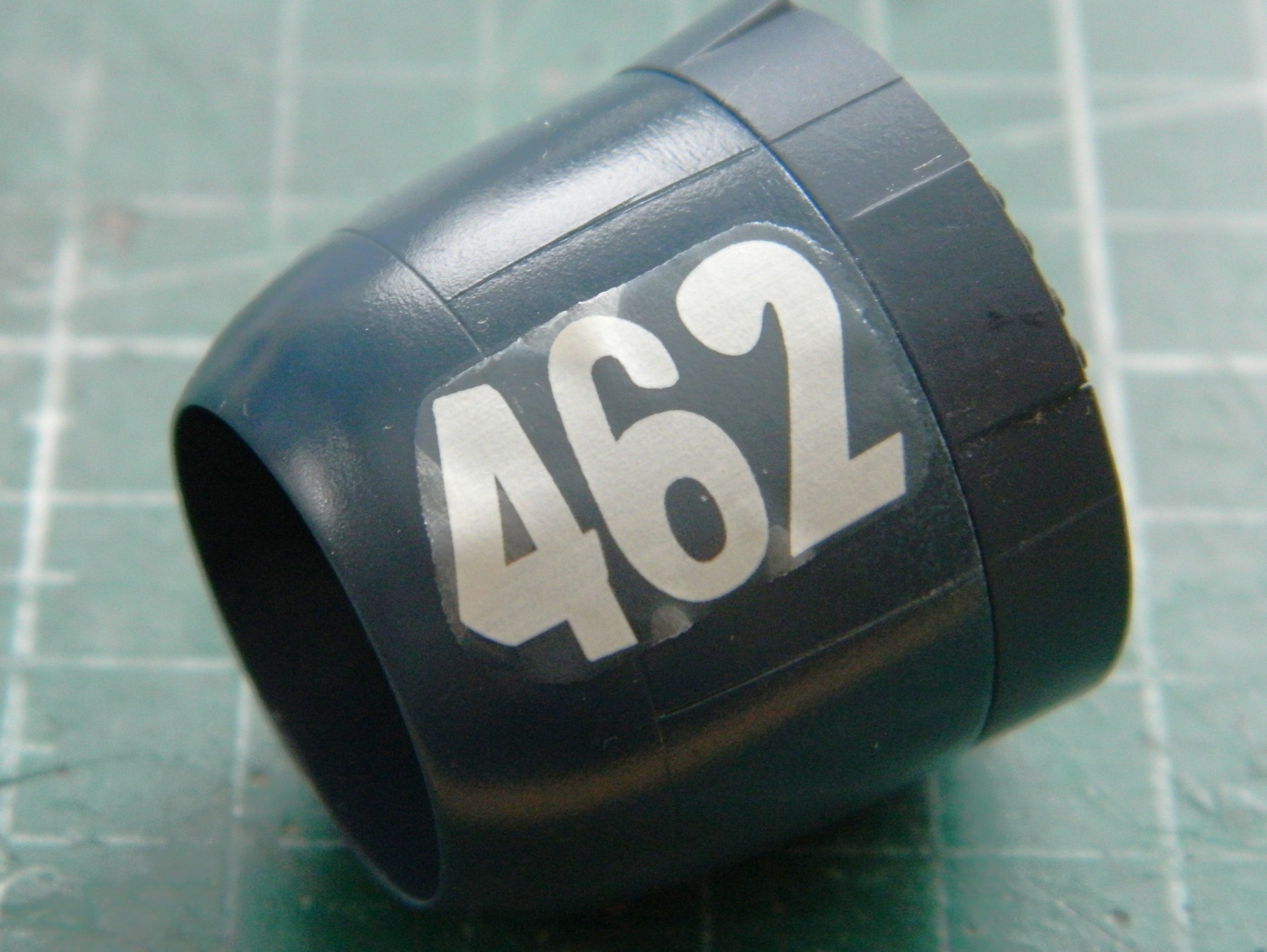
Bad.
Note the carrier film of that decal. Does it look like tissue paper to you? It really looked like tissue paper to me! Having read a few build reviews, that came as no surprise. And because the lower rungs of ladders are there for a reason, I started with Microscale’s Microset and Microsol. Zero effect. I stopped asking and instead went to the top of my ladder and used Walthers Solvaset. (Solvaset is HOT and has been said to dissolve modern decals and I can believe that! Don’t start out with Solvaset, start instead with Microsol because it’s the easiest mistake to rectify should you need to.) It took several applications of Solvaset to eventually conform the decal to the surface.
Did I mention that Solvaset is hot? Sure hope so. I’d rolled the cowling so that the decal was on top which would allow the Solvaset to pool and do its work. It was when I realized that the paper towel was stuck to the cowling that I discovered that Solvaset will and does dissolve the compound that Tamiya used on their paints. If that part is sitting on a paper towel, when the solvent evaporates, the towel stays…and it stays stuck to the surface.
The fix was to sand away the paper and marred paint. I started with 600 grit and worked through 1200 grit to 2000 grit and then used Novus Plastic Polish #2 to finish:

I was very relieved when that worked out fine and shot the Navy Blue and clear gloss again:

Having dodged that self-inflicted wound, I overshot both cowlings with X-22 clear and set them aside for later.
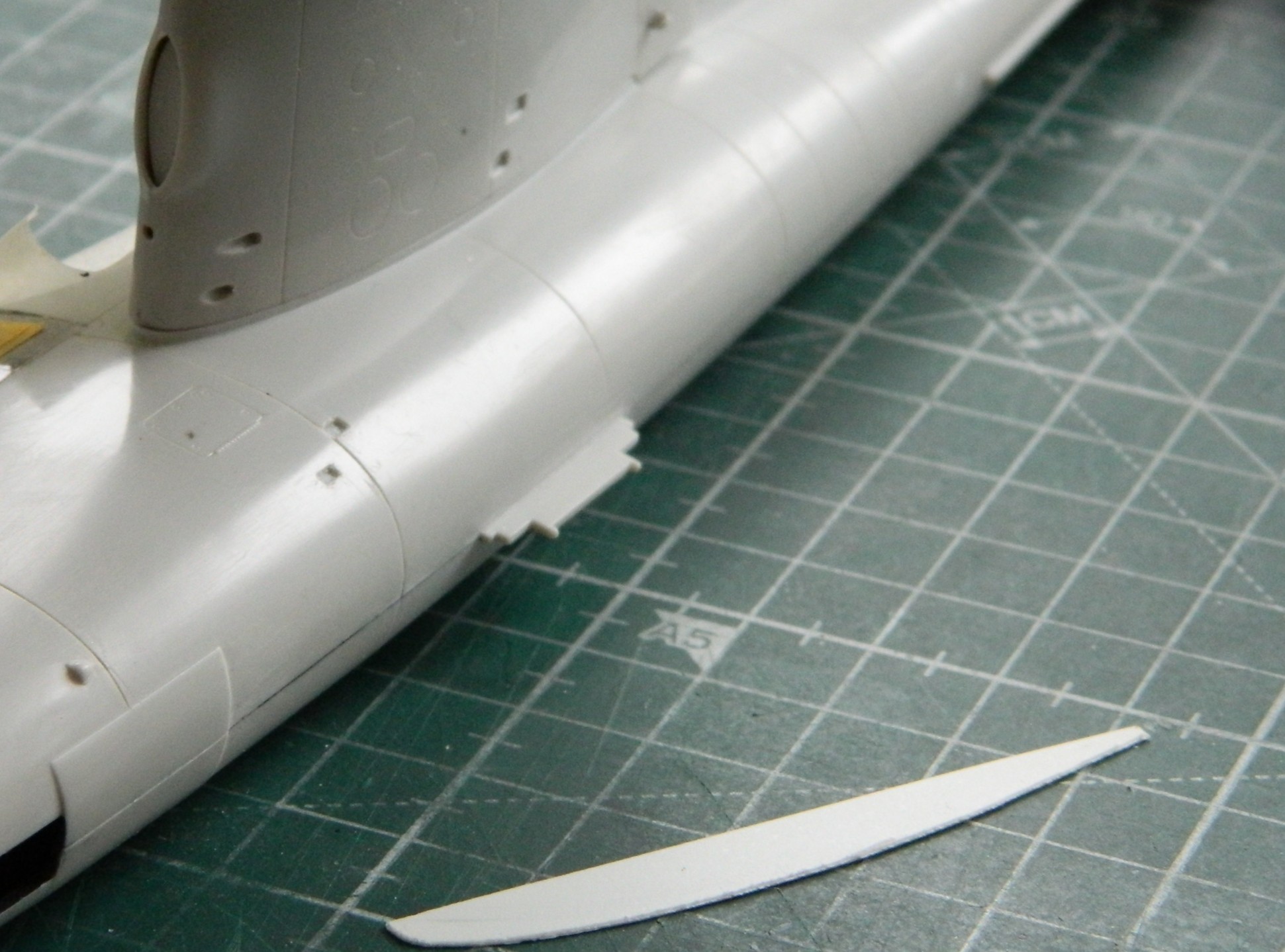
This was a big fighter and sat well off the ground. To get into it, there was a retractable boarding ladder in the lower right fuselage behind the wing. Ever been around an airfield where the aircraft are worked on? Let’s see…an aluminum tube ladder extending downward. I wonder if anyone’s ever backed a truck or tug into one and damage the snot out of the ladder and its mounts? Probably. So instead of mounting the ladder extended, I decided to model it in its stowed position. I clipped the ladder away from the part that attaches to the fuselage and then filed and sanded it down and scribed the panel lines:
The drop tank needed a little bit of detail. I used the punch/die set to knock out a disc that I could use as the filler cap. A piece of 0.010″ (.254mm) was used for it. Once it was mounted, a small amount of 3M Acrylic Putty filled in the edges of the disc that didn’t match the curve of the drop tank:
And while it was in my notice, I used a piece of 22 gauge wire and fashioned a painting handle for it and then set it aside:
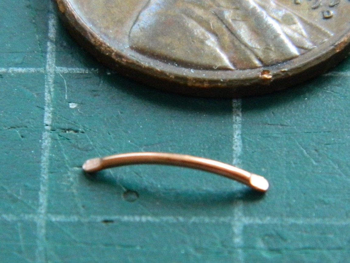
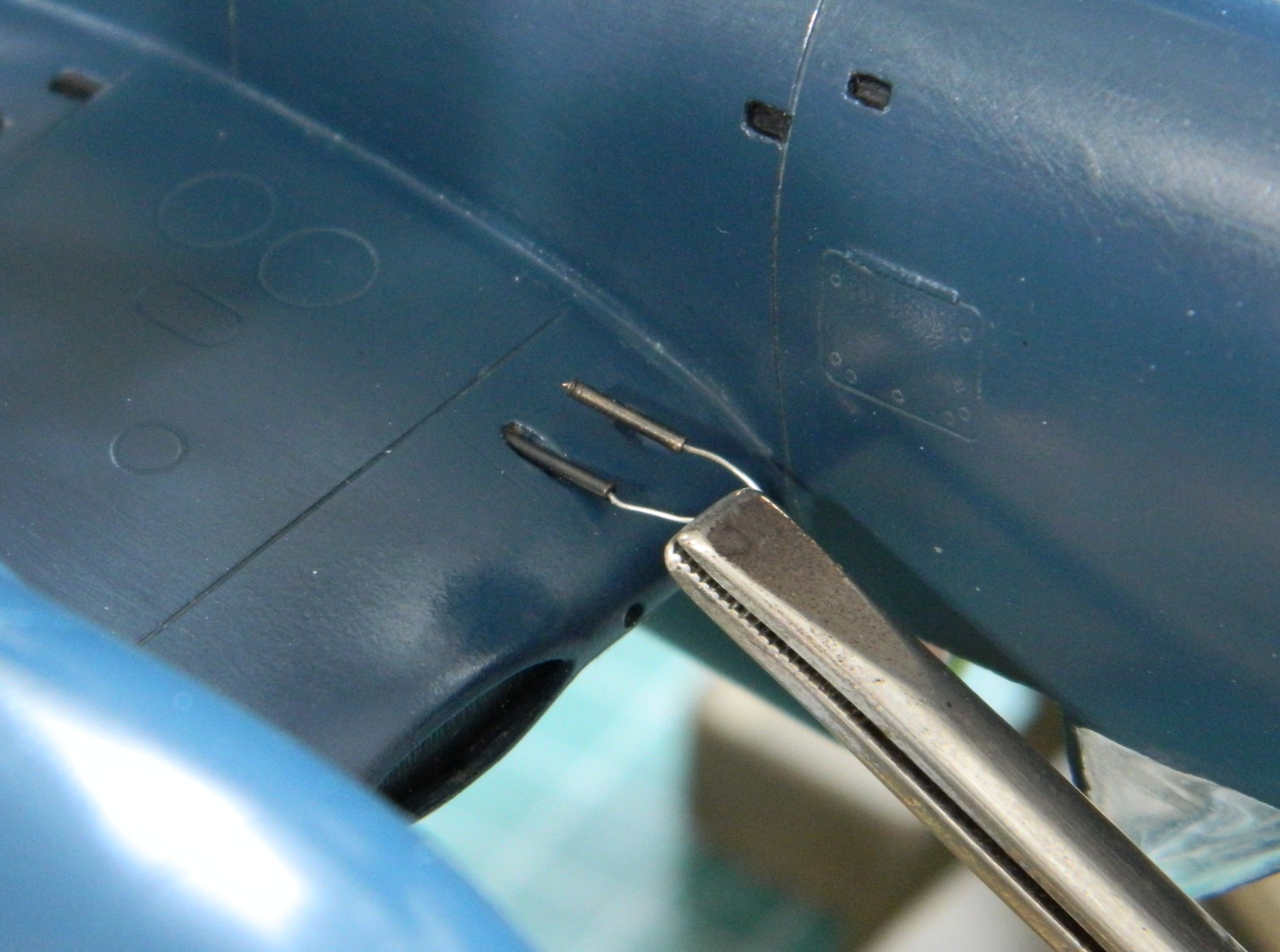
When the tank is hung from its pylon, anti-sway braces are used to keep if from flapping around (always a good idea with an aluminum cigar filled with highly flammable stuff). And though the kit provided the braces, I thought they were out-of-scale. I used more 22 gauge wire to make more scale-appropriate braces:

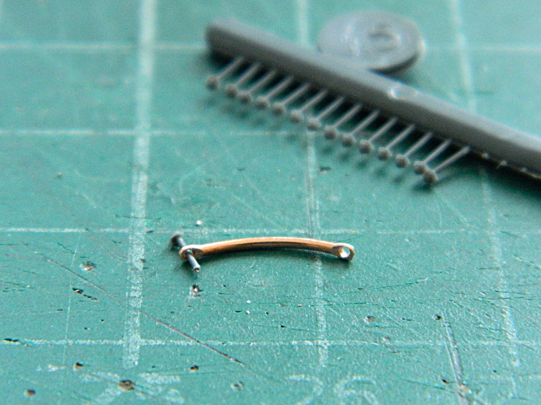
As you can see, the ends of the wires are square cut, but the ends of the braces are rounded. I used a file and pliers to round off the ends of the wires. Once done, I have flat-jawed pliers (not textured for grip) (or her pleasure) that I held the wire with while I filed the ends round. The next step was to take the same flat-jawed pliers and grabbed just the ends of the wire and SQUEEZED to create the flat ends, which I then drilled out for the adjusting bolts:
After drilling, I used Grandt Line bolts as the adjusters:

Those were set aside until later.
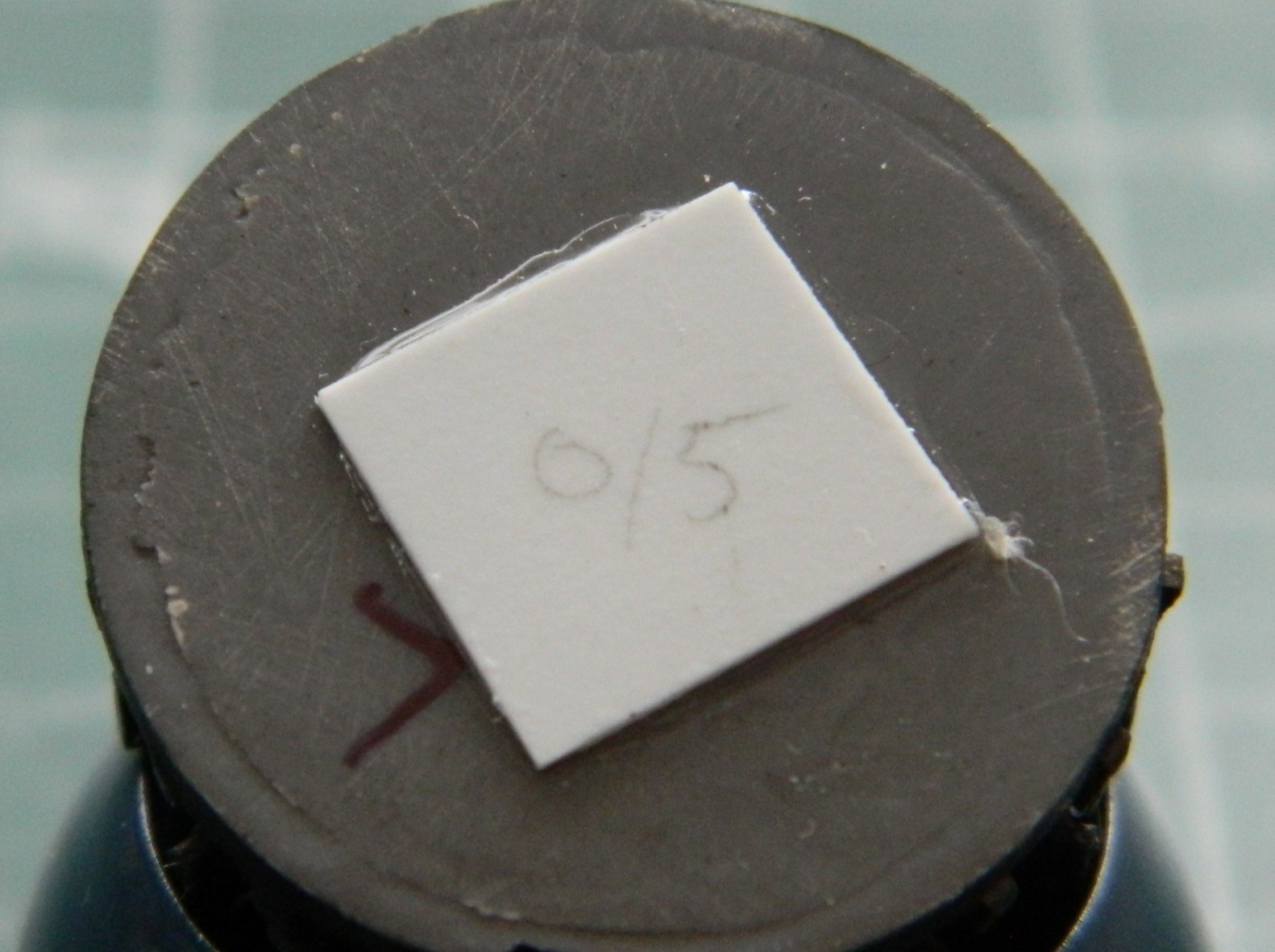
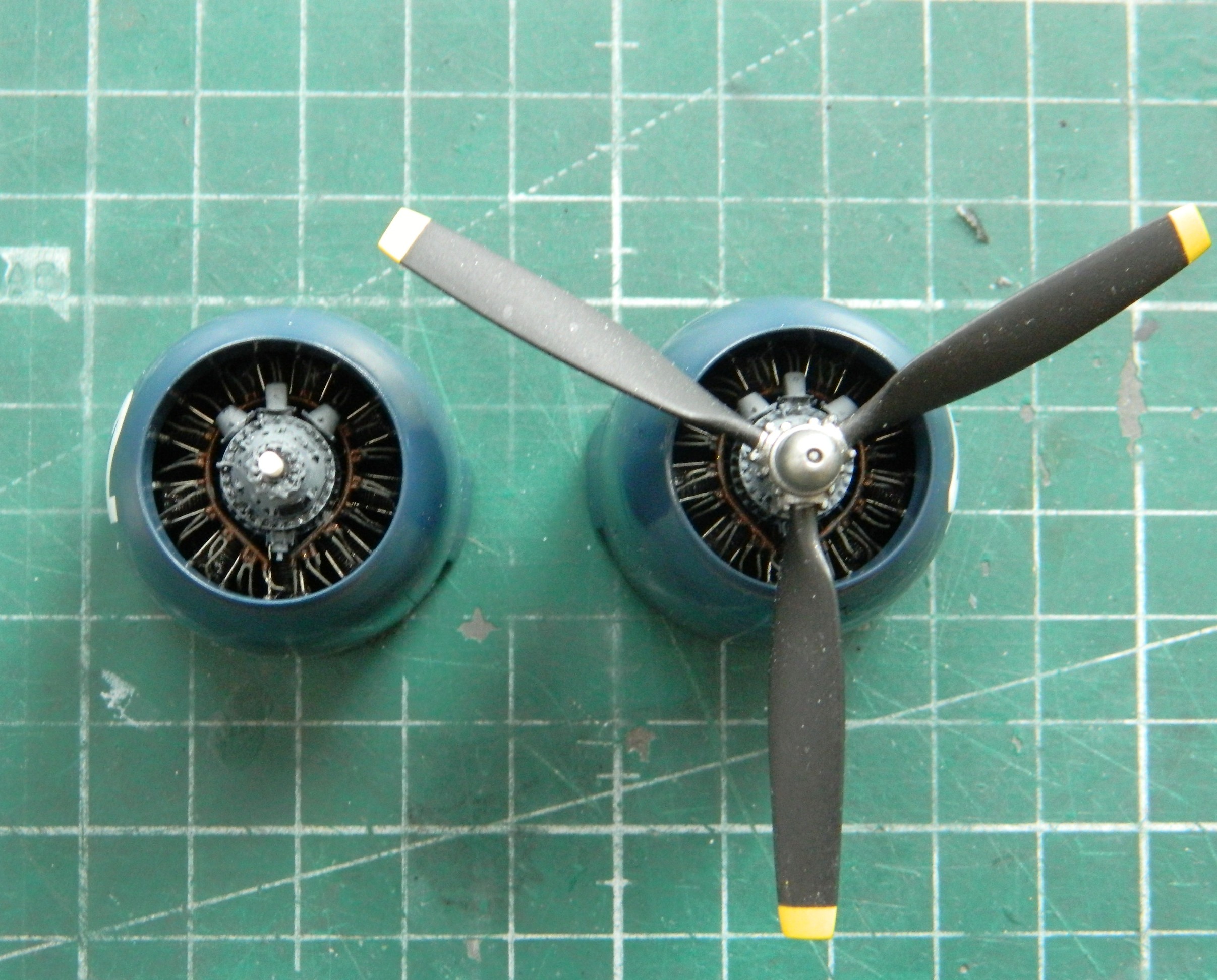
Having painted and applied decals to the engine cowlings, it was time to mount the engines. The engines are AM resin, so fitting them into the cowlings and keeping them centered was going to be the traditional superglue race. I decided not to run that race this time because I RARELY win it. Instead, I used superglue to attach a square of 0.015″ (.381mm) to the resin engines. This way I could do what I did…gob of styrene cement and then take my time getting them centered. (In fact, I was so thrilled with my cleverness that I made a mistake here. I’ll show you that mistake shortly.):
I laid out the landing gear bay doors to paint them:
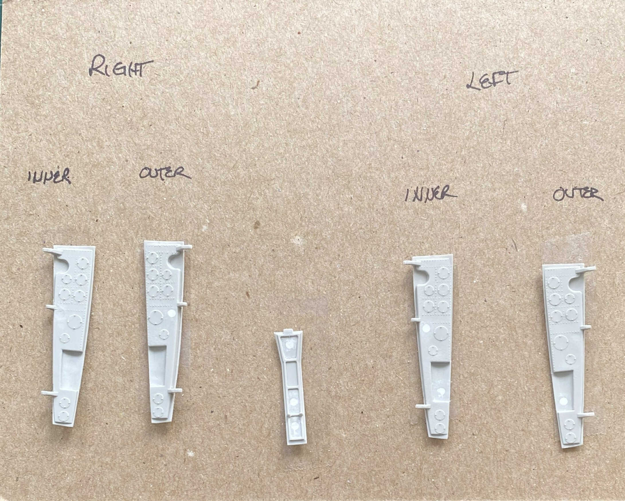
Then painted them using Tamiya XF-16 Flat Aluminum and then a black oil paint wash (now that it’s too late to fix it, I really should have used my darkened aluminum paint instead). Double-sided tape was used to keep the airbrush from blowing the parts into oblivion:

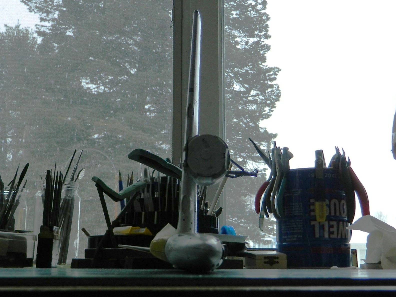
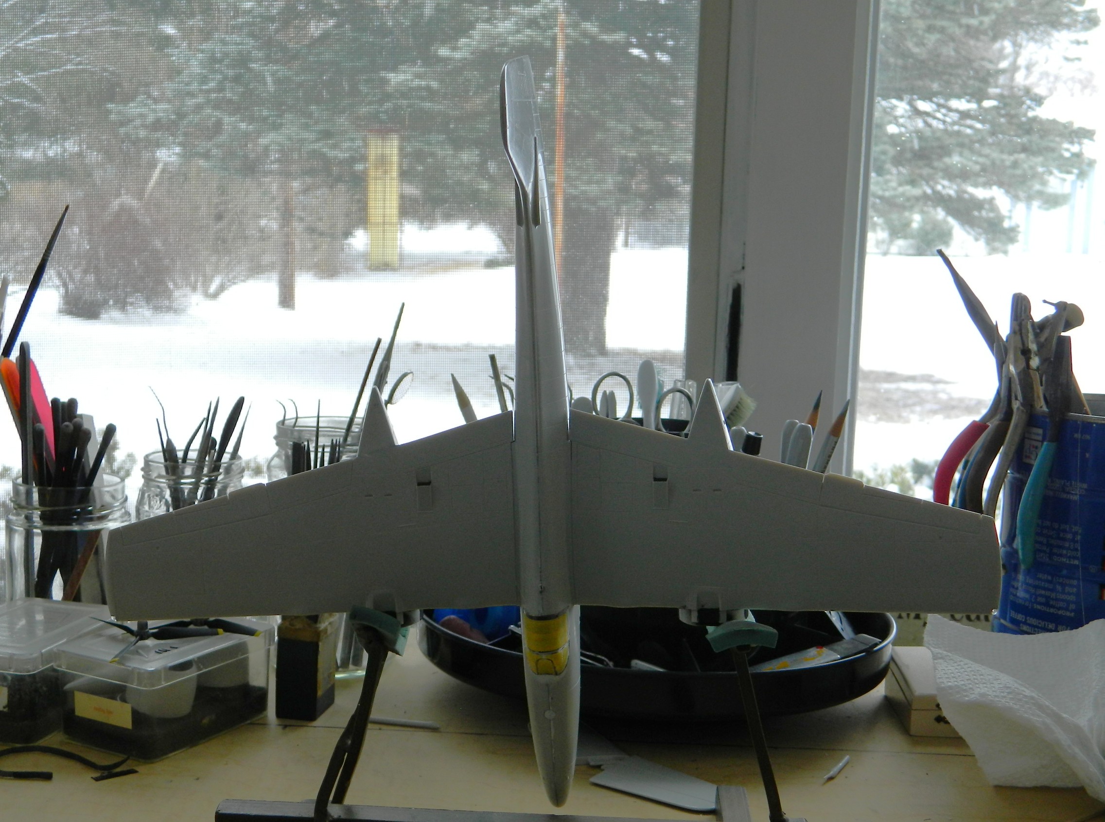
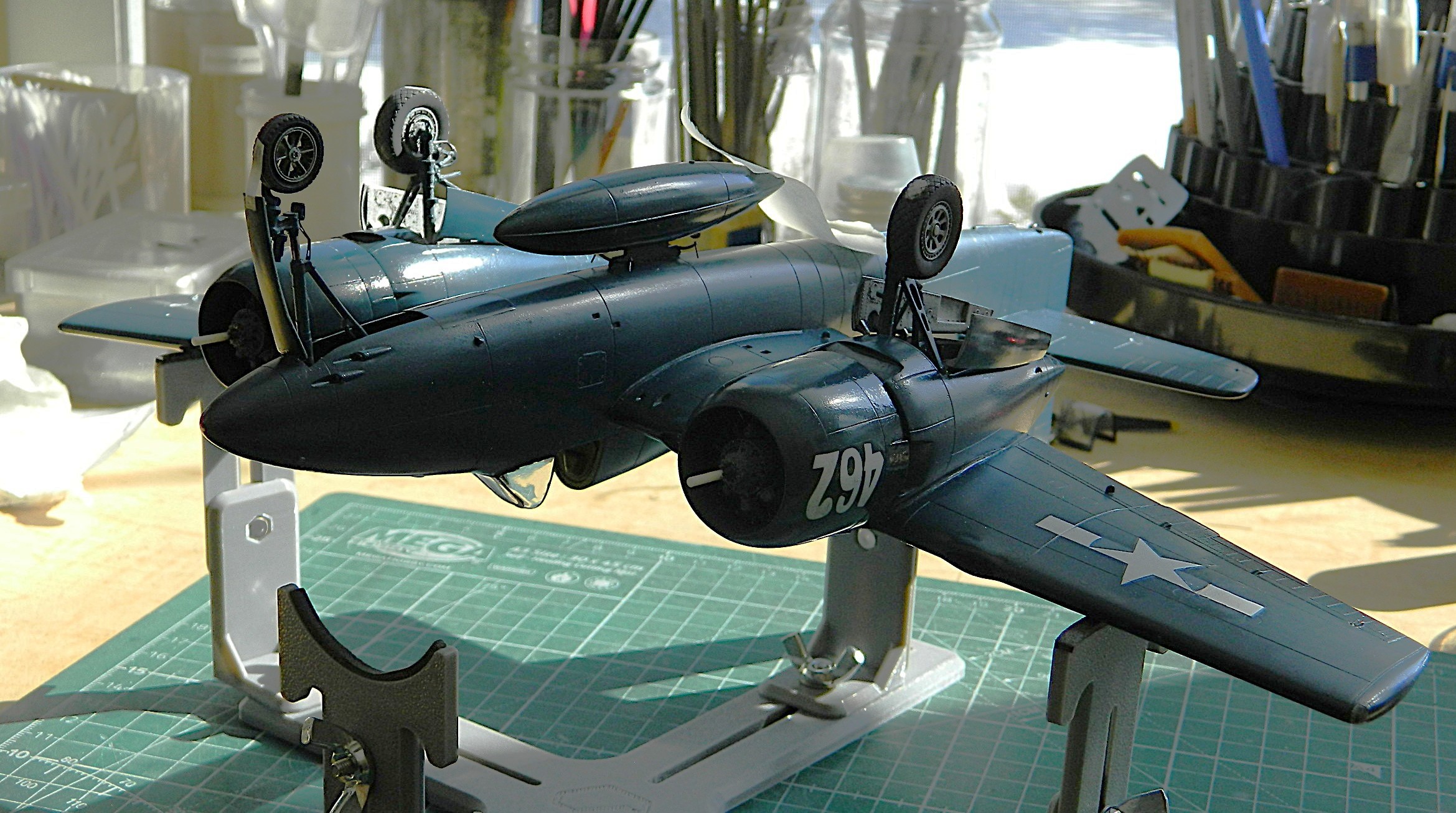
My roommate is very bothered by the smell of rattle-can paint and turpentine (no…I don’t have a spray booth). The AS-8 Navy Blue, being lacquer, has a pervasive odor so that means I won’t spray it indoors. I bring the model and the rattle-can into the garage and spray quickly before the temperatures of the paint and plastic approach ambient temperature (because this month has be single-digit cold here). In looking at this photo, can you tell where I was holding when I put down the first color coat?:
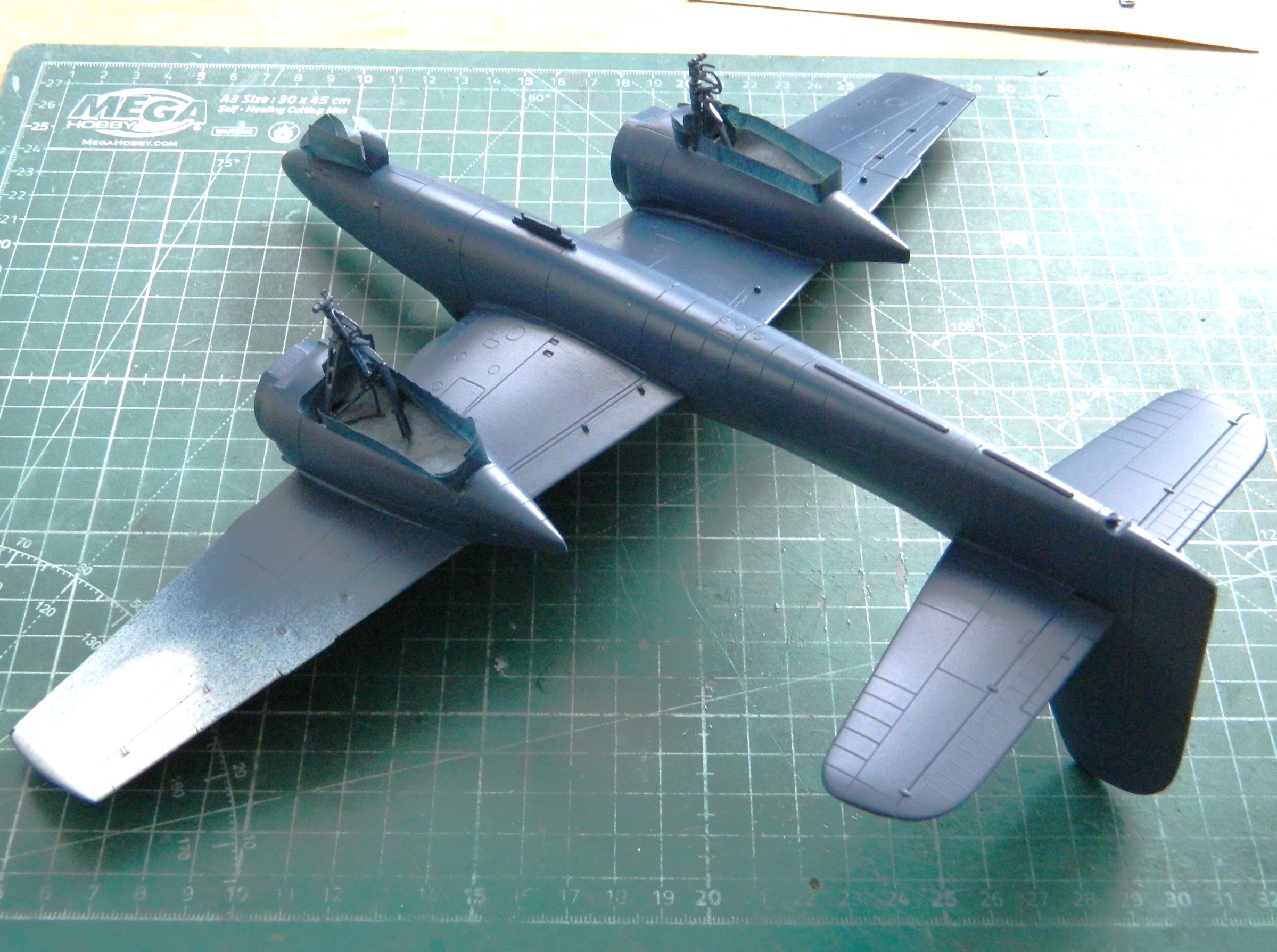
After sitting a couple of hours, I held it by the other wing and painted the other side:
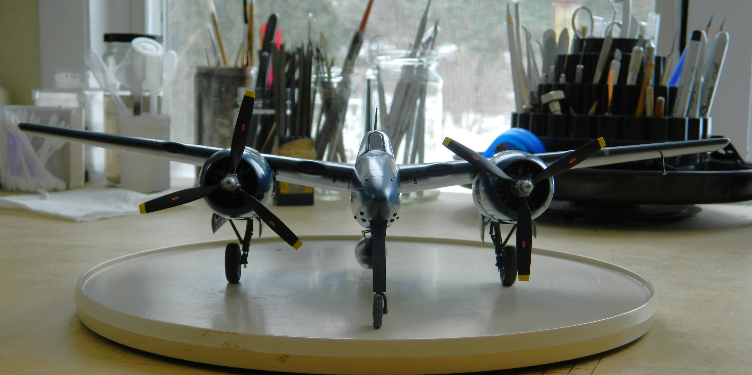
AND I have confirmation that this will not be a tail-sitter…I still have the 27g engines/cowlings to add. Once the paint had dried to touch, I flipped it back over and painted the wing where I’d held it during the first pass with the ‘can.
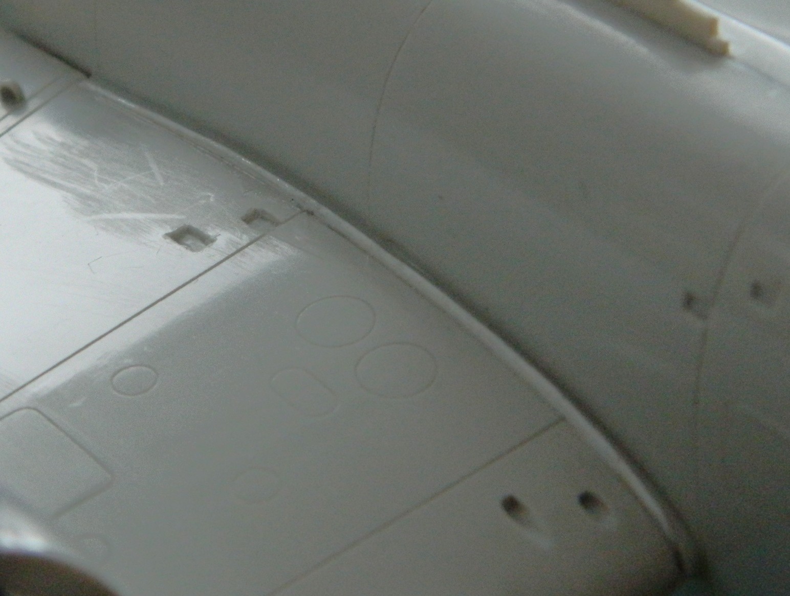
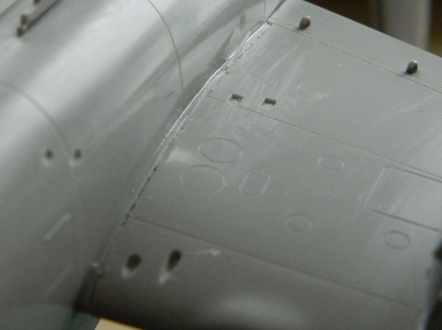
Once the paint had dried (the next day, in other words), I gave it a look-over and saw that the seams still needed some attention in a couple of places:

And I also noticed that I hadn’t been quite as effective as removing scratches from the surface(s) as I thought I’d been, so those needed attention as well:

I don’t know why, but I also decided to check the lights. When I paint with acrylics, I’ve discovered that the acrylic paint is so easy to remove that I don’t bother masking at all. I do my painting, take a fresh toothpick and carve a chisel tip to it, and simply remove the paint with it that’s where I don’t want it. Here’s where I discovered that not only does lacquer smell, it’s not possible to do that toothpick trick with, so all the landing and formation lights were sanded and polished and then masked off using tape:
When taping really small things, I’ve learned that cutting masking tape into really thin strips helps a lot. For the wingtip lights, I masked the borders of the clear covers with tape and then filled in the rest of it with PVA:


I started to mount the engine/cowling assemblies, only to find that they didn’t fit. Okay…they fit when I dry-fitted them, what’s changed. A two word question. “What’s changed.” It took me several hours over a couple of days to find out what the problem was. I was utterly unsurprised when I found the source of the problem.
Me.
I looked and diddled and removed the plastic that I thought was in the way:

Nope…didn’t fix it. And then I figured out what the problem (with its foundation in me) was…
The R2800 series of engines are double rows of nine cylinders. The way Grumman did the exhausts, each cylinder has their own exhaust and they’re clustered in four groups. All but the bottom exhausts have four ends and the bottom exhausts have six. Y’know, if you mount the engines upside down, THERE WILL BE FIT PROBLEMS. Somehow, I mounted the sodding engines upside fucking down. There was no way that I’d be able to dismantle the engine/cowling assemblies without destroying all of it (glue’s cheap, y’know). Okay. So the problem is that I’m trying to stuff six things (exhaust pipe ends) into a space intended for four things and anyone whose age comprises two digits should know that. Normally I know that. If I knew how I made such a basic error, I’d not have made the error. (And I debated if I’d even bring you…plural, I hope…into the sphere of my oversight. But my deal with myself was to make this site as real as I can, and that, lads and ladies, means showing you my errors as well as my accomplishments. ::facepalm::)
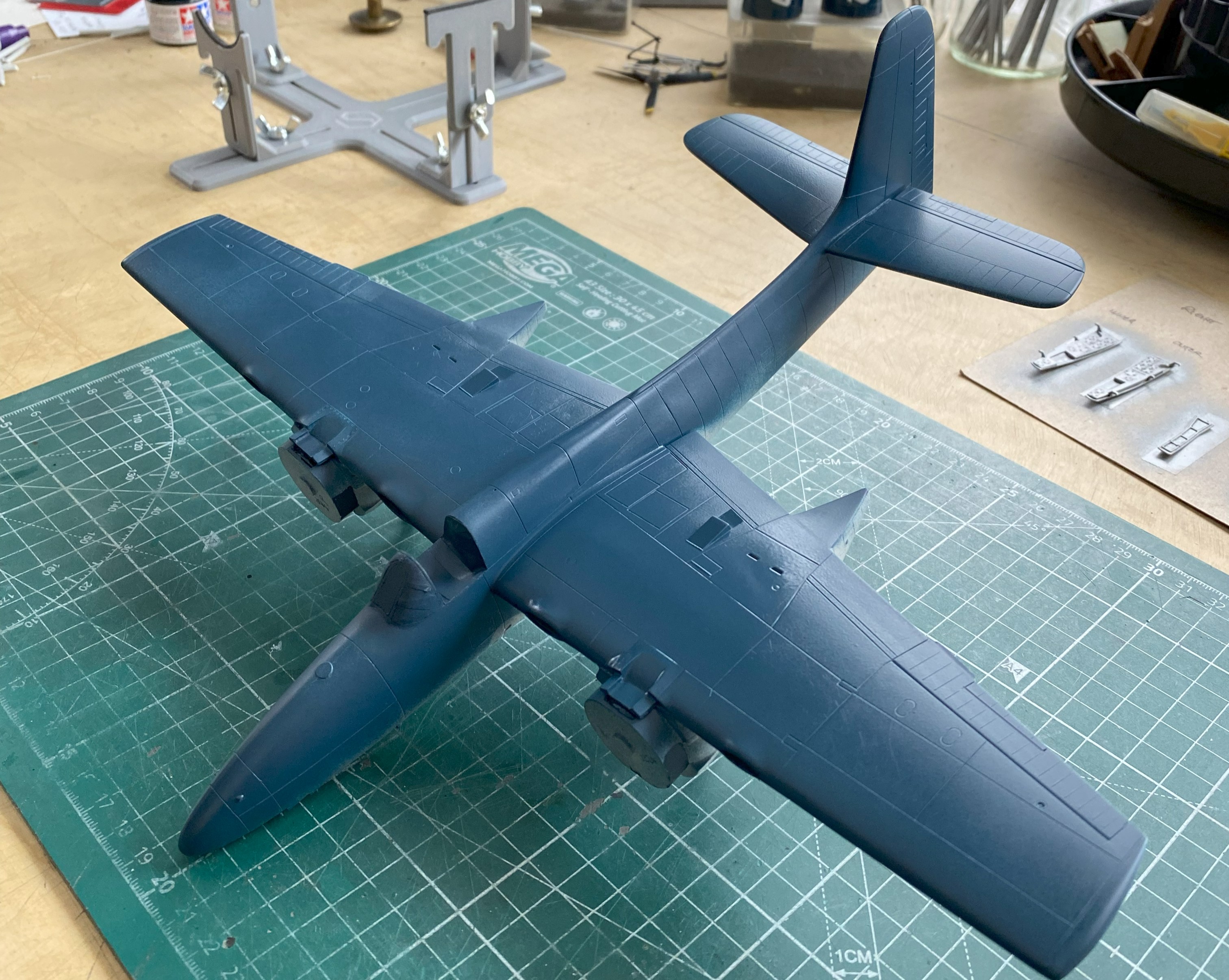
With the mistake “fixed,” the cowlings fit the wings.
At this point, I’m getting to all the things that inhabit my “I’ll do that later” roster. One of them is the antenna. I’m going to use EZ-Line, 0.02″ (.127mm) for the aerial. I’d drilled out a socket for it at the tip of the vertical stabilizer, so I had to figure out how to mount the other end to the mast. Almost immediately (because it’s become clear to me that the only things I can do immediately is break something or attach it upside down) I realized that the tip of the mast is too thin to drill out. Instead, I used a very sharp scalpel to cut a V-shaped groove near the tip of the mast so that I could lay the line in, apply the UV-setting resin, and see if that worked. It did:


The other thing I did (which I didn’t take photos of) was shoot the whole bird with Tamiya X-22 clear. Well, that’s not all I did. I also managed to cover most of the thing in orange peel. Orange peel is that pebbled surface (much like an American football) that one gets when one totally cocks up a paint job. In my defense (should such a thing actually exist), I was trying to put enough clear down that it would self level. Looks like the line between self level and orange peel is vanishingly small. Some places that worked, and other places it did not. How does one fix orange peel? Well, one can strip the paint down to the bare surface and do it again correctly, but that’s the last resort. If one is lazy (and I am), and one has enough paint already thrown down (oh boy did I), it can “simply” be sanded flat. Of course, since all solutions create new problems, I had to be careful not to sand through the clear AND the color (which I did in a few places). Sand paint away, add more paint, sand to the correct depth, rinse the sandpaper and repeat (which I also did in a few places). The color coat, though, couldn’t be shot with an airbrush as it was in a rattle-can. I decanted a bit of it into an empty Tamiya paint jar (“just in case” he sarcastically muttered at the time) for touch ups. Since there isn’t any fine control with a rattle-can, I made CERTAIN to mask off areas around the vertical stabilizer when I had to redo the lacquer:

Recovery of the surfaces that I didn’t repaint started with a pass of 1200 grit sandpaper. If I wanted to spend a month sanding, that would have worked. I didn’t. Instead I used 600 grit where the orange peel was really bad. Then I used the 1200, 2000, and plastic polish. That worked.
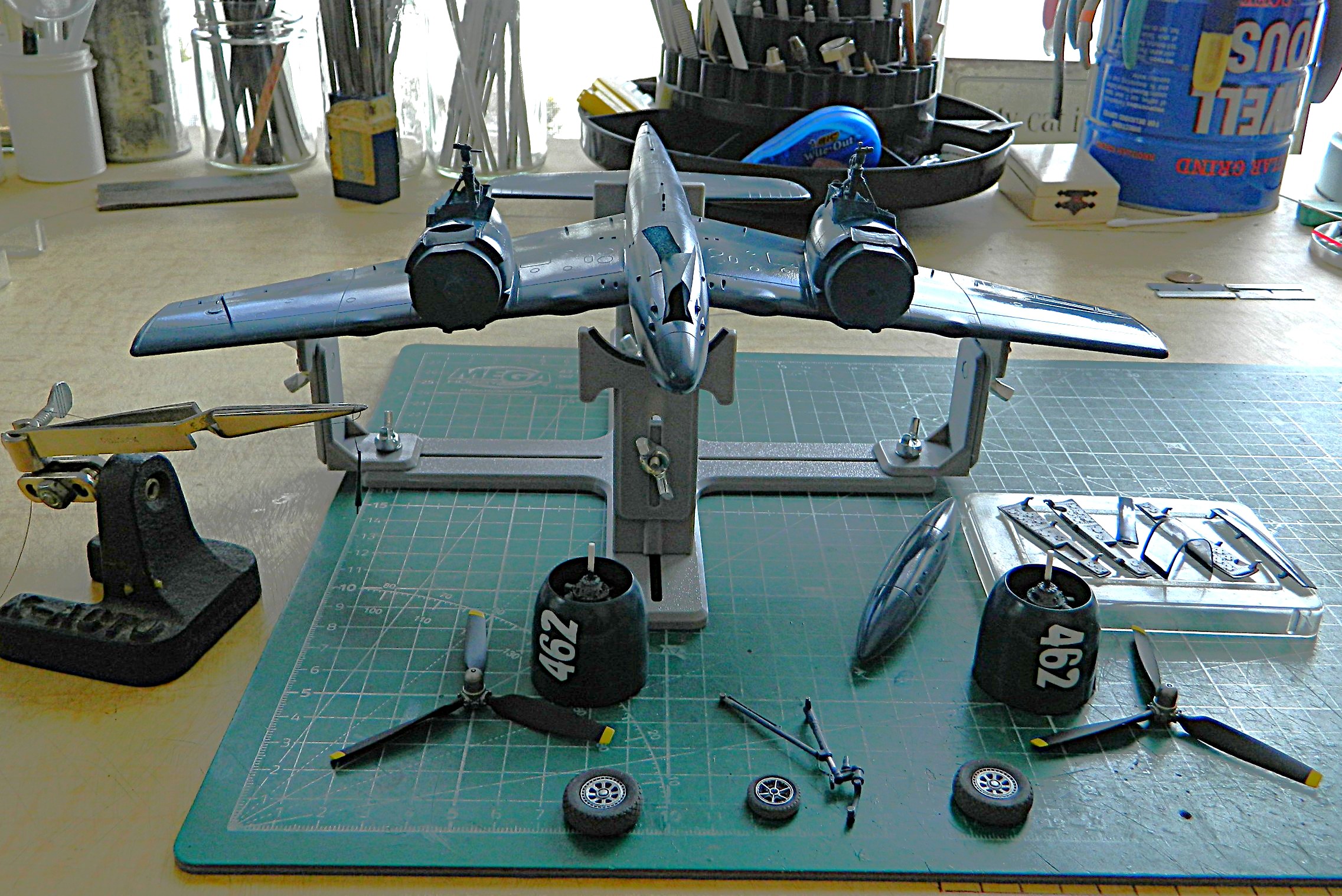
But eventually I ended up here…all the parts ready to assemble:
From here, anything and everything I added was subject to breaking off…which all of them did several times, so it was a week and a half of three steps forward, two steps backward. My favorite.
I attached the landing gear doors…the first time. There were several other “attachments” made:
Then I started applying the kit’s decals. By now I was familiar working with these decals. I applied the Solvaset, and then used a cotton swab soaked in Solvaset to flatten a bubble. Big. Mistake:
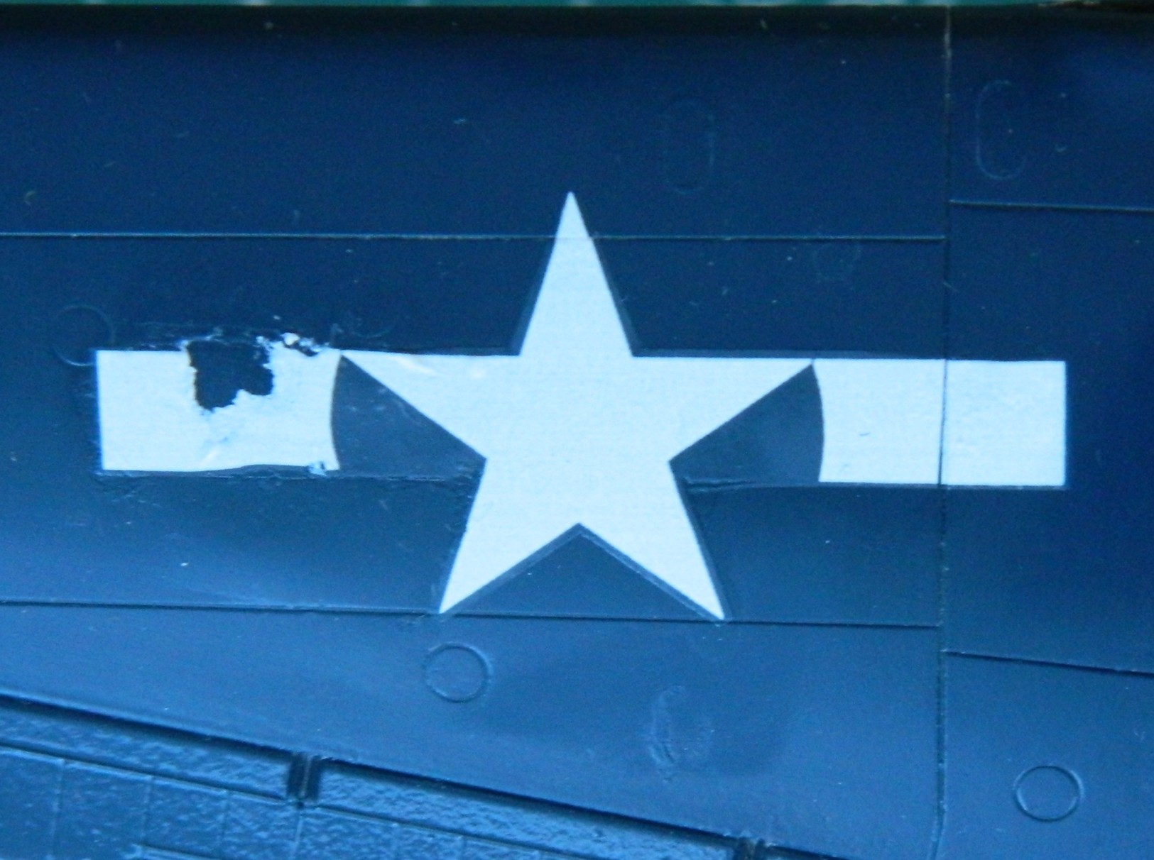
If I’d had another set of decals for this, the one I bitched up would have been sanded off, paint reapplied, and the new decal applied. But I didn’t have any new ones so this one had to be fixed. I masked off most of it and lightly sanded with 1200 and 2000 to bring the texture down and then painted the mistake:

Not exactly show worthy, y’know? Not the clearest shot of it because I was just really annoyed at what I did but this shot shows that from a distance, it doesn’t jump out in the eye. An improvement, if still a botched job:
I added the other decals, of which there weren’t many. I also managed to botch the stars ‘n’ bars on the upper wing on the other side as well as the fuselage markings on the left side. I got one star on without mishap as well as the small production identification markings on either side of the vertical stabilizer. Yay.
Adding small details and closing in on being done, I added the 20mm cannons:
Having painted the oil cooler and intercoolers black (again, as the rattle-can covered what I’d already done), I added the canopy in the open position and used small dabs of UV-setting resin to hold it there, glued the antenna mast into place, and then trimmed the EZ-Line and glued it into the vertical stabilizer, and like that, it’s done: