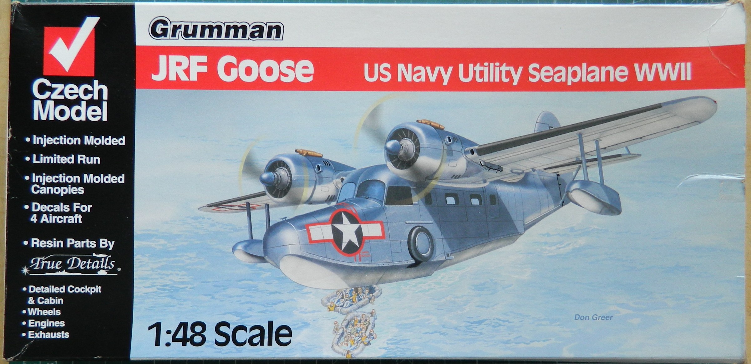
This was what was in the box:


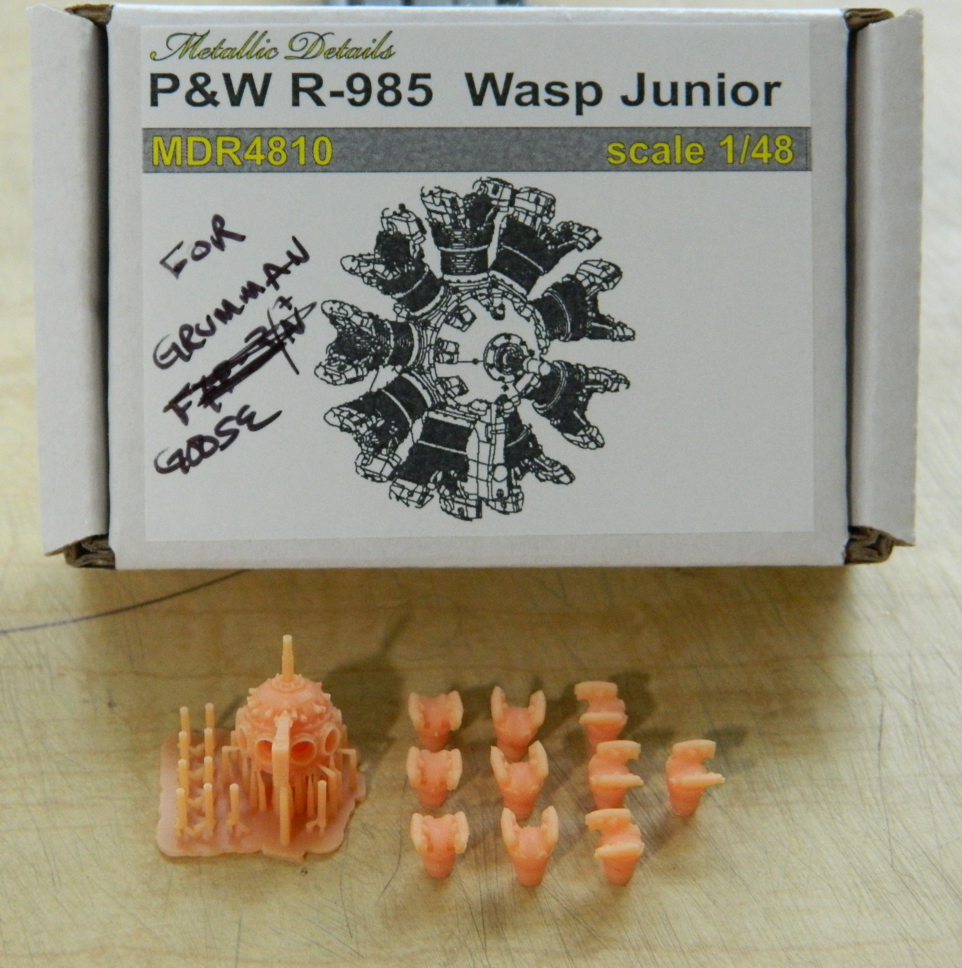
Plus these engines from Metallic Details:
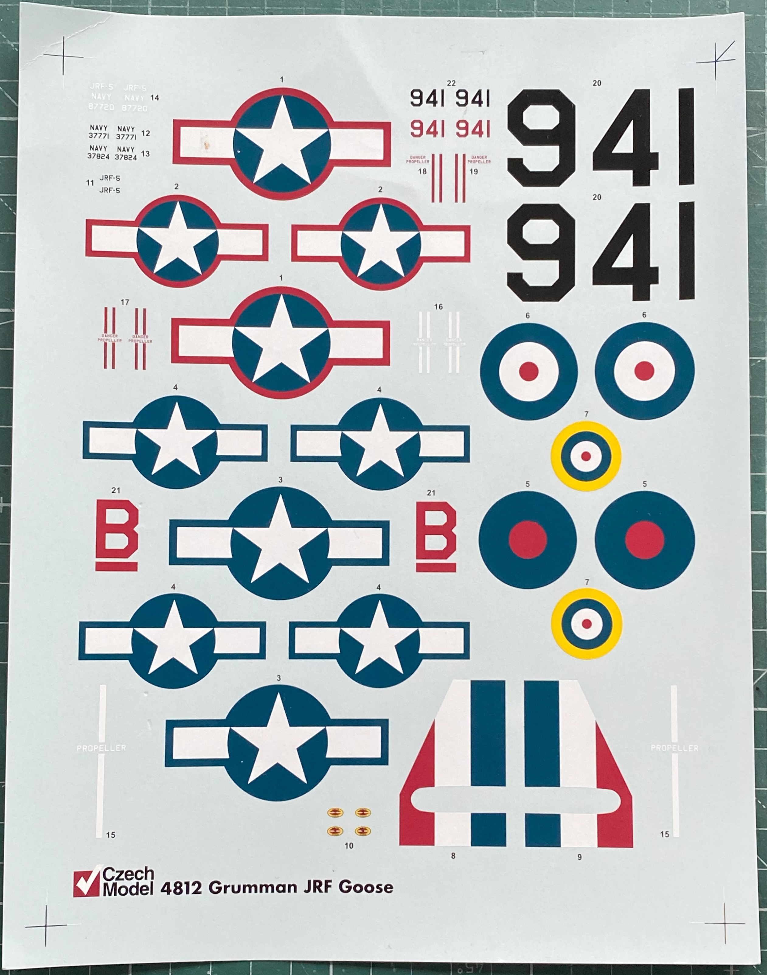
It’s my intention to build this one in its 1944 markings, which means using the national insignia without the red borders. In researching this kit and reading build reviews, the theme here is “limited run” with all that that implies. Thick plastic, subpar fit, and oddly done details. Construction so far has confirmed all that. In one regard I’m getting off with less fiddly work than otherwise would have been the case. Being a high-wing aircraft, that wing gets in the way of seeing the into the cockpit, specifically in this case the instrument panel. So that’s one chore I don’t have to take care of. There were overhead consoles that engine monitoring instrumentation was mounted in as well as throttle and propeller pitch controls. Though the overhead console has to be scratchbuilt, few of the details are necessary since it really can’t be seen. I don’t know how much of the console itself can be seen so the overall shape of it needs to be build, if only to hang the throttle controls from (and maybe the pitch controls as well, which I will find out about later).
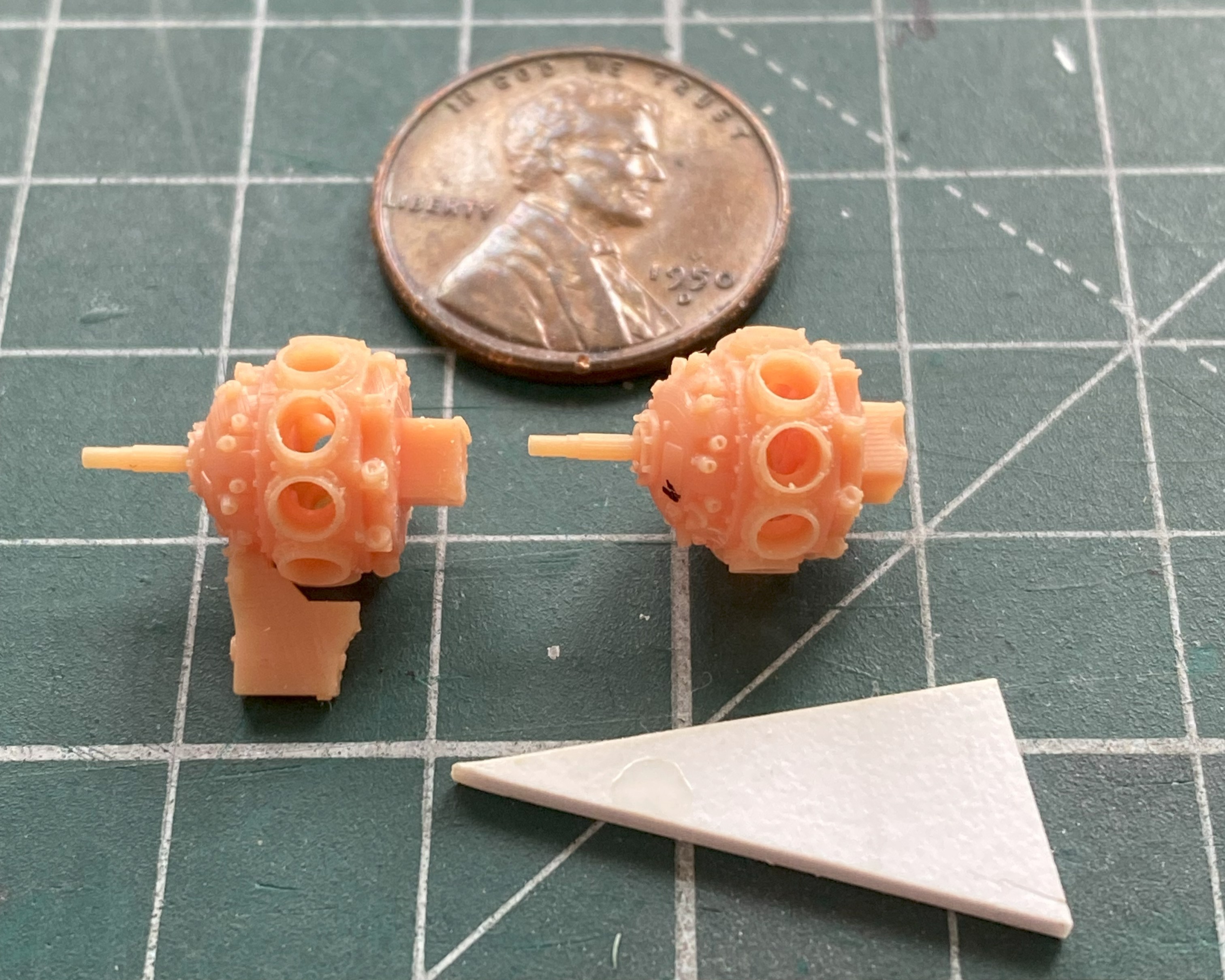
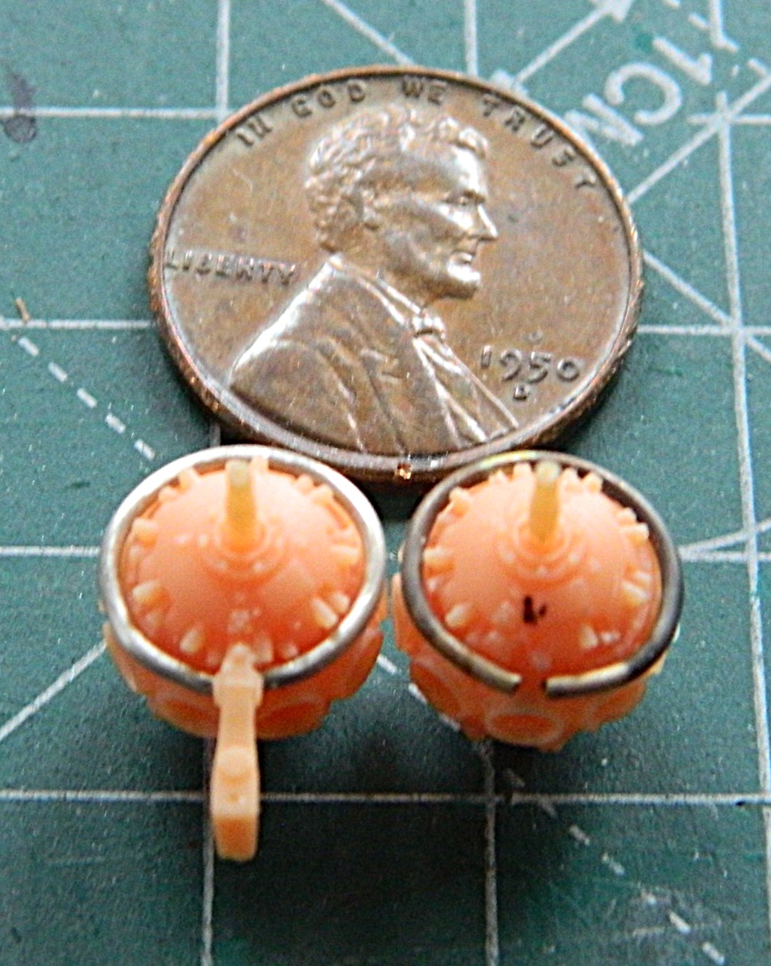
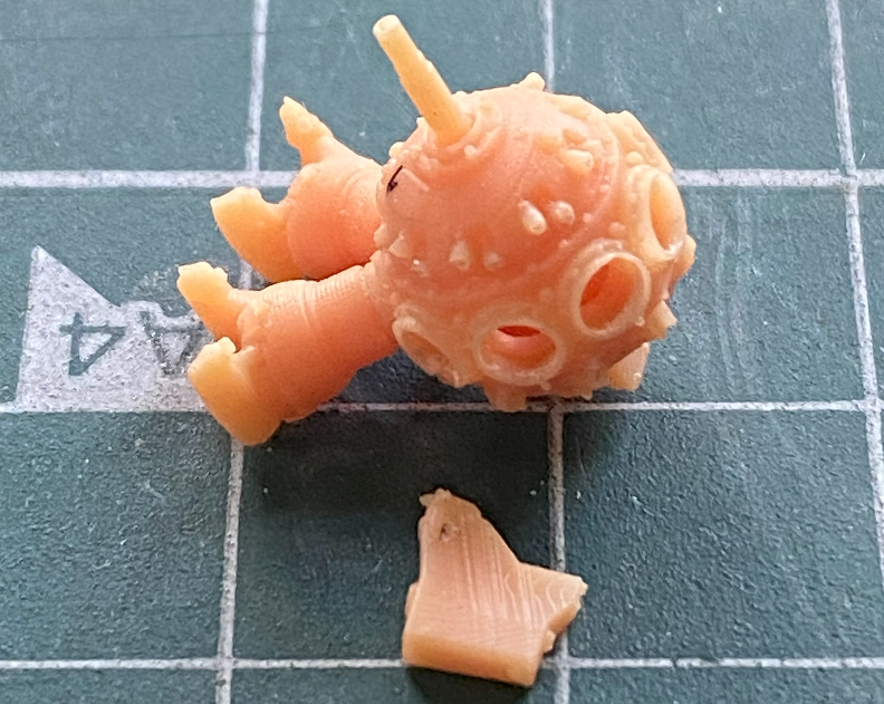
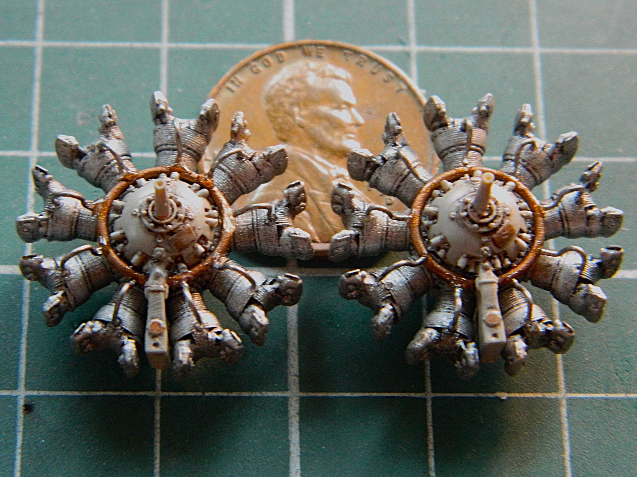
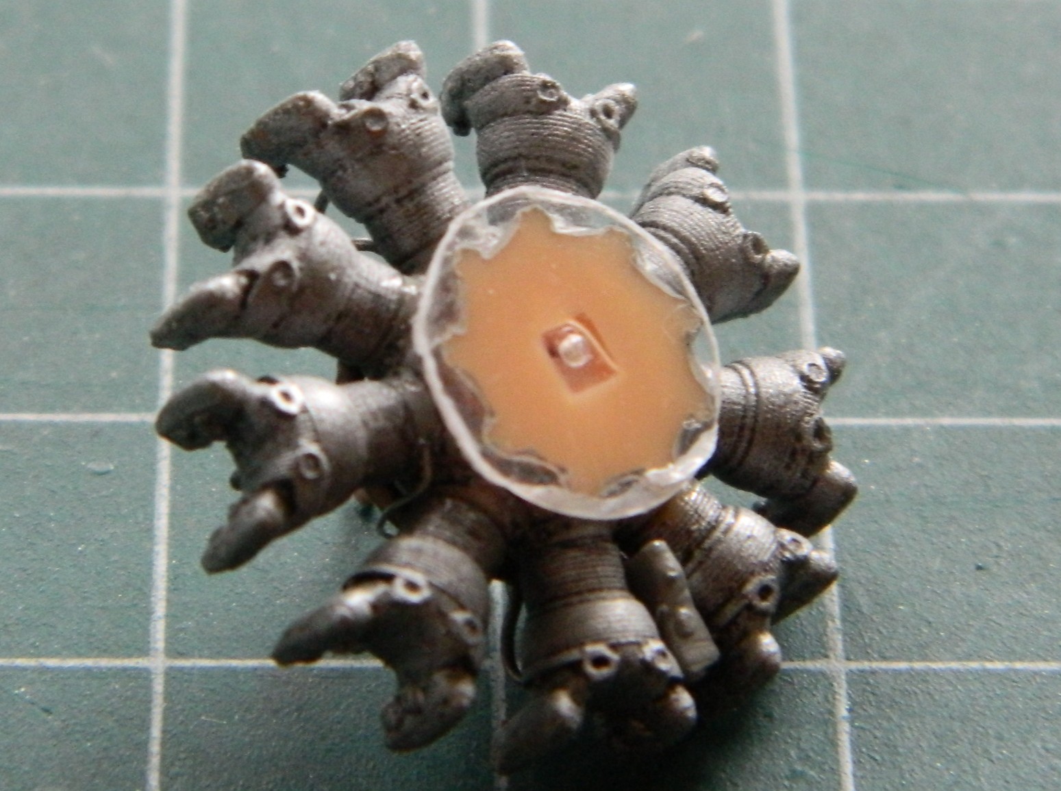
My typical build routine is to start with the cockpit first, but since so little of it can be seen (not the same as none of it since the rear bulkhead of the cockpit will clearly be seen), I decided to start with Metallic Details’ engines. I was about to get a “learning moment” about these particular 3D printed parts…and maybe 3D printed parts in general. If you’ve ever done work on or with as-printed parts, you’ve seen the miniature forest of supports that are necessary for the part to print at all. Those all have to go. I thought I was being careful removing those supports (can you see where this is going?) and for the most part, all went as intended. There is a Mystery Component that is attached to the bottom of the crankcase and hangs straight down. Let’s play a little round of the, “Can you spot the differences between these two things,” game:

If you said, “The Mystery Thing is missing from the one on the right,” you win. While removing the supports underneath the missing Mystery Thing, I discovered that this resin is very brittle. The Mystery Thing just snapped off. And not unusually in my shop, I heard it hit the floor and using my Echo Location ™ ability, I went to where I heard the Mystery Thing hit. Maybe that’s where it hit, but that’s nowhere near where it ended up… I mean, this is my first task and it’s gone sideways. (I never did find out where it ended up.) Fine. I’ll make another one, then:
I was so annoyed at myself for losing a component as part of my first task that I decided that I’d get all the parts of these two engines cleaned up and ready to assemble (or paint…more on that later). That’s when I found out that just because it’s 3D printed, doesn’t mean that the parts that were designed to go together will in fact go to-fucking-gether. The outer diameter of the cylinder jugs (hereafter referred to simply as “jugs”) is exactly the same as the inner diameter of the holes in the crankcases where they’re supposed to go. That means that there isn’t enough space in those holes for the jugs TO go into. [A note to those of you who design and produce these sorts of things: Test fit the goddam parts before you sell the goddam parts.] In order to get the jugs to seat into the crankcases correctly, I had to shorten them (because when I didn’t, each stub at the bottom of the jugs interfered with all the other jugs, preventing any of them from seating properly), and then take my thinnest knife which just fit into the sockets and carve away the GOD DAMNED LIP MOLDED INTO THE BOTTOM OF THE SOCKET! No…not pleased.
Nine jugs per engine and two engines. Holding these small parts with sharp protruding areas right where the fingertips hold them so that the stubs can be shortened and filed to decrease each diameter results in very, VERY, sore fingertips. Once those essentially needless tasks were accomplished (I say, “essentially needless” not because I didn’t have to do the work…because I did…I said it because if whomever had laid out these parts digitally had done their job correctly, none of this work, or sore, VERY sore, fingertips would have been required):
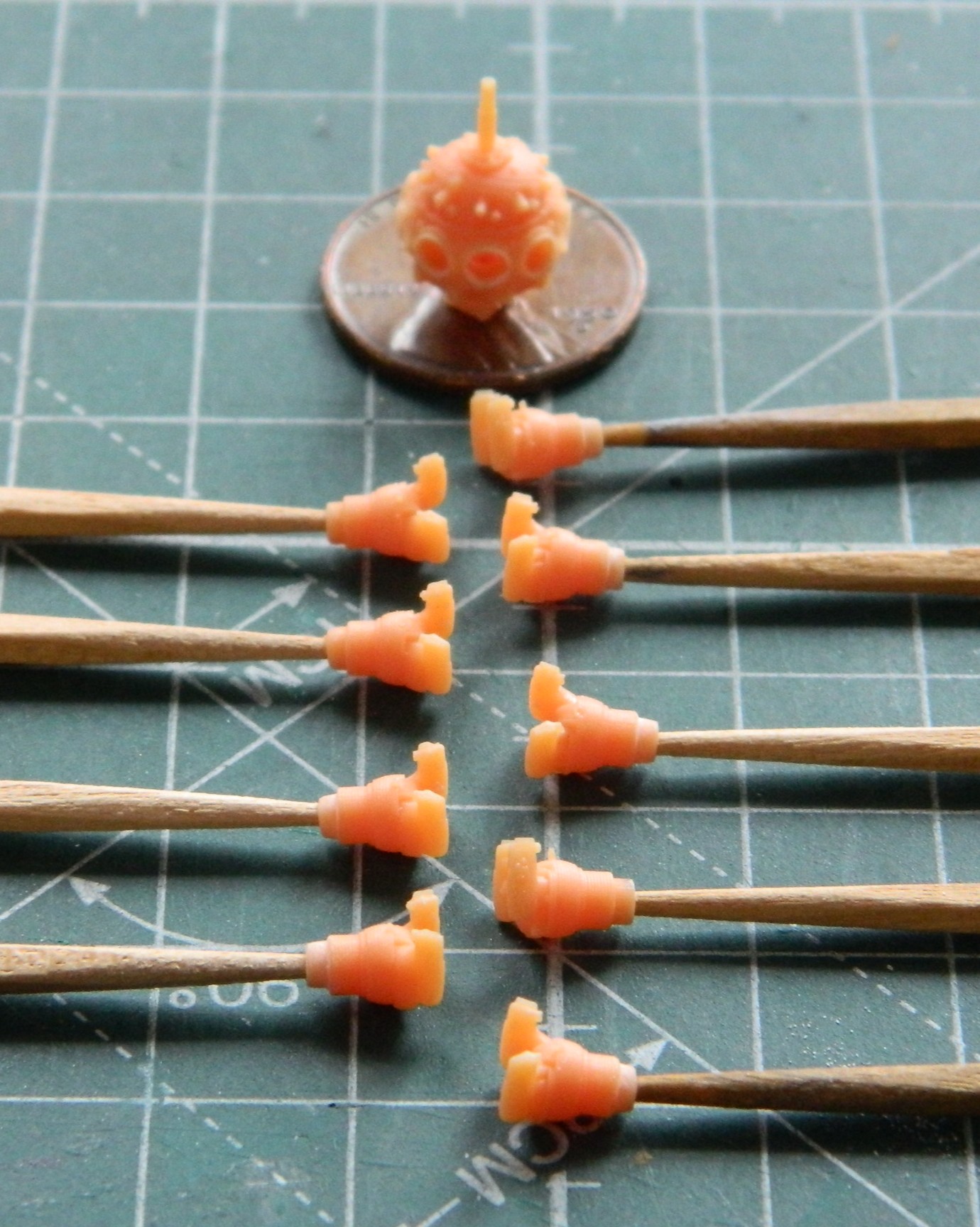
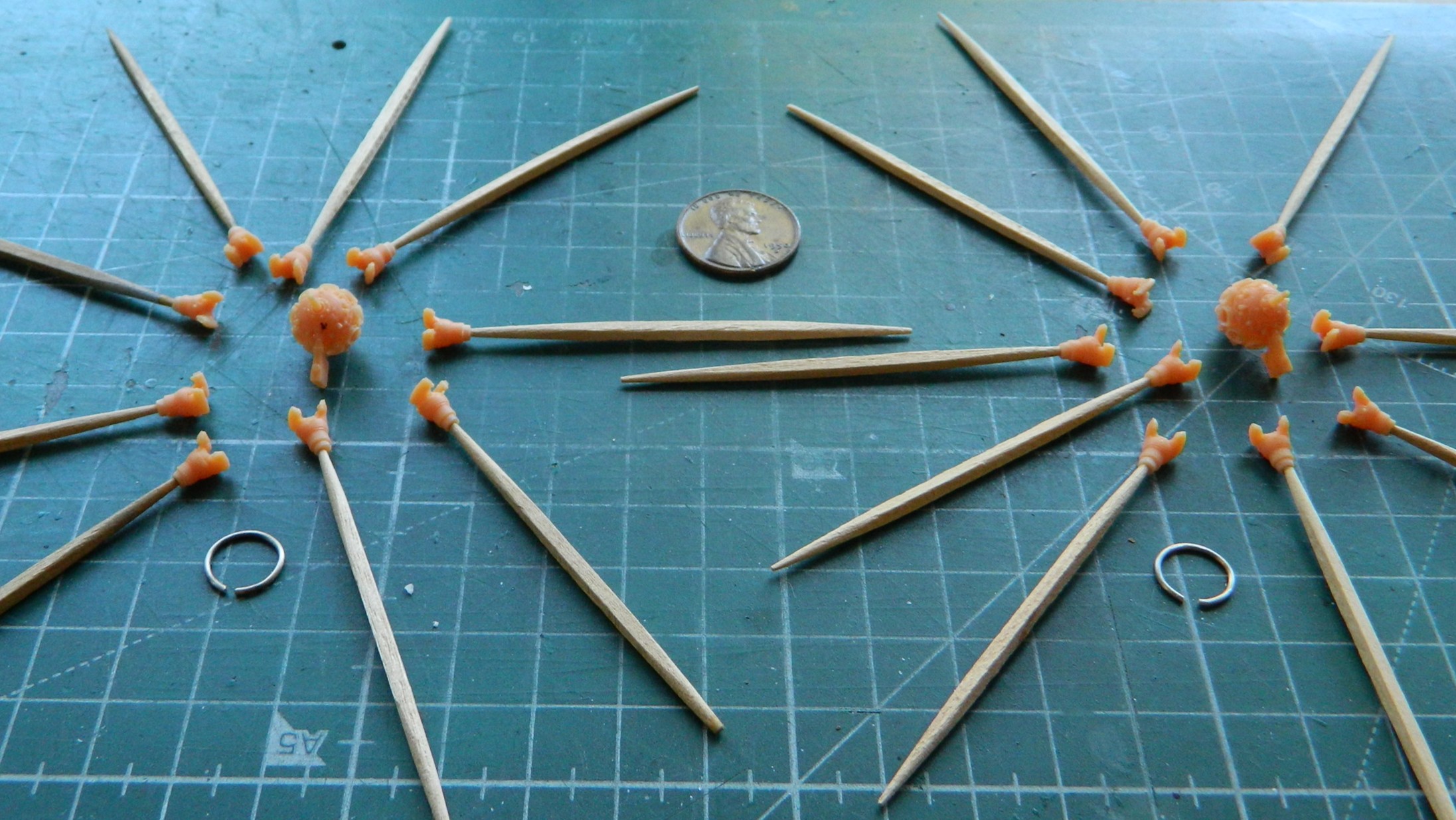
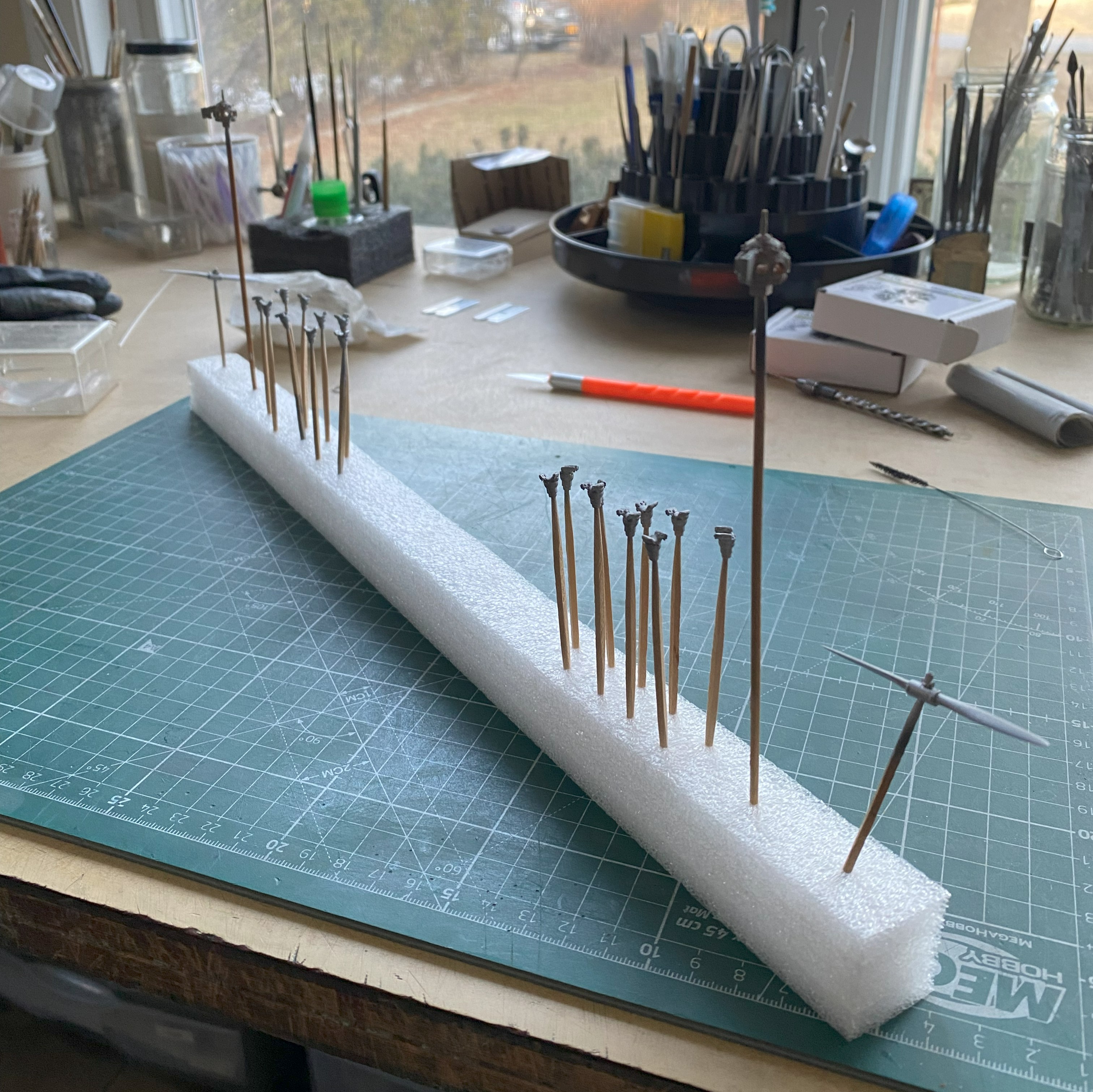
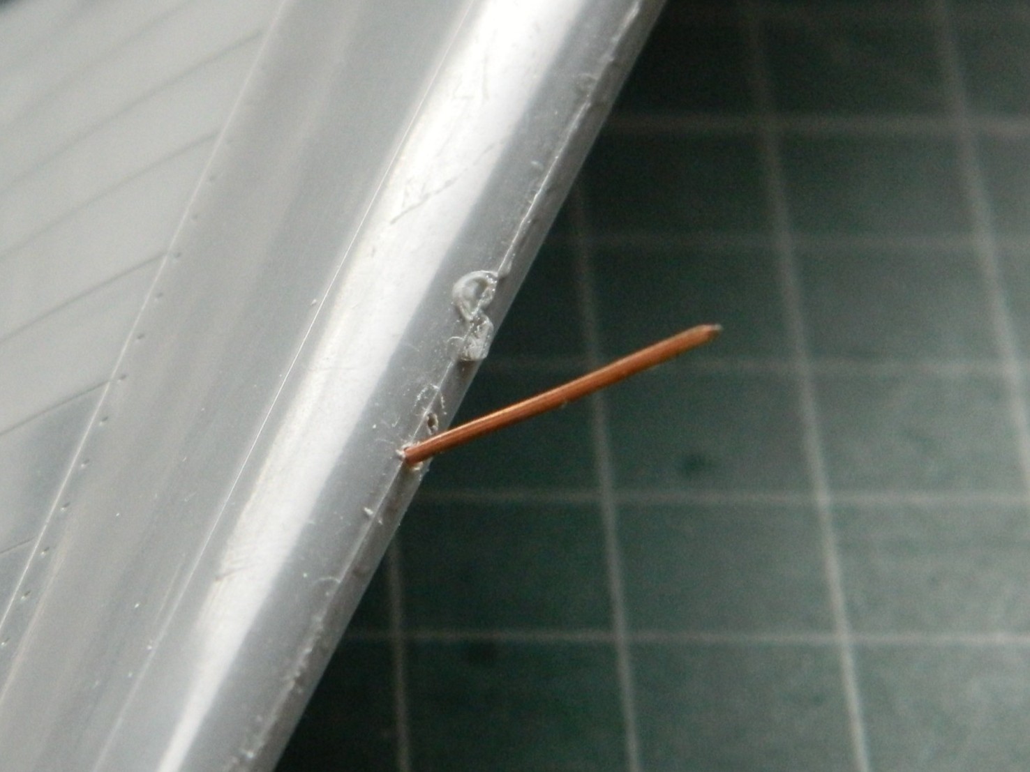
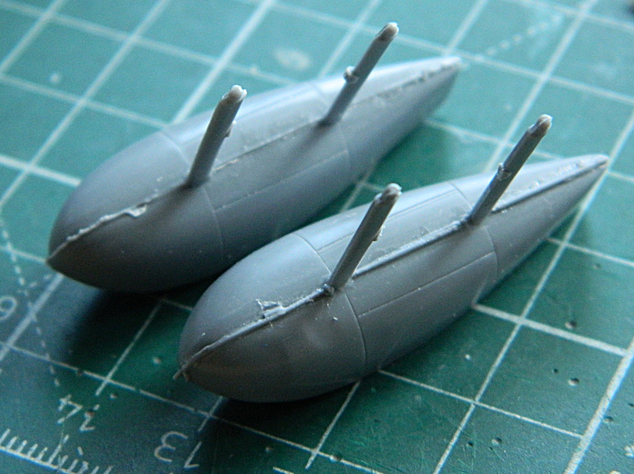
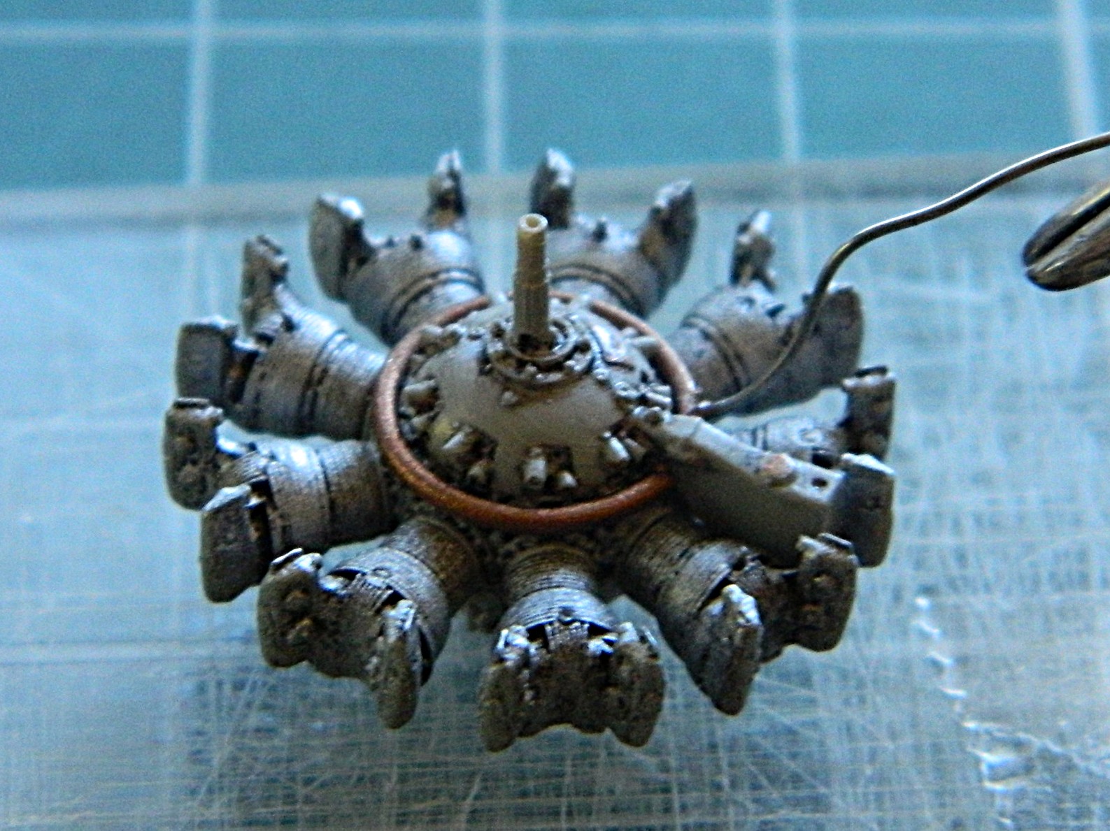
I drilled out the stubs at the bottoms of the jugs so that I could stuff a toothpick into each one to make painting them possible. Sure…I could have assembled the engines and then painted them, but since I’m going through all this supposedly-needless work so that I could assemble them, I’m going to take advantage of that and paint the jugs and crankcase separately and then assemble them. With the jugs good to go, I made the ignition wire ring from copper wires:
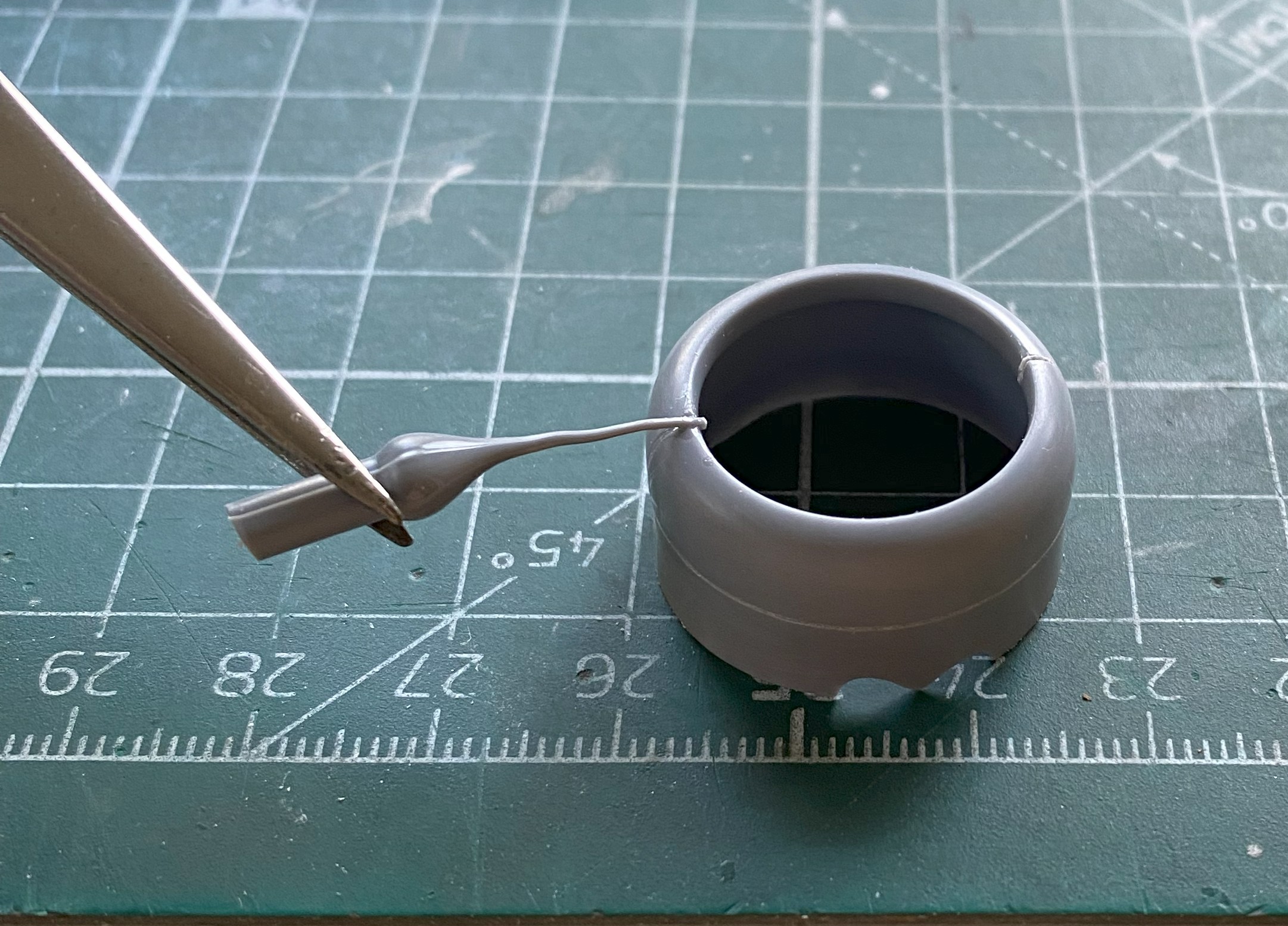
So it’s time to make the Mystery Thing. Which means it’s time to drop the scrap styrene I’d intended to use, bend down to pick it up, and then find the very Mystery Thing that I couldn’t find right where I looked for it to begin with. (And I guarantee you that it was not there when I initially looked for it, regardless of where it first landed on the floor):
I used both UV-setting resin and superglue to make damned sodding sure that this thing, Mystery or not, did not take off again. To be absoLUTEly sure, I added a wire support to the back of it to add strength to its location:
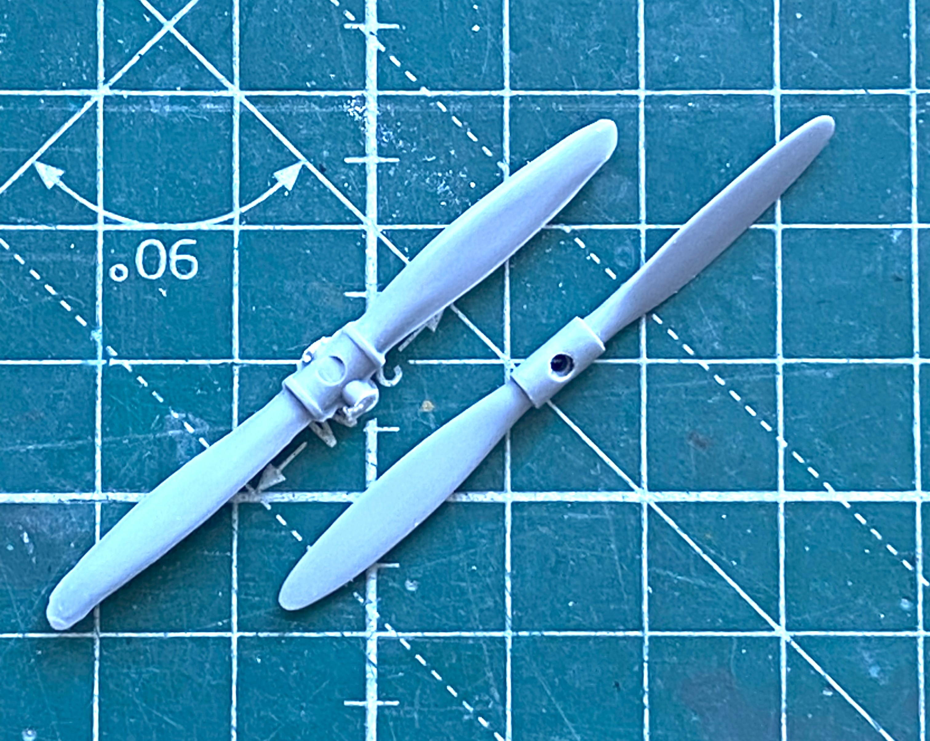
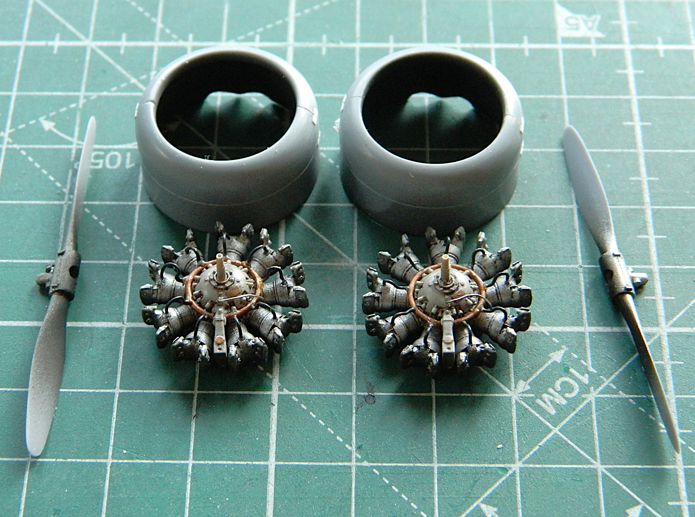
The props on this thing needed some work as well. I haven’t seen any period photos of the prop hubs covered by the shroud the kit provided, so I decided to not add the shrouds but to detail the hubs instead. Obviously, the prop on the right has been started, the one on the left hasn’t been:
I don’t know if I’ve mentioned this before or not. My life is very strange. Strange things happen to me. All. The. Time. The latest (for now) strange thing to happen to me was while I was salami-slicing the parts to make the pitch mechanism. This is how it landed when I cut one slice and the rod I sliced it from slipped out of my hand just as I made the cut:
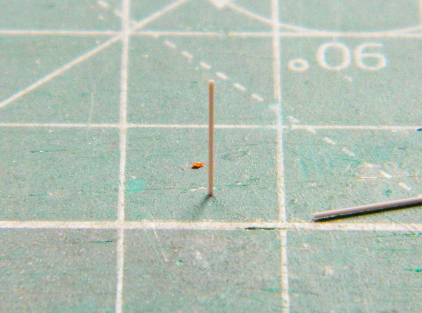
I guess that’s one way of seeing if the cut is square… Seriously. This is my life. ::facepalm::
With the parts all cut out, it’s time to assemble them:
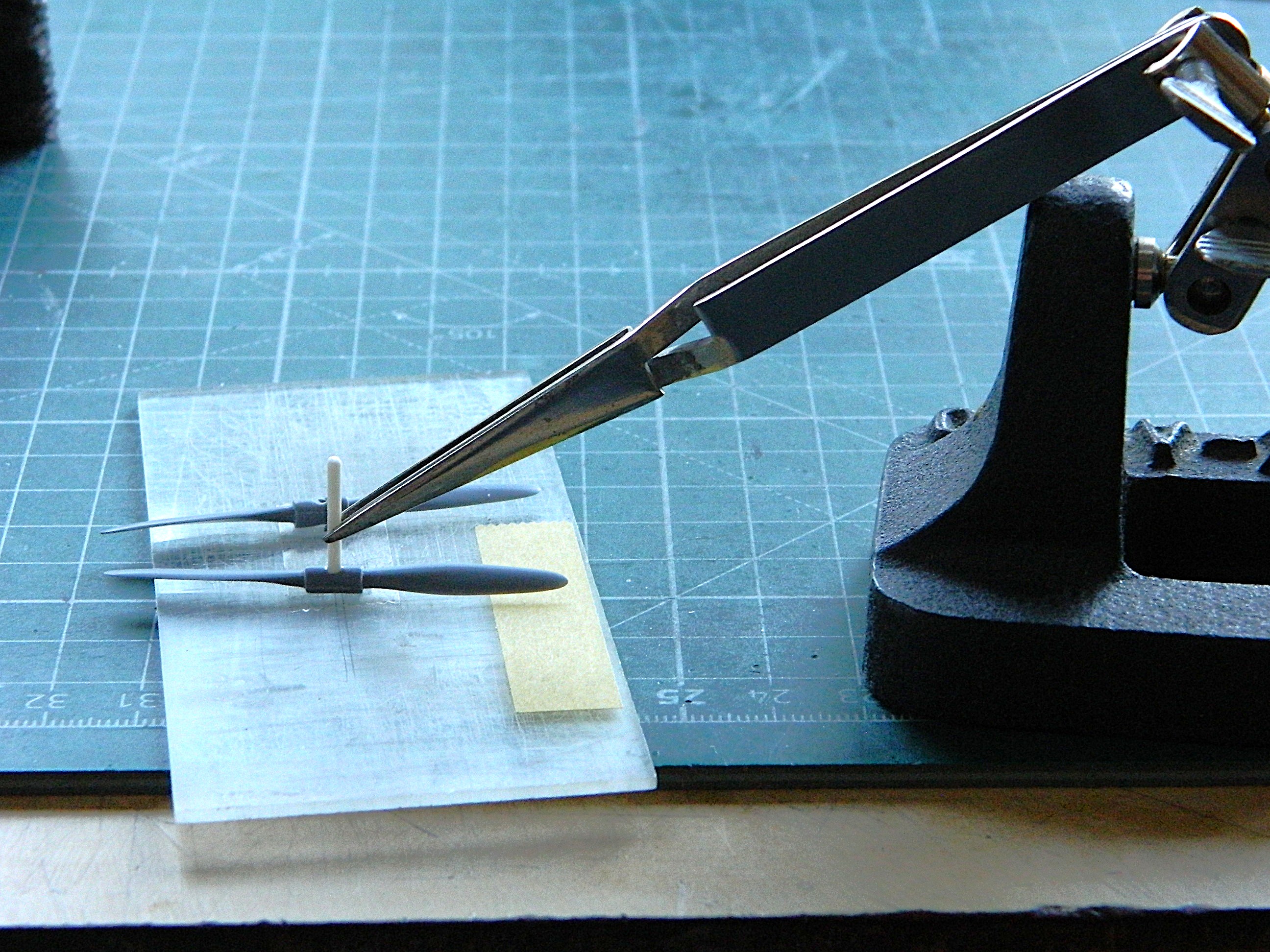
The center of the hub is a two-piece affair but there was no indication on the props to show that. To fix that, I scribed down the center of each side to create the parting line, then added varied scrap styrene to replicate the bolts holding both halves together as well as the pitch mechanisms:
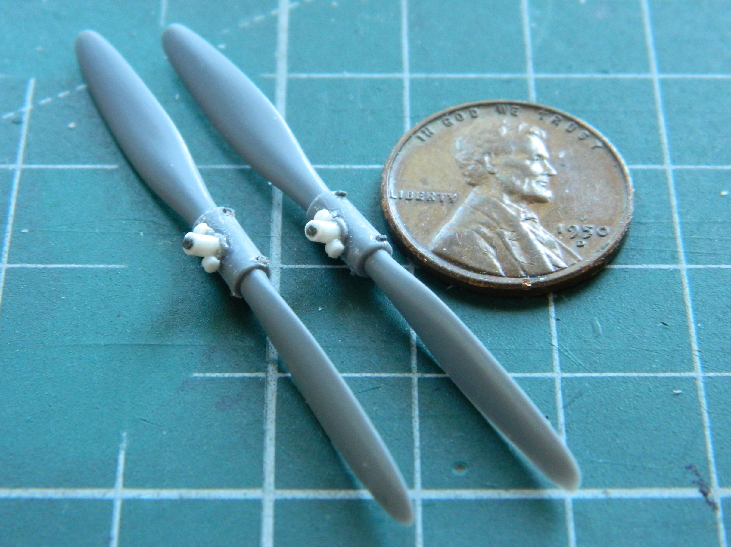
One those were done, it was time to paint these. Aluminum parts were painted with darkened Tamiya XF-16 Flat Aluminum (4 parts) and XF-1 Flat Black (1 part). The crankcases were shot with lightened XF-20 (4 parts) and XF-2 Flat White (1 part):
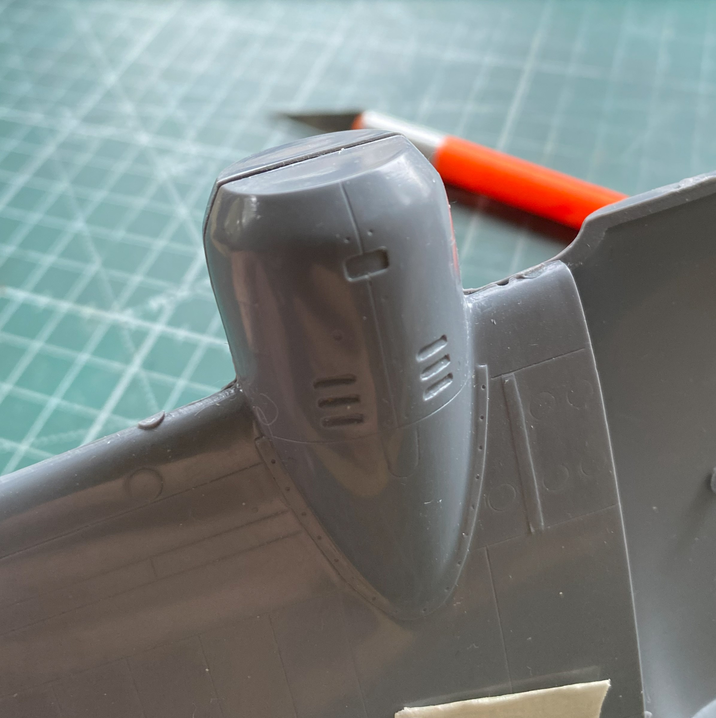
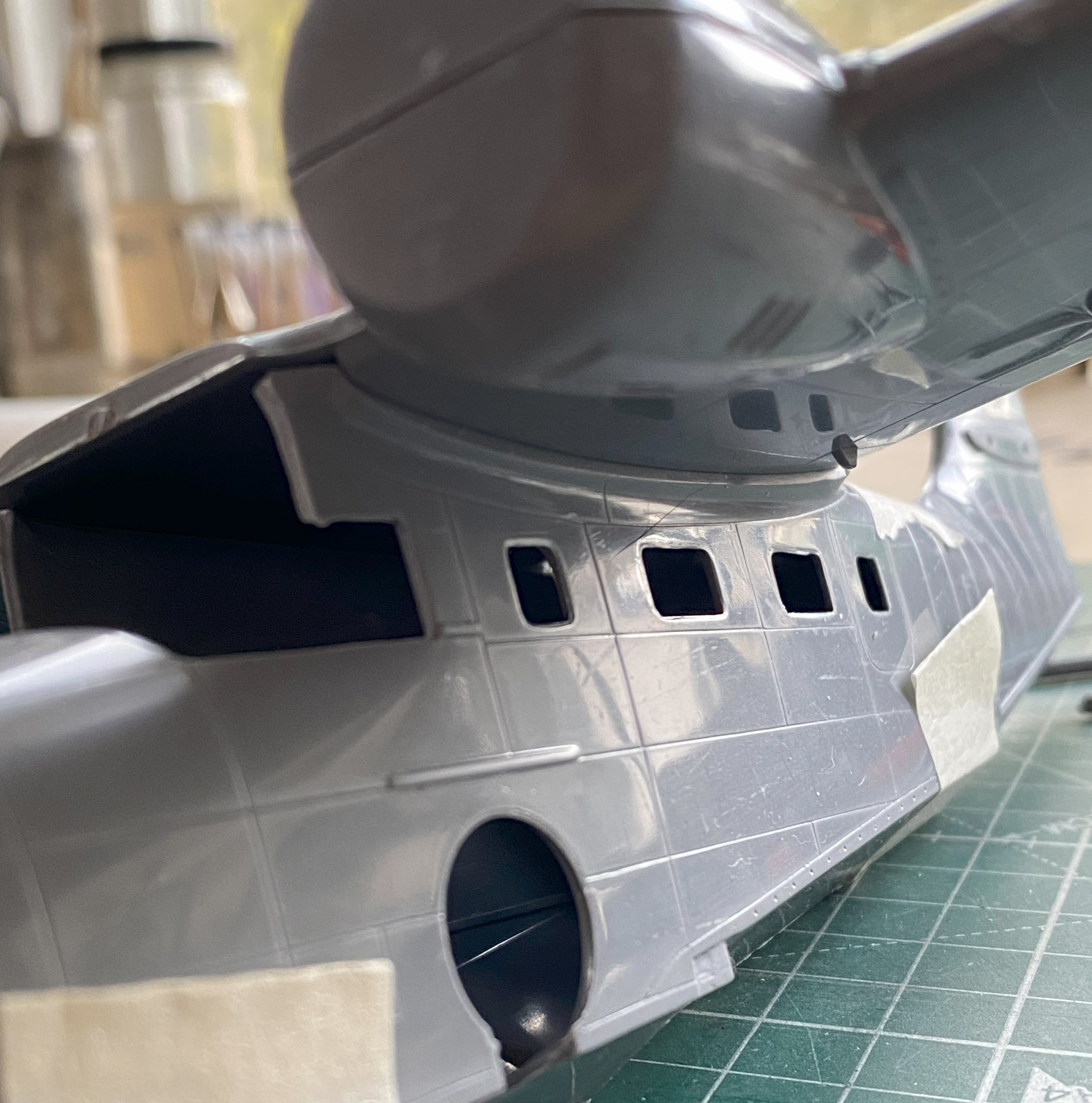
While the paint was curing, I decided to check fit of the wings. For the most part, they fit well enough…then there was the rest of the parts that didn’t fit so well. This is the case with both engine nacelles:

And once again (some more) I didn’t look closely enough at reference photos to see that this bird has split flaps. When deployed, the flaps only extend from the bottom of the wing; the upper wing over the flaps doesn’t move. I wish I had noticed that before I worked the seams and removed all evidence of seams, because that meant I had to scribe the separation from upper and lower in. I know I’ve mentioned this before (and, no surprise, will no doubt mention it again at some point) but I really do suck at scribing. So let’s scribe a line on a very small, long, and rounded surface:
And while I’m at it, let’s screw it up (of course…it’s scribing) and have to add stretched sprue to fix it (which means leaving the added sprue alone for two days so that all the plastic hardens where the sprue was added):


That add-sprue step was repeated a few times before I arrived at something that fell within the 90%-95% goal, but eventually I got there:

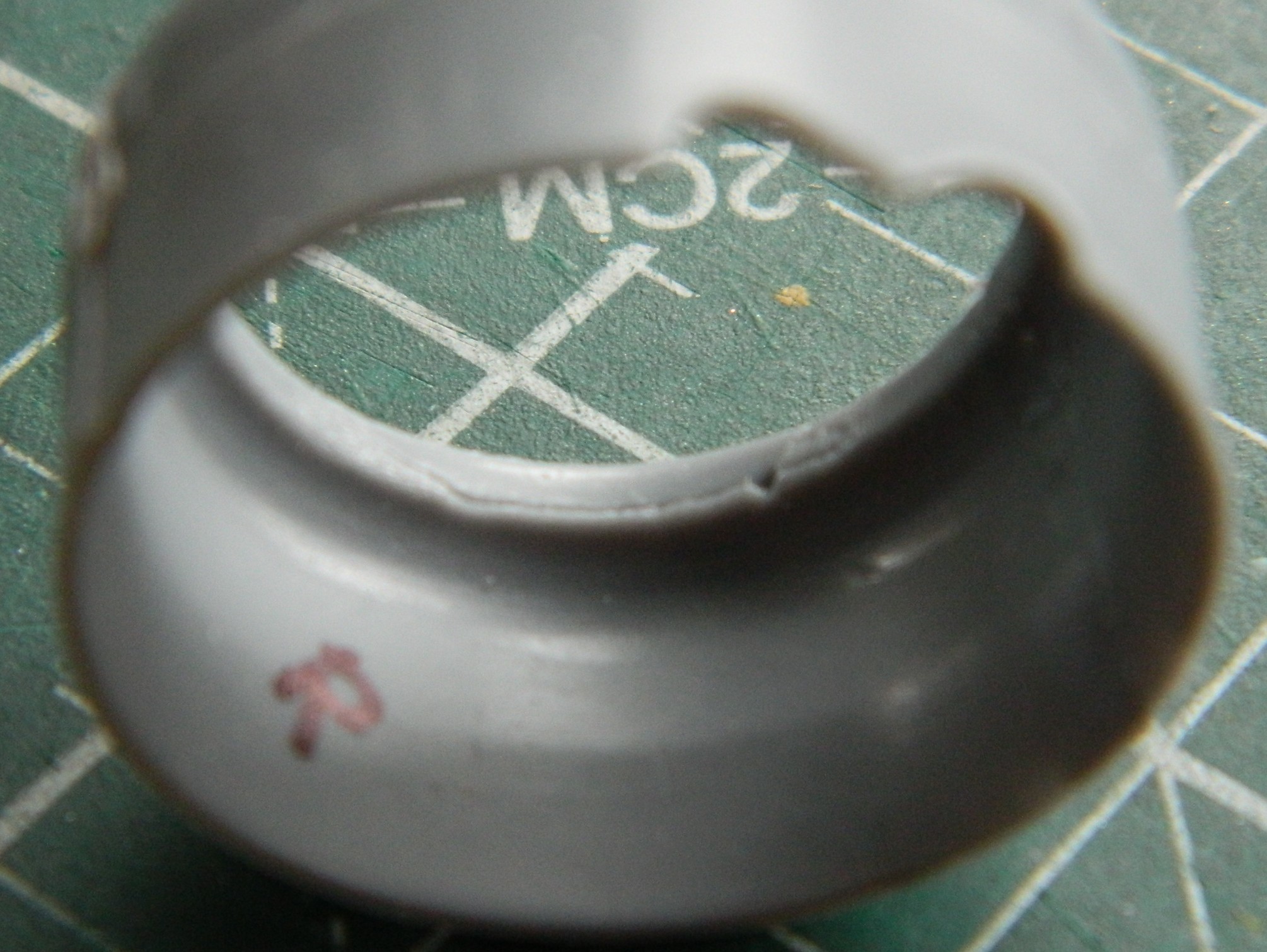
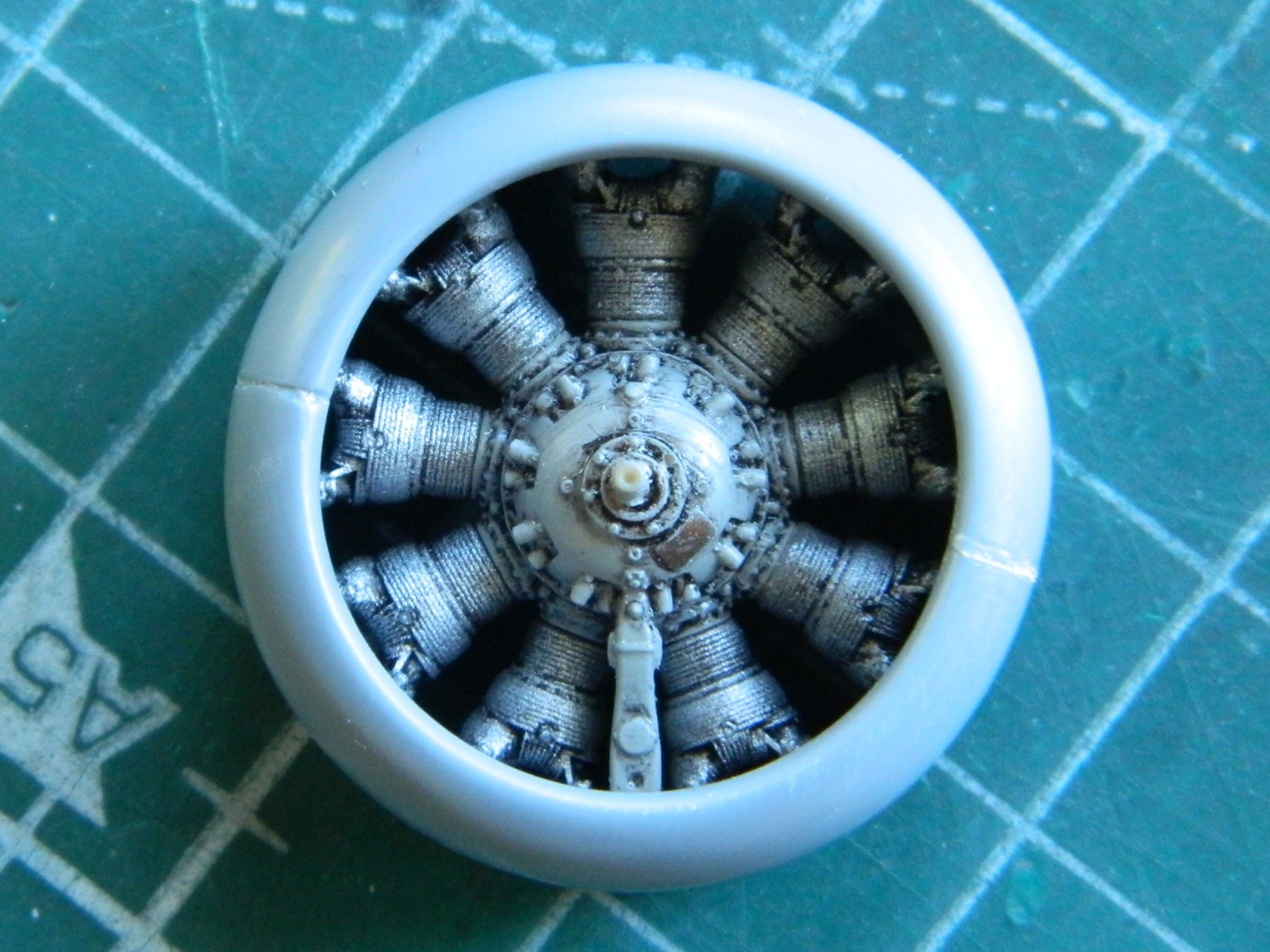
One of the things I was quite curious about was whether or not the completed engines would even fit into the cowlings. I knew that I’d had to wait until the jugs were mated to the crankcases (duh) but I wanted to start assembling the cowlings so that fitting could be checked. These things need some work, too:
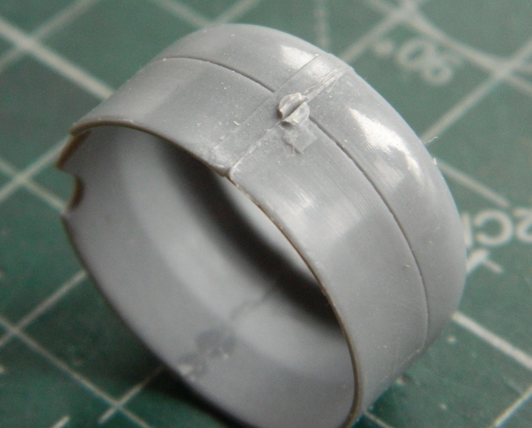
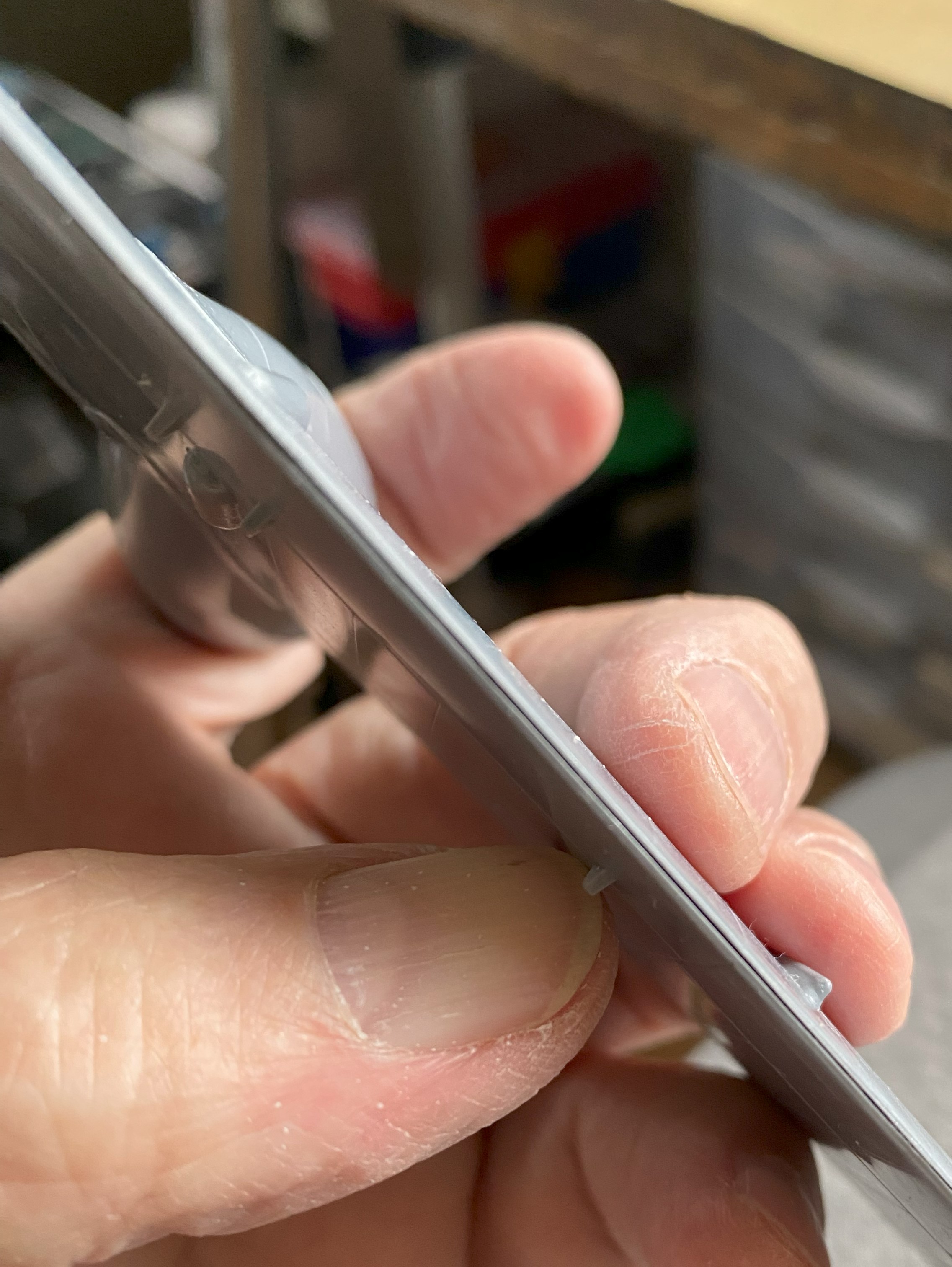
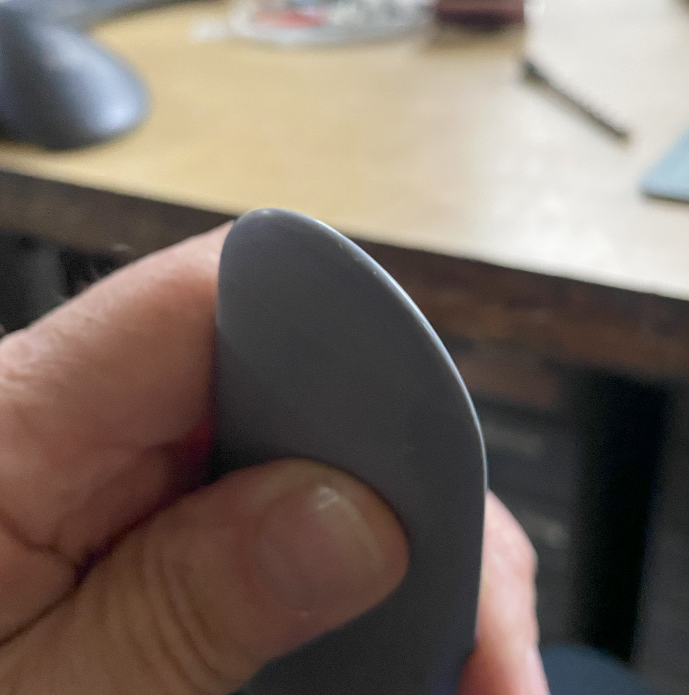
Especially this one. I’ve never seen a casting defect like this (with plastic, anyway…it happens more frequently than anyone wants it to when casting metal in a foundry). So that will be puttied into invisibility. Look closely at the inner lip at the bottom:
After examining the wing seams, I realized that I was going to need more stretched sprue to fix gaps:

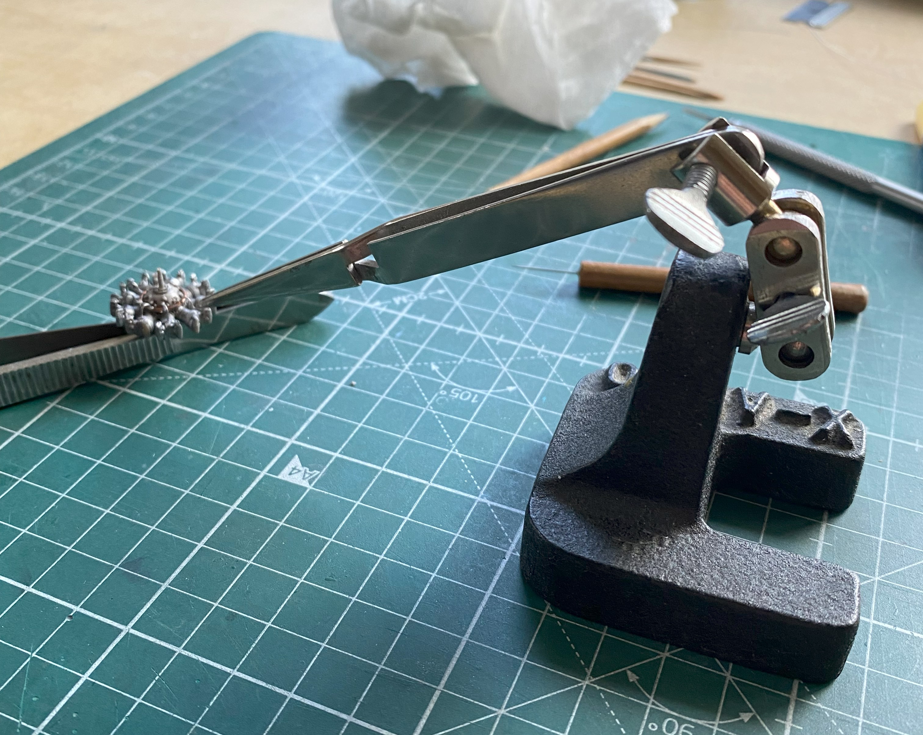
I use that orange handled saw blade in the above photo to separate parts from sprues. Yes…the sprues are that thick and even though I use a set of very old Huron nippers (often resharpened nippers), I didn’t want the thick attachment points (called “gates” in the casting biz) snapping anything. Yes. Huron. Worried about snapping. Yes…THICK gates, often a feature of limited-production kits.
Moving on.
Seeing that a “good fit” isn’t all that good, I decided to check fit of other parts and I discovered that there was going to be much fitting done before this build is done:

I’m certainly forearmed now…
Gaps show up in the strangest places with this kit. Gaps existed at the wingtips. Sprue has been stretched already, so I used that sprue to fill the gaps:

And done:
There are also wingtip lights that there’s zero provision for, so I’ll cut the notches for them and add them later on. (Forearmed, y’know.) There’s also no provision for a pitot tube, either. I used a wire and drilled its mounting hole (twice…the one behind where the tube goes is just evident in the photo):
The front of the engine mounts on the nacelles isn’t flat but has a slight dome. A few quick passes over a sheet of 220 grit laid down on the bench took care of that:

I figured that while I was dealing with the wing, why not assemble the floats? (It made sense to me at the time.) Fit is as expected and since I had plenty of sprue stretched (so far), after assembly sprue was added to fill the gaps:
Oh. A word about limited-production kits. Some things that we’ve grown to expect kits to have, limited-production kits often don’t have. With this kit it’s attachment pins and sockets. So far, I haven’t encountered any of them.
On we move.
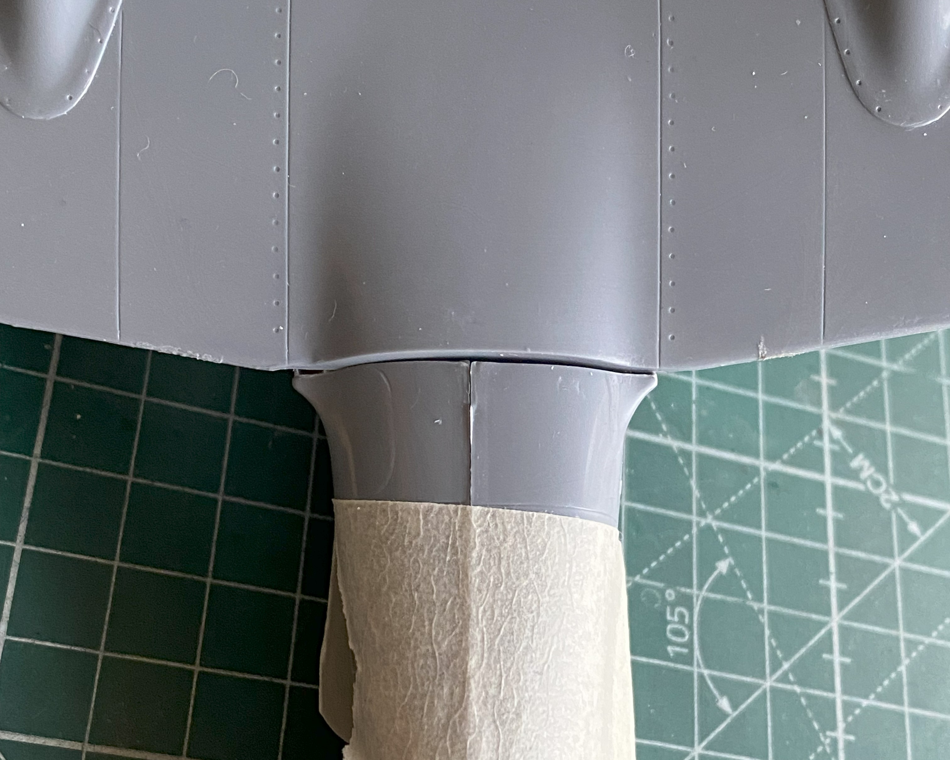
Since I won’t be scribing over the added sprue, I don’t have to let it sit for two days to harden. A few hours later I started working the seams and then added 3M Acrylic Putty where needed (masking tape added to keep putty out of panel lines):

They appear to have come out well enough; I’ll know more once paint is thrown at these:

Finishing the seams of the cowlings meant that small sections had to be rescribed. [Insert obligatory whining about my lousy scribing skills here.] And then patched where I screwed it up. And then wait a couple of days before rescribing:

After painting the engine parts and assembling them, they were shot with Tamiya X-22 Clear Gloss, left overnight to cure, and then I mixed some gloss black oil paint with thinner to create an oily finish on the engines (remember…these were working aircraft, not the pristine examples in museums or post-restoration, and as such were seen as consumable resources…meaning that they had an oily surface) (radial engines, y’know…no oil dripping means there’s NO OIL IN THEM). The downside to using oil paints for washes is that they take a long time to dry. In this situation, that “long time” meant seven full days before I could shoot the engines with the sealing coat of Tamiya X-35 Semi-Gloss Clear:

Oh yeah…they do fit inside the cowlings. They had to be adjusted for fit on the depth of them which was done with a medium-sized file (and could probably do with finer fitting when it comes time to glue them to the wings):
I added the ignition wire ring and painted it a darkened Tamiya XF-6 Copper (4 parts) and Tamiya XF-1 Flat Black (1 part), glued them into position (hindsight indicates I could have used a thinner wire) and started adding spark plug wires using 0.015″ (.381mm) solder:
There are other hoses that connect each jug to the next but since they won’t be seen I’m not going to add them.
One trick I’ve learned is that when adding some scrap that I want to be centered, I use clear styrene to make that easier. Another trick I’ve learned is a way to avoid the dreaded superglue-sets-up-too-fast-to-properly-align-something. These engines are resin and they’re being attached to styrene, so superglue will be necessary (most of the time, when faced with something like this, I avoid epoxy because I’ve found it’s too thick). A way to avoid hoping that I get the alignment correct (or at least how I want it, should the two be different) is to glue a piece of styrene to the back of the engine. Doing this gives me a styrene-to-styrene join and the ability to tweak alignment in less than 0.00001 seconds:
I painted the spark plug wires using Tamiya XF-85 Rubber and the data plates using the darkened copper paint I’d used on the ignition wire ring. Having already hit both engines with semi-gloss, I painted the backs of them Tamiya XF-1 Flat Black for shading, as well as the inside of the cowlings and the backs of the propeller hubs:

I’ve noticed that on period photos, at the root of the wings where they contact the engine nacelles are what appear to be landing lights. Since there are zero provisions for them in the kit, I’m making my own. I used a scrap of 3/8″ (9.53mm) clear acrylic rod. I sliced off a piece wider than I want to use (for ease of handling…the extra width will be covered by paint), trued the ends (make them perpendicular to the center axis of the rod), and cut them in half so I have one for each “light.” Then they were polished until clear:
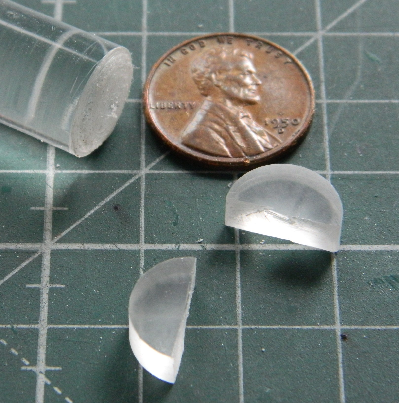

The flat sides will be the insides which will have the “lights” drilled out and painted, then I’ll trace the curvature of the wing’s leading edge on them, rough them in, then glue them in place and finish off the exposed surfaces.
But that’s for next month…
