This month there was a great deal of fitting required for small parts. This means that this post won’t be quite so long as working small parts eats a lot of time.
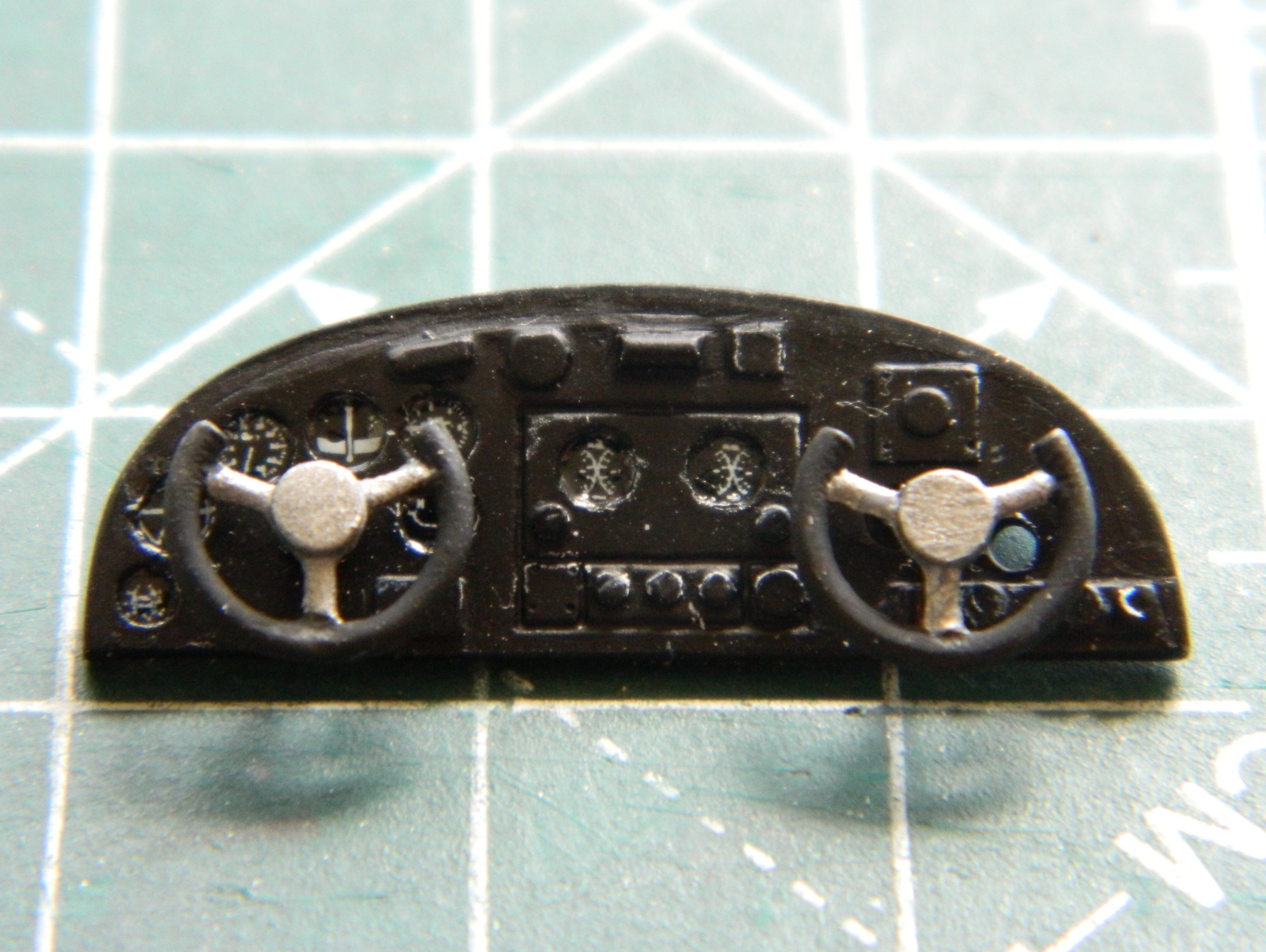
My first task was getting the instrument panel attached. Having painted its face and added instrument decals, it was time to step up and do what’s needed to get the instrument panel to do an excellent “I’m-supposed-to-go-here” imitation. Since I hadn’t painted and added the control yokes, I started there. The face of the panel has raised (and somewhat generic) lumps where someone thought the yokes should mount. Had I looked more closely at those generic lumps, I would have noticed that the “suggested” location for the co-pilot’s yoke was in the wrong place. The last photo in the series below will show those holes where they presently reside.
The stub on the back of the yokes was too short so I added rods (clearly too long, but those will get trimmed once the yokes are in place):
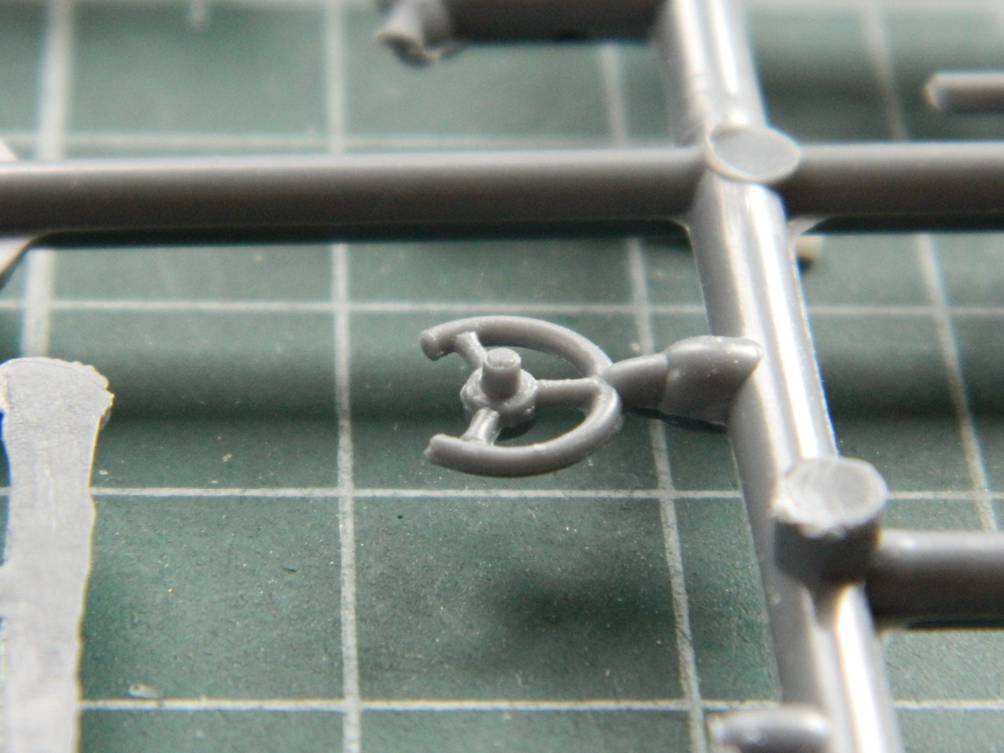
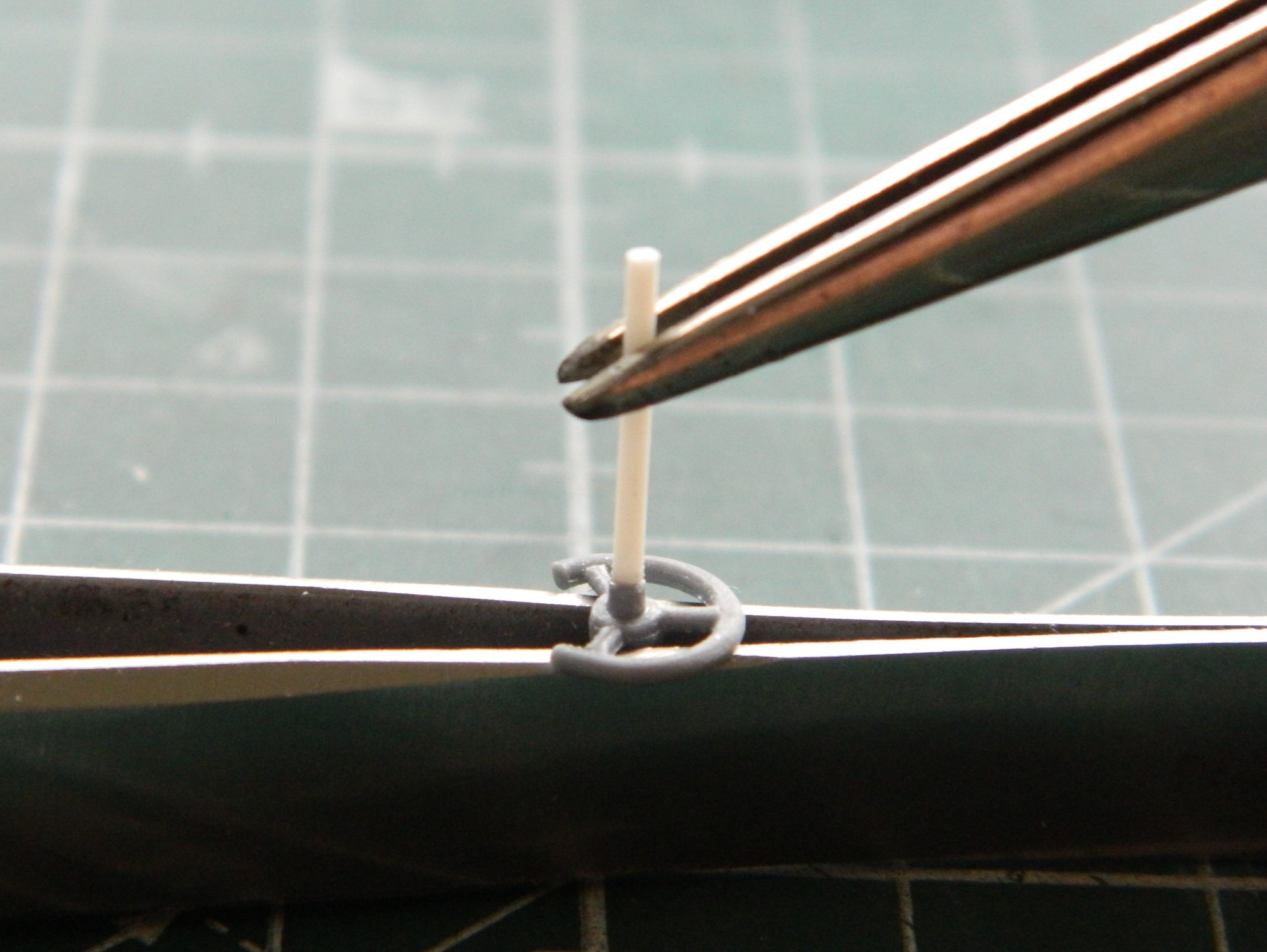

As an aside, subsequent and frequent reattachments showed me that I should have added pins between the rods and yokes. After gluing them back in often, I did that and the problem of knocking those things off ceased. And on to those holes:
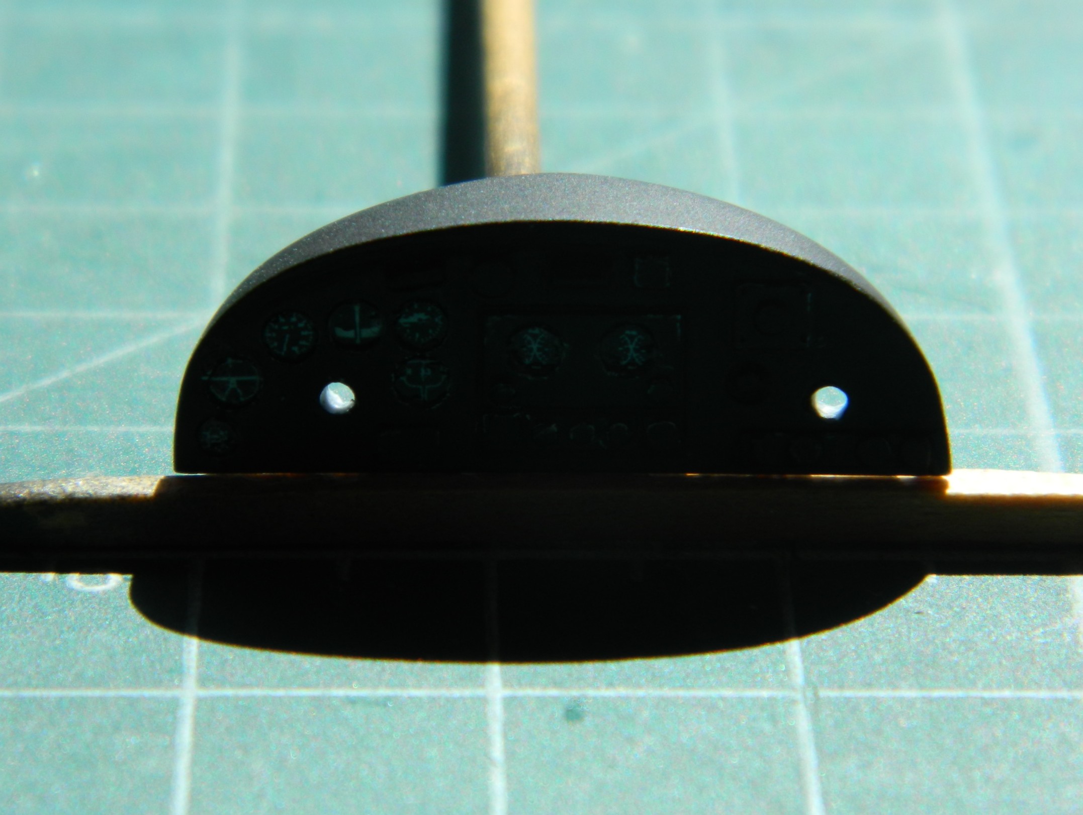
Yeah. I re-drilled the hole on the right and didn’t bother filling the incorrect one for two reasons. The primary reason being that the hole can’t really be seen when the panel is where (I hope) it goes. The second being that I painted the inside of the unused hole flat black and now that hole cannot be seen at all:
The fit of the cockpit’s rear bulkhead showed me that for me, True Details isn’t worth the money. Fit was rotten and the dimensions of the bulkhead are off…as in sides that are supposed to be parallel aren’t parallel. With strategic application of flat black, I doubt that this will be noticed once everything is buttoned up:

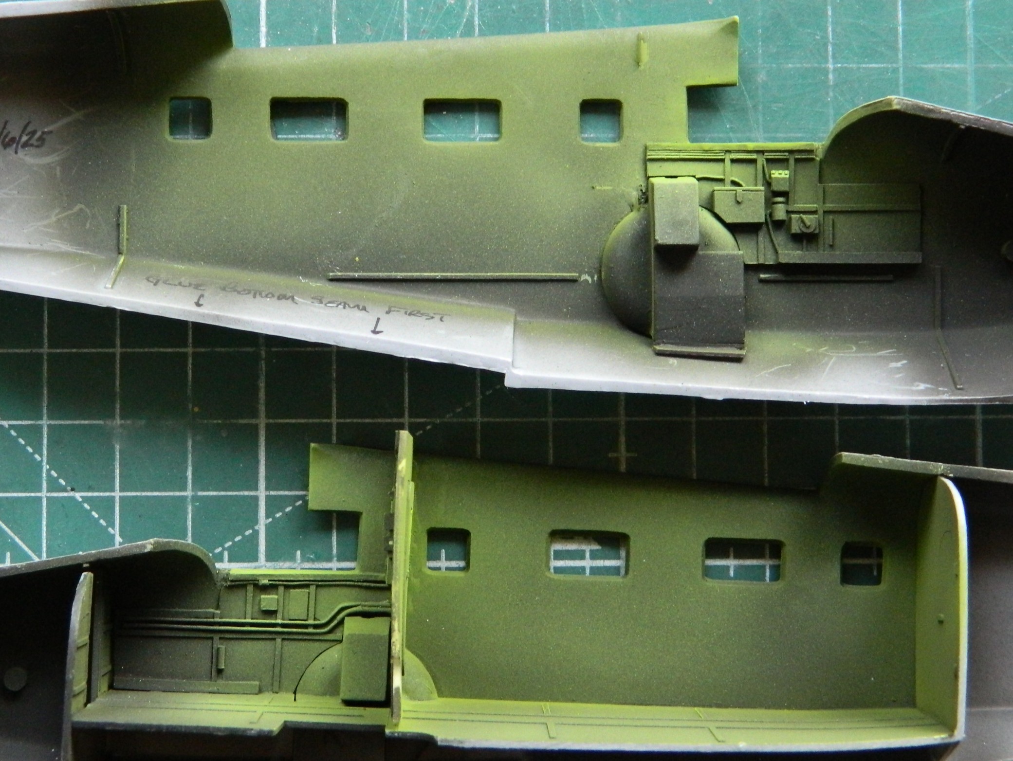
I mixed up some chromate green using Tamiya XF-3 Flat Yellow (2 parts) and X-5 Gloss Green (1 part) and added it to the inner fuselage halves allowing the flat black that was already put down to act as shadows:
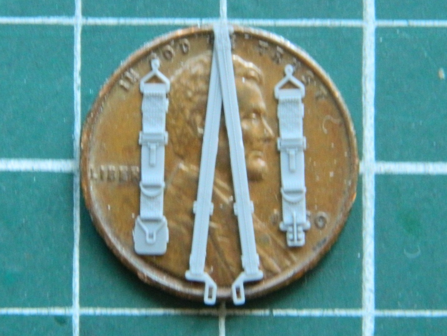
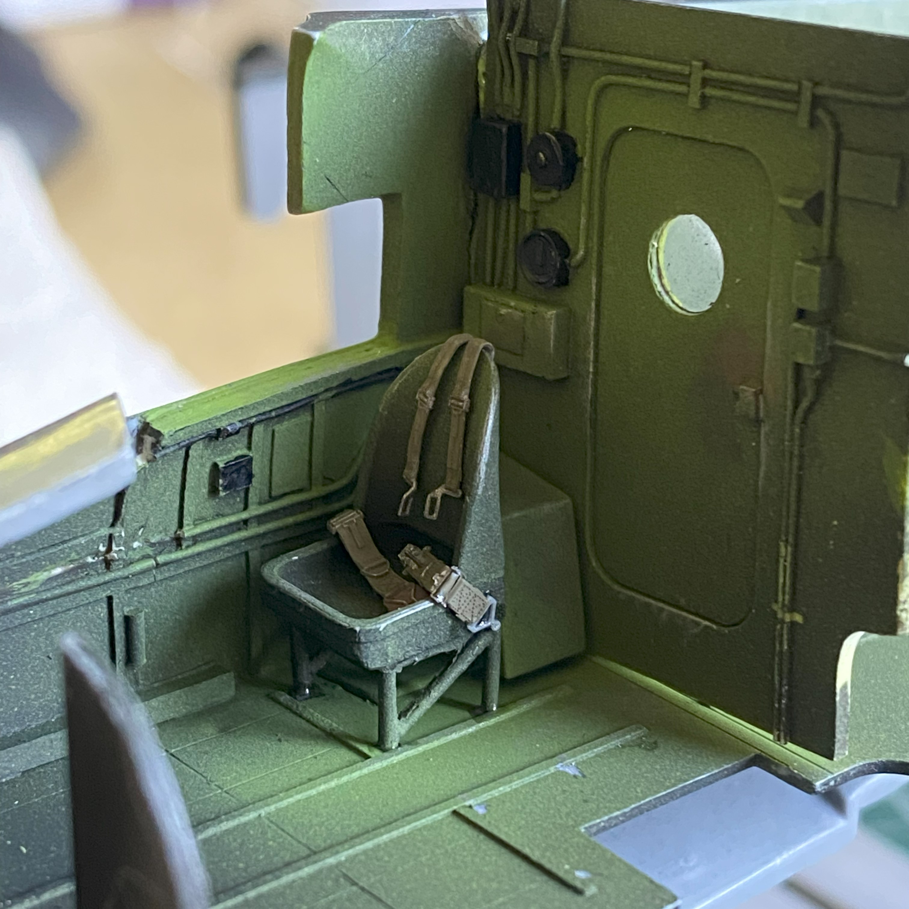
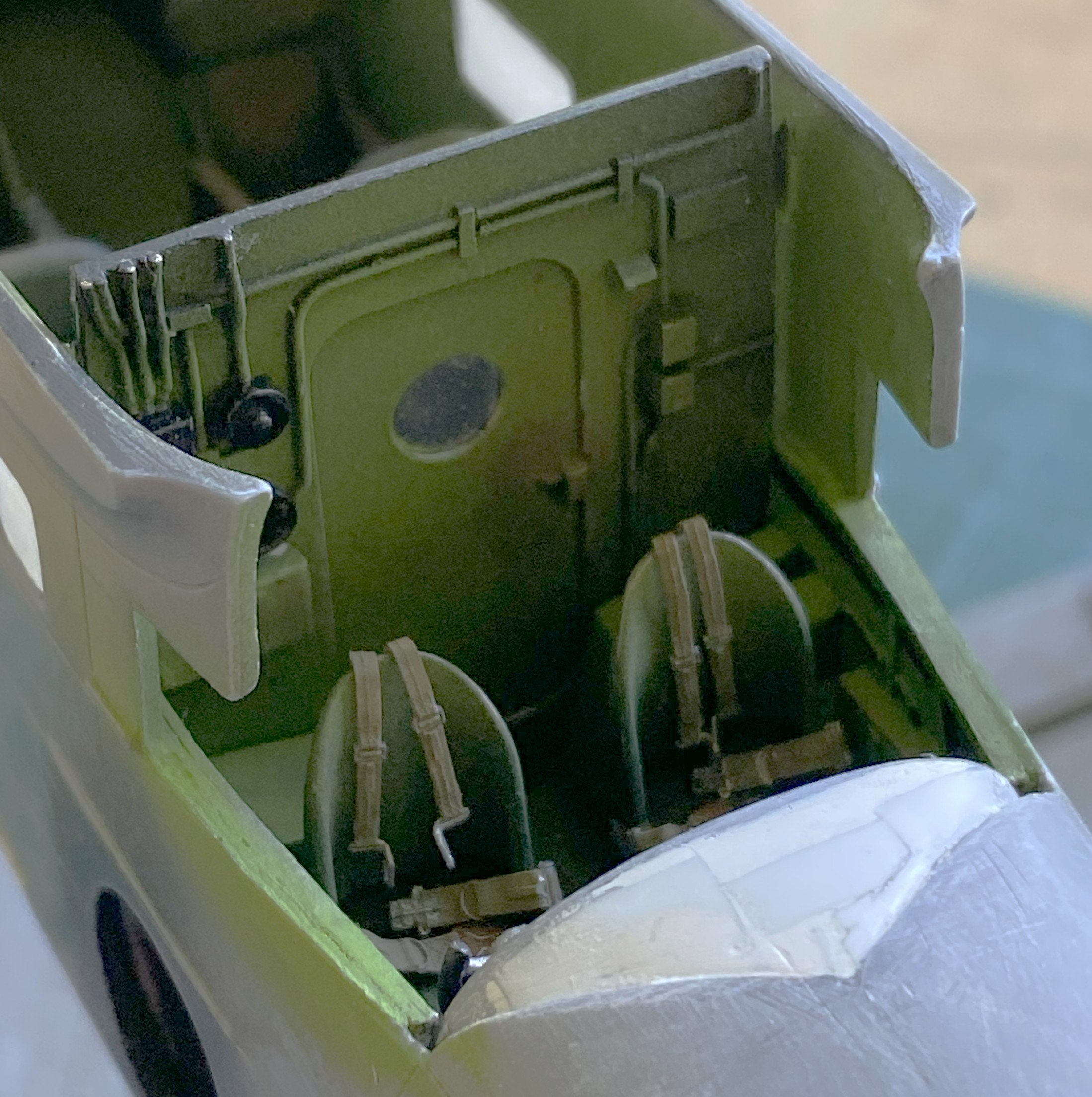
Some time back, I ran across these little beauties. The pilots’ safety harness in delicately molded styrene:
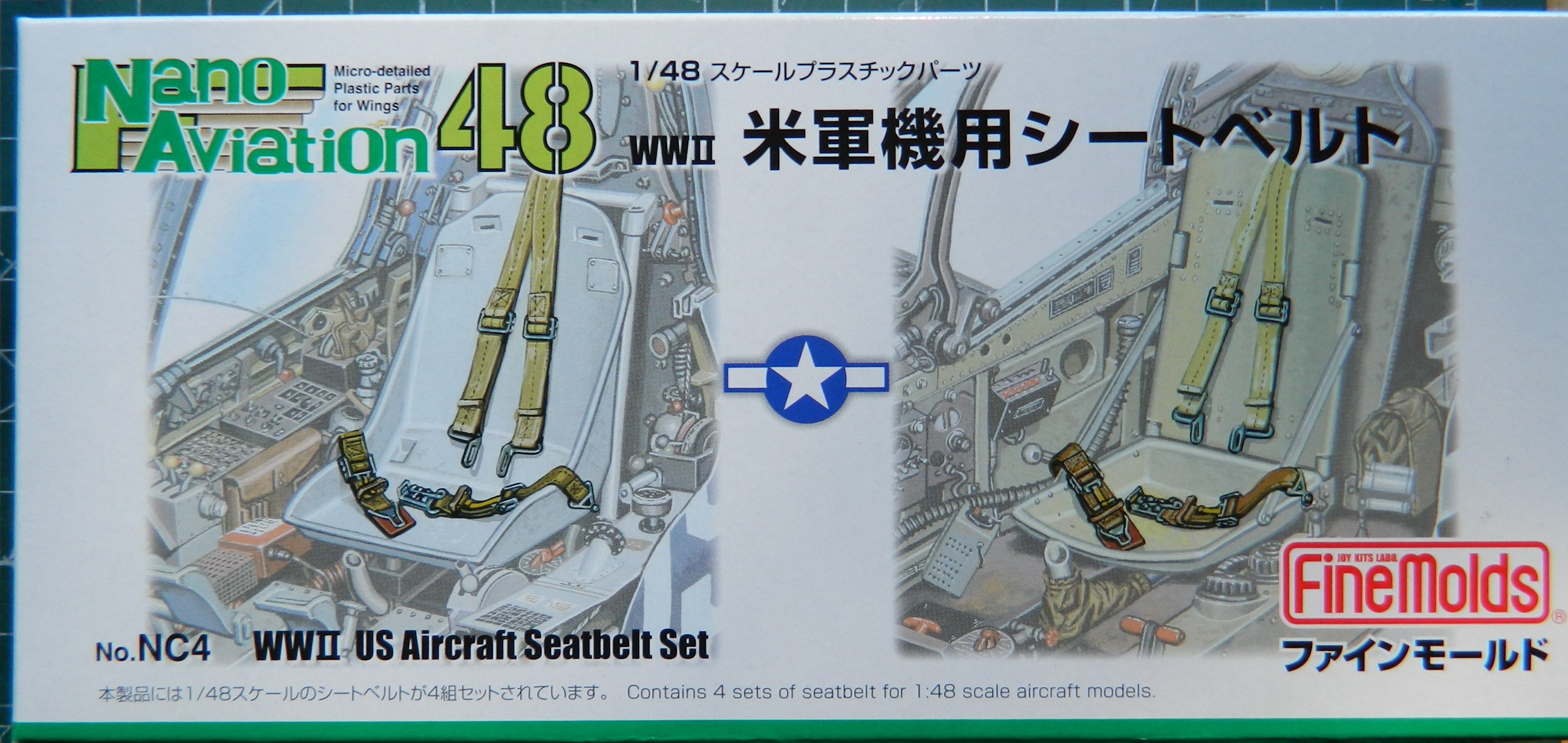
The only vendor I’ve found so far is in Japan. (What with these bullshit “tariffs”, I don’t know how easy they’ll be to get in the future…a problem I’ll deal with in the future.) This is what’s in the box:

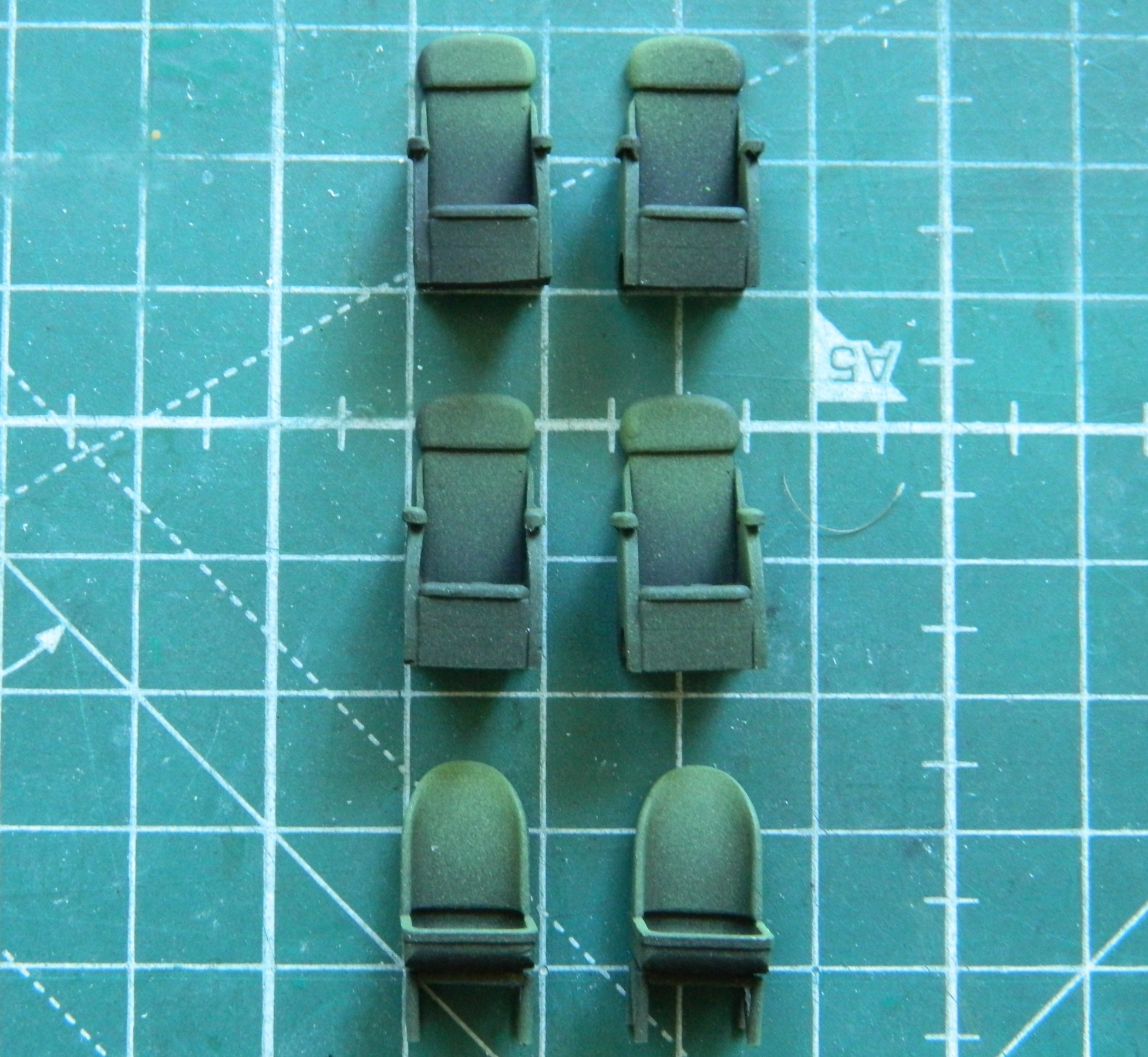
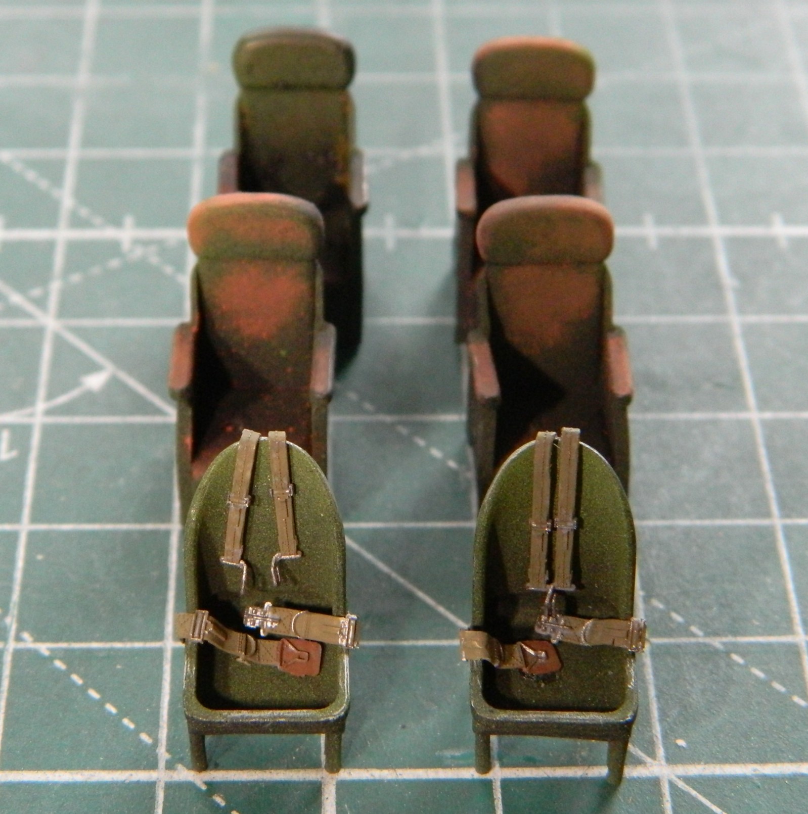
Before I could use those, I wanted to paint all the seats. As typical for me, the first coat of paint was Tamiya XF-1 Flat Black for pre-shading. Then I used my custom-mixed chromate green and painted on the light blooms:
The harnesses were heated and bent to conform to the seats of the pilot and co-pilot:
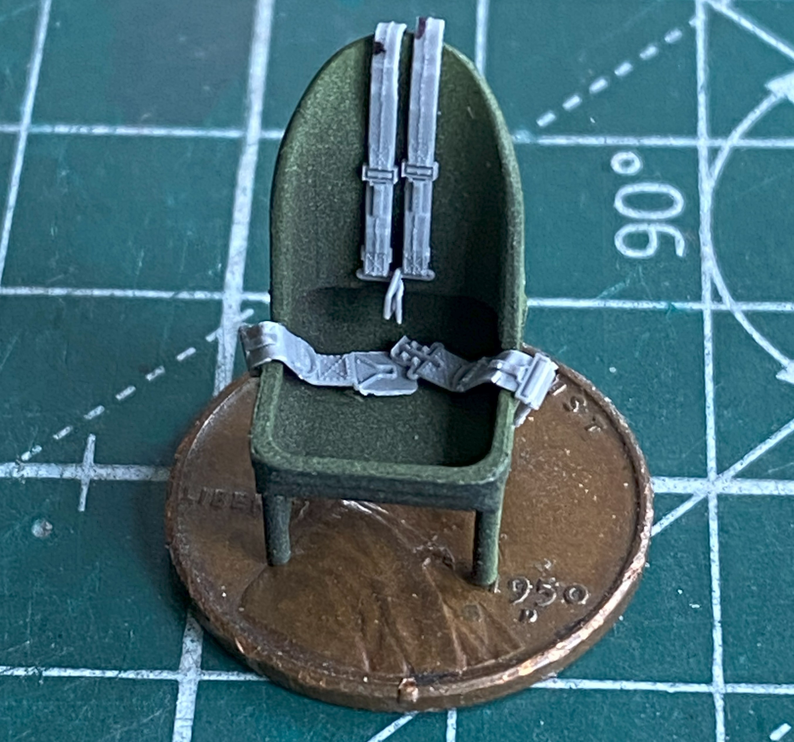
The straps were painted with a mix of Tamiya XF-49 Khaki (3 parts) and XF-64 Red Brown (1 part). The leather pads were painted using tinted XF-64 Red brown (5 parts) and XF-2 Flat White (1 part). The metal bits were painted with X-11 Chrome Silver. XF-51 Khaki Drab (5 parts) and XF-2 Flat White (1 part) color was misted over the areas that would be most highlighted, and then I used a dark orange pastel to replicate wear. I didn’t go crazy on the passenger seats because little of them will be seen. The pilot and co-pilot seats were touched here and there with a silver pencil to replicate wear:
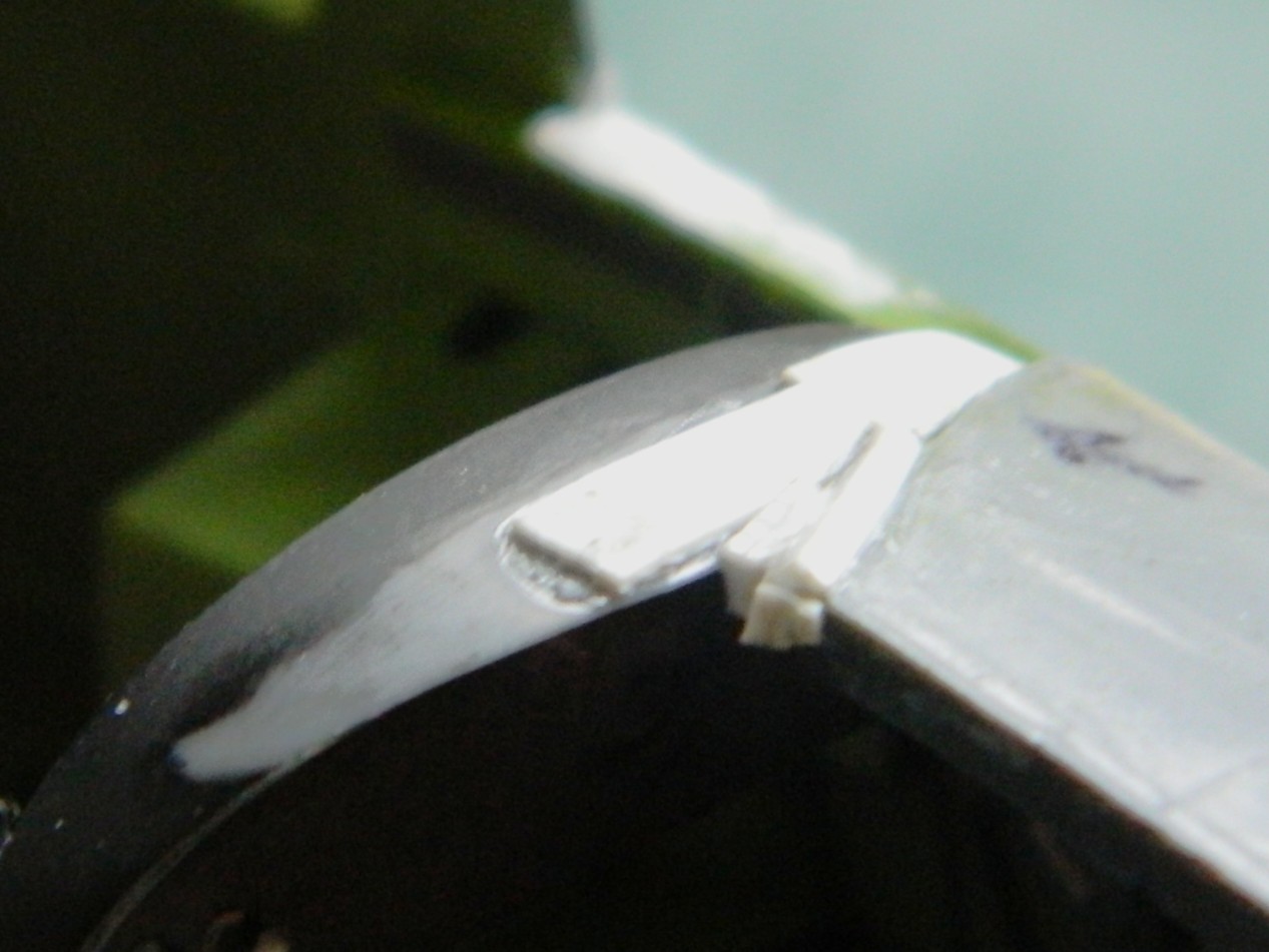
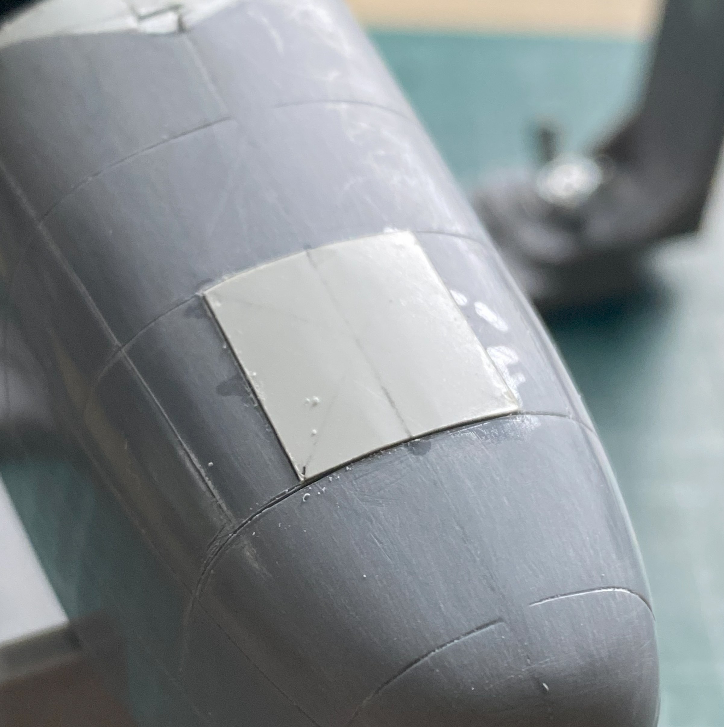
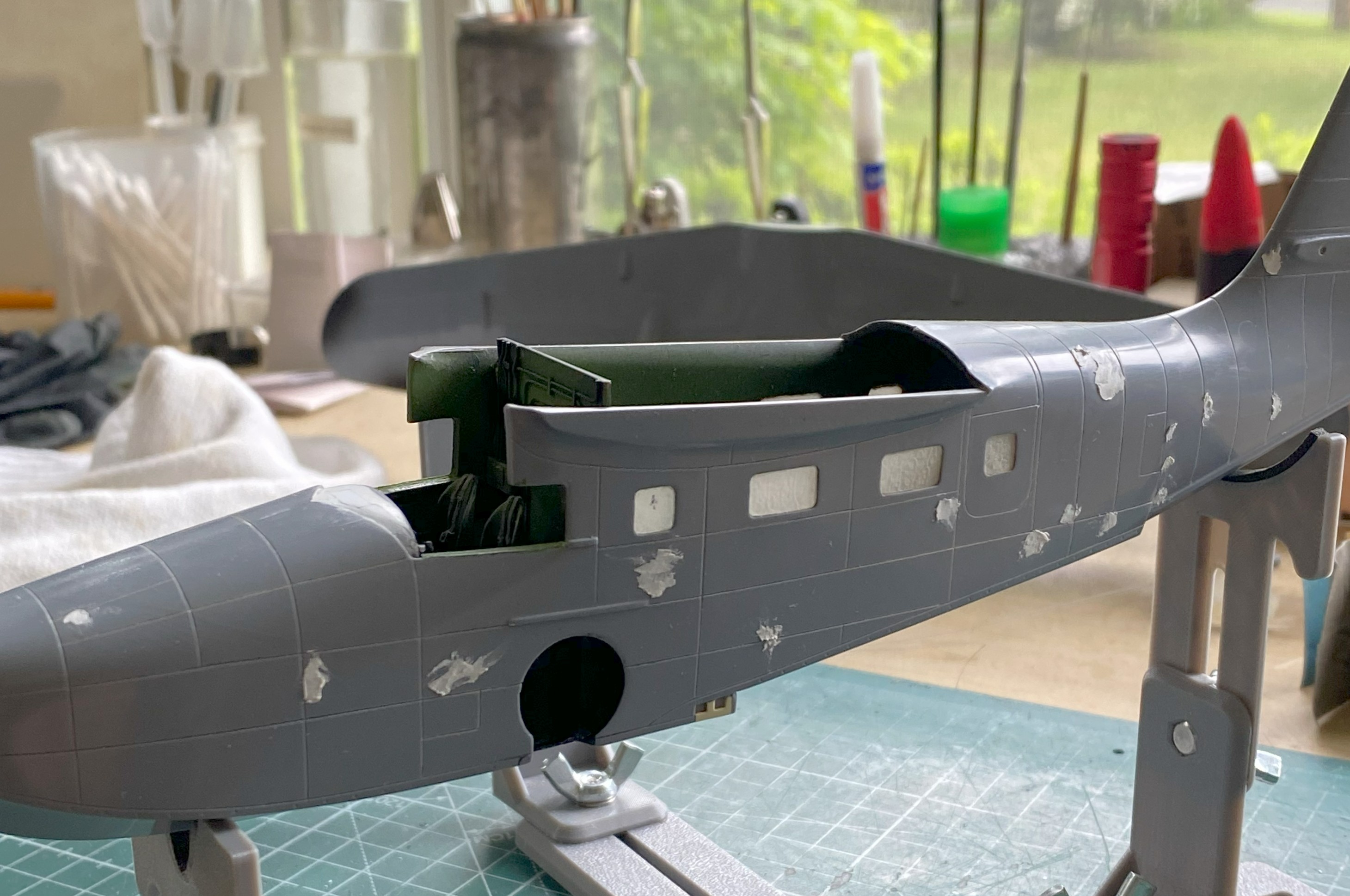
With the fuselage halves taped together, I test-fitted the clear canopy parts (obviously also taped together) to see if my initial assessment held up regarding its fit. Yes…it did. I placed the wings in place to see what had to be diddled with to get a better fit. Check what the arrow is pointed to:
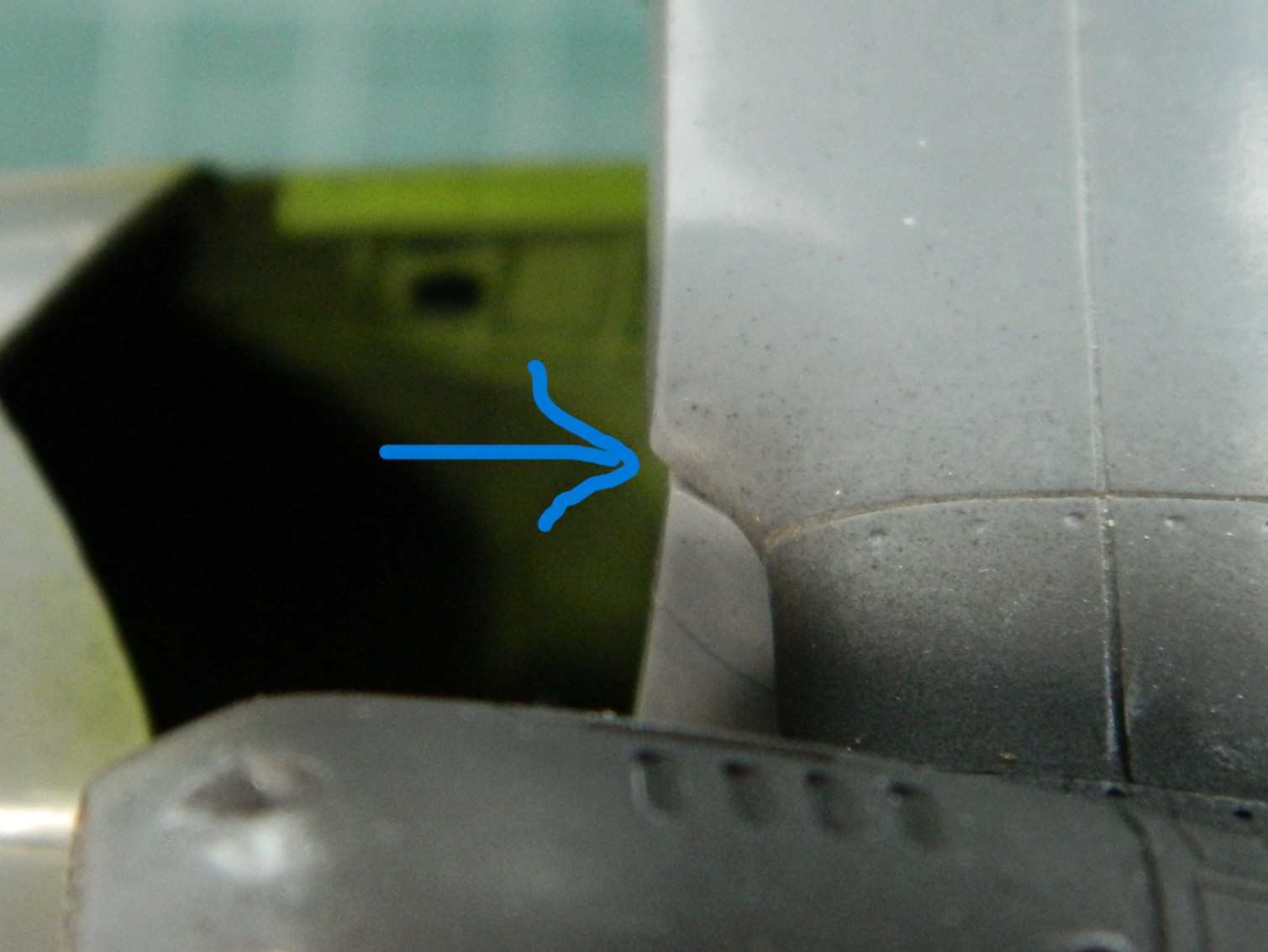
That overhang has to go; those parts are all supposed to conform to the edge of the fuselage. So the plastic above the pencil line was filed to meet the line:

Checking the fit of the clear parts again showed a significant improvement with its fit:

It also showed me that there’s a possibility of having to tweak the attachment areas of the clear parts but I can’t make that determination until the wings are glued down permanently.
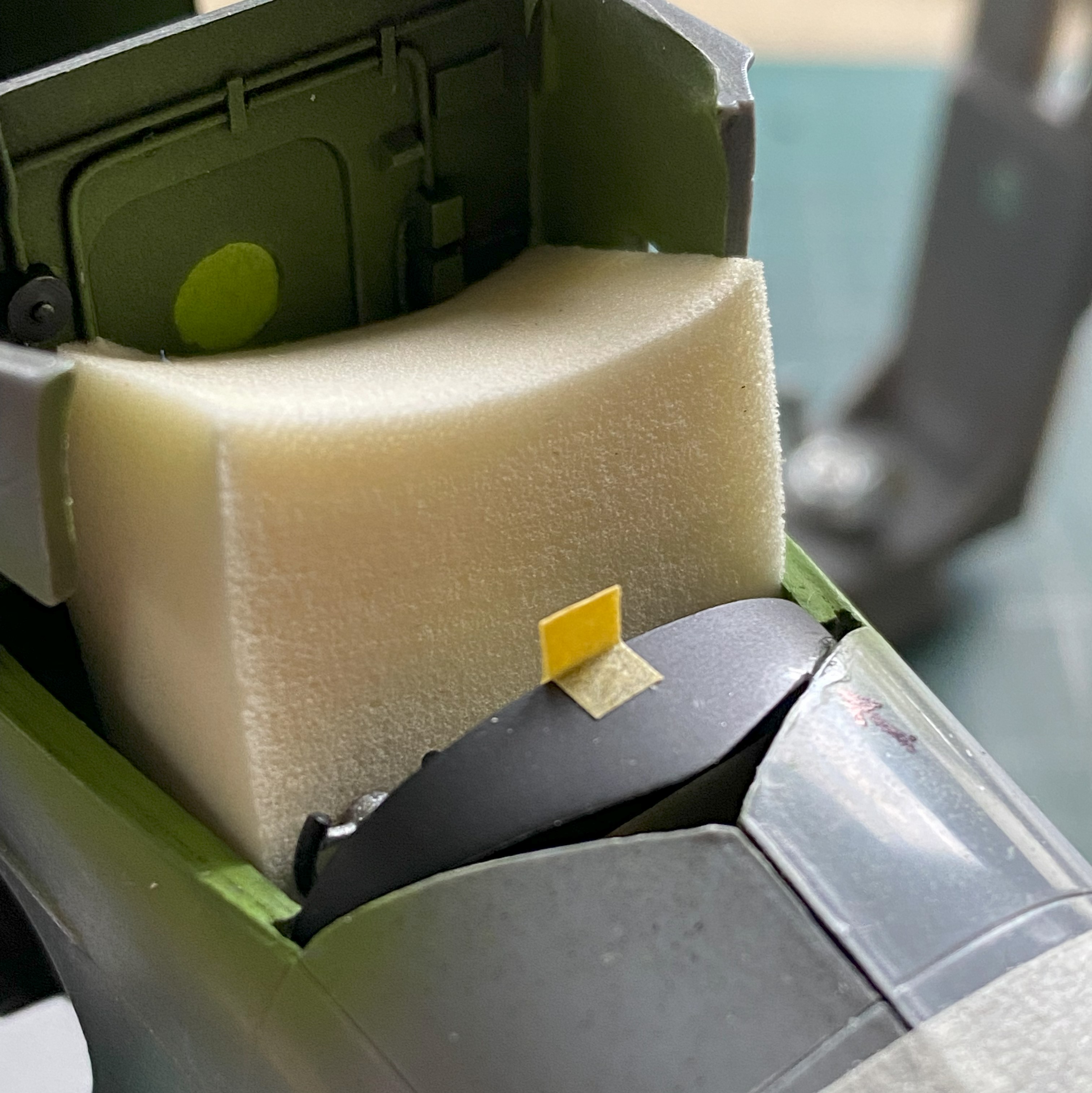
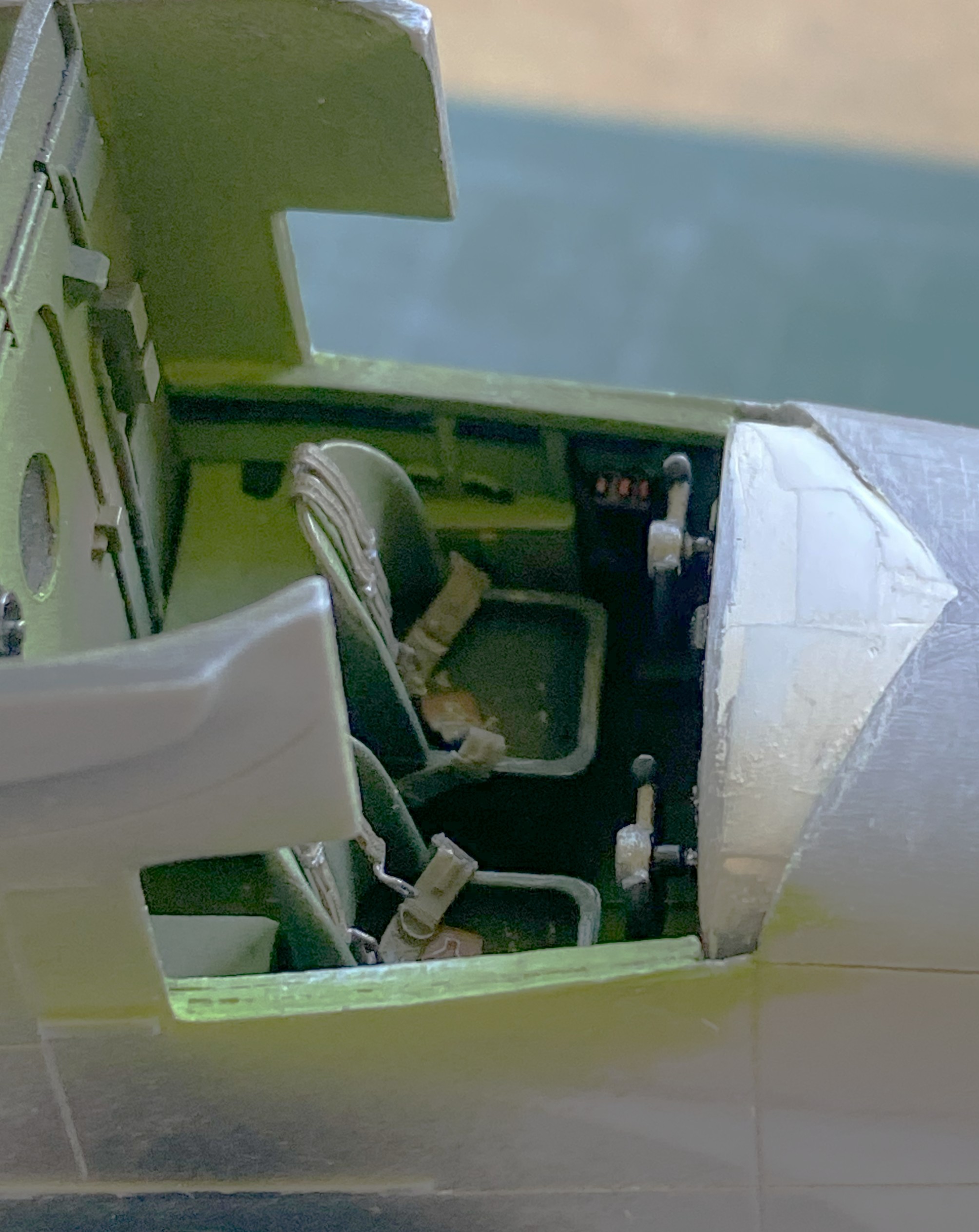
The last thing I had to do before I could marry the fuselage halves was to get the sodding instrument panel to fit (and hopefully not look bad in doing so). I used a foam wedge (sold in drug stores and/or apothecaries) to align the panel to the best of my sometimes-disappointing abilities (the tan square is a loop of masking tape to enable me to move it…and there was no shortage of moving it…without damaging the face of the panel). Where the panel touched the fuselage received a significant amount of styrene cement any place it touched the fuselage half. My brain-fade kicked in and I attached the panel to the left side of the fuselage, where everything else inside the fuselage was attached to the right side. ::facepalm:: It complicated the joining of both halves a little but I didn’t find that out until the trigger was pulled and the Rubicon crossed. As you’ll see, there was no way I could dislodge the panel without damaging things. The bitch is ON there:

After letting it sit overnight to harden fully, I thought that it wasn’t quite firmly attached enough. I used styrene scraps to reinforce the attachment point(s):

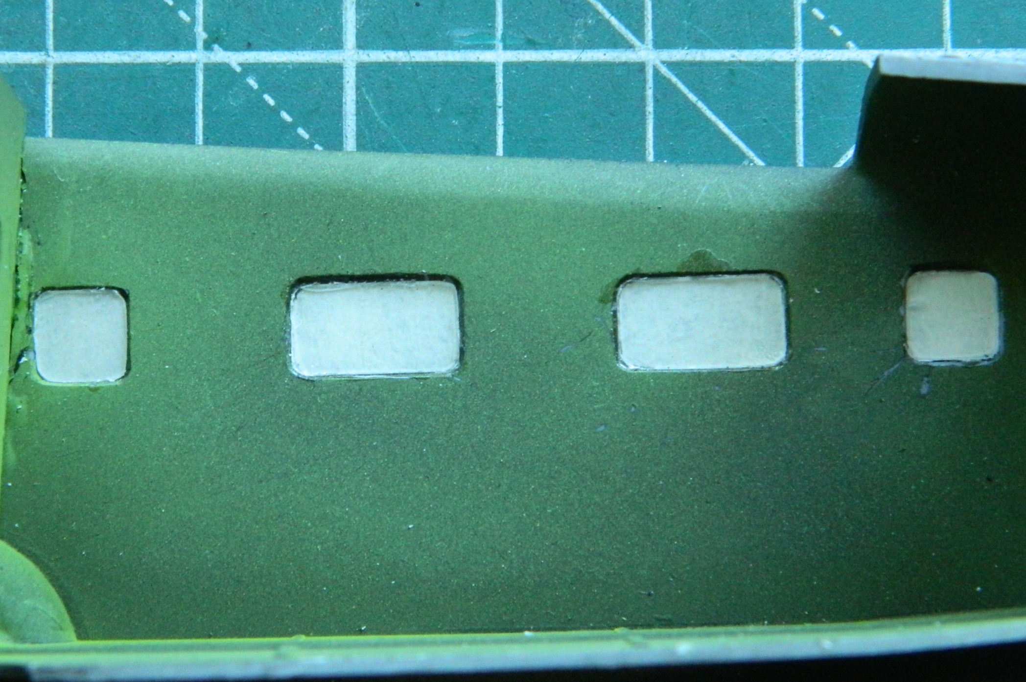
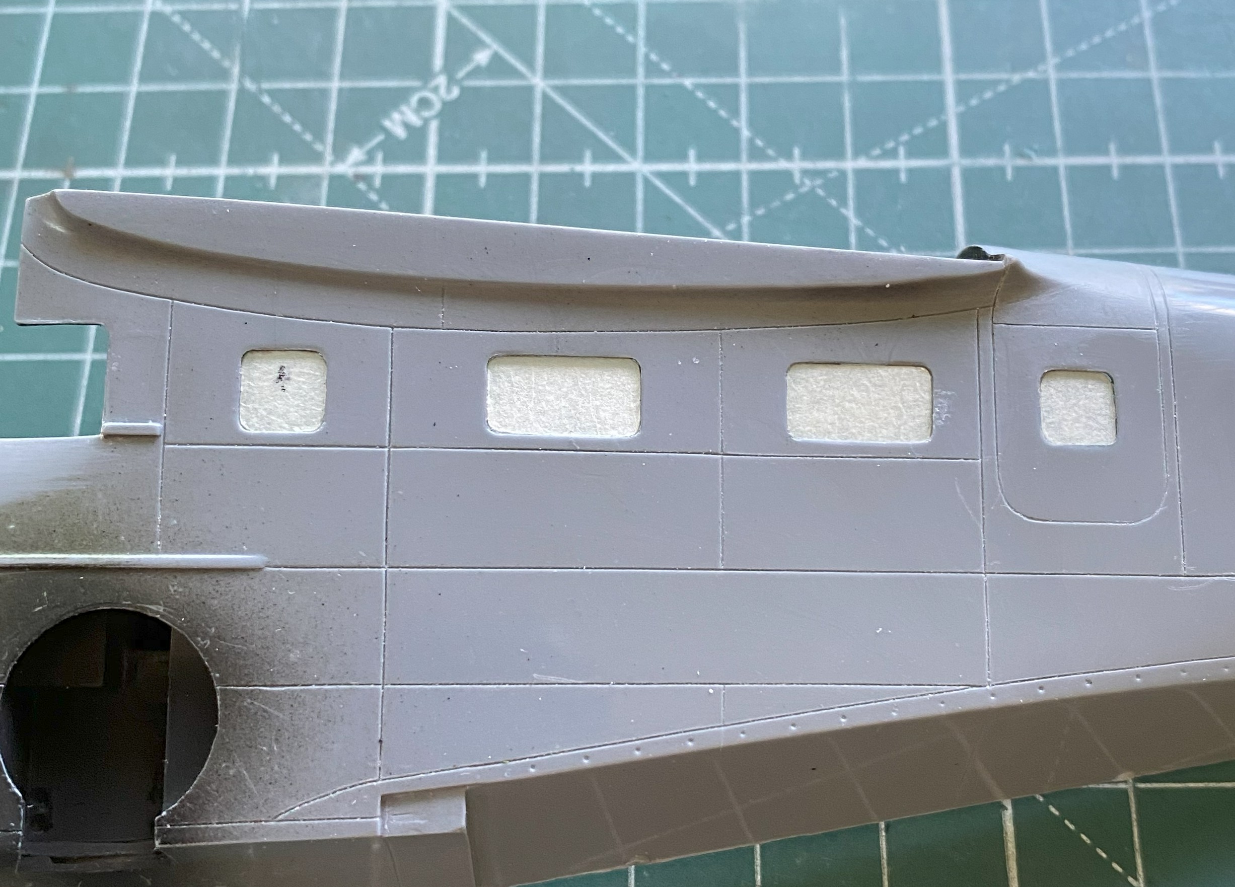
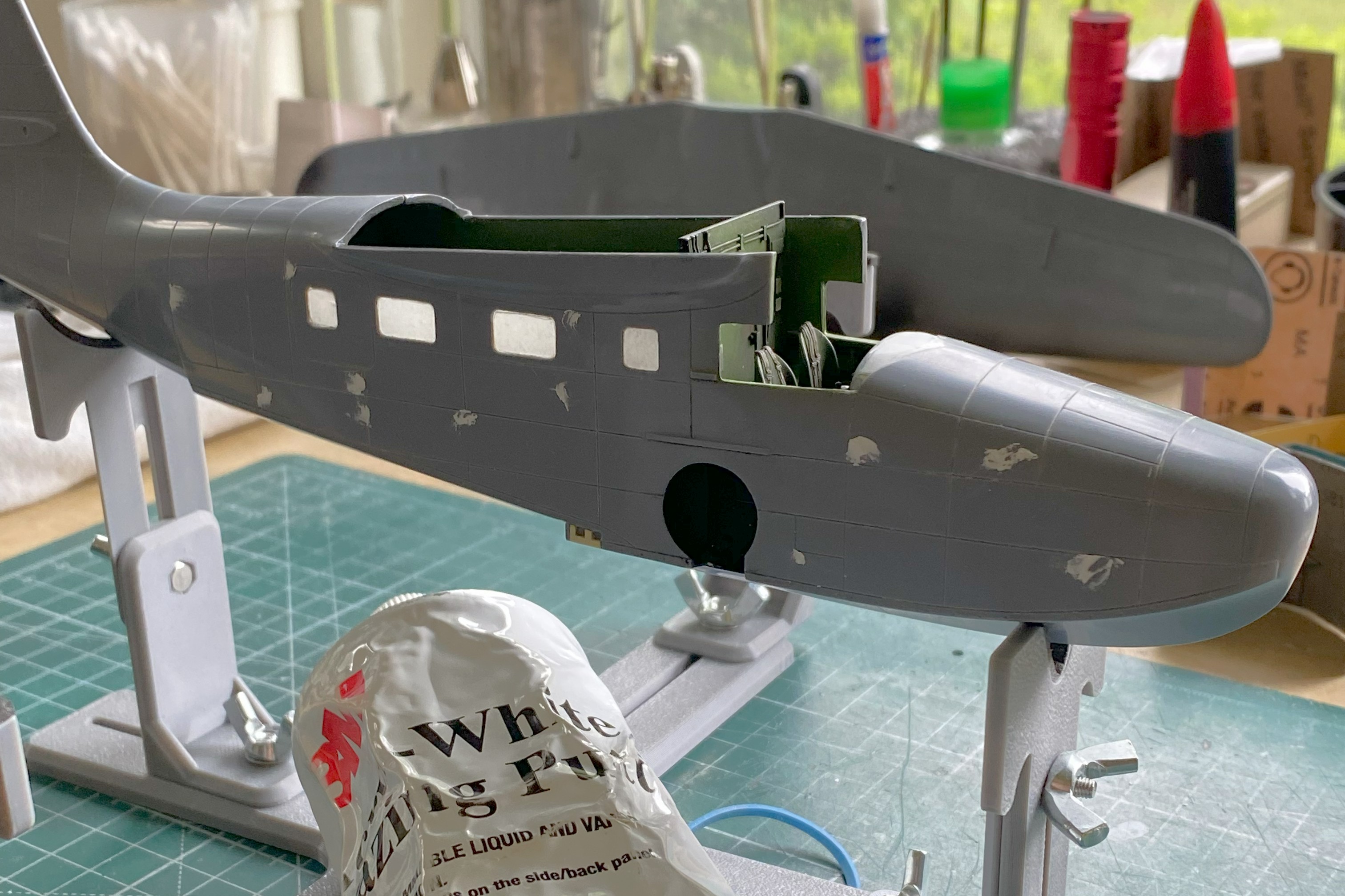
It was time to add the windows to the passenger compartment. Once again, thick plastic:
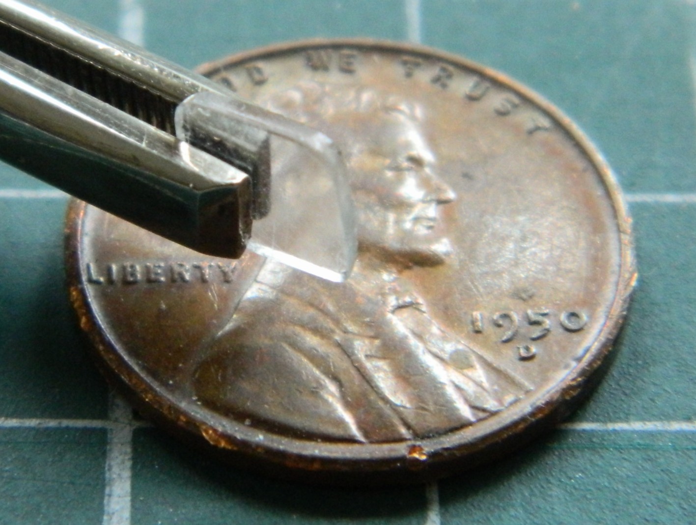
Earlier US WWII fighters had a plate of armored glass behind the windscreen. I’ll keep these thick clear parts for that use in the future. For now, they need to be replaced. I’d intended on using 0.010″ (.254mm) but though it’s to a more scaled size, I wanted a bit more surface for adhesives to bond with so instead I used 0.015″ (.381mm) clear instead. This gave me a closer-to-scale thickness (the thin piece of plastic isn’t usable other than as a comparison of thickness):

When I did the M4 Sherman with a clear side, I decided that the next time I used clear like that (or for any purpose, really) where it had to be fettled and tweaked to fit, I’d cover both sides of the clear styrene with masking tape. After coating a scrap strip of clear on both sides, I positioned the strip under the fuselage and traced the outlines of the windows:

Yes…the sides of the fuselage are too thick as well. What it would take to fix that isn’t worth the effort so I left it as-is. The windows were trimmed and glued into place using UV-setting resin and the inner masking tape removed:
Time to add the seats to the cockpit:
The pilot’s seat wasn’t added at this time because of fitment problems. I had to shorten one of the legs so that it would sit level(ish) and that would be better done after the fuselage was together. The passenger seats were then glued in:


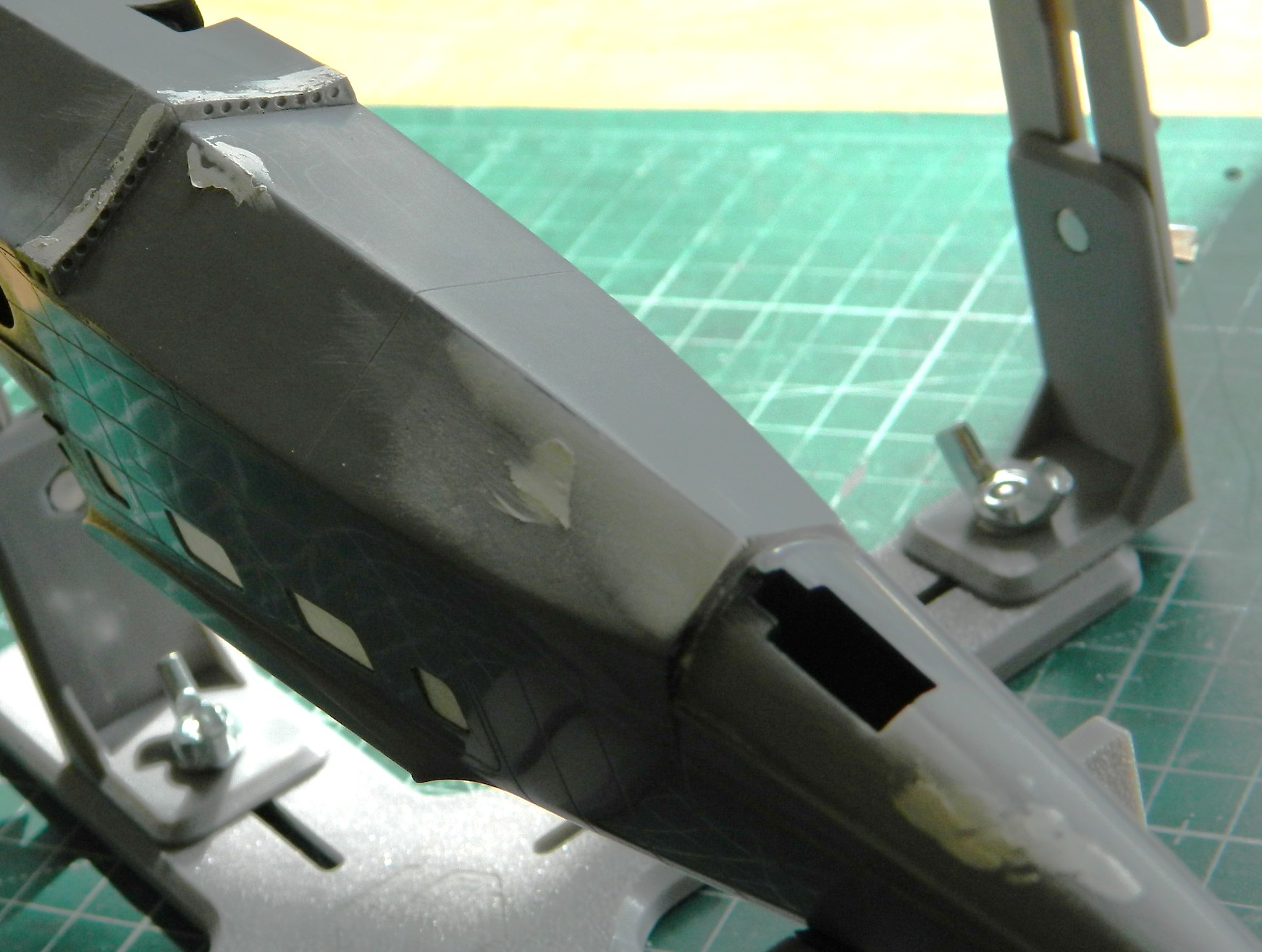
I glued the fuselage halves together. Such a simple sentence to describe a hair-pulling experience (that’s one way to clear out my nose…). Each half of the dies for the fuselage parts was clearly cut by different people. I just wished that they’d communicated with each other. Neither side matched the other in overall dimensions or curvatures. What ended up driving this task was the question, “Which side would be easier to fix than others?” I made my decision to have the top seams match (because those are the ones easier to see) and deal with what happens underneath. The halves were glued together (and most of the filler used to hide the seams, top and bottom, came from 99.9% stretched sprue).
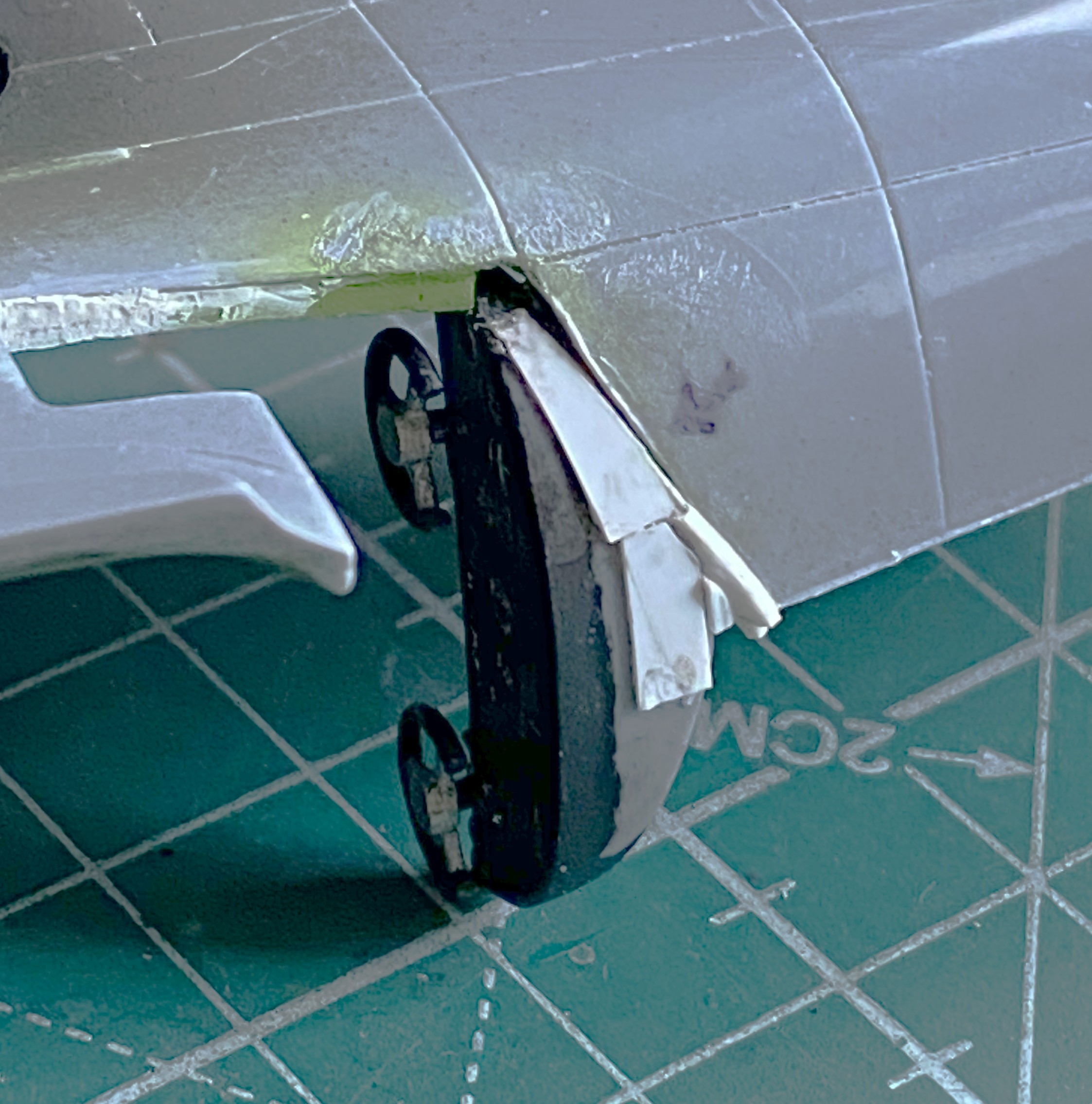
With the halves now joined, it was time to fix the mess underneath. SO much putty would have been needed to do that that I decided to add scrap sheet, mostly 0.010″ (.254mm). While I was doing that, I noticed that things don’t fit (check the arrows):

These photos are included to show you what the good side’s fit was like:


Yeah…filled with sprue.
This is why one should always use photo references from the actual time period being modeled. Most of my references are modern ones, which are okay in general, but it’s in the specifics where they drop the ball. Modern references show the nose hatch to be “proud.” It sticks up. Period references show this hatch fits flush. Can you guess what I didn’t do?:
Back under the fuselage, lot of sanding ensued (and more than a little filing):
With the supports trimmed judiciously, the pilot’s seat is in, as well as the instrument panel top puttied and sanded (though it’s evident that there will be more putty added and followed up by more sanding):
Checking fit (after a LOT of sanding) with the wings shows me that I was correct…most of what’s inside won’t show from the outside, and even less will be visible once the clear parts are in and painted:

I dislike scribing and my results show that. The panel lines with this model were inconsistent with depth and width, so all panel lines had to be rescribed. And then it was three bouts of putty filling where the scriber (me) left lines where there shouldn’t be any lines:
And after doing all that, RE rescribing panel lines often does this:

Fit was so poor that in order to get things the way I want them to be, I ended up with something that looked like a Sub at a BDSM party:

And though it took stretched sprue, scribing, rescribing, and putty, I got the empennage done:
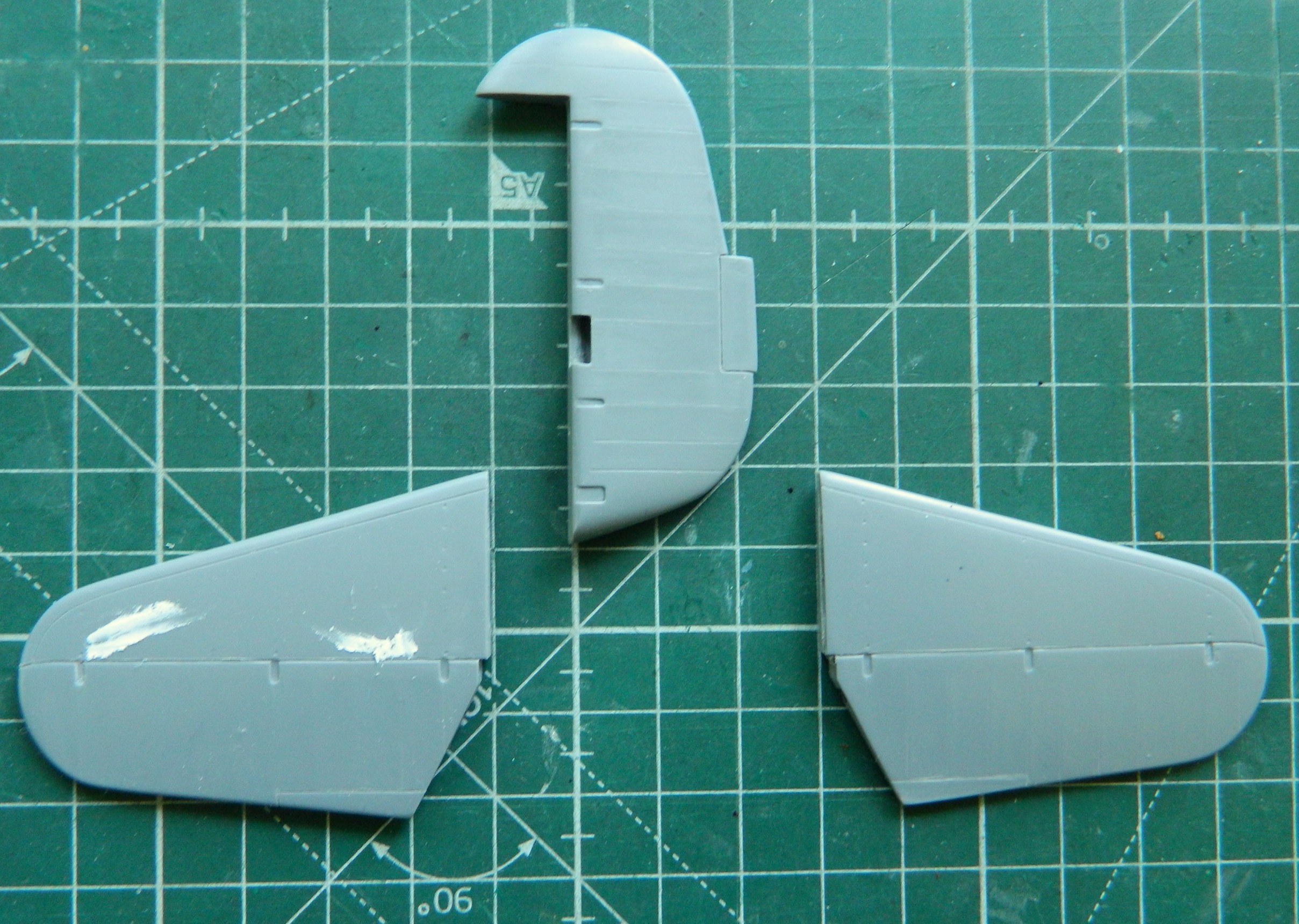
Maybe next month I’ll get to start putting these bits together permanently.
