I surprised myself with the first Part 1. I didn’t realize that I’d done so much work. That meant (means) that I had (have) to do a continuation so that I don’t fall behind. Again.
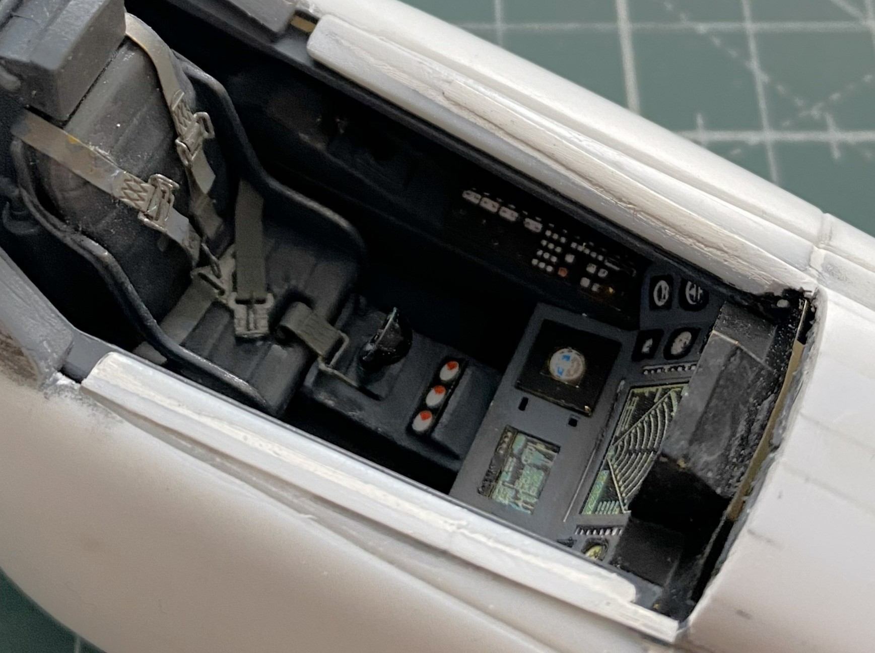
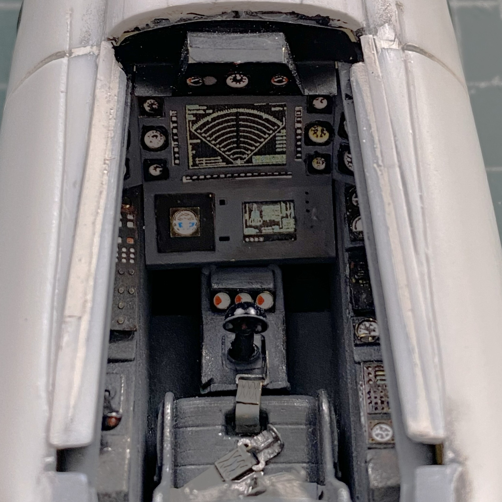
What started the reconstruction of the upper nose was the canopy not fitting well. Now the canopy fits without having to reconstruct the canopy:
Shims were added to the sides of the cockpit on the fuselage so that the canopy fits well there also (this cockpit is supposed to be sealed, y’know):
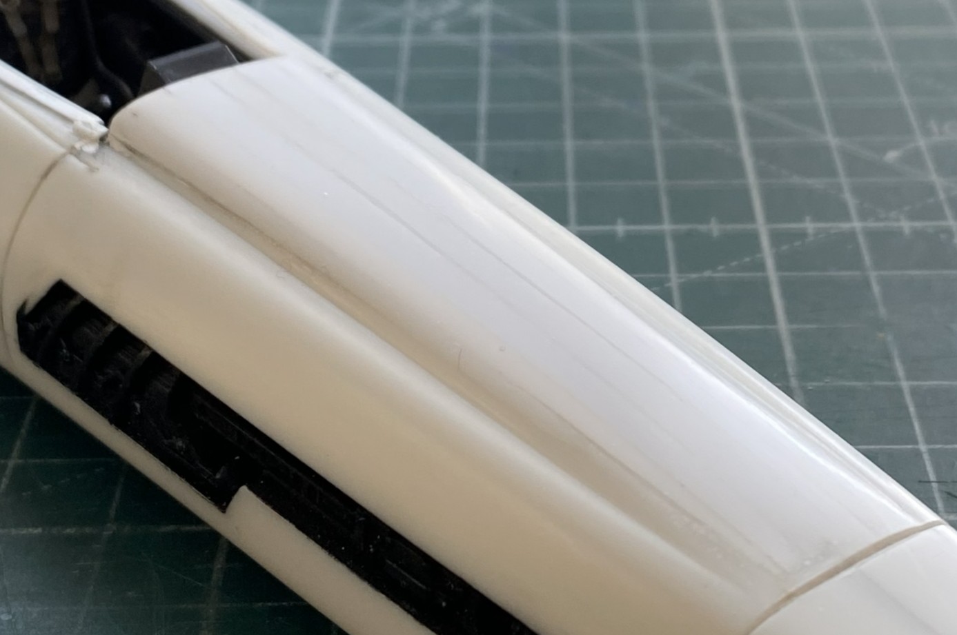
With the nose modification roughed in, I sanded it from 220 grit up to 5000 grit:
The AM set has a PE box that has to be folded and assembled. It also needs room inside the belly pan. Two sections of excess plastic under the lateral engines had to be cut away:
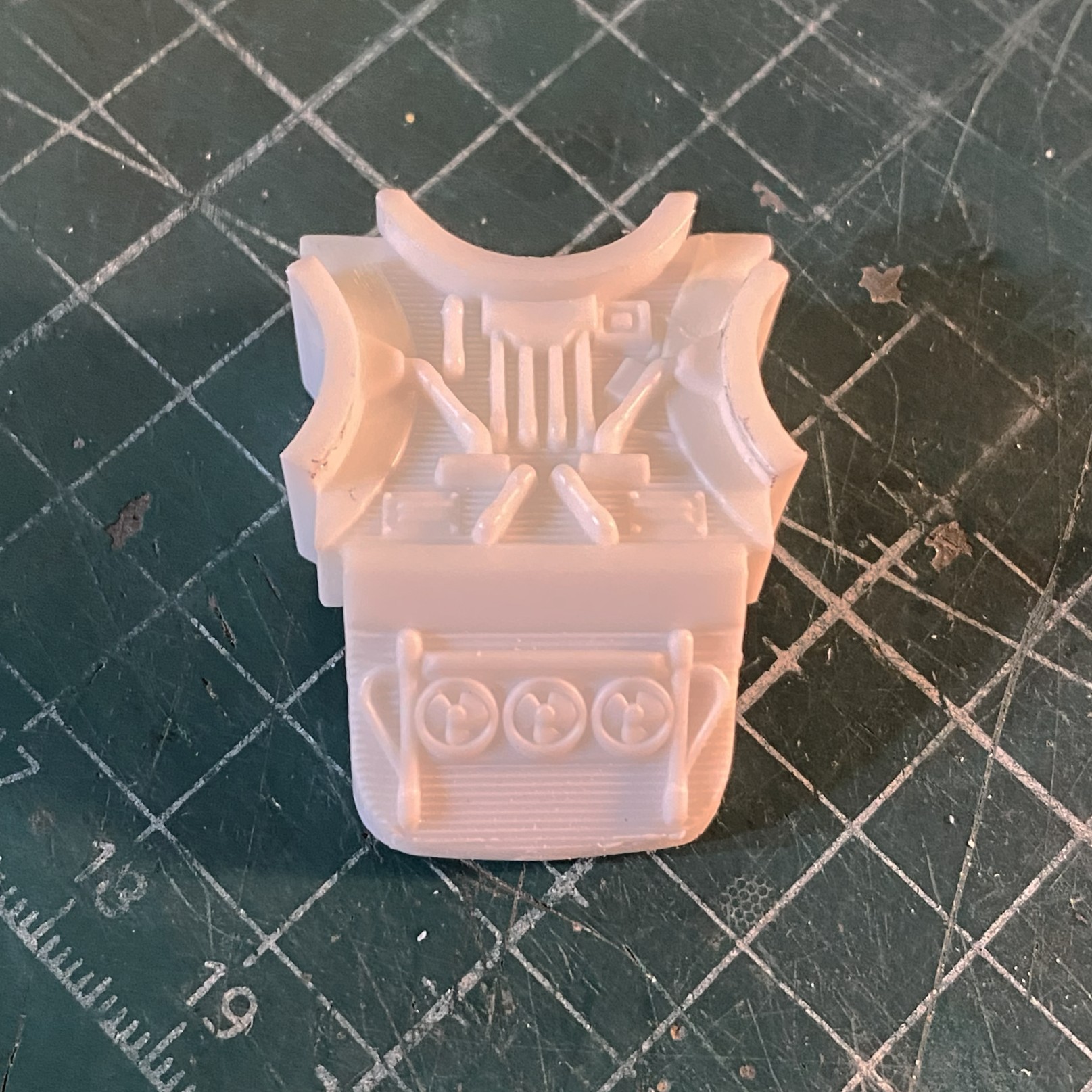
I had pre-shaded the engines with flat black, it was now time to give them their finished color as well as the landing gear legs (same color):

I’ve read accounts of people who either don’t like pre-shading or see no purpose for it. Makes no sense to me. I get great (he says modestly) results from it. I certainly like how they all look when dry-fitted:
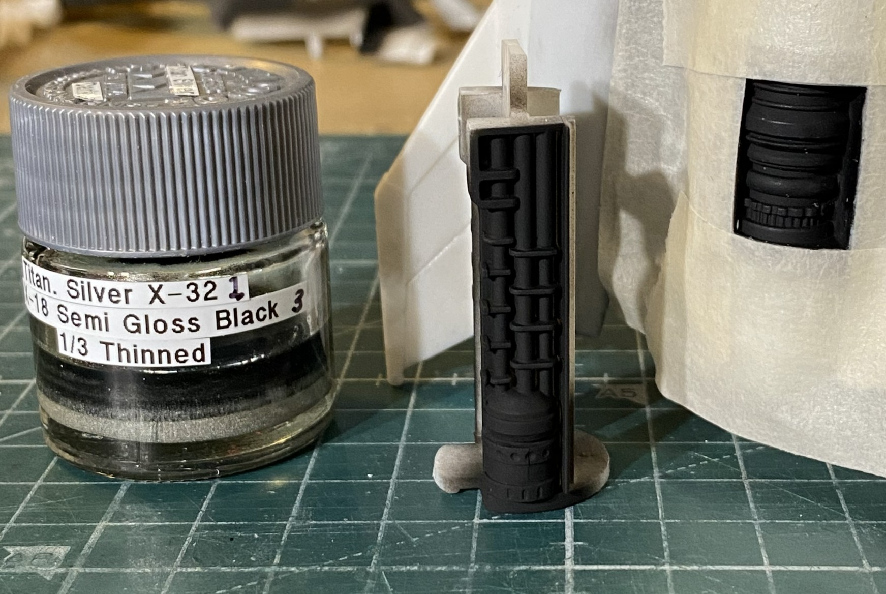
While I had the compressor fired up, I painted the guns with my custom mixed “gunmetal” paint (Tamiya X-18 Semi Gloss Black, 5 parts; XF-20 Medium Gray, 4 parts; thinned 1/3):
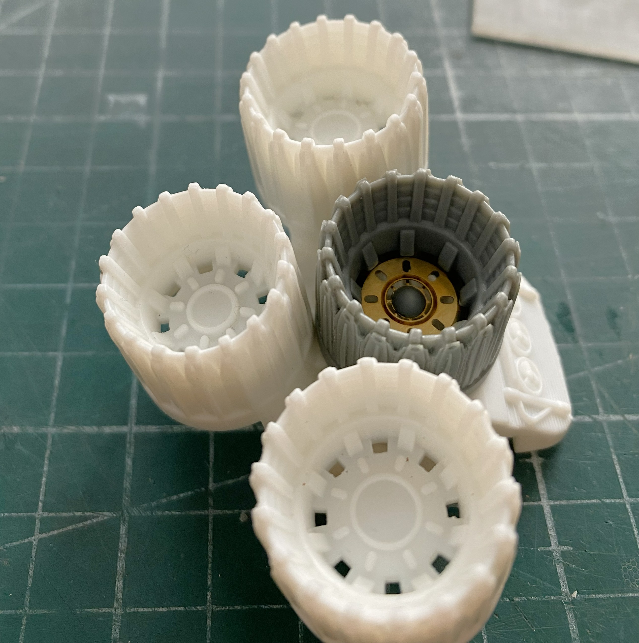
I turned my effort towards the exhaust nozzles. I think the AM parts, resin body and three PE disc inserts, are substantially better:
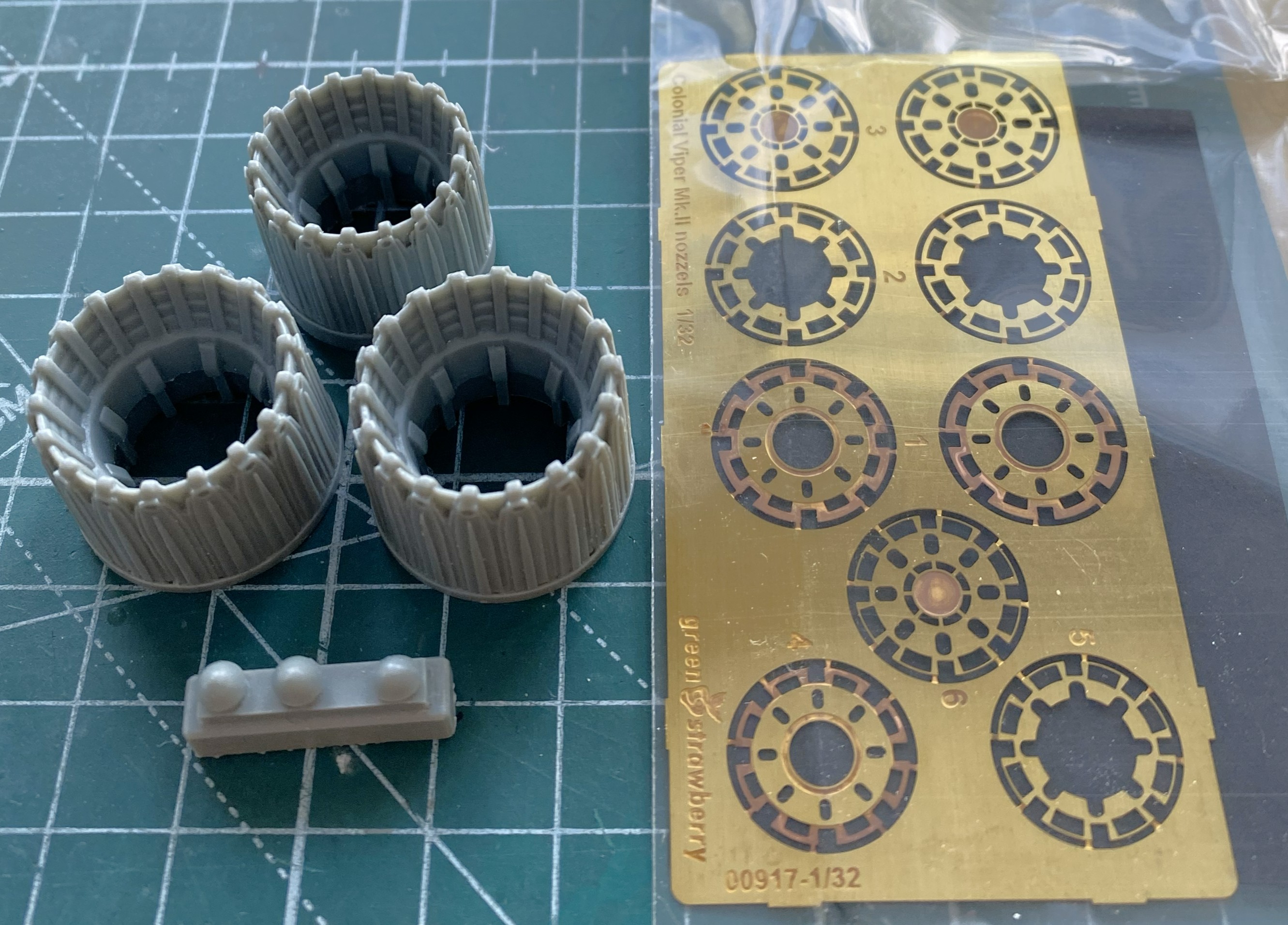
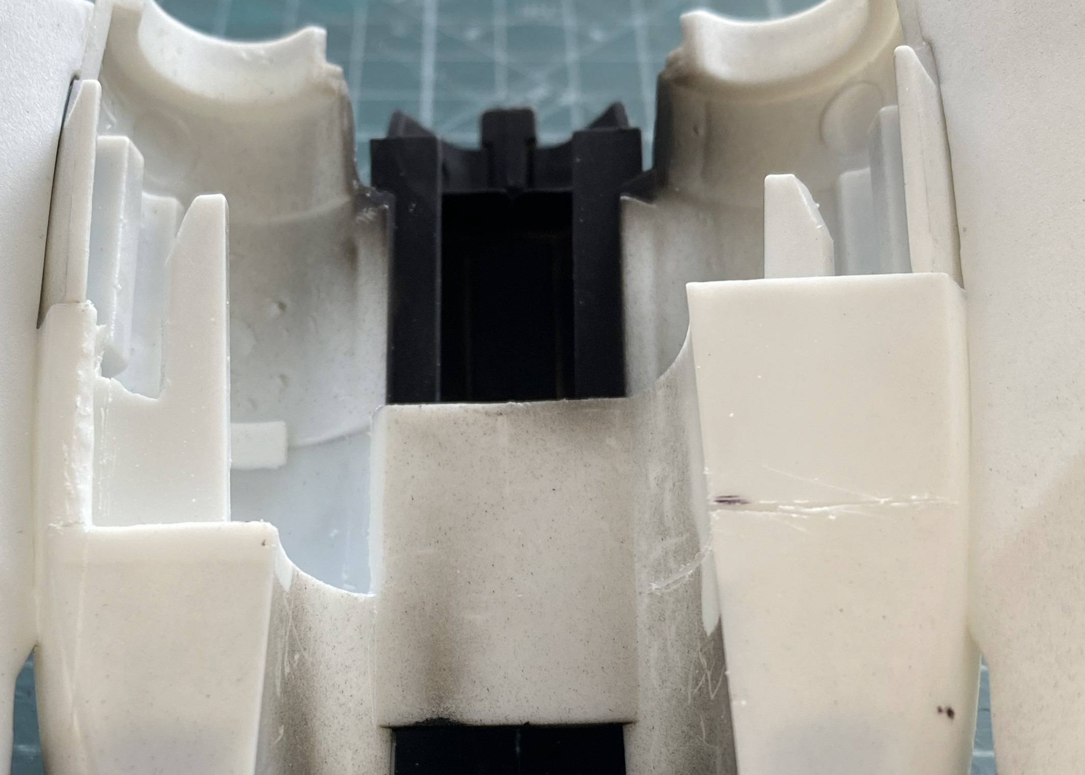
The kit’s nozzles need work. They have to be removed. Note in the below photo the section of the part where all the nozzles attach. Once the nozzles are removed, the center part is what remains:

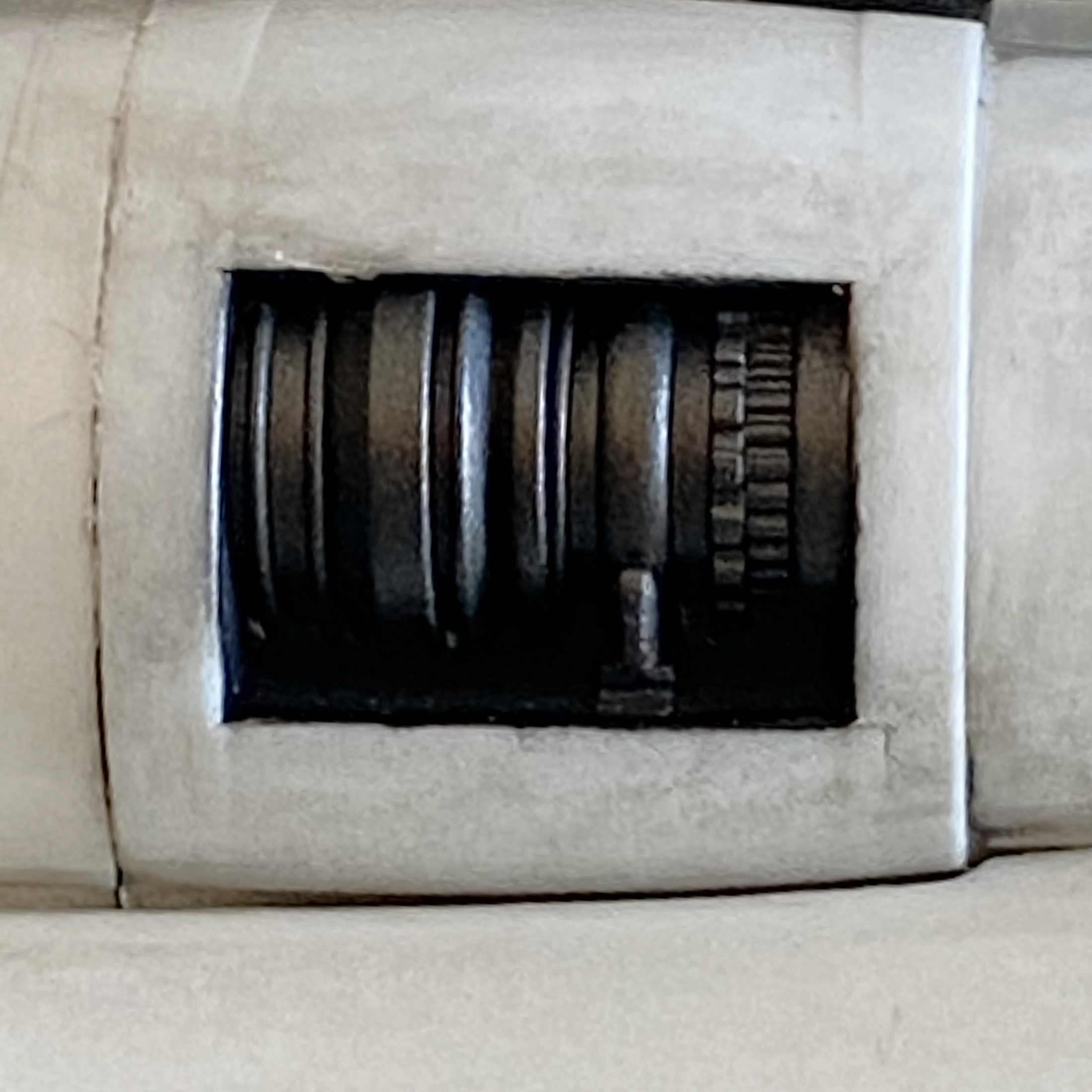
Each of the AM nozzle assemblies has sections where one can see into the hollow fuselage. Easy fix. Cut out discs for the two nozzles that allow that “feature” and paint them black (the upper engine’s rear will get painted black for the same reason):
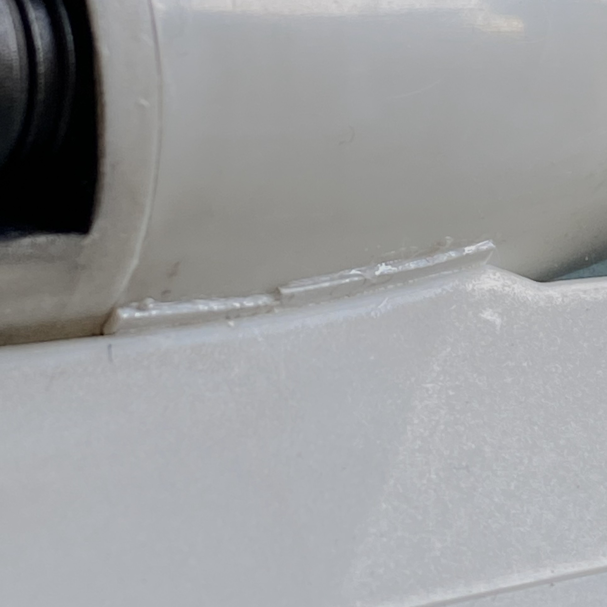
Each wing root has a gap that bothers me. Well, they had gaps but they were filled with scrap styrene. I’ll finish these off before painting:
I’ve had people ask me how I make some of the smaller details I use. I’m going to show you but there are a few steps to the process. If this is of no use to you, just scroll past.
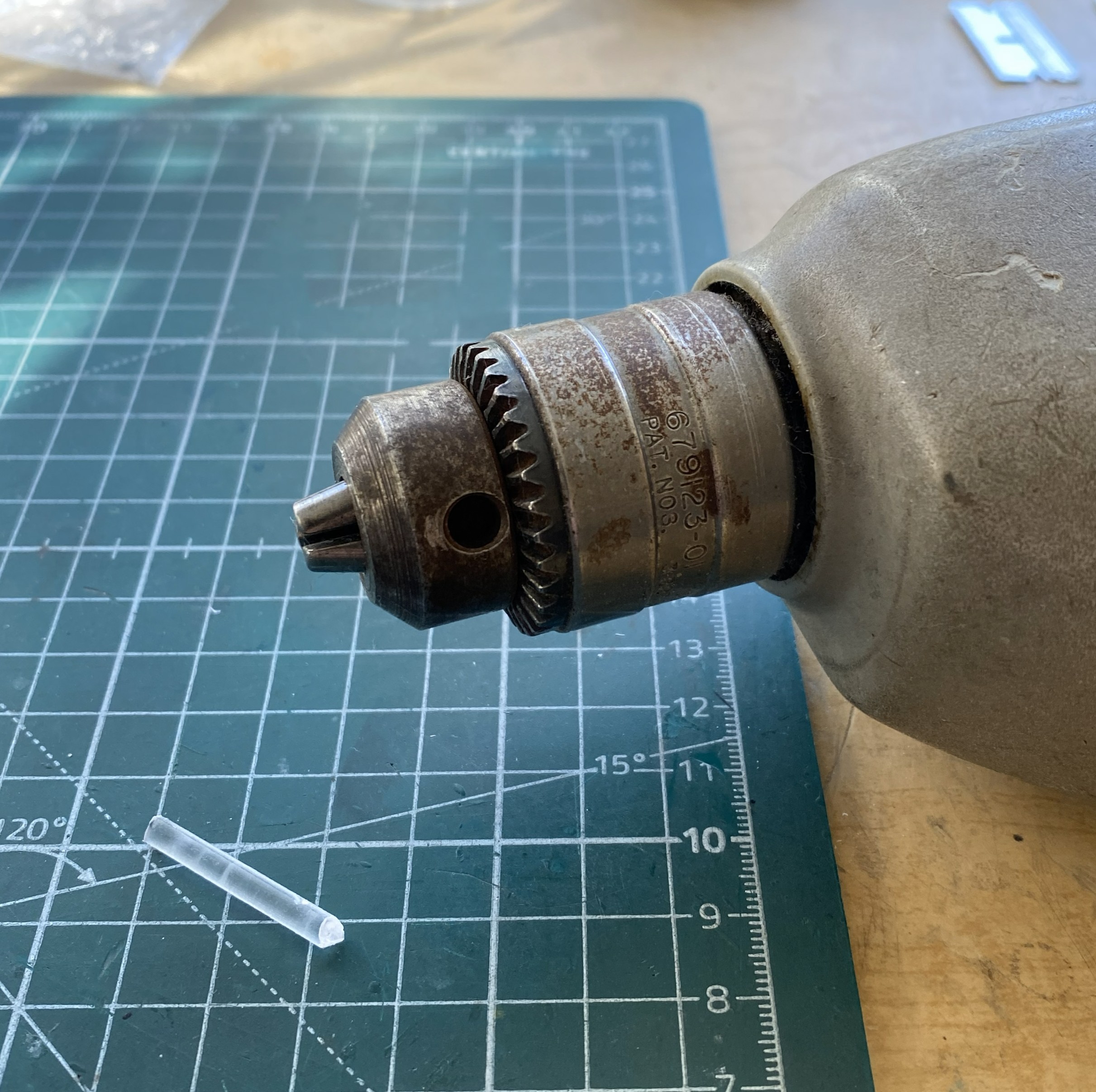
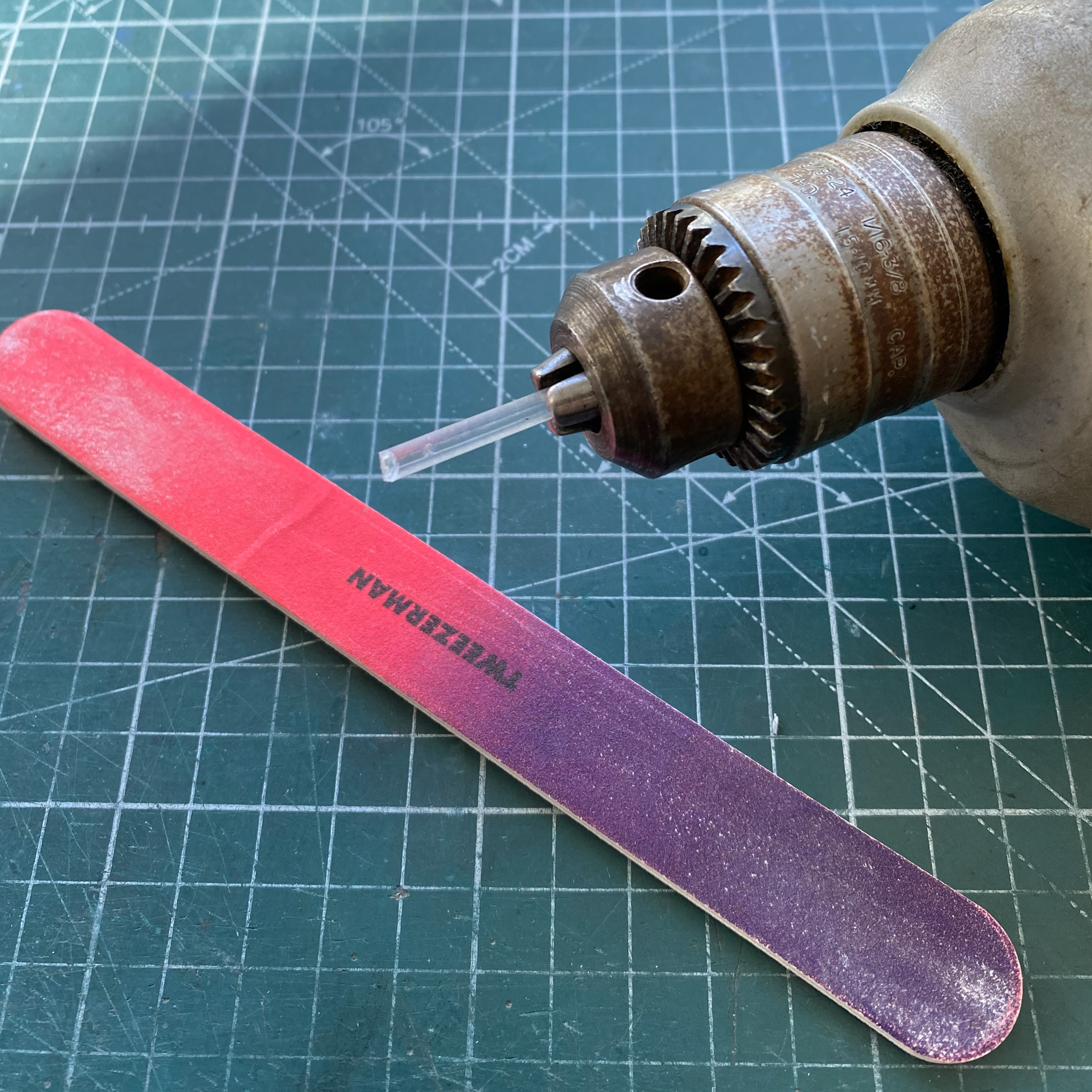
Sometimes I need to make something cylindrical in nature. If dimensions and shape are critical, I have a small bench-top lathe (Harbor Freight, I don’t need anything more accurate and certainly don’t want to pay for more accurate). When the look matters more and it’s a small part I’ll use a variable-speed drill. In this case, all I need is something to hold the stock and spin it.
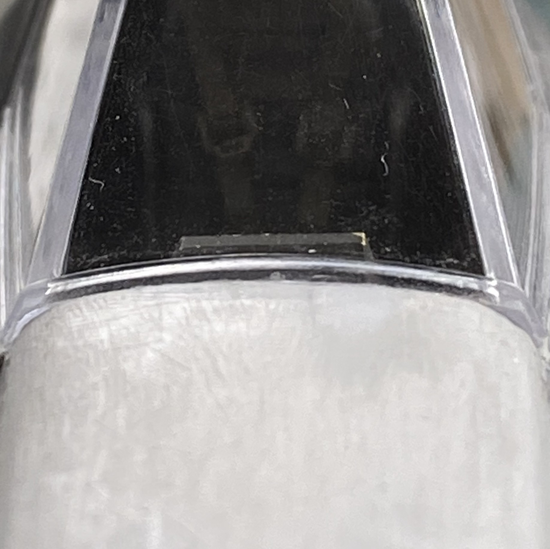
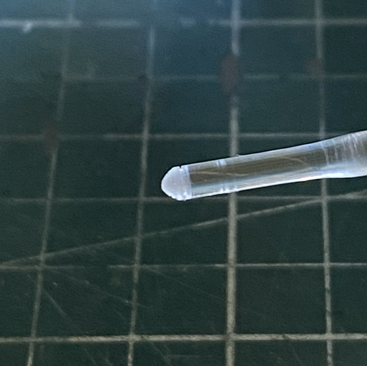
The sensors for the draedus are molded onto the wingtips in opaque plastic. Yes, I could just paint them. (I could also get into stamp collecting as a hobby, too.) Instead, I want to make clear covers for them. So I started with a section of clear sprue and set the drill at a lower speed to keep from melting the work:
My initial thought was to use an abrasive nail shaper:
Nope, it doesn’t take enough off. I tried a razor blade next:
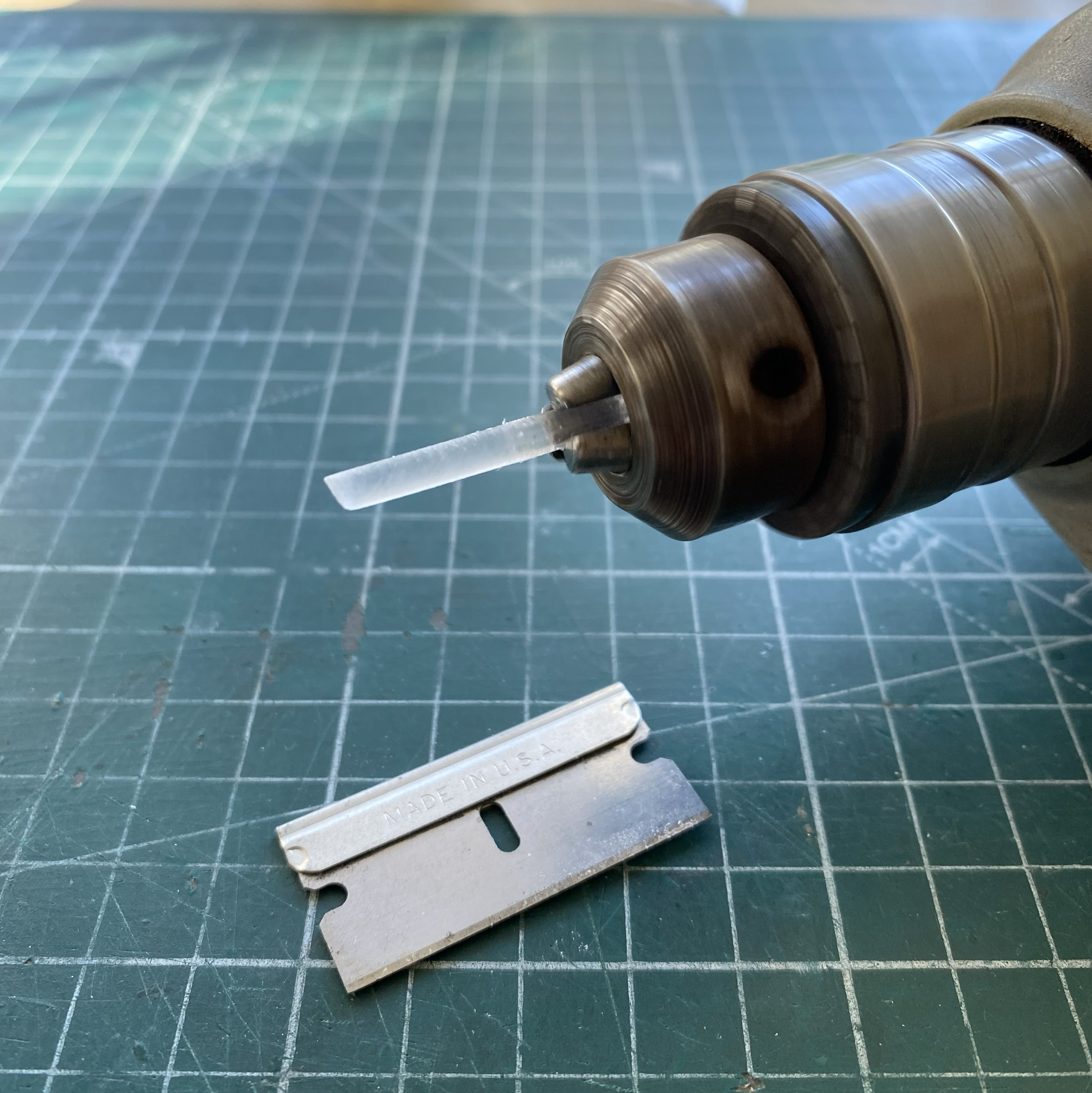
Yes, it took more off per spin, but it was unwieldy (and my fingers, being right next to that sharp bit of steel is full of my SACRED B+), so I used a #11 blade:
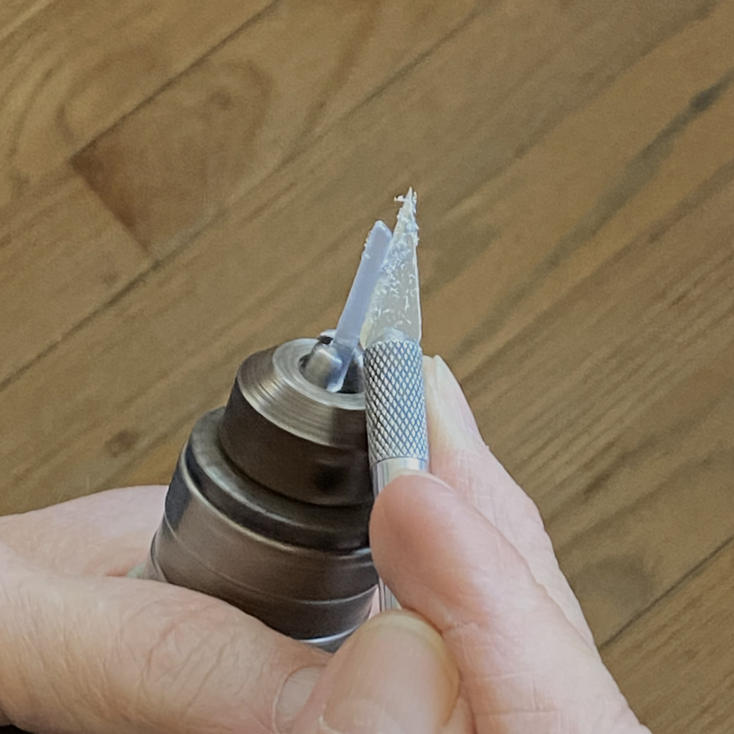
That worked much better! What isn’t evident in the above photo is the angle I’m holding the blade at. I’m holding it at pretty much the same angle that I use to scrape plastic with. Do NOT let the blade bite the work!
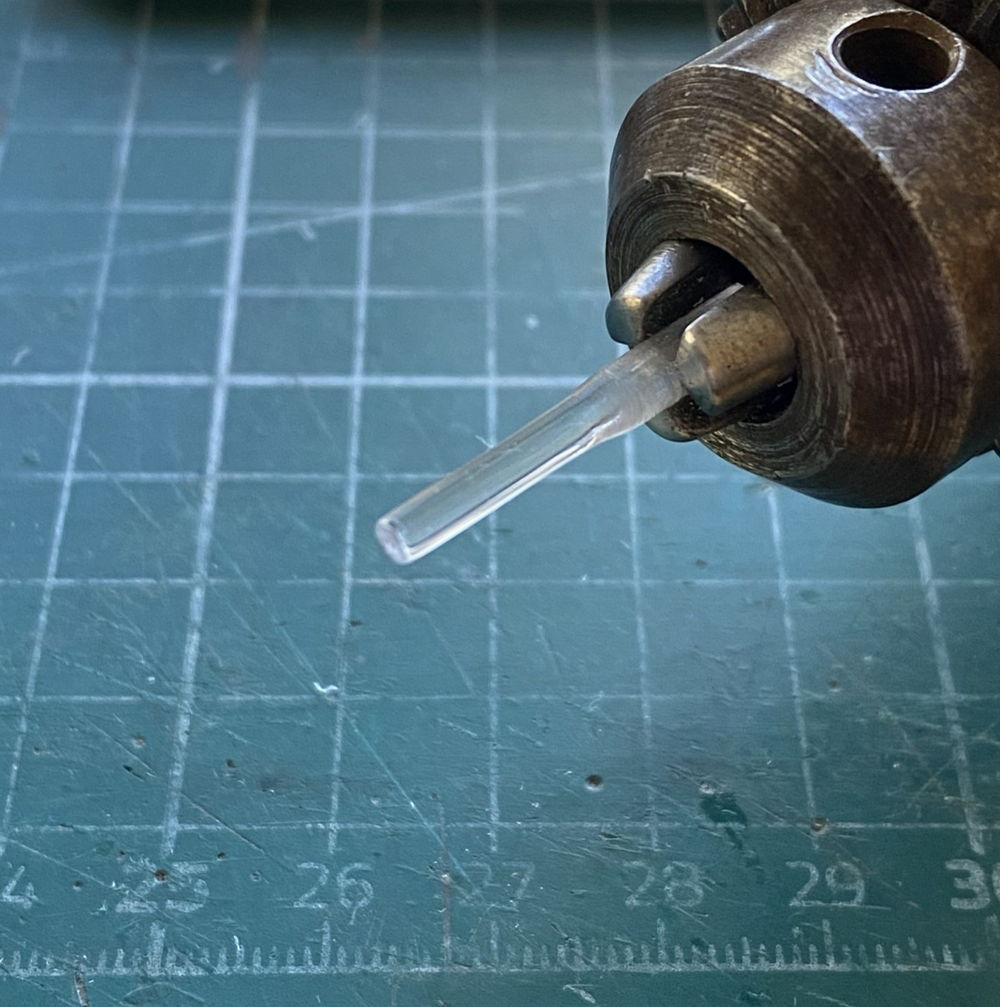
Don’t forget to check the diameter frequently:

Once my Eyecrometer MkI was satisfied, I polished the work:
I used the #11 and a VERY narrow file to add surface details:
Once that was done, I kept the work spinning and used a razor saw to cut off what I wanted. And yes…this is a small part:
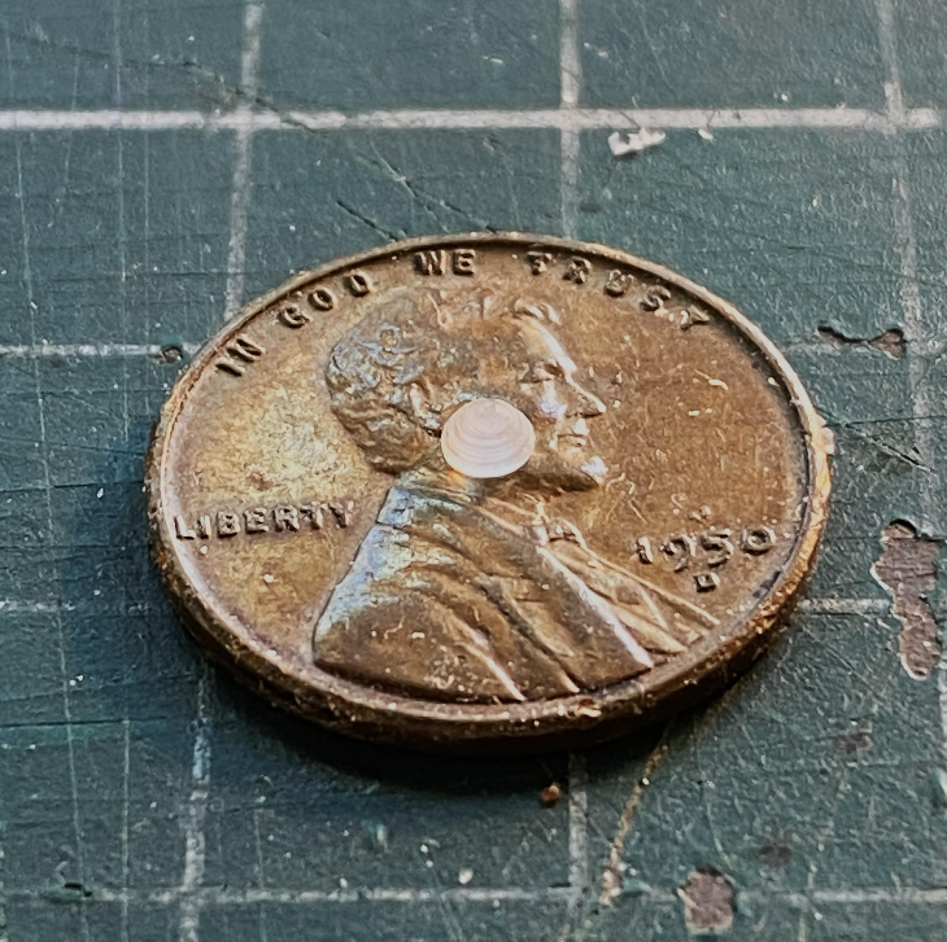
Its size isn’t a problem. The problem is that I have to make three more of them! At my age, I have an understanding of my work process. One of those understandings is that when I have to make multiple parts, I generally nail the first one spot on. The remainders? Well…if I’d followed my process and tried to make three more just like that one, I’d probably would have needed four or five attempts to get the next one. Repeat that process twice more and I’d have a pile of small parts and the task of selecting the best four from that pile. I just didn’t feel like doing it that way.
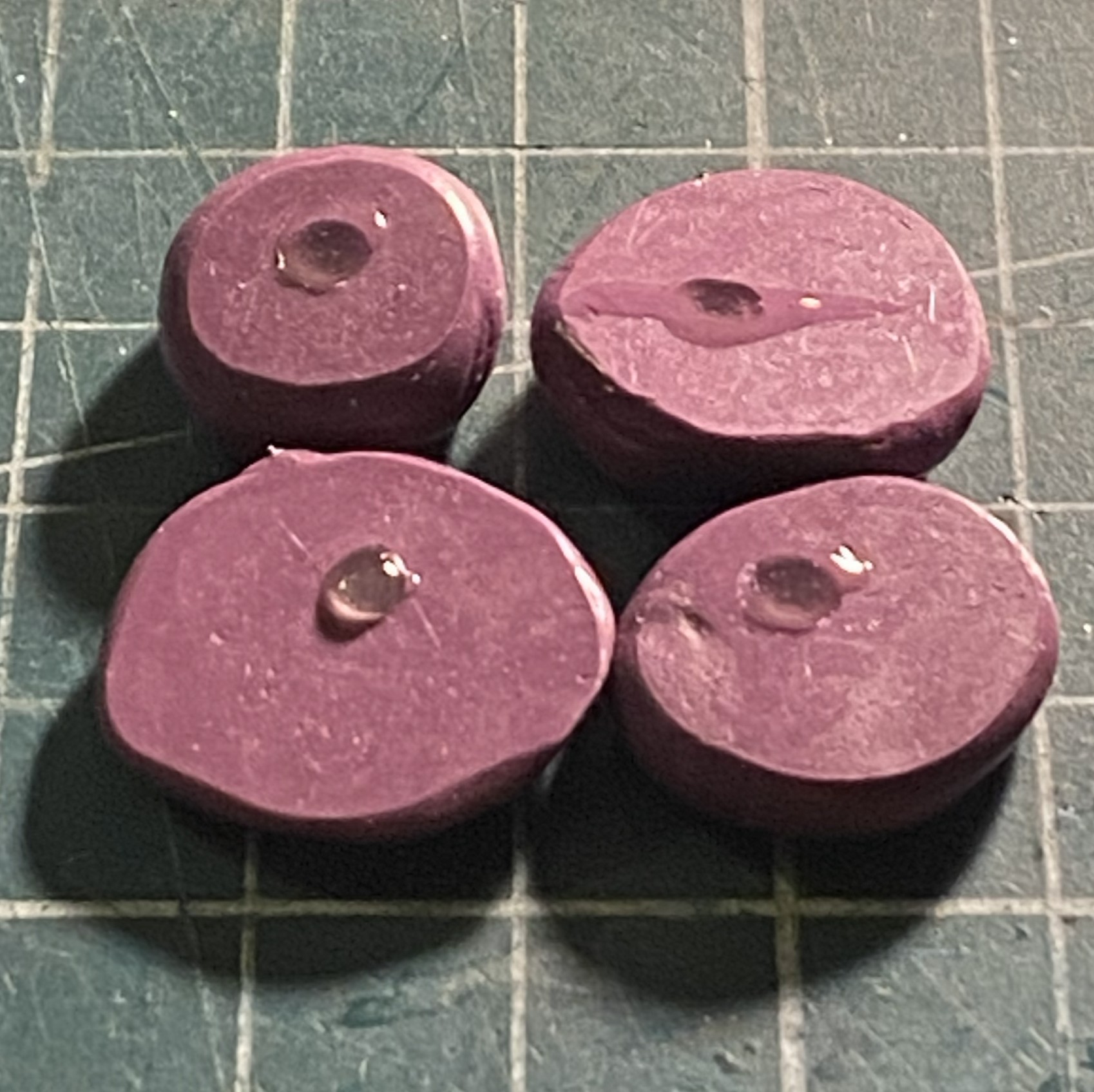
Instead, I used the silicone molding putty and made four molds from the one part already produced:
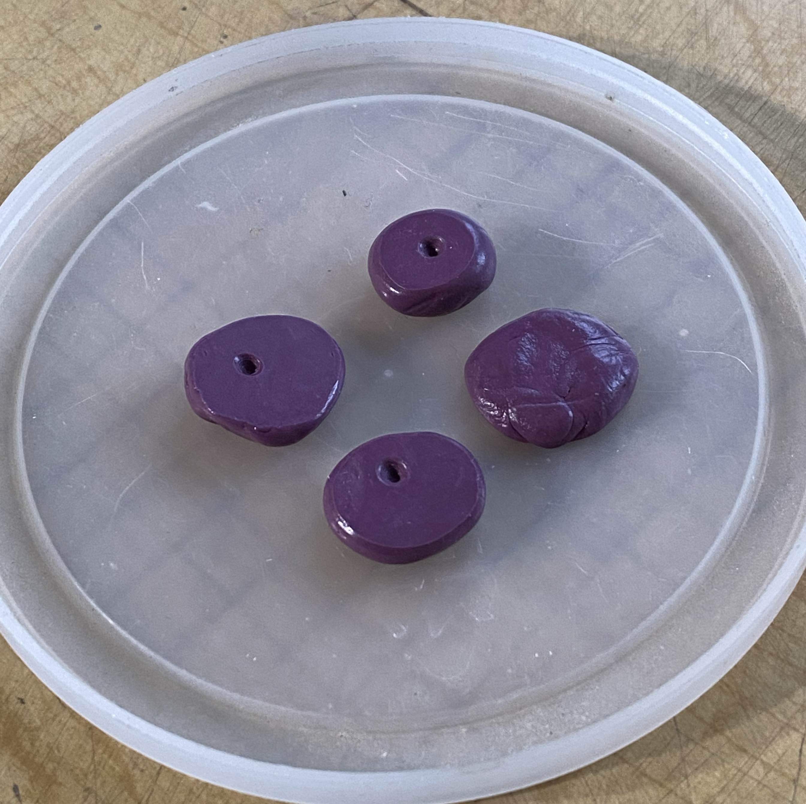
Why four molds? Because it was my intention to make the sensor covers from plue comprised of clear sprue. It takes time for the plue to set up that I didn’t care to wait around for. First, make the plue:
Not easily seen in the above photo are the bubbles that are forming. I use Tamiya Extra Thin to make plue. It’s a solvent that dissolves plastic. The process of hardening is one, essentially, of evaporation. The solvent evaporates and leaves behind shaped plastic. It also leaves behind bubbles. As the solvent out-gasses, it creates bubbles. The bubbles that make it to the surface go away. But as the solvent out-gasses, the plastic returns to its original solid condition and that traps all the bubbles that didn’t get to the surface in the plastic:

Opaque plastic doesn’t show that (them?). I tried several ways of getting plue into the molds in thin layers and without disturbing the plue (and thereby creating more bubbles). That worked, in a manner of speaking, it just didn’t work very well. The parts were VERY THIN. How do these get attached to the tips of the wings? Solvent-based glue. Solvent dissolves plastic. The parts are vert thin plastic and they (or the test piece) do what plastic does when solvent touches it. It dissolved:
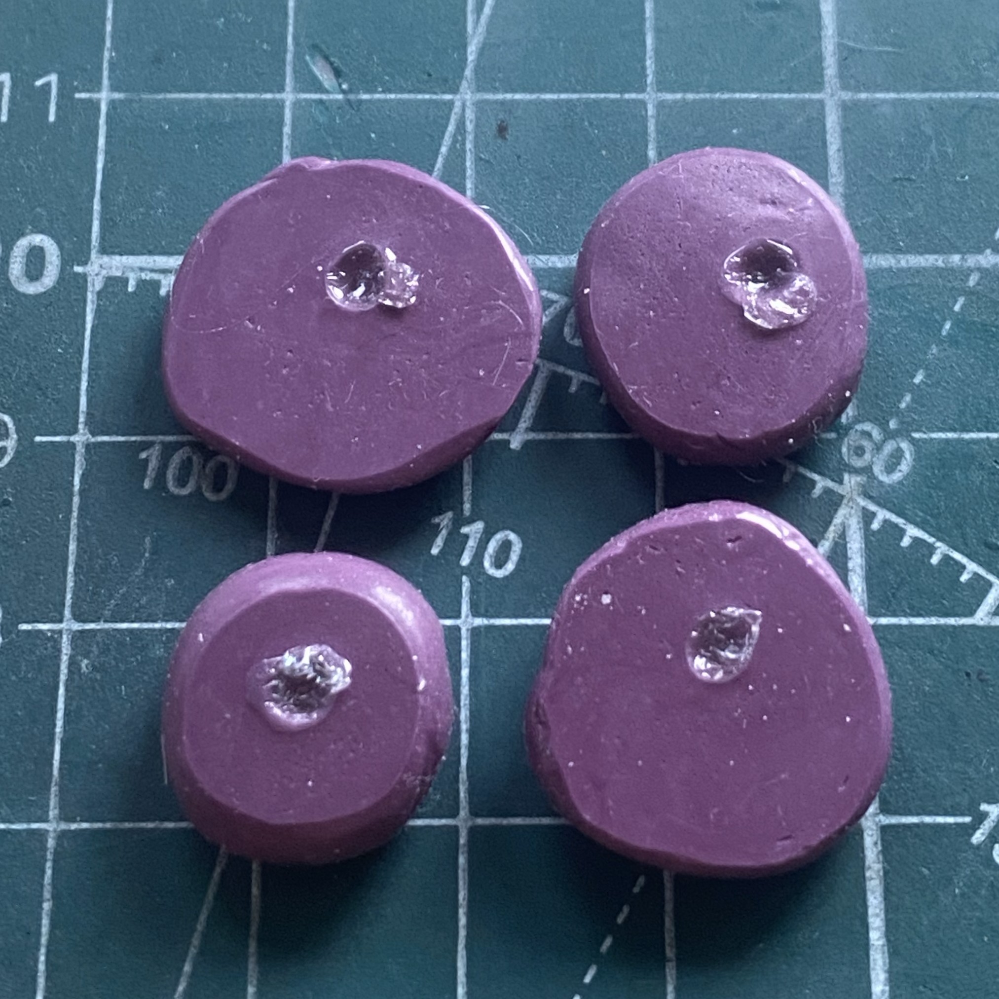

Then I had the incredibly bright (there’s my modesty in play again) idea of using the UV-setting resin to fill the molds. It’s clear, doesn’t react to solvents, and though it can bubble in the mold, that’s more of an application problem. When bubbles were introduced into the mold, I used a needle to move the bubbles away from the part successfully…then forgot to take photos. ::facepalm::
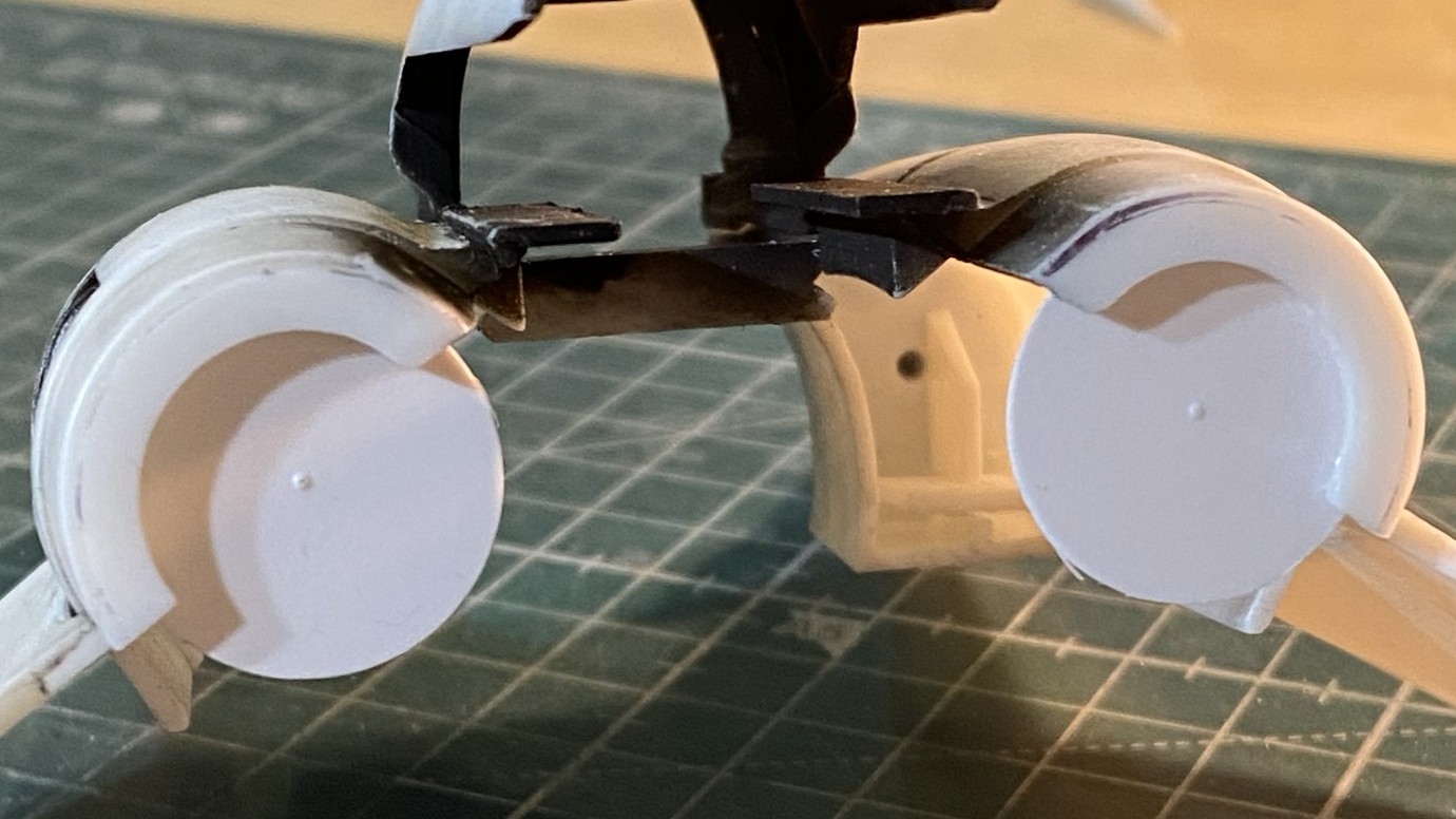
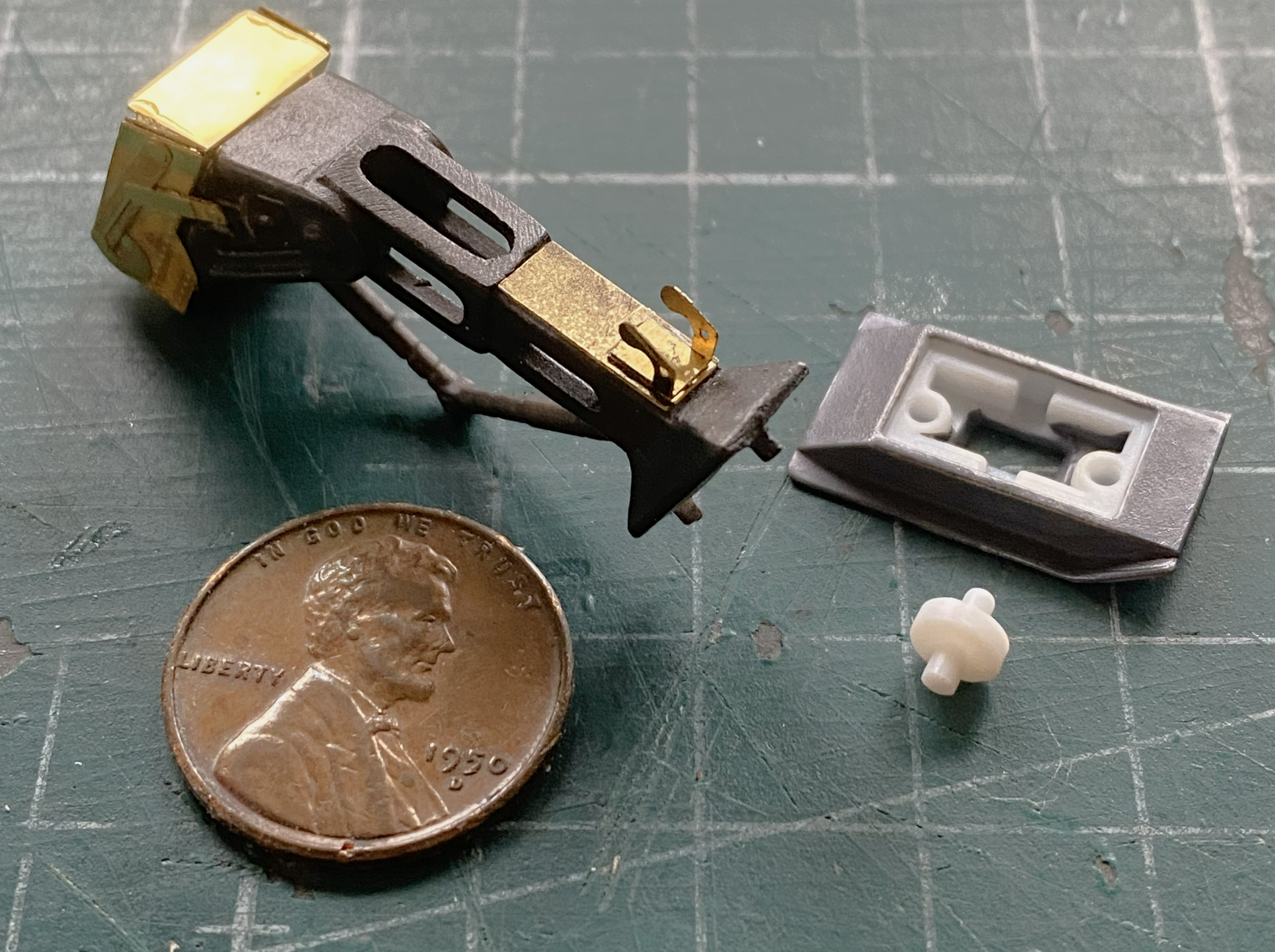
I discovered that I’d neglected to add some PE to the nose landing gear. Fixed that. I also broke out the Humbrol paint (#27003) and painted the feet (because they’re not wheels) buffable steel. (The white plastic part is a wheel that sits in the feet and has yet to be painted, obviously.):
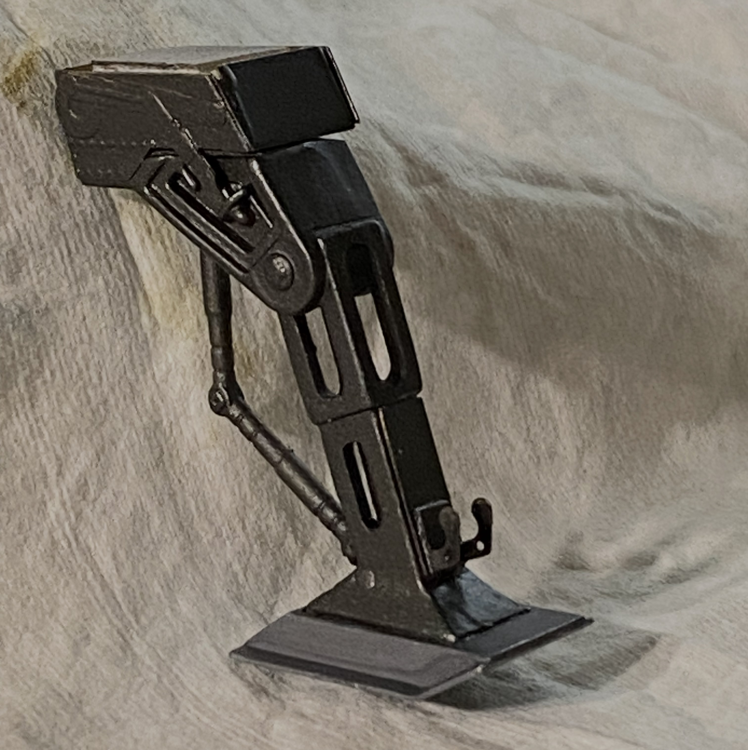
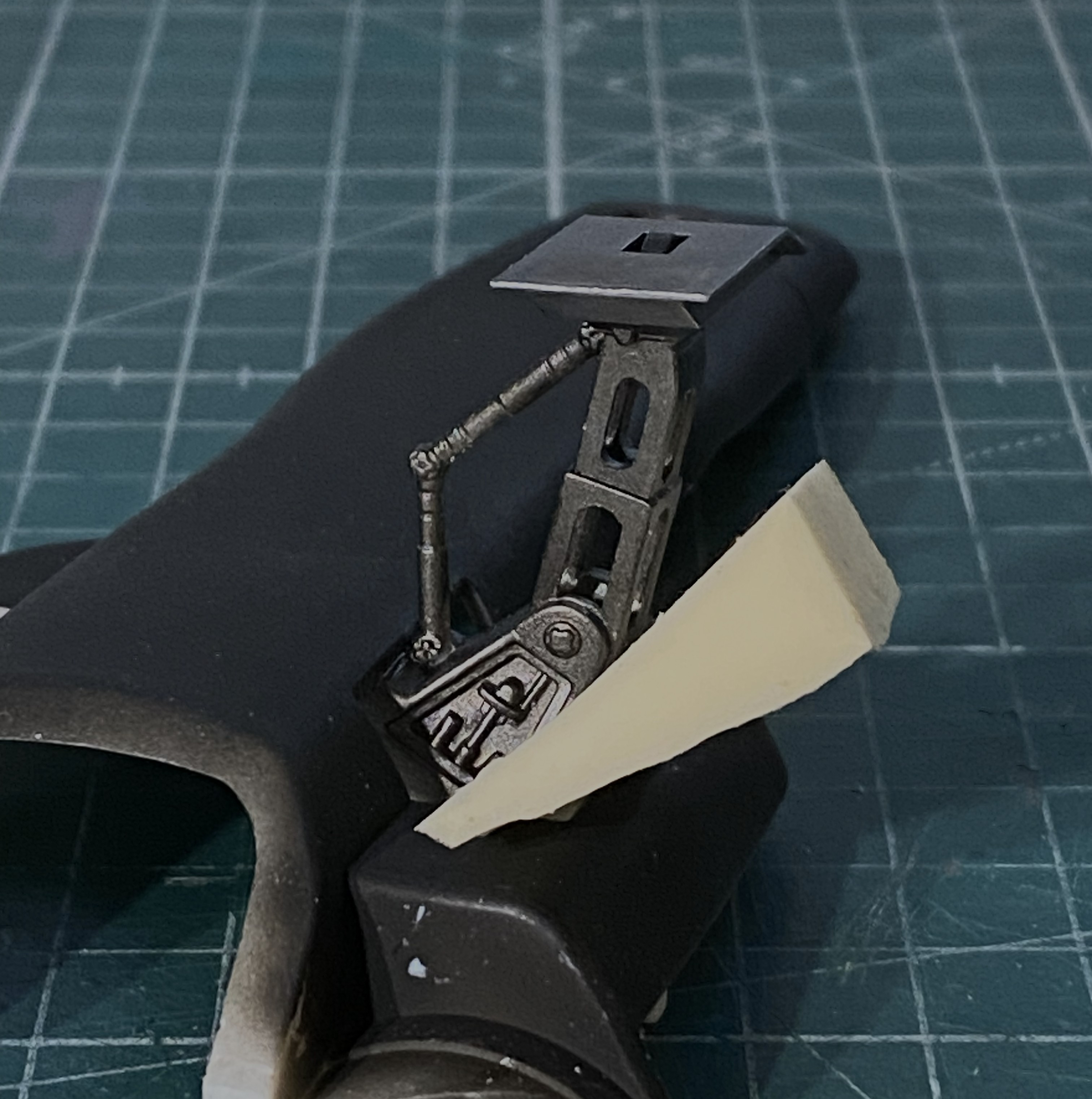
I painted that wheel and PE and assembled the nose strut:
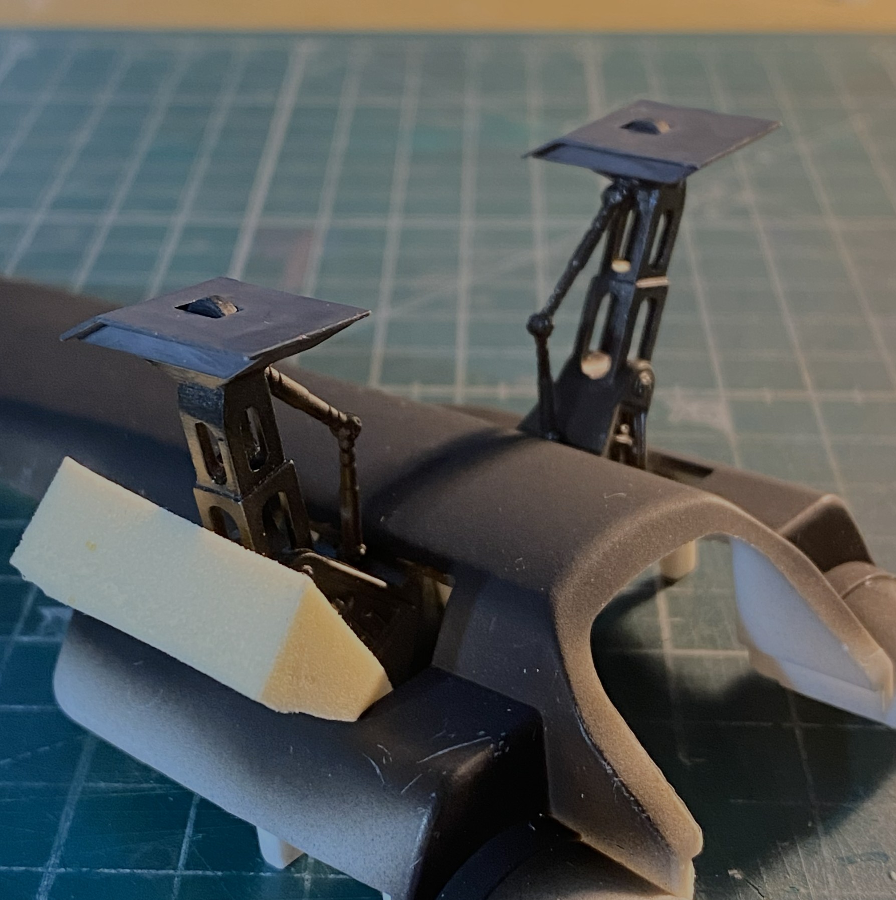
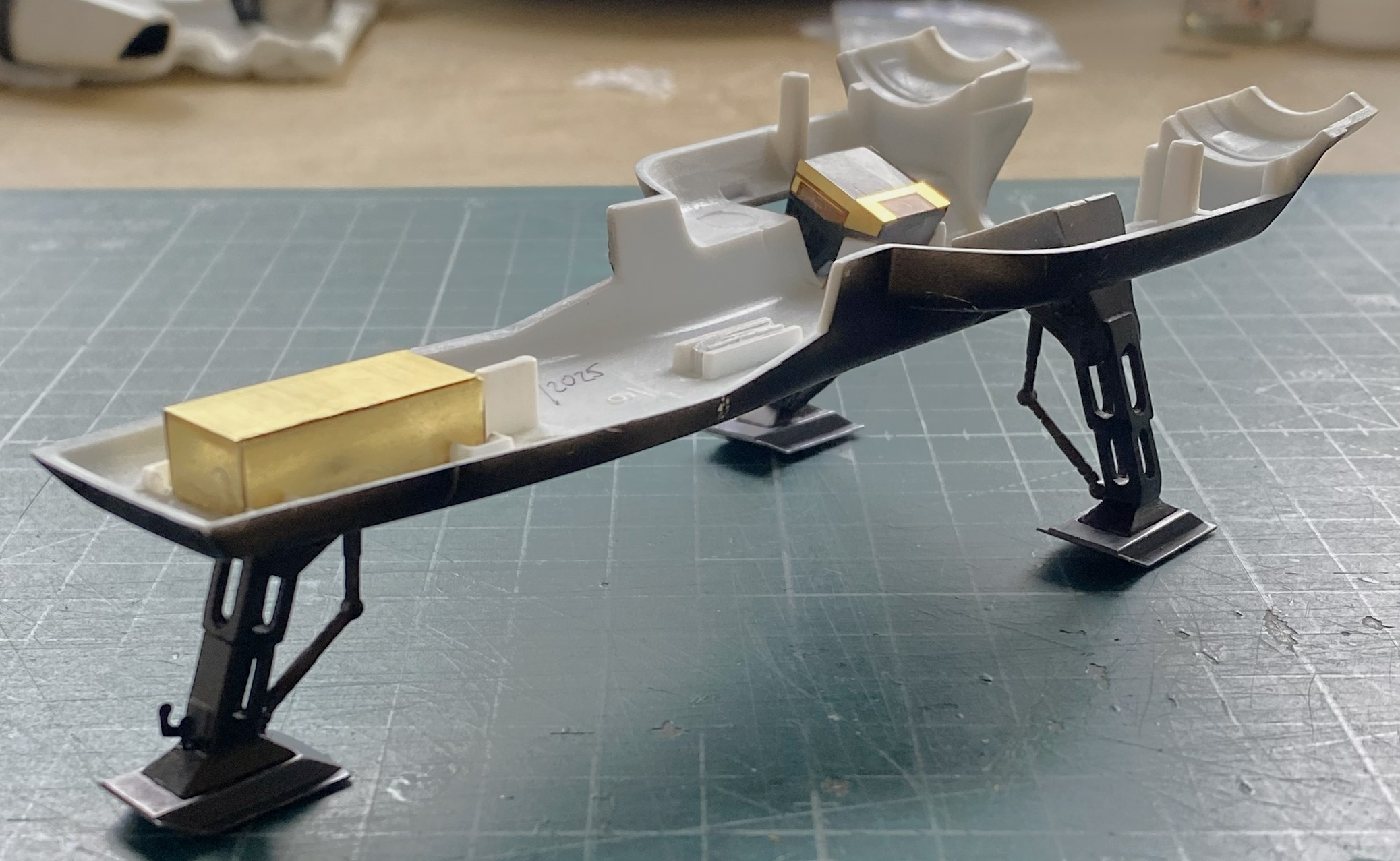
After assembling the main landing gear, I added them to the belly pan. The foam wedge is holding the assembly aligned while the glue sets up:
These PE frets are almost entirely landing gear bays. Brass origami shall ensue shortly:

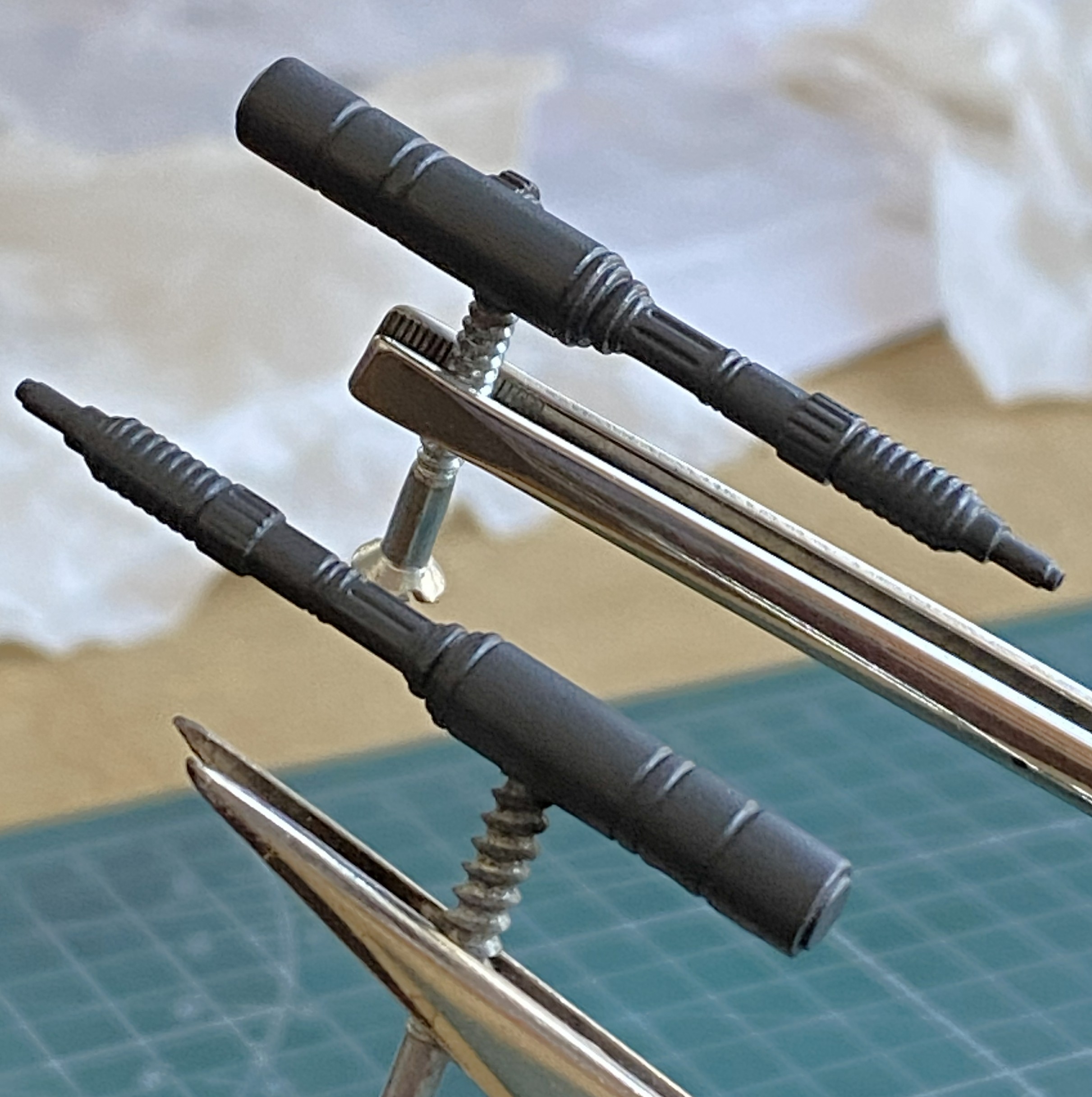
Some of the PE parts from the other PE fret are intended to dress up the engines a bit. The problem with PE is that it’s flat. I used a piece of a D guitar string and three different sized solder (0.020″ [.508mm] is shown but I also used 0.015″ [.381mm] and 0.010″ [.254mm]):
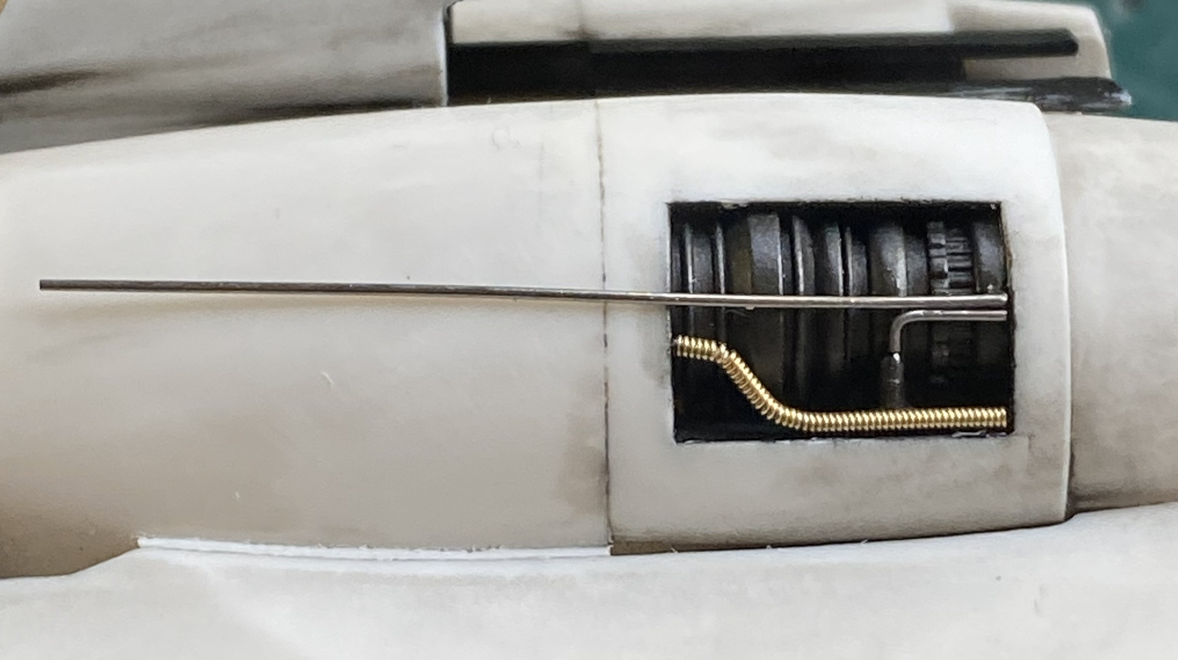
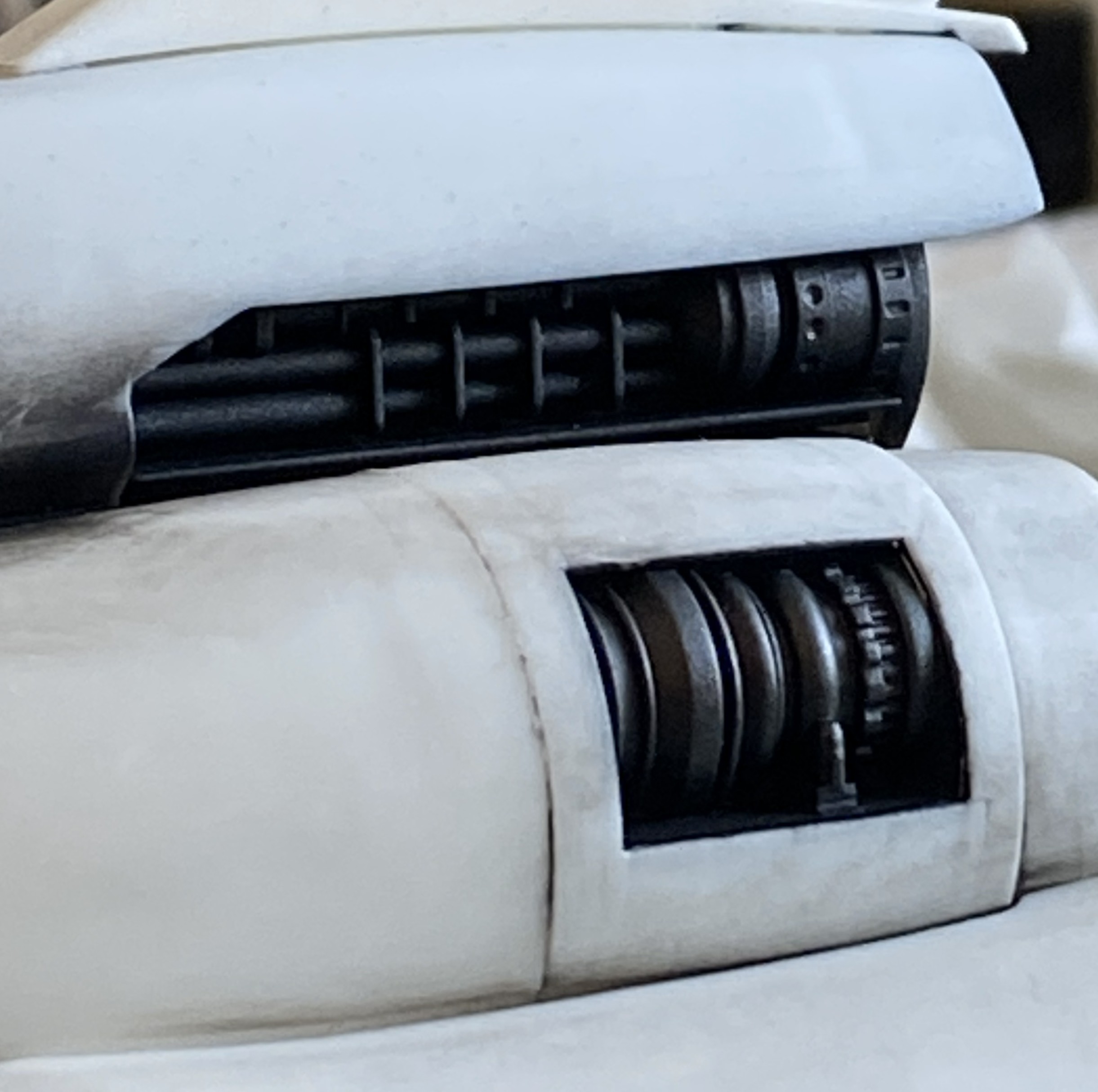
The port engine done:
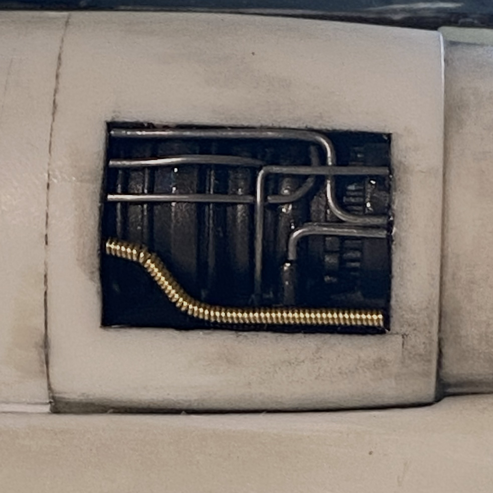
And the starboard engine is done:
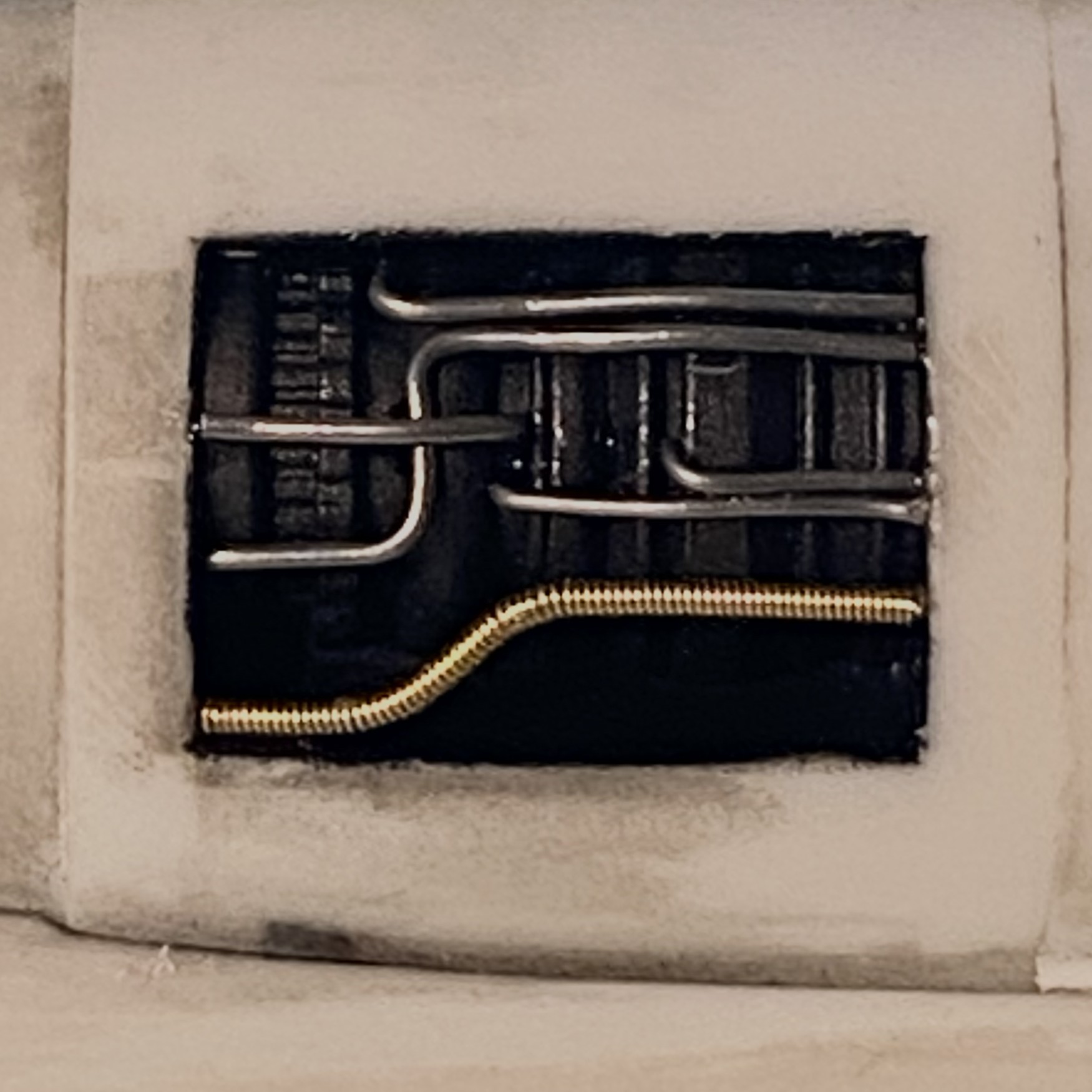
Yeah. I like that, and the pre-shading does exactly what I’d hoped it would do. When it comes time to paint this model, the engine areas will stay as they are now (with the typical paint touch ups).
As it gets closer to adding the belly pan, it was time to add the nose gear. It fit like crap. I’m not especially thrilled with how it’s sitting (after much diddling, fiddling, and offering Deities all sorts of things that They’re aware I’ll never do or stop doing, depending on how I’m wheedling them) but short of taking the nose bay out…again…this is how it’s going to stay:
There! All caught up. Next month’s preview? Brass origami.
This is a Public Service Announcement.
Be careful where you part your truck! There are miniature coyotes in the neighborhood and they’re obviously in a rush: