F7F-3 (AMT/Italeri) 1/48 Scale Build #4 –Engines Get Painted, the Landing Gear Bays and Landing Gear are Pre-shaded, and the Landing Gear is Installed
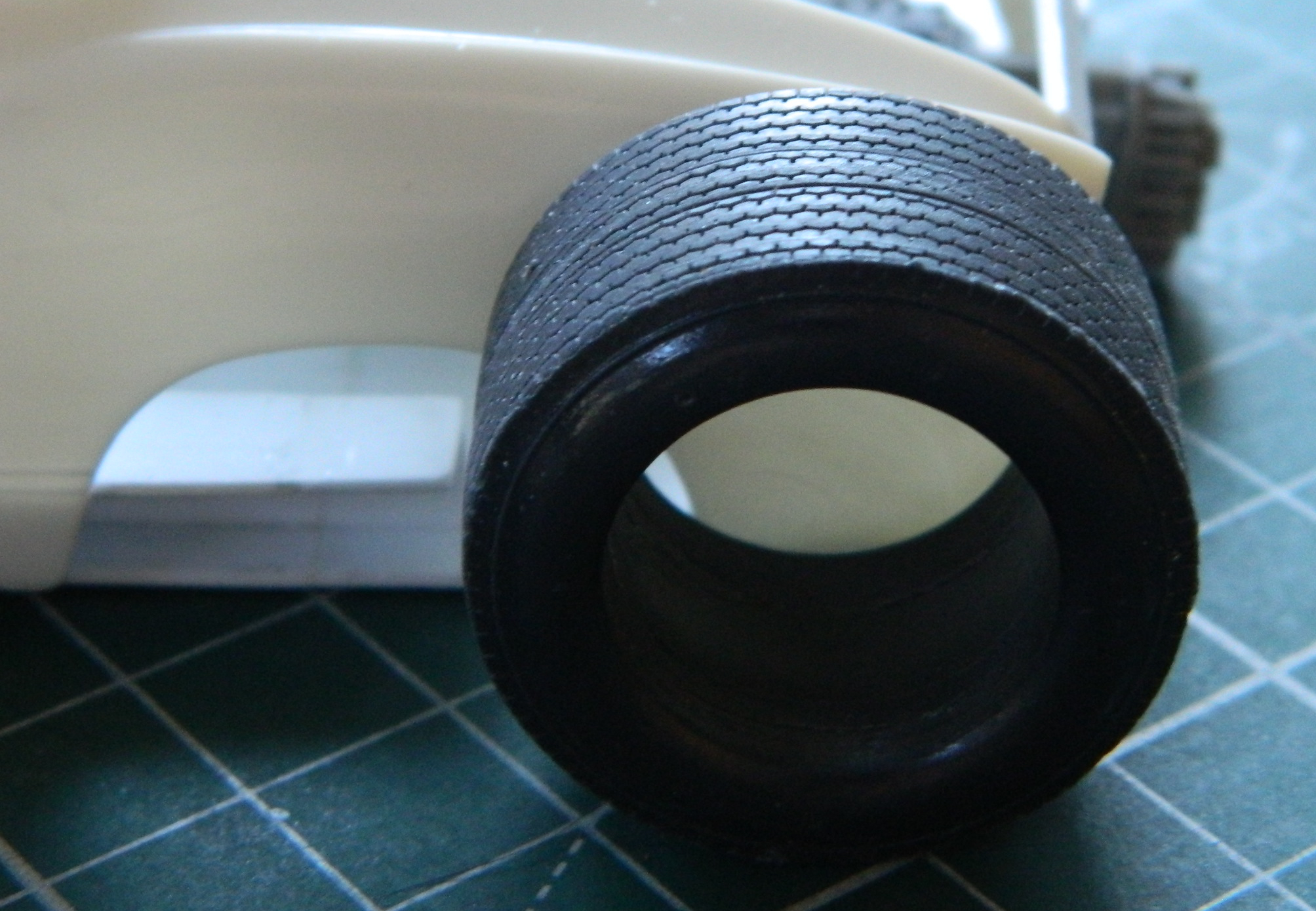
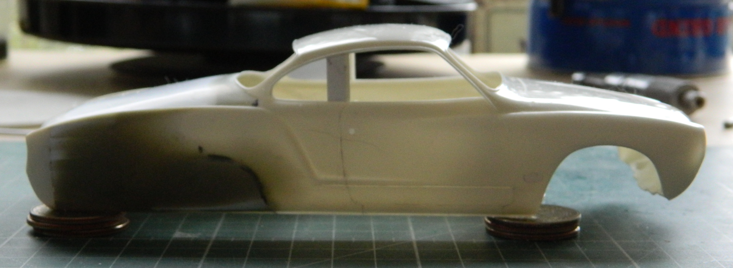
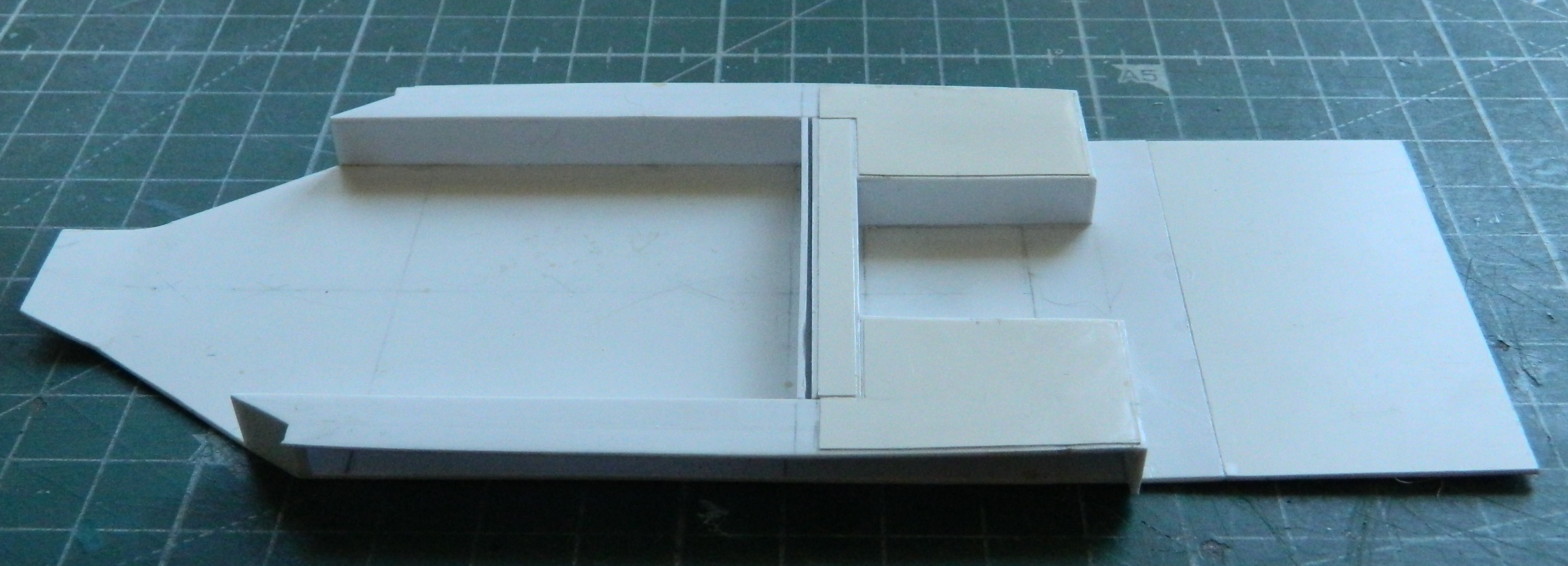
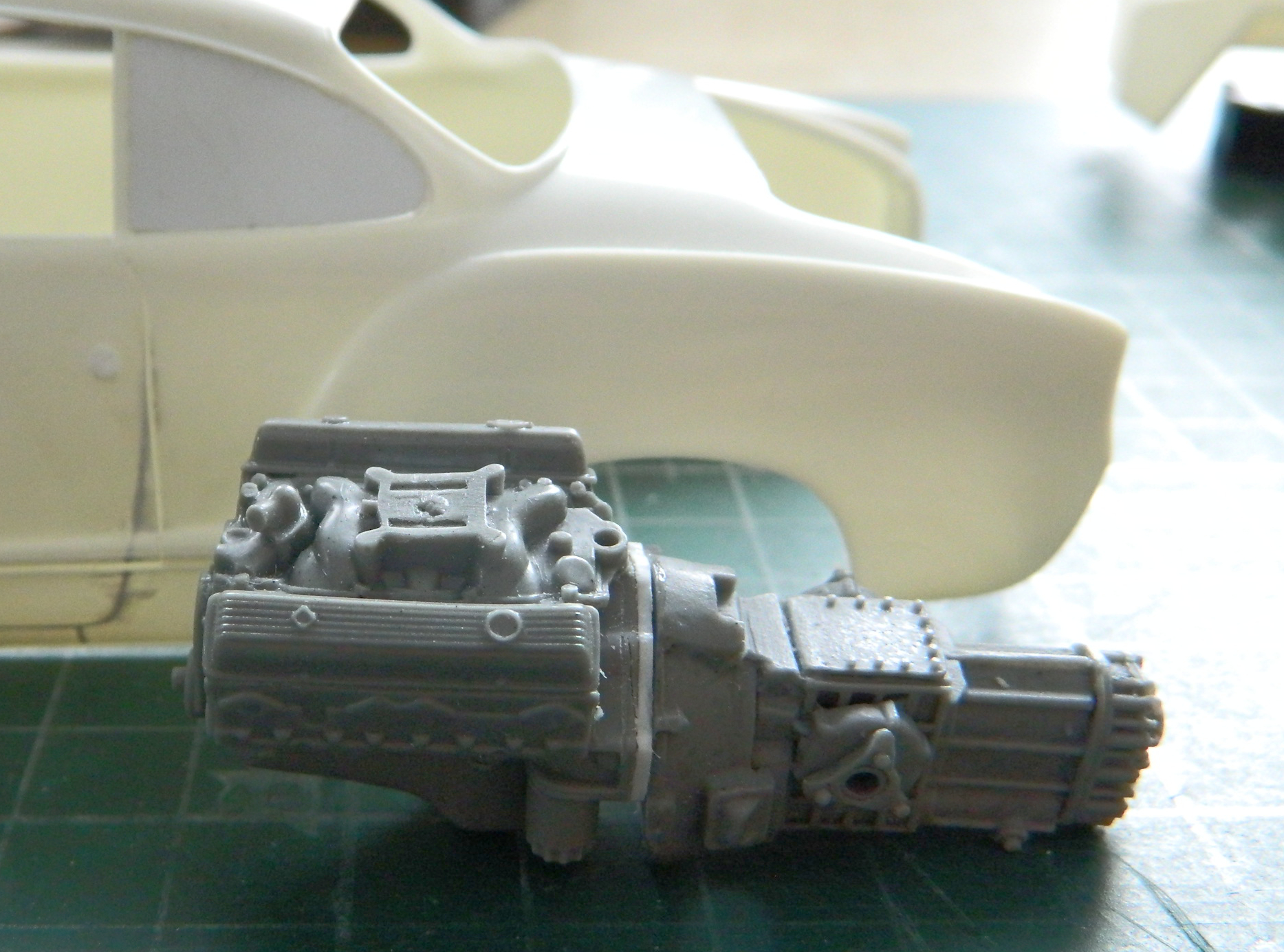
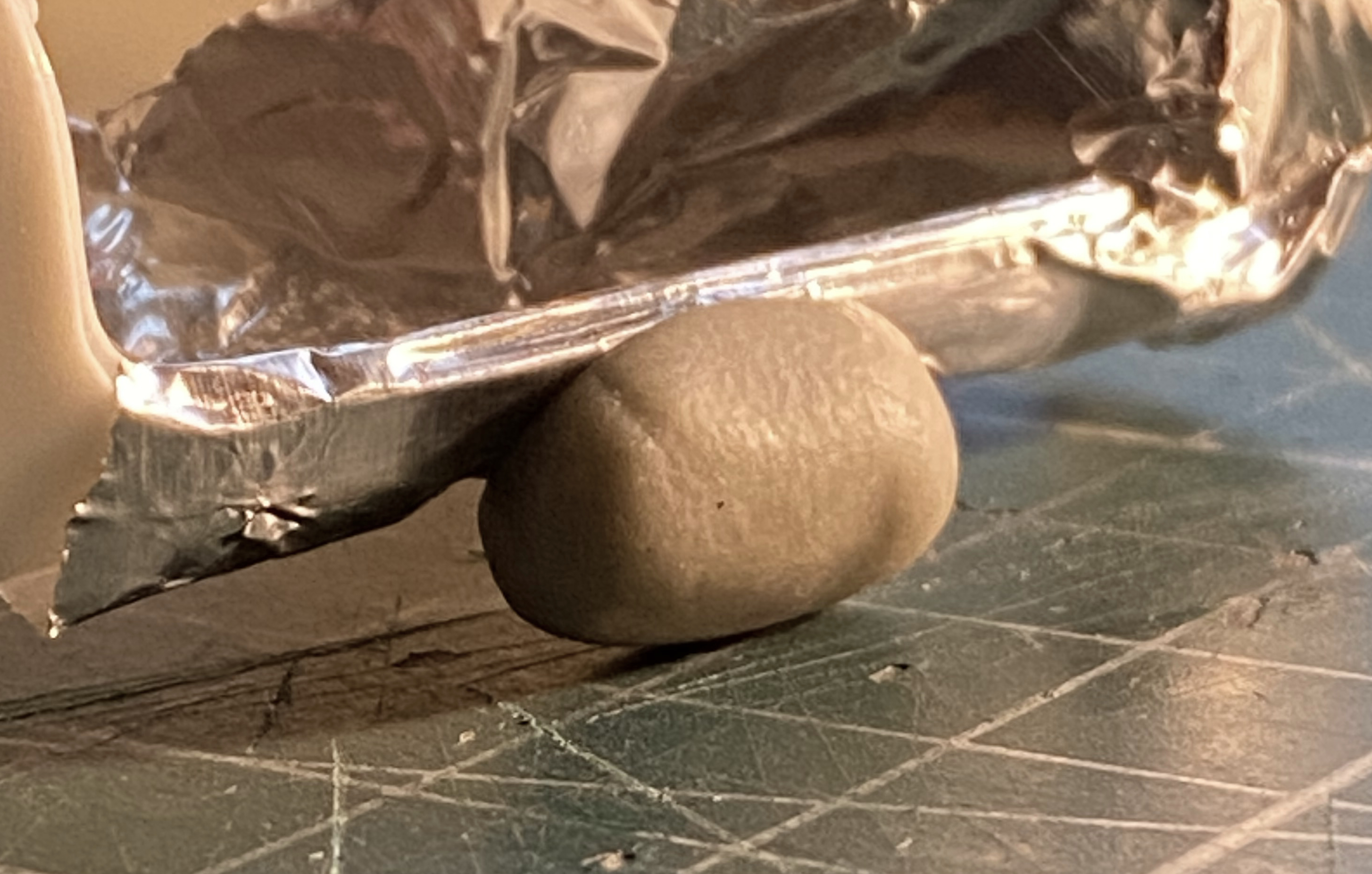
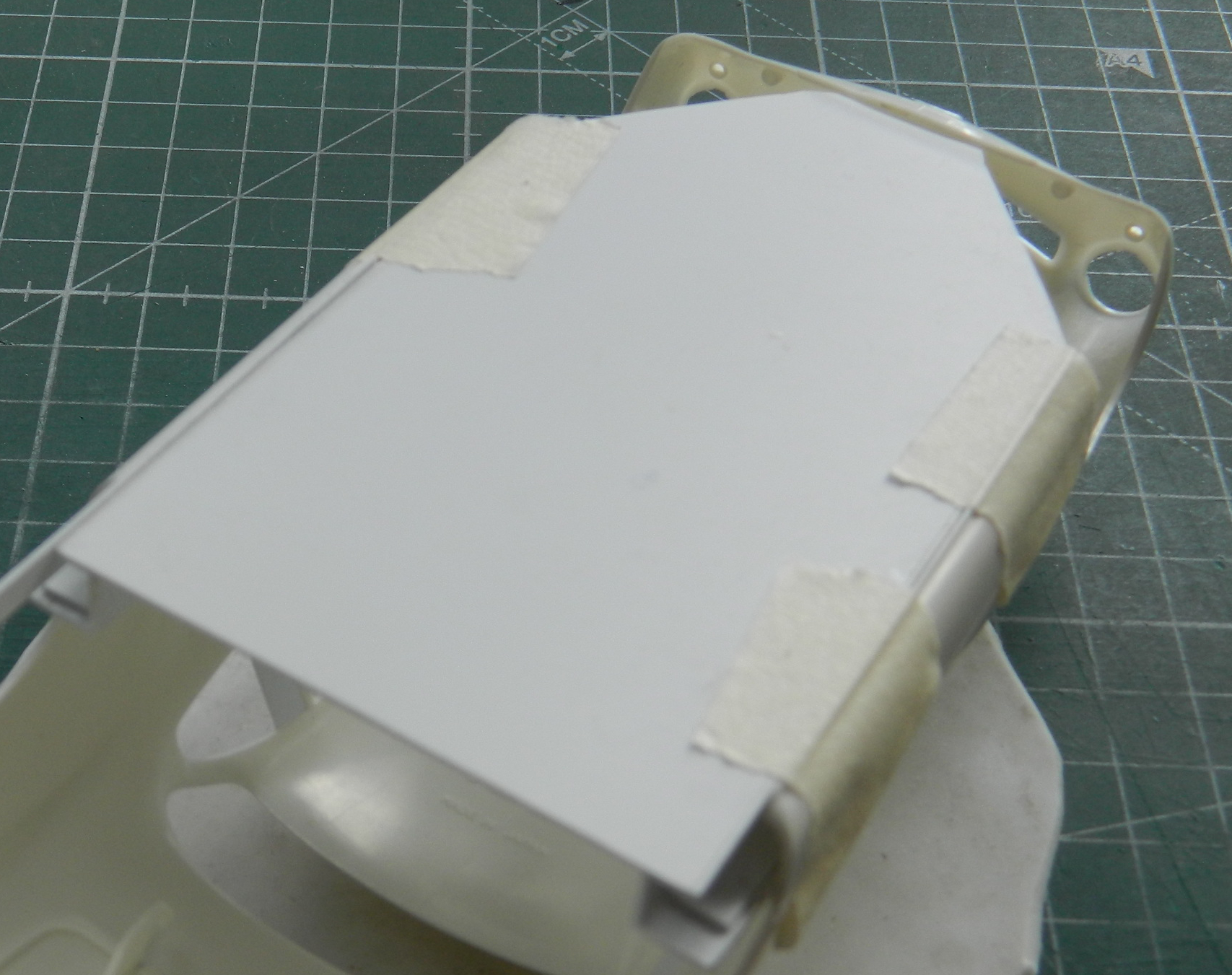
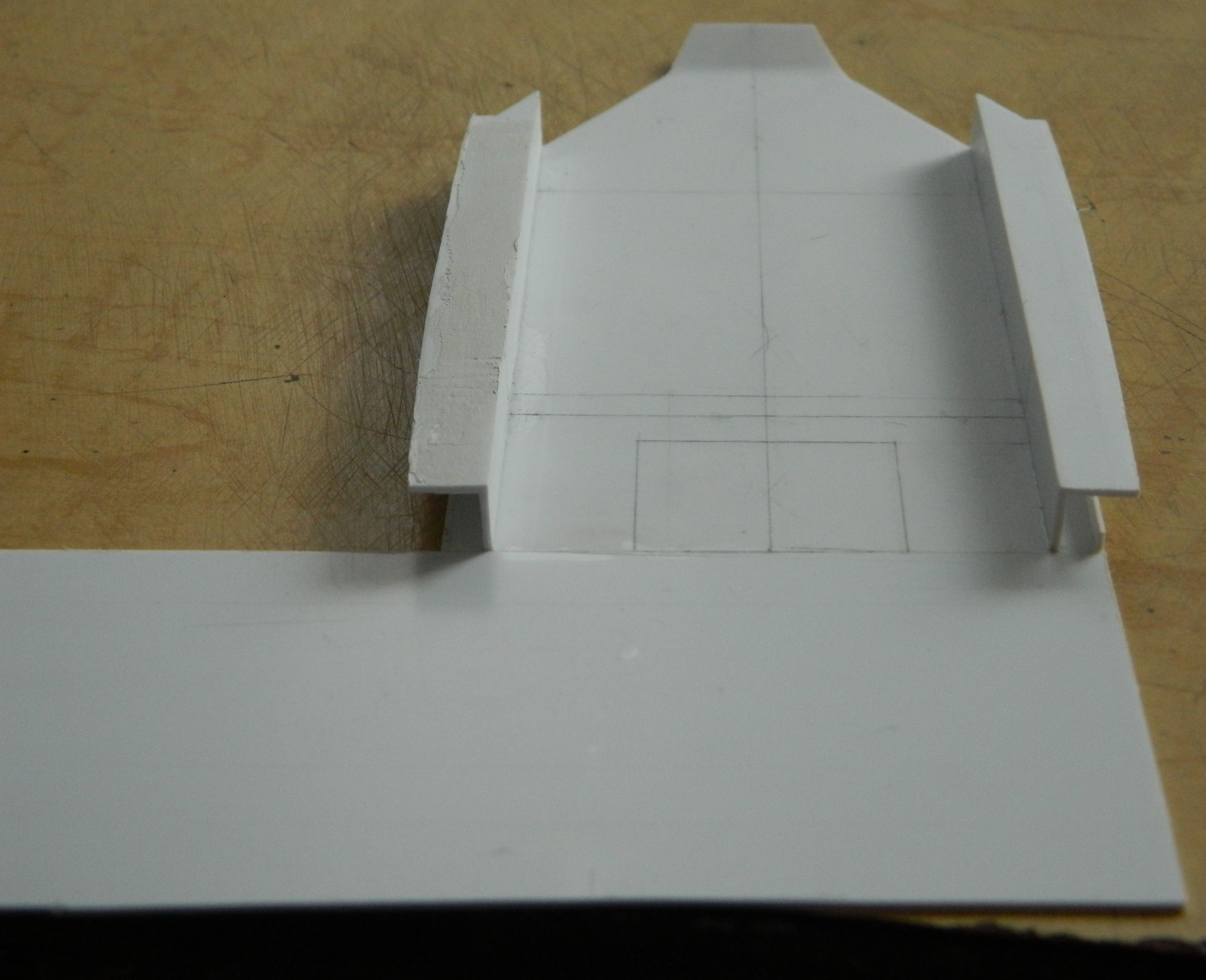
I started this month by asking (and getting an answer) to the question that has been obvious to me. Will this thing sit on its landing gear or will I be another modeler who needs to use something under the tail to keep it off the table. By this point, I’ve stuffed lead and tungsten into any space they’ll fit, so I taped all the major components together to see if I’m even close. I placed the taped-together parts on my fuselage stand with the horizontal supports in touch with the model in line with where the landing gear struts mount:

Yes! It will indeed sit on all three of its tires, though the balance as the nose tire resting ever so gently on the surface. And this is done with zero weight in the nose (not much space but lead will obey the hammer and can be coerced into the shape I need), so since I will be adding more weight to the nose and the forward section of the drop tank (because it extends forward of where the main tires touch the surface). I don’t want an errant breeze having this thing squat like a dog having a slash.
Hammer time:
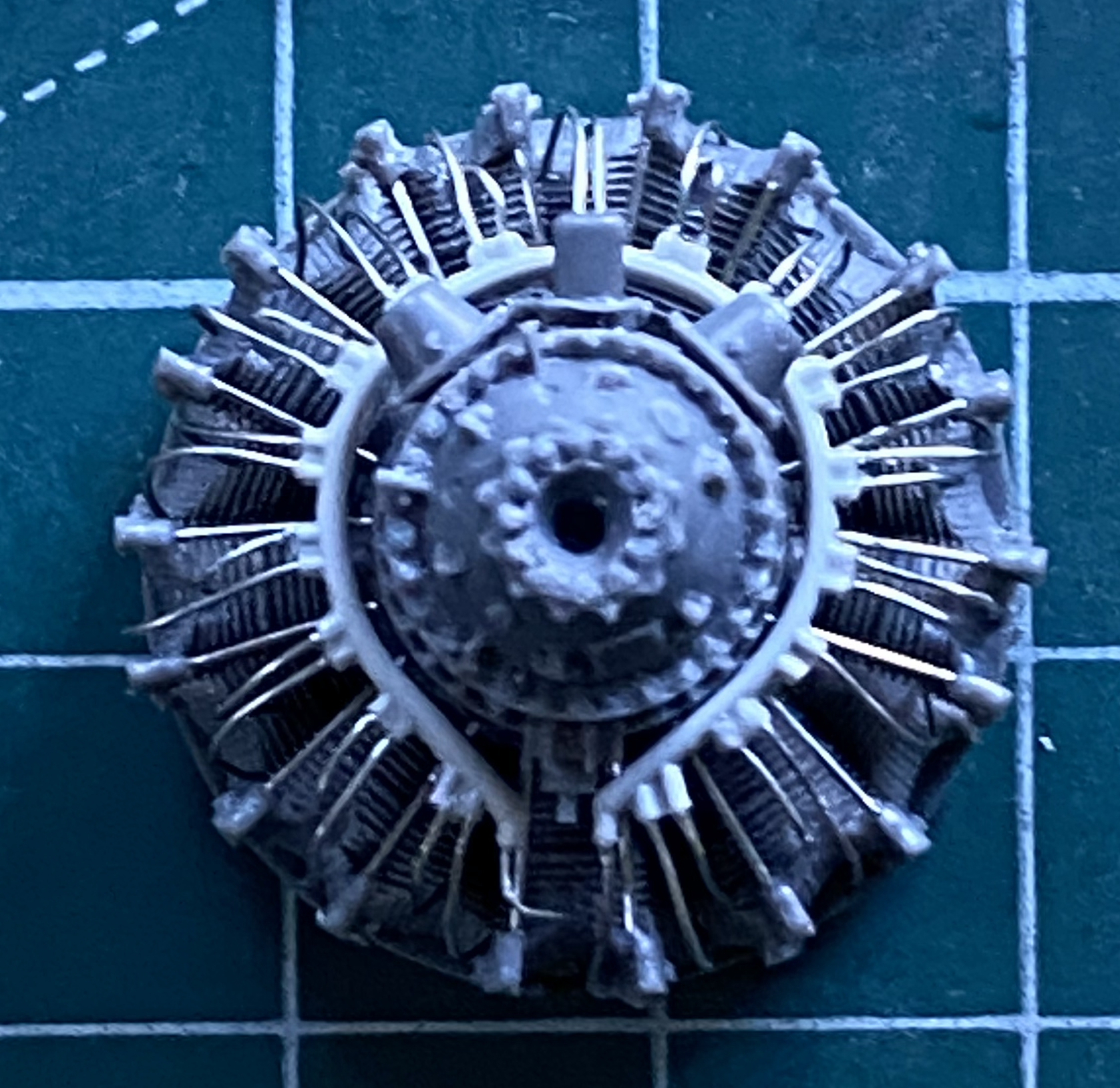
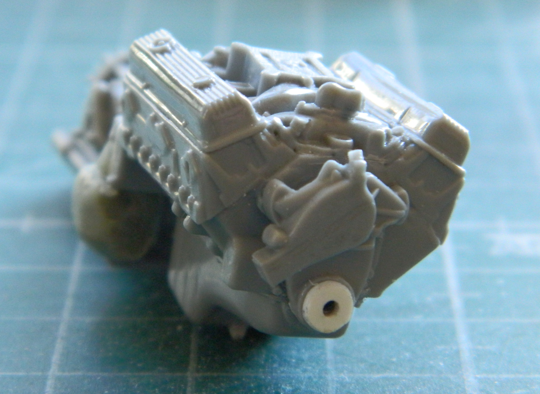
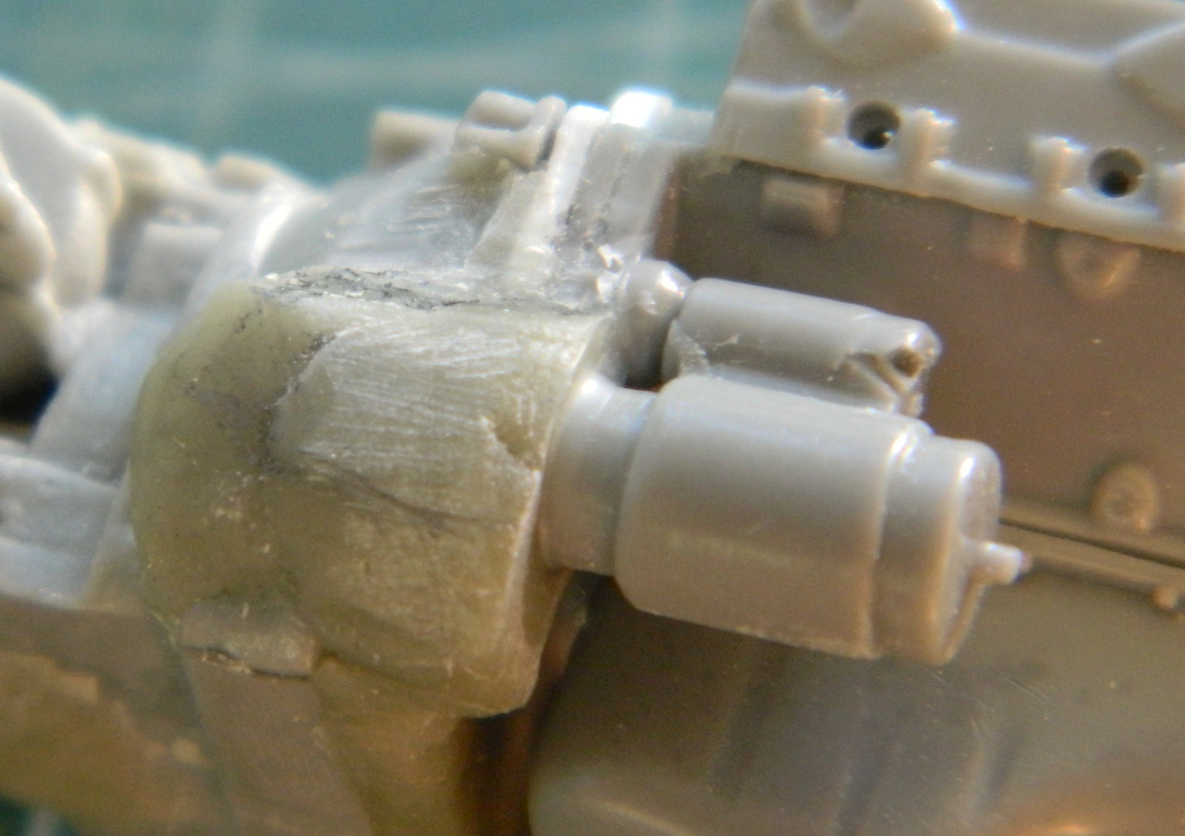
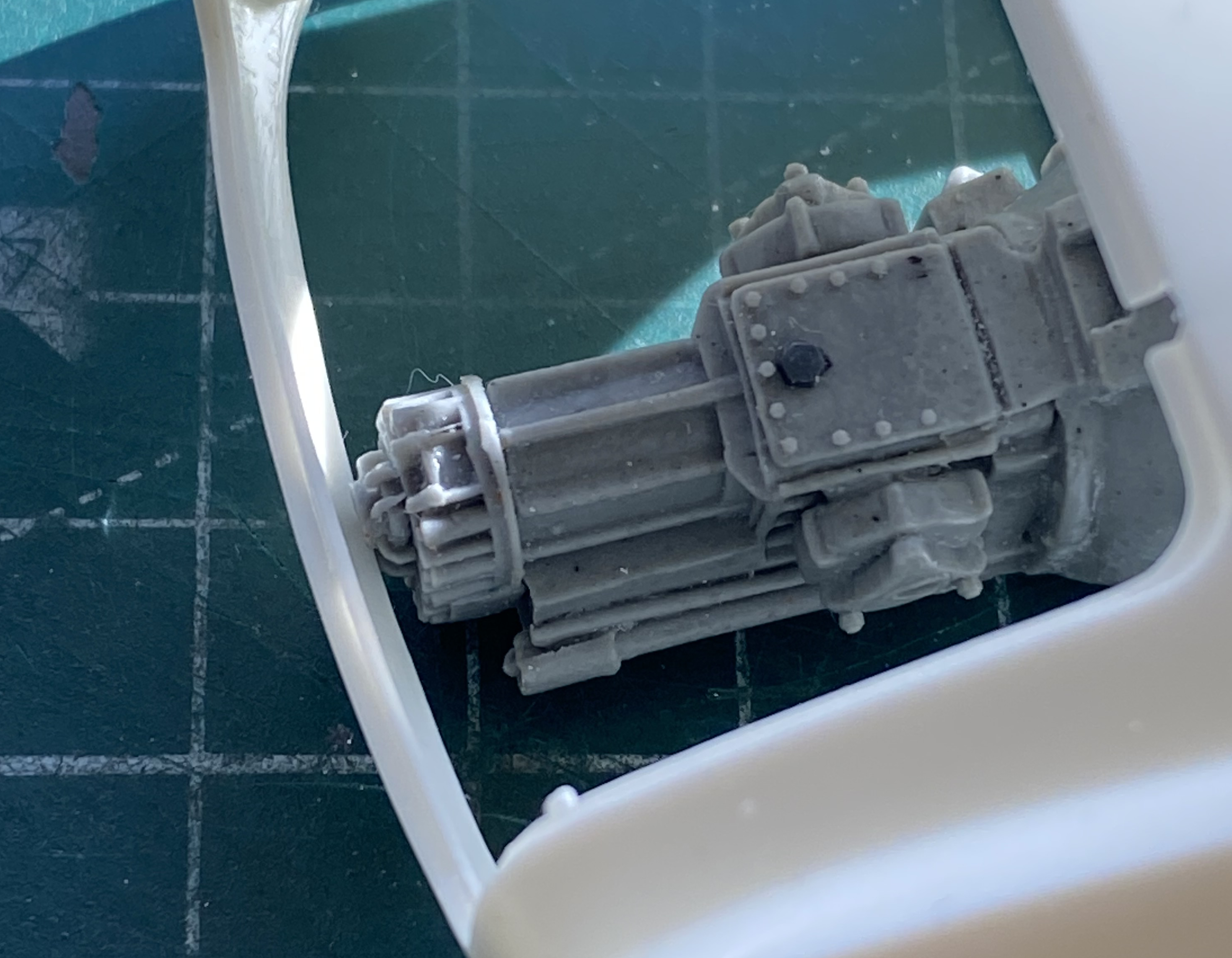
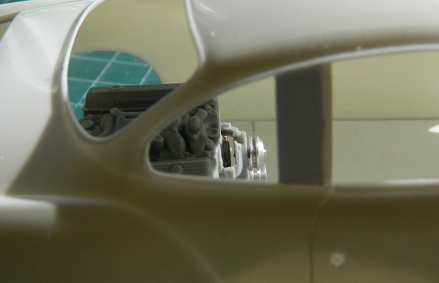
With the Big Question answered, hammer time segued into airbrush time. The engines were pre-shaded with Tamiya XF-1 Flat Black. The crankcase and its bits were brush-painted Tamiya XF-53 Neutral Grey, the ignition tube surrounding the crankcase was painted a mixture of Tamiya XF-6 Copper (two parts) and XF-1 Flat Black (one part), and the wires were done with a mix of Tamiya XF-57 Buff (three parts), and XF-10 Flat Brown (one part). The front of the rocker arm covers were lightly dry-brushed with Tamiya XF-16 Flat Aluminum. The cooling fins were lightly touched with a silver pencil. Then I took a round toothpick with a chisel tip cut onto it to scrape the flat black off the pushrod shrouds:

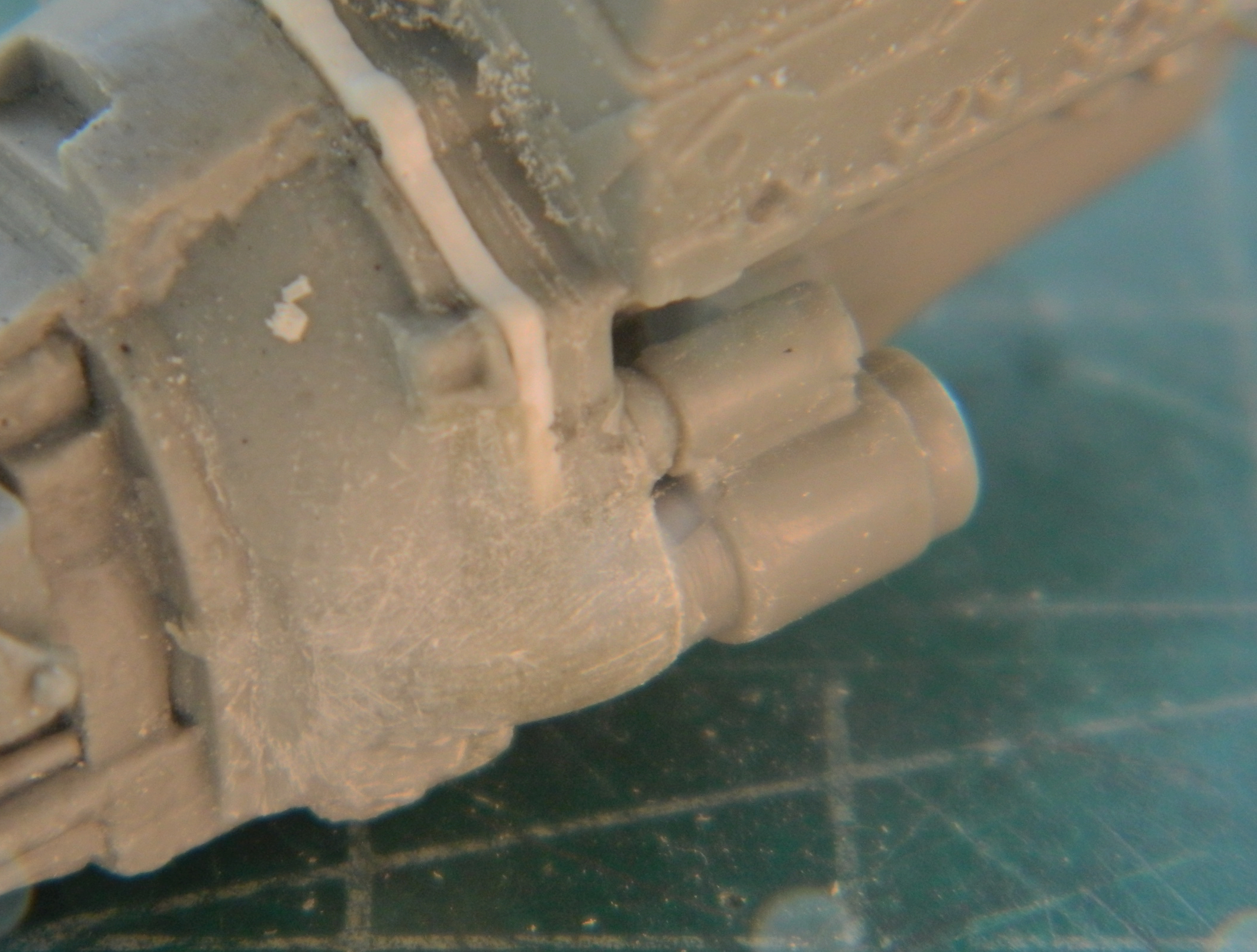
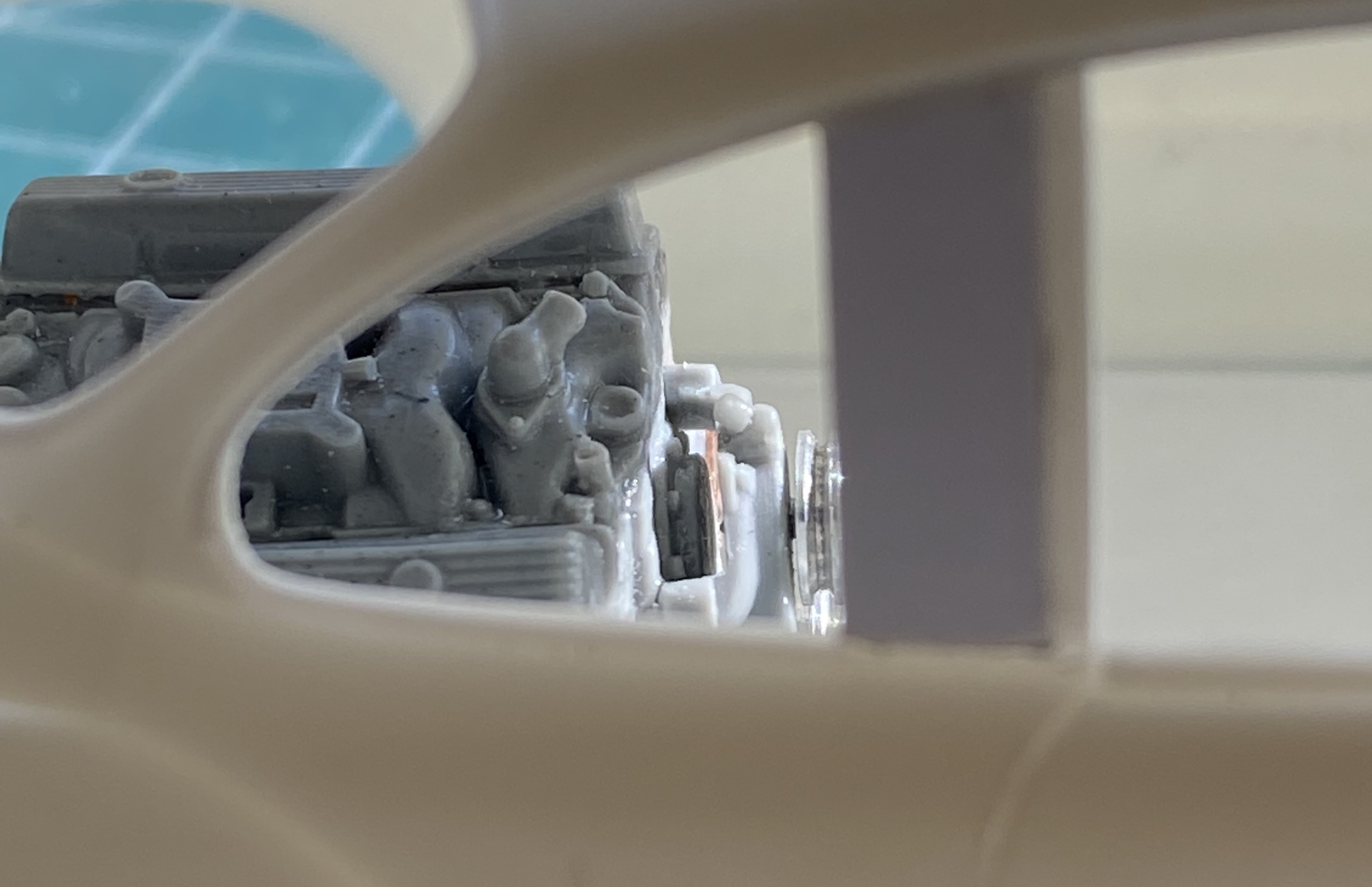
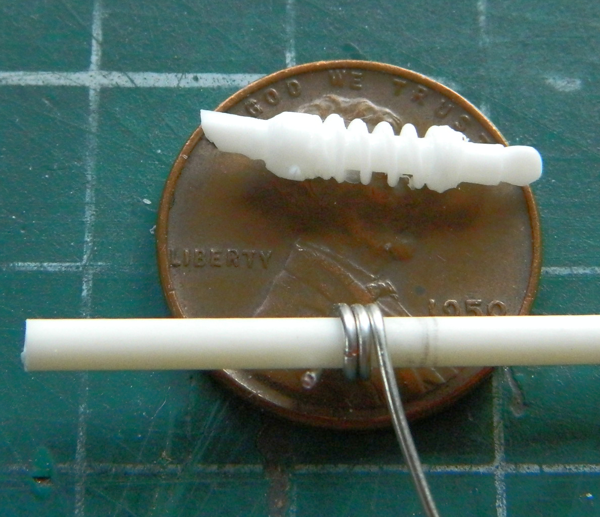
The kit’s pins to mount the propellers didn’t come close to fitting the engines, so I drilled the engines out to accept sections of 0.062″ (1.57mm) instead. (Pain in the thing I’m sitting on that isn’t a chair getting them perpendicular to the crankcases!):
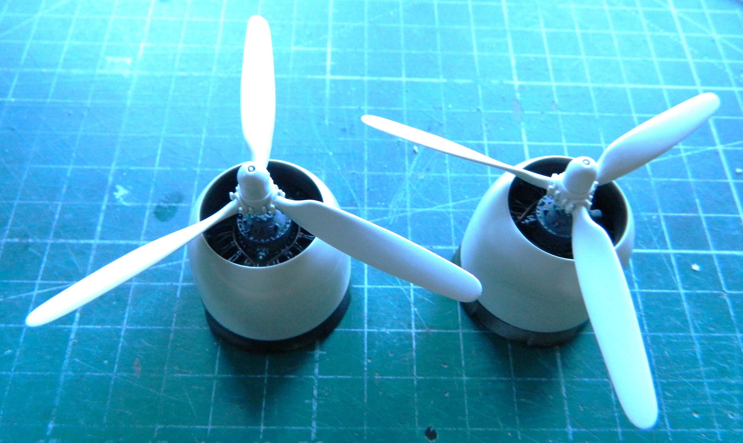

Not a lot showing but that’s as it’s supposed to be.
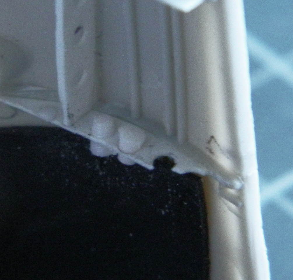
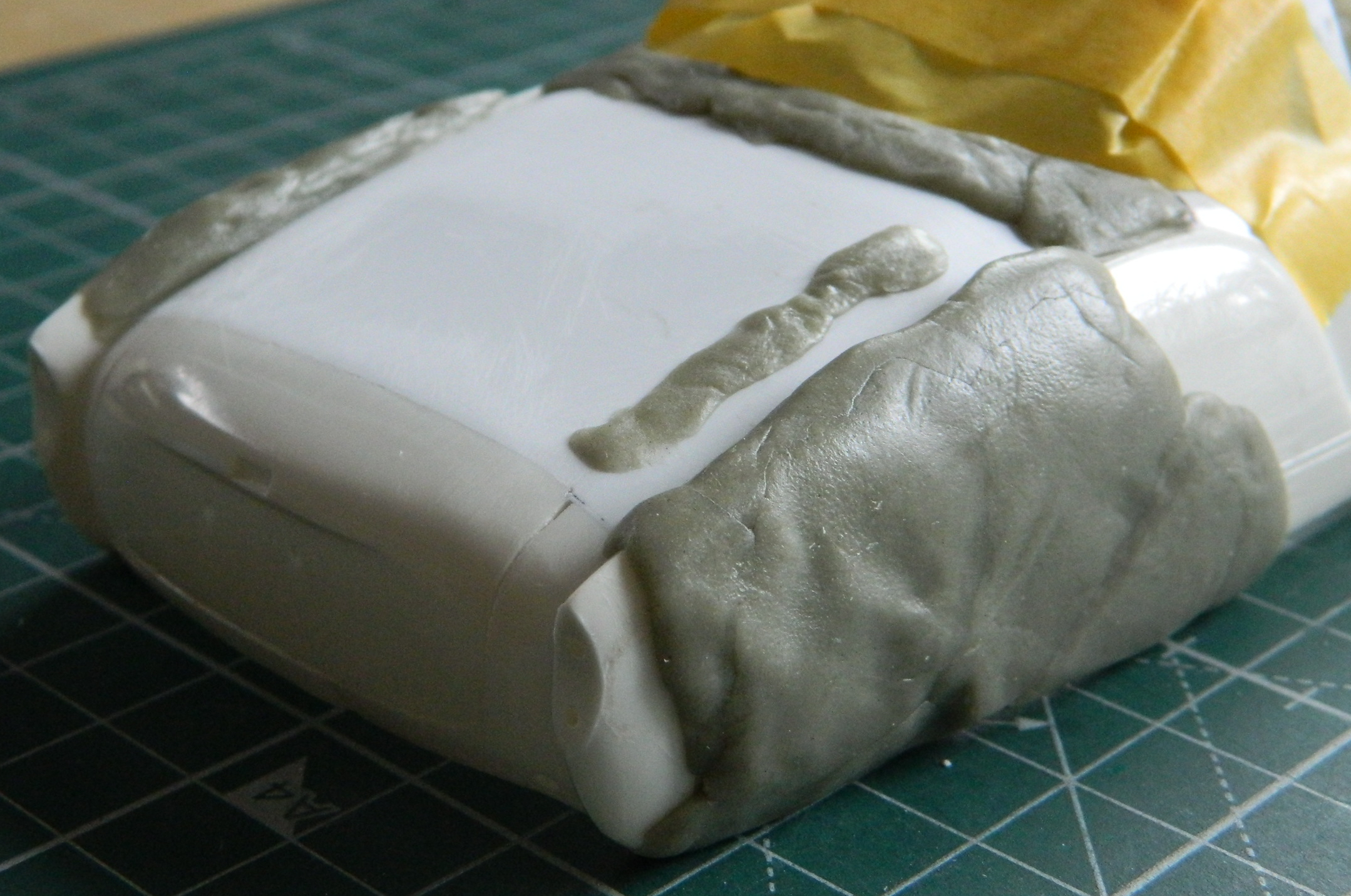
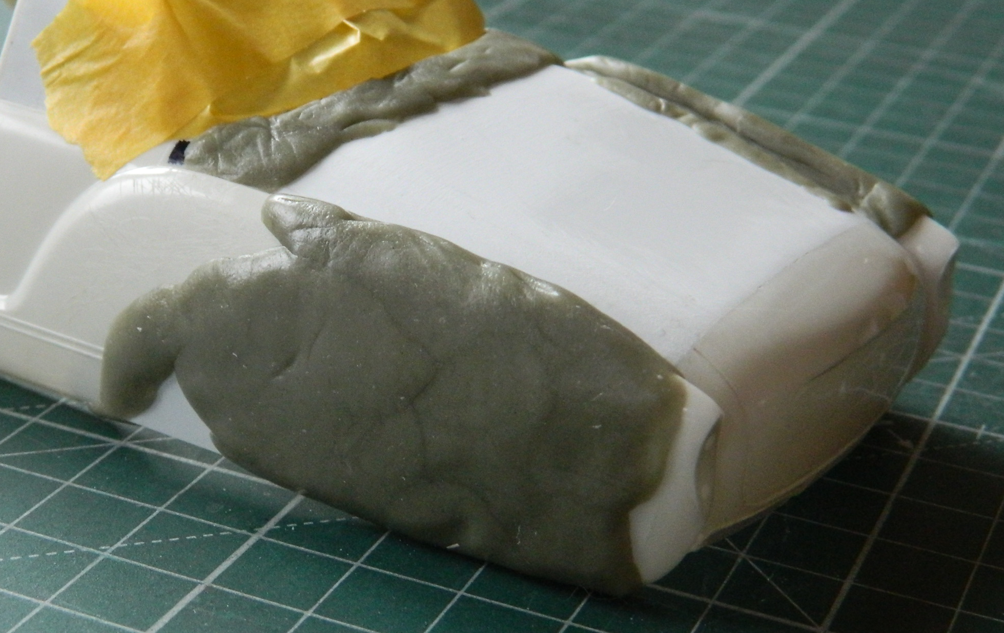
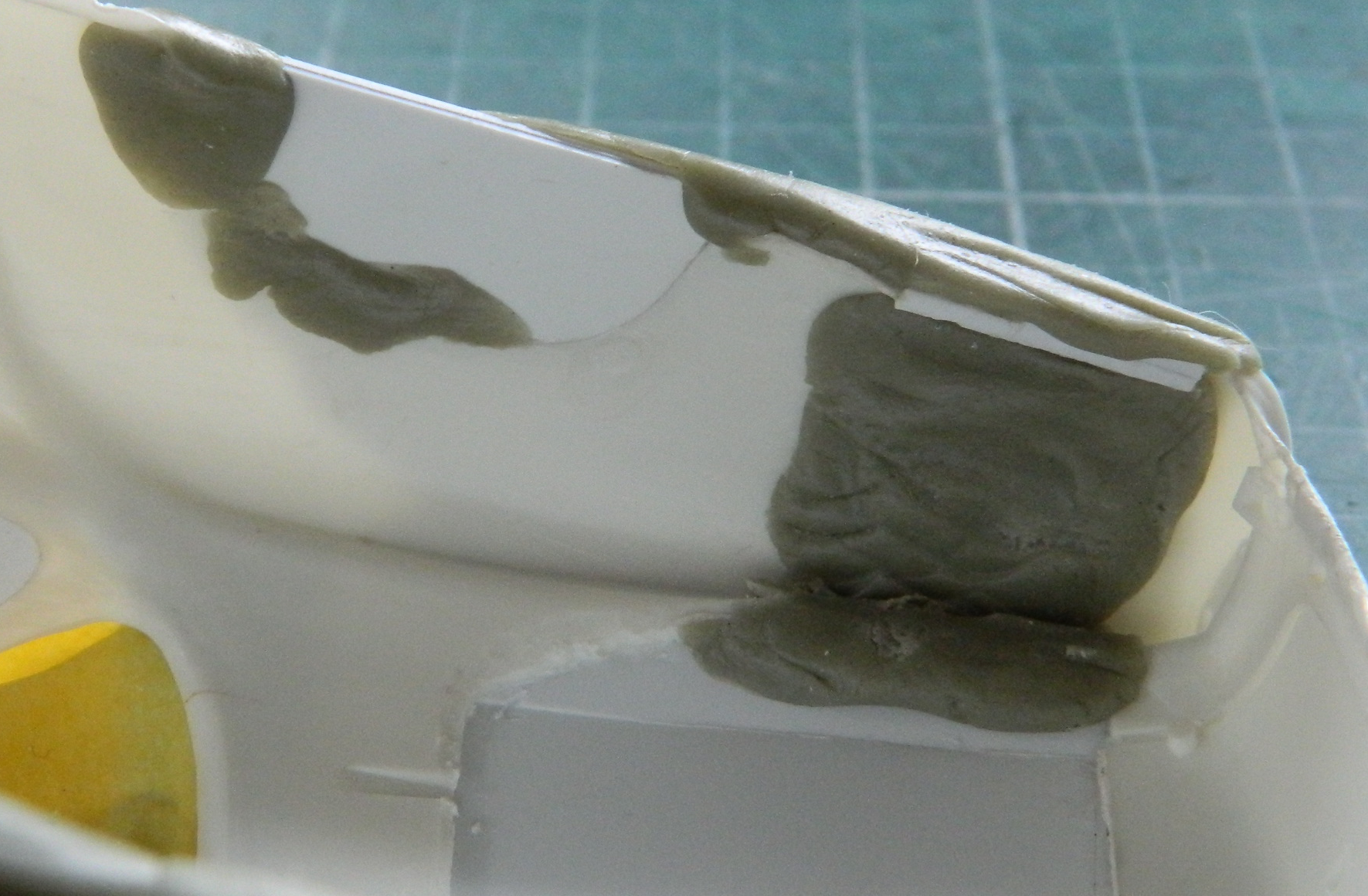
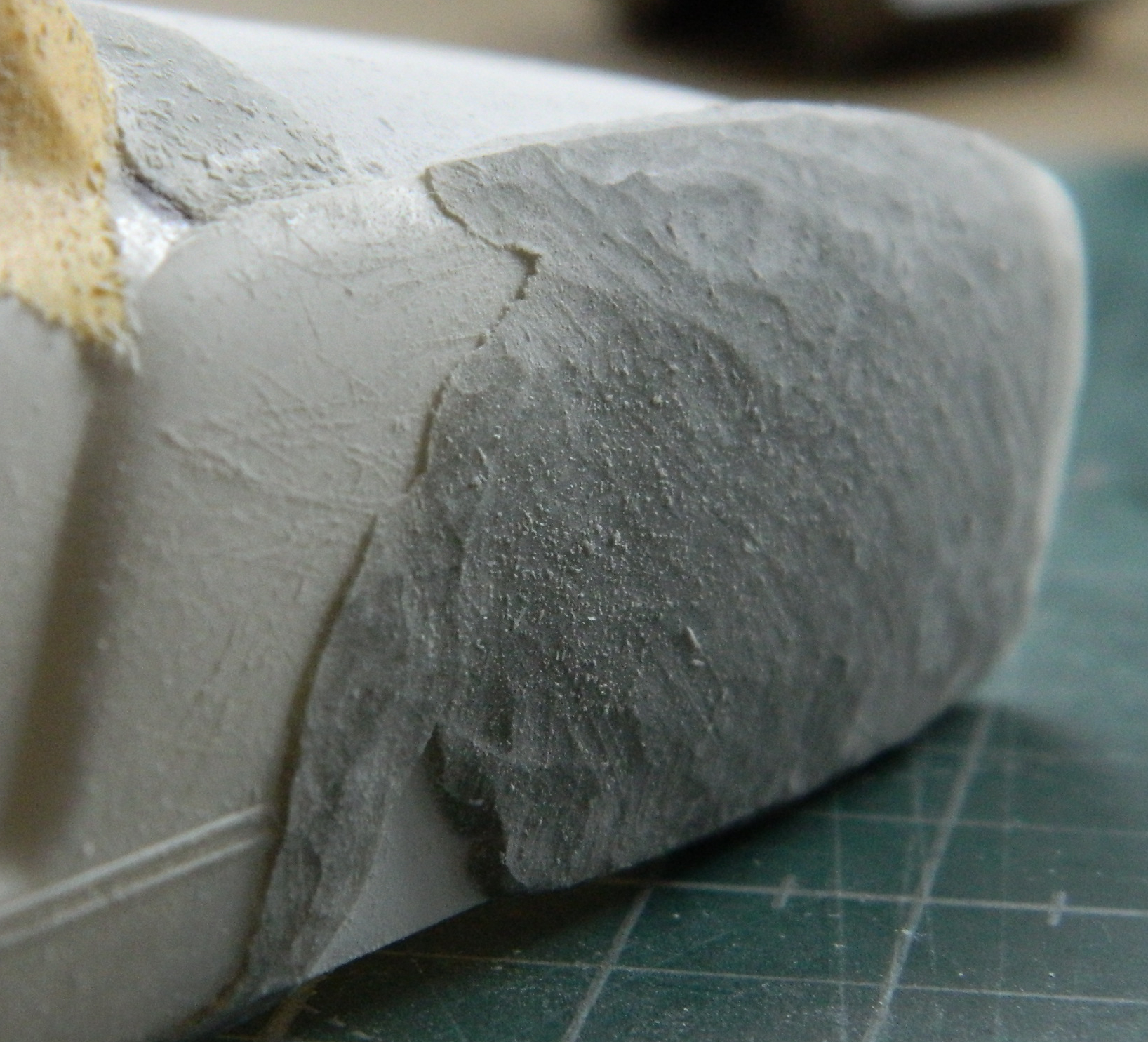
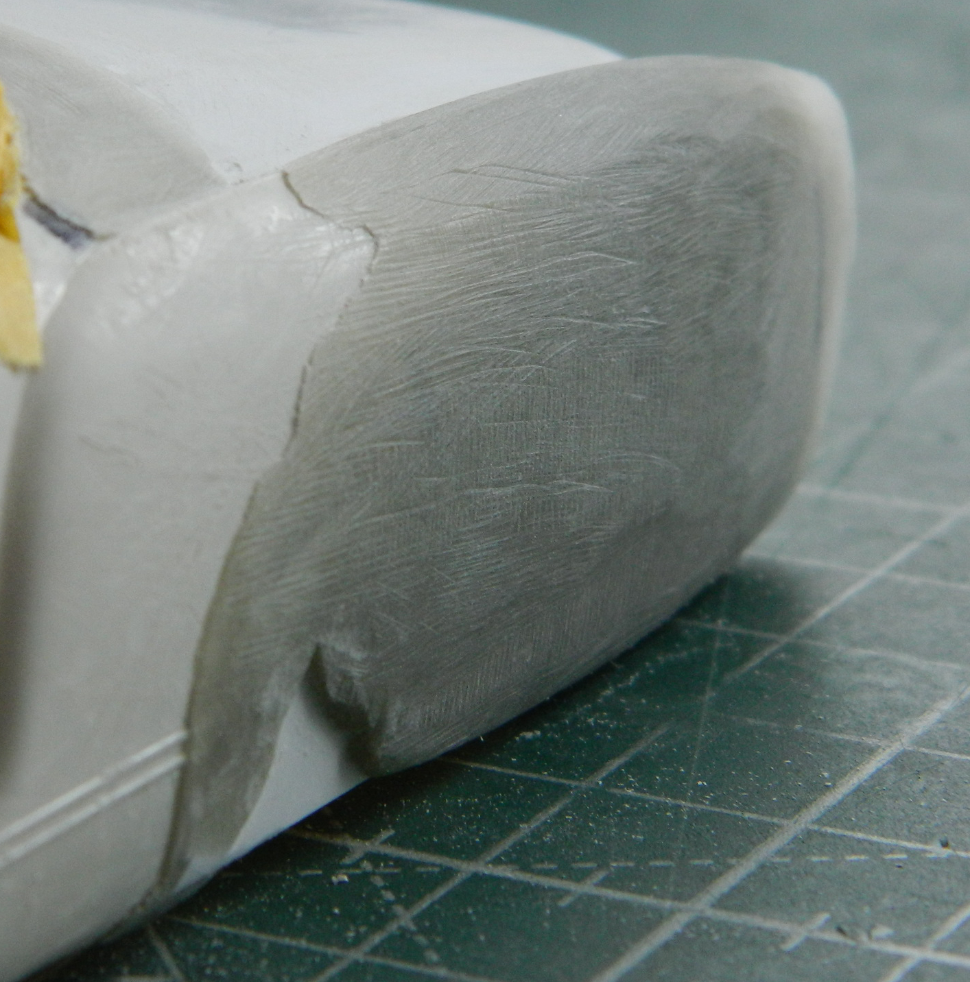
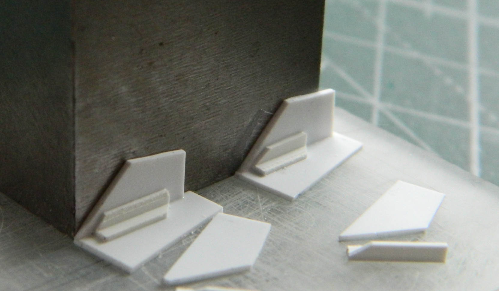
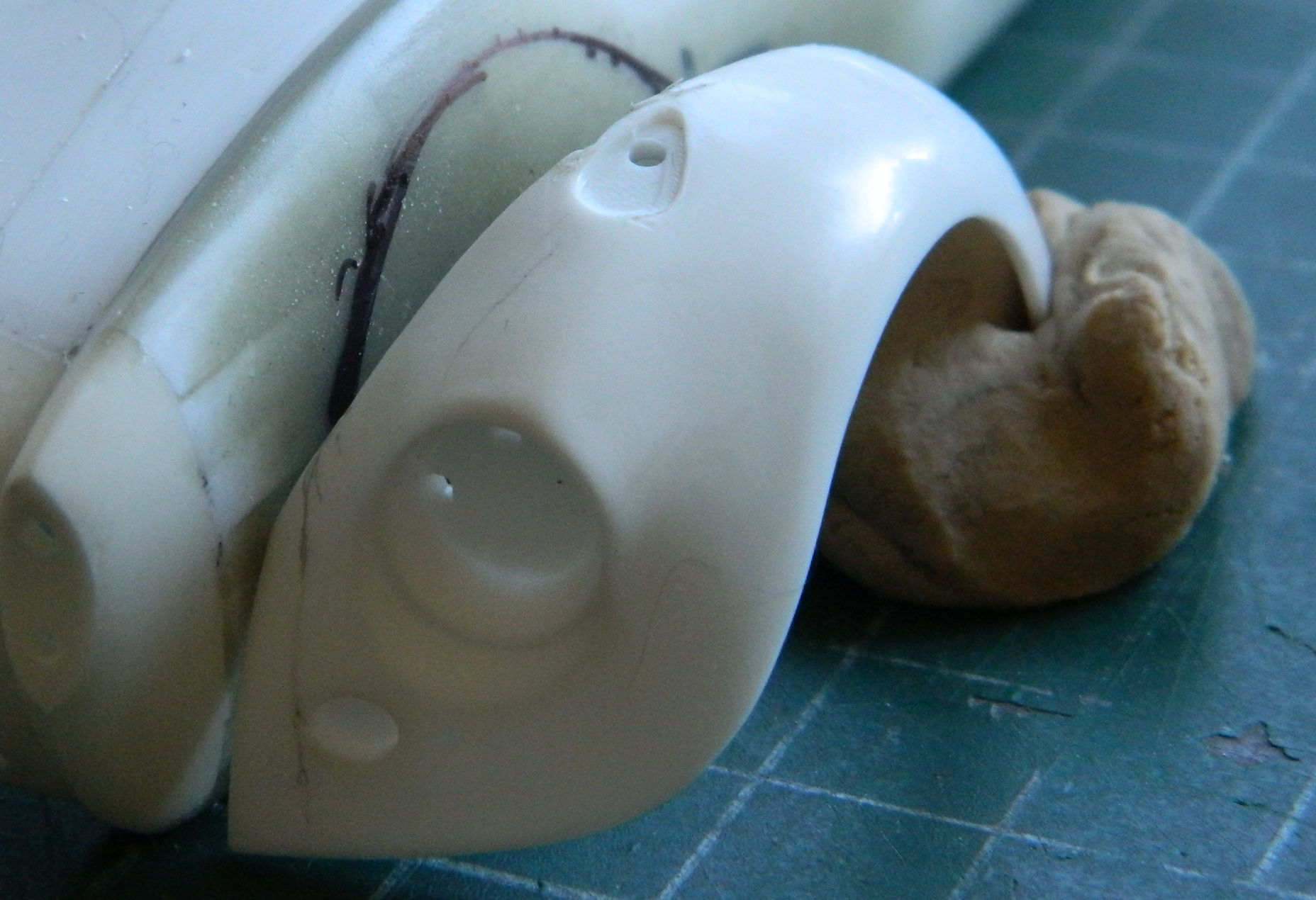
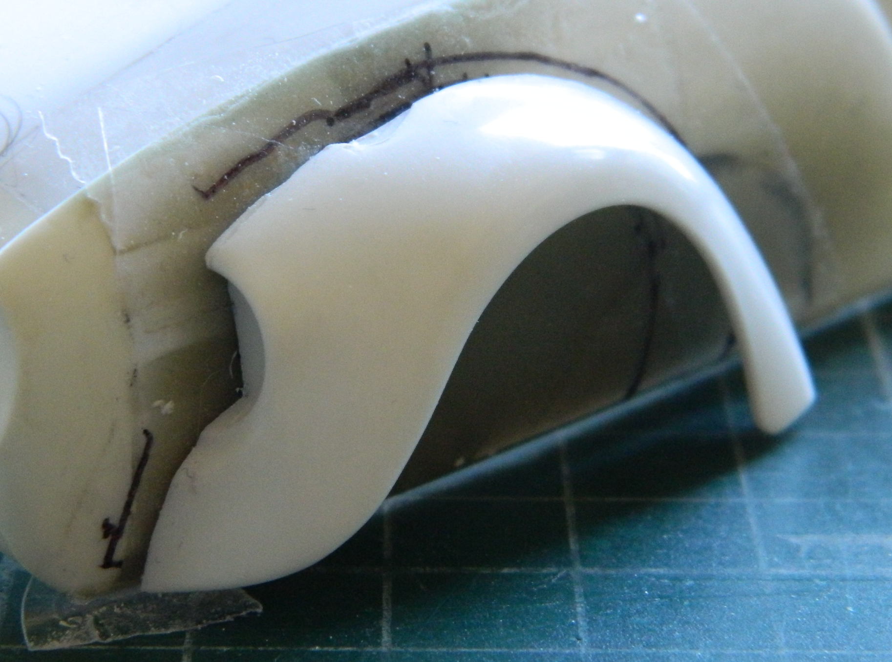
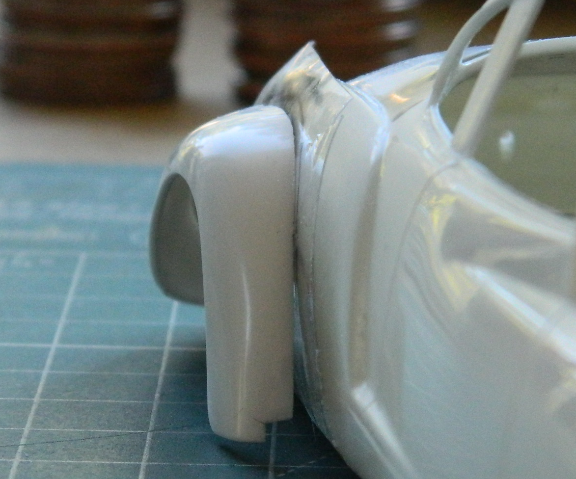
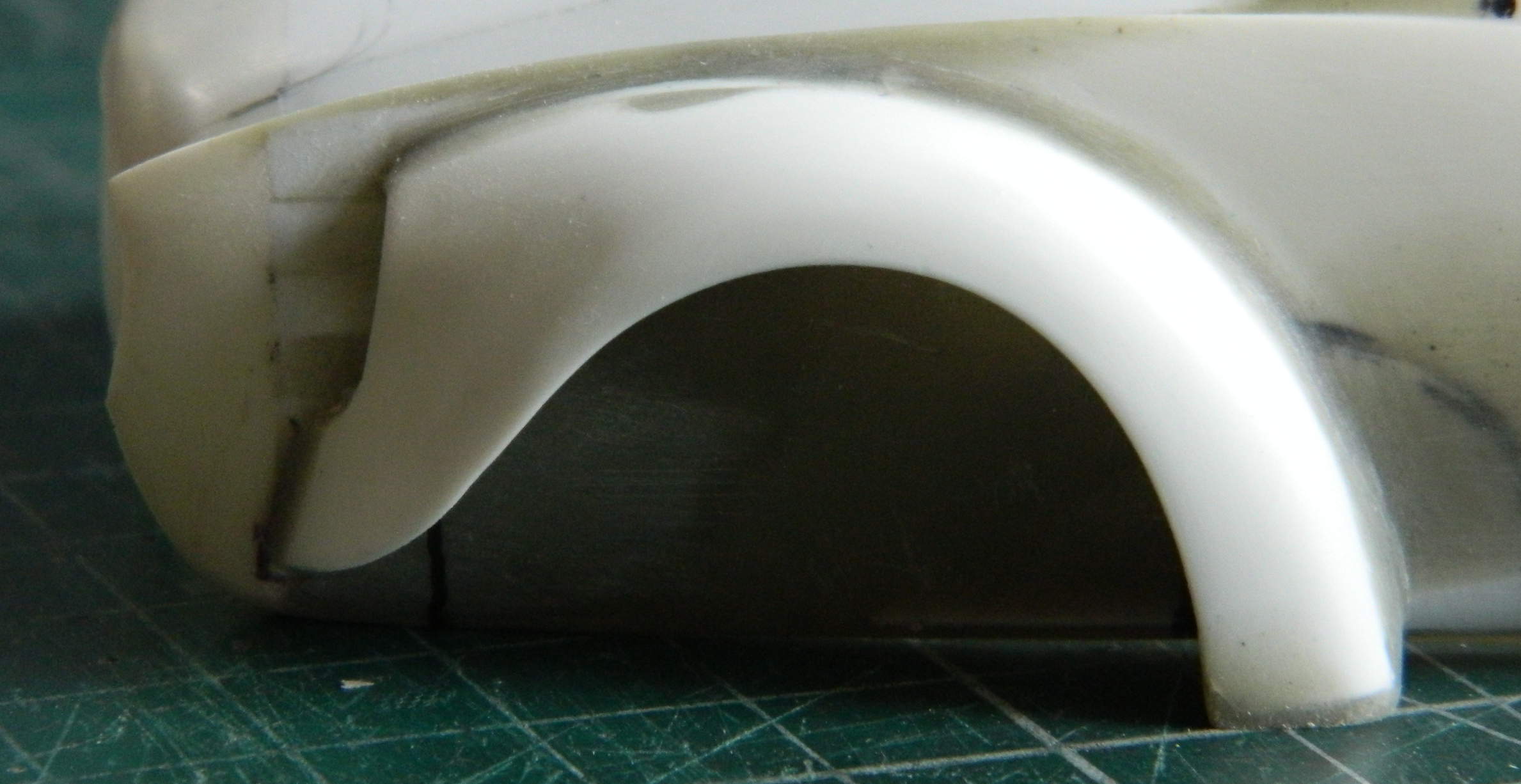
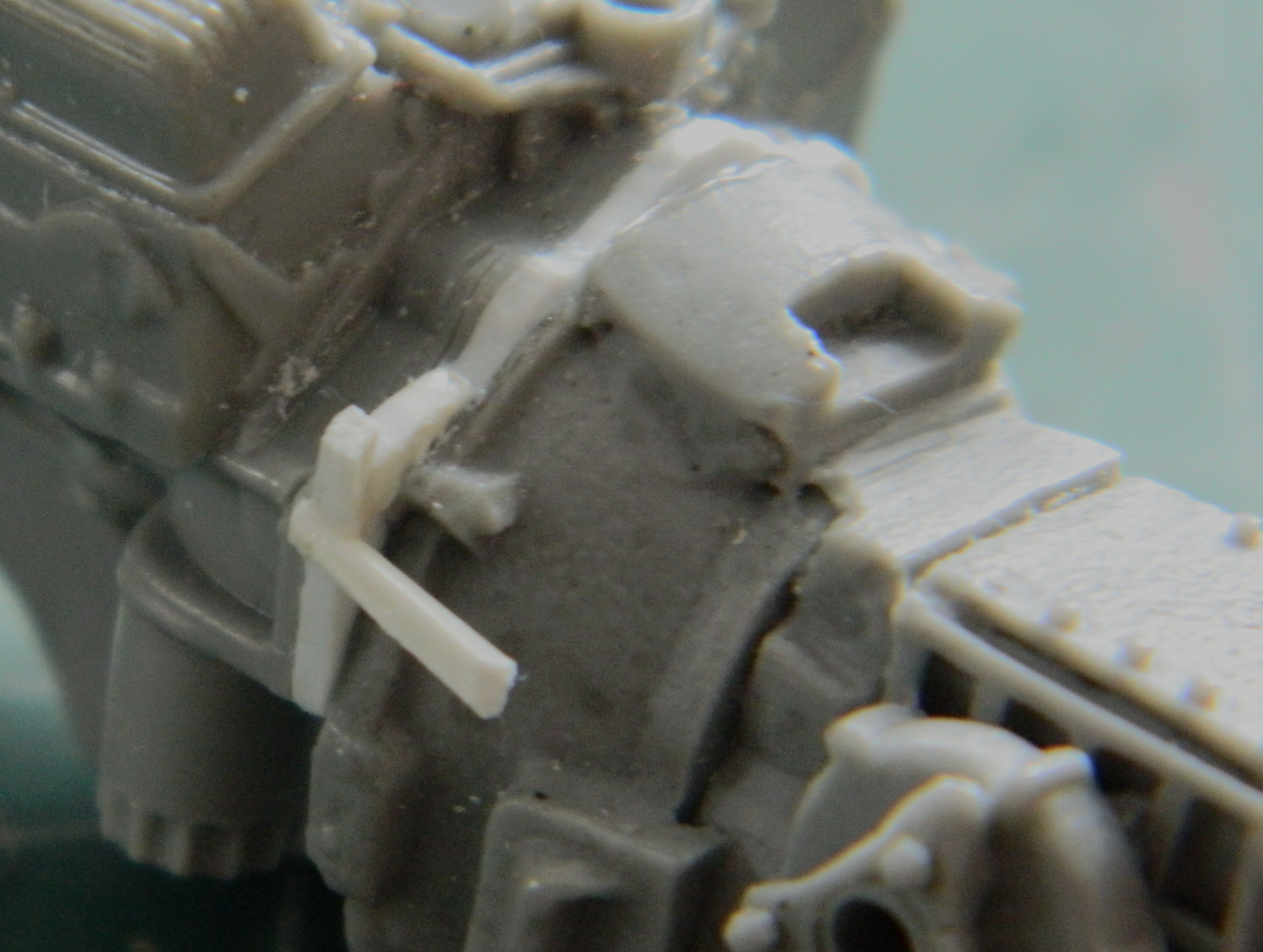
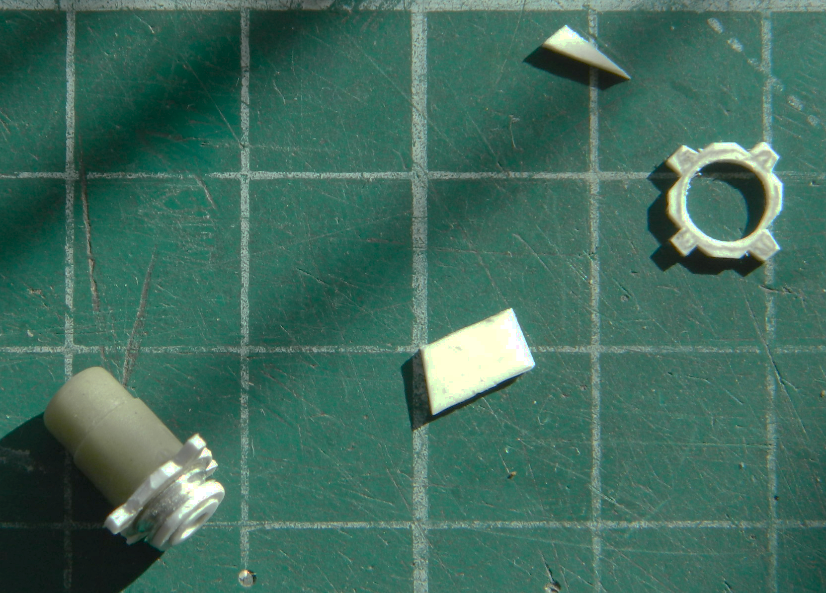
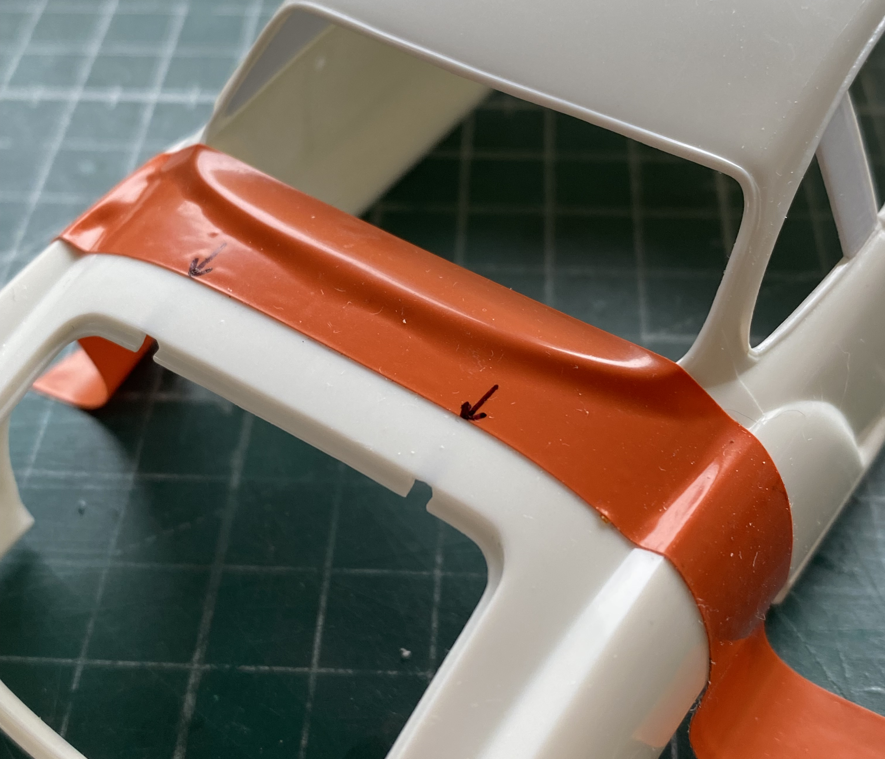
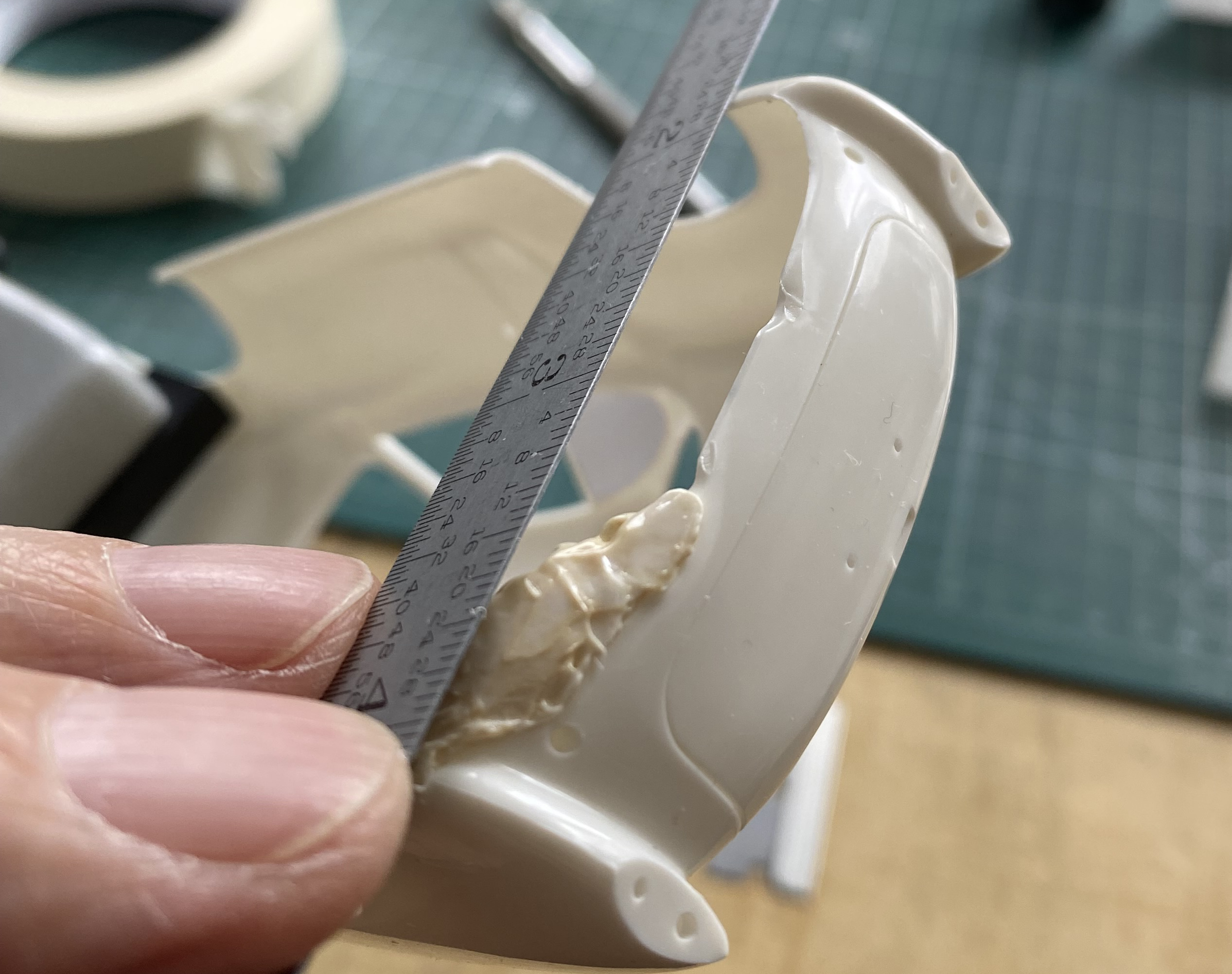
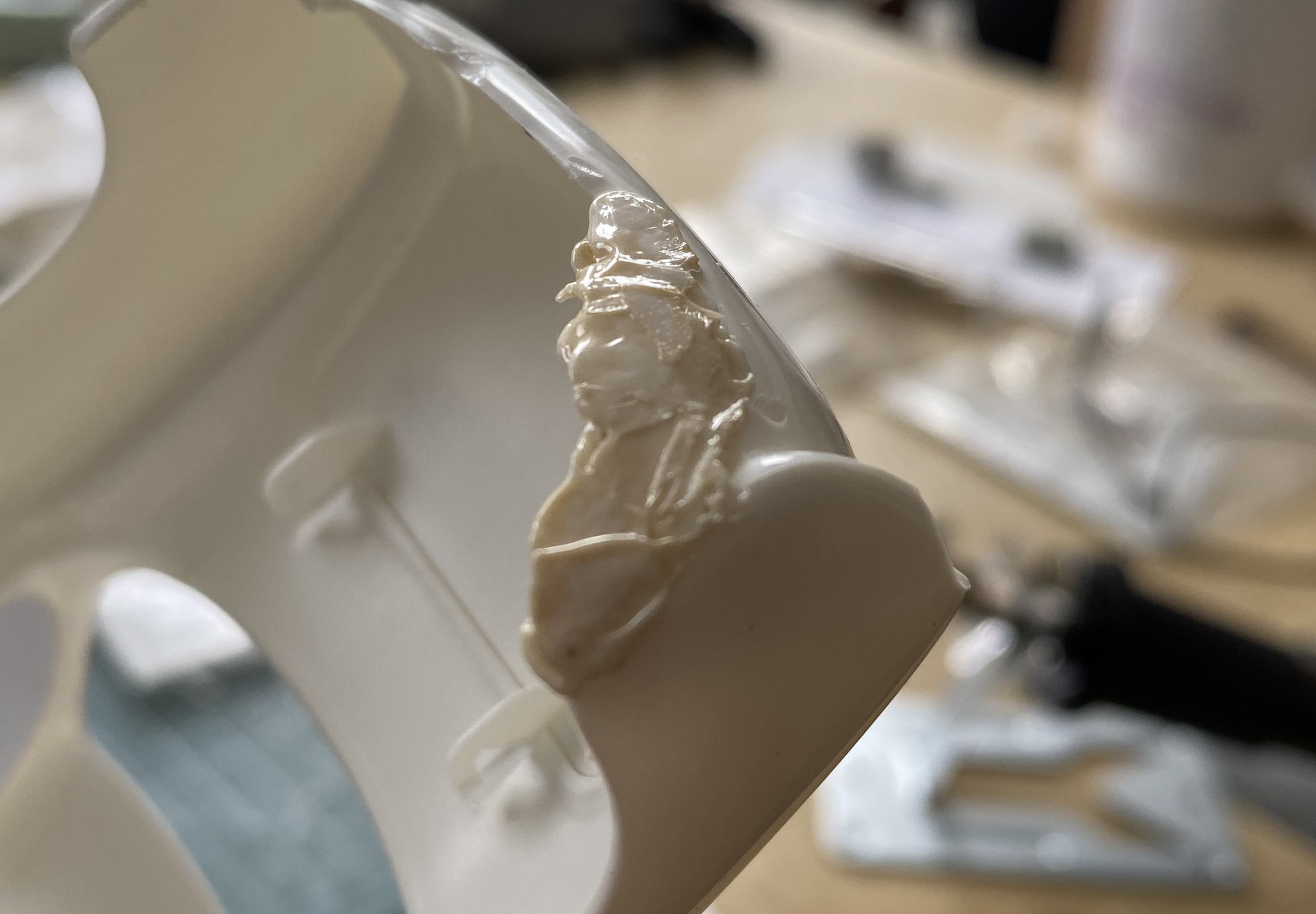
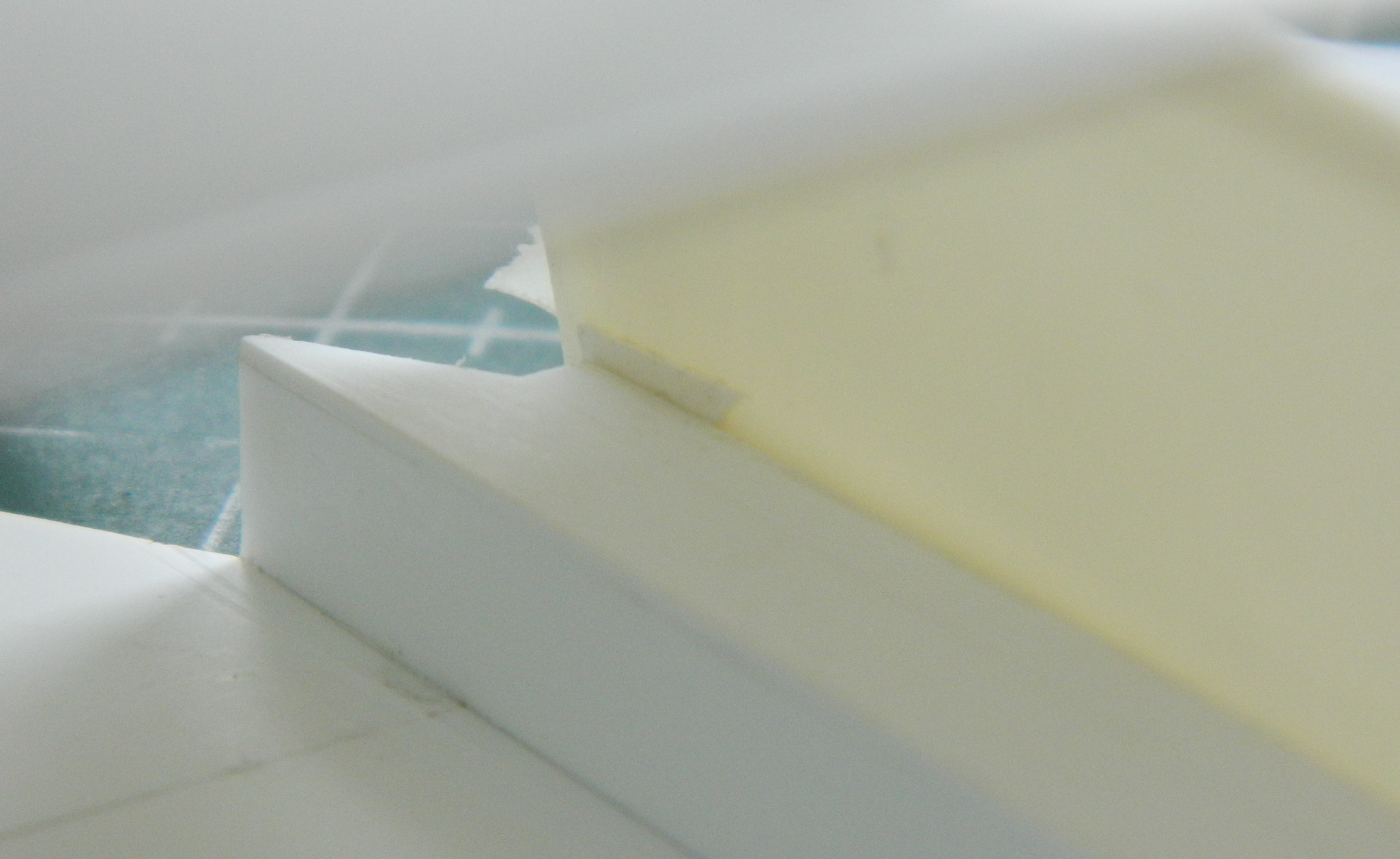
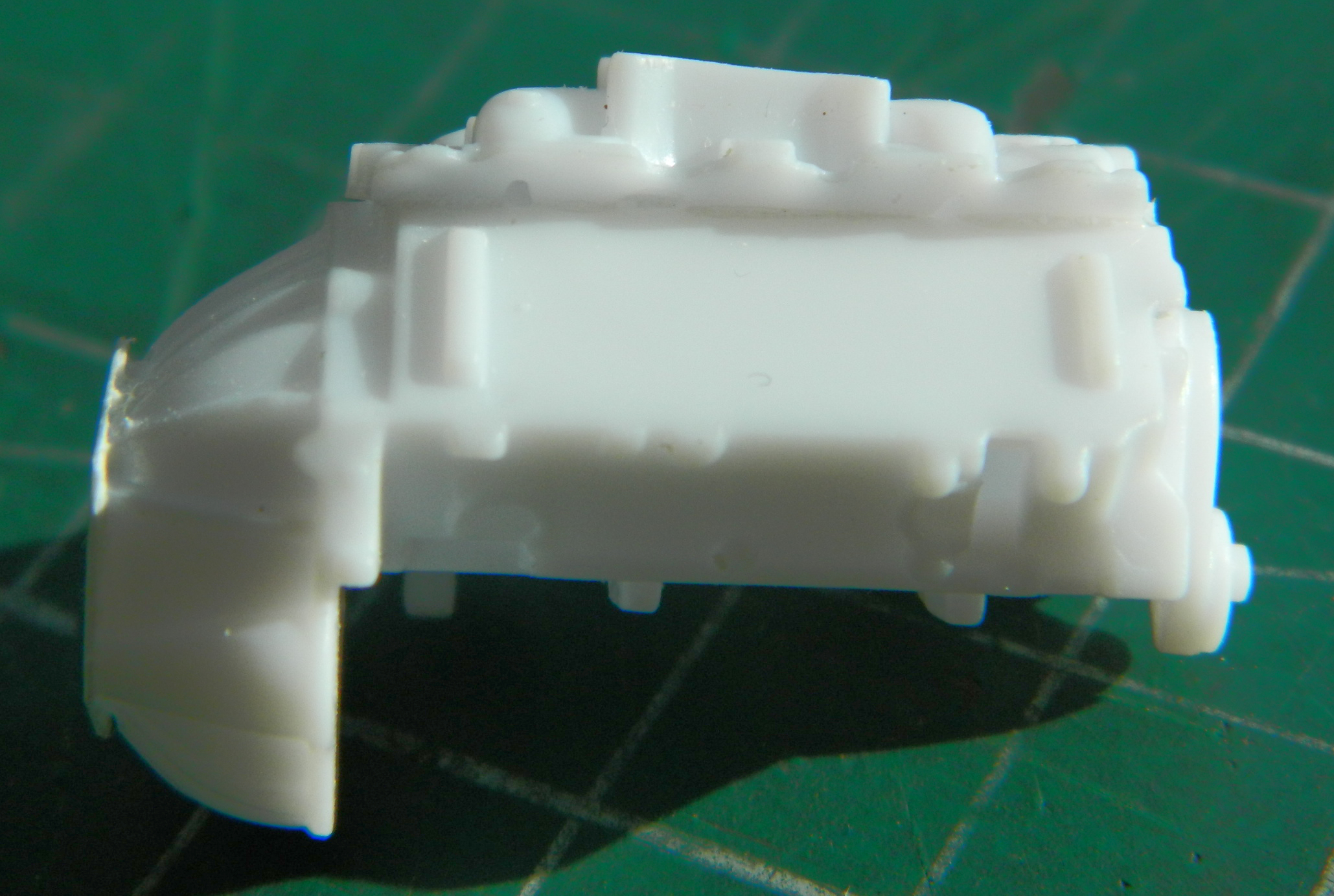
Then it was time to fart around…forever…with the landing gear. My initial notion of using the metal parts was set aside because the alloy is so malleable that working them was akin to trying to work the surface of cooked spaghetti (okay…maybe not that flexible, but after far too many times having to straighten something out I considered going to get tomato sauce and grated cheese) (couldn’t find the cheese and by the time I had, I’d sobered up, so…). I still had the plastic parts from the kit (which I’d assembled to act as a form so that I knew how far to bend the spag…er…metal parts), so I decided to use them instead and hope that this thing didn’t squat over time. I finished off almost all the parts when I found this:

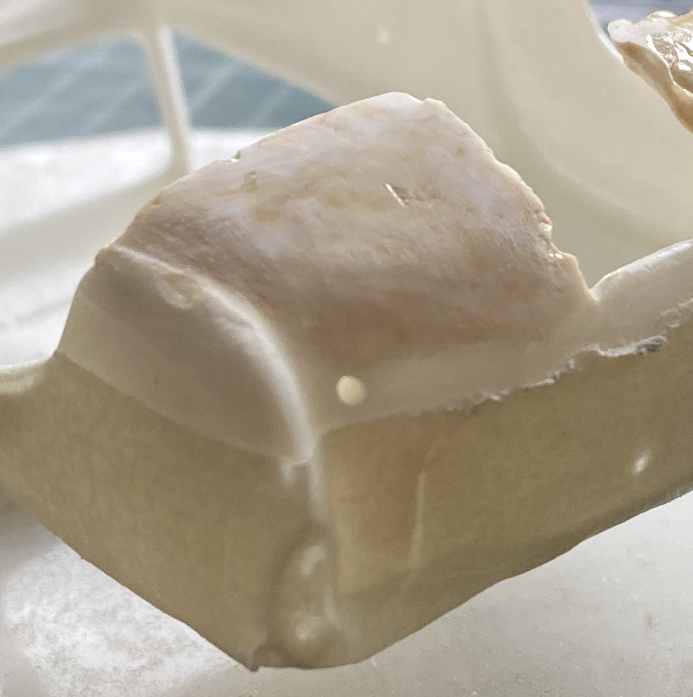
Most of you probably knows what a “short shot” is (and no…it doesn’t mean that). For those of you who don’t (or think it does mean that), it’s when the liquid plastic pumped into the molds doesn’t fill the void completely. That’s what happened (or didn’t happen) to the lower part in the above photo.
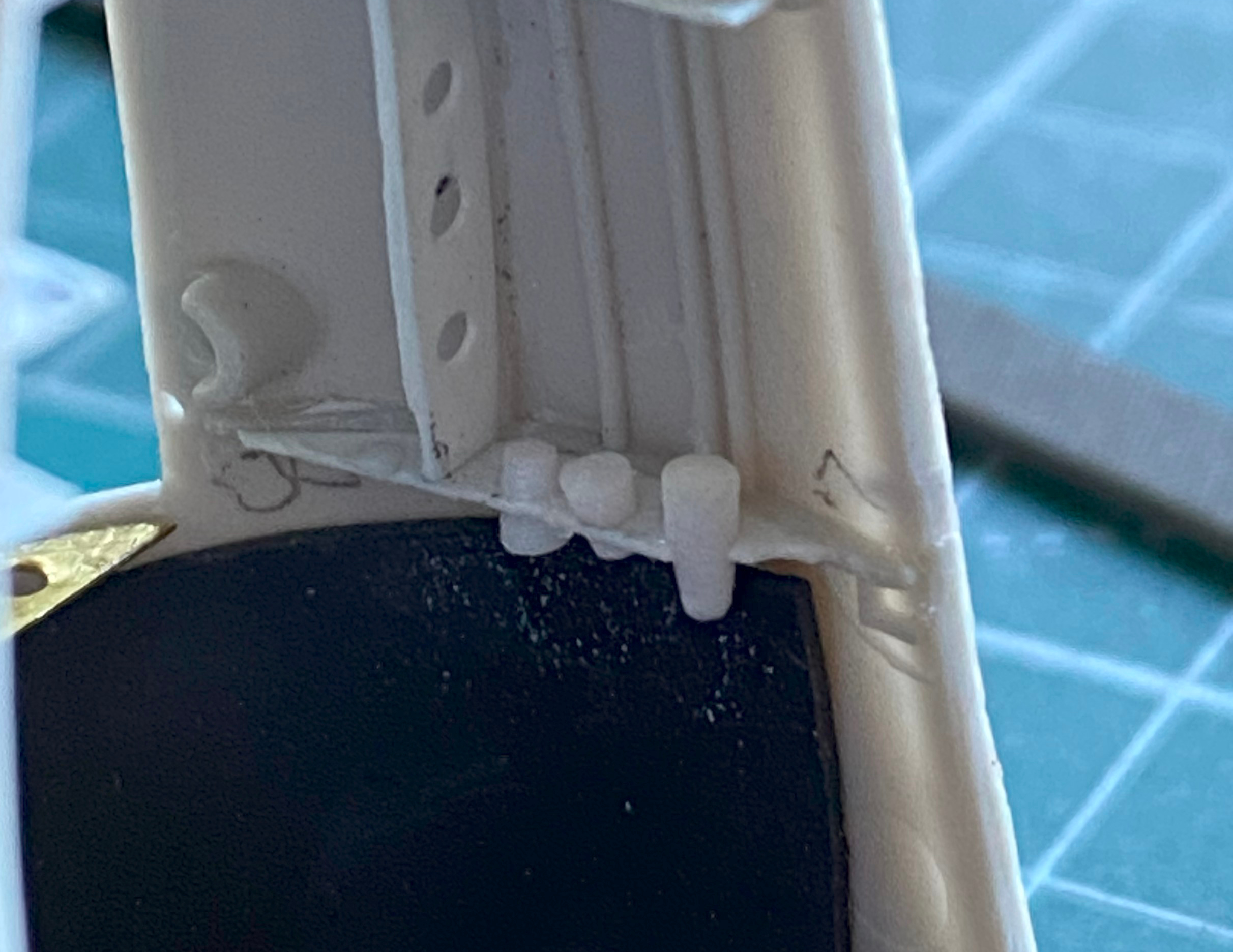
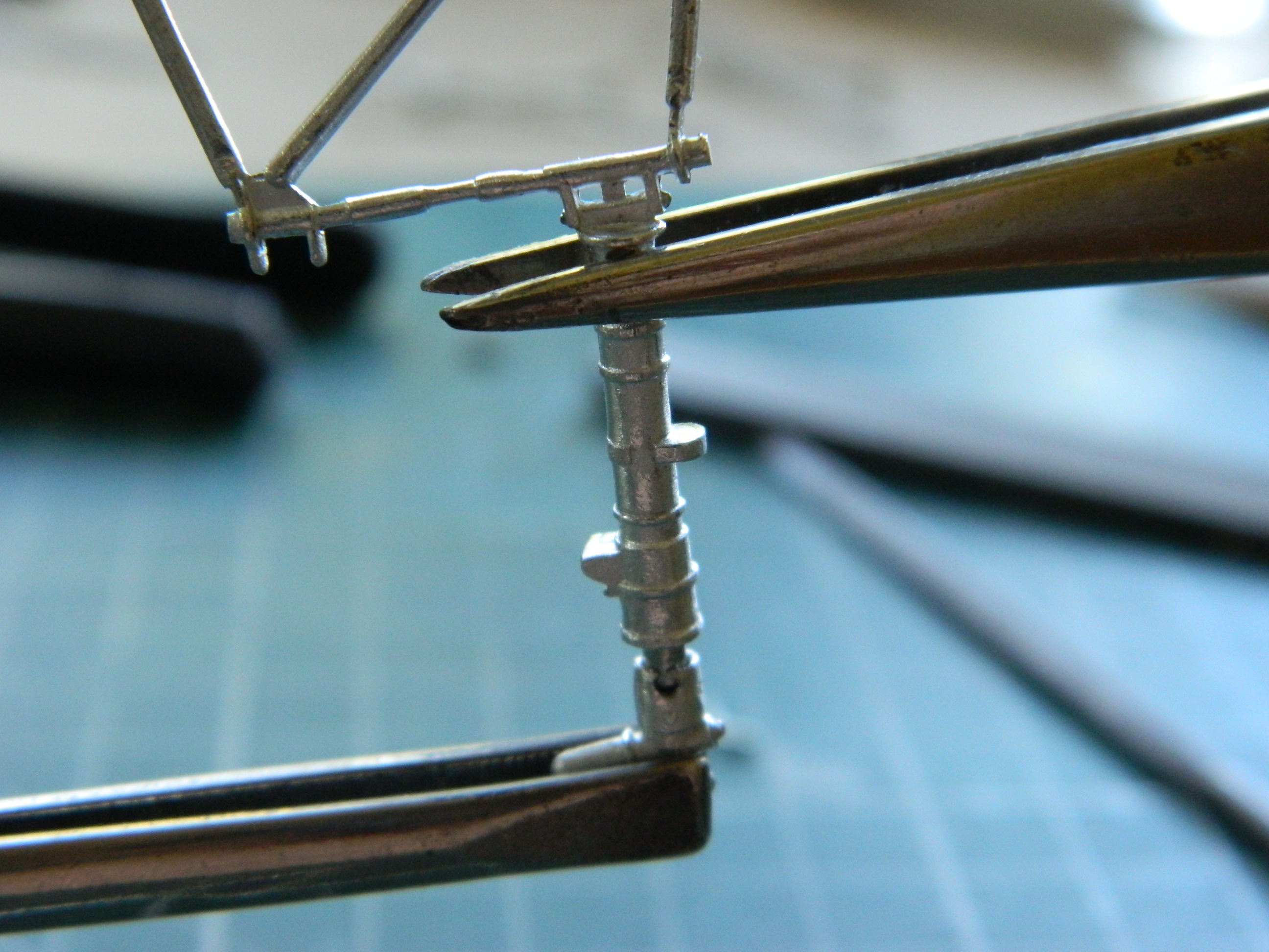
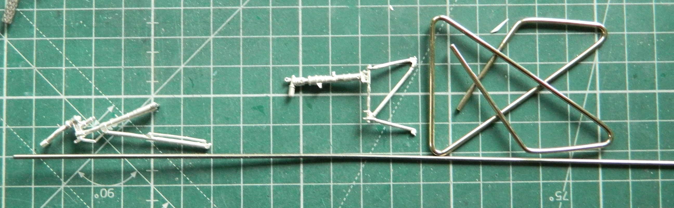
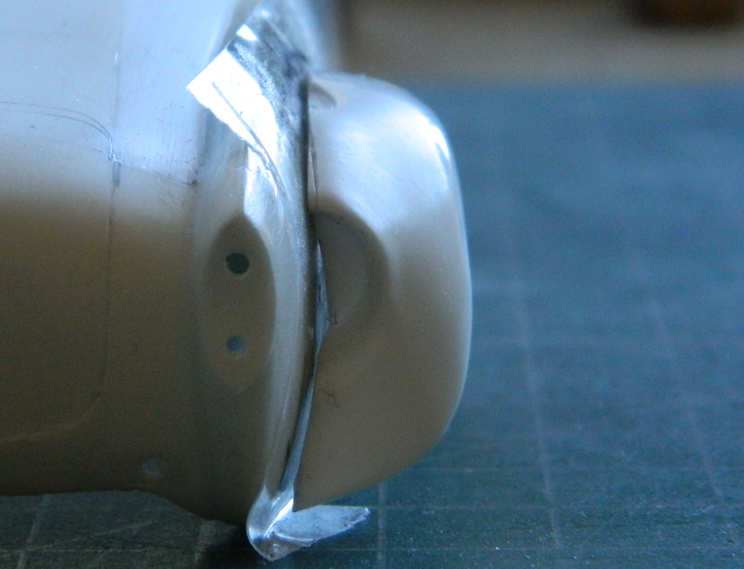
Fine. I’ll use the damned metal parts, then. (And yes…I pouted.) (Probably more because I did sober up but some of the lower lip extension was because I had to change my mind back.):

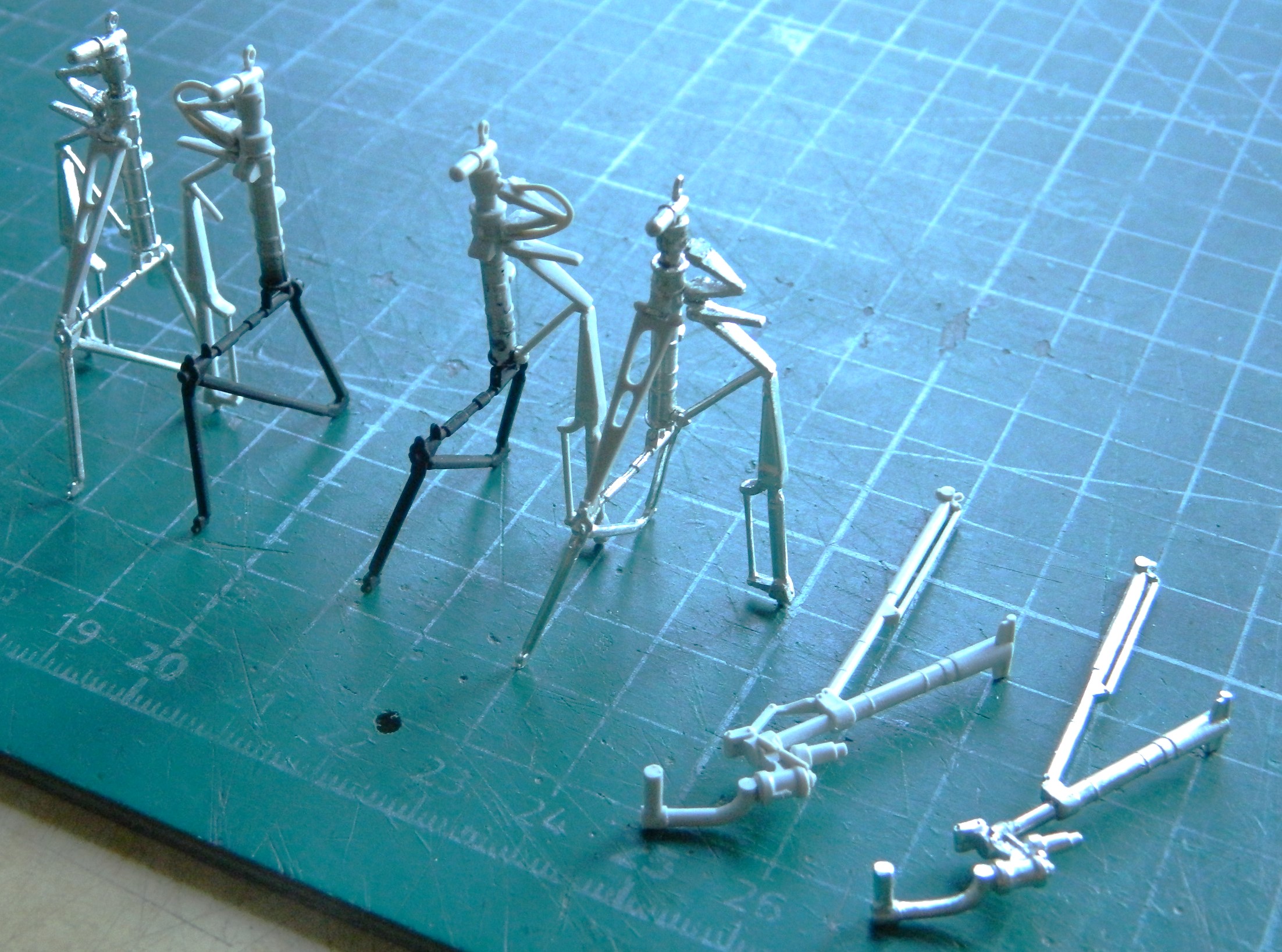
I can be pretty funny sometimes. When I took the above photo, I thought I had everything finally aligned.
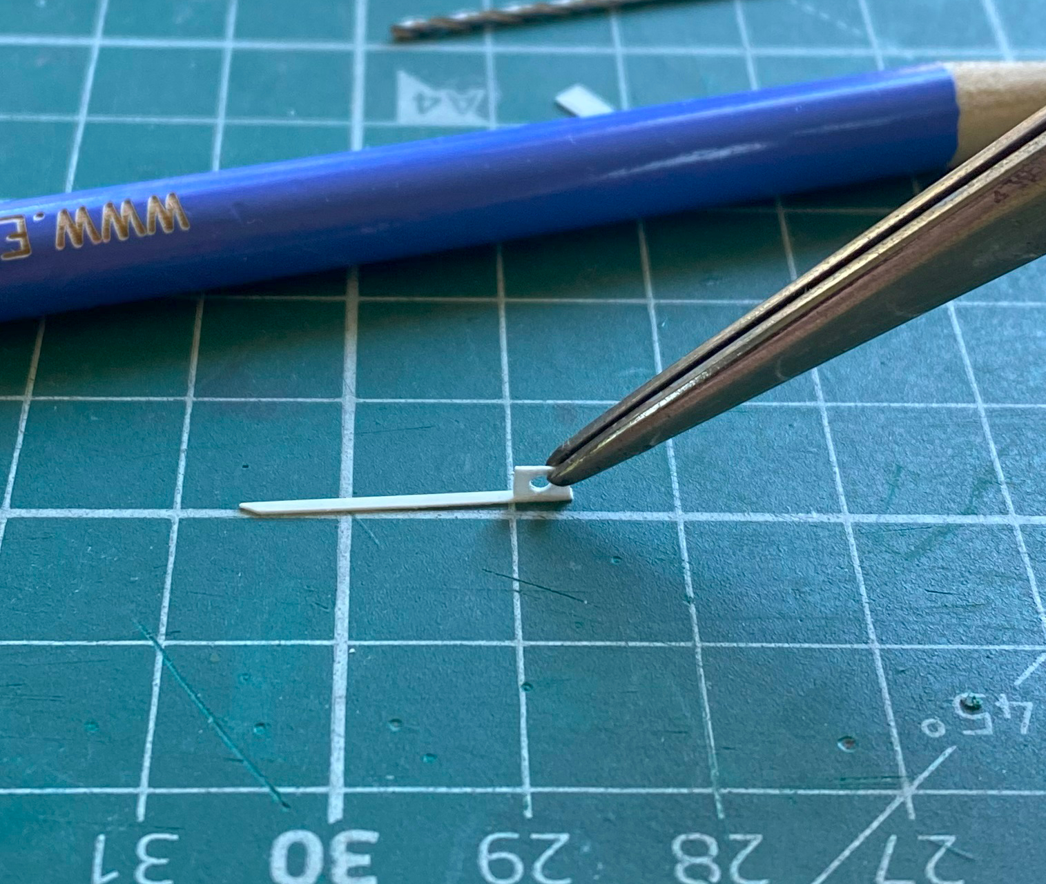
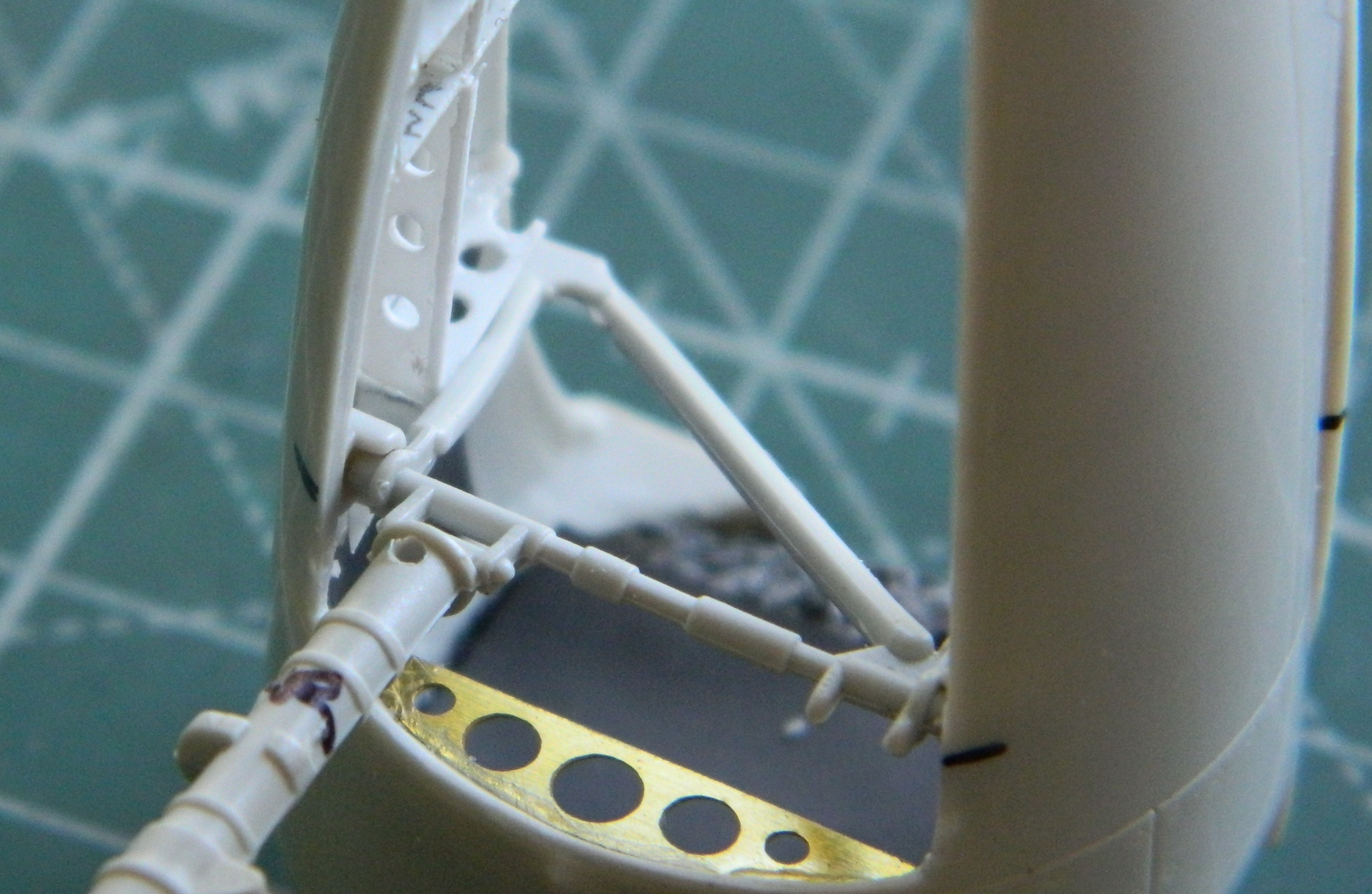
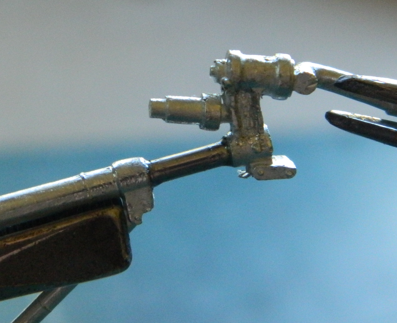
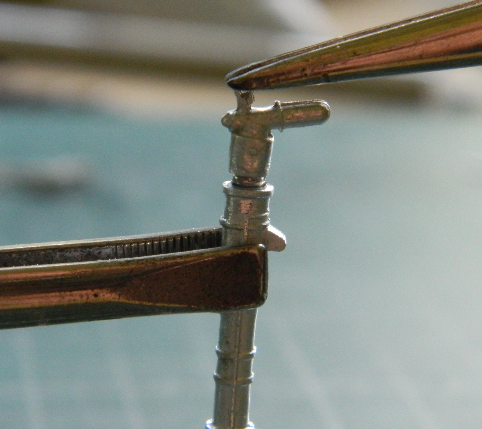
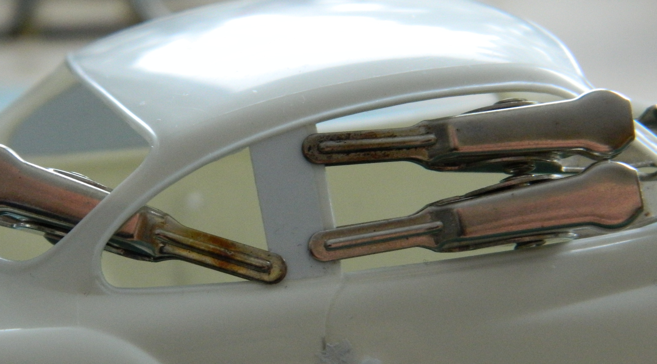
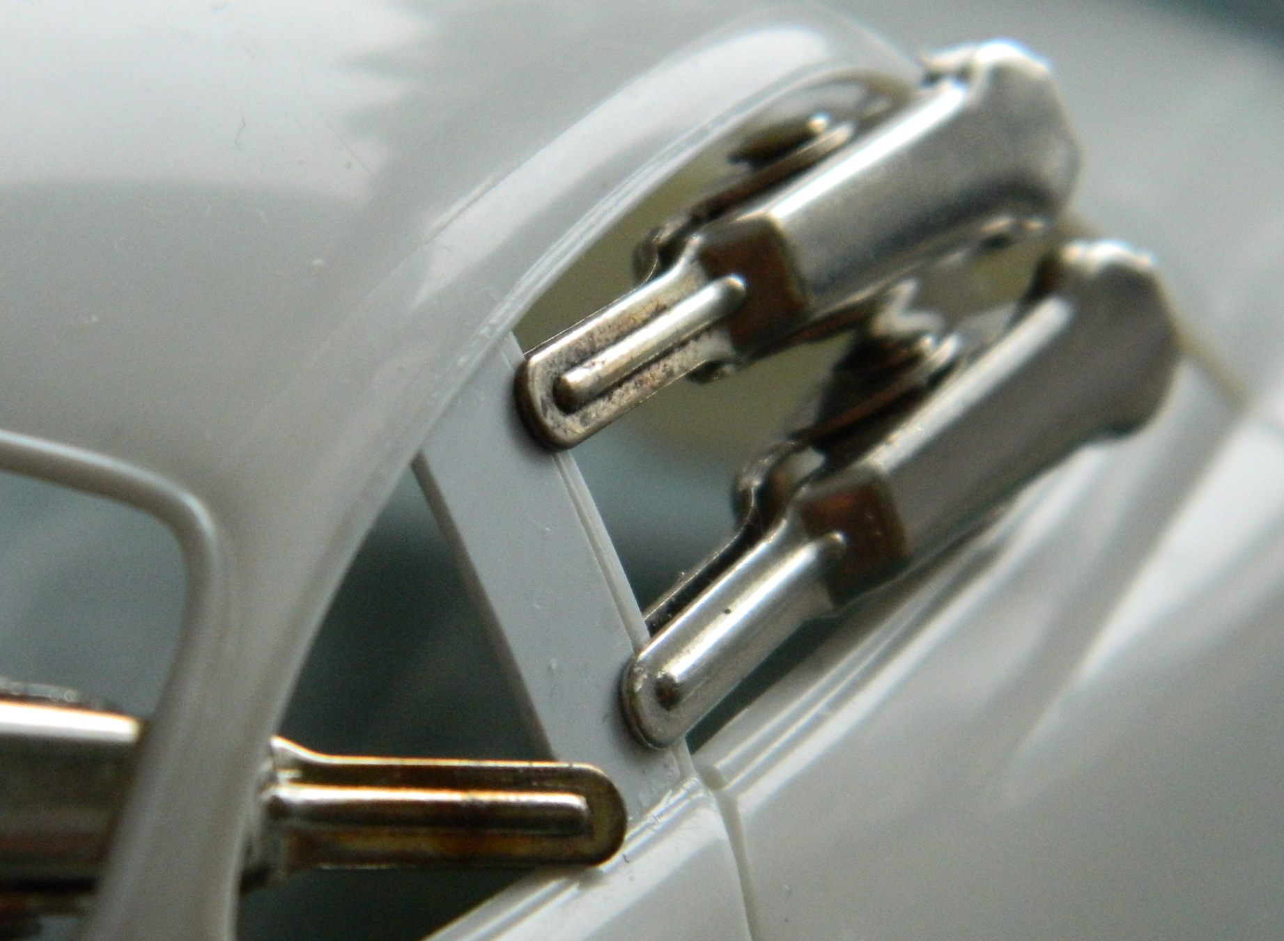
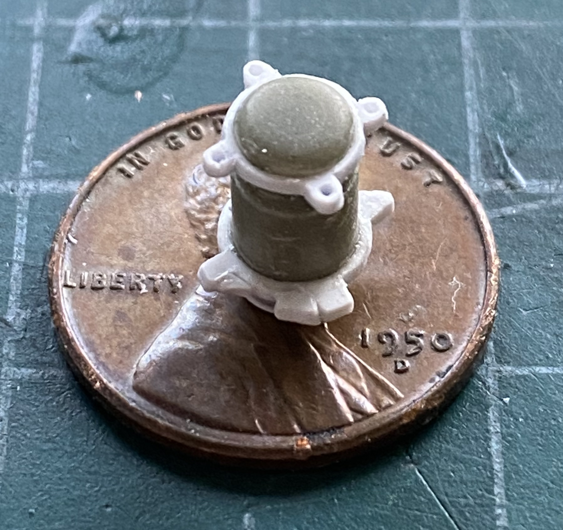
I used the kit’s oleo extension arms on the main gear, but used the arms from the PE set for the nose landing gear (that’s the brass-colored part):

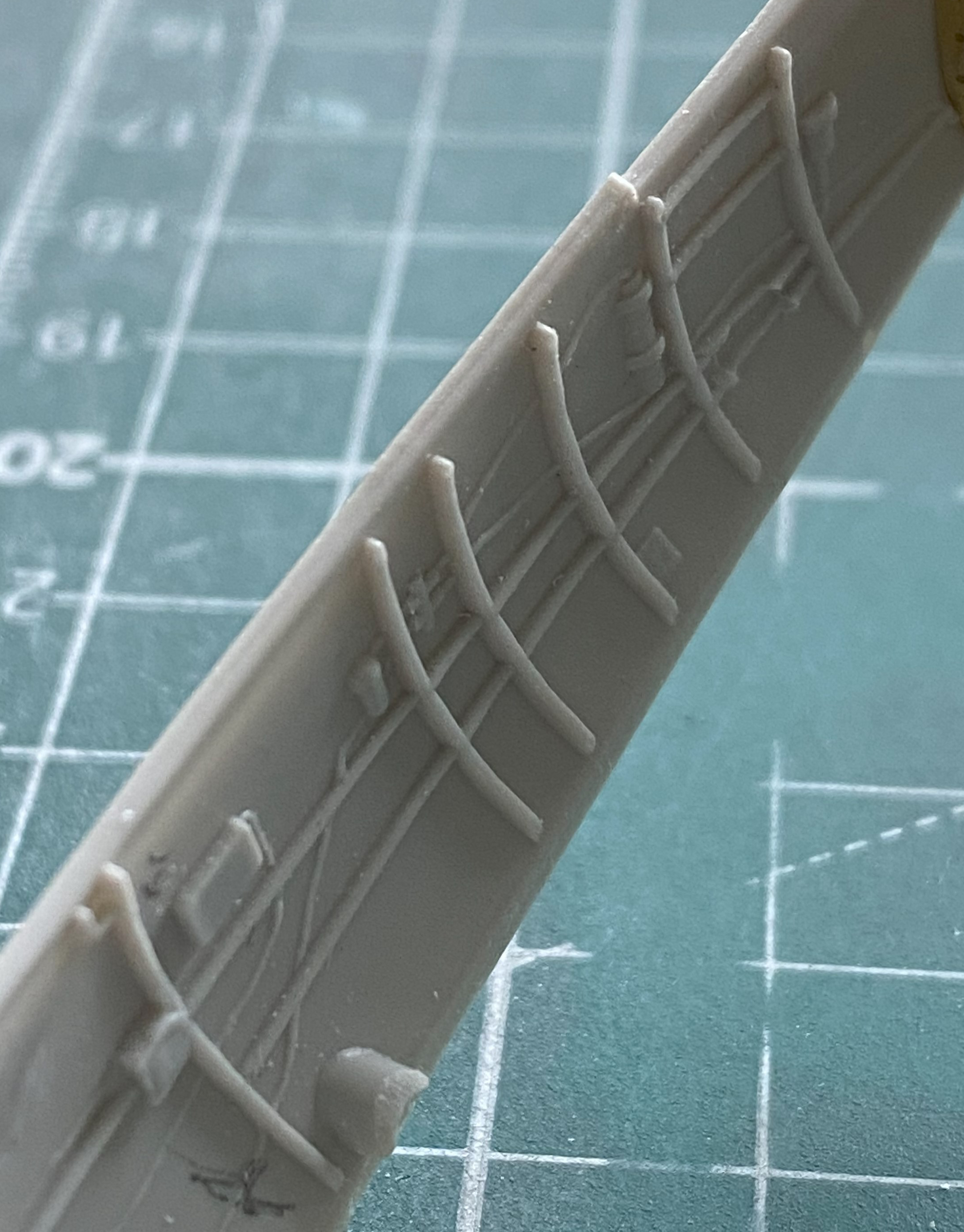
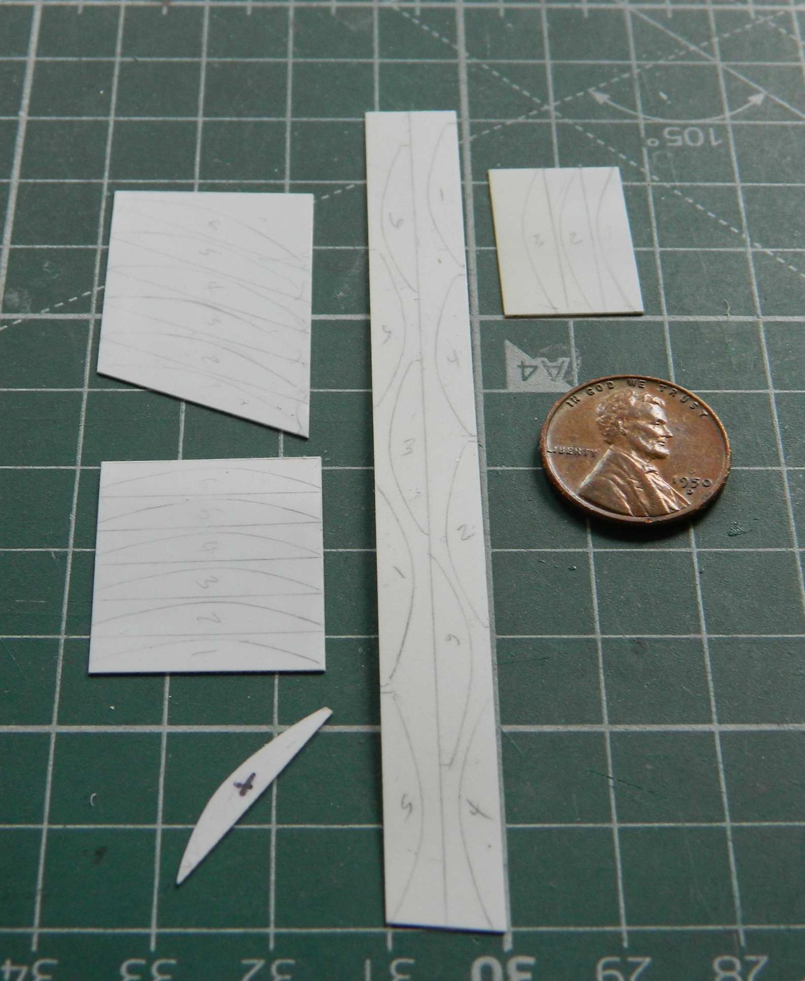
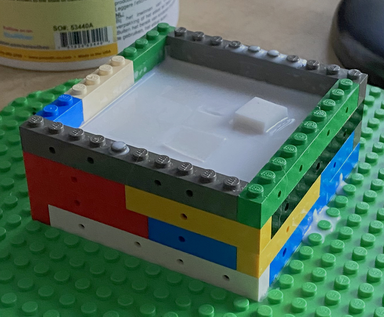
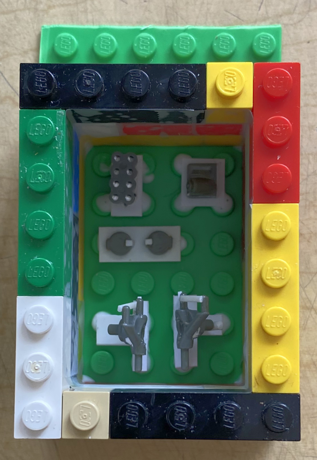
And just as an aside (and because I don’t have a lot to show here for this month, so it’s filler), a few years ago I heard about these, bought a set (which comprises four separate sets of what’s pictured below), and plan to use them on this build (which, with my typical aplomb, I totally forgot that I had until I was looking for something else):
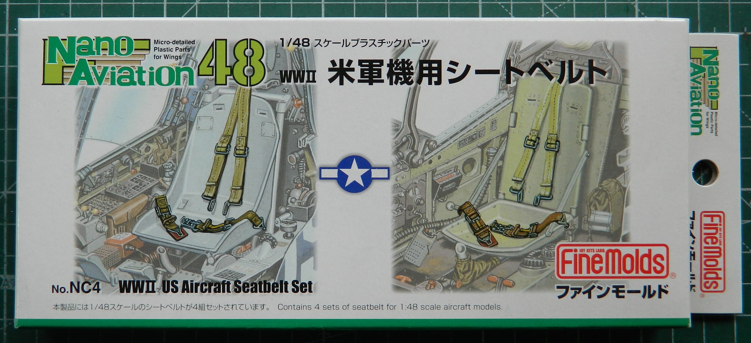

They’re nicely molded with good detail. I’m probably going to have so much fun bending and shaping what needs to be bent and shaped. We’ll see if the effort is worth the result.
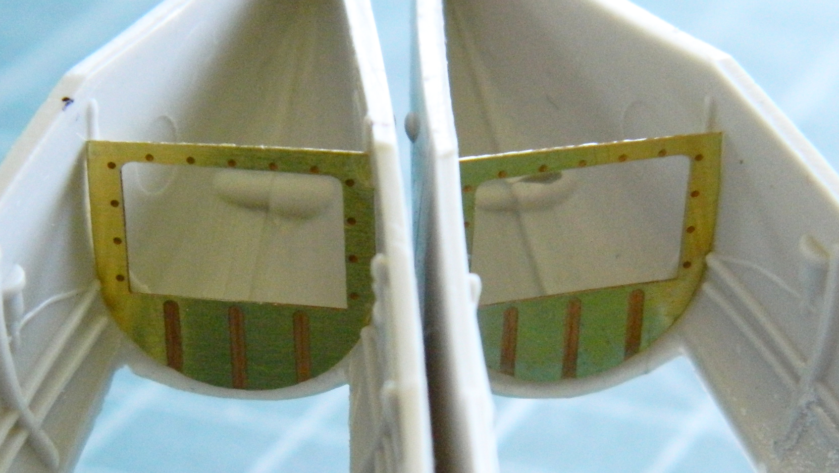
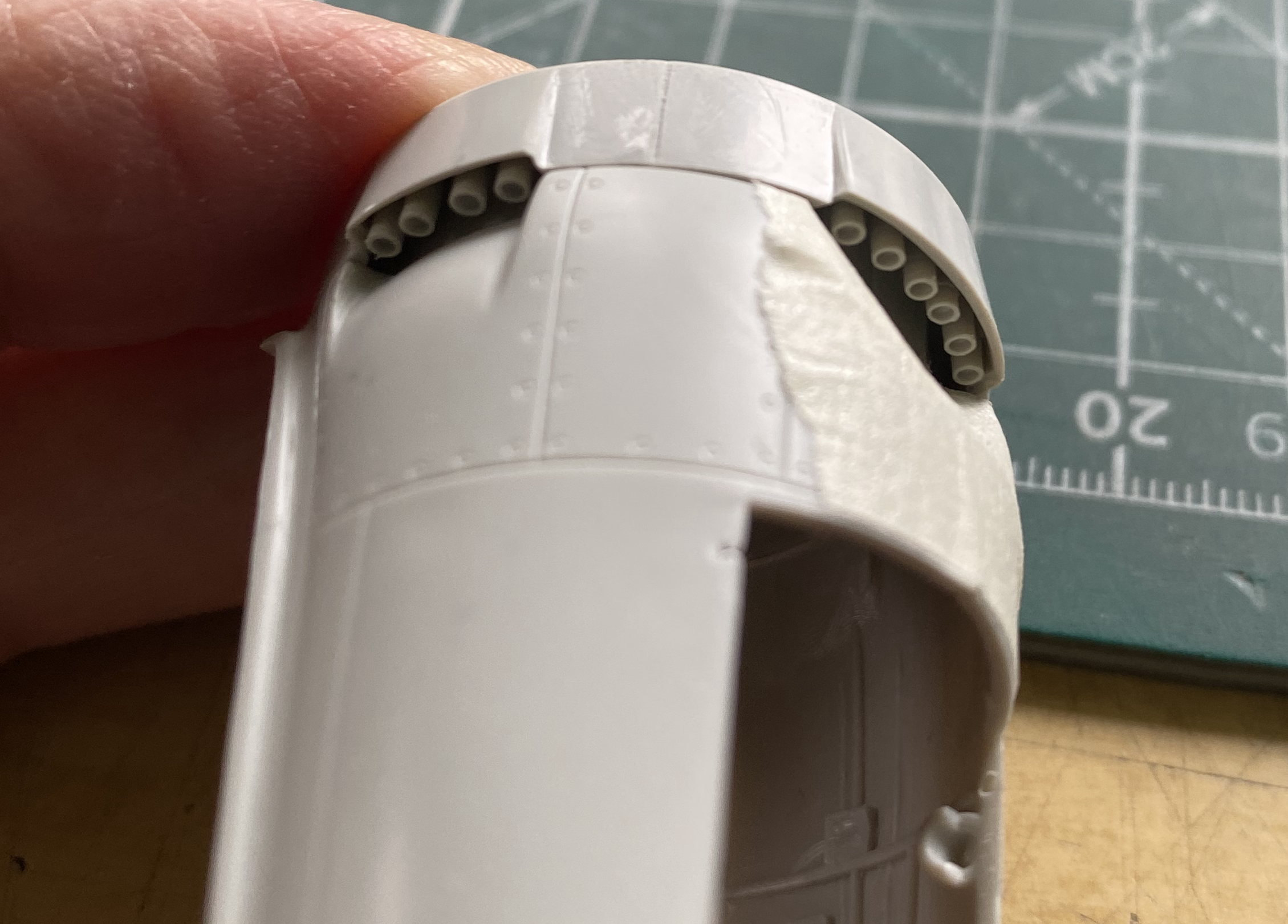
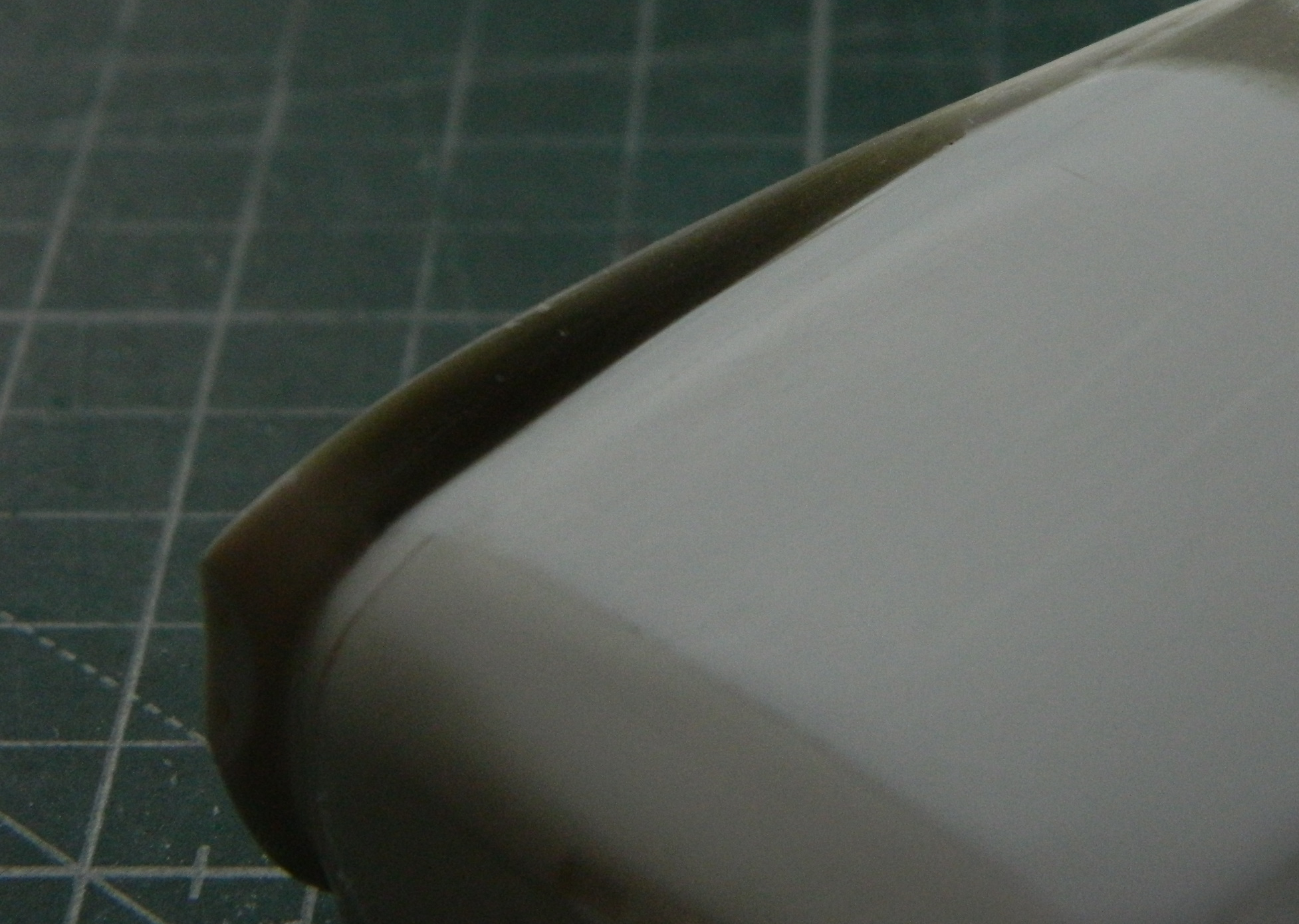
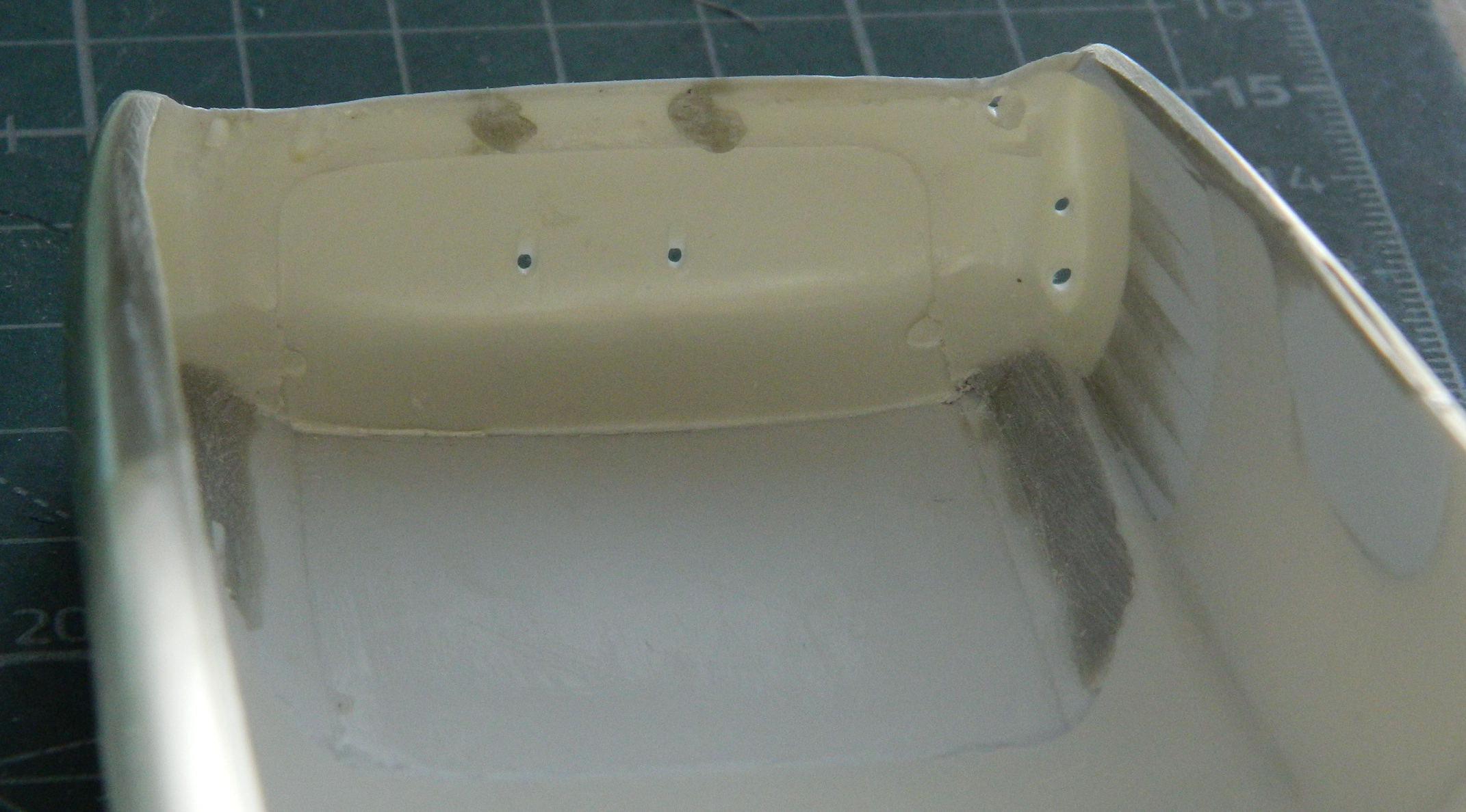
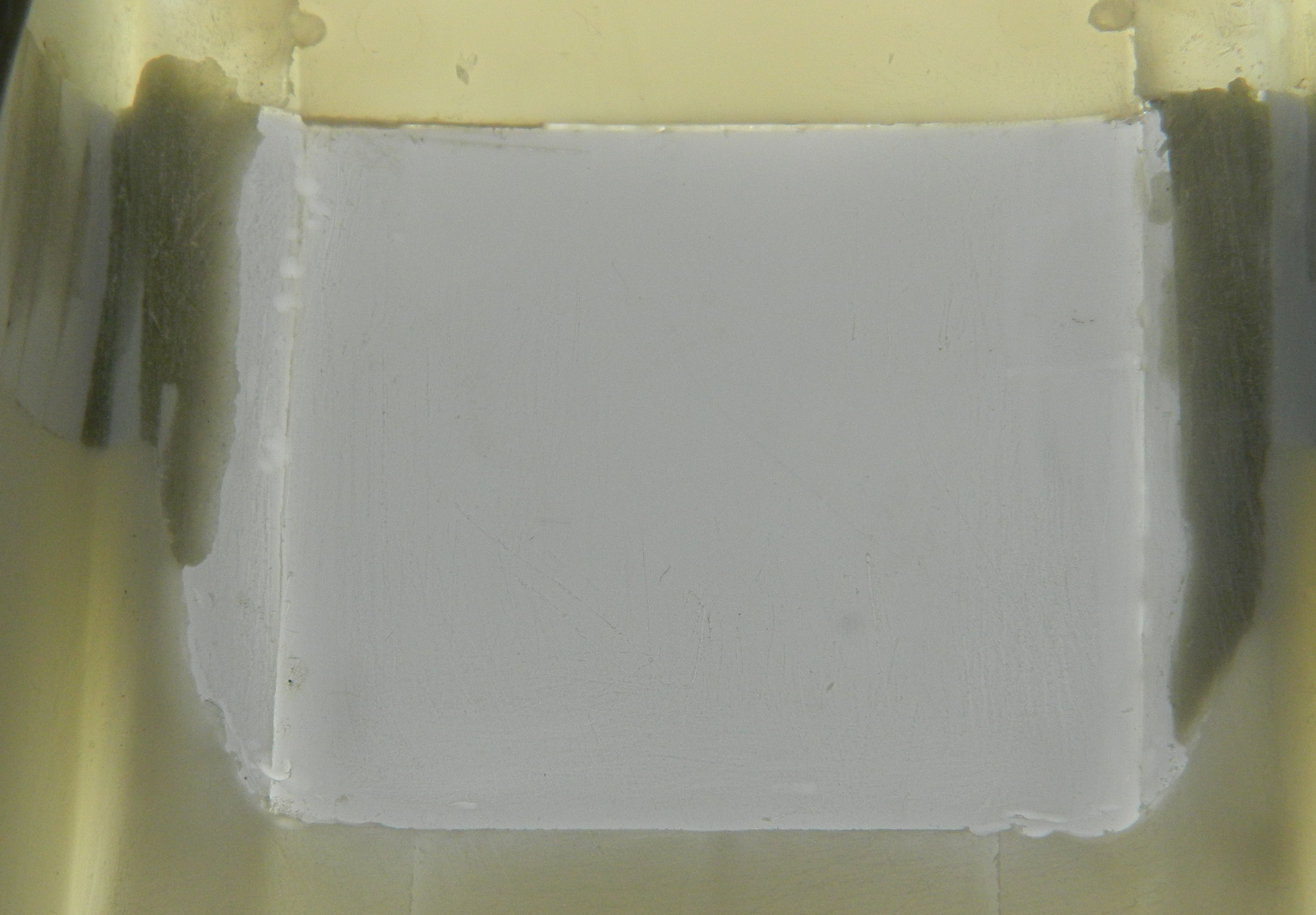
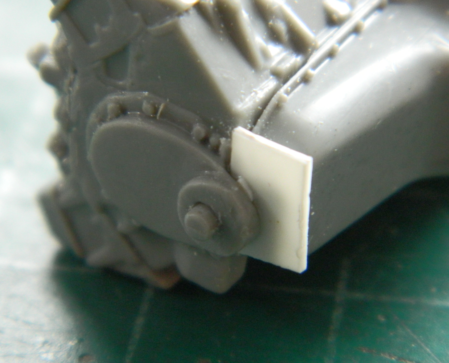
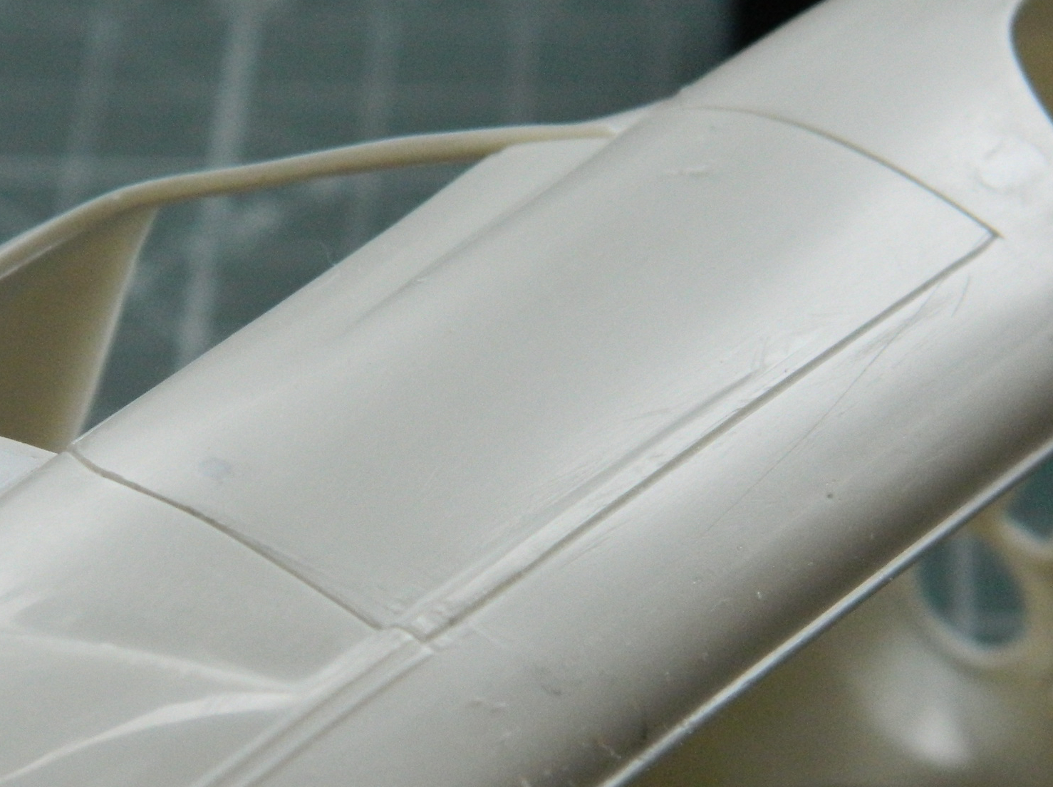
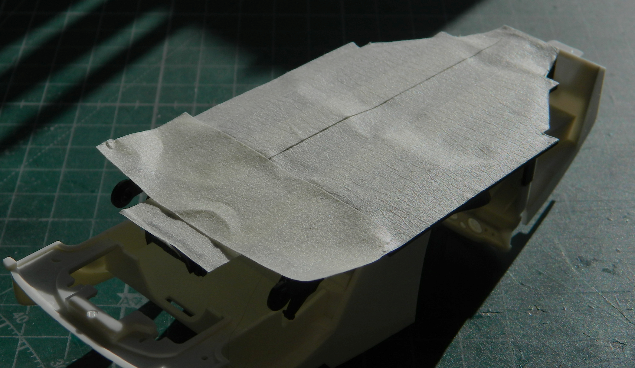
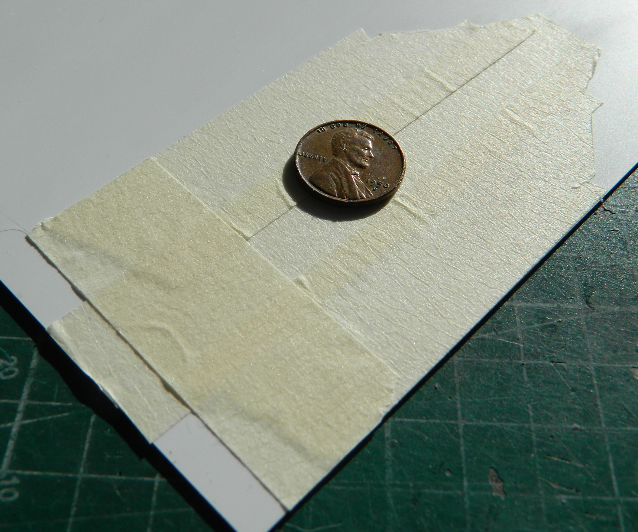
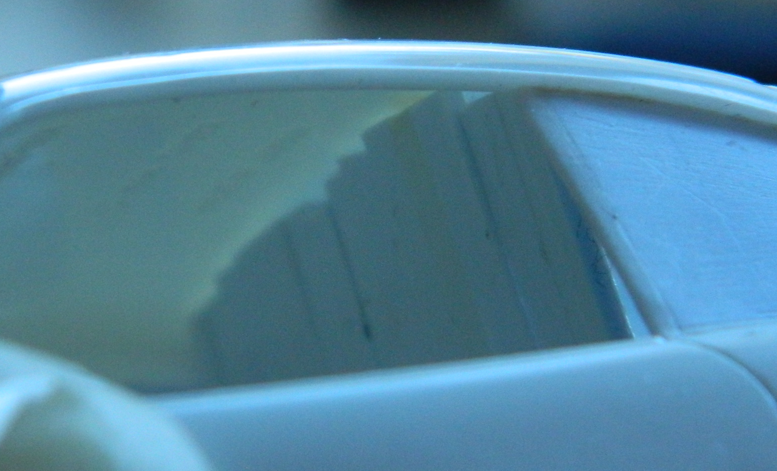
There are outlets for the oil coolers and the covers for the outlets are variable. The PE set offered replacements for what’s molded onto the wing tops but I decided to see if I could thin out what’s there sufficiently:
Yeah. That’s sufficient.
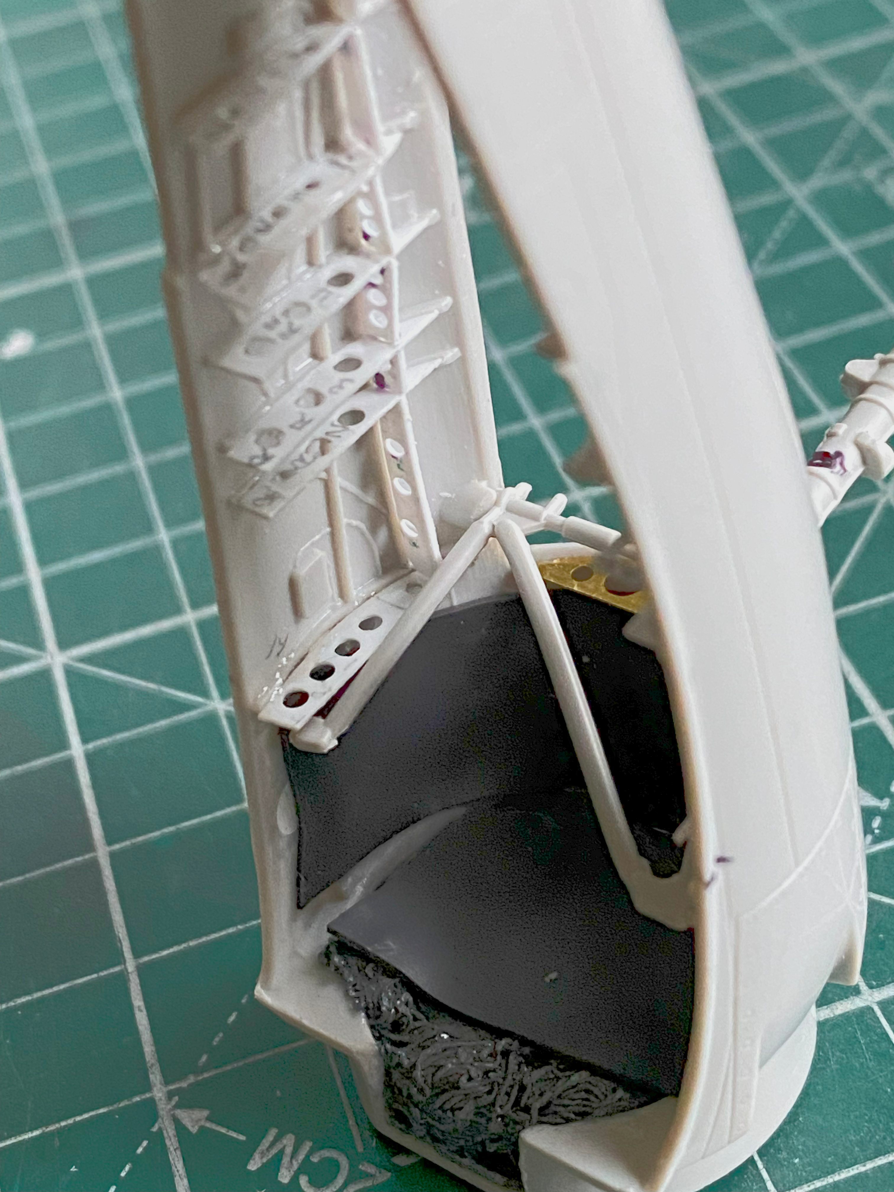
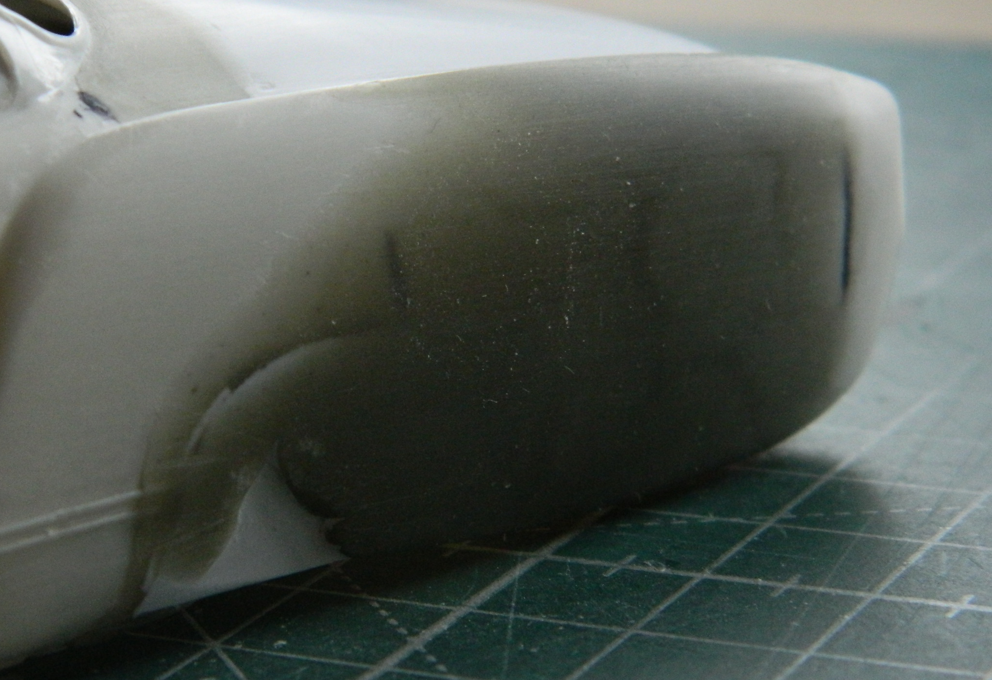
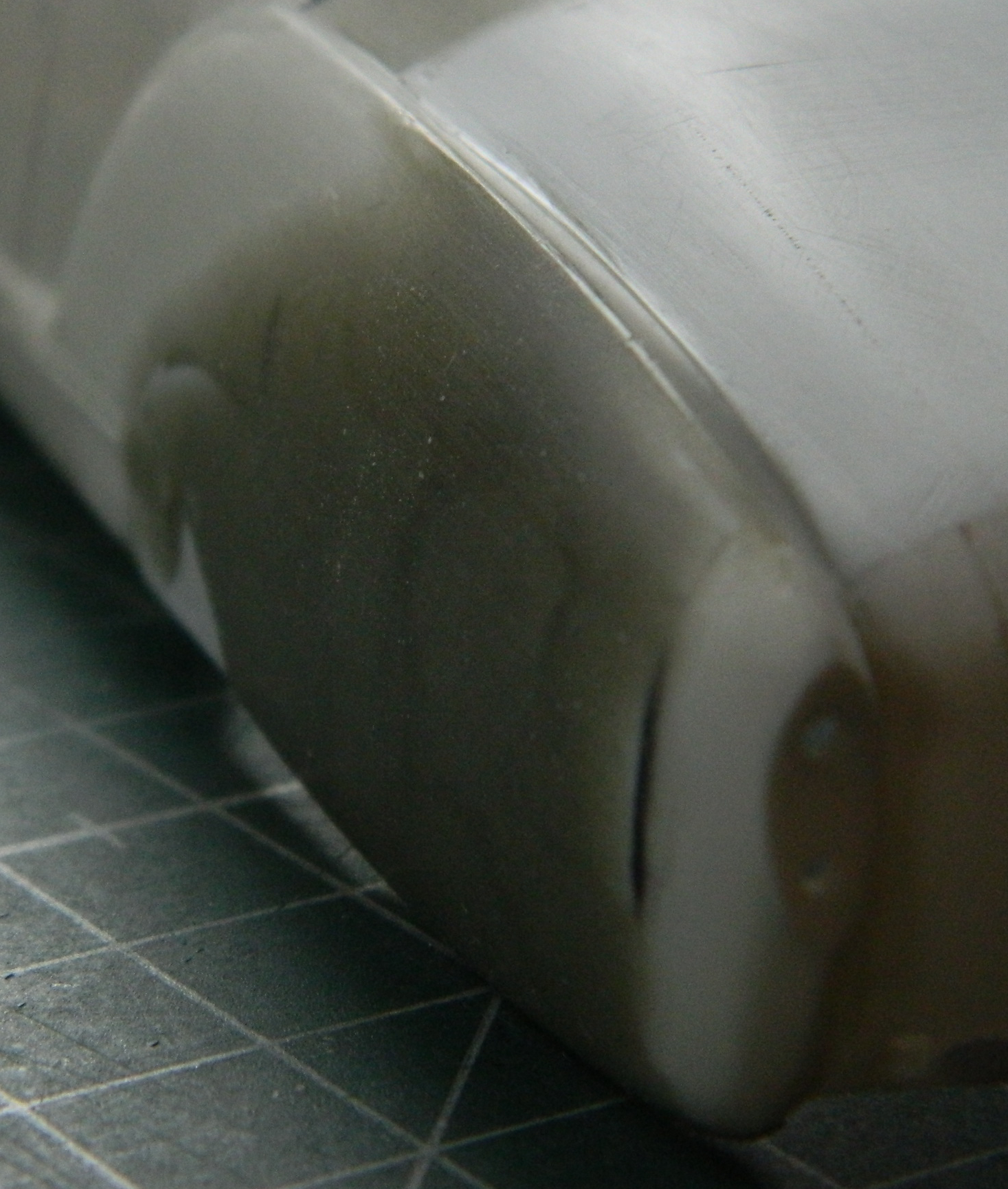
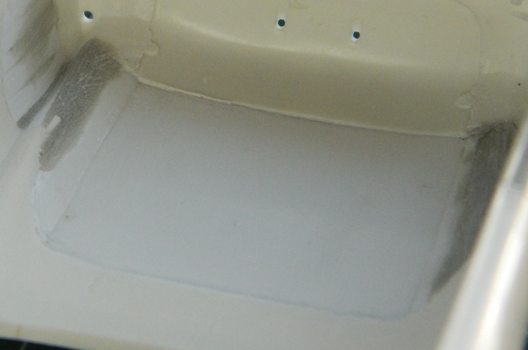
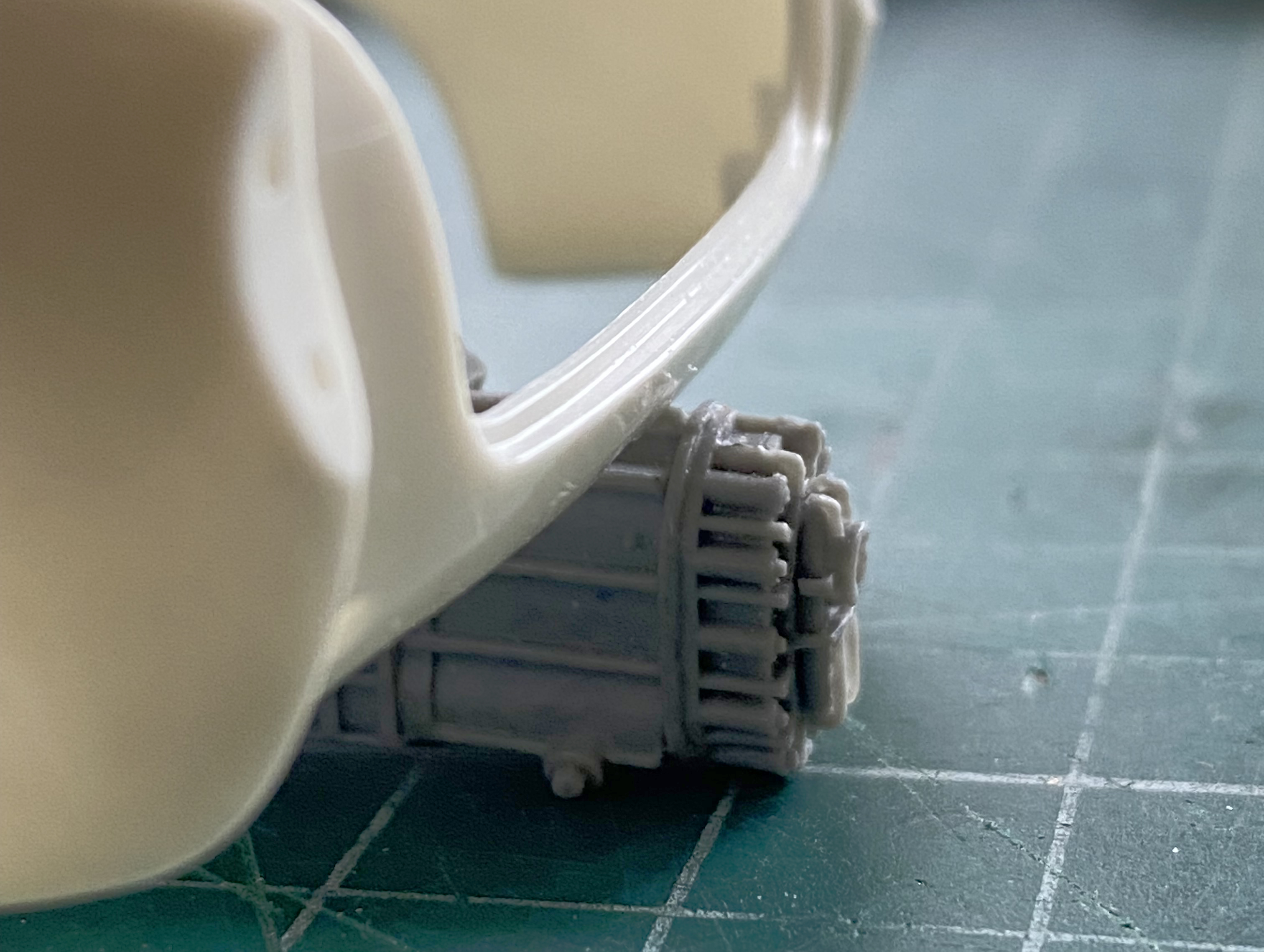
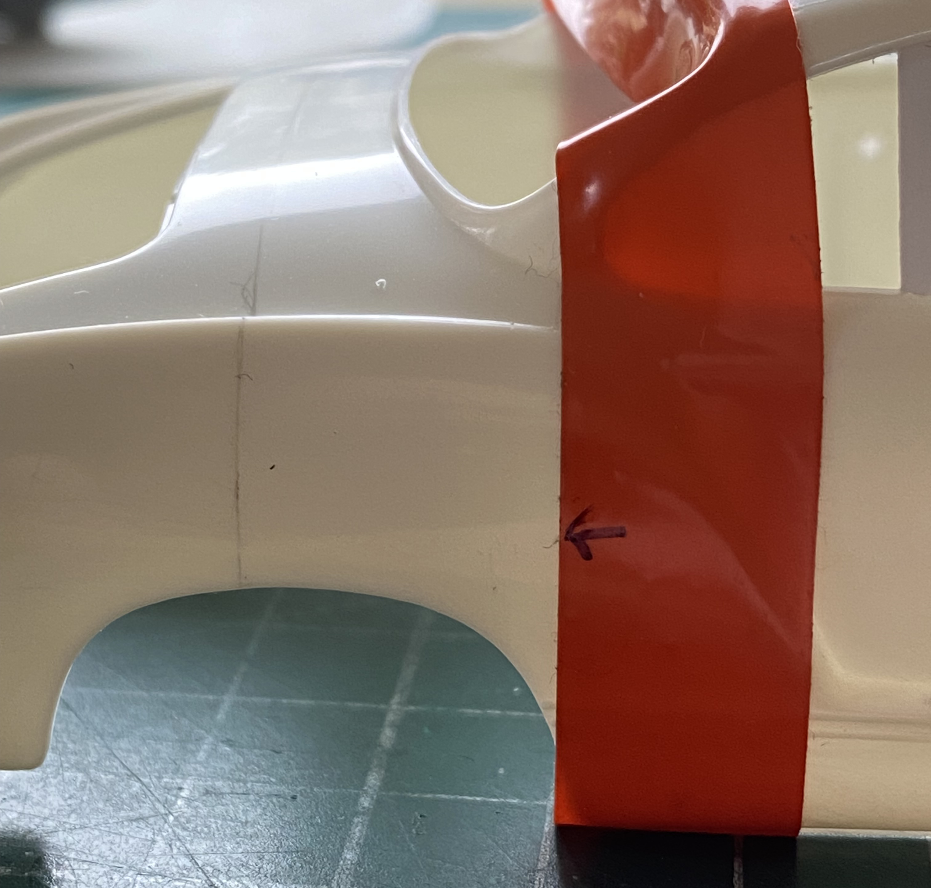
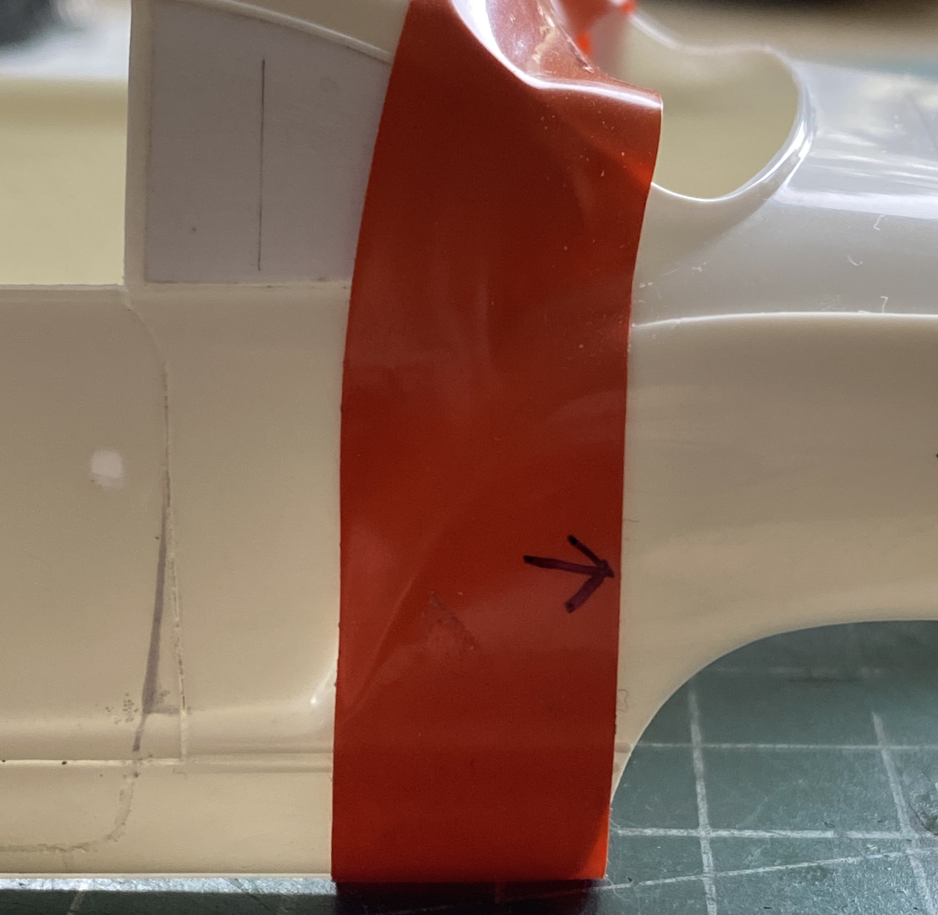
While doing the skull sweat regarding when the landing gear is permanently attached, I realized that trying to get the stupidly flexible metal landing gear inside the bays, things were going to be bent and badly so. Though I prefer to add things as delicate as these are as close to the end of the build as I can, that’s not going to work this time. Initially I thought it was because they’re so sodding bendable. Then when I tried to feed them into the bays from underneath, which is how they’d get attached later on, I discovered that they didn’t fit through the opening. ::sighs:: Okay, I’ll add them now:

Firmly glued in, out came the flat black again to pre-shade everything:

Next month these will all be painted aluminum. Who knows…I might even do other things as well.
F7F-3 (AMT/Italeri) 1/48 Scale Build #3 –Continuing to Populate the Engine Nacelles Some More
The landing gear bays with this kit are large, which I guess shouldn’t surprise me since this kite used a pair of the P/W R2800 which weren’t known for being small. Once upon a time, I would take the opportunity to detail the hell out of these bays as I did with the Blackbird build. And then I realized how infrequently the ‘Bird gets picked up and someone actually looks inside the landing gear bays. Not anymore. I’ve added some structure, the ribs and stringers, that could be seen, but I’m not adding hydraulic lines, cables, or wiring harnesses. The last update showed the ribs being built and installed, meaning this update will show the stringers.
The journey of a thousand mishaps begins with the first step and this is where I’d ended the previous update:
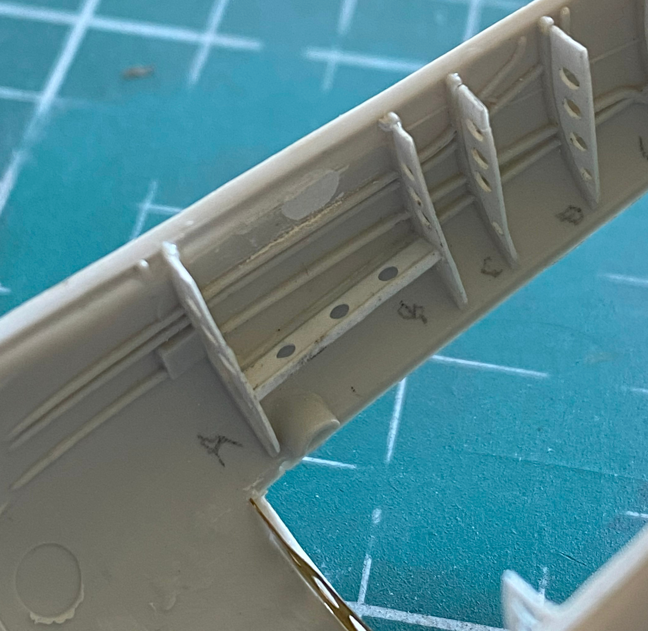
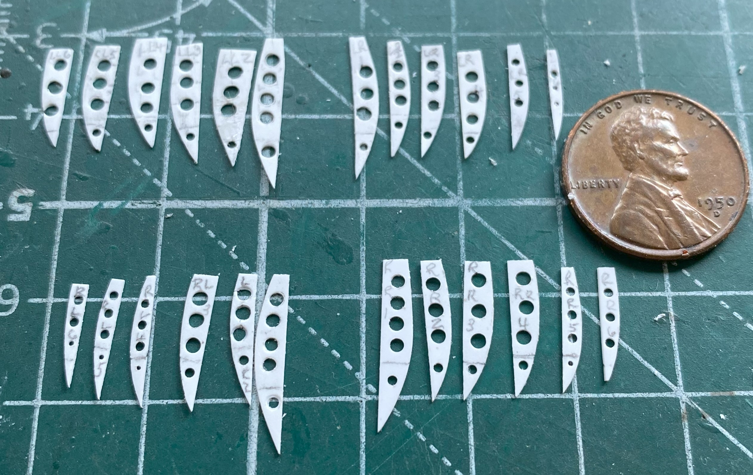
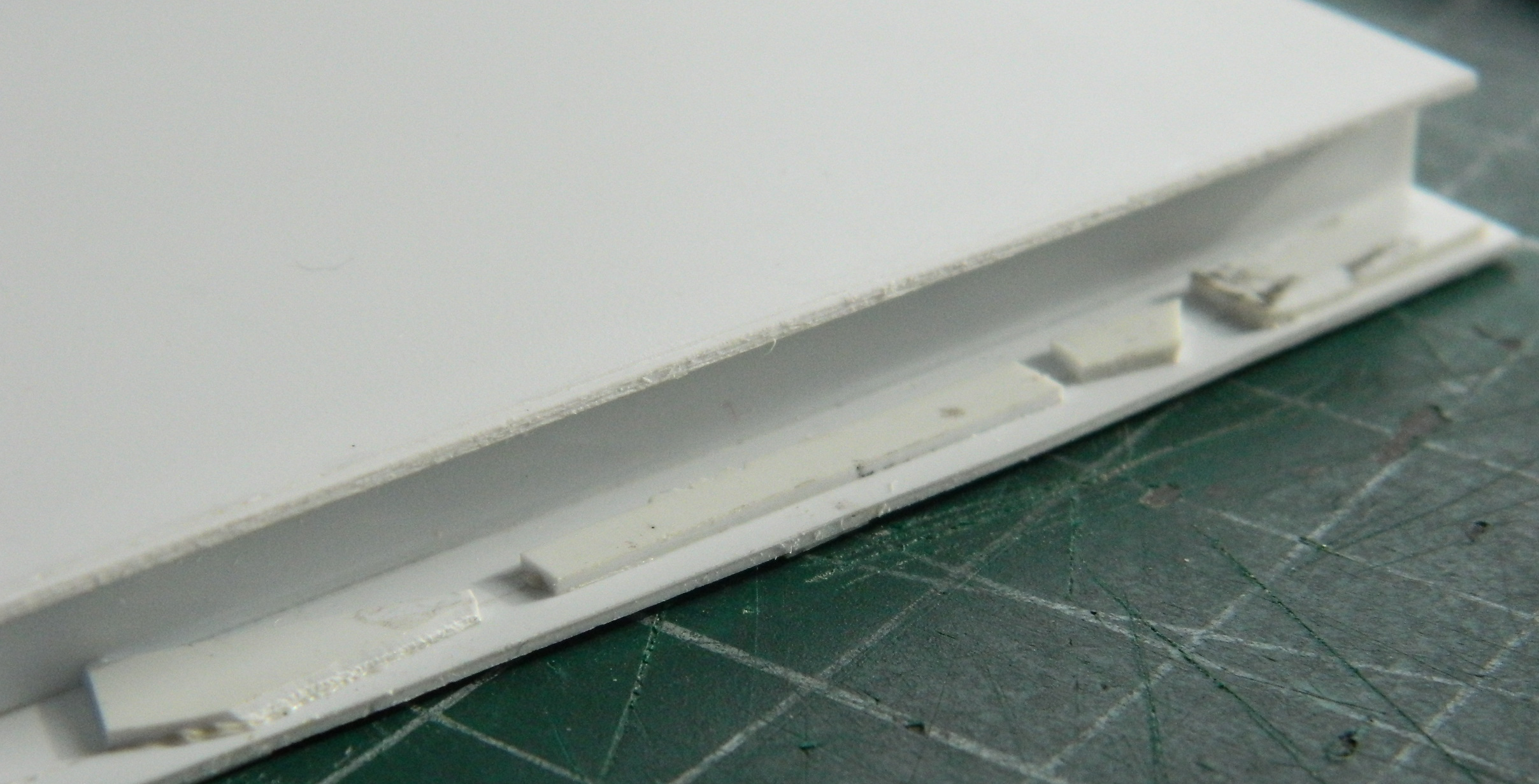
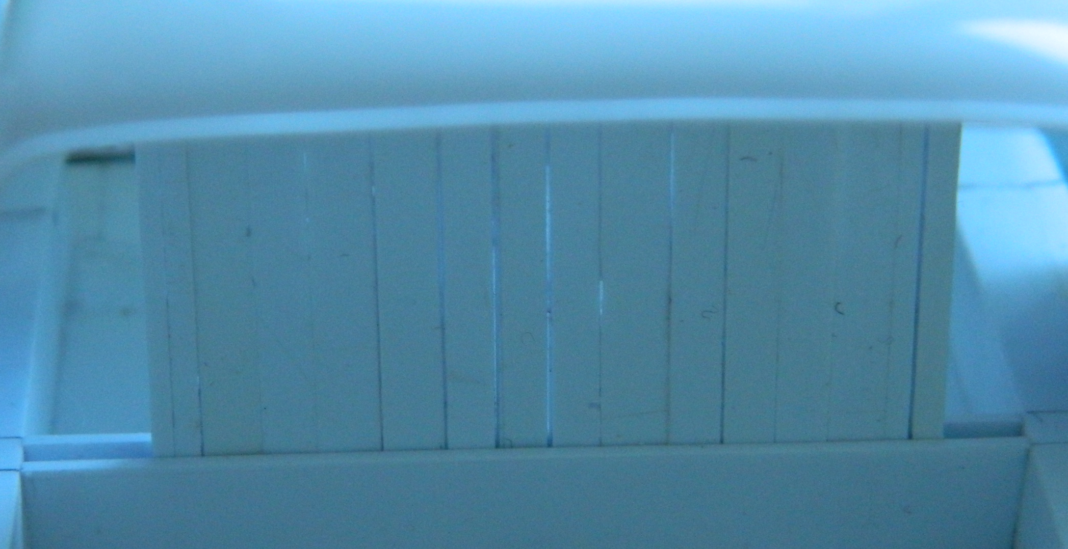
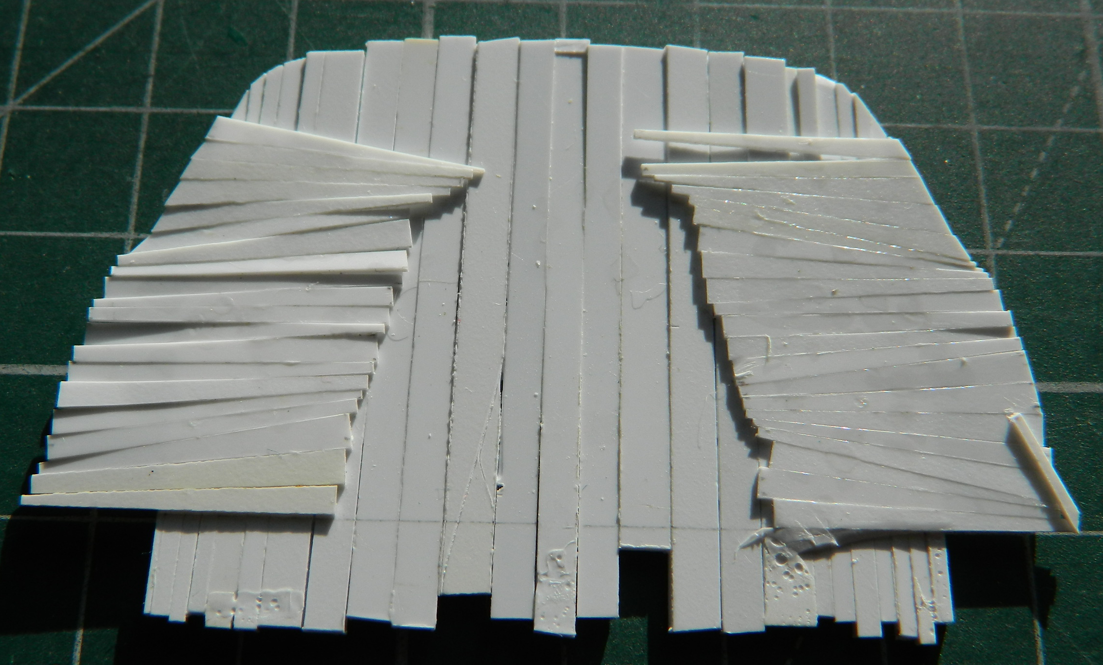
There isn’t a lot of photos in this update because of things like this, which is adding the lip that the stringers had (all 24 of them). Small details take time. I used 0.010″ (.254mm) for both the stringers and the lips. Once I had the approximate dimensions, essentially the length and width, the lips got added before the absoLUTE joy of fitting all these things in:
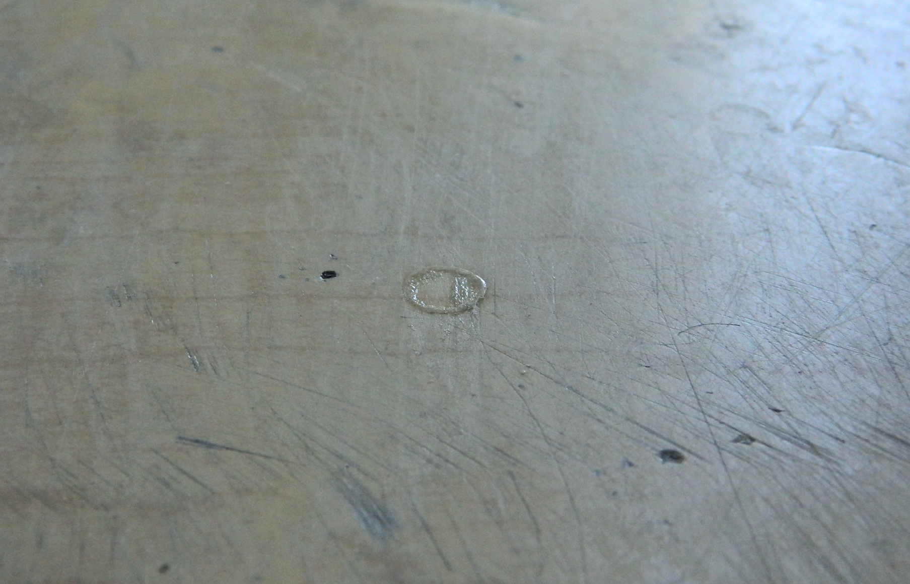
Now that I have a new tool to play with, specifically UV-setting resin, I used it more and more during this phase of the build and my conclusion is that this stuff is DEFINITELY useful. When dealing with a new item, I always read the directions. The directions of this stuff tells me that I can’t rely on natural sunlight to cure it. Well… I used the provided UV light to cure the resin and that works well, sort of like superglue with plenty of time to get the parts correctly positioned. And like how I use superglue, I put a small drop of the resin on my worktable and added it to the model using needles and dental tools. What I did notice, however, is that the resin will end up being cured somewhat by just sunlight. This is what happened after about five minutes of exposure to direct sunlight:
I’m pretty sure I’ve mentioned in other places in this site that I’m parsimonious. And I’m also a cheap bastid. Wasting product, any product, is right near the top of my must-avoid list. So since sunlight will cause partial curing, which is wasteful of product, I took a piece of cardboard scrap and fashioned a sun-shield with it:
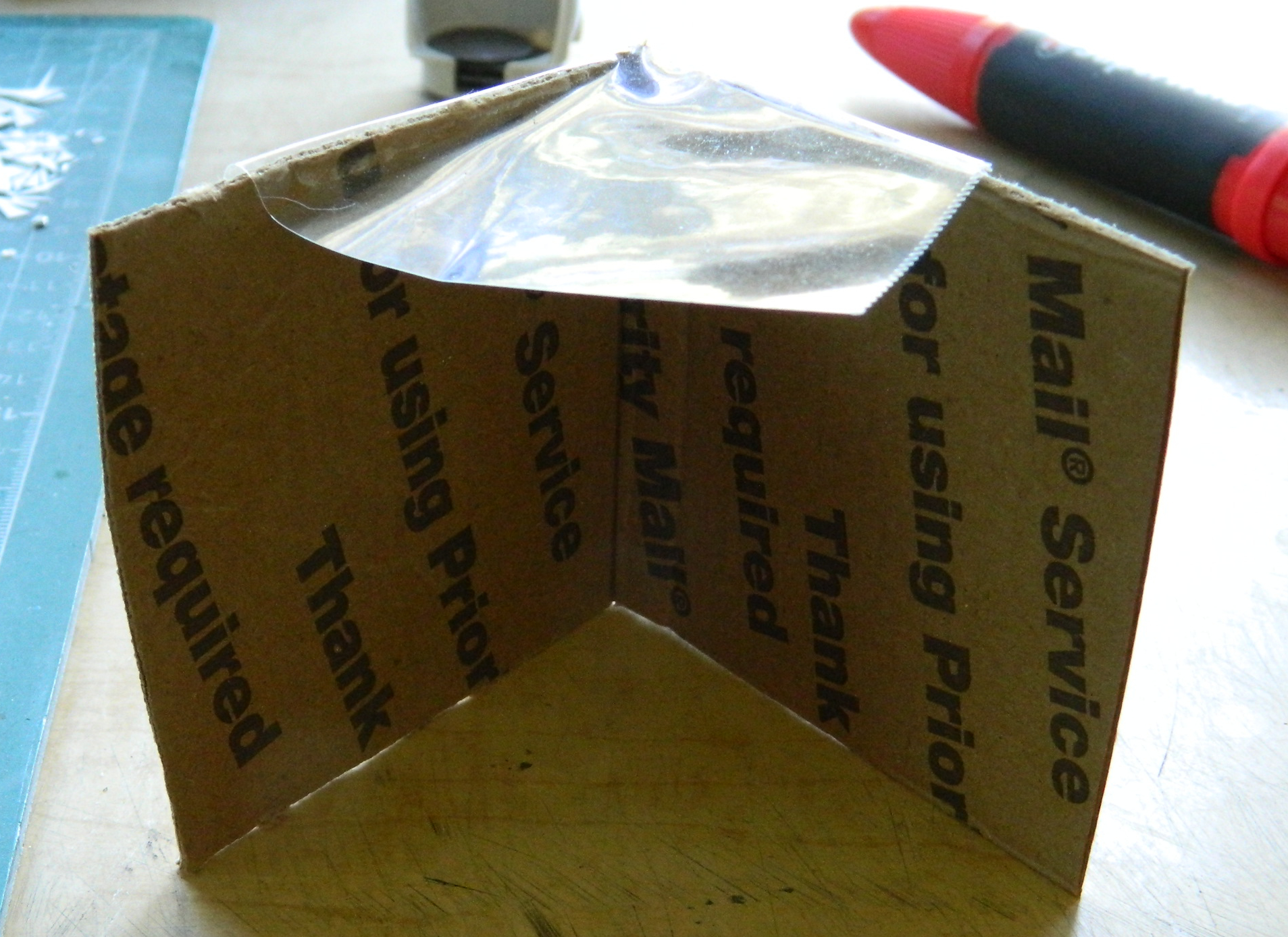
Though the drop of resin will still cure on the table, that rate of curing is substantially slowed. Best I can do so that’s good enough.
So I made a lot more stringers and lips:

I discovered quickly that I can forget which side of which nacelle any given part is intended for. To counteract that, as I made a stringer, I trimmed, fitted, and glued it in place using the UV-setting resin:
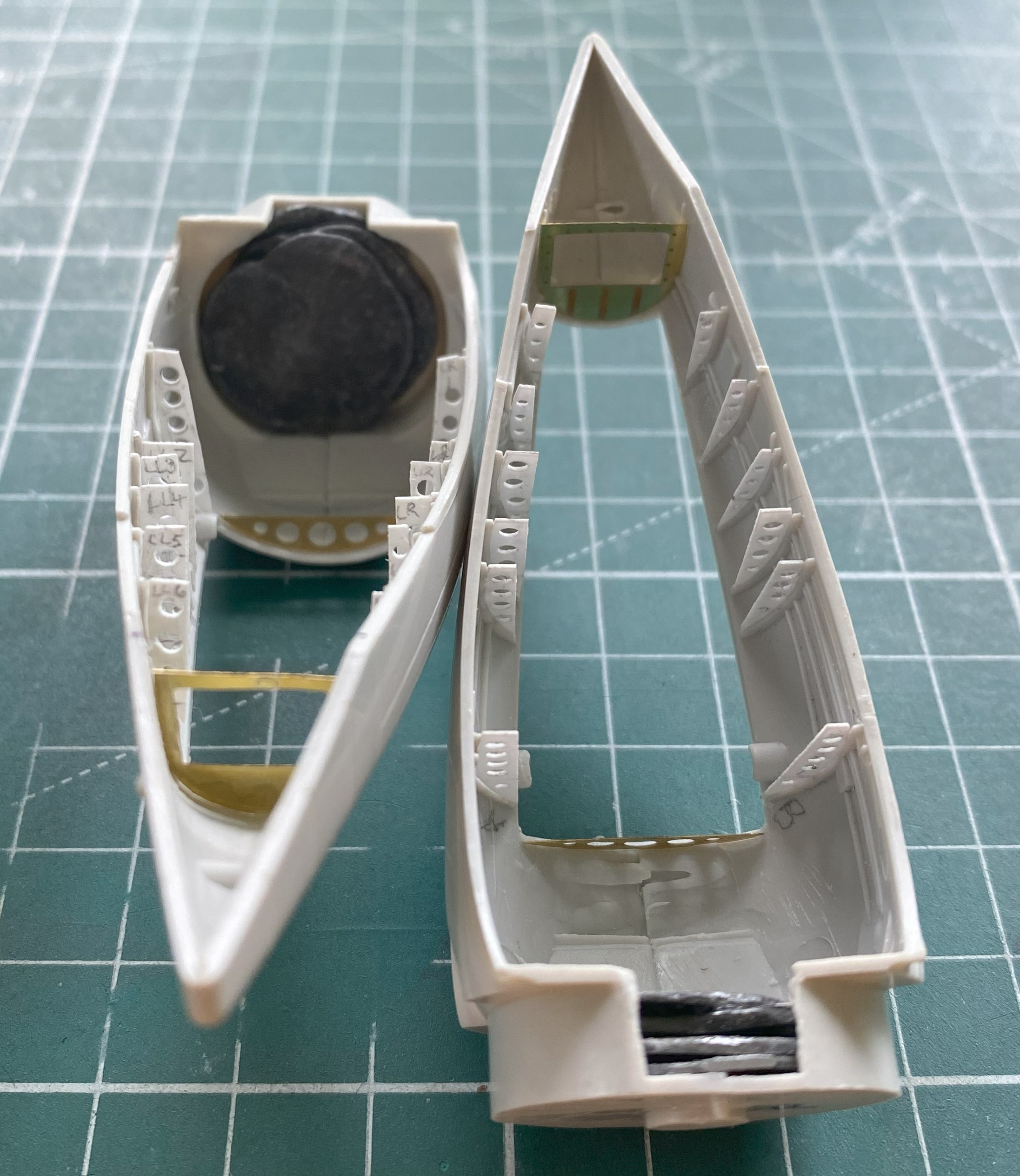
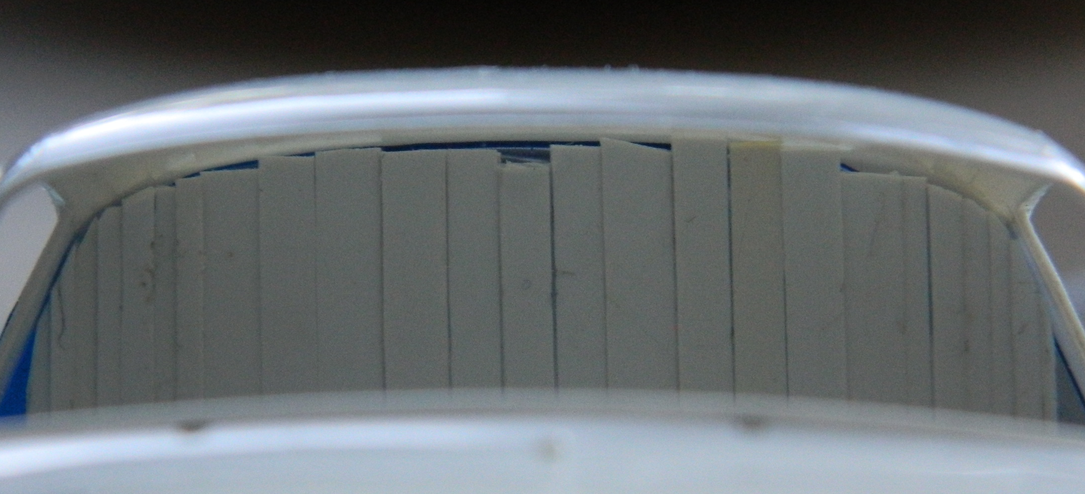
I just kept plugging away at it until I got both nacelles done:
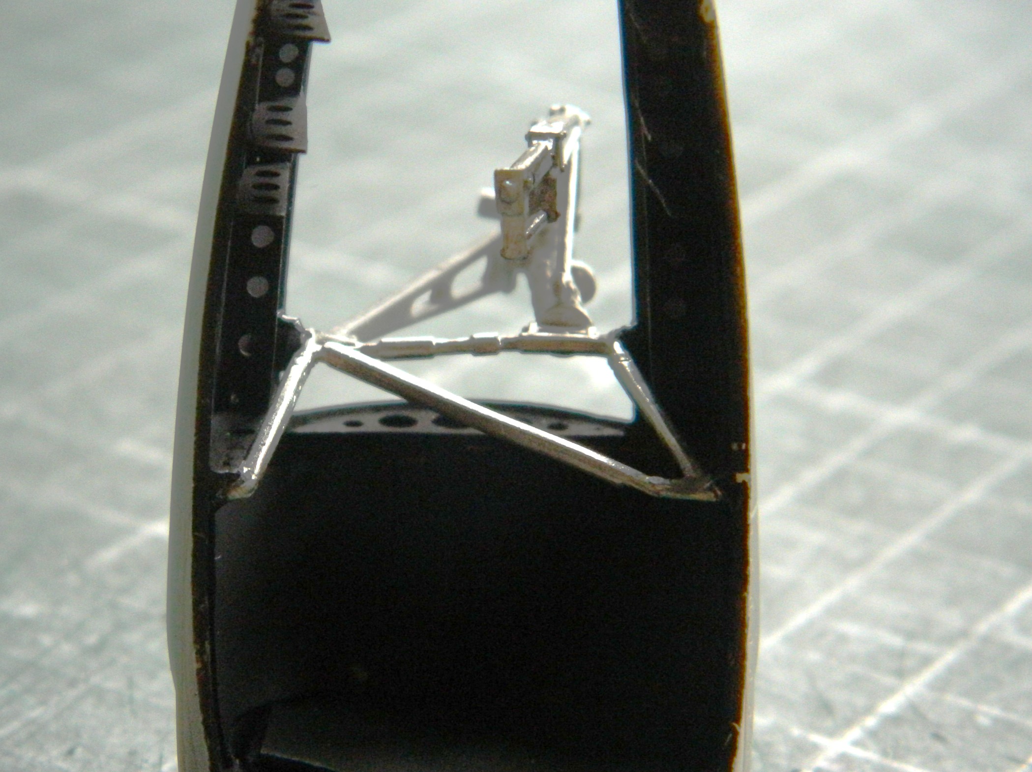
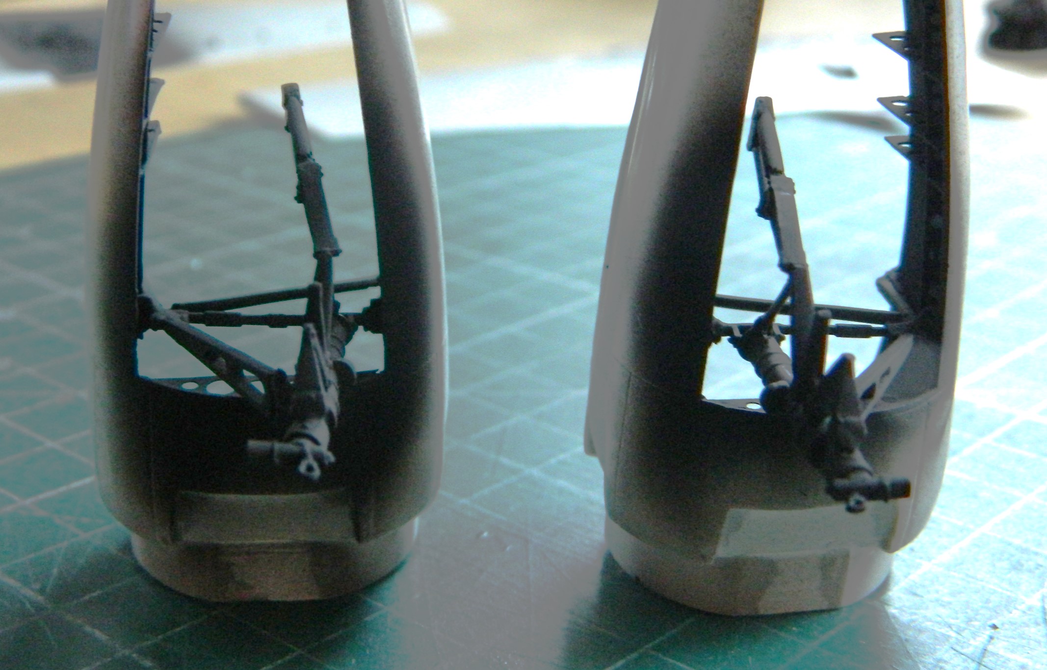
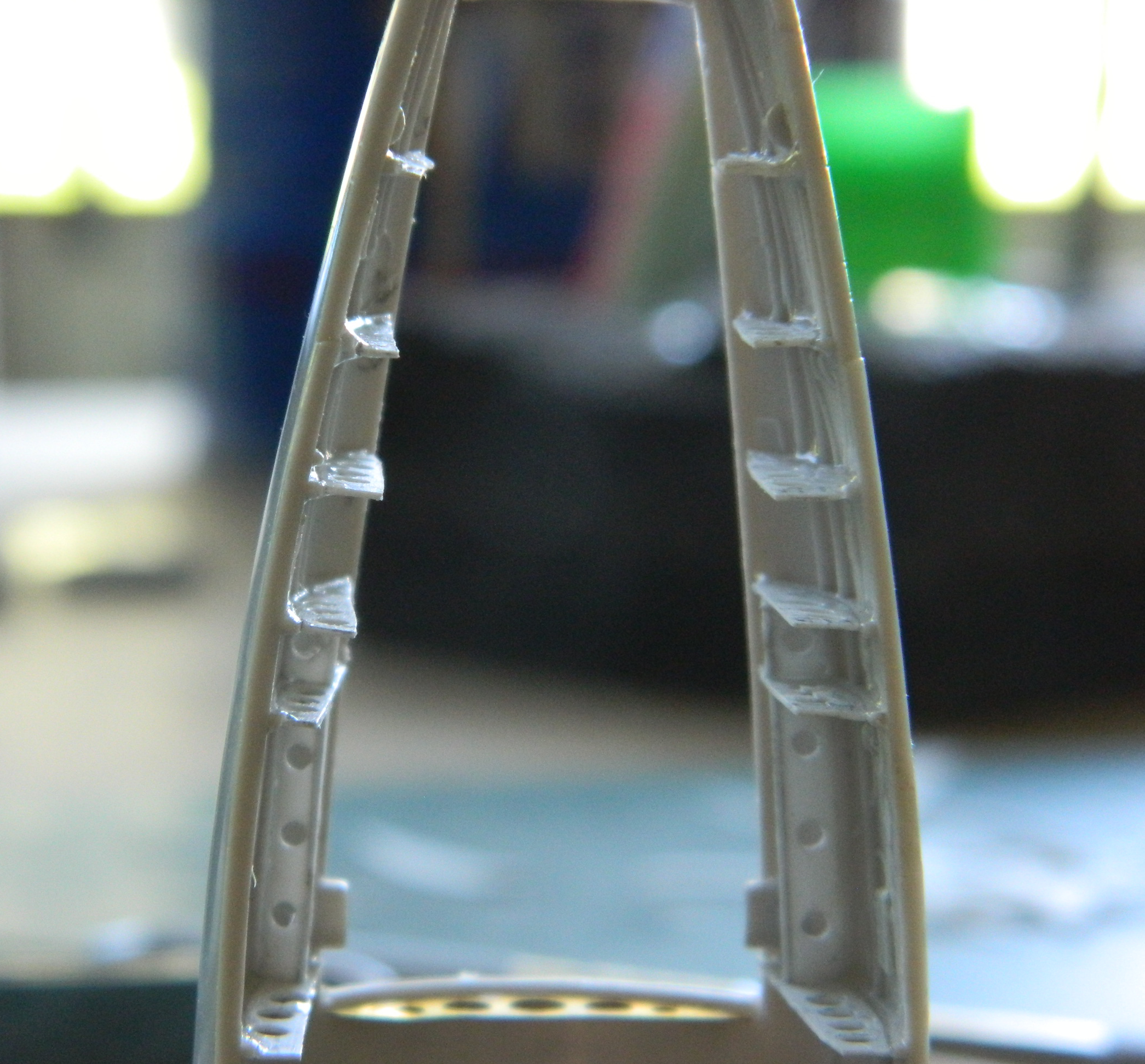
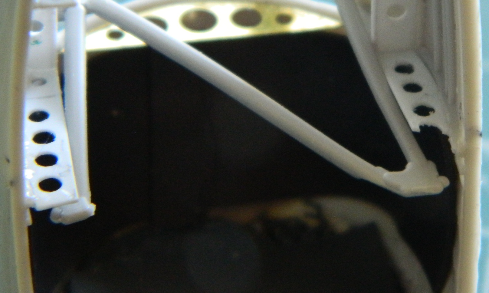
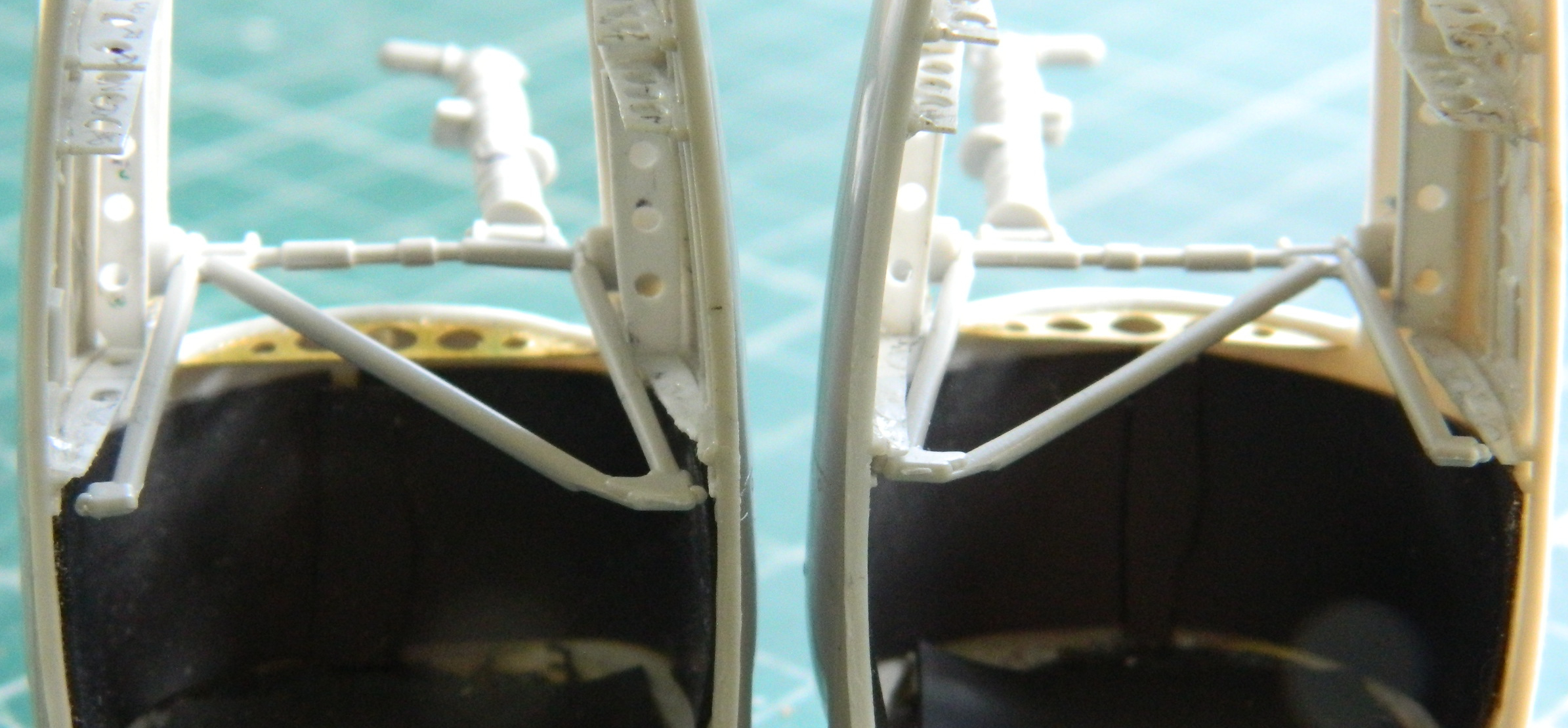
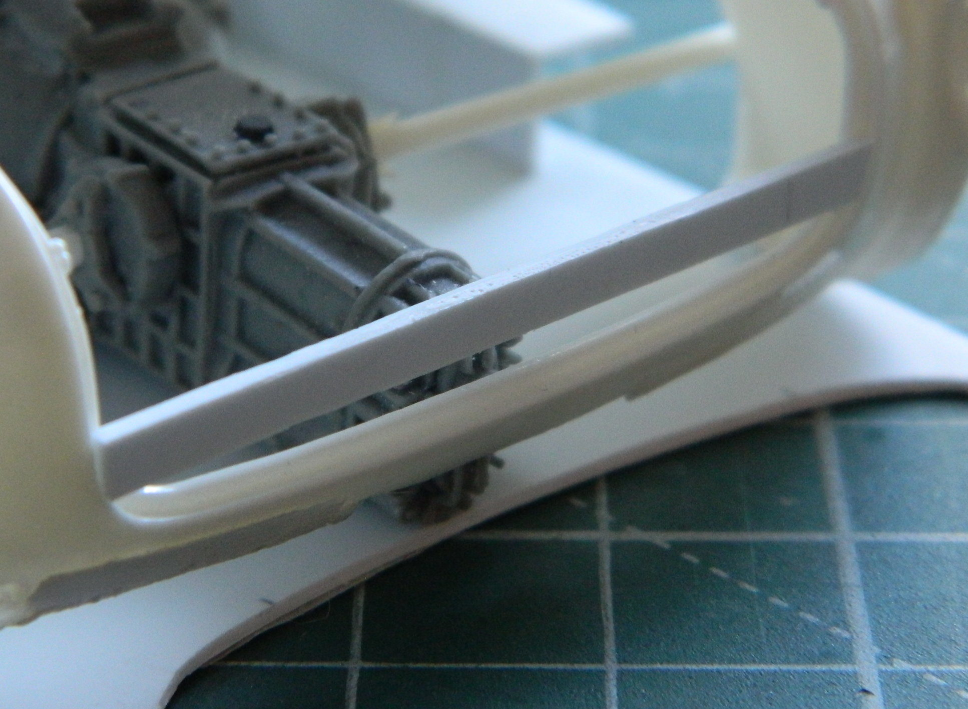
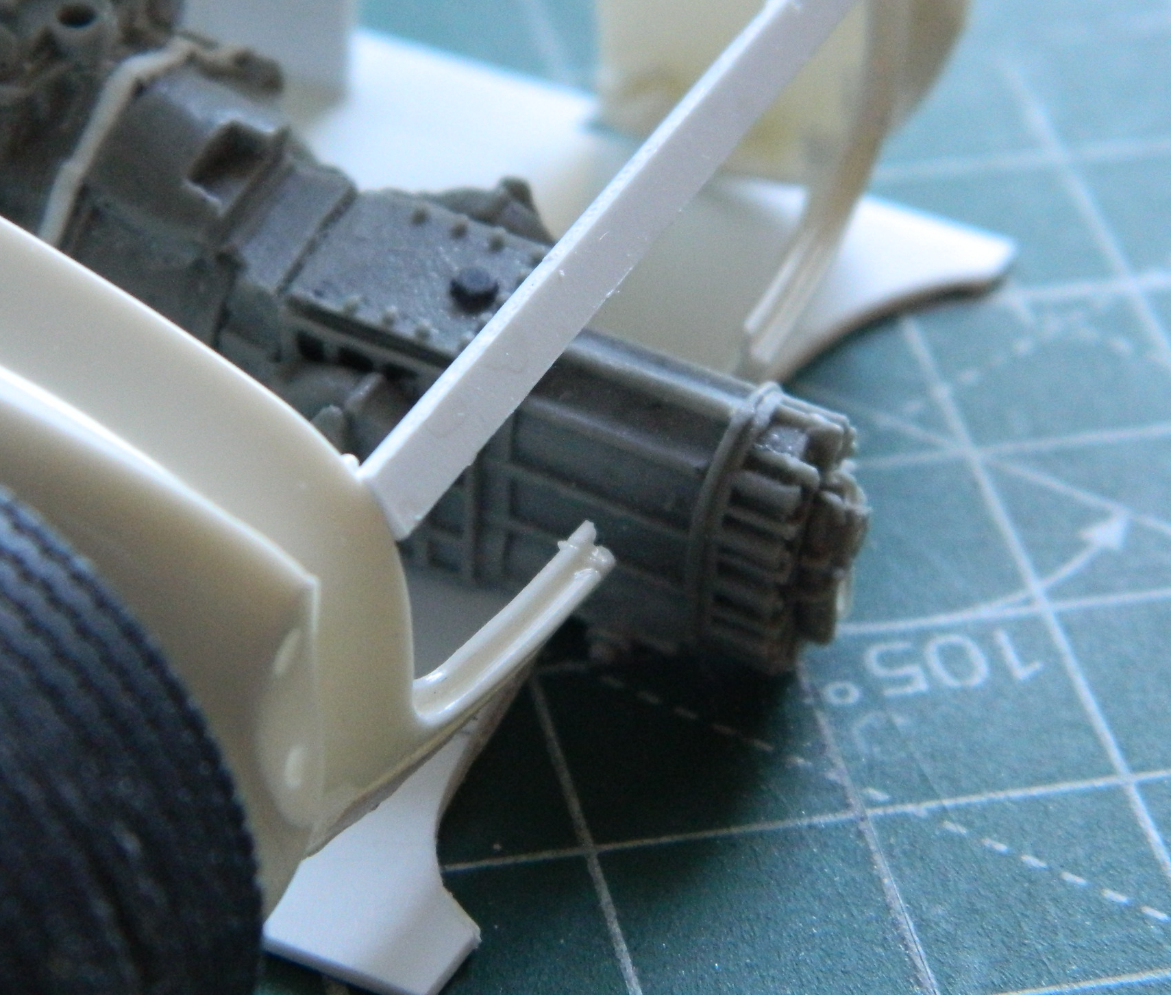
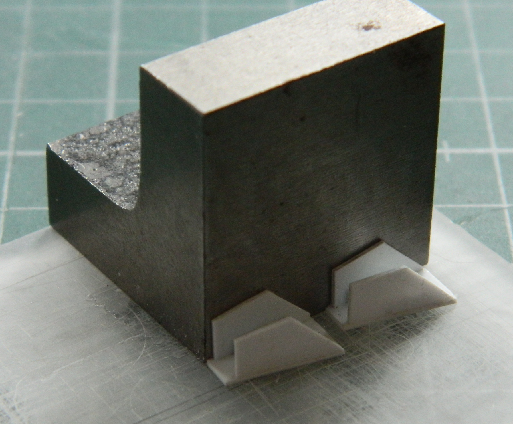
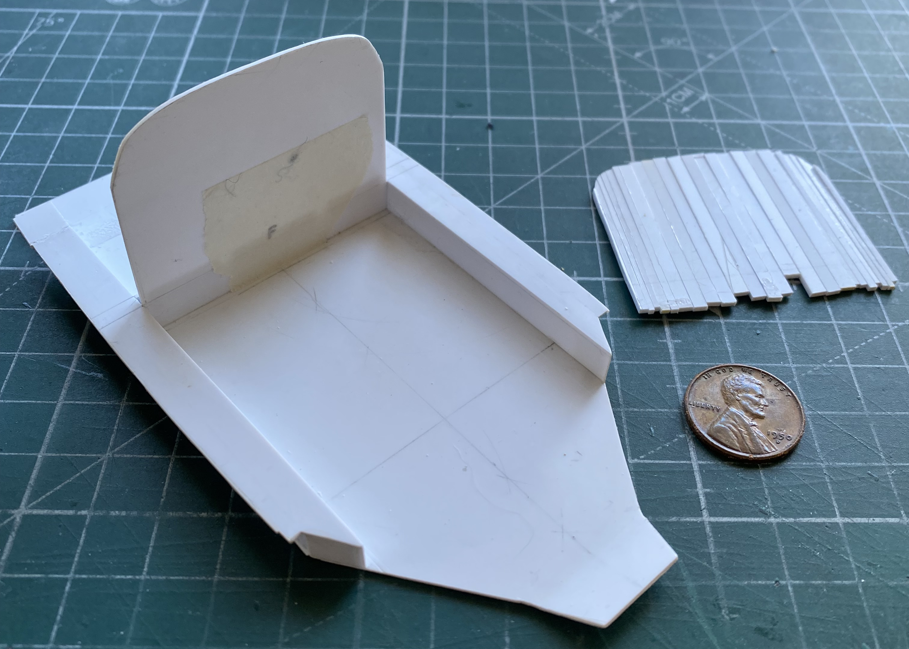
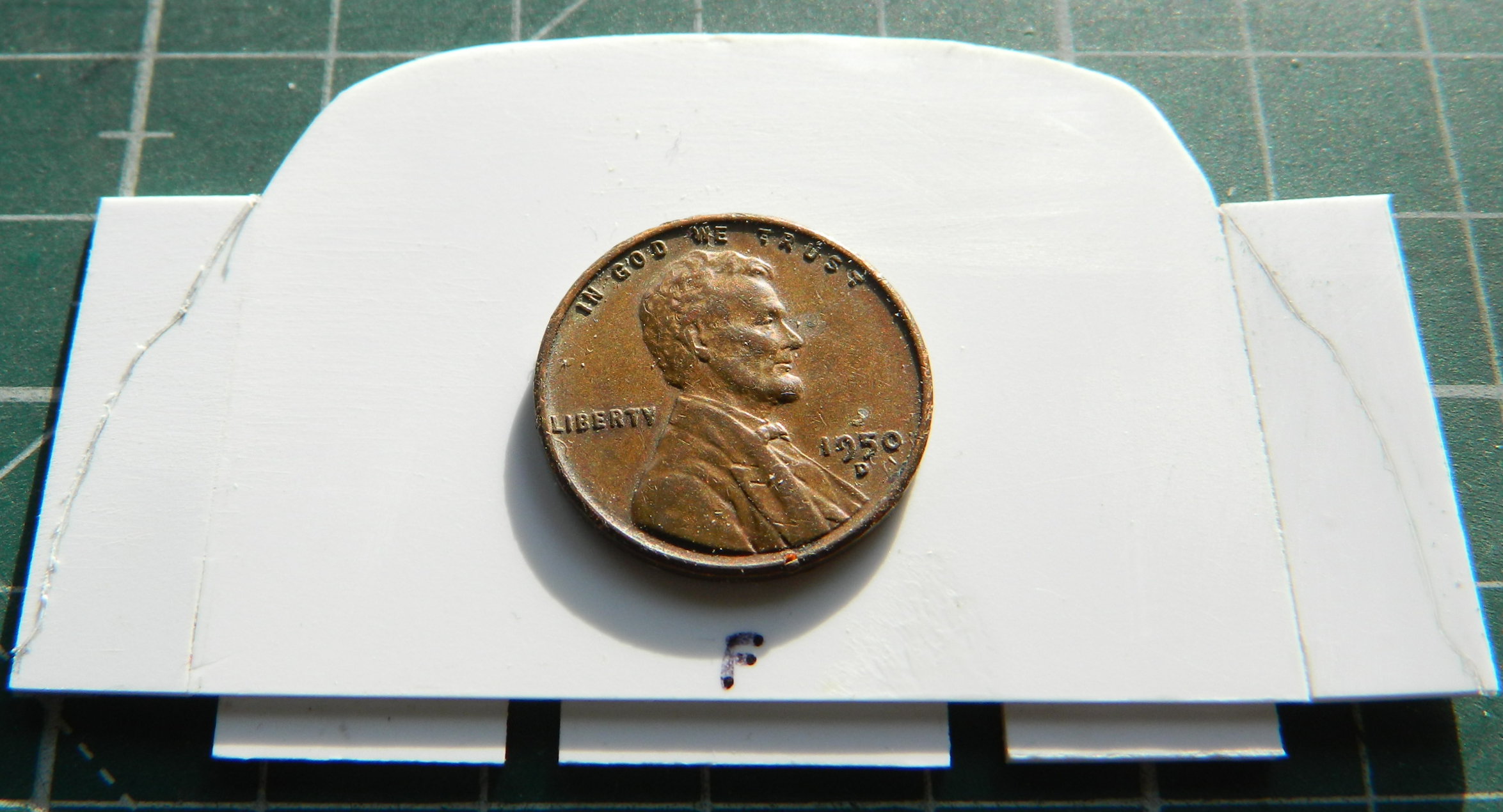
With the ribs and stringers done as much as I’m going to do them, it’s time to fit the landing gear leg assemblies into place…and that took a bit of doing to accomplish. I used the kit’s plastic struts as my gauge because the SAC metal legs are direct copies of the kit parts. I learned a couple of things during this process. The first being that to save myself major hassle, I’m going to break from my usual process of waiting to add the landing gear until late in the build (less chance of breaking them, obviously). When I tried feeding the struts into place through the opening at the bottom of the nacelle I quickly understood what a pain in the ass this would be if I added them after the nacelles were glued to the wings. This time I’ll be adding the struts before the nacelle is glued (and puttied, because dry-fitting showed me that it’s needed) because fitting them into their proper places is SO MUCH easier when going at that task from the much wider top of the nacelles. The second thing I learned is that the ribs in front of the openings are too wide. The brace arms of the strut are in sufficient enough contact with the front ribs to bend those struts (the struts that are being bent are the ones in contact with the ribs on either side of them):


This photo shows how far away the struts are from where they’re supposed to be mounted:
I like emery boards for jobs like this. Good abrasive, stiff, and can easily be shaped to fit the task at hand. Here I’d split the emery board lengthwise and then snipped the rounded ends off (using wire cutters), something I could also do as the abrasives wore away:

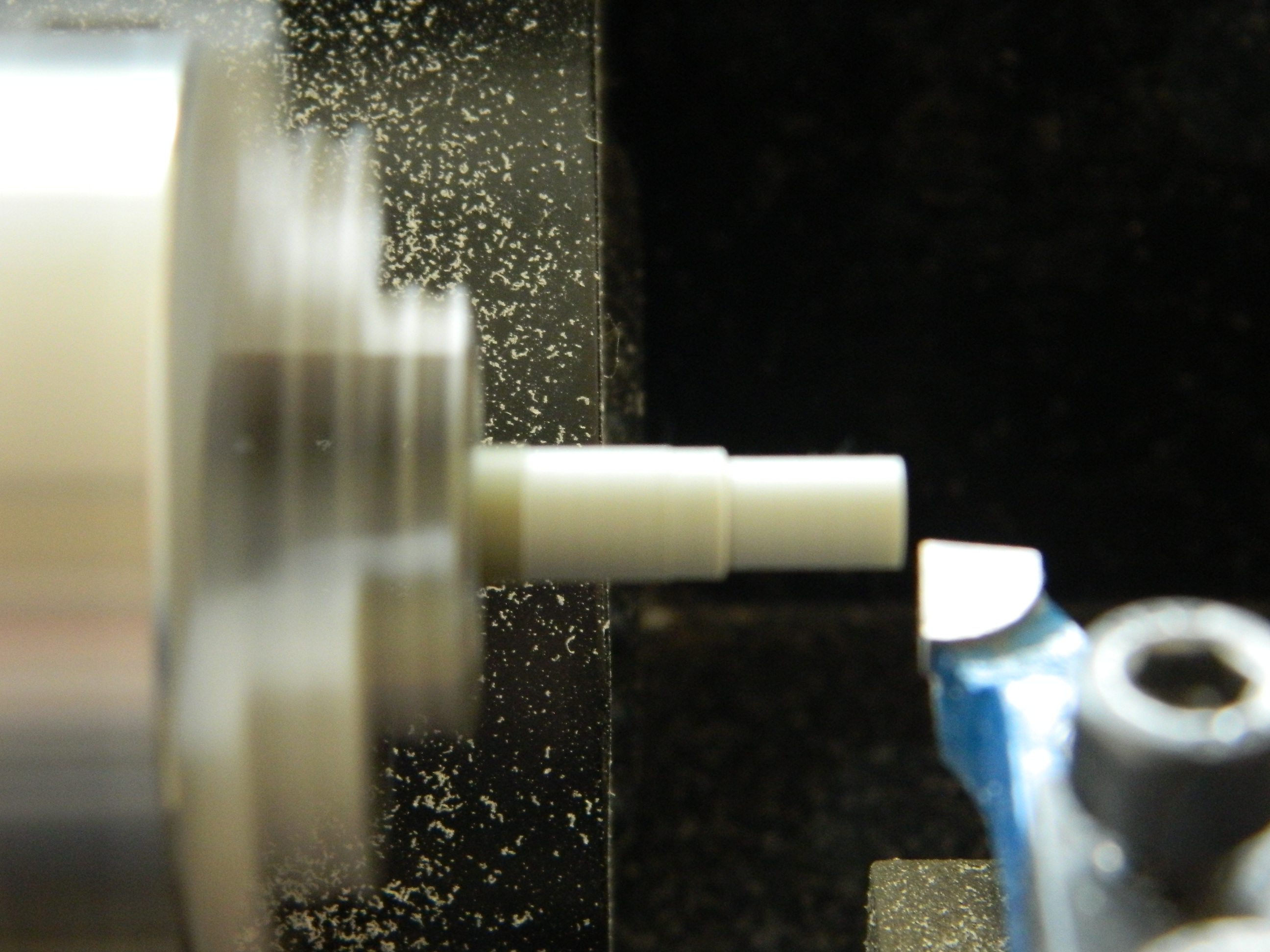
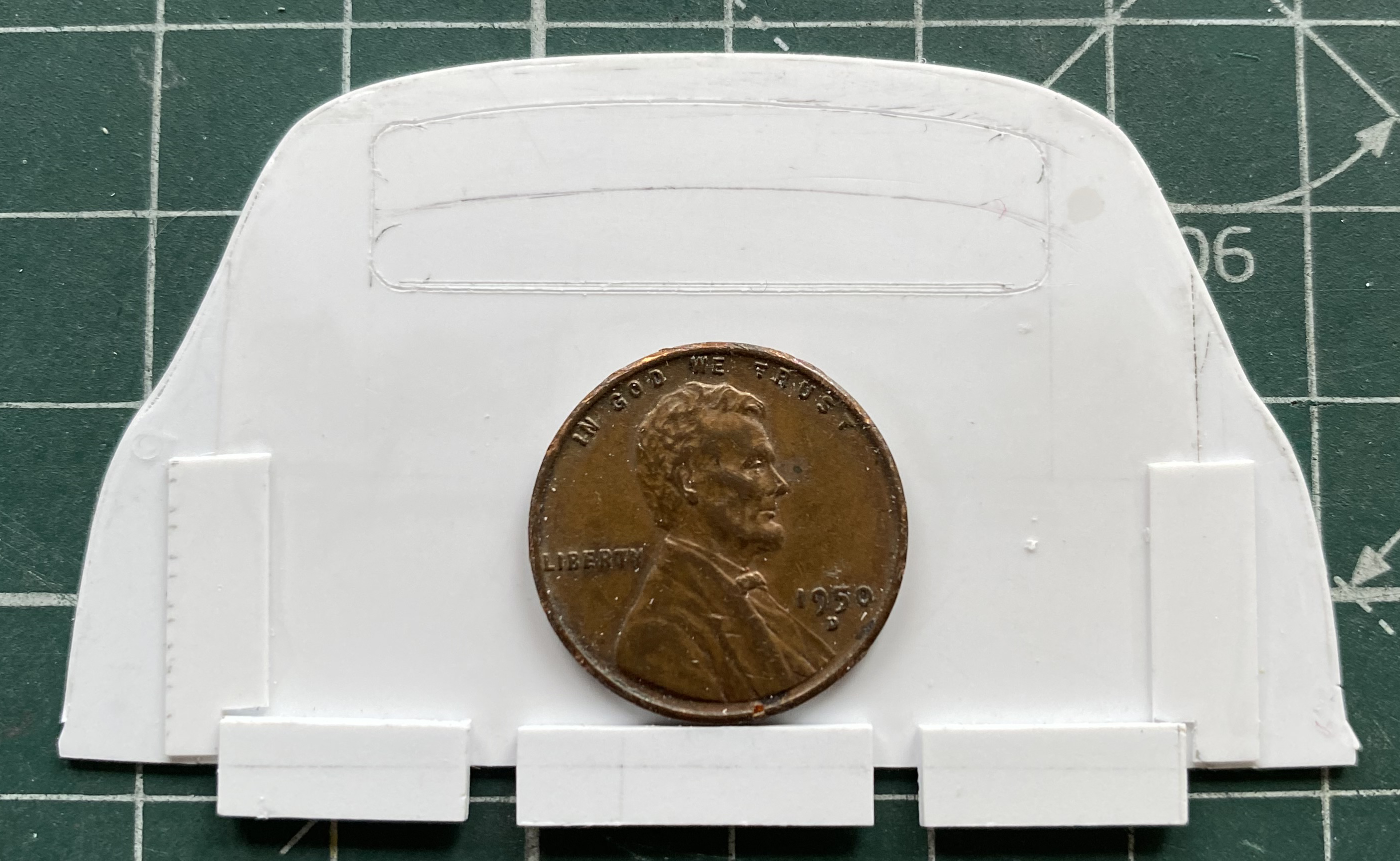
I marked the section of the ribs that needed to be trimmed back and dry-fitted frequently. It became evident that I had to remove enough of the ribs which would cause the lightening holes I drilled into the ribs to be sanded through the edge of. That means I either have to pop those ribs and stringers out and redo them (No. No way.) Or fix them in situ. I opted for that and I used a piece of 0.062″ (1.57mm) Evergreen styrene rod to fill the holes that had to be filled. The rod was a little bit larger in diameter than the holes I needed to plug, so I cut a short section, chucked that section into a variable-speed drill, then spun it slowly while tapering the end of the rod with a file:
Then I started filling the holes. Using styrene cement means that I have to let the glued part sit for a few hours (preferably overnight) so that the plastic, already very thin, would be as solid as styrene can be when I started working it. After a few days of glacially slow progress this way, I finally realized that I should be using the UV-setting resin for this, so I switched to that and the progress of filling holes went much faster:


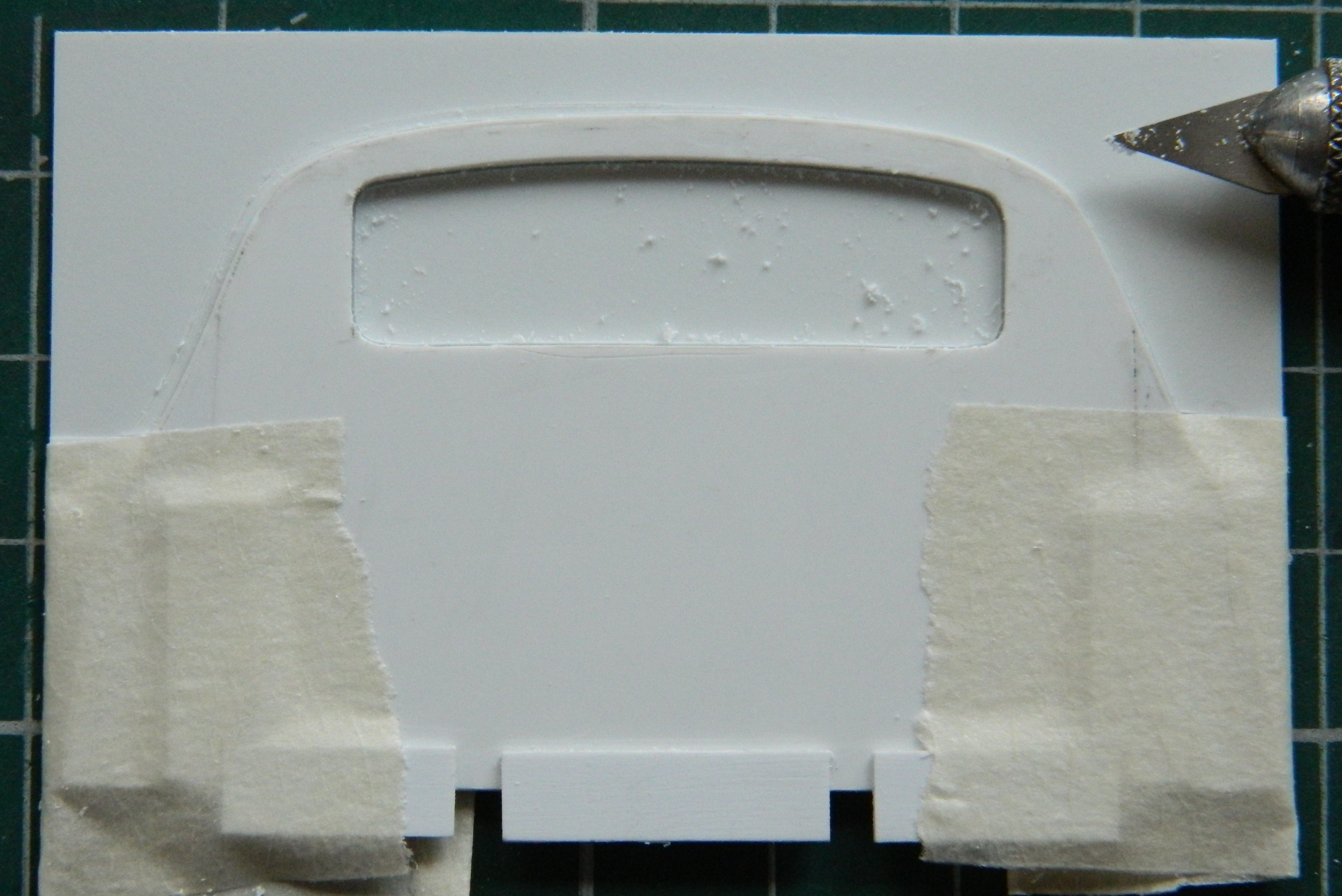
Once I finished down the plugs, I went back at the ribs with the modified emery board until clearance was achieved:
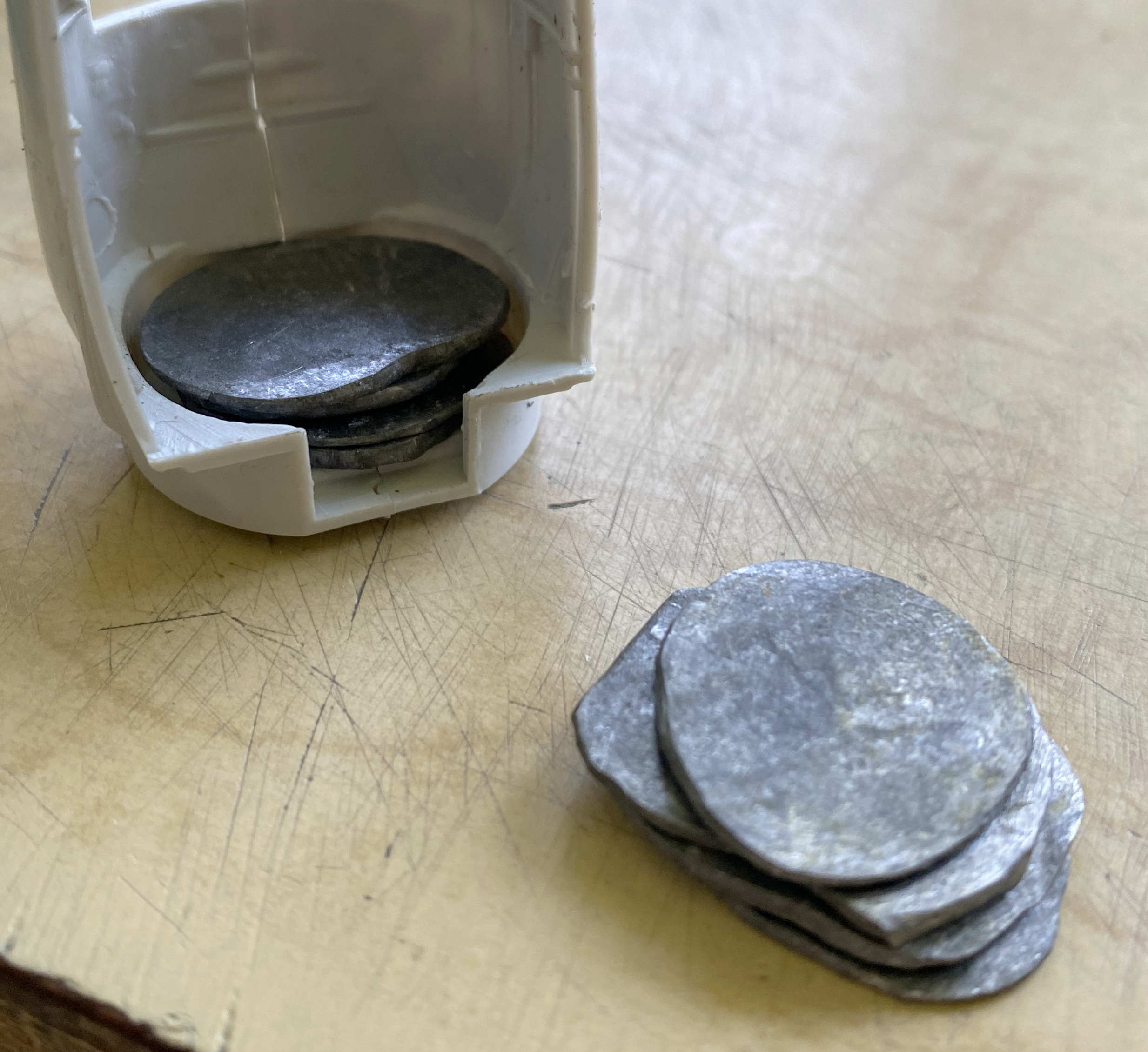
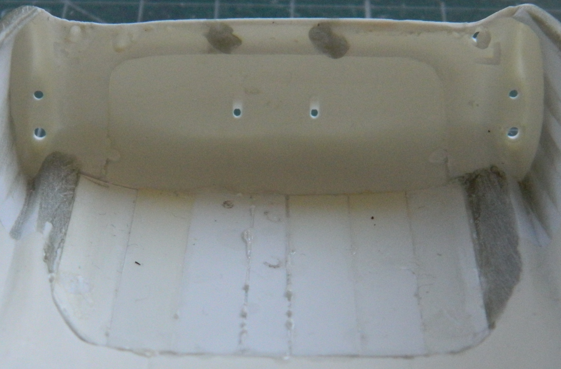
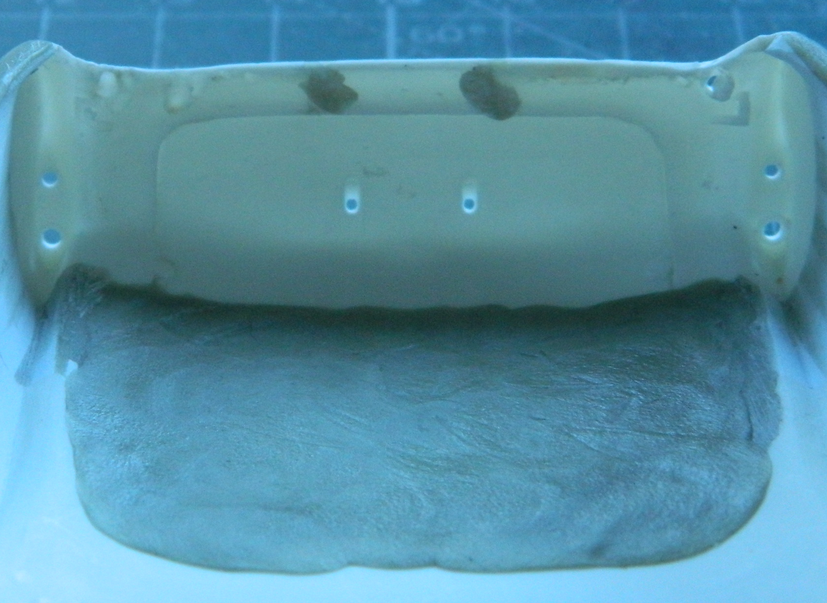
I have also been filling every available space in front of the pivot point (defined by where the main landing gear contacts the surface it’s sitting on) with weighty bits. Most of the added weight is lead. In addition to the flattened lead balls inside the nacelle, I stuffed what space was around them with lead wool on the right side and sliced .093″ (2.36mm) lead solder on the left side (you can see the lead in previous photos). Once glued, I lined the forward bottom with tungsten tape (this is used to adjust the weight/balance of a pickleball paddle, if you want any of it) and put another piece across the back of the lead balls. This shows how much added weight there is:

The next step is to paint the inside of both nacelles flat black. Since I’m going to be loading the airbrush, I also want to paint the engines while the airbrush is loaded with the flat black.
But that’s it for this month…
F7F-3 (AMT/Italeri) 1/48 Scale Build #2 –Continuing to Populate the Engine Nacelles
I debated whether or not to do an update this month because I haven’t spent much time at the workbench. (You can probably figure out what I decided.) Continuing my departure from normal aircraft models, I’m still working on the landing gears and nacelles instead of starting with the cockpit.
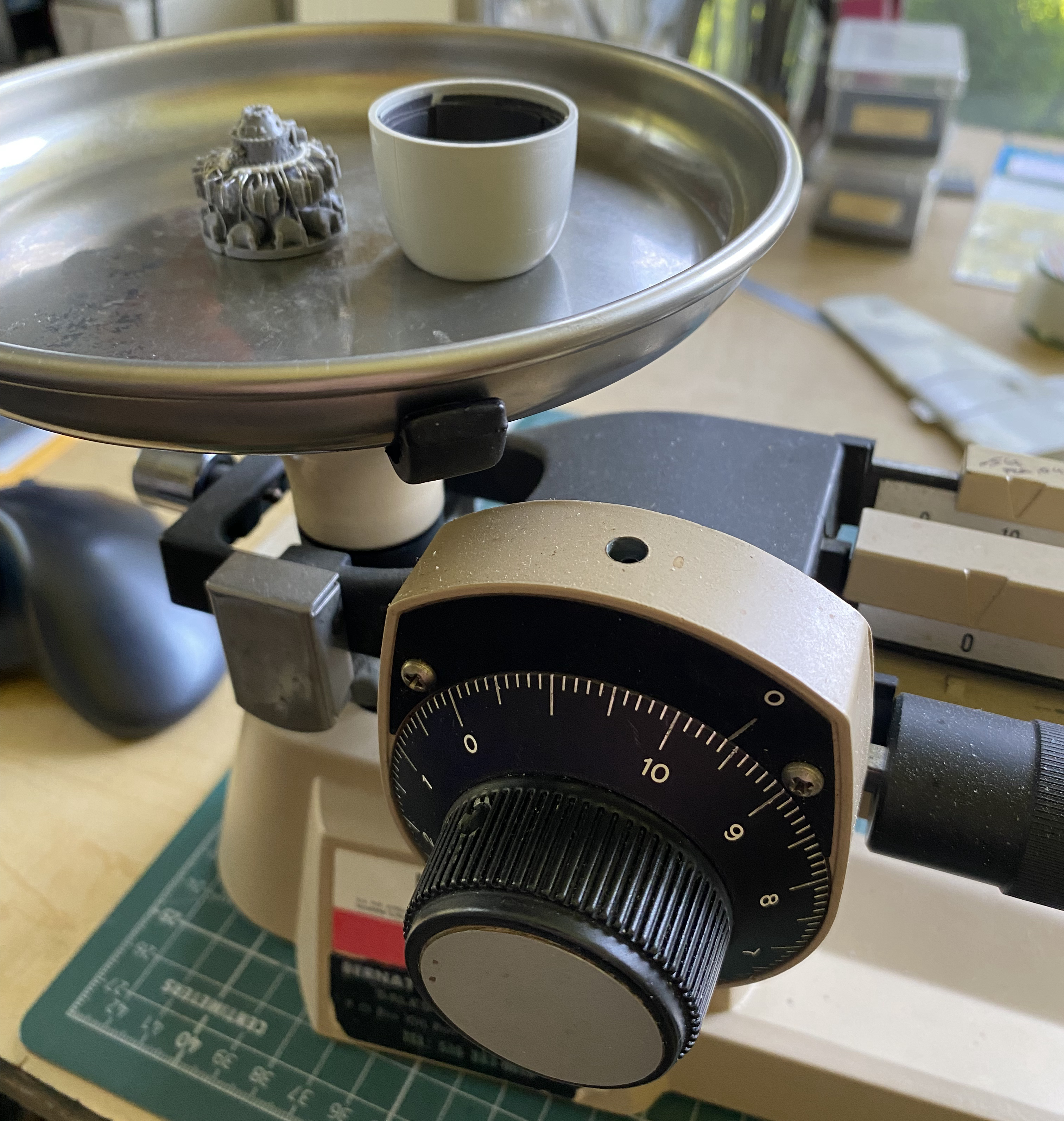
I was curious as to how much the nacelles and engines weighed after stuffing things with lead and tungsten (answer, each set was about 19.6g, and we’ll see if that helps…it certainly won’t make things lighter, which is the point):
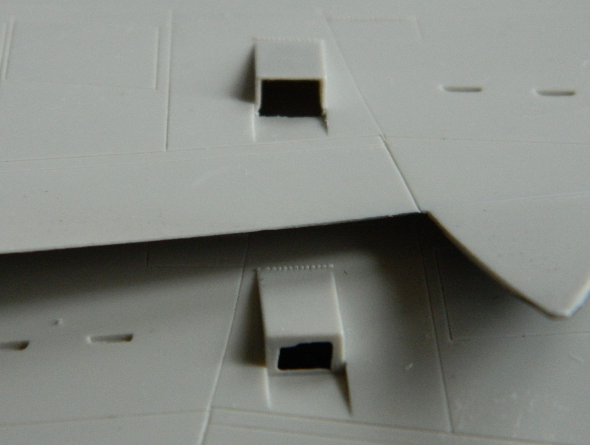
I successfully squared the front and rear of the landing gear openings that I’d started last month:

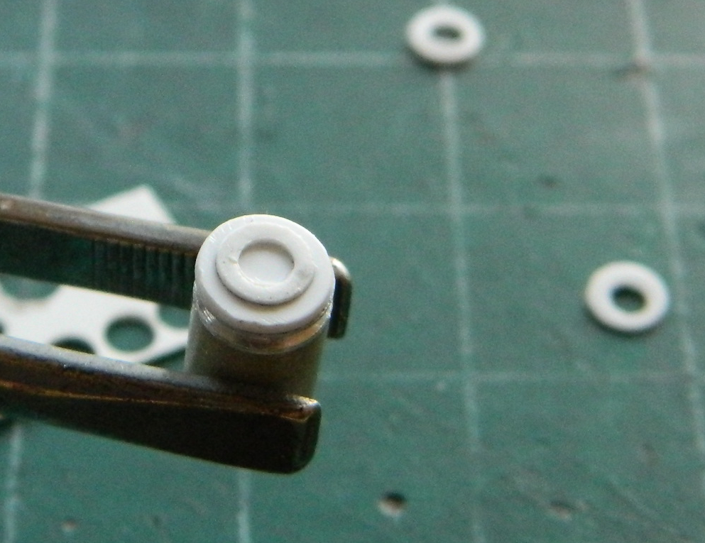
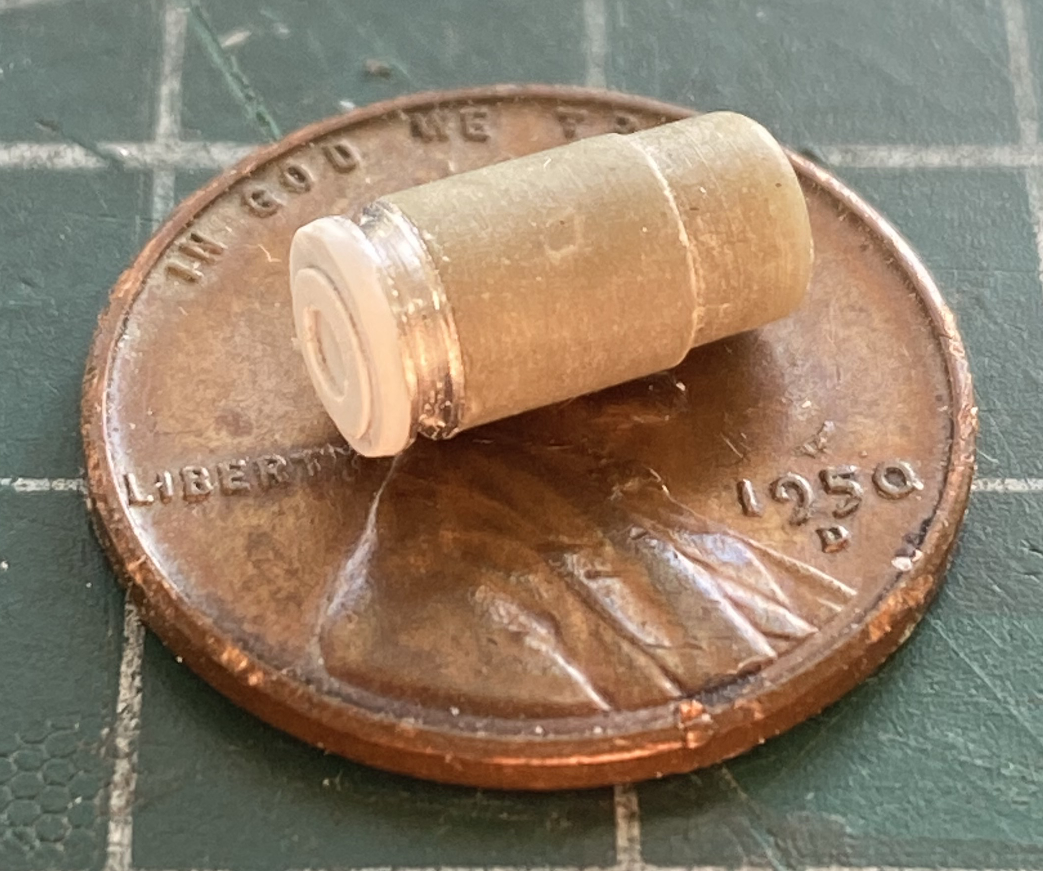
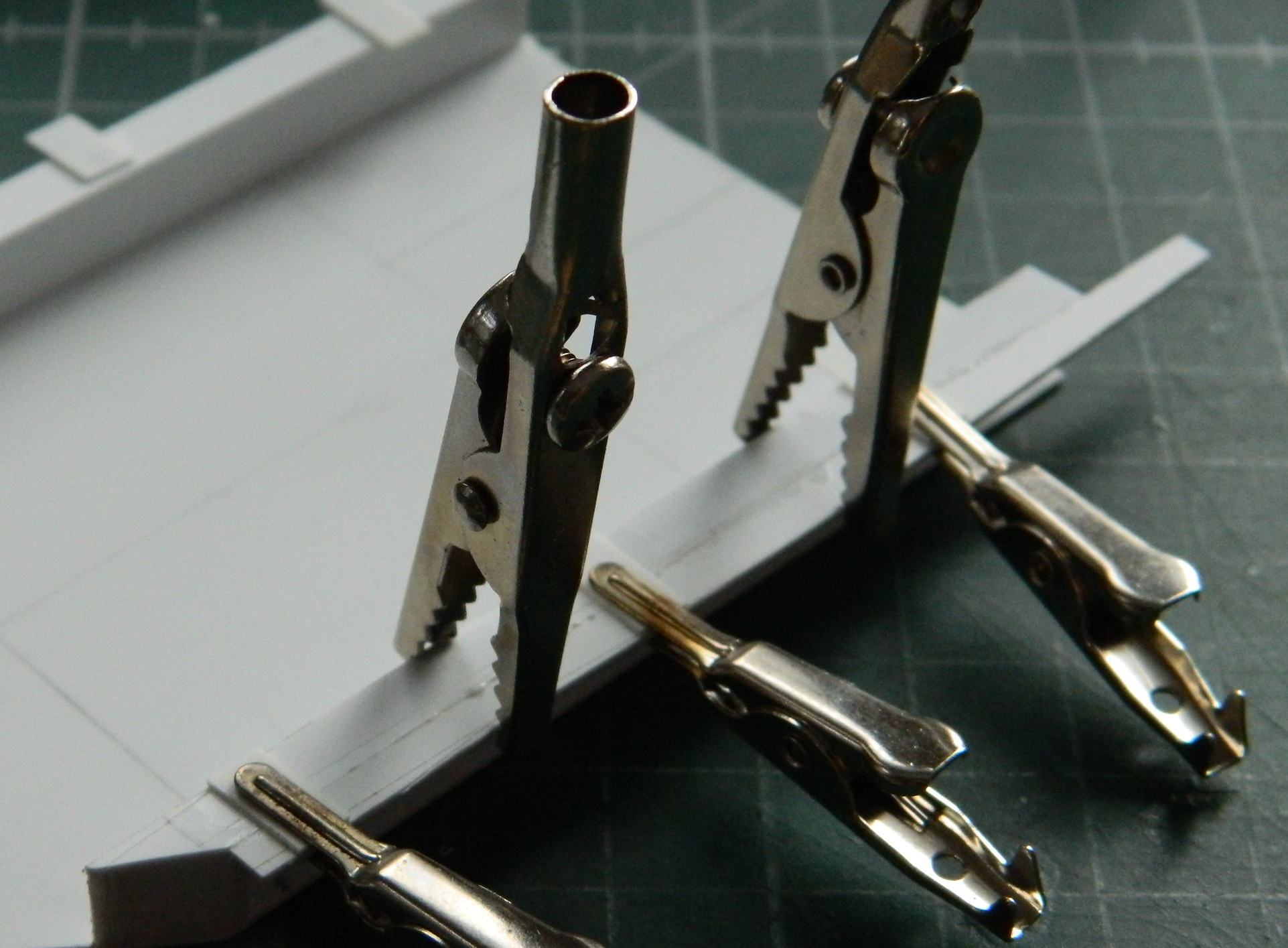
The SAC landing gear parts needed cleaning up. During that process, I discovered that some cleanup had been “done,” which I put in quotes because what was done was less than acceptable. A rod is supposed to have an outer surface of the oleos that is parallel all the way around and none of the SAC parts had been done that way. They were lumpy, so they had to go. I started by cutting the nose gear strut apart (and if you look closely at the stub of the oleo on the left, it’s evident how out-of-round the outside of it was):
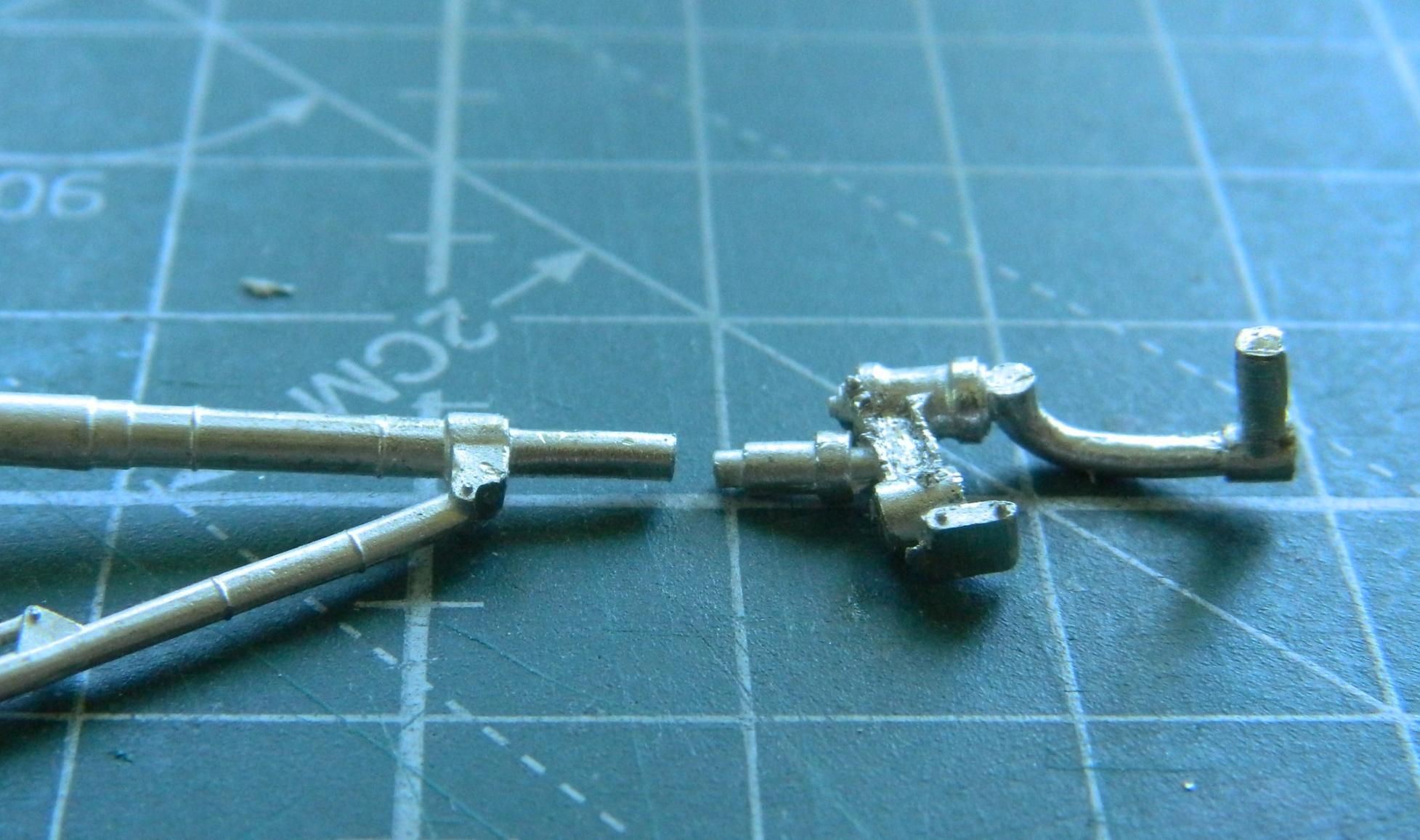
Then I drilled the socket that the paperclip stub would be glued into (apologies for the lack of focus but that’s the best the fornicating camera would do):

I cut the remaining stub off the nose gear leg, drilled another socket, and then cut and filed the welding rod. Once fitted, the jeweler’s tweezers held it in alignment and superglue should keep it there:
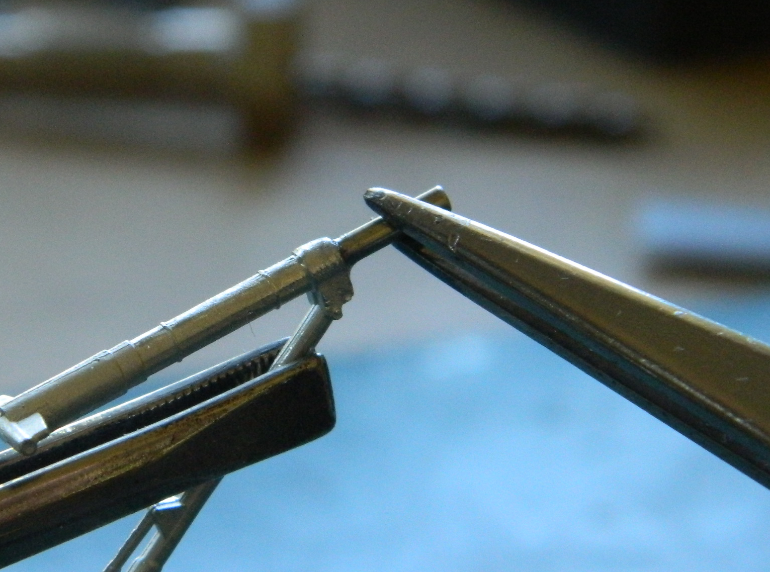
And once that had cured, the bottom of the landing gear was glued on:
That was easy, the main landing gears were not and fought me, requiring a couple of removals when I realized that the lower part wasn’t quite aligned (and somehow I managed to cut one too short so that had to be redone) with the paperclip stubs:


I’m not going into the massive annoyance(s) of keeping the soft, lead-like alloy, straight and properly aligned with the places they have to fit inside the nacelles. It happened and I got it all straight…I think.
That was the easy part of the past month. The rest of the tedious and annoying month (more because that my mind isn’t really very interested in tedium at present) was populating the inside of the nacelles with the internal support structure. The easy part of that was fitting the PE parts (there’s another set at the front of the opening which you will see in other photos because I forgot to take a dedicated photo of them):
Each of the curved ribs is supposed to be much deeper, but this is where the parts I have to make will be glued. There are 12 for each side for a total of 24 delightful ribs I have to make because I just love matching inside curves (NOT):
If I needed any physical manifestation of how my mind is off center, this job certainly did that. First I had to cut the stiffeners and match the curves, for which I used 0.010″ (.254mm) styrene scraps:

Then dry-fitting showed me that I’d cut some of them a bit too narrowly, so I had to reattach scrap bits to rectify that (those?) mistake(s?):
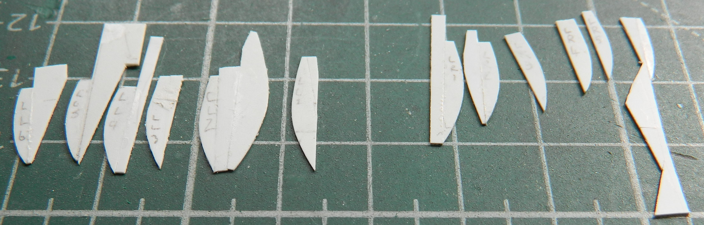
Lightening holes were punched into the stiffeners of the actual aircraft. To replicate that I started with the punch/die set but wasn’t very pleased with the result and switched to drilling the holes:
I attached one and then stopped:

I stopped because when working with something so thin, there isn’t a lot of gluing surface to hold things together well enough to withstand the (albeit gentle) handling while constructing. I decided to (finally) give UV setting “glue” a go. Glue is in quotes because this stuff, though sold as an adhesive, isn’t an adhesive at all. It’s a UV setting resin, much like the material that dentists are now using to fill cavities instead of the old amalgam. It acts like an adhesive because it will hold things to each other once cured. To see which I liked better, I did the first nacelle with the UV resin and the other nacelle with my traditional Tamiya Extra Thin. Each has their benefits and liabilities and I ended up using the procedure of tacking one end of the stiffener with styrene cement, gave it a few minutes to goo up, and then used that as a pivot to align the remainder of the stiffener which I then fixed in place with the UV resin:

Between the two methods of affixing something, I achieved what I wanted:

I dry-fit the nacelle to the wing and by doing so realized that I’d trimmed off too much of what I’d added back and had to redo that:


Having fixed that (I hope), it was time to start adding the rest of the structure. This bit replicated (I hope) the five horizontal stiffeners on each side of each nacelle. I got one done:

At this point knowing that I have 19 more to do made the (already borderline hot) circuit breaker in my mind pop. This is as much as I have to show for this month. We’ll see if I have more inner endurance next month for tedium.
F7F-3 (AMT/Italeri) 1/48 Scale Build #1 – The Parts and a LOT of Things to Add Weight
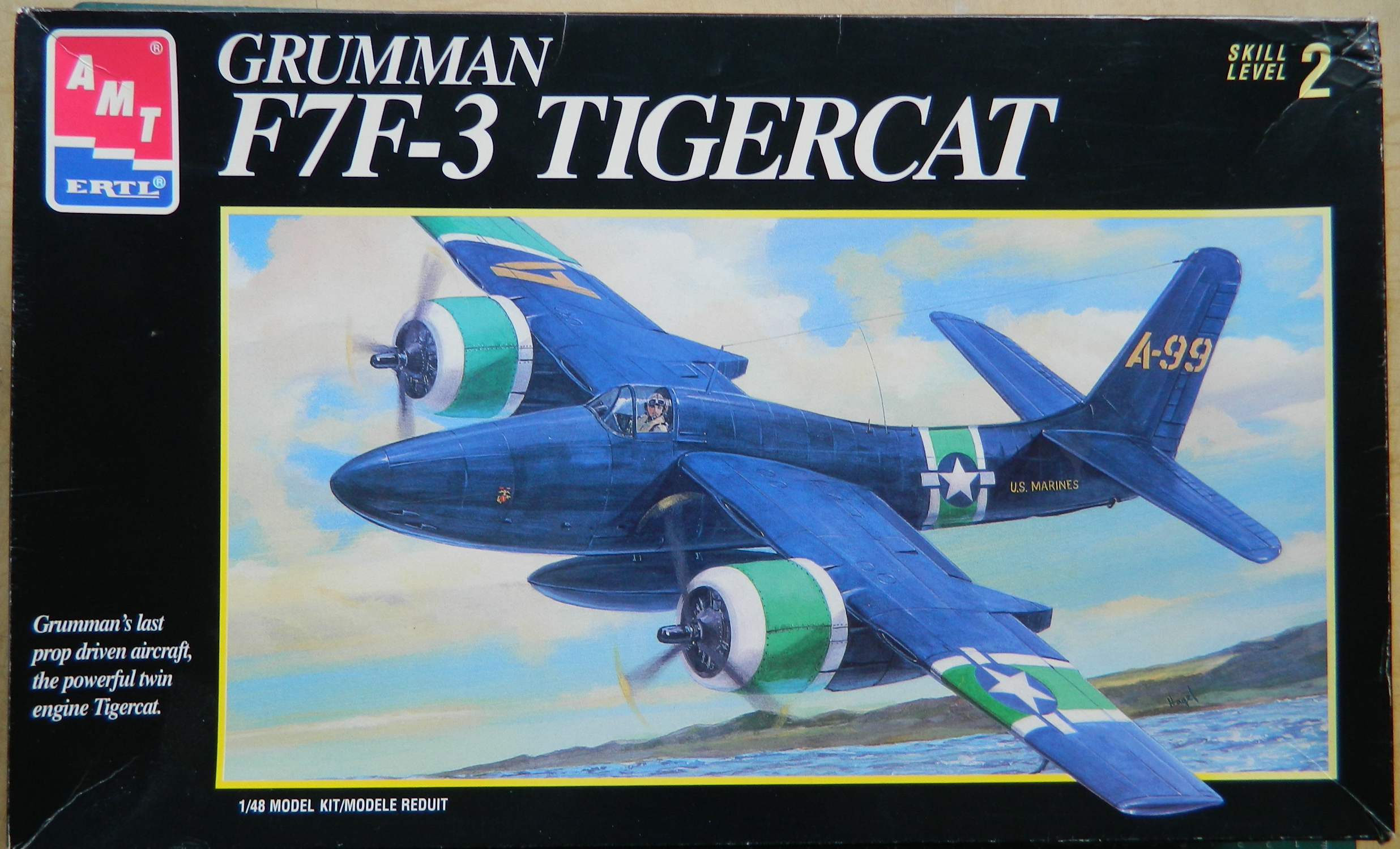
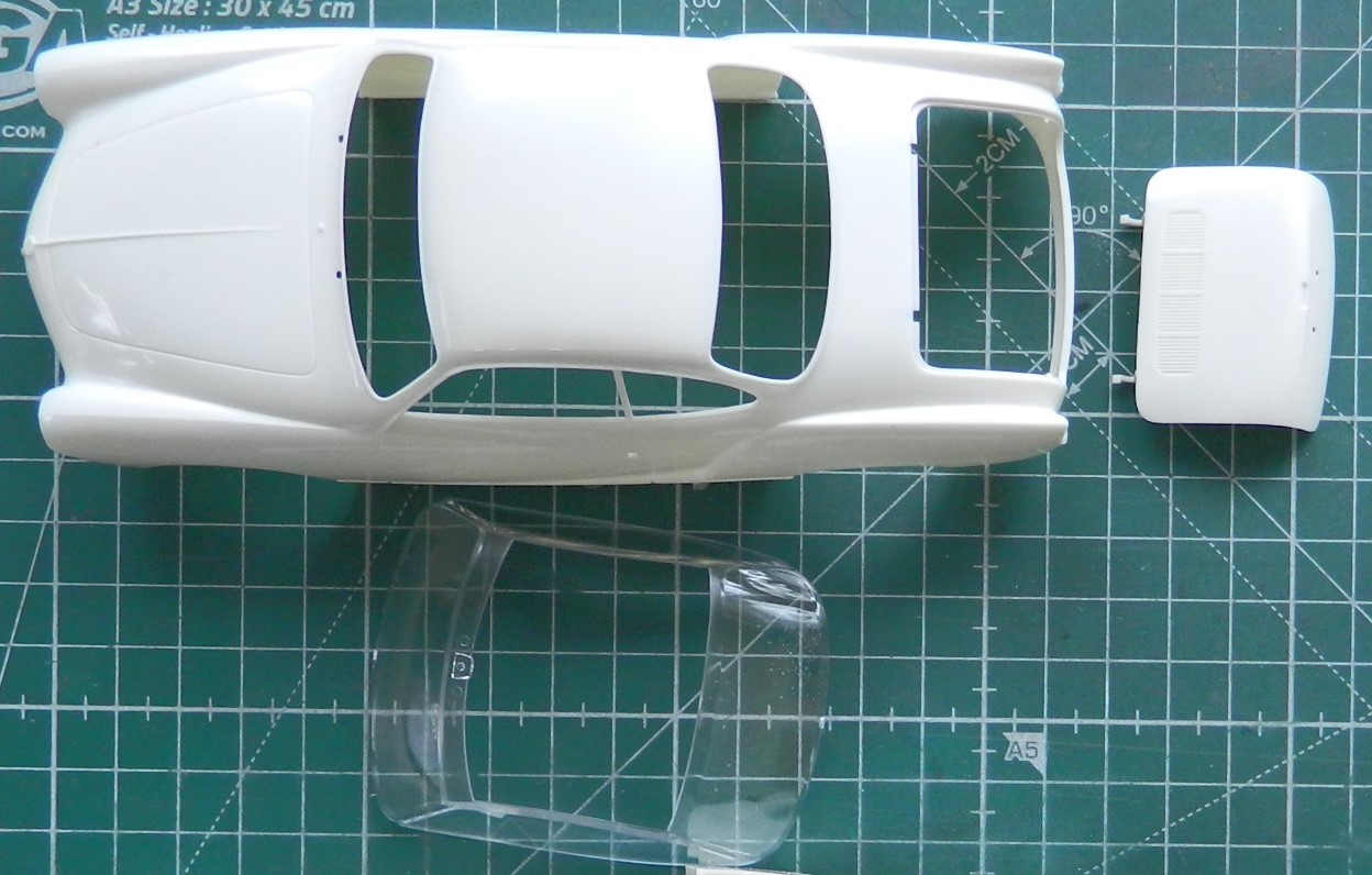
Next on the bench is this:

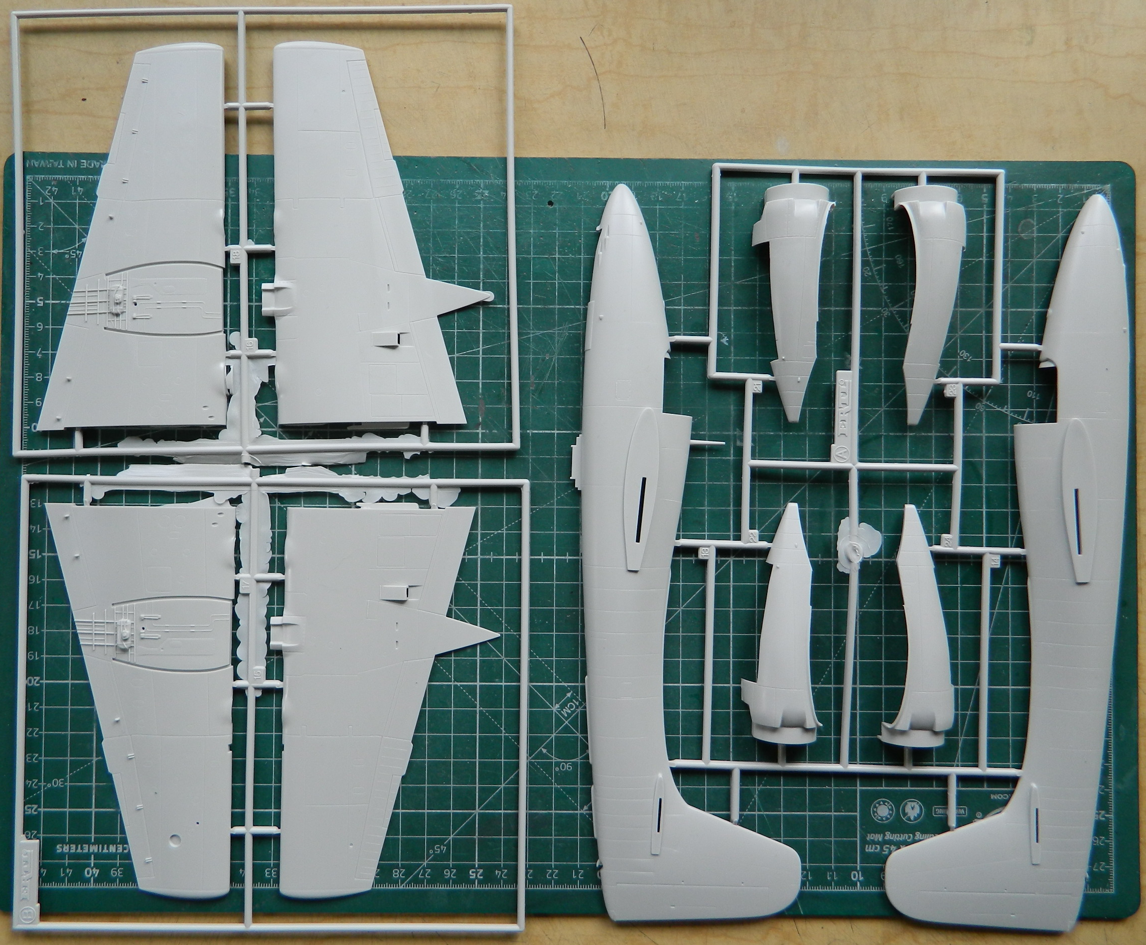
Not a lot of parts (for a change), though I’ve no doubt that I can increase the parts count (not at all a change). There isn’t a lot of AM bits available for this kit. I did get lucky, however. The kit comes with “rubber” tires (::retching noises in background::) and I’ll be able to replace them with CAT 4 resin. Eduard also makes a PE set for this kit which I’ve acquired. Quickboost also makes a pair of P&W R2800 engines specifically for this kit and also acquired (the vial of little shiny beads is to supply control knobs that PE “represents” as flat parts):

I’ve read several build reviews of the F7F (in a couple of other variants) and each builder says essentially the same thing: “I wish I’d put more weight in it!” My initial eyeballing of the kit shows why…there aren’t that many place to put weight. I went into my bits inventory and pulled out all the lead anything I have:

See that tungsten tape? It’s over $20! I was going to get lead tape instead because it was about a quarter of the cost and then I thought. Once I recovered from the novelty of that, I decided to go with the tungsten tape because tungsten is heavier, and that decision was encouraged by the thought that I spend substantially more than $20 for a tank of gas that I intend to burn. Since I’m going to be adding a lot of weight, I decided to try metal landing gear as a replacement for the plastic equivalent:
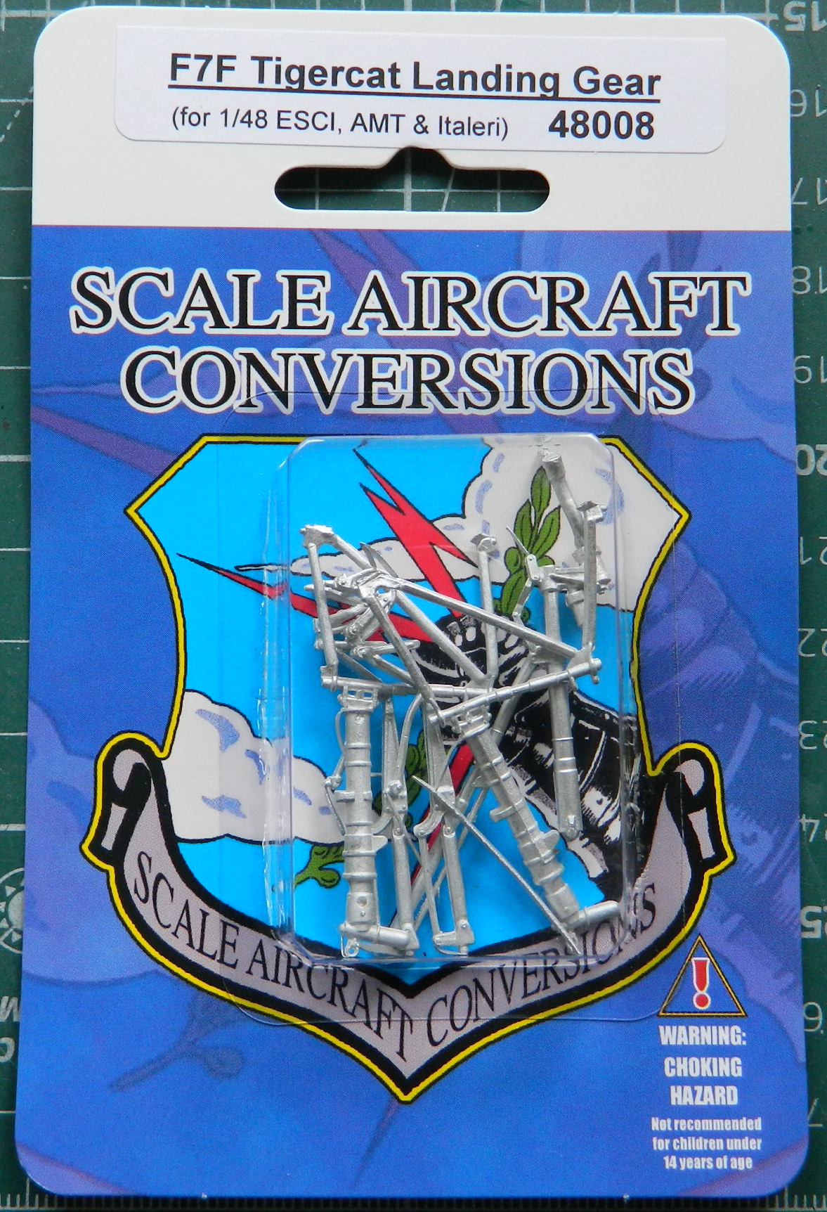
SAC produces these parts by taking a copy of the kits’ parts and then casting them in metal. The problem with that is that they don’t clean up the originals to my level of clean up. But since I’m going to have to clean something, I prefer to clean up landing gear that will support the added weight I intend to add. I don’t want this thing to look like a giraffe getting a drink in a few years. How likely would that be to happen if I used the styrene landing gear? Don’t know and don’t want to find out.
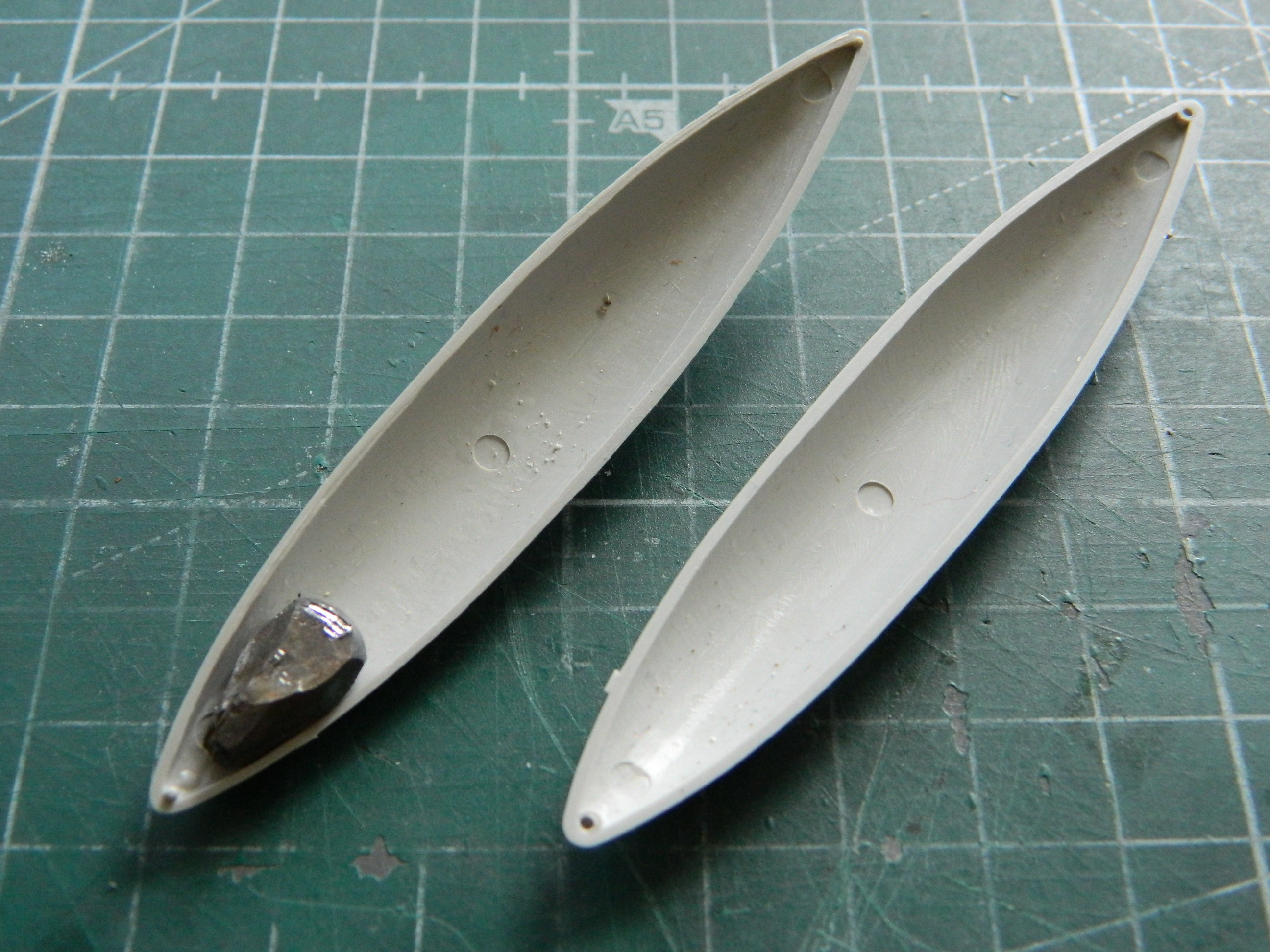
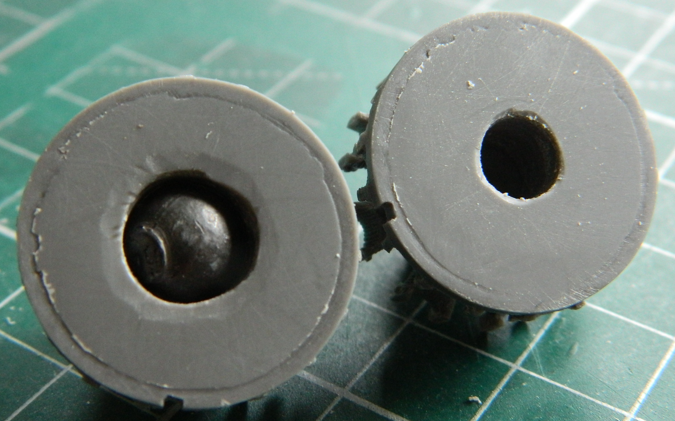
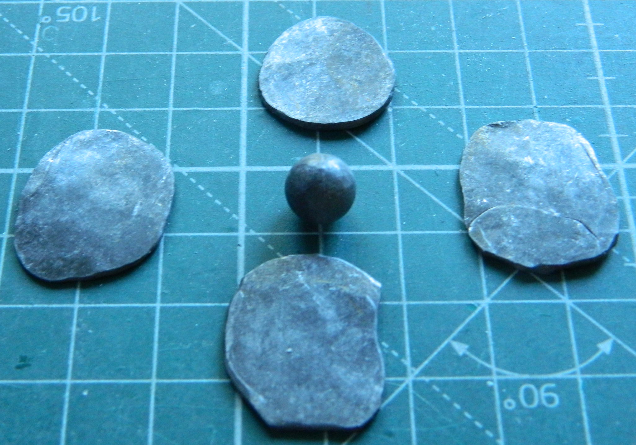
Typically when I’m doing something with wings, I start with the task(s) that enable me to close up the fuselage, so that usually means I start with the cockpit. Not this time. Not having this be a tail-sitter is weighing on (what’s left of) my mind (yes…puns are still intentional). Since I’m planning to stuff Weighty Bits anyplace I can fit them, I decided to start with the engines and I even have a reason. ANY place in front of where the main landing gear touches the surface will be stuffed with whatever Weighty Bit will fit. I intended on drilling out the backs of them to accept lead balls. The .44 caliber are too large but the .36 calibers are (almost) just right… that all starts by assembling the engines:

I found out that the .36 caliber balls are just a wee bit too large when the drill bit started biting away the engine cases. I certainly stopped that as soon as I saw what I was doing! I’d hoped to fit two balls (don’t go there) (which of course you have) into each engine but there isn’t quite enough room for both:
I can’t get the ball out so I spoodged it thoroughly with superglue and the other one I stuffed with lead wool. The glued ball holds the engine together well enough to obviate my Olympic-grade whining.
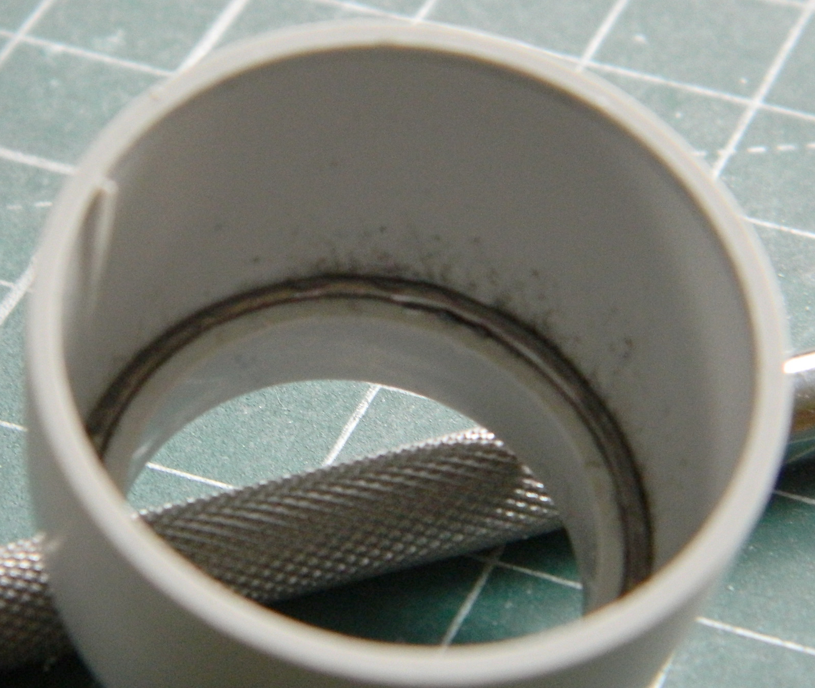
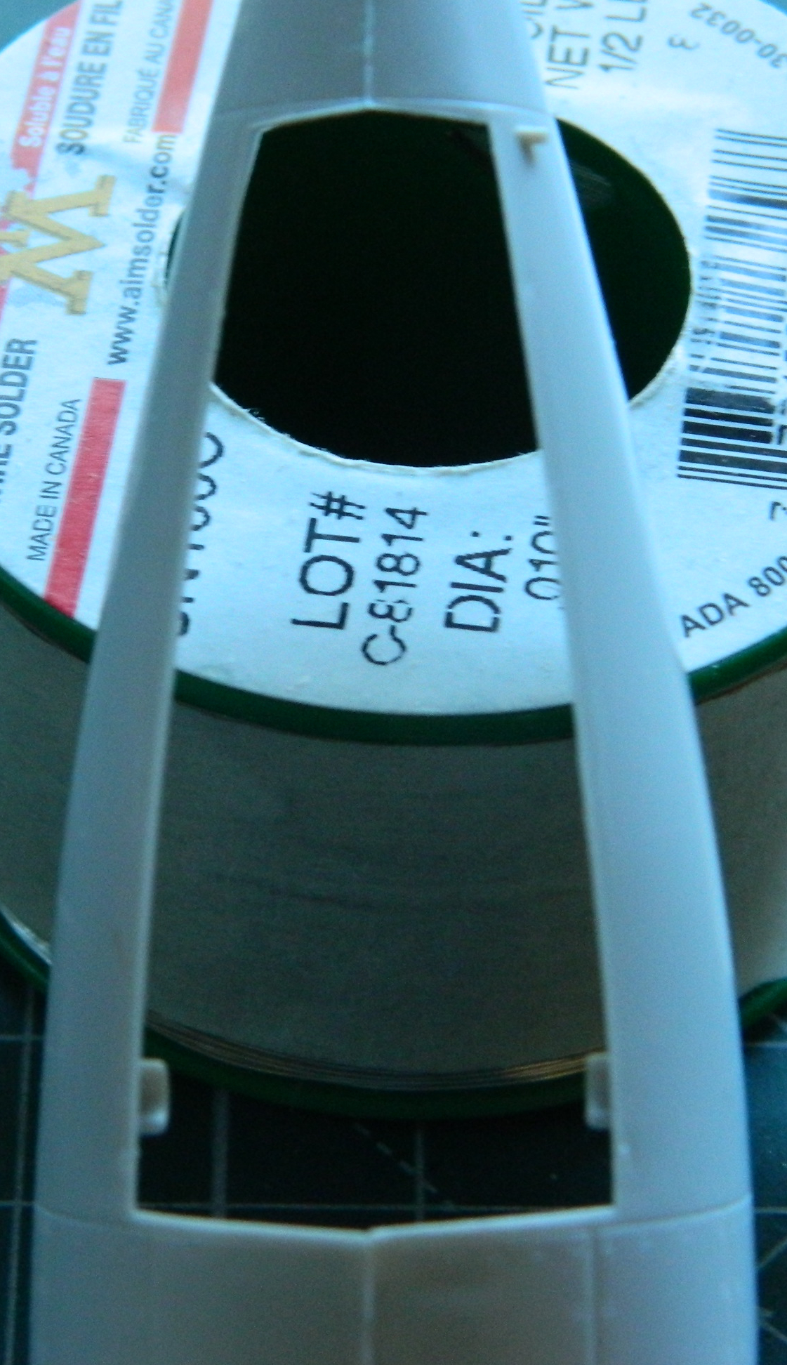
While I was in a lead-stuffing state of mind, I noticed that the cowlings have a little space at the inner front that I can stuff with solder:
While letting the BitB work on this aircraft’s weight balance problem, I decided that since each of the 18 cylinders of each of the two engines need pushrod covers, I figured out the length I needed and started snipping wires for them:
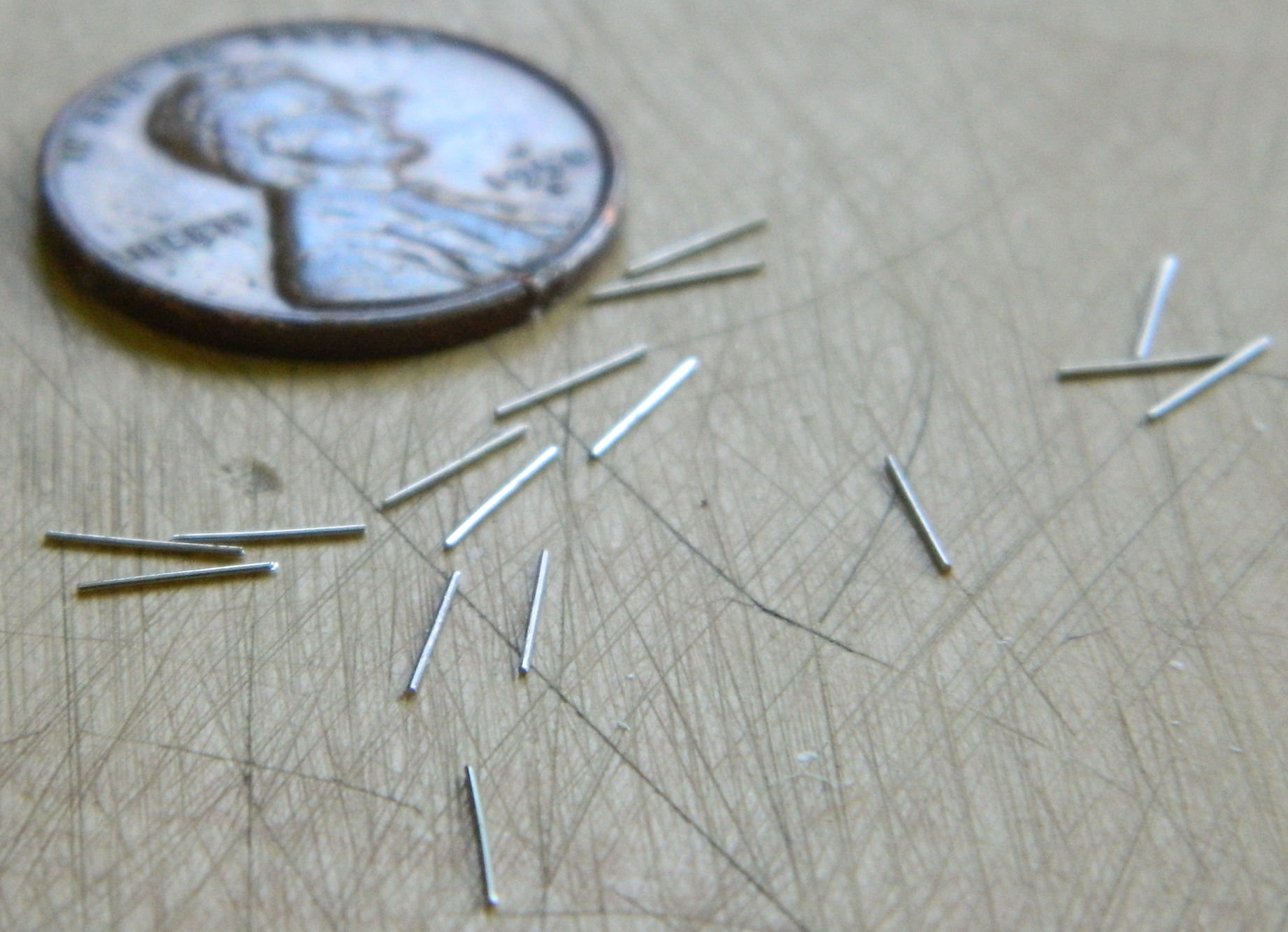
And once I had the 36 wires cut, might as well glue them into place before I lose most of them:

Once I’d added all the pushrods to the first engine, I added the last bits to the front engine cover because I wanted to see just how much room I have inside the cowlings with the engine where it will be, approximately:
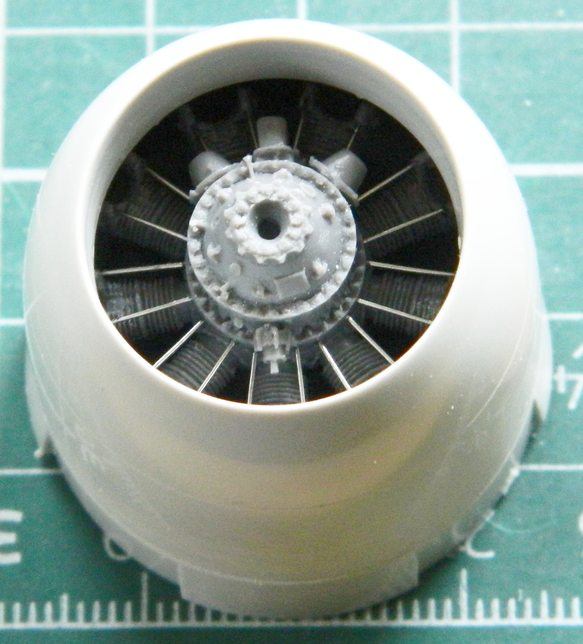
Enough room for the tungsten tape!
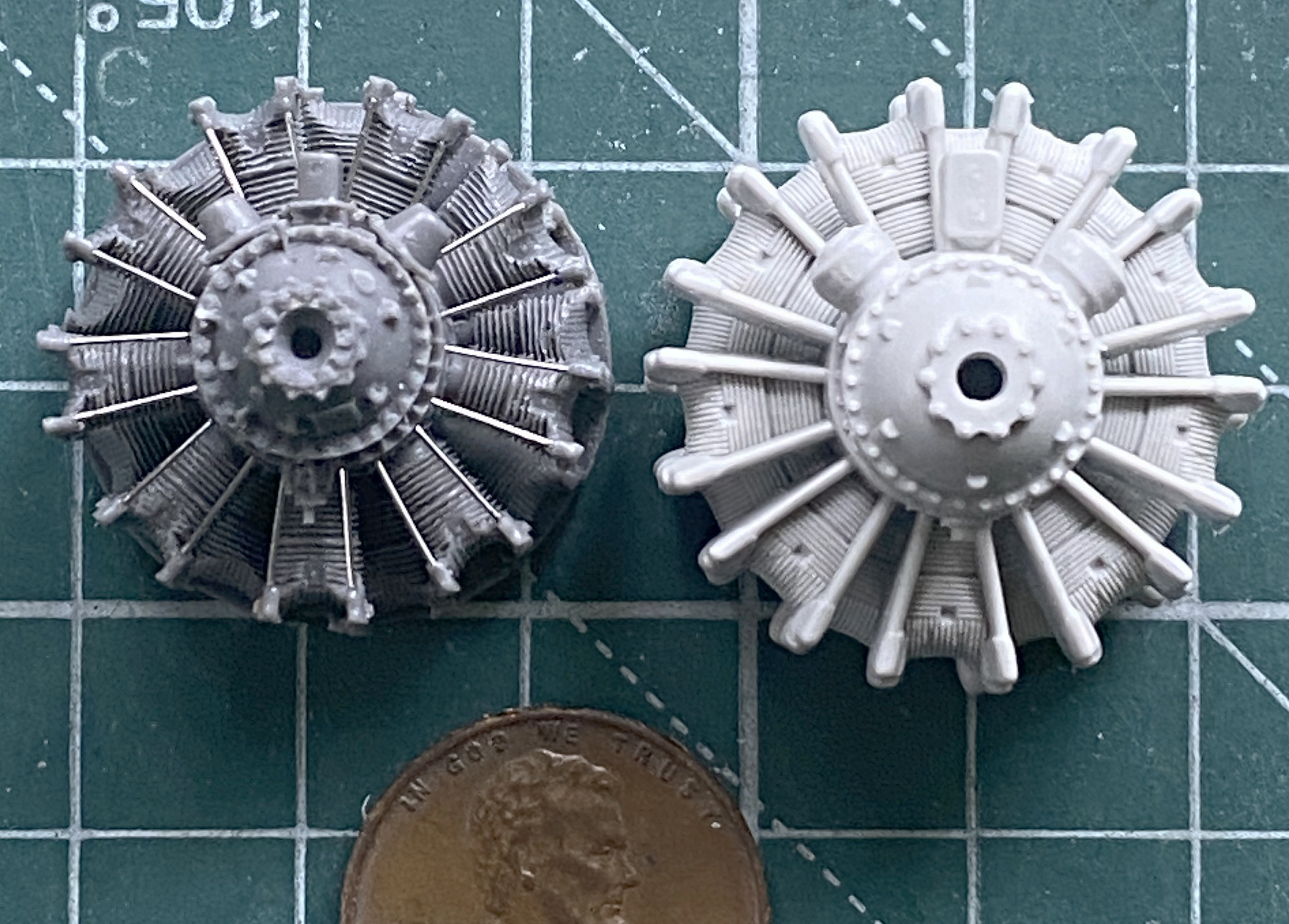
And once I had one done, there was the other:
Looks much better than the supplied engines for a LOT less effort:

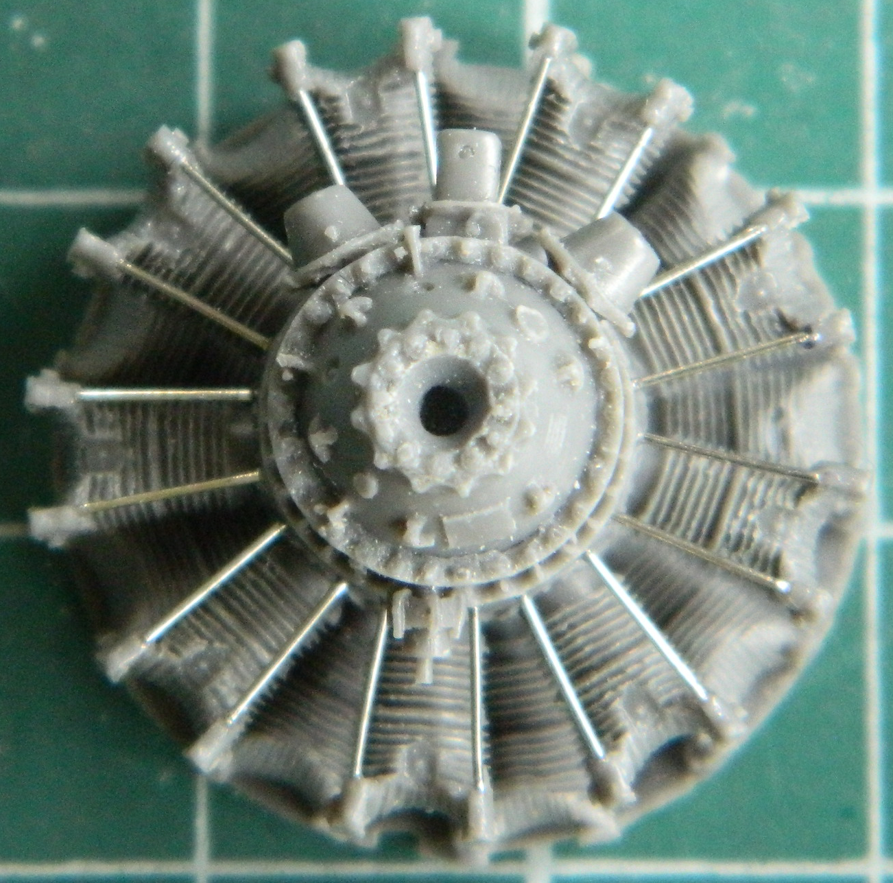
And just for a change, I thought I’d work on something really fiddly and annoying…getting the ignition wires conduits drilled out (to accept 0.010″ [.245mm] solder spark plug wires). Two of them, one for each engine:

You can see in the above photo where the bit broke through the side on a few (one is down near the bottom and there were a few others). Though annoying, it’s not a deal-ender. The breakouts will be filled with superglue and are really tiny. Once I’d done both conduits, they were glued to the engines and then I started adding the plug wires:


And in a curiously funny reveal, it wasn’t until I’d edited the photos a couple of hours ago that I noticed that I’d missed one wire…on each engine! Those were just taken care of. ::facepalm:: This is how I can see such TINY things with such OLD eyes:

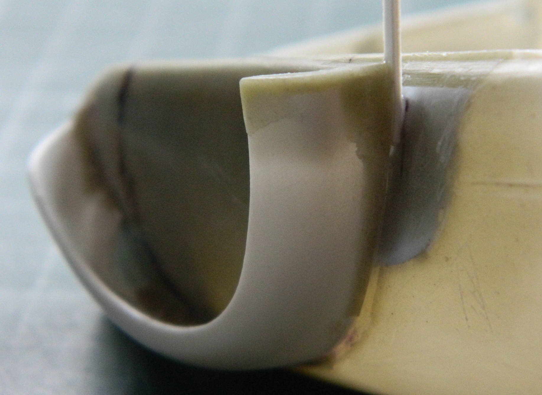
While dry-fitting things, the exhaust stacks jumped up into my attention and since it was an easy fix, the fact that they’re way too thick, I just drilled them out to a less inappropriate wall thickness. Check the difference of the bottom six. The three on the right have been drilled out:

This:

Isn’t as good as this:
Having dry-fitted the engine nacelle together, I saw that in the area right behind the engine yet inside the nacelle, would be a good place to fit lead! It’s in front of where the main gear touches the surface and in a space where, once painted flat black, would probably never be seen. I have my big anvil downstairs in the basement so I took one nacelle and the bag of .36 caliber balls (because I more of them than the .44 caliber balls) downstairs.
Pro modeling tip: If it has a pulse, do NOT wail on it with a hammer:
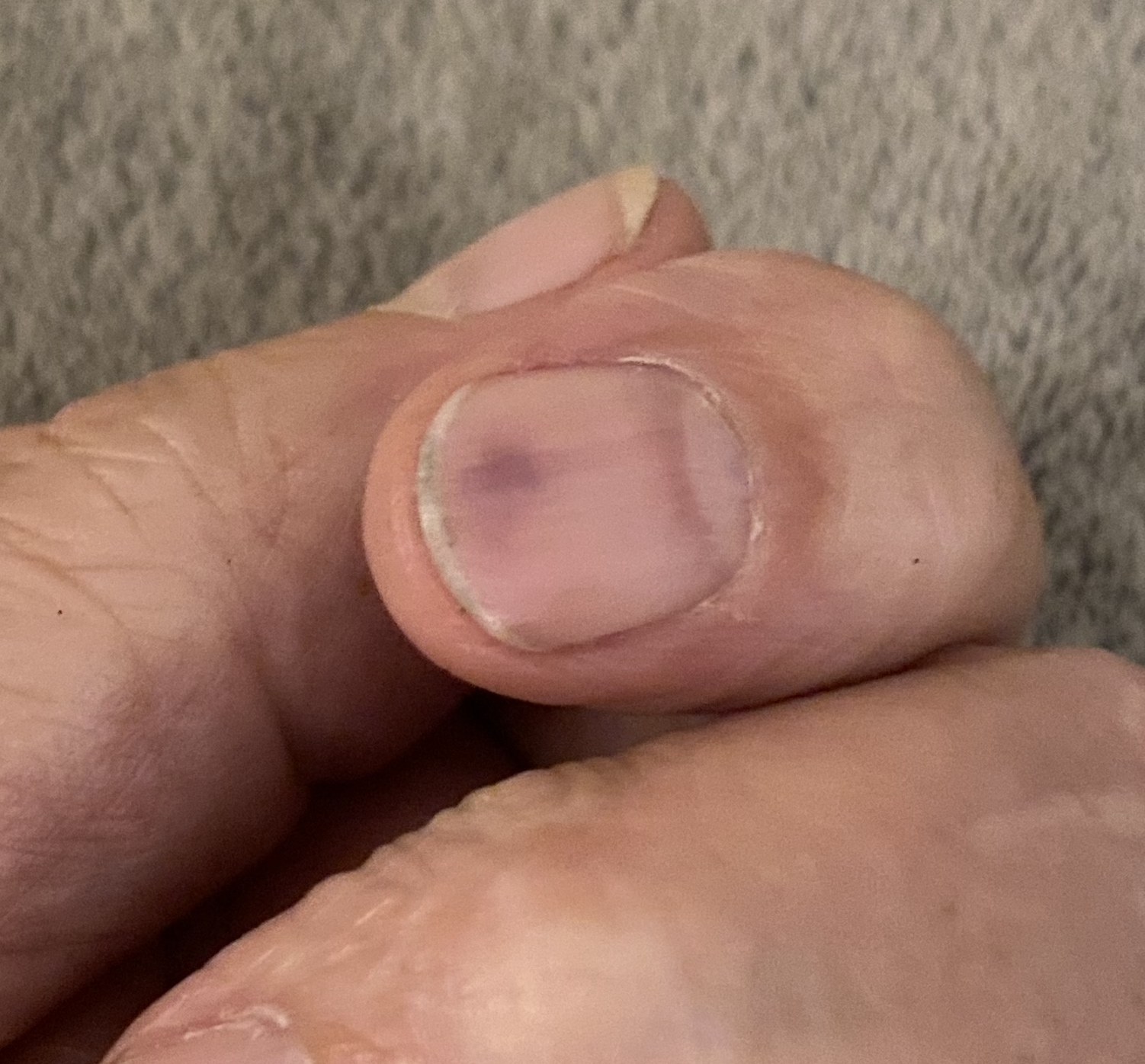
And of course I did that on the last of eight:
Since I’m still in stuffing mode, I started lining the cowlings with tungsten tape:
The above photo shows three layers of tape but since I had the room, I added one more. Then I weighed the engine and cowling together and came up with a total weight of 19.6g. Double that and I’ve added 39.2g. I wish that it was further forward for the mechanical advantage of leverage, but more is still more.
While manipulating the nacelles, I noticed that the landing gear openings aren’t exactly square at either the front or rear:
I fixed that by adding a bit of .020″ (.508mm) styrene scrap to the faces of the openings and let it sit overnight for the styrene cement to cure totally…twice, because the other side had the same problem:

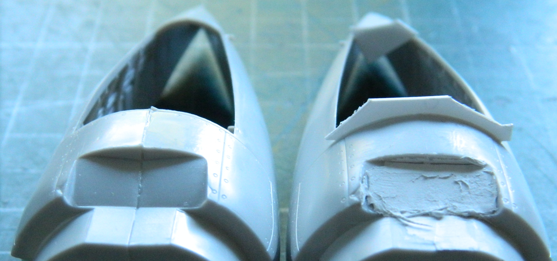
You’ll also note that the nacelle on the right in the above photo has had putty applied. It’s been applied to an area that’s supposed to be flat, not angled.
While they were sitting for the putty to harden, I turned my efforts to cleaning up the SAC metal landing gear struts. ::sighs:: I’m no stranger to working metal. I worked as a metal finisher in a couple of art-casting foundrys. Though working on aluminum, bronze, steel, and stainless steel requires different tools because of their respective hardnesses, working pot-metal (likely tin and antimony, but don’t quote me) is magnitudes worse.
I have a hypothesis (he humorously states as if he’s got just one) that all solutions create new problems. Often the strength of anything is also its liability. Pot-metal does not contradict this hypothesis. Its ability is that it’s soft and bends easily. Its liability is that IT’S SOFT AND BENDS EASILY. And since it’s also a metal, bending it too much introduces stress cracks and that leads to the sodding thing breaking off. So…after I broke the end of one of the main struts off, I got to deal with drilling out the metal, adding a pin (wire), and gluing it back together. Seamless.
Unfortunately I can’t say that about the parts themselves. It’s clear that the molds were taken from the kit parts. Asset: they’ll fit the kit about as well as any other kit part fits. Liability: minimal clean up was done before the molds were taken and the little that was done was poorly done. As you aircraft modelers are well aware of, there’s a portion of the landing gear that moves up and down (it’s called the oleo strut) and since it slides within a seal, that part of the landing gear is very shiny. The “poorly done” verdict was levied because the little clean up that was done was done on the shiny part. Badly. Badly enough that I’m going to cut the struts apart, all three of them, and replace the oleo with steel. For the nosewheel I’ll be using stainless steel welding rod, and for the mains I’ll be using part of a paperclip:
Zoom in on the oleo sections…you’ll see what I mean.
But those parts needed to be cleaned up so that’s what I’ve done (and as further support of my thesis, check out how thin the metal oleo is down near the bottom, and how thick the kit’s oleo is):

Yeah…drilling all that out. We’ll see how that worked (or didn’t) next month.
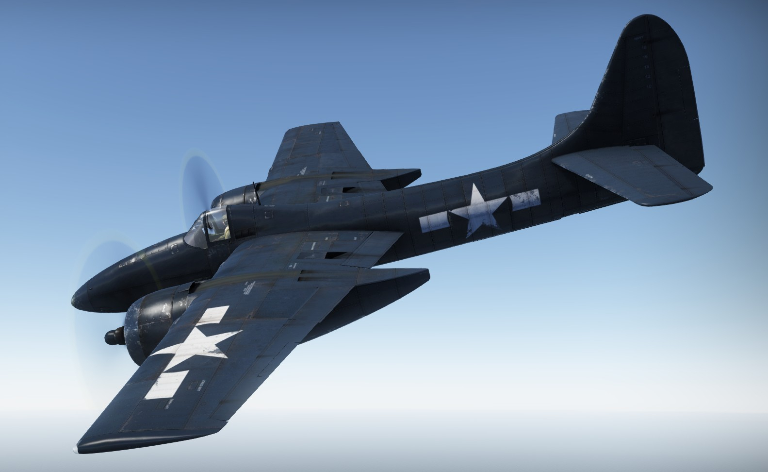
F7F-3 (AMT/Italeri) A Brief Overview
The F7F-3 Tigercat was the Navy’s first twin-engine fighter as well as being its first tricycle landing gear aircraft. Design and development time (the prototype didn’t fly until November 3, 1943) kept it from seeing duty during WWII and most of the -3’s 364 airframes that were built at the end of production in 1946 were given to the Marines. Most of the -3s were converted to either a photo-recon variant, the -3P, or a night fighter, the -3N with the remainder of the -3s being used for training purposes.
Initial problems were pretty much designed in. The first problem was that the Tigercat was too big and heavy for any carrier class smaller than the Midway class. (Its undercarriage, airframe, and tailhook needed to beefed up.) That restricted where and when it could be deployed. It seems its major flaw was that it didn’t spin well. Ah…yeah…maybe it spun TOO well, because it was discovered that after four spins there was no recovery possible. VJ day also meant that the Tigercat was a tool for a job that didn’t need it anymore. It was still big, really fast (70mph faster than the F6F Hellcat), had a range of 1300 miles, and being armed with four fifty caliber machine guns and four twenty millimeter cannons, as well as carrying two 1000lb bombs underwing or a Mk13 aerial torpedo under the fuselage meant that it would smite with a big hammer…but smite what?
Then there was the lousy timing (from the Tigercat’s position) of its introduction. About this time, air arms and aircraft designers were invested in a new bit of kit that is also called “jet engines.” (Things like the Grumman F9F Panther.)
That all meant that once the final peace treaty of WWII was signed, there wasn’t much will expended on (and probably less money) spent on the F7F.
When the Korean War kicked off, we had a lot of propeller driven aircraft that had made their bones in WWII on hand. P-51 Mustangs, F4FU Corsairs , AD-1 Skyraiders, all of which were pressed into immediate service in the Korean skies. No need for F7Fs…
However.
The F7F-3N night-fighter variant carried the SCR-720 radar with a protruding fairing under the nose and this time the second crewman had a job! He operated the radar and his location was in a second cockpit behind the pilot.
The -3N was ferried arrived aboard the carrier Cape Esperance to Japan and VMF (M)-542 Marine night fighters which brought them to Inchon. During the opening weeks of that war, the North Korean pilots flew harassment missions at night in biplanes, the PO2. Tigercats of Marine Night-Fighter Squadrons VMF(N)-542 and -513 were credited with two kills. The F7F’s combat role was brief as the turbojet F3D Skynight soon replaced it in the land-based night-fighter role, though through 1952, F7F-3P and -3N were used in support of B-29s (which were flying night missions because of the high loss rate of daytime bombing operations).
The F7F-3P was the photo-recon variant and carried five cameras. It also had a second cockpit for the camera “operator.” But since the pilot aimed and triggered the cameras, the camera operator was unneeded and his position saw the canopy over it removed and fared over with sheet metal.
Any pilot accounts I’ve read are favorable. Pilots liked that it was comfortable, robust, smooth, and powerful.
Crankenstein – 1/25 Scale Kitbash Build Paused
For personal reasons I’m suspending this build for now and going to do something else for a while.
Crankenstein – 1/25 Scale Kitbash Build #3 Extending the Body and Coming to a New Understanding of the Scope of This
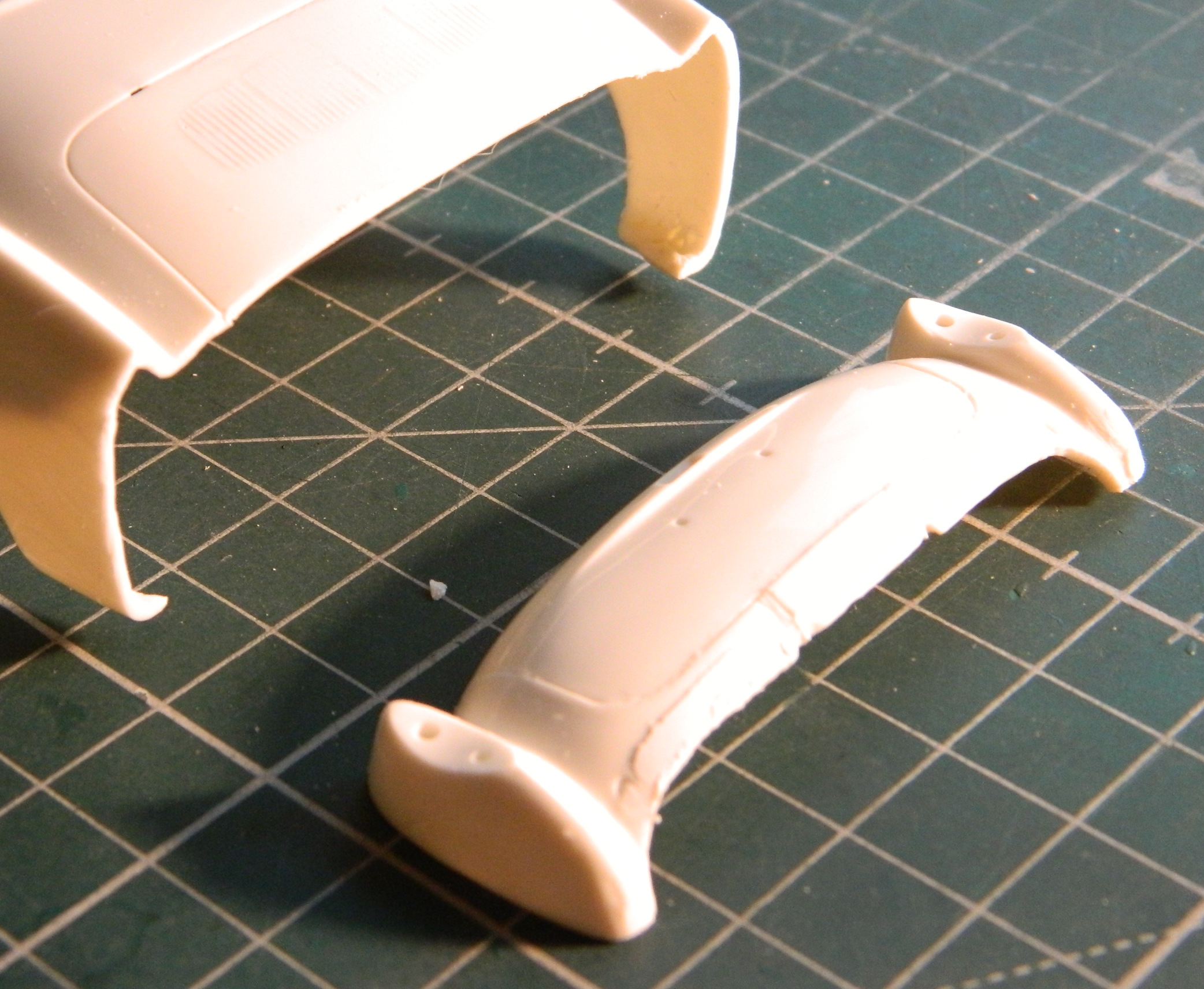
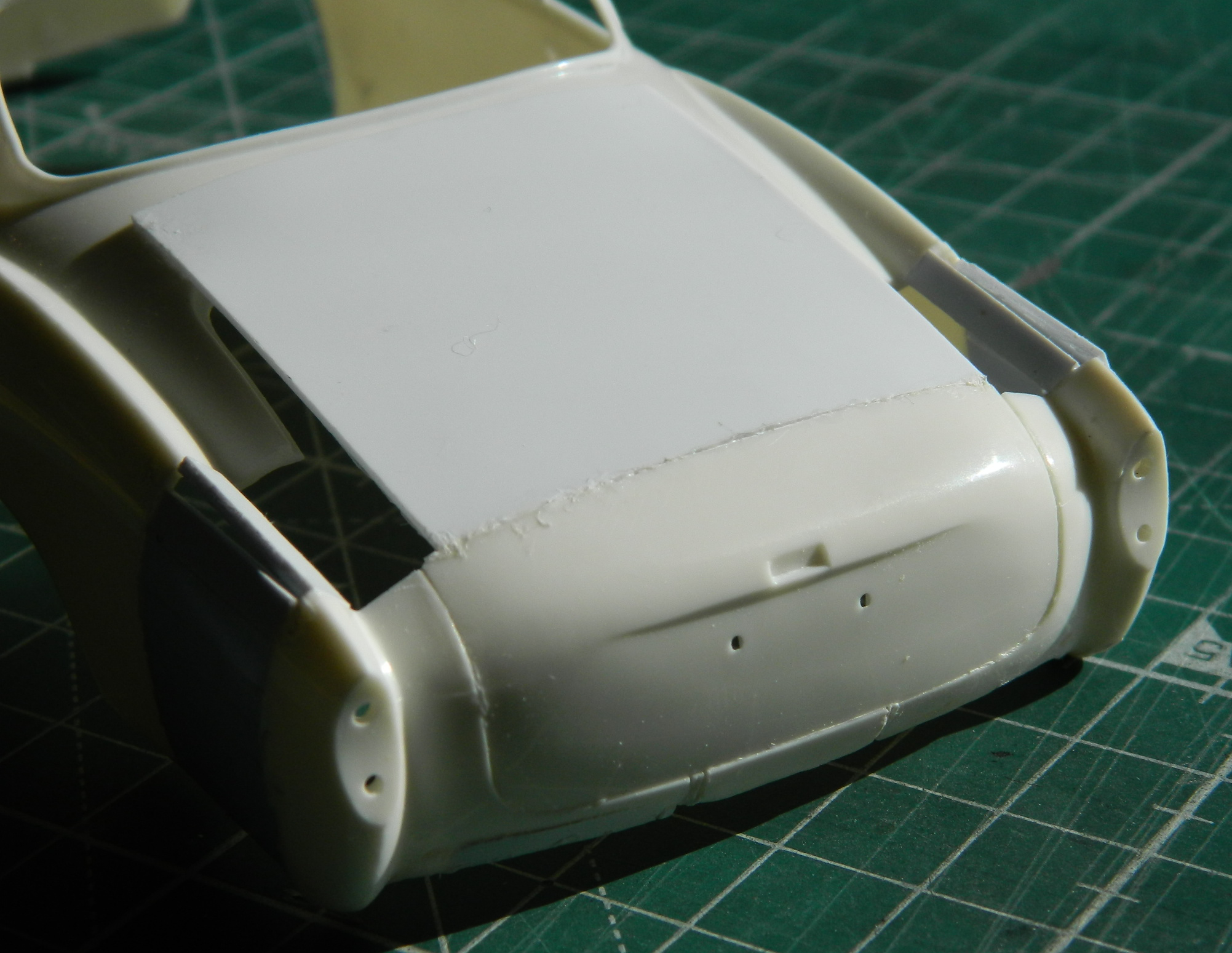
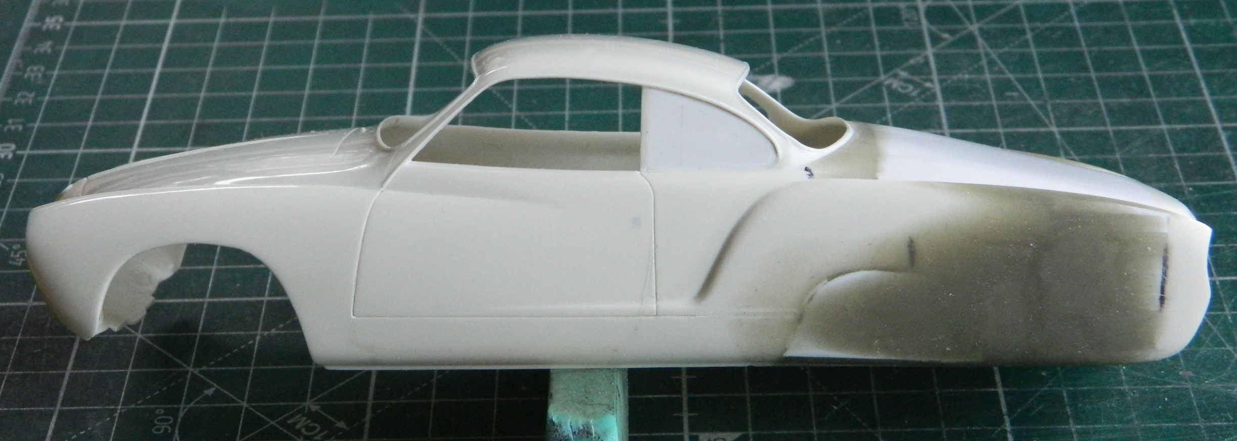
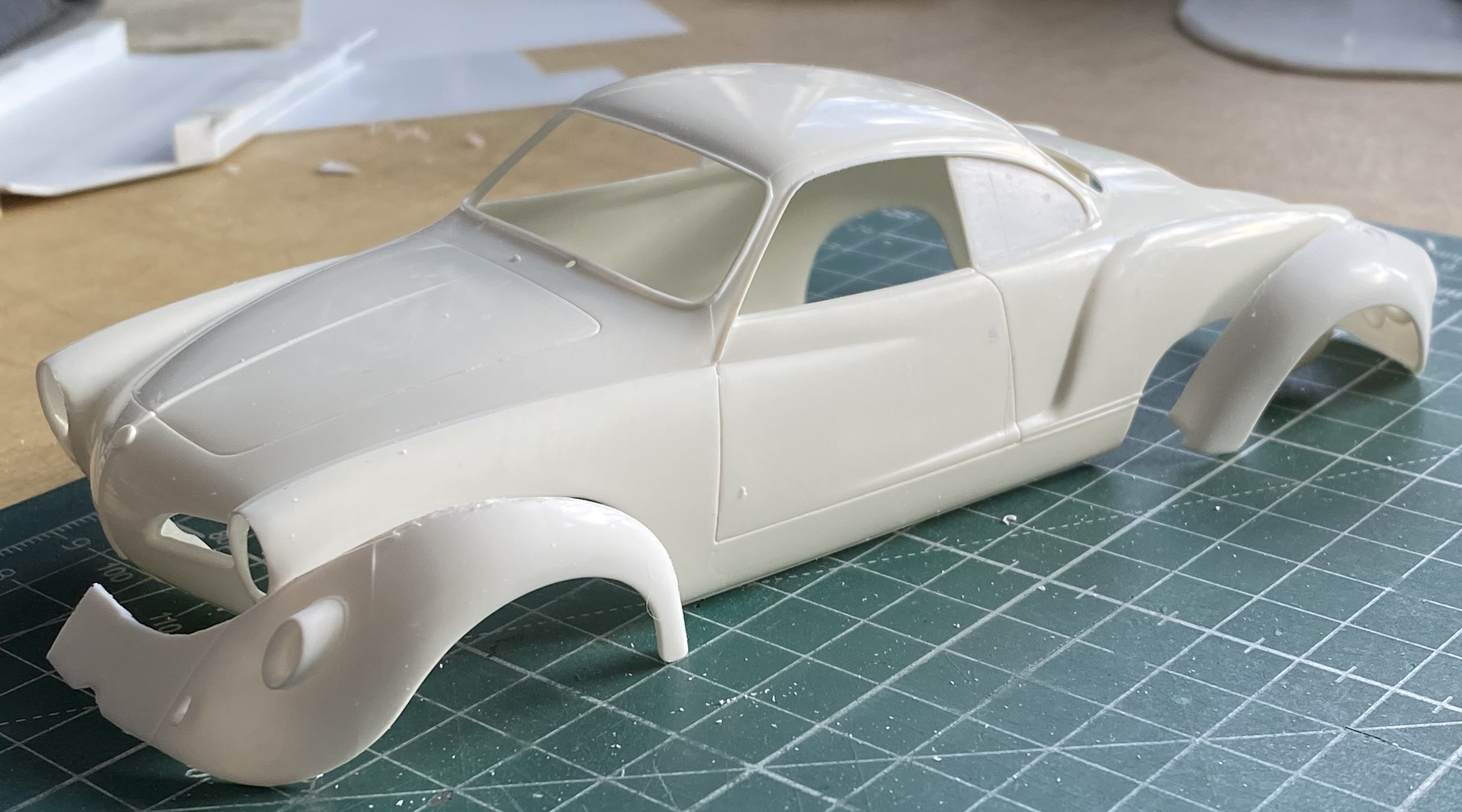
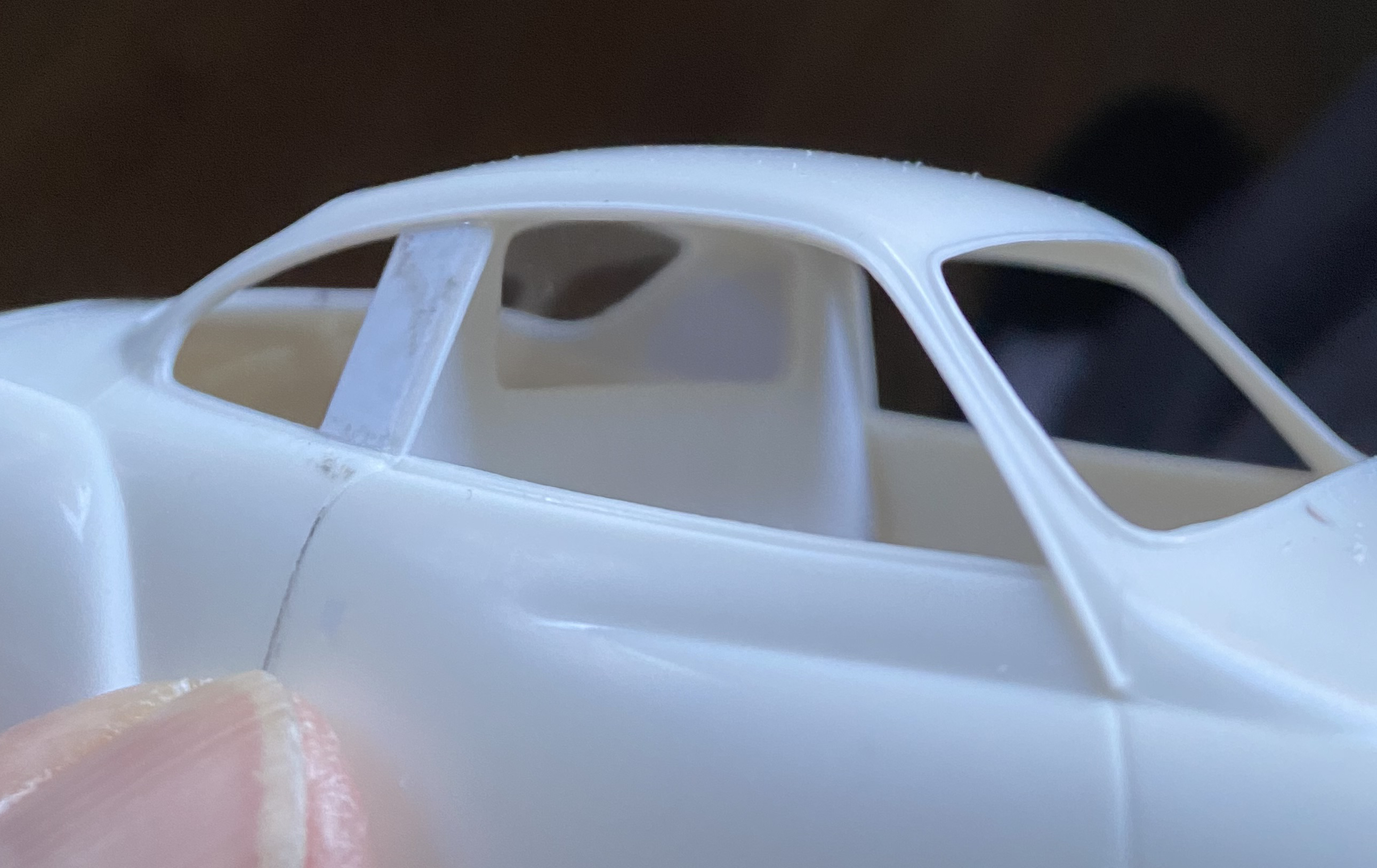
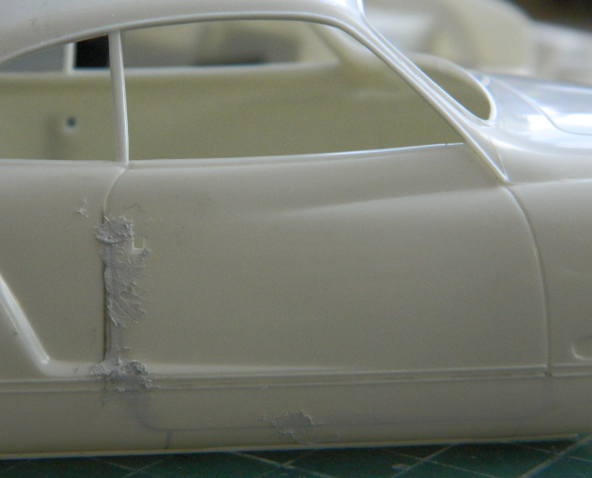
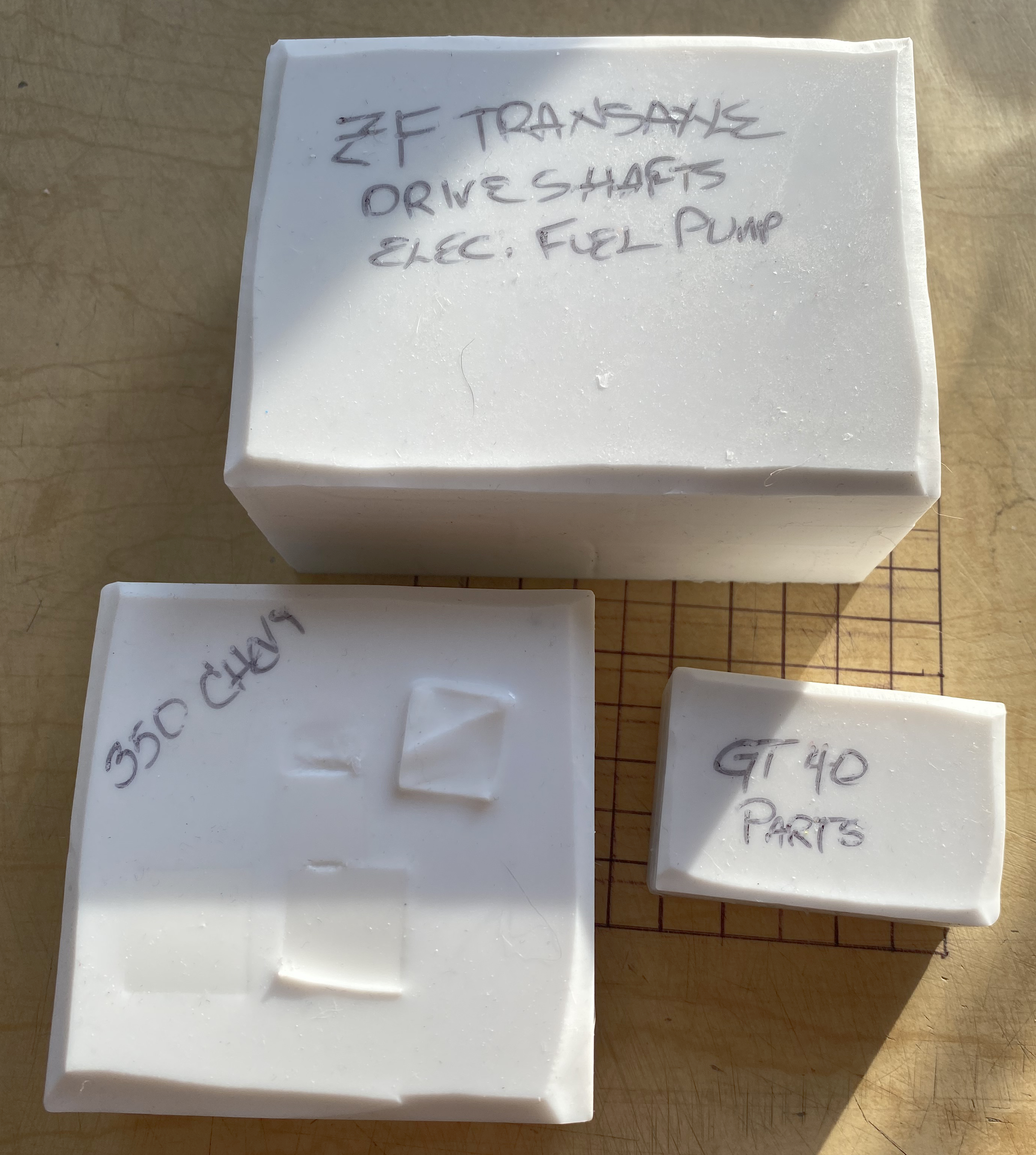
This month’s work was mostly bodywork, specifically coming to the realization that I really am going to have to extend the rear coachwork. This awareness was finalized as a plan once I had enough constructed to lessen the degree of guesswork about where the power-train goes, which determines where the axles go, leading to the understanding of where the wheels and tires will be and thus the rear fender flares. Initially I’d thought that I could just do a speed-hump (no…not at my age I can’t) and cover the rear of the transaxle where it protrudes beyond the body. I added a bit of .040″ (1.016mm) bracing so that the bodywork would be dimensionally stable:
But once I estimated the location of the rear wheels, and subsequently the fender flares, I realized that the rear of the flares extended well past the rear of the body and would end up removing the sense of “Karman-Ghia” that I’m trying not to obliterate:
The brace was removed and the section of body that I’d removed was glued back into place.
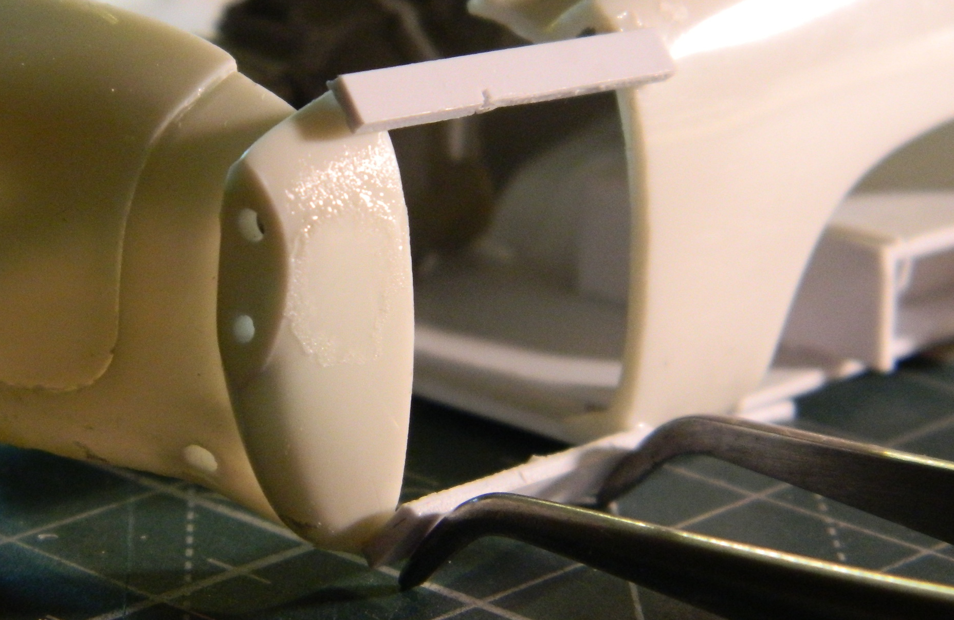
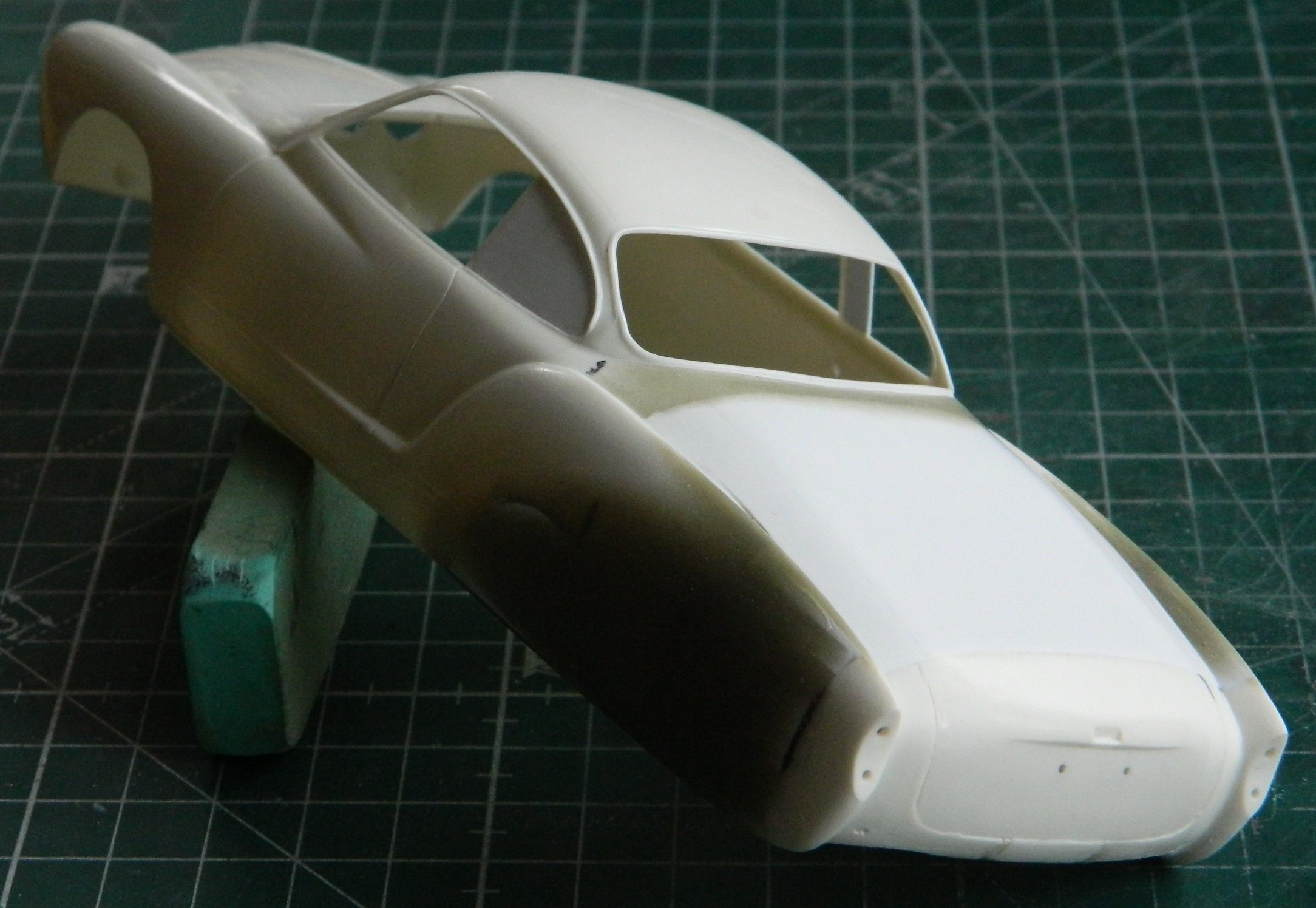
I had initially considered making the cut much further forward, and I’d also considered making a couple (or more) cuts to blend the compound curves. I decided that I was, once again, overcomplicating things. Since I just need the back of the bodywork to extend past the end of the transaxle, I decided I’d just cut the end of the body off. I glued the stock engine cover in place for structural stability, only gluing the part that would be removed with the body (because as this point I still have the notion of having the former engine cover hinged separately from the rest of the hinged rear body to have a small load-carrying space that could be accessed without having to open the whole back of the car to get to it). I laid out the line and made the cut:
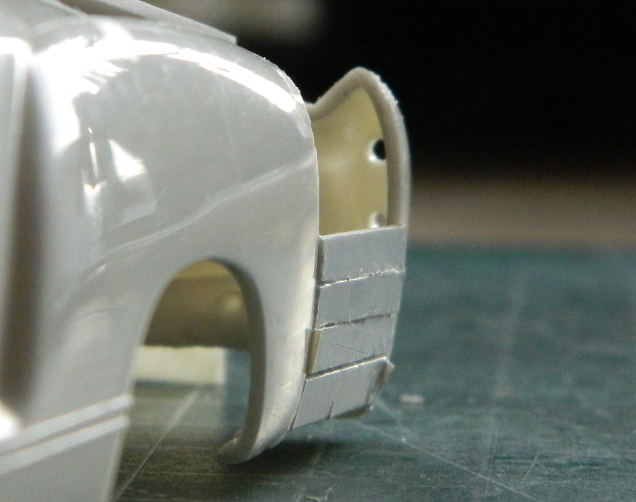
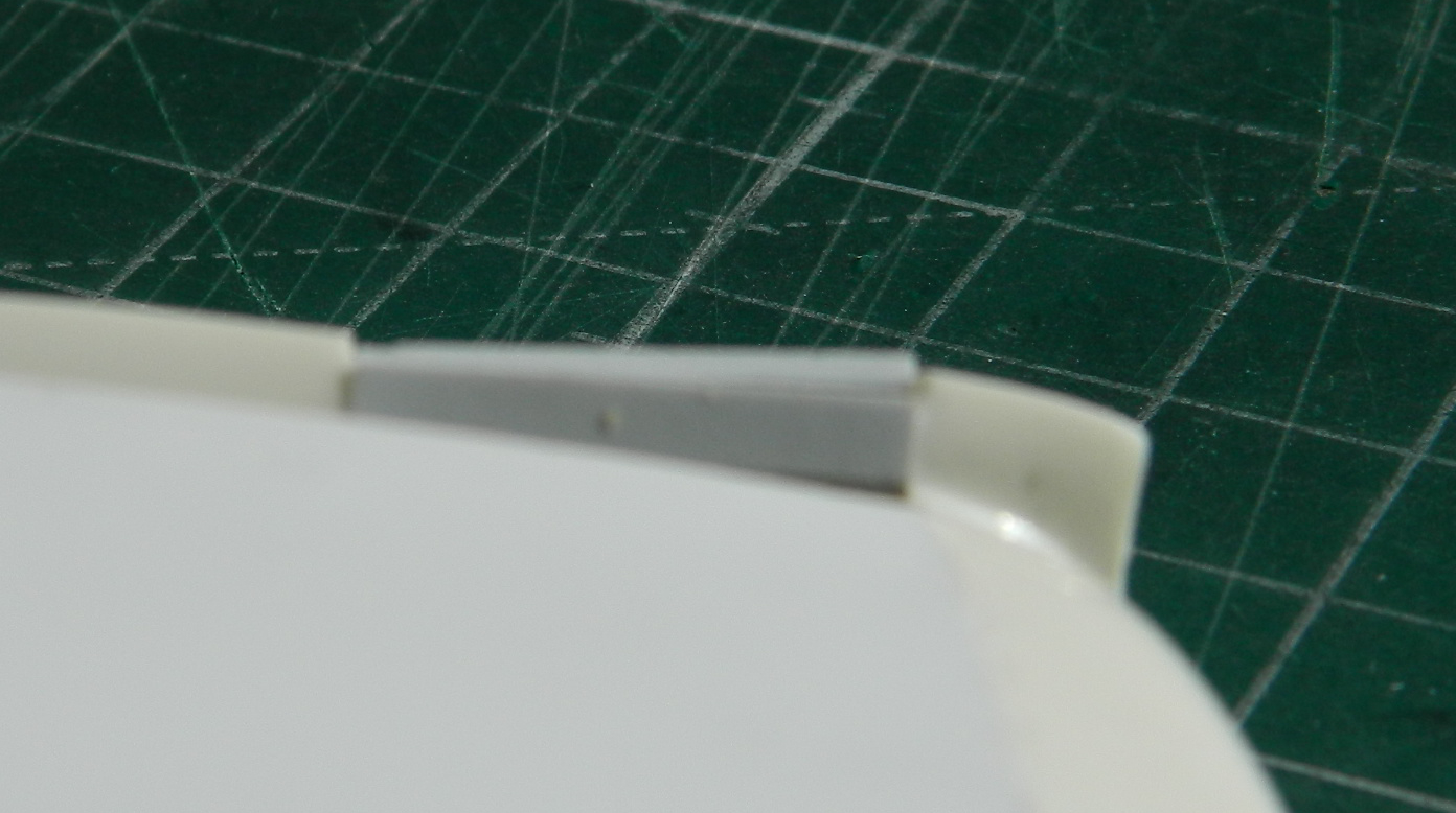
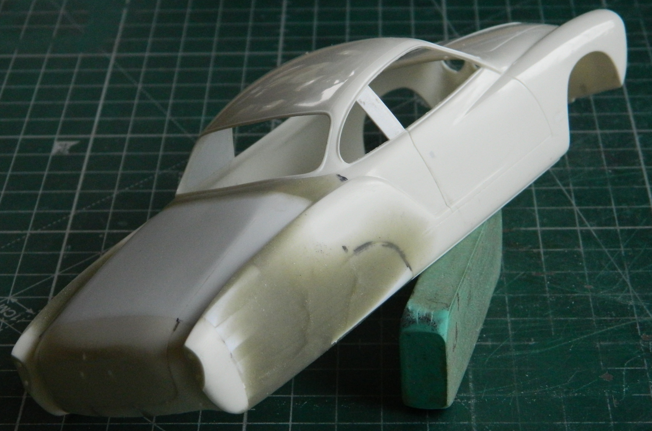
Not only did I move the section that was cut off back 5/8″ (15.88mm), I also moved it down in order to maintain the arc of the upper curves of the rear fenders. Once I figured out where I wanted it, I added .040″ (1.016mm) braces to hold it there (and managed to superglue my thumb to the rear of the fender, as you can see in the photos):

Having positioned the rear of the body, I checked to see if I could just add a piece of flat styrene sheet for the upper body. Looks like I can:

That obviously left large areas that need to be filled. Rather than drive myself crazy(er) by trying to make a single-piece fill section, I opted to use more .040″ (1.016mm) strips as structural filler as well as gluing a flat piece of the same thickness styrene on top. For the ridge at the top of the fenders, I filled the odd shaped gap with .080″ (2.032mm) scrap:
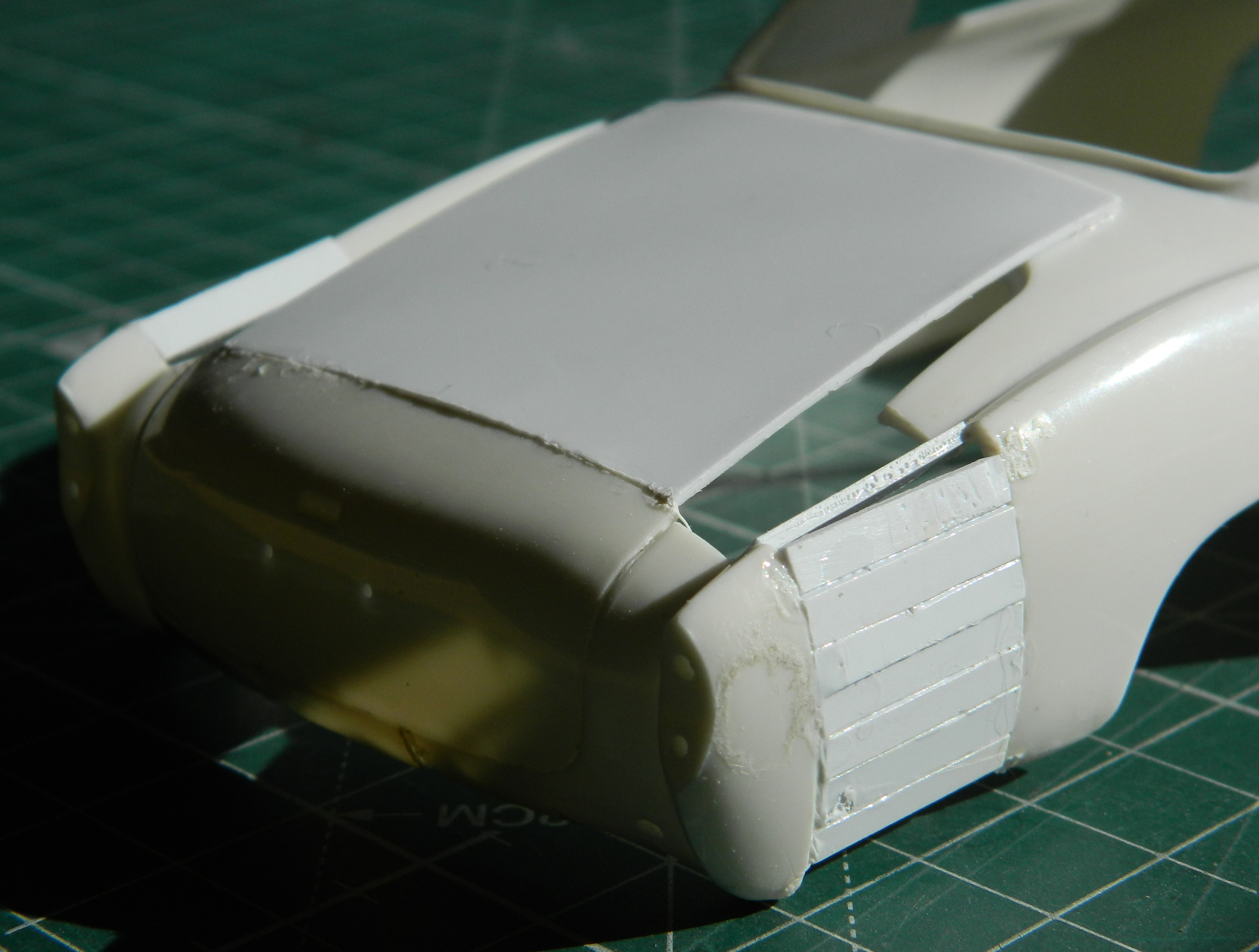


l used more .040″ (1.016mm) to fill the gaps on either side of the top addition and then roughly sanded the additions to shape as well as filling the stock wheel openings using .020″ (.508mm):
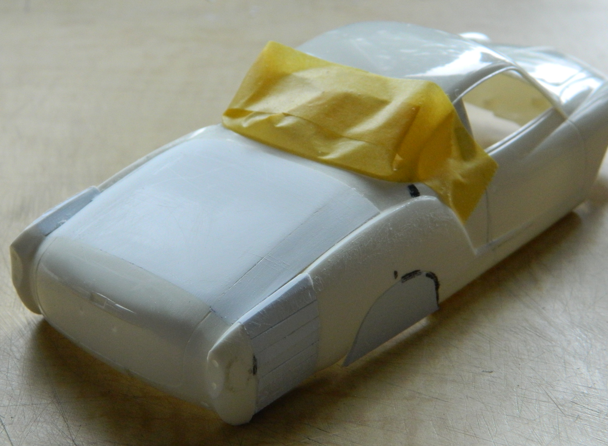
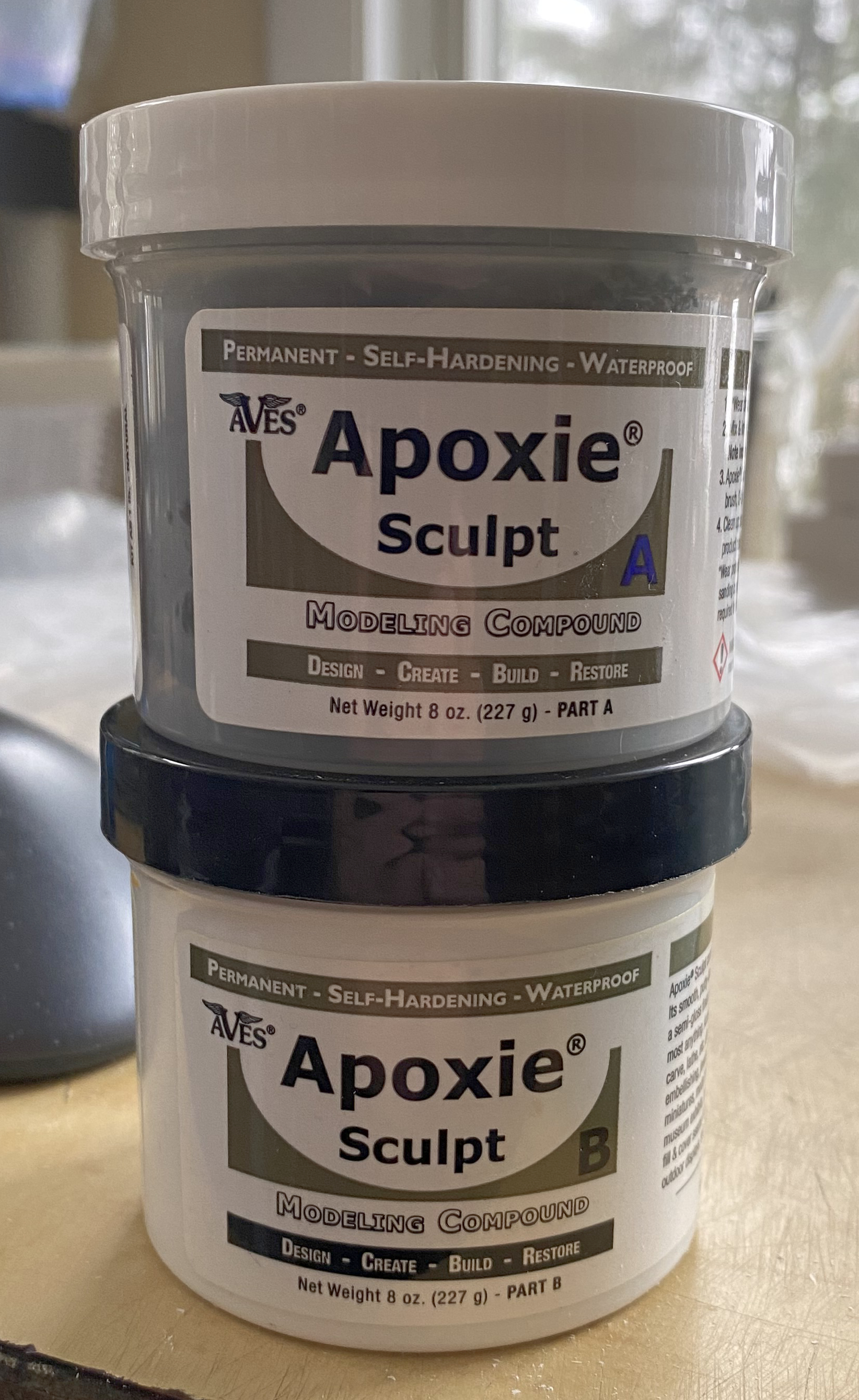
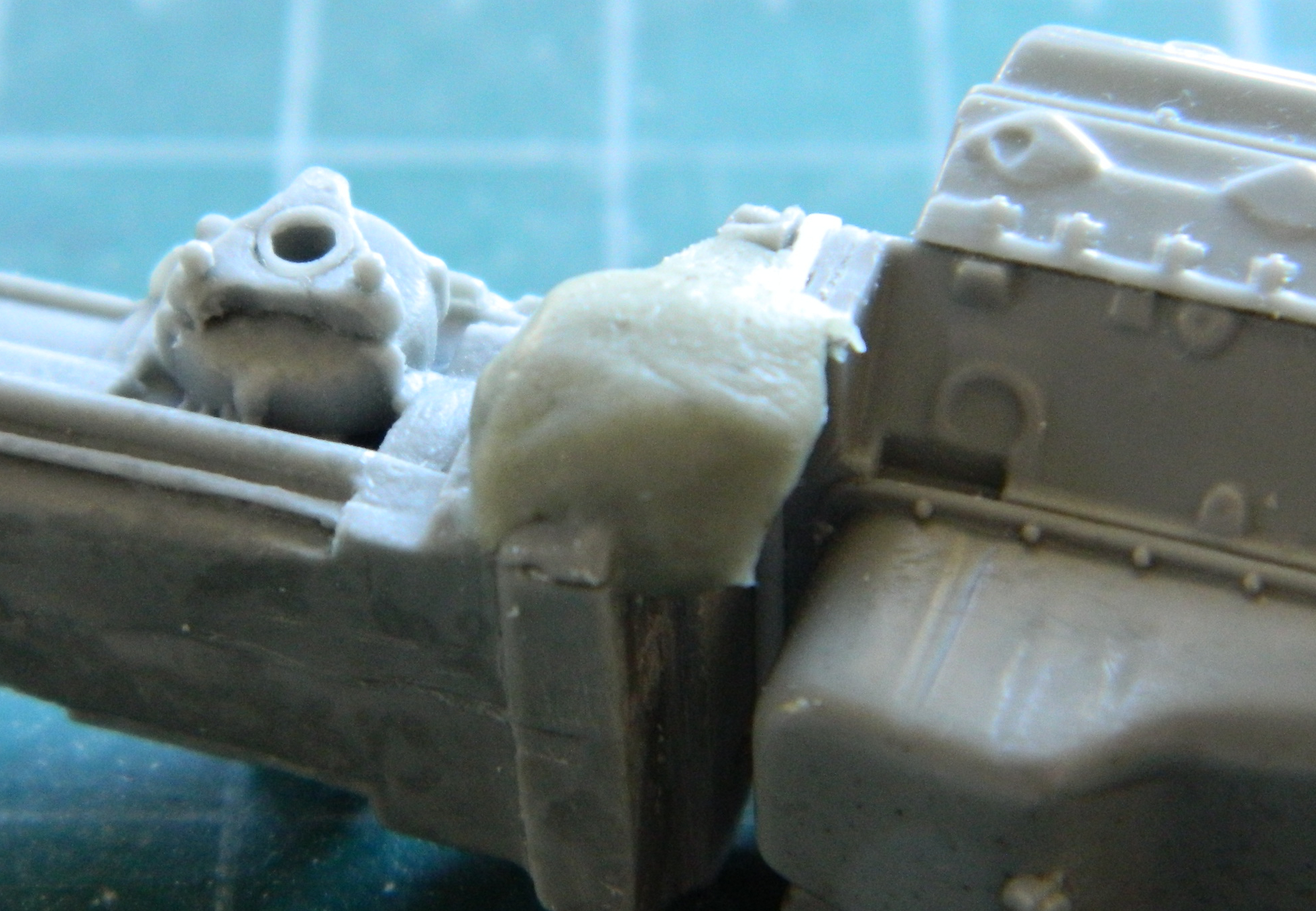
Much putty was needed to smooth the surfaces. Rather than lay down several layers of putty putty, I opted instead to use Aves Apoxie Sculpt (great stuff if you ever need a structural filler!) and waited overnight for it to harden. The join of the top of the rear deck and the side sections started to show gaps after minimal sanding so I added the Apoxie Sculpt there as well:
Since the rear of the body will be hinged, I needed to add Apoxie Sculpt inside as well:

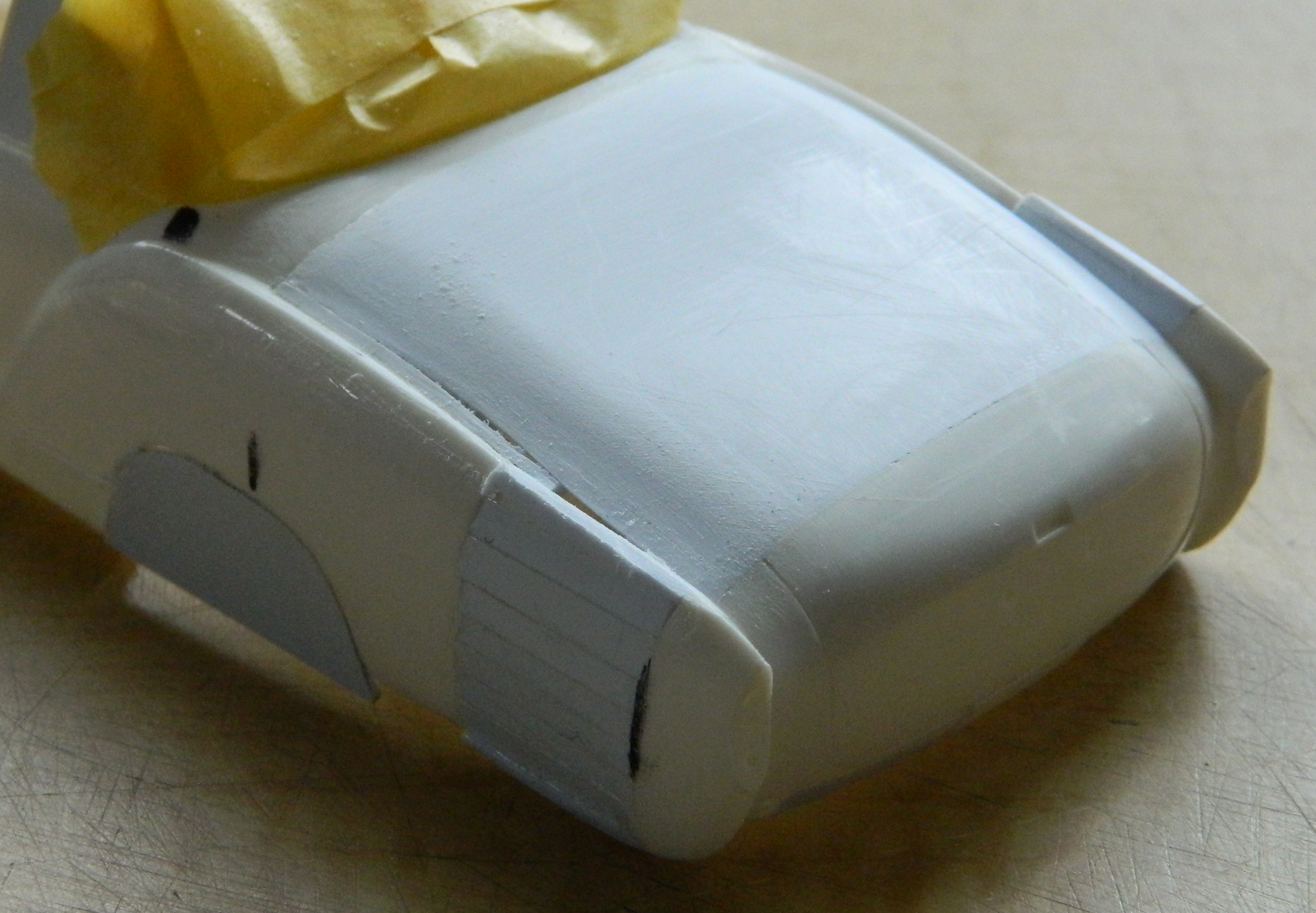
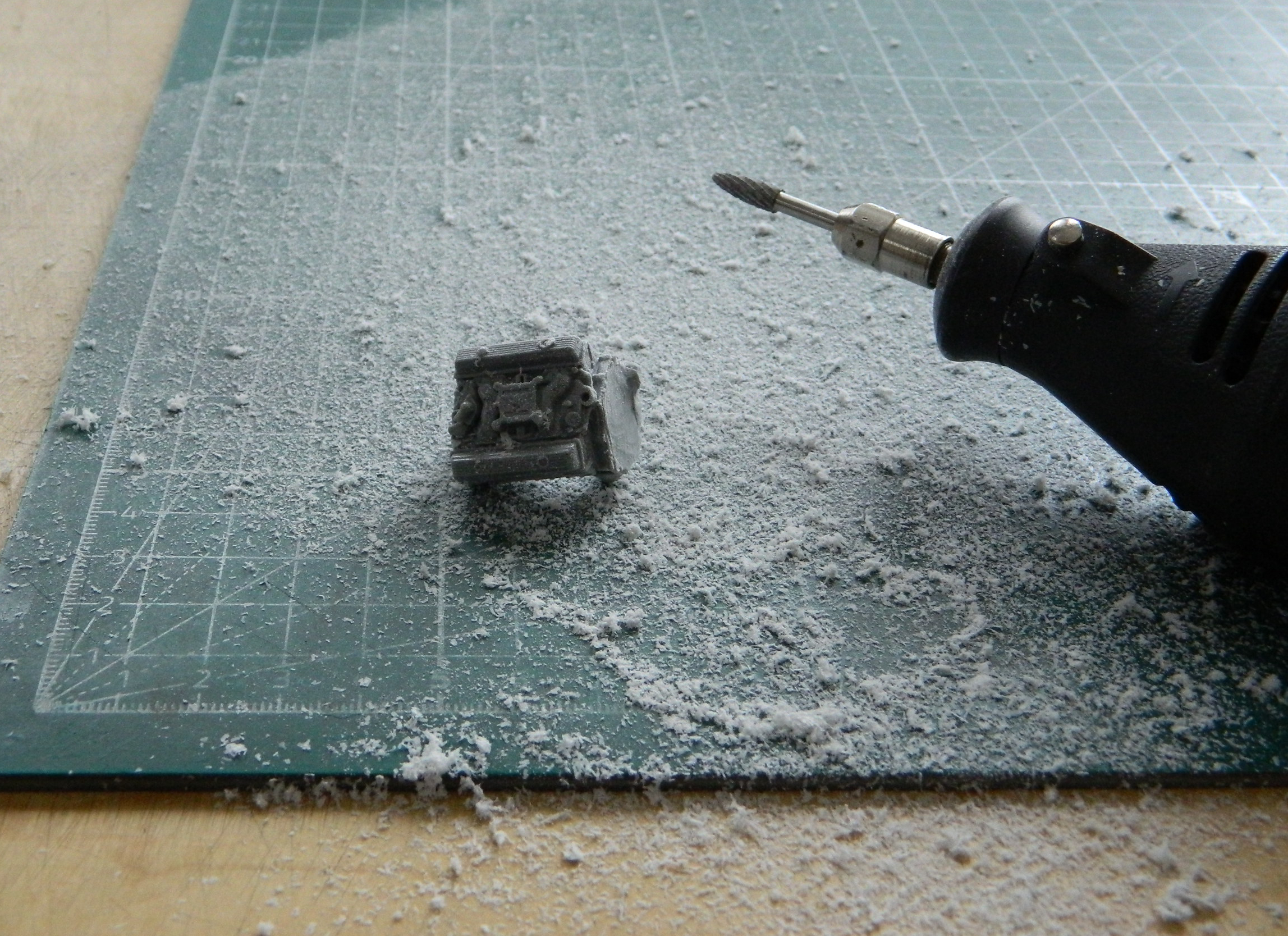
After letting the putty cure overnight, I used my Dremel to roughly shape the putty (and created a metric TON of dust):
The first shaping was done with a file:
Then it was all sanded. I started with 220 grit and went through the grades up to 2000 grit:
My goal of creating a gradual curve on top of the fenders worked well:
I knew as I was doing all of this that a large area would be cut away on both sides to accommodate the wheels/tires. I also knew that I was going to have to fit the fender flares to the body so I wanted the surfaces to be properly shaped before I started that.
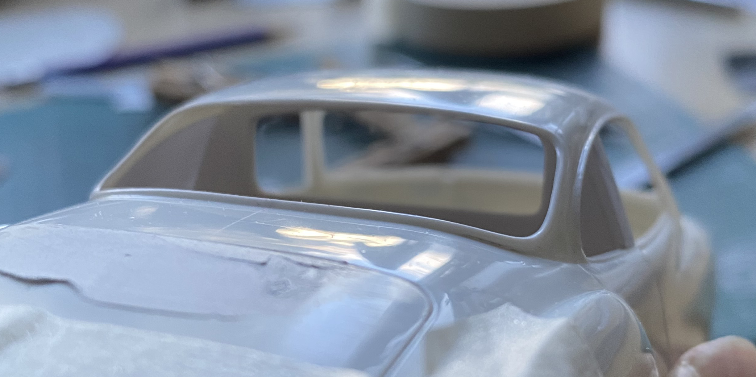
Though it looked odd at first, I rather like the extended body:
To know where the openings need to be cut out, I needed to know where the wheels/tires would be more accurately. Since it’s the engine/transaxle that determine where the rear wheels/tires will be, I needed something better than tape or white glue to determine where the engine will sit. The next task was to build the engine mounts so that I could dry-fit the engine/transaxle to where it will be attached. I knew that not only were these parts need to be sturdy enough to handle being moved around a lot, using .020″ (.508mm) styrene wouldn’t provide much gluing surface, so I reinforced the joins with Evergreen’s L-shaped extrusions:
These parts did what I want them to, locate the engine, but they’re too clunky. I’ll make another set of them later:


I also needed to fit the rear engine and suspension mount so that I have the angles for the driveshafts at the correct height. While that part is still free and the surface of it easily accessed, there was something I needed to fix first. For whatever reason, the resin copy has these two depressions that shouldn’t be there :

Once I added the putty (deciding to finish the surface later), I was able to put the engine where it will end up being (the plastic underneath the transaxle is just there as a spacer to maintain the correct height):


I wanted to determine the ride height of the car. Seeing as it’s a street car, it couldn’t be as low as a custom or race car. The streets are much rougher on a car than a track (or trailer), having things like potholes, speed-bumps, driveways with steep approaches, and all the other wonderful things that street cars have to cope with. I wanted to shim the car and monocoque at a ride height I thought to be realistic. For that I used quarters and now I call this my “seventy-five cent clearance” because three quarters gave me just what I wanted, or about 6″ (152.4mm) scale inches:
With ride height figured out, I dry-fit the engine, aligned things, and traced around the tire to determine the size, shape, and placement of the rear wheel openings. I did this while both the body and the monocoque were sitting flat on the bench instead of at ride height to allow for suspension compression:

Once the putty had cured, I sanded down the putty inside the bodywork:
At this point there has been a lot of sanding of plastic that wasn’t too thick to start with. I wanted to check how thick or thin it was, especially where the seams are. I held the body up to a bright light (the sun) to see where it was getting too thin:
Answer…where the plastic lets the most light through. I knew that I was going to have to thicken this entire area a bit and decided that there was no point to waiting. I laid down strips of .020″ (.508mm) scrap styrene and then another coat of putty:
While that was curing, I did a little work on the monocoque which gave me more room for fuel tanks. I haven’t done the numbers yet but I estimate that I’m probably at the 25 gallon (94.6L) target, perhaps more, and now that I have a better idea of how long the chassis needs to be, I added an extension to the rear and made a less-clunky set of engine mounts:

Having ascertained where things go, it’s time to put some things there. The rear fender flares. If I could design a body for an inveterate modeler, I’d design someone with variable-magnification eyes and four arms so that I could have four hands. I think the second pair of hands would be really small for handling really small parts. Since my body doesn’t have those features (or many other ones lost over the decades), I figure out how to make do with what’s left after the Sands of Time have scoured thoroughly.
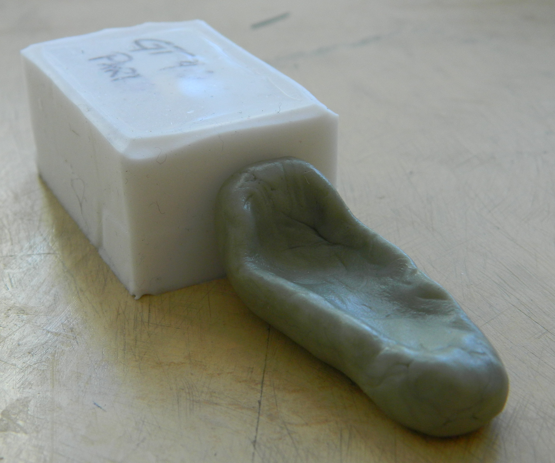
I need to hold the Bug fenders in place while holding the body in place while outlining where I (possibly) need to cut the Bug fenders. Lacking the genetic and physical modifications that I so ardently desire (hmm…buying shirts could pose another challenge), I used a lump of Plasticine to hold the fender in place so that I could mark it:
Once marked (sorta), the cutting, filing, sanding, and fitting began (double-sided tape stuck the flare to the body to allow me to step back and look at how it went):
Well, it didn’t go as I’d hoped (but expected) and some plastic had to be added back and I used various thicknesses of scrap to do that:

This was followed by more sanding, scraping, and filing. Eventually I got things close enough so that I was confident that the Apoxie Sculpt could bring it home:

The I got to do it again on the other side, hopefully (more on that shortly) matching what I had just done. This process was repeated on the other side and all of the putty was filed and sanded:

And…no. I didn’t get both sides identical. I also didn’t notice the difference immediately (the second flare was a bit wider than the first). I worked (snapped, more accurately) the forward half of the second flare loose, figured out how much I had to remove, and started cutting:

I thought it would be easier if I took a little bit more off than I needed because in this manner I could adjust the width easier (and this time I was correct…I’m not getting accustomed to that and neither should you):
That almost did it. Once the front of the flare was narrowed, it showed that the rear of it was also too wide (go figure) and I took care of that in the same manner. Finally satisfied that the flares were as close to identical as I could make them, more epoxy putty was applied. Then the putty was ground, filed, and sanded:


My original intent was to be able to use what had been the headlight sockets as brake lights and the original brake light locations used as backup lights instead. Since lengthening the body meant that the rears of the fender flares wouldn’t match up with the rear of the car’s body, that notion got tossed. Instead I’ll be using what’s left of the headlight sockets as vents to allow air that gets pulled into the engine bay to have an easy exit.
I’m stopping (briefly, I hope) at this point because though I know what I have to do, I’ve less than no idea as to what the build sequence should (and will) be. I think what I’ll do instead is to add the front fender flares while the BitB work on it and hopefully come up with a workable plan because right now I am utterly bereft of having one.
Crankenstein – 1/25 Scale Kitbash Build #2 Starting to Figure Out Where Things Go…and Wondering How to Get There From Here
Since I need the engine/transaxle to define where the interior can fit and where the body needs to be modified, I started this month’s work by removing the bellhousing from the engine. I’d started to use a saw but on that particular morning my hands weren’t as steady as the job required. I took out the Dremel and made a dusty mess of things:
I used a flat file to true up the end of the block. I figured that I’d probably need an adapter plate to mate engine and transaxle. For that I used .040″ (1.016mm) styrene. I countersunk holes to match the bolt locations at the back of the block and stuffed tiny bolts into them and then glued the transaxle to it. I trimmed excess plastic away (and added some where I needed more):
Since the location of the power train determines so much of what happens with this build, I was eager to see if I was going to have enough room for it:
And it doesn’t look like it. Well, not unless I modify the body to fit it, and since there’s going to be a lot of body modifications anyway, I see this as another bucket of sand on the beach in terms of effort/work.
At the front of the engine and there a gap between the timing belt cover and front of the oil pan. I slid a bit of styrene scrap in and filled the odd gaps with superglue:
The rear of the body will be detached so that it can be opened. The B pillar is quite narrow. With the plug on the left side replacing the window, I know I’ll have enough to work with on that side. On the right side I had to add something large enough to split. I used .020″ (.508mm) for that, using flat-jawed alligator (toothless alligator?) clips to keep things aligned:
While the glue was curing, I added a disc to the front of the timing cover to provide the harmonic balancer that hadn’t been molded on:
The bellhousing that’s attached to the ZF transaxle doesn’t have the provision to mount a Chevy starter motor. I built one from Aves Apoxie Sculpt…:
…and attached it to the bellhousing:
When I realized that I hadn’t quite added enough where I need it, I mixed up more and fixed that. (This material is very versatile and adding new material to already-cured material is no problem and it bonds well enough to be indistinguishable from the already-cured material…and yes…I plugged the bubble on the end of the solenoid.):

Continuing with the theme of a street-legal car used on the streets, I live in New York State. Summers can get quite roasting what with 90F-100F (32C-37.75C) days and relative humidity within the same range. Hot and sticky. At this point of the build, though I intend for the windows to be operable, I’m not entirely sure they will be. In order for this not to be a mobile over-powered bread oven, air-conditioning stops being optional. Because there is more than enough work to do yet, I went online to find an a/c compressor and the only one I found was unacceptable. That means I have to make one.
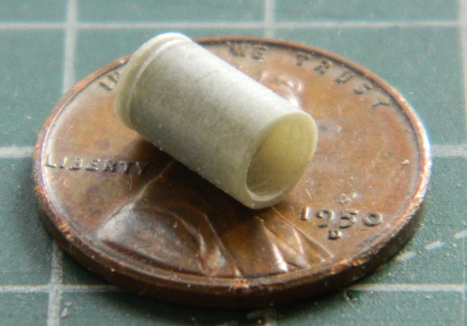
I have a few sets of AM pulleys and used one for the compressor. The only styrene tubing I have is either too little or too large. Once again I used Apoxie Sculpt. I mixed it (it’s a two-part compound mixed 50/50) and rolled out a rope of it. After it cured overnight, I took the straightest section of it, chucked it into my bench-top lathe, and turned it to match the pulley’s diameter and then drilled out on end of it to socket the back of the pulley into it:
I punched a couple of discs from scrap using .020″ (.508mm) for the face detail and .010″ (.254mm) for the clutch face (getting the hole in the thin disc took a couple of tries to get correctly…punching the hole first, centering what will become the disc):
I made the mounts from .030″ (.762mm), making the required holes for the compressor and mounting bolts:
I failed to notice that the front mounts have longer lugs than the rear. Rather than redo the part, I added little scraps that I’d removed in error to it:

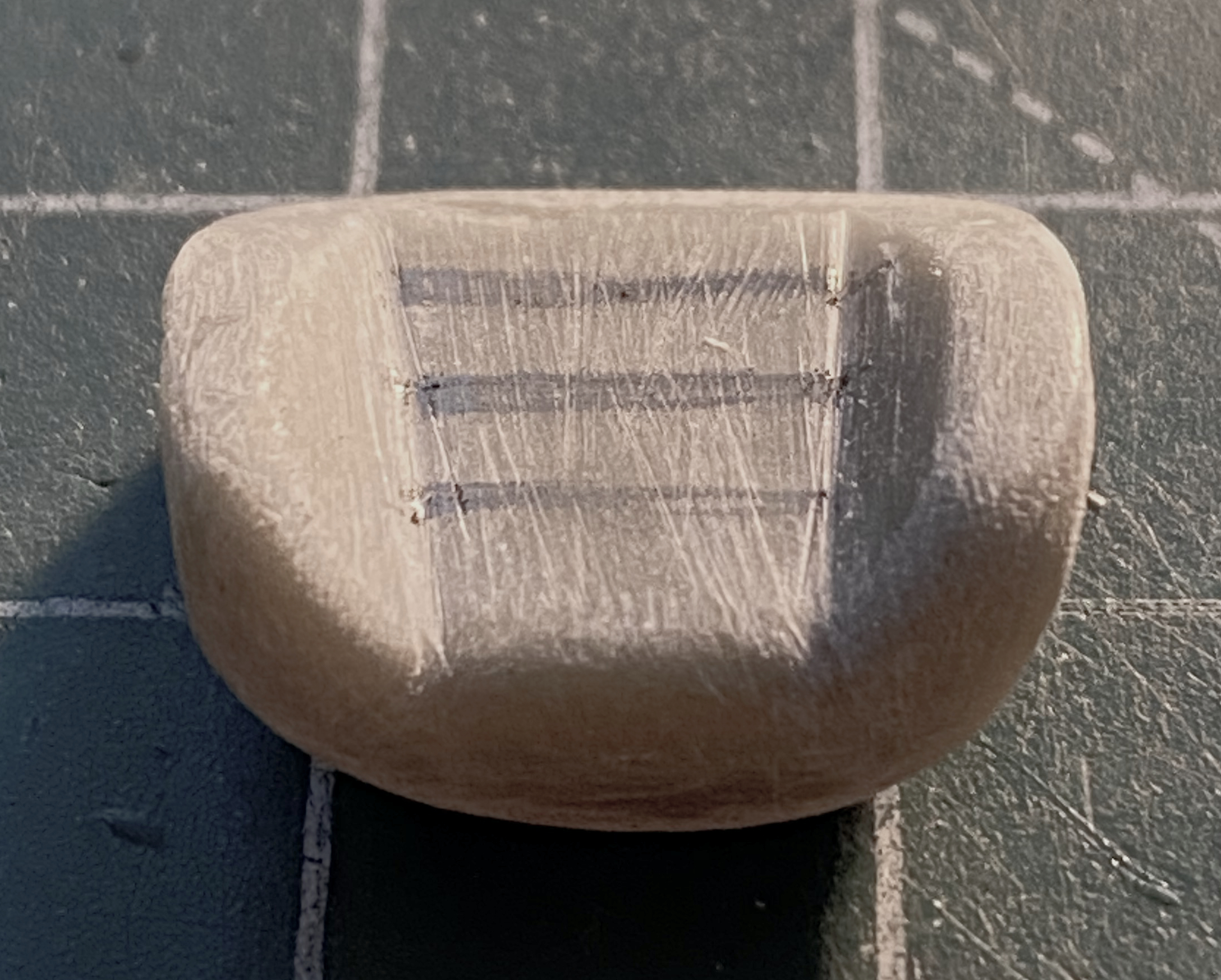
The last things I added were the wiring (two twisted strands of 40 gauge wire and sandwiched those between two pieces of .005″ (.127mm) scrap to replicate the connectors, a couple of small plastic bolt heads, and two resin nuts for the Freon line connections (sourced from resin AM bits of 1/35 scale bolts used to hold trunion caps onto suspension bogeys of a Sherman):
With the compressor built, I need a way to attach it to the engine. Generally, the compressor is attached to the upper left corner of the engine. Unsure as to whether or not that location would interfere with the exhaust headers I’ve yet to build, I decided to make a custom mount at the lower left of the engine and for that I need mounting brackets. Detail Master makes a number of nice PE bits:
The problem with these parts is the Detail Master parts are only .003″ (.076mm) thick. Funny. I used the word “thick” because they are not thick at all and turned out to be far too flimsy to use. Instead I decided to trace them onto .005″ (.127mm) copper shim stock. My first try, as is typical for me, went well (I used hemostats as a clamp so that I could use a needle to trace the part):

Also typical for me, the next couple of attempts were horribly unusable. Rather than keep trying the same method, I used Tamiya masking tape to trace onto instead of the copper. That worked better and, after filing/sanding (no pictures of which I’d taken), ended up with something I could use:

I used a really tiny bit to drill holes and then cut away the material between the holes to get a slot:
Well…something slot-ish. Copper is a relatively soft metal. I bent back the shape to expose the serrated edge inside the curve and filed/sanded it smooth. That worked well enough to do the same thing with the outside of the curve:

Yes, it’s a little bit thick but subsequent filing/sanding thinned it out more correctly:

Needing a break from SODDING SMALL PARTS, I turned my efforts back to the body (unlike the decrepit wreck I inhabit). For whatever reason, the 3M Acrylic Putty was flat-spotted after sanding…like all over the place. None of the photos I took really show the problem well, this is the best of the lot:

I used a scriber to scrape all the putty out and redid the unneeded panel lines with stretched sprue:

And in this photo, I filled a poorly scribed line while I was gluing sprue down:


That seems to have worked better (later on a coat of medium gray will reveal if I’d been successful):
And completely by chance (because I wasn’t really checking for it), I discovered that the body is twisted and doesn’t sit flat. Everywhere else on the body is in contact with the cutting mat except this area:

I tried a hairdrier on high setting. I tried boiling water. Nothing worked. Then I decided to use a mode that’s worked for (and too often against) me over the decades. BFMI. Brute Force and Massive Ignorance. I grabbed the body and just TWISTED IT. It took a few attempts but now it sits flat and didn’t break:

With the water pump and pulleys on the engine, now that I know what real estate is needed, I did a closer inspection of engine placement. With the power train at its furthest rearward point, it sits too far forward:
In order for the front of the engine to be back far enough to where I want it to be, a bit of the transaxle sticks out of the back:

So not only will the rear wheel openings need to be moved, I was thinking that the whole body would need to be stretched. I started playing around with that notion, laying out lines that I thought would involve the least amount of work:
Note that I’m not concerned at all about having to move the wheel wells. I’m going to be adding fender flares so those areas are going to be reworked anyway. I just don’t want the rear of the transaxle flapping out in the breeze. I could have added lots more pictures of the various notions I investigated (Mssr. Goldberg would have been awestruck). Each “solution” created more problems, none of which was I remotely interested in dealing with. I pulled the tape off and went to bed.
When I awoke (and properly, necessarily, caffeinated), I found myself wondering if I’d been a German engineer in my previous life. I don’t need to stretch the whole back of the body. And I didn’t want to stretch the whole back of the body. It wasn’t because of the amount of work that would require. If that bothered me, I wouldn’t be doing this. What I wanted was a way for the curves to move smoothly from the rear of the back window to the rear of the car…and I couldn’t see how to do it. What I needed was a way to cover the rear transaxle. Just that.
My first thought (in a German engineer sort of way) was to use the epoxy putty to form a buck and then vacuform a cover (I put aluminum foil over the body to keep the putty from bonding to it):
While that was curing, I started working on the belly pan, which is what would form the floor of a semi-monocoque frame. My first attempt was to just trace the kit’s belly-pan onto a sheet of .030″ (.762mm) styrene. I thought that would fit but it didn’t. I spent far longer than I should have on making it fit (chasing pencil lines across the styrene, erasing, doing it again, erasing it again) until I realized that it just wasn’t working. I checked the fit of the kit’s belly-pan again and it fit. Okay, that means that I’m somehow screwing up the tracing process. I covered the belly-pan with masking tape, trimmed it, and took the tape template from the belly-pan and placed it onto the styrene, cutting around the tape with a scriber:

That was the starting point. It seemed that nothing was really square. But since I had the basic dimensions, I erased, measured, squared, erased some more, until finally I had something that didn’t contradict itself visually:
I dropped the body over the pan and checked the powertrain placement again. To get the engine placement where I want it, I am indeed going to have to deal with the transaxle fitment problem:
I’ll bridge that cross when I get to it…
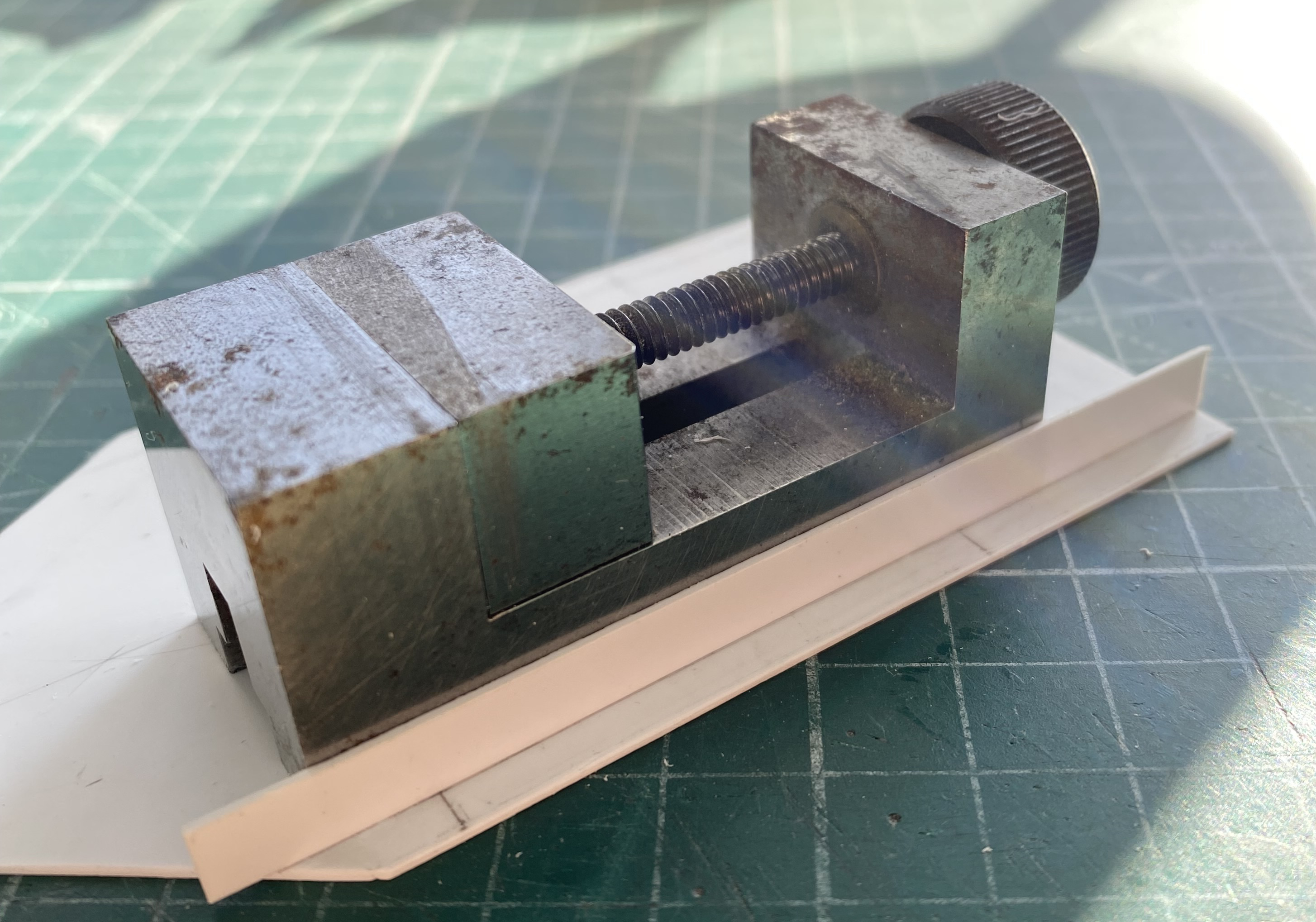
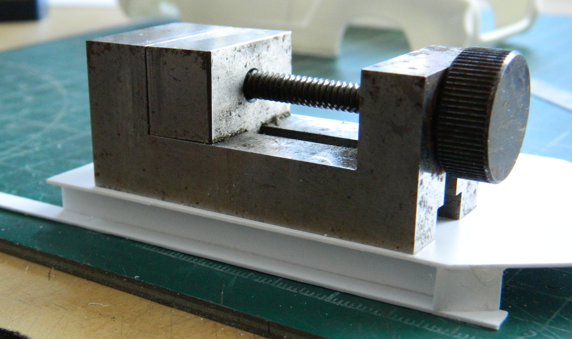
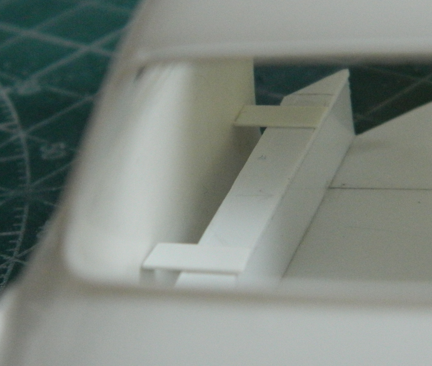
The reason I moved the bottoms of the doors upward was to have a space for sponson-mounted fuel cells. Best I get started on them. I used a milling vise as my 90-degree angle and used .030″ (.762mm) for the sides of them, using the lower edges of the doors as my gauge, the height of these are about 1mm below the opening:
Then I used the vise as a weight to hold the tops down firmly:
While those were setting up, I put the rear tires (resin parts from HRM, the same source for the ZF transaxle) roughly where they go longitudinally to get a very rough approximation of what I’d need from the fender flares:
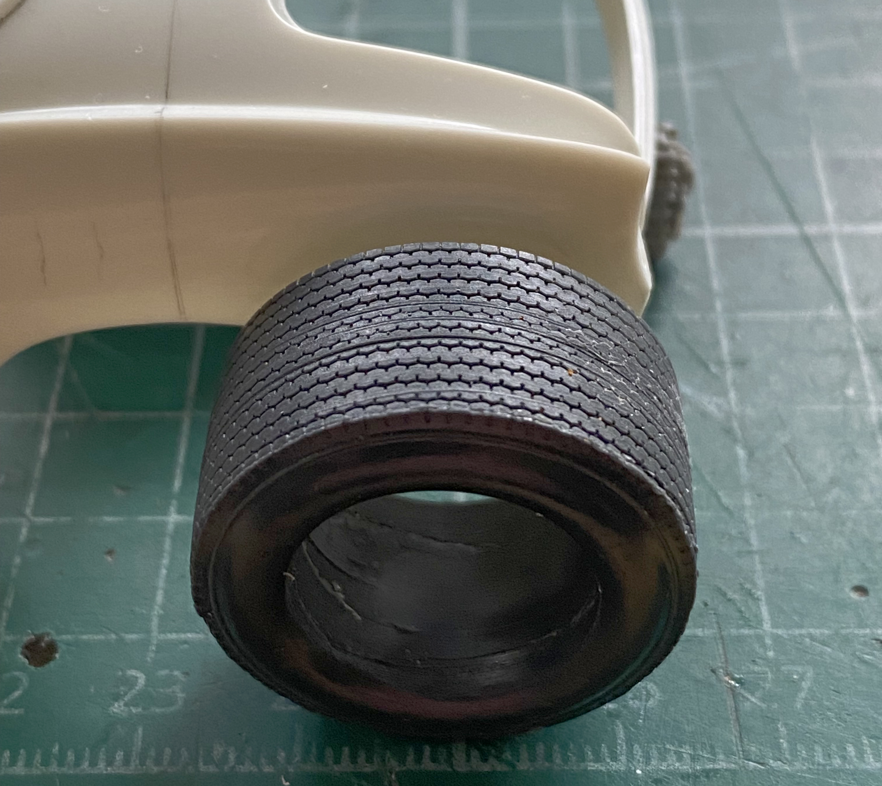
It’s looking like about half that tire will stick out beyond the body. Also note how far back from the stock wheel opening it sits. And there is going to be substantial reshaping of the back of the car to accommodate it all. For fender flares, I’m going to use highly modified VW Bug fenders. Because of the taper to the rear of the rear Bug fenders, I’m going to put those on the front and connect them under the nose of the body and create the “cow-catcher” front spoiler so common at the time (and yes…I bought a VW Bug kit just to get the fenders):

I’m going to use the Bug’s front fenders on the rear:

Because of the amount of work and reshaping required, I’m waiting until I have the fenders fit and attached before I reconsider what I want to do about the transaxle sticking out. And because of the prominent headlight buckets, I’m going to transform those into the taillights. At some point I’m going to have to decide where I want the air that is sucked into…wait…did I tell you about the radiators? Now wouldn’t be a bad time to do that.
I’m not putting the radiators in front. I’m going to reshape the forward portions of the rear fender flares into scoops. Air inlets. Behind those inlets will be the radiators, which is why I’m discussing the radiators in plural. Racing cars that have front-mounted radiators have to deal with the volume of air introduced INto the car in some manner. The GT40s (and more than one of the 60s and 70s F1 cars) had two triangular-shaped outlets on top of the nose of the car with ducts to allow the introduction of all that air some way out. Air that comes in needs someplace to get out, otherwise odd and unwanted things happen when, and where, all that air gets compressed. A front-engined, front-radiated, car will start to get light in the nose at very high speeds because the air has no easy egress. It stuffs the engine compartment, meets the firewall, and gets out at the base of that firewall. The high-pressure air can get so high-pressured that it starts to lift the nose of the car. As it lifts the nose, the simple downforce created by the weight of the car is lessened and the nose rises. This allows more air under the car and, in addition to the air being stuffed into the engine compartment, the air allowed under the car as the nose punches through it lifts the nose even further. From the throttle-jockey’s perceptions, steering authority degrades into steering requests. Not pro-survival when the speed of the car is into triple digits and not merely because there aren’t tires on the roof.
Putting the radiators towards the rear of the car mitigates the lifting effect of all the above. But the air still needs to get out. It will find a way out, but with a car possessing a full belly-pan, lots of drag is the result because the air can’t simply force its way out from under the body. If you notice Group 7 cars from the 60s and 70s, almost all of them (including the GT40s) had screen panels at the rear so that the air has SOMEplace else to go and an easier way to get there.
There. Now I’ve mentioned the radiators. It’s not unlikely I’ll mention them again later on.
Now that the basic structure of the sponson tanks has been blocked in, I have to get them to fit the inside of the body. I did it by placing the body over the monocoque and gluing (lightly, I mistakenly thought) blocks to the top of the sponsons and up against the body:
Then I added strips of .030″ (.762mm) to that width:
Once that glue cured, I added scraps of the same thickness under the seam. These extensions are wider than the bottom of the body and with the many, many, on-and-offs ahead for dry-fitting, I’d really rather that they didn’t snap off:
While those were curing (both sides), I used the scriber and razor saw to remove the Bug fenders. Curious being that I am, I wanted to get a notion as to how much work was going to be needed to get these to go from detached fenders to solidly attached fender flares. In short…LOTS:
Both sets of fenders are roughly where they need to be. In looking at the rear, I can see that the back of this engine-sled isn’t going to look very Ghia-ish. Since I’ll be using the headlight buckets for brake lights, if the stock taillight positions are even visible after all the surgery, that would be a good place for backup lights. For certain, though, I’ll have no shortage of options for where the exits for air could be!
Mistakes teach us. I’ve learned a lot. The implication is that I make lots of mistakes…and that is true. Here comes another learning opportunity…
I’d seen a YouTube video (the name of the channel is “Model Car Muse”) where the content-creator used a woodburning tool to weld plastic (see the episode “Scale Model Body Modification Without Filler or Glue”). I decided that, since I’d been a metal finisher at art casting foundries, I wasn’t unfamiliar with using welding to fill a hole. I’d often had to fix a casting where something went very wrong with a section that in turn had to be excised and rebuilt using welding. There’s a big hole where there shouldn’t be one, so I went around the edges of the hole laying in welding bead until the hole wasn’t a hole anymore. I thought that I’d try that with styrene! My experiment with this was building up the underside of the rear of the body so that I could bring the belly-pan to meet it. I used a woodburning tool:
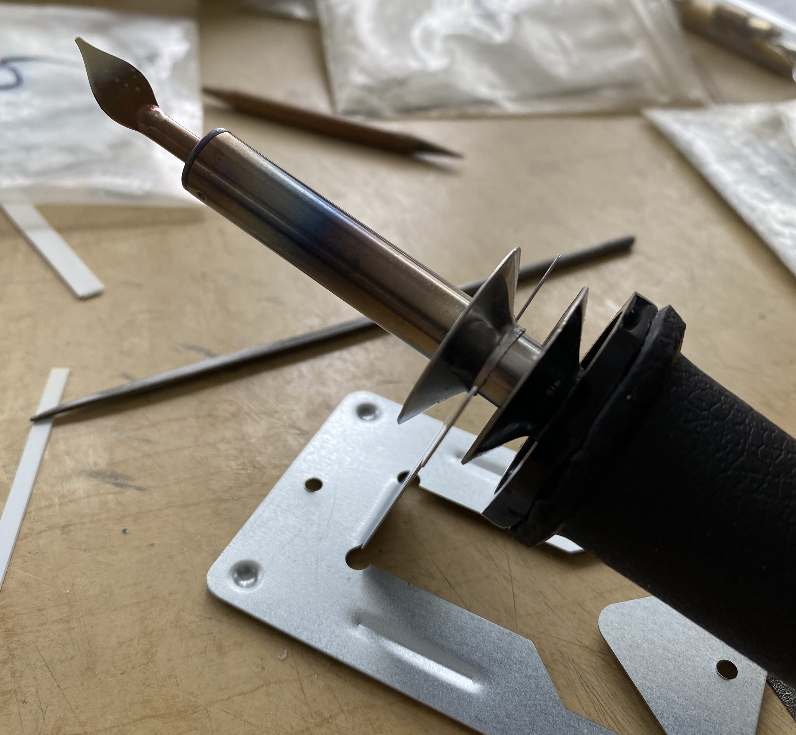
I then cut some sprue from the kit to use as “welding rod,” figuring that the same plastic as the body would probably be visually indistinct once it had been filed and sanded to shape. Then I started melting plastic (the engine cover is just tacked into place so that the body would be dimensionally stable):

Well…it worked, sort of. I discovered some things in this attempt. First, just like metal, cast plastic isn’t as dense as welded plastic. Welded plastic is HARD. I’d thought that being plastic, styrene cement would adhere to it, and it does, sort of…just not to the surface after being melted. The surface has to be ground/filed/sanded away and then the cement will work. Sort of. A large clamping force was needed and the resultant joint easily snapped. These sections of the body are compound curves (he says as if the remainder of the body wasn’t) and getting each side identical IS A BITCH. So the conclusion is that yes…welding plastic with a woodburning tool “works.” In this application it doesn’t work well enough to justify the large degree of work and fettling required. So I snapped them off and roughly cleaned up what was left. I can see a use for it down the line, just not here for this.
Moving on…
Once the glue had cured on the sponson extensions, dry-fitting showed gaps. I used .010″ (.254mm) and .005″ (.157mm) styrene scraps to fill the gaps between the edges of the extensions and the inside of the body:
Then I noticed that the belly-pan had gaps at the edges. Though not snug to begin with, I suspect that this had been exacerbated by shimming the sides of the extensions which pushed the sides of the body slightly outward. Again, with all of the dry-fitting ahead in mind, I decided to shim the edges of the belly-pan instead of all the on and off needed to fit the sponson extensions better:

I knew when I made the belly-pan that it was too short and would need to be lengthened, so I attended to that:
With the sponsons at this stage, they will also need to be lengthened. Before I can do that, I need to know exactly where the wheel openings are going to be. Before I can do that, I have to build more inner structure so that I can precisely determine where the powertrain is going to be, so the sponsons will be extended once I have made that determination. However, one of my goals is for there to be a minimum of 25 gallons fuel capacity. I took the measurements, converted to full-scale numbers, and determined how many of gallons the volume of these sponsons were. 11 gallons (41.64 liters) combined. In the above photo, there is a rectangle drawn just above where the pan has been extended. This is the space for the engine (considering tuneups, maintenance, etc. I would need space to get at the work). The space to either side can be additional fuel tanks! I haven’t done the numbers and conversions yet, waiting until they’re done before I drive myself to drink (any excuse, y’know) getting to the fuel capacity of them.
Torque would be a major concern if this was an actual car. The two forward lines drawn across the pan delineate where the doors are, which in turn delineates where the seats go, and so forth. I broke out the Mk I Eyecrometer and determined where I wanted the partition between the people space and engine space to be. The forward crosspiece is where that will be. The rear crosspiece is for structural rigidity and…oh wait! That’s an empty space! I could put more fuel in there! The thought is that the sponson tanks would be fuel cells. Since there is a float on an arm inside a gas (petrol) tank that enables the fuel gauge to work, I knew I was going to need a feed-tank for both fuel cells to feed into (which is where the fuel pumps would draw from) and that’s where the fuel sender assembly would go. The fuel gauge would always read “full” until both sponson tanks had emptied into the collection tank. Once the the fuel gauge began to move, it would be time to find a refueling place, the potential distance to which would be governed by the capacity of the collection tank and the distance this car could go on that amount of fuel:

Of course I’d glued (securely, of course) that second crosspiece in place before I realized that I could move it back and increase the fuel capacity, and therefore range, before the absence of go-juice turned the driver into an annoyed pedestrian. That will be taken care of!
And speaking of partition, it was time to get to work on that.
I HATE MATCHING AN INTERIOR CURVE. HATE IT HATE IT HATE IT. Yet match it I must. Ever see a contour gauge? That tool with all the movable wires that gets pressed across the face of a curve to be replicated? I have one. No. It doesn’t work all that well on something this small. But the idea of that gauge I could reproduce using strips of styrene. So I used .040″ (1.016mm) strips instead of wires. The body was placed over the monocoque and taped in place, then I placed one strip of plastic into the space between the two crosspieces and lightly glued it vertically at the base with the top (I thought) in contact with the roof. Subsequent strips were glued only to each other (I thought) in the same manner until I have a workable copy of the inside of the roof between the sponsons:
Yes…I see the space at the top of the center strip. Now. I didn’t then and just continued blithely on with it.
But I got it to work in spite of myself:

And then traced it onto .030″ (.762mm)” for rigidity:
And then the fitting happened…and happened…and happened… Finally my brain decided to join the party and I realized that I would be adding a strip of styrene on either side of this partition because in reality, I would need to attach this to the roof somehow:
Certainly good enough!
Now to add the wings using the same procedure with styrene strips, only using .015″ (.381mm) for ease of removal:
It ain’t pretty, but it worked. I added the wings of the same thickness as the center section of the partition:
Once fitted (and yes…it was as tedious as the last one was), I added structural support to the back and then laid out the rear window and cut the opening:

I learned my lesson with the M4 build as to how difficult it can be to fit clear styrene into an opening. I’m not doing that again. What I am doing is to using a sheet of .015″ (.381mm) clear and sandwich the clear between the part I just made and the one I’m about to make, also of .015″ (.381mm):

I placed the clear panel in place and then added .015″ (.381mm) around it for structure and to keep the clear panel from having any ability to move and then glued everything down:

Then it was time to join the front to the back and check fit:

Fits there…let’s see if the Eyecrometer got the window opening correct relative to the body:
Yep! Just where I wanted it.
Crankenstein – 1/25 Scale Kitbash Build #1 Parts Layout and Resin Casting
This project has been rattling around under my wig (not that I wear one) since I rekindled my model-building fire in ’14. I’m going to stuff a Small Block Chevy (SBC) into a Karmann-Ghia where the rear seat would go if it had one. (I’d always rather stuff too large an engine into a car than a back seat.) Nobody makes a kit of this…configuration…which means there will be much kit-bashing and scratch-building and whining complaints. (Hopefully it will also be entertaining.) It’s my intention to clam-shell the rear body from the doors back (and possible the front body as well but I haven’t decided yet), rework the doors so that they’re “suicide doors,” which are doors that are hinged at the rear (because of how I’m planning on doing the roll-cage), plus fender flares. That’s the short list!
It starts with this:
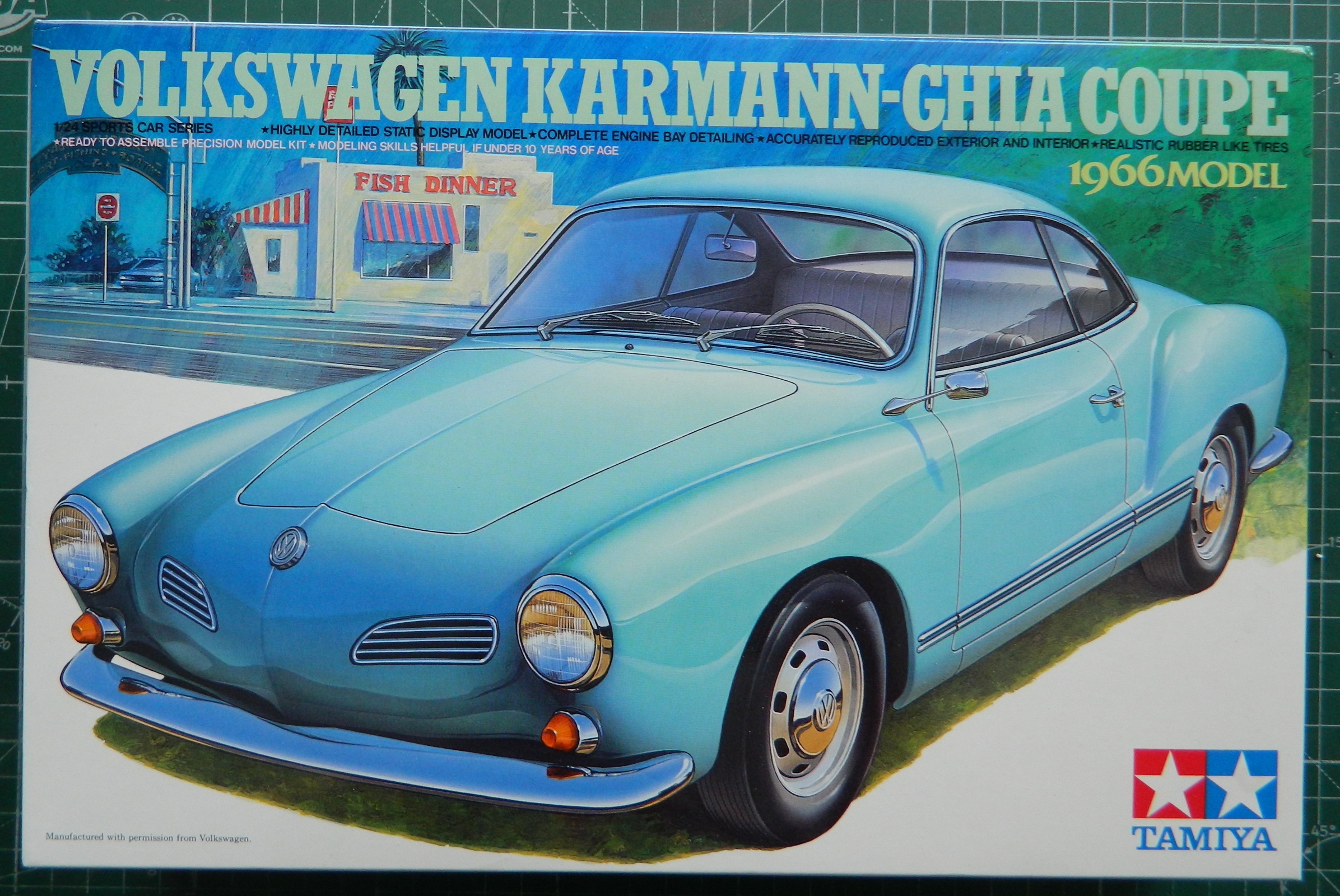
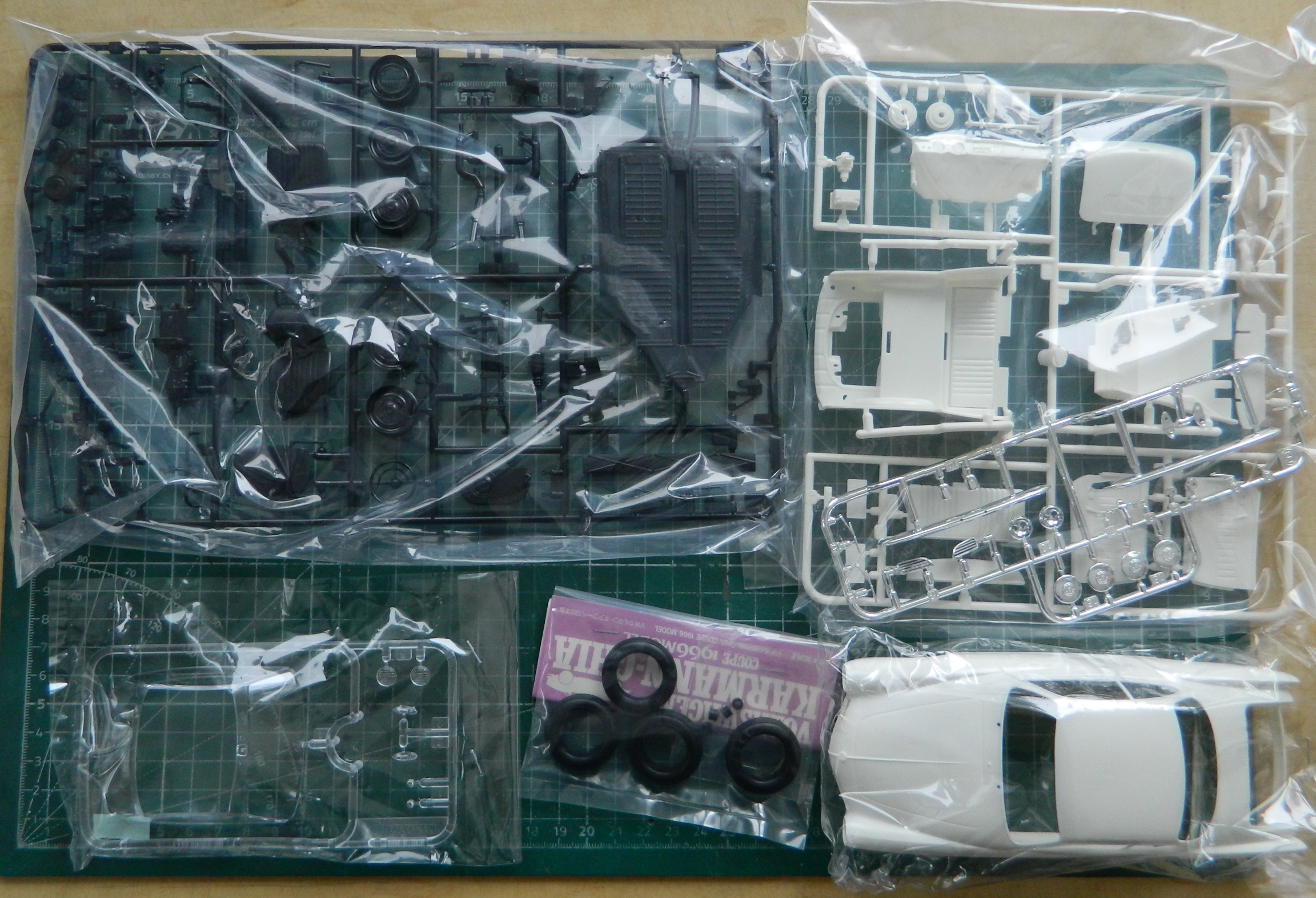
At this point, the only parts I’m fairly certain I’ll be using from the kit are these (I’m not sure about some of the clear parts):
What will drive this build and determine where things go will be where the engine goes and how much room that allows. I want to play automotive engineer as little as possible because I’m not an automotive engineer. That means I’m planning on raiding kits that I have in the stash. A small, light, over-powered car…hmm…where have I heard about this before? Oh! The Ford GT40! It so happens that I have two IMC GT40s, the MkI (#104-200) and the MkII (#112-200) on hand. Those were really good kits back in the mid 60s (Adam’s navel, that was FIFTY YEARS AGO!) but half a century ago [INSERT WHINING HERE] the standards of accuracy were so much lower. I took the engine/transaxle parts from the MkI kit, glued enough of the parts together to learn if I have enough room to do this (looks like it, sorta) and that the transaxle supplied with this kit is utterly inaccurate.
I went online to see if anyone made a 1/24-1/25 scale ZF transaxle and I found naught. Okay…I’ll scratch-build one. To see if the transaxle from the MkII kit was any better, I opened the box and was pleasantly surprised. No, the transaxle in the MkII wasn’t any better (it looked identical to the MkI), I had gone online to see if I could find any AM goodies for it back when I’d purchased it a few years ago and I did. Historic Racing Miniatures made what looked like a nice resin AM set. Excellent! I’ll just cut the ZF off the 7L engine and…whoa. Wait a sec. I decided that before I sacrificed this part, because I do have those two kits I’d hoped to use this in, let’s see if I can replace the part that I’m about to butcher. Good thing I looked because it seems that HRM closed its doors shortly after my purchase. Bugger. That means it’s mold making time.
Since both my molding rubber and casting resin have been sitting around for at least a couple of years, perhaps even to the pre-Covid period, they’re certainly past their use-by date. So I ordered more.
I’ve seen resin SBCs online but for some reason I decided that I didn’t want to do a resin engine (I have no actual reason for that decision, so chalk one more notion up to mood and whimsy), so I checked online and FB modeling groups to see if there was a kit that offered a nice rendition of the SBC in plastic. The consensus from a couple of online locations is that Revell’s ’69 Chevy Nova SS (kit #85-2098) is pretty good. Got my hands on one and I support the consensus. It’s pretty good.
So look…I get that I’m a bit off center (amazing what one can learn about oneself in SIXTY YEARS). For whatever “reason” (because mood and whimsy ain’t always “reason”) (in fact, they’re rarely “reason”), I decided that since I’m going to be making molds anyway, I’ll go ahead and take a mold of the SBC and cast one in resin! I’d bought another kit for its engine because I didn’t want to use a resin AM part, but I’m going to use a resin copy of the kit’s part instead? The irony isn’t lost on me (unlike my sanity, evidently, or consistency). In order to mold the SBC parts I’m going to need to do some assembly and cut the 4-speed transmission free (the nicest replication of a Muncie 4-speed I’ve yet seen) and then block off the holes left in the engine and trans (I’ve also attached the intake manifold) so that they don’t fill with rubber when I pour it:

I wanted to make the mold with the heads and valve covers attached to the block along with the spin-on oil filter. Fitting the heads to the block shows an unacceptable gap between the heads and manifold so I shimmed the gaps with .005″ (.127mm) and .010″ (.254mm) scrap styrene:

Since I’m going to change to suicide doors, I needed to decide how. It will be much easier to move the hinges from the front to the rear if the rear of the doors are vertical instead of curved and angled. And since there are going to be lots of bits stuffed into a volumetrically-challenged interior, I need to figure out where the fuel tanks will go. At this point I realized that I need some idea of what I have to work with. I tacked the major interior parts together so that I could check how much space, and where that space is, to work with:

My intent is to have a minimum of 20 gallons (just under 76 liters) of fuel onboard. I haven’t taken exact measurements yet but if I take another notion from the GT40 and put the fuel tanks in the door sills, that could give me the total fuel quantity I want. And if I move the door sills up just a little, that would work to help the chassis by adding rigidity as well as increasing fuel quantity. I’m going to open the doors at the bottom between the two chrome strips. I’m also going to need an air intake for the carburetor (no fuel injection…I’m doing this using early/mid 70s tech) so I added .020″ (.508mm) scrap styrene to blank out the left side rear window which is where the air intake will go. I puttied the panel lines I won’t be using and penciled in a rough approximation of where I want the doors to hinge:

I added the heads to the SBC and trimmed back the shims and realized that, once again, kit manufacturers seem to replace what should have an aluminum finish with chrome (more irony since the “chrome” added to car kits isn’t chrome, it’s aluminum). In the case of this SBC, that means the valve covers, fuel pump, and air cleaner housing (which I think I’m going to replace with an AM assembly) are chrome…which I don’t want. I’ve noticed that when builders want to strip chrome, they use some pretty caustic stuff; oven cleaner, brake fluid, and several types of paint strippers. Well, if it works for them… I’ve found that simple household bleach works great. It’s cheap (so that I can spend my cost savings on more AM goodies) and I can just flush down the drain without ecological penalty after using it. I think the longest it took me to strip chrome was from the Bugatti Type 35B I built. Half an hour. These parts were stripped to bare plastic in 15 minutes:


I’m not building a show car or custom anything (well, aside from most of the build, that is). This isn’t intended to be a trailer-queen and I’m building it as the street racer I wanted when I was young and more enthusiastic than smart. And if I had built this Back Then, I wouldn’t bother with dress-up parts; stamped metal is just fine. I’ll be painting these the standard color that Chevy used.
I wanted to get a rough idea about how well (nor not) this thing will fit into what limited space there seems to be and it looks like it’s going to be snug. I’m prepared (grudgingly) to move the rear wheel wells rearward if I need to:

As you can see in the above photo, I added some bolts to the engine that it needed as well as what will be the pouring block when it’s molded.
Since I was still awaiting the molding materials, I figured it was high time to get the parts ready to mold:
When doing the GT40 suspension upgrade parts, I realized that molding a coil-over part would be tedious, if even possible, so I just scratch-built a pair. My first attempt used a plastic rod with annealed copper wire wrapped around it for the spring:
Freakin’ tedious for marginal results. Instead, I used annealed 22 gauge copper wire twisted around a screw. It was easy to maintain even gaps between the coils and the gaps between the coils were easily adjusted. I will do the coil-overs for the front suspension later using thinner wire. On the two rear coil-overs, I left one end flat; I’ll figure out later what sort of attachment I’ll need there:

With the molding supplies in hand, I started making mold boxes and going through that process. Once again perfection eludes me. I thought that all I’d need was 150g of rubber. Nope. Events showed me that I should have mixed up (and boy am I often mixed up) 200g. 150g just barely covered the SBC block. I’m being giddy using the word “covered.” Had it cured at the thickness as poured, the “covered” area would be more of a membrane and therefore easily ripped. I scraped all the rubber out of the mixing container that I could to get that inadequate coverage. Then I remembered seeing someone who had cut the cured rubber left over from other molds and I filled out the volume of the mold box a bit and by dropping the cured rubber chunks into the uncured rubber, being certain that I got enough support over the engine part by dropping a block of cured rubber directly over it:
Once that had cured, I laid out an estimation of how I wanted to mold the HRM parts that I want to use in this build:

While that rubber-filled box was curing (without repeating my previous error of not enough rubber mixed), I laid out the IMC parts in its own box (these parts have also been dechromed):
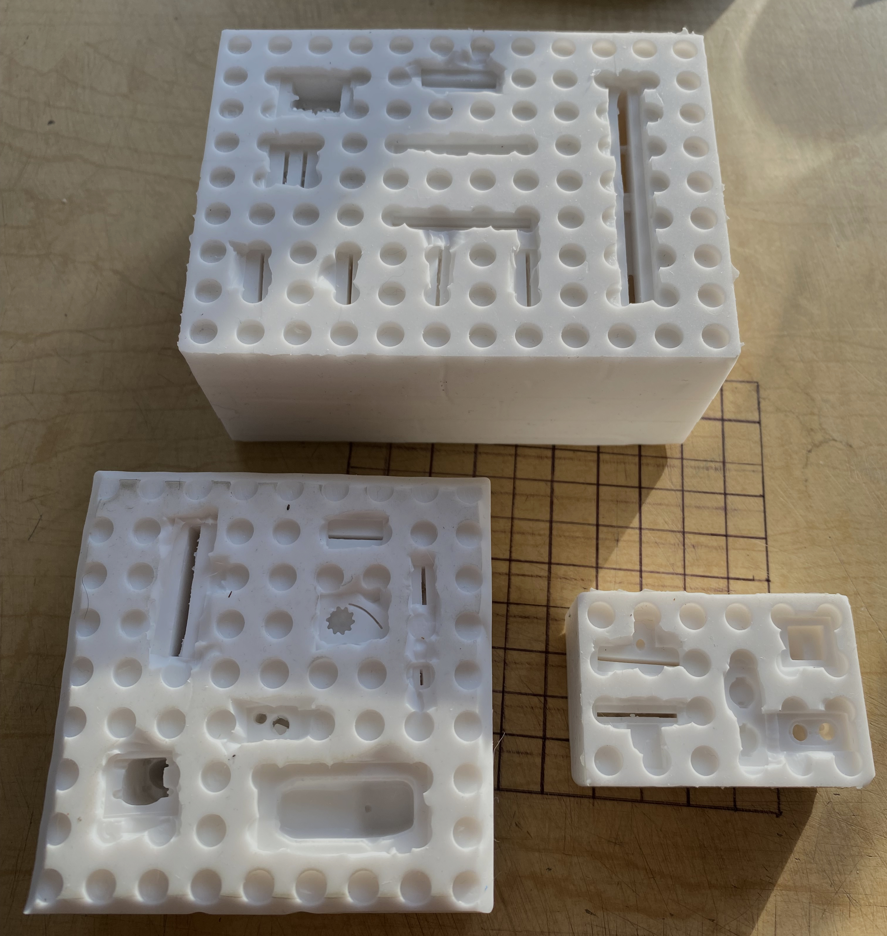
Molds are done:
The next thing I tried was to make a custom bucket seat for the driver. I’ve seen a lot of resin seats online but they’re all modern or intended for drag racing. Why can’t I used a drag racing seat? Road racing cars are subjected to lateral G-loading more often than drag racing seats because unless something really goes wrong, that seat won’t have to deal with lateral loading as much as a road racing seat. I started with Aves Apoxie Sculpt:

It cures into something pretty hard, yet it’s easy to cut and shape. I started with a block that I intended to form into a buck that I could vacuform the body of the seat over (the rubber mold it’s resting against is to keep one end of it bent up until it hardens):
After sawing, filing, sanding, (and bitching at another one of my “clever” ideas) I ended up with a shape I thought would work. The buck was mounted on a scrap piece of styrene tubing and then it was glued to the platen of a vacuum-molder:
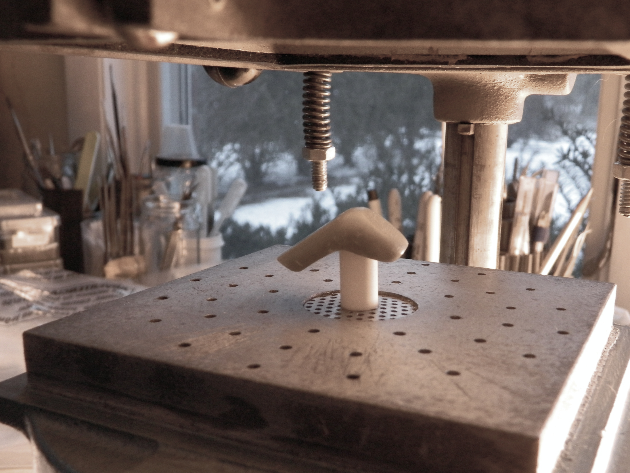
Normally I use .010″ (254mm) up to .020″ (.508mm) for vacuforming, but plastic stretches quite a bit when it’s vacuformed, meaning I would end up with something far too thin for scale. This time I used .030″ (.762mm) and this is what I ended up with:
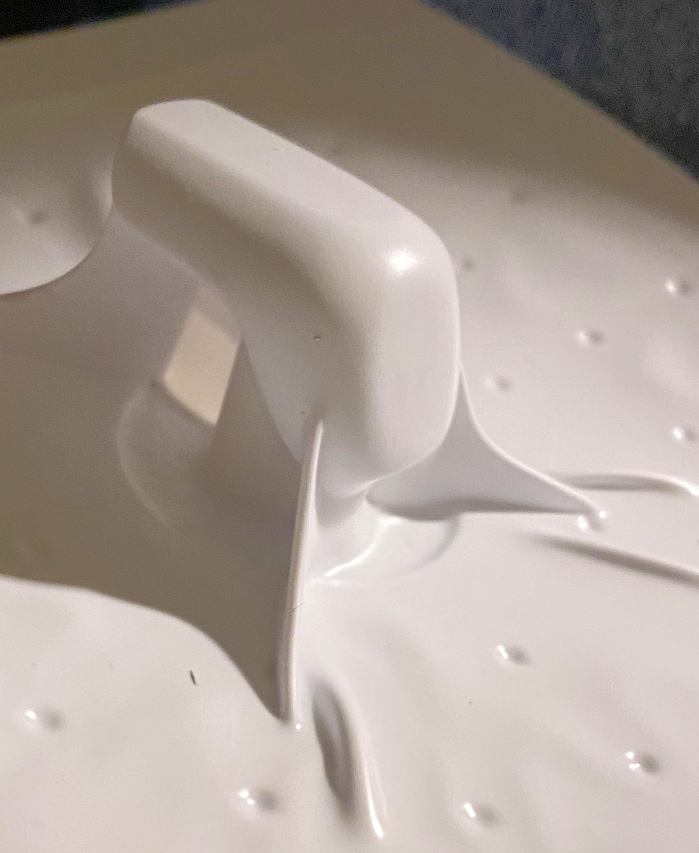
The folds to the right of the photo going from the platen to the buck are significantly thicker than I’d expected. I’m not sure why it happened like this but my suspicion is that the thicker plastic combined with the significant suction of this molder (an old dental molder) may have been responsible. But because the plastic is thicker than what I normally use, I wondered if I could fix that. I mean…I still have the buck so the only thing at risk was a sheet of styrene. Once I had cut away the excess plastic, I applied a liberal quantity of Tamiya Extra-thin inside and out, and clamped the outside of the “fins” tightly. After letting it sit overnight, I cut, filed, and sanded the fins away. Though it almost worked, the last bit on the inside of those “fins” didn’t bond. It was so close that I used a couple of strips of scrap .005″ (.127mm) styrene as reinforcements inside the bucket, figuring that the seat cushion will hide the addition, and filled the gap with 3M Acrylic Putty. I think it worked well. At the bottom left corner you can see where the fold was:

A closer shot of the other side:
And if you look closely at the above photo you can see an oval penciled onto the plastic. This is the cutout for where the lap belt will go through. To keep the unsupported plastic from deforming under the drawing and drilling steps, I placed it back onto the buck for support (and this photo clearly shows the strips I’d glued to the inside of the bucket to support the fix of the sides):

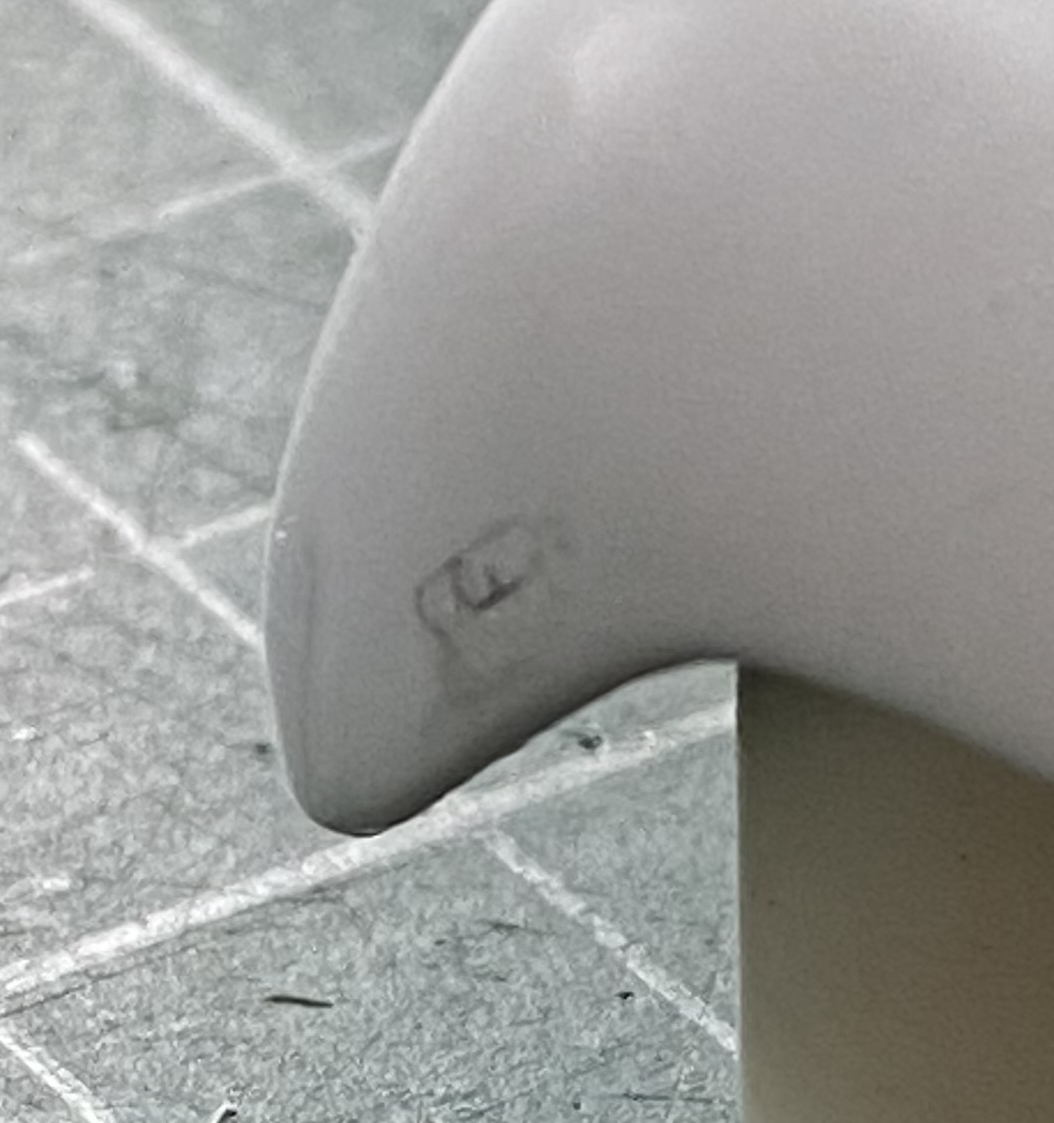
Using more Apoxie Sculpt, I formed the raw blanks for the seat cushions. This epoxy putty will adhere to whatever it rests on/against while it hardens. Rather than try to make a more generic form, I wanted these cushions to fit snugly to the bare seat (for what I hope are obvious reasons), but I knew that if I just stuffed the plastic seat with the putty, I’d probably destroy the seat getting the cured putty to release from it so I could shape them. So I wrapped the seat in plastic wrap before stuffing the putty into place(s):
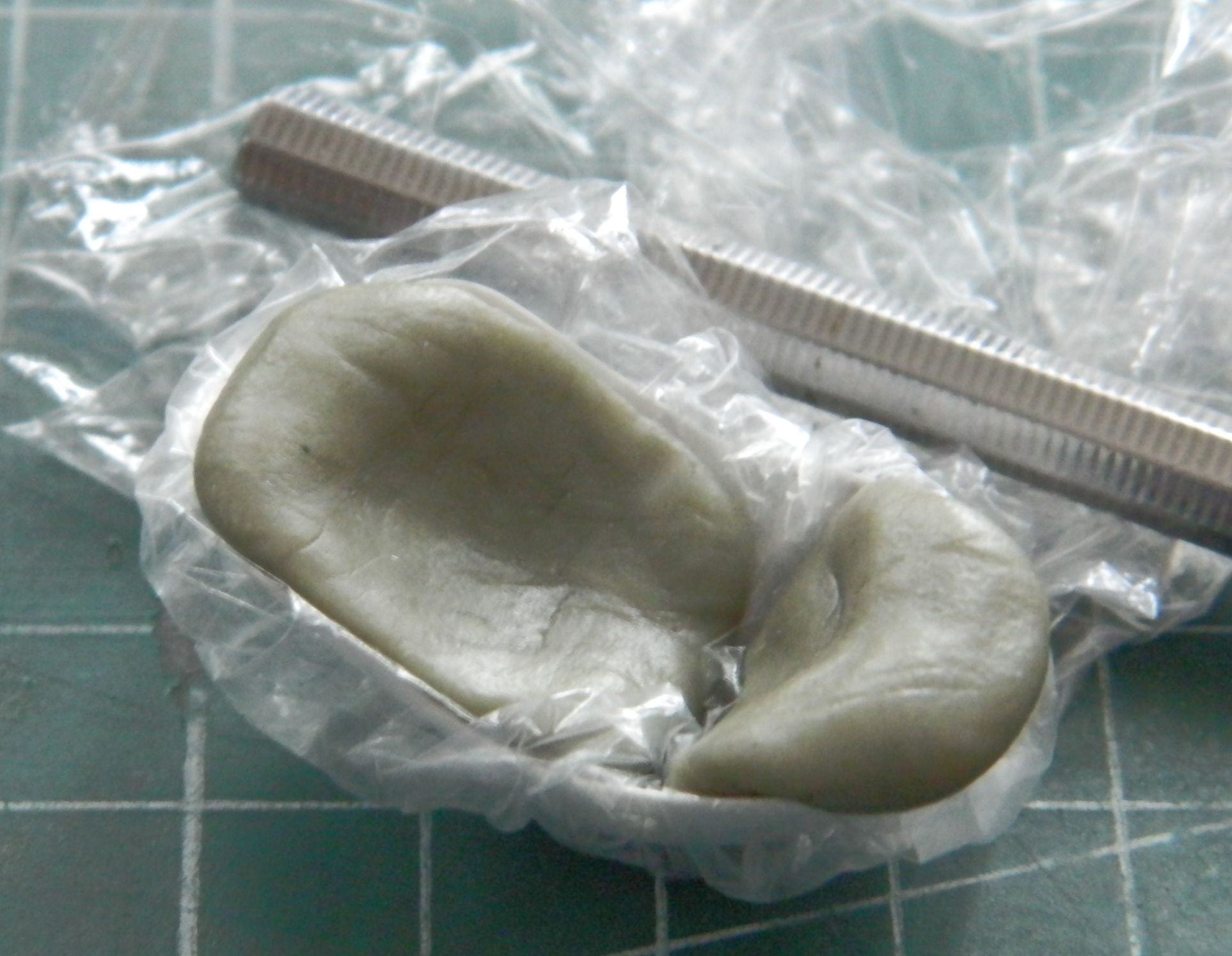
I came back the next day, peeled the plastic film off, and checked the fit of the blanks. Just right:

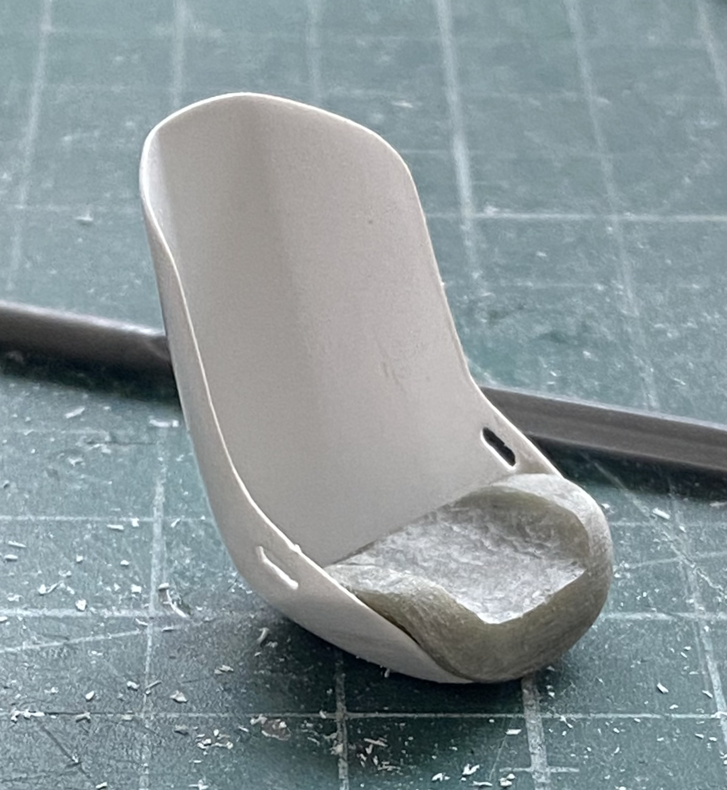
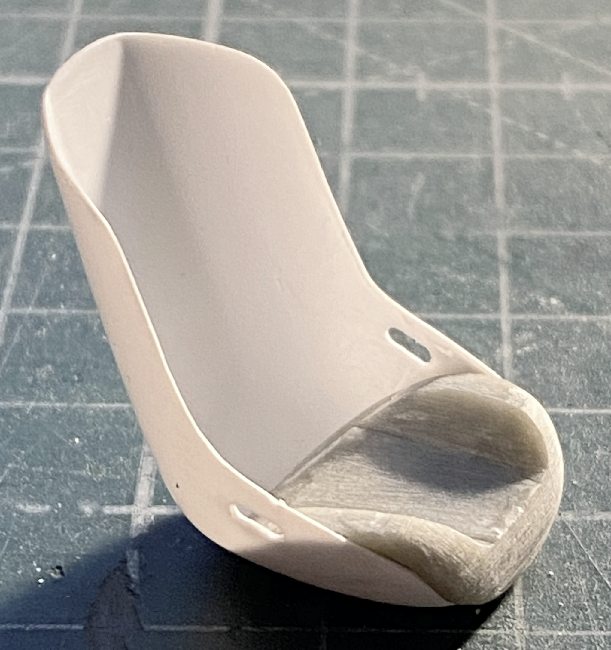
Then the sculpting process (which isn’t finished yet) was started on the bottom seat cushion, initially using a Dremel, and then graduating to files and sandpaper:
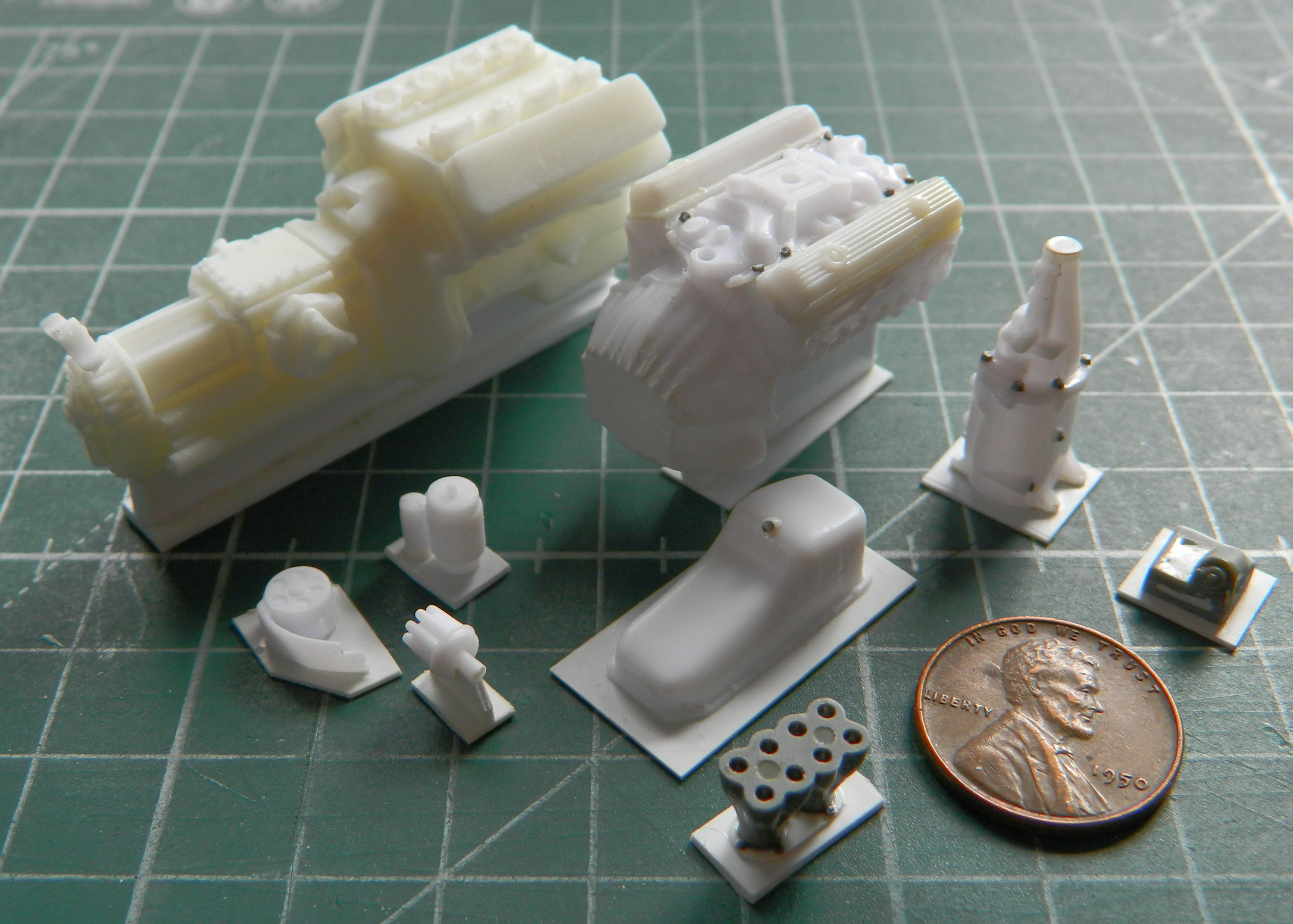
With all the molds made, I mixed up a batch of resin, added just enough dye (formulated for this purpose) to make the parts gray (or grey) and make it easier for my old eyes to see, and poured resin. Most of the parts came out quite well, with a couple of exceptions. The large part above the ZF transaxle is the suspension mount subframe. One of the lower arms snapped while I was prying it out of the mold (you can see the resultant crack at the bottom right, just above the pouring block…no problem to glue back together). The other problem was the oil pan for the SBC. With the first pour I didn’t add enough resin to fill it and the flange where it mates with the block didn’t fill. Essentially an open-back mold, I filled it with resin again and, figuring that there really wasn’t any place for bubbles to form, I didn’t put it under pressure. It was late and I didn’t want the compressor in the garage cycling on and off as pressure leaked out, so I just let it sit overnight on the bench. Mistake. The resin, being exothermic, produces gas as it cures. With it under pressure, the gas bubbles are compressed into invisibility (where they form at all). That doesn’t happen if some beef-wit lets it sit on his work bench overnight…and every place there’s supposed to be a bolt head on the mounting flange is also a bubble:


So I tried it again and poured another one, except this time under pressure. Well…as it turns out, my garage, being unheated and where the compressor is, didn’t really allow enough heat energy for the resin to cure within the four-hour elapsed time it’s supposed to cure. When I took the mold out of the pressure pot, I saw that the resin was about the consistency of grape jelly. I figured that since there wasn’t enough heat energy in the garage, I’d stick it in the oven for a half hour at 170F (76.66C). I was only half successful. The resin continued to cure, but since it wasn’t under pressure…well…let’s just call that a “learning experience.” The next day, I mixed more resin, stuck it into the pressure pot at 60psi, and instead of letting it cure for four hours, because it’s still cold in the garage, I let it stay out there for nine hours. By this time it was getting a bit late and I still didn’t want the compressor to cycle all night. I closed the valve on the pressure pot but disconnected it from the compressor (which was shut down and drained). Without releasing the pressure (which still indicated 60psi on the gauge), I brought the pressure pot into the (comfortably warm) shop and let it sit for another three hours while the pressure bled off. After that three hours the pressure had dropped to a little over 20psi. I opened the valve, took the molds out, and demolded the oil pan. Success! A nice, dense, bubble-free, casting that I can use.
I’m interested to see what other “learning experiences” the next month will teach me.
Crankenstein – A Brief Overview
This is an unusual Overview in that the object I’m discussing never (to my limited knowledge) existed…and this starts with Kelmark Engineering.
Back in the 70s, Kelmark offered a square tube platform chassis to replace the floorpan of the VW bugs and Ghias. Why? So that one (or a team) could put a V8 where the back seat would go. As someone in their 20s with more enthusiasm than common sense, I thought that this was a fantastic idea! The fact that half a century has passed between then and now indicates that I did not have the funds to create this monster…but I wanted to. Clearly the notion has stayed ensconced in my mind because I decided that I would be more likely to survive the experience if I built a model of the car instead of the actual car.
That’s what this build will be, putting a small block Chevy (SBC) into a Karmann-Ghia.
This will require kit-bashing, scratch-building, and scouring the Internet for bits ‘n’ bobs that I can buy instead of having to build. This is going to be a kit-bashing and scratch-building extravaganza!
Let the insanity commence…
Tamiya M4 After-action Report
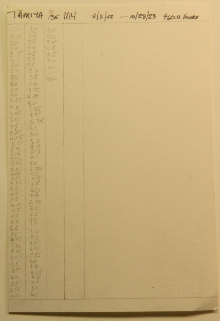
Total time building 460 hours* (of which 36.0 hours was spent crawling around looking for parts that dropped onto the floor).
Begin date November 11, 2022; end date October 28, 2023.
Vendors:
Tamiya
Kit #35190 – M4 Early Production Sherman
CMK
CMK turret set #3027 and inner hull detail set #3026
Tiger Model Direct (TMD)
Set #1236 – M4/M4A1/M4A3 PE Engine Deck Set
Set #1289 – M6 Detailed Periscope and Mount Set
Set #1317 – U.S. Footman Loops Type 3 (Small w/Feet)
Set #1171 – Sherman Return Roller Arm – Straight
Set #1237 – Sherman Ventilators
Set #1086 – M4A2 Rear Armor with Adjustable Idlers (I bought this set just for the adjustable idlers)
Set #1258 – M4 Sherman Grouser Compartment Vent Covers; Factory, Asymmetrical
Set #1176 – VVSS B197681 Intermediate Production Track Return Skid
Set #1251 – Sherman “Slatted V” Siren Set
Set #1232 – Small Hatches (for DML but they can obviously work with a Tamiya hull with some fitting
MiniArt
Set #35321 – Continental R975 Engine
Panda Plastics
Set #Worn T48 Rubber Chevron
Archer Transfers
Set #AR35273 – Pin-Ups
Set #AR35209B – Gauges and Interior Stencils (unfortunately dry-transfers are no longer available from any vendor…the last company that produced the chemicals to manufacture dry-transfers has closed and this handy modeler’s resource is as gone as my hairline is)
M&Models
Set #RB082 – .30 Caliber Barrels, turned brass
Tamiya
Turned brass 75mm ammo set (sorry, I lost the packaging and don’t have the item number)
Squadron
Set # SQAA35002 – Resin .30 caliber ammo cans
Resicast
Set #35.226 – Super detailed cupola for Sherman tank
Asuka Model
Set #35-L9 – Browning M2 Machine Gun Set B with cradle
Lots of solder, wire, lead foil, paint (five different manufacturers), and sprue
My opinion
I used Tamiya’s kit because most of the kit would not be used. It’s a basic kit, no sponsons, fins instead of grab handles, recessed welding beads (I’ve found that the best thing that Vallejo’s 100% Acrylic Resin Plastic Putty, item #70.401, is good for is replacing or making welding beads…the tip is fine and with minimal practice allows for the rippled effect of a bead of weld), all the things Tamiya was known for 30-40 years ago. Research showed me that the tank that Tamiya used as their source was an ALCO-produced Sherman. The ALCO tanks had a unique casting where the bow machine gun mounted; it came to more of a peak than the constant-radius mounts used by other manufacturers, so I tried to do all detailing in that style. I did use the kit’s bogies (accurized and modified using skull-sweat and TMD parts), road and sprocket wheels, and idler wheels which I detailed a bit. I didn’t have to cut the engine covers off because they were molded separately. I stuffed that hole with some kitbashed parts from MiniArt’s M3 Lee using their bottom and sides of the engine bay. Since the front engine bulkhead wouldn’t really be seen very clearly, I used TWS’s bulkhead from their R975 resin set. It took some (frequent) judicial trimming to get the engine to fit and the end result was rather accurate. It just fit.
One thing about the CMK interior set was that the directions regarding the location of the interior sponson boxes is not accurate. If those parts are installed as directed, you will encounter fit problems when you try to stuff the turret basket (preferably attached to the turret) into what you thought was the space for it. It’s almost the space for it. Getting the basket to fit (thereby allowing the turret to settle down correctly) is a bitch if everything has been installed, painted, and the upper hull on. It can be done but you won’t enjoy the process!
Once again, Panda Plastics did not disappoint. Their worn T48 track shoes fit perfectly around the kit’s drive sprocket once the upper, inner, edges of the shoes are slightly radiused (rounded off for you non-engineers).
This was my first time using Asuka’s .50 cal set and I really, really, liked it. Enough parts are supplied to build an early or late mount and more than enough scale ammo belts. If you want to do a diorama of the M2 machine gun being serviced, this is a good starting point. You’ll just need to scratch out the inner details of the bolt area. I’ll be using this set again!
The TMD PE set was decent, particularly for the diamond-patterned sponson vent screens. But if you want to use the light guards, don’t. They’re FAR too thin. Instead, use them as templates to scribe .010″ (.254mm) parts instead…you’ll be much happier with the outcome and with the .010″ (.254mm) thickness they’re a MUCH easier to work with and substantially less fragile.
*And now for about the only part of this build that was disappointing and not worth the time and effort to do. Clear panels.
I knew at the outset that putting clear sections to this model was a gimmick. I was hoping it would be a good gimmick but my hopes were left unrealized. Anybody who’s had to deal with clear styrene, and wants to keep it clear, knows how delicate their surfaces are…and that was for the “easy” part, the flat surface of the upper hull’s side. The clear section for the turret was a small section of a clear resin casting. The reason it was a section wedded to the opaque styrene turret was because NO tape I had would stick to the resin snugly and well enough to just mask a section off. The resin was also much thicker than the turret wall it was being inserted into so I had to file it to thickness. Not being completely insane, I did all thickness adjusting from the outside and I am very glad I did. LOTS of filing, sanding, polishing, and many visits back to that tedious well! Once I had both the inner and outer surfaces smooth enough to be clear, I discovered how optical lenses are made! The curvature of the inside of the clear resin plug was not at all parallel to the outer curvature which resulted in a lens and less (as in, not at all) like a window to view the interior bits. As a result, not a great deal can be seen through it and had The Coin come up tails, I would just have painted over it and left it opaque. Being simply flat, the side clear panel didn’t have that problem. With the efficacy of hindsight, I should have realized that the INside of a tank is full of stuff. All that stuff doesn’t really allow much of what’s in there to be seen.
Lesson learned and I highly doubt I’ll revisit this gimmick again.
As ever when adding a plethora of parts to a model that wasn’t intended to have that plethora, there was much fitting, refitting, and colorful invective. Had I not added the gimmick of clear panels I could have probably knocked 60-80 hours off the total time spent. My intent was to model a tank of the 3rd Armor Division, 32 Armored Battalion, which landed after D-Day on June 9 while it was getting kitted up for Operation Cobra, the breakout from the beachhead.
I’m pleased with how it turned out, clear panels excepted.
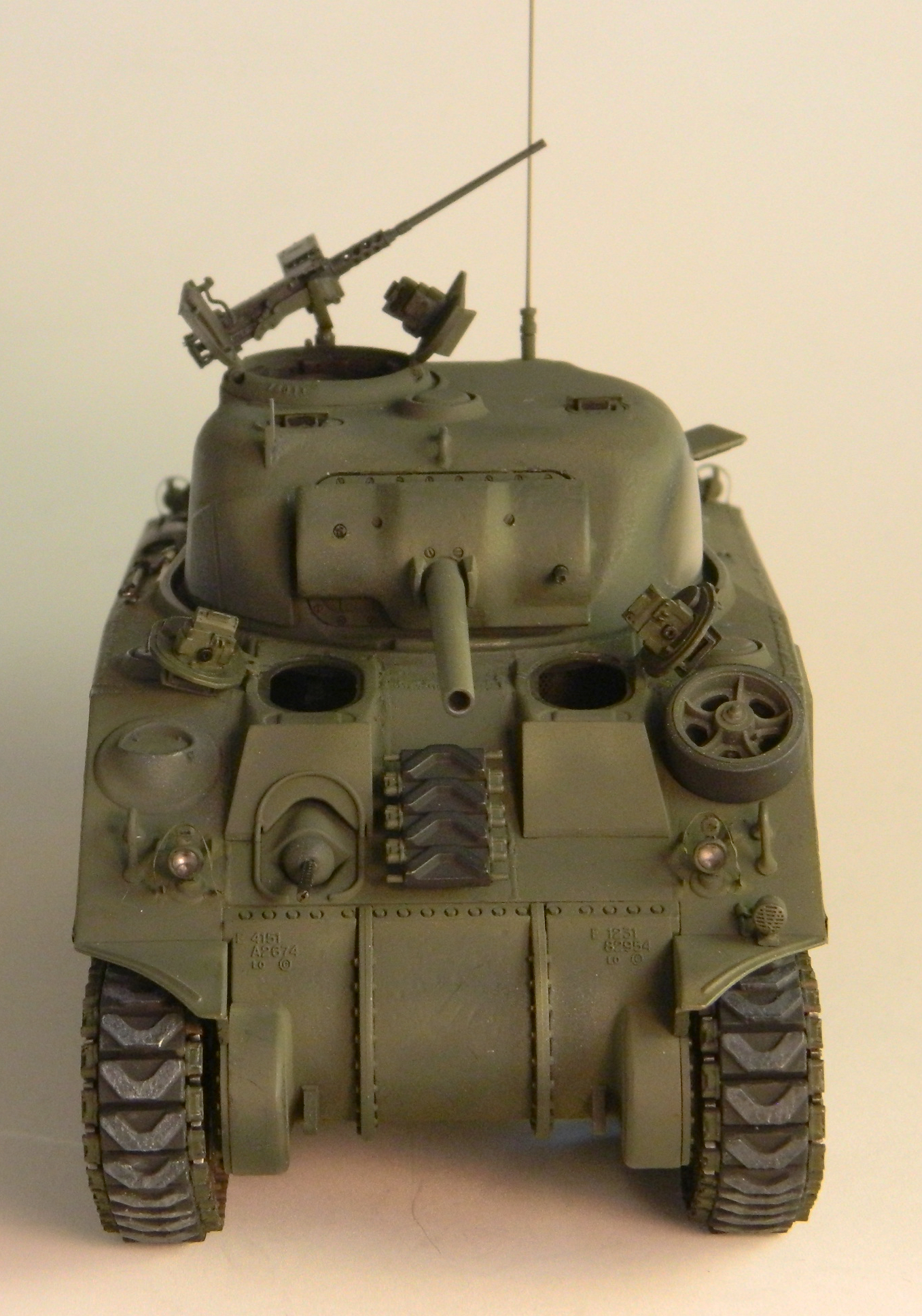

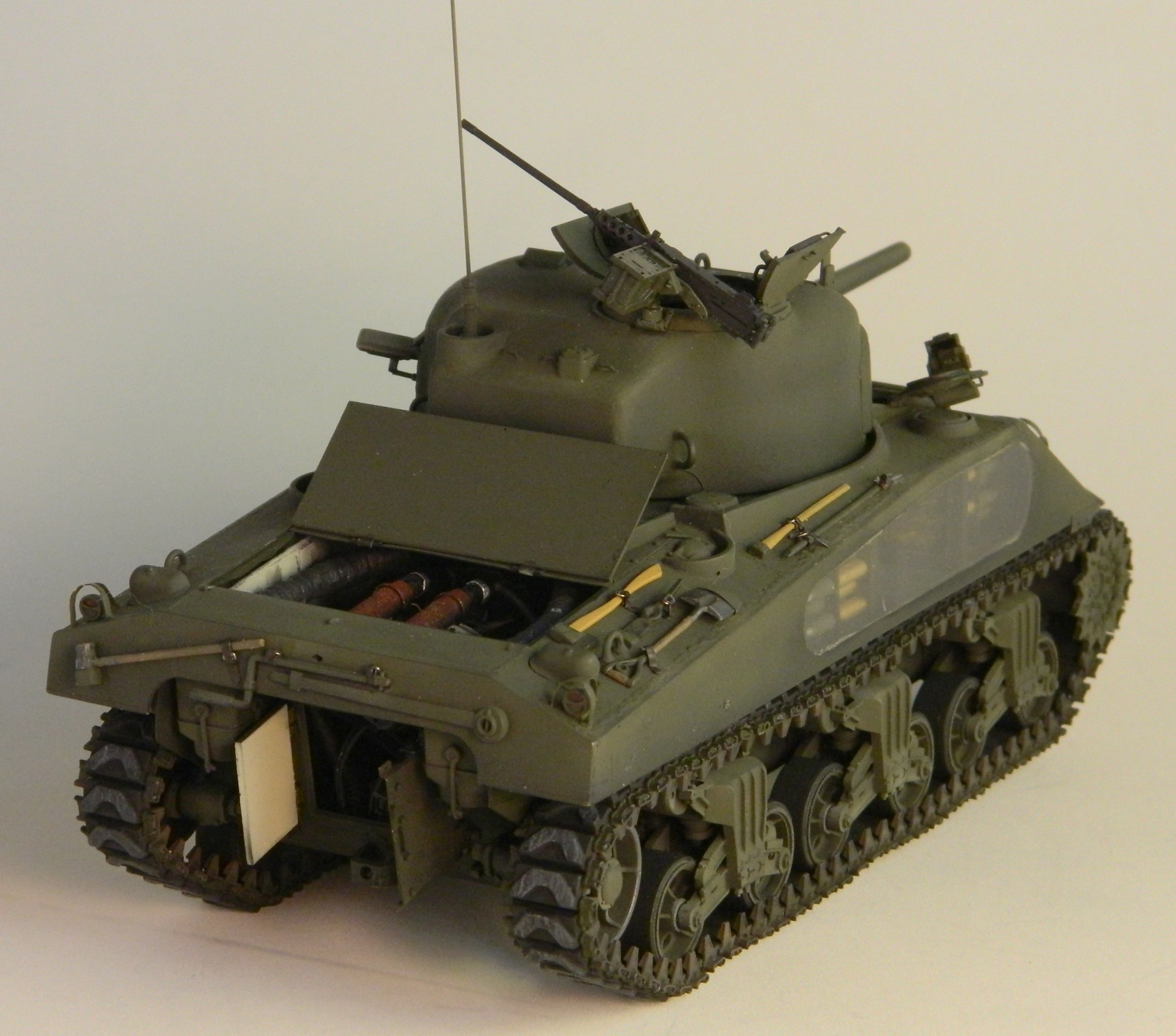
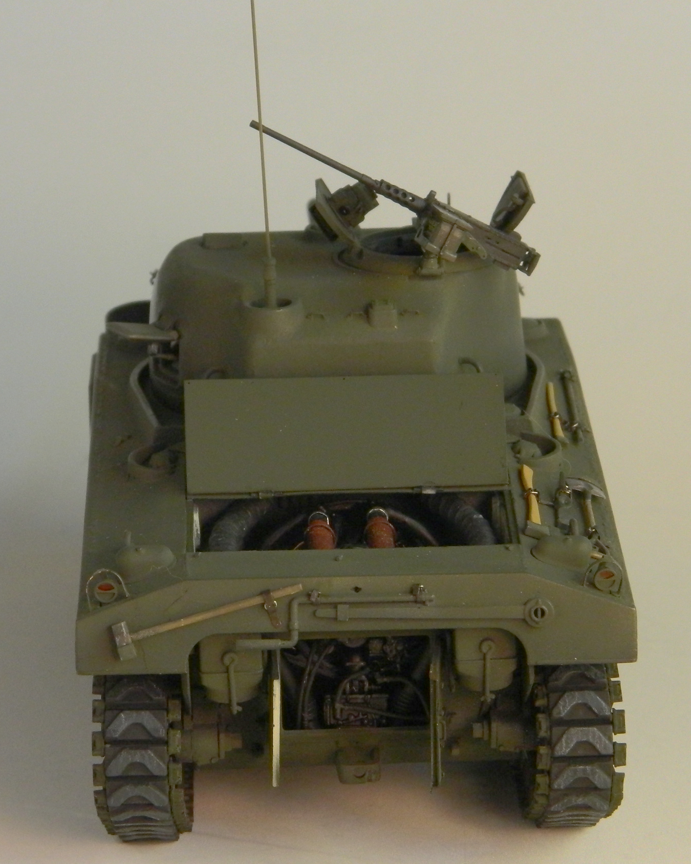
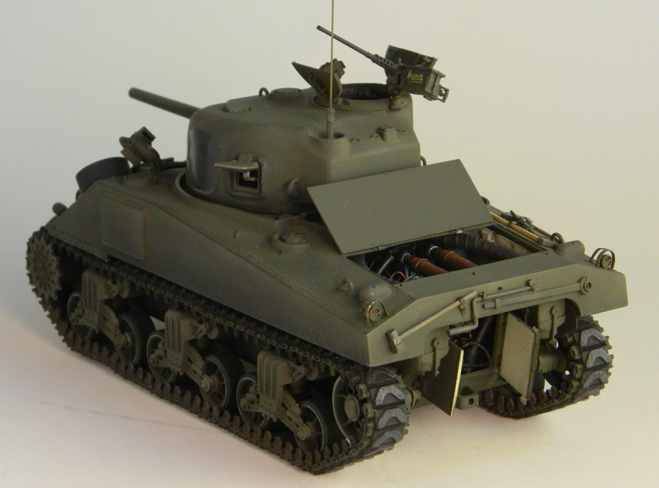


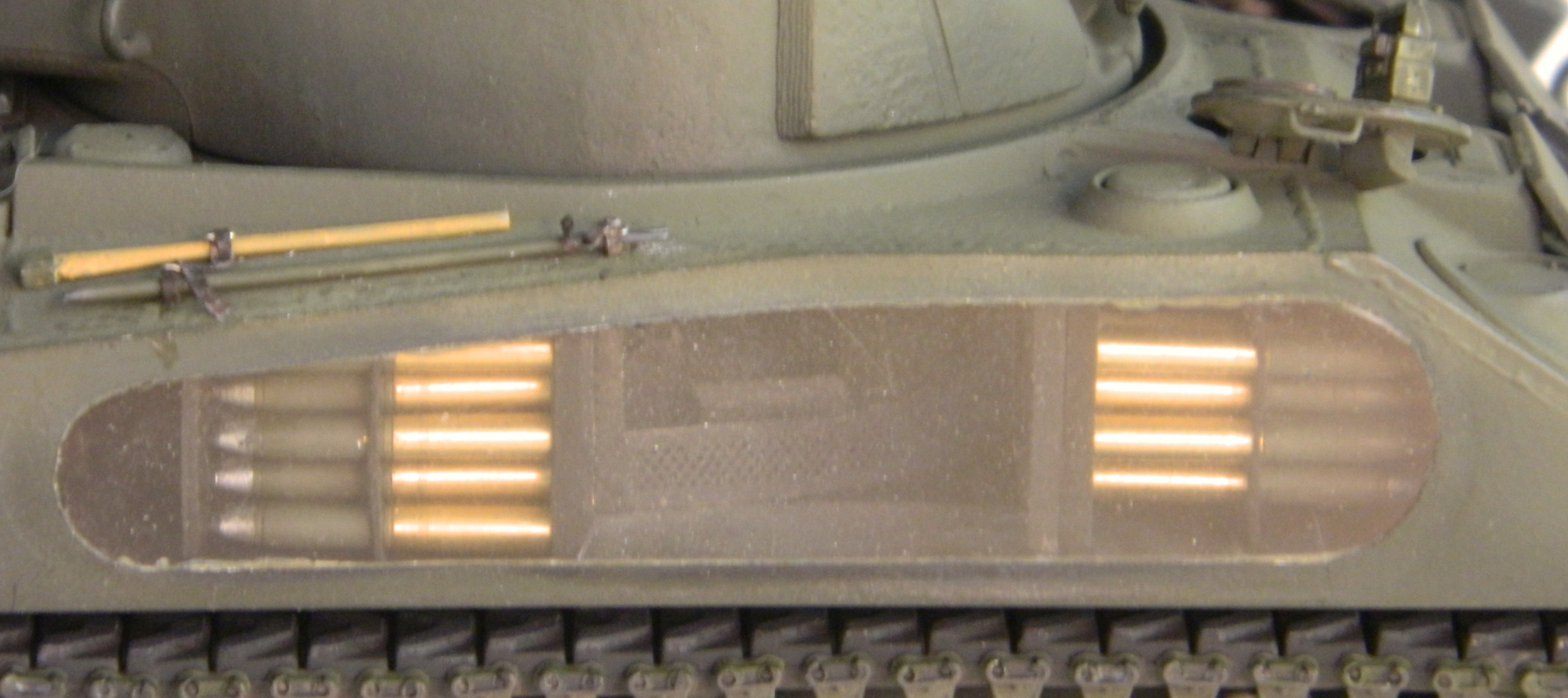
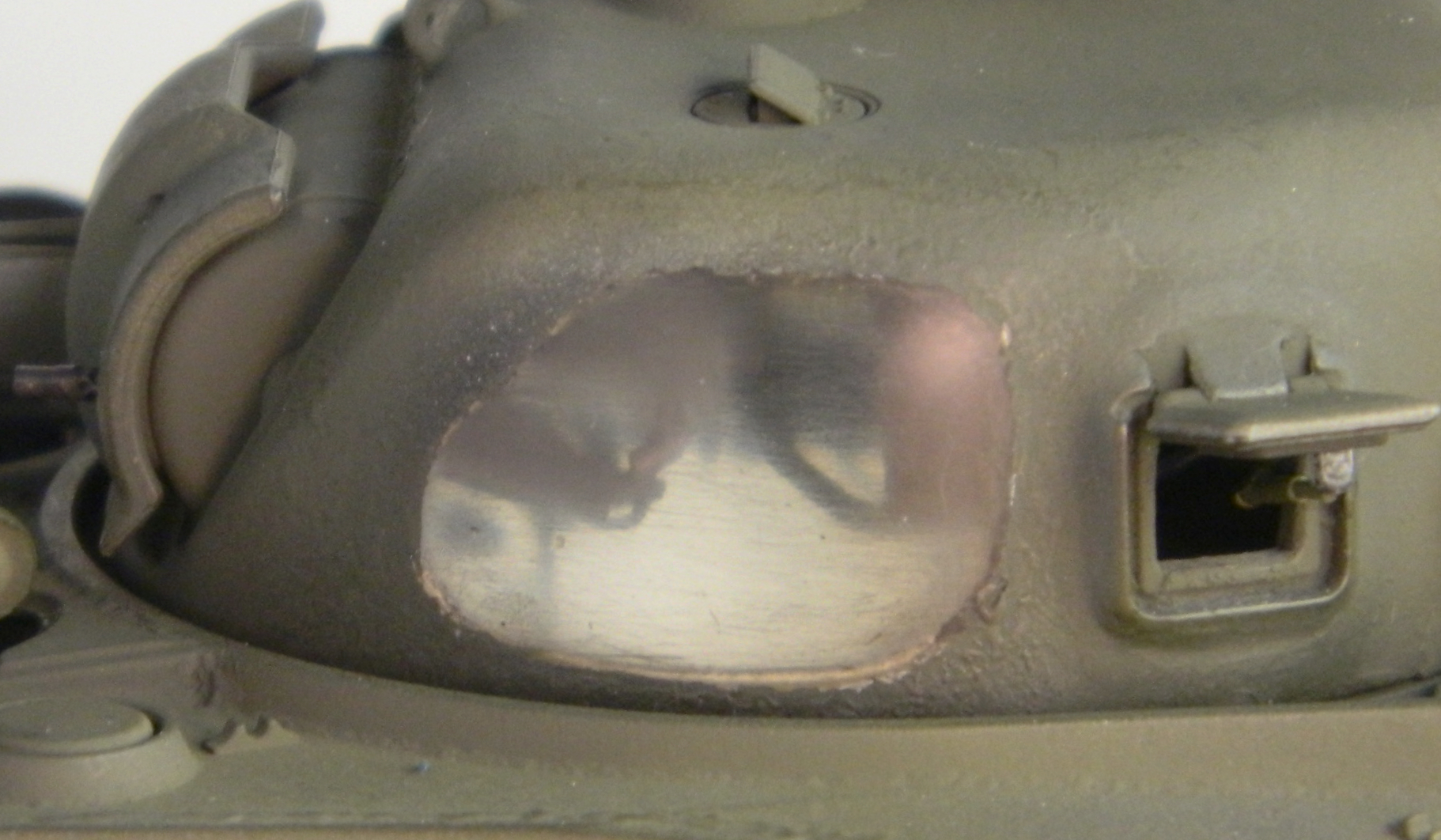
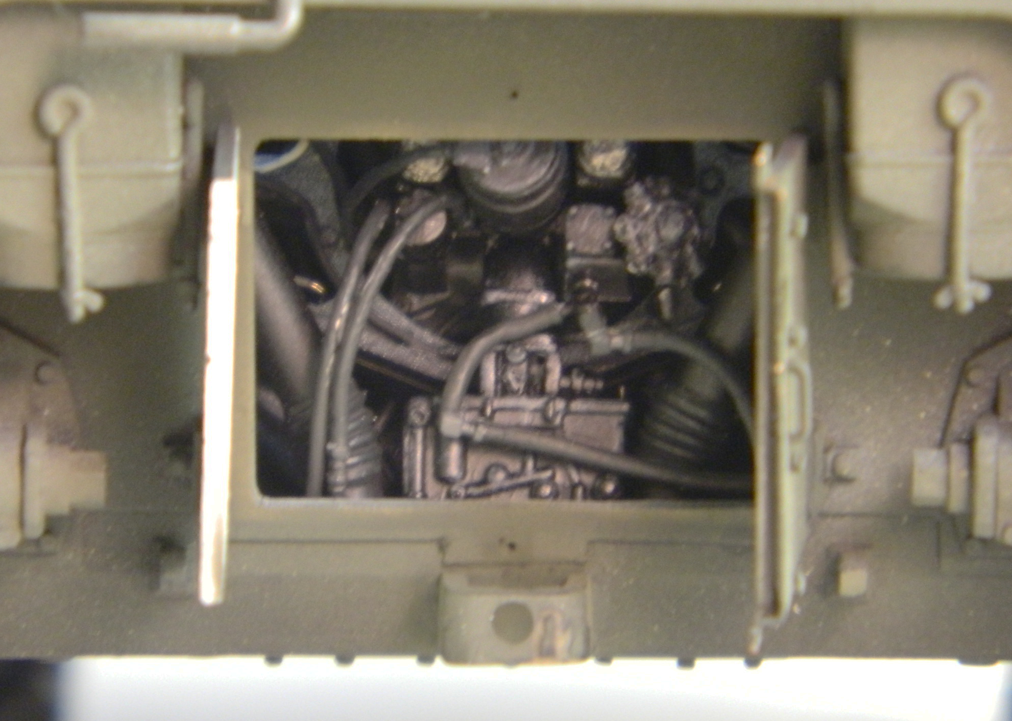

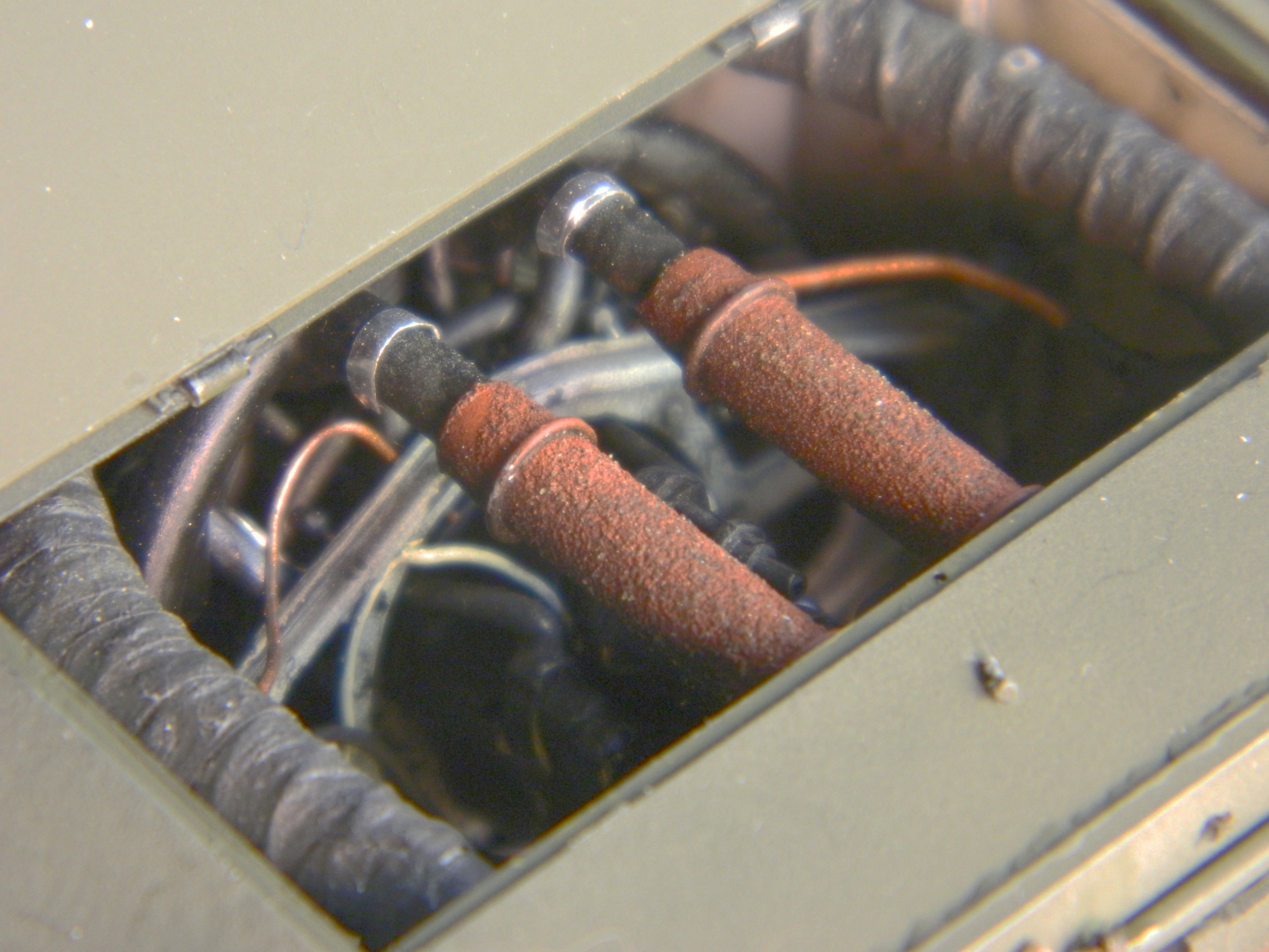


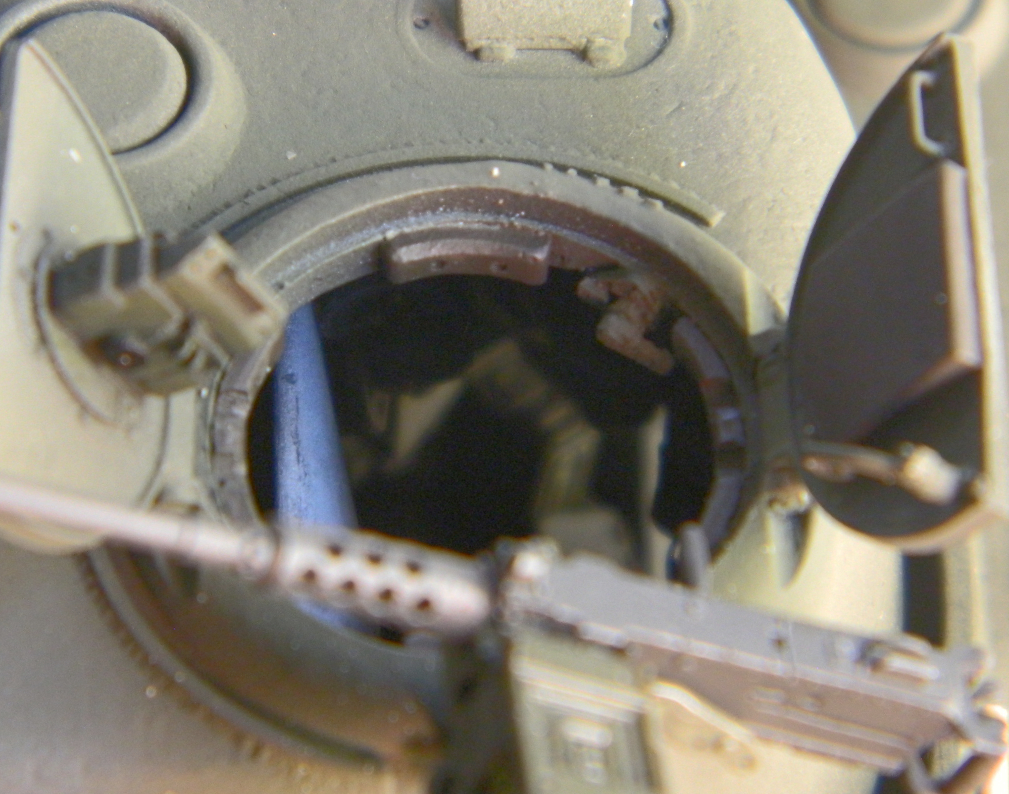

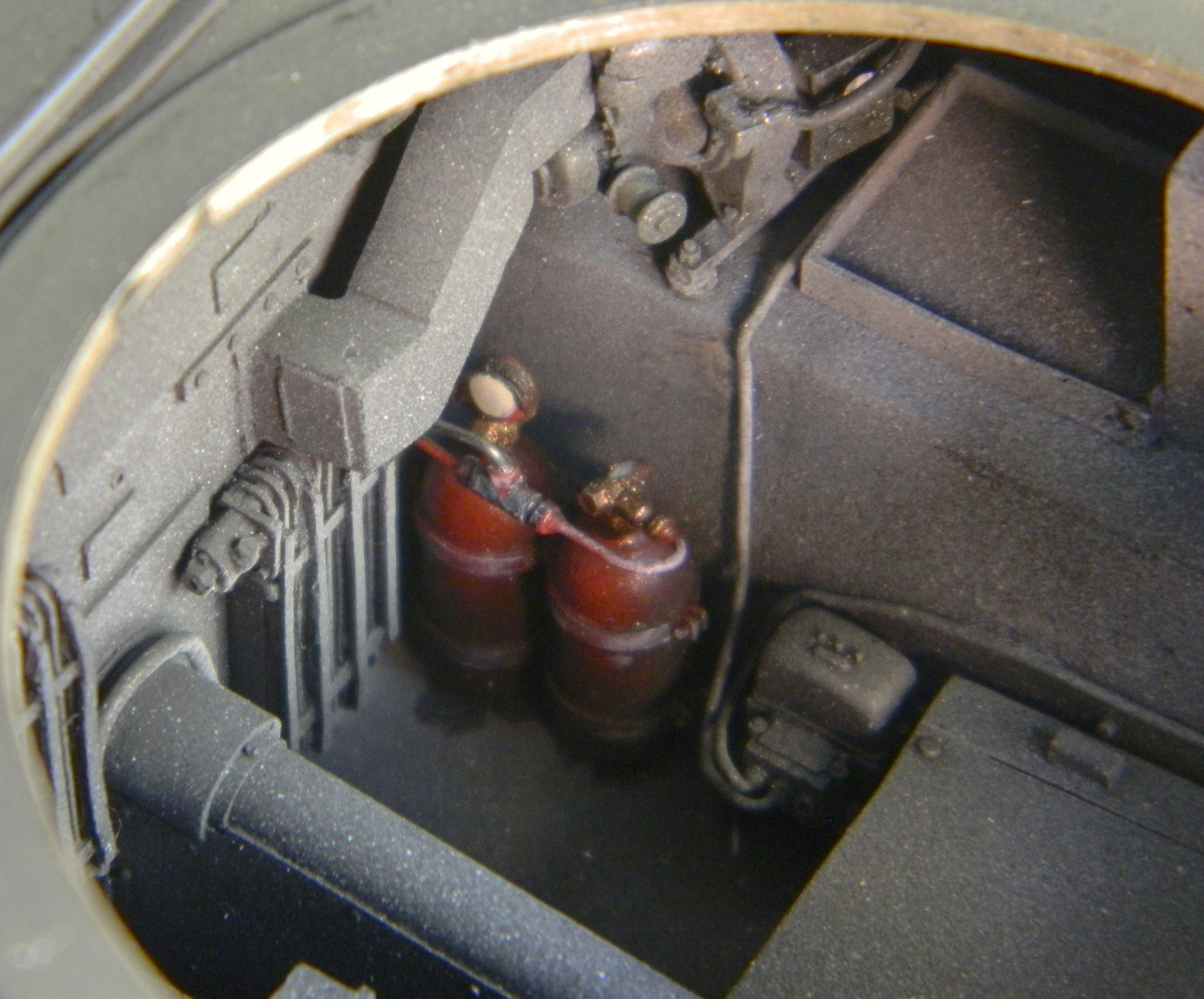
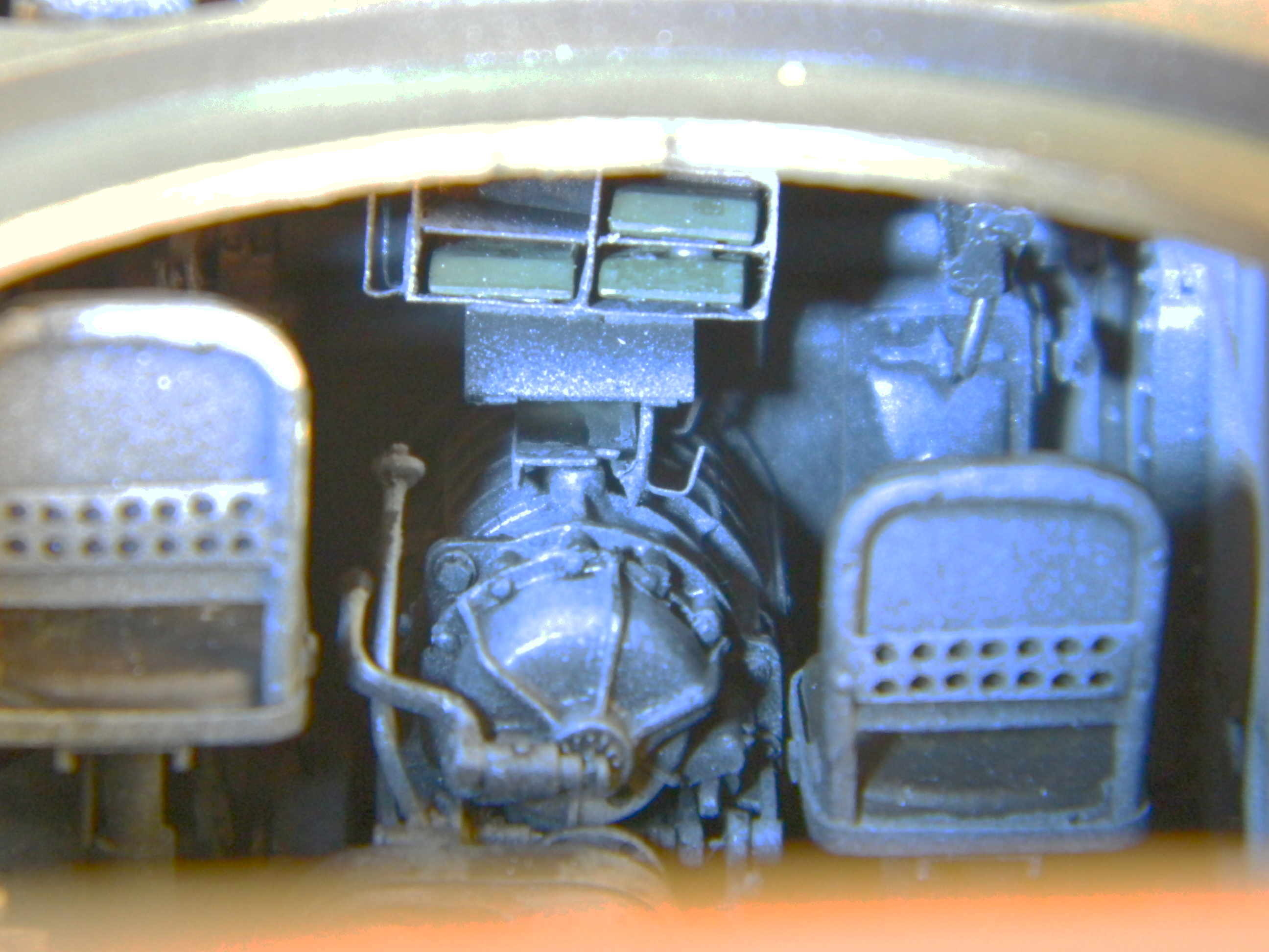
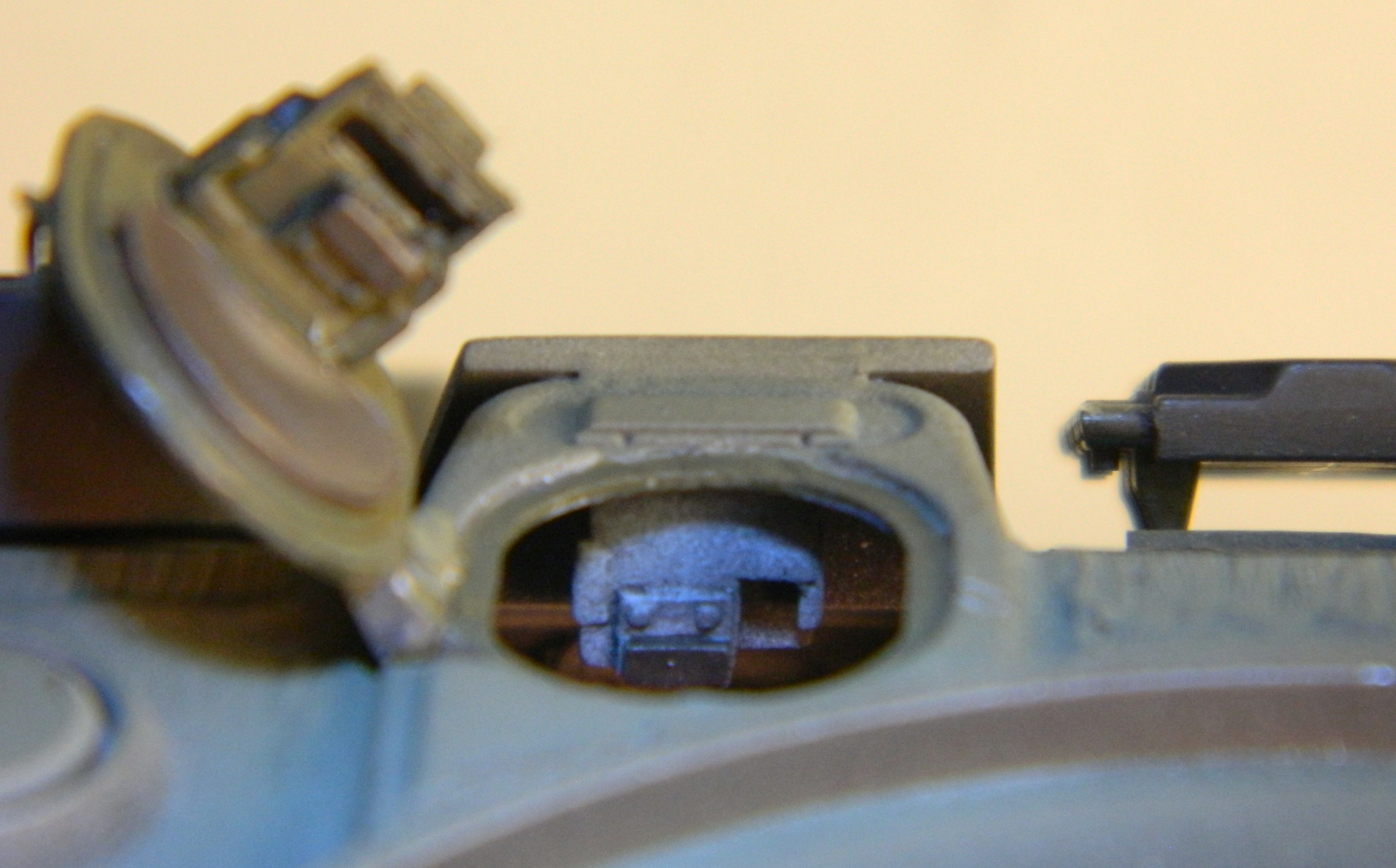
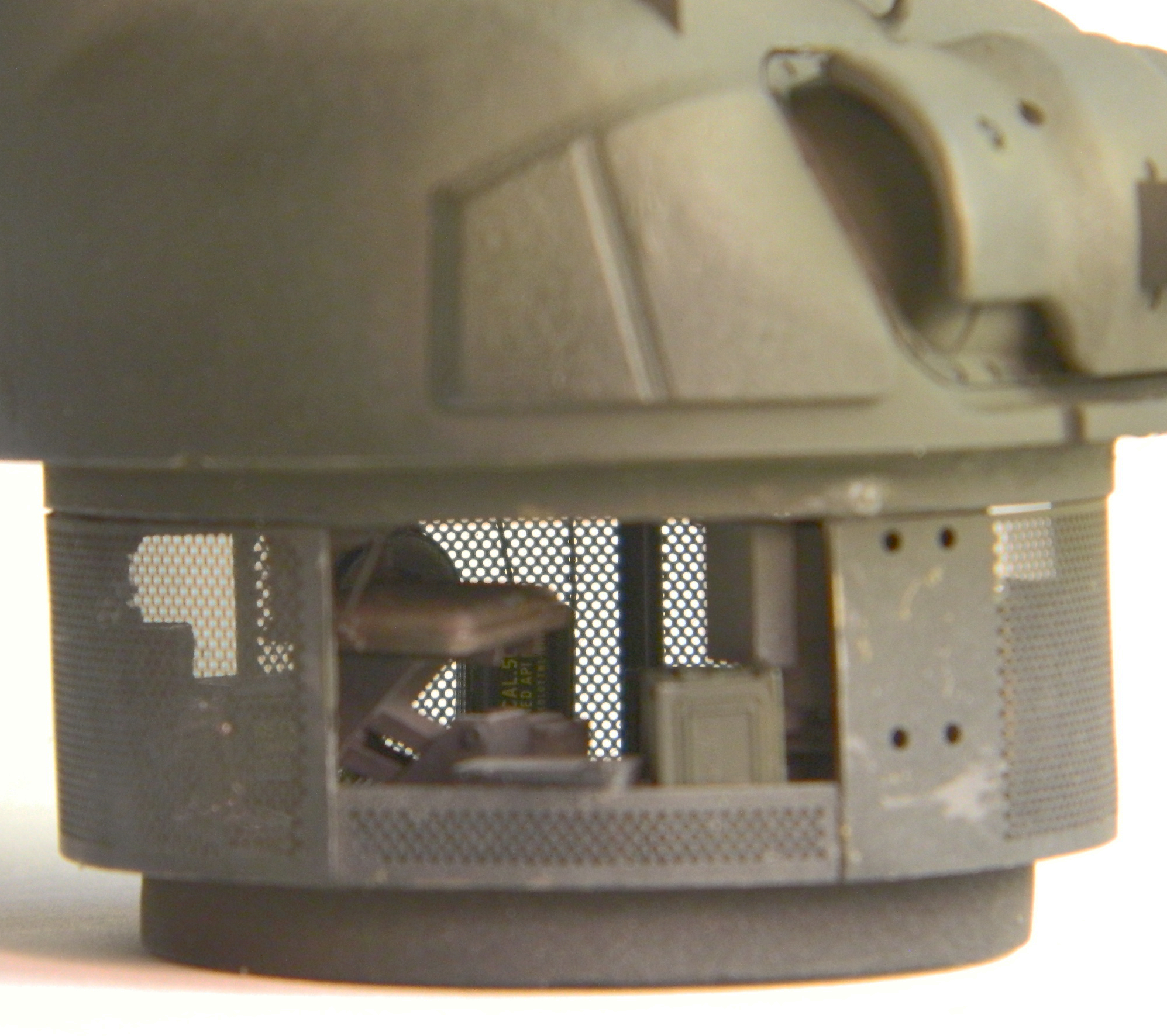
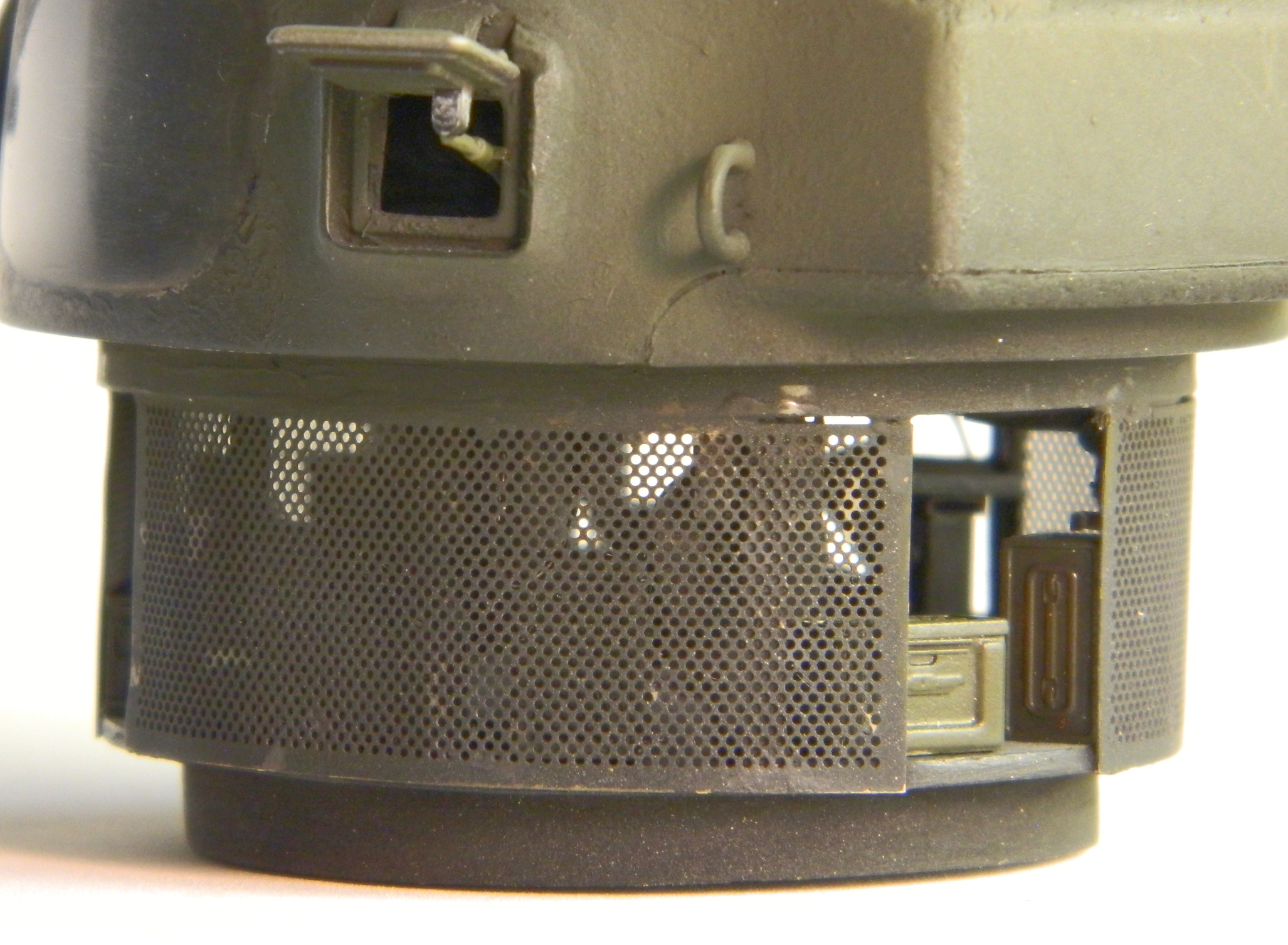
M4 (Tamiya) Build #11 – Finishing the Turret, Dealing With Tracks and My Mistaken Assumption, More Hull Details, and a Concerted Stagger to the Finish
Having masked the commander’s hatch from the inside, I added the padding to the lip of the hatch opening:
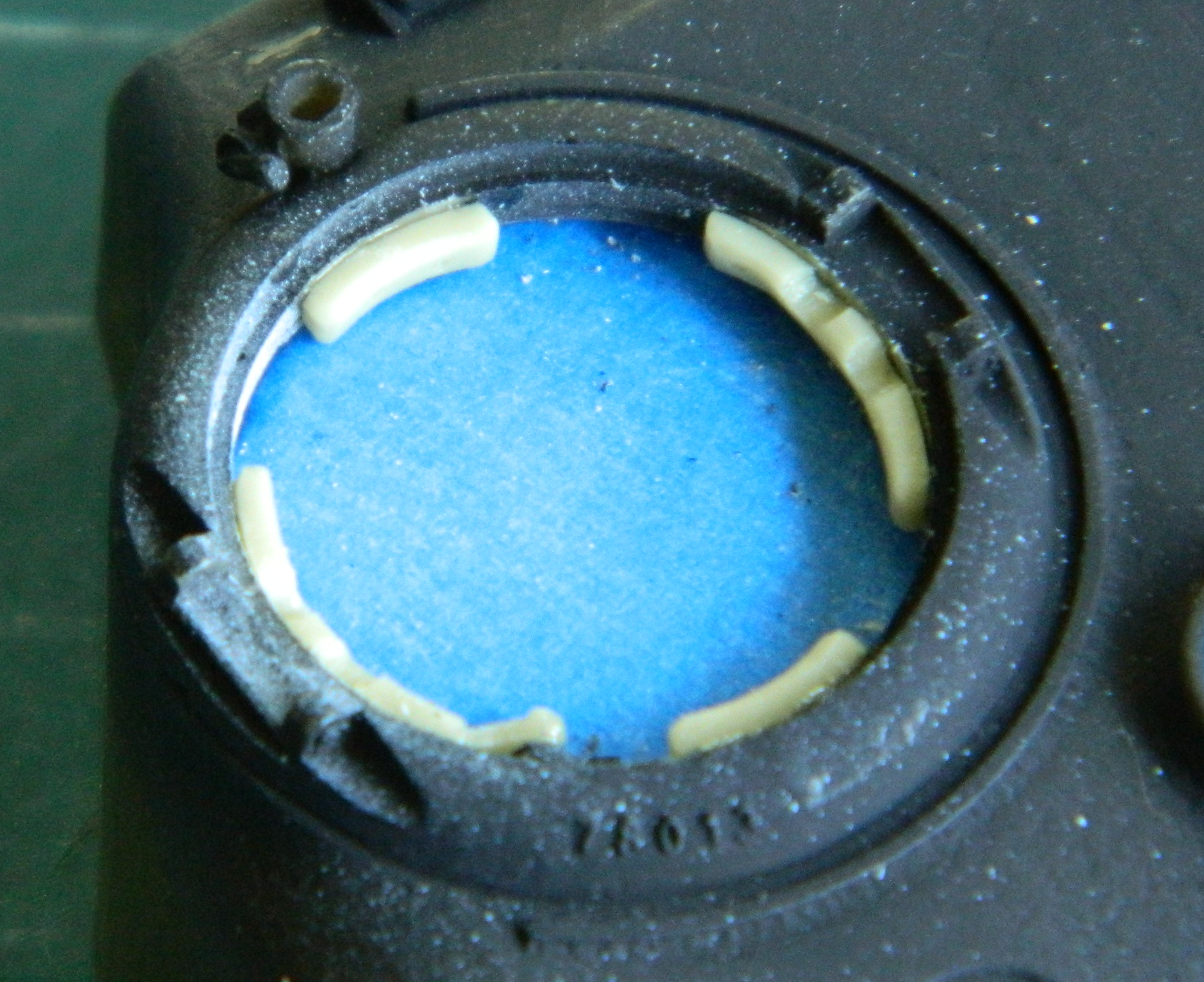
While I was working the top of the turret, I decided to add the front lifting loop and vane sight. Rather than over complicate things (probably just for the novelty of it), I used the kit’s loader and gunner periscopes; they were already dimensioned for the openings and only needed their heights adjusted, so only the tops of the periscopes were needed. There was an unwanted gap at the base of the vane sight which was remedied with 3M putty:

My references has shown a few Shermans that had vestiges of the mounting strip for the unused sand shields still in place. I used .005″ (.127mm) copper shim stock to replicate the remnants I’d seen in period reference photos, drilled the mounting holes, then trimmed and flattened the strips and installed unequal lengths at the front of the sponsons’ lower edges on both sides:


I stretched OD using a sprue from the kit 7mm in length for the radio antenna. I make my antennas detachable to lessen the chances of this part being snapped off. I used a Dragon antenna mount, cut it in two, added a wire pin to the antenna part and drilled a mounting hole in the antenna base:


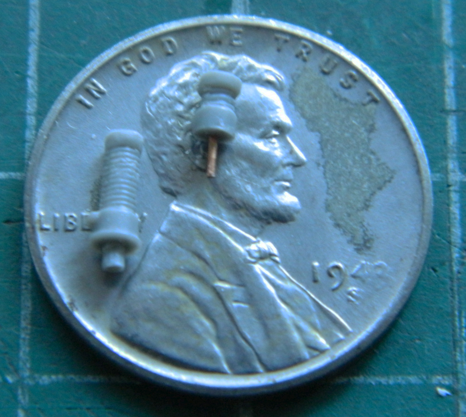
The top of the upper piece was drilled to accept the antenna which was then clamped into a jeweler’s vise with the antenna propped into vertical orientation with a cutout on the edge of a single-edged razor blade while the glue cured:
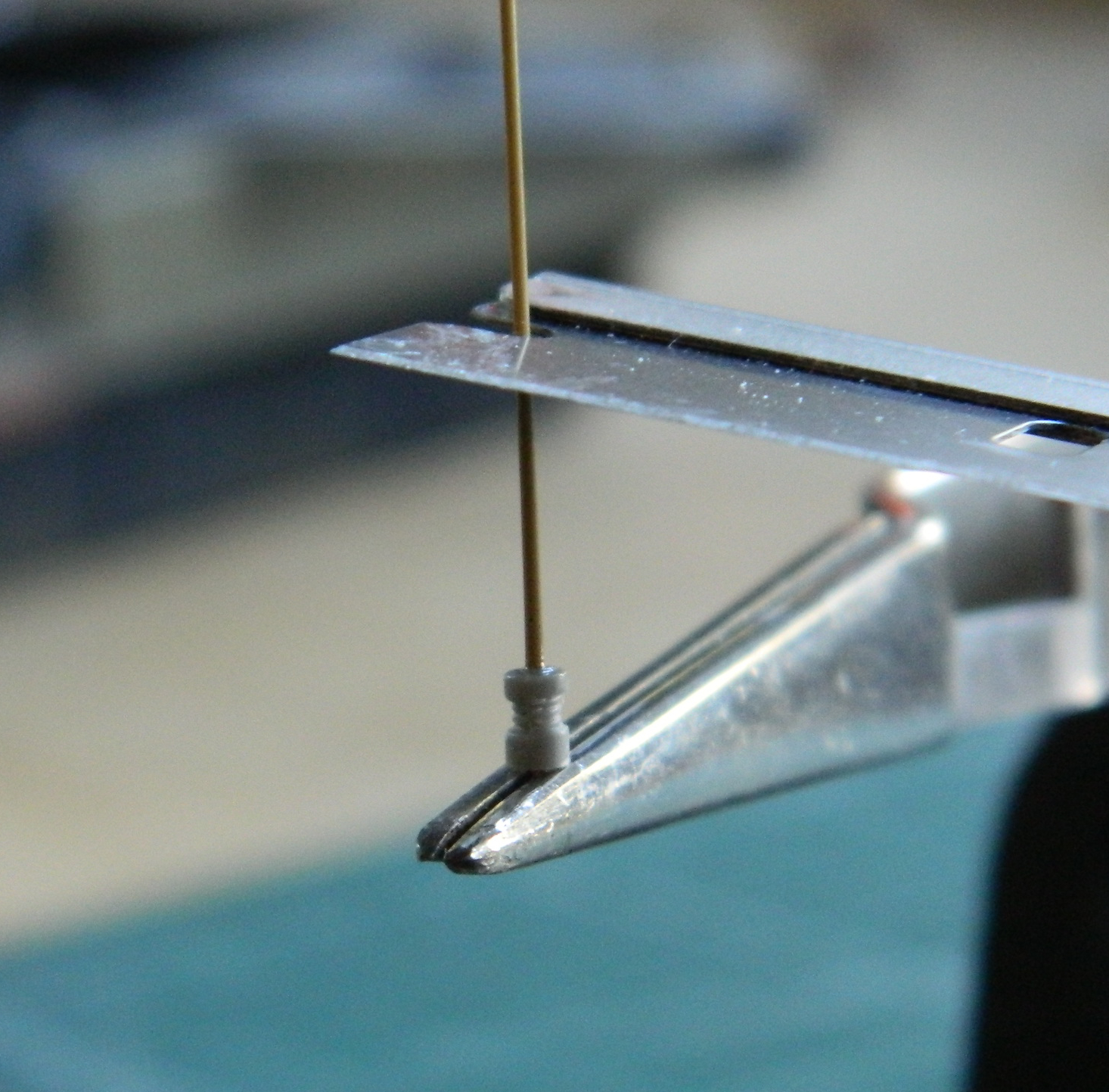
Assorted details were added to the turret’s exterior. The molded-on loops on top of the bustle (where the crew would frequently fix their rucksacks) were replaced with TMD’s small loops, the siren was added to the fender with a section of .015″ (.381mm) solder serving as its electrical feed and a TMD holding bracket. Periscope covers, lifting loops (another Dragon item from the spares inventory…though it wasn’t until too late that I discovered that ALCO tanks used a flat pedestal under their loops), a small PE “L” bracket was added, and the antenna base was glued into place. I used TMD’s periscope for the commander’s hatch by cutting the opening for it through the hatch:

I started work on the pioneer tool mountings. As I’ve whined about before (and will probably whine about again), small details take a lot of time. When I make tool mounts, I’ll use both styrene and copper shim stock of .005″ (.127mm) in both cases. I use the shim stock when structure is required and styrene when it’s just (“just”?!) cosmetic:

The above photo shows how many tools get used for something essentially simple. The dividers mark out dimensions (and sometimes put down a line while doing so), scissors cut the shim stock (I used a razor blade and a small hammer…tapping the blade through the plastic…when I want a straight edge in plastic), a file so that by holding the copper with flat-face pliers I can file errancies created by old hands trying their best to make a straight cut (another ability I suspect lost to the passage of time), and tweezers to enable Fattie McFumblefingers to handle the sodding parts. And that’s all just for those little tools… I hold up the hoop and jump through it because it does impart a very nice effect:
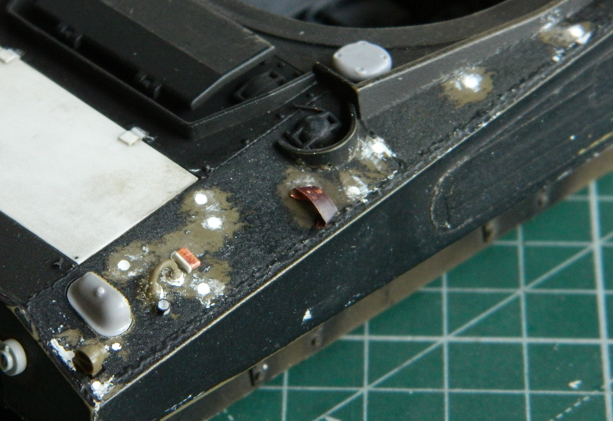
For the sledge hammer and shaft of the pickax, structure wasn’t needed, just appearance, so styrene was glued directly to the parts and then the excess trimmed away with the razor-blade-and-hammer trick once the glue had cured (the straps cut from lead foil weren’t used…I made better ones later and used those):
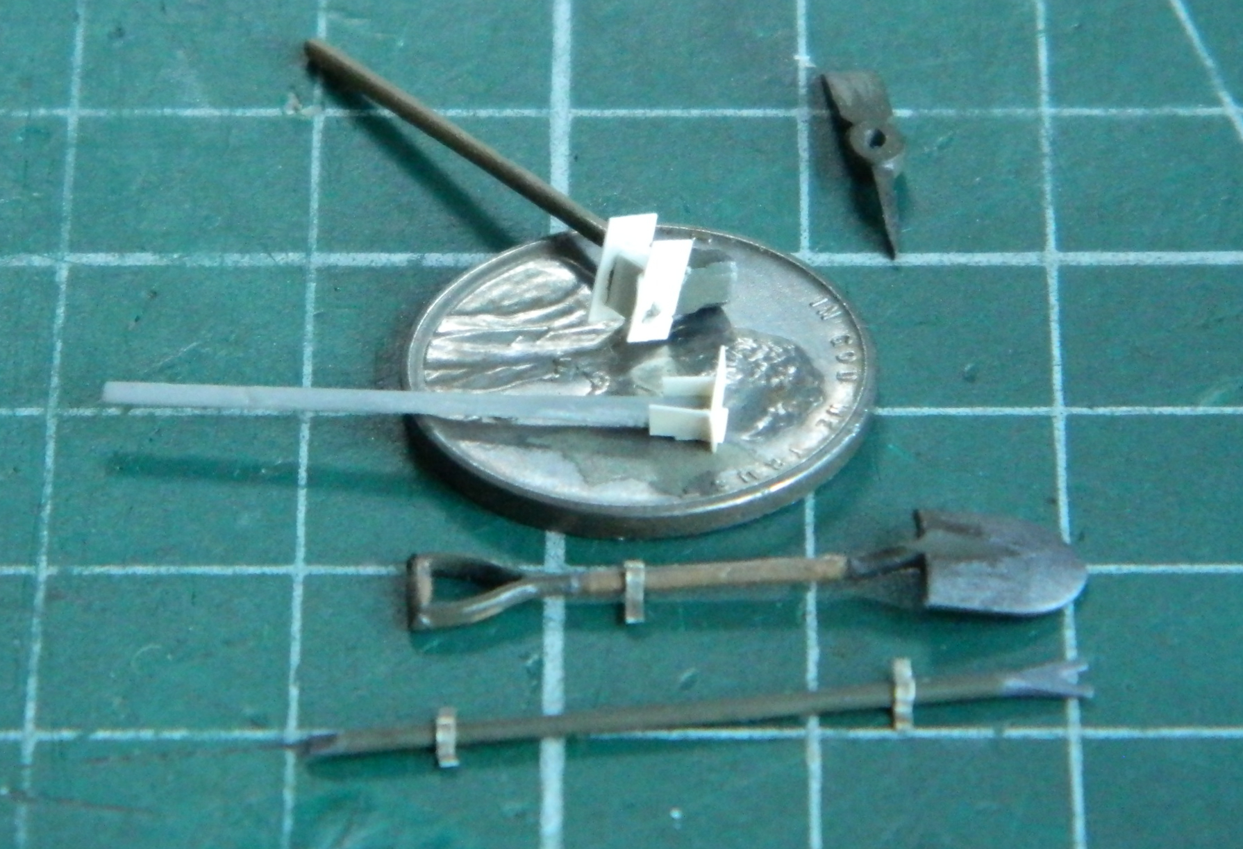
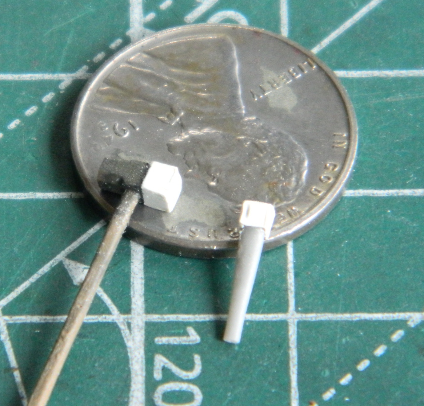
And of course the handle of the pickax broke off. It was glued back on (a few times) later.
What the work on the exterior of the turret and those annoying tools was really for was to allow my mind to ponder, consider, and ruminate on the idea of was it really time to add the turret basket to the turret? Well, at some point one must pull the trigger so I did just that:

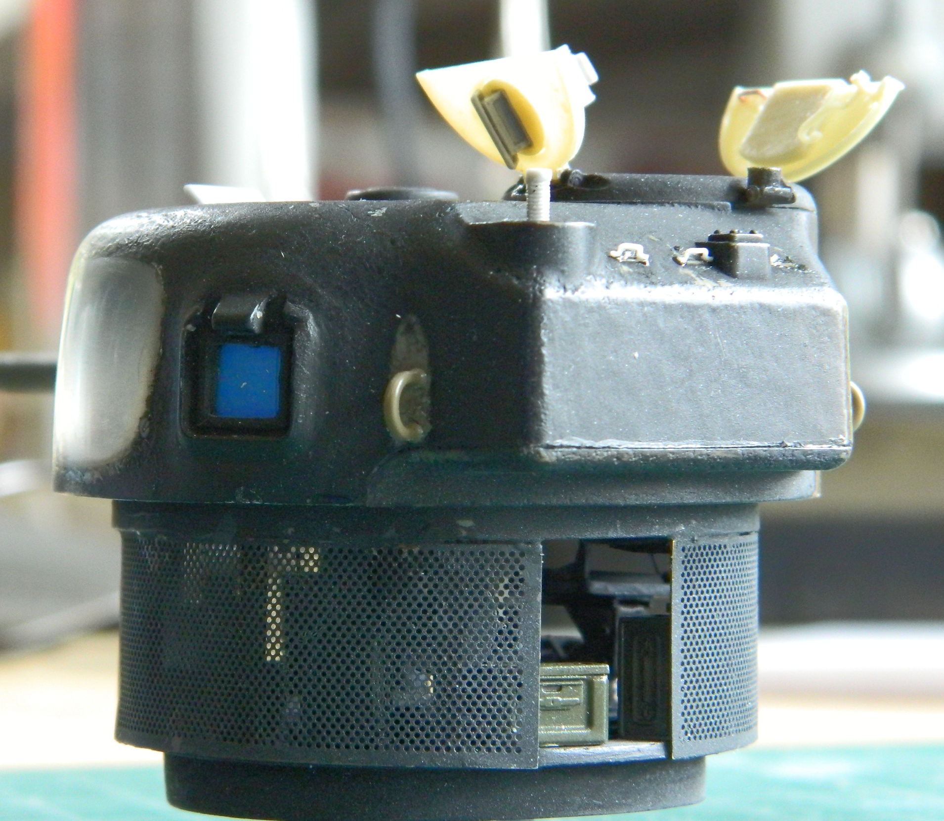
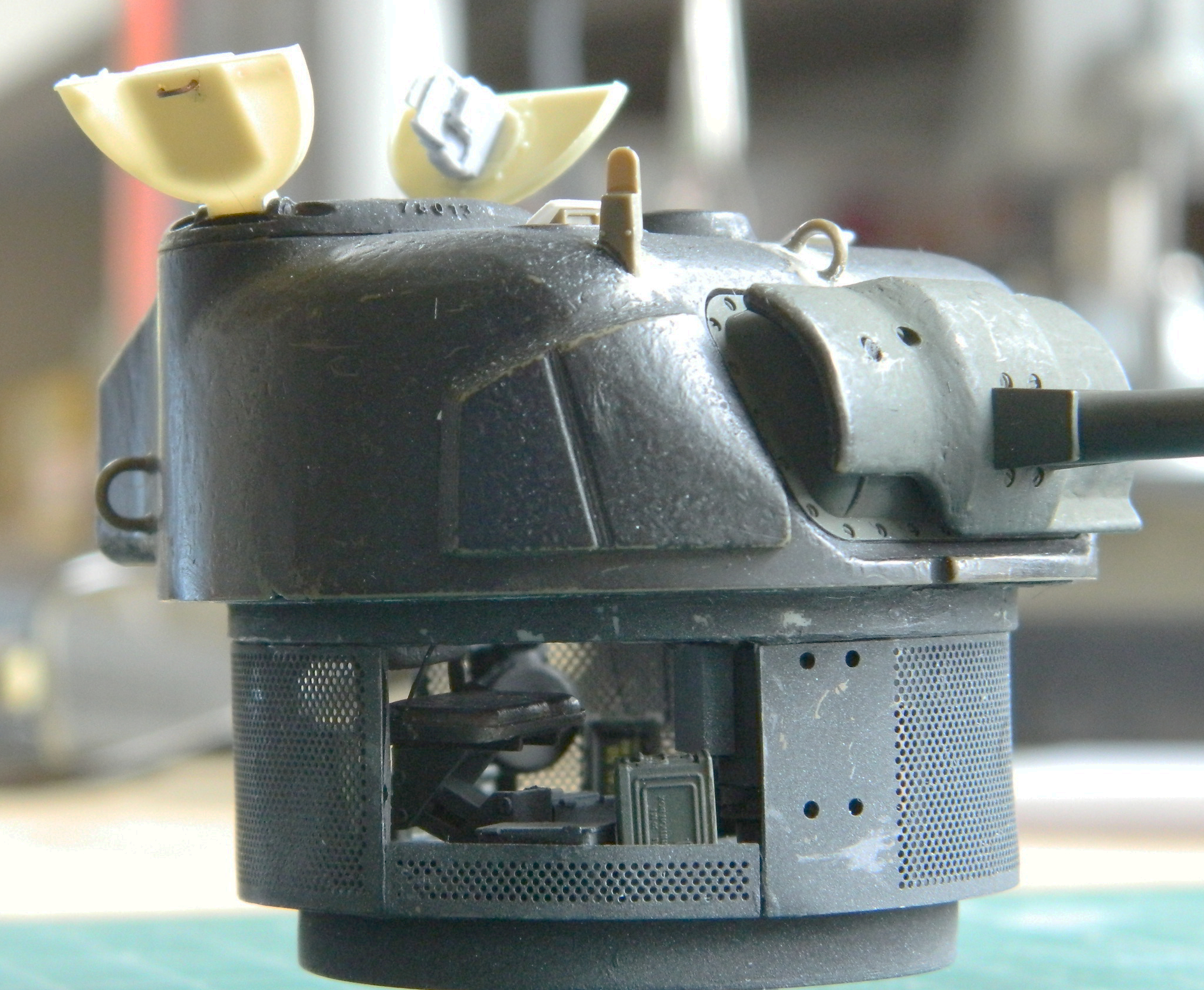
For the record, I am not pleased with how the sides of the turret basket came out. Sufficiently displeased that I started plotting and planning how I would fix them. Before I could start, however, I got a good night’s sleep (my sleeping patterns anymore resemble a stopped clock and that “good night’s sleep” was my circadian version of that stopped clock being accurate twice a day…which means that for the other 22 hours it certainly is not) before I could start and realized that as the tank would be displayed, NObody would ever notice. The sides stay as they are and I continue to be displeased with them. (A metaphor for life, methinks.)
At this point I needed to decide if this thing was prepared for paint. Step one was to cover it with black (again) to make sure there wasn’t anything I’d overlooked. All the different colored bits were now all the same color. Before breaking out the color, I decided to see if I could get another good night’s sleep (and the answer was no, in case that’s of interest to you) before loading the airbrush with Tamiya XF-62 Olive Drab and going for it:
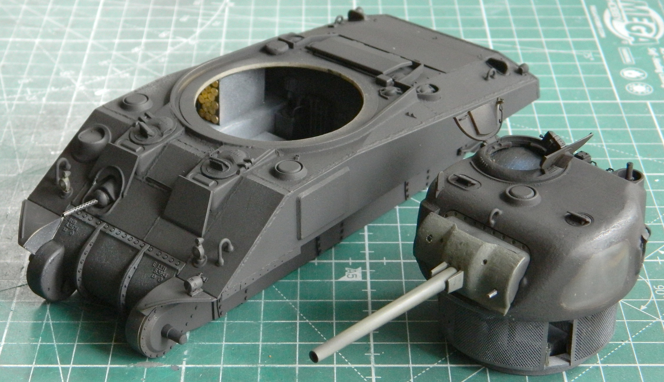
Satisfied that I hadn’t overlooked anything too obvious, I used Tamiya XF-2 Flat White to define where I wanted the highlights:

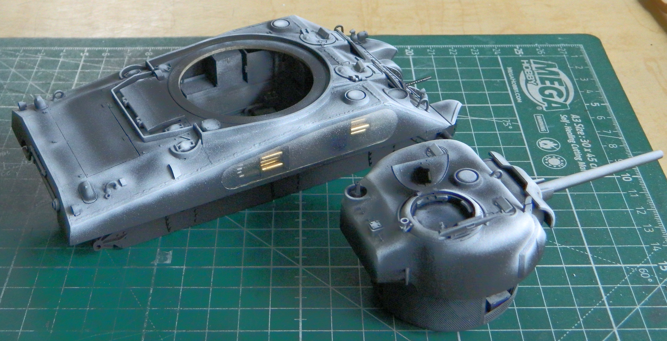
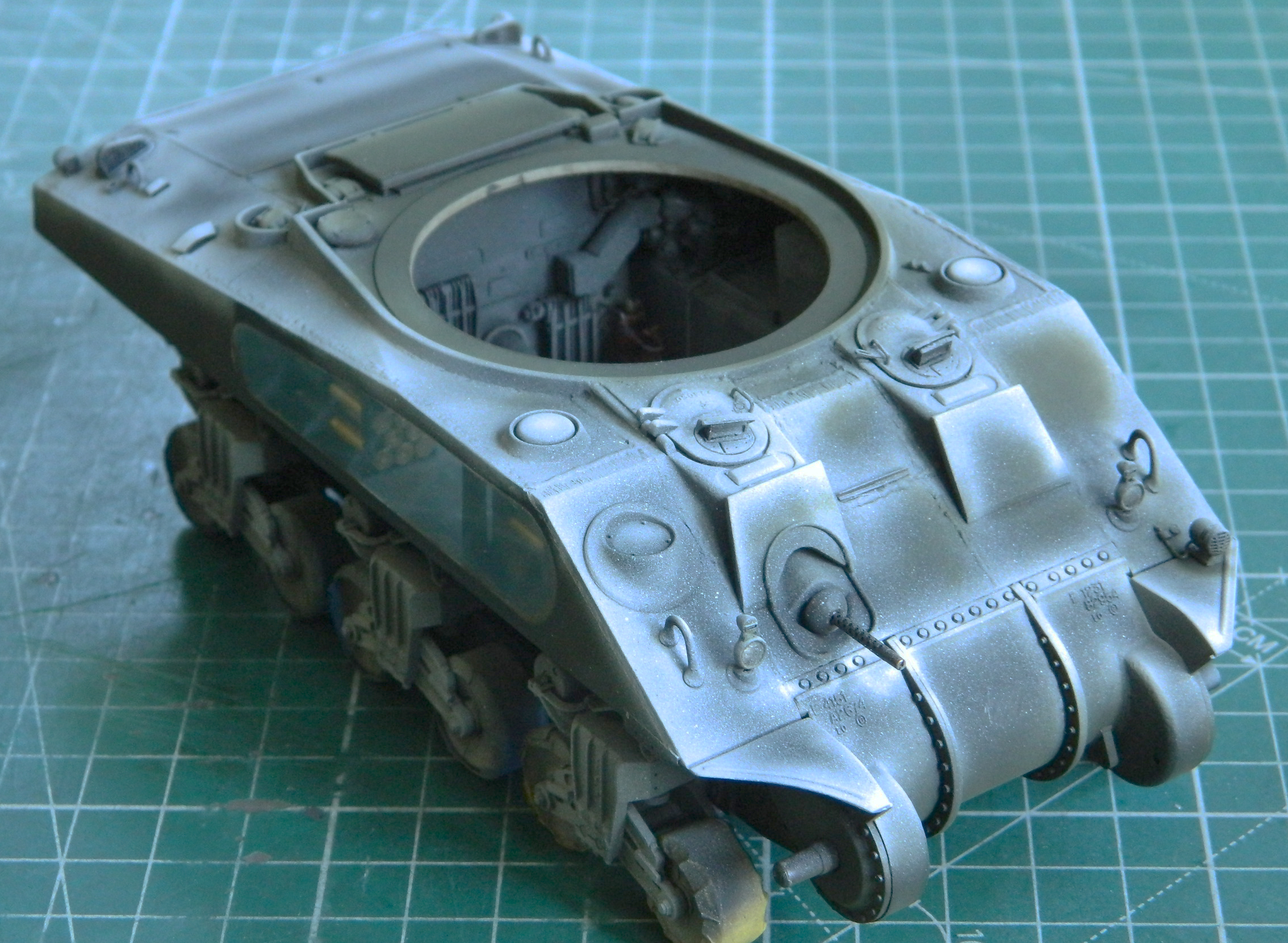
By misting on a color coat over something like this, there is a subtle difference between where the black is and where the white is. (Sometimes I wish more modelers were aware of the arcane notion of “subtlety”.)
Although I had PE parts for the front headlight guards, I didn’t for the taillight guards. I resorted to .005″ (.127mm) again to make them:

I didn’t realize it at the time but I came to wish I’d built the headlight guards as well. The PE parts were far too thin and they were mashed, popped free, reshaped, reattached, and that whole process repeated too many times to count. Final takeaway is that the headlight guard were too damned thin. Next time I need to use these PE parts, I’ll use them to trace their shape onto shim stock:
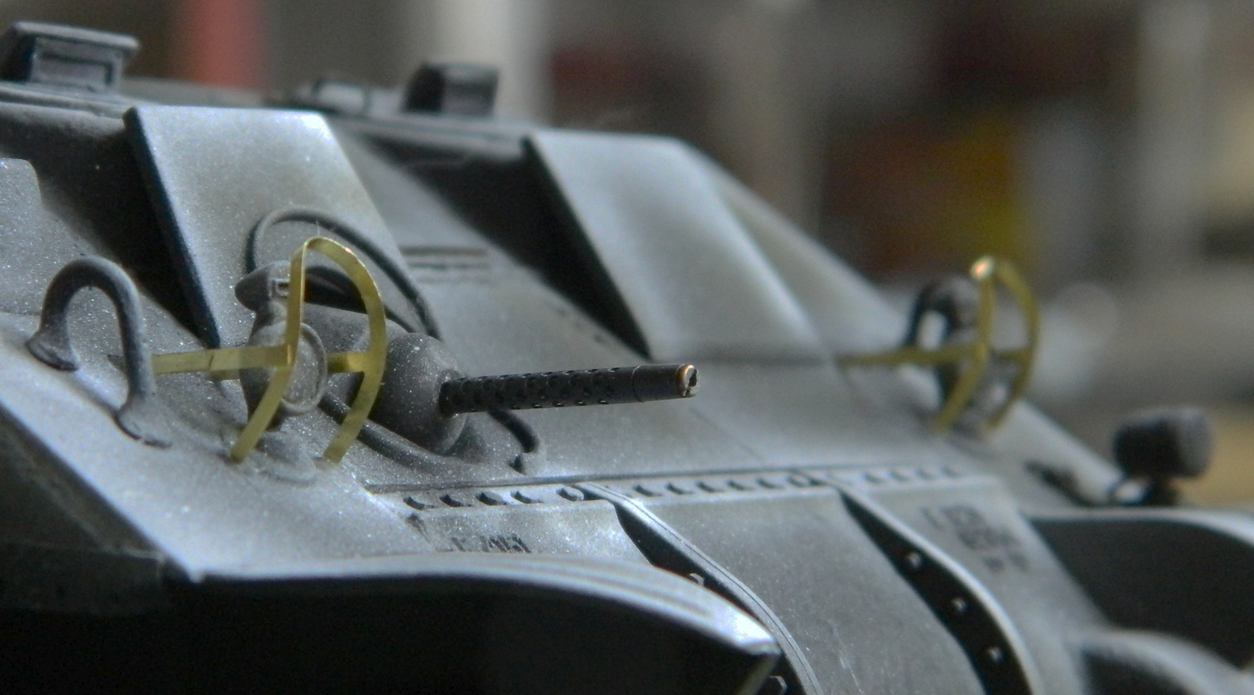
Those headlight guards never looked that good again. Five minutes later I had to reshape them (the first time…there were many subsequent reshapings to come). The taillight guards fared better, only needing to be reshaped twice:
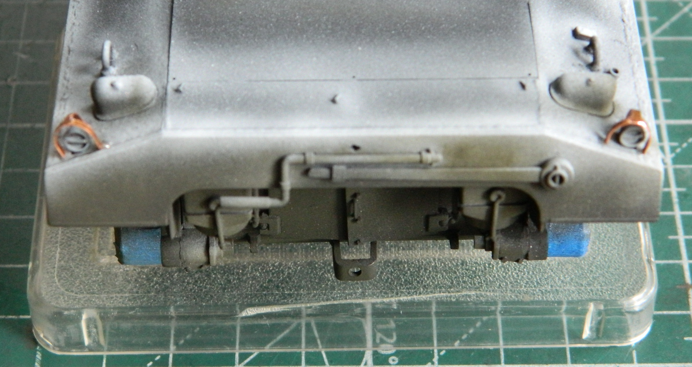
Then I used color-corrected Tamiya XF-62 with XF-2 added (about a 20-25% addition of white) and laid down the color coat. It’s not as evident in the photos as it is when looking at the model, but the highlighting worked well and the effect is subtle:
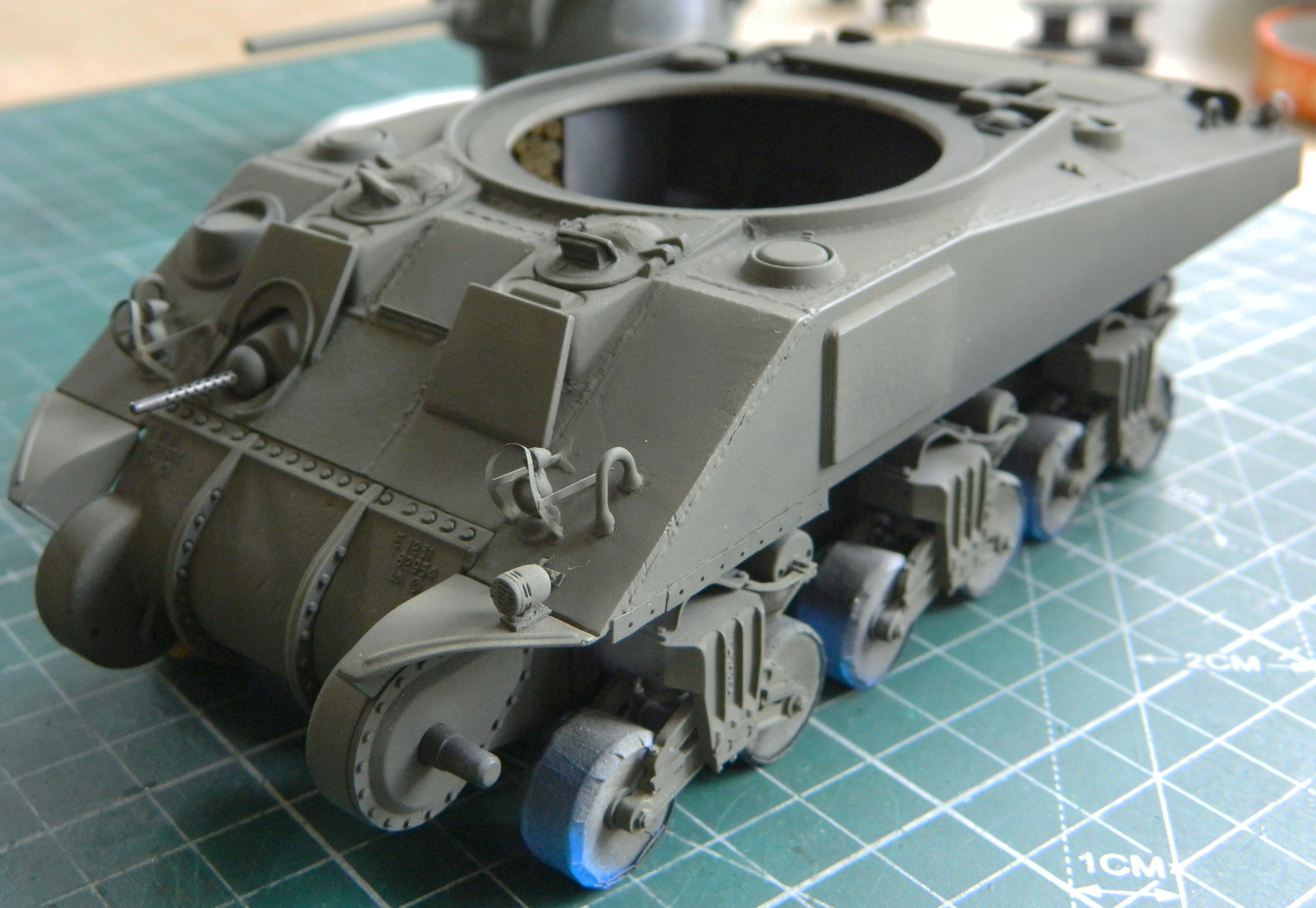
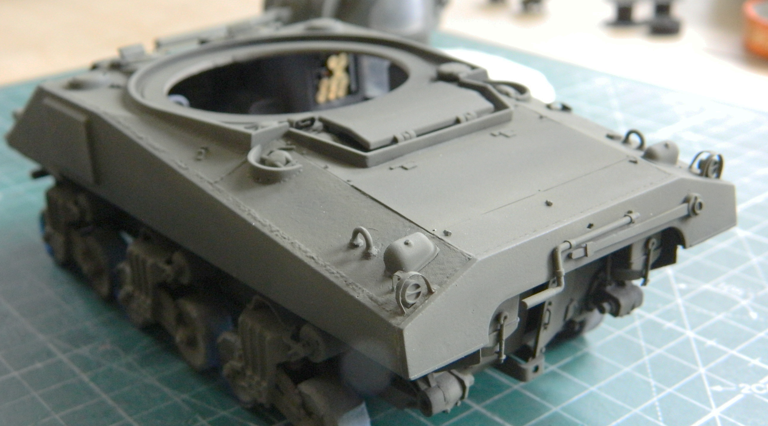

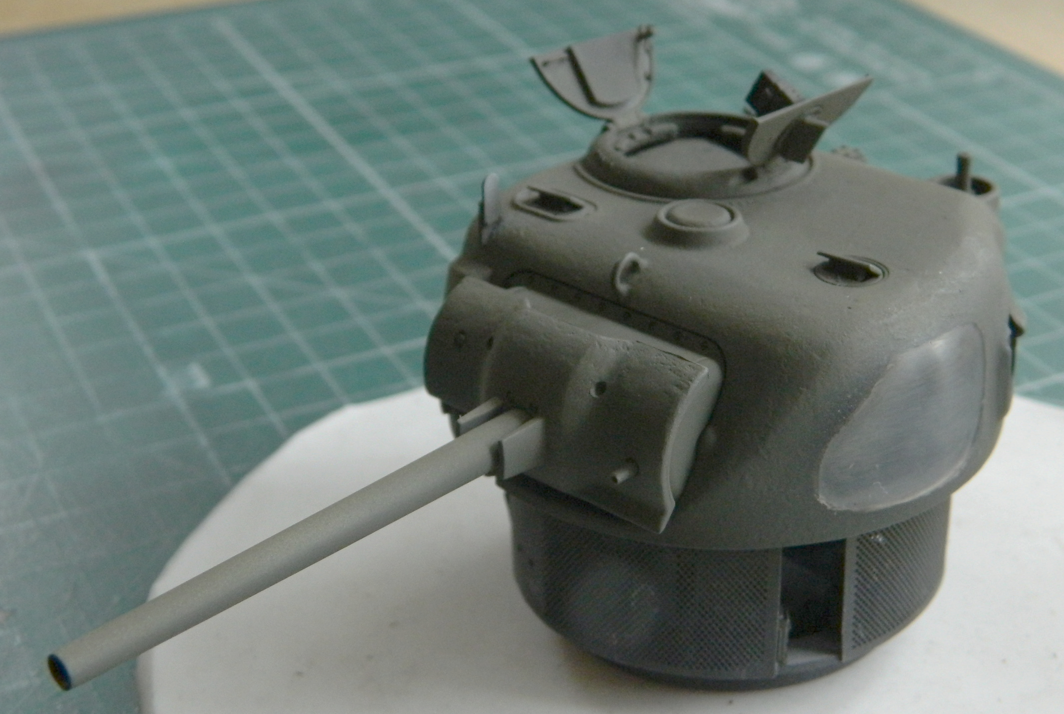
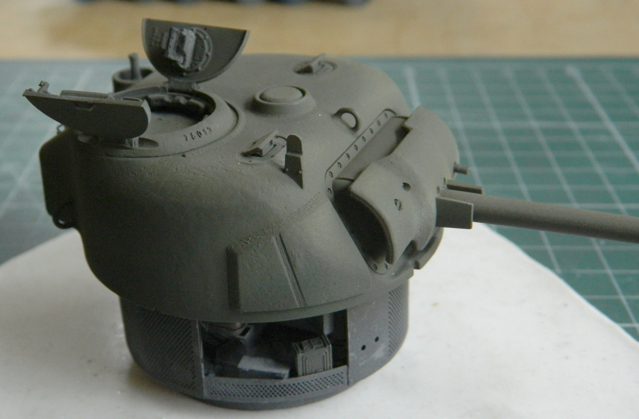
If you decide you want to try this method, a point to consider. If you lay down a thick enough color coat over the black/white paint, there’s no way you will see the highlighting. The color will eventually even out and all you’ve done is waste the white paint. As with many things in modeling, if you think that just one more pass will do it, stop there. If you’re correct and one more pass will do it, then go ahead. But please remember that it’s very easy to lay down enough color to obviate your attempt at highlighting. I mist the color coat on and don’t go for surface saturation. The thinness of the color coat over the black and white will allow the subtle differences of the surface to display what you’re after.
Before I threw color at this, I unmasked the clear sections. I had already put down several coats of paint and I didn’t want an obvious step at the point where opacity switched to transparency. Yes…there was overspray to clean up. The nice thing about acrylic paint (Tamiya’s specifically since that’s the paint I use about 99.8% of the time) is that it lifts easily off with a cotton swab soaked in denatured alcohol. And I didn’t go for a complete removal when i got to the edges where clear meets opaque. I got almost all the color off the clear sections and then cut a chisel tip onto a toothpick and scraped the color to the edge I wanted (I did the same thing for the headlights…it’s SO much easier than trying to mask little tiny areas with tape):

To see how my Clever Idea ™ of using clear panels turned out, I stuffed the turret into its place. I can honestly say that I am utterly unimpressed with the results of both the turret (the resin insert acts like a lens and not at all like a view port) and the hull (why am I surprised that the turret basket filled the view?!). A lot of effort for disappointing results and not something I’m ever likely to do again. It’s just a gimmick and one not worth my time for the results.
This is how we learn.
By the time of D-Day Normandy, the T48 rubber-chevron tracks were quite common (and were the most produced of all the track shoes used for Sherman and Sherman-derived vehicles). Steel tracks last longer, but they are absolute sodding hell on paved surfaces and can turn a paved road into a gravel path in short order. On a route march over paved surfaces with a company of tanks equipped with steel track surfaces, I don’t know when the pavement turns to gravel. I would guess that the first tanks of a 15-vehicle tank company had a smoother time of things. I rather doubt that the 15th tank did. And regardless of how smooth the ride of the tanks, any subsequent use of that road would be as much fun as I find scribing panel lines to be. None. The initial track shoes were the T41 rubber tracks. The shoes were simple rubber blocks without tread and sufficiently thick enough on both sides to be reversible. Worn tracks? Simple (if that word could be used to describe putting new tracks on any tank). Turn them over. You know, all 76-79 shoes, unbolt all the track horns (the guides on either side of the track), turn the shoes over, all the track horns bolted back on, and reattach the tracks. Simple, right? You bet. But they didn’t chew up pavement. They also didn’t offer much grip off the pavement, especially in mud. (There was a variant of this track shoe, the T51 shoe, which was also a rubber block but that one wasn’t reversible.) Chevron tracks, tracks with V-shaped contact area, offered better off-road traction. There were a few different types of this sort of shoe and the steel variants all did Bad Things to pavement.
I’m modeling this one as a “Normandy” tank (and specifically as the 3rd Armored Division, 32nd Armored Battalion tanks were equipped, as you’ll see later with a spare road wheel and T48 track link hung onto the glacis). A tank that had already been deployed, recovered, and put through the “Blitz” program in England. This program updated older tanks with added welded-on supplemental armor to the sponson sides and turret (in front of the gunner’s position), in front of the driver and co-driver hoods, deleted racks in the turret for ready round storage (major fire hazard), new engines, differentials (where needed…many tanks with three-piece differentials landed on Normandy beaches), and some other upgrades. It was easier to take a tank that had already been transported across the Atlantic (and Mediterranean), recover it if it had been knocked out (but not burned because the heat of the fire removed any “armor” effect the steel had), and bring it up to the current standard of production line tanks as much as was possible. A lot of hardware and machinery was necessary for the invasion so anything that would meet service requirements was used. So my thought is that the tank I’m building was either first deployed in North Africa or the Italian campaign, returned to England, and “Blitzed” before being re-issued for the invasion of France.
All that was to say that this tank would have rolled off the LST on T48 tracks (and being as it was 3rd. Armor, 32 Battalion, they went ashore June 9). Because of training, those tracks wouldn’t be new anymore. Panda Plastics is my go-to source for Sherman tracks. They have a good selection (including tracks that have had all the rubber burned away, leaving the steel inner structure exposed, if you need a set of those for a diorama of a burned Sherman) and one is of worn-but-still-serviceable T48 tracks like the set I’m using.
I had thought that I’d paint the tracks with tan colored dirt overall with just the contact areas of the chevrons showing rubber. Okay…so how do I paint those things? I can’t just mask off the contact areas because rubber compresses and the edge of the contact areas creates a soft edge between worn and just dirty track surfaces and masking those things would leave a sharp division. Oh. Yeah. Before I forget, there are about 76 shoes on each side, too. And this idea had been rattling around my bald noggin for a few hundred hours while I worked on everything else. As the time approached, I needed to figure out a way to mask these things…oh. Wait. Do I have to mask them or is there a different way I could get what I want?
On one of my (dreaded) (am I over using that word?) trips to market, I passed through the make up section. Oh look! Micro-cell foam wedges used to blend make up! I wonder if I could paint the tracks the dirty color and then used a square-cut foam block as a rubber stamp is used to apply the rubber-colored paint? Dip it in color and dab it onto the wear areas? I took a section of kit-supplied spare shoes and tried it:
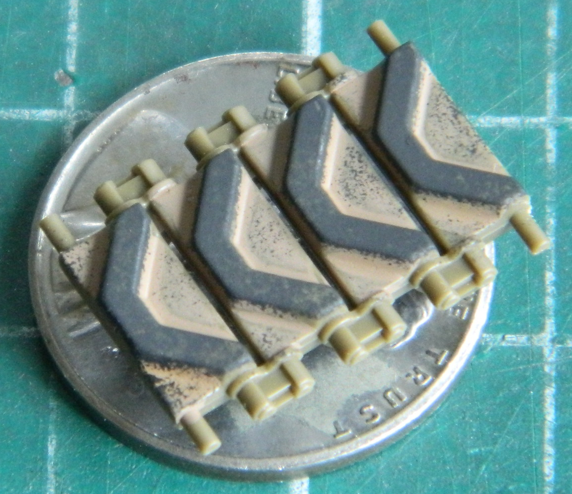
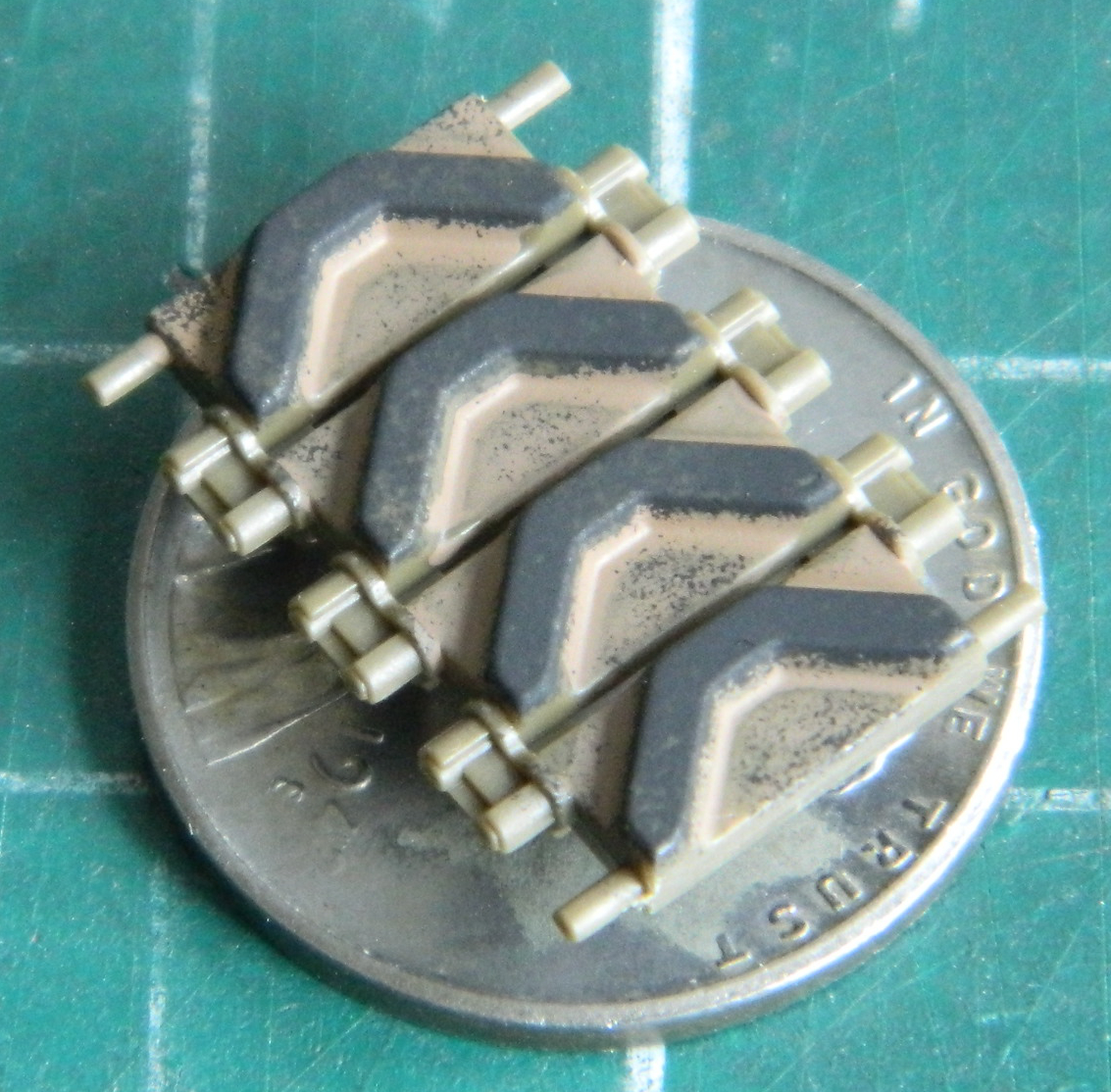
Worked great and wouldn’t take me many tedious weeks of masking each shoe individually! And since the foam is compressible the way the chevrons were compressible, there was enough coverage of the other parts of the shoe’s face to replicate a realistic wear pattern! For a short period of time I was ecstatic…or at least my reserved version of it. I think I might have even smiled. Once. (Though in fairness, that could have been gas.) So I concocted a mix of paints to paint the tracks as I had the test links and shot the tracks:

I almost engaged in massive reverse peristalsis (as in, puked) when I saw what I ended up with. No. If I was doing a tank that had been out in the field for a few weeks, maybe. Maybe. As a track fresh off the boat? No. My next Clever Plan ™ required me to paint the rubber tracks rubber using Tamiya XF-85 Rubber (though Tamiya’s XF-69 NATO Black also works well to replicate rubber). I had an idea that I could use the rubber-stamp notion using a grayish paint or use a white pencil to replicate wear and set it off from the supposedly-unworn backing. The penciled track is on top, the rubber-stamp track is at the bottom:

Rubber wears like an eraser does, by being scraped and dragged across a surface. The painted tracks didn’t look like they’d been dragged and the penciled tracks did, they looked like they passed over a puddle of gray paint. I went with the penciled tracks and I’m as pleased as this process allowed.
I brush-painted the outside of all the track horns OD Green and ended up with something that would work well…until I tried to bend them. Ever try to open a window that had been “painted closed”? The paint had insinuated itself inside of some of the track shoes where the pins go into the track horns and locked them as tightly as a window that was painted closed.
I took a section of about 12 shoes that had broken off when I tried to bend them and soaked them in denatured alcohol for two days and they refused to budge, though there were easily snapped.
The word “assumption” is used in the title for this post and here’s where I made the mistaken assumption. Because I had one run of track that was now missing a dozen or so links, I assumed that I was a dozen or so links short on the other side. I ordered another set of tracks from Panda Plastics and played Zelda for a week or so. One morning, propped up in the shop with my requisite bucket of coffee, I figured that I might as well put on the run of tracks that hadn’t locked up. When I did I realized that I had far more track than I needed. But did I have enough track to make up for the track length that was missing?
Yup:
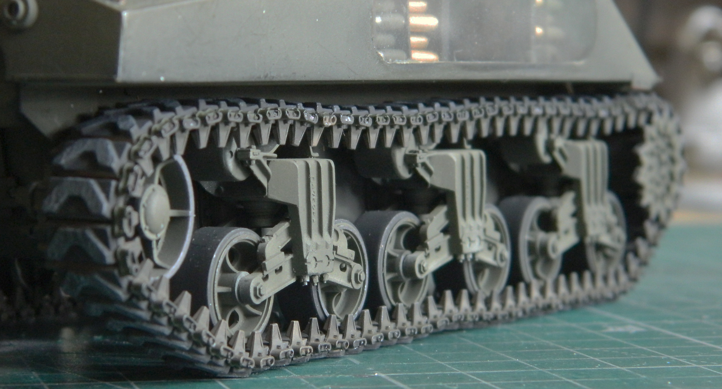
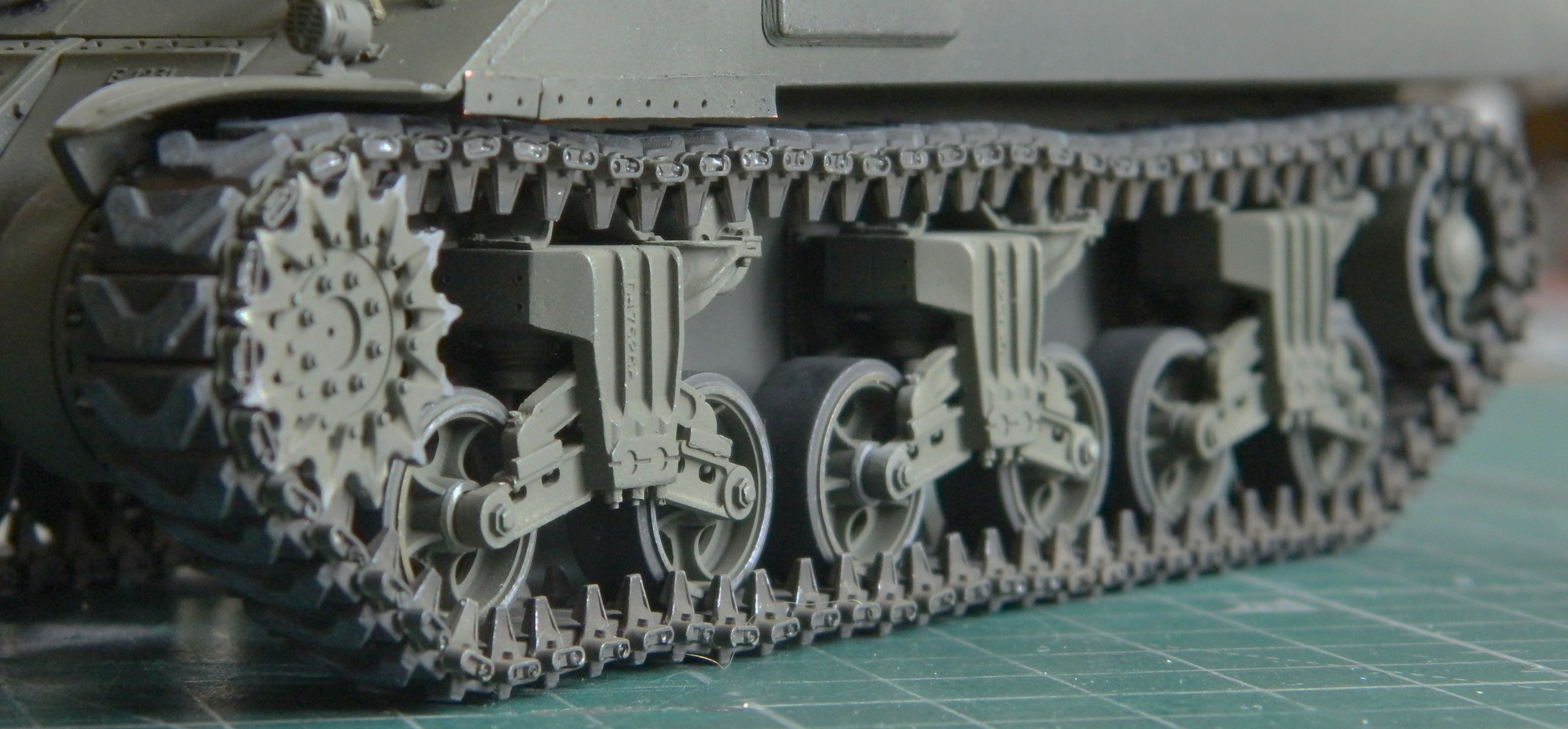
And here I thought I’d already learned to look first…evidently I needed the reminder. (And the paint on the outside of the drive sprocket didn’t wear like that, so I fixed it.)
Now that I have an extra set of T48 tracks in stock, it was time to add minimal markings. At the time of their deployment (pre-Operation Cobra), 3rd Armored 32 Battalion didn’t have stars that I could see in the half-dozen reference photos I could find so I didn’t add them. They did have serial numbers and I used an old set of Archer Transfers to cobble together a fictitious number:

As you can see, it didn’t go well. It didn’t even go adequately. Having more numbers, I tried transferring the same numbers over the first ones:
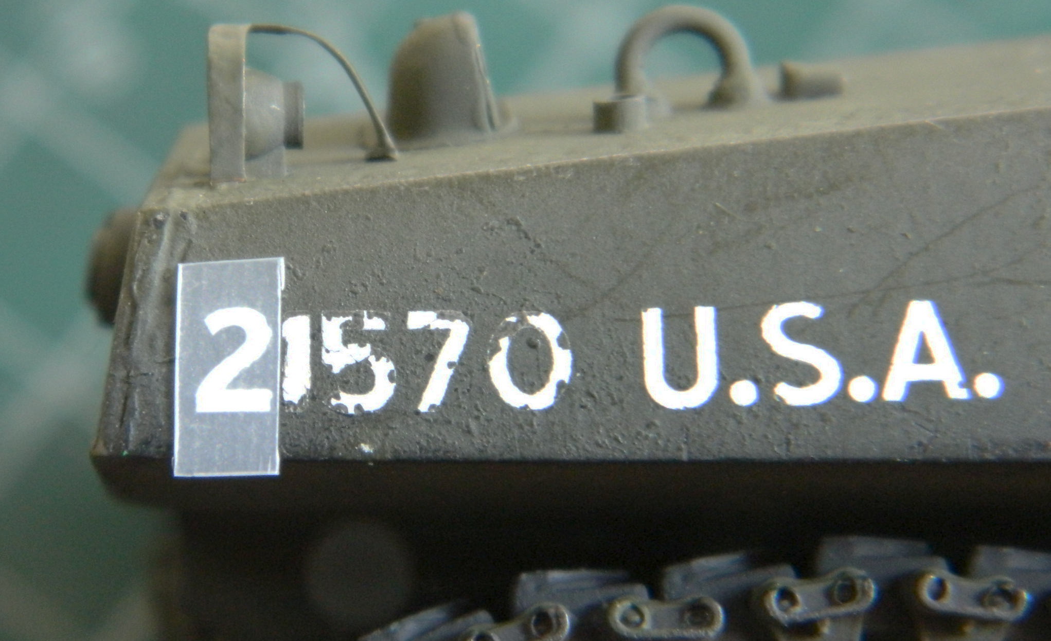
That didn’t go well either:
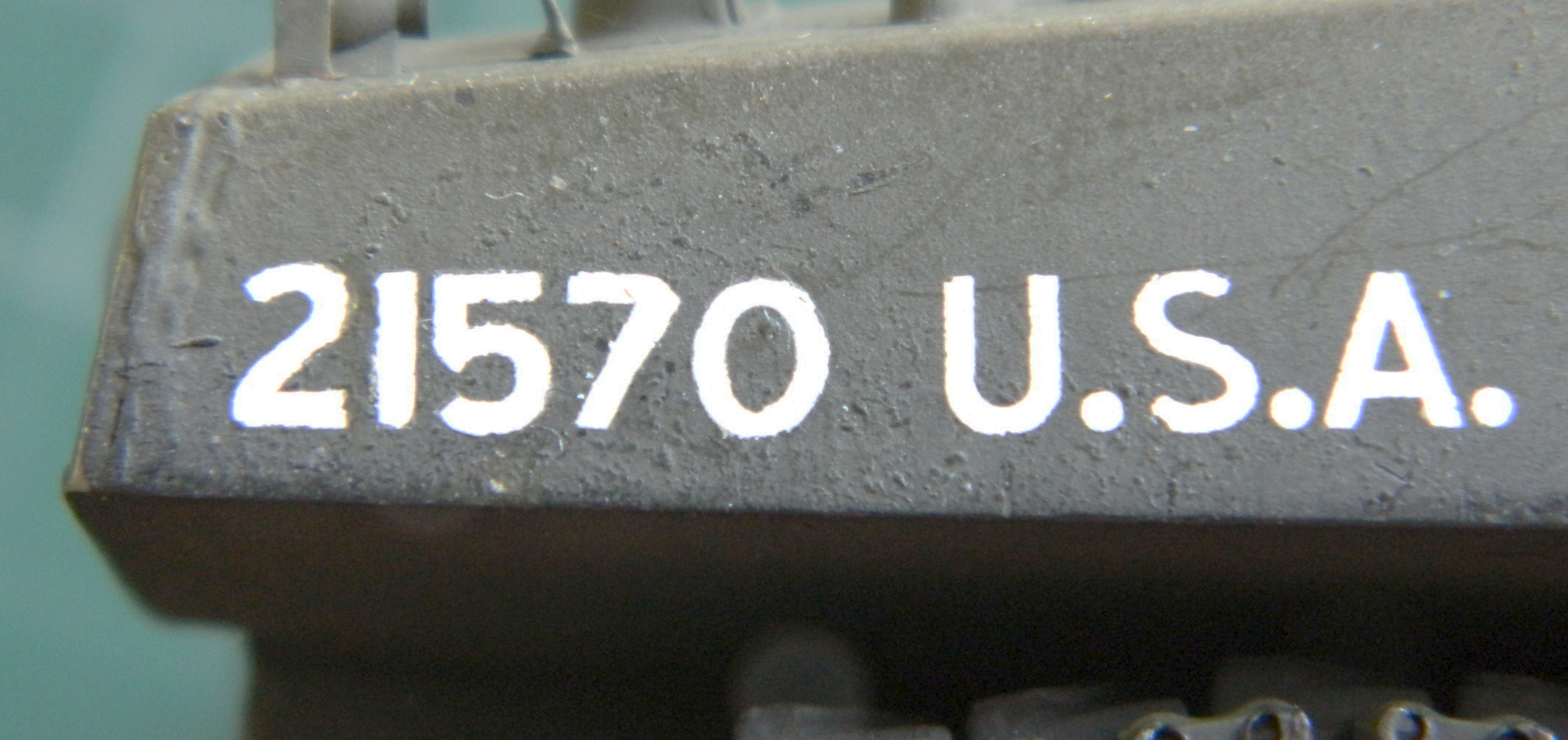
I tried touching up the many misalignments with paint and though it was better, my boat wasn’t floating. Doing the other side was even worse (as you’ll see later). If that wasn’t enough “enjoyment,” it took four hours to do something this lousy. They day came to an end, I managed to feed myself and find the bedroom in less than six tries. The next morning I looked at the garbage I had done and using scotch tape, pulled the numbers off. That was the only easy part of it all…and it shouldn’t have been. That led me to think that what I had was new old stock and that the adhesives just didn’t work well anymore. I briefly considered the more typical approach, decals, and decided to hell with it. So my tank has no numbers. I’ll live (for now).
Then it was time to mount the pioneer tools. To do that, I needed to make straps and buckles. I started by annealing copper wire so that it would bend easier, and I modified a paperclip to use as a mandrel to wrap the wire around so that I could cut them into square links for buckles:
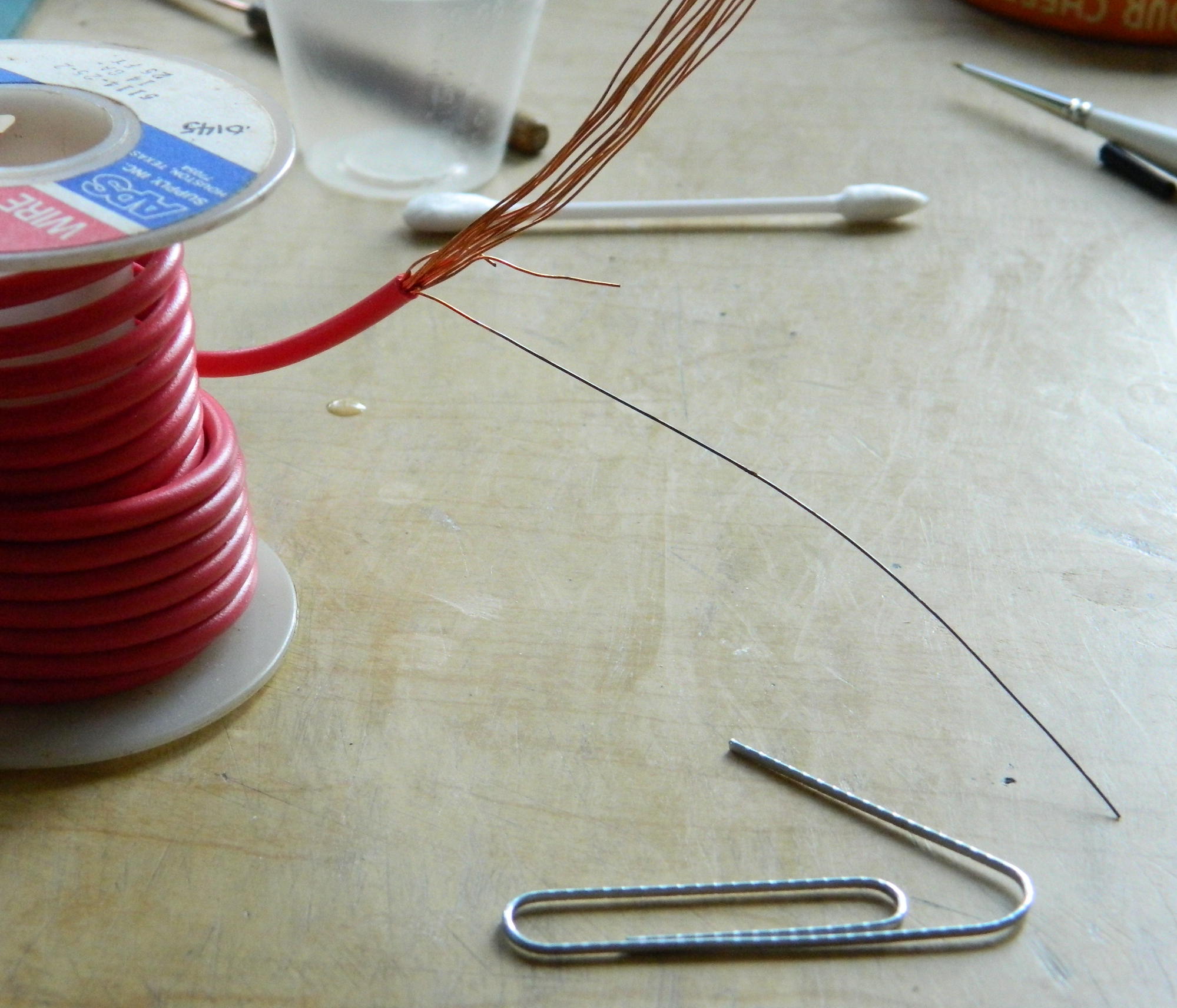

Though it worked well enough, the result was sufficiently out-of-scale as to be useless. Next I tried using .010″ (.254mm) solder around the same mandrel and ended up with something that would work (though they’re FRAGILE). I cut lead foil into strips, painted them my mixture of “black leather” (using Tamiya paints, the formula is X-18 Semi-Gloss Black 5 parts and XF-64 Red Brown 4 parts), and ended up with all the straps/buckles I need to mount the tools:
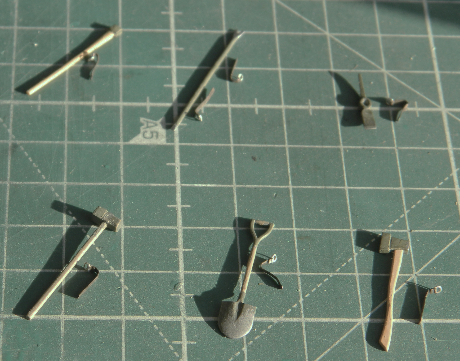
Then I added the pistol port hatch:
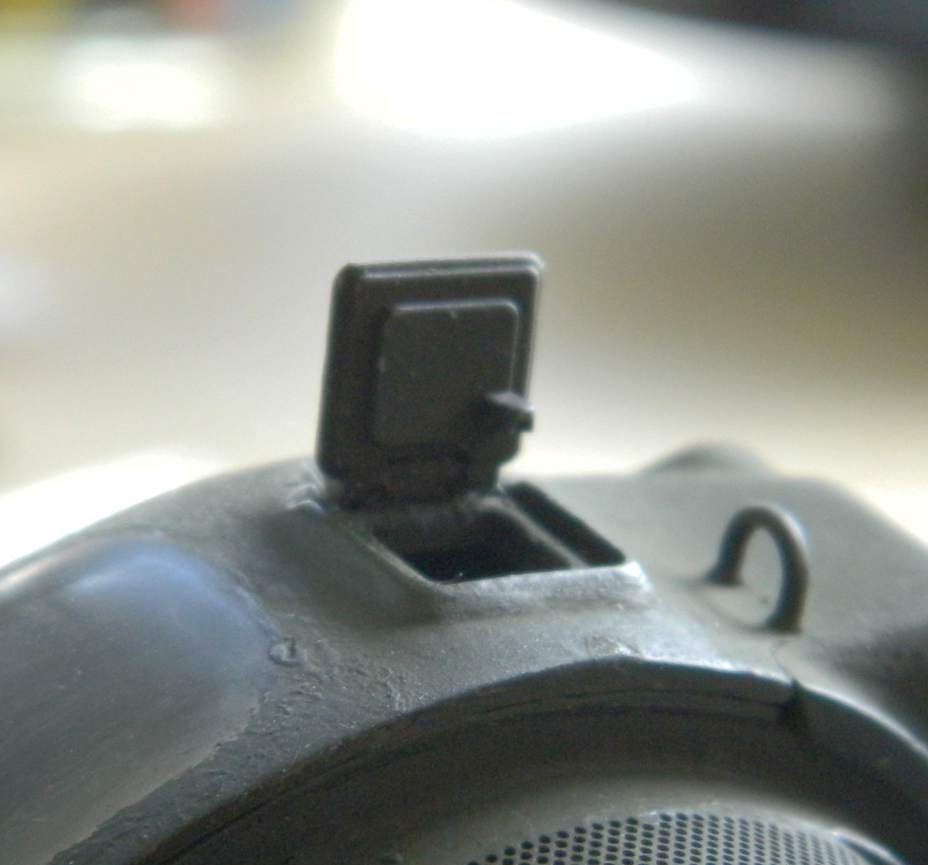
While I was moving and rolling the turret assembly around, I heard…a rattle?! What the aerial intercourse is RATTLING IN MY SUPPOSEDLY FINISHED TURRET?
Nothing major. Just the breech of the main gun! The cylinder sticking out of the turret basket is the errant breech:
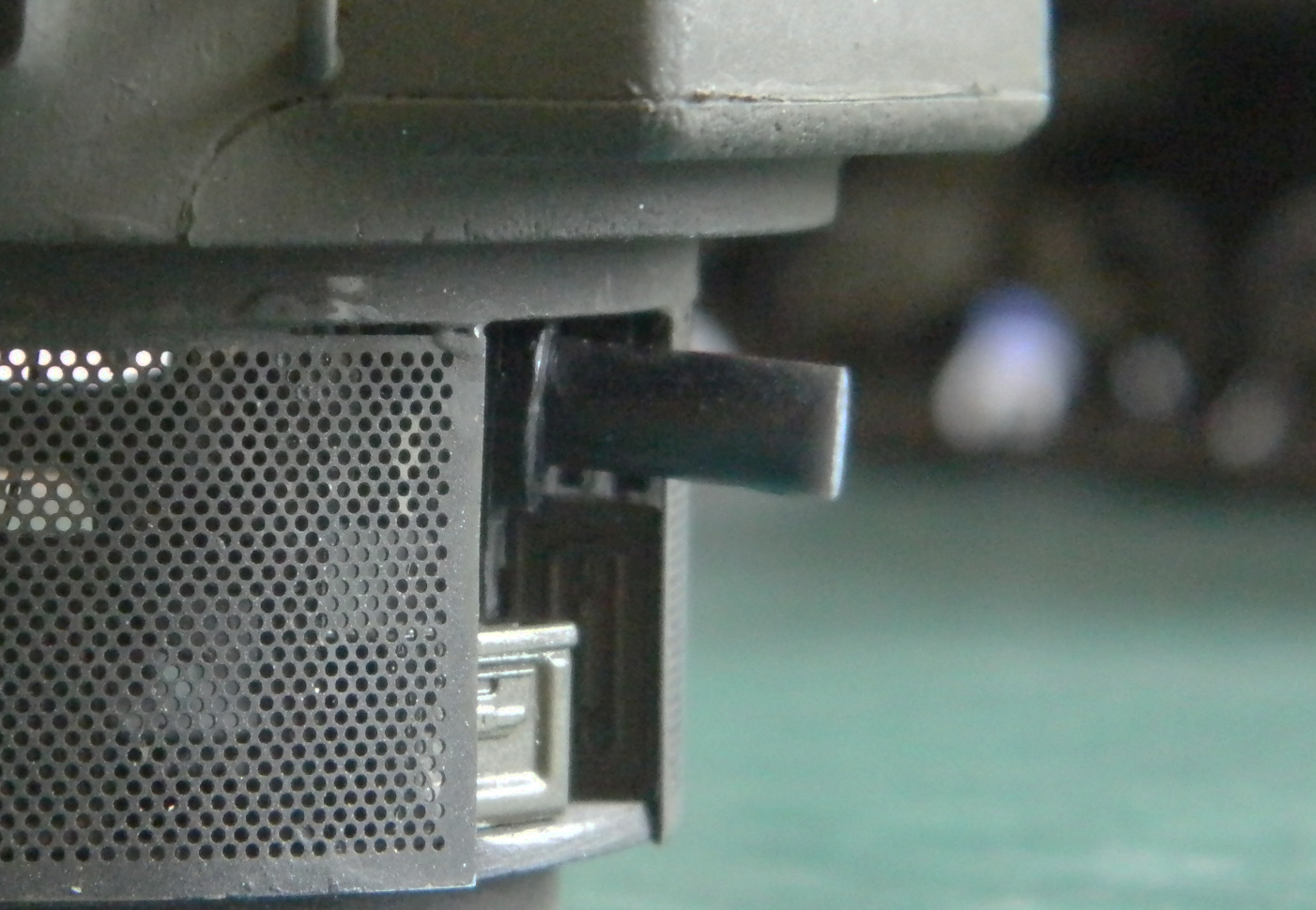
::facepalm::
This turret was, I thought, done. I know that turret basket will not come loose in a reusable manner, so that approach is out. The only other approach (that doesn’t involve a big hammer) is to pop the gun out through the front of the turret (which is the way it went in). I broke out in flop-sweat. Taking time to clam down, I wandered around the house engaging in very colorful (and anatomically unlikely) invective (yes…that’s my version of “calming down”…which rarely, though not always, involves a hammer). Suitably calmed (uh huh…), I took the thinnest steel tool I have that would have enough torsional rigidity to not only get into that really small gap between the turret and the gun mount, a #15 scalpel, and pried that bastid out of there:

If you look at the upper left of the opening in the front of the turret, on the turret face you can see where the paint chipped. I thought that I’d probably give myself several days of having to repair and repaint the damage that I’d do getting that [EXPLETIVE DELETED] gun out of there. Nope…just a wee nick in the paint and I spent more time stirring the paint than fixing the nicked paint took. It’s a win and I’ll take it. And of course I examined the errant breech closely to see how the glue failed. Well, the glue didn’t fail because I forgot to glue it in to begin with.
Brain fade. Insidious.
But I assure you that it’s glued in now.
So I glued the .50 caliber (1.27mm) in place and went to bed. The next morning, all pleased and flushed with my victory over, well, me not gluing the fornicating breech in, I looked at the machine gun mount and saw this:

When I walked away from the bench the previous evening, that mount was as perpendicular to the hatch ring as it was supposed to be. Seeing as the gun mount is plastic and the turret ring is resin, I of course used superglue to attach it. Clearly it had not set when I mistakenly thought it had. The mount itself is very thin and delicate and I know, KNOW, I used enough glue to hold that thing in place until the sun’s death when it will expand and incinerate the planet I’m sitting on. No way I’m going to be able to twist that thing out of there. So I took my thinnest RB razor saw, cut it free, and after making both meeting faces parallel to the resin casting, drilled the mount and socket and installed a pin. It’s now perpendicular and will stay perpendicular.
With that, this one is done, in spite of its last-minute resistances, and is finished as if it’s in a museum (these photos were taken when it still had its lousy serial numbers on it):
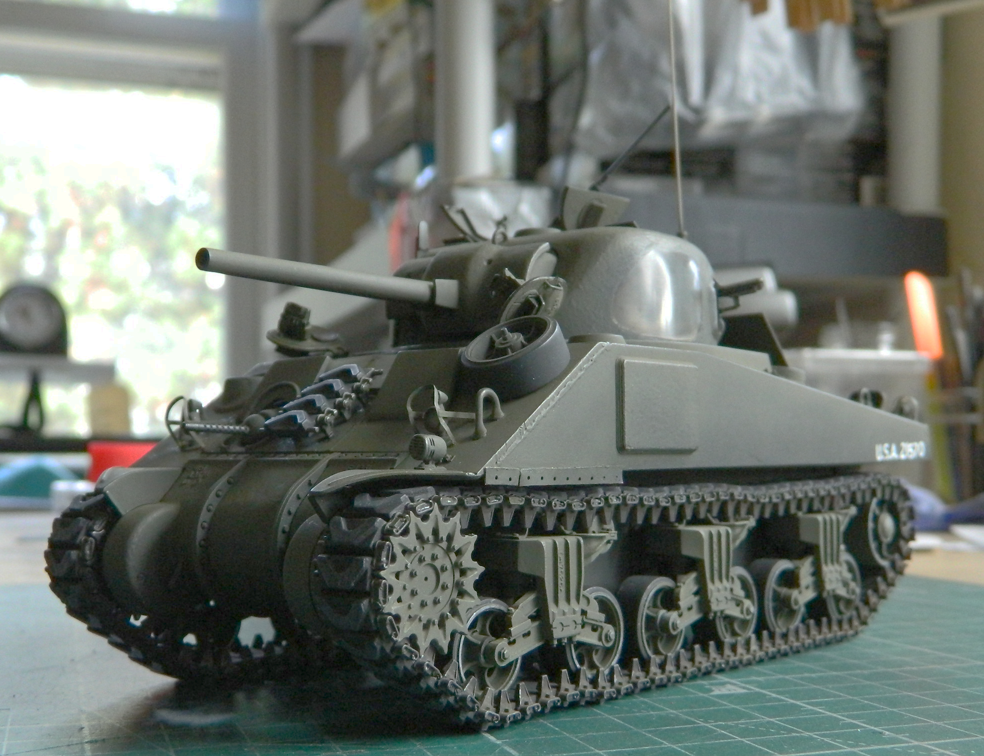

See? I told you the numbers were lousy:
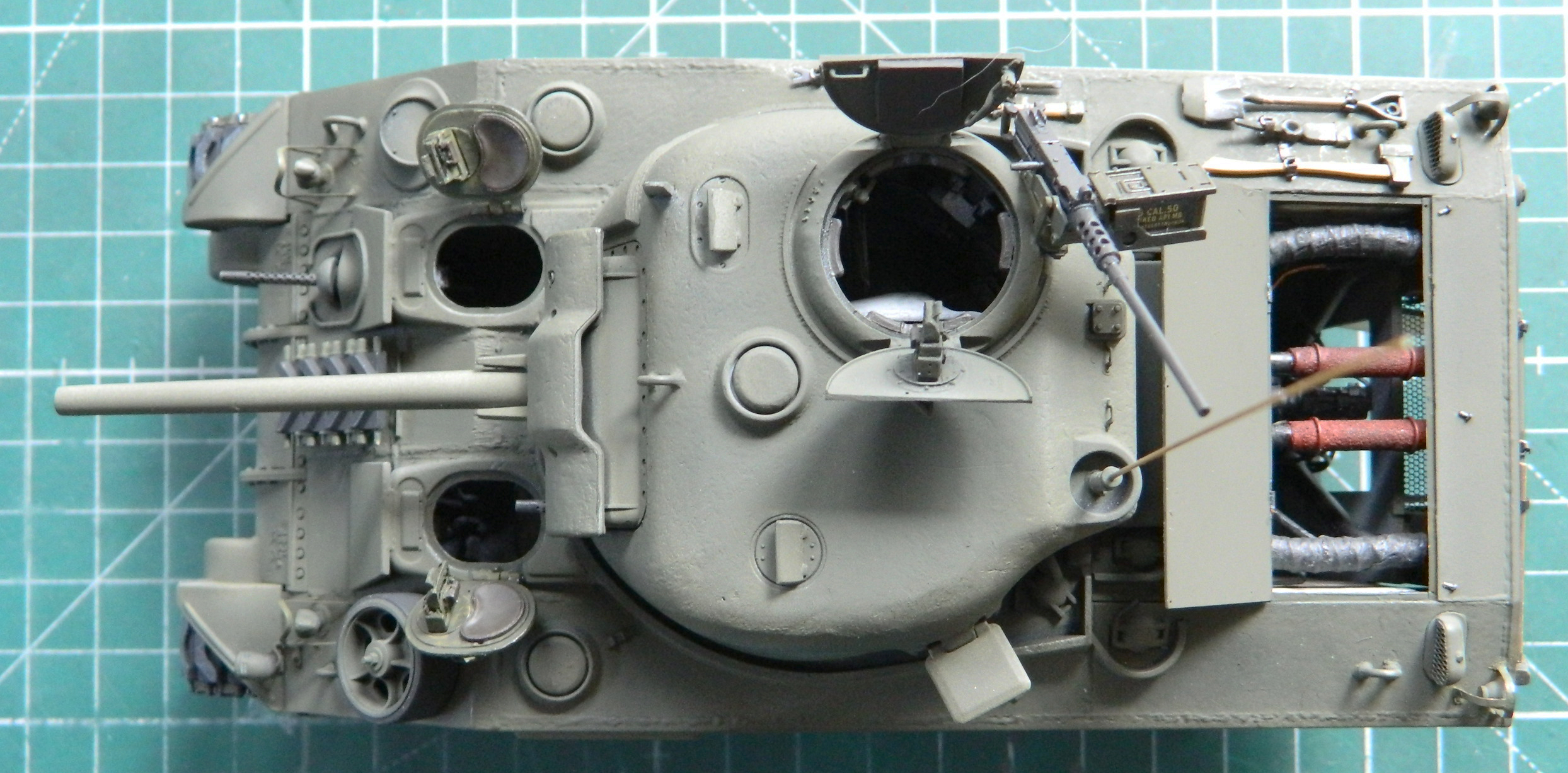
M4 (Tamiya) Build #10 – Wrapping Up Turret Work, Getting the Suspension Sorted, and Starting on Hull Details
After a month (or so) away from the bench, I returned this month with fresh eyes. I had to remind myself that this isn’t a job and I can do things like that. My eyes appreciated it (eyestrain, while not actually here, was on its way) and so did my brain (which is always the case).
I want to get the turret done so that I can move on to the remainder of my to-do list, so I started by painting the small details that inhabit that space:

And while I was invested in micro-vision, I added some wear to previously painted tools:

And then I actually remembered something that I’d wanted to attend do during the M24 build. This item is the .50 caliber (1.27mm) that I did for my return to this hobby in 2014. To the point…I got the color OH so wrong:
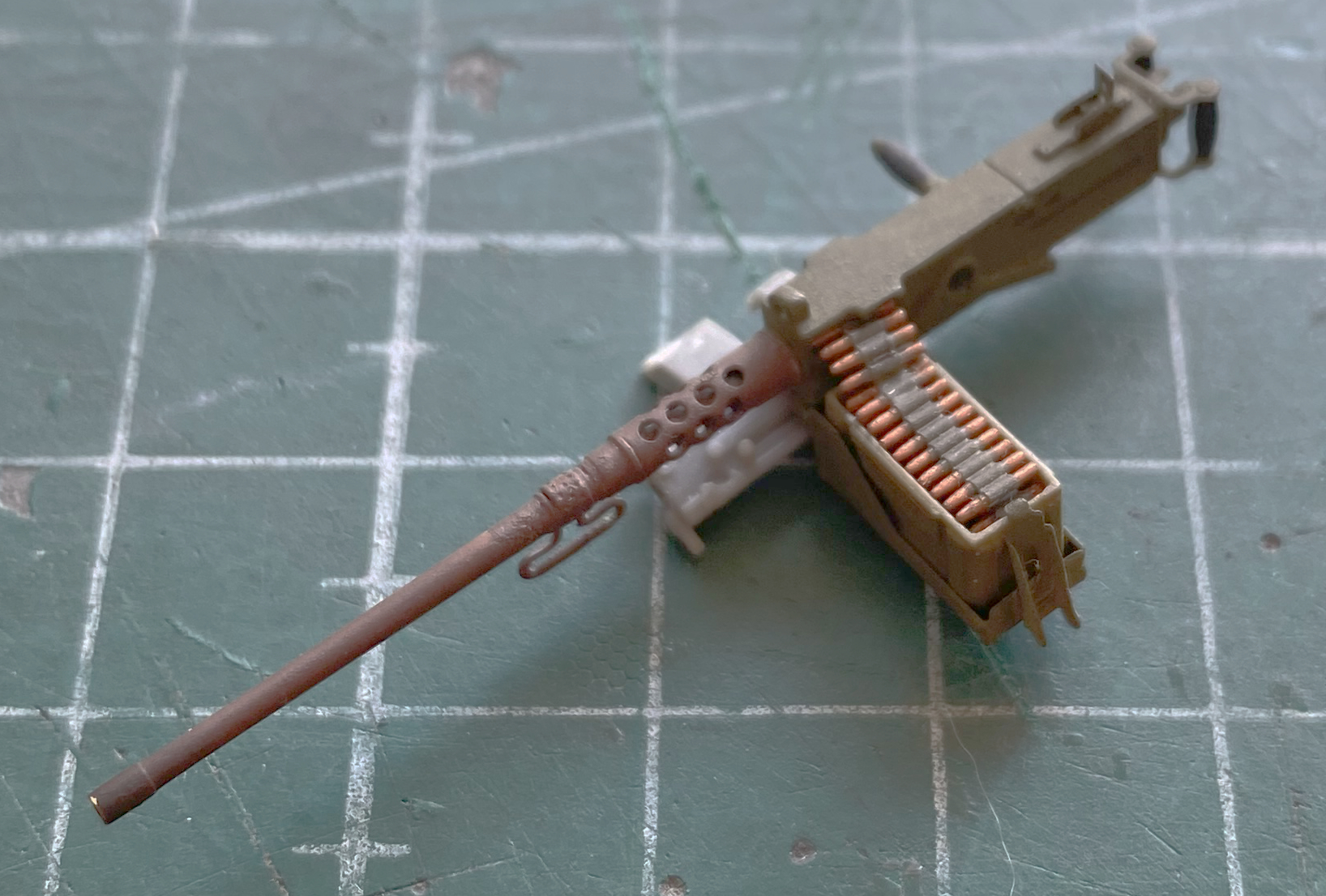
Who lets their weaponry get into such lousy condition?! Well, this maniac with the color-vision problem, is who. It’s rare that I’ll go back to a model once I’ve declared that it’s done, but this little abomination just had to be fixed. I decided to that I needed to fix that and, having forgotten to do it when I did the M24, now’s the time.
I’ve used a few different brands of gunmetal paint and liked none of them (unlike what I’d painted that gun with…). I brewed up my own:
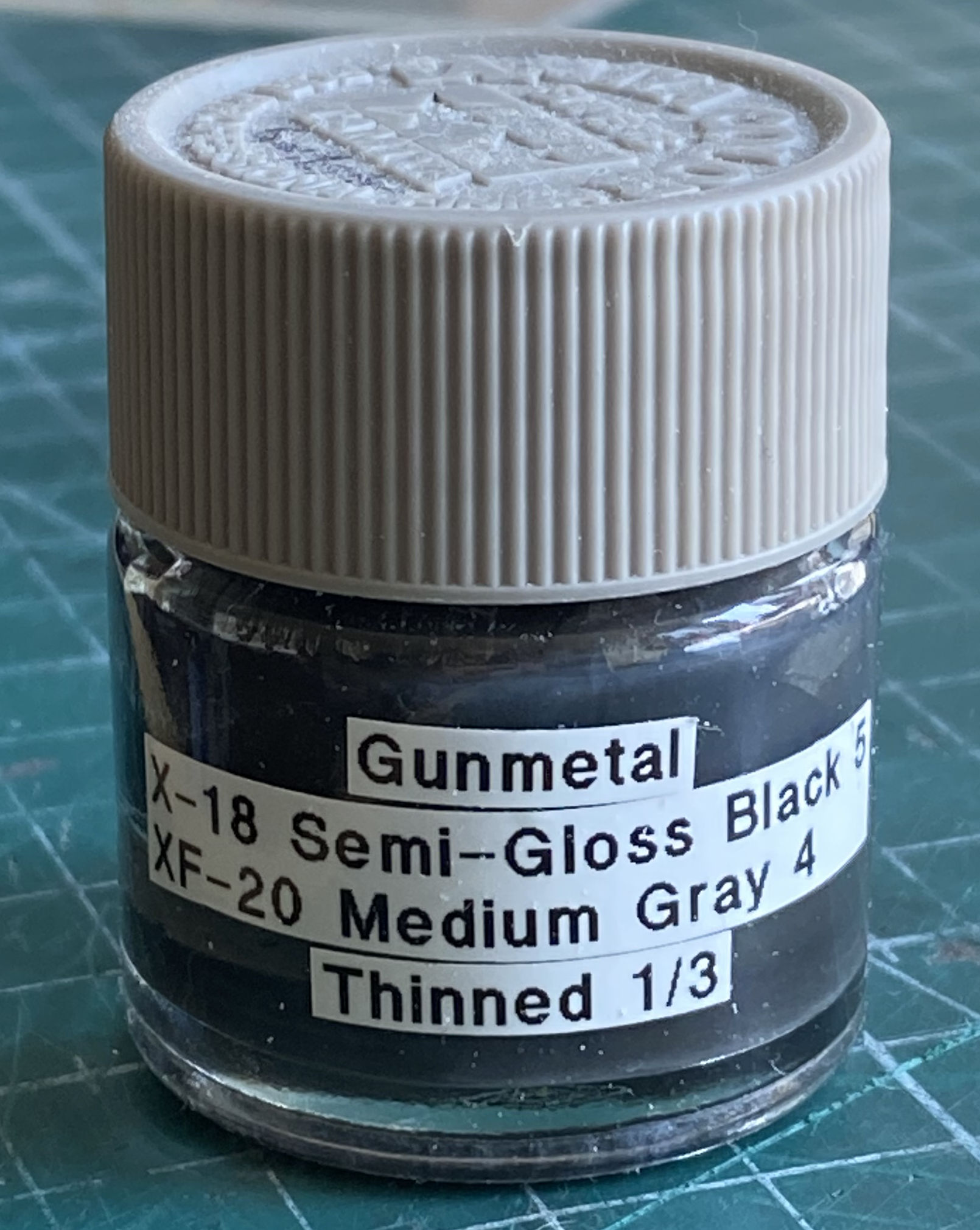
Much better:
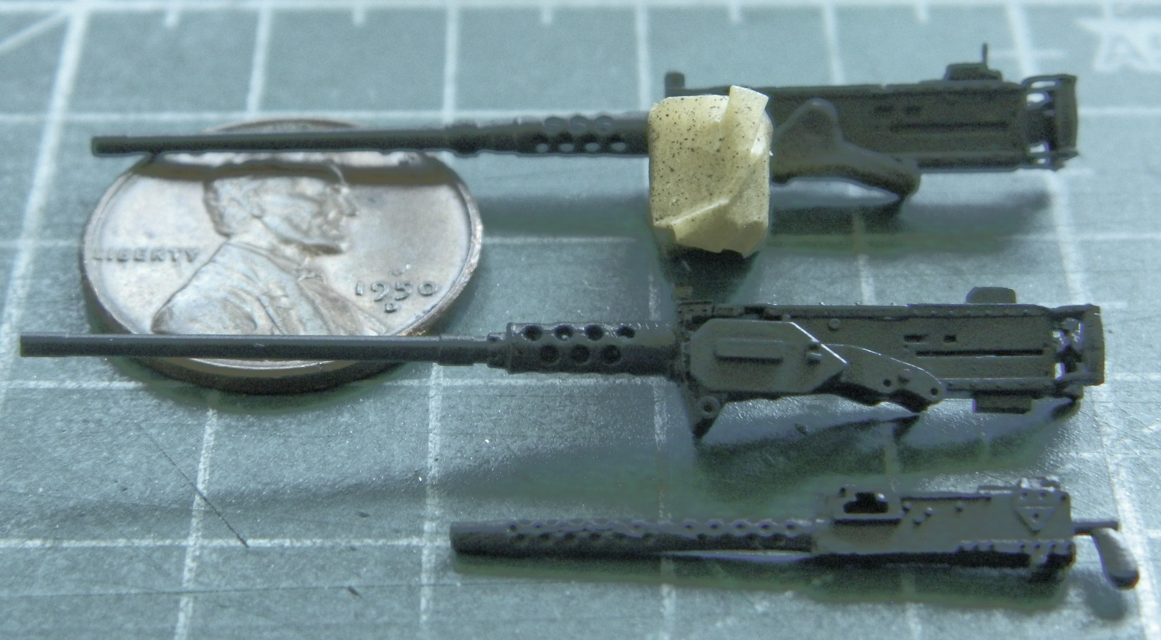
I added the light splash with Tamiya XF-2 Flat White to the major bits in the turret:
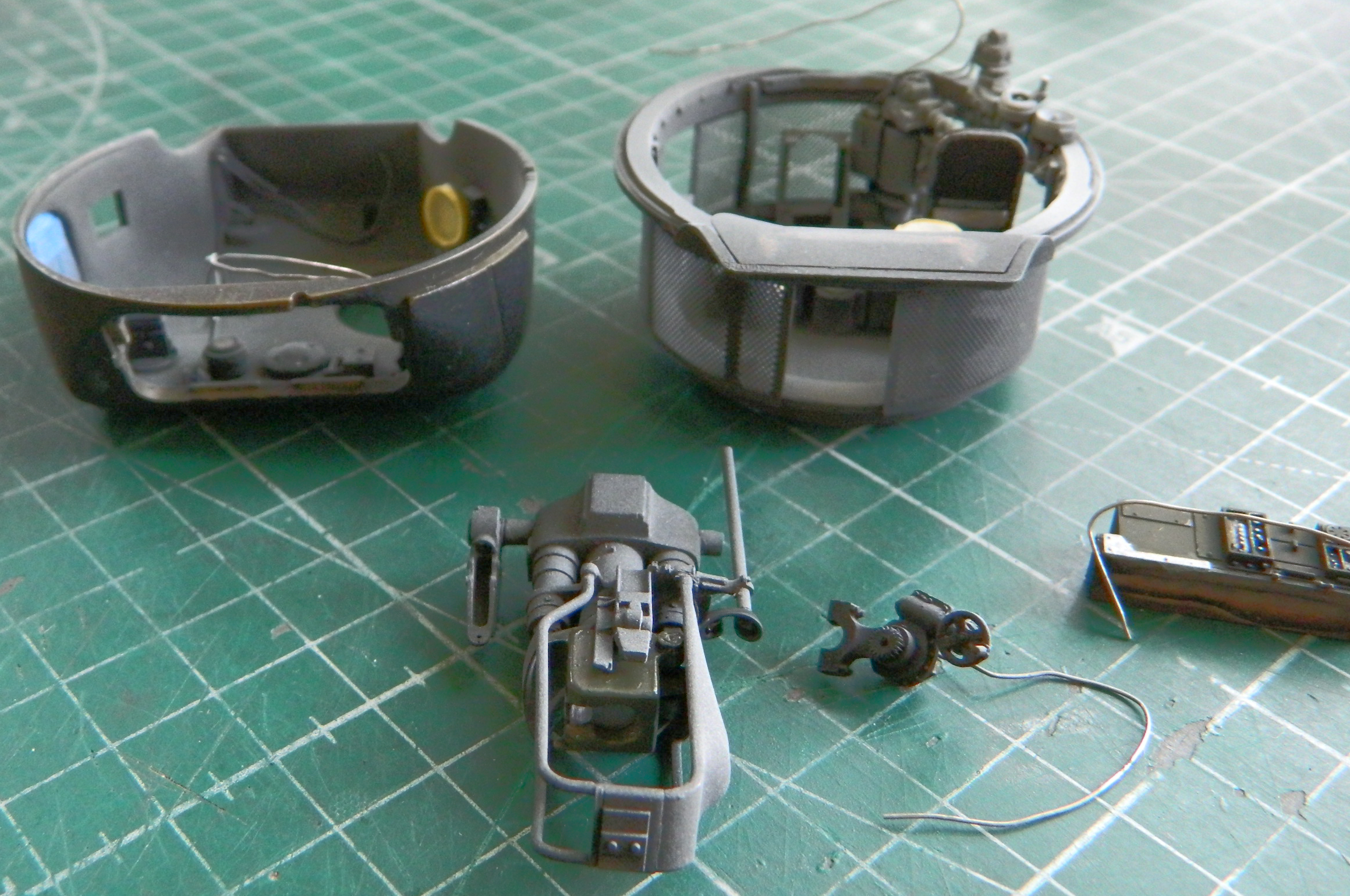


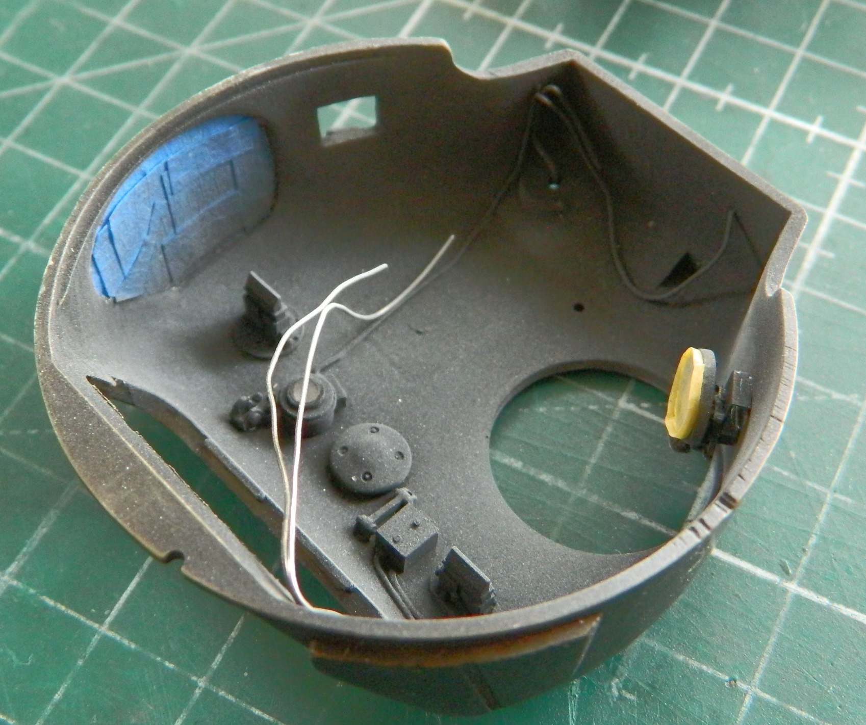
And then added the .30 cal (7.62mm) and the firing solenoid:

I dry-fit the 75mm and decided that I hadn’t added enough white:
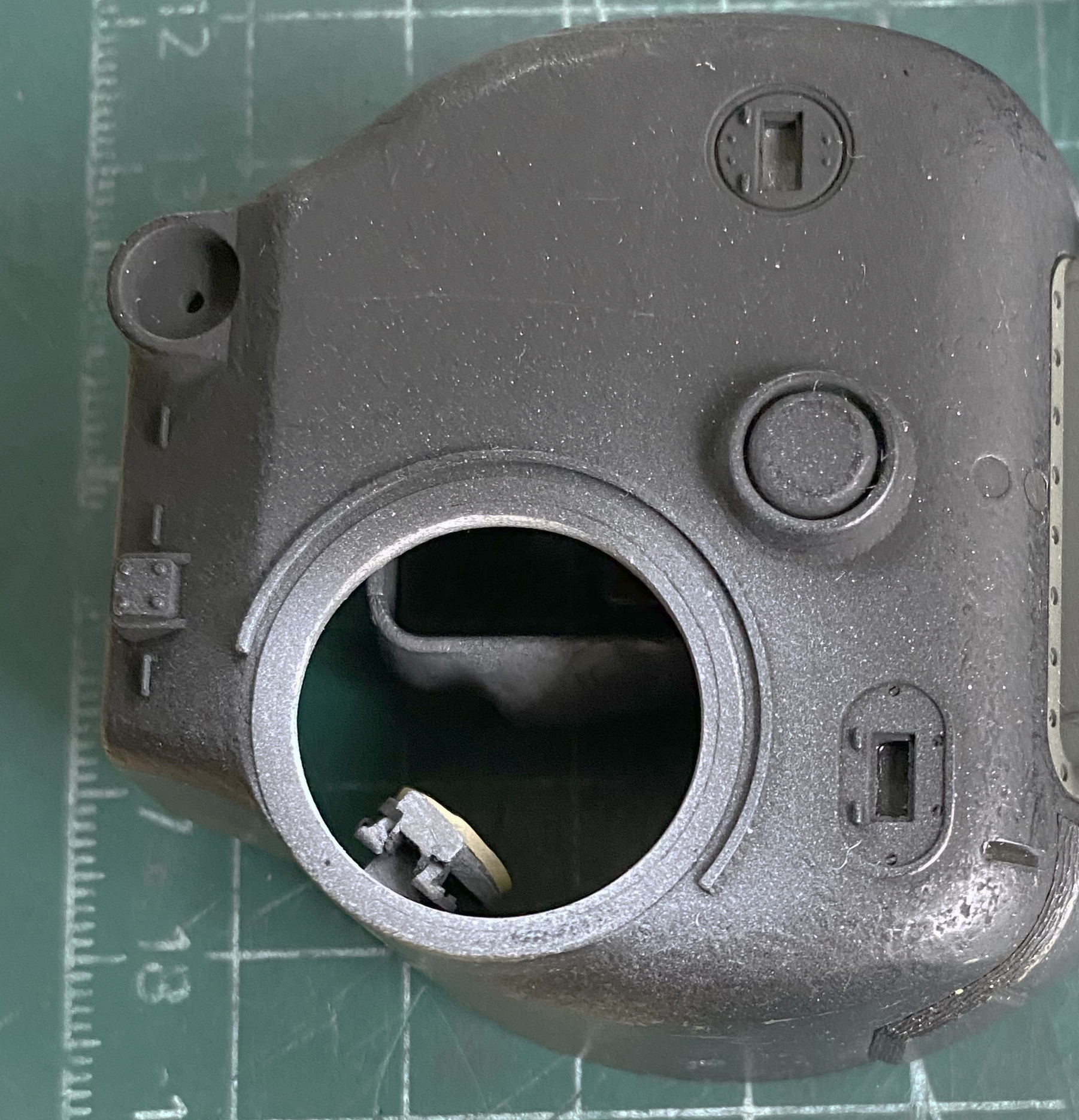
More flat white got tossed and it looks better:
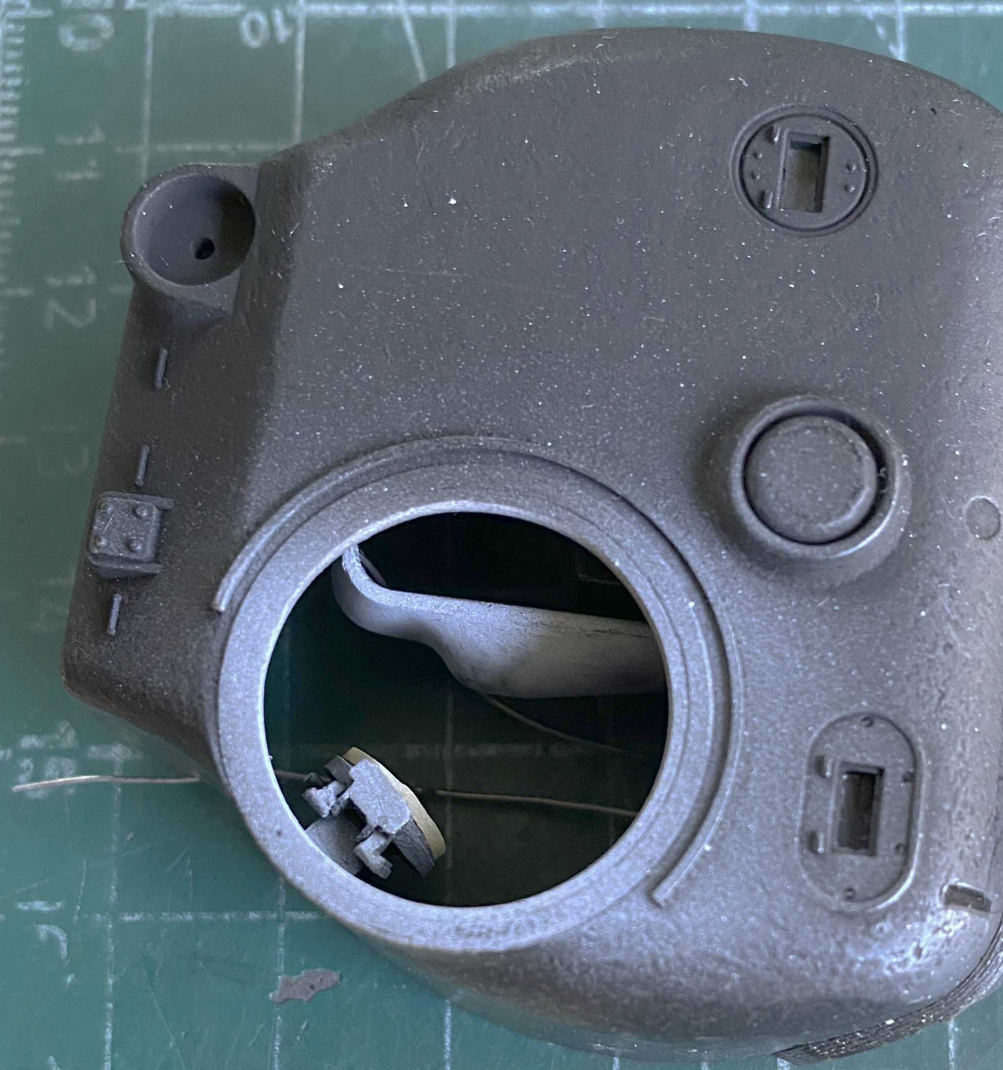


The junction boxes for the interphone weren’t supplied, so I made some using scrap .040″ (1.016mm) and .025″ (.635mm) rod. The styrene blocks were attached to a section of scrap cardboard with double-sided tape (because I really don’t like it when the tiny bits go skating around the bench). Jeweler’s tweezers are almost as good as having four hands:
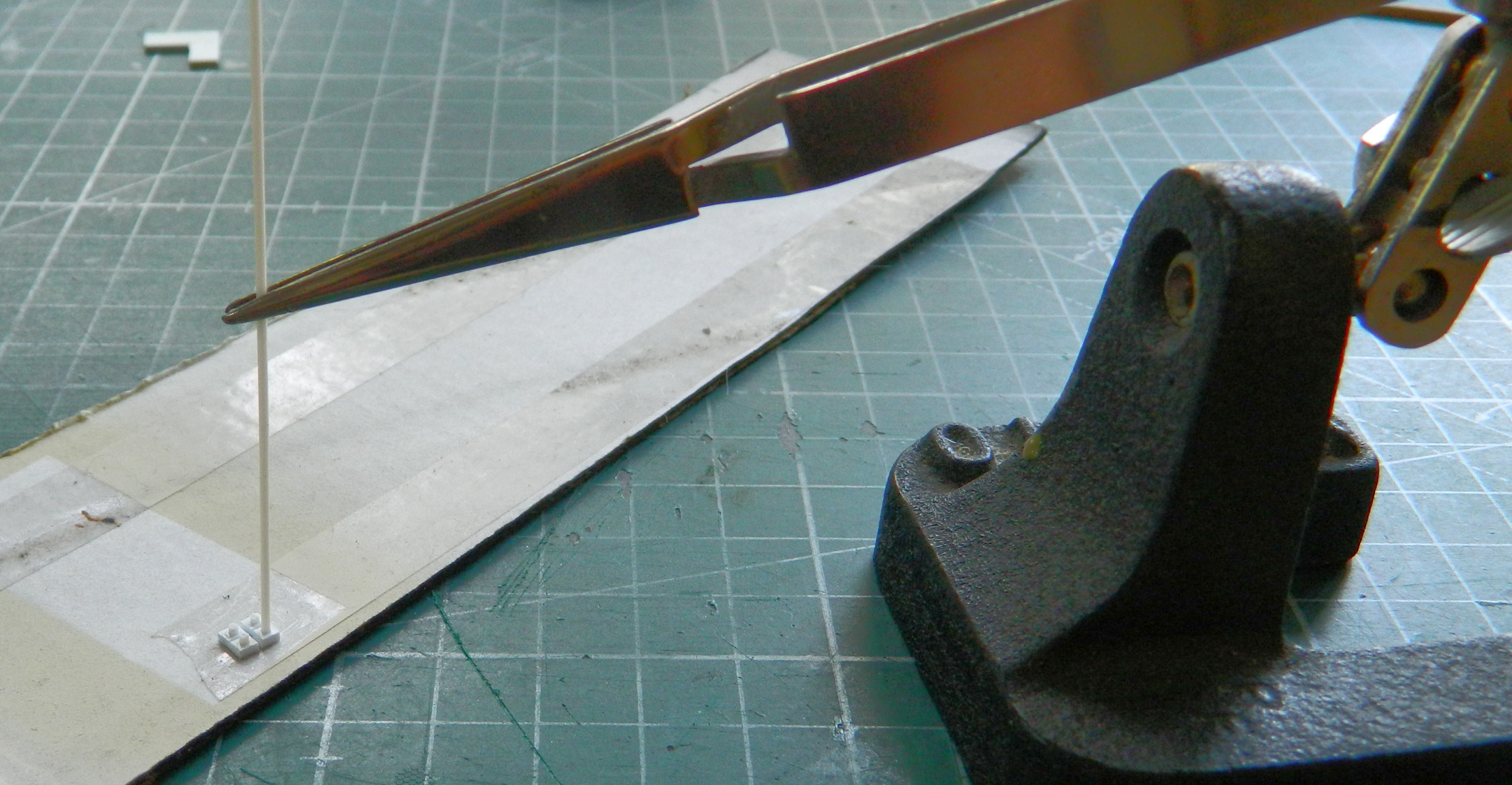
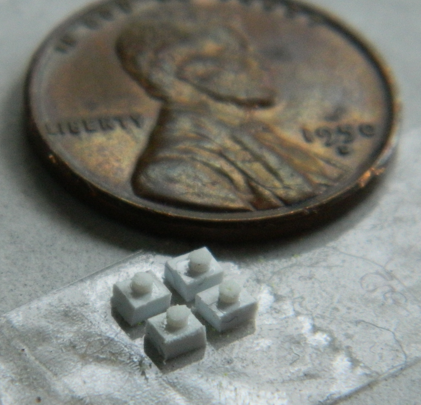
With the junction boxes built, holes for .010″ (.254mm) and .020″ (.504mm) solder “cables” were drilled and the boxes attached:
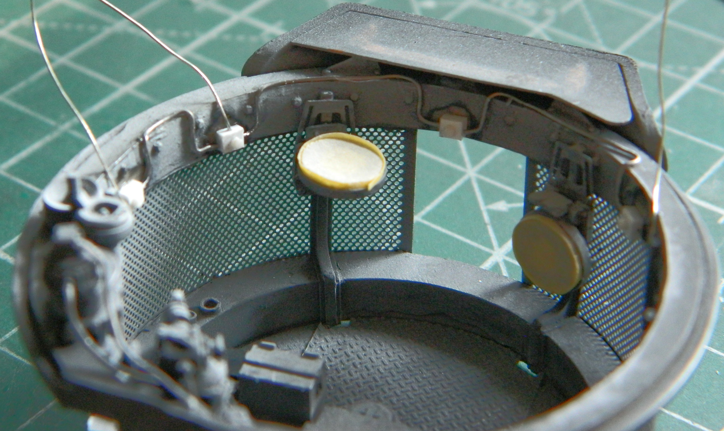
Next was to make the microphones. I knew that I was going to use only three (because the two by the driver and co-driver would never be seen) but I made five to be able to pick the best three. I started by punching discs for the mouthpiece from .015″ (.381mm) and (.635mm) rod for the handles and transducers. Once all the parts were ready, I used a bit of scrap .015″ (.381mm) to hold the handles parallel to the mouthpieces which were set onto double-sided tape to hold things while the bits were glued and the glue cured:
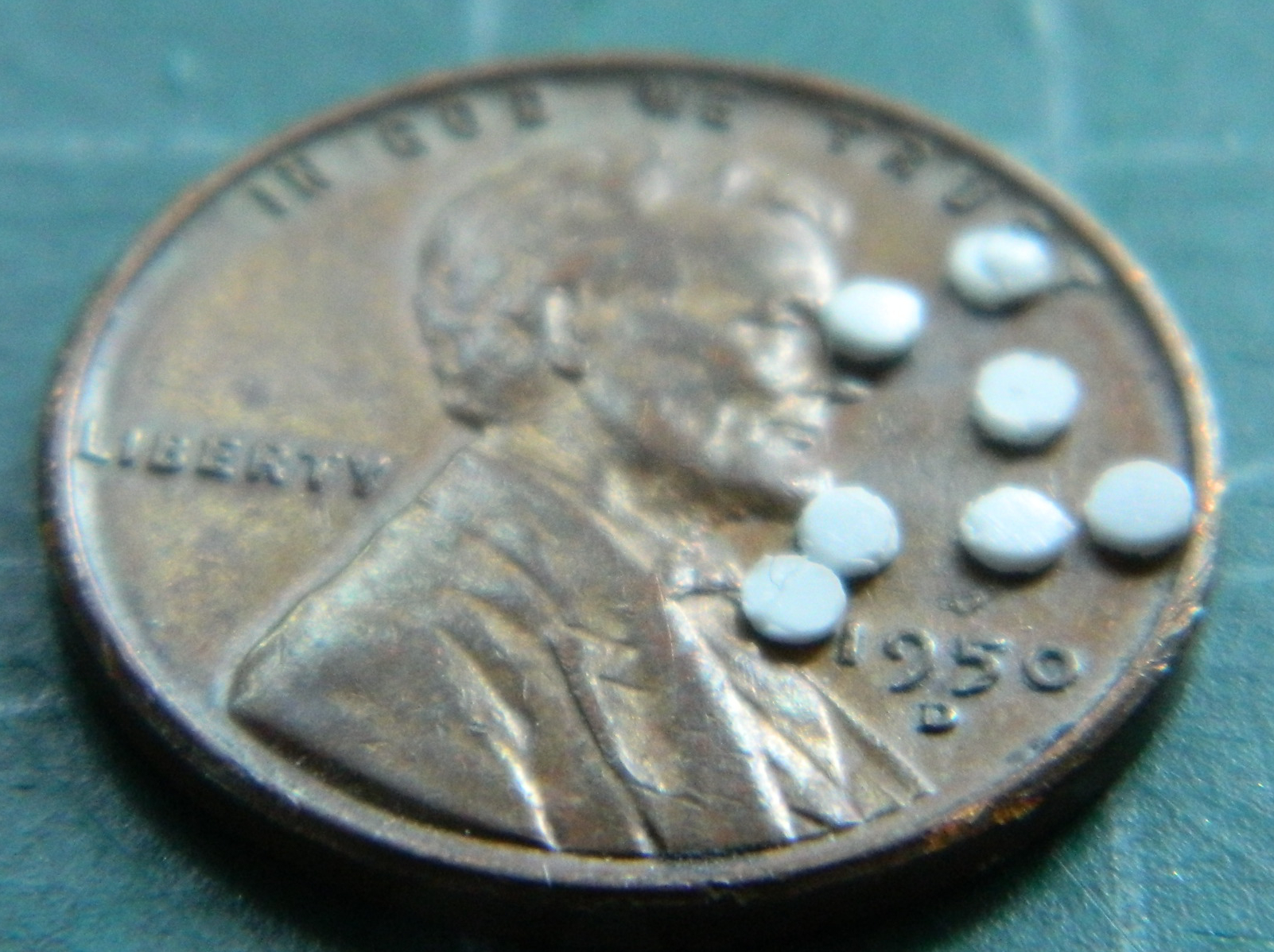

The “backstory: for this build is a tank fresh off an LST and being loaded for action (pre-Operation Cobra), which meant that I’d need several .50 caliber (1.27mm) ammunition cans. Once upon a time, Archer offered dry transfers and unfortunately the last factory that supplied the chemicals necessary to produce dry transfers shut its doors. Archer adapted and now offers very nicely done decals, in this specific case for the ammunition can labels:
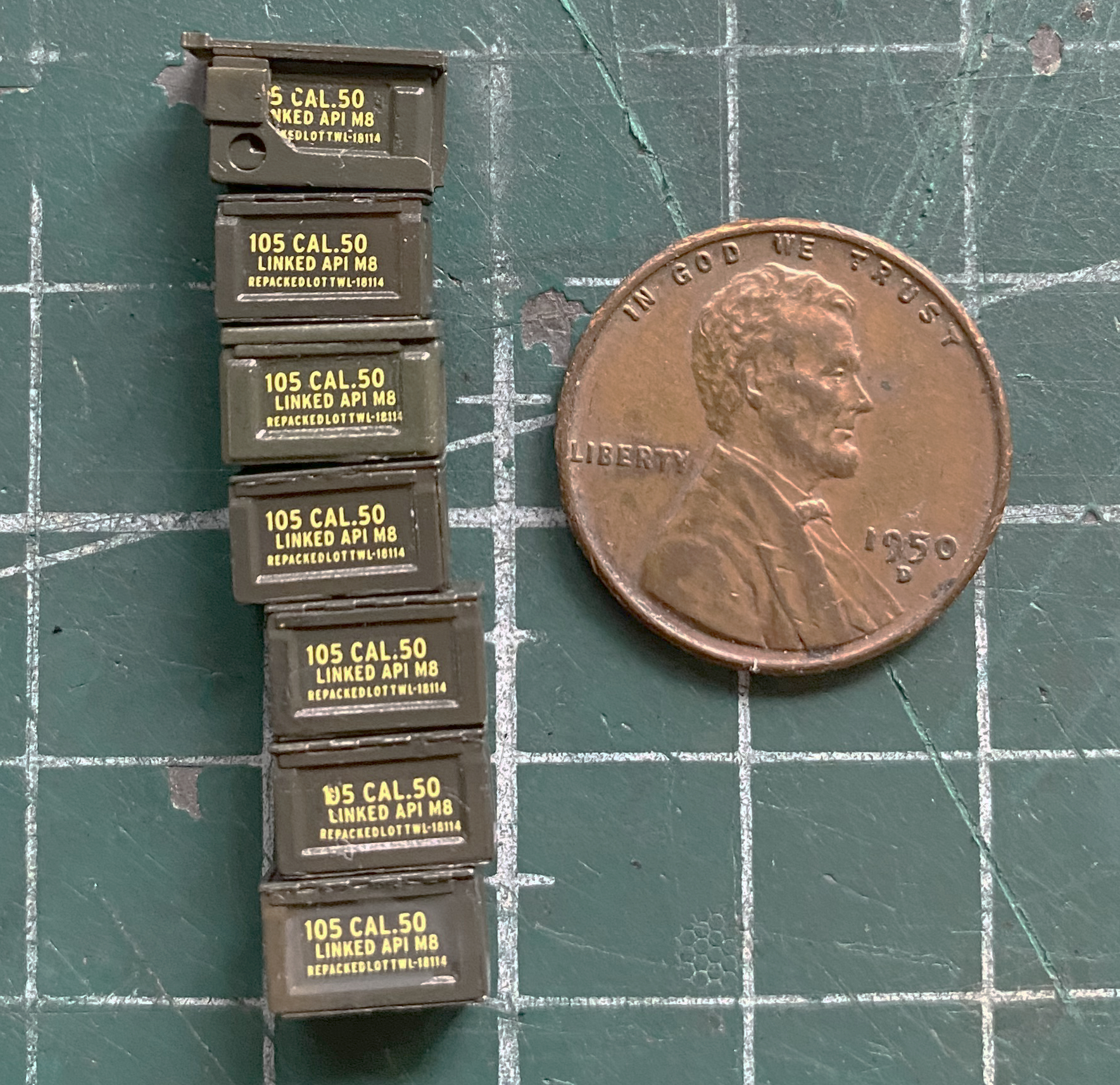
Then I hit everything that I wanted to do a black wash on (which turned out to be utterly unnecessary) with clear gloss:

Having done an oil-based wash, I needed a few days for the oil paints to dry. While waiting, I set up the parts I’d need to do the road wheels and suspension and got them all cleaned up:
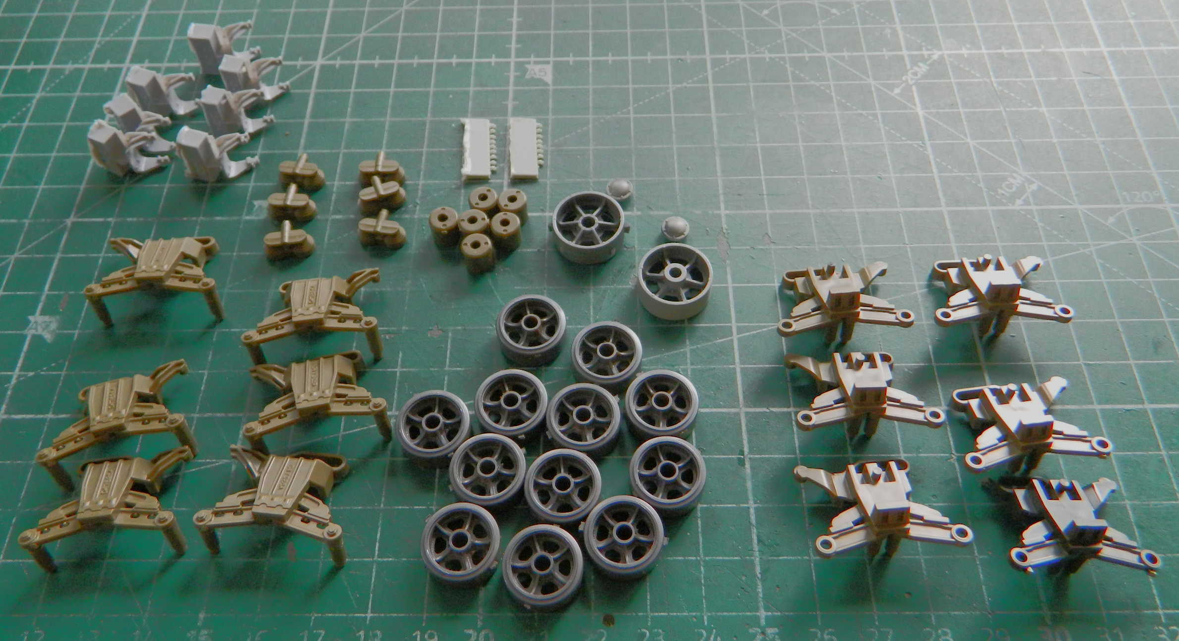
When that photo was taken, I’d planned on using a set of early road wheels from Dragon (spare parts inventory) because because their detail was a little bit crisper. The diameter of the center holes is larger enough than the Tamiya parts, whose bogeys I’ll be using, and I’d have to shim the center holes of the road wheels to get the correct fit. I took a close look at Tamiya’s road wheels and decided that the little bit of crispness that the Dragon part offered would be offset by the hassle getting them to fit would create. Instead I used the Tamiya road wheels.
This is the Tamiya bogey assembly:
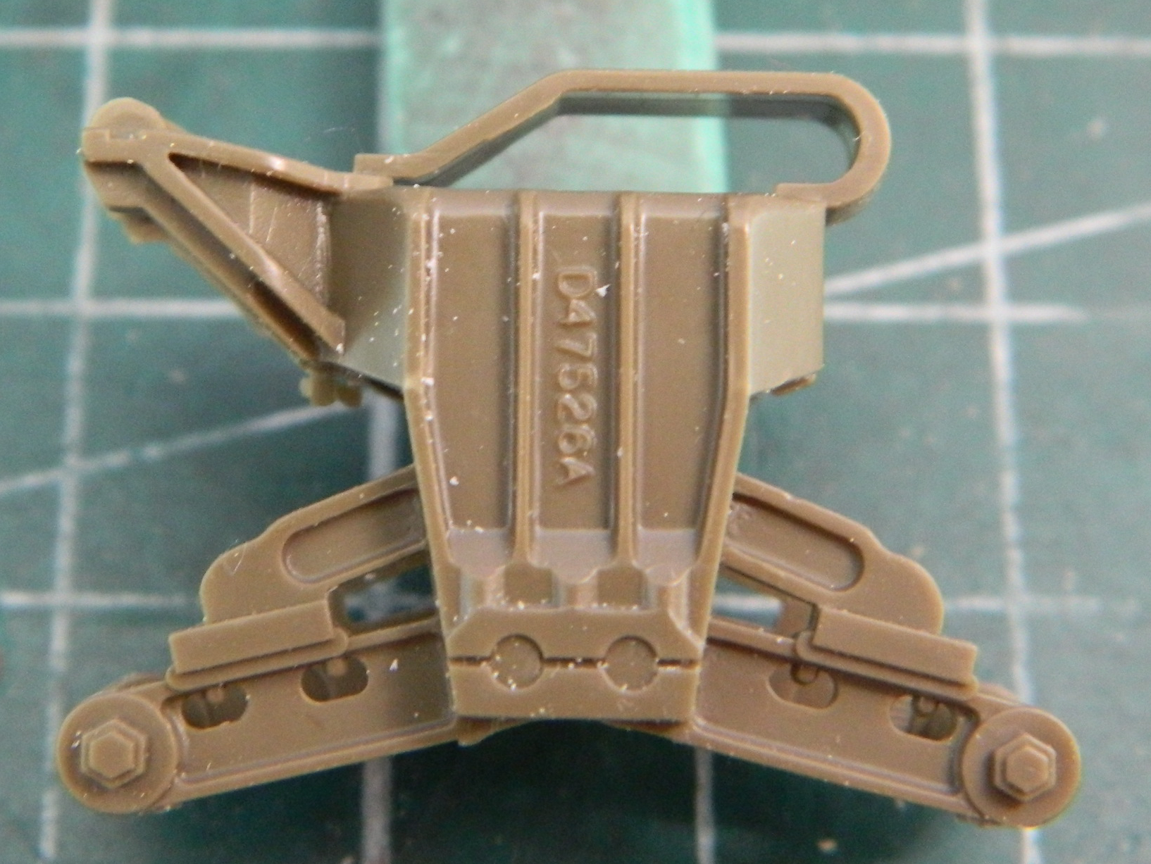
The roller return arm (top left on the outside of the bogey) is a later-production unit than I want to use on this earlier production tank. On top of the bogey is the track return skid. Not only is that a later production part as well, it’s quite out of scale. That means that both the roller return arm and the track return skid have to be removed and replaced. However, the mounting points for the return roller are on the arms. When they’re gone, so are the mounting points. That meant I had to come up with a shaft for the return rollers.
Checking my stock of styrene rod, I saw that one was too small and the other too large (and no Goldilocks rod to be had):
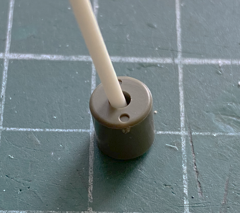

It’s easier to turn down something too large than it is to expand something that’s too small (or so she told me, anyway). I cut short sections of the larger rod and chucked them into my desktop lathe spun slowly and used a sanding stick (sourced from the nail supply section of the nearest drug store) (or apothecary if you live Over There) to reduce the diameters (I’m using the tip of my thumb…because my roommate wouldn’t cooperate…to hold the styrene rod against the sanding stick, otherwise it would flex too much and/or break off):
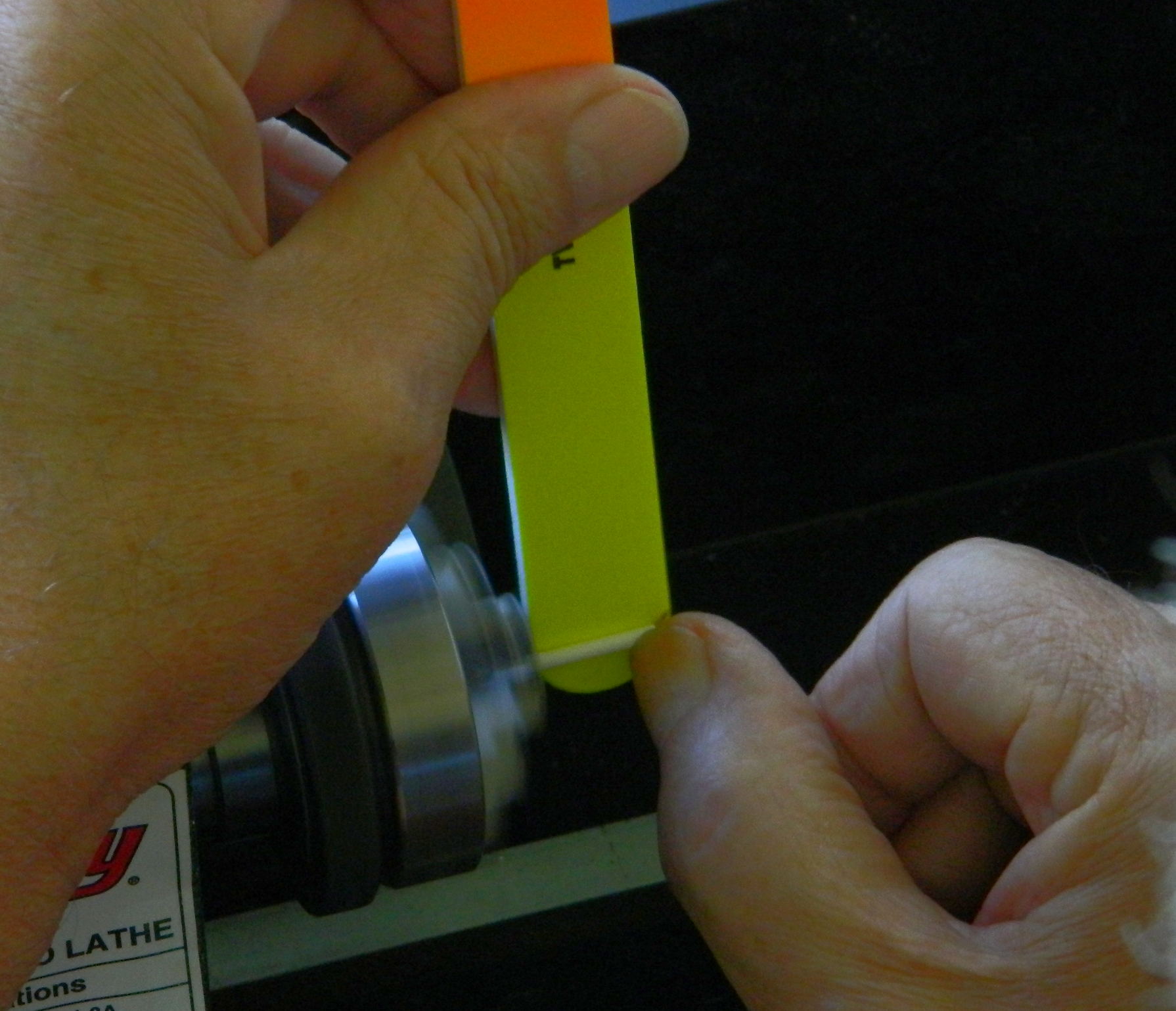
And that worked just fine:
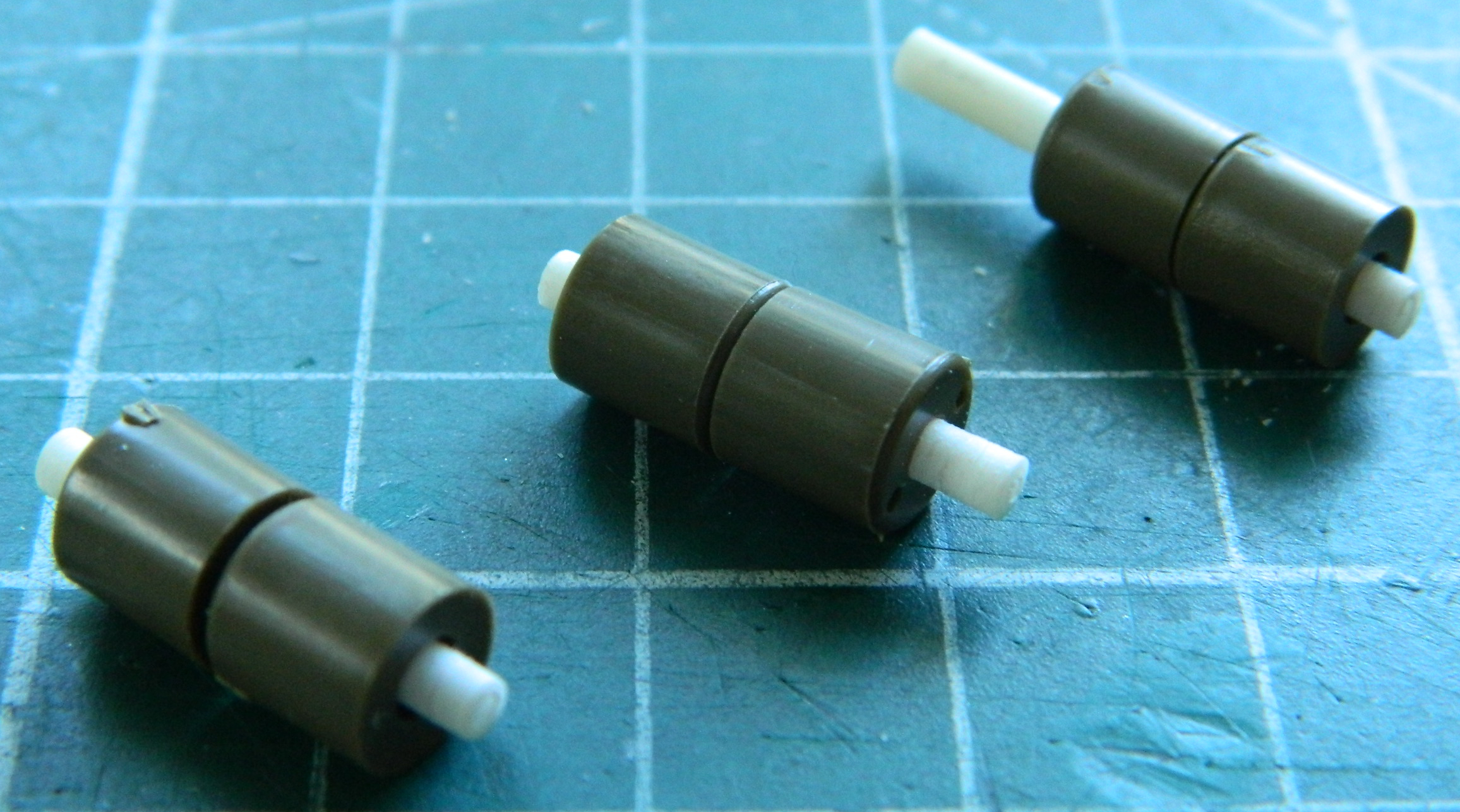
Often when I’m at a build, I’ll prop myself up in the shop (it has the best light at this house) and sip my Elixir of Life (coffee, in case that’s not obvious). As my ability to focus, both my eyes and my brain, returns, I will frequently (okay, okay…sometimes) start to notice things that I hadn’t. This time it was how Tamiya molded the suspension arms where they attach to the bogeys. In the next photo, check how those arms attach to the bogey. The one on the left could move. The one on the right CANNOT move (look between the arms where they contact the bogey). I cut the plastic away from the unit on the left and then did all the other ones:

I flipped them over to make removing the errant plastic easier (the white plastic on the upper arms is where I’d nicked them while filing away the incorrect return roller arm):
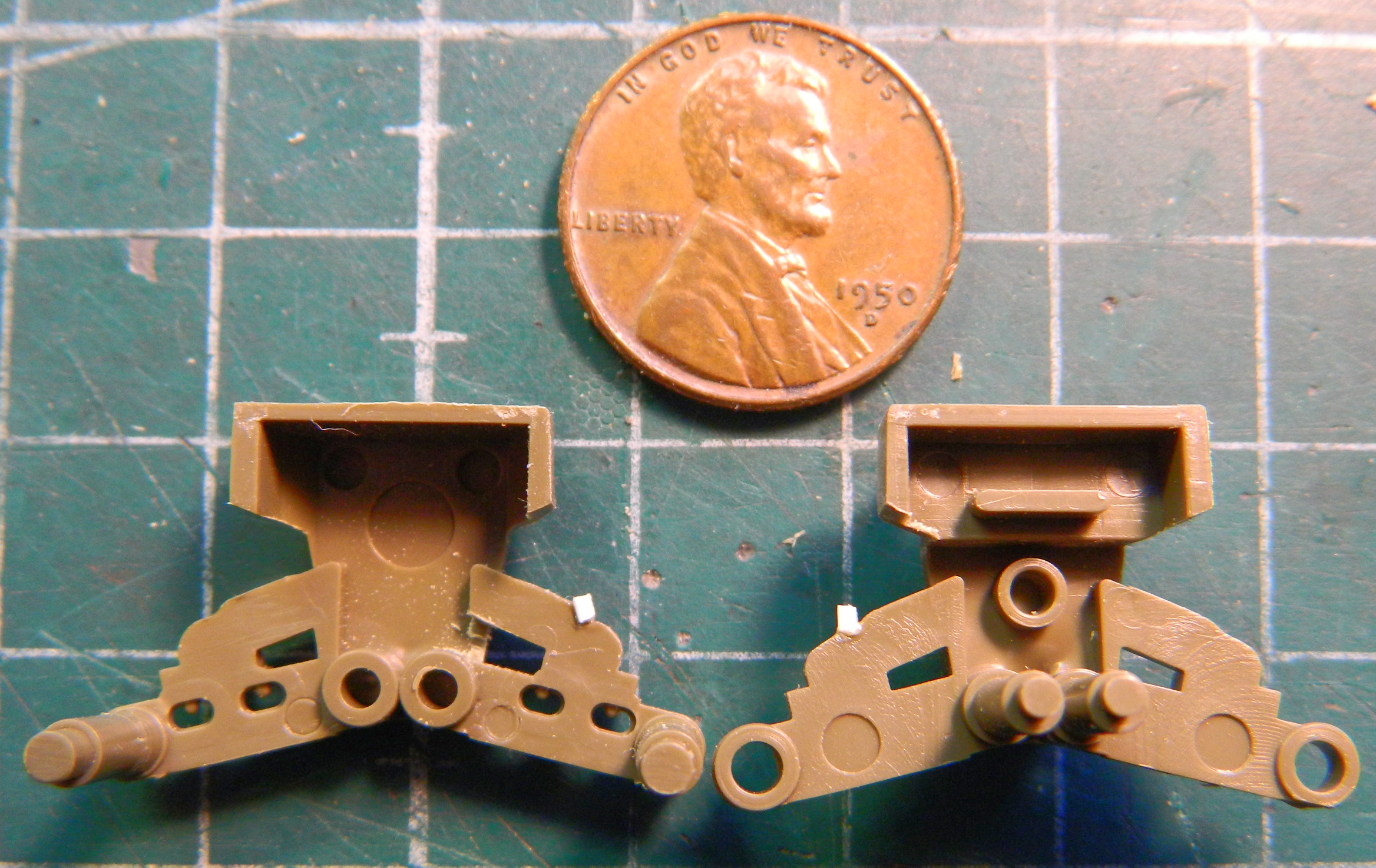
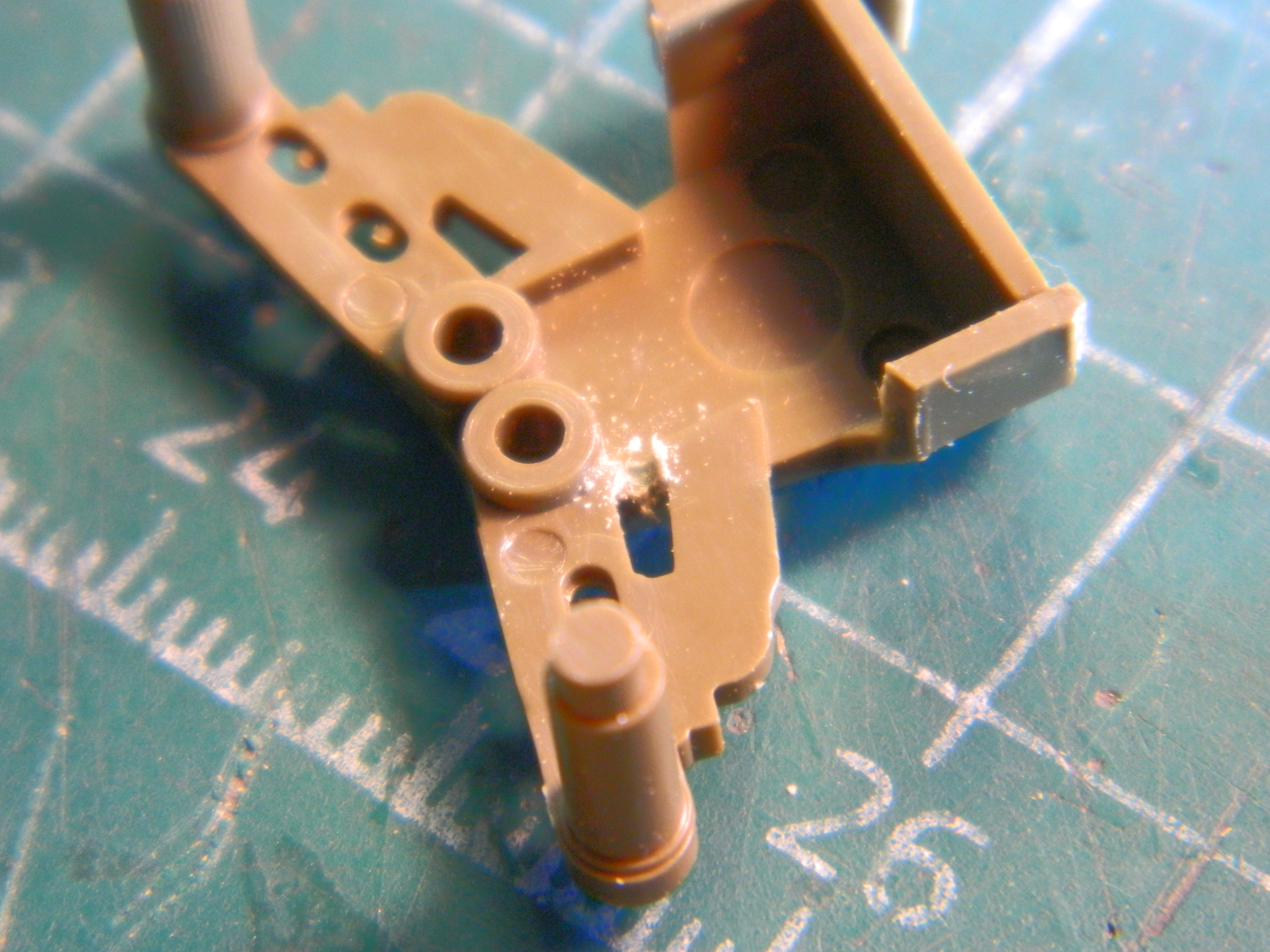
Once the needless parts were filed off the bogeys, I ended with this:
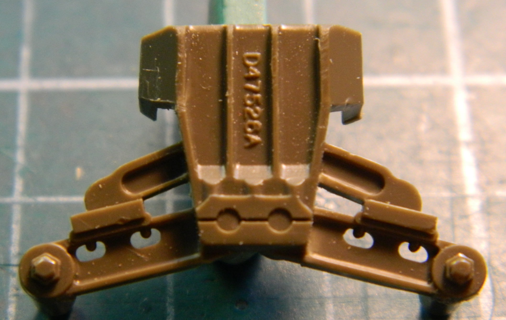
Since the tedium was starting to annoy me, I switched tasks and painted the road wheels with Tamiya XF-85 Rubber Black and stuck them on skewers to dry:

After sitting overnight, I painted the steel hubs Tamiya XF-62 Olive Drab (3 parts) combined with Tamiya XF-2 Flat White (1 part). The easiest tool I’ve found for masking wheel hubs is an artist’s circle template (which I’ve used for aircraft wheel hubs, car wheel hubs):
For these road wheels, the half inch (1.27mm) circle is about perfect. There’s sometimes a very minor bit of overspray around these wheels which perfectly mimics what can be seen on the real tanks. I held the wheel against the template with a fingertip from behind and got the wheel hub as centered as I can:
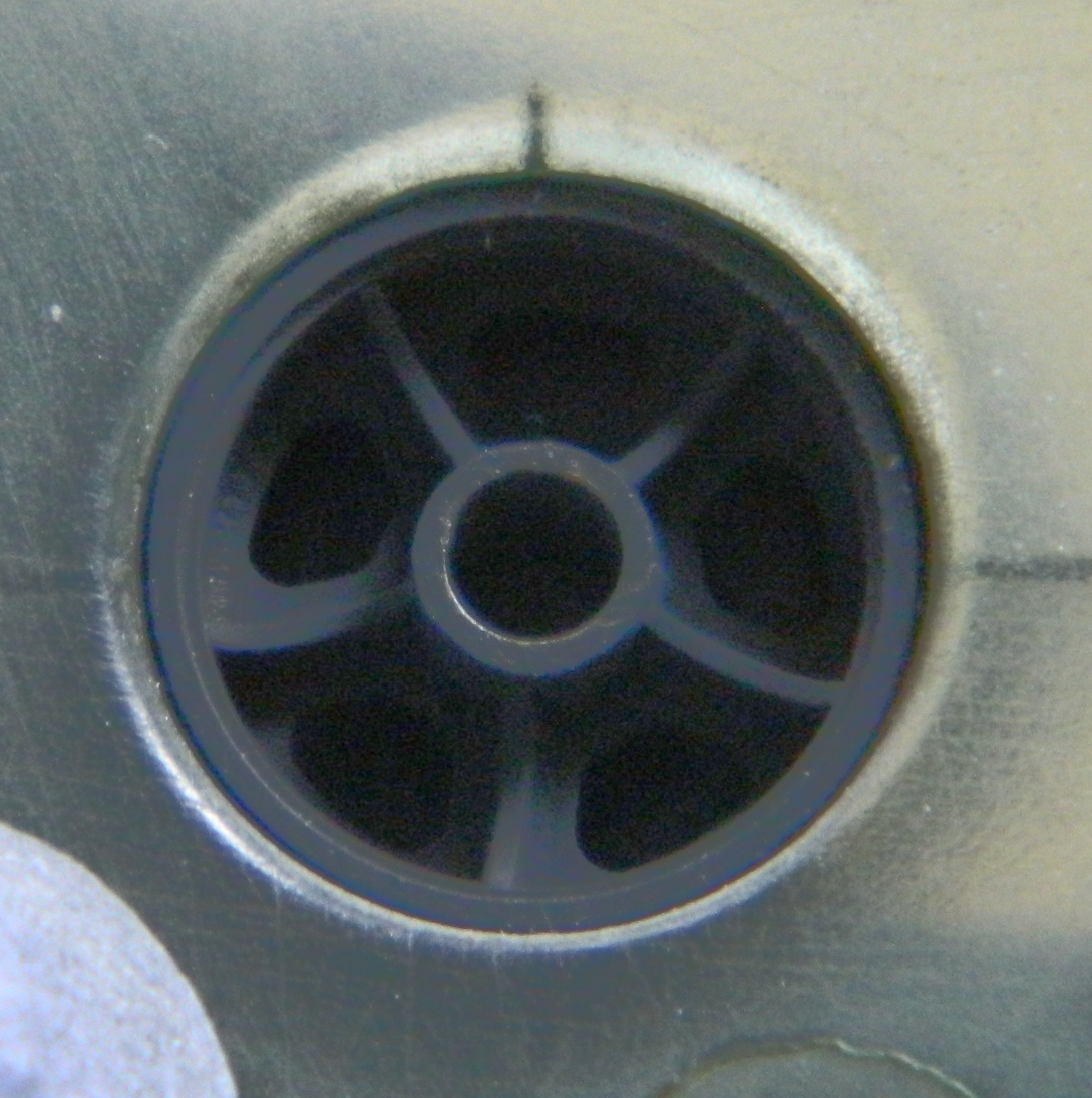
Having already painted the hubs’ lip with steel enamel, I used the edge of a toothpick to scrape away the OD and expose the steel where they’d rub against the track shoe locators (only half was done for the photo to offer a point of comparison)

Once all the road wheels were painted, I masked them before attaching to make my life easier. Since the masks need to stay on until I’m done painting suspension parts, each section of mask is C-shaped so that they’re easily removable, and then a band of tape goes around the rubber rims:
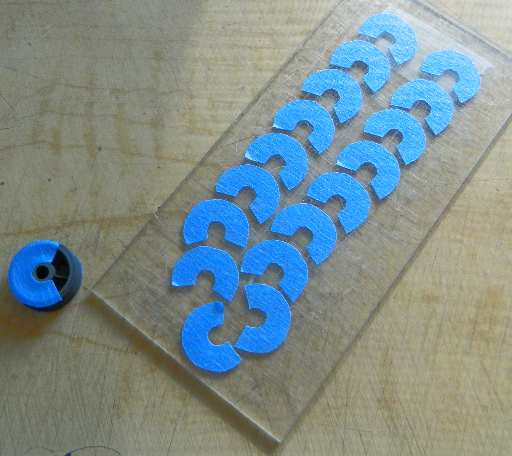
Other things needed to be added to the bogey assemblies.
The return roller arm needed a little detail. Ordinance decided that the return roller needed to sit a couple of inches higher than the roller arm allowed. They inserted a steel “pillow” (their term, not mine) to raise the roller and bolted it to the arm. I used Tiger Model Design’s early arm, added the pillows using scrap styrene, and then used Grandt Line bolts to finish the part (I’m using a 50 cent piece as a scale indicator in the second photo because somehow I lost my penny…it’s in the shop somewhere):

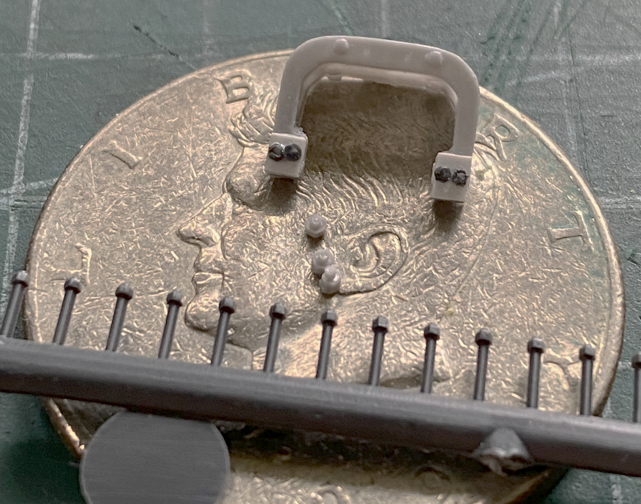

This is the mostly completed (more on that shortly) bogey assembly. The return skid has been replaced by Tiger Model Design’s (TMD) mid-production skid, the earlier straight return roller arm (also TMD), the return roller with its replacement axle, and if you look closely on top of the upper suspension arm, you’ll see the bolts that I added that should be there and were not. The bottom of the bogey has a cap held in place with three bolts to hold the trunion pins that were also not molded on. Once again, TMD had the parts and I added those as well:

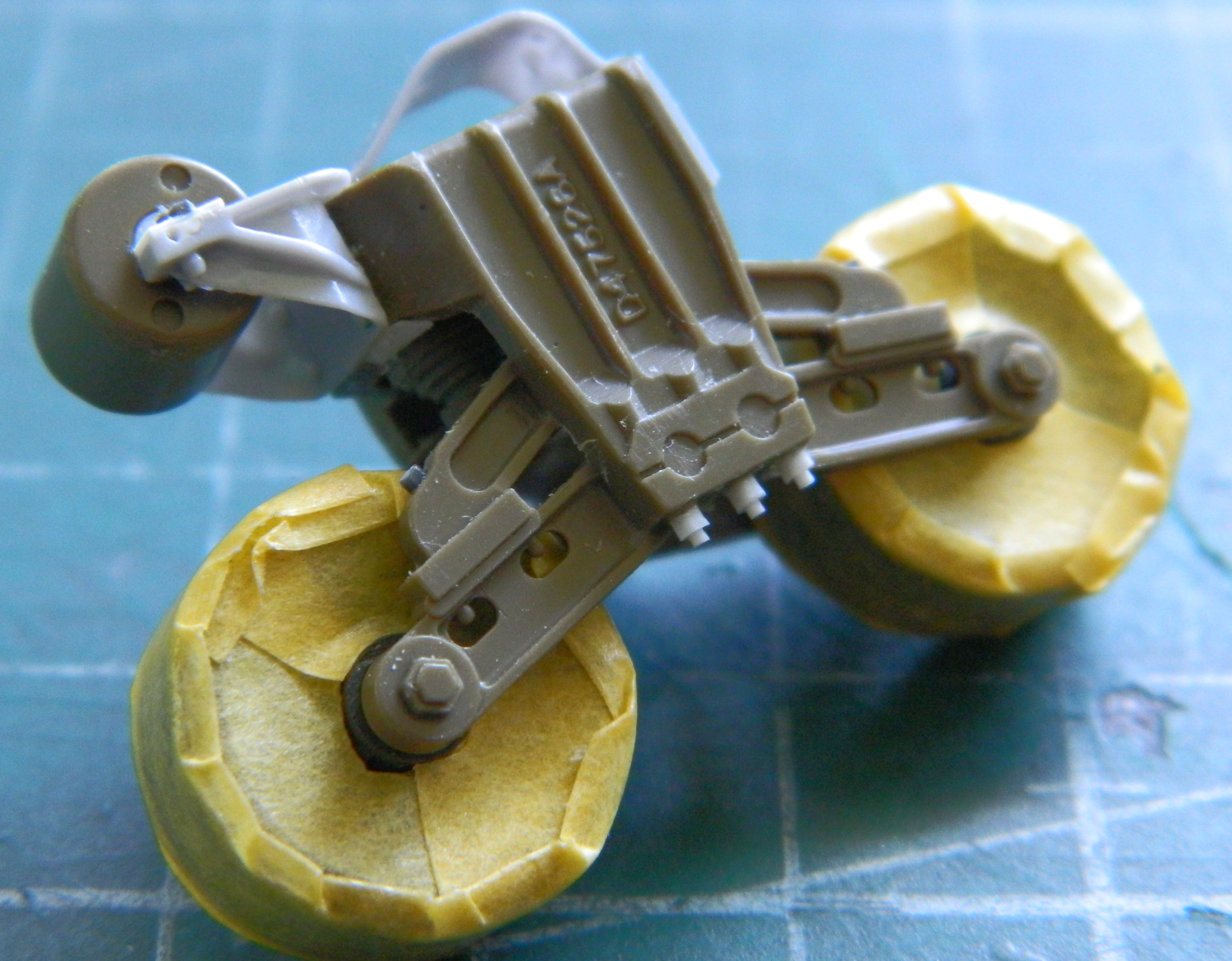
There was one bogey casting used for either side of the tank. What determined which bogey went to which side was where things were bolted on. Making things SO much easier in the field to source parts from disabled/destroyed tanks was the bolt holes for the return roller arm were drilled and tapped into both sides of the bogey. I replicated those as well:
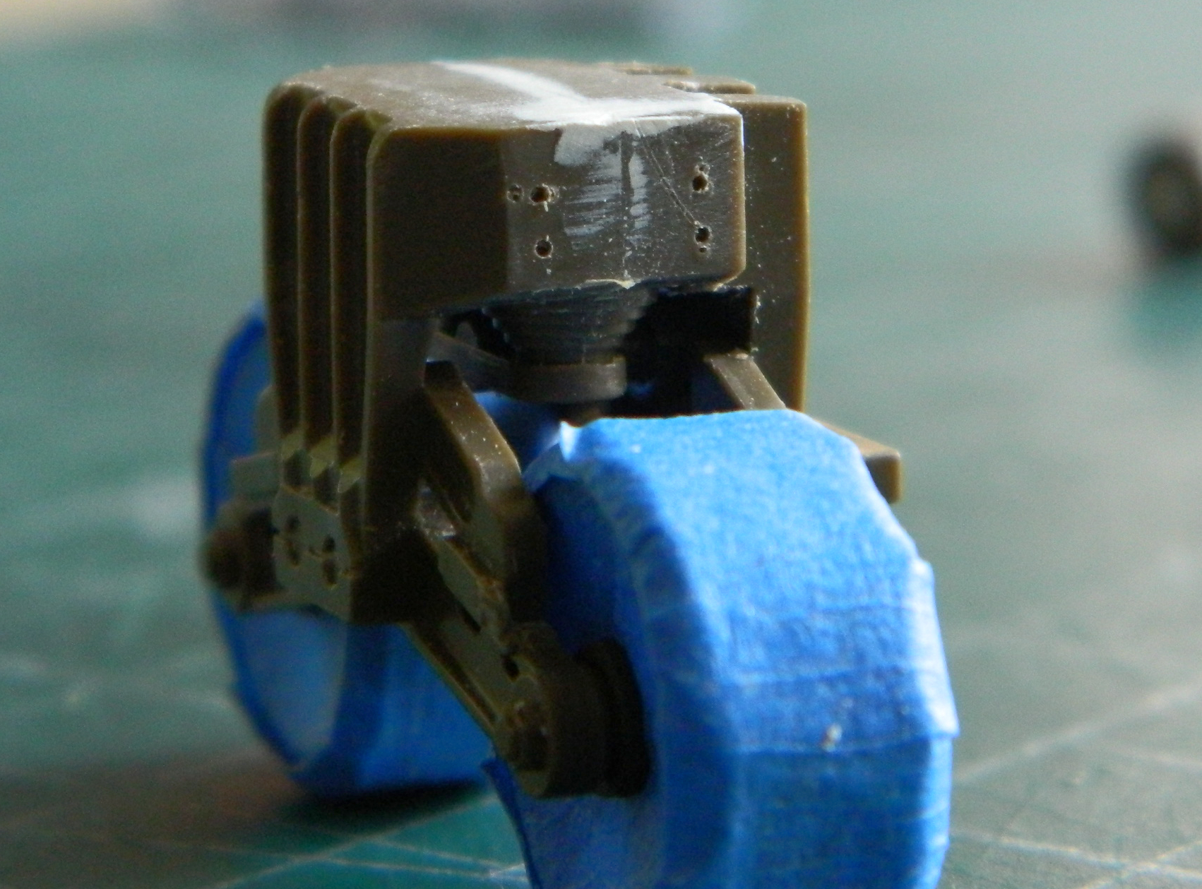
And now we get to the “mostly completed” part. I’d thought they were complete, needing only assembly after the first one shown above. And then I noticed this reference:
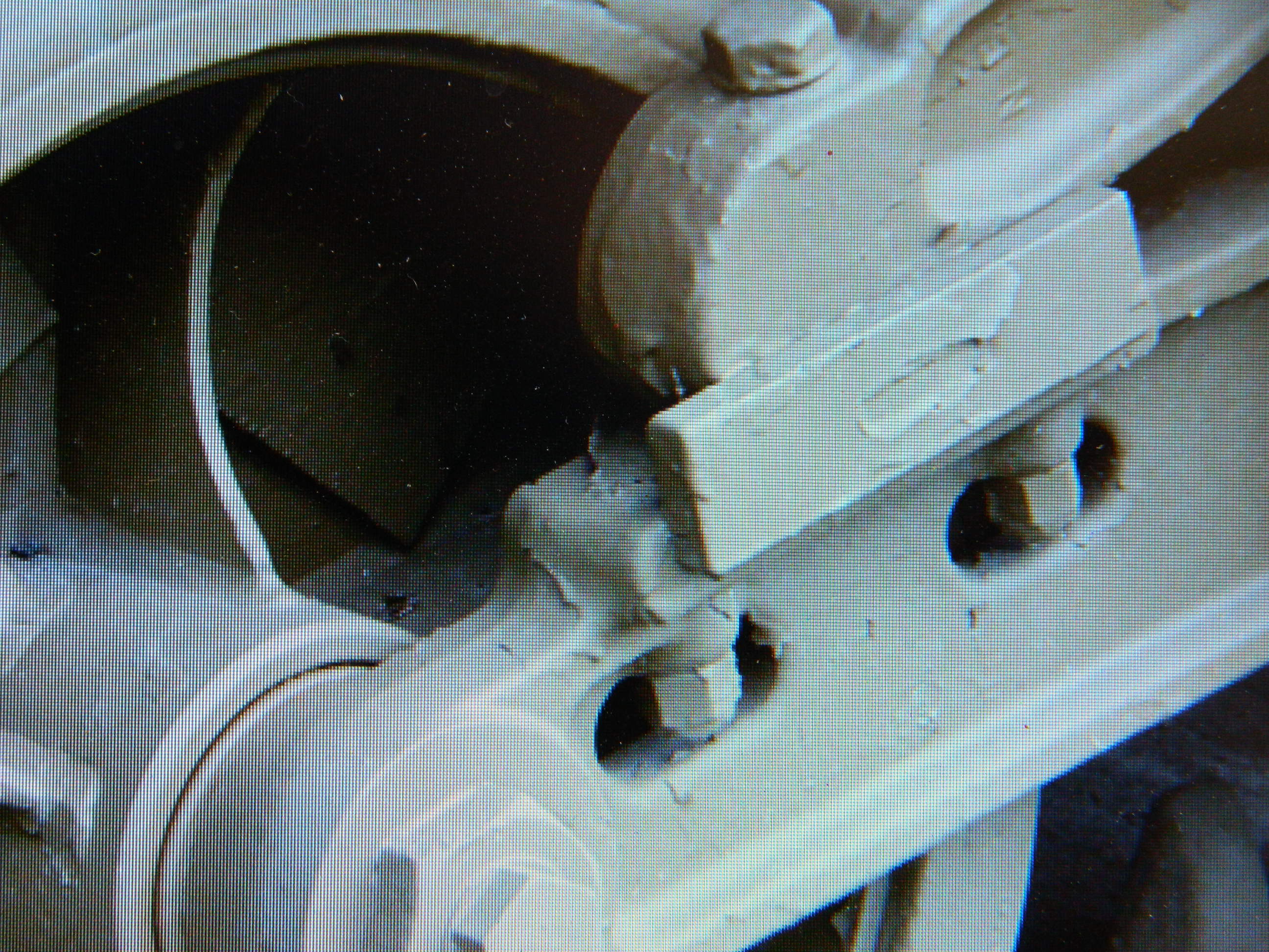
Where the upper suspension arm meets the lower suspension arm, the outside has a plate (to take most of the lateral forces that this assembly would experience I assume). The kit, however, has molded that as a block:

::sighs::
Okay, now that I’ve noticed it, I have to fix it. On the assembly pictured above, I had to be very careful with my excision, but I did manage it without damaging anything:

If I had to notice something like this, at least I noticed it before I had the other five bogeys assembled. It was much easier working with unassembled bogey halves and all were modified accordingly.
With all the bogey assemblies done, I turned back to the turret. I wanted to add ammunition cans stowed wherever they would fit. I dry-fit them so I could get some sense of what I would need shortly. The .50 caliber (1.27mm) are painted and the .30 caliber (7.62mm) are not and once I had their placements arranged, they were set aside to be painted:


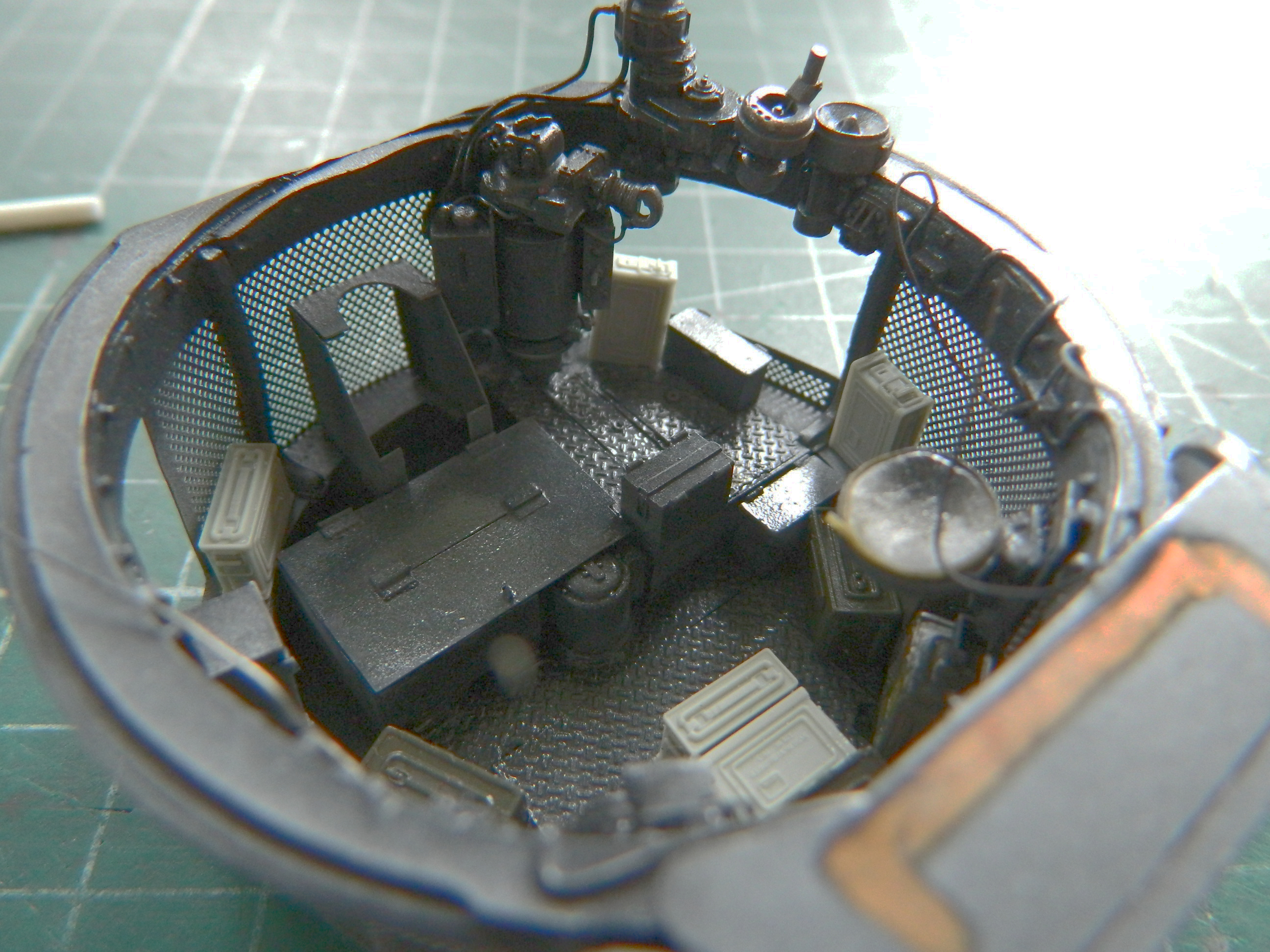
Tracks on the Sherman didn’t sag. Once again, TMD had very handy parts that would allow me to draw them tight once they were fitted. To enable their use, I had to remove the molded-on pin that the idler wheel attaches to:
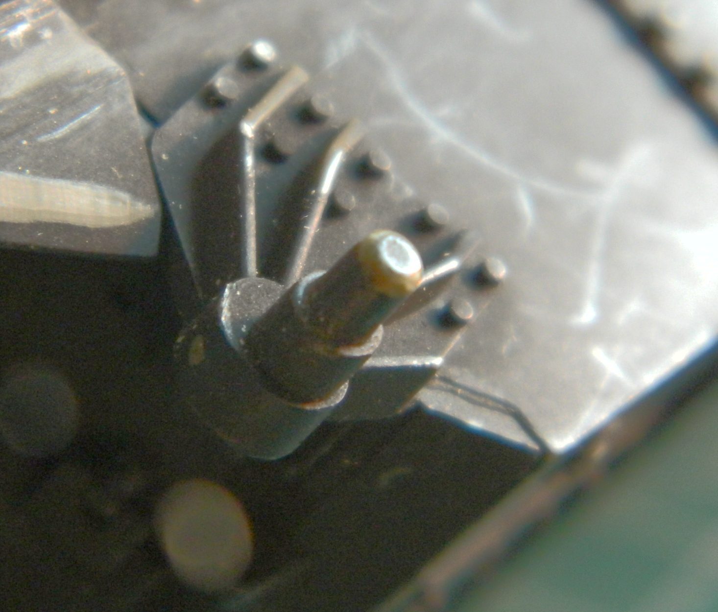
Once removed, I drilled out the hole for the mounting pin on the eccentric mount:
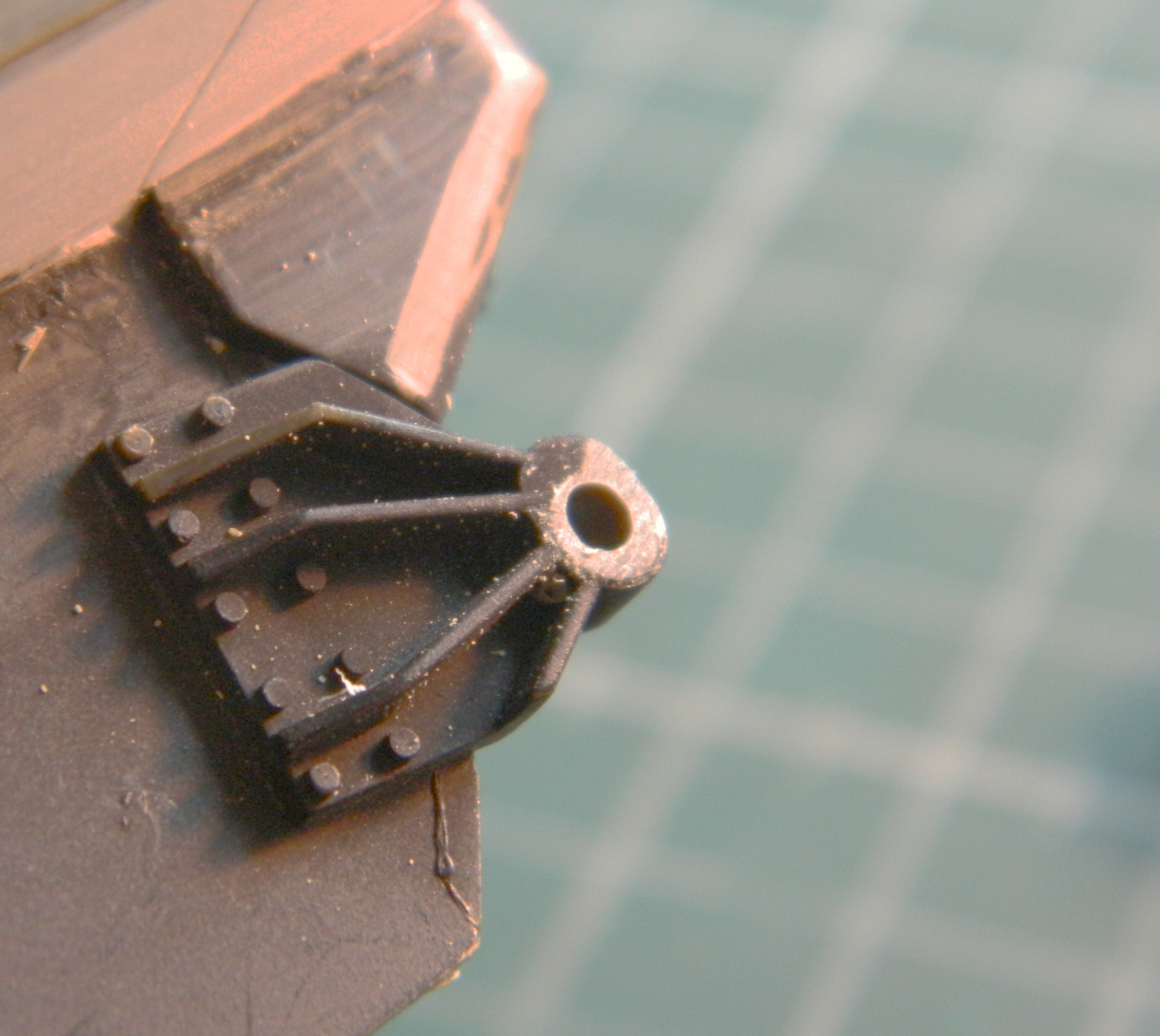
Dry-fitting shows how much I can move the idler wheel and though it doesn’t move a lot, it moves enough to work:

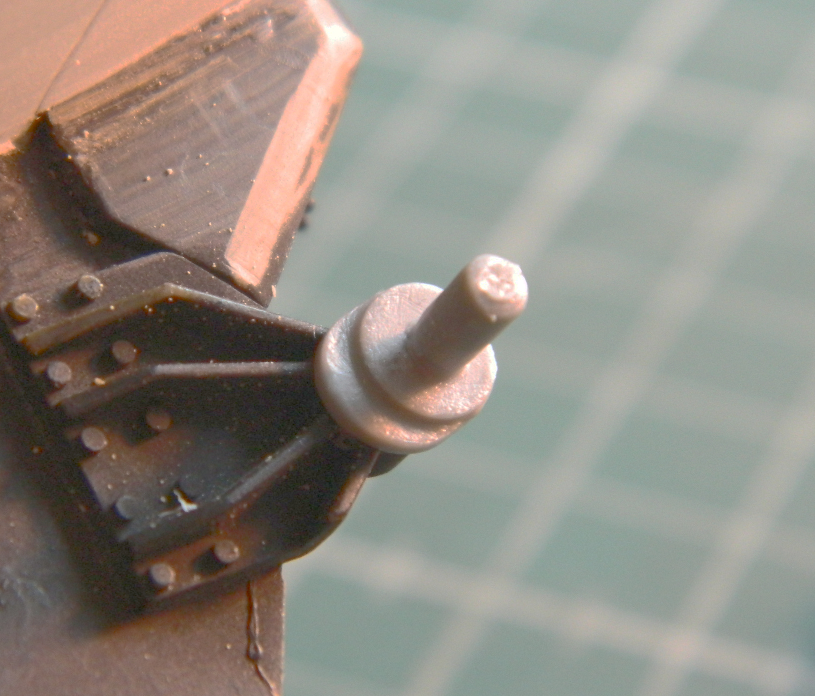
I wanted to use the earlier style spoked wheel. It’s another Dragon part from my spares inventory and it’s shown below with the kit’s part for comparison:
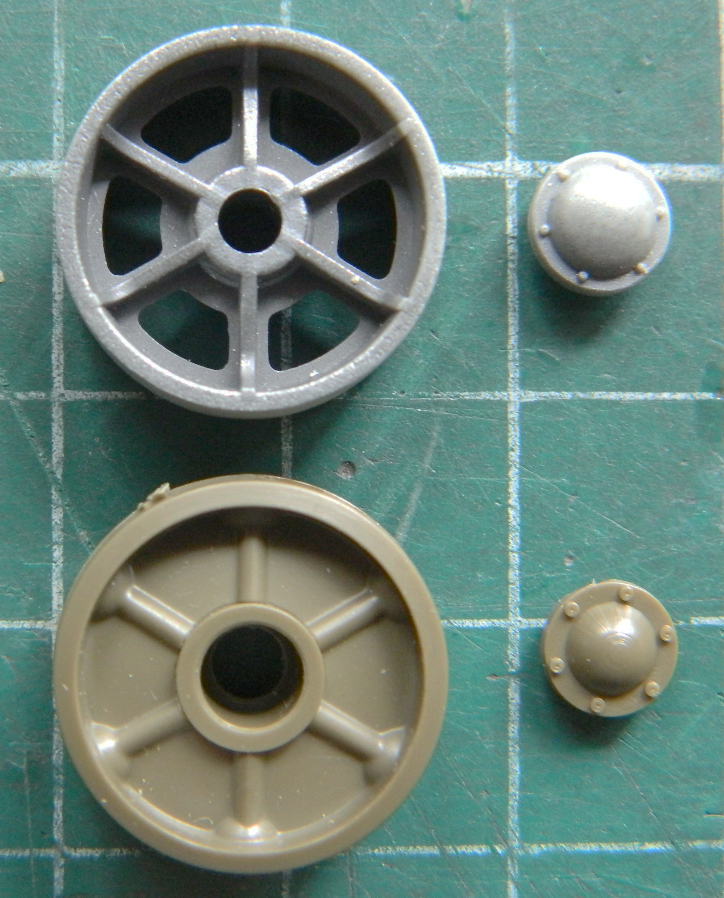
If you look for it, you can see that the pin that the idler is mounted on has a smaller diameter than the wheel’s hub:

Of course I thought of the most complicated and fiddly way to fix the fitment problem. Fill the hole and drill it out and hope that I get it correctly centered. Then my brain joined the fray and came up with something that would work well and be much easier to do without any reliance on hope. Since I don’t need the wheel to rotate, I centered the wheel on the pin and then filled the gap with superglue. Before the superglue set up, I added the hub cap:

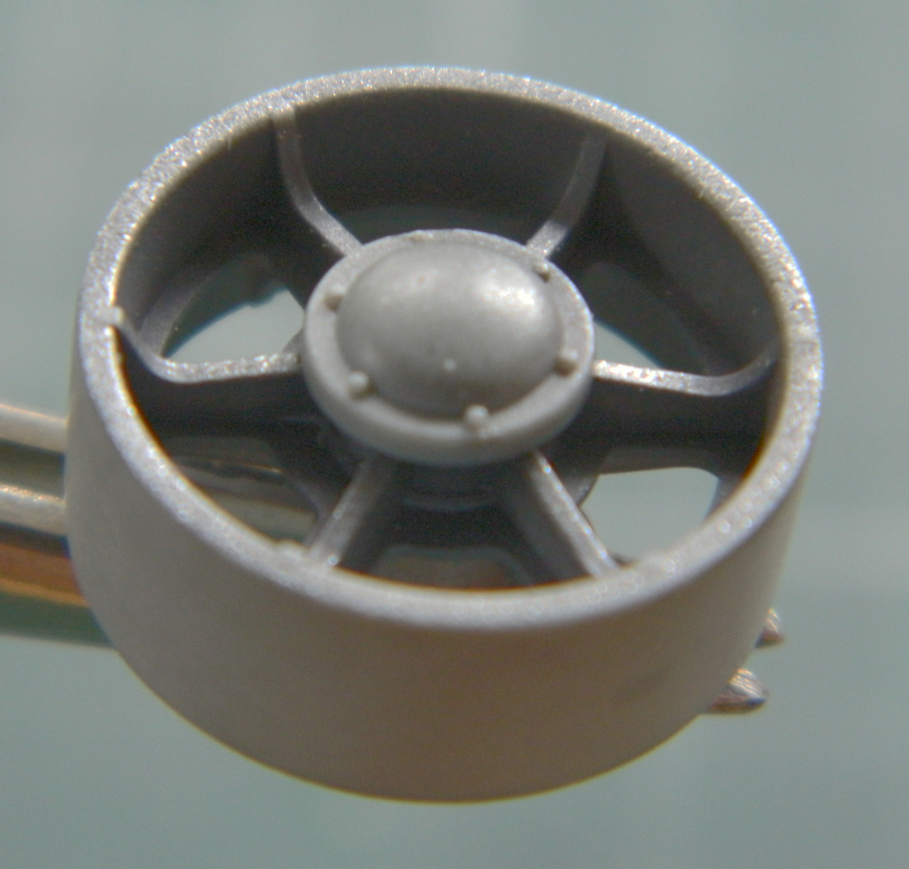
Much easier!
Another thing I quite dislike is trying to use opaque paint to replicate something clear. Again, it’s TMD to the rescue. They offer headlights of clear resin. I used a large needle to impress a socket on the back of the headlight and then applied a drop of black paint with the needle that created the depression. Then I coated the back of the headlights with a Molotow chrome marker and the result is what I was after:

Once all but the lens is painted OD, the result works nicely.
Then it was time to paint things. Most were done with color-corrected Tamiya XF-62 Olive Drab (3 parts) and XF-2 Flat White (1 part). And since I’ve decided to model a tank from the 3rd Armor Division, 32nd Armor Regiment, they mounted a spare road wheel on the upper left corner of the glacis plate and spare track centered on the front (some of their tanks didn’t have the added armor in front of the hatch hoods and had spare track mounted there as well, but since this build does have the added armor, only one run of track will be used) so those will be added. I shot the spare road wheel the same way I shot the road wheels with rubber rims and OD hubs using the template and I shot the spare tracks with rubber also, adding the OD to the track guides with a brush:
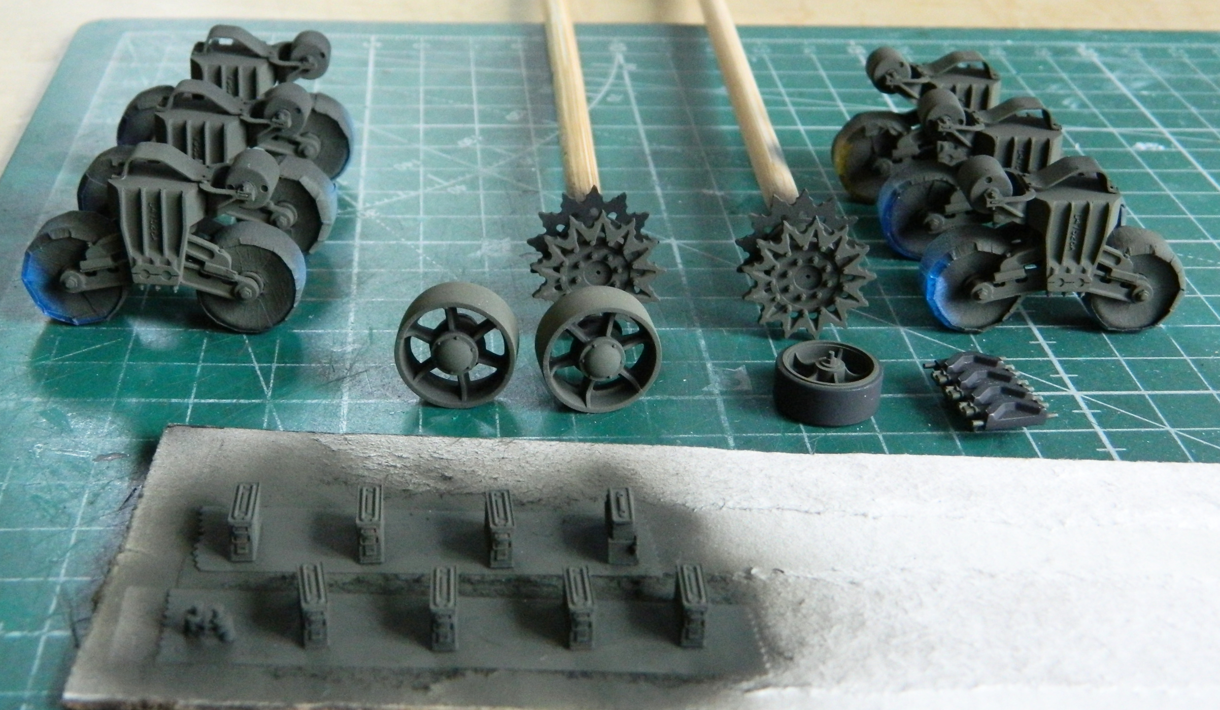
Time to close in on finishing the turret. The first step was getting the gun mounted permanently and attaching the various lines to and around it (I still have to trim back the end of the gunner’s optical sight). Prior to mounting the gun, I peeled off the masking tape from the inner surface of the clear panel and used a 50/50 mix of flat black and flat white to touch up the paint around the edge of the inner opening:

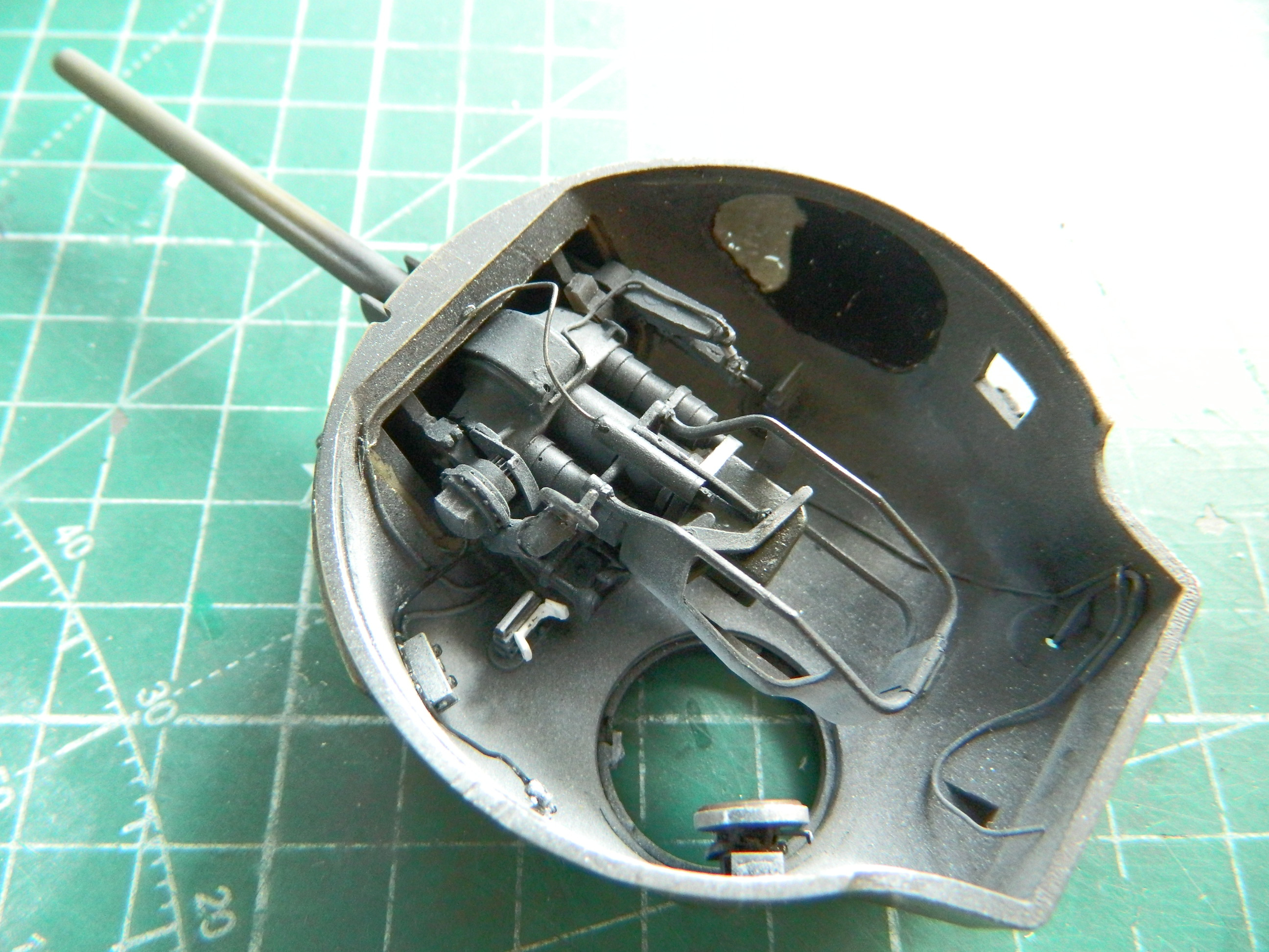
The final tasks with the turret basket were attended to. Errant lines were attached to their forever home, mics were painted and glued in place, the radio was glued down and various lines attached to it, masking peeled from the seats, and the ammunition cans were glued down using PVA:
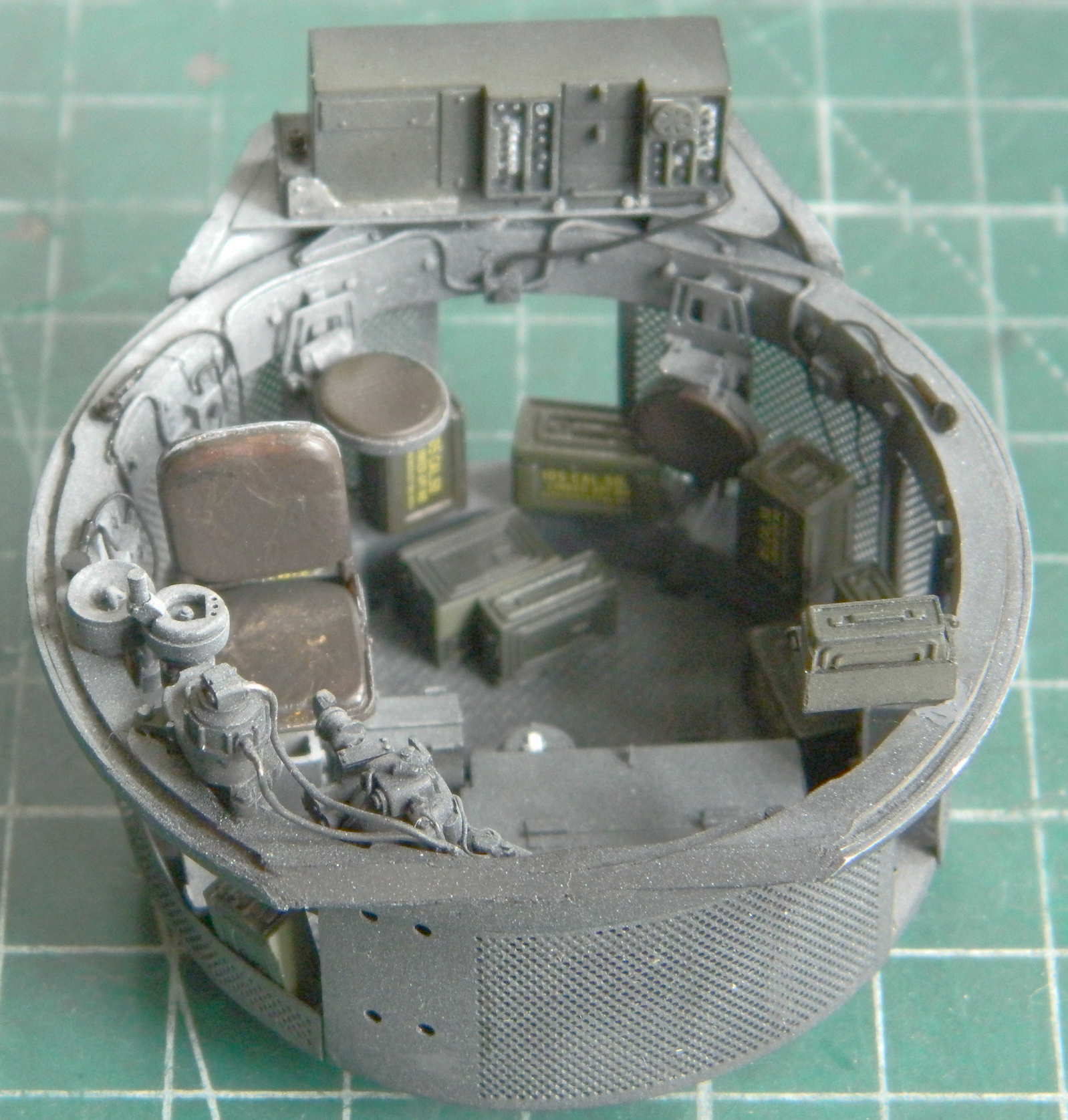

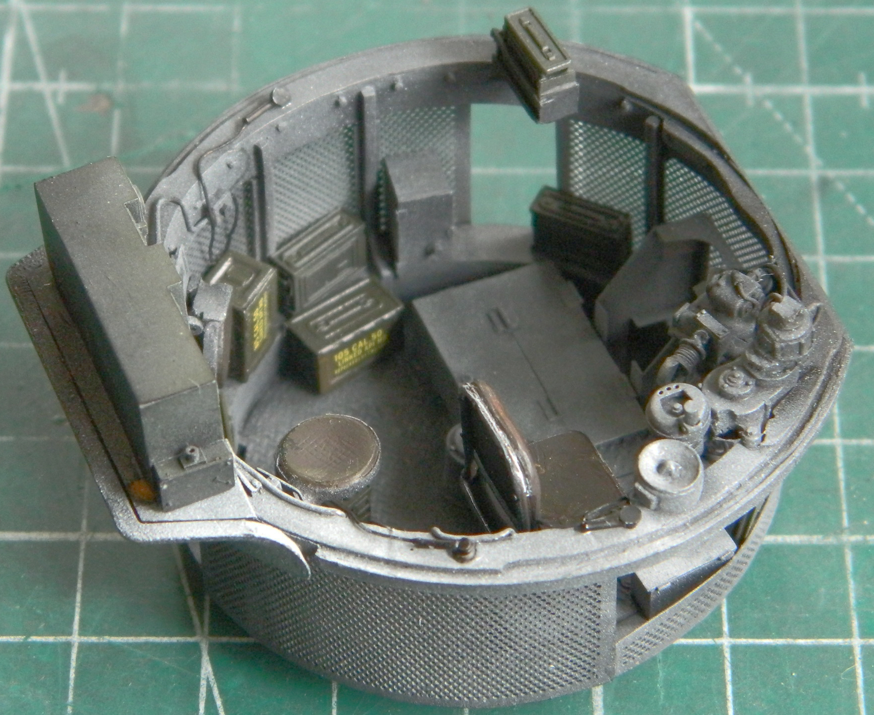
Before this is attached to the turret, there will be some staining with pastels. Since I’m modeling a tank more-or-less fresh off the LST, weathering and wear will be minimal.
When I was having fitment problems trying to get the turret basket to play nice with the interior of the hull, I had to move things in the hull to get that to happen. And since I’d already painted the interior, I had to touch up that paint. I put down flat black and then misted flat white light splash over it. I choked the airbrush spray pattern down about as far as I could and still allow the paint to spray:
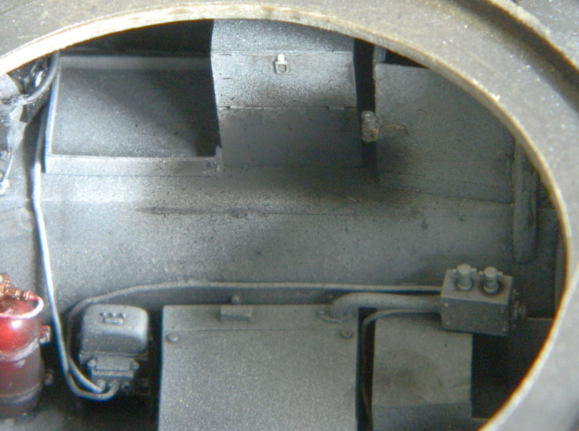
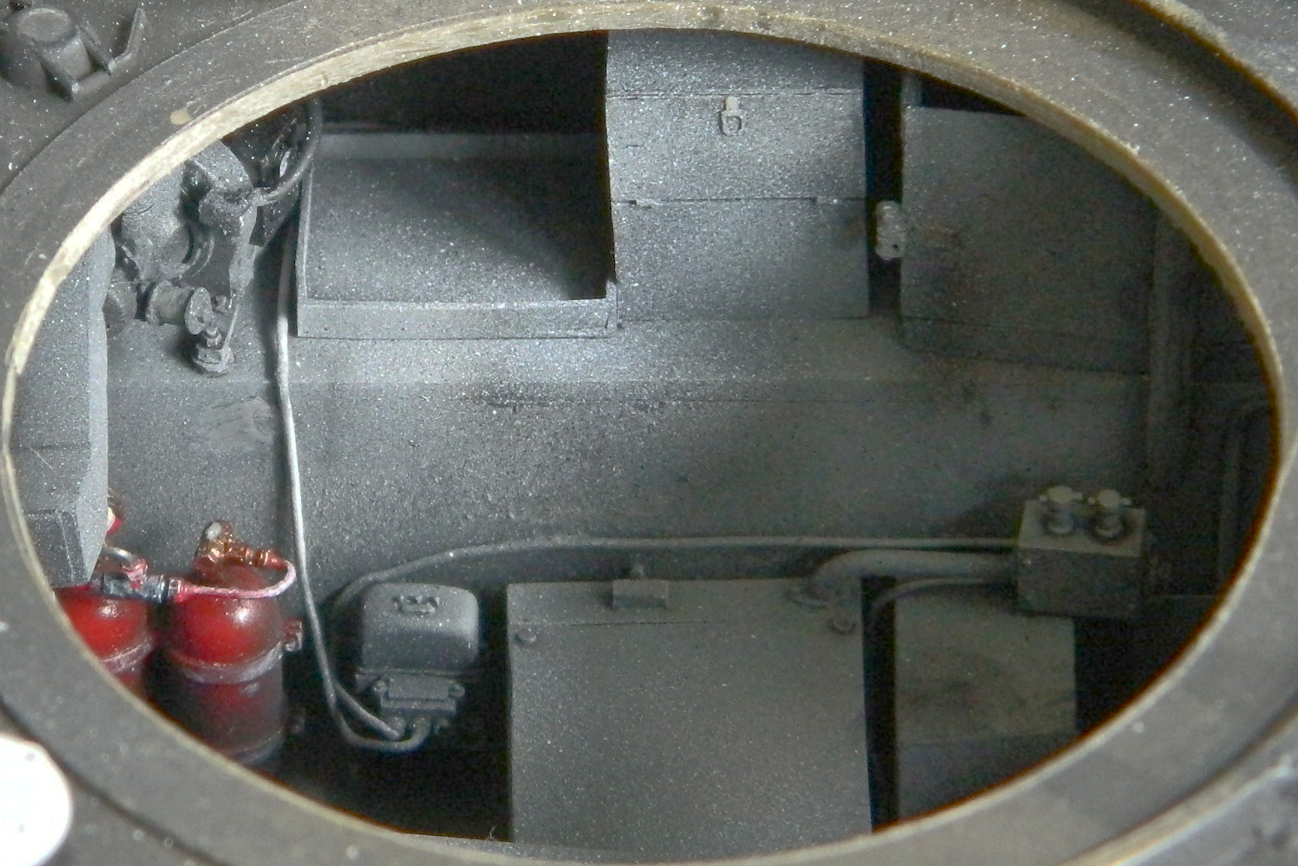
I masked the hatch and gun port openings from the inside:
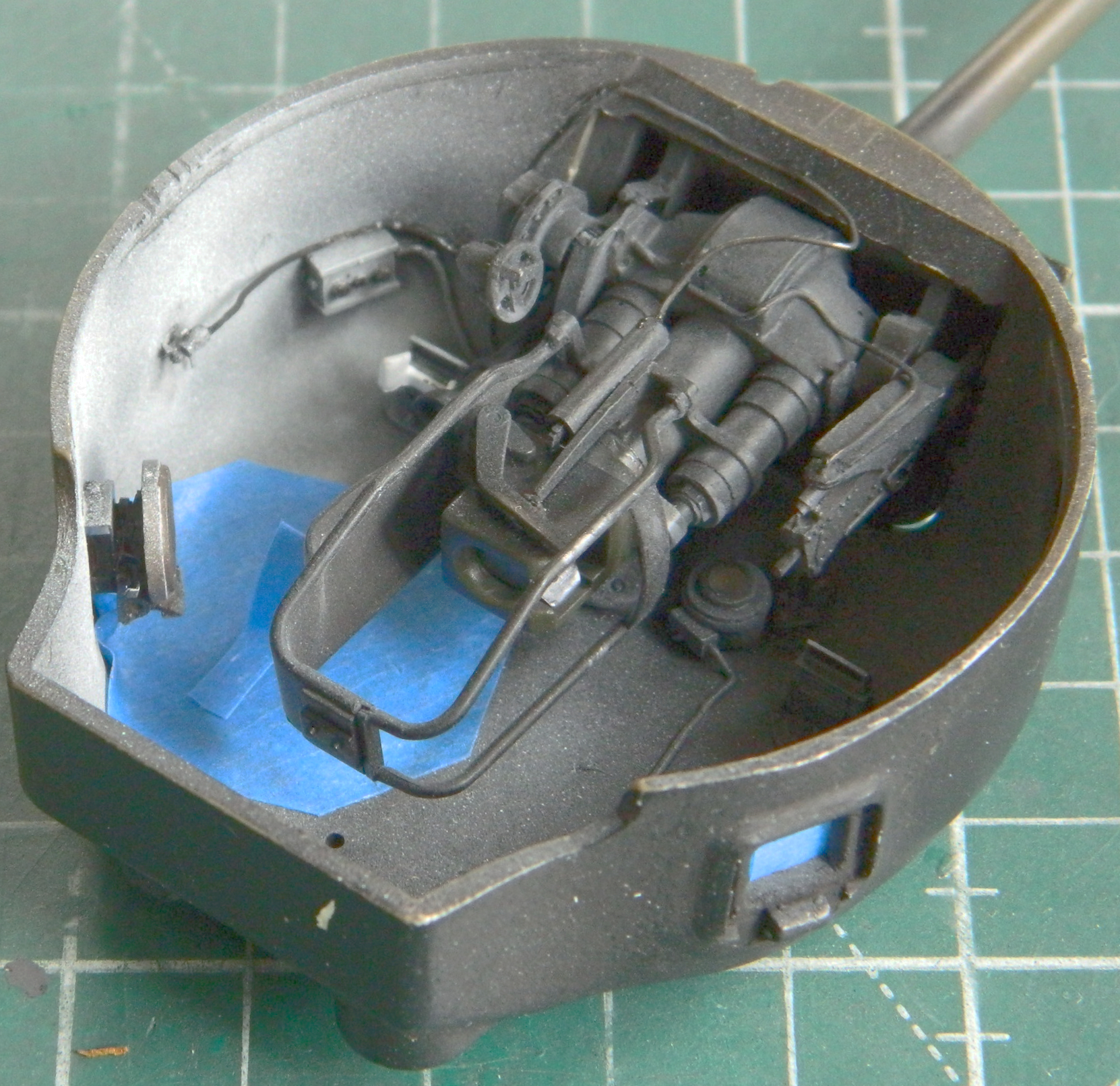
This tank will have the asymmetrical vents with PE screens (also supplied by TMD). These parts weren’t intended for the Tamiya kit and as such were just a little bit wider than the depressions molded into the kit. I widened the depressions (the left side is done, the right left alone for the photo comparison):
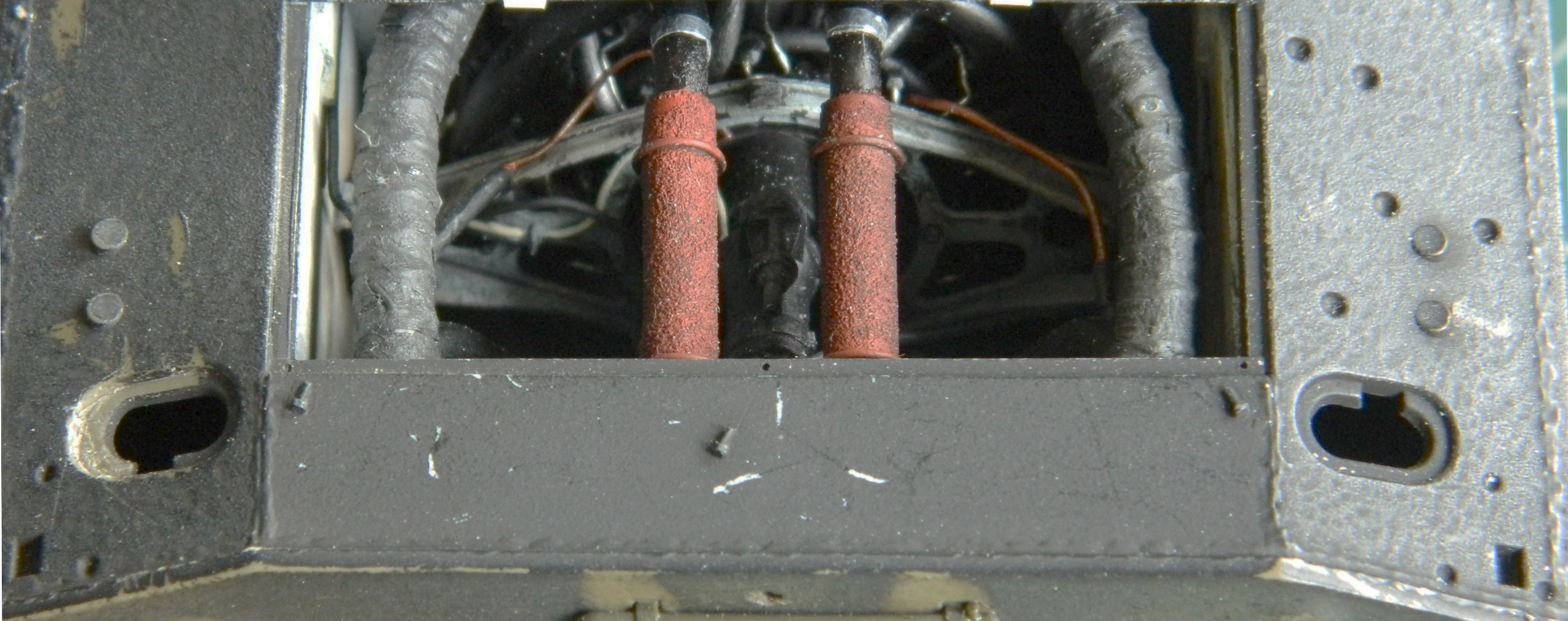
Keeping with my process of realizing too late that something needed to be painted before installation, I didn’t paint the inside of the vents before adding the PE grills and gluing them down. Rather than try to pry those out and then have to fix the gouges, I’ll go with painting them flat black later, since the that’s what I’ll be painting the outside with anyway:

Next time I’ll be working the hull exterior.
A Question for the Hive-mind
Hopefully this isn’t the first time you’ve been to this site, but this question is for anyone who reads it, even if it’s your first time here.
I’m thinking of moving my content (I like that word…makes me sound like an actual adult instead of the ancient 12-year-old that I am in reality) from a blog to a YouTube channel. (Yes, Lily…it’s all because of you.) That said, what’s your opinion about making that switch?
There are no wrong answers, just the rude ones that I don’t allow to be posted (there haven’t been many of them over the years, but there have been a few). I appreciate your input and responses. T’anks!
M4 (Tamiya) Build #9 – More Work on the Turret Continues With Even More Tiny Stuff
I needed a .30 caliber (7.62mm) machine gun for the coaxial mount. I figured it would be easy enough (yeah, silly me) since I have several of them in my spare parts cache. Yeah, well, what I was reminded of rather quickly was that though I needed a machine gun for the coaxial mount, the mount was much narrower than the gun(s) I was trying to fit into it. More searching (not restricted to spare parts) showed me that TMD did one that fit perfectly and that’s the one I used. I wasn’t thrilled with the grip that was provided with it so I cobbled one together using scrap styrene and then used 0.010″ (.254mm) solder to add the trigger. That’s when I noticed that the mounting bracket wasn’t molded with a clear channel for the barrel of the gun to slip through. I drilled it out and dry-fitted the gun to see how it worked and it did:
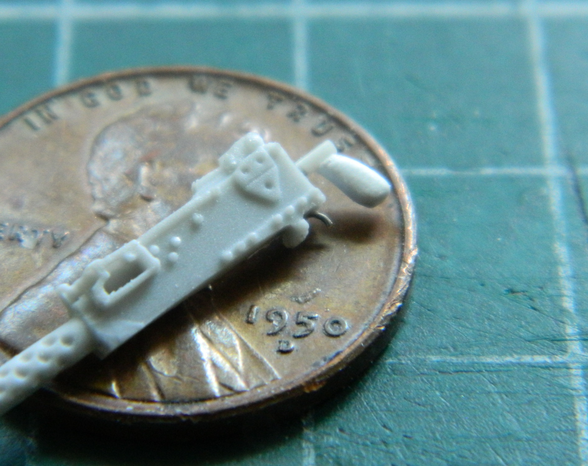
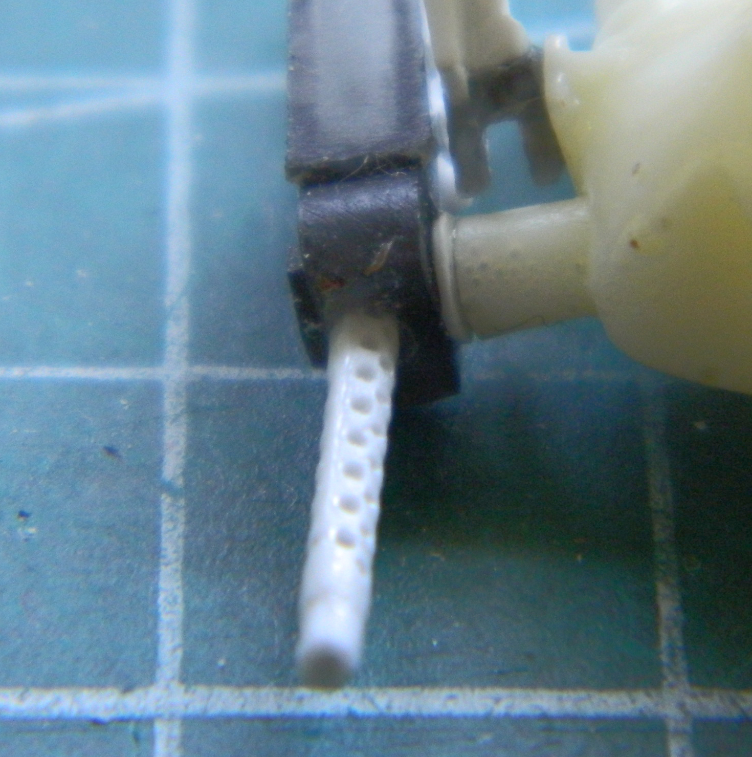

In the picture above, you can see how little of the barrel is visible; none from inside and just a bit outside. Usually I replace molded machine gun barrels with RB Products’ beautiful brass machined parts. In this case I can’t get behind the notion of wasting a finely detailed product when so little of it will be seen so I decided that I would use a small drill bit to clean up the round openings in the cooling jacket that can be seen and use the resin part entirely. The gunner operated both the main gun and the coaxial machine gun, the triggers of which were activated by solenoids wired to a foot switch. That mean I needed to make the solenoid. I used 0.035″ (.890mm) styrene rod for the body of the solenoid and stretched sprue for the plunger:
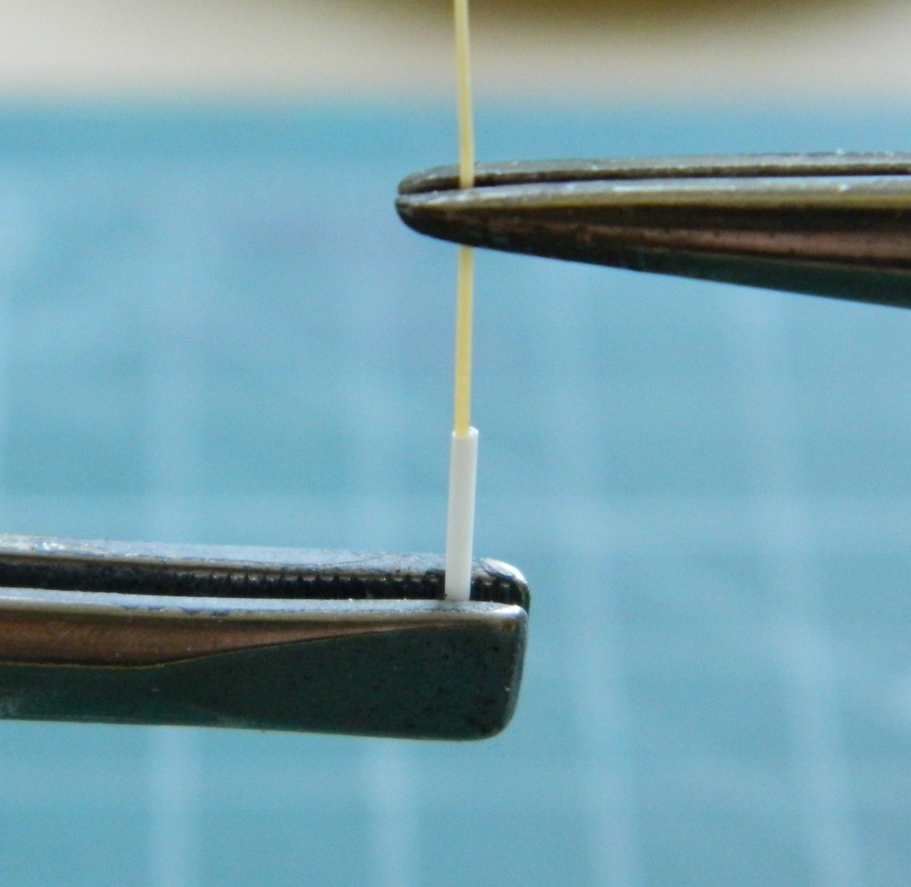
I didn’t trim the body of the solenoid at this point. That will be easier once it’s time to glue it in place and can see how much has to be removed. Once glued in, I will add 0.010″ (.254mm) solder for the wiring.
I switched to the other side of the main gun to add the gun sight. There was an inordinate amount of fettling required to get the sodding mount correct…or what I thought was correct. I also took an inordinate amount of photos of the ridiculously small part that I won’t bother including (if you want that level of excitement, go to an auto recycling yard and watch bumpers rust). Once completed, I used a spot of PVA to hold the sight in place and let it sit overnight before I put the breech assembly in place to check fit. Yeah, well, it neither fit nor aligned correctly. The sight tube is far too short and the sight mount (which was a very tedious process to get to work as poorly as it did) was way off. The first photo shows this part’s complete lack of alignment (the tube of the sight is supposed to go through the oval opening to its left) and the second shows that it’s too short. It’s supposed to extend to the mantlet:
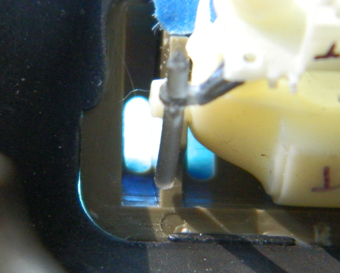
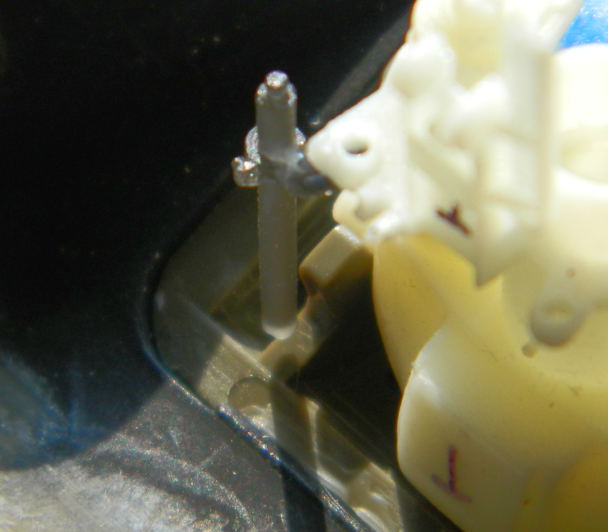
This is a simple part to fix. I used 0.047″ (about 1.143mm) to extend it and cut the molded section just in front of the clamp. This resulted in a very small contact area for adhesive. I fixed that by drilling the resin part and and added a pin of copper wire (if you look at where the resin and styrene meet, you can see the pin in the translucent resin part):

Again, I left the styrene rod untrimmed to be shortened to the correct length later, which will result in the end of the sight terminating just inside the mantlet as it’s supposed to do. The important thing is that the sight now aligns with the opening and is long enough:
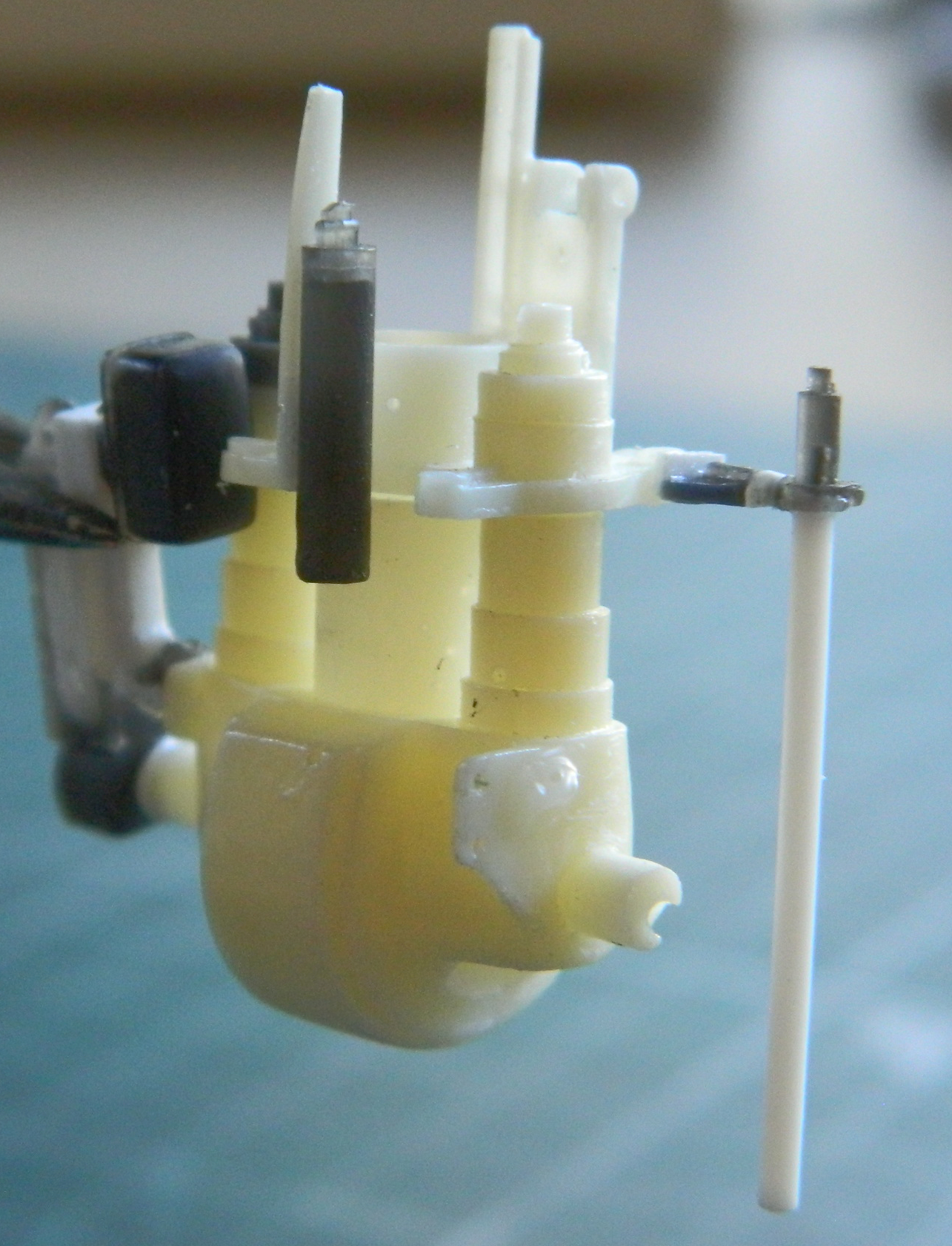


I thought I had fixed the turret basket so that it wouldn’t hit any of the items in the hull and I was just slightly incorrect. With the screens in place, the damned thing hits again. Repeating the process of moving the items the basket hits wouldn’t work this time because one of those items can’t be moved from where it is. I mean, it could, but I’d have to deconstruct the whole of the area around the driver’s position. To do that I’d have to take the upper hull off of the lower hull. No. That upper hull won’t ever come off of the lower hull in any sort of manner that wouldn’t render the upper or lower hull (more likely both) unusable. I needed a different approach so this time I looked at the turret basket to see what I could change. Once I did, I realized the real problem. The supports that attach the basket floor to the turret ring are in the wrong places. I know I got those buggers in where CMK (the producer of this AM set) intended them to be because there are pins on the ends of the supports and holes in the flange of the basket floor. It’s the supports that have been causing all the sodding fitting problem(s) (the black Xs show where the fit problem is):
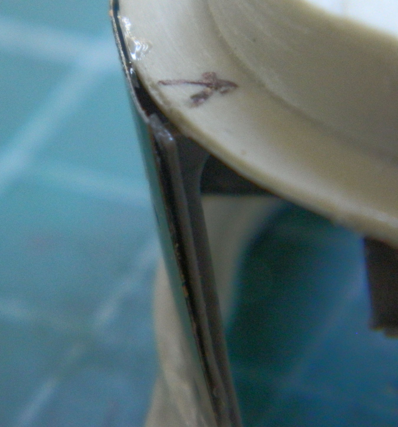
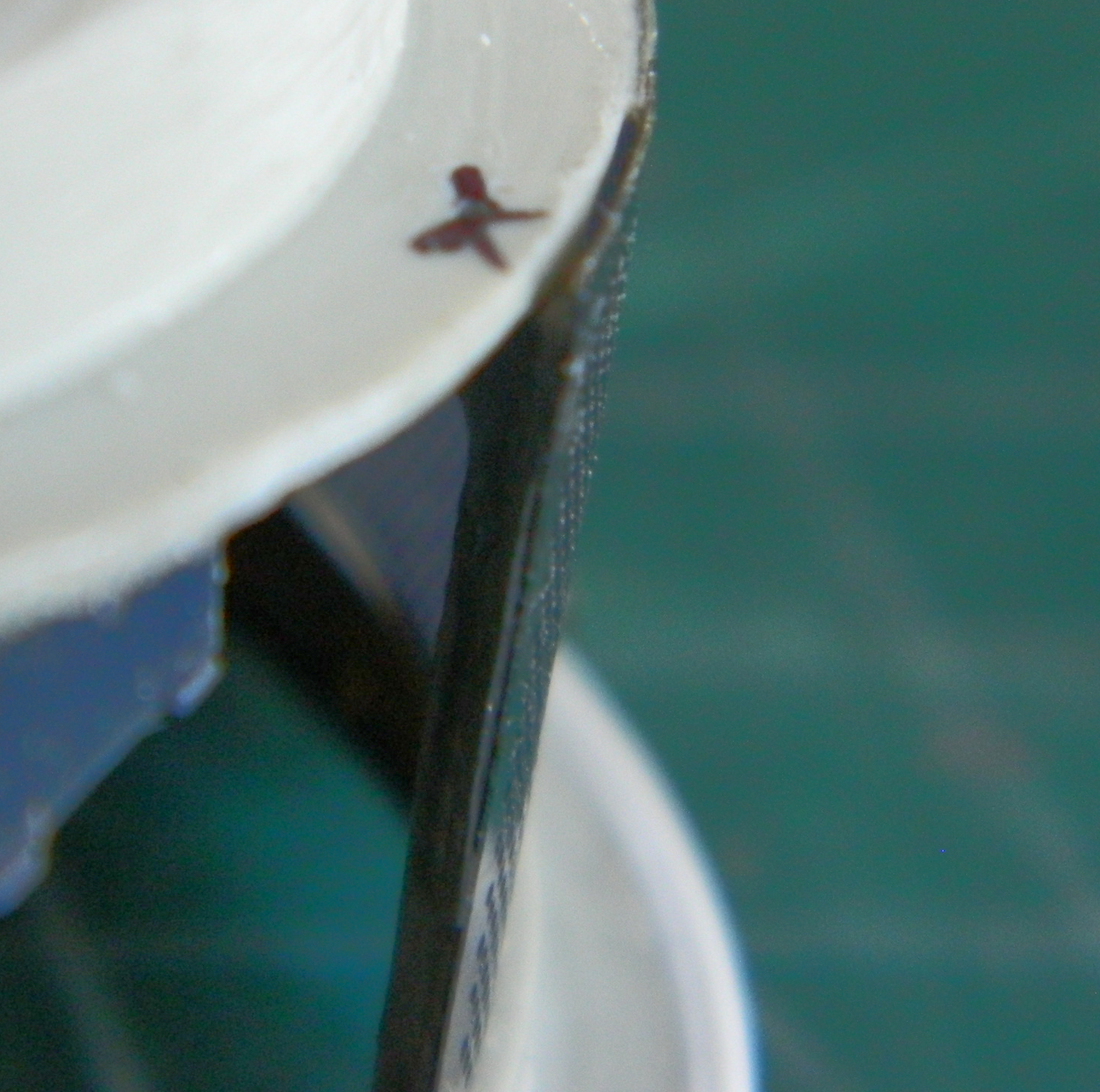
So I went a played Zelda for a few days…
Refreshed (and CALMED DOWN), I went back at it. I used chisel blades to carefully pop the screens from the basket assembly and cautiously started thinning the supports where they extended past the basket’s flange. The screens were glued back to the trimmed supports and the fit tested. This time it all fits. (Nope…forgot to take photos of it.)
Yeah, so, masking tape. The adhesive of masking tape expires. If it’s left alone long enough, the adhesive of the tape de-bonds from the paper of the tape. The clear panel in the turret has been masked off for quite some time and when I checked it, the de-bonding had just started. Okay…got to it in time. I pulled the old tape off the inside of the panel, used lighter fluid on the couple of very small spots where the adhesive didn’t want to leave, and started to mask again. While doing so, I was using a toothpick I’d carved and angled chisel face on and evidently though I didn’t break the toothpick, I did press hard enough to snap one of the thinner sections of the panel free from the turret and that left a gap. Using denatured alcohol, I removed the paint to facilitate putty sticking, realized the gap needed plastic before putty, then added the plastic. After sitting overnight to cure completely, I trimmed down the excess and then started filing (to maintain the correct curves on the surface), sanding, and then polishing. Once it was all fixed, I used Mr. Surfacer 500 to replace the casting texture. Again:

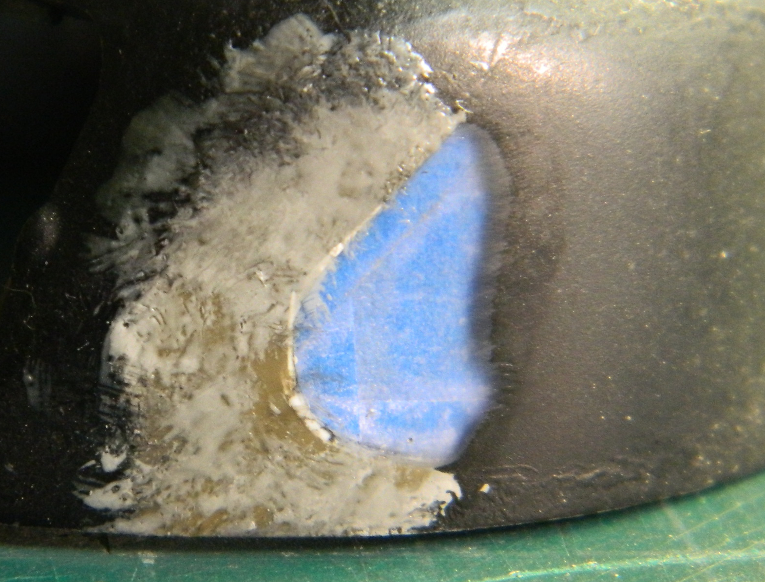
I didn’t take any photos of it, but for the .50 caliber (12.7mm) gun on top of the turret, I didn’t really like anything I had on hand. I decided to try Tasca’s .50 which is available as a stand-alone product. It’s beautifully molded (and if you ever want to model a Ma Deuce with an open breech, this is the part to use!) and for the price you’ll get two of them as well as ammo belts, three different barrels, and two different ammo can mounts (early and late). Fit is excellent. You’ll see it later once it’s painted.
I’m at the point where I’ve been adding things to the main gun assembly so that I can get it painted and installed. CMK clearly intends for builders to use the front gun mount that comes with the kit. What they didn’t mention was that the kit part where the trunnions fit is off. The trunnion caps require that the kit’s part has to be cut down, so I did. During the fitting process, that small arm I made for the gun stabilizer had to come off. There simply wasn’t room for it to stay. The elevation control was assembled and the elevation wheel was cut carefully from the pouring block, cleaned up, and then it fell onto the floor…whereupon it vanished. Well. That’s a necessary part (unlike the gizmo for the gun stabilizer that I’m still pouting over) so I had to make another one.
Experience has shown me that trying to form a styrene rod into a good-enough circle is a frustrating process that results in something worthless. This time I decided to use solder. 0.040″ (1.016mm) is noticeably too small. 0.062″ (1.57mm) is just a wee bit too large. I decided to go with the 0.062″ (1.57mm) diameter because I think that once it’s in place, shaded and painted, that won’t be all that noticeable. I started making the rings by using a piece of copper tubing of the appropriate diameter as a mandrel and wrapped solder around it:
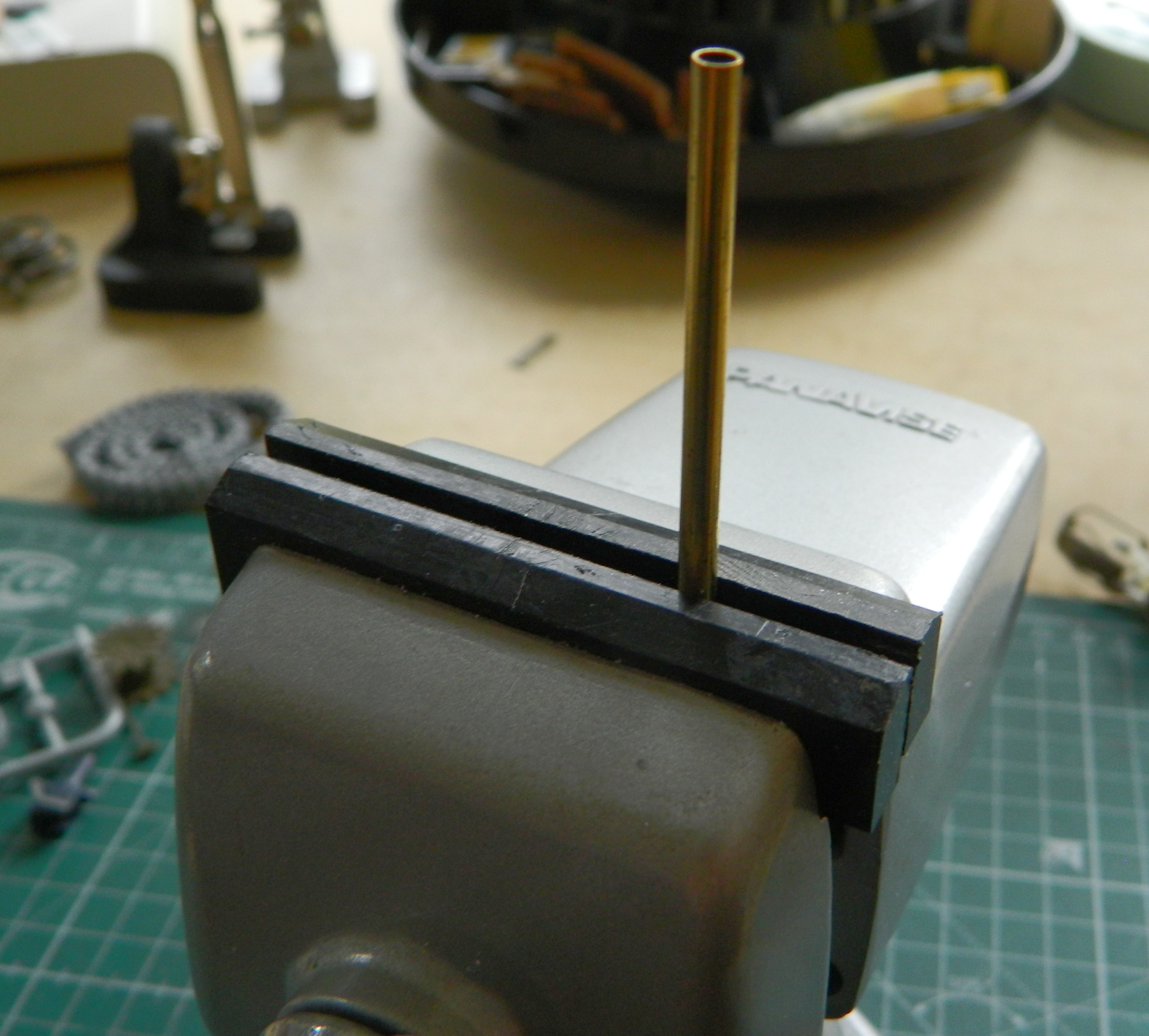
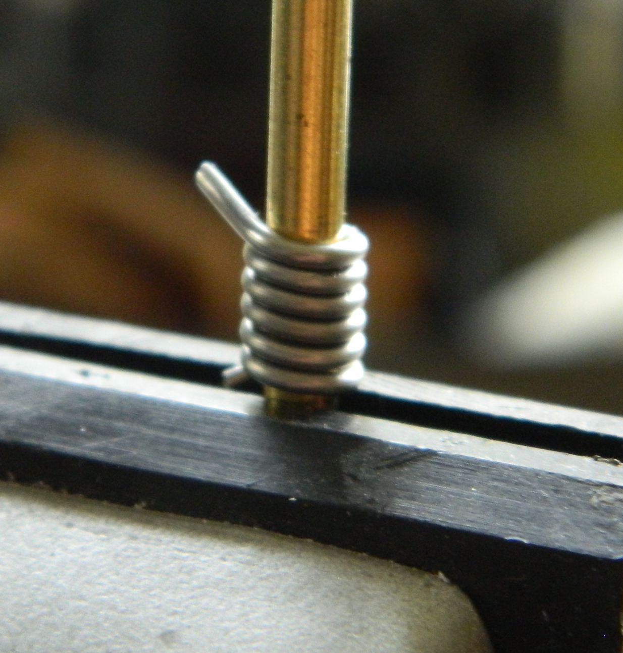
Once I had it wrapped as tightly as possible, I used a fresh razor blade to make a cut down one side through all the loops:
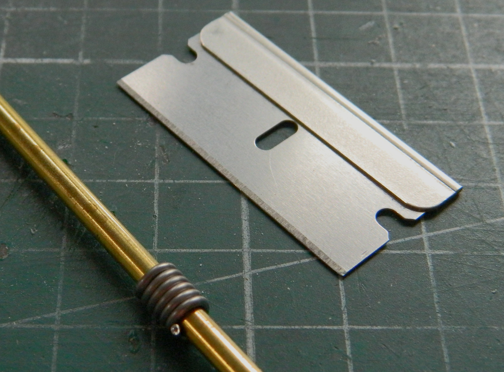
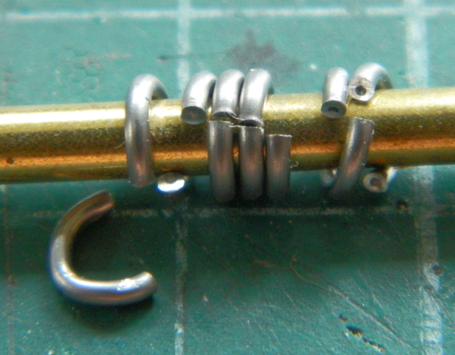

With the loops cut free, they were flattened and then the ends pressed together:

I chose the two that I thought were the best of the lot and used one:
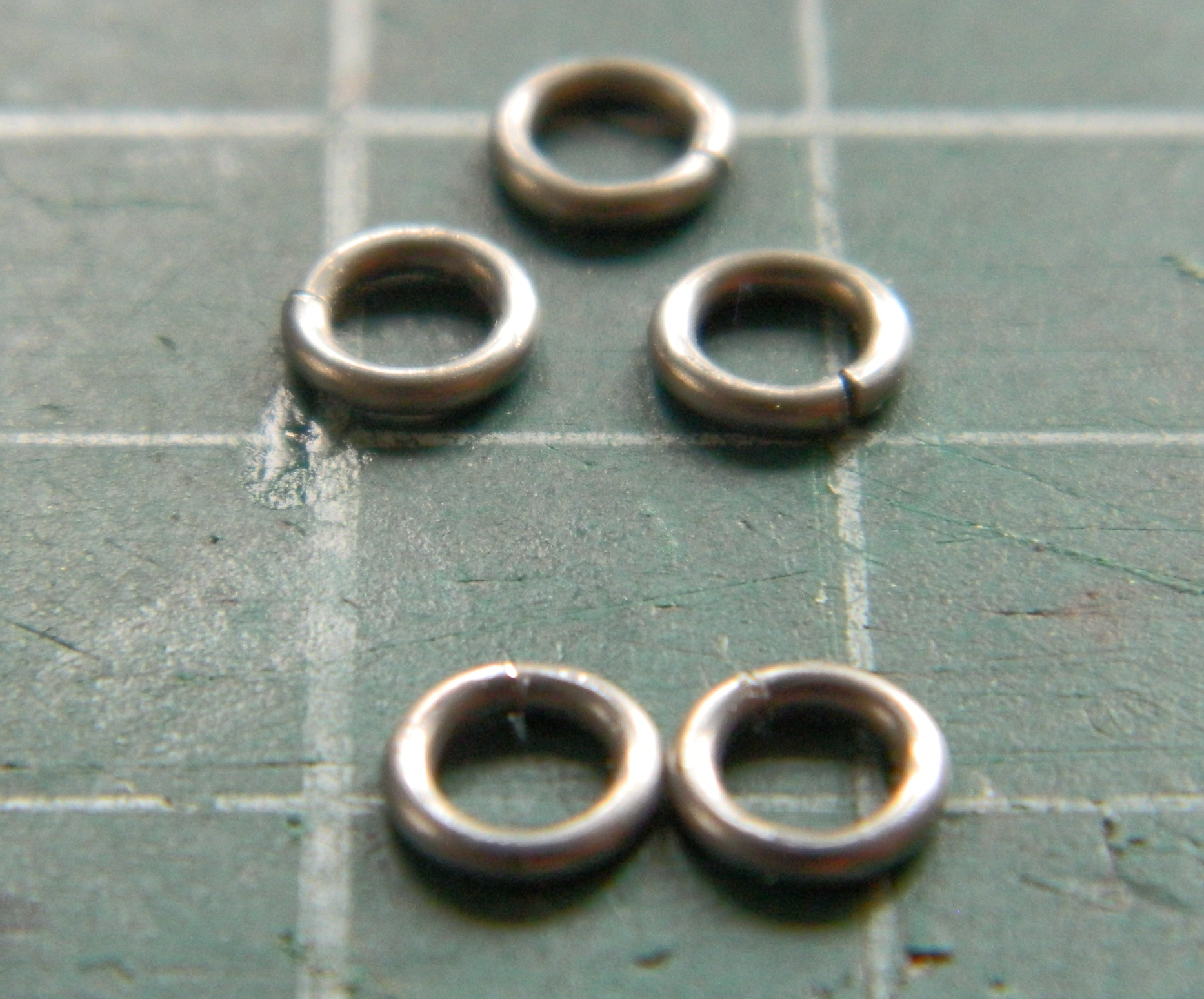
Then it was a matter of making the spokes for the wheel:

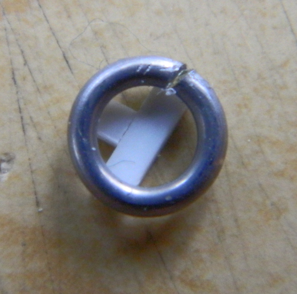
Since I could see that the ends of the loop had a slight gap, that’s where I decided I’d put the handle. The superglue would fill the gap and the handle itself would help hide it. Once completed, it was glued onto the elevation housing:
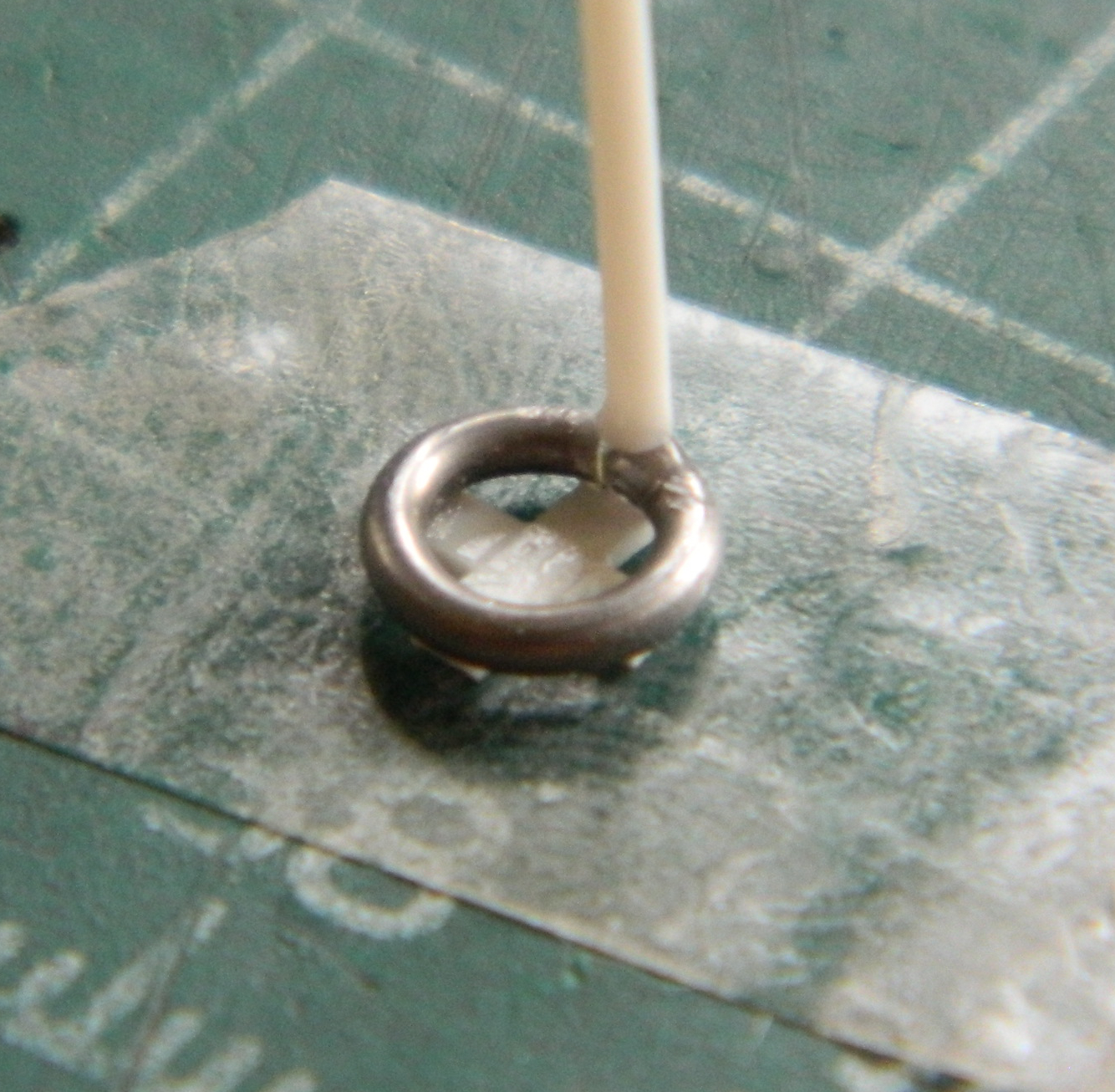

Though not perfect, it worked well enough.
Since it was getting late, I decided that I’d had enough “fun” for one day and cleaned the bench, put stuff away, and went to read before (hopefully, if only for the novelty of it) going to sleep. The next day, after coffee of course, I went into the shop, sat down, and promptly dropped my tweezers. Gravity being a law, it fell onto the floor. It landed right next to the resin wheel I dropped yesterday. It landed in the first place I looked for that resin wheel and there was NO resin wheel anywhere on the floor of the shop. Fine. I pried the wheel I’d fabricated from the elevation mechanism and used the part I’d WANTED to use all along:
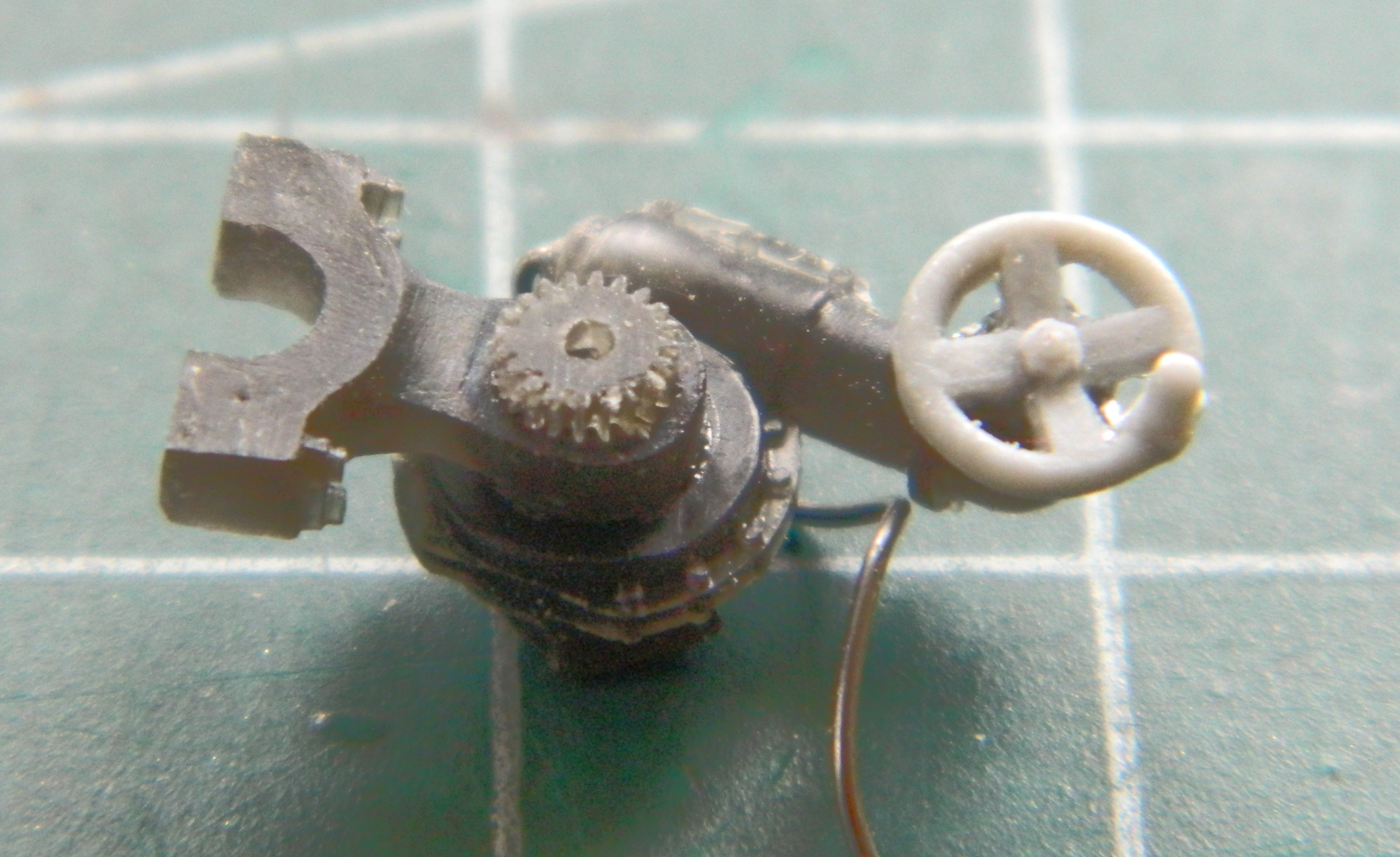
::sighs::
At this point, there was painting that had to be done before I could proceed. There are a number of items that I want to show as steel. I use Humbrol’s # 27003 whenever I want a steel surface and it’s an extended period of mixing whenever I do, so I tried (later on I’ll know what I forgot) to paint everything I could think of that would require that steel appearance:

Then I broke out Tamiya’s XF-1 Flat Black and laid down the preshading coat:
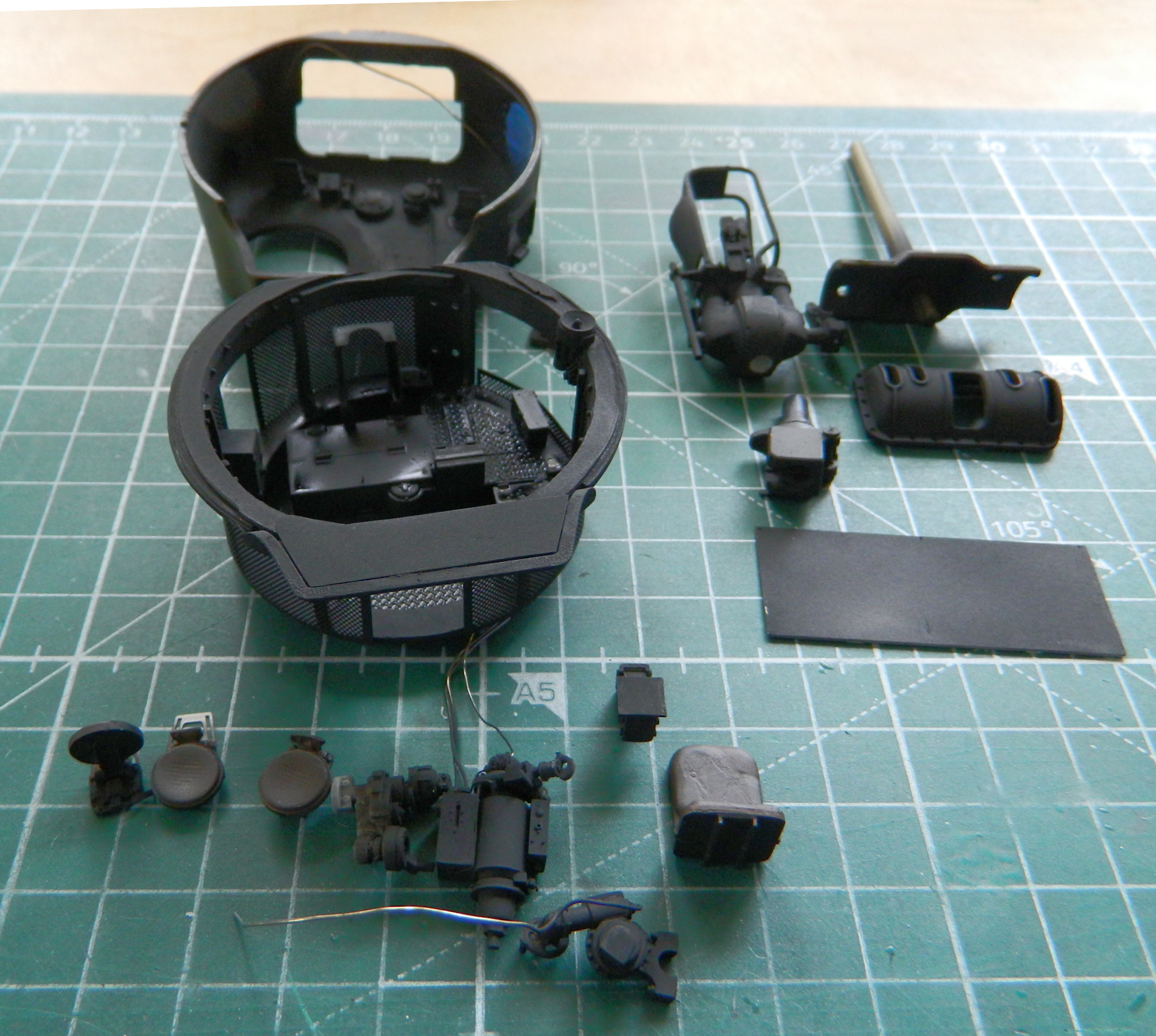
One thing that I’ve seen in a number of earlier M4s is the commander’s turret traverse override lever. Neither the kit nor the AM set have that part so I made one from various bits of scrap styrene and added a (former, since they sold their business…or at least this aspect of it) Grandt Line bolt and some 0.020″ (.508mm) solder for the control cable:

Then I glued it in place:
With the Humbrol Steel having cured and then buffed, I hit many of the parts with Tamiya’s XF-62 Olive Drab where light would splash:
Then I rubbed and scraped the OD away to expose the “steel” underneath (and doesn’t that Ma Deuce look great? I’m using the earlier version of the ammo can):
Next month will no doubt feature even more small stuff. With a bit of good fortune I could maybe even start assembling things!
M4 (Tamiya) Build #8 – Work on the Turret Continues With Me Finding a Glaring Flaw, Fixing it, and More Tiny Stuff

Subscribe to continue reading
Subscribe to get access to the rest of this post and other subscriber-only content.
M4 (Tamiya) Build #7 – Finishing the Gimmick of See-Through Panels, Getting Started on the Turret Basket, and MAKING that Sodding Upper Hull Fit to the Lower Hull
I left off with the turret being ready to have its clear panel installed, so (oddly enough) I started installing the clear panel. There’s only so much fitting that can be done because each time it’s fitted, there are subtle differences in alignment and at some point the thing just has to be glued in. I’m attaching resin to plastic so superglue is used:
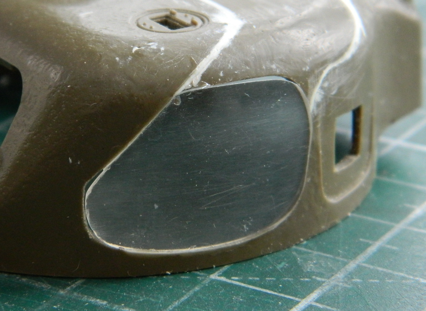
Then the gaps around the clear panel get stuffed with scrap styrene, primarily 0.005″ (.127mm), 0.010″ (.254mm), with a bit of 0.020″ (.508mm) for diversity:

Anyone that’s been building models for any length of time knows that these things, and particularly shape and dimension, will vary depending on how any given manufacturer goes about it. And all of these things vary, even when one is working the same subject in the same scale in the same area. Whichever manufacturer’s turret was used as the starting point for the clear turret I sourced this panel from was different from Tamiya’s turret and the actual curve(s) differed, resulting in something that didn’t quite match:

The shape differed no matter which angle I looked at it from; the above photo is shows the differences (and there were a few). Having spent a few hours filing, sanding, grinding, and polishing, I was most eager to go through that process again (I hope you realize that was sarcasm), starting with the filing step. Once this had been filed so that all curves matched, sanding and polishing followed (I managed to avoid the grinding step) to restore what transparency the medium (resin) would permit:
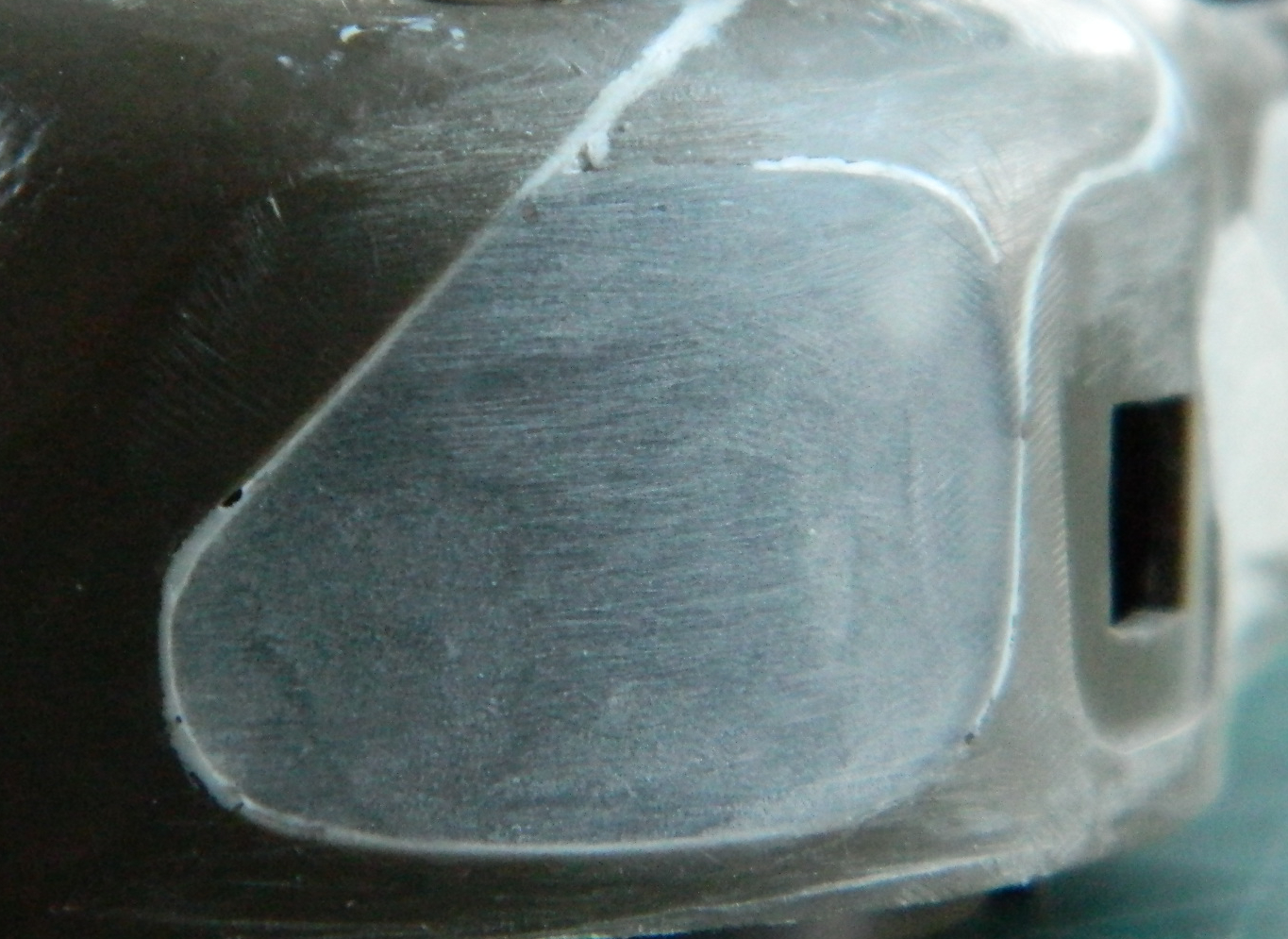
Seeing as the remaining gaps were so small, I tried something different and used Vallejo’s Acrylic Resin Plastic Putty #70.401 to fill them:

I don’t intend to trash this product. There are probably those who use it and like it. Until this project, I’ve only used this putty to replicate weld beads and have liked the result. Once the putty cured overnight, I started sanding it and didn’t like how that went. The putty came up in chunks without really bonding to either the plastic or the resin. Having tried something new for me, I removed all the Vallejo putty and went back to using my preferred product for this task, 3M’s Acrylic Putty which worked as well as it always does.
While the putty was curing, I started work on the clear panel for the hull. That started by outlining the area I wanted to excise and replace with clear styrene:

Then there were many, many, passes with a panel line scriber to dig through the plastic. I got the outline subtly off and didn’t notice that I bobbled the lower left where the curve meets the lower line (because caffeine levels in the bloodstream vary over the course of a day). I cut the error square (ish), inserted scrap styrene, and reworked the curve while cleaning up the jagged edge left by the scriber. The upper hull was dry-fitted to see if I had achieved what I was trying for:


[It’s at this point that we’re having a quiz. I have overlooked something that I didn’t notice until later in the month. The question to you is, have you figured out what I overlooked? The answer will be revealed at the point in the build where it finally dawned on me.]
With the opening defined, it was time to cut a piece of 0.015″ (.381mm) clear styrene to fill it:


Rather than attempt a rather long butt joint by cutting the clear insert to the dimension and shape of the hole, I decided to carve a depression of about 1/8″ (.0625″ or just under .2mm) wide for the styrene to settle into:

As you may have noticed in the above photo, what is the bottom of the hull’s side is a long and narrow strip of plastic. The line that crosses it perpendicularly is where it snapped. Significant pressure is required to scrape away the plastic and you can see that I didn’t get very far along before it snapped. I knew there were fairly large gaps where the sponsons met the upper hull so I had the room to use 0.010″ (.254mm) styrene to back the long and narrow strip. Even with the backing, because plastic is flexible, the break kept opening. I widened the gap of the break and inserted a scrap of 0.010″ (.254mm) to provide strength to the repair. It worked because during the rest of the excision, it didn’t break again.
It took some time but I finally got what I was after (I thought):

I didn’t realize before I had glued the clear panel in place (probably a drop in caffeine levels) that the depression I’d scraped into the plastic wasn’t quite uniform in depth. (If I ever do something like this again, I will jig a tool that will show me when I have reached the intended depth.) By the time I came to that realization I had already glued the clear in quite firmly and didn’t want to even try to remove it. Lesson learned, continue on.
I was most careful with the glue (Tamiya’s Super Thin). I got almost all the way around the periphery with the gluing process before an errant nerve pulse (twitch) caused my ancient hand to bobble the glue. In the following photo you can see where that happened at the bottom right of the clear panel:
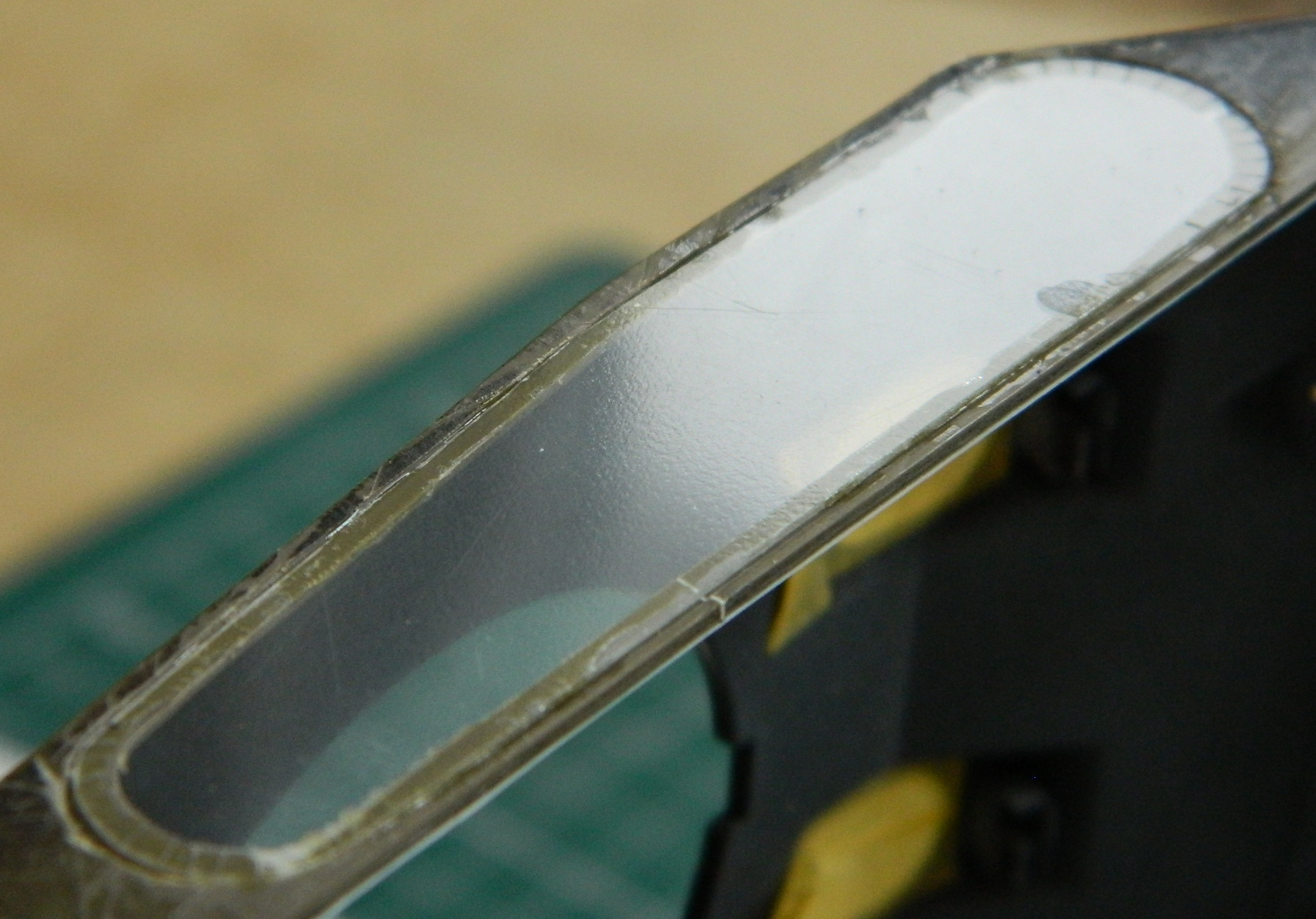
Not optimal but by this point, the process of this built has increased my depth of experience with getting something that isn’t clear to become clear.
With a lot of puttying and sanding pending, I wanted to mask the sections I want to stay clear. Since I will also need to mask the inside (because, painting, y’know), I started there. It will make aligning the masked-off area match on both sides easier to start inside the hull and match that from the outside:
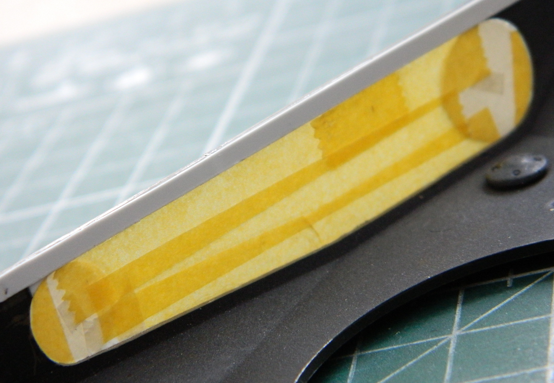
Then mask the outside to match:
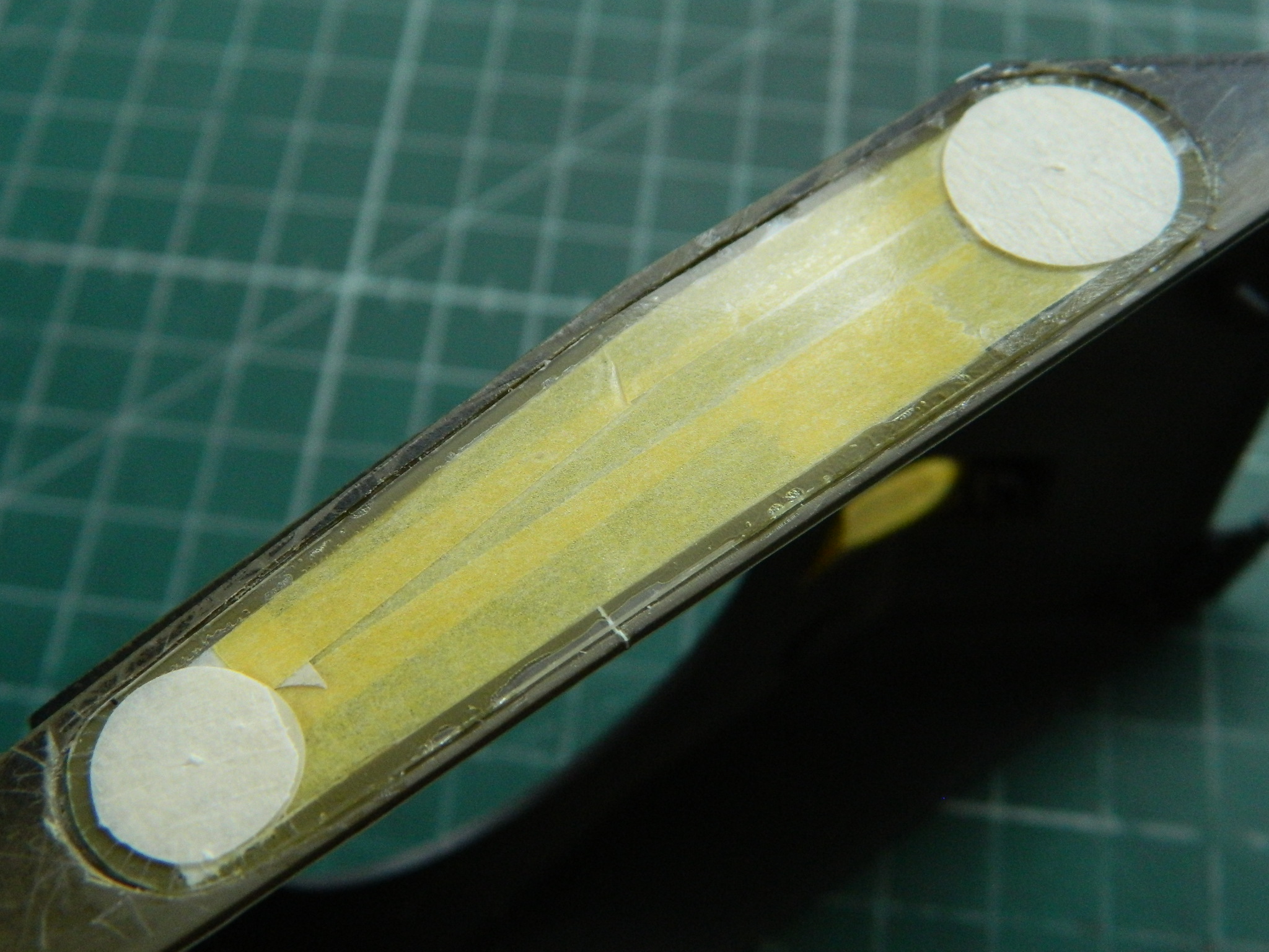
“Insanity can be defined as doing the same thing over and over while expecting different results each time.” Yeah. That would be (and frequently is) me. Don’t ask me why because I have no answer that makes sense (even to me), but I tried using Vallejo’s putty again:

Probably surprising only me, it worked as well as it didn’t on the turret. ::face palm:: Fine. Got the hint. I removed all the Vallejo putty and replaced it with the 3M putty.
Since the driver of this build is to attach the upper hull, I added the screen to the rear of the engine compartment while I was waiting for the (CORRECT) putty to cure:


Time to address the glue bobble. I masked it off from the surrounding plastic:
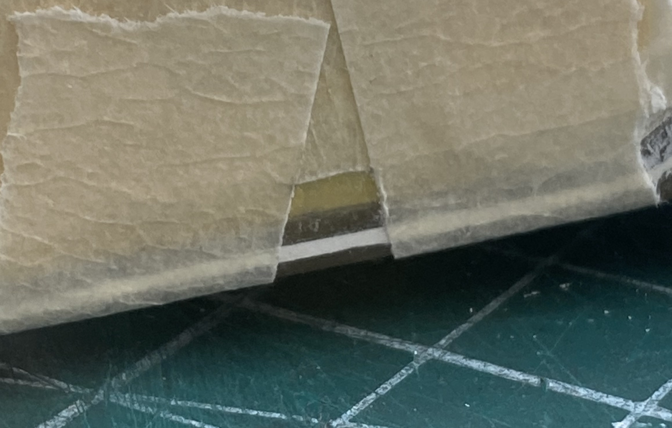
I started sanding out the glue splotch with 320 grit, then went through the grits of 400, 600, 1200, and 2000 and finished off with Novus #2 Plastic Polish. If one knows where to look (and looks very closely) there is a very slight haze at the repair site. I will be surprised if anyone ever notices it:
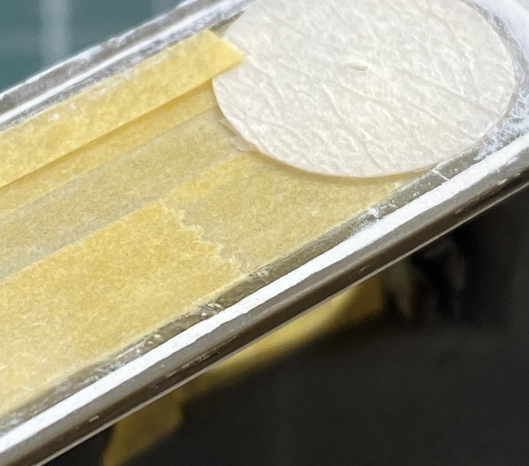
With the putty cured, the area was masked again and it was filed and sanded:
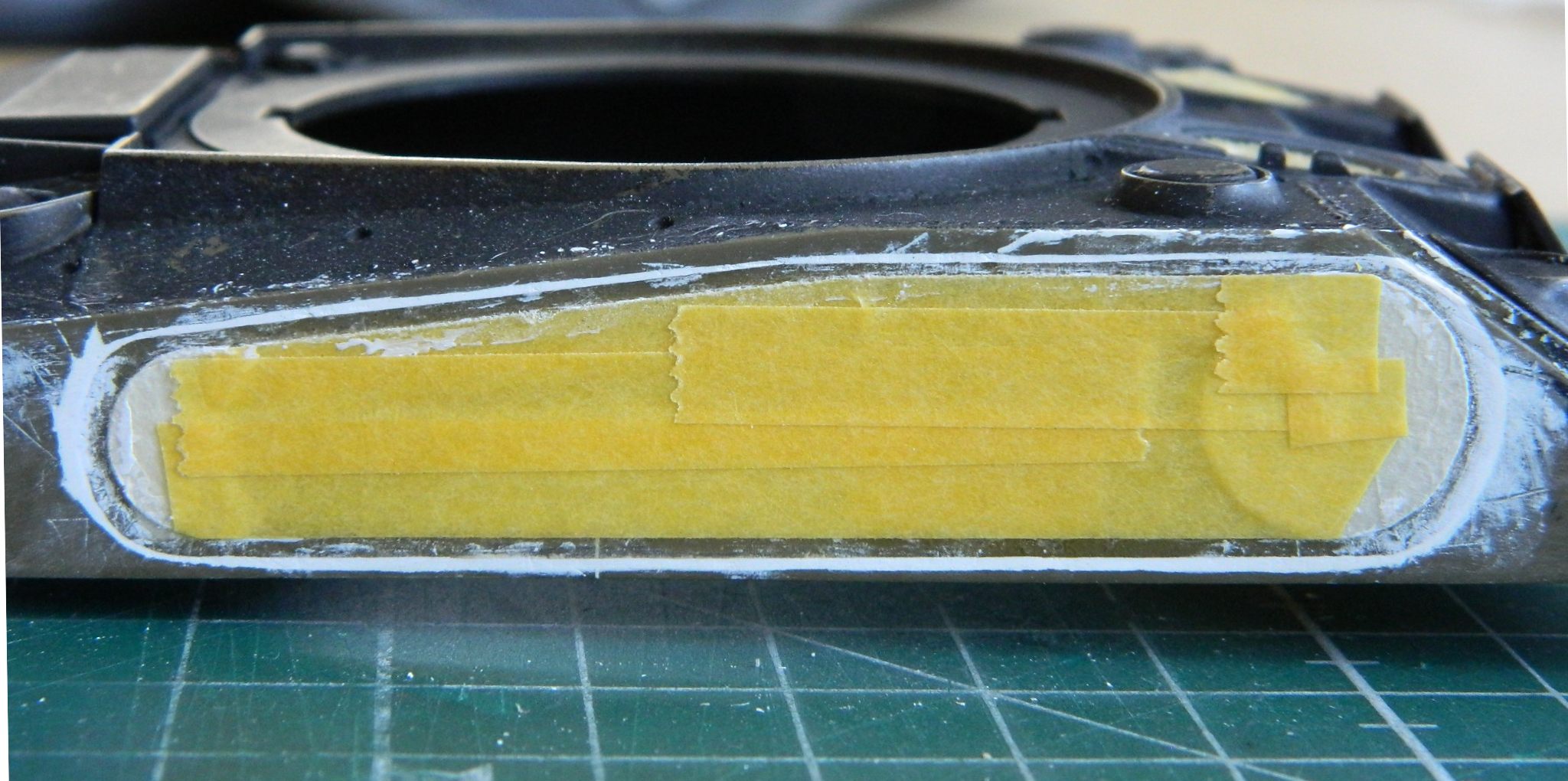
I forget what I was painting (this from the person who can get up to go get something and forget what he got up for before leaving the room he’s in) but I had OD Green in the airbrush cup. I decided to use that as a primer to see how well I did blending the putty between two surfaces. My efforts can be summed up in one word.
Inadequately:
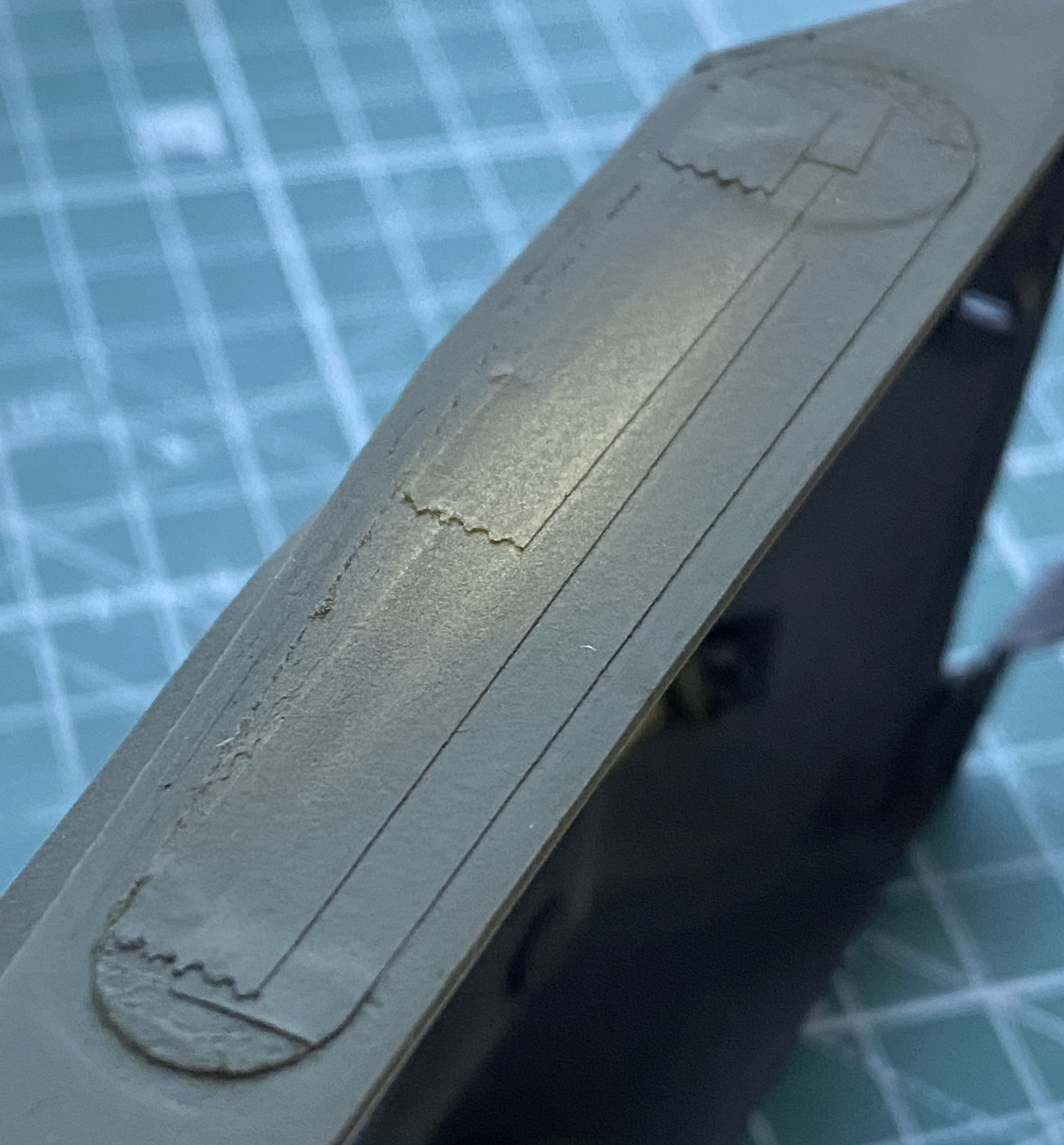
Time for more putty, more drying time:

While the putty was curing, I added Grandt Line bolts and the locking pins to the gas cap covers:

I also checked the exhaust tips of the auxiliary generator. The kit molded them as solid stubs. I found a piece of .020″ (.508mm) copper tubing that the Eyecrometer said would work, drilled out each end of the tubing to a more scale thickness, and then cut off each end of the tube. They were aligned and glued in place:
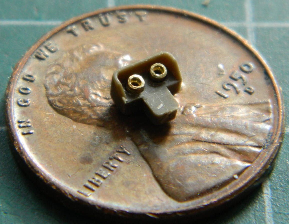
With the putty completely cured, this time there was more filing than sanding. Files have flat surfaces so I decided to use that property. And since I had pretty much bollixed up much of the added weld seam of the glacis, I replaced that as well:

This time I had flat black in the airbrush cup so I primed the hull side again and this is when I (finally) realized that the depression I’d scraped into the side was of inconsistent depth. A wee bit of jiggery-pokery (evident at the left side of the clear panel) was required to get things to look like they were properly fit:
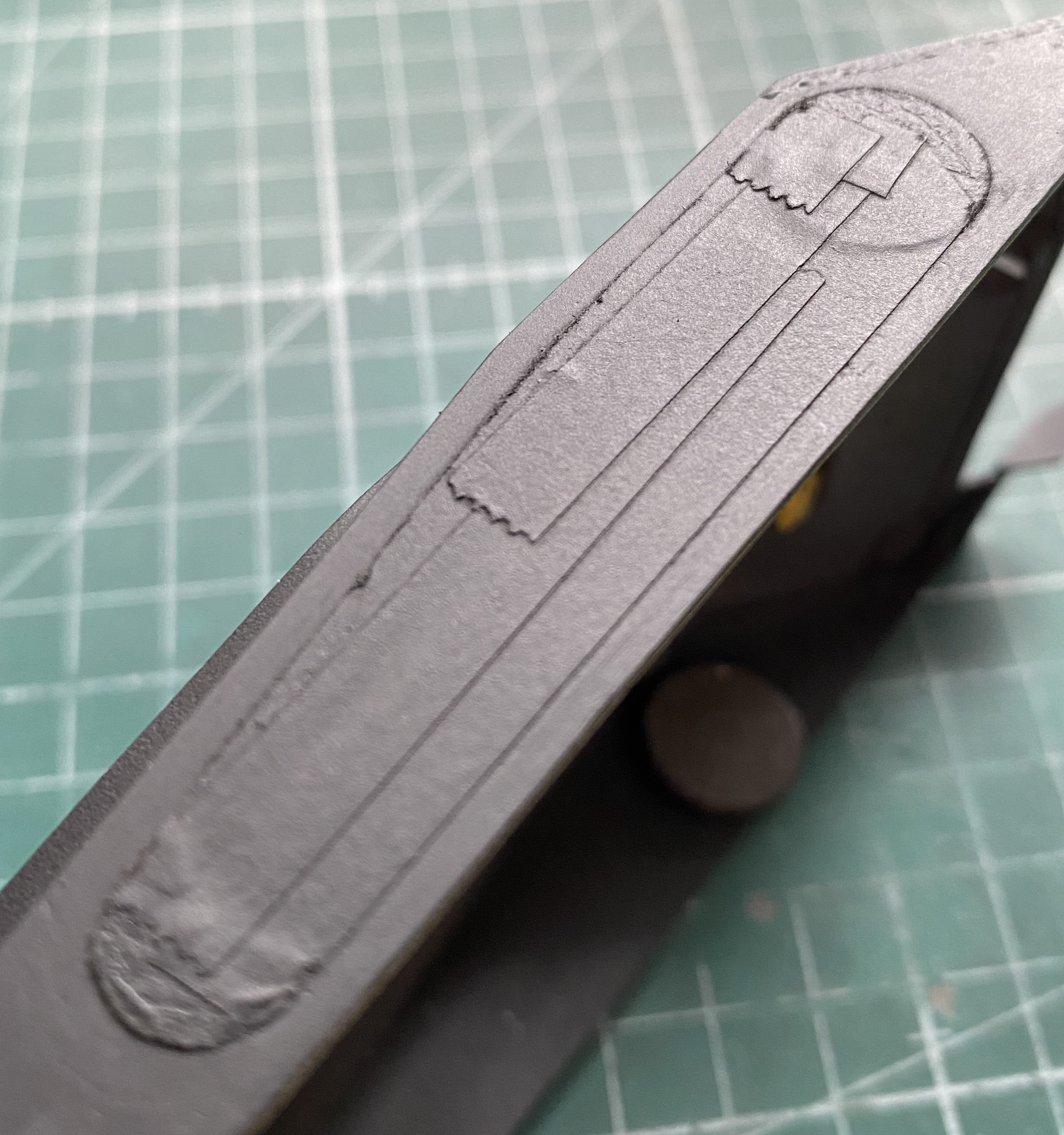
Close enough.
There are actually lights inside a Sherman so that the crew can see what they’re about with the hatches closed. The later lights have a changeable filter between clear and red (the latter to keep dark-adapted eyes dark-adapted), the early lights only have the clear. I decided that the demands of the day probably precluded mechanics from upgrading bits that weren’t essential…such as interior lights. I found a reference photo that I could pull dimensions from and scratch-built one:
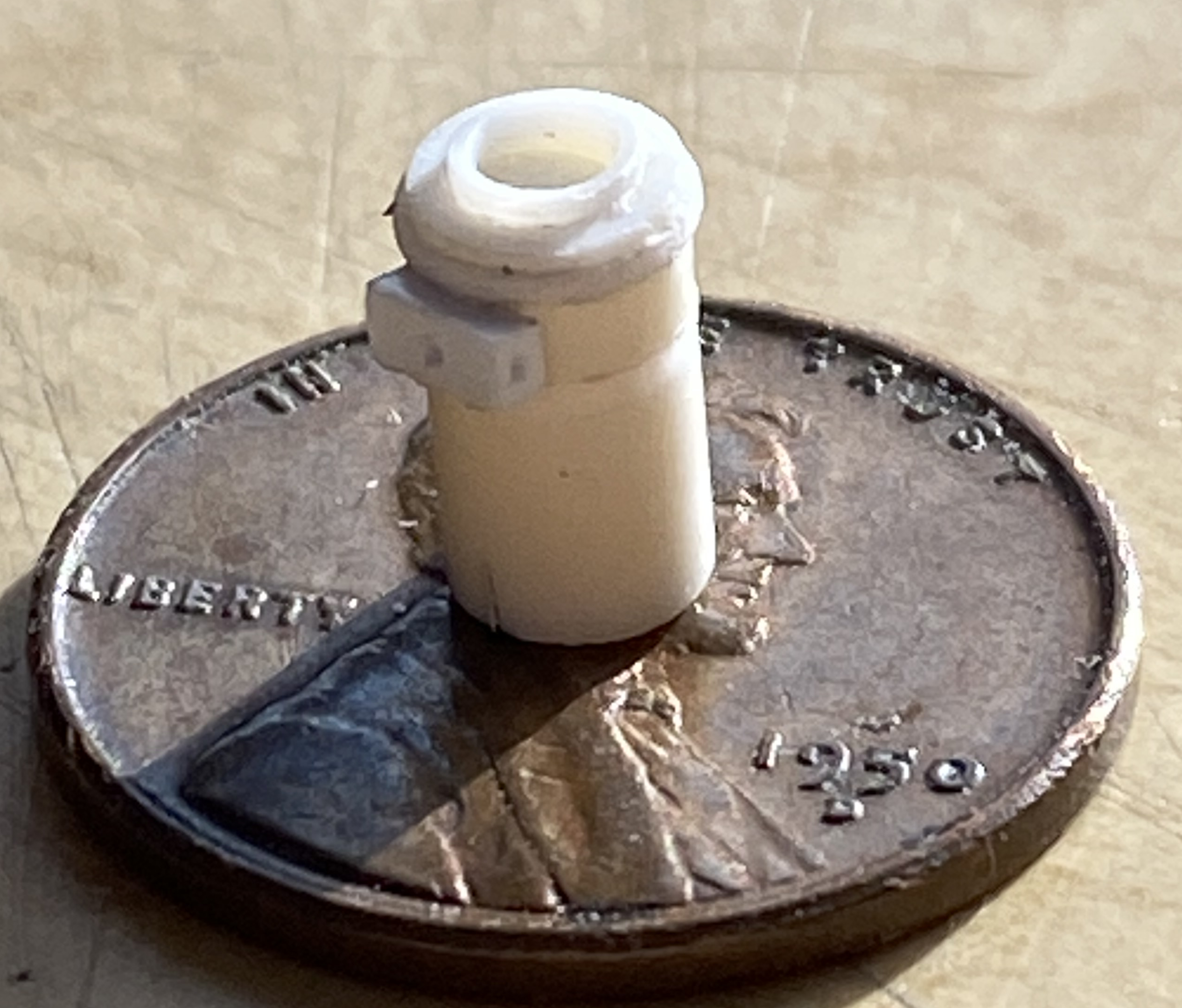
I can scratch-build one. I can scratch-build multiple copies. I just cannot seem to build the copies as easily (or as well) as I could the first one. So the one in the photo above is the first one…and I used silicone molding putty to make copies of this one. This is what I used and it’s available from Michael’s (at least in the US):
Mix equal weights of A and B, WORK QUICKLY because this stuff sets up quickly, and in 15 minutes there’s a mold. Since I need three lights, I made three molds and filled them with resin:

I wasn’t thrilled with how the casting on the left in the above photo turned out so I didn’t use it, I used the master instead. The pour stubs were cut off and 0.010″ (.254mm) solder used as toggle switches:
Time to add them to the crew compartment in front (two of them) and the turret roof (one, obviously). Of course I wanted to put them in the correct places, so I spent a couple of fruitless hours online looking for a photo of where they should go. Fine. I’ll guesstimate and put them where I would want them (and it wasn’t until I had the upper hull WAY past the point of removal before I found a photo…because I was looking for something else, of course…showing where they went) (I like where I have ’em better):
I was curious as to what the exhaust tips I made would hook up with so I dry-fit the upper hull to see what’s underneath them. As it turns out, there are two Mystery Objects molded onto the bulkhead directly underneath the exhaust tips’ location. So once again I guesstimated that these Mystery Objects were part of the exhaust pipes and added 0.20″ (.508mm) solder to represent them:

It was shortly after I redid the interior paint (flat black with flat white misted over it) that I found the correct location of these lights. Having decided to leave them, once the paint was redone I used a toothpick I’d carved a chisel tip onto to scrape away the paint on the area I want clear (it’s just easier than trying to mask something so small…I do the same thing with landing lights and periscopes):
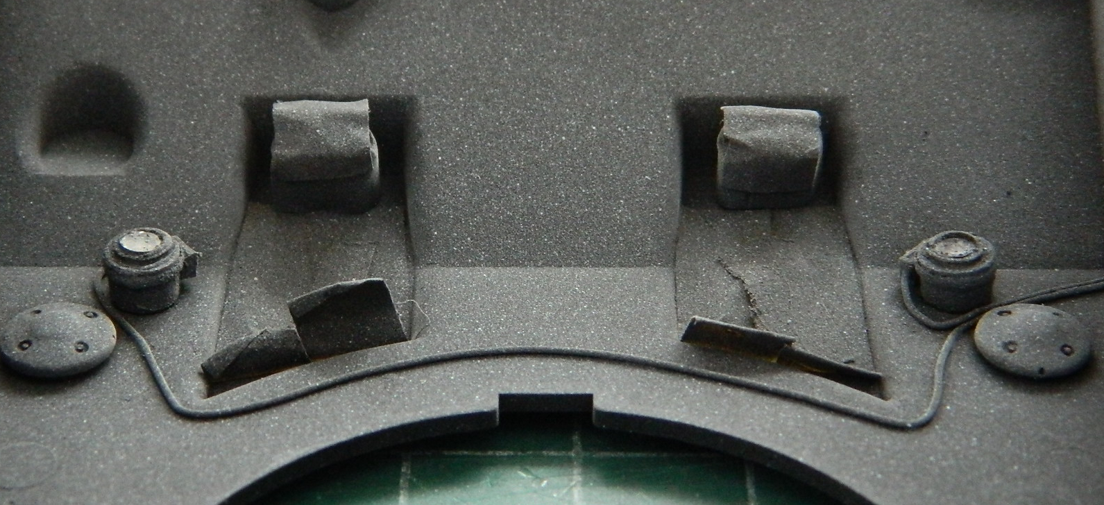
Adding the .30 caliber (7.62mm) machine gun will be much easier with the upper hull unattached. I painted the receiver my custom gunmetal (Tamiya X-18 Semi-Gloss Black 5 parts, XF-20 Medium Gray 4 parts) and added the Master GM-35-004 Brass Machine Gun Barrels that I colored using Birchwood Casey Brass Black Metal Finish (BRILLIANT stuff, that):
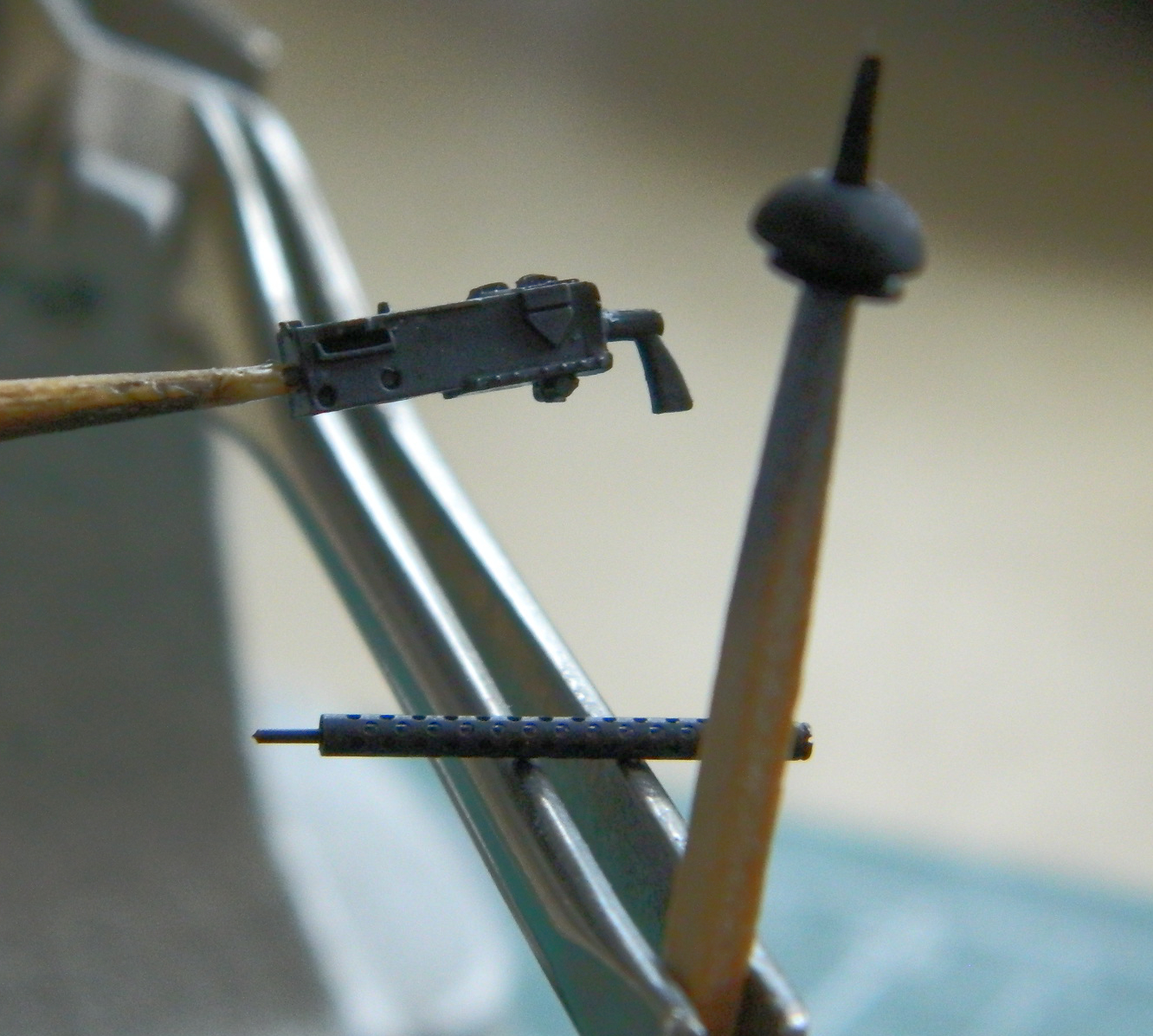
Then it was assembled:
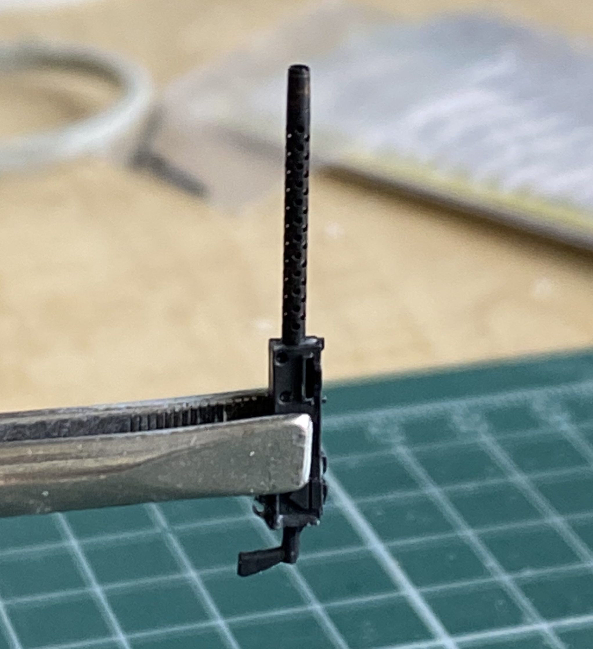

No point in detailing the receiver because where it’s located the details won’t be seen.
With the upper hull still free, it was time to fit the turret to it. I’d checked the parts earlier and knew that they would need work to fit. These are the parts that have to play nice with each other:
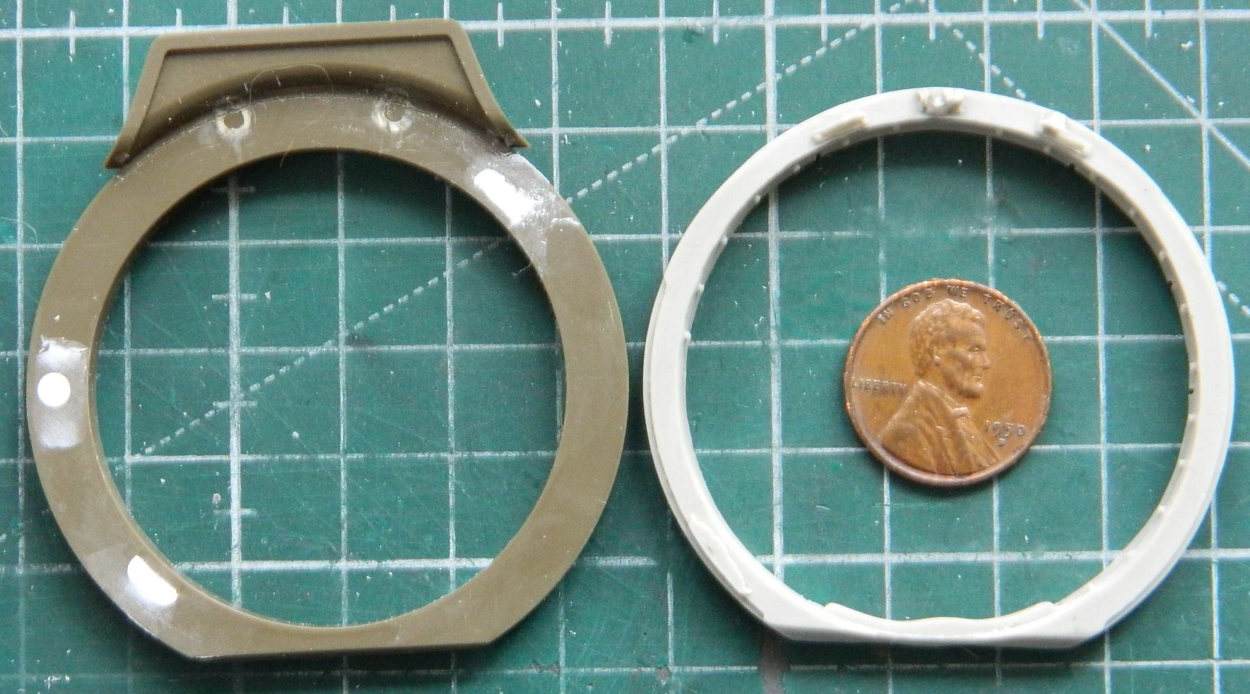
They also have to play nice with other parts, as in, fit:
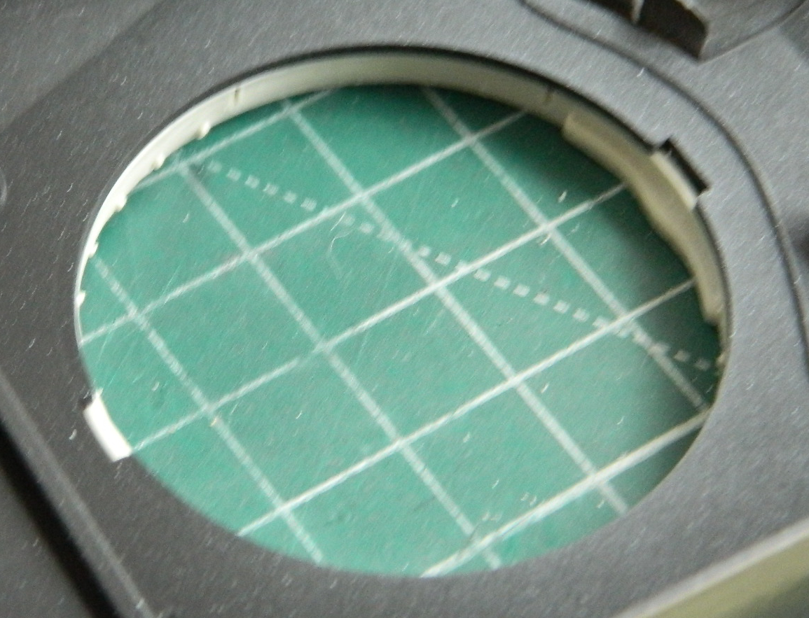
I can make that happen:
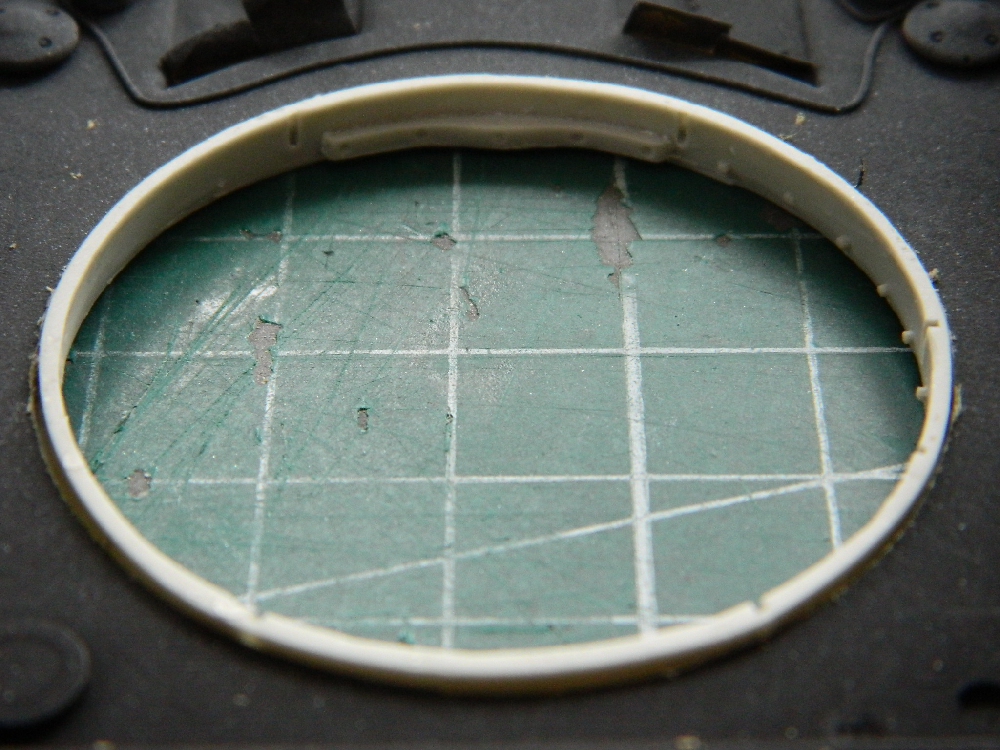
Often:
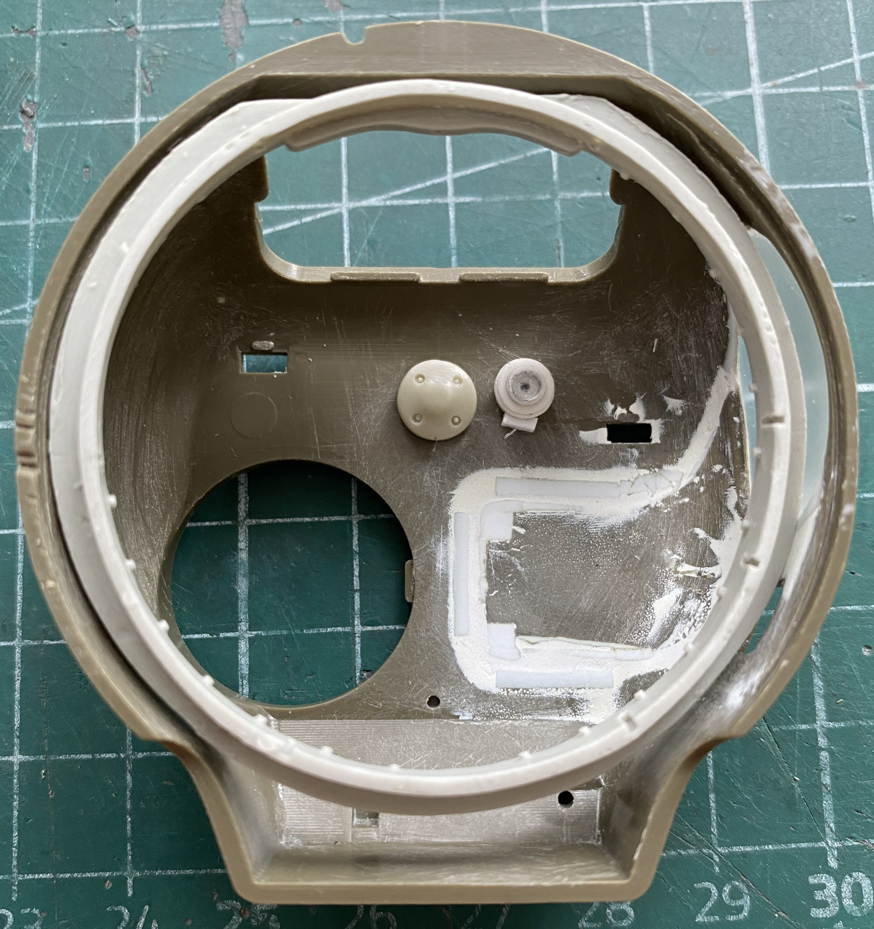


I also need to graft the bustle bottom to this part. It starts with tracing where I need to make the cut:

Then doing the fitting:
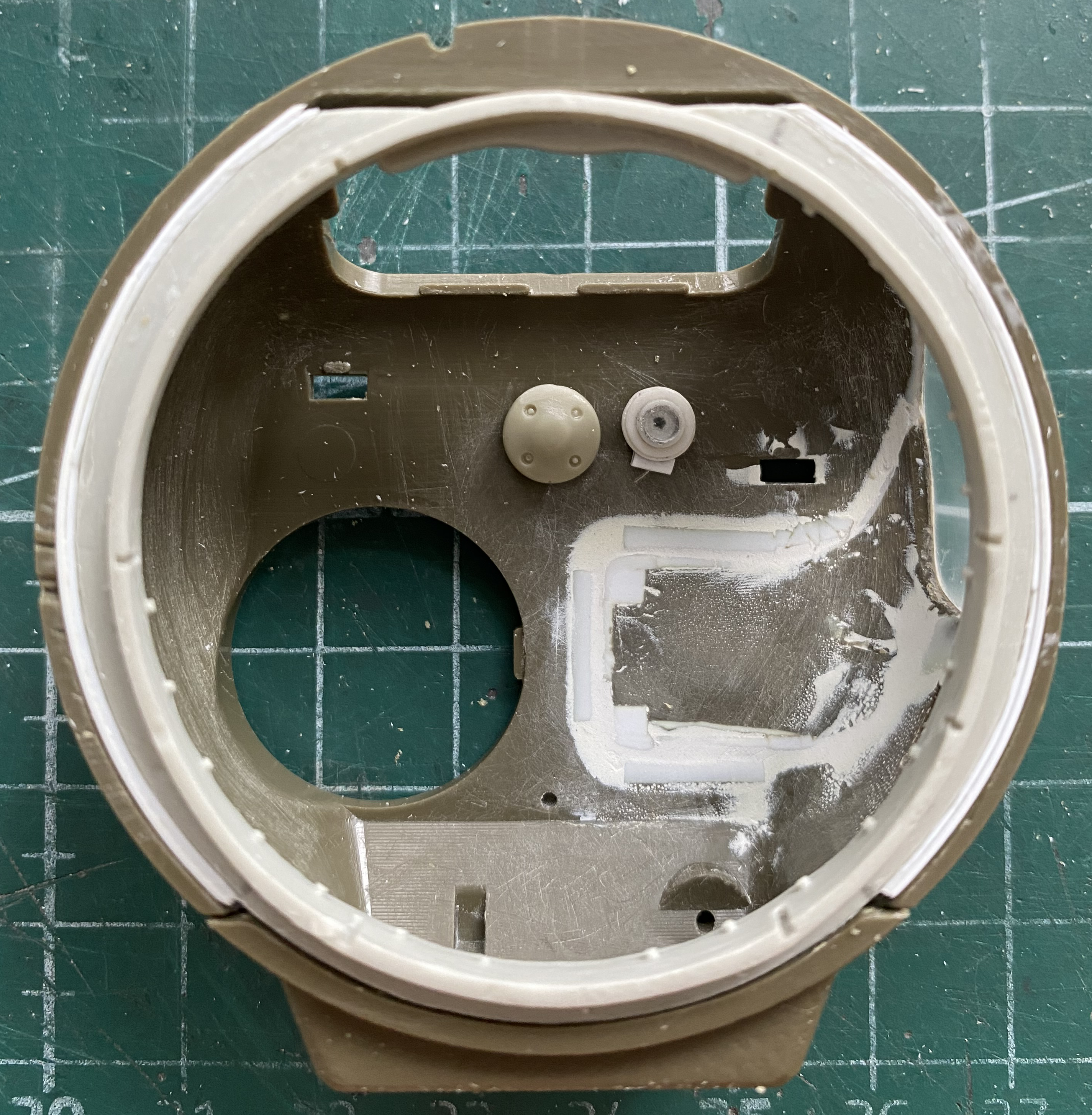
Fiddly but doable:

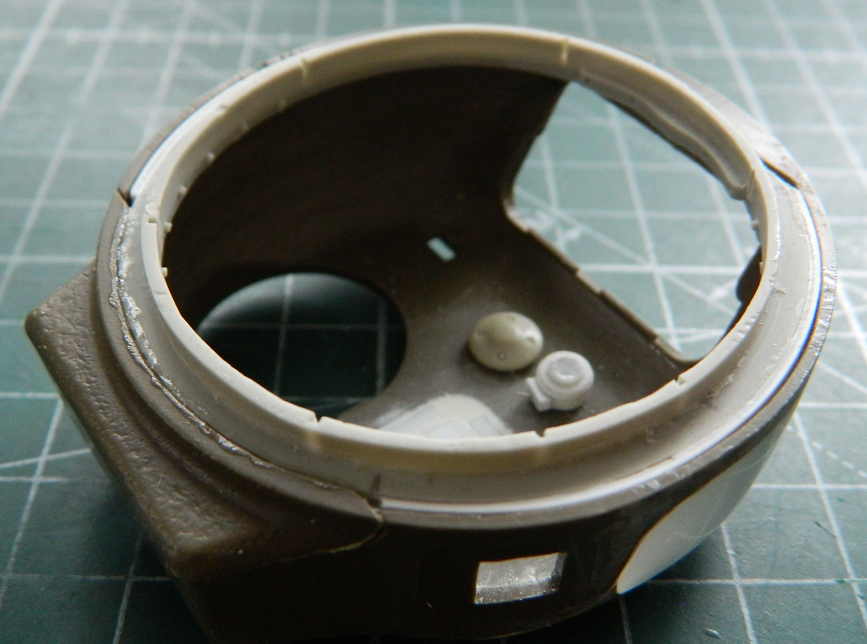
Tamiya used to mold the pistol port as an applique without the option to be opened. When I did the M4A3, I used silicone molding putty to copy the detail of the opening from a Dragon turret I have in my spare parts inventory. This enabled me to open Tamiya’s pistol ports with a bit of grafting, some putty, and cutting a hole. The resin copy was put back into the mold so that I could support it while I ground away resin to make this thinner. If I had tried to hold it in my hand to grind it, the warmth of my hands would have made the resin too flexible:
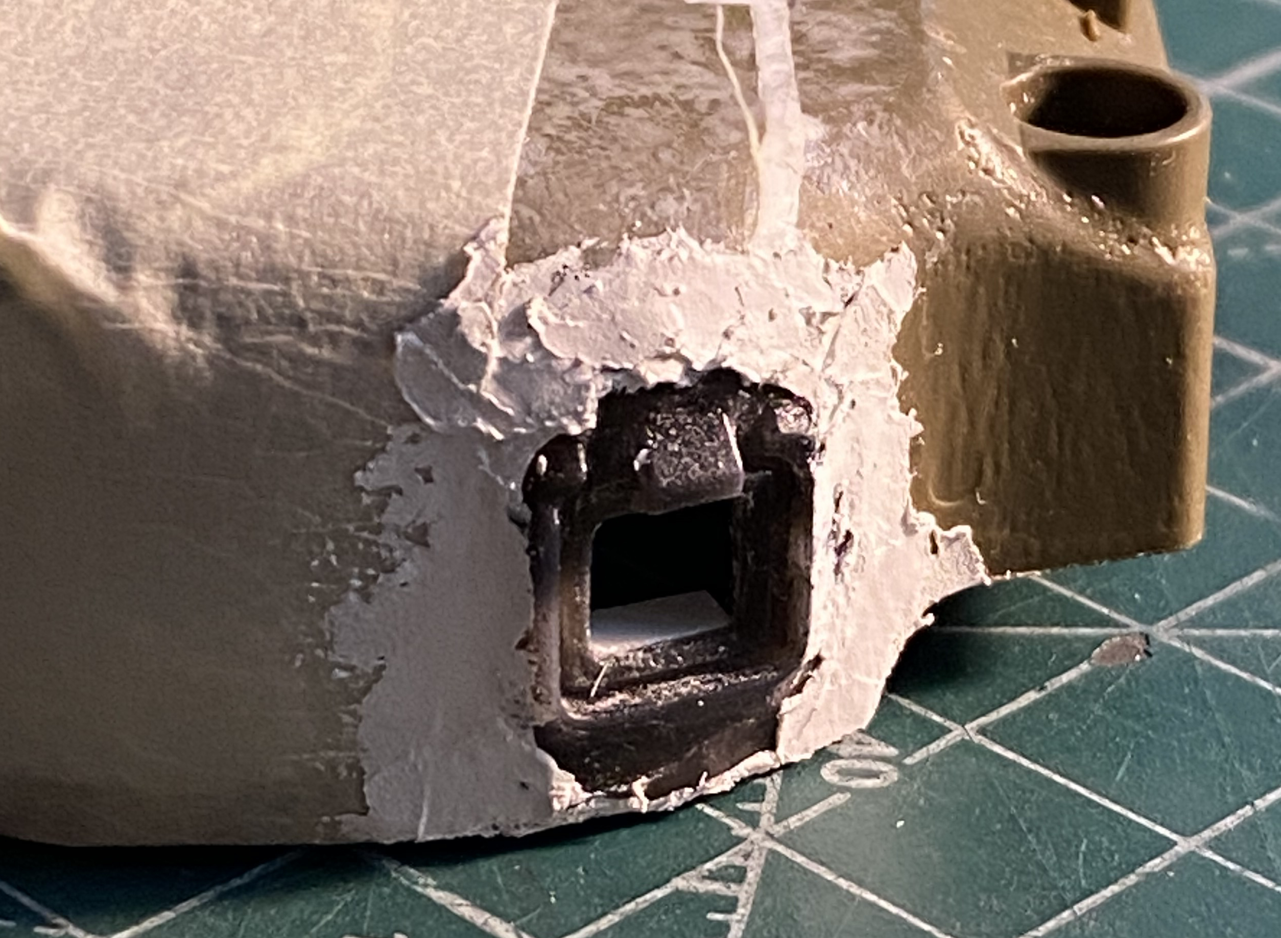
Once it was glued into place (but before the putty), I discovered that I’d misaligned it. It was easier to modify the hole than to try to pry the putty up (and have the resin part even survive):

While the putty around the pistol port cured, I worked on the shelf the radio inhabits. The radio I want to use is resin, making it heavier than a plastic part is. I thought the PE shelf was too thin and that using 0.010″ (.254mm) styrene as a replacement would allow the weight of the resin to result in the shelf drooping (I assume). Instead I used the PE part to create a heavy stock paper template and then transferred that to 0.010″ (.254mm) copper shim stock. Dry-fitting showed that the shelf wouldn’t sit level, so I used a scrap of 0.010″ (.254mm) styrene to fix that:
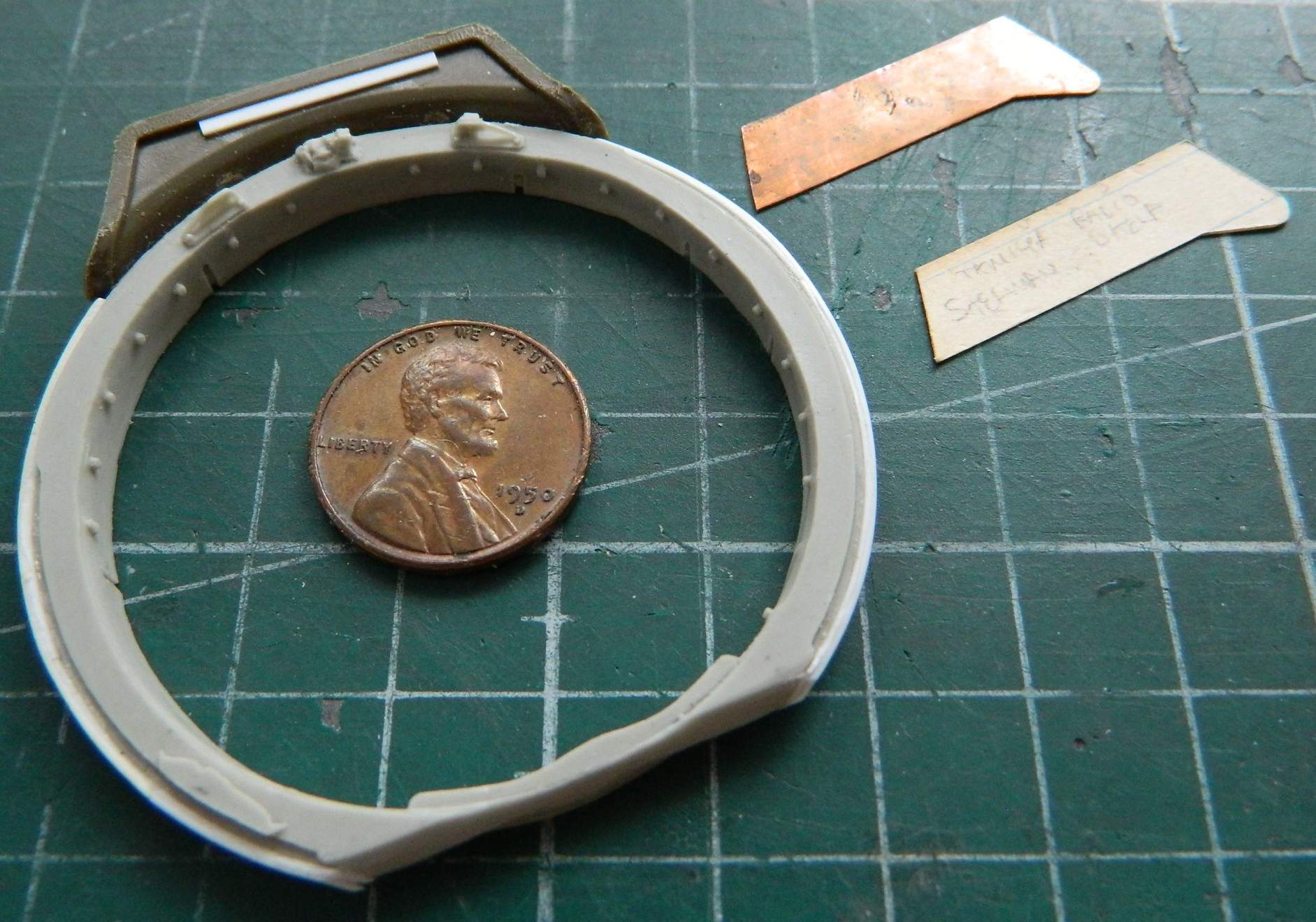
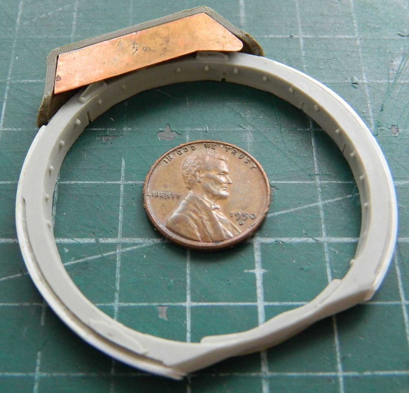
Once the resin cured, I masked over the clear panel and filed and sanded it to a precise (relatively speaking) fit:

All that sanding removed the as-cast texture which I replaced with Mr. Surfacer 500. A thin coat was put down with a disposable nylon brush and then the texture was replicated by stippling the surface with the flat tip of the brush:

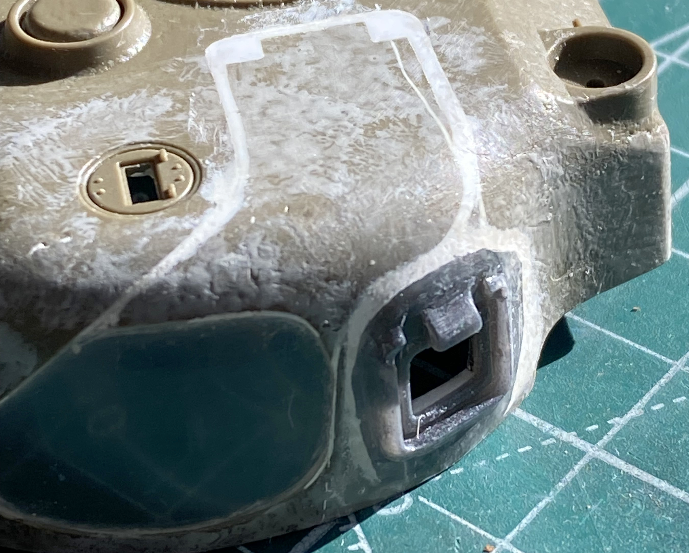
And since the inside of the turret was never intended by Tamiya to be seen, it also got a Mr. Surfacer treatment:
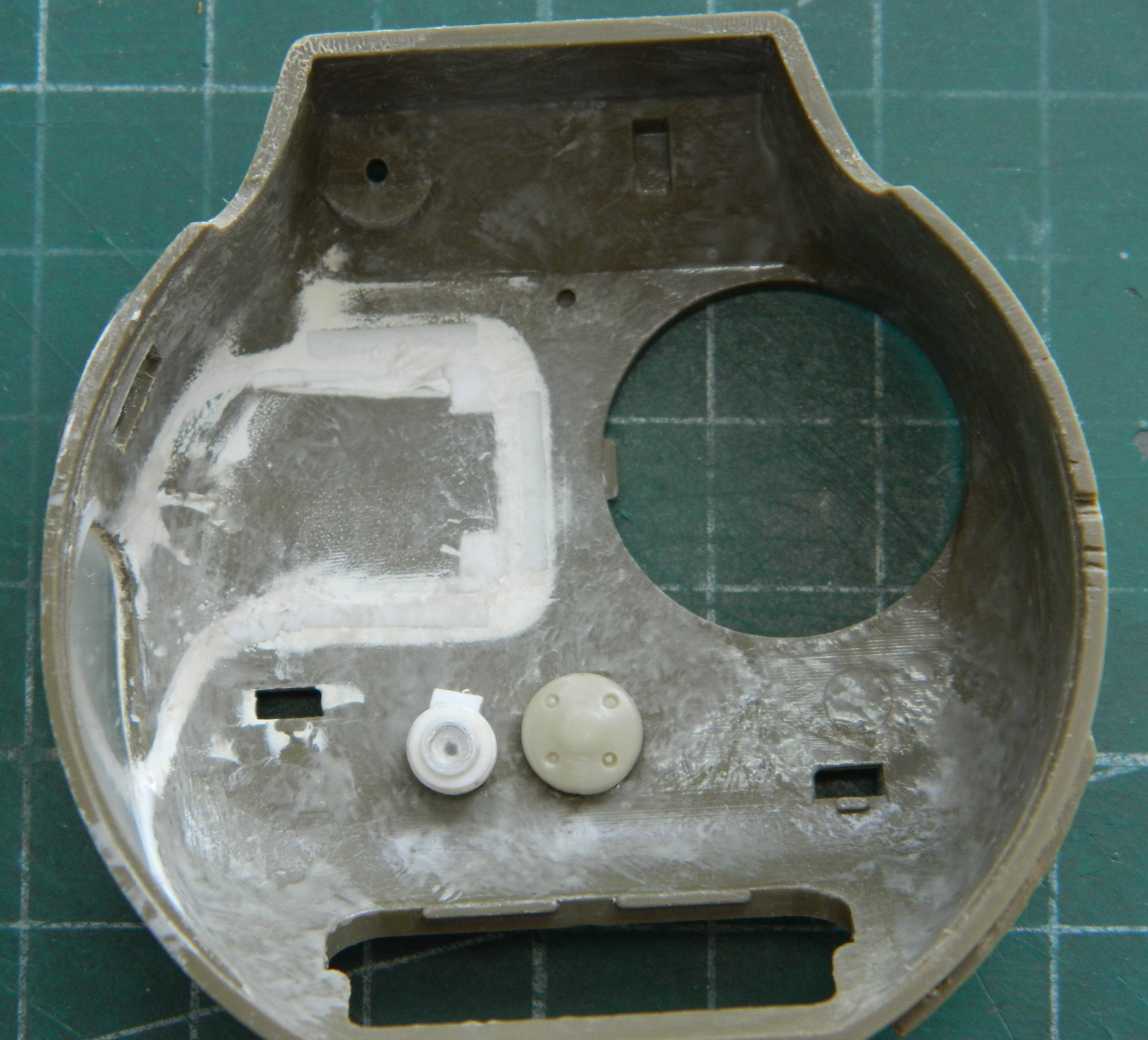
I primed the clear panel on the outside of the turret with flat black. I didn’t mask the clear because the tape doesn’t stick well to it, planning instead to remove the paint with denatured alcohol and a chisel-tipped toothpick after the OD Green is shot. The priming shows where there are still some little gaps:

While I was here, I masked the interior of the clear part. Yes, the tape doesn’t stick very well, but it sticks well enough when tape is put in place where it will not be handled. Then denatured alcohol took off the exterior paint (easily, which is why I use it to remove paint, clean brushes, and clean the airbrush) and putty was laid down:
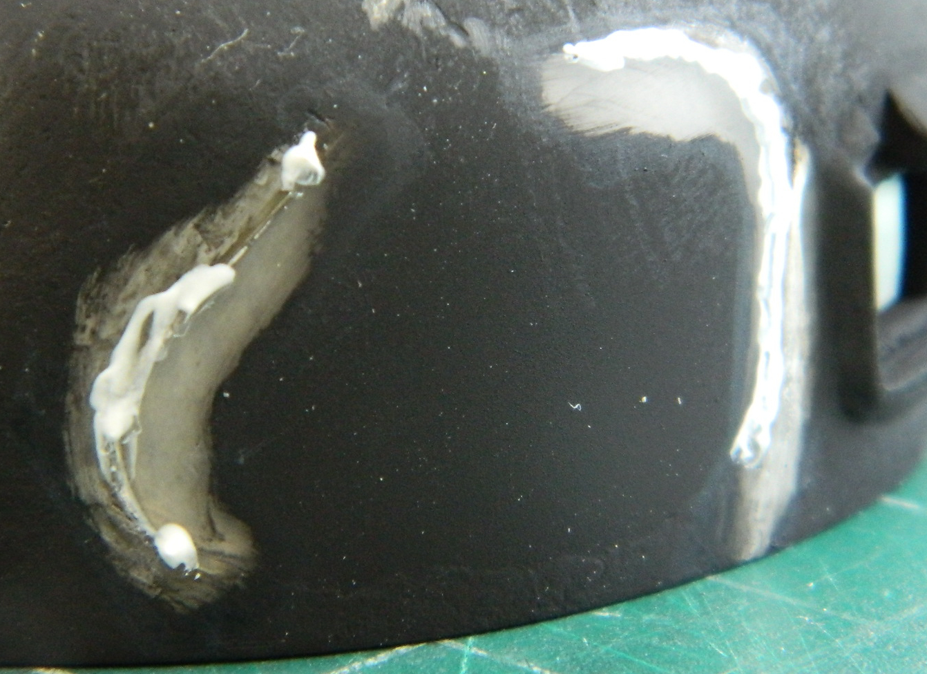
Mr. Surfacer replaced the texture that was sanded (and polished, of course) away:
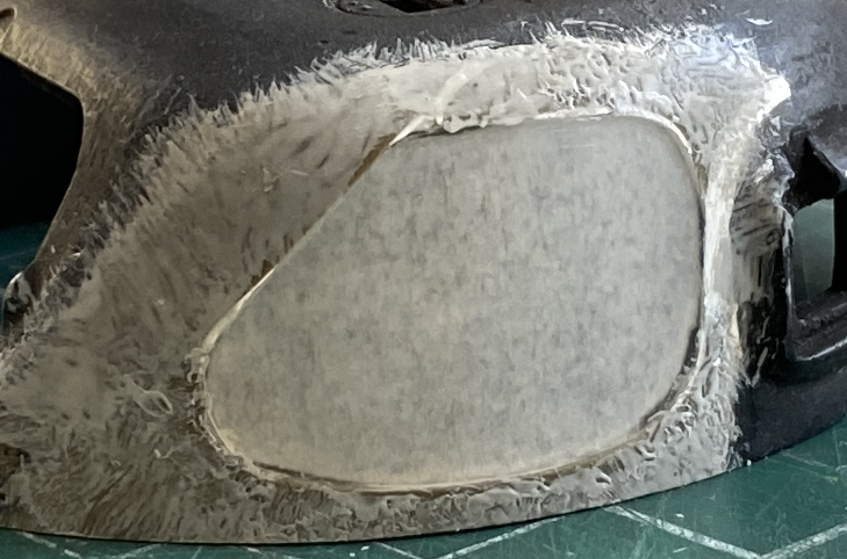
Reapplication of primer shows that it all worked:

Before the upper hull can be attached, the .30 caliber (7.62mm) is attached:
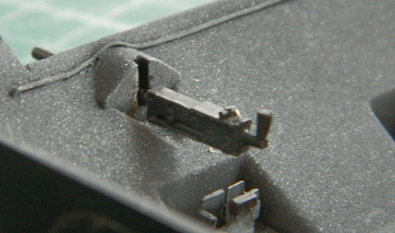
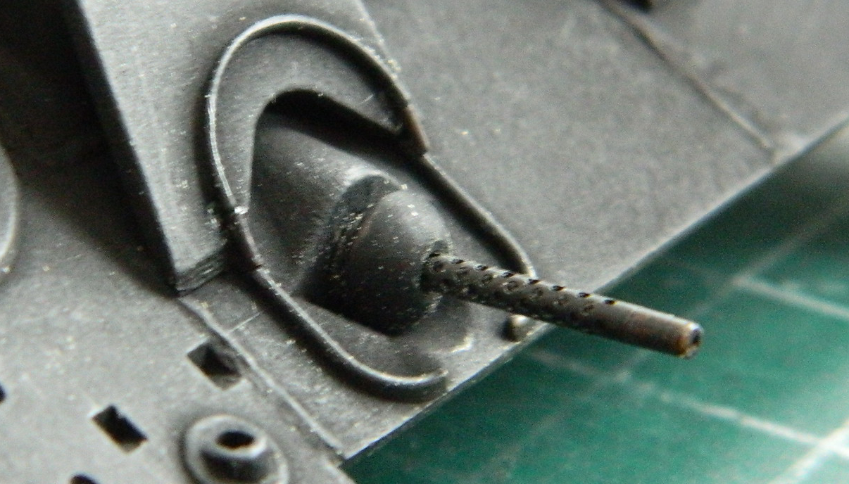
These are about 99% of the parts that comprise the interior of the turret:
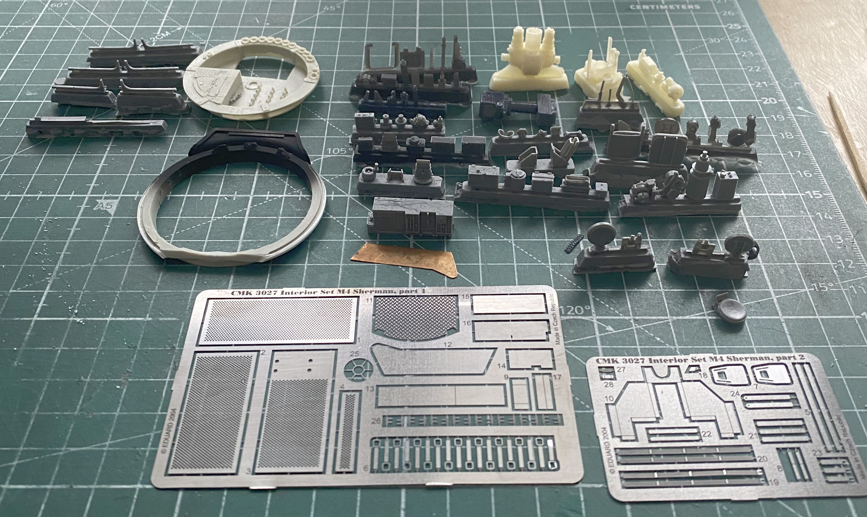
And this is what I’m replacing the kit parts with:
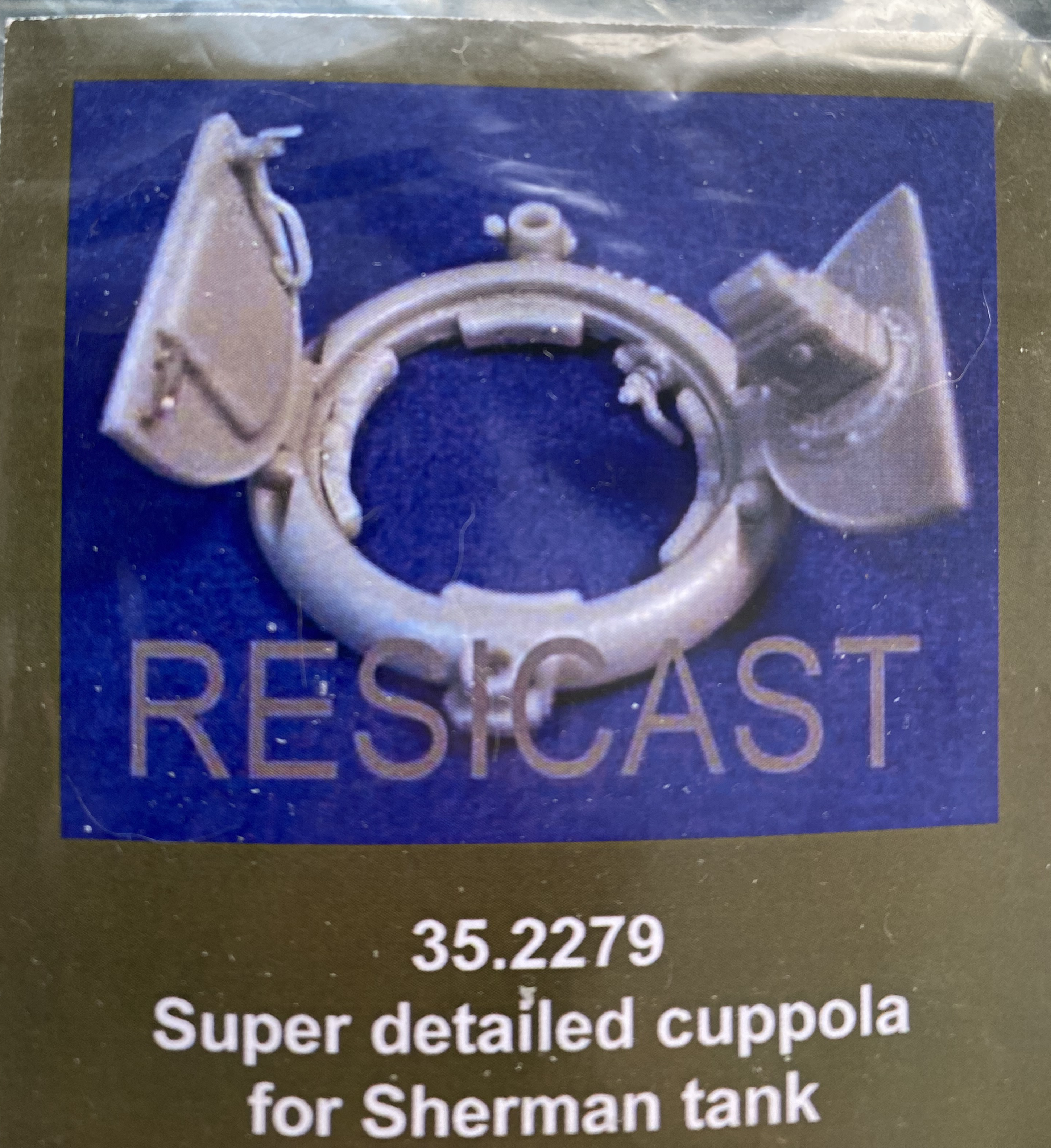
I started with the loader’s and commander’s seats. The commander’s seat is on a track that enables it to be moved up and down. Both seats also fold down (even though the directions of the AM set show them folding up) which enable the commander to have just the top of his head (at about eye level…go figure) exposed and folding down the loader’s seat gives him more room to maneuver during a fight:
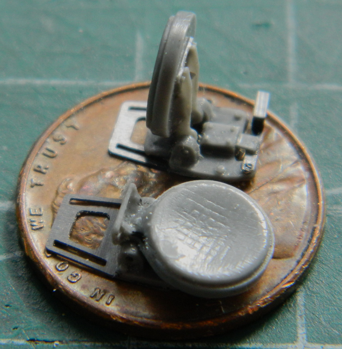
The shortcomings of the Sherman’s design became evident in North Africa and emphasized during the Italian campaign. An interim measure, called “the blitz program”, was instituted to address some of these shortcomings without having to halt production to do so. This program added armor over the outside of the hull’s sides to add protection for the ammunition storage (the location of which is why a Sherman would explode and burn, not because they were gasoline powered), added armor to the turret in front of the gunner’s position, and angled plates in front of the driver and co-driver’s hatch hoods. These kits were also provided to be added at depots to upgrade tanks already deployed. Part of the blitz program was to address ill-conceived stowage of ready rounds along the periphery of the turret basket. A penetrating shot would cause the rounds to fracture, igniting the propellant, which would then lead to a catastrophic ammunition fire and explosion. The ready rounds were removed from the turret basket.
The resin AM part shows where the base of the shell would rest. Since I’m doing a “Normandy Sherman,” something that would have had the blitz upgrade, I removed those shell rests:

It was at this point that I realized that there really wasn’t anything stopping me, now, from marrying the upper hull to the lower hull. Dry-fitting showed me that there would be A LOT of tweaking and fitting necessary to get these two parts successfully mated. I went, literally, inch by inch. Fit, clamp, glue, go back to the turret basket. There was much rinse and repeating with that (made so much easier by the fact that little of the upper hull was parallel with the sponson bottoms):
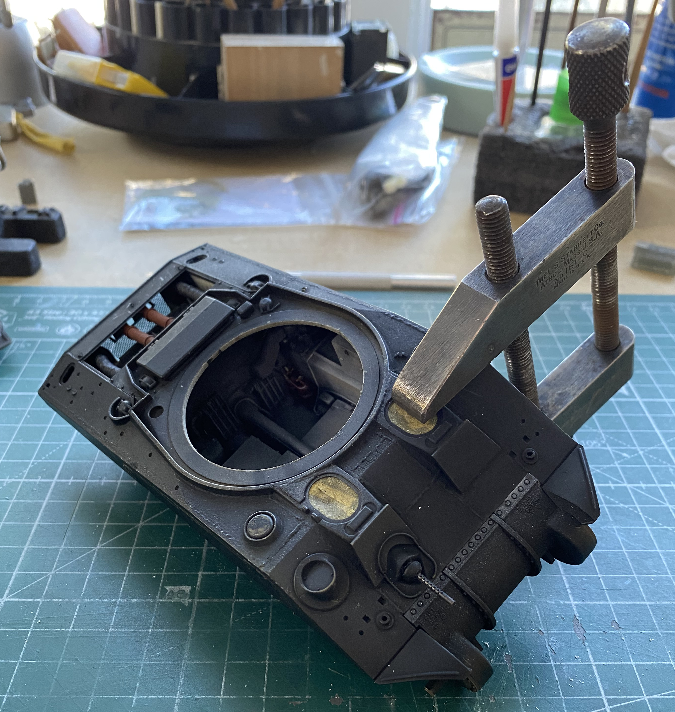
Back at the turret basket, that all started with attaching the frame supports to the basket floor:
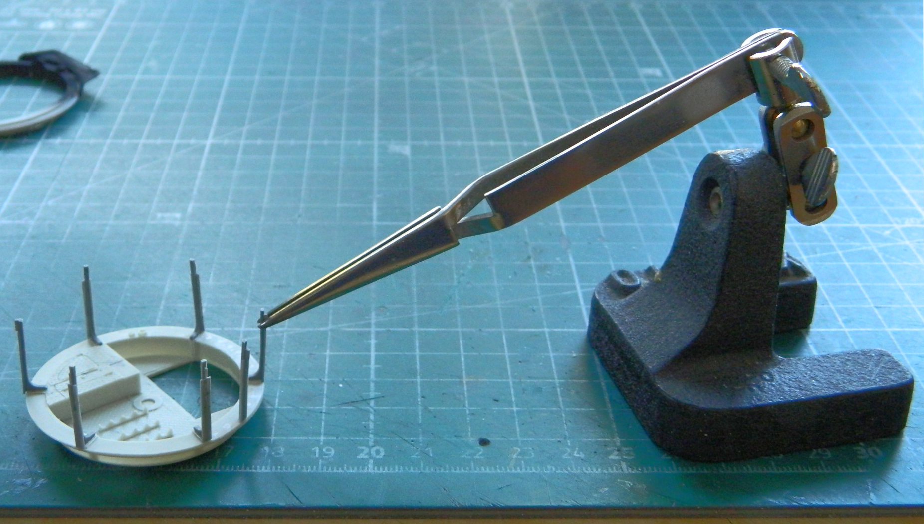
There were things that had to be added to the basket, much of which had to be assembled (and detailed, of course). This is the gunners turret control unit:
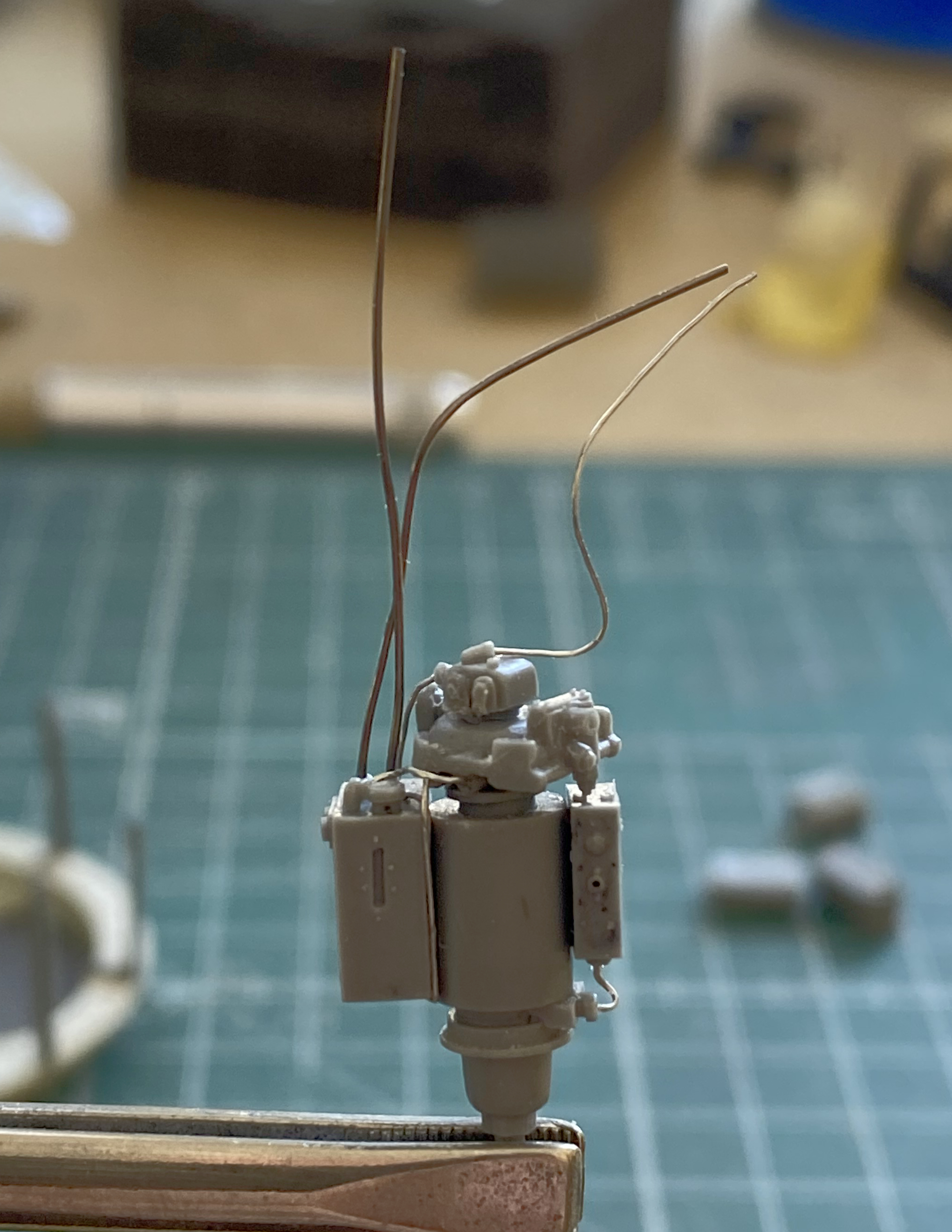
Most of which is there. One part failed to pour and it was the gunner’s control handle which was used to traverse the turret. So I had to make one. I used a piece, a very small piece, of resin from a pour block to carve it to size and shape:
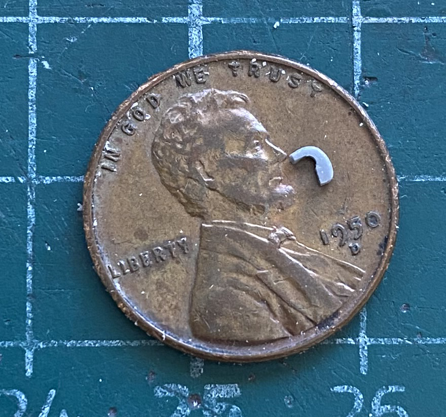
And before that got lost, I glued it in place (the directions are also incorrect with this part…they show this part as upside down as well):
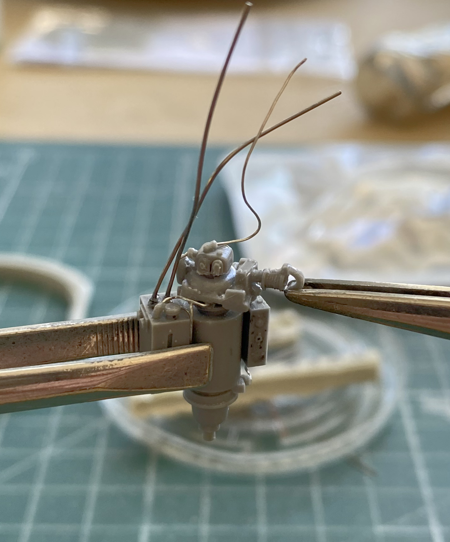
Lots of things were added to the turret basket:
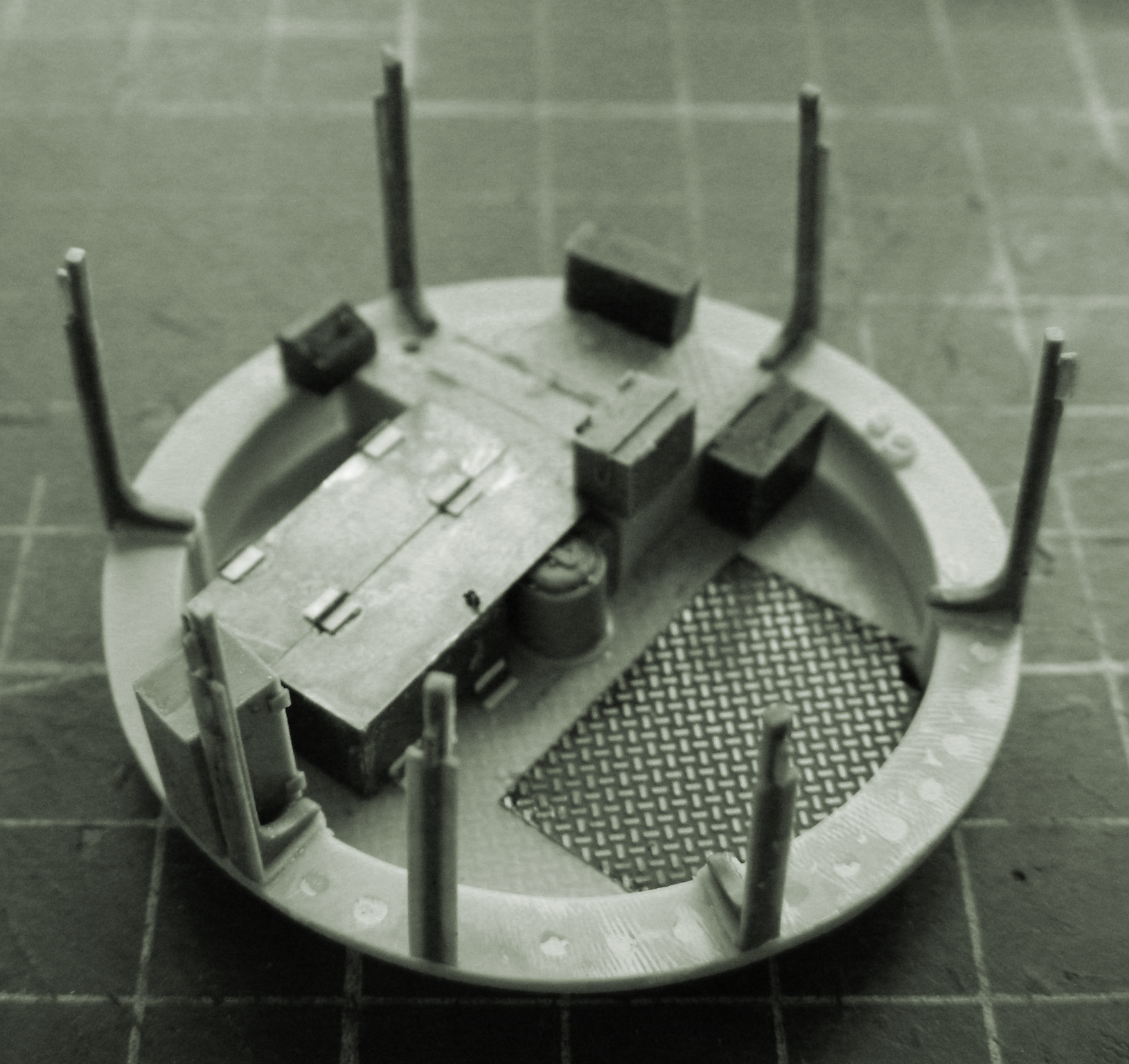
One of the things was a bit or PE that whoever laid this thing out GOT WRONG. There are 9 folds that have to be made. Two of them are attached poorly from the factory. This photo is from the AM set’s directions. Part 10 is poorly, ROTTENLY, laid out:

Between the two larger areas to the right and left, the center part has a large “U” shaped opening. The two larger areas on either side of it are connected to it by ONE TINY POINT on each side. Well, freaking, DUH, you sodding beefwit!! Rotate those two larger areas on either side 90 degrees. Doing it that way would have allowed a much LARGER area to connect those sides to the central part THAT HOLDS THIS WHOLE DAMNED THING TOGETHER. (I suppose it’s…heartening…to see that a beefwit that failed out of engineering school can still find work in the field.)
Fine. This is what they gave me to work with. Fine. FINE. I’ll fornicating work with it, then. I started folding and all was looking good until the last fold (of course). I had an errant hand twitch while hold this thing. (Next person who tries to float this whole “age is just a number” bullshit will be at the receiving end of another “errant” nerve twitch involving my elbow and their solar plexus.) Anyway, the damned thing tore:

And that was the end of that day at the bench!
The next day I’d figured out a fix. A small piece of .005″ (.127mm) copper shim stock, bent 90 degrees, and glued in to serve as a larger anchor point (shown braced to a small machinist’s square to ensure that it is IN FACT at 90 degrees,with the part attached to the resin plate underneath it with double-sided tape to hold it in place):

And while I was in the process of doing that, I realized that just because the other side hadn’t ripped free, there wasn’t any chance that it wouldn’t rip free, so let’s fix that before it also breaks:
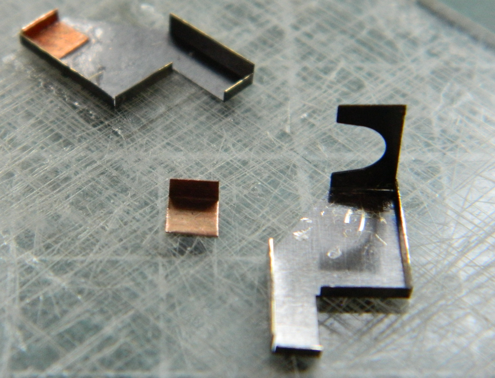
Then not only did I glue it together and attach it to the basket’s bottom…:
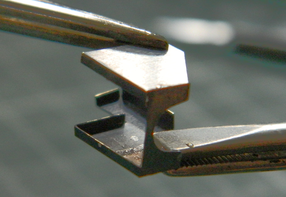


…the whole thing had to be done again because while using a hairdryer to warm the resin posts so I could position them correctly, it slipped out of my fingers and fell. Yep…it landed right on the PE part I’d repaired and came off the basket floor and apart from itself. So I got to do it all again.
‘Kin’ ‘ell.
[So. Do you remember the quiz I’d mentioned earlier? That whole thing about realizing something a bit…late? Here’s where I realized it! This turret basket being of early construction has screened sides. They block the view. In fact, the whole turret basket is going to block the view through the clear panel in the side. Well, well…talk about not thinking something through…sort of like the clear panel in the turret. Being unable to get both sides of that panel parallel, the sodding thing acts like a lens which distorts the view. Lessons learned.]
Clamping proceeded throughout all the above Modeling Magick:
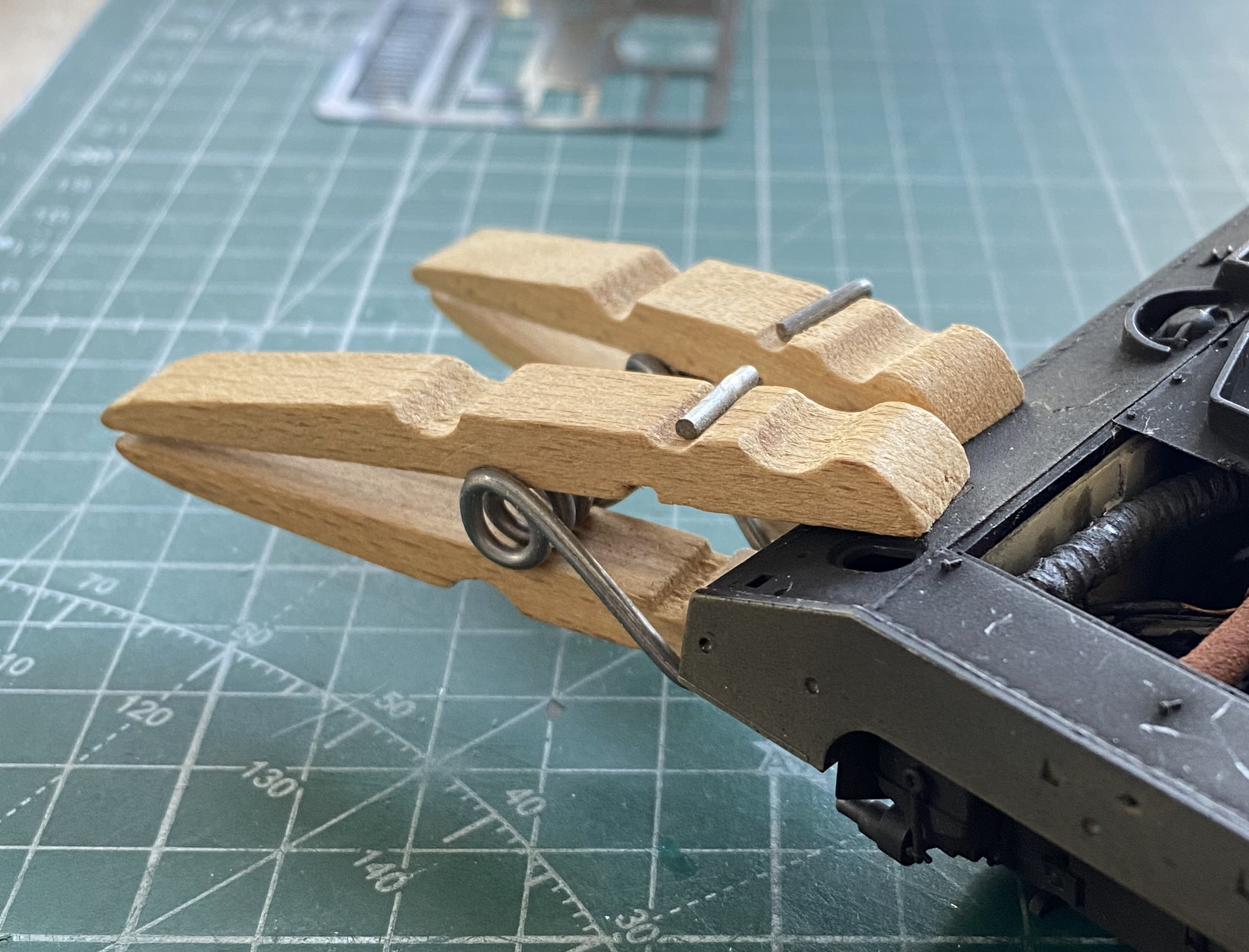
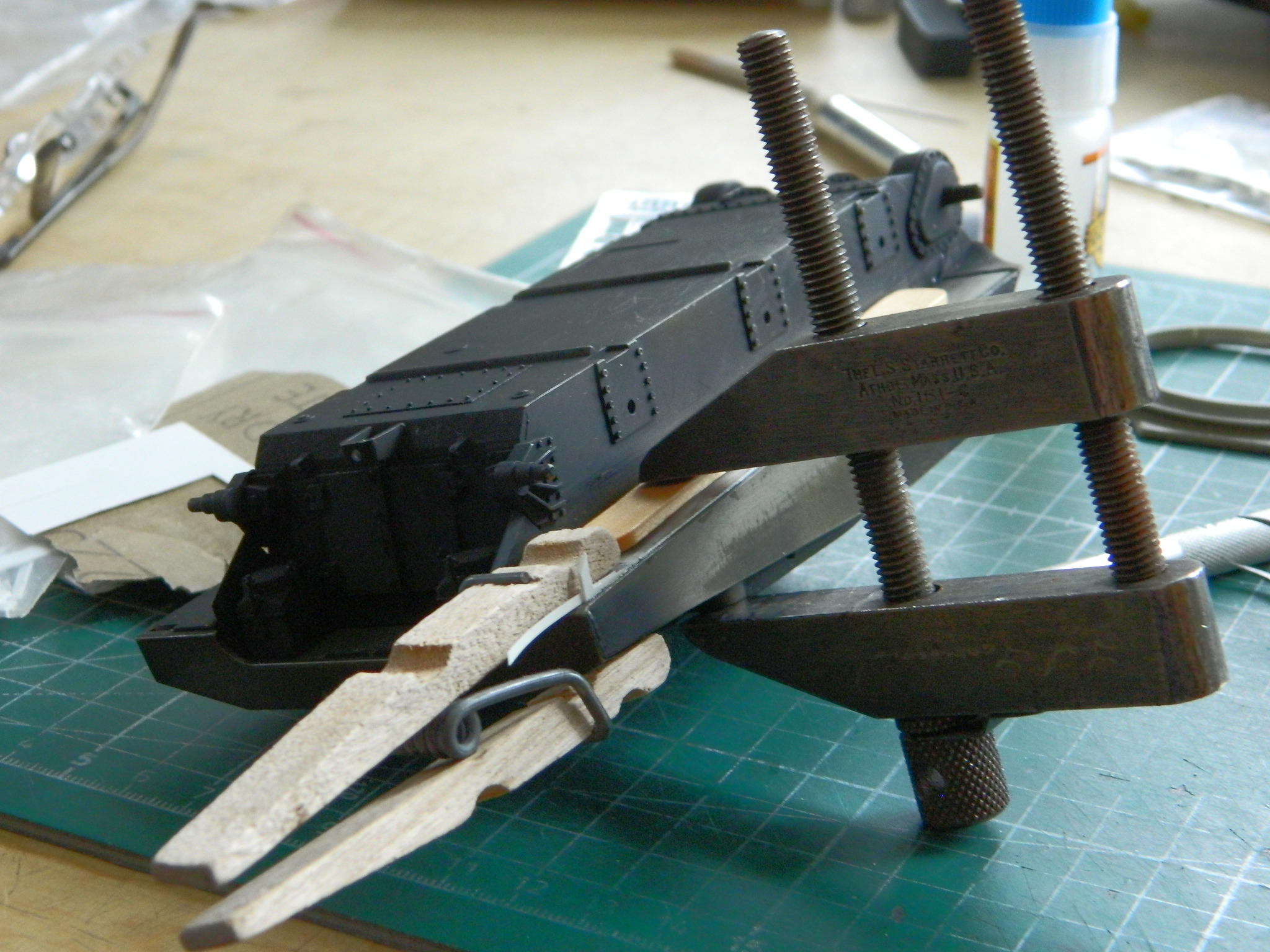
This process was approximate. It quickly became obvious that the best I could get out of this process was a closer approximation of alignment. It wasn’t going to end up being correct. The gaps between the sponson bottoms and bottom of the hull sides were between 0.005″ (127mm) and 0.035″ (.890mm). Most of the sponson bottoms are resin, the extensions at their rear are styrene. To fit scrap styrene into the gaps between resin and plastic required me to glue the scraps to the inside of the hull sides using styrene cement and between the scraps and resin with superglue. Then the clamps were removed, repositioned, and the whole thing done again. And again. Each side required four clamping sessions. This is the first side in process:
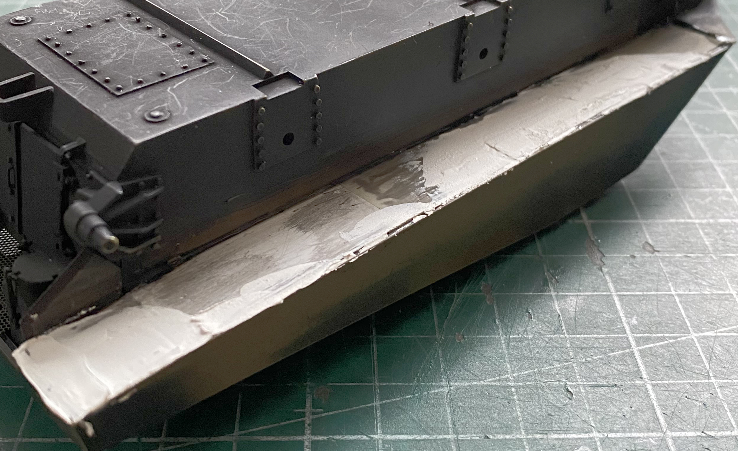

I remembered to take photos of the second side to show what I was dealing (successfully!) with. Gaps and a razor blade to apply pressure to the outer side where the scrap is pressed against the hull:
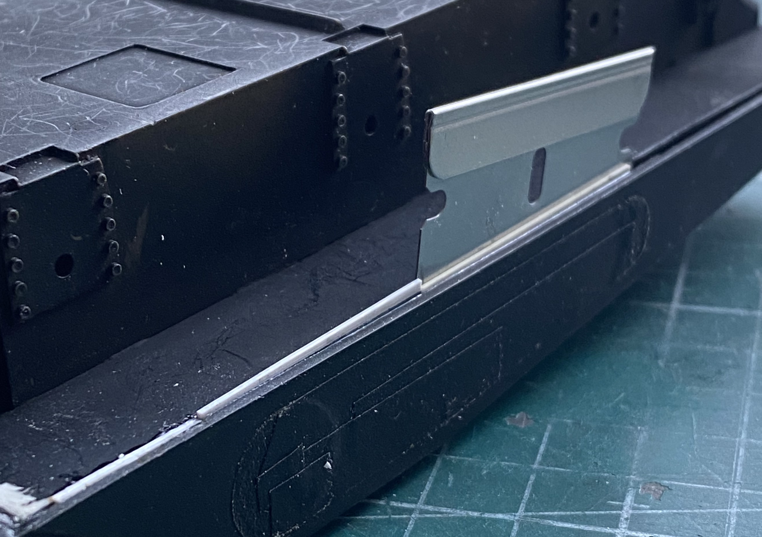
A better look at this gap (the other side was worse, if y’can believe that):

Not only were the sides out of alignment laterally, they were also out of alignment vertically:
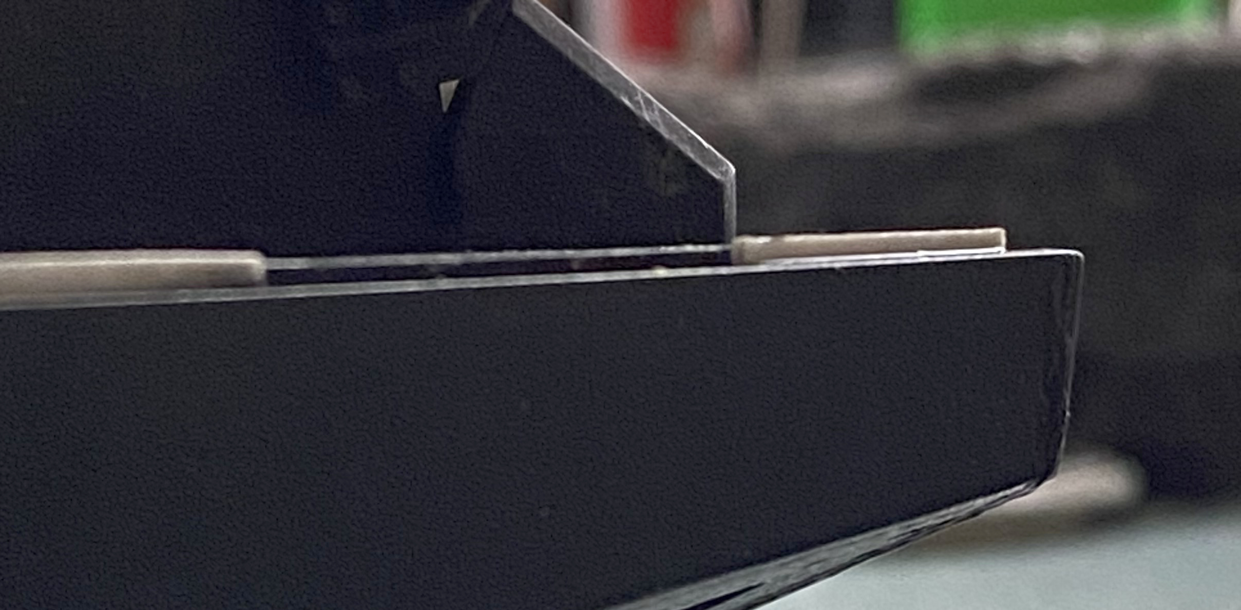
Clamping under significant pressure (I figure when the thing starts creaking it’s time to stop adding more pressure) and lots of filing (filed because the surface is supposed to be flat and a file’s face is flat), and several sequential applications of putty along the entire lengths gets to this:
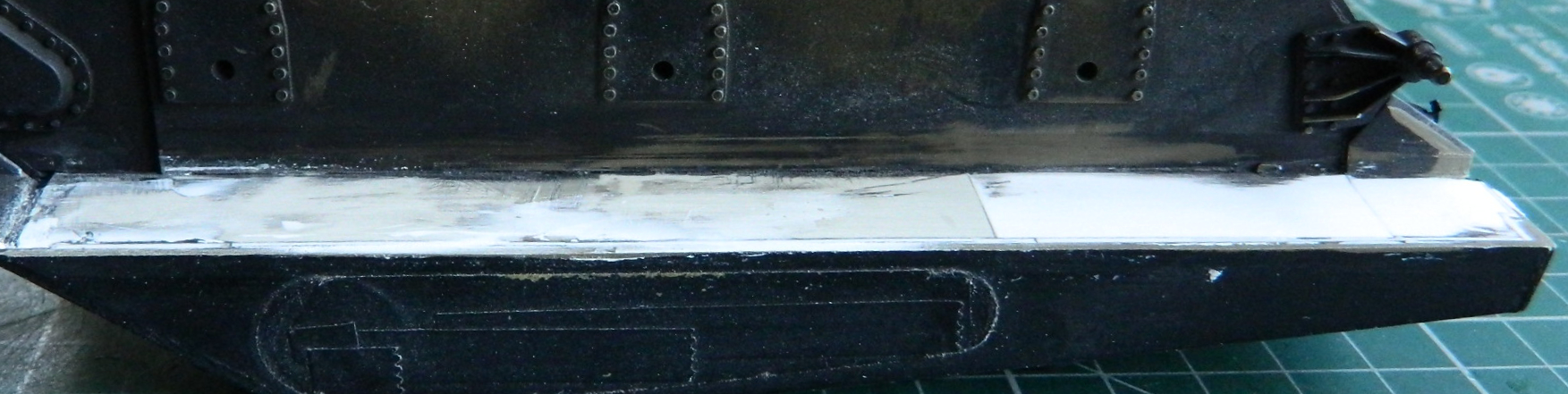
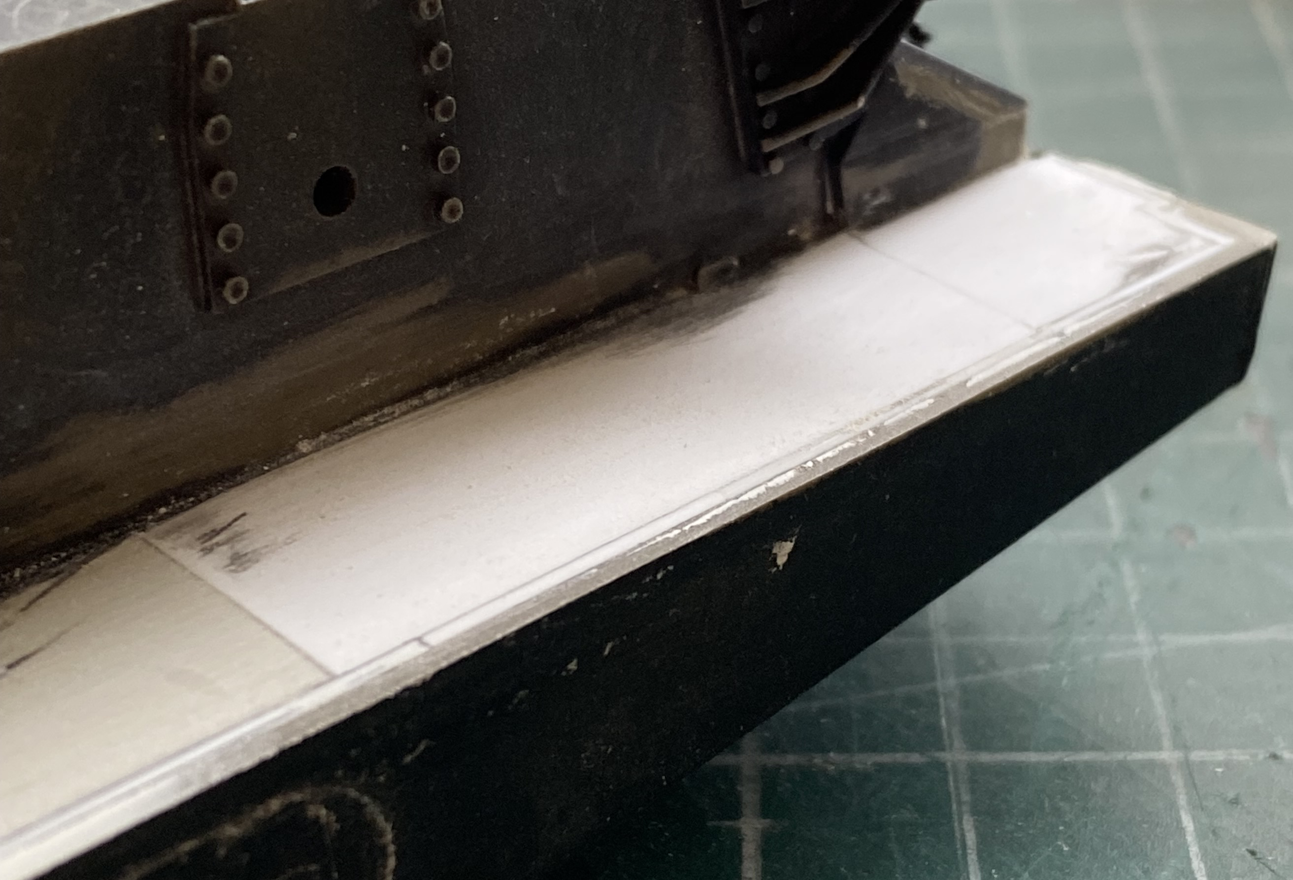

The sponson bottoms are supposed to be at 90 degrees to the lower hull sides. They aren’t. The sponson bottoms are supposed to be flat. They aren’t. But they look as if they are, and this is now before any application of paint. Both the lower hull and the sponson bottoms will be mostly flat black with a very faint misting of OD Green. Suspension, bogies, road-wheels, and tracks will fill most of that space. The end result (which is the goal, remember) will be that the sponson bottoms will look like they’re at 90 degrees to the hull bottom’s sides and look like they’re flat.
And that’s what Modeling Magick really is…making something look like something it won’t ever be.
M4 (Tamiya) Build #6 – Finishing the Engine, Engine Bay, and Discovering That Another Clever Idea for the Turret Simply Will Not Work, and Then Figuring Out What to do Instead
One thing modelers should get used to is after developing a build plan, being able to modify or abandon that plan selectively when events show that the original intent is just a dumb idea or simply cannot work. When I fitted the rear engine access hatches, I got the clever notion (proving that once again perfection eludes me) to have these doors operational. So I did that. Having done the work and spent the time to do that, I then decided that “operational features” is a 60s gimmick that I shouldn’t do. In the following photos, the hatches (which I wish I’d seen weren’t exactly accurate before I superglued the hinge pins in place) aren’t quite accurate. But, having already pulled that trigger, I dug out my Big Boy Knickers, donned them, and kept going:
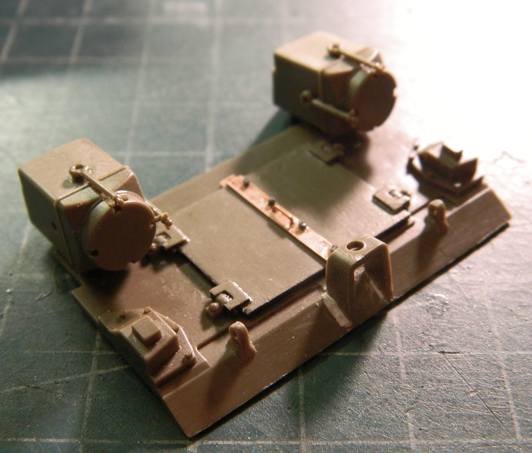
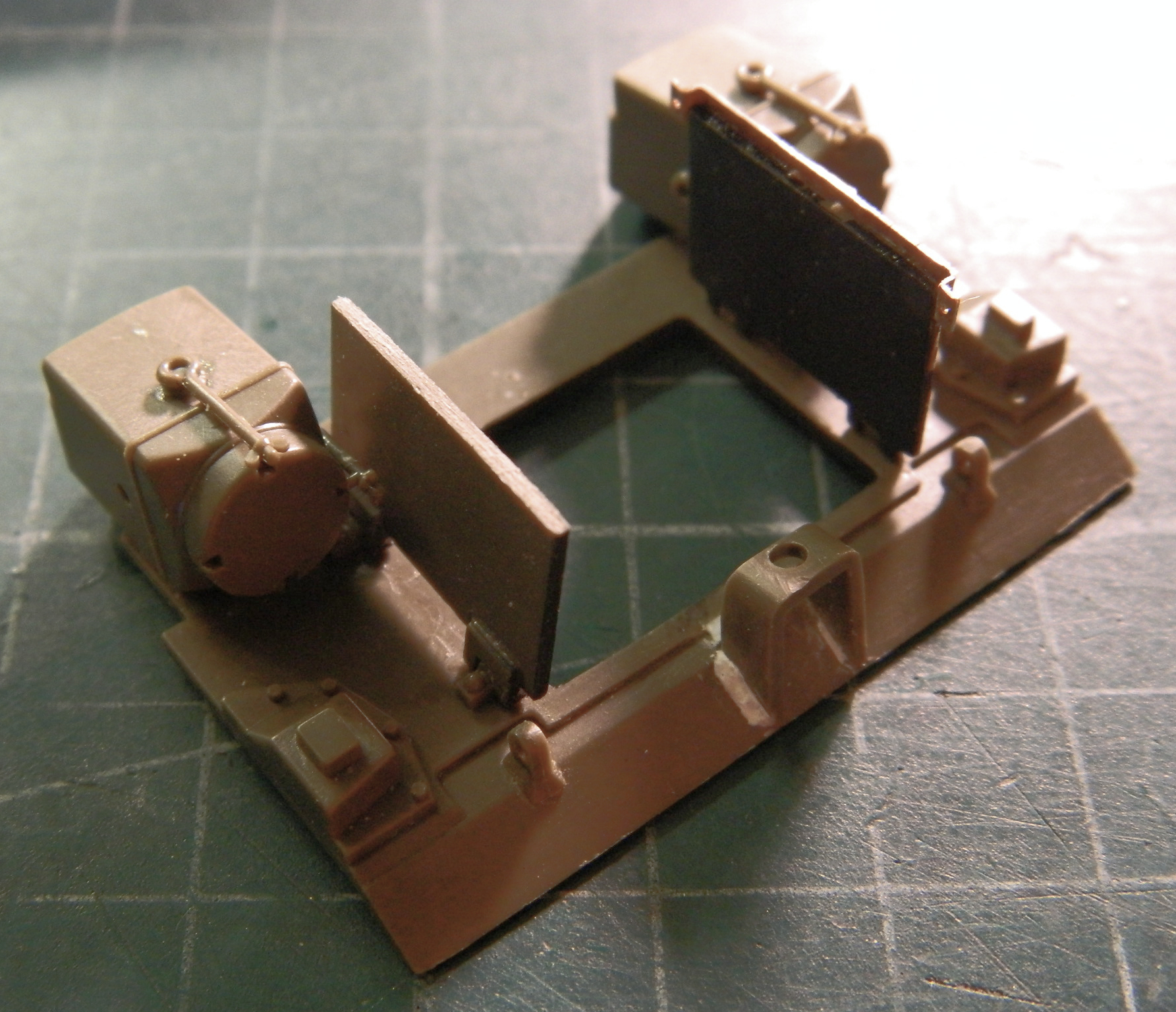
Once the hull is painted, I’ll glue these hatches open. I’m leaving them as they are for now because though putting masking tape on the inside to keep the OD Green off the engine could be done now while this subassembly isn’t attached, getting the tape out once the part is glued on and the exterior is painted would create a problem I don’t care to deal with. So once it’s painted, these hatches will be glued open and bugger the “operational feature.”
Before gluing the engine in, I added stains and wear using pastels, enamel washes (supplied from the bottle of contaminated thinner I keep for just this purpose for its glad-I-don’t-have-to-match-this-color hue). Some of the wear was done with Humbrol Steel, some with silver pencil.
It’s at this point that the engine is glued in. There are more bits to add, but having the engine out where these bits are exposed would mean that they’d break, I’d do a lot of cursing, and they would have to be repaired and reattached…often. Gluing the engine in place now will create new challenges but the new challenges will be easier to surmount than riding the install-break-fix-break-fix carousel while my blood pressure spikes. Glue the this thing in (FINALLY) now:
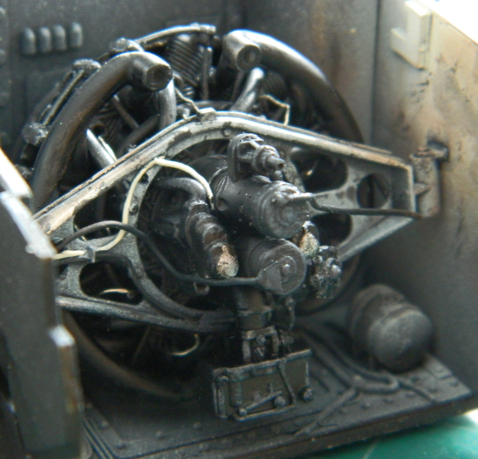

There a several really small, thin, DELICATE, lines and hoses that get added now before the rear hull is glued on. (Later there will be more bits added that require the rear hull to be in place first…and my goodness ain’t I looking forward to that!) This little…gem…is comprised of three STD parts (no, not a dose of spirochetes but small-thin-delicate), one of which had broken (and fixed…twice) before I even removed it from the sprue. And since each part needed the two other parts in place before it could be added…where the hell to start?! (This is one of those times when four hands…all under my direct “control,” would have made this quicker and a lot easier):
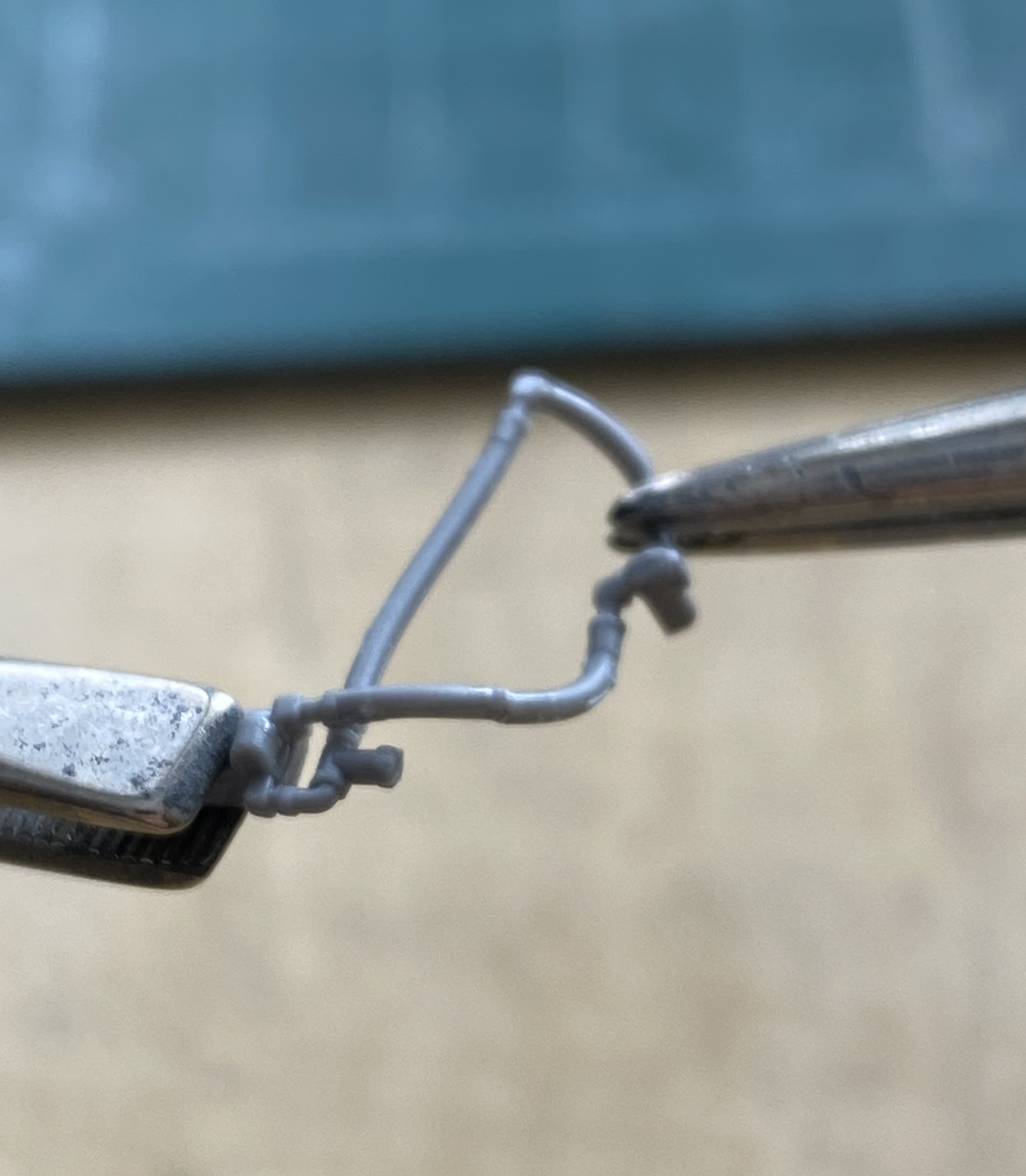
While I was waiting for glue to set up, I adjusted the carburetor intake ducting to meet with the air filter housings. I was very surprised at how close they did match, though some bending (with the requisite entreaties to My Big Friend in the Sky) (known as “prayer” to you believers). Once I had them as I wanted them, I glued the ducting to the carburetor (the rear plate to which the air filters are attached to is just held in place with tape because this is the opening salvo of what turned out to be several days worth of work):

The exhausts and mufflers are prominent features in radial engined Shermans (and derivatives that also used the radial engine) and sit directly under the access hatch. Fortunately, styrene tubing of 1/8″ (3.18mm) is a perfect match for the diameter of the exhaust manifolds. I used a couple of lengths for that, relying on my Mk I Eyecrometer for length. As subsequent work showed, it’s spot on (a novelty I found refreshing):

Around these tubes I needed more tubing for the mufflers. What would be perfect is if I had a tubing that would just slip over these so that I didn’t have to go through the machining process to get the parts accurate. I was most pleasantly surprised to find out that 3/16″ (4.76mm) worked if I drilled out the center to allow sufficient room to slide over the smaller tubes. I attached the smaller tubing to the manifolds temporarily with white glue:
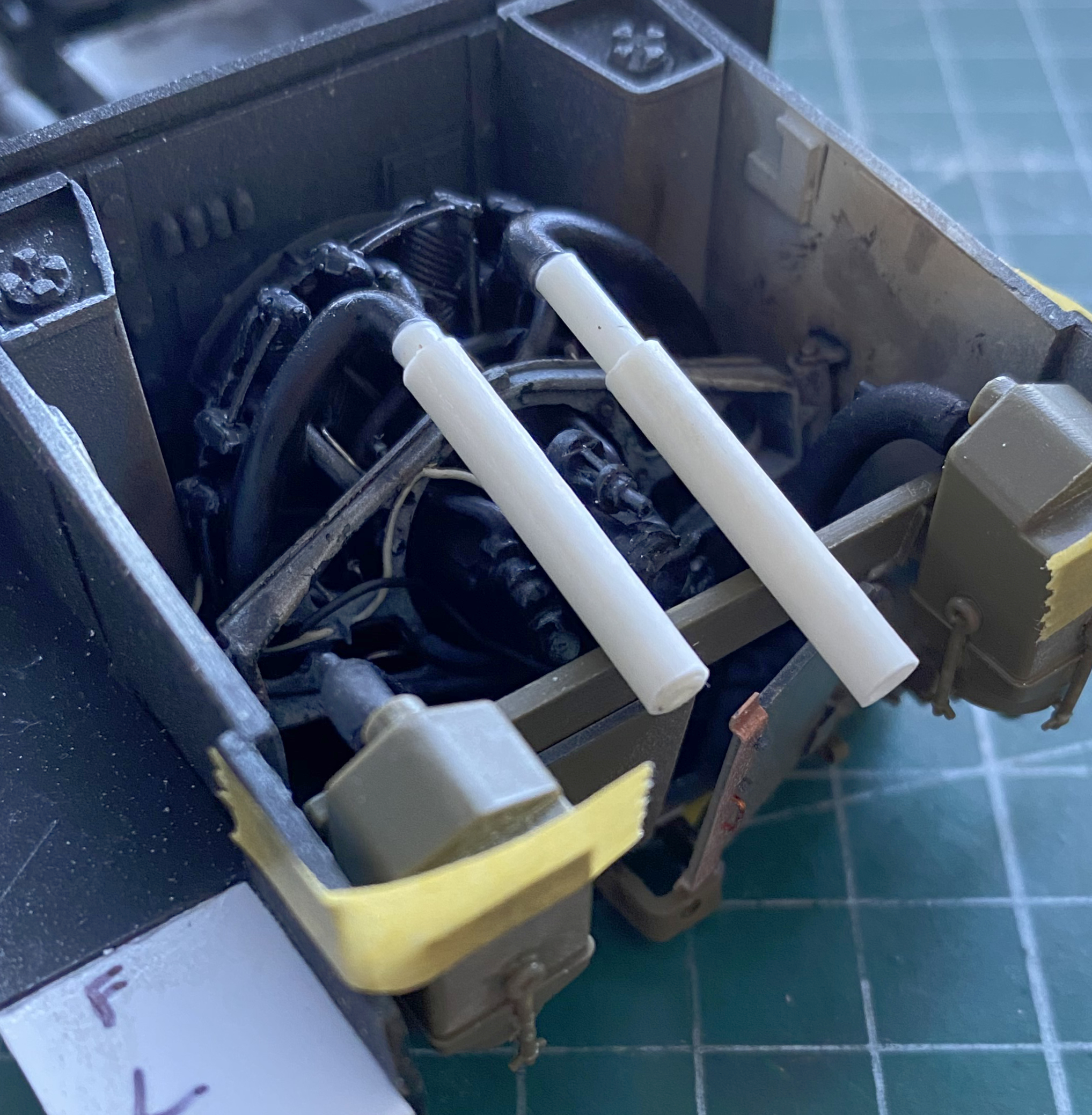
Dry-fitting the upper hull showed me that there is a large opening between the top of the rear hull and the underside of the upper hull. Well…ain’t that interesting. The question became, what the hell did they use to fill that gap? Many fruitless hours were spent online trying to find a reference photo. Okay…fine. What would I use to fill that gap? (That gap has to be filled. It’s large enough that an enemy infantryman could easily drop a hot grenade into the engine bay and that’s never a good thing for the tank or its crew.) I decided that I would extend the rear armor up to contact the upper armor, but that’s not what was done. Okay, let’s use a piece of PE screen, with cutouts for the air intake ducts and the exhaust pipes:
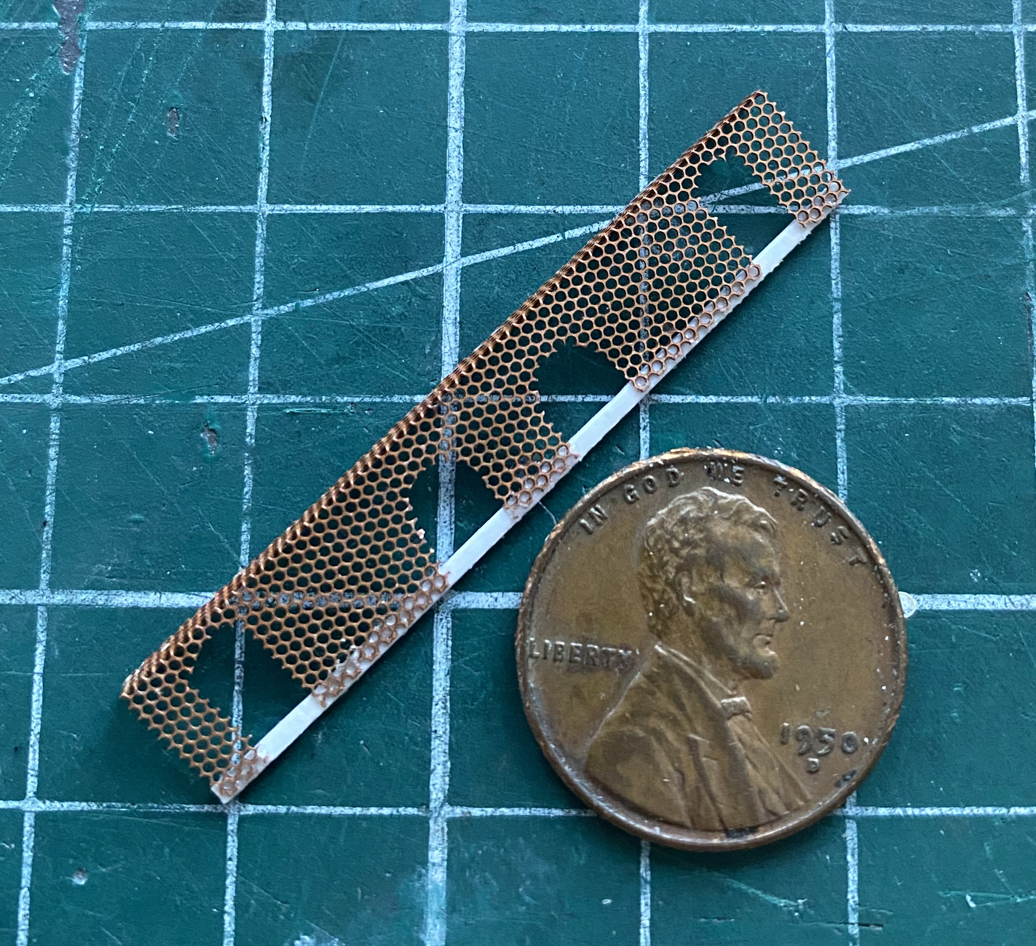
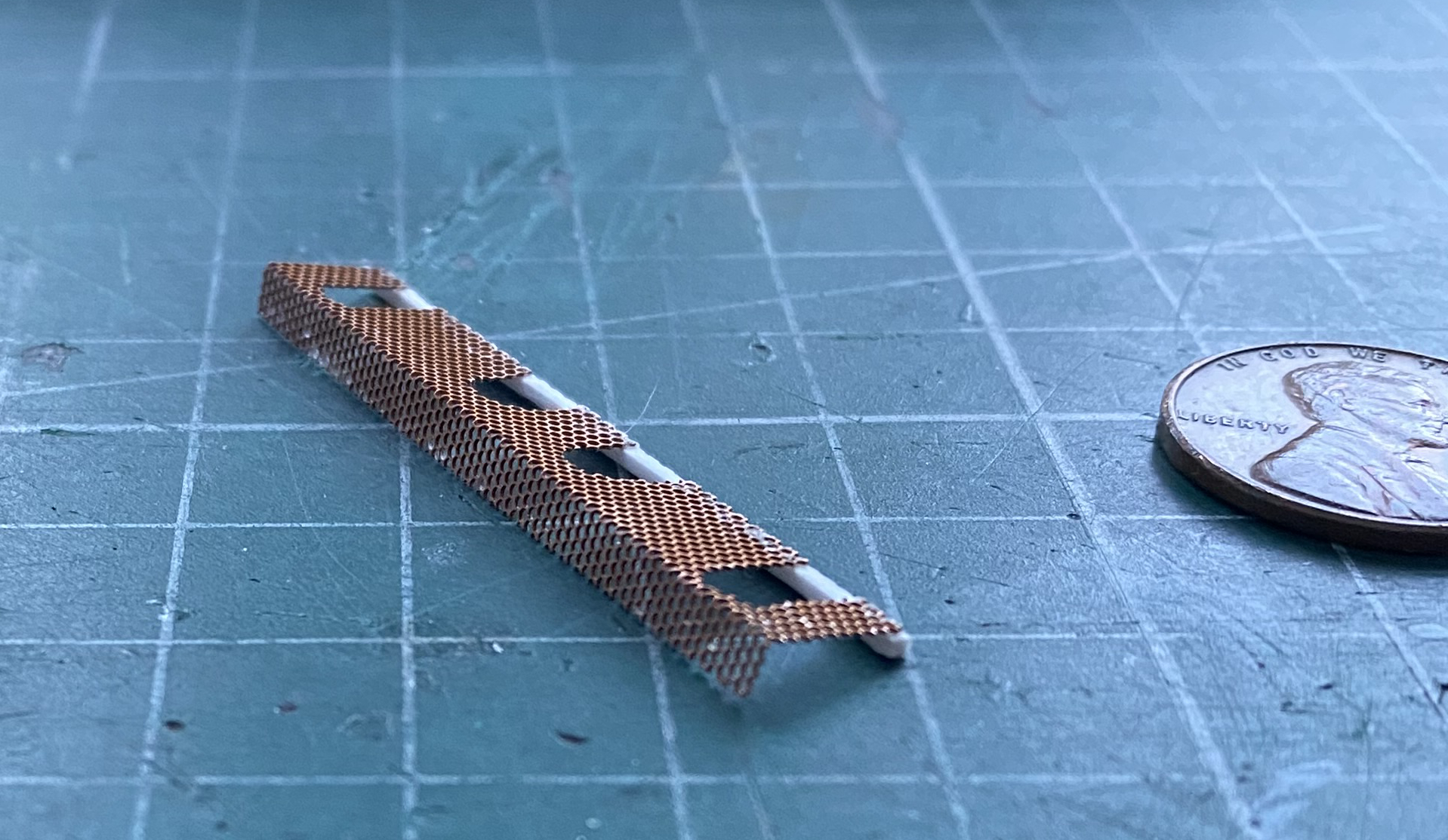
At this point I decided to dry-fit it and see how it fit…which it did not. The air filter housings plug up both sides of that gap. ::bangs head on desk:: Okay, let’s use a template this time:
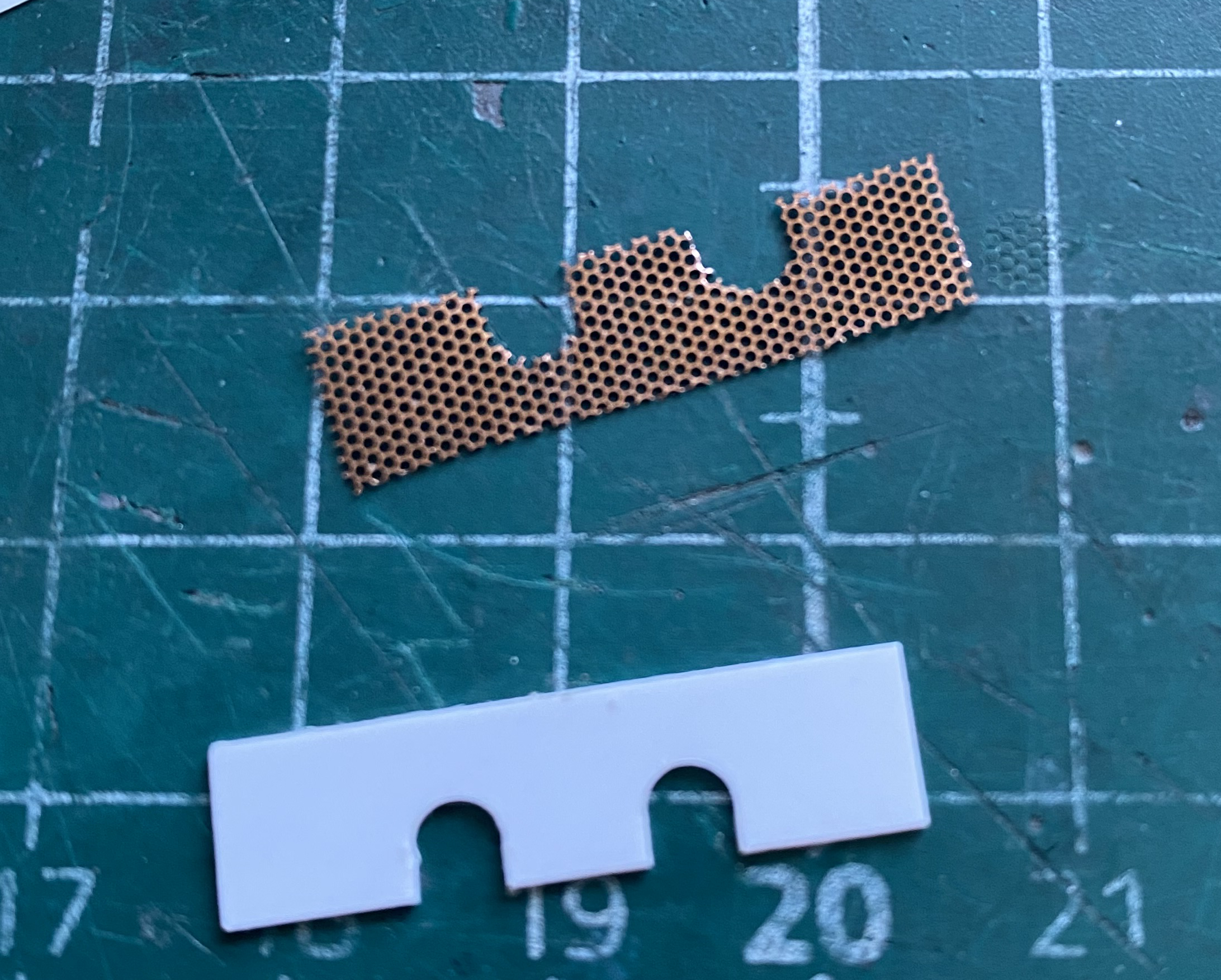
And that seemed to work fine (please note “seemed to”…):
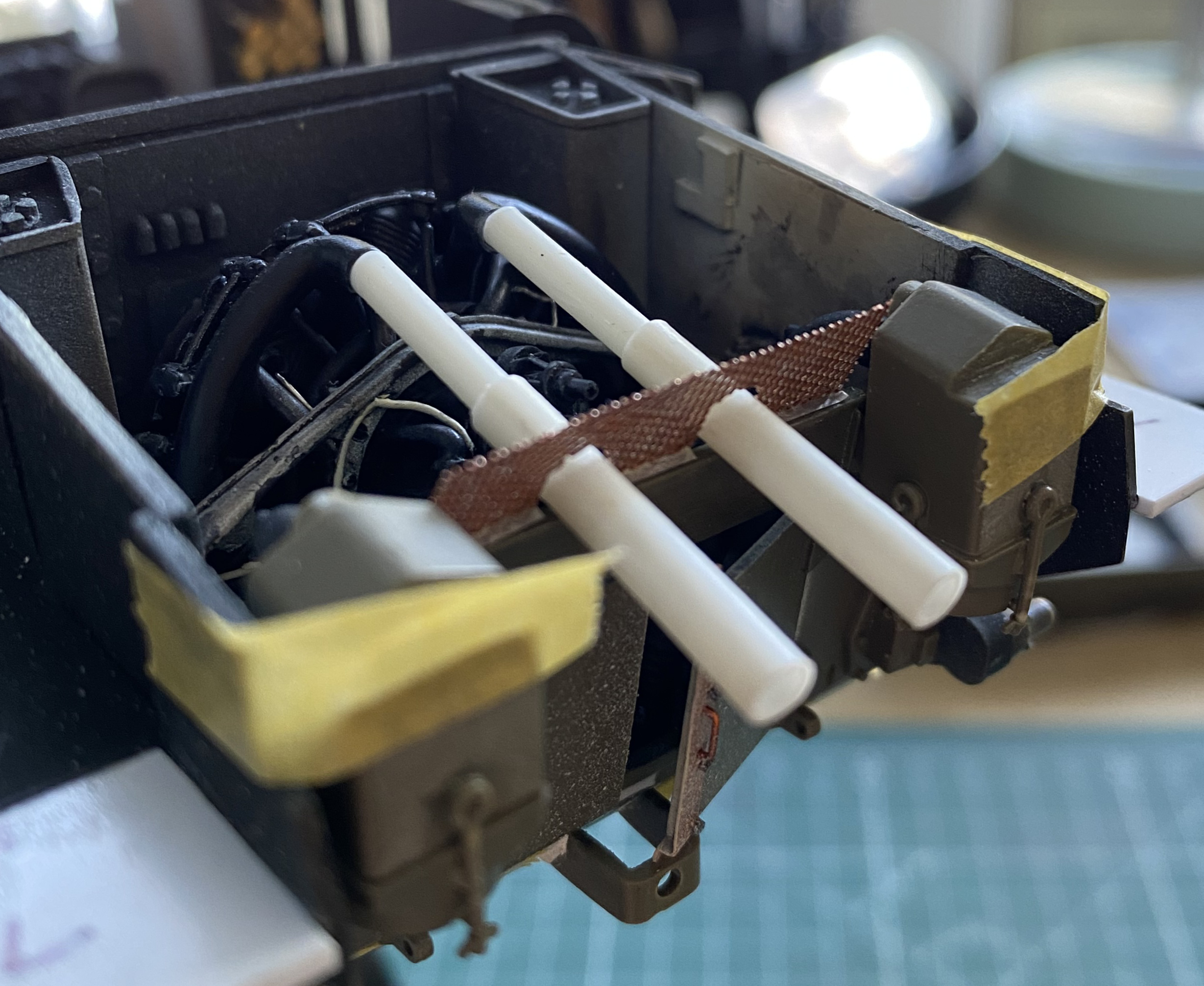

I don’t remember why I was online looking at M4s (maybe because I was building one…I don’t know) but I found a photo, a lousy photo, but a photo nonetheless, of that area of a Sherman and how about that! There’s a screen there! Since every silver lining has a dark cloud wrapped around it, the dark cloud in this case was the orientation of said screen. As you have seen, I oriented my notion vertically. ::sound of raucous buzzer:: Nope. That screen is supposed to be horizontal. (More banging head on workbench followed.) So I made another one, using Archer’s resin rivet heads (not that anyone will freaking notice, y’know) on the added plastic strip:
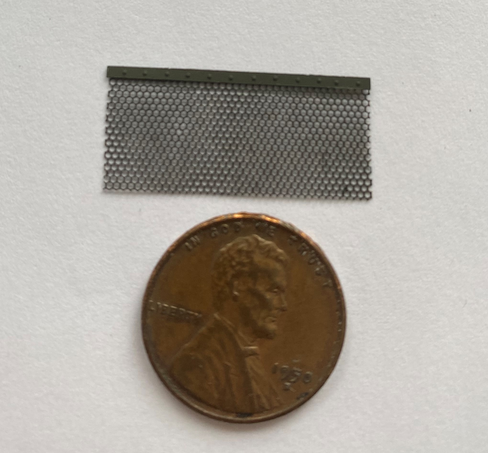
The screen goes under the mufflers with just the turned-down exhaust tips protruding beyond it. That will require me to cut the opening for them, but that’s a task for later on.
The next task, because finishing the engine bay is the driver, now, is making both intake ducts for the air filter housings. Those ducts look like they were constructed in the same manner that home clothes dryer vent ducts are; spiral wrapped with something that looks like fabric. Yes, I’m pretty sure it wasn’t fabric (heat, petrochemicals, etc.) but that’s what it looks like so that’s what I set out to replicate.
I started with more 3/16″ (4.76mm) tubing and bent them using heat (and anatomically impossible threats). Only having two hands, sometimes one must be creative about holding something in place to be able to mark it:
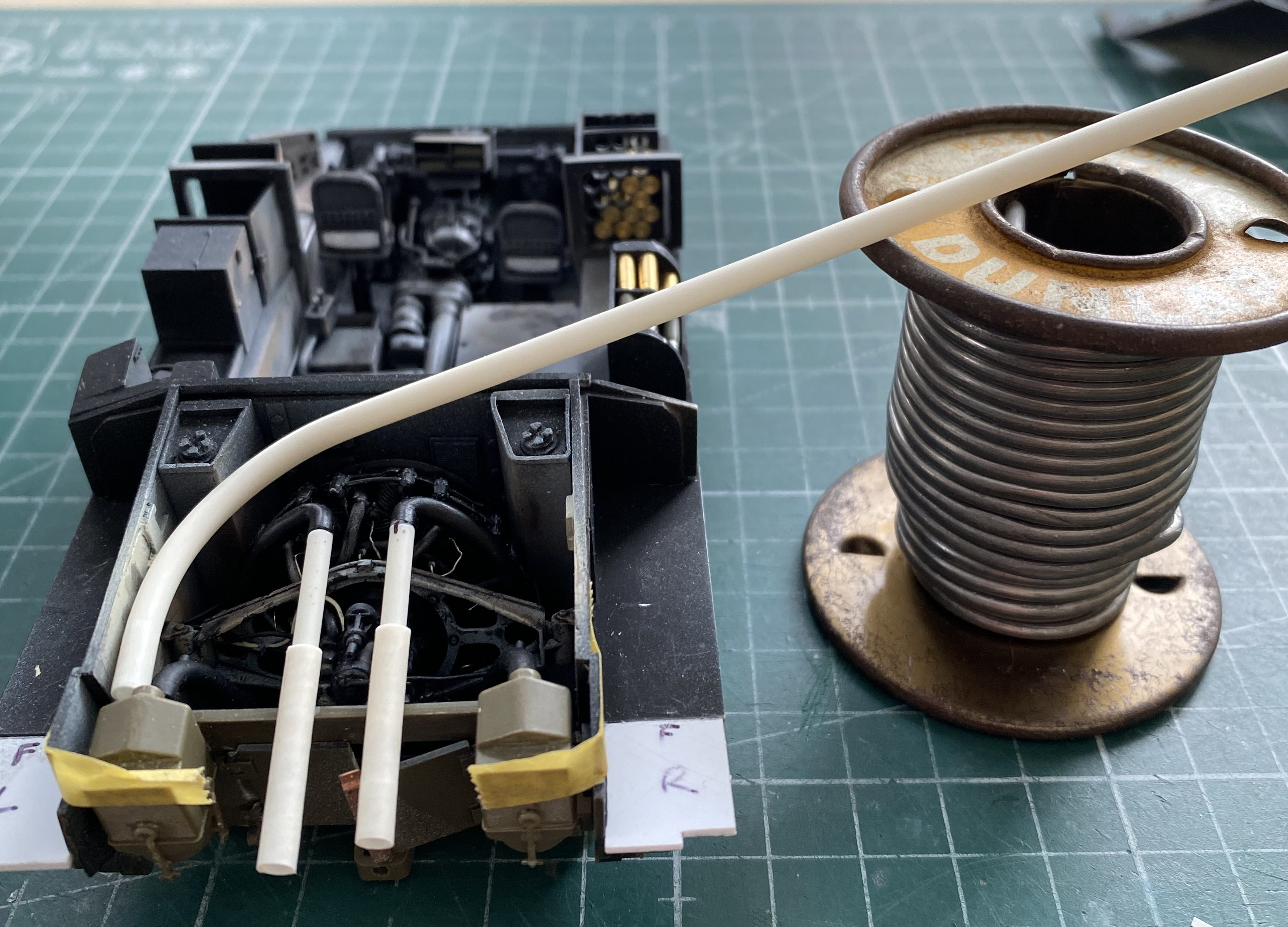
Having accomplished that seemingly impossible task (which could be any modeler’s epitaph), it was time for the application of heat. It took a couple of tries for me to consider using the tubing’s propensity for straightening out (don’t ask me how I found out that you canNOT anneal a styrene tube) in my favor by bending it seemingly too far, applying heat (another thing I’d rather you did not ask was how I figured out to use tape to hold it…but don’t worry, as if you would, the blisters are just about completely healed), and letting it cool resulted in just the amount of curve I was after (also…use a hairdrier, NOT a heat gun):
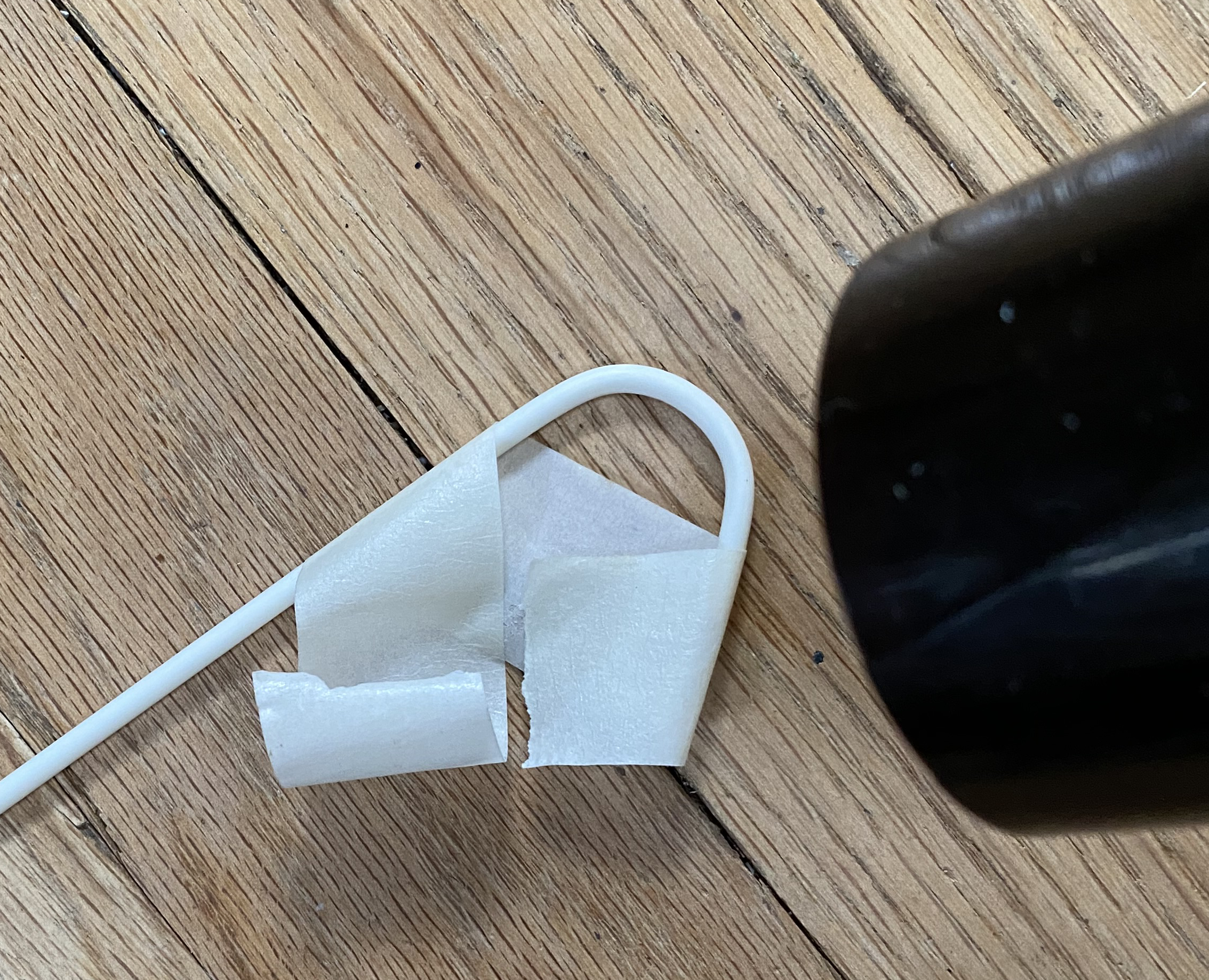

With the blanks formed (and all the melted styrene off the bench, floor, AND MY LAP cleaned up), I used 22awg wire for the spiral wrap. If you try this method, use a drop of superglue for each loop and then you can run a bead of superglue the length of the wire (this time I annealed the wire after I rediscovered that the wire won’t stay wrapped long enough for the superglue to even be applied):

With the spiral in place, I cut textureless paper towel into a strip. For the first one, I applied diluted white glue after I’d wrapped the paper towel around it. For the second one, I applied the diluted white glue with a brush as I was doing the wrap. The second method is MUCH easier and resulted in a better looking finish (these photos are from the first one I did):
A hairdrier dried them quite quickly (and didn’t result in more puddles…with paper…needing to be scraped off anything). You can see the difference between the first, awkward, method and the second, much cleaner, method. The first one is on the left:
With the glue dry, I used my “gun metal” paint mix, Tamiya X-18 Semi-Gloss Black (5 parts) and Tamiya XF-20 Medium Gray (4 parts), to paint them:
I set those parts to the side and went back to the tedium of gluing the STD lines back together. Sometimes one must get inventive aligning things:

And you can see below how well that didn’t work:
So I tried again, this time off the sprue:
It worked about as well as the first attempt didn’t:
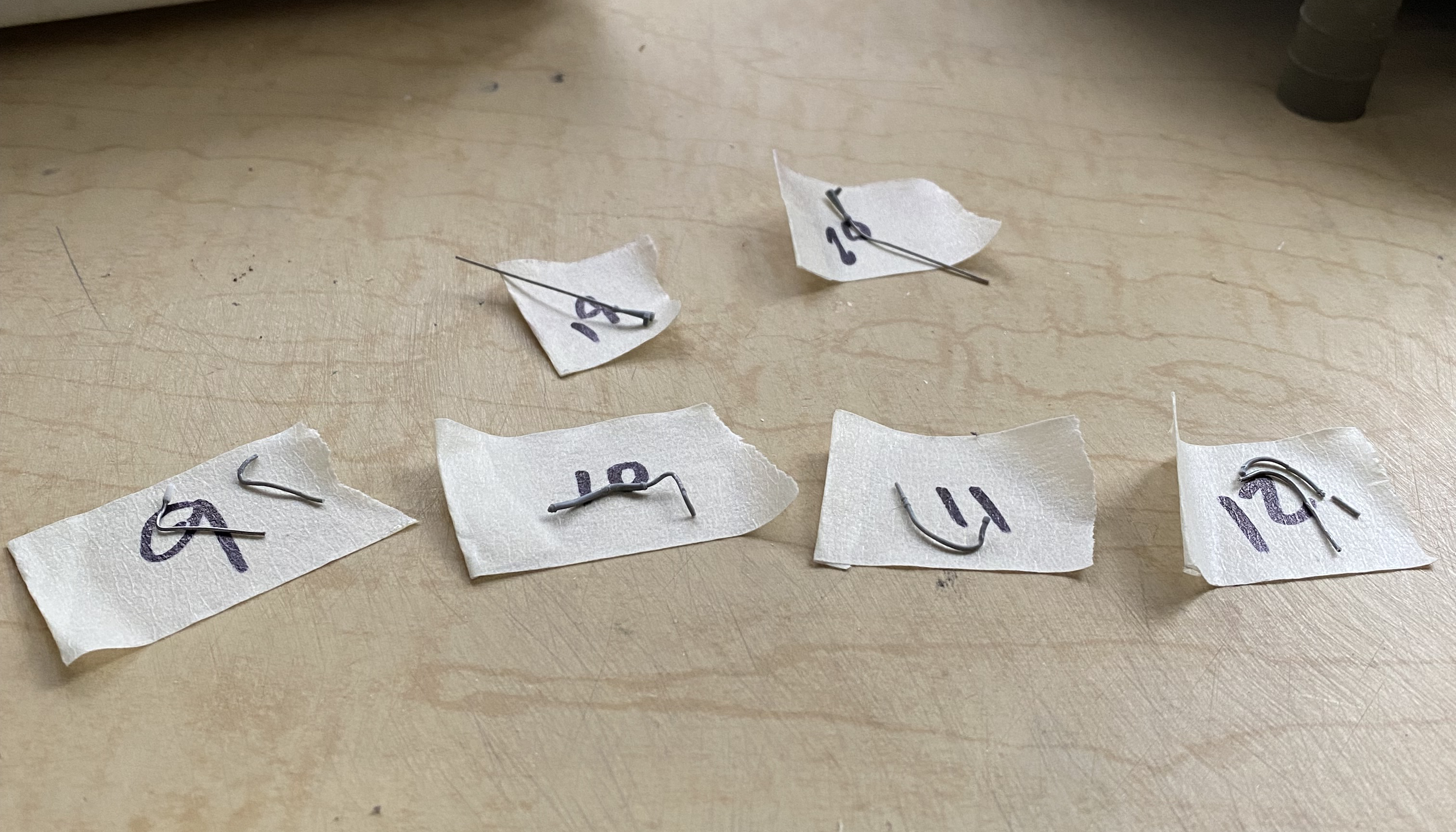
So why did I waste so much time on this minutia? Because I liked the fittings that were molded onto these STDs. By the time I got to the point where I realized using these parts wasn’t going to work, I realized that I should have just used solder and replace them all…which is what I ended up doing. Near the top right of the photo below, you can also see where I added the tips of the fire suppression system:

Earlier variants of the Continental R975 had a breather/filler cap sticking up from the top of the crankcase. I forget where I’d read it, but after about 200 hours these engines were pulled out and replaced. I figured by the Normandy Invasion (the parameters of this build), the original engine would have been several engines ago. So I modeled this engine after a later variant. Instead of the breather neck, later engines had PCV lines between the air intakes and the crankcase. Those lines can be seen below as copper lines. Once I had the PCV lines in, I added the air intake ducts to the air filter housings:
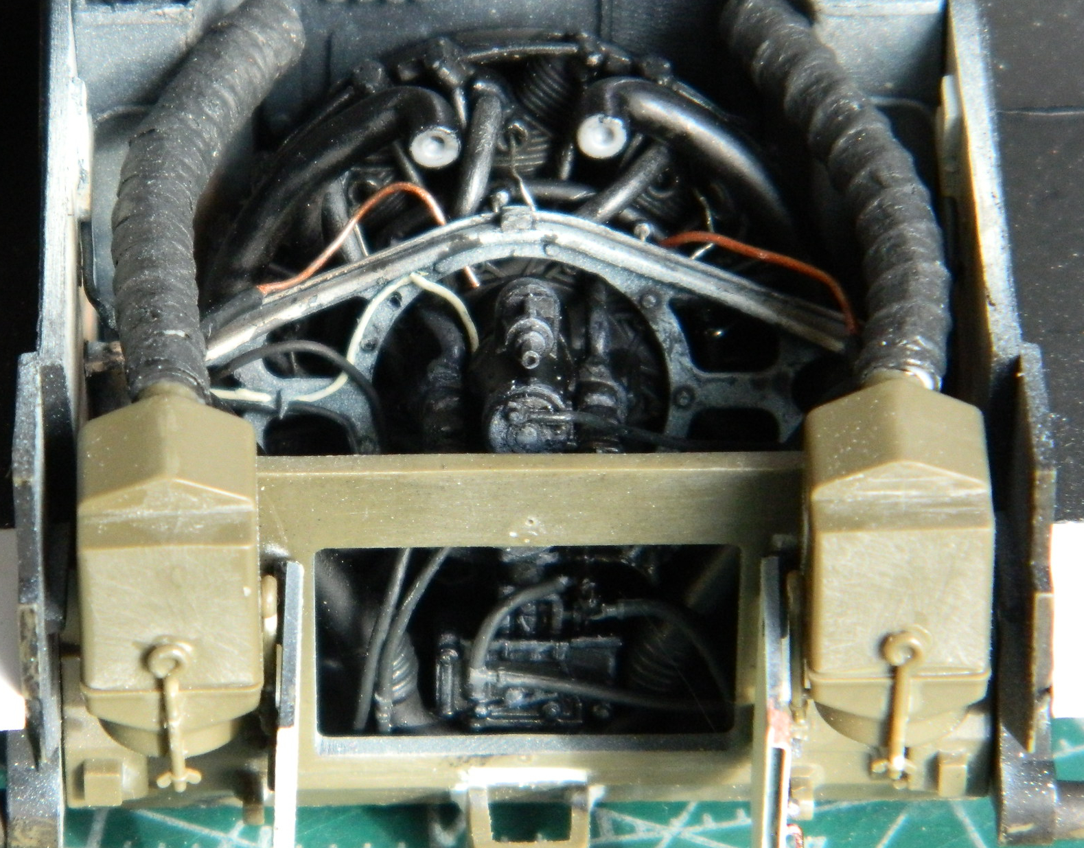

The cat’s cradle lines assembly that needed four hands to do easily was added as were two descending lines to the left, and I mixed ivory black and white oil paints to create a color used to dry-brush the highlights onto the engine (which you can also see in the previous two pictures, just not quite so evidently):
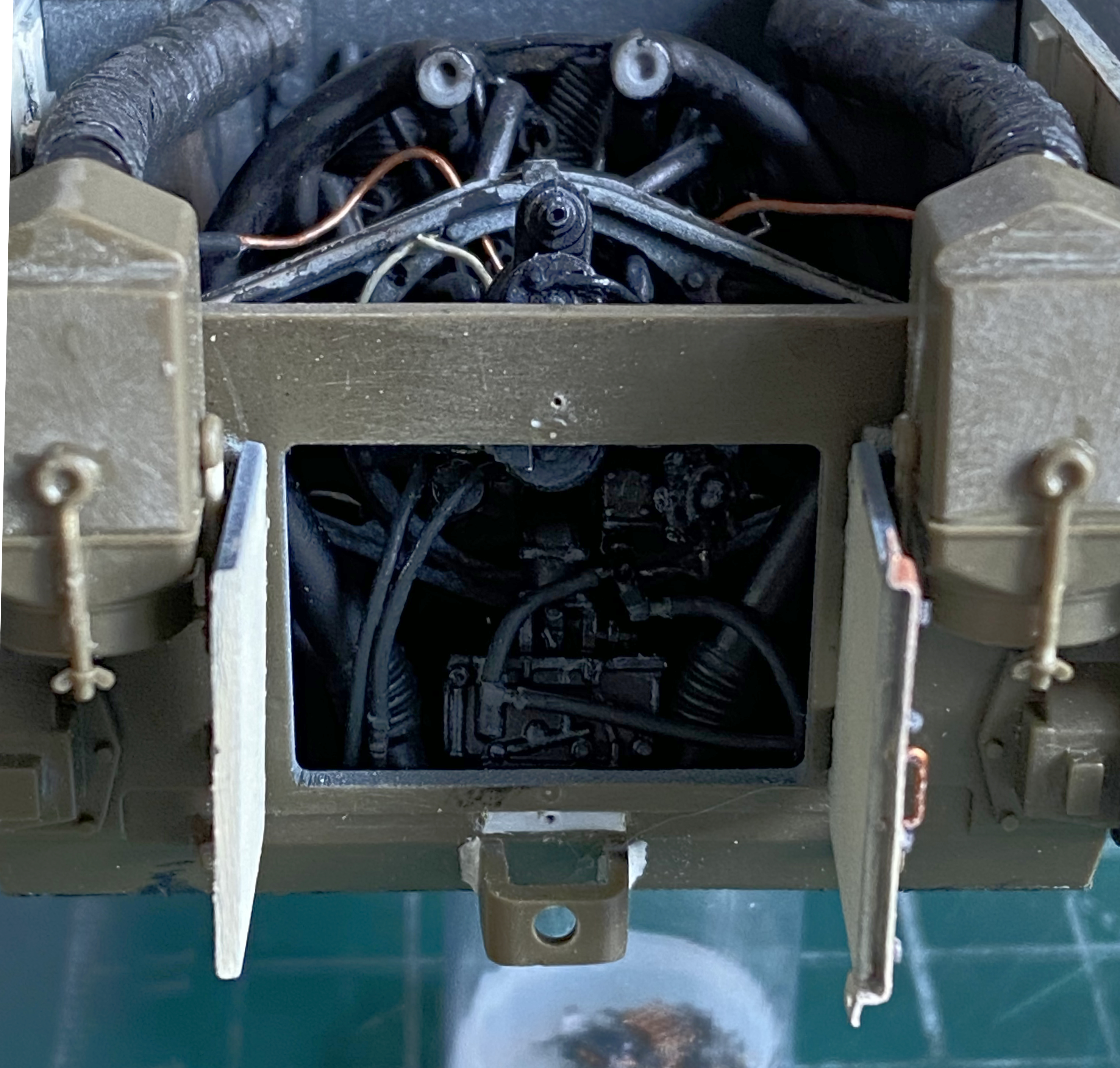
I again wanted to see how much of the engine would show with the hinged engine cover open. Not much. But I know that at some point at least one person will take out their flashlight, bend down nervously close (for me), and look under the bolted-down engine cover:
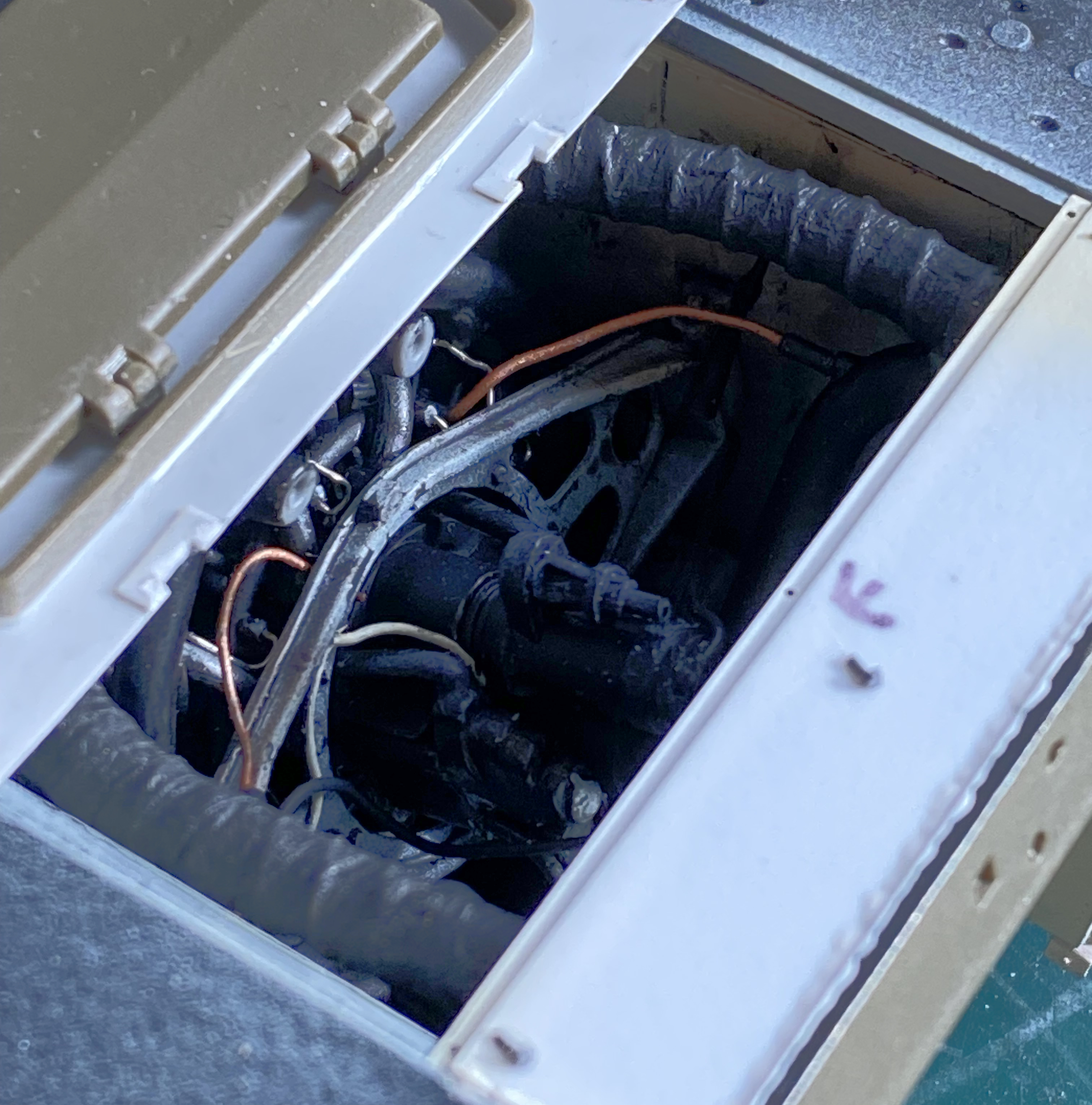
Now that most of the engine parts have been added, it was time to add the exhausts pipes and mufflers. References have shown me that the mufflers seemed to rust more than the pipes leading into them were. I wanted to add the rough texture to the mufflers that I have seen while spending far too many hours on my back under a car wondering what broke (and wishing I could afford to have someone else under there instead of me). I wanted to coat the mufflers with superglue and roll them in baking soda. I really don’t like supergluing my fingers to each other (no matter how many times I manage to) so I made an armature/axle from a solid 18awg wire, rolled the mufflers in a puddle of superglue, and then rolled the gluey mass in baking soda. It’s not evident but at the top of the aluminum foil I used as my pallet there’s a puddle of superglue with the baking soda below it in the photo:

It was at this point that I realized that the two rings that go on each muffler had been forgotten. I used solder (I forget what size) to add them. The ends of the exhaust manifolds that these will attach to aren’t exactly square which required me to trim the smaller tubing to fit properly. So that I got these added correctly, I marked the top of each one with an “L” on the bottom of the one that doesn’t go on the right:
I used Italeri Flat Rust #4675AP thinned to something substantially less than the putty-like viscosity it came with and used a brush to apply it (because after wrestling with the Vallejo Aged White, I didn’t feel like cleaning my airbrush for another hour). It looked good before it dried, whereupon it became more red than I wanted. I’ll mute that color with pastels later after I’m done handling things. After this photo was taken, I painted the pipes before the mufflers Tamiya X-18 Semi-Gloss Black:

I used the jeweler’s tweezers (self-locking and on a pedestal) to align the exhausts and hold them in place while the glue set up. The second photo below shows how RED these things turned out:

After the exhausts were set, I added the exhaust tips. I was pleased that the fishtail exhaust tips that came with the kit were good enough to use without much modification. They were molded with the intent that they would be glued to the underside of the upper hull where it overhangs the rear armor plate (and y’know…Tamiya never did supply a part to deal with the gap where there’s supposed to be a screen…but then again, they also didn’t supply any sponson bottoms, either). I cut them apart, removed the mounting stubs where they would glue to the underside of the upper hull, and after testing for fit relative to the upper hull (just right), glued them to the ends of the mufflers:
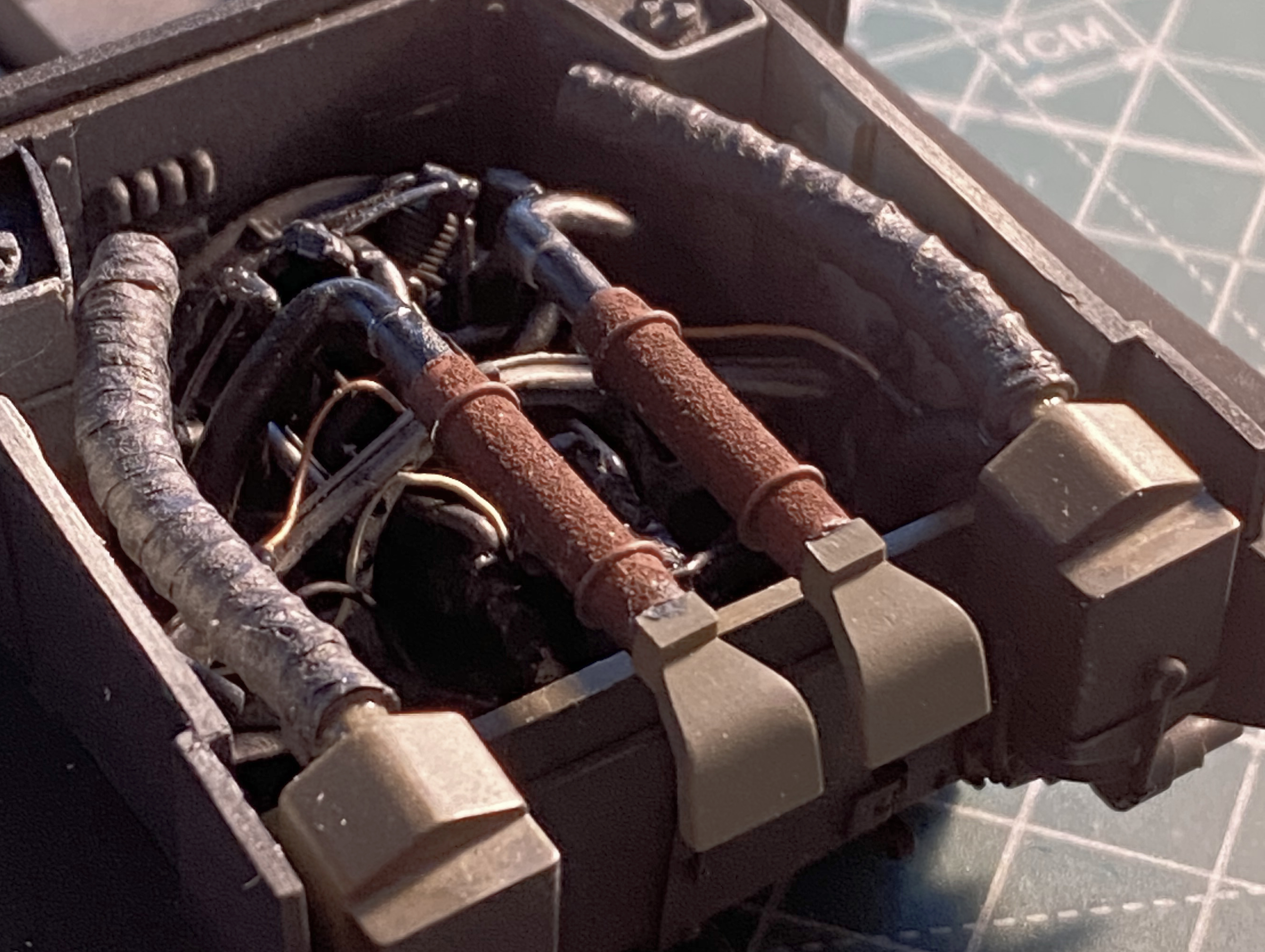
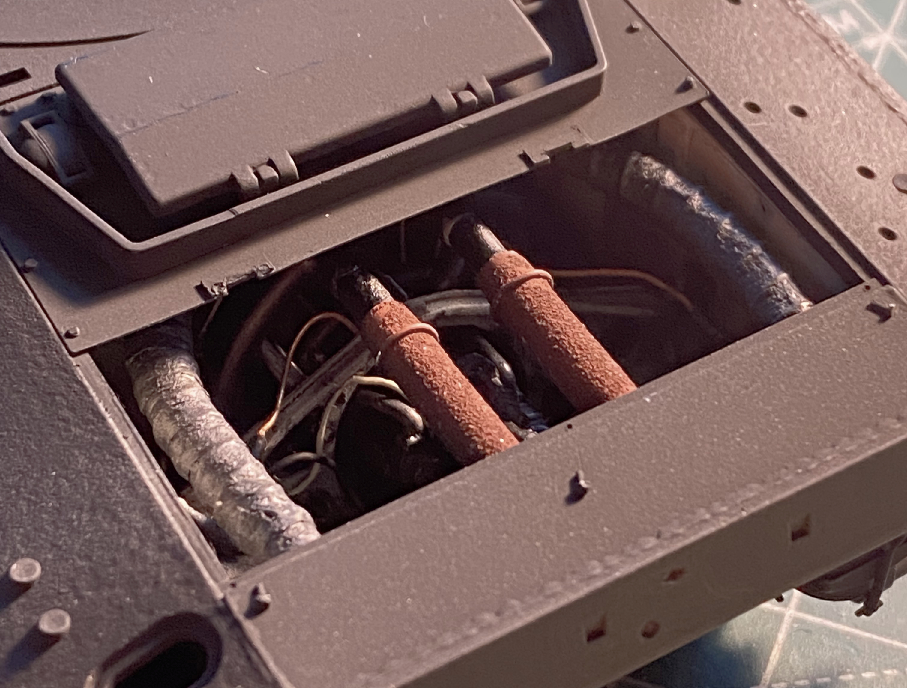
And with that, I think that I’ve done everything I needed to do to the fighting compartment and engine bay! ::trumpet fanfare:: Next I puttied and blended the additions to the rear ends of the sponson bottoms, and spent a LOT of time getting the upper hull fitted to the lower. I got it as close as I could manage without destroying everything. It’s close. When it comes time to permanently attach the upper hull, I can see I’m going to have to get creative with clamps. But that’s a headache for another time.
The next headache is the turret.
My usual build order is to attach the upper hull to the lower at this point. But have you forgotten I want to add clear sections to this? The upper hull will have the clear section on the right side and the turret will have the clear section on the left side. I figure inserting a flat piece of clear styrene will by much easier than doing the same thing to the left side of the turret. Since this was the challenging part that I wasn’t sure how to do (not having done something like this before), I wanted to work on the deal-breaker that failing to pull this off would be. Masking the clear turret to leave a portion of it unpainted would be sort of tedious. I had NO idea how funny that notion was.
I found out.
The turret as it was delivered:

And of course I had a clever plan! I had intended to delineate the section that was to be clear. My first warning that Loki and Eris had…again…involved Themselves in my plans was when I had a difficult time even getting the Sharpie to stick to the turret:

Plan A was to cut out an area of the turret, fit it snugly to replace the kerf (that’s the slot a saw leaves behind as it cuts…sawdust has to come from someplace), and then use that as the buck to vacuform a piece of clear styrene to replace what I’d cut out. Lots of tedious and fiddly work. That gave rise to Plan B.
For Plan B, I was going to polish masked off the area inside the outline on the clear turret, paint everything but that area, and bam…clear panel in the turret without any fiddling involved and still a PERFECT fit.
I have tape. I have regular, tan, masking tape, blue painter’s tape, duct tape, 200mph duct tape, house sheathing tape, packing tape, electrical tape, and of course Tamiya tape. I wish I had as much money as I have tape. Well…that was before I tried masking that outline. It wasn’t as if it just slid off, but just about! NOTHING stuck to it. Nothing. It would simply move (or fall off) if I so much as touched it. Cut it? BWA hah hah hah. Well, if I can’t mask it, that torpedoes Plan B. Looks like Plan A it will be.
It was much easier to make the outline on the kit’s turret:
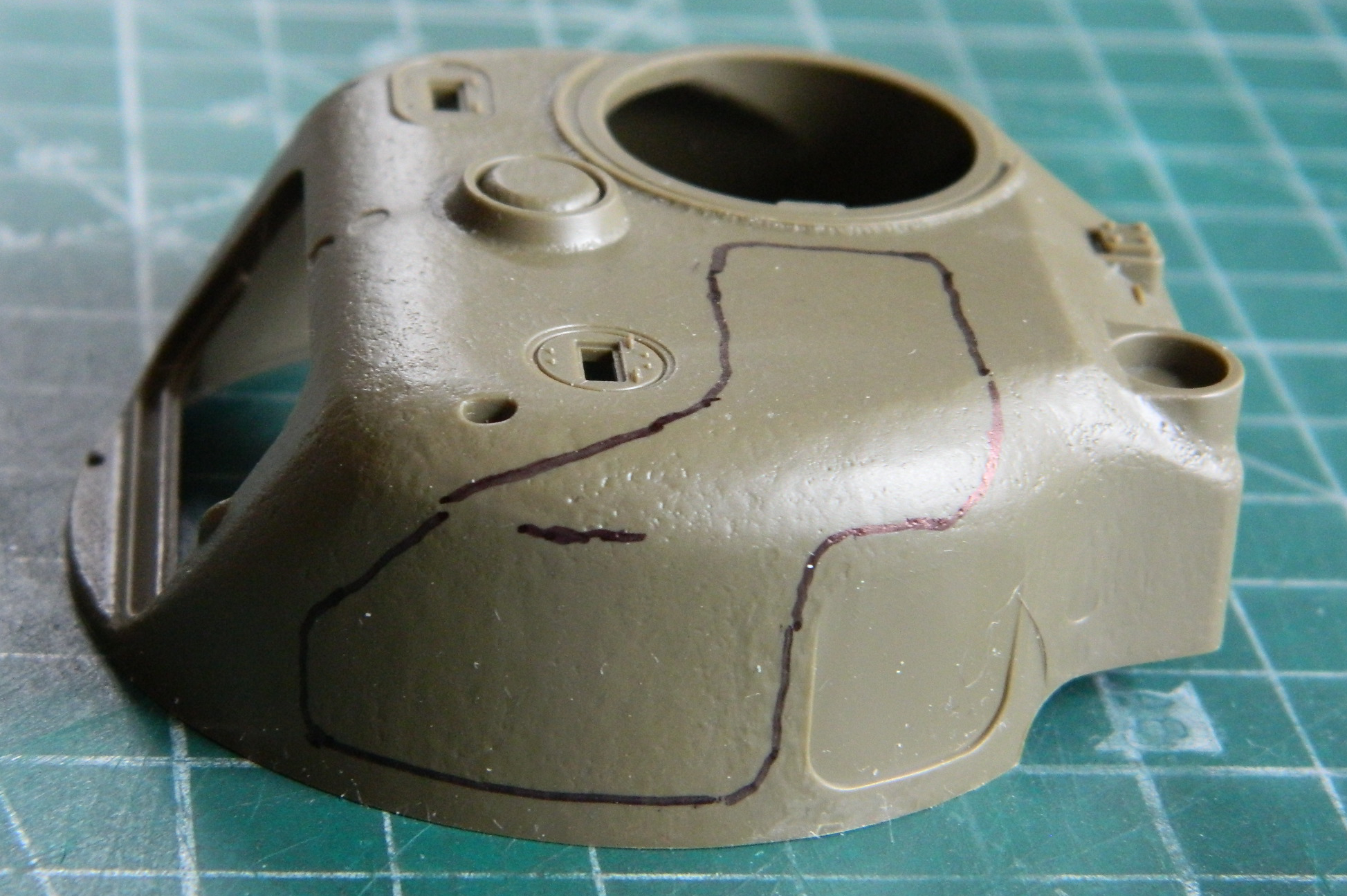
Even if I did bobble the cut a bit. (I haven’t used a coping saw since 1994.) You can see on top right of the cut where I missed the line:

I used a different saw to cut away the part I’d left behind during the bobble and glued it back where it belonged, and then started playing styrene scrap Tetris to refit the plug I’d just cut away. Once I had that done, I added little wings to increase the strength of the gluing process:
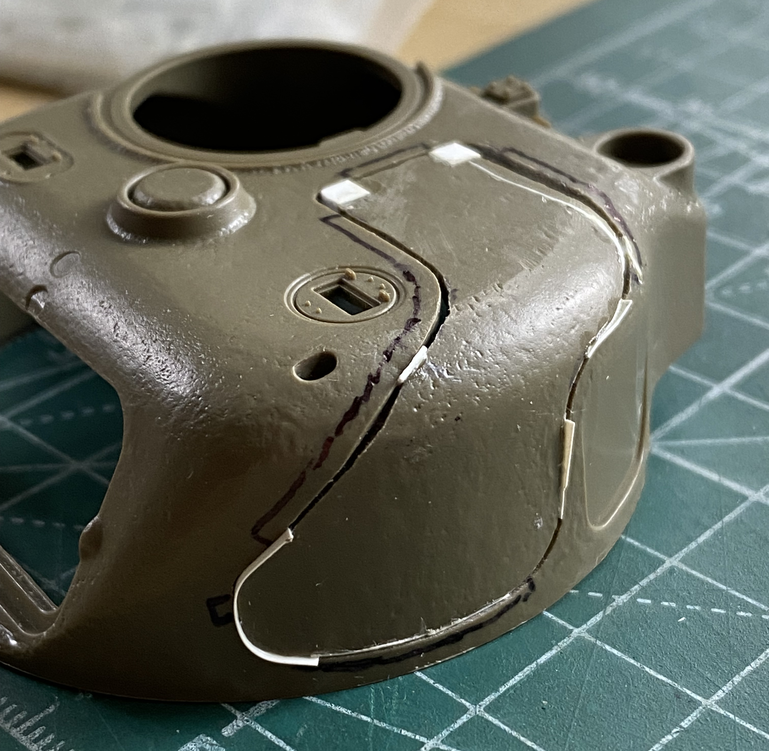
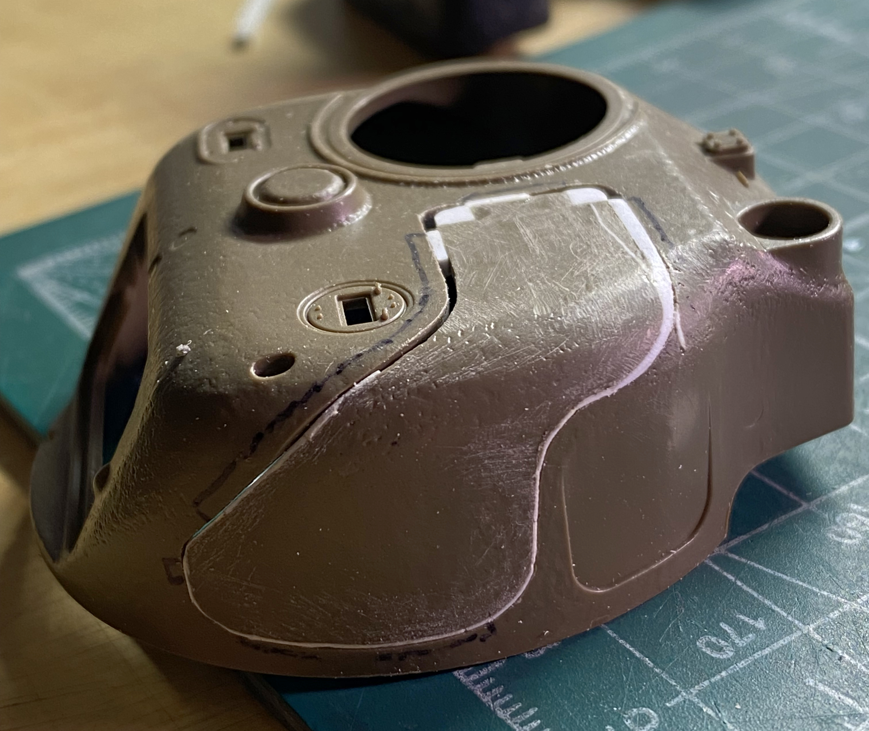

Since the inner edges of the hole would be visible, I needed to thin the plastic to scale thickness. As it was, that’s about 6 scale inches (152.4mm) thick:
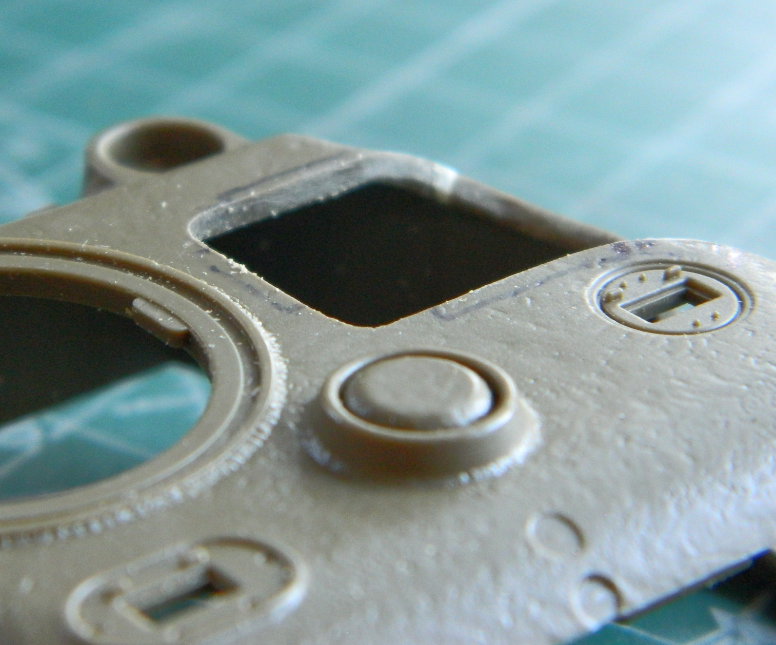
The armor on top of the turret was 1 1/8″ (about 25.58mm) thick, so I kept at it until it was the correct thickness (yes, I have a 1/35 scale ruler):
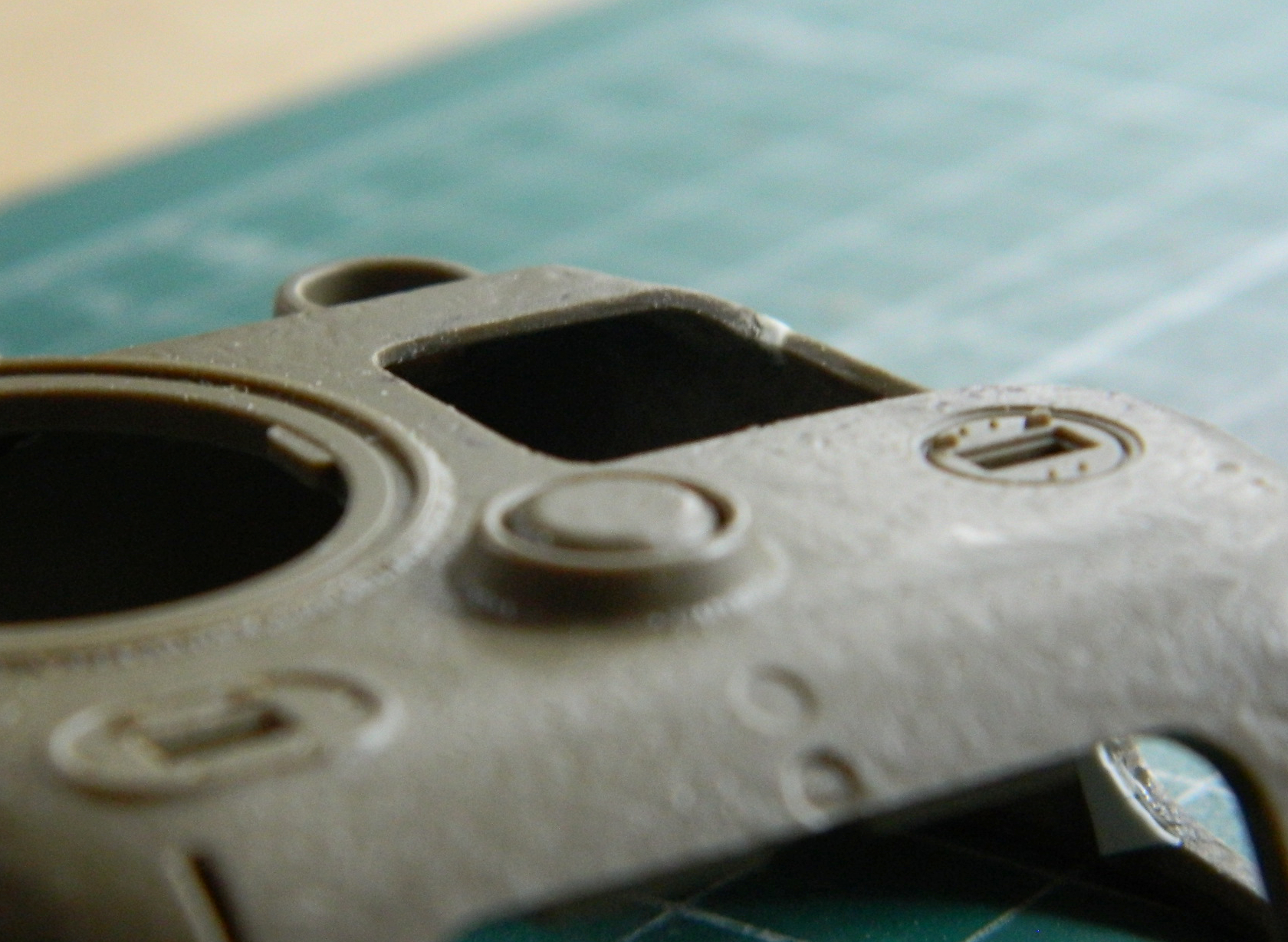
The sides of the Sherman’s turret were about 2″ (about 50.8mm) thick, so I thinned the sides to the correct scale thickness while I was in a plastic-scraping mood. With that done, I set about setting the buck on the vacuum molder:
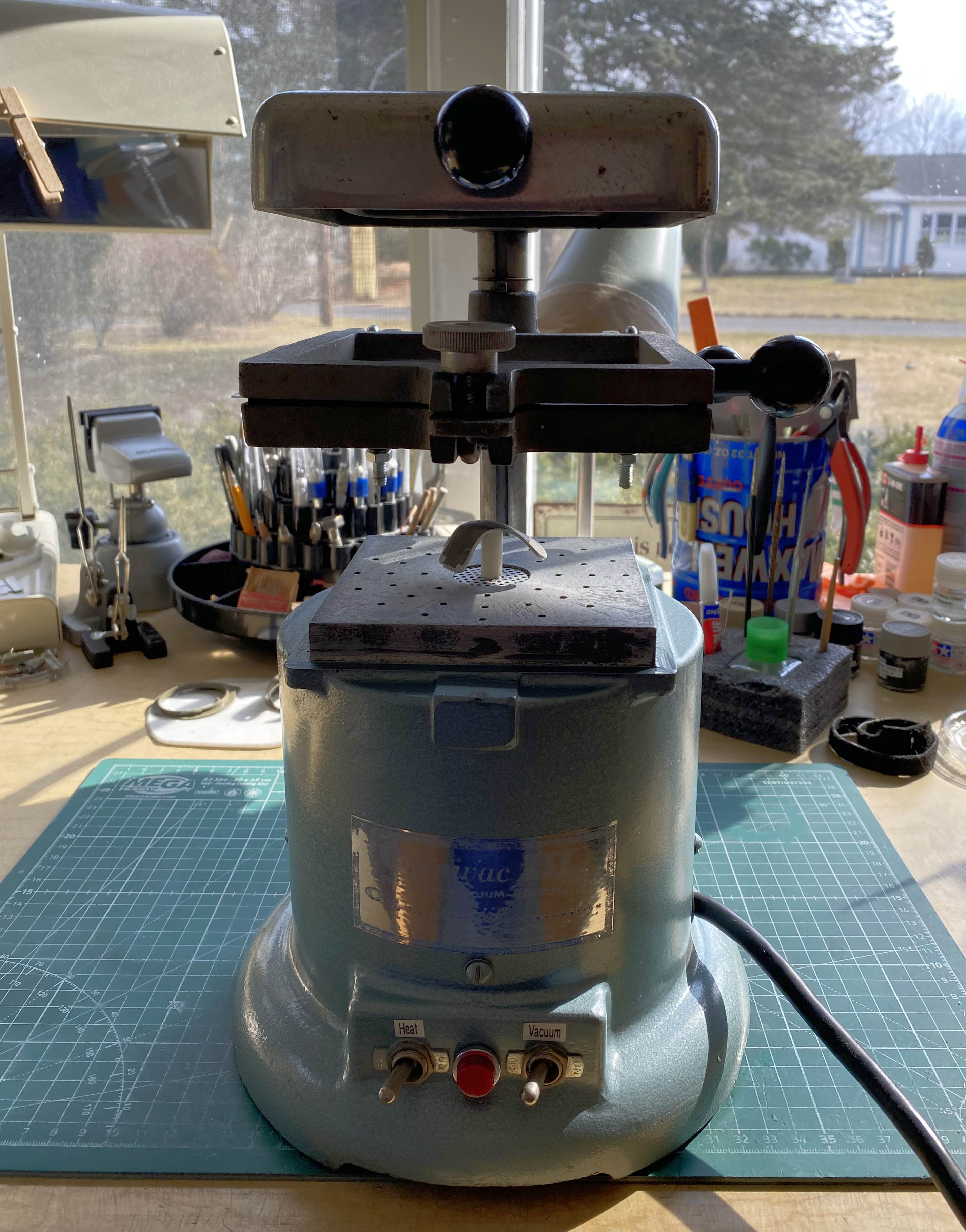
The thickest sheet styrene I could find is .015″ (0.381mm) so that’s what I used:
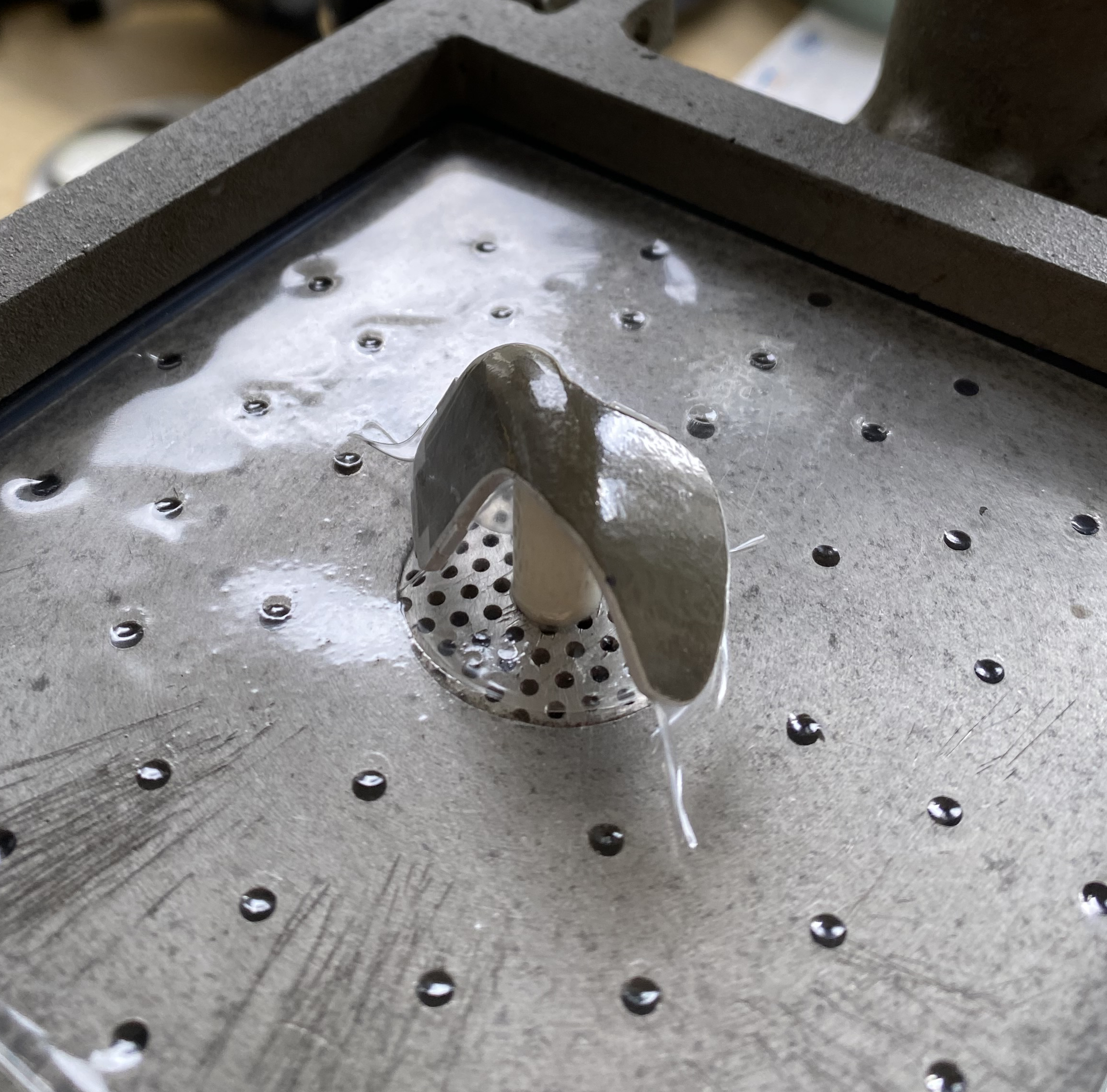
When I cut the plastic from around the buck, the wheels didn’t exactly come off the cart, but they were wobbling like crazy:
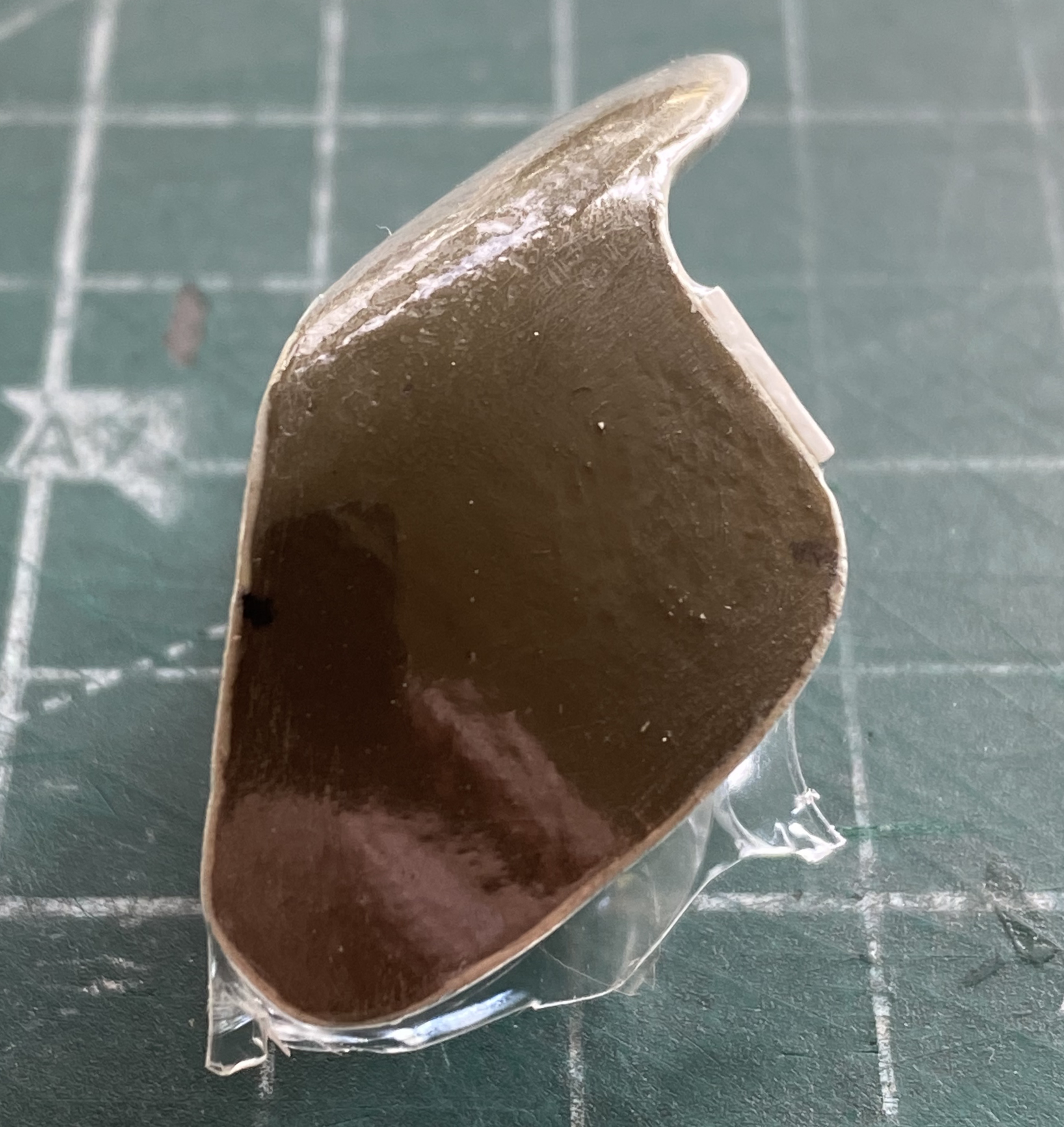
When the wheels come off the cart, the cart becomes a really poor sled. This is where that happened:
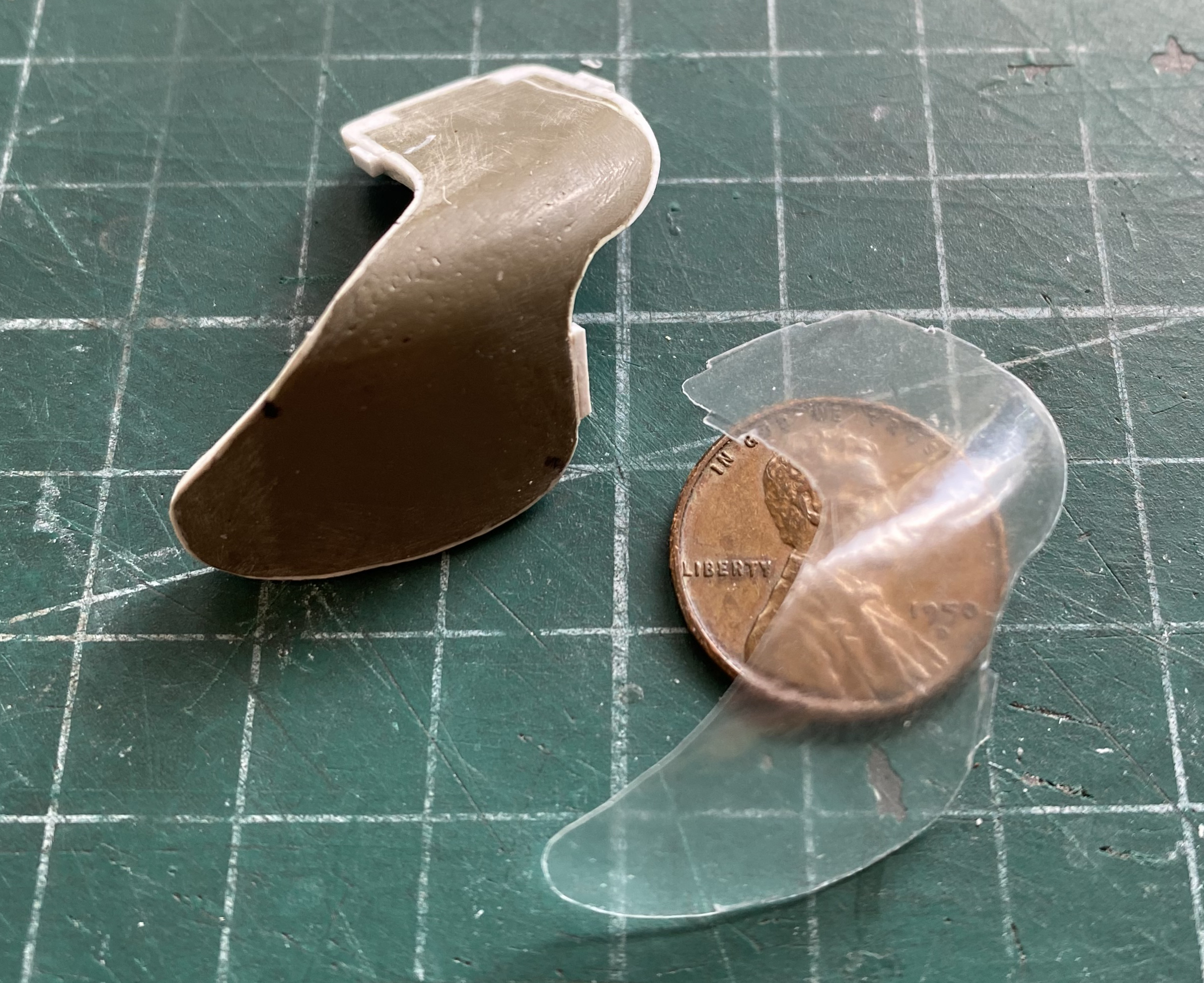
I’m sure you can see how thin that clear part is. Since I just had to know, I took out the digital calipers and tried measuring the thinnest section. My calipers will not measure anything smaller than 0.001″ (0.0254mm). Only one point measured that thick, everything else read 0.000″ (approximately 0.000mm). Yeah. Right. That’s going to give me a lot of gluing surface, not to mention great resistance to any pressure against it (sarcasm…probably the most used service I don’t just offer, I insist upon). Those of you who are old enough to remember cellophane know how thick this part wasn’t.
Hmmm…Plan A ain’t off to a stellar start, methinks. That’s when Plan B-1 arose. CUT WHAT I NEED FROM THE CLEAR RESIN TURRET!
All I can say (no…not really, there’s lots I could say) is Plan B-1 was a pain in the ass. Righteously so. But if I couldn’t get the clear section into the turret, there would be no clear sections at all, and dammit I want clear sections.
This time I didn’t use the coping saw. I made a bazillion shallow passes with the smallest burr I have for the dental drill. To accomplish that, I used white glue to attempt to attach the cellophane part to the surface of the clear turret. This is when I found out that there a subtle difference between the curvature of the clear, donor, turret and the intended recipient of the transplant, the kit’s turret. You can see where the white glue failed to harden even though it sat all night to do just that:
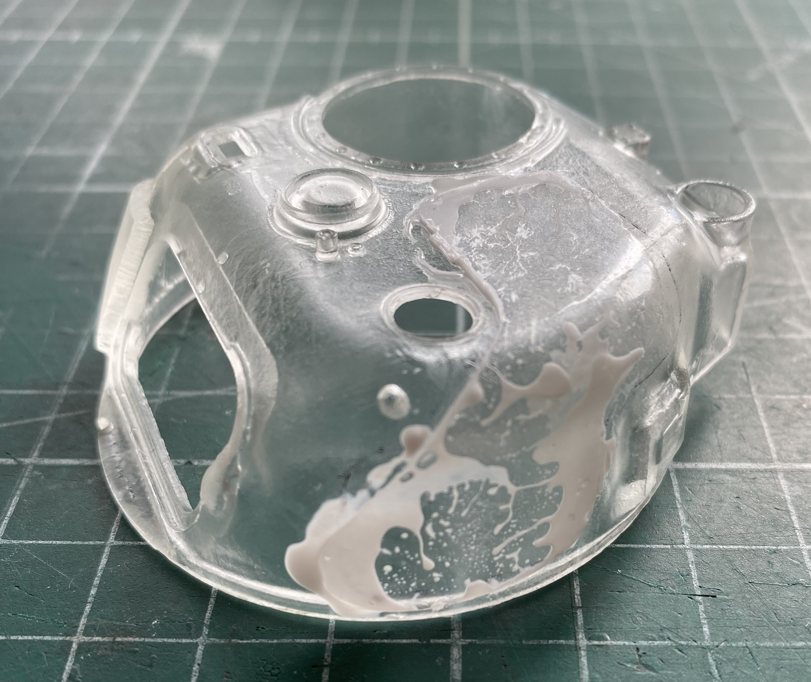
Knowing when to quit is still an arcane skill I’ve yet to even become conversant with; forget mastering it:
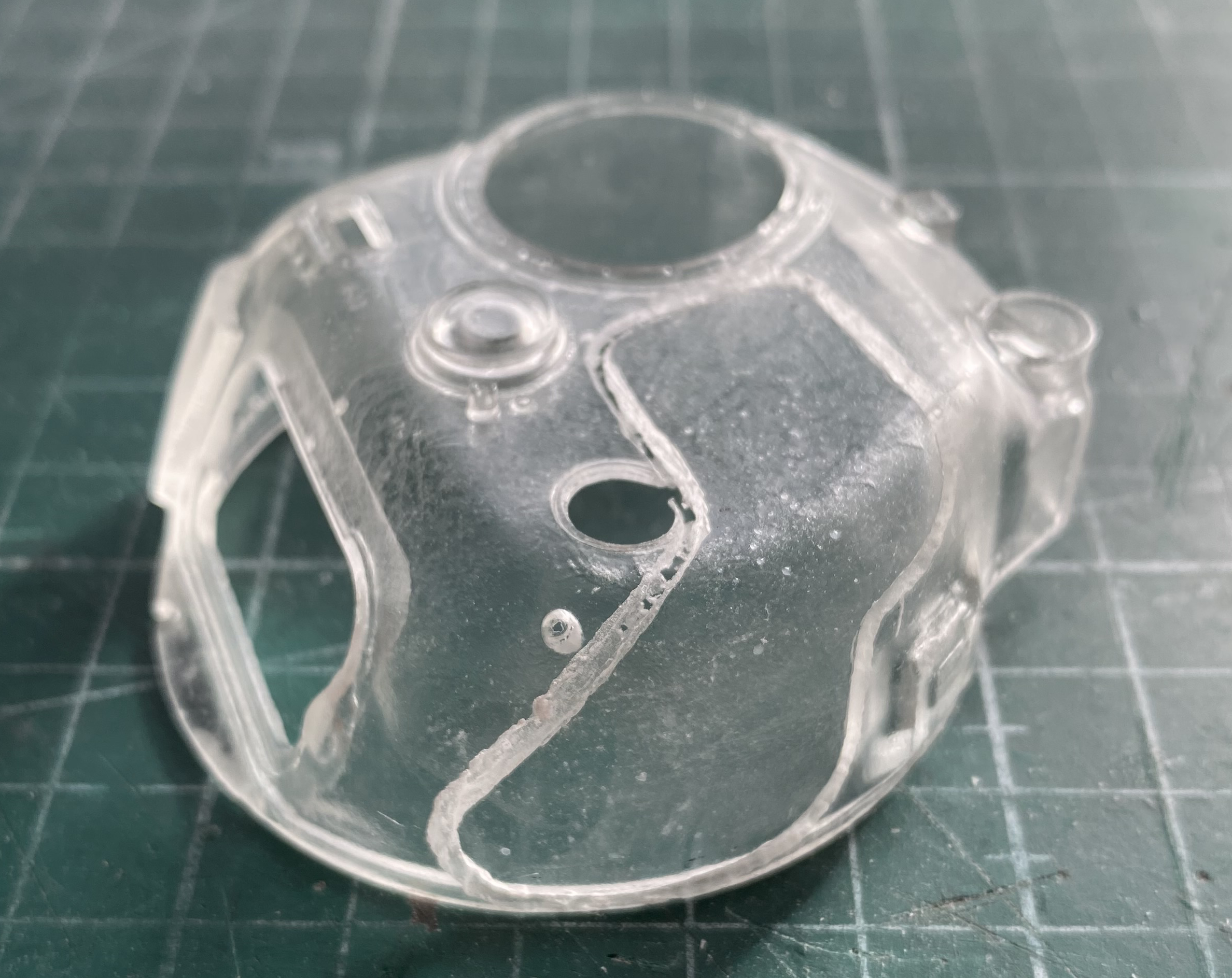
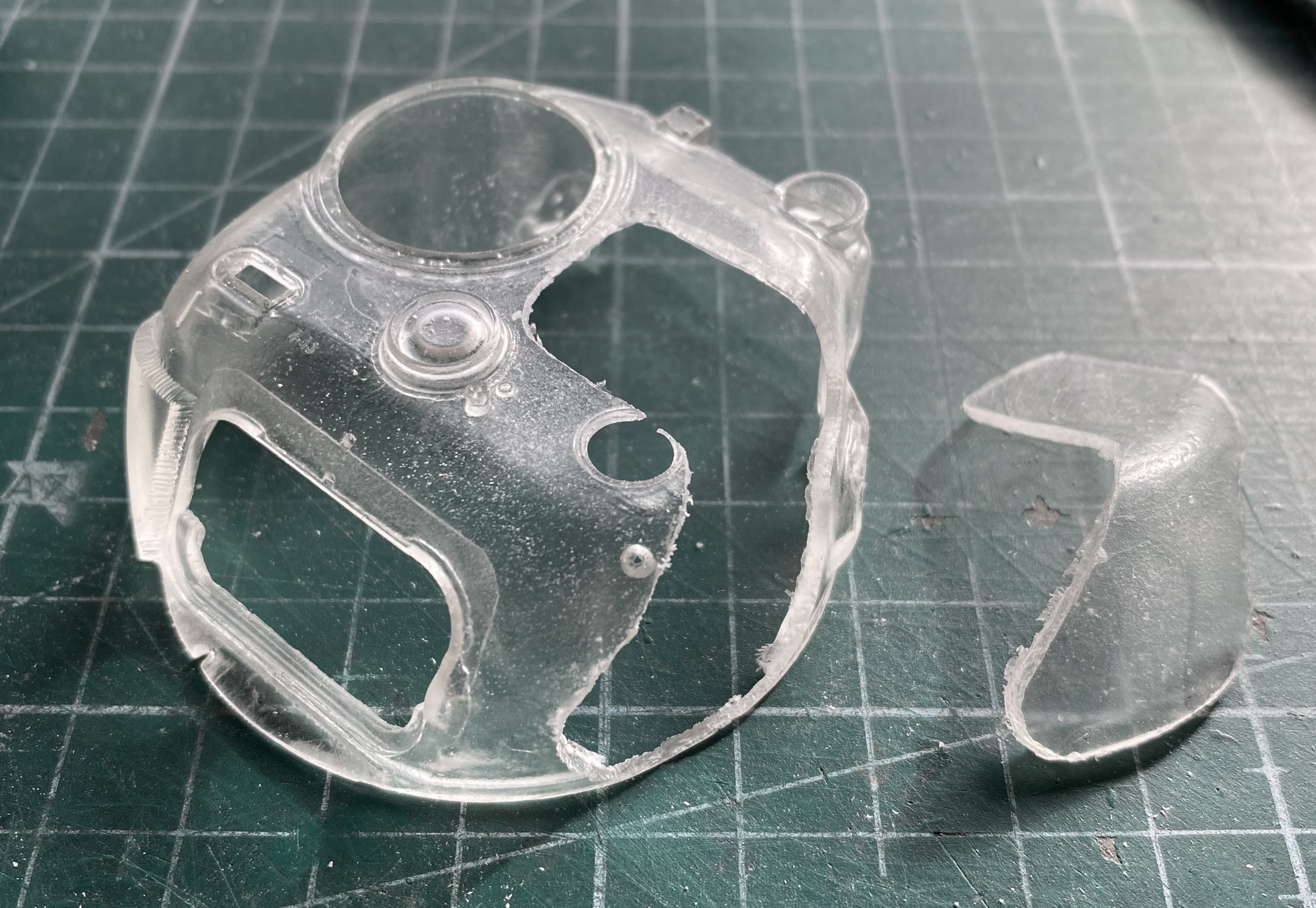
Then came the fitting process. I spent took two days to get to this point. Since I just mentioned it above, you’d better remember…er…I’m sure you remember when I said that the shapes were subtly different? The gaps below…after taking two days…are the best I could do with it at this point:
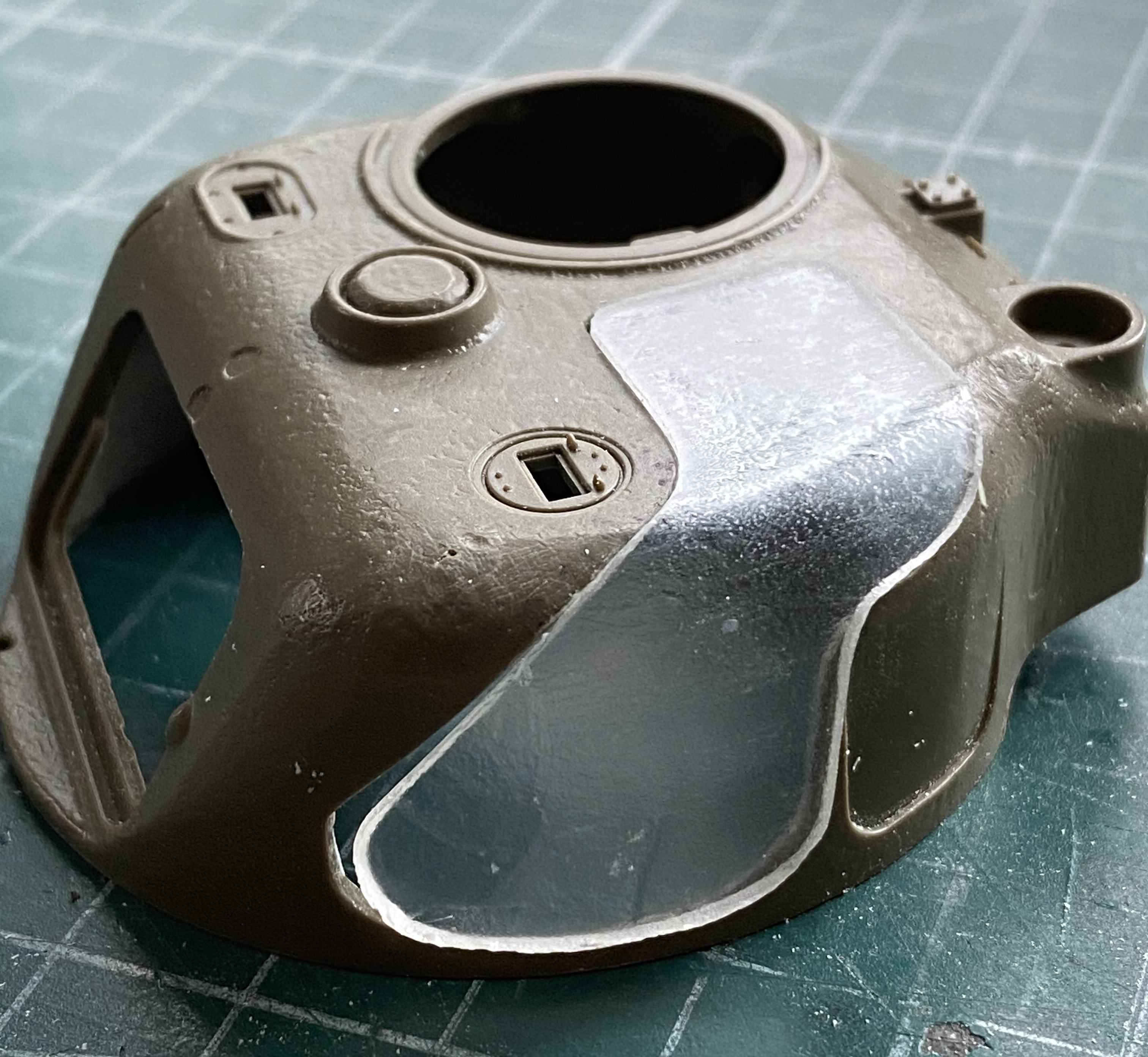
Gaps can be adjusted and filled, resin can be heated and recurved. But it’s all for naught unless it’s clear, so the grinding, sanding, and polishing commenced. Resin doesn’t melt as plastic does which allowed me to use a Dremel for the initial shaping. Files followed. Then I started with 220 grit sandpaper, to 320, 400, 600, 1200, and 2000 grit:

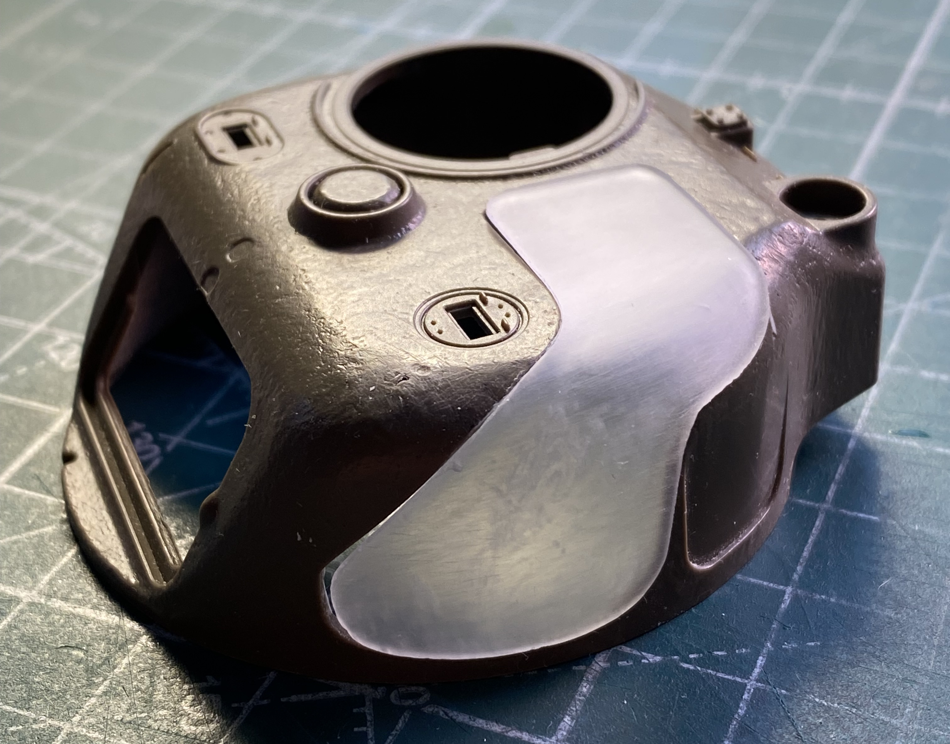
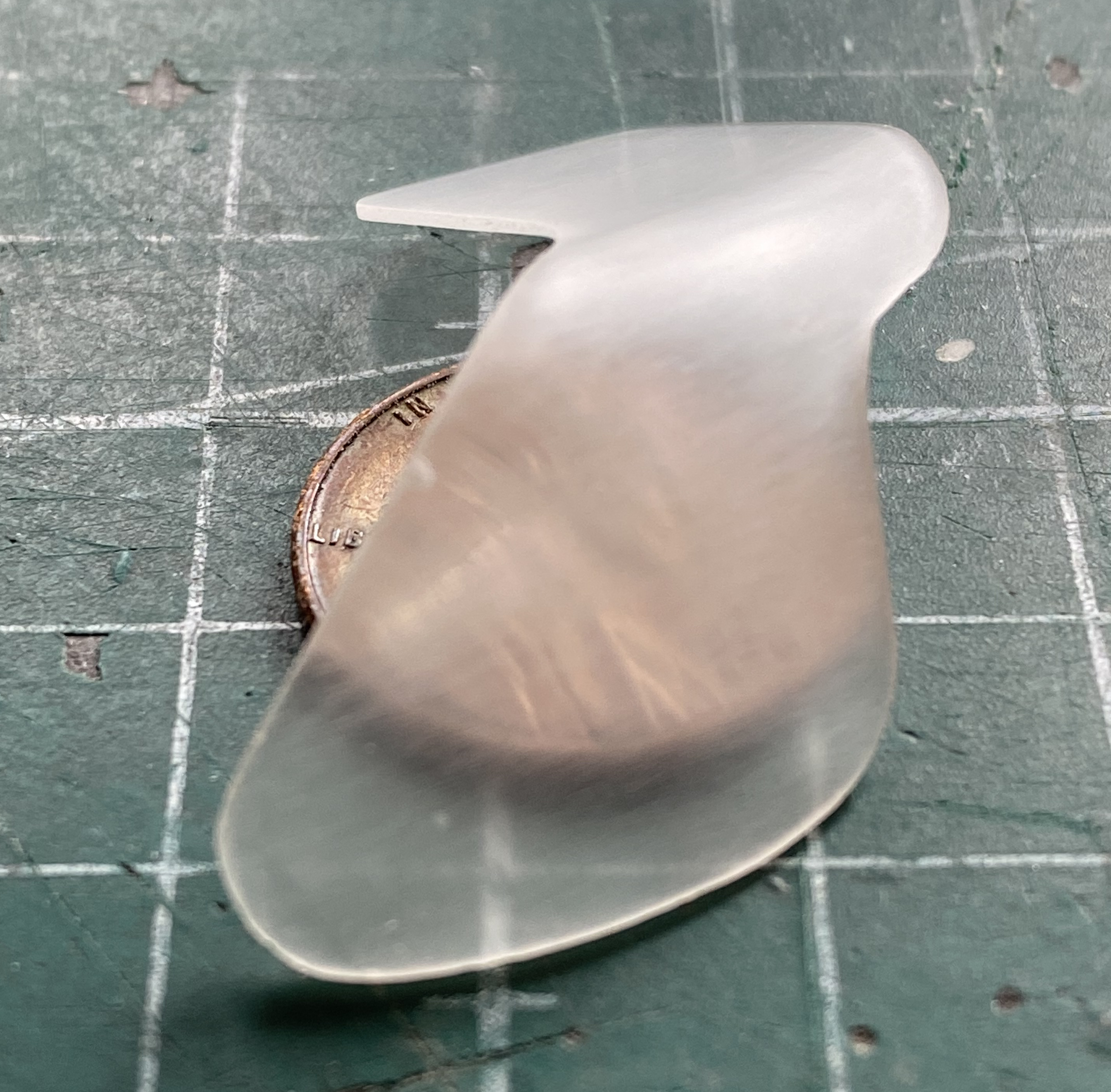
I was just about to go to Novus #2 plastic polish when I saw this little tiny scratch; tiny but deep, requiring me to go back to 320 grit to excise it (the needle tip is pointing at it):
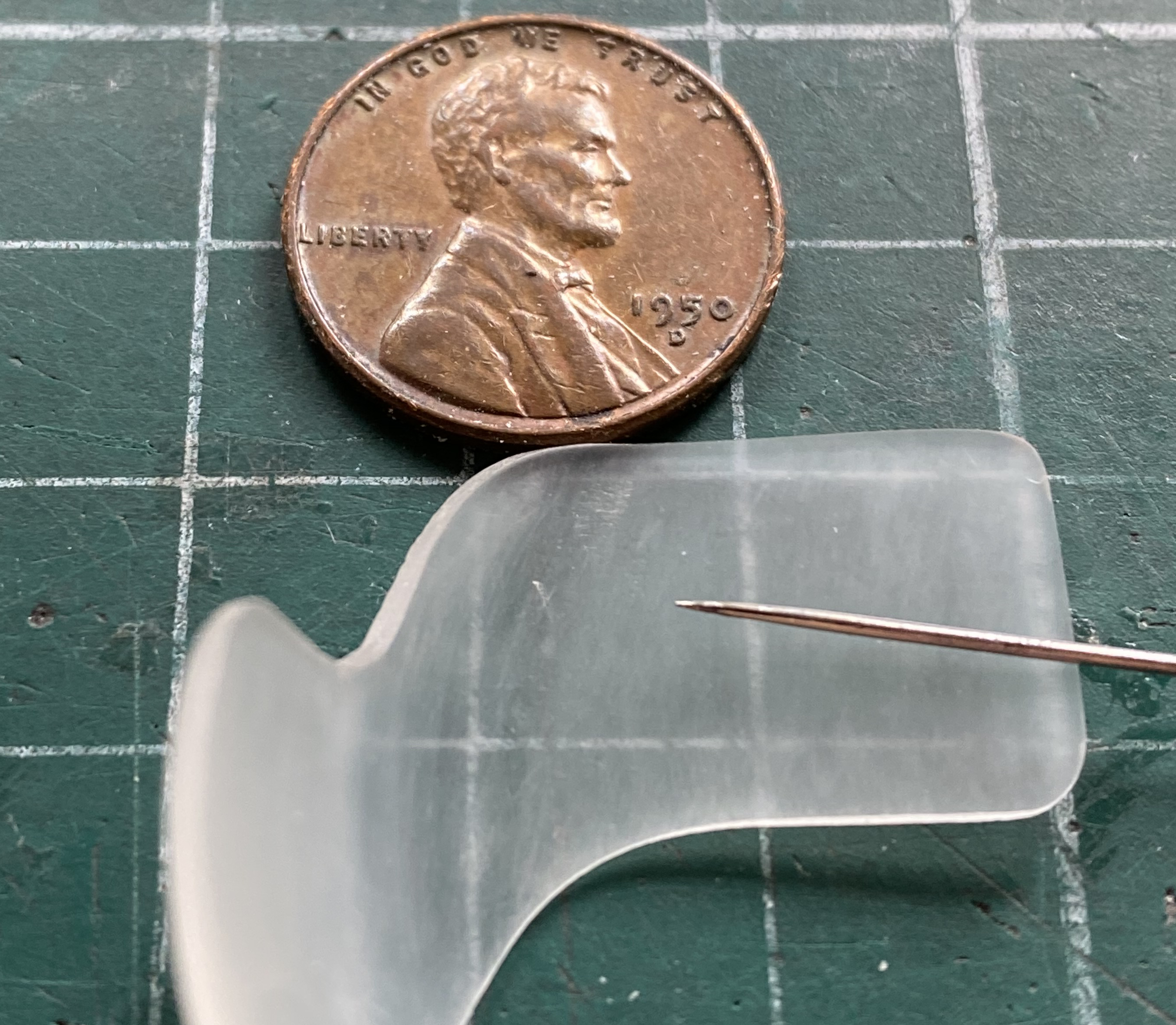
It was at this point that I tried fitting the clear plug to the turret. No, resin doesn’t melt like styrene does. As I have just learned, this resin became warm enough to change its shape:

I decided after a few days of this, I needed a break. Behind the clear plug above, you can see a U-shaped depression. This is where the pistol port goes. Tamiya never thought anyone would need it open so the pistol port itself is a single piece. As ever, I have other plans.
When I did the M4A3, I encountered the identical situation with its pistol port. My solution was to take a surface mold of a Dragon turret that was not only molded open, it had the correct flange around the opening. I still have the surface mold and I tend to try to use the left over resin whenever I do a pour and I had cast a pair of pistol ports from that mold. I used one of them here.
I’m familiar with the physical properties of the resin I use (Smooth-On’s Smooth-Cast 322, a polyurethane compound). It becomes very flexible from just the warmth of my fingers which renders it quite flexible. This is a small, thin part, and I knew that it would be challenging to thin it out enough. I put the casting back into the mold so that my hands wouldn’t warm it and the entire surface of the casting would be supported before I used the Dremel with a burr to thin it out as much as I thought practical. Since the turret has no opening for the port, I held the part in place, traced the opening onto the turret with a pencil, and then cut a hole for the port. I checked alignment by dry-fitting the casting. It works:
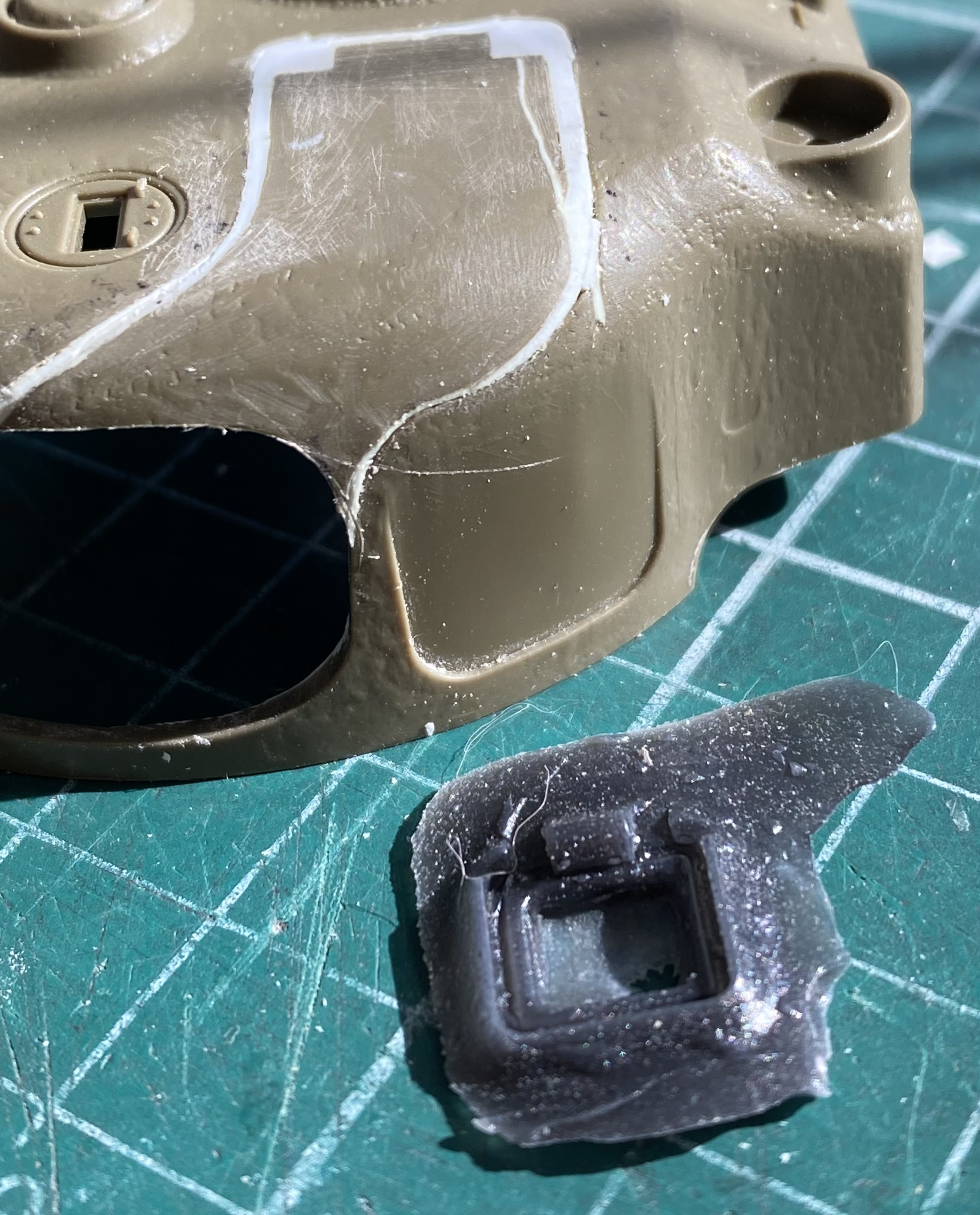
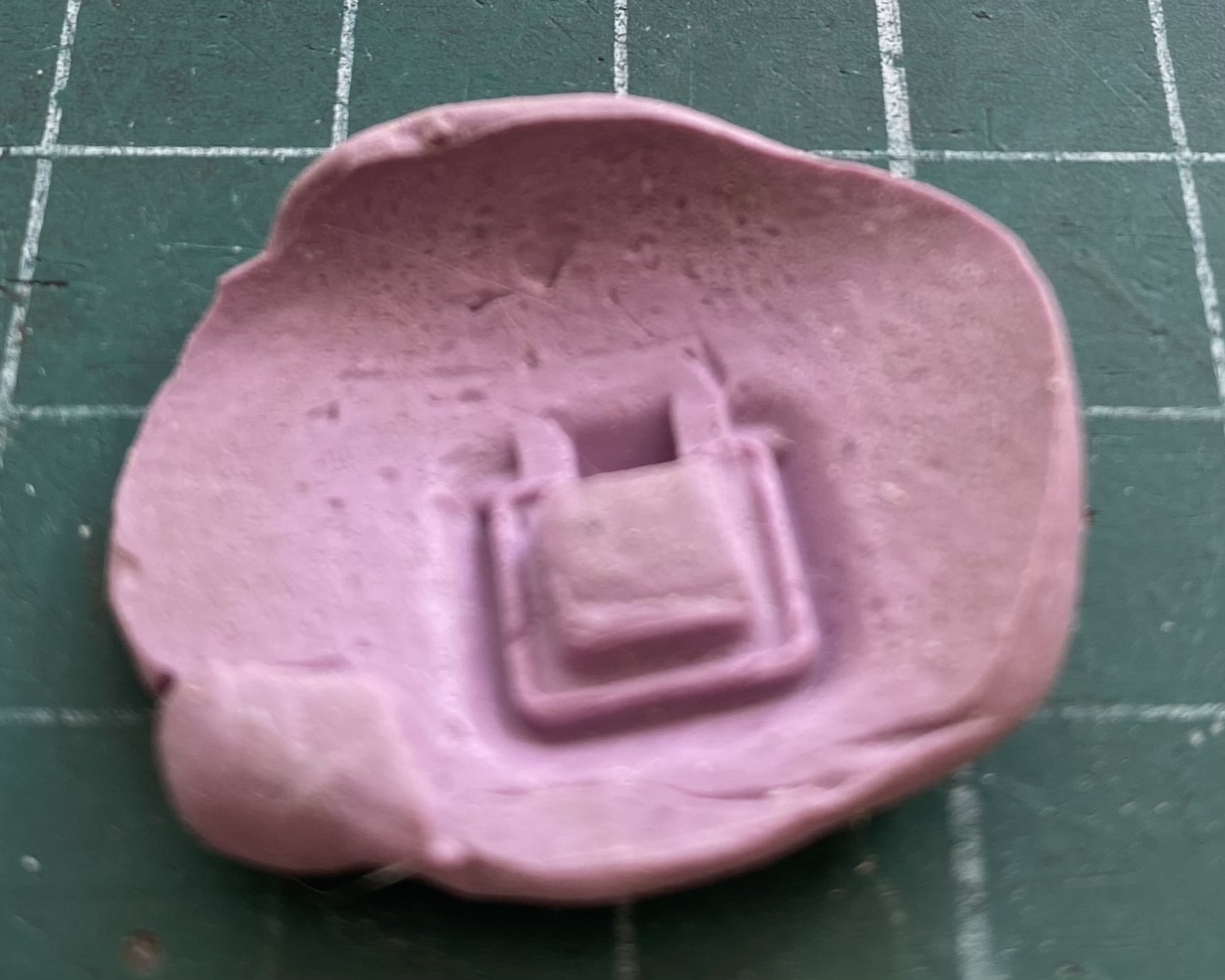
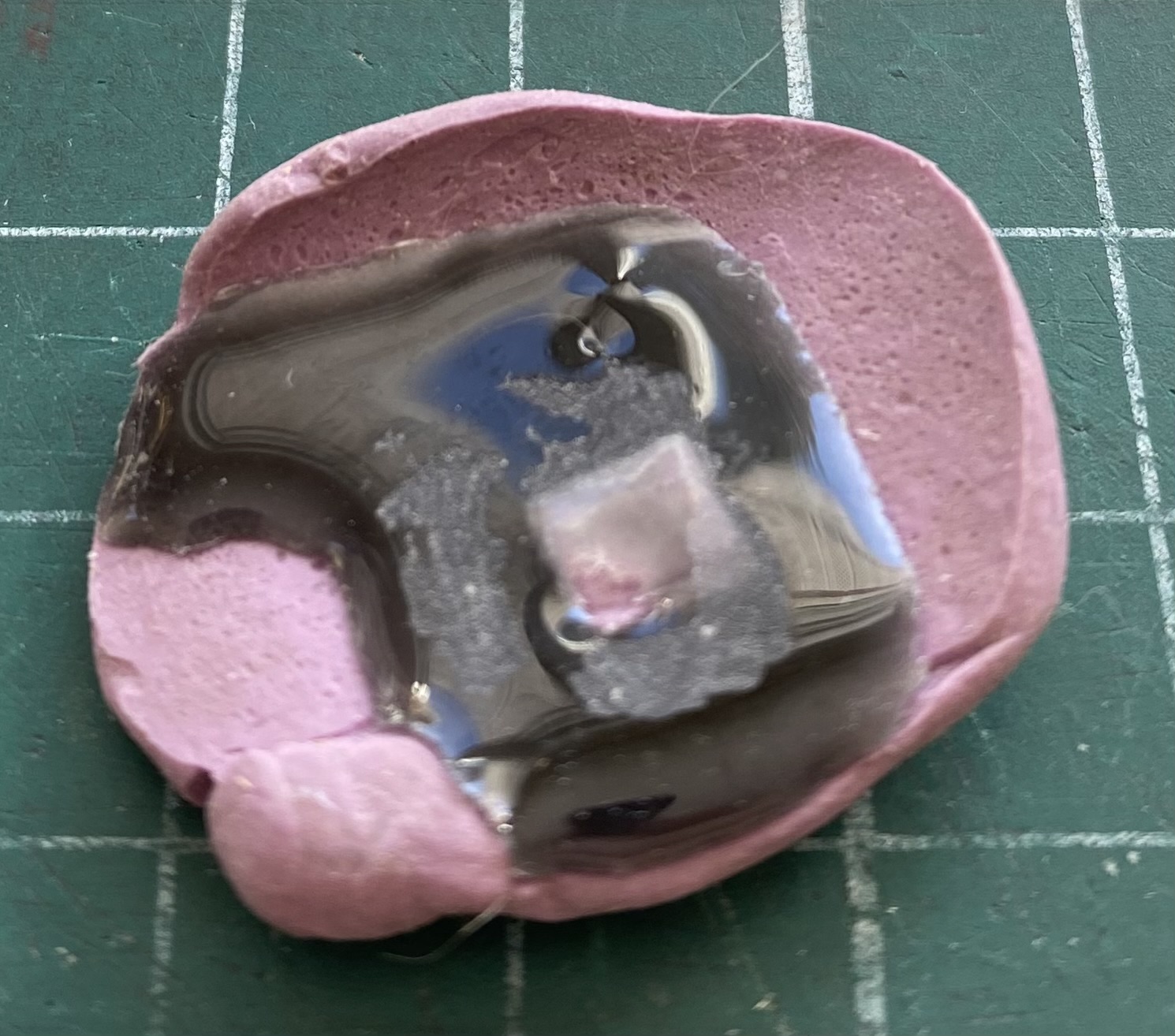
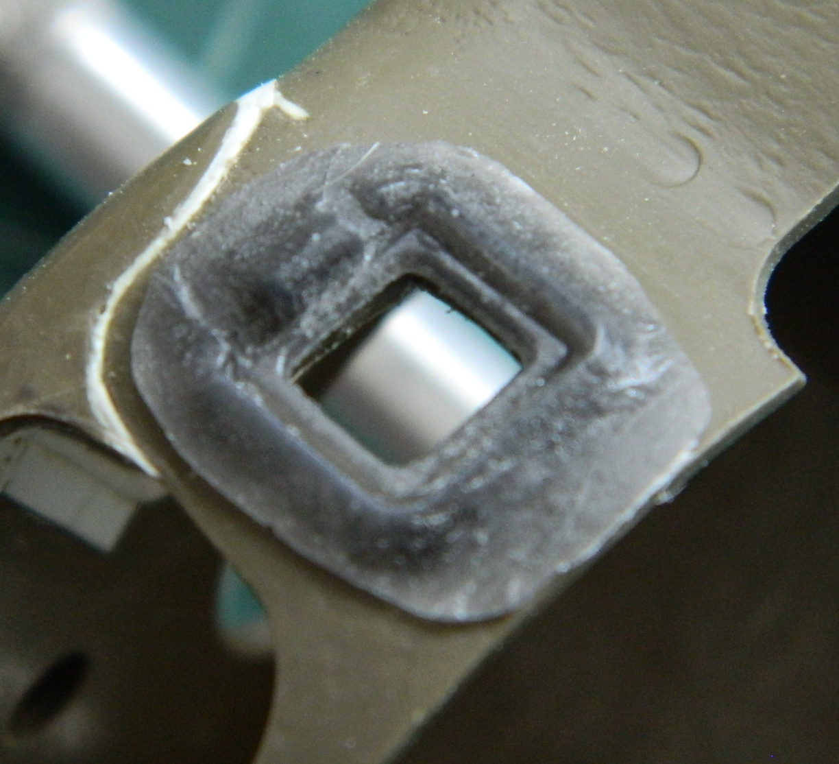
Frankly, I was never content with the area I’d thought to make clear, it just took me a bit to figure out what I didn’t like about it. I didn’t like the area on the top of the turret. What that area would allow seen can be seen through the commander’s hatch. Being an earlier turret without a loader’s hatch, this turret didn’t come from the factory with the vision cupola seen on later versions (though they were frequently fitted in the field), it had the old split hatch which allows a larger view of the turret’s innards. I made my decision, cut the opaque plastic from the buck, and refitted it to the turret. Having thinned out the periphery of the roof opening, I filled the resultant depressions with 0.010″ (0.254mm) scraps and then 3M’s Acrylic Putty (the deformed plastic near the opening was where I had glued the plug to a bit of styrene tube to support it on the vacuum molder’s platen):
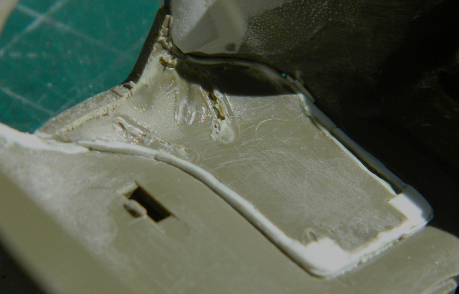
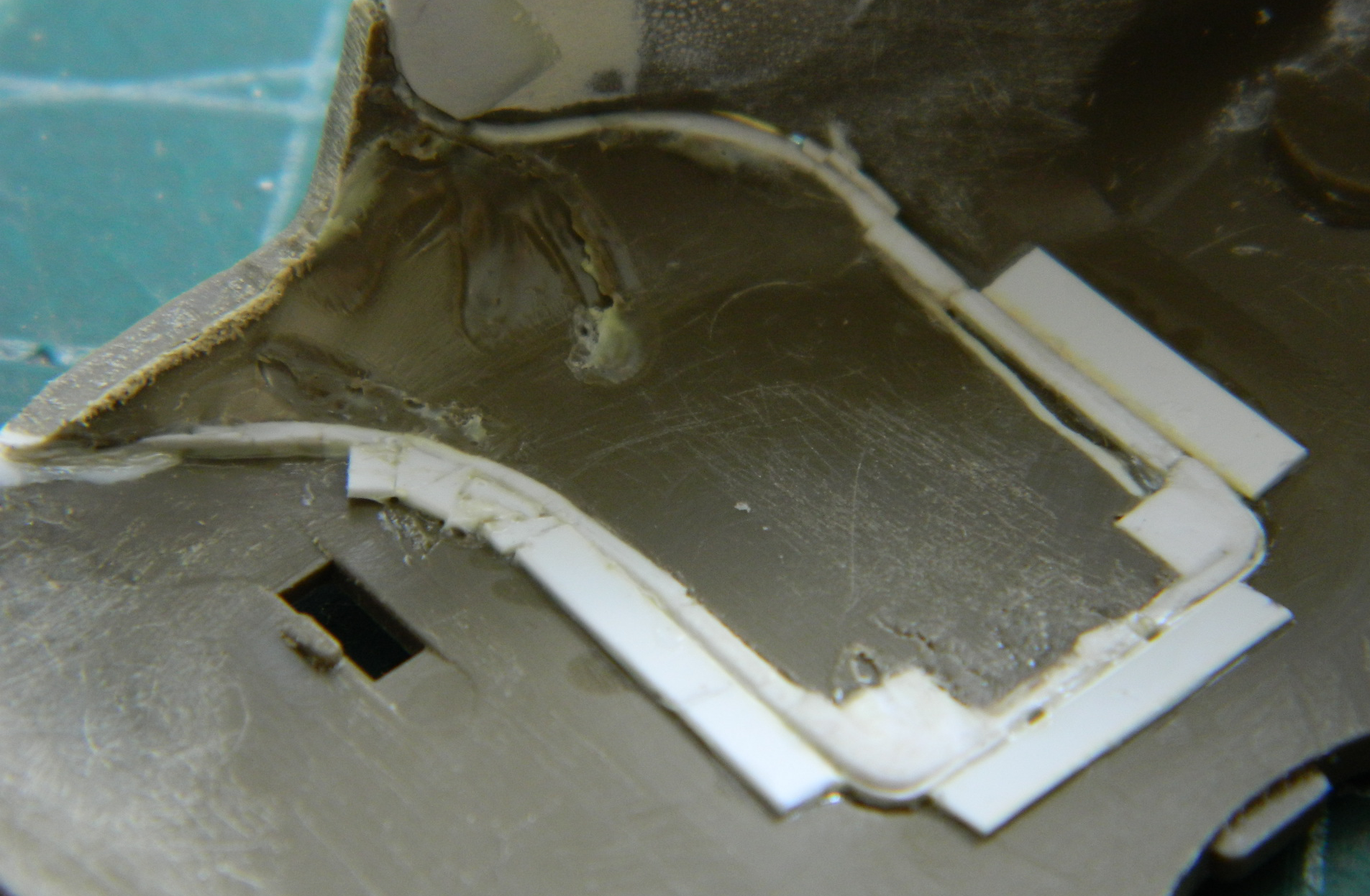
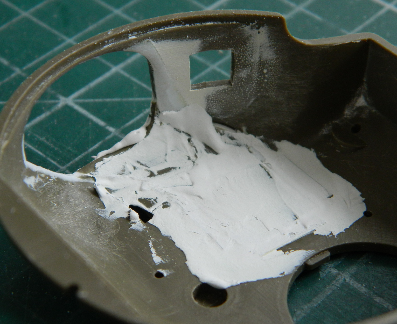
Then I puttied the outside:
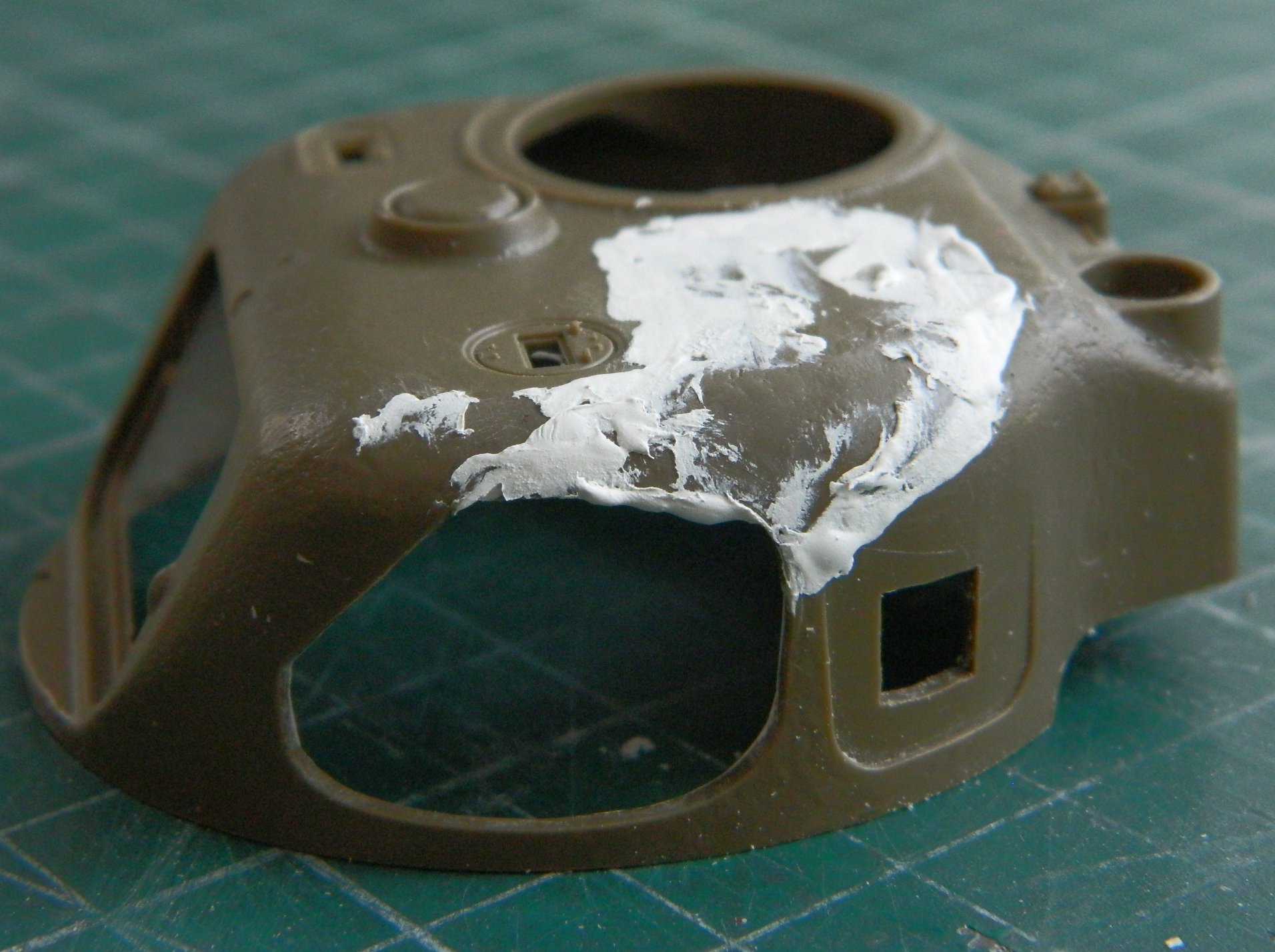
I like this opening much better.
Since the opening is smaller, the clear plug had to be as well:

After letting the putty sit overnight, I scraped it down. Sanding it would make the surface too smooth. These things came from the factory with very little, if any, finishing. Yes, scraping it would make it smoother than it should be, so I’ll try using the Mr. Surfacer 500 to replace the rough-cast surface texture:

That was the easier part, next was the interior. I scraped, sanded, and muttered imprecations and realized I would need another application of putty to fill in minor depressions (sort of what happens when I look at my checkbook balance, only without the “minor”):

Next month I hope to finish the installation of the clear plug. I consulted a fortune teller who told me that I have much polishing in my immediate future.
Next time I have my fortune told, I think I should consult someone who reads tea leaves instead of someone who reads my entrails. I just don’t have the guts to do that again.
M4 (Tamiya) Build #5 – Assembling the Lower Hull is Mostly Completed and then Painted, Stained, and Worn, the Upper Hull is Fitted, and I Finally Get to Fit the Engine Into the Lower Hull
What drives the build changes as things move from the “pending” category into the “all done” category. The driver of this build has now switched to what needs to be done to attach the upper hull to the lower hull. I started by detailing and reworking the engine bay access hatches on the rear hull. I removed the molded-on retaining strap and replaced it with .010″ (.254mm) copper ship stock. The grab handle was replaced using 22awg wire (the holes are drilled over the hatch to show me where I need to add bolt heads, the holes on the bent tabs stay vacant) and as of this post these hatches are intended to be operational:


Fitting the upper hull to the lower hull showed me there was a bit of work required to accomplish that. The first fit impediment was the box on the sponson next to the co-driver. It was too far forward and needed to be moved rearward:
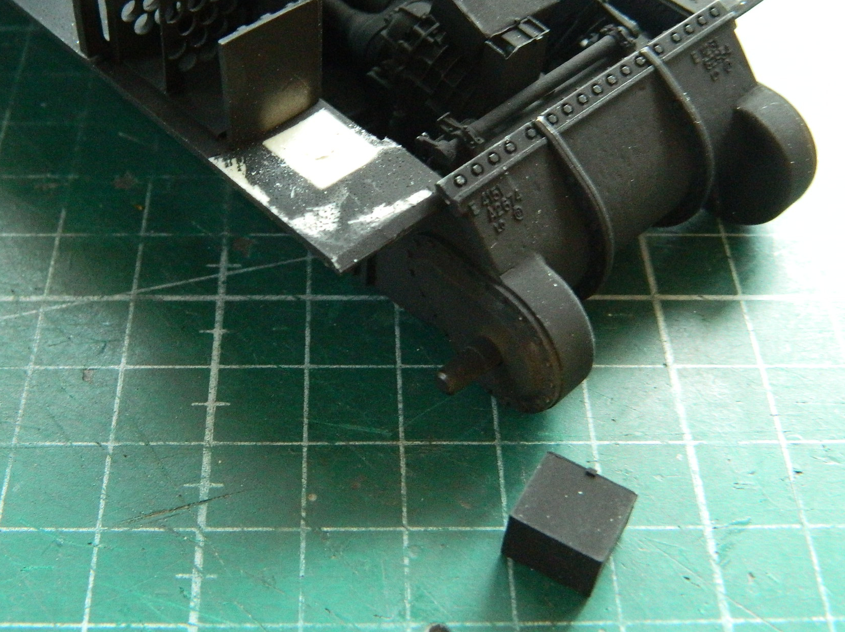
Once that box was moved rearward until it was in contact with the ammo rack, that part of the hull settled down correctly.
While I was mucking about with the upper hull, now seemed to be a good time (or maybe just not a bad time) to decide exactly where I’m going to replace the opaque plastic with clear plastic. I lightly scribed the outline (the actual execution of this replacement has occupied many hours of skull-sweat this month) onto the hull:
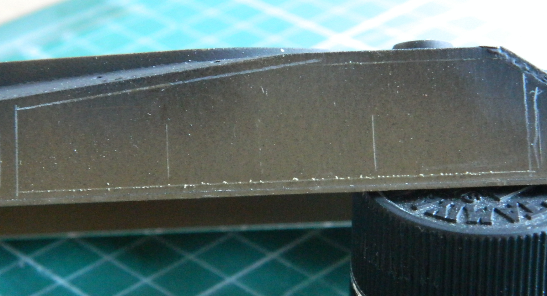
Another question I’ve gotten is, “How do you know where the light falls?” Being lazy (and more than a little bit nuts), I figured out a simple way to do that. Use light. I used my cellphone (which is where these photos came from) to take a photo so that I can actually remember something for longer than five seconds:
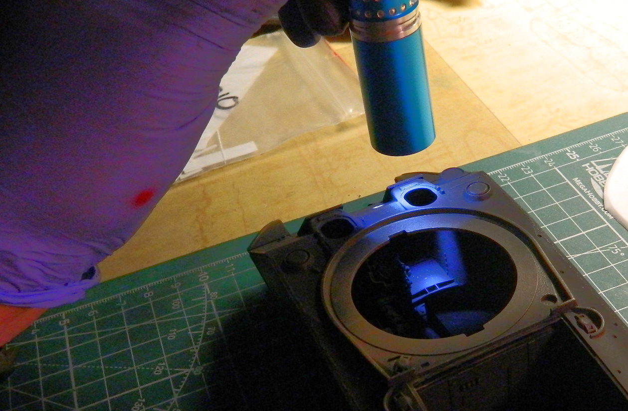

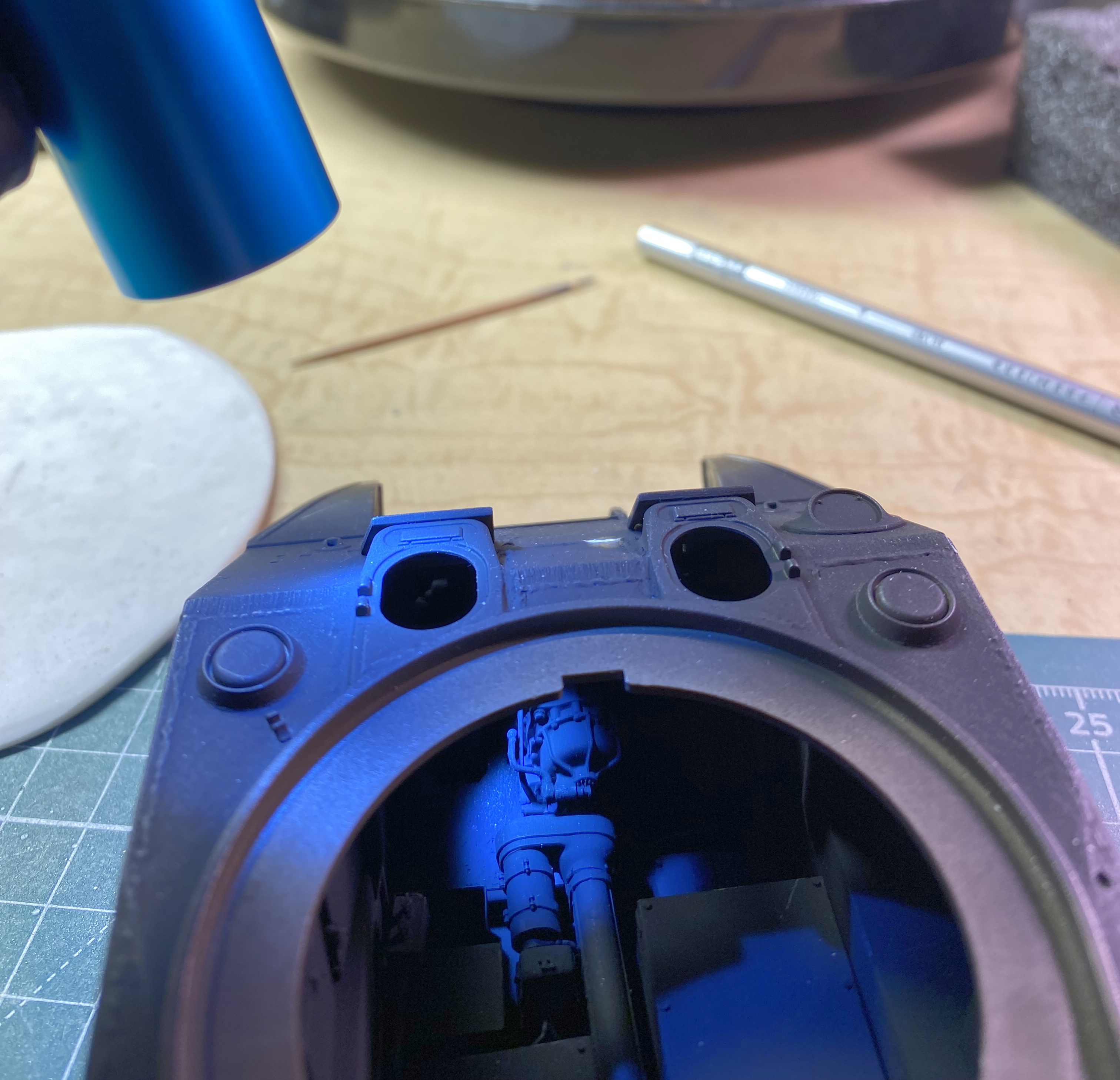
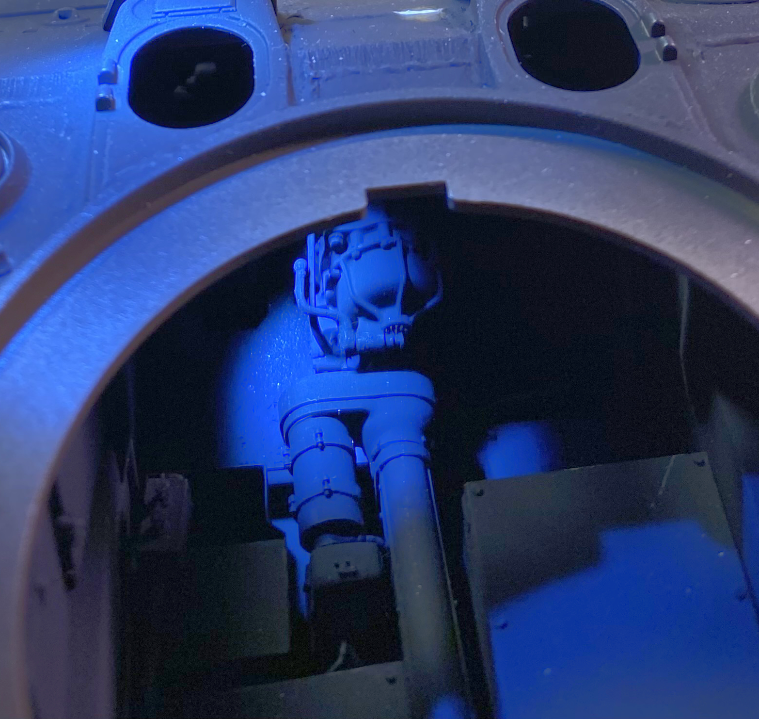
I added oil lines between the oil cooler and oil reservoir using .020″ (.508mm) solder:
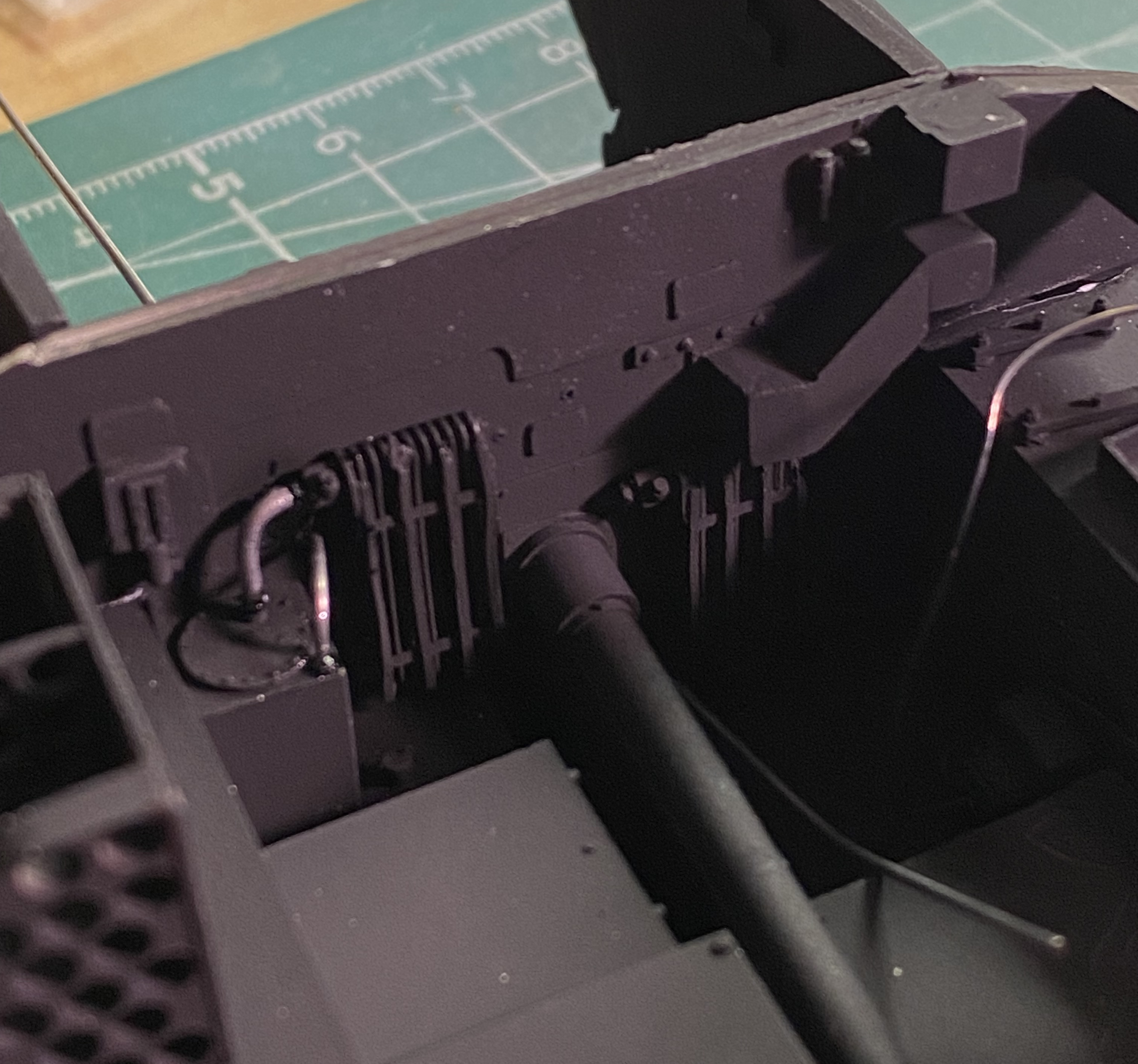
At this point I painted a few items that will need to be added once the “light splash” is added to the interior. The leather was distressed by using colored pencils and a wee bit of dry-brushing:
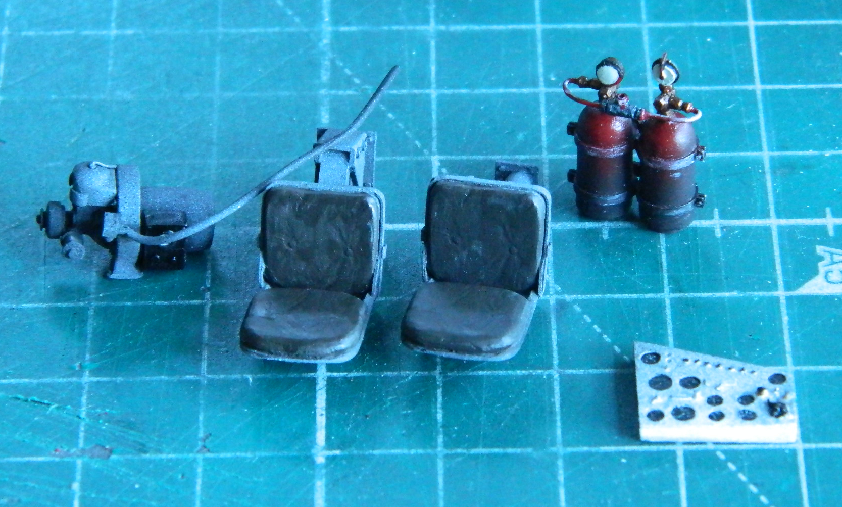
And since I had the latex gloves on anyway, I loaded the airbrush with Tamiya’s XF-2 Flat White and did the light splash effects:
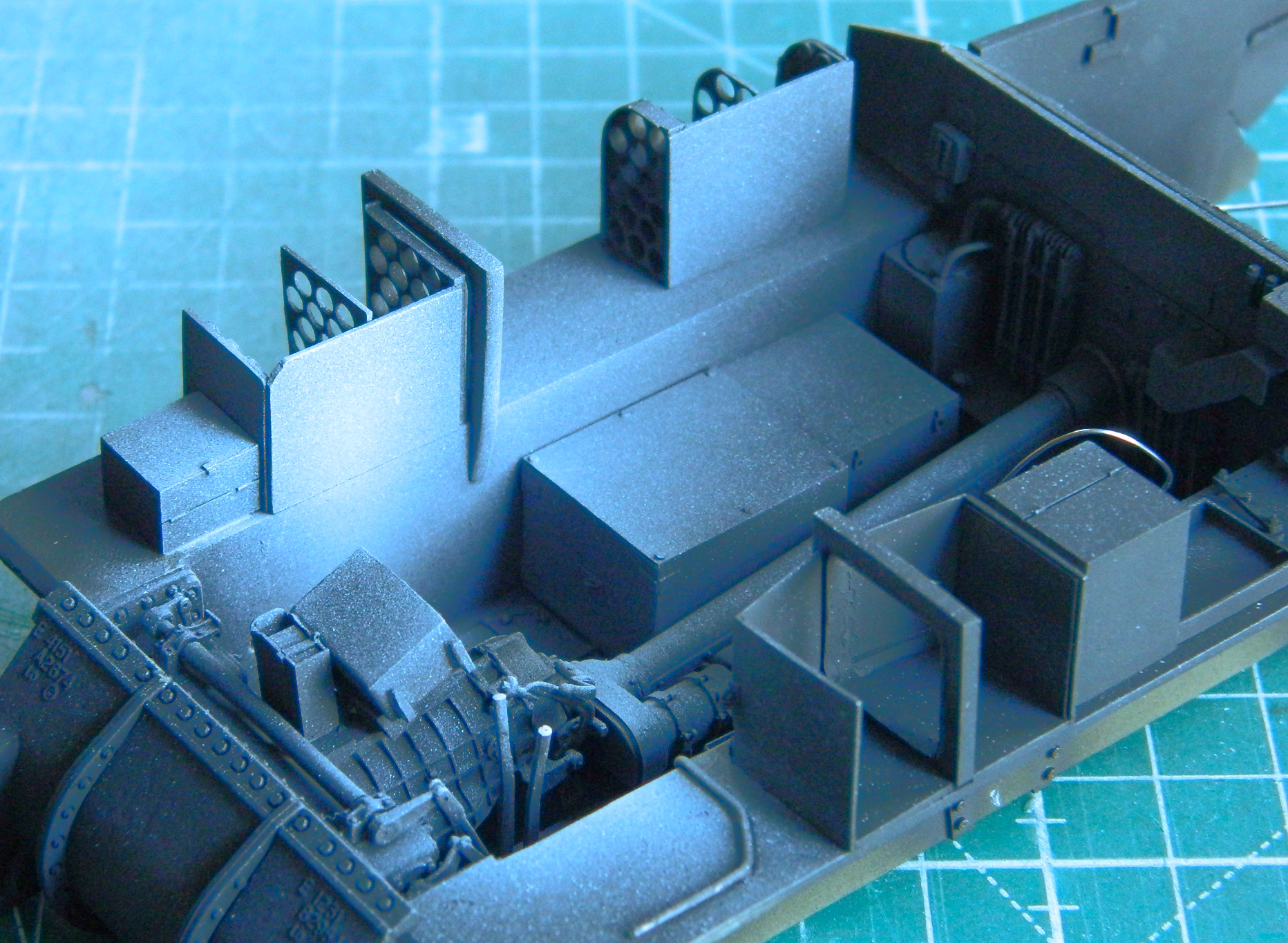

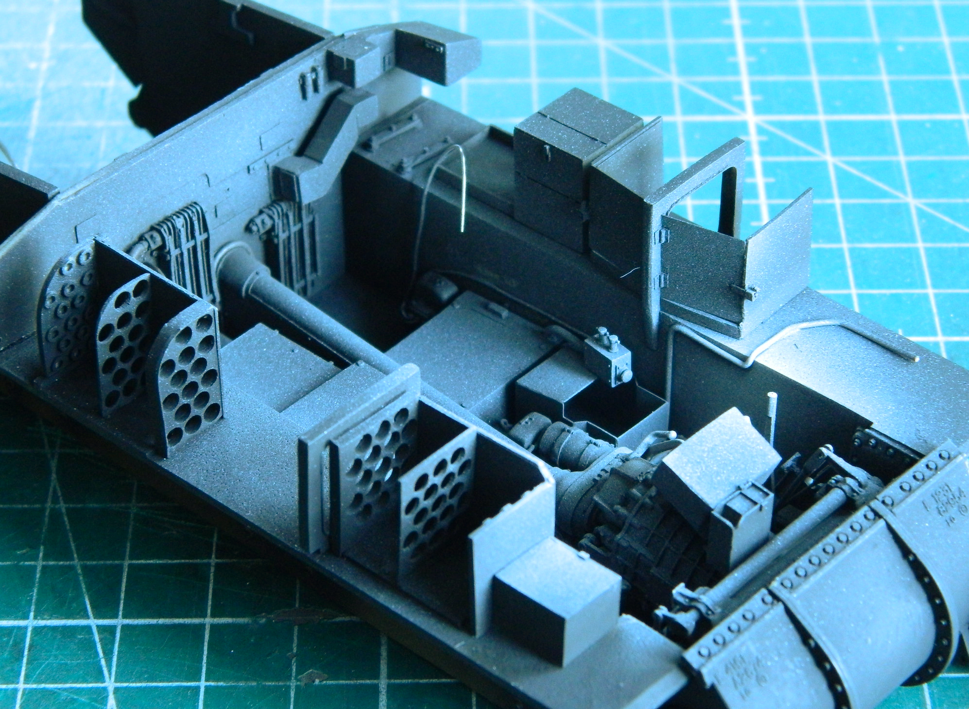
Though recent Tamiya kits evidence excellent fit, t’weren’t always that way. Where the front mudguards “fit” the differential cover needed help. I added successive layers of .010″ (.254mm) styrene until I had more than enough and then sanded/filed them to a more correct fit:
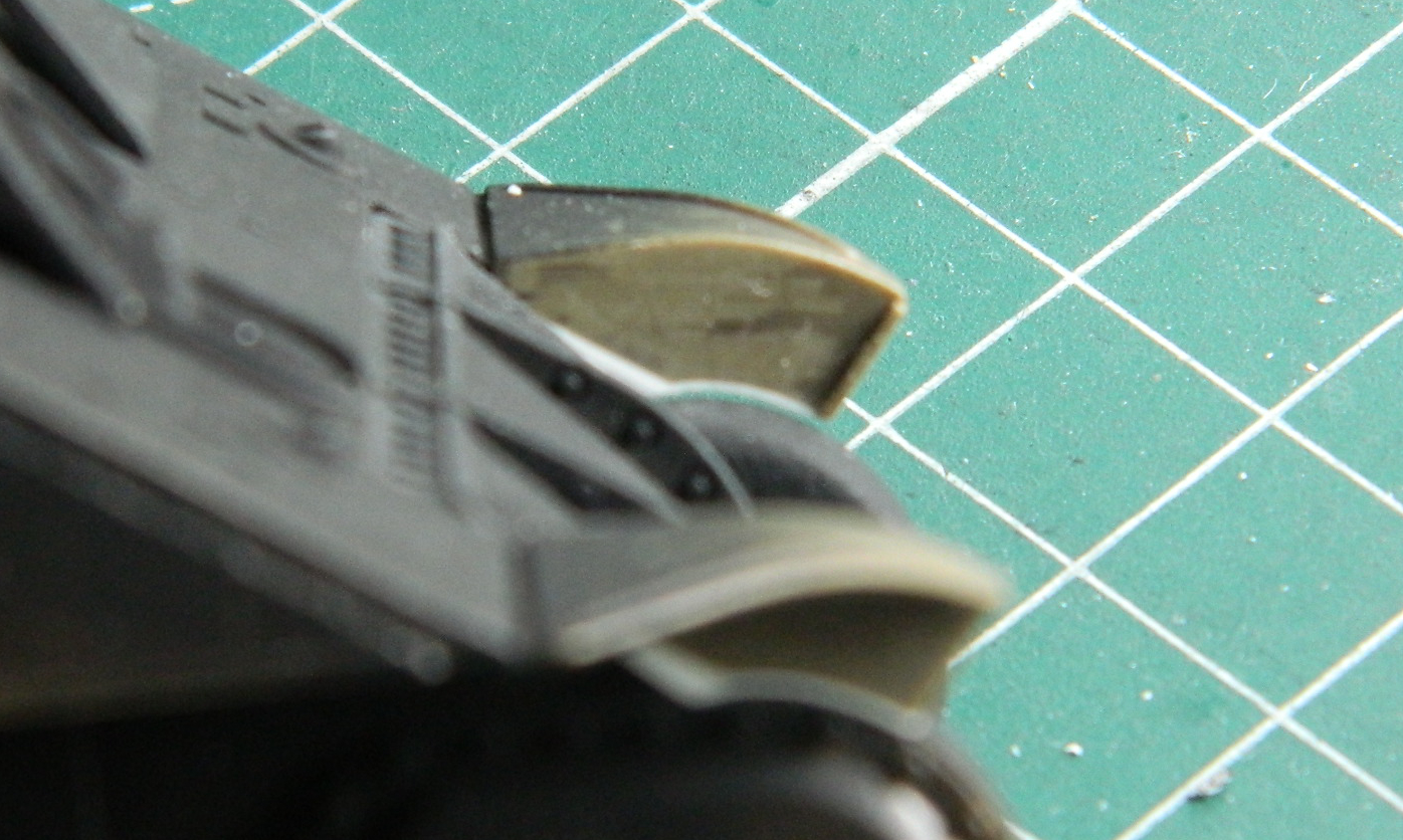
I always try to add a pin-up to my armor models (the FT17 didn’t have one). This time it’s Jane (different Jane, Firefly fans):

And speaking of Tamiya, they made an excellent 75mm ammo set (#35191) that was beautifully machined out of brass (which takes care of what to paint the casings). For those of you this sort of minutia matters to, the shells with the silver stripe (and gun metal fuse housing, though that’s next to impossible to see) are HE (high explosive) and the shells with the solid OD green projectiles are AP (armor piercing). The only thing I did to these parts before painting them was a 20 minute bath in salted water to slightly oxidize the brass surfaces. To paint these things, instead of trying to mask off all those parts, I held each one by the shell casings (tweezers, obviously) and dipped the tips into a bottle of Tamiya XF-62 Olive drab (3 parts) and XF-2 Flat White (1 drop for scale color correction), and stuck the bases of the cases to double-sided tape affixed to thin cardboard to dry overnight. The next day, and completely unsurprisingly, I saw where I’d dipped some of them too deeply into the paint. Since acrylic paint doesn’t like to stick to metal bits, I used that characteristic and scraped away the overage with a fingernail. The next day I came back and applied Tamiya X-11 Chrome Silver with a brush. For the fuse casings I used my custom-mixed “gunmetal” of Tamiya X-18 Semi-Gloss Black (5 parts) and Tamiya XF-20 Medium Gray (4 parts):
And then they were added to the ammo racks. Some rounds fit snugly (almost too much so) and some required a tiny dab of superglue to stay in place. I kept some rounds to add later to the ready-racks in the turret (and aren’t those primers fantastic?!):
And then I added the auxiliary generator…Three hours of diddling, twisting, touching up paint, more diddling and twisting, until it FINALLY settled in where it goes:

With that little nightmare accomplished, I added the fire extinguishers, seats, and instrument panel.
So, in the last post I mentioned where I thinned out the opening around the engine bay to get “scale thickness.” What I got was another instance of where I over-clever myself into more work. On the M4/M4A1s, the sides of the engine bay come right up to and even with that opening. So that meant that once again, I over-clevered myself and did the work to fix my “cleverness” by adding scrap styrene and then finishing it down:
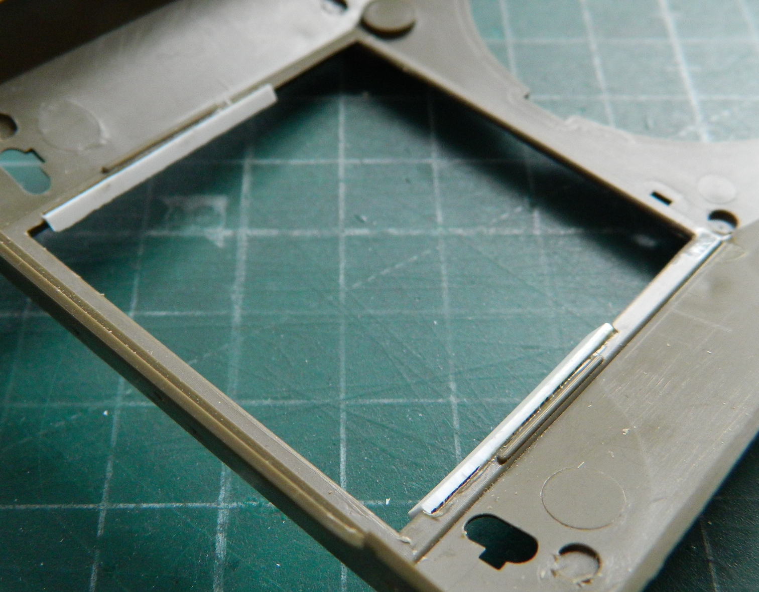
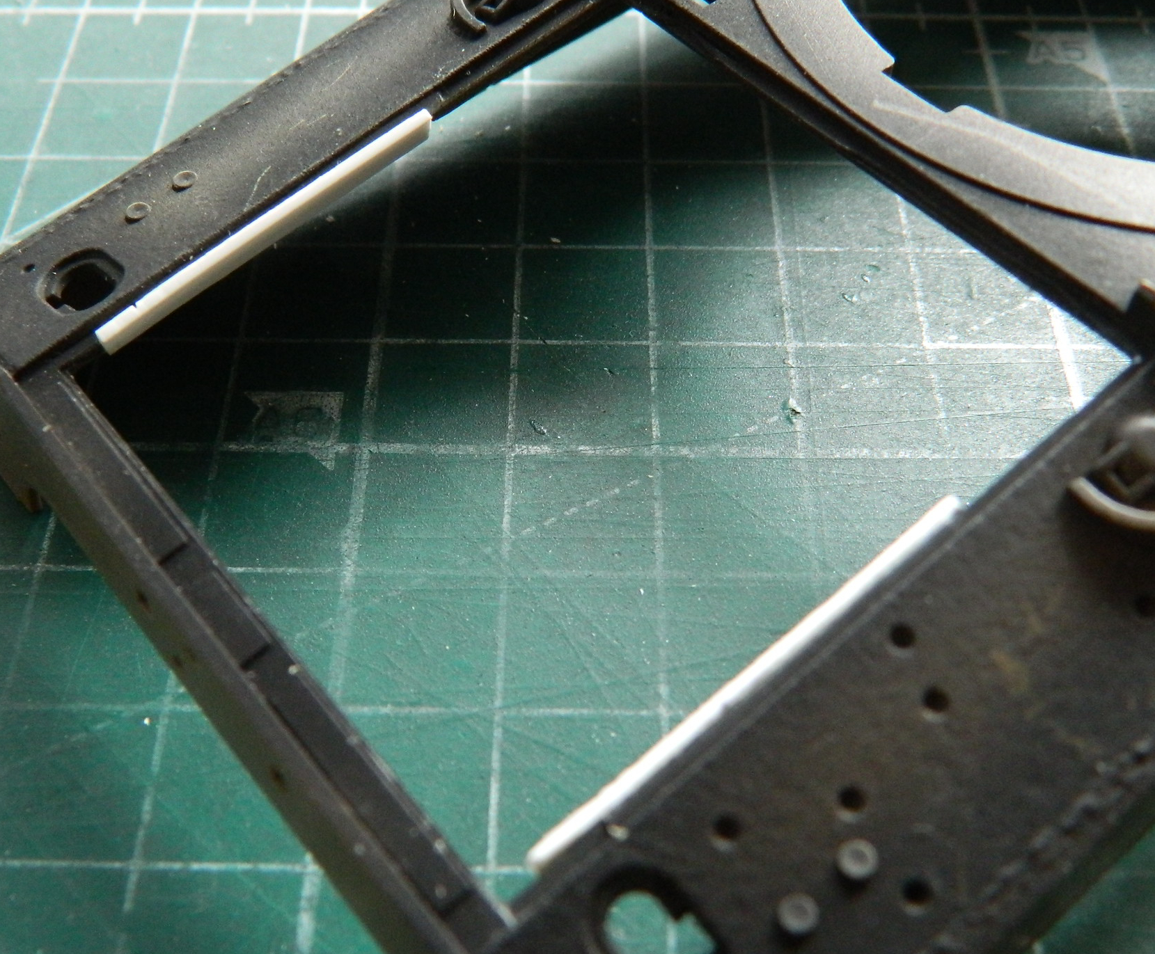
While that glue cured…completely… I sprayed lit areas with clear gloss and used a black wash using oil paint to pick out details. Then I used pastels, Humbrol #27003 Steel, and a sliver-colored pencil to add wear and staining. Since I am (attempting to) model a relatively newly-deployed tank, I did not weather and wear the interior to the same extent I did with my M4A3 (and also added the spare periscopes to the stowage box over the transmission):
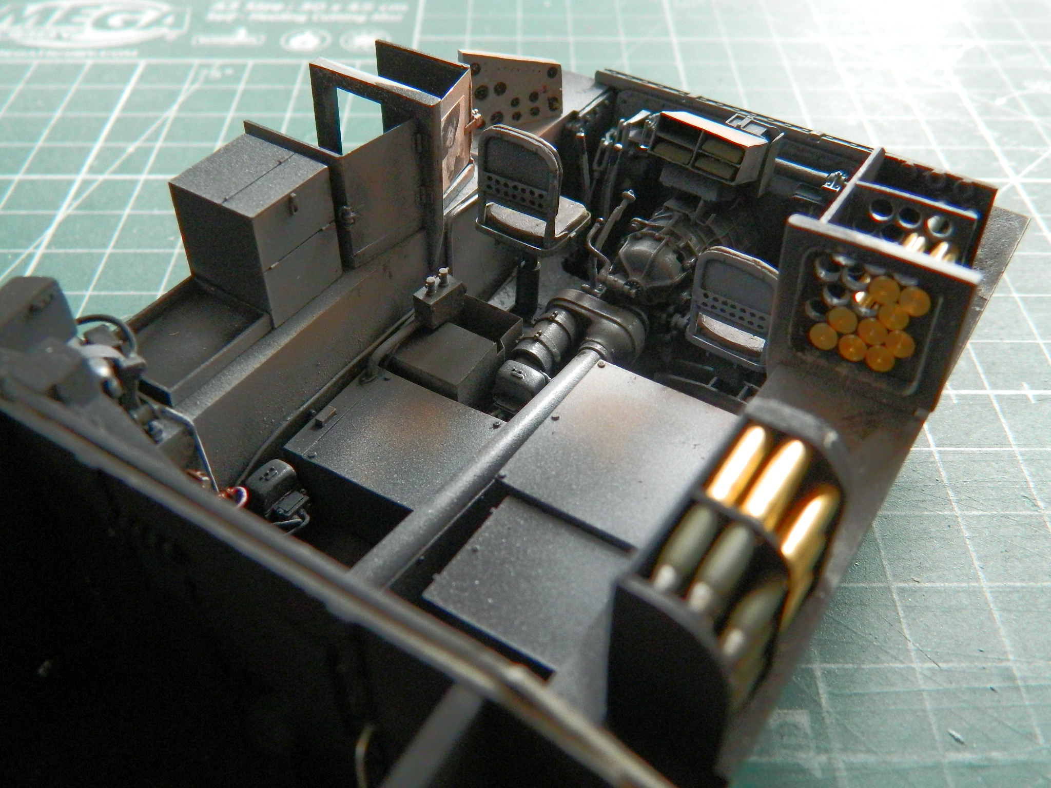
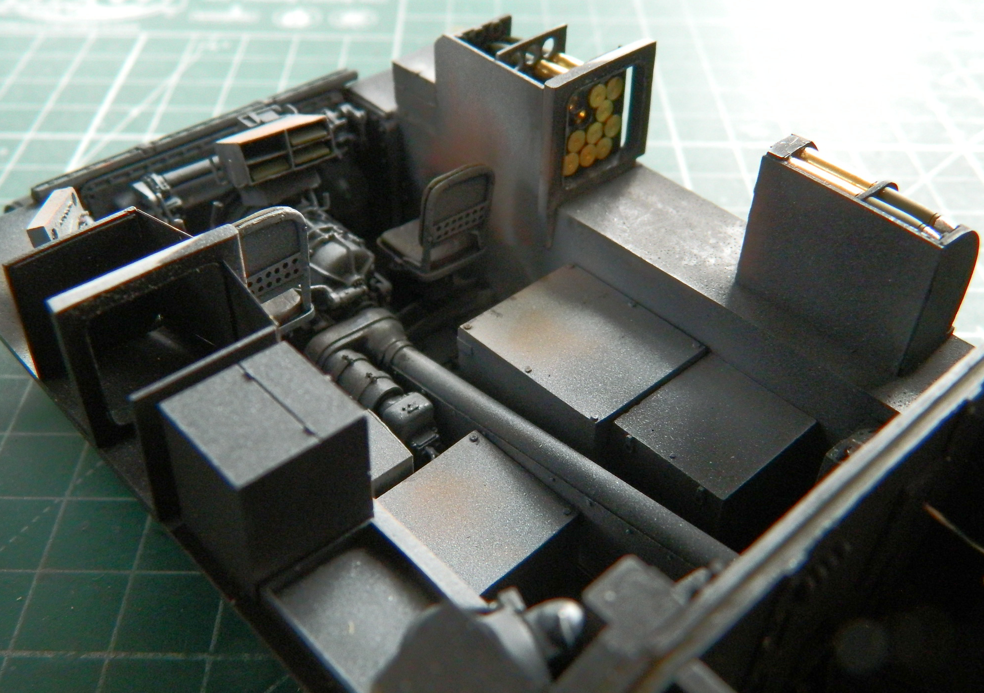
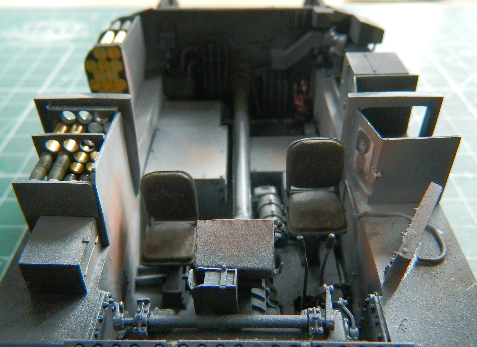
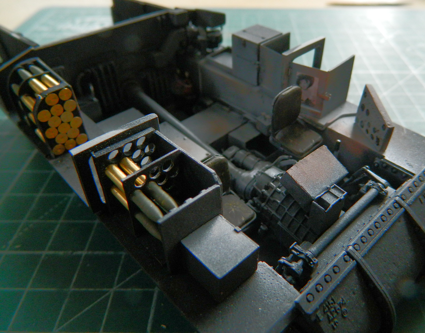

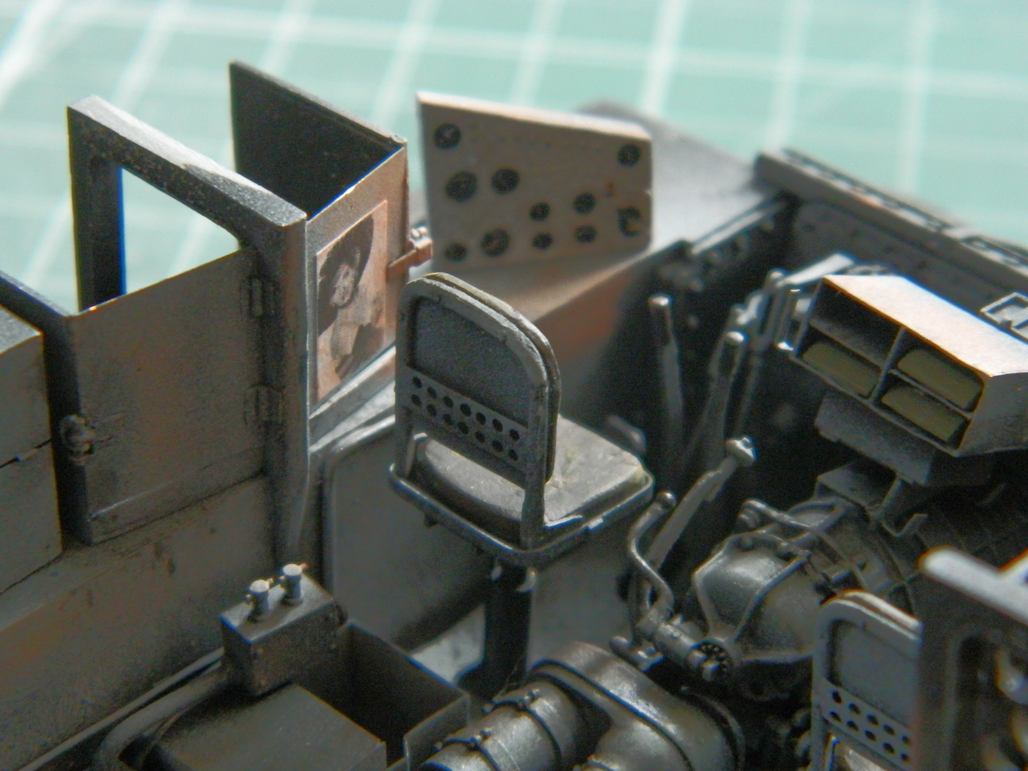

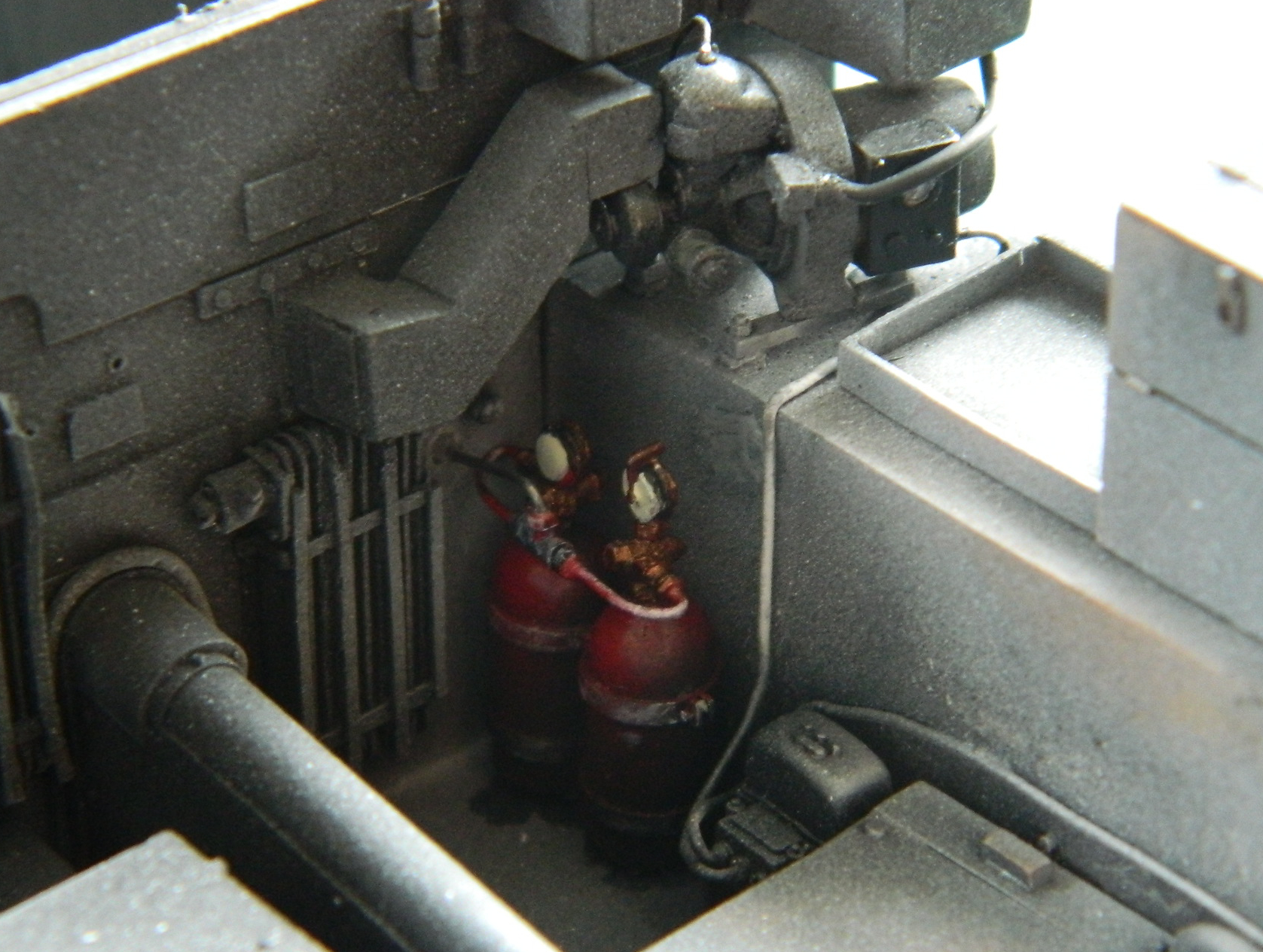
There is another ammo bin next to the driver. Frankly, I can’t see how that bin could be opened without the forward door smacking the driver seat…and forget having enough room to get the round out. I also just don’t understand how the supplied parts could work…so I didn’t add them. The doors to the bin are closed and empty bins won’t show on that side (the other side that has the rounds in the racks are right where the clear panel will go so I added those there):
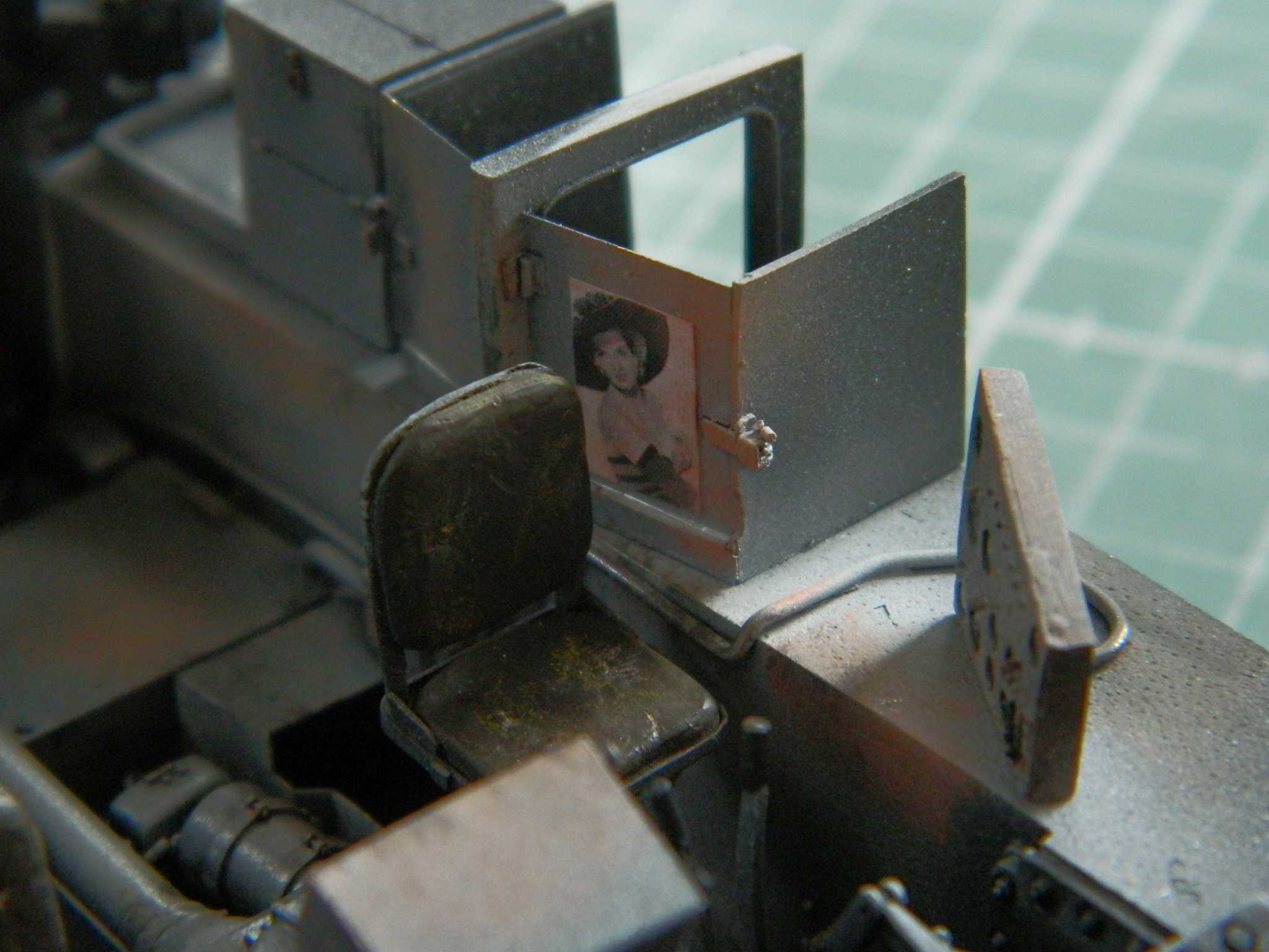
With the crew compartment populated, my attention turned to fitting the upper hull. If you look closely at the following picture, you’ll see where the forward bulkhead and both sides of the engine bay don’t meet the upper hull:
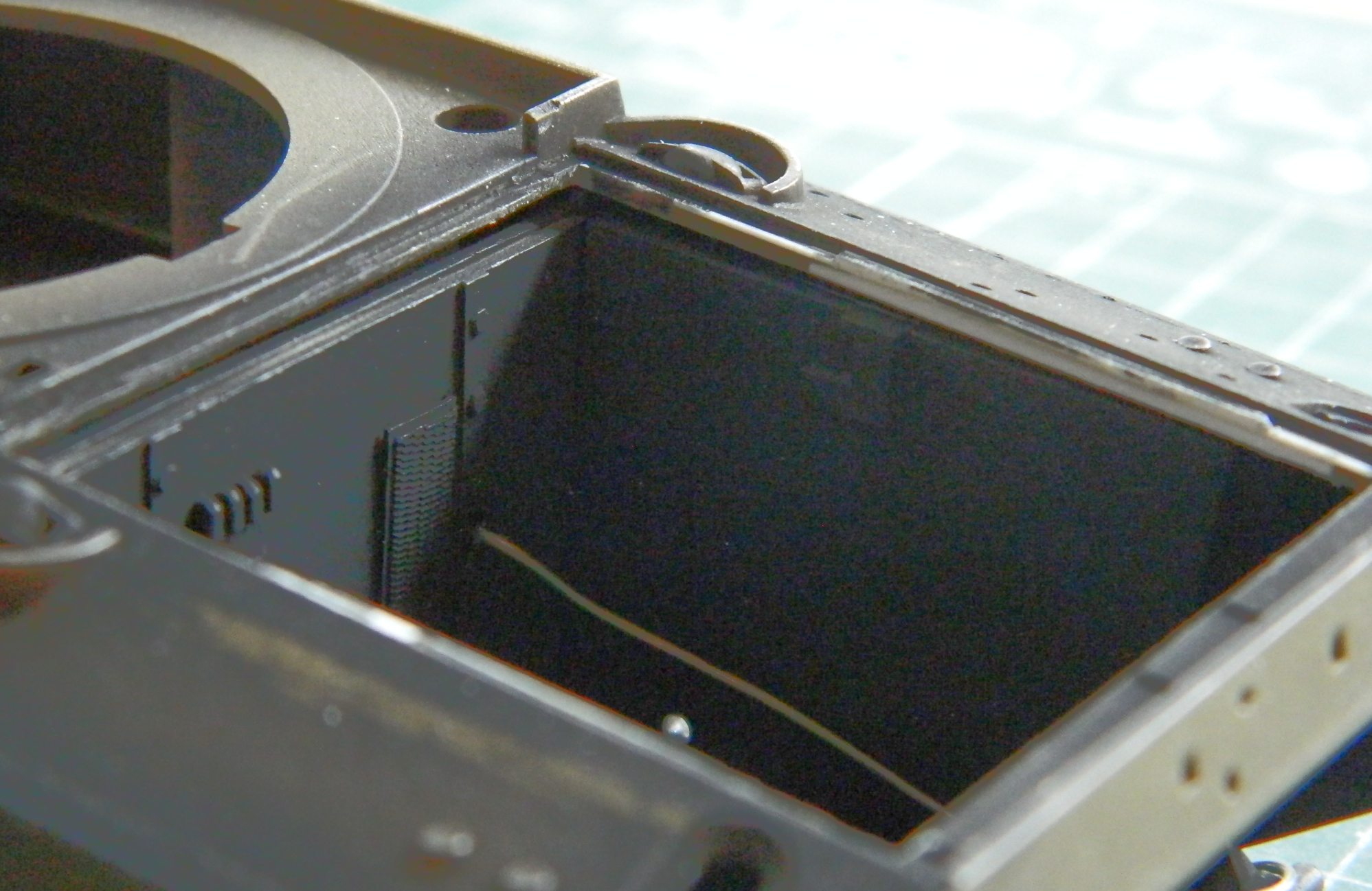
When I looked closer, I saw that this section of the upper hull really doesn’t fit. There are substantial gaps where there shouldn’t be gaps. First photo is with the flash, the second is backlit:
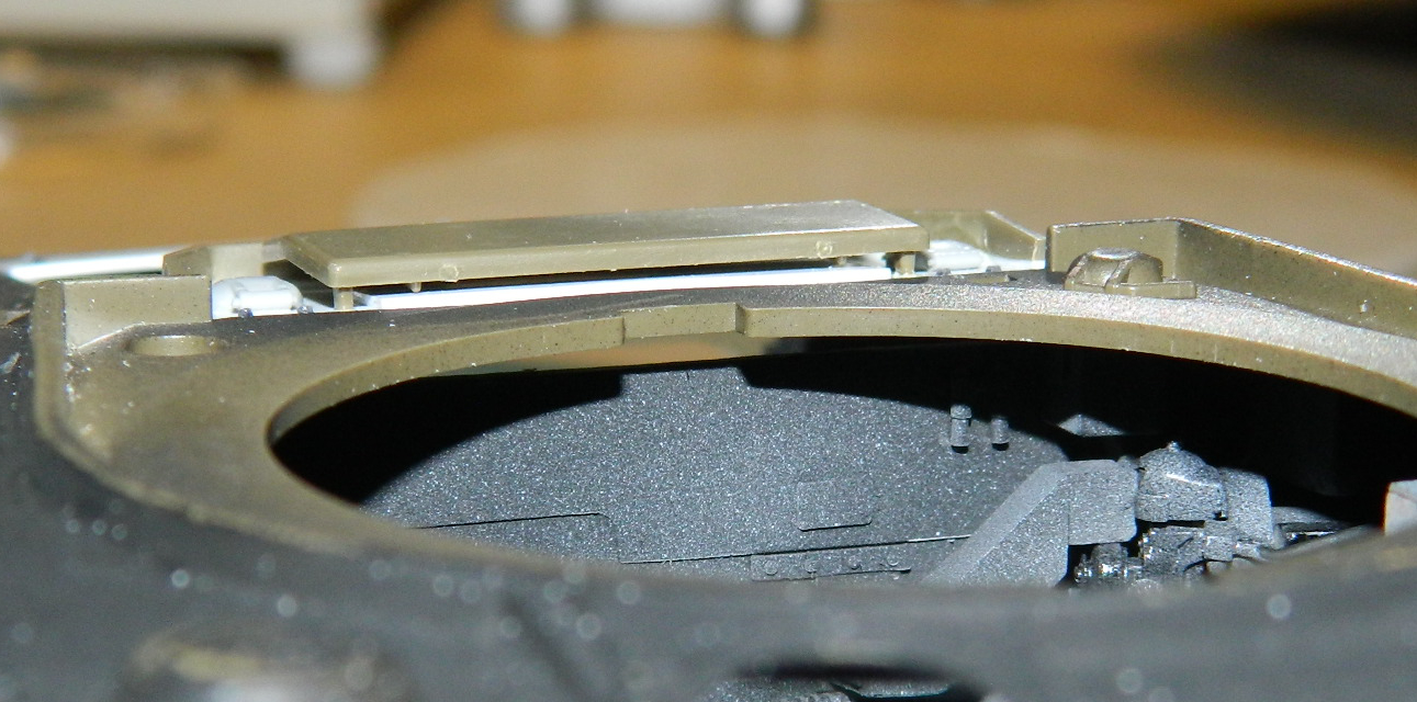
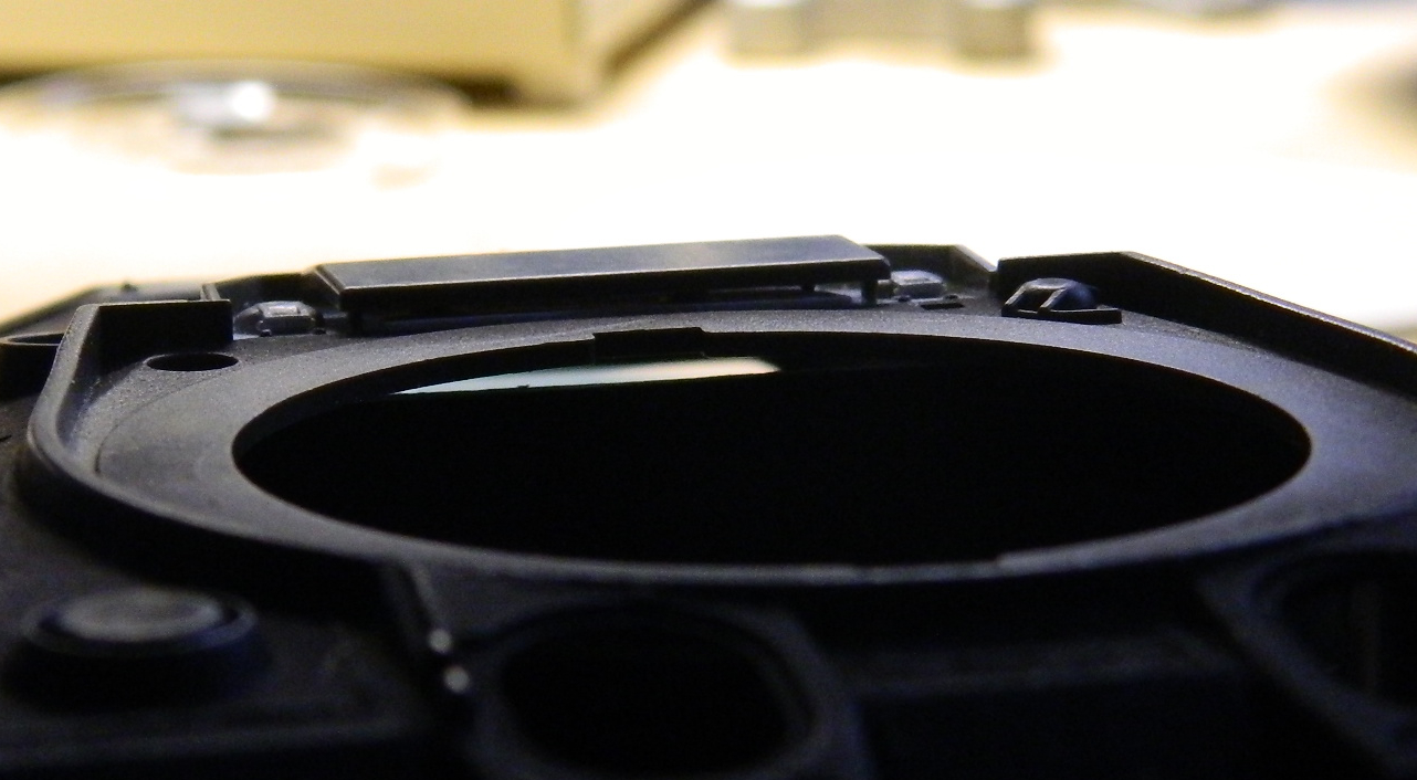
To fill that gap I used .030″ (.762mm) scrap styrene to start filling the gaps:

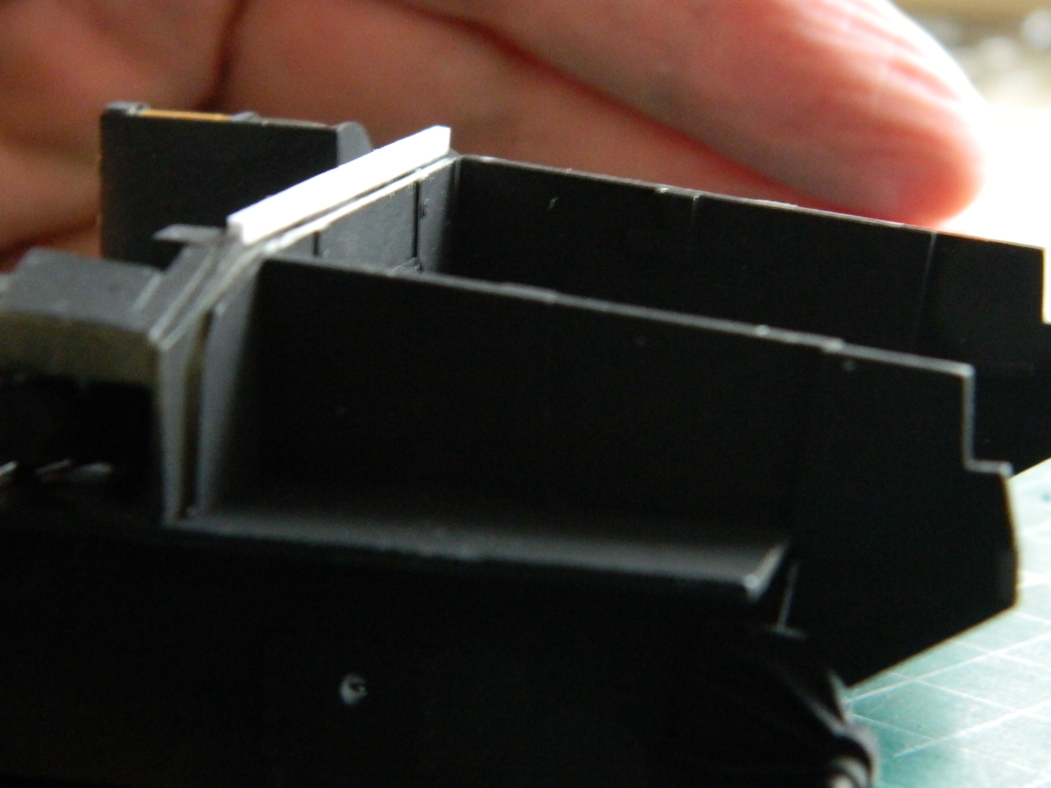
With the upper dimension of the added plastic in place, I added more of the same scrap to the sides:
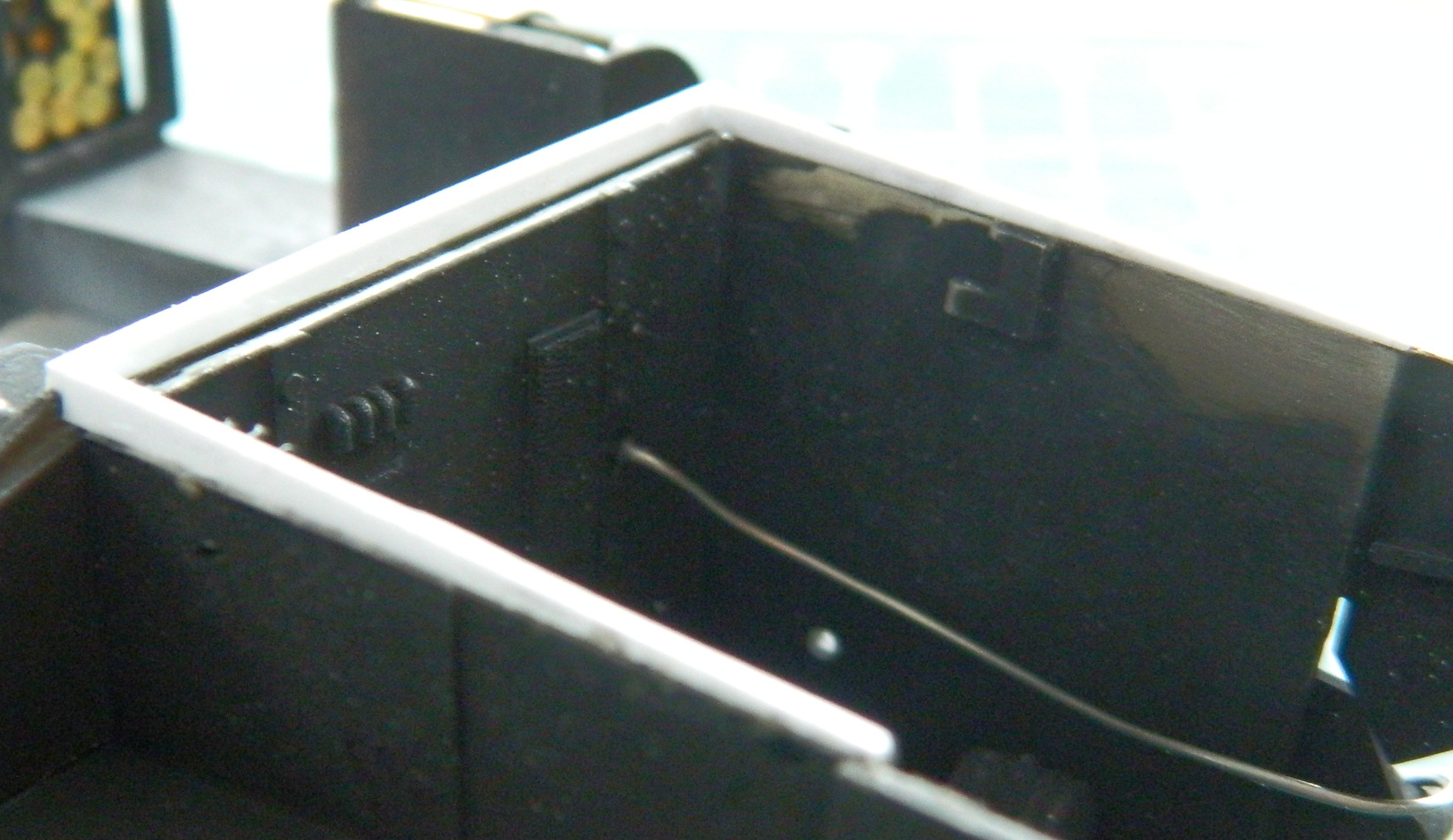
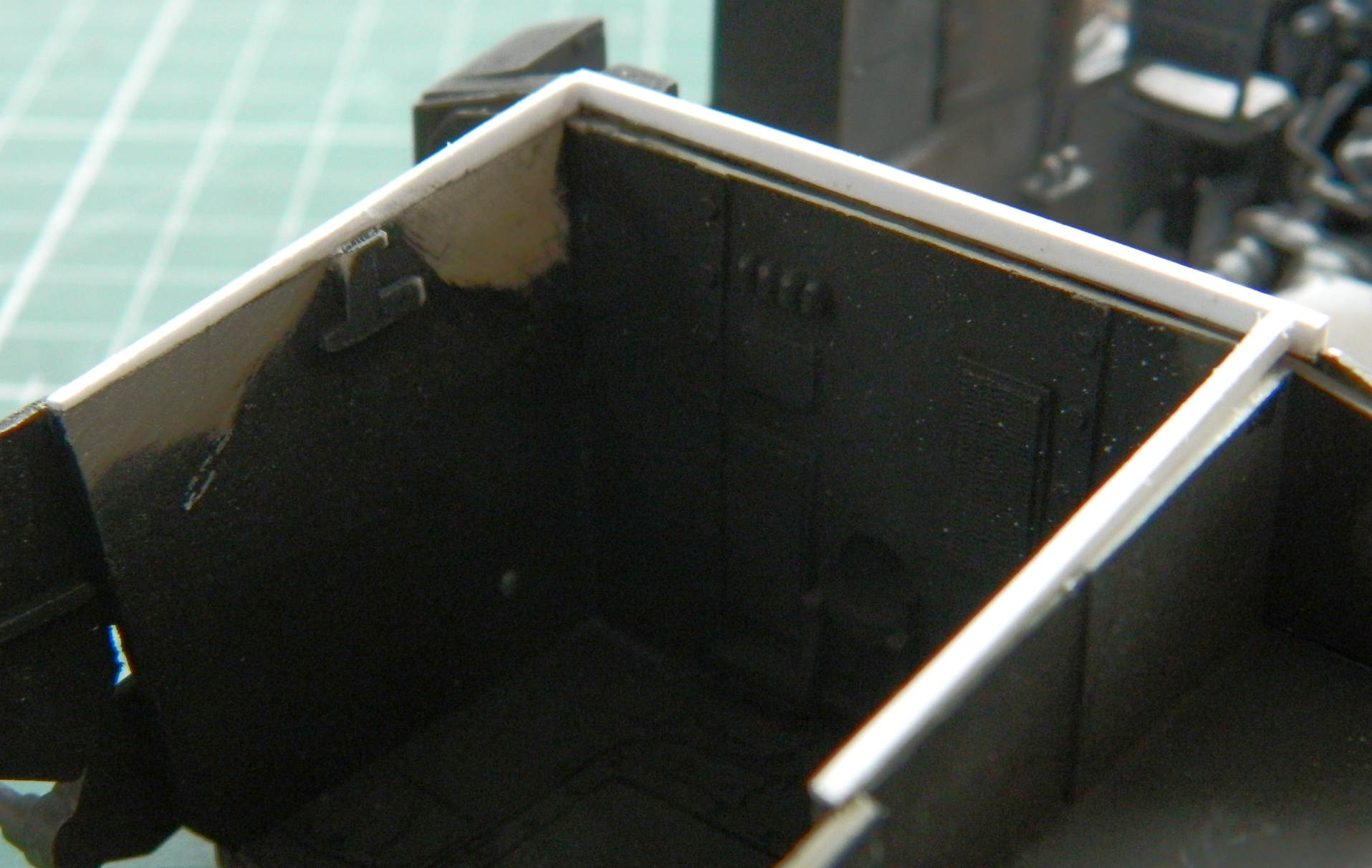
At this point I wondered if I needed to add more plastic to the engine side of the bulkhead so I dropped the forward engine cover in place to see if that section would even be seen. It won’t be, so I didn’t bother:
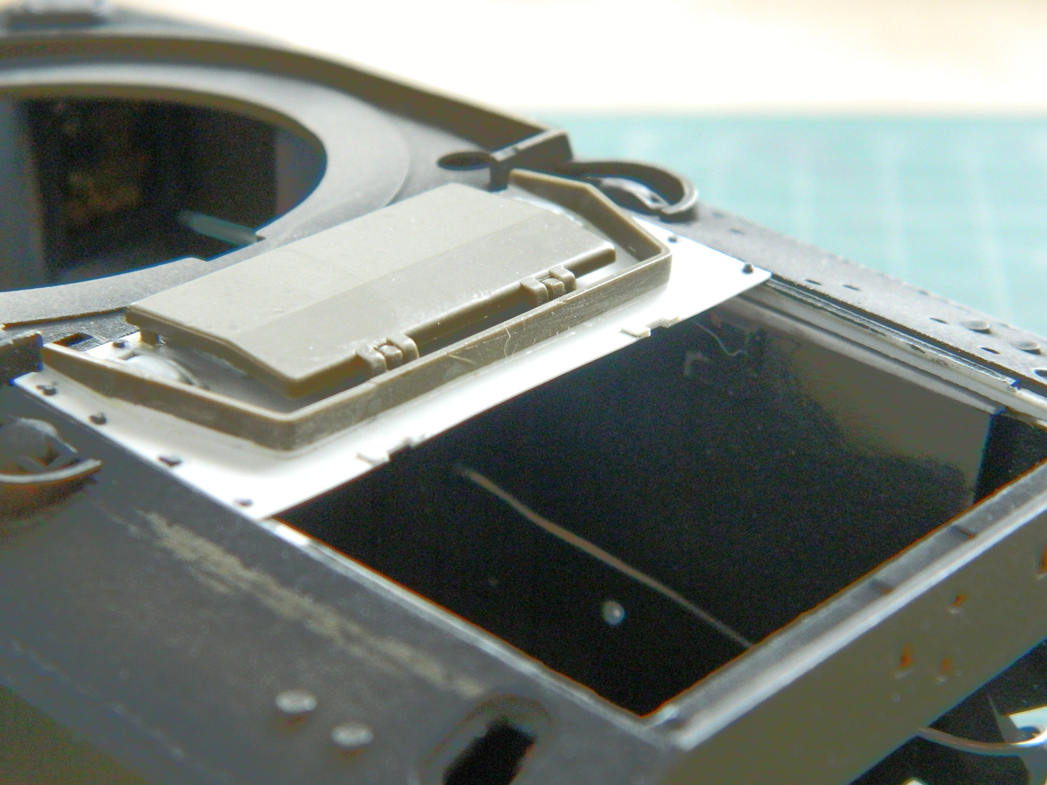
A LOT of filing ensued before I achieved the effect I wanted. A trick I used that made this easier (relatively speaking) was using a flashlight to back-light the sides of the engine bay to see where the gaps were:
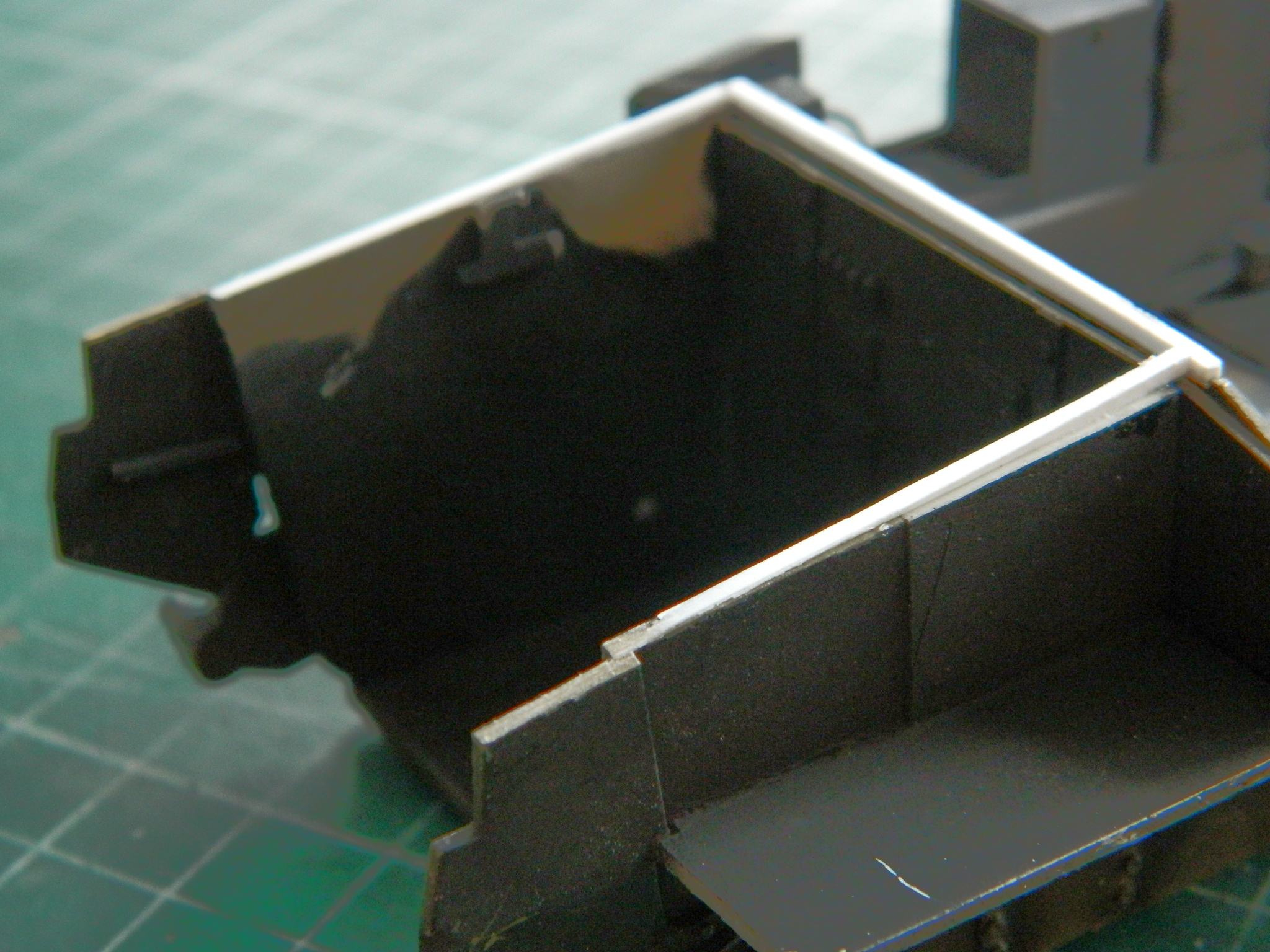
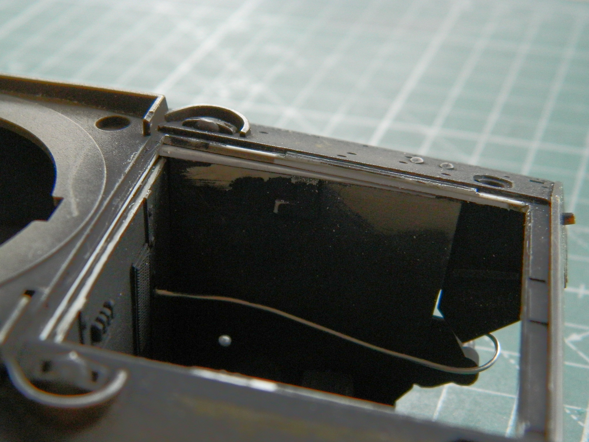
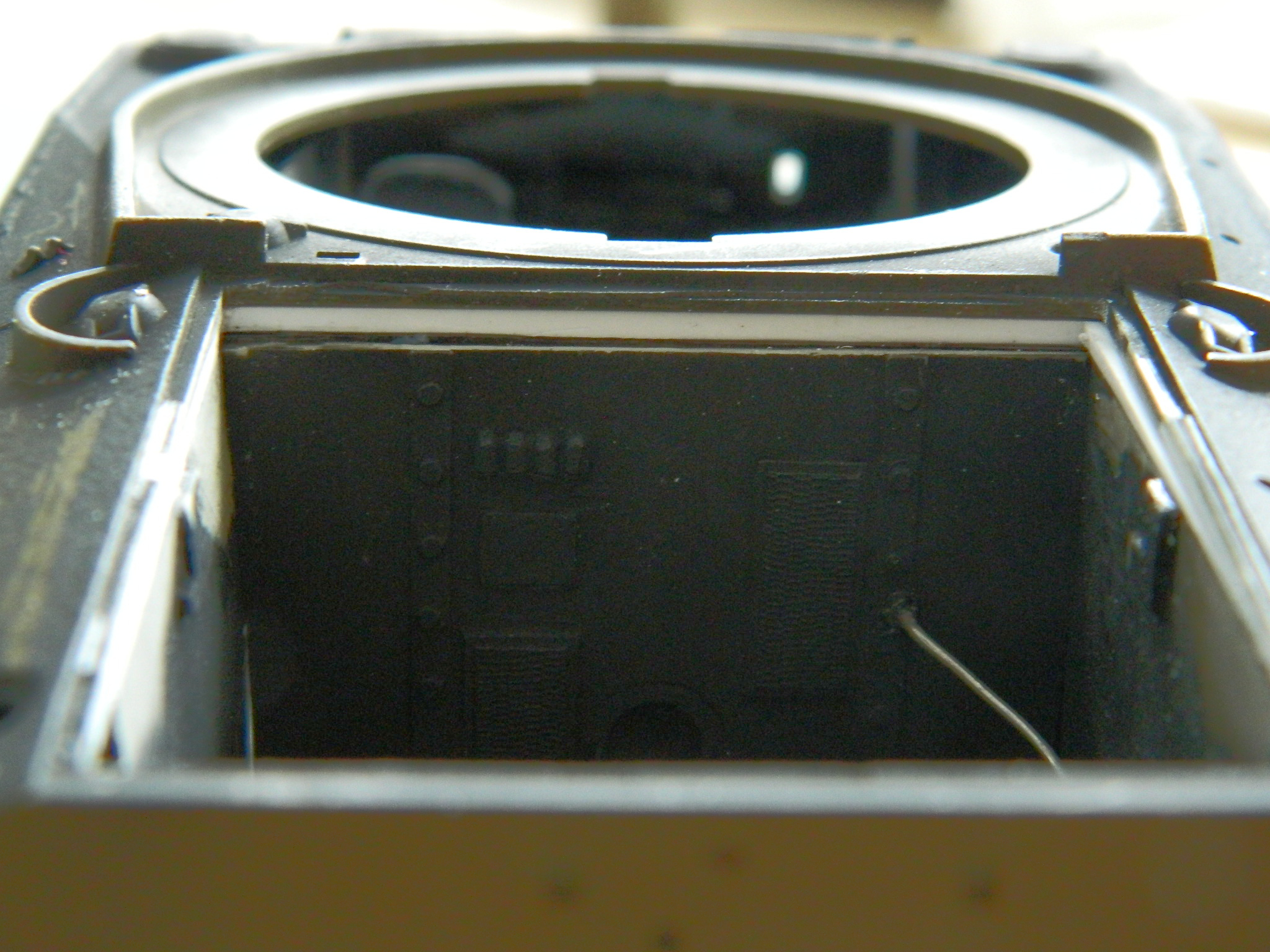
Finally. Fitting the engine. It had been awhile since I last checked the fit of the engine. So it was with no small amount of trepidation that I put the engine in place and dropped (again, all terms being relative) the upper hull in place, dry-fit the engine covers that will be in place, to see if it still fit:
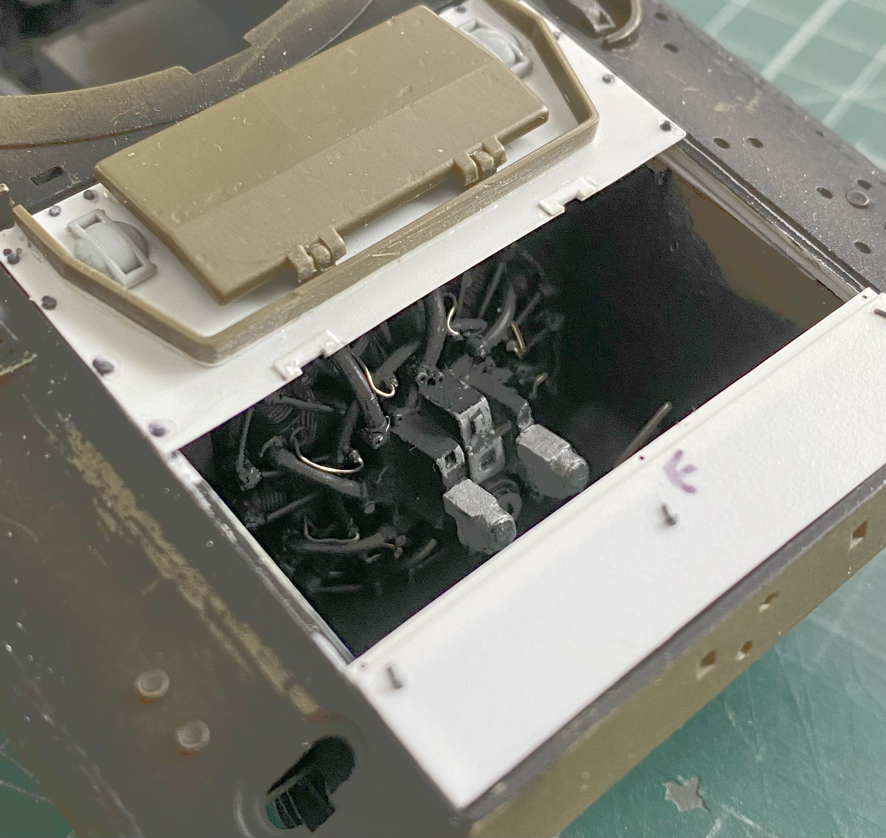
YES! And the Sword of Damocles is returned unused to its celestial scabbard!
Before I could do more additions to the engine, I had to attach the rear mounting. Before I could do that, details had to be added, so details were added using .015″ (.381mm) solder:
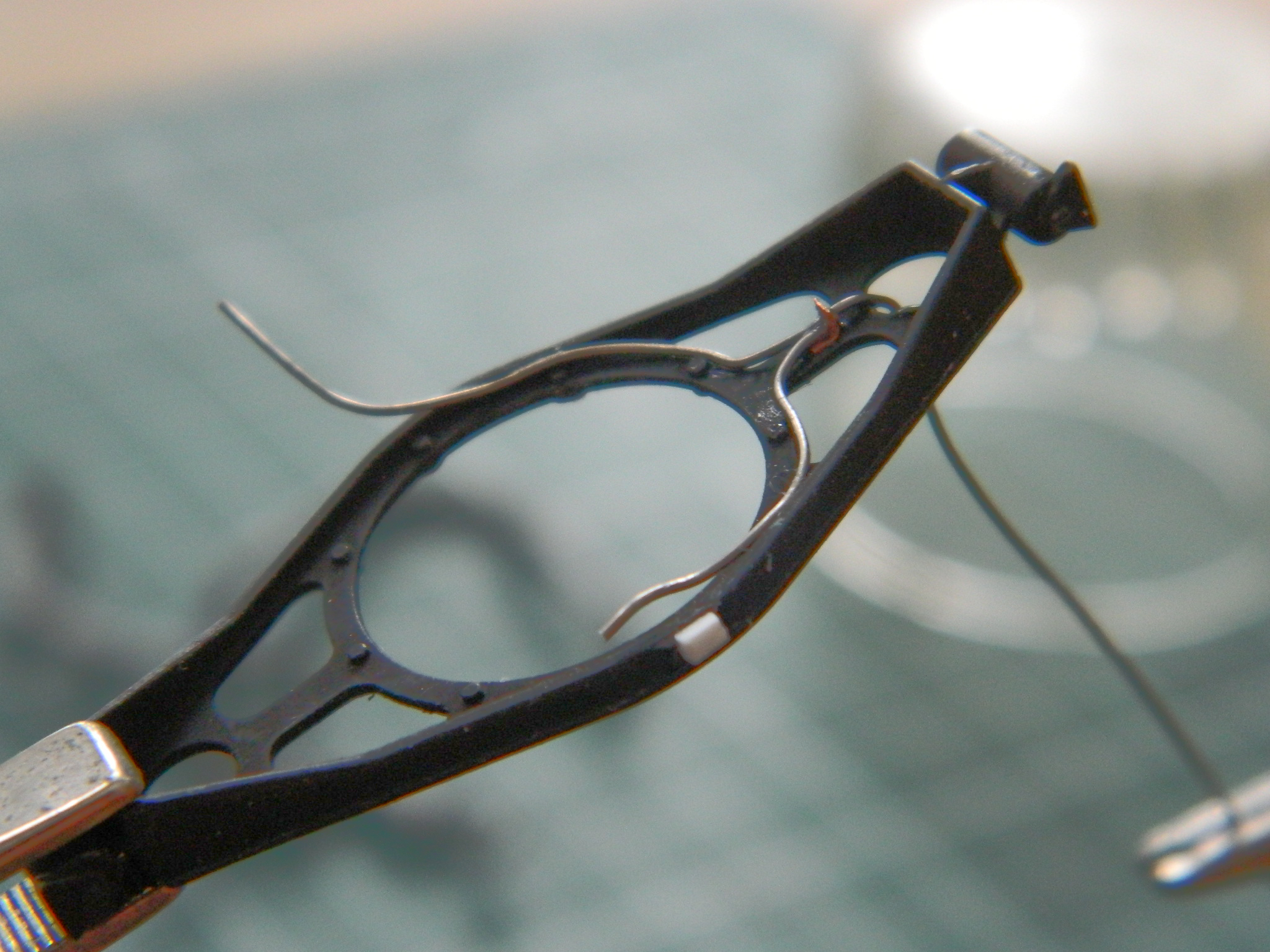
Then I did the starter (on the left) using .025″ (.635mm) solder and the generator (same diameter solder):
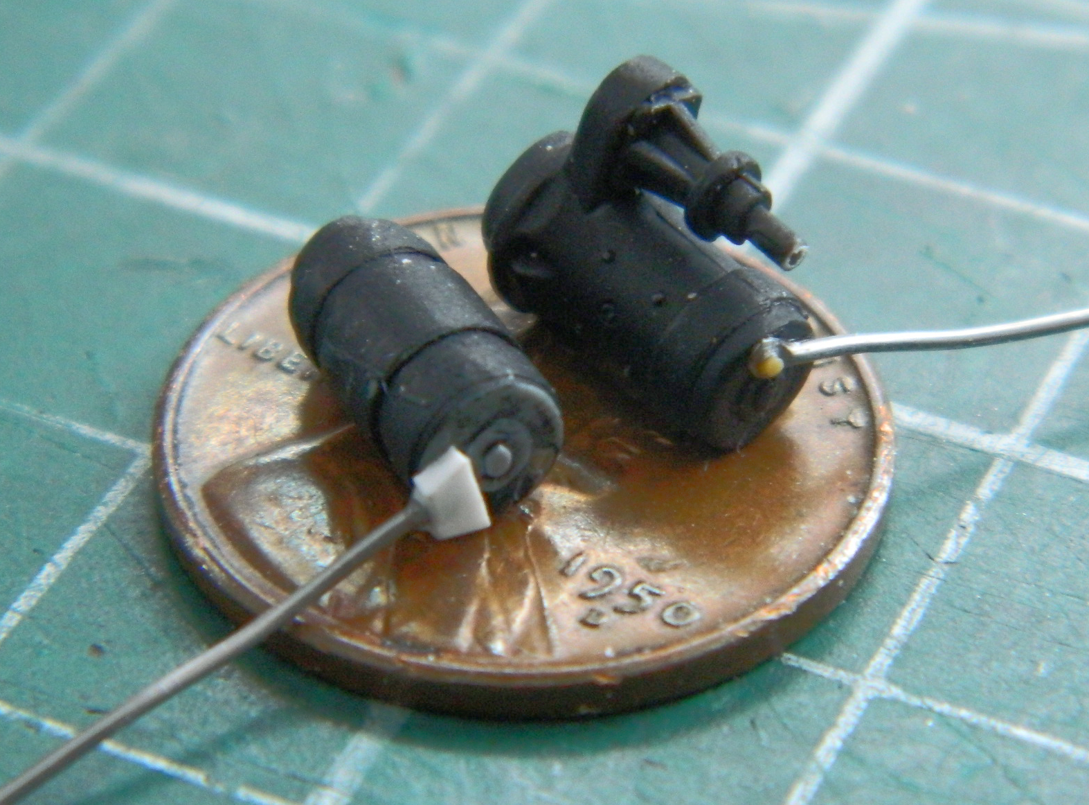
And then I remembered that I had yet to paint the inside of the upper hull…which reminded me I still had a few bits to add before I could do that. Reference photos indicate that the fixed periscopes (no doubt in there to take the place of the direct-vision slots) weren’t fitted often, probably due to the periscopes in the hatches blocking any view out of the fixed ‘scopes. The now-closed-but-definitely-missed TMD offered the empty ‘scope mounts. Having a few of those on hand, I cleaned up and glued a couple in place. Also from TMD are the mushroom-shaped inner (passive) vents that were added:
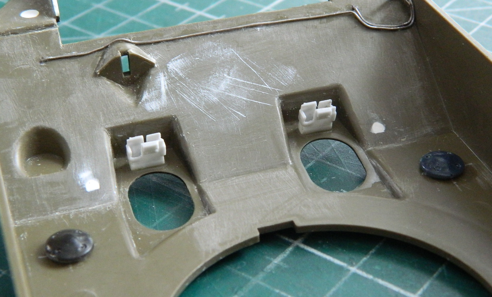
To finish the inside of the upper hull, it was painted Tamiya XF-1 Flat Black and then Tamiya XF-2 Flat White was misted over that. Because the empty periscope mounts are easily visible from outside, and therefore in more direct light, I shot those from above and through the hatch openings:
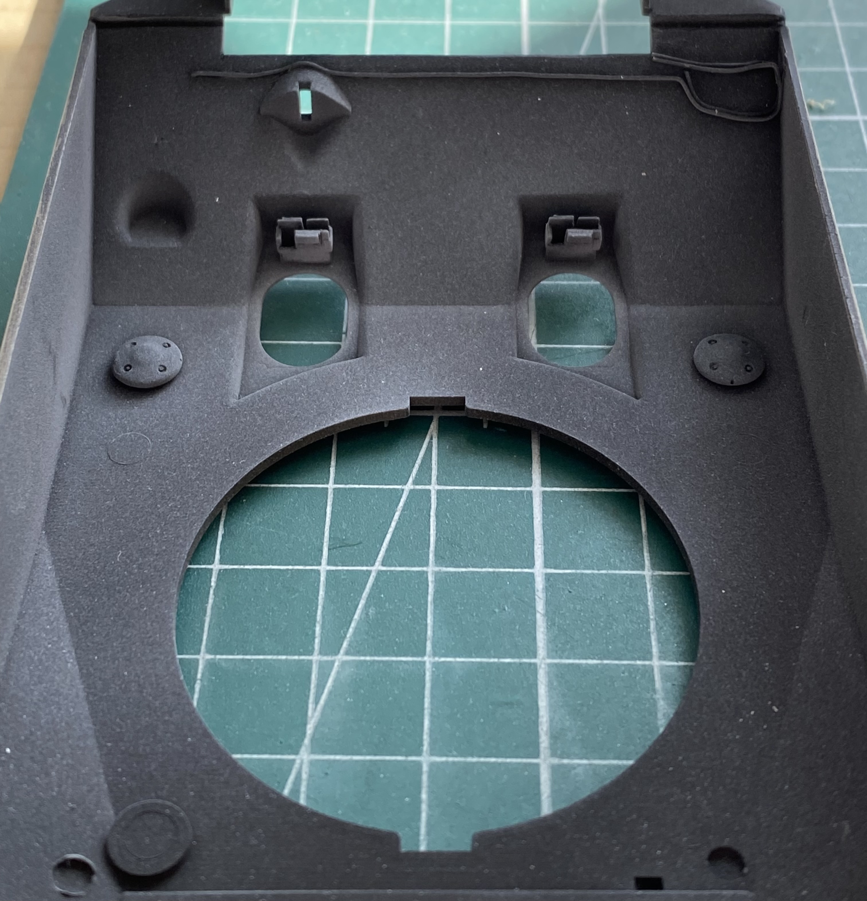
While dealing with upper hull minutia, I added weld beads using Vallejo Acrylic Resin Putty #70.401 (which, if you need to apply weld beads is GREAT for doing that…best technique I’ve yet found to add weld beads) to the applique armor in front of the hatch hoods:

While I was in the let’s-add-weld-beads mood, I glued the rear engine cover in place and added weld beads to it and the sides of the rear applique armor where it joins the upper hull:
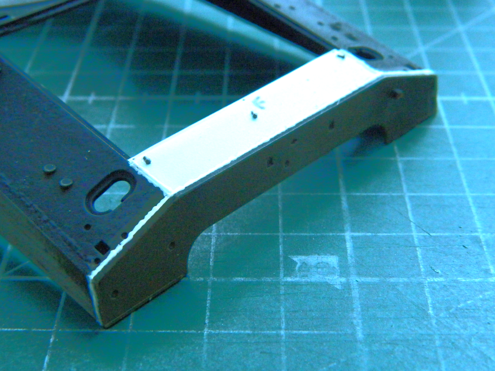
With all the additions to the engine bits done, the engine bay and associated parts were all hit with Tamiya XF-1 (with the exception of the generator and starter motor which were done with Tamiya X-18 Semi-Gloss Black to match the paint on the rest of the engine):
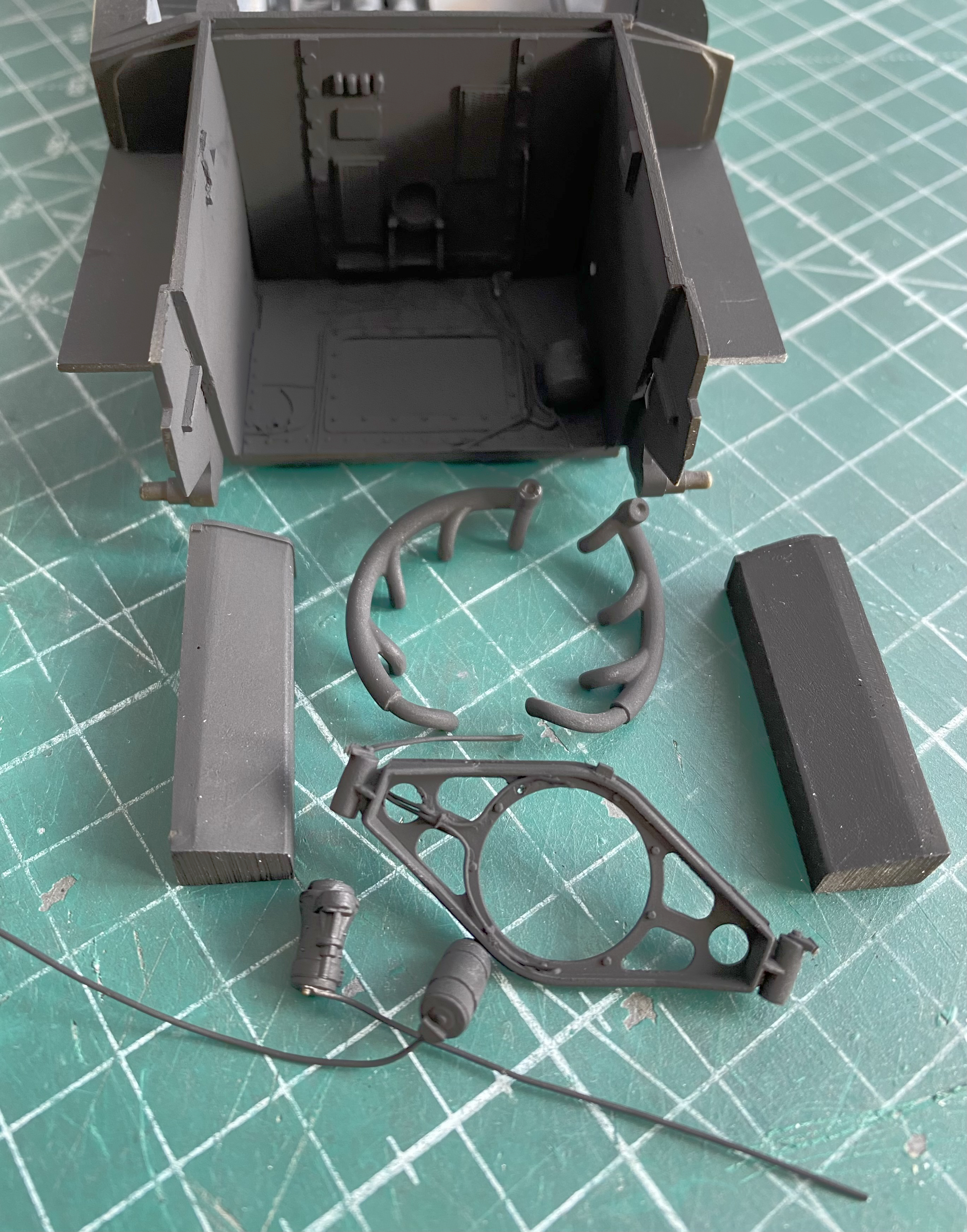
The rear engine mount was misted with Vallejo’s #71.132 Aged White. Once it had set up, the mount was glued to the engine. Once the glue set, I added the starter motor, generator, fuel pump, and carburetor and connected the “wires” where they could be connected and routed the ones that couldn’t be connected (because…where?) to where they would disappear into the dark engine bay. The hoses and wire insulation were painted with Tamiya XF-85 Rubber Black, with one wire being painted Vallejo’s Aged White:

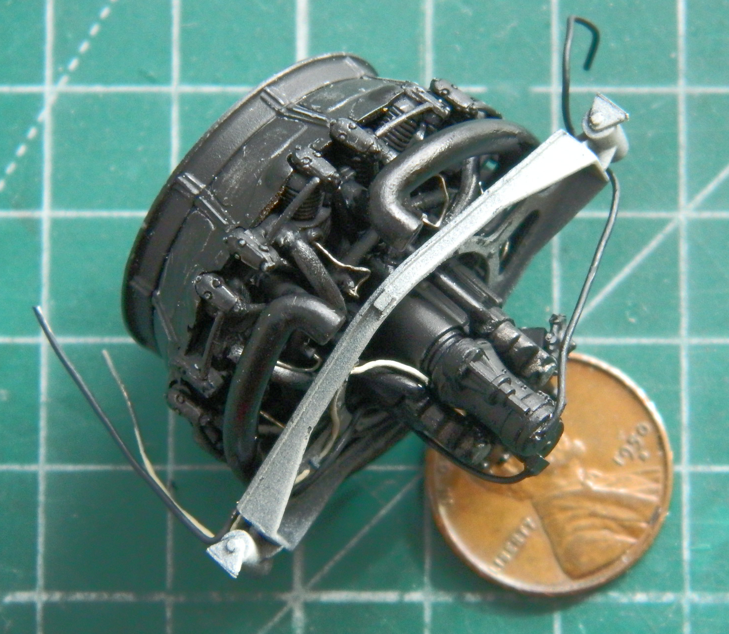
I used Aged White again to “splash” light into the engine bay (and neglected to take any photos of that). I came back the next day to see if the engine still fit into the only space I have for it:

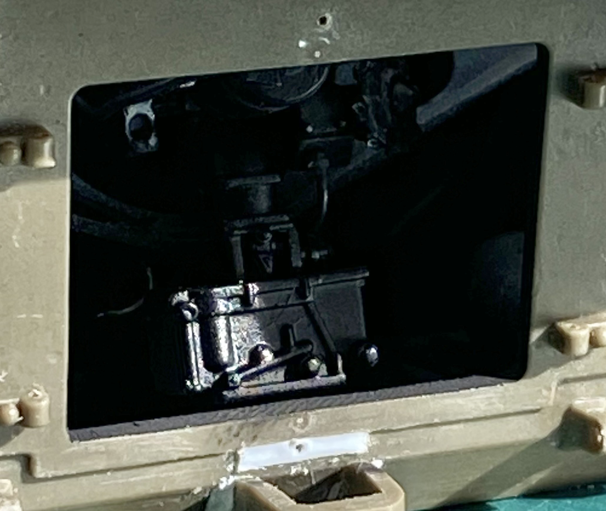
And yes…it does!
So. There. The engine is finally fit! Next post will (I hope) include where I glued it in and the remaining hoses and wires that still need to be added.
Whew…
