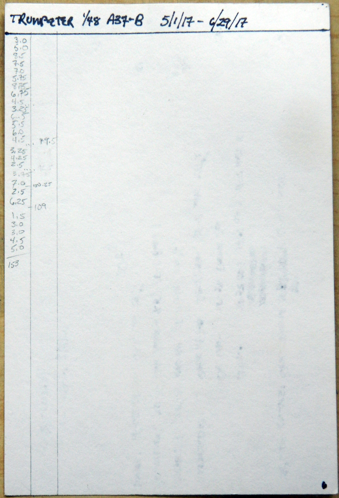
Total time building 153 hours (that’s about 6.375 24 hour days, 3.825 work weeks).
Begin date May 1, 2017; end date June 30, 2017.
Vendors:
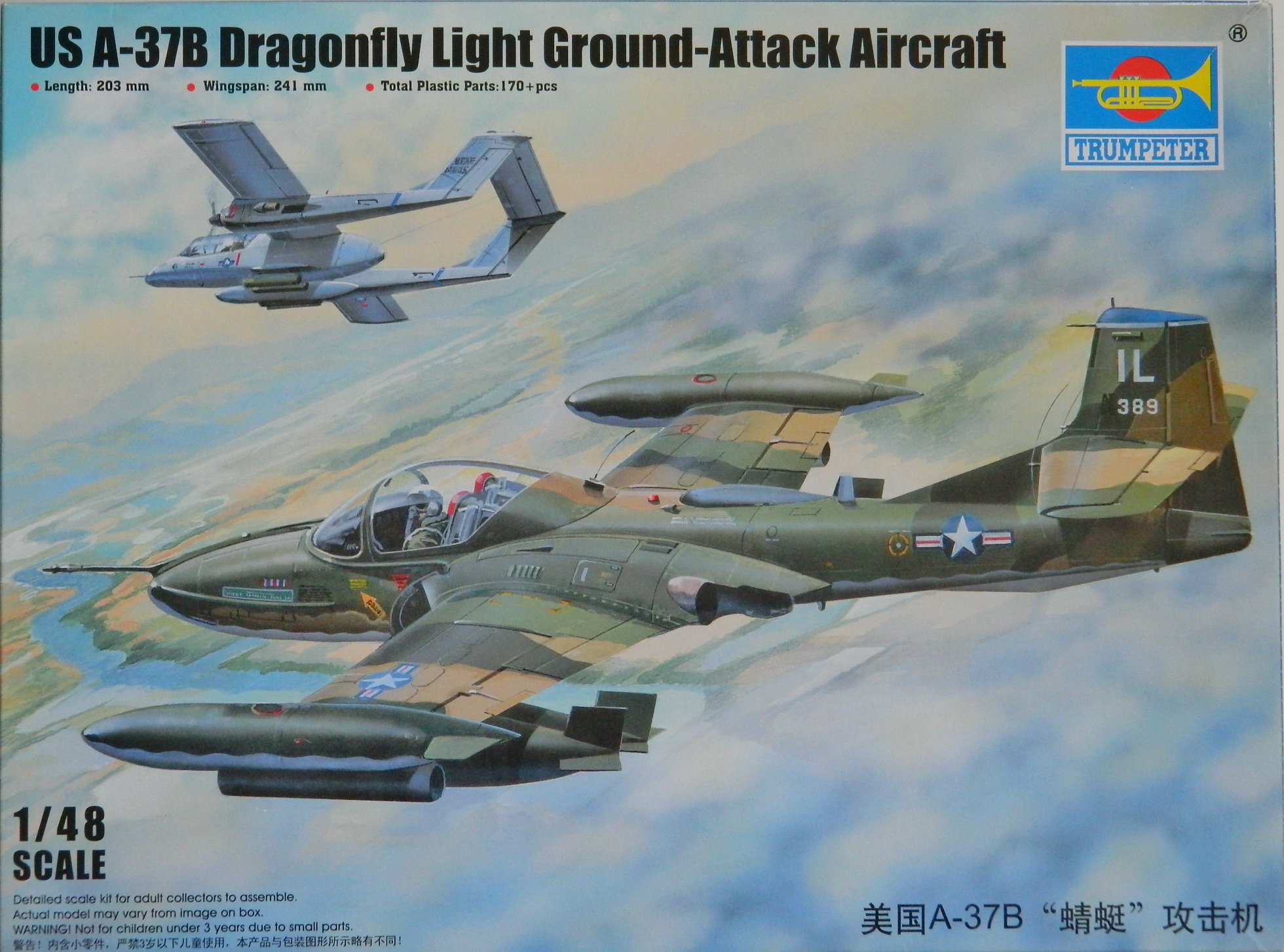
Trumpeter
Kit #02889 1/48 scale
An aircraft that isn’t really in a class by itself; it was a reconnaissance platform like other reconnaissance platforms, yet it certainly was unlike anything before it or since (I assume, lacking the security clearance to know that). It’s also the fastest thing with wings that takes off and lands with a human crew aboard (that we know of, anyway…there are rumors…and the SR-72), setting its (official) absolute speed record July 1976 of 2193.13 mph (though there have been rumors that the Air Force unofficially clocked it at 2242.48 mph…and the A-12, the CIA’s version which preceded the SR-71 is supposed to have been even faster) . Depending on which source one reads, the Blackbird made it across the Atlantic in just under two hours (3,461.53 statute miles in 1 hour, 54 minutes, 56.4 seconds at an average speed of 1,806.95 mph) and from California to DC in just under over an hour (1 hour, 17 minutes, 53.69 seconds at an average speed of 2,124.51 mph).
Designed and built by Kelly Johnson’s team at the famed Skunk Works at Lockheed, its first test flight was in late 1966, (though its close cousin, the A-12 from which the SR-71 descended, had been flying since 1962). Thirty-two ’71s were built of which twenty-nine were SR-71As and two SR-71Bs (the only dual-control Blackbirds built and intended for training; one SR-71C was built from a crashed 71A to replace one of the 71Bs that crashed). In late 1989, early 1990, DC politics spelled out the retirement of the Blackbird, but Bosnia (not to mention the Middle East and North Korea) resulted in that decision being re-examined in light of the tactical situation (and not who was doing whom) and its service life was extended. Its last flight on the Air Force inventory was 1990. Typical of its performance history, the last flight of the last in-service Blackbird, tail number 972 flown by Lt. Col. Ed Yielding and his RSO (Reconnaissance Systems Operator) Lt. Col. Joe Vida, took place on March 6, 1990, with a cross-country dash from Beale AFB to Dulles International in DC and broke four speed-over-distance records. These records still stand.
During its twenty-five years of service, it’s rumored that over four thousand surface-to-air missiles were shot at it without a hit. No Blackbird was lost on a mission, twelve being lost in non-mission accidents, with one fatality.
The technology to build the Blackbird didn’t exist until Lockheed invented it. Its shape was intended to make the aircraft difficult to see with radar. Its published service ceiling (how high it can fly) is 85,000 feet and the top speed admitted to is Mach 3.2+. Because of the environment of the extreme altitudes it operated at, the crew’s flight suits looked like astronaut suits (no surprise considering they were based on the flight suits used by the Gemini program).
Upon its arrival at Dulles, #972 was turned over to the Smithsonian Air-Space Museum where it is presently displayed at the NASM’s facility in Virginia.
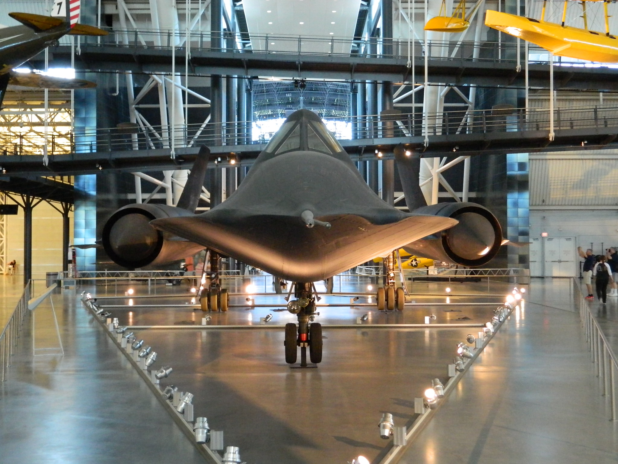
Tail number 61-7972 displayed at Steven F. Udvar-Hazy Center, Washington Dulles International Airport, Chantilly, Virginia

Total time building 153 hours (that’s about 6.375 24 hour days, 3.825 work weeks).
Begin date May 1, 2017; end date June 30, 2017.
Vendors:
Trumpeter
Kit #02889 1/48 scale
Built out-of-box, no aftermarket parts or decals
My Opinion
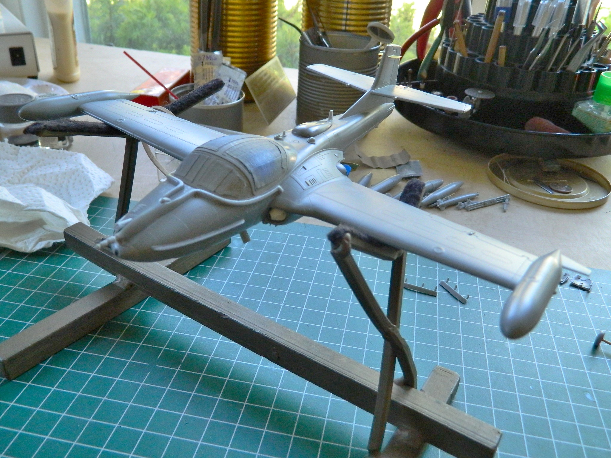
The molds for this model were cut about 2015 meaning it probably utilizes modern CAD-CAM tooling. Overall the fit of these parts was excellent. As ever, dry-fit the parts before gluing. There aren’t many places where fit needs to be adjusted, but they are there.
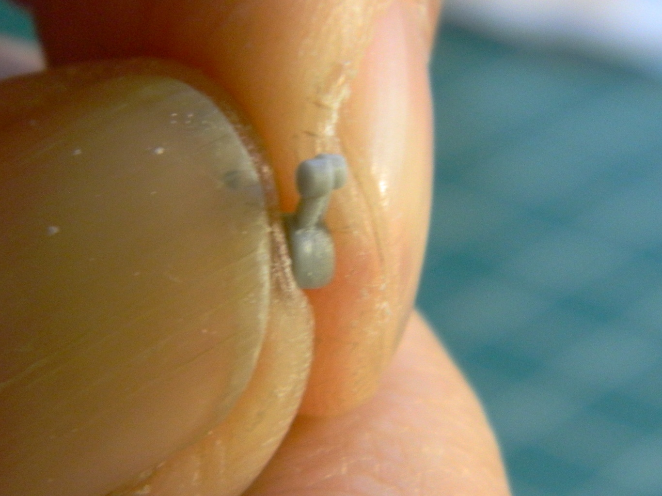
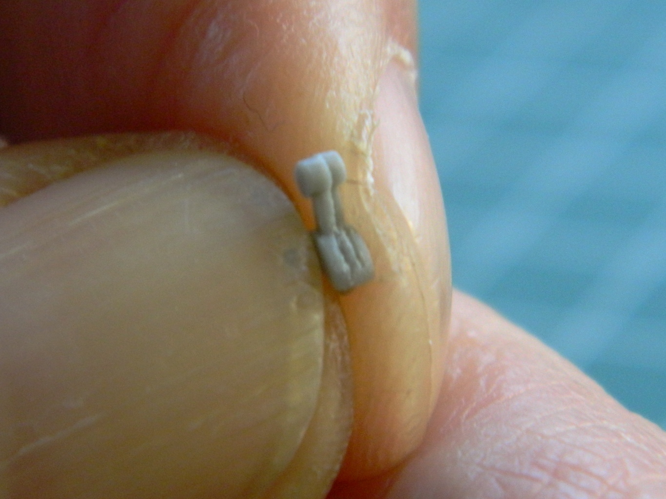
You’re going to need nose weight(s) to keep this thing from being like me…a tail-sitter. I used two .44 caliber lead balls delicately and gently coaxed into shapes that will fit using a jeweler’s anvil and a hammer. (Yes…that’s sarcasm.)
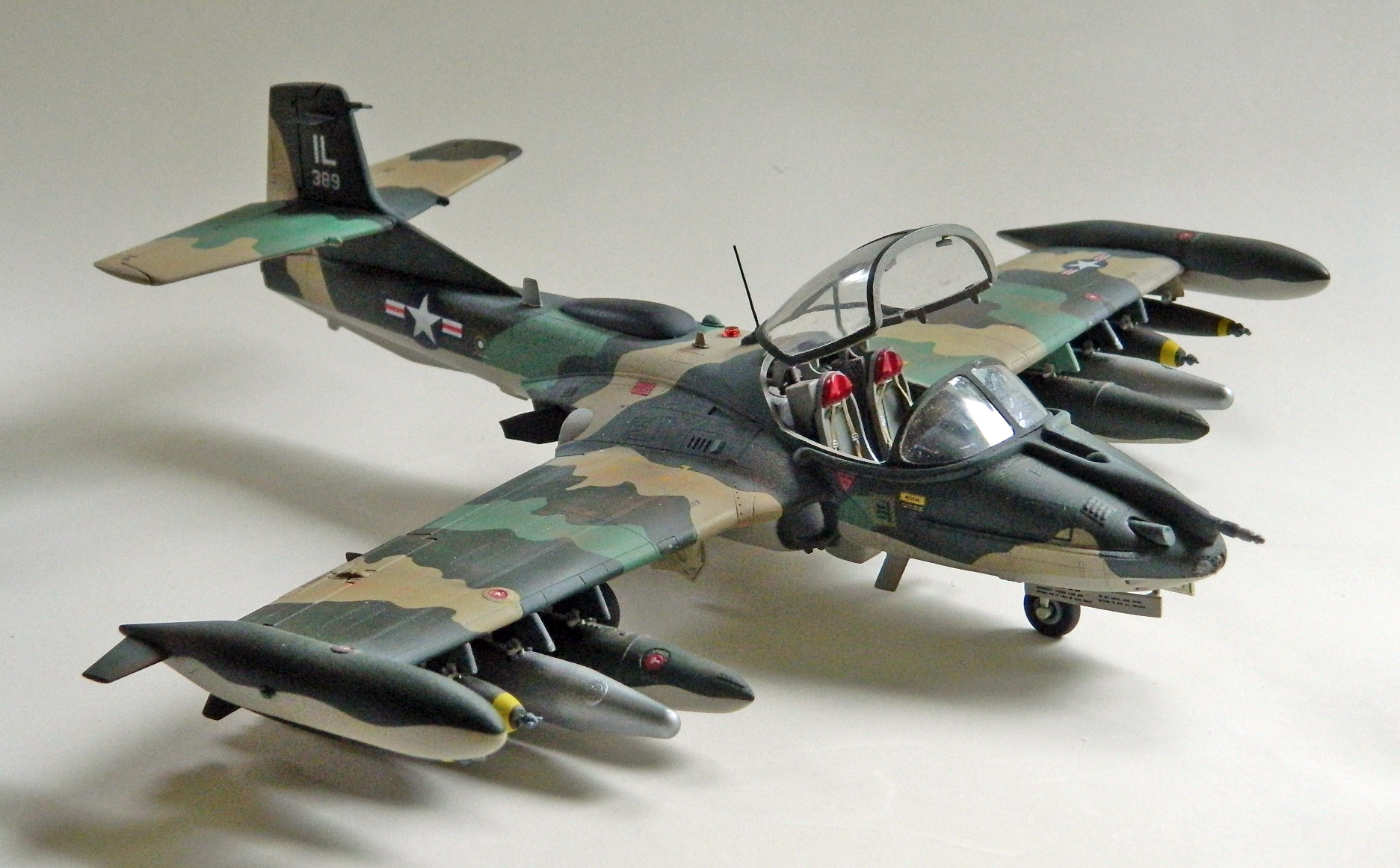
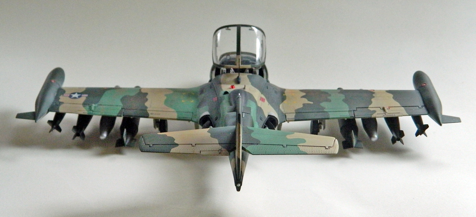
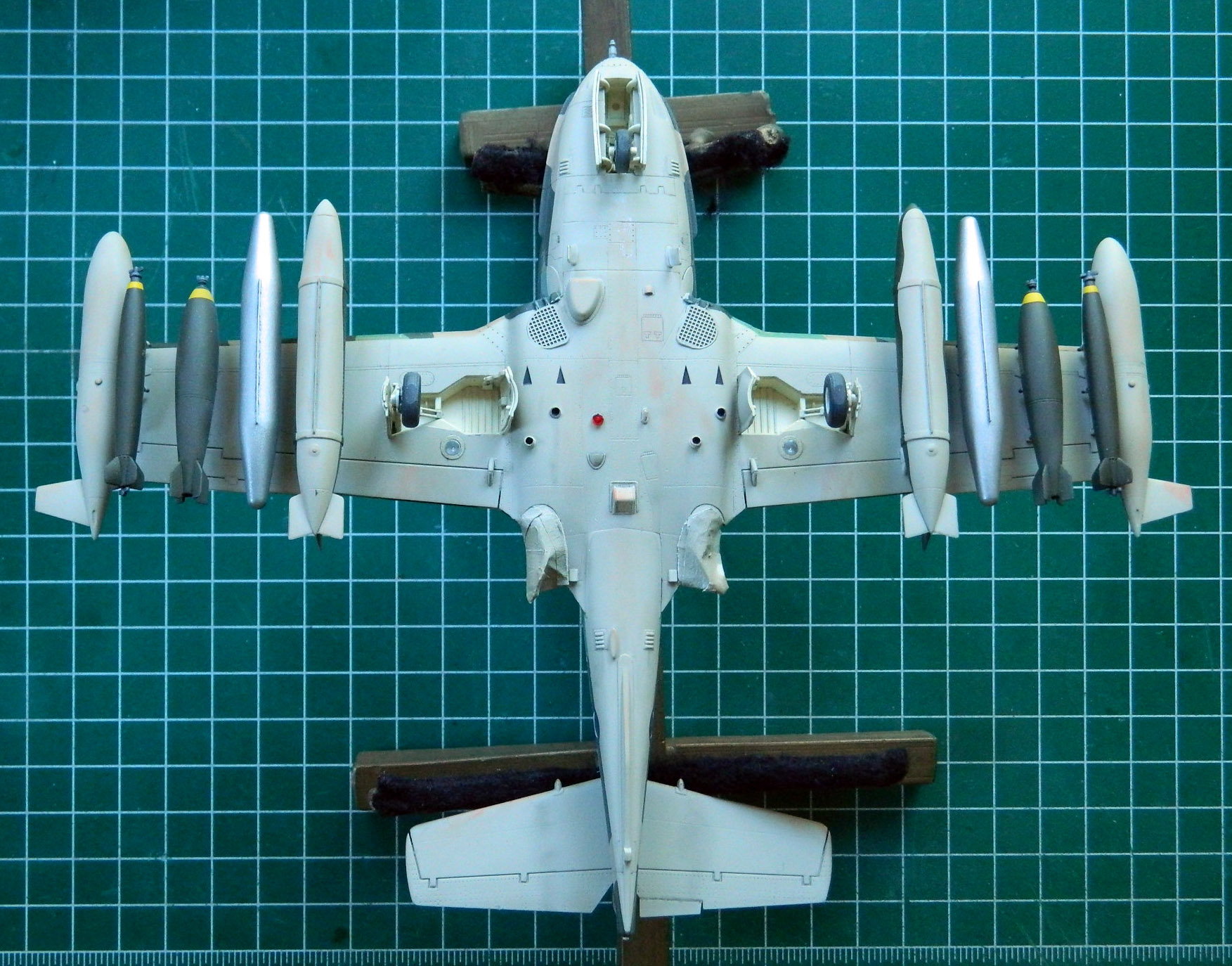
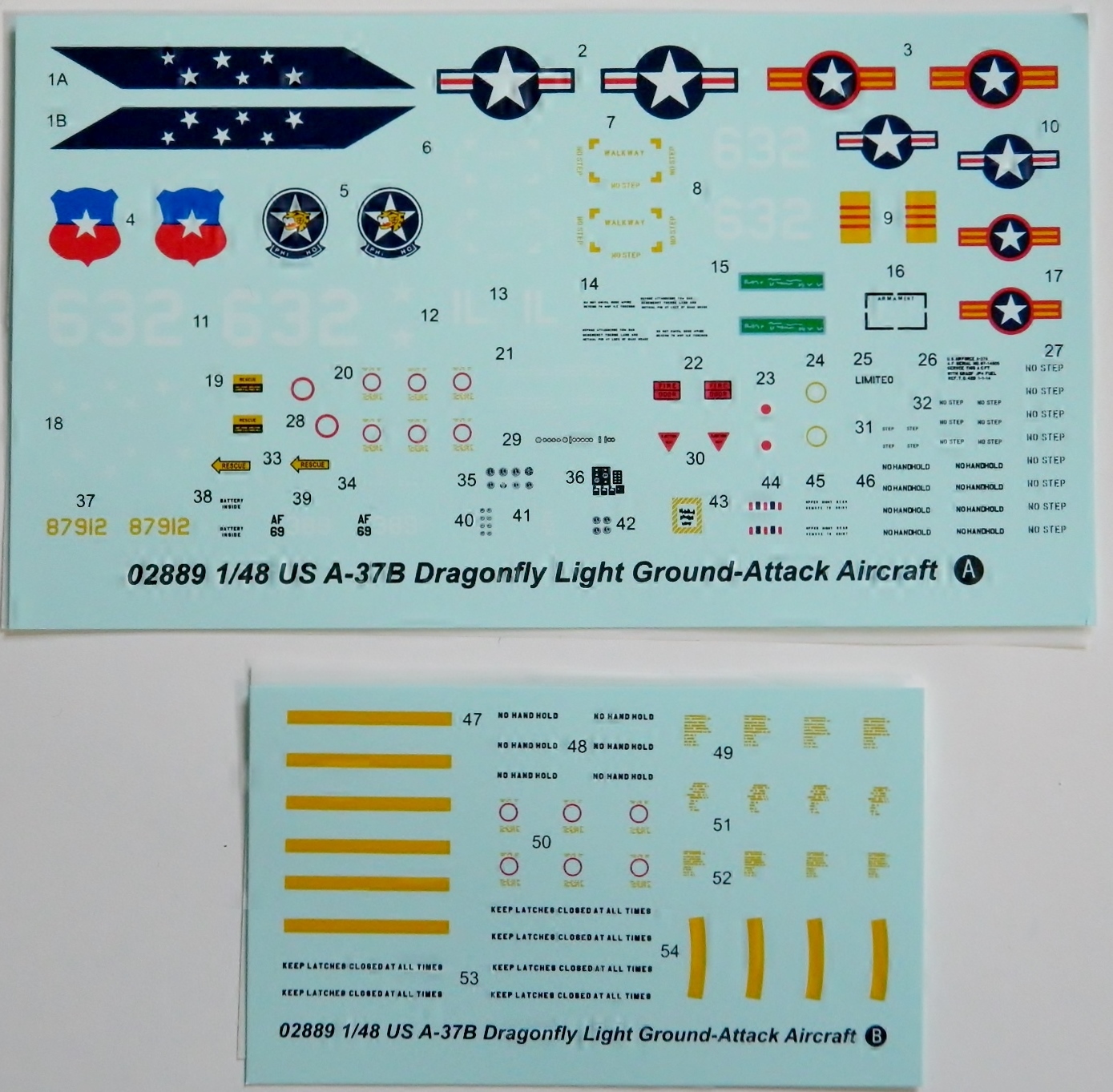
The kit’s decals can model one of three A-37Bs; Chile, Grupo 12,FACH, J-632, South Vietnam, 516th Fighter Squadron, 41st Tactical Wing, 1st Air Division, 68-7912, or USAF, 182nd Tactical Fighter Group, South Vietnam, 69-389. I chose the USAF bird. And while I’m on the subject of decals…
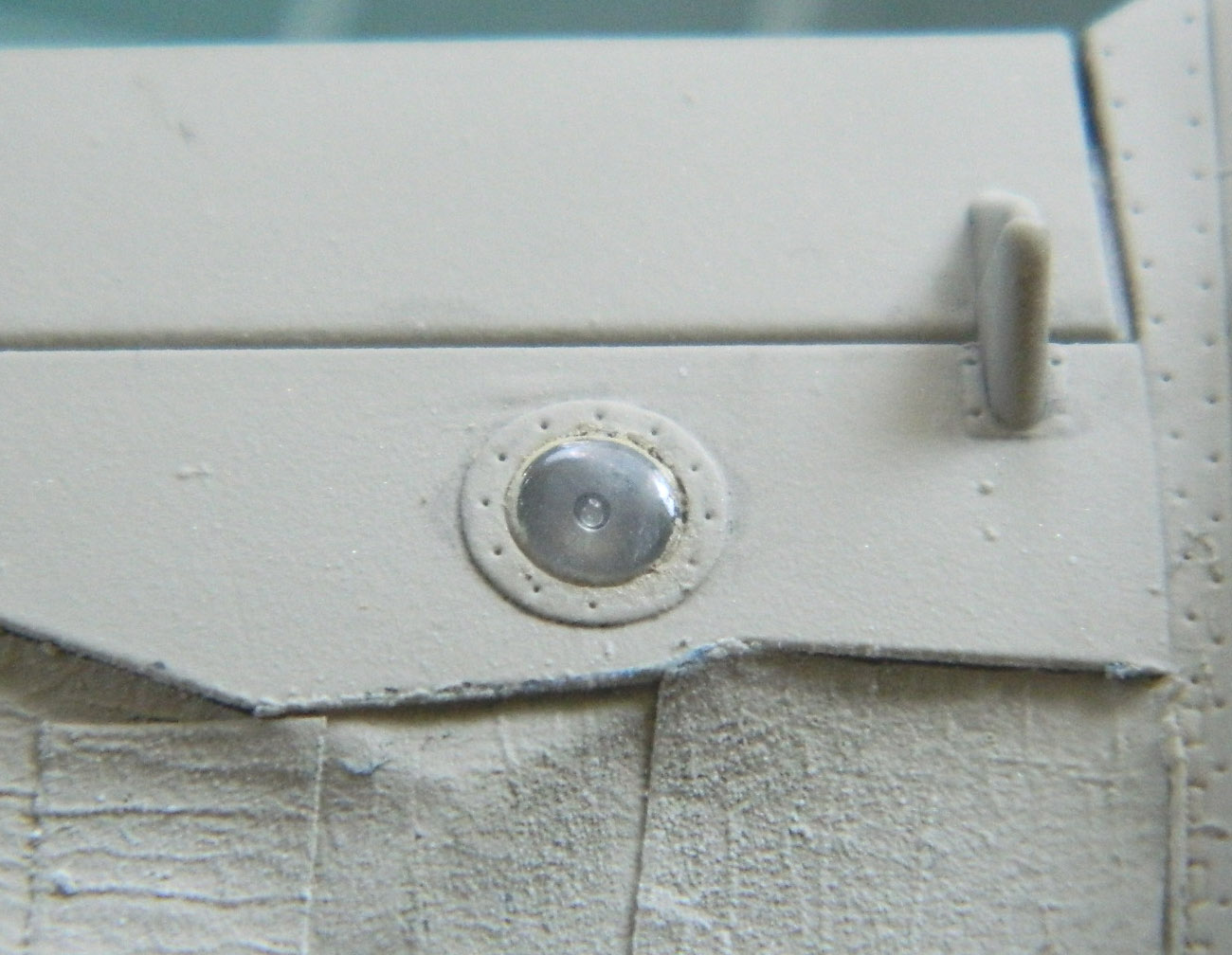
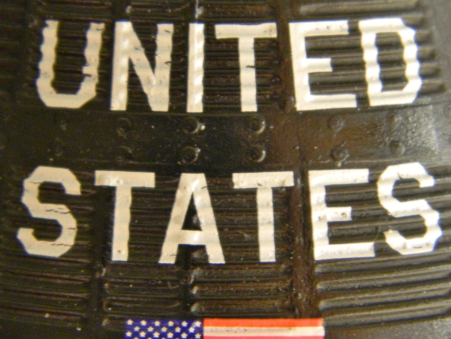
The decal for the data plate painted on the left side of the fuselage is wrong. It’s for an A-37A, tail number 67-1505. I put the decal on anyway; one really must look at it under very bright light with magnification to see it’s wrong.
The decals were interesting. The did not want to come off the paper (I tore one finding that out, in my ham-handed way) until they’d been soaked long enough to NOT WANT TO STAY ON THE PAPER and just floated off into the water. I’m still not exactly certain how I managed to fish it out (that’s the easy part…tweezers) and get it onto the model (that was the hard part involving needles to lift and unfold the decal, much cursing, water, more cursing, and at one point I almost resorted to prayer [saw no reason to get struck by lightning so I didn’t]). Once onto the model, blotting with a cotton swab just about made the carrier film disappear. A coating of Solvaset did make the carrier film disappear. The flat coat went down and the decals look like paint.
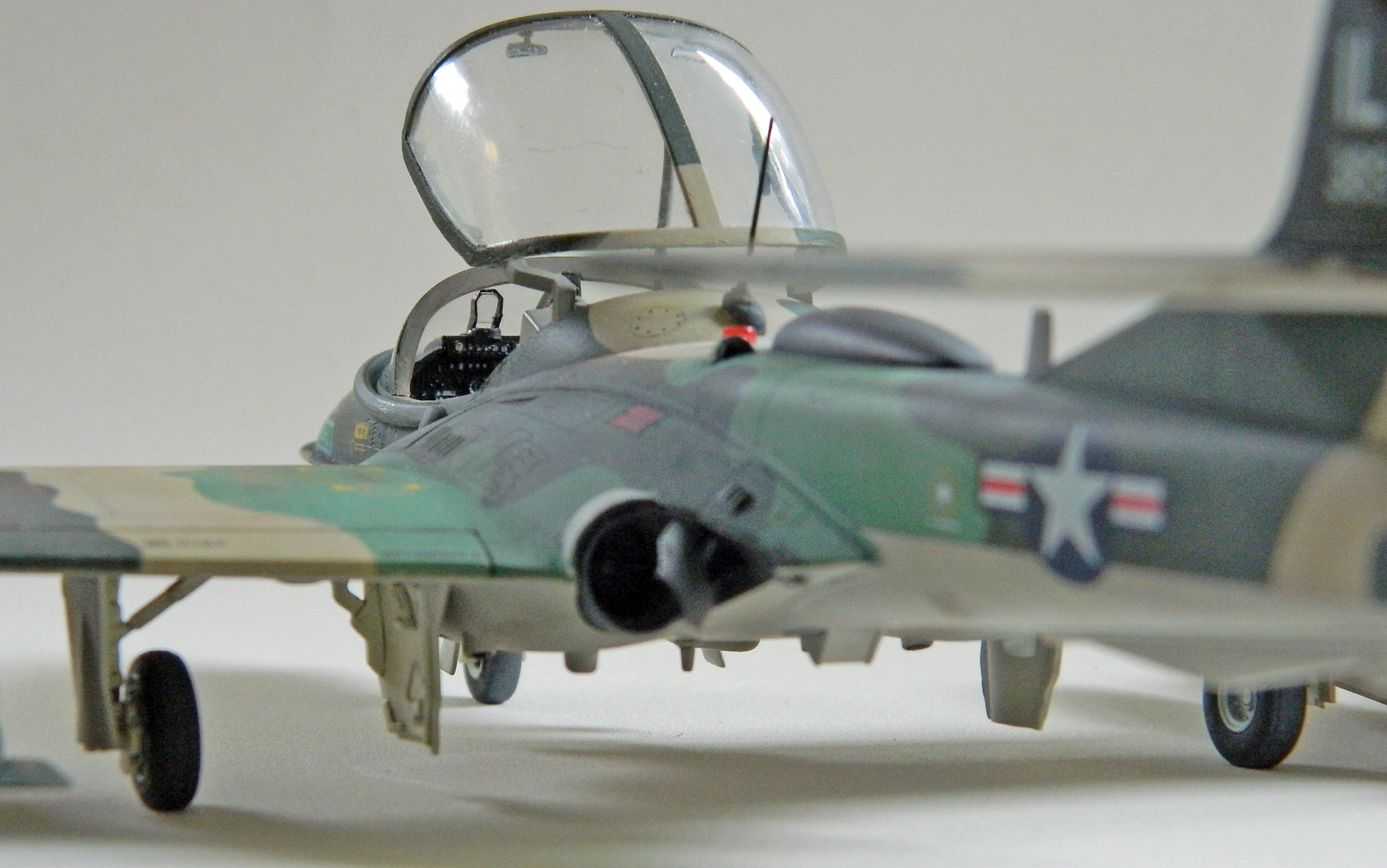
On the painting and marking guide there were a couple of inaccuracies. The inverted red triangle, “Ejection Seat” is only called for on the left side and it should be on both (not to worry, there’s two on the sheet). The “Armament Bay” decal is called for on the left side of the nose. The gun is on the right side of the nose and the decal goes there.
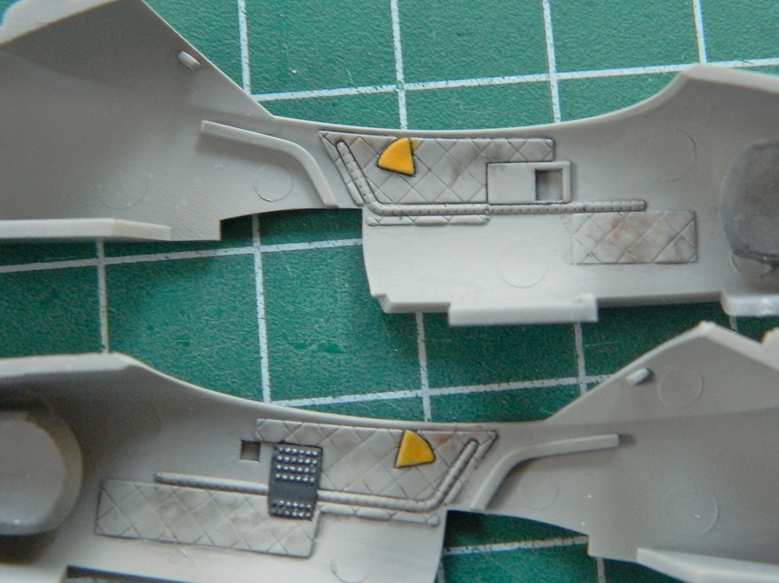
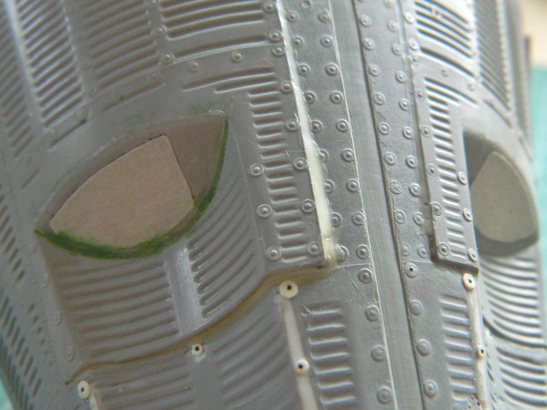
An error on the painting and marking guide is the color call-out for the right marker light on the wingtip fuel tank. The guide calls for that to be blue (and I even found one photo where it looks blue) but it’s supposed to be green. (Red – left, right – green.) So as ever, check your references…where they’re not incorrect. (What…you thought Catch-22 has gone away?!)
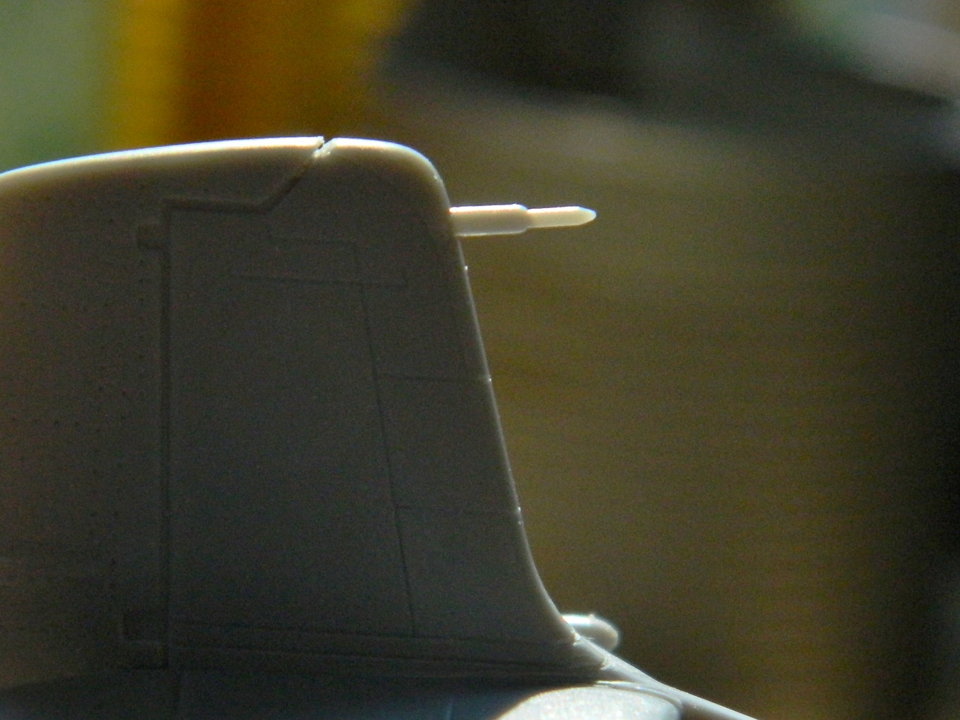
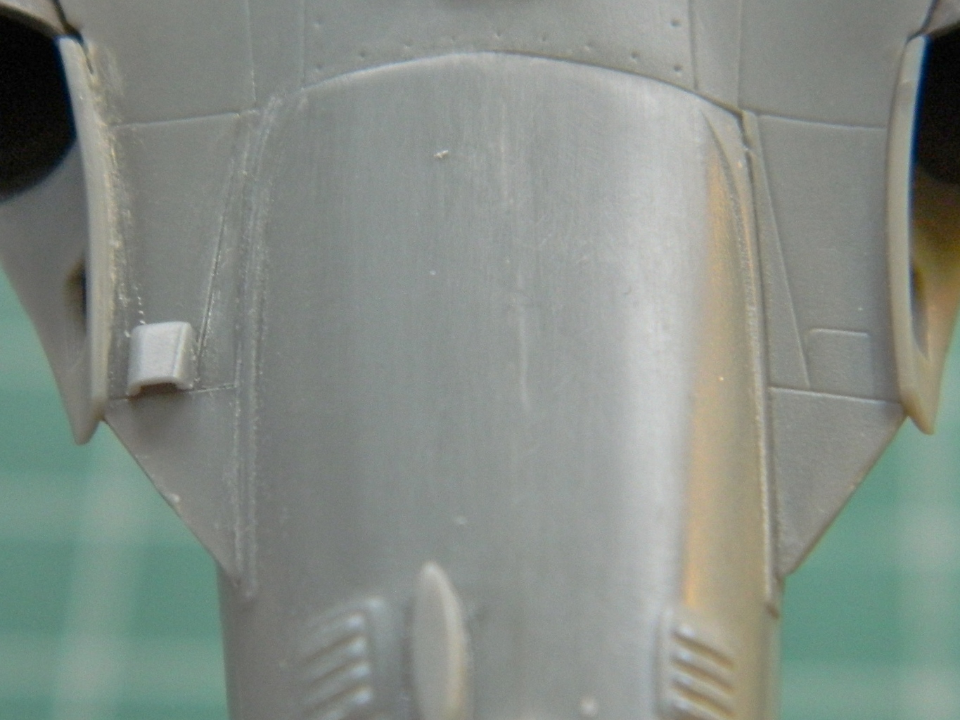
Another interesting omission is in the instructions. There’s a pitot tube near the top of the vertical stabilizer. It’s shown on the box art and the painting and marking sheet. There’s even a socket for it mostly molded into the fuselage halves…but it doesn’t go all the way through to the surface. AND the part is provided. So drill out the mounting socket for it. BUT. DON’T GLUE IT IN PLACE!! I broke that bastid off at least two dozen times. (Yes, it took me at least twenty four times to realize…hey…maybe I should just leave this thing off until I’m done?) (Yes, I’m quick like that.) My suggestion is to not glue it in place but make it removable (which is what I did with the dorsal whip antenna…which wasn’t supplied with the kit – I made mine out of stretched sprue). I should have also done that with the nose-mounted refueling probe. That bastid only broke off a dozen times.
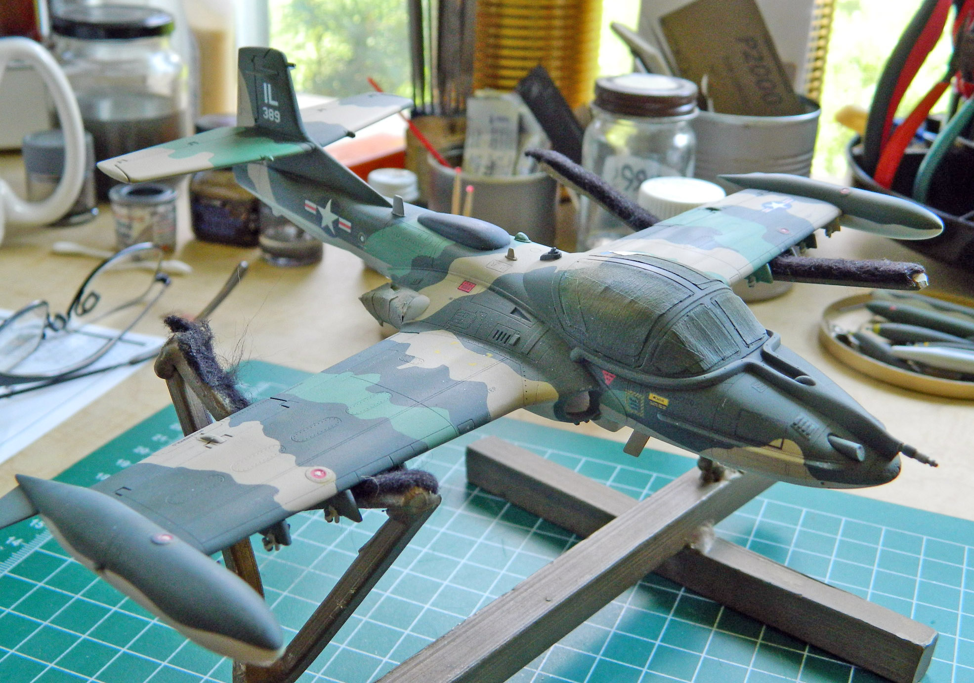
After building old “classics”, the ones that don’t really fit, doing a modern kit was a nice change and it displays nicely. I recommend this one to y’all.
With the decals successfully done, there are a few more things to do before I call it complete. The most obvious is the coat of matte clear but there’s a bunch of final assembly chores still to do.
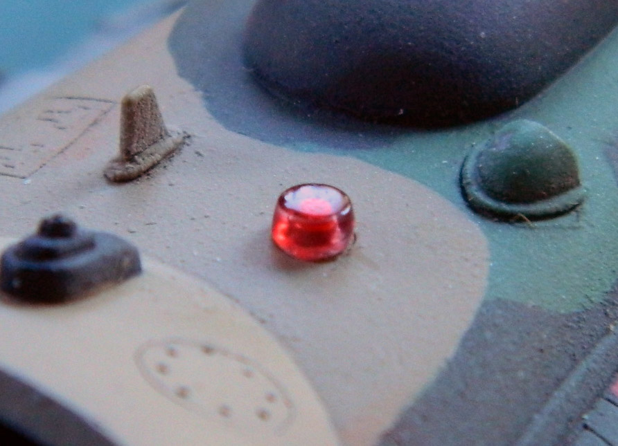
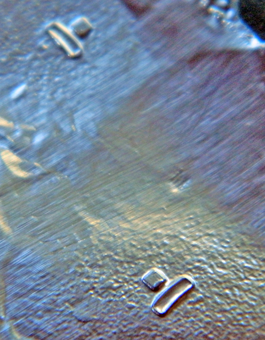
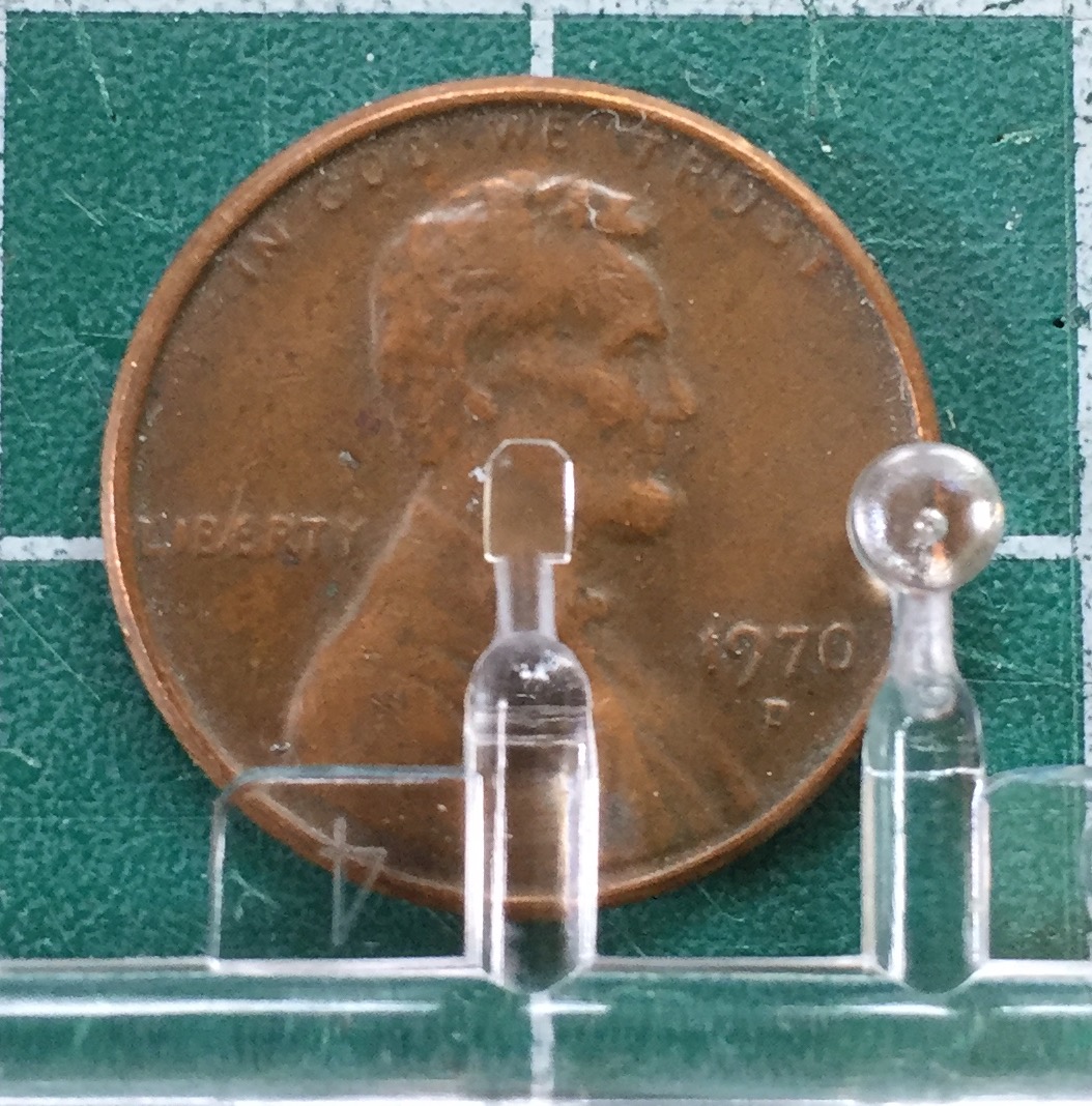
It starts with the dorsal and ventral marker lights. The kit parts are molded clear (with light bulb voids molded in!) and they have to be red. I used Tamiya’s X-27 Clear Red. These weren’t as difficult to do as I thought they’d be (due to their small size and the need for them to be clear no matter what I did to remove the sprue attachment points). They were clipped from the sprue and trimmed toothpicks were jammed into the void molded in for the “bulb.” Having a handle on things made the work much easier (doesn’t it always?). Once the attachment points were sanded down, I used progressively finer sandpaper and sanding films and plastic polish to restore transparency to the parts. Since the parts were still on toothpicks, rather than brush or spray the clear red on, I just dipped them into the jar of paint and set them aside to dry:

At this point I applied (or tried to, anyway) a coat of clear matte overall on both the model and the ordinance (I didn’t flat coat the napalm tanks; I liked the luster of the bare aluminum paint as is and it contrasts well to all the matte finishes around them). There’s a problem with my airbrush that’s just getting more pronounced. The spray of paint is intermittent. I’ve tried cleaning it with a (brand new) ultrasonic cleaner and though much cleaner inside now, it didn’t solve the problem. That resulted in an uneven “coat” and needed to be shot twice:


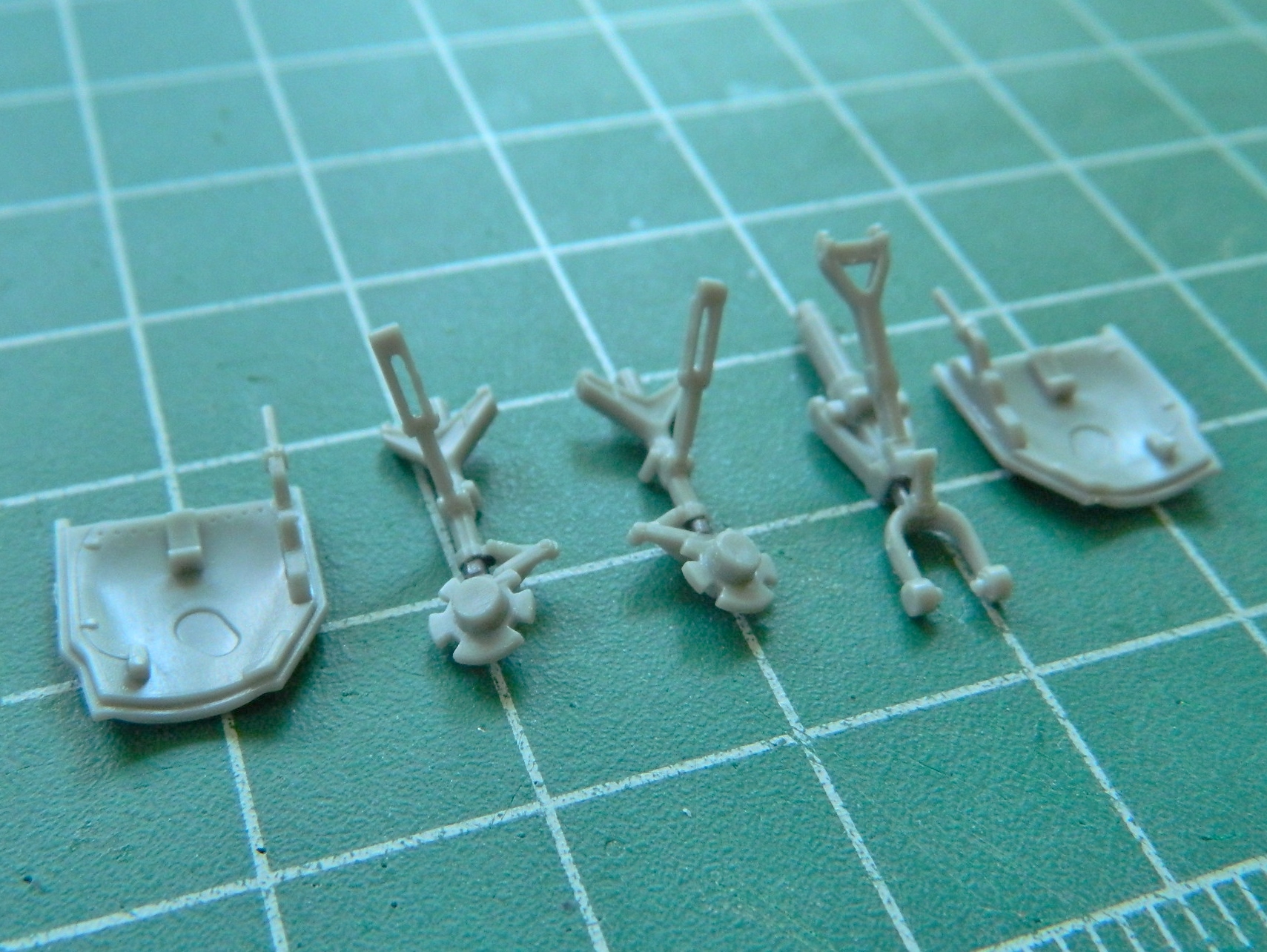
While that was all setting up, it’s time to put the landing gear on. I’d painted the oleo-struts “steel” (Humbrol #27003 again), masked those sections, and did the color, clear coat, wash, and flat coat. Time to take the masking off and put the nose wheel on:

I also removed the paint from the under-wing landing lights:
With the two coats of matte clear dry, I removed the masking from the windscreen and canopy and did the touch-ups necessary when the white glue I’d used to seal the canopy to the fuselage was removed. Then it was time to mount the landing gear to the model. The masking was removed from the gear bays and minor paint touch-ups attended to. Once things were aligned and glued, I added the main landing gear tires, aligned them so the flat bottoms were flat on the surface, and glued those in place also. Now it sits nicely on its landing gear:

Landing gear doors go on next (and haven’t those turned out to be VERY DAMNED EASY to knock off the model):

Before I started hanging ordinance and drop tanks from the pylons, I added subtle dirt effects using pastels:

Then the ordinance and drop tanks were attached:

With the dorsal and ventral marker lights dry, it’s time to add them. I painted the bases silver and used a very diluted (and tiny) drop of white glue to attach them:

Then it was time to do the really tiny bits. I started with the rear-view mirrors:
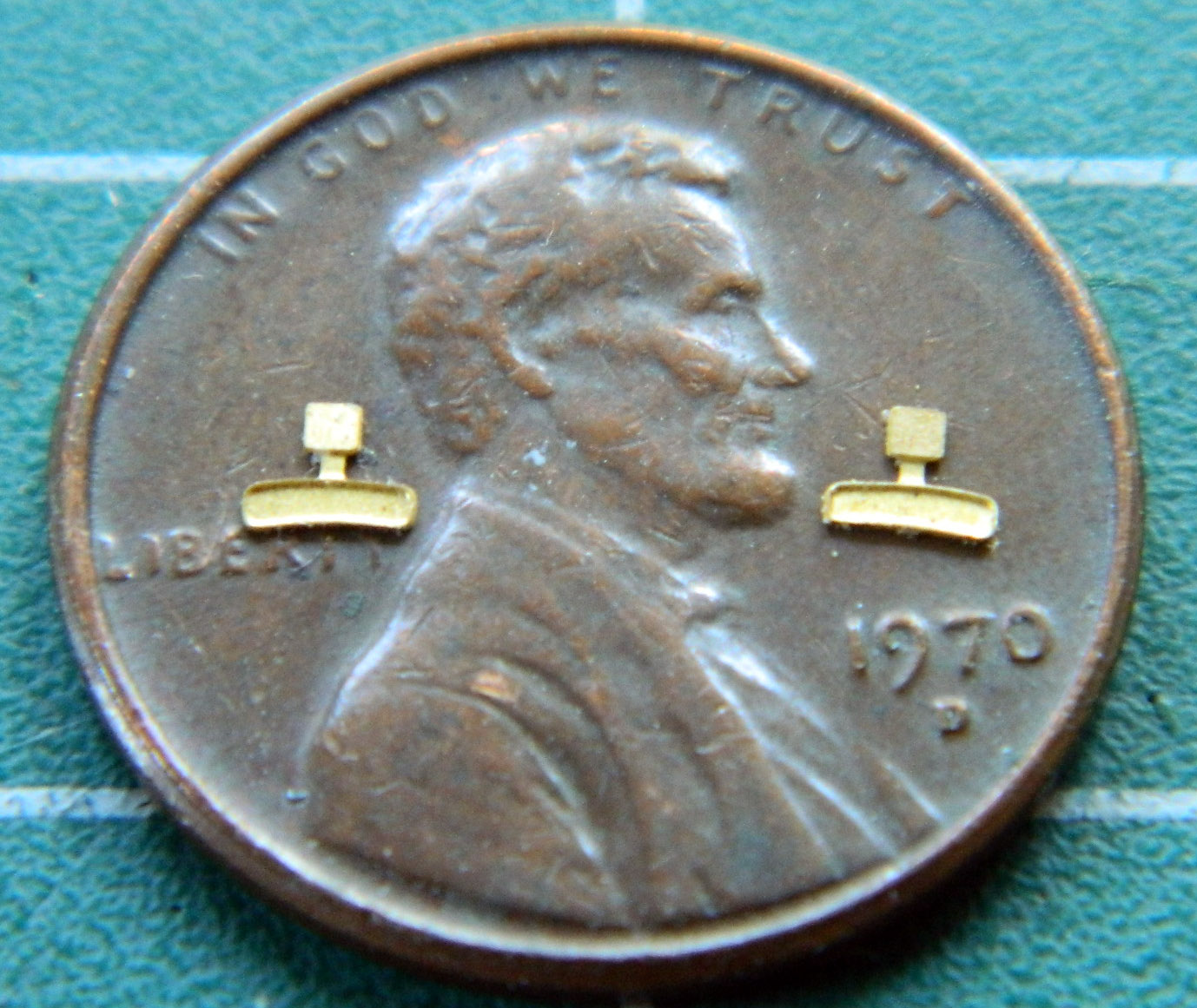
I didn’t even consider painting the reflective surfaces. That looks like what it is. Paint. Instead, I used aluminum foil. I used a TINY drop of superglue on the face and then hammered regular aluminum foil onto them using a rubber eraser and a (oddly enough) hammer:
Then I used a sharp razor blade to trim them:

White glue added them to the canopy:
Nothing left to do now but add the canopy to the model:
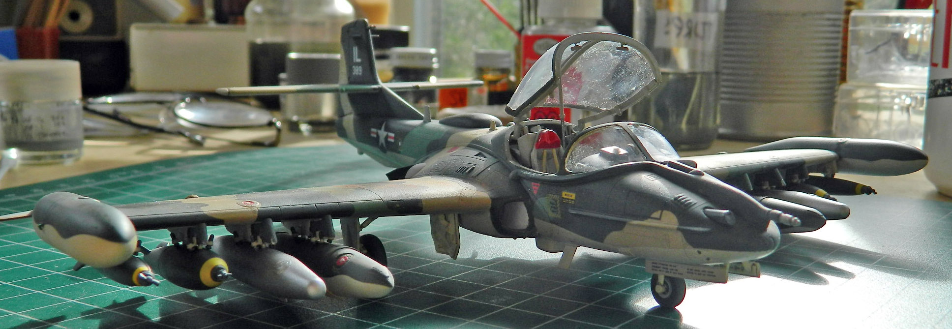
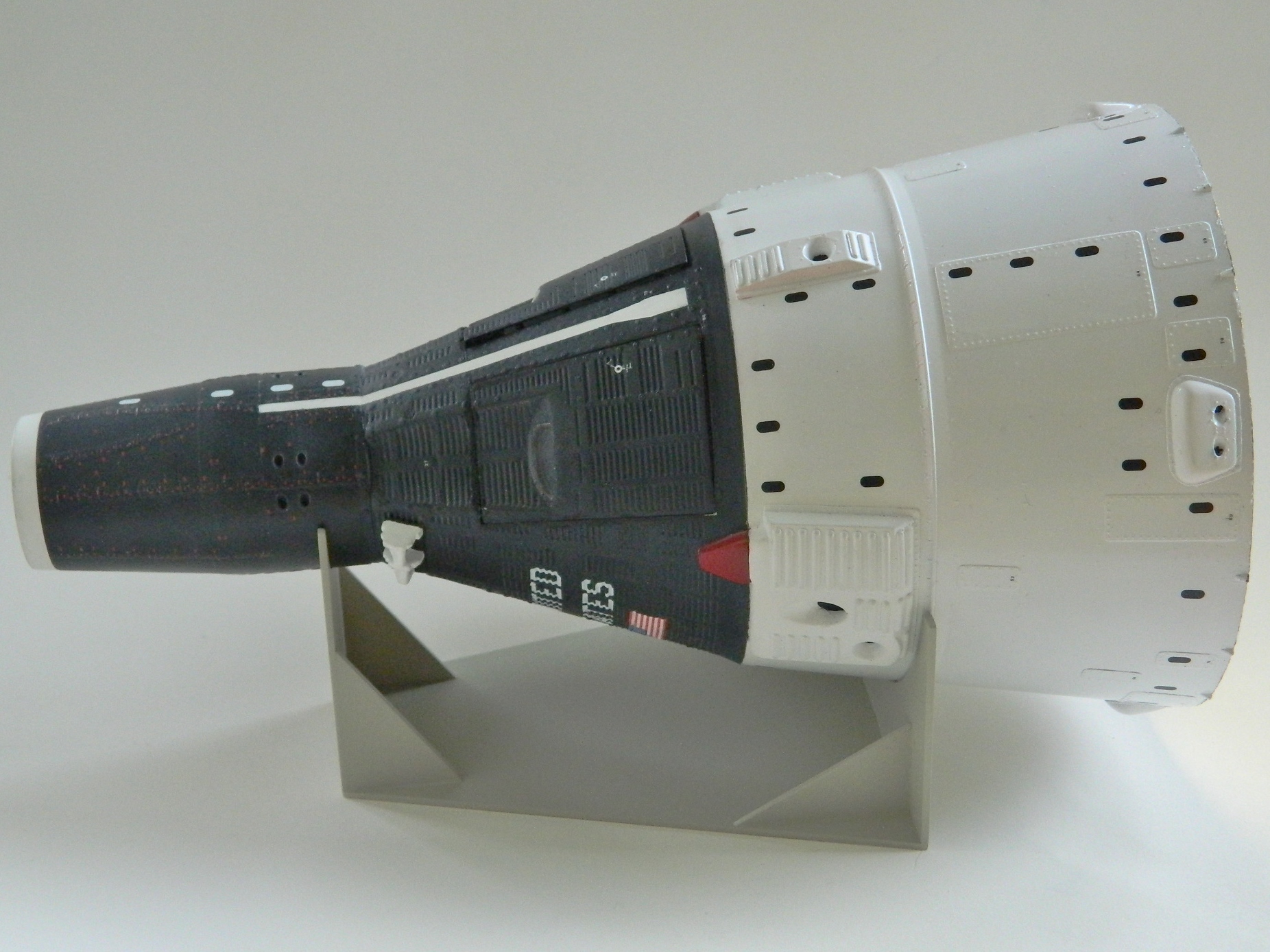
Hmm…y’know, I think this thing is done:

Having finally realized that I’d forgotten to paint the outside of the landing gear doors, I took care of that as well as doing the underside of the drop tanks and add detail paint to the stores pylons:


The front of the stores pylons were painted to match the camouflage paint of the wing above it so I did the same:


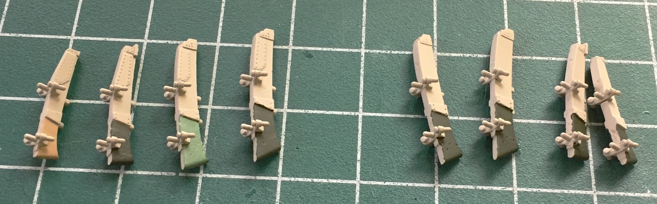
Setting those aside, it was time to get after something I was pretty sure was going to be annoying (and I was correct), painting the bombs. The first step was painting the arming propellers “steel” using Humbrol #27003:

There are decals for the stripes around the noses of the bombs. Two problems with that. The first is that the color of the decals was too orange. The second being that getting those decals on properly could consume far too many hours. So even realizing that painting and masking these stripes would be annoying, it wasn’t the greatest annoyance possible.
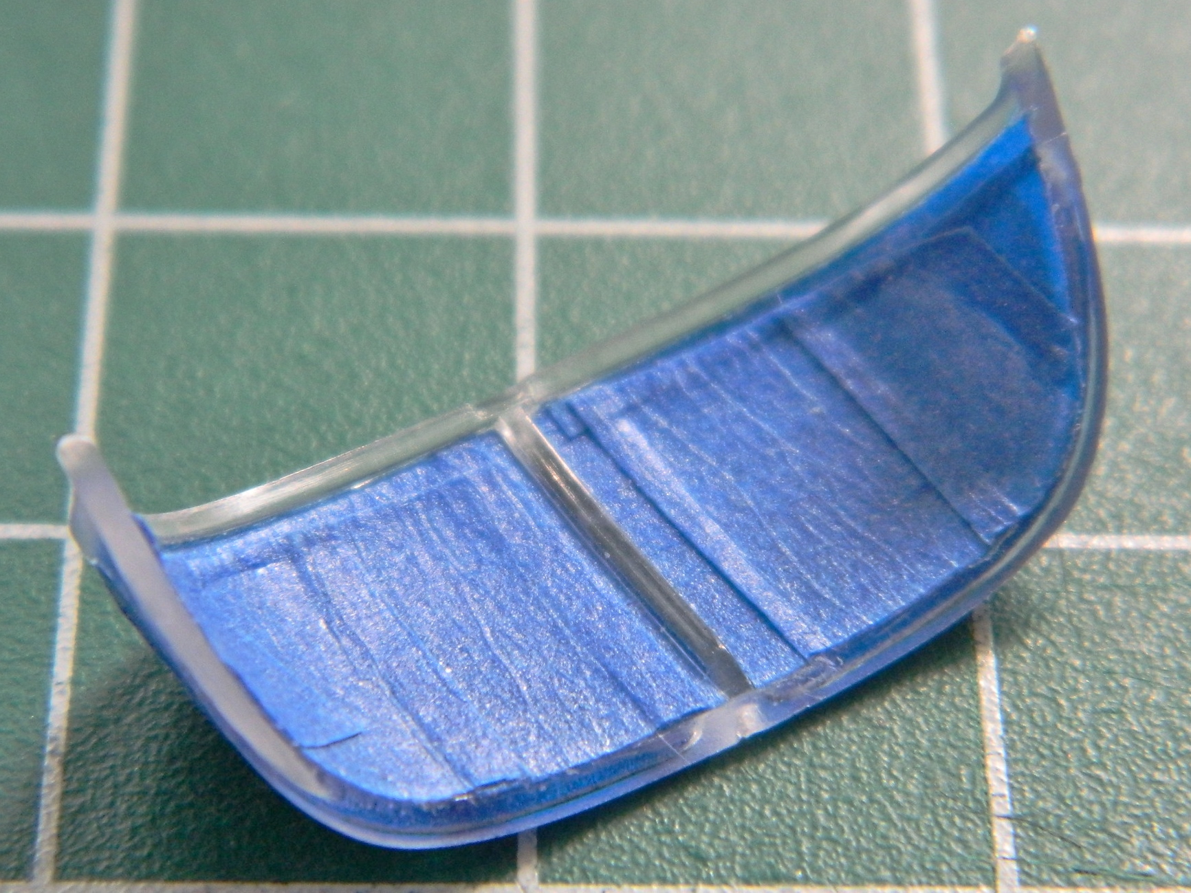
Step one of the stripes was spraying the color (Tamiya XF-3 Flat Yellow with about 10% Tamiya XF-2 Flat White):

The annoying part is trying to mask off a SMALL compound curve. The least bothersome way I’ve found is thin strips of masking tape to define the edges and then fill the middle with more tape (the prepainted “steel” was encapsulated by tape):


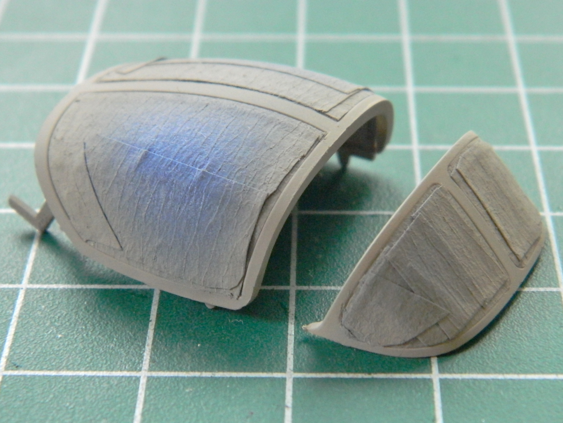
Then the bombs were painted with OD Green (Tamiya XF-62 Olive Drab with 25% Tamiya XF-2 Flat White). Though annoying, the result was worth it (AND the correct color):

The last thing to paint before shooting clear gloss was the filler caps of the wing and drop tanks. I used the punch and die set to knock out holes of the appropriate diameter from strips of tape to mask them before shooting Tamiya XF-7 Red. Once painted, I used my smallest brush to paint the locking levers white (would that my old hands were more steady, perhaps I would have done a neater job):


Then I shot everything with Tamiya clear gloss to create a smooth surface for decals to adhere to without silvering (and this time I remembered the sodding landing gear doors). Once again I encountered the problem of what to hold while painting, only this time it was on the model itself. The only solution was to paint the top half, let it set up, and then do the bottom half:

Trumpeter’s decals are “interesting.” They aren’t really all that interested in leaving the backing paper until they’re VERY interested in leaving the backing paper and have to be fished out of the water. Lots of fun doing that without having the damned things fold onto themselves until I figured out that a 30-second soak followed by another 30-45 seconds of the decal out of the water and letting the paper soak worked better. Once off the paper and onto the model, they did snug down nicely. I tried some Solvaset on them and the results were amazing. The carrier film of the decals just about disappeared.
With just the water:

With a puddle of decal solvent over it:

And after the solvent evaporated:

After two painstaking days, all the decals are on. A word about references (again). Check them. Often. The decal call-out sheet wasn’t a hundred percent accurate. One decal (the inverted triangle for the ejection seat warning) was correctly shown on the left side but the right side also got the same type…and that wasn’t on the call-out sheet yet it was on the decal sheet. The decal for the gun’s information was shown on the left side but it should have been (and now is) on the right side:


I’m going to let things sit overnight before coating everything with clear flat.
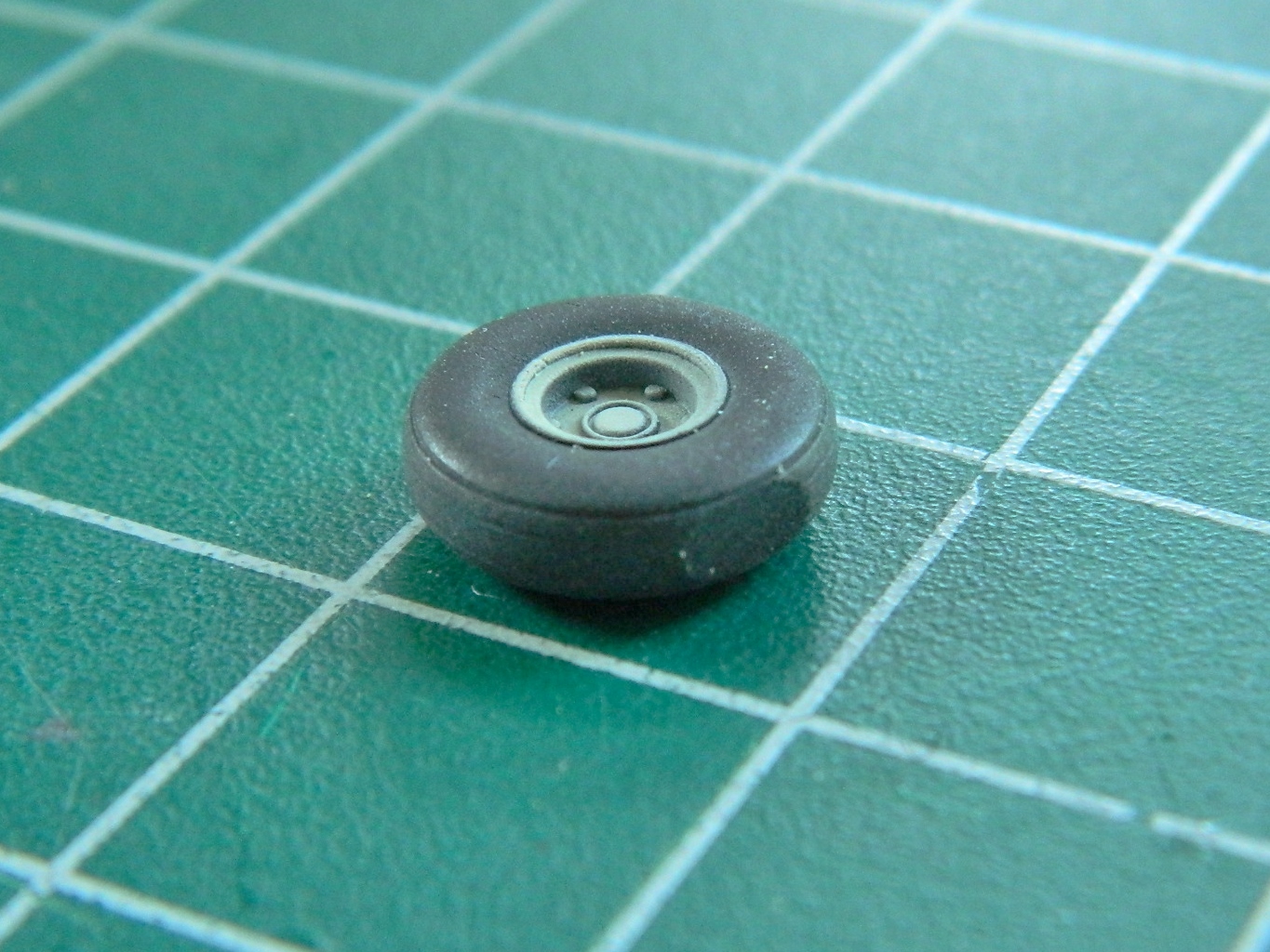
To paint the wheels/tires, I reverse the typical painting procedure where the light color is shot first. I do the entire wheel/tire black, and then use an artist’s circle template as a mask. I find the hole that’s closest to the diameter I need (and I’m constantly surprised how frequently I find the exact size!), center it over the wheel, and shoot the wheel color through it.
Tamiya makes an excellent paint that replicates rubber (XF-85). I’ve used it on other builds and it’s my go-to for “rubber” parts:
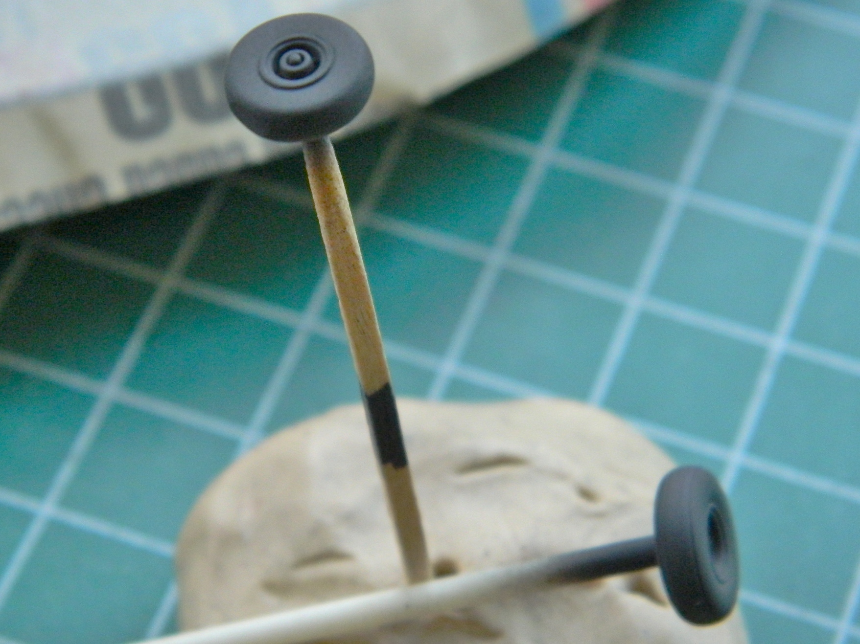

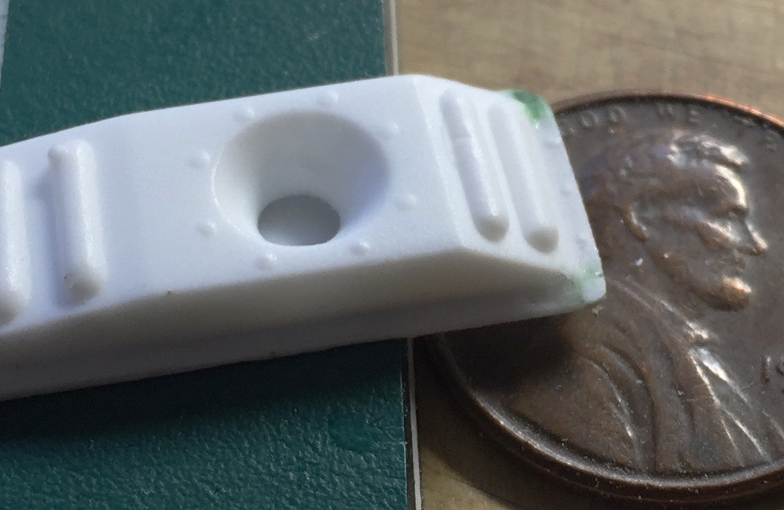
If you look closely at the above photo, you can see where flat spots were filed onto the bottoms of the tires. Unless I do something to replicate the way a tire compresses under load the finished model looks wrong. Here’s a close-up of the nose wheel:
To shoot the undersides of pretty much everything (napalm tanks and bombs excepted), I used Tamiya’s XF-55 Deck Tan color-corrected with 25% XF-2 Flat White:
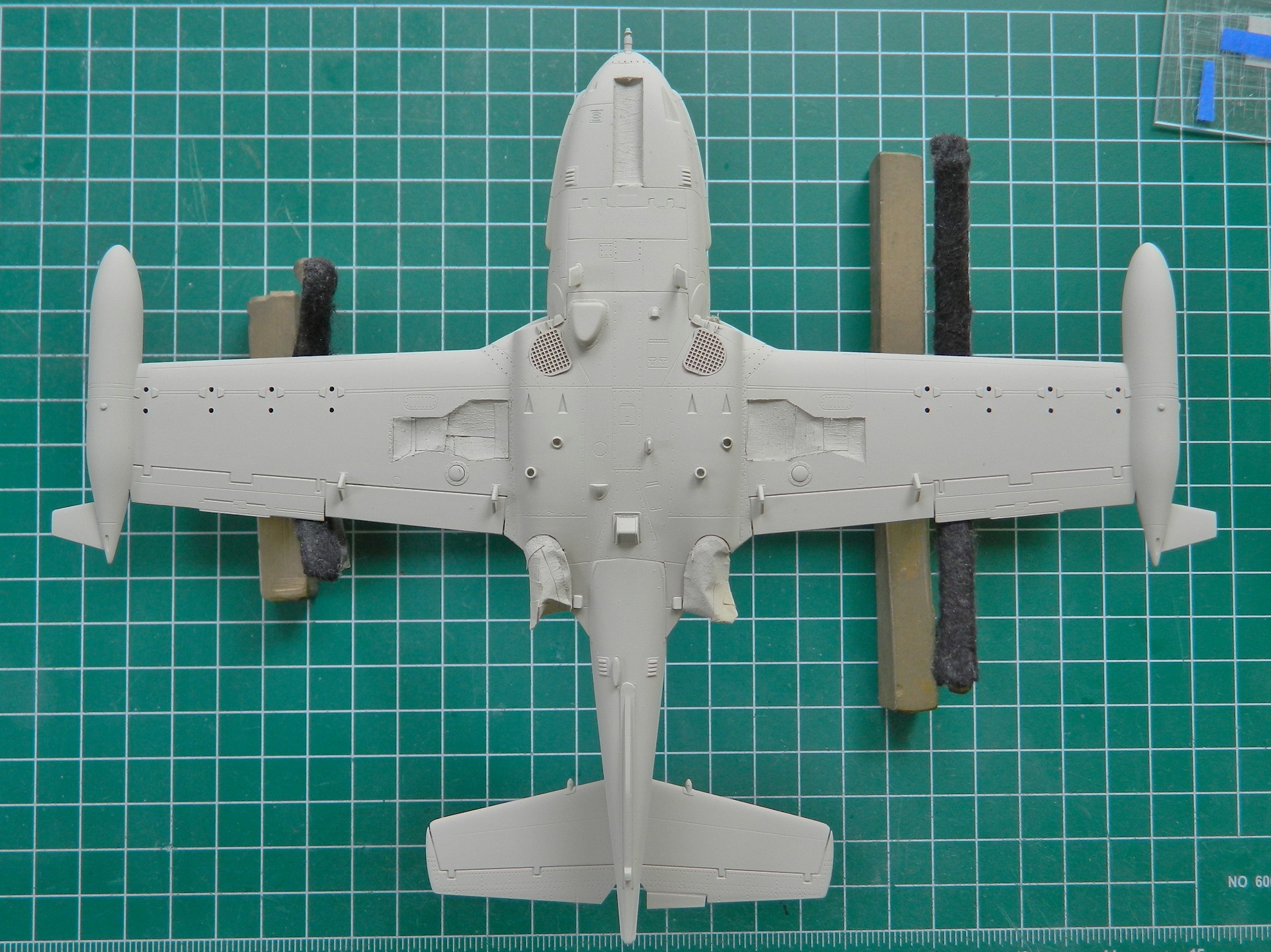

I’ve learned that it’s SO much easier to scrape acrylic paint off a small surface than it is to mask it, so the under-wing lights just got painted over. They won’t be cleaned off until all painting is done:
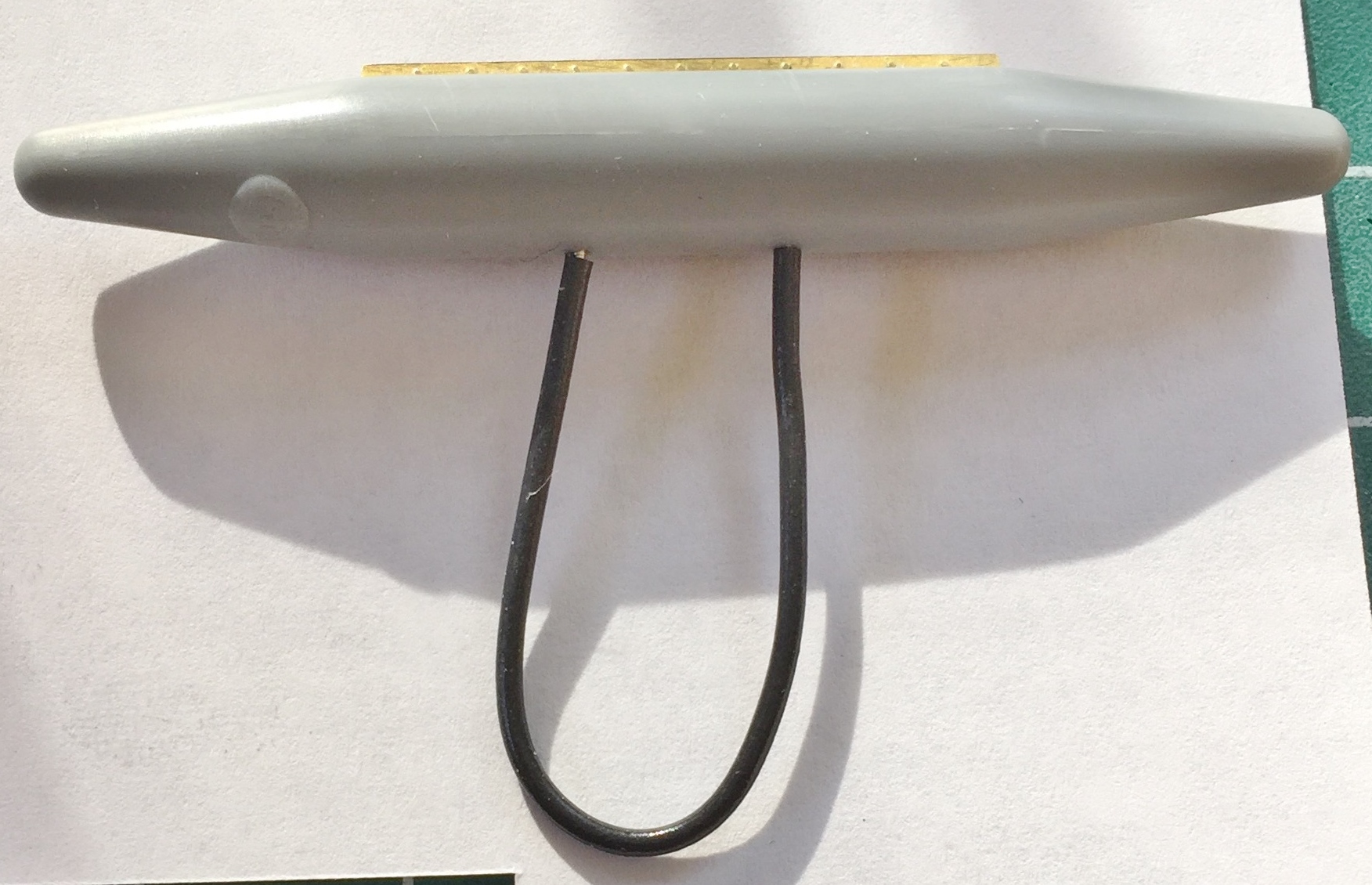
No…this isn’t a homemade IUD. It’s a clever solution to a problem. How do I hold the drop tanks, napalm canisters, and bombs while I paint them:
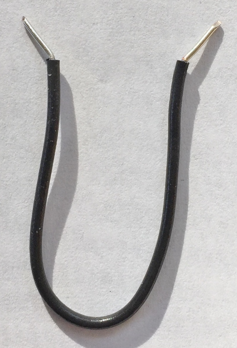
Make a handle (people quickly point out I need to get a grip on things). The bare ends of the wire (22awg) are inserted into the holes used to mount the part to the pylon (turns out I needed to make the bend sharper):
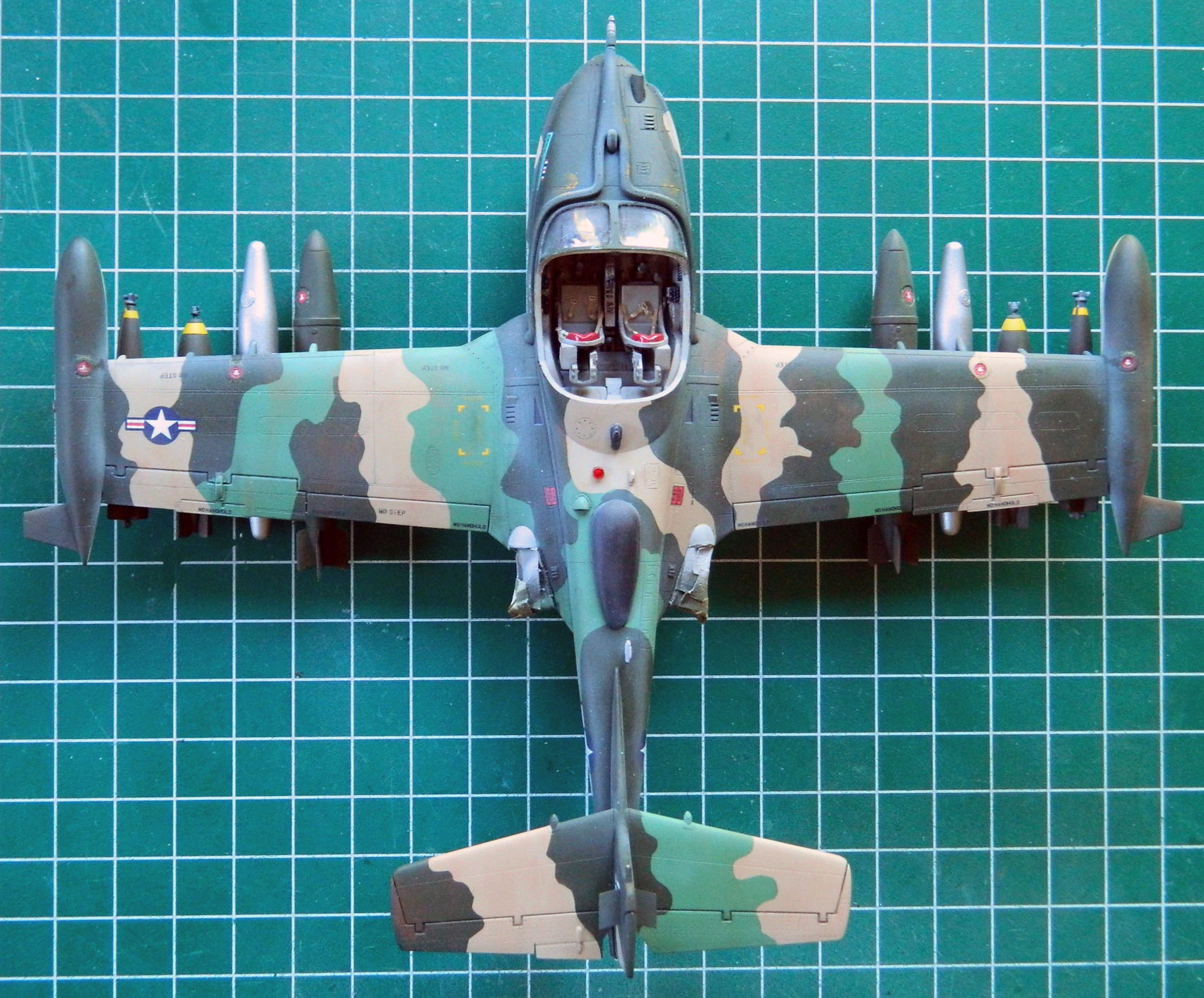
The overall color of the camouflaged paint is tan. So of course I thought simply lightening brown would get me tan. Well…what that got me was this:

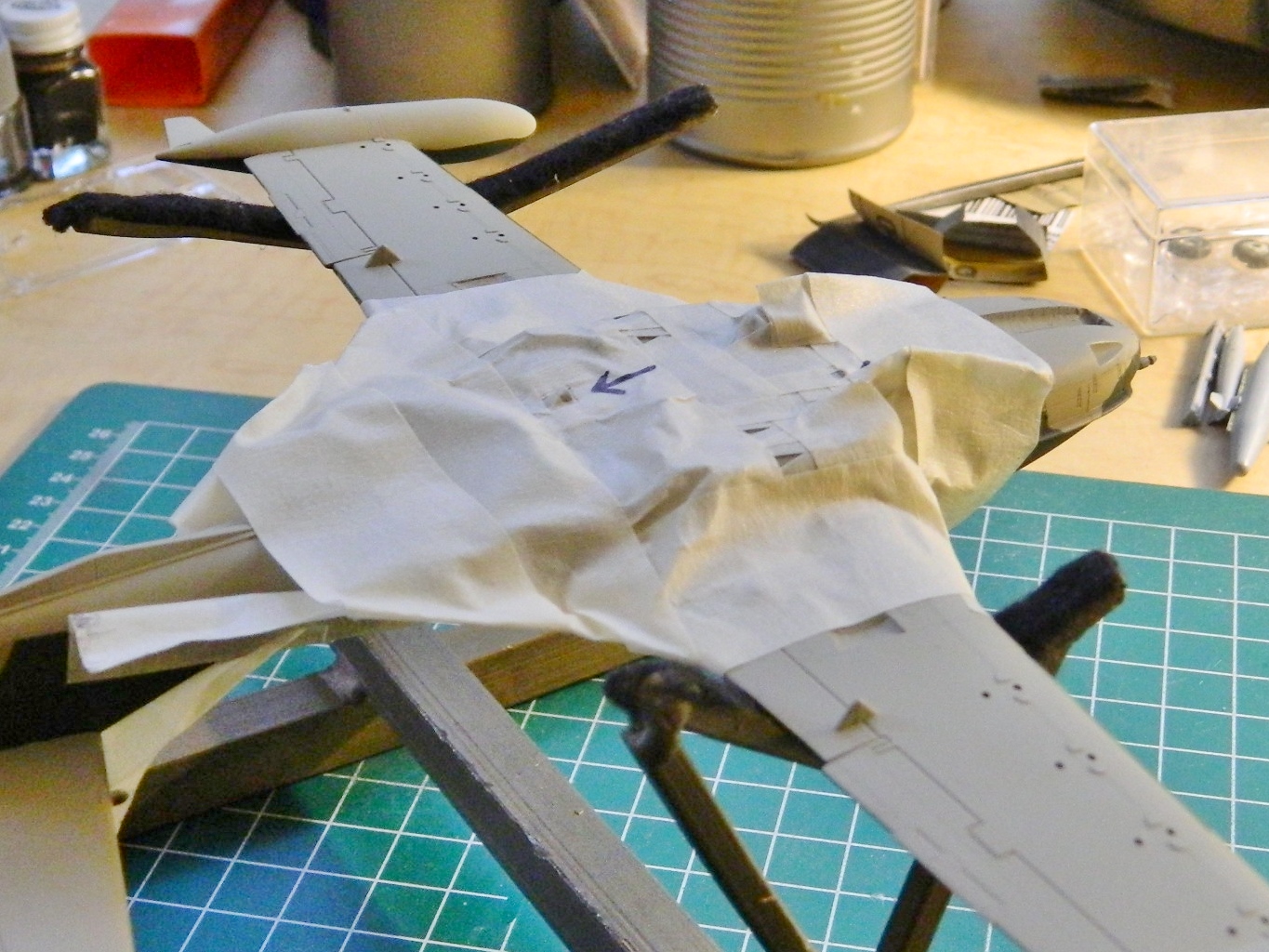
That looks like the aircraft needed sunscreen. I rummaged through my paint stock and ended up using Tamiya’s XF-20 (“Buff”) instead. Looks much better:
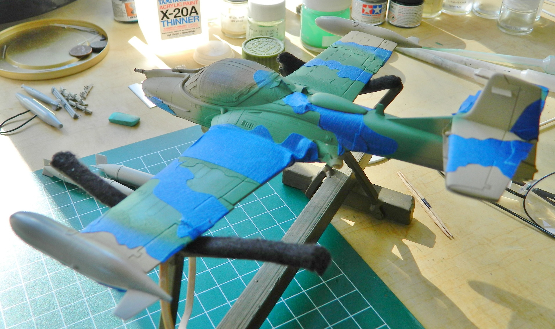
With the overall color down, I started masking it off. All my reference photos show the edges of the colors with sharp demarcations, so that’s what I did also.
The odd green that was used was a mix of Tamiya’s XF-62 Olive Drab (5 parts), XF-5 Green (4 parts), and XF-2 White (8 parts). The masking goes over the areas I want to stay tan and then I shot the areas that will be green (the little tags are painting cues…I’m easily confused):
Leaving the masks down over the tan, I added more masks over the areas I want to stay green:
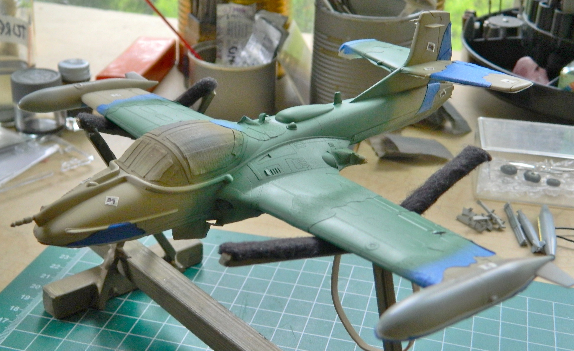
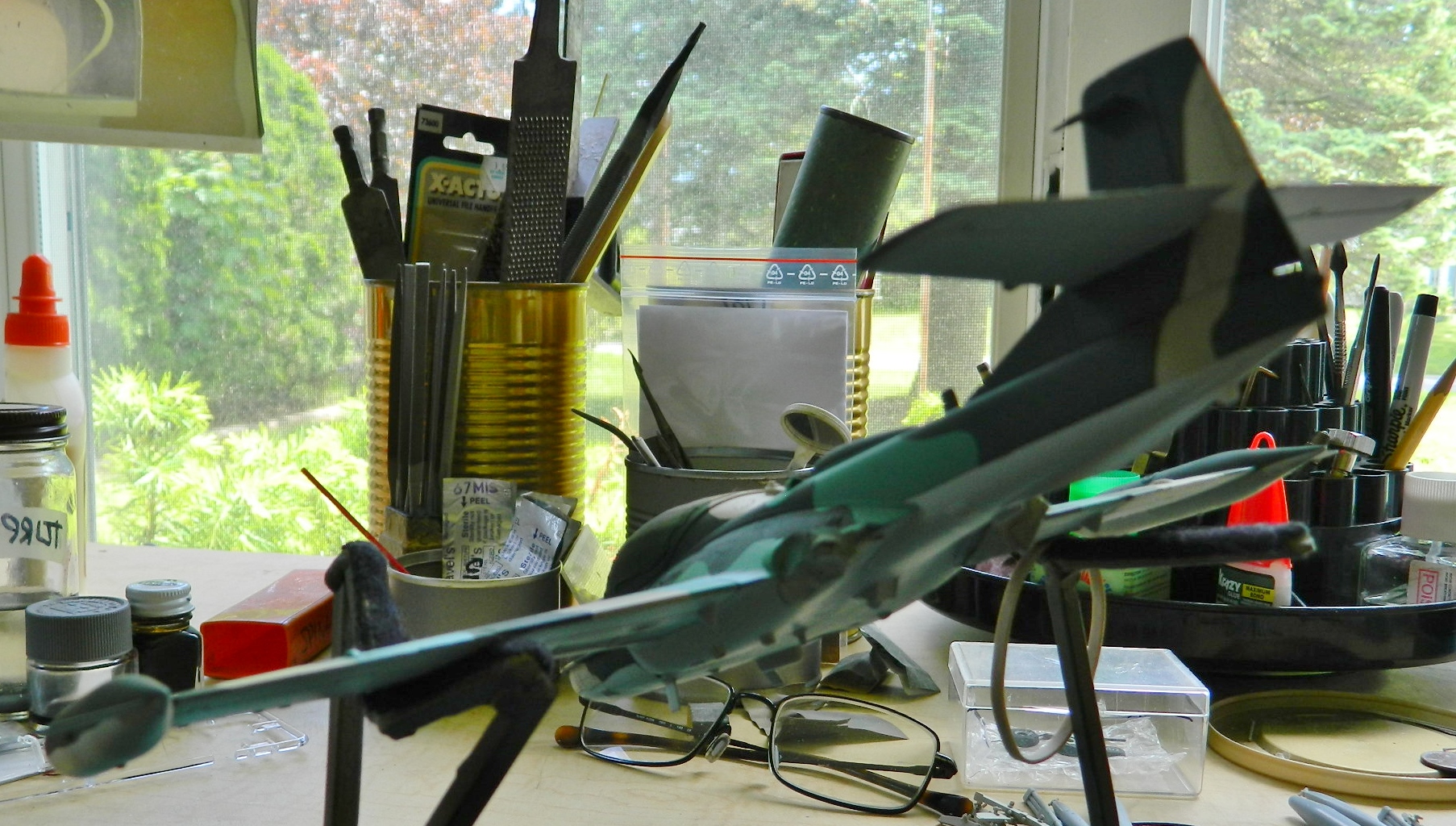
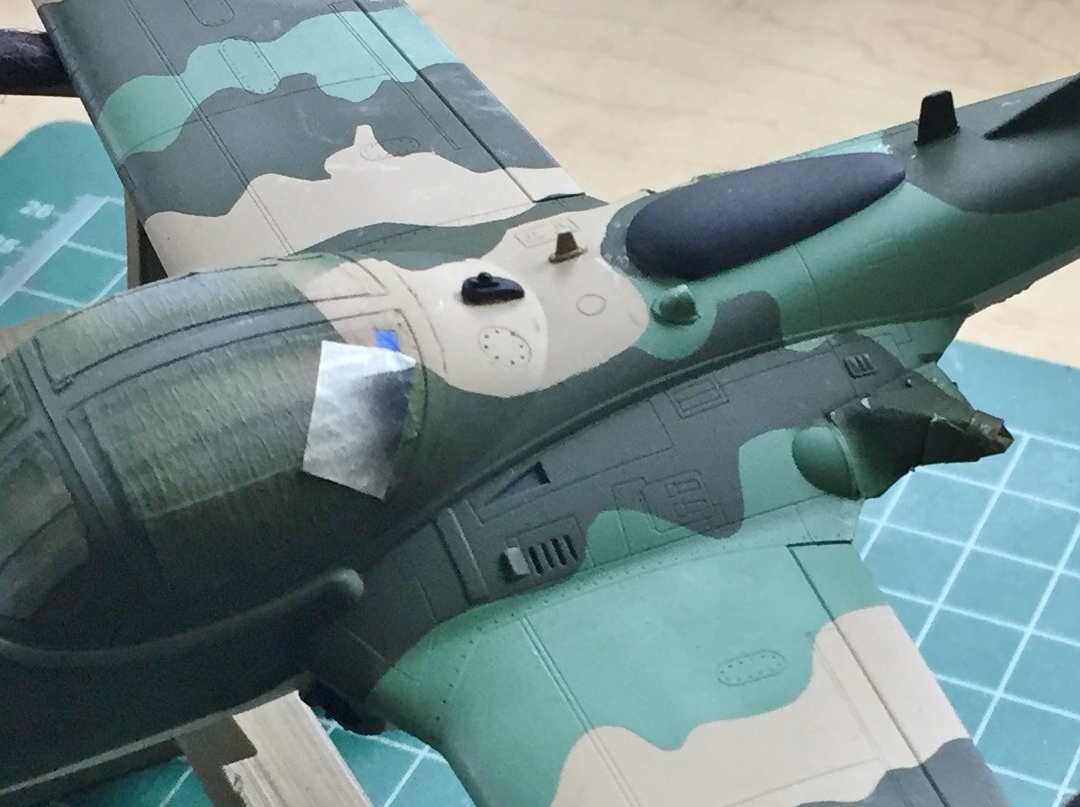
Then it got shot with Tamiya’s XF-58 Forest Green:

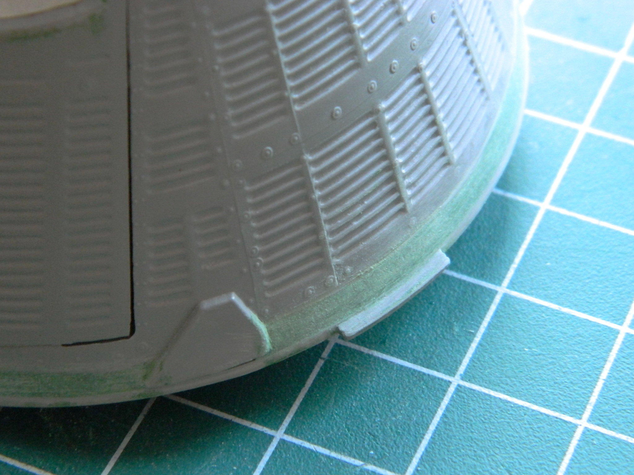
I let the paint set up for a few hours and pulled the tape:


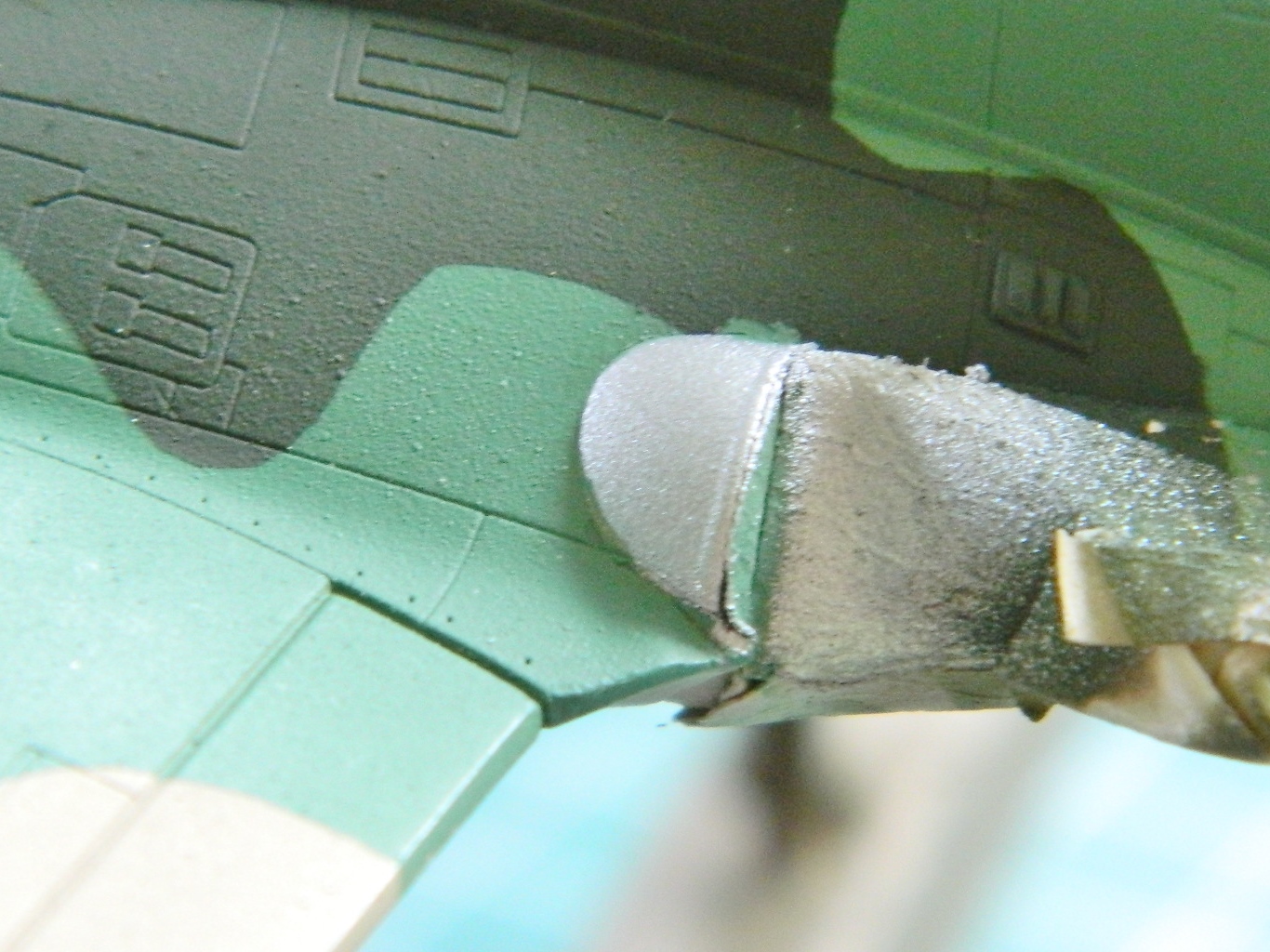
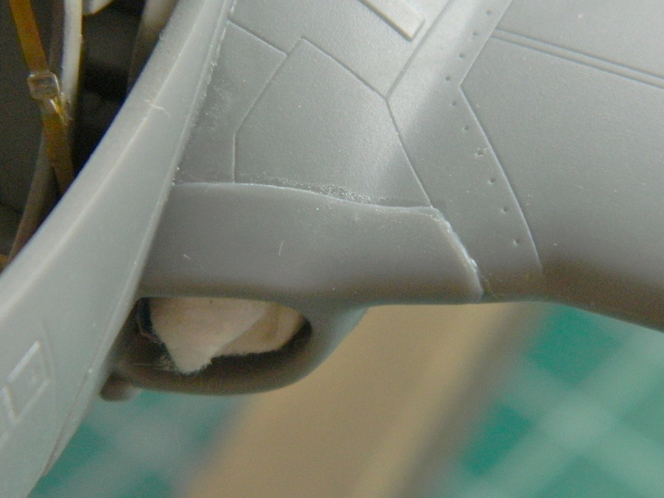
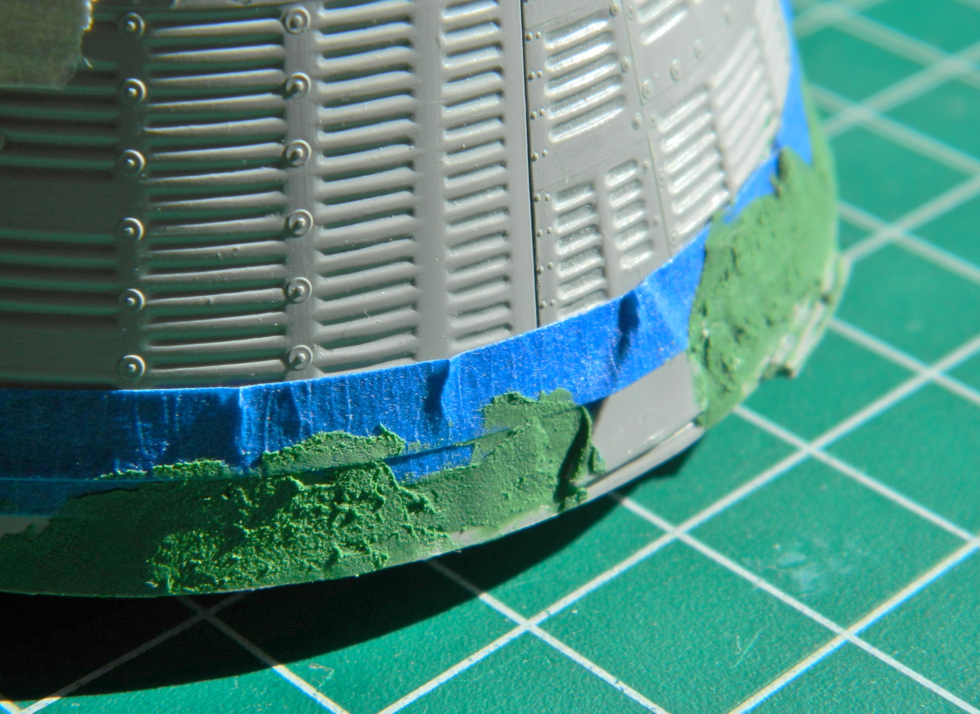
There were a few minor flaws, the largest of which were these two, where the paint pulled up from in front of the port (left…I only used “port” to make myself look more knowledgeable) intake and a gap on the underside where the tape didn’t quite seal around the cylindrical vent:
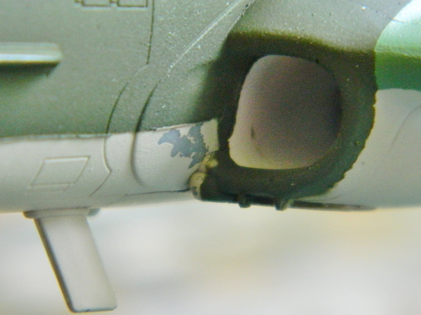

I sanded the peeled area with 2000 grit to get a nice and gentle feathering. If you look at the photo of the intake above, you can see where the green meets the underside color, the line isn’t quite sharp. I masked the green and reshot with the underside color while I was reshooting the area in front of the left (port, if I’m being pretentious) intake and the area where the tape didn’t seal.
There are areas on both top and bottom that had to be shot flat black, so I started playing tape-Tetris:
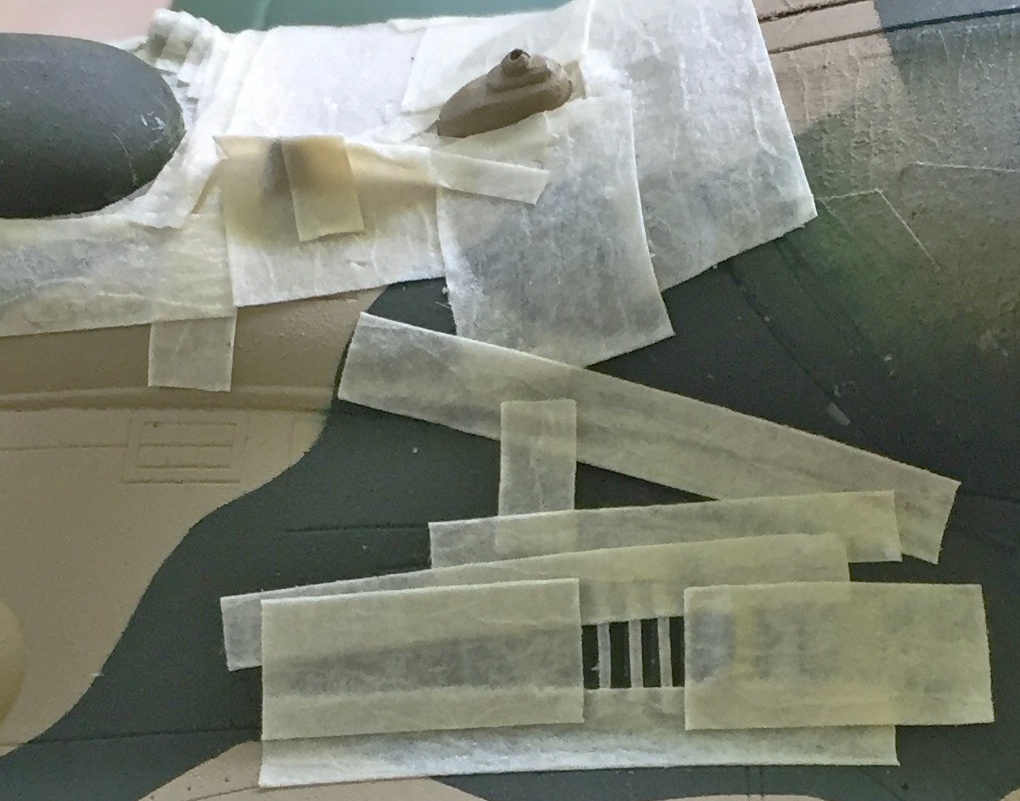
Since that was such fun, I decided to play tape-mummy:

And of course though it looks like it came out well, there were a few areas of overspray. The areas were so minor that instead of masking and spraying…again…I decided that since dry-brushing works so well putting down a very small amount of paint to replicate wear, a very small amount of paint would also deal nicely with minor overspray:

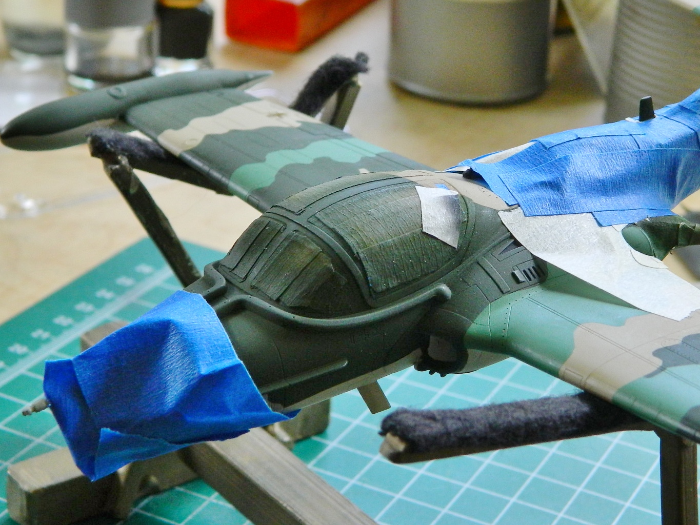
Then it was time to glue the refueling probe back on. Again. Some more. I stopped counting at an even dozen how many times the probe and the pitot tube broke off (I left the damned pitot tube off…I’ll put it back on once I’m done handling this thing). I broke it off many times after I stopped counting. But since I wanted it on there when I painted it…IT WAS ON THERE WHEN I PAINTED IT. Masking complete (I thought), the aluminum parts were sprayed aluminum:


Most of the pylons were painted the same color as the underside, but the leading edges were painted the same color as the camouflage paint on the wing above it:
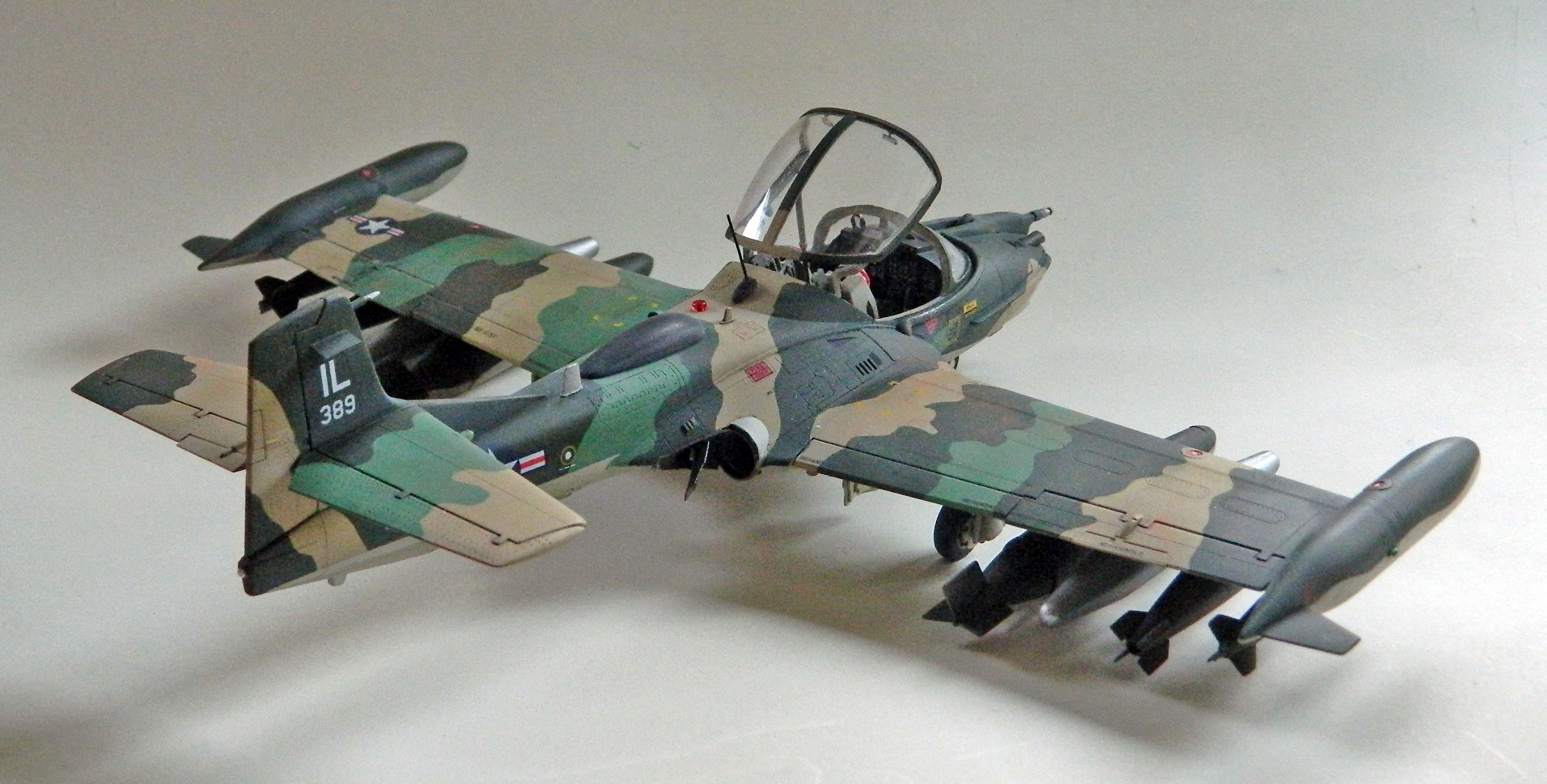
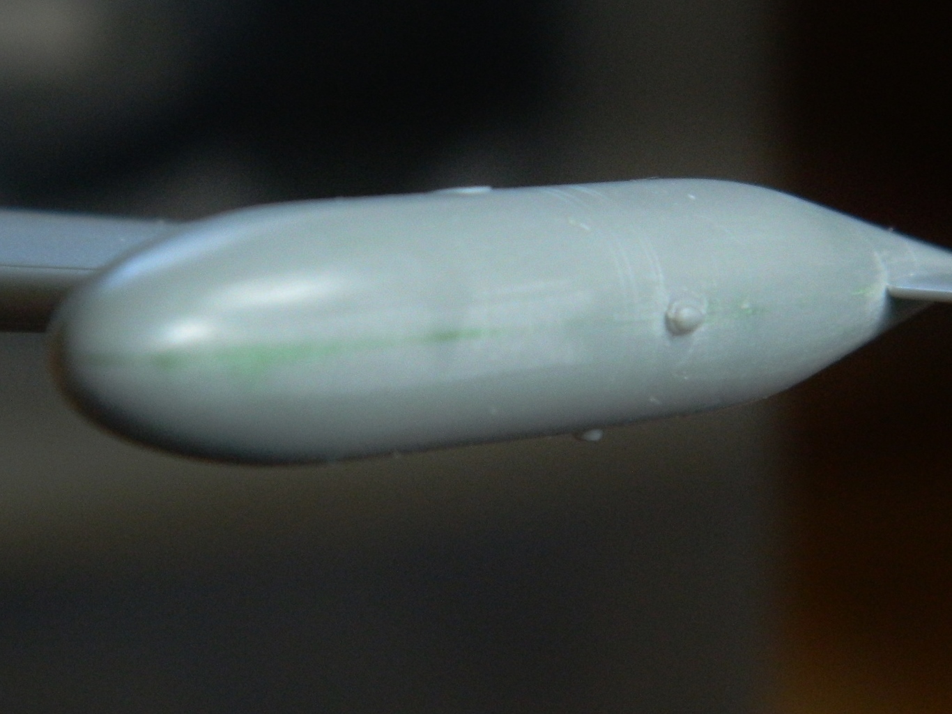
I had intended on using the SUU-14/A launcher tubes on the outermost pylons. The way the parts went together was a sodding nightmare and I wasn’t able to finish off the seams to my satisfaction. My original intent was to have each wing have a drop tank closest to the fuselage, then a napalm tank, a Mk. 80 bomb (250 lbs.), and then the SUU-14/A launchers. Since I’m not using the SUU-14/A tubes, I’m going to put the Mk. 80s on the outer most pylons and an M117 bomb (750 lbs.) next to the napalm tank. So that means I gotta put the bombs together. At least they were more accurate than the Mk. 80s were and though I had to thin some fins on them, I didn’t have to thin them as much:

The rear of the fins is hollow and the kit molded them solid, so I drilled them out for a more scale appearance:

So. My initial goal was to see if I could build this in 50 hours or less. I can be so funny… My secondary goal was to see if I could build this in 100 hours or less. Sometimes I can be so naive… I’m at about 107 right now (told you not to bet on it) and I’ve yet to add chipping effects, clear coat with gloss, add decals, do a wash, clear coat with flat, and stain/weather with pastels. My tertiary goal was to have this done before my field trip to the National Air Space Museum on June 12. I still may, but had that been a hard goal, I certainly could have done it, even without the various setbacks along the way.
Oh shit. I just remembered that I’d wanted to paint the outside of the landing gear doors and forgot to. ::rolls eyes::
I can often repeat myself. I’m about to do that again. The smaller the details, the longer they take to do. One of my original goals was to see if I could complete this build in under 50 hours. Nope. As of this writing, I’m at 85.75. It’s possible I may get this done in under 100 hours, but I’m not betting on it; you shouldn’t, either.
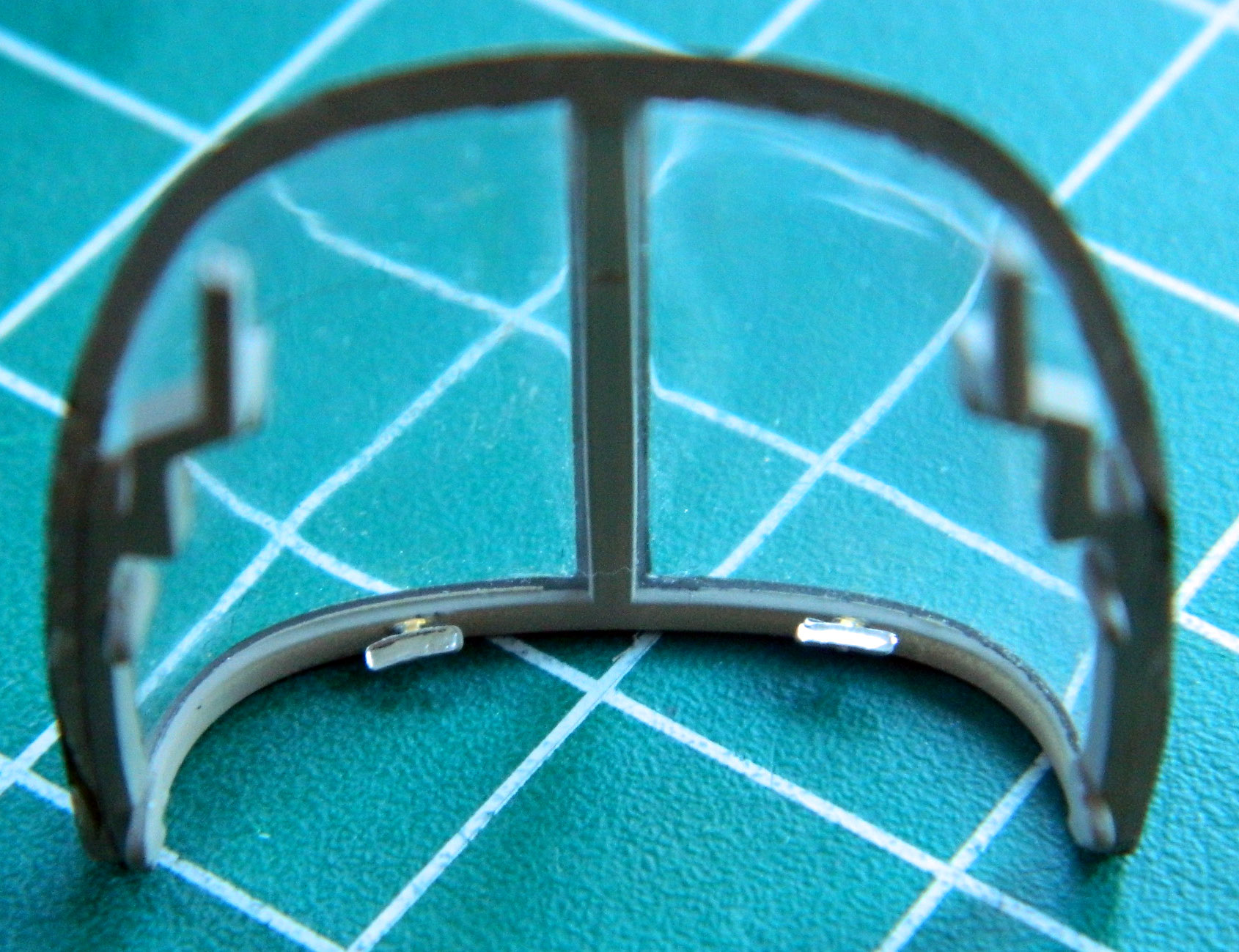
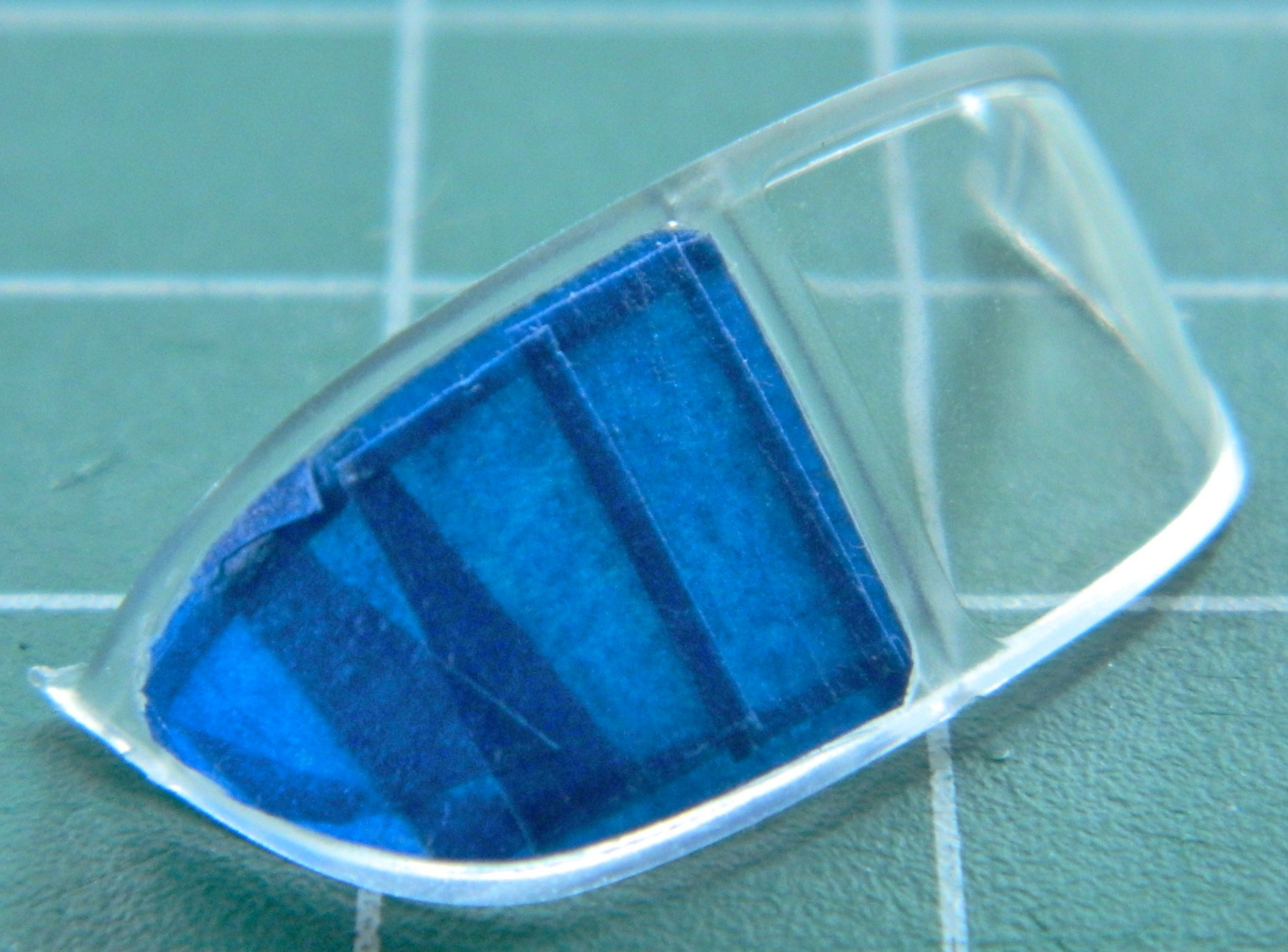
I finished masking the windscreen:

The canopy had rails had to be added:

The top canopy seen above was also masked inside and out. Once the masks were laid down, the interior color was painted on, inside and out. Why outside? Some of the external framing is larger than the internal framing. If, as would seem logical, I’d painted the outside color first, where the framing extends past the inside framing the outside color would show…and I don’t want that. So the inside color will show inside, and the outside color will show outside:
I added the magnetic compass to the top center inside the windscreen, painted it black, and glued the windscreen into position:

Then I fitted the canopy into the closed position and sealed it with white glue to keep exterior paint from infiltrating the interior:

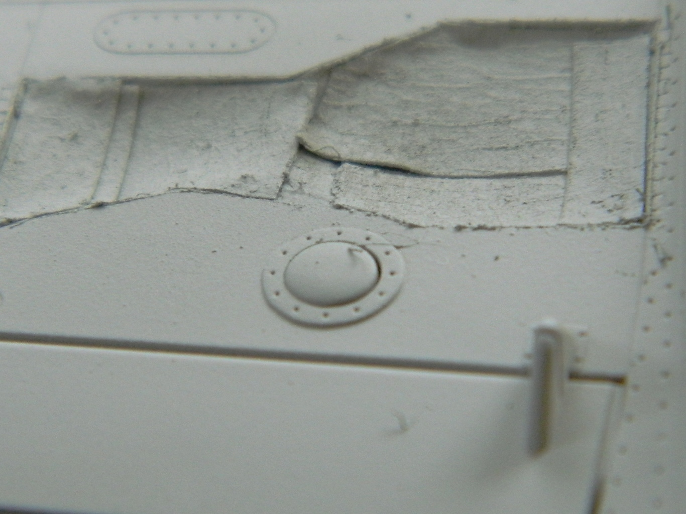
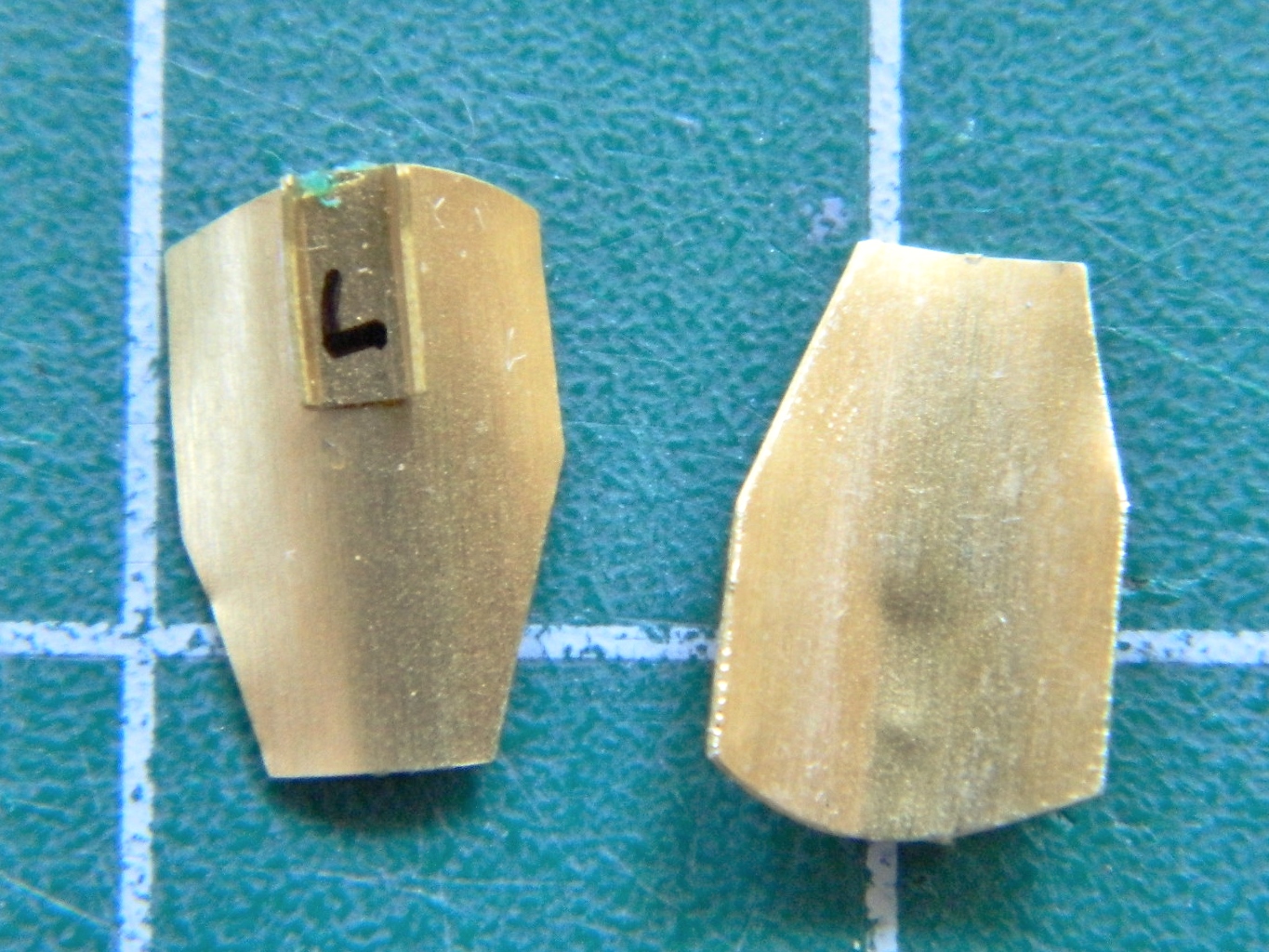
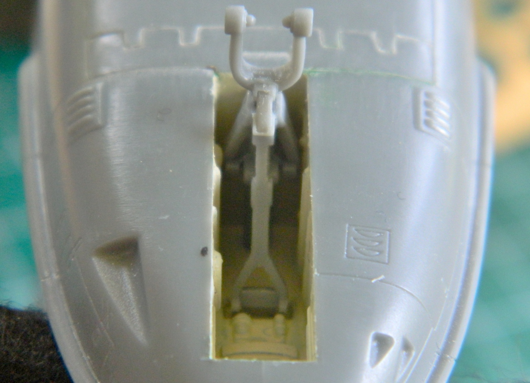
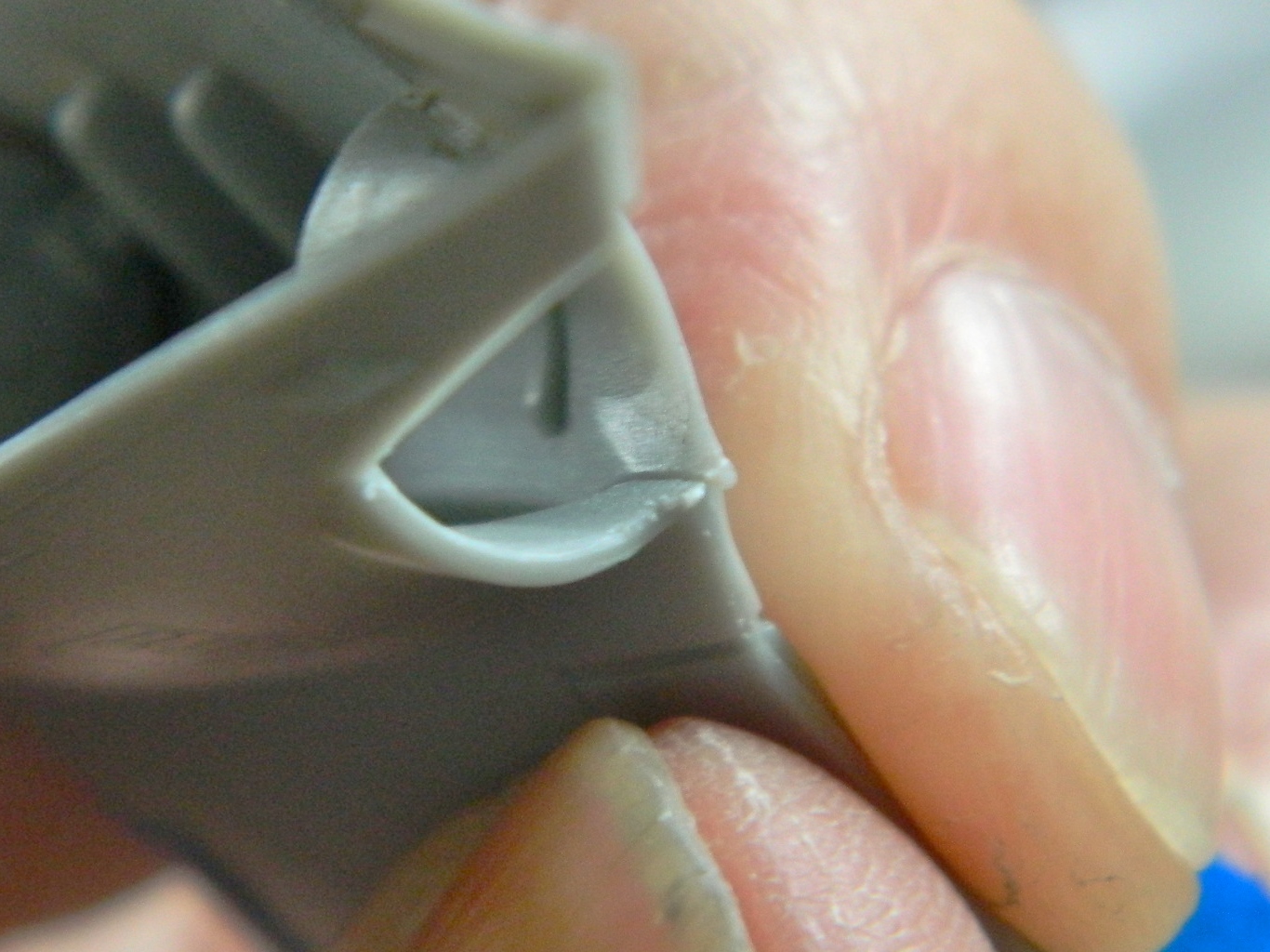
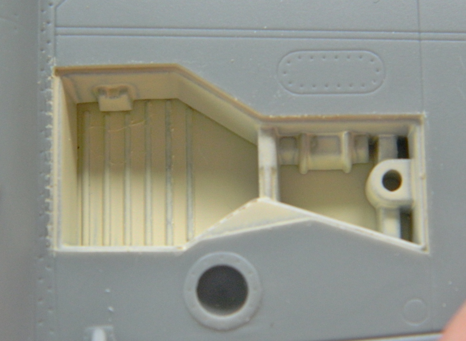
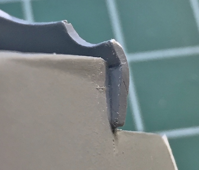
The main landing gear struts have locking arms that keep the gear extended. The recessed rectangular area should be open as when the gear retracts, the brace leg to the left folds into that area, meaning that has to be cut out:

Starter holes were drilled and I used a piece of broken jeweler’s saw blade to connect the holes, then a freshly sharpened knife to smooth it all out:


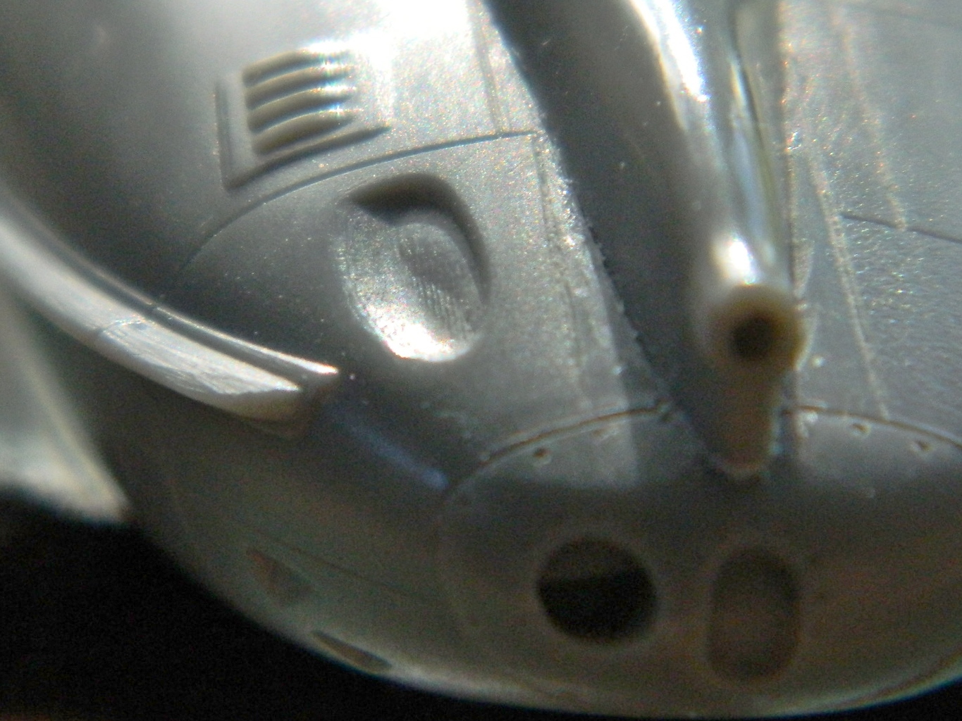
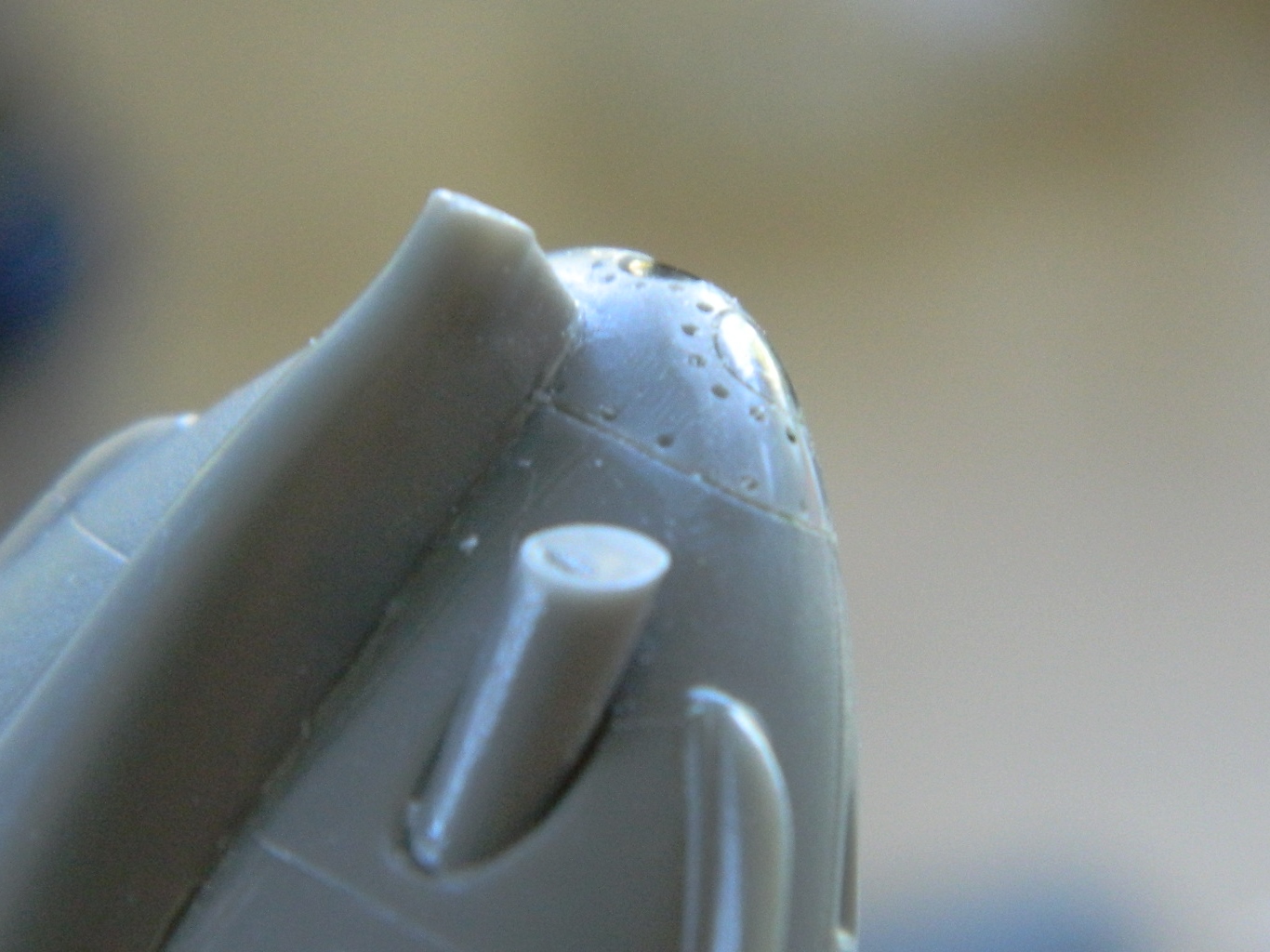
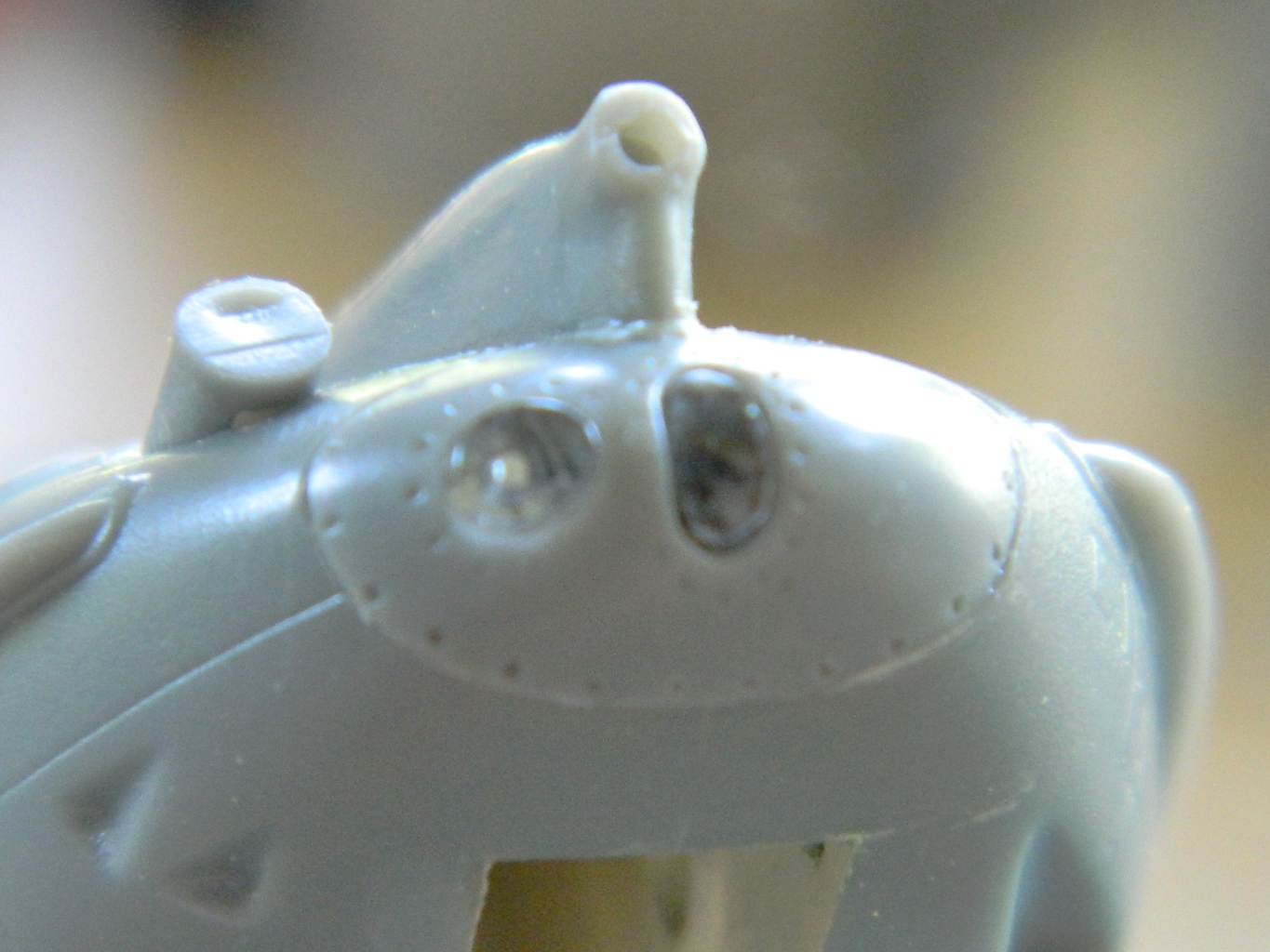
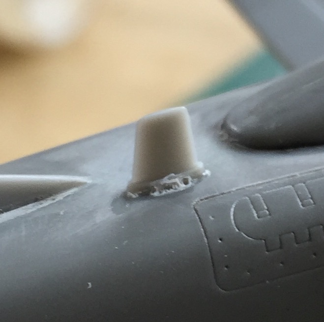
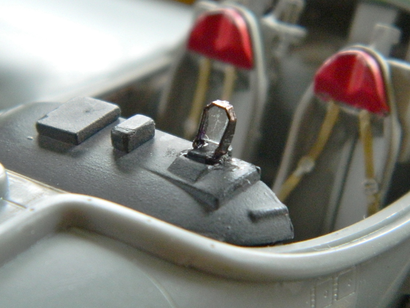
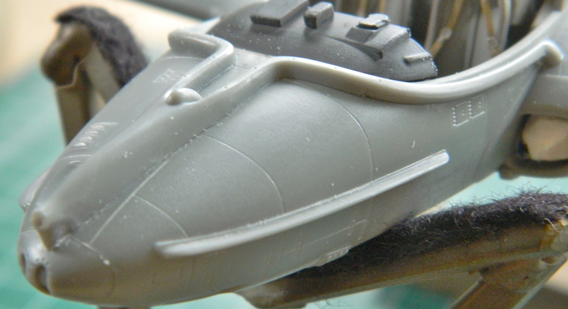
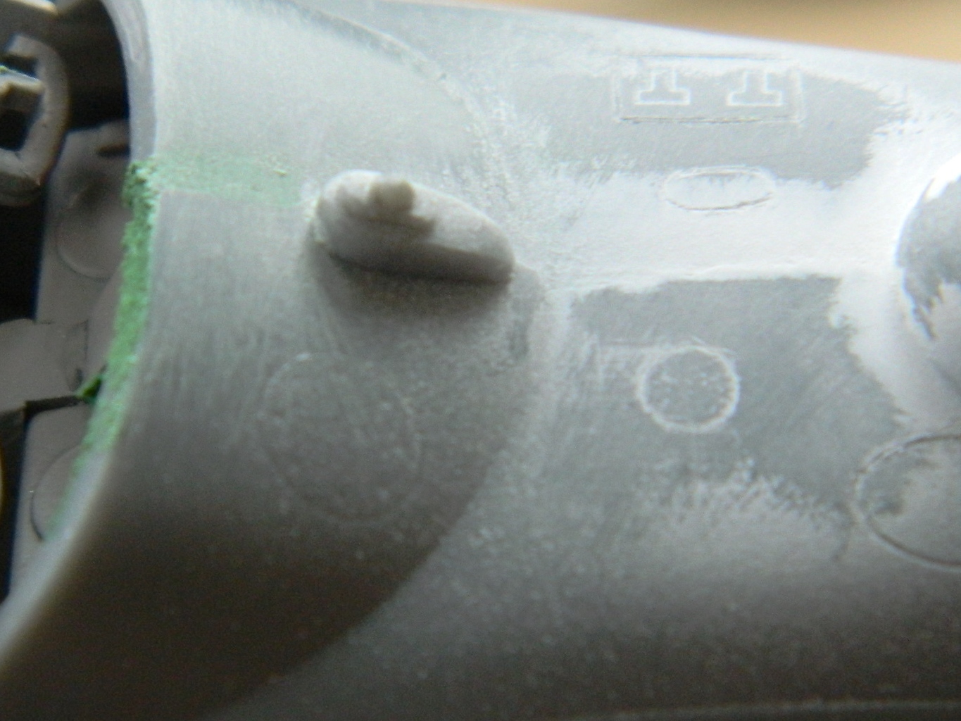
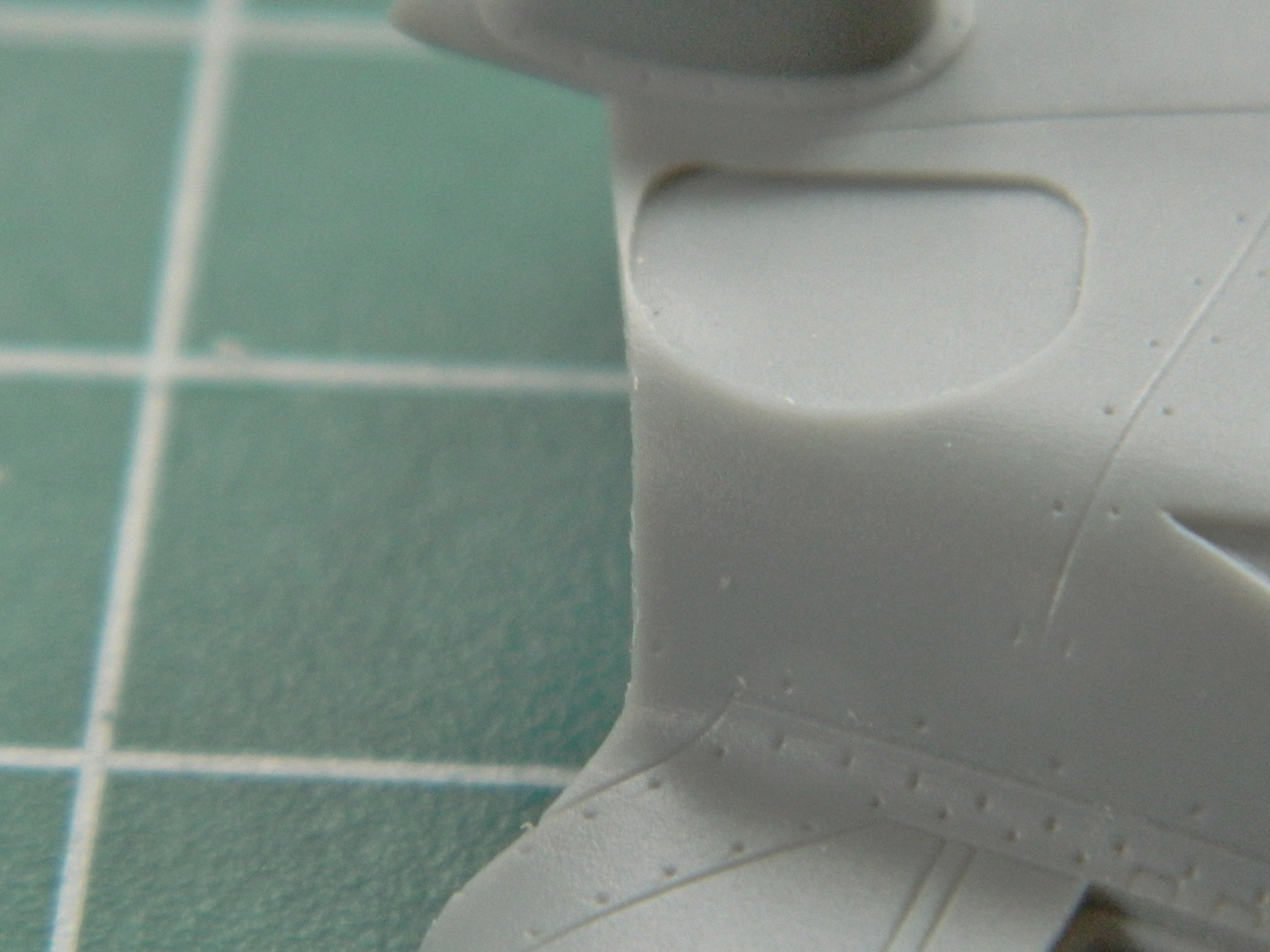
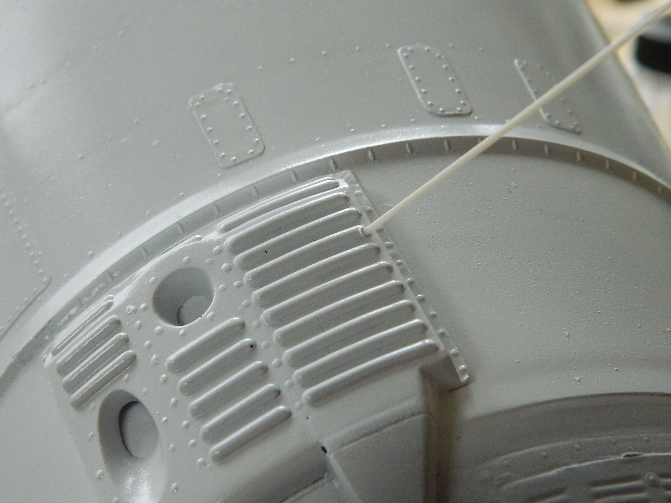
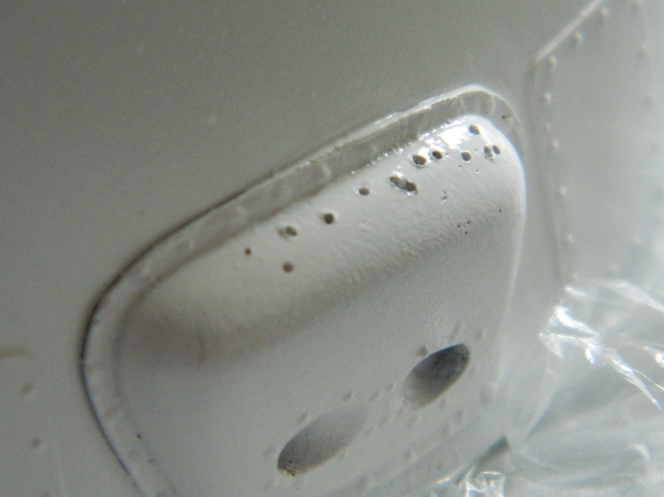
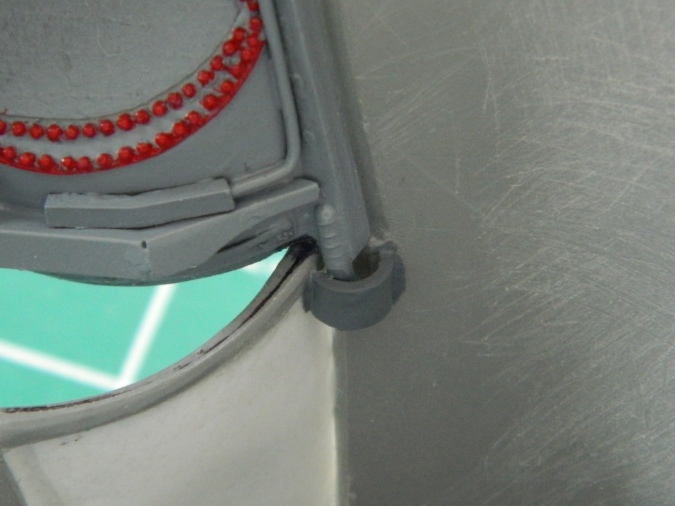
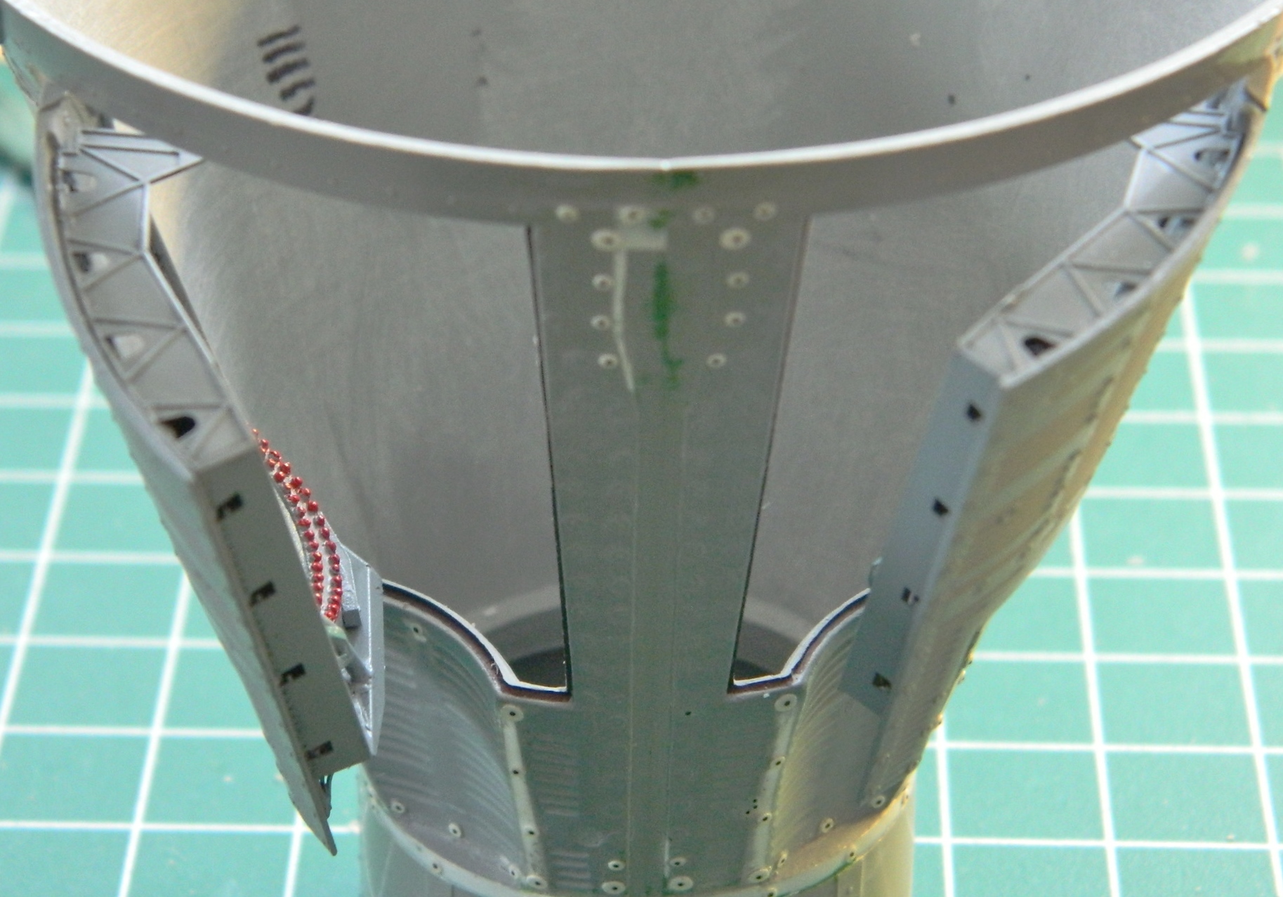
While dry-fitting the gun shroud, I found it didn’t fit correctly. It didn’t settle down into its recess enough and the oval ramp-like area to the left is why. That will need to be cut down (later). At the nose of the fuselage are areas that will be getting clear parts installed. The round area is a landing light and the oval area is…well…I dunno what it is. I just know it’s clear, it’s the size of a large grain of rice, and it certainly had me concerned (they both did, actually):
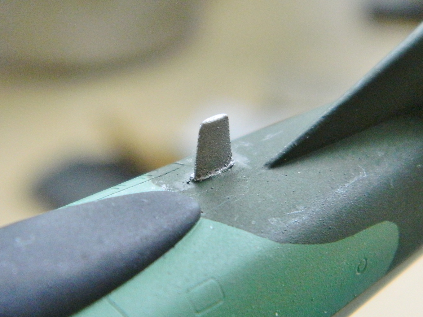
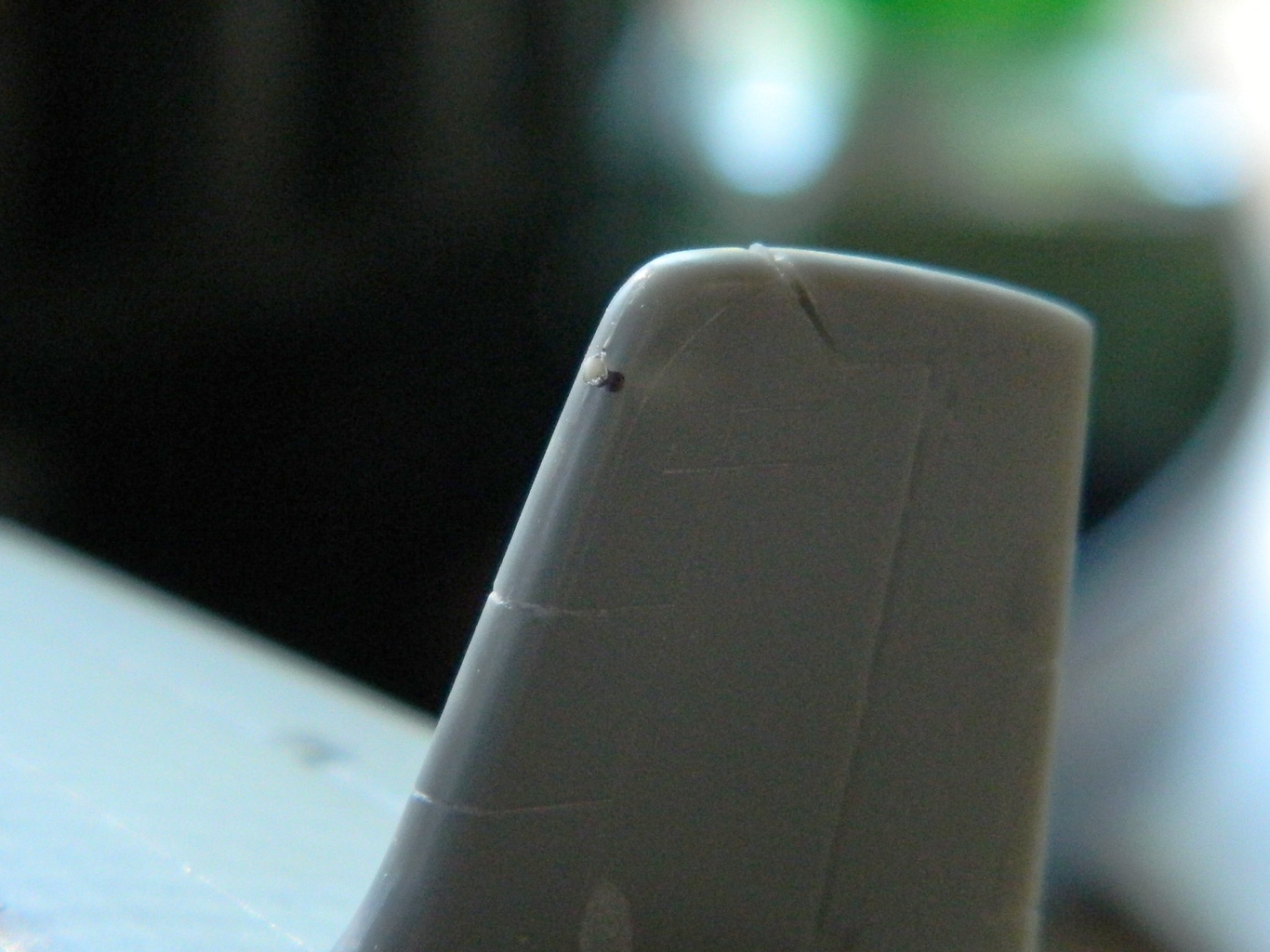
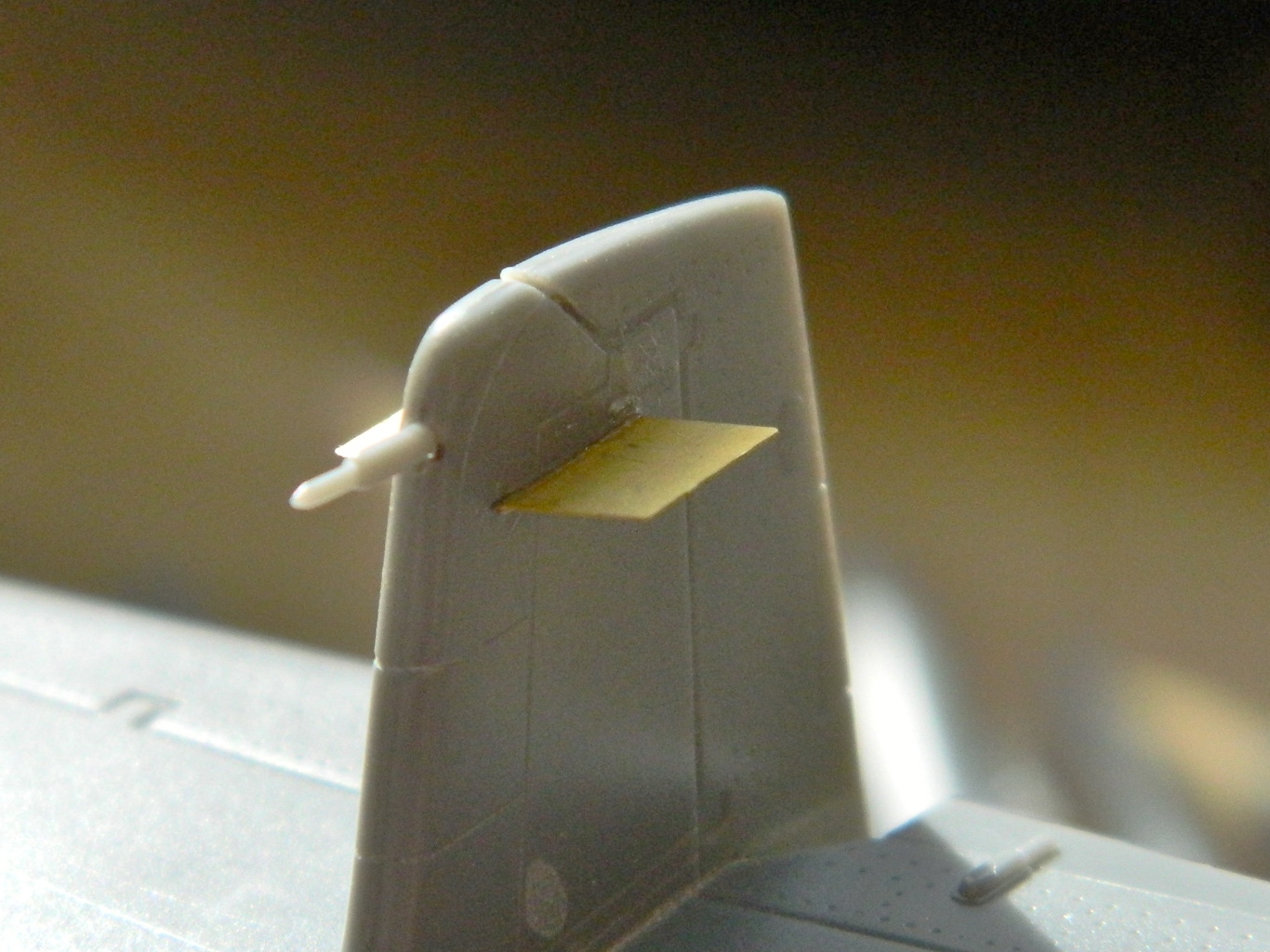
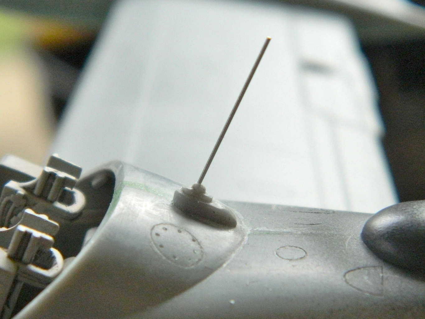
There is a curious omission with the kit’s directions. All my references show the pitot tube (a device that tells airspeed by the air pressure created by motion acting upon it). The kit supplied a pitot tube. The parts lists states it’s not used. That’s incorrect. Looking at the area at the top of the vertical stabilizer shows something else interesting. Most of the socket for the part to fit in has been molded. But the outside of that area is molded solid. Interesting… Also incorrect. I drilled out the socket and added the pitot tube (if you look closely at the first photo, you can see the area behind the black dot is lighter; that’s where the socket was molded in):
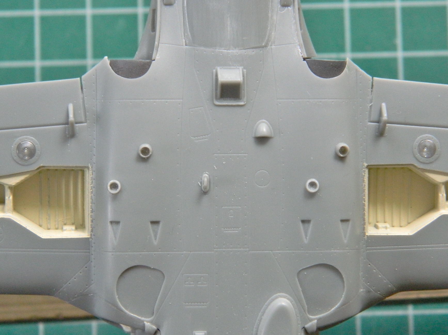
I flipped the model onto its back and started adding small vents and antennae.
I did mention “small,” didn’t I?:

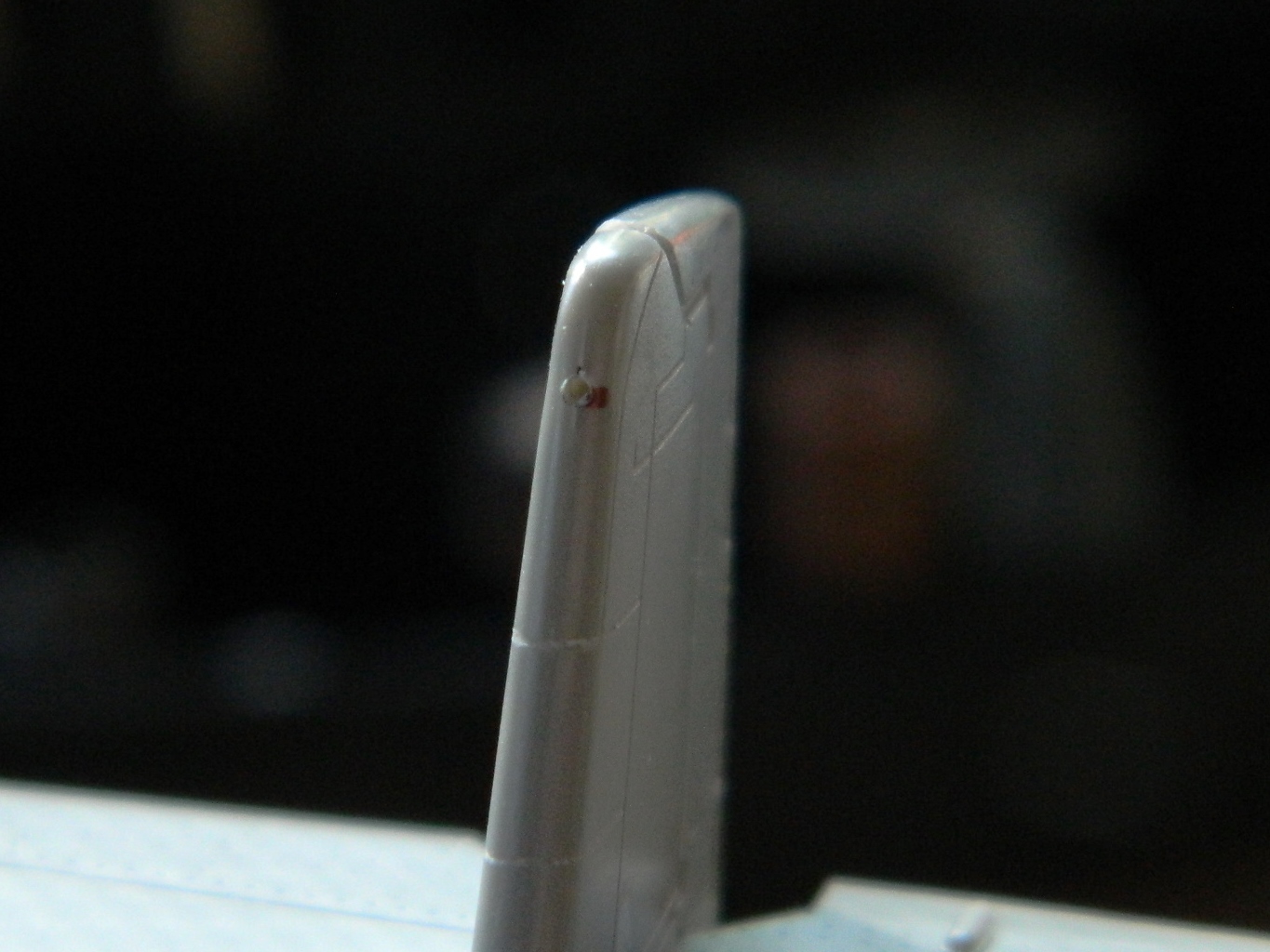
The bases of all the fin-style antennae are too thick. I’d already thinned the ones on top, I also thinned the bottom ones:

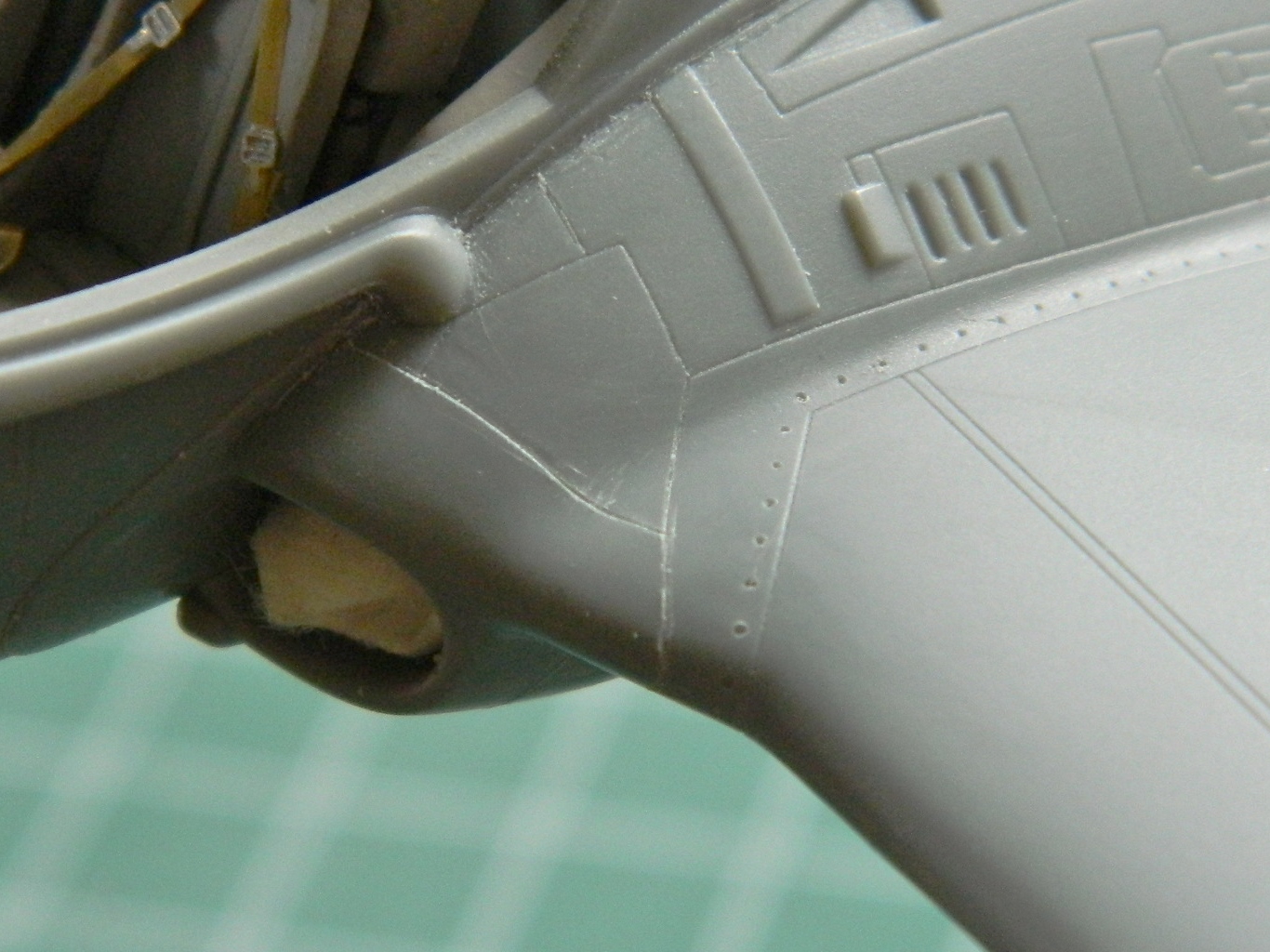
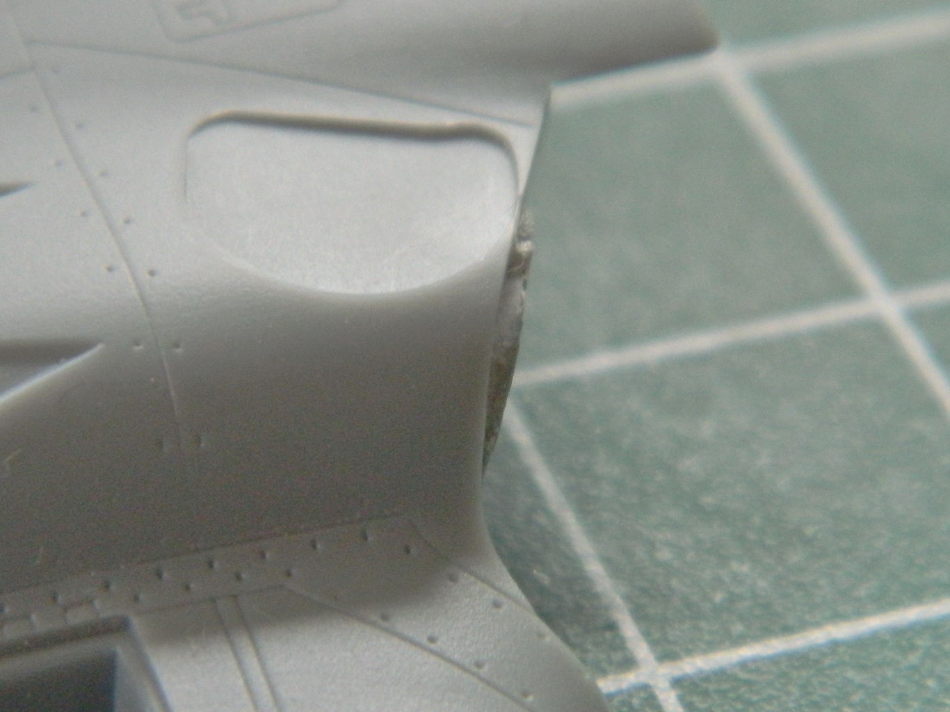
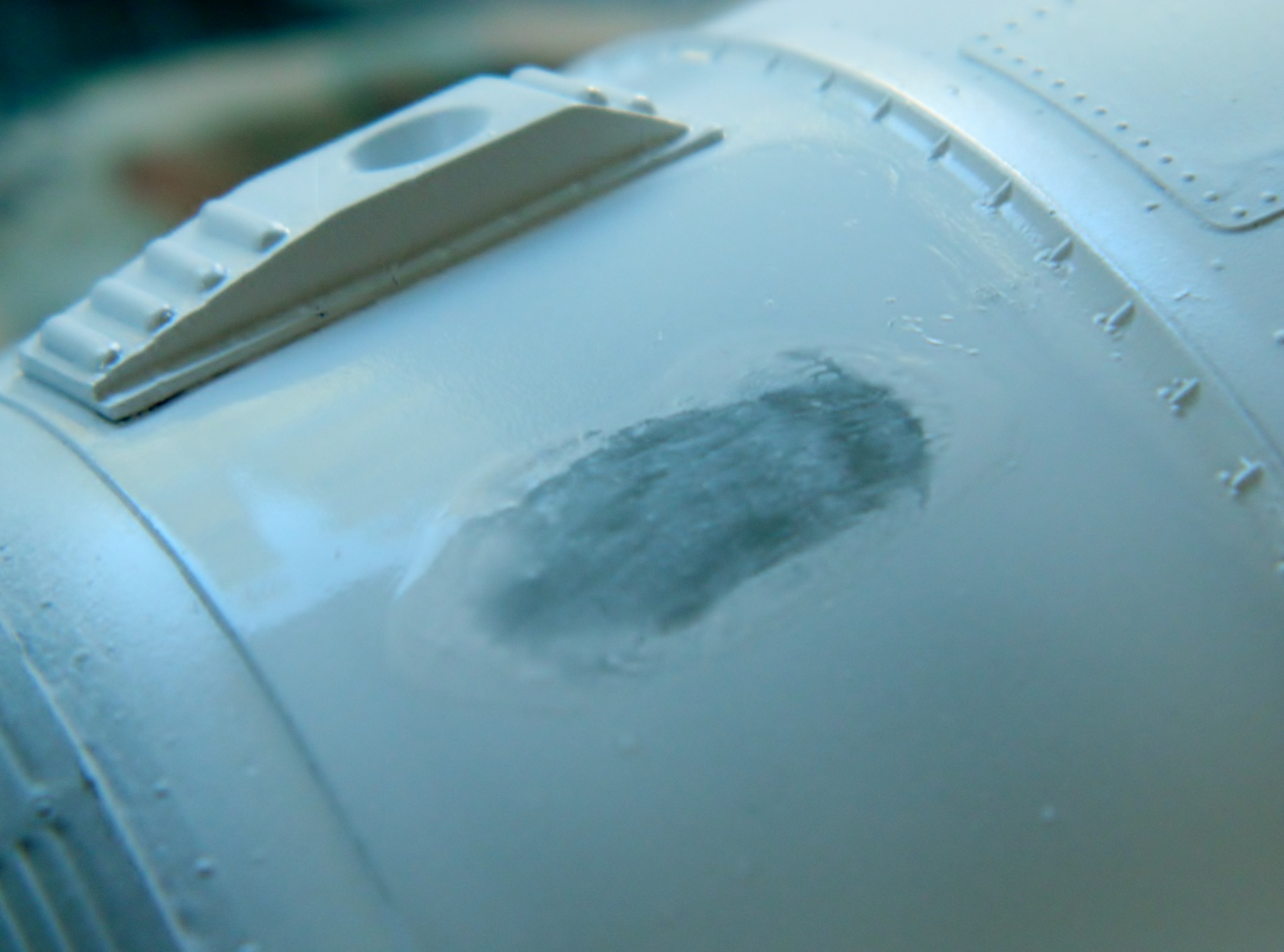
The color of the nose-wheel bay needs to be brought down to the fuselage and to do that, I needed to fill that gap with putty and paint it:


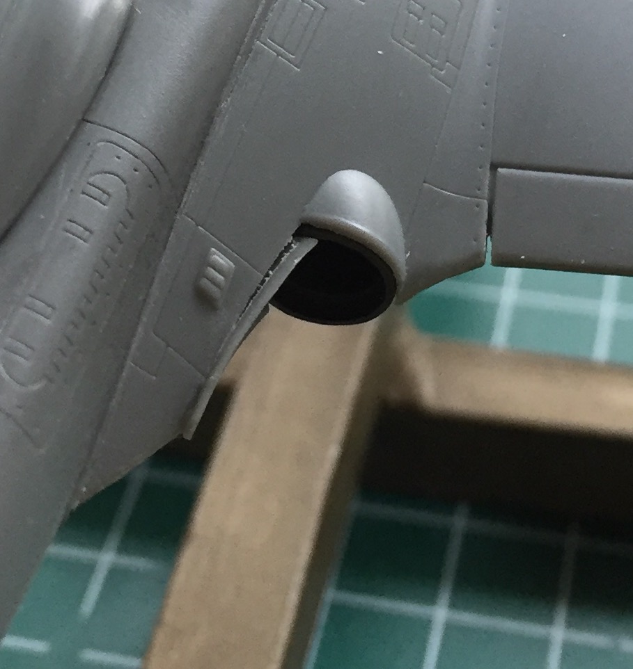
There are round vents on the underside that were WAY too thick. They’re still too thick but since this is an OOB build, I won’t be replacing them with brass tube the way I’d like to. I drilled them out to improve the scale appearance:
When I started assembling the under-wing stores I noticed is that some of the stabilizing fins are far too thick. Those had to be thinned more to scale:

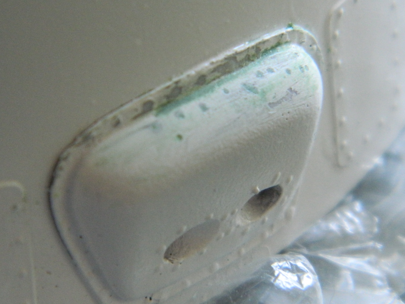
Then I had to ignore my apprehension about the clear parts that go into the nose. I got the oval-shaped part right the first time! (Considering how nervous I was, I’m surprised I didn’t launch the clear part into a multi-hour session of flashlight-in-mouth-crawling-around-on-the-floor-examining-each-square-inch fun). I had painted the area behind it black and the area behind the light silver. I wasn’t so fortunate with the fit of the nose light, though. You can see how far it sticks out and it’s supposed to be flush:
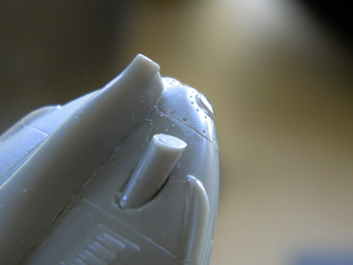
I filed the protruding area to fit the curve of the nose, then used successively finer sandpaper until I’d removed all the sanding scratches. (Had it been a canopy, the next step would be to polish it…for hours…but it’s not so I didn’t) (and also note how nicely the gun shroud sits in its oval mounting area):
I’m pleased with the end results:
It took some time, but now all of the detail parts are about ready to start hanging onto the kit. The ordinance and drop tanks will be added after painting:

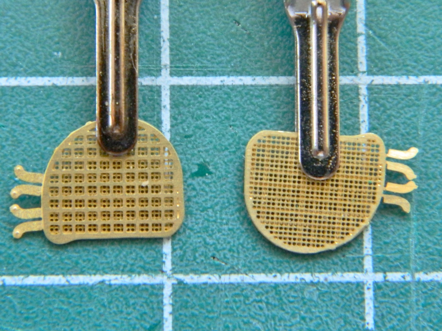
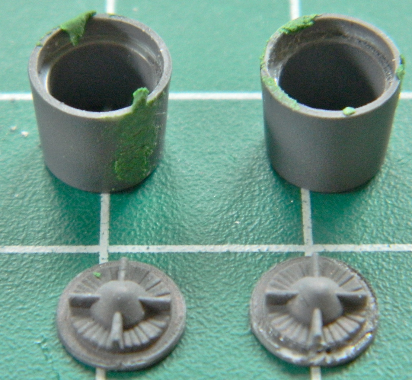
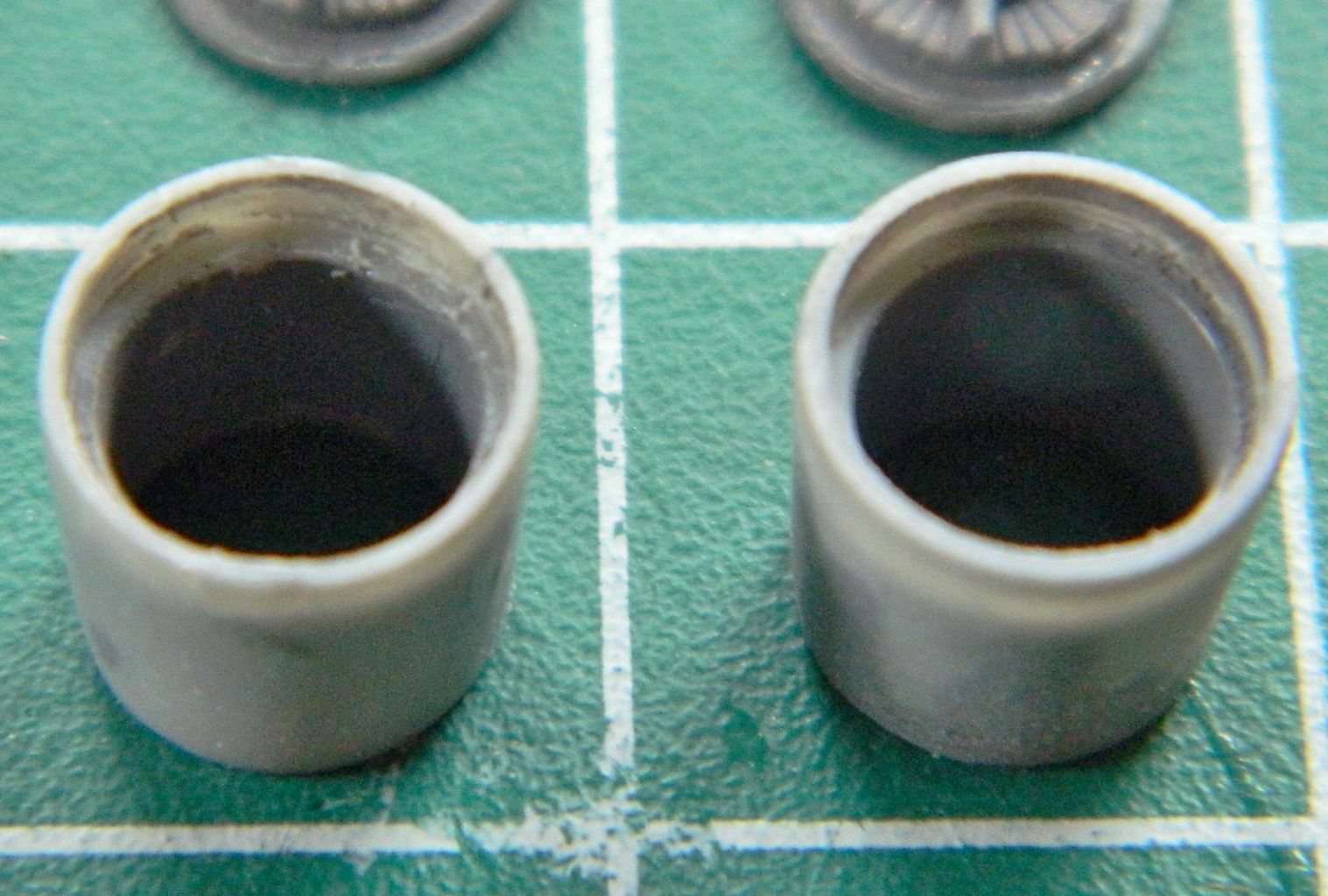
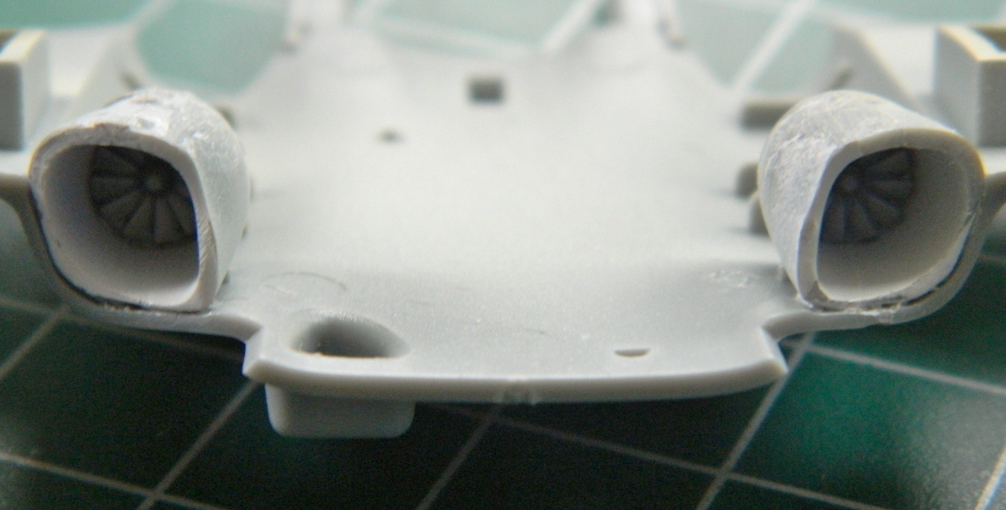
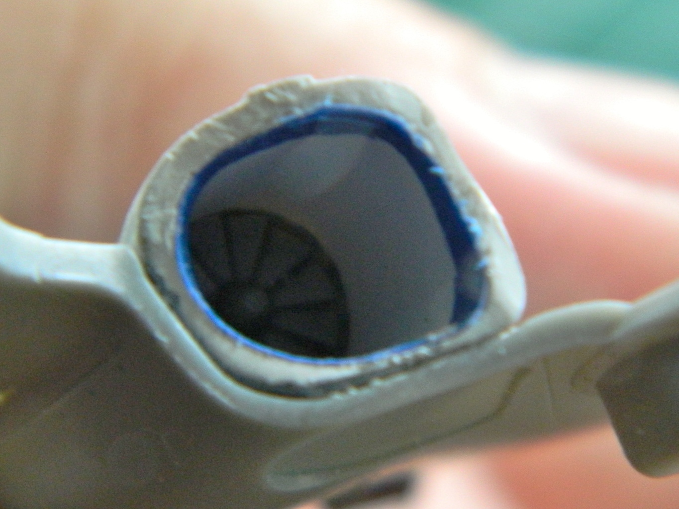
The A-37 sits so low to the ground that it was quite prone to sucking bits of crap into the intake. A jet turbine is a finely balanced bit of kit and does NOT like being unbalanced (unlike myself, who’s made a lifestyle out of being unbalanced) and quits in a huff when that happens. Sometimes it quit in something much more dramatic than a mere “huff.” The fix was to mount FOD (Foreign Object Damage) screens. The pilot(s) could raise or lower them at will from inside the cockpit. The kit offers nicely done two-part FOD screens that had to be assembled. I briefly considered soldering them but realized that was taking things too far; superglue would work just fine:
Next, I had to curve the exhaust deflectors and glue the mounting brackets to the back of them:
At the top of the vertical stabilizer a pair of antennae are supposed to be attached. There’s a problem with that…the antennae that are supposed to be mounted to the plastic is .005″ (.127mm) thick. That’s not enough surface area to keep them there (a gnat landing on it could cause one to pop off), and the attachment point is a very fine recessed line which helps as much as a screen door on a submarine does:

One of my line scribers actually cuts plastic away leaving a slot and that’s what I used to cut slots the PE parts will be glued into:

While I’ve been working on the larger assemblies, I was thinking about how to paint the landing gear parts. Some of them are very small and not only would they be a bitch to handle while painting, the airbrush would blow them off the painting backdrop if I wasn’t holding them. My solution was to attach them to the parts they get attached to which are larger and easier to handle. That meant I had to dry-fit the parts and align them:


This I can work with:
Then it was time to start hanging the last of the PE parts onto the model. First I did the exhaust deflectors:
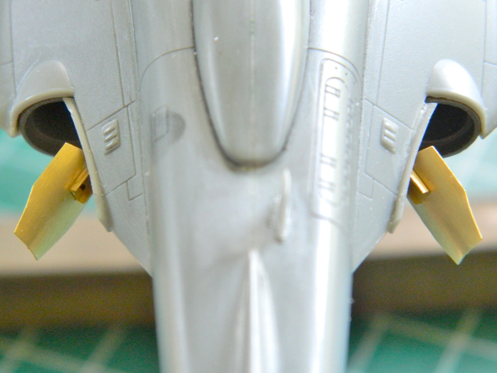
Then I did the fin antennae on the vertical stabilizer (and the FOD screens):

And then I managed to knock the damned thing off the stand and snapped the refueling probe off:
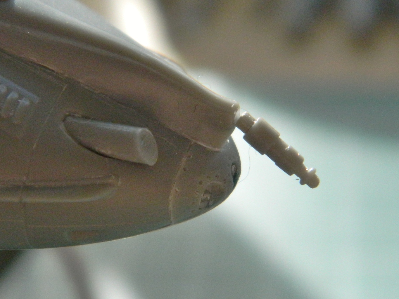
So that got glued back in position. Thank you EVER so much, Eris and Loki.
To keep the exterior color out of the differently-painted landing gear bays and off of the exhaust nozzles, they were all masked off:

And y’know? I think I’m ready to start tossing paint at this thing:
Next is airbrushing…
The smaller the details, the longer it takes to do them. I think it’s because homo sapiens are ill-suited to the task of scale modeling. Think about it. We only have two hands, all ten fingers are either too thick or suddenly turn into thumbs (y’never know when either), the smaller the part we’re working the more we notice our hands are anything BUT steady, our vision doesn’t self-magnify…and the list goes on.
Today was small details.
I started by fixing the exhaust deflector on the right side. The left side fit perfectly. It wasn’t until I’d glued the right side in that I realized that it didn’t quite fit (see the Glossary for “brain fade”), so that got fixed:
Scribing panel lines raises little “feathers” of plastic. Being lazy, rather than chase them all down, I use a small amount of styrene cement and painted the scribed lines. The glue causes the tiny feathers to dissolve into the plastic and vanish. The “rivets” were mostly sanded away during the fitting of the intakes (and in a few other places) so I replaced them with a small drill as well:
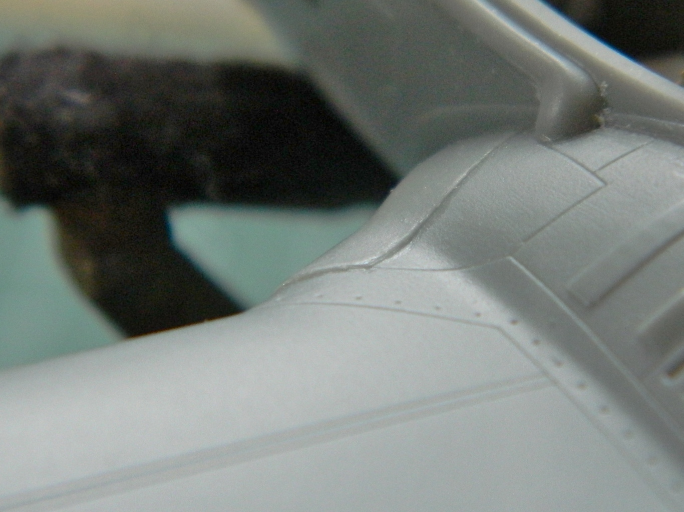
While I was looking at panel lines, I realized the strakes on either side of the nose didn’t have panel lines across them to match the panels underneath. I checked references and yup…they should be there, so I added them:

One of the interesting things I noticed was that the panel lines that wrap around the leading edges of the wings don’t match up. I sanded away the ones underneath and rescribed them. Later on, I noticed the page with the load call-outs a saw that the mistake was also done on the printout:

In drilling the antenna mount behind the cockpit, I dropped the pin vise and snapped the bit. I have extras of the bits that are easy to break and thought for a second I’d use the broken bit as the antenna. If this build wasn’t OOB I’d have done that. But since the bit wasn’t included in the box, I stretched a piece of sprue (it was included in the box) and used that instead. Since I’m making the aerial removable, instead of painting it with acrylic, I used enamel instead because I find enamel more durable. I dipped the sprue in the bottle of black enamel and set it aside to cure:


I wasn’t pleased with the paint job on the black dorsal hump. The edge of the white primer underneath could be seen under certain conditions, so I stripped the paint off. I also added other antennas and a vent to the top. Of course, once I’d added the antennas, I didn’t pay attention to where I grabbed the fuselage and laid one of the antennae over on its side. I pried it up, glued it back into its proper place, and tomorrow after the glue has fully cured I’ll rework the surface to remove the marred area:

Another fit problem is at the root of the elevators and that still needs to be fixed:
The last thing I wanted to add to the cockpit before putting the canopy on was the HUD. These are the parts I started with:
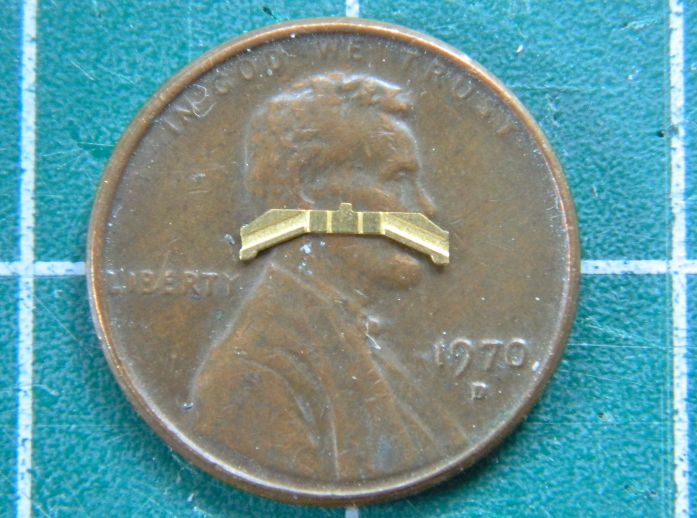
The PE part needed to be bent around the clear part:

And that was the end of the easy part. I noticed that the dimensions were off regarding the slots on the gunsight’s body and those were fixed:

And of course, the paint had to be touched up. While I was thinking about paint, I wanted to blacken the brass PE mount with something other than paint because I suspected the paint would be too thick on such a small part…and a total bitch to do properly. So I used a marker pen:

About an hour later, because it was SUCH an annoying part to get properly aligned, I finally managed to get the sodding thing on and in place:
Now to mask the canopies. They’re very nicely done parts…and they have framework on BOTH sides, so that doubles the…”fun”:
I’ll continue this “fun” tomorrow when I’m more rested.
Properly chastised, I made sure things fit this time:


And with that, it was time to glue the upper halves of the wings on and start getting rid of the seams:

In so doing, I discovered an interesting trick. I was checking a seam with the edge of my fingernail; if I could feel it, I’d be able to see it. I noticed that where I’d slid the edge of my fingernail across the plastic, it removed all the sanding striations. So I tried it all along the wingtip tank and damned if it didn’t do just that:
Now that trick will end up being quite useful someday! (Probably tomorrow.)
Done with patting myself on the back, I worked the seams until they were gone:

I cut away where the control surfaces should have gaps that the model does not.
Before:

After:
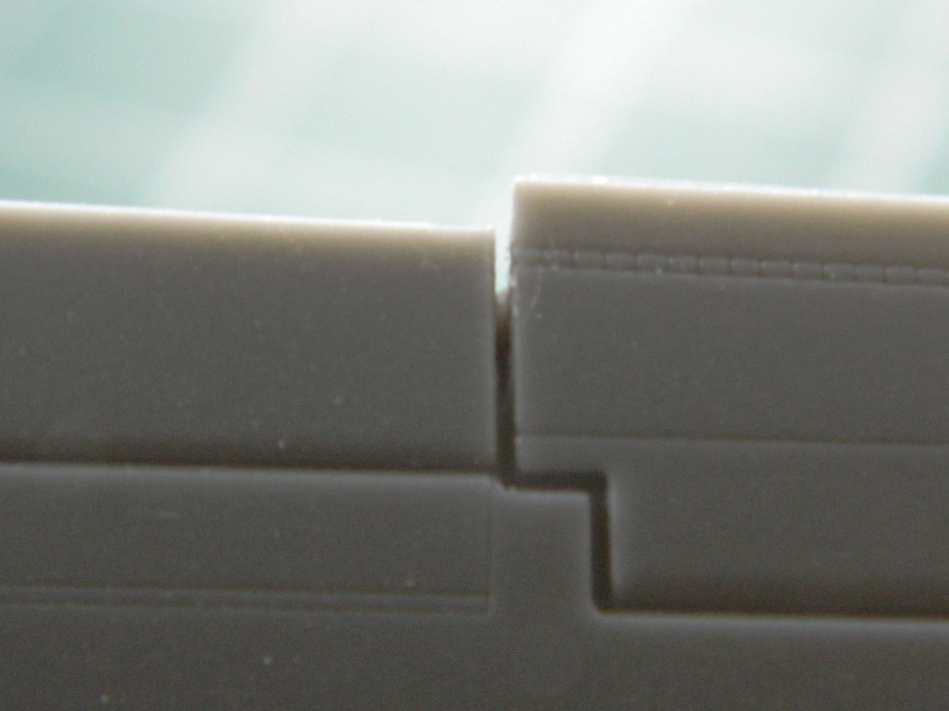
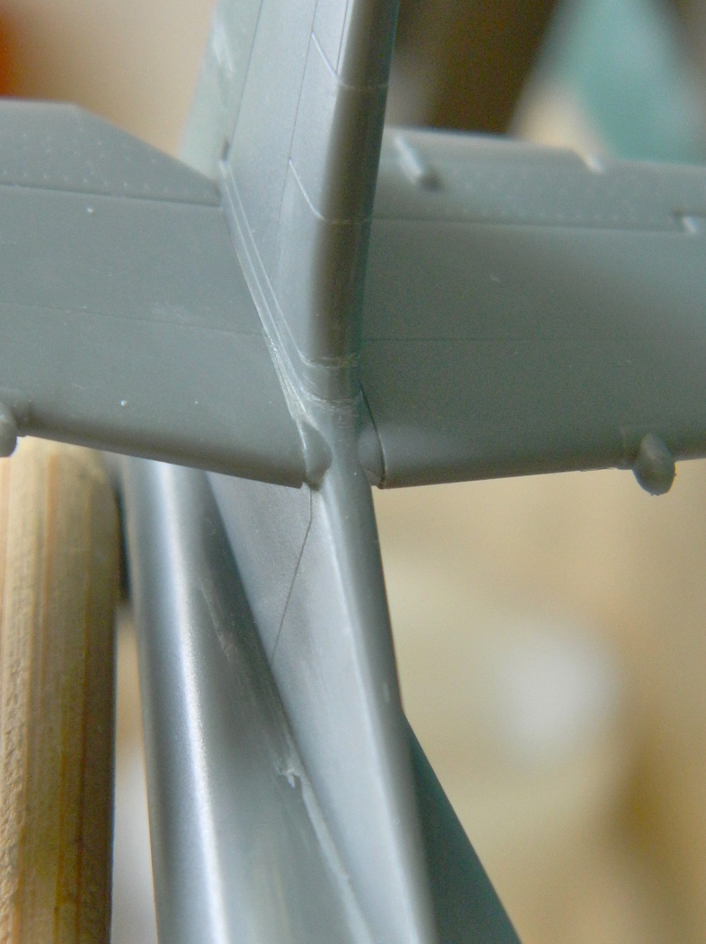
At the end of the nozzles, the wings are supposed to come to a sharp point…but they don’t:


I cut the areas flat to allow for a greater surface for the glue to work on and tried two ways of adding more plastic; a piece of scrap (top) and a piece of stretched sprue (bottom) to see which would work better:


I’ve learned that though the glue seems to set completely in about a half an hour, it doesn’t, really. Trying to work it (shaping or scribing) shows that the plastic is still not completely hardened. I set the wings aside overnight to let it cure completely. The next day I went back at it and ended up with something acceptable. That done, it was time to attach the wings to the fuselage. Fitting showed me an uncharacteristic (for this kit) fit:

I glued .010″ (.254mm) styrene to the face, let it sit for a bit, and once trimmed the fit was much better:

While I was waiting for the glue to set up firmly enough to trim, I touched up the paint on top of the instrument panel coaming:

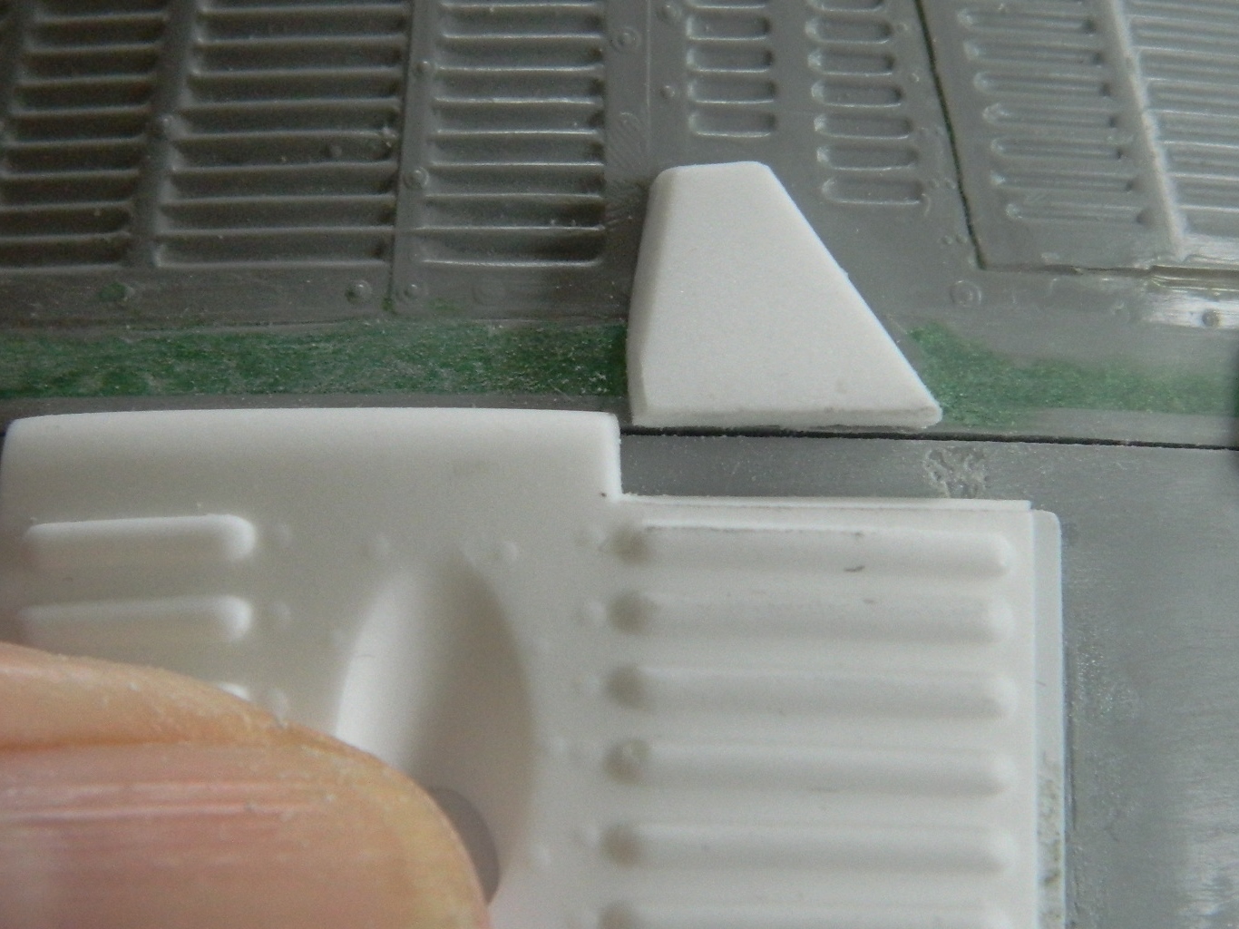
There are strakes on either side of the nose. The kit has them molded a bit too thick and rounded, so I covered the surface to keep from damaging surface details and thinned them a bit and sharpened the edge a little:
I added the nose, elevators, and intake frames:


With the wings now on, I started adding other parts that wouldn’t be too fragile to handle during the rest of the assembly. The lines for the in-air refueling probe needed some work and a little shim at the nose to fit but that went on:
As did part of the exhaust deflector assembly:

A lot of work went into very small areas cleaning up where dissolved plastic had bubbled out under pressure. Almost as much work went into making the intake frames fit:
But fit they did:

Since I need to rescribe the lines of the intakes, I’m letting the work sit overnight for the glue to fully cure before I go at these areas with scribers.
In my Wild and Misspent Youth ™ a few decades gone, one of the many things I’ve done was to run a small karate school. I used to emphasize to my students, “Be careful of confidence…you could end up not taking proper care.” The keynote here is, not taking proper care.
I was confident with this build. It’s out-of-box so what could possibly go wrong? When one is confident, it will be something one does not see coming… (And when one asks, “what could possibly go wrong?” it’s not uncommon to find out.)
It started well enough. Hitting the seams with flat white showed me the places that still needed attention. Sanding. One of the downsides to sanding is that yes…it gets rid of what you want to go, but it also gets rid of what you don’t want to go. In this case it was some finely recessed panel lines and those will need to be rescribed. However. I am NOT very good at rescribing panel lines (or even scribing them in the first place, which is why I ordered a scribing template from the Ukraine, of all places). I am PARTICULARLY bad at circular scribing, so of course that’s exactly what I need to rescribe and OF COURSE it’s right on top where they’re easily seen:
Rather than wait for my scribing template to arrive, I decided to make one. I got out my punch and die set and made circular templates from .005″ (.127mm) copper shim stock:
Worked just as I’d hoped. Excellent! Well, let’s get down on these engine intakes and exhausts and get this wing assembled!
Well…I was too confident yesterday. I thought I knew what I was doing (yes…that’s gotten me into the ER on occasion) and it turned out I was incorrect. When I went to put the exhausts in place, they didn’t fit. Hmm…they should fit… I wonder why they don’t? I looked at the instructions (that in itself is a novelty for me) and noticed that the narrow end isn’t the outer end, the wide end is.
Okay. At this point I walked away (silently…never a good sign) thinking, “Great…now I have to buy another kit!” I had a cup of coffee, gave Her Majesty (the cat) her due attention, and then the Boys in the Back came up with an idea. “Maybe you can knock the flame holders out of the tubes, clean things up, and glue them onto the proper end?”
So I did. I covered the flame holders with micro-cell foam so that details weren’t obliterated (or too badly) and used the largest piece of plastic tubing I could fit into the opening, and smacked it with a hammer. It worked so well, I did the other side the same way. Whew! Okay, so I clean up where things were glued, put them back where they belong this time, repaint, and go on (now I know why that one tube split, though):
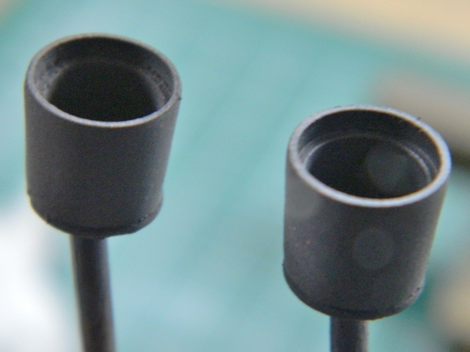
That’s when I noticed that the intakes didn’t fit well (no…the alarm didn’t go off). That protruding lip is supposed to be flush. Did I check to see if maybe there was another reason it didn’t fit? Y’know…something like maybe an ERROR ON MY PART? Noooo…:
So I trimmed it to fit (because what’s an error if one can’t compound it):
It was only then that the Boys in the Back said, “Maybe you should check the instructions again.” Well, fine. I did. Well, not fine. I put the intakes together wrong which placed the intake trunks on the wrong sides! Well, fine. I popped the intake vanes off, switched them to the proper sides, and gee…whadya know…they fit. Well, they mostly fit. There’s now a gap where Mr. Clever & Confident, here, trimmed it. I’d considered building it back up to where it should be but where it is isn’t very noticeable and I don’t feel like spending 8-12 hours fitting it.
You may now call me Mr. Clever, Confident, & Lazy.
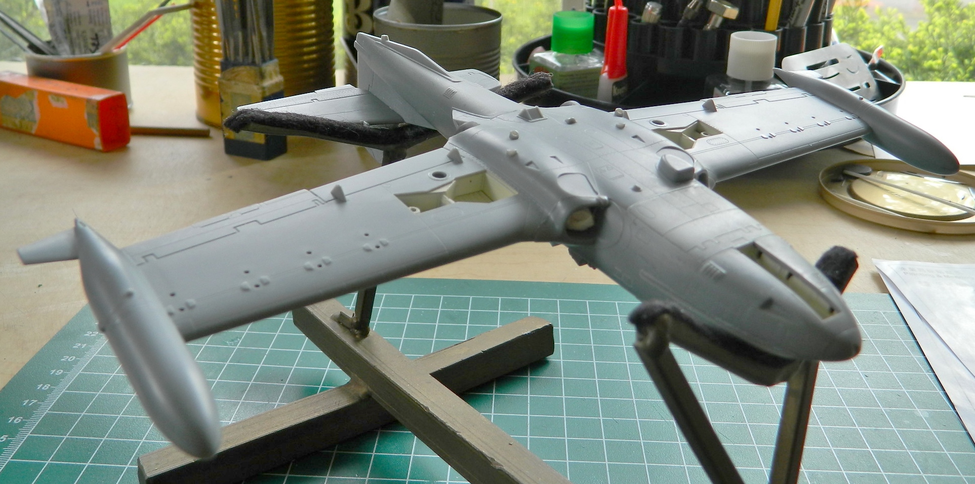
So. With the nozzles correctly assembled (and checked for fit) and the intakes correctly assembled and on the proper sides, it’s finally time to start getting the wings ready to assemble:
The paint chart calls for interior green landing gear bays. I’ve never seen them painted anything but white so I used aged white and got those under color:
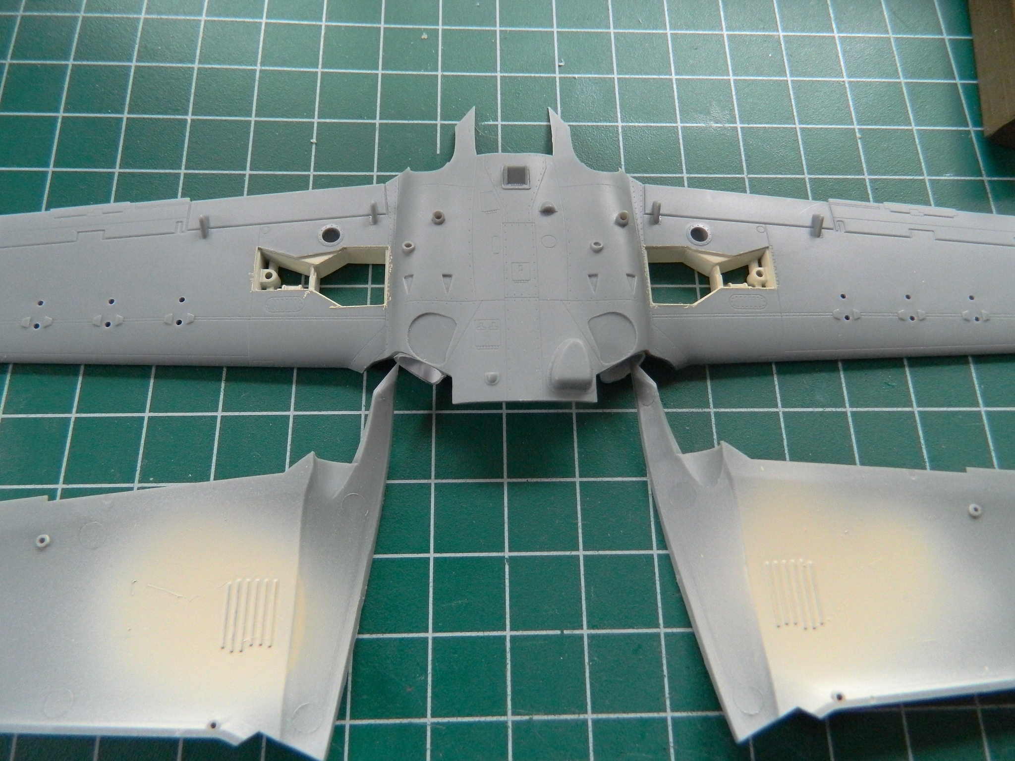
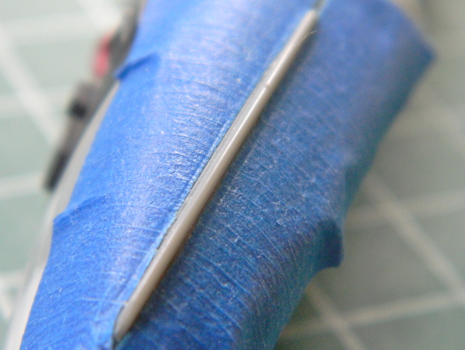
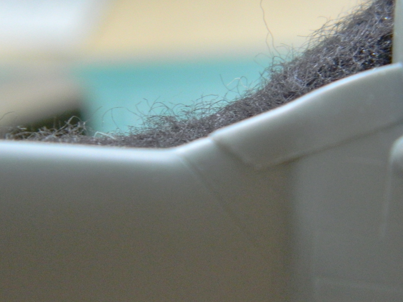
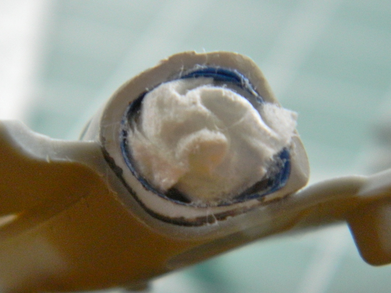
The intake trunks stay white, but the nacelle around the intake openings will be painted a camo scheme, so they need to be masked. However, they need to be masked in such a way to enable the masking to be removed once the painting is done. I lined the leading edge of the trunks with masking tape and filled the space with a paper towel:
Whew…okay. I’m back where I should have started today at. However, I am now properly chastised. So much for sodding confidence…
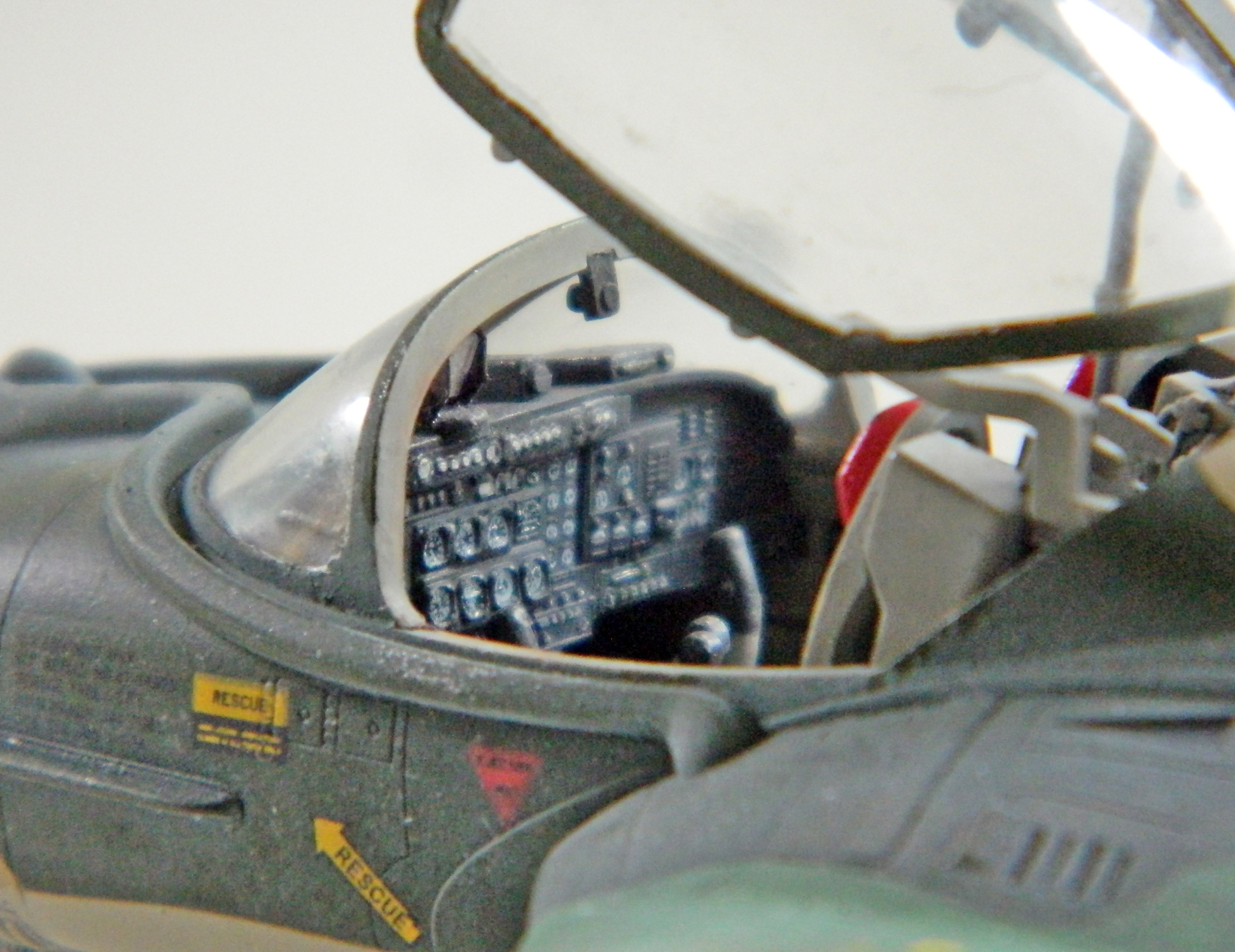
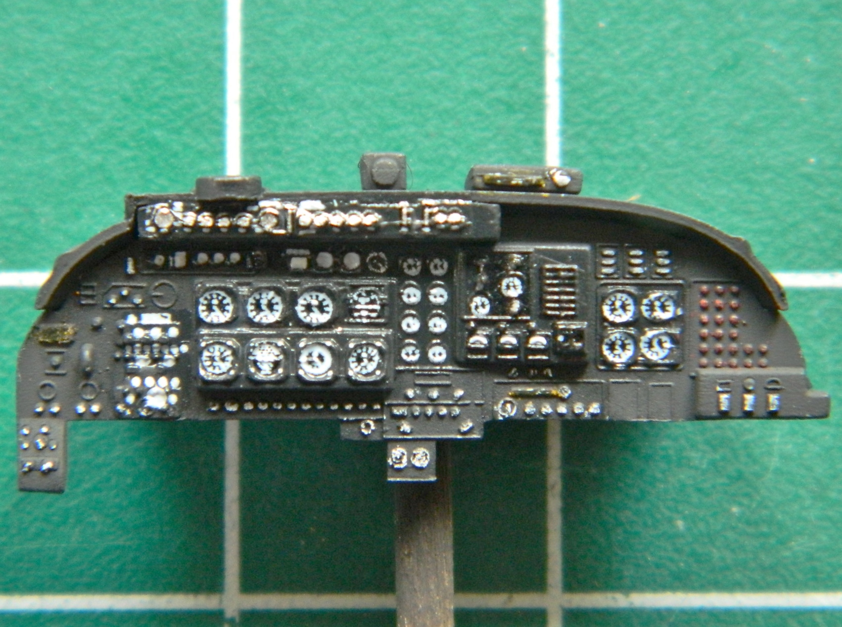
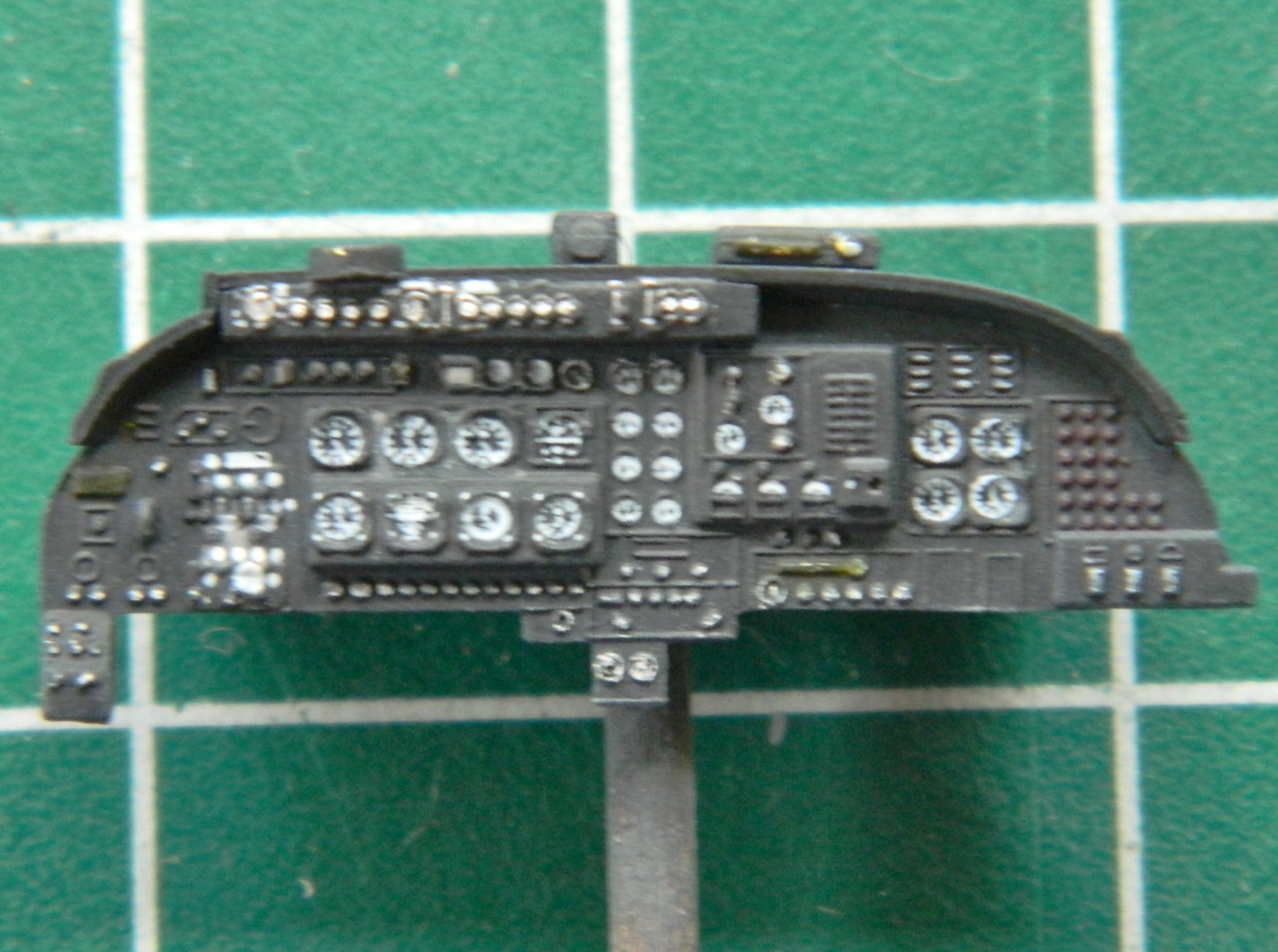
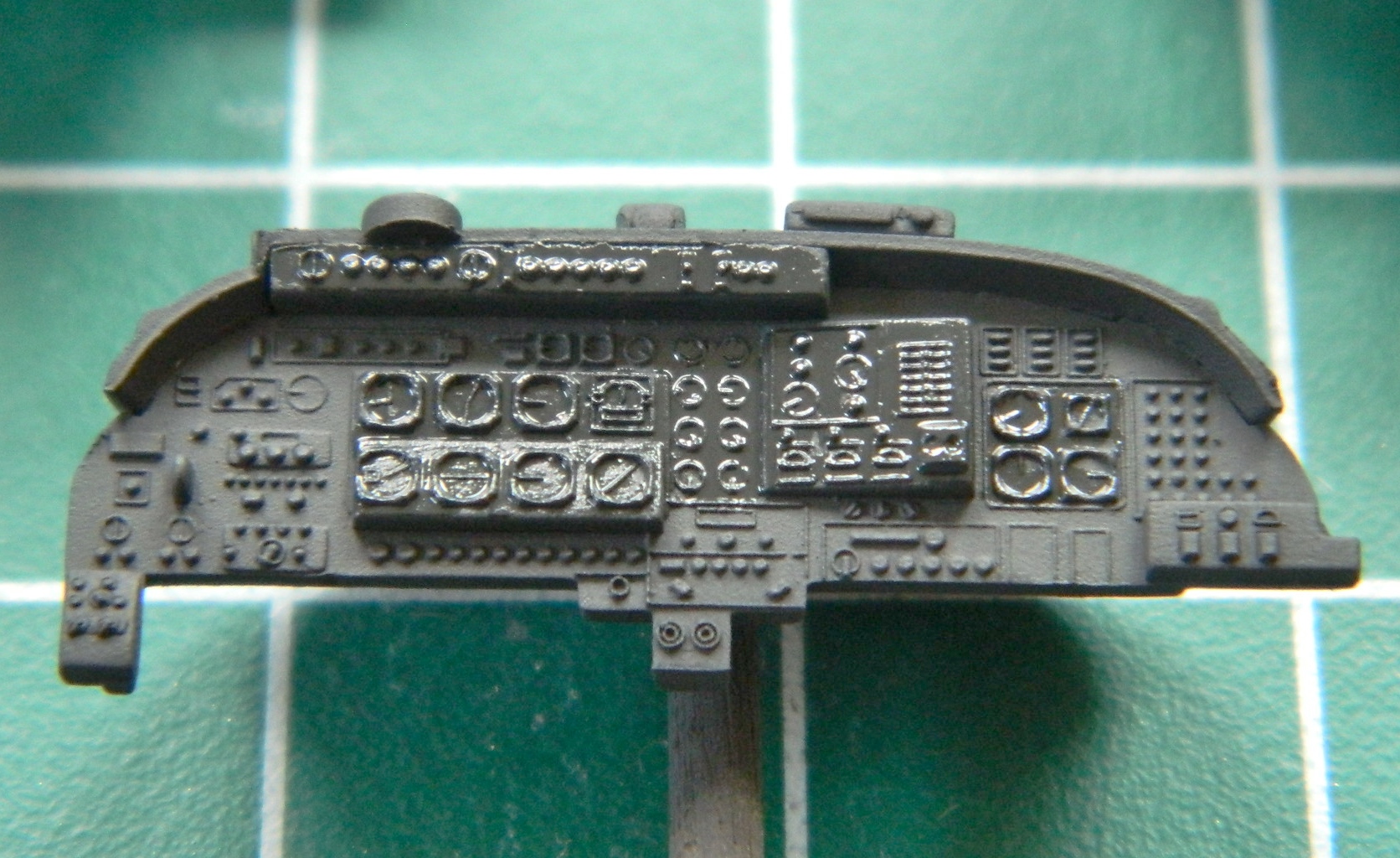
With the clear gloss cured, it was time to add the decals for the gauges and some of the switches. As evidenced by the four gauges clustered to the right of the panel, the dimensions of the decal were slightly off. (They should have been a bit wider and had I known their dimensions were off, I could have cut the decal into sections and aligned each gauge cluster individually.) Once in place, a couple of coats of decal solvent got them to snug down. Once the solvent dried, I used colored pencils to add contrasting colors to switches and gizmos. Next, the panel will be shot with clear flat but I wanted to make sure things were dry before doing that:
The next step was to paint the cockpit. The overall color was a color-corrected light gray and then black details were added:
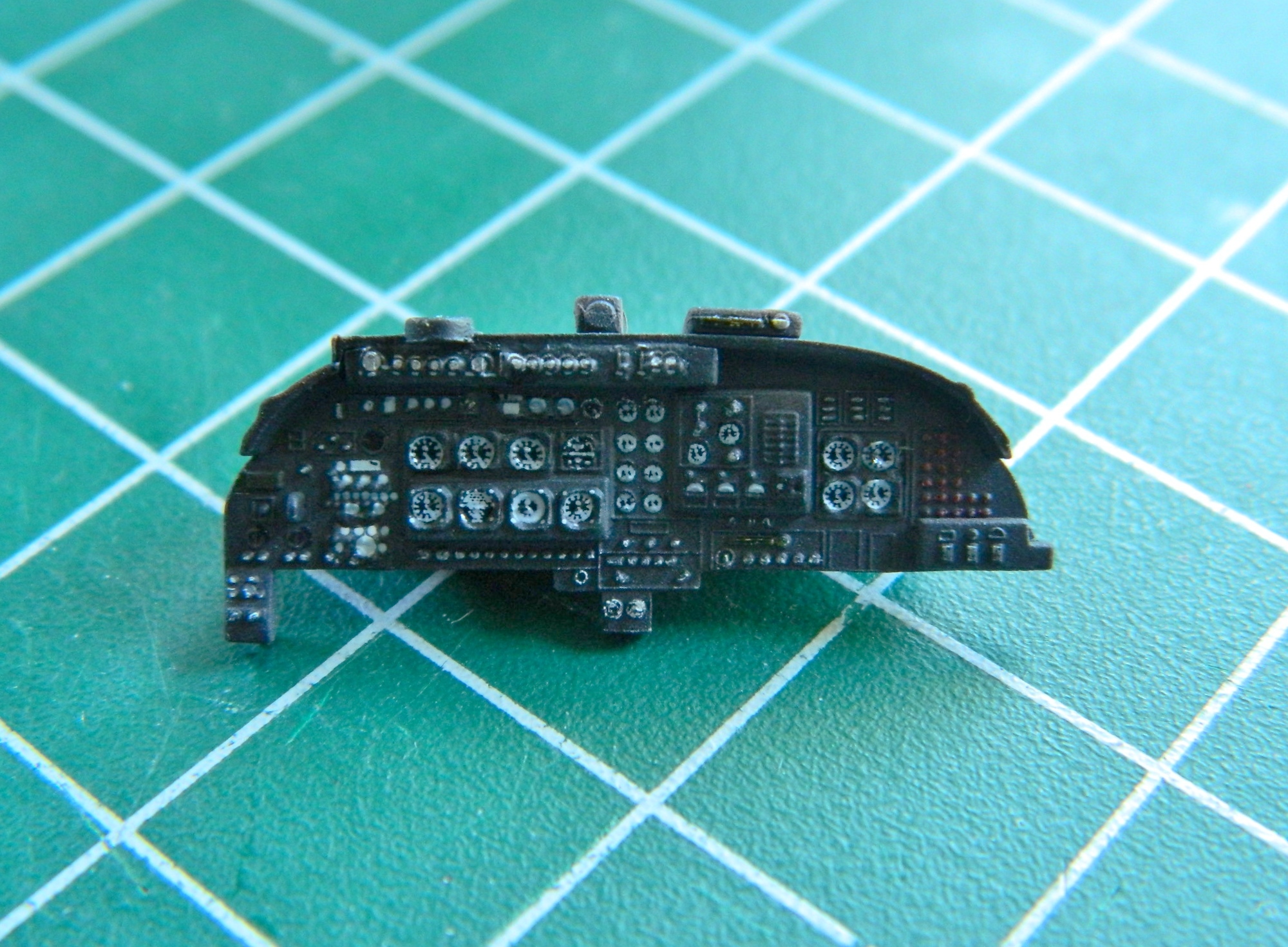
While that paint was curing, I shot the instrument panel with matte clear. The matte removed any hint that the gauge faces are decals:
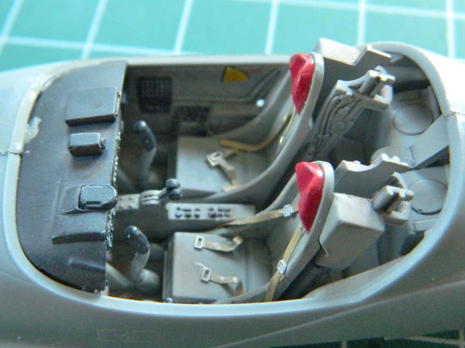
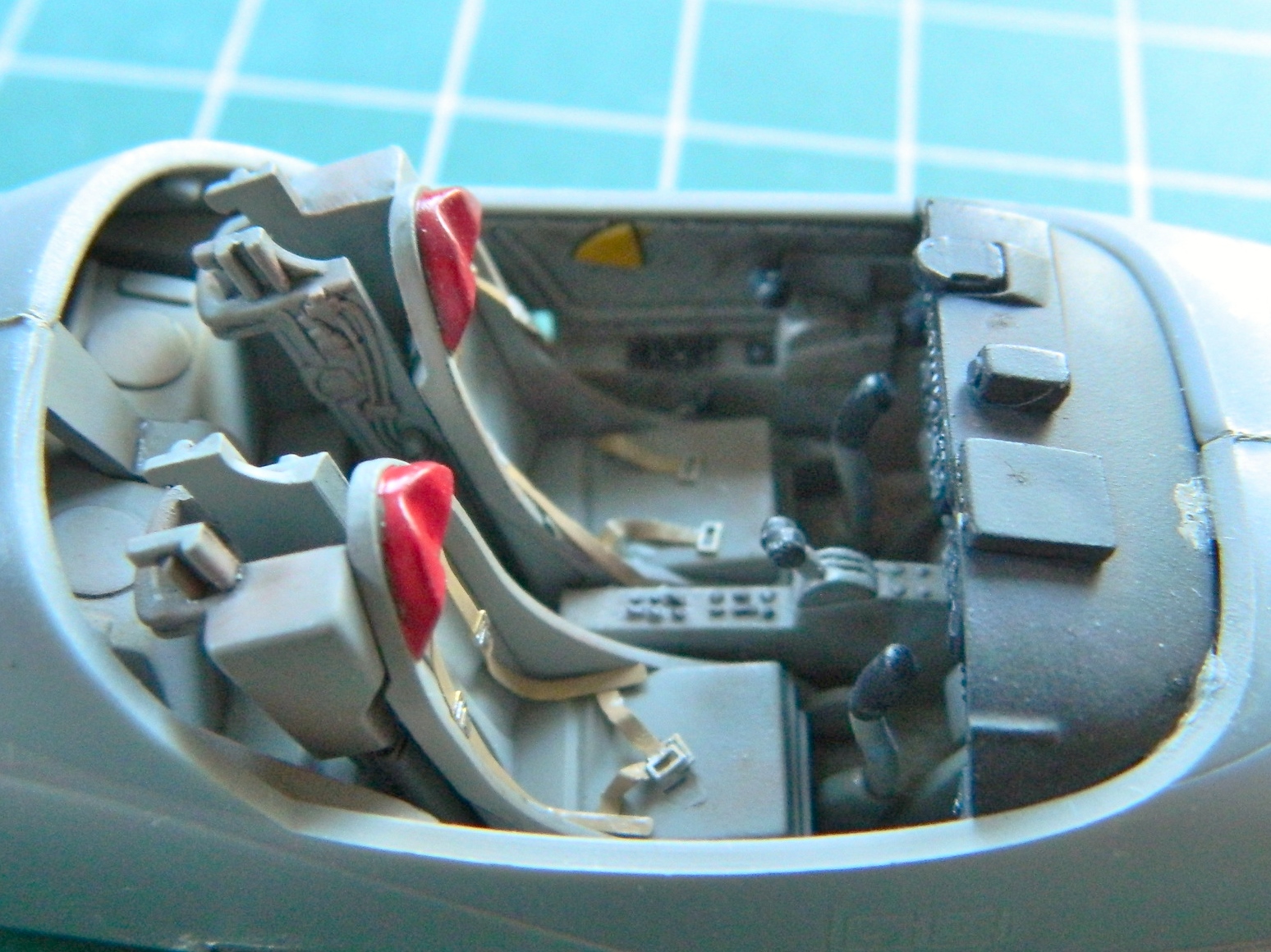
With the cockpit paint dry, I hit it with a coat of gloss clear and gave it a black wash and a coat of matte clear. Once the paint set up a bit, I added a bit of dirt using pastels:
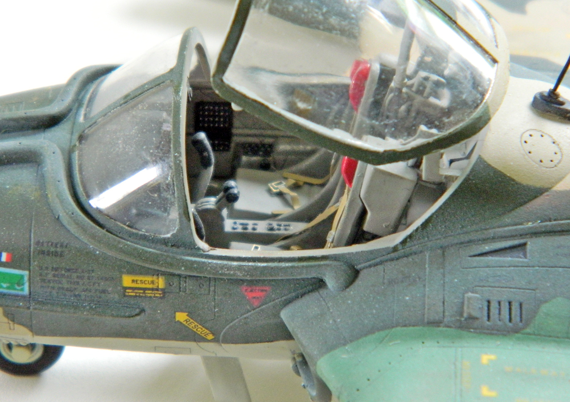
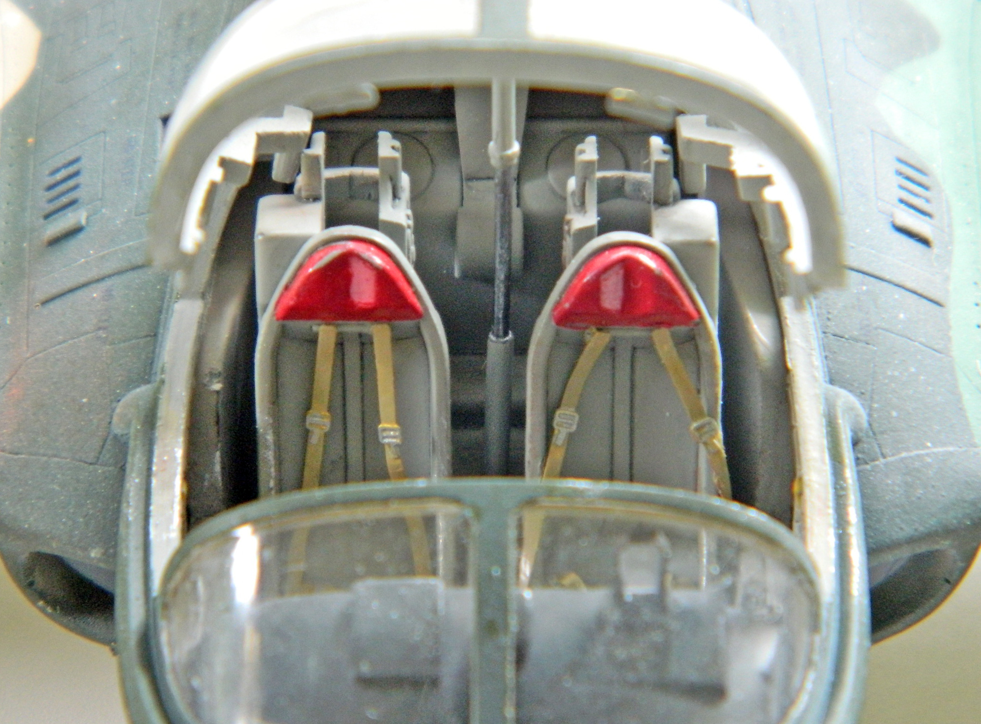
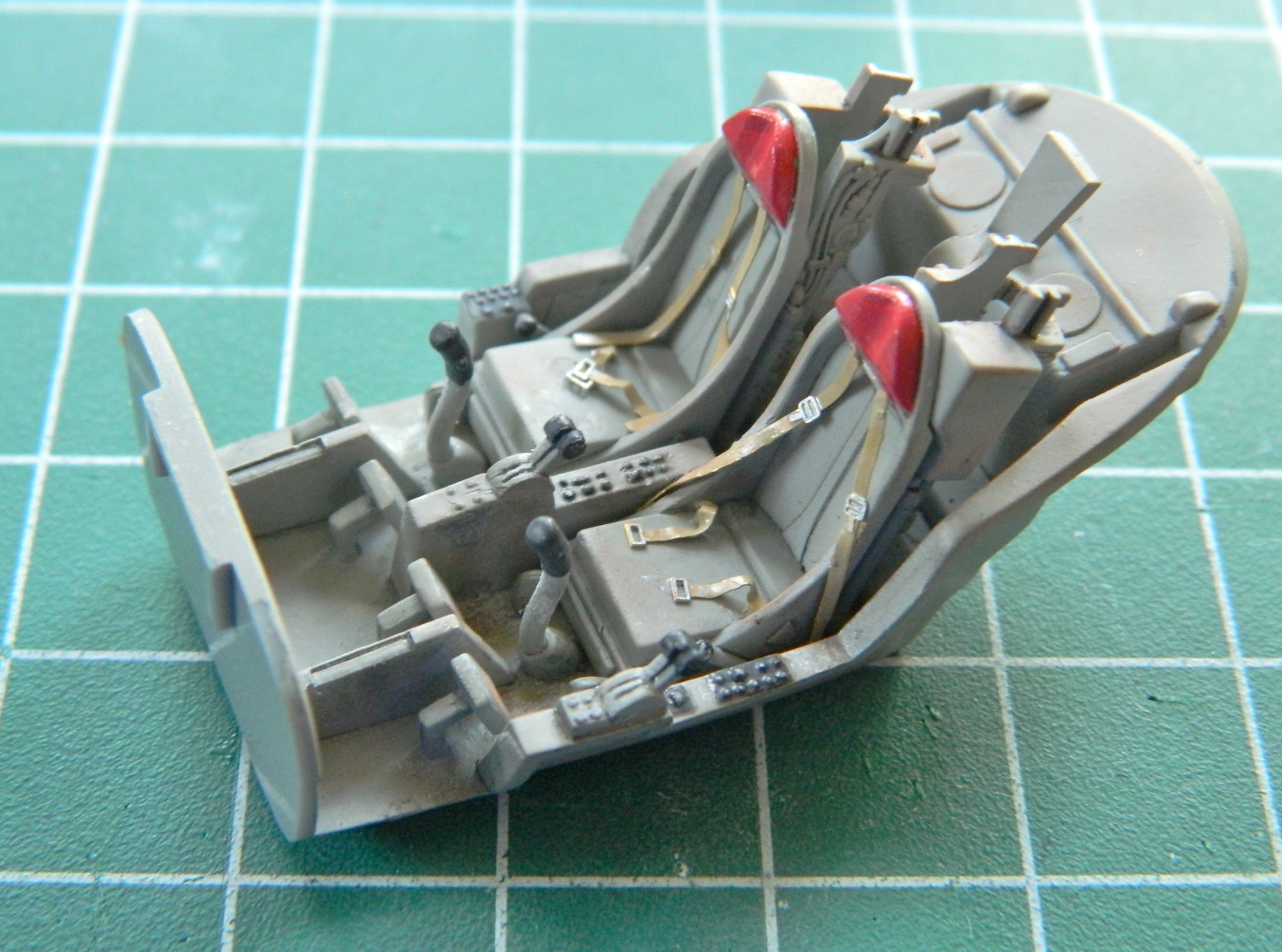
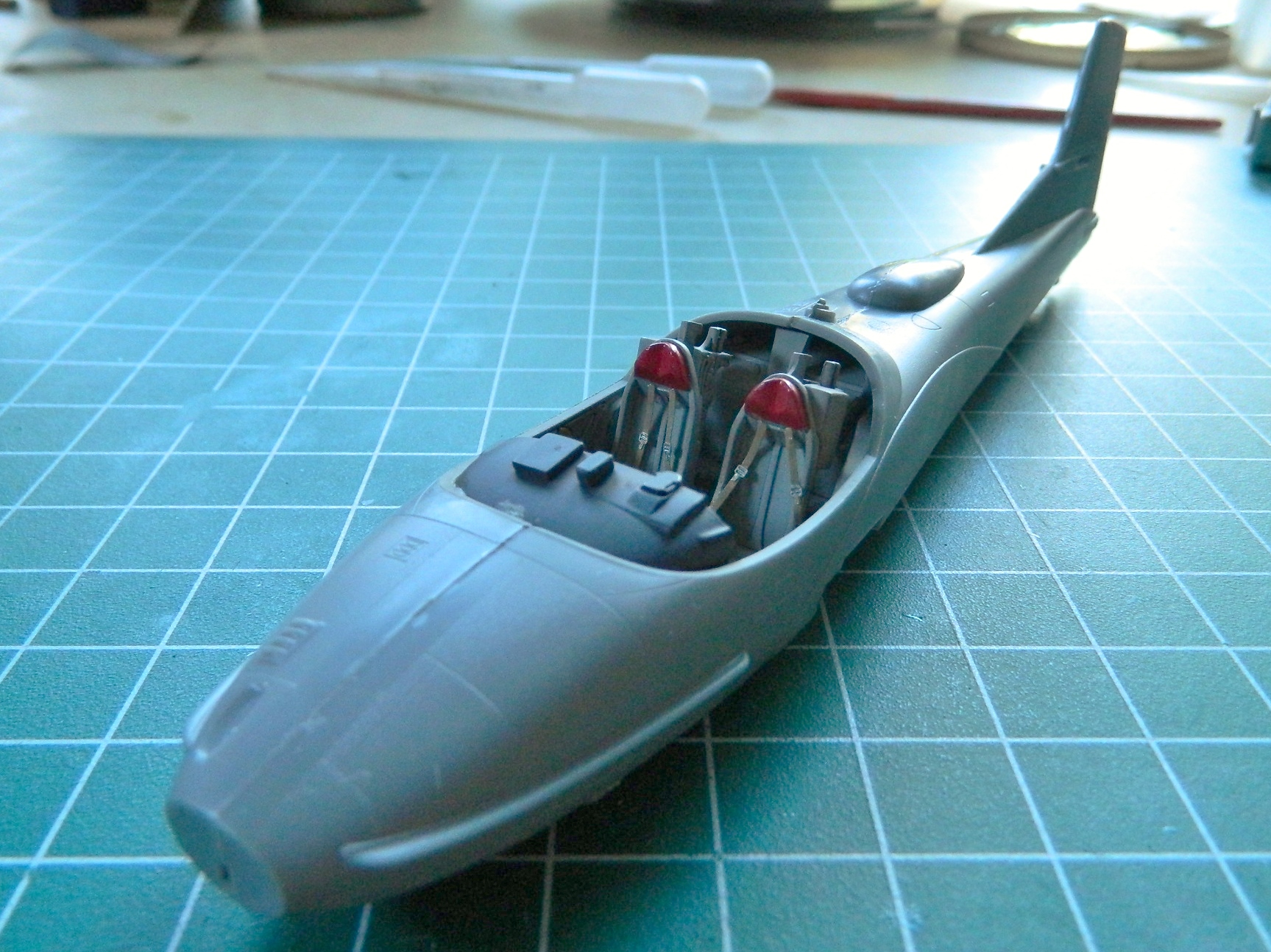
After the wash dried, the interior was shot with matte clear, the red added to the headrests, and the PE harnesses painted buff and glued into place, and wear replicated by dry-brushing aluminum in areas subjected to wear:
I used a drop of clear gloss on each of the gauge faces and touched up the decal borders with flat black in a few areas and the instrument panel is done:
At this point there’s nothing to do but to glue the fuselage halves together:
And that was it for this session. I wanted the glue to set completely before I started working on the seams and I’m going to need to touch up the front of the instrument panel coaming where glue caused the black paint to lift and smear. Speaking of which, the location of the instrument panel turns out to be the first real fit problem I encountered. It doesn’t sit in there quite level. Unfortunately, I had already glued the fuselage halves together before I noticed it and trying to separate the fuselage halves to fix that would have resulted in the potential for damage I didn’t want to fix. The instrument panel stays that way.
Next, I start on the wings.
This build is going to be substantially different from my usual builds. I’m going to build this one out-of-box (OOB). If the part isn’t in the box, it’s not going into the model. I’m also going to try to do this in less than a hundred hours (actually, less than fifty, but I don’t want you to think I’m…oh, never mind…I’m crazy). The copyright date of this kit is 2015 so that means I expect the parts to fit. (My…what a novelty!)
That said, this is what I’m starting with:
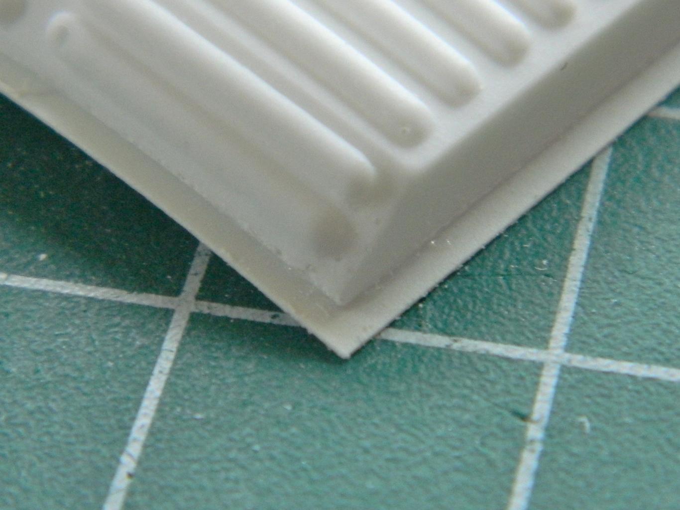
In looking at the parts, I’m impressed in some areas and not so much in others. This kit comes with a small fret of PE parts, so that’s impressive, and so is the quality of the clear parts. Not so impressive are some of the details. Some of the moldings are a bit thick for scale, particularly the fins of the ordinance:
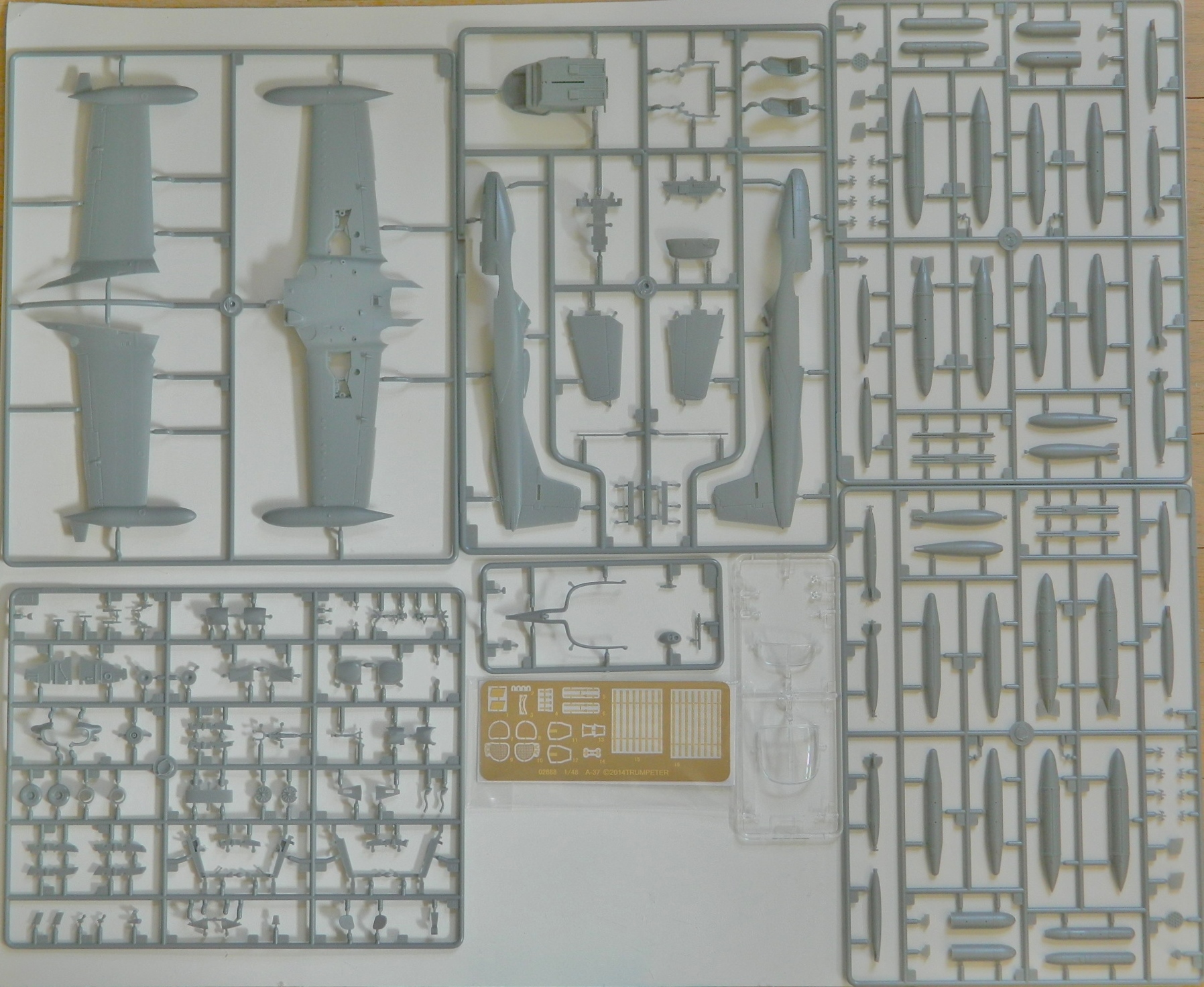
The painting diagram will be very helpful, particularly since I’ll be using the kit’s decals. Of course, I’ve already noted an error in the painting call-out as well as in nomenclature. One of the bombs isn’t a “bomb” at all…it’s a napalm canister:

The decal sheets look good also, including decals for the instrument panel gauge faces:
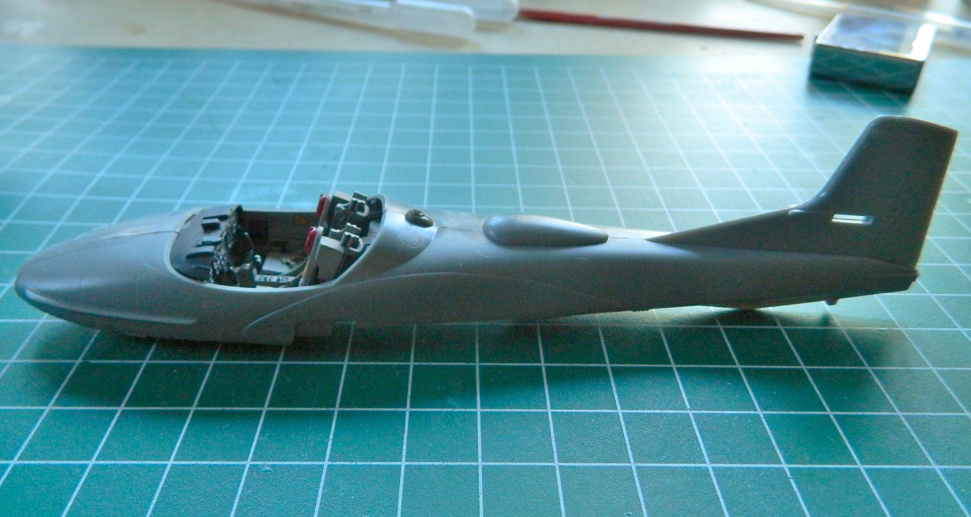
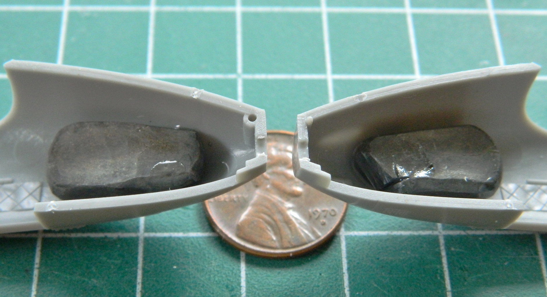
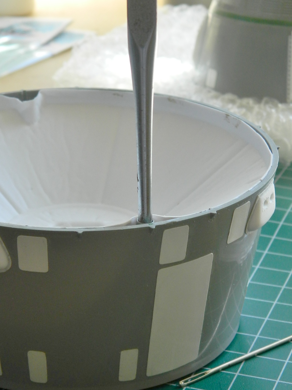
I’m going to be building the aircraft shown on the box’s cover art, and that starts with the cockpit. But before I started with that, I wanted to add weight to the nose so that the finished build will sit properly on its landing gear. I used two 4g lead balls (.44 caliber, if you’re interested in that sort of thing):

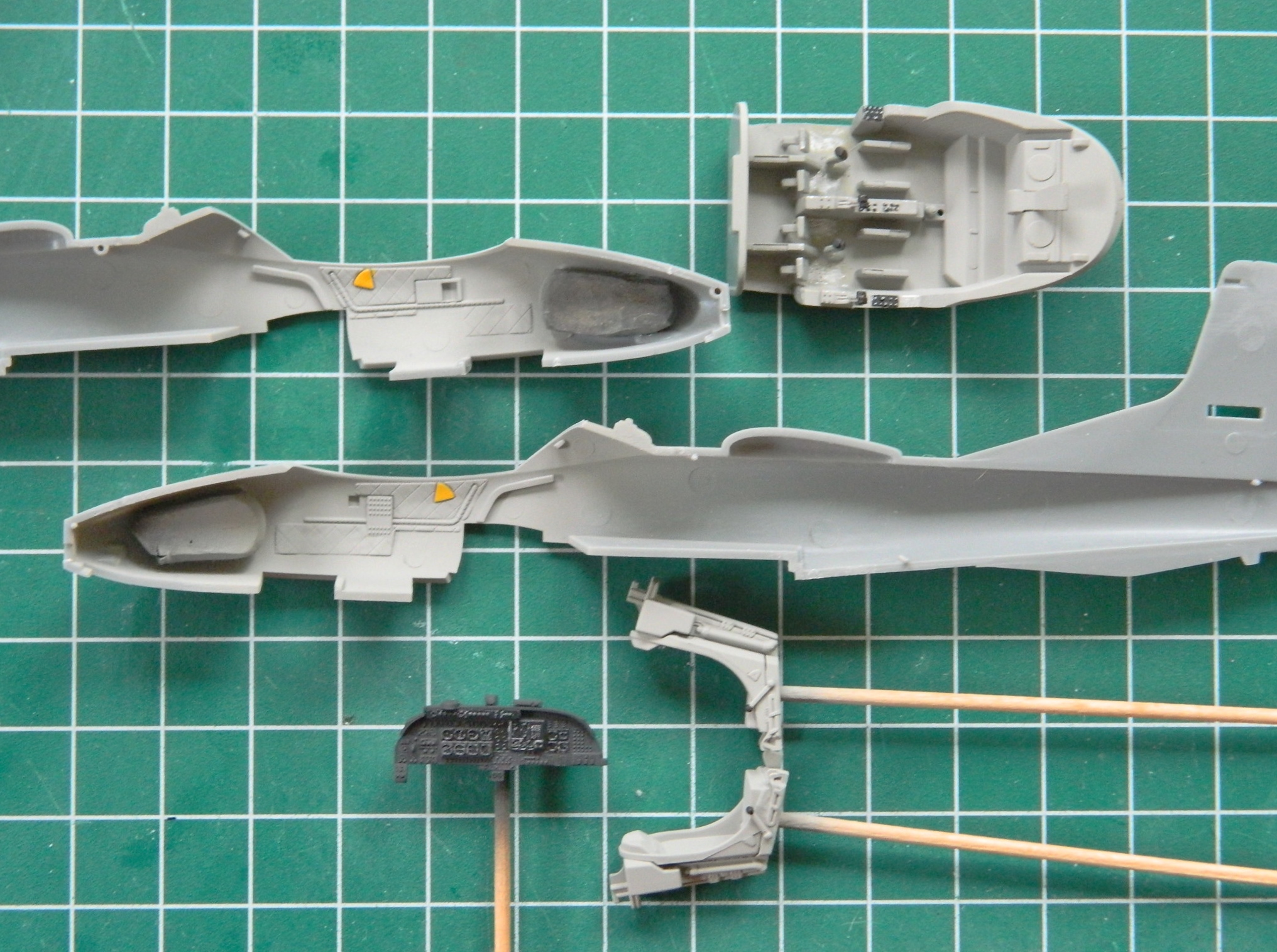
Before I could get them into the nose, they had to be reshaped. Before they could be reshaped, I needed to know exactly how much room I have. To do that, the nose landing gear bay had to be assembled:

I dry-fit the bay into the nose to see how it fit (perfectly!) and see what had to be done with the lead to fit into the spaces available:

Lead is soft and a hammer is hard and the first smack of the hammer showed me that unless I like sore thumbs (which I do not), best hold this thing with needle-nosed pliers:

Fit the nose bay again and it works, so I did the other ball the same way and superglued them into place:
I taped the fuselage halves and wings together to check the balance and it’s good.
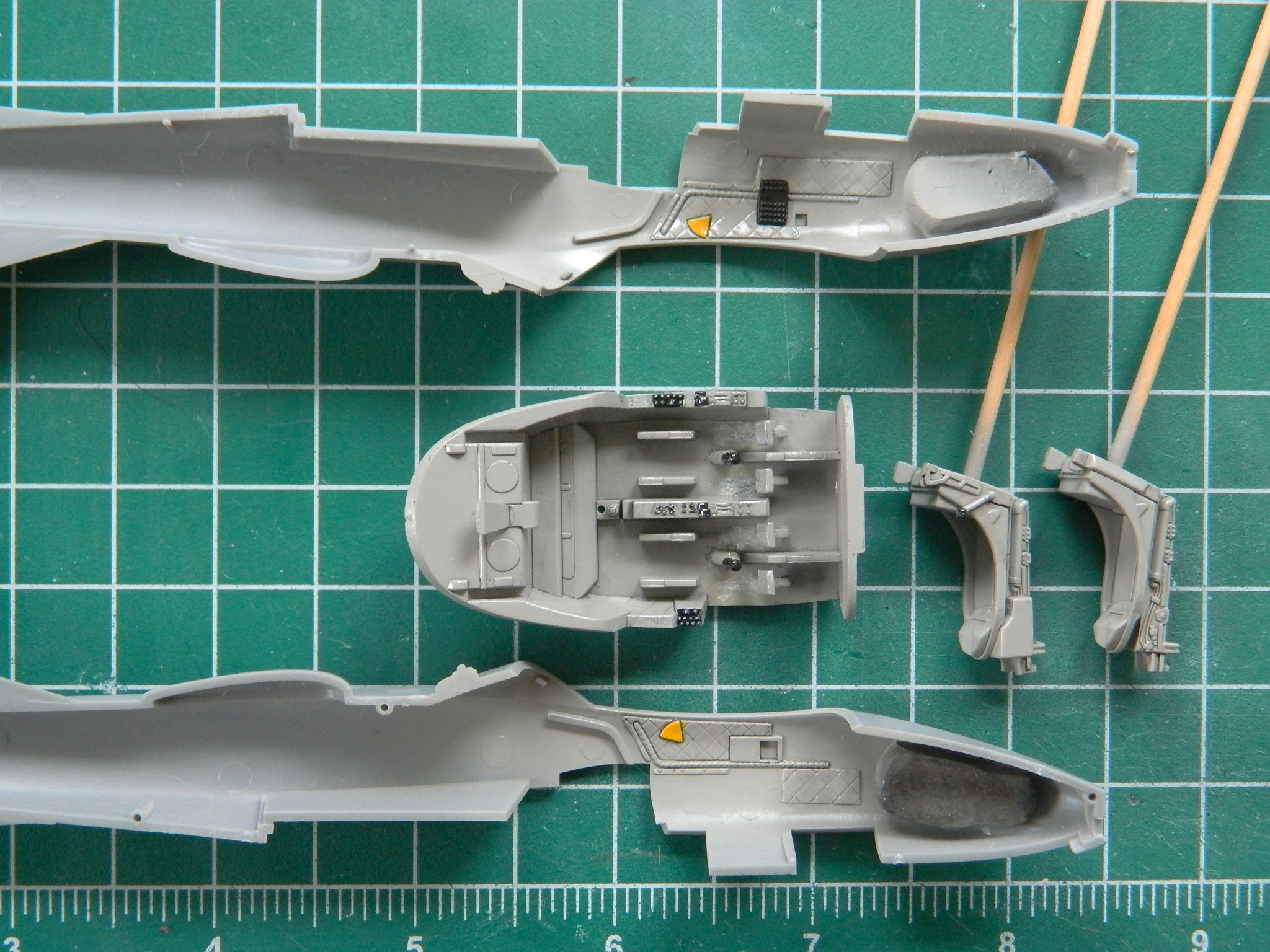
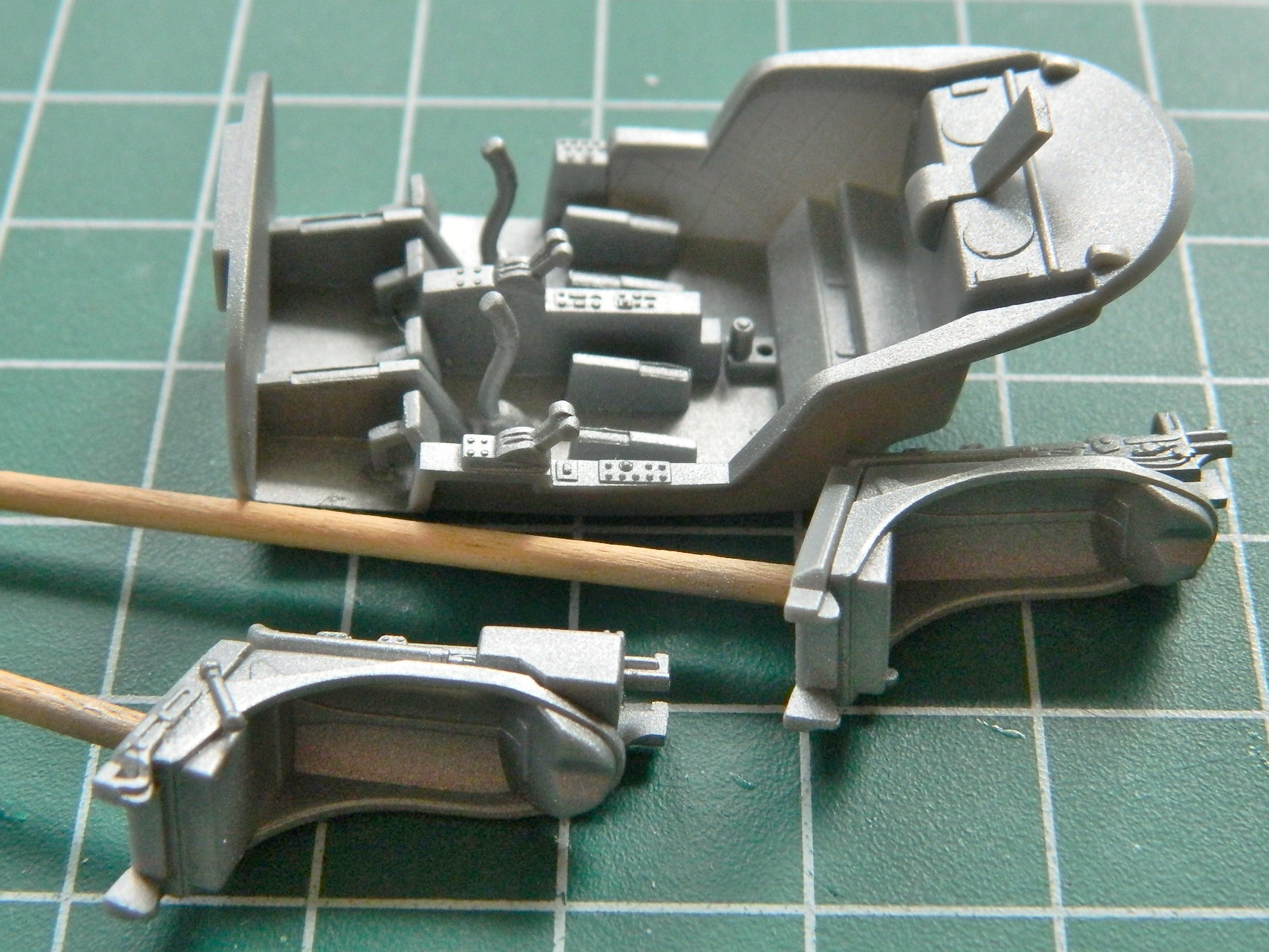
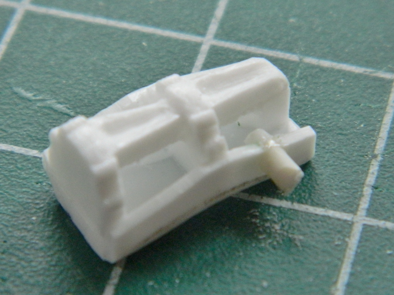
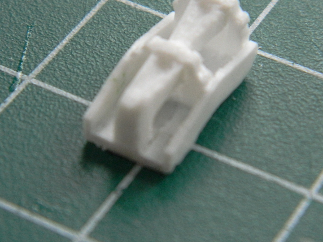
The kit’s seats aren’t bad (but were this not OOB I’d replace them) and I assembled both:


There are separate parts for the rudder pedals and throttles. The throttles needed a bit of seam removal and adding slots that the throttles would slide in:
I added all the bits I needed to so that I could paint, leaving the seats out until later. The instrument panel has three parts that sit on top; the gun sight, back up compass, and a radio:

Didn’t take long:

Since this is being modeled as a combat aircraft in a war zone, there will be wear and dirt, so I started by putting down a base coat of aluminum:
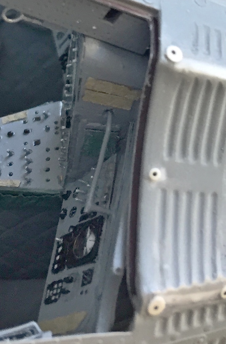
Over that I shot a cockpit gray, added wear, and painted details in the cockpit tub and sides of the fuselage:
I’m going to try using the kit decals provided for the instrument panel. Since decals go on over a gloss coat, their locations needed a gloss coat. Since I didn’t want to involve myself in TINY masking tasks, once I’d shot the flat black (light-corrected with about 25% white added to the black), I brushed the areas where decals go with clear gloss. Good enough:
The plan at present is to pick out the other instrument panel details and switches using paint and colored pencils.
So the parts are sitting on the bench for the paint to set up properly. So far, so good enough…
The A-37B was a development of Cessna’s T-37 trainer, aka, “Tweet.” Its cockpit layout was unusual in that the crew sat next to each other instead of the more common tandem seating. The Air Force wanted a counterinsurgency platform to deliver ordinance to a surface target and approached Cessna with the intent to beef up the T-37 for the ground attack role. The initial evaluation was done using a pair of T-37C aircraft and though promising, the T-37 needed stronger wings (gotta hang the ordinance somewhere), the ability to carry more fuel, a multi-barrel gun (General Electric GAU-2B/A 7.62 mm with 1500 rounds at 3000 rounds/minute), combat-capable avionics, and tougher landing gear for rough-field operation. To get all the increased weight into the air, Cessna doubled the aircraft’s power by replacing the original Continental J-69 engines with General Electric J85-J2/5 turbojet engines.
The Air Force doesn’t seem (even to this day) to be all that interested in small, simple, aircraft. Interest waned in the early 60s in light attack aircraft. But as you know, the early 60s became the mid-60s and Vietnam heated up considerably. The two trial aircraft had been “retired” to the National Museum of the United States Air Force at Wright-Patterson Air Force Base. Light attack was being performed by the A-1 Skyraider, a large propeller-driven attack platform developed in WWII and used during the Korean War. The Air Force (and Navy and South Vietnam) was losing a lot of them and was looking for a replacement and revived the A-37 program. The second prototype was taken from Wright-Patterson and a contract was let to Cessna for 39 “YATD-37D” aircraft (quickly changed to “A-37A”) to evaluate the platform under combat conditions.
Twenty five A-37As were sent to Vietnam in August of 1967 under the “Combat Dragon” evaluation program and were operated out of Bein Hoa Airbase and were operated on “air commando” missions. The program was a success with the A-37A flying thousands of ground-attack missions with no losses to enemy fire (two were wrecked in landing accidents), and it was decided that for the aircraft to be fully combat capable, some changes were needed. The A models lacked range and control response became heavy in the attack approach as well as not having a redundant control system. The Air Force issued a contract for 57 of the improved aircraft, designated A-37B, and quickly raised the amount to 127 (ultimately 577 would be built). All A-37B were new air-frames.
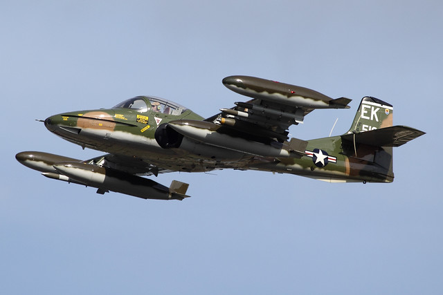
The A-37B was a much more robust aircraft and weighed roughly twice what the T-37 did. To get the increased mass airborne it was fitted with new engines, the General Electric J85-GE-17A engines, canted slightly outward to improve single-engine operation (it was not unusual for the pilot, as most were operated by a single crewman, to cruise on one engine to conserve fuel and extend range). The B models were also fitted with nylon flak curtains inside the cockpit, armored ejection seats, could tolerate 6gs (an increase over the A model’s 5g), a fatigue life of 4000 hours (combat experience showed that 7000 hours could be tolerated), was fitted with redundant elevator controls, modified control surfaces to improve handling, and self-sealing fuel tanks. A mid-air refueling probe was added to the nose (the feed pipes wrapped around the front of the cockpit) of probe-and-drogue which was a departure from Air Force equipment which was usually configured for boom refueling. Avionics were updated, the instrument panel reconfigured for easier flight from either seat, revised deicing inlets for the engines, and hardier landing gear. None of the 37 family had pressurized cockpits, requiring them to stay below 25,000 feet.
The A-37B was very effective at close-support. Due to ease of maintenance, the aircraft only required two hours of maintenance per hour of flight, lower than more complicated platforms, turn-around time was low and sortie rate was high with 1000 sorties per month not being unusual. Because of its small size, it was more difficult to hit with ground fire, and due to its low operating speed (and high loiter time) its bomb delivery accuracy average was 45 feet.
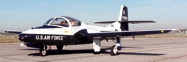
T-37
A-37A

A-37B

Total time building 452.75 hours (that’s about 2.69 24 hour-a-day weeks).
Begin date August 20, 2016; end date April 24, 2017.
Vendors:
Revell
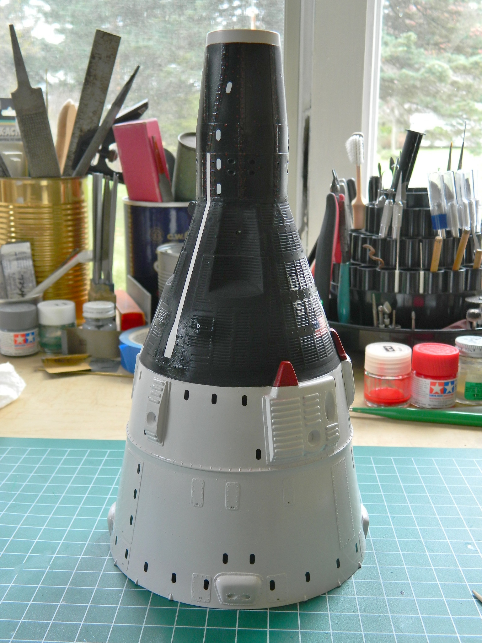
Kit #8618 – NASA/McDonnel Gemini Space Capsule; 1/24 scale
Archer Transfers
Set #AR88001 – Resin Rivets; Various scales
Airscale
Set #AS48 USA – Instrument Dial Decals; Generic: WWII USAAF; scale 1/48
LVM Studios
Gemini Interior Detail Set 1/24 scale
RealSpace Models
Exterior Gemini Detail Set 1/24 scale
Space Model Systems
Set #GS24 decals
My Opinion
The molds for this model were cut back in the mid 60s so I thought I knew what I was in for. There would be accuracy and fit problems. I didn’t realize how optimistic that opinion could be. By the time I got this thing done, I had a thorough realization of how optimistic I was. I’ve read blogs and reviews from other builders of this kit how they thought the fit was “okay” and detail was “good.” CLEARLY these builders and bloggers operate to much looser standards than I do. “Okay” is NOT the four-letter word I’d use. “Shit” comes closer.
I’d wanted to build this spacecraft to replicate Gemini VIII and that was just not possible. Yes, there are a fair amount of detail photos out there. The problem is that for the most part the available photos do not indicate which damned capsule they’re showing. So the result is more generic than specific. Doesn’t please me at all.
There aren’t a lot of after-market bits for this kit and with the exception of two crew figures, I purchased them all. With the exception of the decals, made by Microscale Industries and marketed by Space Model Systems (#GS24), which were quite amazing in how clearly legible even the smallest decals were, the exterior made by RealSpace Models and the interior made by LVM Studios were disappointing (to say the least).
The LVM interior details were mostly PE brass and though they built nicely (though incomplete), they were too large for scale. Had I not moved the walls of the interior out, I can’t imagine how they’d fit.
The majority of my bile is directed towards RealSpace Models. What absolute garbage. Though the parts initially look more accurate than what the kit provides, the initial look didn’t tell the story. The hull parts are too large (I didn’t use the nose piece since I didn’t model an orbiting Gemini, which is the only time that section would be exposed). And saying “the quality of the resin castings” in the same sentence takes humor to greater lengths than I’m comfortable with. There was no “quality” to these resin castings. If they were pressure-cast, well, maybe the pressure should have been higher than one PSI. Any attempt to work these castings showed bubbles EVERYWHERE. Everywhere. They showed up on the exterior. And when I used denatured alcohol to remove a blown paint job, I discovered that the alcohol would also remove the exterior surface of the resin castings which in turn exposed MORE bubbles. (The alcohol also made whatever formulation resin that was used flexible. If I were ever to use RealSpace parts again…which I am not…that trait might be used to some advantage.)
452.75 hours was a long time to spend on what is essentially a simple model. The single biggest time consumption was spent making the AM parts fit (to whatever miserable extent they “fit”).
I do not expect it will show well. [And though I made it to the show that I wanted to attend with this build, it didn’t show well. It got beat out by another Gemini capsule that, even in 1/144 scale, was even LESS accurate than this one. No…don’t get me started on the judging…]
The only bright spot to this build is that it’s DONE and I do NOT have to deal with it ever again.
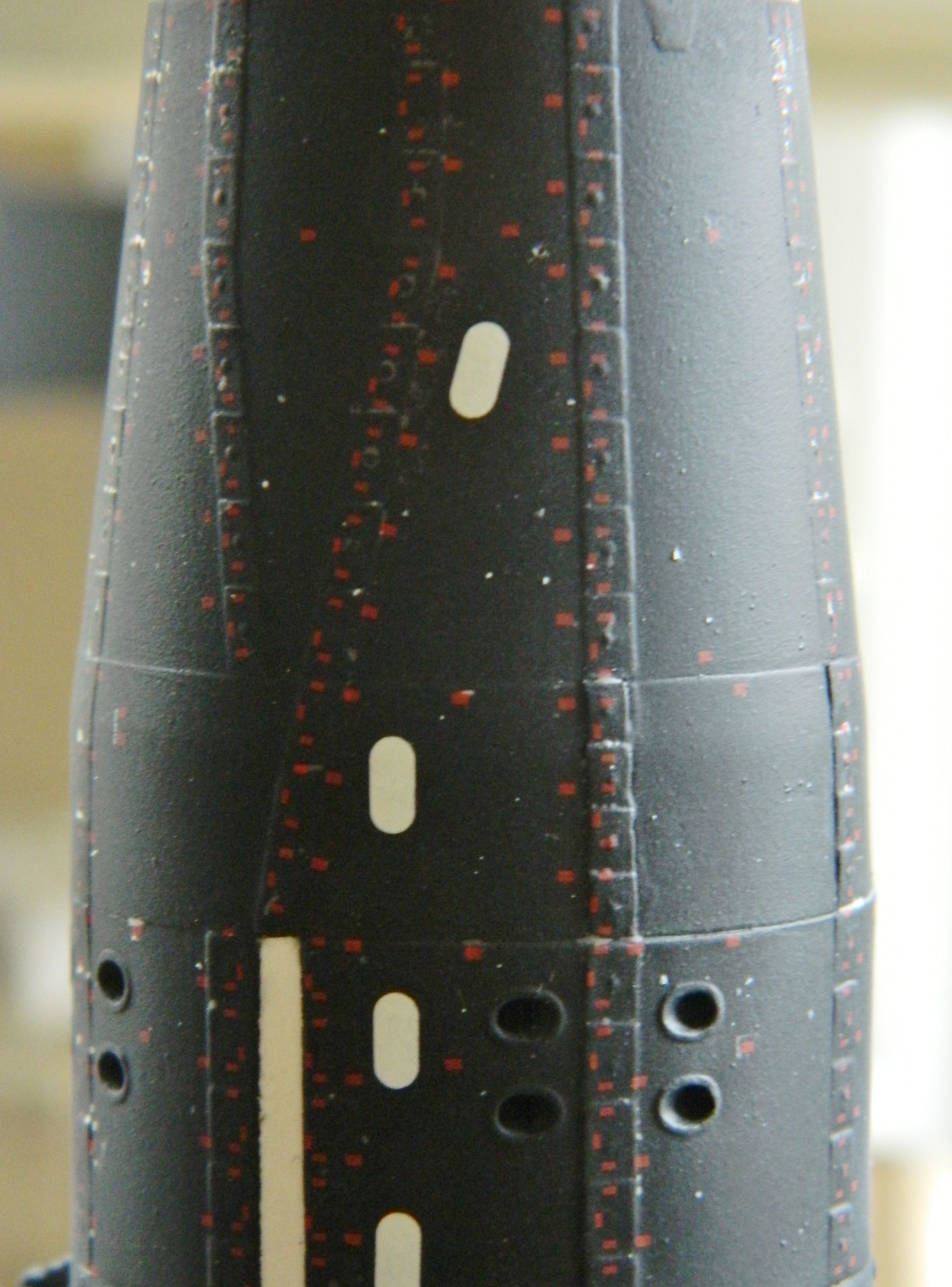
Applying decals over a matte finish causes the background film to frost. This is because the surface is actually pebbled which reflects the light away from your eyes making the surface look matte. Great for your eyes, lousy if you want decals to appear painted on. To give the decals a smooth surface, everywhere a decal goes gets shot with clear gloss.
Once I’d done that, I started with the decals that would require the most work to get right. The surface of the capsule is corrugated and I need the decal to fit down into those small troughs and up over the raised details. Decal solvent is what allows that to happen. The solvent dissolves the decals slightly enabling them to conform to whatever surface details they have to fit into and over. Never touch a decal after applying solvent! The solvent really does dissolve the decal slightly and if you don’t touch it, as the solvent evaporates, the wrinkles in the decals’ surface go away and they snug down.
Sometimes decals require more than one application of solvent. Sometimes they require MANY applications of solvent. Surprising me not at all by this point, these decals are in the MANY applications of solvent category. Each decal took two and a half hours until they had conformed to the surface.
The decals go on and you can see how they’re resting on all the high points of the surface:

The first (of many) applications of solvent begins softening and dissolving the decal:

Two and a half hours later, this is what I ended up with. The decal had to move so far that it actually tore during the process:
I was fortunate in that the torn areas are simple white over black which enabled me to touch up the tears with white paint:
The other side received the same treatment of decal, solvent, solvent, solvent, tears, and painting. It took a while but the results were good.
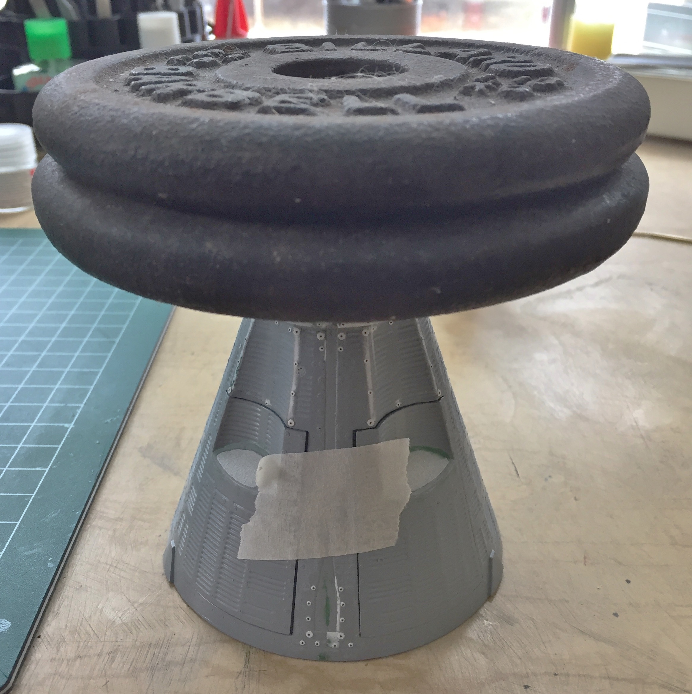
While I was waiting for multiple coats of solvent to work, I went back to building the display stand:

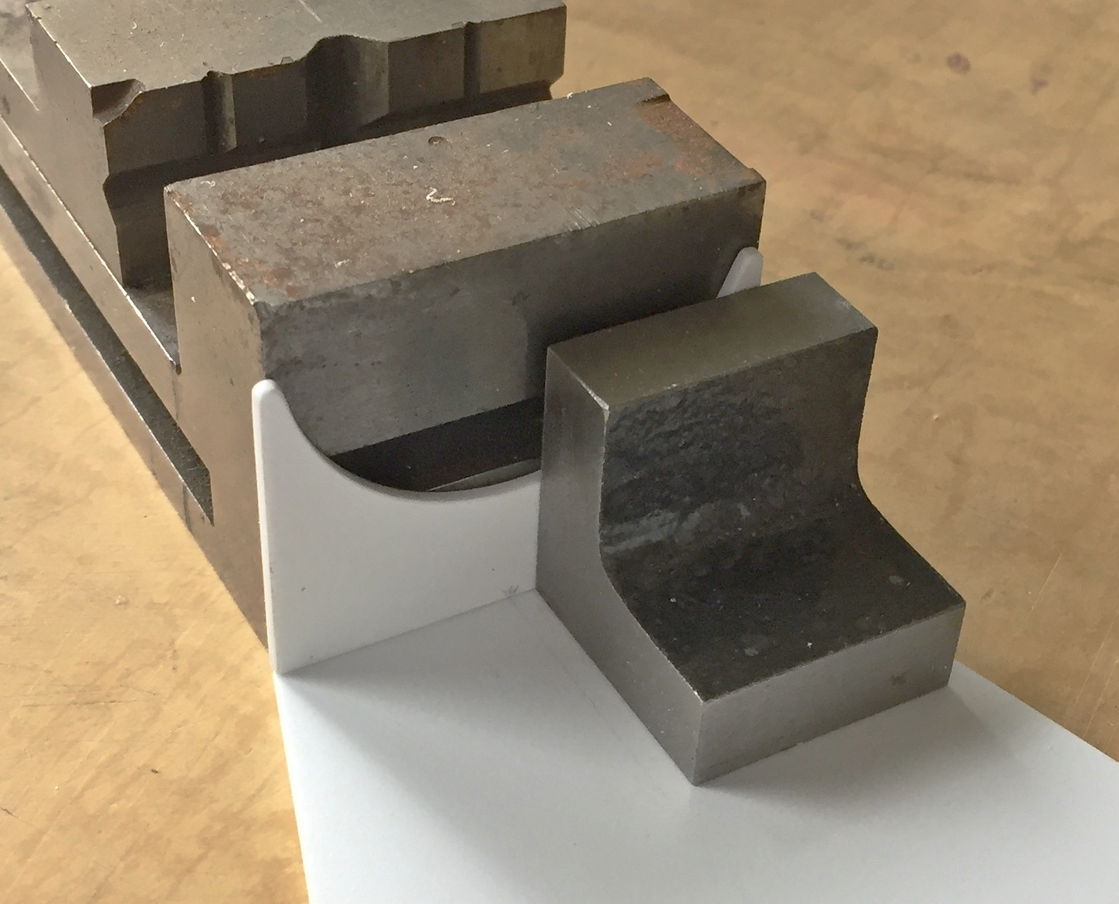
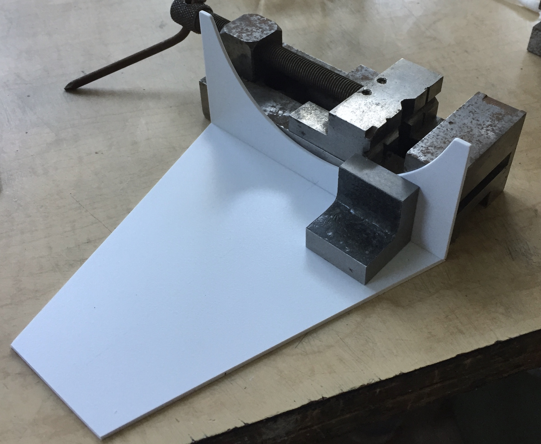

I didn’t like how the model displayed on it so I needed to snap the nose cradle off and redo that:

I added more plastic to the nose cradle and ended up with something much better:


Once the solvent had set up, the rest of the decals were added:


Once the decals were dry, the black was sprayed with matte clear. I don’t know (yet) why my airbrush added all these white speckles but they needed to be dealt with. Some of them I could pull off with tweezers, some wouldn’t budge. The recalcitrant specks were touched up with flat black:
The horizon sensor snapped off during all the handling, so I took this opportunity to spray it matte white. And well, gosh…more bubbles:

So I used denatured alcohol to remove all the paint and fill more freaking bubbles:
Once I’d filled all those DAMNED bubbles, the mounting plate was done in matte black and the sensor mounted to the hull:

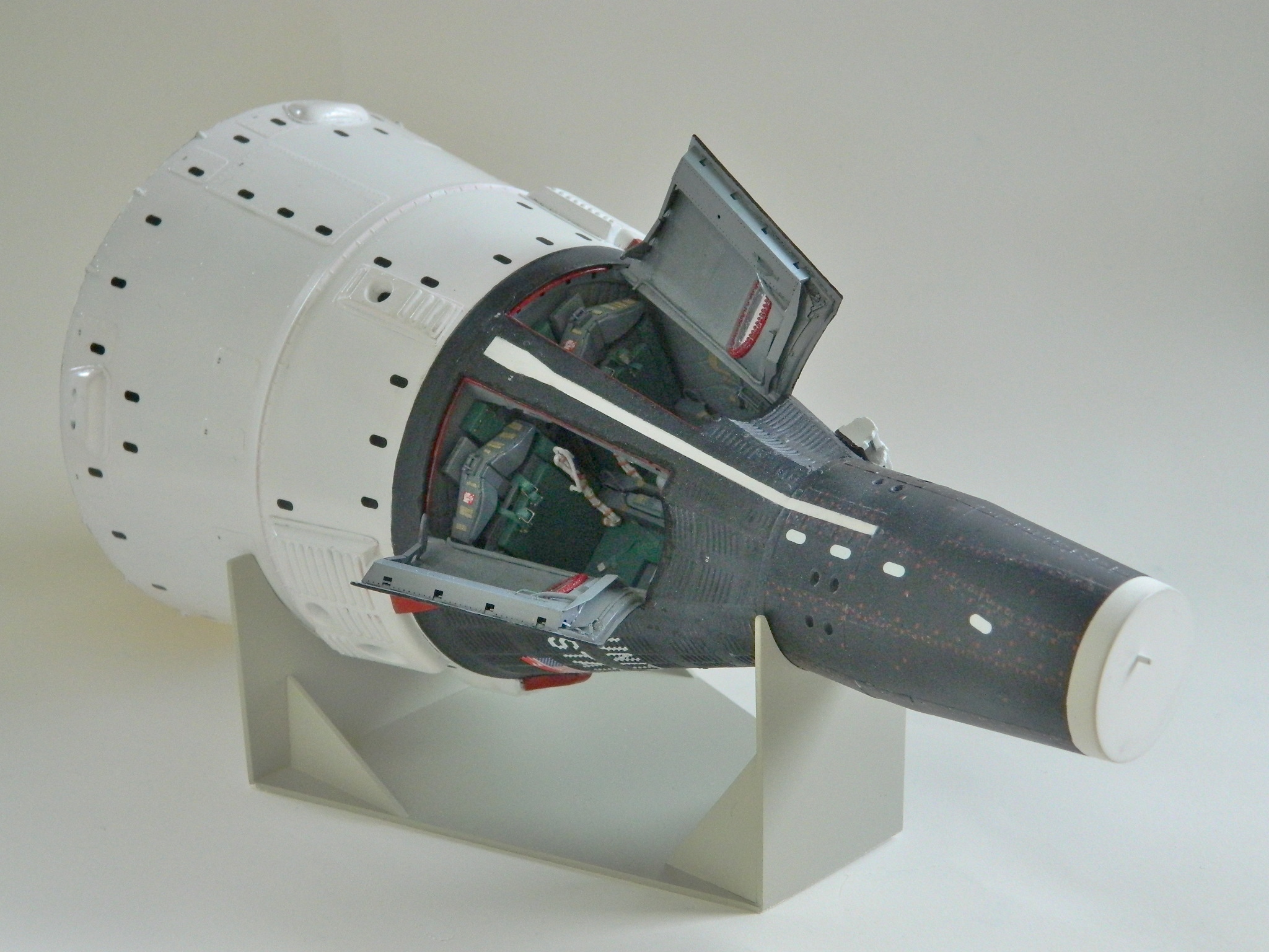
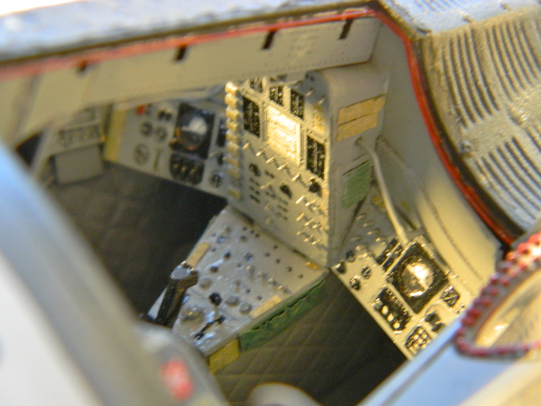
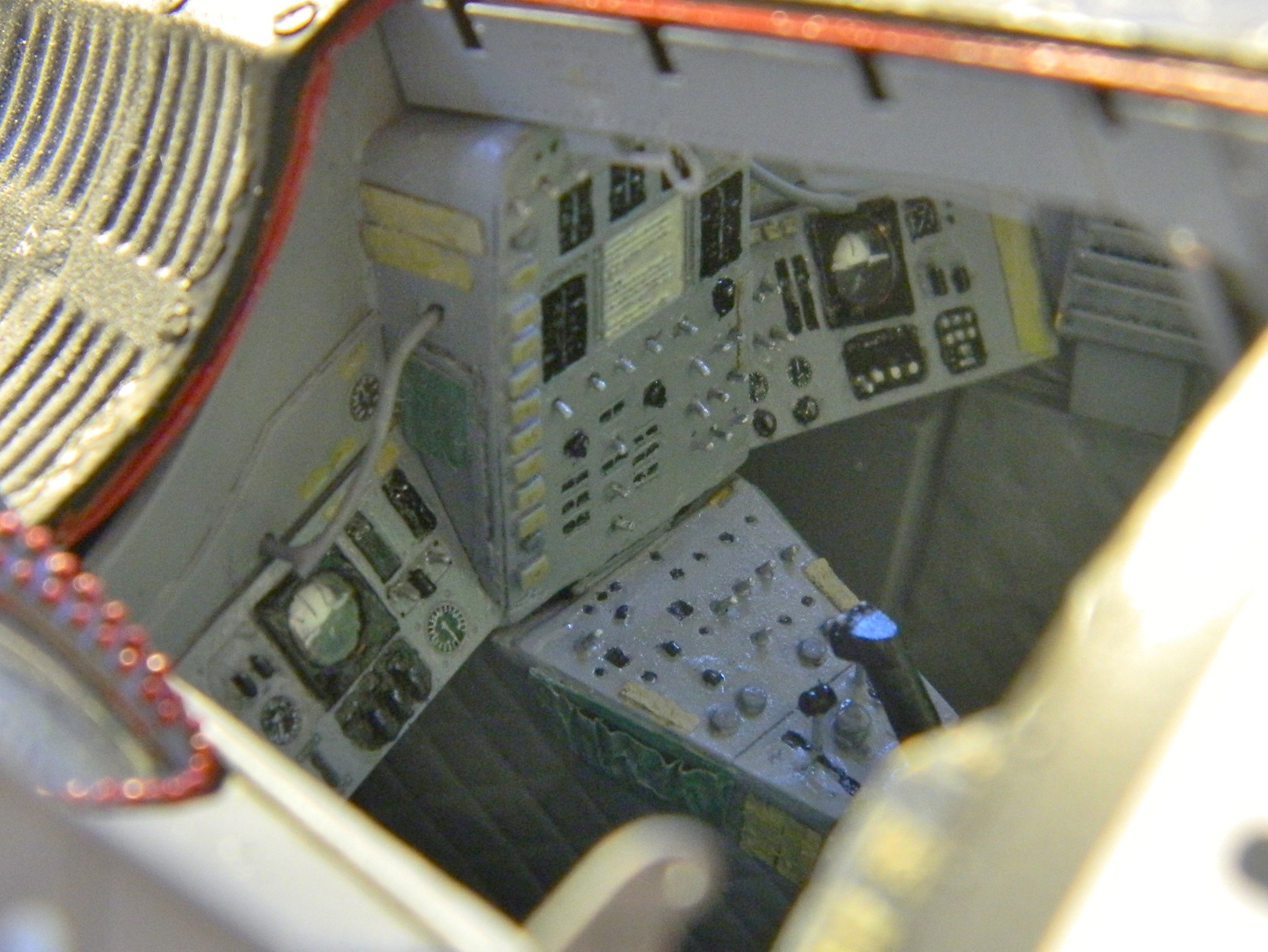
During the working and reworking of the exterior paint, a LOT of denatured alcohol was used. I was pretty sure that none had insinuated itself into the cabin but until the hatches were popped open, I couldn’t be sure. With more than a little apprehension (because ANYTHING that could go sideways with this build did…and many of the things that couldn’t go sideways went there anyway) I pried the hatches open and removed the white glue:
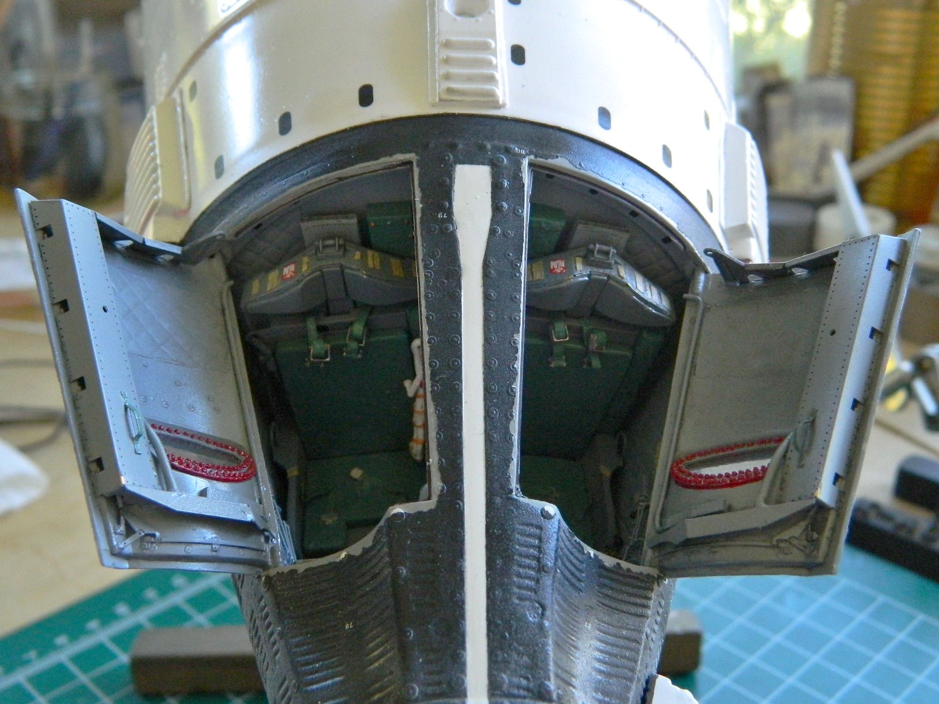
Good news! Nothing worked its way into the cabin so THAT nightmare was avoided! I knew there would be touch ups needed around the hatch openings and the edges of the hatches. What I didn’t know was that I could NOT match the paint of the hull exactly (or even moderately). Since by this point I’d overshot the matte black with clear semi-gloss, I’d mistakenly figured that black semi-gloss would work. No. Not even close. I ended up using matte black instead. Yeah…it worked, but I’m not really pleased with the result. (That could be the theme for this ENTIRE build.)
With the edges of the openings and hatches done as well as was possible, the red hatch seals were replicated with paint:
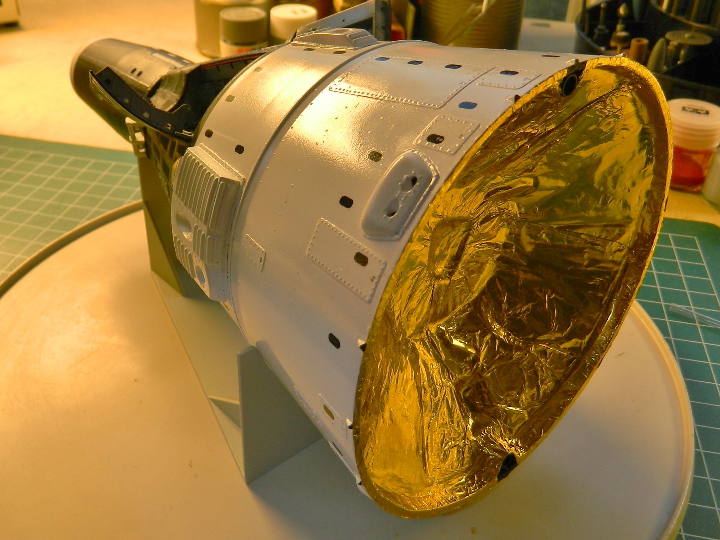
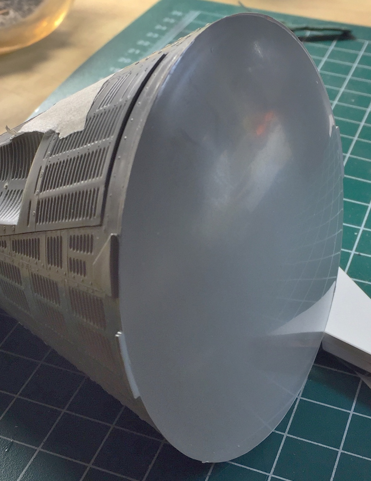
I decided to not use the sunscreens which meant that the last part needed to be added was the gold-colored foil used to replicate the mylar thermal shield. The “funny” people at RealSpace Models (the people that made the resin exterior details, and you already know how impressed I’m not with those) gave me just enough foil to cover the support:
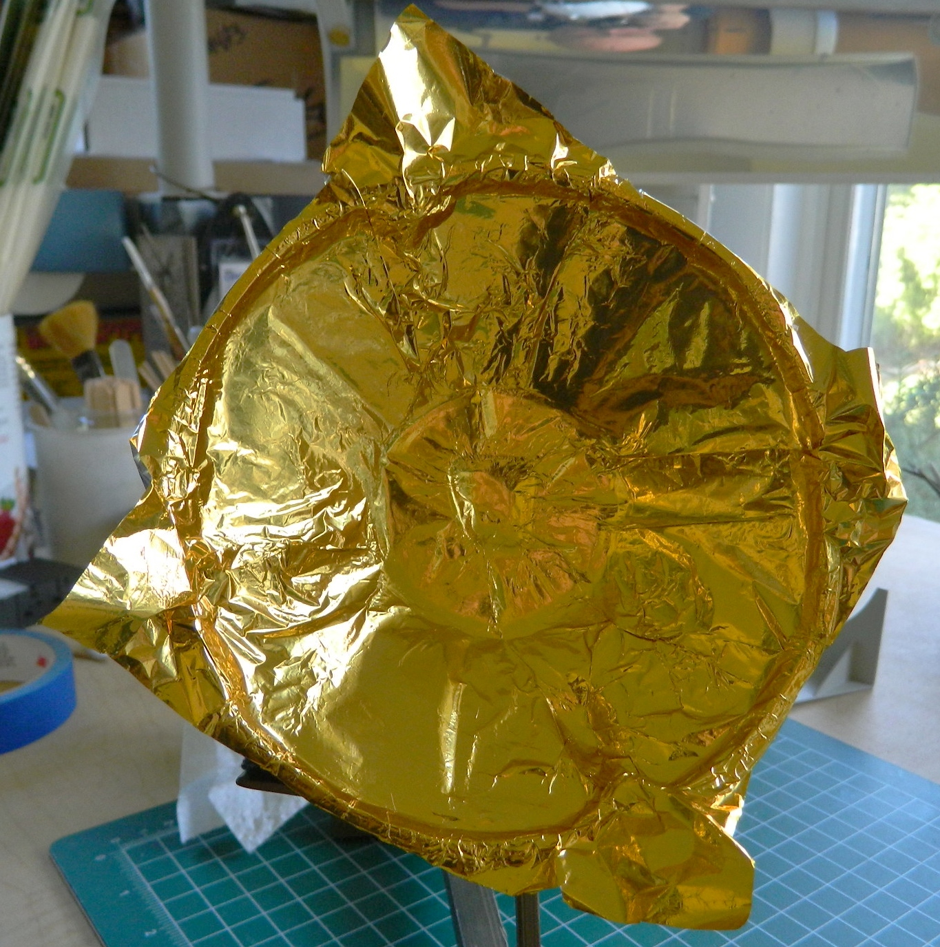
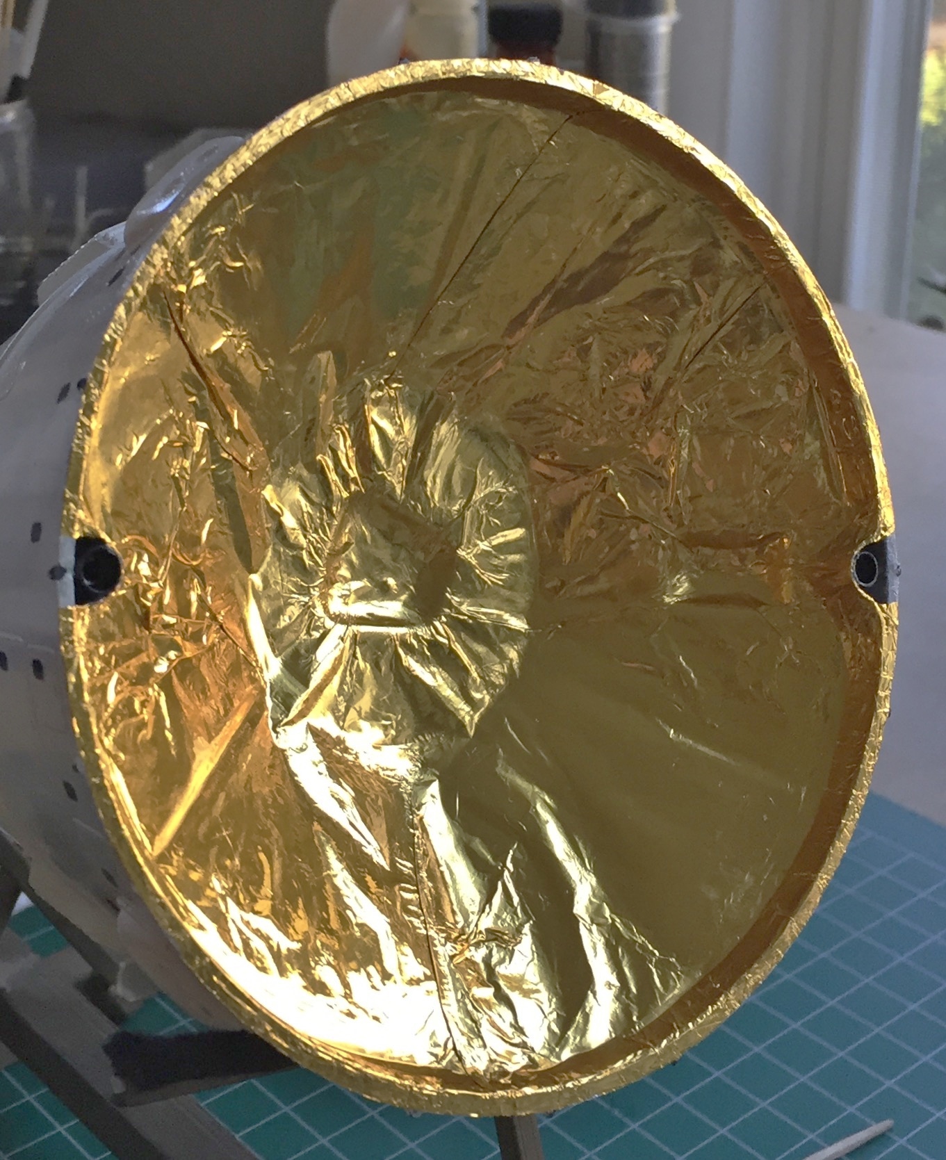
I used watch crystal cement to attach the foil at the periphery, and then came the nerve-twisting trimming:

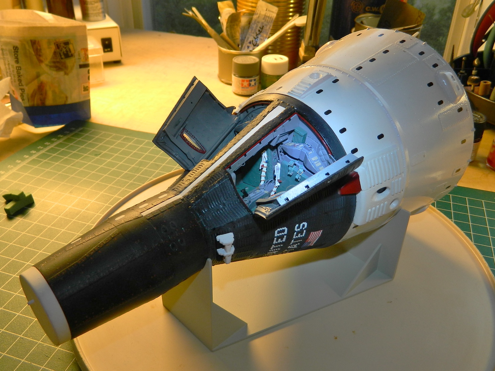
Once my pulse rate dropped back to normal, I touched up the maneuvering thrusters and edges of the service module where the foil didn’t cover:
Then I sat there looking at the build and wondered what was next…AND THERE WASN’T ANYTHING “NEXT”! I’m DONE!! I had already painted the display stand so there was nothing left to do but be OH so thankful that this pissy build was finished:


Prior to gluing the service module to the retro module, I wanted to add the support for what had been mylar on the original capsule that will be replicated by gold-colored foil here. I have come to expect that the kit parts don’t fit well. And I thought that now that I had added all the kit parts, I wasn’t going to have to deal with that fit crap anymore. Silly me. The AM set doesn’t fit very well either. The seats didn’t fit into the crew cabin without major surgery on the cabin tub and the seats, so why did I expect the foil support would fit? Fact is…it doesn’t. So I tacked it in place in four locations and clamped it while the glue cured:
You can see how much that’s stretched the support at the lower right of the above photo. I tried easing the next round of glue-and-clamp into place and for a (short) while it looked like it was going to work…and then the form cracked at the edge. My next attempt involved a hair dryer to heat the plastic so that I could flare the edge of it outward into contact with the inside of the module.
Here’s a tip. If you want to clean your workbench and move everything light off of it whether it’s parts, junk, or dirt, turn a hair dryer on. Belatedly I realized there’s a fan in there. So I braced an empty box behind it to use as a blast deflector (because that’s what it looked like when I first turned the hair dryer on…like the bench was blasted) while I heated the plastic:
With the edge heated, I used the modified clothes pins to clamp the section I’d just heated in place and then glued it. All seemed to be going well until this one time when I smelled melting plastic. Hmm…hadn’t smelled that before. What’s different? Melting one of the reshaped maneuvering thrusters is what was different:

::sighs::
Good thing I had another kit on hand with two more thrusters:
When I looked at the other thruster, I saw that I had also melted it but only slightly. I found a punch in my toolbox that would serve to move the slightly warped thruster mouth back into shape with the application of (more) heat:
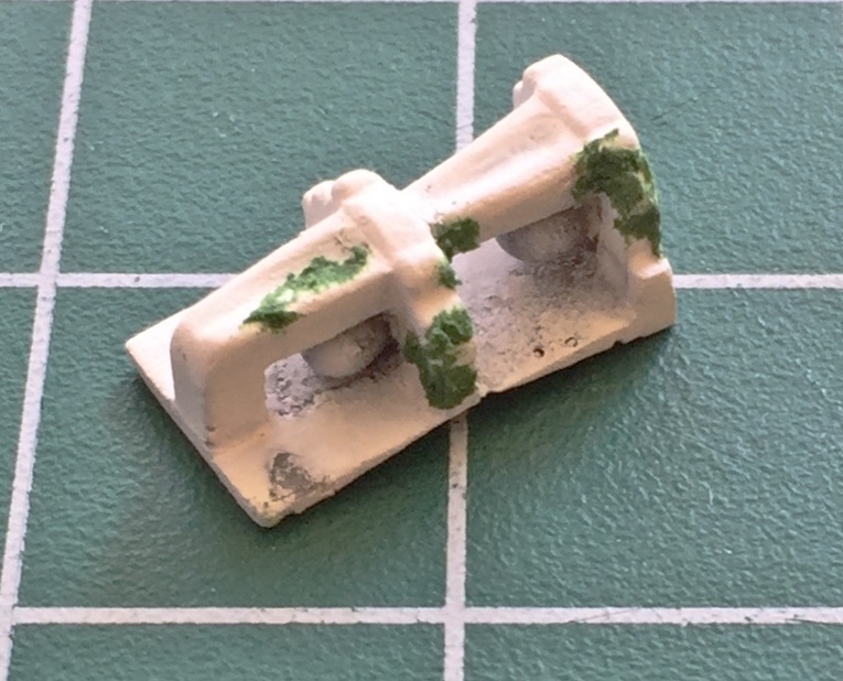
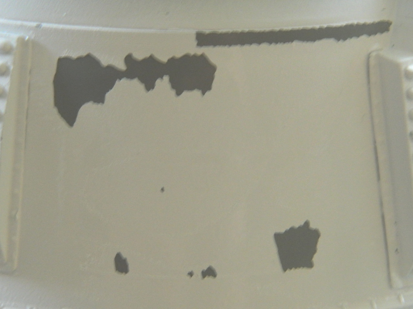
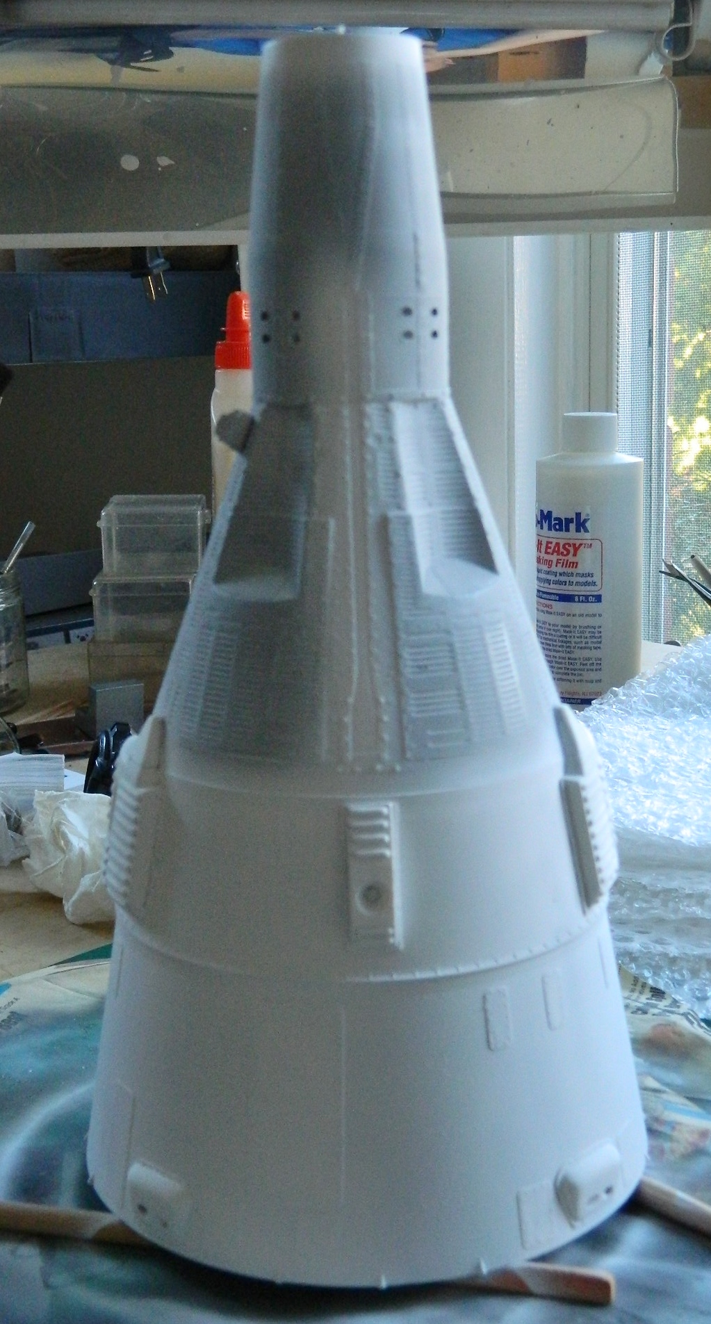
Before I glued the service module into place, I wanted to check all the work I’d done on the capsule and retro module. The best way to do that is to get the surfaces to all reflect light the same way. The best way to do that is to hit it with a coat of primer:
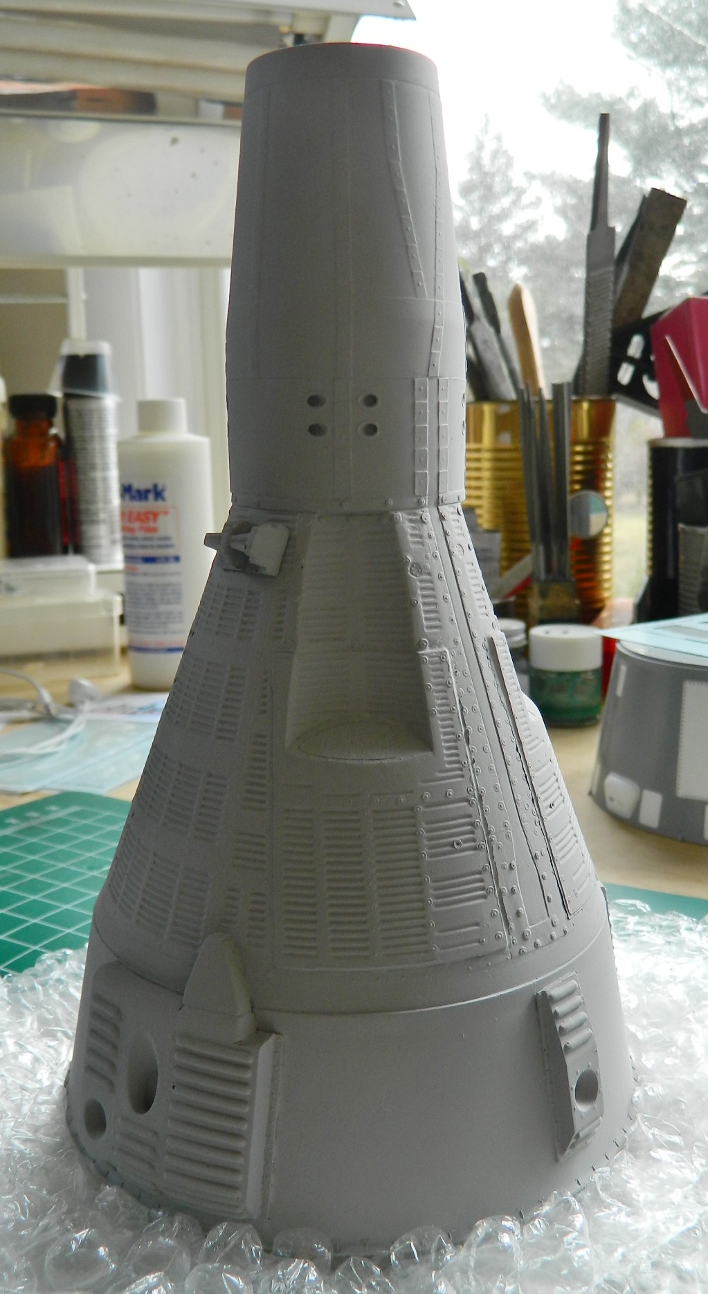
And that’s when I saw all the SODDING BUBBLES! I don’t know if the vendor who cast these parts is aware of pressure casting or not, but I am certain these parts were never pressure cast. (Frankly, I make better resin parts than this vendor does…and I’m a sodding amateur!). This part is the only one I took a picture of but every other part had bubbles to some degree. Unacceptable bubbles:
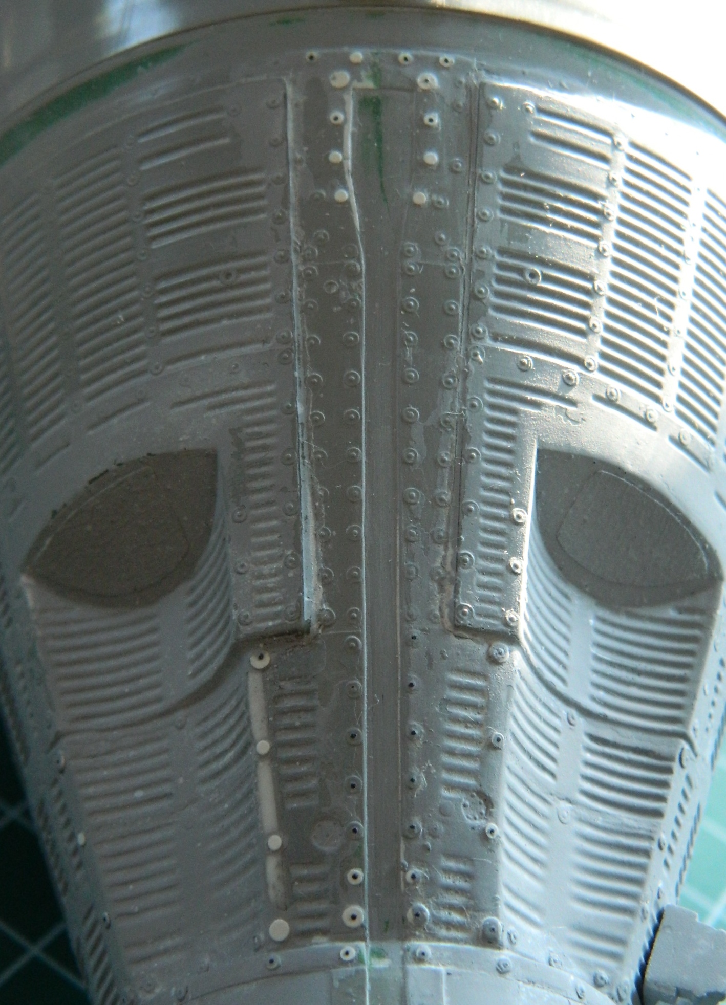
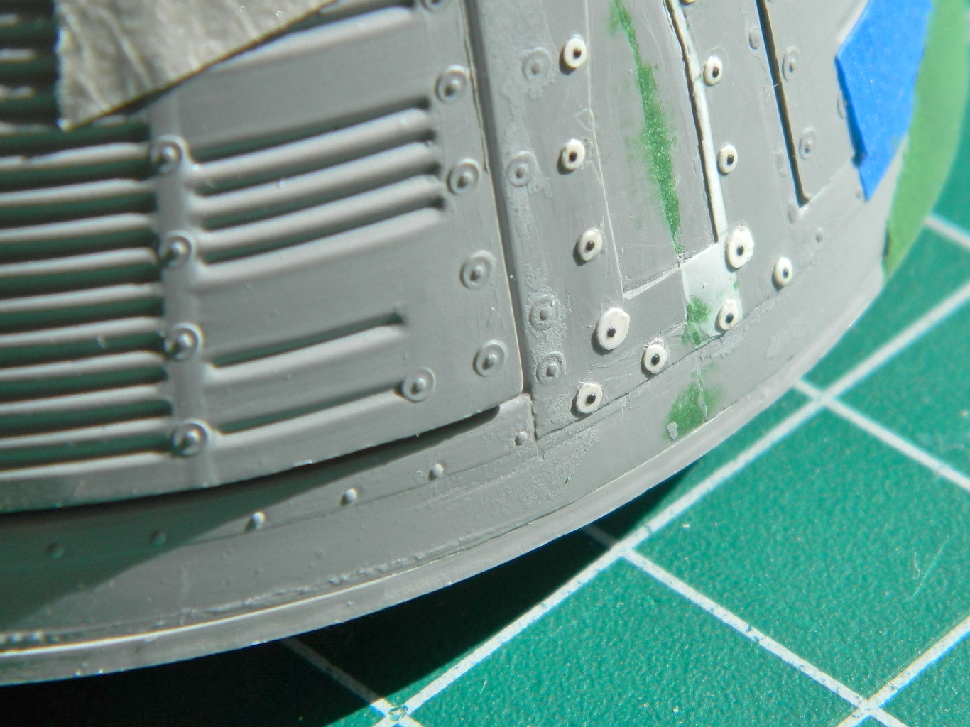
Some bubbles were small enough to putty (such as the ones in the above photo), some were so large I needed to plug them with plastic (again). I set the primed stack of bubbles to the side to let the primer cure and started adding the rivets to the panels on the service module. As tedious as the task could have been, using Archer Transfer’s sheets of resin details eased that task greatly. They print 3D resin details onto decal film and then the details are added the same way decals are. Trim, soak, transfer, align, curse, re-align, and repeat. Often. Keep at it, though, and this is where it ends up:

If there’s a downside to using these resin decals, it’s fragility. These things are SMALL. Sure, they can be cut, soaked, and applied in strips, but there isn’t a lot of surface area for adhesive and unless one is VERY careful (which sometimes I’m not, in spite of my best effort), they’re dislodged and have to be done again. Painting over them, however, greatly increases their resistance to being dislodged, so I hit the service module with a coat of primer and glued it into place at the end of the retro module:
These two modules are gloss white, so I painted them gloss white. It seems as if each time I paint this thing, I find MORE bubbles in the damned resin parts. Large ones require plastic be used to fill them:
Small bubbles can be puttied. Often the bubbles have to be enlarged so that there is space for the putty to be able to fill the hole and have enough surface for the putty to get a good bite. I used a needle to enlarge the bubbles for that:

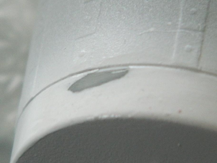
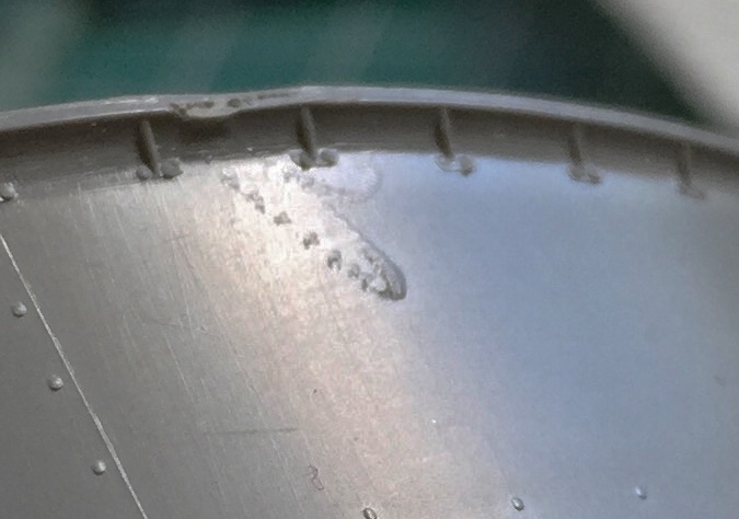
And it seems no matter HOW WELL I dust the shop, sweep cat hair, some always lands in the paint job. By the time I noticed this one blob of cat hair, the paint had started to skim over. When I pulled the hair away with tweezers, it took a blob of paint up with it (and this foreshadowed a much larger problem as you will see later). I coated my finger with thinner and smoothed the edges to make feathering easier (or at least that was the plan…):
I let the paint dry overnight and in the morning discovered that I’d missed another blob of cat hair on the nose cap. I sanded it away and noticed something disturbing. Yes…the color coat feathered nicely. No…the primer did not feather at all. Just about the time it was one pass of 1500 grit sandpaper away from being feathered, the primer would come off in a chunk and I’d have to start over. And over. So what was a relatively small repair turned into this:
The big blob on the side was treated with another coat of gloss white and once it dried, 2000 grit worked well to smooth the blemish away:
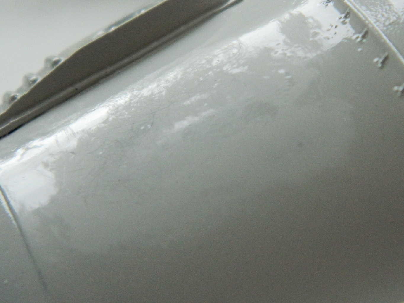
More paint and more sanding and the flaw on the nose cap was minimally acceptable:

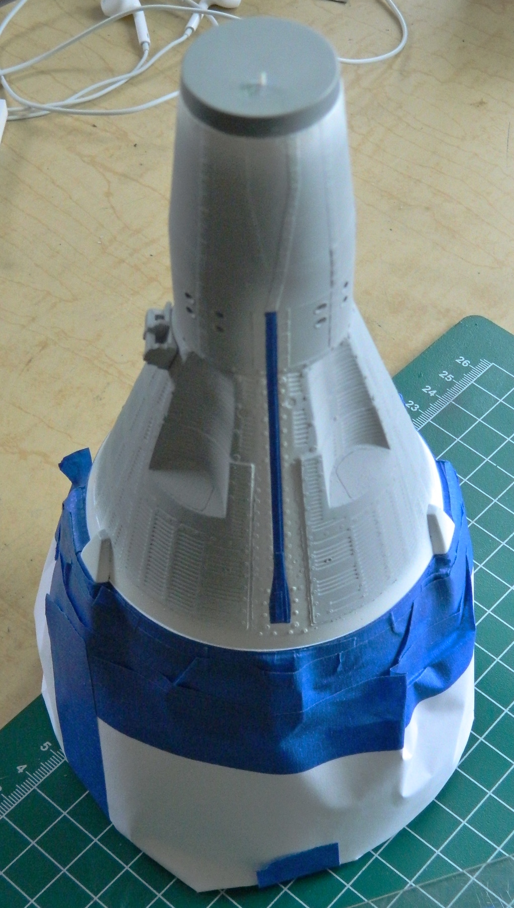
I’ve noticed that gloss paint seems to take longer to set up than matte paints do. So before I started masking off the white of the cap, parachute bridle channel, and modules, I let it cure for a couple of days. When it was no longer even faintly tacky to the touch, the parts I want to stay white were masked:
One small piece of masking tape went down in the wrong place, so I moved it. Now look…this is the blue masking tape which is NOT high-tack tape. It ain’t that sticky! When I picked up the small piece of masking tape to adjust placement, THE PAINT UNDERNEATH IT WENT WITH IT. So I tried moving the tape in other places and each time, THE PAINT UNDERNEATH IT WENT WITH IT, leaving me with this:
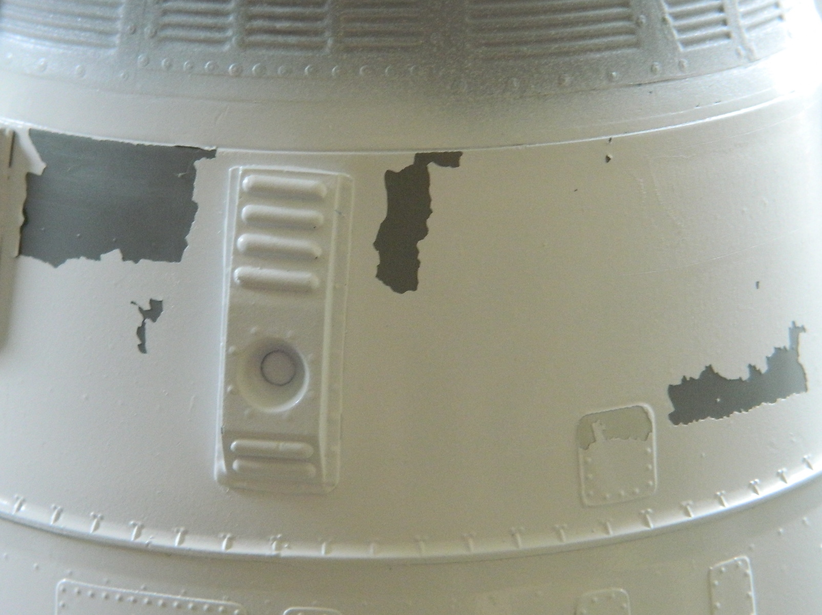
Not. Pleased. (Livid is more accurate.)
So my first thought was to sand and feather the paint. Remember the primer that doesn’t feather? Yep…that’s the primer that covers THE WHOLE SODDING MODEL. Well, how do we fix this? We fix this by stripping the paint off and starting over…and that’s what we did:

Denatured alcohol does a GREAT job of stripping acrylic paint, even old acrylic paint, away. Remember those fragile rivets? Remember what held them securely? Yup. Paint. The very same paint I’m stripping away with a toothbrush. And many of the rivets went with the paint:
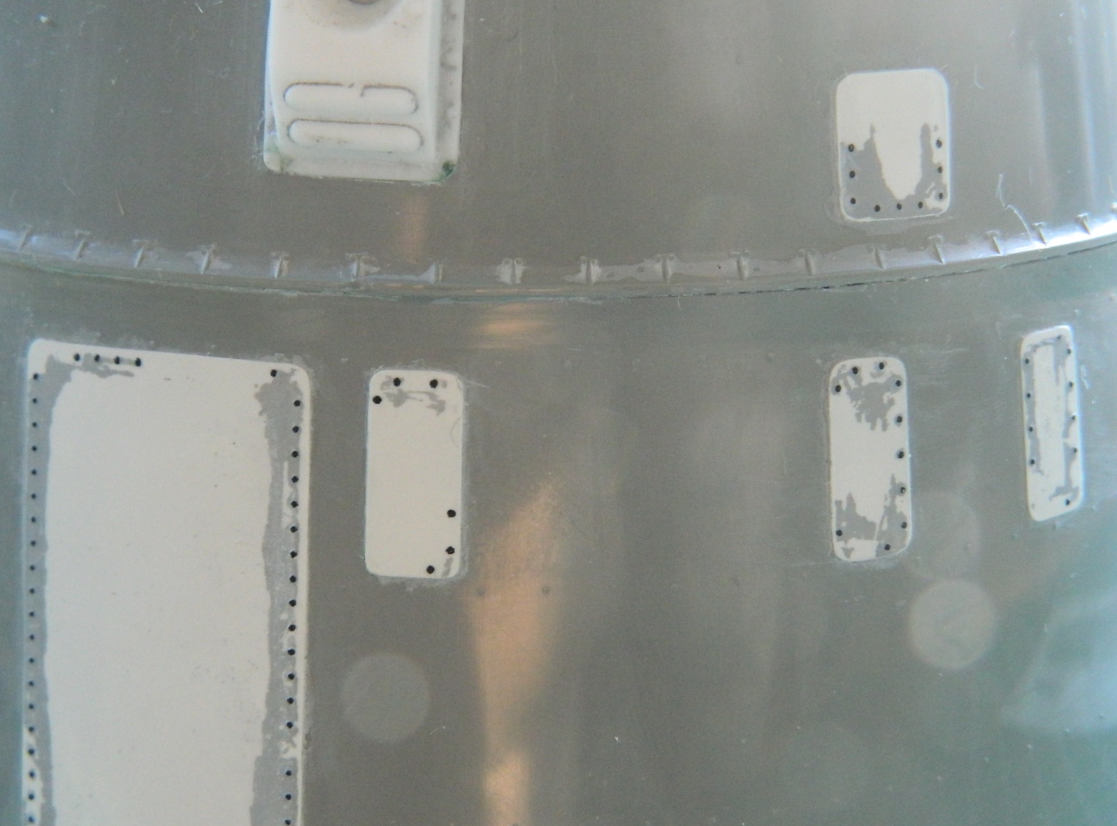
Once all the paint was removed and the surface cleaned thoroughly, step one of the recovery was replacing the missing rivets (and yes…I didn’t remove all the lousy, REALLY lousy, primer…that was so that I didn’t have to replace all the rivets):


Step two was to repaint the white. This time I didn’t use gloss, I used matte. I don’t know why the paint peeled away but time is running out and I didn’t want to repeat the previous nonsense (dunno as my blood pressure would take it well):
Step three was to mask the white areas again. This time, after letting the matte white sit overnight, I tested the tape on the paint to see if the paint lifting would repeat…and it didn’t:

Back to where I was a couple of days ago, it was time to shoot black onto the capsule (though shooting the capsule itself did occur to me):

No masking job is perfect (okay, mine aren’t) and I figured there would be touch ups required. When it was time to remove the masking, I probably burned through five years of stomach lining before I touched the tape. Needlessly. Everything worked just fine:
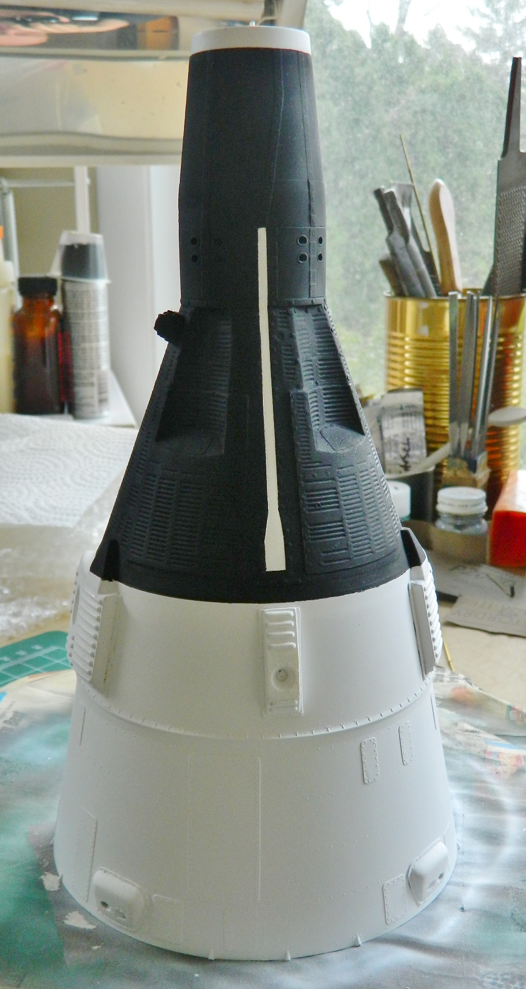
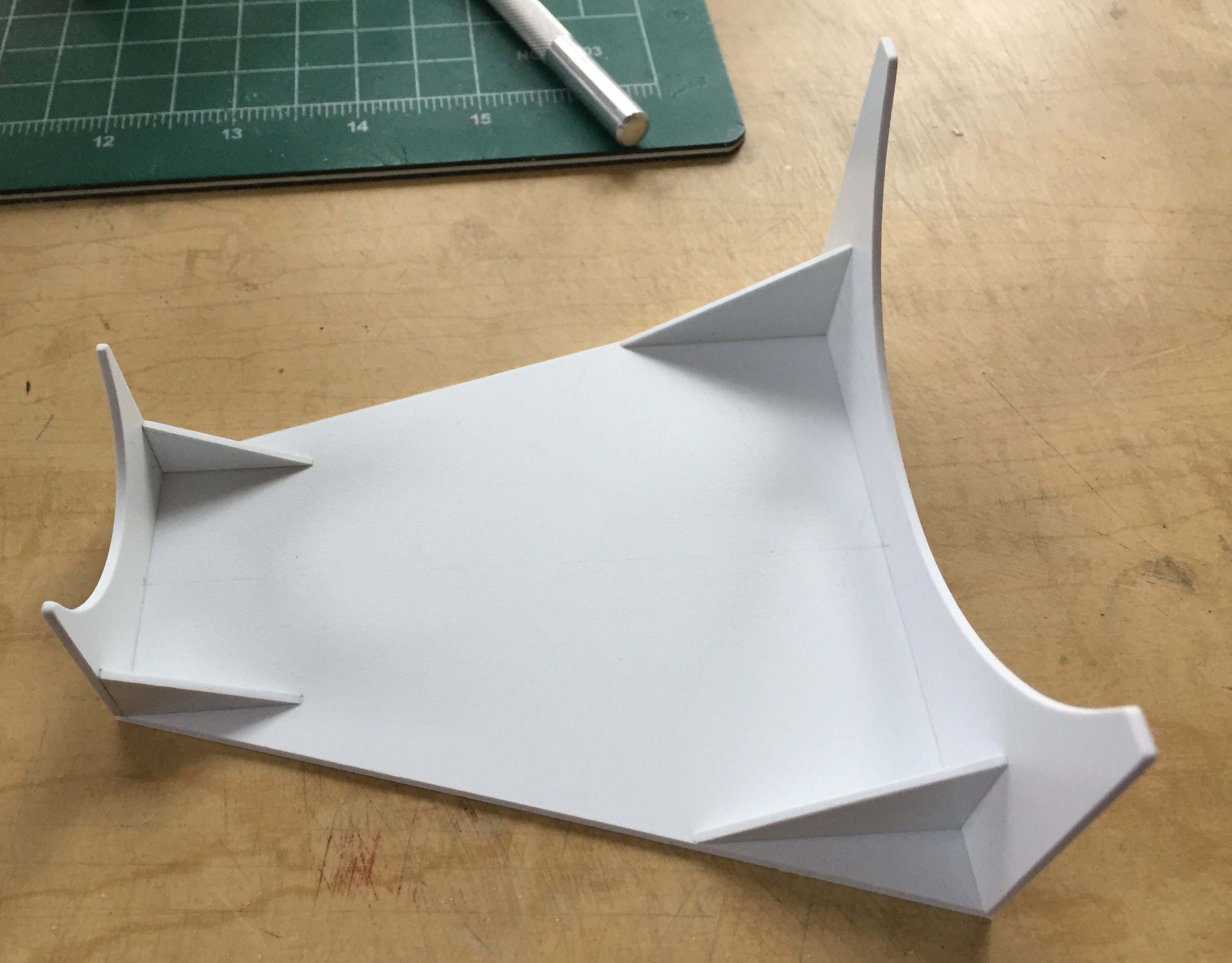
So I touched up what needed paint, sanded away the over-spray where I could, and set the beast aside to let the touched up areas cure before moving on to the next step. While that was happening, I started work on the display stand:

I know…that doesn’t look like much of a display anything. Later on it will all make sense.
There are three places on the exterior that need to be shot with red paint. With both the black and white down, I masked off the areas and got ready to shoot the red:
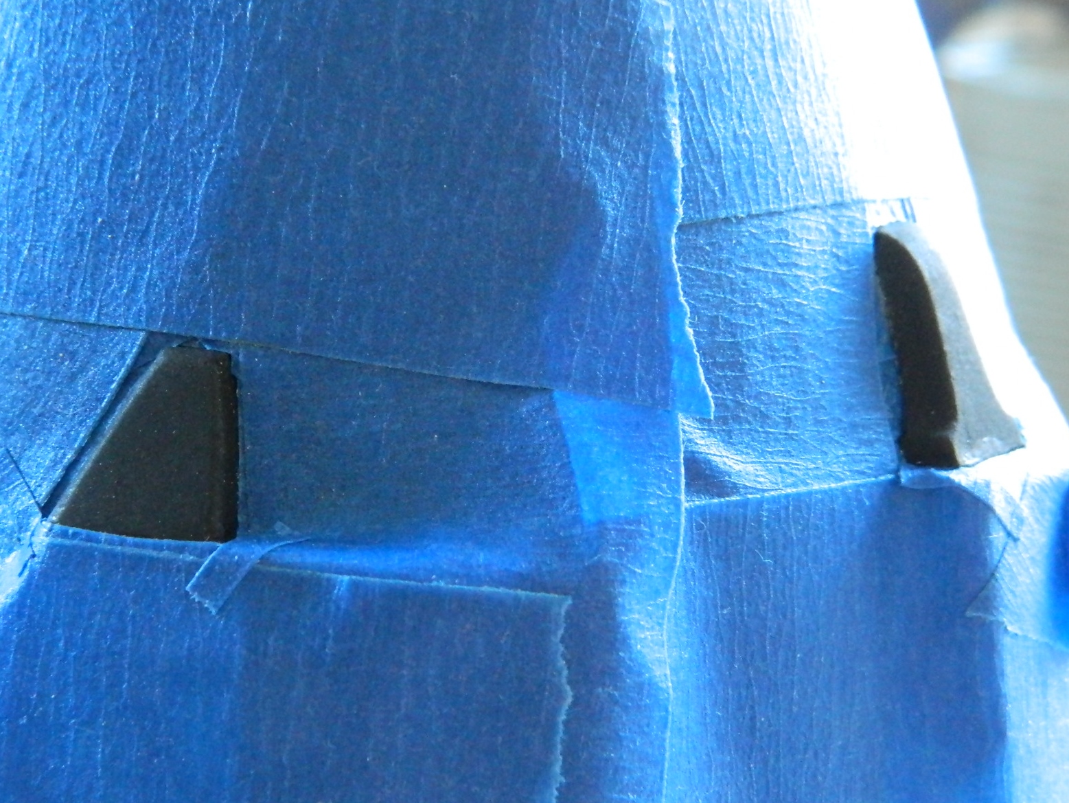
Paint mixed and shot, then the masking was removed:
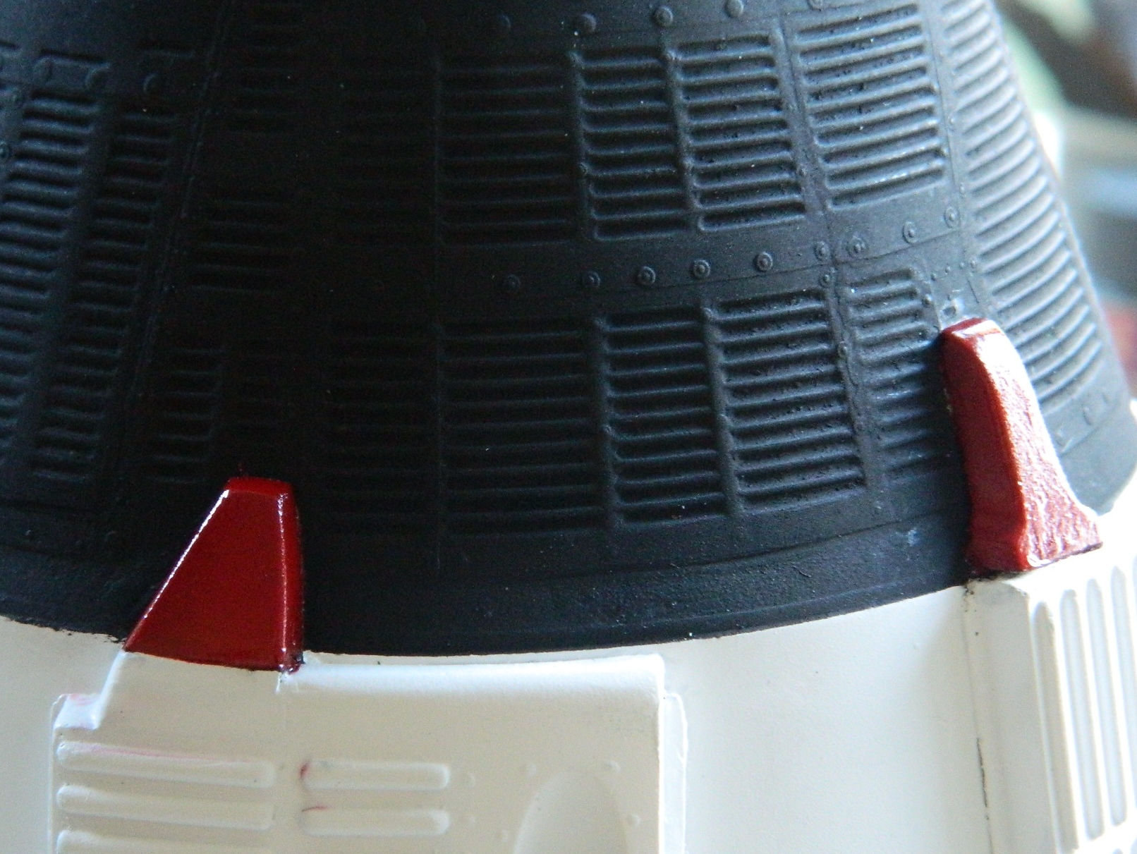
I’m letting it all sit overnight to set up more, then tomorrow the white modules get coated with clear gloss. There are some areas on the black paint that also have to be given a coat of clear gloss. That’s because the next step is to add decals!
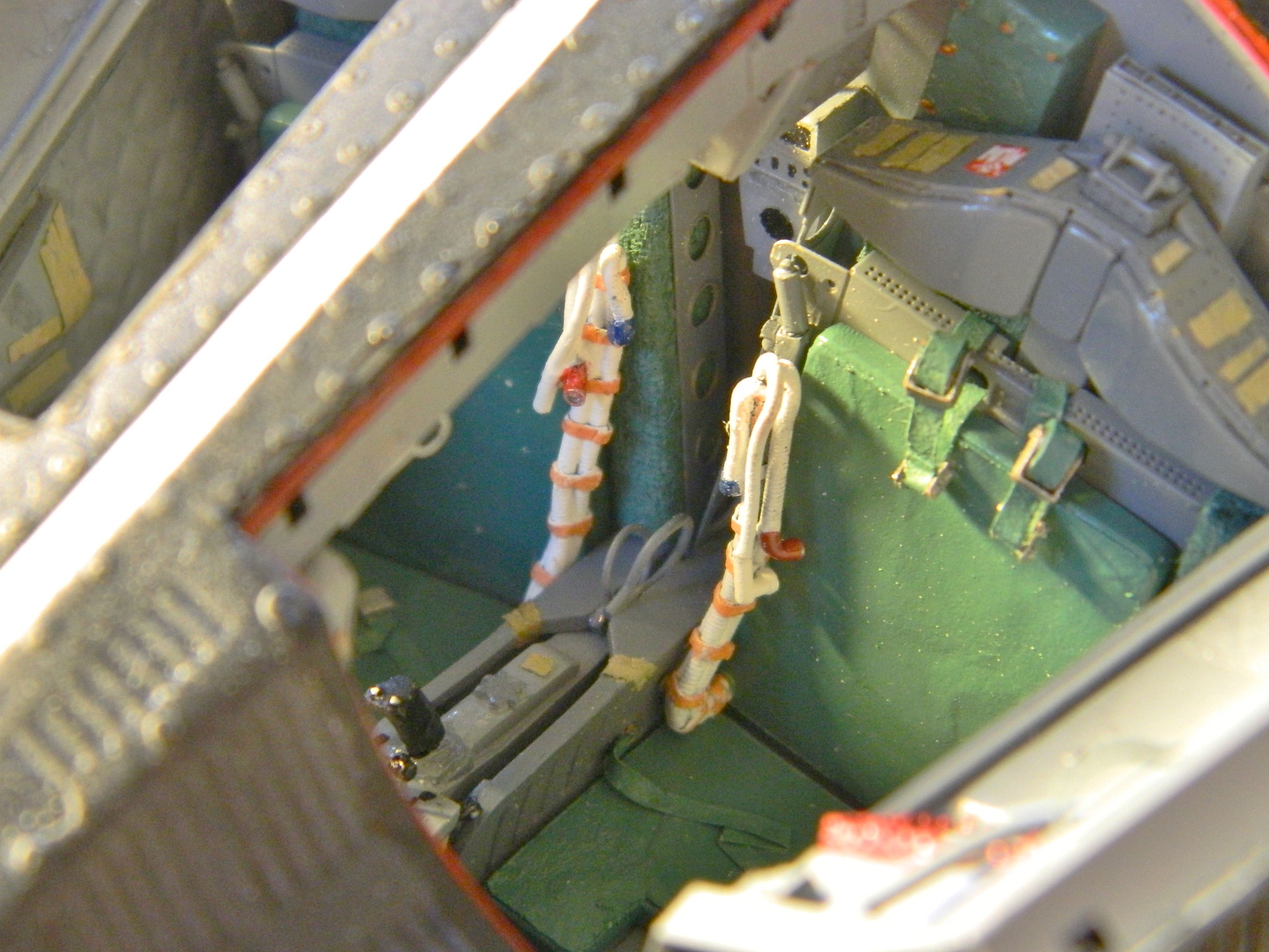
The oxygen hoses were originally purchased for aircraft builds and were just sitting on the shelf. The hose I used is 1 mm in diameter. As there are two hoses per crew member, I superglued them together:

The hoses are made of what feels like silicone rubber; it’s certainly flexible enough to be and I needed something to stiffen them so they’d hold the shape I want. There’s also a communication cable bundled with the hoses which gave me the chance to use a copper wire to allow me to bend the hoses to the desired shape. I used lead foil for the straps and solder for the suit connectors (and of course I drilled out the ends of them):
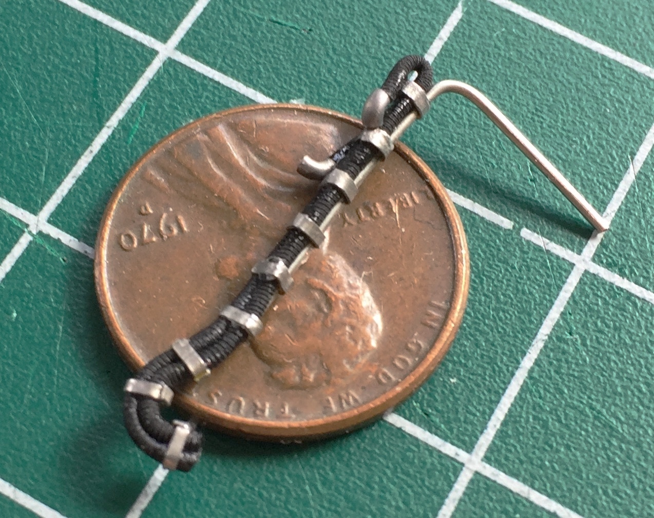
Then I made the electrical connection and added that to both hose assemblies:
The base coat is white:
The straps are buff and the hose connectors are painted either red or blue. That completes the hoses:

The hoses were the last parts I needed to finish seat assemblies:
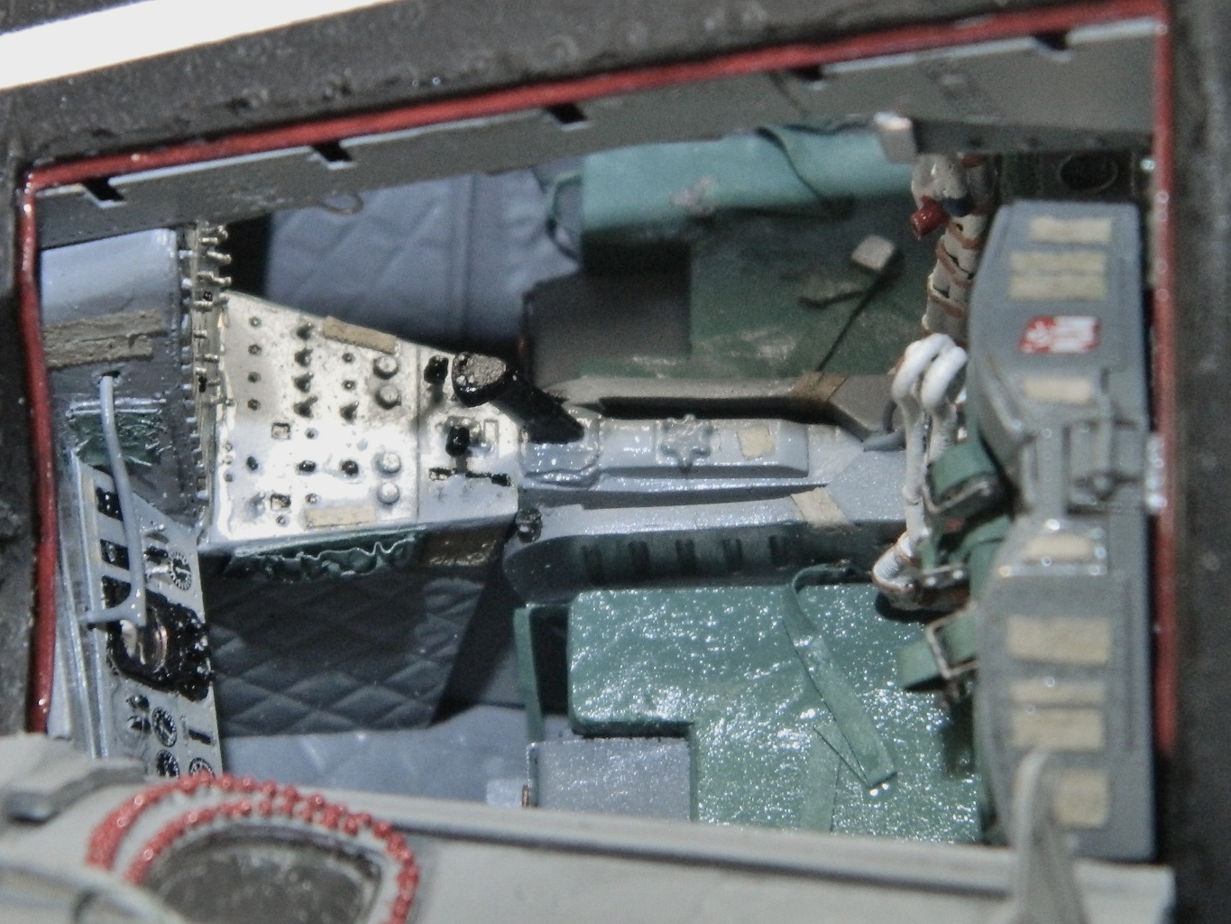
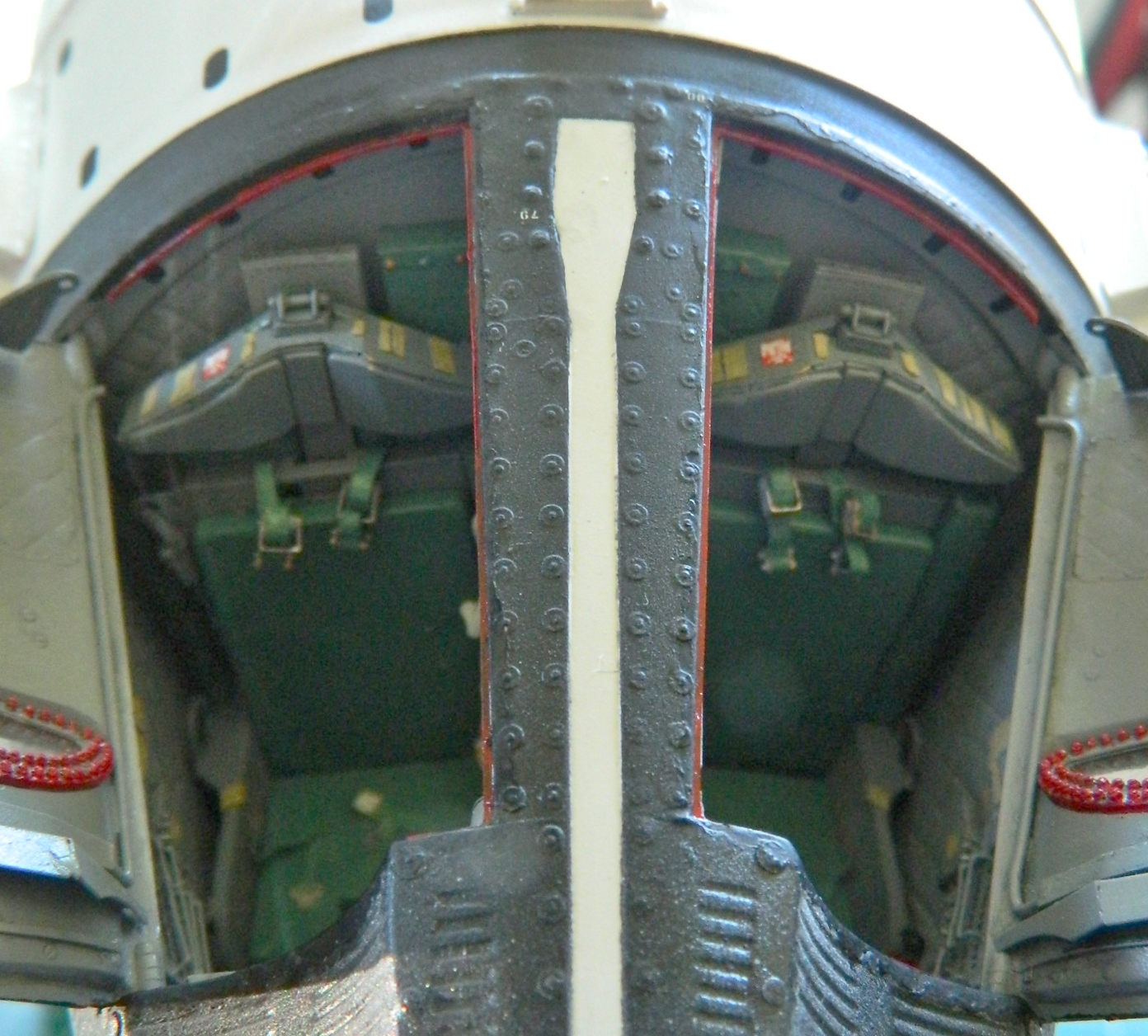
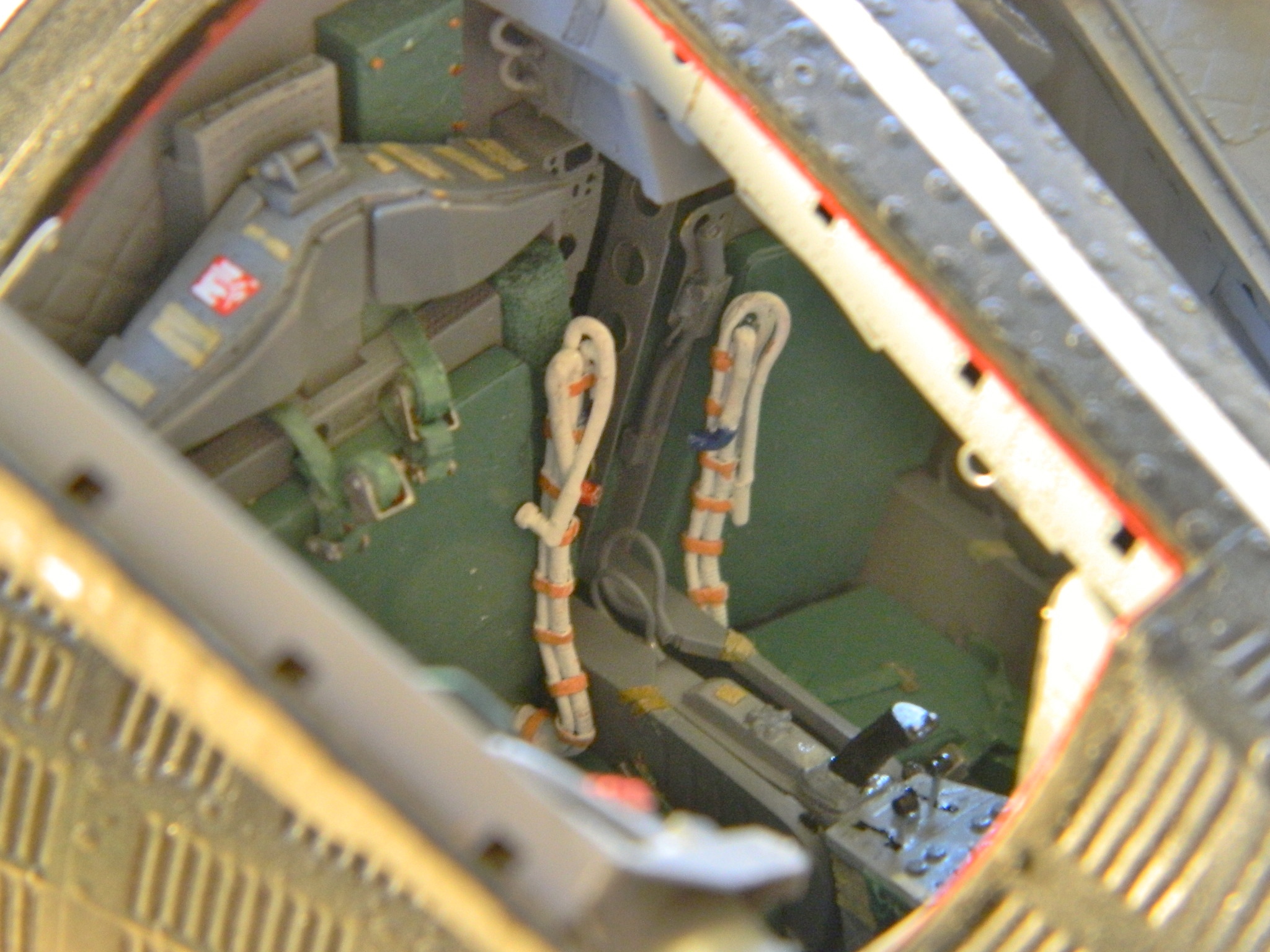
First major assembly! Assemble the crew cabin:
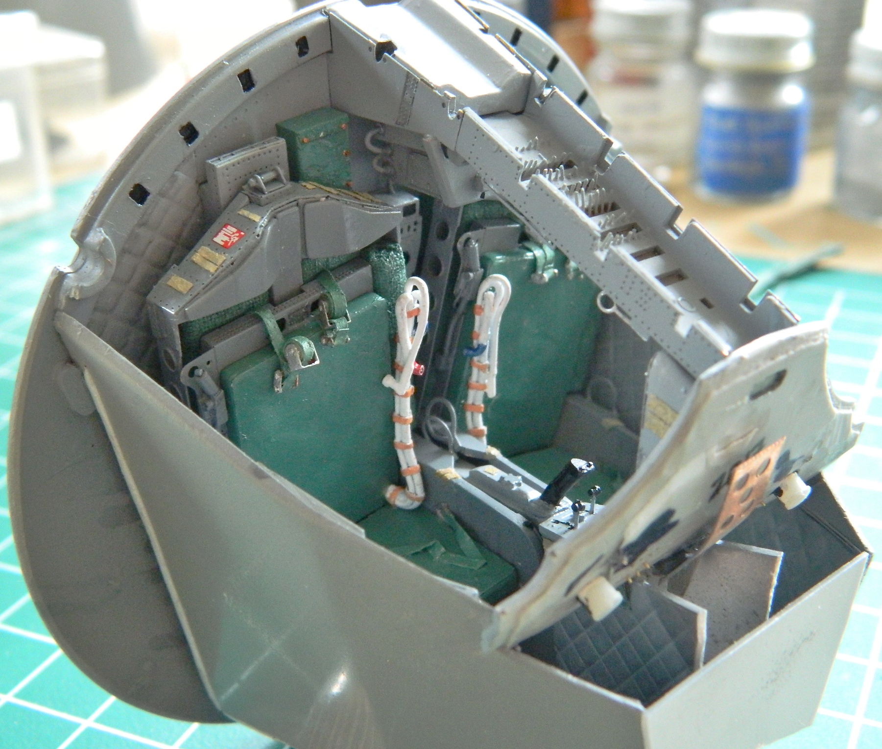


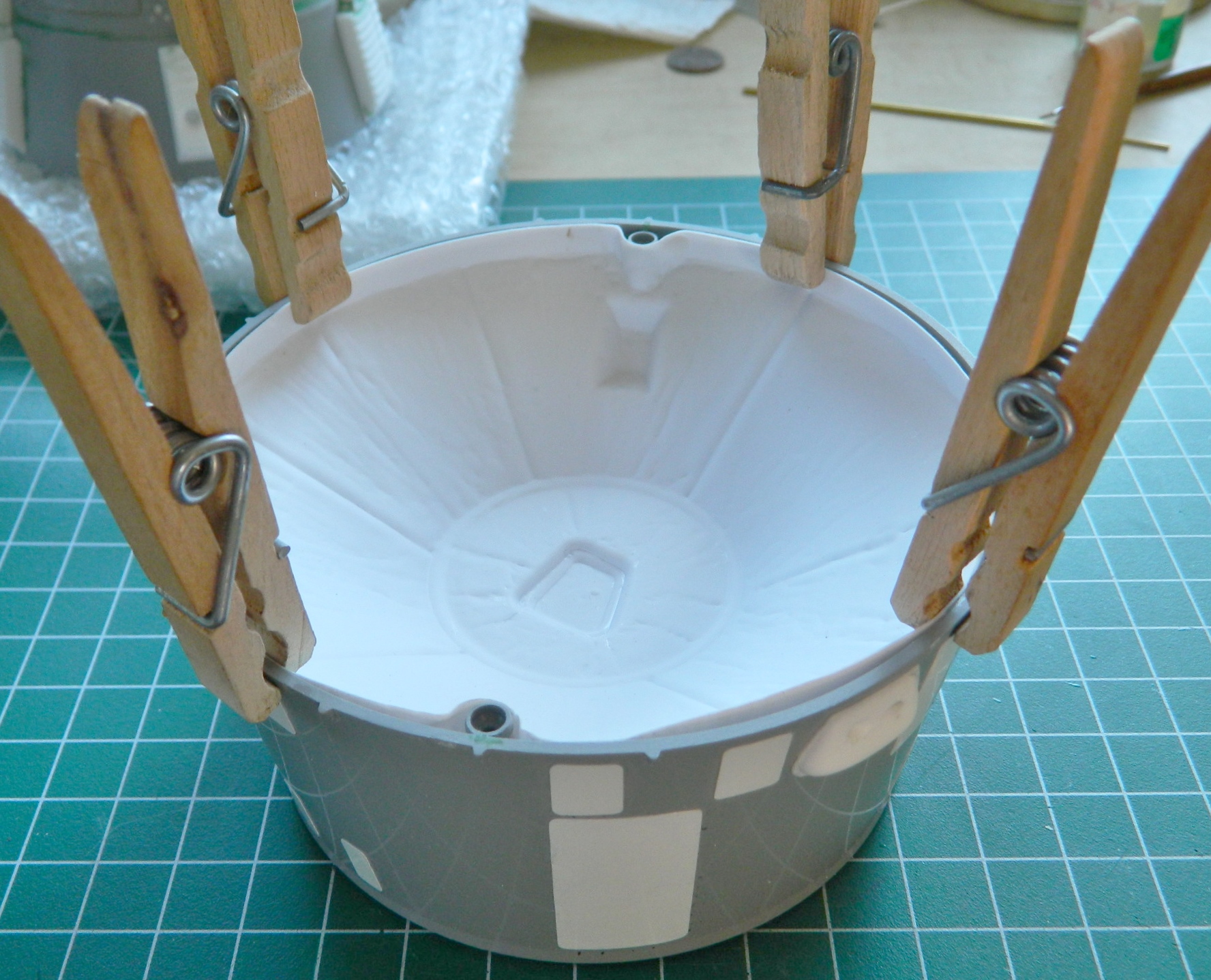
With the cabin assembled, it was time to stuff it into the body of the capsule. There was only one small problem with that. IT DIDN’T FIT:

When my head ceased exploding (like, the next day), I started checking references to see where it was off (other than…well…EVERYWHERE). The seats on the actual capsule don’t sit as far back as what I had sitting on my bench:
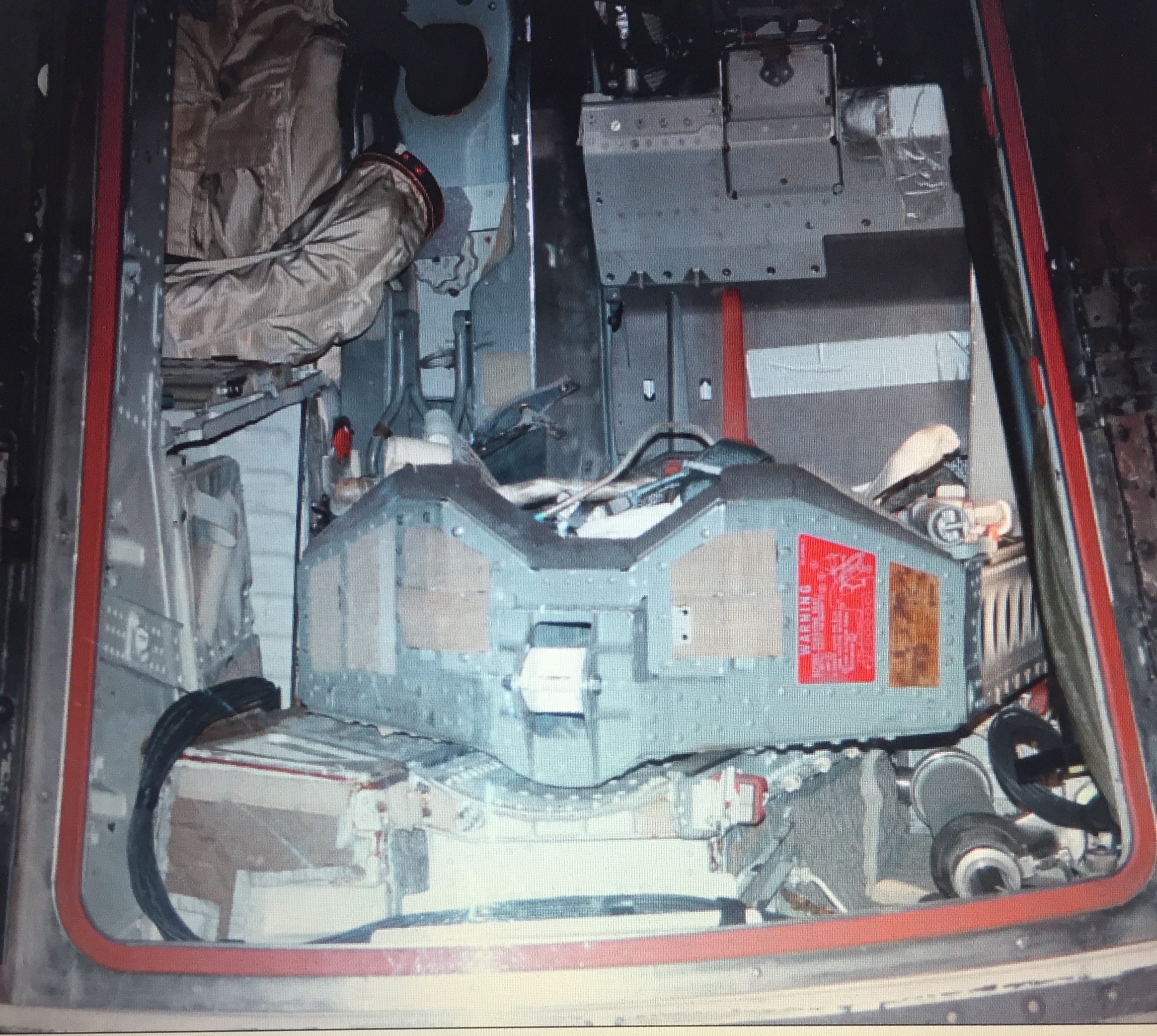

Okay…aside from the fact that the back of the interior assembly was STICKING OUT OF THE BACK, that indicated that the interior assembly wasn’t getting in far enough (“Captain” Obvious? Try “Colonel”). Well, I did fit that thing and it did fit. Why doesn’t it now? What’s changed?
The last time I stuffed that cabin into the capsule, nothing was glued together, it was all taped. Hmm… Evidently being taped together allowed just enough flexibility in the location of the parts for it to conform to the space available. But now it’s all glued (quite thoroughly) together and there is NO flexibility of location. That indicated to me that I didn’t need a lot more room inside the shell, just more room. Okay…I can work with that (I hope).
I had already removed as much from the corners of the cockpit tub that I could without breaking through the walls. That meant that whatever space I needed had to come from the inside of the shell. I used 100 grit sandpaper and scoured the inside of the shell. I figured out a handy trick to discover exactly where the tub was hitting the shell. I ran a bead of petroleum jelly along the edges and pushed it into the shell. When the tub was removed, the petroleum jelly left some of itself where it was contacting the tub…and that’s where I concentrated my efforts at material removal. And then I got to the point where the petroleum jelly wasn’t leaving any deposits inside, yet the damned thing still didn’t fit. It took some time and clever use with a flashlight but I discovered the last impediment to a proper fit.
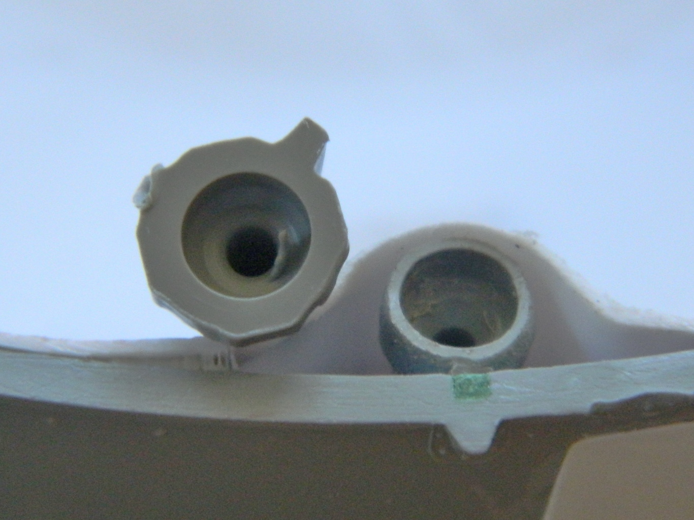
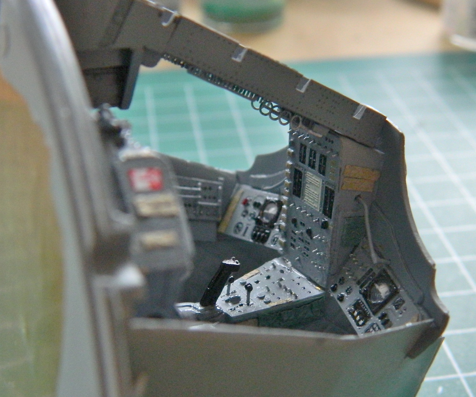
It was the edges of the instrument panel. The little protrusions on each side had to come off:
And after a couple of hours of dicking around with it, I finally got it to fit:
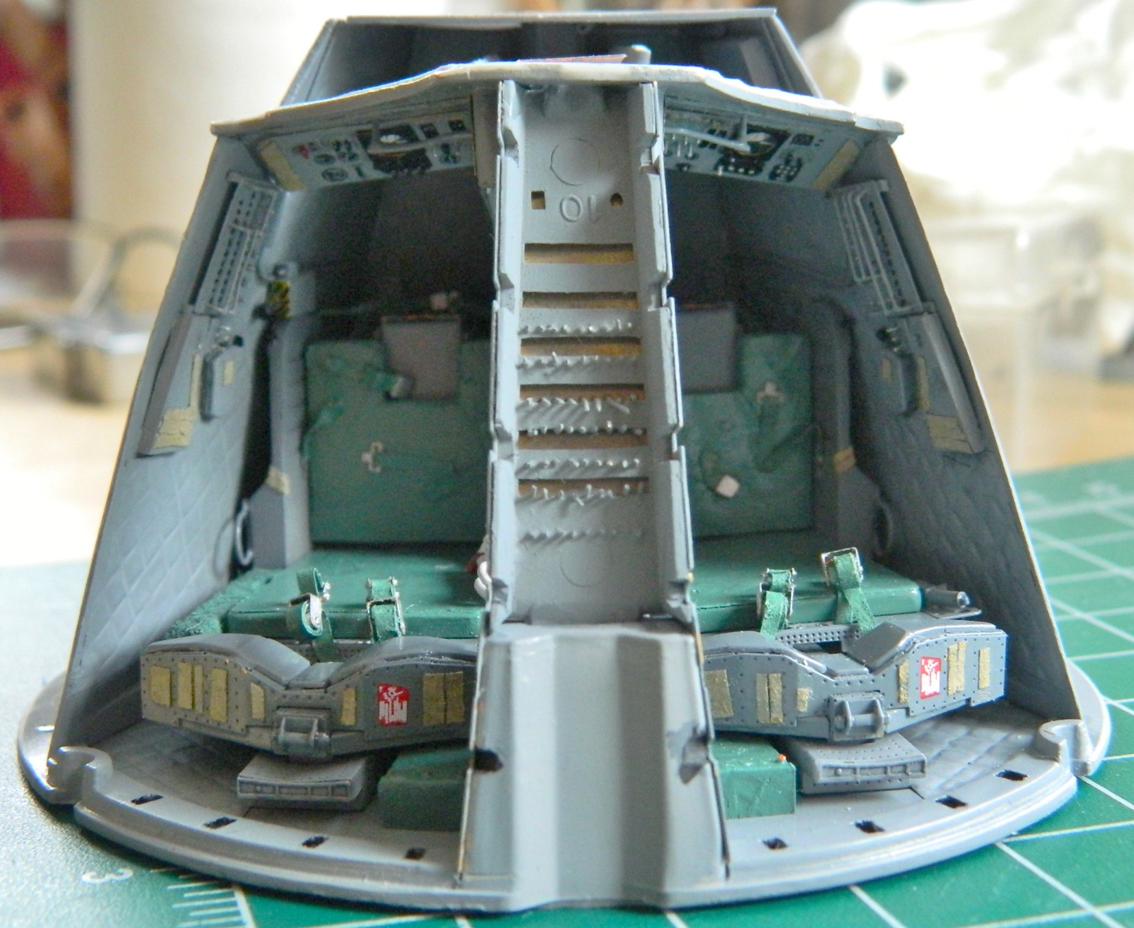
The last parts I had to add before I could button up the capsule were the hatches. I used some styrene tube to make the front hinges [As an aside, I am NOT AT ALL PLEASED with how the hatches hinge. But short of reworking the corners of the instrument panel to an accurate configuration and making more accurate hinges, that’s what I’m stuck with.]:
With the hatches in place, now I can stuff the interior into the hull and glue it in. Here, as well as far too many other places, the fit is abysmal. I had to use superglue jell to fill the spaces between the outer edge of the rear bulkhead of the cabin and the interior surface of the hull. When I say I had to jam the interior into the hull, that’s exactly what I had to do. Once I’d run a (wide) bead of jell around the mating points, I put the base of the capsule on a flat surface and added weight to press the cabin assembly as deeply into the hull as it has to be. Superglue jell takes A LONG TIME to set up. I put the hull/interior aside and let it cure for over twelve hours:
The next day the jell had hardened so I glued the heat shield into place, finishing the interior construction:
With that odyssey take care of, attention and effort turned to the exterior…and there’s plenty of attention and effort required.
There are two modules aft of the capsule. The closest module is the section that contains the de-orbit engines (aka, retrorockets), and the module furthest from the capsule is the service module where fuel cells, batteries, oxygen, and the like are contained. The end of the service module wasn’t flat, so I placed a sheet of 220 grit sandpaper on the table and sanded the high spots down:
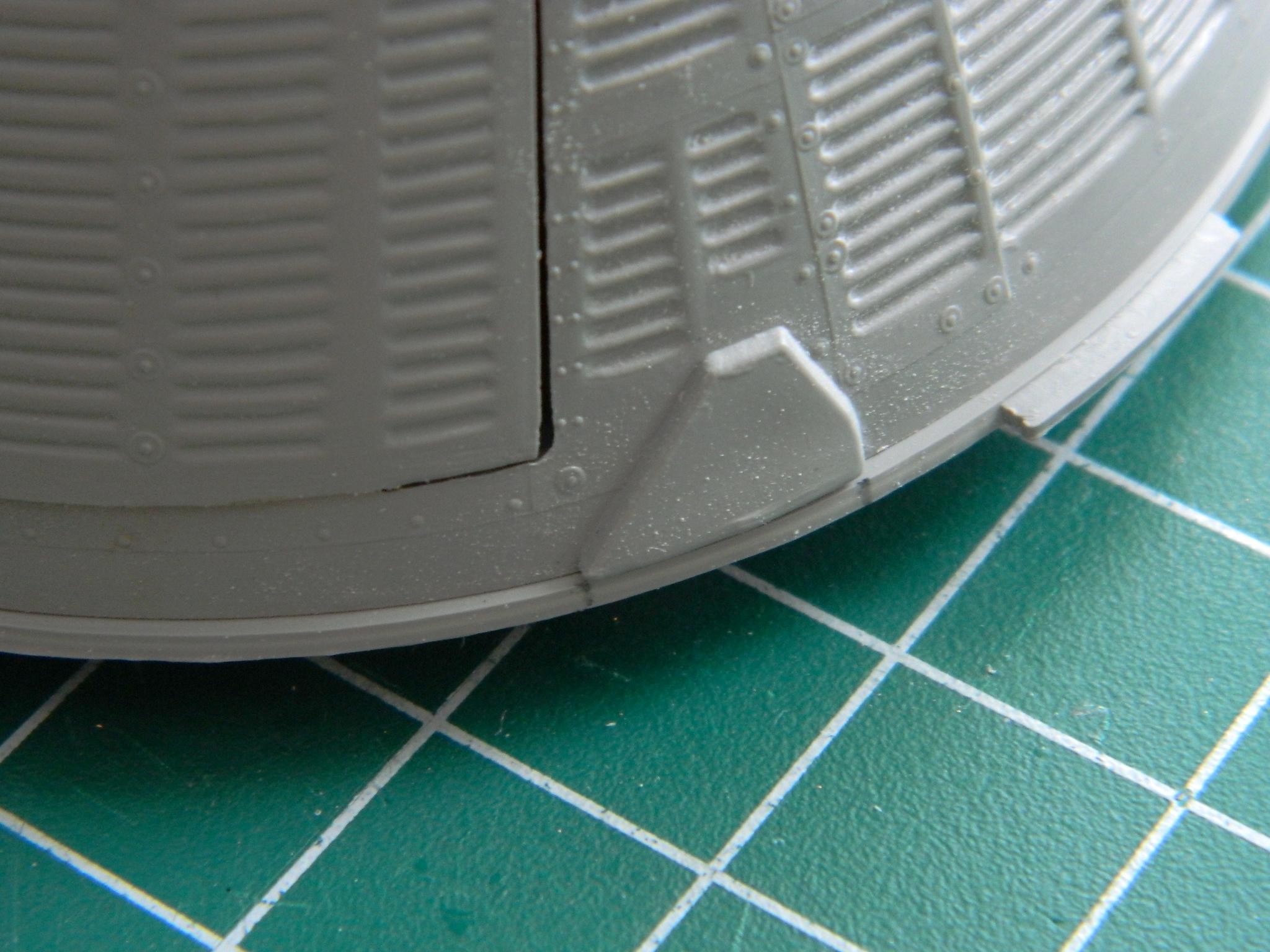
All the problems I’m having with the kit parts were engineered into it, guaranteeing problems. I don’t think that was Revell’s intention, but that’s how it is. In my kinder moments (rare that they are), I suspect the person(s) who cut the dies for this kit wasn’t a master die cutter. I don’t think they were journeymen. I suspect they were new-hire apprentices. And what makes me think that? In the next photo, that U-shaped area is a positive; it sticks up from the surface. That means that when the dies were being cut, the die cutter tool (I mean the tool…I’m hoping the person holding the tool wasn’t also a tool…) skipped across the surface of the die and left a groove behind. And I mean left a groove behind! What sort of quality control lets something like that out of the die cutter shop and into the production area? Nothing I can say would be a “kinder moment”:
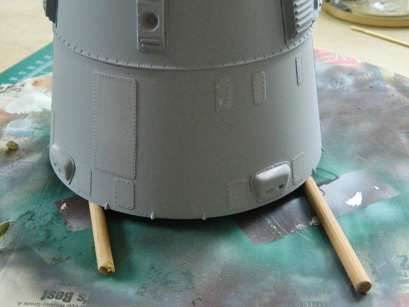
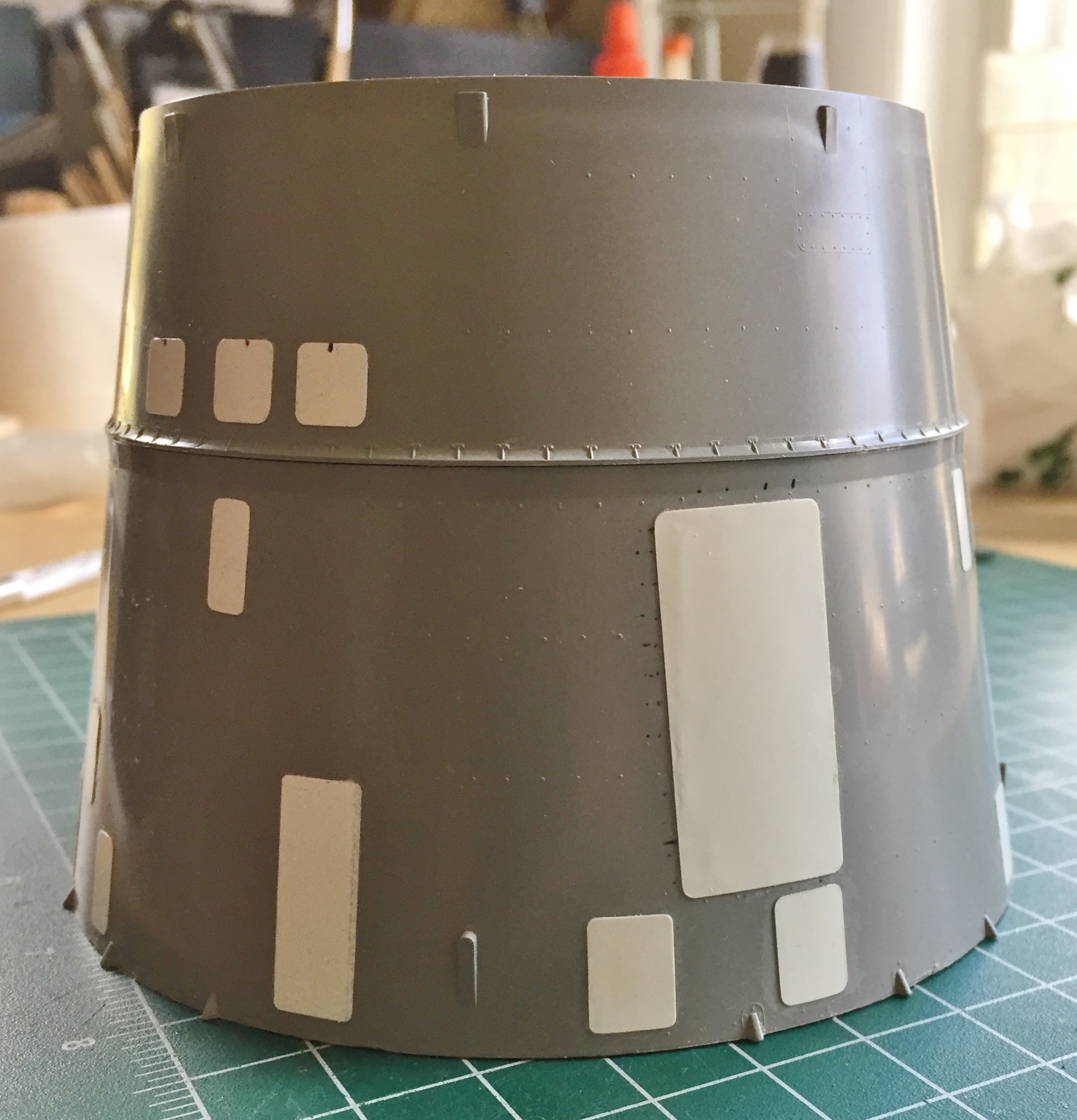
There are panels on both the retro and service modules. On the kit they’re hinted at with REALLY LOUSY raised lines. The lines are inconsistent in height, shape, and any other factor that makes them what they are…instead of what they should have been. So they have to be redone…and the usual way to do that is to scribe into the surface the raised lines.
Major problem with that task is personal. I hate scribing panel lines. Thus far, no amount of practice has made me any better at doing it. (Hmm…maybe I can get a job with Revell cutting dies?) (Meow). This photo shows the abysmal raised panel lines on the right, my crappy attempt at scribing in the center, and what I finally decided to do instead. Add panels to the surface:
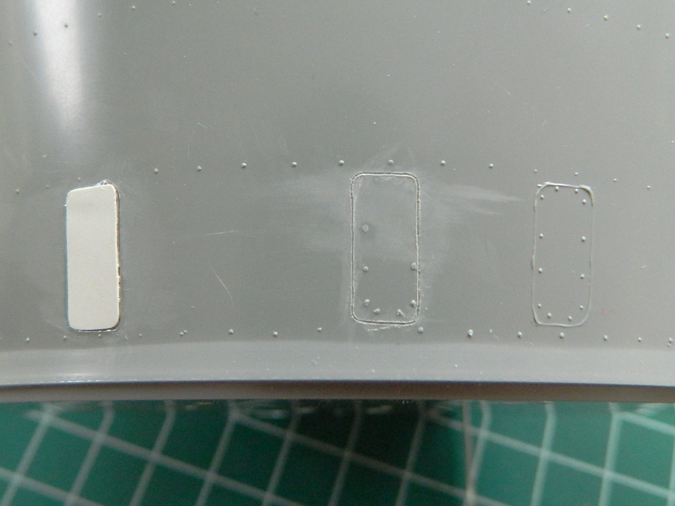
Yes, on the actual spacecraft, those panels weren’t on top of the surface. But the accuracy of this model is bloody atrocious, even after all my work, so one more inaccuracy with this build is just another bucket of sand on the beach:
I doubt you’re surprised at this point (I certainly wasn’t), but the heat shield doesn’t quite fit well on the back of the capsule:

Initially it seems like an easy fix. Just file down what extends past the edge of the capsule and add plastic to where the heat shield doesn’t quite meet the edge of the capsule. The problem with that is that this heat shield also has to fit the top of the retro module and if I did that, it wouldn’t fit at all. I had to make the edge of the capsule conform to the shape and edge location of the heat shield. Putty time:
Not my preferred way of doing things but that’s just what this [INVECTIVE DELETED] thing requires.
Next step was to use the resin AM parts to replace the incorrect kit items for the orbital maneuvering system (OMS):
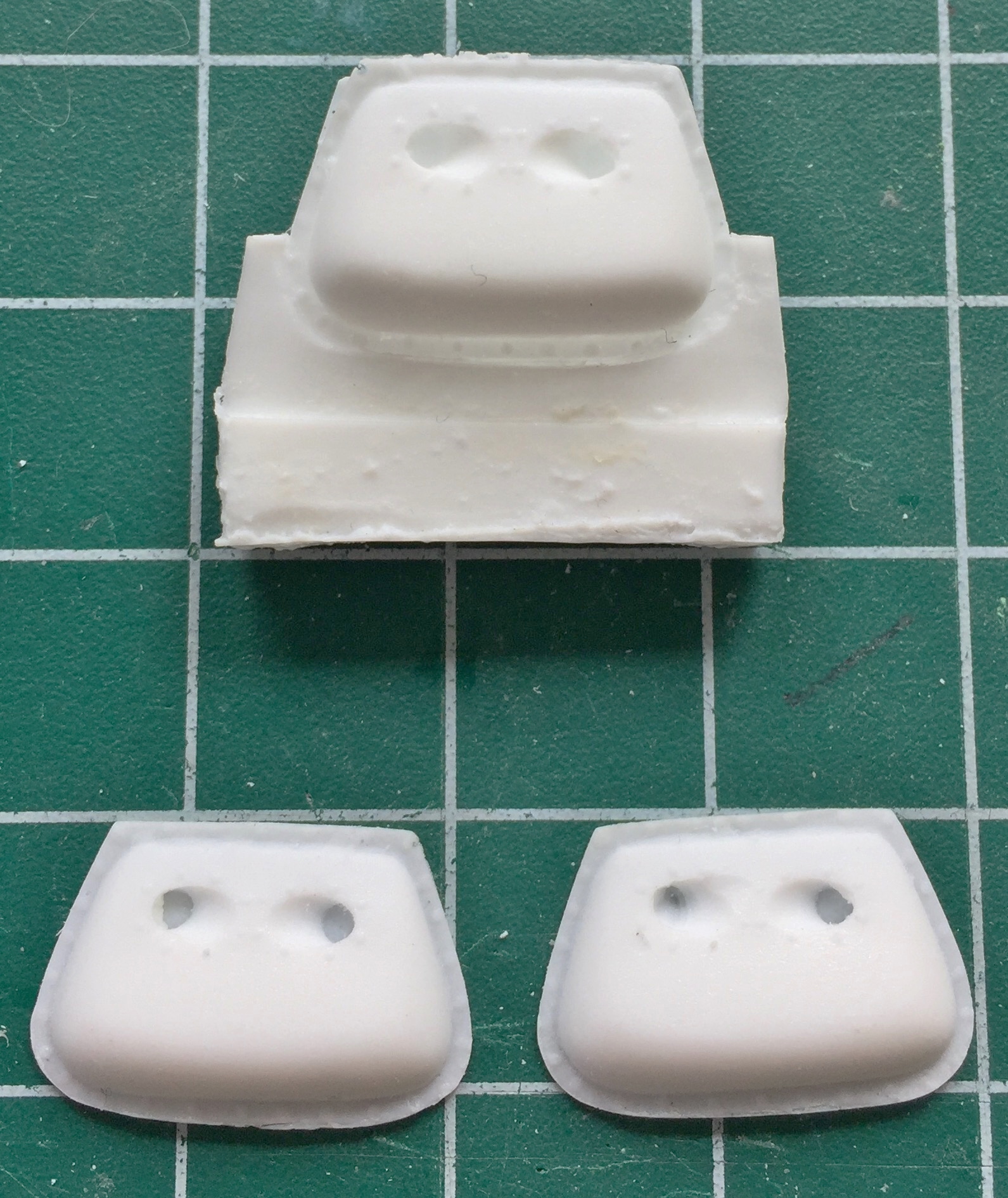

And here I encountered another disappointment. Yes, whoever built the masters for these parts did an adequate, NOT good, job. The OMS parts that go on the outside of the retro module are too tall. References show they should be half the height than what was provided in the set. Also, though I am not a professional mold maker or resin caster, at least I know that resin casts better and denser under pressure. This idea had not occurred to whoever made the molds and poured the resin into them. The castings are FULL of bubbles, some of which show up in the least opportune places, and the handling of the masters during mold making only left one thing to be desired.
Care.
The edge of this OMS unit was poorly cast and had a very pronounced bubble along its edge. To fix that I cut away the mounting flange and replaced it with a sheet of .010″ (.254mm) styrene:

On the other side of this OMS pack, close examination of the flaw at the edge in the picture below was molded that way. That meant the damage to the master was already done before the mold was made. Gosh…what a surprise it showed up in the casting:

This part is supposed to represent the horizon sensor. The bubbles were large enough that putty would not have fixed them. Instead I opened the bubbles so that I could insert styrene to fix them (and subsequent checking of references showed that it’s pretty inaccurate generally; I fixed it to the best of the reference’s detail…which wasn’t enough, but there it is…again):


This part, a wiring shroud, also had a couple of large bubbles also (the smaller ones on the face could be filled with putty) that needed plugging:

Before I could add the resin AM parts, the retro module had to be glued to the capsule. The kit provides rudimentary details for the inside of both retro and service modules. Because I can’t find any reference photos of exactly how things were mounted, wired, and plumbed, I’m not adding those details. The only exception were the braces for the retrorockets. Initially it was because there are a couple of locating pegs to mount the service module. As I’ve been working on this and considering exactly how I was going to hold this thing while I painted it, I realized those engine braces would do quite nicely as a painting handle:

After adding the OMS packs to the service module, they needed to be added to the retro module, which is where most of them go. When I went to add the OMS packs to the sides and align them with their respective wiring shrouds I found another fit problem. The wiring shroud shown below is where it belongs. To get the OMS pack to meet up with it the way it’s supposed to would mean that the OMS pack would be MUCH more forward than references show, or, the wiring shroud would be too far rearward:
So for everything to be where it’s supposed to be, that gap needed to be filled and puttied:
And the same thing had to be done to the other side:
Since I am (too damned slowly) closing in on throwing paint at this, and I CERTAINLY don’t want any over-spray to insinuate itself into the capsule, I needed to close the interior off from that possibility. I closed the hatches as much as they would close and went around the edges of the hatches with white glue, sealing them. Later on the white glue will be removed and the paint touched up, MUCH easier to do on the outside than it would (not) be on the inside:
When I put the outer window plastic over the face of the port, I eradicated the surface detail and that got put back using Archer Transfer’s resin rivet decals:

Brain fade is an insidious thing. When it’s happening, it can go completely unnoticed and too often it stays unnoticed. This time I caught my most recent brain fade (I hope) before it was too late to fix. I put one of the OMS packs on backwards! That has to be pried off and reversed. I’m coming to a brand new appreciation of single-edge razor blades. That’s what I used to work under the edge and cut/pry the superglue away to release the module:


At this point I’ve got more experience than I wanted to have adding plastic to fix bubbles. I didn’t see there was an interior bubble on the mounting flange until I popped the module off, so that needed fixing. Once I’d trimmed the plastic to fit, the module was reattached properly:

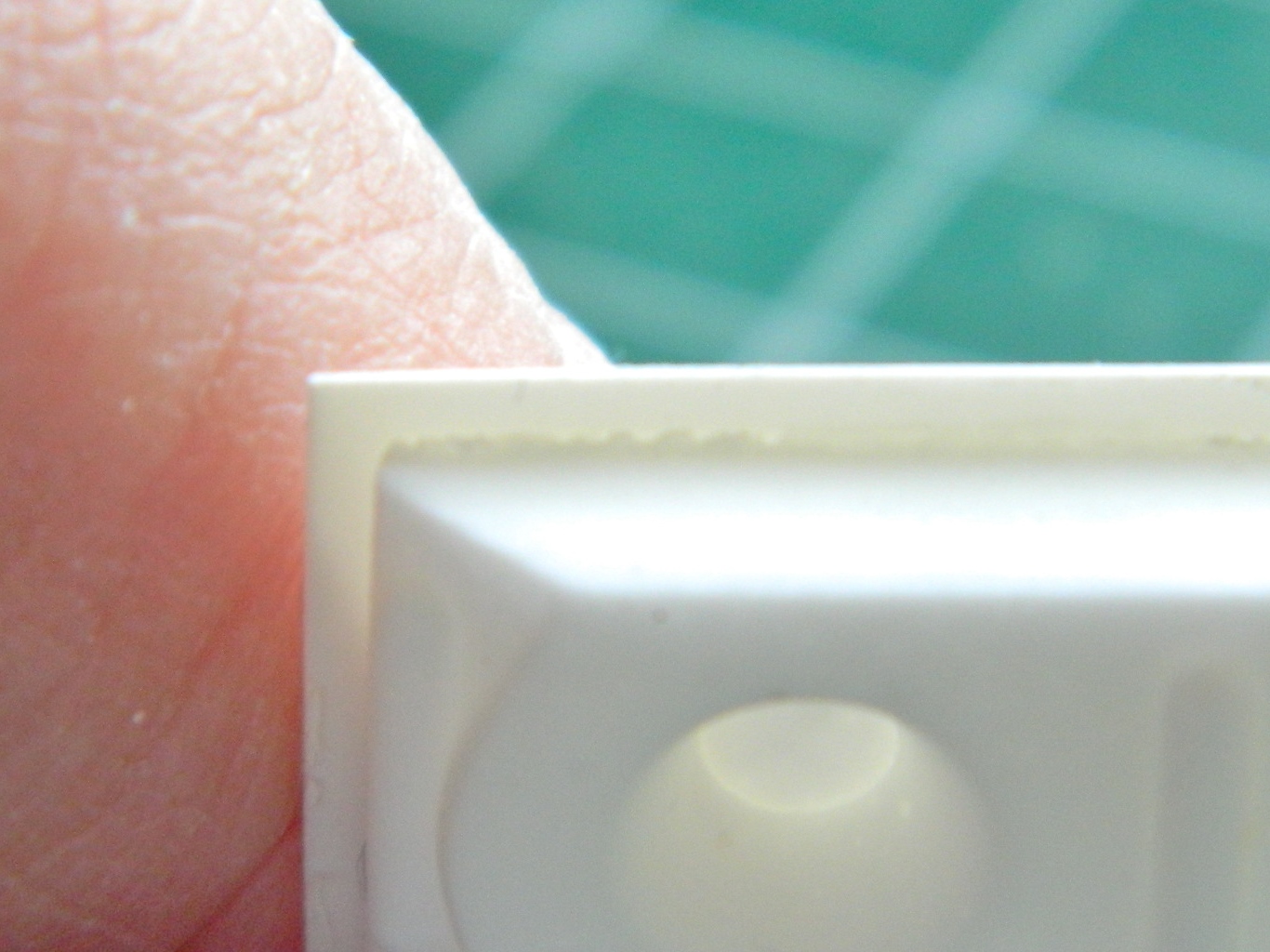
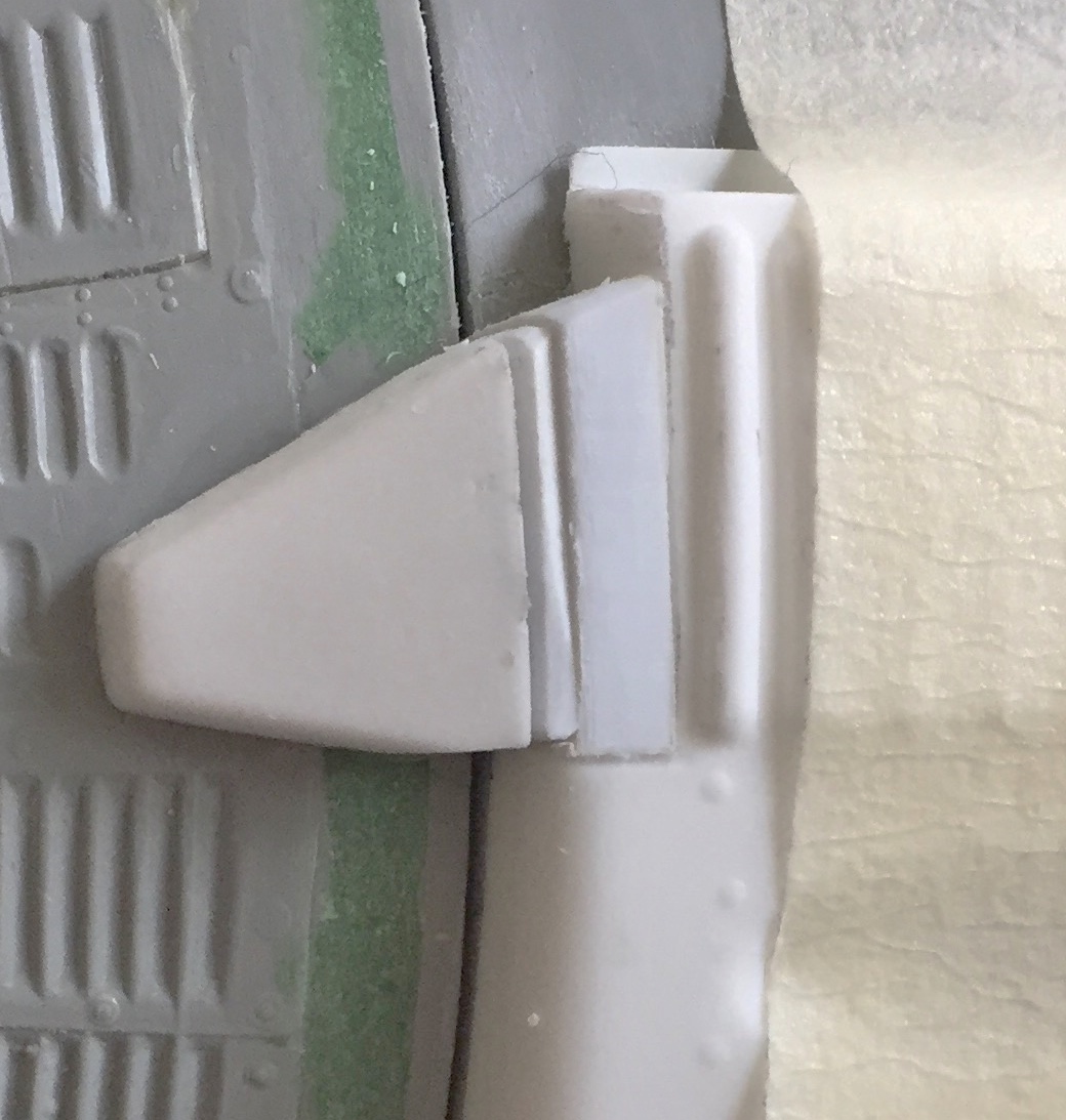
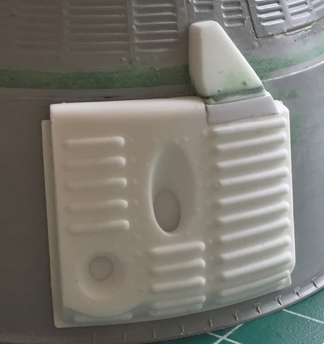
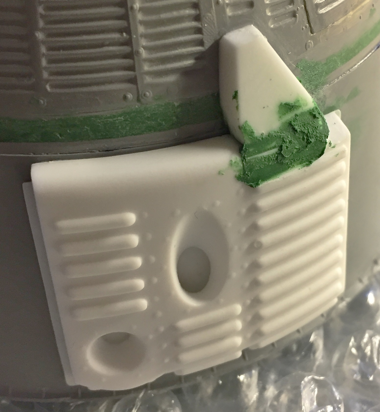
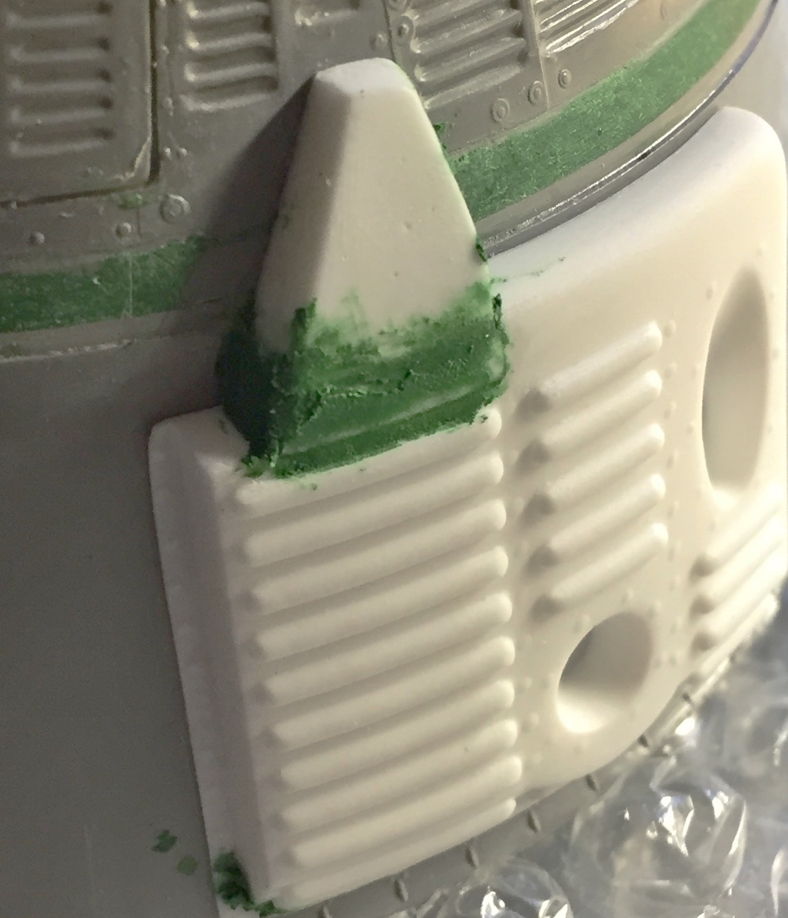
And one last thing (for now…I’m sure there will be others) that I really did not want to do. The fit of the nose cone to the OMS ring was as high as all the other fittings were not. I didn’t want to deal with the shingles that would be destroyed in fixing this fit. Yet I’ve gone to such lengths for other things, and people will probably look closely at that (quoth my Ego), so I don’t want them to wonder why I went to such lengths in other places and overlooked an obvious fit problem. Well, excrement…let’s just fix the sodding thing. I added putty and worked it until the fit was correct:
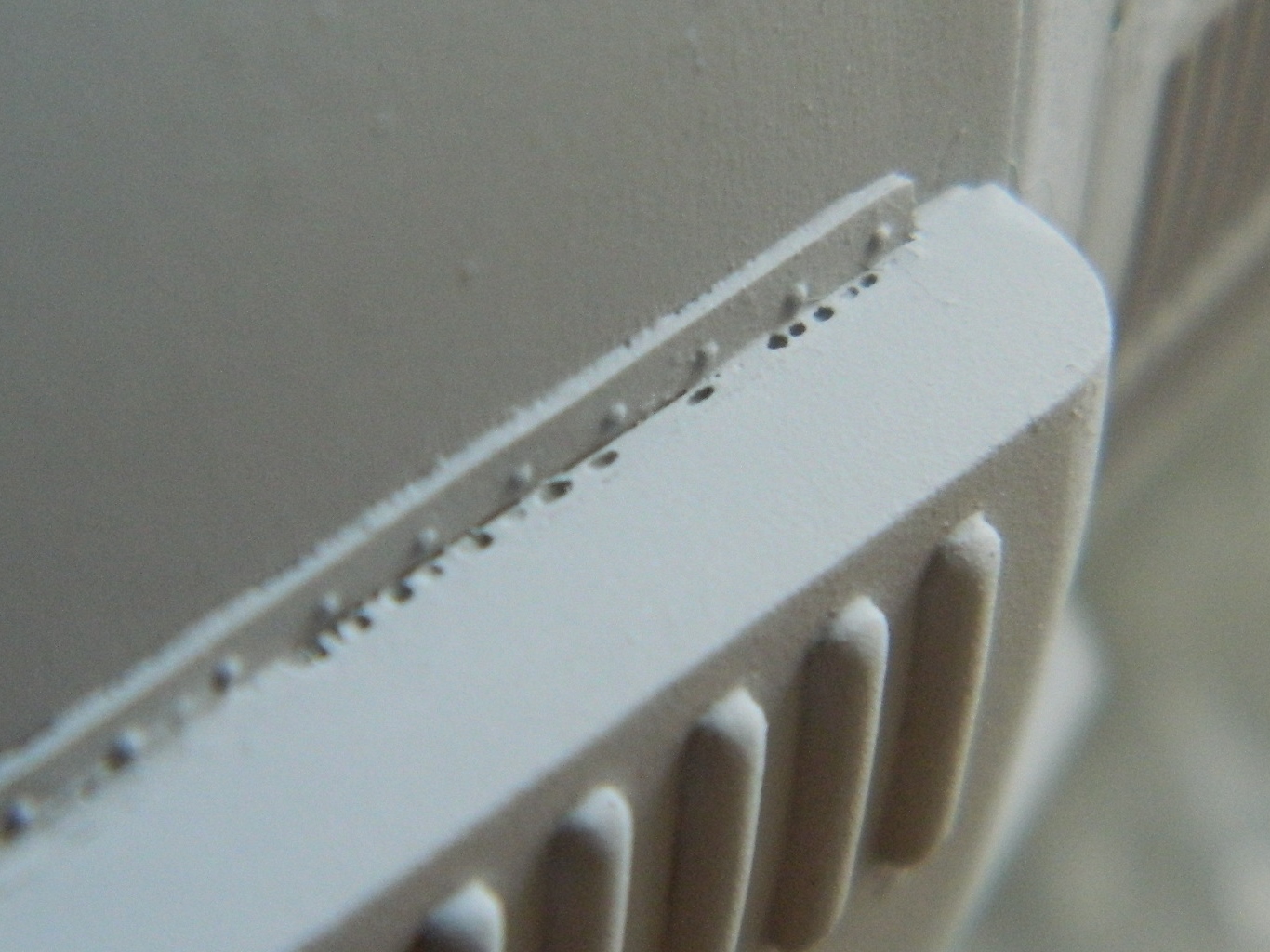
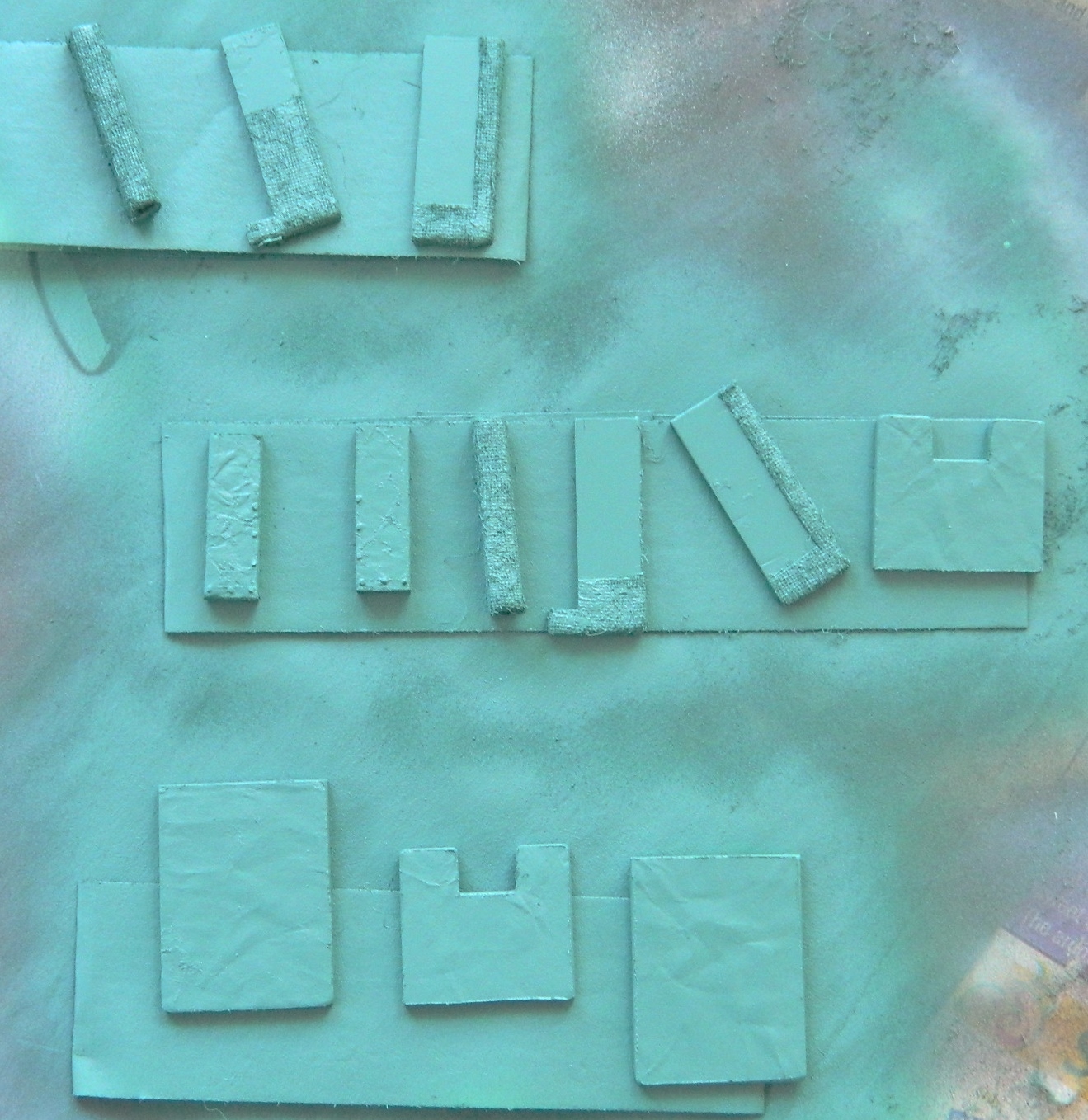
To put the shingles back, I had to make them. A strip of .005″ (.127mm) plastic with more .005″ (.127mm) plastic cut to the dimensions of the existing (and unmolested) shingles had to be made:
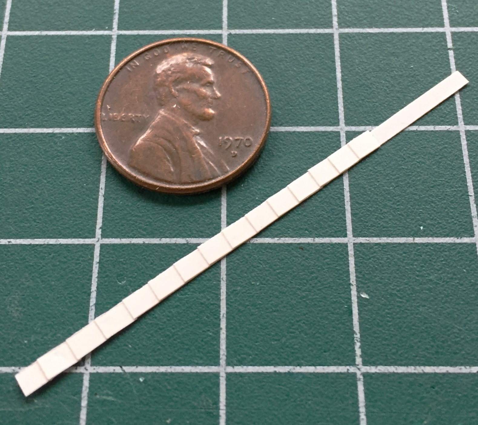
Then the shingles were cut away from the strip and added to the nose. They stuck out too far from the other shingles, and I did not want to replace all the shingles, so those got sanded until they were closer to the correct height (if I sand them any more, they’ll probably vanish). Once done, I added resin rivets:

There’s only one more part to add to the capsule, the horizon sensor (which still needs some work before it’s ready to go on), before it’s ready to paint.
I’m generally not superstitious but Eris and Loki do pay far too much attention to me, so I’m a little trepidatious saying, y’know…I just might, might, MAYbe, have this done in time for the show at the end of April!
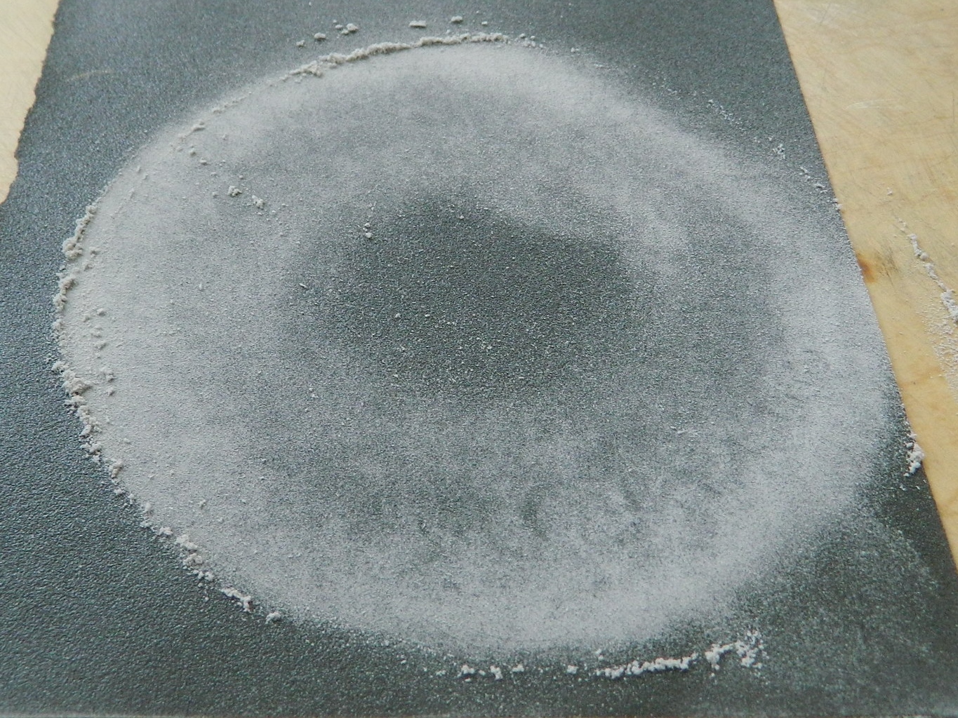
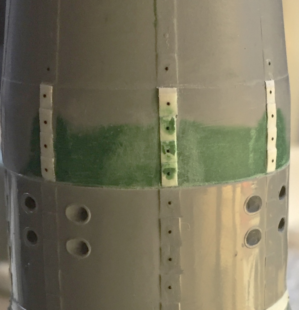
To paint, some things need to be masked. Masking can be trying but one simply cannot do a decent paint job without it. (An adequate, or even somewhat poor, build can be saved by a sterling paint job; a great build can be ruined by a bad paint job.) I tend to have difficulties masking small round areas. An easy fix for that is to use liquid masking (various manufacturers make it). I apply it with a toothpick and move the masking agent to the edges of what I want masked. A really great feature of liquid masking is that there’s no bleed-through under the edge of the mask. The white over the artificial horizons is the liquid mask (which turns clear when dry):

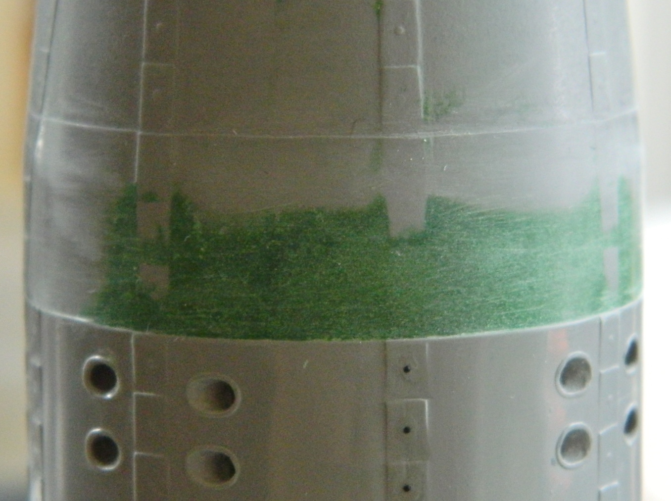
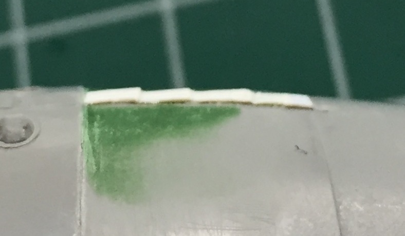
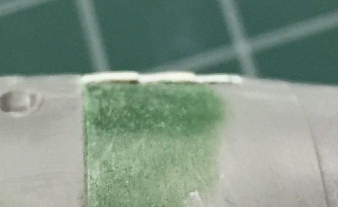
While I was waiting for the mask to set up, I mixed what I thought was an adequate sage green:
Uhm…no. Not even close. So I added A LOT of medium gray to the mix and ended up with something better:
There are pouches on the sides of the center console:

To replicate them I used standard household aluminum foil:
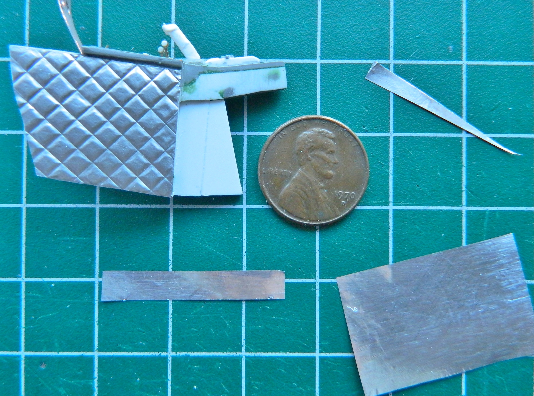
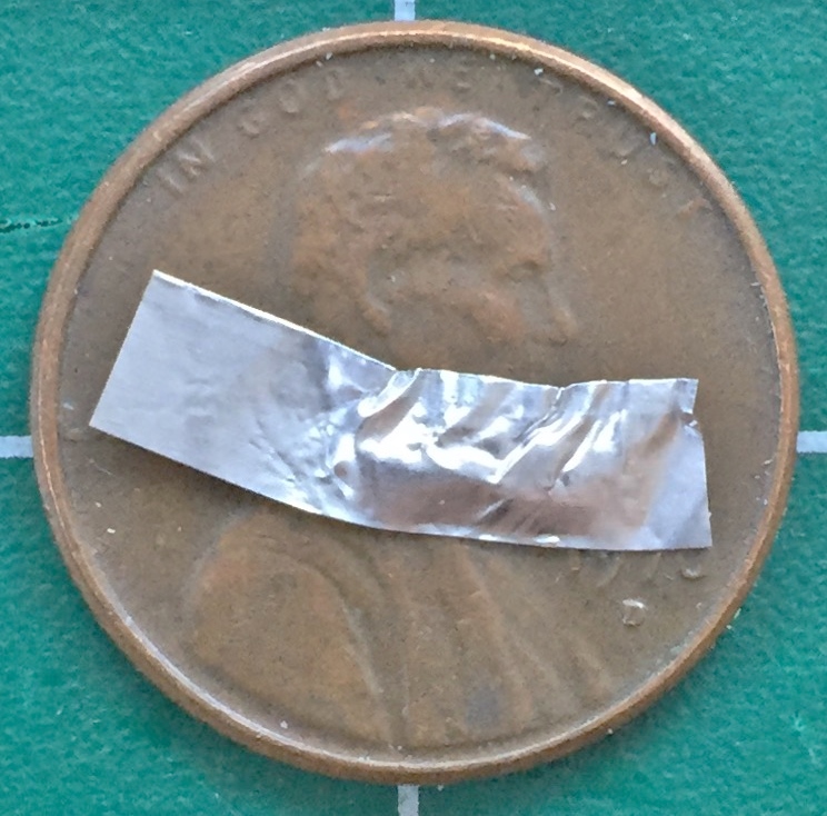
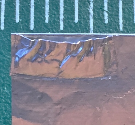

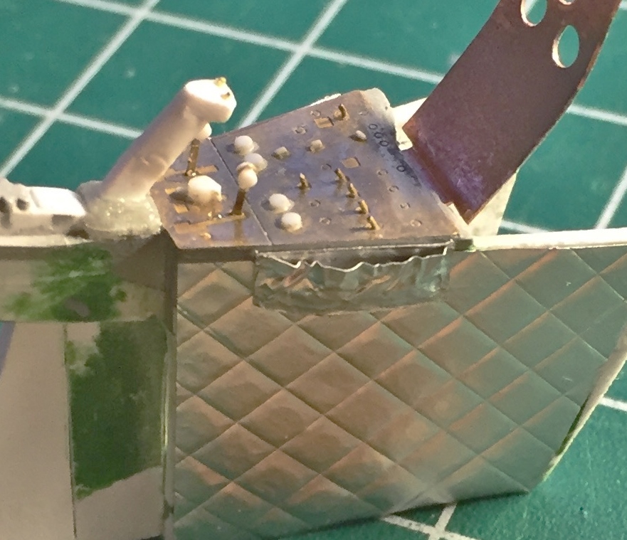
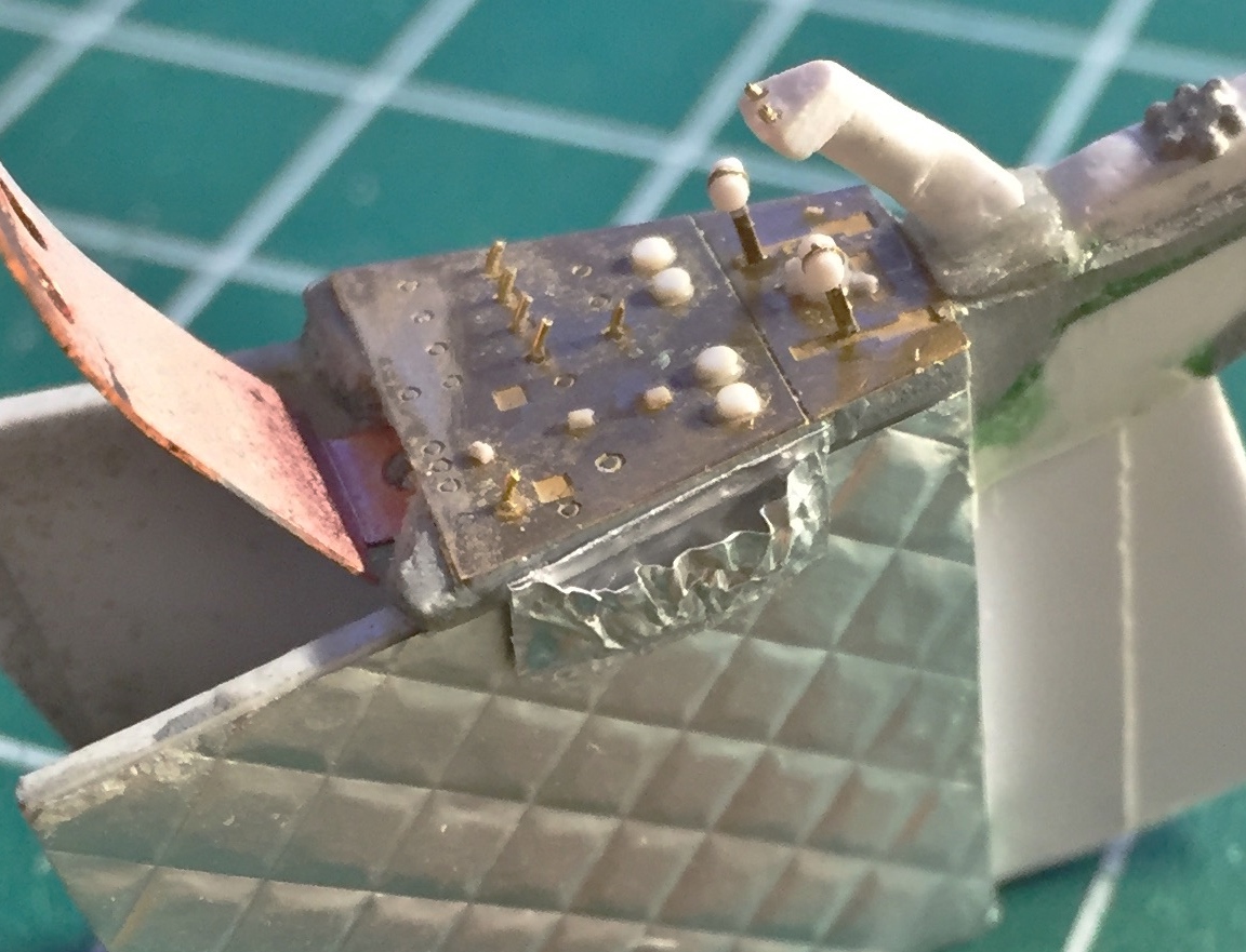
I’ve mentioned the miserable fit of this kit’s parts before. Check out how “well” the insides of the hull meet the edge of the cabin tub:
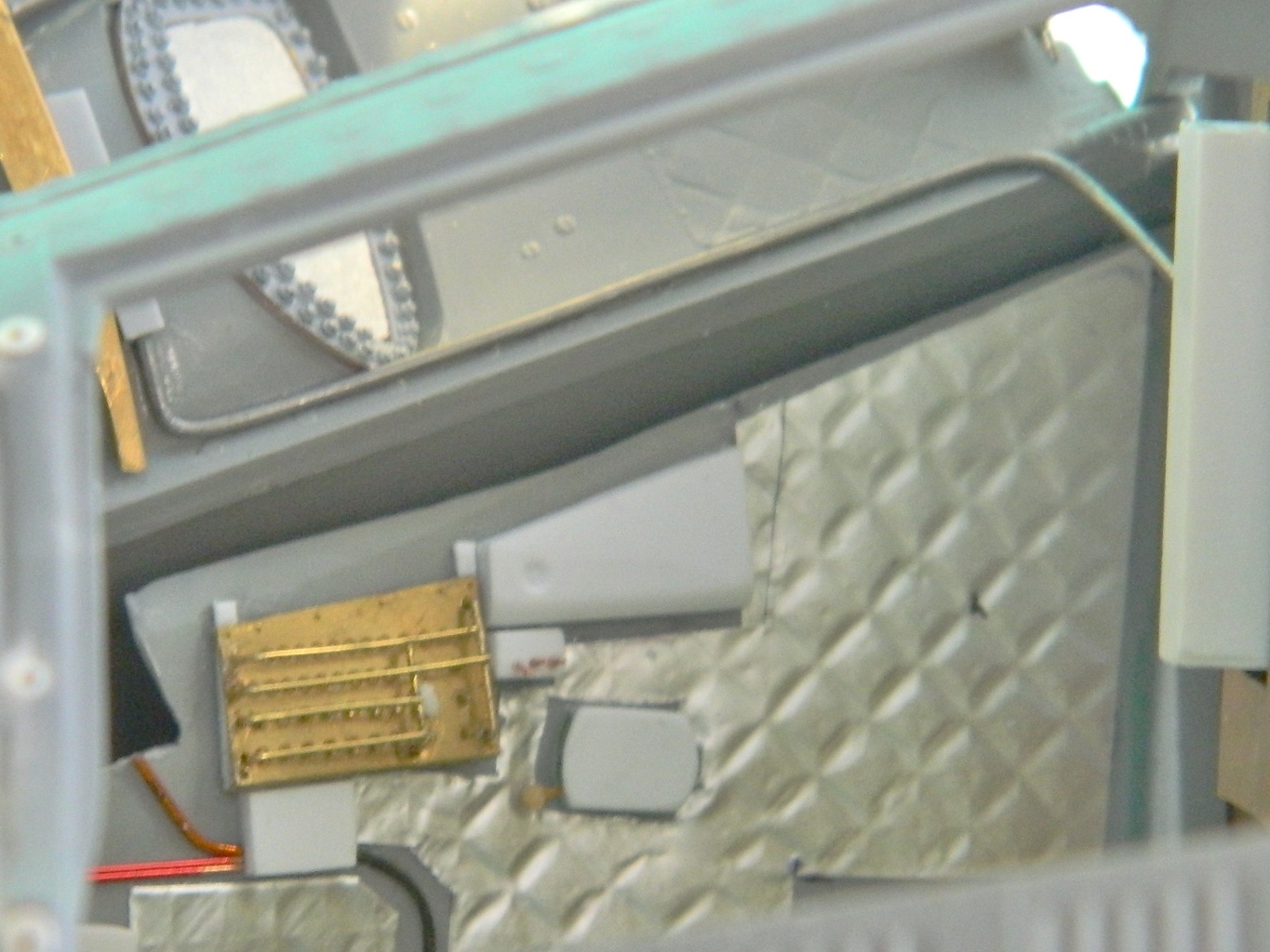
Thankfully I noticed something in reference photos that saved me a metric butt-load of hassle trying to extend the cabin wall to meet the exterior. There were what I can only assume were sun screens that zipped over the inner opening of the hatch. When they weren’t deployed, they were rolled up along the lower edge of the hatch…just where I have a large gap I need to fill! I used the paper towels one finds in public restrooms to make the sun screens. (What I like about this type of paper towel is that there is no cutesy texture embossed into its surface.) So step one is to dimension the towel and cut it:
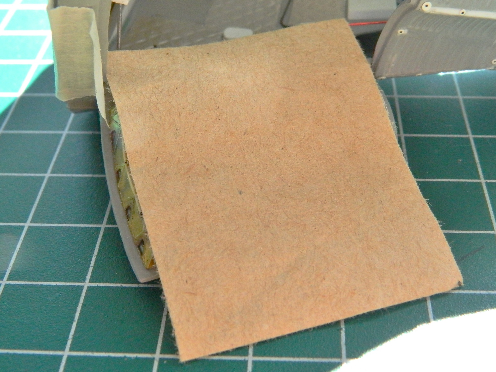
The paper towel is cut to its rough shape then dipped in diluted white glue, folded, tied, and set aside to dry:
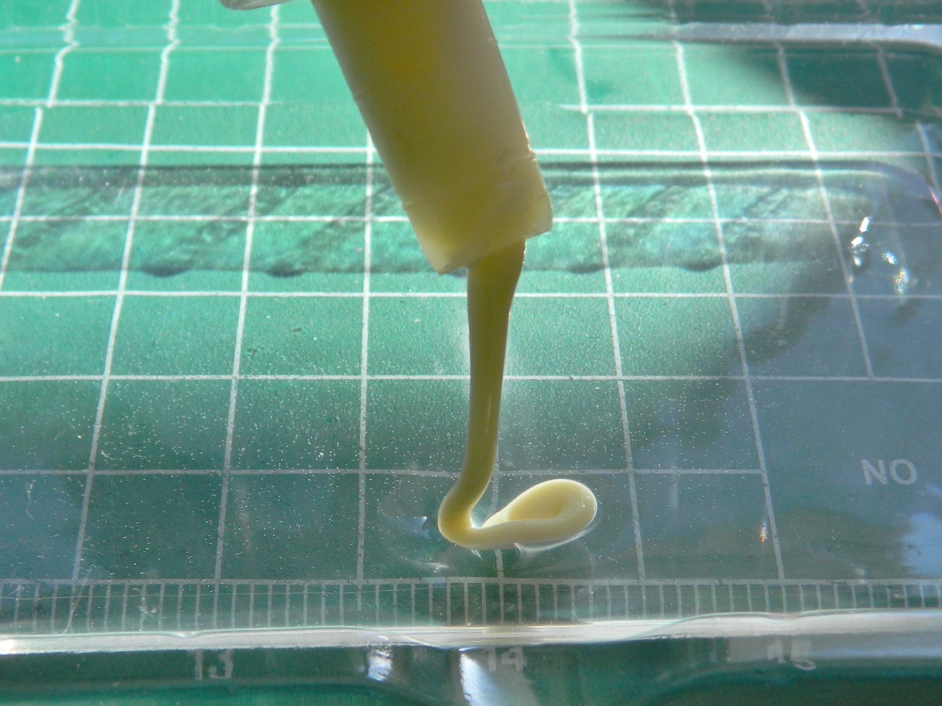


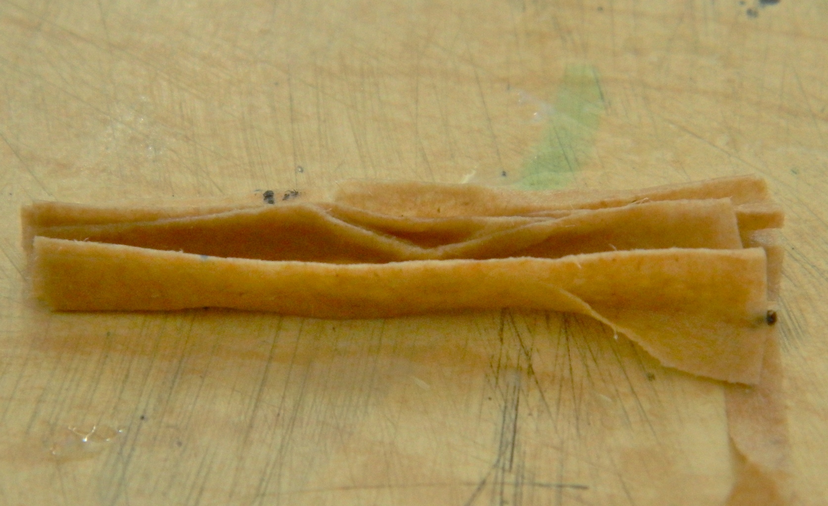
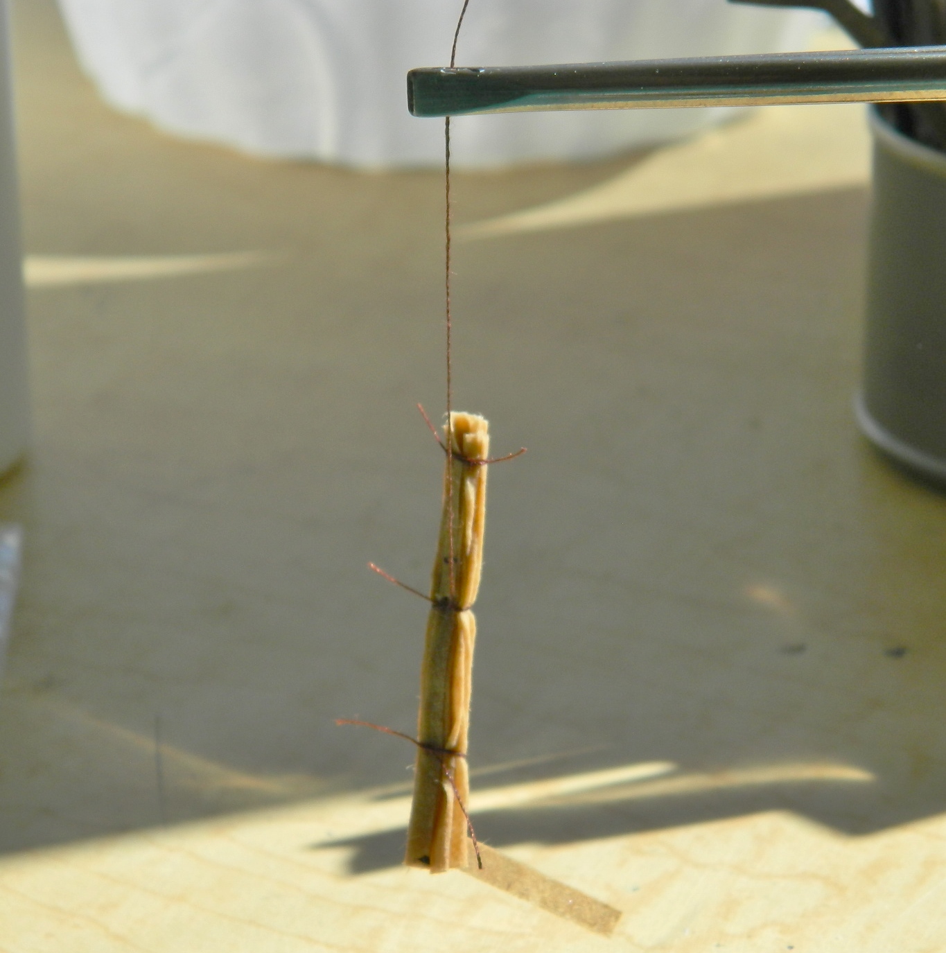
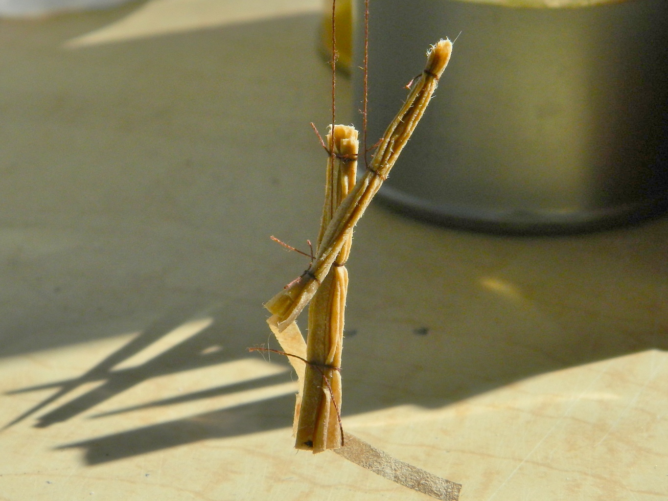
I mixed medium gray with white and thought I’d gotten the shade correct…but I didn’t. Too dark. So I mixed more white into the gray (a lot more white) and kept checking to see when I had it correct:

Once the shade was correct, everything gray (and that’s most of the cockpit) got resprayed. I started adding the black details next. A frequent question I get is how I manage to paint such small details. As a smartass, I tell everyone one, “carefully.” But the way I actually do it is like this…
The first pass of paint is to cover what I want to be the color I’m using. Yeah, I try to “stay between the lines,” but that doesn’t always work (in fact, it rarely works):
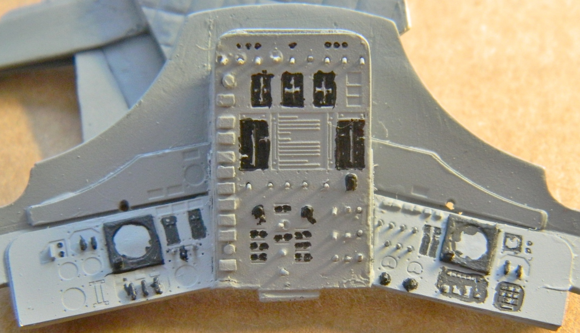
Once the paint I just laid down is touch dry, I go back with a very small brush and cover what isn’t between “the lines” which in this case was gray. A technique I use to bring out (or add) small contrasting color details is to use colored pencils. I can get them to a very sharp point and they’re MUCH EASIER to control than paint, and that’s how I did the details below. I also shot the panel with clear and added decals for the gauges (turns out that though this model is 1/24 scale, the 1/48 scale instrument face decals I have are just what I needed as well as being the correct size!):
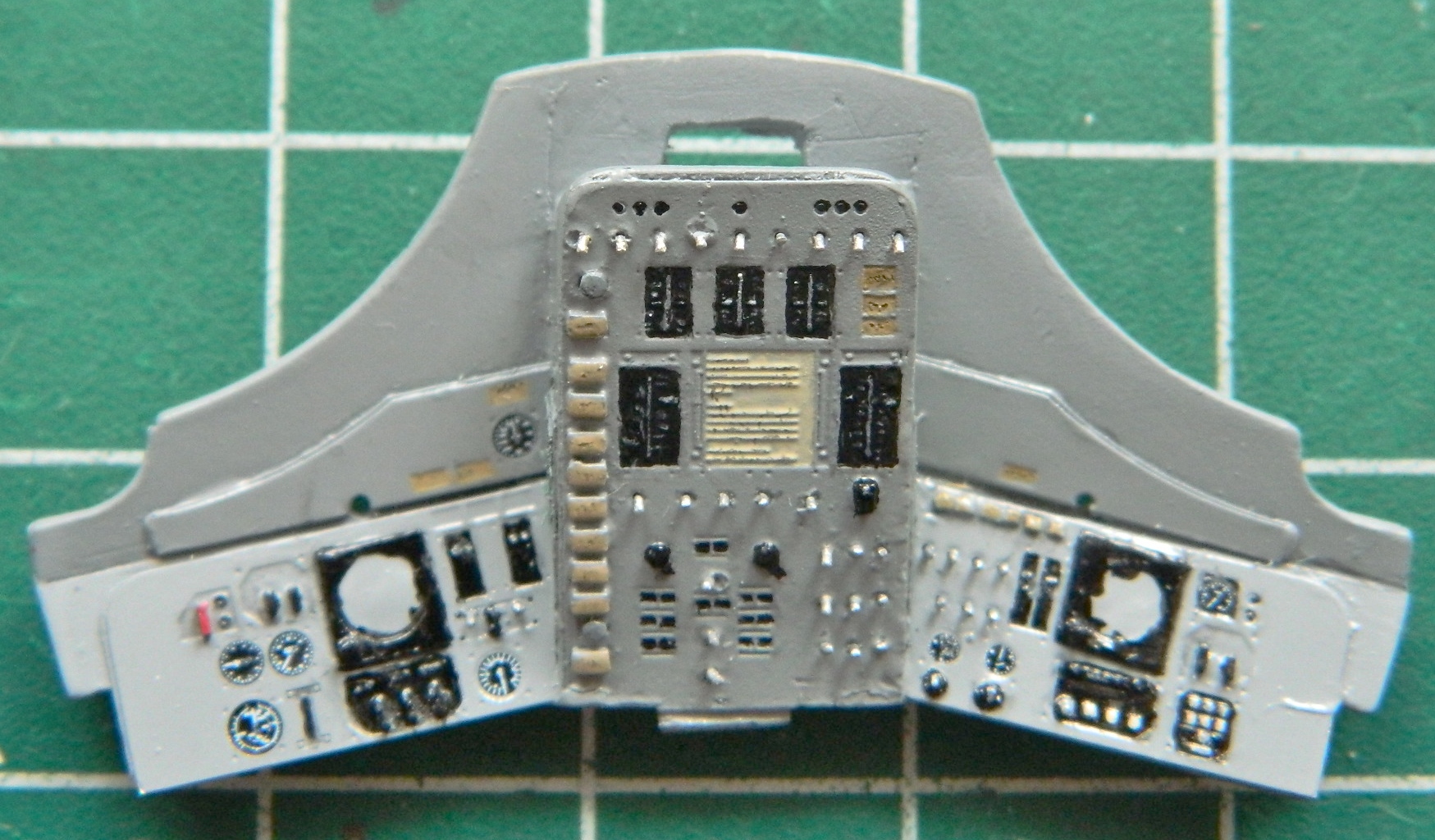
Once the decals dried thoroughly, I put a drop of clear gloss paint over the faces to replicate glass. Then I peeled the formerly-liquid mask of the artificial horizons, added the grab bars to the sides of the central panel, and ended up with this:

Yeah. That gets it…
Since a person can’t just “put something down” in micro-gravity, there has to be something to keep things in place. That something is Velcro and it’s pretty much all over the inside of the cabin. I used the same paper towel material I used for the sunshades for Velcro (the superglued pantyhose was out-of-scale). Below, the bare paper towel is on the left of the panel, the painted paper towel on the right (and I’m not satisfied with using the light gray for the Velcro…it looks more tan to me so I’ll be fixing that before assembly):
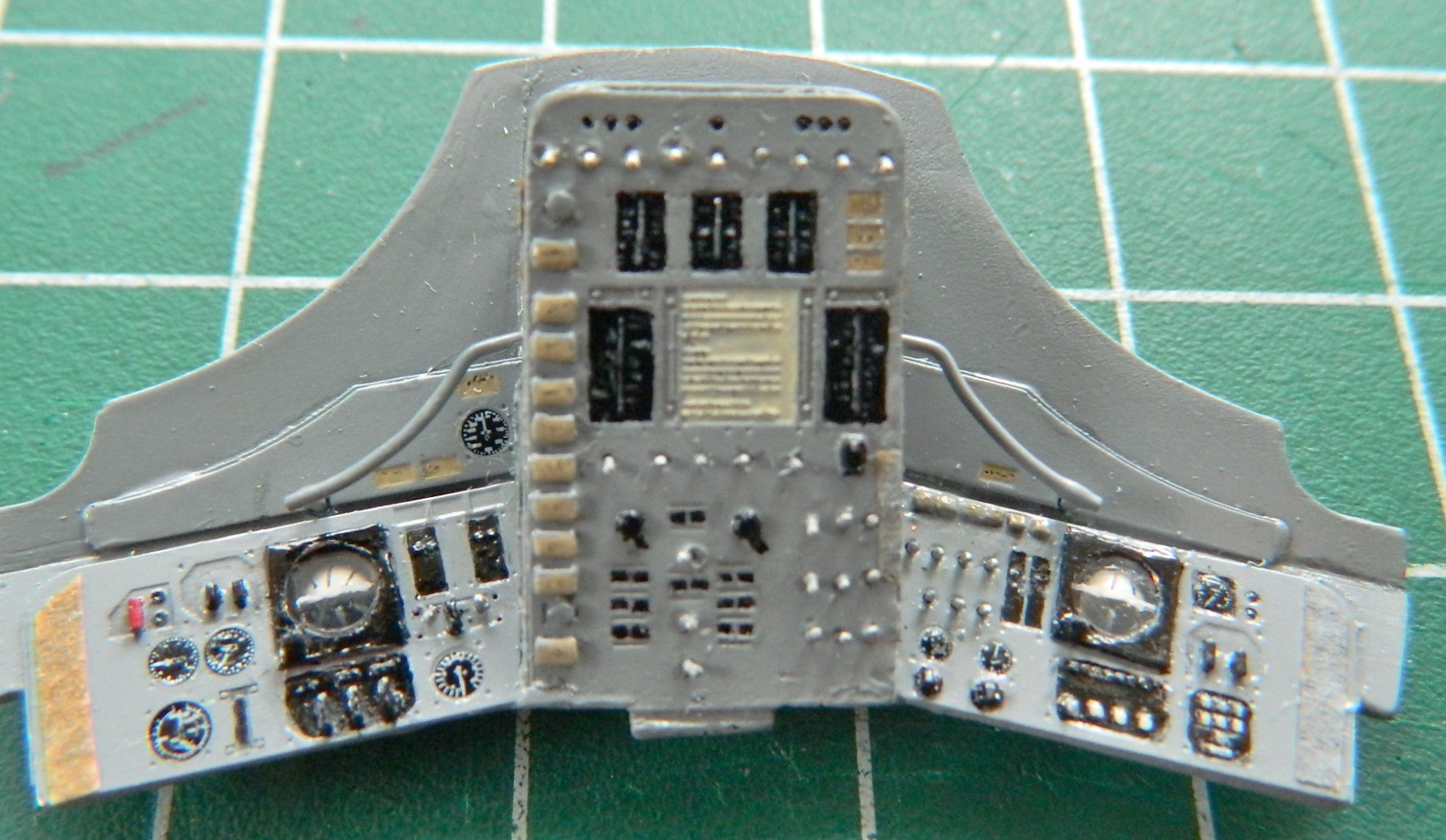
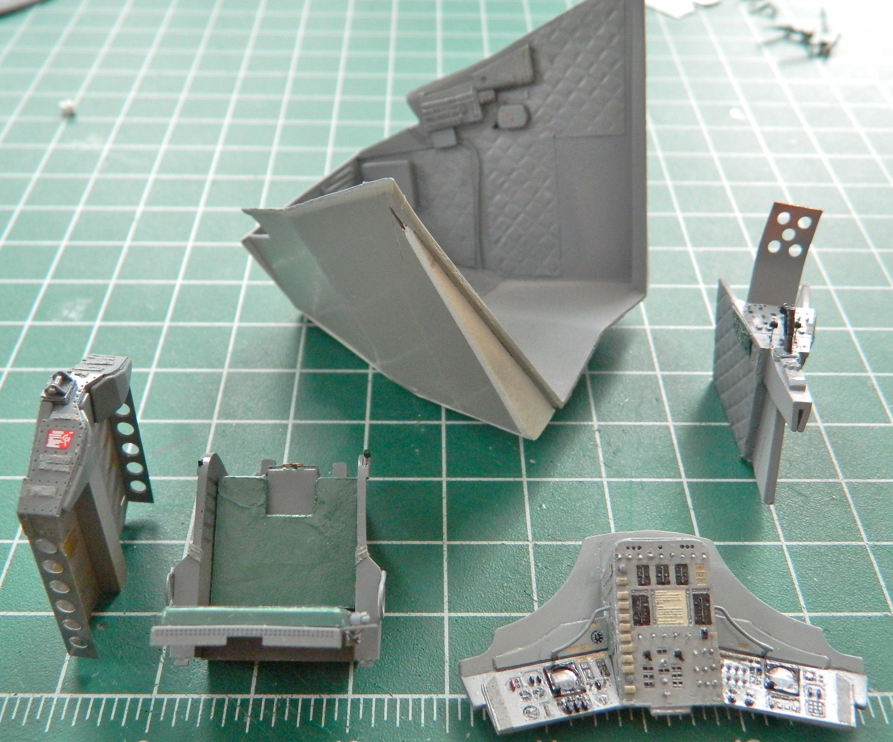
The last thing to add to the cabin parts are the oxygen hoses, get them in paint, and then I can start assembly!
With the brass origami folded, it was time to add it to the hatches. Well! The fit of the PE parts wasn’t exactly…well…exact. So I pushed and tweaked and finally got everybody to play nice with each other:
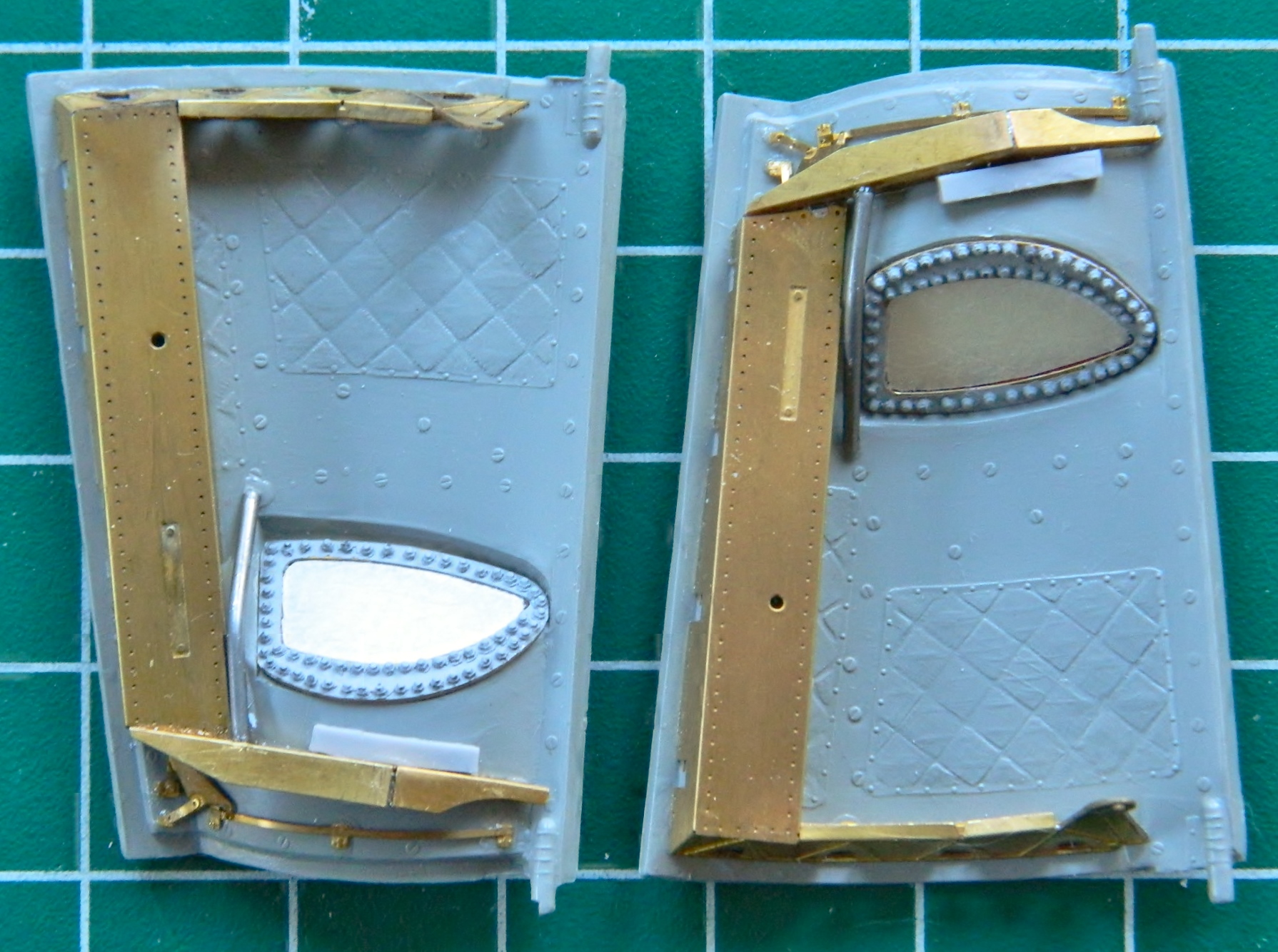
Setting those aside (a few more minor details to add before painting), I needed to perform an experiment to see if what I wanted to try would work. There are Velcro patches all over the inside of a Gemini spacecraft. I mean, one can’t just put something down in micro-gravity, so something needs to hold stuff in place, and that something was Velcro. And it is ALL over the interior, so I need some way to replicate that in scale. So cue the PANTYHOSE! Perfect texture, I just needed to see if I could stabilize the flex of the material and for that I used superglue. Worked just fine:

There is an equipment mount on the ceiling console of the cabin, so the mount and the boxes that mount there had to be made. I made the mount out of .010″ (.254mm) copper shim-stock, folded it, and then soldered it to the PE part (as well as adding a pull-switch to it):
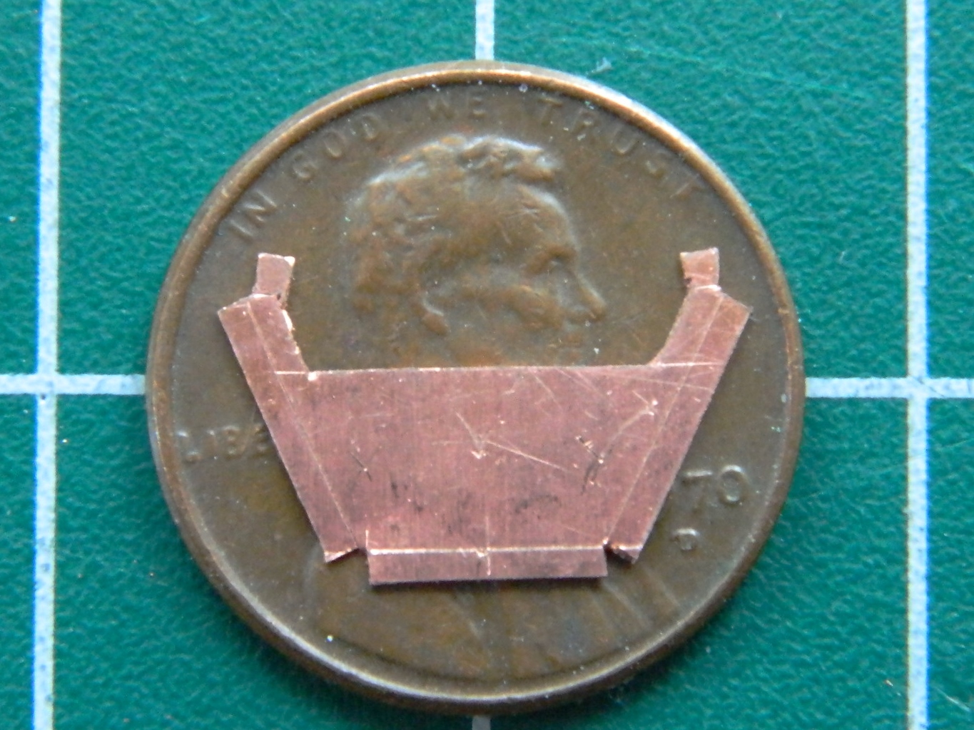

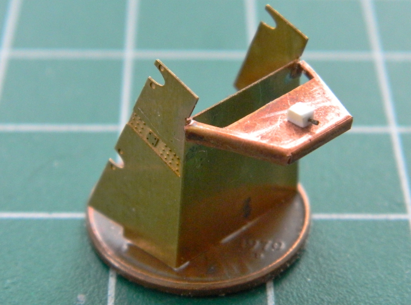
Then I made the boxes that get mounted to that bracket out of scrap styrene, added details, and glued them into position:

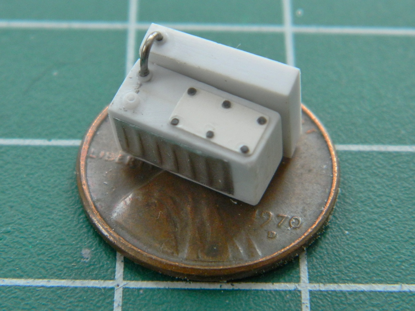

There were a few lines I could add now (the remainder have to wait until seats and gear containers are added):
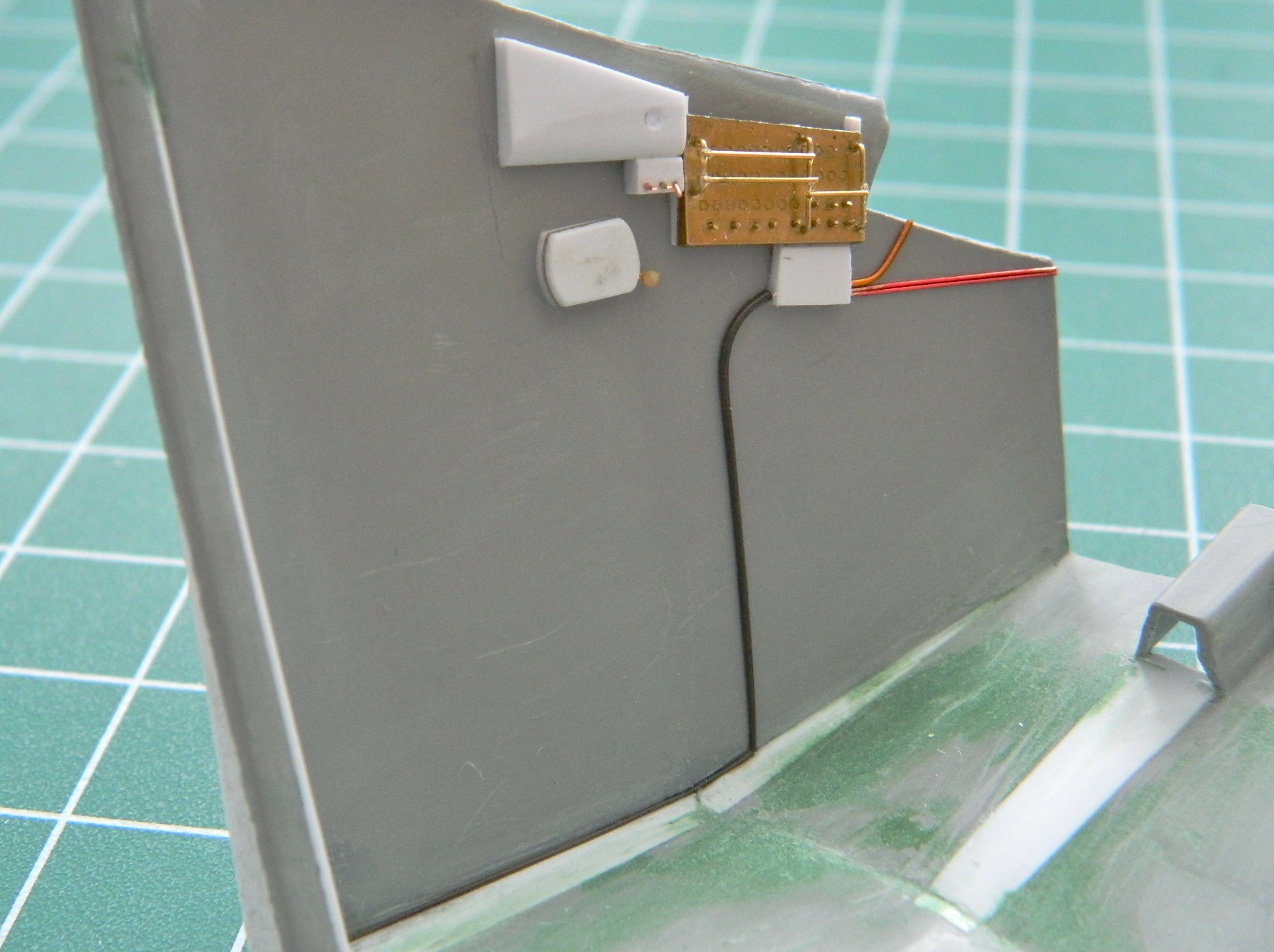
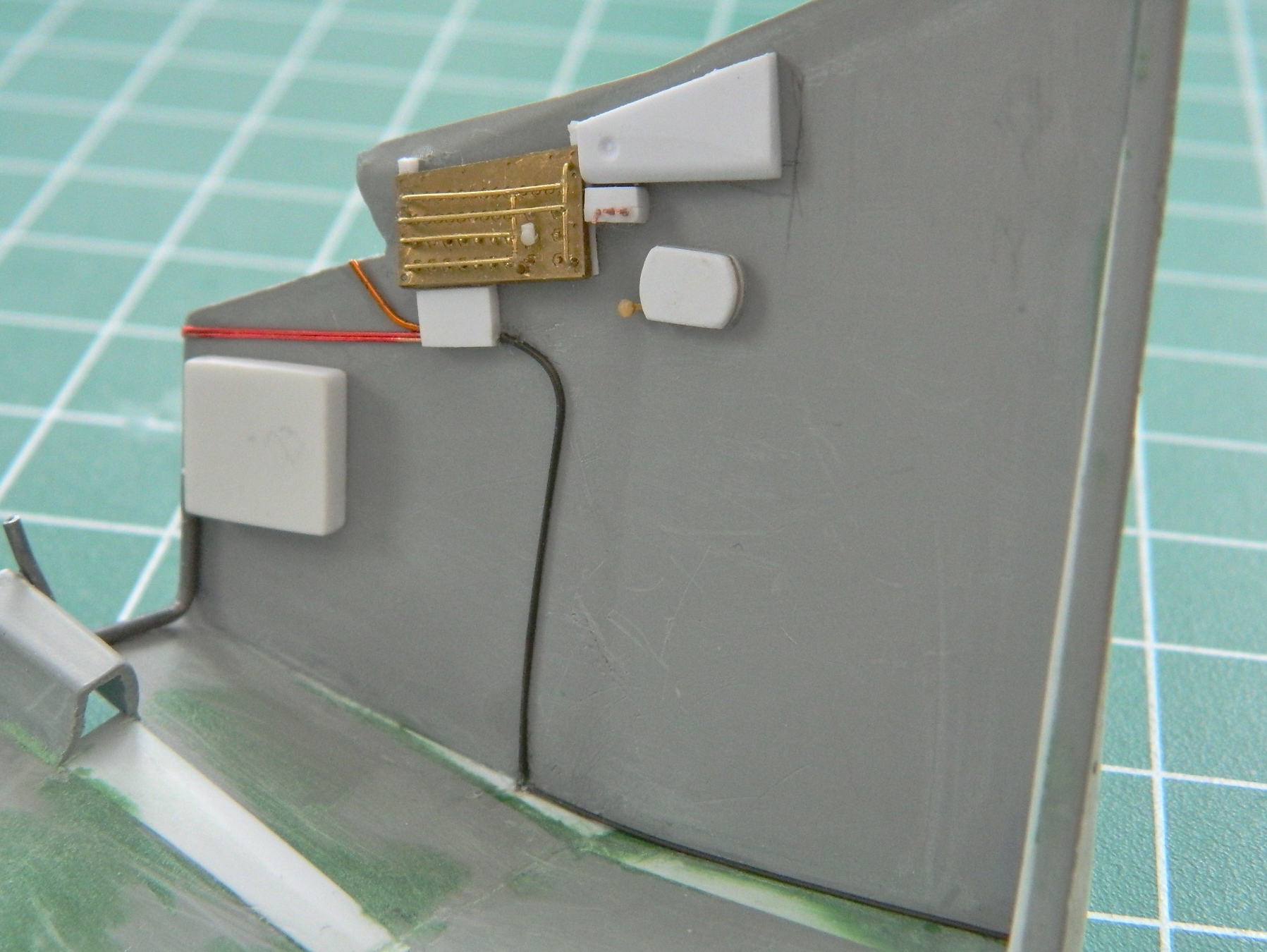
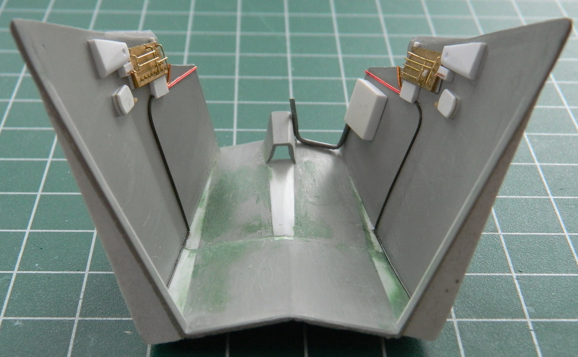
There were quilted pads lining the cabin. I replicated that with heavy (very heavy) aluminum foil that I tweaked for detail and superglued to the cabin walls and floor:

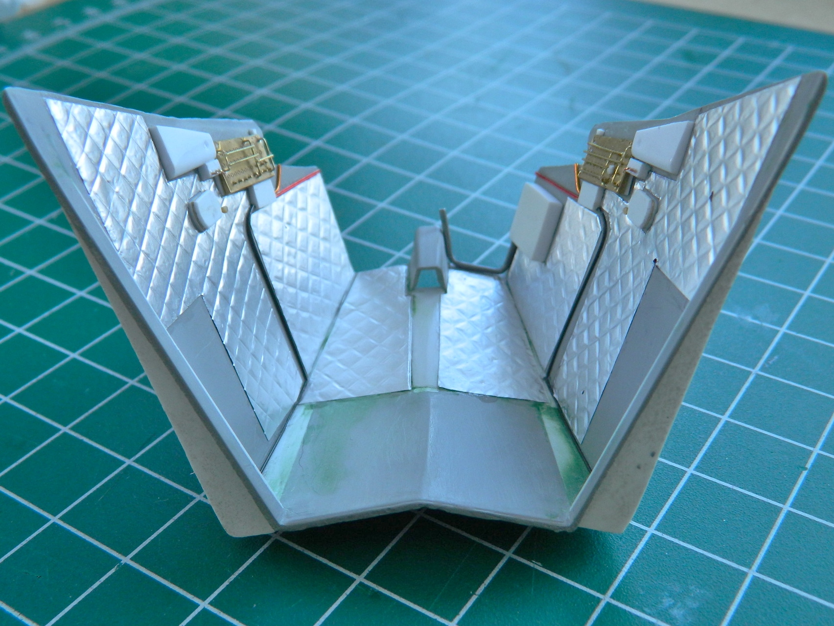
While I was supergluing aluminum foil, I added the corrugations to the front interior bulkhead:
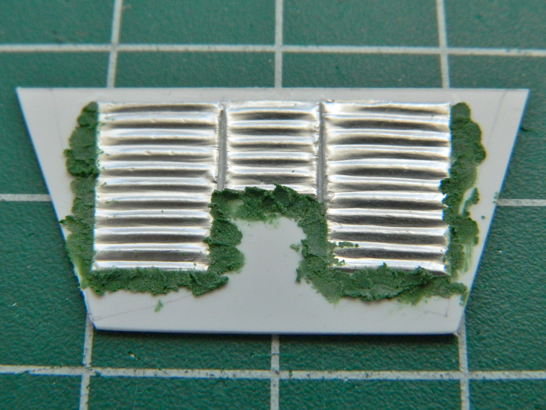
Then I dry-fit things and discovered that though the panel/console assembly will fit in the cabin, the console won’t fit between the seats. It sits too high:
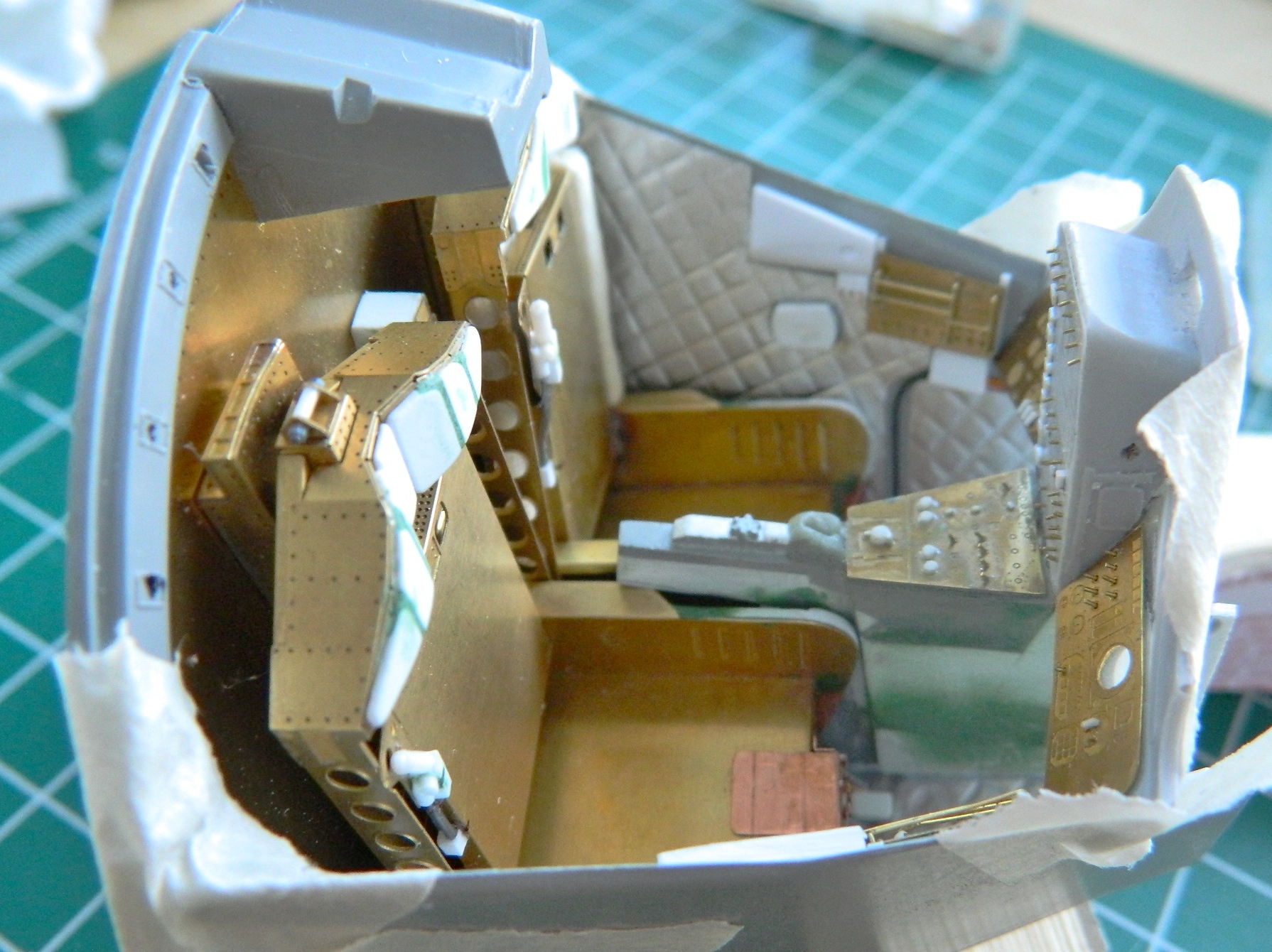
I sawed, filed, and shaved until the top of the console between the seats sit as low as it’s supposed to. Then there was another detail I needed to make. The command pilot (left seat) has an abort lever, it’s prominent, and it needs to be there. So I started making that:

There is a round knob that sits on top of the stalk. It’s large enough that a blob of white glue or several coats of superglue wouldn’t work. Then I remembered what happened to solder if it wasn’t touching a surface when the torch hits it. It forms a ball! Okay…let’s try that! The first one was too large, the second one was just right:
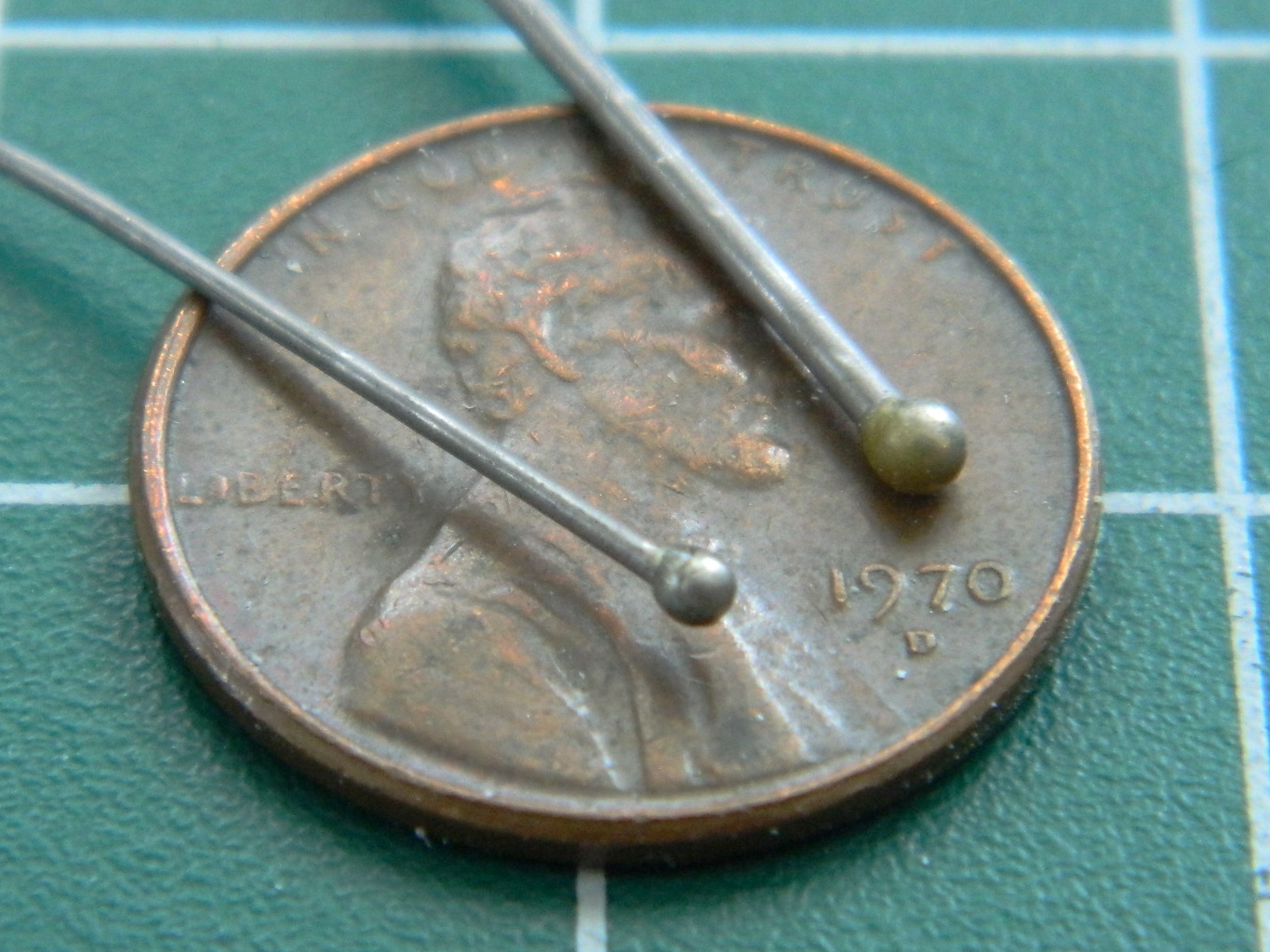
Okay…that was the easy part. Now I have to cut the ball off, drill it to fit the shaft, and glue it on:
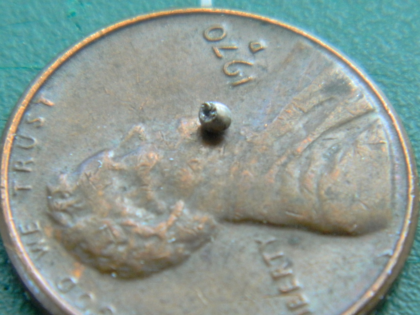
Well, THAT was fun! But in place (well, not exactly in place…it’s supposed to fit between the outside corner of the seat and the cabin wall, but there just isn’t the space for it, so I put it where it is), it looks good:
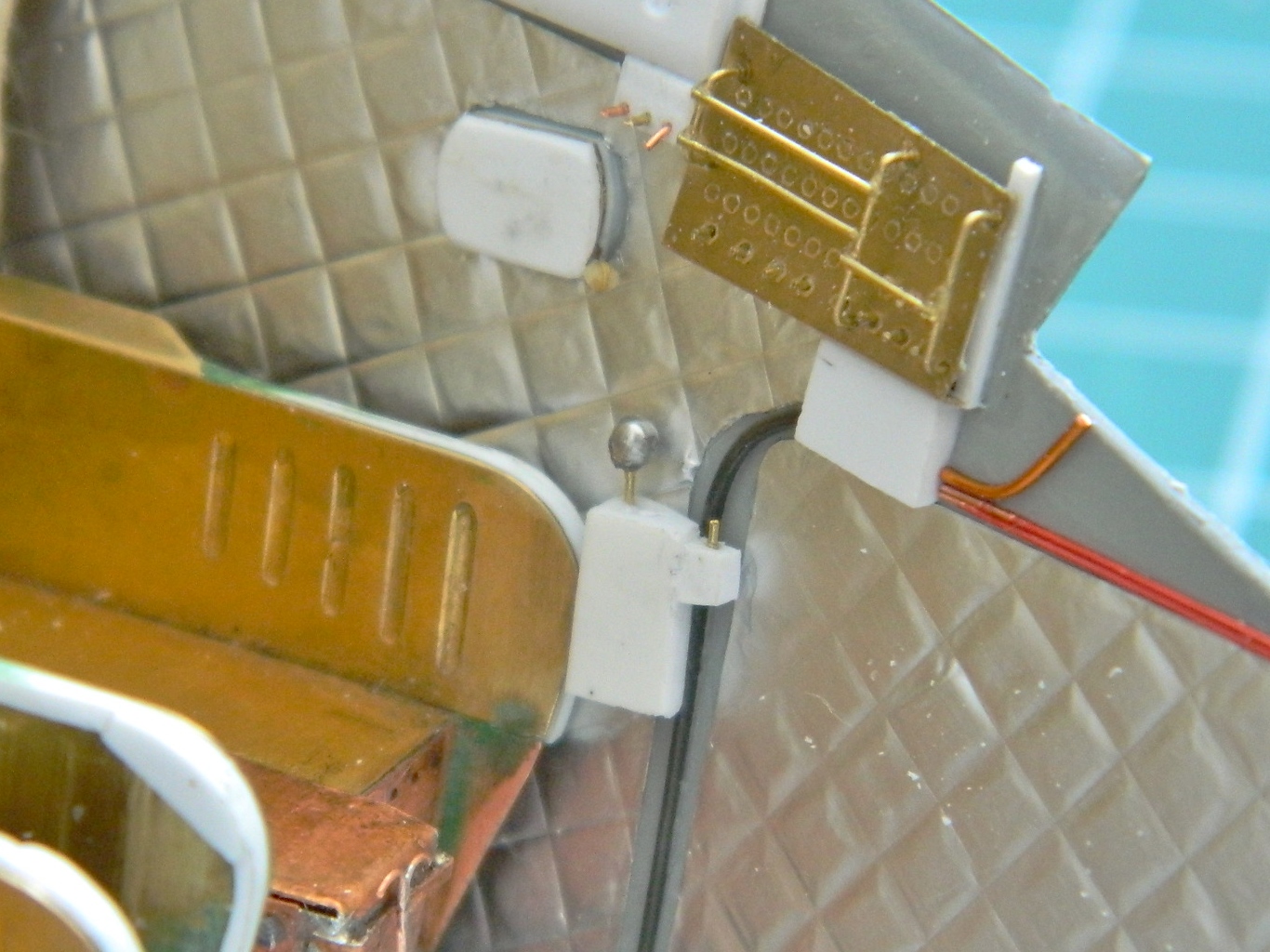
There were a couple of small levers that had to be added to the seats before paint could be applied and those were added:
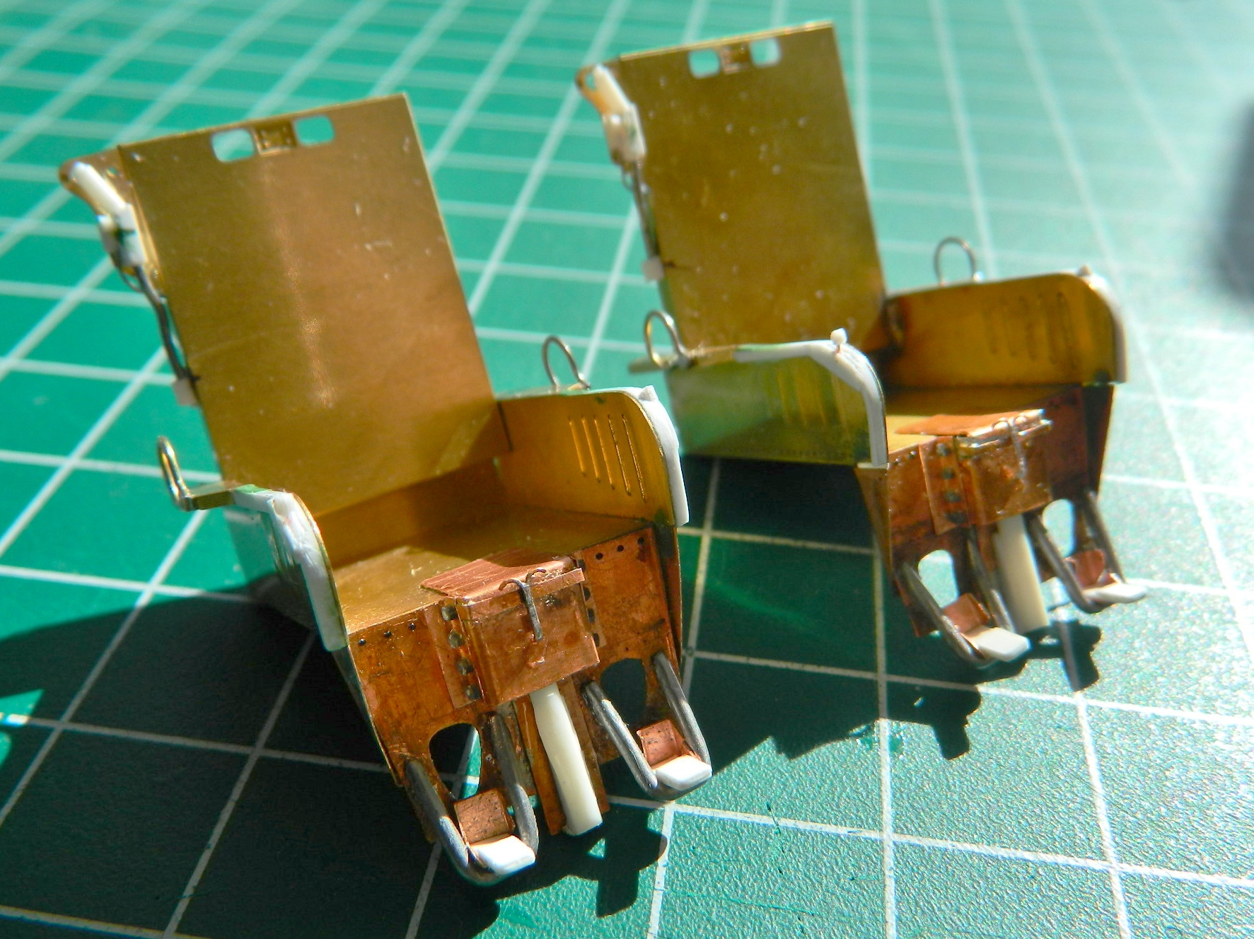
And then it was time to start work on the main instrument panel. First step was to paint the balls for the artificial horizons:
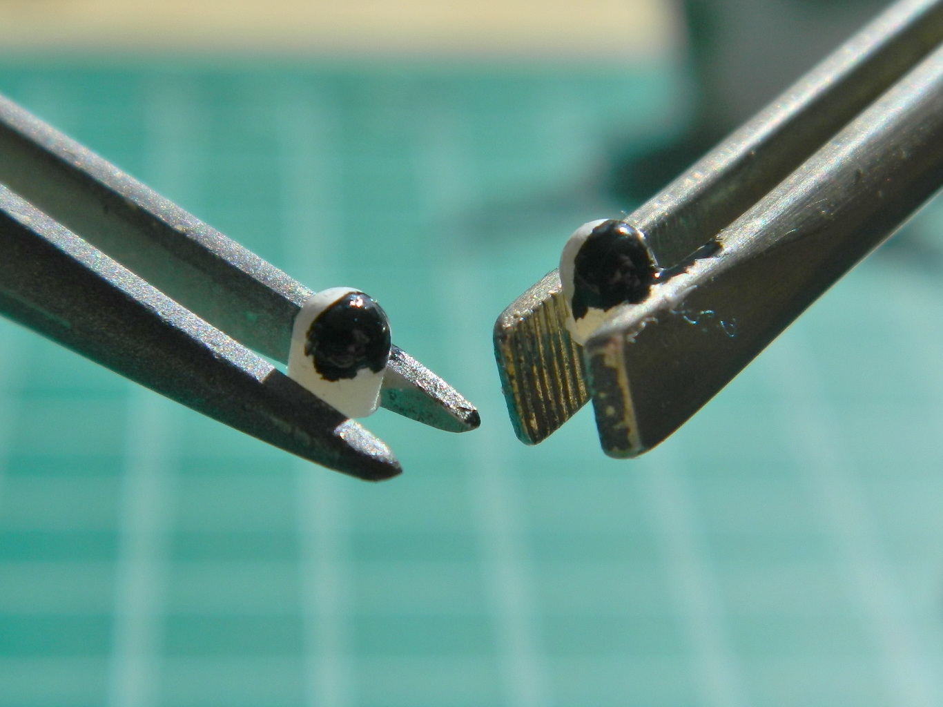
While the paint was setting up, I painted (several times…it was a BITCH to get right) the reference markers on the inside of the gauge faces:
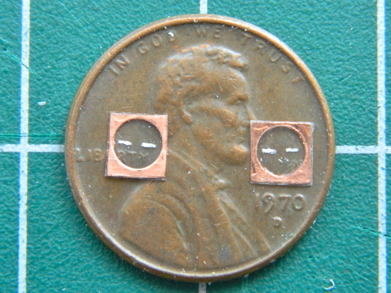
And speaking of “BITCH to get right,” there are the markings on the balls. I tried colored pencil. Nope…didn’t work. I tried slicing decals very thin. Also didn’t work. So then I took my smallest brush and tried painting the lines on. Ta da:

So, muttering a few prayers (and a LOT of begging) to whatever forgotten gods there are/were/will be, I glued the balls into the holes and added the face-plates of the gauges:
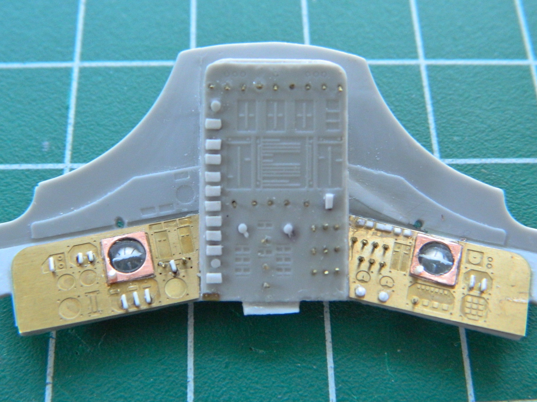

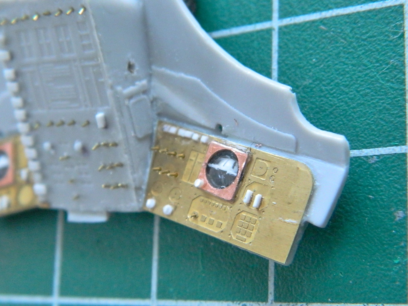
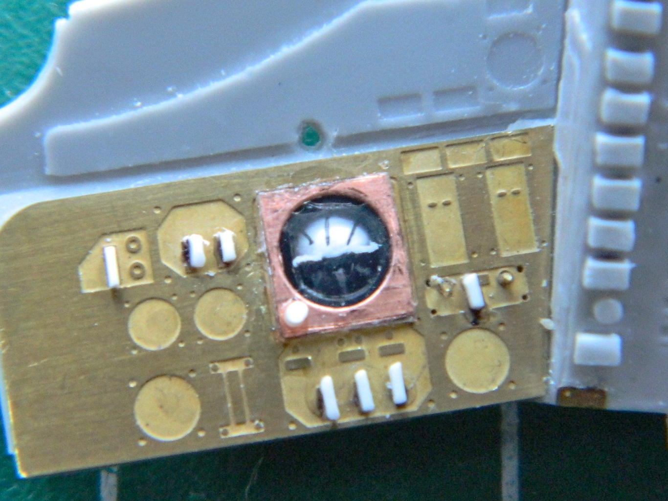
SO much better than how it started out:

And it wasn’t until I saw how it turned out that I realized how concerned I was about this. I’ve never done something like that before and though logic said it should work, I wouldn’t know if it would until I had them done. AND IT WORKED!
So now we’re closing in on painting!