Gemini (Revell) Build #9 – Fixing exterior details, adding washers & rivets, starting work on hatches
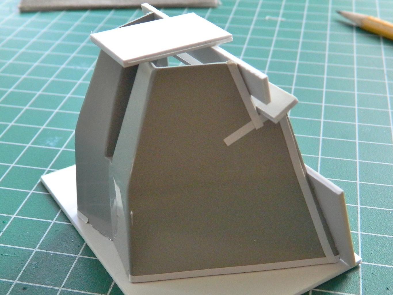
Seeing the outer part of the capsule sitting there on the workbench with the nose attached incorrectly bothered me so it was time to fix it. Sometimes in order to create, one must first engage in destruction. Step one, saw off most of the old nose:

That allowed access to where the part was glued so that I could begin what I thought would be a long time of carefully removing what I didn’t want there anymore while still leaving enough to attach the new nose. Sometimes it’s good to be incorrect. It actually came off relatively easily.
Then it was a matter of getting the attachment area fitted so that the new section fit better than it didn’t:
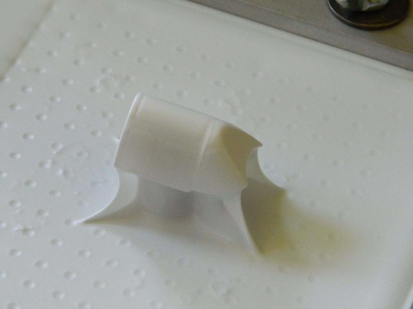
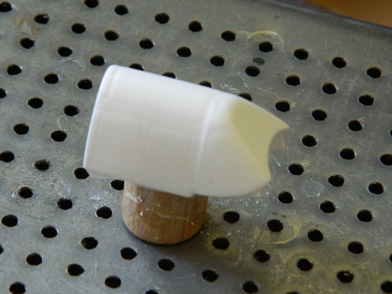
With that taken care of, there were a couple of things I wanted to do to the new part. I glued the two halves together and reworked the thruster nozzles. This is what the kit provided:
I experimented on the old part to see if it was worth drilling the nozzles out and replacing them with tubing or if drilling them out would work better. Yeah, the tubing was better, but the amount of work required to get them all identical and properly aligned would probably have taken days to accomplish. Drilling the nozzles out was certainly acceptable:

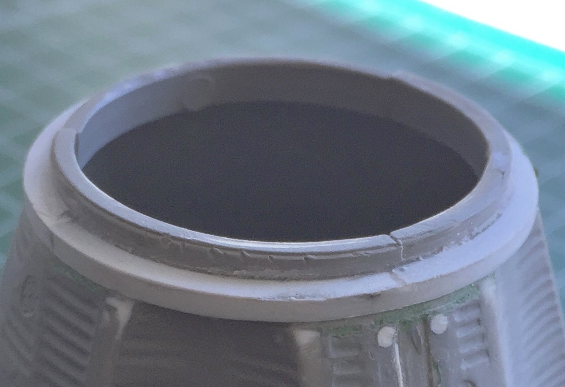
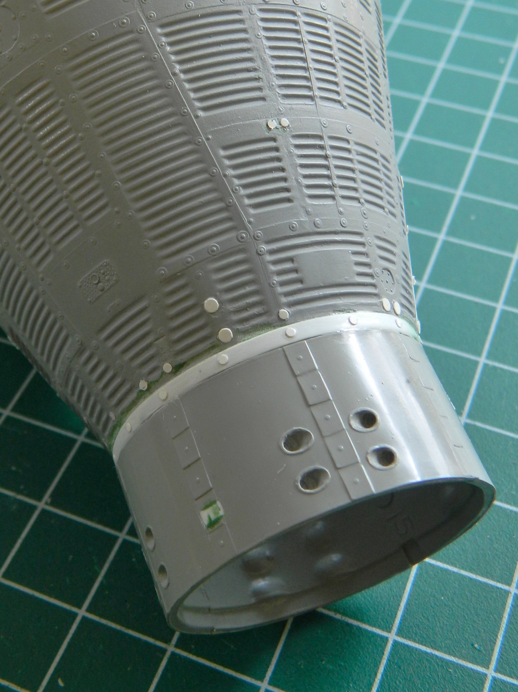
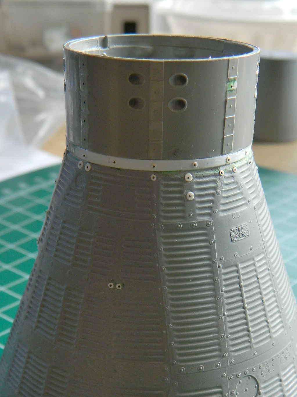
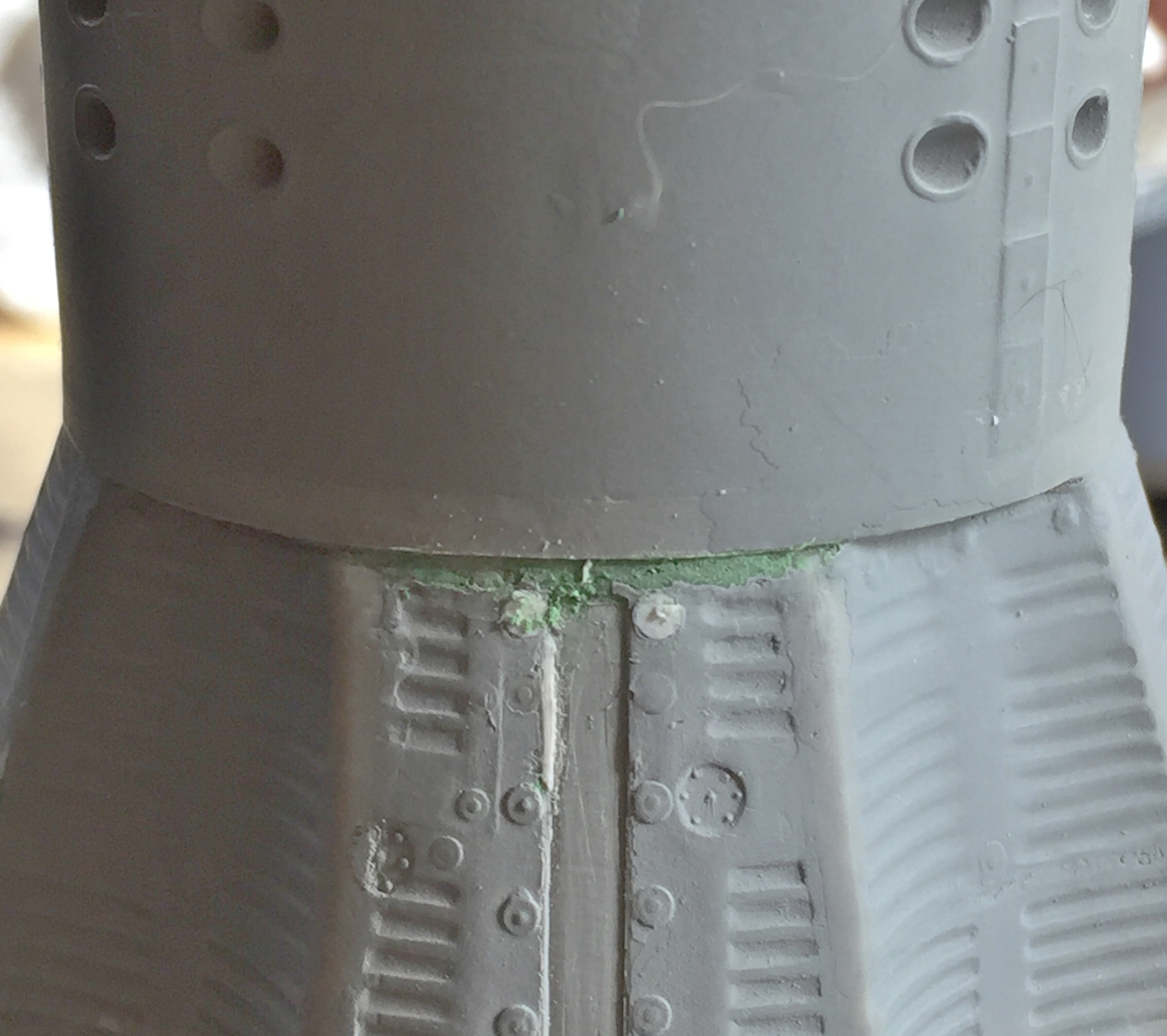
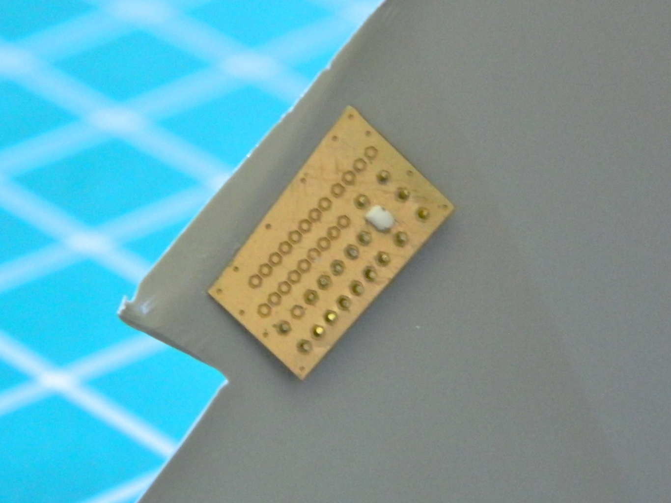
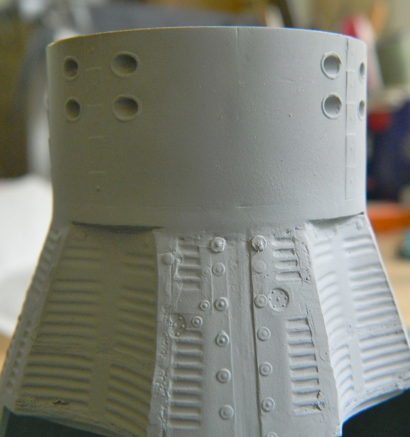
There’s a locating hole on the side of the collar for an incorrect module to be mounted at. Even if I was going to use that incorrect module, the hole that was supposed to locate the attachment point was 90 degrees off, so I stuffed it with a piece of plastic and filled it:
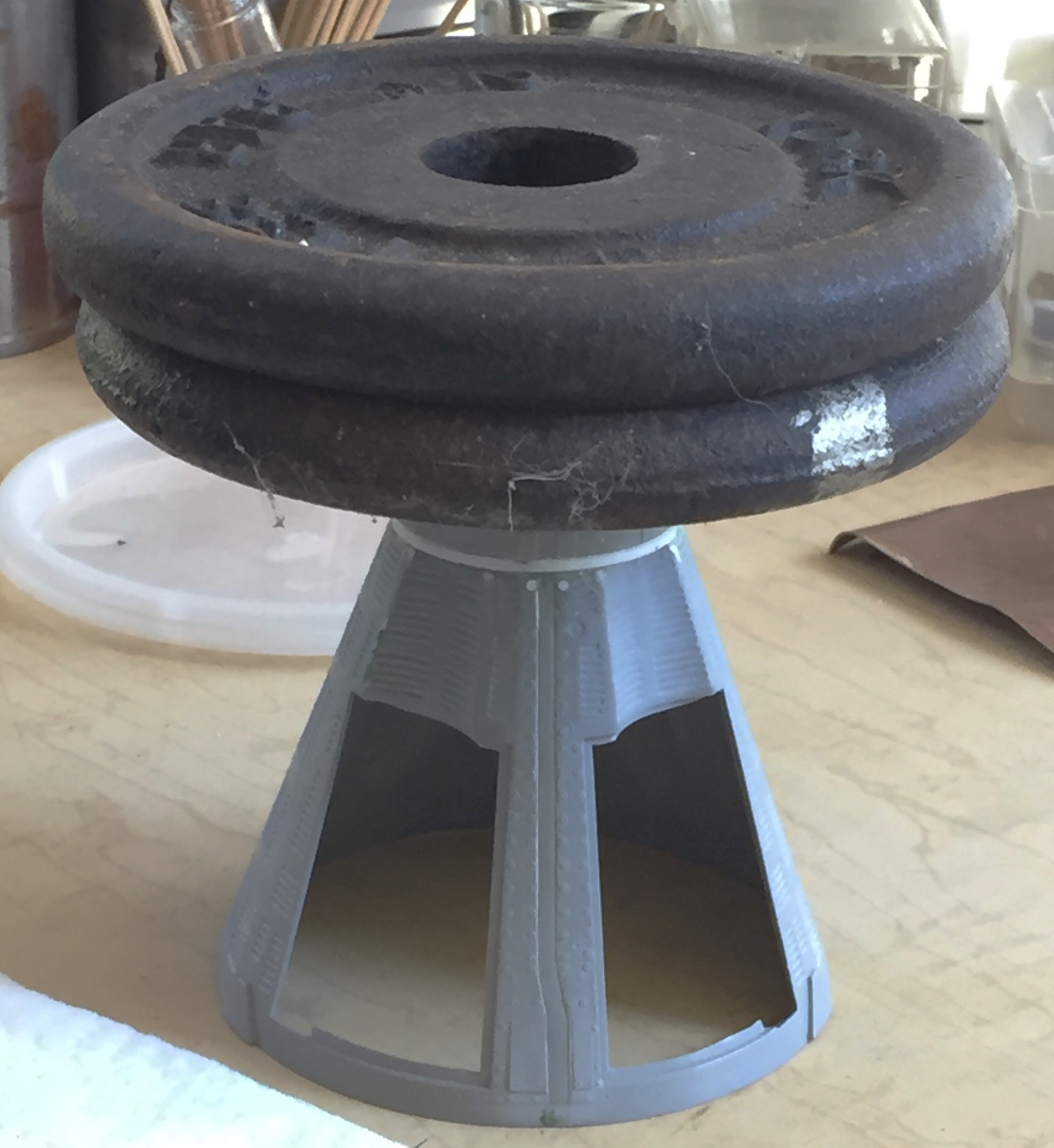
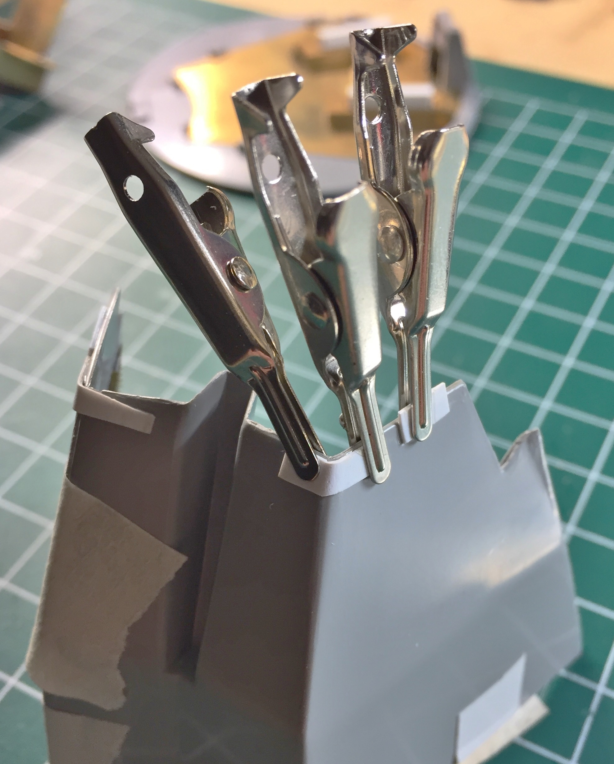
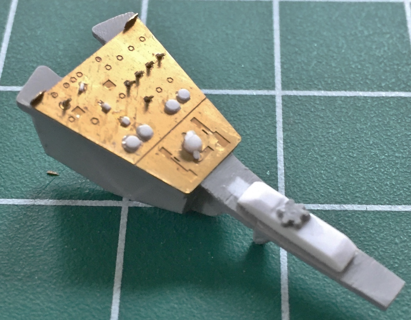
When I glued the collar on, I used five pounds of weight to fit this part as tightly as I could manage:
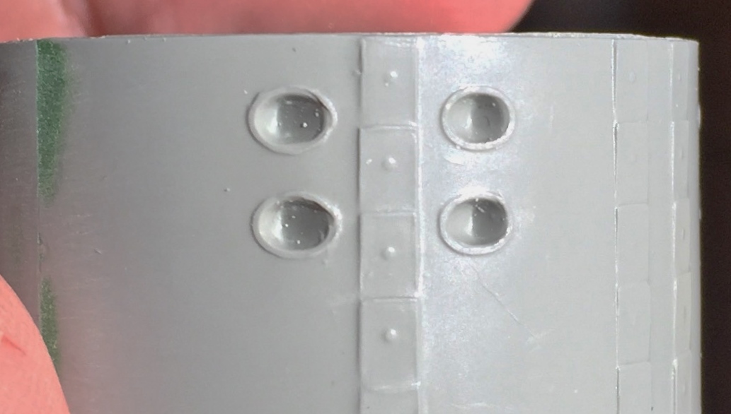
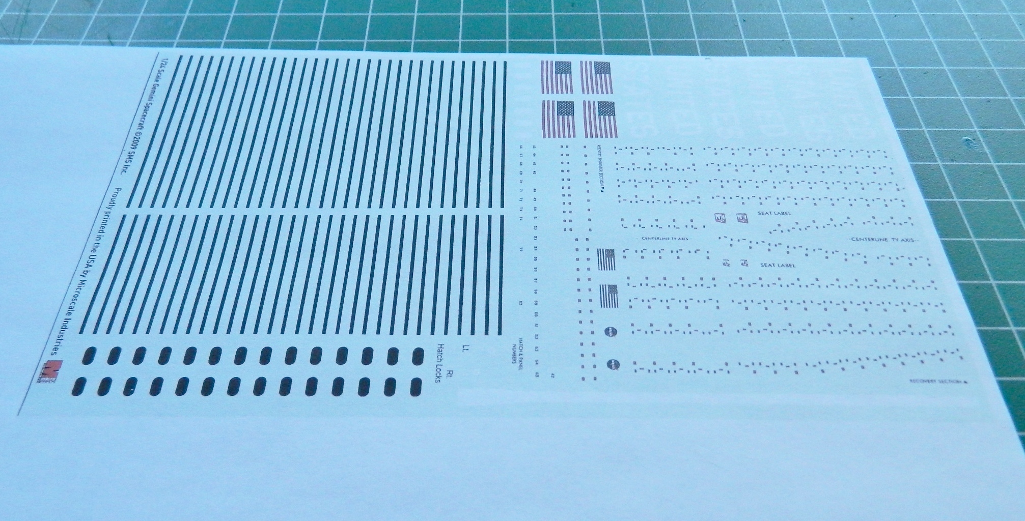
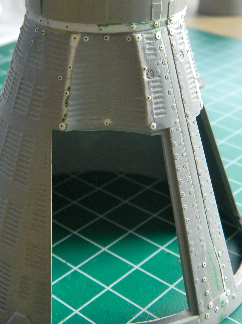
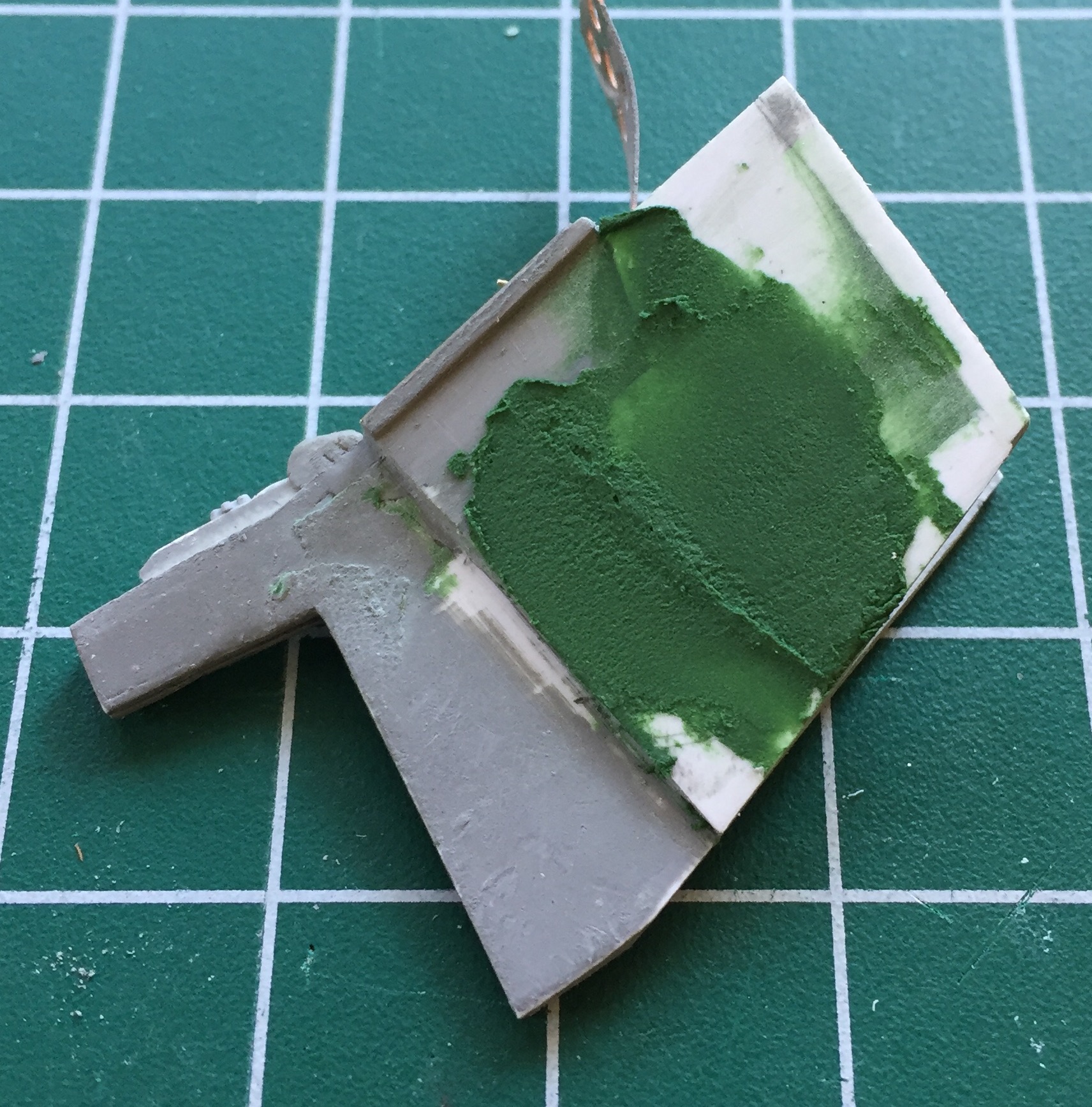
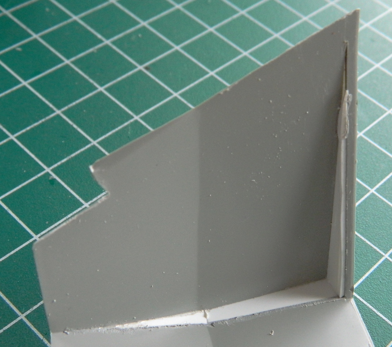
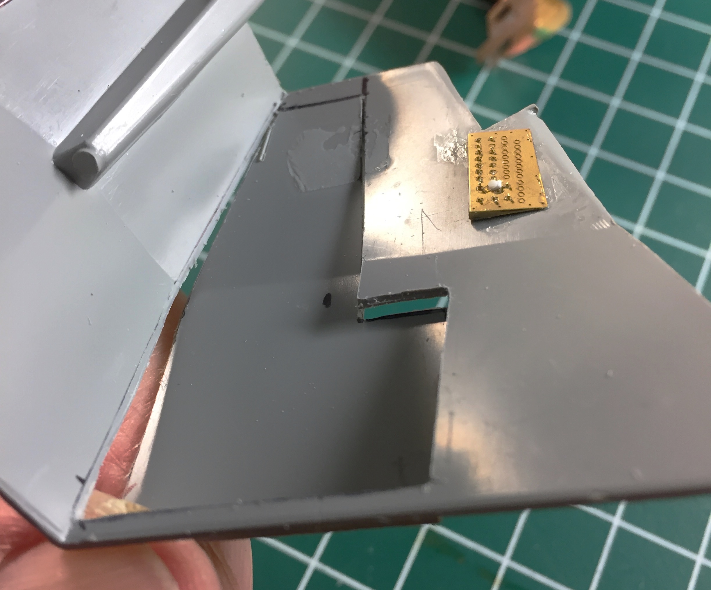
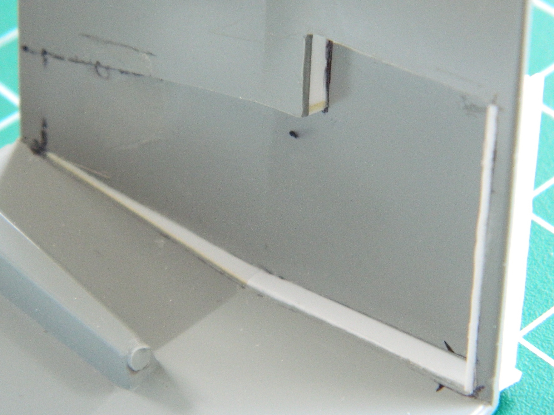
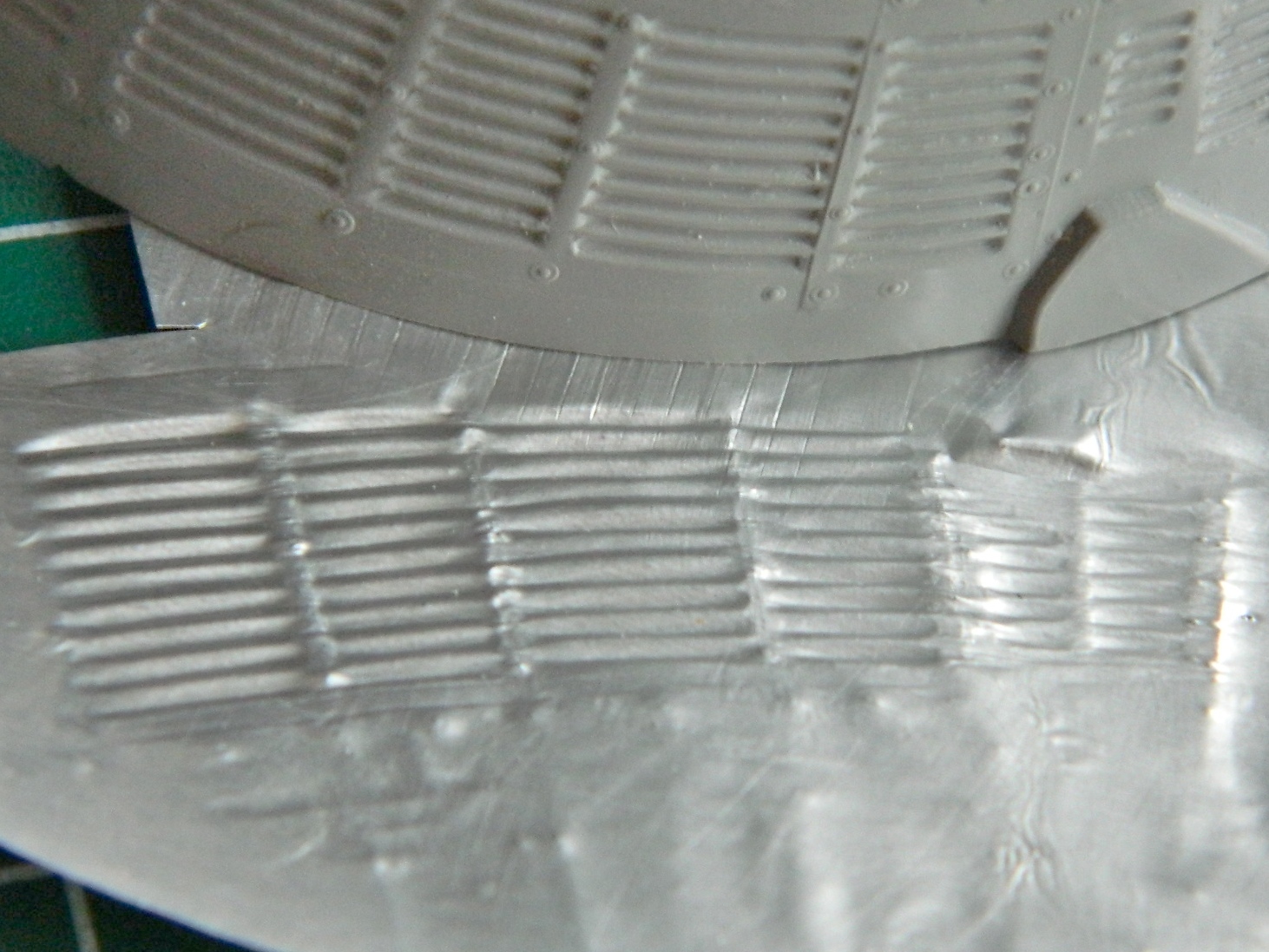
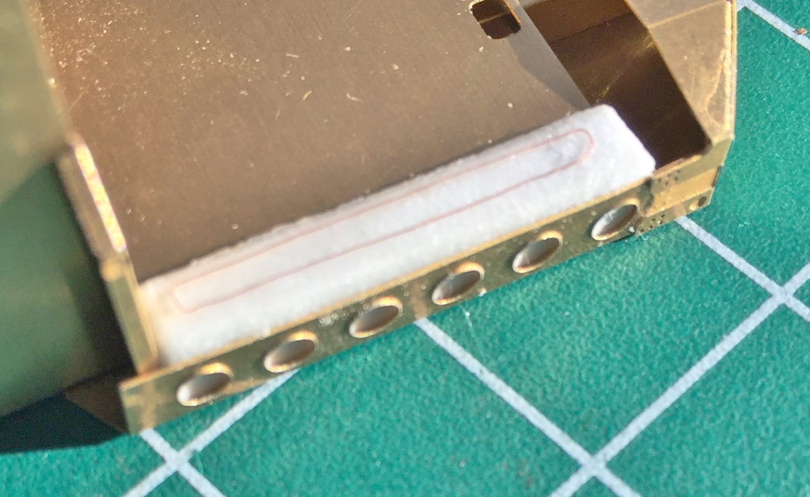
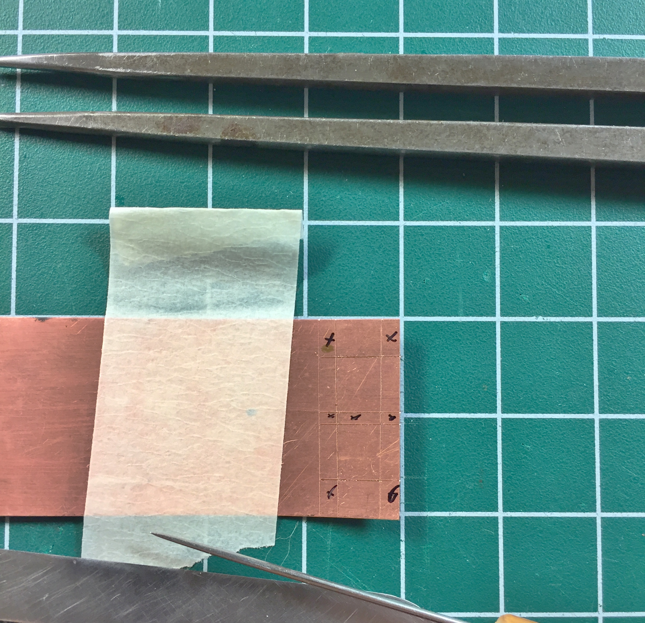
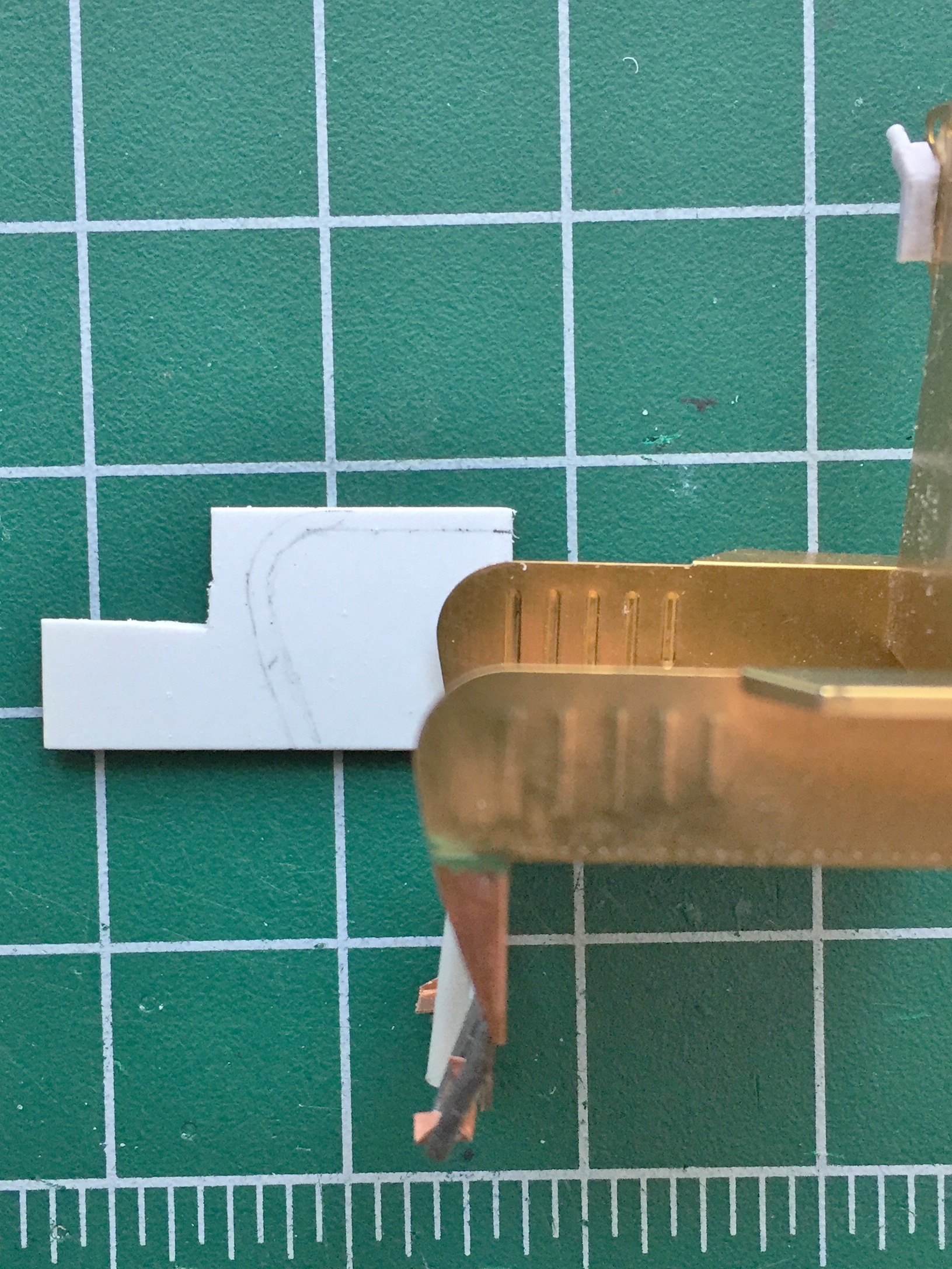
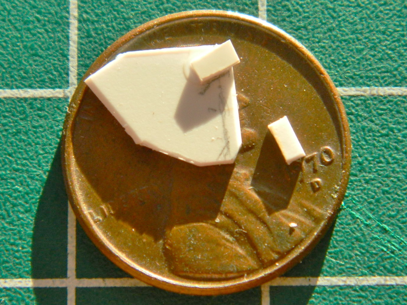
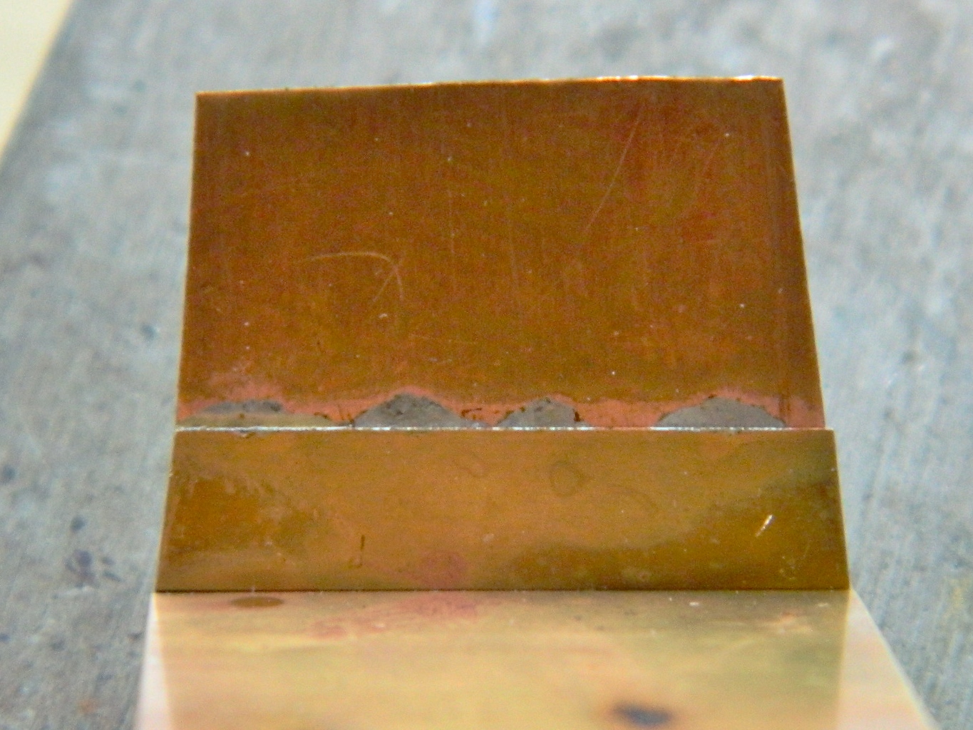
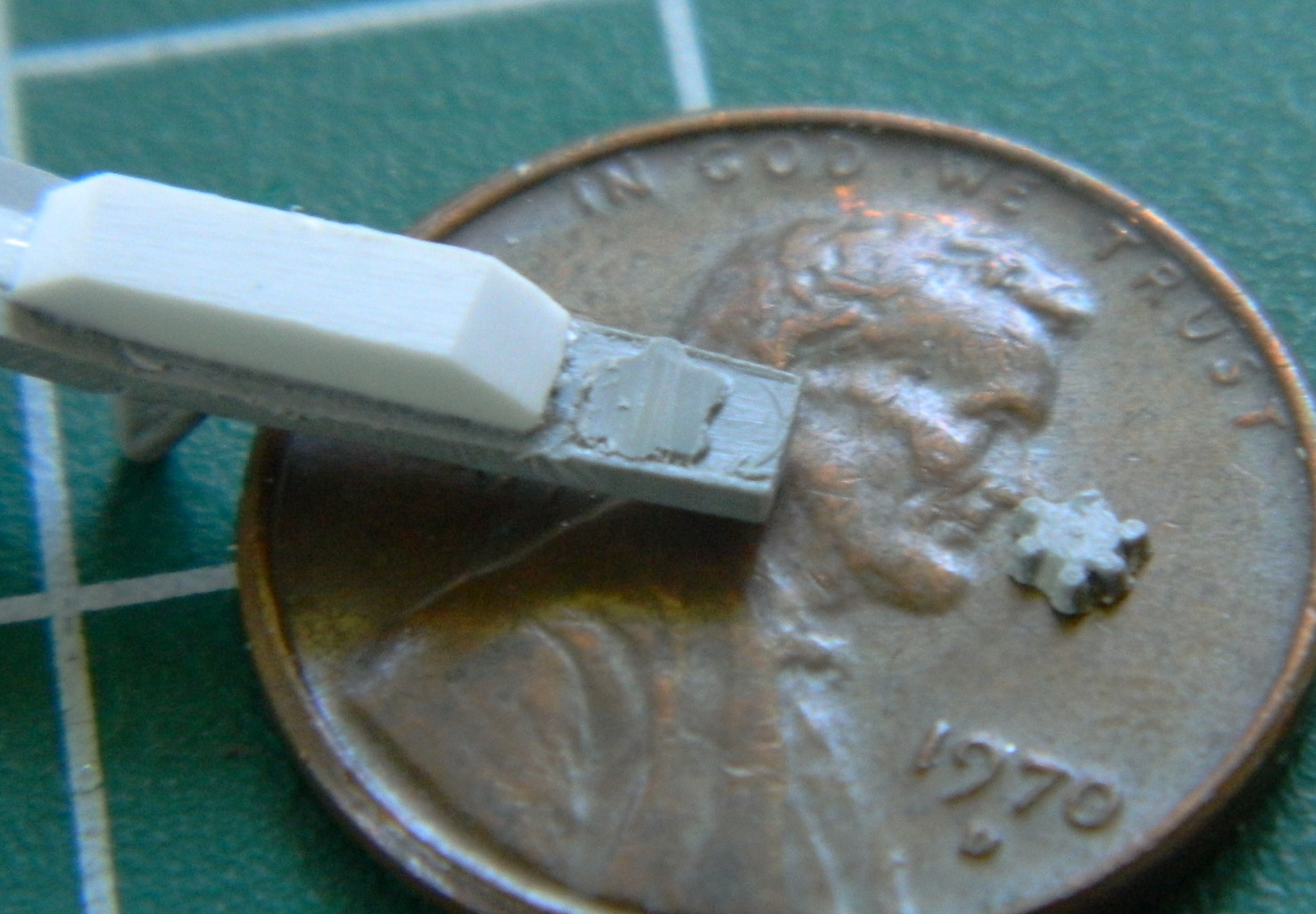
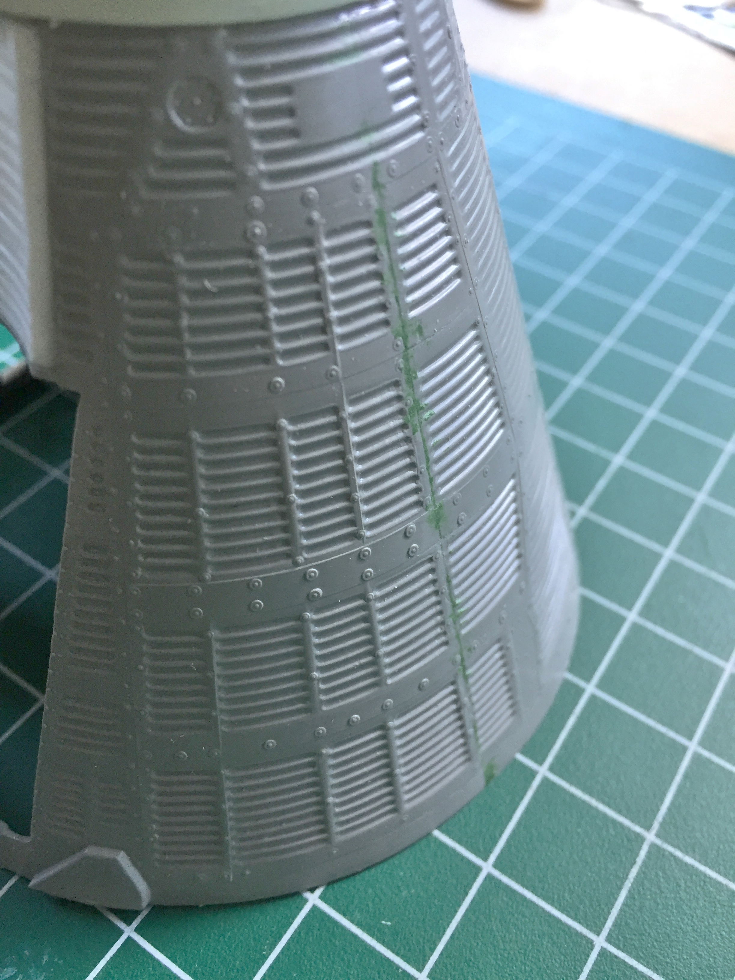
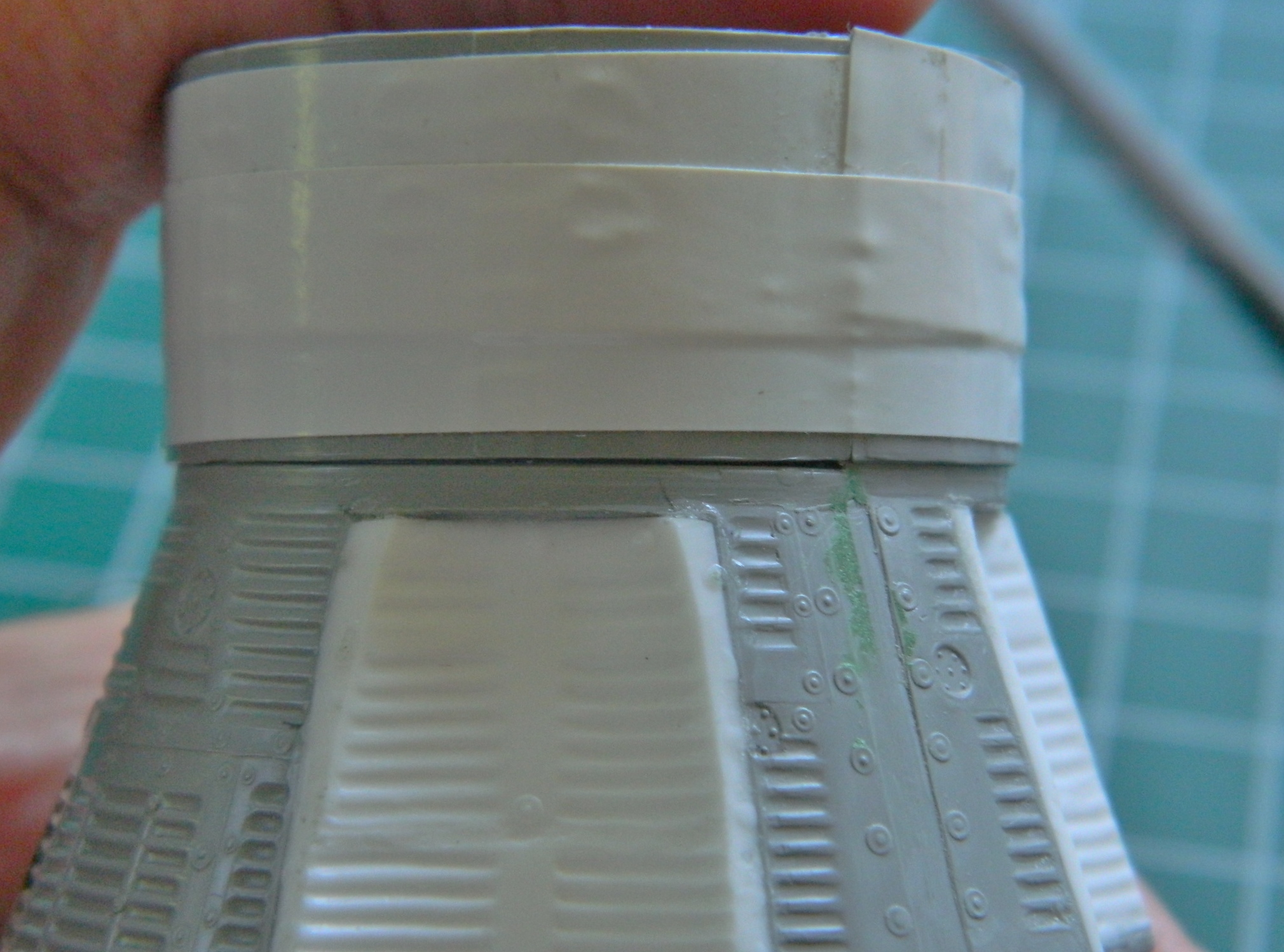
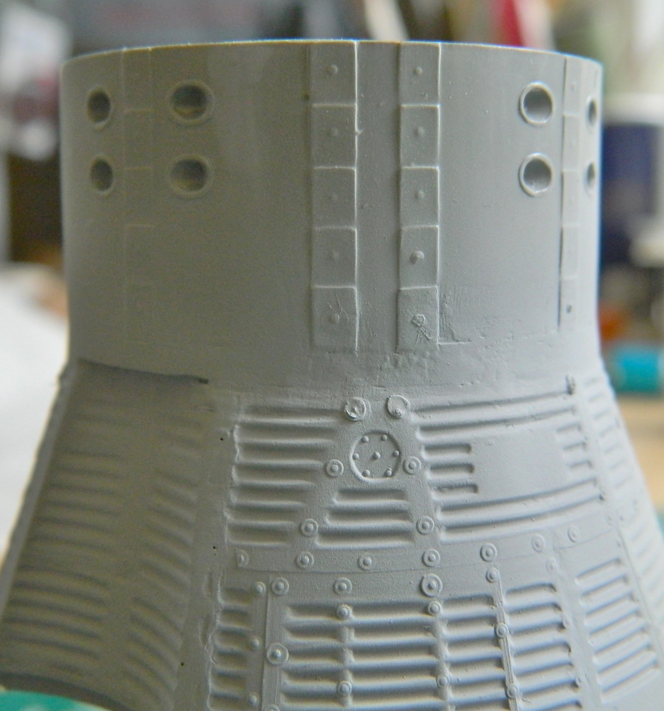
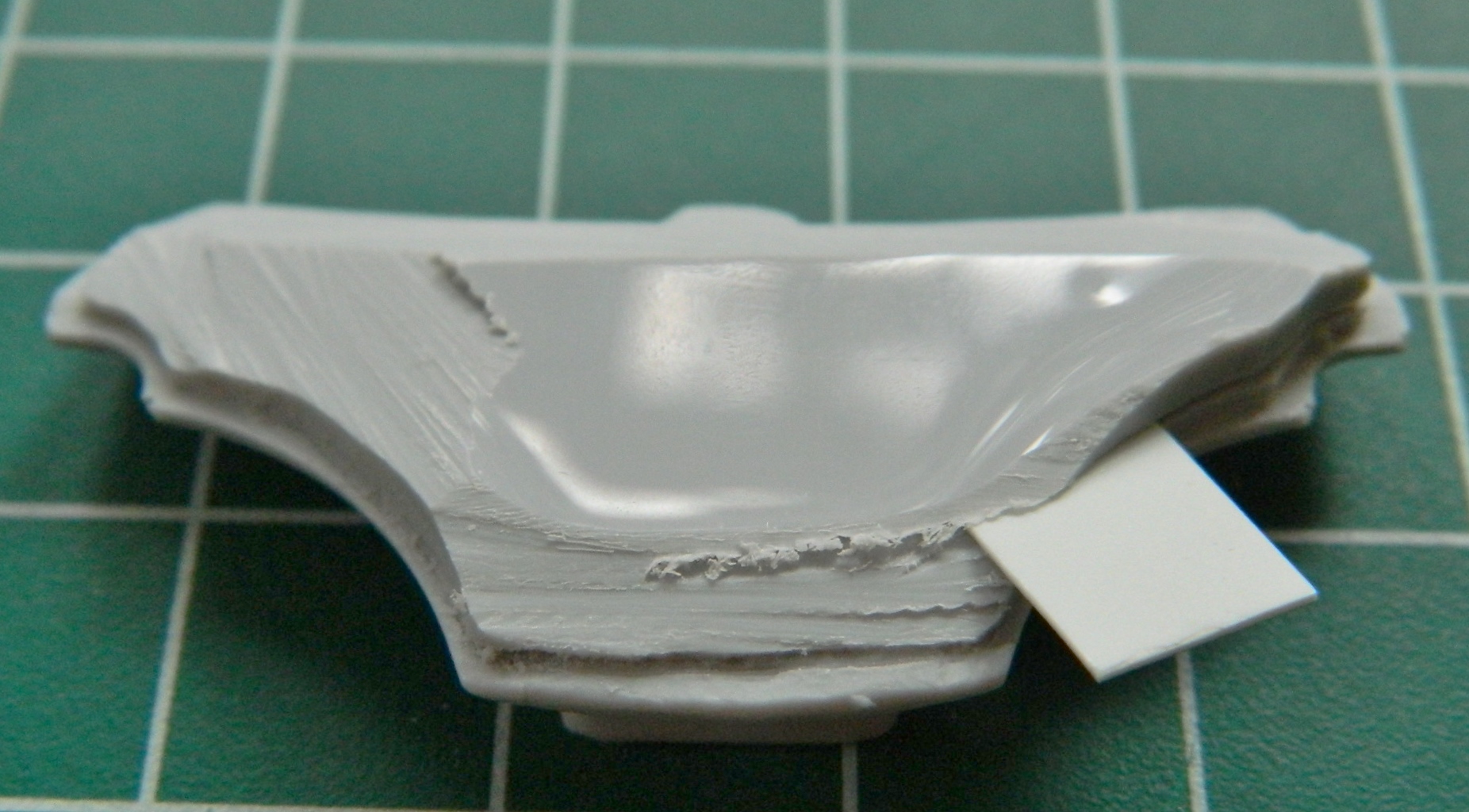
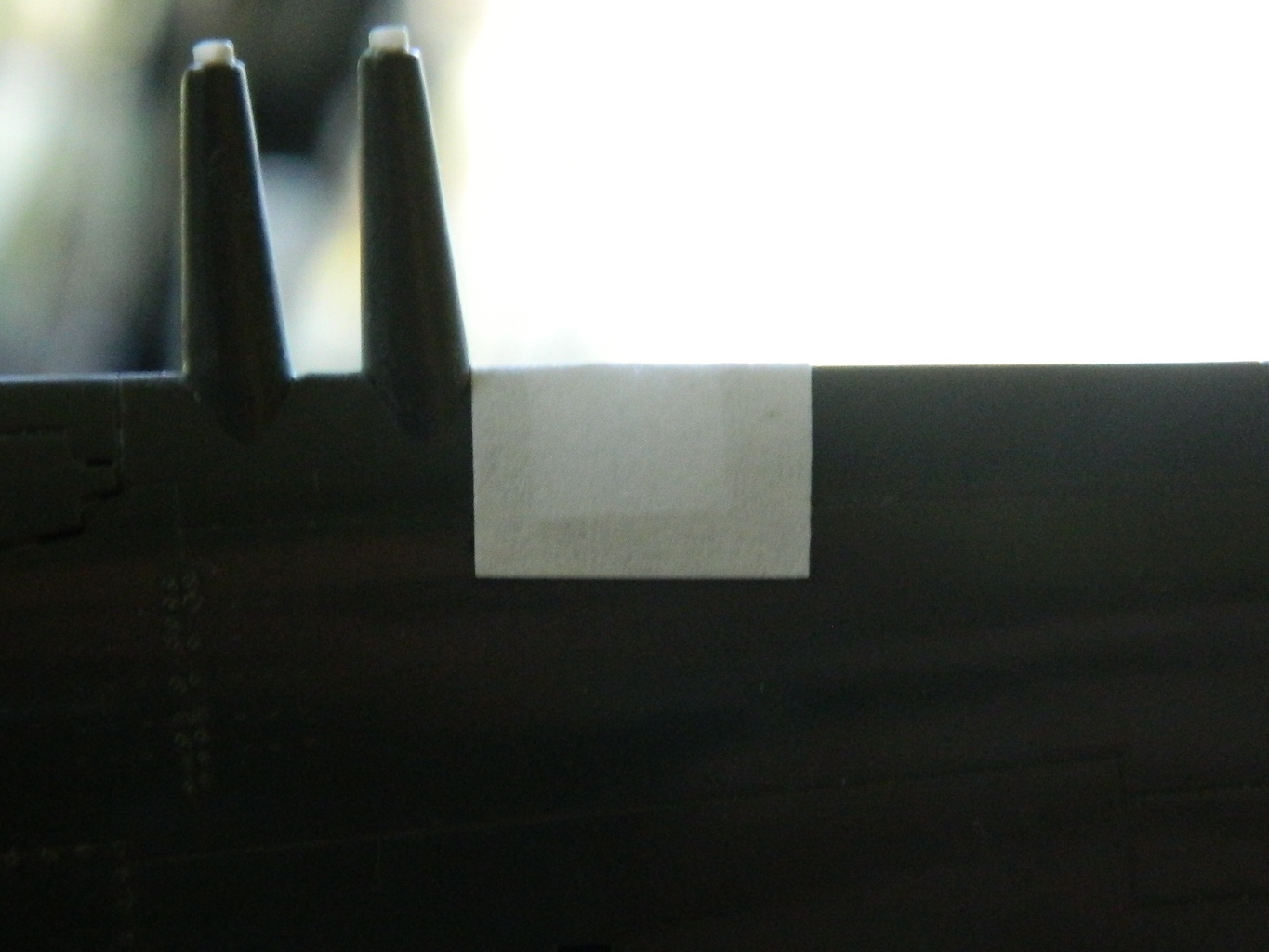
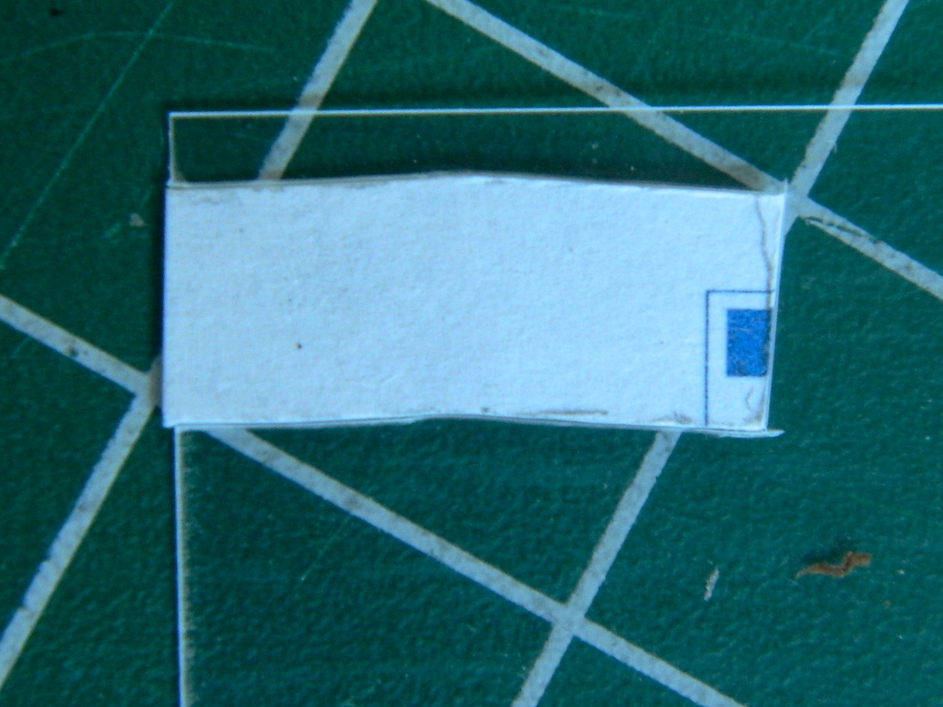
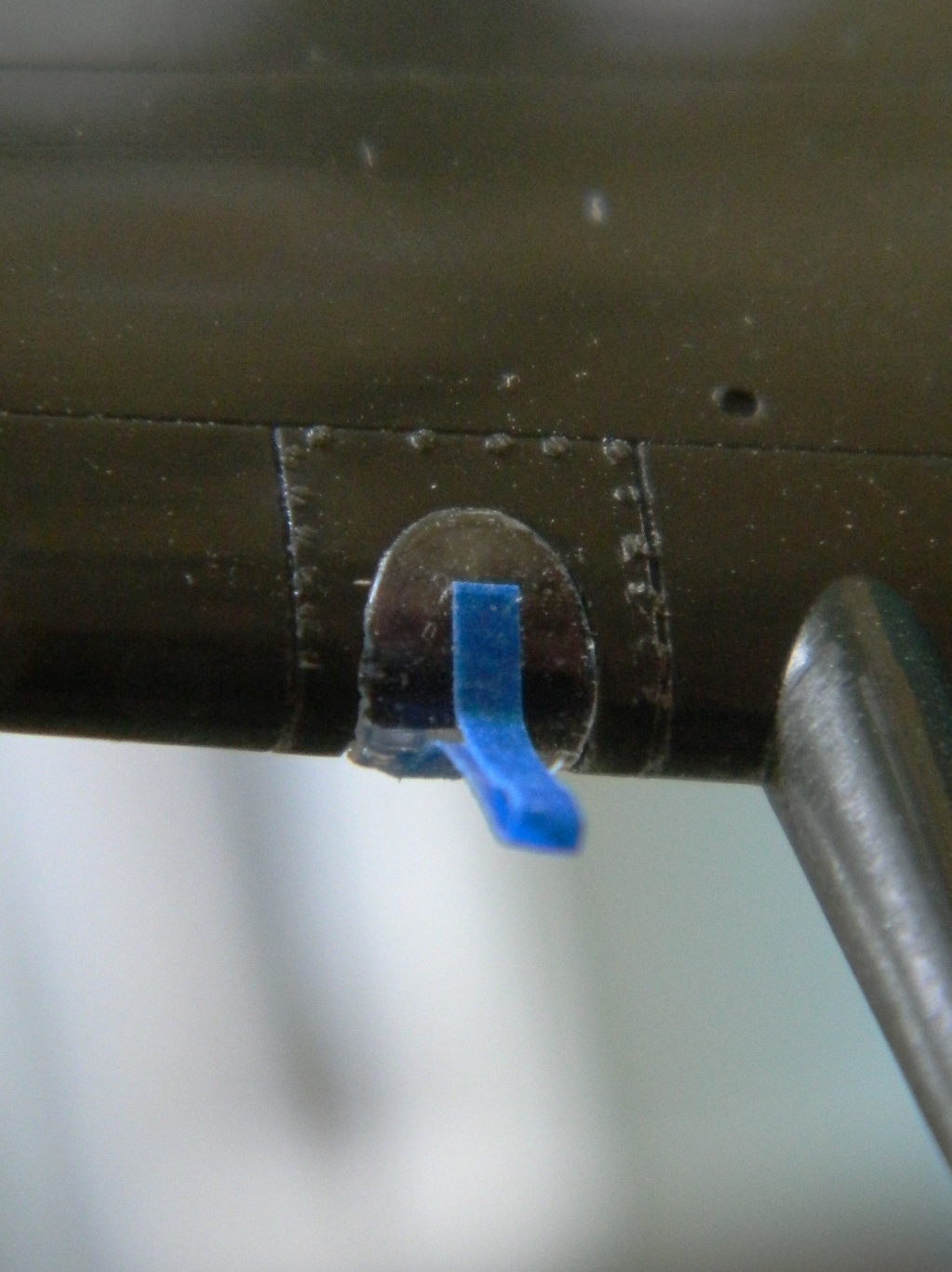
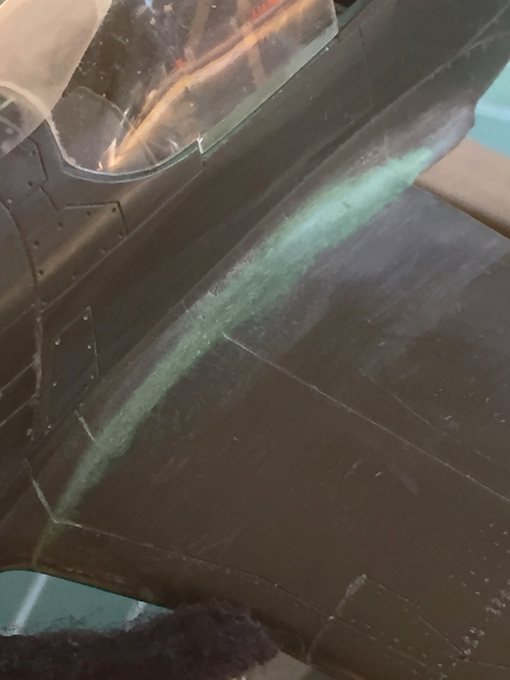
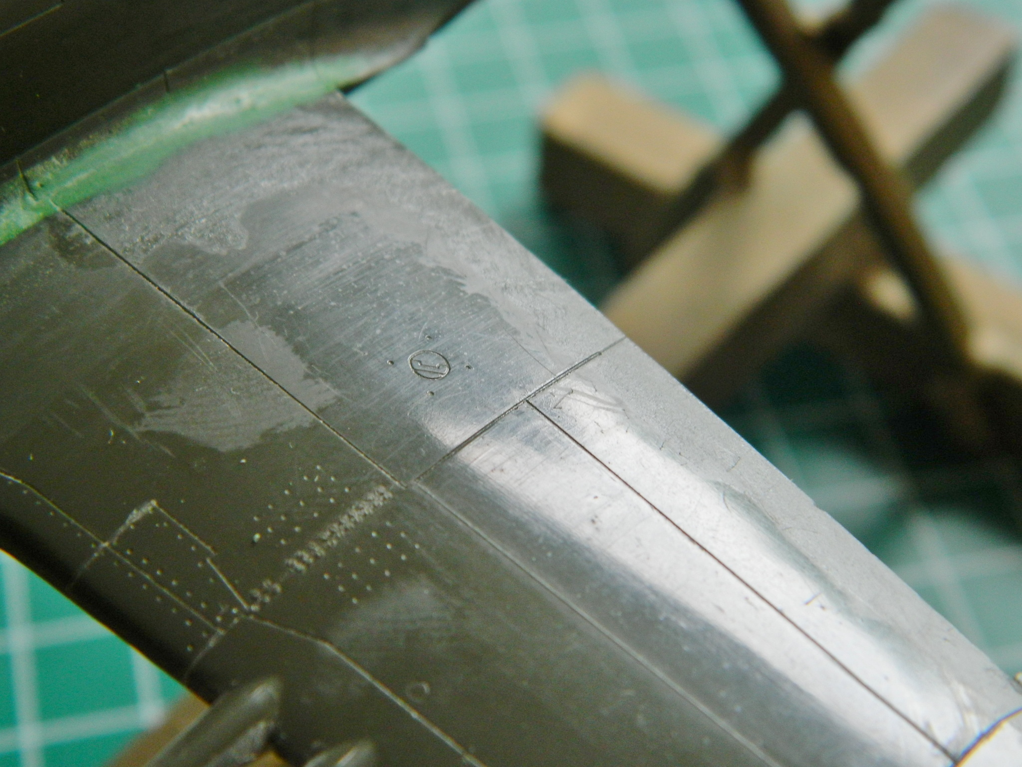
While that was setting up, I started addressing the inaccuracy of the bridle channel between the hatches. I copied the AM decal sheet and cut out the decal that’s supposed to be used in that channel (I’m going to paint it instead) as a template to show me what needs to be reworked (it’s that light strip in the lower right corner):
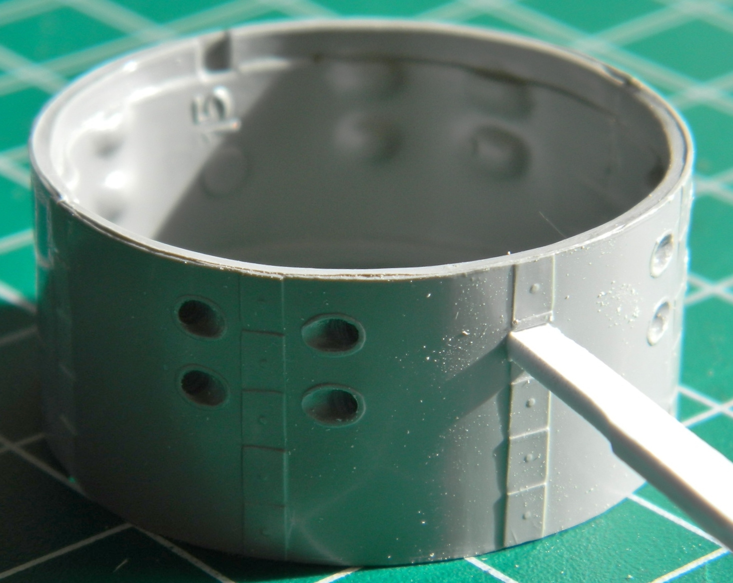
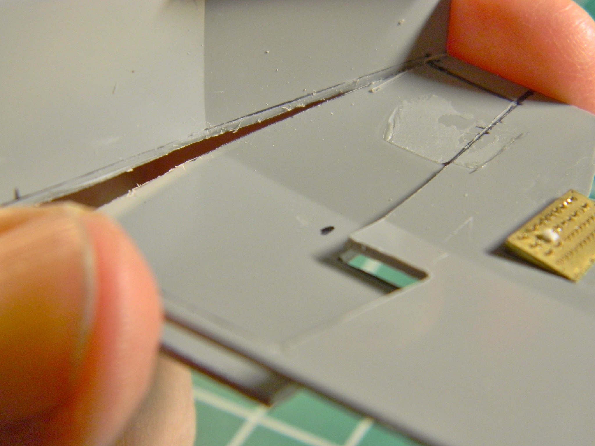
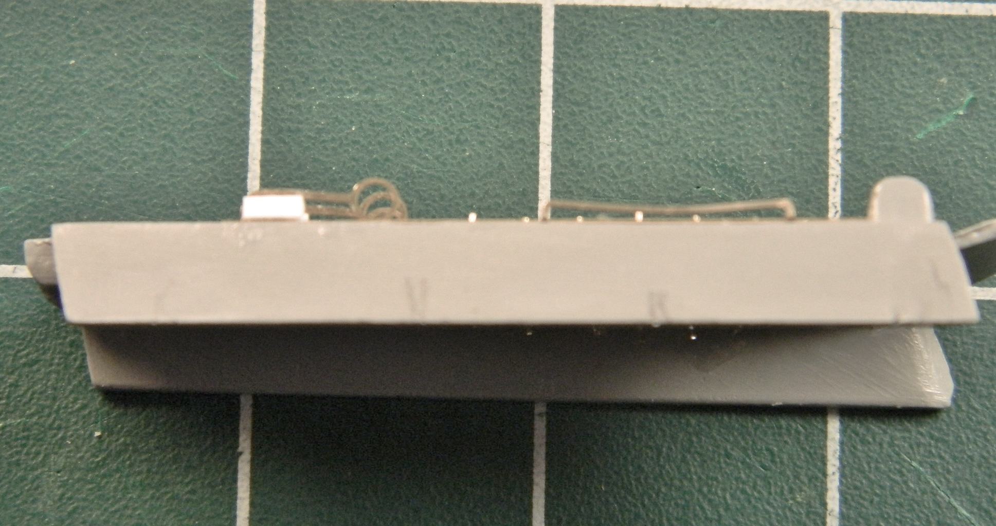
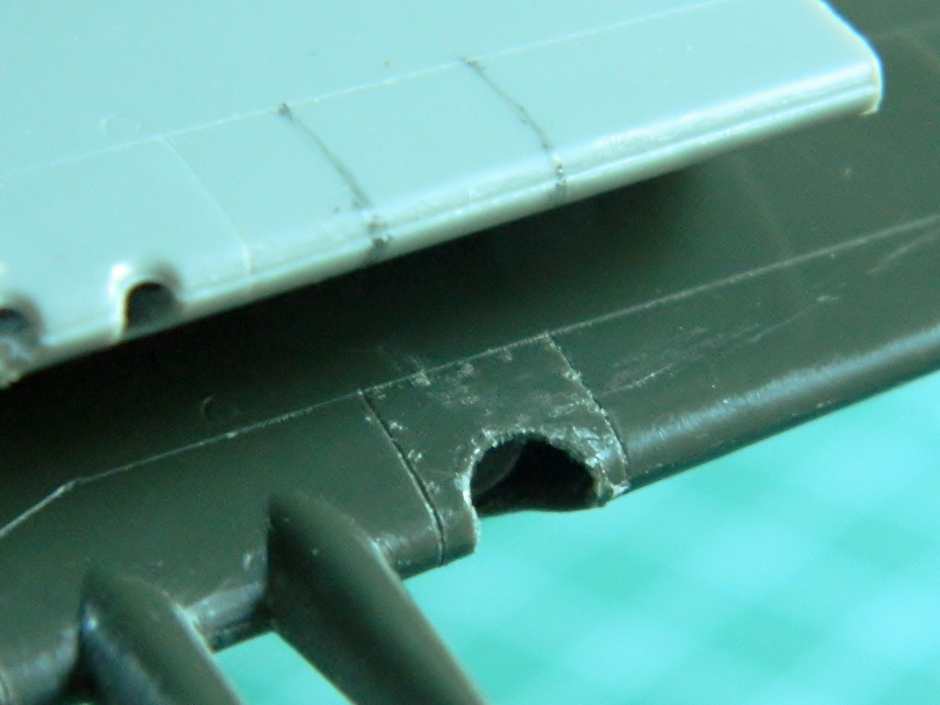
This is how far off it was:

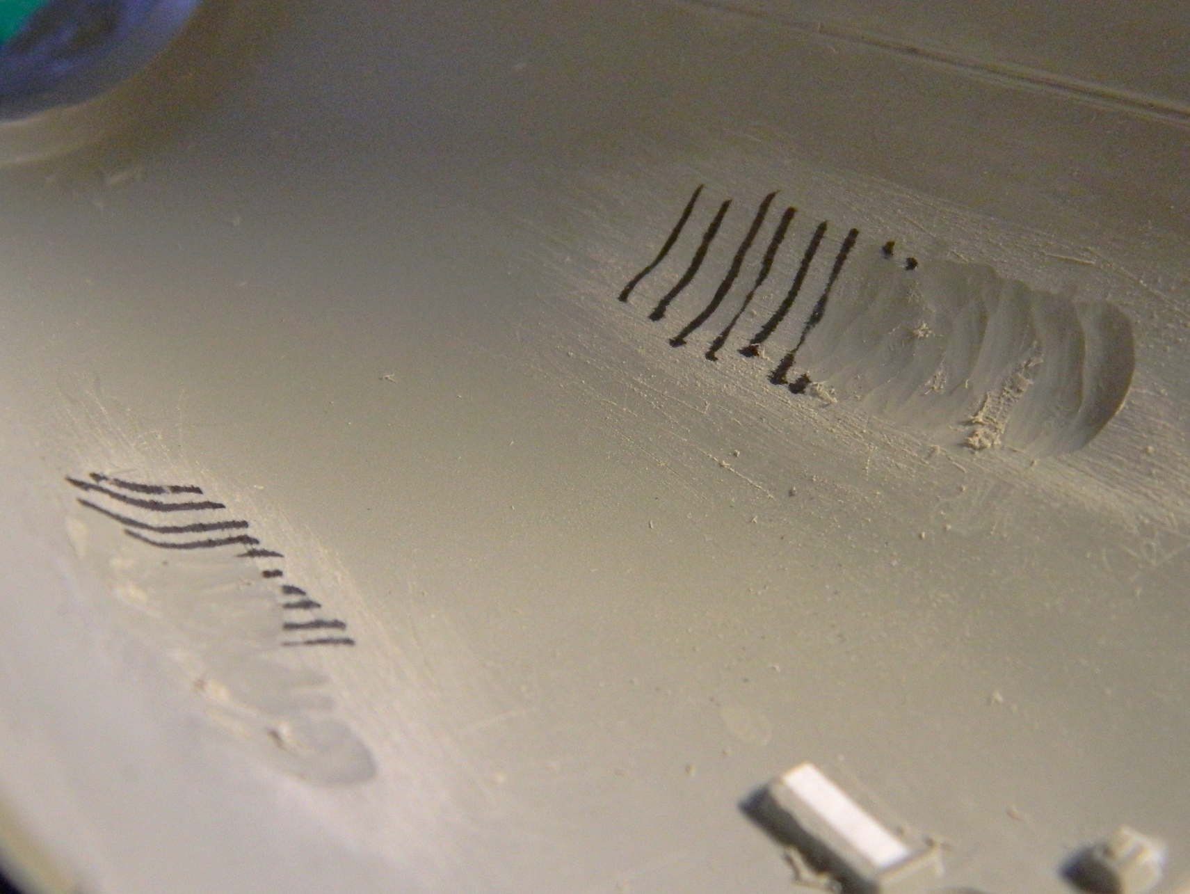
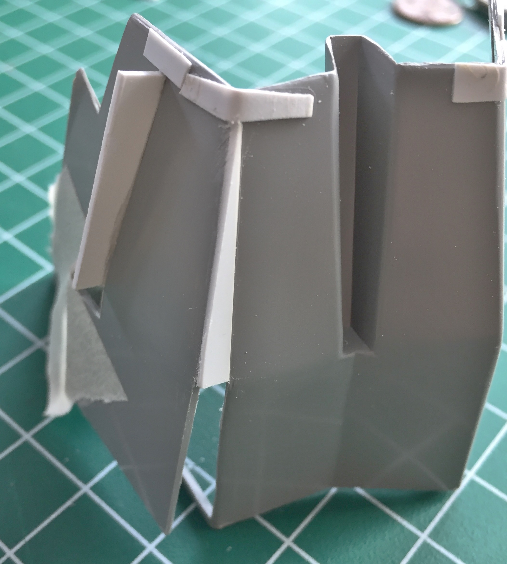
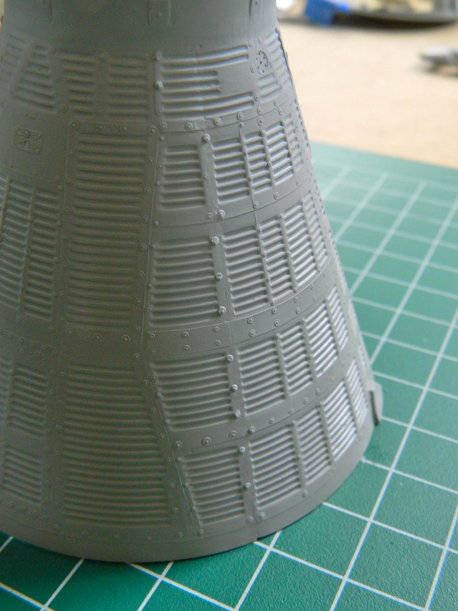
There are a lot more inaccuracies in this area (and over the entire exterior) but what I would have to do to fix them is staggering. In essence, I’d have to take surface molds of ALL the exterior corrugations and re-skin the whole thing…and even then there would still be inaccuracies. Not worth it. This will certainly be good enough:
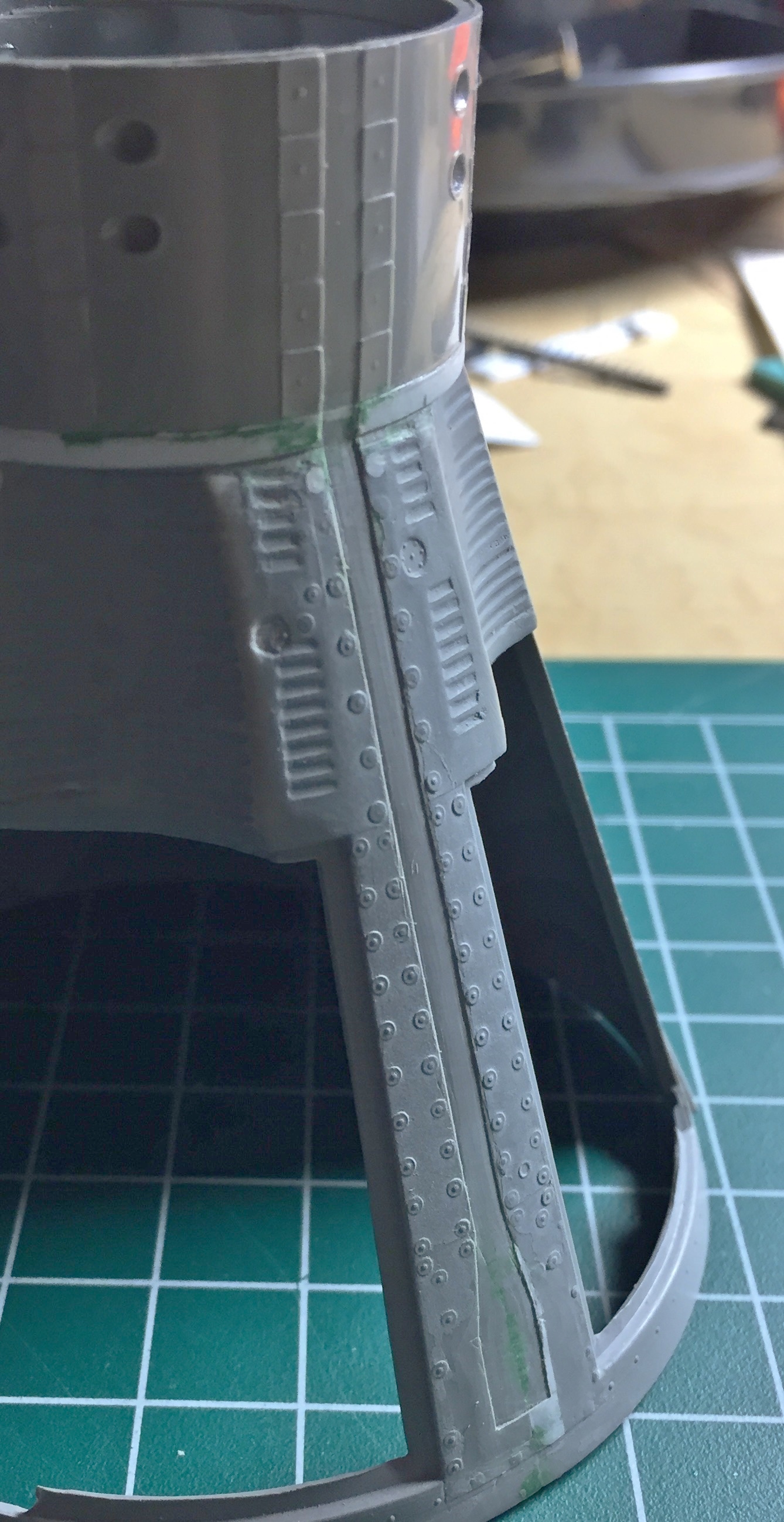
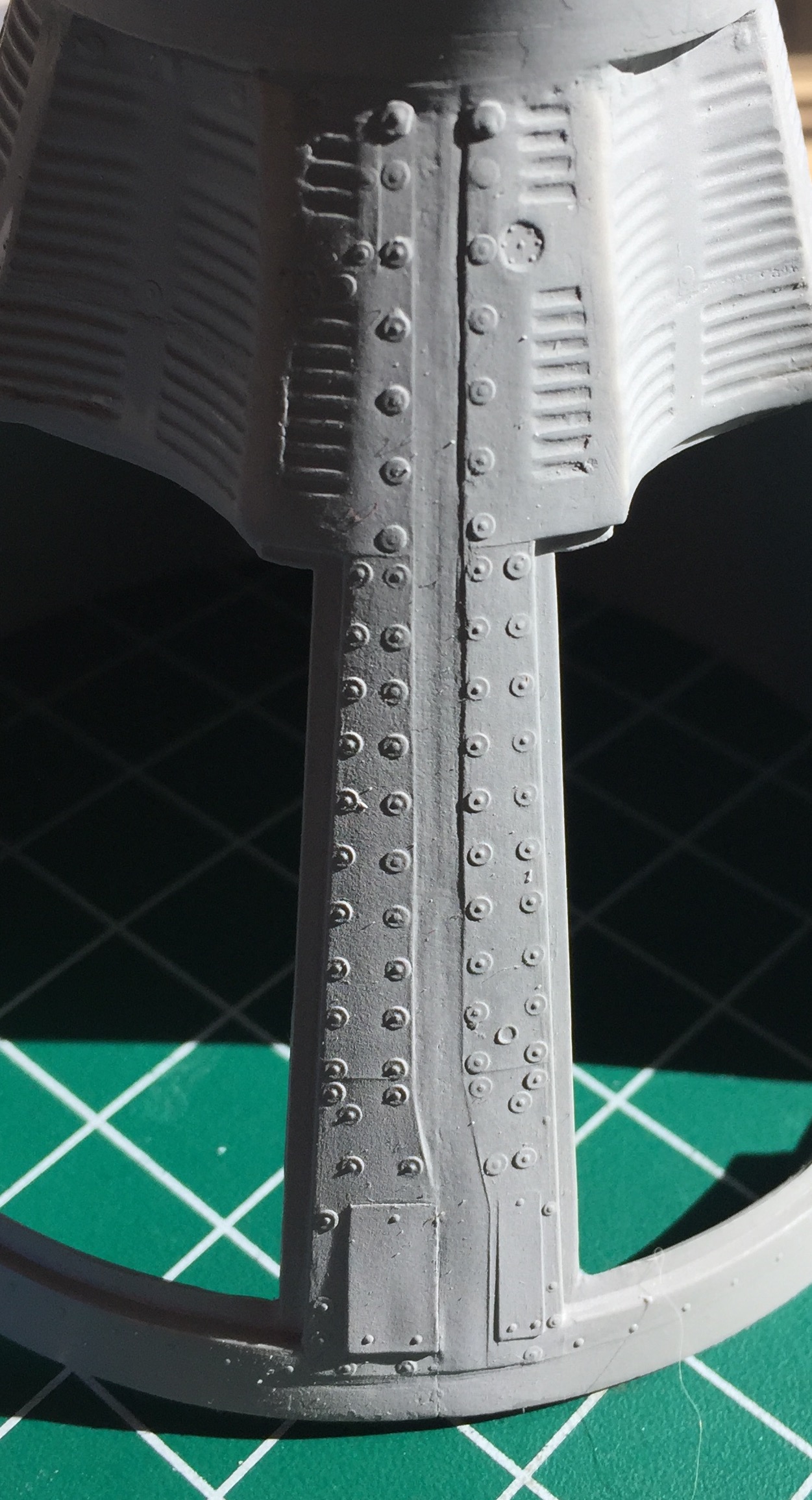
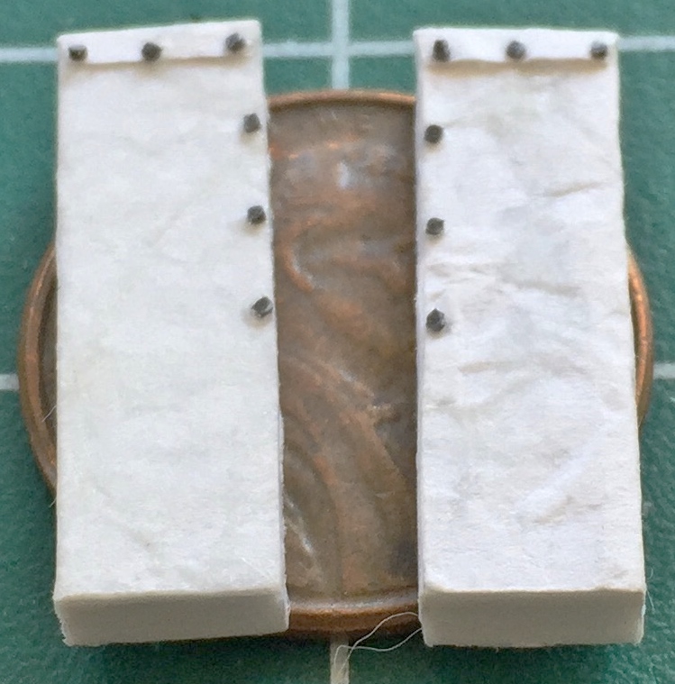
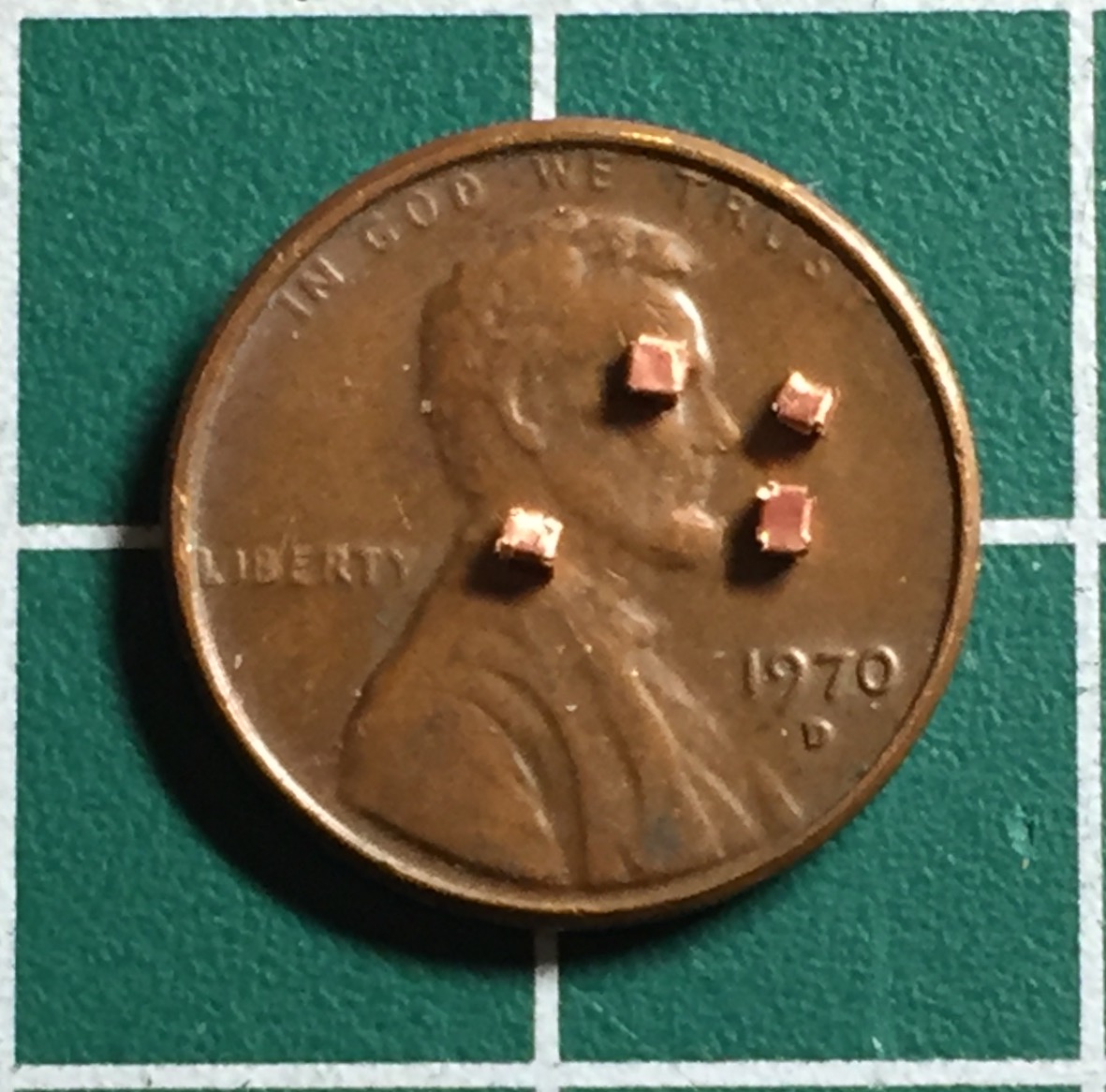
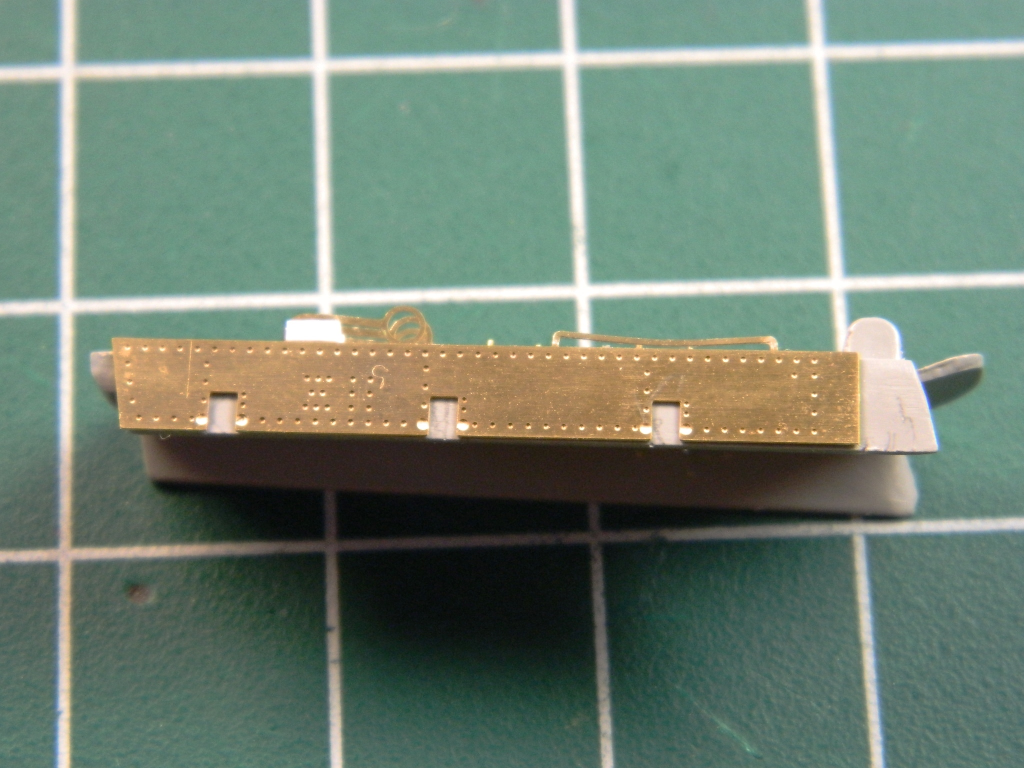
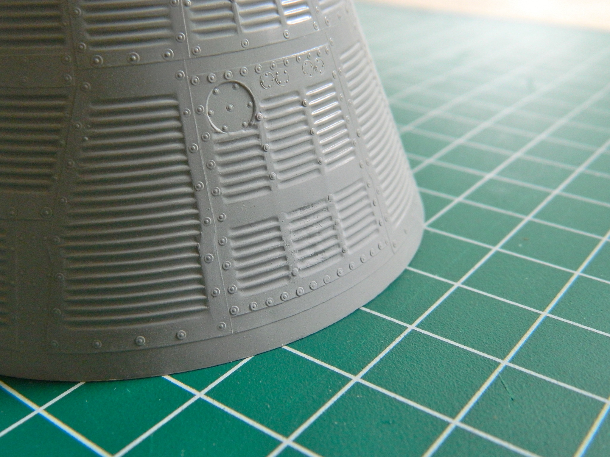
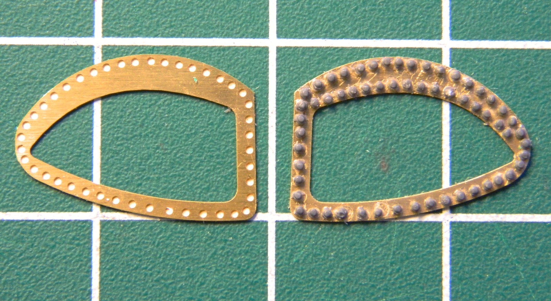
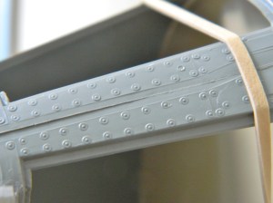
Because of seams and surface reworking, some of the details were lost. From what I can tell from references, the surface skin panels of the Gemini capsules were attached to the framework with screws and these screws all had large washers. The washers I replicated by punching small discs from .005″ (.127mm) sheet styrene:
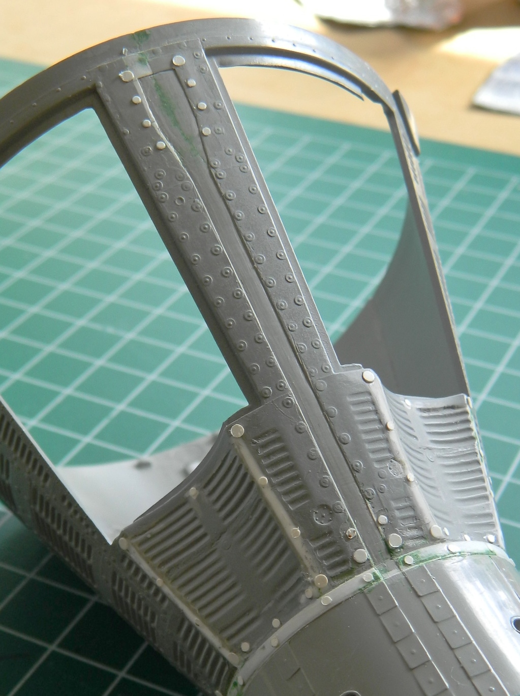
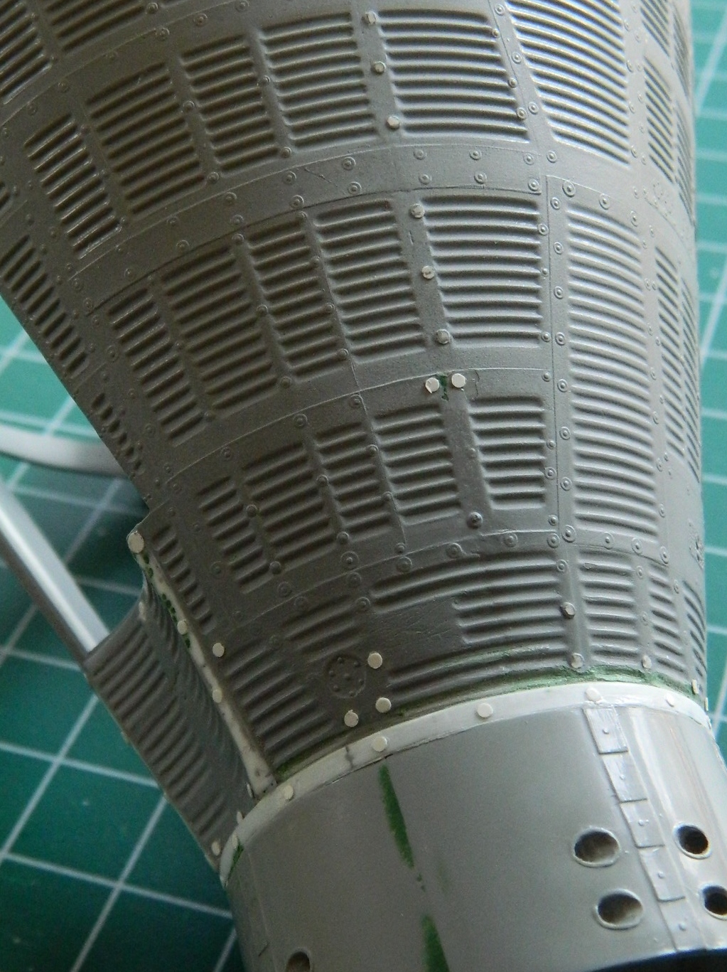
Then I needed to replace the screw heads. My first thought was a small drop of superglue but the problem with that was size variations of the drops. Then I thought about stretching sprue and using small pieces of that but the HASSLES involved in getting something that small located while the glue was trying to dissolve them wasn’t something I wanted to deal with. Then I remembered Archer Transfers! They make SHEETS of rivets and screw heads! Somehow they have managed to print resin details onto decal film and to use them, they’re treated like decals. Cut out what you want, immerse in water, and just slide into position. Well…these things are small. Very small. And they are going onto a piece of plastic that cannot be considered “large.” That means that the decal film that these screw heads are printed on won’t provide much surface for adherence (I learned this during my M4A3 build when I used Archer’s resin weld beads…look at them strongly and they’ll come off). My work-around was to position the screw head where I wanted it and then put a drop of clear flat acrylic paint over the entire washer/screw assembly to hold the resin decals in place. Seems to have worked, certainly MUCH better than hoping I don’t knock them off (which I managed to do with 4 out of 92 of them anyway). The end result was worth the hassle:
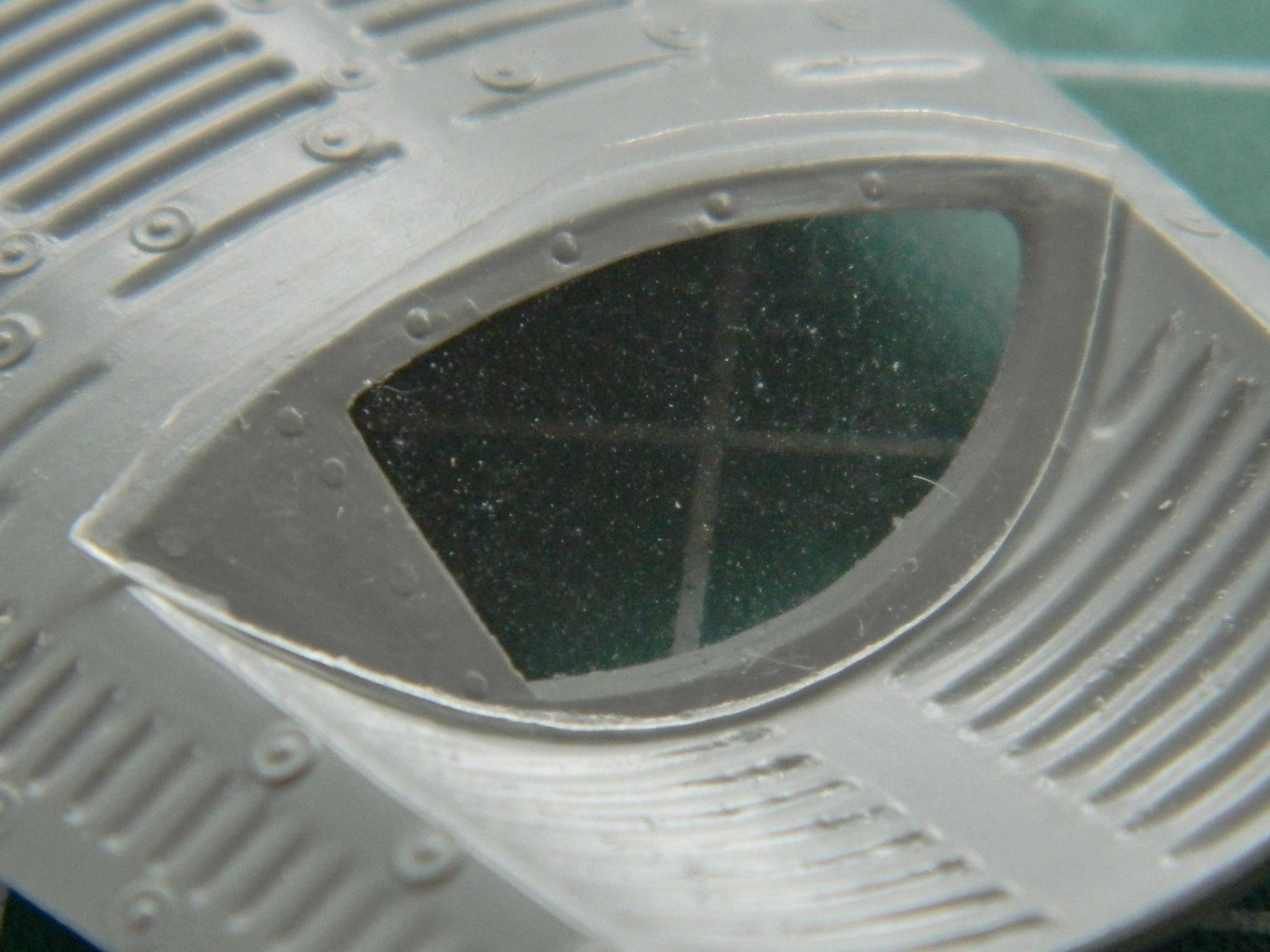
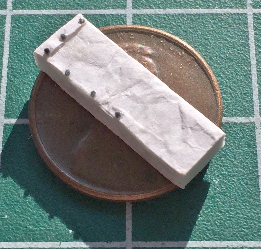
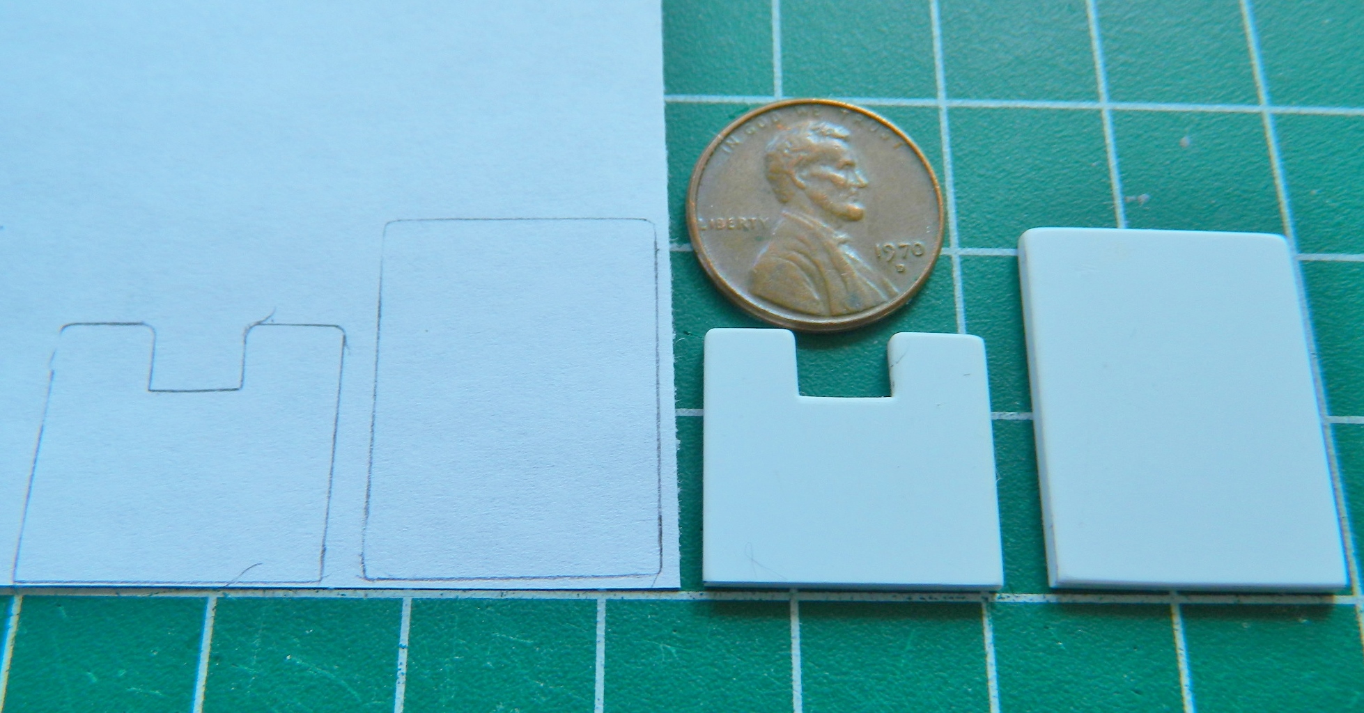
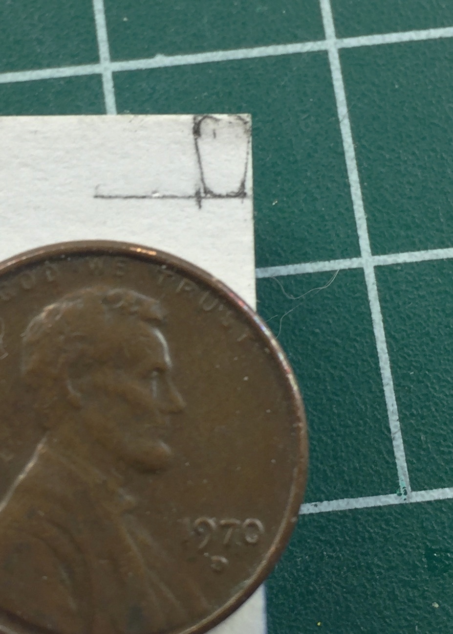
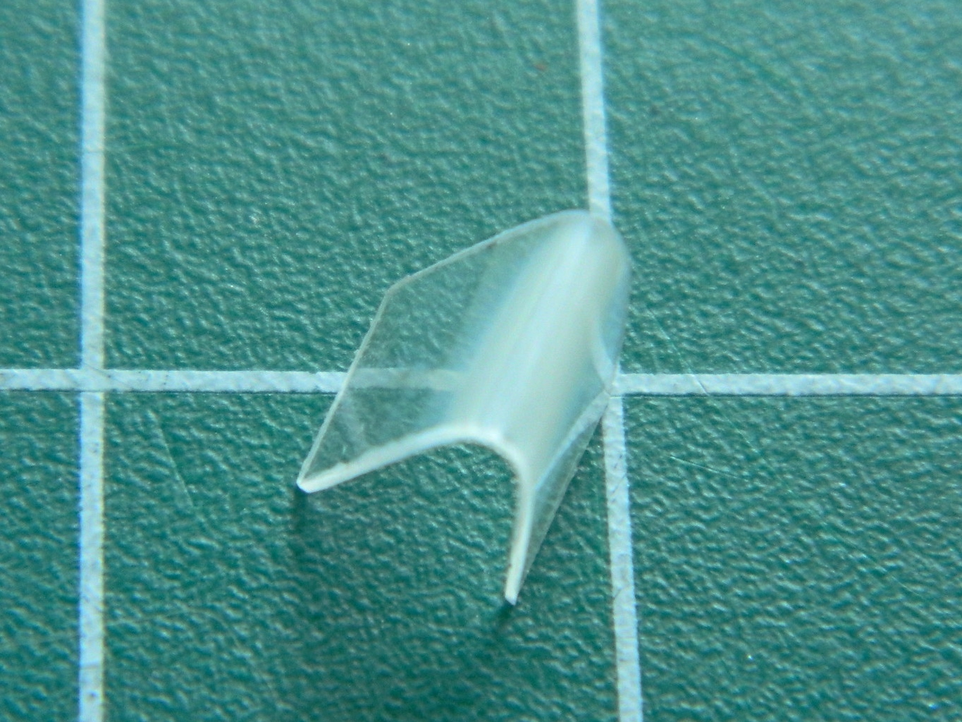
My attention turned to the hatches. The windows in the hatches are double-paned. I started to address this when I added all the nuts and bolts to the inner plate of the window that holds the inner pane in place. I briefly considered cutting clear styrene to fit the opening in the hatches and realized that doing so would be damned tedious and gluing them in place would present its own set of problems. The work-around for that was to add a section of .010″ (.254mm) clear styrene in front of the opening (like, who’s going to notice the front of that section was moved out ten thousandths of an inch (or .254mm)?), then mask off the window, and paint it when I do the rest of the exterior. Step one to that process was a template:


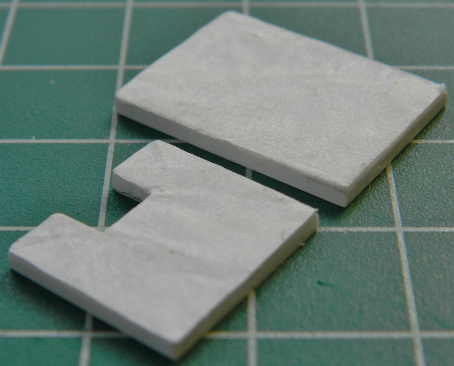
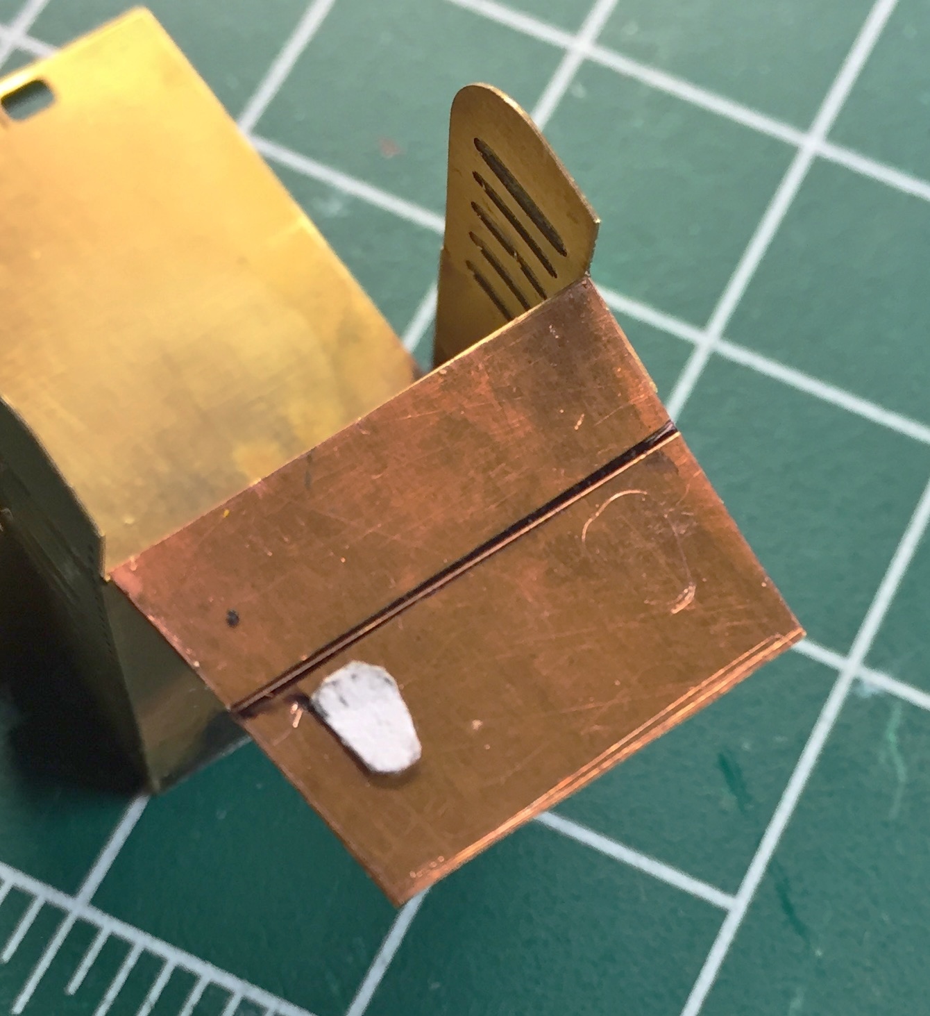
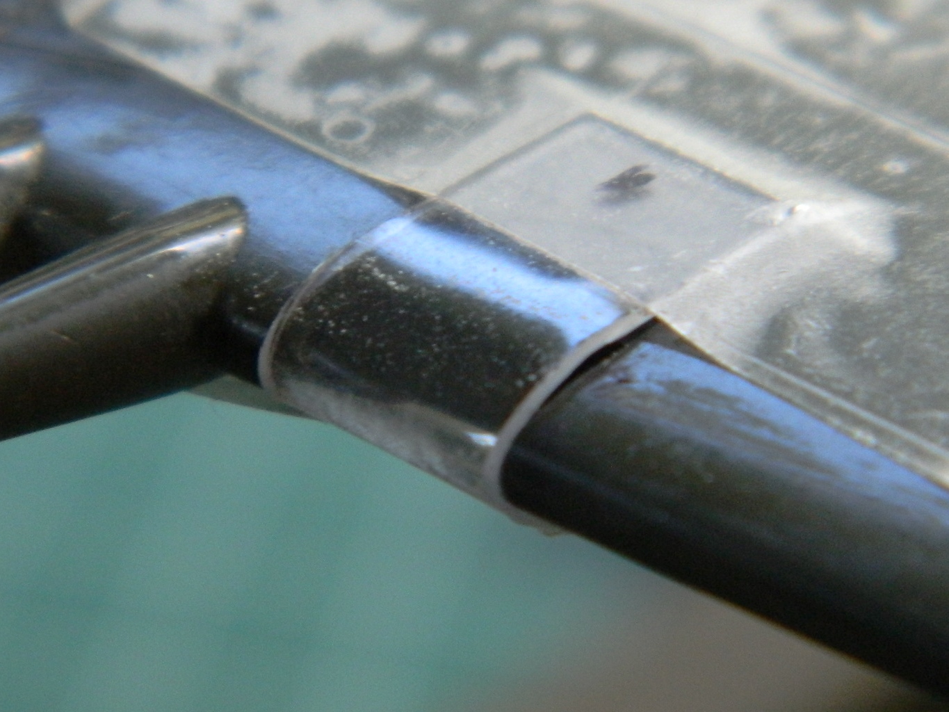
Much sanding ensued to get the fit as close as I could (and no…this picture doesn’t show it properly fitted):
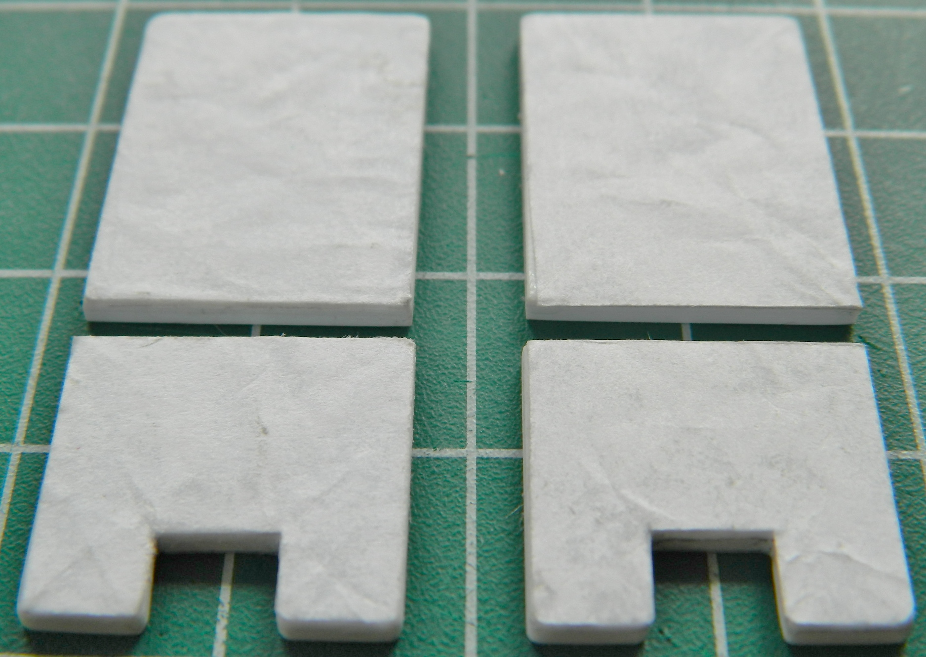
Gluing the styrene to the hatch required care. It would be very easy to have the glue move into the area I needed to stay clear. I got the first clear part in place with no problem. However, true to my pattern, doing this again presented problems, the glue migrated to the area that needs to stay clear, and the only way to fix it was to remove the clear plastic and start over:
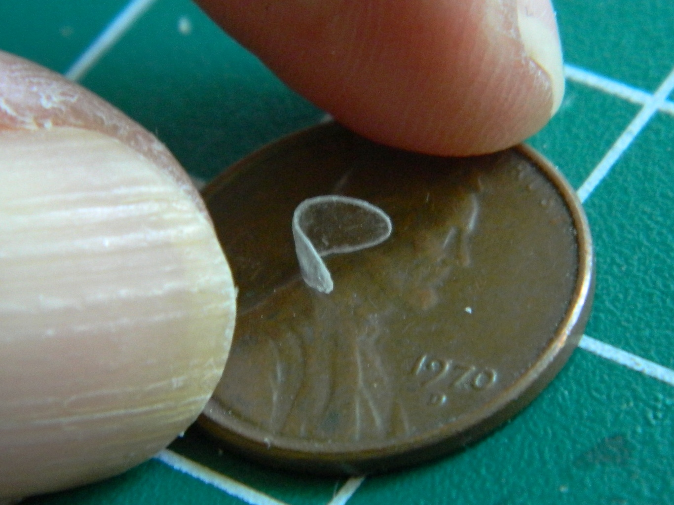
But I did it. I did it four times. The fourth time worked.
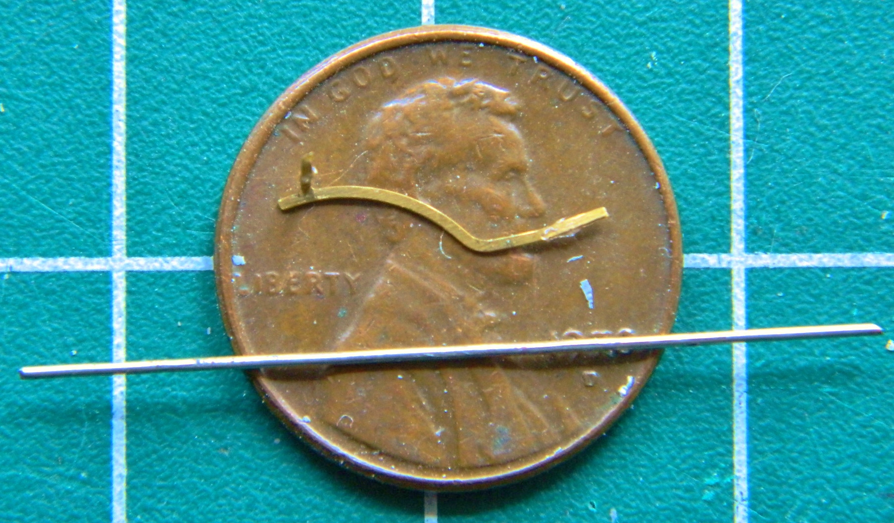
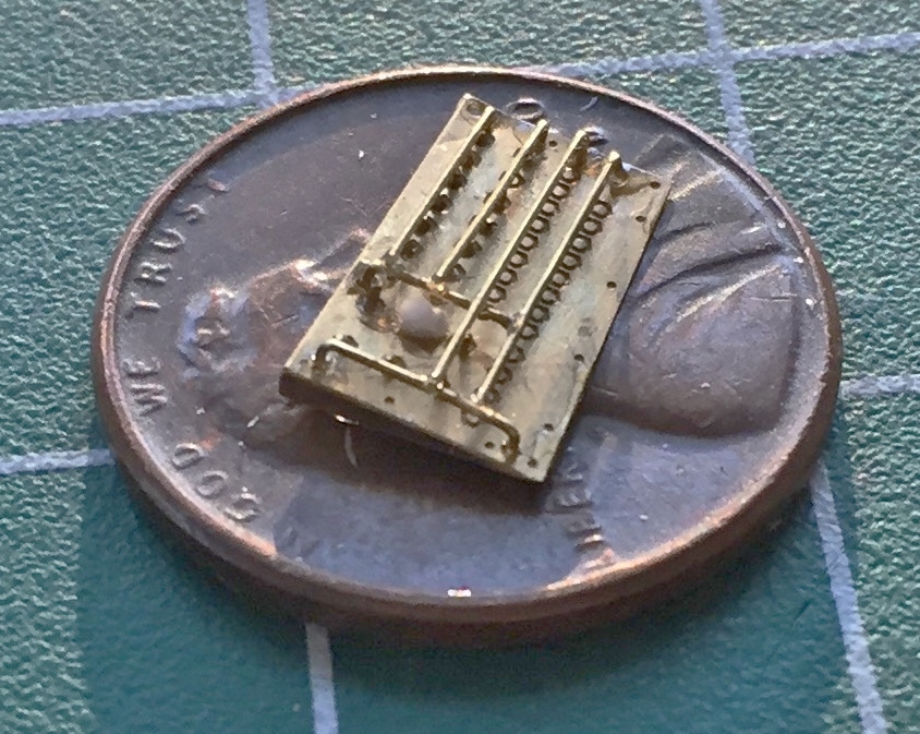
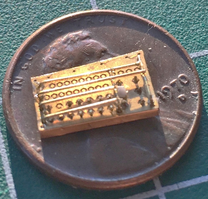
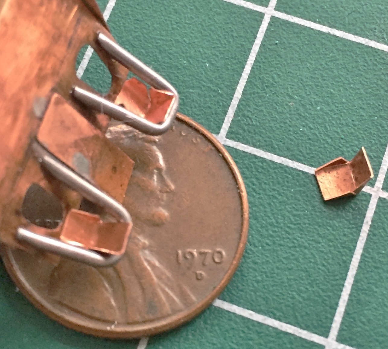
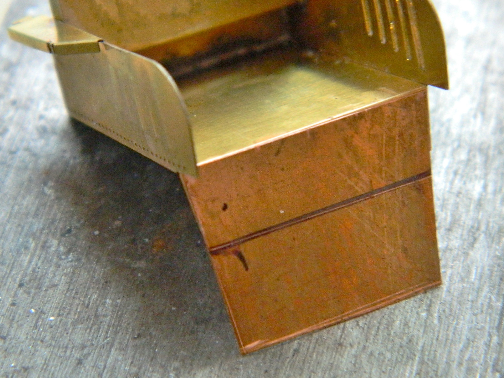
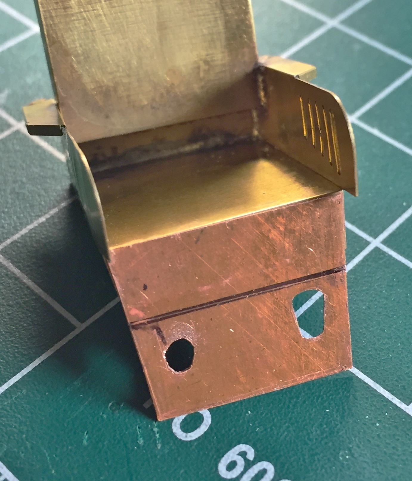
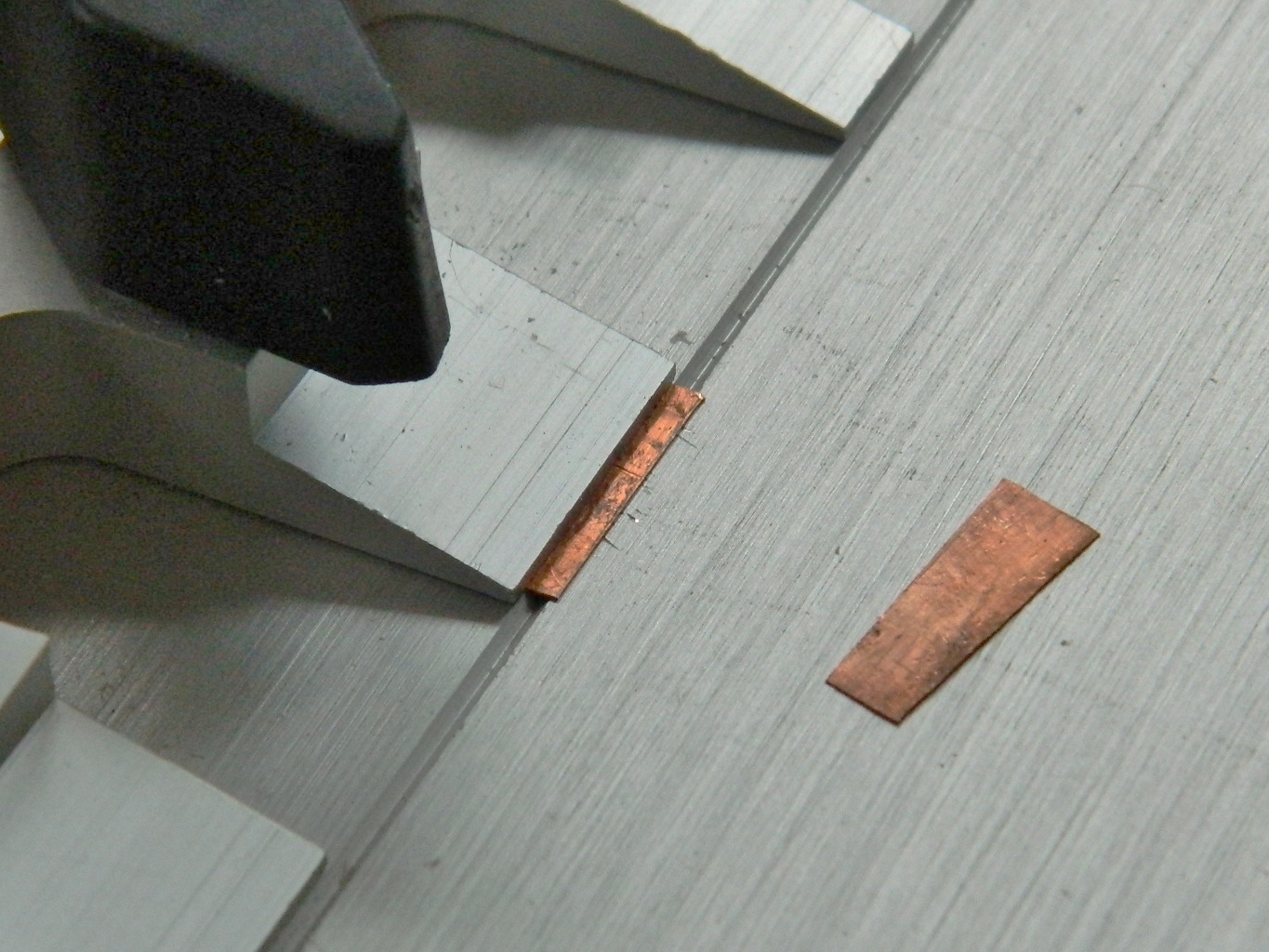
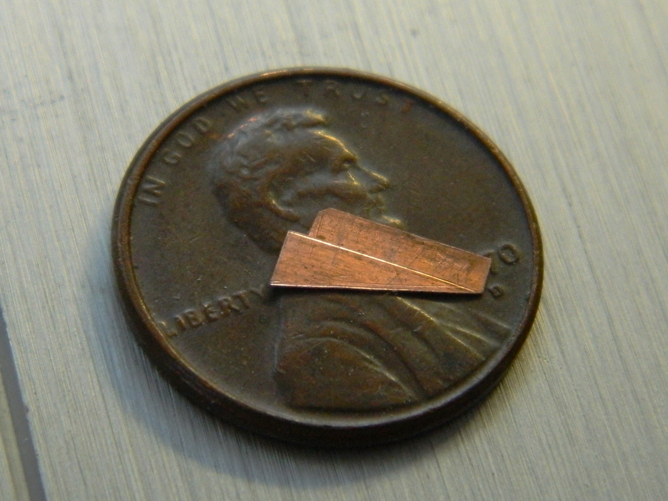
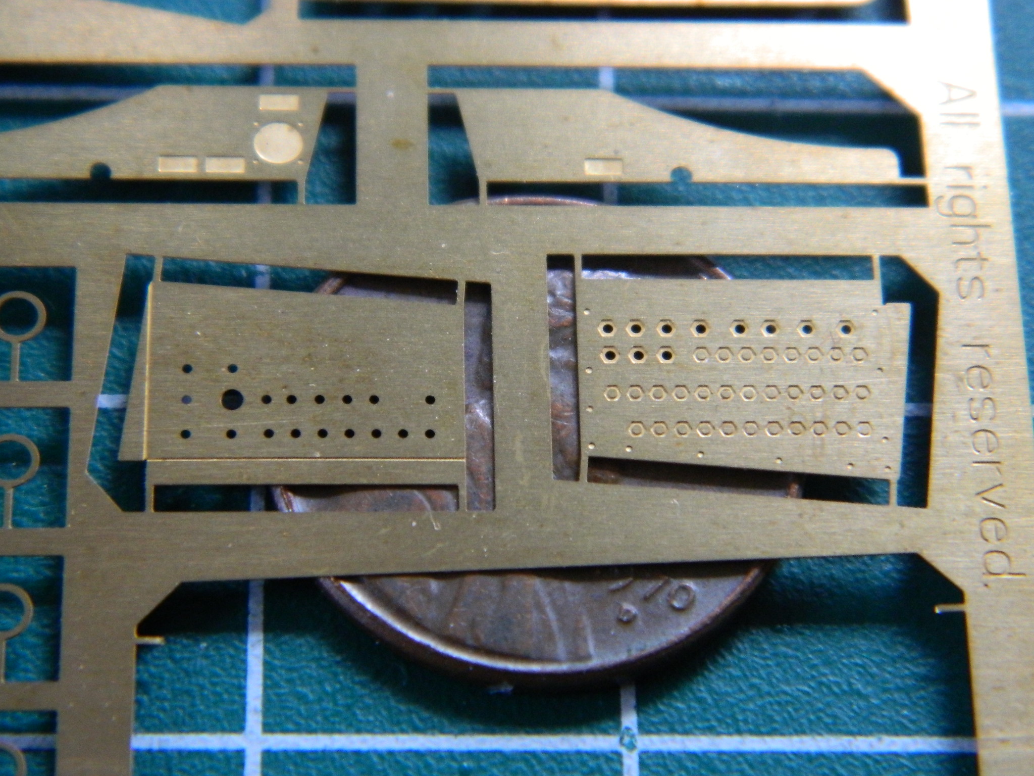
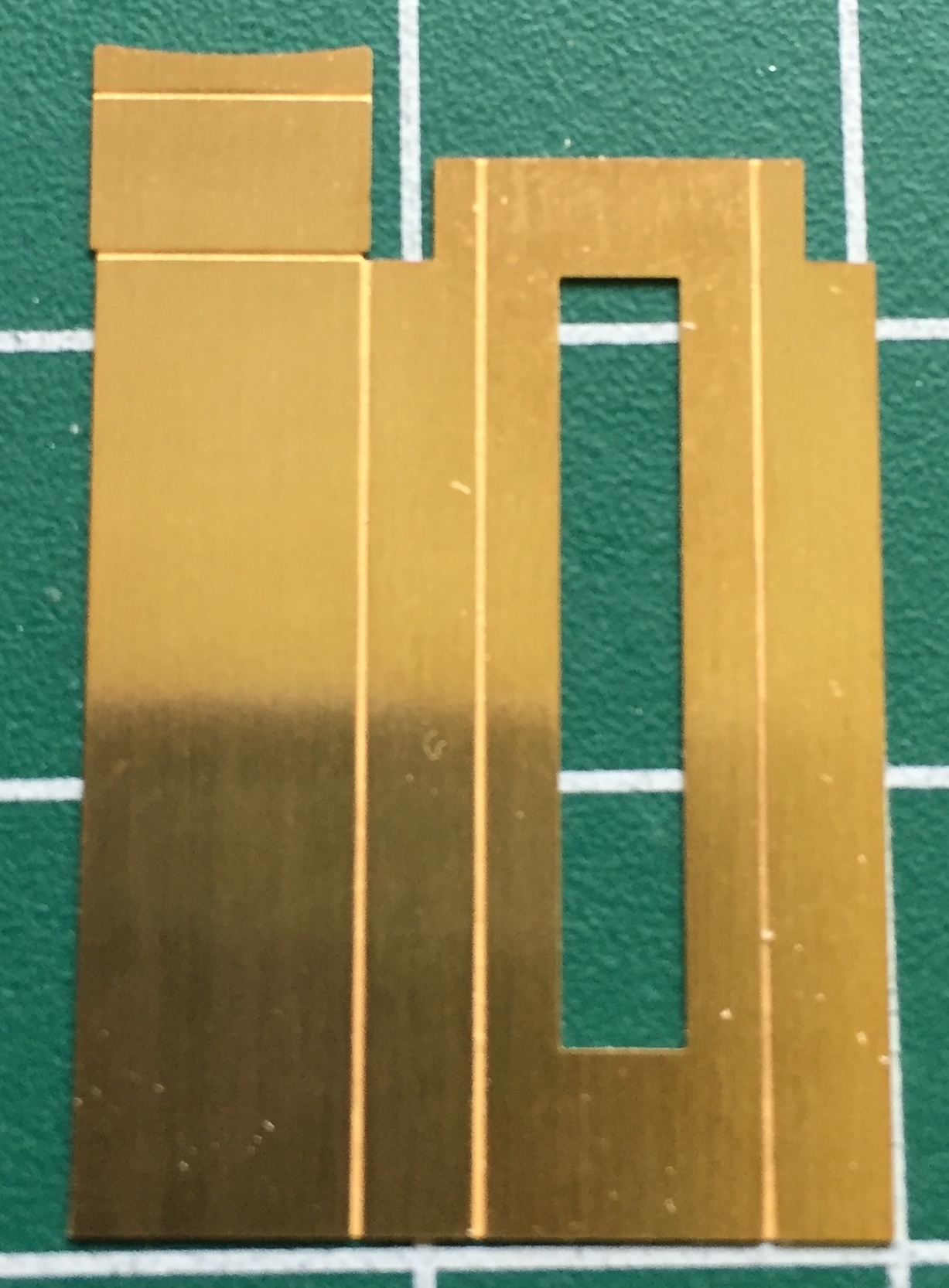
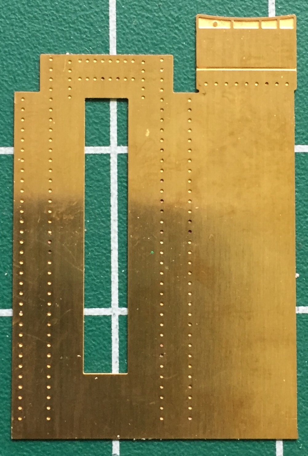
Next I engaged in what a friend called “brass origami.” Folding this:
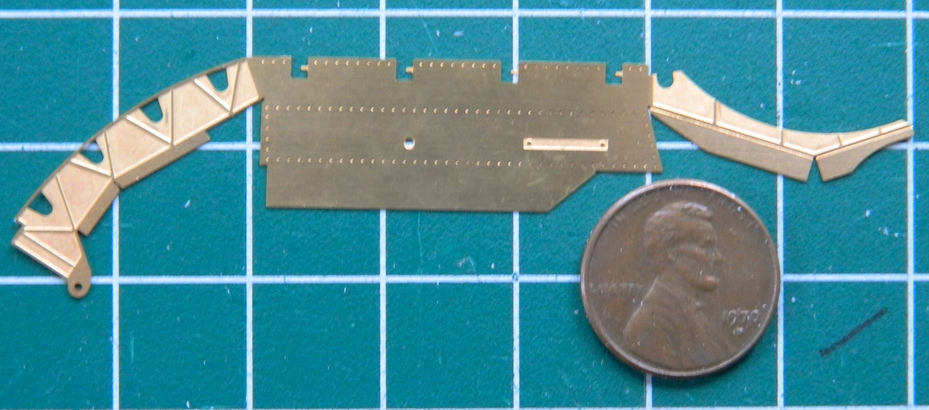
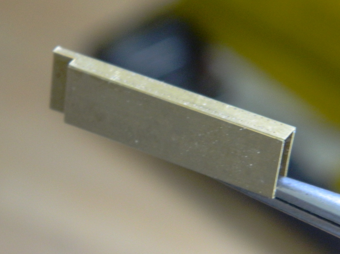
So that they ended up like this:

Obviously I needed two of these parts; they’re the internal structure of the hatches. Have you noticed my pattern when I have to make multiples (even if its only two) of something? The first one went well, what needed to be soldered was, and I then started on the second one.
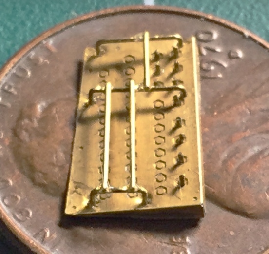
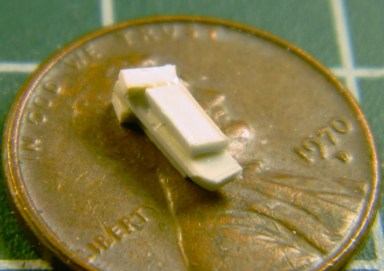
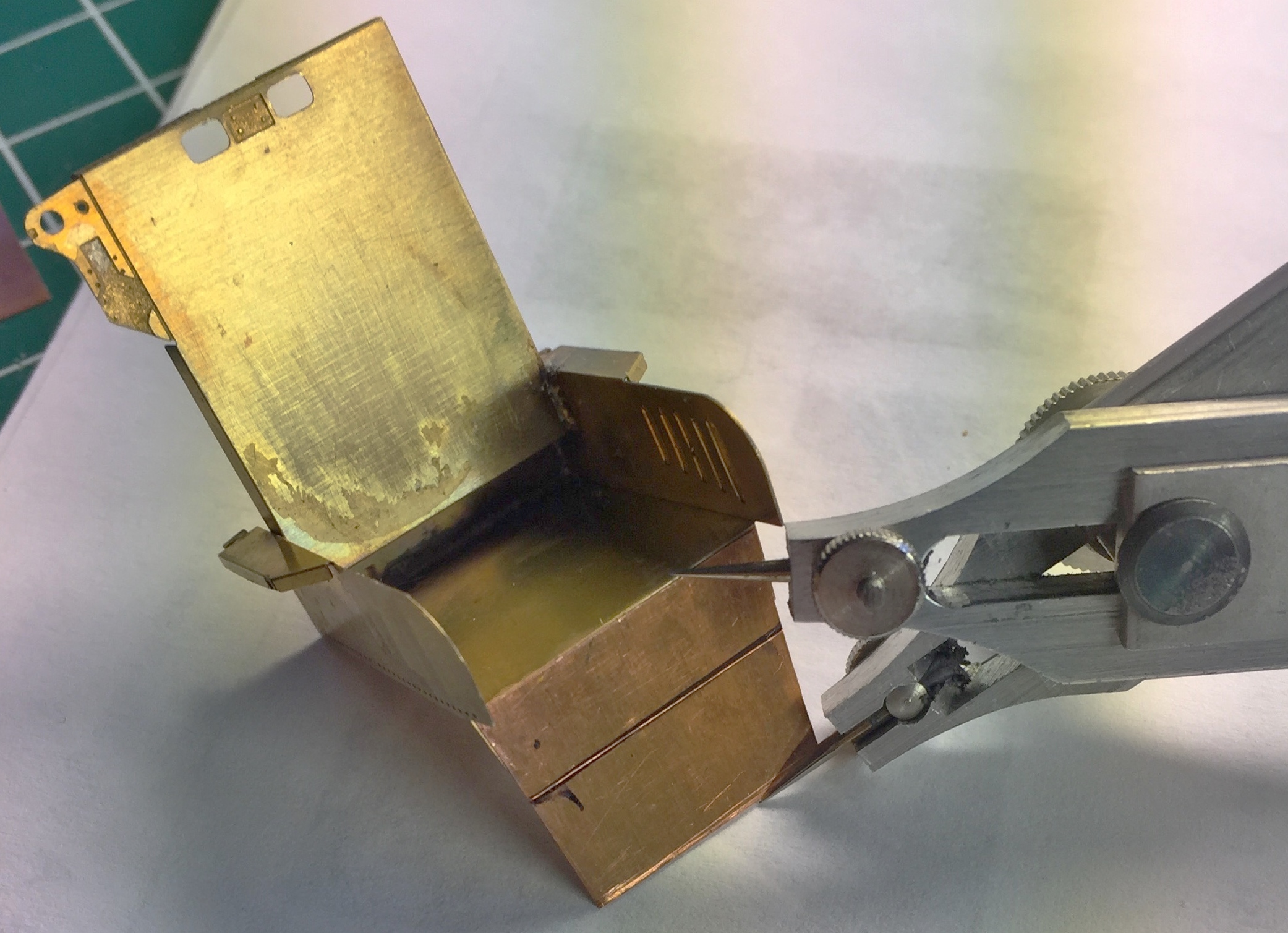
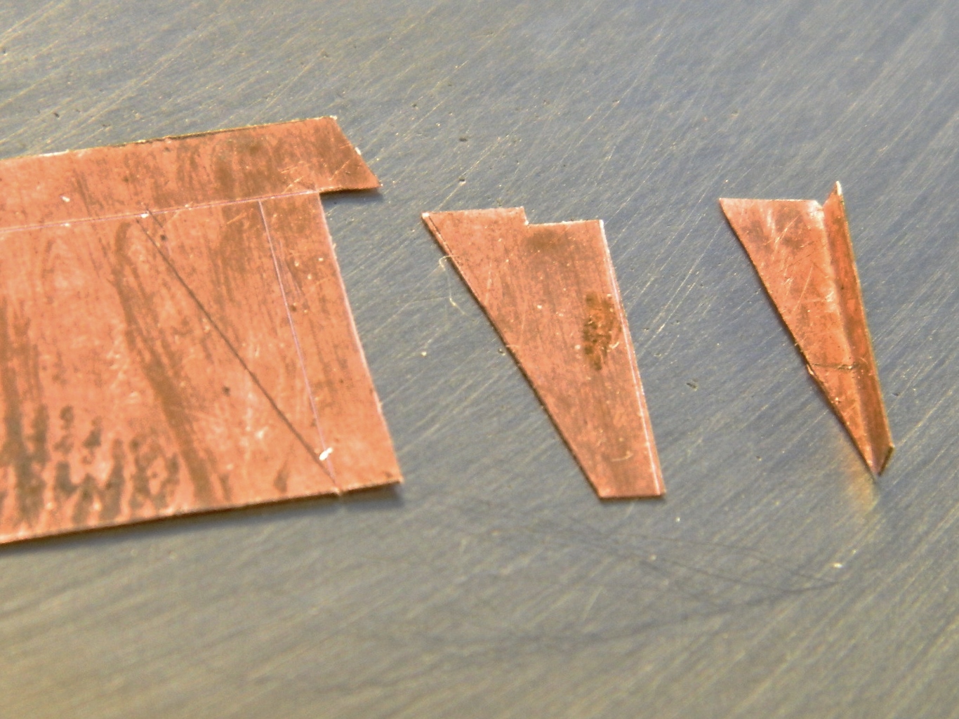
Ohmygawd what a freaking hassle. I used a lot of four-letter adjectives during the process of folding and soldering the next one, and not ONE of those adjectives was “easy.” And when I got to the soldering stage, I discovered that it’s possible to heat the brass to the point where it becomes so soft that it won’t hold its shape. Note the curve to the right piece. That’s not supposed to curve:
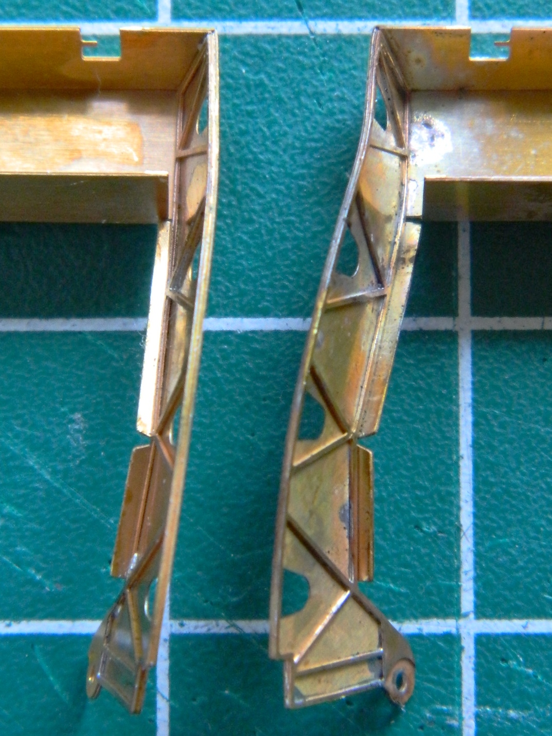
And heating brass to the temperature I did (which I think was just before it would have melted) anneals it. Clearly the brass used to produce these parts was cold-formed. Cold-forming alters the crystalline structure of the brass. Annealing the brass supplies enough energy to the metal to allow the crystalline structure to re-position themselves. This is a wonderful property that allows armorers (the people who make armor from sheet steel, not the people who maintain weapons) to make some amazing shapes out of what started as a flat sheet. What it doesn’t do for me is allow the brass to maintain its strength.
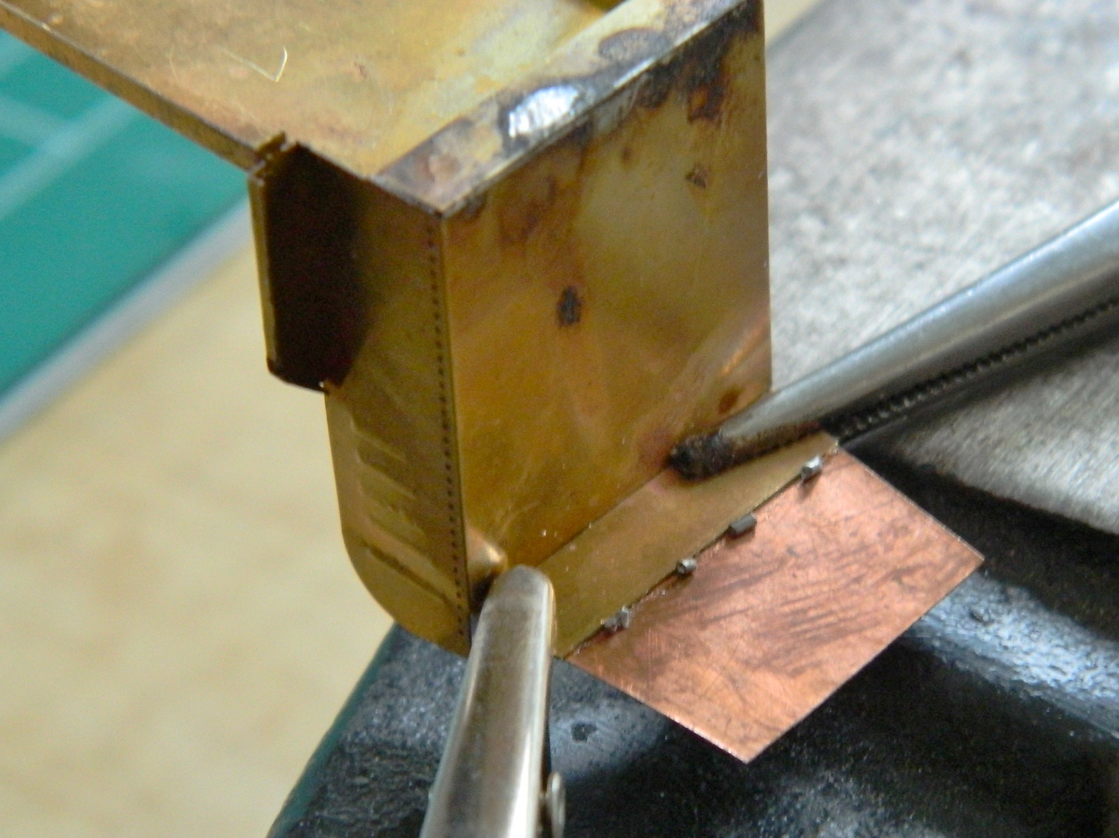
If you wanted to see something funny (and only funny to the observer because they wouldn’t have had to deal with it), you should have seen what it took me to get that GODDAMNED SECTION STRAIGHT AGAIN.
But it’s straight again…
Gemini (Revell) Build #8 – Adding Interior Details (Most Notably the Artificial Horizons), Discovering the Interior Surgery and Exterior Work Were Botched, Fixing Said Botches
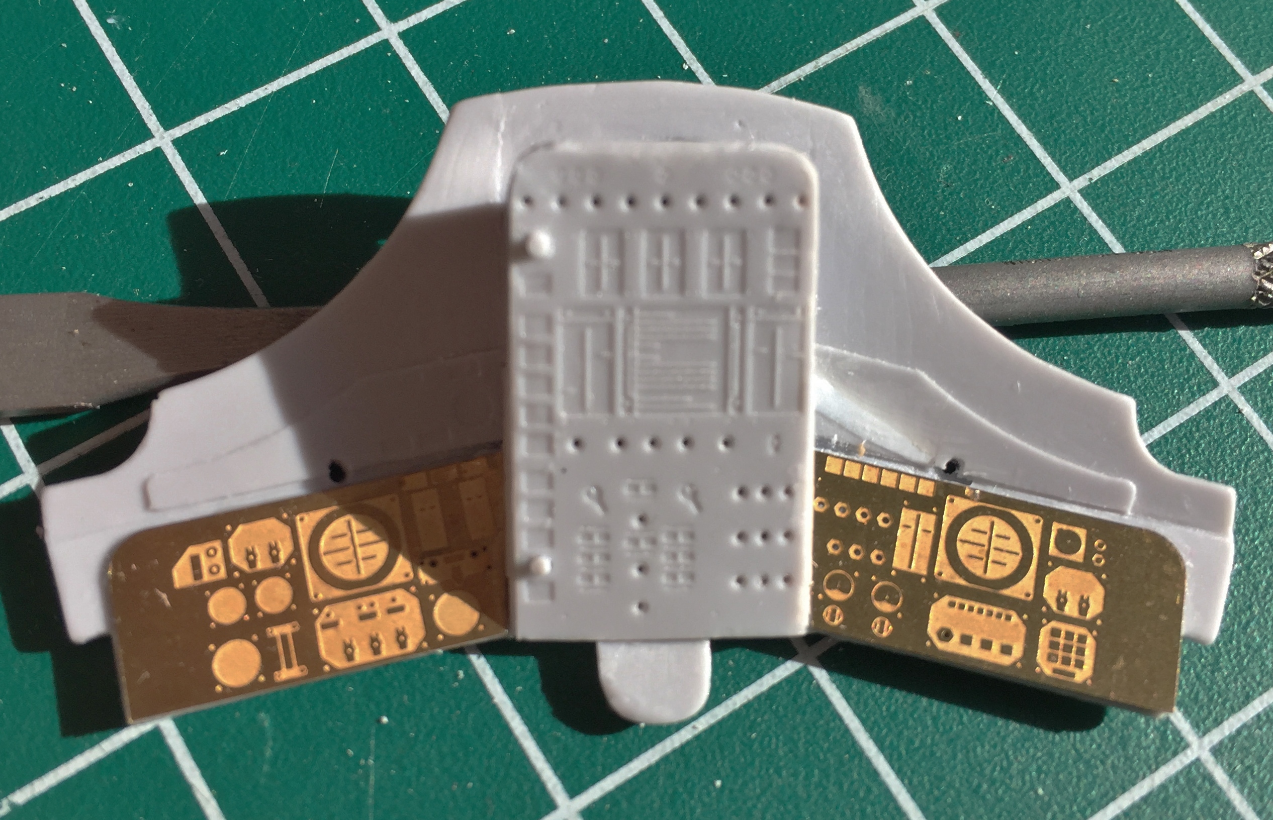
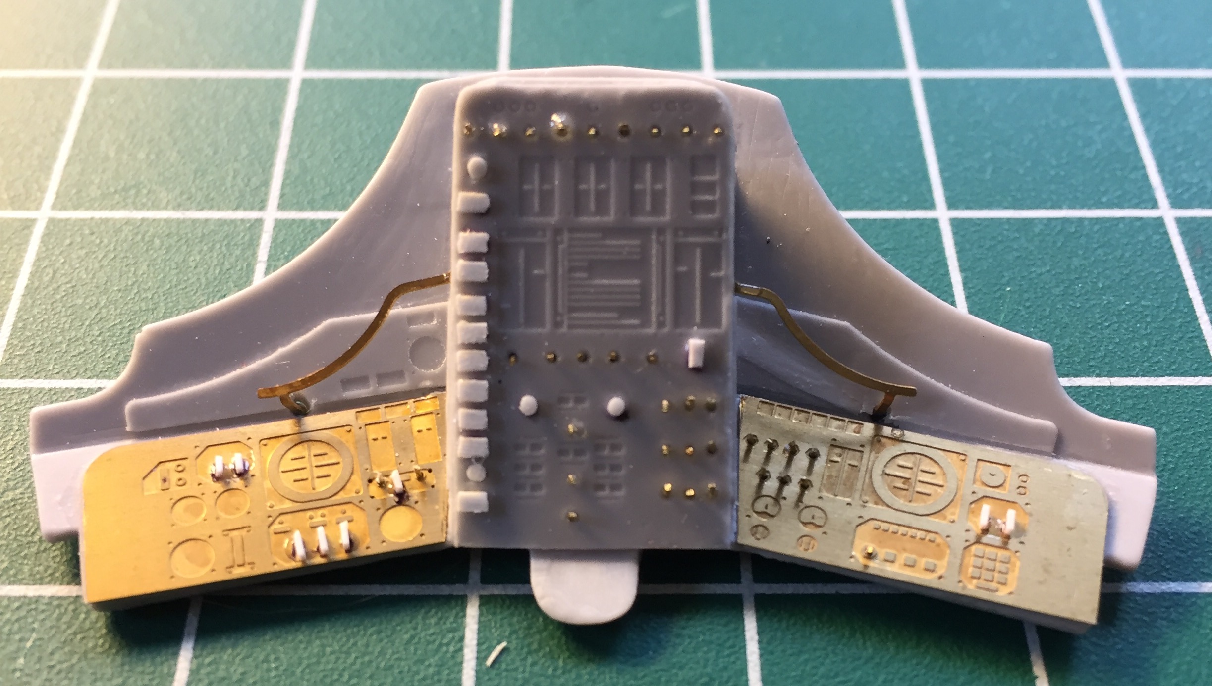
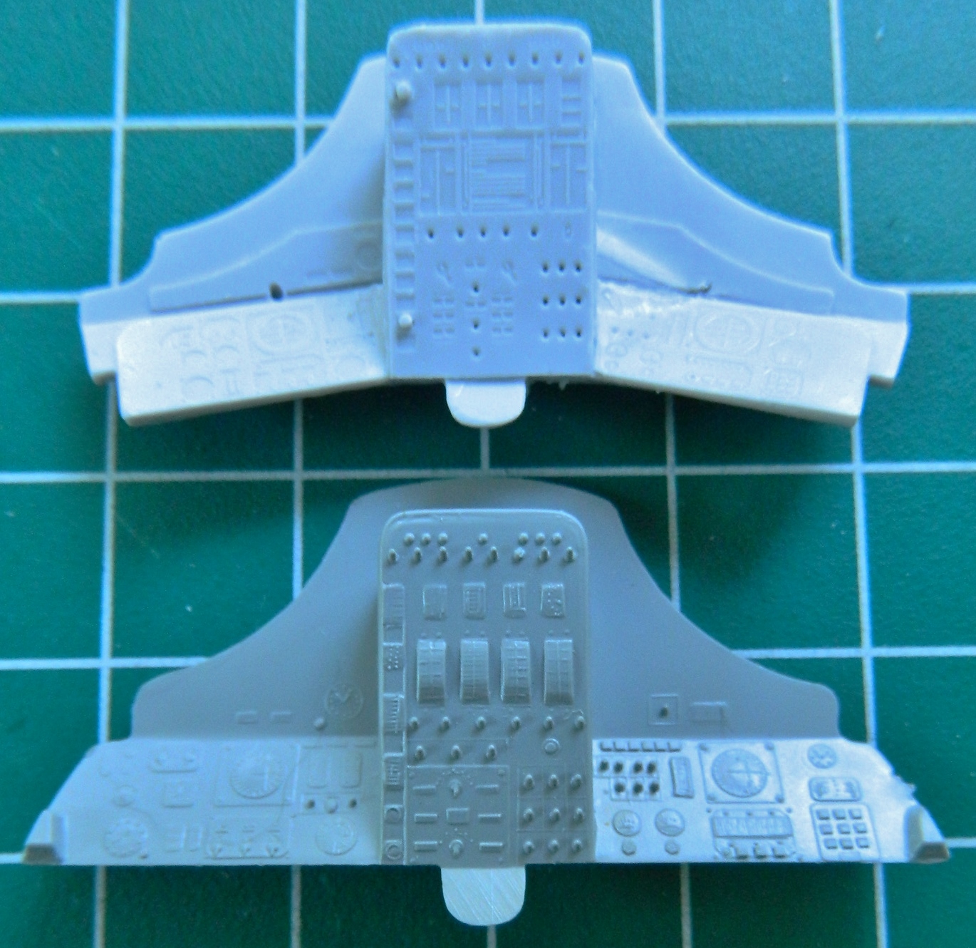
Since I was working on interior parts, I decided to address something that’s been bothering me since I first opened the aftermarket interior set for this model. The instrument panel. Yes, the AM set is A LOT better than the thing the kit provided and I’m pleased to have it. But this is a relatively large scale kit (1/24) and things are easily visible. This is a reference photo of the artificial horizon (of which there are two, one on each panel):

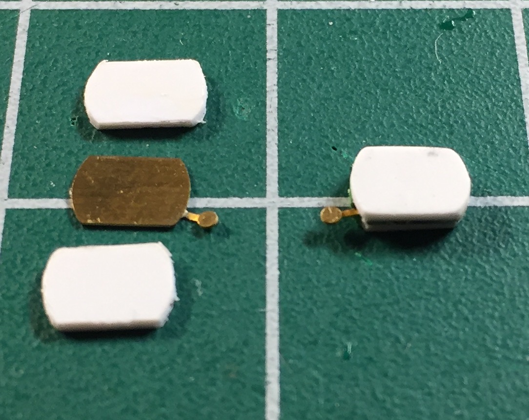
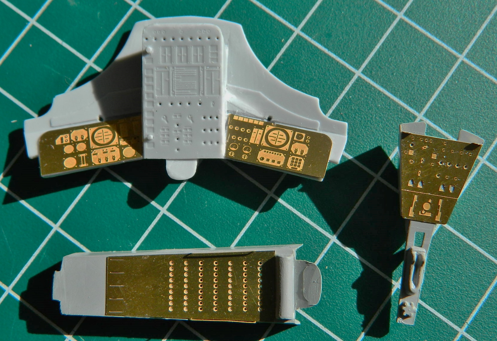
The artificial horizon is the big instrument with the round ball, top half white, bottom half black. As you can see, it’s prominent. This is the PE panel that the AM set provided:

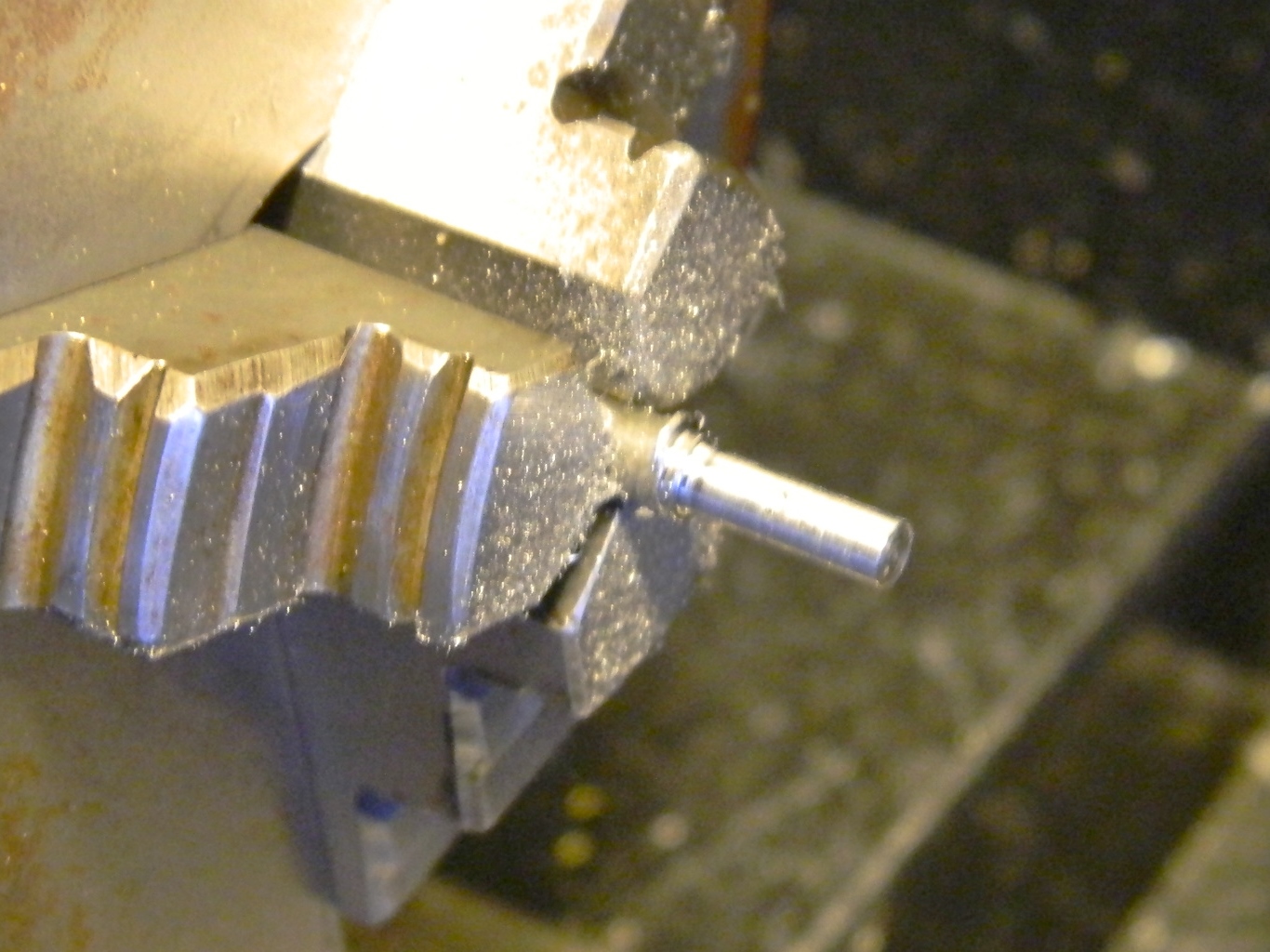
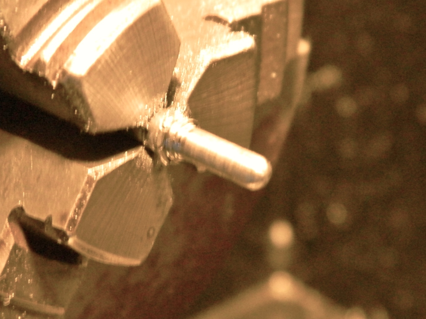
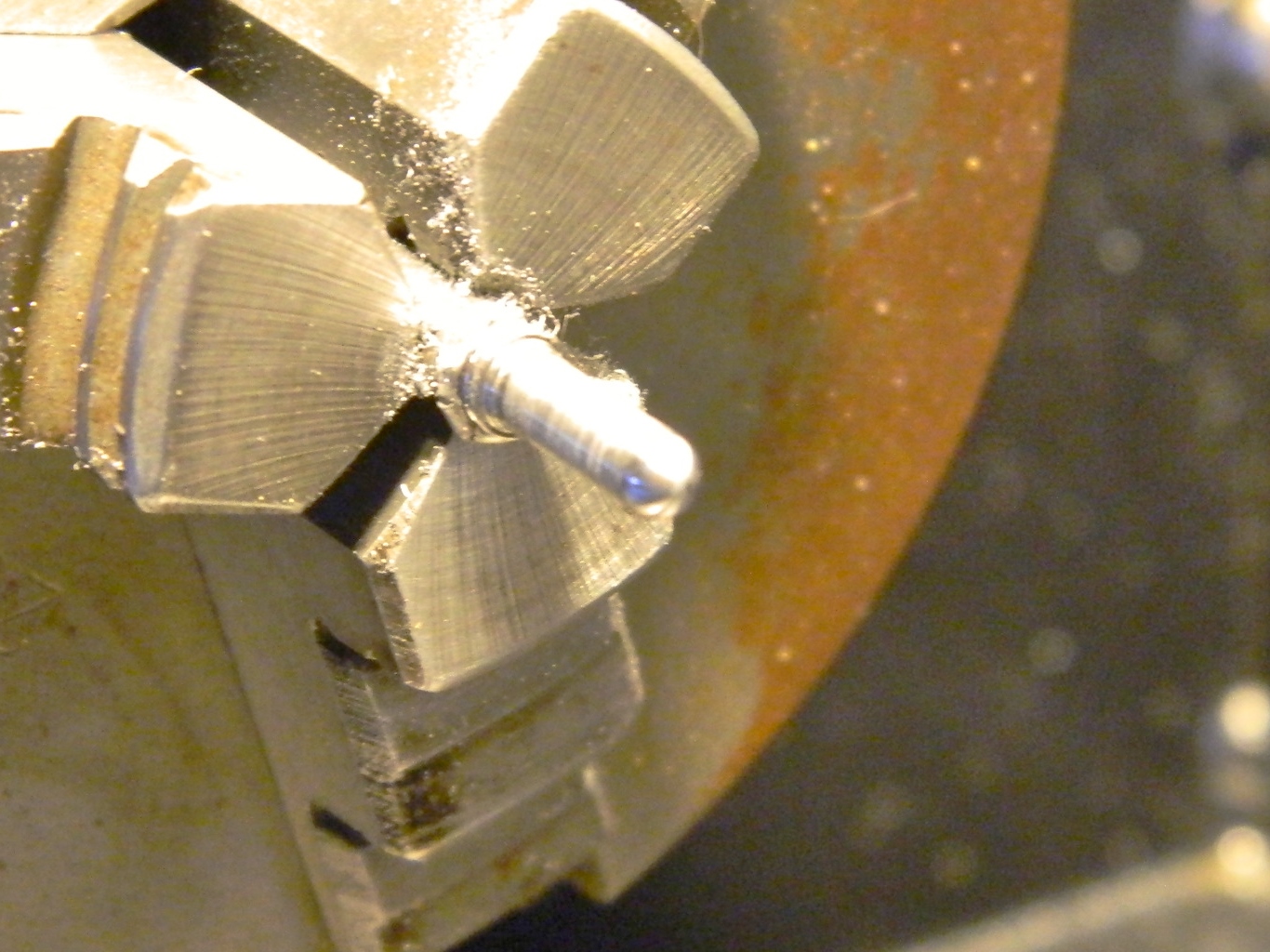
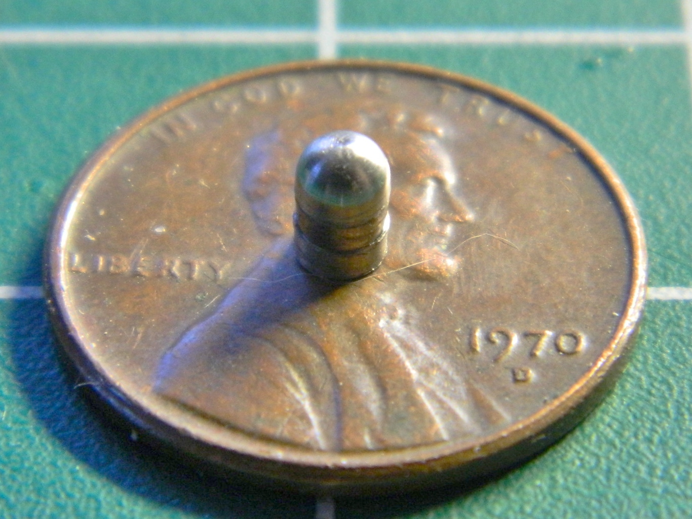
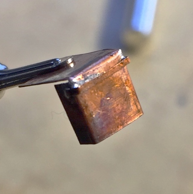
The artificial horizons on these parts are about as convincing as a hooker’s orgasm. I needed to fix that. (The part, not the hooker’s performance. I have my limits, such as they are.) I checked all the parts I have laying around from sword hilt making days, car parts, even model parts, and nothing I had was of the dimension I need. And then I noticed this nail. Its diameter was a little larger than I needed. Okay…I have a lathe. I chucked it into my lathe, turned the diameter down to the dimension required, rounded off the end, polished it a bit, and then cut the part off:

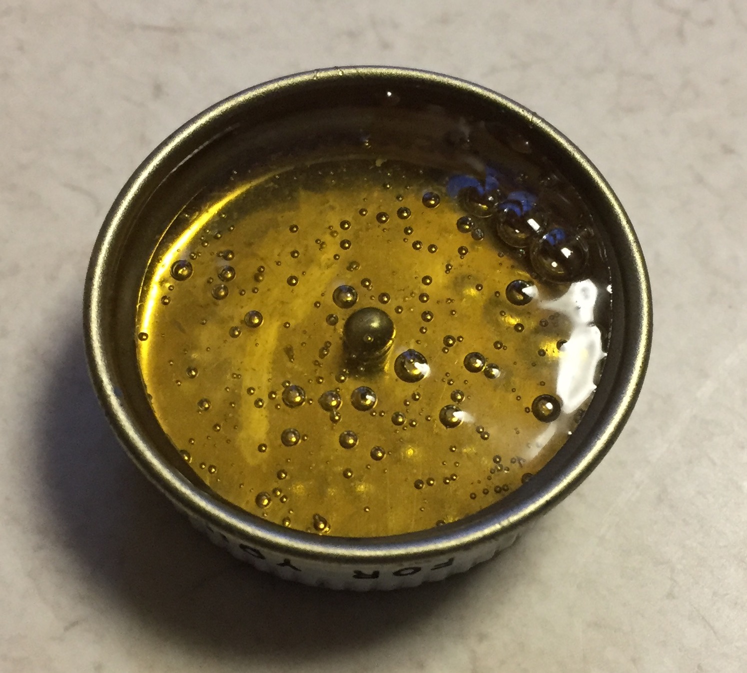
I glued the master (which looks a lot like a scale 40mm grenade to me) into the lid of an empty paint jar and then poured the reusable molding compound over it. Twice:

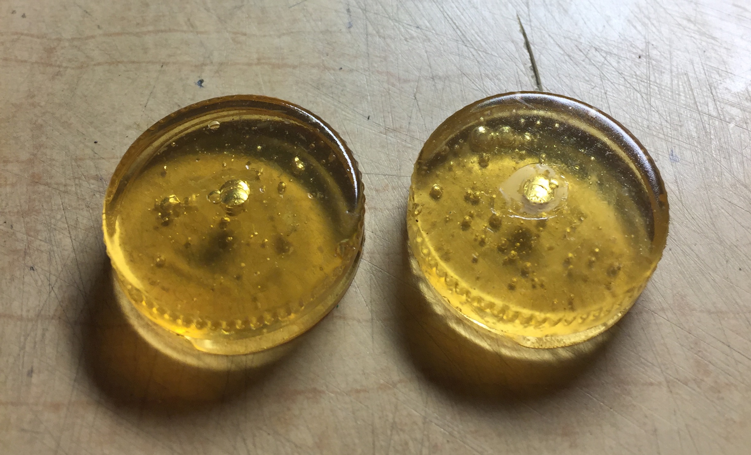
Now all I had to do was to mix up some resin and pour:
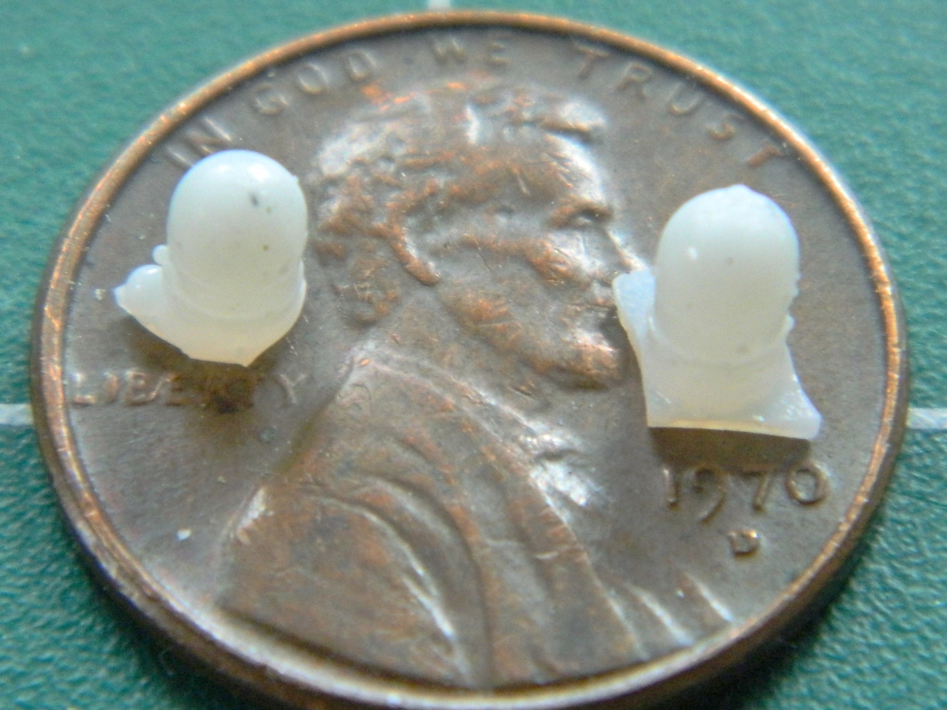
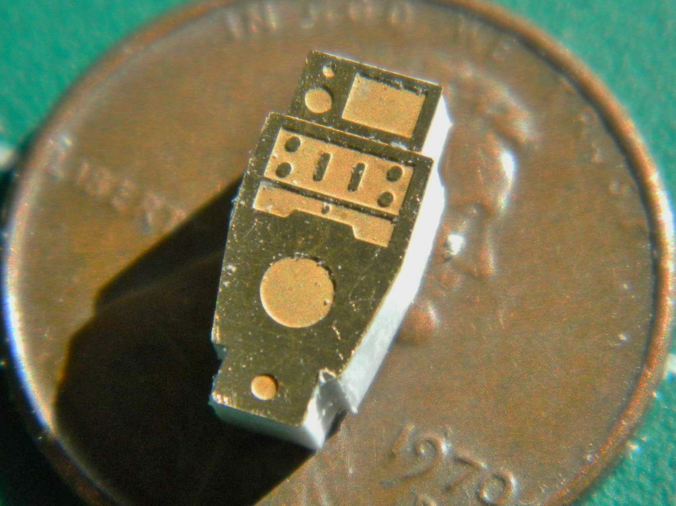
VERY CAUTIOUSLY, I drilled a starter hole in the AM panels, then I used a very fine rat-tail file to open the holes up to the required diameter…and didn’t take any photos of it. ::bangs head on desk:: But as soon as I had the resin copies, I had to try them out (because if they didn’t work, I now had two holes in the part and would have to figure out what to do next). And yeah…I think it worked just fine (CERTAINLY better than what was there!):

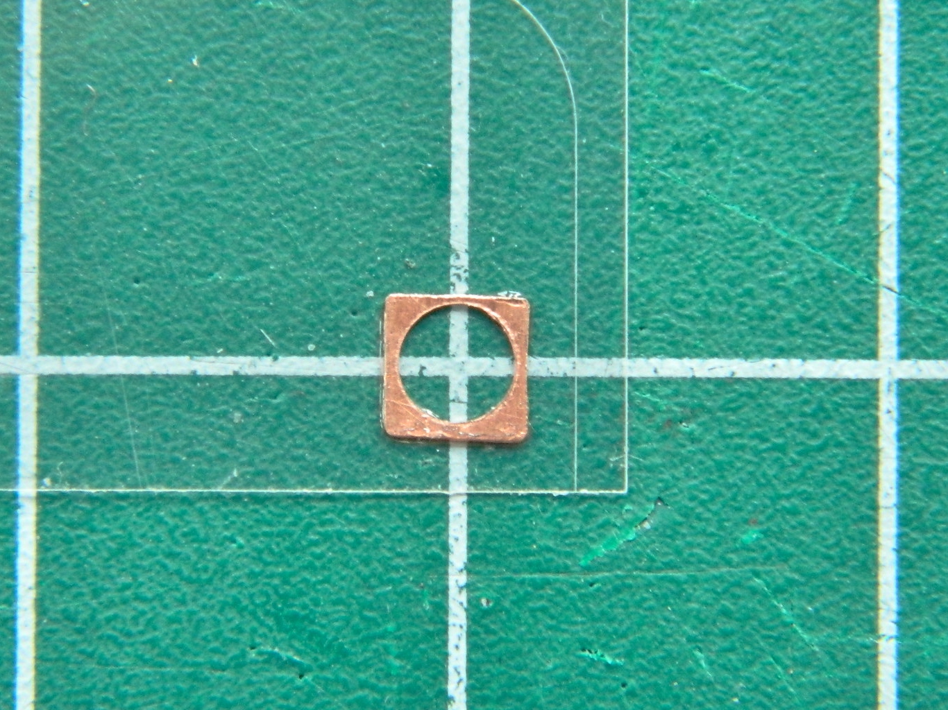
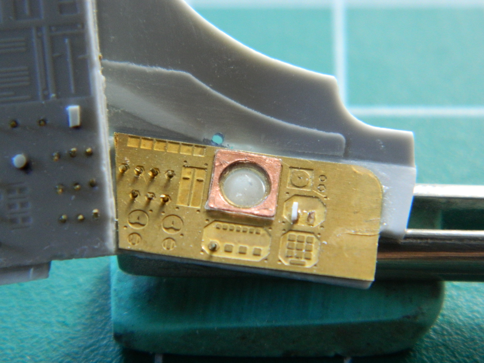
There is a clear front that goes over the artificial horizon, so I made a bezel out of .005″ (.127mm) copper shim stock, used the punch and die set to open the hole, then glued it to a bit of clear acetate. Yeah…once this is painted, it’s going to look just fine:
Now that I’m pleased with the artificial horizon, I realize that all the other gauges on the panels have to be brought up to the same standard. Oh great…NOW what do I do?! I went into my decal stock looking for 1/48 scale instrument face decals. Yeah, the scale is different (1/24 being twice as large as 1/48), but the physical dimensions of the decals are just perfect for this build, so that’s what I’ll use. With only one exception, which I can easily work around, I even have the type of instrument faces I need! When time comes to start throwing paint is when I’ll install the instrument decals.
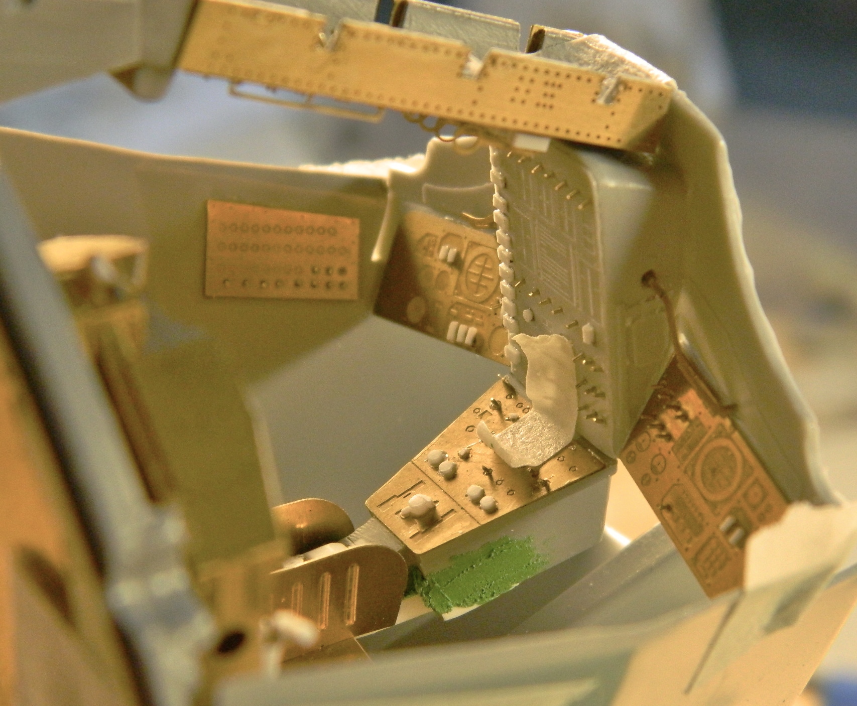
Moving to the sides of the cabin, it was time to start making the other details that belong there. The AM set had the oxygen control boxes for the sides, it’s just that they’re WAY too thin to use as-is. I used .020″ (.508mm) stock to thicken them to the proper size:
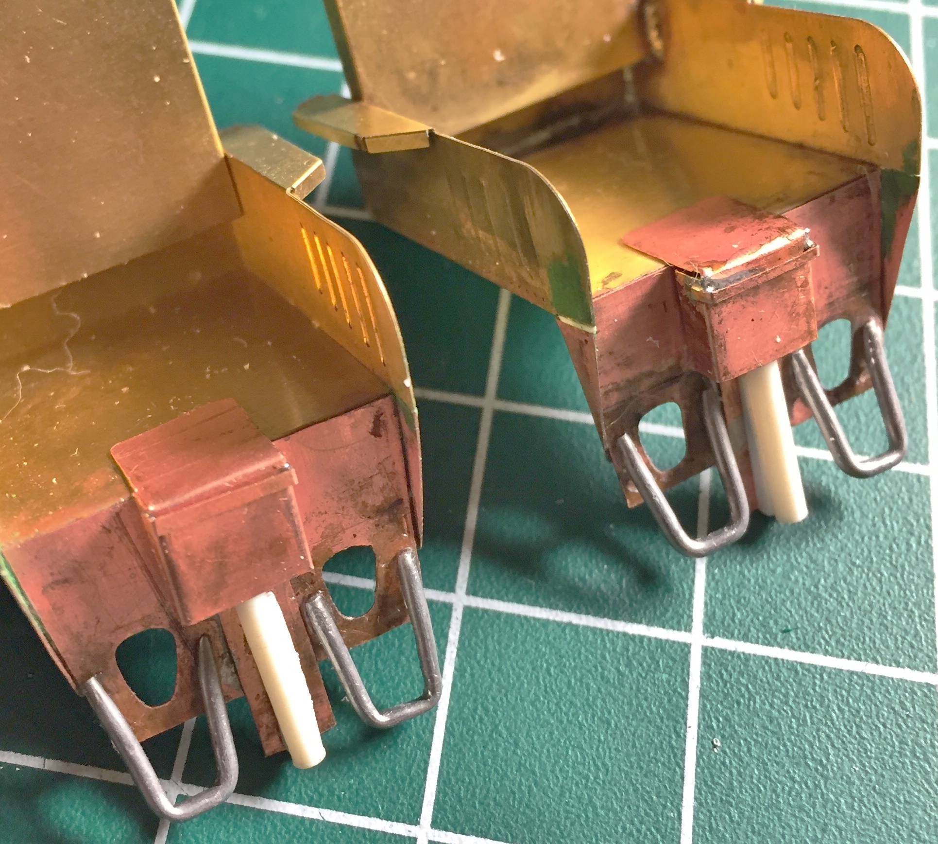
Then I dry-fit them to the cabin walls. You remember the cabin walls? The ones I had to move to make room for the seats? Well…I got the dimensions wrong. WRONG. Yes, I’m quite familiar with “measure [insert number here], cut once.” I thought I had done that! In fact, I’d done that A LOT. And each time I made the same error. If you look at the photo below, I’m sure you’ll see the error much sooner than I did… The right side is taller than the left side by about a quarter inch (5.08mm):
And no…I have no idea how I made such a fundamental error (if I knew that, I wouldn’t have made the error).
Okay, then, how do we fix this? By this point I’d discovered how fragile the part that forms the inner cabin walls really is. I’m not ham-handed and I still had to glue this damned thing back together four times. So that means I’m not going to be able to redo the part I have. Okay, so how about scratch-building a new cabin wall assembly? Uhm…no. This part, though comprised of flat panels, has some pretty funky angles to it. Could I scratch-build this part? Yeah, I could. But to get it right would take time. It would take a lot of time. Normally I’d shrug at that idea and have at it. But I’m trying to get this model ready to bring to a show on April 29…and there’s LOTS left to do and I’m not sure I have that time. How the hell do I get another cabin wall part?
I go to eBay and buy another kit. And that’s what I did.
It’s not like I don’t have anything else to work on while I’m waiting for the second kit to arrive!
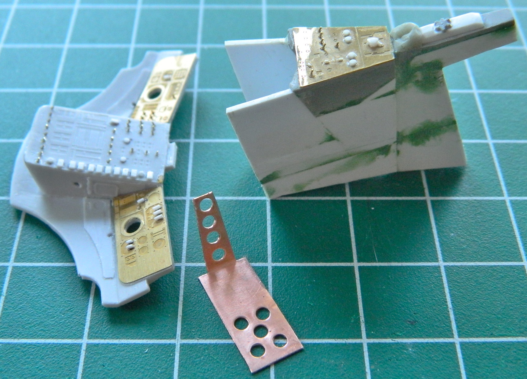
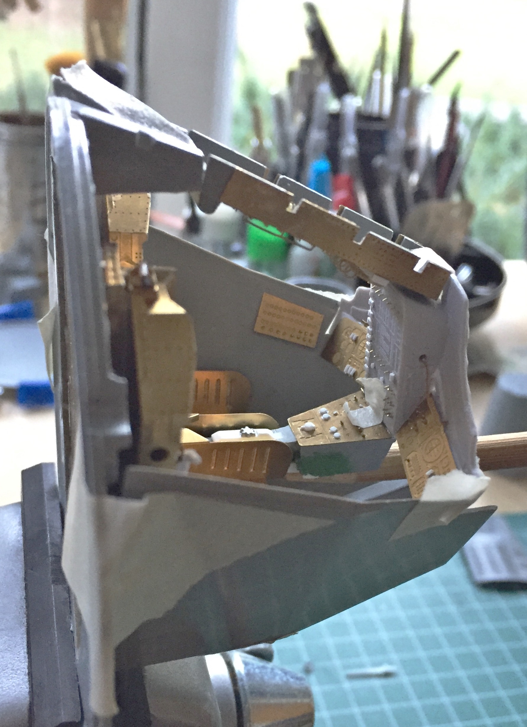
Dry-fitting the cabin parts has been “interesting,” in the most Chinese sense of the word. I decided to make things easier on myself (if only for the novelty of that). I’ve been having serious problems with getting the instrument panel to stay attached to the center console. The problem with that is that there is such a small surface for any adhesive to work on that any nudge or torque, no matter how small or gentle, causes the two parts to separate. I needed something more robust. What I did was take a section of .010″ (.254mm) shim-stock, punch holes in it for better adhesive adhesion, and using Shoe Goo (great stuff, that!) I attached the support bracket to the underside of the console:

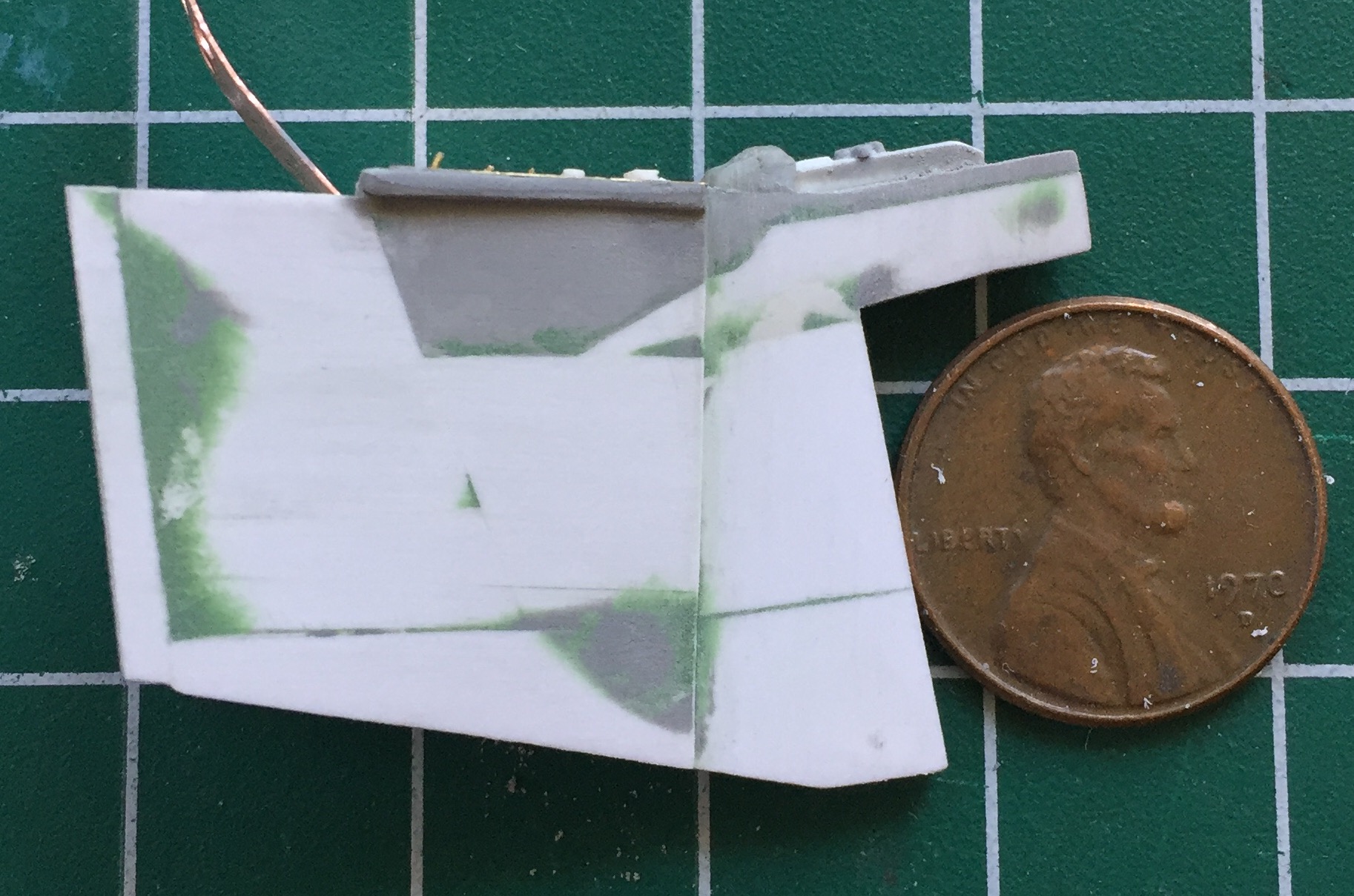
That also eased dry-fitting the parts. The only point of reference I have is where the instrument panel attaches to the walls of the cabin. Rather than permanently attach the panel to the support, I taped it in place and used that as my reference to finish fitting the console to the cabin (even though the sides are wrong, the floor isn’t and that’s what the console with its added sides need to fit to). I used a lot of pieces to build up the sides and I needed to check the seams to make sure they won’t be visible. I used a rattle-can with what I thought was acrylic primer (there will be more on this later on) to show the seams…and show them it did. The surfaces got sanded, puttied, sanded, and puttied again, until the added sections were, well, seamless:

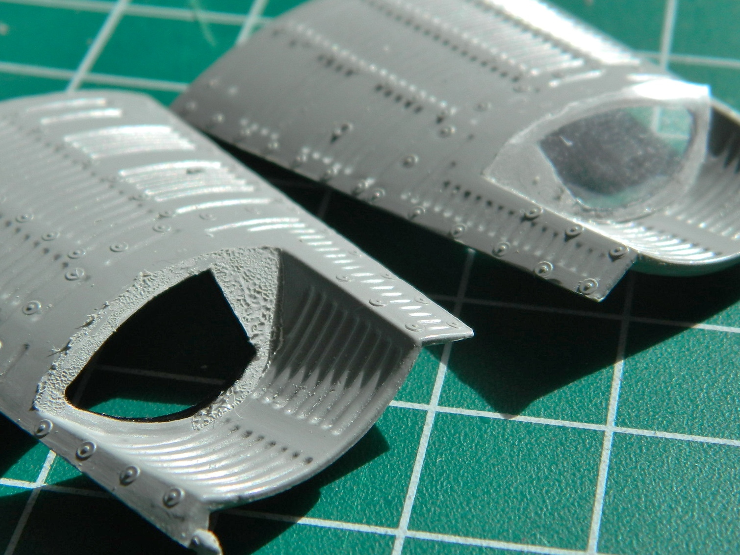
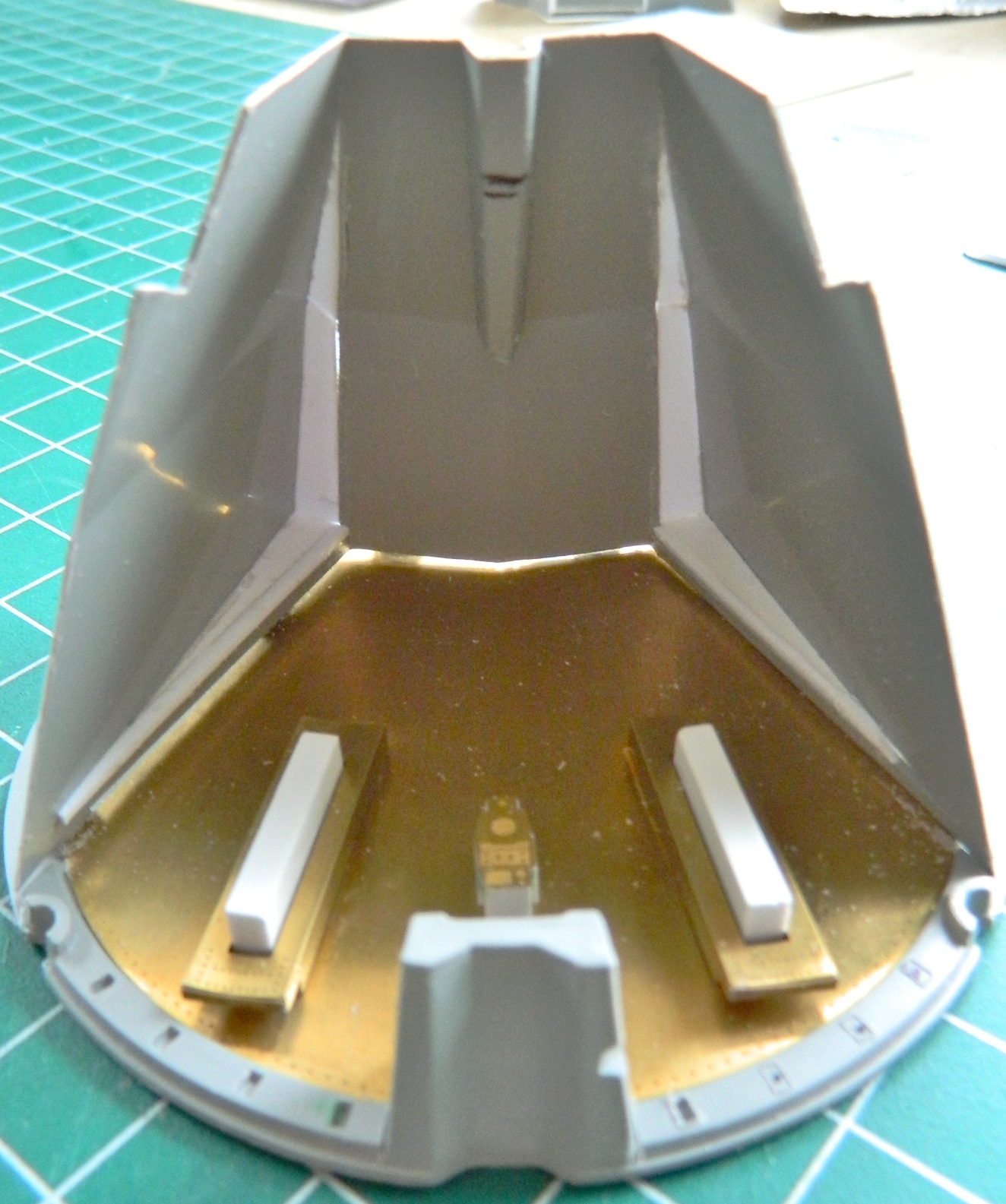
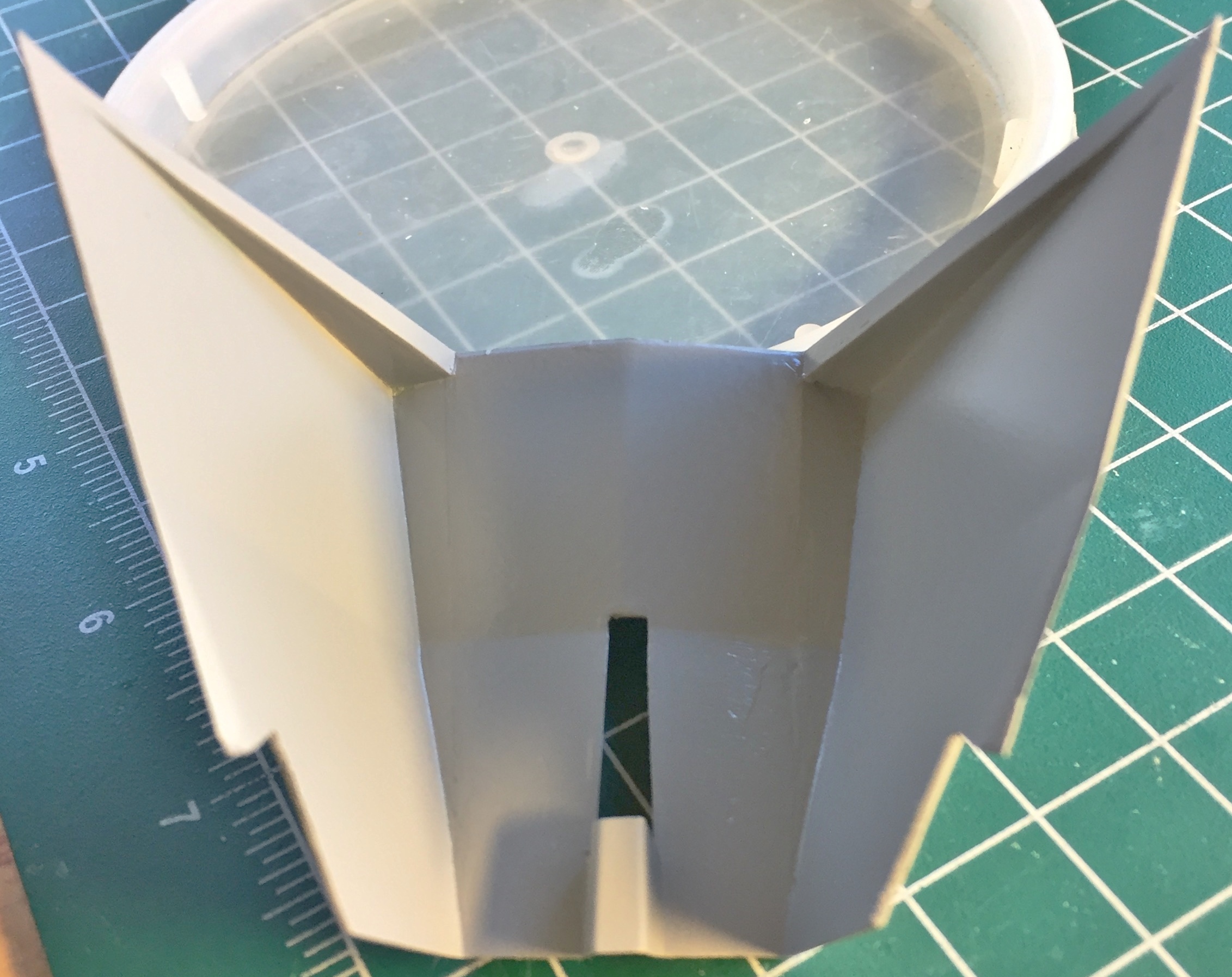
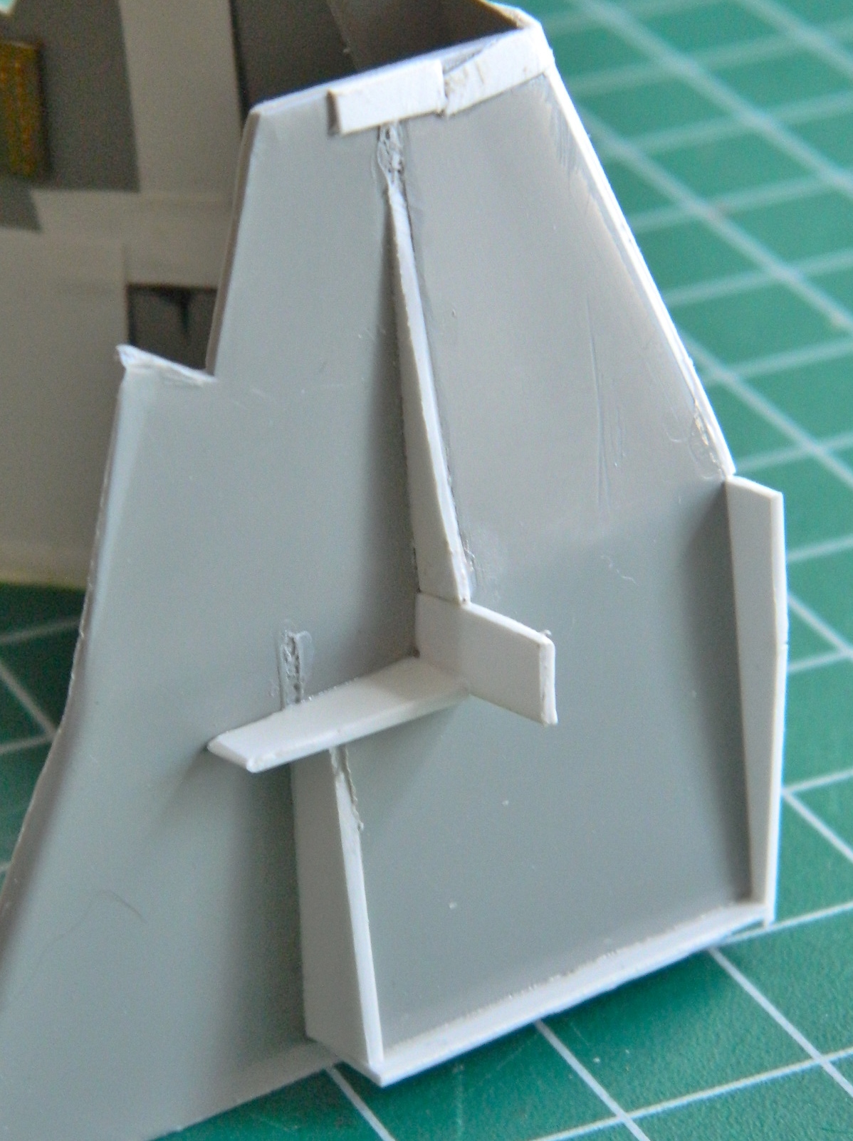
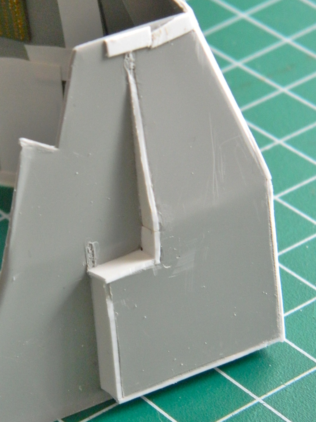
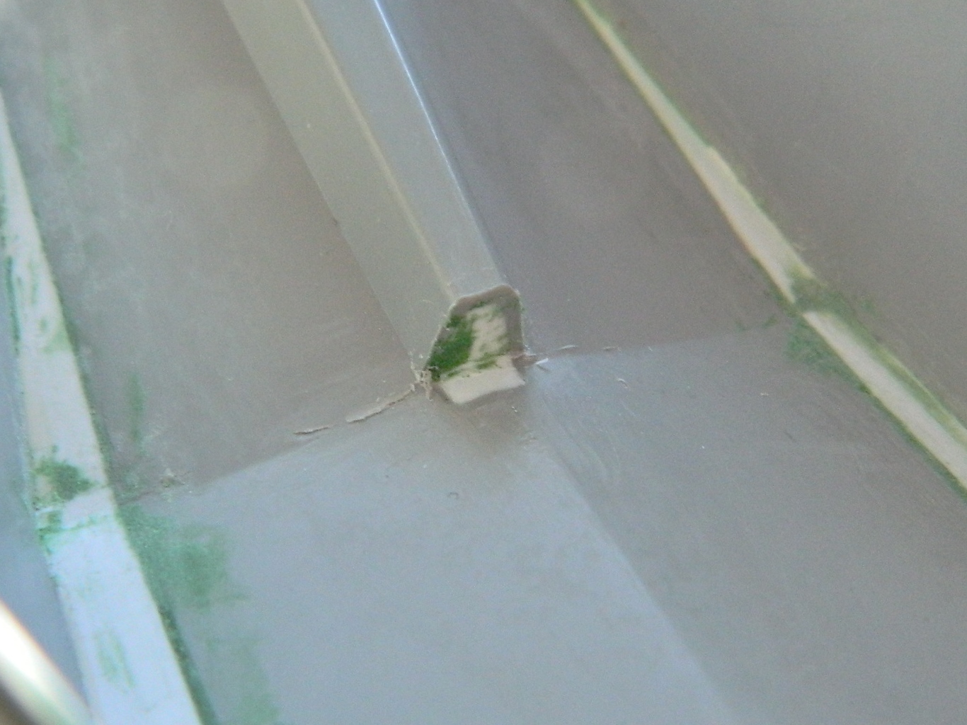
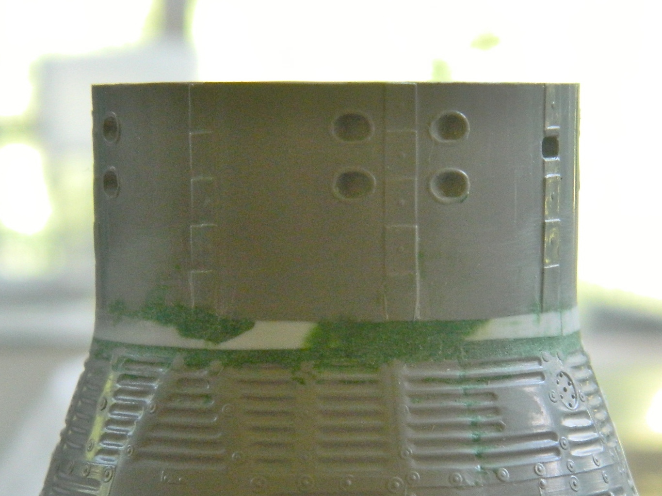
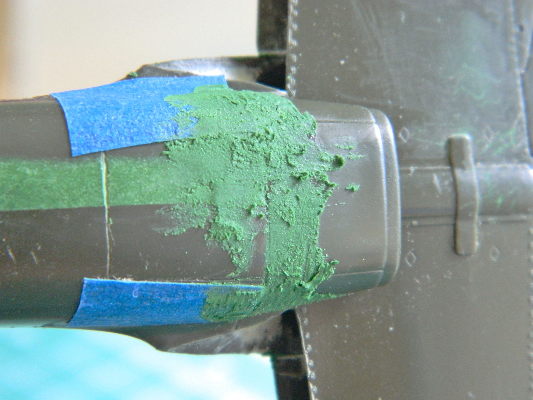
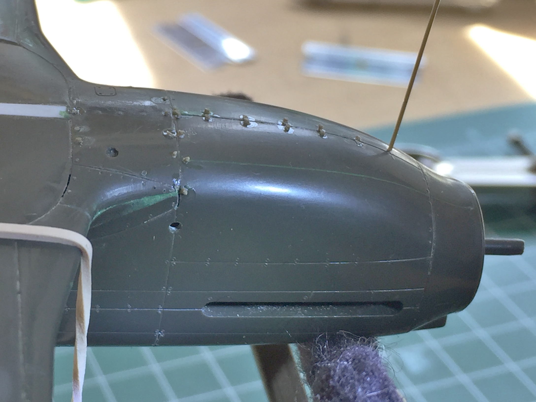
An area that I knew needed work was the channel between the hatches. This is where the bridle for the parachutes was stowed and as such it needed to be flat. As you can see, it wasn’t:
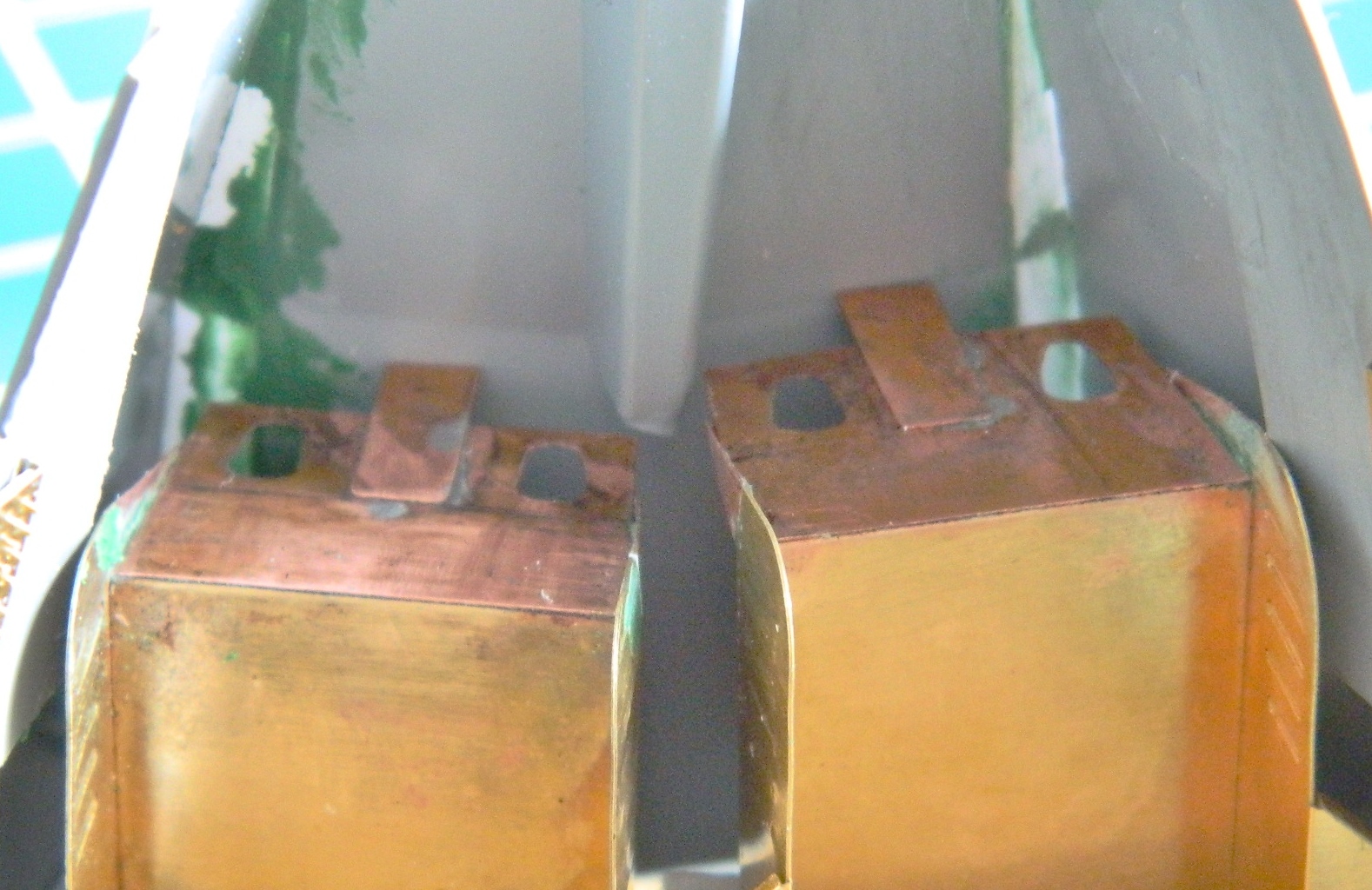
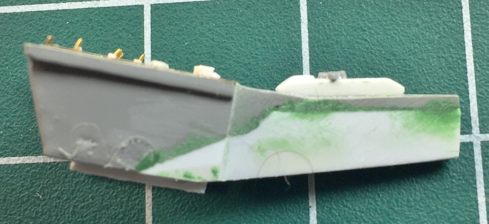
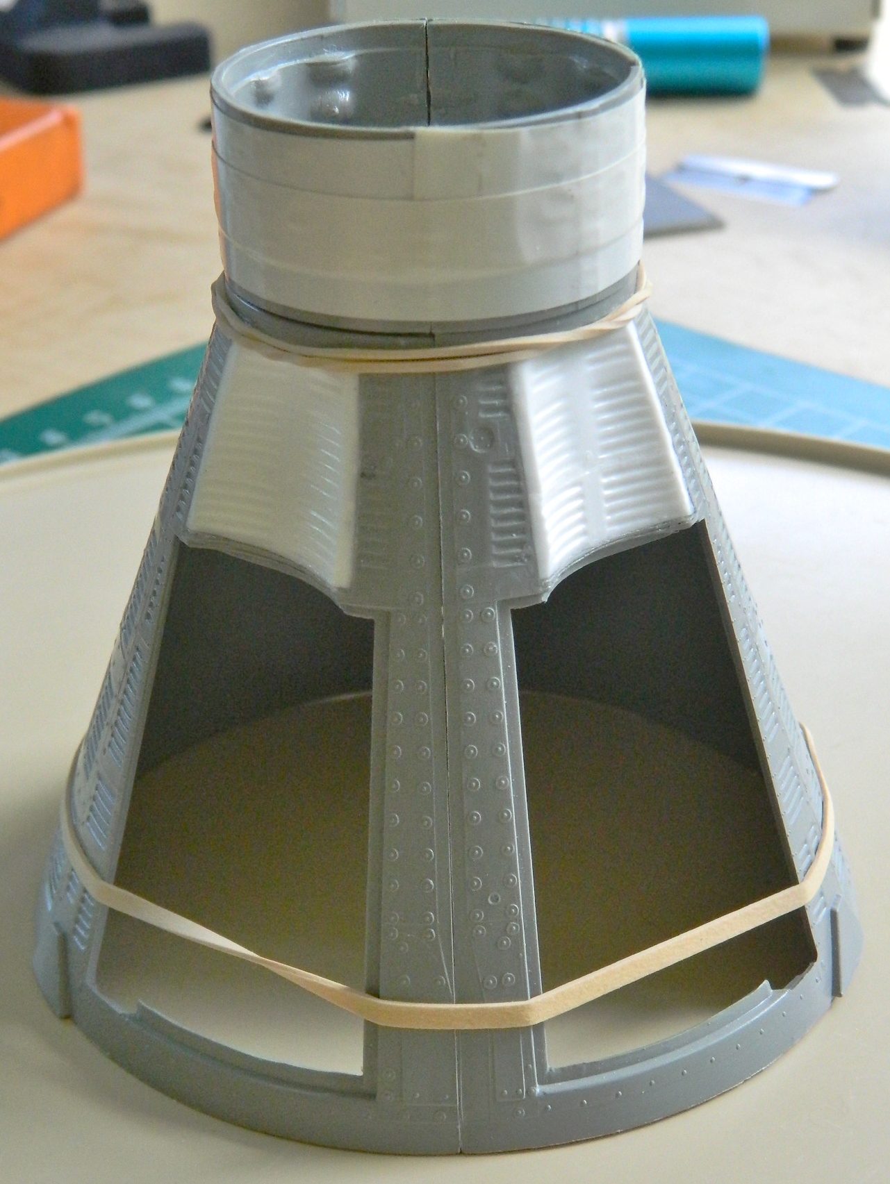
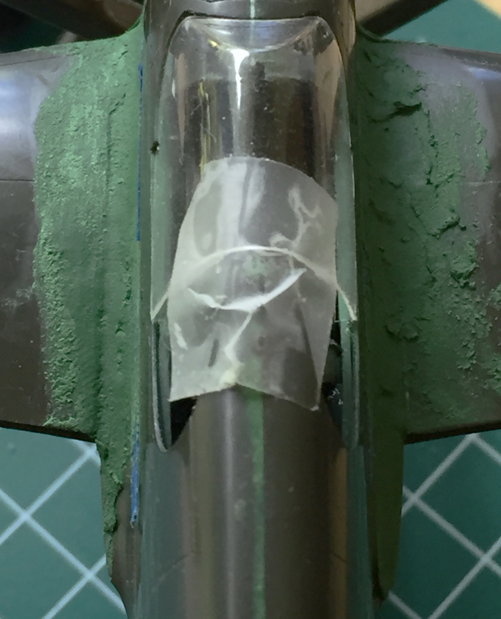
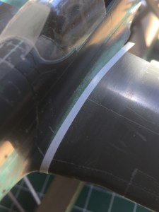
After working on it and getting it suitably flat (I thought…once again I was in error), I needed to see just how far towards the nose of the capsule this channel went. Finally getting the hint about checking references, I checked references:

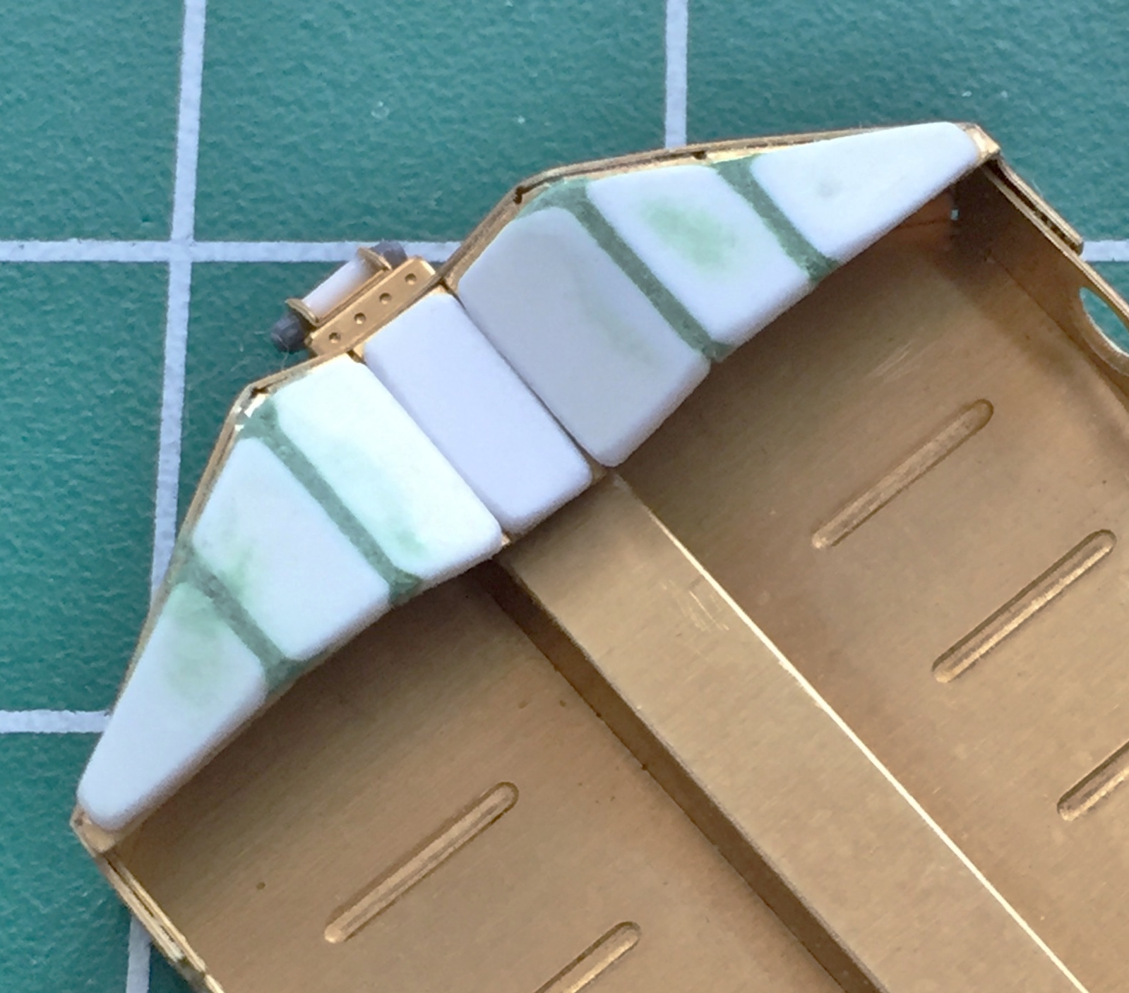
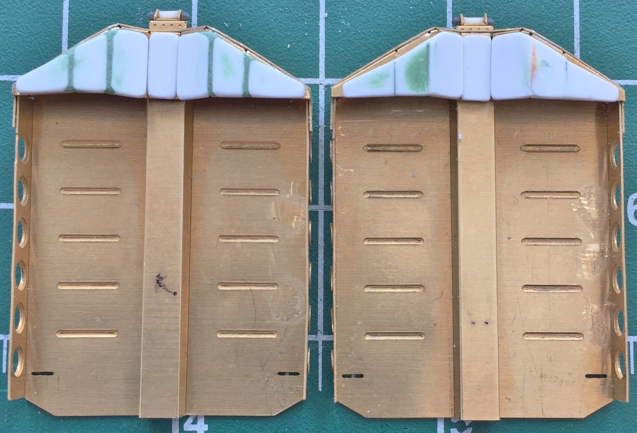
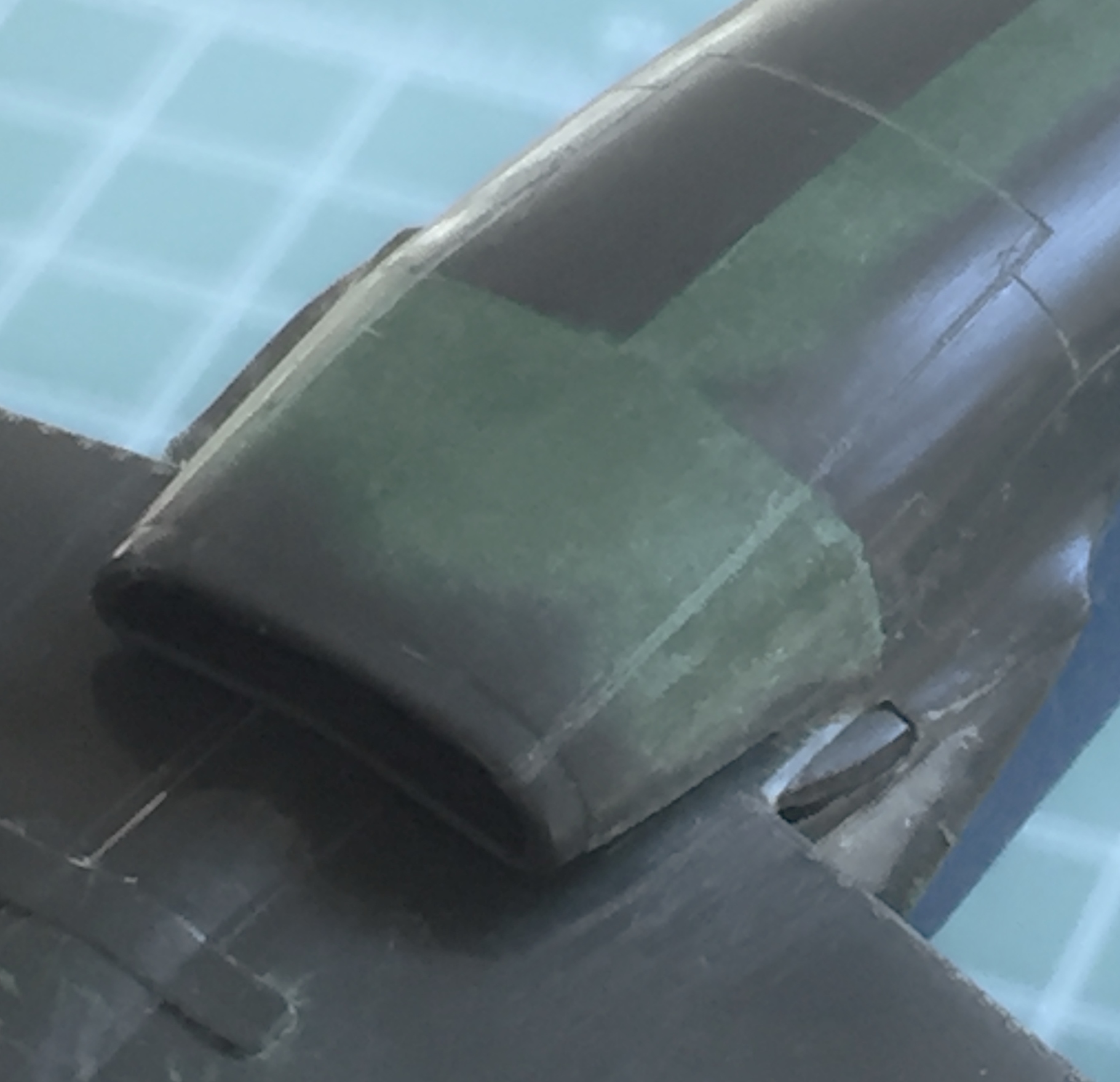
Yep…it goes all the way to the point where the nose starts to taper. In the above photo, note the white stripe where it crosses the cylindrical section. See those flat tiles on either side of it? Compare it to these photos:

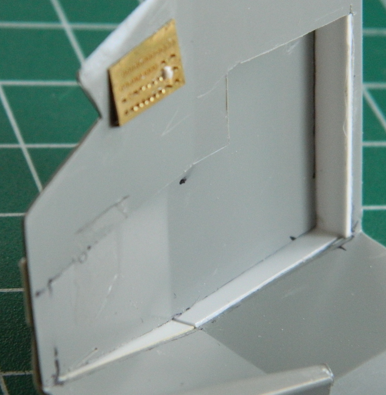
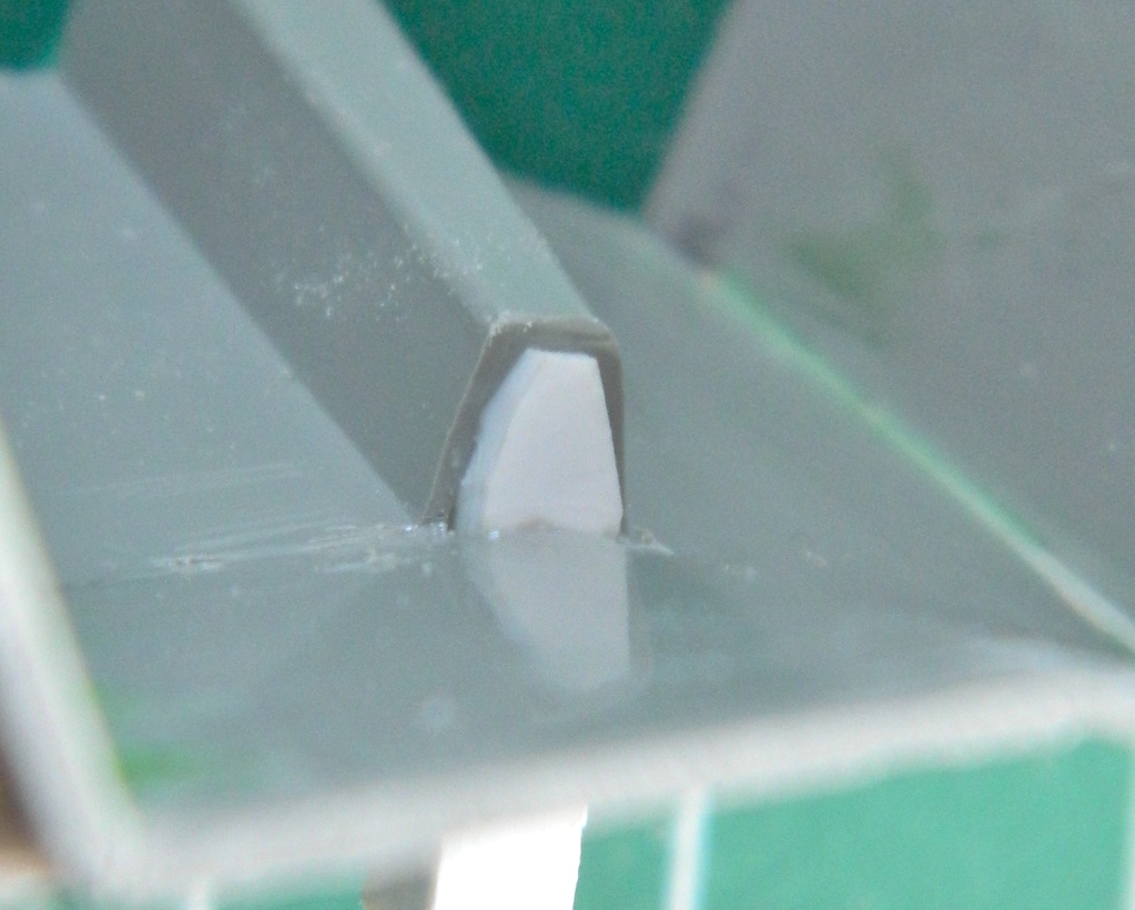
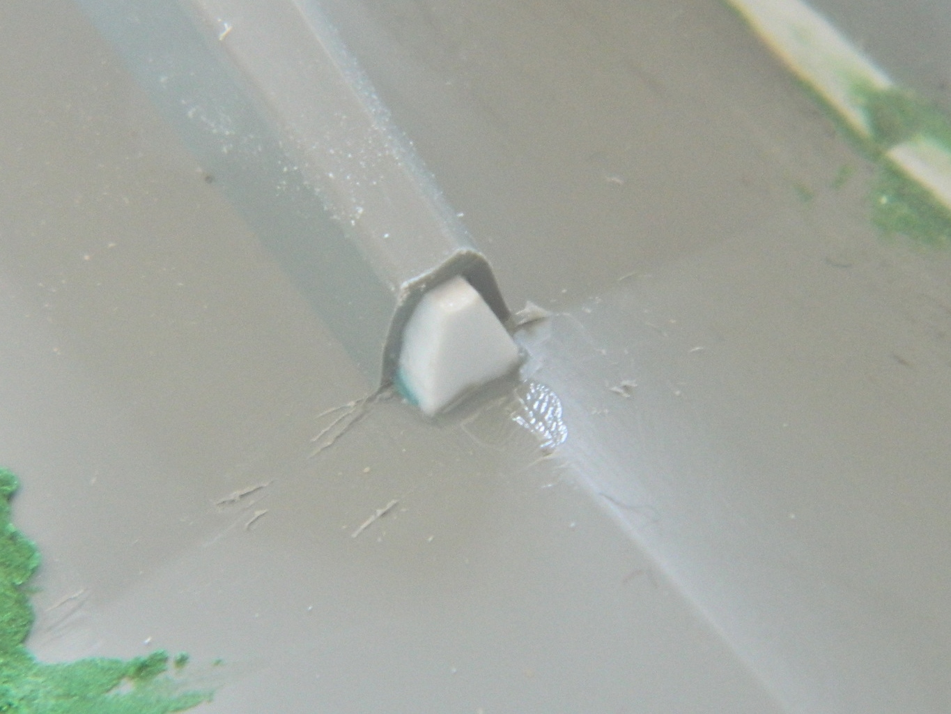
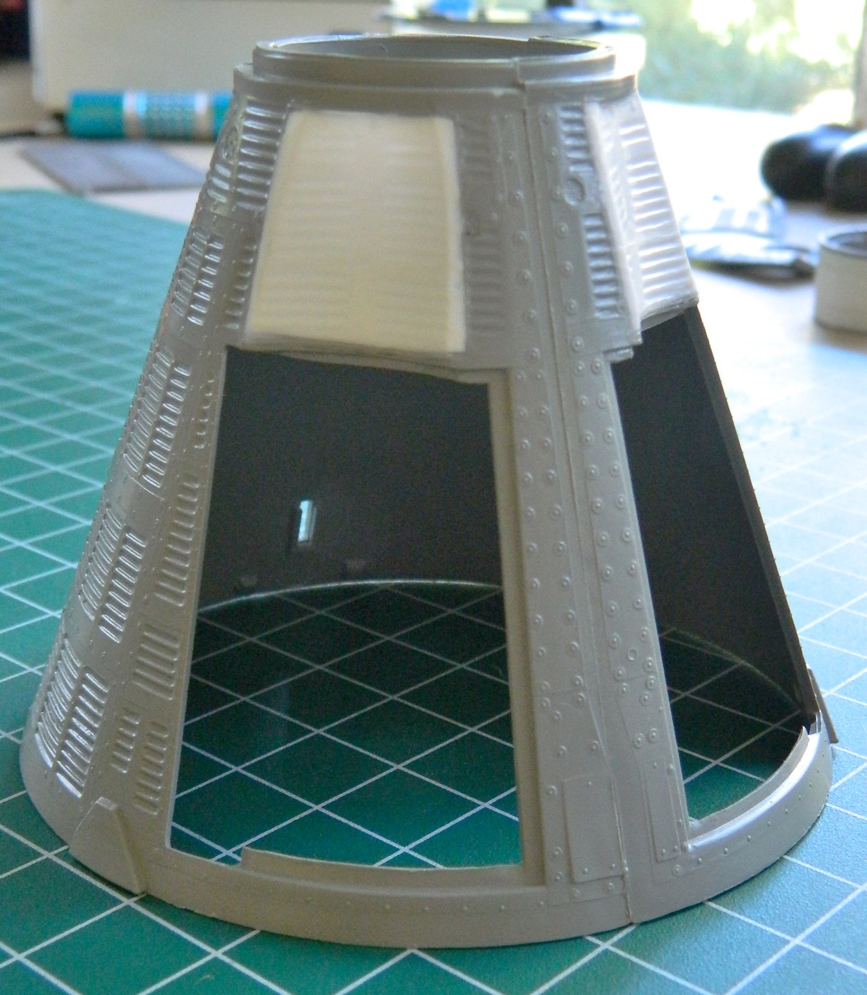
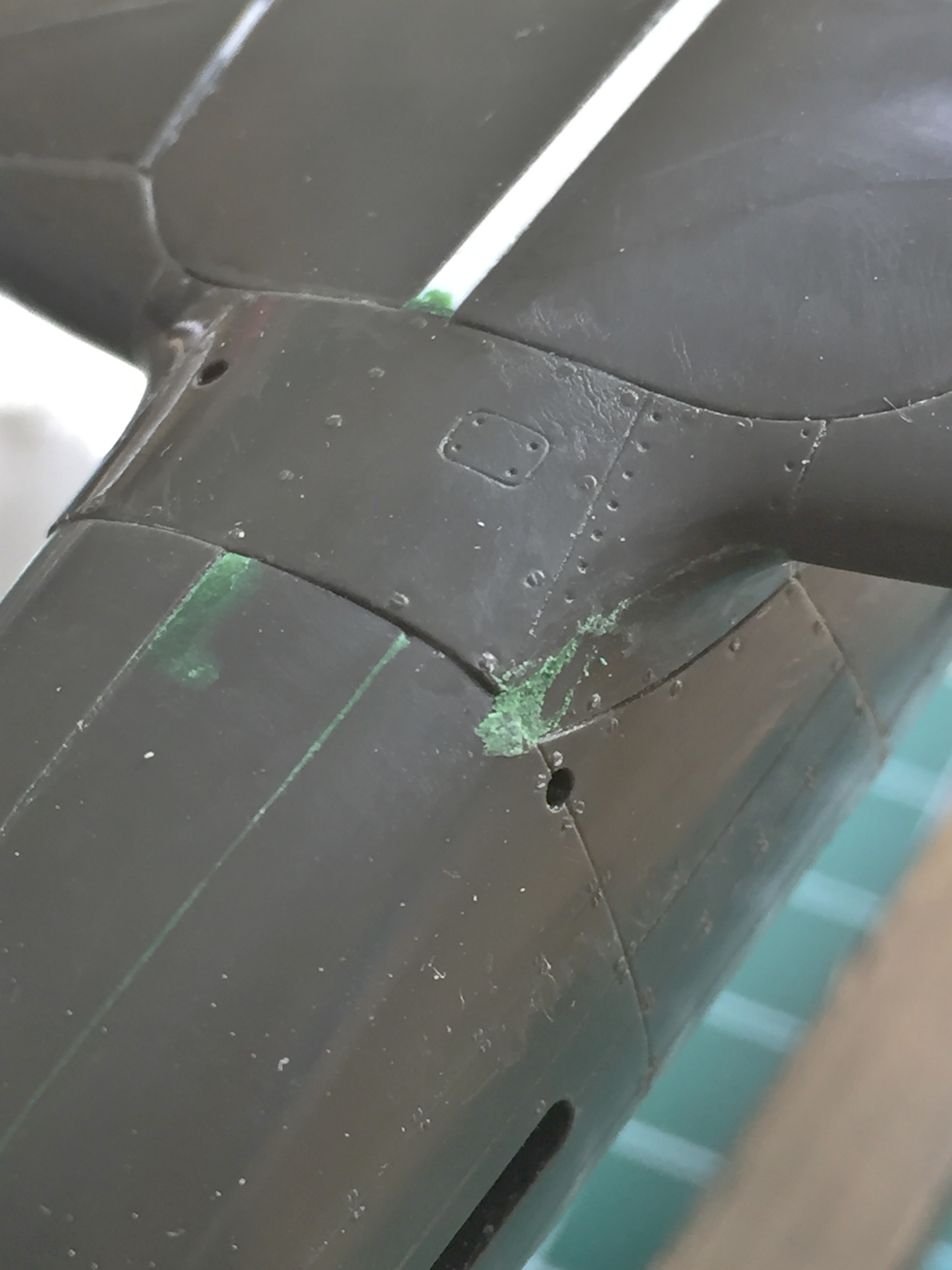
At the end of the channel where the cylindrical section meets the conical section, there are no tiles! Hmm… So I rotated the hull to see if they were there at all. Yes, they’re there. They’re 90-degrees away from where they’re supposed to be. Oh great. Another error. How the aerial intercourse did I manage to put that part 90-degrees off?! Well as it turned out, it was easy. The locating tab and slot are in the wrong place! Now, when I glue something on, I goddamned well glue something sodding on! There’s no way I’m going to be able to remove the cylindrical section without destroying it. Aw, damn…if I only had another kit.
Oh. Wait. I don’t have it yet, but it’s on the way! Whew… So that gets set aside for now.
There were a few details provided on the PE fret of the AM set that I didn’t like. PE parts are flat. The details they replicate aren’t flat at all and the difference nagged at me sufficiently that I knew at some point I’d have to make new details. Okay, looks like “some point” has arrived.
On both side of the seats are handholds. Living at the bottom of a gravity well the way we do, there are ALL types of unconscious assumptions we make that do not hold true in a micro-gravity environment. In micro-gravity, there is no “just sit down” possible. Gravity is what makes us able to “just sit down.” In micro-gravity, if you want to plant your ass in a seat (and the inside of a Gemini capsule was so small, you had to plant that aforementioned ass someplace to allow room to breathe), you have to pull your ass to where you want it and then strap it to that location. So the clever engineers at McDonnell (the contractor who built the Gemini capsules) made handholds for just that purpose. They mount on gimbals to the sides of the seats so they can be rotated out of the way once the ass(es) were strapped into the only place they’d fit. The seats.
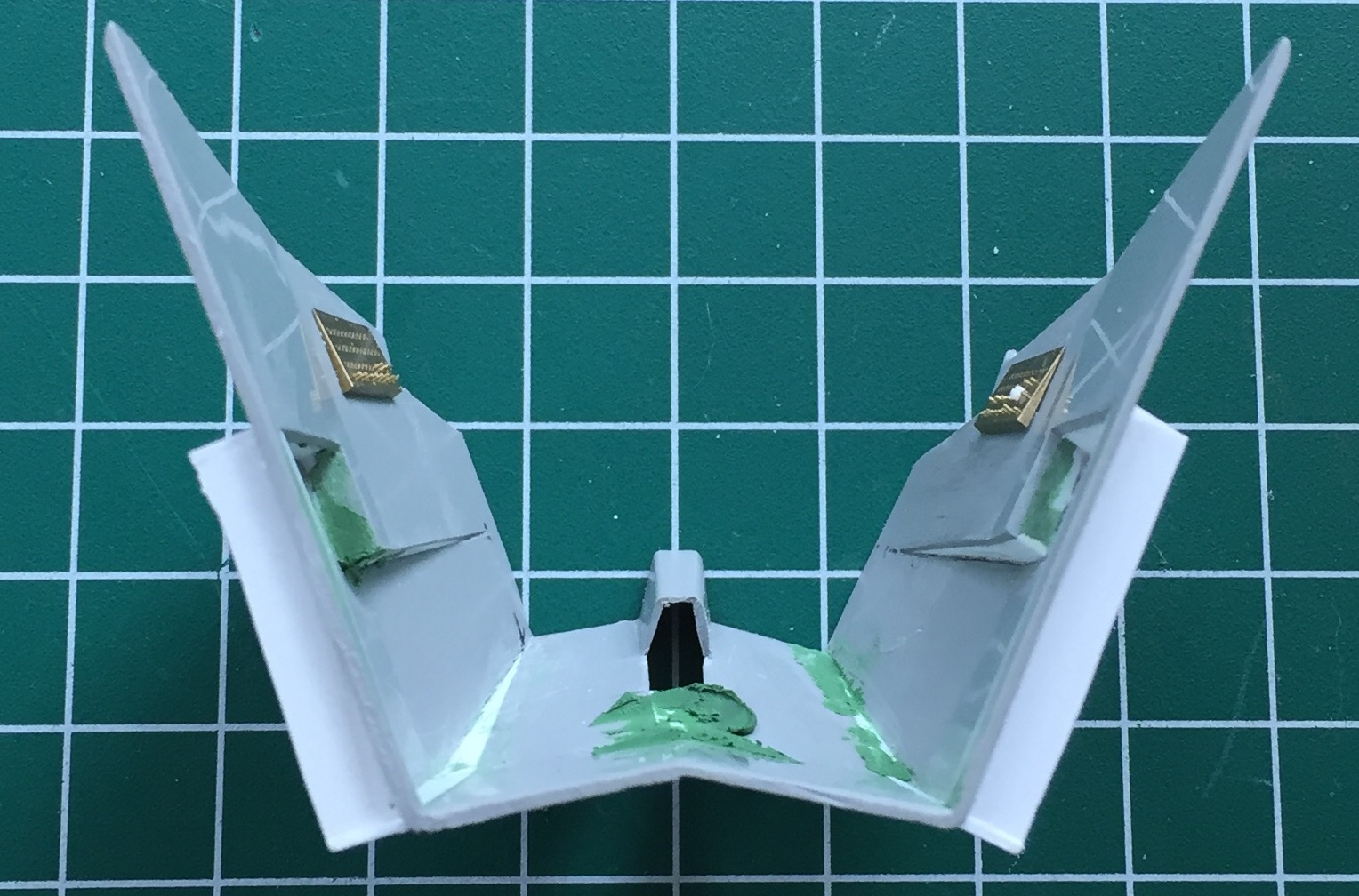
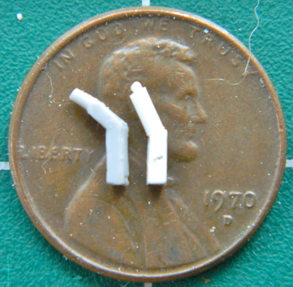
There’s also grab-bars above the instrument panel which the PE set has. They’re flat, too, and they shouldn’t be. 24 gauge copper wire was bent and soldered to replace the flat PE details (the flat details are shown to illustrate the differences). When you’re forming something, even something as simple as a curve to a wire, you’ll find the shape you need in the strangest places. To get the curve accurate for the grab bars, I used the pein end of a small ball pein hammer as my form (buck). I used the shank of a drill bit to form the seat-mounted grab handles:


Since I was on a bagel (which is much like a roll, only firmer), I decided to add the safety bars to the side switch panels. (In the process I also decided that I’m a lot crazier than I realized!) (Those of you who know me even moderately well probably wonder why it’s taken me so long to realize that. Simple. I try to pay as little attention to that maniac as I can manage!) Adding the safety bars, 26 gauge wire, was tedious. It was maddening. I’m also not 100% happy with how they’ve turned out. But they do fall within the 90-95% tolerance I allow myself so this is as they will be (and no, I’m not looking forward to having to paint all those switches and buttons that are underneath the bars, but adding the bars after the panels have all been painted wouldn’t work…paint interferes with glue adhesion, so…). This is the panel for the right side:
And this is the panel for the left, command, side:

I tried to solder them correctly but there was no way that was working. Solder this and the heat unsolders that. Okay…so the bars don’t butt the way they’re supposed to. 90-95%.
There are also containers for the various pieces of gear on the LDF (long-duration flights), there’s even a fecal collection bag. (Yeah…those astronauts kept their shit together!) The capsule I’m modeling didn’t engage in an LDF so I don’t need the collection bags. (And I don’t EVEN want to know how the hell they took a dump in such confined spaces! I’m sure the crew ended up knowing MUCH MORE about each other than they ever wanted to know. And the smell must’ve…nah…let’s not go there.) The gear bags were fabric so the absolutely smooth surfaces of plastic were not acceptable. Attempts to carve/scrape folds onto the surfaces was equally unacceptable. I didn’t want to use the texture I’d already used (more on that in the next post), instead I used a piece of printer paper, crumpled it a bit, and glued it to the surface of the plastic block and added very small bits of plastic for the snaps that held the real ones closed:

I was so pleased with how that worked that I decided to solve another problem I had, how to texture the seat cushions. More printer paper, strategically folded. I think the edges of the paper will replicate the seams nicely:
And then the second kit arrived:

One of the problems I created for myself the first time I moved the cabin’s sides out was how to adapt the details that belong there with a surface that didn’t have that depression. This time I decided to move the entire wall out. But the same restrictions applied. I couldn’t alter the location of the upper edges of the cabin walls. They need to fit inside a specific space. So to move the entire wall, I had to fix the critical dimensions so that they wouldn’t move. I did this by gluing flat .060″ (1.524mm) stock in place to keep the critical dimensions from shifting once structure was cut. My initial thought was to move all of the walls out so I used 2mm plastic masking tape to outline the areas that could not be altered:

Then I decided that since I had everything so well braced, I didn’t need to make more than two cuts; one down the back and one across the bottom where the sides meet the floor:

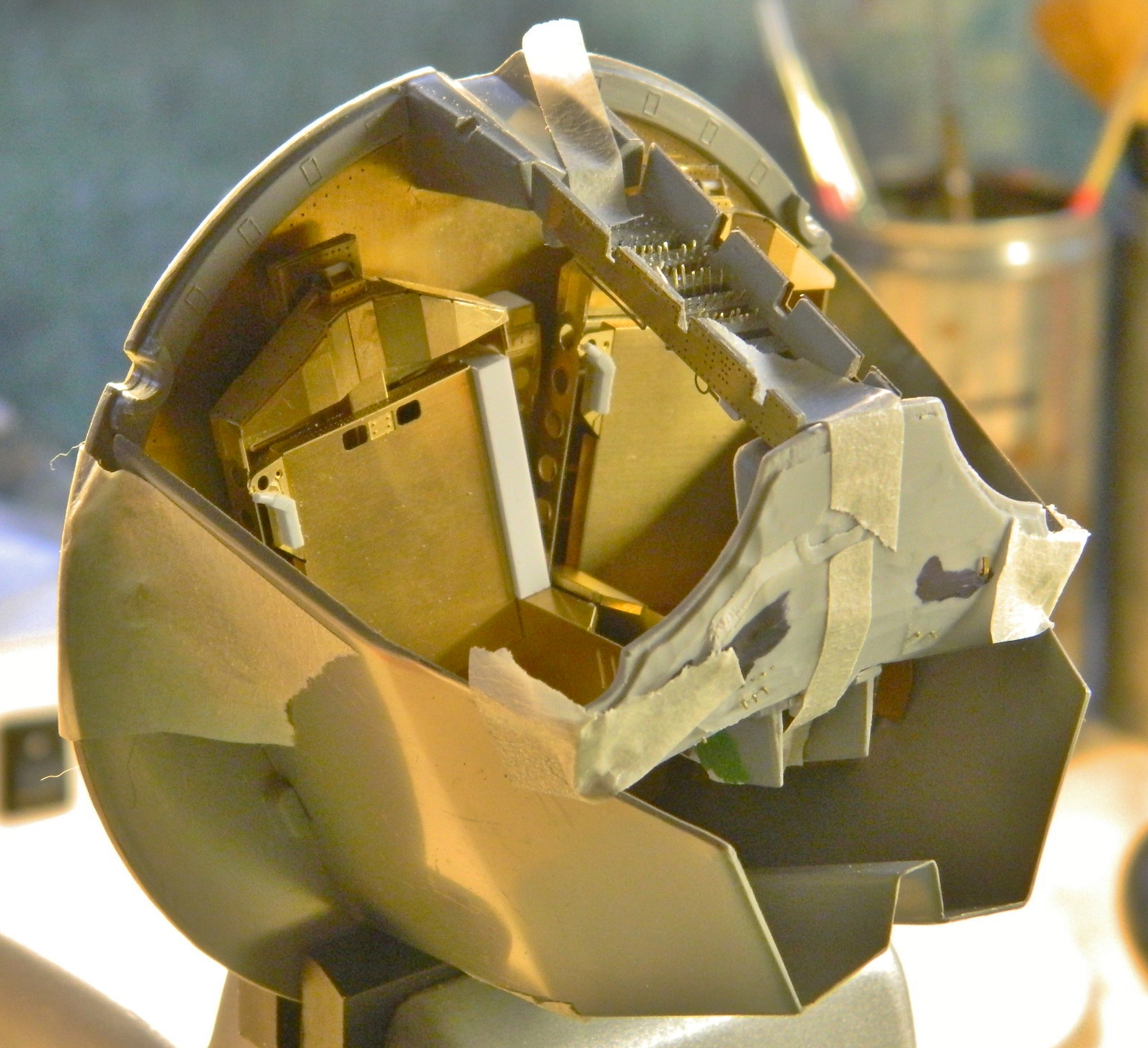
The added bracing snapped off easily with no damage to the part. I checked the fit of where the rear of the cabin meets the rear bulkhead and so far so good:
Then I slipped the hull over the taped-together cabin/bulkhead parts…and discovered I’d made another problem for myself that I needed to solve. Y’see, I decided to get clever. Yes…the distance I moved the first walls worked, but it was just still a bit too snug for the details I have yet to add to fit in there. So, clever monkey that I can be, I moved these walls out just a wee bit further. Further enough so that the cabin would now not fit inside the exterior! Well, I was NOT going to buy another kit again! I’m going to make THIS one fit…and I did. That was accomplished by sanding away as much of the addition’s corners and edges that I could without sanding all the way through (and it was close…it was very, very, close). Test fitting showed me I was on the correct path, I just needed more room. Thankfully these old kits often have very thick walls and this one could be the poster-kit for that. The Dremel tool allowed me to remove just enough from the inside of the outer part for this new and improved cabin assembly to fit. Barely:
Then I primed the cabin interior with what I thought was acrylic primer. The primer showed me that the joins of the wall extensions needed a little more finishing:
Rather than have fresh primer gum up my sandpaper, I decided to wash the primer away. If you don’t let acrylic paints set long enough to fully cure (a couple of weeks, then it’s not as easy to remove), it can be washed away with soapy water and a toothbrush (preferably an old one you’re not using anymore, but hey…it’s your mouth, so…).
It didn’t wash away. In fact, it acted just like enamel! The reason for that is because the primer IS enamel! ::bangs head on desk:: (Again.) Well…okay, I know what can remove enamel. Turpentine!
Well…there’s a problem with that. As I discovered, turpentine attacks the plastic and makes the surface gummy. Oh. Groovy (yes, I’m that old). I let the turpentine evaporate and the surface, albeit with a texture imparted by a paper towel, hardened. Then I used enamel thinner to remove the enamel primer. It also attacked the surface of the plastic with the same result. Well. Since I’m going to have to sand the entire surface of the cabin’s interior anyway, so much for a supposed short cut. I waited for the plastic to harden again and sanded the bastard smooth.
Now there is no discernible line where the addition meets the floor.
Gemini (Revell) Build #7 – Interior Work; Last Seat Details Added and Making Harnesses
Now that I know the seats will fit, it’s time to finish detailing them.
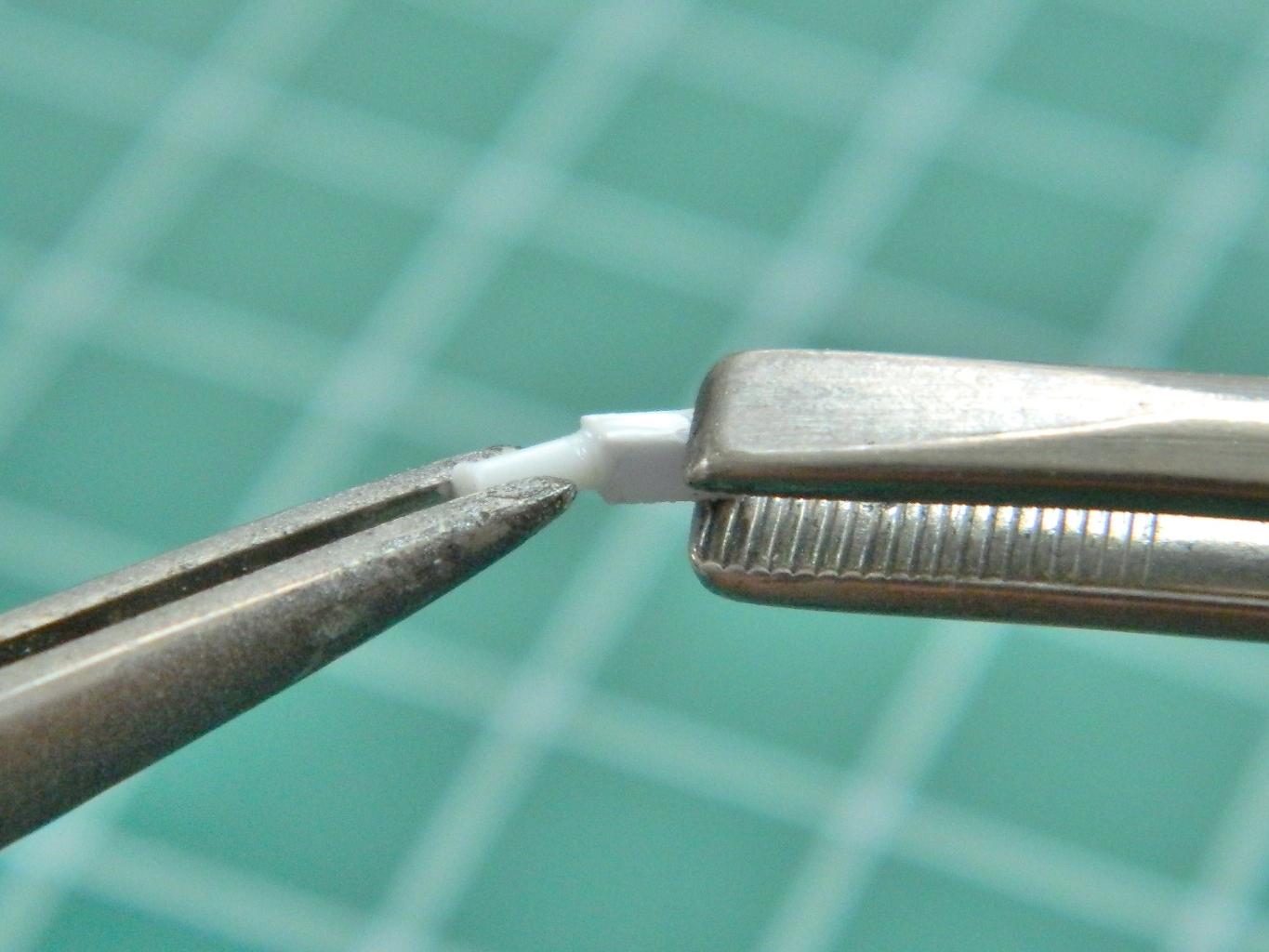
The seats are ejection seats and ejection seats have triggers. I’ve seen two types used with the Gemini seats. The first is a more or less standard loop (yellow and black striped) and the other is a T-handle. I decided to go with the T-handle trigger because I was not looking to have to stripe a part that small (yeah…I’m lazy). For size I used 26 gauge wire to make the handles. Step one was cutting the wire and curving one end:
Then I aligned the two pieces in a flat-jawed clip, applied a small dab of flux, and then shaved off a very small slice of solder and used the pencil torch to affect the soldering:
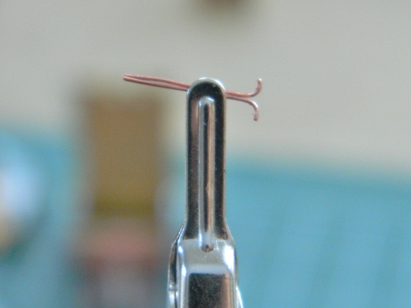

I did that twice and ta-da:

Then they were superglued to the seats:

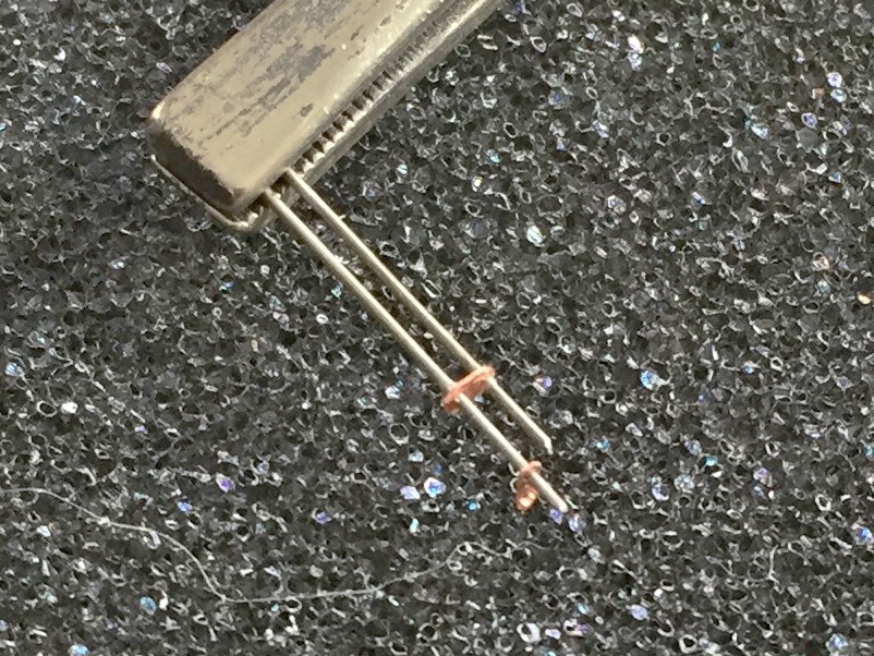
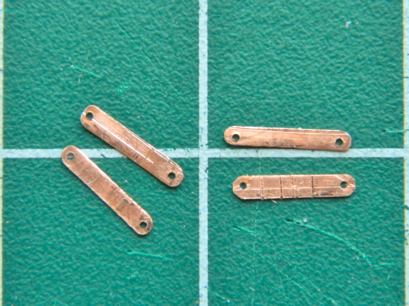
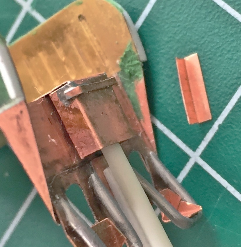
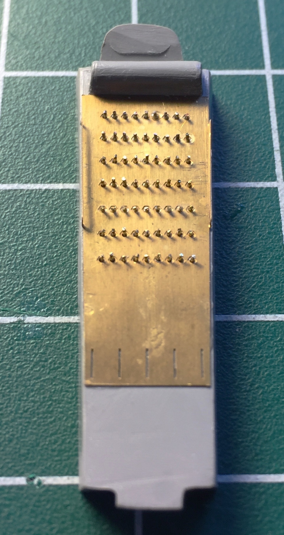
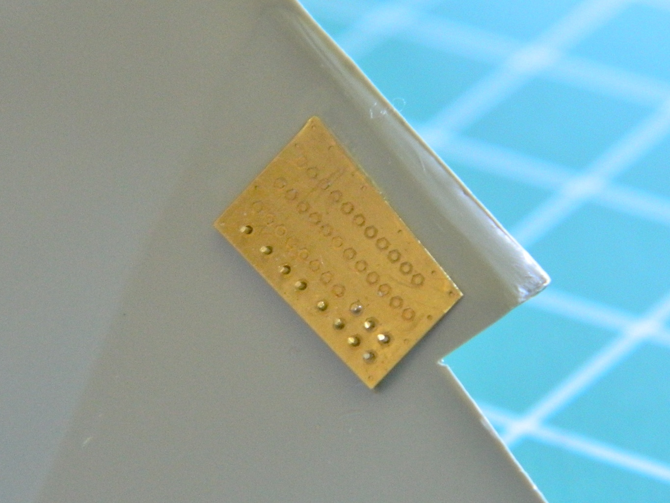
The next major detail to be added are the harness straps. Because of their location in the finished model (directly in your face), and because there are NO aftermarket parts for these, all the hardware had to be scratch-built. First to build is the buckles which I made from .005″ (1.27mm) copper shim stock and 24 gauge wires.
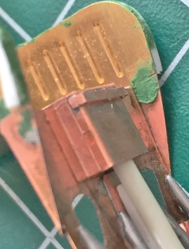
I discovered early on that what would make these things look correct was getting the spacing between the holes consistent. A friend gave me the idea of taping two needles together for consistent spacing. I used the needles to make a small depression in the copper for my bit:
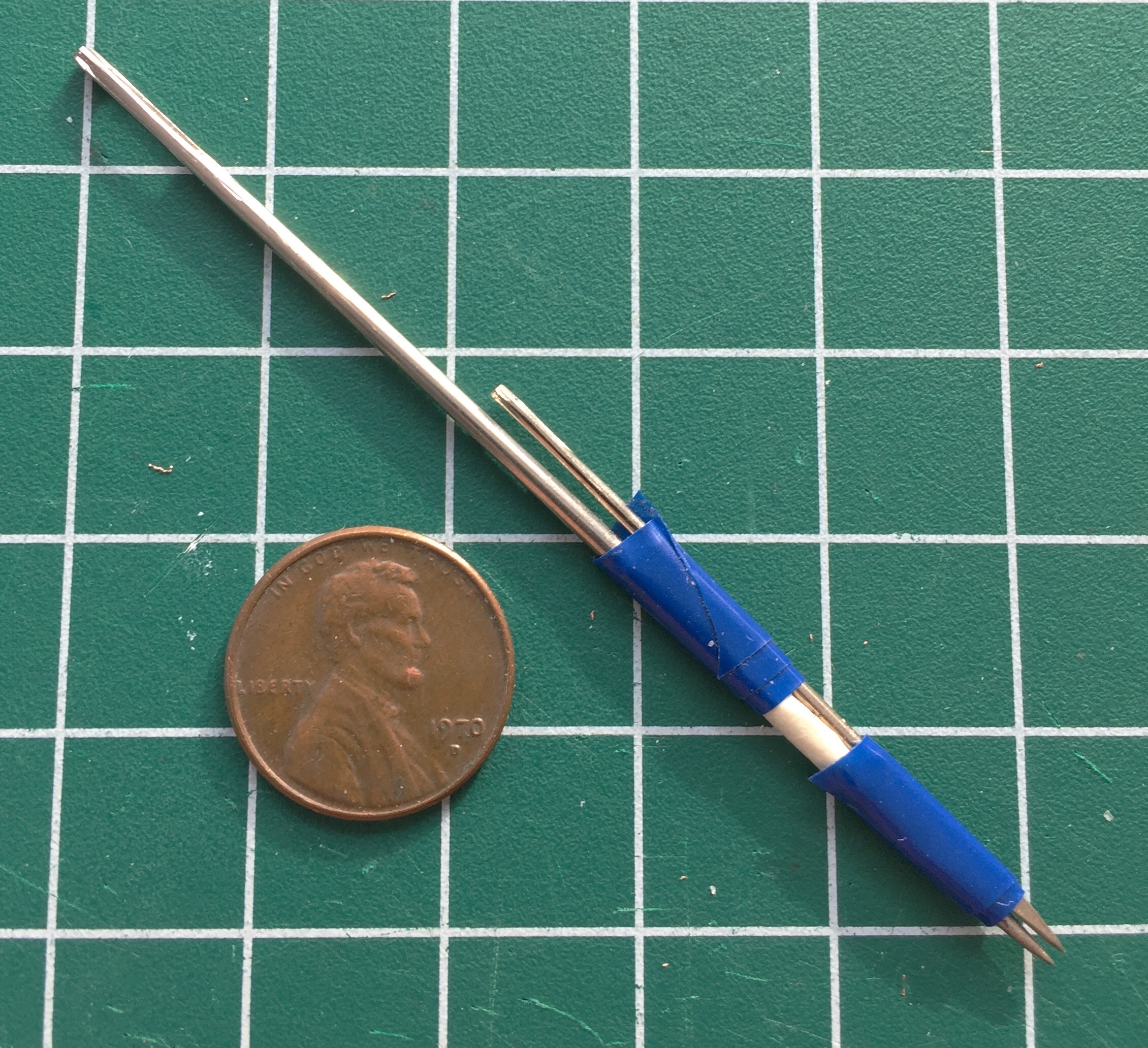
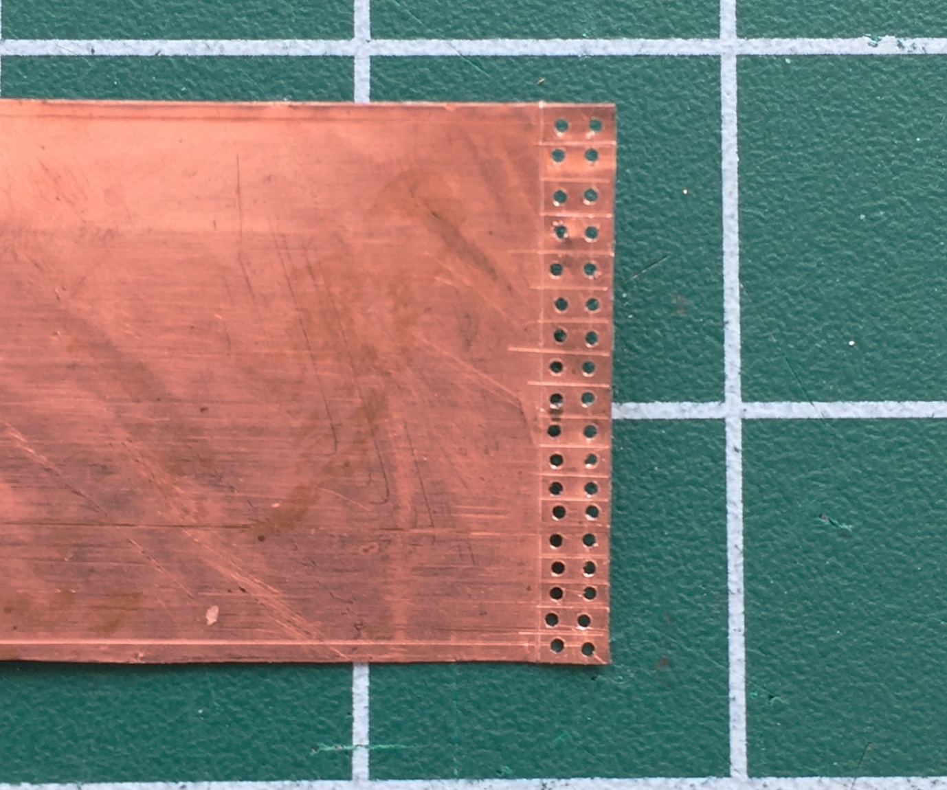
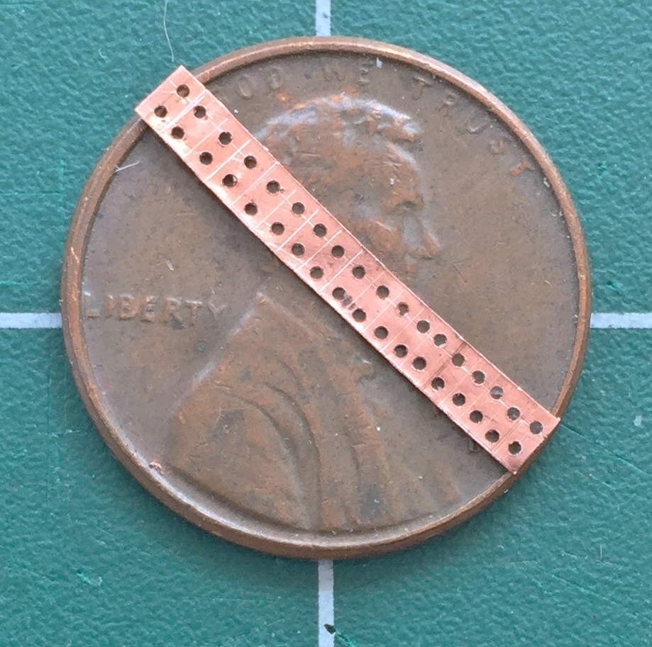
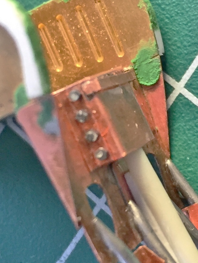
I determined (using the Mk.I Eyecrometer) how wide these plates needed to be and made a strip of them using a drill bit of .018″ (.457mm) diameter, then cut the strip free using a very high-tech tool. Scissors:
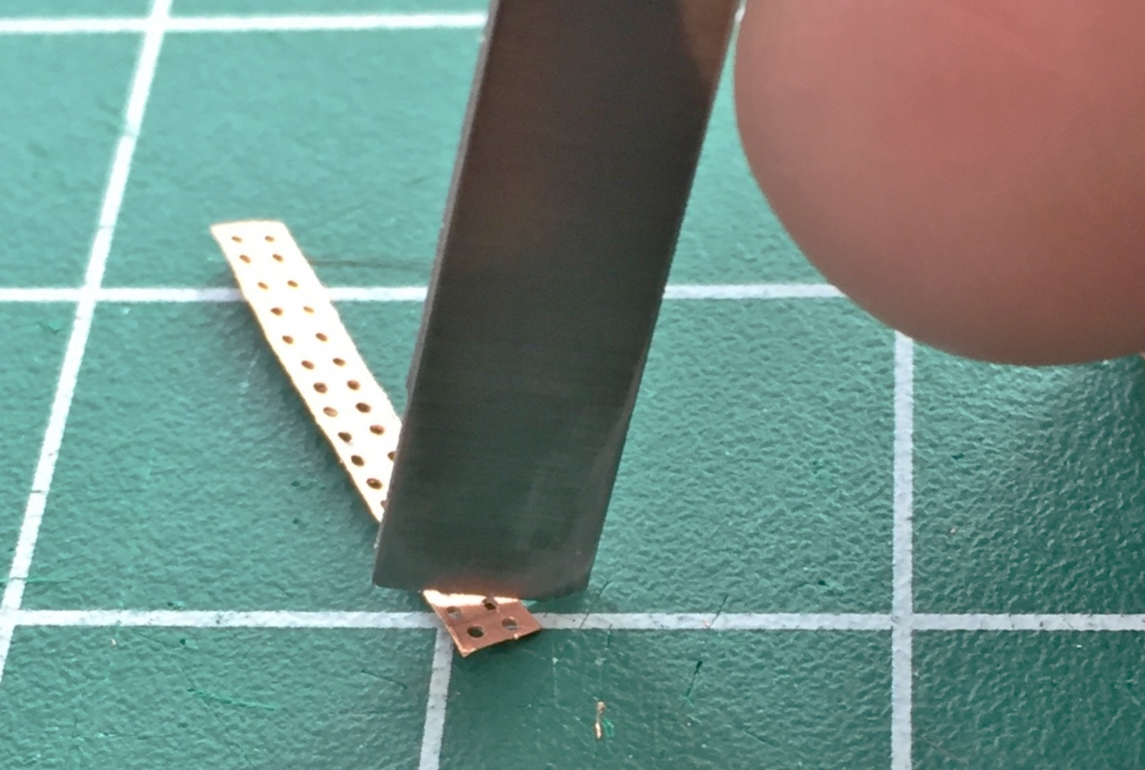
With the strip free of the sheet, each plate was cut free. I used a sharp chisel blade instead of scissors because I could control the precision of the cut better. I found that rocking the edge of the blade across the surface of the copper gave me an accurate cut with the least amount of deformation of the copper (and a well-fed gnat landing on .005″ (.127mm) copper deforms it…after every action on the copper, I had to flatten the part out again):

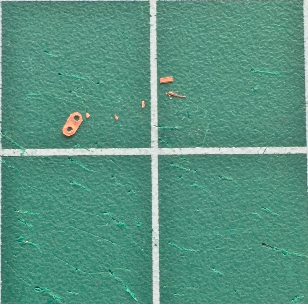
I made a few extra plates because it’s SO easy to trash something this small:

Then using the chisel blade, I trimmed each plate to size:

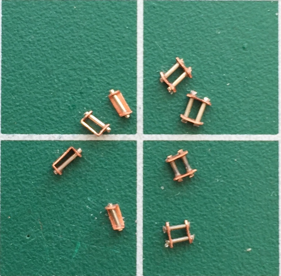
I also needed a bracket to hold the take-up reel of the shoulder straps. You can see my first four attempts to the right in the photo below. “First” was used because I got the dimensions wrong. I got good at getting the dimensions wrong…like three times:

Some tasks have a built in bitch-factor. I call it the bitch-factor because not only do I bitch about having to do it, it’s a bitch to do. For these parts, it’s a real bitch to get them started. My first attempt and multiplying how many hands I have (I still think having four would be nice, though I’m sure there’s some wimmen out there who would blanche at the thought of me having four hands) was to use locking tweezers to hold the two wires while I slid the plates over them. Yeah…it worked, but I came up with something better after doing this first one:
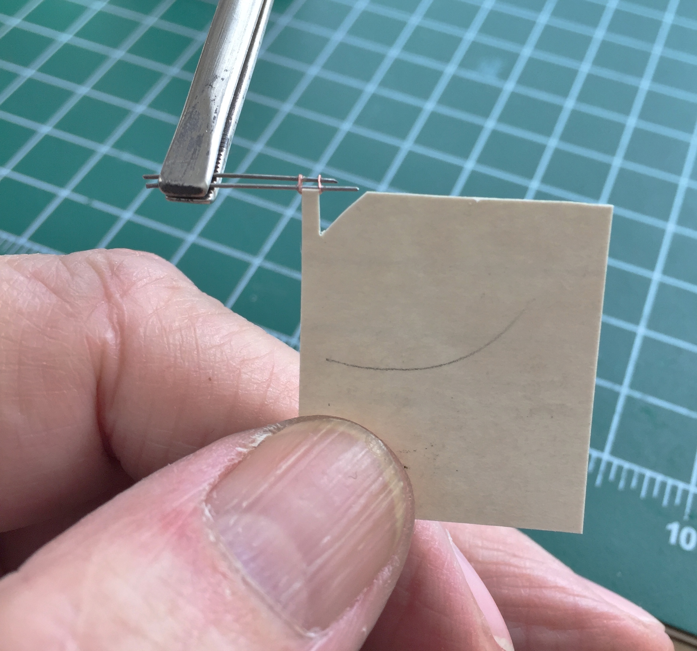
Once I had the plates at the correct spacing, I made a gauge out of an old 3″ (76.2mm) x 5″ (127mm) card to ensure consistency:
My initial thought was to solder the plates to the wires and I tried that:

Not only was I not especially pleased with the outcome (though I was quite pleased that I could solder something this small), I realized that I was over-complicating things. Again. For this application, superglue would work just fine…and it did. I used a piece of scrap plastic, drilled two .018″ (.457mm) holes in it, and used that to hold the wires while I slid the plates onto them and then glued them. Worked perfectly:
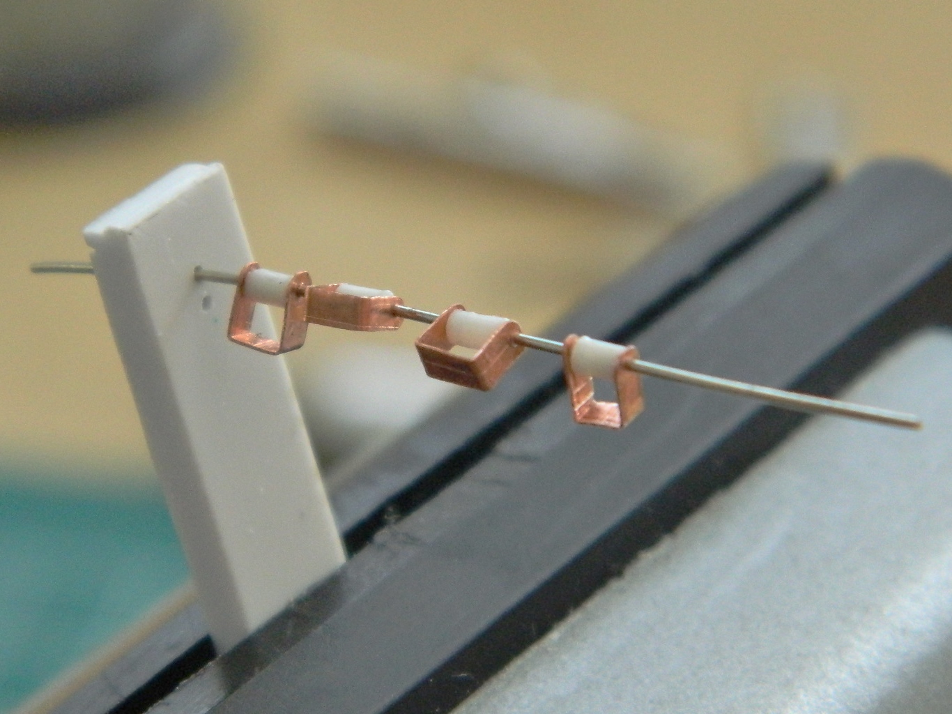
Once I had everything aligned and glued, I had some of the parts I needed:
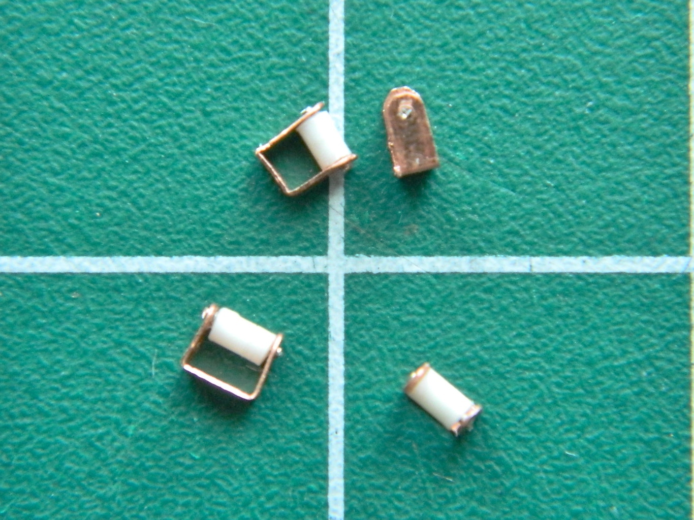
It was at this point that I realized the single-wire parts, which are the take-up reels for the straps, were sized incorrectly. I went through three attempts before getting the depth to the parts that I wanted:
I didn’t want to have to wrap a small diameter wire with enough paper to replicate the rolled up strap, so I decided to bulk that out using plastic rod. That meant I had to use .047″ (1.19mm) diameter rod and center-drill it (again using the .018″ (.457mm) bit). A bit fiddly but it did work:
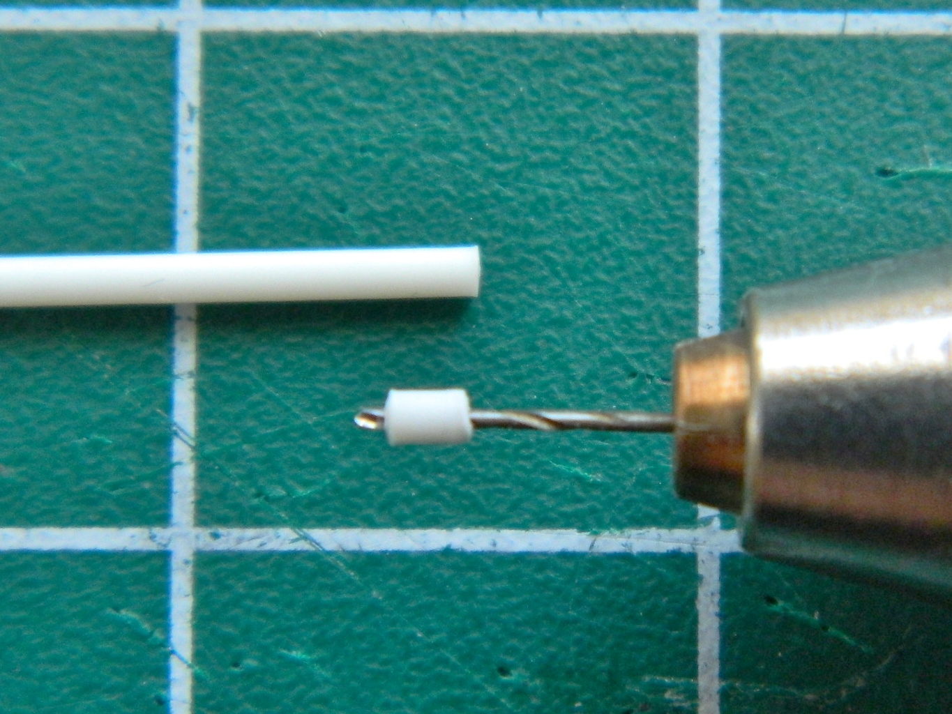
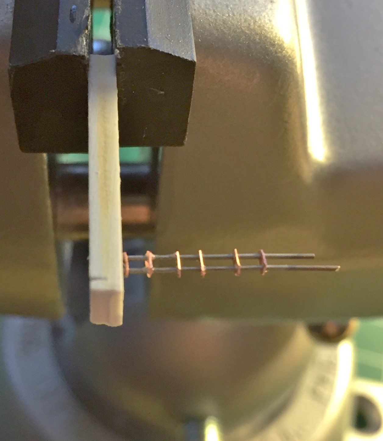
I slid the wire into my jig, slid the plastic tube over the wire, and with the wire in position, glued it all together:
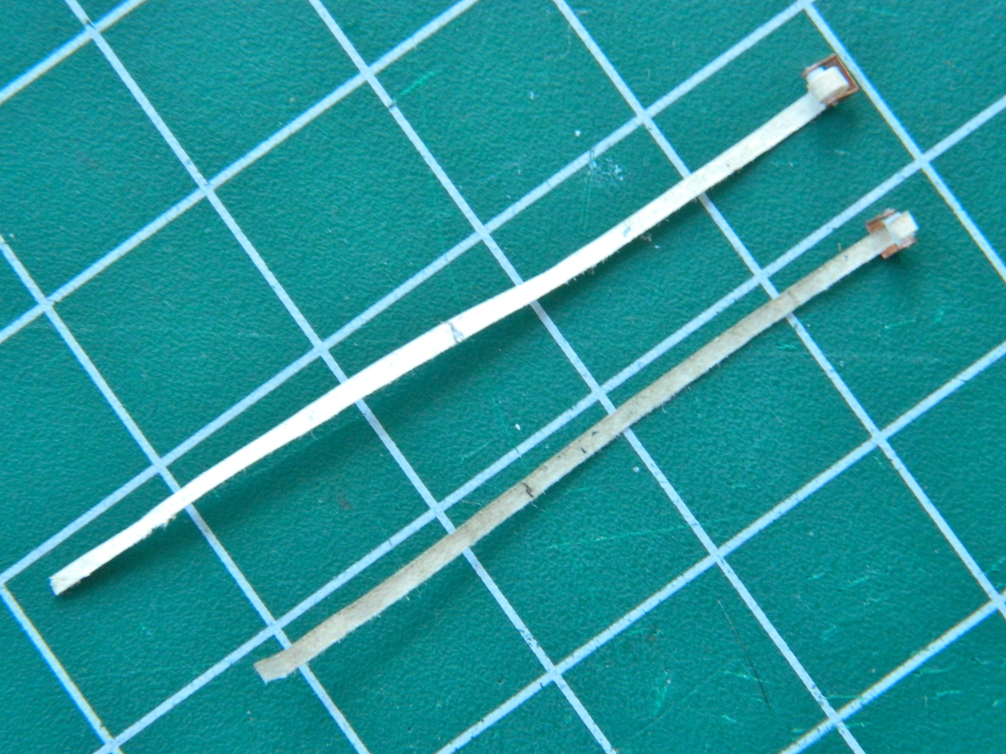
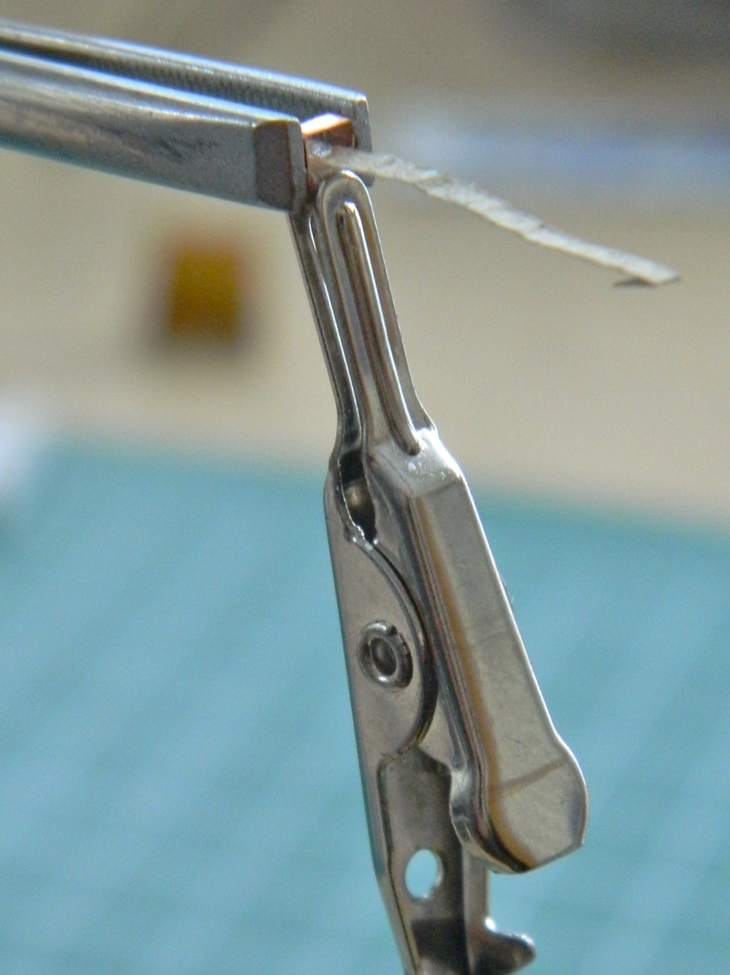
Time to add the straps. On a previous build, I’d made the pilot’s harness from Post-It paper soaked in diluted white glue. Yeah, I did it but it was not easy. Paper tends to turn to mush when soaked and I went through a lot of paper to get the effect I was after. Between then and now I’ve done some skull-sweat (thought, for those of you who aren’t Heinlein readers) (heathens) on what type of paper to use. What I needed was a paper with a higher rag content AND still thin enough to be in scale. While paying for something with cash (just for the novelty), I noticed that the money was made out of paper. It’s made out of a high rag content paper! So I took a dollar out of my wallet and set it aside for future use:

The future arrived (which explains all the wrinkles I see in the mirror). I cut the edge of the dollar’s paper to width and tacked it onto the plastic tube without needing to soak it in white glue first:
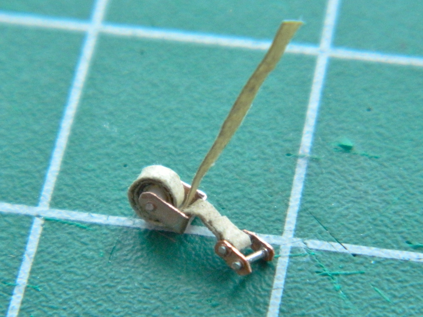
There are two straps that wind around the take-up reel and one of them has the connector I’d made out of copper and wire. But first I had to wrap them around the tube:
Once I had the wrap, a touch of superglue on the edge of the wrapped strap holds it in place, the “buckle” (which it really isn’t but I don’t know what else to call it) added, and there’s the finished shoulder strap assembly. Now to make three more:
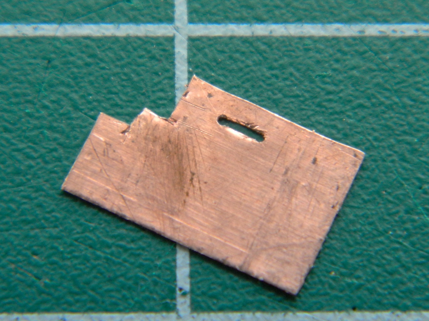
The lap straps need hardware for where they attach to the sides of the seats. .005″ (.127mm) copper shim stock and sharp knives allowed me to make this (and three more). It starts by drilling a hole, then using sharp knives, opening up the hole to dimension:


Once the hole is cut, then I can trim the outside to fit. The .005″ (.127mm) of an inch is damned thin and trying to cut the hole inside after the outside has been cut to dimension may be possible for others, it certainly wasn’t for me:
Since belts have buckles (y’know…real buckles), I made four of them from the shim stock:

Then my brain caught up with my enthusiasm. These buckles (y’know…real buckles) don’t have to brass, plastic will work just as well. The little brass bits got tossed.
However, the buckle (y’know…oh…never mind) is only half of the mechanism that makes a buckle work. There’s the tab that the buckle grabs. Those had to be made too.
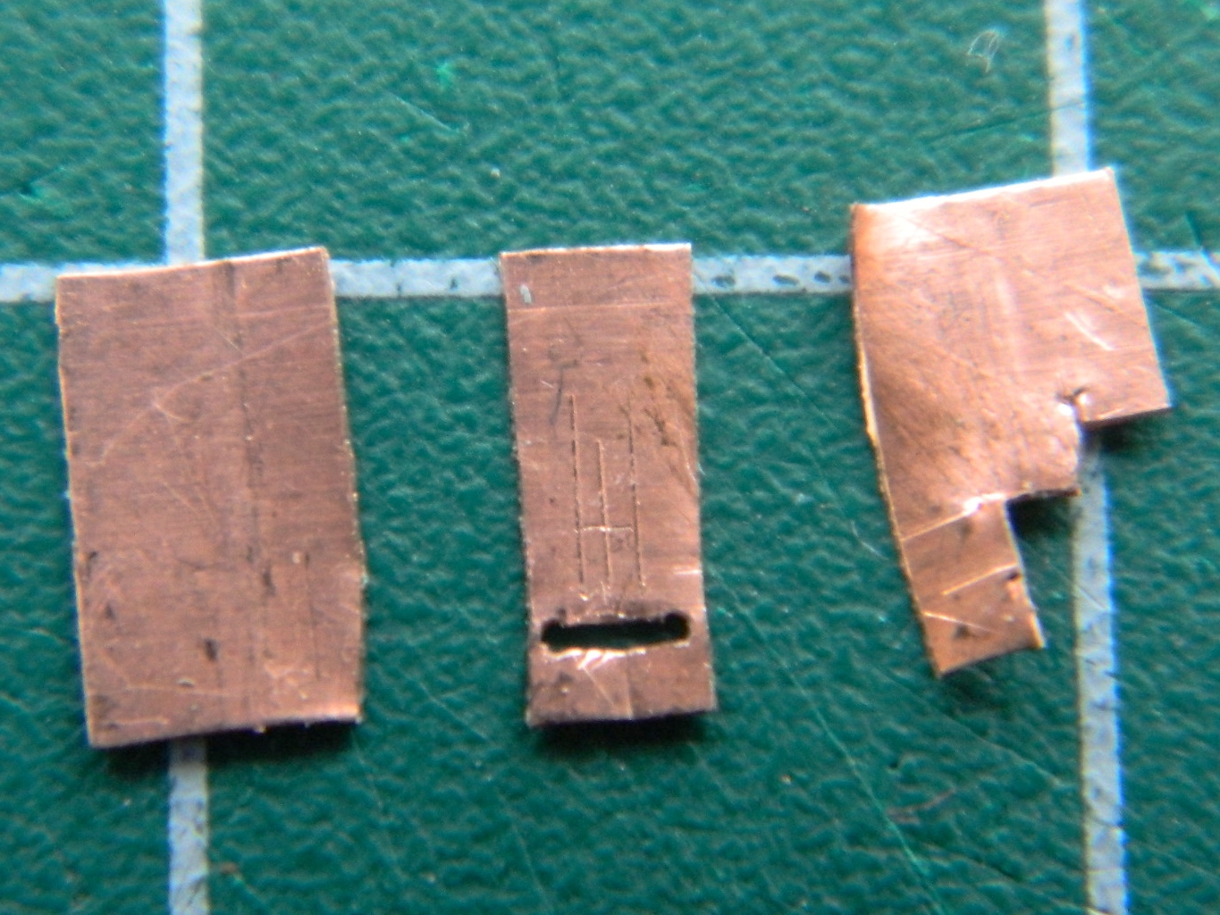
This is the process I used to make all of these harness parts from the shim stock…
The first step is to drill two holes of the required diameter (.018″ (.457mm) in this case) and then cut away the material between the holes leaving a slot:
Then the sides are trimmed to dimension (I used the chisel blade):
The business end of the part is the tab that slides into the buckle. I started by cutting the shoulders of it before doing its width:

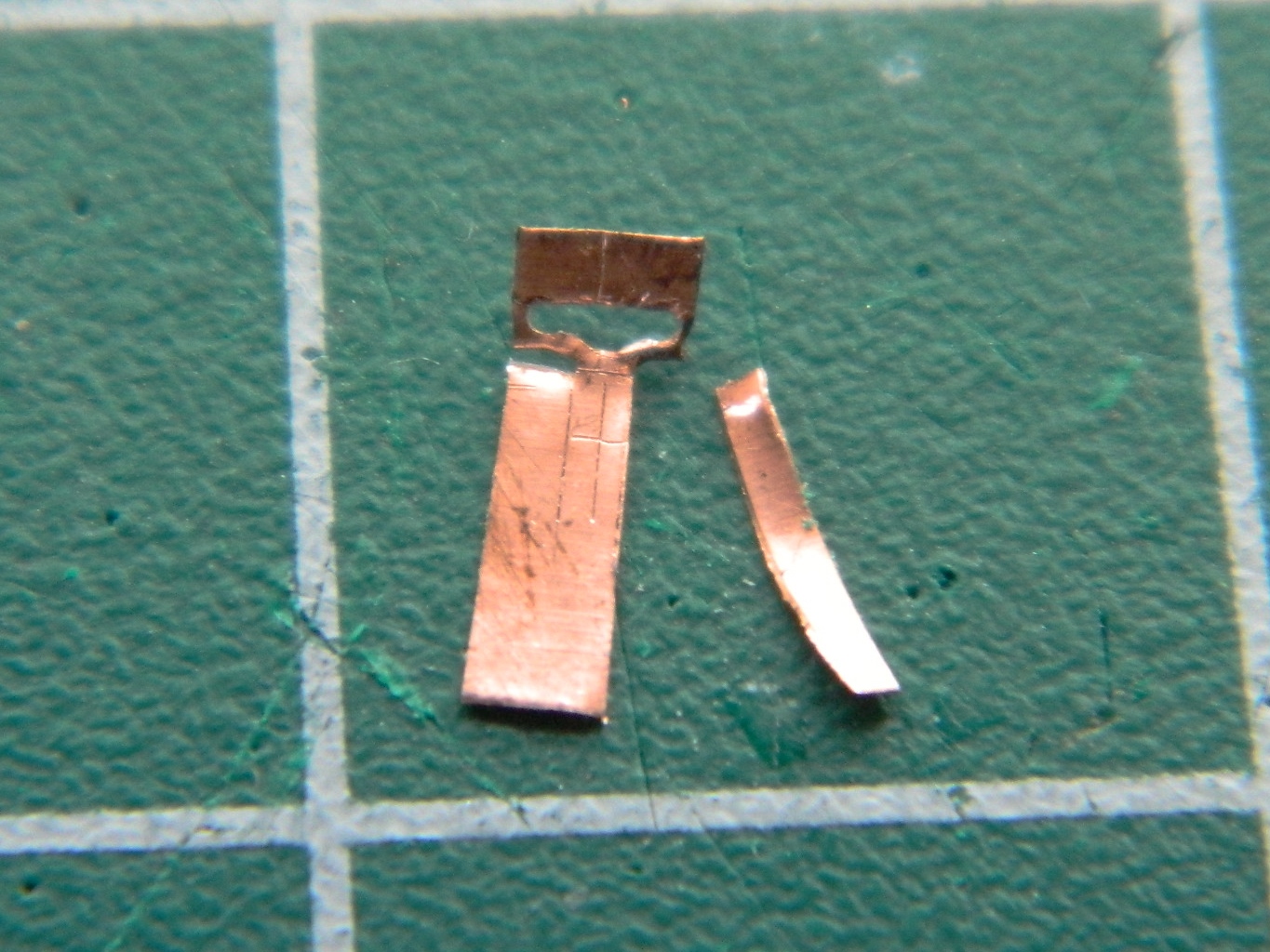
At this point I noticed that the stress of the knife blade deformed the copper causing the tab end to pull away from the slot. I used tweezers to move it back as much as I could:
Now the outside of the part needs to be trimmed to dimension:

One TINY trim more:

To round the edges, I grabbed the part firmly in tweezers and used fresh 600 grit sandpaper:

Before (on the left side) and after (on the right side):

I’ve found an interesting thing regarding my work. It’s common for me to have to make more than one part. So I make the first one and it comes out fine. Then I go to make the next one. It RARELY comes out well:

But I do persevere…

So now I have two seat “kits.” I can’t assemble them before painting the parts. But excepting two small details to be added, they’re now done:

Gemini (Revell) Build #6 – Interior Work; Finishing Seat Details and Discovering Major Surgery is Required to Make Them Fit
Once I’d made the basic (very basic) additions to the seats, I taped everything together and checked how things fit…and they don’t. Without the additional details, the seats barely fit, and with the additions they don’t fit at all. ::sound of screeching brakes on soundtrack:: I needed more room.
But I don’t have more room! I mean, this cabin has to fit inside the outer hull. So I wandered around for a while, mumbling, bumping into things and scaring the cat:

Then I realized that the only place the cabin needed to fit was the periphery where it mates to the outer hull. So if I sectioned the sides of the cabin and moved them out, that should give me the room I needed. No, the actual Gemini capsules don’t have their sides moved out. But unless I want this project to stop here (which I do not), then something has to be done. What matters is that things look right and seats that stick out of the hatches certainly don’t meet that criteria!
Step one was marking the area that needed to be moved and laying electrical tape in place to act as a guide for my scribing tool:

Once I’d scribed and sawed through the plastic, I cleaned up the edges with a file. Since I didn’t cut through on all sides, I had a section in front that would serve as a hinge. A thin hinge. A hinge thin enough to snap the plastic so those areas needed to reinforced. I fixed where it had snapped and reinforced the other side before beginning work there:

That allowed me to bend the side out without anything snapping (again):
For strength, I boxed the open sides using .040″ (1.016mm) styrene:

Once I’d finished boxing the side, I trimmed the excess:
And that left me with this:
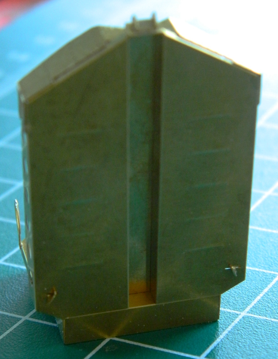
The seams got a coat of putty, sanded smooth, and then the seats were dry-fit:

Things fit, mostly, except for the center (and a little bit of trimming of the copper shim stock I added). To get the seats to sit as far down as they need to, I have to trim that. Since trimming away the end of that raised area cut all the way through, I had to add a piece of .080″ (2.032mm) scrap to fill the holes, trimmed it to fit, added a bit of putty, and sanded the area smooth:

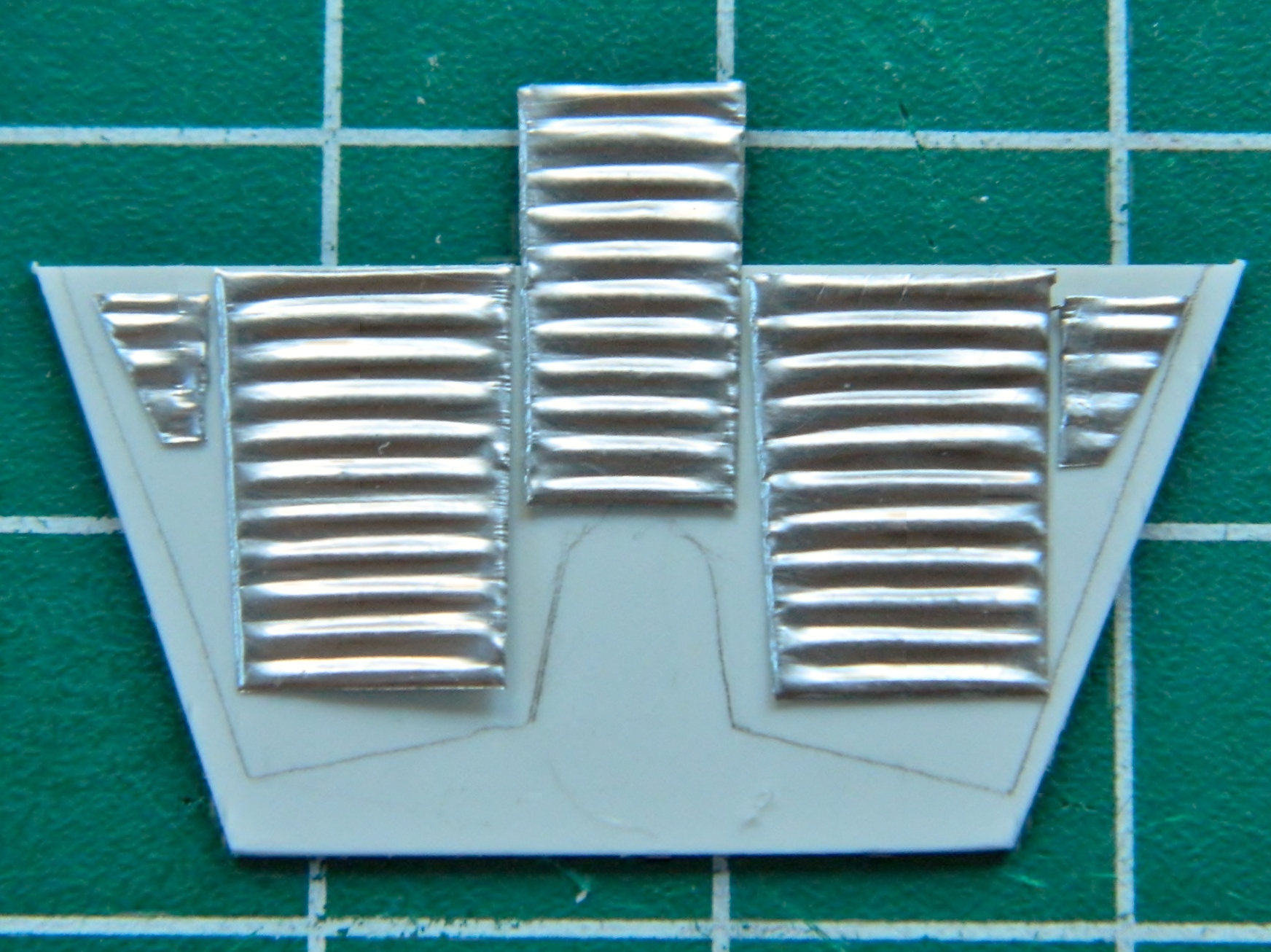
During dry-fitting I noticed that the open front of the cabin was visible. While I was modifying the cabin walls and floor, I mocked up the part I will fix that with. I’ve also noticed that the walls of the cabin are also corrugated. I took some heavy aluminum foil and rubbed the exterior corrugations to give me thin corrugated panels that will get glued and puttied onto the front wall later in the build:

Getting back to the seats (that will now fit into the cabin), I had to add fabric texture to some of the parts. That long, white, piece of plastic is actually a zippered pouch and it needed a fabric texture (and there are other pouches behind the seat that need adding and fabric texture). I’d considered tissue paper and diluted white glue but it didn’t offer me quite the texture I was after. I ended up using a flushable wipe (which, I’ve come to find out, aren’t at all flushable…I mean, you can flush them, but you can also flush marbles, too…doesn’t mean they’ll dissolve) because of its woven texture (let them dry out first):
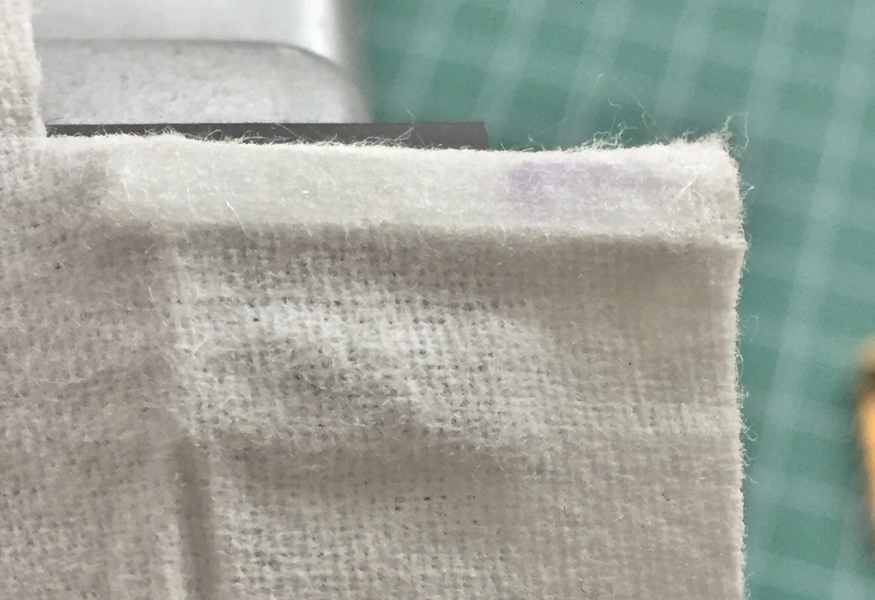
I draped the wipe over the plastic and then dripped superglue through the weave onto the plastic. Once the glue set, I added a bead using 40 gauge wire. The front of this compartment zips open and there’s a welt that runs around the zippered opening. Later after it’s painted I’ll draw the zipper in using a sharp pencil:

Some additional trimming of the fabric is needed, but even as it is, it looks much better than bare plastic:

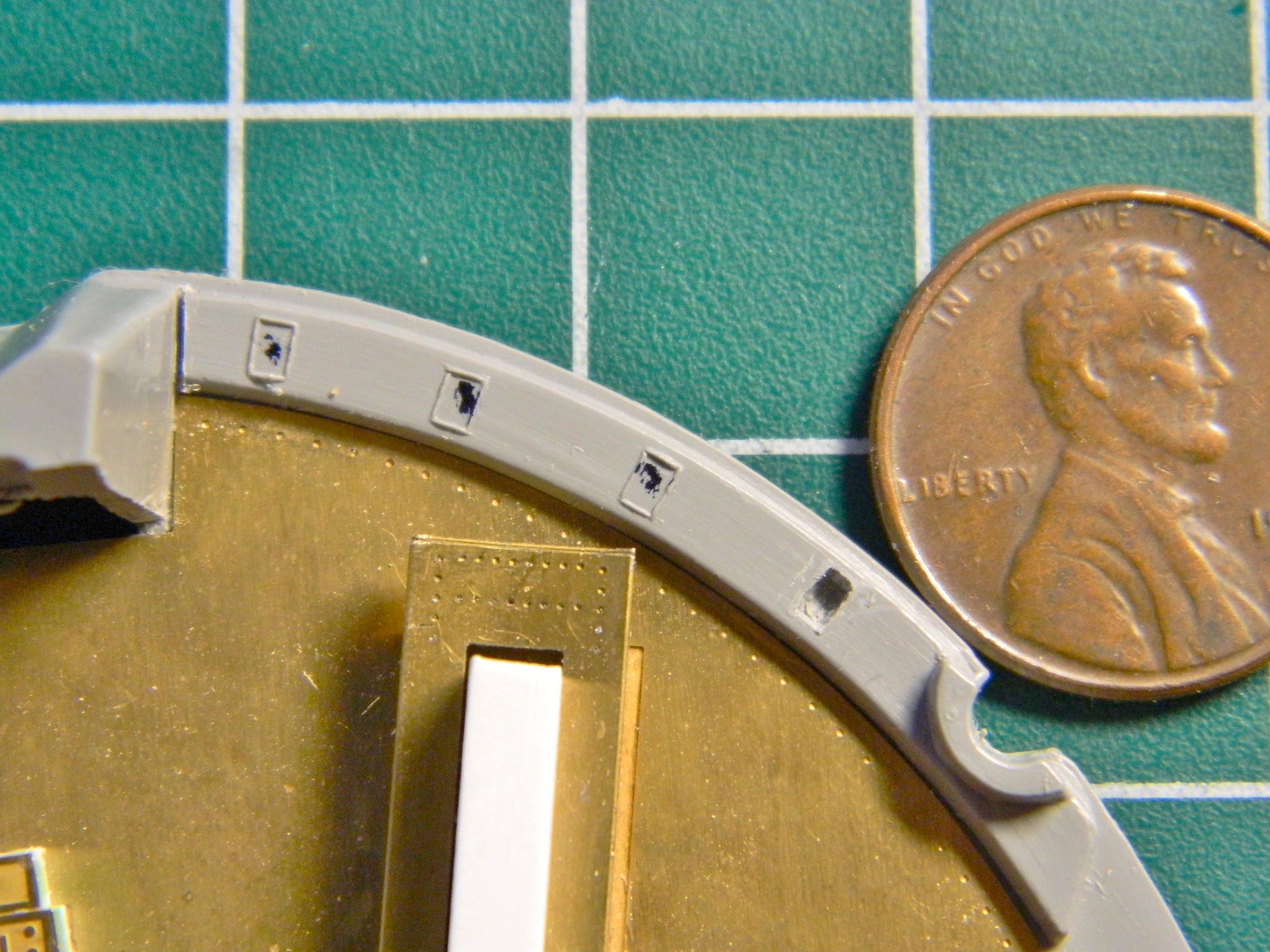
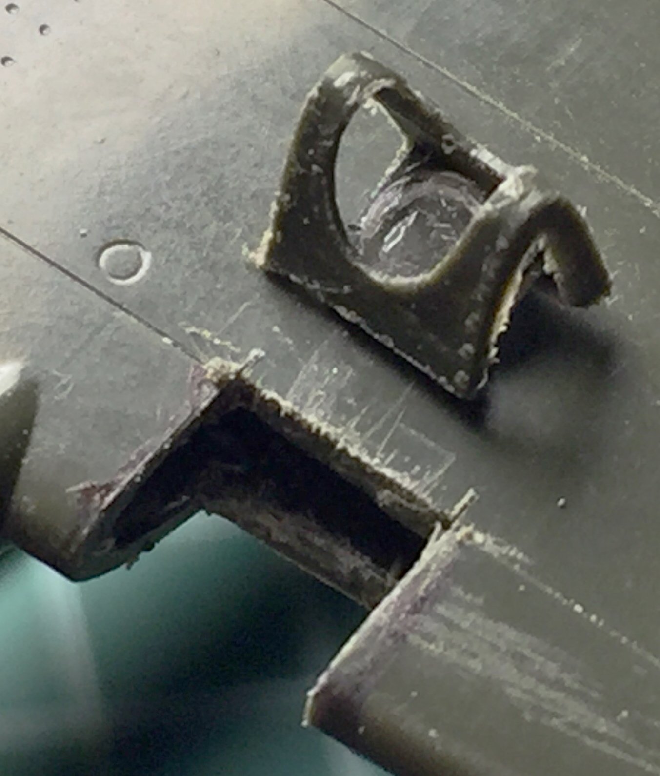
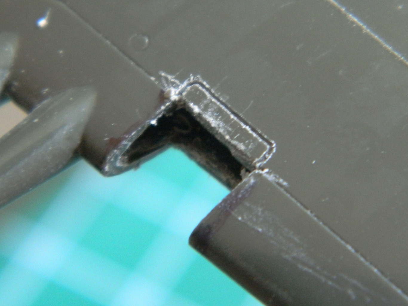
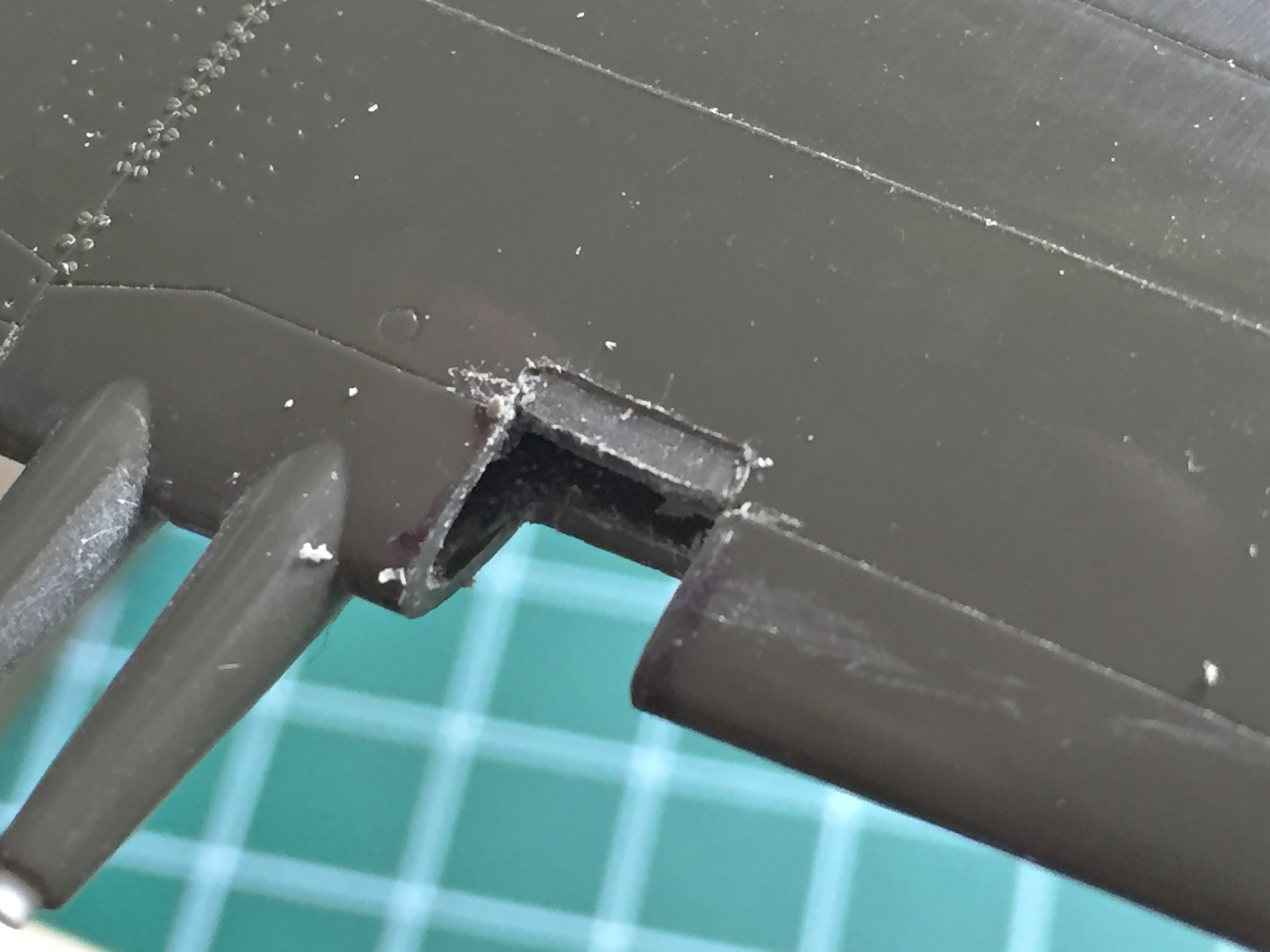
Needing a short change-of-pace, I checked to see how difficult it was going to be to open areas that were molded solid. The rectangles around the periphery of the rear cabin wall are actually openings that the catches of the hatches go into to close the hatches securely. Ideally those are hollows. Since they weren’t molded that way, I wanted to see if I could cut the hollows into the kit piece or if I was going to have to cut away the area and build something less inaccurate:
I can hollow out the individual sections. It’s a bit tedious but I can do it without (more) reconstructive construction.
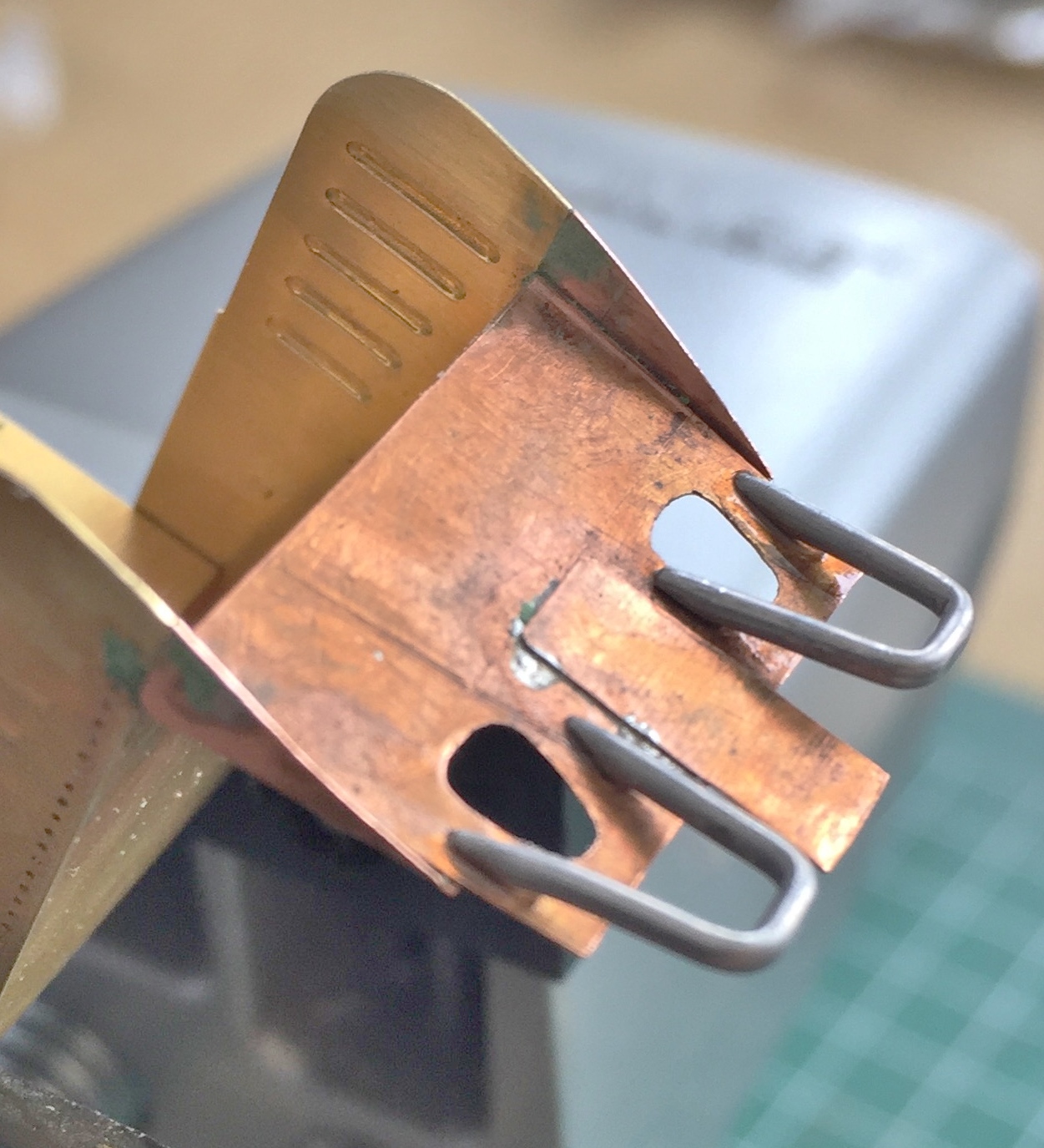
Back to work on the seats, I added the support for other details (the function of which I cannot fathom so there’s no label for that strip soldered between the two loops) for the foot stirrups (which were intended to keep the feet and legs from flailing around and getting injured should the crew need to eject) using solder:
I didn’t realize at the time what a major ass-pain these things would turn out to be. They snap off with the slightest provocation and attaching them is another major ass-pain…and I got to reattach them frequently.
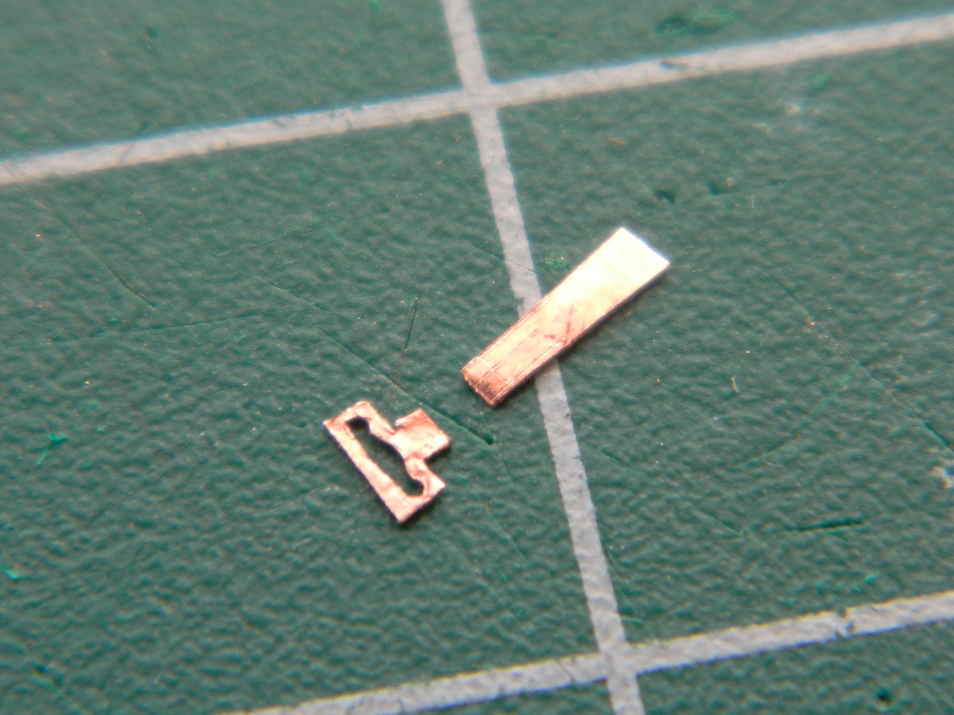
There are foot rests for the stirrups (wouldn’t be much of a “stirrup” without them, I guess). My first thought was to make them out of .010″ (.254mm) styrene. My second thought was to not do any work until sober. My third thought was to use the .005″ (.127mm) copper shim stock instead. Scale thickness is more correct and for all of the annoyances of working small copper sheet like this, they’re a lot less annoying than trying to do the same thing with styrene. First step was to scribe the lines I wanted and then cut them out. I used scissors for the longer…all terms being relative…sides and a SHARP chisel bladed knife for the notched cutouts on the sides:

As it turned out, I got the pattern incorrect. I diddled around until I got the pattern and sizes (plural because I wasn’t exactly standardized about the solder stirrup supports) correct and then superglued them into position:
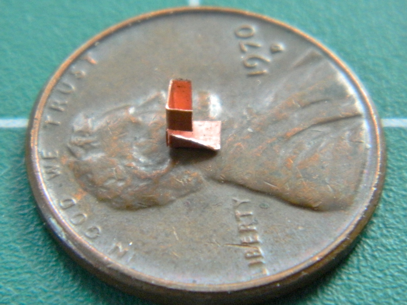

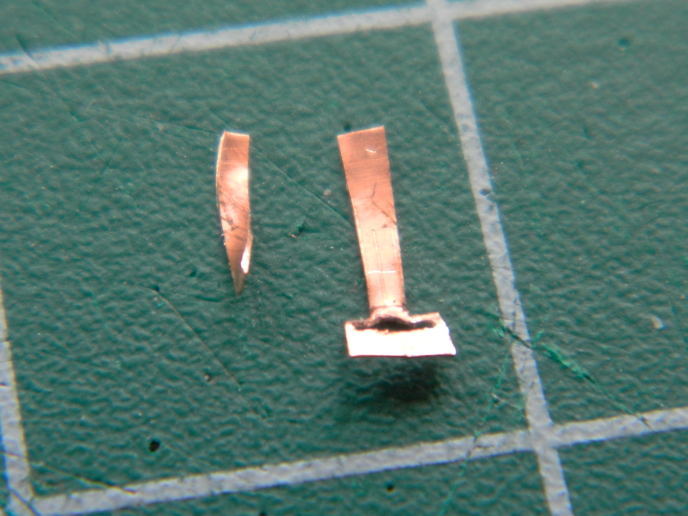
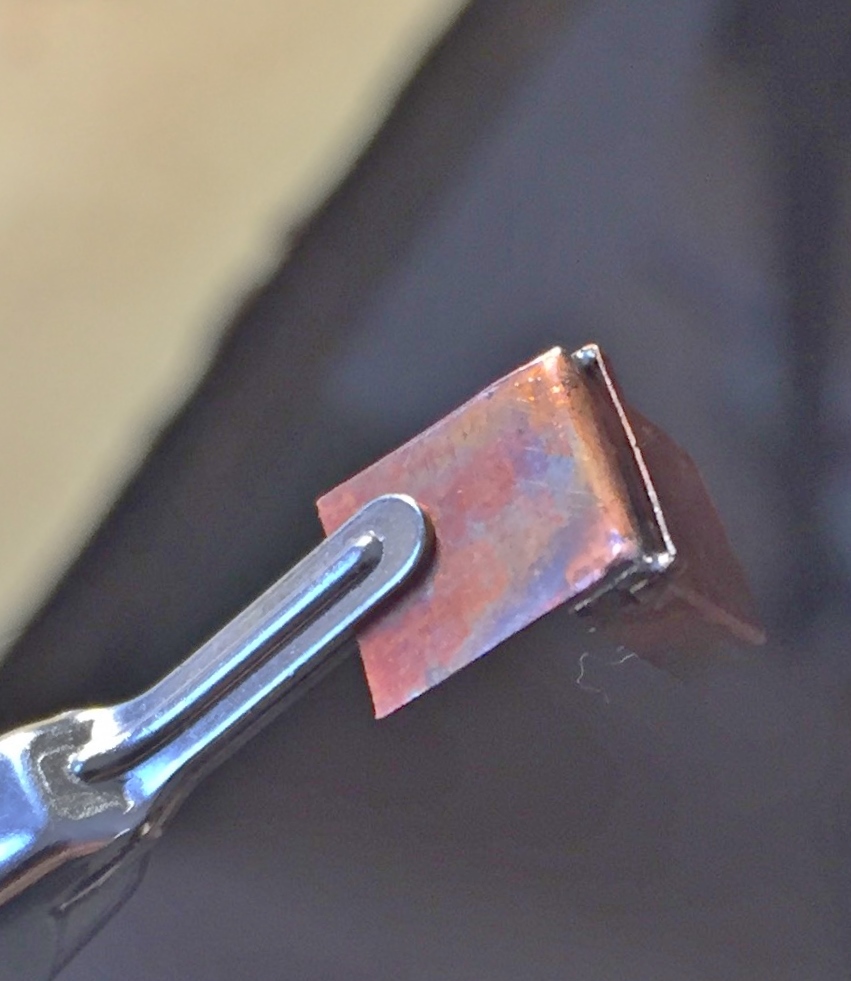
There’s a prominent box on the front face of the seat that the ejection seat trigger is mounted to. Again, I used the .005″ (.127mm) shim stock and again I got the pattern slightly incorrect:
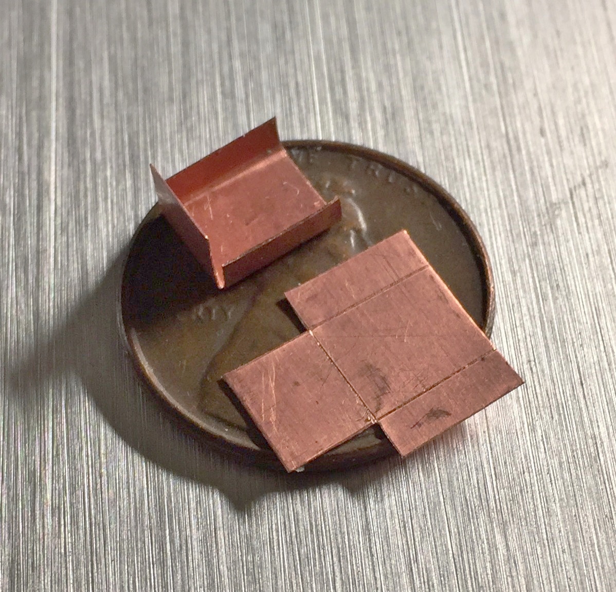
The pattern is incorrect because I forgot to allow for the dimensions of the sides; that has to be added to the flap at the top (as indicated by the penciled outline on the seat):

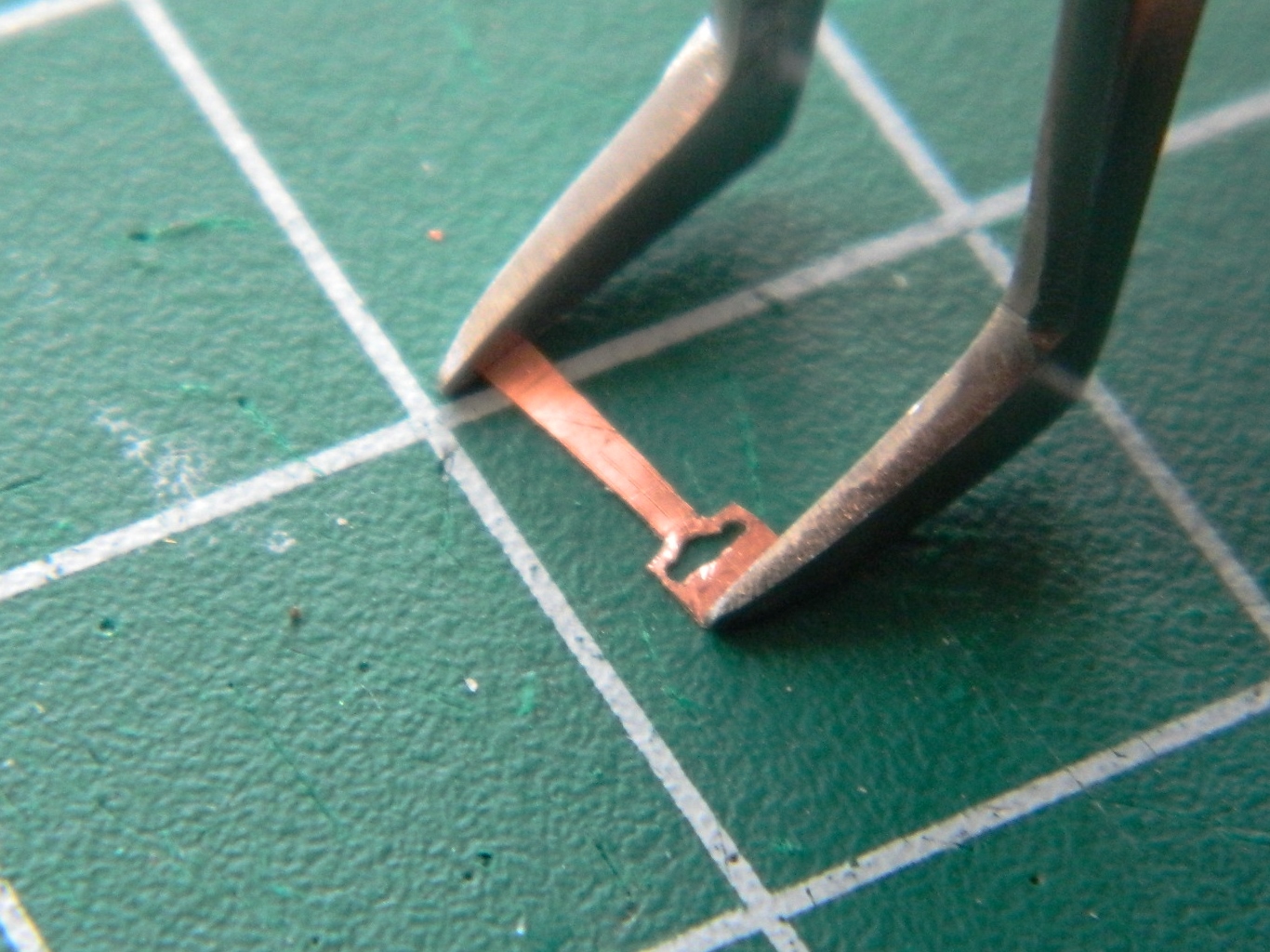
With the boxes properly dimensioned and folded, I needed to add a support bracket for the ejection trigger handle. I impressed myself by soldering these SMALL brackets into place:
Then I added the mysterious details between the stirrups:
The headrest area of the seat frames have padding. This is where the references get…interesting. For a great many of the details shown in a photo as looking like this, there’s another photo that shows it looking like that. I imagine that’s because of the different mission parameters and goals, but it’s…interesting…when trying to find out what something looked like. So I picked one design for the head rest padding and went with it. Then, while looking for something else, I ran across another reference photo that showed the headrest padding of a different design that matched the seat padding I decided on. Sure do wish I’d found that before I superglued the pads in place… That meant the gaps between the individual pads got filled with putty:
The second headrest padding went easier:
The sides of the seats are also not as thin as the PE parts would have them be. I added thickness by using .040″ (1.016mm) scrap:

Yeah…looks much better:

Another thing I noticed about that box at the front of the seat is that there’s a 90-degree mounting bracket that I had to add. And this is good because there’s a gap between the body of the box and the front of the seat that these brackets hide nicely:
The box is mounted with bolts and I used Grandt Line bolts to replicate that (sorry about the blur; the camera DID NOT want to focus where I wanted it to focus) (stupid camera):
There’s another (mystery) detail on the side of the seat that came supplied with the AM set. Problem is, it’s inaccurate. The shape of the top is incorrect (should be round and not rectangular) and the angle is also off. Scrap styrene was used to fix that (those?):
Much better:

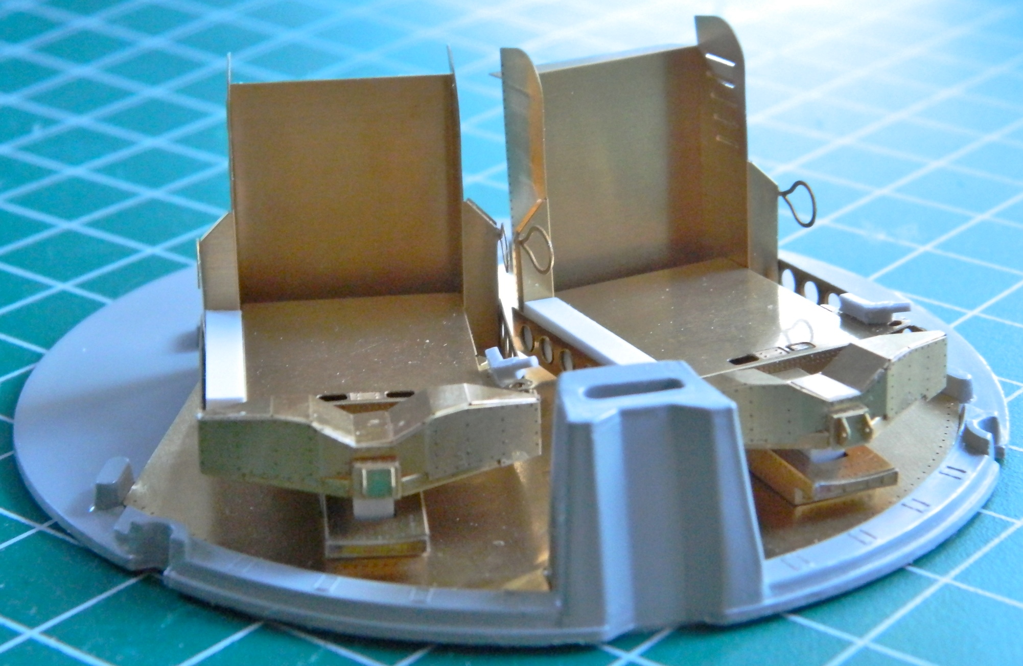
Having widened the seats, it finally occurred to me that maybe I might want to dry-fit the seats with the additional details that added width to an already cramped cabin:


Yeah, it’s snug, but it fits!
A Word About How Tools Affect the Work
The tools you use to do your work will affect the work you have to do and will often add to the work you have to do. (Yes, it’s a poor craftsman who blames his tools. It’s a ignorant craftsman who doesn’t choose his tools wisely. It’s a stupid craftsman who doesn’t take care of his tools.) A simple form of that is a screwdriver. A flat screwdriver does different things than a phillips screwdriver does. In my case (modeling), I find myself sometimes using copper shim stock in place of styrene. It works differently (duh) and the stock itself often needs to be shaped, usually starting with being flattened.
To flatten the shim stock, I use a small ball pein hammer and a small anvil. The ball pein hammer I’m using I inherited. If you look at the face of it you can see where it was used…roughly:
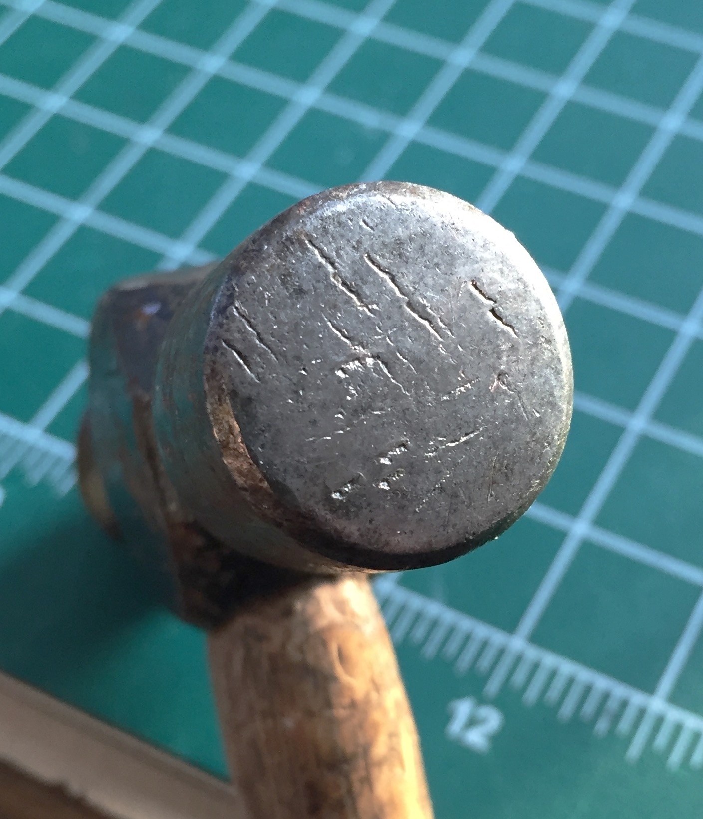
Hitting a piece of softer metal, such as copper, with that will imprint the texture of the hammer onto (and into) the copper. And knowing that can be useful if you need to impart a texture to the surface you’re hammering…but it’s quite annoying if you don’t want a texture.
I used 220 grit sandpaper on a sanding disc to get the face of the hammer to look like this (and later on I intend on polishing it but right now it’s too cold in the garage where my buffing set up is):

The other part of metal forming is that the metal used will need a surface against which to be shaped. Since I’m mostly interested in flattening the metal, having a flat anvil face is a good idea. The anvil I purchased was not finished by a metal finisher! It was sandcast and the surface roughly smoothed with a belt or disc sander…using a coarse grit. So I started filing the face of it flat using a coarse mill bastard file and moved to a fine mill bastard file, finishing with 220 grit on a sanding disc. As you can see below, the top of the anvil wasn’t remotely “flat,” and the curve of the horn (the pointy part) still had texture from the casting sand. All that had to go:

And after a few hours work, gone it is (and will be polished when the hammer gets polished) (I hate polishing…dirty work, that.):

Now when I use this hammer and anvil, there’s no undesired and unwanted texture added. Don’t be afraid to modify your tools to suit your needs and purposes! If you screw one up, it can always be replaced. You own your tools, they don’t own you.
Gemini (Revell) Build #5 – Interior Work; Adding Missing Details on the Seats
With the control and instrument panels detailed, it was time to fit them. Checking references, I see that the sides of the center console doesn’t float unattached the way the kit parts do; they go all the way to the floor:

So using .040″ (1.016mm) sheet, I started extending the sides of the console:


Dry-fitting showed me there’s still a way to go with this:

I still have to add more to the sides of the console, but lacking four (or more) hands, I needed to reduce the number of individual parts (and tape) for dry-fitting so I attached the console to the main panel. Normally I use superglue to attach resin bits to each other. Due to such a small contact area between the console and the panel, this time I used 5-minute cure epoxy:
There is a joystick on the center console which will also need to be replaced. I started with five pieces of .020″ (.205mm) sheet (scraps, actually), drew the outline of what I wanted on the spine of what will become a more accurate joystick, and started dimensioning and gluing the other four pieces into place:
Then there were MANY DAYS of holding the sodding TINY part between increasingly sore finger tips while I scraped, filed, sanded, muttered, CURSED…er…exercised my ability with colorful (and anatomically unlikely) invective, interspersed with A LOT of time crawling around the (filthy, as it turns out) floor with a flashlight trying find out where the [INVECTIVE DELETED] thing landed this time after I dropped it. Finally I ended up with this:

When I spend so much time on something that is so small, I wonder if I’m actually in a small room somewhere, rocking back and forth and whimpering. Anyway, the joystick is mostly done with only a few very minor tweaks (as if the joystick itself isn’t minor) left to do to it.
One of the things I’ve found I have to deal with when building is the “before you can do this, you have to do that first, otherwise you won’t know how things fit.” With the console I’ve reached that point.
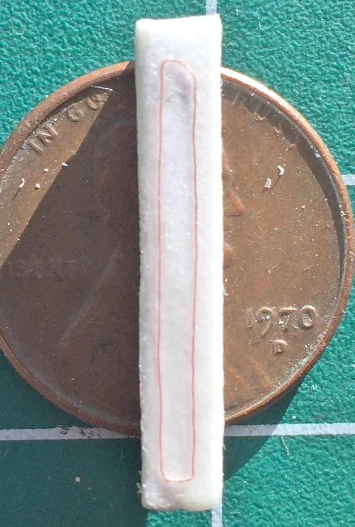
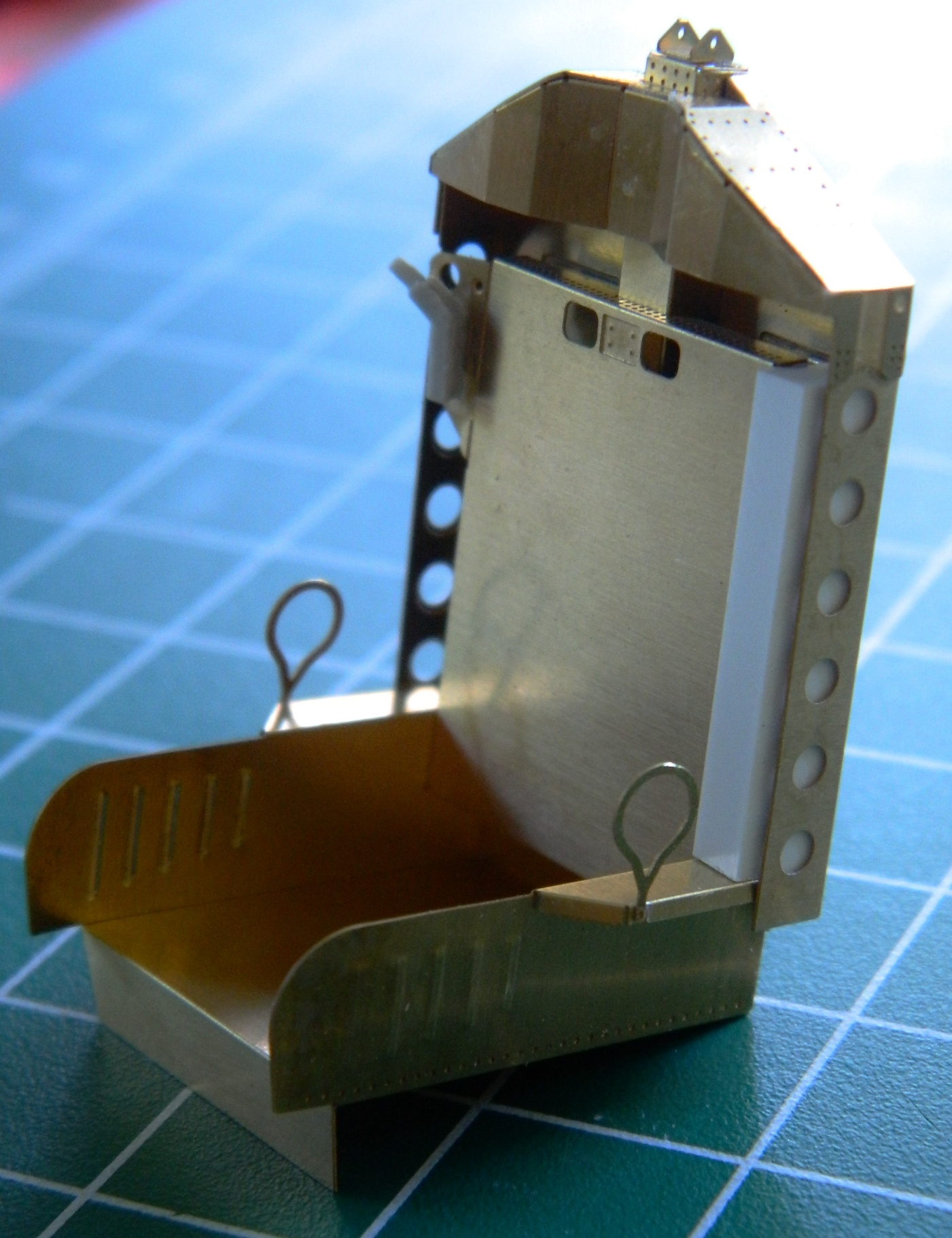
The ejection seats fill the interior. I’ve known since I assembled the PE parts (and decided that I wasn’t adding the astronaut figures) that I was going to have to detail them more than the PE set had. That started with taking the seats away from their backing. First step was making cushions. I had originally intended on making the cushions out of epoxy putty, taking a mold of them, and then casting resin parts to install. Then I realized I was making this far too complicated. I wanted to start with something about .070″ (1.778mm) thick and to do that, I needed to laminate sheets of .030″ (.762mm) and .040″ (1.016mm) to get that. Once laminated and cured, I cut them to dimension, shaped the bottom cushion, and then rounded the edges (and while you’re there, note how short the forward bottom face under the edge of the bottom cushion is…that has to be extended):

That worked well, and since there’s two seats, I needed to make another set:

Then I had to extend the front vertical bottom face of the seat. I used .005″ (.127mm) copper shim stock and soldered it into place on the front, figuring the seam between the two parts would be easier to hide at the fold line.
A word about soldering…
Using a soldering iron works fine for soldering small things that will heat up quickly. The soldering iron doesn’t do so well at heating up a large surface that heats slowly. For one thing, it only heats the area it’s in contact with. Fine if you want to solder something small at a small contact area. NOT so fine if you’re trying to solder a long(ish) part that’s been folded one too many times and has snapped off. It’s also not so fine if you’re trying to solder a wide, flat part to another wide, flat part…like I had to do with the extension to the front bottom of this seat, for which I used .010″ (.254mm) copper shim stock:

In the following picture, let me direct your gaze to the SLOP at the top center of the photo. This is where the seat back joined the seat bottom. It got dropped one too many times and snapped off. There isn’t enough surface area at the join for adhesives of any sort to work. I tried soldering it with a soldering iron and the charred lumpy crap you see is the results of my efforts. Yeah…it does hold the seat back to the bottom, but it looks like shit (and the only reason I haven’t redone it is because it does hold the back to the bottom and the shitty area won’t be seen). And while online looking for something else entirely, I ran across a soldering tip (idea, not something you’d attach to a soldering iron). Put a little bit of flux onto the part where you want the solder to flow and then clamp the two parts together. Then cut small bits of solder (as I learned, smaller bits than what I used here) and lay them in place along the seam of the join:
THEN use something along the lines of this little beauty. It’s a butane pencil torch (in case there’s someone from the UK reading this, I mean torch…not a handheld light source…which is what a torch is, I guess, but…well…I’m digressing a lot, here). A propane torch works well, also. It doesn’t take a lot of heat to solder:

Fire that baby up and make several passes across the surfaces you’re soldering together, starting further away from it than you think it should be and then gradually moving closer. First the flux will liquefy and flow between the parts. Then the solder will liquefy and follow it. Quickly remove the heat source and you should end up with a nice clean soldered join:
And that’s how I ended up getting that extension neatly attached.
There are details that now need to be added and removed. Reference photos show the details on this area of the seat. To transfer the dimensions from a photo on my computer screen to copper parts on my workbench, I used these…proportional dividers:

By adjusting the pivot, dimensions of one scale can be easily reproduced in a different scale consistently. Reminding myself (again) that in modeling, things have to look right…in engineering, things have to be right (there is no “alternative engineering” any more than there is “alternative truth”). I placed the large spread of the divider against the screen and the small end against the seat front, and diddled with the pivot until everything matched, and then I took the relative measurements:

The details that are replicated by removal are those holes. I took out my Eyecrometer and made a template. Since this area is VERY small, I needed a template that would hold itself in place as my fingers are just too large. Masking tape “worked” but was problematic in use (too thick for the size I needed and more difficult to remove that I wanted to deal with). Instead, I used the sticky section of a Post-It note:
Then it was a matter of drilling and filing things to shape:
The sides of the seat come down further than the PE parts do and those needed to be fabricated and added:

Then I needed to fill gaps my ham-handedness left. I tried my structural putty which didn’t work. The gap was large enough for a piece of scrap plastic to be sanded to thickness and superglued into place. Then commercial putty was used to blend everything (hopefully) seamlessly:

Since there are two seats, that all had to be done again. Having made my mistakes (and rectifications) on the first seat, the second seat went much easier and was neater:
Gemini (Revell) Build #4 – Interior Work (and a Bazillion Little Tiny Switches)
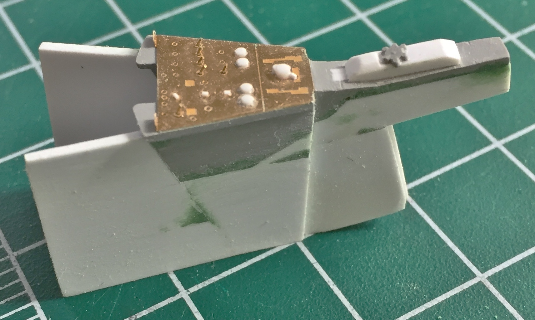
Since the surfaces of the resin and PE parts are different, I used both PE on both instrument panels for commonality:
And since I was working with PE parts, I went ahead and did the rest of the panels in the cabin. The center console (lower right) and the overhead switch panel (bottom) both had details molded on that had to be removed. Once that was done, I superglued the PE parts in place:
A small console that’s mounted on the rear of the cabin only had a pedestal for the upper section of the main body. I don’t know how visible this part will be once everything is assembled, but I do know that once everything is assembled I won’t be able to get in there to fill in empty spaces that turn out to be visible, so I added some flat styrene to the back and then trimmed it to fit:

As it turns out, that rear console isn’t particularly visible for most of it, but the top of it is visible so I’m glad I decided to add what was missing:

I prefer to get tedious jobs done so that they aren’t hanging over my head. Having to put 63 individual toggle switch bats in place, this classifies as “tedious” to me and that’s where I started:
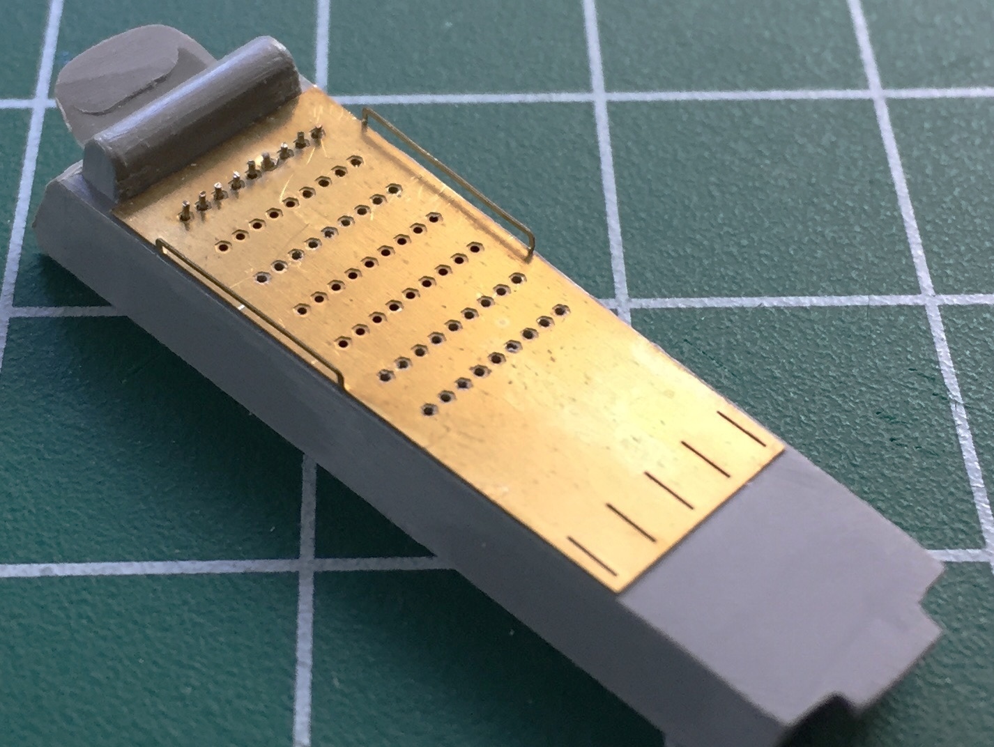
And since I was knocking tedium out of the way, I bent the side panels (more switches) and added scrap flat styrene to the back to allow for more surface area for the glue to hold the wires (24awg) that I’m using for switch bats in place:


Since there are two panels, I did that twice. There is a larger selector knob in one of the panels. I used styrene rod and a tiny bit of scrap to make that knob:

There are a number of selector switches as well as toggles on the main panel and all those got added:
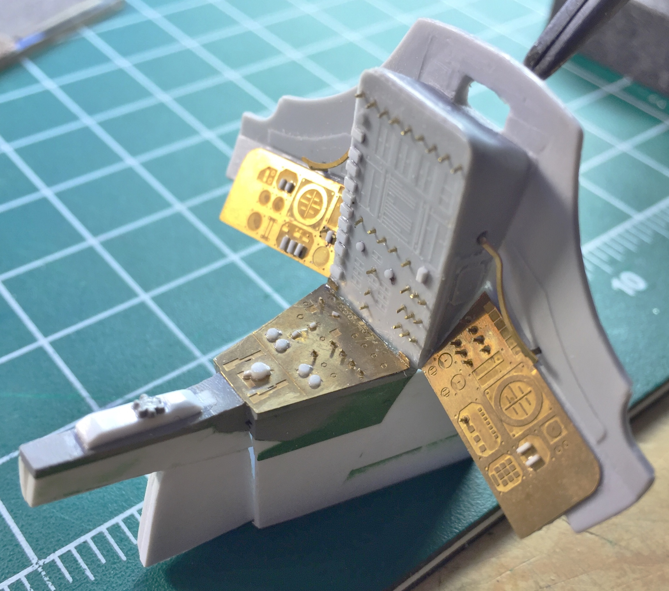
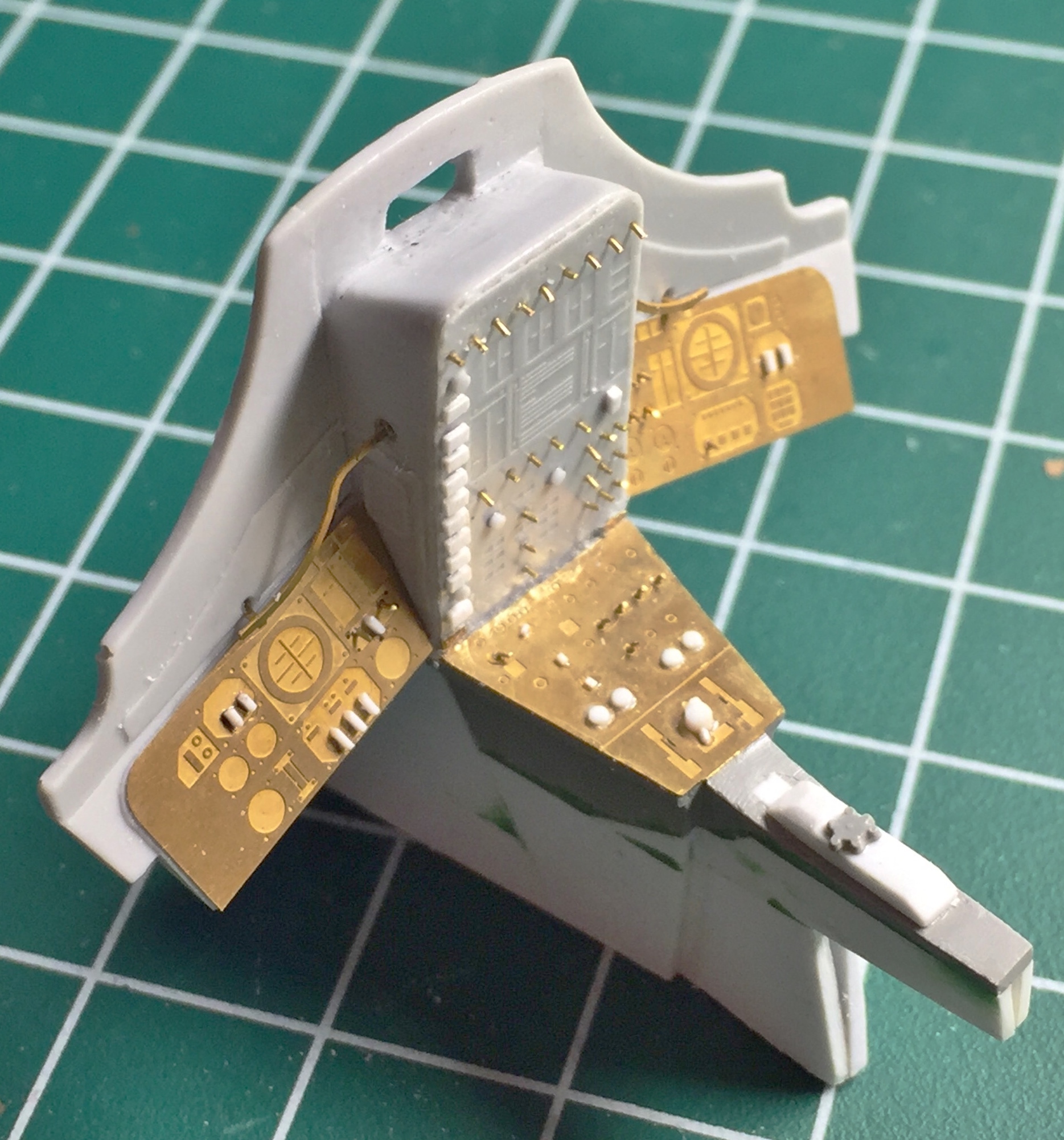
I taped the major parts in place so that I could determine where the side panels go and then I glued them in place:
(Once I had all the switch bats in place, I looked at a drawing that showed what each individual switch for the main panel and center console were for. I’m not going to add figures to this so that means the capsule isn’t in space. I adjusted the switches to all their “off” positions.)
The center console also had another inaccuracy for a production capsule. The knurled knob is the main cabin heat control and it doesn’t go there. However, where it does go wasn’t molded on. I took some scrap styrene and changed the top of the console, then I took a very thin saw and removed the knob. I added the final shape to the addition to the console (the big white section) and glued the knob on:
The overhead switch console has PE parts to add details that weren’t molded with the kit. Dry-fitting the PE parts and then checking references show me that I have to cut away sections of the kit part. Doing my best imitation of a four armed, glue-sniffing, rivet counter, I put the PE facade over the part it gets glued to and outlined the areas that needed to be cut away:
Then I dry-fitted and taped the major components together to see how everything fit. There will be modifications necessary to get all these parts to play nice with each other (if you look at the console at the top of the cabin, you can see where the plastic was cut away from the PE part) (because I forgot to take a picture before I took these):
Gemini (Revell) Build #3 – Cleaning Up Exterior Seams and More Interior Work
My suspicions regarding how well the exterior parts align was optimistic. Thus far it looks like nothing lines up well; it’s a trade-off regarding which area(s) of the surfaces are more difficult than others to add/replace surface details.
Peeling away the masking tape gives me join lines that look like this:


And the section that houses the maneuvering nozzles is too large in diameter where it meets the body parts (note the gap between the ring and body; this will be shimmed with styrene stock). To make up the difference I added a ring of .015″ (.381mm) styrene stock as well and then added putty to fill in gaps and misalignments:


The attachment area was also rather approximate so when I used styrene cement to attach this ring, I added weight to get the tightest fit possible:

Once the putty hardened, it was time to remove the putty I didn’t want:


The model comes with a display stand (you can see it on the box top in the first post of this series) that I’m not going to use. That means the slot has to be filled in and carved to match the surface detail:


Sanding seams and putty removed surface details that I had to put back. I used my punch/die set to make the washers and a (very) small drop of superglue as the rivet:

At this point I have four different surfaces, each of which bounces light differently, and all of which have to play nicely with each other. I primed the surface so that I could see what areas needed more work (which is pretty much all of them):


Needing a break from dealing with the surface of the capsule, I decided to do some of the work the hatches need. The PE parts were close but the bolts that hold the ports in place are quite prominent. I used Grandt Line bolts, adding the perimeter bolts and most of the inner bolts (there isn’t enough room to do all of the inner bolts):

I also removed the ejector pin marks on the inner hatch surfaces (as-supplied on left, mostly finished on right):

Not having enough work to do already, I figured I’d screw up the resin instrument panel by not paying attention to where the saw went. Luckily I stopped and checked my cut, which is when I saw I’d cut into the raised details of the right side instrument panel. I glued in .015 (.381mm) styrene and cut it down to meet the surface:

I didn’t destroy all the raised detail but I did wipe out enough to require some sort of clever fix. My first thought was to modify and use the kit part, but the part is so inaccurate that the amount of work (assuming my skills made it possible) to fix my screw up was too much:
Fortunately the AM set also included PE panels that I will use to cover my mistake:

Gemini (Revell) Build #2 – Starting on the PE Interior Parts
With the glue (finally) set, I masked off the surface to minimize having to clean putty away from unnecessary surfaces and applied the putty:

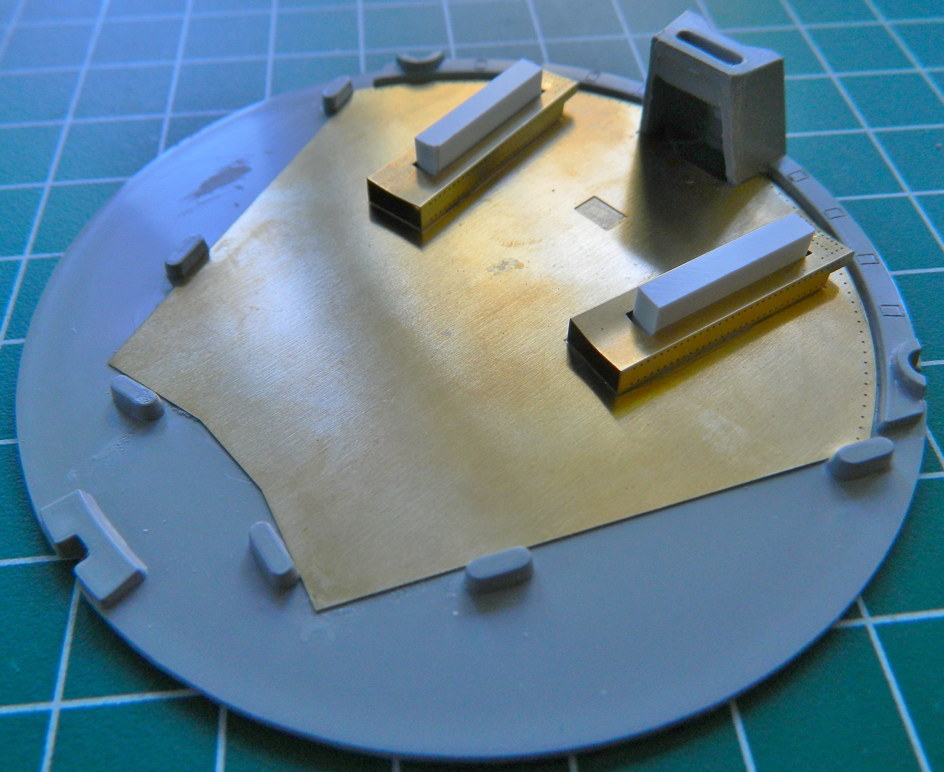
I added the mounts for the ejection seats to the rear bulkhead:
Then I started on the ejection seats themselves. When I first cut the parts free, I wondered how much of a drill this was going to turn out to be:
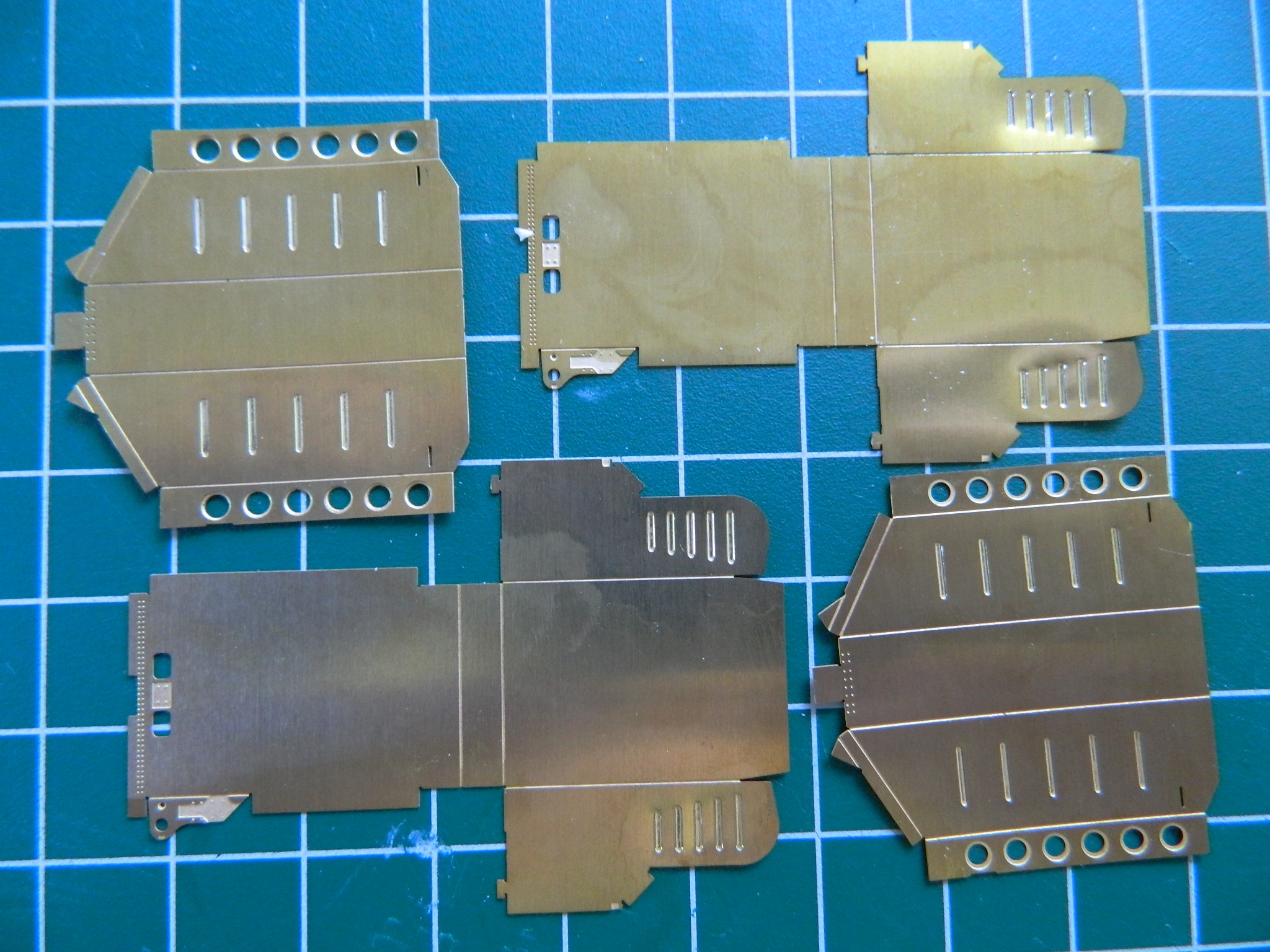
LVM Studios, the people who produced this AM set really engineered it beautifully. The parts fell together as much as something this complex can. The scored panels made making all the bends SO much easier:

The first one went together easily using superglue; no solder. So I made the second one and dry-fit them to their mounts (I’ll attach them permanently after painting them):

The (surprisingly) easy part done, I’ll turn my attention to cleaning up the exterior next. I suspect that won’t be easy at all.
Gemini (Revell) Build #1 – Parts Layout and the Start
To the best of my knowledge, only one kit of the Gemini capsule has been produced in 1/24 scale. Revell cut the molds and first released it in 1965. The kit was reissued in 1982, the early 90s, and finally in 2012. The kit is a straight reissue (all but the last reissue were molded in gray, the last reissue in white, which included a better decal sheet). It’s an old set of molds. The parts are thick and don’t fit very well. When Revell tooled up for the kit, they only had the McDonnell prototype to work from, so that’s what the kit represents. There are substantial differences (at least from a modeler’s perspective) between the prototype capsule and the production capsules. There were further differences in detail of capsules optimized for specific missions. One of the differences is that from what I can tell, the prototype did not have ejection seats and the production capsules did.
There are MANY variations of the actual Gemini capsules and the details vary from mission to mission. I’m going to try to replicate Gemini VIII (check the after-action report for more details on that one!).
Here’s where it starts:

The parts:
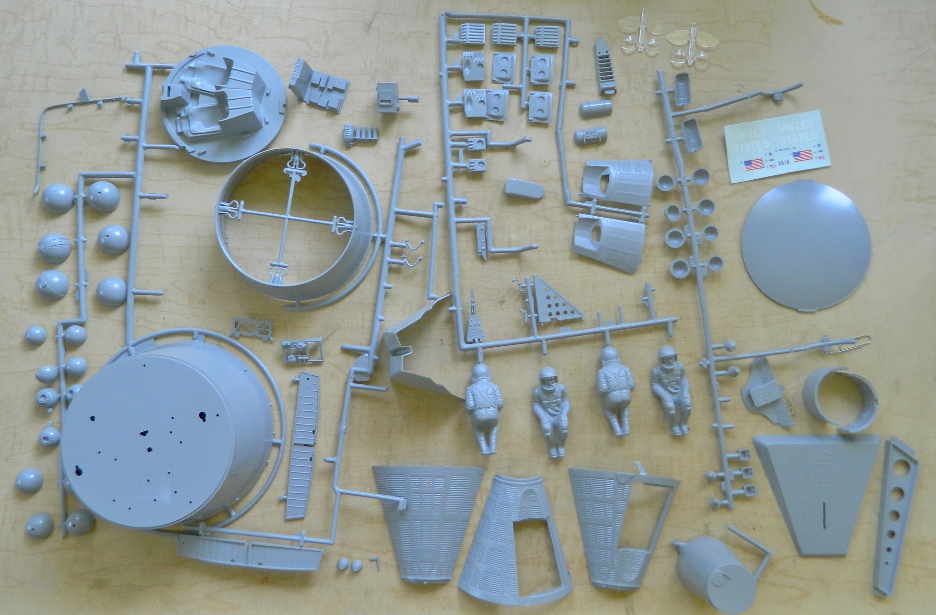
There are differences in the external details, most notably the OMS (orbital maneuvering system) thrusters, and the nose of the capsule was configured differently depending on the goals of the specific missions:
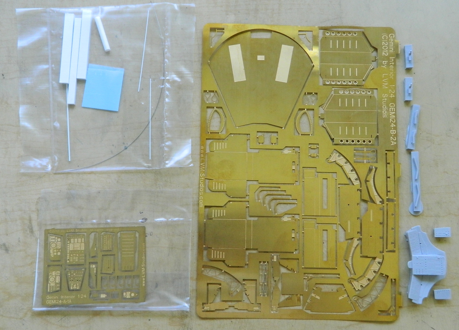
The differences inside the capsule are represented by this set (and it looks like I’m going to get to practice my PE bending/soldering skills):

And finally (I think) the markings:
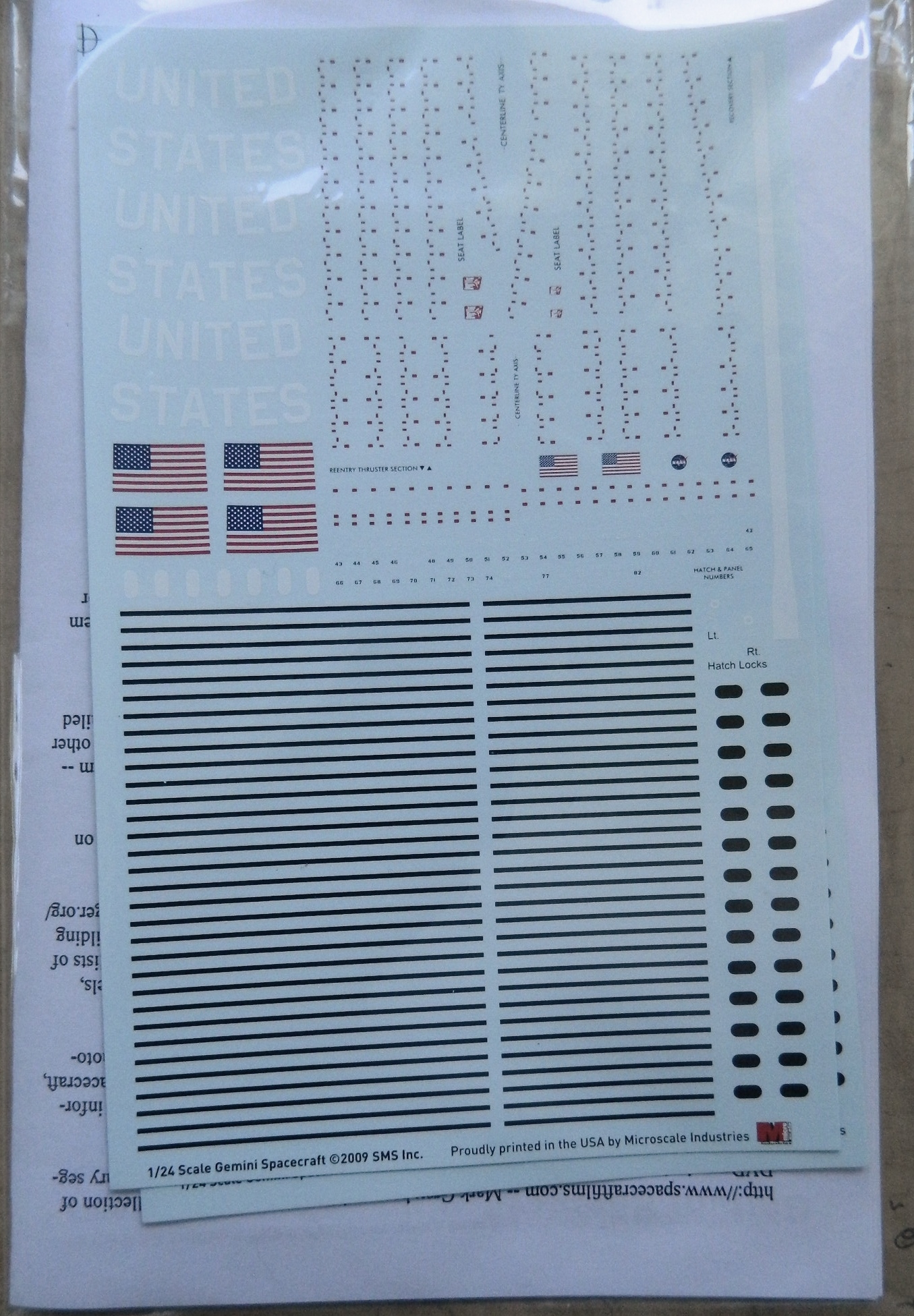
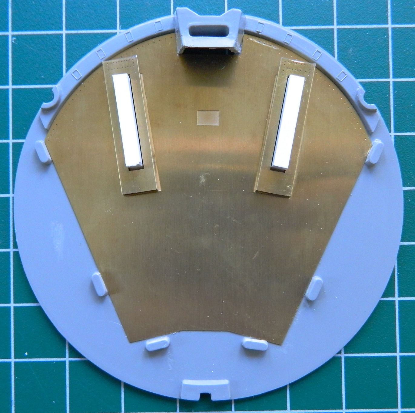
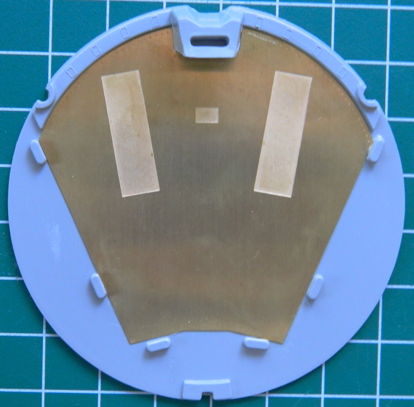
Construction starts by removing the prototype-style crew seats from the rear bulkhead of the cabin and replacing it with a sheet of PE brass:

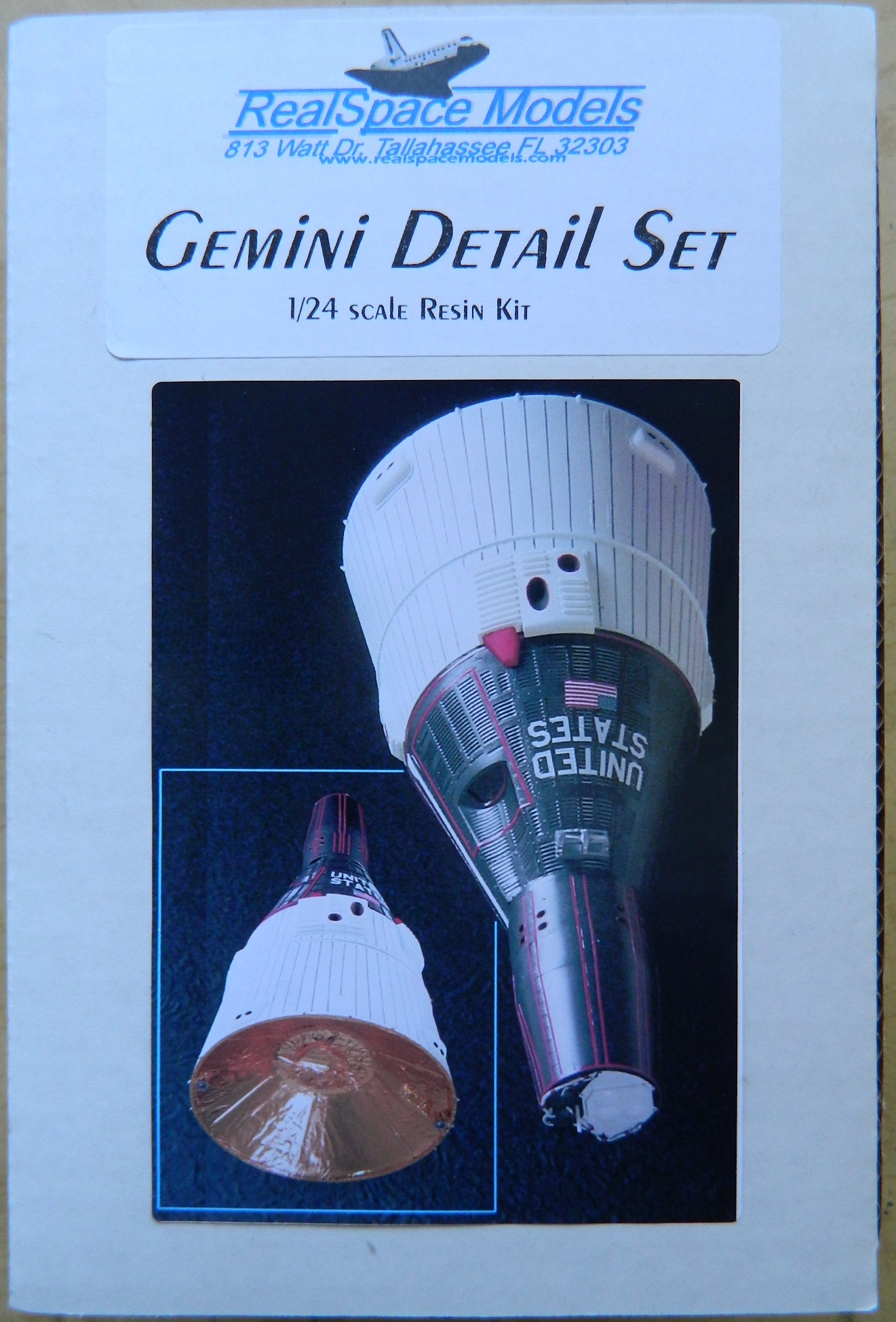
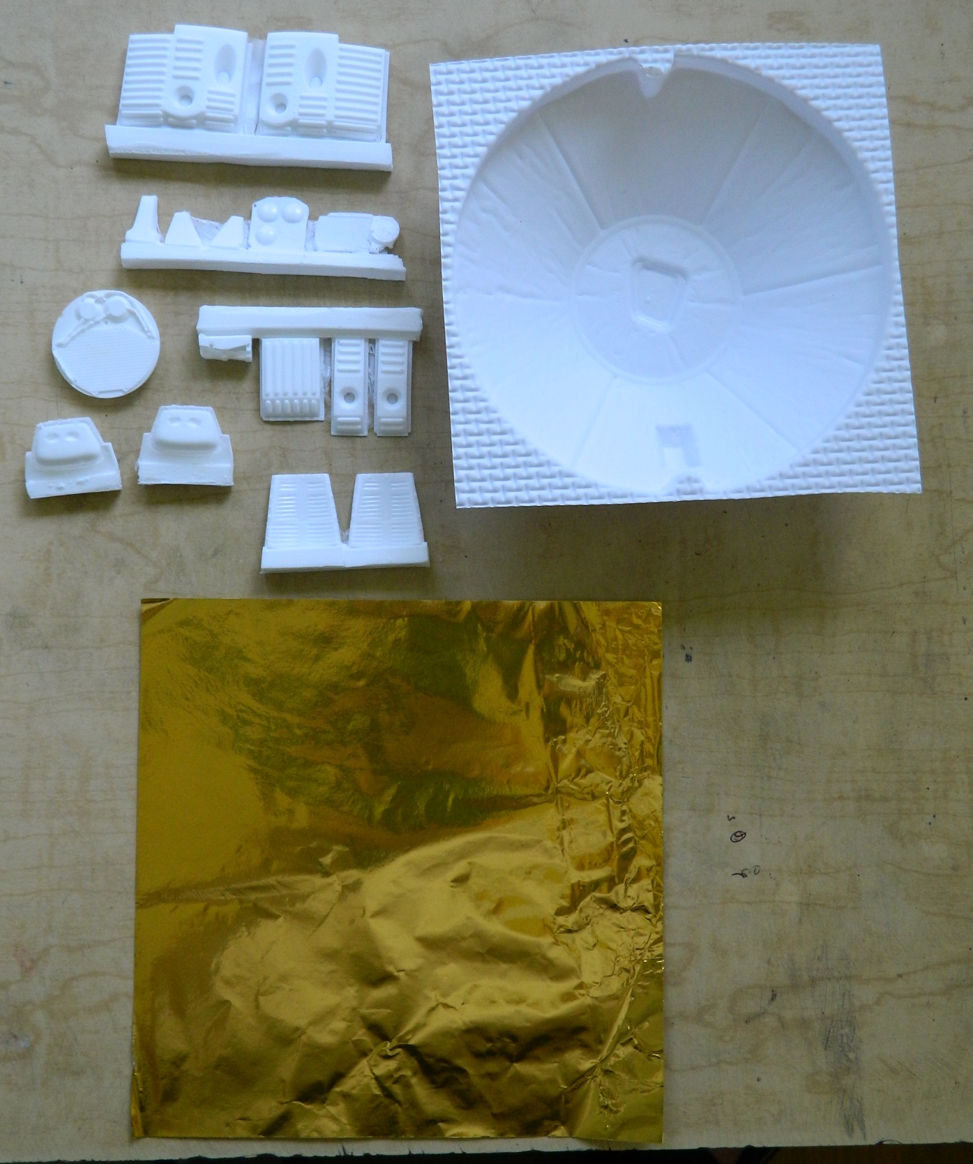
The exterior of the capsule in front of the hatches was different on the prototype, shown on the left. RealSpace Models included the corrected panels in their kit. The good news is that I don’t have to scratch-build these sections. The bad news is that the resin replacements aren’t very well done and will require a fair bit of surgery and adapting to work:
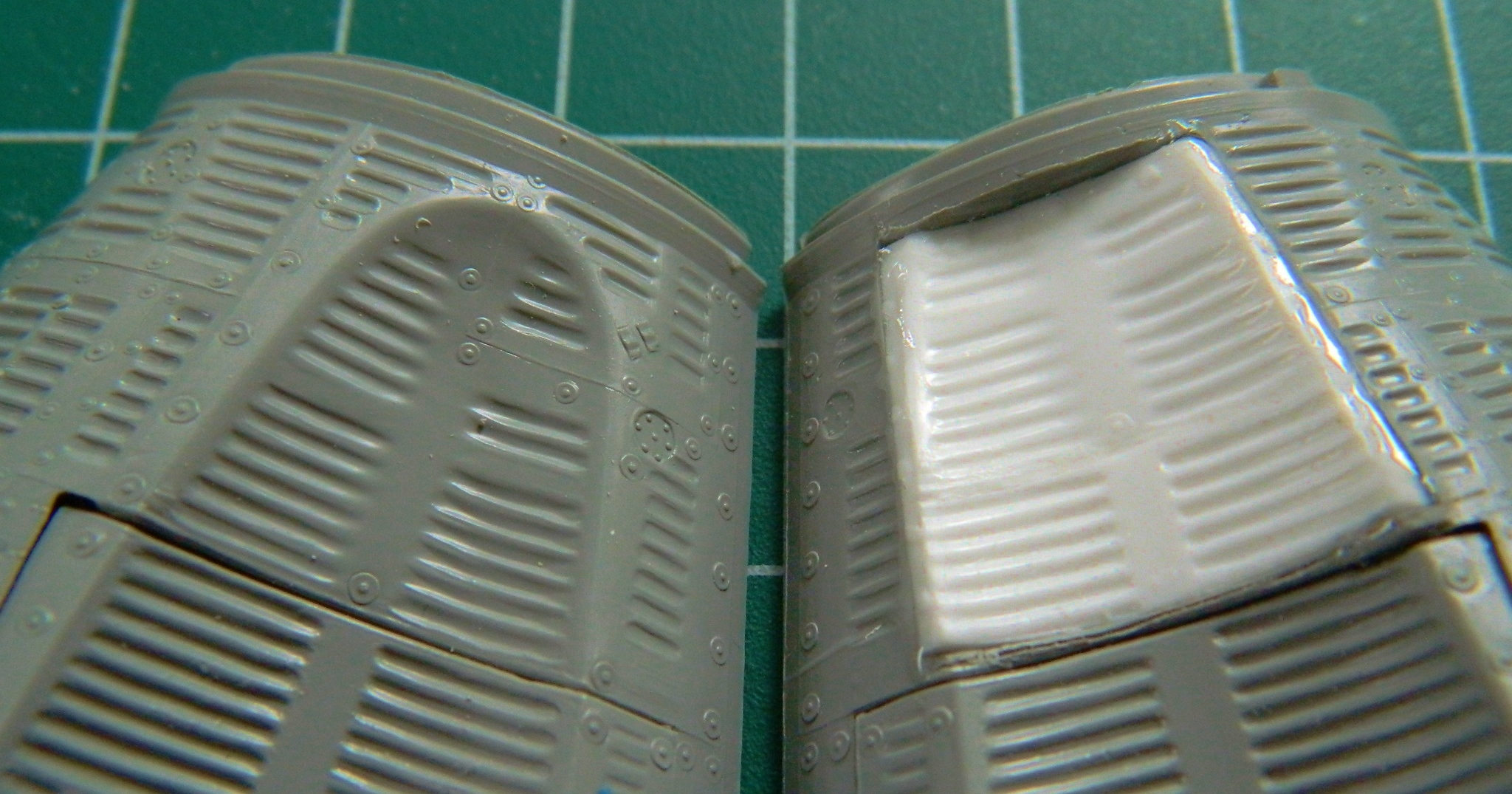
With the kit’s section cut out, dry-fitting begins (and there was a lot of it). Once I was satisfied (relatively…these panels are going to require a fair bit of work to look correct) with the fit, it was superglued in place. There are fairly wide gaps that I filled with gap-filling superglue:

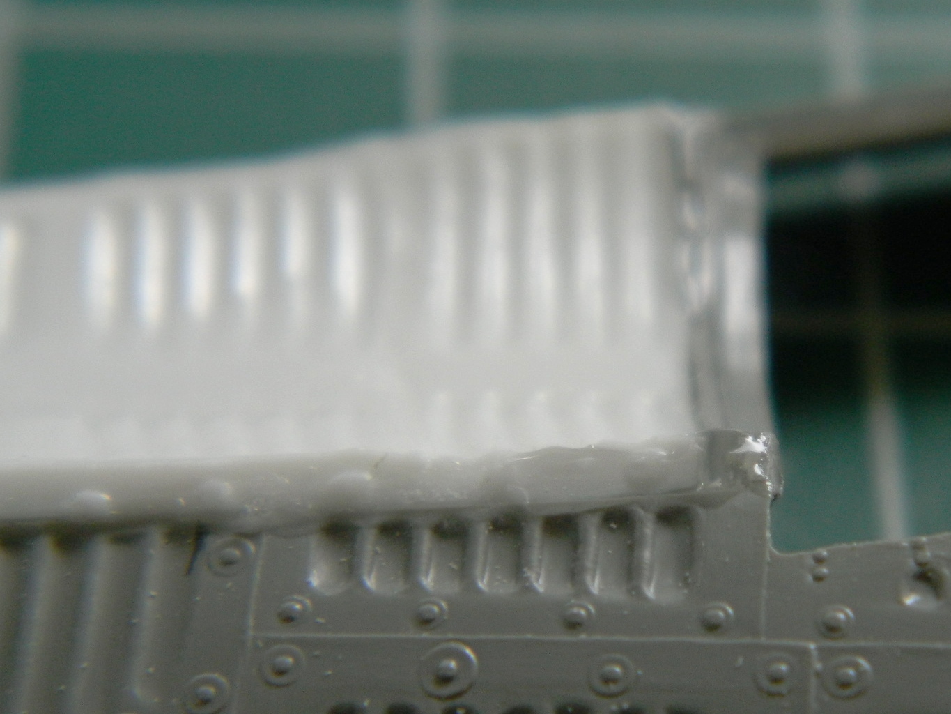

Using superglue accelerator would have hastened this part of the build but I don’t especially like using it for two reasons: the superglue becomes brittle, making trimming it annoying, and the accelerator dissolves the surface of the plastic slightly (which then does re-solidify but I still don’t like it). So while I was waiting for the superglue to cure, I started working the PE parts, starting with the ejection seat mounts:
These aren’t the hassle they could have been due to the manufacturer etching scoring lines (which makes for MUCH cleaner and easier bends). So the first step was to bend them:
Then the edges where the bent part joins get soldered. If your soldering skills are as poor as mine, you could likely end up with something that looks like this sloppy crap:

Judicious use of files to get rid of the blobs of solder, then 1500 grit sandpaper to get rid of the filing marks resulted in a pair of these:


I switched between working on gluing the resin patches to the hull and bending/soldering the PE brass until done with both. Then it was time to glue the capsule sides together and here is where the age of these molds really show. The plastic is much thicker than modern kits and the fit is at best…approximate. I had to get creative to get these parts as aligned as I could; three parts, two hands, and I really needed four hands. There was no way I could get the surface details to match from section to section so I had to decide which of the misalignments would be easier (all terms being relative) to fix. And the join of the surfaces were uneven down their lengths so I had to tack a section at a time together, aligning the surface as well as I could, and then wait seemingly forever for the thick plastic to set up (the collar is just taped together and taped in place to aid in “alignment” as clamping a cone is…problematic):
Three straight seams should not have taken over an hour to glue, but clearly I’ve been spoiled by state-of-the-art kits:
Gemini Program – A Brief Overview
[Information taken from, http://nssdc.gsfc.nasa.gov/planetary/gemini.html%5D
In December of 1961, NASA announced a plan to extend manned spaceflight. The goal was a manned mission to the moon and to do that, NASA needed to learn everything. What were the effects of weightlessness on a human body? Could humans function in space at all? What where the psychological effects of being confined to a (VERY) cramped spacecraft for a long period of time? Though the math supported the idea, could humans actually effect docking with another spacecraft? What would happen to a human’s perceptions outside a spacecraft? Communication and tracking needed to be refined. None of what we know today was anything other than a theory in 1961. If the US was to fulfill Kennedy’s mandate of a man on the moon by the end of the ’60s, all of this had to be ascertained first.
There were a series of twelve launches, two unmanned for testing and ten crewed launches.

It was an ambitious and successful program (even when things went wrong). Aside from the obvious difference of two crew and a larger capsule, I think the major difference between the Mercury program and the Gemini program was in the basic paradigm. Mercury was primarily ground-controlled research and development vehicle and the astronaut’s ability to control the capsule could be effected, though limited (however Gordon Cooper’s manual re-entry after the onboard computer crashed really stretched the limits of what the astronaut could do!). The Gemini capsule was designed to be primarily controlled by the crew, though ground-control could effect back-up control. The Gemini program intended to develop procedures astronauts would need to get to the moon and back.
Another major difference was how the capsule itself was constructed. Mercury capsules were essentially built from the inside out. If something inside broke, everything outside that was in the way had to be removed before it could be repaired. The Gemini capsule offered modular construction enabling just the affected module to be replaced.
About the capsule:
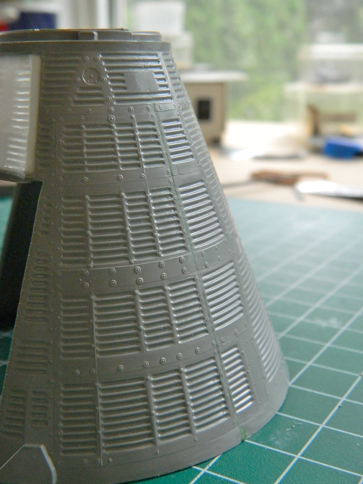
The Gemini spacecraft was a cone-shaped capsule consisting of two components, a reentry module and an adapter module. The adapter module made up the base, or rear, of the spacecraft. It was a truncated cone 228.6 cm high, 304.8 cm in diameter at the base and 228.6 cm at the upper end where it attached to the base of the reentry module. The spacecraft consisted of a truncated cone which decreased in diameter from 228.6 cm at the base to 98.2 cm, topped by a short cylinder of the same diameter and then another truncated cone decreasing to a diameter of 74.6 cm at the flat top that housed the radar. The reentry module was 345.0 cm high, giving a total height of 573.6 cm for the Gemini spacecraft. The adapter module and radar module were detached in orbit and the capsule then became the reentry module.
The adapter module was an externally skinned, stringer framed structure, with magnesium stringers and an aluminum alloy frame. The adapter was composed of two parts, an equipment section at the base and a retrorocket section at the top. The equipment section held fuel and propulsion systems and was isolated from the retrorocket section by a fiberglass sandwich honeycomb blast shield. The retrorocket section held the reentry rockets for the capsule.
The reentry module consisted mainly of the pressurized cabin which was to hold the two Gemini astronauts. The unmanned test flights had instrumentation pallets holding cameras, accelerometers, batteries, and other devices situated in the astronaut area for those missions. Separating the reentry module from the retrorocket section of the adapter at its base was a curved silicone elastomer ablative heat shield. The module was composed predominantly of titanium and nickle-alloy with beryllium shingles. At the narrow top of the module was the cylindrical reentry control system section and above this the rendezvous and recovery section which holds the reentry parachutes. The cabin held two seats equipped with emergency ejection devices, instrument panels, life support equipment, and equipment stowage compartments in a total pressurized volume of about 2.25 cubic meters. Two large hatches with small windows could be opened outward, one positioned above each seat.
The program started with the first unmanned launch on April 8, 1964, and concluded on November 11, 1966.
About this build:
I’m looking to replicate the capsule used on the Gemini VIII mission. That was an interesting mission and certainly showed how adaptable a crew could be when the alternative was death. Here’s the highlights of that mission:
Gemini VIII March 16, 1966
Crew: Neil Armstrong (Command Pilot), David Scott
Mission: Three-day mission. Planned rendezvous and dock with an Agena target vehicle and perform one EVA (Scott). Mission aborted after 10 hours, 41 minutes, and 26 seconds due to thruster malfunction.
Problems: After a successful dock the stack went into a tumble. Armstrong attempted unsuccessfully to use the OMS (orbital maneuvering system) to stabilize the stack. He undocked and the capsule went into an even worse tumble, turning one revolution per second, causing the crew to black out for a short period of time.
Out of radio and radar contact with Ground Control, Armstrong decided to abort the mission. Without confidence in the OMS, Armstrong switched to the Landing System, took manual control, and stabilized the capsule, using most of the fuel required to de-orbit.
Managing a successful de-orbit burn, Gemini VIII splashed down in a different ocean than had been planned for. Instead of the intended splashdown site off the east coast of the United States, the capsule came down a thousand miles south of Japan in the Pacific Ocean. The USS Leonard F. Mason successfully retrieved the crew and capsule.
No conclusive reason for the thruster malfunction was determined*. It has been assumed that an electrical short, probably due to a static electricity discharge, allowed power to flow to the thruster, even when switched off. Subsequent designs changed the circuits so that each thruster would have an isolated circuit. The thruster problem never repeated.
*The reason for the lack of determination of what caused the problem is due to the fact that all the hardware associated with the problem had to be detached in orbit in order for the capsule to reenter successfully.
P-51 (Accurate Miniatures) Build #14 – An Inattentive Error Sidelines the Build For Now
With the arrival of the clear styrene, I turned my attention and effort back to finally getting the landing light covers done.
I needed to cut a piece of styrene that would fit and to do that I needed a template. I decided to use the sticky strip of a Post-It pad that I cut to cover the opening and wrap around the wing. Needing to determine the dimension of the opening, I held the wing up to the light and traced the lighter shape of the opening:

With the shape I needed outlined, I cut the paper, tacked it down to the styrene, and traced the shape I needed to cut out:
I taped one end in place and then used a hair drier to heat the plastic so that I could bend it around the wing. But once I took the tape off, I discovered that bending styrene caused the curved section to fog, which is not what I want:

Okay, so I repeated the process on butyrate:
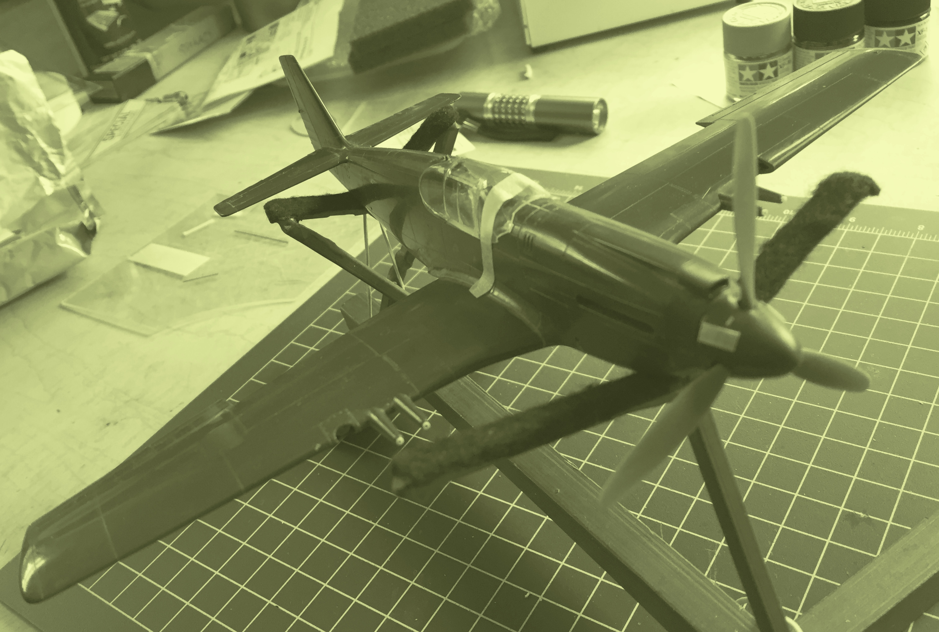
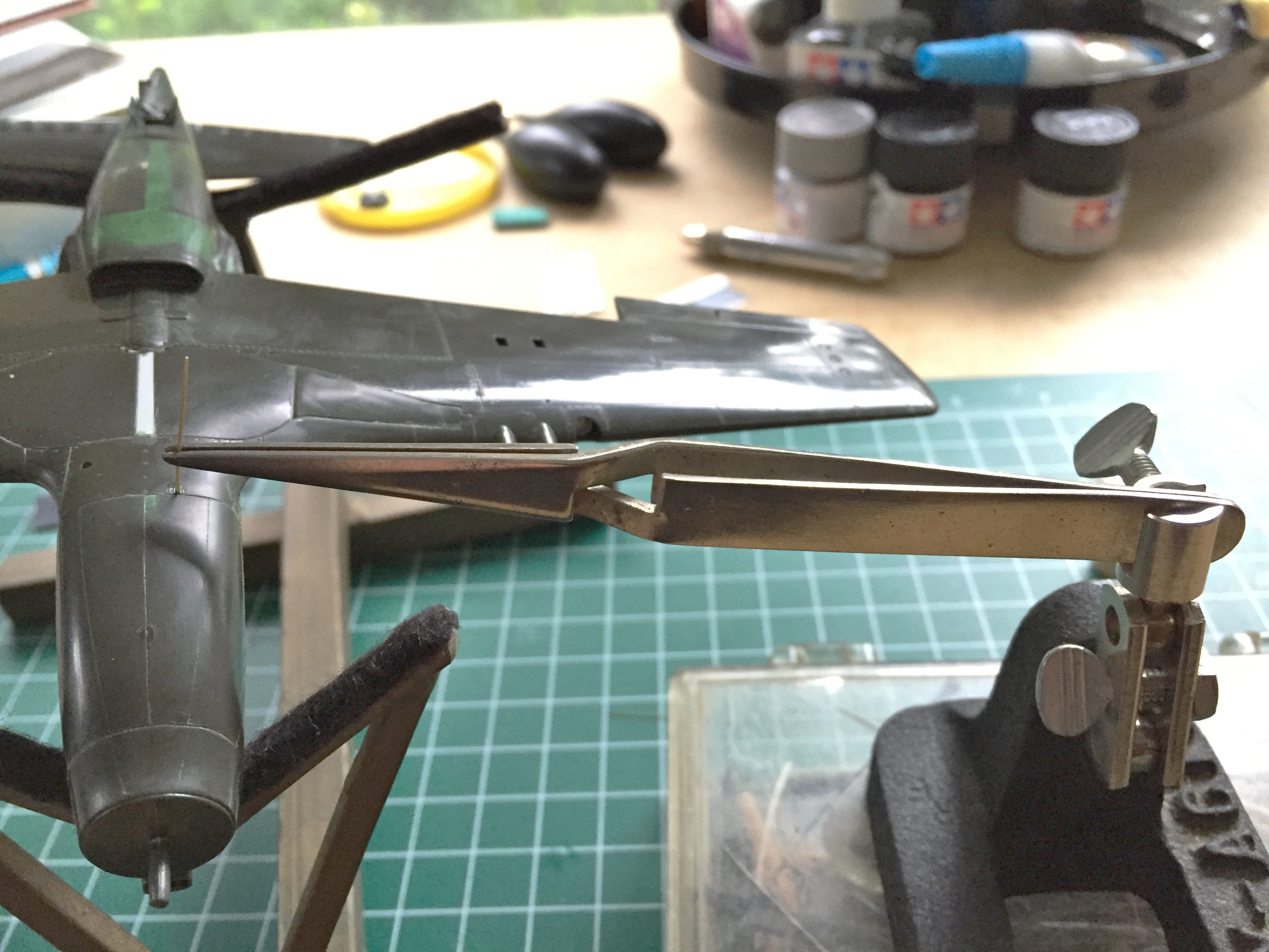
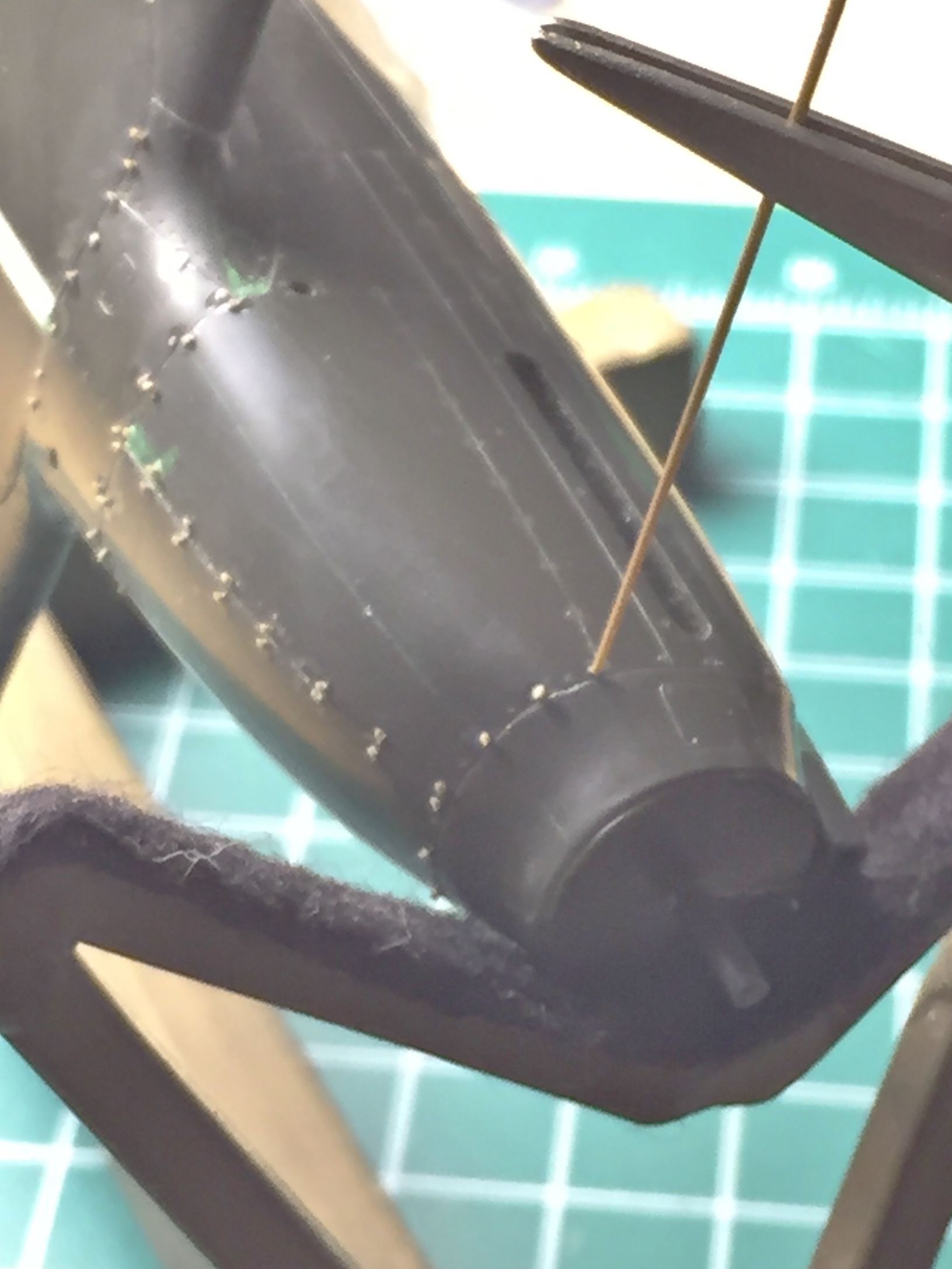
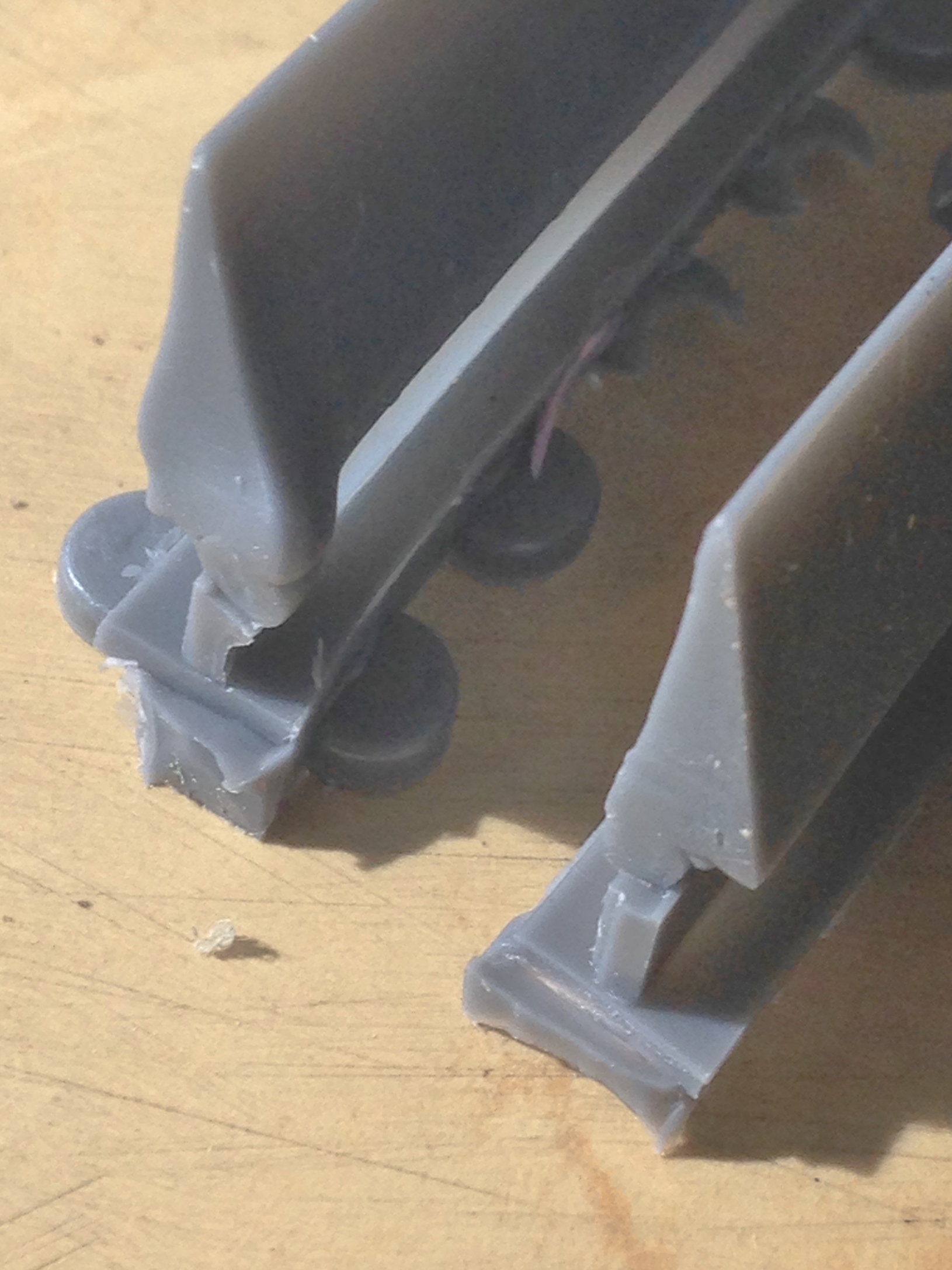
And THEN I dropped the sodding model and snapped off the shaft the propeller was supposed to slide over:

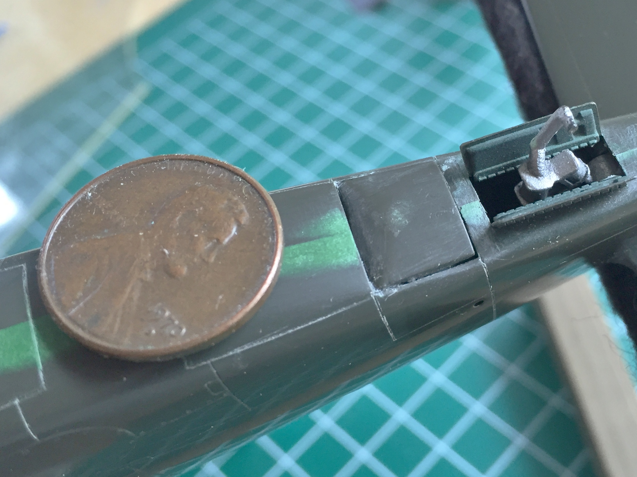
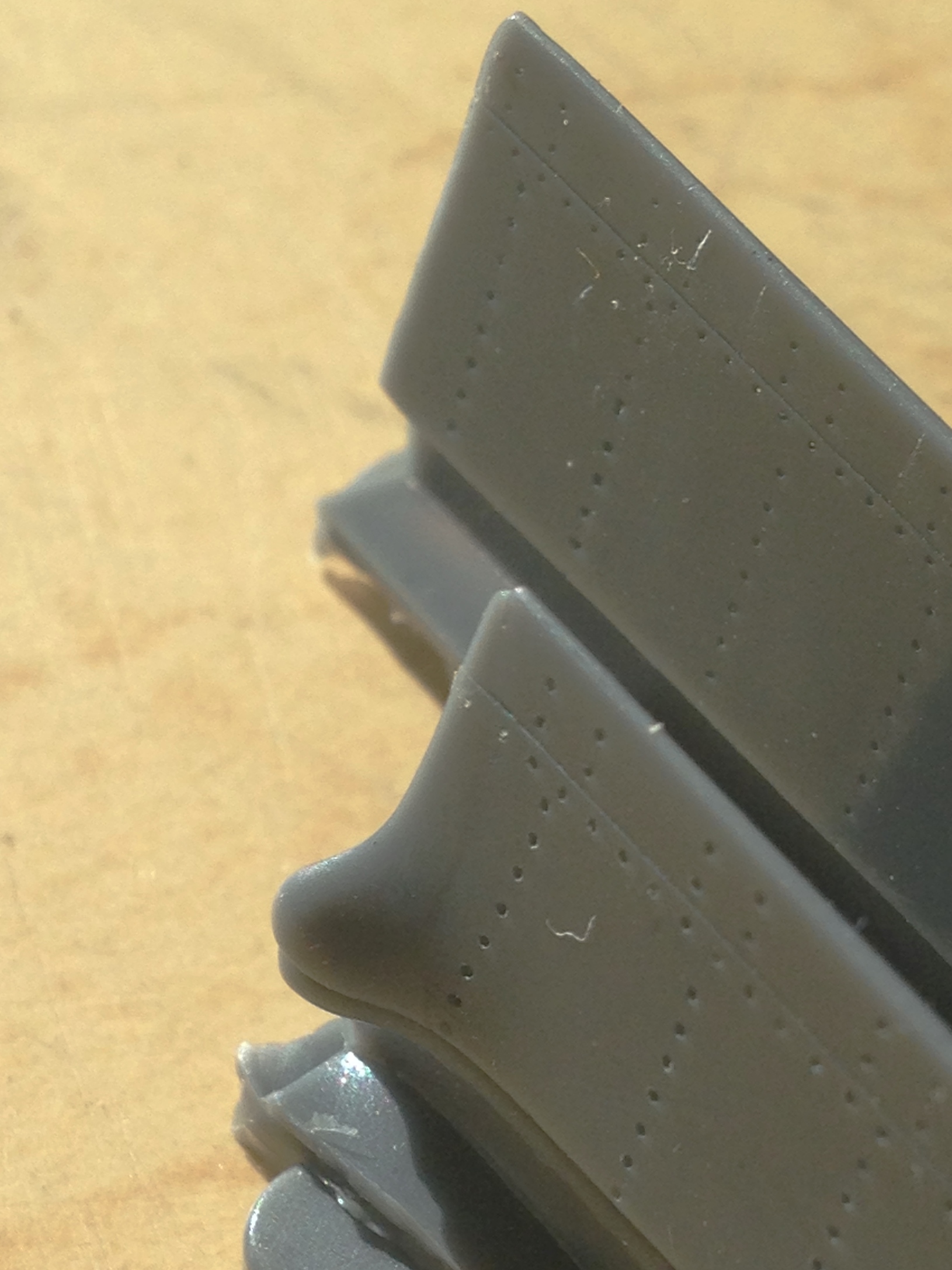
Not AT ALL pleased with myself, I figured, “Okay…I can fix this.” And then I noticed that the hair drier, though it did a good job at heating the butyrate landing light cover, also did a FINE job of deforming the collar and shroud of one of the guns:

Well. My head didn’t exactly explode, but my reaction was…well…bad. Very bad. Ears ringing, nose running, earwax melting, eyes narrowing, claws extending, BAD.
Perhaps not obvious in these posts is the fact that this build has (as much as an inanimate object can) fought me every step of the way. Well, okay…I like a challenge. And then there’s this thing called “erosion.” Erosion operates very slowly and is rarely evident until whatever is being eroded is gone. And looking at that deformed gun mount brought to my attention the fact that my enjoyment found in surmounting challenges and difficulties had eroded away.
This isn’t my job. I’m not getting paid for doing this. It’s supposed to be enjoyable (the grown-up word for “fun”). I am NOT ENJOYING THIS ANYMORE. So I’m going to do something that I’ve never done before. I am stopping this build before finishing it. It’s getting boxed up and put on the shelf. If I don’t do this I am going to take a hammer to this thing and reduce it to a pile of plastic and resin (with a little butyrate) fragments.
The best part of being good is knowing when to quit. Perhaps I’ll come back to this ANNOYING build at a later date but for today I am done.
DONE.
Time to go put things away, clean the shop, and decide what I’m going to build next.
P-51 (Accurate Miniatures) Build #13 – Wrestling With Landing Lights, Replacing Propeller
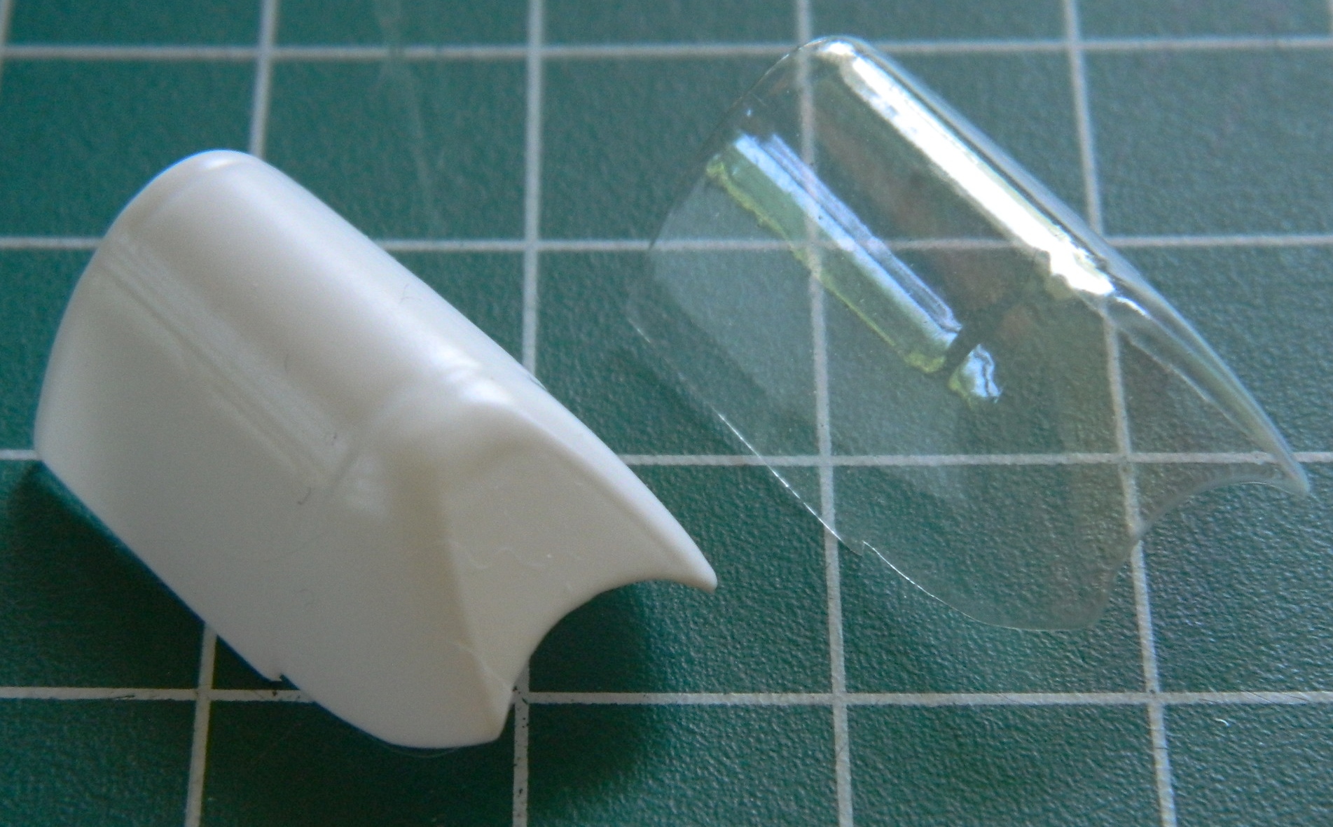
Next, I wanted to get the clear covers over the wing-mounted landing lights. When I vacuformed the canopy, I also used the kit light covers as bucks to pull clear over. Well…I learned something with these parts. The easy part was forming them. Then I had to figure out how to hold something this SMALL while first trimming it, and then trimming it to fit:
Then I had to figure out some way to hold it while I glued the cover in place, so I made a “handle” using masking tape:
Okay, though tedious, up until now everything was going as planned. Past tense. Trying to glue the cover on was a massive exercise in futility. There just isn’t enough surface area on the edges of either the cover or the wing to effect a decent (not even good) bond. Well, poop.
Then I had the idea of using the spare kit to provide that area of the wing where the landing lights are as a buck. The idea was to use a larger piece of plastic and effect the gluing process by making it larger than needed so that I could cut recesses into the surface of the wing to provide a larger surface for gluing and then putty/sand the addition into obscurity:
At this point I suspected that how I was viewing the task was creating a cage for me. Did I have to vacuform these covers? Well…no. In essence, it’s a flat piece that curves under and forms the leading edge of the wing. So why not cut a flat piece of plastic, glue one end in place, and use a hair dryer’s hot air to create the curve? This would also allow me to remake the landing lights (because I knew the ones already made would not likely survive the excision) and fit them into the clear plastic prior to installing the assembly into the wing.
I began by cutting the molded-in landing light away:
Then I used masking tape as guides for the panel scriber. I scribed first so that I could use the panel lines to guide the knife when it came time to remove plastic from the wing’s surface to recess the clear piece:
The grooves act as guides to keep the knife from skipping across the surface (again) as I removed the plastic:
This part of the build came to an abrupt halt when I realized I didn’t have any more clear styrene on hand. I could use butyrate instead but I want to use styrene so that I can use styrene cement to effect a solid bond. Okay…put this aside for now. I’m sure there’s something else I could do.
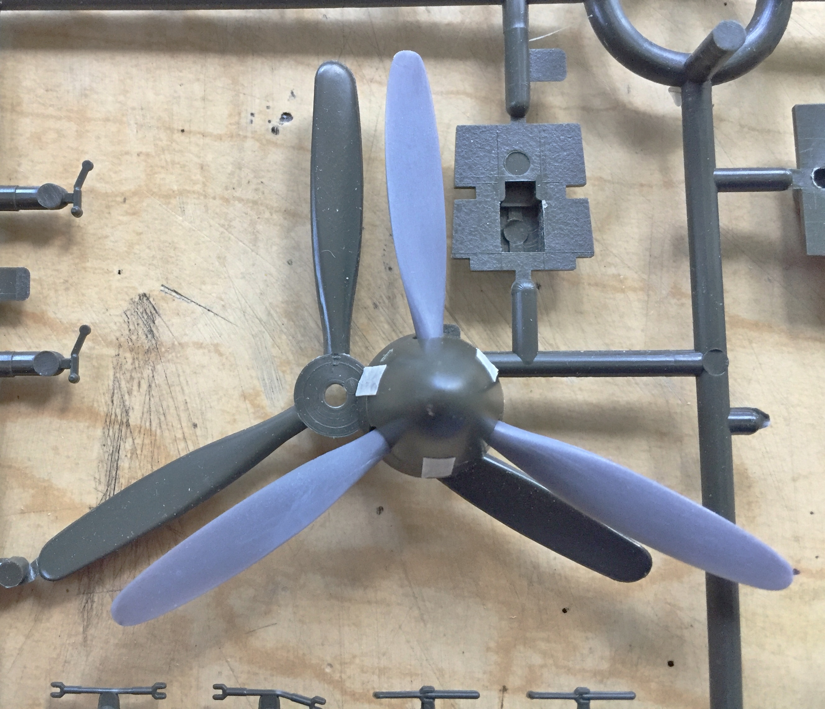
I could do the propeller!
A famous weak point in the Accurate Miniature Allison Mustangs is the shape of the propeller. They look less like propeller blades than they do elongated canoe paddles. Yeah, I could rework the kit parts. Or, I could replace the prop with something more accurate. On my shelves I happen to have the AMT/Ertl kit of the A-20G Havoc. I checked one of the props from that kit against the Accurate Miniature’s prop and it’s a very close match, only without the inaccuracies. But I also want to build the A-20G so I’m going to need those props. In looking online, I found a resin Hamilton Standard prop set for the A-20G. I bought ’em, made molds of the parts, and cast copies.
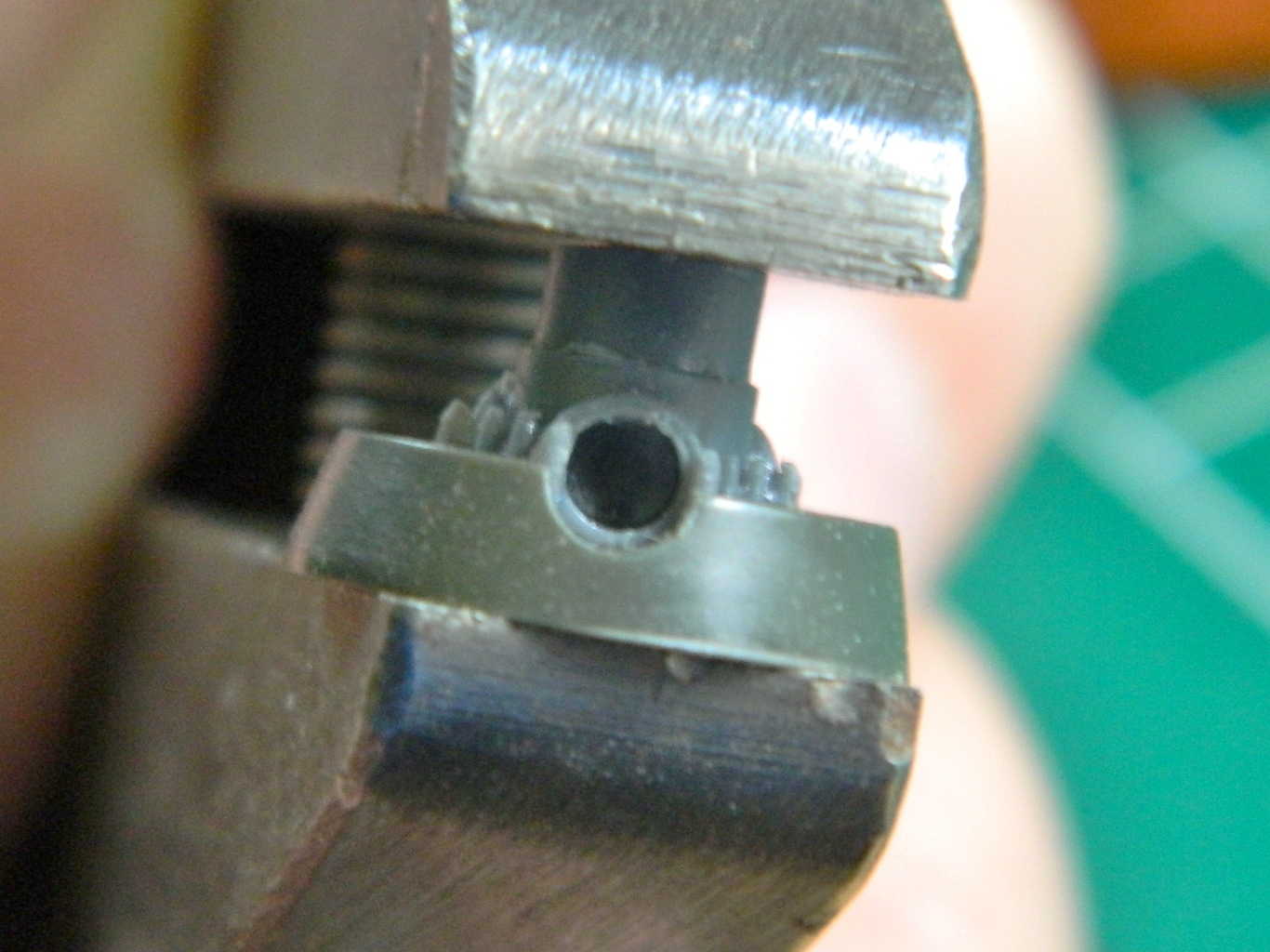
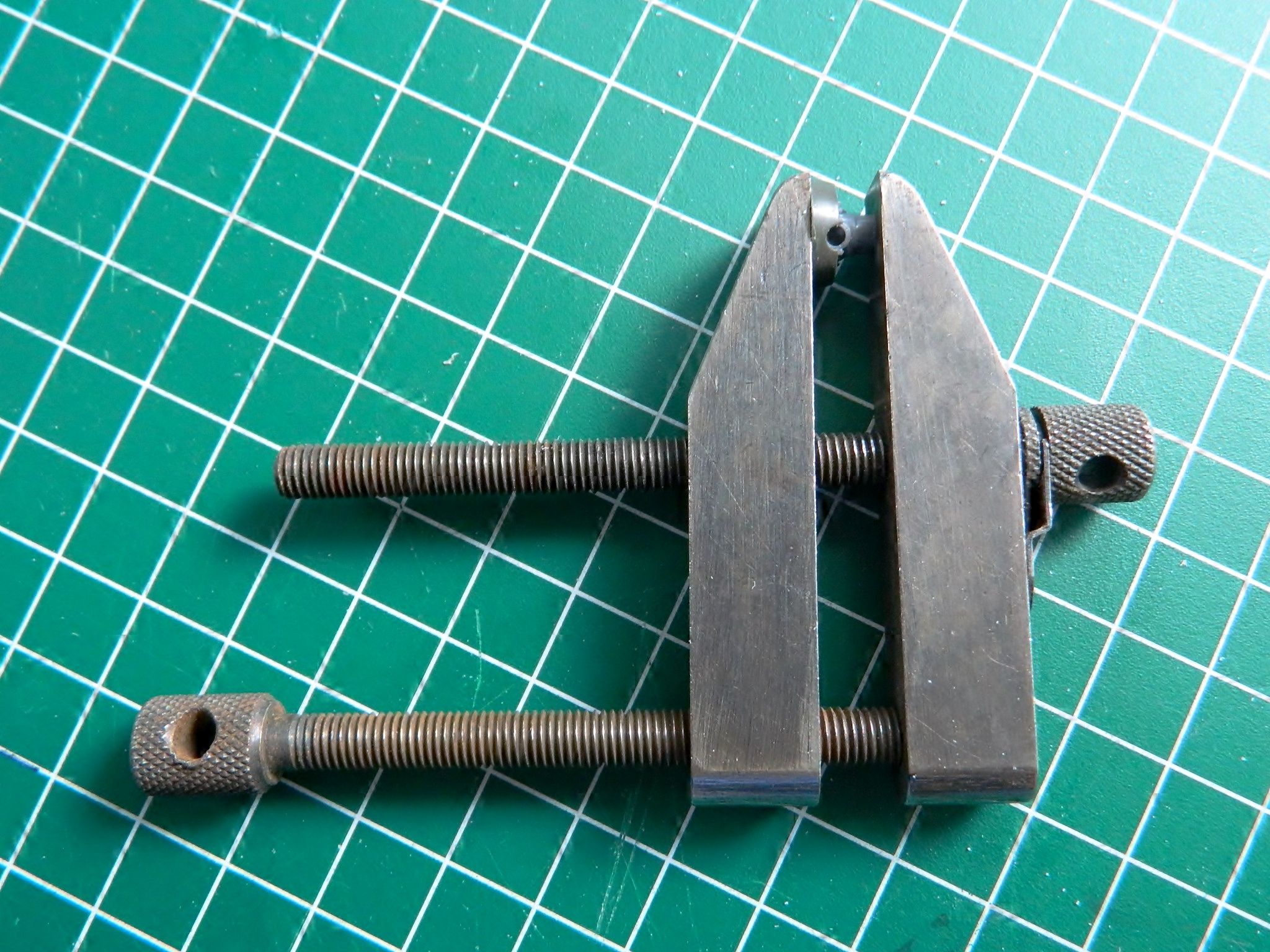
In order for the hub to fit inside the Mustang’s spinner, I had to cut the end off the propeller hub. Then I had to center the hub on the backing plate. To do that, I used a machinist’s parallel clamp to hold the hub in place, then used the MkI Eyecrometer to line up each of the blade mounts with the openings for them in the backing plate:


I superglued the hub to the backing plate and then cut and trimmed flash away from the individual blades and dry-fit them to the hub and then placed the spinner over the assembly to check for fit:


The result is MUCH better than the kit part:
I measured the diameter of the pin that the prop mounts onto and drilled out the resin hub and checked for fit (sorry about the color…):
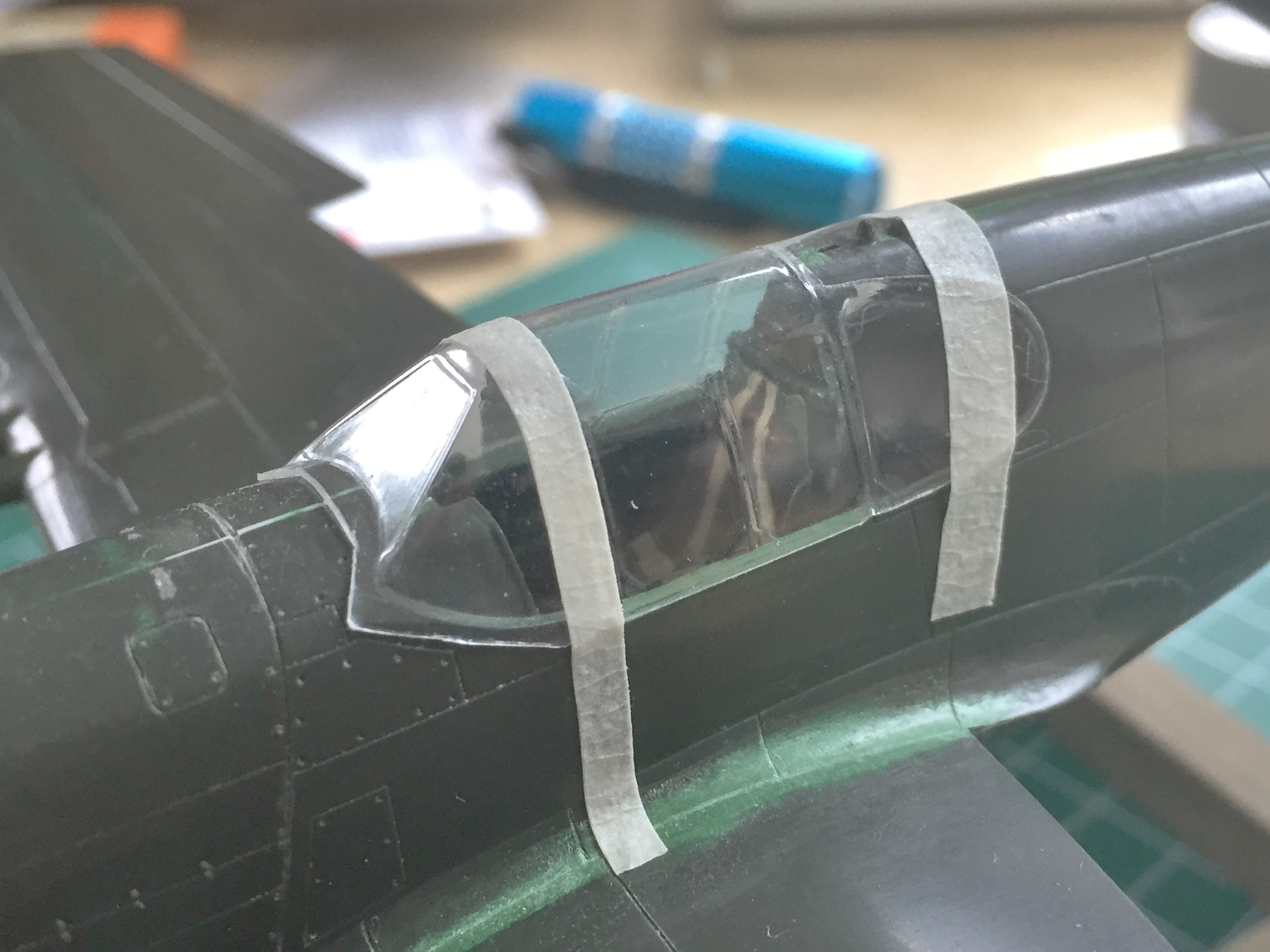
Pending the arrival of the clear styrene, I could also finish up a couple of things in the cockpit that has to be done before the canopy can be glued down and blended it. The coaming over the panel and gun-sight needed to be painted and then the clear reticle for the gun-sight had to be cut out, trimmed, and glued to the gun-sight (talk about fiddly…that reticle is very small):


With the cockpit finished, I can now glue the canopy down and start blending it to the fuselage while I’m waiting for the arrival of the clear styrene…
P-51 (Accurate Miniatures) Build #12 – Making Things Fit, Replacing Lost Details, Reworking Incorrect Panel Lines, Canopy Work
As is evident, there’s a lot of putty, here:
And that requires a lot of sanding. Before wadding the putty on, I covered adjacent areas with tape to keep as much of the surface detail as possible…and then sanded:


After sanding, panel lines had to be rescribed. I used Tamiya’s tape to lay down the line where I wanted it to be:

Then the rest of the lines obscured by putty and sanding were scribed back in:
Probably because of the previous sanding under the nose, the fit of the wing-plane also needed putty and sanding:
To finish additions of fuselage parts, I added the oil-cooler door (and trust me, if you want to eat up a couple of hours building this bird, drop that door inside the fuselage – a couple of times – to really spin yourself up):
With sanding accomplished, it was time to start putting back the raised details that were casualties of sanding. Below you can see to the right of center where I’ve added a stub of stretched sprue to begin replicating the dzus fasteners used to hold the panels in place and how I did that:

Then I got to do that a lot:
With the stubs in place, careful sanding was needed to bring them closer to the surface without assaulting more panel lines:

Turning my attention to the wings, I started by adding drops of superglue to areas that needed to be sharper. Where the flaps were cut out and that opening met the wing root flare, the join was rounded. Because that area is mostly putty, I needed to make those areas harder so that I could get the sharp angles I needed in a puttied edge that is lousy at unsupported areas. I had been using the standard thin superglue, getting a blob/drop in place, and waiting an hour or so for it to harden enough to file/sand/cut to its final shape. Back when, I’d had good luck with superglue accelerator. Put the glue in place, spray with accelerator, and instant hardness (albeit at the cost of some bonding strength, but since this wasn’t structural…) is achieved.
Well. Either my memory is faulty (and if so, this instance would certainly not be unique) or the formulation of accelerators has changed. I don’t remember accelerator dissolving the surface of the plastic…and that’s just what happened. So after putting the model back down (from where I was ALL wound up to throw it against the wall), I sanded down the texture created when I tried to wipe off the excess accelerator with a paper towel:

I had intended on using the shaped and fitted kit canopy as a buck to vacuform clear sheet over. I had also intended on putting a framework inside the clear, so first I pulled some .010″ (.254mm) over the buck, and then some .010″ (.254mm) clear over both:


Nice idea, and I probably could have gotten it to work. But in the process of fitting the clear, I realized that the edge of the trimmed part, which had started out at a thickness of .010″ (.254mm) and due to stretching was probably thinner, didn’t offer very much surface area for glue (I haven’t yet figured out which type of glue would work) to offer a secure bond. Squadron Products offers very nice vacuformed canopies for a wide variety of kits and I decided to go that route instead (I think):

In looking at the part, I realized that this buck had been formed by gluing the fuselage halves together, gluing the canopies on, then cutting out the areas of the fuselage around the canopy, offering a much larger surface for glue to work on (and this is a great idea that I’ll be using myself in future builds!). But since I’d already gone well past grafting this clear part onto the kit as intended, I had to trim the canopy to fit:
I left a flange on the front canopy part for gluing. The right-side canopy as well as the right side rear window won’t be separated, but the top and left side canopy will. I haven’t cut them free yet because they work well to locate the rear canopy windows in their respective openings. At present the idea is to glue the canopy in front securely down using superglue (with the requisite crossing of body appendages that the glue doesn’t fog the clear parts), then extending the superglue down the right side (which isn’t going to be opened, as per the way these aircraft were used in the field), and around both rear windows. I’ll seal the bottom left side canopy with white glue to keep any paint from blowing into the cockpit.
At this point I turned my attention to the wings.
P-51 (Accurate Miniatures) Build #11 – Flap Problems, Wings, Elevators, Belly Scoop Attached
This will be a short post because though I spent a fair amount of time diddling with the flaps, not many photos were taken.
With the flaps now dimensioned and shaped, I made the molds (when I pour the rubber, I try to mold other items I know I’m going to need; in this photo, I’m also molding propeller parts):

About this time I noticed how lumpy the rubber stayed. Usually, this all levels out as the rubber cures. Not this time. Why? Well, it’s because I absolutely SUCK at math. Suffice to say that I suspect I put about 10% more hardener into the mix than I should have…and it may have been more. But, having poured the damned stuff, I decided to see if I could pull a usable casting from a really lousy mold. The answer was, “sorta.” One of the flaps’ corners is bulged on both sides:
No, it wasn’t from misalignment of the mold halves since this mold doesn’t have “halves.” It’s because of this:

That, ladies, gentleman, and children of all ages, is a bubble. It’s a damned big bubble. I sat there for a while trying to figure out how I got a bubble. The best I can come up with is that due to some idiot (me) putting in far too much hardener, the rubber set up in the vacuum chamber before that damned big bubble could migrate to the surface where it would pop. But that doesn’t explain why it’s a bubble under pressure. And it’s obviously pressurized, otherwise it wouldn’t bulge like that. That bubble wasn’t there when I broke down the mold box. That bubble wasn’t there when I filled the mold with resin. And that bubble should have collapsed when I put the mold/resin into the pressure pot and left it there for 24 hours under 55 psi (121.25kg), either. But there the bubble stayed and, for some reason, expanded. How the intercourse it did that I still have no idea…and I have less on an idea as to why it did that on both sides.
I took a sharp knife and cut a hole into the bubble to allow the (mysterious) pressure to escape and tried another resin pour to see if I could pull a useful casting out of this mystery mold…and I did.
The flaps required EXTENSIVE reworking to both fit and droop the way I want them to. The reason there are no pictures here is that some idiot (me again) forgot to take pictures of that TEDIOUS AND DRAWN OUT PROCESS. I spent the second half of last month figuring out why the flaps didn’t fit or droop properly, which is why this post is going to be so short.
But I got them to fit and droop.
In the process of all that fitting, the resin flaps were handled and manipulated. A lot. This resulted in me wearing away the corners of the resin parts. To put back the shape I used gap-filling superglue:


Once the glue had solidified I trimmed and rough-shaped the corners. After letting the parts sit overnight, because superglue gets much harder over time, I did the final shaping and sanding:
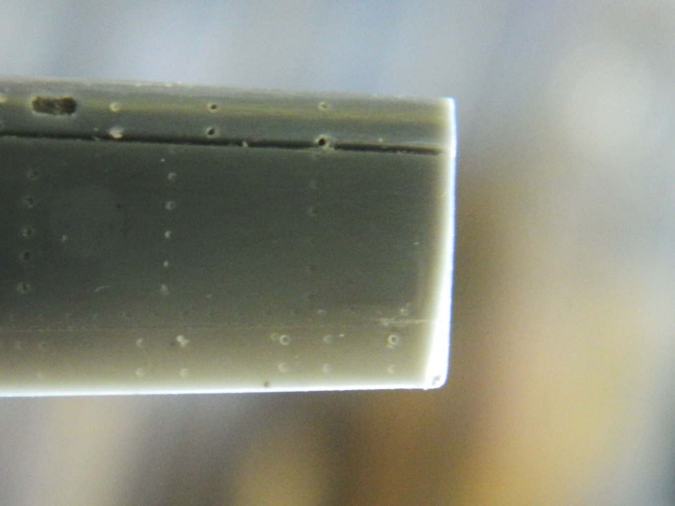
Having crossed that task off the list, I added the elevators, wing, and belly scoop. I also added the landing gear strut doors temporarily (using white glue) to act as masks for the landing gear wells and so that when the underside gets paint, the strut doors get painted (and weathered) at the same time so everything matches:
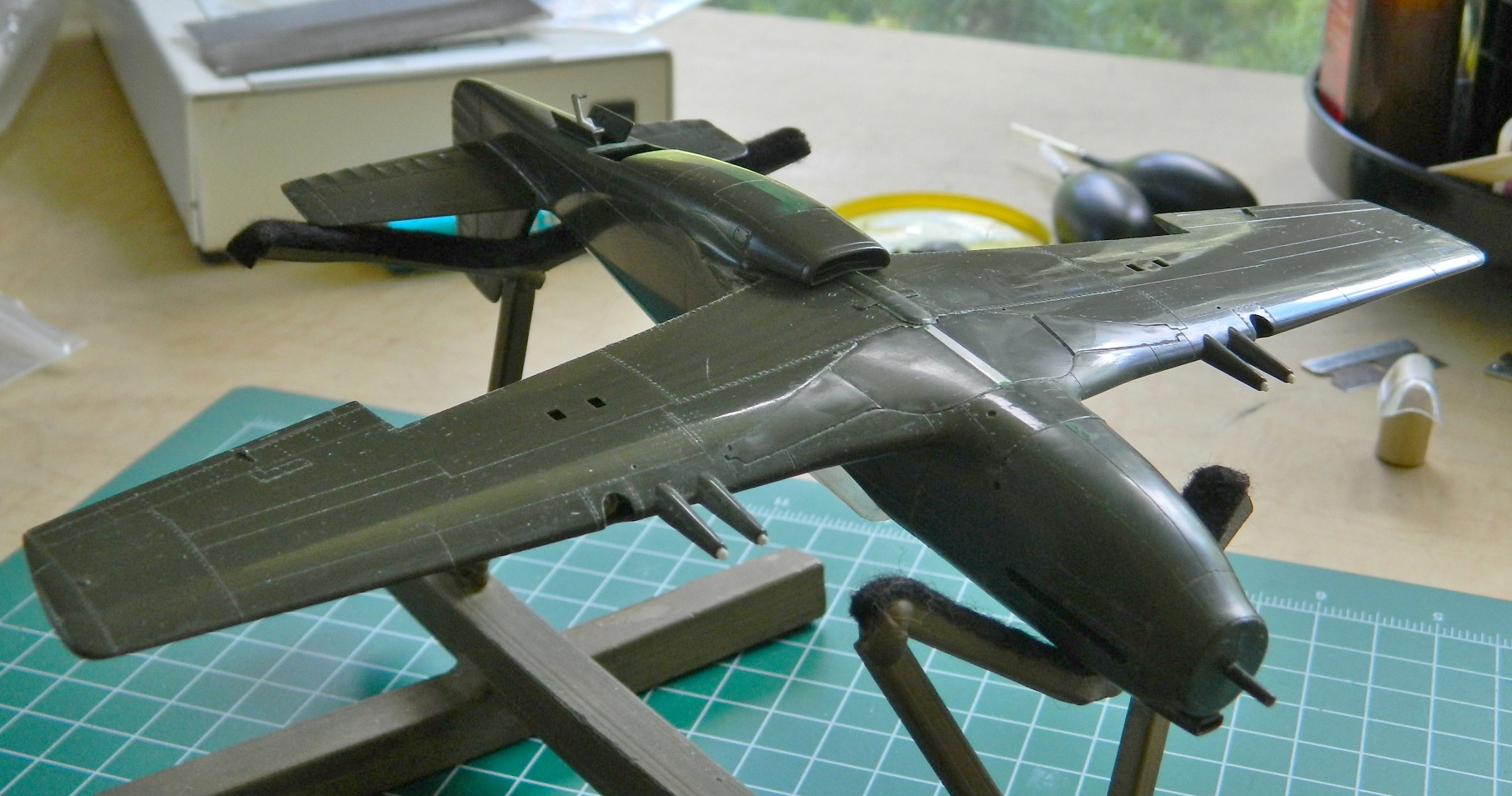
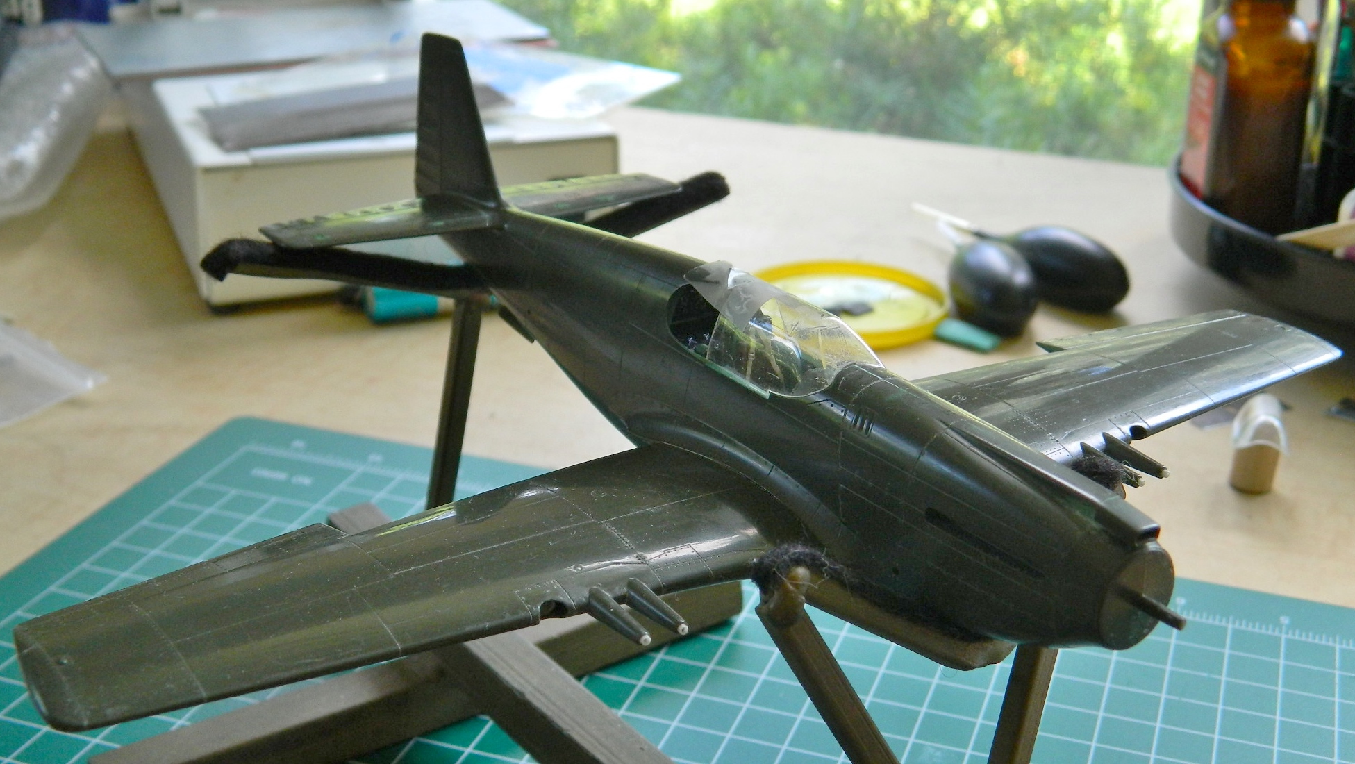
Accurate Miniatures, the company the produced this kit, has a reputation for well-fitting kits. Perhaps it was because this kit sat in a hot attic for 13 years and things warped/shifted, but the fit on this kit ain’t all that grand. Substantial putty is going to be required to get the proper fit, so the first coat of putty has been applied. Once that sets up overnight, I’ll begin the sanding process that I’m sure will lead to the next application of putty.
I will repeat as necessary:
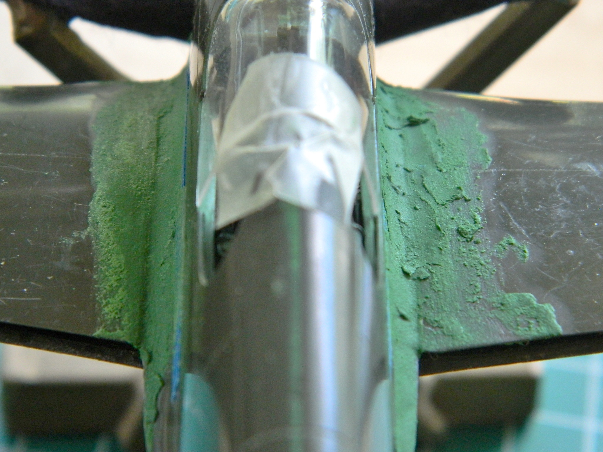
P-51 (Accurate Miniatures) Build #10 – Flaps Finished, Formation Lights Built, Landing Gear Bays Attached, Wing Tops Attached
I added scrap styrene and started removing the excess until I had it where I wanted it, then I did the same thing (more carefully with the Dremel) with the other flap and both put back and added surface details:


I dry-fit the bottom wing to the fuselage and noticed that I had made the cut in the lower surface in the wrong place. What I had was straight and to clear the belly scoop when the flaps come down, it has to be curved, so I removed that section from the flaps and returned it to the lower wing:
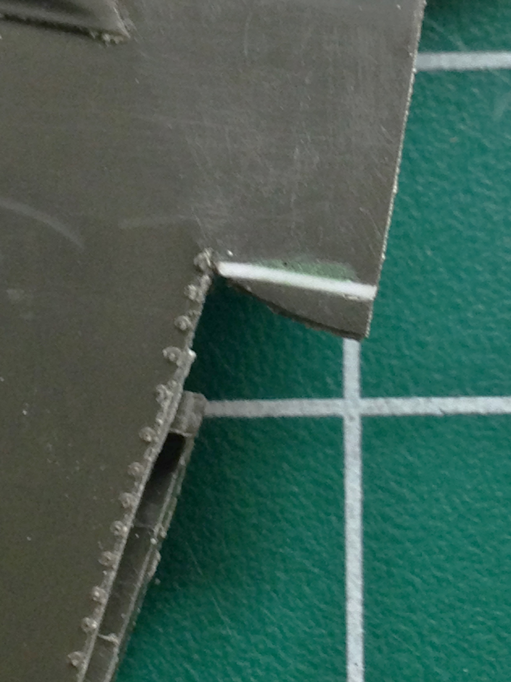
I also needed to thin the section of the wing where the flap meets it. The top piece has been done, the lower piece is there for reference:

All the Mustangs (at least through the D variant) have three lights under the right wing. Rather than do the easy (and probably sane) thing and just paint the molded details, I decided I’d drill out the lights, replace it with clear sprue, and back paint them the proper colors:
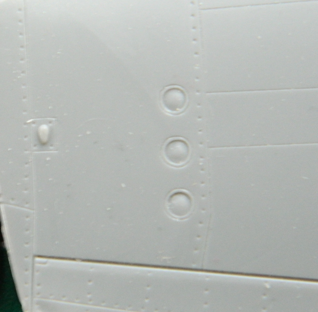

A section of clear sprue was chucked into a drill and spun slowly while I used files, emery boards, and fine sandpaper to create a tapered section large enough to fill the hole:

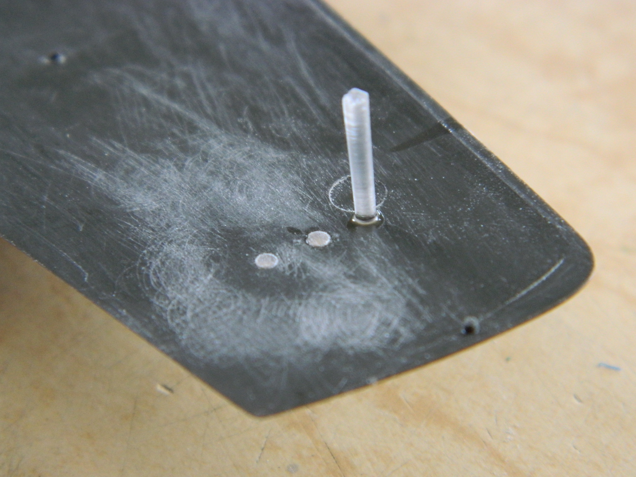
I traced the contact area with styrene cement, cut the clear part flush, and then sanded them up to and including polishing them (which I also did with the lens faces that can be seen) and then applied the proper color paint:
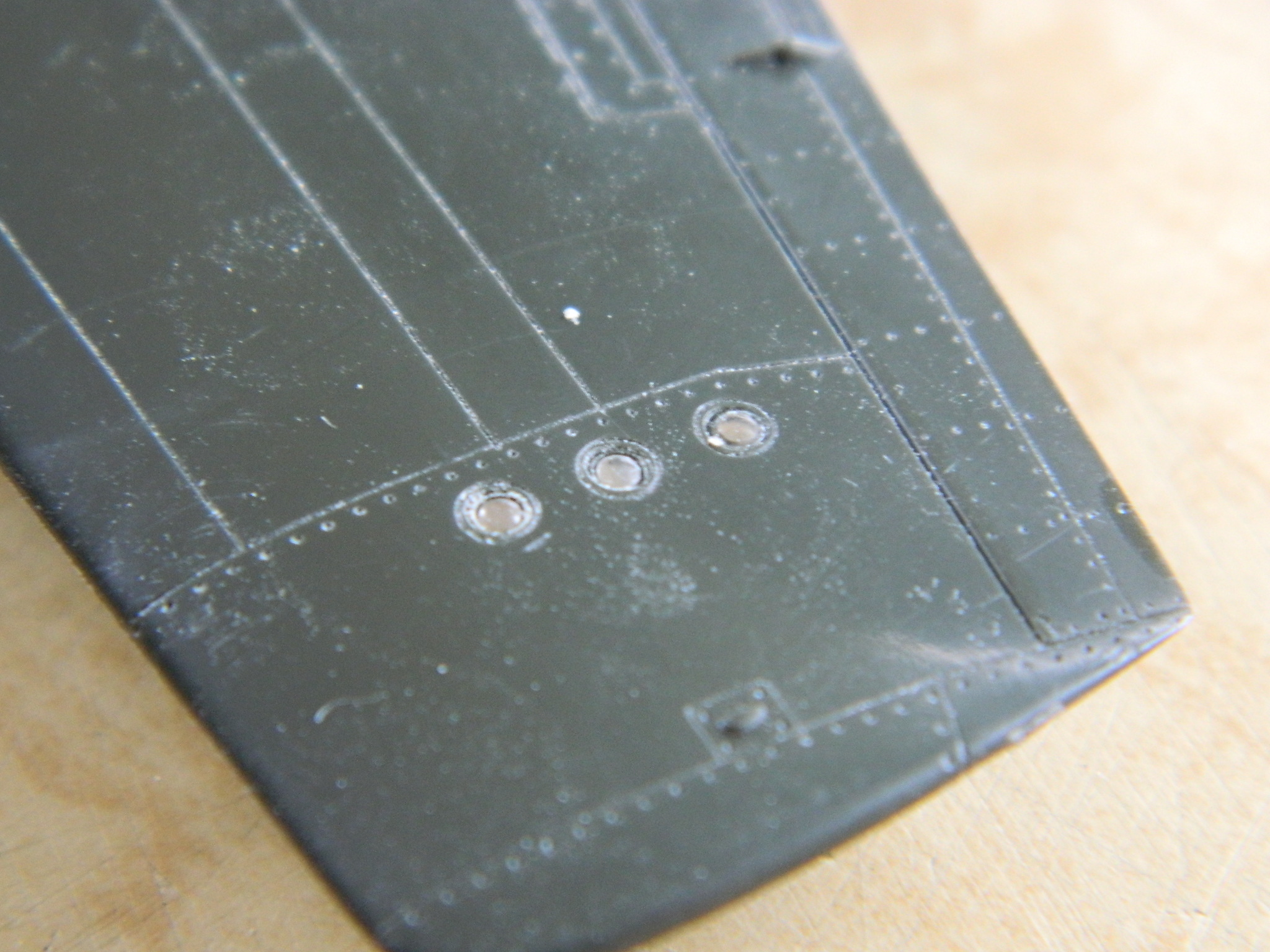
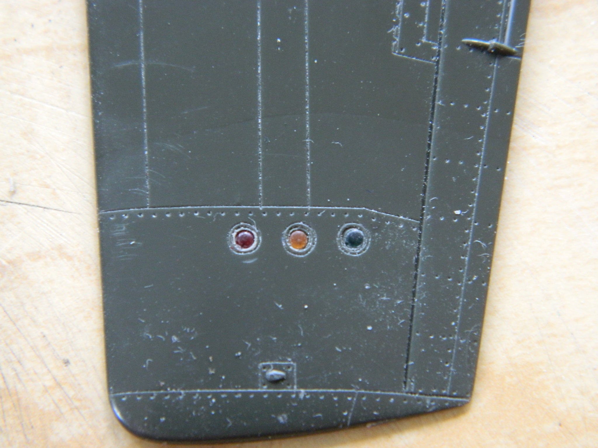
And as these things go, I rather doubt anyone who doesn’t know how that was assembled will ever notice…
With the lights, guns, and flaps all attended to, it was time to add the resin landing gear well tub and glue the wing tops to the bottom:

With the wing tops in place, I could now finish fitting the curved section of the flaps and trim the lower surfaces back so that they droop at the correct (looking) angle, then I added the detail(s) that I lost while puttying the scratches, sanding the added plastic, and added the rivet detail:
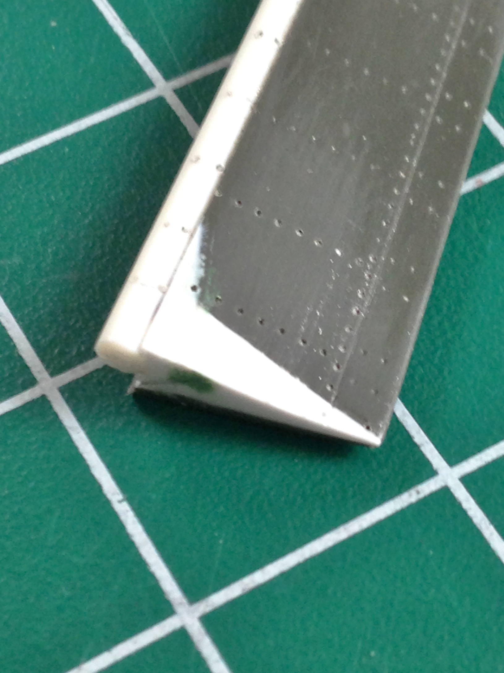


Before I add these parts to the wing, I’ll make a mold of them, pour resin, and use the resin parts (this way I don’t have to do this again for the next Allison Mustang build).
While I was doing the dry-fitting, I noticed other fit problems. Where the lower wing met the fuselage, the fuselage was too narrow (or the wing was too wide, but it was easier to fix the fuselage’s width). There was also too much of a gap where the wing meets the faring and the wing where the flaps were removed needed to be fit to the curve of the faring, now that the flap that did that isn’t there anymore. To fix the narrow fuselage, I diddled about using a piece of styrene tubing as a spreader until I had the fuselage properly aligned with the wing:

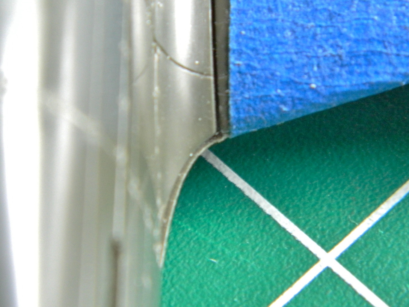
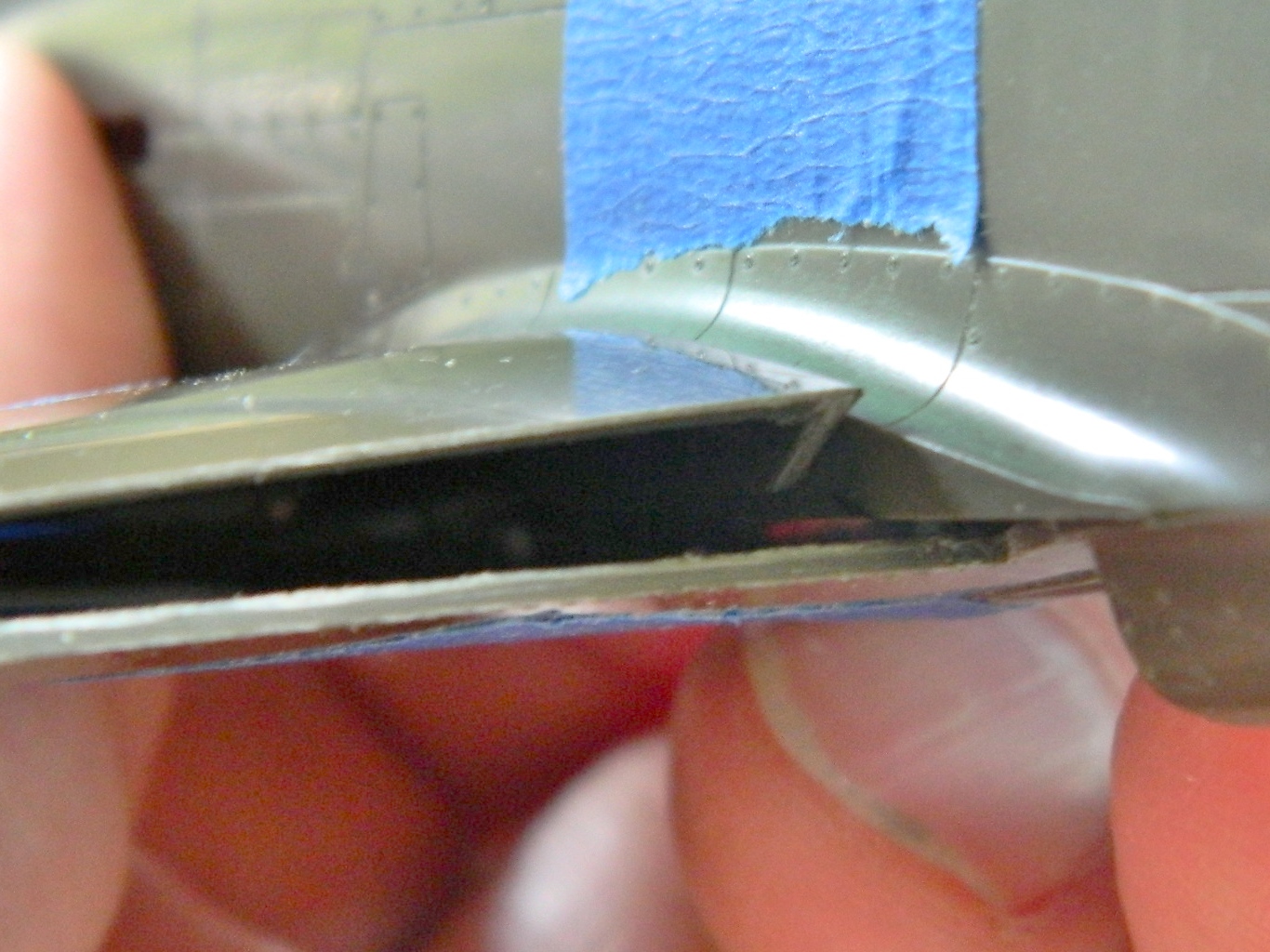
To fix the alignment of the wing/flap area, I used a piece of masking tape to hold the wing’s surface in proper alignment, then used scrap styrene as feeler gauges (you Millennials can google it) until everything was in contact inside the wing and the surface was where it needed to be, then I glued the shims in place:
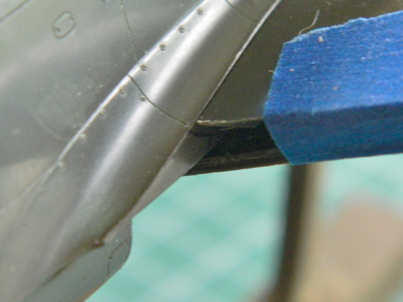
The wing root farings are thin aluminum. That area of the kit isn’t thin at all so that needed to be thinned to scale. With the wing bottom in place, I outlined the area that needed to be removed:

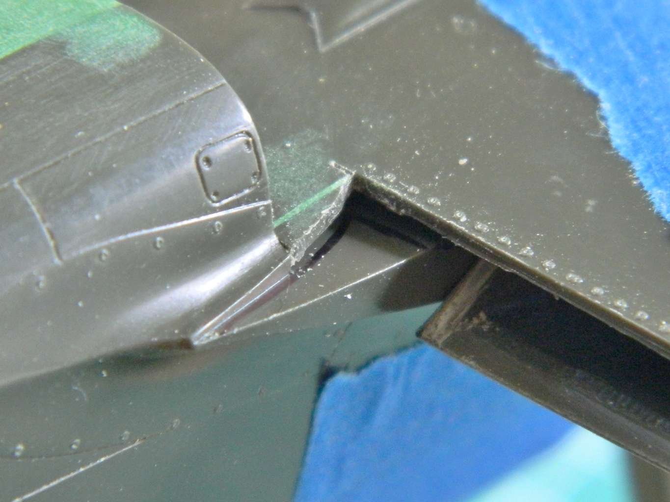
In the process, and as I expected, I cut completely through that area of the fuselage. I used my homemade structural putty to fill the voids:

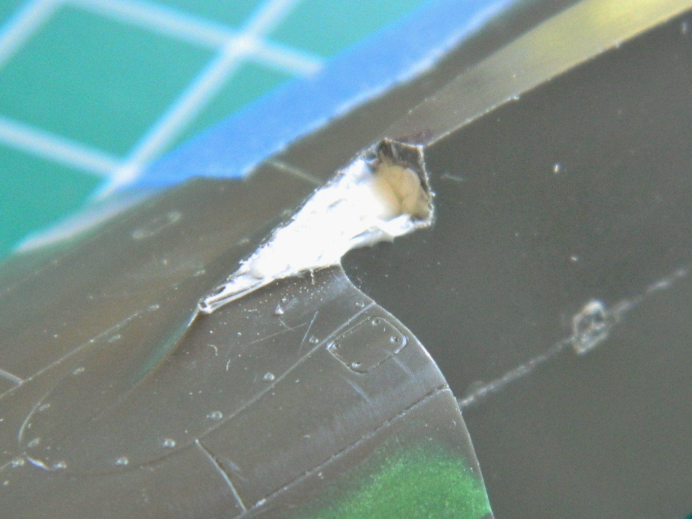
P-51 (Accurate Miniatures) Build #9 – Fixing Gaps, Making Landing Lights, Gun Details, Making More Accurate Flaps
Time to turn my efforts towards the wings but that gap in the fuselage in front of the cockpit just sat there…looking at me. Fine, since it was going to be like that, I’ll fix it. Sheet stock was added and trimmed and now the coaming is ready to paint:
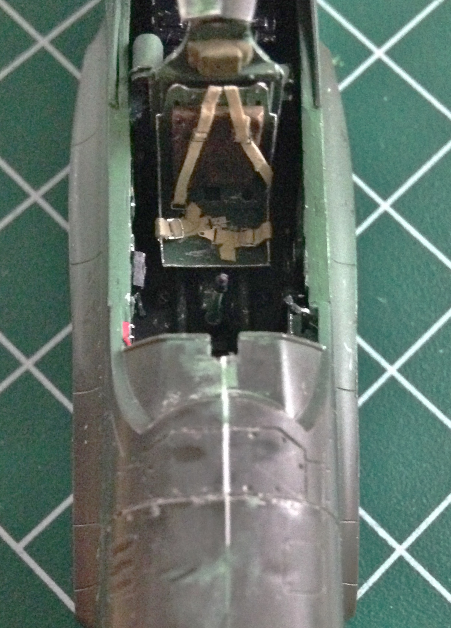
With that annoyance dealt with, my efforts did go towards the wings…for about five minutes. Then something else started demanding attention. This kit had sat in a hot attic for about 13 years. Evidently, this caused things to warp (other than my mind) so when the fuselage was being assembled, I realized I needed the addition of putty to smooth things out, so I added putty to smooth things out:
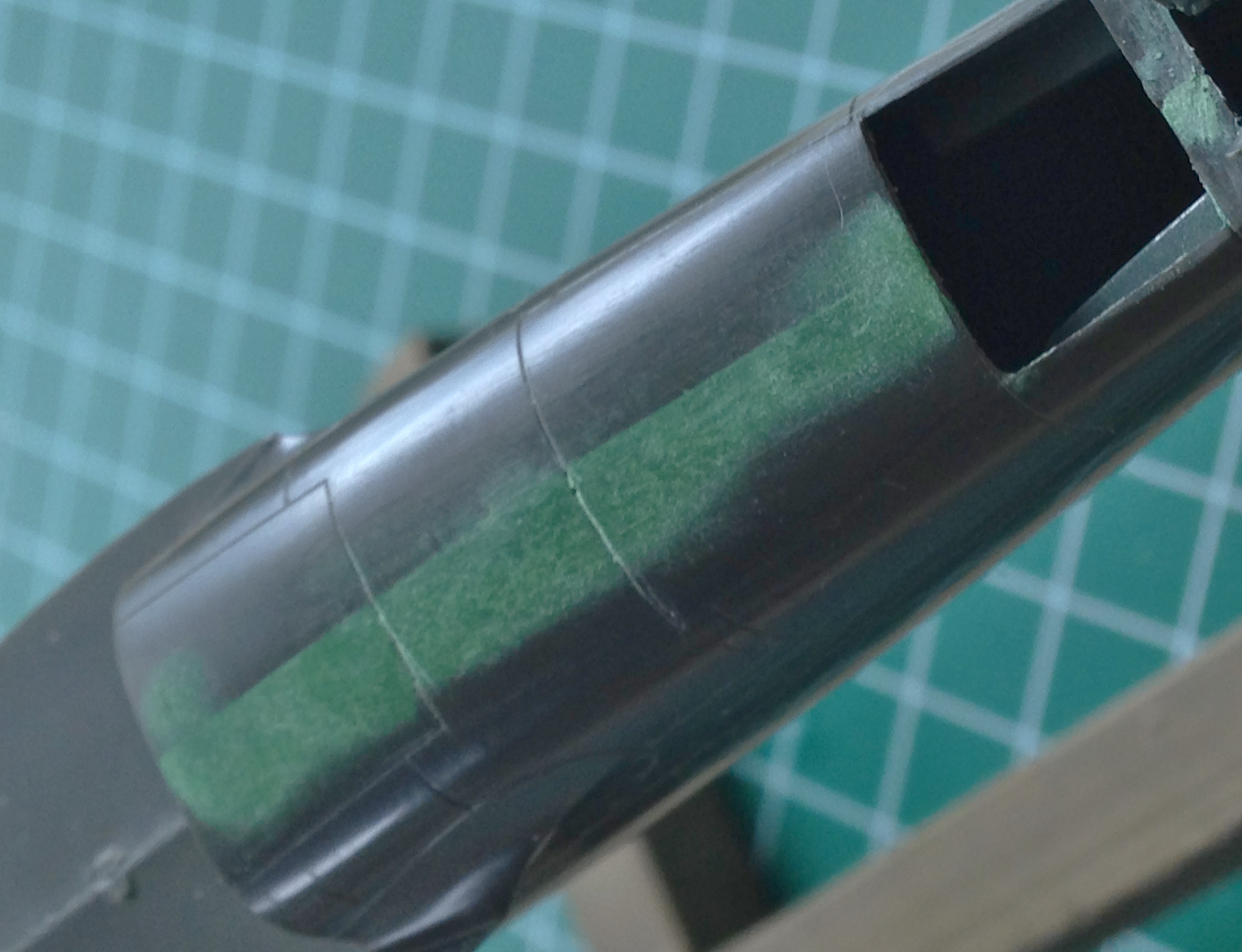
Right. Wings. Let’s get to those now. The first thing that jumped out in my eye was the apertures in the leading edges of both wings for the landing lights. The P-51 was the only Mustang to have a landing light in each wing. Though Accurate Miniatures made the attempt to thin this section, it was still far too thick, so I had to thin that area to a more scale thickness:

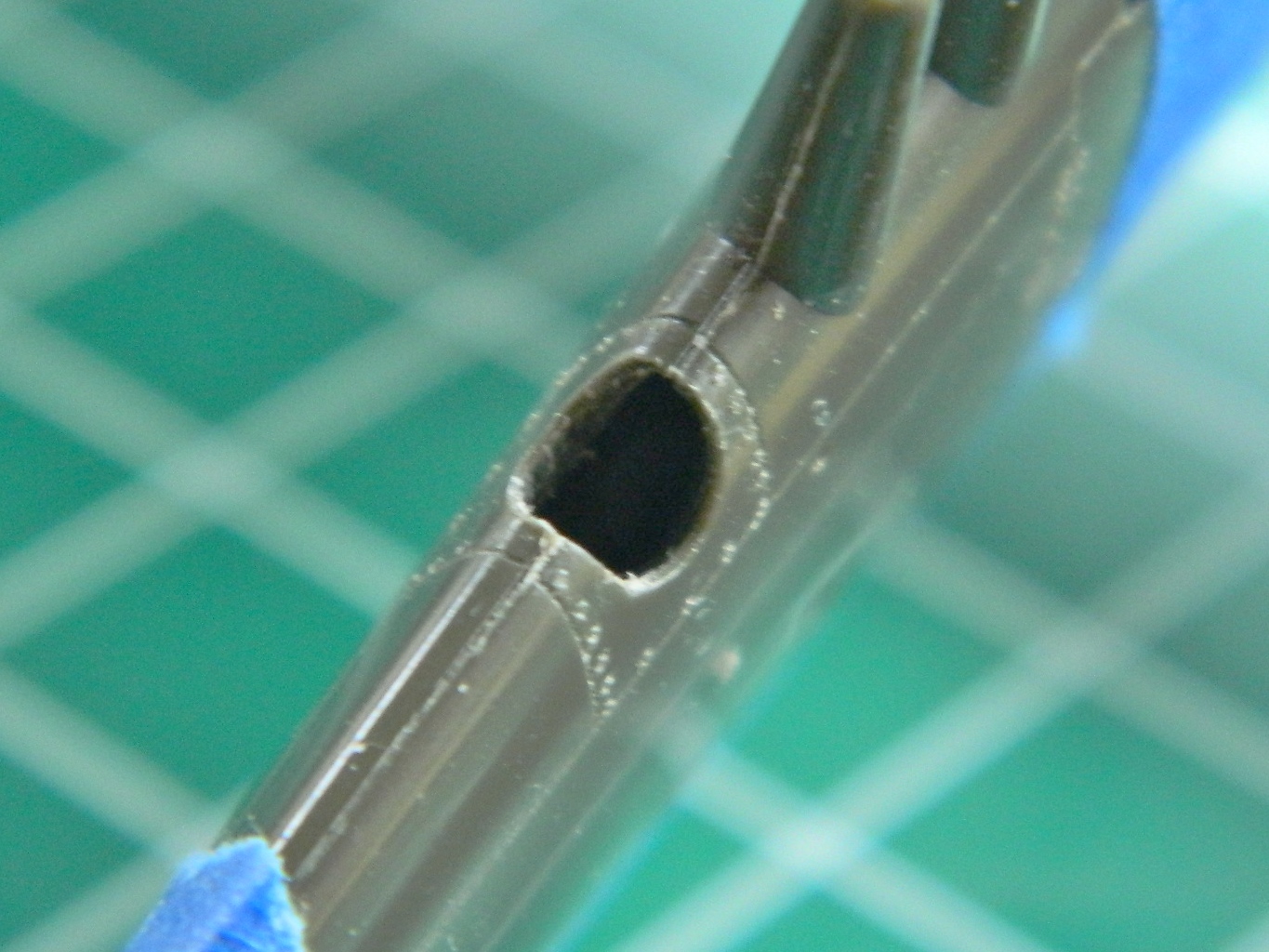
And then I noticed that the landing lights are angled downward (which, given the location of the ground to a taxiing or landing aircraft, makes sense), meaning there is less of a cutout in the upper wing surface than there is in the lower:
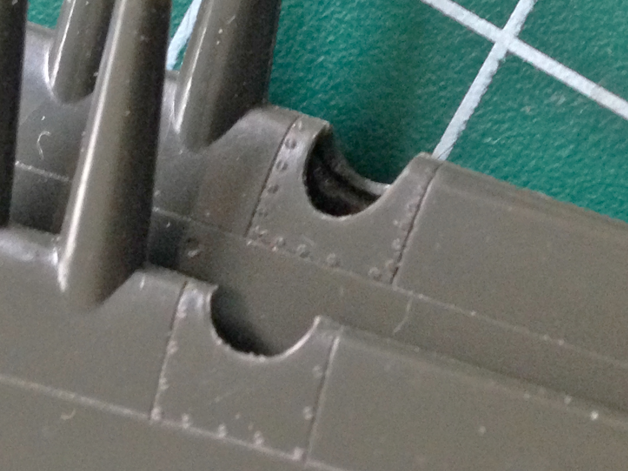
My initial intent was to build scale lights (that’s what that cylinder in the photo below-left is the start of). Then I realized that I don’t need scale lights, I need something that looks like scale lights. So I decided to see if easily constructed lights would look correct (reminding myself that building a model is not engineering, where things have to be correct…it’s modeling, where things have to look correct). I started by finding a punch of the appropriate (as in, looks right) diameter. I punched out a disc of .020″ (.508mm) plastic. Then I centered the disc over the next smallest die and punched the center out so that I would end up with a pair of bezels (he says using 26 words that made it sound easy and carefully not mentioning how many off-center discs got tossed):


Aligning the bezels to the holes was easy; I used the punch as the alignment tool:

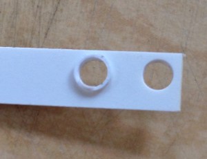
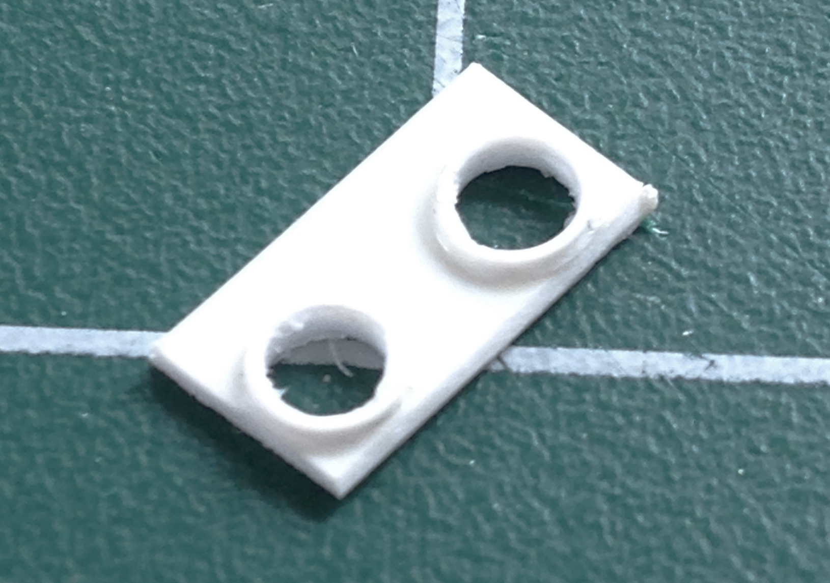
I cut the two apart and then roughly placed one inside the wing to see how things would look (not bad) and how things would fit (not good):

I carefully thinned the area where the landing lights go on both wings:
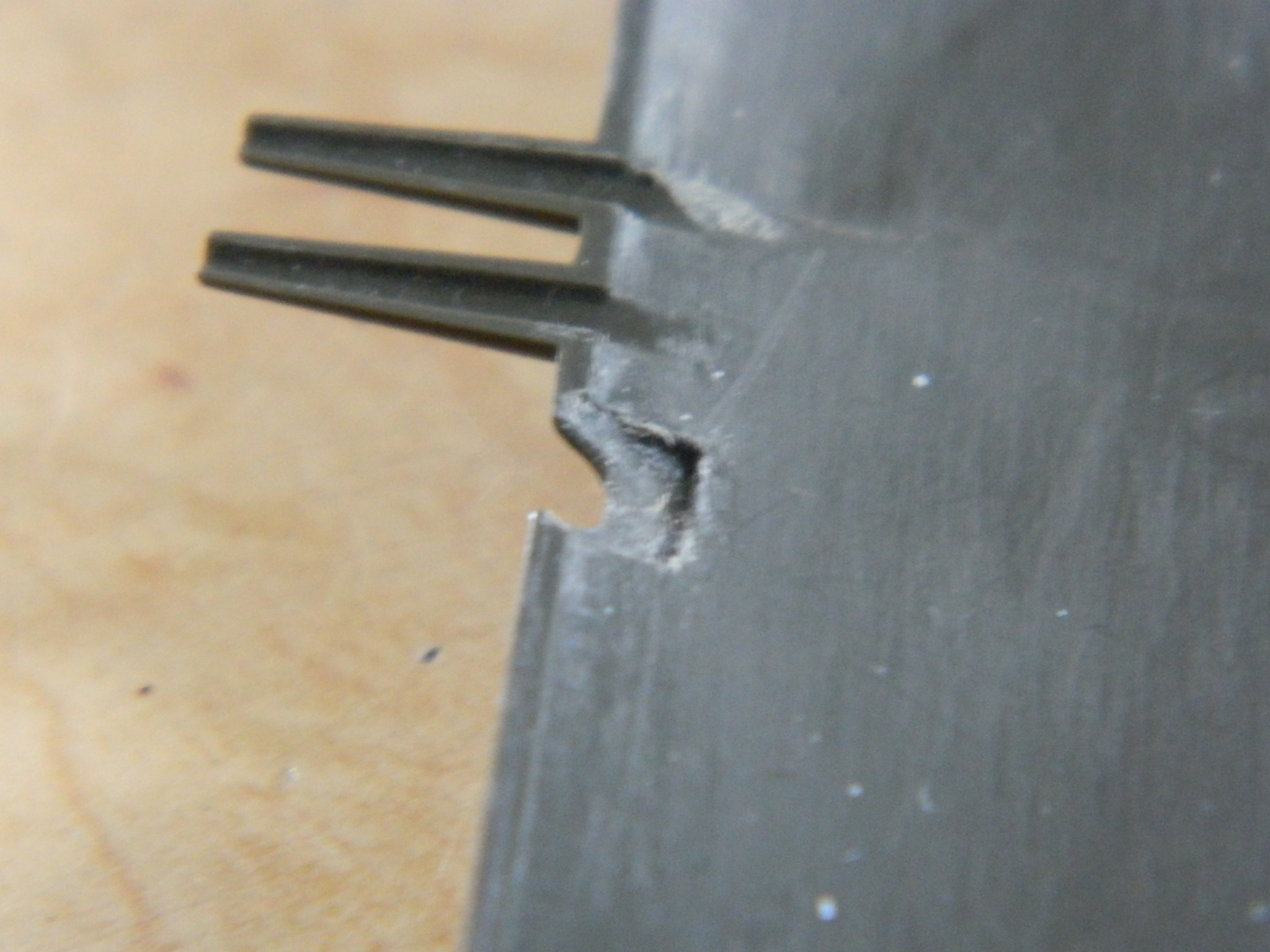
I placed a landing light in place and dropped the upper wing where it goes and was pleased with how it looked:
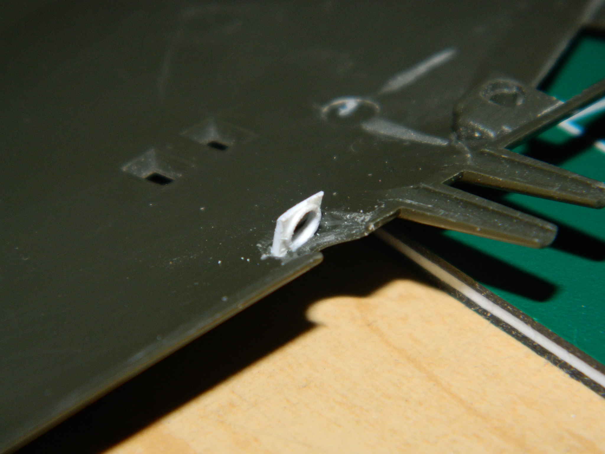
Now I needed the landing lights. For a reflective surface, I took a disposable aluminum baking pan and sanded and polished it, then I cut the polished area out and glued it to the back of the landing light, using a fine marker to make a dot for the “bulb”:

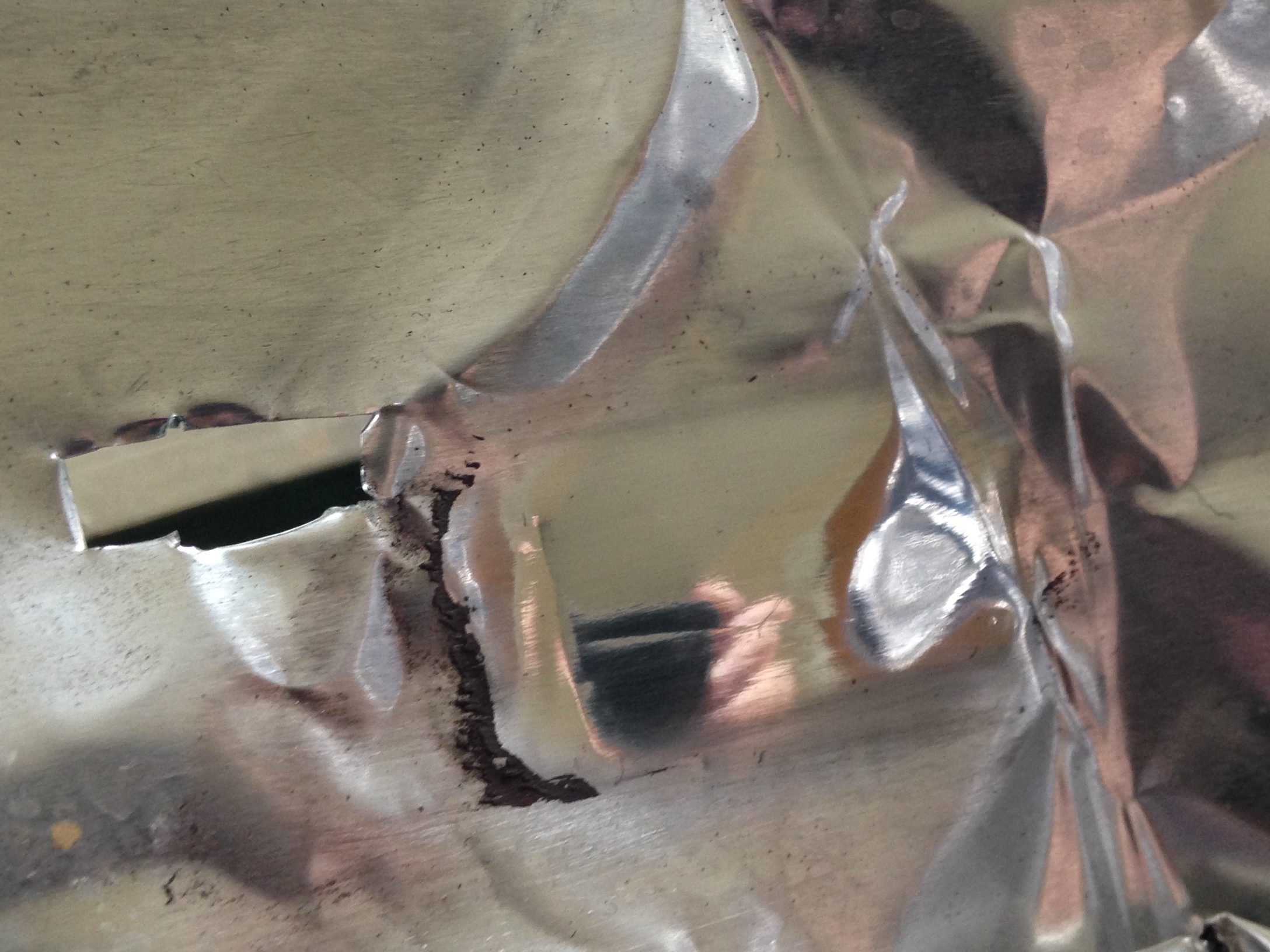
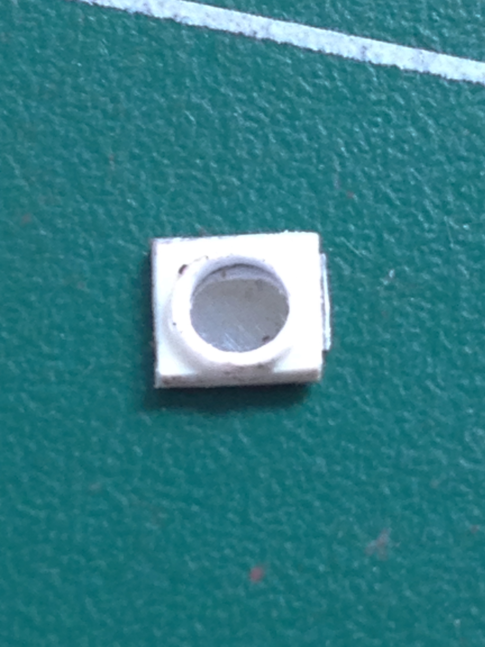

To make the lens, I punched out a piece of clear butyrate, put it in place, and was pleased with the effect:
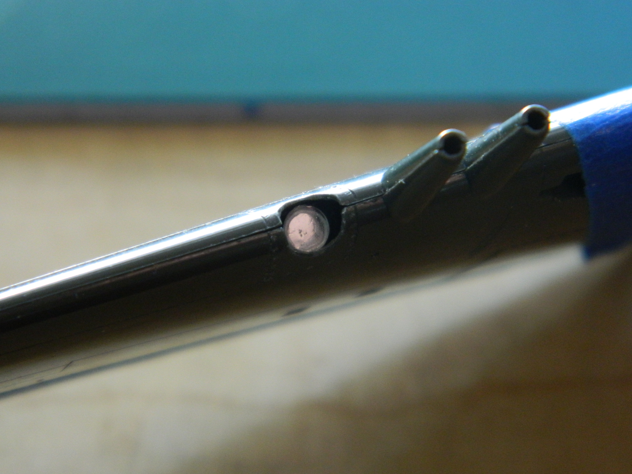
Moving inward from there, I wanted to fix the armament. The P-51 was the only Mustang to have 20mm cannons (Hispano Suiza units with 500 rounds per gun) and those were fairly large, resulting in much of the barrel being shrouded where it extended out of the wings. The kit’s “barrels” have what I take are cooling fins along the section of the barrels that aren’t shrouded. Some of my resources showed P-51s with those fins and some showed P-51s without those fins (since my attempts at making fins to fit were so frustrating and BAD, I’ll be making barrels without them). The kit-supplied guns were really bad so it that means that I’m not using those parts. Instead, I used .032 (.082mm) brass tubing that I widened the holes in. The references (see…sometimes I consult them) show a lip around the muzzles. I drilled the center out of .047″ (1.1939mm) styrene rod:

After doing that eight times, I ended up with a decent set of 20mm gun barrels (the muzzle band will be aligned better later):
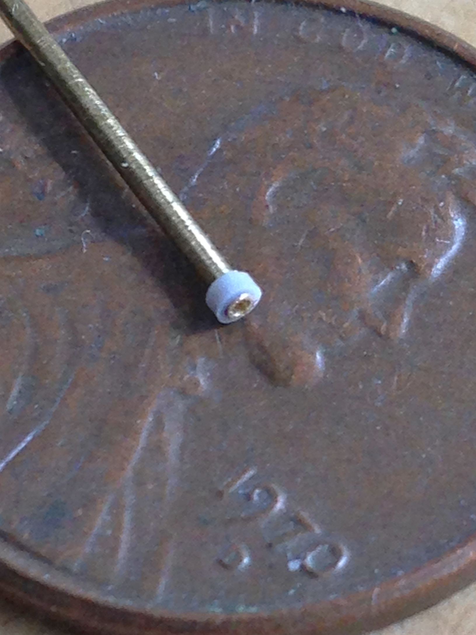


And then I drove myself crazy(er) concocting elaborate and complicated means of getting the barrels mounted and aligned. Thankfully, before I started burning through materials and/or screwing up the only set of wings I have for this variant, I hit on a Clever Idea ™. I noticed that there is a slight lip where the barrels meet the shrouds on the actual aircraft. Since I had the .047″ (1.1939mm) rod right there, as well as recent (successful!) experience center-drilling them, I’d use the drilled styrene rod as mounting sleeves! I also made a fence so that the barrels extended the proper distance from the shrouds (that turned out to be unnecessary, so I didn’t do it for the other wing/gun setup):
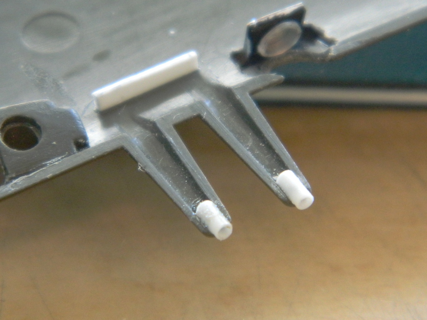


I didn’t attach the barrels at this point. Having them removable (they just slide in and out like…ahm…yeah…never mind) will make painting them a lot easier.
A word about dropped landing gear doors and flaps…
I’ve read references that stated the reason the doors on Merlin-powered Mustangs drooped was because they lacked the mechanical locks that kept Allison-powered doors up once hydraulic pressure in the system bleed off. I’ve read references that said the opposite. I’ve also read the same things for the flaps, both one way and then the other. From what I’ve been able to figure out, the flaps would stay up unless someone pulled the T-handle that released the hydraulic pressure from the hydraulic system (the reason given was so that nobody would step on the relatively fragile flaps while they were in the up position and thereby damage them). It seems the landing gear doors are still a matter of mystery (at least to me) as to when and why they would drop down. (If I ever come up with a definitive answer, I’ll come back and edit this.)
For whatever reason they drop down, most of my references show the flaps down regardless of which variant of Mustang pictured and the landing gear doors down on Merlin-powered Mustangs. That’s how I will build them and that starts with this one.
The Verlinden cockpit detail set also included a set of flaps, so I thought I’d use those. The first thing I noticed was that the flaps weren’t long enough, which meant I had to add plastic to the ends of them:
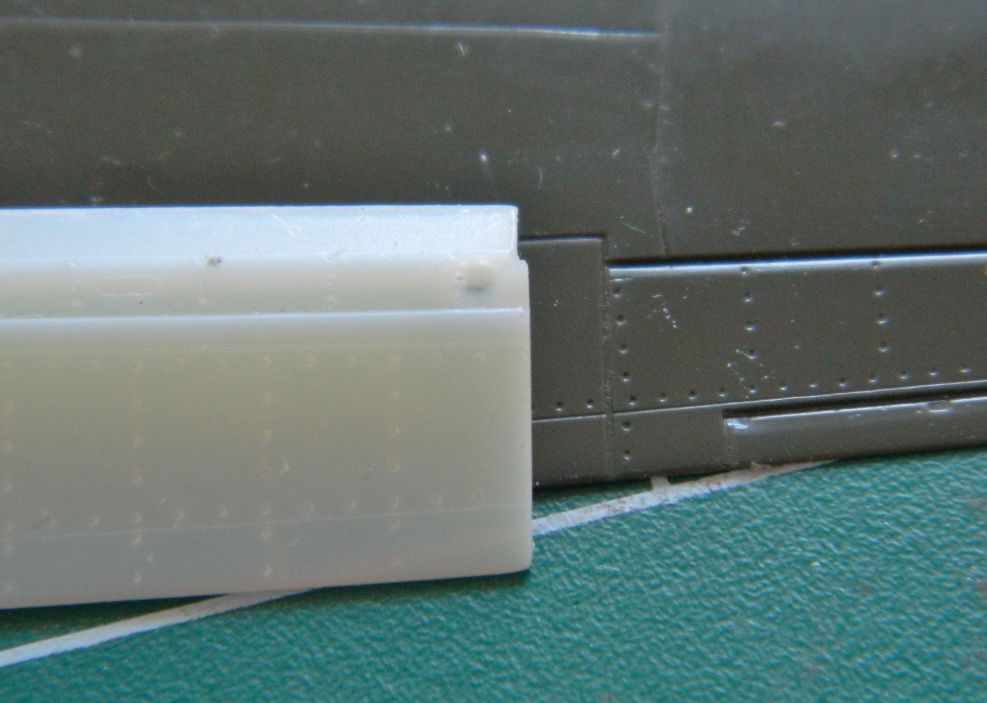

And then I noticed that the resin flaps were about half as thick as they should be where the flap meets the wing:

Well, then…looks like I’m going to cut the flaps out of the wing and make those work instead:
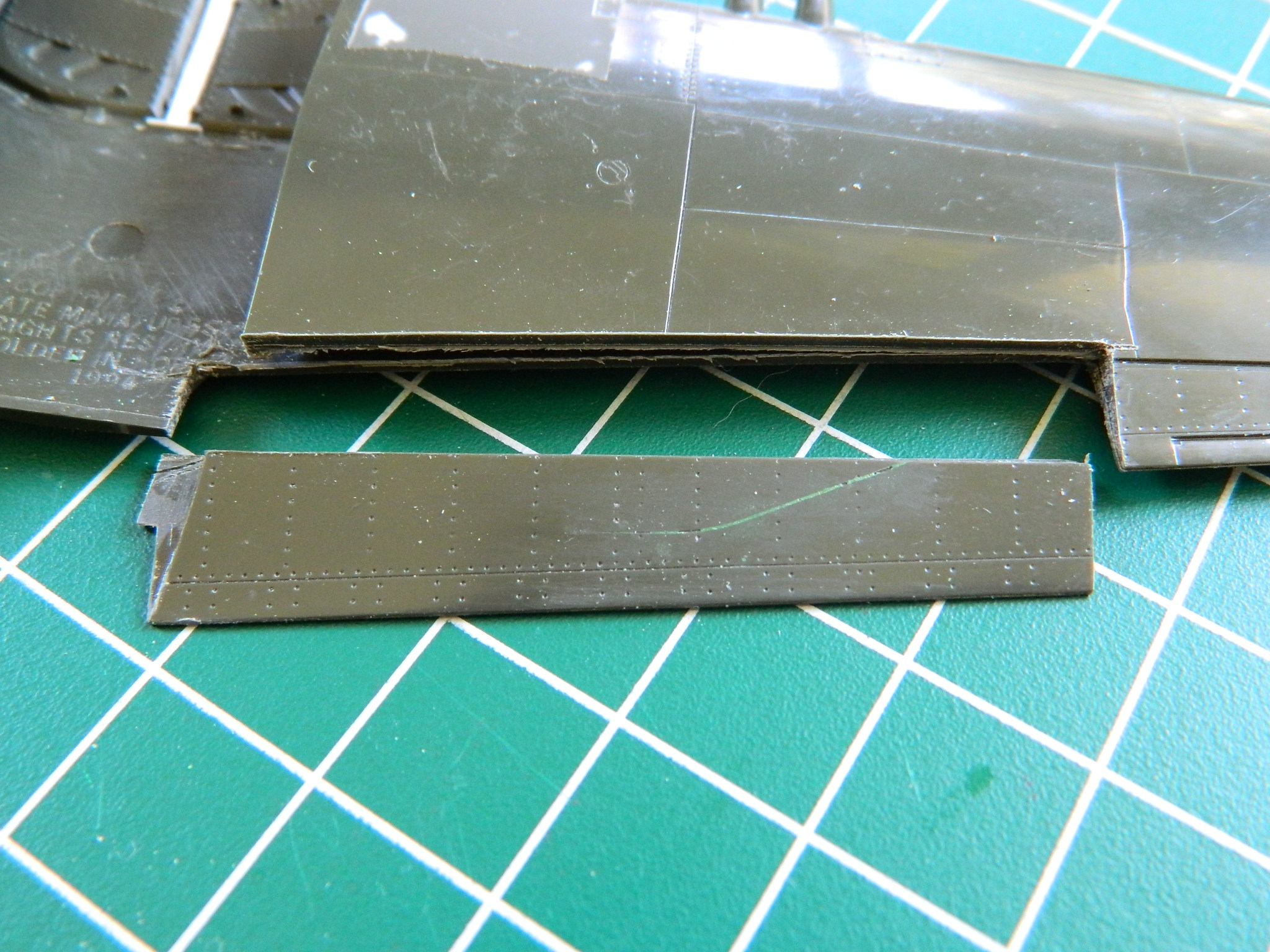
First I carefully glued just the flap sections together so that the profile would be established. To keep the kerf as small as possible, I used a panel scriber and MANY passes to separate the flaps from the wings.
And here I insert a warning about scribing tools. I like them better for most panels than using the back of a knife tip or needle because the knife tip is often too wide and the needle raises a lip on either side of the resulting groove that has to be sanded away. I’ve reshaped my scriber to be about as thin as I can get it and still maintain its structural rigidity and most of the time it works quite well. But it’s a tool. Any tool can be misused and if you look at the above photo closely, you’ll see a diagonal scrape to the right of center on the flap. This is what happens when a person gets impatient and tries to take too big a gouge out of the plastic too soon. Several light passes are MUCH BETTER than trying to take a lot of plastic out with one pass. Several light passes do create a groove that keeps the tip of the scriber from doing what I did with it, having it wander and gouge a surface that should not be gouged. So what my impatience has done, as it so often does, is make more work for me. The errant gouge needs to be filled. ::bangs head slowly on desk::
Look closely at the flap in the above picture again, but this time look at the curved section on the left of the flap. The actual flap fits under the faring at the wing root. The kit part meets the faring and, were I building this with the flaps up, that would be fine. So that area needs to have plastic added so that the surface of the flap is even across its width (after much scraping and sanding, of course):
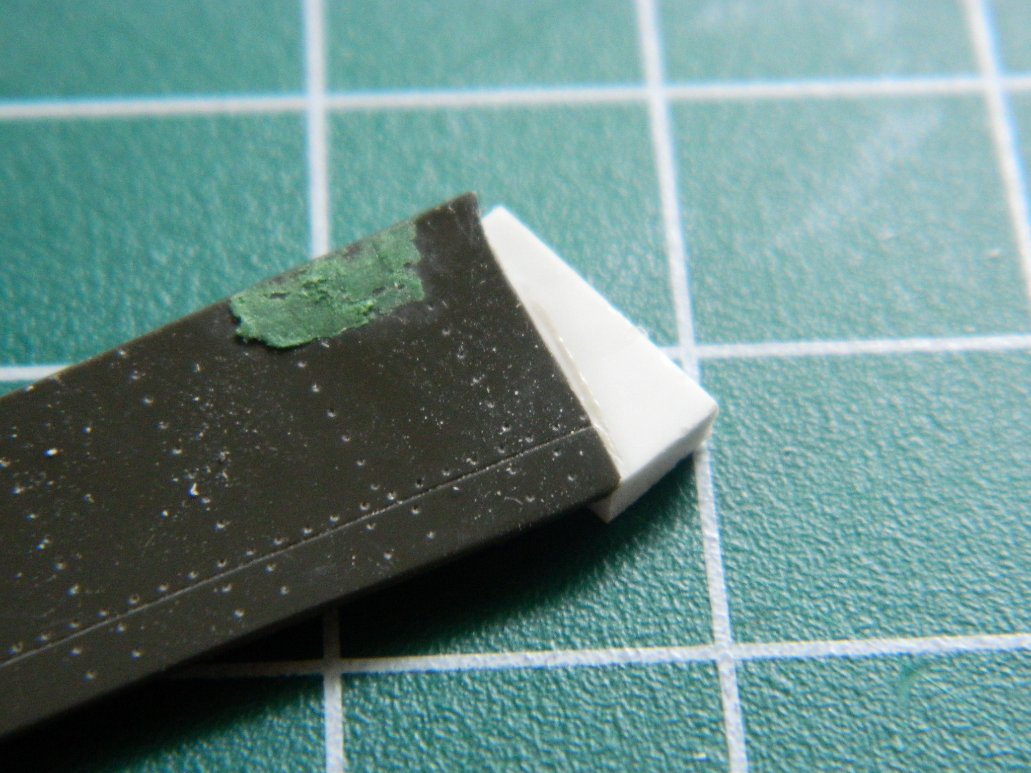

If you look closely at the lower picture at the edge near the plastic addition, you can see where the TINIEST of brushes by a spinning Dremel tool’s bit took a gouge out of the plastic. So that will need to be fixed with another addition of plastic (and since fine motor control had deserted me at this point, I glued on more plastic and called it a night):
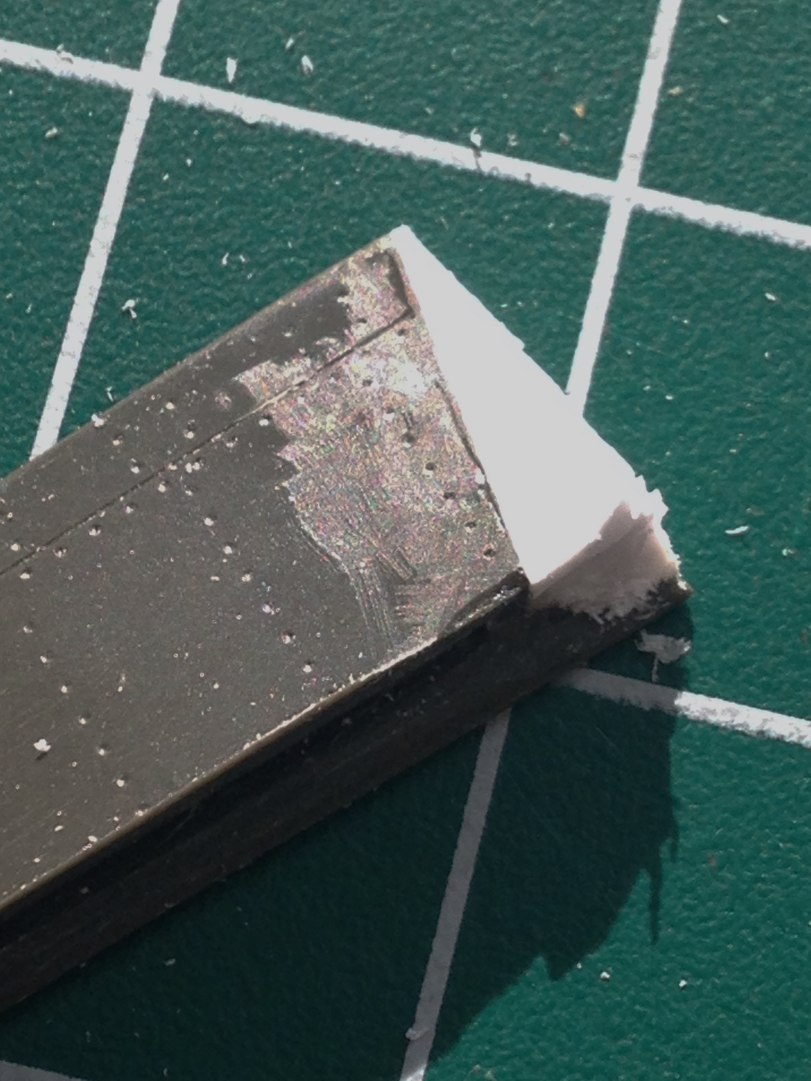
P-51 (Accurate Miniatures) Build #8 – Cockpit Details, Molding Tailwheel, Detailing Main Landing Gear, Painting Landing Gear, Installing Cockpit, Joining Fuselage Halves
Once upon a time, there was a California-based company called Model Technologies that produced some very fine photo-etched details. I was fortunate enough to pick up a few of their items way back when because they have since gone out of business and if anyone has picked up their line, I can’t find them. What made MT’s stuff so nice (other than the fact that it was a damned good product) was that they used stainless steel for many of their products. This is a good thing because I’m using MT’s seat belt buckle set and it’s VERY SMALL. Brass of this size would be more fragile than useful. Stainless steel is strong enough to survive the manipulations required of them:
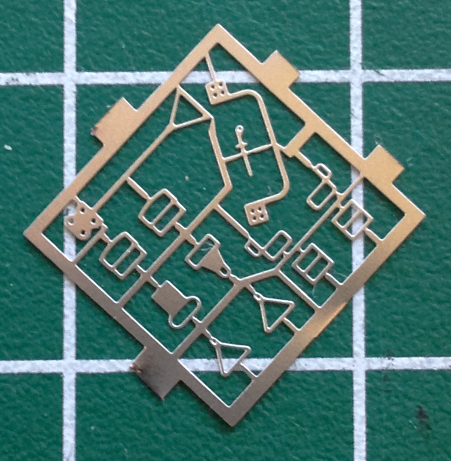
And from my initial attempt to convert a P-51B to an Allison Mustang, I had a seat cushion I’d made from a sheet of .060 styrene. I checked its fit and though slightly smaller than I would make today, I decided it was certainly close enough so I painted it and glued it in place:

With the MT buckles, the harnesses are replicated using paper that is then threaded through the buckles the way the actual harness was threaded. The first paper I tried was paper towels from a public restroom:
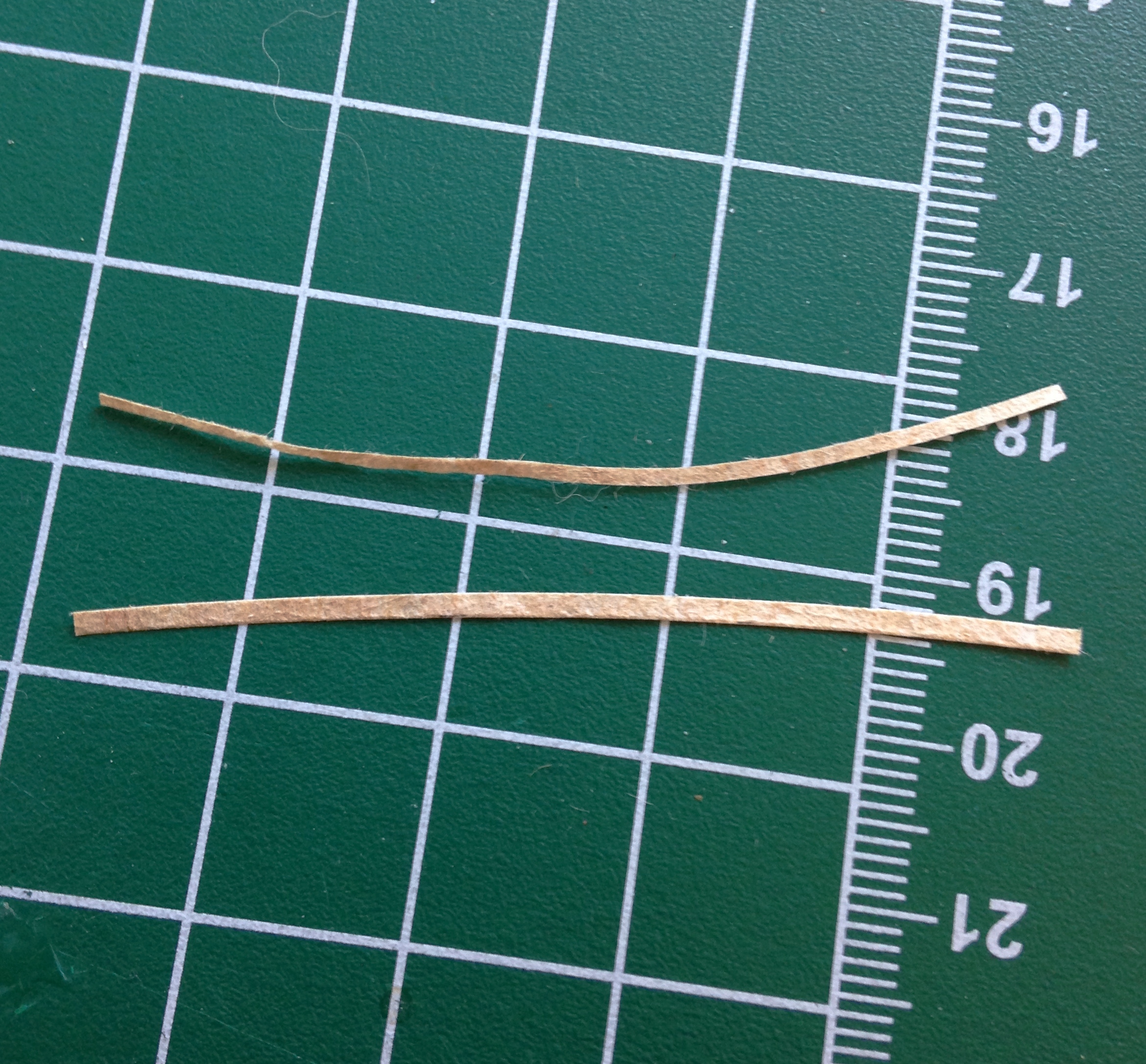
One of the things I liked about this paper was it was already about the color I wanted. But I discovered that once soaked in dilute white glue, the physical properties of the paper itself was too loose to survive any manipulation, coming apart instead:
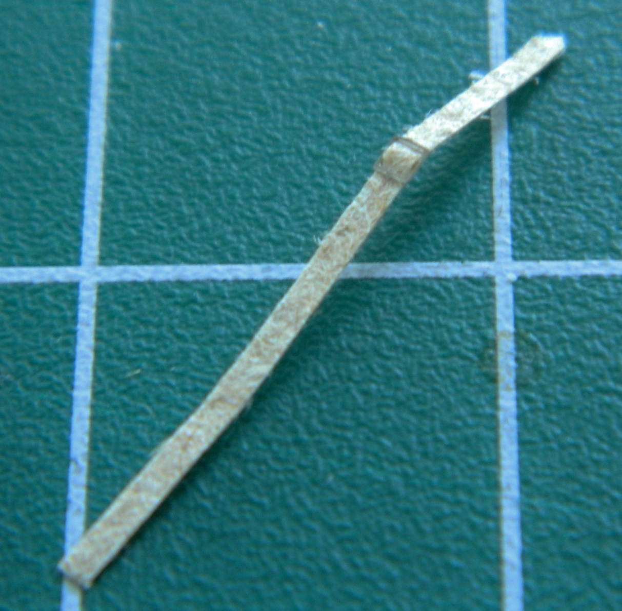
What I ended up using was the paper from a white Post-It pad (though I’d also considered using the paper of a dollar bill because of its high linen content):
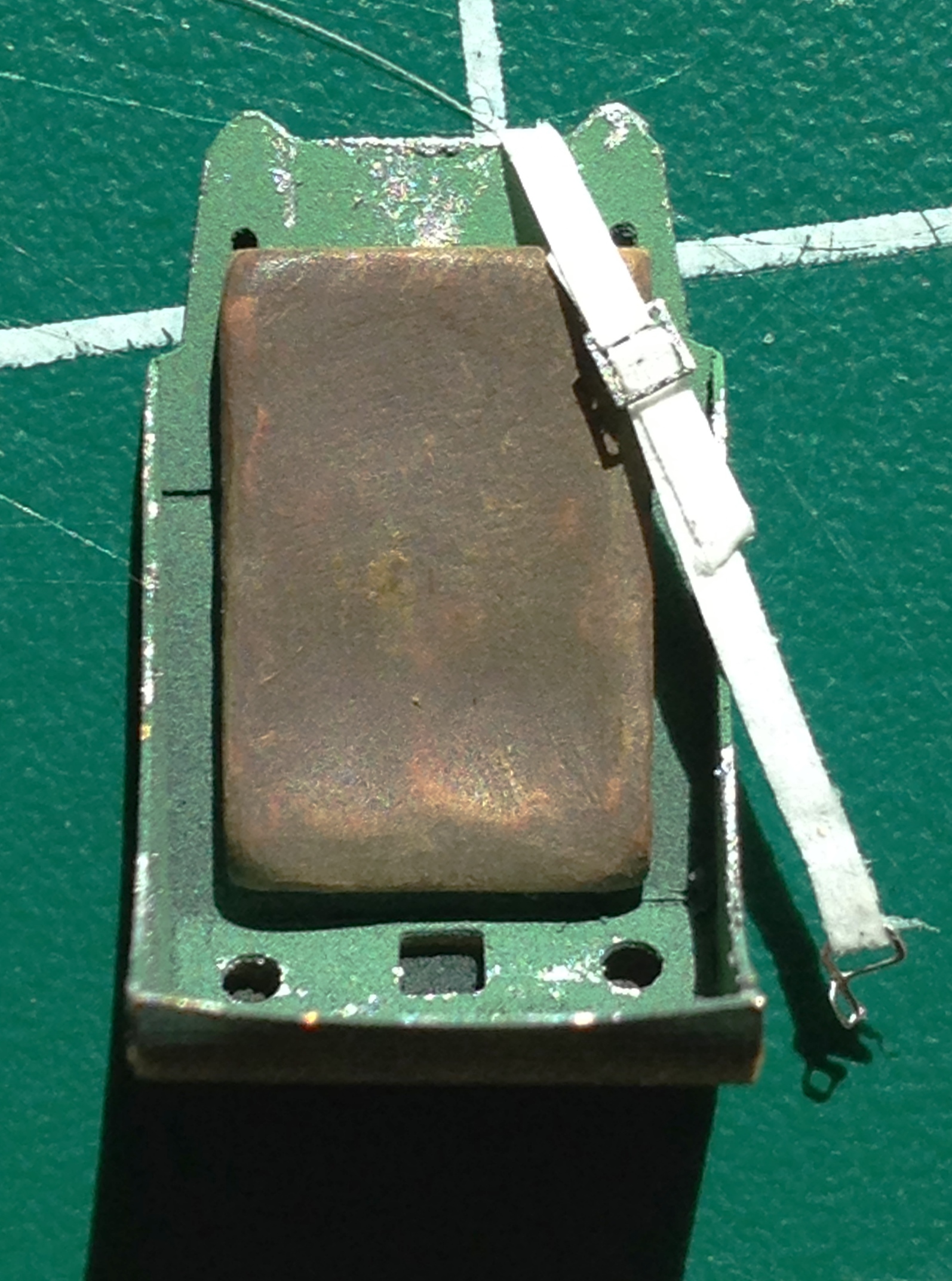
Pleased with how it turned out (and equally pleased it didn’t come apart once soaked with dilute white glue!), I went on to the FIDDLY task of threading all the straps through buckles and getting them ready to paint. And speaking of “small,” the latching mechanism on the end of one of the lap straps is not only FREAKIN’ TINY, the loop has to be turned ninety degrees and the tail curved and THEN glued on:


Once done with the tedium of the straps, they were all painted and glued into position:
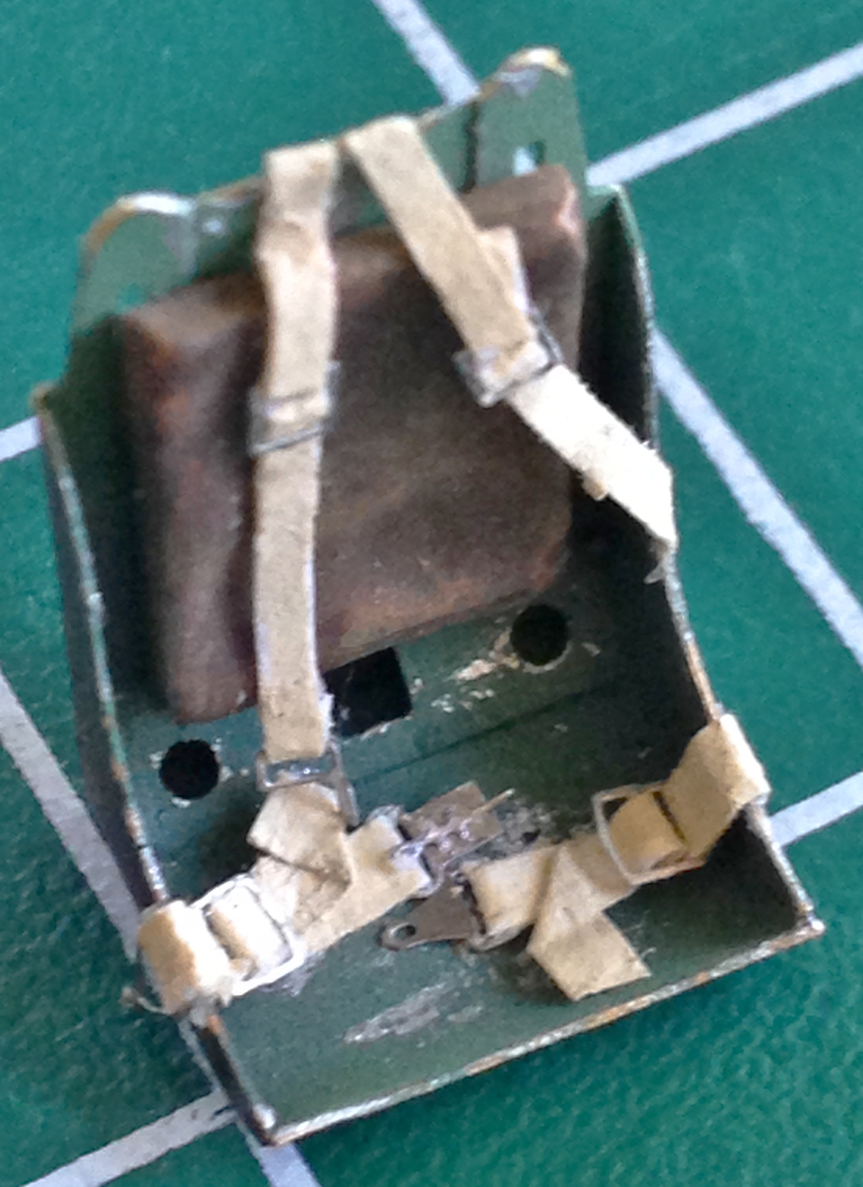
This is an illustration about why I go through all this trouble. In the next photo, the seat on the left is the kit-supplied part, the center is the seat that came with the resin detail set, and then obviously the one I’m using:

While the acrylic paint cured a bit, I turned my attention to the tail wheel assembly. The first thing I noticed is that this assembly is molded as one piece…and it’s obviously so. So before I can use it/them, I wanted to separate the wheel and tire from the strut:

I used the tail wheel part from my sacrificial kit as well. From one part I cut the tire away and re-sculpted the strut to the proper L-shape, and from the other part I cut away the strut to end up with just the tire:

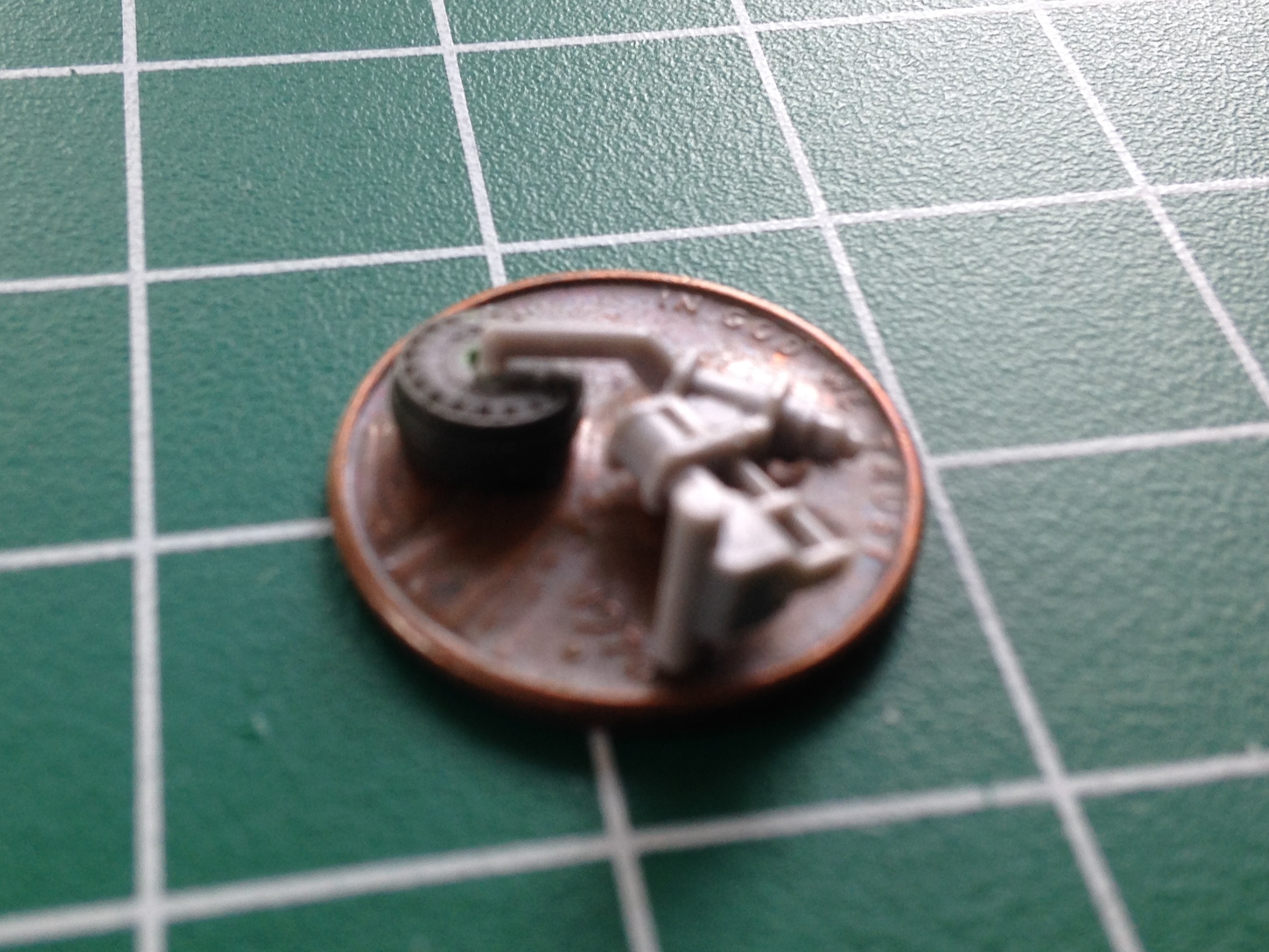
I have plans to build other Allison Mustangs, most of them are Accurate Miniature kits, and that means all the tail wheels are molded the way this one was. Being lazy, I didn’t feel like going through this process six or seven more times, so I made a mold of the tire and strut, poured resin, and will be using that instead.
It seems that all solutions create new problems. I poured the resin for the tail wheel assembly, put it under 55 pounds (121.25kg) of pressure, and de-molded it the next day. See that white band on the strut? That’s a sodding bubble:

Okay, so that means I can either try another pour or fix this one. One thing I am more than lazy is cheap. Doing another pour means wasting resin (the smallest increment that can be mixed is an ounce…and I have NO need of that much resin just for this little sodding bubble). That means I cut the strut where the bubble is, add a disc of styrene (.015″ (.381mm) as it turned out), and finish it to invisibility:

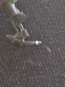
At this point what’s driving the build is the need to shoot parts with aluminum paint. The end goal is to have everything painted so that I can join the fuselage halves. The rear landing gear strut needs to be painted aluminum, but so do a few more parts. So the next step is to get everything that’s going to be painted aluminum detailed and finished, and that starts with the main landing gear legs.
Aside from cleaning up seam lines, I also needed to drill out a couple of mounting protrusions and then turn them into two separate protrusions instead of one ridge as it had been molded. The needle tip points to the unmodified ridge and the finished strut is next to it:


Then the extension scissors needed to be removed and replaced with more accurate photo-etched parts:
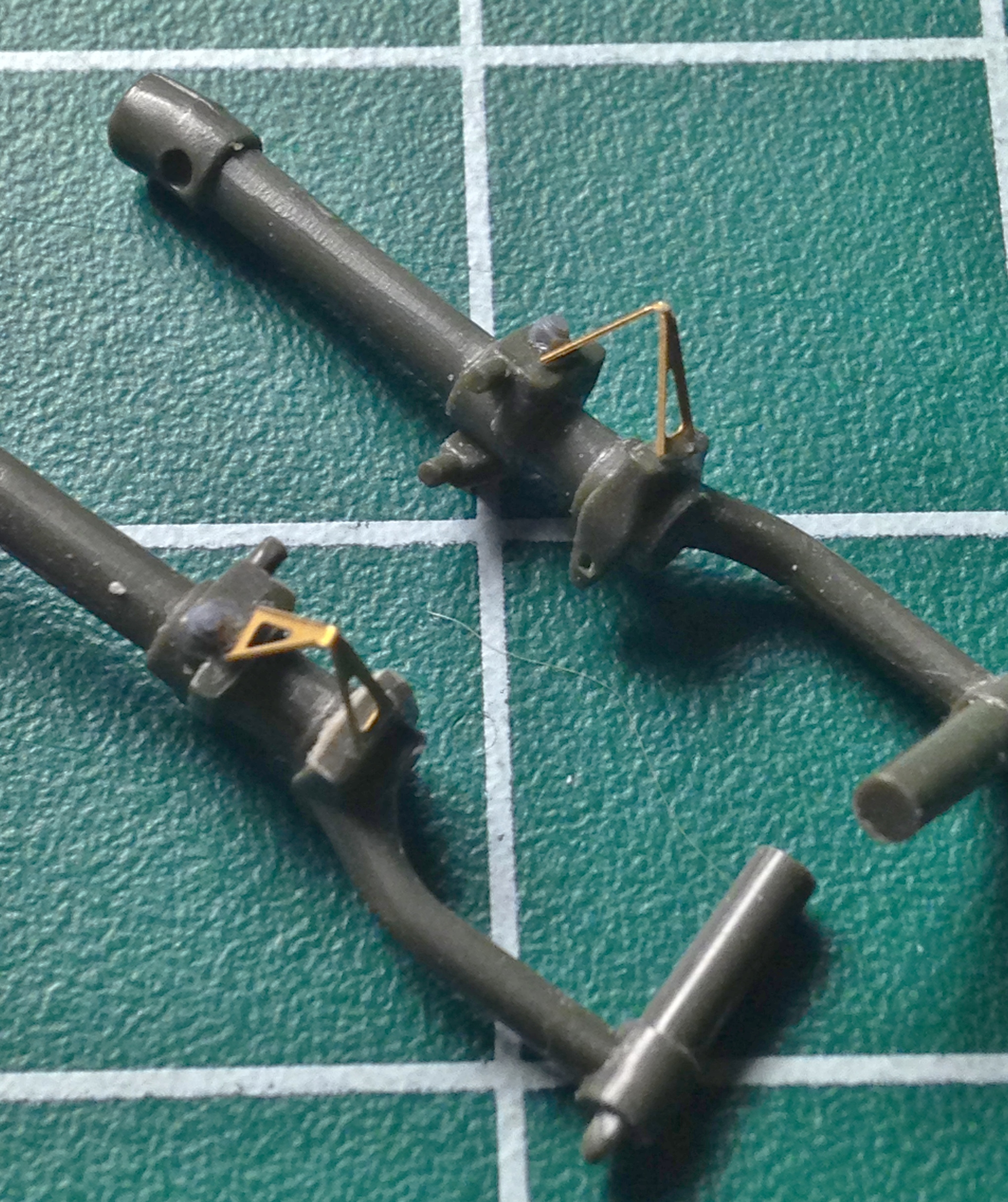
Next step was to add the brake lines. I used annealed copper wire (it bends easier) for the brake lines. Before the brake lines were added, I painted the steel section of the strut “steel” and then masked those areas off and then glued the wire in place before adding two bolts to each strut (if you look closely you’ll see the purple bolts):

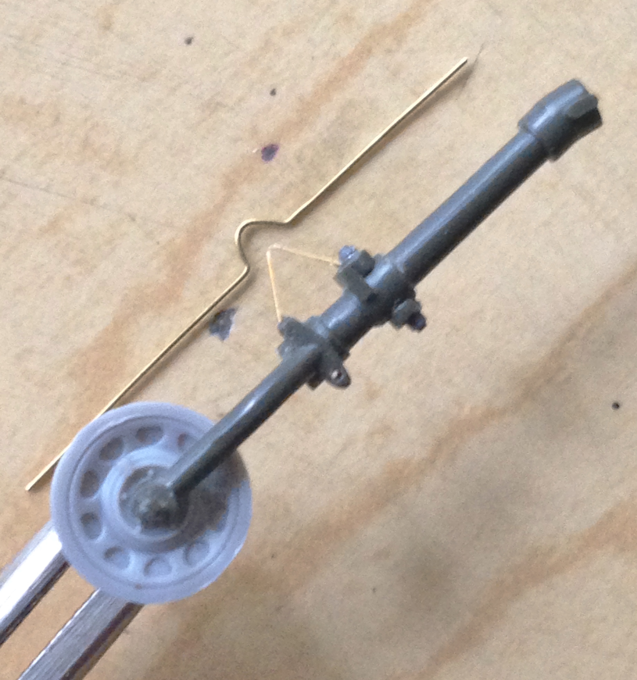

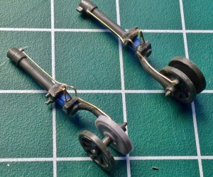
With the struts detailed, it was finally time to toss paint at the parts, 75% flat aluminum and 25% semi-gloss black. I also loaded the airbrush with “rubber” paint and did the tires:

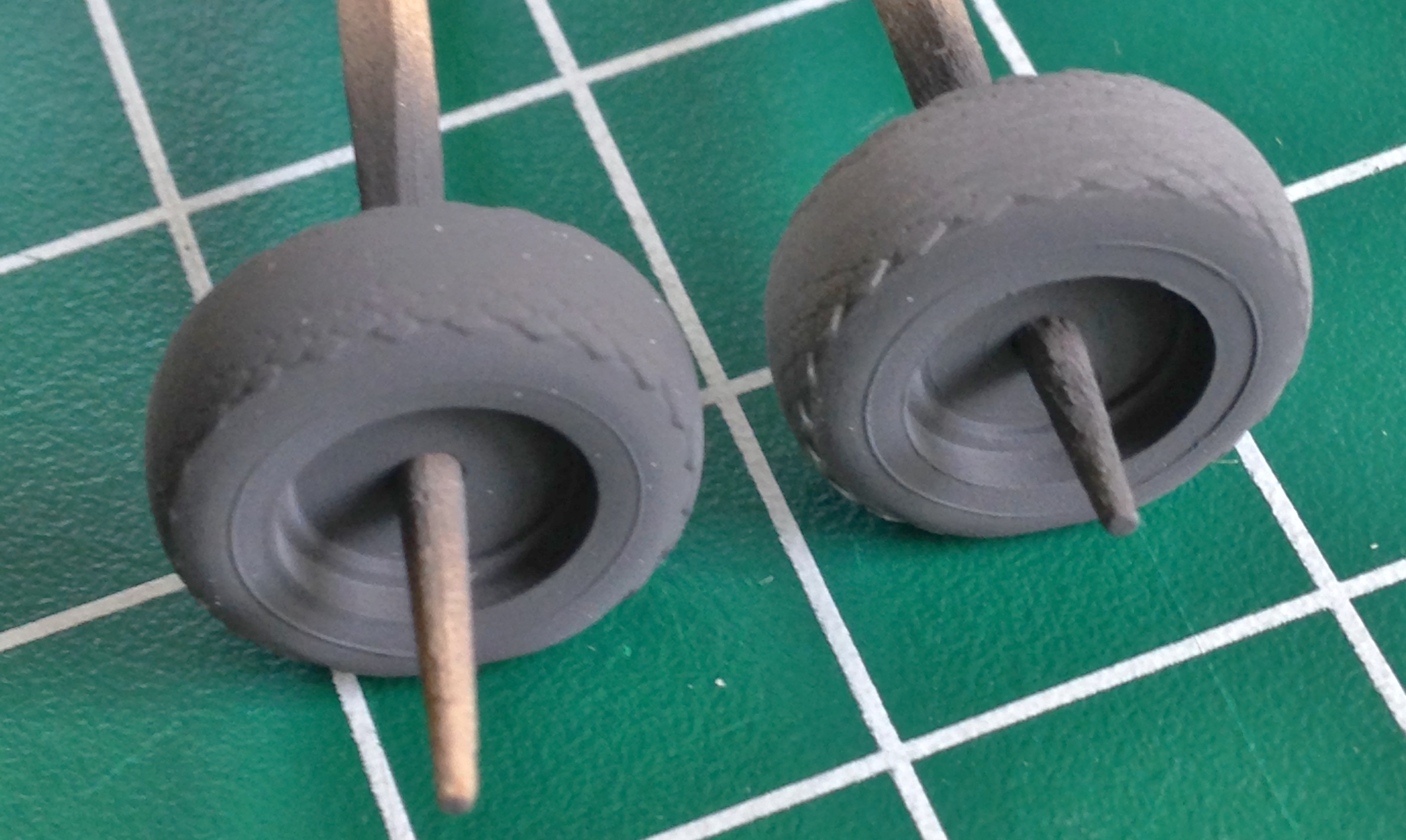
And while I had the “rubber” paint open, the curved section of the brake lines are rubber hose, so those got painted as well:

All the aluminum-painted parts were treated to a smoke-gray wash and the masking tape removed:
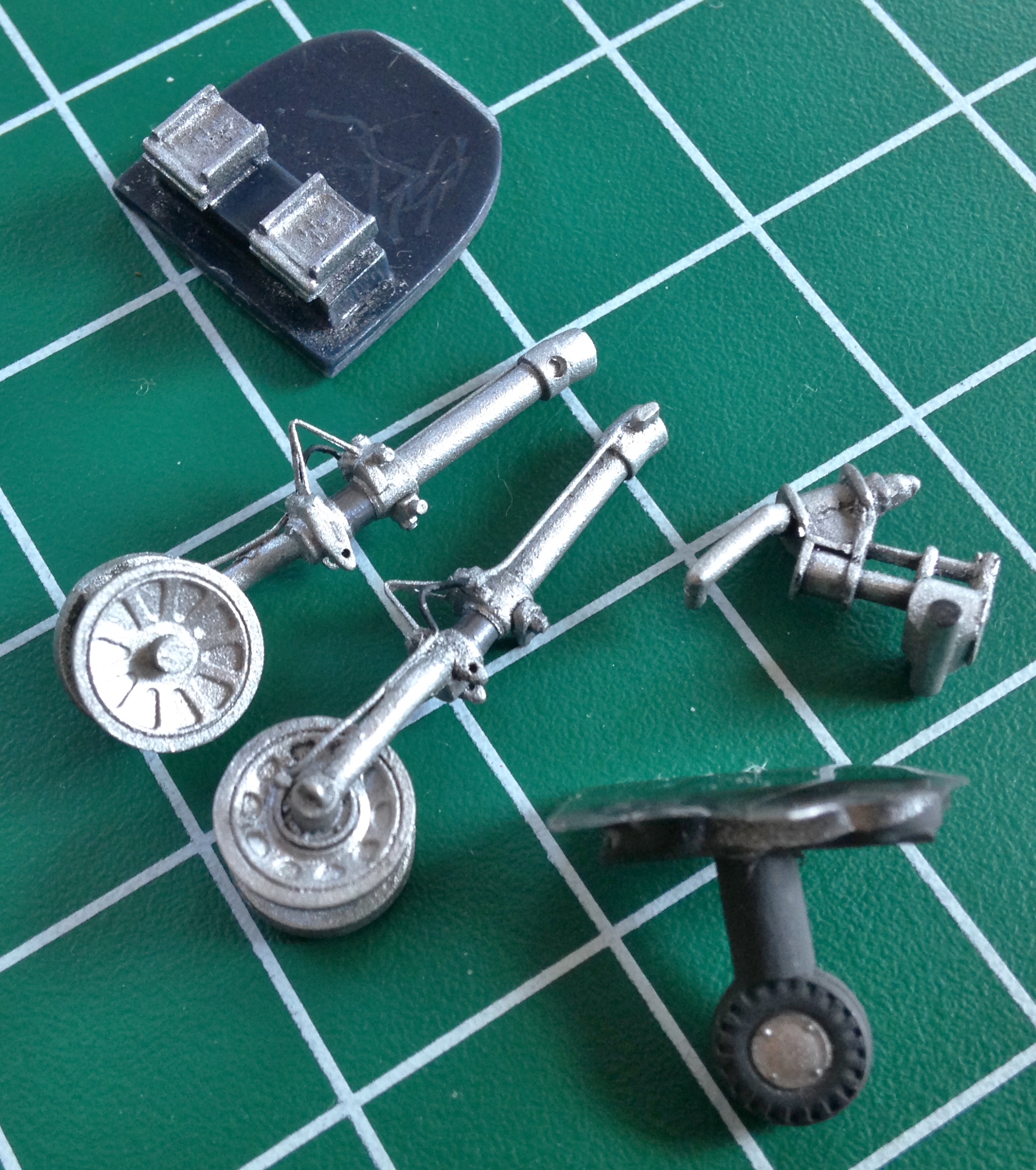
Then I needed to address the spokes. Once upon a time, I would have (and did) cut out the openings between the spokes. Then again, once upon a time my hands were much steadier than they’ve become. And even the painting showed me (again) that my hands are no longer quite (or even remotely) as steady as they were in my yout’.
I’m often asked by people how I can paint such TINY details. Being the smartass that I am, I tell them, “Carefully,” but there actually is a trick to it. Because the hands ain’t no longer steady, coloring between the lines ain’t no longer possible:

But there’s NO way I’m letting that kind of sloppy paint job stand. So when painting the tiny details, I’ll add the paint the details call for. Then I note the slop. Then I use the appropriately sized brush (usually TINY) to put back the paint my twitching digits slopped onto areas that the paint shouldn’t be on. Sometimes it takes several back-and-forth applications, but if I stick with it, I end up with something that isn’t sloppy. This is the same part as in the above photo:

One of the things that needed re-sculpting was the edge of the hood (aka, coaming) above the instrument panel. On the actual aircraft, there’s a hose that’s slit and slid over the edge of the aluminum. I’d briefly considered removing the molded-in ridge but the surface area the glue can work is VERY thin and stood a good (or bad, really) chance of dissolving it. Rather than go down that hole, I re-sculpted the areas of the lip that was out of scale. Below the section on the left has been done and the section on the right not done (sorry about the blurred photo…it was the best I could manage):

This variant of the Mustang had a separate door for the oil cooler and the kit provided the part. What the kit didn’t provide was a scale-thickness lip to it, so I thinned out that trailing edge of the oil cooler door:
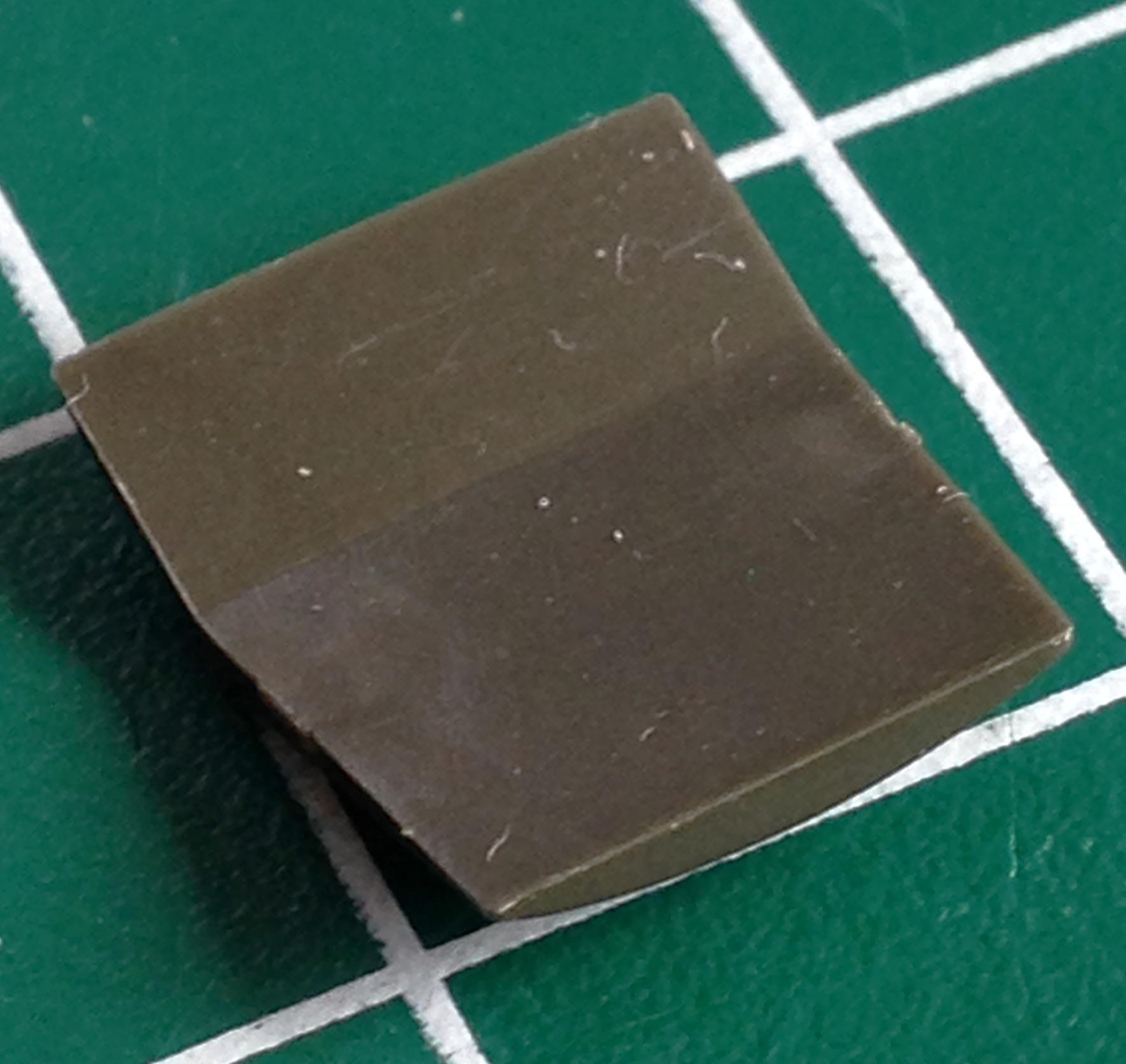

The last details to paint were the radios and those were done in semi-gloss black and chipped paint added, the seat and front bulkhead (with rudder pedals) were then glued into position:

With everything painted, it was time to begin the installation process of the various sub-assemblies so that the fuselage halves could be joined. It started by assembling the cockpit and installing the instrument panel:
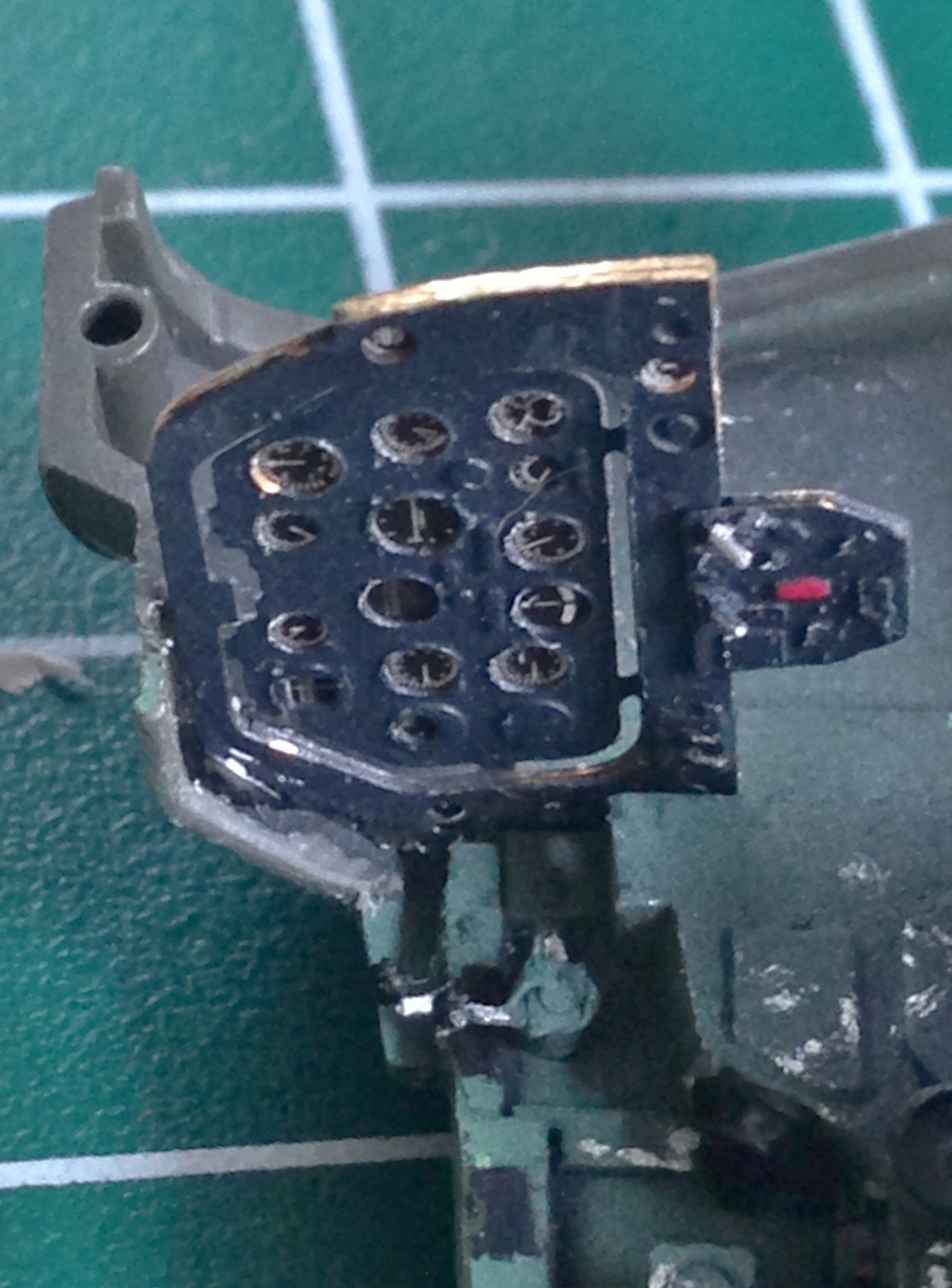
The first thing I did was to attach the engine cowlings to the fuselage sides. I’d debated joining the sides before attaching the cowlings but I decided that I would rather deal with one seam in an area that was easier to work than having that seam and the join where the cowlings met the fuselage. It took some time, fitting, additional invective, and more fitting before everything lined up as well as I could get it and then things were glued in and together:
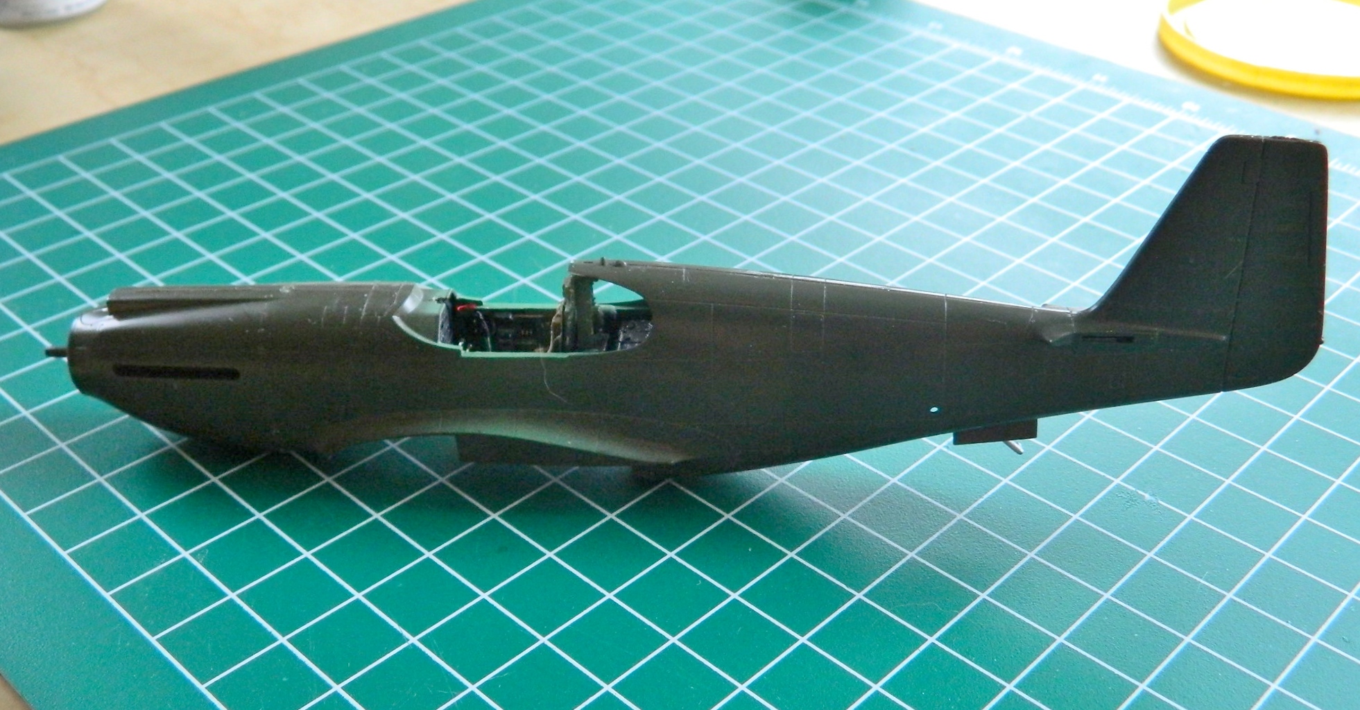
And in SPITE of all the careful fitting, heating resin and bending, there was still a fit problem; the front area of the cockpit floor was too low and you can see the gap between the floor and side (and the joystick was far too tall, so that got removed, trimmed, and re-glued). So there was more resin heating before I could glue and clamp things into the best fit I could attain:

With invective, heating, bending, and gluing accomplished, I am now here:
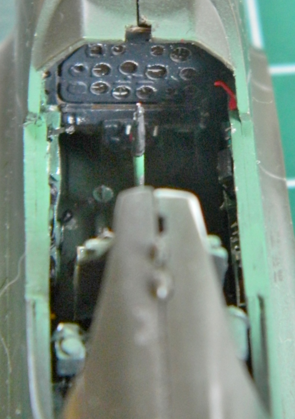
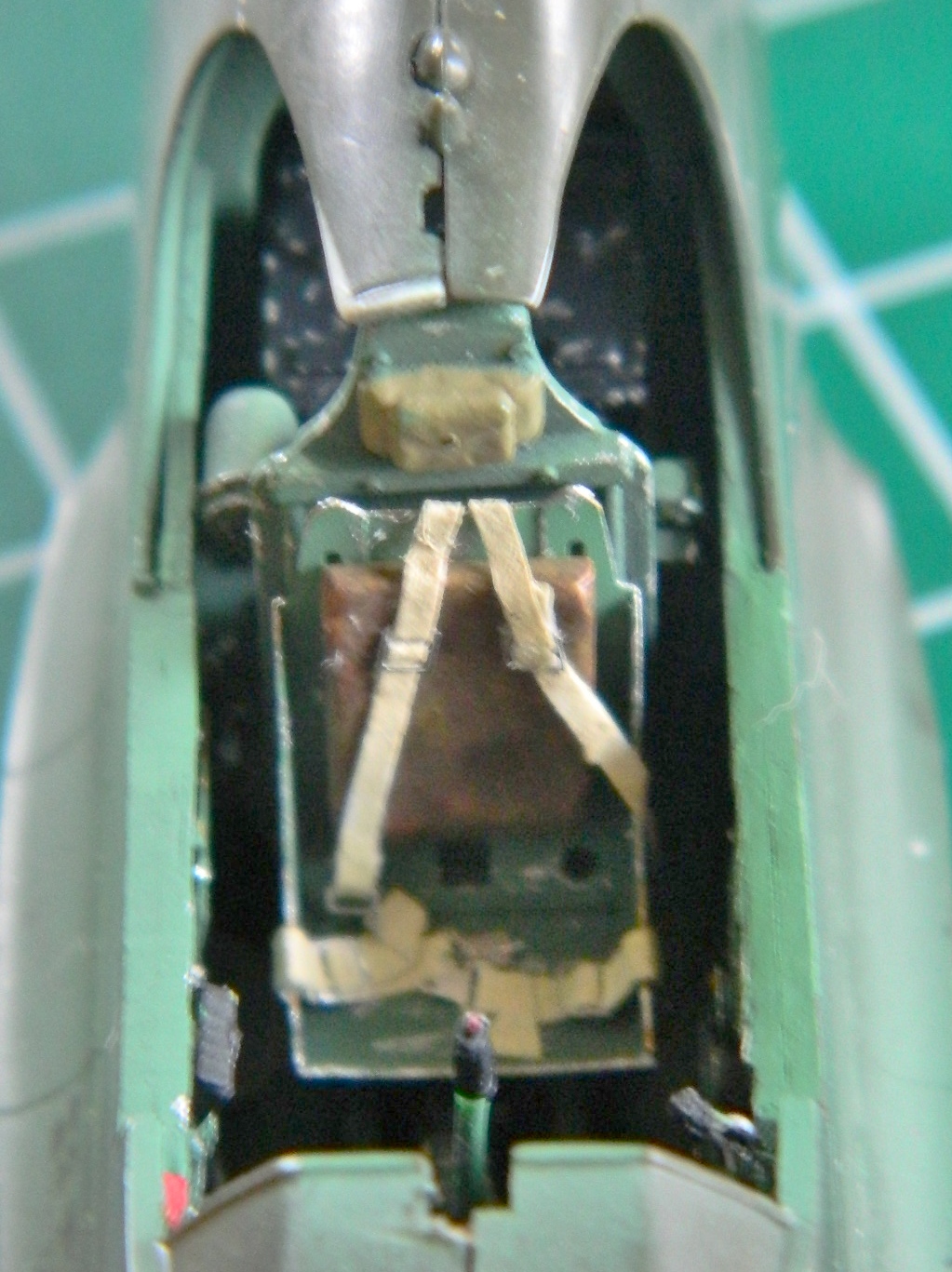

Now the seams all need to be dealt with. In some places I’m going to add sheet styrene and some places are going to need putty.
P-51 (Accurate Miniatures) Build #7 – Cockpit Details and Painting, Landing Gear Bays Painted
My original intention was to scratch-build the instrument panel from sheet styrene and the Waldron instrument faces. And though I got a decent start with it, what I ended up with would not work. I estimate that I was about six scale inches short of the space I needed to be able to use a scratch-built instrument panel. I could have thinned out the sides of the cockpit where the panel mounts, but that would have left me with extremely thin plastic and I didn’t want to go there. The PE set has a very nice photo-etched panel with a sheet of gauge faces printed on what I suspect is acetate and that’s the route I decided to take.
The P-51 panel has an inner panel that isn’t really attached to the surround (there are brackets behind the actual panel that it mounts to). The PE set had a two-piece panel that nicely replicated the original’s panel, it would just some tweaking (and as it turned out, fitting) to work.
One of the (many) interesting features of the P-51 was that it had no hard-points under the wings from which to hang bombs or drop tanks. I’ve already removed the salvo controls (those things that transform something being carried to something being dropped) but there are three toggle switches that have to come off the panel itself. Those three toggles are the “master arm” switch and one toggle each to arm the nose and tail fuses of bombs. Easy to not put something there, but I also had to plug the holes where the toggles go as well as trim down the switch panel itself, then to add the wire to replicate the bats of the toggle switches. With that done, I mixed flat black (75%) with gloss white (25%) to achieve scale color representation. Once the panel was painted, I used a white colored pencil to VERY lightly add highlights to the upper edges of the instrument bezels. The areas of the gauges faces that aren’t black are clear. If I want the gauge details to show (AND I DO), they need to be painted white, so I covered the areas of the faces from behind with white paint. I used the watch crystal cement to attach the acetate gauges and superglue to bond the instrument panel’s surround to the panel proper, and then painted the toggle switch bats:
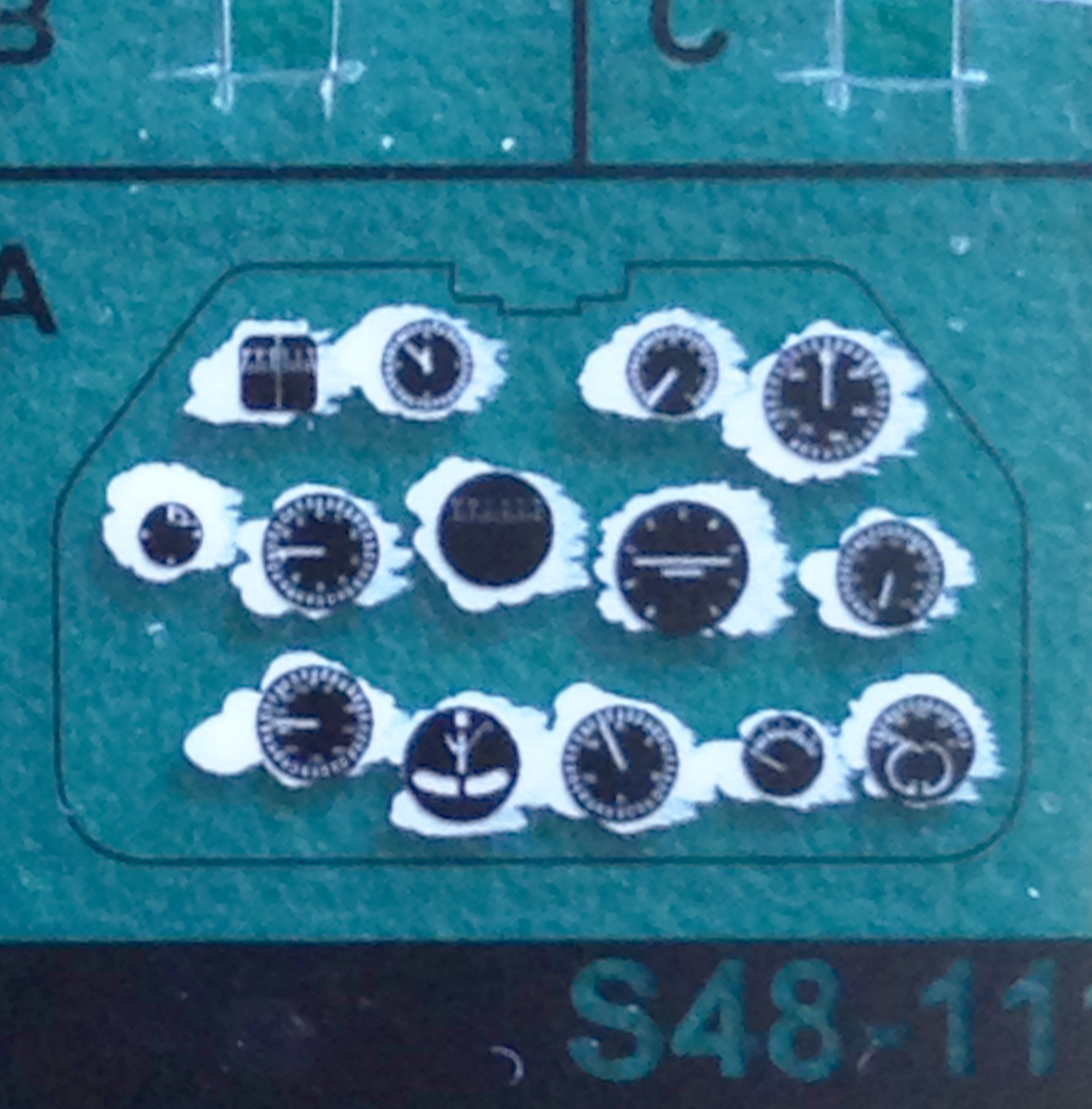
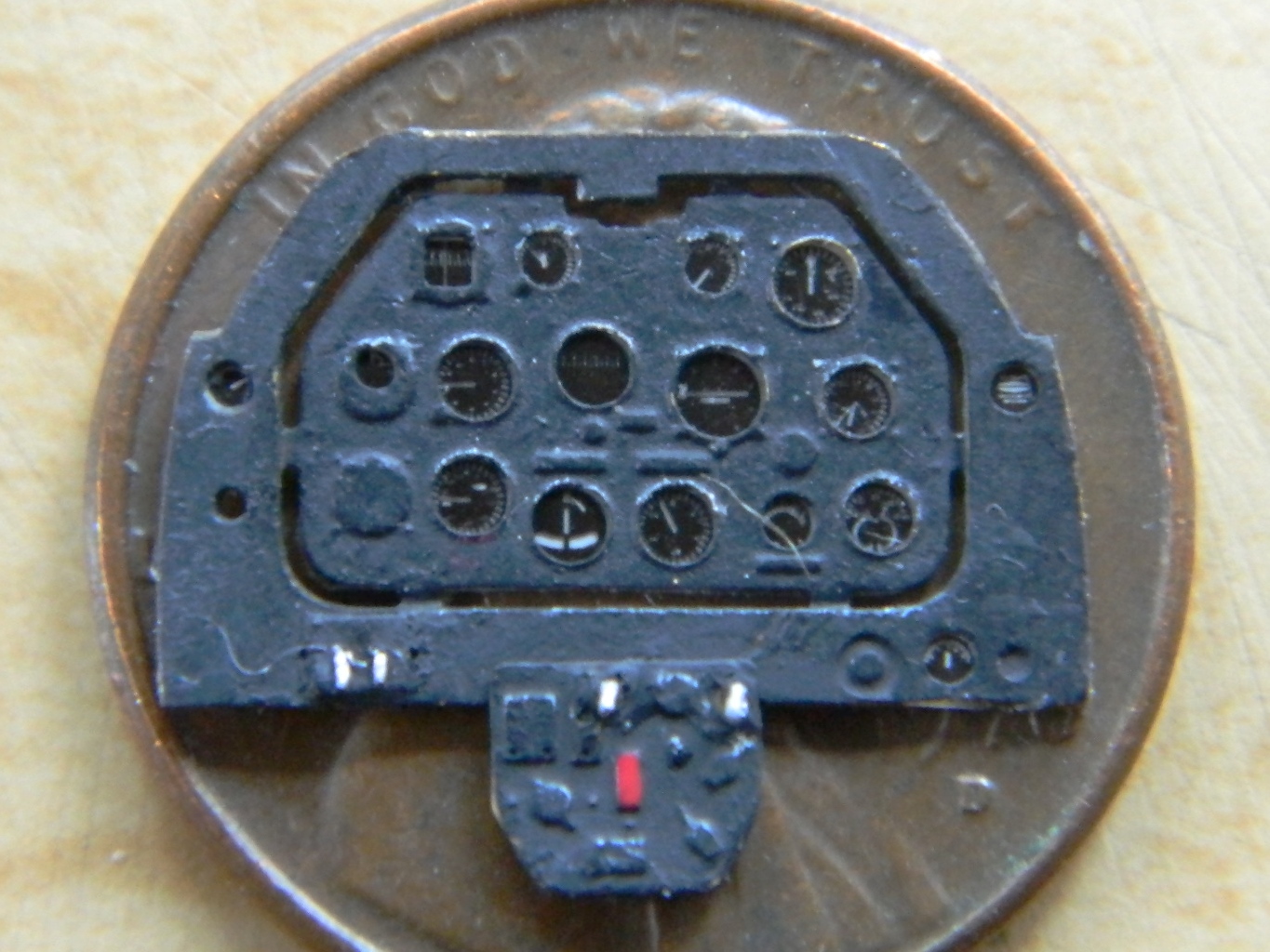
I decided that while I was doing gauges, I would also do the main wing tanks gauges, which are set into the floor. The acetate sheet that came with the PE set also had the fuel tank gauges. An insurmountable problem developed when I used the punch/die set to punch out the gauge faces. There is just enough slop in the punch/die set for the gauge face to not punch cleanly through. Instead, about 75% of the face was separated, but the remaining 25% caused the face to curve inside the die and the punch scraped the instrument detail off.
Once I was done with my (useless but satisfying) invective, I remembered I had a lot of dry-transfer gauge faces in my armor parts stash. All I needed were two basic “quantity” gauge faces (a needle pointing to the left and a series of marks arcing across the top of the face). Once I found what I needed, I also needed to make sure that they were of the proper diameter. I used the PE bezels for that determination.
Did I mention these things are small?:

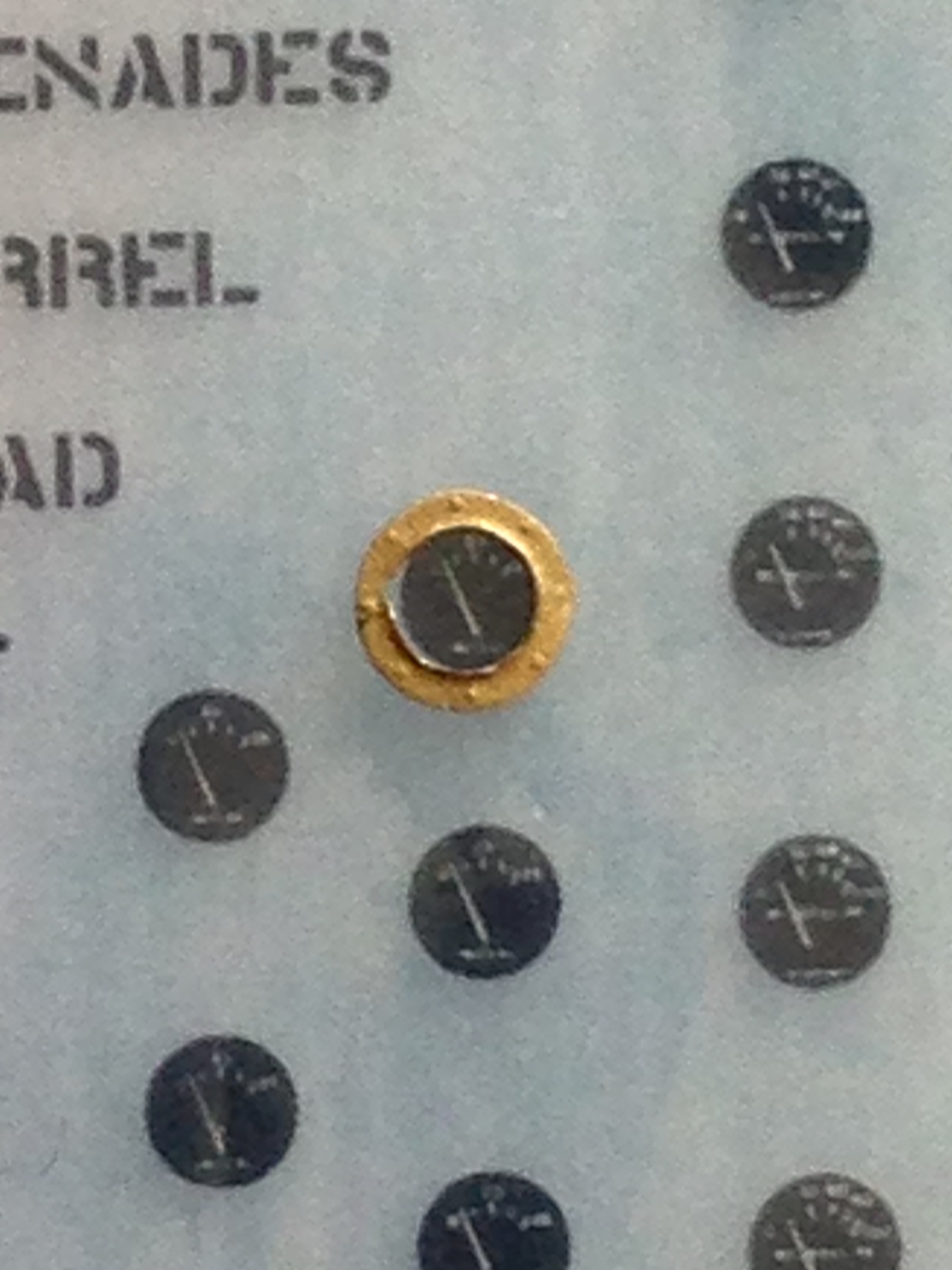
To use the acetate gauge faces I had to drill a depression for the faces to fit into. And then I discovered I couldn’t use the acetate faces so those depressions had to be filled in with styrene:
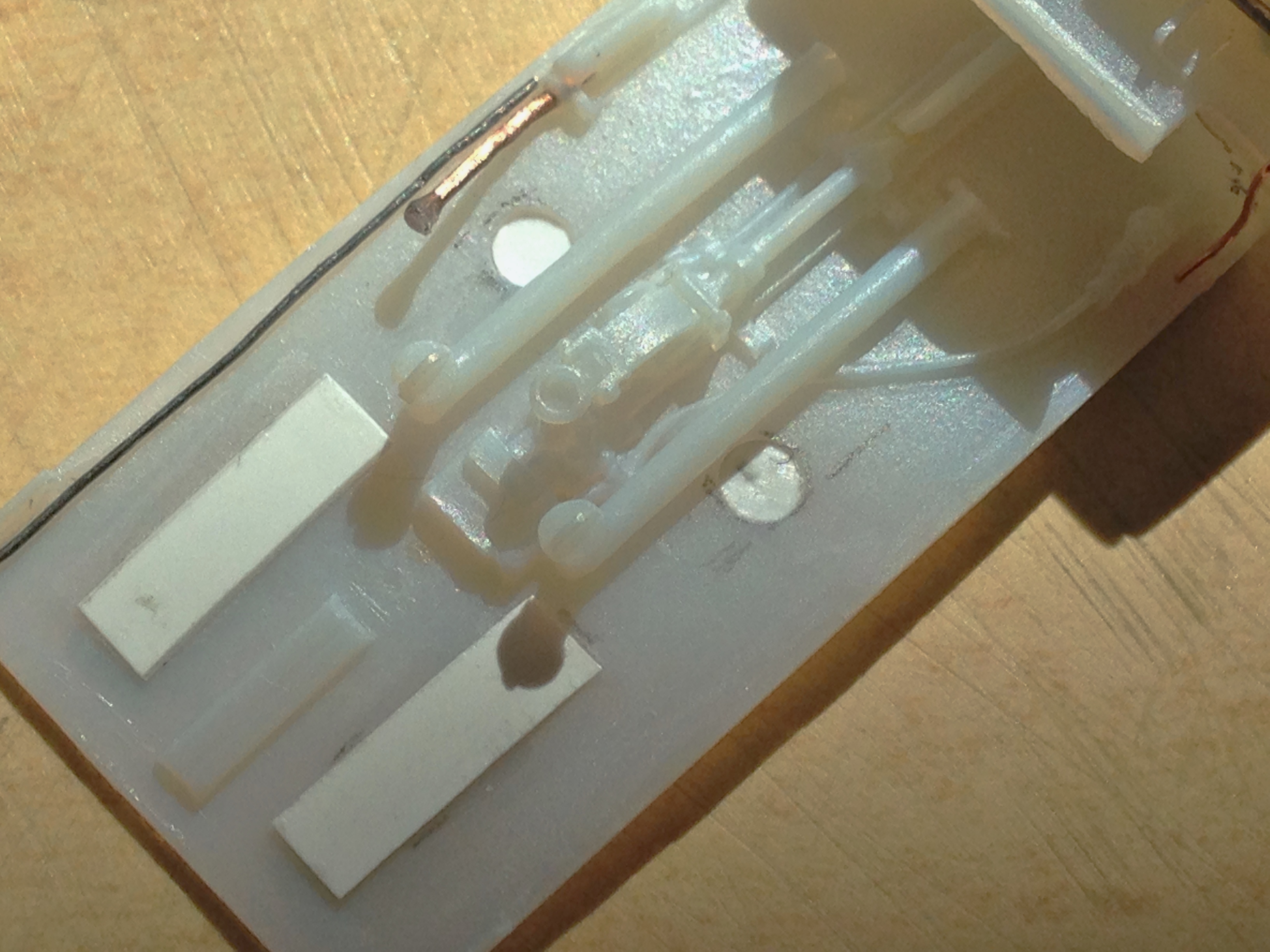
The dry-transfer faces were applied and the bezels set in place and glued (I used a very small dab of watch crystal cement to hold the bezels in place because experience has shown me that with parts this small, as soon as I touched the needle with the superglue on it, the small part would stick to it; the watch crystal cement worked perfectly to hold the bezel in place while capillary action moved the superglue from the needle to between the bezel and the floor) (yes…I actually glued something in place so I could glue something in place):
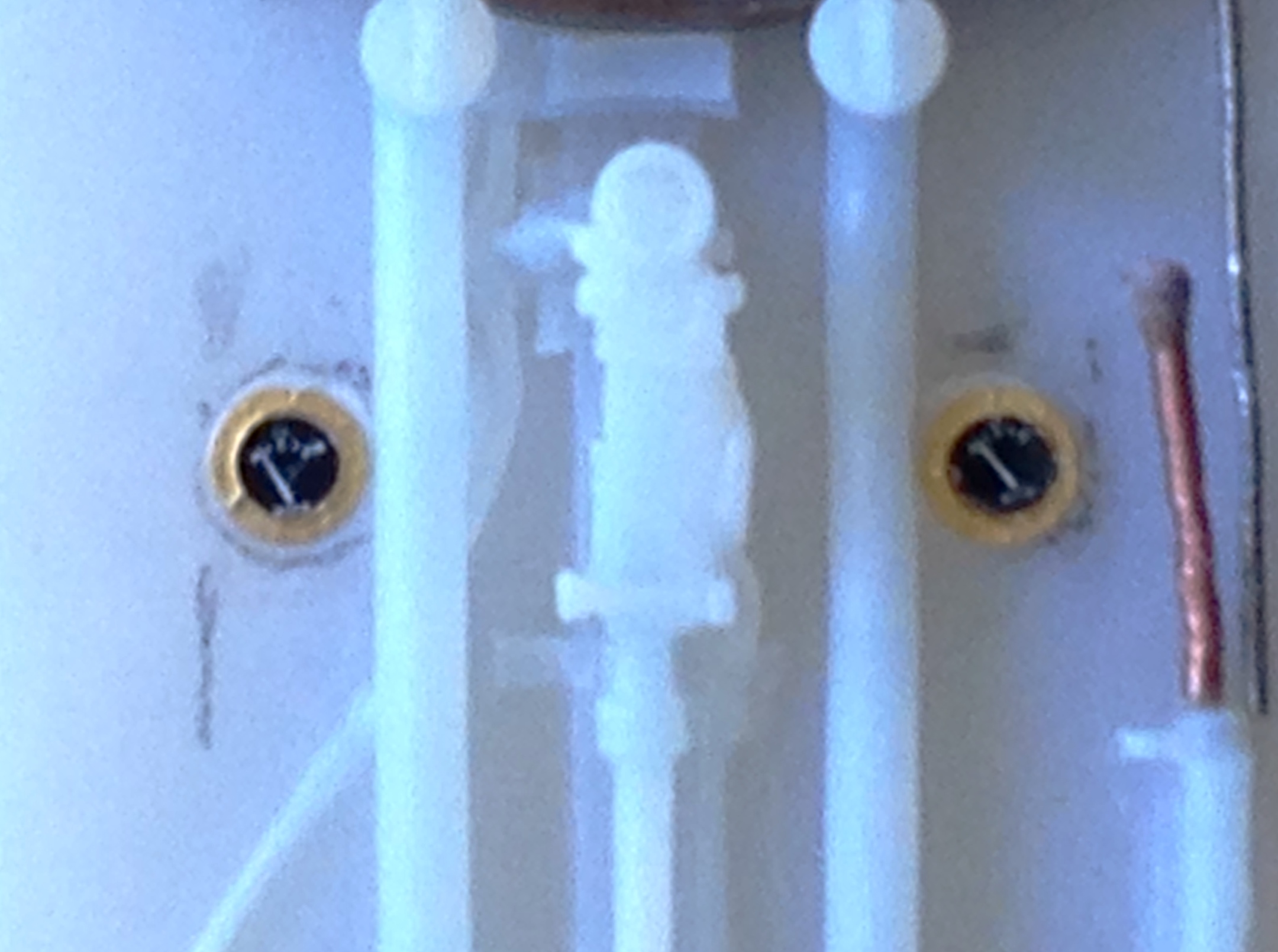
I used the punch/die set to punch out a couple of discs of masking tape which I laid over the bezels to keep them from being painted over. With gauges taken care of, I started work on detailing the sides of the cockpit by adding the control cables of the throttle and propeller pitch controls and the landing gear controls at the bottom of the left panel:
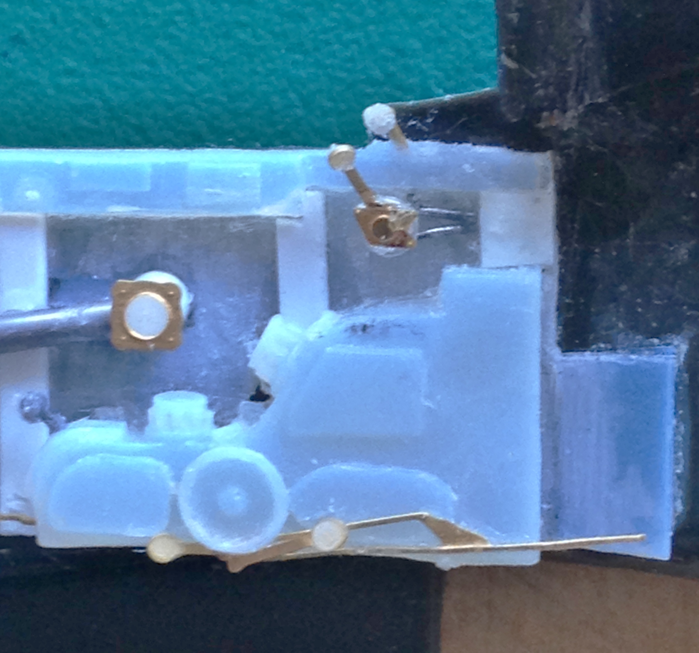
Satisfied with that, it was all ready to paint. I prefer to work with acrylics because clean up is SO much easier; water is the only solvent required. The problem with that is that I couldn’t find the exact interior green color I wanted in acrylic. What I ended up doing was using 75% Tamiya’s “IJN Cockpit green” (“IJN” stands for Imperial Japanese Navy), which is lighter than what the US used, and 25% of Tamiya’s basic green, which is darker than what the US used:
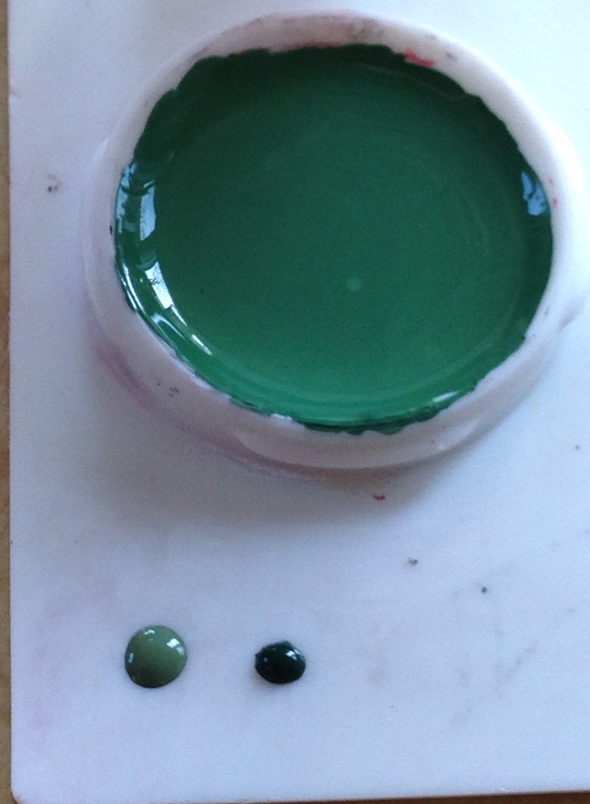
Once I had the mix correct (and added 25% white), it was painting time.
If you consider that a cockpit is a hole in the top of the fuselage that’s then filled with the controls of the aircraft and the pilot’s seat, it’s no great stretch to the realization that light isn’t going to reflect from the floor and the bottoms of the sides of this hole as much as it will from the those items that are in direct light at the top of this hole. My first step to painting the cockpit my green mix was to paint it flat black. The flat black would end up being the base shadow value, and since I’m basically lazy, I decided that all the parts that get painted green would be pre-shaded:

Next was to overshoot the “shadow” with the cockpit green. The landing gear wells are underneath the aircraft and would get the least amount of direct light and would therefore be mostly shadowed with just highlights of green:
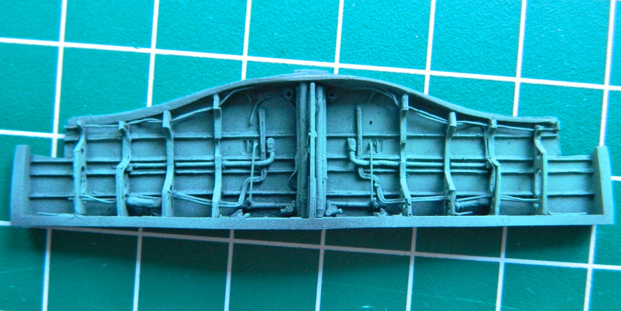
The rest of the application of green followed the idea of what areas would reflect the most light and the green was misted on top of the black and then I used aluminum paint to replicate paint wear:
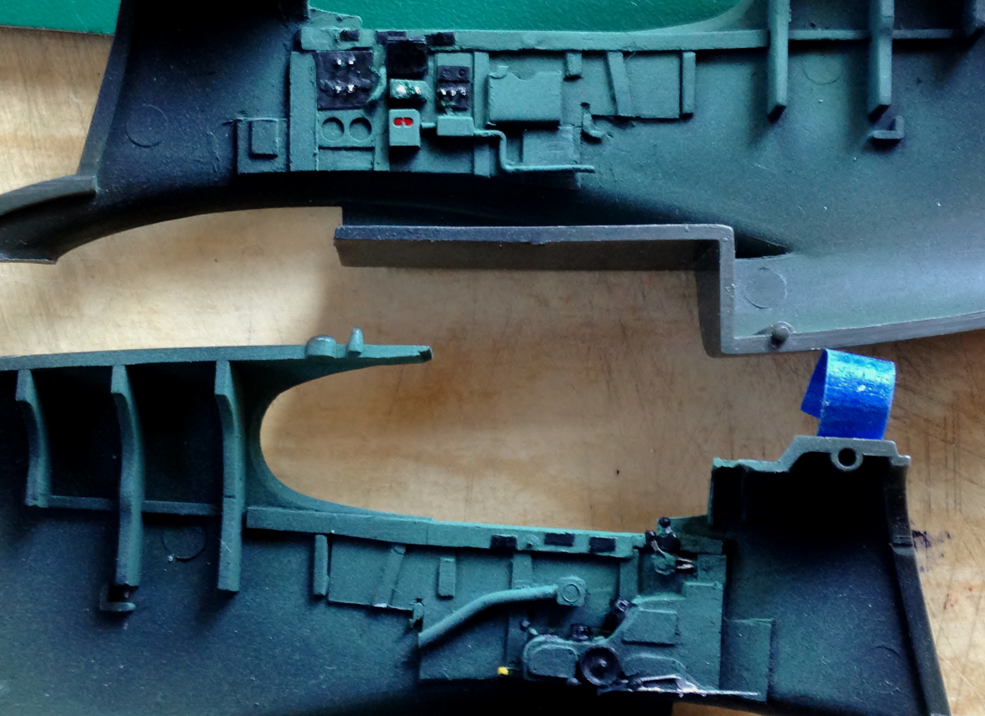
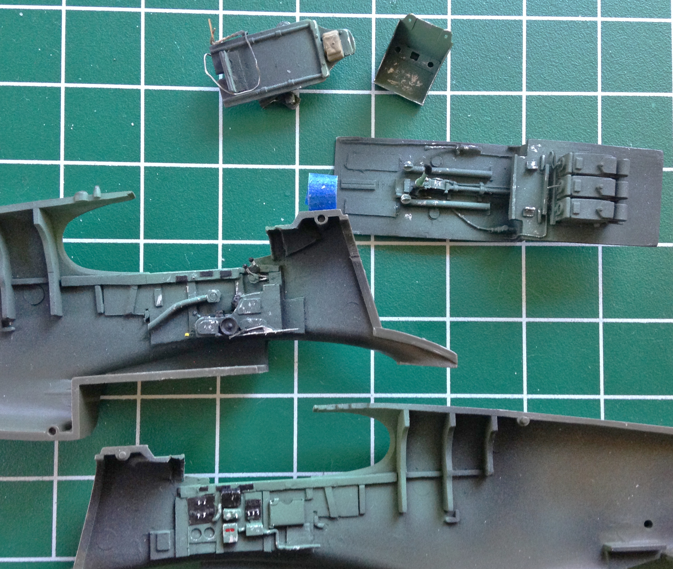
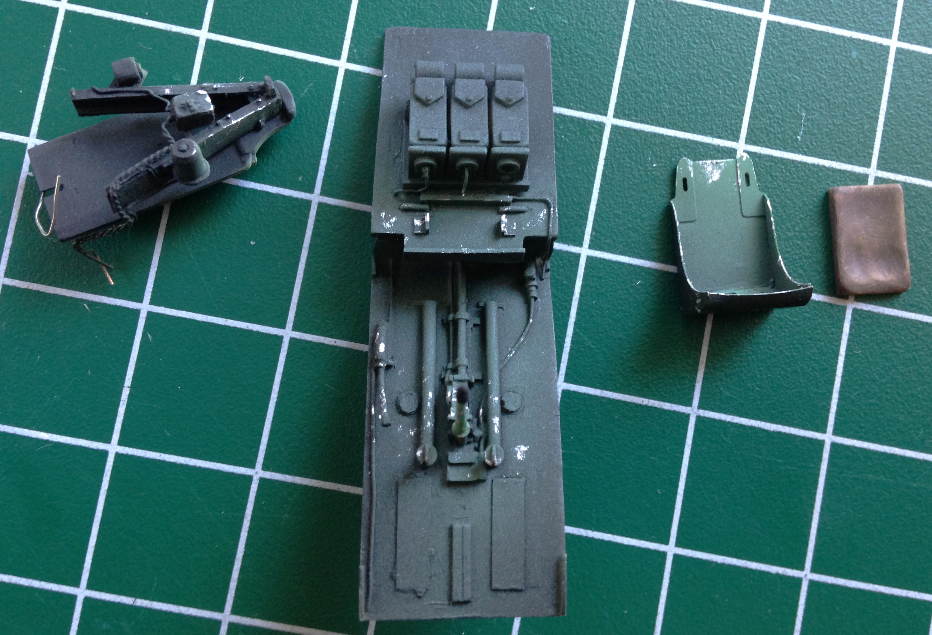
With the cockpit parts shaded, painted, and chipped, it was time to turn my efforts to the seat.
P-51 (Accurate Miniatures) Build #6 – Fixing Cockpit Detail Errors, Canopy Fitting
One of these days I sincerely hope and intend to take my own advice. That advice is, refer to references often. Doing so has the potential to save me self-created work.
After doing the modifications (I thought were) necessary to the cockpit’s sides, I actually did check my references. Had I done so before gluing the side panels in, it may have been easier to do the other modifications I needed to do. And what modifications were those? Well, nothing really major, just taking the details that are accurate for a P-51B out and putting in the ones that are more accurate for a P-51. In short, don’t take the printing on the package as factual. Verlinden’s details are good for a P-51B but are mostly inaccurate for a P-51. That meant I had to remove the incorrect details and put in the ones that are more accurate:
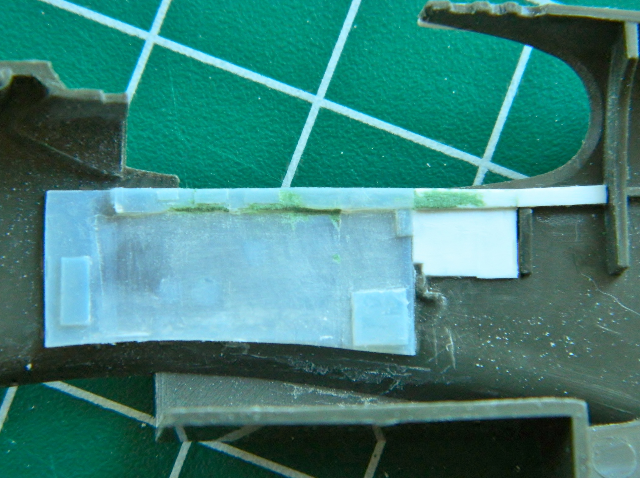

I used the Polish PE set (which were the easiest set I’ve yet worked with; the really small parts were scored to make the bends easy):


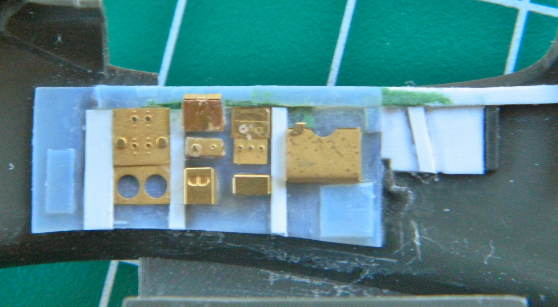
The holes in the various panels and boxes in the photo are places where there are toggle switches. I rummaged around in my wire inventory and found the correctly sized wire (.006″) (.0152mm) to replicate the toggles. The real trick was getting them aligned and glued in. Much colorful invective later, I got them glued in, let them sit overnight, and then trimmed them to length the next day (with much more colorful invective required), and then added the electrical conduits:


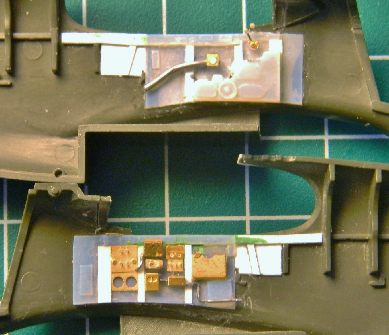
I’m also going to be vacuforming a new canopy from .010″ (.254mm) clear styrene. I’m going to need a form to pull the clear plastic down around and I’ve previously had good results using the kit-supplied canopy as my form. In order to do that, I’ve found it works better if I fit the kit-supplied canopy better than is allowed for in the kit. So the various parts were dry-fit first to get an idea of what needed to be fixed:


Then after determining where the fit needed to be adjusted, I added .010″ (.254mm) sheet styrene behind the front canopy section, to the fuselage, and then determined which areas of the canopy itself needed to be filled for a smooth transition between sections and added putty:


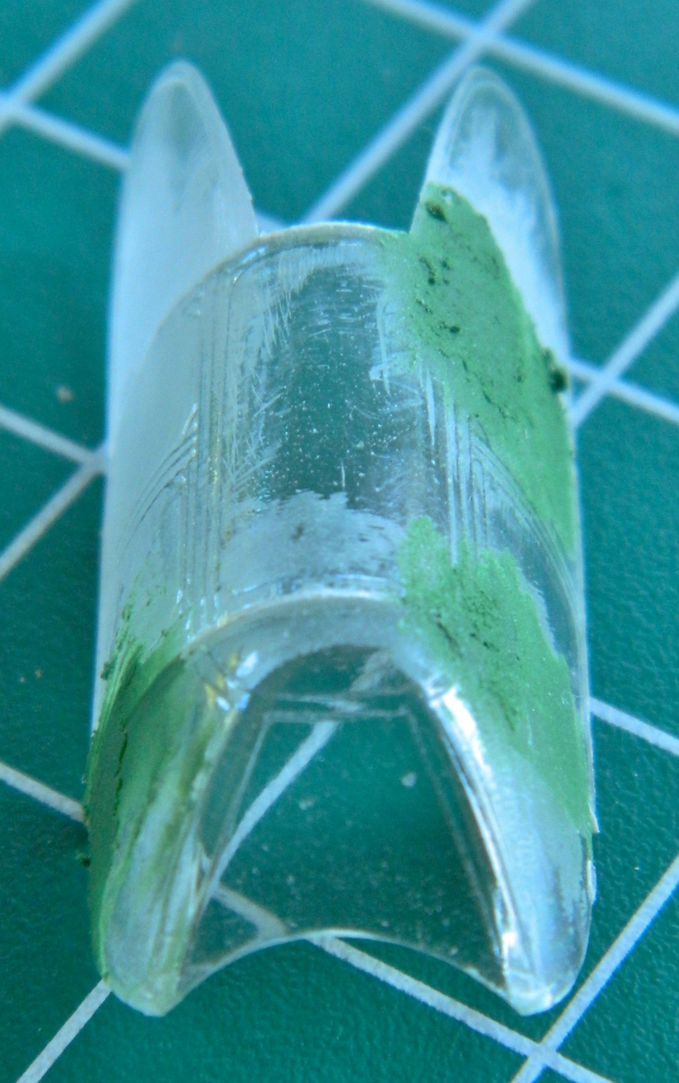


With all that taken care of and set aside for when it’s time to paint, I decided it’s time to address that instrument panel. I have a few ideas…some of which may actually work.
