


P-51 (Accurate Miniatures) after-action report

Total time building 421.0 hours (that’s about 17.541 24-hour days, 10.525 work weeks).
Begin date December 12, 2015; work suspended August 20, 2016; resumed work September 20, 2020, end date November 11, 2020.
Vendors:
Accurate Miniatures
P-51 Kit #3400 1/48 scale
Elementy
Photo Etch Set #S48-111
Verlinden (out of production)
P-51A Cockpit & Moving Surfaces #1789
Model Technologies (out of production)
American WWII Seatbelt Buckles and Mounting Hardware (PE)
MMD-Squadron Products
Vacuformed canopy #SQ9553
Ultracast
A-20 Havoc Props & Spinners #48242
EZ Line
Fine black
AeroMaster Decals (out of production)
Early Mustangs #48-106
My Opinion
This kit was produced in 1994, about the time that recessed panel lines were becoming the standard and not the exception. If you want to build this Out Of Box, don’t count on having a show-winner. There are a few inaccuracies, notably the guns (way out of scale and inaccurate) and the almost-standard landing gear bay that follows the opening of the landing gear doors instead of the main wing spar. The cockpit is also dated and the canopy needs to be cut open if you want to display it open. There is an enclosed Malcolm hood but it doesn’t fit. The tail wheel is molded as a single piece (lazy, in my unasked-for opinion). The flaps are molded in the up position so unless you want to cut them free, that’s what you’re stuck with. Still, if you want an Allison Mustang, this is the only game in town. Yes, ICM has a kit but it’s a re-box of Accurate Miniatures so that won’t help.
At 421 hours, this was a long build for a small model. A large bulk of that time was spent scratchbuilding a correct landing gear bay and then making molds of it and casting the parts in resin (I have other Allison Mustangs I want to do, all of them Accurate Miniatures). There was also a four-year hiatus taken due to me screwing something up that I didn’t know how to fix. Once I figured out how to fix it, the finish was relatively quick.
It feels good to have this finally done. I had wanted an Allison Mustang since 1991. I started with a resin conversion of the Monogram P-51B that replaced the fuselage with resin modifications. I scratchbuilt the cockpit just before I noticed that the cowling around Allison engines was much different than the cowling around Merlin engines. Whoever had built the masters for the resin copies didn’t correct the engine cowlings; I had Allison carburetor scoops on a set of Merlin cowlings. Before I could figure out how to fix that, I found the Accurate Miniatures kits but before I could get back to the build, I moved and lost space for my shop. Then, life took me off in different (sometimes very different) directions. So now, in my twilight years, I finally have the early Mustang I wanted 29 years ago.
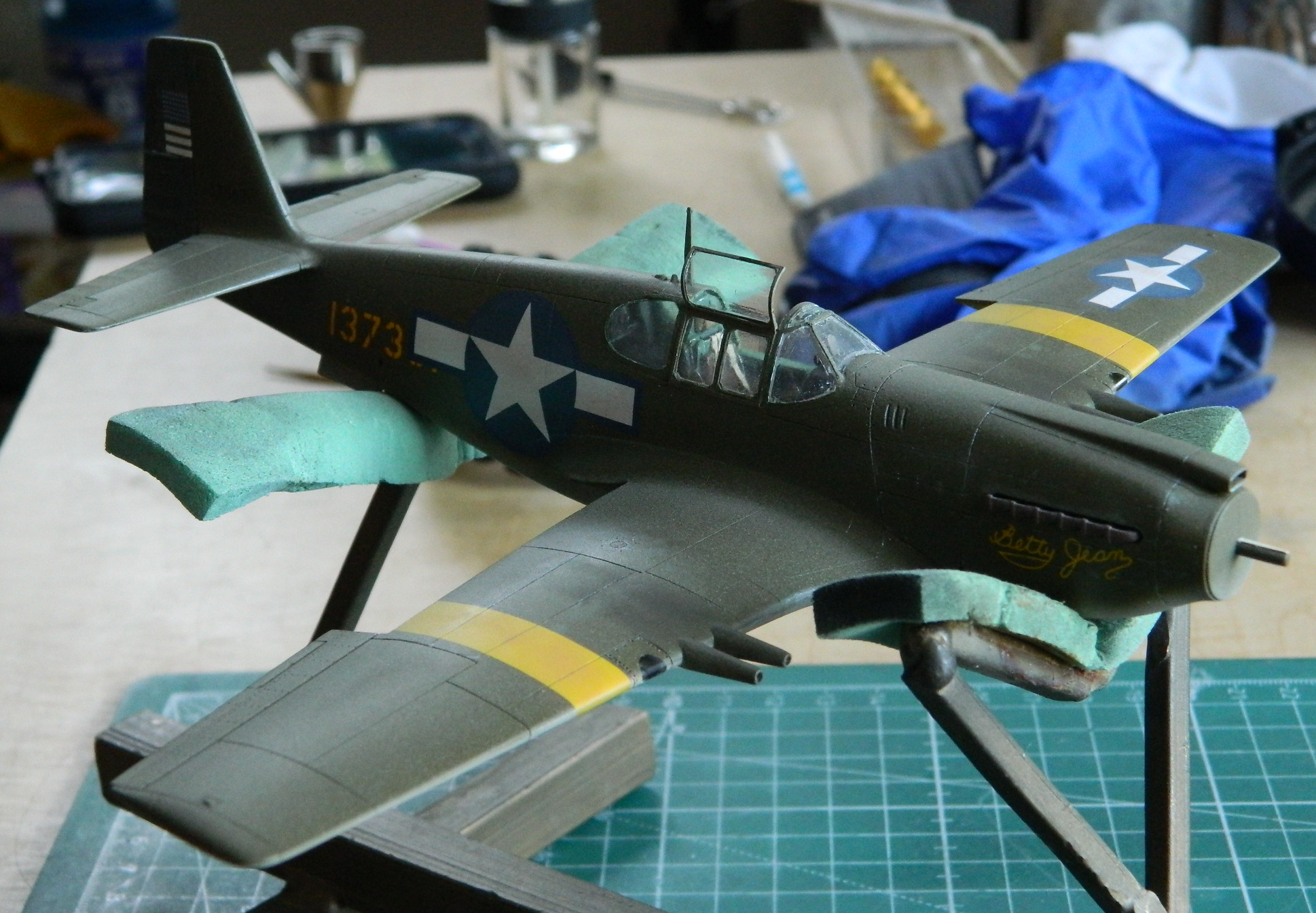
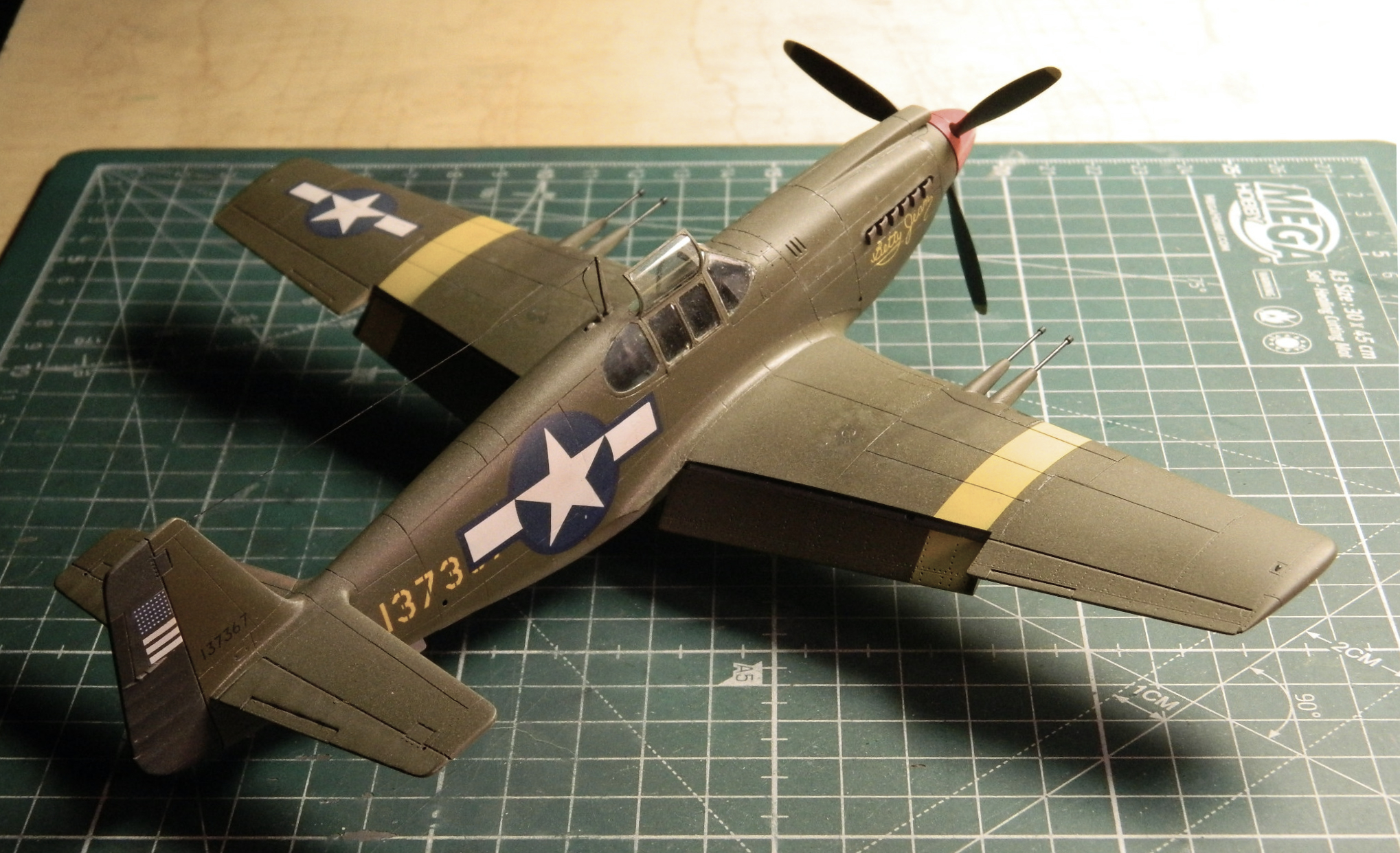
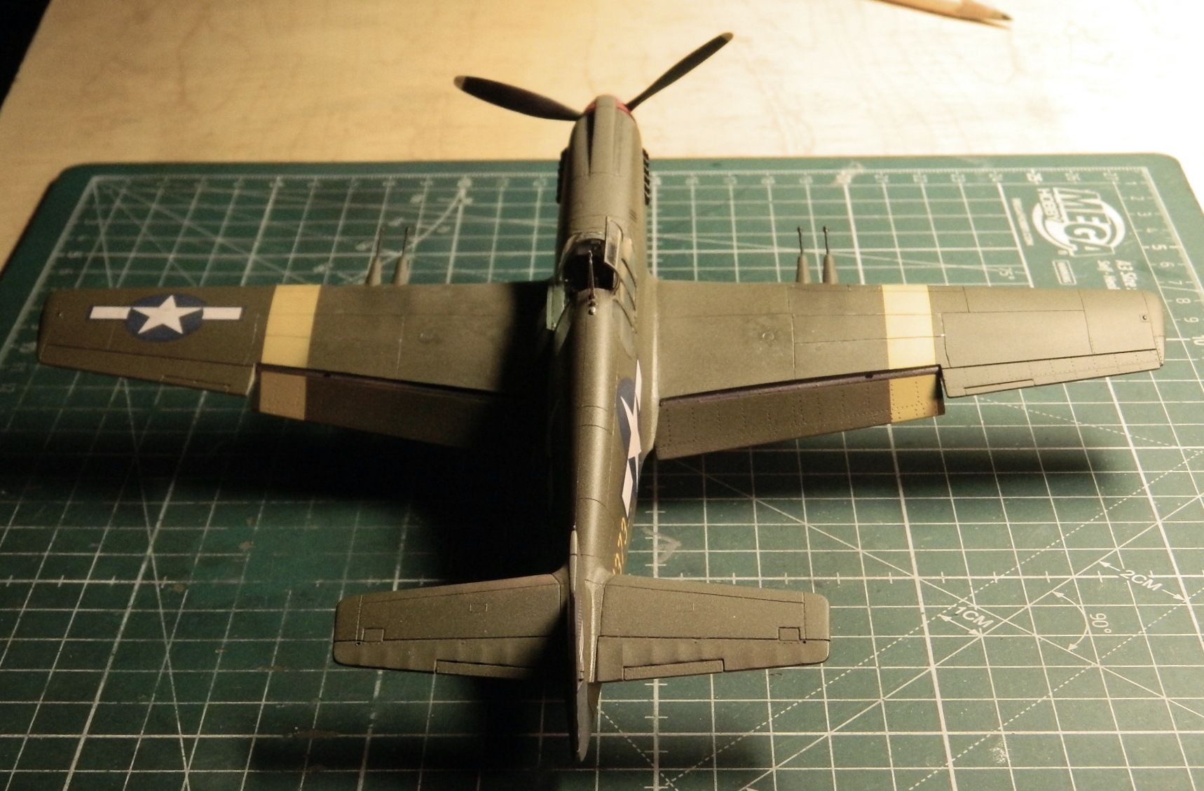
P-51 (Accurate Miniatures) Build #16 – Painting, Final Details, and DONE
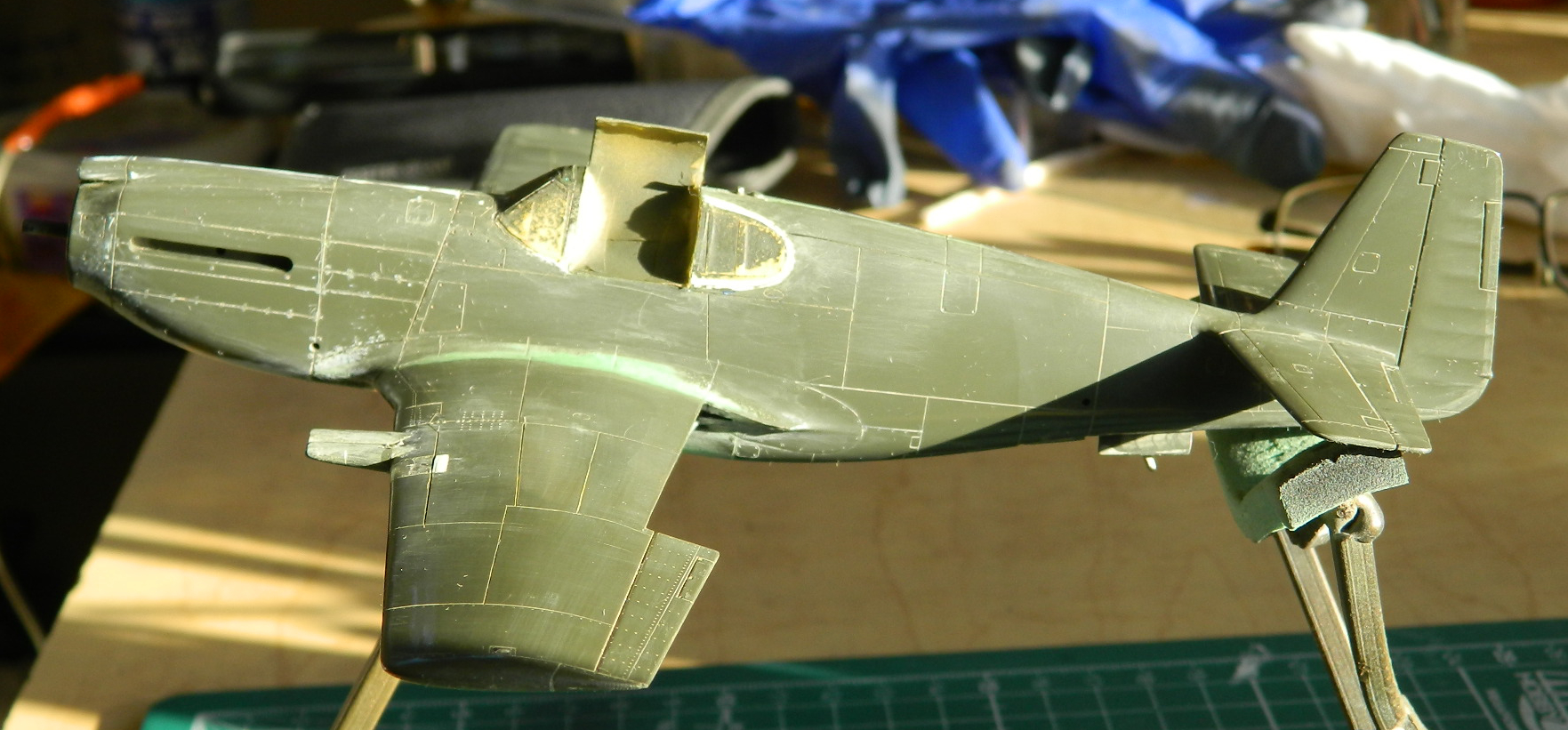
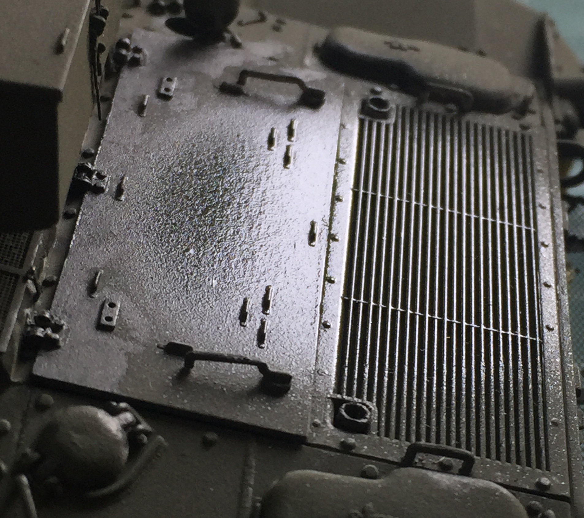
Getting ready to paint things is what is driving the build at this point. I needed to add fasteners that had been knocked off during handling and once that was accomplished, I protected the fragile resin decals with a coat of Tamiya XF-28 Medium Gray (15 parts) and Tamiya XF-2 Matte White (2 parts):

Everything I’d already painted was masked off so that finish colors could be laid down:

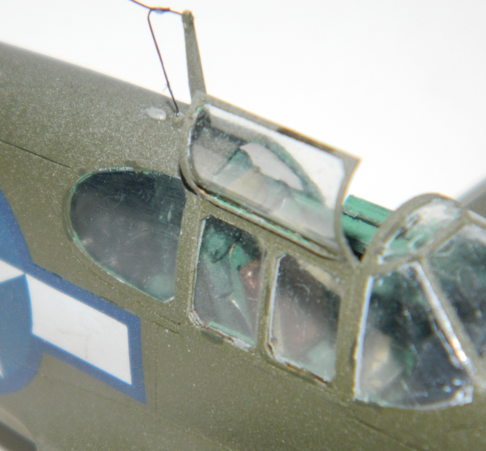
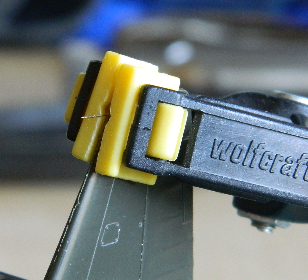
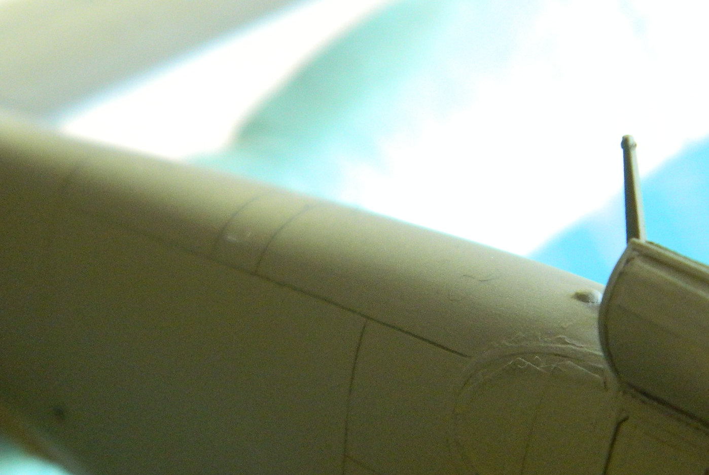
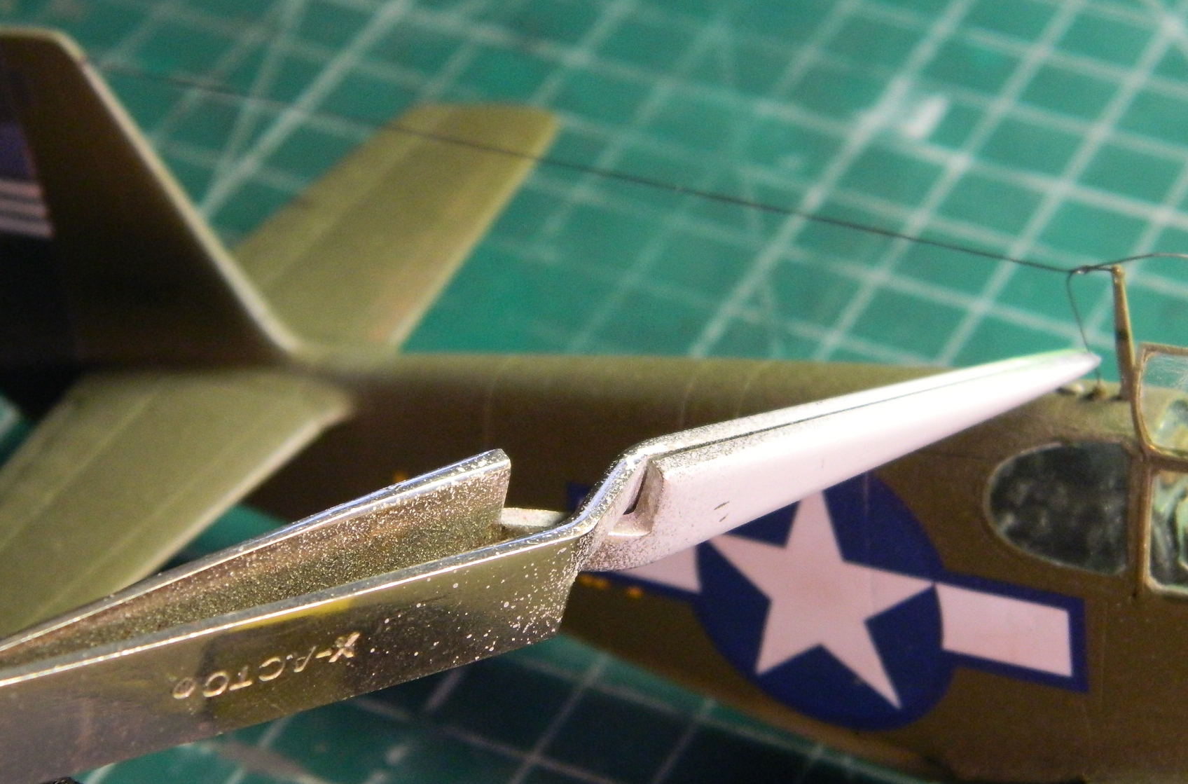
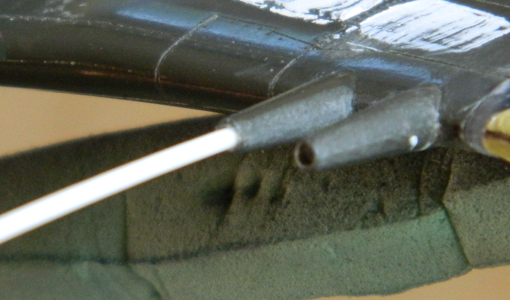
My usual method of doing antenna wires has been the classic stretched sprue “fun.” Time marches on (quoth the old fart in the mirror who is really surprised at the “old” part of that) and technology evolves. Rather than take the stretched sprue path (which isn’t really all that smooth and hassle free in general, and often very annoying in specific), I had a roll of EZ Line delivered (“fine,” .02″ (.508mm) black). I needed to drill out the tip of the antenna mast and vertical stabilizer to accept the line. In doing so, I discovered that the front upper half of the leading edge and about half the top of the vertical stabilizer hadn’t been glued! Easily fixed, and I added a small piece of stainless steel wire to keep the opening to socket the EZ Line into:
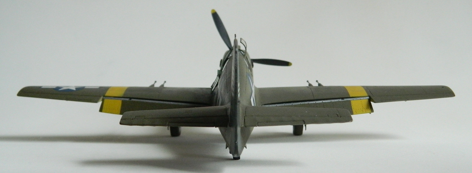
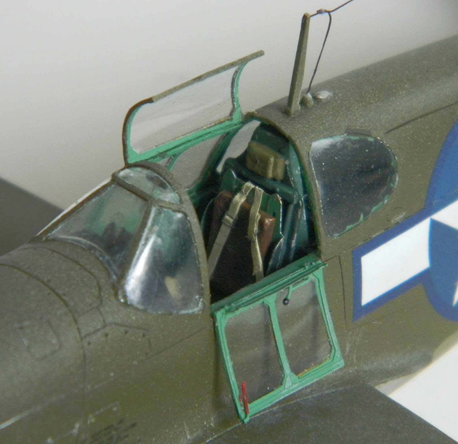
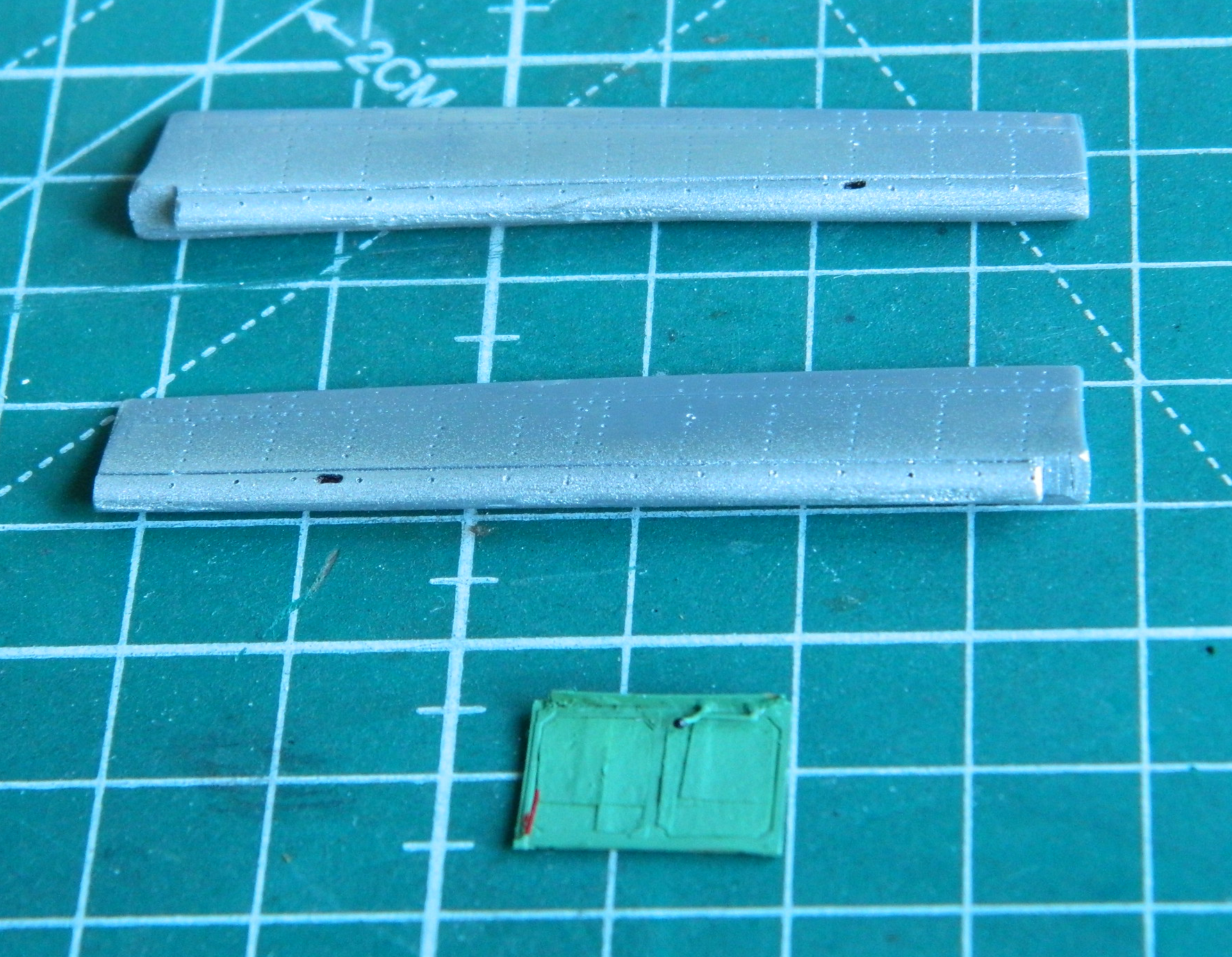
The leading edge of the flaps where they rotate into the wings is unpainted aluminum. Since I’m dealing with a resin part, that area was painted Tamiya XF-16 Flat Aluminum. I’d also painted the interior framework of the drop-down left side of the canopy using a mix of Tamiya XF-71 IJN Cockpit Green (3 parts), X-5 Green (1 part) and XF-2 Flat White (1 part):
To prepare for wear and chipping, I put down a coat of XF-16 Flat Aluminum in the areas I thought would need it:
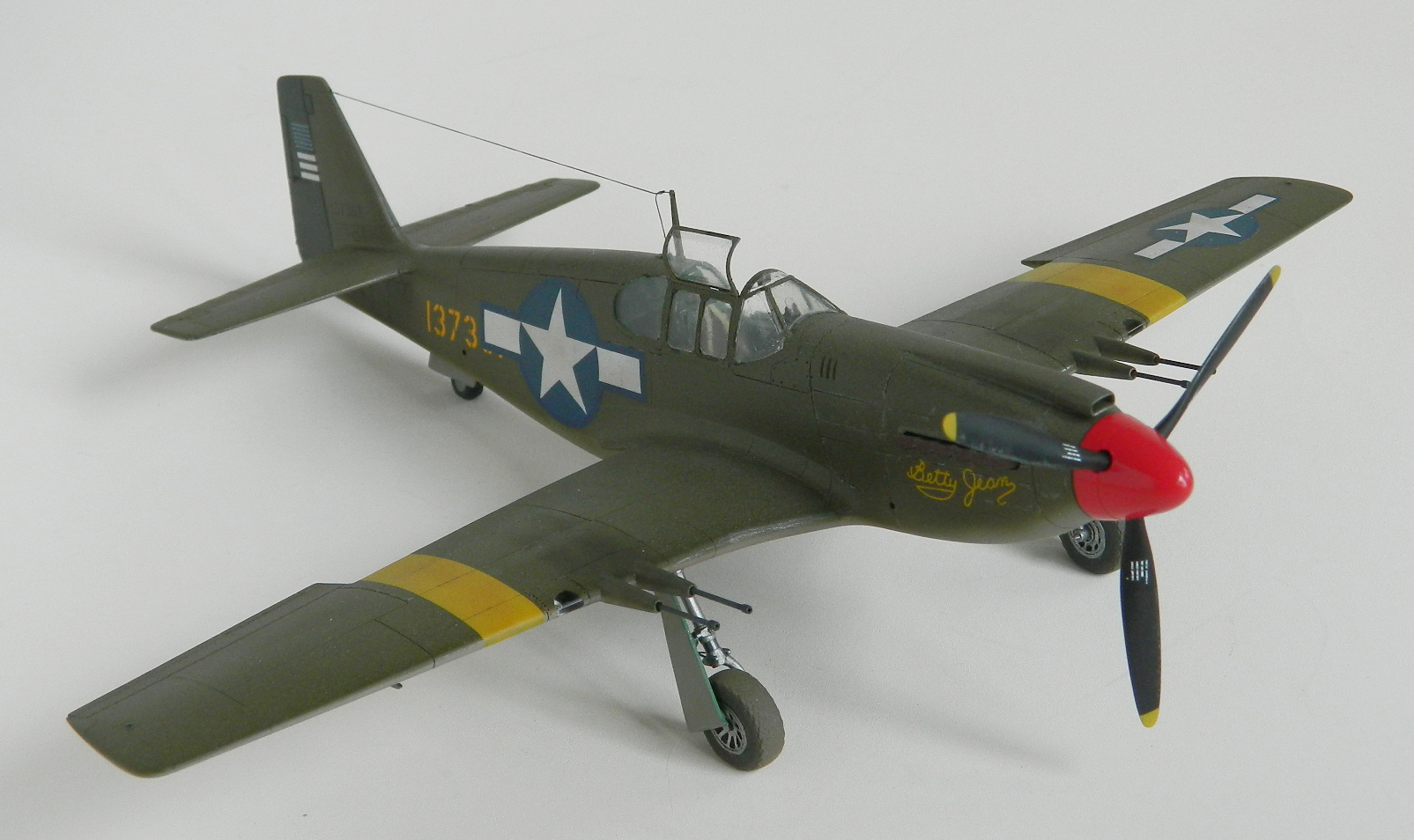
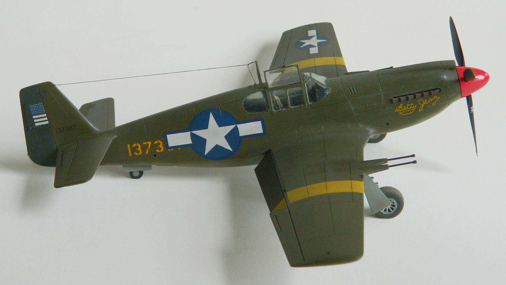
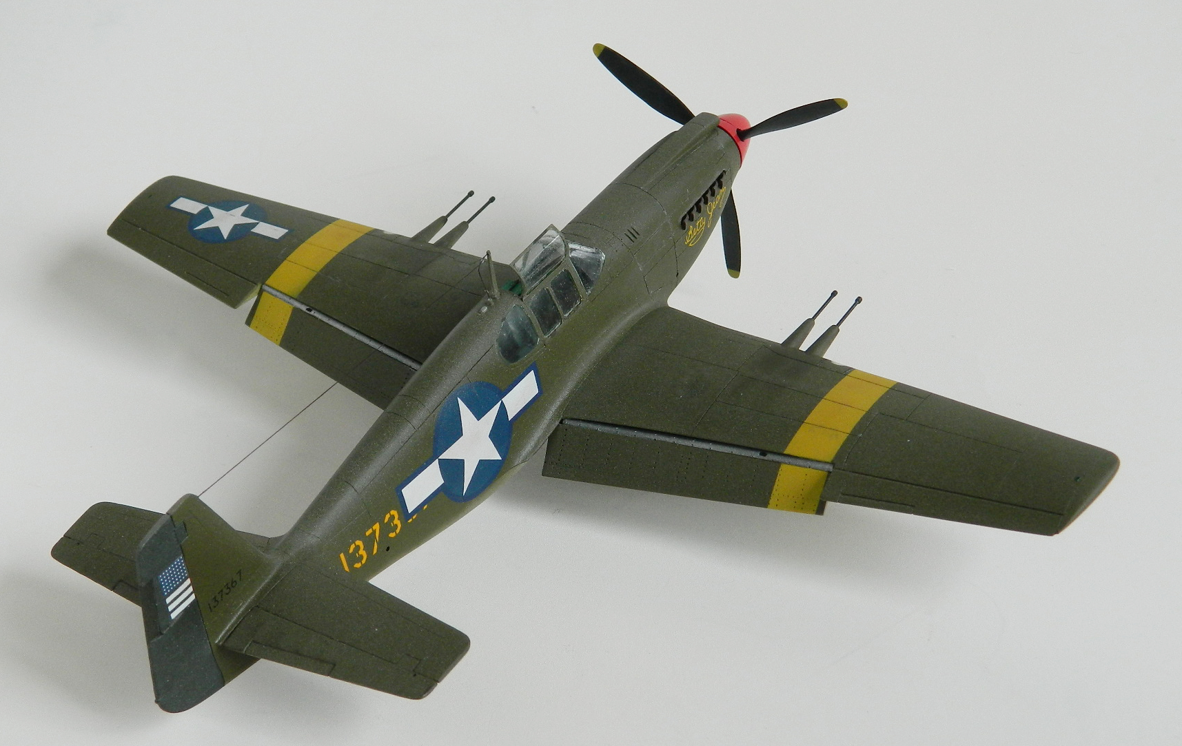
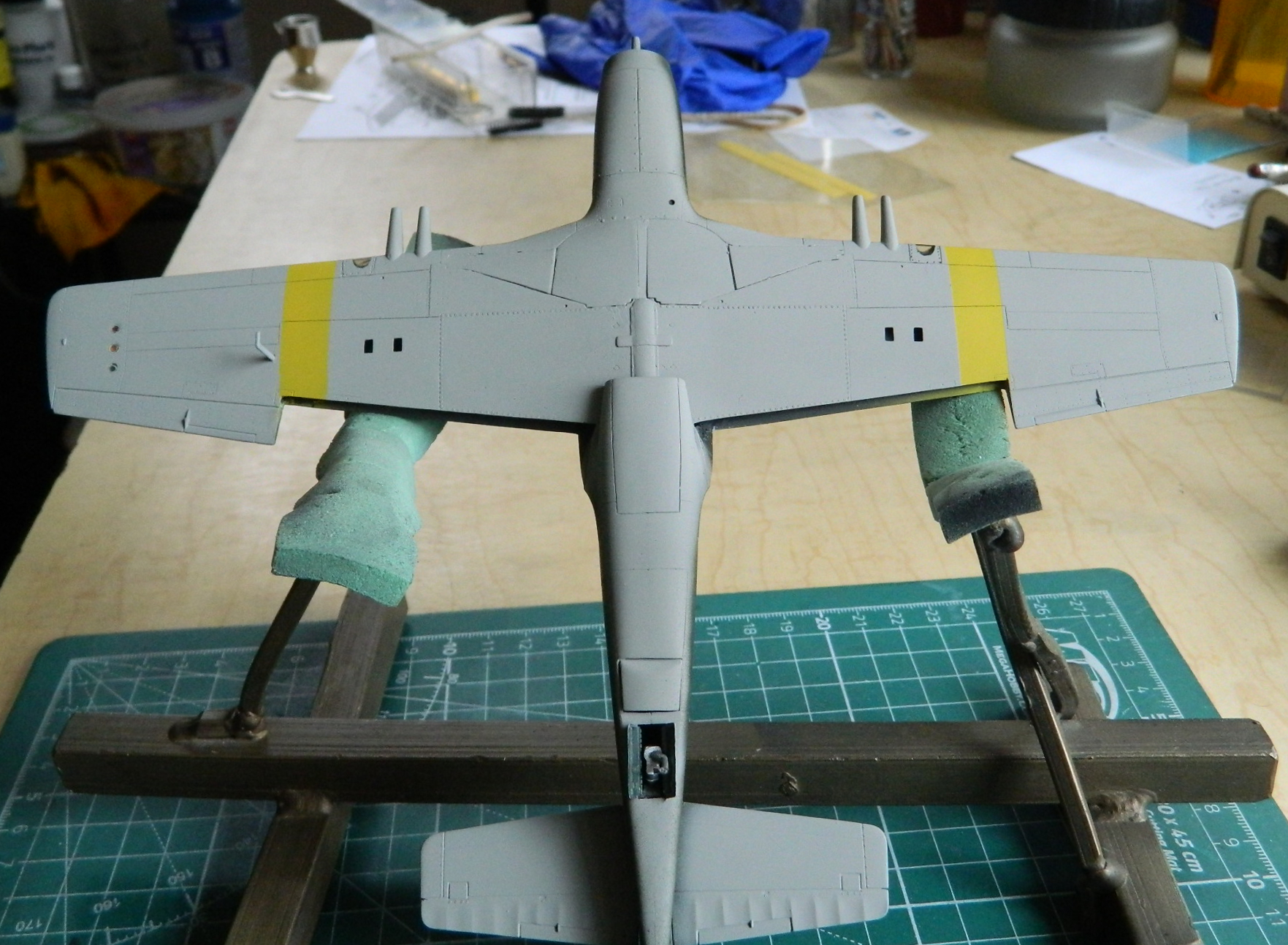
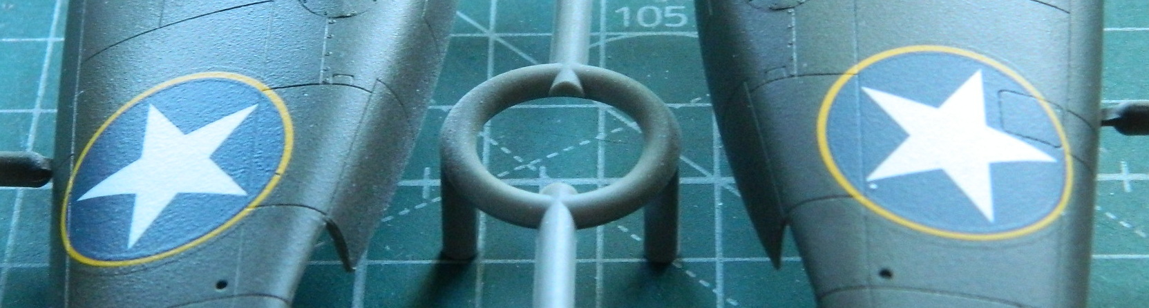
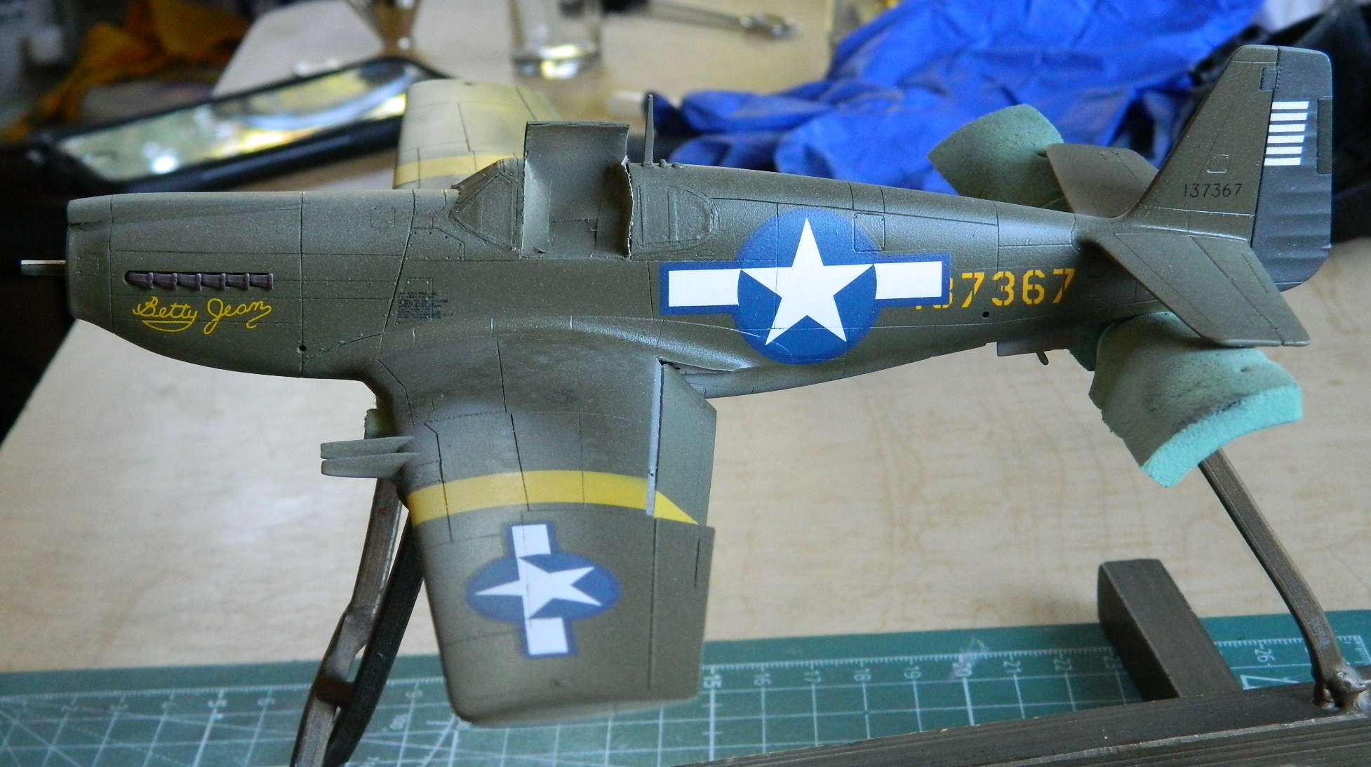
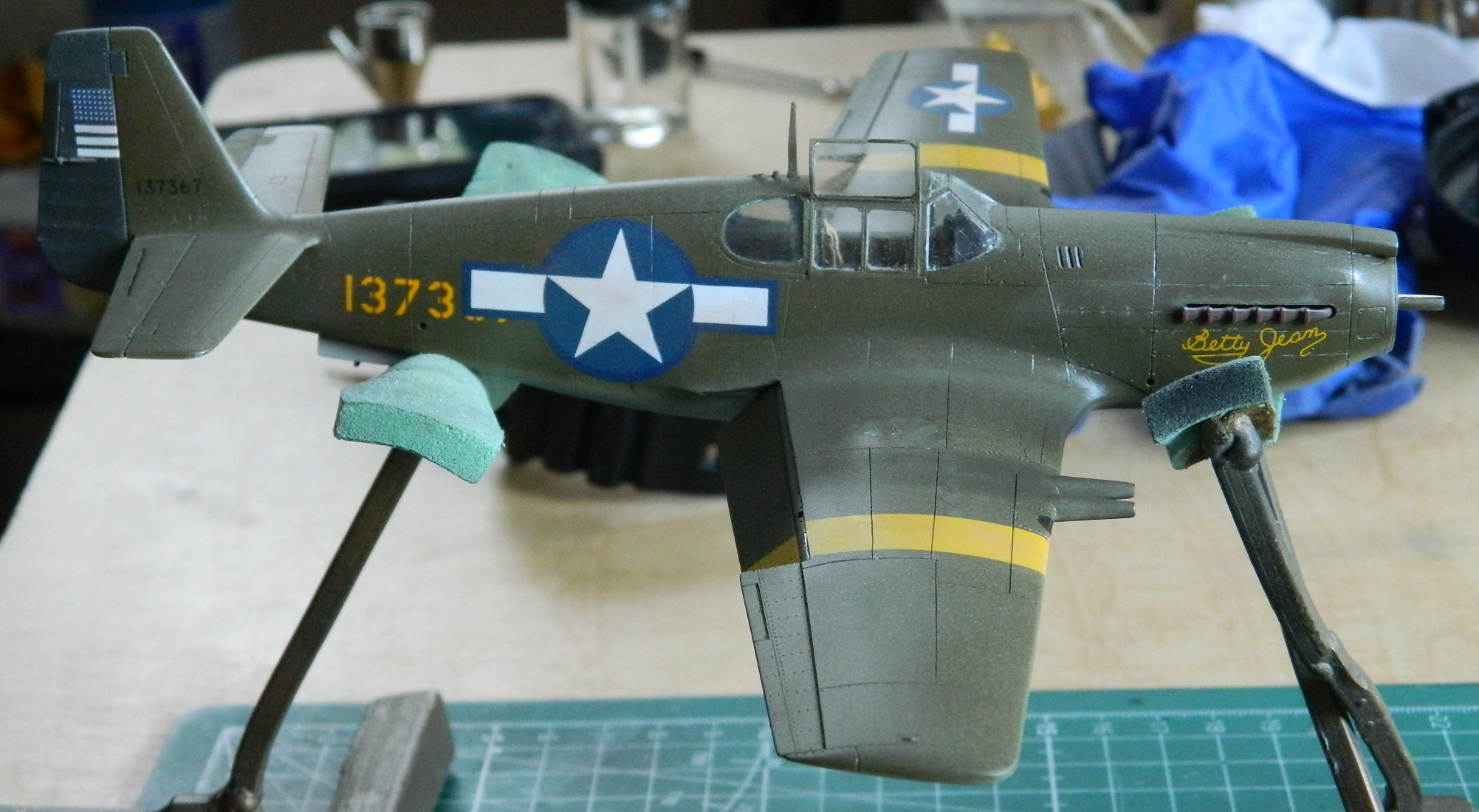
Part of the markings that the 154th Reconnaissance Squadron used starting when it was based in Tunisia in 1943 and continuing through its move to Anzio in 1944 were yellow bands on the upper and lower wing surfaces (I’m thinking that was to help differentiate it from the Bf-109 which, if you’re scared enough…and I certainly would have been…look much alike). The kit supplied decals for these bands; I decided to paint them on instead. Tamiya XF-3 Flat Yellow is (unlike myself) FAR too bright. I added one part of Tamiya XF-60 Dark Yellow to three parts of the Flat Yellow and ended up with something VERY close to the color of the decals. Once the paint set up overnight, I added the 18″ (4.572m) (scale, obviously) masking for the bands:

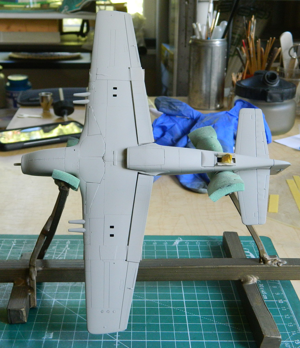
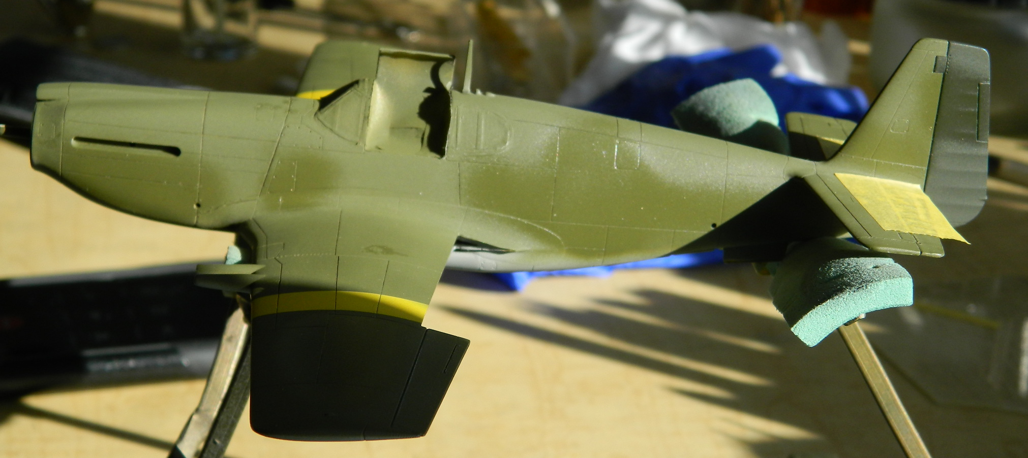
With the yellow masked, I shot the underside with the same medium gray/white mix I’d used to protect the resin decals:

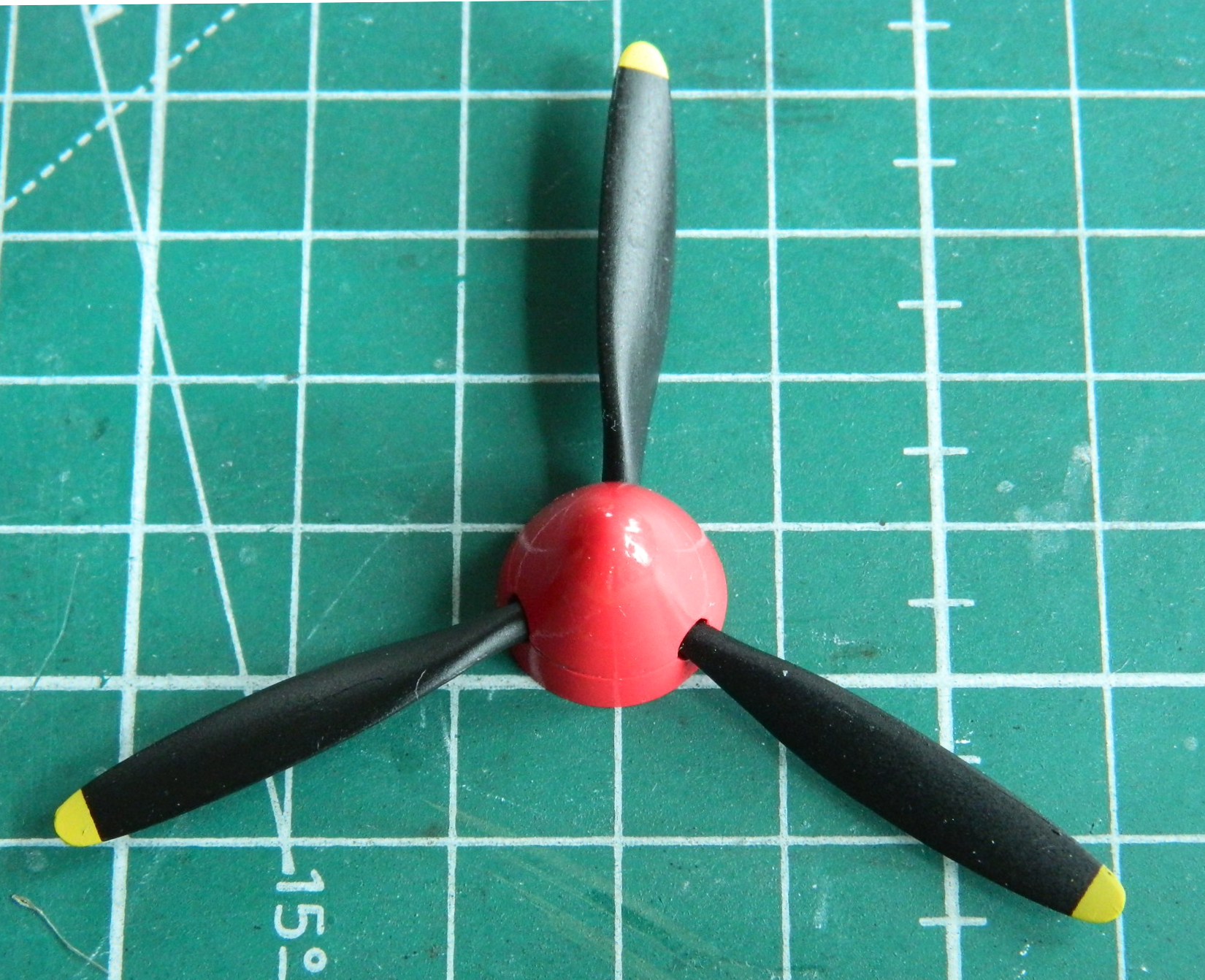
I wanted the gray to sit overnight before I turned it over for the OD Green. While that was set aside, I painted the prop and spinner (the previous day using Tamiya’s rattle can flat black TS-6 and the toned down yellow of the ID wing bands on the tips; the spinner was 4 parts Tamiya X-7 and 1 part XF-2 flat white), which is more satin anyway, (which is what I wanted ) and assembled them:
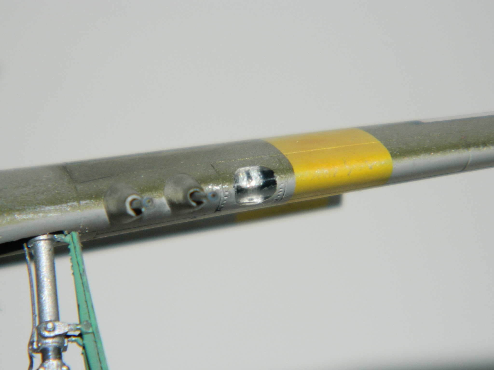
I then cleaned the tarnish off the brass barrels of the cannons and treated them to a soak in Birchwood Casey’s Brass Black. Once they were out of the soak and lightly buffed, I painted the muzzle bands Tamiya’s XF-69 NATO Black (which is more of a dark gray):


The next day I put down a coat of Tamiya’s XF-XF-62 Olive Drab on top. The demarcation between the two colors is simple so I used a tight spray pattern at a lower air pressure:
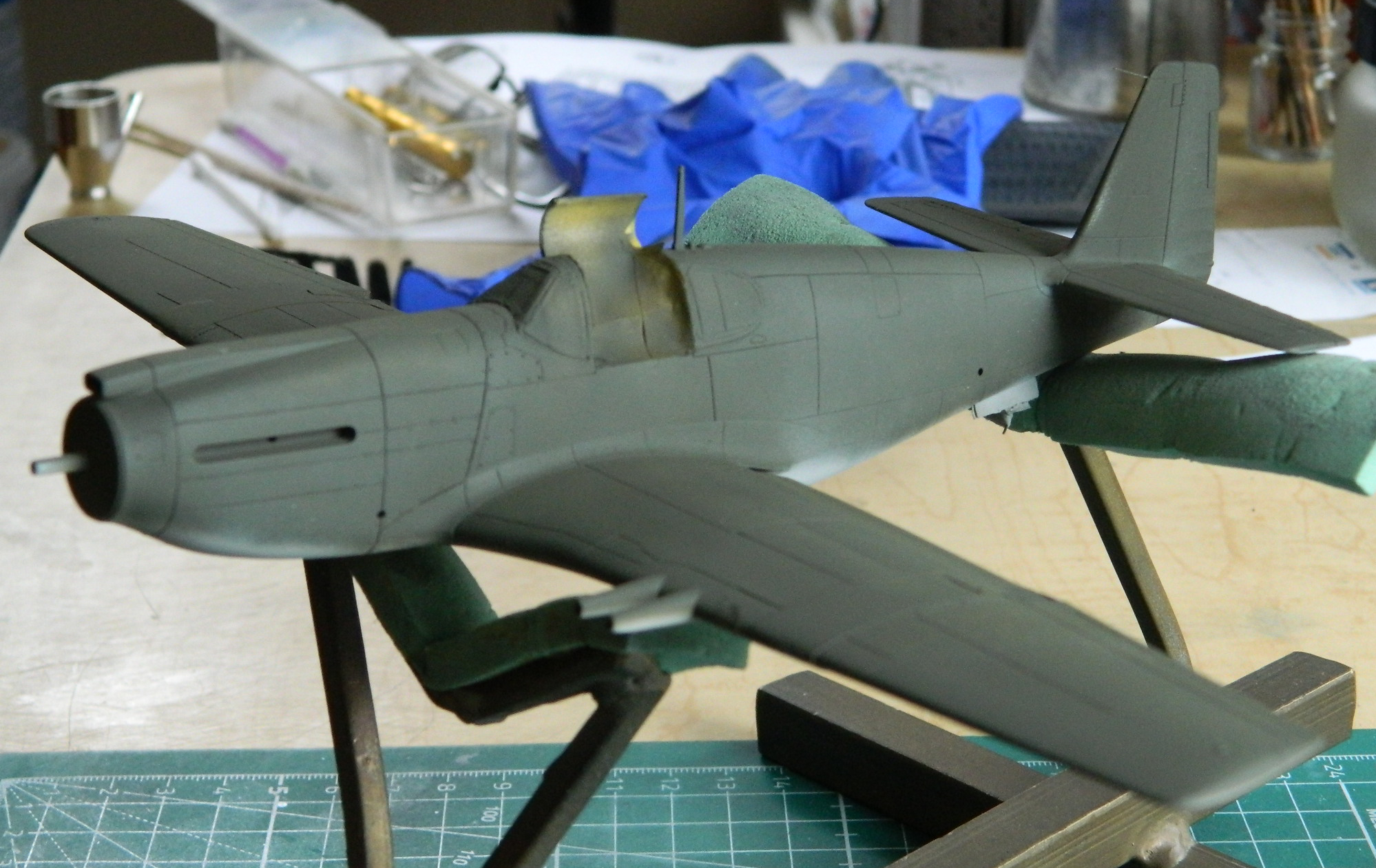
It took a couple of back-and-forths between the gray and OD to eliminate what little overspray occurred.
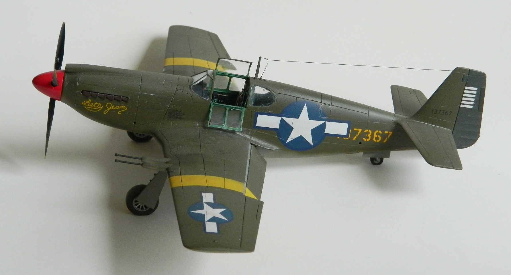
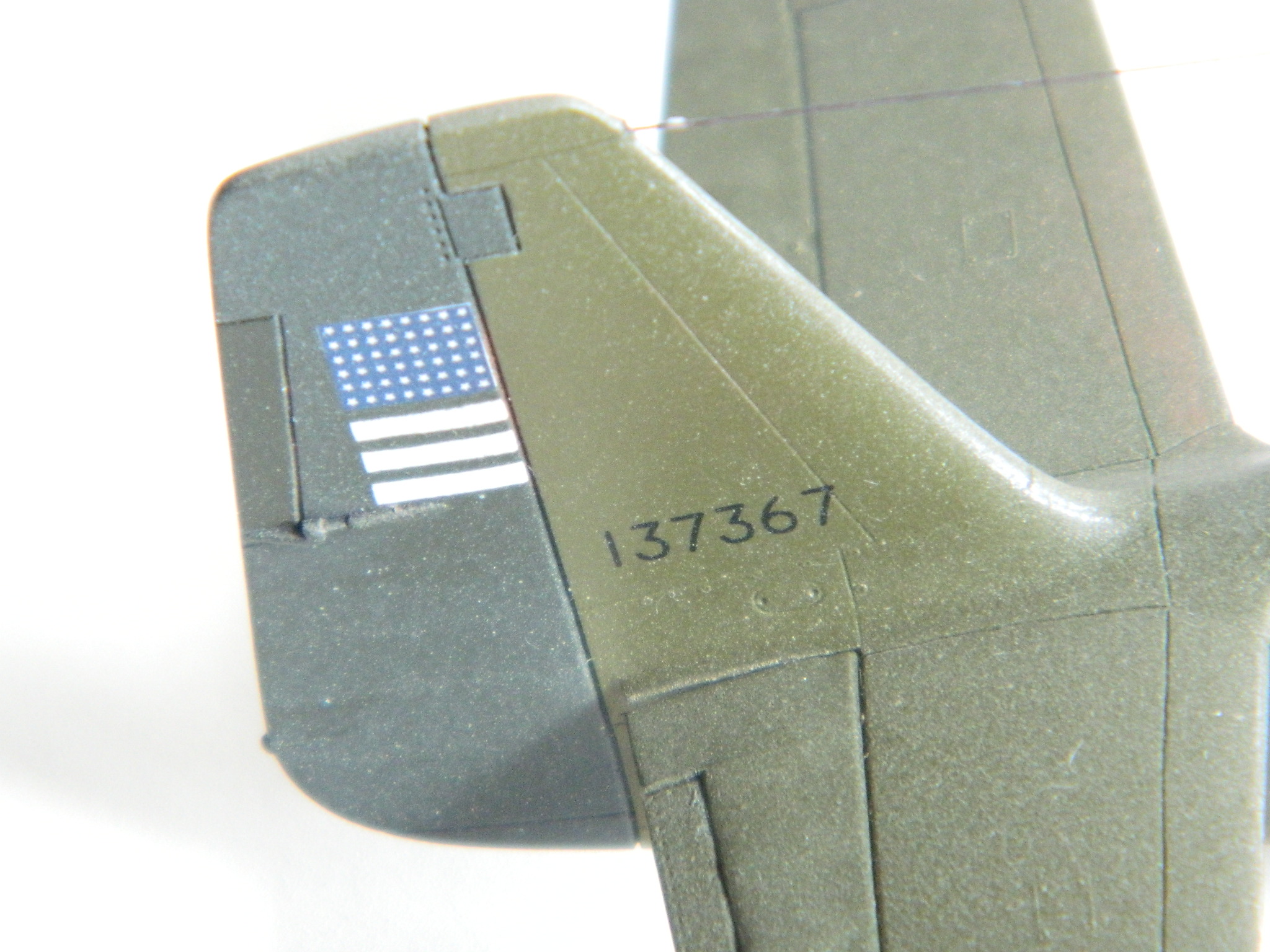
My one reference photo of this aircraft shows that its original rudder had been replaced with a different rudder (most likely from the base’s boneyard) and the OD was a different shade. I added 2 parts NATO Black to 15 parts OD:

The one photo I have of this aircraft (from P-51 Mustang in Action, by Larry Davis; page 12) isn’t exactly conclusive as to color (no surprise since it’s a b/w photo) or tint (the rudder is deflected to the left and catches sunlight more directly). After unmasking the vertical stabilizer, I was unsure as to whether or not I’d gotten the difference right…something that would mostly fix itself shortly. (Ominous thunder on the soundtrack.)
I unmasked the yellow bands and landing lights and put down Tamiya’s X-22 Clear Gloss where I was going to put decals, which in this case were on the fuselage and upper wings. The lower wings didn’t get any markings other than the yellow bands:

I had taped the flaps into position so that the bands would align and I painted the exhaust tips Tamiya XF-68 NATO Brown (14 parts), XF-69 NATO Black (3 parts), and XF-7 Red 9 (1 part) and removed the masks from the drop-down canopy side:

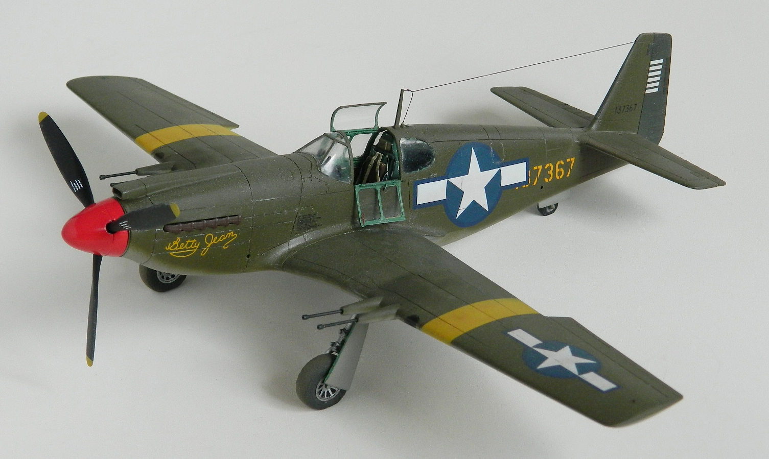
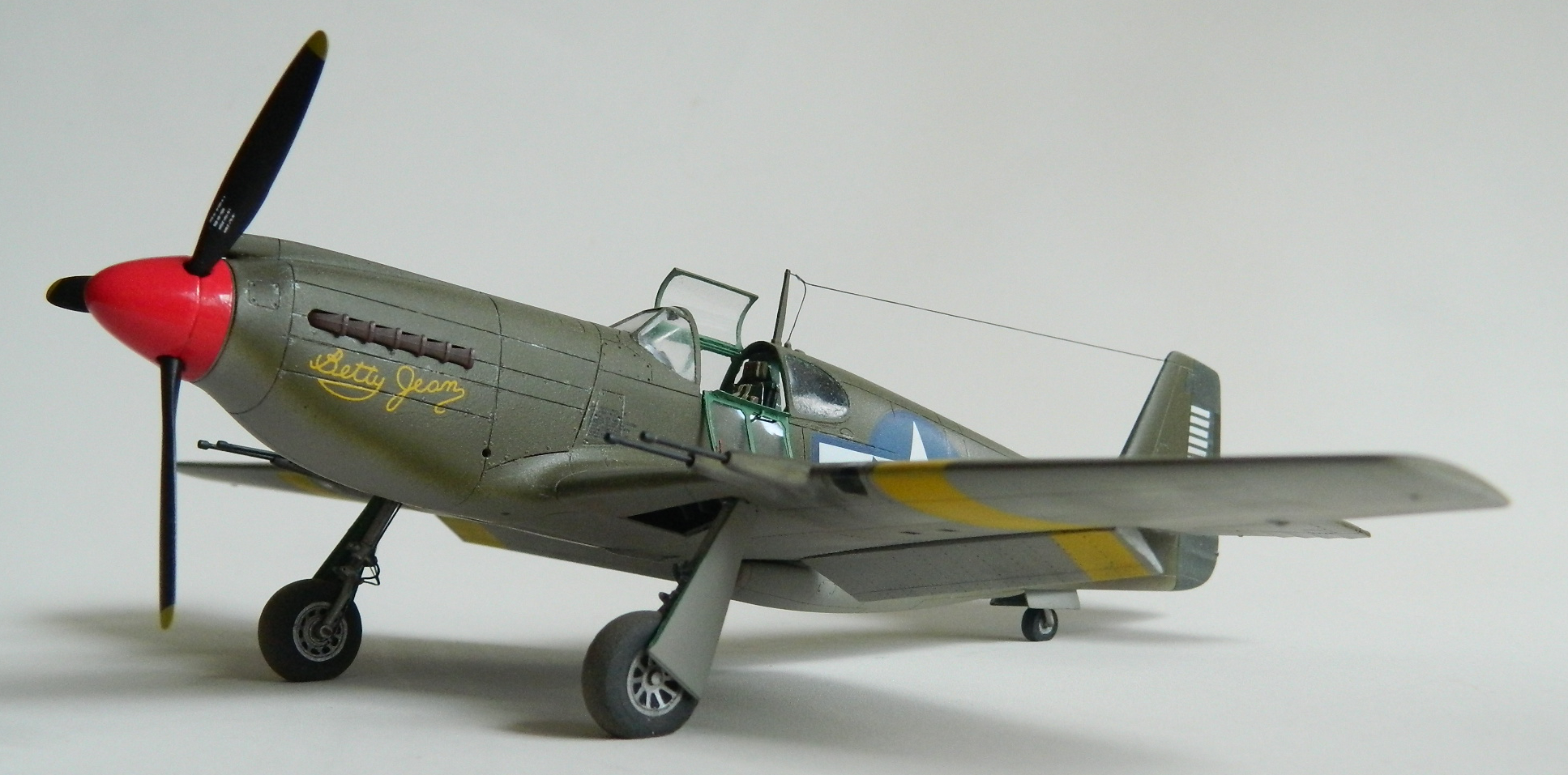
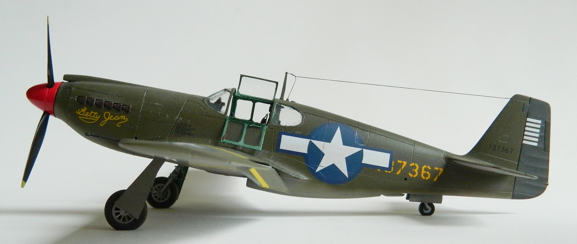
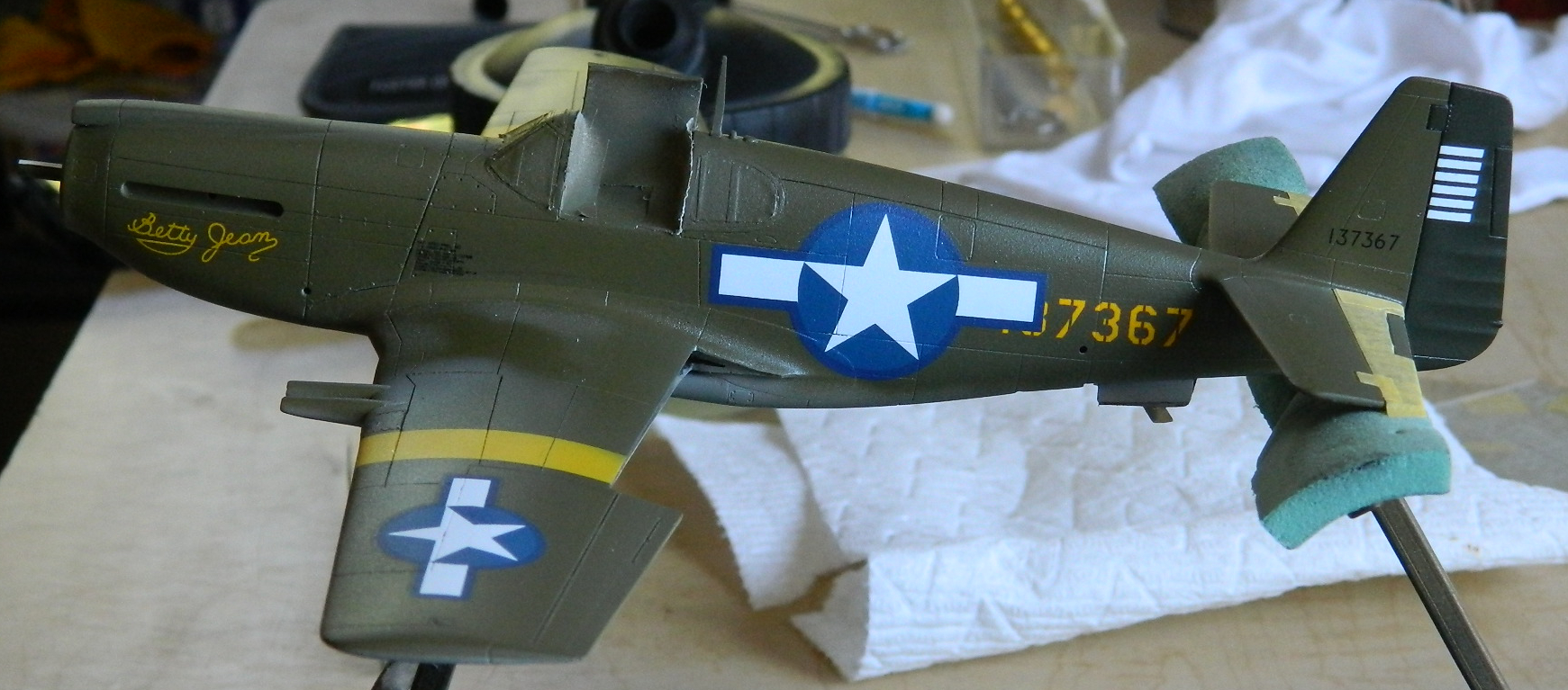
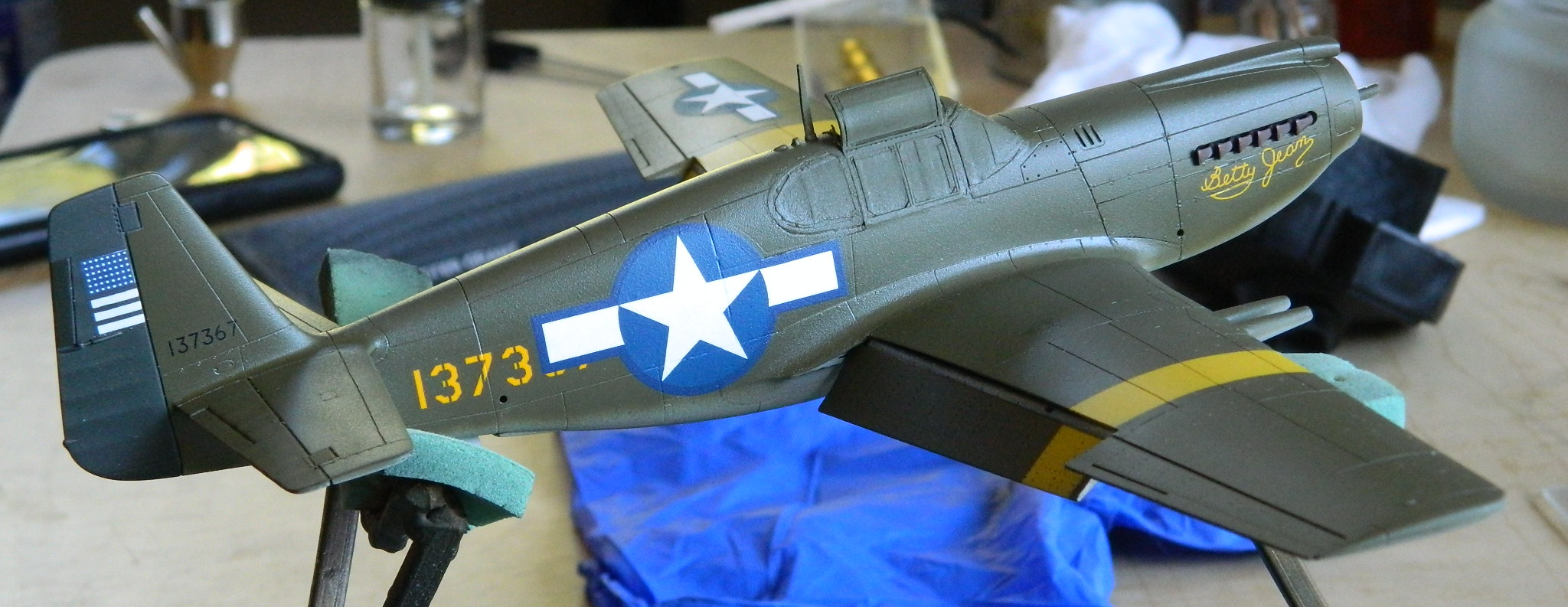
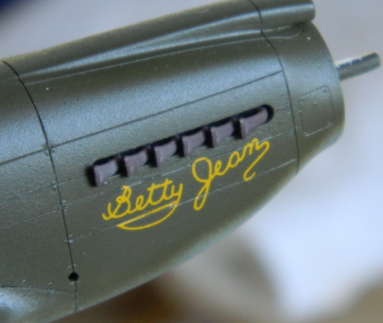
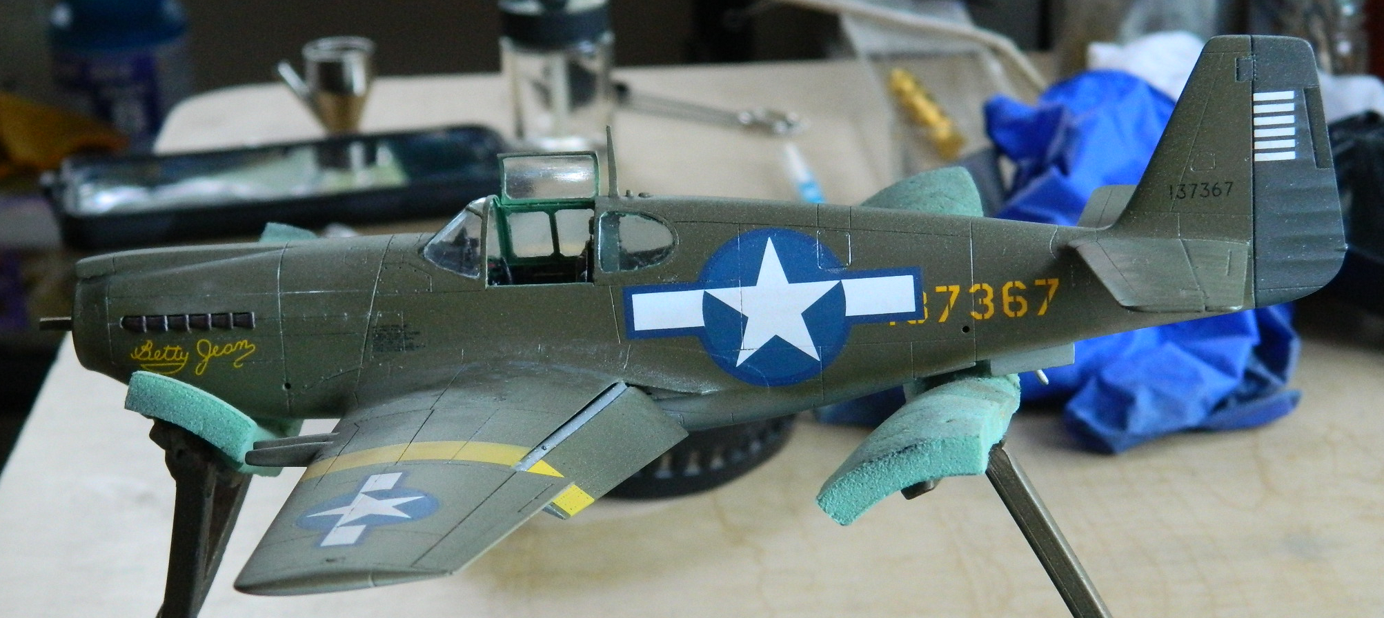
After letting the clear gloss sit overnight, I started adding the decals. I was using an old Aeromaster decal set,”Early Mustangs, #48-106″ as it had the markings for “Betty Jean” that I wanted to use (to match that one reference photo). The only kit decal I used was for the data panel on the left side of the fuselage. Yeah…the serial number on the panel doesn’t match the serial number of “Betty Jean,” but one would need a loupe to see that and I am NOT letting anyone get that close to this. The kit’s decal and the clear-backed Aeromaster decals settled down nicely with Micro-Sol. The stars-and-bars did not, requiring Walther’s Solvaset to behave the way I wanted them to…multiple applications of Solvaset. However, in their defense, these decals did not behave like they were over 20 years old:


The only problem I had with the decals were that they were too large. The fuselage insignia could have been 10-15% smaller as could the insignia on the wing (I used a smaller one of the same set intended for a different aircraft).
Remember the ominous thunder of earlier? Here it comes…
I got lazy. Brainfade. Caffeine deficiency. Or perhaps just plain dumb. Dunno. What I did, however, was use Tamiya’s rattle can TS-80 Flat Clear. To say that it didn’t play nicely with the clear gloss would mistakenly lead one to think that it played at all with the clear gloss. As it dried, it shrank and cracked. Not fun. What was REALLY fun was that the TS-80 also dissolved the decals a bit:
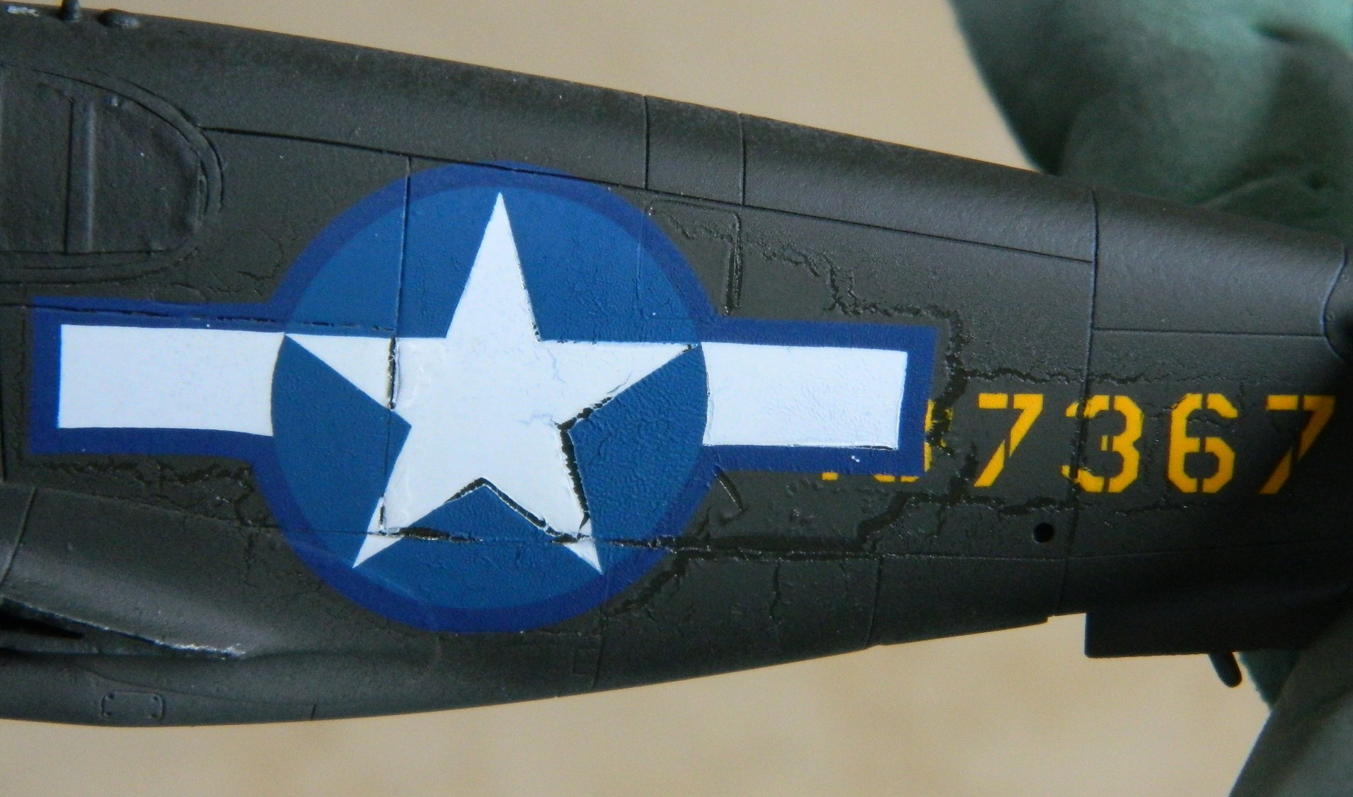
I usually read all and every direction on a product I’m going to use and I thought I’d done the same with this fornicating TS-80. Guess what small print I missed on the top of the cap:
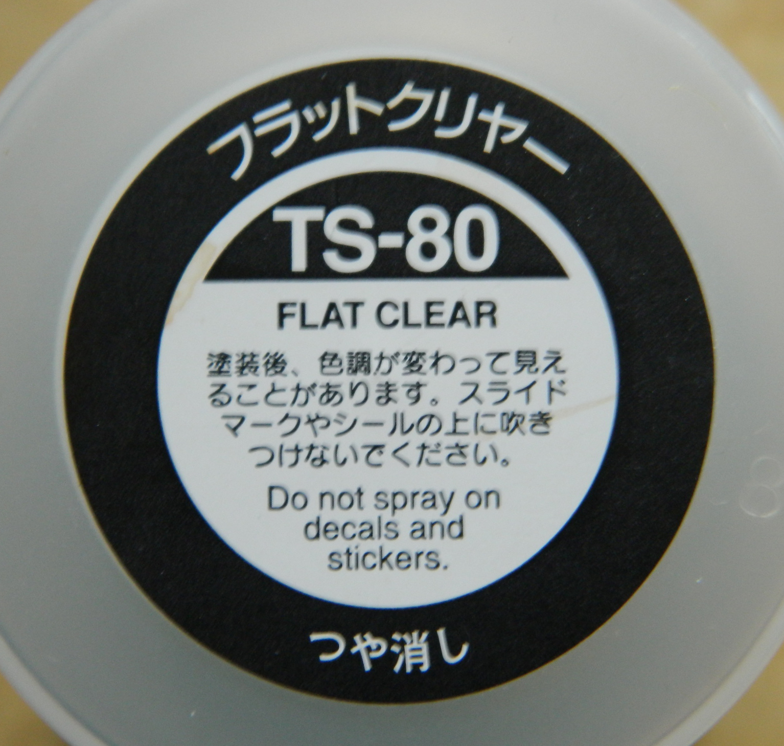
I doubt you can imagine how FORNICATING THRILLED I was to read that…after it had dissolved the decals. (If you can imagine that, you have my sympathies.)
That was JUST what I wanted to see happen to an old, out-of-production decal set. I went online and the first set of these decals I found were over $50. After changing my knickers, I came back and found an Etsy vendor, WingsAndRails.com who had a set for about half that [EDIT: Guess what decals came with the rebox of Accurate Miniatures P-51 from ICM. Betty Jean.].
I almost sprained my fingers ordering a set.
While I was waiting for them to arrive, I started a process that I’d gotten quite used to during the SR-71 build…stripping paint and repainting things. You know…mix and paint the yellow (didn’t shoot aluminum this time), mask the landing lights and bands, etc.:
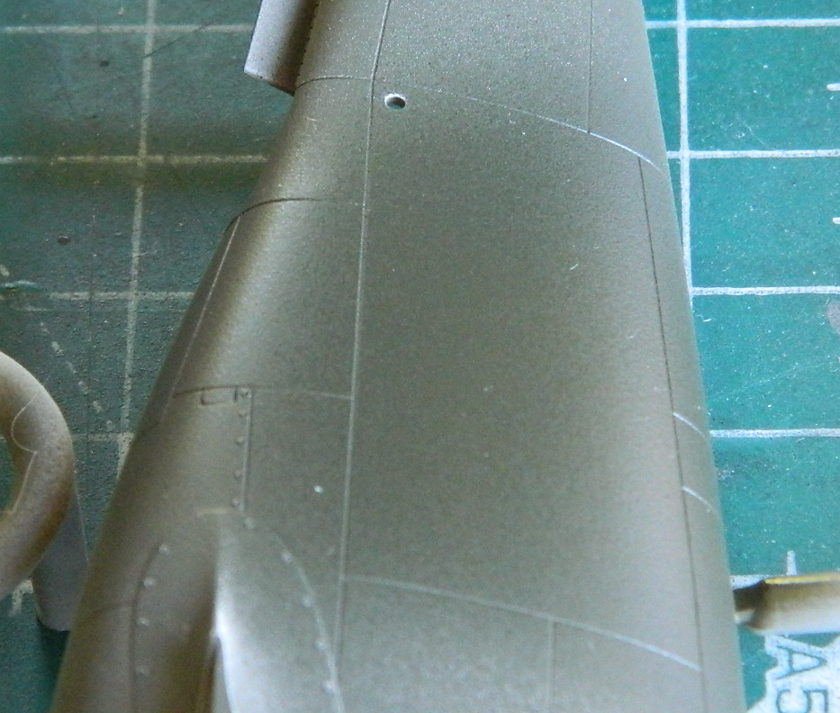
One of the other differences in the second paint job is the color. I noticed from a couple of WWII color photos that the Olive Drab was more green than the first Olive Drab I used. For the second painting, I mixed Olive Drab (6 parts) with Yellow (1 part) and Flat White (1 part). All looked okay until I looked at the fuselage seams in bright light. Either I had not done a proper job the first time (like that ever happens) or the denatured alcohol did more than just remove paint. Regardless of the cause, I found these two spots:
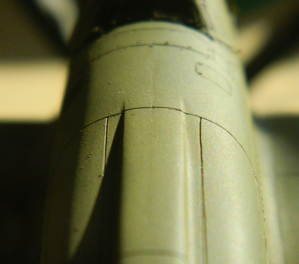
I removed the paint (and probably more putty) and redid the seams:
Better:

Since I had such a grand time (sarcasm…just another service I offer) (constantly) with my first attempt at doing decals properly, while I was waiting for the next set to arrive (a habit I really have to get away from) I decided I needed a bit of practice. I painted fuselage parts from the spare kit:

I went through the decal process of clear gloss, decals (avec solvent), and clear topcoat. This time, however, I used Tamiya’s clears (more on all that in a bit). Instead of putting clear gloss down first, I recalled having very good luck with the SR-71 putting decals down directly on top of a flat color coat (it was heresy then, it’s heresy now…all I can say in my defense is that it worked). Instead, I put down Tamiya’s X-35 Semi Gloss Clear first on both sides:
Then I used kit decals that I would not have otherwise used (they have the markings for Operation Torch which is a yellow band around a round insignia and no bars) and used Walther’s Solvaset on them:


After letting them sit overnight, I shot the Semi Gloss Clear over the left decal and Tamiya’s XF-86 Flat Clear over the right decal:
I decided I like the clear flat better than the semi gloss and decided to go with that.
Now…a bit of a digression about clear flat paint and why I seem to be struggling with it.
Prior to my present stint at modeling, the last time I did any of this work was in 1991. In that year, Polly S was still producing paints (and I recently found out that Polly Scale, primarily rail road paints, has also shut down) and their clear flat was magnificent. Thinned with water, it went down perfectly and left an outstanding, even, flat finish. When they closed operations of their S division, that wonderful paint vanished. When I picked this hobby back up in 2014, I found out that Micro-Mark had gone to Vallejo with color chips to replicate some of Polly S paints, and one of those was clear flat. Vallejo’s clear flat is NOT Polly S clear flat. It really requires being run through a fine screen to remove chunks that form (and I can stir that stuff for AN HOUR and still have my airbrush spit chunks…another reason I quit drinking tequila) all OVER a mostly finished and decaled model. Very displeasing. (The only thing I liked about it was that it leaves a MATTE finish.) I wanted a different clear flat. Tamiya’s clear flat paints and covers as well as all their other paints that I’ve used. The only problem with it is that it’s not flat, it’s satin.
::sighs::
Fine. I’ll deal with a satin finish on this build. I’ll pout and stamp my little footies about it, but I’ll deal. Poorly.
With all that said, I put down clear semi gloss where decals go:
After waiting overnight, I put down the decals and treated them with a few applications of Solvaset:

Again, after letting it sit overnight, I overshot the olive drab areas with semi gloss and then added the exhaust nozzles and flaps:
Then I let it sit for two days.
I gave the upper surfaces a misting of Tamiya’s XF-57 Buff mixed with about two-thirds XF-2 flat white to replicate a dusty surface. After letting it sit for about an hour, I used a cotton swab slightly moistened with denatured alcohol and picked up the dust coat in areas where people would walk and/or work:
I weathered the surface with with pastels and discovered that the semi-gloss doesn’t pick up the pigment dust as well as a true matte finish does. When I used a silver-colored pencil to add chips and wear, I discovered the same thing; true matte picks up pigment better:


Fine. I’ll deal with it and I am NOT going to strip this again and buy another set of decals (Or the ICM kit).
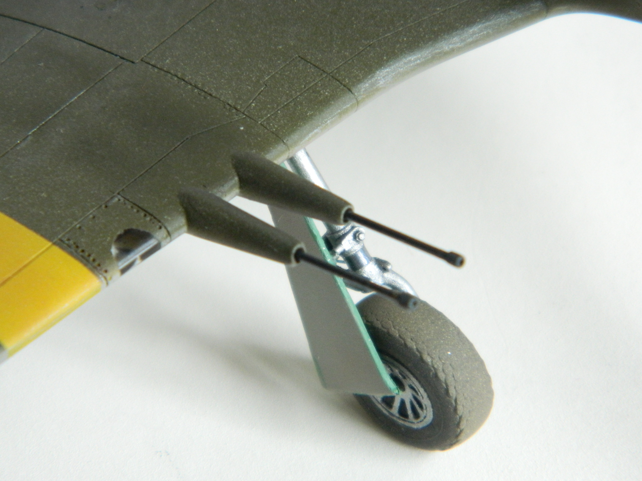
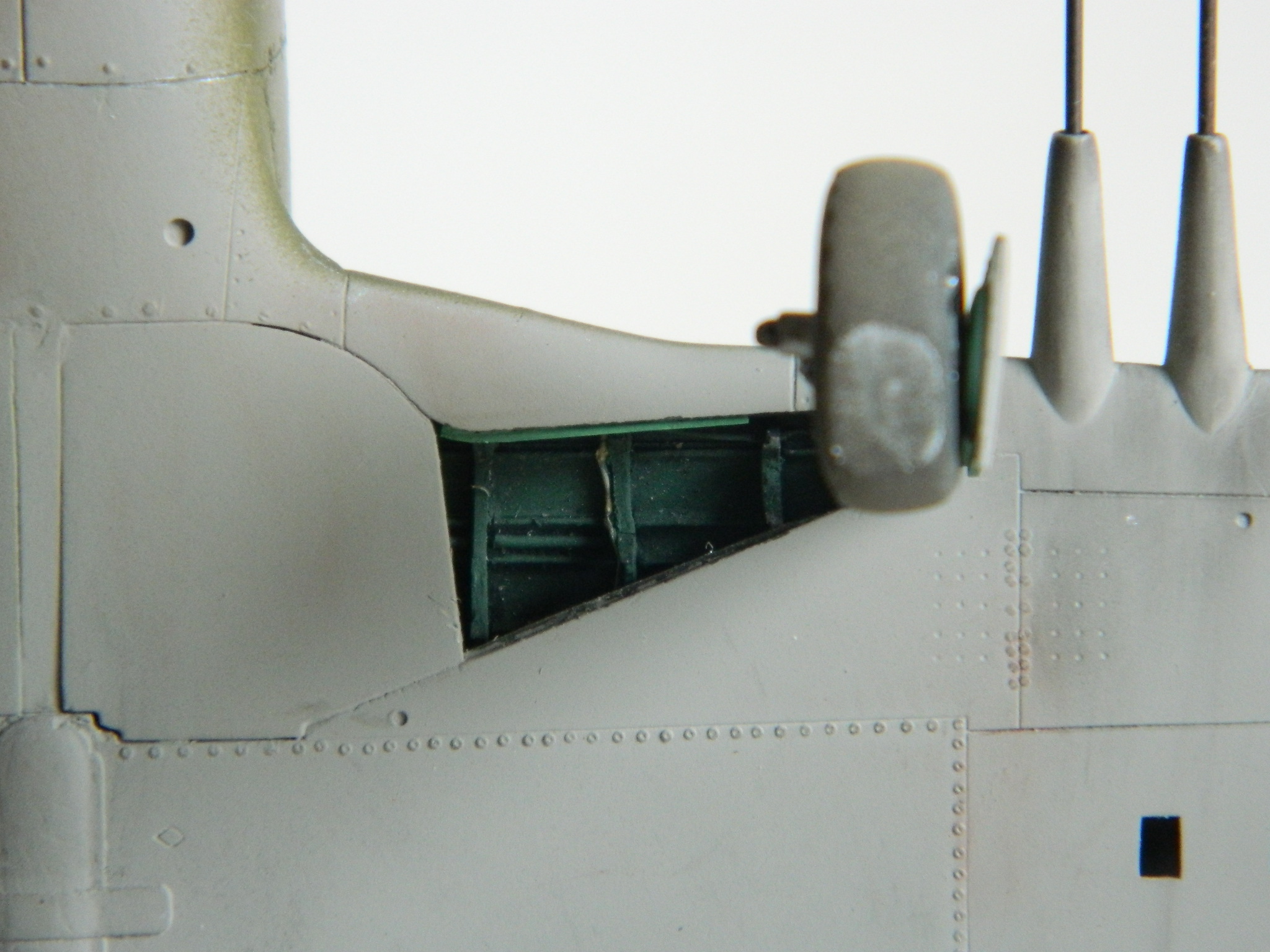
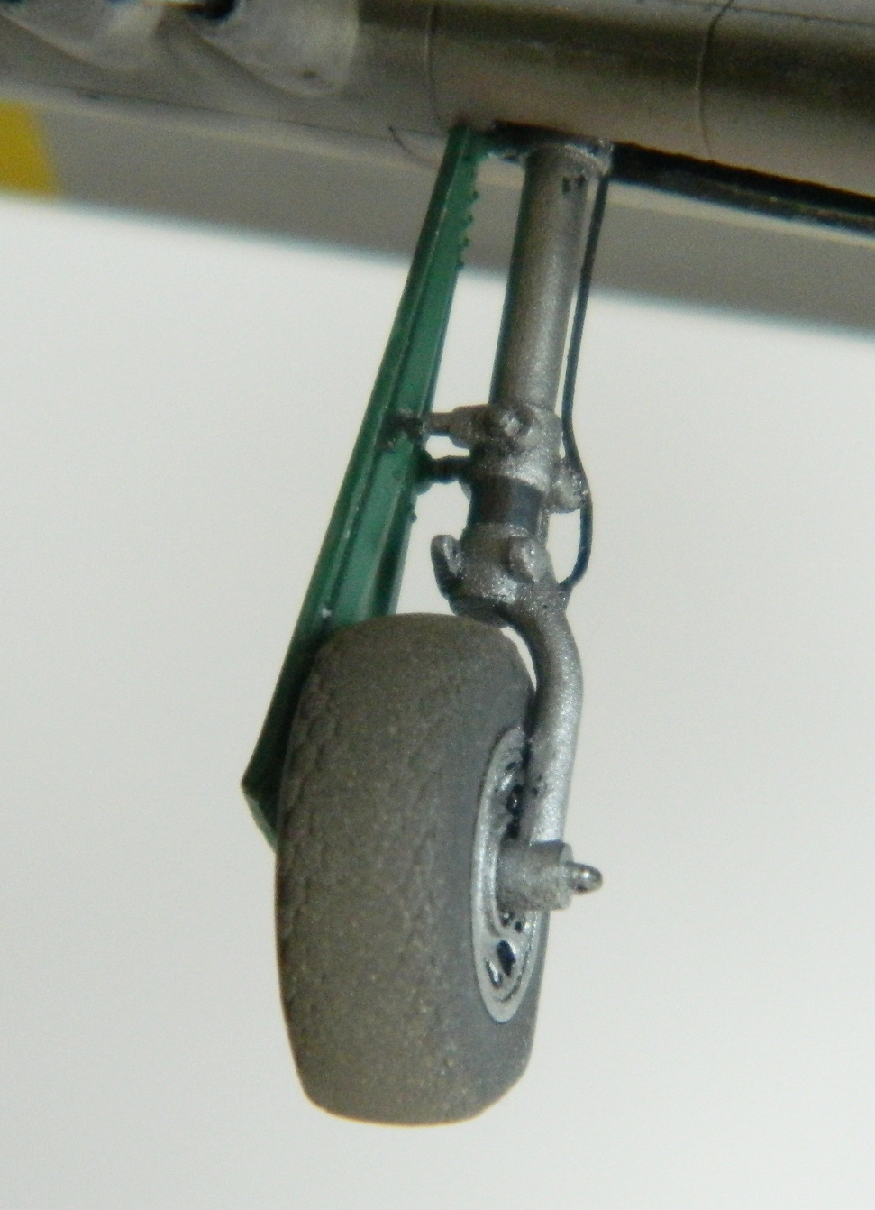
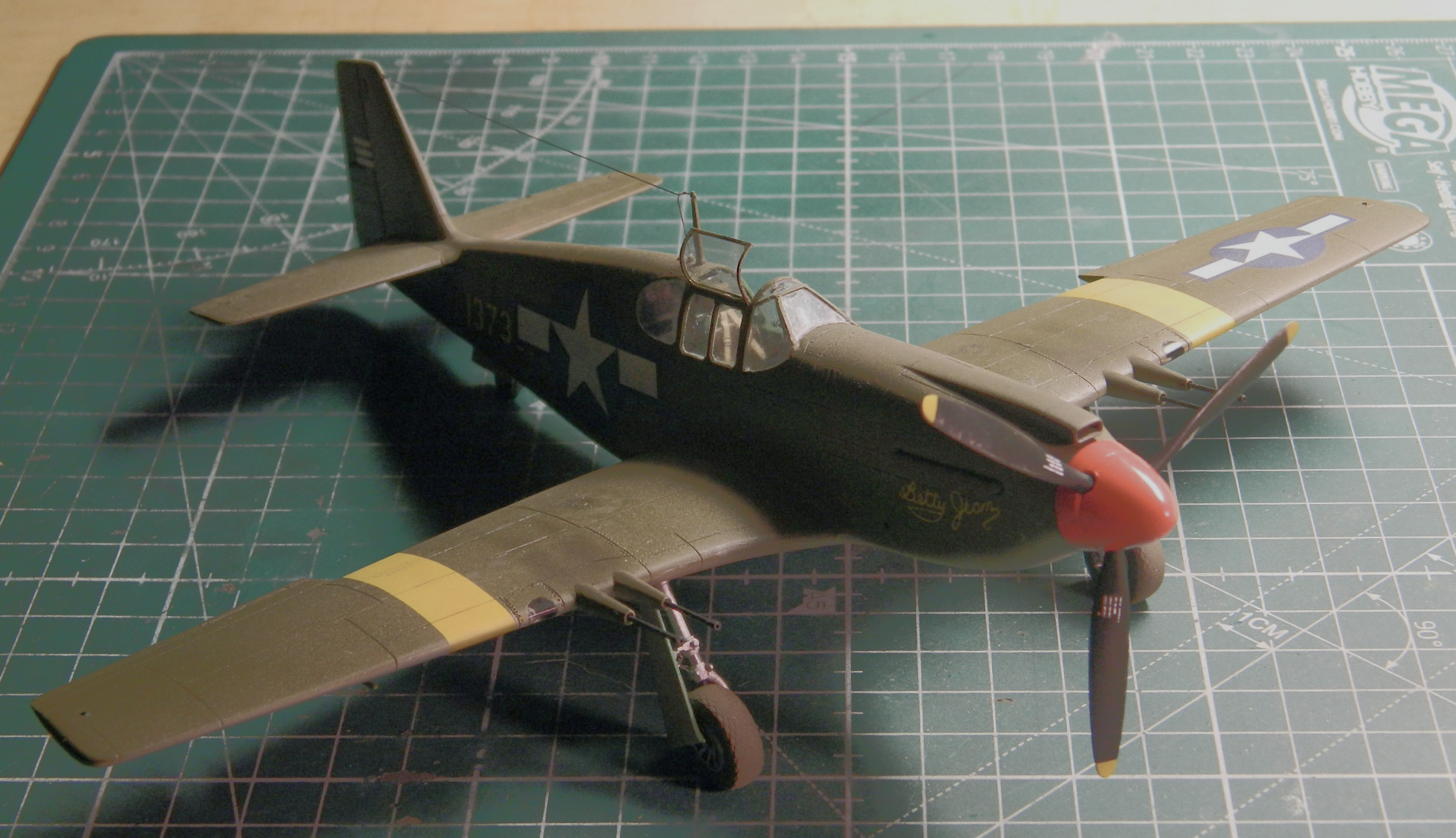
As you can see in the above photo, I pried the landing gear doors free. The Allison Mustangs had another trait. Their inner landing gear doors had mechanical locks that kept them up when the pilot or crew chief dumped the hydraulic pressure. Unlike the Merlin Mustangs, those doors stayed in the up position unless the mechanical locks were released manually to work in there. And with the landing gear doors out of the way, it was time to add the landing gear. I used masking tape to hold them at the proper angle as the mounting socket wasn’t snug enough to do it alone:

Typically I’ve used stretched sprue to make the antenna run. The kindest thing I can say about that is that I’d never stretched the sprue thin enough on the first pull to use it. (The most accurate thing I can say about that is that I spent a great deal of time cursing.) A more accurate thing I can say is that I would stretch a lot of sprue to get something useful. THOSE DAYS ARE OVER!! The EZ Line worked MAGNIFICENTLY. I superglued one end into the vertical stabilizer and after waiting until the glue set, I threaded the other end through the antenna post (not easily but nowhere near as much of a pain as I thought it would be…certainly much easier than the stretched sprue method). A very nice feature of the EZ Line is that it stretches. A gentle tug on the very thin line and a dab of superglue held it in place nicely. I cut the excess from in front of the post and used it as the feed line into the fuselage. Once the glue had set, I used base-mounted tweezers (why is that word plural when I only use one tweezer?) to align the feed line to its location:
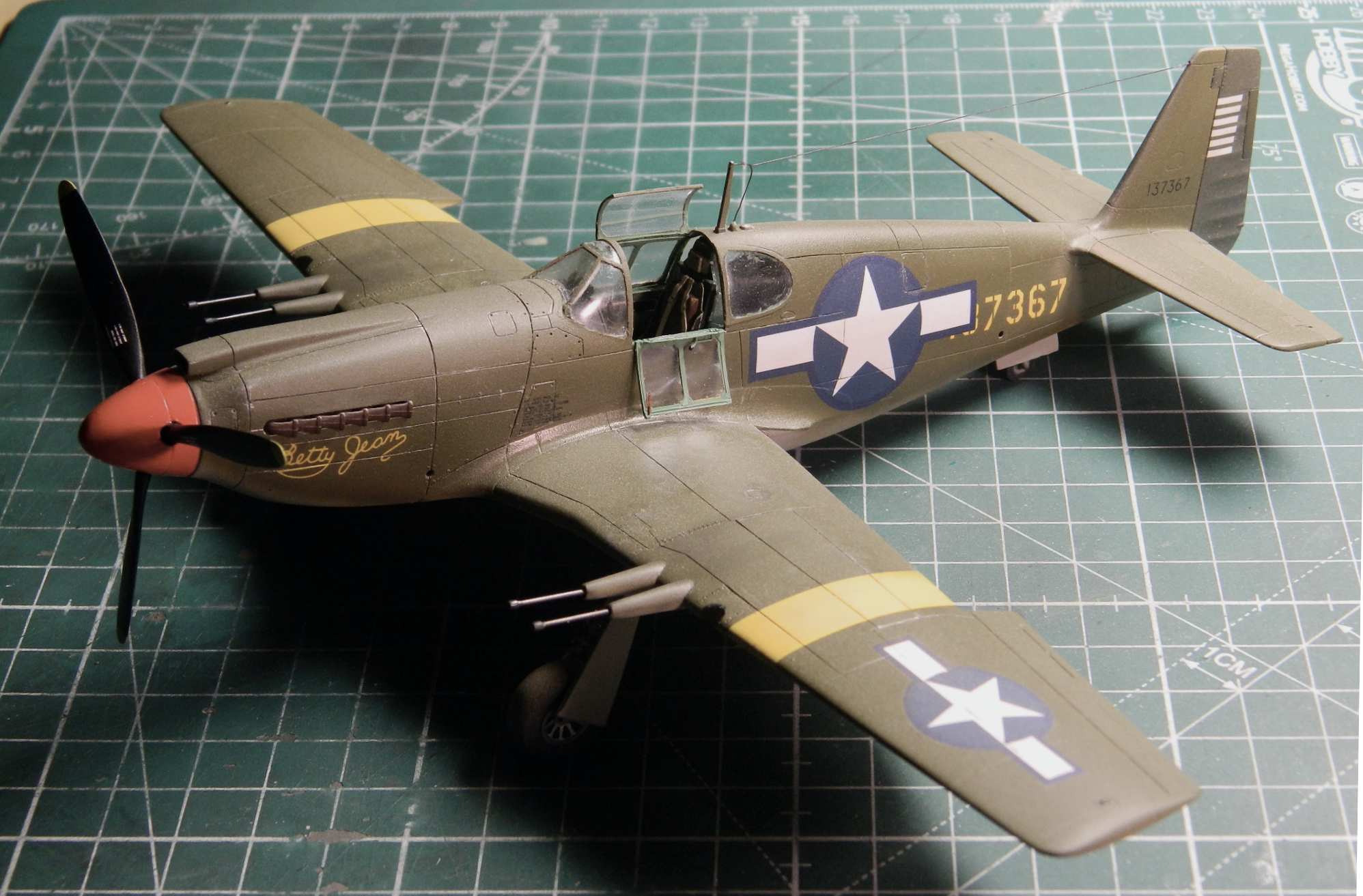
The formation lights received a little dab of the appropriate paints and, without the trumpet fanfare I think I deserve…
IT’S DONE:


P-51 (Accurate Miniatures) Build #15 – Adventures in Forensic Modeling…Picking Up Where I Left Off
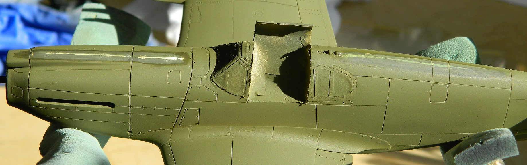
I have now discovered that “for now” can mean four years because that’s how long it’s been since I worked on this one. I knew when last I screwed this thing up what I needed to do to fix it…well…most of what I needed to fix it. At the time I crashed this build, I didn’t have my lathe, so I hunted eBay to acquire another Accurate Miniatures P-51. Took a couple of months of sporadic checking but I did find one and shortly it was on the shelf along with the box the aborted build was on. The big stumbling block for me, though, was how to do landing lights, or more accurately, landing lights with covers. Another problem was after I dropped the model (rarely does the build any good) and broke the propeller mount off, I tried to insert a short section of brass tubing to accept the brass post I planned on adding to the prop. The mistake there was in using a Dremel tool with a cutting disc. Cutting discs make heat. Heating a brass tube socketed into a plastic surround can (and in my case did) get you something like this:

While I was looking the model over, I noticed that the watch crystal adhesive I’d tried had failed. I don’t know how long it actually held the film with the gauge faces on it in place, but it was evidently not four years. Look under the instrument panel to the left of center:
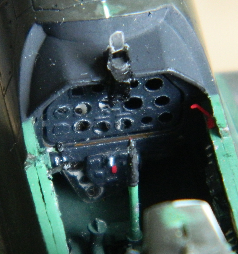
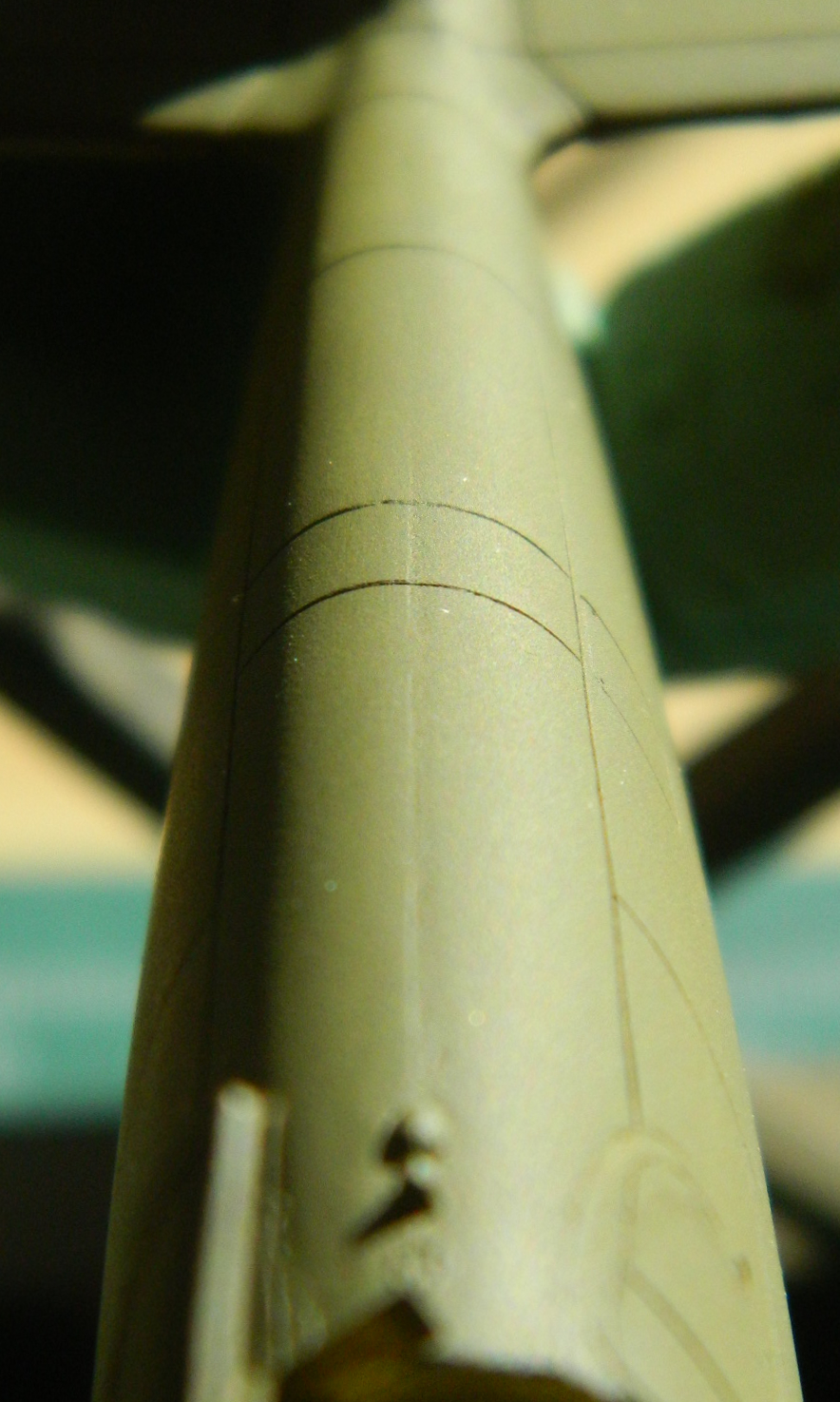
Yeah…they’re obviously not supposed to be there. I needed to get behind that panel and the only way I could think of was to cut the nose off and I made the cut(s) along panel lines :

With the nose off, I encountered a couple of features I’d forgotten about; the tubular spacer I’d inserted to help the wings fit tighter to the fuselage and the forward bulkhead of the AM resin part:

I drilled a hole large enough to insert the tip of a saw blade into and gained access to the rear of the instrument panel:

There are many benefits to using acrylic paints. After four years, I could just dab the back-painted gauge faces with a cotton swab soaked in denatured alcohol and the white paint just came off. That enabled me to line things up nicely. Having discovered that the watch crystal cement is not what I want to use again for this task, I drilled a couple of holes in the film so that I could wick small drops of superglue in between the film and the panel. Then I reapplied white paint to the backs of the gauge faces:

I opened the second P-51 kit, assembled the wing, and then cut the cannon shroud from it. Then I (gladly) cut the shroud that I’d melted the tip of off:

Then it was a simple matter (and I certainly appreciated that novelty!) to graft the new shroud in place, shim it into alignment, and then glue the hell out of it:

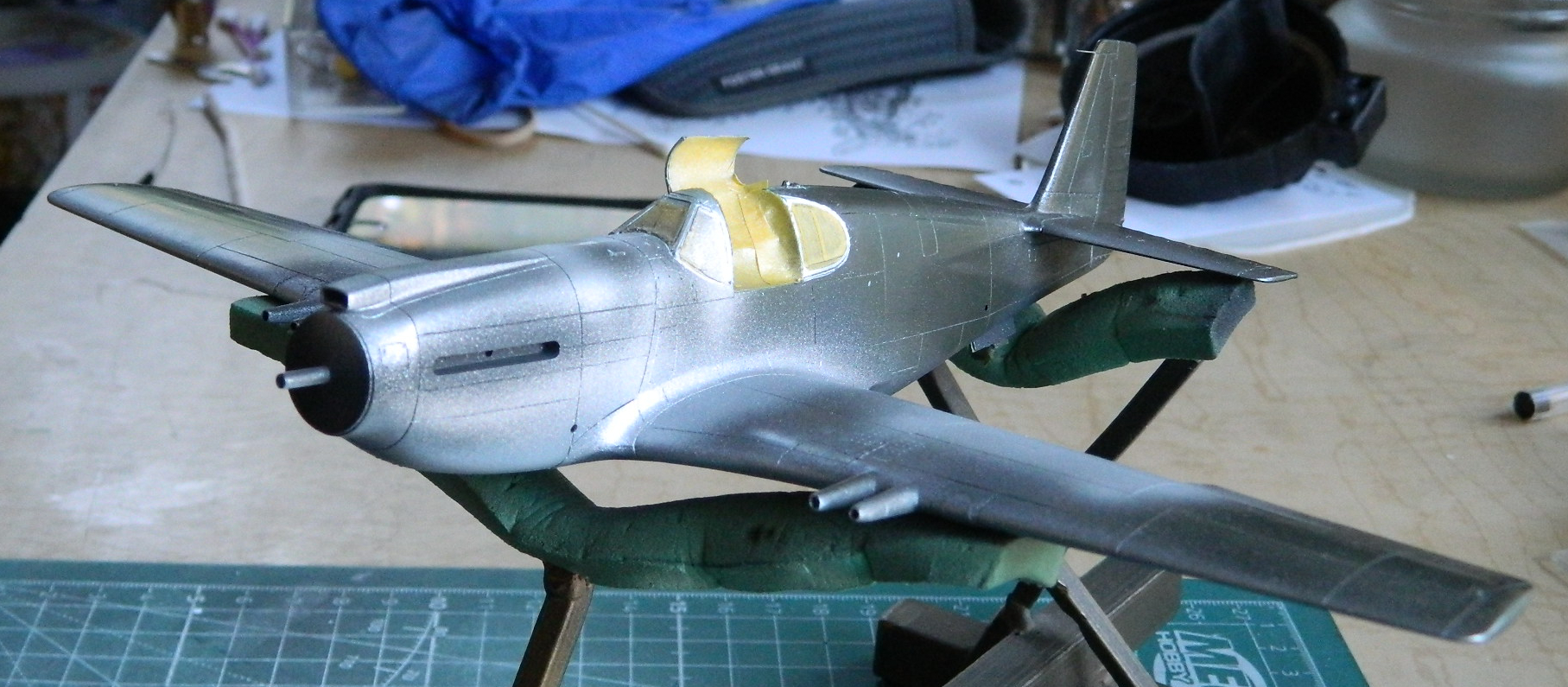
The kerf was puttied and over the course of a weekend, managed to get this build back on track (the vacuformed canopy is taped in place to protect the cockpit…particularly the gunsight) (which I managed to snap off anyway, lose completely, and made a replacement for):

Well…that was easy…
The only modeling magazine I subscribe to (and recommend) is FineScale Modeler. A GREAT many of my modeling techniques have been pulled directly from their pages (the colorful invective is of my own creation). In the October 2020 issue they have an article on page 18, “Age Before Beauty.” The article is about taking one type of aircraft, the F8F-1B Bearcat, and using two kits to compare those kits. The interesting thing is that one kit is 40 years old (Hawk) and the other is modern (Hobbyboss). The intent is to see what is required to bring an old kit up to modern standards. (A LOT!)
I told you that to tell you this…
One of the things the builder did to the old Hawk kit was to replace the wing-mounted landing lights. (I was going to say, “Just like I did,” only he was successful and didn’t melt anything.) That was just the information I needed to pull this kit off the shelf and get on with it, which I did as soon as the build I was working on at the time was completed in.
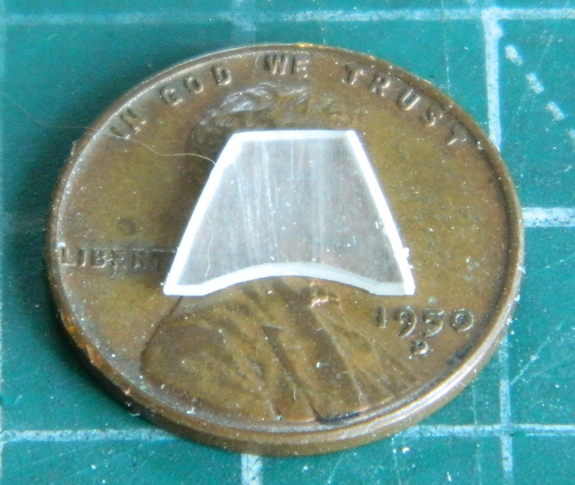
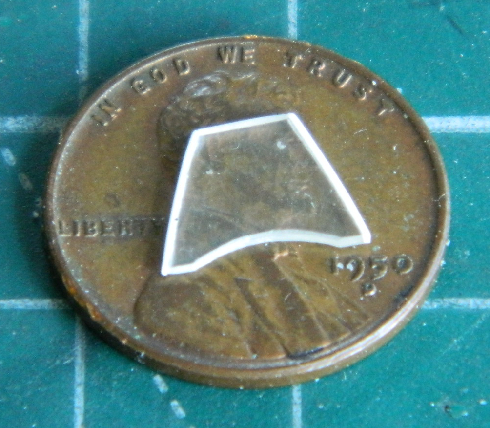
The idea was to take a solid piece of clear acrylic, cut/shape/polish it to shape and then drill the back of it slightly to replicate the light itself and then paint it silver or chrome…and that’s what I did:


With all that done, the back of it was painted black, it was then glued into place (a bit prematurely, as I will point out shortly), and then filed/sanded/polished into an adequate representation of a landing light behind a clear cover:
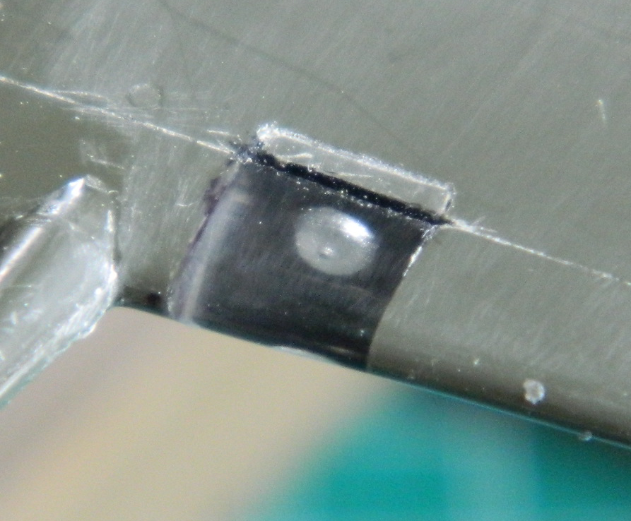
Shortly after that was glued…PERMANENTLY…into place, I decided that I could have used a slightly larger drill. But I didn’t, can’t get the part out, and had to do the other one the same way. Even so, it was a magnitude better than what I’d tried originally. (“Originally” didn’t work, this way did. I’d say that’s better.) I used the spare kit’s landing light sections as a template to make the masks for the landing light. Where the tape is stays clear, what’s around it gets painted:

The area behind the acrylic insert, being round, doesn’t quite match up with the upper wing surface. I added plastic and sanded it all smooth, scribing in the necessary panel lines.
While I was at the site of past trauma, I decided to stay there and get the shrouds ready for the cannon barrel analogs. One of the thing I’d noticed is that most of the cannon-armed P-51s had barrels that free-floated inside their shrouds. I drilled away the mounting collars (the white plastic) I’d originally installed, then used the same diameter styrene rod to stuff into the holes of the shrouds:
After cutting the rod flush with the shroud, I used the rod to push the stub inside the shroud in a wee bit and then glued it. Once I treated all four shrouds that way, I drilled a hole in each to slide the barrels through. The result was nicely floating cannon barrels (the tape on the nose in the lower photo is to protect it from the putty I added when I corrected the panel lines under the nose of the fuselage):


Having done that, I was now completely recovered from prior oh-gawd-dammits and the “forensic” part of this build was done. On to new stuff!
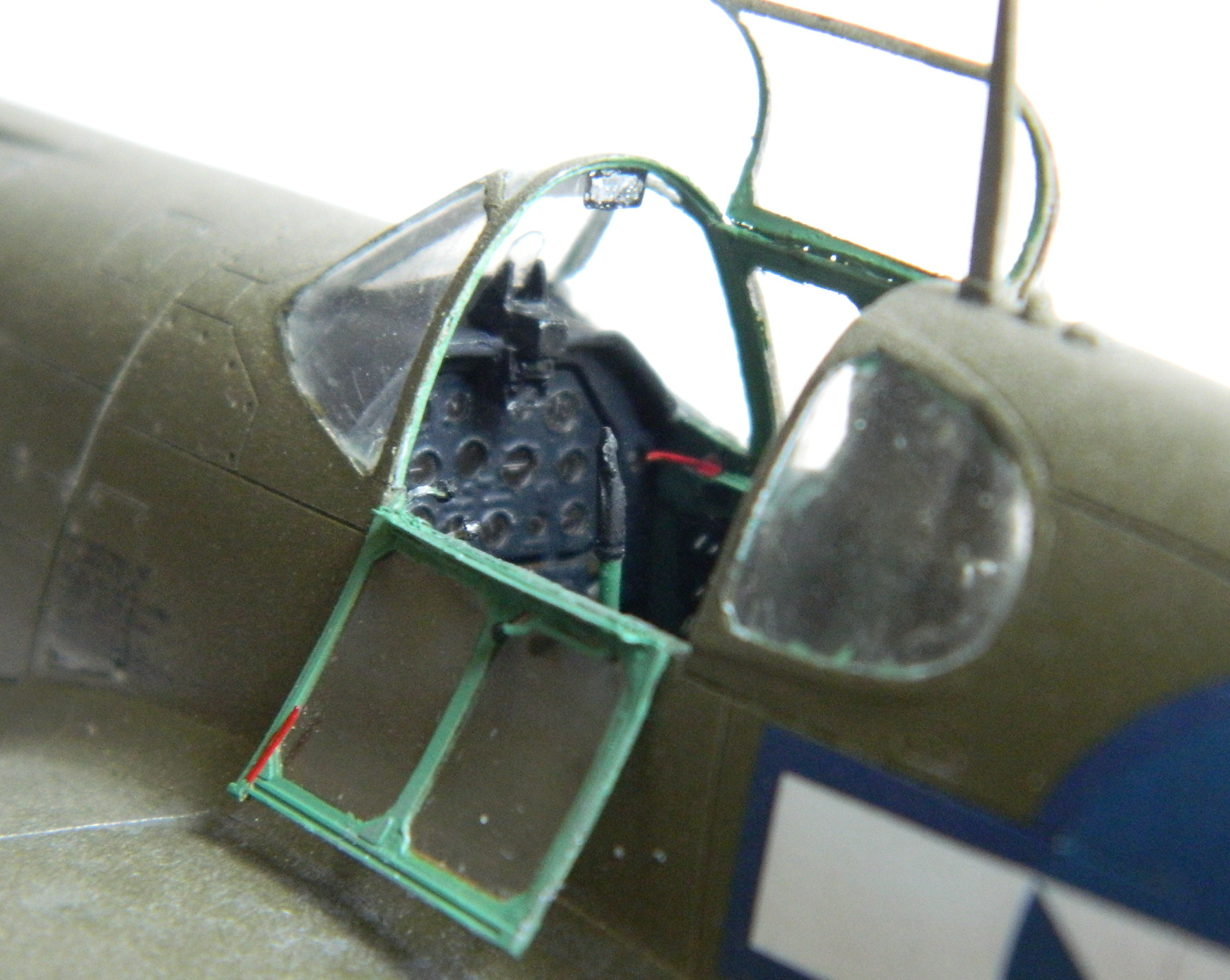
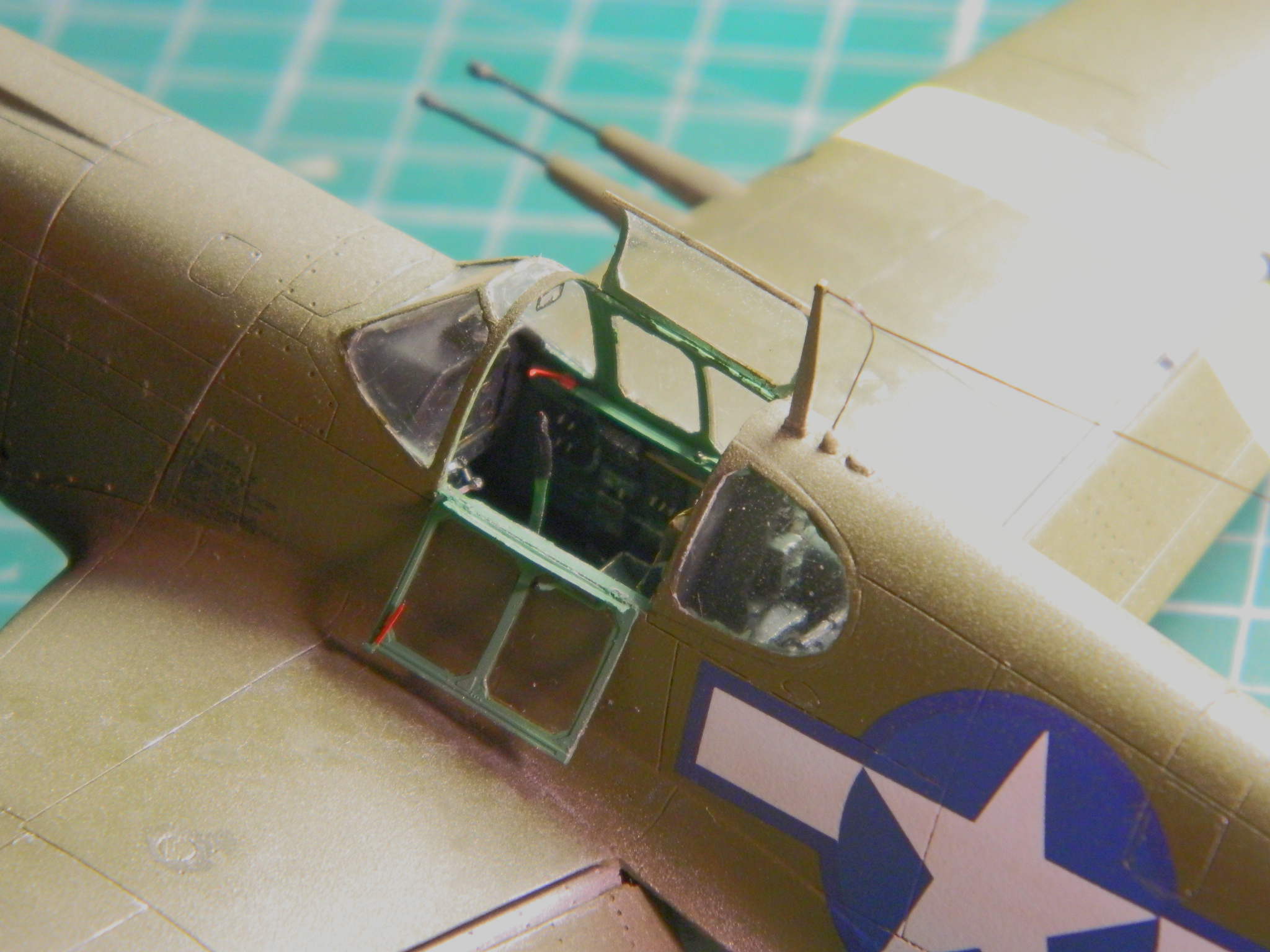
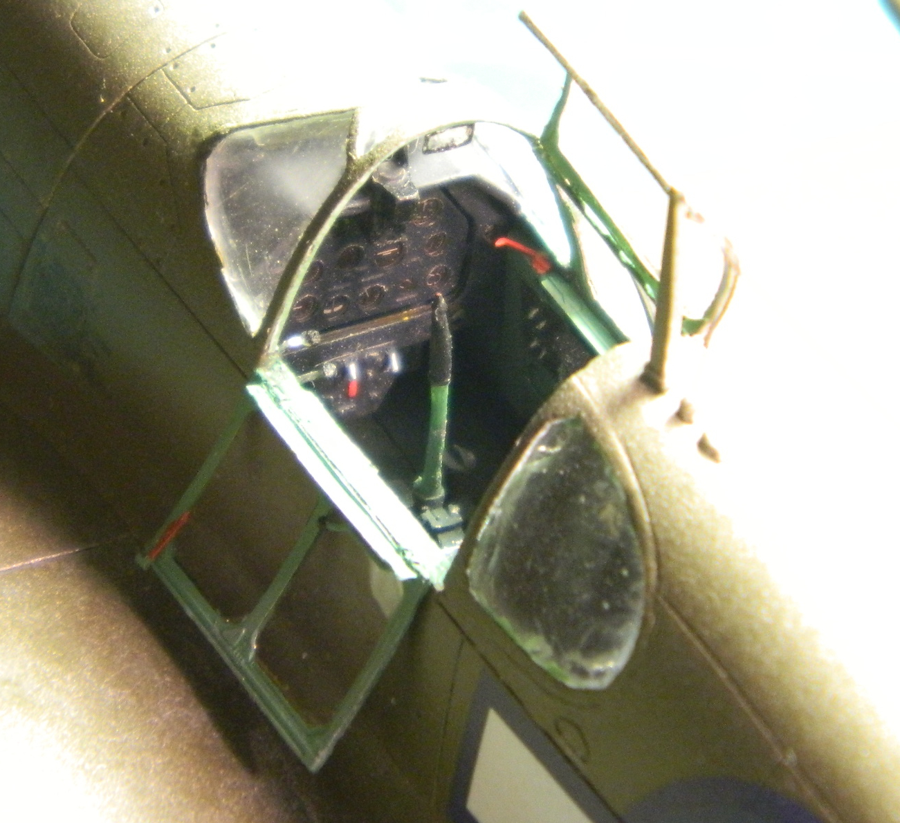
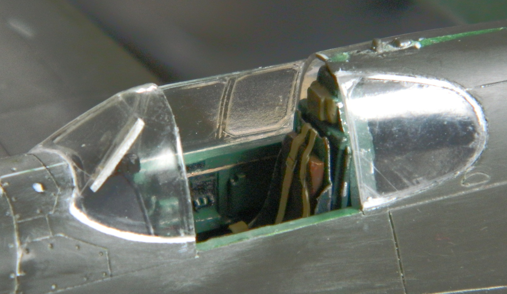
“New stuff” started with the canopy. One thing I noticed with some of the earlier P-51s (and others…the P-38 did it the same way) was that the armored glass wasn’t a part of the canopy but instead mounted on brackets behind the front canopy section. To do that I used the canopy I’d tried to vacuform a canopy over and cut the section out between the two framing sections:

With that section cut out, I used .010″ (.254mm) styrene scraps to form the mounting frame and then sanded and polished it, resulting in a to-scale thickness “armored” panel:
Now all I had to do was to glue the armored glass inside the canopy and then add all these delicate and thin parts to the fuselage:

“All I had to do,” he says as if it were simple. ::giggles::
My original intent was to use the vacuformed rear canopy sections. After carefully trimming them and noticing how FREAKING THIN they are (which is actually the point to vacuforming to begin with), I realized that I had an incredibly small contact area for adhesives (and yes…I did realize that I would have that same problem with the rest of the vacuformed canopy…but I’d bridge that cross once I got to it). Once again my original intent was discarded and I tried something else. Instead of the vacuformed parts, I used the kit parts. The fit wasn’t the best, which is why I tried using putty to make up the difference (the white stuff around the top of the part):

Then I figured I’d deal with the very thin canopy and see what I had to do to get that part glued into place (other than virgin sacrifice…at my age I don’t have the time to find one of those). I used superglue and it worked, after a fashion (no frosting), resulting in the application of more putty:

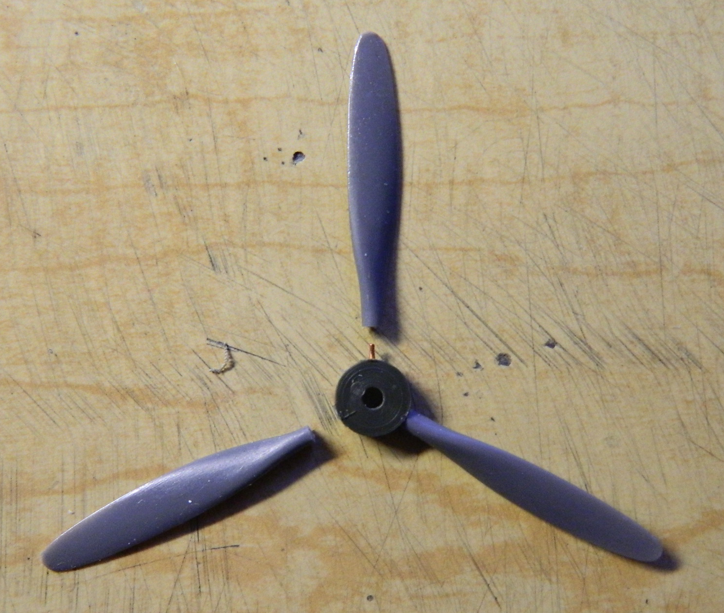
While the glue was curing, I turned my attention to the propeller and spinner. The kit’s propeller blades aren’t at all representative of what the P-51 used; they’re more like ungainly canoe paddles. Instead I used a set of props I bought for an A-20G Havoc I have in queue. I took molds of the props/hubs and cast resin copies to use. The P-51’s prop was 10’6″ (3.2m) long and the A-20’s was 11’3″ (3.43m) so I shortened them slightly:
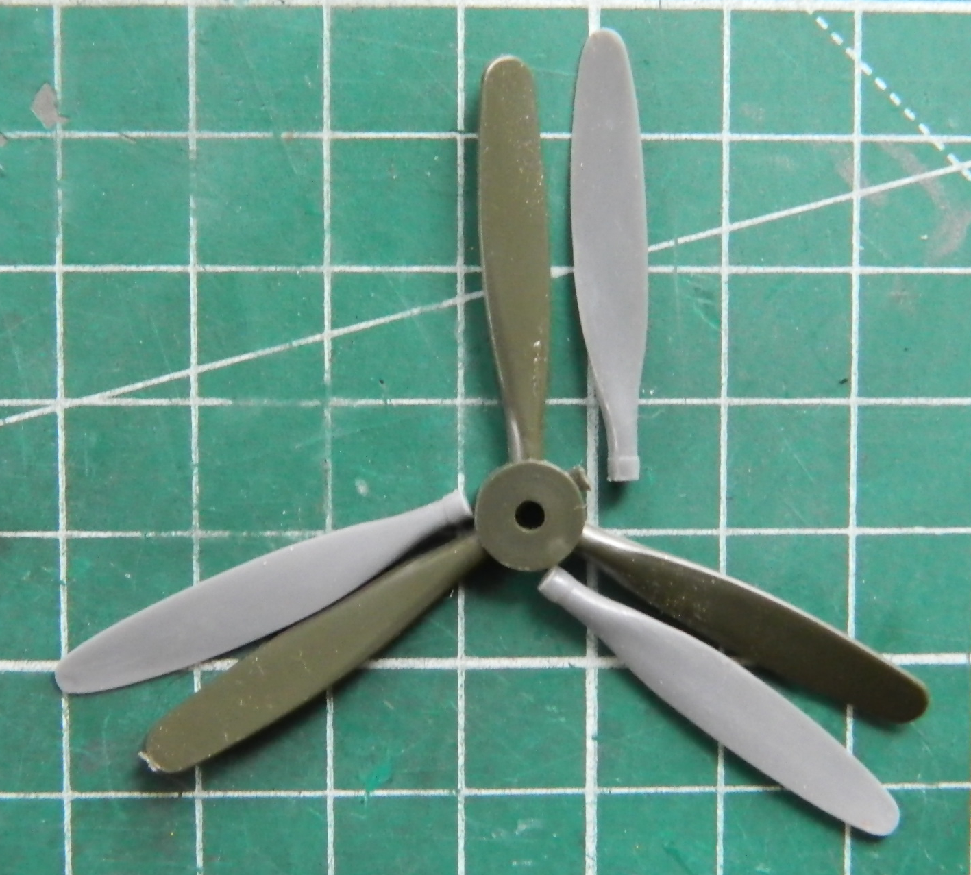
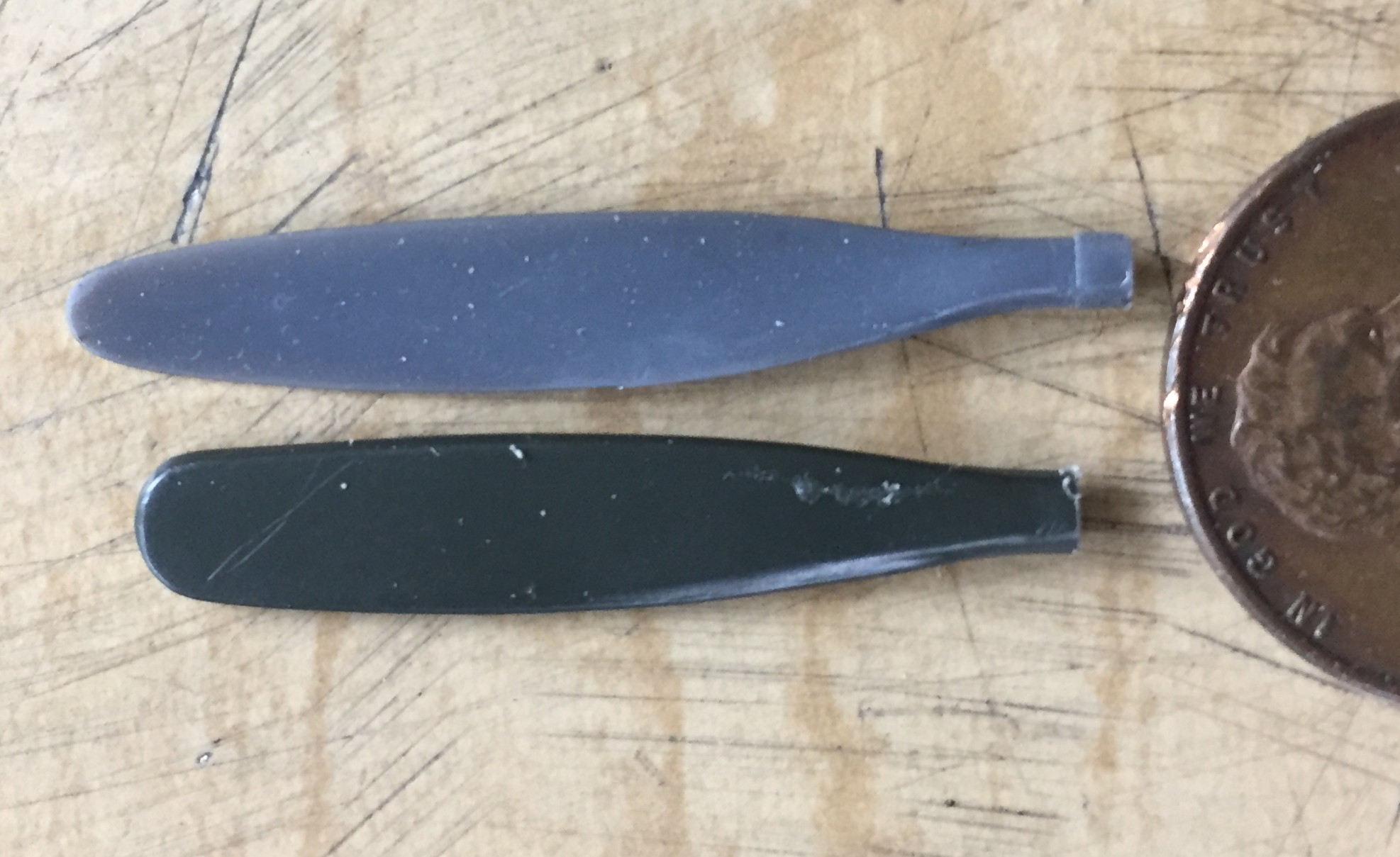
I cut the kit’s paddles…er…props from the mount and added pins to glue the resin prop blades more securely:

And what’s a propeller without a spinner? (Oh, I dunno…a drag, maybe?) While cutting the parts from the sprues, I cut just a wee bit too closely and flat-spotted both the base and nose of the spinner, which required me to add styrene scraps:

Perfection still eludes me.
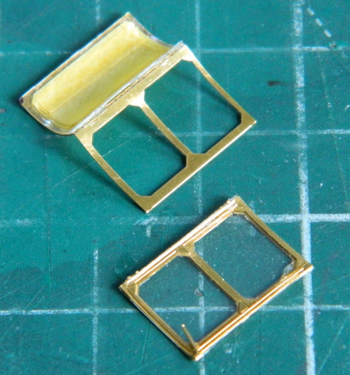
With the glued canopy now cured, I opened the parts box and realized that yes…perfections ELUDES ME. There are PE frames in there that I wanted to use! Well, okay, then…let’s get these things to work. Shortly after my initial attempt to fit them, I realized that once again my “error” saved me from AN ERROR. Or if not having saved me from AN ERROR, the “error” actually saved me a metric tonne of hassle. The vacuformed canopy (courtesy of Squadron Products) is very thin. Trying to bend PE parts to conform to them without deforming them would have been OH such a joy. It was enough of a “joy” with the bottom of the canopy glued into place, offering much more rigidity than would have otherwise been possible had I not “erred.”
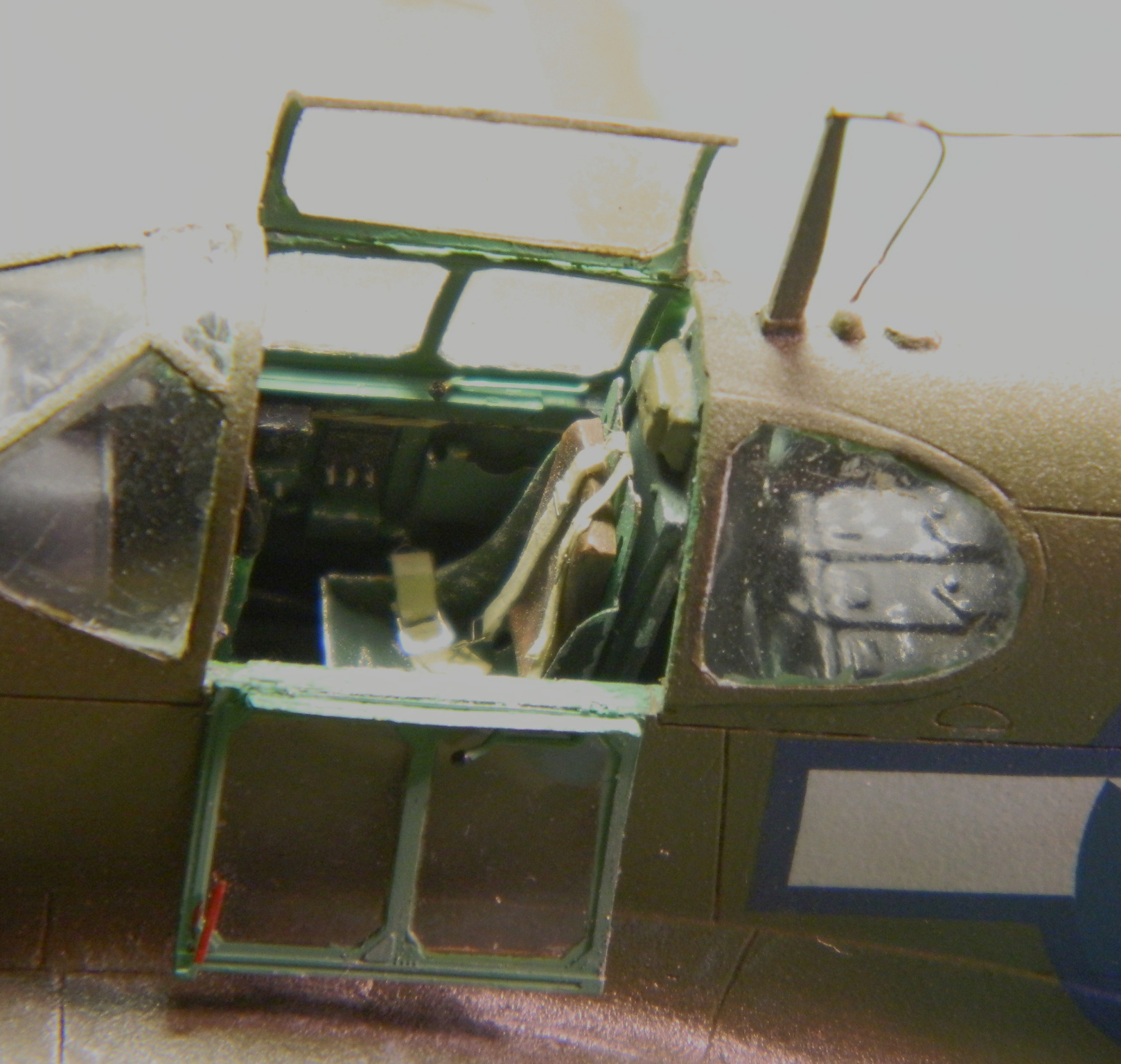
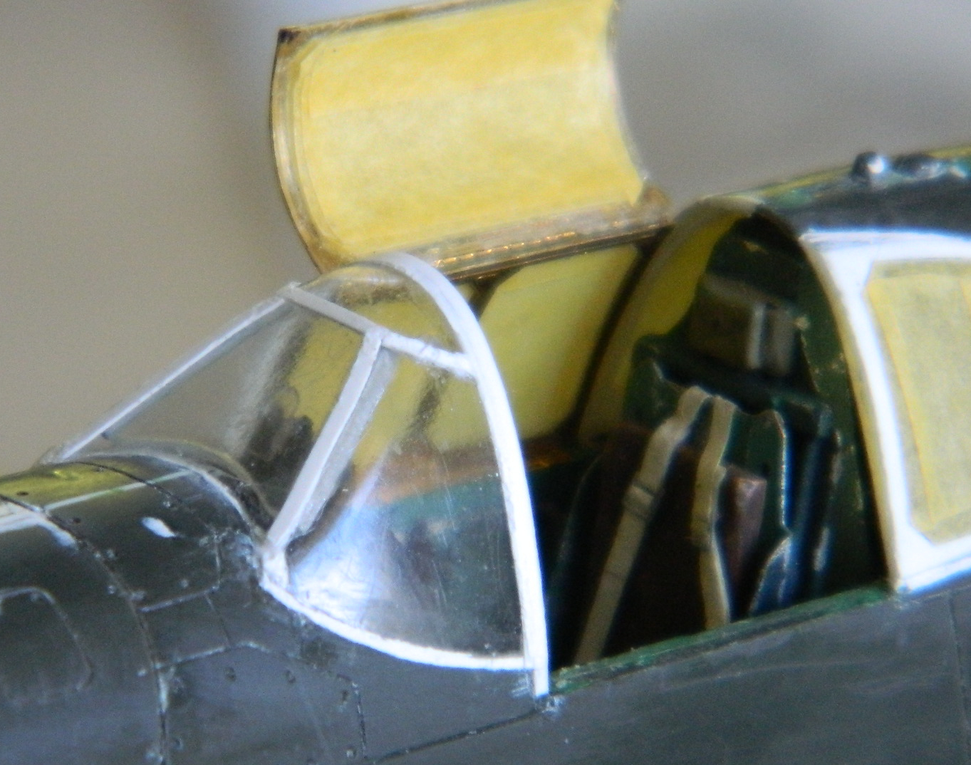
I started bending, fitting, and bending some more. (Repeat those steps a lot so I don’t have to write them out.) Eventually I got the right side frame in place (totally ignoring…by intent…how much fun I was going to have getting that thing painted):

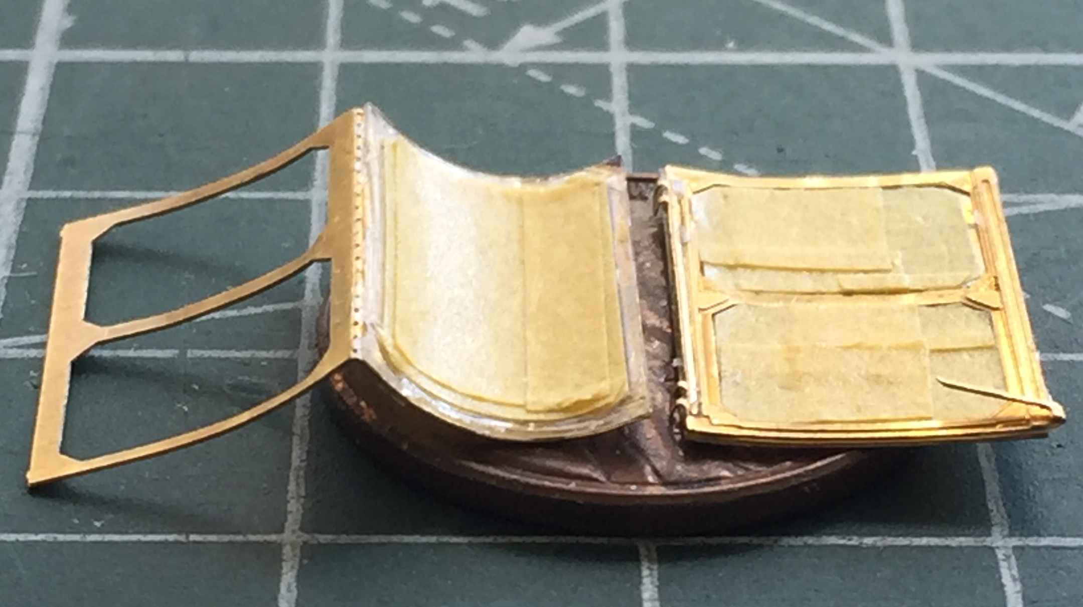
Then I had to form the outside frame, which also included the top of the canopy that swung open to allow the pilot to get in and out of the kite, as well as the left side of the canopy that hinged downward to enable such access:
In my attempt to add the inside PE frame to the hinged top I realized that the result of two PE frames and the plastic between them would result in something far too thick. Bugger that. I didn’t add the inside frame, figuring to replicate it with paint. Some detail would be lost but it struck me as an adequate trade-off to a part that was ridiculously thick. To avoid the same problem with the open side canopy, I used some .005″ (.127mm) thick acetate. Still a bit thicker than I would prefer but it falls within the 90-95% tolerance.
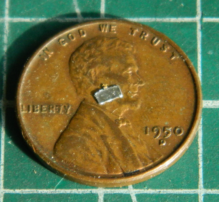
The rear sides of the canopy also has PE frames:

Though not especially large, these frames are not the smallest part I’ve used. They’re also not the smallest part I’ve dropped. My ability to find this PE part that I dropped indicated to me that SOMEwhere on the floor of my shop is an inter-dimensional portal. After I dropped it, I spent the next hour crawling around on the floor, moving everything movable (my drawer units are on wheels enabling that to be accomplished easily) out of the way and, as I sit here typing this, have STILL not found the [EXPLETIVE DELETED] thing. And while I’m on that topic…
Four years ago when I was constructing the cockpit from AM resin parts, I discovered that the joystick had a bubble in it just below the grip of the joystick. I discovered this by snapping the Damned Thing off. That part, also, eluded recovery. Lost and gone. Alas. Then four years passed. During that time the shop floor has been swept (relatively frequent occurrence) and vacuumed (I do that at the end of every build). Four years. Frequent sweeping and not infrequent vacuuming. While I was down there looking for another part I’d dropped (I’m old and feeble…I drop things) (so far not me, but I’m sure that’s coming), guess what my frail and ancient eyes did spy.
The grip of the joystick!
Go figya, because I certainly can’t…because the Damned Thing was right out in the open and not in or under anything else. (And don’t go there because I DO know how to vacuum and sweep!)
Moving on.
Since that PE part is in some undiscovered dimension elsewhere, I used the remaining PE part as the template to copy another one. That’s why the photo above has an aluminum background, because my first attempt was to use thick aluminum from a disposable baking pan…which created many more problems that it would have solved:
Yeah…go ahead an trim that for size and smooth edges! I’ll sit and watch. I tossed it and used .005″ (.127mm) styrene instead (yeah….005″ (.127mm) styrene was a better choice, that’s how difficult it would be for me to clean up the aluminum copy):

I added the frames to the rear canopy sections and fared them into the fuselage with putty:

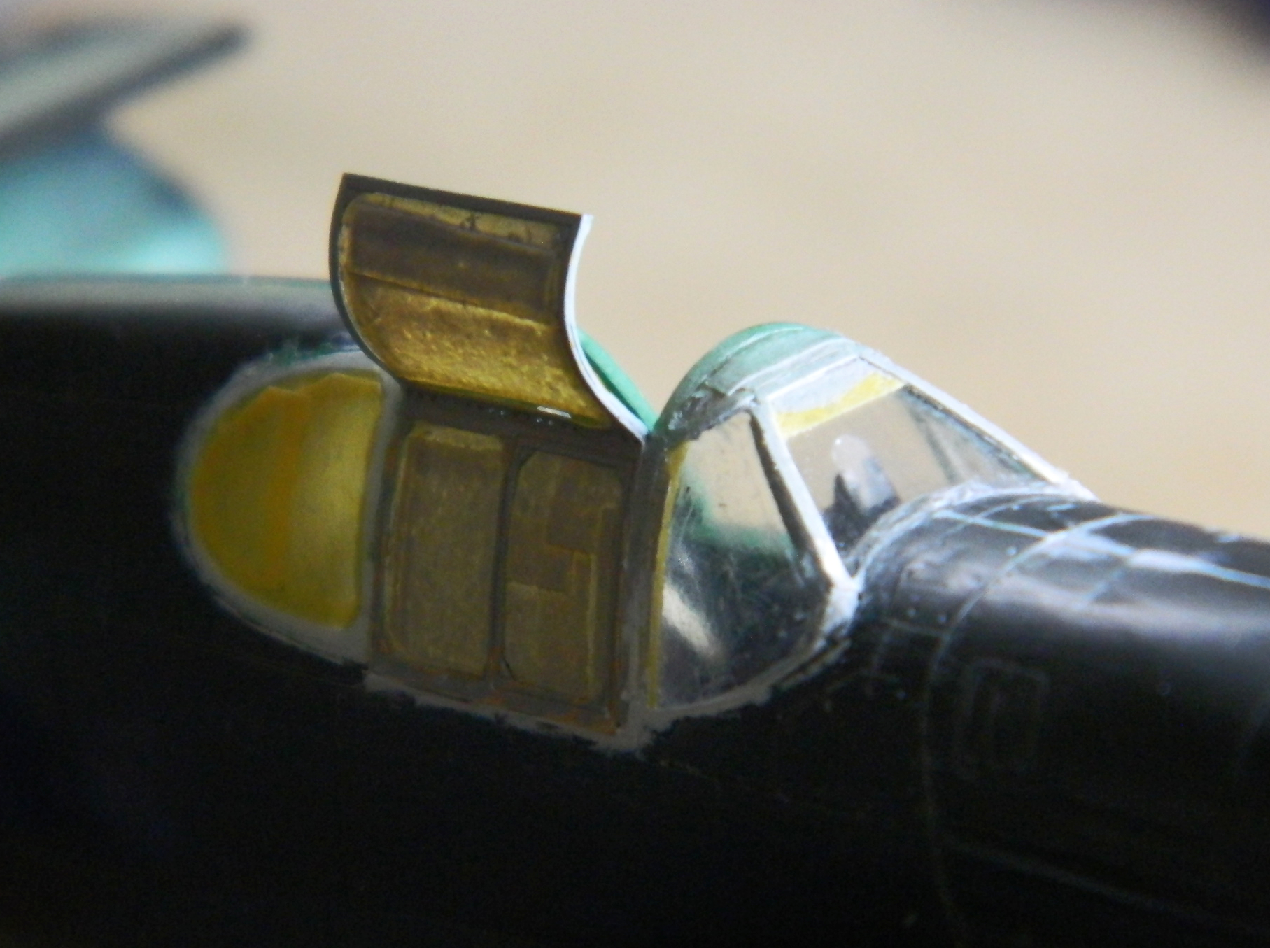
While the putty was curing, I went back to diddling with the PE canopy frames. This time I got smart (or more likely less dumb) and didn’t add these parts before I masked them (A quick word about Tamiya’s masking tape. It’s great. It’s thin and a little stretchy, enabling it to be curved around shapes, and isn’t highly tacky, enabling it to be removed without taking off what it’s stuck to. End commercial.):
Having gotten those parts masked, I added the side/top framework to the canopy. With those in place, I started building the framework for the front canopy using .005″ (.127mm) scrap:


With the canopy frame built it was time to mask it, and this is where I found a pothole in the path of my build. Just the wrong amount of pressure (with a very sharp knife) at just the wrong point of the canopy exceeded the gripping strength of the superglue and the whole fornicating thing popped off:

I was so thrilled.
And then I looked a bit closer at it. Y’know…I’d totally overlooked the fact that the INside of white plastic strips is also white. But the INside of the P-51’s canopy framing wasn’t white. It was the same color green as the rest of the cockpit. Well, well, well. Dodged another one! It will be SO MUCH EASIER to mask and paint the inside of the canopy with it off the fuselage than it would be on the fuselage.
Yep…sure was:

It’s true. Sometimes it’s better to be lucky rather than good (assumes the person who’s still working on “good”).
Before the canopy can go back on, it needed to be painted the green of the cockpit. While I was at it, I filed/sanded down the added chunks of styrene to the spinner, used white glue to hold the parts together, and painted both parts:

I glued the canopy back onto the fuselage and then turned to the PE rear-view mirror. I put a tiny drop of superglue onto the PE part and then pressed standard (aka, thin) aluminum foil into the depression and then trimmed the foil and painted it semi-gloss black before adding it to the inside of the canopy:

The canopy was glued back onto the fuselage and gaps around the edge was puttied:

I usually don’t remove the masking tape until after painting has been done but this time I removed it to be certain that I’d trimmed the putty back far enough…and it looks like I had:

A friend of mine’s father used to be a dentist. He retired, moved away, and my friend was getting his house ready for the market. Any modeler will become emotionally erect when the phrase, “dental tools” is mentioned. Yes…they’re that handy. And all of the hand tools my friend passed on to me are that handy. But the really BIG SCORE was this little beauty:

It’s a Buffalo Model #15 electric grinder. Zero to 25K RPM controlled by a foot switch. It also came with a lot of really small burrs (grinding tips). Some of which are REALLY SMALL.

Those aren’t even the smallest burrs. What that lovely little machine allows me to do are things like this:

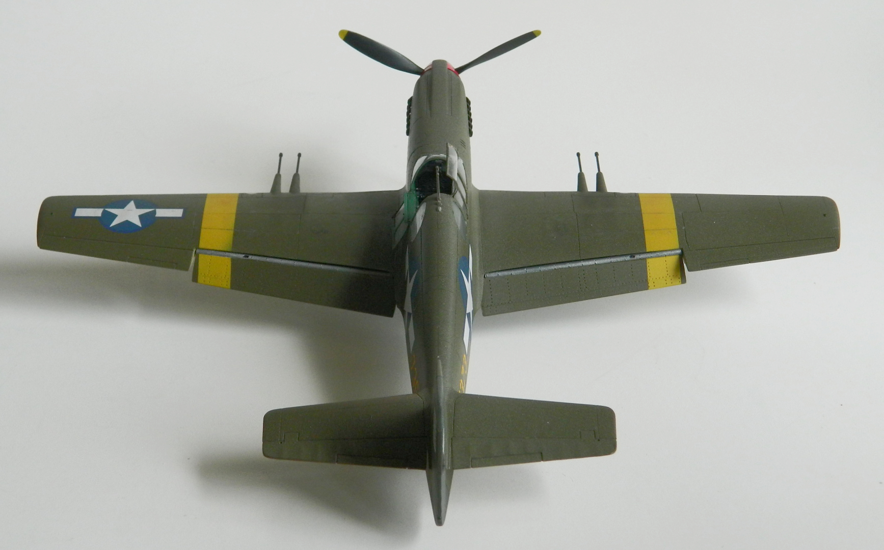
In 1994 when this kit was copyrighted, slide-molds weren’t used in making model kits (I don’t know if slide-molds even existed at the time). That means the outlets for the exhaust tips, which is what those two parts are, were molded solid. If you look closely at the strip of tips to the upper right, you can see where I used that LOVELY little machine and the smallest burr to depress the surface of the exhaust tips. They’ll look great once they’re painted!

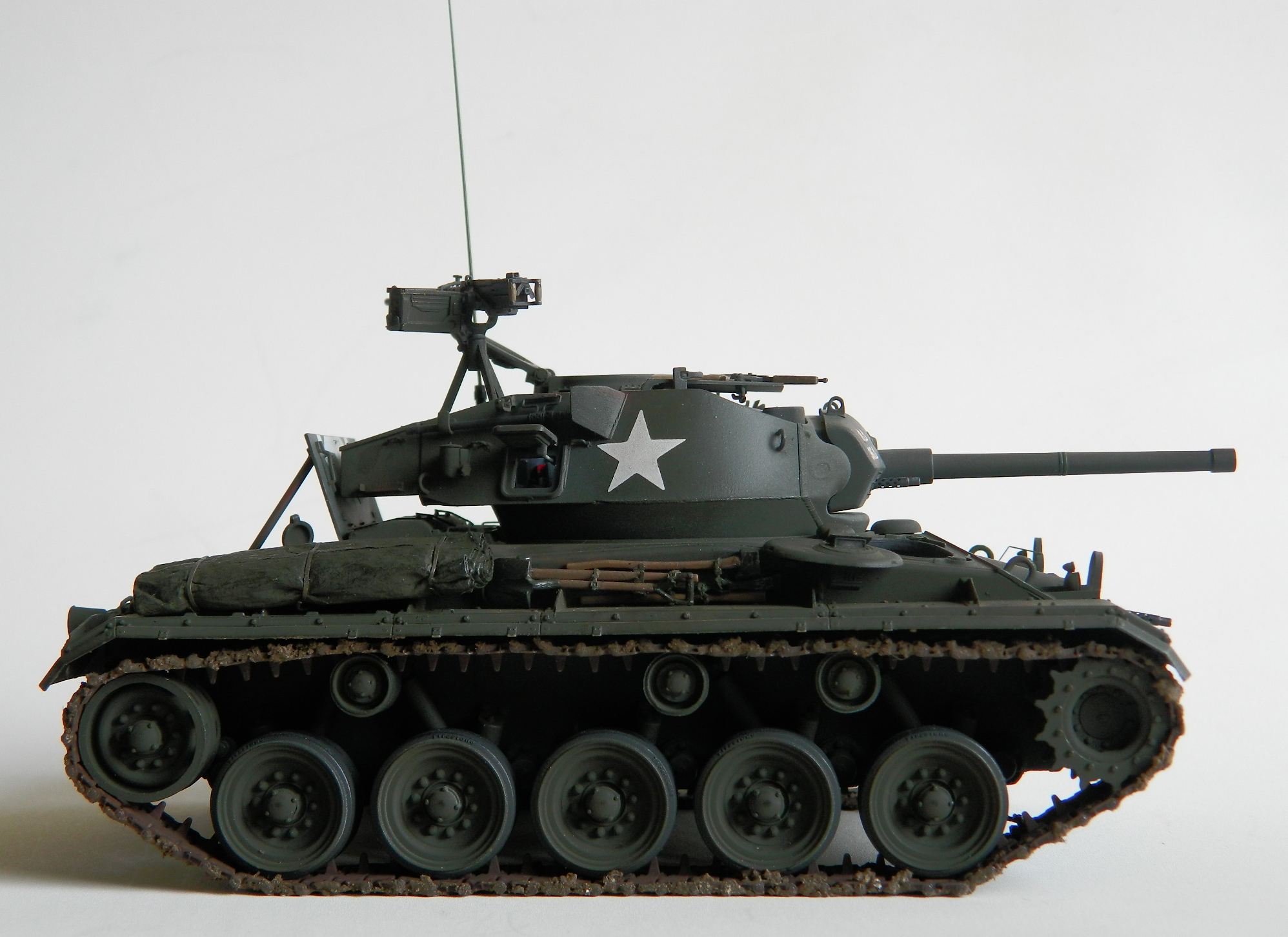

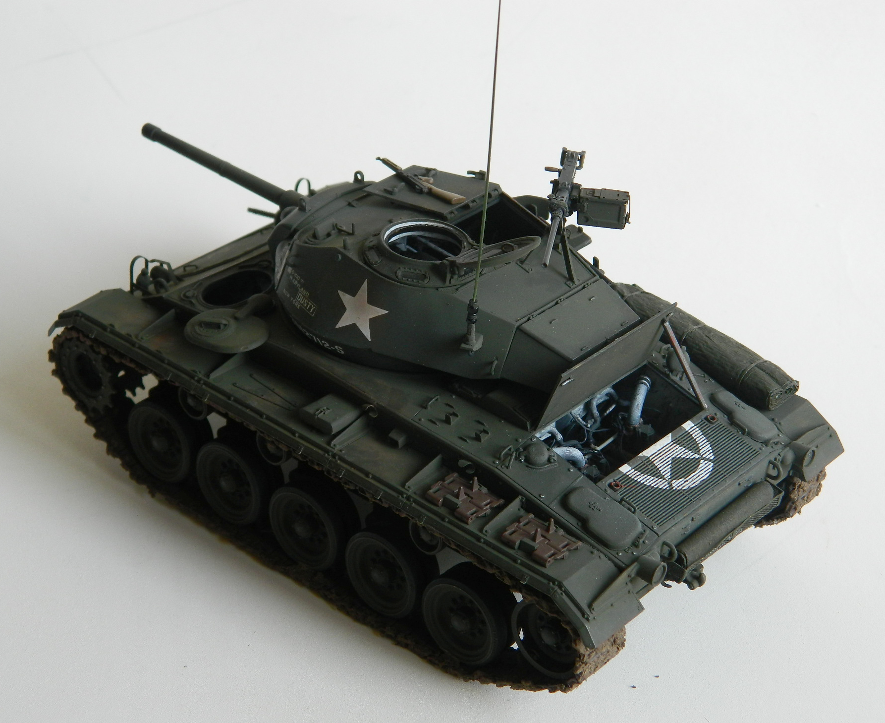


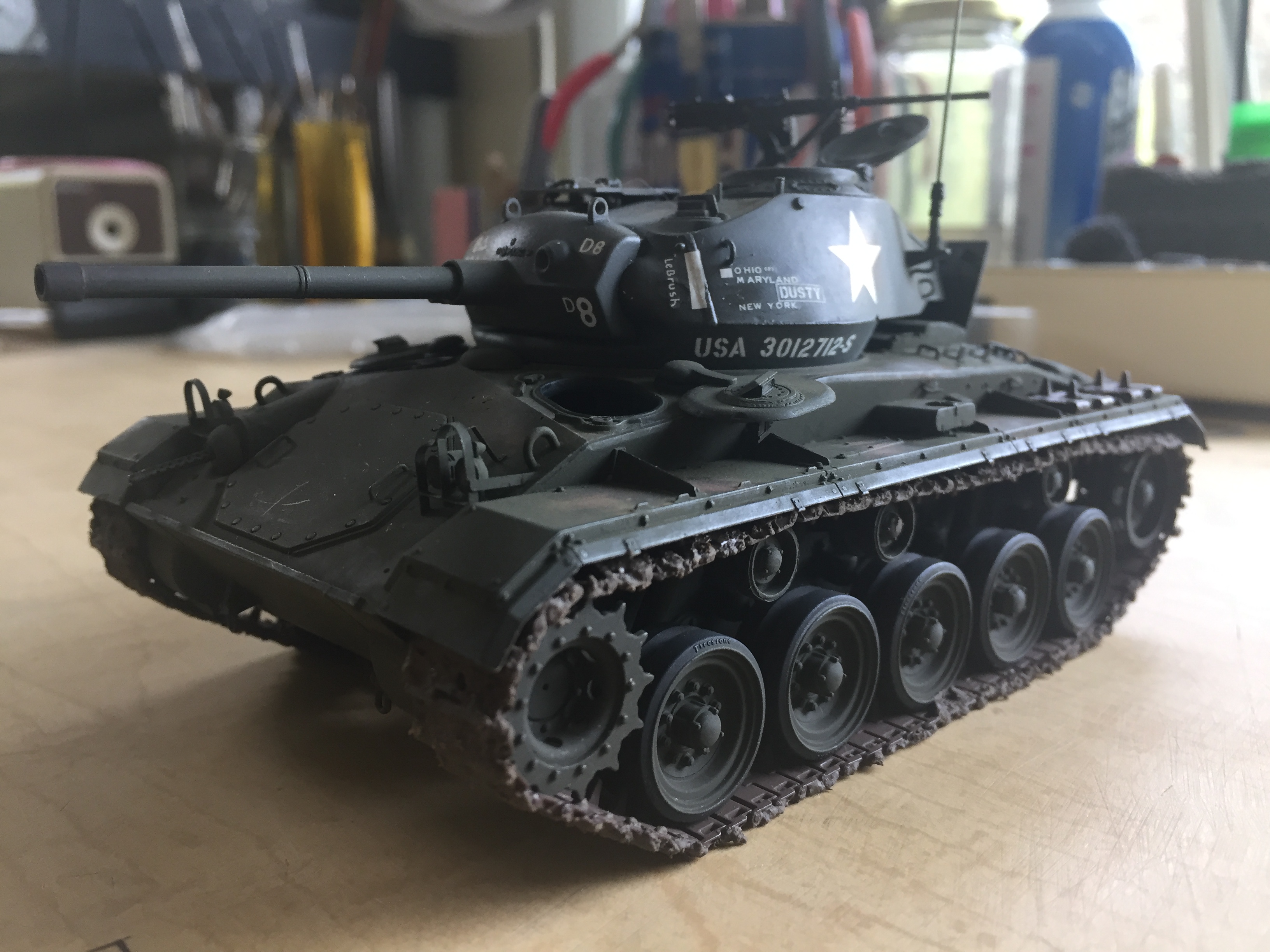
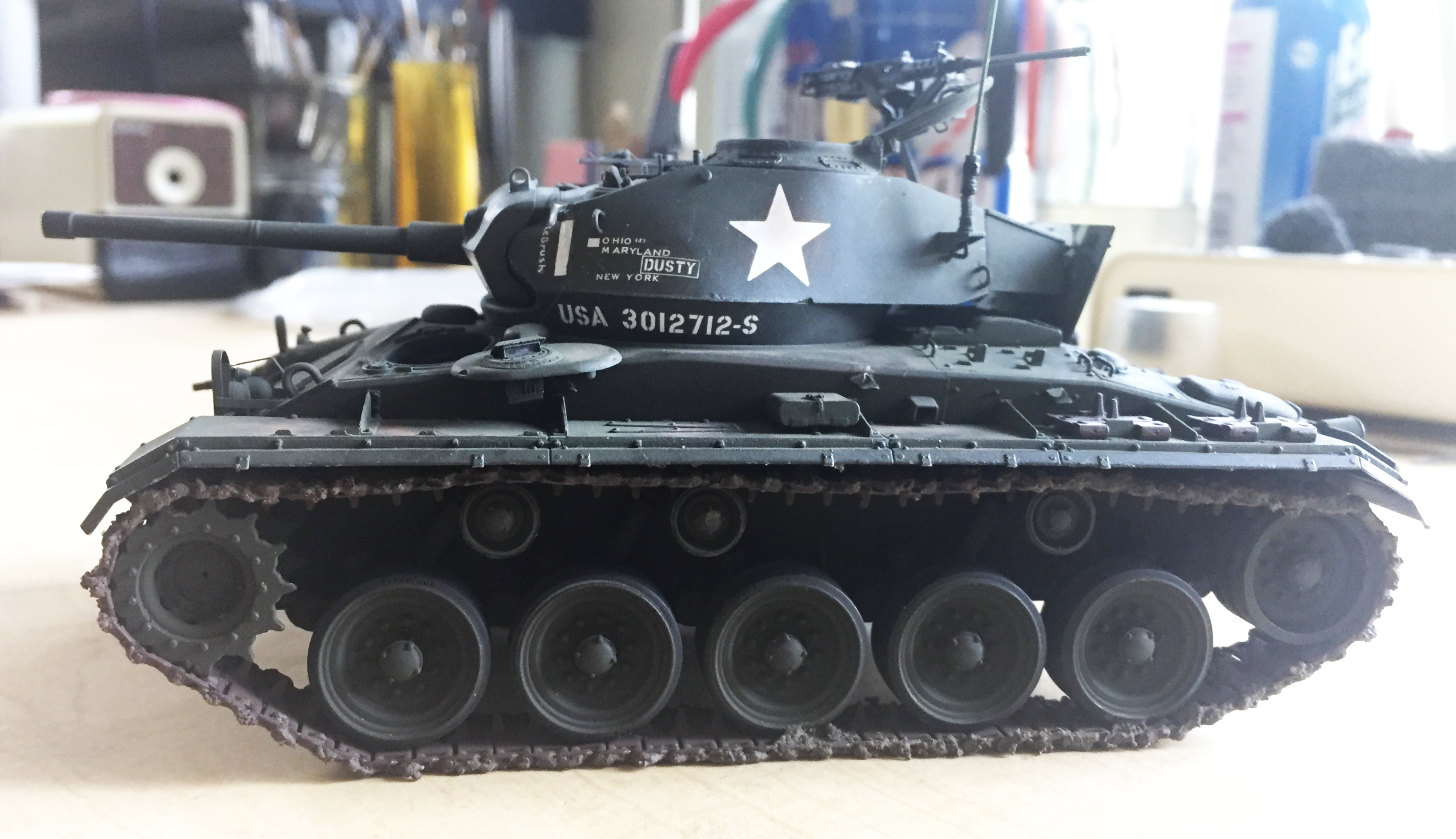
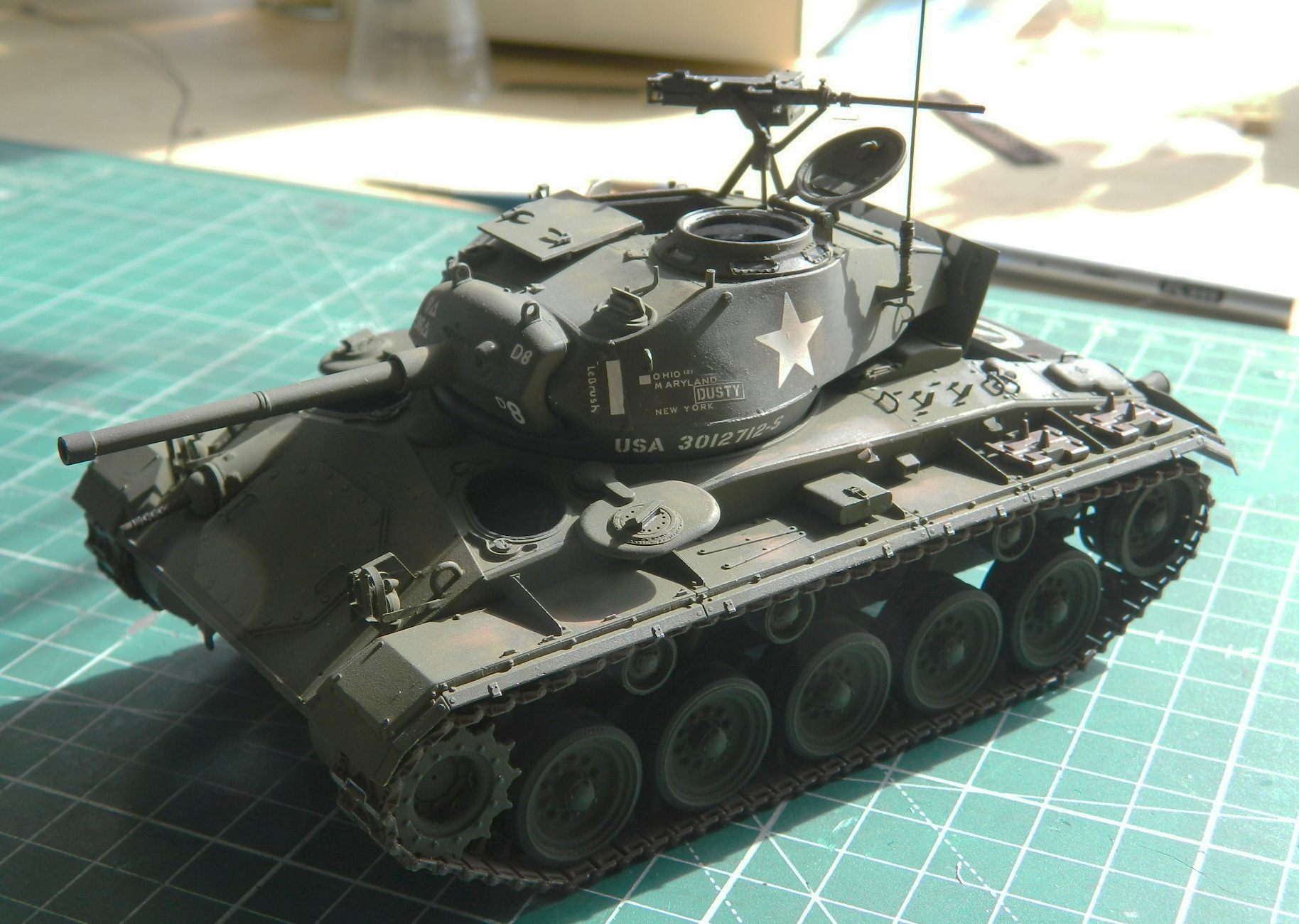
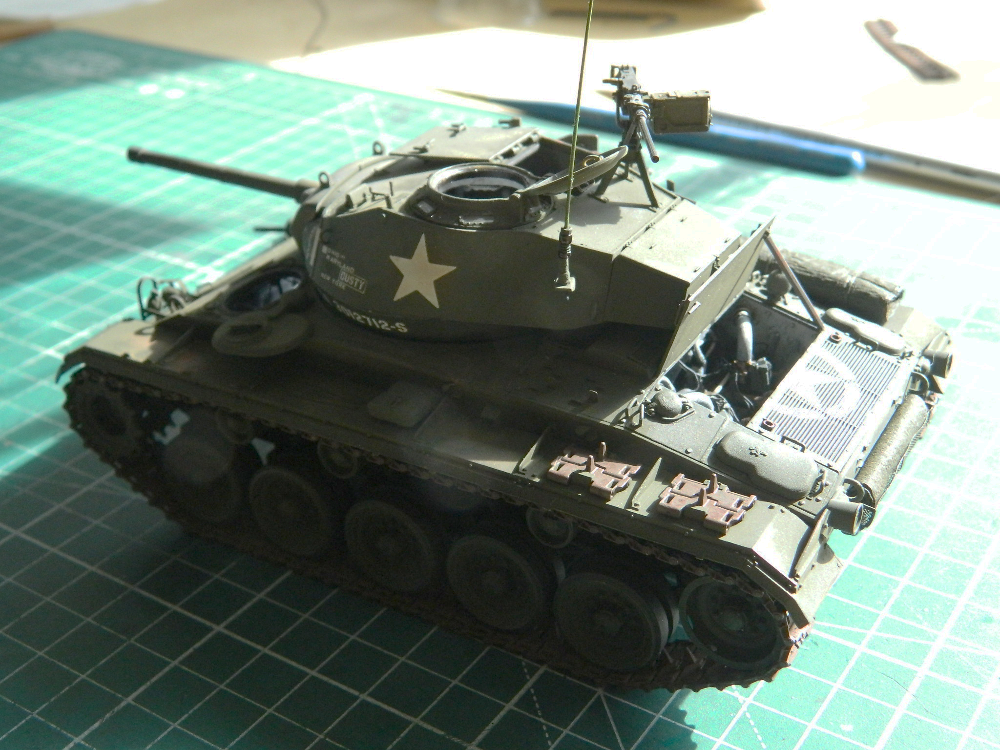
M24 Chaffee (Bronco) after-action report
Total time building 320 hours.
Begin date January 12, 2020; end date September 24, 2020
Vendors:
Bronco
Kit #CB35069 – M-24 Chaffee (Early Production)
Tiger Model Designs (TMD)
Set #35-70023 – Tie-Down Cleats, Small
Verlinden
M-24 Chaffee engine compartment set #2728
M-24 Chaffee interior details #2735
Dry Transfer WWII US Army-type Stars #DTM1305
Tamiya
Infantry Equipment Set #35206
Archer Transfers
Set #AR35209B – Gauges and Interior Stencils
M&Models
Set #GM-34-005 – .30 Caliber Barrels (s), turned brass
The Scenic Factory Mud
Set #MK-02 – Ardennes Forest Kit “Dry”
Lots of solder, wire, lead foil, paint, and sprue
My opinion
I really wanted to like this kit…but I really do not. These notes are my experience with kit number CB35069 which is the early production US version, 1944 – 1945.
This kit is definitely a mixed bag. On one hand, it’s finely molded (which creates problems of its own, as I’ll get into in a bit). On the other hand, once building starts it quickly becomes evident that in far too many situations, location indicators for subassemblies aren’t poor, they just aren’t there at all (more on that later, also). If you’re hoping that the instructions that come with this kit will save you, you are SO out of luck. Given the kit’s initial production date, none of these problems should exist.
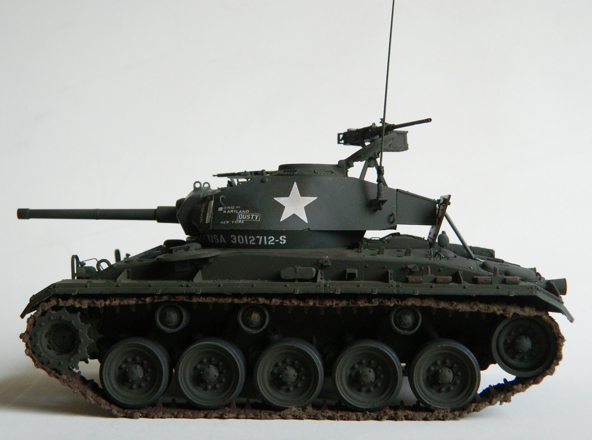
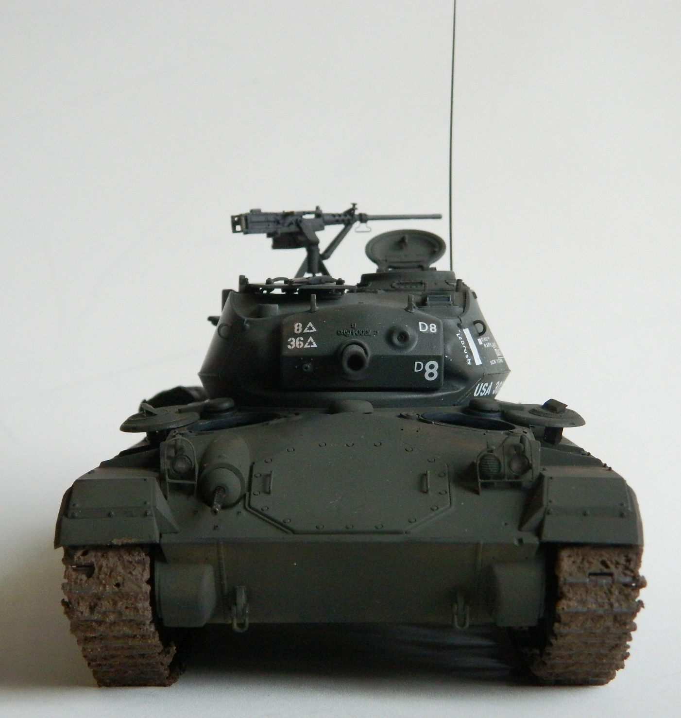
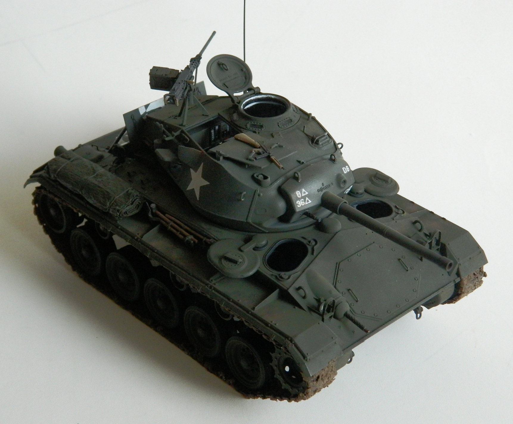
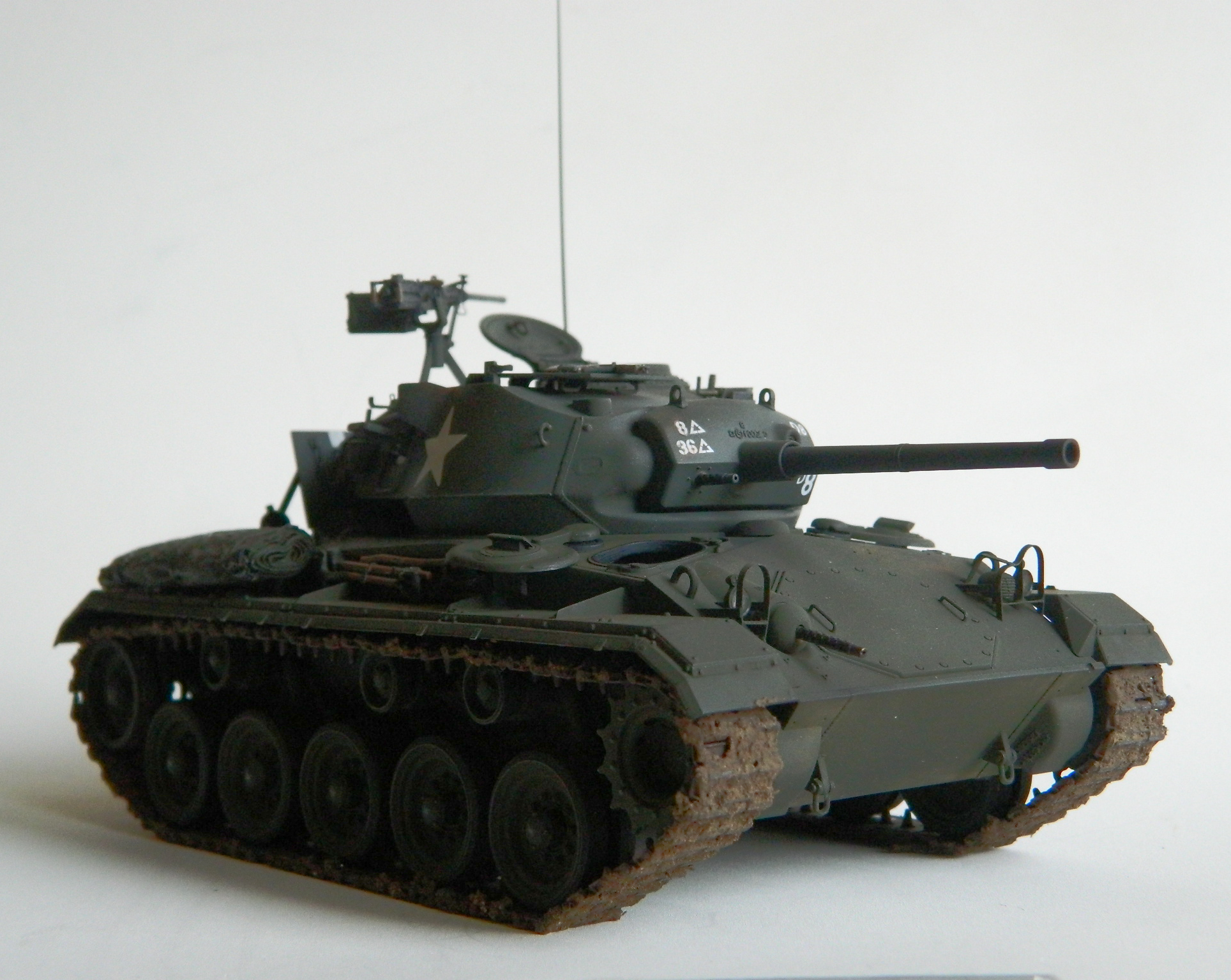
According to Scalemates.com, this kit has a production date of 2012 and has six variants. The kit is molded in light tan, has a small photoetch (PE) fret, and two decal sheets. One decal sheet is of rank and unit patches for the nicely cast crew figures, the other decal sheet offers markings for three different tanks (interestingly, they’re all for vehicles from March 1945); option one is for Company D, 36th Tank Battalion, 8th Armor Division (Rheinberg, Germany, March 1945) and is the one I used I this build, option two is for the 81st Reconnaissance Squadron, 1st Armor Division (Northern Italy, March 1945), and option three is for the 37th Armored Battalion, 4th Armored Division (NW Europe, March 1945). The decals were a mixed bag. The large ones did not go down well and ignored ANY decal solution I threw at it, including Solvaset (they just laughed at Mircrosol). The decals were less like commercial decals and more like the horrible home-printed crap I tried to use on another build.
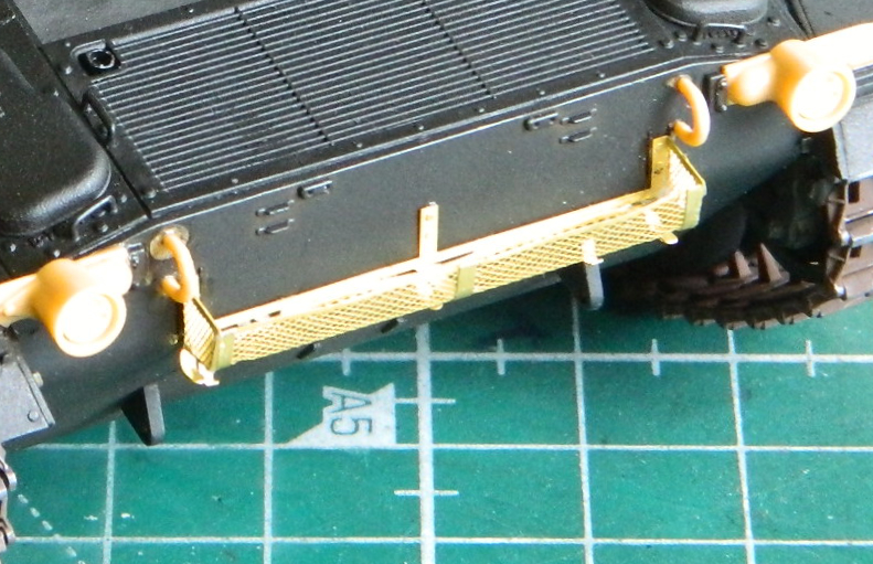
It seems as if Bronco couldn’t decide what “early production” meant. The lower front hull is accurate, providing the stirrup-style steps frequently seen on early production tanks to make getting into them easier. The rear hull, however, does not have provisions for mounting the steps (though they’re provided in the kit) and it should. What it has instead are provisions for attaching the mounting pads for the float assemblies that ended up not being used (developed for the land invasion of Japan, which thankfully for us didn’t need to be used)…and this is a feature of later production tanks).
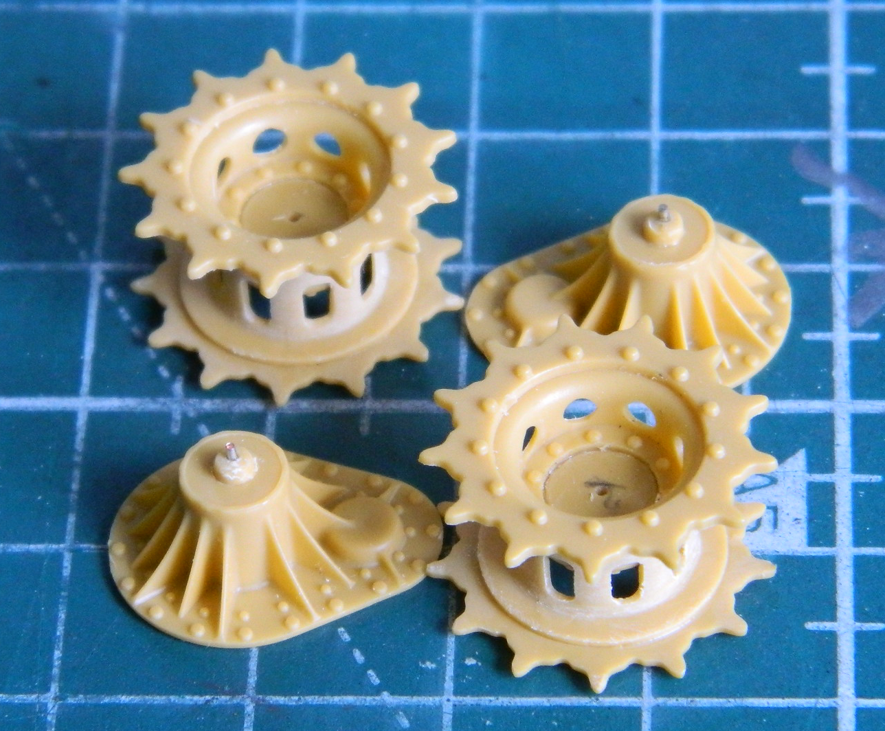
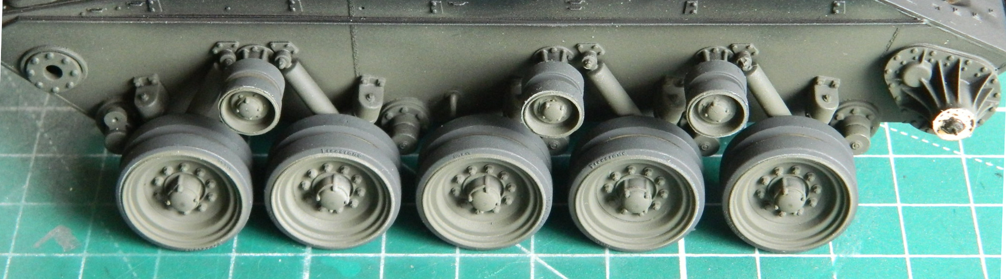
The tracks are individual track shoes. They are, as are most parts of this kit, nicely and delicately molded. I am not ham-handed when dealing with delicate styrene parts, yet during the assembly process I managed to break two tracks shoes to where they cannot be used. Not an auspicious beginning, to my mind. I replaced the kit’s tracks with those from Fruilmodel, part number ATL-39. Well, I thought I was going to but the suspension when assembled is so fragile that I couldn’t be sure that the suspension parts would support the weight of metal tracks, so I wasted the money on Fruilmodel parts and used the kit’s tracks anyway.
When I started assembling the suspension is when I realized that Bronco had designed these parts, the road arms, torsion bars, shock absorbers, and compensating idler wheels, to be operable. I’m trying to figure out some manner that I can use to express my reaction to that that doesn’t involve profanity. Operable “features” on model kits were okay 55-60 years ago. Back then the kits weren’t really miniatures representing actual equipment as much as they were toys that had to be assembled. It was about this point that I discovered that Bronco included a plastic spring that was intended to go into the main gun assembly so it would have a recoil feature! Okay, so this is really very weird to me. Weird segued into annoying when this whole “operational” notion dictated a needlessly high part count combined with little delicate plastic parts in order for things to be “operational.” The tracks, the suspension, and the main gun all have problems directly caused by some moronic engineer (or project manager) that decided “operational” was a good idea.
Since I’ve mentioned high part count…
The breech of the 75mm gun is comprised of TWENTY-THREE parts. Well…okay. Hopefully the instructions will show me where these damned parts go because there are NO indicators on the parts. I hope you don’t have any problems fitting parts to the right side of the breech because there is no illustration for the right side. Clever.
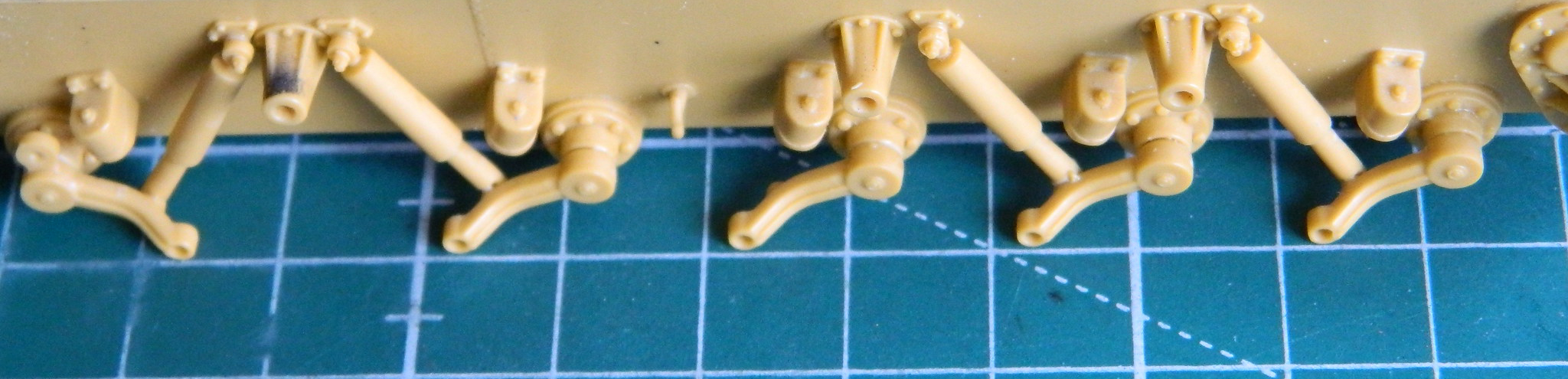
Each road wheel and return wheel is comprised of six parts. Why?! Each shock absorber is comprised of two parts (plus two more for individual mounting bolts for each shock absorber) so that they’re “operational.” WHY?! Each suspension arm that road wheels attach to has its own torsion bar. Yes. Really. An individual, thin, torsion bar that’s supposed to be “operational!” Why?! If Bronco’s engineers/project manager wanted these parts to be posable, okay. That makes sense. Aircraft kits have canopies that can be posed open or closed. They often have flight control surfaces that can be posed as well as landing gear with the same option, to name only a few. But operational?
It’s freakin’ stupid and complicates the model needlessly.
And since I’ve mentioned the torsion bars…
No matter how much I tried, I was not able to get all ten torsion bars mounted identically. They must be mounted identically because there’s a little square extension on the end of each torsion bar that the suspension arm mounts to. If they aren’t all exactly aligned, then the suspension arms that attach to them won’t be exactly aligned. If the suspension arms aren’t exactly aligned then the road wheels won’t be at the same height relative to a flat surface, which is what I want this thing to sit on. Sure…were I doing a diorama where the tank is sitting on an uneven surface, then having the ability to pose the road wheels at different heights would be of benefit. But does each suspension arm require an entire torsion bar? [REALLY FOUL LANGUAGE DELETED] A simple mounting stub would be sufficient and a lot stronger. Since that’s now how this kit was engineered, I took advantage of the flexibility of plastic by dry-fitting the suspension arm over the protruding mounting stub. I cranked the arm past the position I wanted to fix it at, used the shock absorbers to determine how far each suspension arm had to hang…and then glued the arm in position. It took some doing to get all five suspension arms per side to hang at the same angle so that all of them touched a flat surface equally. It took some more doing to get each suspension arm to be laterally identical so that when the road wheels are attached, they are all the same distance from the hull and will therefore sit in the tracks along the same line.
It’s freakin’ stupid and complicates the model needlessly.
Small parts, and there are many of them, are a stone bitch to clean up. They’re often tiny and don’t offer much in the way of grip. Ghastly.
2011, when this model was copyrighted, is well within the 21st Century. CAD/CAM is widely used. Dies aren’t being cut by hand anymore, computers attend to that. As a result, fit tolerances are much tighter than they were before the advent of CAD/CAM…or they certainly should be. That is not always the situation with this kit.
The upper hull parts, which are comprised of seven parts (of course…isn’t every armor kit engineered like that?), don’t fit the lower hull very well. Either the seven parts are too wide, or the lower hull is too narrow at the top. 1/16th of an inch is too large an error for a kit produced by CAD/CAM, I don’t care what the scale is…and that’s how far off the upper hull parts, plural, PARTS, were off. I checked to see if perhaps the box the parts were packed in was too crowded, resulting in pressure deforming the lower hull. No. Not at all. That means the lower hull was built too narrow. (I managed to reduce, not eliminate, the size disparity by submerging the lower hull in hot water while the upper hull’s front part was taped to the lower hull to spread it. The rear parts required very careful sanding for them to fit, particularly as the end of the lower hull was approached; there was no easy way to spread the end of the hull whether it was the front or the rear of the lower hull.)
The front of the upper hull was mostly one piece assuming one doesn’t count the transmission cover plate at the front because it’s separate. The one piece upper hull ended just after the turret ring, where six separate parts have to combine to create the upper hull aft of the turret ring. This is a nice feature if the builder is adding interior parts and/or wants to build a diorama of the tank undergoing servicing and adds an engine bay, fuel tanks, and batteries. The problem with that is that as of this writing, only one aftermarket vendor ever made a detail set to enable that. Verlinden. The same Verlinden that closed its doors and went out of business three or four years after this kit was released. If someone has the Verlinden parts to add the engines and engine bays (plus associated parts), that’s good. As of this writing, good luck finding any of these aftermarket sets. You will, however, find Bronco kits with six separate panels aft of the turret ring in every M-24 kit…
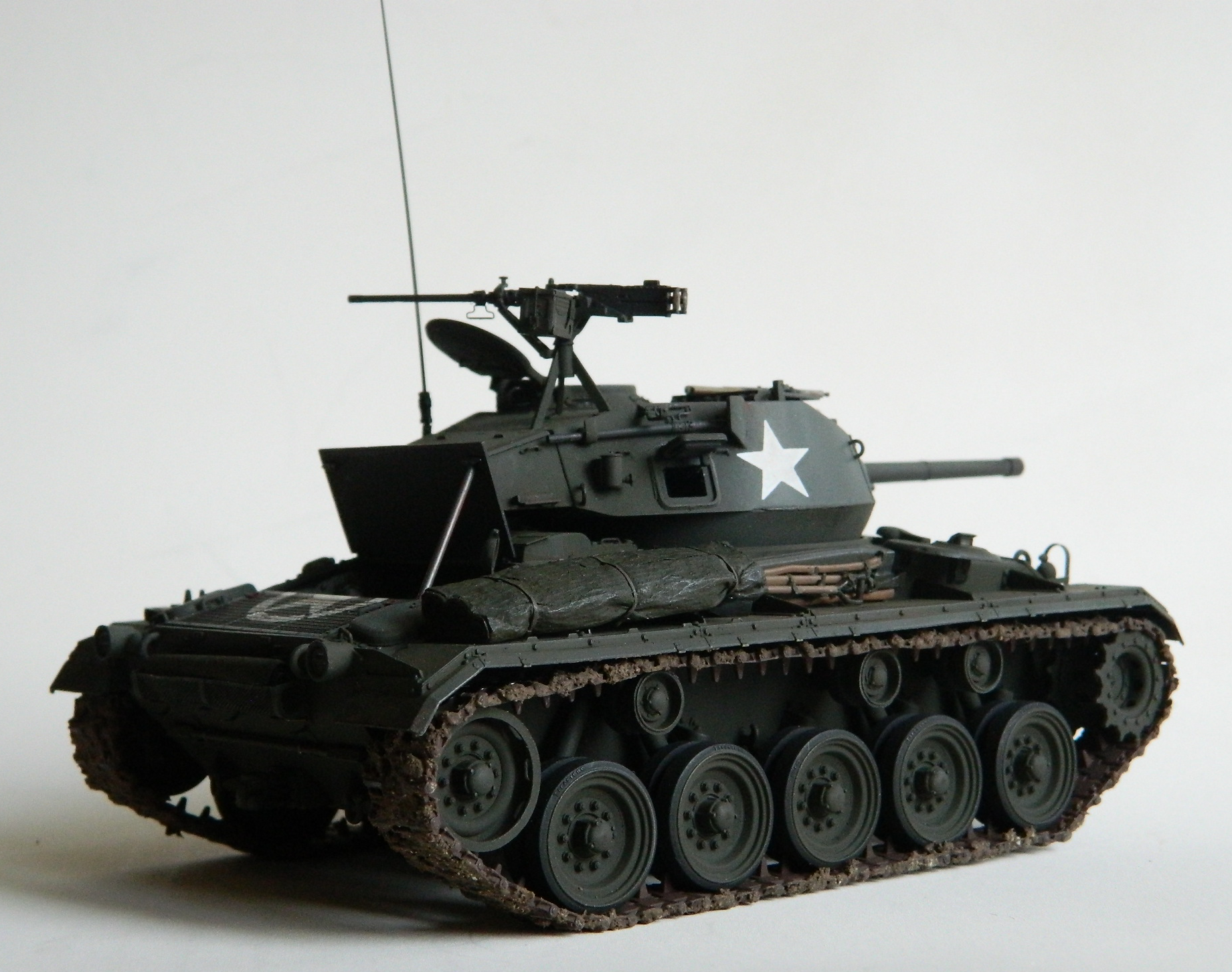
And after whining about the high parts count and how complicated Bronco has made just about the simplest tasks, there is one place they could have engaged in their preference for complications…the M2 .50 caliber on the turret roof.
The gun as molded is quite nice. The top where the breech opens is molded as a separate part (of course) but there’s no bolt or chamber detail in the receiver, so if you want to mold this open, you’ll have to supply that yourself. The carriage the gun sits in can be built relatively easily if you look at the illustrations in the “directions” closely. (Whoever authored the instructions should have used the instructions as written. Maybe after trying that they would have rewritten them to be useful.)
PE parts. Bronco seems married to the idea that the more parts needed for a subassembly the better. The PE fret and the parts supplied takes that notion to stupid lengths. And as far as the rear basket that attaches to the rear of the hull, I would like five seconds with the idiot that engineered this part as two pieces. (The last three seconds would be spent gloating over his cooling body.)
The PE fret also includes VERY SMALL numbers for the casting numbers on the final drive cover…well, most of them. There are two sets, but one set doesn’t include the numeral 1. I managed to get one set of numbers glued on but with the second set of numbers (for the other side) I managed to launch two of those VERY SMALL numbers into oblivion. That means I’ll only have one set of casting number in place, unless I decide to tear the DAMNED THINGS off.
I do NOT like this kit at all and as such do not recommend it. It’s needlessly fussy, parts are ridiculously delicate and there are LOTS of them. Fit is lousy. Of course there are inaccuracies…it’s a kit, after all. If you absolutely MUST have an M-24 in your collection, look around. Yes…it will build into a nice looking kit if you take your time, enjoy a warm, steaming, cup of luck, and I don’t know as you’ll enjoy the process of building it. I CERTAINLY would not recommend it for any but an experienced modeler! I was SO ANNOYED AND ANGERED by engineered-in problems that the bloom was off that rose right quickly. I am SO put off by having to wrestle with problems that were engineered into the kit at the basic level that there are two things I will not be doing with Bronco kits.
1 – Show mercy
2 – Ever buy another one (or even accept one as a gift…eBay is my friend)
M24 Chaffee (Bronco) 1/35 Scale Build #8 – Dealing With Suspension, Tracks, Adding LOTS of Small Details, Wrestling With Decals, and DONE!
I was correct; this has been an interesting month. I didn’t realize how close I was to the end of this when I started this month’s work. The finish always seems to take me by surprise (largely due to my difficulty switching from micro to macro view).
Frankly, I dreaded doing the suspension. I had started assembling road and return wheels early in the build and was impressed by Bronco’s ability to over complicate anything! The “Uh oh” alarm started going off about then because not only were things needlessly complicated, the parts were very, very, delicate. I’m all for scale fidelity, but there comes a point where practicalities have to take precedent over scale. Odd times like actually building the damned thing. (I will go into all that in the After Action Report. Preview: I’m less than complimentary.)
Yeah, so, the suspension. Finicky. Far too delicate (more on that when I get to the tracks). VERY ANNOYING to get everything in place and aligned.
I started with the drive and idler wheels. I wanted to pin the drive wheels to make getting the tracks less annoying to put on:
The came the joyous event of attaching the suspension arms and shock absorbers. There was no definitive, and aligning, points for the suspension arms to attach to. Due to unintended variances in how I mounted the torsion bars (because who freaking needs torsion bars…they will never be seen), the rotational alignment of the arms were all over the place. I rounded off the square ends of the torsion bars where they extended from the hull because as location devices (which I mistakenly assumed they would be) they were as effective locating the arms as a screen is in holding water. I used the lines on my cutting pad to align the arms longitudinally and my Eyecrometer to align them vertically. What “helped” was the limited stroke of the shocks because Bronco molded them as two-part items (not counting the top and bottom mounting bolts which were STUPIDLY delicate):

While waiting for the glue to cure completely (because these parts are delicate enough without having to dick around with them to realign them if they get bumped/nudged out of place), I did something I wish I’d taken more photos of.
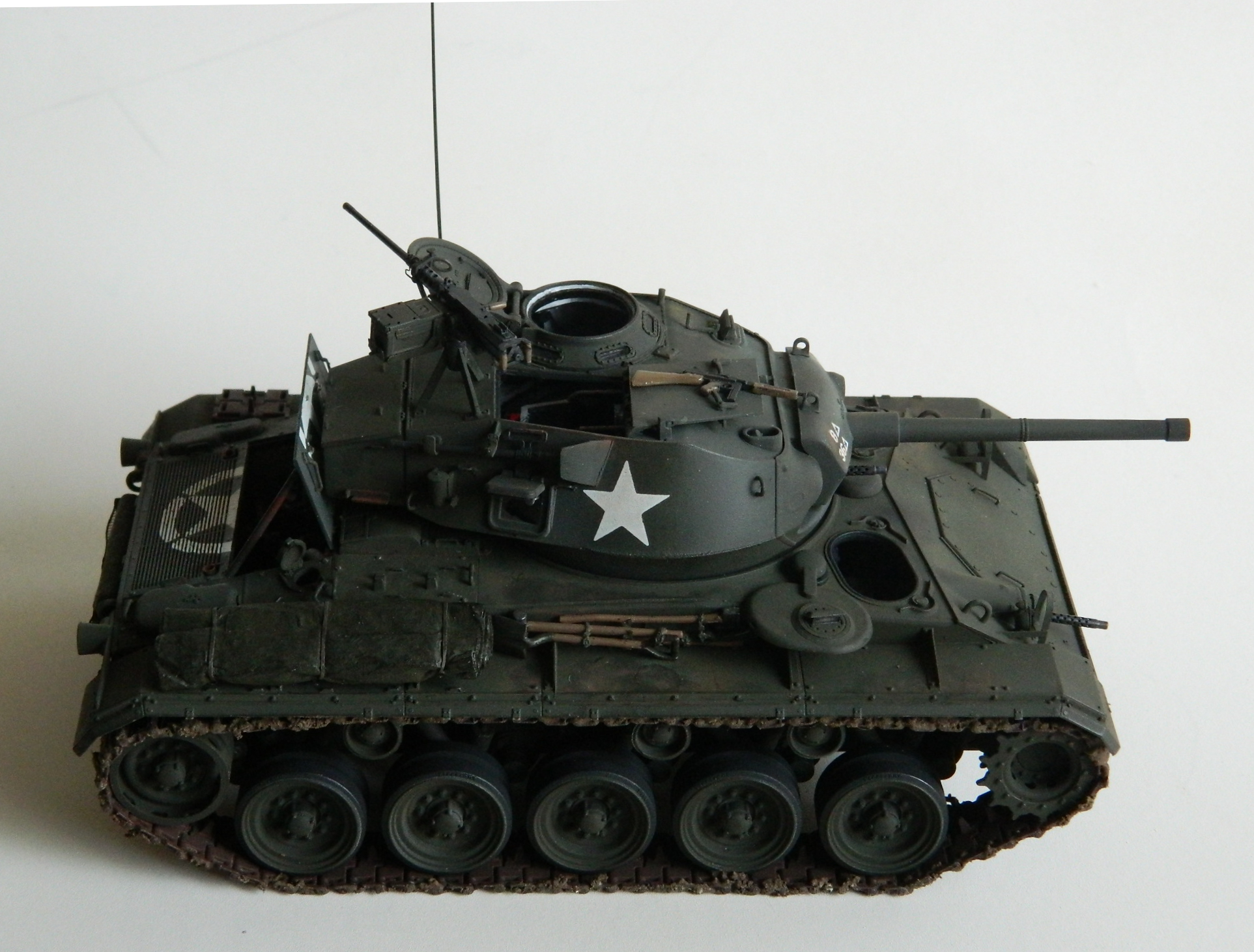
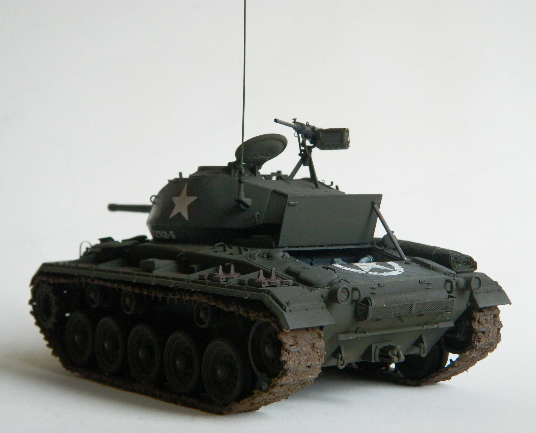
The .50 caliber (12.7mm) on the turret roof has a travel lock. That’s a hinged arm with a clamp that will swing up and hold the 80 pound (36.2874kg) machine gun in place so that it doesn’t brain someone during travel. The kit offered the travel lock, but they set it up so that it’s not holding the gun in place, it’s down with the clamp lying on the turret. I wanted to show the gun in the locked-for-travel position. That turned out to be easier than I’d thought it would be. All I had to cut open was the clamp and then add a small piece of stretched sprue to replicate a longer bolt. I liked how Bronco did the machine gun and used it instead of going to AM parts for this. Slide molding provided a hollow cooling shroud and a muzzle bore:

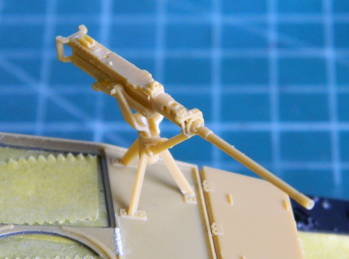

Bronco did not provide the “butterfly” trigger so I made one out of heavy aluminum foil:

Having done all that, in order to keep from snapping the gun and its mount off, I sawed it off and set it aside to add later on when the amount of handling will be much less.
I’ve seen a number of builders who will assemble the tank and then paint it. I am in awe of their masking skills (I assume because I don’t know how they do it). Mine aren’t of that caliber; I have to paint before assembly. I painted the road and return wheels black first:

Then added what will be lighter areas using flat white, “masking” the rubber portion using an artist’s template:

Finally dusting Tamiya XF-62 Olive Drab over it all, using the artist’s template again:

Once I was totally convinced (and so far so good) that the cement had set up completely, I preshaded the tank using flat black, then lightly misted OD Green over the black under where the fenders will be:
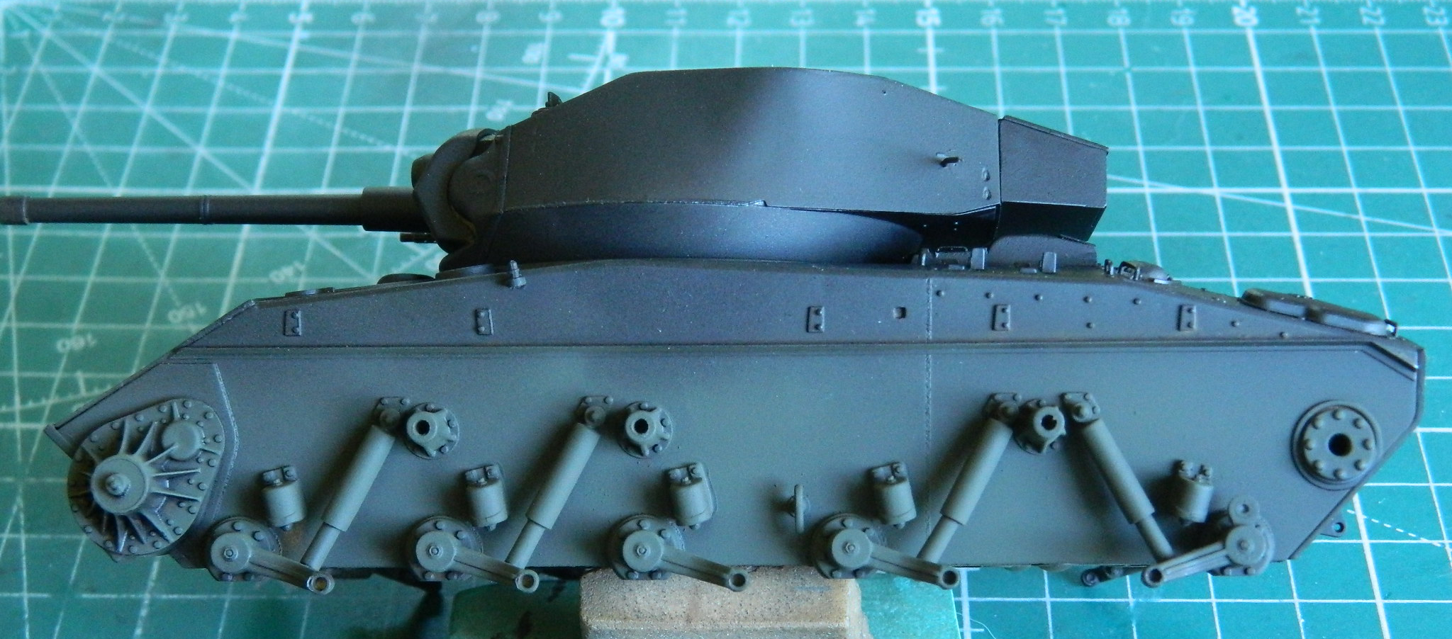
Then I glued the wheels on. Six little words that took a looooong time to get everything aligned for the same reason(s) I had to work to get the suspension arms aligned. There are no positive alignment aids engineered (if I dare use that term) into the kit:

During the fitting of tracks, I broke two wheels off once and one wheel off twice. It’s nice to see that engineers that flunk out of college can still get work.
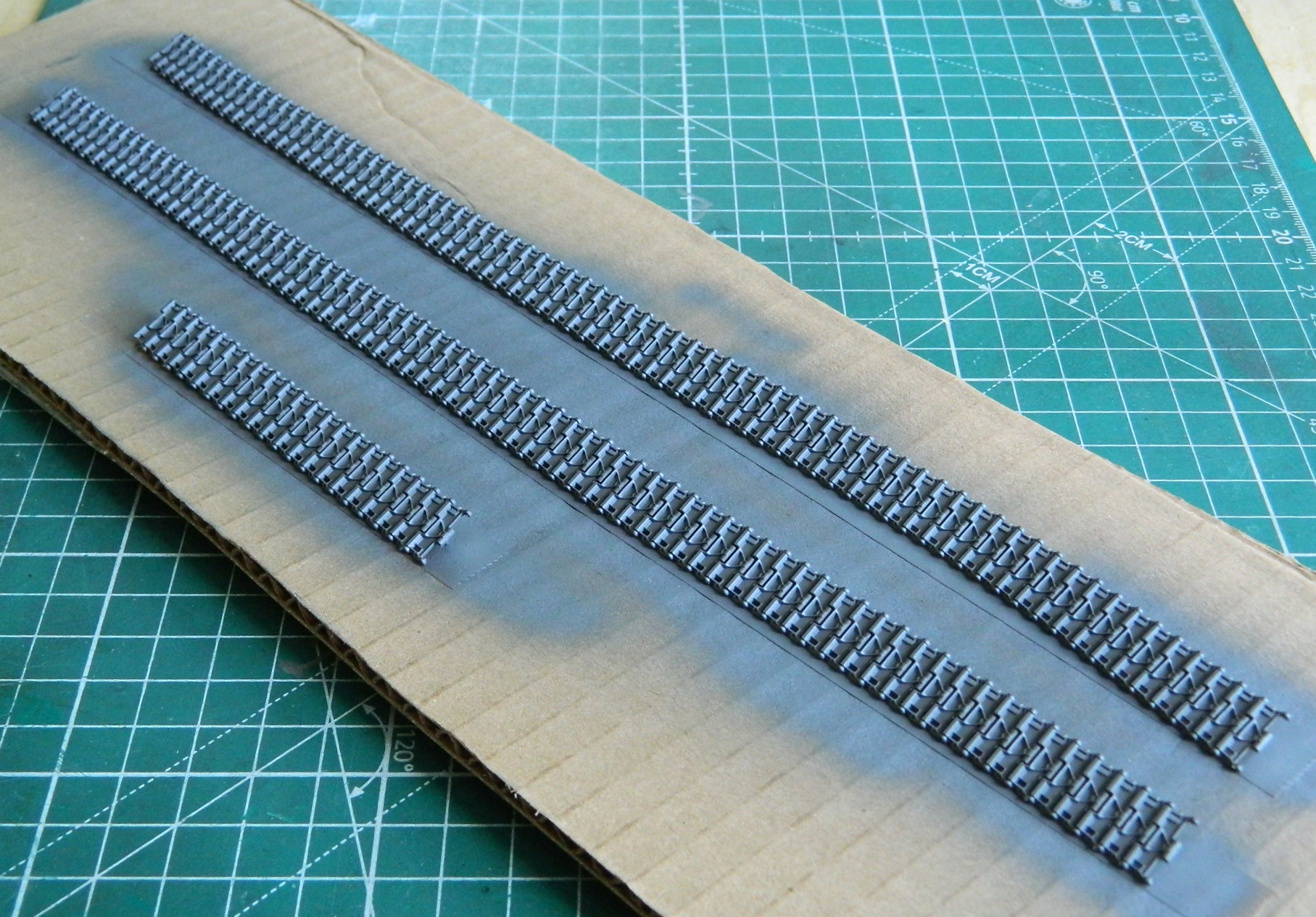
I had intended to use the metal tracks from Fruilmodel. Yeah. NO. No, no, no, no, NO. I don’t think this delicate suspension is up to supporting the weight of them, so instead I went back to the (now familiar) delicacy of the kit’s tracks. I started by painting them Humbrol Metallizer #27003 Steel (using double-sided tape to hold the track runs in place). The long runs are what Bronco suggested, 72-73 shoes per side. When I fitted them to the suspension, it was more like 75-76 shoes per side. The “extra” links came from the short run of track below:
Once the paint dried, I buffed the faces of the shoes where they would contact (and thereby wear) the ground:

With all the contact points buffed, I painted the tracks using Tamiya XF-68 NATO Brown (14 parts), XF-69 NATO Black (3 parts), and XF-7 Flat Red (which has become my go-to mix for tracks). I used a chisel-tipped toothpick to remove the acrylic paint from the enamel of the steel paint:

I love the look of individual track shoes, I don’t like the tedium of getting them to the way I want them.
That led me to the point where there was nothing left to do but mount them onto the suspension. There was about 15mm worth of play in the tracks. What that means is that if I compressed them longitudinally, stretching them out to the extent of their play gave me 15mm, or a little over half an inch. That enabled me to get the tracks as close as possible to being almost sag-free and aligned on the sprocket wheels and road wheels before gluing the pivot points of the shoes. Having separate fenders made putting the tracks on MUCH easier than trying to snake them under sponsons, over return wheels, aligned on the sprocket wheels, and then adjusted for sag:

With the tracks on, it was time to mount the fenders, mask the suspension and tracks, and paint them black:

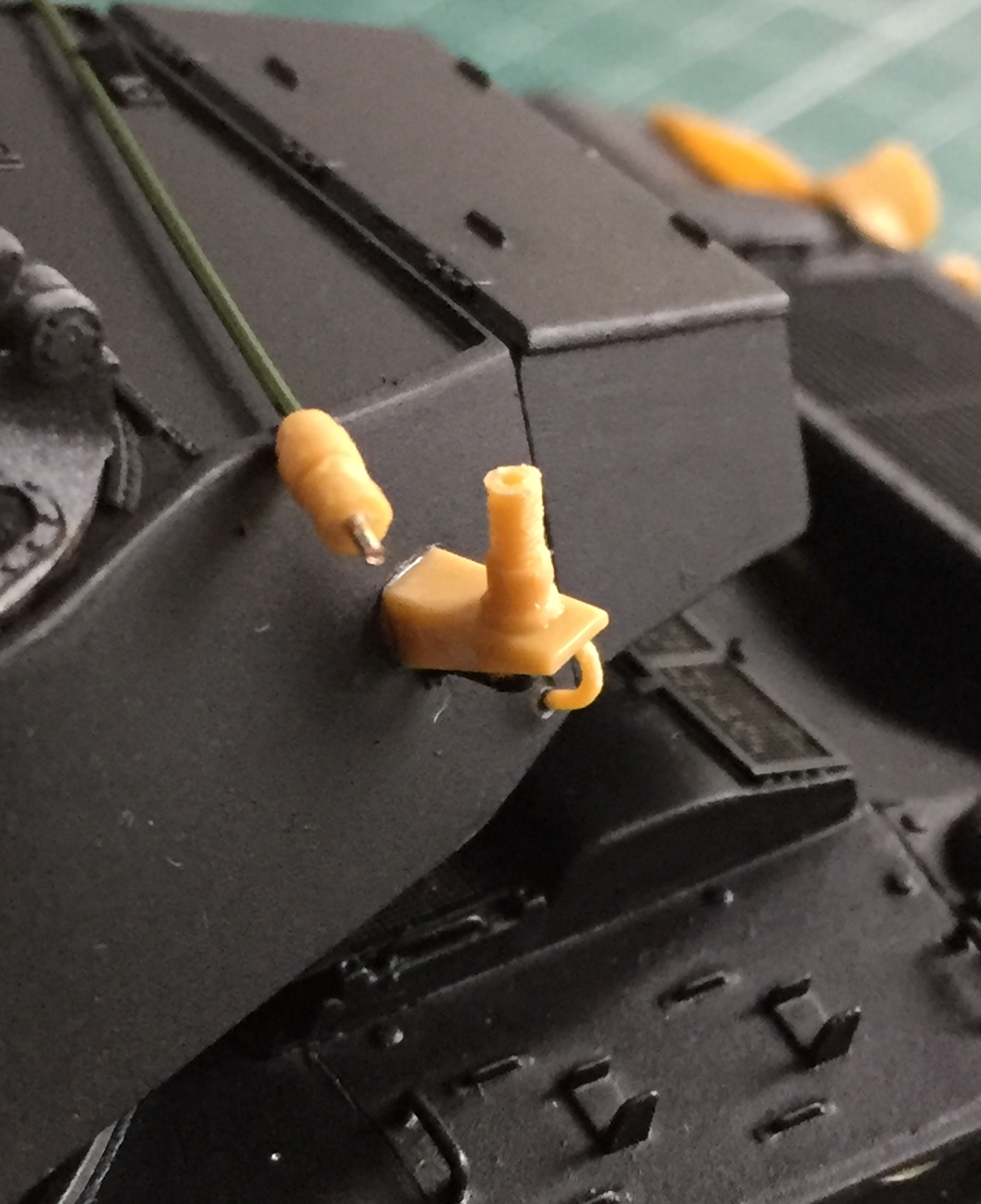
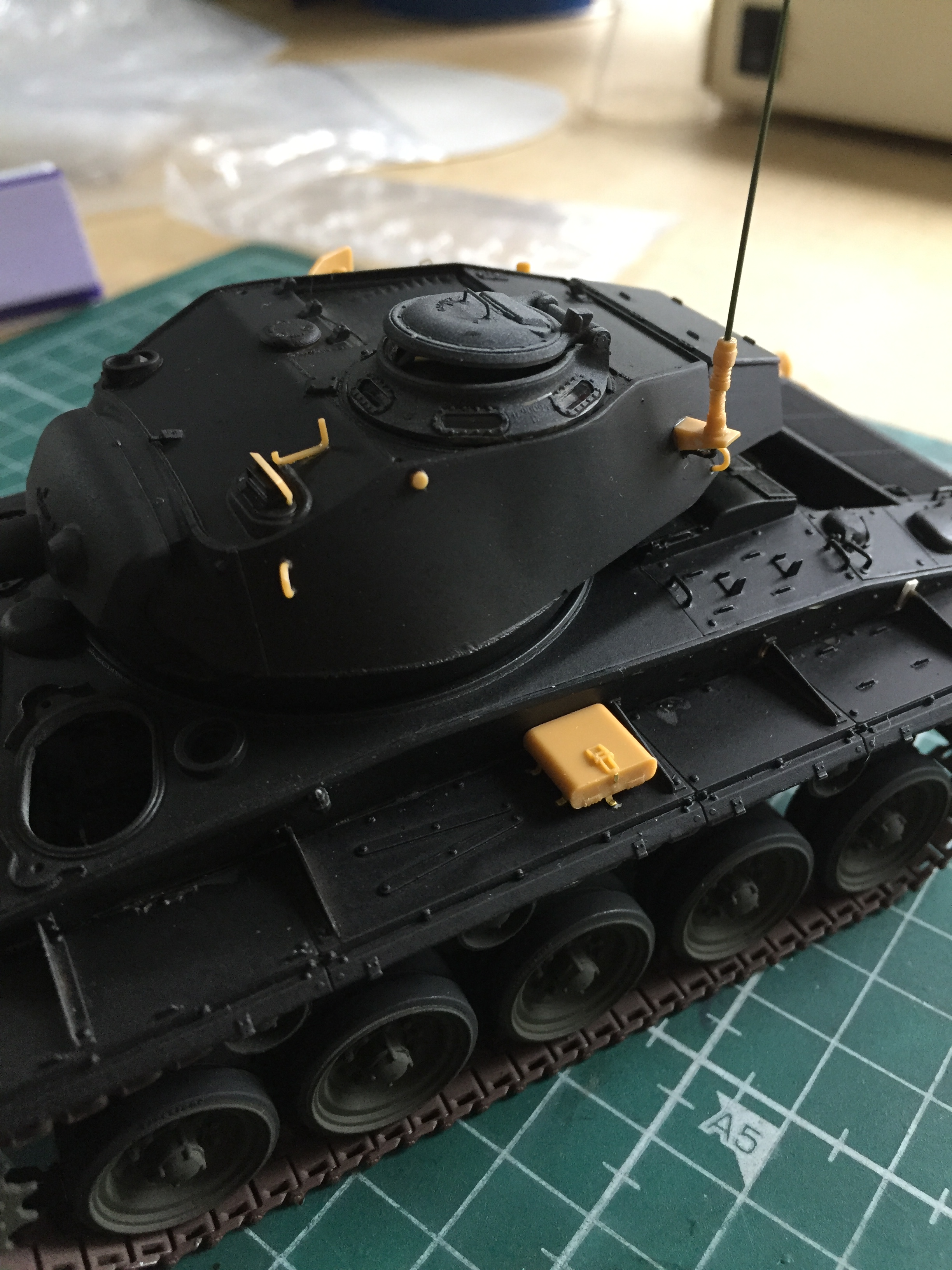
Then it was time to start adding all the surface details. I started with my traditional two-piece antenna mount:

And then I encountered THIS little lovely. The basket on the rear of the hull. Bronco TOTALLY screwed this part up, making it a two-piece part because why would they ever do something FORNICATING GODDAMNED SIMPLE?!? It simply bit and gnawed on the short curlies and what I ended up with was better than nothing (I assume, because it’s fornicating there) but NOwhere near “good”. This part should have been produced in ONE piece so that the long edge where the body of the basket mounts to the back of the basket (or at least tries to) would be a simple damned fold, NOT A LONG PART WITH NO REAL SURFACE FOR EITHER GLUE OR SOLDER TO ADHERE TO. In the process of finishing the kit after this piece of garbage part was “attached,” I got to REattach it several times…and each time I did it looked worse and worse…all because some beef-wit couldn’t engineer the damned part correctly:

I assure you, in case you missed the subtext here (and in several other places), I am not remotely fond of how Bronco engineered this kit. I have no tolerance for amateurs that masquerade as professionals.
The remainder of the small detail parts had varying degrees of ease and annoyances, but I adjusted my medications, then waited until I was (somewhat) sober, and persevered (the small gray cleats are TMD parts):


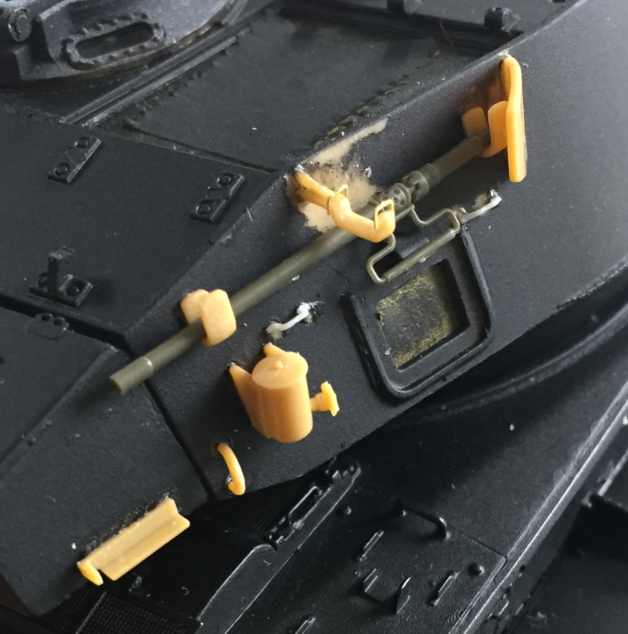

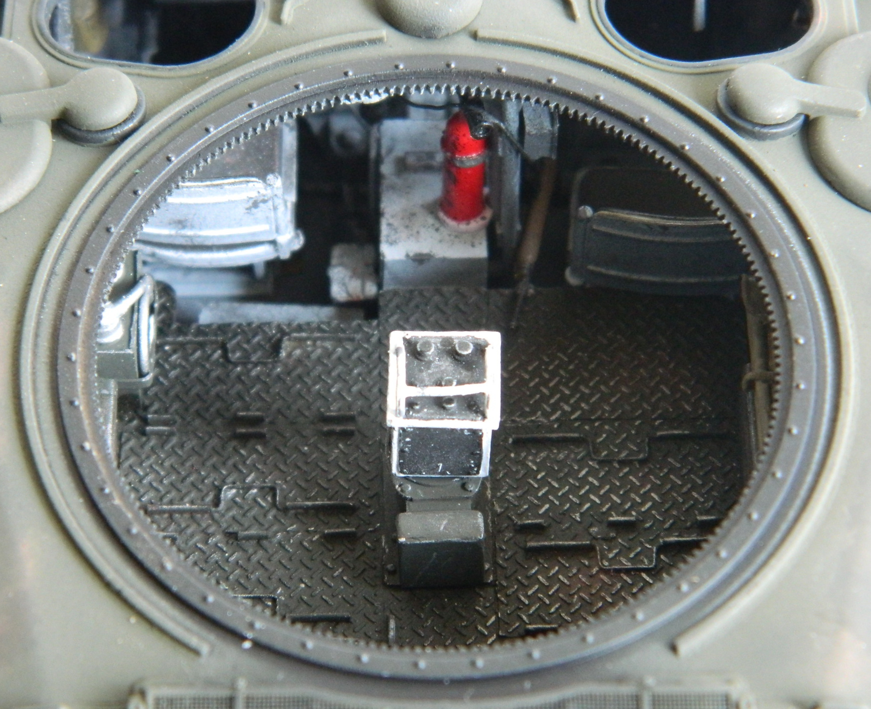
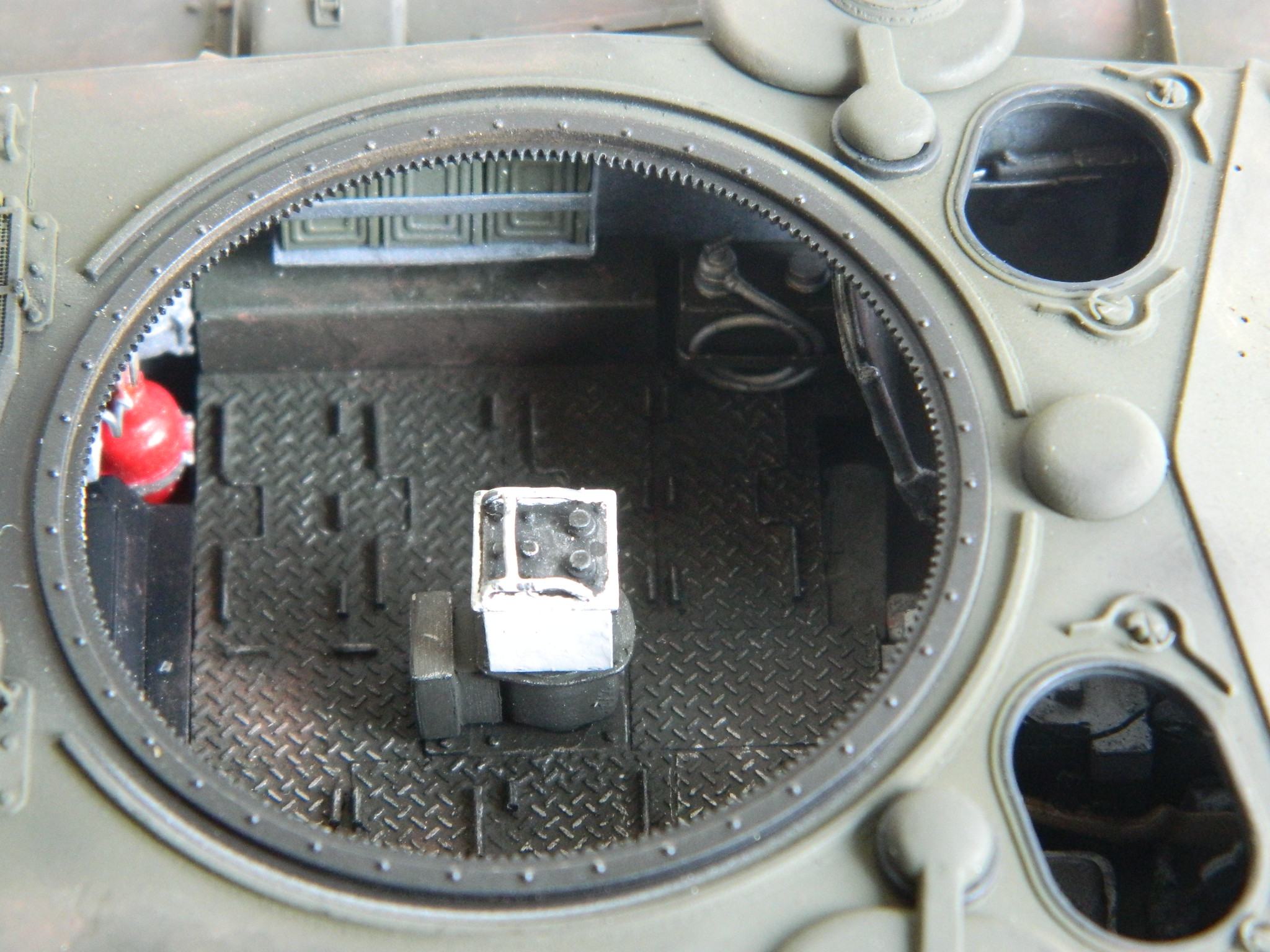
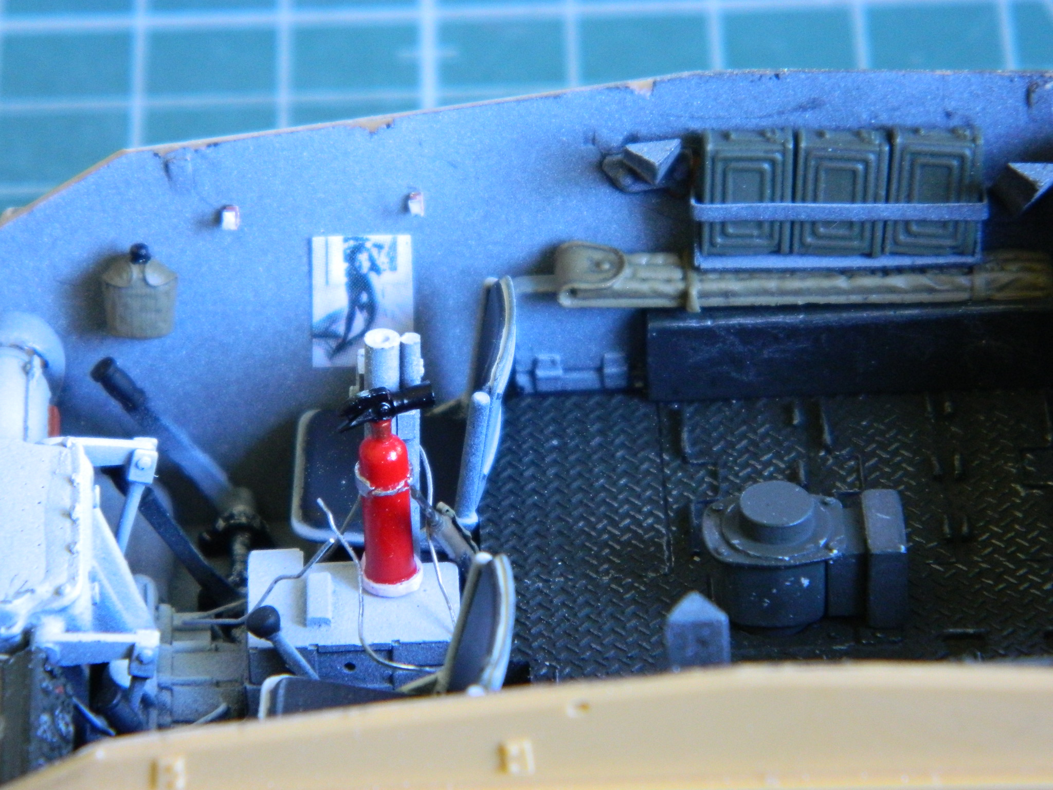
There is a large fire extinguisher that mounts to the bulkhead between the crew and engines compartment. There is also an external T-handle that someone outside can use to activate it. The kit provided the shroud, but amazing me completely, missed an opportunity to make a RIDICULOUSLY small part that’s a sodding NIGHTmare to remove from a sprue and clean up…so I made one from stretched sprue:

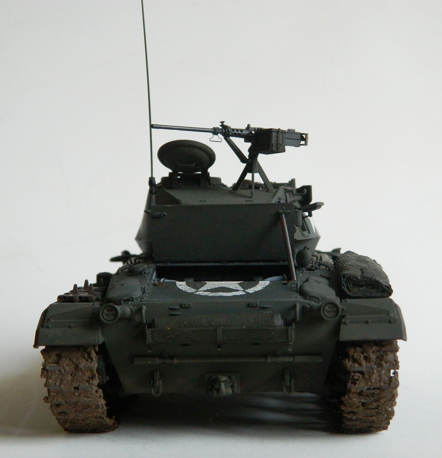
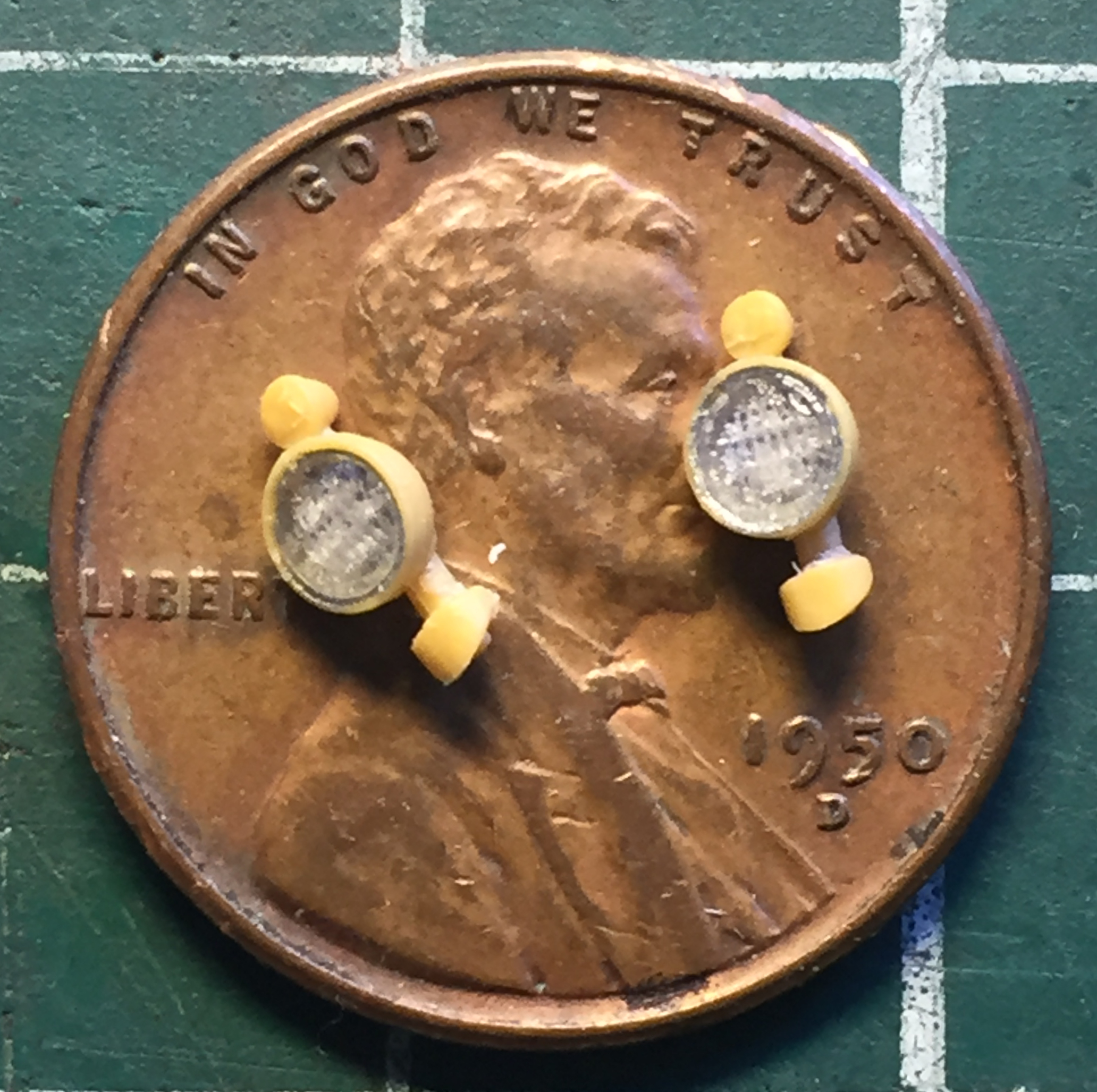
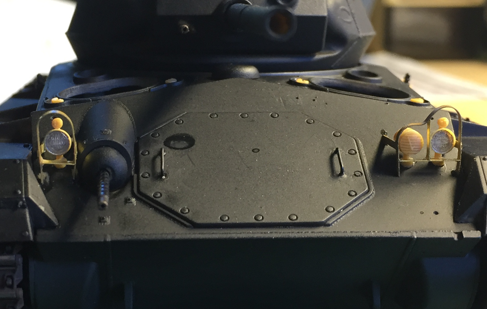
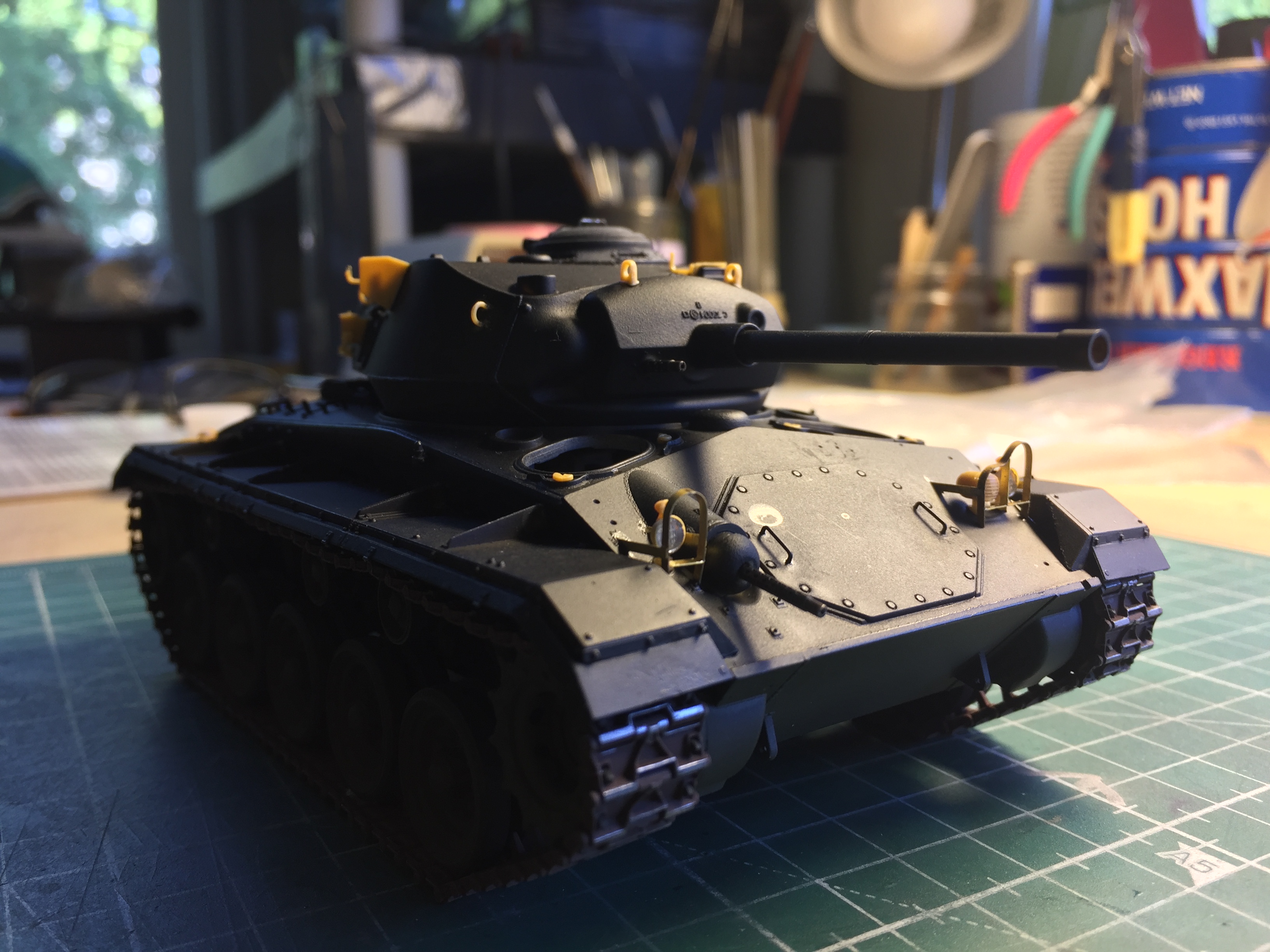
Amazing myself completely, I did not break these delicate headlight assemblies during construction, attachment, or painting. Amazing:
With the headlights in place, it was time to do the same thing with the headlight guards:

More from dogged persistence than for any other reason, I eventually got all the small bits on and the whole thing was ready for paint (which is another way of saying, “Discovering the small things I forgot to add before painting”) (the engine cover is just placed in the closed position to serve as a mask for the engine compartment):

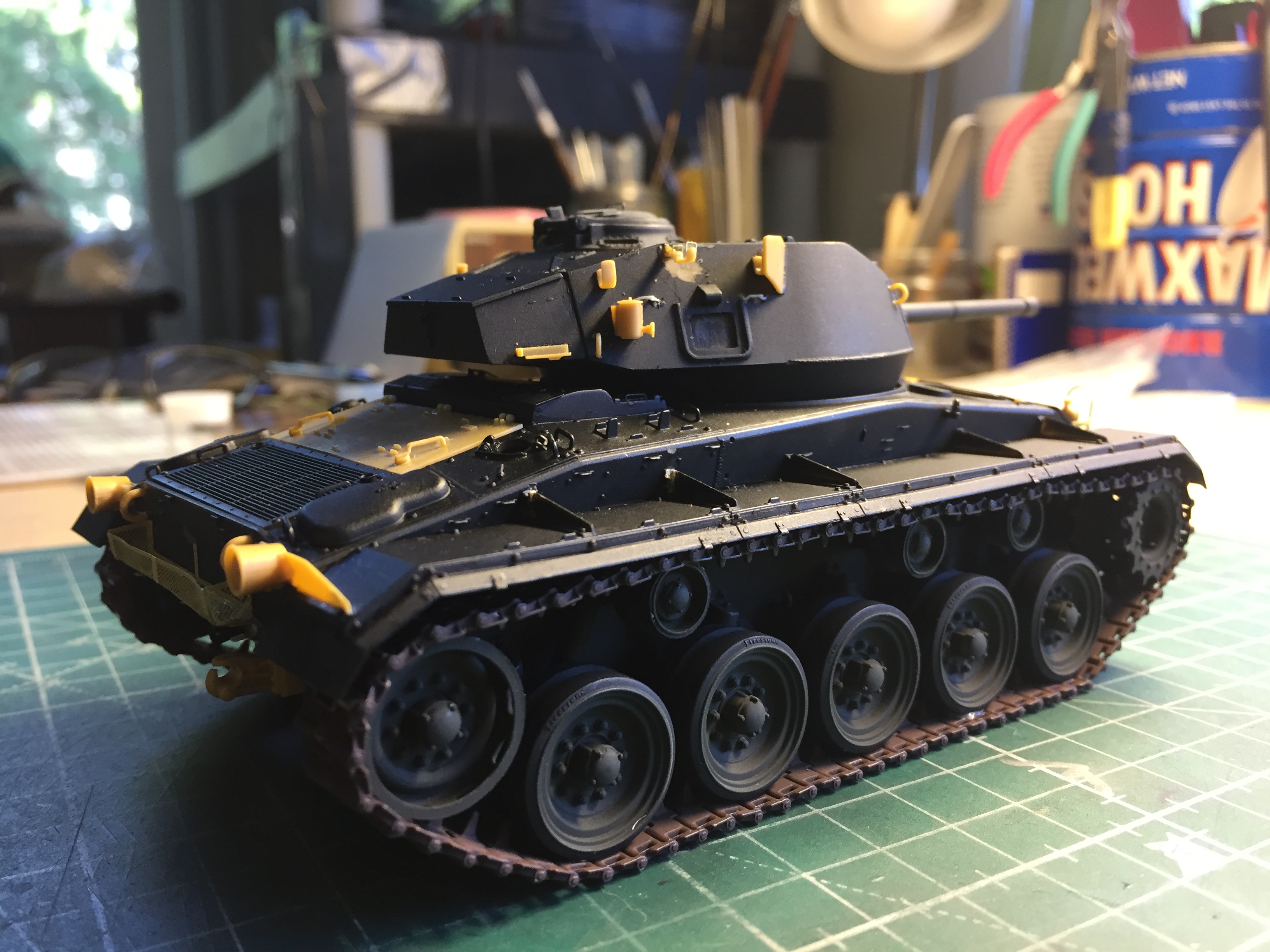
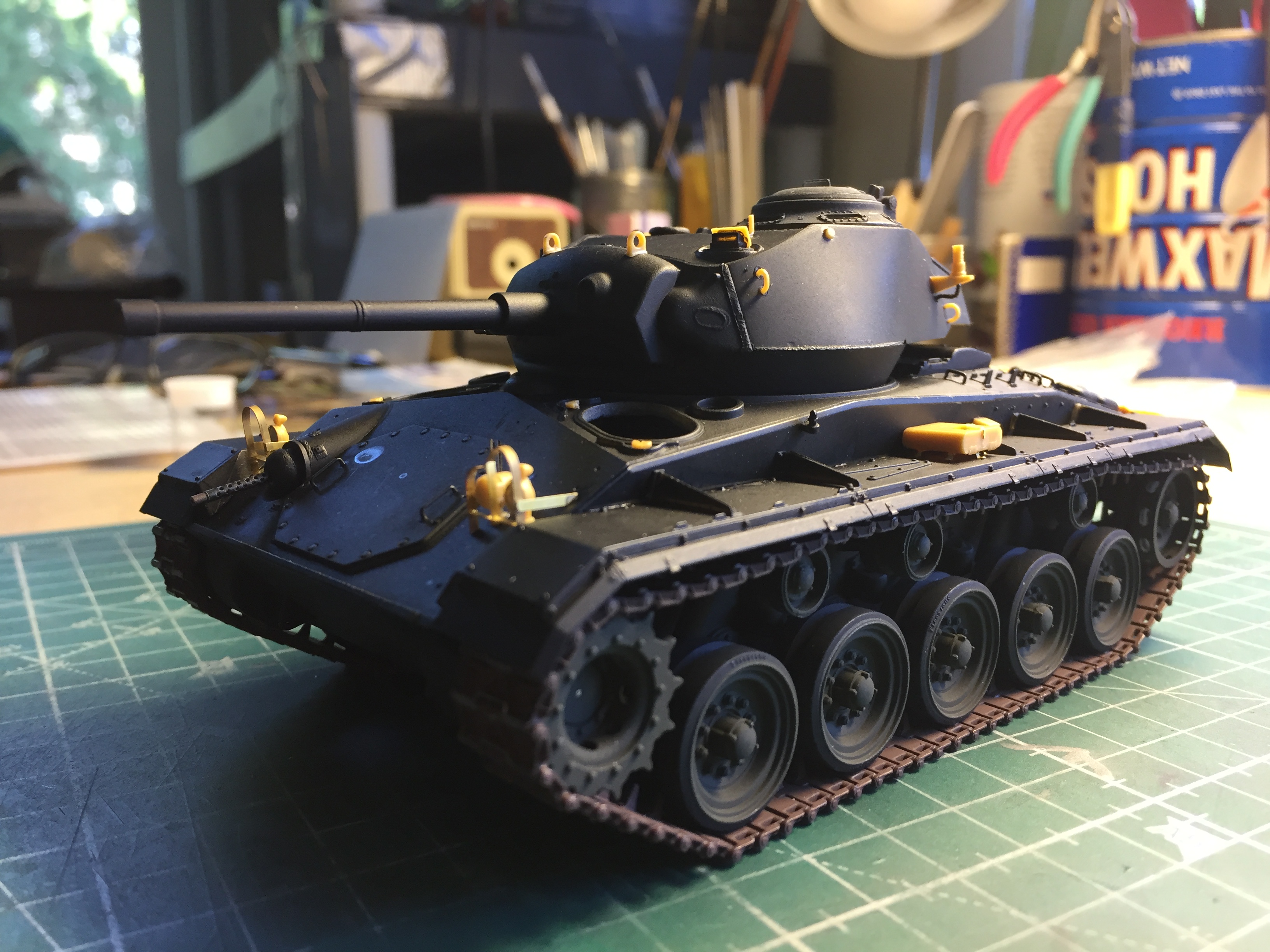
Right! Well, now that it’s been pre-shaded (all the tan parts were hit with Tamiya XF-1 Flat Black), it was time to add the highlights (Tamiya XF-2 Flat White):


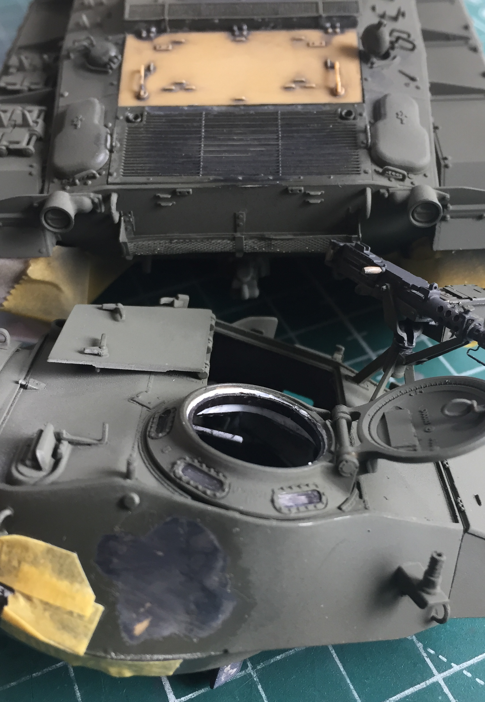
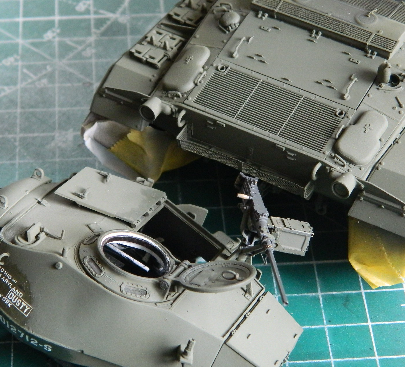
Time for the base color coat (so that it blended in with its new home, at this point I reattached the .50 caliber (12.7mm) and masked it with aluminum foil):

It was about this time that the novelty of having an operational commander’s hatch wore off. It’s not a toy and it was a gimmick. A touch of glue fixed that.
I mask where necessary to get the results I want. Sometimes I don’t mask at all because the mere attempt, usually with something very small, is more hassle than the results are worth. I can adopt that attitude because I paint with acrylics and they are relatively easy to scrape off what I would otherwise have masked…like the vision blocks of the commander’s cupola. I use a toothpick that’s been sharpened to a chisel point to remove paint from unwanted locations:
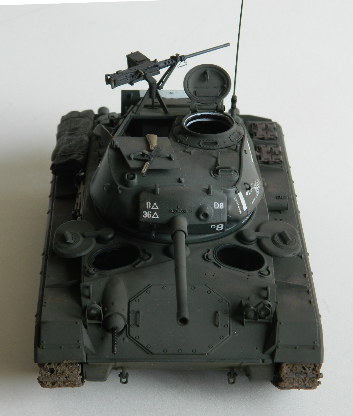
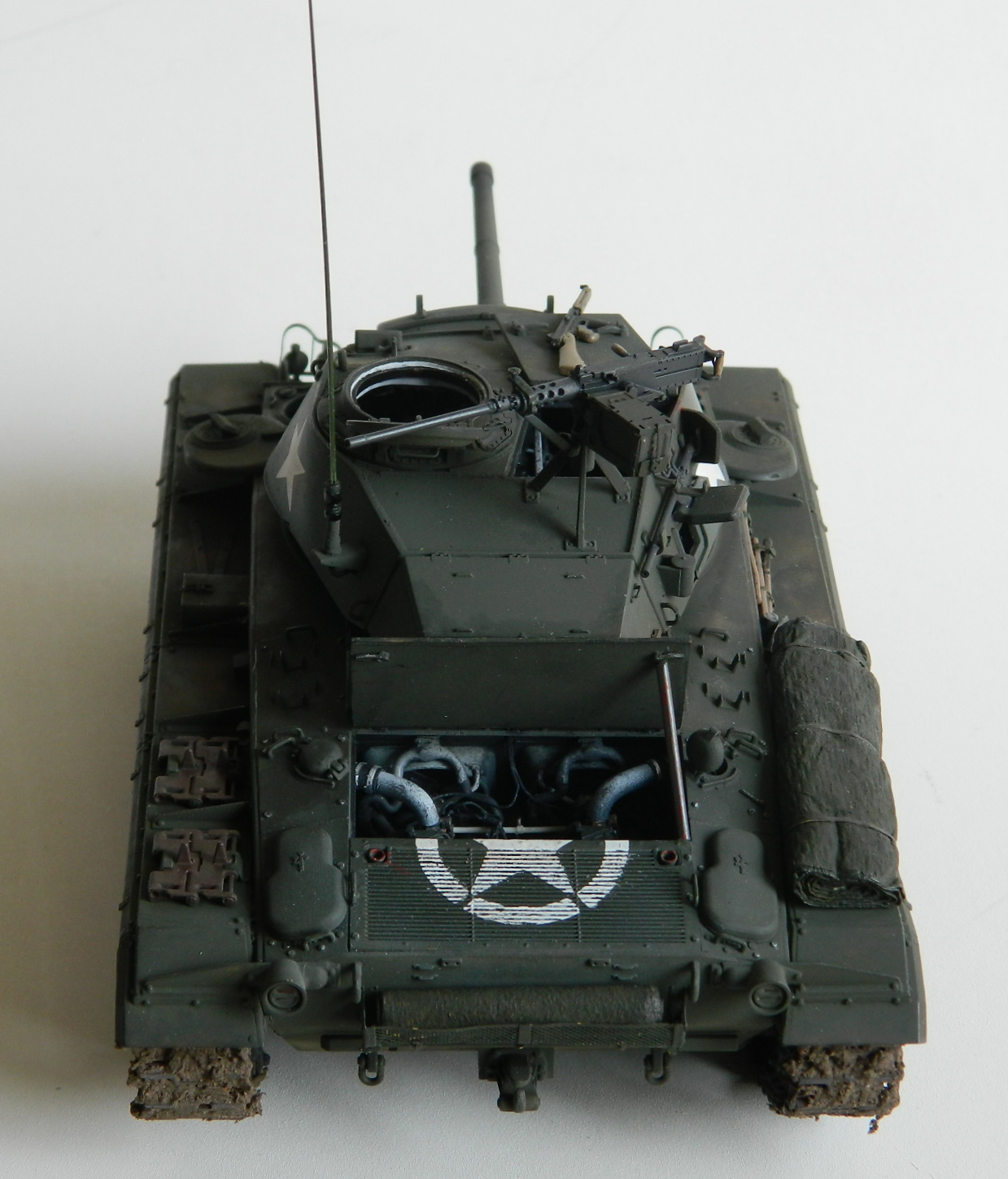
The paint/decal call-out shows this for the star over the engine deck:

It’s not centered or aligned vertically. Screw that. I was going to do mine centered and not rotated off vertical.
For the decals, clear gloss goes down:

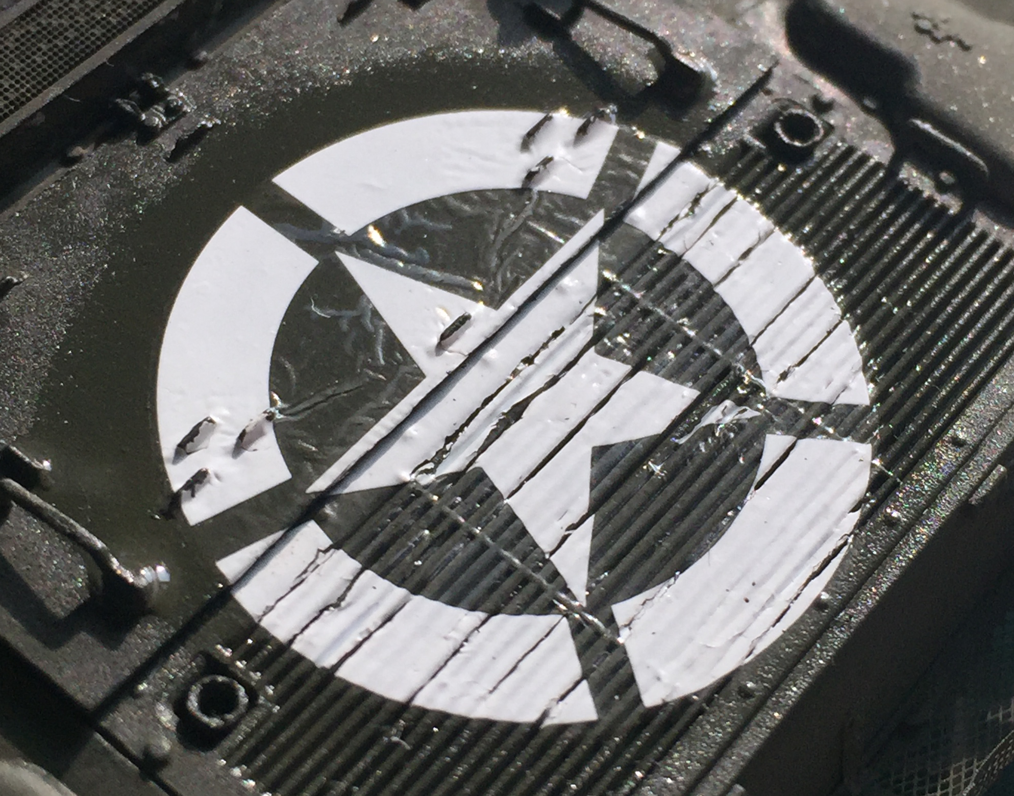
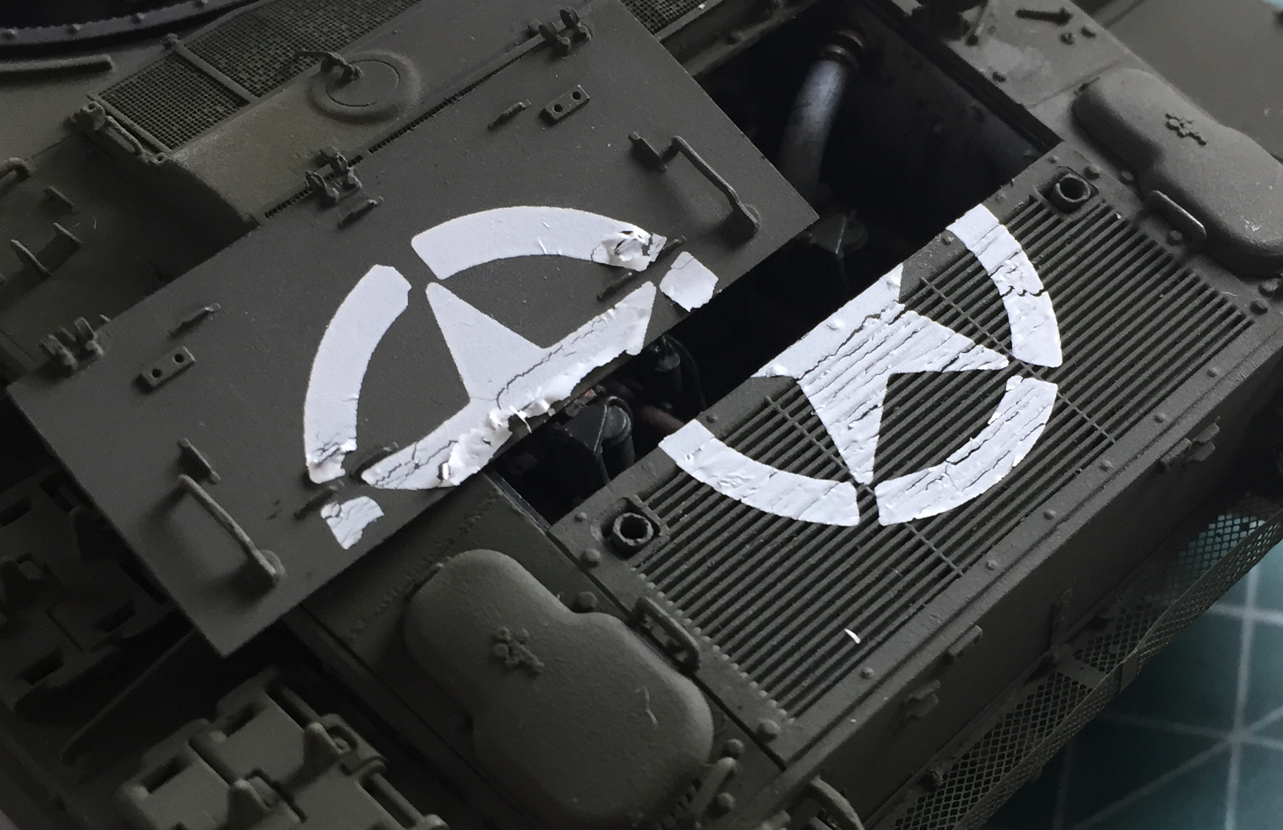
Then I applied decals. This is the star over the engine compartment. More than half of the decal is supposed to rest on top of the vent grate. One would think that whatever [DELETED] made the decals knew that it would need to be slit to replicate paint on the grill, not bridges over the grill openings. Well, I would think that…that’s not how it was done. The decal went down, Micro Sol went over the top of it, and I waited:
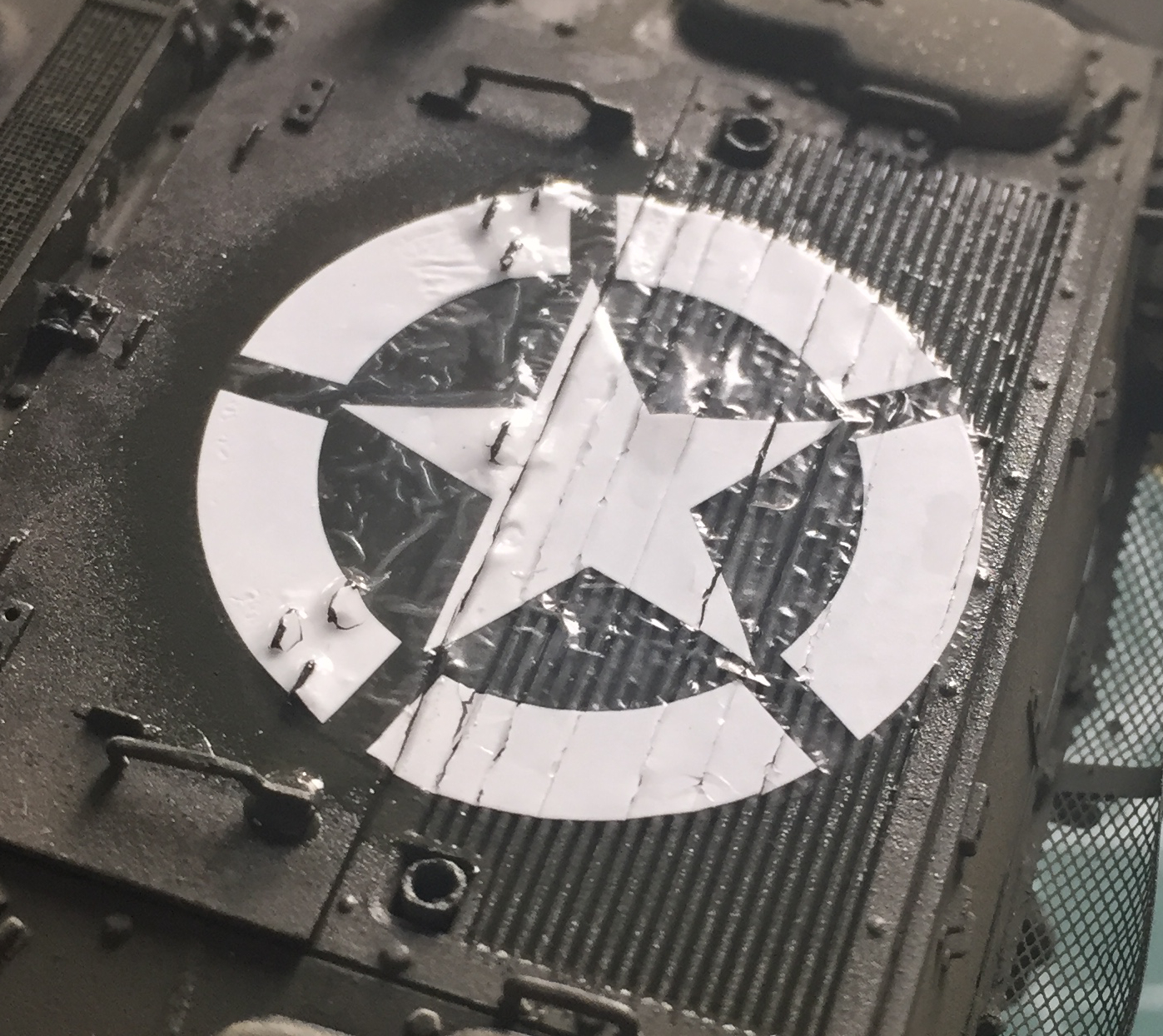
I waited a loooooong time. I waited for nothing. Even using the hottest decal solvent I have, Solvaset, and multiple applications, and waiting another loooooong time only resulted in this unacceptable outcome:
Which resulted in me doing this:
The stars on the turret’s sides weren’t any better. They refused to snug down. The grill and the turret sides got the same treatment as the engine cover above:
Then I laid down more Tamiya XF-62 Olive Drab:
Having destroyed (gladly!) the decals in the process of removing them, I resorted to dry transfers for these markings. Decals and transfers each have their own quirks. I figured the transfer for the engine deck would most likely shatter in the process of being laid down and that’s what happened:

I pressed the transfer down where it had lifted up, then used a sharp single-edge razor blade to clean up the areas over the grill, then used Tamiya XF-2 Flat White to retouch the areas that need to be white:
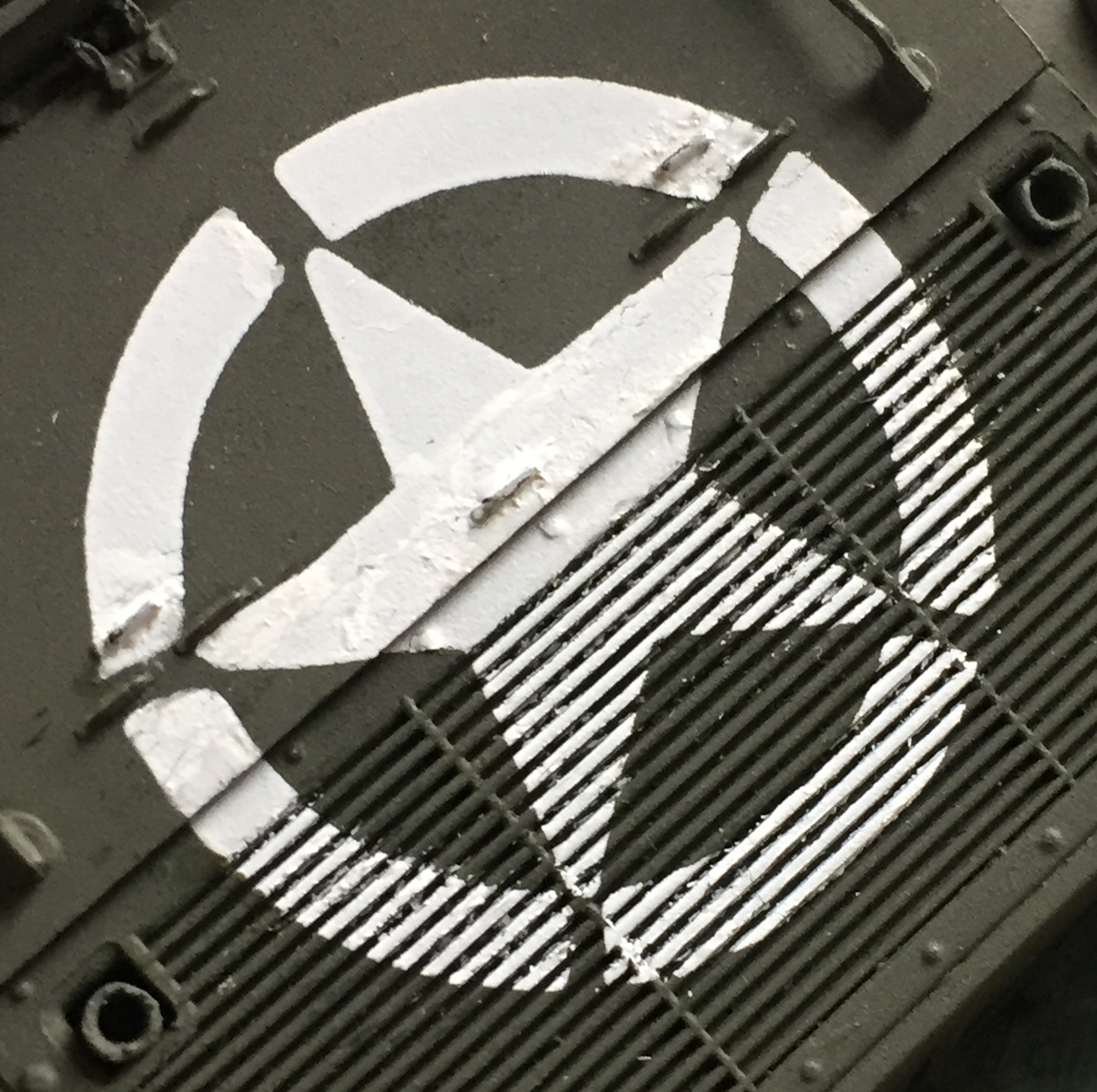
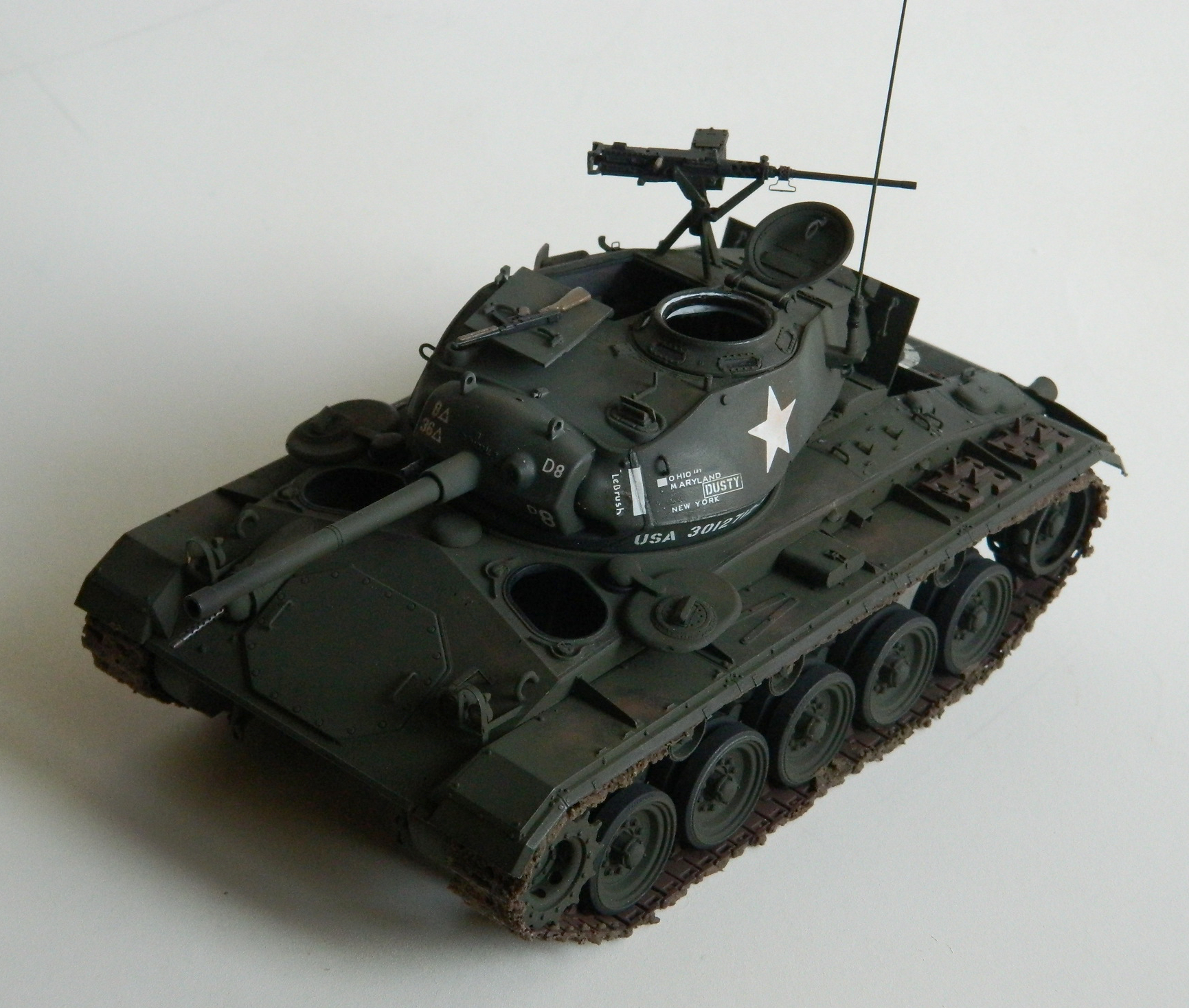
Because of the camera’s magnification, the above graphic looks much rougher than it does to the eye. It’s certainly better than the decal Bronco provided. Oddly, most of the small decals went down well. The major exception was on the left front side of the turret where there are states painted onto the turret. In the gap between “Maryland” and “New York,” there is supposed to be “Calif.” I have NO idea where it ended up. It was on the carrier film when the decal went into the water. When I applied the decal, it was missing. It’s not the first time I’ve had a decal come apart on me and normally, though a hassle, is often not insurmountable. Not this time. I’ve NO idea where “Calif” went. It was not in the water, on the paper, or anywhere I had the wit to look. Okay. Moving on…
It’s got its decals:

I rarely like kit-supplied tarps (or even resin AM tarps) and prefer to make my own. It starts with a dilute solution (suspension, actually) of white glue:

I get paper towels and toilet paper from public restrooms. Why? Because it’s cheap and has no embossed texture. I laid out a sheet of it, ironed it (y’know…with a steam iron) to get rid of unwanted wrinkles and folds, then used a scale ruler to define a 25′ x 50′ (7.62m x 15.24m) “tarp.” I folded it lengthwise in thirds, then rolled it up. I waited a few minutes for the fibers to take a relative set, then unrolled it and ran it through the diluted white glue. It gets rolled back up and I use wire to form the tarp to conform to the straps I’ll put on later. Since I want the tarp to fit over an uneven surface, I used aluminum foil as a mask to keep the glue from staining and adhering to the paint, then waited for the glue to dry (in this case, three days, which is typical):
After it had dried, I painted it Tamiya XF-62 Olive Drab and then added straps made from lead foil (from a wine bottle neck):
Then it was time to weather and wear the beast.
I discovered that if I moistened a cotton swab with denatured alcohol, NOT wetting it as wetting it leaves stains, I can replicate areas where generic surface dust and crud are worn away by the crew using that area. It’s a subtle effect and it’s very easy to overdo. If you think one more pass will do it, it’s time to STOP right there. If you look at the texture and reflected light, you can see the darker areas delineated by the alcohol:
The effect is more subtle than the above photo would suggest. I took that shot for how the light reflected and ease of seeing. In reality it’s a bit more subtle.
I don’t use dot filtering because my color vision isn’t ideal. But I get good service from using pastels and the added benefit of ease of removal if I screw it up. I also use color pencils for bare metal wear if the area is REALLY small, and I use a regular pencil for that dark worn-surface look painted armor often has.
That blood pressure raising basket on the rear was becoming more and more abysmal as I had to reattach it over and over. To hide the absoLUTEly lousy job I did with it, I made another small tarp to drop in there to obscure as much as possible.
The paper, measured and rolled:
The paper soaked, re-rolled, dried (instead of waiting three days for that, I hurried things along with the microwave and it worked perfectly, 30 seconds at a time), and painted:
And once in place in the basket, it goes a LONG way in hiding the rotten job I did with that basket:

The last nightmare was adding the pioneer tools. Again, Bronco over-complicated things and made the job magnitudes more annoying than it needed to be. I mean…four hours for this (and above the tools on the hull and next to them on the fender you can see how alcohol replicates the surface dirt being worn away by traffic):
I wanted to replicate a pipe being used as a prop-rod holding the engine cover open. Initially I was going to use plastic rod, paint it steel, and then dry-brush surface rust onto it. Then I saw an old paperclip sitting on the bench. It was steel, old, surface discolored from age, and the exact diameter I wanted. Clip, snip, file, fit, dry-brush red, and it’s done and glued on.
Finally the next thing was…erm…ah…sacred excrement! This thing is DONE:


M24 Chaffee (Bronco) 1/35 Scale Build #7 – Finishing the Interior of the Turret, Gluing it Closed, and Some Hull Details
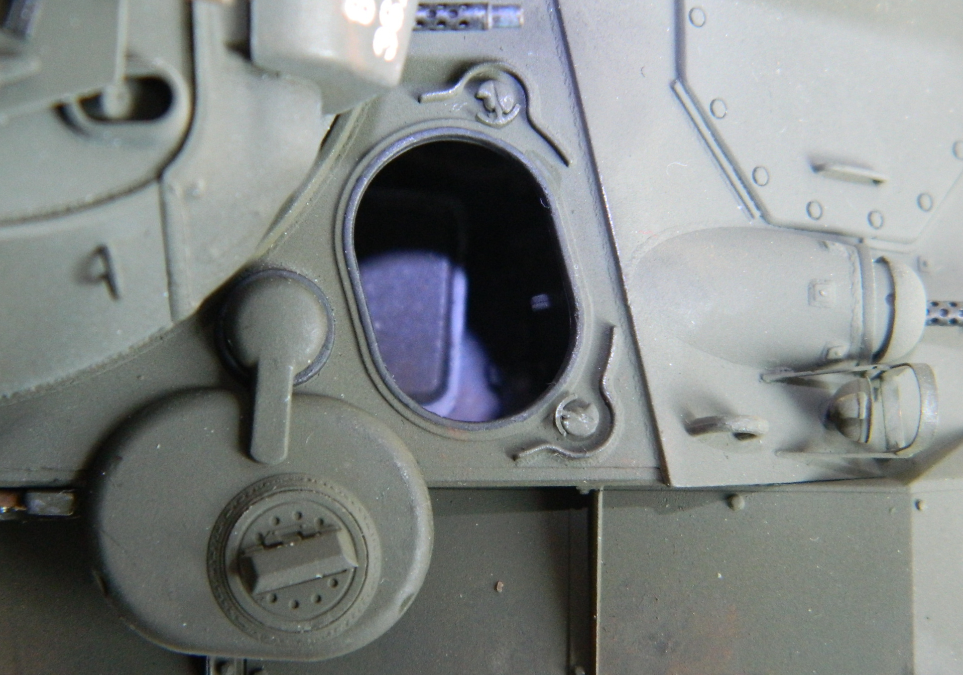
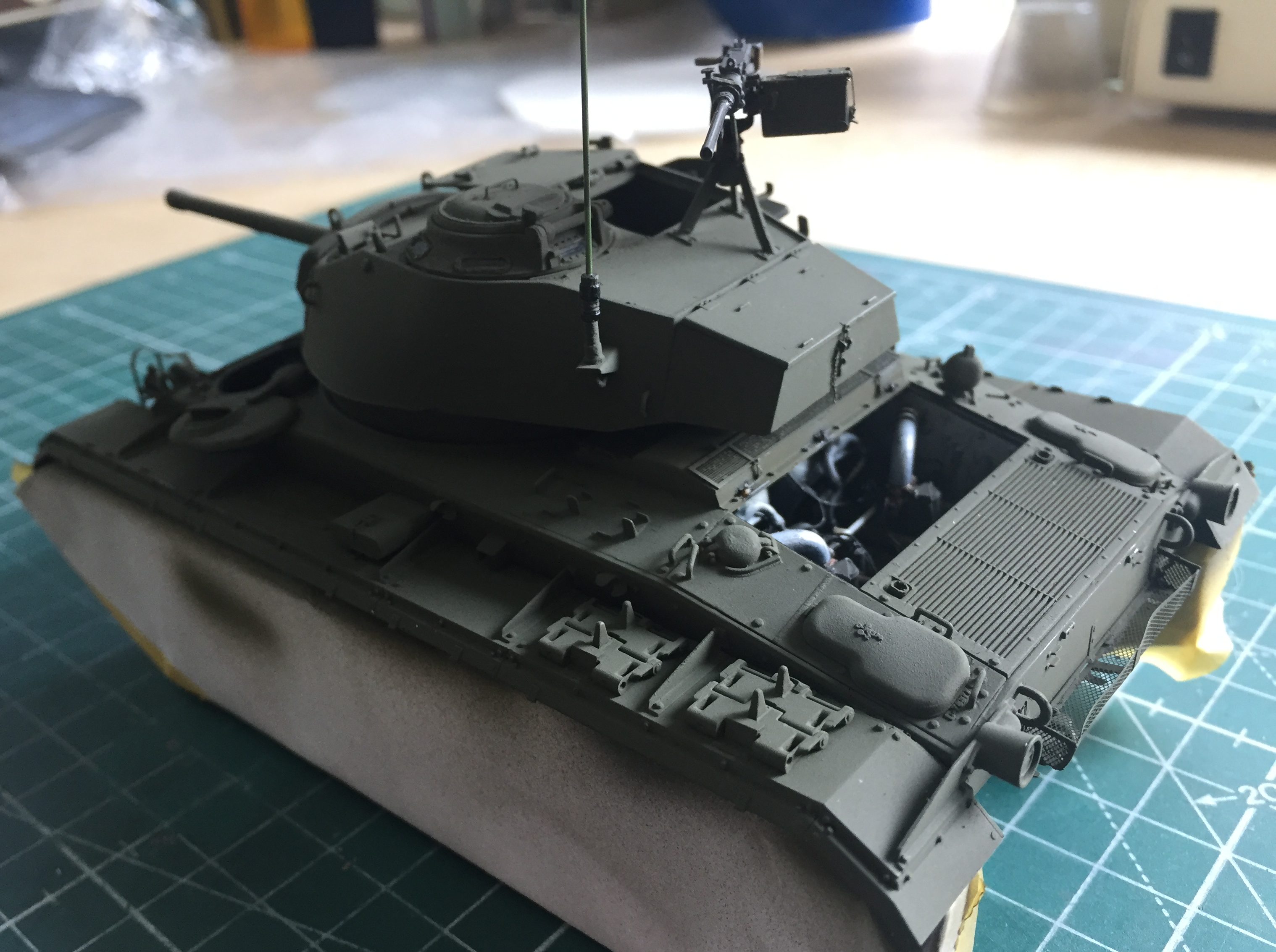
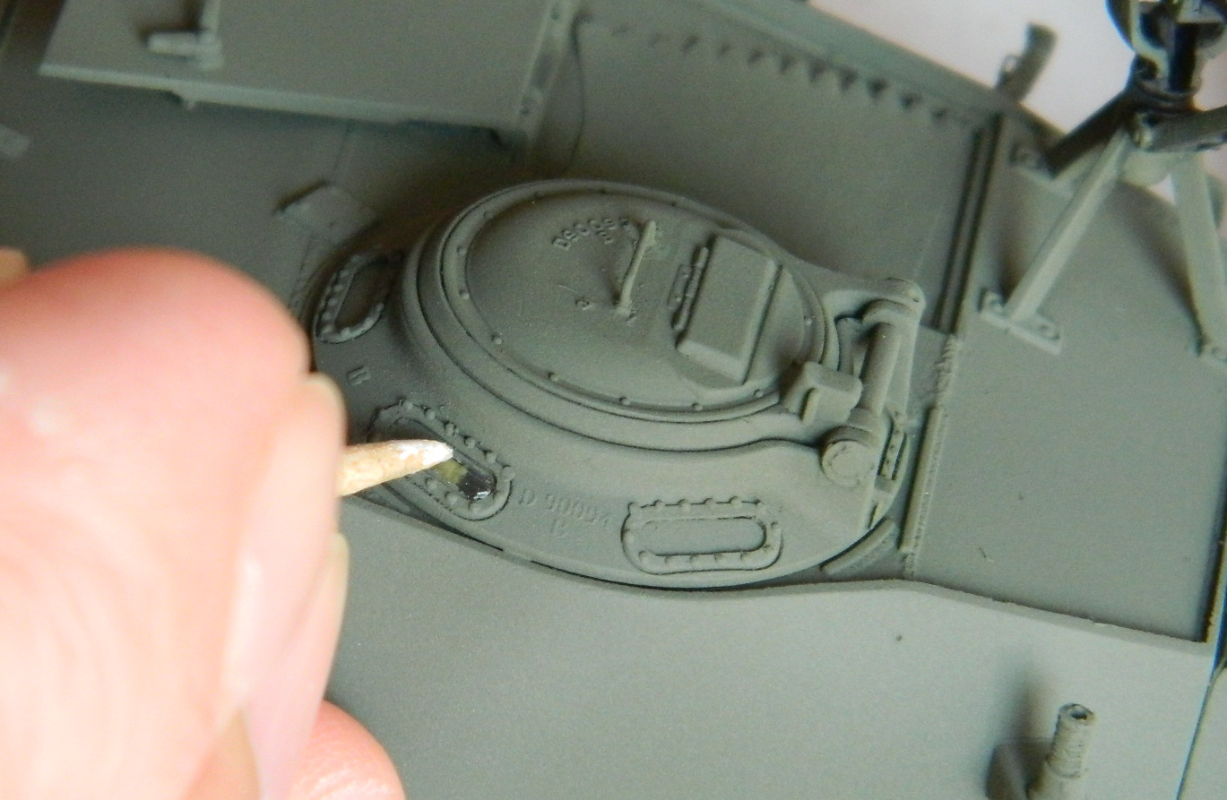
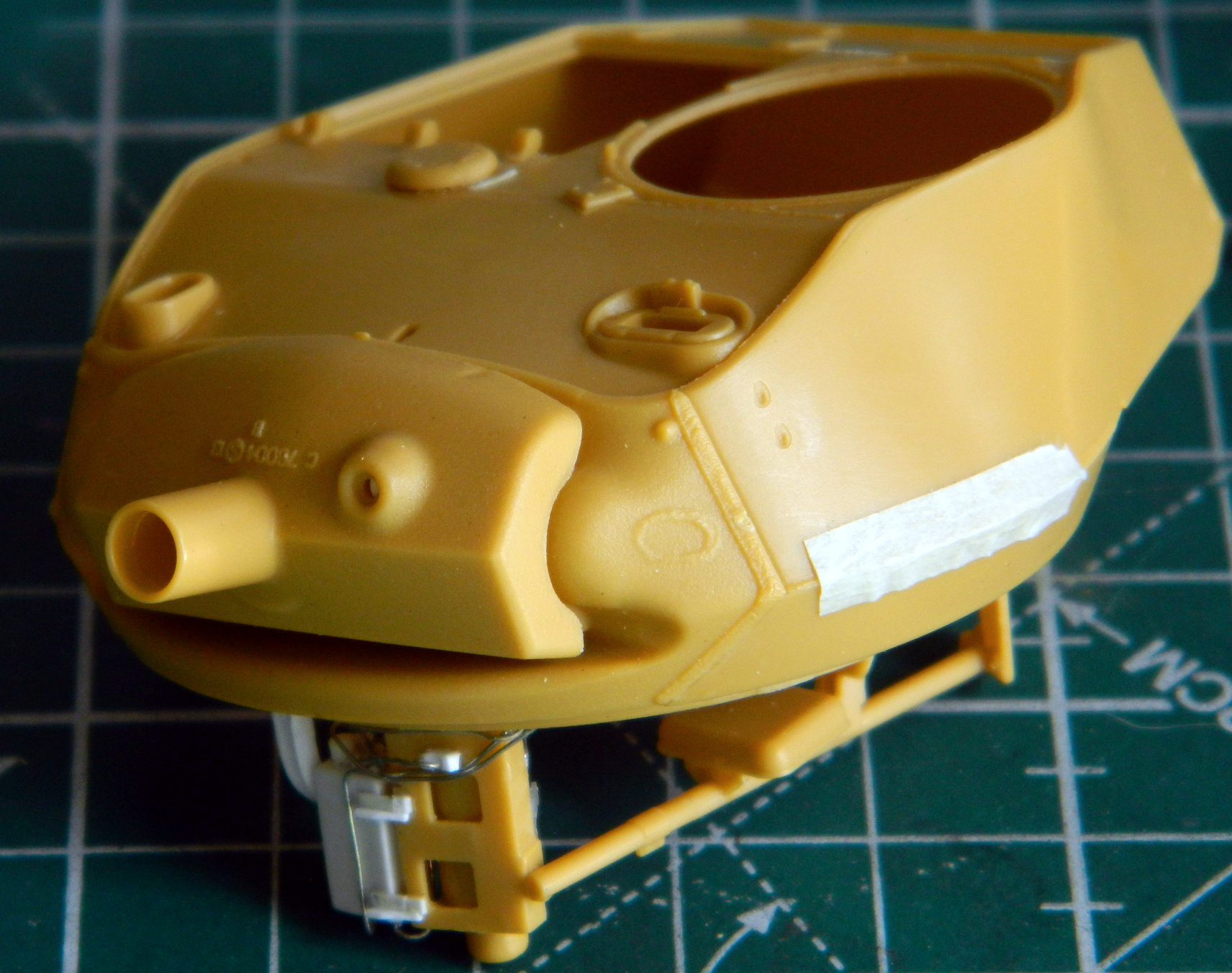
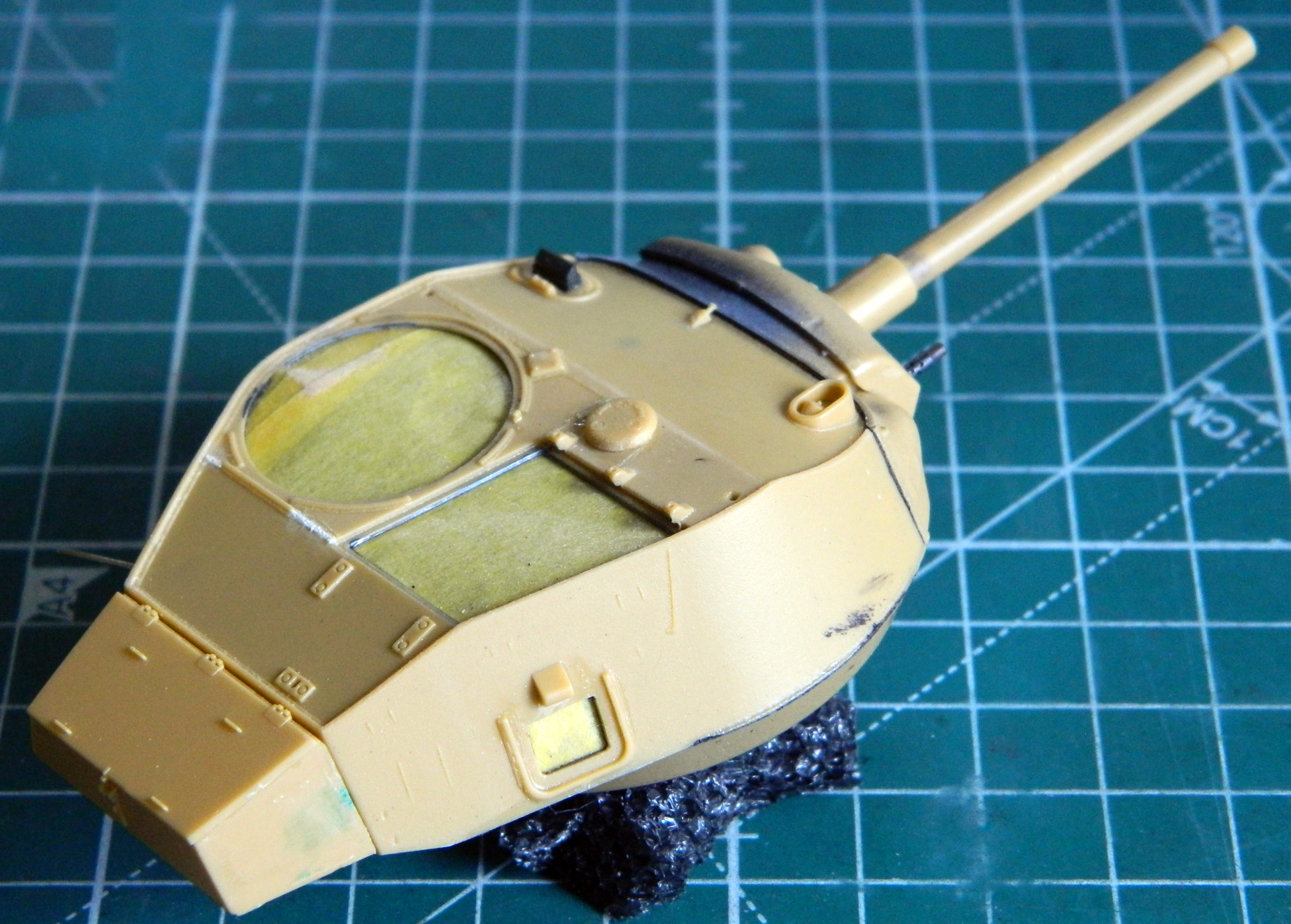
There are a couple of minor errors on top of this turret (I said “this” turret because the early kit production turrets had the welding seams incorrectly placed; later production kits, as well as some aftermarket companies, issued the correctly configured turrets). The small hole in front of the hatch openings is where the vent cap goes. Early production M24s didn’t have the bullet splash ring around the opening so that has to go. Once it’s gone, the weld seams have to be reworked to accurately reflect what rolled off the assembly lines. The weld seams at the rear of the large round hatch opening were incorrect so I used .005″ (.127mm) strip styrene, half dissolved them with styrene cement, and then used a toothpick sharpened to a chisel tip to replicate weld beads:

Once I’d carved away the bullet splash ring, I added more .005″ (.127mm) styrene to fix the missing weld beads:
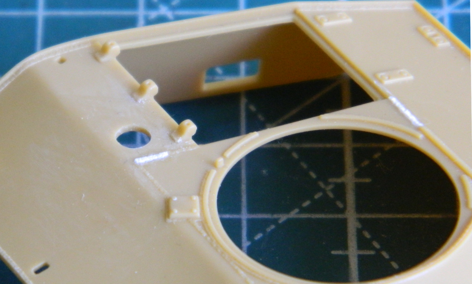
I suspect they will need more blending in but the difference in plastic color hides that from me presently. This area will get hit with primer and the weld beads adjusted accordingly.
At this point I kept trimming the sides of the engine cover so that it would settle into the space provided for it. I have no intention of modeling this cover closed, it just annoys me to know that it wouldn’t fit if I did. So 400 grit sandpaper on a flat surface with a lot of rubbing and checking removed said annoyance.
The engine cover is molded to scale in thickness as well as hinges. That means the hinges will snap off if a mosquito (the insect, not the DeHavilland) blows its landing. Several bugs landed on those hinges and they all needed to be replaced. I used thin slices of .025″ (.635mm) styrene rod to replace them:
Since this will be modeled in the open position, I had to add the latching tongues to the underside. I used stretched sprue for the shafts and .010″ (.254mm) scrap as the tongues:
There are PE screens that go over the air inlet vents. There are also VERY small parts that get added to them. It took patience but I managed to get the straps that hold the screens in place where they were supposed to be. Then I noticed that of the M24s that still had the screens mounted, almost all of them were deformed from weighty objects being placed on them. Once I had the PE parts in place, I waited overnight for the superglue to cure more completely and then GENTLY pressed down with a fingertip to give the screens’ surfaces the bowed appearance:
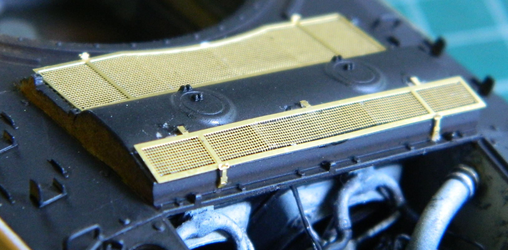
There are a couple more items that get added to the screens but I’ll wait until later to lessen the chances of knocking them off.
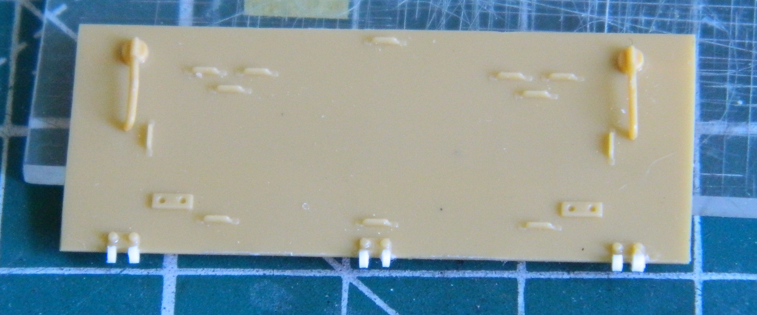
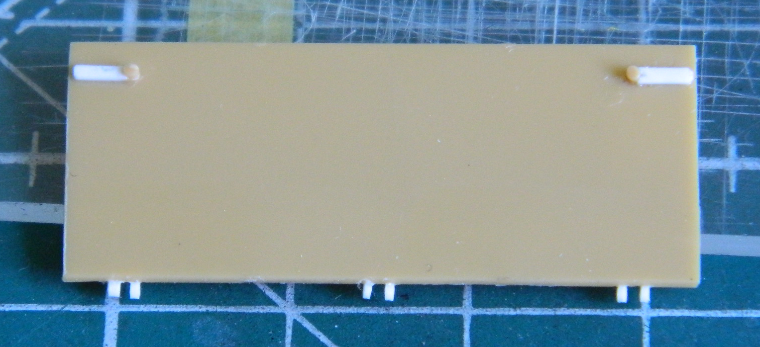
Brain fade struck again. I removed the armored gas cap covers from the sprue, and then mistakenly removed the parts that were supposed to stay on and left the sprue attachment points instead. Of course I didn’t realize the error until it already happened, so those parts get replaced:
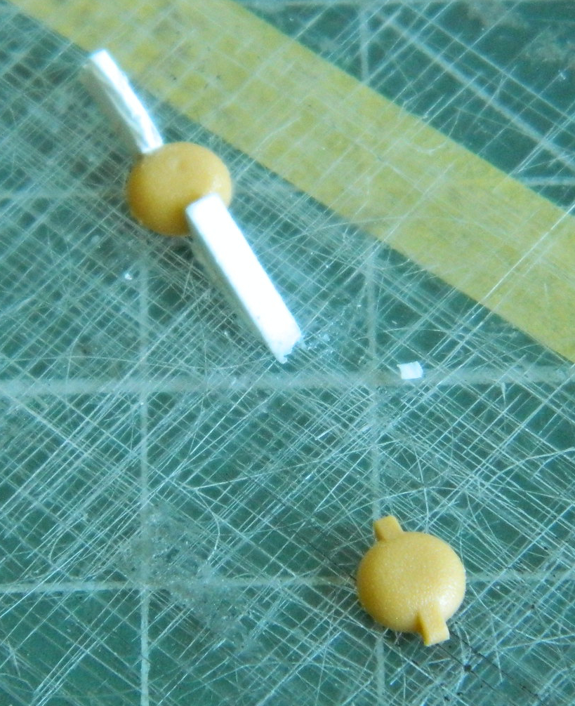
::rolls eyes::
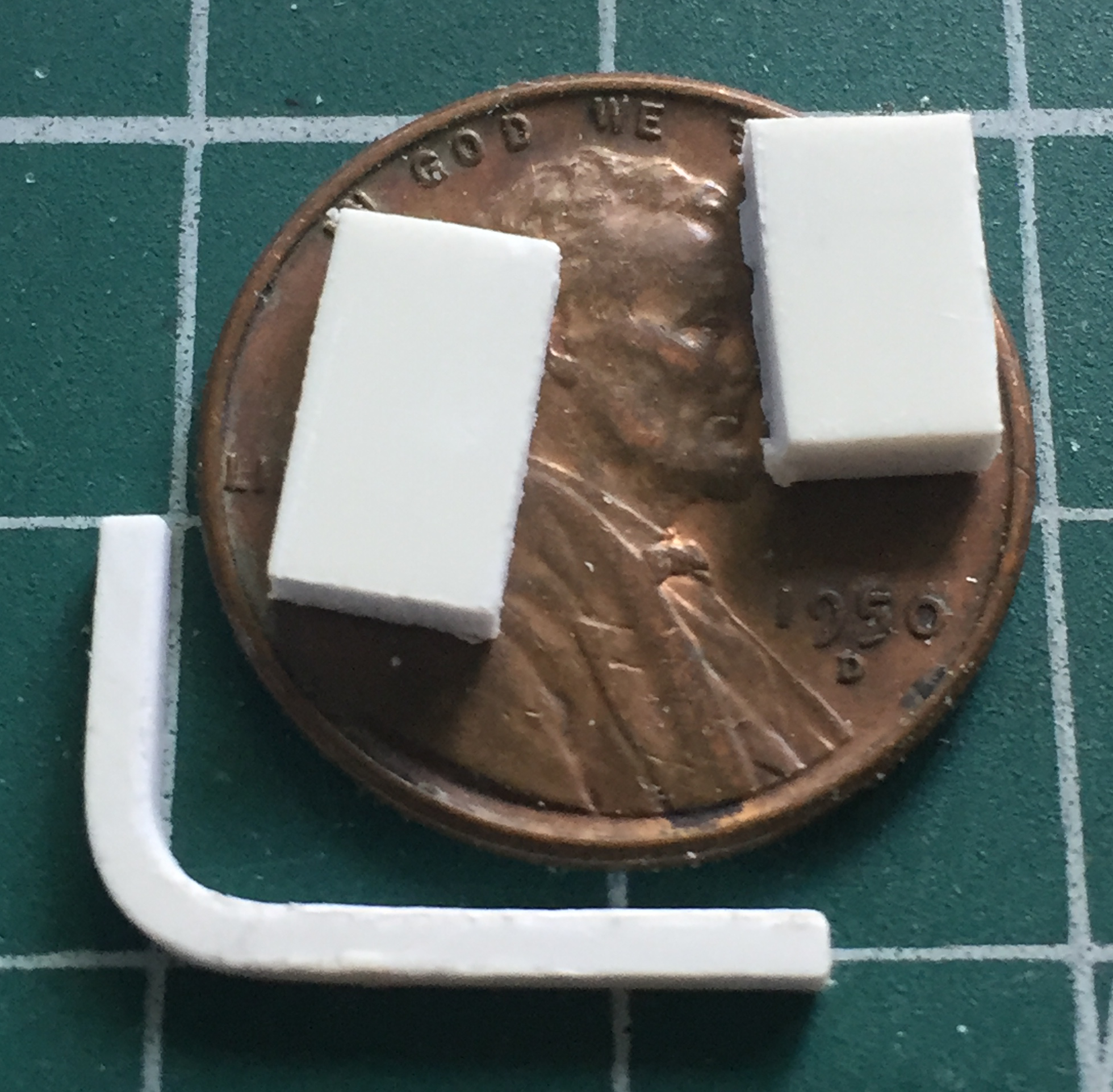
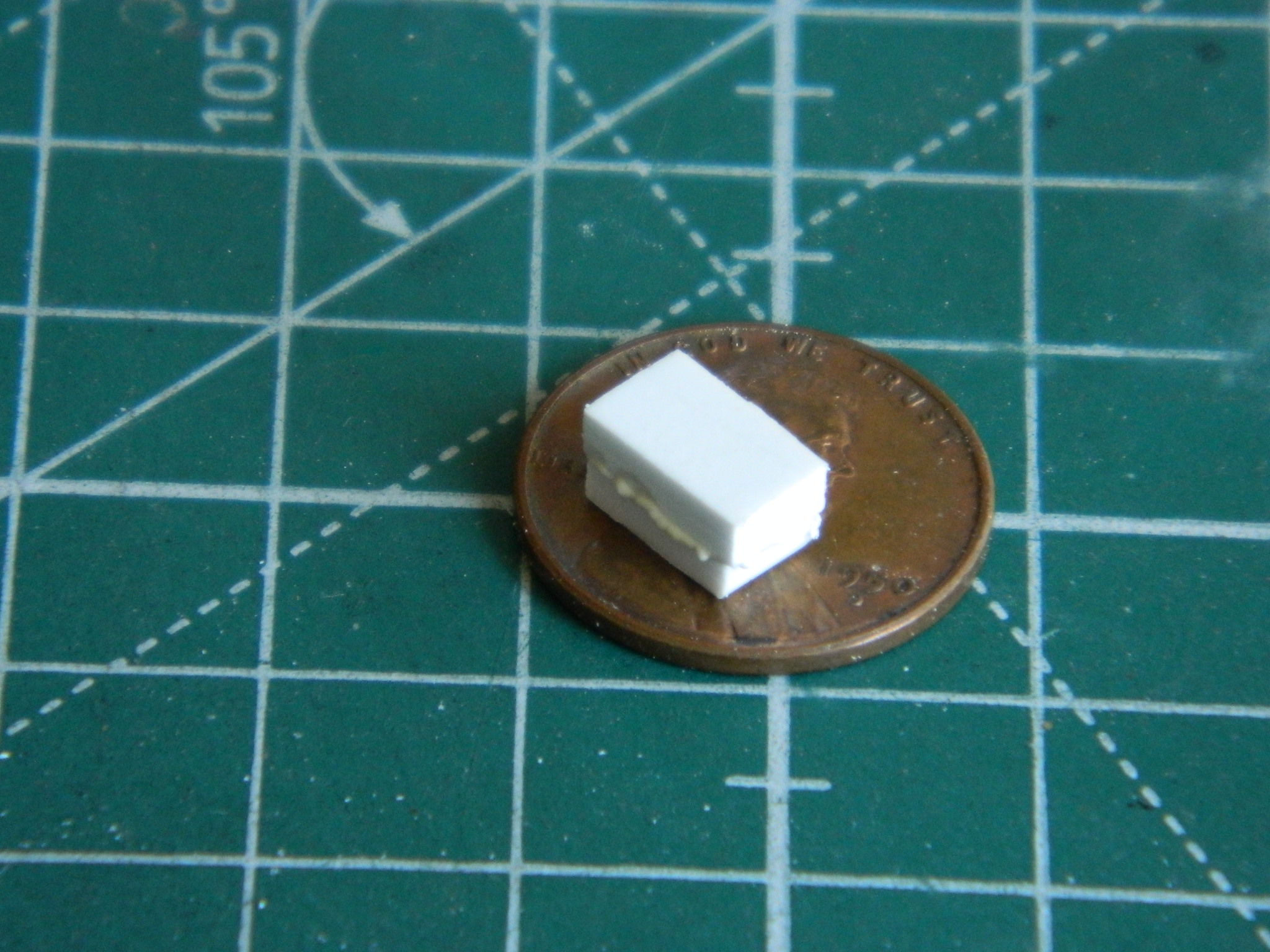
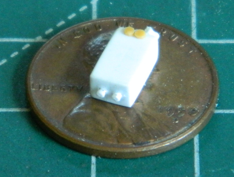
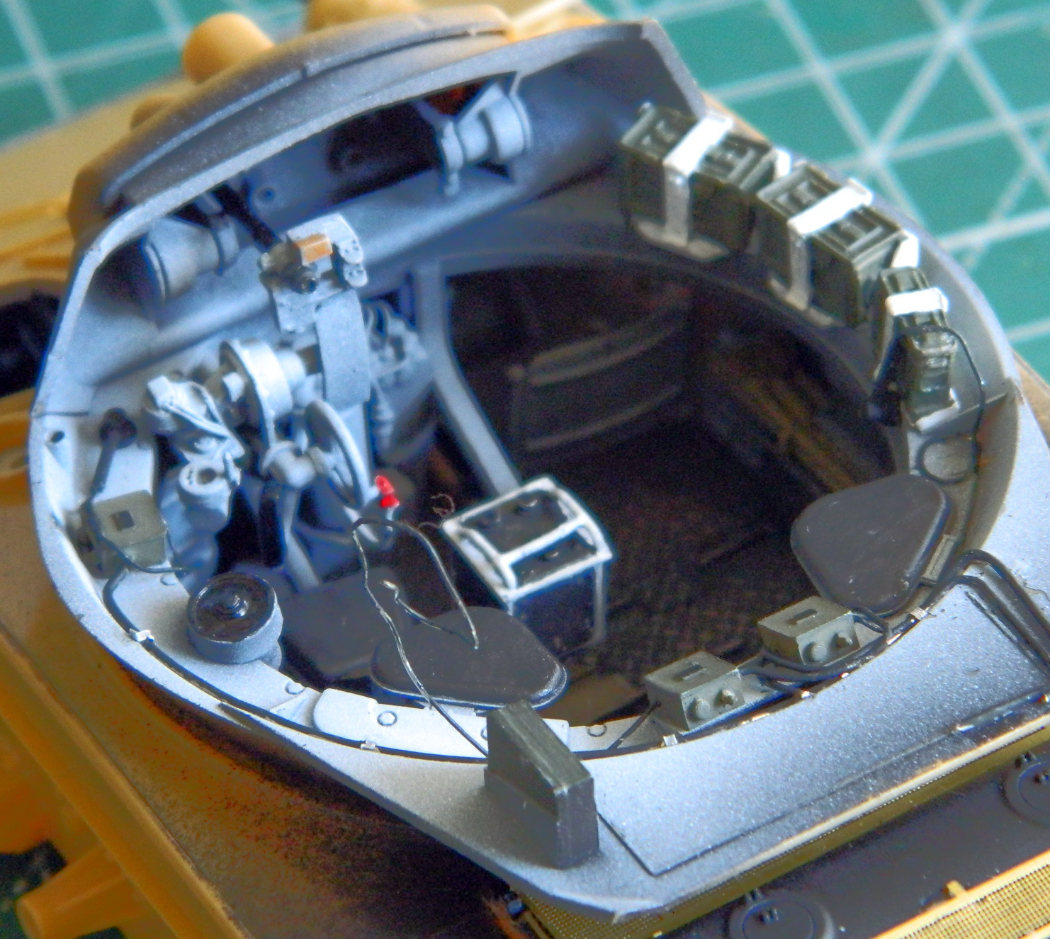
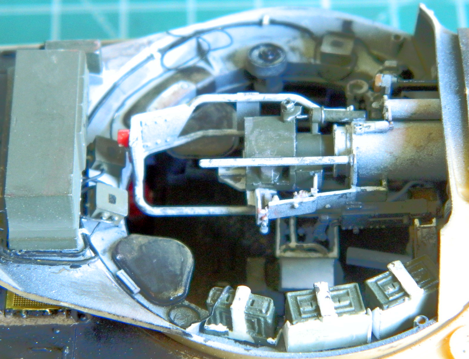
There are some details in the turret that Bronco didn’t provide and they should have. The control box that sits under the turret doesn’t have a turret basket to mount to. Instead, it’s mounted on a pedestal and has an arm to attach it to the turret. The arm turns the control box with the turret as well as providing a conduit for wiring. It should be there. I started making it by approximating dimensions and cutting its profile from .060″ (1.524mm) styrene (that’s the L-shaped part in the photo below). The turret rotates by electrically pressurized hydraulic fluid. Bronco added most of the turret’s rotation hardware but left out the hydraulic oil reservoir (those are the two rectangular pieces in the photo below). So I’m going to make them:
Scratch-building seems to intimidate modelers and I don’t think it should. Plastic is inexpensive and it’s not difficult to work. Scratch-building something just takes time and looking at pictures…lots of pictures. If one screws the thing up, it can either be fixed or tossed and the project started over. Remember, this isn’t engineering where things have to be correct. This is modeling where things just have to look correct. Keep working the part until it looks correct to your level of acceptance. When scratch-building, sometimes a person simply cannot get it 100% accurate, largely due to size (though with the dropping prices of 3D printers, I expect that’s changing even as I sit here typing…and if I were twenty years younger I’d git me one).
So I decided to scratch-build the oil reservoir, and here’s how I did it.
These are the parts that Bronco provided (mostly already assembled):
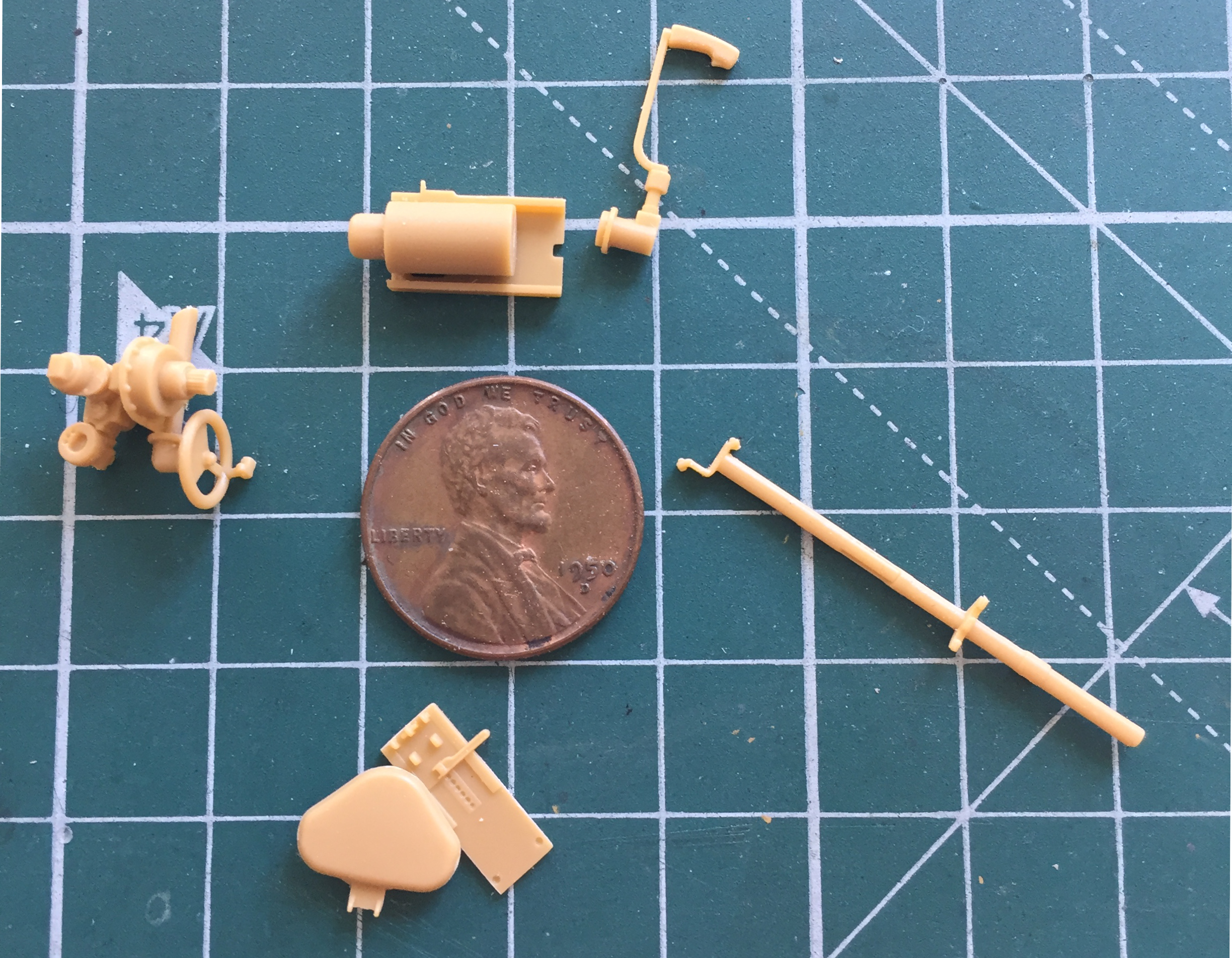
When glued into place, they give me the dimensions and space that my scratch-built part has to conform to (and of course I didn’t take a photo of this area with these parts in place before I started working). Putting these parts together was a very Chinese interesting due to an almost TOTAL ABSENCE of indicators showing where things are supposed to go. (And as it turned out, that notion is something I needed to get used to because I found that lack in other places.)
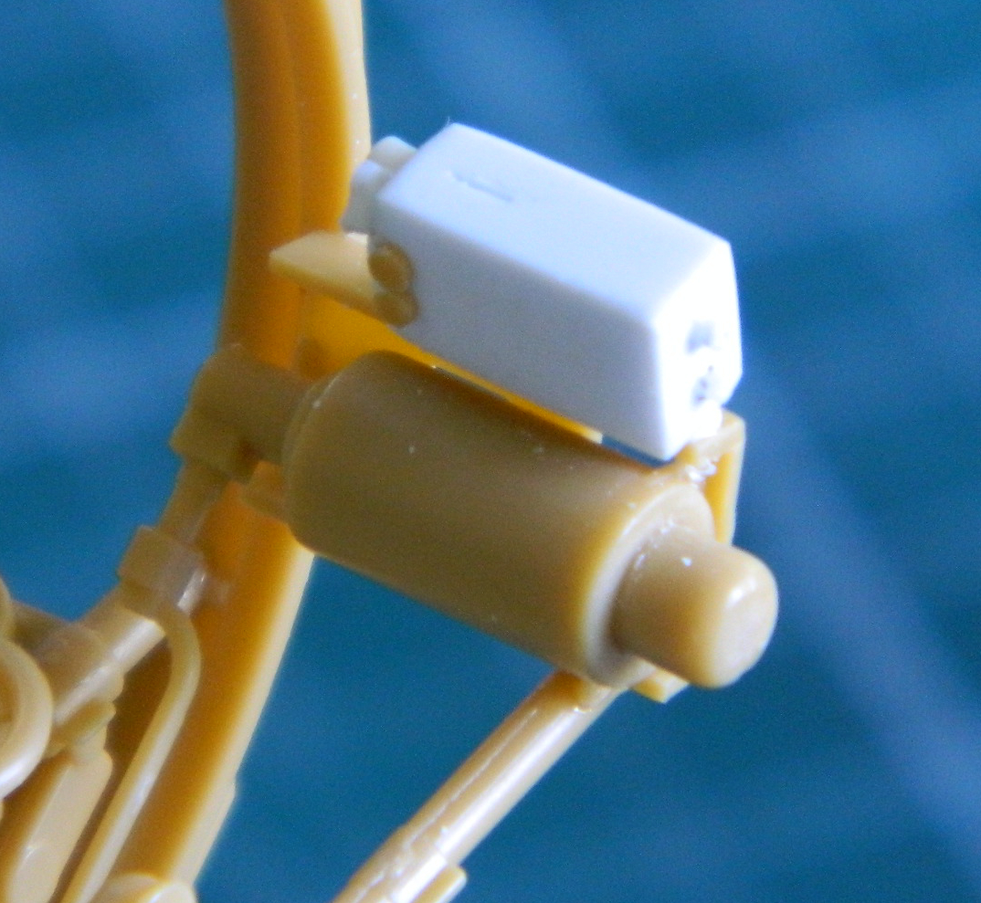
I took those two pieces of rectangular plastic in the above photo and glued them solidly together because I didn’t have anything thick enough to use as is. I smeared glue liberally over one part, aligned the other one on top of the glued surface:
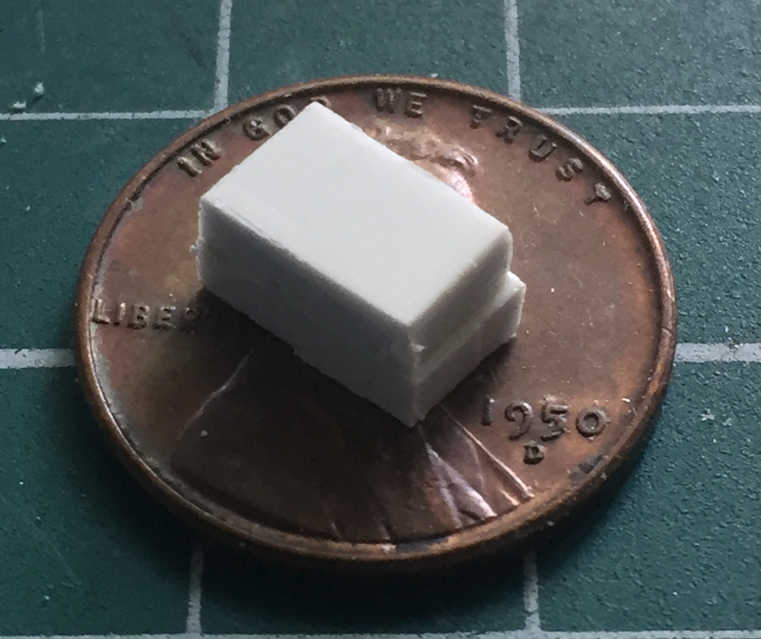
Then after waiting a couple of minutes for the glue to dissolve the faces, clamped them together in my vice until the squidge oozed out. The goal is to make these two pieces ONE piece:

I left this assembly in the vice overnight to insure the two bonded into one. The next day I took the bonded plastic out of the vice and started truing up the sides so that everything was square (in a rectangular sort of way) and perpendicular (in a 90-degree sort of way):
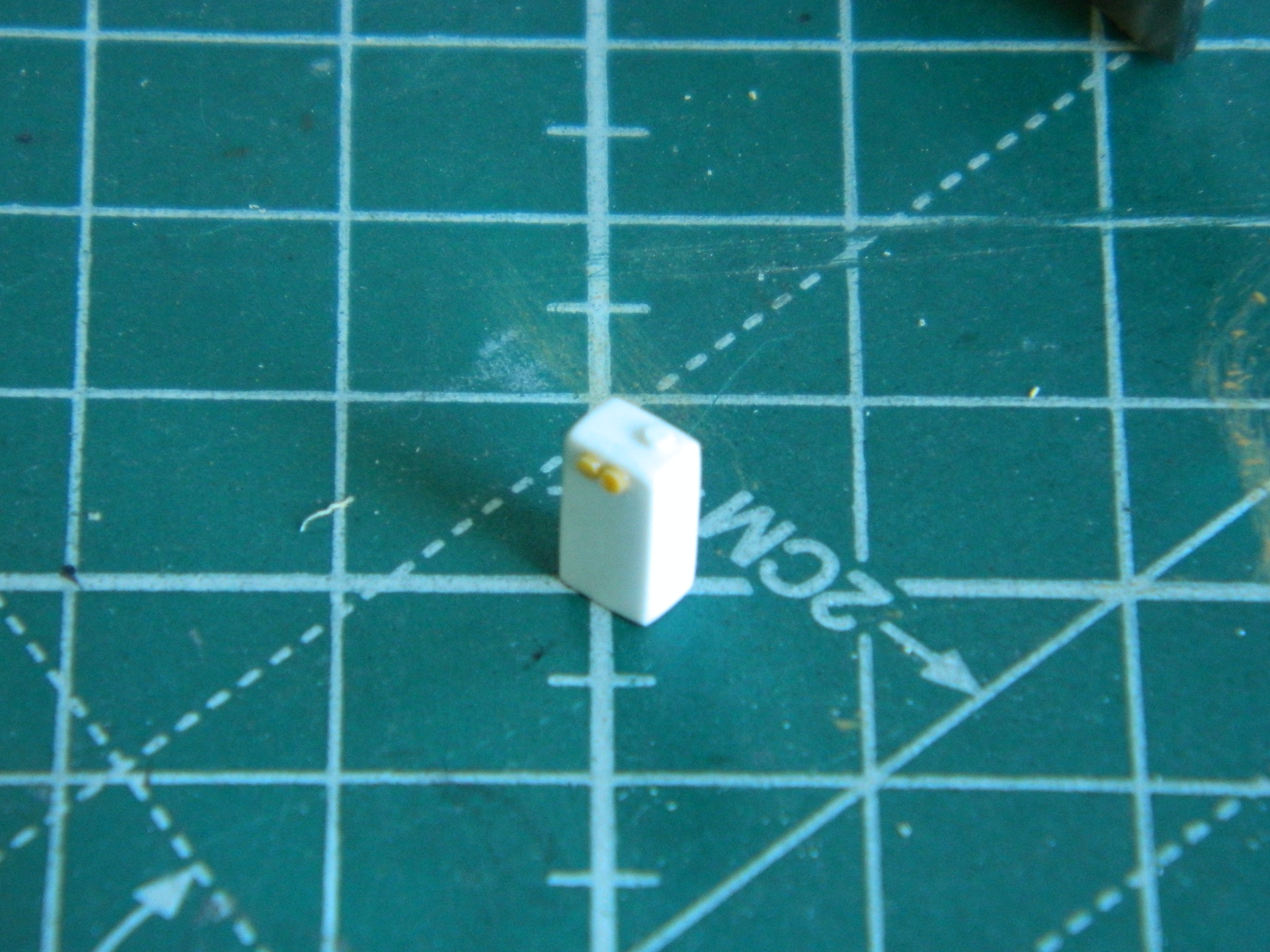
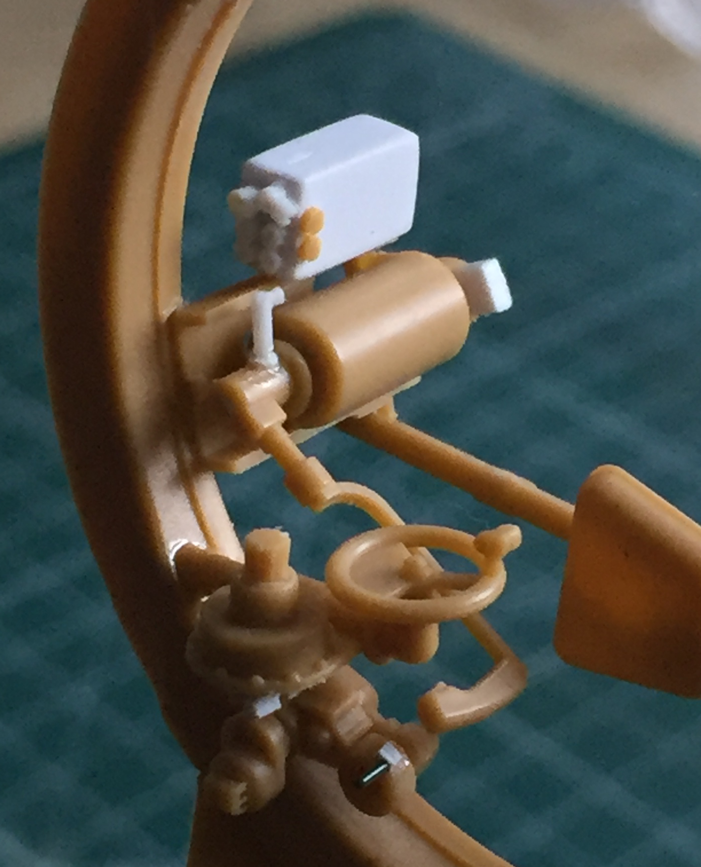
Then I used the assembled (but unphotographed so far) gunner parts to determine how tall, wide, and deep the reservoir had to be. Once I was satisfied with the dimensions, I rounded all the edges and corners as the actual reservoir has them. There are two large nuts on the upper front of the reservoir. I scraped some sprue into an octagonal shaped, stretched them slowly (ends up with a thicker result, which is what I wanted), then sliced them and glued the slices onto the front of the reservoir:


While the glue was curing, I started making part of the brackets that mount the reservoir to the motor’s mount:
There is a fill port that I replicated by using two different sized styrene rods. The smaller one made the filler tube, the larger one made the cap; I rounded the edges of the cap to match the original. Then I started adding stubs of styrene rod to replicate the fittings where hydraulic lines are attached. Once the glue cured overnight, I drilled out the stubs. Most of them were drilled for .010″ (.254mm) solder or wire (haven’t decided yet which to use):

With the fittings in place and the side of the reservoir scribed to replicate the oil level window (that will never be seen once built), the part gets mounted in place:
Because there is SUCH a small contact area for glue and the fact that the brackets are cosmetic, not structural, there is a small wedge of styrene between the reservoir and the motor mounting bracket. No, it’s not there on the actual tank. But since this will all get pre-shaded black and it’s under the gun (so to speak), nobody will ever see it.
And aside from paint, that’s a scratch-built hydraulic oil reservoir. As you can see, it’s not difficult or really very complicated. Don’t let your apprehension hold you back! (This seems to happen often when dealing with PE parts…and just because the kit supplies PE parts, doesn’t mean you have to use them. As you’ll see shortly, sometimes PE parts are just stupid; use them as templates to replace them with plastic.)
With the fluid reservoir done and in place, it’s time to add other tiny parts where the hydraulic lines and electrical conduits attach:
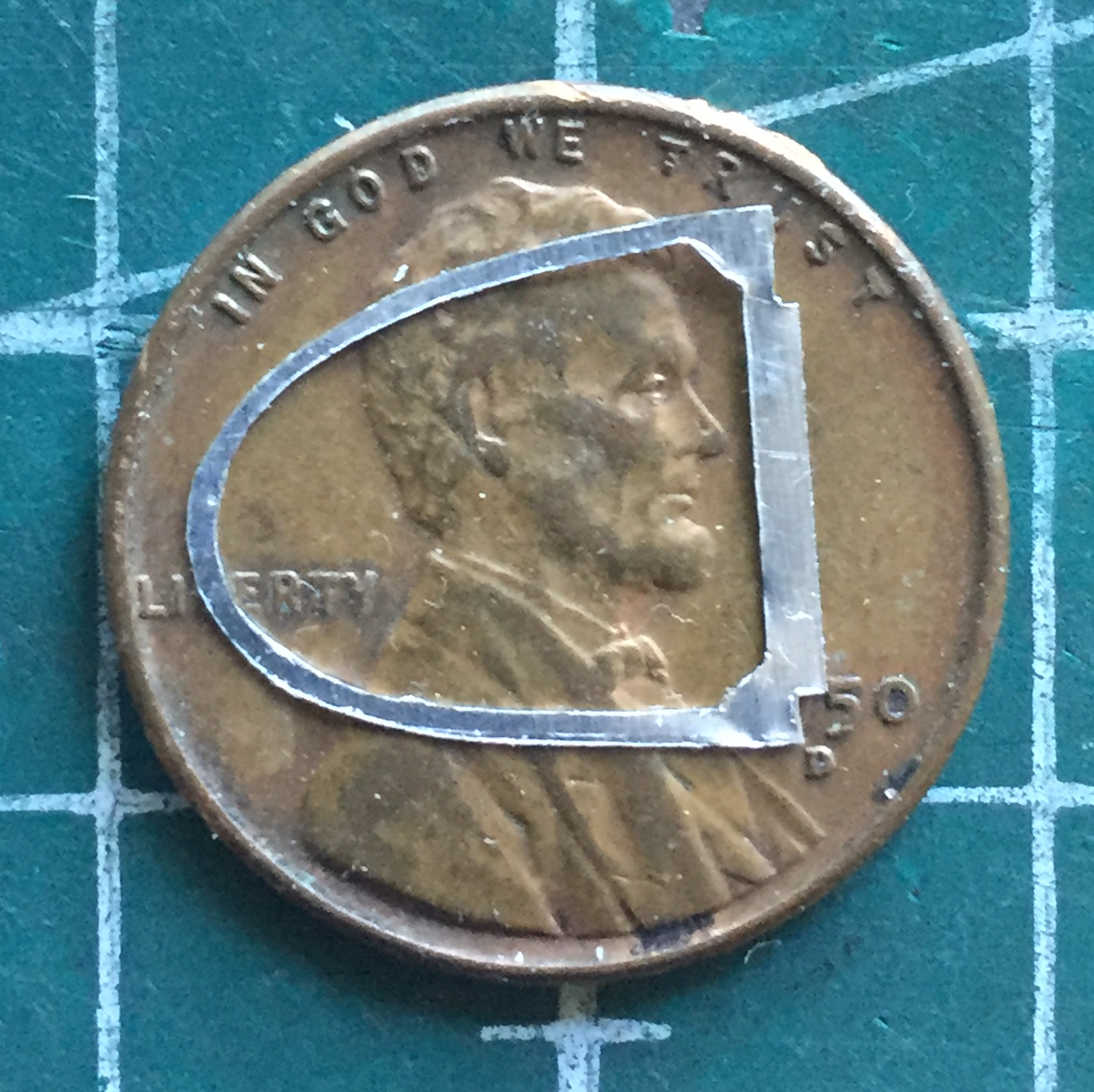
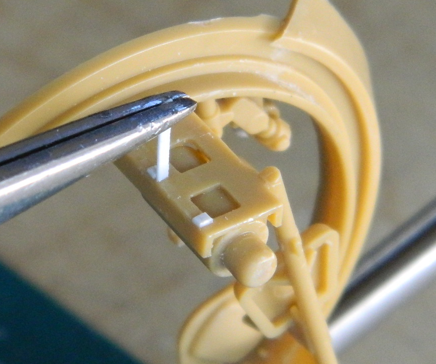
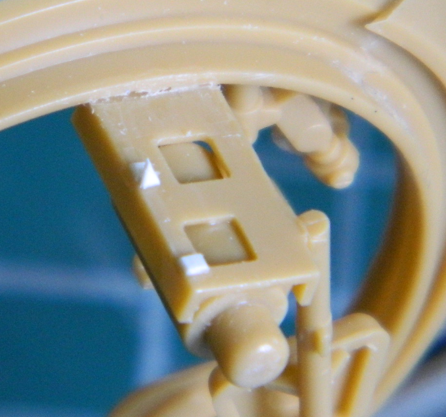
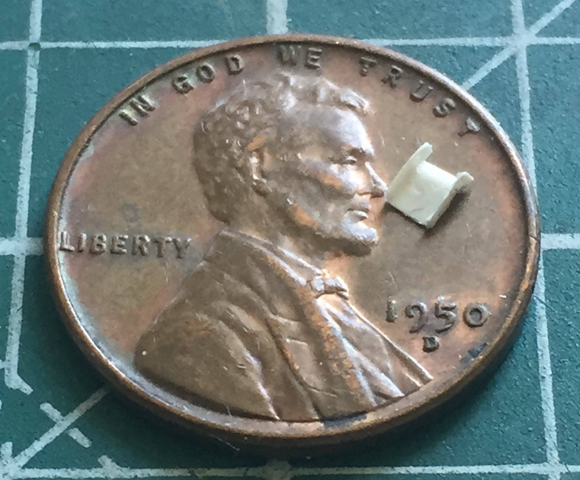
Speaking of PE parts, Bronco decided that the feed chute for the coaxial .30 caliber (7.62mm) machine gun needed to be PE (parts 33 a and b). Note the penny behind the PE fret. These parts are stupid small! I just imagined how much expletive-filled fun bending the bottom of the chute to conform to those really small J-shaped sides would be:

My imagination was good enough to decide not to play Bronco’s stupid-ass game. Instead, I used these PE parts as templates (and didn’t even remove them from the fret, because you remove them and then try to trace them onto plastic) and traced them onto .005″ (.127mm) scrap, then glued the pieces together:

MUCH EASIER!
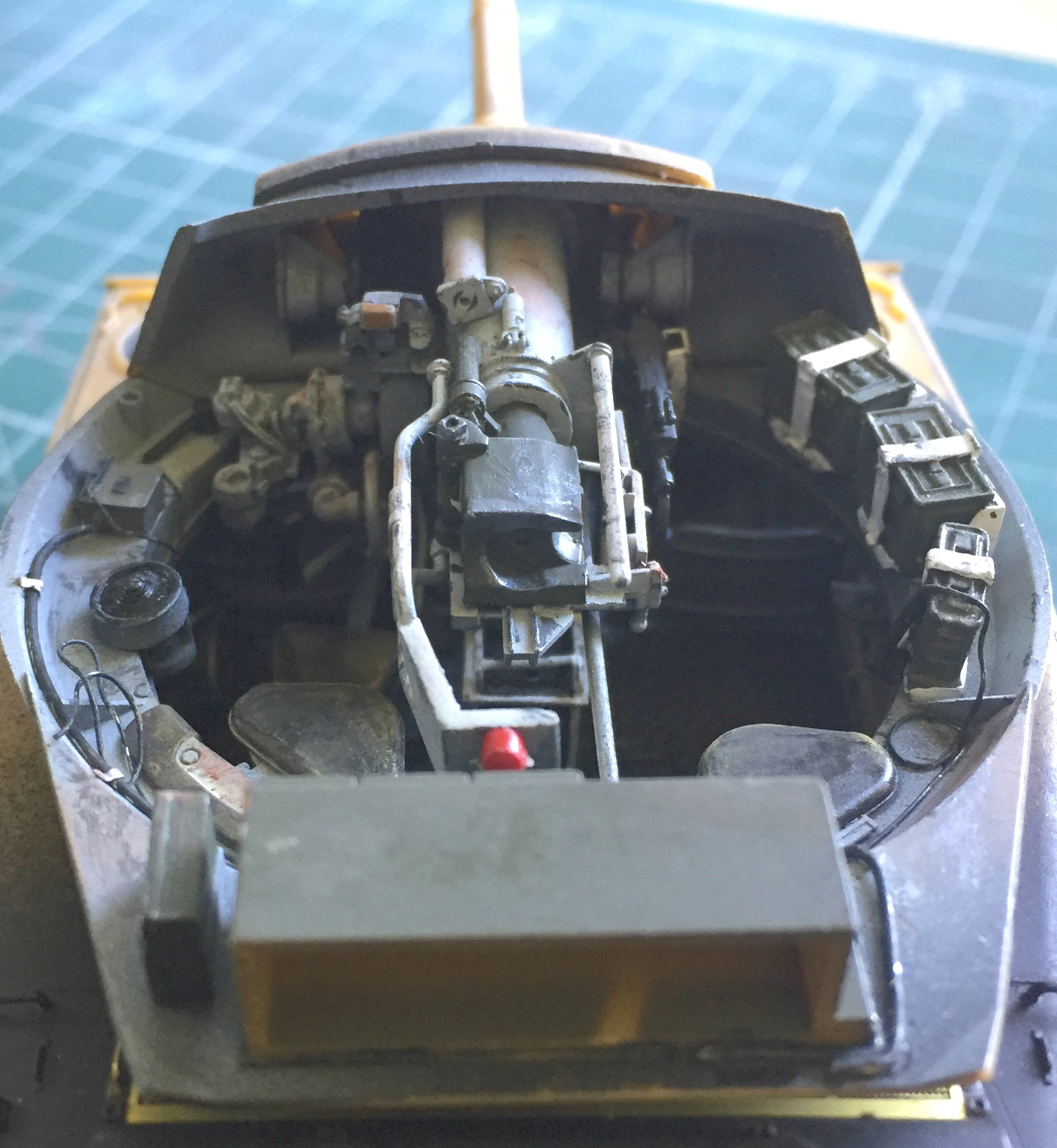
A large part of July was spent wondering just how I was going to mount the coaxial machine gun to the place it was supposed to go. Bronco does not supply much in the way of attachment points (less in the way of indicators). And though I’m all for scale sizes, there comes a point where practicality has to replace scale “purity.” The solution to the conundrum of how to get this subassembly correctly positioned (because it’s not just the gun, there’s also the ammo tray/box, link chute, and mounting plate) on such an incredibly TINY mounting point stalled me for a couple of weeks. Finally I realized the obvious. I couldn’t use just the mounting point because it really was too small. In dry-fitting the machine gun, I discovered that the cooling jacket of the barrel just fits through the mantle. Well, duh! GLUE IT TO THE MANTLE. This photo is of the dry-fit:

And this photo is with all the other parts added to the machine gun to see if it still fit:
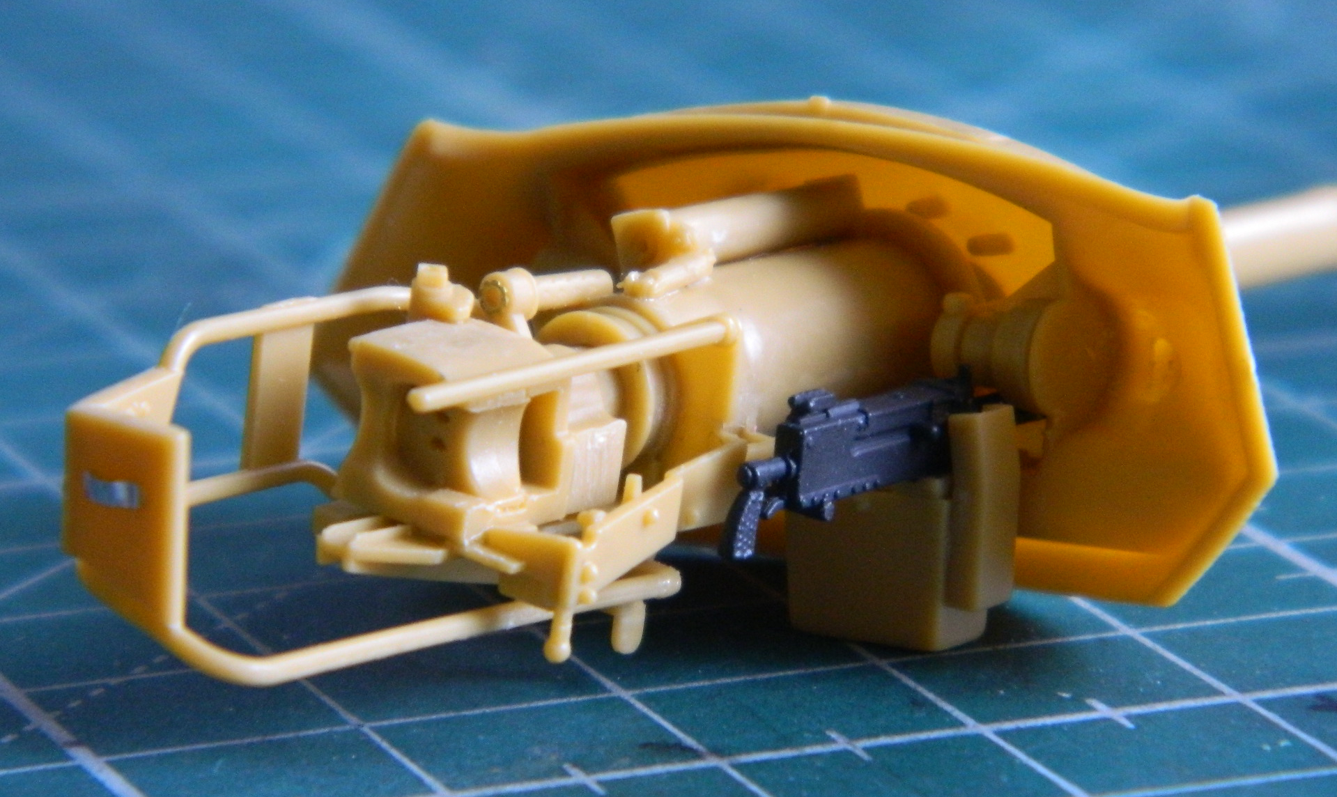
Not a lot of extra room, but that’s how they built these things…and enough is enough.
A recurring problem with this kit (and only time will tell if that’s typical of Bronco’s kits) is a lack of definitive attachment points. That problem is compounded by the knowledge that some of these vague subassemblies determine where subsequent parts can go and fit later on. (No pressure!) And Bronco seems to be totally committed to the maximum amount of individual parts to make any subassembly. Getting the gear quadrant correctly attached to the gunsight parts took more effort than it should…except that there was no clear indication as to the proper location for the parts:

All that for one relatively inconsequential part, and when it came time to add these subassemblies into the turret, I still managed to get the quadrant mounted in the wrong place. Thanks, Bronco. Next time have the engineers that decide what goes where and how, they should build the sodding thing so they have SOME DAMNED IDEA as to how to do it…and then modify things so things can be done.
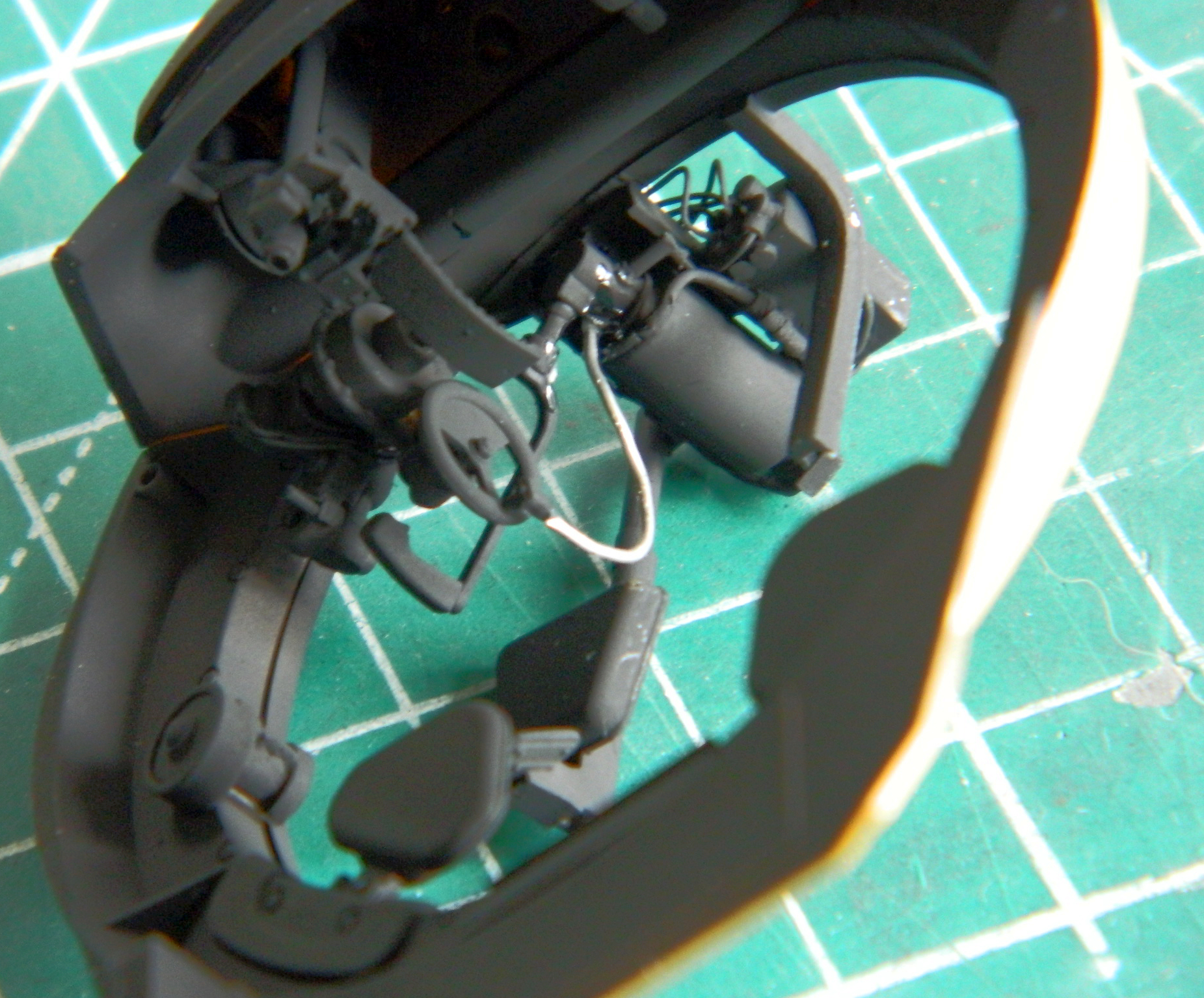
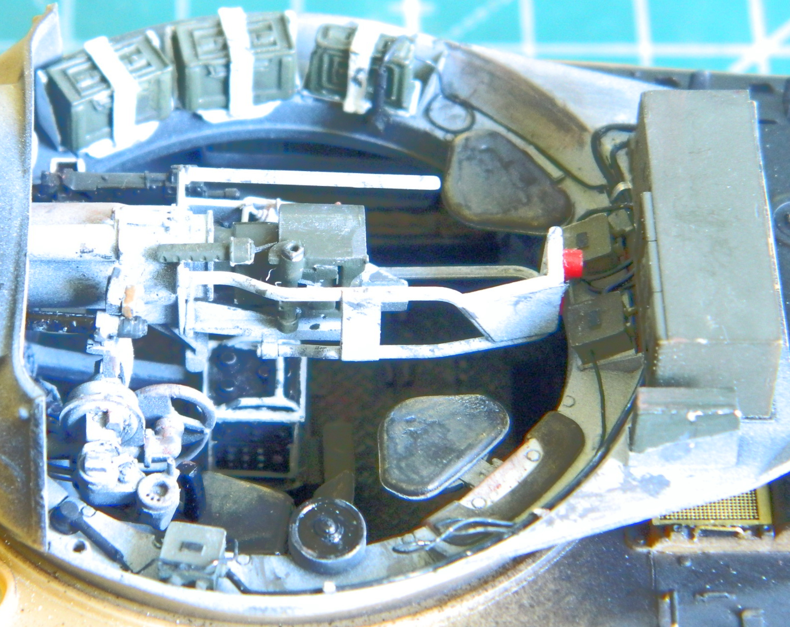
With the scratch-building done at the gunner’s station, it was time to start running hydraulic lines and electrical conduits. Solder of a few different sizes were used, from .010″ (.254mm) to .020″ (.508mm), depending:
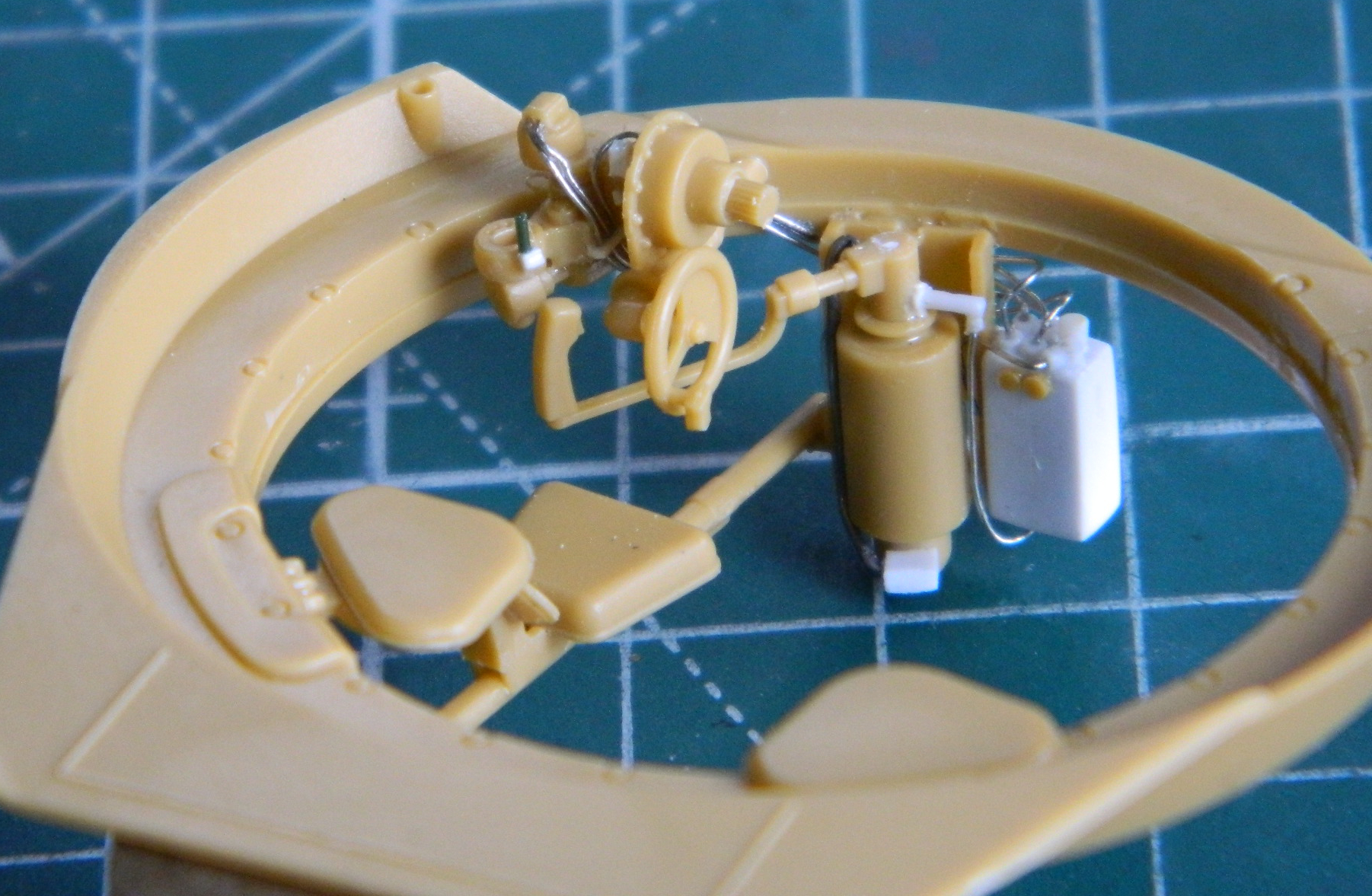
Belatedly it occurred to me to actually check to see what could even be seen. As it turned out, not everything I added would be:

It looks as if most of it will be seen, but these views are without the main gun and that blocks most of it. See the nice details I added to the front of the gunner’s controls? The only way they will ever be seen again after this is built is if the turret is taken off:
So all that was an utter waste of time. Yes…I’ve heard comments to the effect of, “Well, you will know it’s there.” Why yes I will! And I’ll know how much time I wasted putting it there. I really must stop doing that! These builds take long enough without spending time on things that will never be seen.
The L-shaped bracket that attaches the turret/gun control box to the turret so that everything rotates as a unit needed to be fitted and then detailed. I’d originally hoped that I could attach the control box to the L-bracket and then everything would turn as a unit. Uhm…no. Things are really snug in terms of space at the forward edge of the turret ring. So tight that it showed me that I had mistakenly put the driver and co-driver’s seats too far rearward. Unfortunately trying to dislodge the seats and move them would result in lots of broken resin parts and no easy way to replace them (big difference in working room once that upper hull is on, y’know?):

Checking how much I can see of the L-bracket saved me a lot of work. Not much can be seen. There is a metal panel that attaches the control box to the bracket on the actual tank. Had I added that, kiss goodbye the ability to ever remove the turret without breaking things. So I checked to see if it was visible:
Nope. Not easily seen at all. So I moved on to something that would be seen…
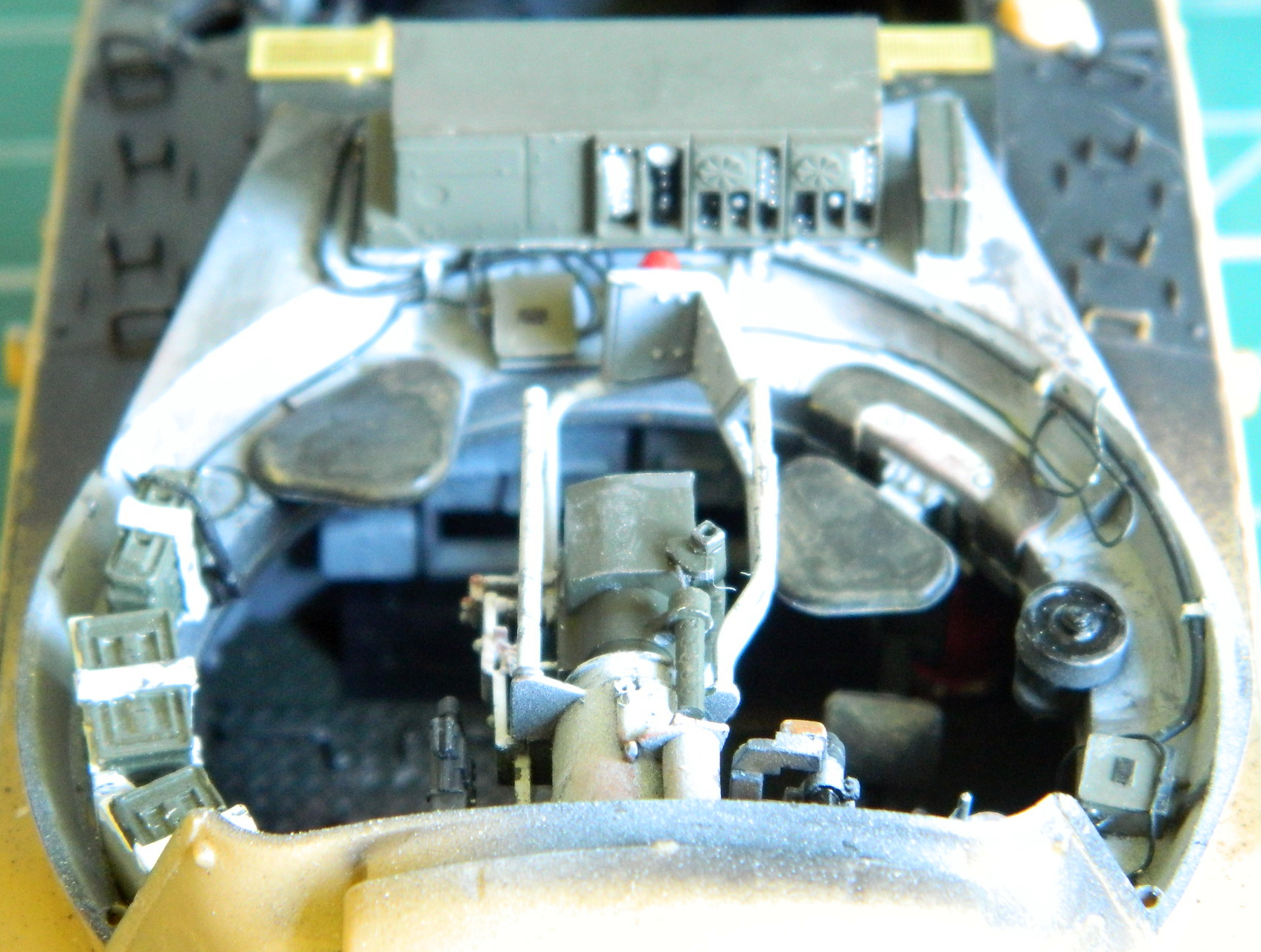
There are easily seen gussets around the base of the turret that Bronco didn’t provide or mold on. I used .030″ (.762mm) scraps to make them and used .010″ (.254mm) scraps to make the shelf in front of the dry-fit radio as intercom junction boxes get mounted there:

I also glued the gunsight assembly in place (which is actually incorrectly done; the mounting bracket was molded at the wrong angle but that’s one of those things that will never be seen). And yes…there is a pad for the gunner’s forehead that Bronco decided needed to be a separate part. In this case, it’s white plastic because the kit’s part departed (no pun intended, this time) for sections of the shop that are also unseen:

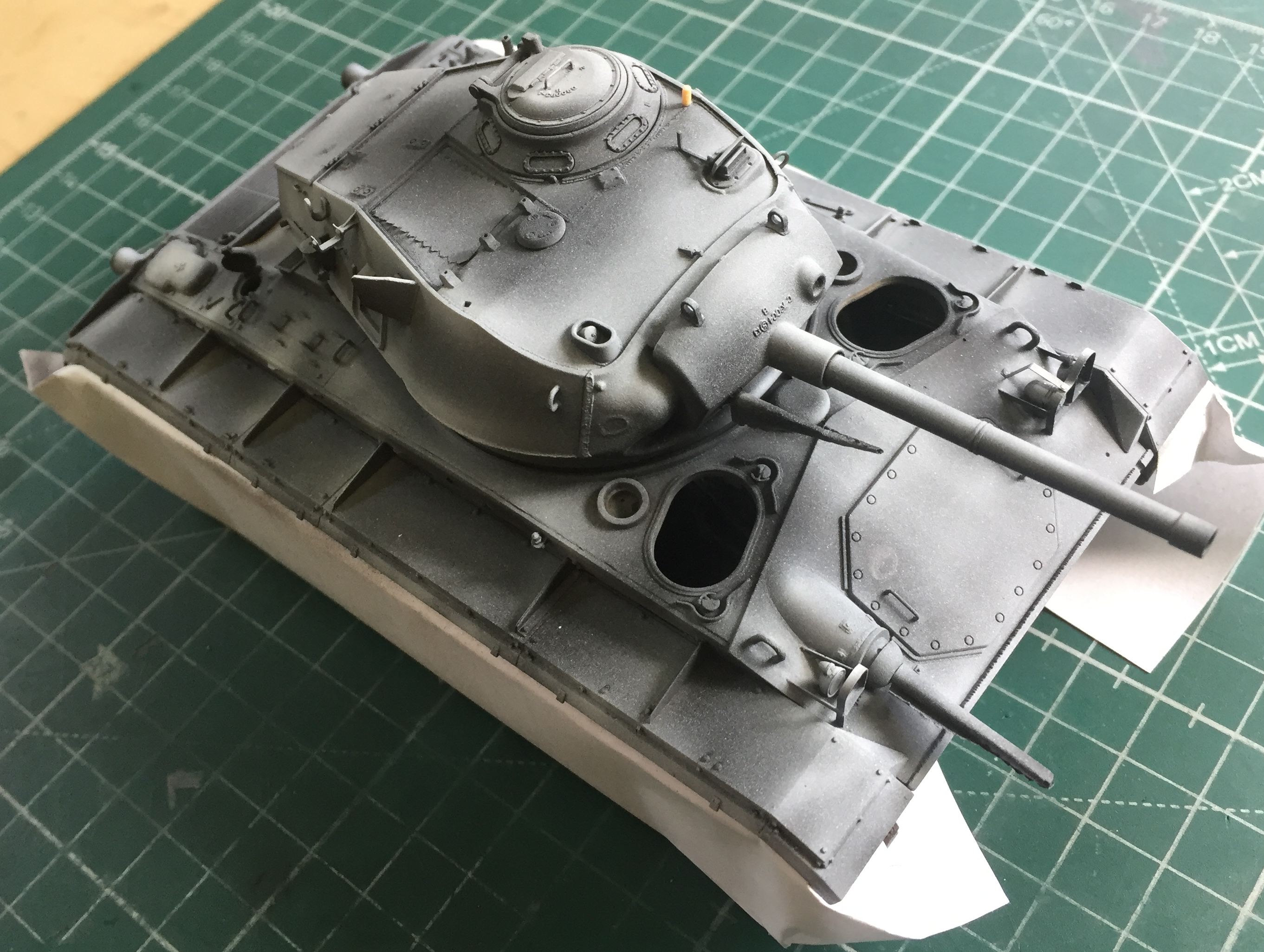
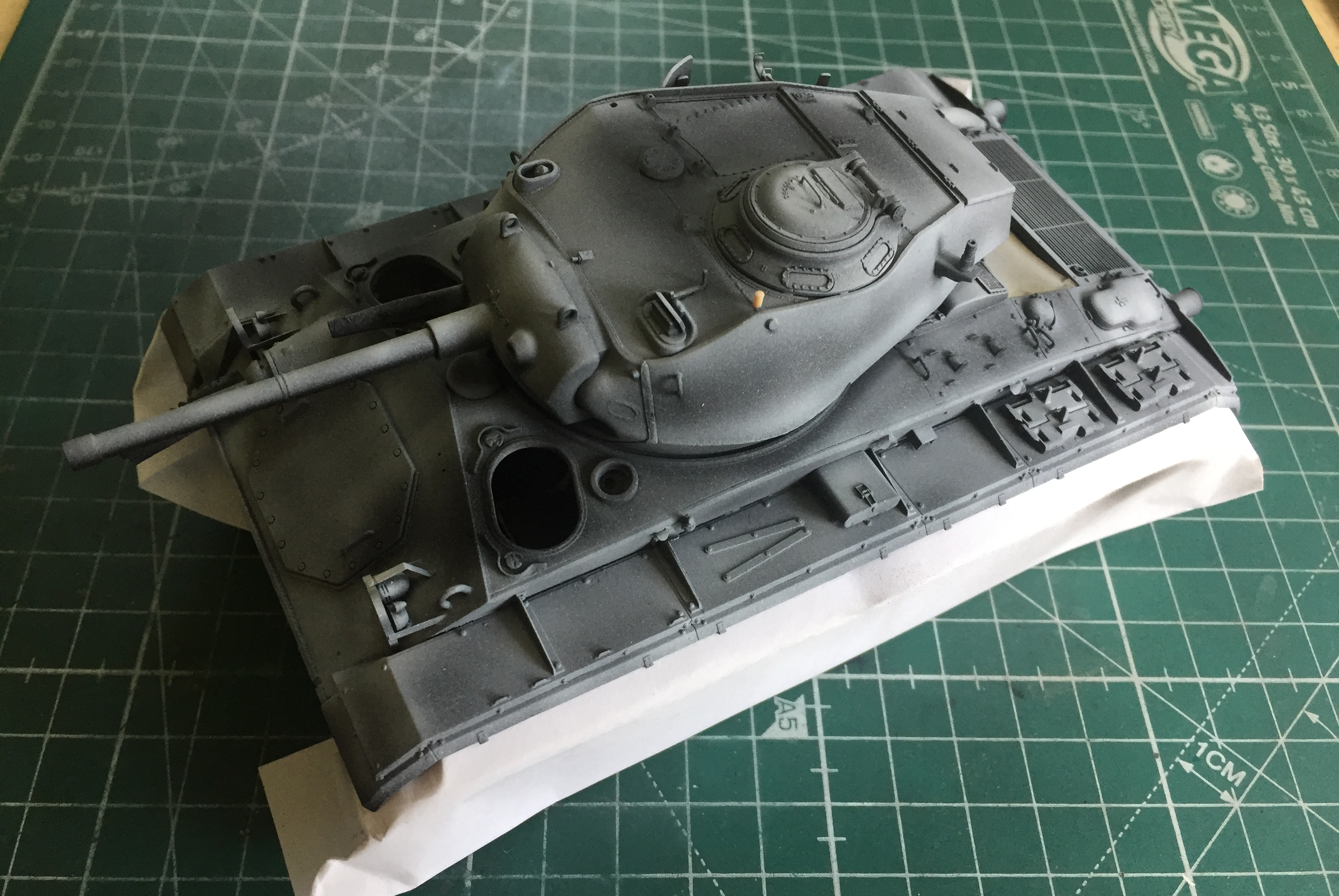
There were a number of things I had to do before I started populating the turret interior with bits. I thought I’d taken care of adding them, however I have discovered a sure method of discovering what I forgot to add. Paint it. In the spirit of discovery (snark), I put down the pre-shade Tamiya XF-1 Flat Black and painted the radio and intercom junctions Tamiya XF-62 Olive Drab:

Worked like a charm! I immediately discovered I’d forgotten to add the conduit that runs from the elevation wheel to some Mysterious Place under the main gun. It’s the only thing not black in the following photo:
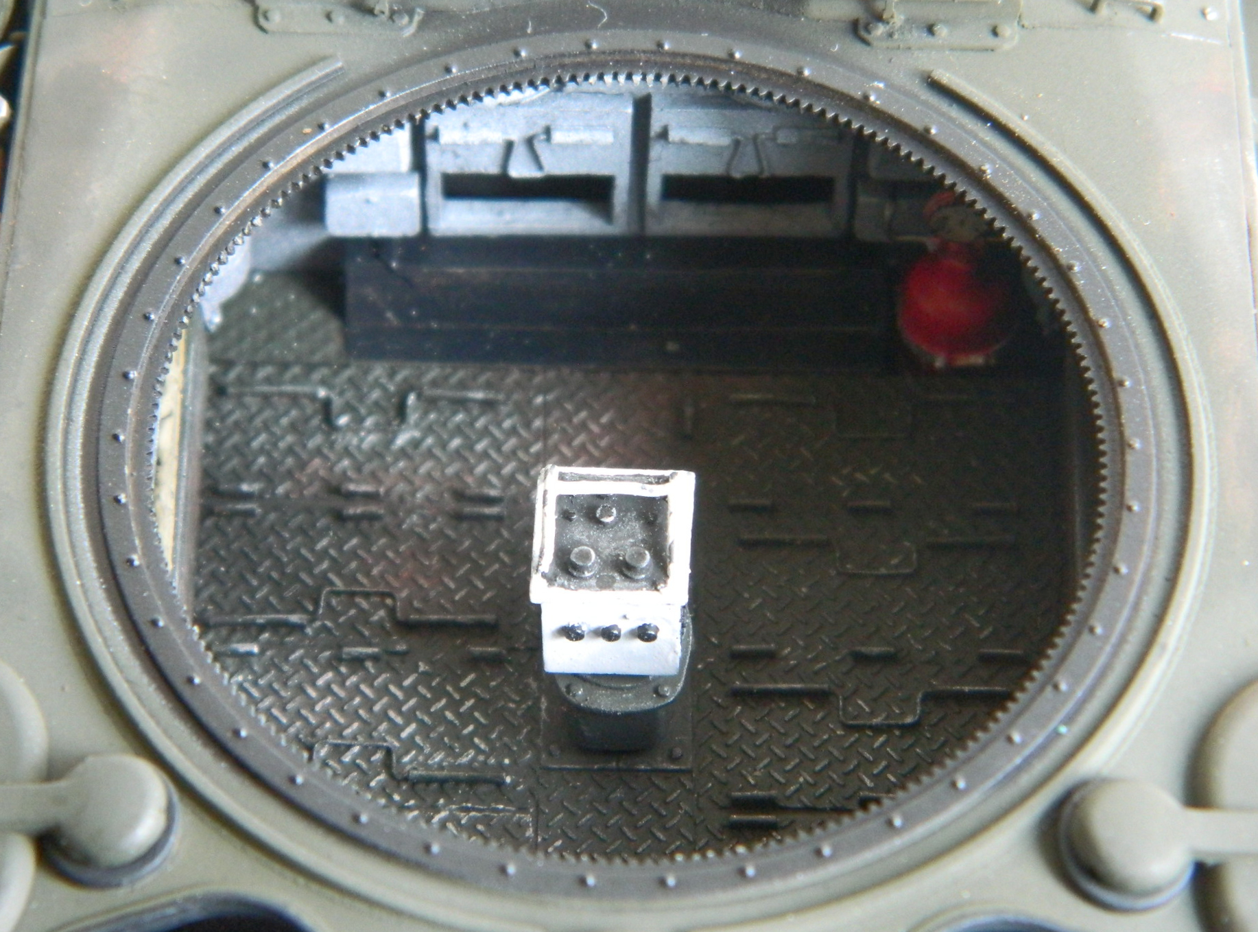
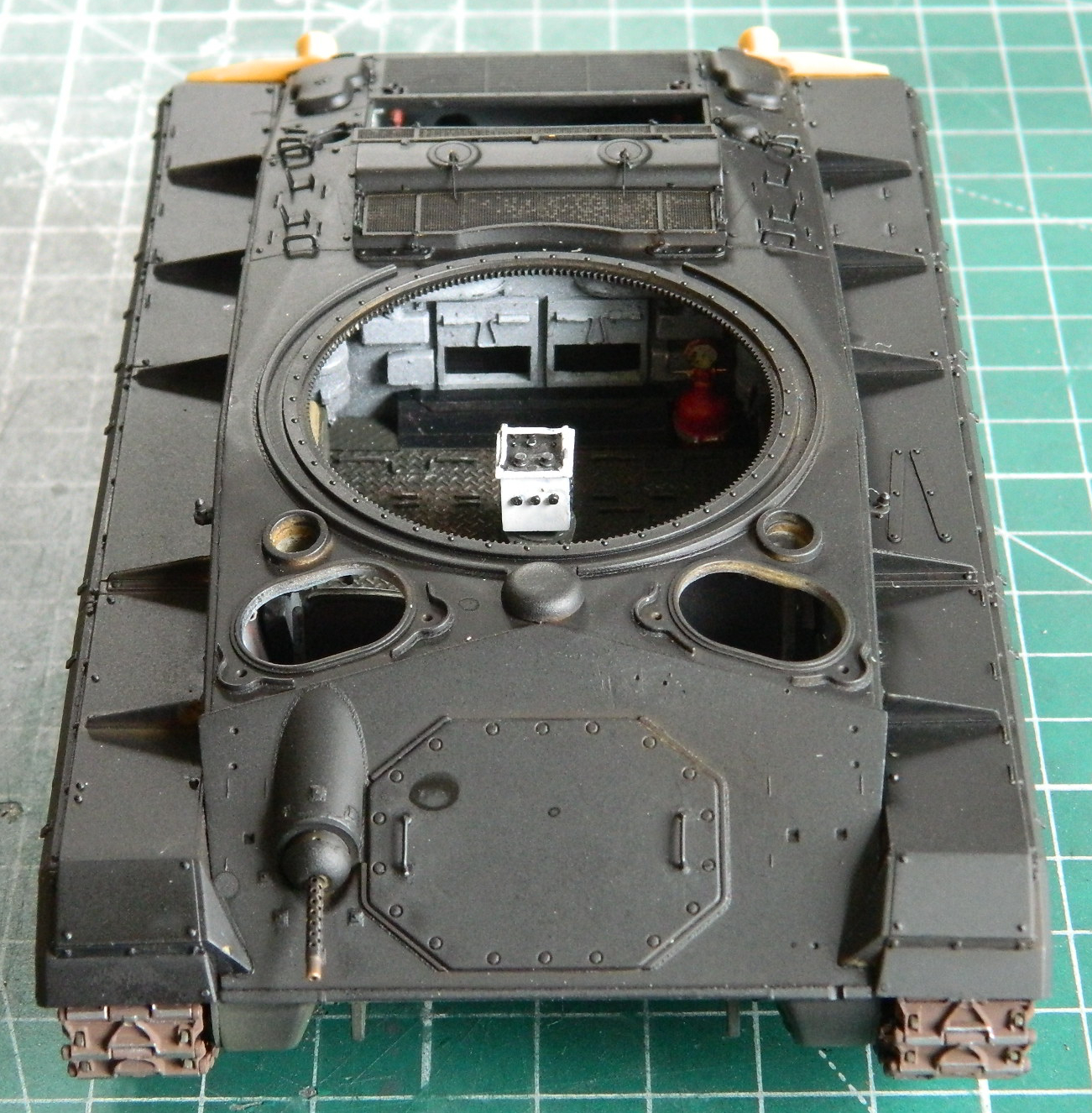
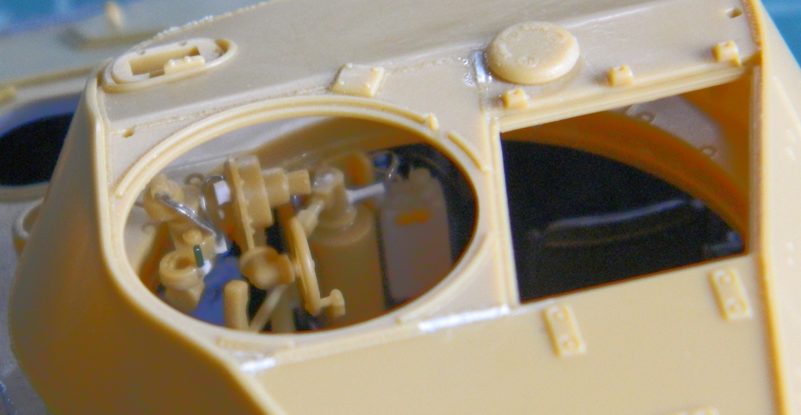
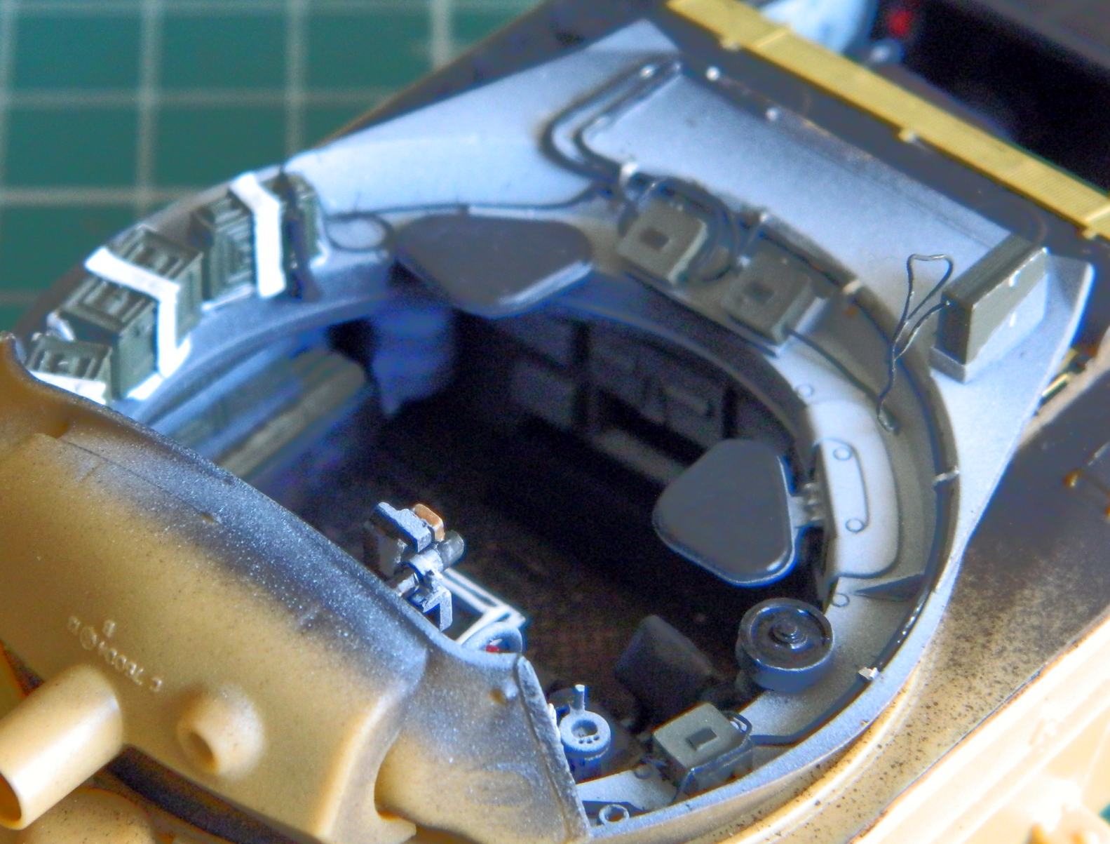
With the pre-shading done and the forgotten part discovered and installed, it was time to mist the color coat, Tamiya XF-2 Flat White, on the highlighted areas and then start populating the turret ring with AM resin, run the electrical lines, and touch things up and/or paint little details. Speaking of little details, there is a first aid box on the bustle floor next to the radio. Neither the kit nor the AM set provided it, so I scratch-built it and its mounting bracket:
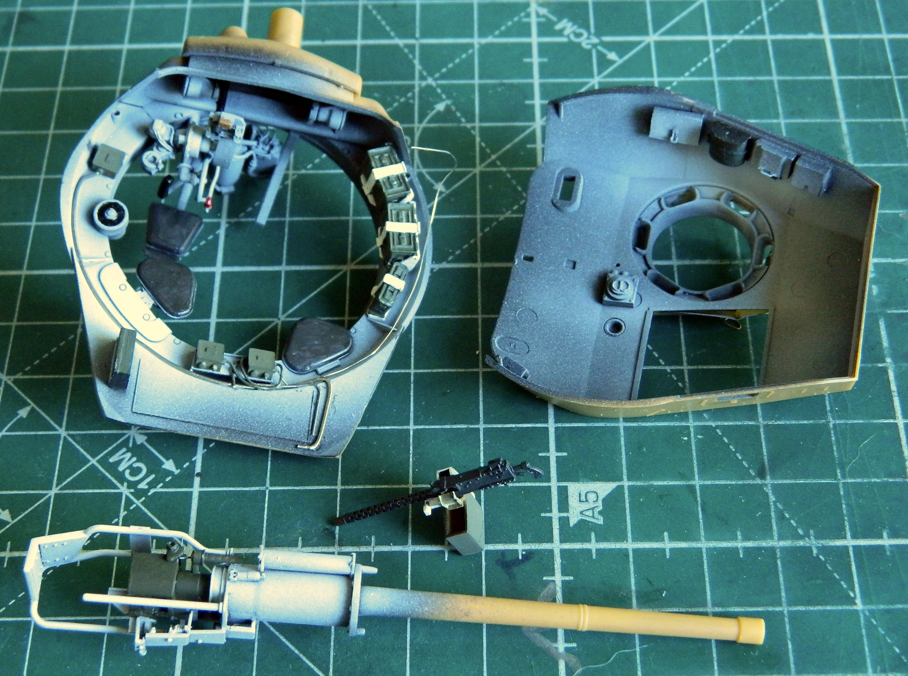

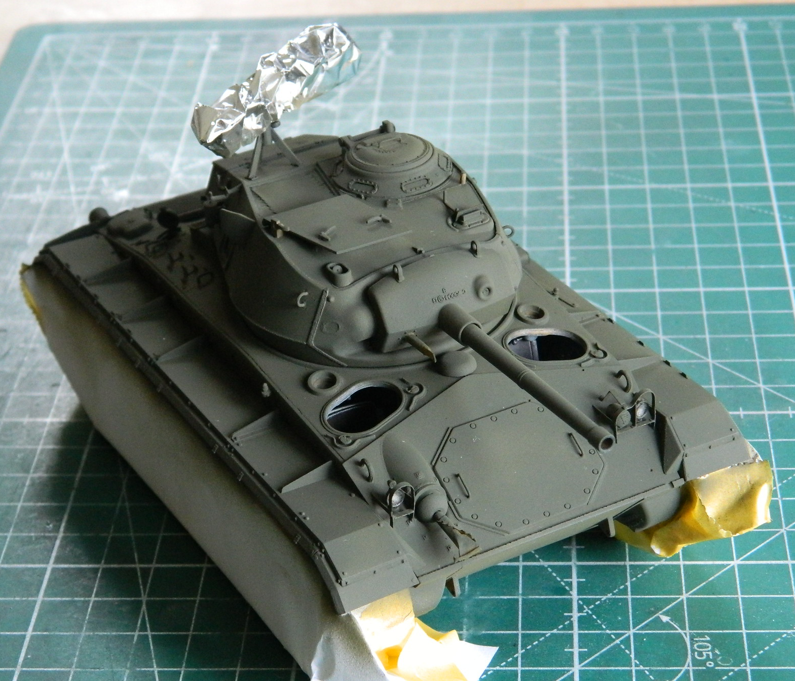
Before the radio could be fitted, the main gun and coaxial machine gun needed to go in next. The territory where the radio sits wouldn’t allow room or the necessary angle for the main gun to be added. I also discovered that, for whatever reason and also not showing at all any time I dry-fit the gun, once the gun is in place, it’s in place. And good sodding luck getting in there to glue the face of the gun to the mantle. This one is held in place with only one gluing point! Once I had the main gun (precariously) mounted, I applied chipping, wear, and dirt (Humbrol Metal Kote #27003 for anything that was exposed steel, a silver pencil for where edges of small things rubbed through, and pastels for the grunge):

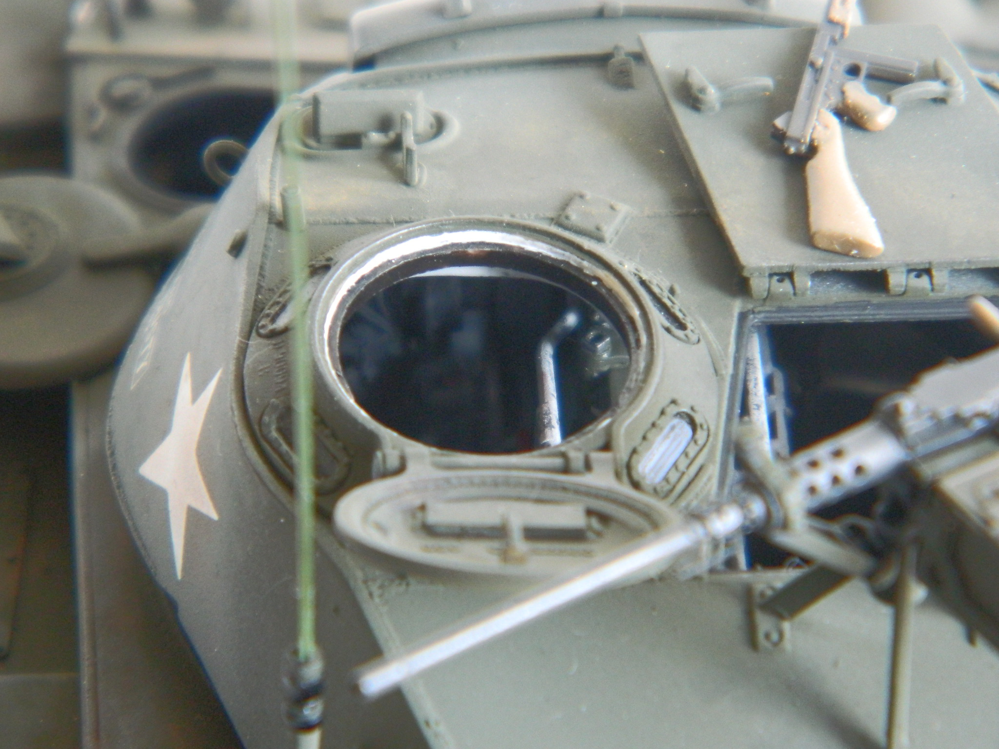
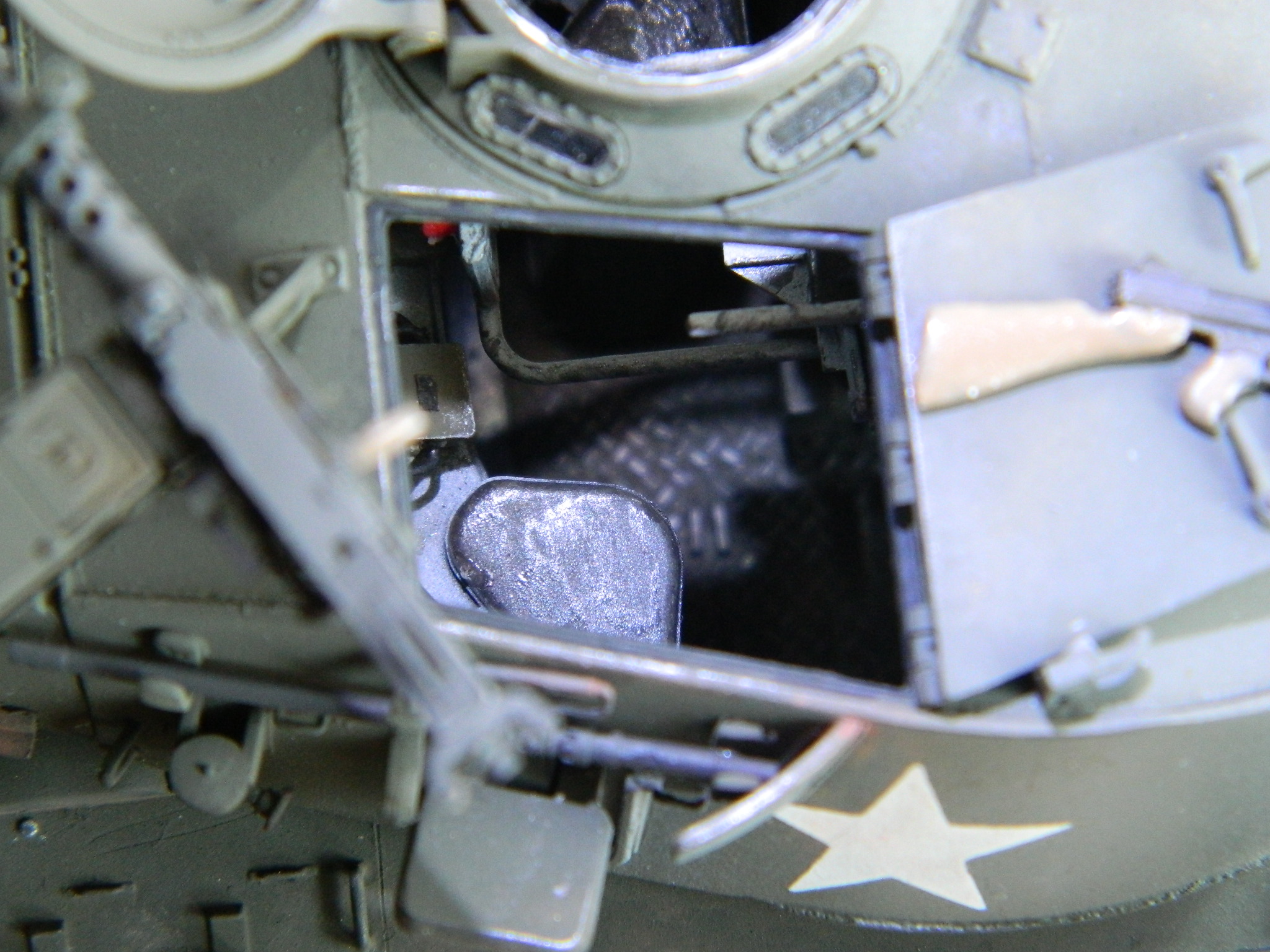
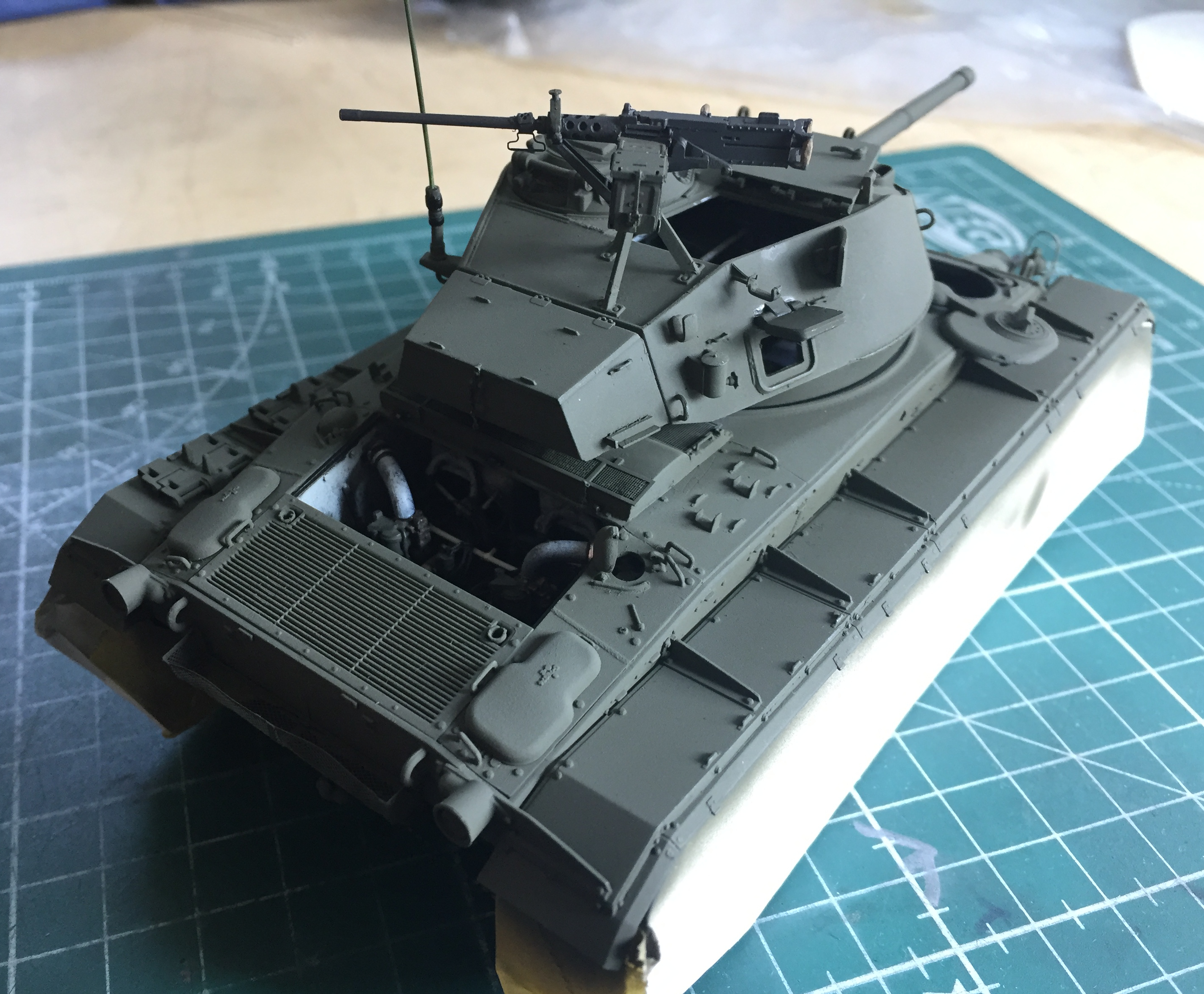
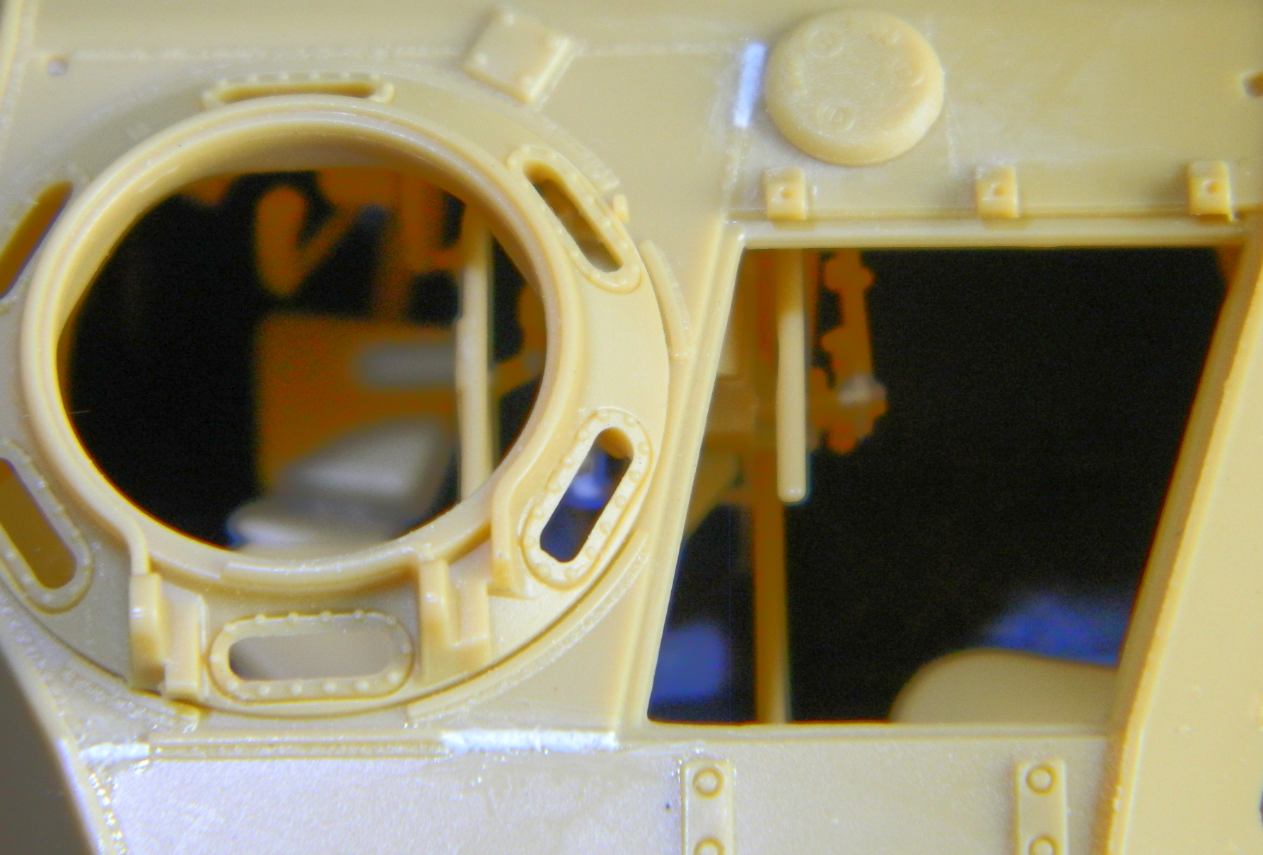
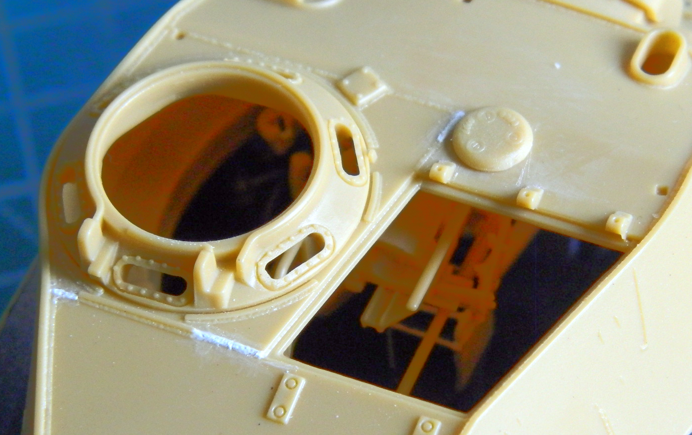
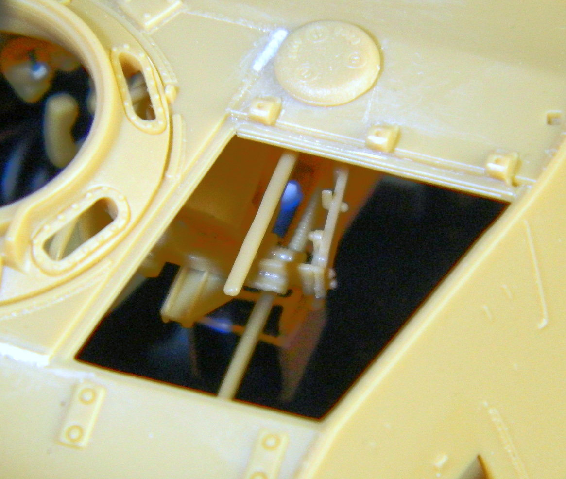
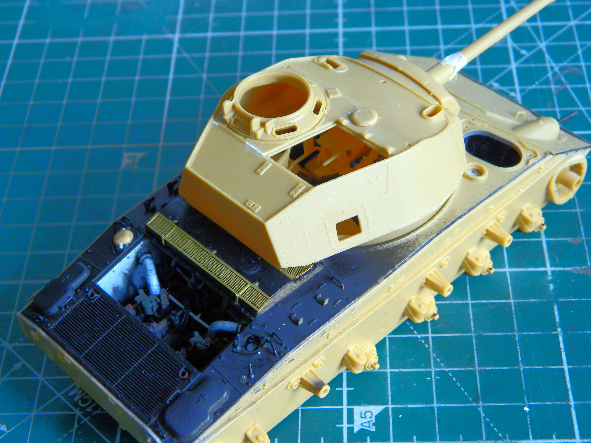
Various boxes, canteens, and holders populated the interior of the upper turret as well as the gunner’s periscope. I taped over the hatch openings from within the turret to keep subsequent painting sessions from intruding into where it (they) are unwanted. With all that painted, stained, and worn, it was time to glue the turret (with the bustle box added) top to the turret bottom:

Having completed that milestone, I detailed the commander’s cupola a bit. There is a pad that goes around the inside of the cupola so that the commander doesn’t brain himself looking out of the view ports while the tank is bouncing across terrain. I used two pieces of .020″ (.508mm) scrap for the pad. The kit provides clear parts for periscopes, headlights/spotlight lenses, and the view ports for the commander’s cupola. That was a very nice touch and the parts fit so snugly that they make the south end of a north-bound bull in fly season seem loose:
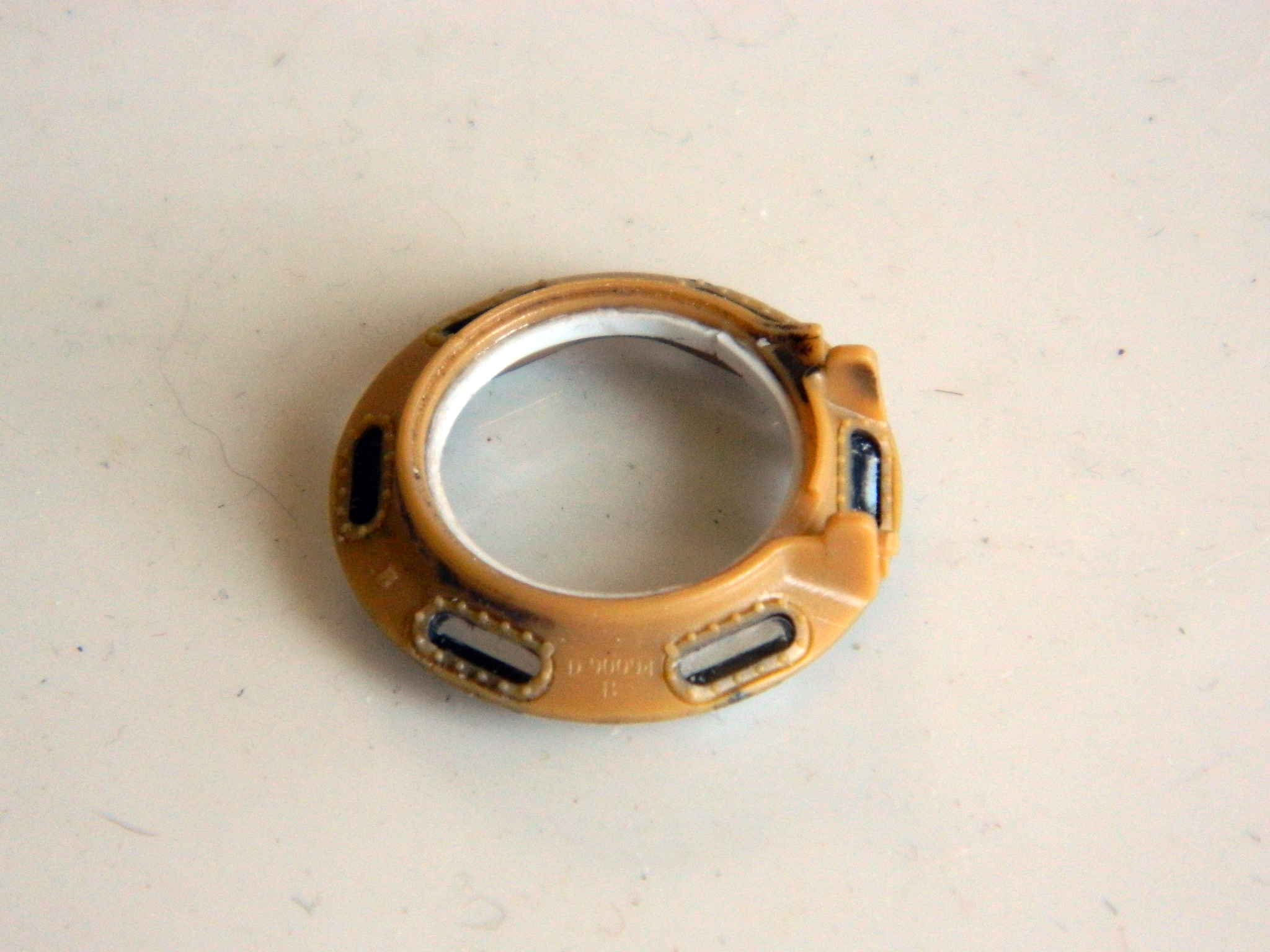
That will get painted OD on the outside, white on the inside, with the pad painted “black” leather (the color is in quotes because it’s two parts semi-gloss black, two parts flat brown, and one part gloss white).
But I’ve been dodging this next step as long as I can. It’s time to paint and attach the suspension, road wheels, idlers, return wheels, and sprockets.
Should be a fun month…
M24 Chaffee (Bronco) 1/35 Scale Build #6 – Small Details Find a Home and More Small Details are Produced
Now that many (but certainly not all) of the small details have been painted, it’s time to put them where they’re going to stay. The .30 caliber(7.62mm) ammo stowage racks were mounted to the sides and the M-3 “grease gun” and canteen were mounted to the side of the driver’s position:
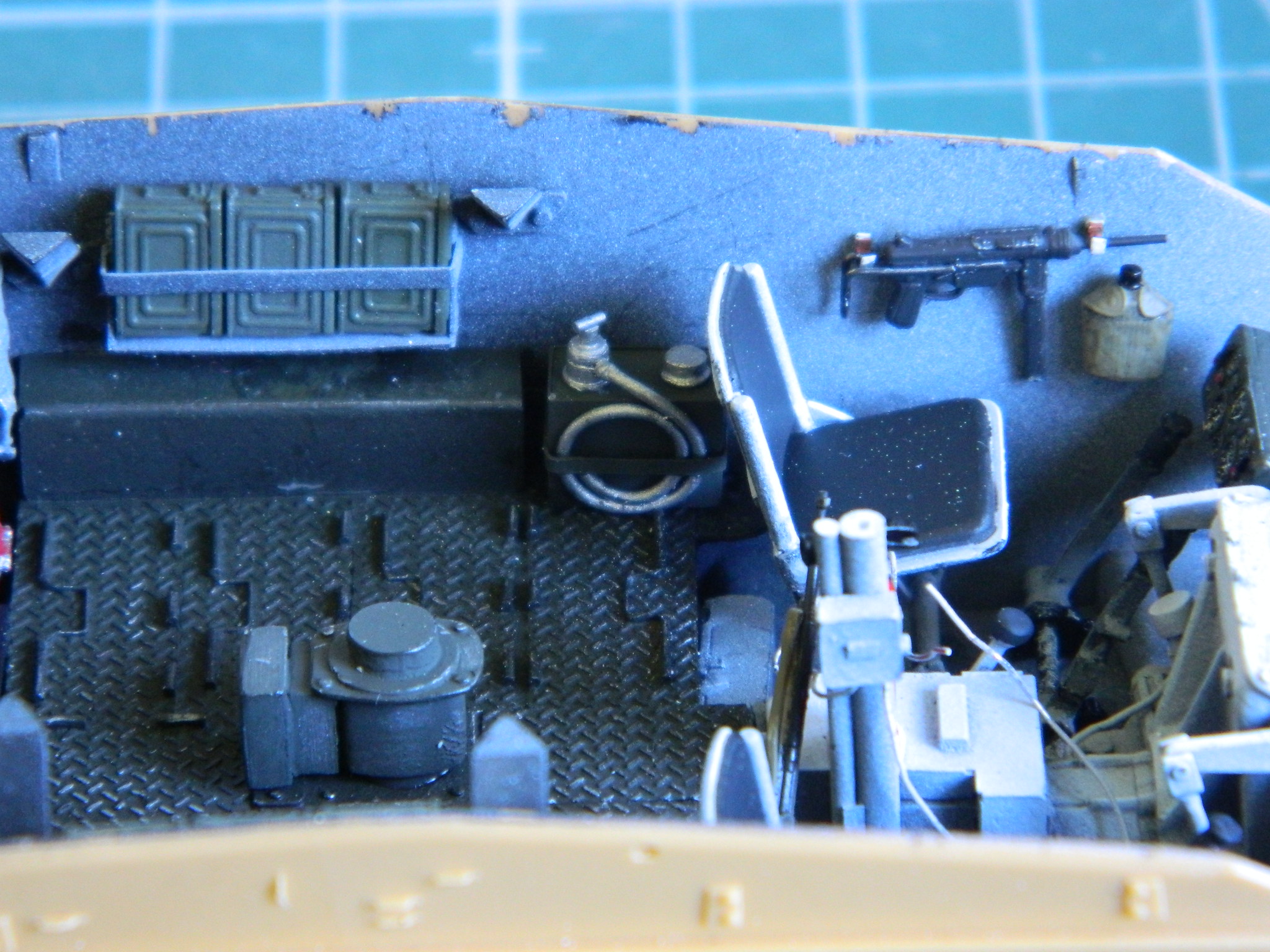
The pin-up (Rita Hayworth) and canteen were mounted next to the co-driver’s position and behind it in addition to the .30 (7.62mm) ammo stowage, the signal flag bag was slid in (barely) underneath it:
I turned my attention to the rear of the tank and discovered that the engine cover was just a bit too wide, so that will get taken care of later:

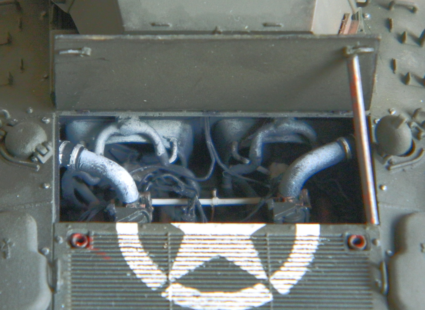
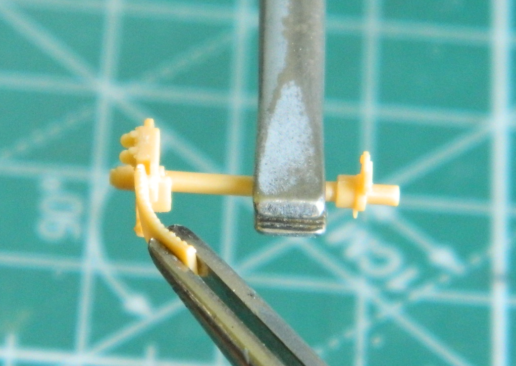
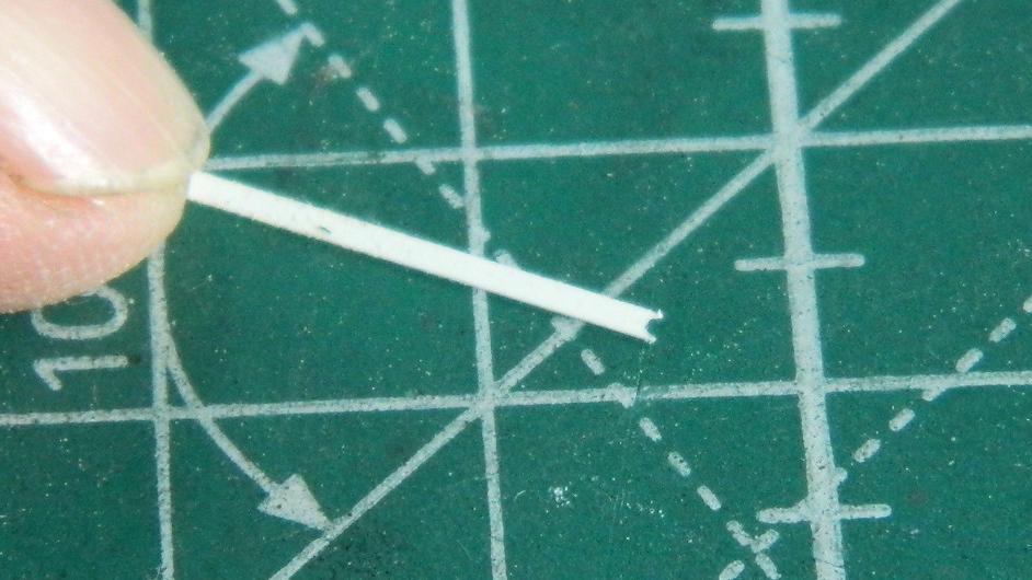
One of the prominent features in the engine compartment is the throttle linkage. The first step to making that part was to find out how long the cross-shaft that connected two carburetors to one lead foot had to be and a compass with two points did that well:
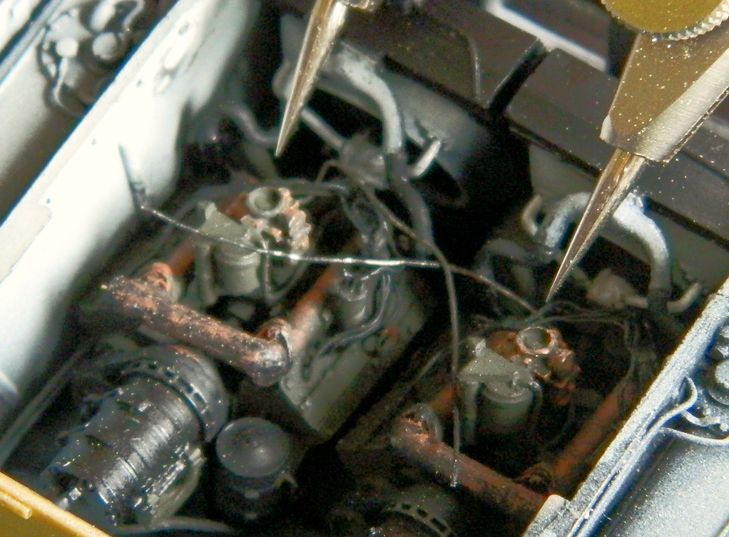
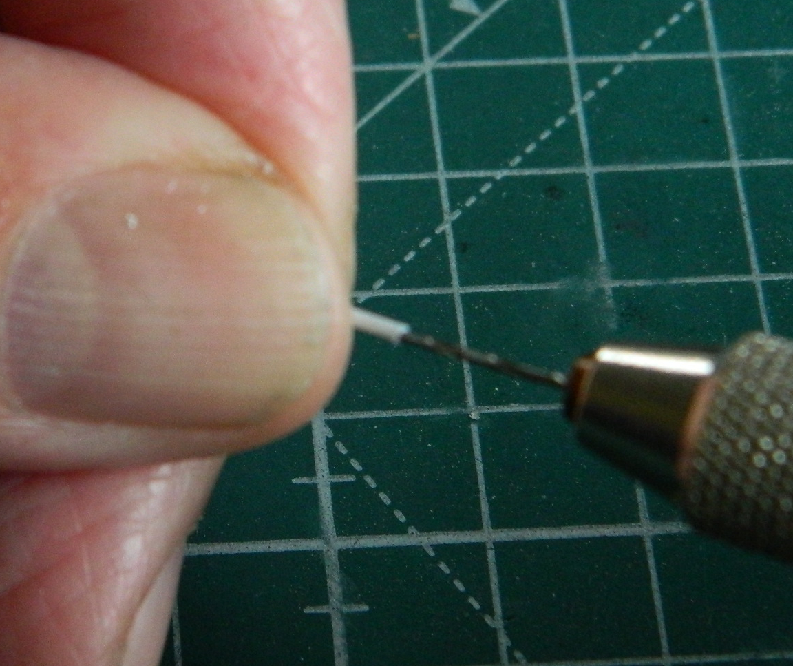
There is a linkage arm that’s attached to the cross shaft and to replicate that I used a #75 (.025″) (.635mm) bit and center drilled the end of .035″ (.89mm) rod to make the attachment base of the linkage arm:
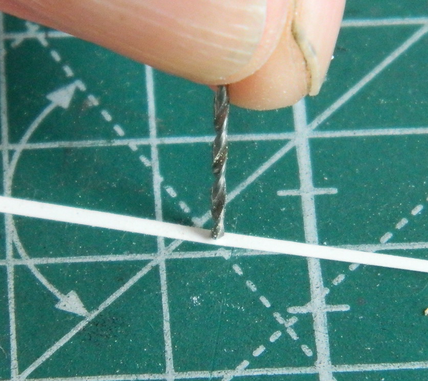
To make the linkage arm, I used a piece of .005″ (.127mm) scrap and used a #65 (.035″) (.89mm) bit to make a curve where the arm mounts to the cross shaft:
The styrene was cut across the hole leaving a semicircular cutout to glue to the mounting base of the linkage arm:
A small section was cut off the drilled out rod and slid over the rod that will serve as the cross shaft:
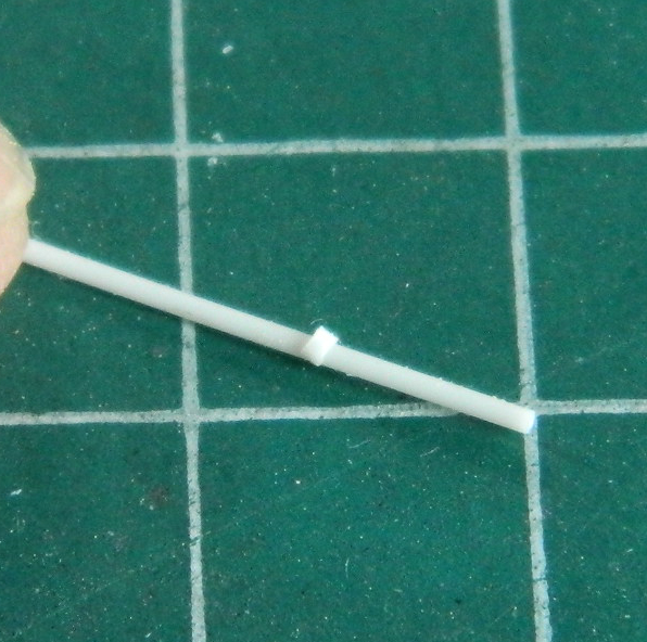
Then the length of the cross shaft was transferred to the rod and the cut was made on the mark:
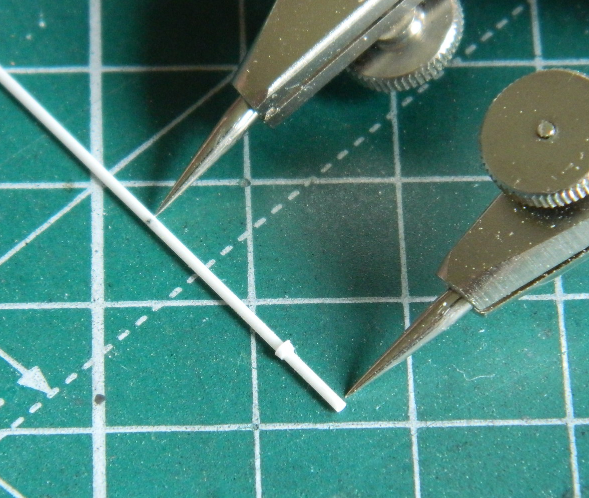
The arm’s base was centered and clamped in locking tweezers on a base, then the trimmed linkage arm was aligned in another locking tweezer on a base and both parts glued to the cross shaft:

While the glue was curing, I started assembling the main gun since work inside the turret is rapidly approaching. A part of me really appreciated the very fine molding of very small parts that inhabit this kit’s box. A part of me wonders why the aerial intercourse a sub-assembly that could make do with three or four component parts needs TEN OR TWELVE component parts! Really…too much of a good thing is more annoying than merely “too much.” An example of this is the main gun (though it is far from the only example in this kit). This thing is comprised of twenty-three separate pieces (it would have been twenty-four if I’d used the gimmicky recoil spring that allows the barrel to move backwards in the receiver). I neglected to take a photo of all the parts laid out; here it is with construction already started:
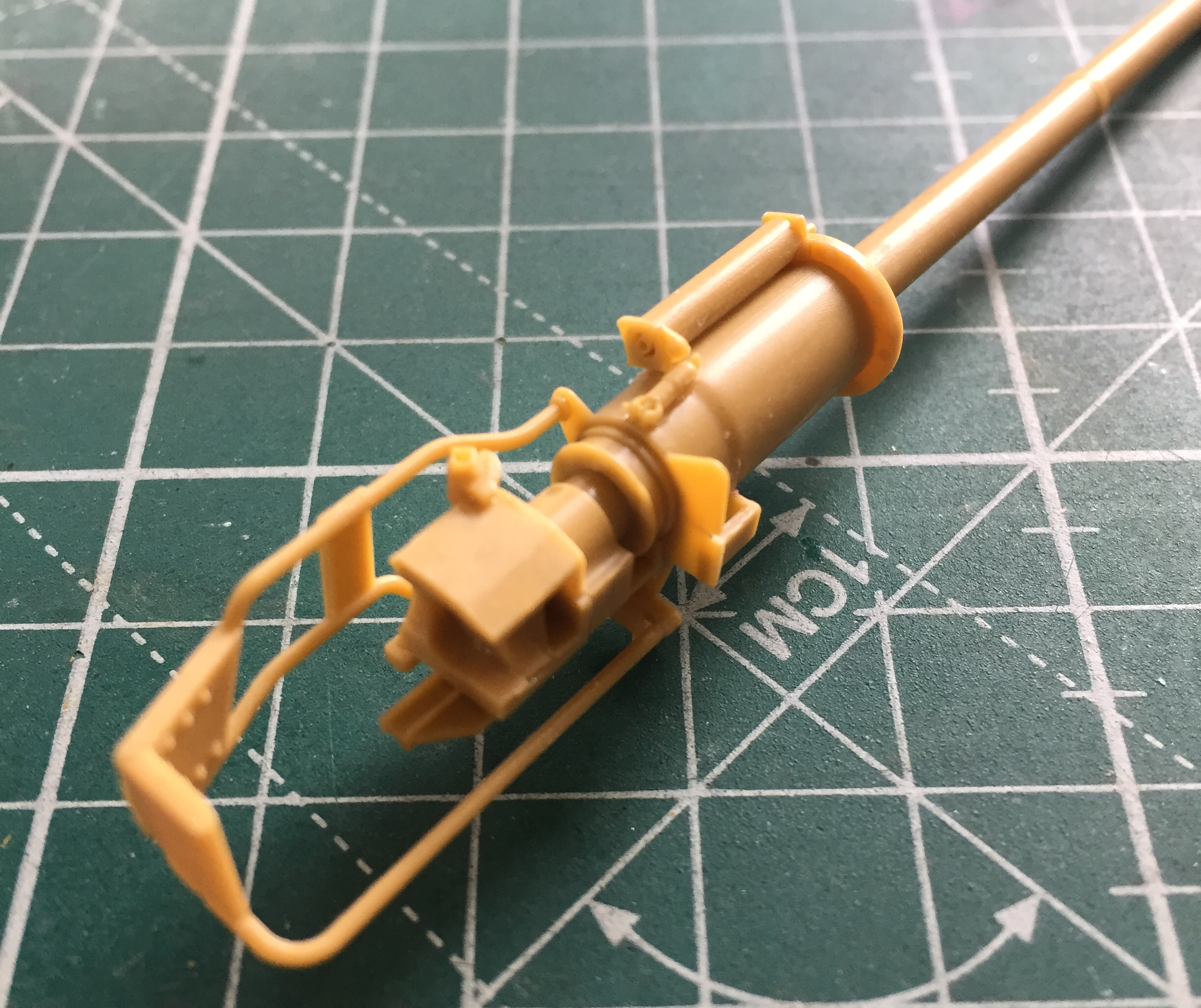

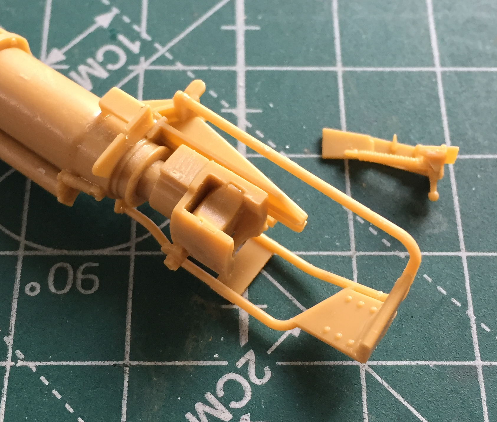
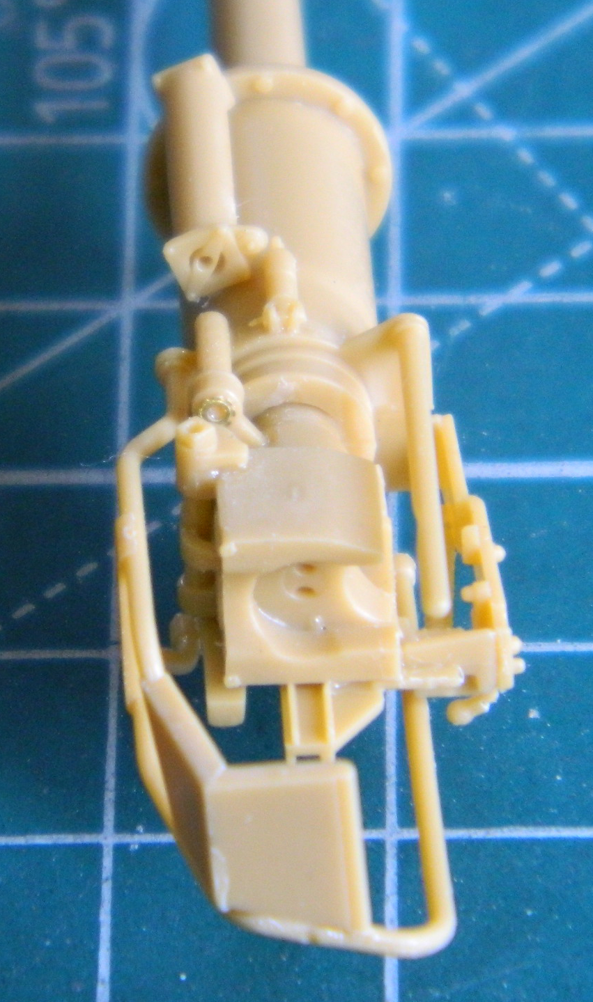
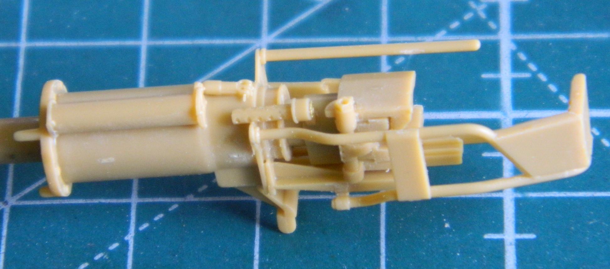
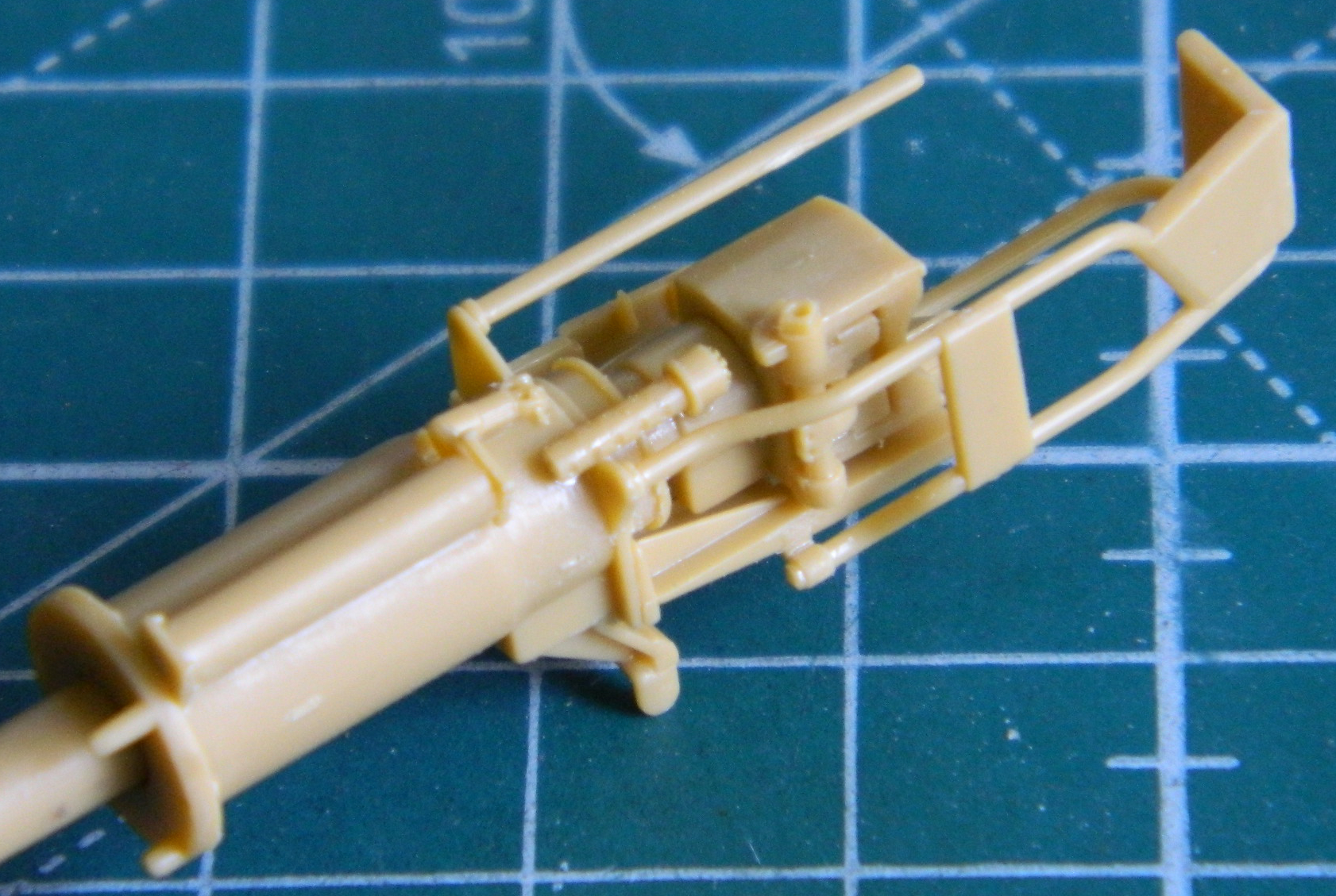
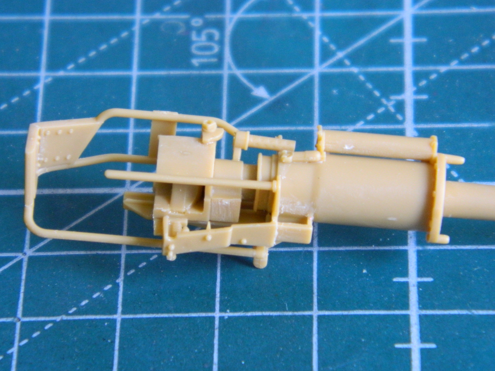


If having twenty-three parts to this gun wasn’t enough pleasure (spits), there are no location marks or pins. None. Sherlock Holmes, Hercuile Peroit, Travis McGee, and my mother would have been impressed by my investigative efforts to get (what I hope is) a reasonably accurate representation of the T13E1/M5 gun (the two rings cast around the barrel show this, correctly, to be the 75mm tube from the ground attack variant of the B-25 it was taken from). I was impressed that Bronco also molded in rifling in the muzzle (sorry but this was the best photo I could take of that given the light and the autofocus’ unwillingness to focus where I wanted it to focus):

Masking and painting this thing will probably drive me to drink (something to look forward to…while I can still see).
Oh. And as if there weren’t enough parts, I discovered that Bronco, in all the parts they made for this thing, actually forgot two! They forgot the breech opening lever and the bracket it stows in when not in use. So I had to make them.
The socket was made from a piece of sprue chucked into my lathe, turned to the appropriate diameter, and the edges of the nut cut (CAREFULLY) in. A scrap piece of .015″ (.381mm) styrene provided the handle:

I used a piece of aluminum to make the stowage bracket, and although pleased with my efforts, I realized later that where I have the bracket is too high. It should be centered on the rear of the recoil guard and later I moved it down to a less incorrect location:
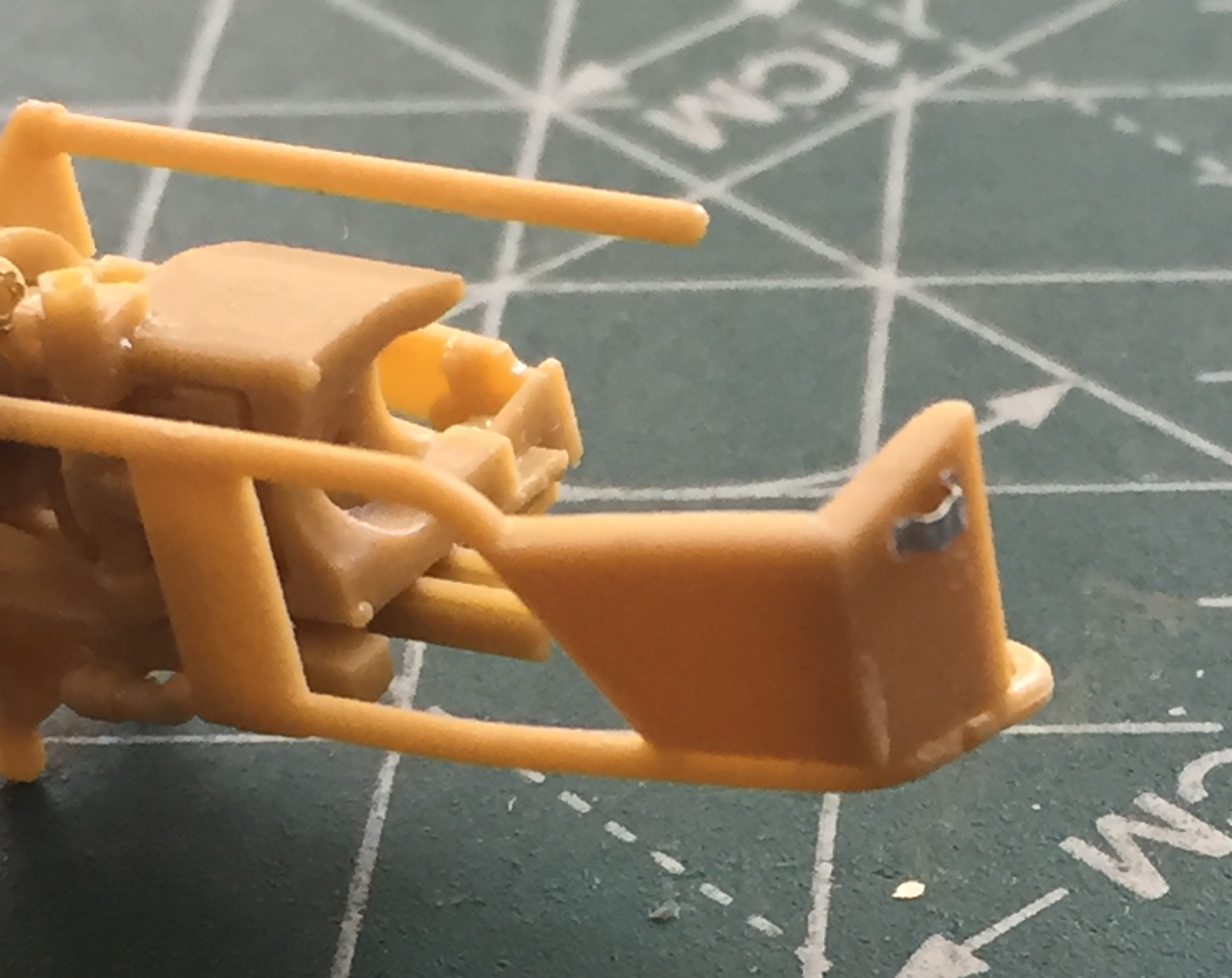

After dealing with the main gun for a couple of days, the glued parts of the throttle linkage was thoroughly dried and cured, so that got installed. It had aspects of trying to give a snake an enema and several of the delicate solder “wires” were dislodged, but obviously I don’t know when to quit so the installation was accomplished:

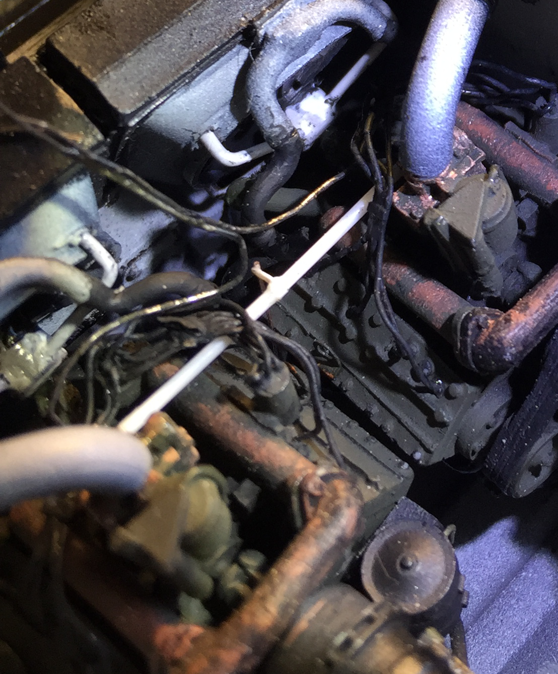
The next serious test of patience and commitment was installing the mufflers and exhaust tips. I’m very glad I decided not to mount these parts before engine installations because had I gone ahead and mounted them, the right engine would never have fit…not even remotely. A little foresight helped a bit when I drilled out the parts that had to be mated and added pins. But to get the right (or starboard) muffler to sit where it needed to (more on that shortly), I had to grind away substantial portions of the inner bottom of the muffler and the outer side of the oil filter. The good news is even knowing that moderate surgery was necessary to get the starboard (or…well, never mind…you get it by now) muffler into position isn’t evident. It’s a tight space and the black pre-shading hides the butcher…er…surgery. But it turns out there was one more tiny little thing.
Getting the exhaust pipe to exit the upper hull where it has to is that “little thing.” If the exhaust pipe lines up along the vertical axis, it doesn’t even come close to the opening provided for it. (Part of me wonders if that’s because the engines are probably misaligned…another part of me doesn’t give an intercourse.) I rotated the muffler/pipe around the pin glued into the cross-pipe until the tip of the exhaust pipe was under the little square opening. Now (as it is in other things), I just needed a longer pipe.
It turns out that .062″ (1.57mm) solder is the exact diameter I needed to lengthen the pipe! (Would that other lengthening were that easy, or even possible.) I drilled out the ends of the solder and resin pipes, added a wire pin, and then glued the solder to the resin:


A little paint, a little glue, and that problem was solved! (One cannot count on luck, but it’s sure nice when it shows up.)
With the “pipes” correctly aligned and installed, they needed to be cut to the appropriate length and the ends drilled out so that they look like pipes (alignment where the solder meets the resin is slightly off, but once painted with the top hull plate in position it’s unnoticeable):


I GLADLY turned my attention elsewhere! The next major step is to get the upper hull glued down to the lower hull. There were still a couple of items I needed to attend to before that could happen, the primary one being the bow machine gun. The kit parts are fairly decent and given the location of the bow machine gun, it’s not going to be easy to see the receiver. But the barrel will certainly be easy to see, so I worked those next.
My go-to for coloring brass machine gun barrels has become Birchwood Casey’s Brass Black Metal Finish. The Polish company, Master, makes exquisitely turned and drilled, two-piece (separate barrel and cooling jacket), brass barrels in their Ground Master series for 1/35 scale machine guns. They’re so finely constructed that paint plugs things up. When I was building the M-3 Stuart, I ran across BC’s blackening compound and discovered that it does a BRILLIANT job of coloring the brass without adding perceptible mass to the barrels or plugging the holes in the cooling jacket.
Use of these barrels requires that the molded on barrels be cut off, a socket be drilled for the pin on the end of the barrel, and the barrel glues on. So far, so good. However, the bow machine gun is slightly different from the co-axially mounted machine gun. There is a ball around the base of the barrel and a sleeve that connects the ball to the gun (allowing the machine gun to traverse and elevate in its mount). So, yeah…I had to drill that out, too:

Whew. Nerve wracking.
The barrels were masked (I used a tube of paper) and the receivers painted with five parts Tamiya X-18 Semi-Gloss Black and four parts Tamiya XF-20 Medium Gray. I like this combination SO much better than any “gun metal” paint I’ve yet encountered. It has just enough sheen to look metallic and avoid the toy-like appearance “gun metal” paints strike my eye as:


Other than replacing the barrels because they’re visually evident, I didn’t do much detailing on the .30 cals (7.62mm) because they’re not easily seen. (Of course I did some because, well, I HAVE TO!) So far in my experience, I like how Bronco does their .30s (7.62mm). It’s nice not having to add those tiny, sodding, triggers myself…
One last look at the innards before the upper hull goes on. Dirt and wear were added, things were chipped and worn. And in the first photo below you can see the crew’s microphones “hung” from the upper hull supports. There are NO words that can convey the ABSOLUTE FRUSTRATING TEDIUM involved in getting the solder “wires” connected to the ends of them:
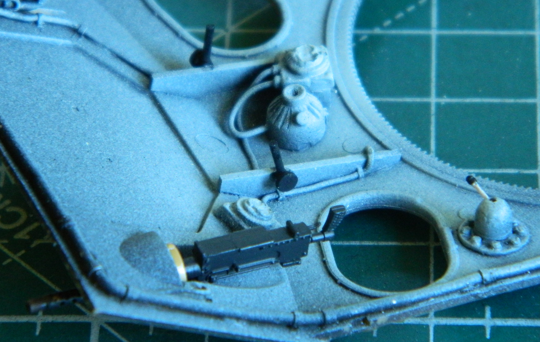

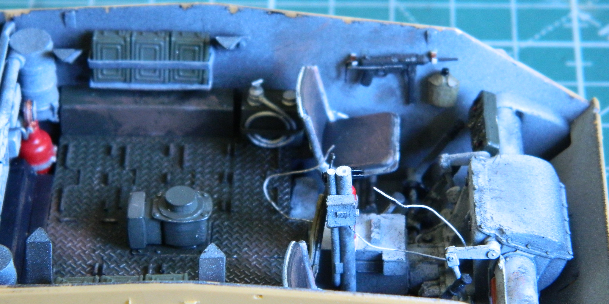

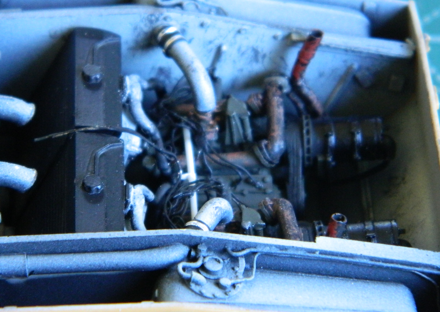
I sprayed the rear upper hull Tamiya TS-6 Flat Black (rattle-can) to pre-shade all the louvers and grills:
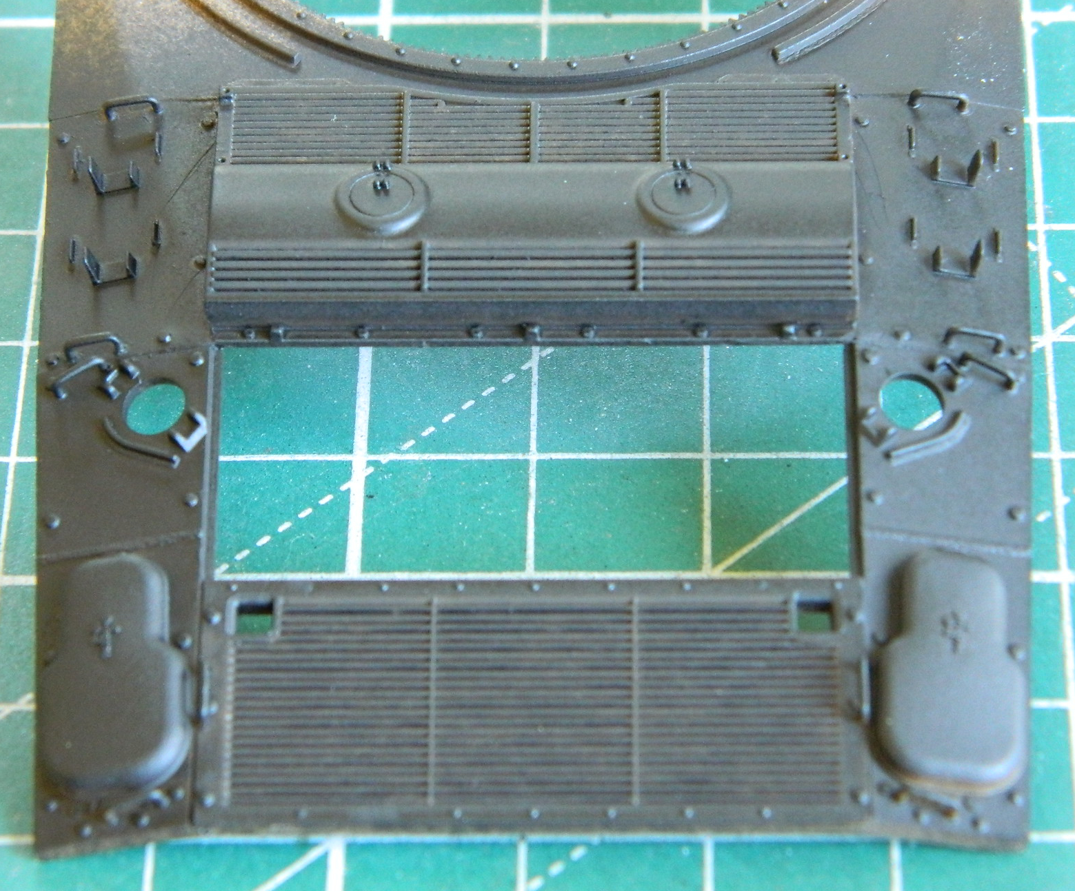
And the major step of marrying the upper hull to the lower has happened:


Now to work on the turret…
M24 Chaffee (Bronco) 1/35 Scale Build #5 – More Small Details
Before the upper hull can be mated to the lower, there are a fair bit of small items that have to be worked and painted:
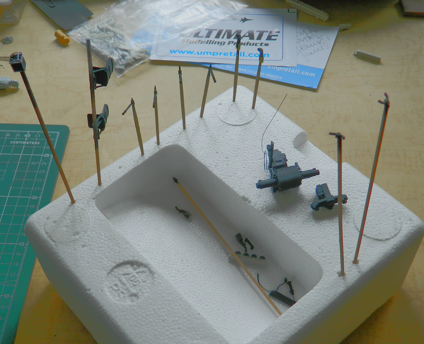
I decided that either I overdid the preshading or I under-did the color coat on the differential/transmission assembly, so I hit that again with white after this photo was taken:
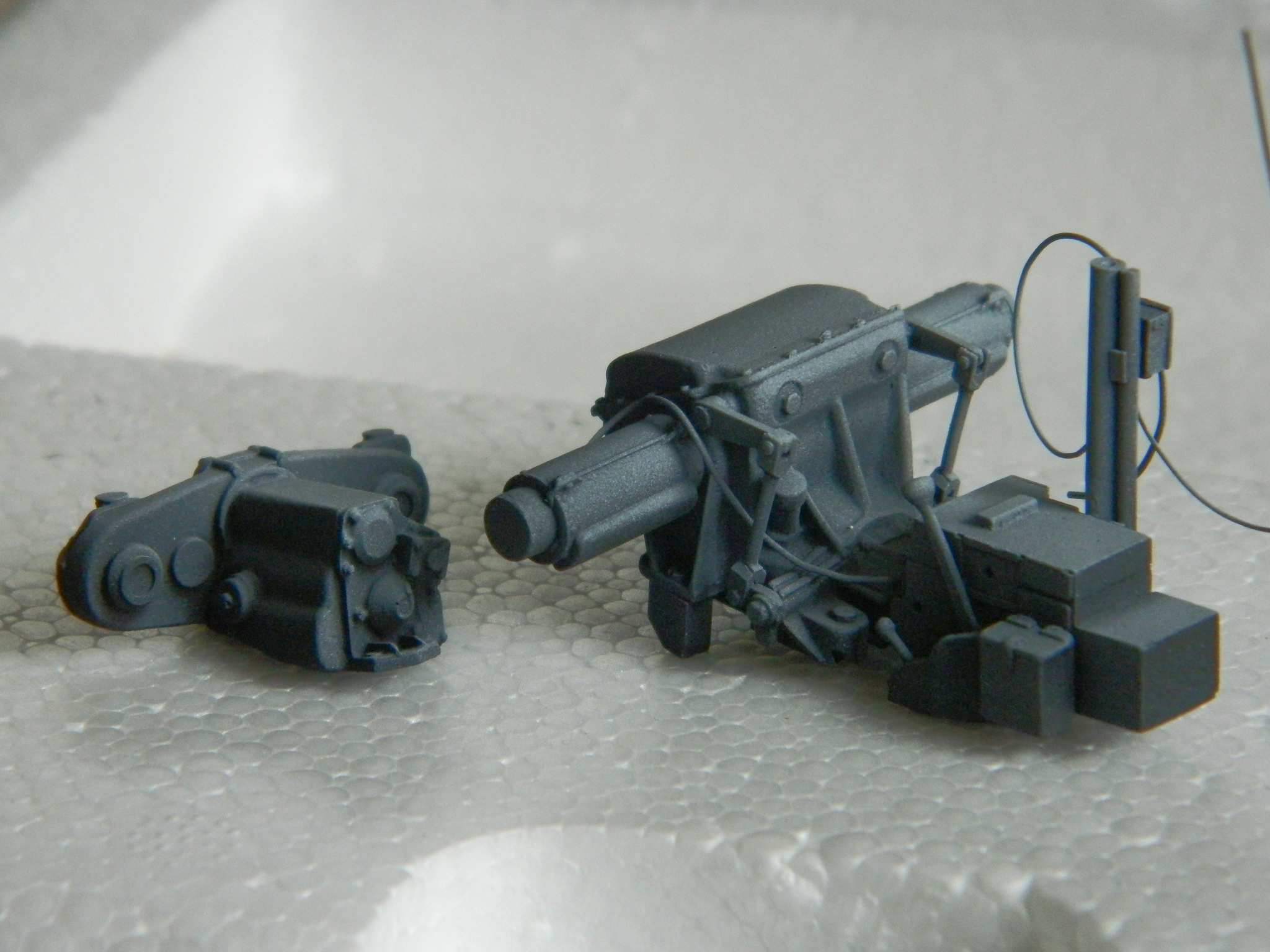
My initial intent was to have all of the upper hull panels be removable. As I tried fitting things together I came to a couple of realizations. The first was I was disappointed with how the parts fit. Good thing I don’t smoke cigars because it was a matter of close but no cigar. The second was that I thought having them removable was too much of a gimmick and that I was just begging for something to break. The more things get handled, the greater the opportunities for things to be damaged. I taped the forward section of the upper hull into place so that I had a reference point to align things as well as they could be, then set about gluing, aligning, and using scrap stock to fill gaps. I started by filling the gaps:
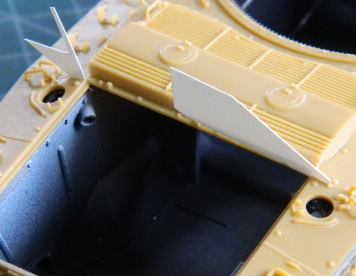
Then making the engine cover fit, which if you look to the left of it you’ll see it doesn’t really:
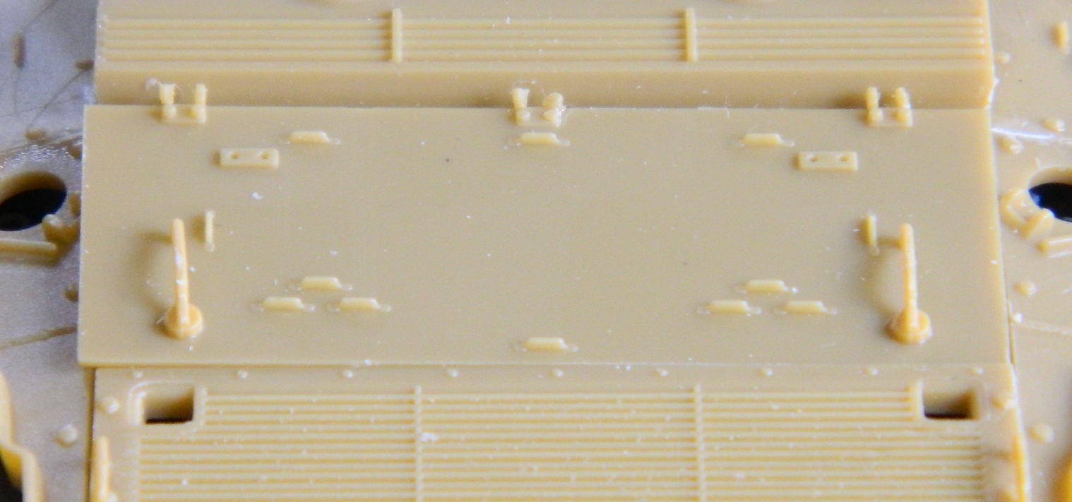
And done:
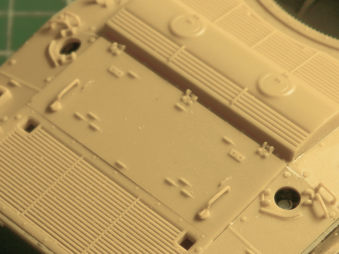
The upper hull was set aside to let the glue cure completely:
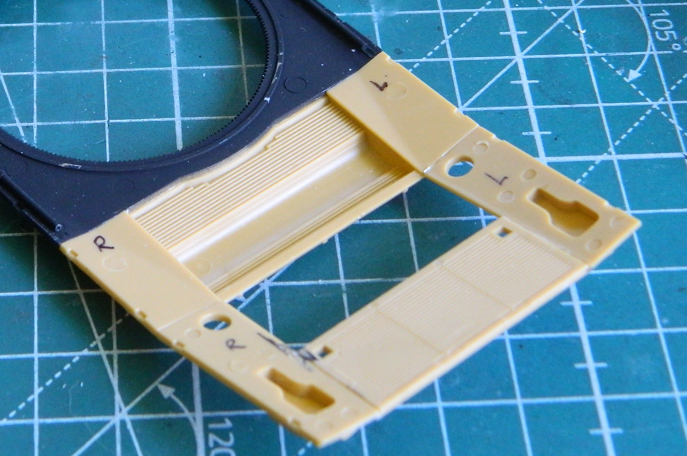
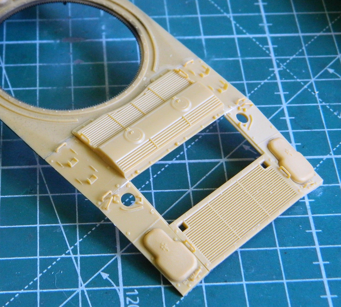
Then it was time to see how well, or not, the engines would fit. I started that by first dry-brushing Italeri’s #4675P Flat Rust onto the exhaust manifolds and pipes, and then touched up the spark plug wires:
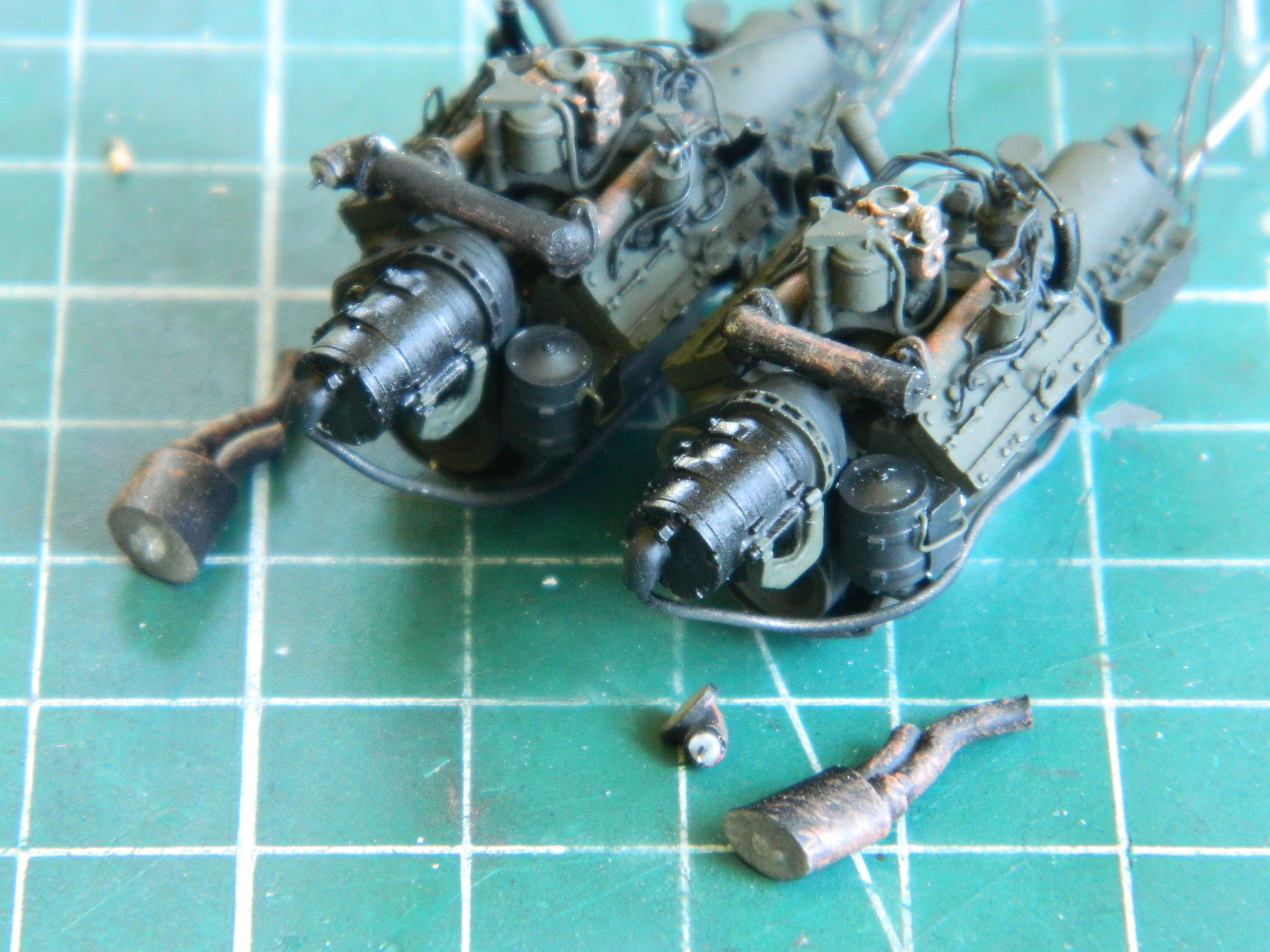
If you look closely at the above photo, you can (barely) see where I added pins to the exhaust parts to make aligning them easier when it comes time to put them together. I also added pins to the transfer case where each engine joins it:
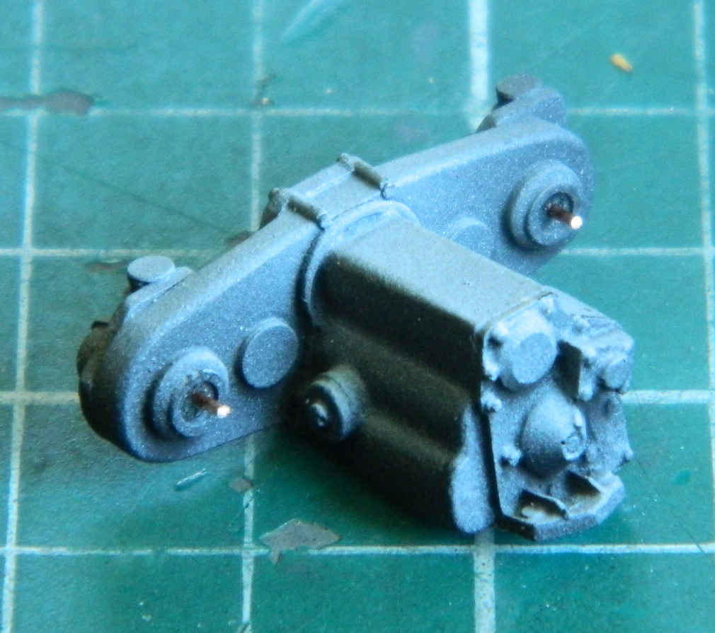
I needed to finish the radiator/fan assemblies as well. Dry-fitting showed that the fans dropped too deeply into the radiator shrouds:
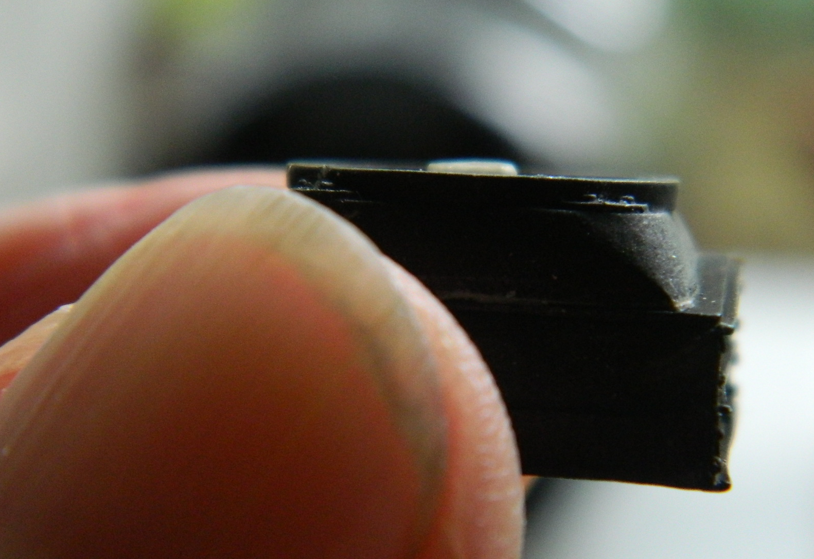
I made spacers from styrene scrap so that the fans would sit at the correct depth and glued them under the fan where they can’t be seen:
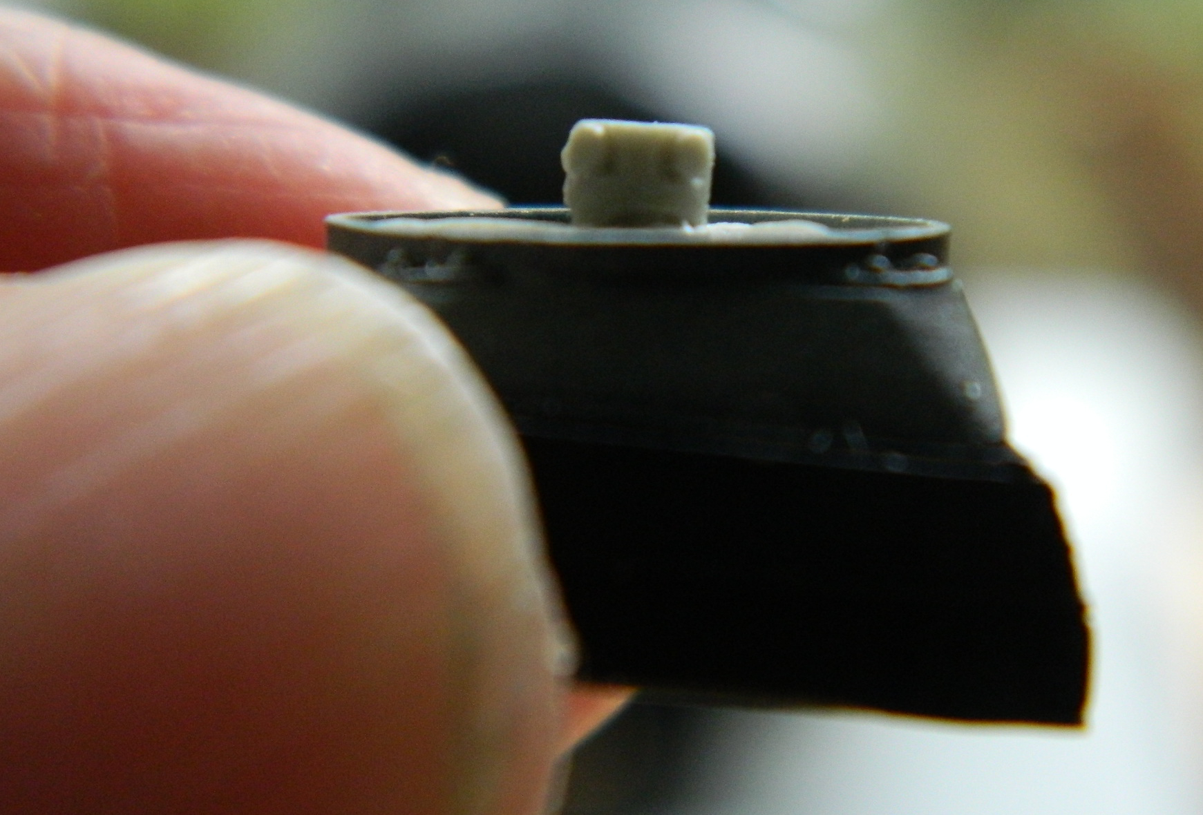
I used 18awg solid strand wire for the mounting brackets (and I dry-brushed aluminum onto the radiator faces in case it can be seen…which it cannot, of course):

With the necessary alignments done, the fans were trimmed and their edges thinned, the U-shaped hose manifolds were aligned and glued to the radiators, then they were glued in place. Once the glue had set a bit, things were painted:


Now to see if the engines fit…and no. Not quite. Either the space allotted is just a bit too narrow or my detailing took up more lateral space than existed. I couldn’t get them to sit straight:
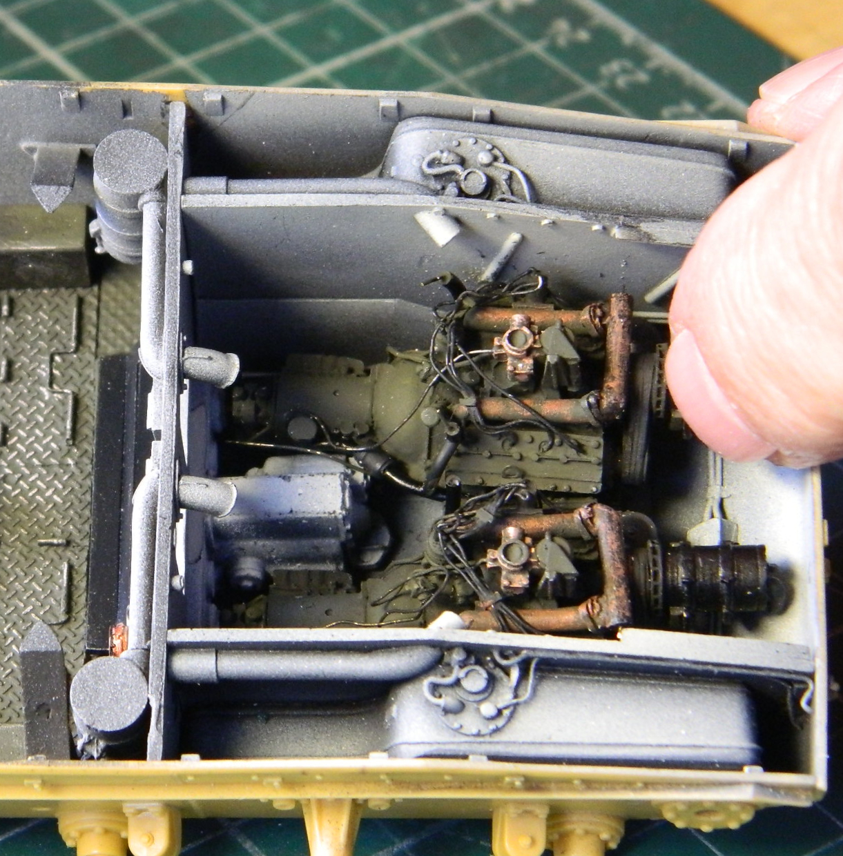
There are raised ridges next to the cylinder heads of the engines and I realized I could probably get just enough space to get the engines in place if I removed some of them. I got lucky:
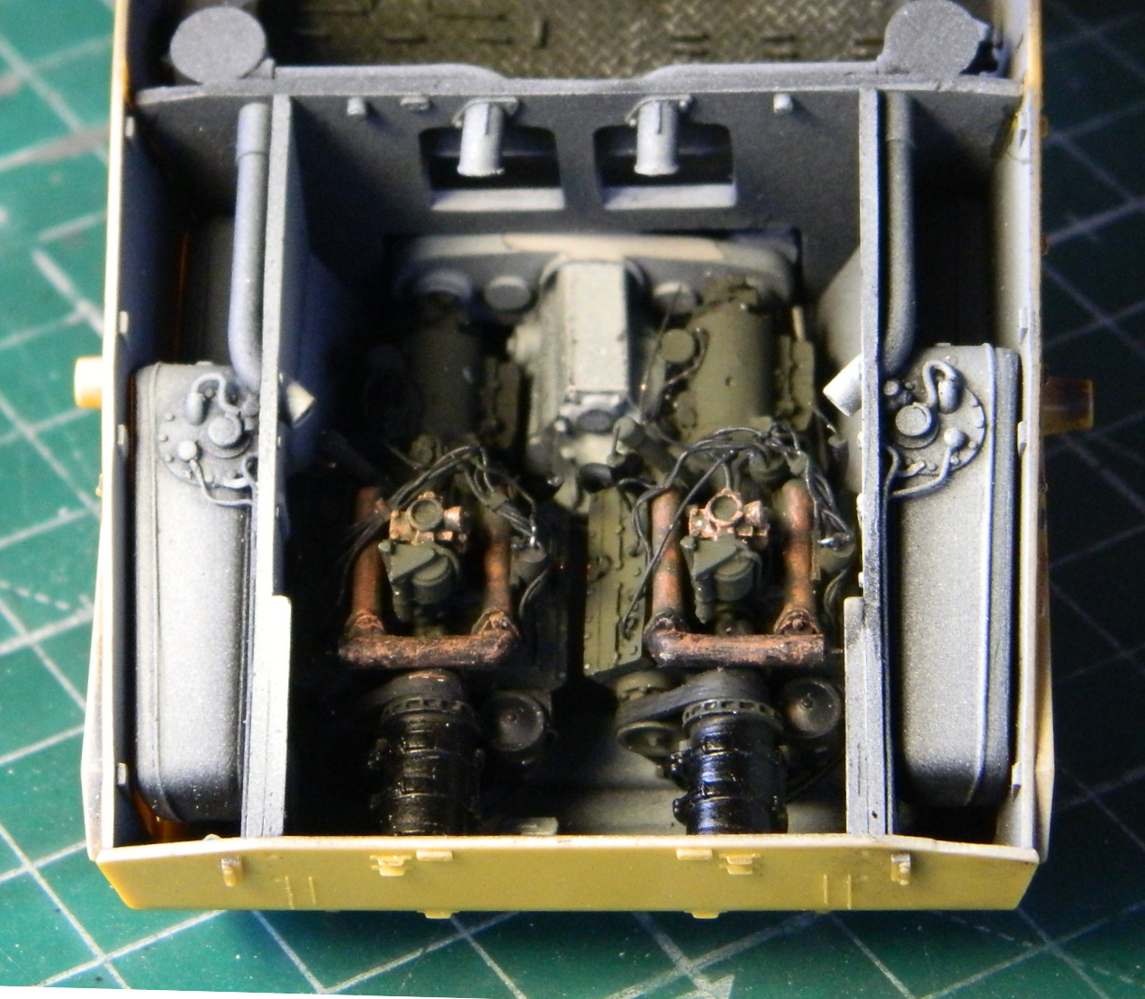
I walked away with the pressure relieved, took the next day off as reward, and came back to realize that yes…they were indeed in straight. And yes…they were indeed too far forward. I walked away for the remainder of the week.
It’s quite vexing to make a mistake like that and not know how it was made. I thought I’d checked fit and alignment along every axis involved. Clearly not and no answer to “why,” meaning at some point I could do it again. Quite vexing.
I had been making a video of this particular step; fitting, aligning, checking (giggles), and gluing. Much gluing. Enough so that as soon as I realized the error, when I tried prying the engines and transfer case free, I don’t know if it was plastic or resin that I heard creak. Regardless, that ended the notion of prying anything out of there. In the process of editing the video, I saw exactly what I did that resulted in a major Brain Fade.
I was having problems getting the transfer case to fit between the gap of the bulkhead on top and the torsion bar housing underneath. Very early on in the fitting and head scratching phase, unnoticed by Yours Truly, I reversed the transfer case. I certainly did get it to fit nicely, though, I just did it with the part backwards. Then when I added the engines to the mix, I had to put the transfer case in correctly due to the engines and pins needing to meet. That meant the transfer case wasn’t fit correctly, it was too far forward. Attach the engines to it and they were also too far forward.
The angels didn’t exactly sing, but there was much melodic giggling heard from On High when I finally realized how the mistake happened.
The first domino after that mistake was the fit of the floor inside the crew compartment. The forward end of the transfer case extends into the crew compartment and has a raised section of the floor to accommodate that. With the transfer case in its new position, it didn’t allow the floor to set down where it should. It’s not blatant, but if you look at the semi-gloss black ledge that extends from the rear of the diamond tread floor, it isn’t parallel with the openings and boxes of the bulkhead as it should be:

Not thrilling but neither unexpected nor insurmountable. The solution is to simply grind away however much of the transfer case I need to in order for the floor to settle into place. The areas removed will be never be seen again after the floor is glued in:
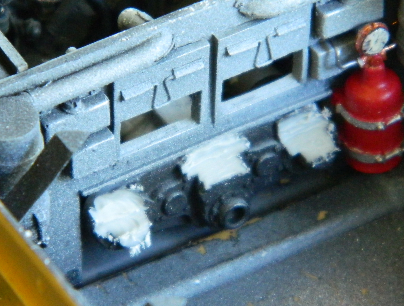
Once the resin in the three locations had been ground away sufficiently, the floor was glued down.
With the engines in place (permanently) I was able to install the radiators. The two lower support arms for the fans were dry-brushed black to blend in with the pre-shaded engine bay:
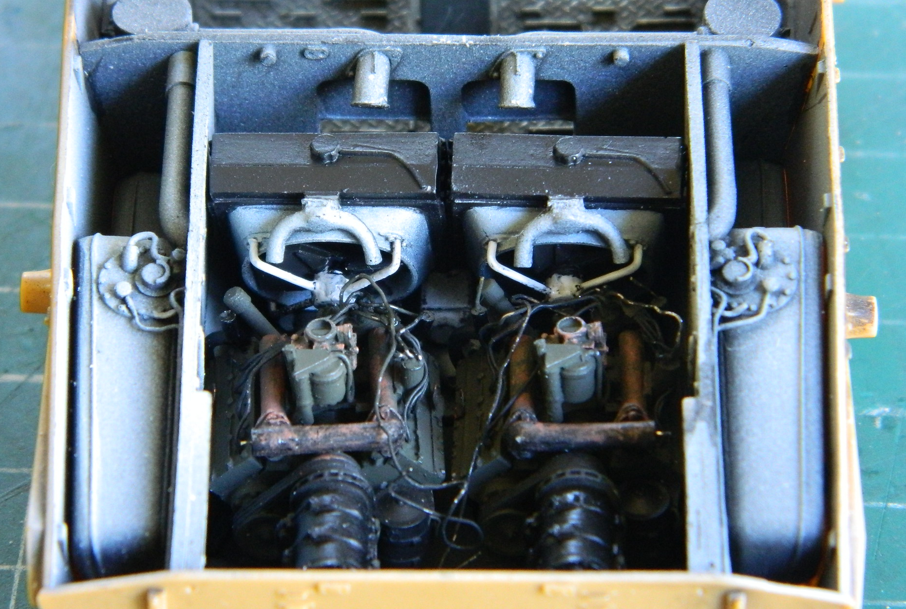
With the upper hull in place, not much will be directly seen (and is why I didn’t add the oil cooler radiator). What can be seen is as correct as 90-95% allows for:
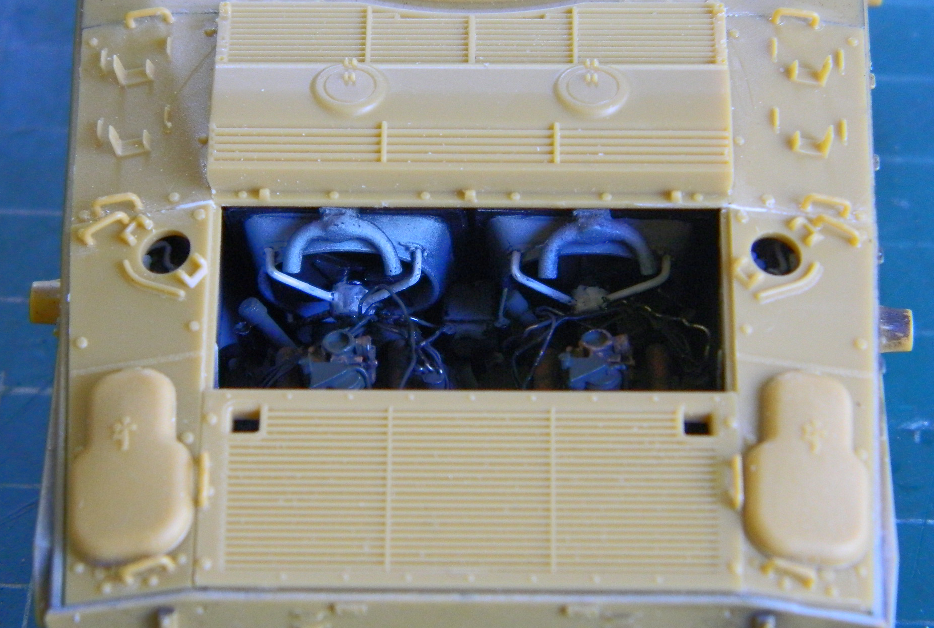
Next I had to connect the hose attachments on the radiators (the inverted U-shape at the top of the radiators) to the attachments on the coolant manifolds. Once again, solder came to my rescue. I used .062″ (1.57mm) solder to fabricate the “hoses”:

Sometimes one must persevere. None of it happened the first time:
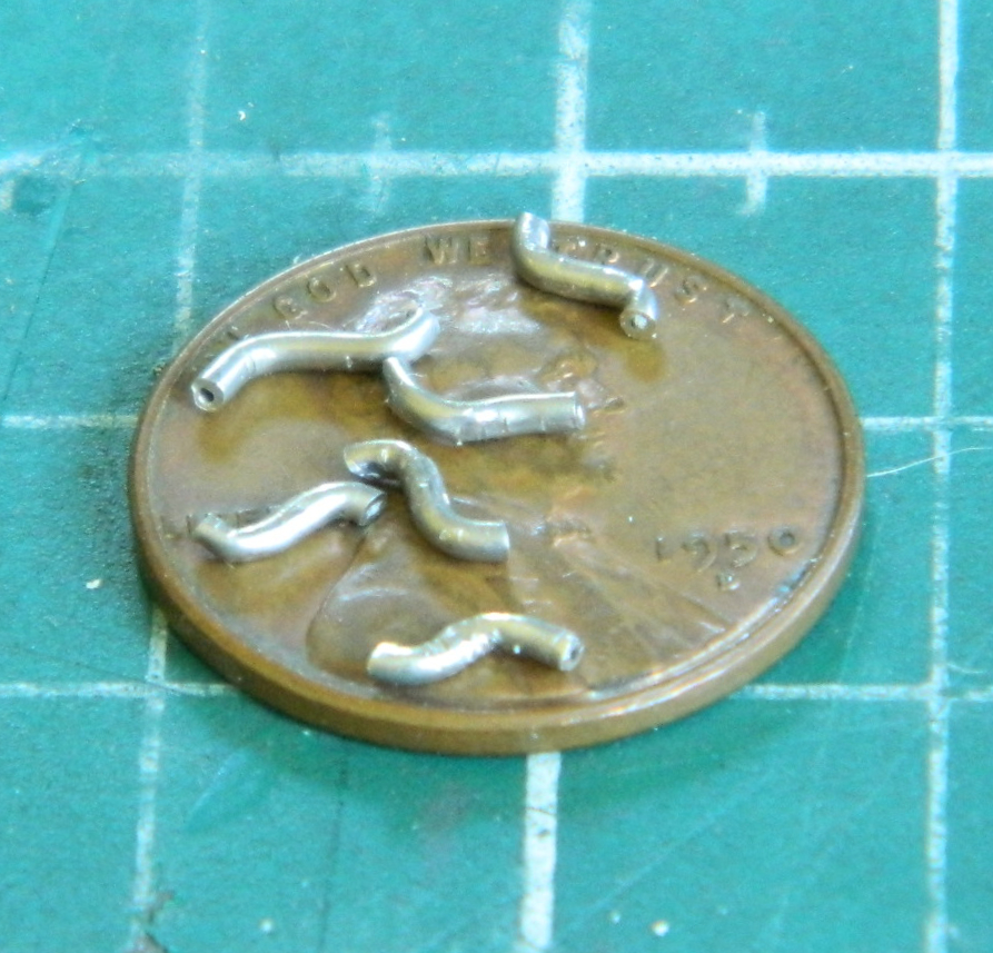
A quick coat of Tamiya XF-85 Rubber Black and the “hoses” settle in visually:

With the floor glued in place, it was time to begin populating the crew area. Seats, pedals, control levers, seats, oil can, and fire extinguisher were glued in, not to mention the differential/transmission:
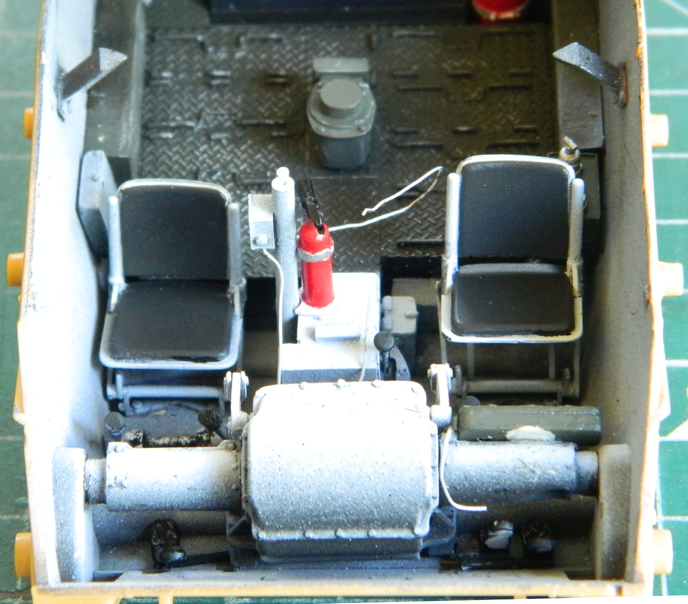
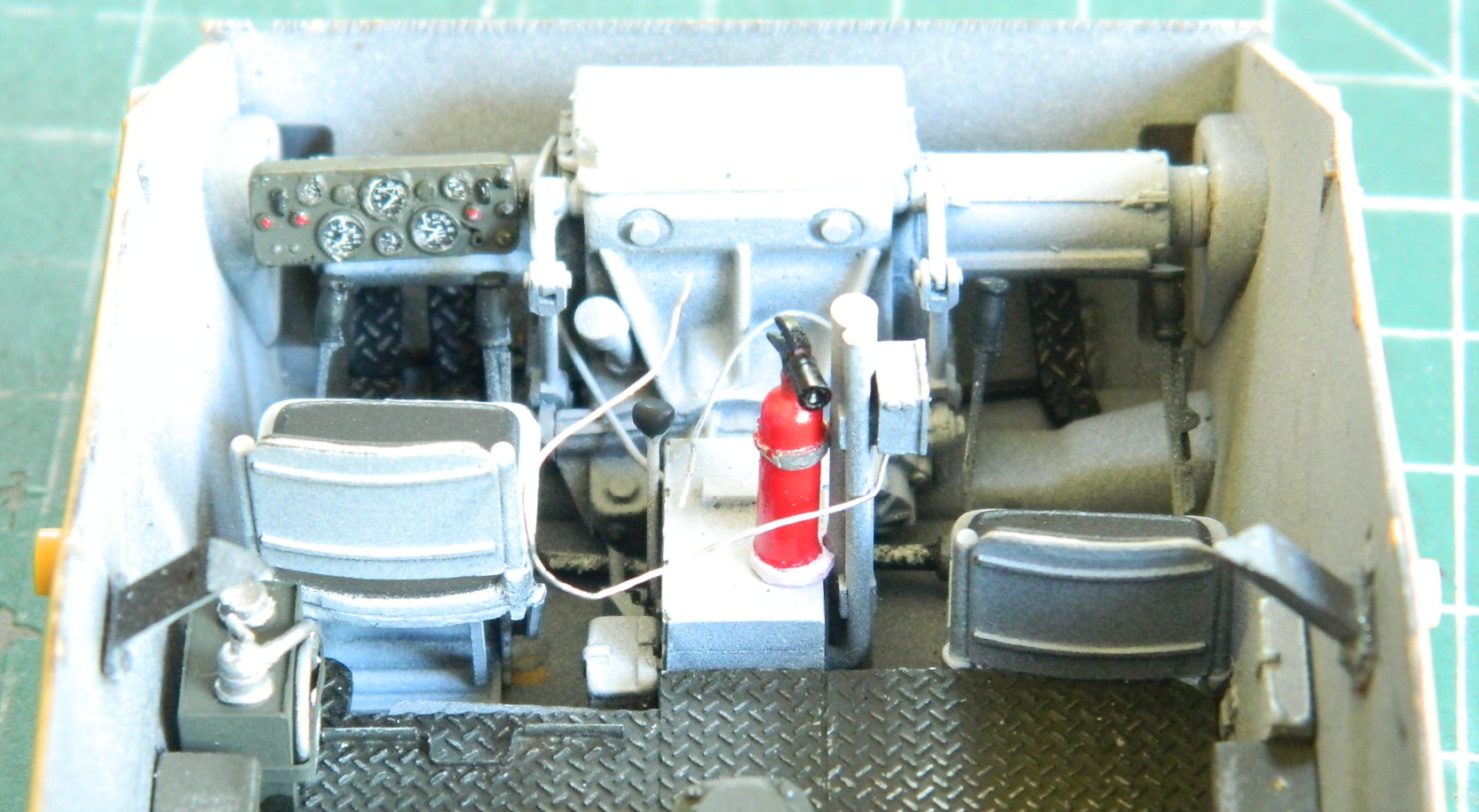
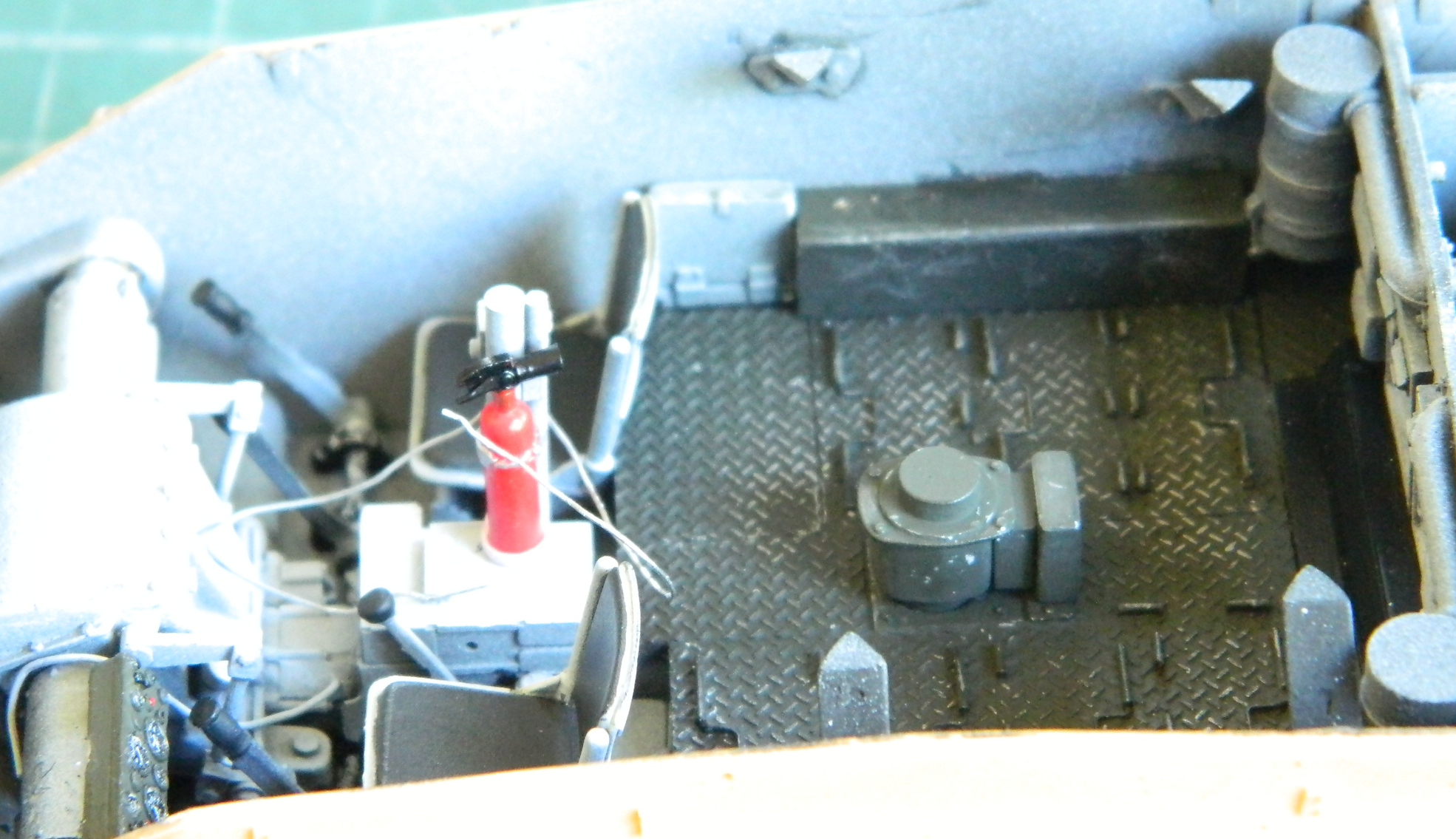

Then the list of what needs to be worked, made, and painted starts to grow. There are many things all competing for limited space inside a tank. One of the complaints about the M24 was a lack of stowage space and a small ammunition load. I needed to make racks to stow cans of .30 caliber (7.62mm) machine gun ammo. 0.015″ (.381mm) sheet and 0.010″ (.254mm) brass sheet made the brackets, the ammo cans came from spare parts:

With the exception of the helmet and binoculars that I decided to not use, here’s what has to go either inside the tank or tied to the outside grouped by the paint color(s) they get shot with:
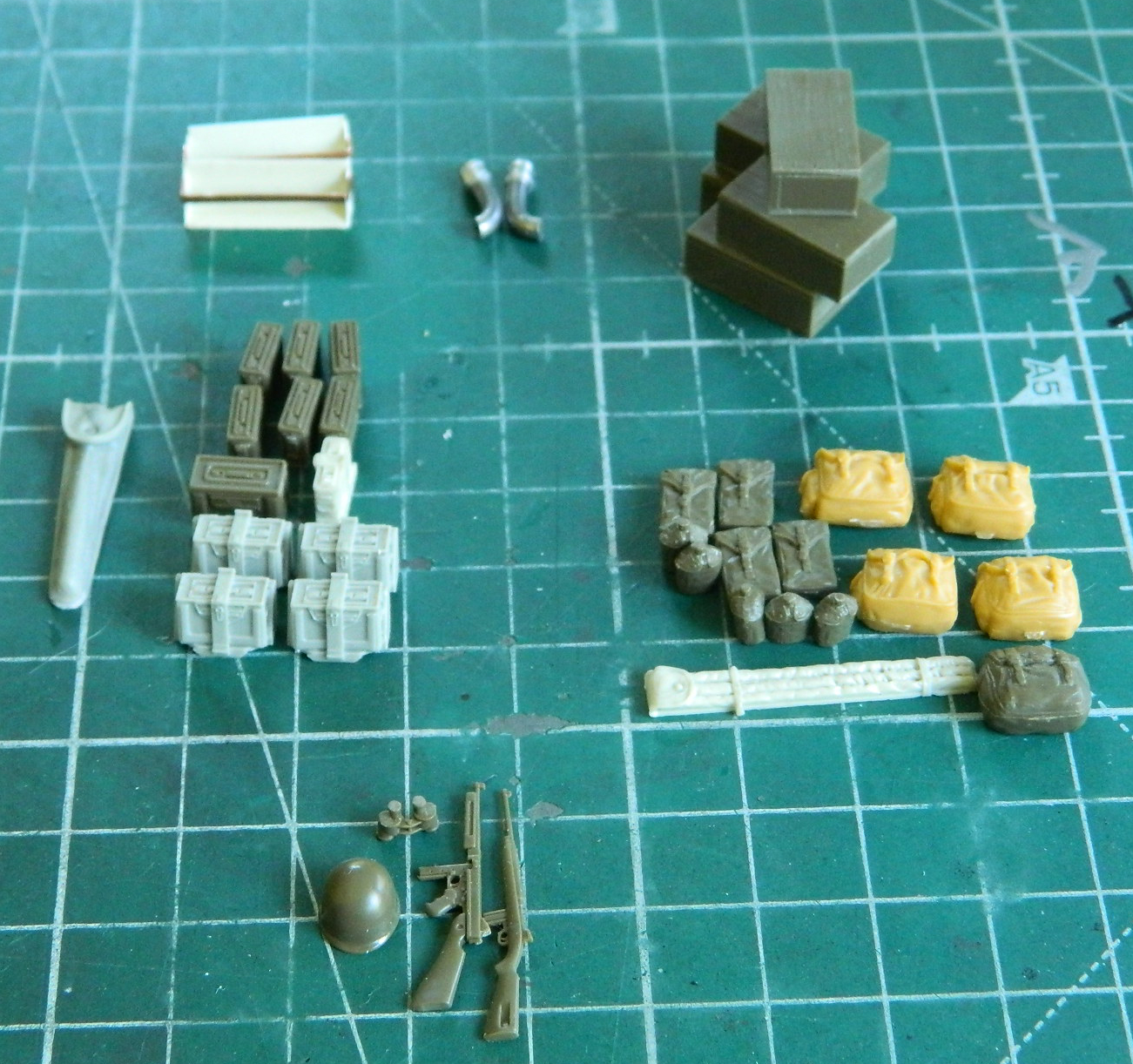
Bronco provides figures and their gear for the kit. I’m using Bronco’s M3 “grease gun” submachine gun (for the driver) and Tamiya’s M1A1 Thompson (stashed in the turret) and M1 carbine (for the co-driver) (and couldn’t the Army call their hardware something other than M1?!).
The M3’s barrel and sliding stock were plastic and definitely out-of-scale. Instead I used a hypodermic needle for the barrel and 24 gauge wire for the stock (Tamiya’s small arms were fine to use as-is):
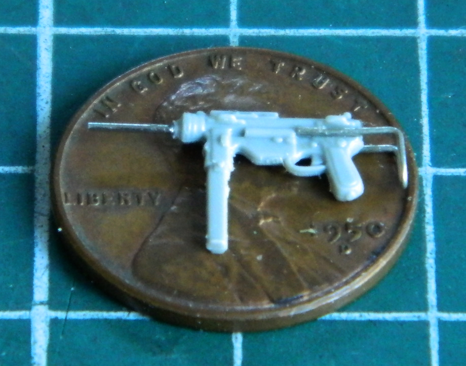
One of the things I wanted to do was to fill the hollow backs for the rucks and pouches. I used Apoxie Sculpt as filler:

I let the putty cure overnight before refining its shape and making it look like the rest of the item. The small parts were glued (small dab of superglue) to bamboo skewers and the base colors were put down. Tamiya Olive Drab (XF-62) for ammo cans and the spare .50 caliber (12.7mm) barrel bag, and Tamiya XF-49 Khaki for cloth items:
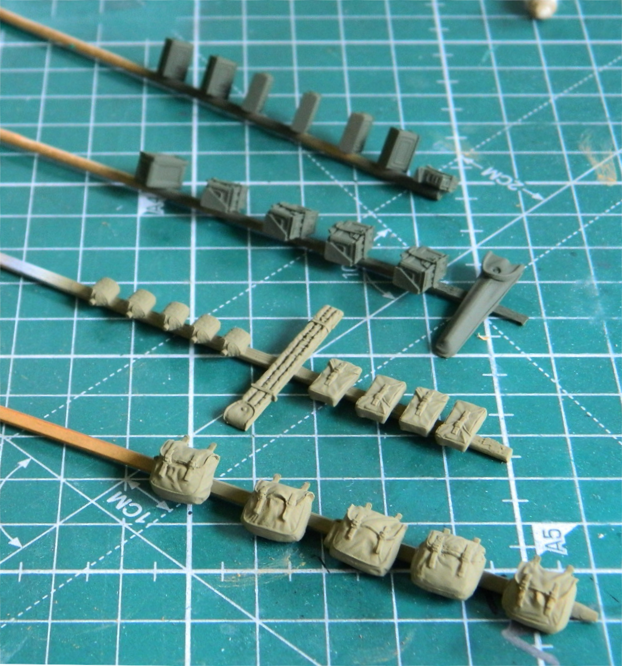
After sitting overnight, I hit them with Tamiya X-22 Clear Gloss and let them sit overnight again. I used Testor’s Gloss Black for a wash and hit all items before the last coat of Tamiya XF-86 Flat Clear finished it:
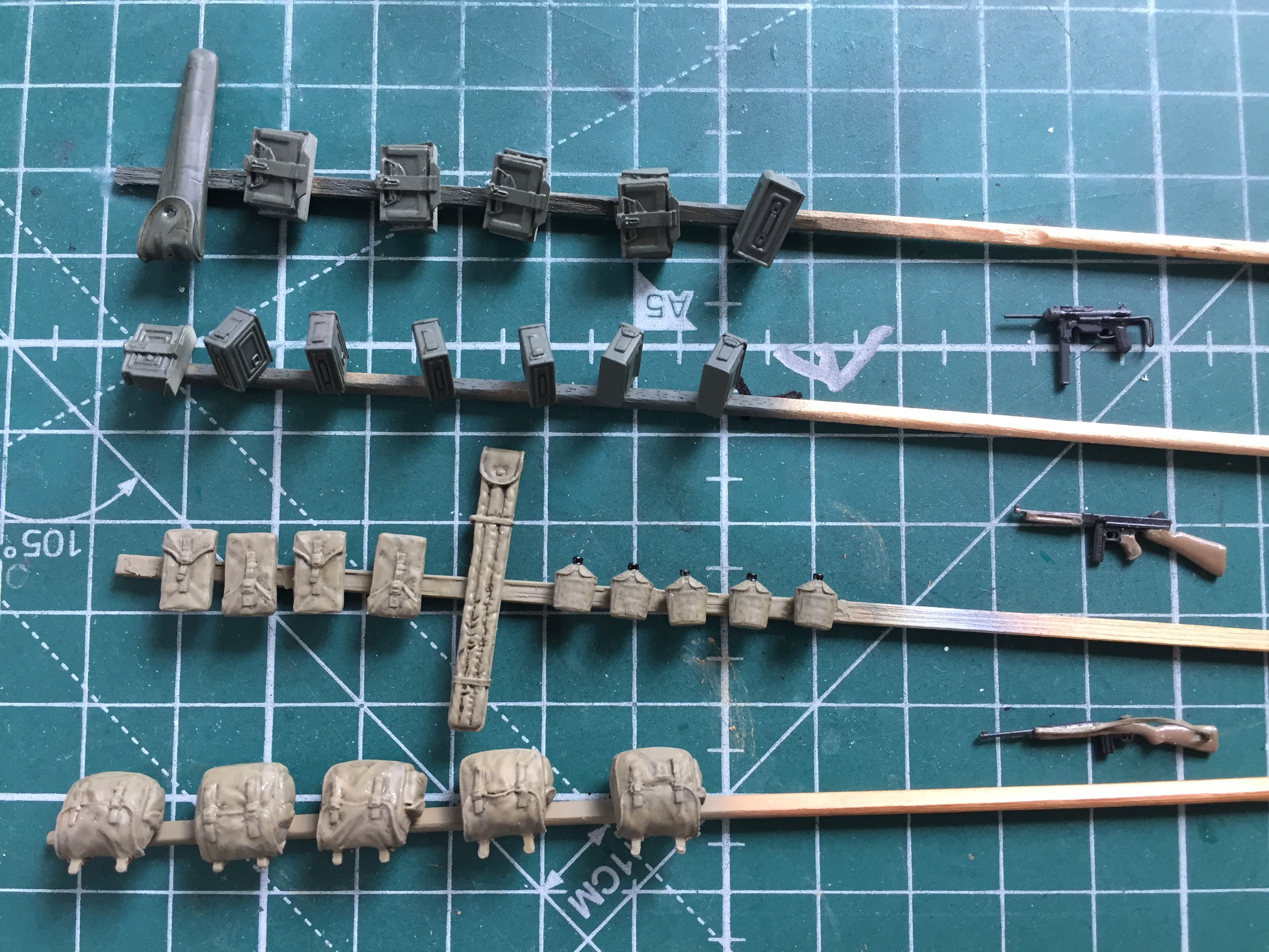
Generic dirt/grime/wear will be added with pastels.
The small arms were painted with five parts Tamiya X-18 Semi Gloss Black and four parts Tamiya XF-20 Medium Gray where metal would be exposed (The M3, not having wood parts, is all that color). The wood parts were painted with Heller Natural Wood (sorry, no part number). Heller Natural Wood does NOT mix well using denatured alcohol as a thinner…unless you want something that looks like wood-colored cottage cheese. The sling for the carbine is lead foil painted with Tamiya XF-49 Khaki:

There are (and will be in the model) brackets to hold the crew’s small arms. As they were probably issued M3s, the co-driver having an M1 means it won’t fit in the M3 brackets. Were I sitting in the right seat, I’d want my piece close to hand but where it wouldn’t get in the way of moving hardware (in this case, leaning to the left of the seat):
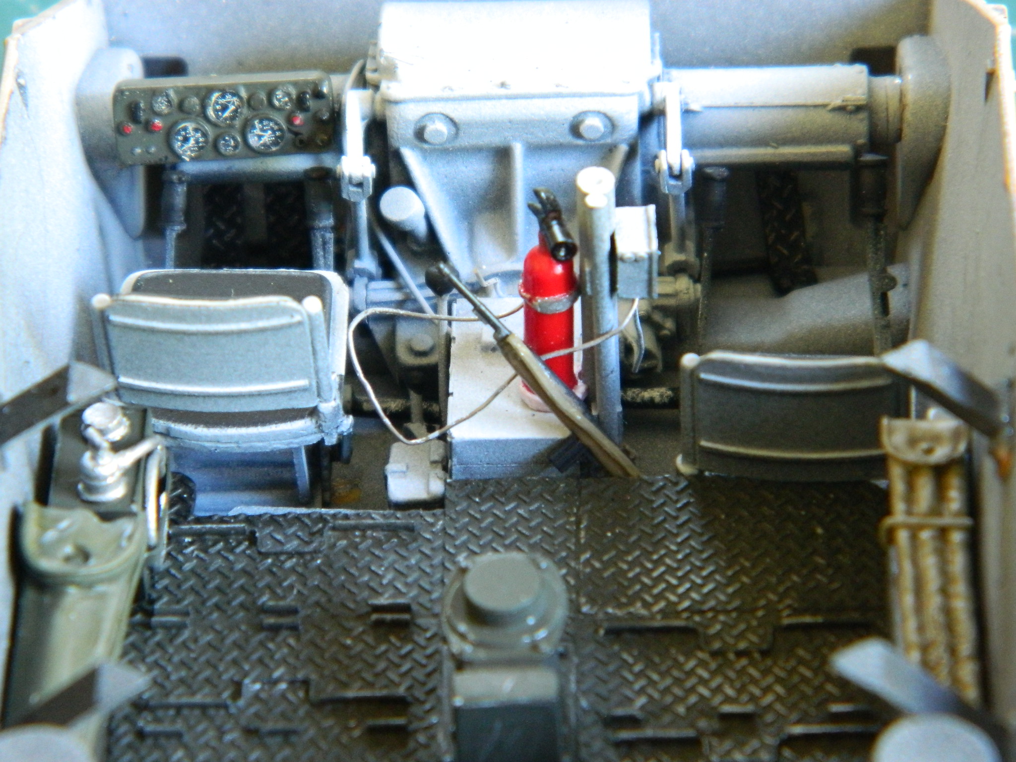
From here, what drives the build is what I have to do next to be able to put the upper hull on permanently. And speaking of that…here comes the next domino.
With the engines sitting too far forward because of the transfer case error, that means the radiators should be sitting too far forward also; the location of the engines dictates the placement of the radiators. It was with no small sense of trepidation that I put the upper hull in place. There is a raised area over where the radiators should be and I wasn’t sure how badly the misalignment of the radiators would be or how that would affect the upper hull placement.
There wasn’t any misalignment of the radiators! What I lack in quickness I like to think I make up for with thoroughness (but then, we all have our illusions). I made sure the upper hull was where it has to be. I checked quite closely to see where the raised area lined up. I even walked away for a couple of days before checking it again with fresher eyes.
Nope. No misalignment. Falls WELL within the 90-95%.
That leaves me with the conclusion that where I had intended to put the engines was inaccurate. Serendipity saved me much vexation by having my “mistake” counter my impending MISTAKE.
Just about the time I’m arrogant enough to suspect I know what I’m doing, something like this happens. So no…I’m not being humble when someone tells me how good I am at this and I demure. I’m not humble.
I’m experienced.
M24 Chaffee (Bronco) 1/35 Scale Build #4 – Small Details…Many, and a Useful Track Trick.
Sometimes I build myself into an impasse. “Well, gee…how the aerial intercourse am I going to do that?!” Most times, rather than sit here and rock back and forth (at my age, that time is quickly approaching anyway…why rush the matter?), I’ll hare off and do other things. Unless I’m right at the end of the build when the Ohgawdammit moment shows up (y’know, like after having painted something that took me a couple of years to build and then having the decals flip me off), there’s generally many other things I can do while I figure out what to do about the Ohgawdammit moment.
That’s what this post is…my rocking back and forth substitute(s).
Dry-fitting showed me that the transmission/differential was too narrow. To fix that I determined what the measurements were (about .060″ (1.524mm) per side), punched out a couple of discs from scrap, and then glued them in place:


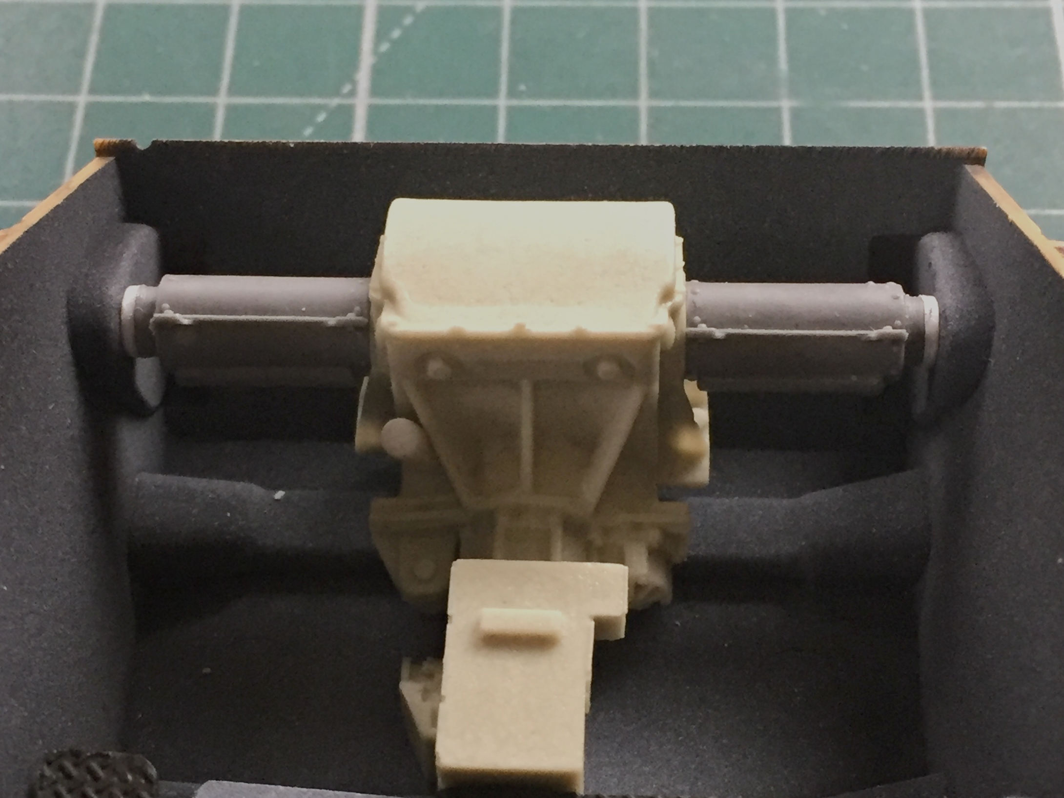
One of the things I noticed about Bronco’s individual track links is that they’re very refined and detailed. Maybe they’re a bit too refined (unlike myself) and detailed; I broke a few while assembling two 74-piece tracks. A crazy friend from England suggested Fruilmodel’s metal tracks. If you go this route, don’t buy them directly from Fruilmodel. They’re expensive. But you can find them quite reasonably priced on eBay, which is where I got these:

If you go this route, check the track shoes carefully. Sometimes they’re “handed”; one set goes on one side, the other on, well, the other. The M24 tracks aren’t handed, but now you know. They’re also not as difficult to assemble as I’d heard. I used my Panavise as the assembly jig and did them in sections of five and then joined the sections. Fruilmodel provides copper wire to use as track pins. I pushed them (firmly) through to the other side and then clipped them flush:
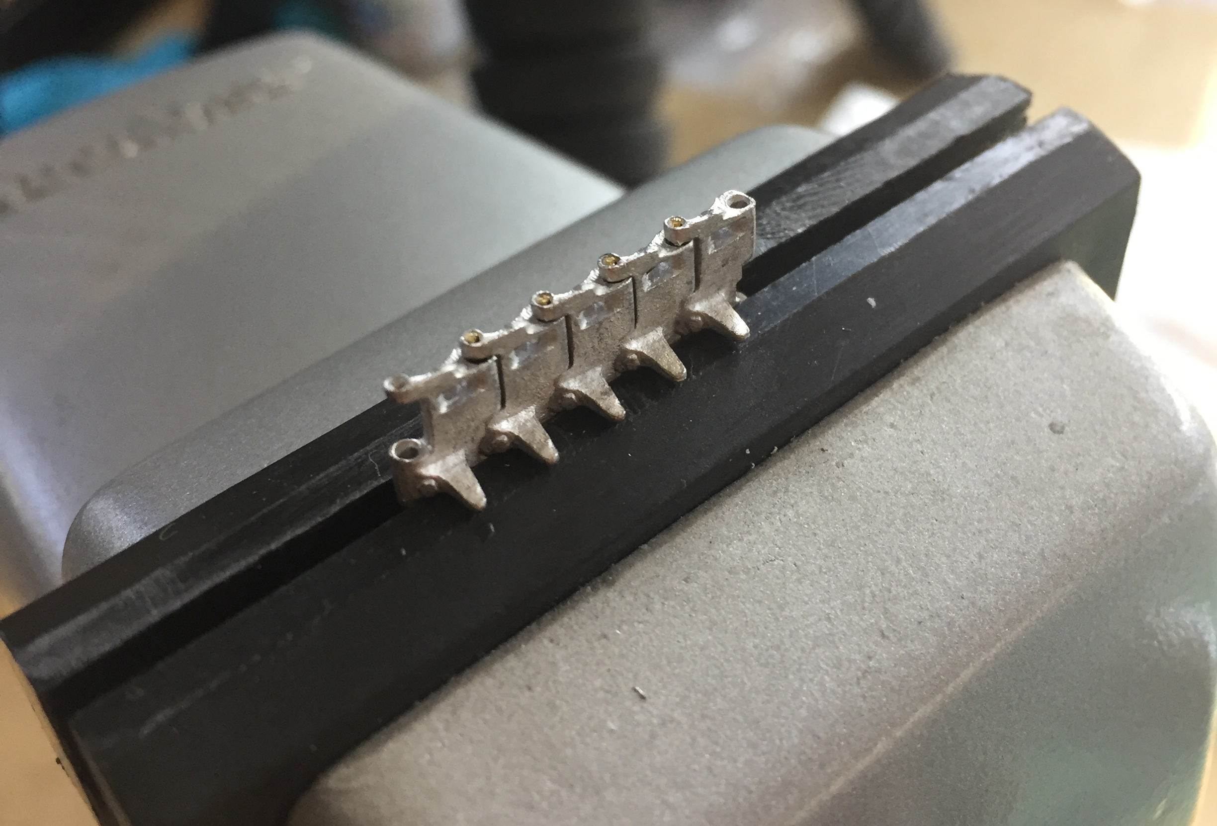
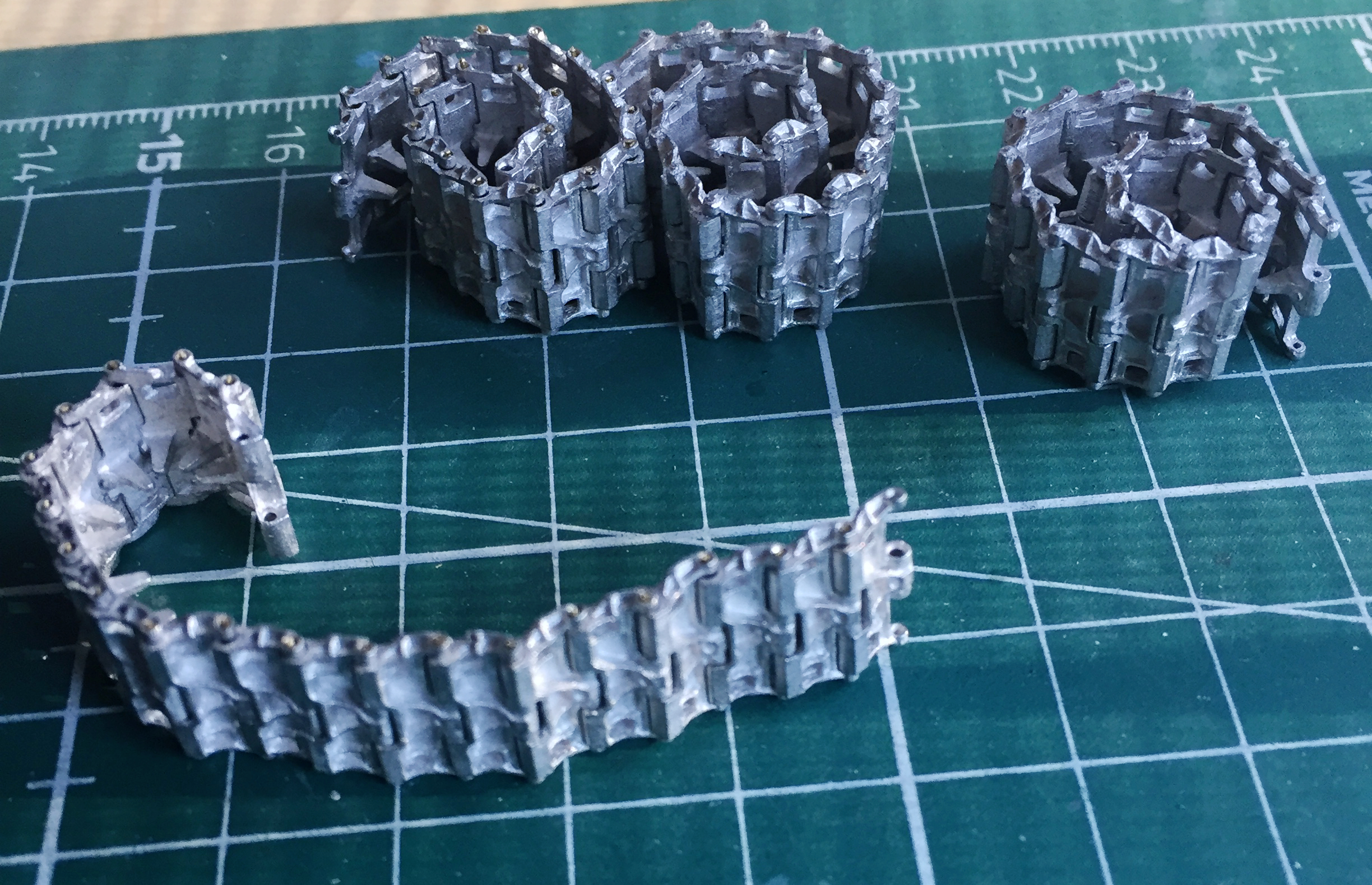

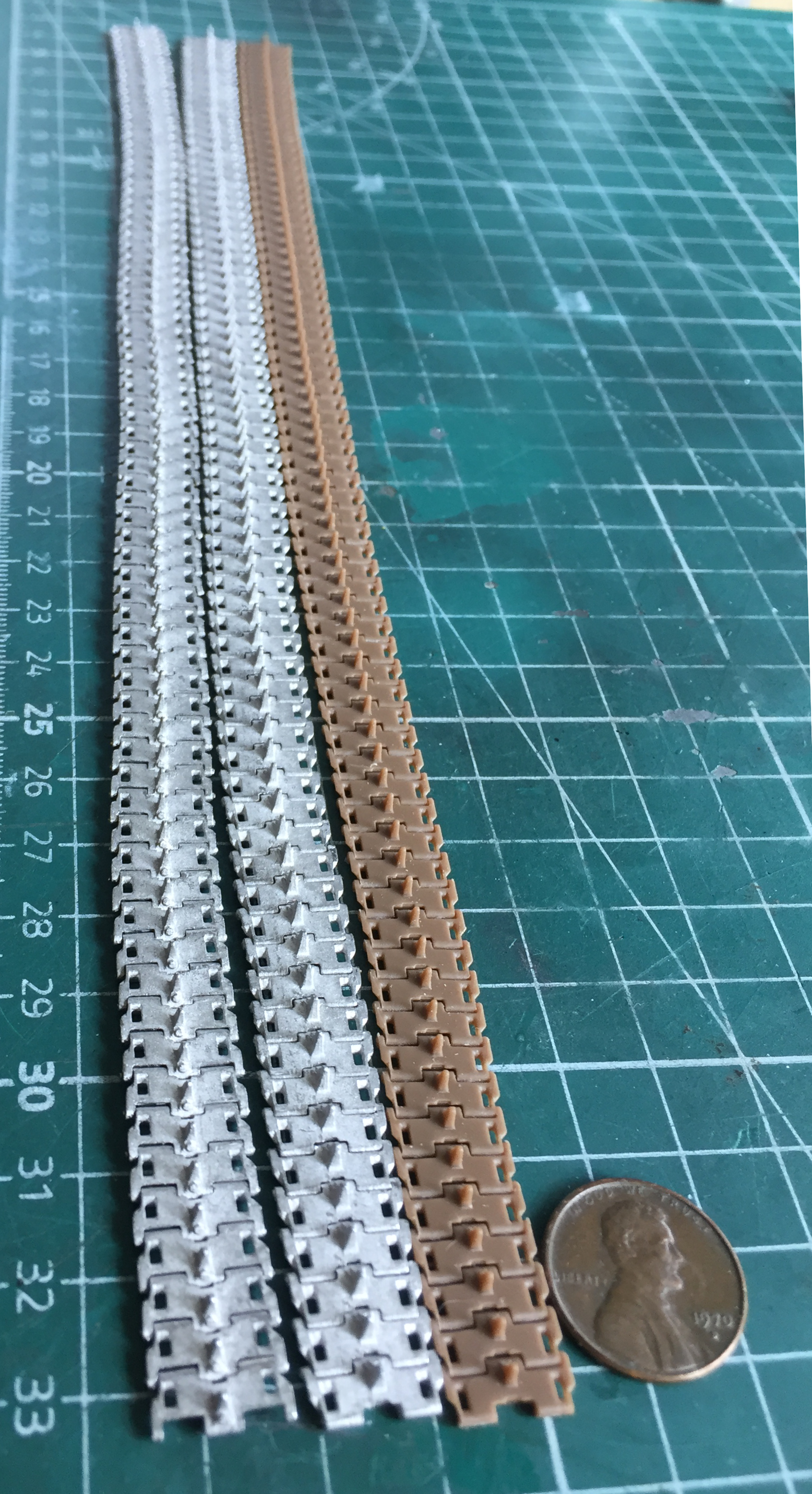
The person who suggested these to me (THANK you, Al!) also informed me of a very handy item, track burnishing liquid. I ordered some and stayed relatively busy awaiting its arrival.
Sometimes in spite of all attempts to keep it from happening, bubbles end up in a cast resin part. I had been considering just recasting them. But I’m a parsimonious git. The minimum quantity of resin that I can mix is an ounce. Doesn’t sound like a large quantity until I only need to recast a few small parts. That annoys my parsimonious side. When I discovered a few small parts that had bubbles that were too large to ignore, this time I tried something I learned on a previous build (Gemini Capsule); plug the hole with plastic.
The bubble in the separate part is easy to see. If you look closely at the part still on the pouring block, you can see a light spot in the shadow. That’s the other bubble:
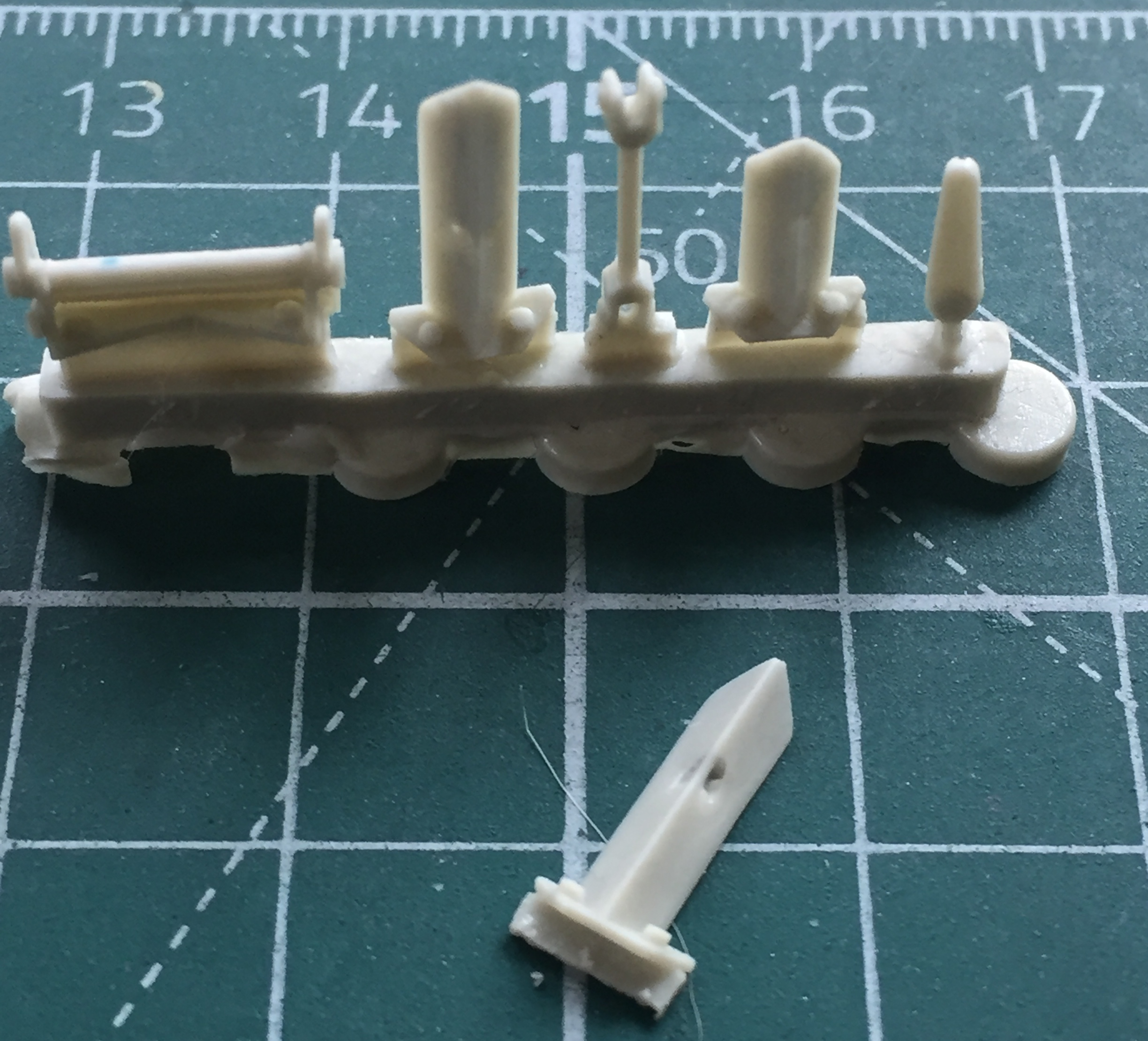
It’s easier to fit a plug into a square hole than a randomly curved one. So the first step is to open up the bubble hole and square the socket. The second step is to fill that opened and squared gap with plastic and a generous application of super glue:

Superglue hardens the longer it sits. So that I don’t have HARD superglue and soft plastic and resin bordering it and run the risk of the superglue holding up to sandpaper better than plastic or resin does, once the superglue is hard enough to work (gave them about an hour), I start trimming the plugs until they’re flush:


Since the parts weren’t usable as they were, I had nothing to lose by trying to fix them…and I didn’t waste a large amount of resin to fix a small problem. I did the same to the binocular case:
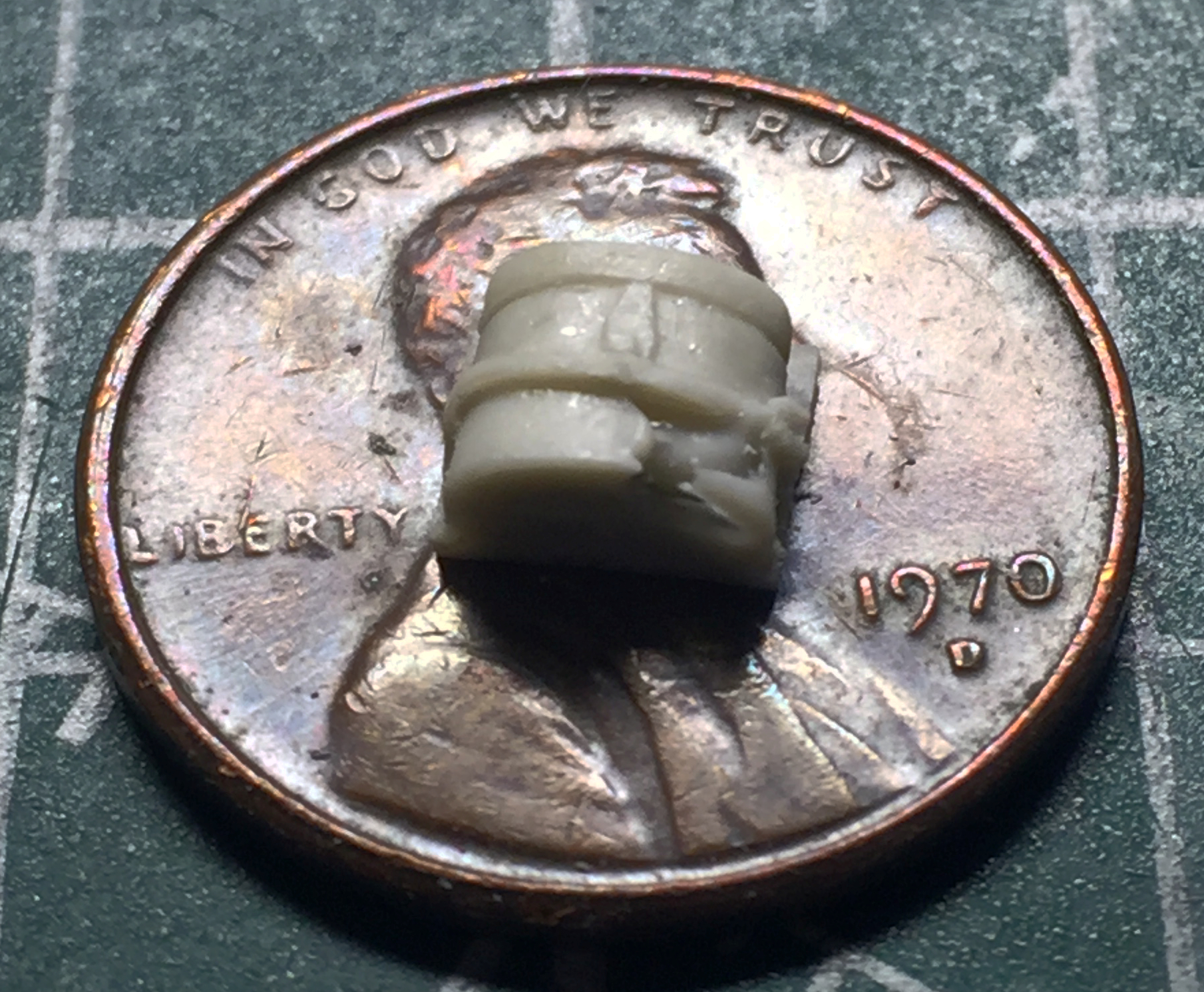

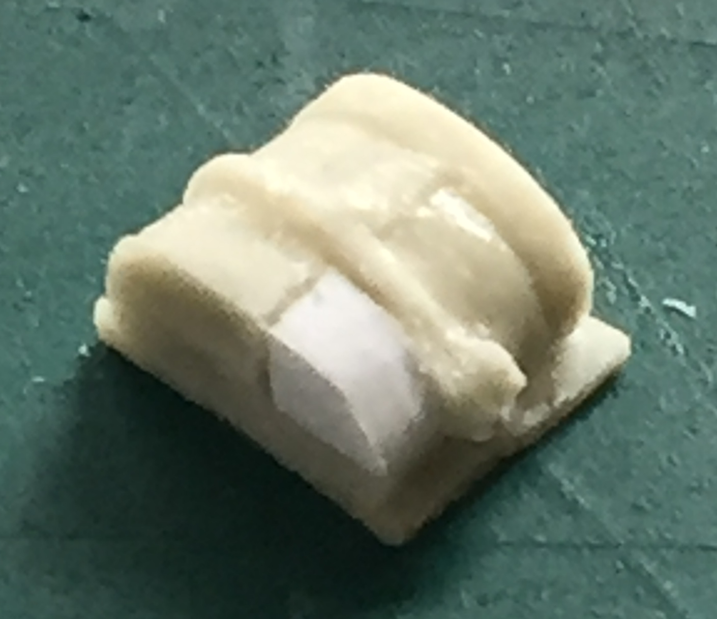
With the parts plugged, it was time to put some of them in place. The first parts I plugged are supports for the upper hull where the turret sits. I taped the upper hull in placed and then diddled mightily until the supports fit where they (relatively) go. I used denatured alcohol to strip away the paint I’d added prematurely and glued all four of them to just the lower hull:

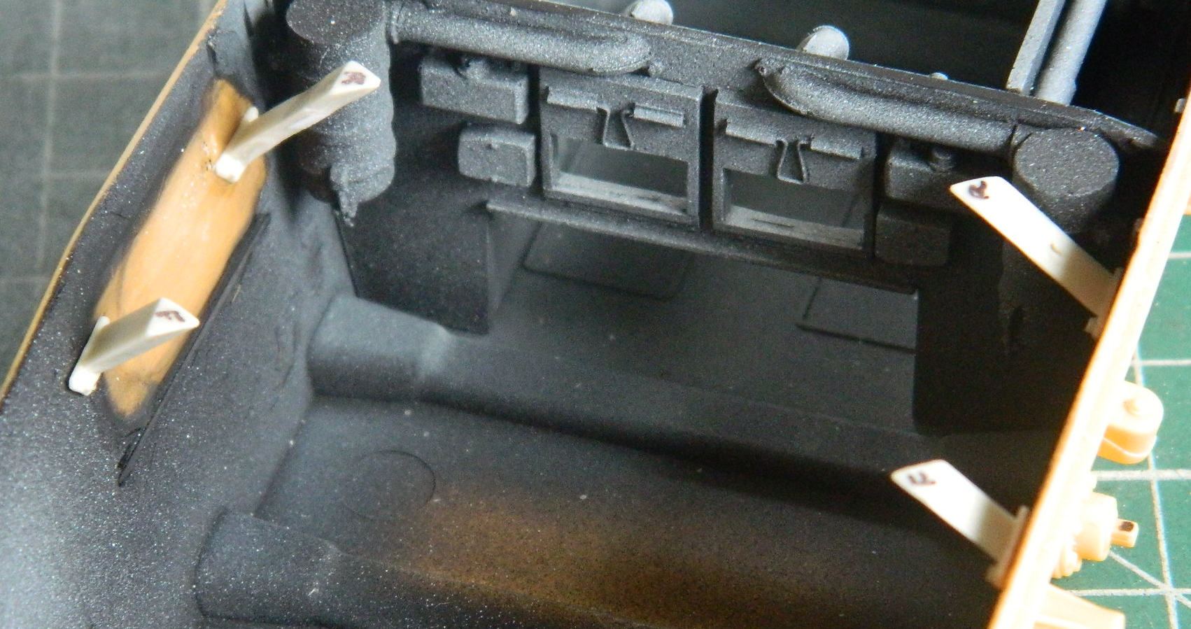
With the transmission/differential adjusted for fit, I added the other parts that go with it. Experience has shown me that really small parts are easier to align and stay glued better when they’re pinned. The two holes on the trans/diff will match 24awg copper wire pins in the parts that go there:
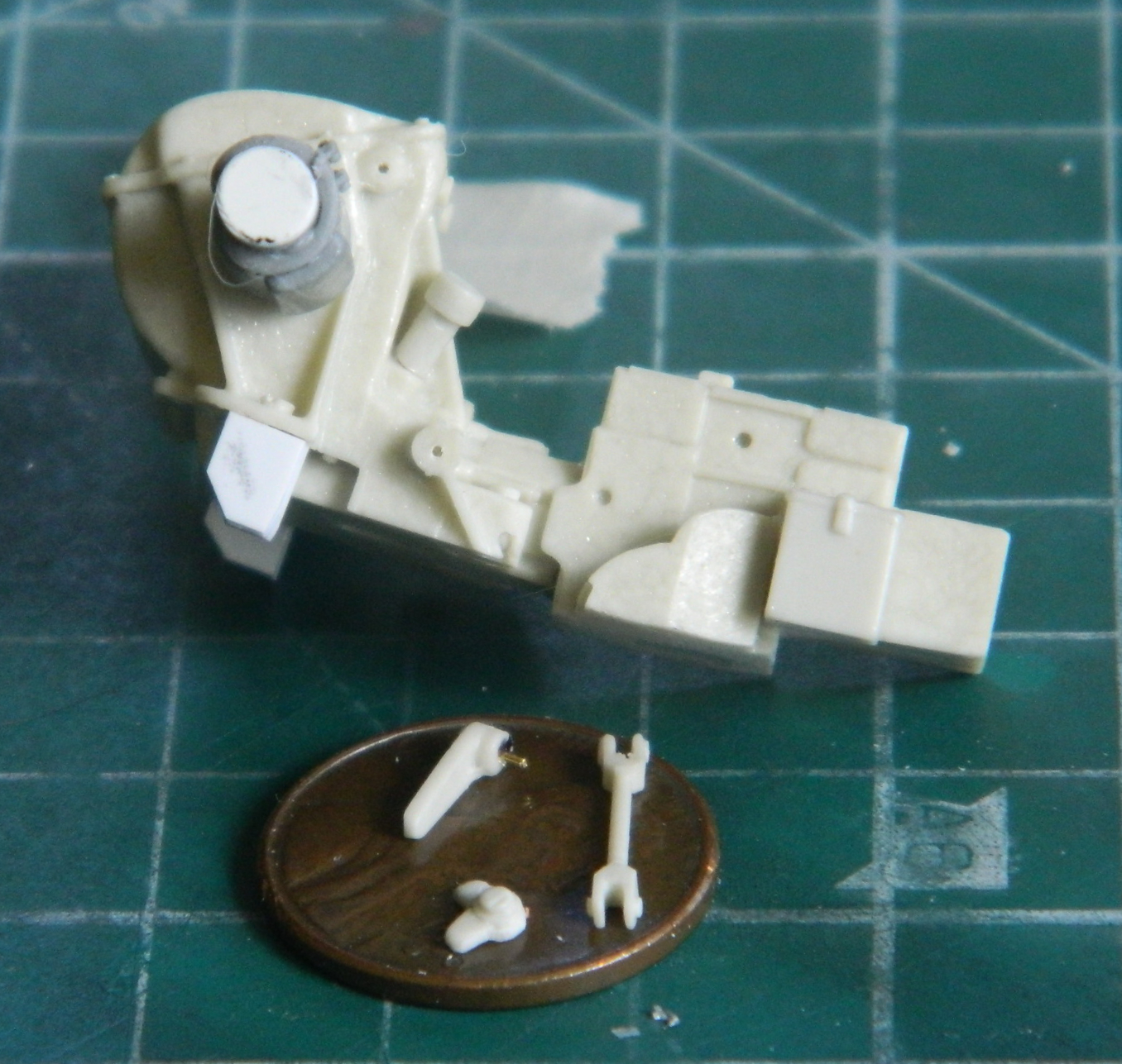
And now it’s ready for paint:

The two seats in the front of US WWII tanks, for the driver and co-driver (aka bow gunner, loader, ammo mule) adjust. They’d raise upward so the crew members could ride with their heads out (of the hatch…where else they may keep their heads isn’t mine to fix) or drop quickly down into the hull and under cover (as much as “cover” can be used describing something as obvious as a sodding tank). I’d never modeled a seat in the up position, and I’ve not noticed that anyone else had. When one can cast one’s own parts (parsimonious or not), a certain ballseyness shows up. “Well, let’s try this. If I totally bitch it up, I’ll just pour another one.” (And then whine about having to waste resin.)
The first step required me to cut apart the adjustment arms of one of the seats (which I’ll probably use in the driver’s position). Once cut apart, I QUICKLY realized that with only two hands, there was no way I’d be able to hold these small and difficult to grasp parts AND assemble them. I drilled out the arms and their mounts to the seat (the white plastic) and added pins to the base:
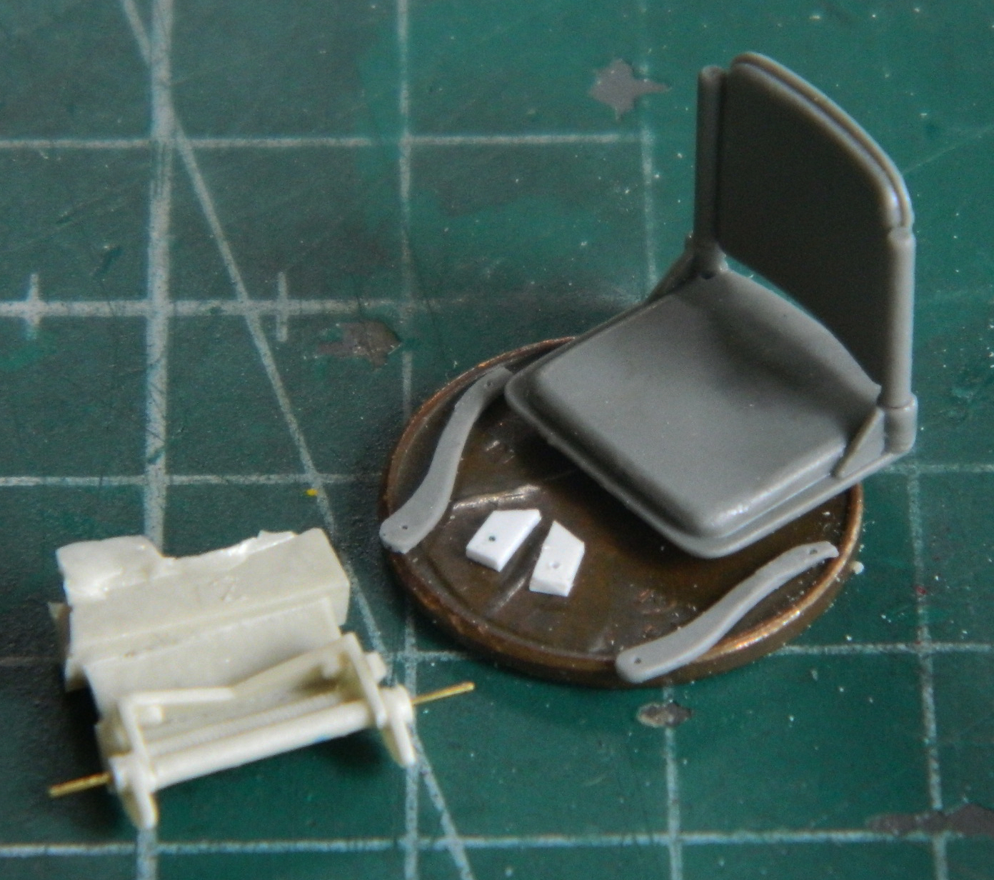
I needed something to be referenced physically (ad fancy way of saying “get something to stay in place so I could work the Damned Things) so I used double-sided tape to attach the base to the workbench:
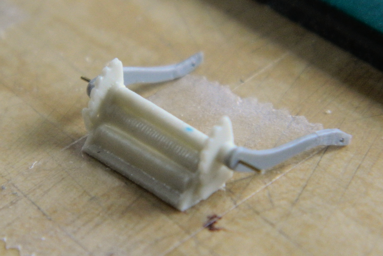
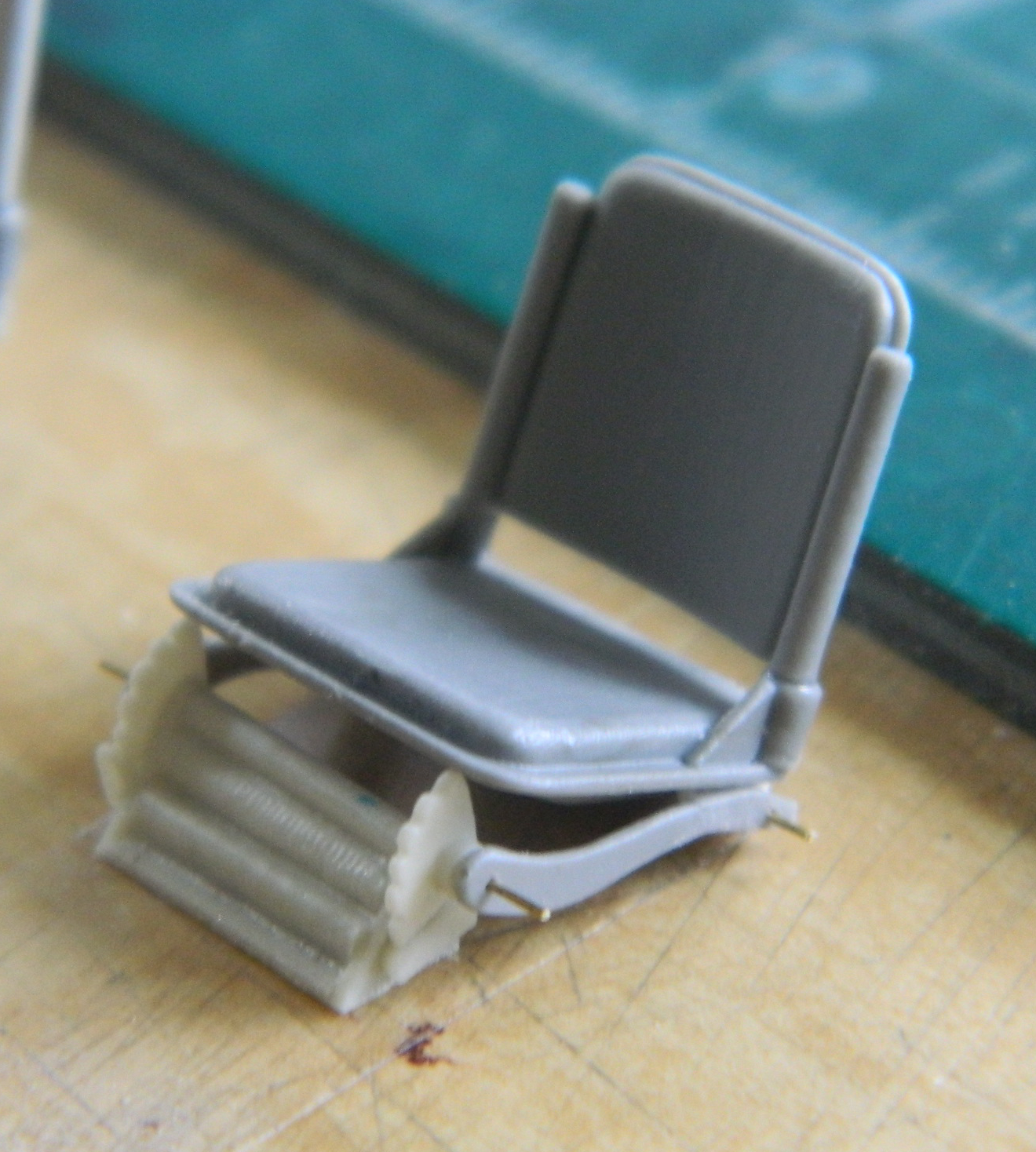
If you compare the gray arms of the seats in the first photo above, something I failed to do, you’ll notice that the arms aren’t positioned the same way on the arms I’d cut apart. One of the arms is correct (the left one) and the other is reversed (the other left one). What I also failed to notice was that I taped the base down front-to-back. Yes…this turned and bit me in short order. But these errors didn’t get noticed at the time and I glued the Damned Thing together all cocked up (the blurry seat in the background is correct):
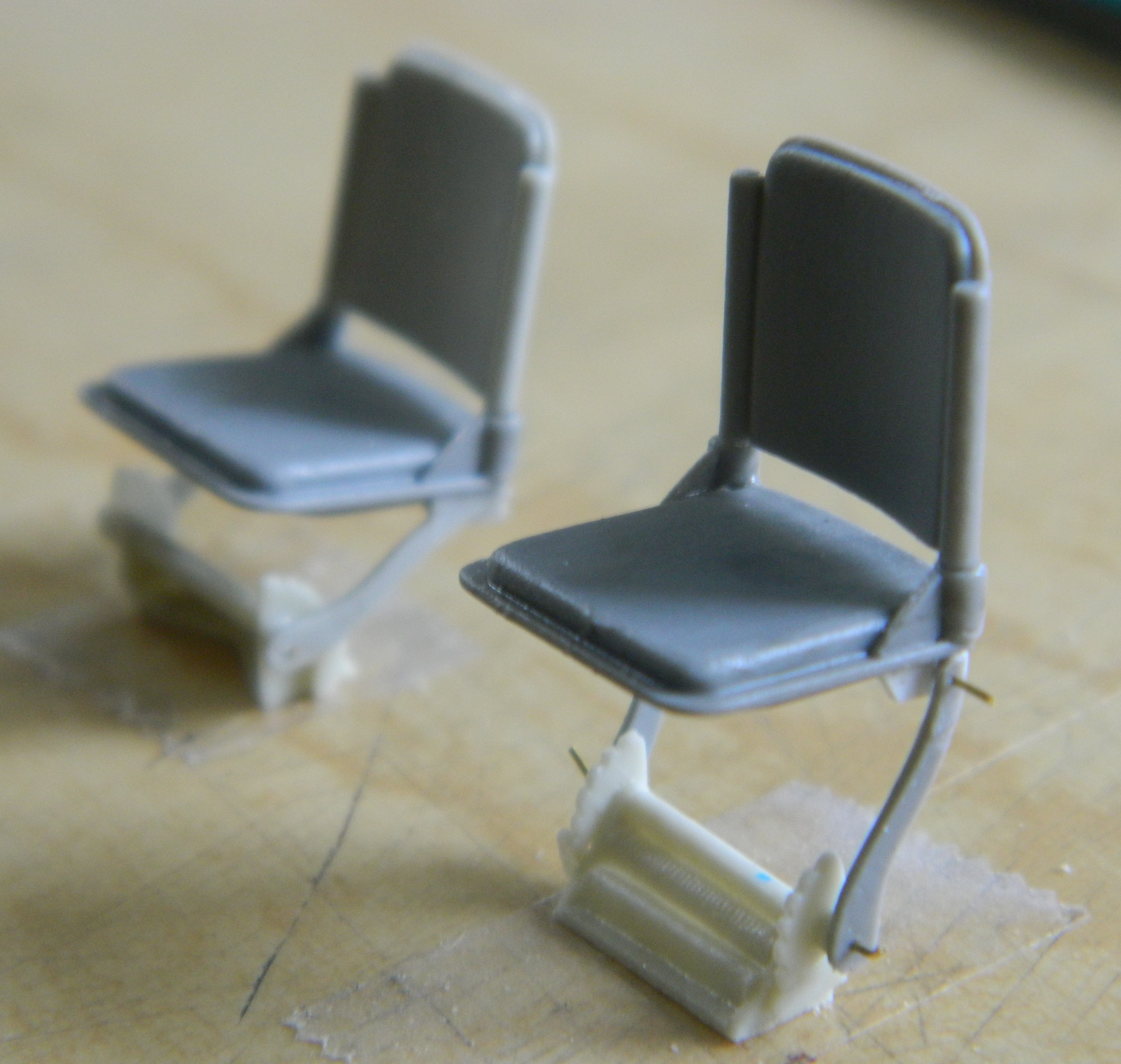
This was when the Boys in the Back proved they existed. Several hours later, after dinner and a movie, I was in bed reading when out of nowhere I had AN URGE: “Get up and check the fornicating seat!” That’s when I realized that I’d put things together backwards: the base and one of the support arms. Earlier I’d mentioned that superglue sets up hard over time. There was NO way I was going to go back to bed with these very delicate parts glued together incorrectly and let that glue cure overnight…
An hour later the parts were correct and myself and the Boys in the Back could rest for the night:
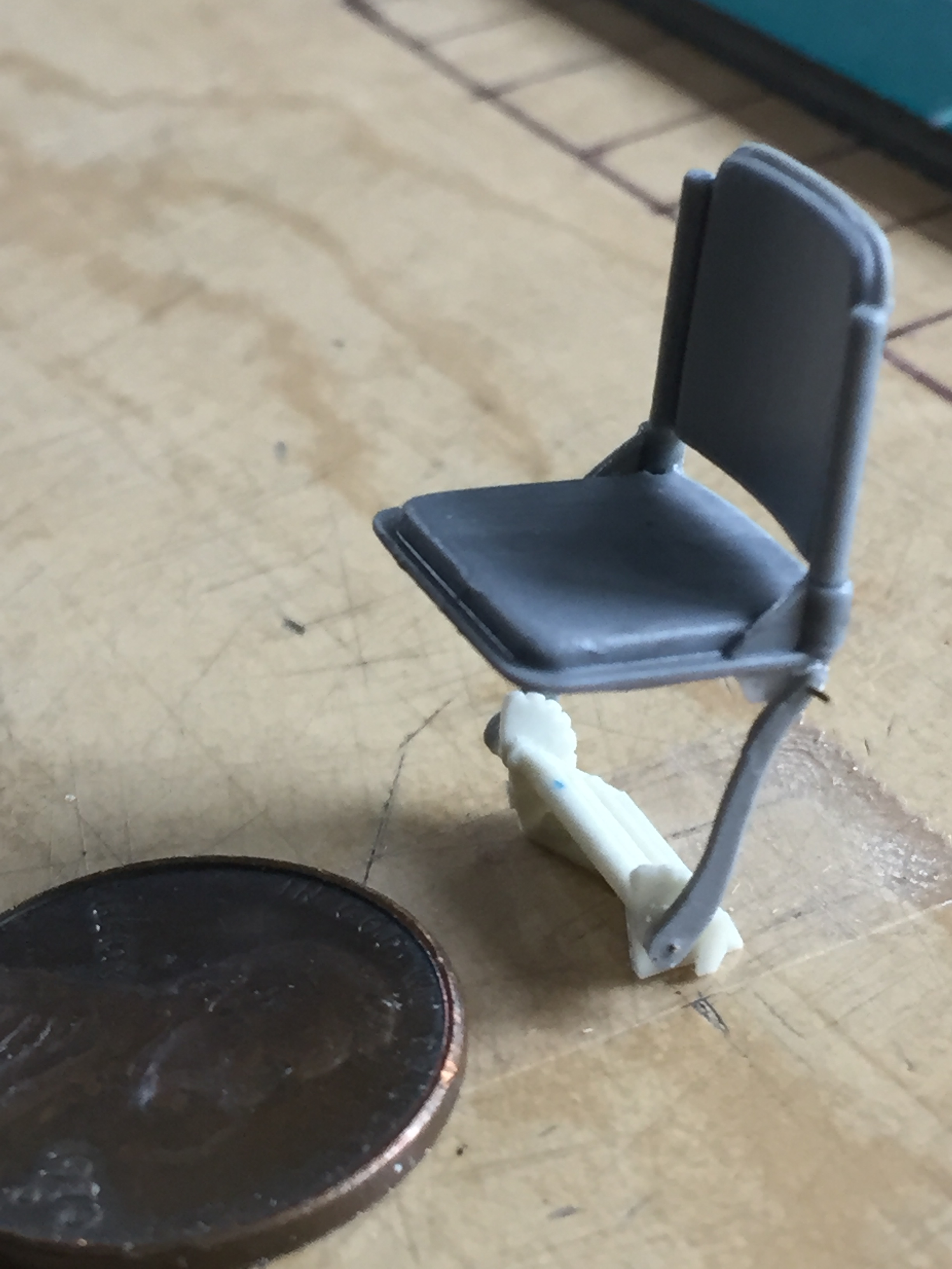
Just because a wound is self-inflicted doesn’t mean it doesn’t hurt.
The hatch hinge mechanisms were different with the M24’s front hatches than previous US tanks (turret hatches were typical simple hinged affairs). Once unlatched, there was a lever inside that the crew member pulled down to raise the hatch a few inches and then used to rotate the hatch away from the opening. Verlinden added the housing for the hinge mechanism, he didn’t provide the lever. Also, the hinge mechanism was vertical relative to the tank overall but not perpendicular to the upper hull; the area where it mounts isn’t level. These hinge mechanisms only fit one way. I wanted them to be (mostly) centered on the opening in the hull so I used a circle template of the required diameter to delineate their locations:
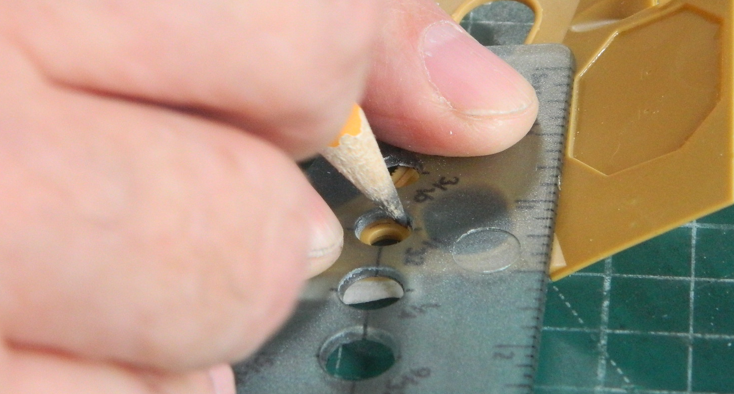
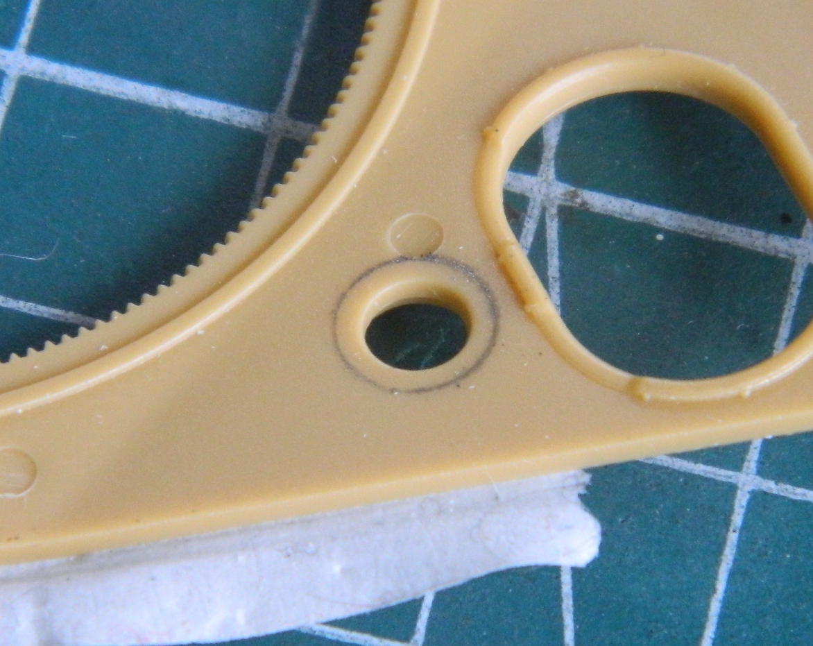

There are also slots in the hinge mechanism that I had to add (“easier” to see to the right side of the right part below):
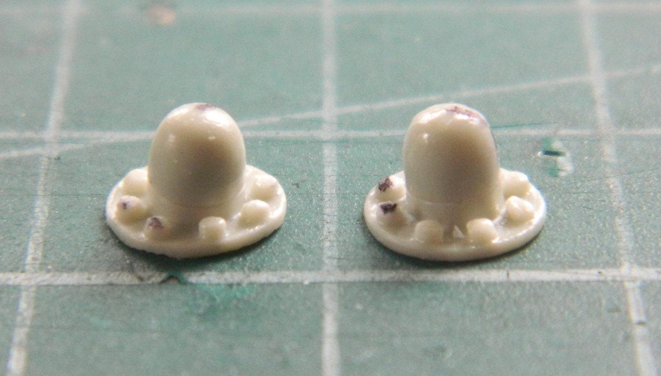
I used stretched sprue to make the lever and I dipped one end repeatedly into a puddle of superglue to build up accretions resembling knobs:
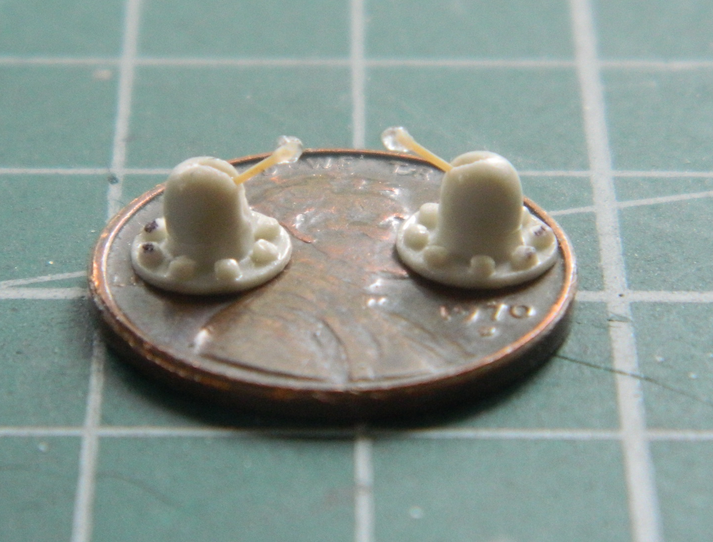
The M24 didn’t have a turret basket. There were three people in that turret; commander, gunner, and loader. Their respective seats were attached to the turret so they didn’t have to scramble as the turret rotated (well…I assume there was a degree of scrambling for the loader…there were no provisions in the turret for ready-rounds to be mounted, the rounds were instead kept in water-jacketed bins in the floor). There was a pedestal affixed to the floor that supported a box with various turret controls and there was an steel arm that allowed the control box mounted on the pedestal to rotate with the turret. There were tubular guards mounted to the top of the control box so that someone’s size 11 didn’t kick something that shouldn’t be kicked. The ones shown below were made from solder…which I decided were too thick so I redid them with a thinner solder. I didn’t take a picture, however, so you’ll have to put up with a photo of the wrong sized one:
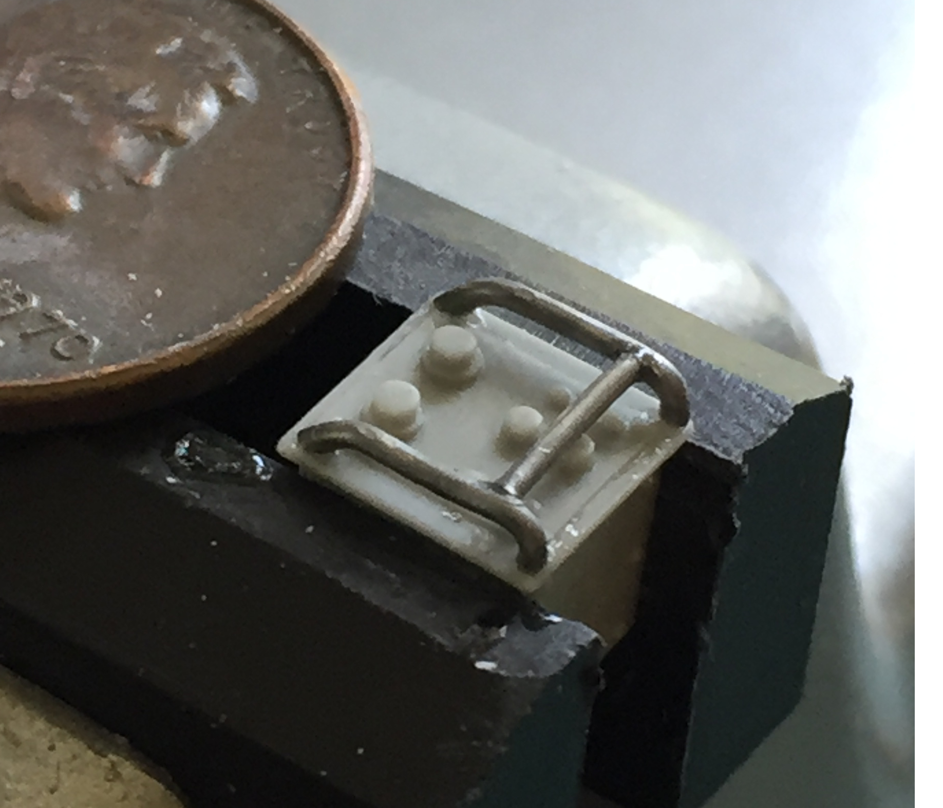
The pedestal had the shroud to protect the wiring conduit that I mistakenly cut off, thinking it was part of the pouring block. I replaced it with styrene:
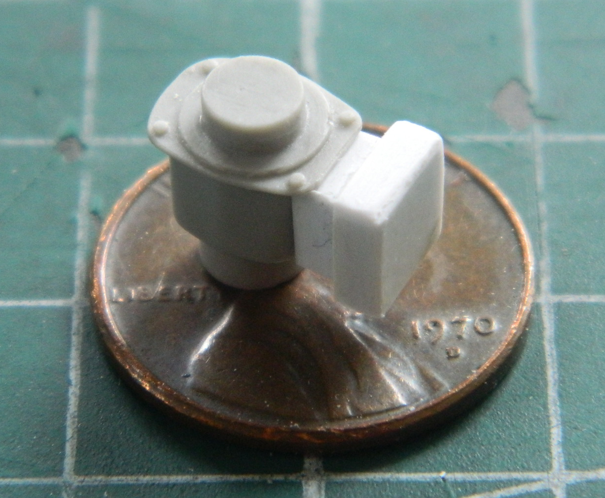
When the turret gets added to the hull, I’ve no idea how I can make the control box rotate with the turret and still allow the turret to be removed. I’m hoping the BitB come up with a clever (defined as effective and simple) solution, but I’m prepared to not have that feature.
Mounted on the hull behind the driver is a prominent feature the AM set didn’t provide. It’s an oil can with a hand pump and metal hose. What wasn’t provided had to be made:
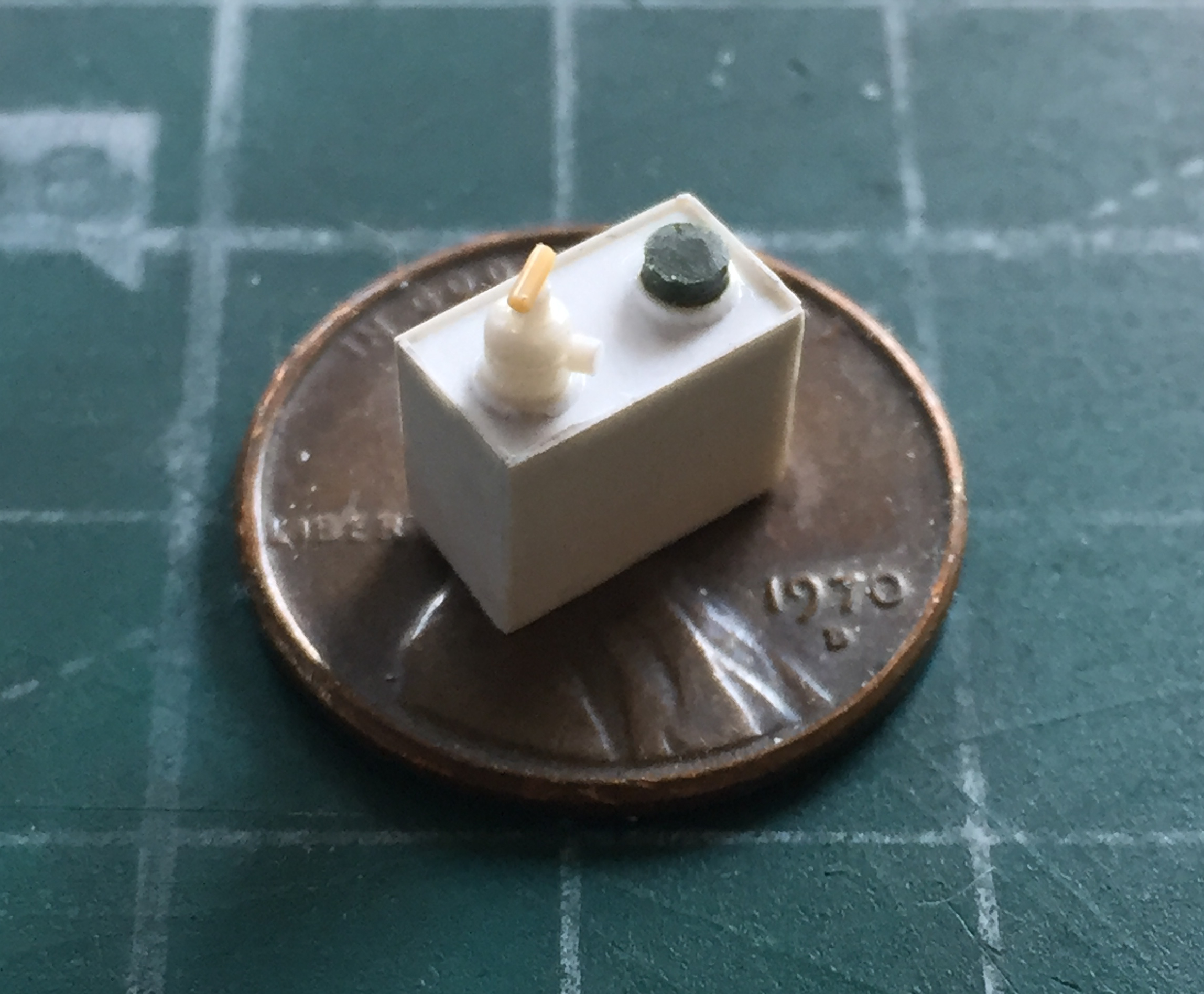
I used solder to make the metal hose:

I used lead foil to make the mounting bracket:

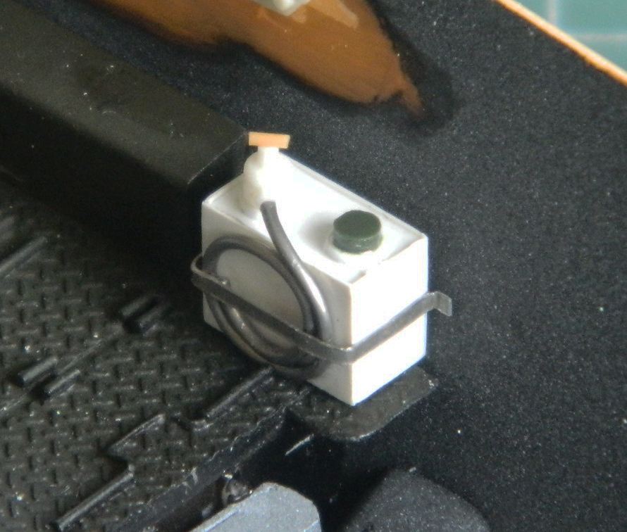
Between the noise of the machine itself and the sound of its guns firing, I can’t imagine it was easy to converse at a time when the crew needed to converse. Tanks had an “interphone.” No…that’s not analog phone sex, we’d call it an “intercom” today (the interphone, not the phone sex). The AM set didn’t provide the microphones so I made them (though only three are shown, I went back and made two more so that each crew position had it’s mic). I started using discs punched out of styrene (.015″ (.381mm) for the earpiece) and used .035″ (.89mm) rod as the earphone and some .025″ (.635mm) styrene rod as the handle:
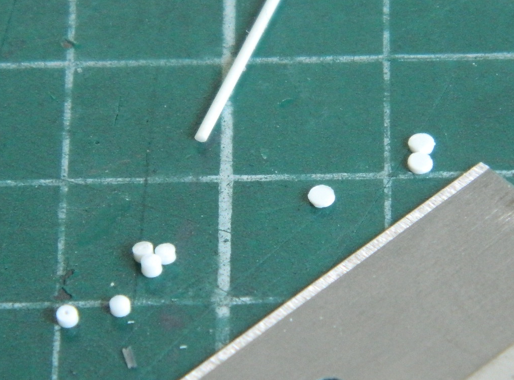
Double sided tape allowed me to hold the tiny parts in place as I stacked and glued the rest of the pieces:
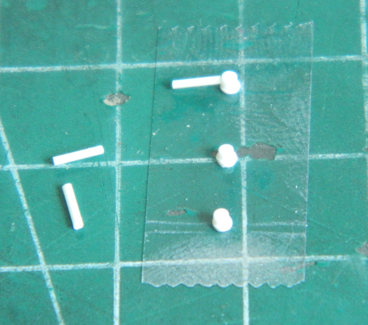
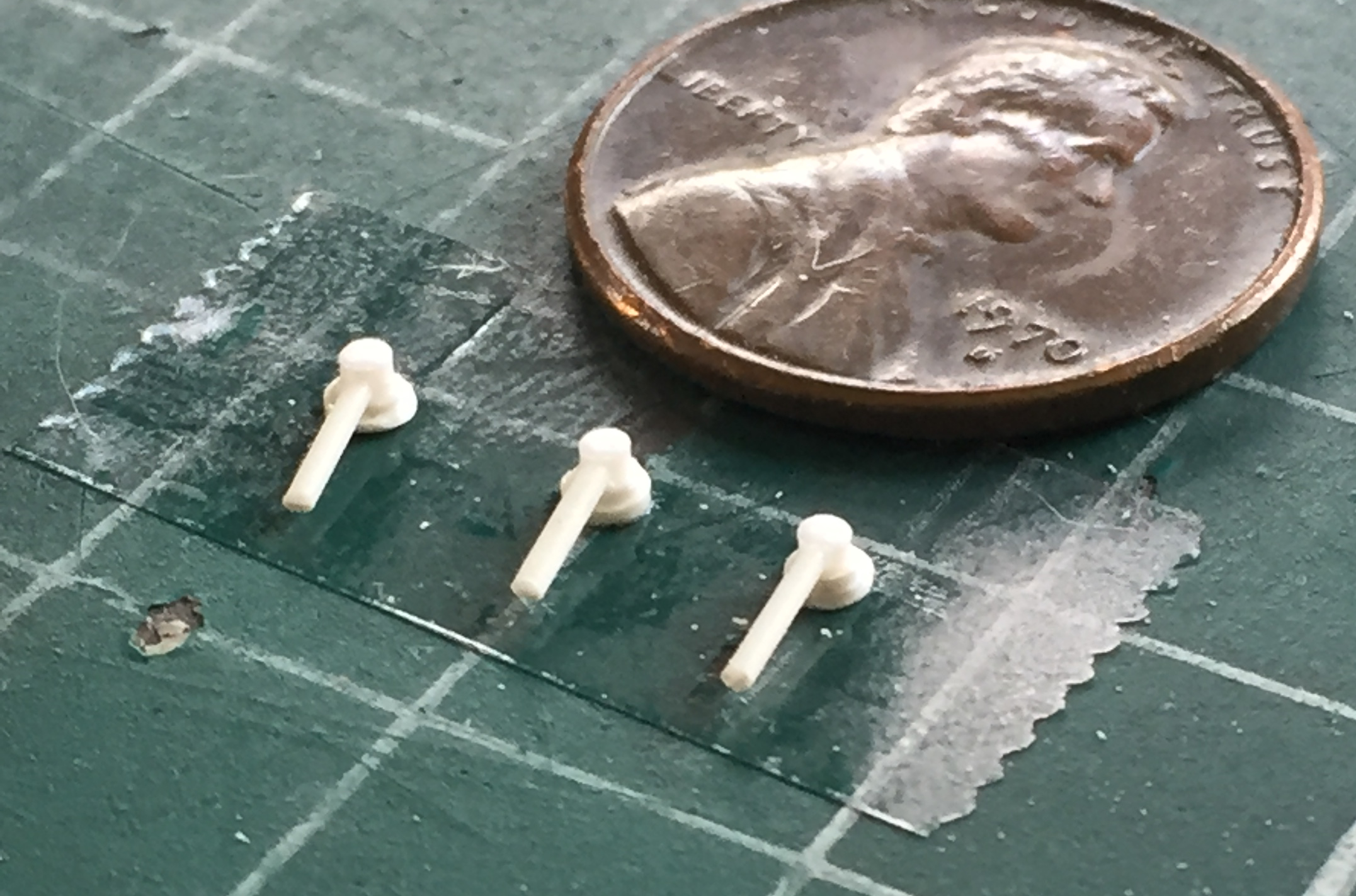
Attaching the wires to these things is going to be a challenge.
In the process of making the microphones, I realized that the co-driver’s mic (and probably the driver’s as well) hung from a support under the upper front hull that neither the kit nor AM provided. So I used card stock to make a template (the gray part is the vent blower):
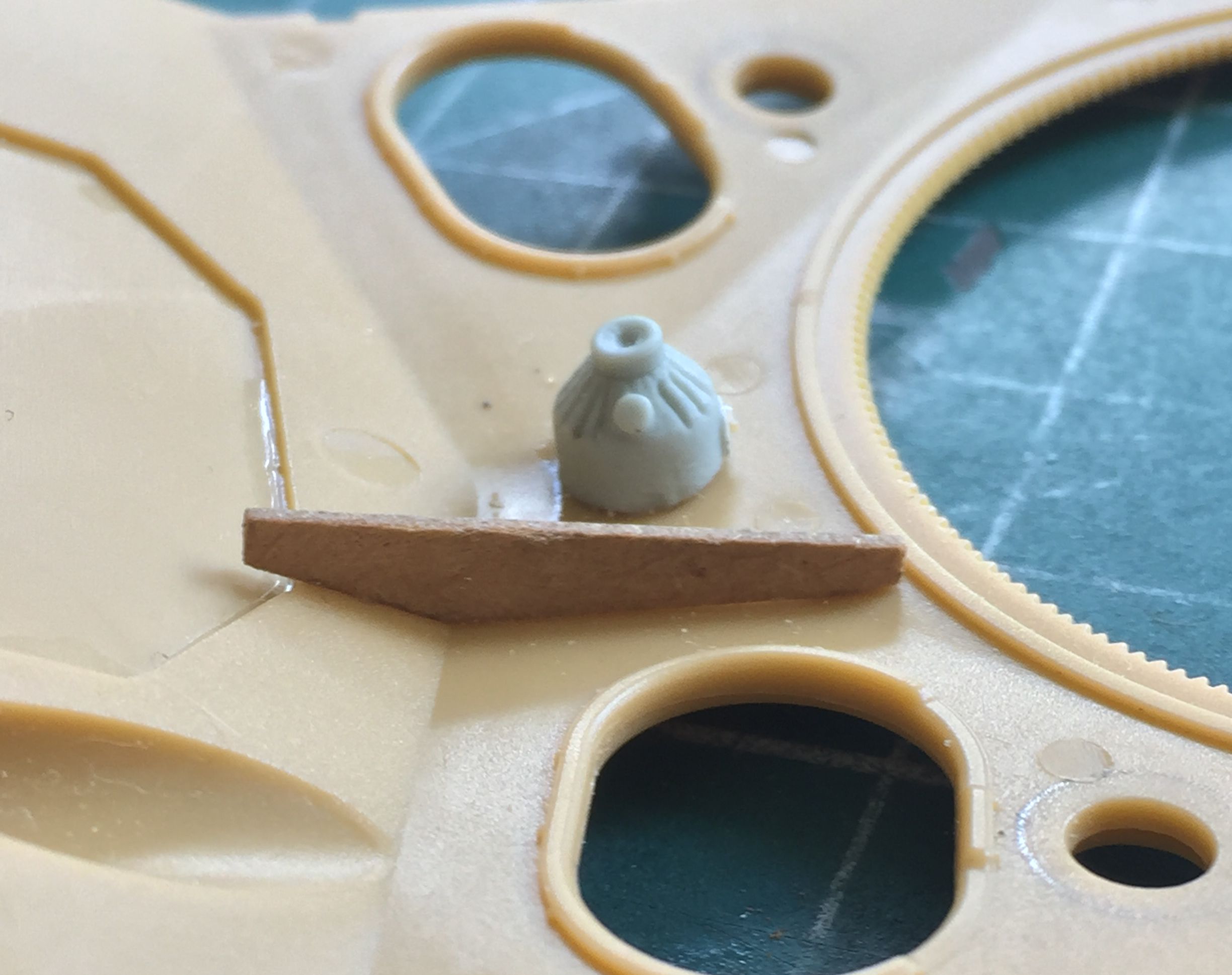
I traced the shape onto .030″ (.762mm) styrene and glued them in place:
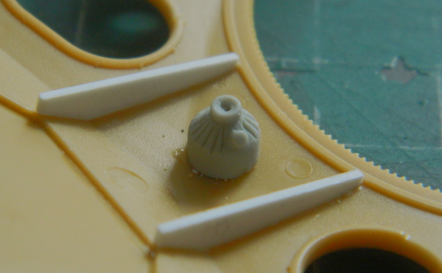
The area was populated by making a switch box that fit underneath the driver’s ceiling light, adding it along with the co-driver’s ceiling light and then added wiring conduits of .020″ (.508mm) and .015″ (.381mm) solder with lead foil strips as mounting brackets for the conduits:
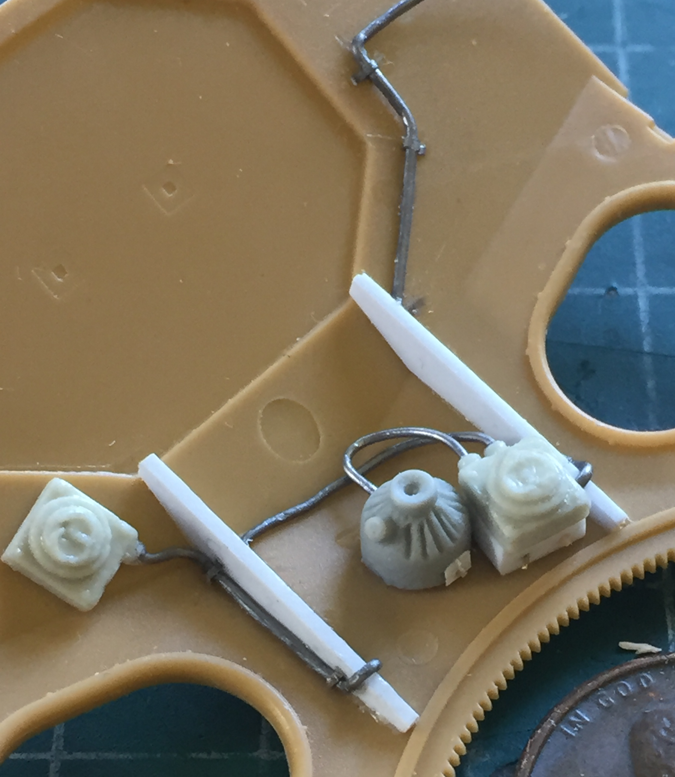
And then I added all the other conduits:

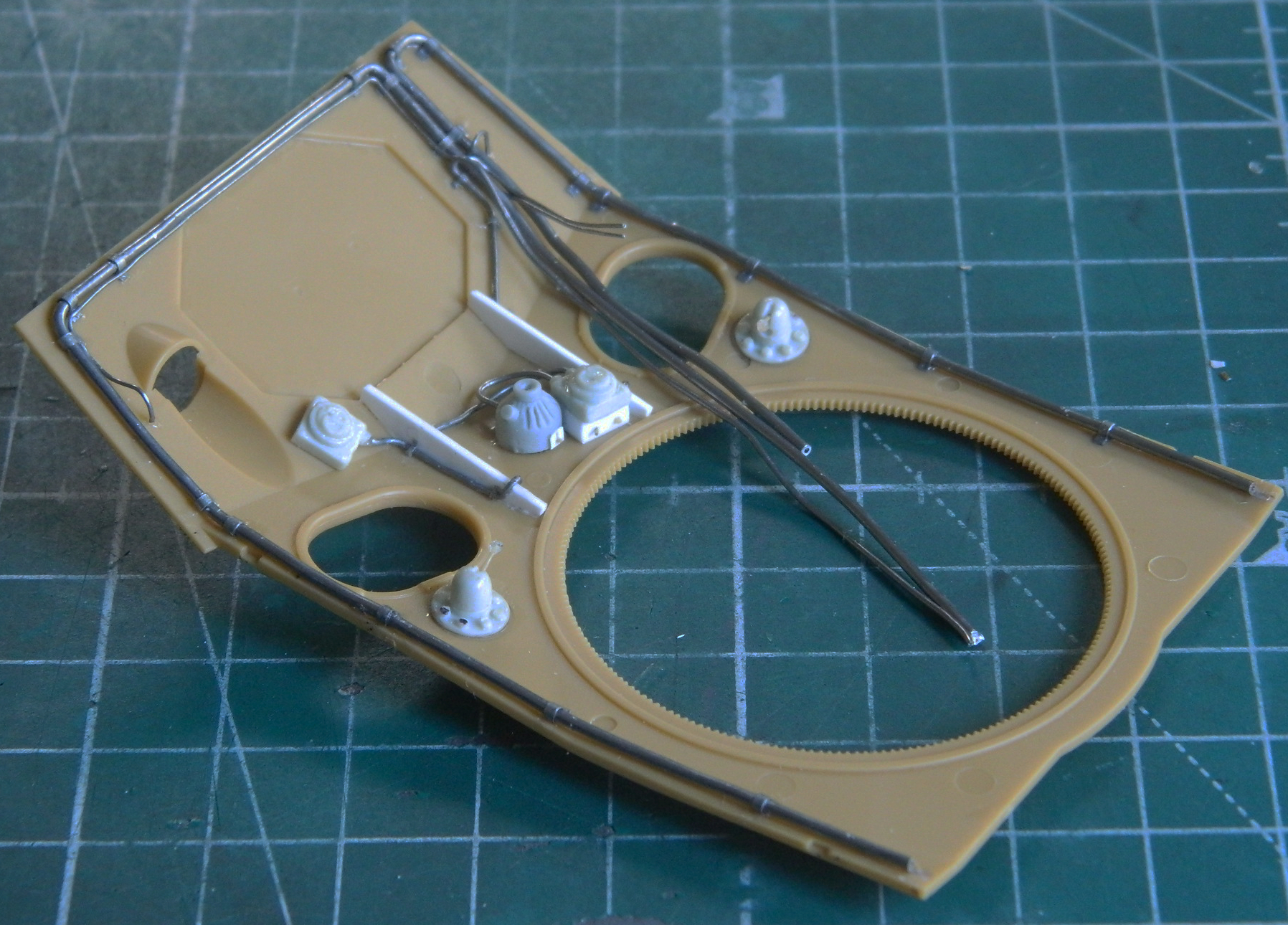
Then I realized that given the location of these conduits, nobody’s likely to ever see them. ::rolls eyeballs::
There are other conduits and a junction box that needed to be added to the engine compartment (and these will be easier to see). I drilled a spare resin junction box to accept . 015″ (.381mm) and .020″ (.508mm) solder and glued the box in place after scraping paint away for a good bond:
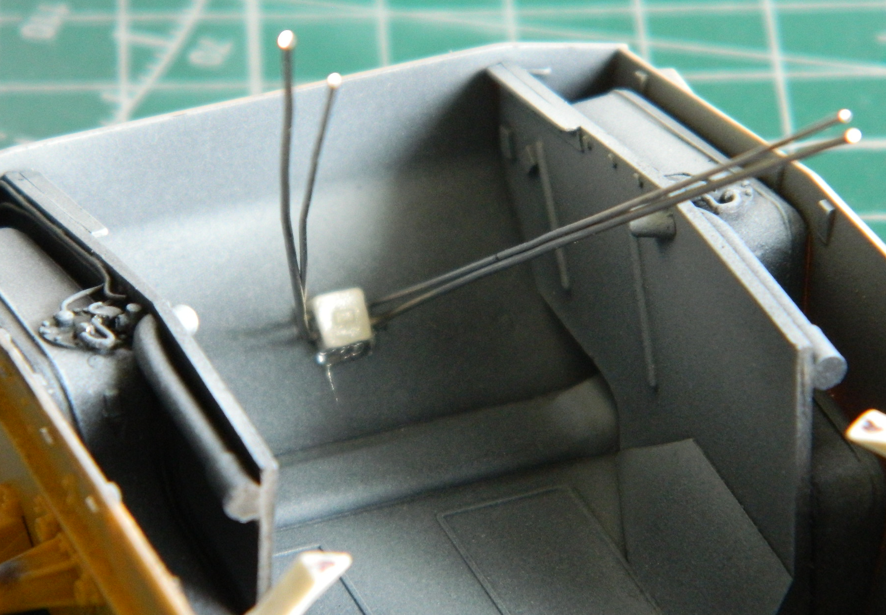
Then it was a matter of running the lines and adding the mounting brackets (lead foil again):
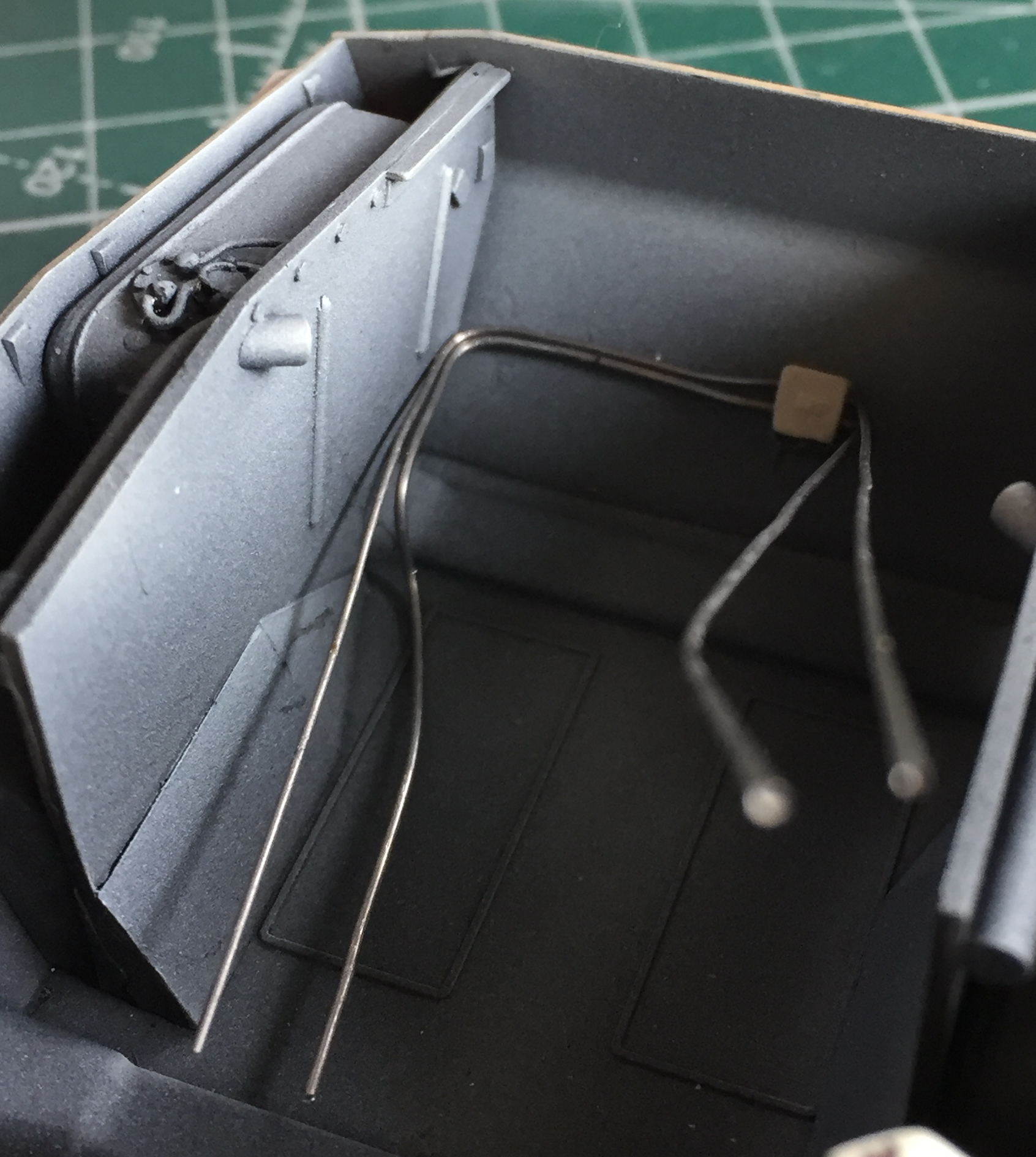
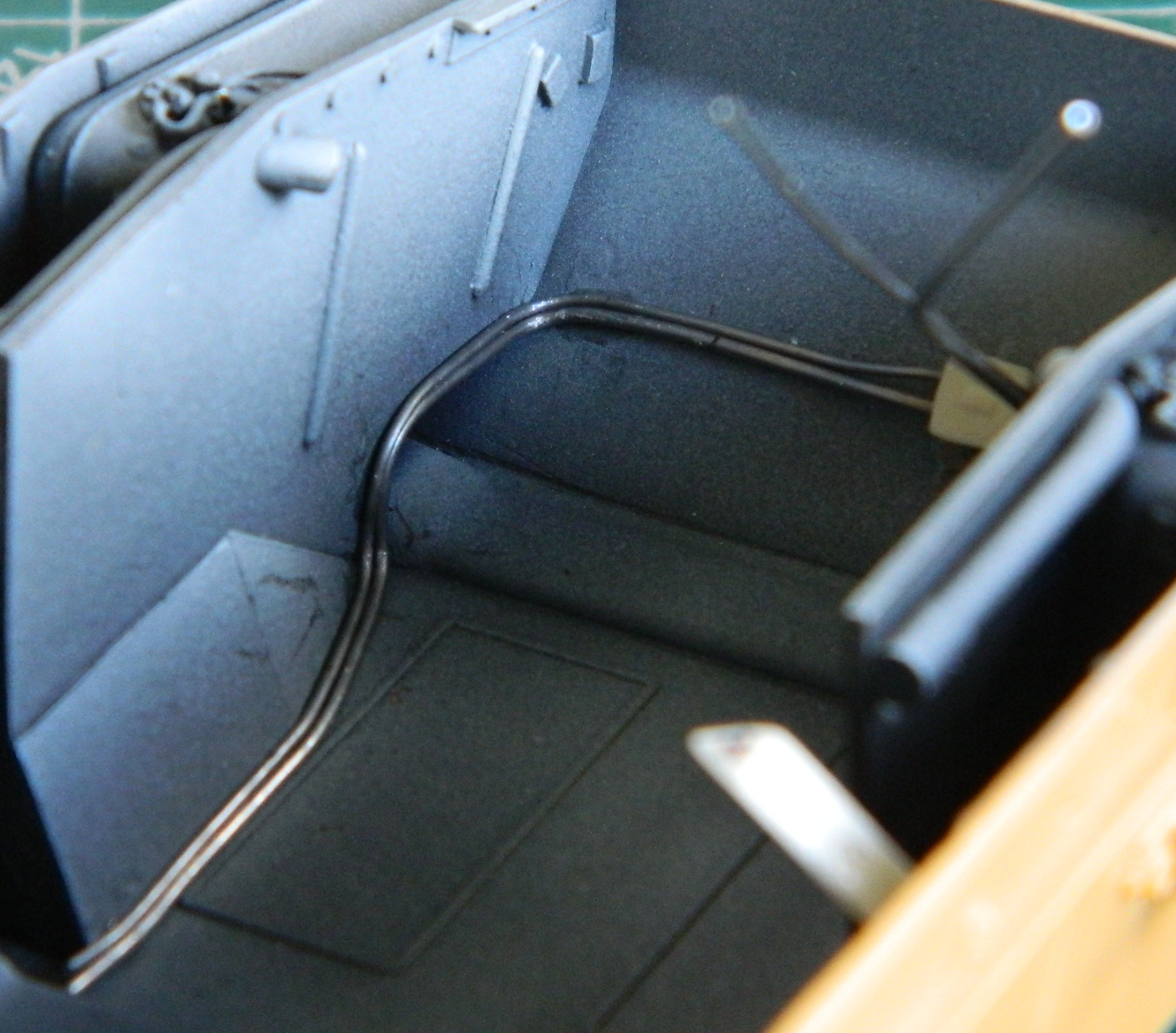

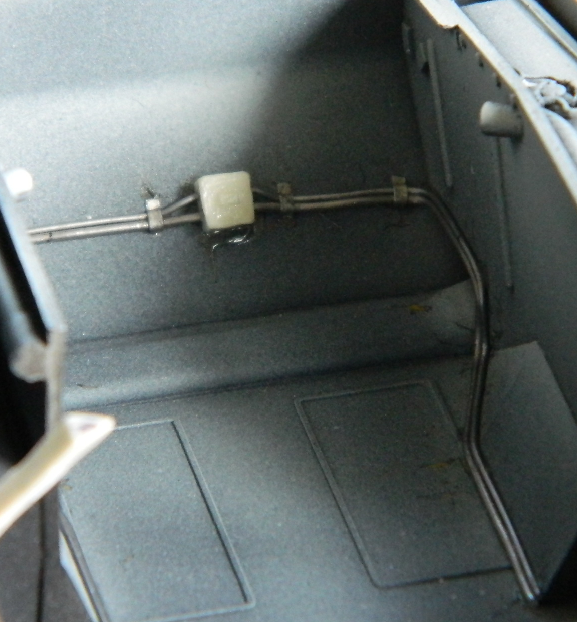
Small parts require special handling and forethought. How does one paint parts that a gnat’s sneeze would blow off the bench and into oblivion? I do that by getting a handle on things. Literally. It starts by very careful drilling holes into resin parts to add styrene rod through later on. Before later on, though, I can stick toothpicks (CAREFULLY) into the holes I drilled to allow them to be handled for painting:
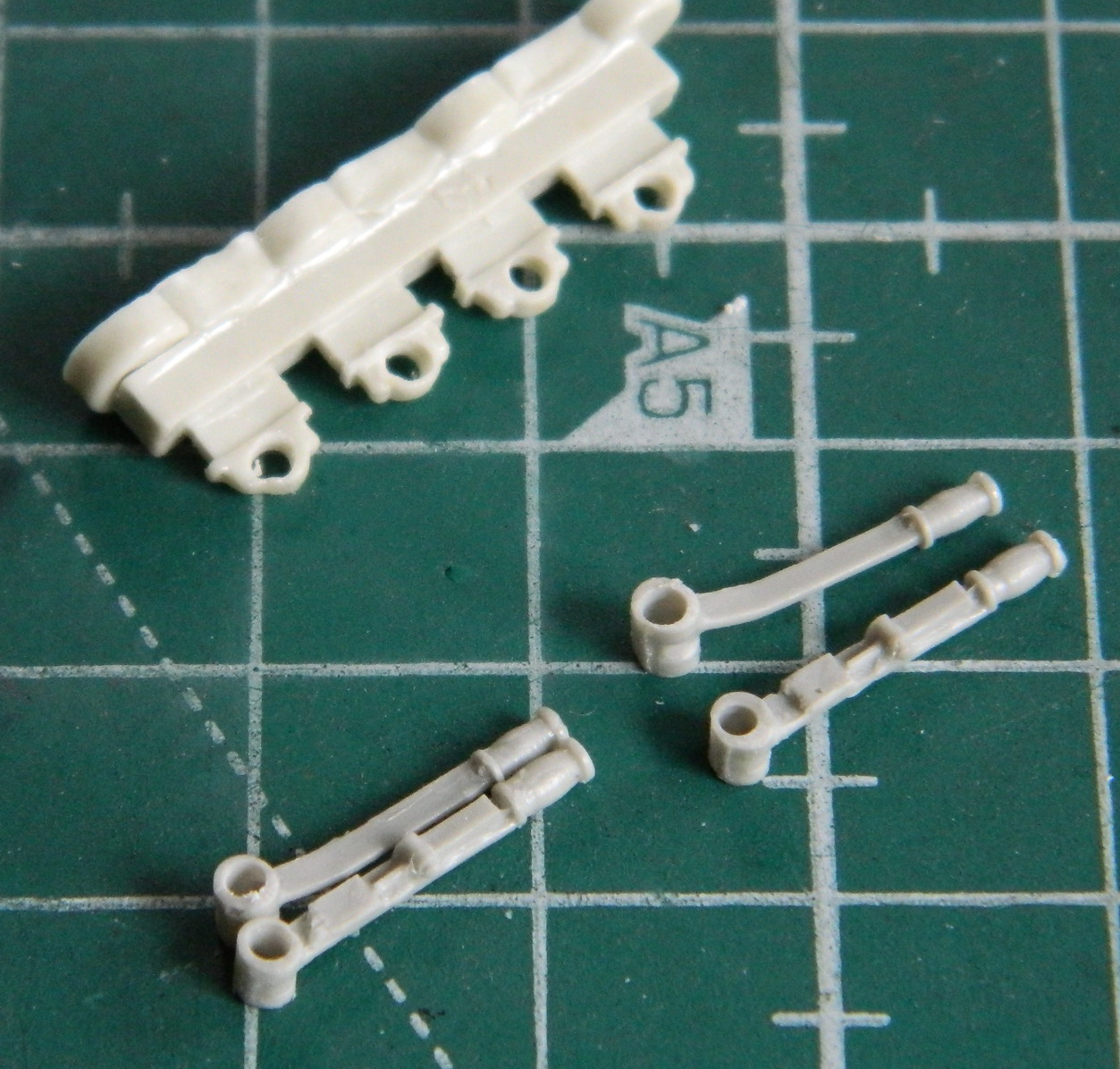
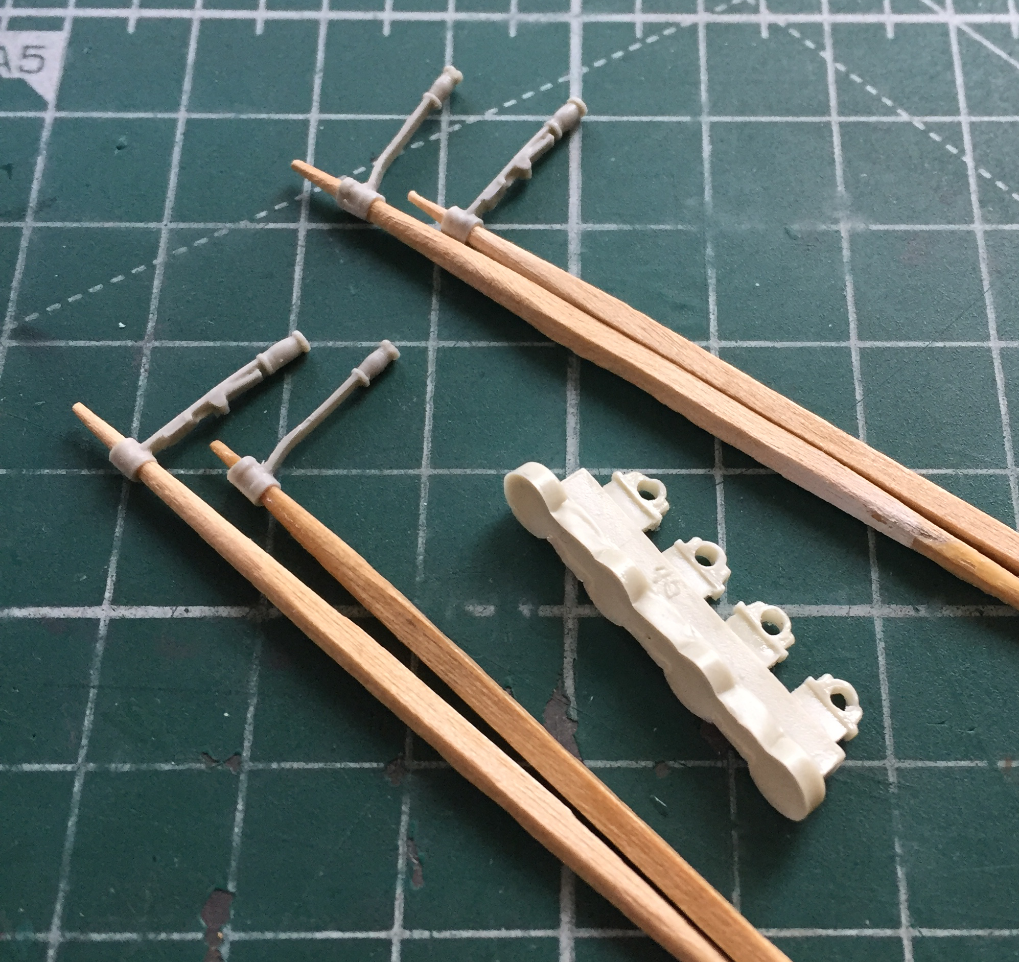
Finally the rocking back and forth got so pronounced that I started getting motion sickness. Fine. Fine. I’ll deal with the sodding Ohgawdammit thing…painting the engines…something I wasn’t at all looking forward to attempting.
In very small space(s), after painting them flat black for pre-shading, I had to paint each engine with Tamiya XF-62 Olive Drab overall, Tamiya X-18 Semi-gloss Black on the generators and water lines, Tamiya XF-85 Rubber Black on the spark plug wires and water line mounts as well as two hoses connecting the radiators to the water lines, custom mixed copper for the carburetors, and finally Italeri’s #4675P Flat Rust on the exhaust manifolds (which I dry-brushed on to control the paint laid down and not over painting the top of the engine). So the hell with it. I did (and note the now-painted oil box, too):
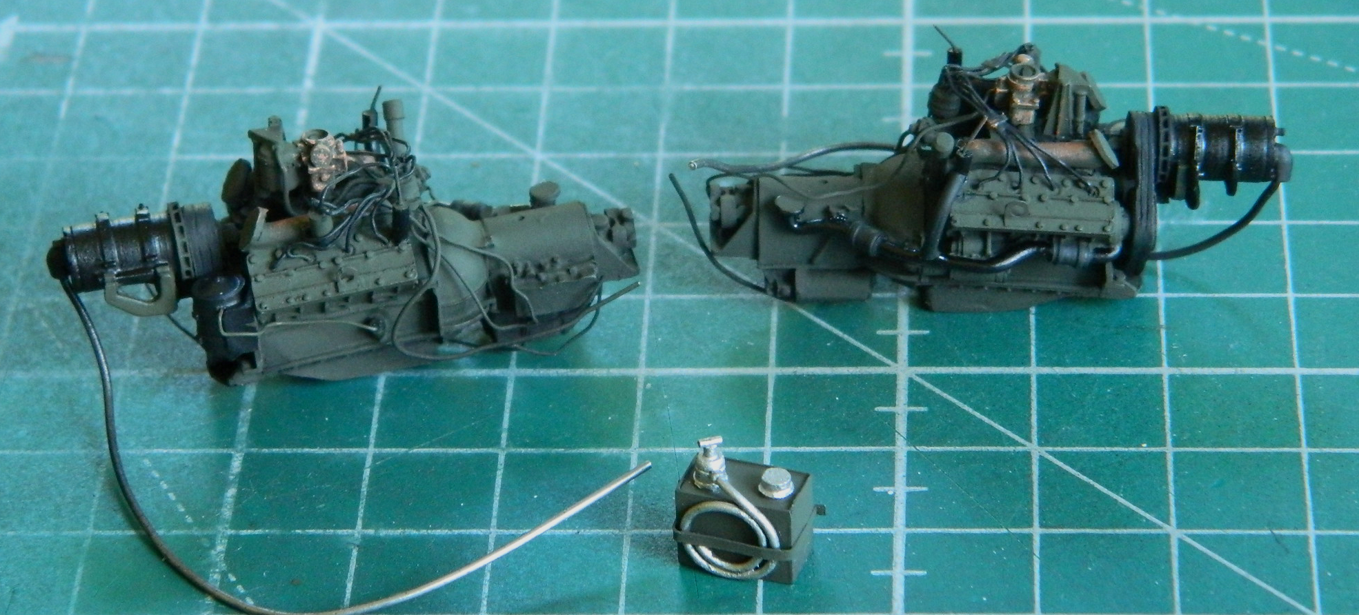
A few days prior, the burnishing liquid arrived so I decided it was a good time (or at least not a bad time) to test drive the burnishing liquid and get the basic track color on.
This is the stuff:
It gets diluted 50% with water. The water where I live is very hard so rather than use it from the tap, I used distilled water (I do the same thing for wet sanding and decals for the same reason). I emptied the contents of the bottle into a plastic tray and then used the bottle to measure the water and mixed it well:

Any references I’ve read regarding Fruilmodel’s tracks and burnishing liquids (not just this brand’s) stress washing the track shoes thoroughly before attempting any coating, so I did. References stated that the tracks should be immersed and then bubbles knocked and/or shaken away from the surface so that the liquid gets into all the crevices. I used an old toothbrush and the task was surprisingly tedious. I found it easier to wash and de-bubble assembled tracks instead of individual track shoes:
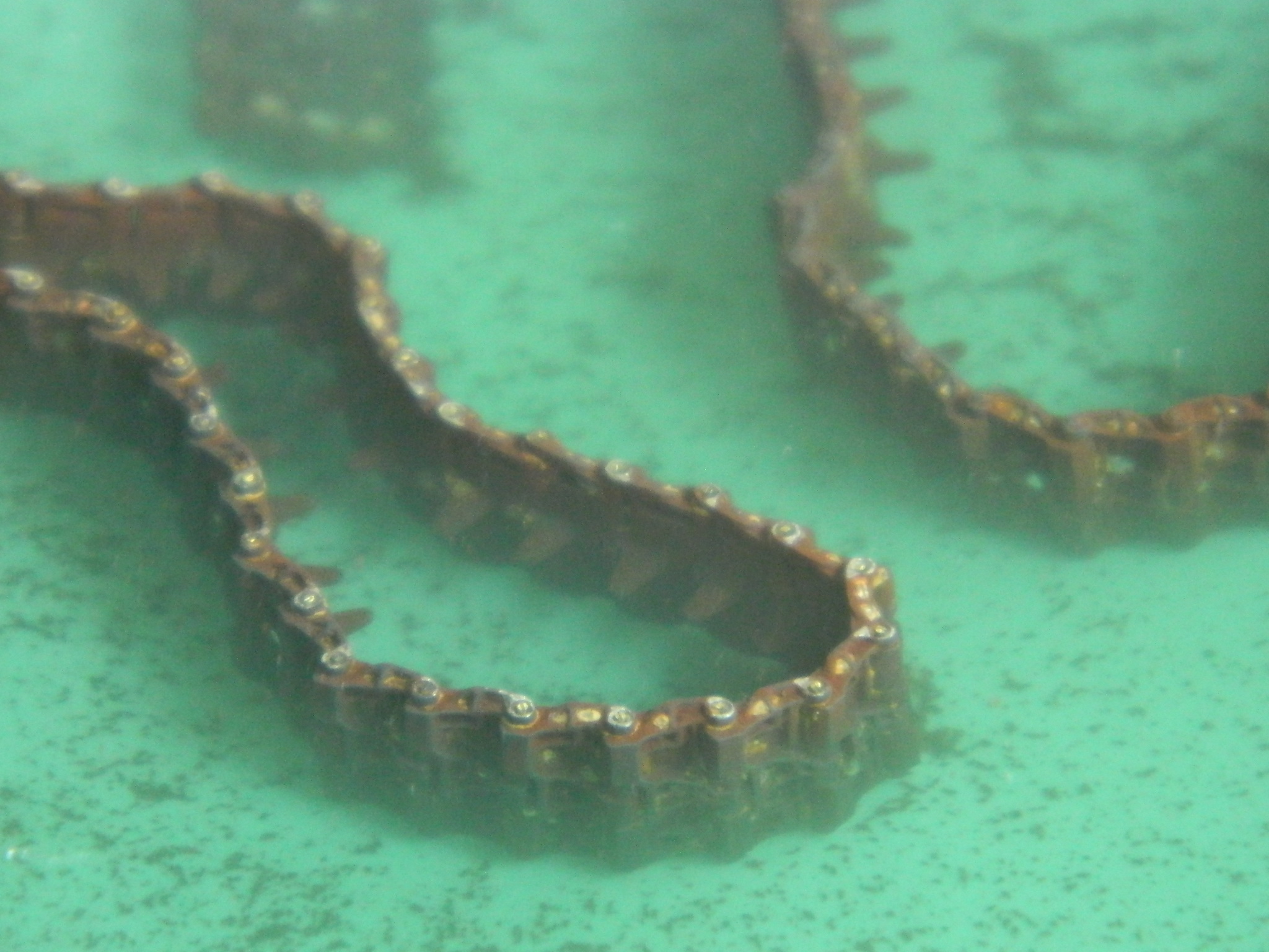
After a few minutes, I took one of the tracks out and checked it (forgetting that I was going to have to de-bubble it again):
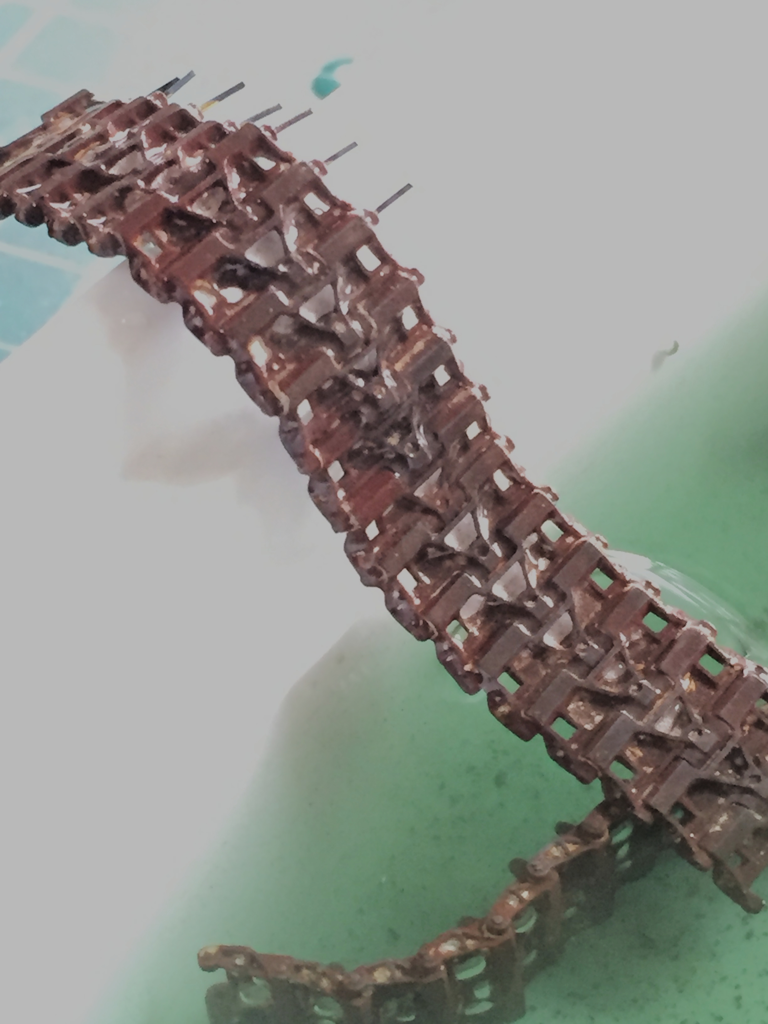
In checking the tracks, I saw the areas that just didn’t change color. There were no bubbles and I have no idea why they didn’t color. I KNOW I scrubbed the metal thoroughly. Others using this and similar products have had the same results. Okay…looks like parts of these tracks will be caked with dirt or mud! References also state that the time parts are soaked alters the look, obviously tending towards darker with more time immersed. I decided that four hours gave me the look I wanted (though there was one YouTube video where one builder left his tracks in 12-13 hours):
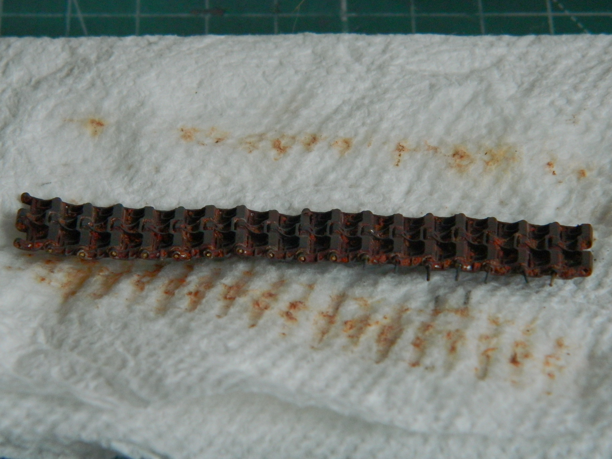

I LIKE IT!
M24 Chaffee (Bronco) 1/35 Scale Build #3 – Painting…Kind of
I suspect there’s an aspect of myself that’s like an old trail horse. As long as I’m going along in my self-established grooves (or ruts), I’m fine. But bump me out of said ruts (or grooves) and my procedure goes to pieces. What I wanted to do was to get the interior ready-ish for some paint because I wanted to show my “trainee” what pre-shading is and why I painted things black to be able to paint them other colors. What I did was focus so much on the instructional aspect that I forgot some construction things. What that means is that much of what this update is going to show will end up being undone or redone because there were some things I wanted to add before painting and just forgot about them.
I started assembling the raised floor (under which the actual tank has water-jacketed ammo storage). With the bulkhead just dry-fitted, I placed the floor and added the parts needed, using the hull as my assembly jig:
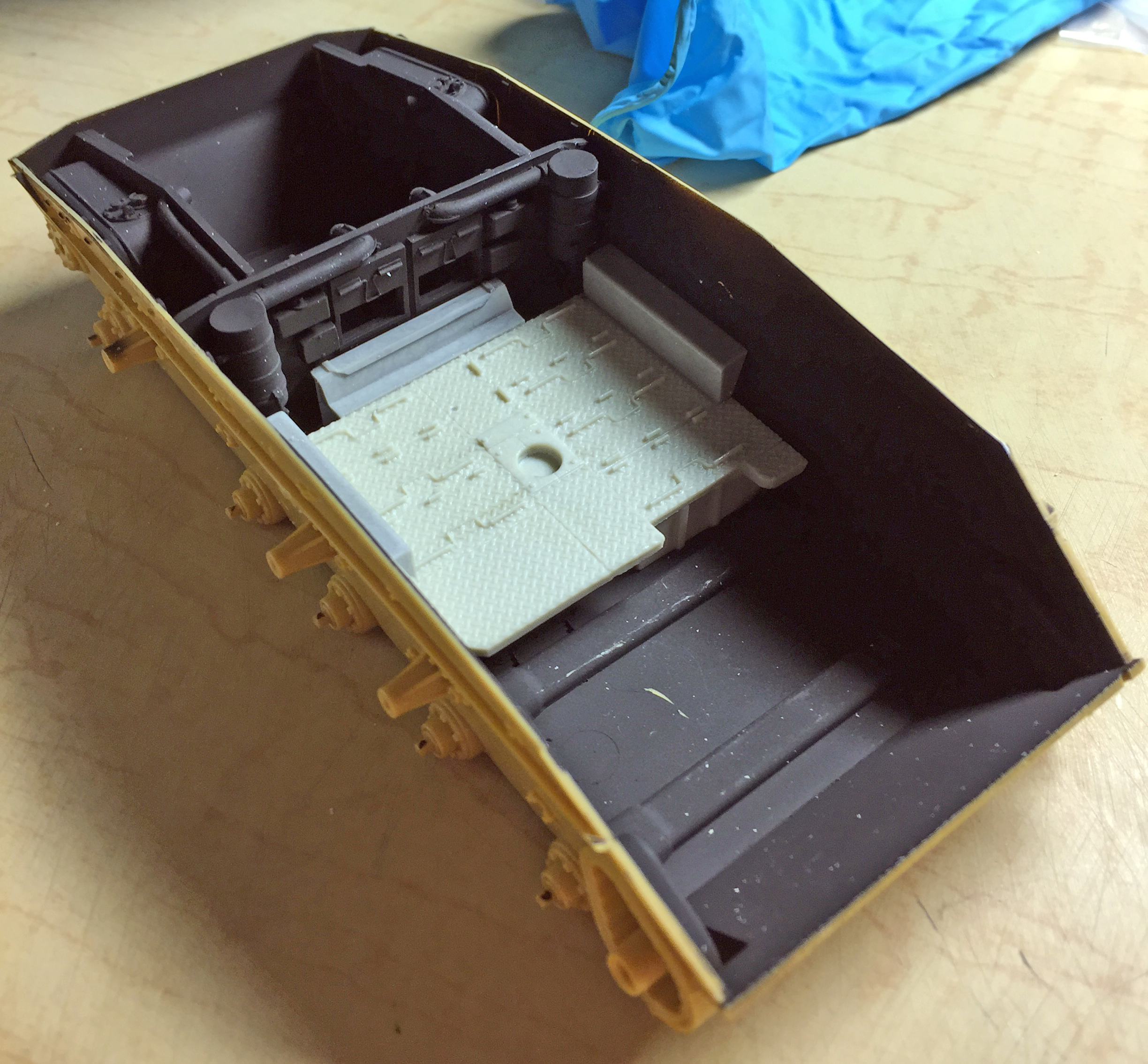
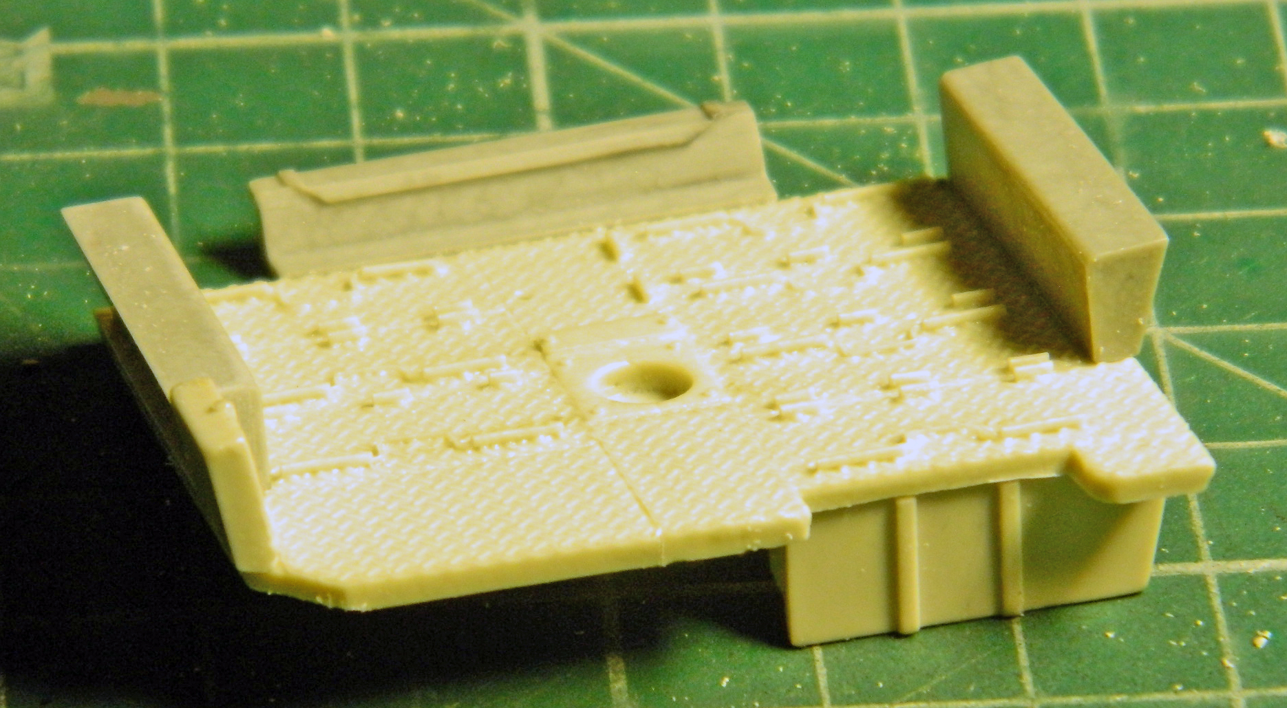
One prominent feature of the differential is either a breather or an oil filler tube, so I had to make one. Another prominent feature of the differential is that I didn’t paint it flat black! So I’ll have to attend to that:
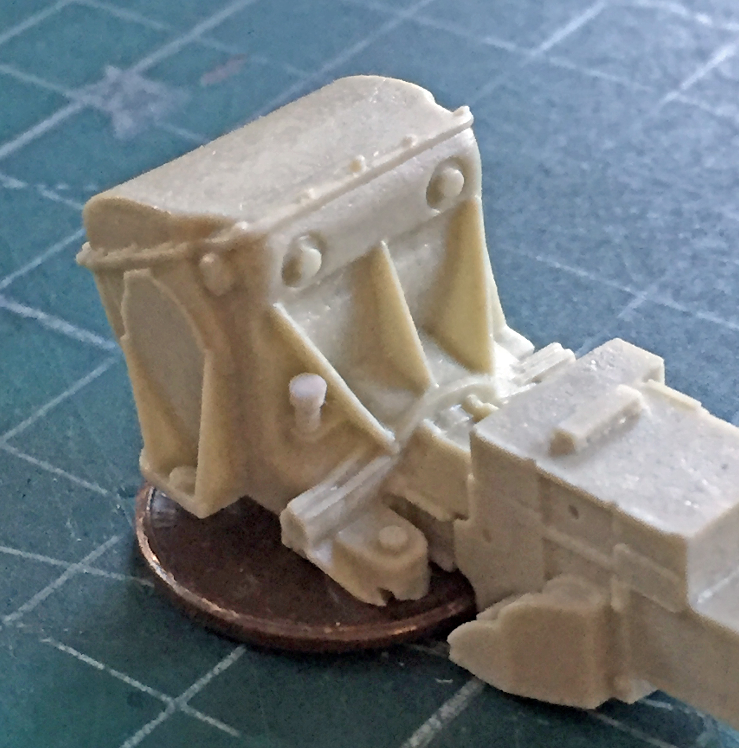
The raised floor also covers more area than the AM part does. I’d intended to make additions to both rear corners where the floor-plates were missing, but on the left side is where the on-board fire extinguisher sits. Yes, I could have put that in but the large amount of work required to get that accurately done is for something that will be difficult to see (at best). Since it will be mostly unseen, I decided to save myself a few hours of fiddly work to achieve dubious and mostly unseen effects.
Since I don’t have any scale diamond tread plate (something I should rectify), I copied a section of floor from Academy’s M3 using heavier gauge aluminum sheet and supergluing a .060″ (1.524mm) styrene section to the aluminum and then trimmed it:
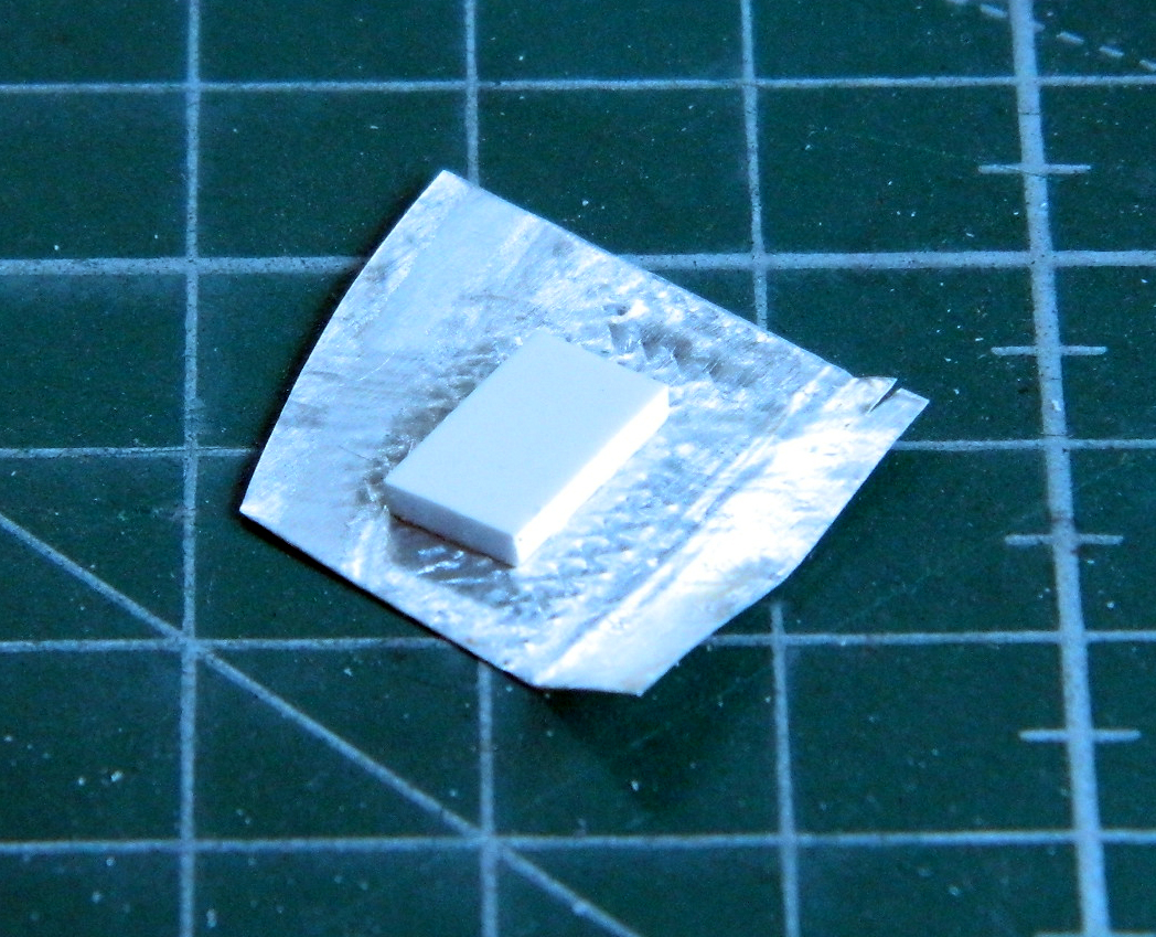
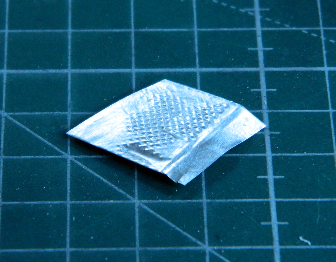
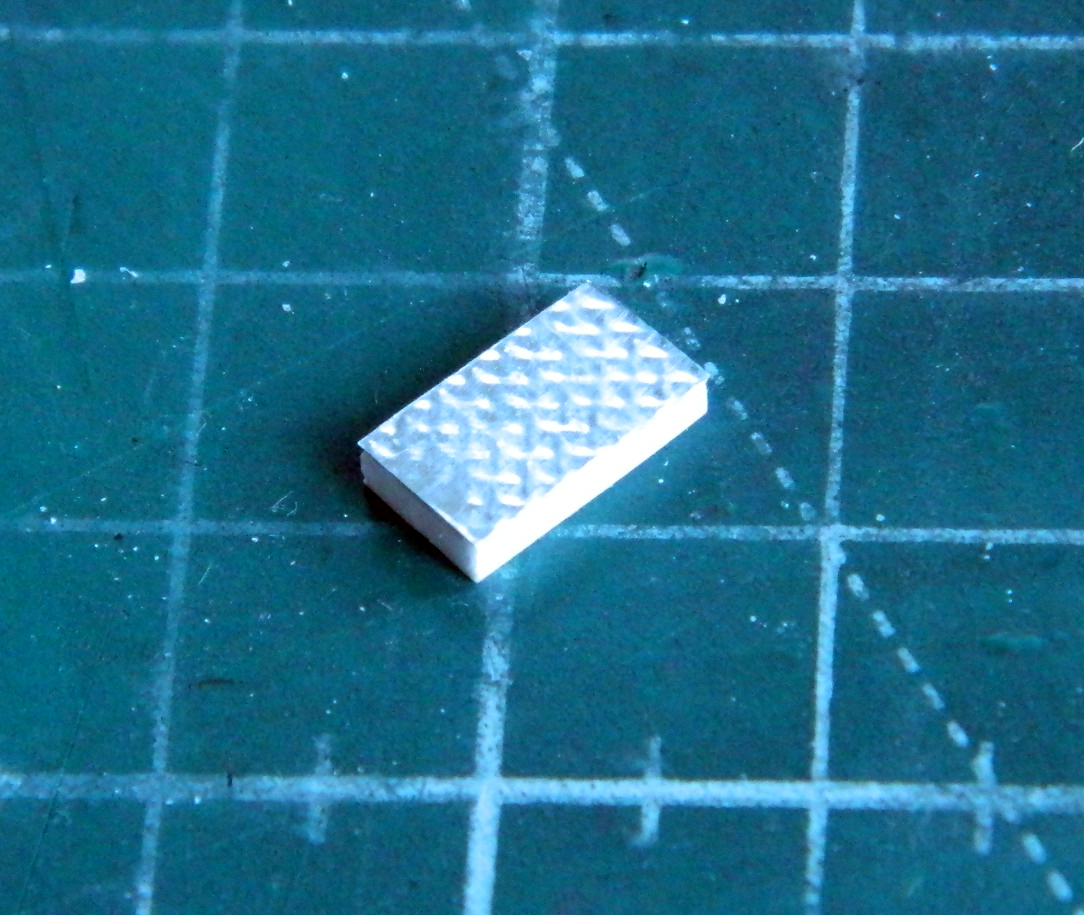
I added a section of .020″ (.508mm) scrap to provide more gluing surface, then glued the new floor piece into place. And though not evident in these photos, I also thinned the edge of the resin floor where the actual floors of these sections just sort of hangs out:

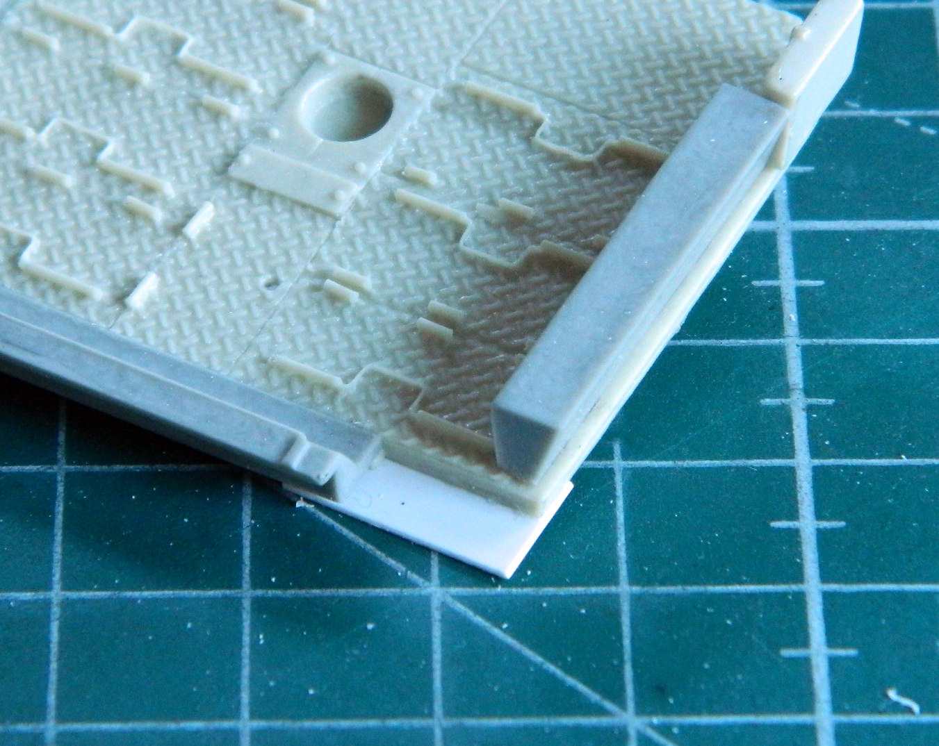
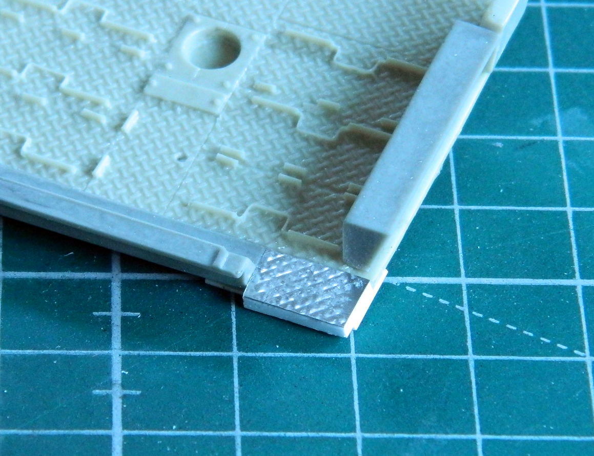
One of the (several, I think) things I’d wanted to add before painting and forgot to do was the plumbing around the tops of the fuel tanks, so I added it:

I drilled sockets for skewers so that I had handles to make painting small parts easier. Some sections were painted with Tamiya X-18 Semi-Gloss Black over the flat black. There’s a shroud at the rear of the floor (left in the photo below), the caps to the radiators and oil cooler (not shown), and the batteries that were painted semi-gloss:
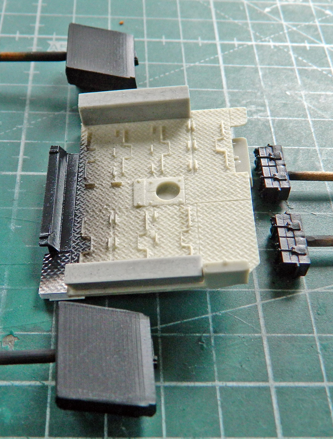
Then the floor and oil filter housings were painted Tamiya XF-62 Olive Drab:
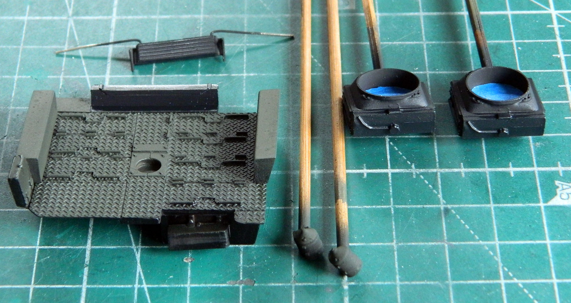
At least I remembered to paint the on-board fire extinguisher. Tamiya X-7 Gloss Red was used on the canister (the bottom will never be seen once it’s in place) and Tamiya XF-6 Copper was used on the valve body. Vallejo 71.132 Aged White was used on the gauge face (later I will use a SHARP pencil and draw on the face details):

To prepare for Tamiya XF-2 Flat White, I masked off the interior parts I don’t want to paint white:
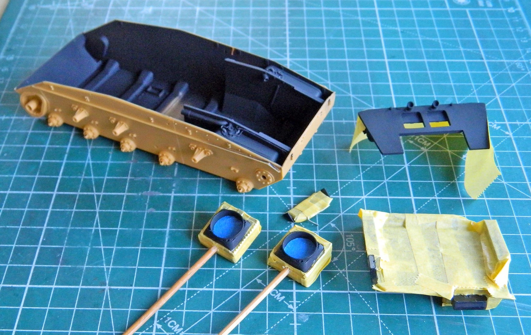
And then I misted the flat white over the parts that will be in the crew compartment and the aged white over the fan shrouds on the radiators (I like the look of the aged white in the engine compartment). Later you will see photos of “that.” The quotes are because it’s very possible that most of what has been put down will be taken back up so that I can add the parts and bits that my mono-focus has already missed.
About this point I’m thinking that Bronco has engineered this kit with diorama builders in mind. MANY of the kit parts are comprised of several pieces that other manufacturers would have done either in one piece or certainly not “many.” An example is the drive sprockets:
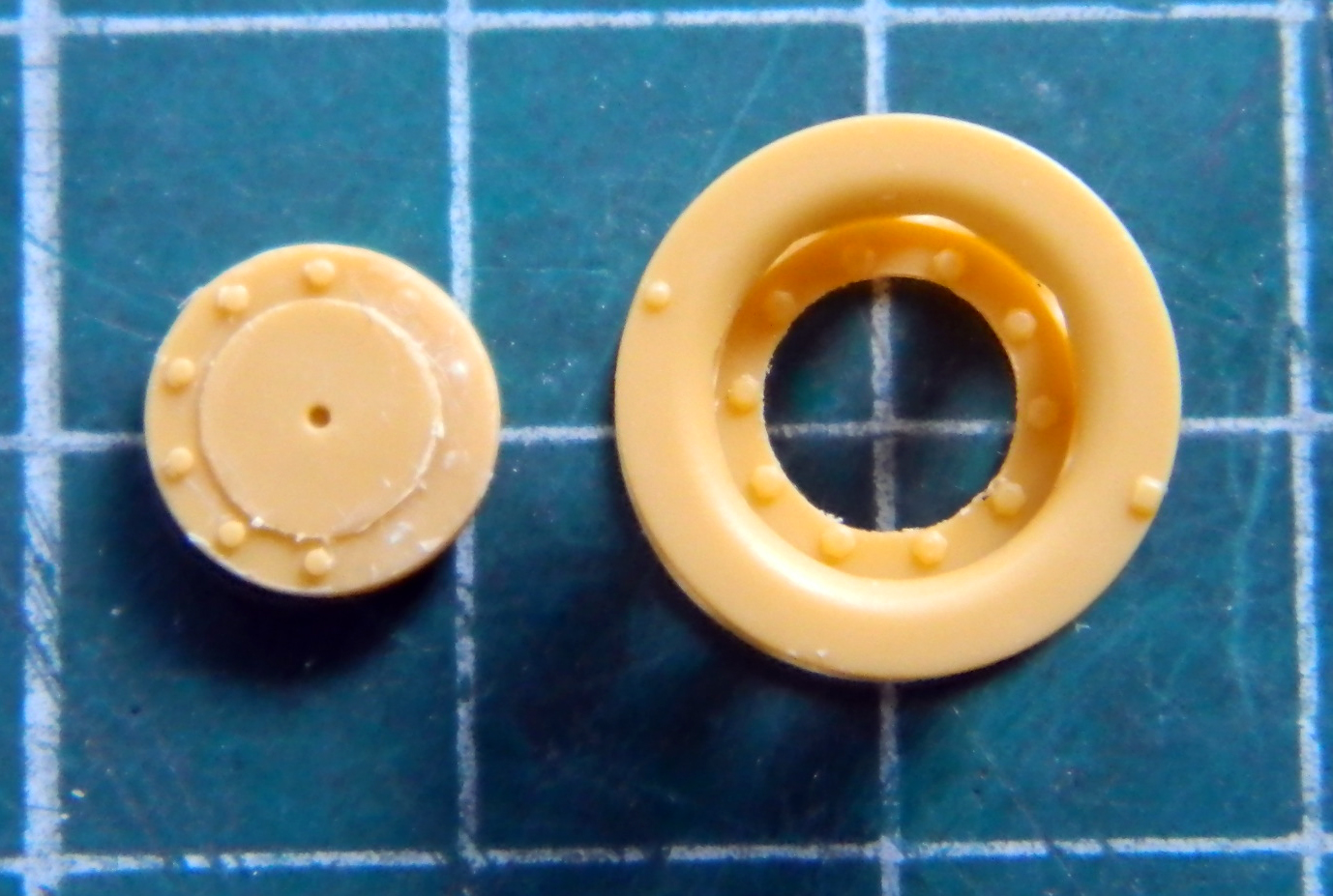
There are two parts in that photo and they’re only half the parts the drive sprocket is comprised of. The part on the left is the hub that fits behind the body of the sprocket. For it to fit into the body correctly, the bolt heads on the face of the hub have to be shaved off. The other two parts are separate sprocket plates. If you wanted to do a diorama of the crew changing sprocket plates, the kit parts are preconfigured to allow you to do that easily. It’s not much more work if you only want a sodding drive sprocket, but this sort of thing I’m starting to see throughout the kit. This adds to the parts count, obviously, but it also allows for some VERY FINE AND TINY PARTS as well.
The road wheels are also multipart subassemblies. Every road wheel is comprised of six parts and there are five road wheels per side (and three return rollers just about as complex as the road wheels):
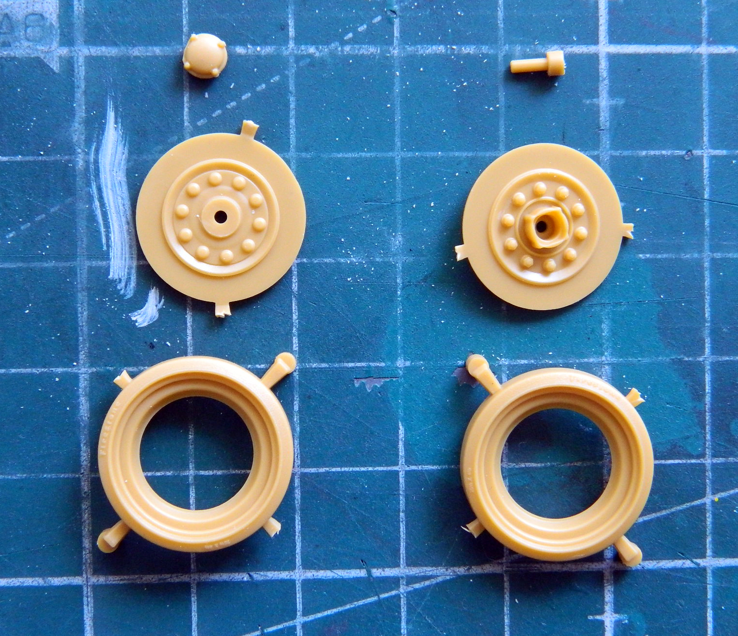
The idler wheels are beautifully cast and like the idler wheels on the actual tank, they have an inner lip on both sides of the rim. Had I bothered to check references I would have seen that these rims are recessed and not even with the outer edge of the rims the way I have them (and all nicely puttied, too). The plastic is SO thin that I’ve no doubt that if I try to pop those out of there to place them deeper, they won’t “pop,” they’ll “snap.” Fine…I’ll live with my mistake. Again:
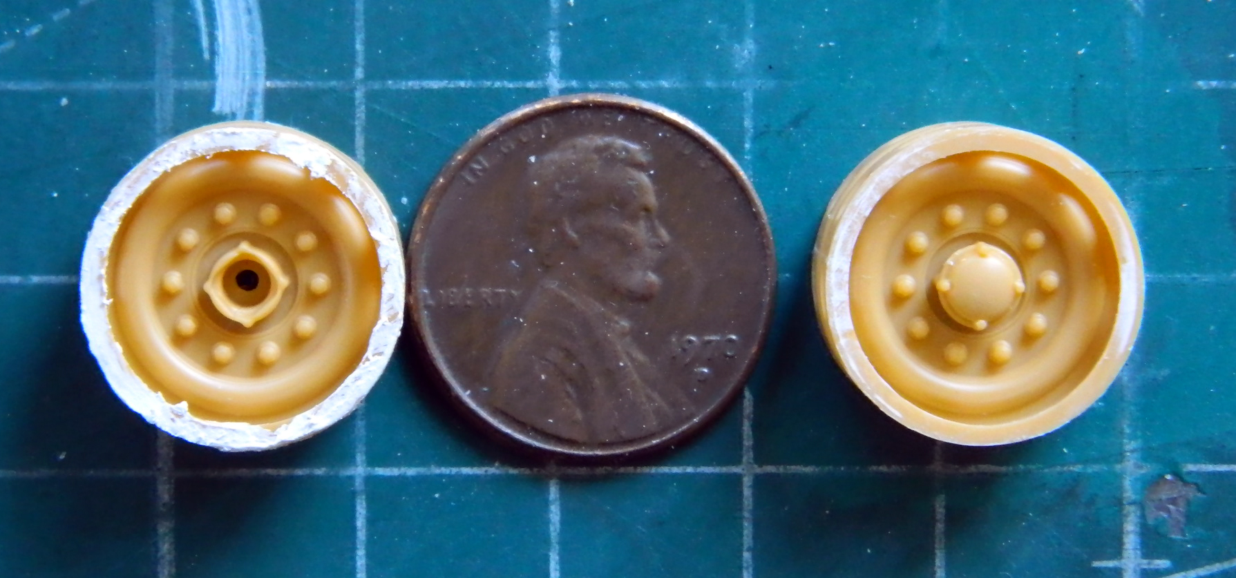
Duh.
This kit provides a PE fret for the really tiny stuff, like headlight guards. The kit also provides a forming buck that the PE can be bent over! Nice touch! I annealed the brass before bending. I tried my best to solder the braces to the main hoop but that didn’t work at all, so I ended up resorting to superglue:

Dry-fitted:

The other guard is much simpler.
The batteries were detailed a little:
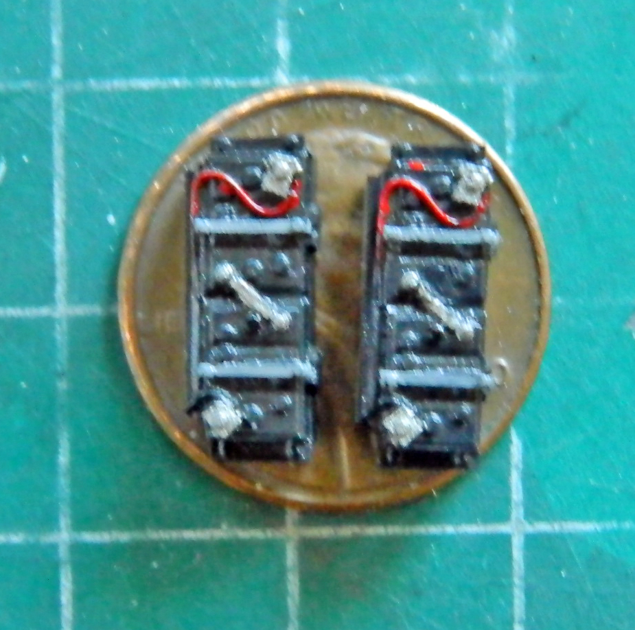
Each of the five-gallon cans has six parts (and were I crazy enough, the locking lever has its PE equivalent…be seeing as I’m merely colorful and not crazy [snicker], I used the plastic part instead):
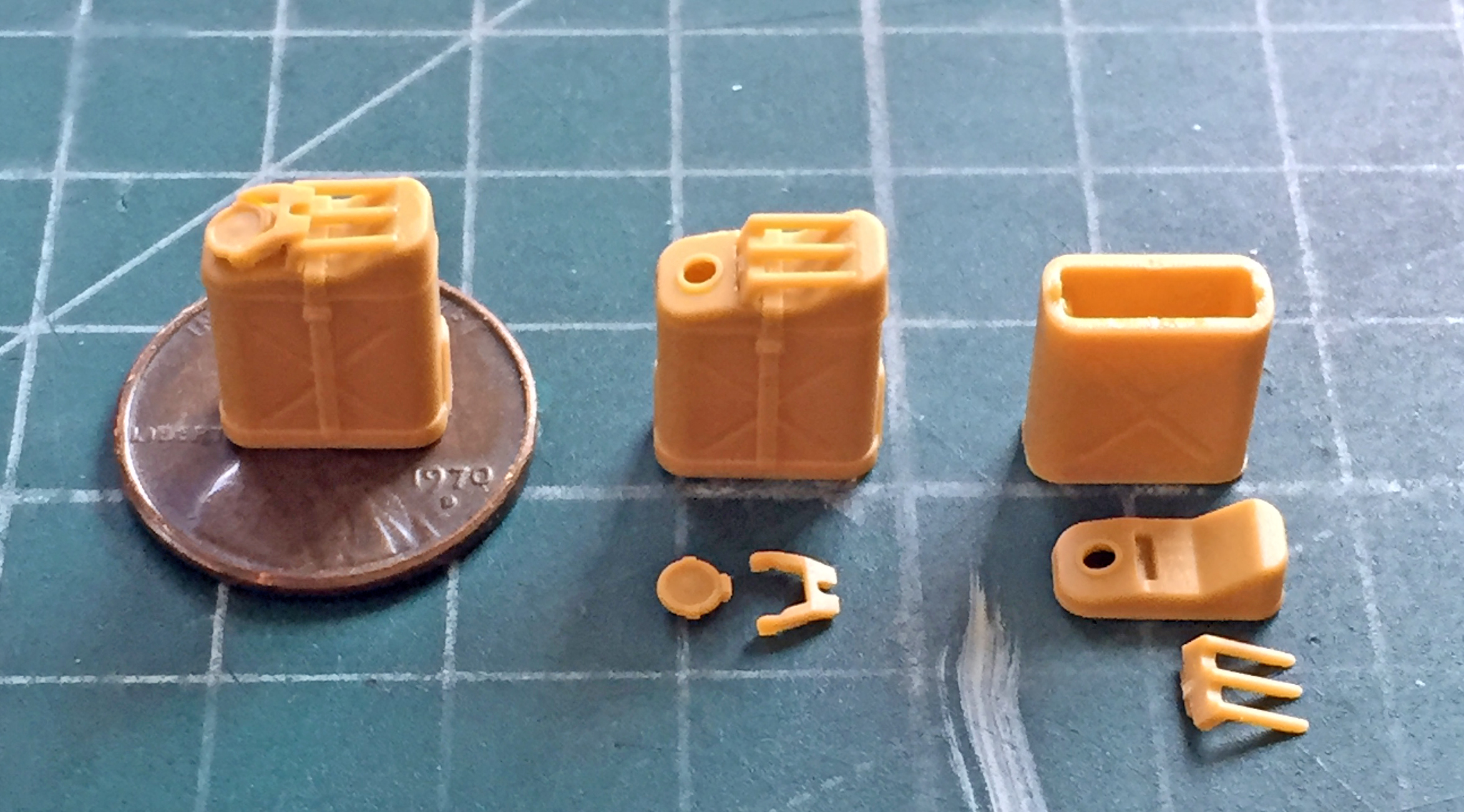
Why did I do the cans? I needed something to do while I mapped out what I have to go back and do…and that will probably start by me stripping the paint I’d already laid down.
::bangs head on desk::
M24 Chaffee (Bronco) 1/35 Scale Build #2 – Getting the Engines Ready for Paint
Having started on the engine bay, seemed to make sense to get the engines assembled and detailed. I quickly discovered that the carburetors wouldn’t stay glued on. There’s very little surface for the glue to adhere the parts to so the carburetors needed pins:

The most challenging of what the engines would need was to get eight TINY (.010″ (.254mm)) holes drilled into the distributor caps and then glue eight TINY lengths of .010″ (.254mm) solder into them:
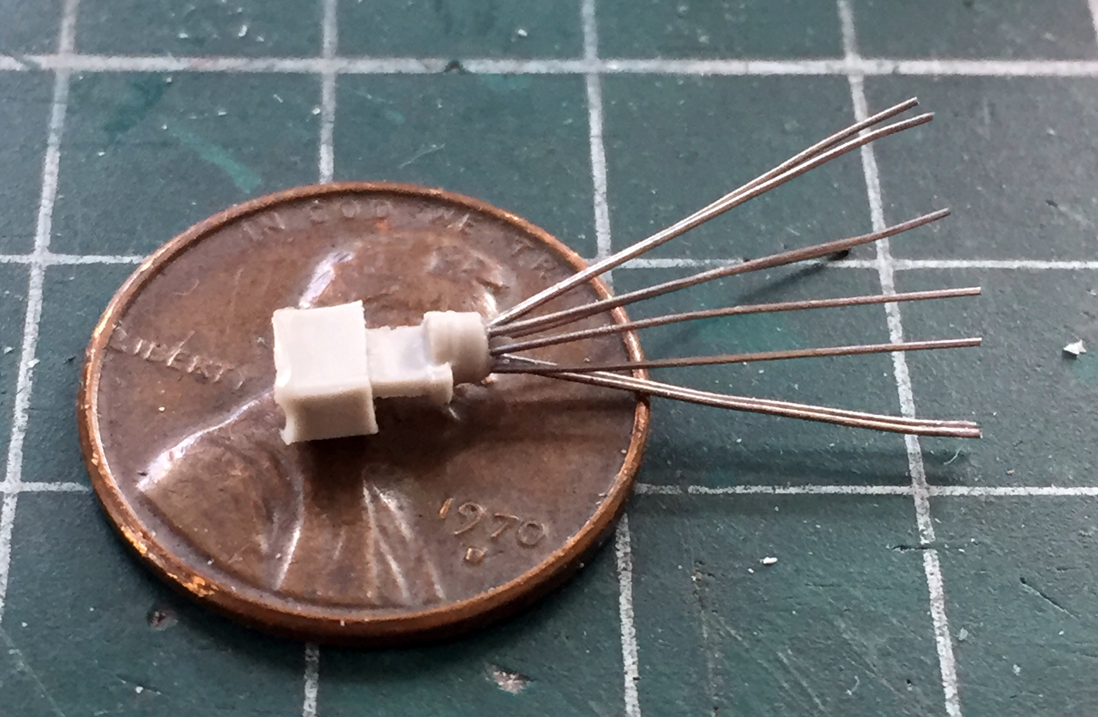
While the superglue cured a bit, I added the fuel lines to the carburetors’ float bowls:

Then I had to drill the distributor mounts to accept a pin; there’s NO WAY this solder and resin assembly could stay on with such a small surface to adhere to:
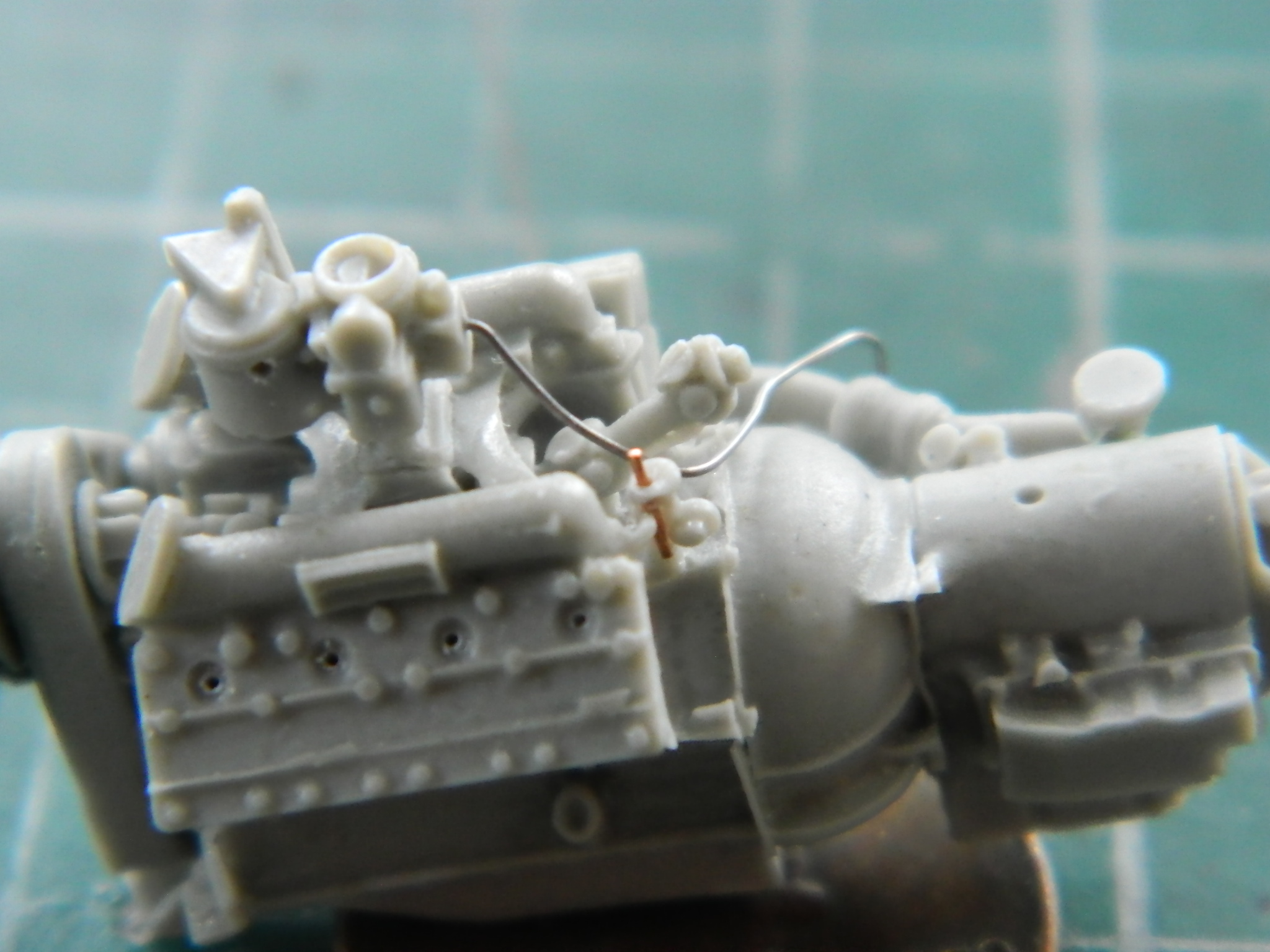
Okay…time to add the distributors:
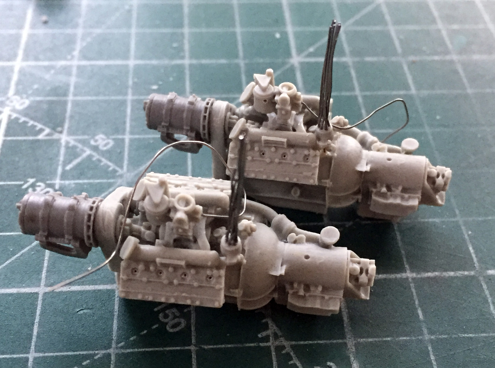
Of course, ignition wires (which I manage to get the firing order correct on) then get routed:
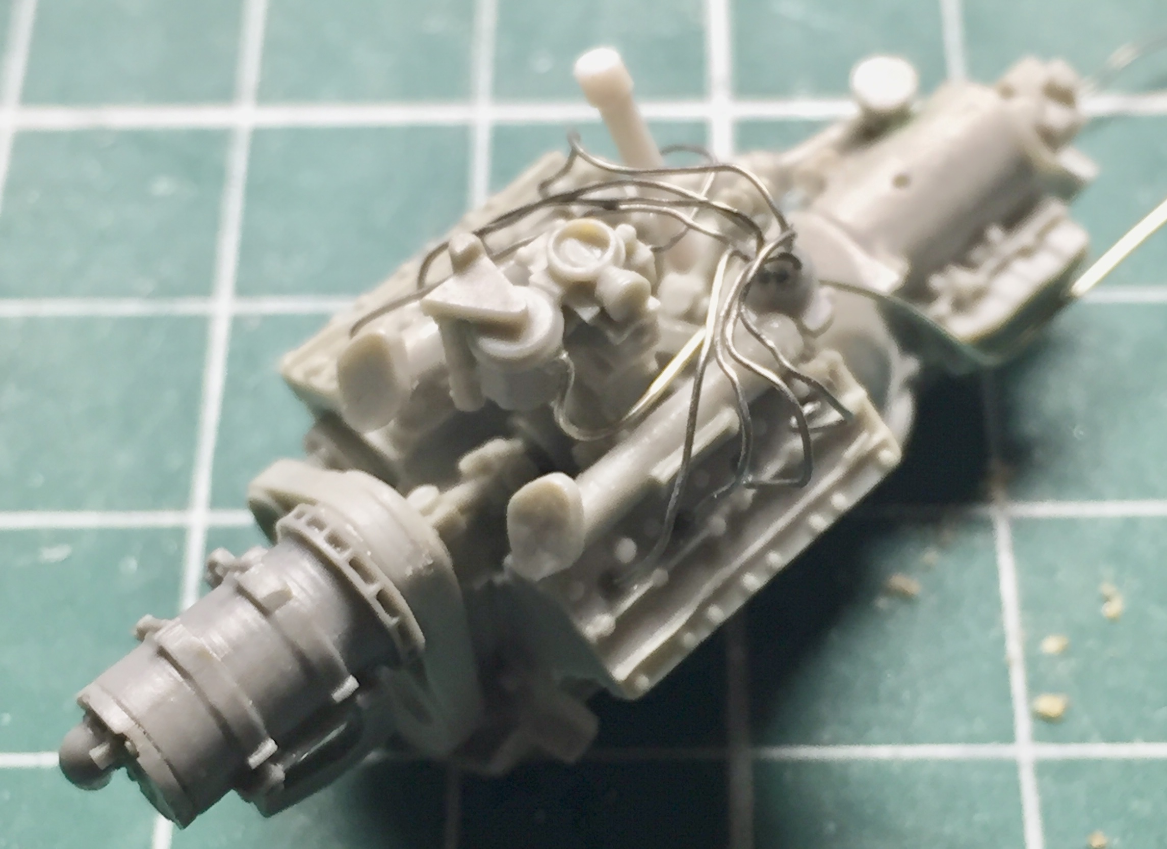
Each engine required the coil to step up the voltage for the spark(s). I used 1/16″ (.062) (1.58mm) plastic rod as the coils, drilled three holes for more .010″ (.254mm) solder, and then mounted them to their respective engines (as well as adding some lead foil for the wiring loom):
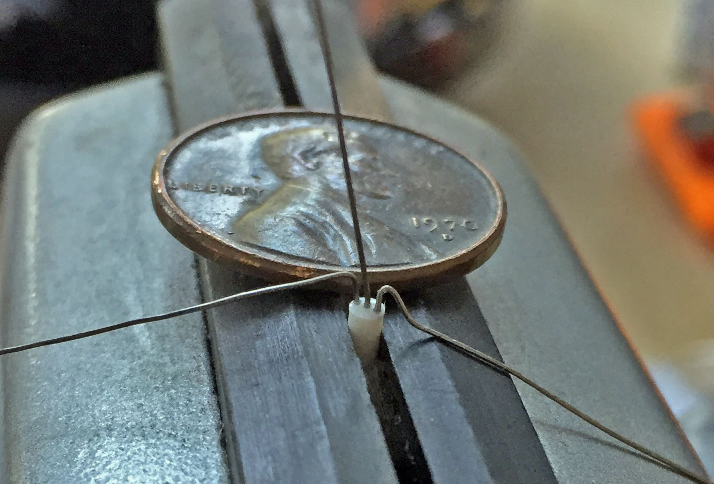
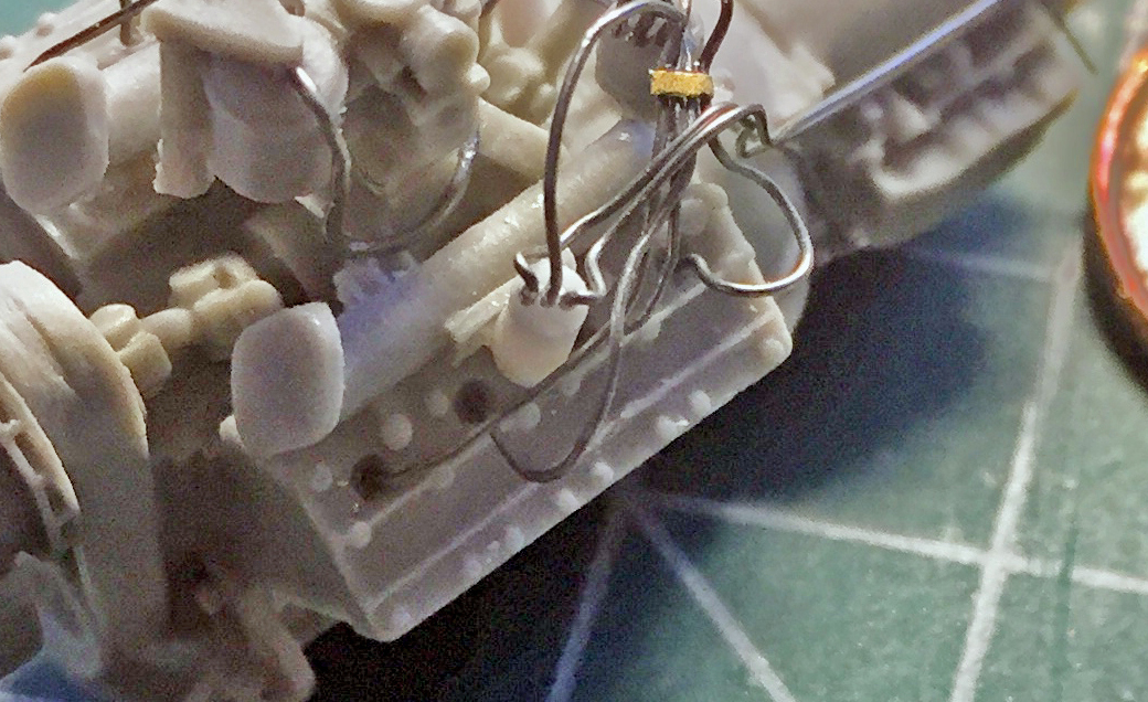
The hose/pipe arrangement needed details added as well as adding the oil filler tube and cap (the styrene rods that have a copper wire sticking out of them are part of the hoses; later those wires will be trimmed to fit):

Return lines were added to the crankcase vents, and the power leads were added to the generators:
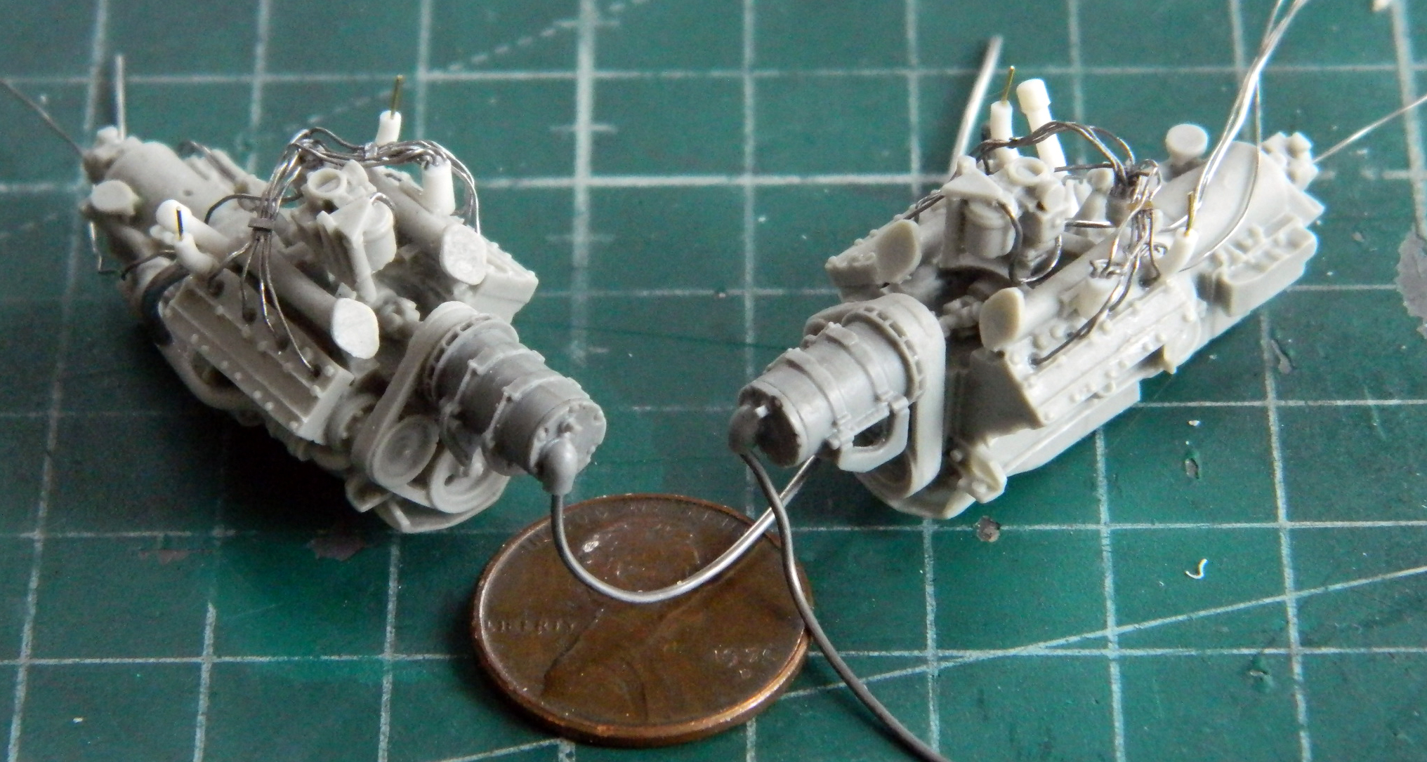
Somehow I failed to notice that one of the exhaust manifold parts had a large bubble in it. I cut the thinnest sections of the bubble away to see if I could fix it. The part as-is isn’t usable so I had nothing to lose by trying:
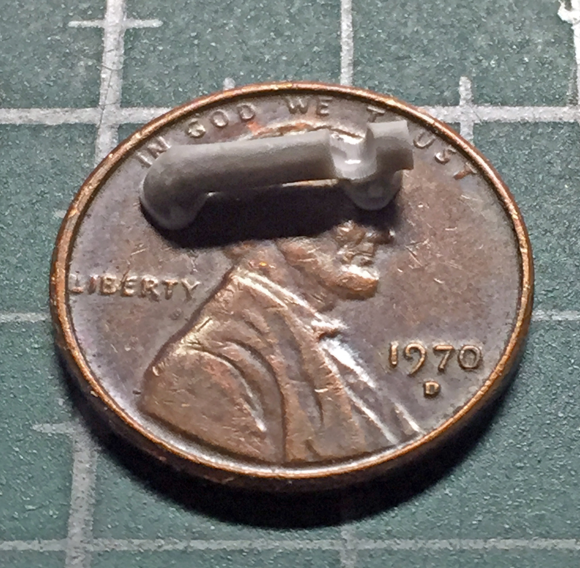
I squared the bottom of the gap and then added styrene scraps to fill and then glued the hell out of it all:
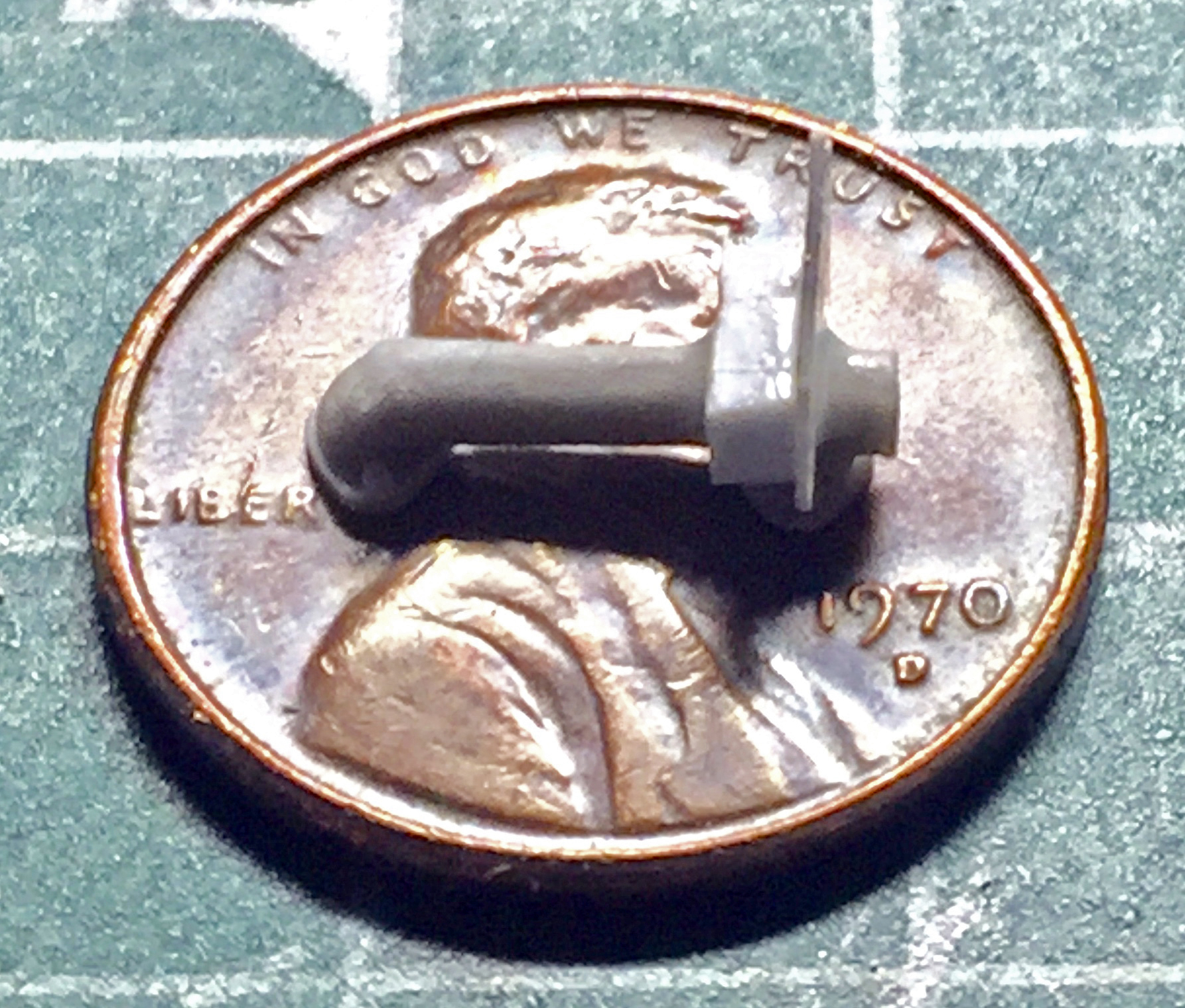
It worked:

A prominent feature on the engines is the lifting rings bolted to the top of each head. I didn’t consider using styrene at all as scale size dictates .005″ (.127mm) be used. Instead, I used .005″ (.127mm) copper shim stock. I was fortunate that the smallest punch of my punch and die set was just the size opening I needed. For ease of manipulating very small bits, I punched the holes first:

I used scissors to cut the strip from the stock and then LIGHTLY tapped the surface with a hammer to return it to a flat shape:

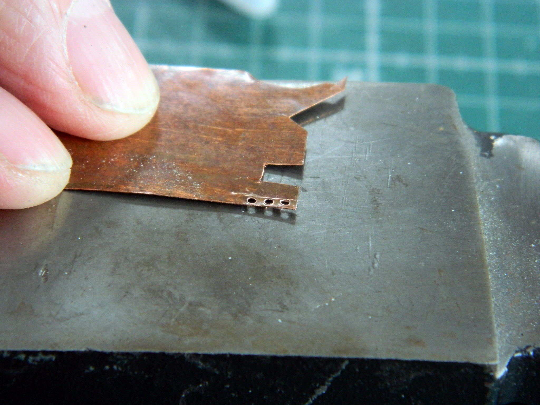
Hammering too hard will cause the soft copper to deform, so if you ever do this, softly with the hammer is required.
As it turned out, my first attempts were too small. There isn’t enough material left on one side to form the mount:
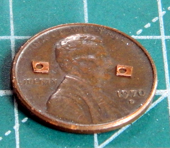
Then my brain caught up with events and informed me that IF I wanted a nice bend with a tight radius, maybe I’d better anneal the sodding copper…so I did:
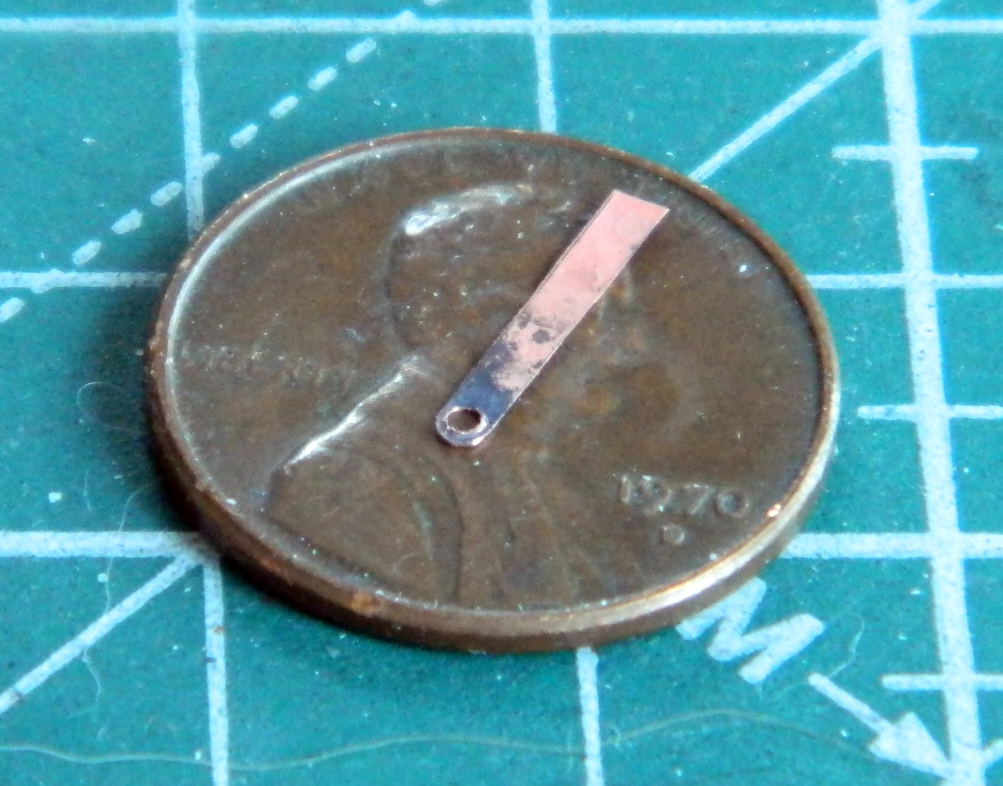
The first attempt (shown in the above photo) worked well. I needed three more. Then my pattern of the-first-is-easy-and-the-rest-anything-but-easy showed up. Again. I only needed another three, but it took me eight more sodding tries to get three that were acceptable.
::sigh::
With the lift rings finally done, all that needed to be done was to shave off the head bolts so the parts would fit flatly and then glue said parts in place:

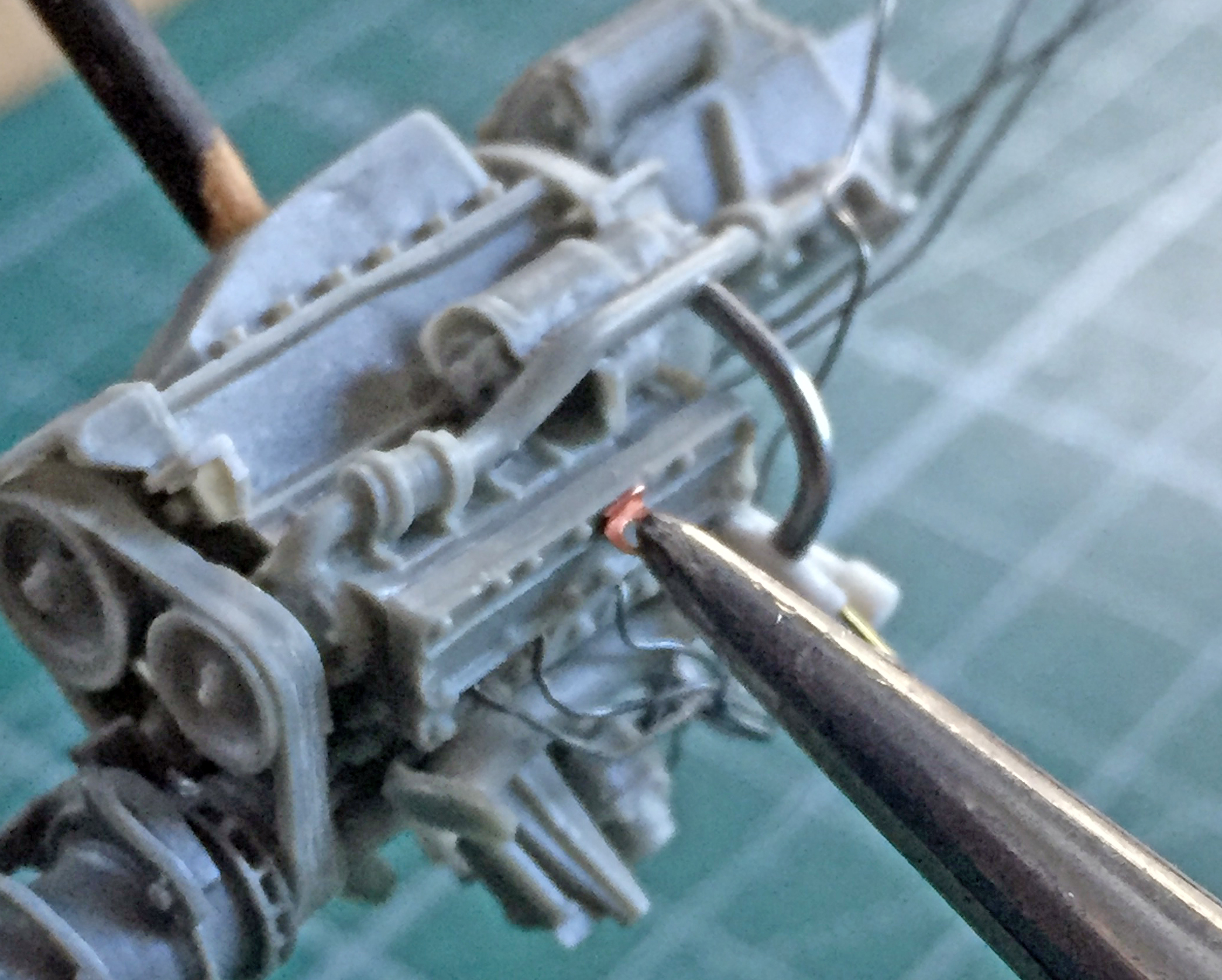
I was surprised that this part of the assembly was easy:

Whew. Tiny details. They take forever (it seems). Having done all that, the next step is to start painting while the parts and assemblies are out and accessible. I want to pre-shade the parts, assemblies, and engine bay, which meant that I had to spray them Tamiya XF-1 Flat Black:
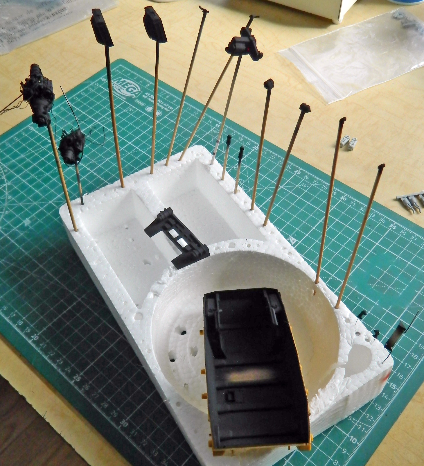
While I had the airbrush loaded with flat black, I did the inside of the lower hull:
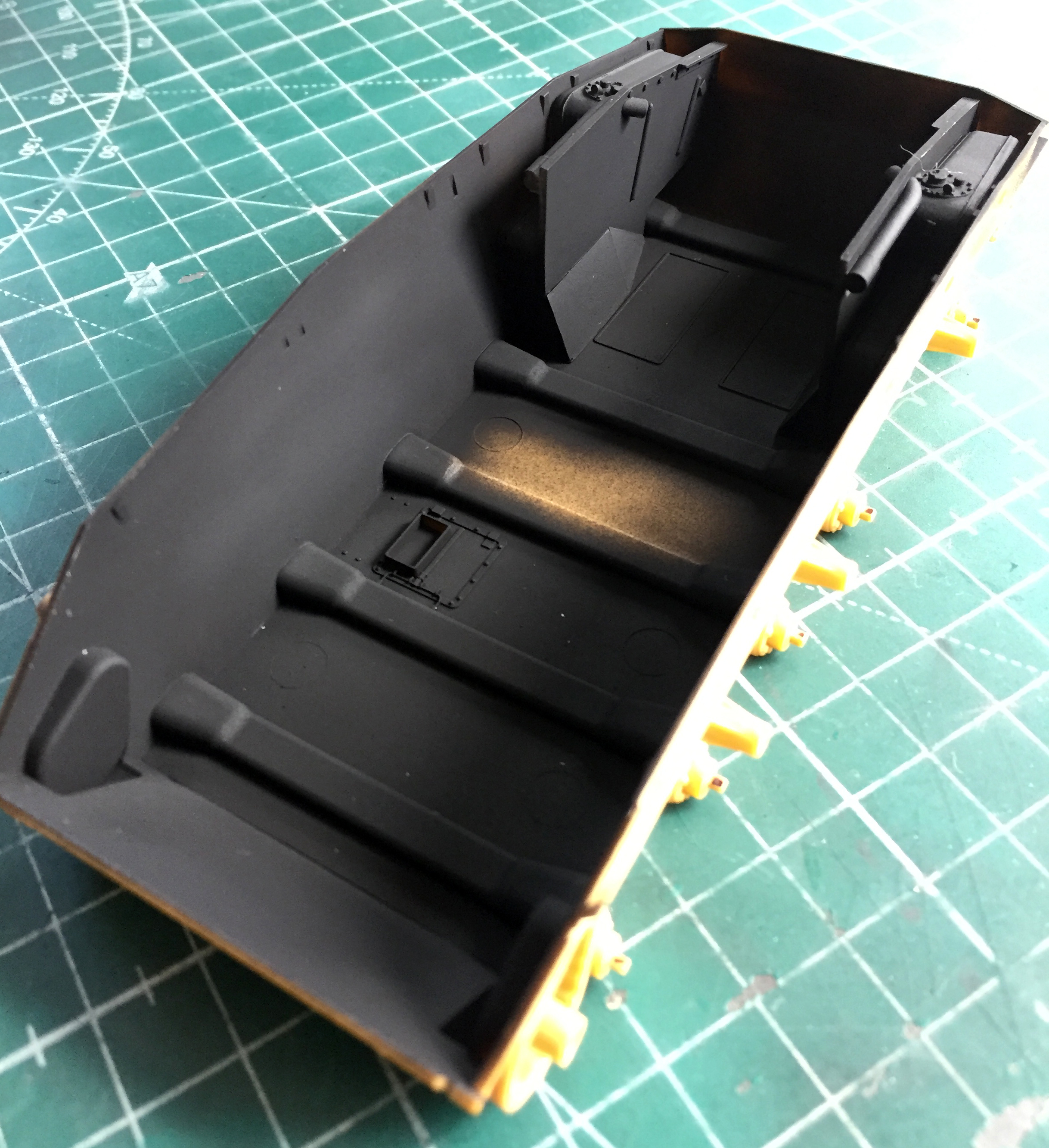
That was the easy part of painting the engines and associated parts. What comes next could be challenging…
M24 Chaffee (Bronco) 1/35 Scale Build #1 – The Parts and Hull Construction Begins
Thus far this build has been a little different. I usually sequester myself in the Mad Scientist’s Lair, and while cackling gleefully, immerse myself in my latest obsession…er…build. As those of you Out There who engage in this activity know, it’s mostly a solo activity, interrupted for bathroom breaks, refilling of the beverage of choice (with sharp things and potentially hazardous chemicals, I think alcohol consumption should not be part of that scenario…unless your local hospital ER has cute nurses and you’re more desperate than I am) (assuming that’s even possible), and sometimes sustenance to keep the vision from blurring. Okay, so maybe you don’t build that way, but I certainly do…or had until this build.
A dear friend of mine (for whom I had built the M3 Stuart) wants to see how I progress from a pile of parts and pieces through the Process of Modeling Glory (TM) and manage to end up with something that looks like [INSERT MODEL TYPE HERE]. Yes, this site is informative for her, but the process of Q&A can be rather cumbersome. So she’s been sitting next to me while I’ve been working. Being a simple-minded sod with limited multitasking capabilities, this has upset my routine of clip, scrape, diddle, and fit and then take pictures for inclusion here. So the beginning of this is a bit off from my usual form. That said…
Here are the parts:

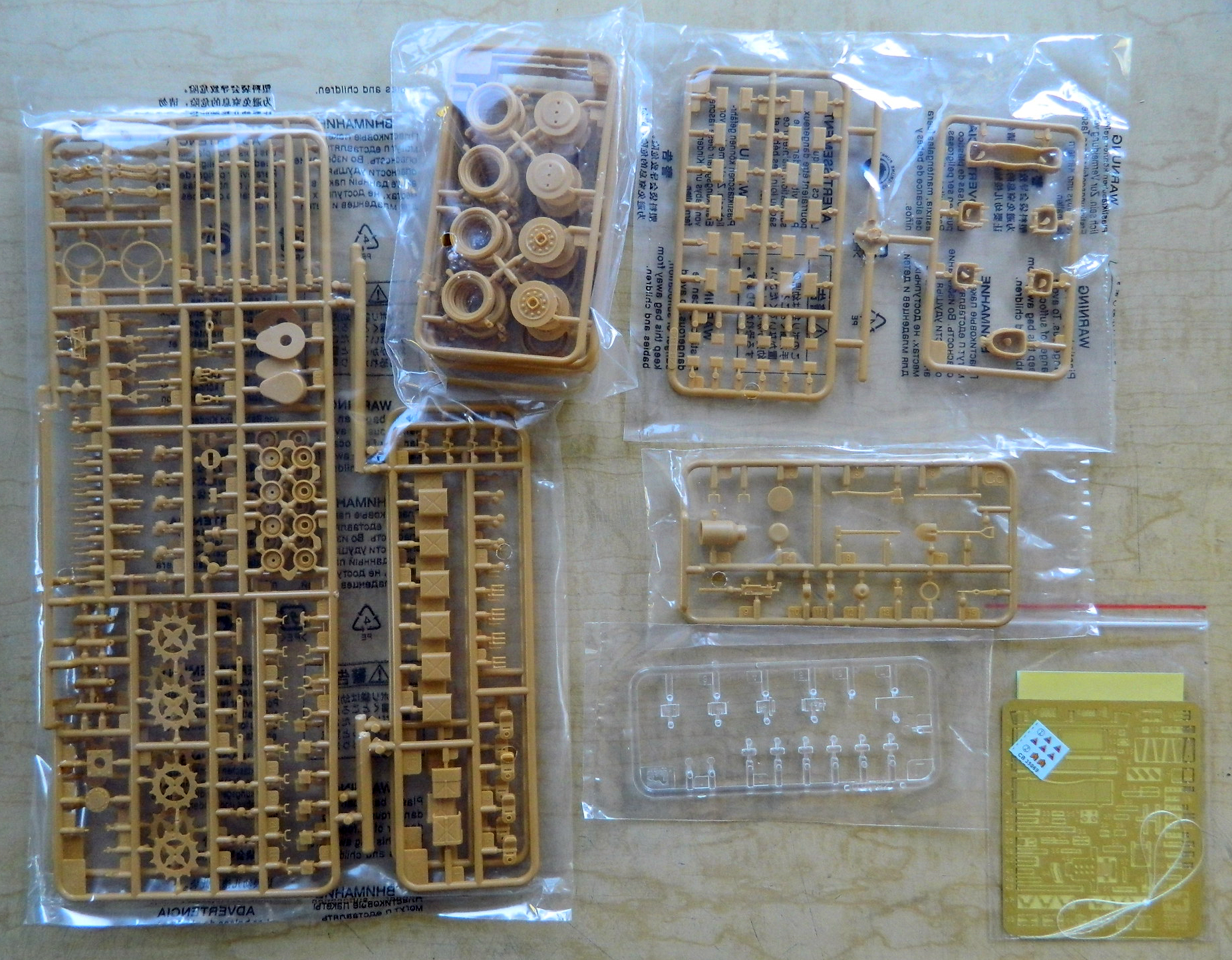
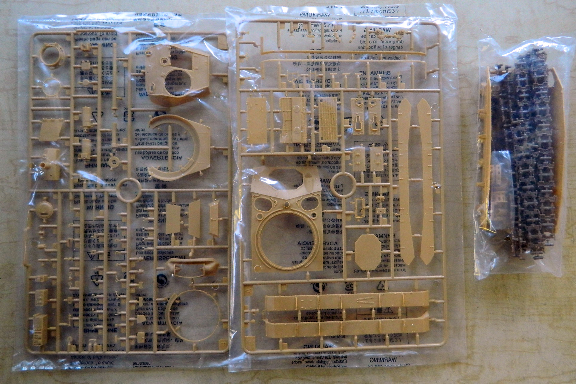
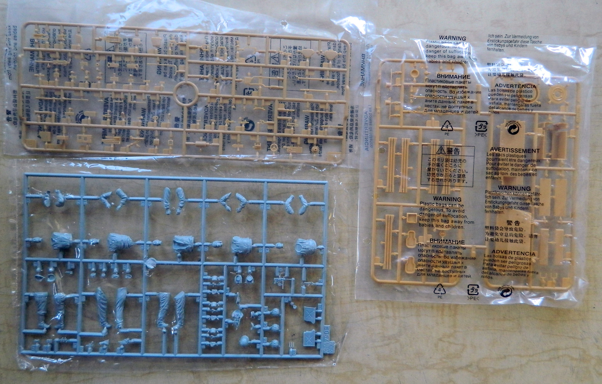
First look at the parts shows judicious use of slide molding. The main gun barrel was molded in one piece including the muzzle and rifling. I usually use metal barrels whenever possible but the kit’s plastic barrel seems good enough to use instead. Parts count is high but they all seem to be well molded without flash. I’ll see as I go along how the fitment of these parts works out.
I intend to add an engine compartment and engines as well as a full interior. Verlinden made a resin detail set for both the engine compartment and interior (interesting note – if you look at the box for the interior set, you’ll see it was made for the Tasca model…except to my limited knowledge Tasca never made one):
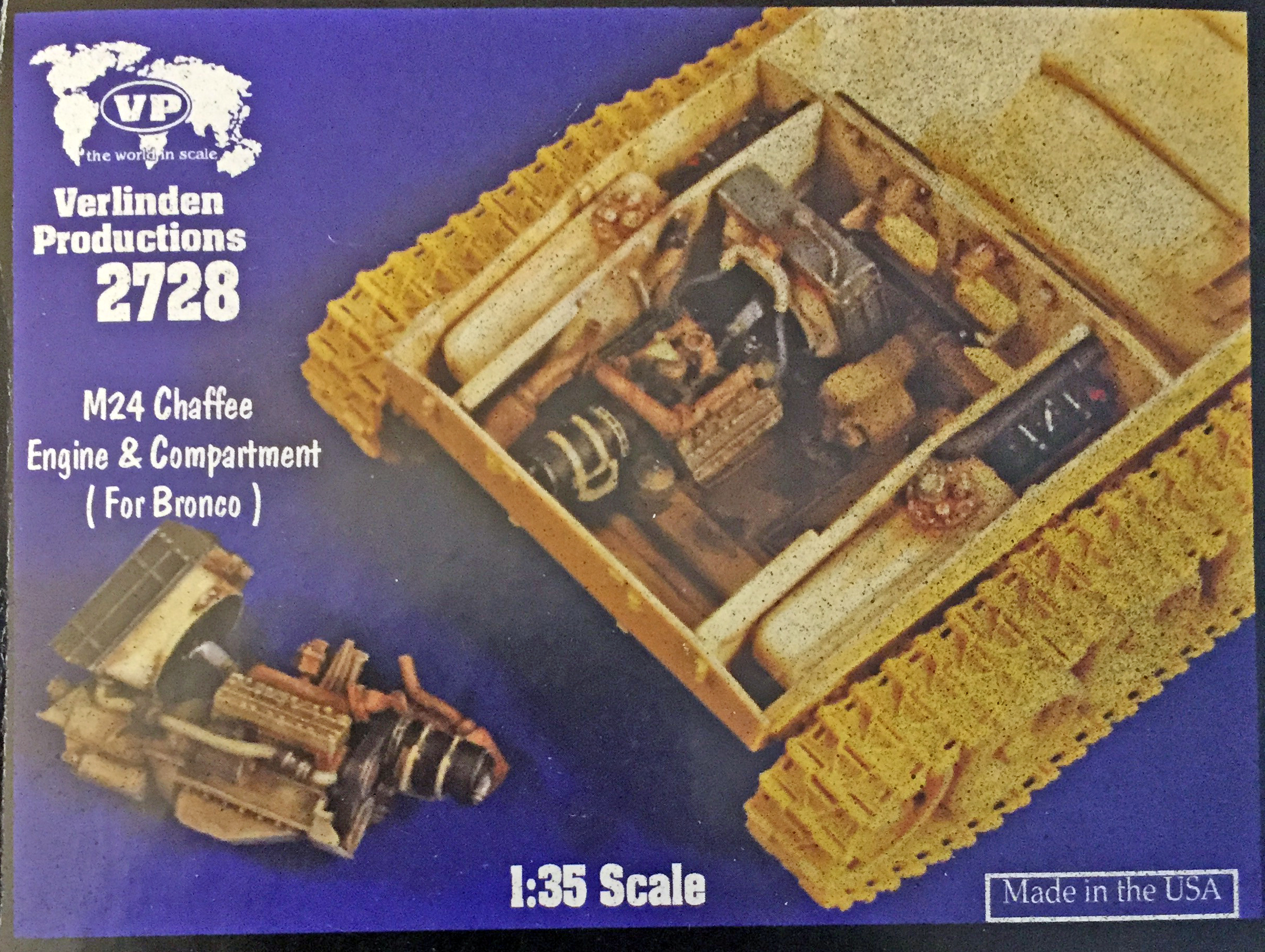

Since Verlinden parts will become more scarce, and thereby more expensive, as time passes, I’ve made a habit of copying Verlinden’s resin and using the copies instead of the actual Verlinden parts:
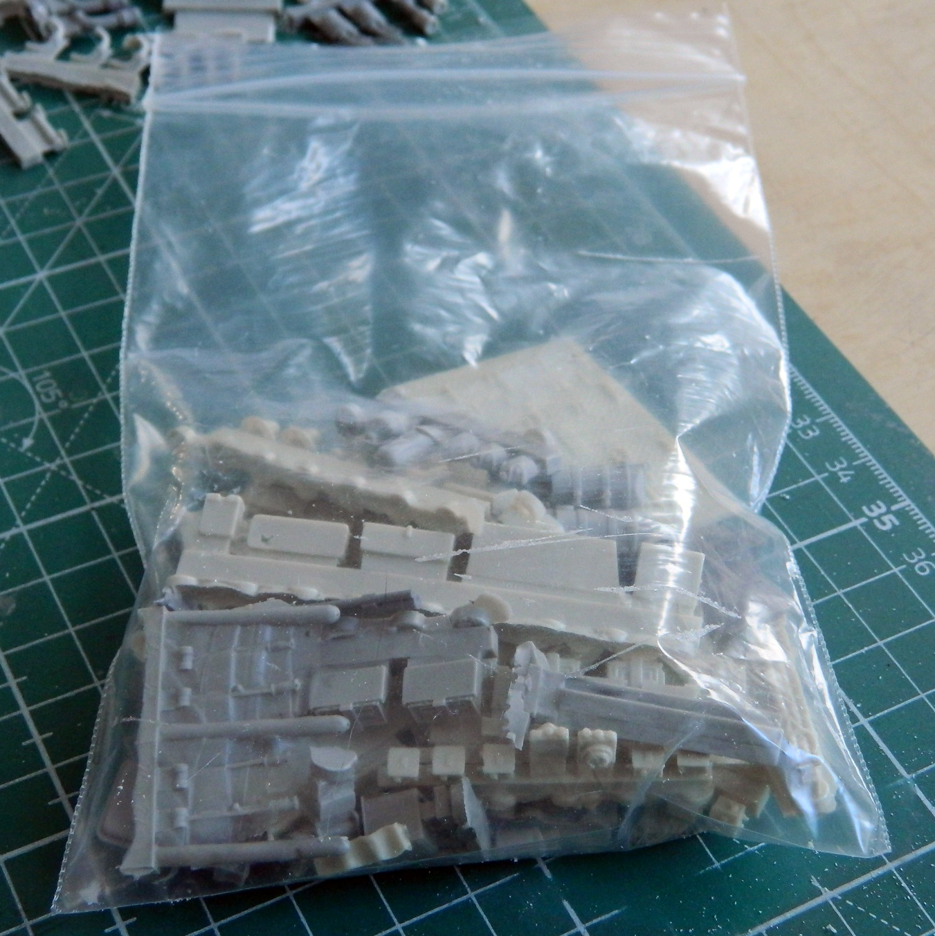
I started by constructing the lower hull. The bottom and sides are molded as one unit and show very nice surface details (including casting marks found on the actual M24). Once those were in place, I added the tow hook mounts at both ends. Since this is supposed to be an early production vehicle, the mounts for the flotation devices shouldn’t be there. The mounting pads aren’t on the front lower hull but there are mounting holes for the rear mounting pads that the kit supplied. Oops. Not supposed to be there. I filled the mounting holes with stretched sprue. Since both the interiors of the hull ends will be seen later on, I had to fill the places on the inside where the tow hook mounts showed through:
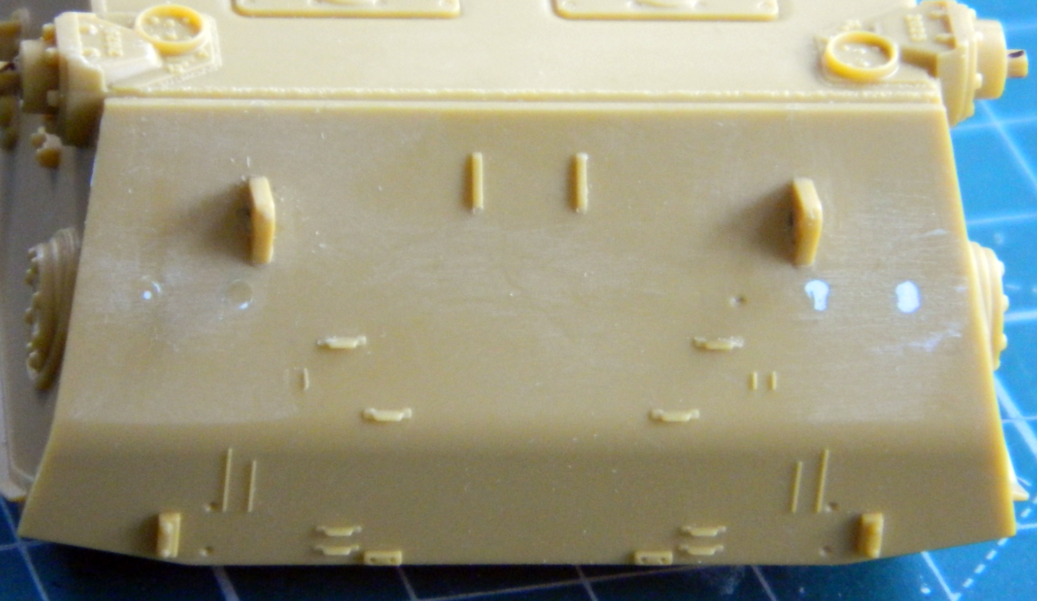

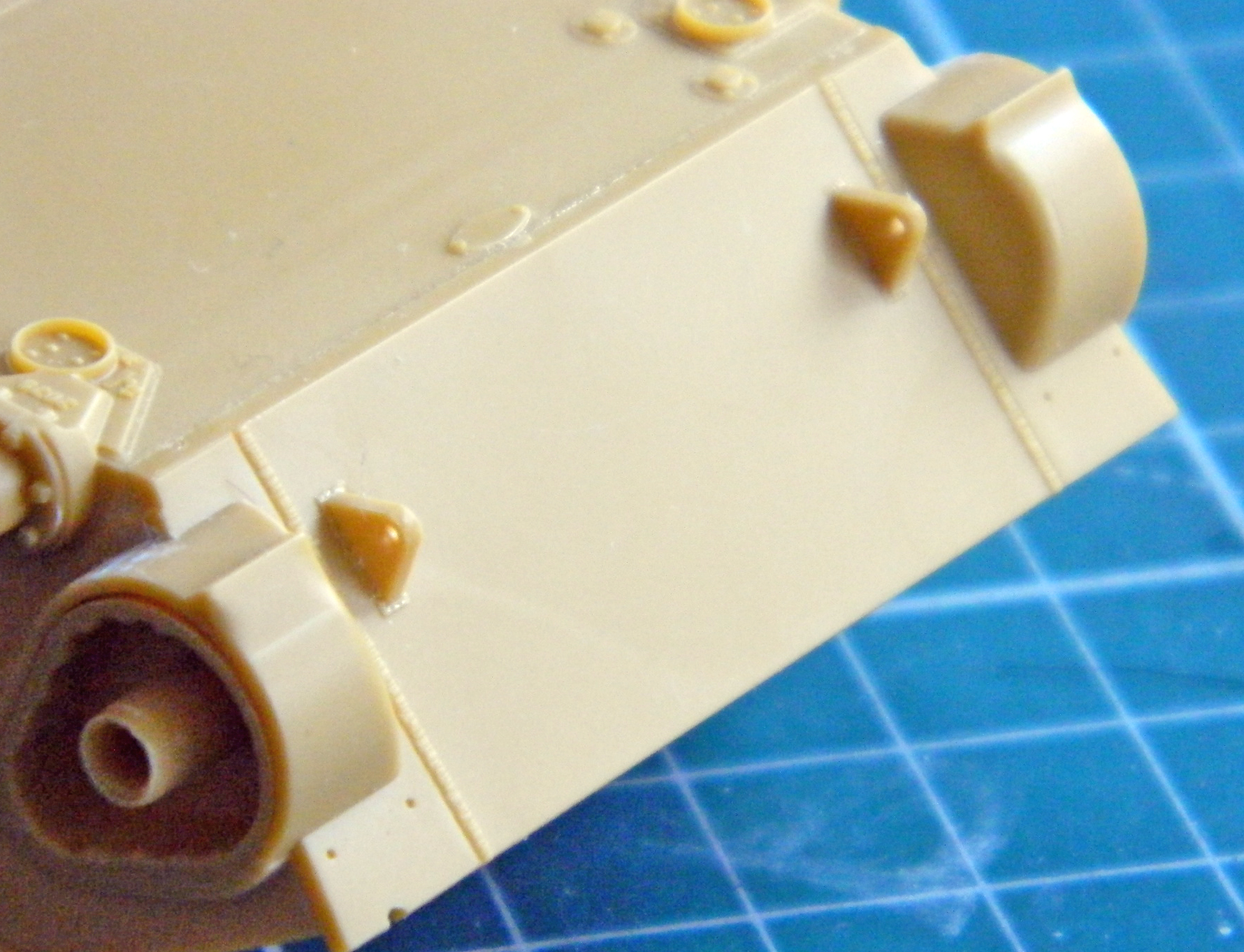
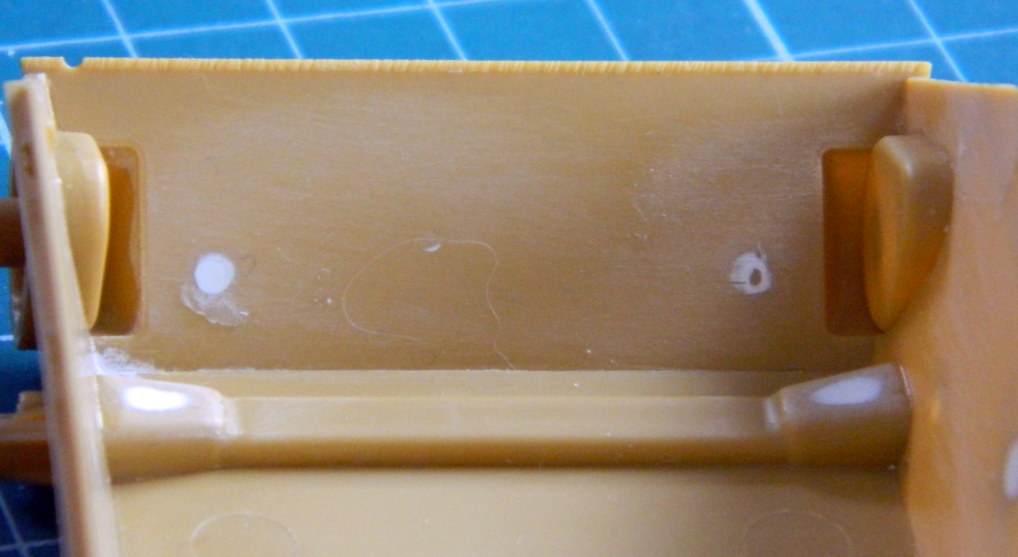
The first observation I made after mounting the front and rear lower hull is that the upper front hull doesn’t fit well with the lower (check the lower right of the next photo). Not a good start, Bronco:
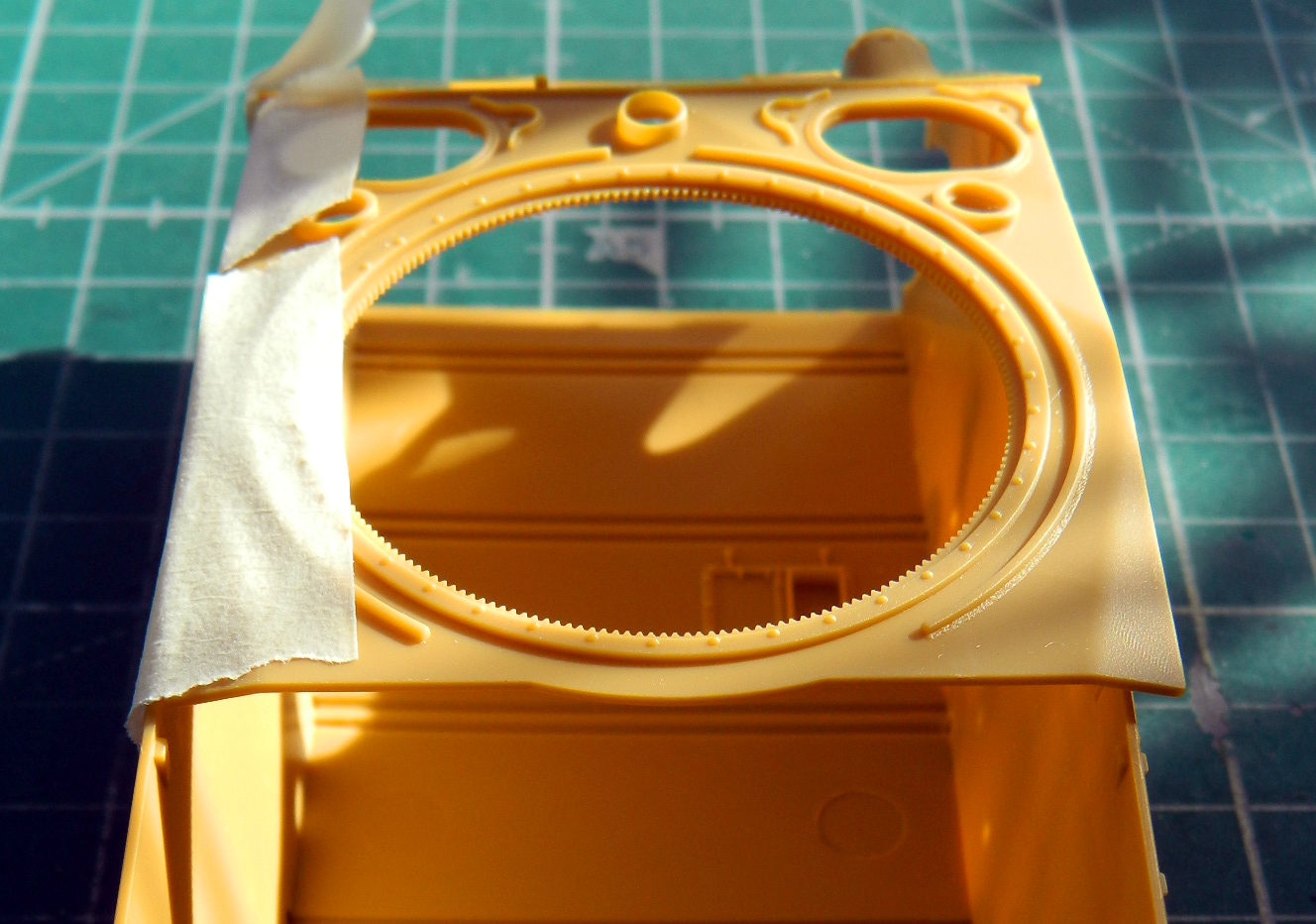
I pressed the sides out and settled the upper hull where it’s supposed to go, taped both sides to the upper hull, and immersed the whole thing into a sink of HOT water:
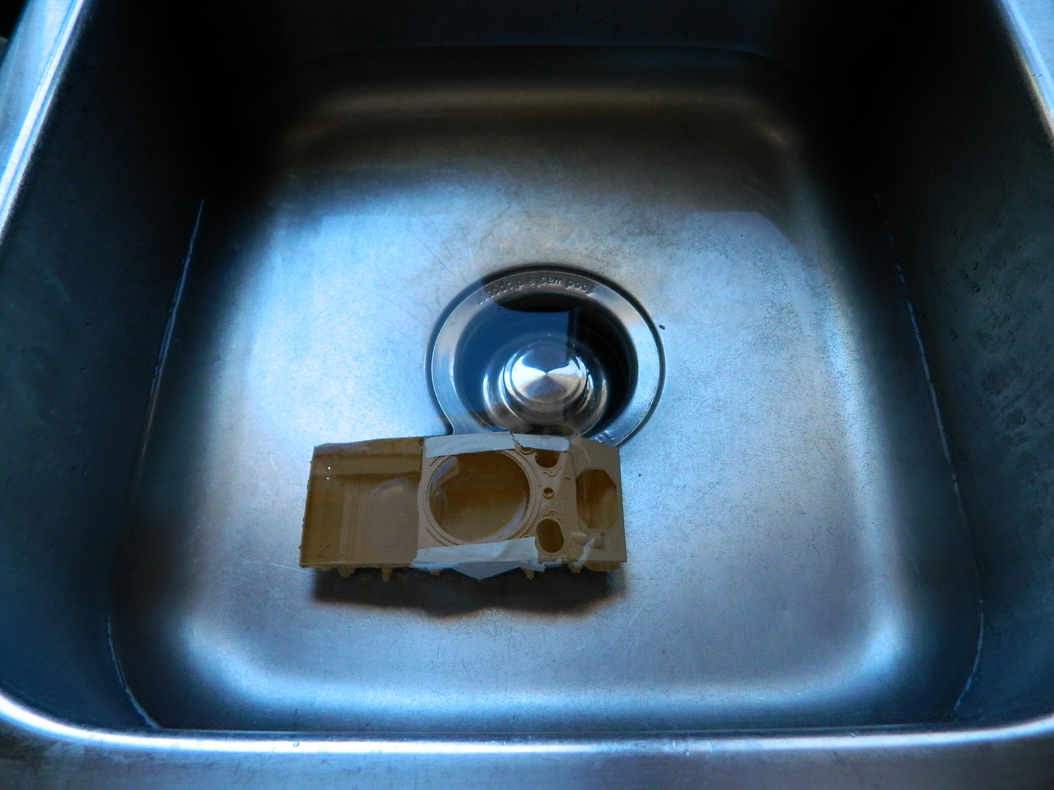
The result was better; about 75% of the misalignment was fixed. The remaining 25% will be dealt with as I add interior parts, particularly the bulkhead between engine and crew compartments.
There are things about this kit I find somewhat gimmicky. There is a spring inside the main gun’s receiver that allows the barrel to “recoil.” Why? And the suspension is clearly designed to be “workable.” It has separate torsion bars for each set of sprung road wheels. Again…why? I suppose having the suspension posable could make posing the tank on an uneven surfaced diorama possible, but posable is different from workable in my mind, leading again to the question of why. The days of models with “workable features” are over. I’m building a model, not a toy that I’m going to play with until it breaks. I added the torsion bar housings and torsion bars as well as the final drive covers that show inside the hull:

There aren’t many sinkholes in the parts, but I found that all the torsion bar housings had them on the flared ends:
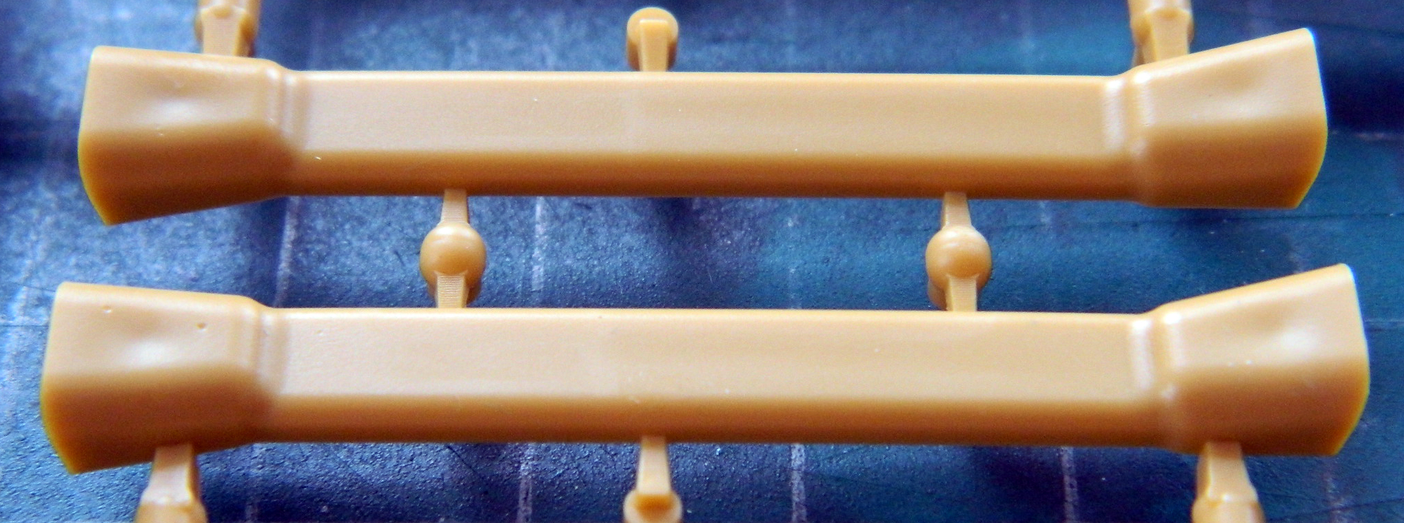
Not a big deal, just add putty:
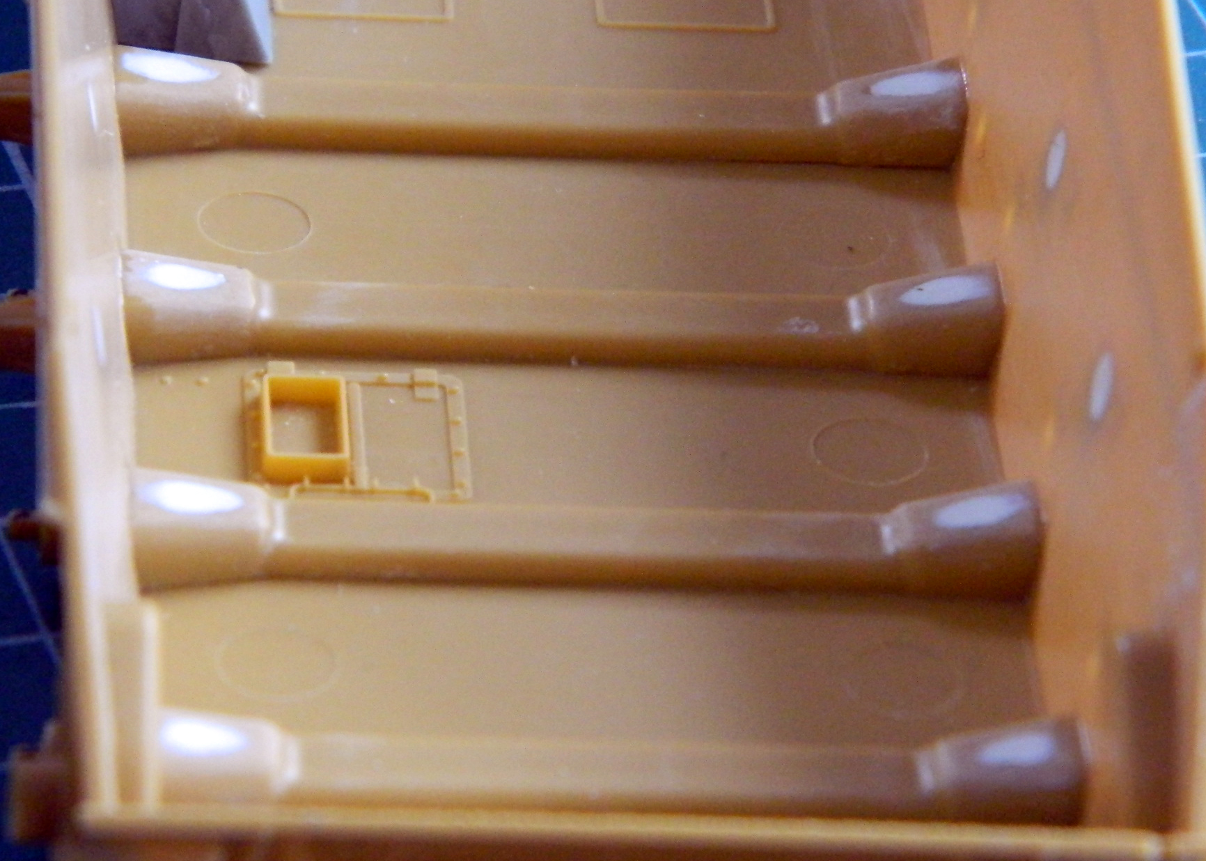
Time to start populating the hull interior. Using an AM set will frequently result in me sitting there wondering where to start. There’s a lot of parts that have to fit inside this thing and not many definitive places for me to start at. In this case, though, there are two places that the parts can only go into the hull one way; the differential in the front and the sides of the engine compartment in the rear. I decided to start at the rear and installed the fuel tanks/compartment walls (molded as one piece):

With both fuel tanks/compartment walls in place, that gave me the position for the bulkhead. In this photo, the bulkhead is just taped into position to check how it affects its position relative to the sides of the hull, which according to the upper hull is too narrow:
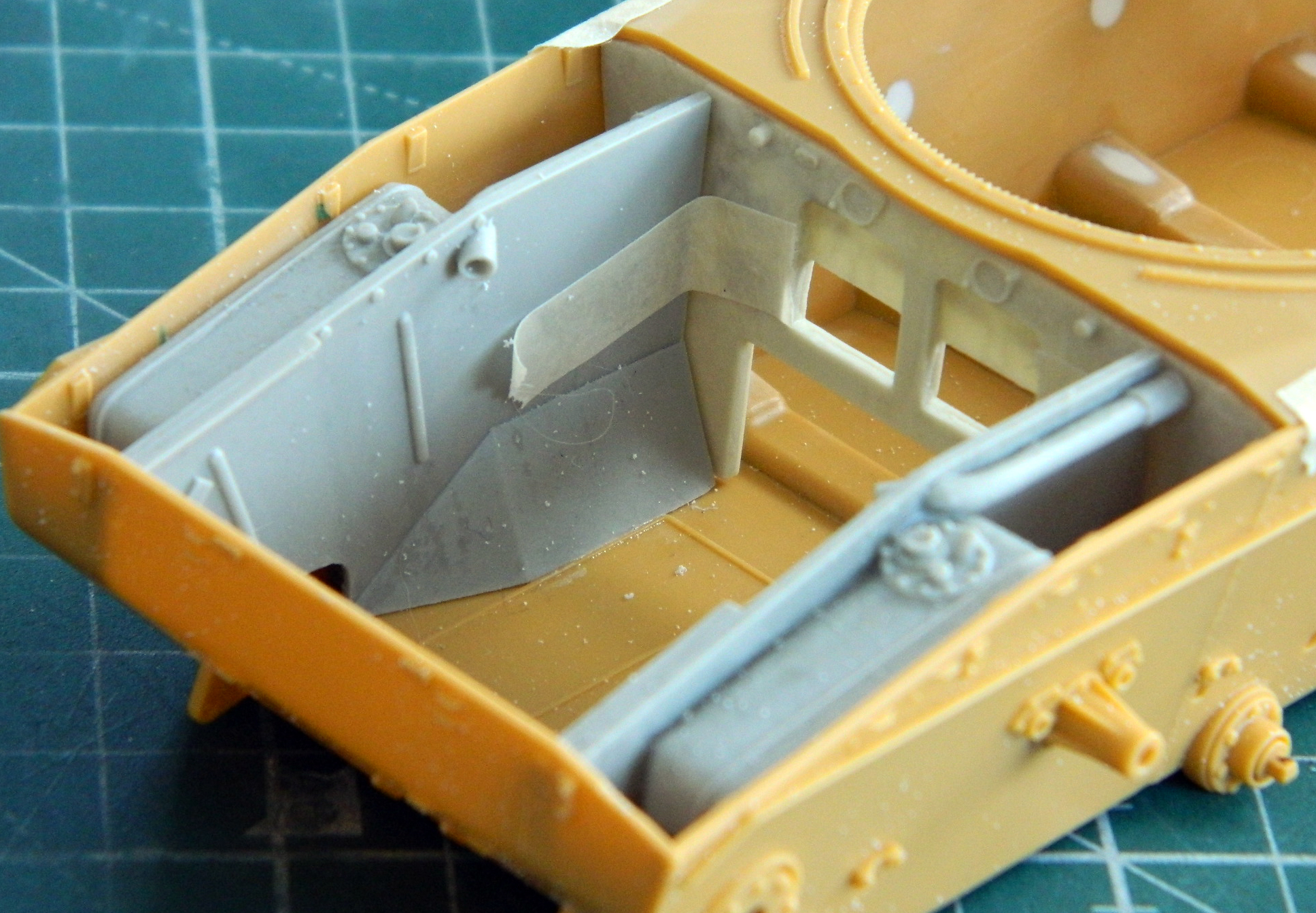
There are gaps on both sides and the top. I’ll add plastic strips to fix them later. Before I do that, there are more parts to add to the bulkhead which will be much easier to do with that part free.
Since I now have a rudimentary engine compartment, it was time to start assembling the engines:
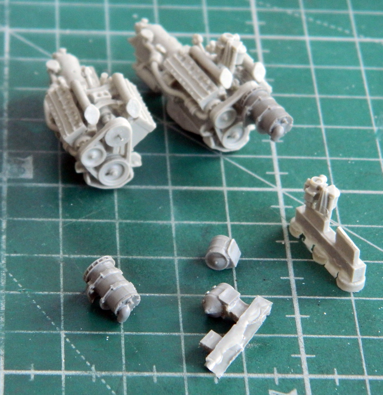
Here are more parts for the engine compartment that I will need to find permanent homes for in there:
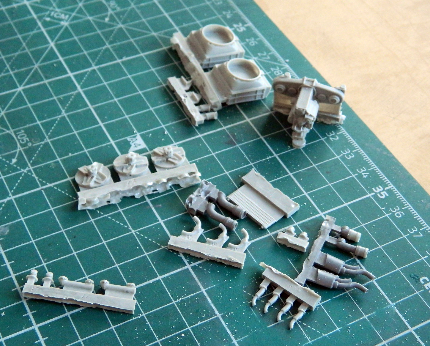
This kit contains a fret of PE parts. Among those parts are the casting marks for the lower front hull. They’re VERY TINY and so far I’ve managed not to launch any of them into oblivion. One side is done. Oh…and on that note, Bronco failed to photo-etch one of the “1” numerals…so it’s missing from the left side (there’s supposed to be a “10” next to the star, not a “0”):

I also started assembling some of the suspension components. Each of these return rollers is comprised of four parts and the bolts that hold the shock absorbers in place are tiny and INCREDIBLY fragile:
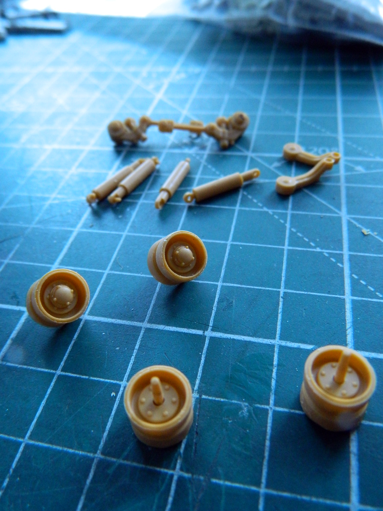
Once I started the build, I assembled the tracks, ten shoes a day while I sat at the workbench in the morning, having my tea and waiting for my dried up neurotransmitters to hydrate and begin transmitting sparks again:
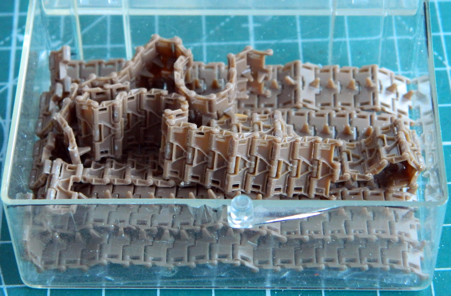
The tracks are finely molded. Perhaps they’re too finely molded. I managed to snap two into unsuitability while assembling them. Fortunately while perusing the ‘Net, I found a discounted set of metal T72 tracks that I will try using instead…which means I get to do this tedious task again.
M24 Chaffee (Bronco) an Overview
Since the US deployment of light tanks in WWII, the M3 variants and the M5 variants, crews wanted something that offered more protection and had a larger gun. Being that both the M3 and M5 were essentially developed designs of a mid 30’s design, neither the M3 nor M5 could mount a larger gun. And seeing as the light tank doctrine had to be modified to fit the tanks’ capabilities, such as they were (or perhaps less inaccurately, deal with their shortcomings), the North African campaigns showed that any tank that relied on a 37mm main for defense would lose and that light tanks could not effectively be used in any other role than scouting. One “funny” person suggested that the only effective use of a light tank was to discover where anti-tank guns were situated, which, though I suppose offered a tactical utility, was rather rough on the crews.
For reasons I certainly don’t understand, the US Armored Force remained convinced that light tanks could be useful. (In addition to thin armor and a tiny gun, the armor of M3s and M5s wasn’t proof against any of the anti-tank guns.) So the M3 morphed into the M5 but shared with the M3 a high profile. A thinly armored tank with a high profile was easy to see and knock out. The M5, however, didn’t use a radial engine, which is why the M3 light tank, the M3 medium tank, and the M4s all shared the same flaw of being tall tanks. Instead of designing a new hull, the M5 used a variation of the M3’s basic hull design, even though the M5 used a pair of Cadillac V8s instead of a tall radial engine and could have benefited from a new hull design with a lower profile; they wouldn’t have had any greater firepower or thicker armor, at least they wouldn’t have been as tall.
Finally realizing that the M3 and any development of the M3’s basic hull design were tactically ill-advised, a new requirement was drawn up (1943, I believe). The requirement specified that the new light tank should not exceed 20 tons in weight and be capable of mounting a 75mm gun. The US Armored Force also decided that the four-man crew of existing light tanks was insufficient to combat efficiency and instead stipulated that a five-man crew was required, adding the additional crewmember to the turret crew.
With the pressures generated by an on-going war, as much of the M5 that could be used would be incorporated into the new design. The Armored Force remained convinced that a light tank would be useful for reconnaissance.
Cadillac had been working on an enlarged hull design intended for self-propelled artillery and incorporating as many of the M5A1 components as possible. Chrysler (then a part of GM) used the Cadillac-designed hull and offered a new design, the T24. It used a modified configuration of the M5A1’s Cadillac engines feeding a transfer case to combine the output of two engines into one drive shaft as the M5A1 had, feeding the M5A1’s transmission in the nose (the major difference from the M5A1 was that the new design used a manual transfer case instead of the M5A1’s automatic transfer case which turned out to have problems) as well as larger radiators for improved engine cooling. The original design required a larger turret ring to handle the 75mm gun and rather than make the body of the tank wider, instead the design employed sides that sloped outward at the top (and having an angle to the face of the side armor offered a slight improvement over a vertical side without increasing the vehicles overall weight of additional armor). The Armored Force also wanted wider tracks for decreased ground pressure (lessening the likelihood of the new tank becoming mired in muddy conditions) and designers moved away from the volute-style suspension of the 30s (which had become about as advanced as that archaic design could be) to the more modern torsion bar suspension used in more modern tanks of the Germans and Russians (torsion bar suspensions are still in use on tanks today). As a result, the track used on the M24 during WWII was the T72, a single-pin, center guide, metal shoe, track with a width of 16″. (Post-war track was changed to the rubber chevron, double-pin, T85E1 shoe with a width of 14″. Rubber tracks were easier on paved roads, a consideration of Occupation Forces in Japan.)
Even with the larger turret ring, using the 75mm of the M4 Sherman didn’t work as intended. However, a light-weight 75mm, the T13E1, with a different recuperator and shorter stroke design to absorb the recoil of the 75mm had been developed for the B25G and H models. Though the light-weight T13E1 of the B25 shot the same round as the 75mm of the Sherman, the barrel was shorter which resulted in an even lower velocity of the round, already considered a low-velocity shot. The initial gun, the T13E1, was taken from stores already produced for the B25 ground attack variants. Later on, a purpose-built gun for the M24 was produced and designated as the M5. The only way to tell the T13E1 from the M5 tube was that the former had a pair of rings around the barrel sleeve to engage the recoil mechanism of the B25 installation.
Initial trials of the new T24 went well and the Armored Force requested various changes in the prototypes, and once those changes were instituted, the T24 was standardized as the M24 in July 1944 and production began at the end of the M5 production in May 1944. Cadillac produced 3,592 M24s and Massey-Harris started production in July 1944 and produced 1,139. Total production was 4,731.
The M24’s combat debut was at Bastogne during the winter of 1944 (aka, the Battle of the Bulge) when a pair of M24s intended for 744th and 759th Tank Battalions were intercepted by the 740th Tank Battalion that had arrived in-theatre without any tanks. They were first deployed in Company D at Remouchamps on December 20, 1944, and saw action in the fighting for Stoumont and La Gleize.
The M24 was a profound improvement over the M5 and M5A1s that they replaced and the crews liked them. From what I can tell, the major complaint of the new tank (and probably every tank fielded) was its limited ammunition loadout (not at all uncommon for an M24 crew to go through the standard ammo load twice during an engagement…talk about awkward!). Mobility was praised as was its ability to get into (and most importantly, out of) places neither the M4 because of its size, and the M5 series because of their higher ground pressure, could. The first two tanks were pressed into service without the crews being trained in them. However, due to the mechanical similarities of the M5 series and the similar gun of the M4 75mm, they seemed to have no problem putting the new tank into service.
The M24 was thought to be the tank to use in the invasion of Japan because of its lighter weight (though a bit over the 20 tons initially specified) than the M4 series in consideration of the bridges found in Japan. Tests were conducted to see if the tank could be made to float, thereby decreasing the need for LSTs, and the flotation devices (including 28.5″ grousers bolted to the T72 track to increase propulsion in the water) developed for the M18 were successfully (all terms being relative) adapted and tested between late 1944 and early 1945.
The Enola Gay and Bock’s Car changed all that and the program was dropped. However, the mounting pads for the flotation devices on the nose and rear of the tank had been incorporated into the production lines and never dropped. I found one reference, “M24 Chaffee Walk Around, by David Doyle, ISBN 978-0-89747-592-1 that gives production numbers when the flotation mounts were added to the hull, the only problem being that different production numbers for the start of those additions. On page 12, he states that Cadillac-built M24s started adding the mounts at #1101, and then on the next page, 13, he states that Cadillac started adding the mounts at #713. So that is hardly informative! Either way, early production M24s, therefore, had the rings around the barrel of the T13E1 gun and no flotation mounts whereas late production M24s didn’t have rings around the barrel and had the float mounts. Some of the early M24s also had U-shaped stirrups added to the lower nose and rear plate and some did not. None of the M24s with the flotation mounts show these stirrups.
As mentioned earlier, M24s were used by US Occupation Forces in Japan (my father crewed, and later commanded one, and finally became a platoon commander).
Then Korea erupted.
The T34/85s that the North Koreas brought with them had been good enough to stop the Wehrmacht’s Panzer IVs, Panthers, and even Tigers. Encountering M24 light tanks, the only tanks we had on-hand that were close enough to throw at the North Korean invaders, posed no problem for the T34/85 crews (even as poorly trained as they were…which would significantly change when M4A3E8s and M26s arrived later). (The last tank my father had shot out from under him he was the only survivor of the experience, largely because he was standing in the open commander’s hatch when his tank was hit and destroyed. The explosion blew him clear of the flaming wreck.)
Post-WWII, France was the largest recipient of M24s and used them in Indo-China (Vietnam). The Vietnamese army also used them (too frequently in coups, which earned the M24 the nickname of “ballot boxes).
During its initial uses in WWII, the M24 was considered by some as America’s best tank (as if that determination can be made!). Side-stepping that debate, it was certainly the most advanced armor of the European Theater that the US fielded until the arrival of the M26.

M24 of the 18th Cavalry Squadron at Petit-Thier, Belgium February 1945
M3 Stuart (Academy) After-action Report

Total time building 270.5 hours.
Begin date March 21, 2019; end date* December 30, 2019. * Six-month hiatus during the build.
Vendors:
Academy
Kit #13269 – M3A1 Stuart
Tamiya
Kit #3542 – Stuart U.S. Light Tank M3
Kit #35360 – M3 Stuart Late Production
Kit #35250 – M4A3 Sherman
Tiger Model Designs (TMD)
Set #35-1039 M3 USMC Interior
Set #35-70023 – Tie-Down Cleats, Small
Verlinden
M3 details #1647 (just the vision block covers for the commander’s cupola)
AFV
Set #AF35056 U.S. Light Tank M3/M5/M8 Stuart Vertical Volute Spring Suspension
Archer Transfers
Set #AR35209B – Gauges and Interior Stencils
Set #AR88001 – Resin Rivets, Various Scales
M&Models
Set #35B24 (RB Models) – Turned Aluminum 37mm Barrel
Set #GM-34-004 – .30 Caliber Barrels (s), turned brass
The Scenic Factory Mud
Set #MK-02 – Ardennes Forest Kit “Dry”
Lots of solder, wire, lead foil, paint, and sprue
My opinion
Academy has a reputation for being soft on details and this kit would support that viewpoint. The kit is labeled as an M3A1 which it’s not. Depending on how you look at it, it’s either an M3 with an M3A1 interior (yes…the two interiors really are that different), or it’s an M3A1 with an M3 hull. So that’s the starting point.
The suspension has earned its reputation as a cock-up. It appears as if the engineers got the ground clearance incorrect with it and rather than start over and get it correct, they “drooped” the roadwheel arms much too far. If you’re concerned with accuracy, scrap the kit’s suspension and get the AFV suspension kit, which is MUCH better. I’d suggest getting that set if you’re doing any Academy M3 variant. The Academy drive cover (the lower nose) isn’t very accurate and the AFV drive cover is…and it’s included with the suspension. Yes…you’ll have to cut the Academy part off and graft on the AFV part. It’s worth it. If you decide to go with the AFV suspension, you’ll either have to use the AFV drive sprocket with their tracks or if you use the Academy tracks, you’ll have to use the Academy drive sprocket. The tracks are sufficiently different that you won’t be able to use the AFV drive sprockets with the Academy track and vice versa. (And each drive sprocket has inaccuracies.)
I was surprised (and somewhat disappointed) by Tiger Model Designs. Their Marine interior for the M3 didn’t really fit. It appeared that I needed more length in the lower hull to fit all the stuff that was supposed to go into the crew compartment, but when I extended the compartment, the driveshaft cover turned up too short (requiring me to lengthen it). I don’t know how that happened; I’m hoping that it was an as yet undiscovered mistake on my part as I really like the guy who runs TMD. And to be transparent, no…I didn’t complain or tell him about it (I think he’d needlessly beat himself up over it and I like the selection he has and the quality of his castings). I made the modifications required to get what I needed and just went on with things. So if you decide to use the Marine M3 interior set, be aware you may have fit problems.
This was my first attempt at adding a light to a model. It was easy, limited more by my ignorance than any other factor, and I suspect I’ll be adding more LEDs in future builds. (And I was proud of myself for figuring out what to do with the battery and switch.)
I knew at the outset that I would be doing a tiny bit of kit-bashing as I wanted to backdate Academy’s turret from the kit-supplied D58101 turret to the more correct (for an earlier M3, not an M3A1) D39273 turret. The ancient Tamiya M3 #3542 has the rounded commander’s cupola that I wanted and that was my source for it. I didn’t expect to do as much kit-bashing as I ended up doing. Tamiya cupola, AFV suspension, and final drive cover, and then the new Tamiya M3, #35360. I’d originally intended to use just the headlights from the new Tamiya kit, but once I opened it up and started looking at what Tamiya’s engineers put in the box, I realized that a few other parts were much better than the (loosely) corresponding Academy parts. I used the air filter assemblies, sponson storage boxes, siren, headlights, and tail lights from the new Tamiya kit. The results were substantially better than if I’d used the Academy parts. (The next time I do an Academy M3, and I have two in the stash, I’ll source the same parts from Tamiya again.)
Another surprise was The Scenic Factory’s mud. GawDAYUM what a nifty product! Versatile and realistic, it’s easy to use and gives a great finish. If you need mud, check this stuff out.
I’m also surprised that this build was as short as it was. Then again, I suspect after the Blackbird, the heat death of the universe would seem quick to me.
This kit was a secret build for someone. Actually, it was done for the wife of the friend I built the Blackbird for. He likes aircraft, she likes tanks…so I built one for her (I managed to be slick enough for her not to know what I was up to when I managed to get her to decide which tank I built!). I didn’t mention it before this because I wanted to keep the secret and surprise her with it (her name is Brenda and I figured her tank should have her name and I managed to forge her handwriting for the name). Mission accomplished. The tank was delivered to her on February 2:
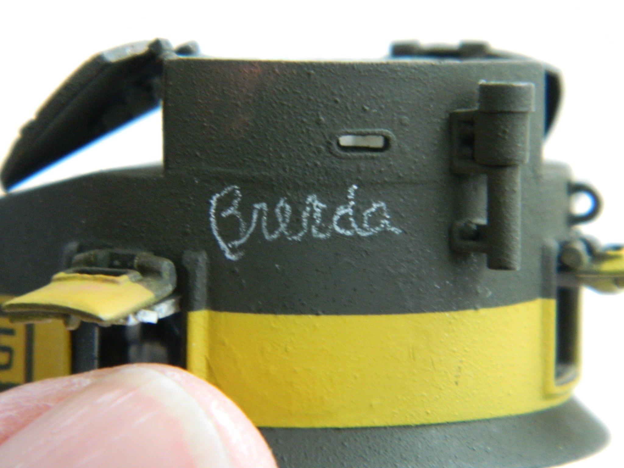
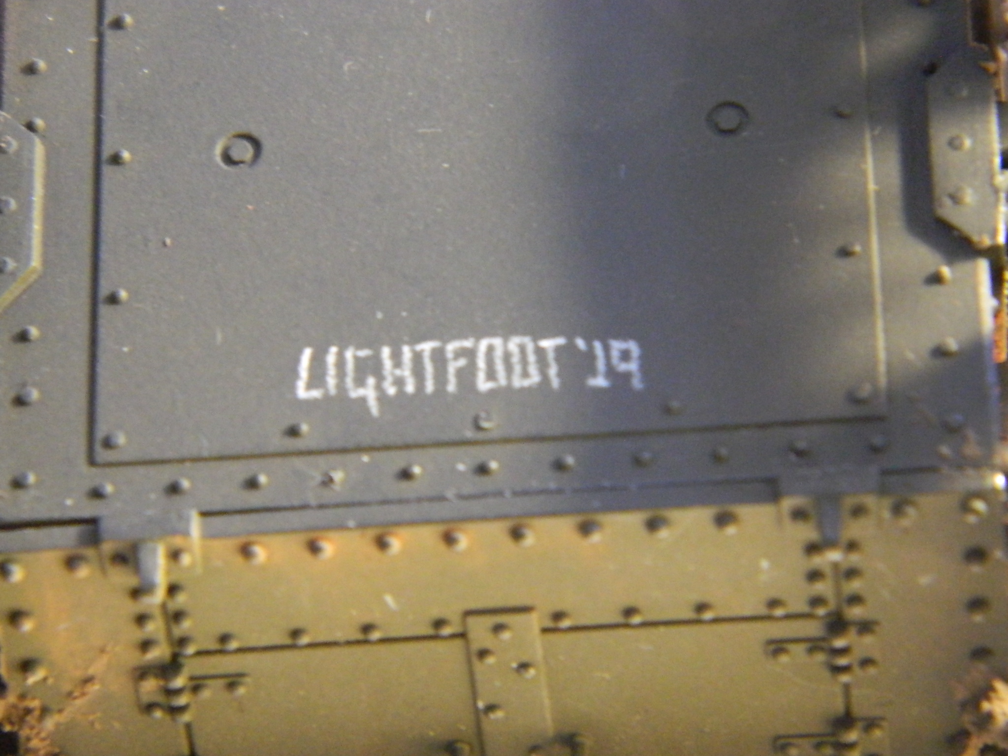
M3 Stuart (Academy) 1/35 scale
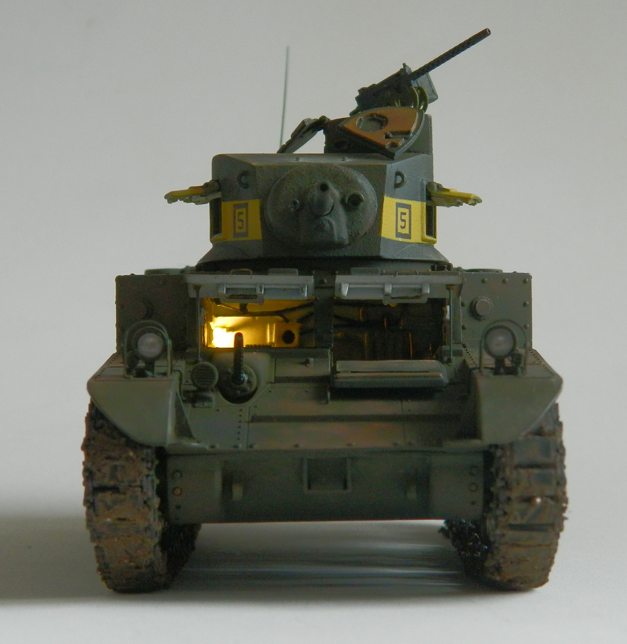
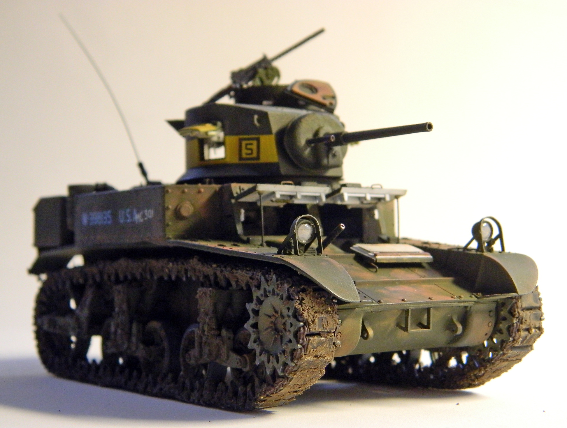
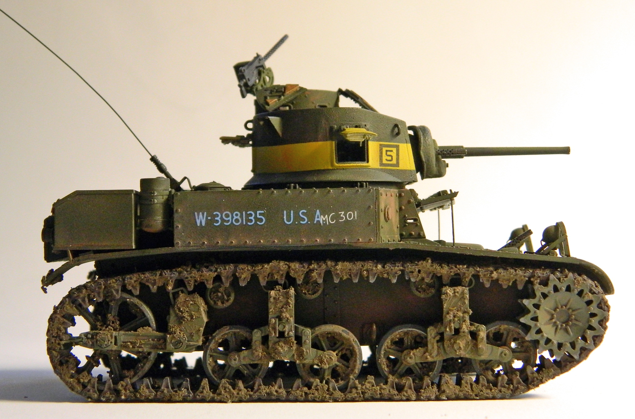

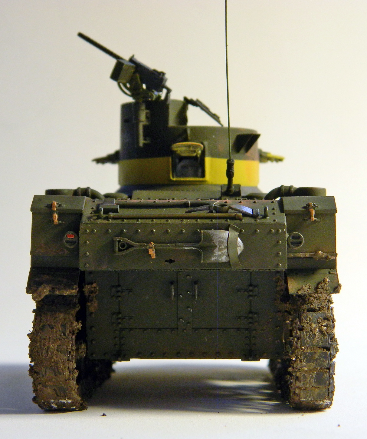
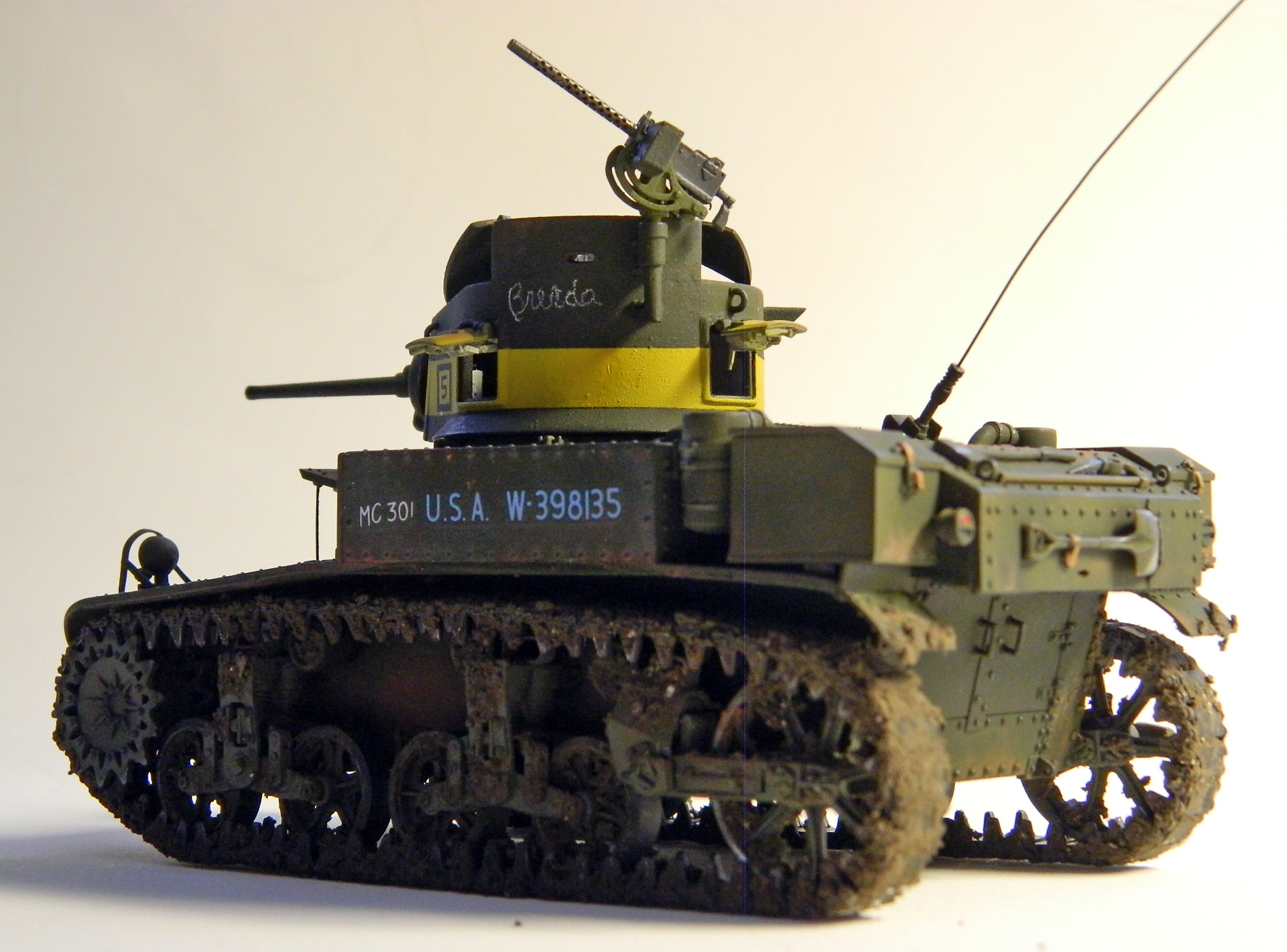


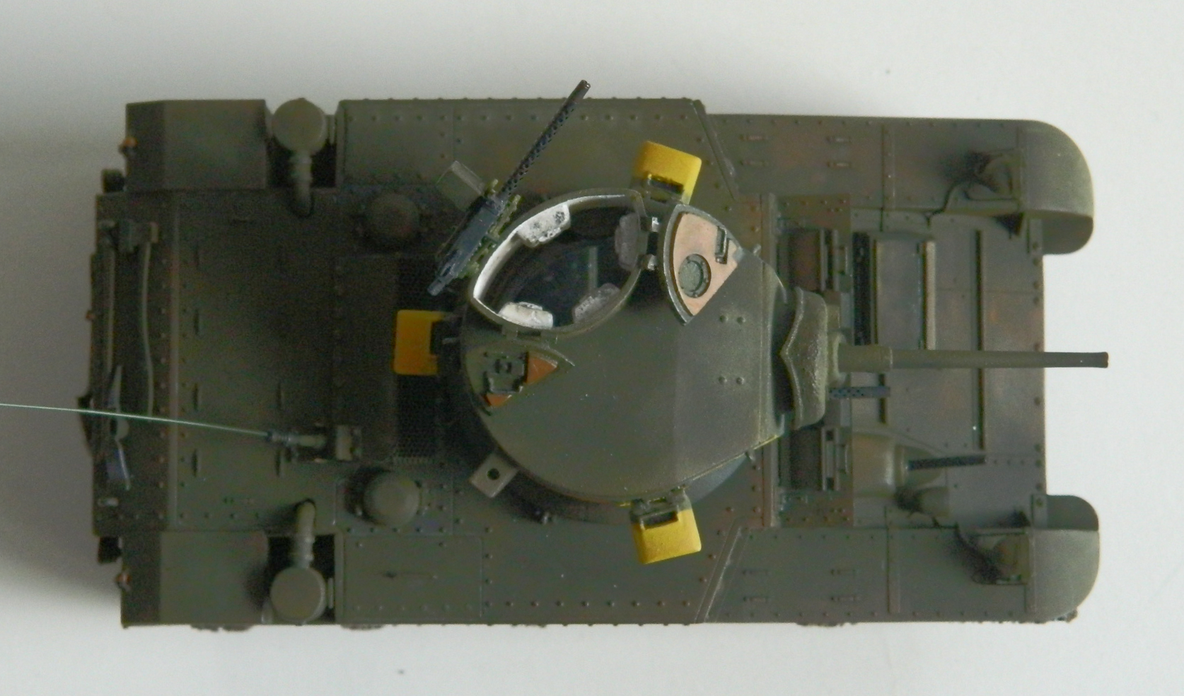
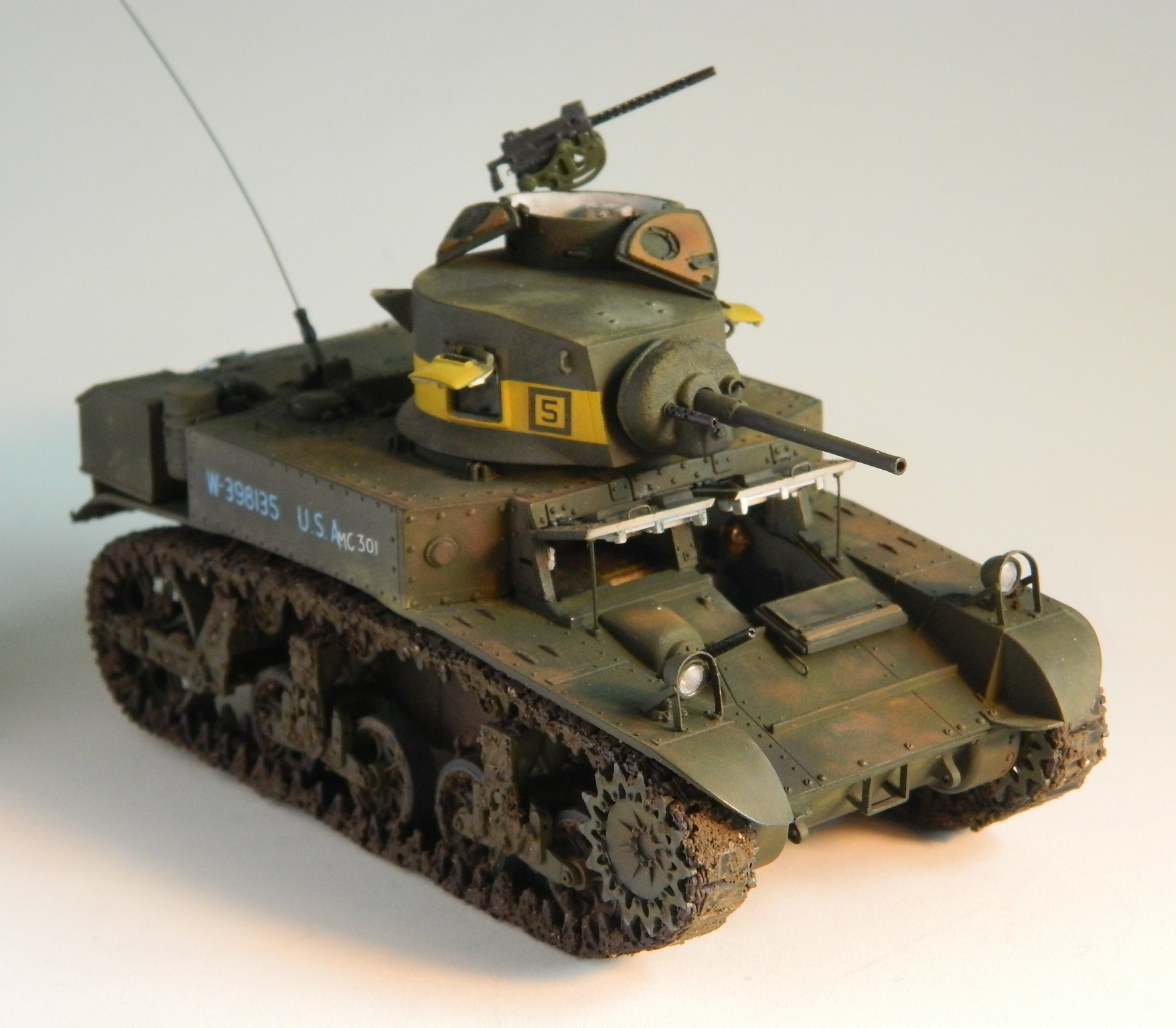
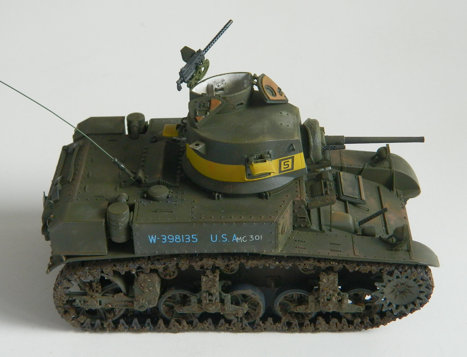
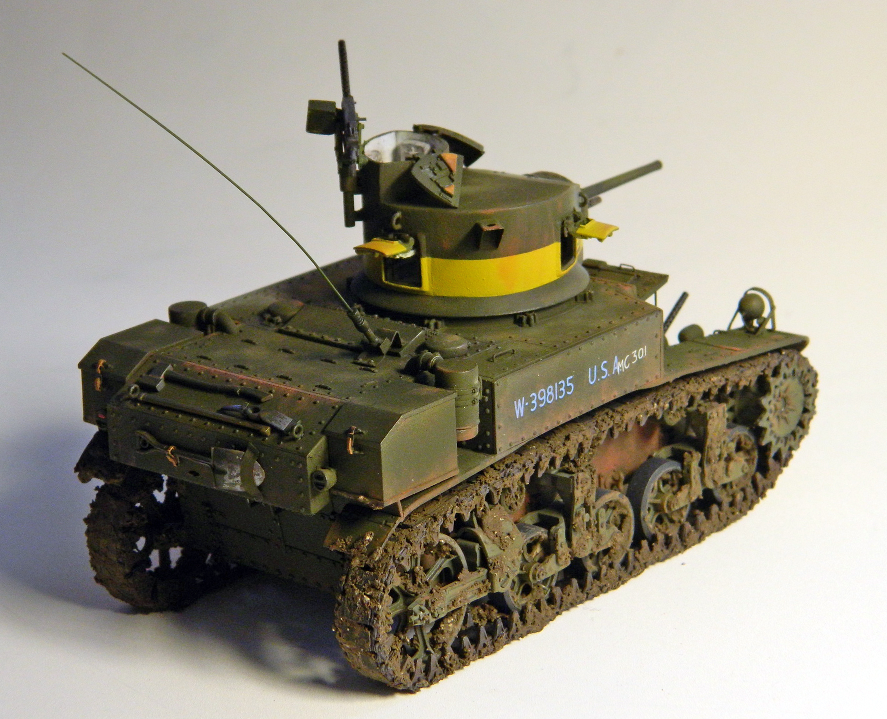
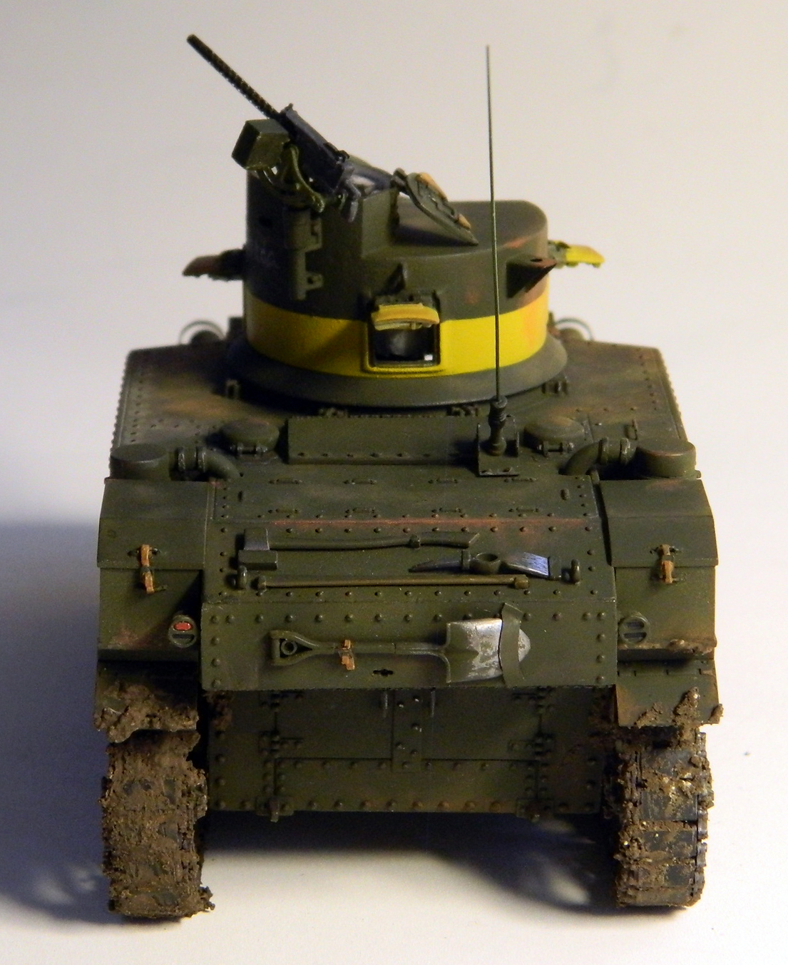
Then turn the light on:
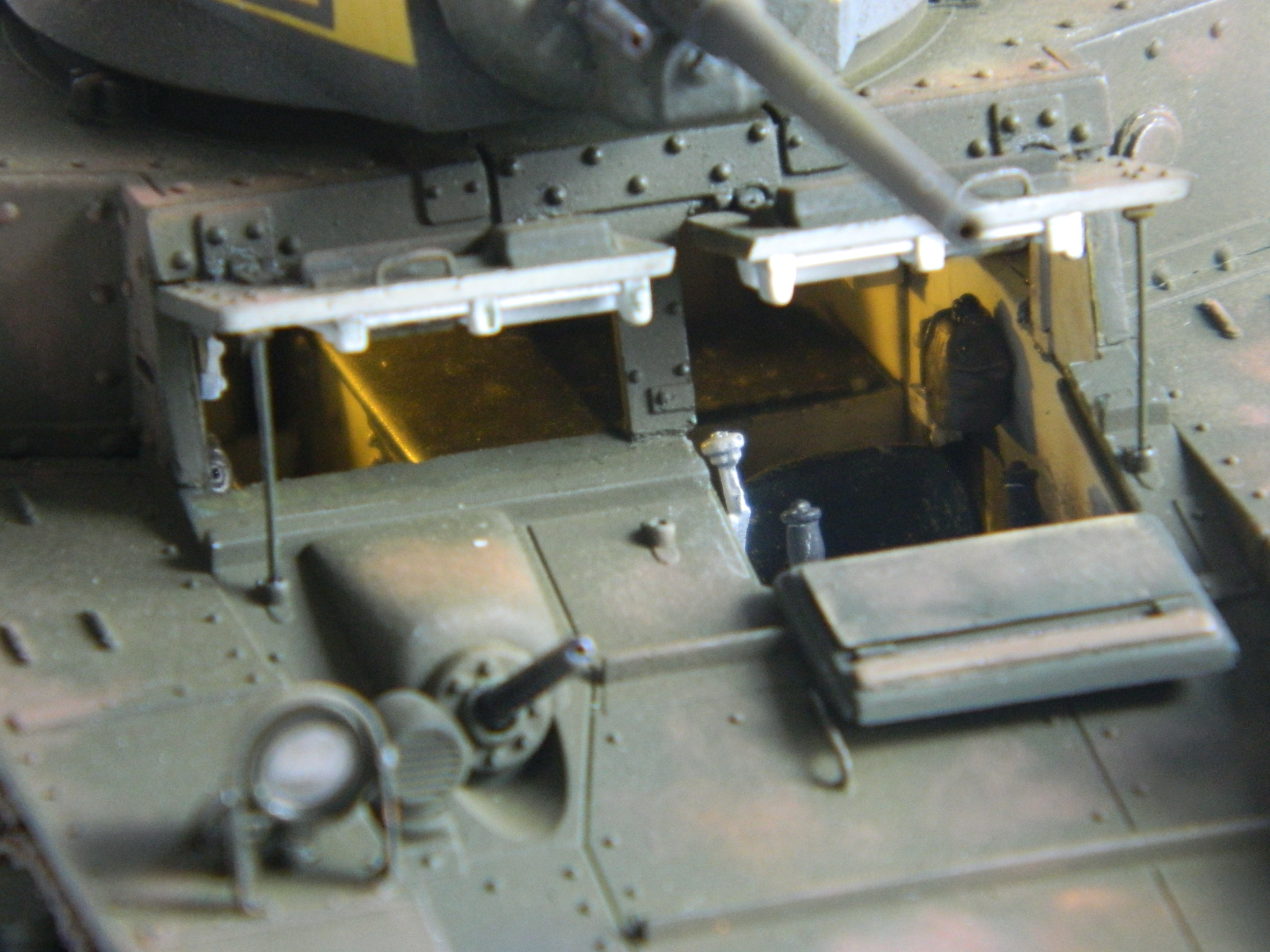
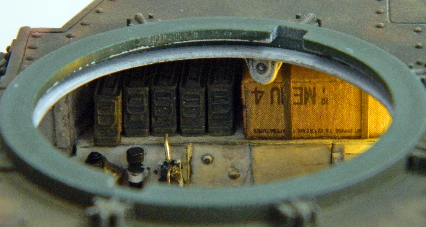
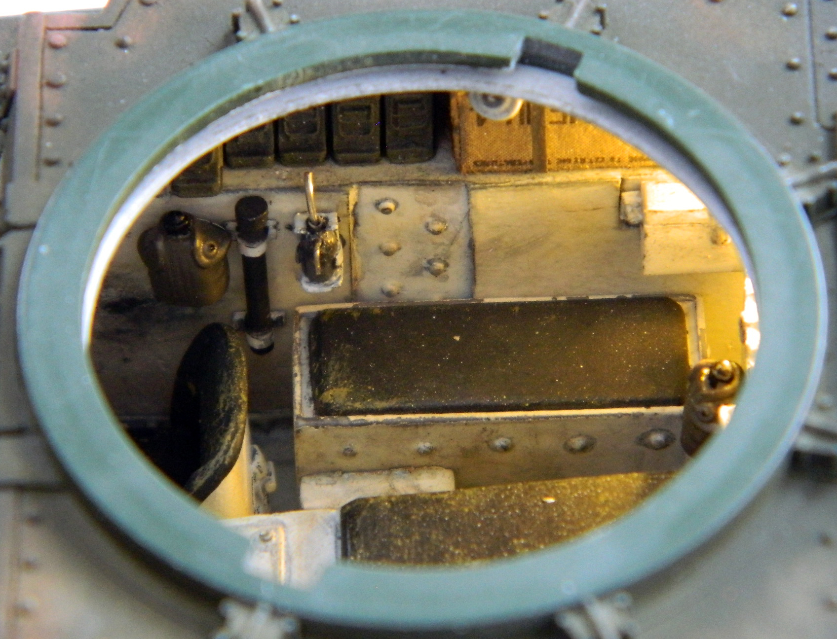


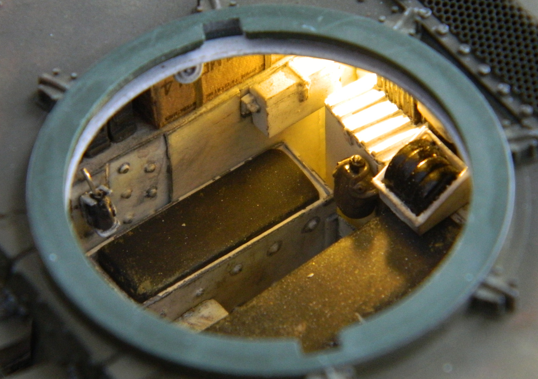
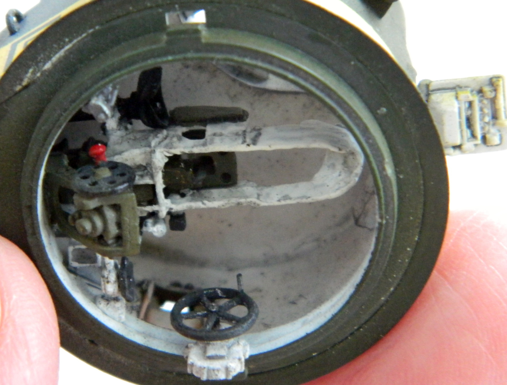


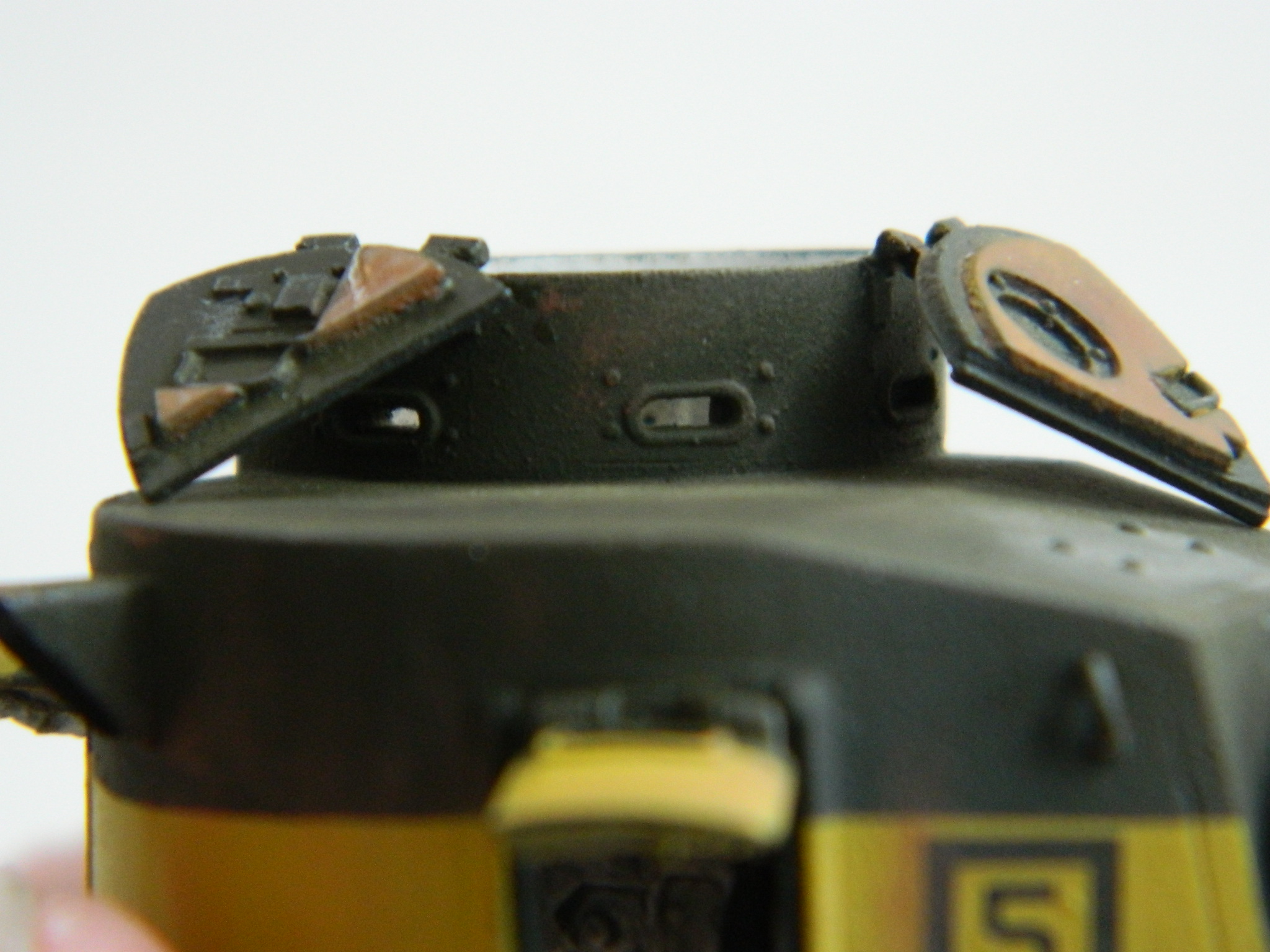
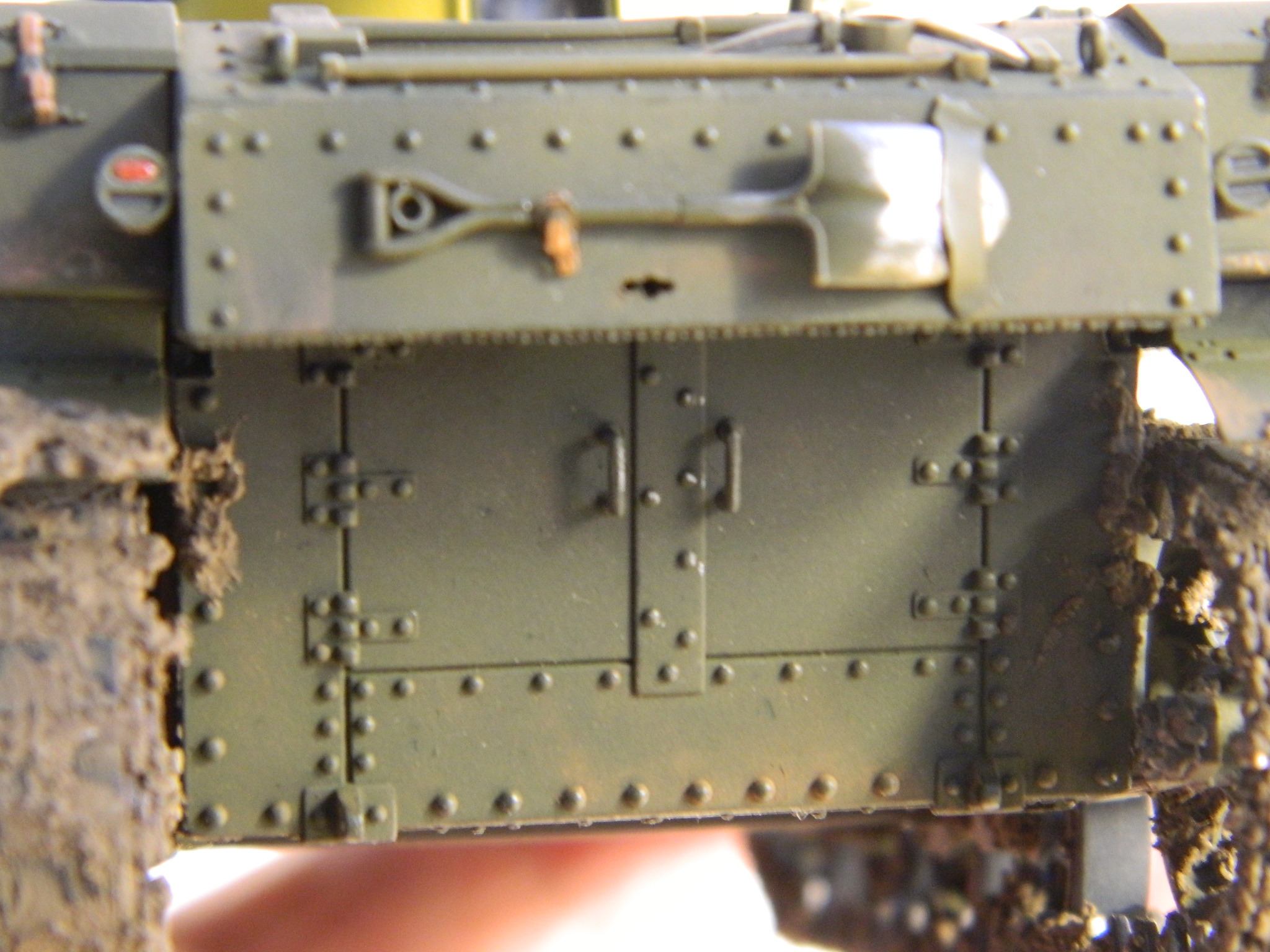
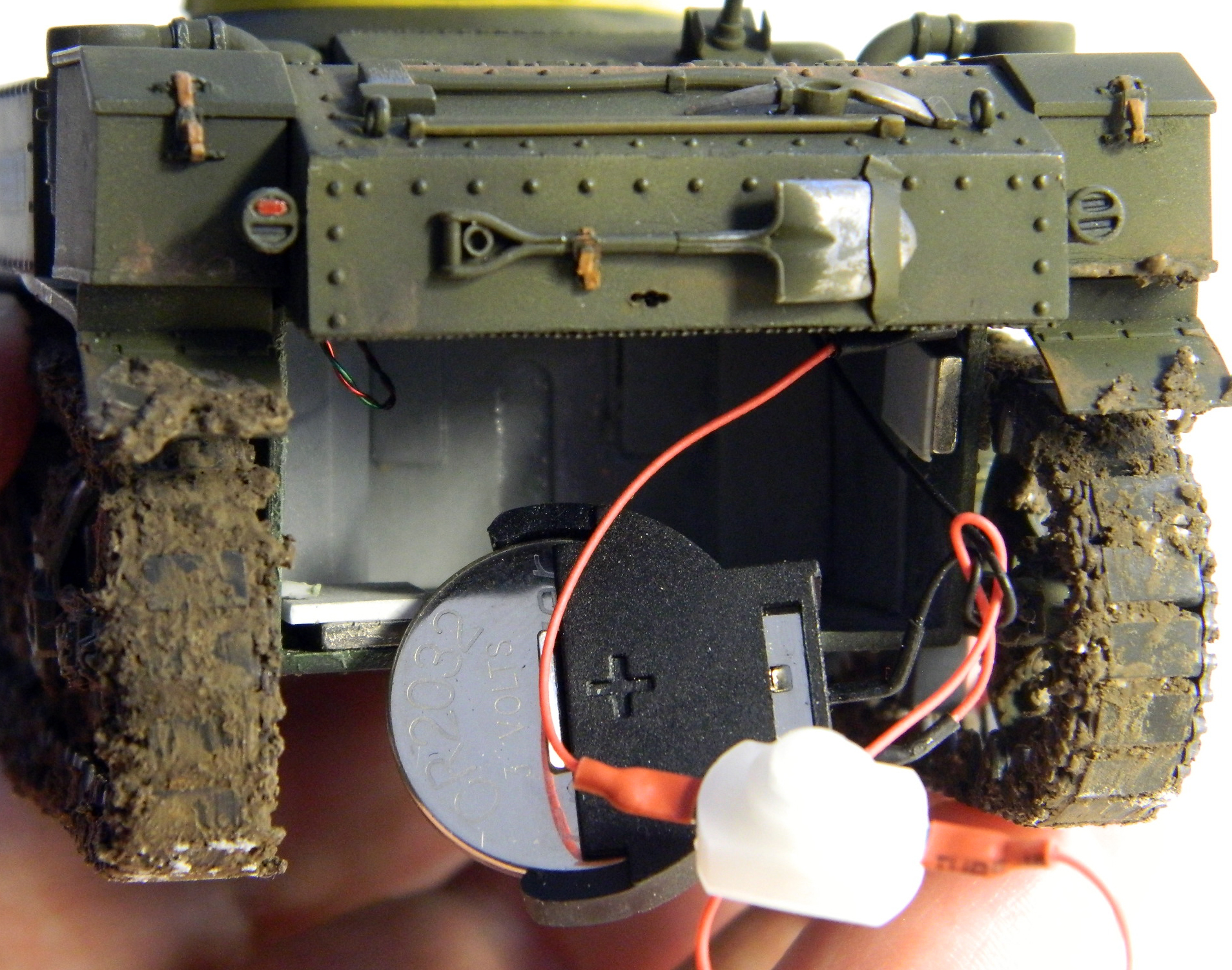
M3 Stuart (Academy) Build #7 – Final Paint, Decals, Pastels, and DONE
This will be a short post to wrap up this build. December, not my favorite month in general, was particularly crappy this year. A dear friend died and I had a very rare (THANKFULLY) heartburn incident that took over a week to get over. There wasn’t much left to do and once I could get back to it, it wrapped up quickly.
The decals arrived and they’re not bad, more like what I would expect from decals; neither too thick nor vanishingly thin, they did what I wanted them to. First I removed that hideous circle I’d painted onto the turret, repainted the OD, then did the yellow stripe around the turret using Tamiya XF-3 Yellow and XF-60 Dark Yellow. The yellow is YELLOW so I toned it down with the dark yellow by using three yellow to two dark yellow (which is more of a general buff to my eyes).
Once the yellow stripe dried overnight, I added the square markings with the numeral taken from a VERY OLD set of Microscale aircraft decals (which surprised me by going on as if they were new…I thought they’d shatter):
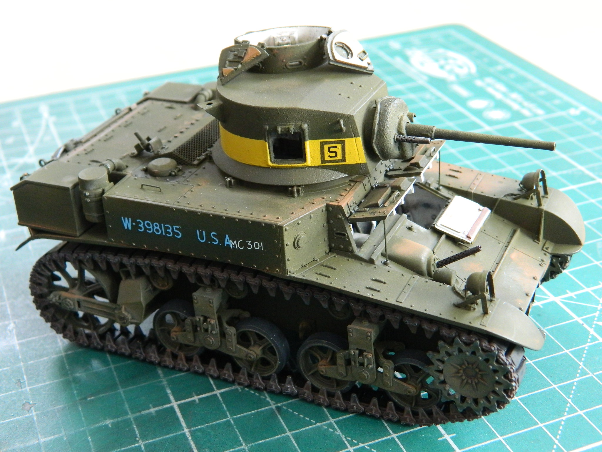

With the decals on, the only things left to do are apply mud to the tracks, then attach the hatches for the pistol ports, and then weather.
If you want mud and don’t want to make your own, The Scenic Factory makes a great product. The Scenic Factory has a YouTube channel for its products and I recommend you check it out. I’m using “Ardennes Mud” for this. It supplies the basic “mud,” which is acrylic-based, can be thinned with water, tinted with paint or pigments, doesn’t stink, and dries hard:
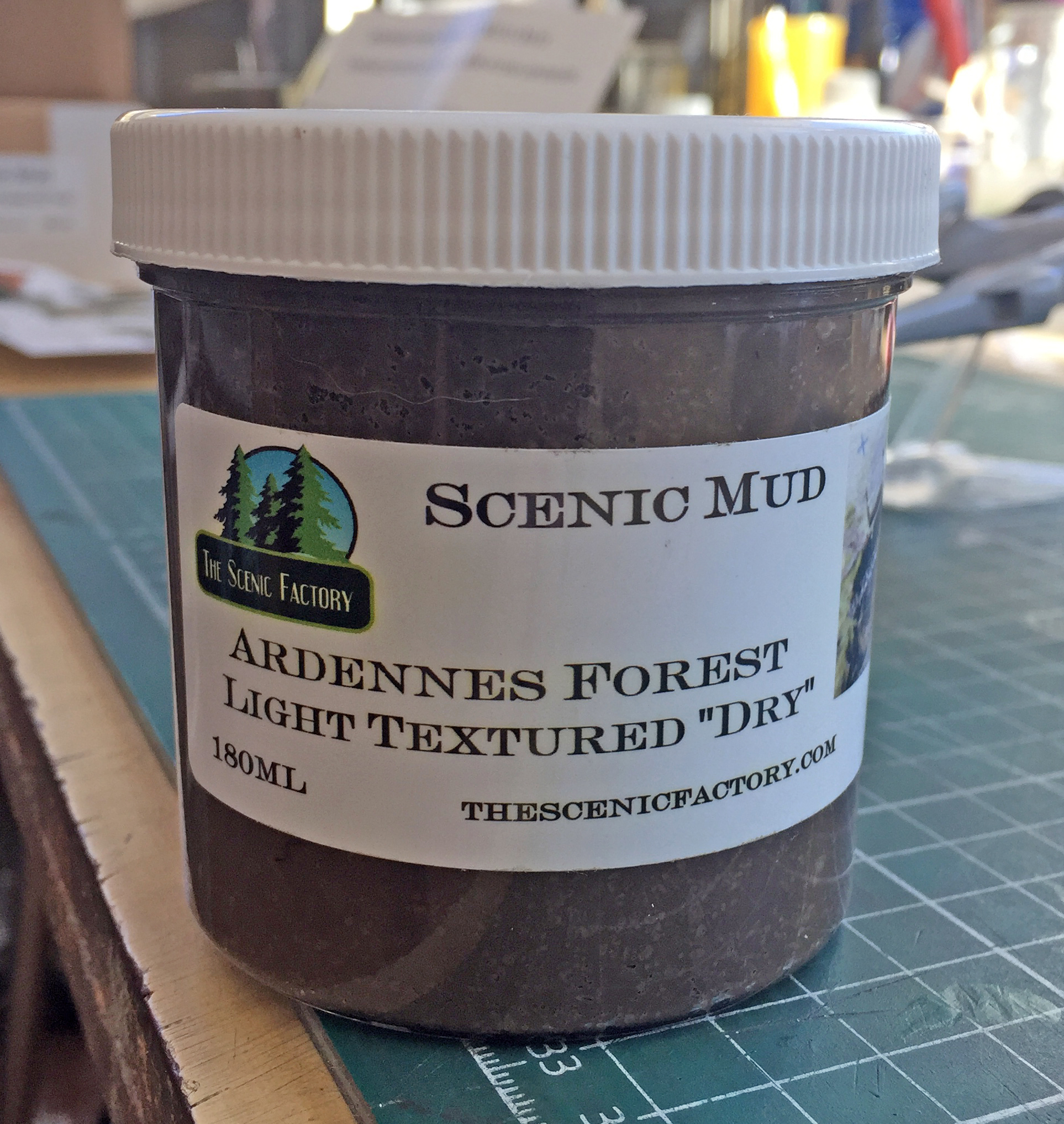
The kit also provides glycerine-stabilized (he says as if he knows what the intercourse that means, other than it doesn’t decompose) leaf and stick bits:
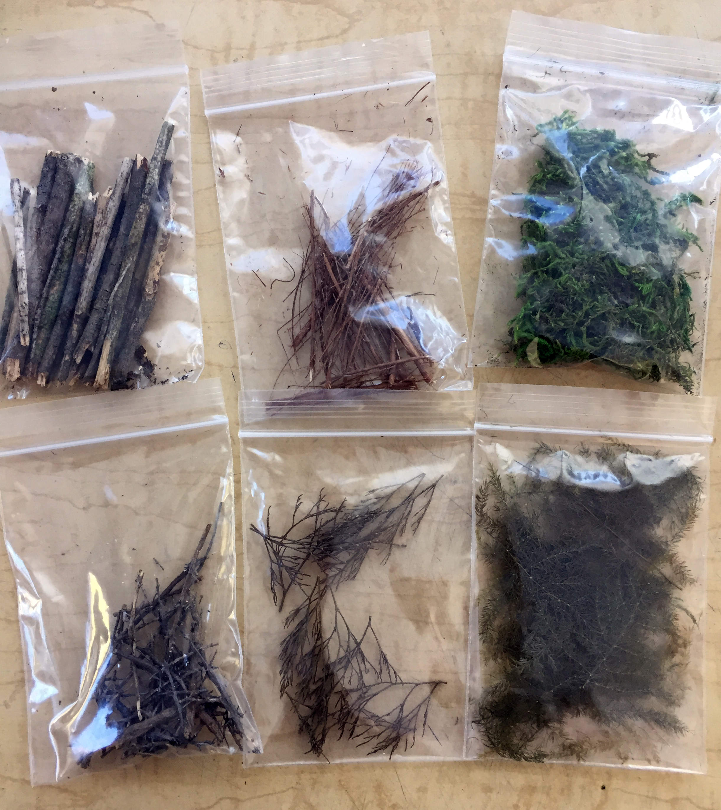
Okay. Enough free advertising. This is the mud on the tracks:

The last items to add were the pistol port hatches. Then the surface was worked over with a silver-colored pencil and a few different colored pastels…and like that, it’s done:

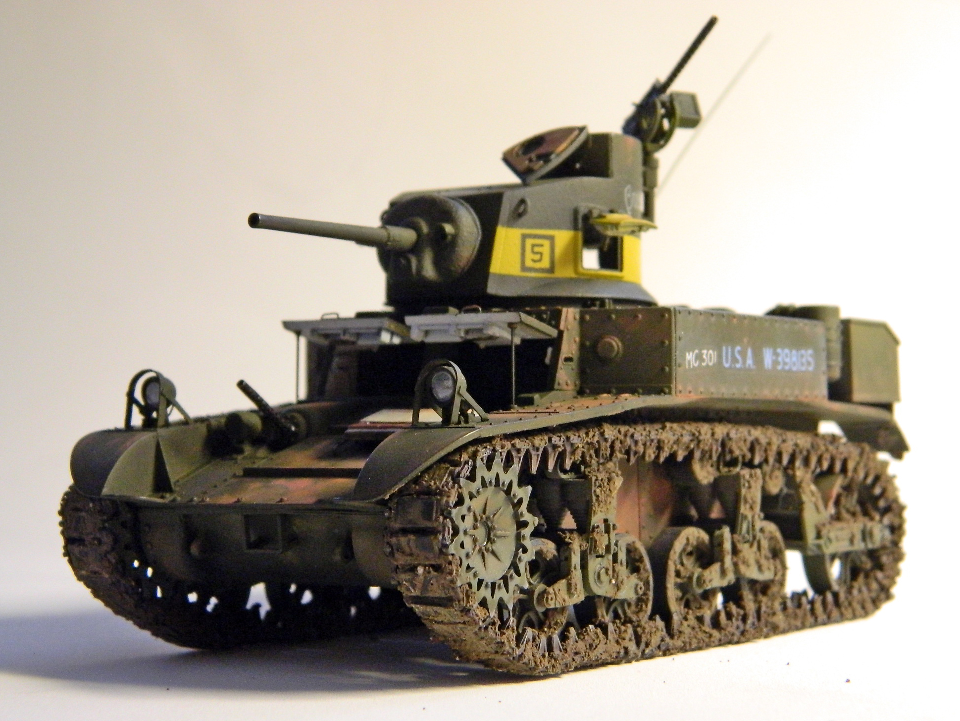
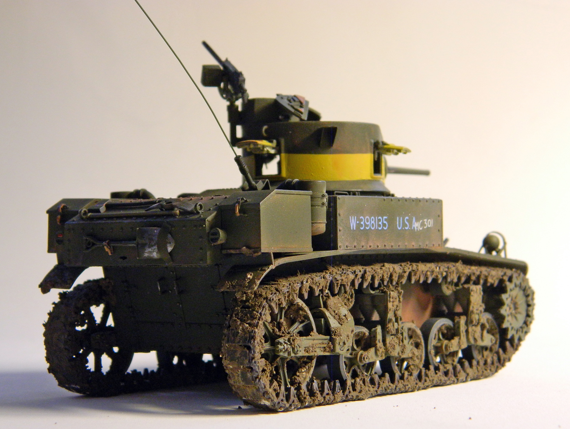
M3 Stuart (Academy) Build #6 – Dealing With Tedious Details and Being Adaptable
At the start of this build, I hadn’t really considered kitbashing. I figured that between the kit, an AM interior, and being able and willing to diddle really small details into the state/condition I wanted them, I’d end up where I wanted to get with this.
And then there are the headlights.
I did not like what Academy provided, and I spent several evenings lying in bed (waiting to get to sleep) wondering just how the intercourse I was going to be able to diddle the provided headlights into anything remotely acceptable…fruitlessly. One afternoon I was chasing M3 Stuart references all around the Internet and encountered a site that did a quick build of Tamiya’s new-tool M3 Stuart (kit #35360) (okay…so I lied about the porn). I noticed that the headlights Tamiya provided were SO much better and about 99.5% of what I wanted straight out of the box. Okay…so I bought one.
Once I had the Tamiya kit, I cut the headlights off the sprue and did the other .05%, making the bases thicker and more accurate, then adding bolt heads to the bases:
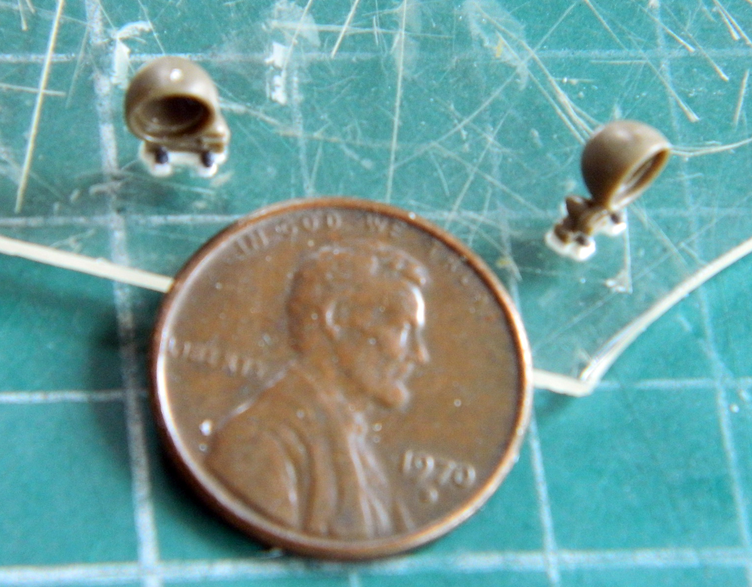
Checking fit, I can see that I’m already liking these bits MUCH more:
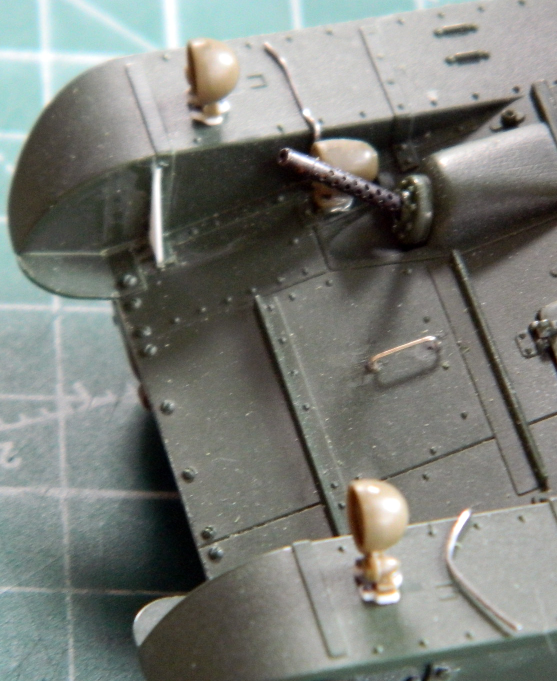
It made sense to me at the time (which is a different way of saying, “I have no idea what I was thinking* when I decided to make the headlight guards from styrene), so I cut a bit .015″ (.381mm) scrap to width and then tried (key word, that) to form them using hot water and something (small cable ties) to hold them to shape and set this aside to settle into the shape I was after:

This wasn’t something I was looking for and checking. My eye chanced across the left rear idler wheel and discovered that it’s out of alignment with its mounting arm:
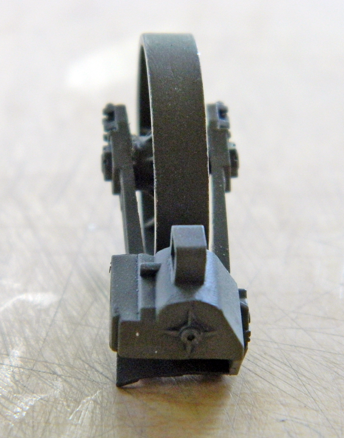
Blast and bugger. That has to be straightened and that puts the assembly at risk because I’m not shy about the application of adhesives. Nothing for it but to go for it and I used a chisel blade to get in there and break the wheel free:
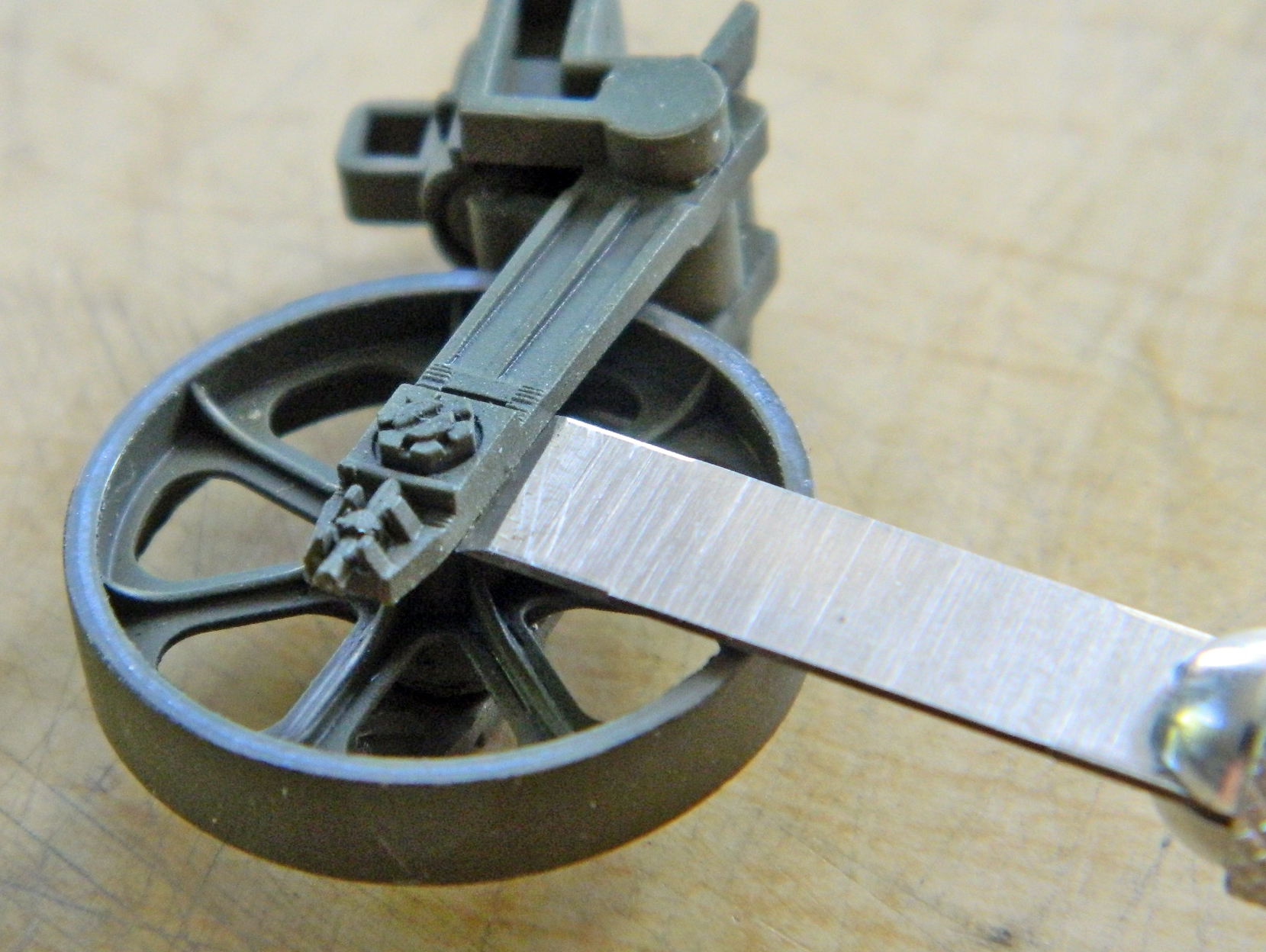
There was MUCH careful rocking of the edge back and forth to get the wheel loose and I managed to do that without destroying anything. After aligning the wheel better than it had been, more (and plentiful, of course) adhesive kept it there:
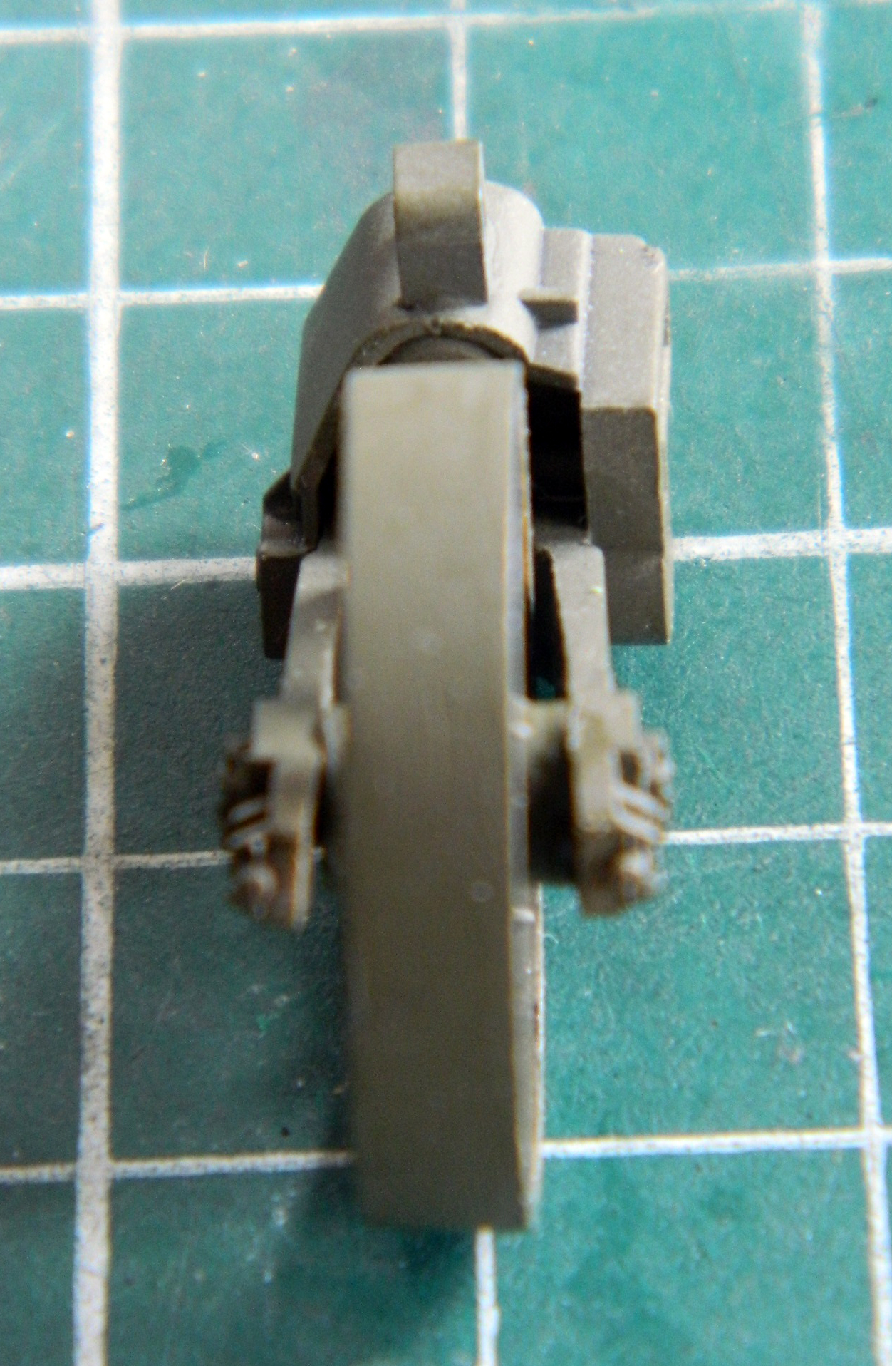
While opening the battery compartment, the hinge broke (and somehow the sodding muffler came loose while all this was going on):

I popped the screen off and reinstalled the muffler, considering how to fix the hinge:
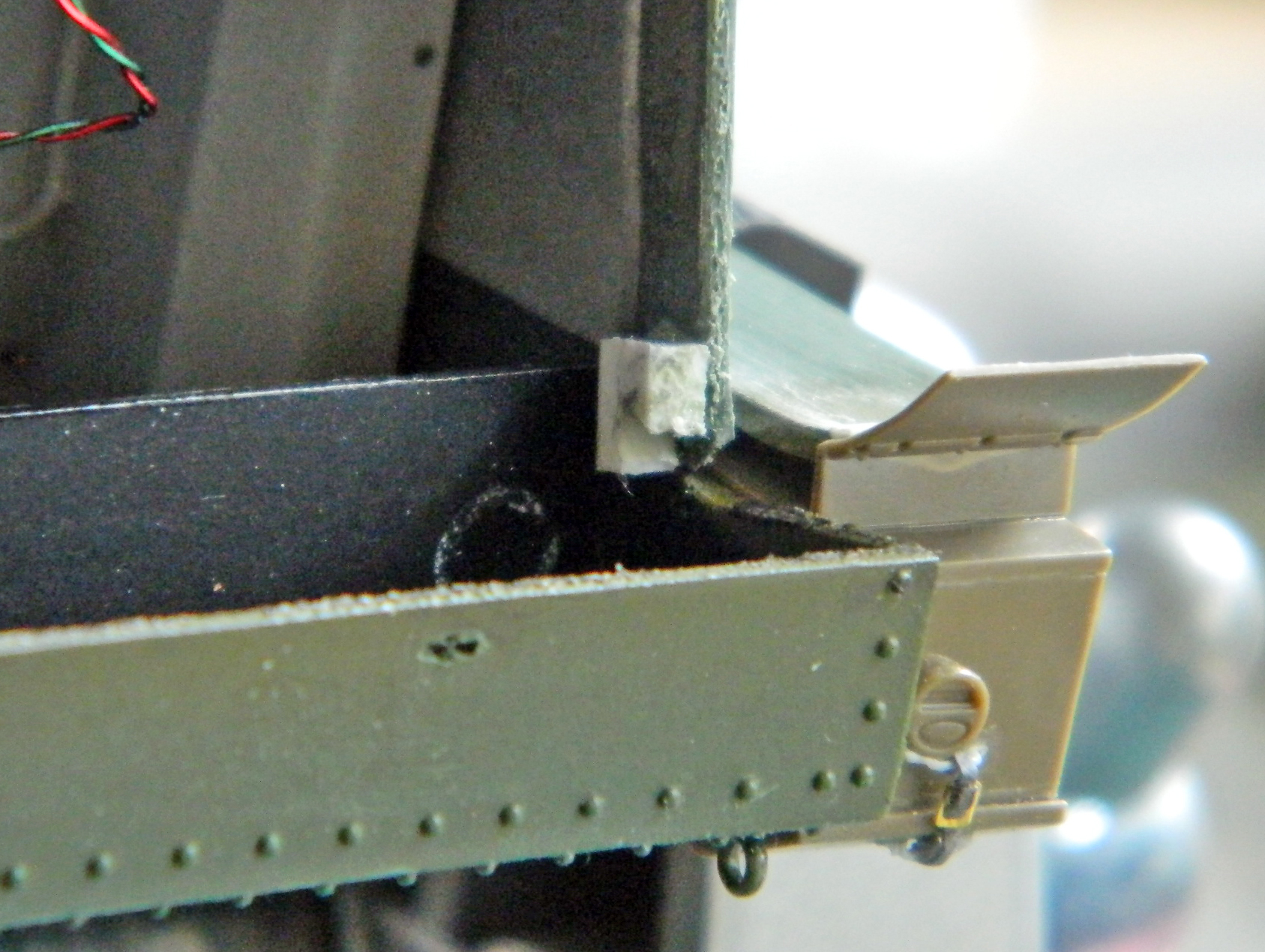
That consideration led me to the opinion that if I repaired the hinge, at some point down the line I would have to fix it again (and the further “down the line” this thing broke again, the worse the job of repair would be). So repairing this wouldn’t work long-term (doing things short-term only creates long-term problems), I would have to do something different. That’s when the Boys in the Back asked me if this had to be hinged…I just needed access.
Oh. Yeah. That.
Instead of repair, I removed the hinge completely and replaced it with another magnet/steel set up:

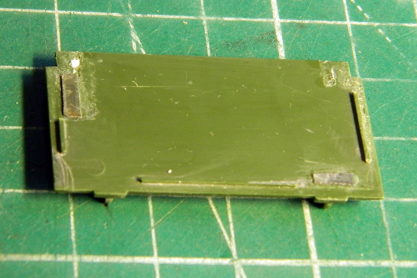
The result is certainly good enough and even more simple.
Having dealt with that, I went back to the headlight guards…realizing that using thin styrene was rather dumb of me. Where these parts sit, they’re exposed to various unintended contacts. Maybe making them out of sterner material would be a better idea.
About this time, I had someone ask me how involved the process was of using copper sheet for these. My response is, “About this involved.” These are the tools necessary:

The needle is to scribe the outlines of the parts I have to cut from the .010″ (.254mm) copper sheet. The scissors and chisel blade to make the cuts. The anvil (sorry, I forgot to pose the ball-peen hammer for the photo) to hammer the copper flat against after the scissors and chisel blade deform the copper. The smooth-jaw pliers to hold the copper while it’s annealed. The shaped wood to act as the form to curve the copper over. The tweezers to check fitment. (The small clamp was intended to hold the parts in place while being soldered, but instead, I used locking tweezers on bases for that.) The parts were cut out (the kit part in the background for comparison):

Then the parts were aligned and soldered:

The result was something more to scale and much sturdier:
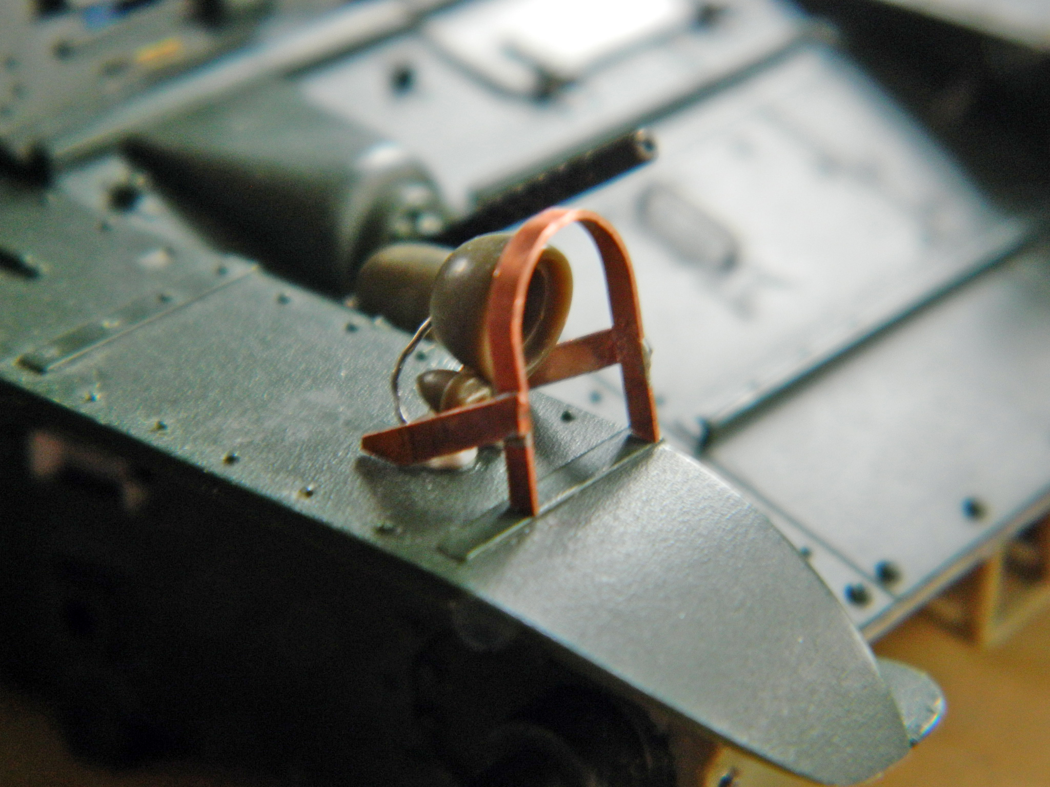
I let myself glow in the light of accomplishment a bit before I realized that I hadn’t gotten these things quite correctly. There are bends at the bottoms of all the flat sections that I had not either put in nor allowed extra length to put in.
So I redid them:
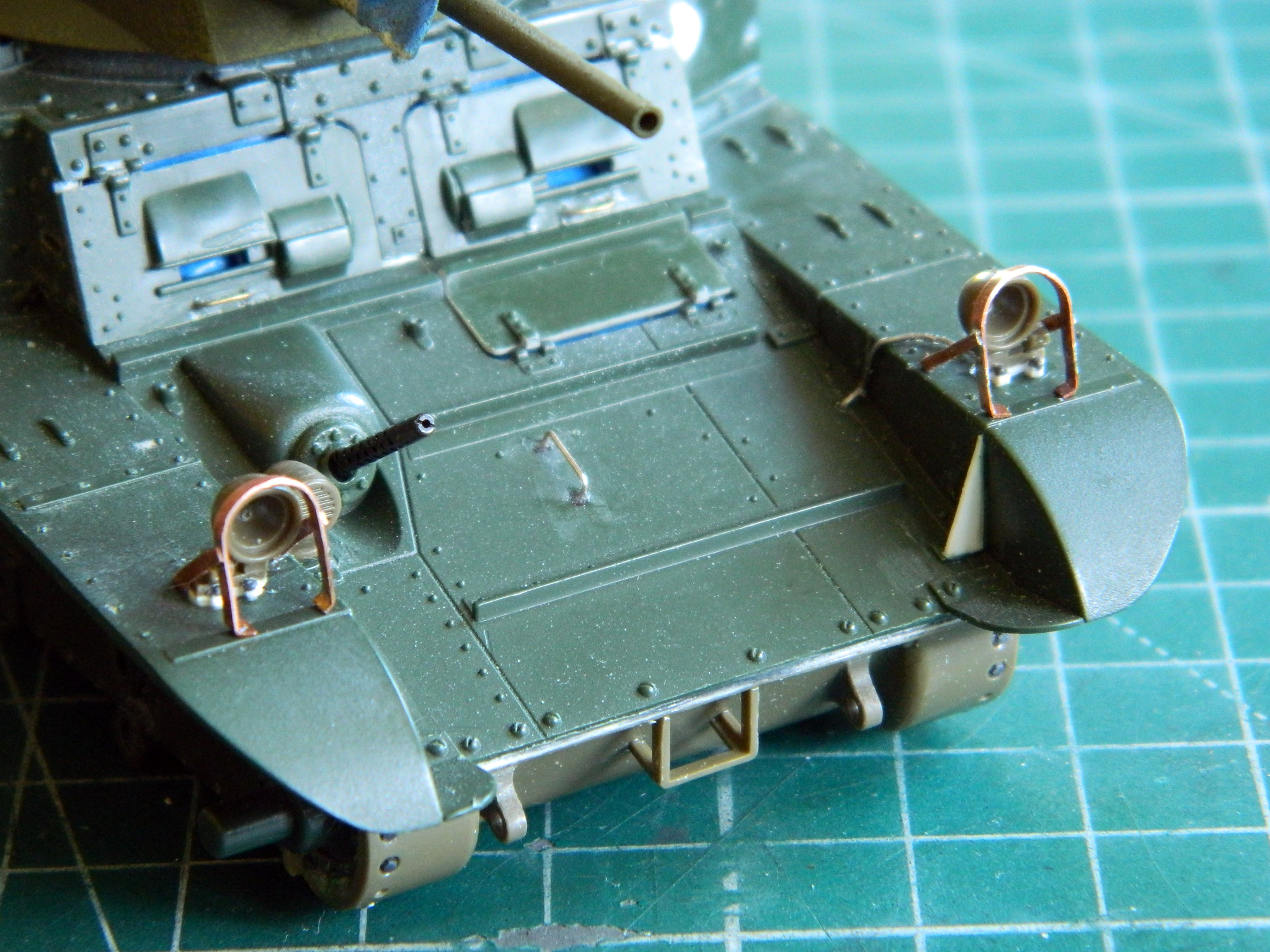
About this point, my brain decided it had other things to attend to*, leaving me sitting at the bench wondering what the hell I needed to do next (actually happens a lot) (stupid squirrels…). I knew I wanted to try a bit more in-depth pre-shading, so I had to paint this flat black. And I know once I did that, I’d find all the things I should have done before I painted it flat black.
Okay…let’s do this pre-shading thing:
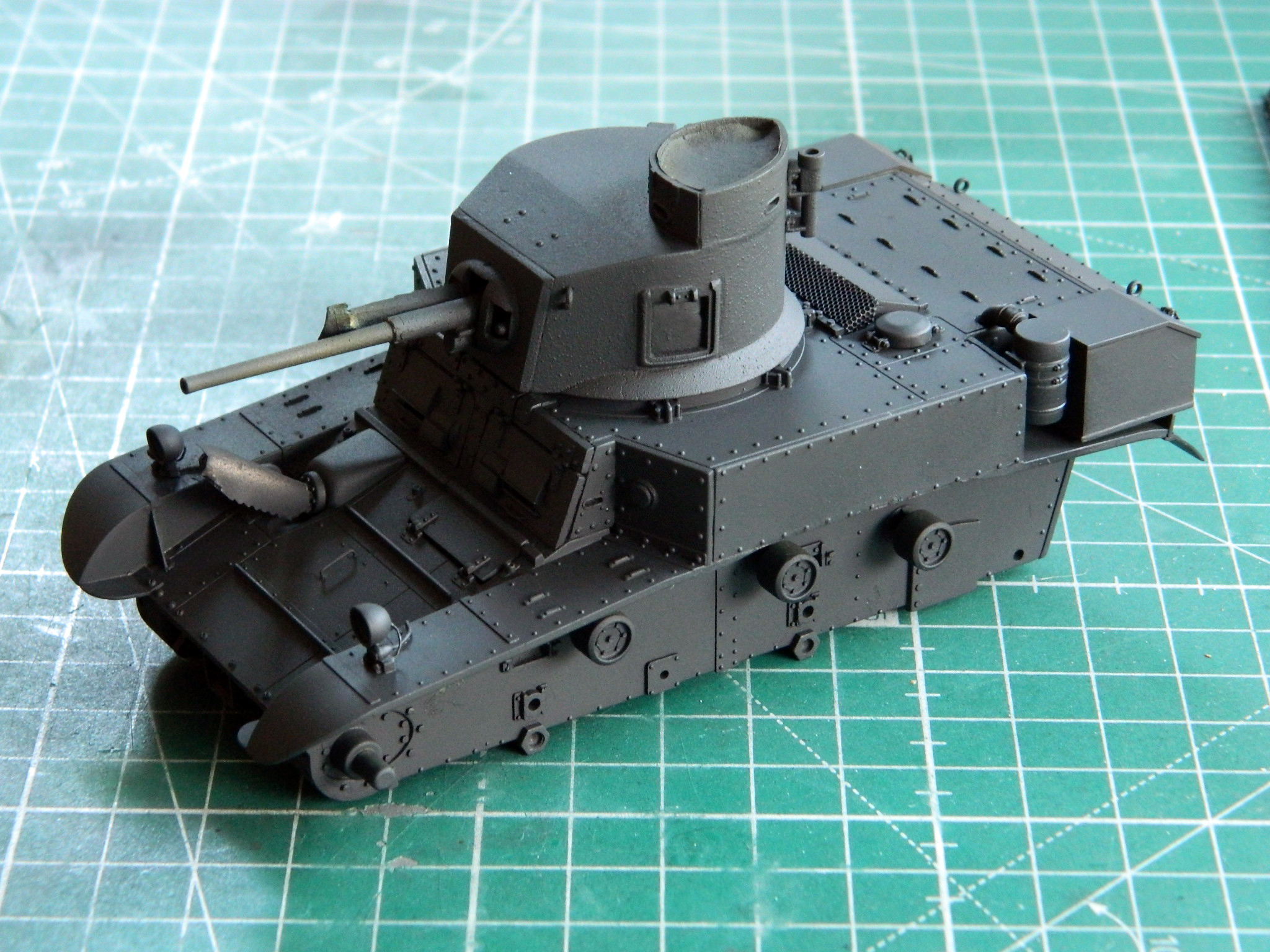
Huh. Whaddya know. I did forget to do a few things. I forgot to add the headlight guards I just spent all damned day on, forgot that I had to add rivets to the strap in front of the headlights (sorry about the blurred photo…I thought it had come out better than it did), and totally forgot to make the antenna mount (and then forgot to photograph the installed headlight guards):
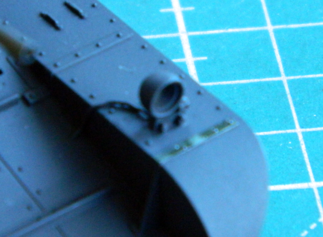
Once the .010″ (.254mm) copper was annealed and folded into the antenna mount, I added the bolt heads and glued it in place:
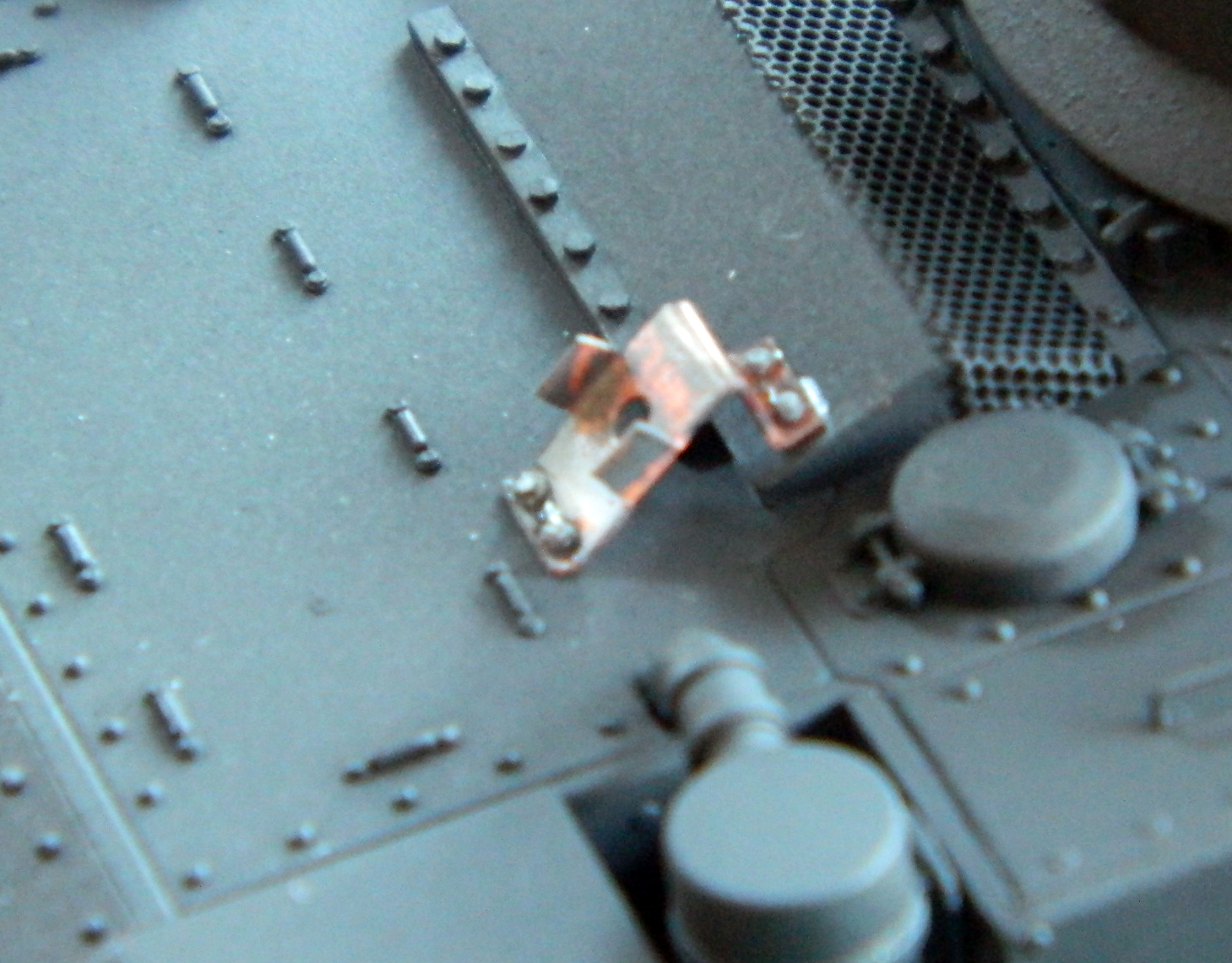
The next step in pre-shading is to paint all the areas I want lighter in appearance with flat white:
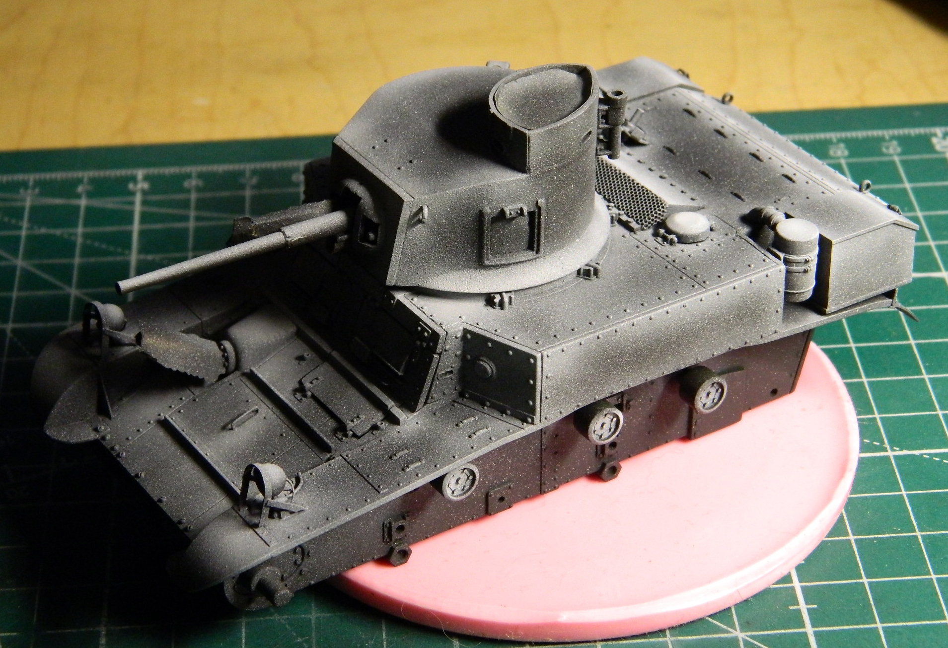

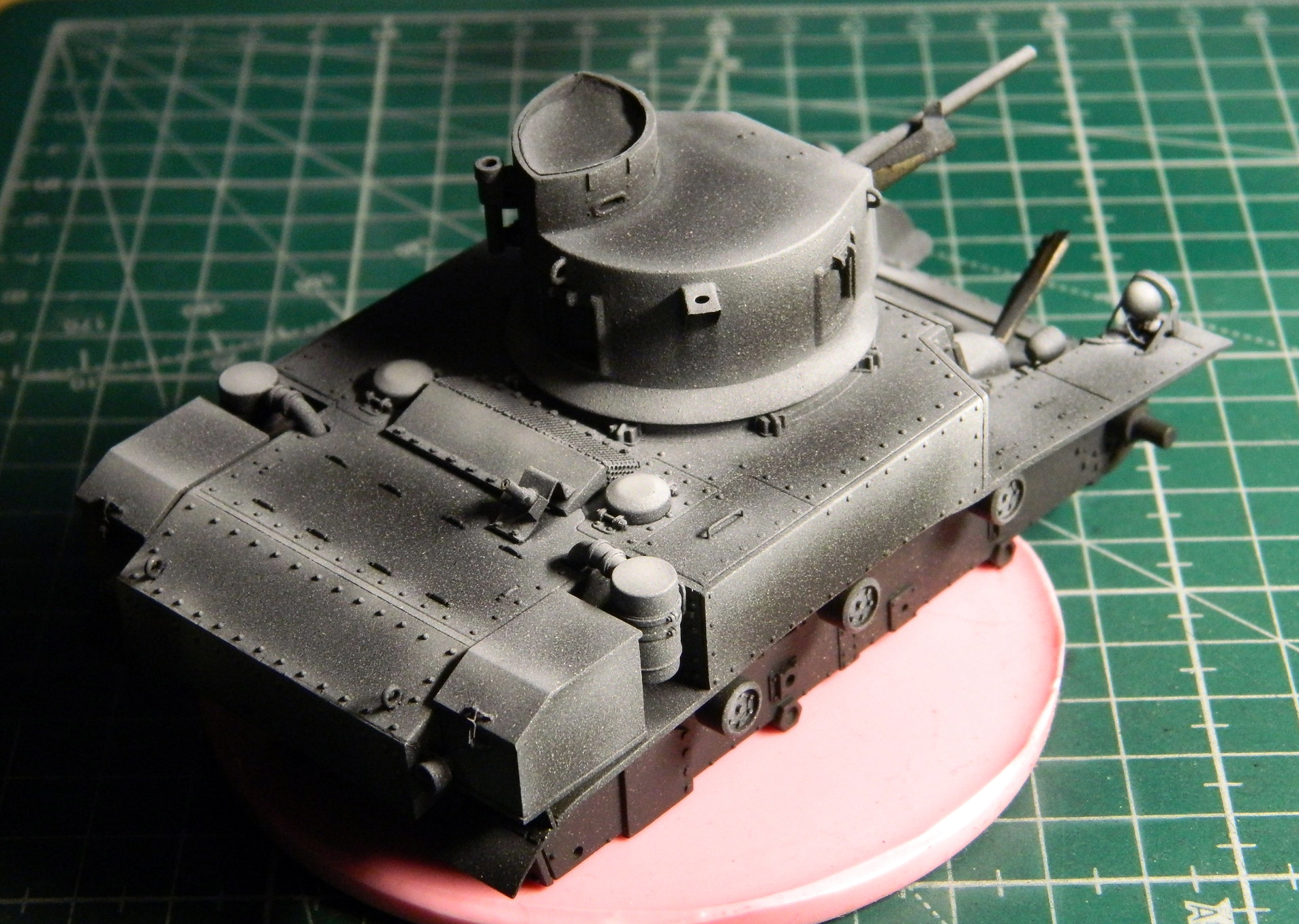
As things turned out later when I hit this with the color coat, I could have laid down a heavier amount of white in some areas. Lesson learned.
I set that aside for the paint to cure and went at some of the other small details. At present, I’m planning on using the track grousers that came with the AFV suspension upgrade. They were assembled and glued to a flat stick so that I could paint them without the airbrush blasting them into places I’ll probably never see again. I used a small dab of superglue:
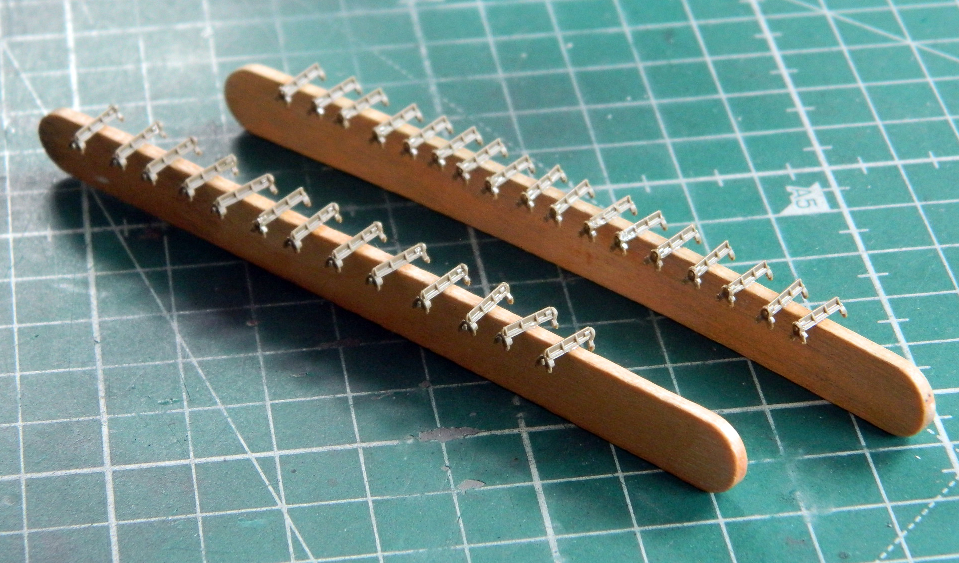
The first coat of paint was Humbrol’s “Steel”, #27003 (my FAVORITE when I need plastic to look like steel…you can see the grousers on the right have been buffed as have the tools). While I had the airbrush loaded with that paint, I also did the tools:
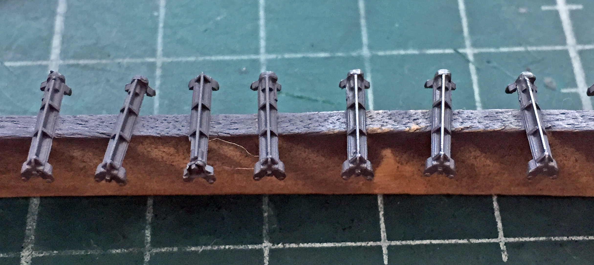

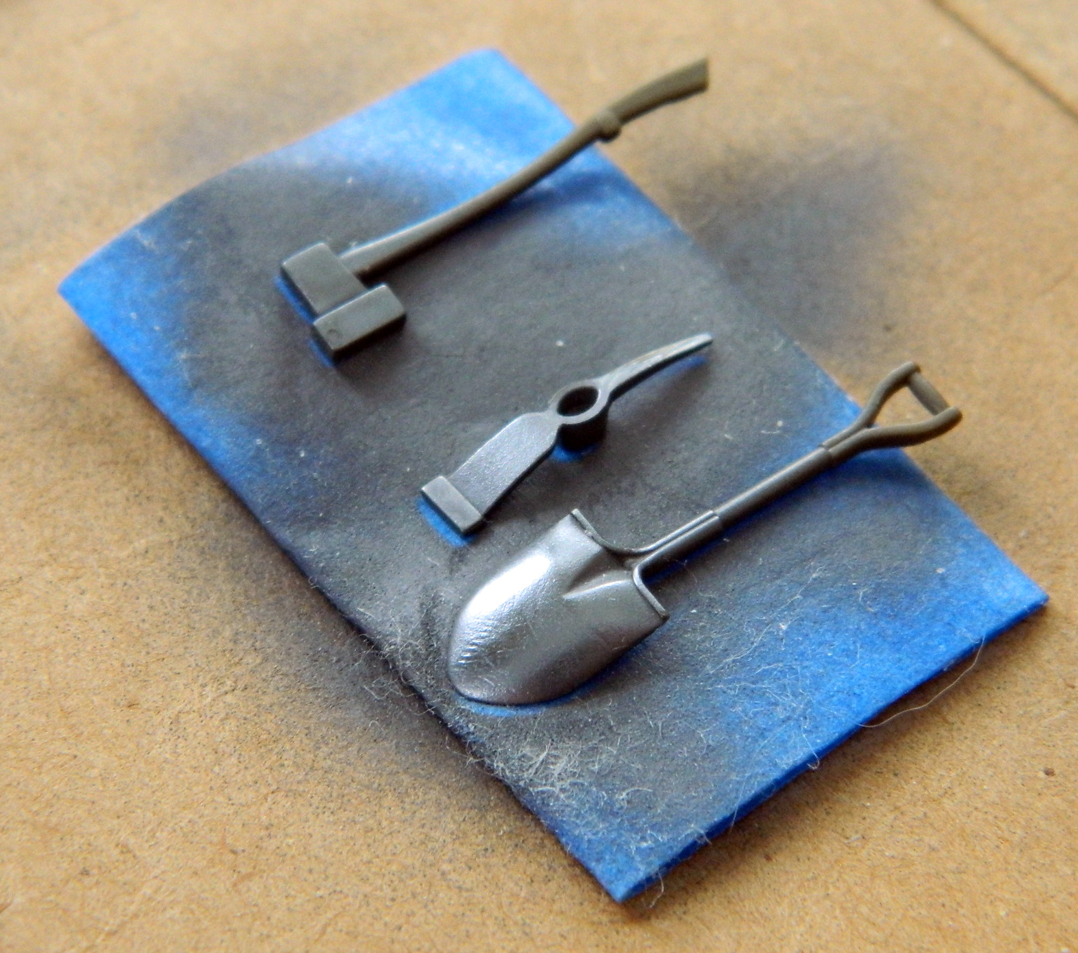
The grousers and track connectors were painted the track color (new formula I found online using Tamiya paints: 70% XF-68 Nato Brown, 25% XF-69 Nato Black, and 5% XF-7 Red) and the tools Tamiya XF-62 Olive Drab:
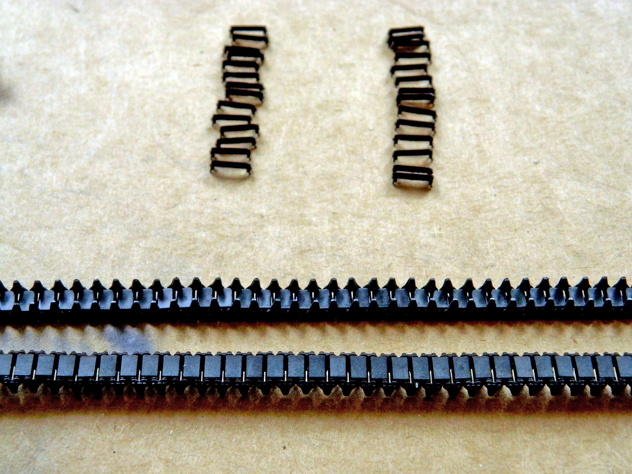
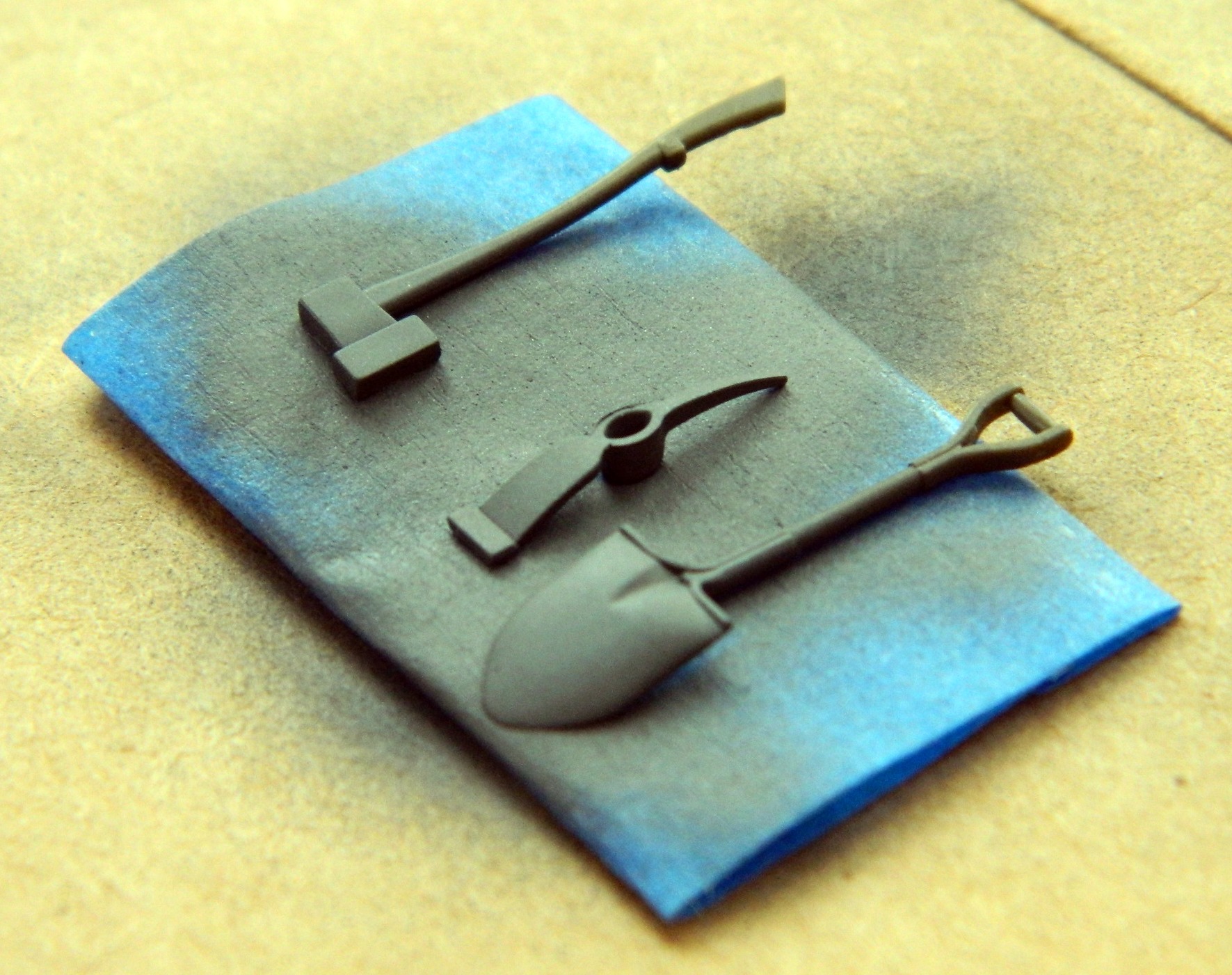
Before the OD set up for too long, I used a fine abrasive (nail polishing sticks from the beauty section of a drug store) (or apothecary, if you prefer) on the shovel and a toothpick on the pickax to replicate wear:


And while I had the OD in the airbrush, I tossed the first color coat at the tank:
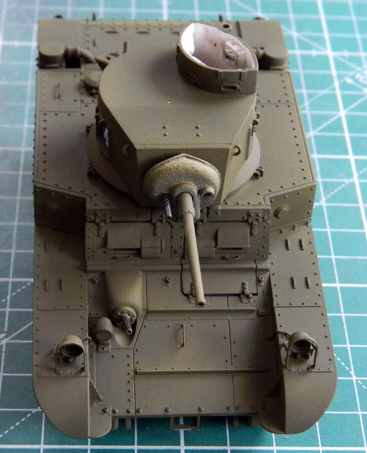
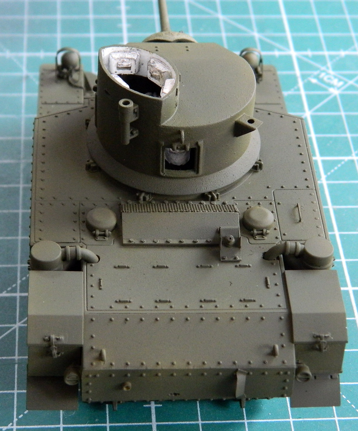
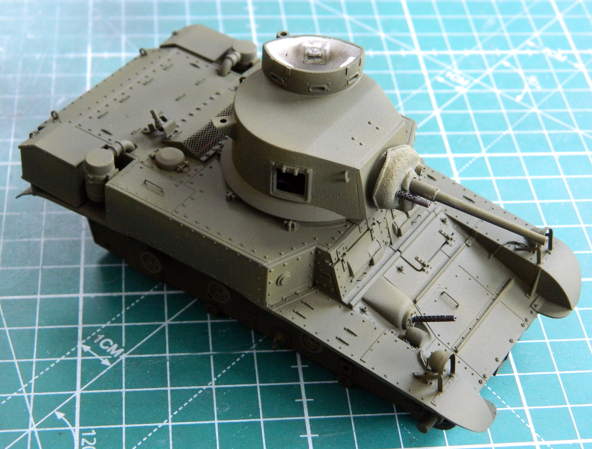
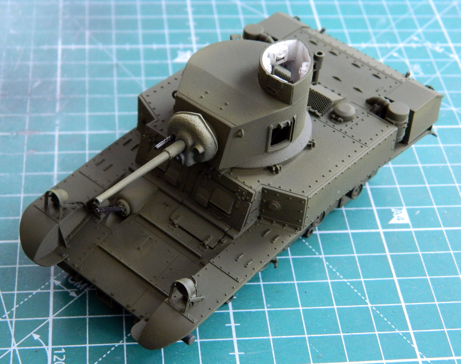
At this point is where I realized I could have been a bit heavier with the application of white. But, if I have to err, I’d prefer to err on the side of subtlety. I’ve often thought that some of the shading gets overdone, so if I have to adjust it, I’d prefer to adjust to more (pastels are my friend) than to attempt to tone it down.
What I’ve been working towards has been being able to attach the suspension and tracks…and now I’m at that point. The suspension did not come with the kit and the individual track links did. So before I could put the tracks on (not to mention the suspension), I needed to know how much track I needed to use. This would establish where the only variable left in the suspension goes; the idler wheel assembly. I thought I had the perfect meter, the rubber-band tracks that also came with the kit. I laid them down, placed the track I was going to use next to them, and ended up removing ten track shoes per side:
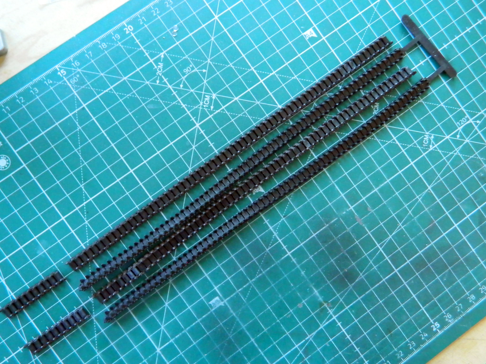
But once I tried to do that, hold the track in place while holding the idler wheel assembly in place while holding the tank, trying to get the sprocket wheel in place, AND snake the track over the return wheels, I discovered that just two hands made that all IMPOSSIBLE. If I had four hands it would have been difficult. I went back to reference photos, figuring that without the idler assembly in place, NO track gets mounted, so get the damned assembly properly in place, aligned to the ground, and then diddle with the tracks:
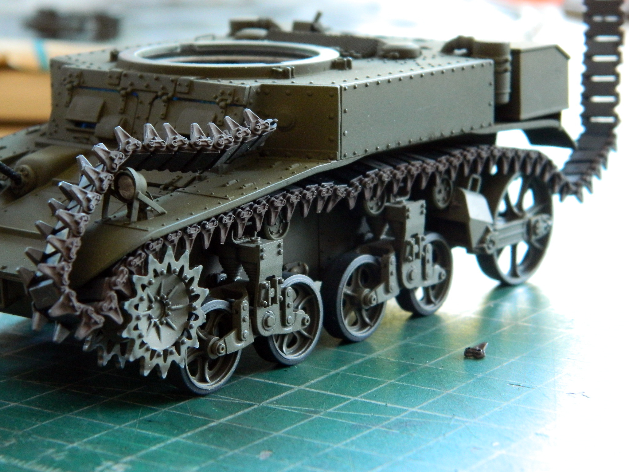
Trust me…MUCH colorful invective was abused getting the GODdamned…er…never mind. It was interesting. But as the above photo shows, not impossible and ultimately accomplished.
And when I tried to join the tracks, I discovered that the length as delineated by the kit’s tracks was just fornicating WRONG:
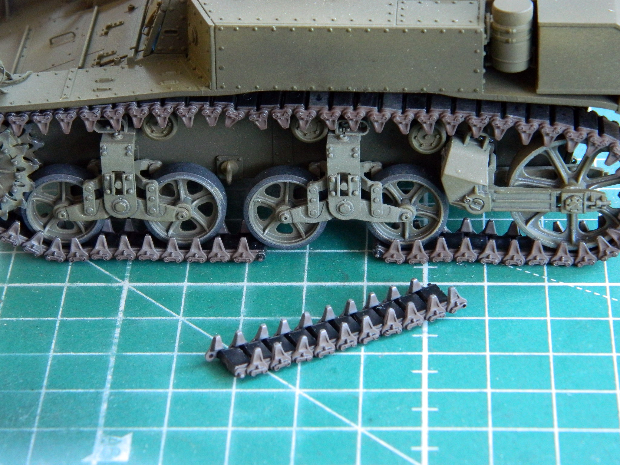
It was four track shoes wrong! Okay…I get that I’m using a different suspension. But I compared what I’m using to what the kit intended to be used and the difference should NOT be four track shoes!
::spits::
Getting the tracks to where they go is just annoying. It can be done with only two hands, though more would have made it easier:

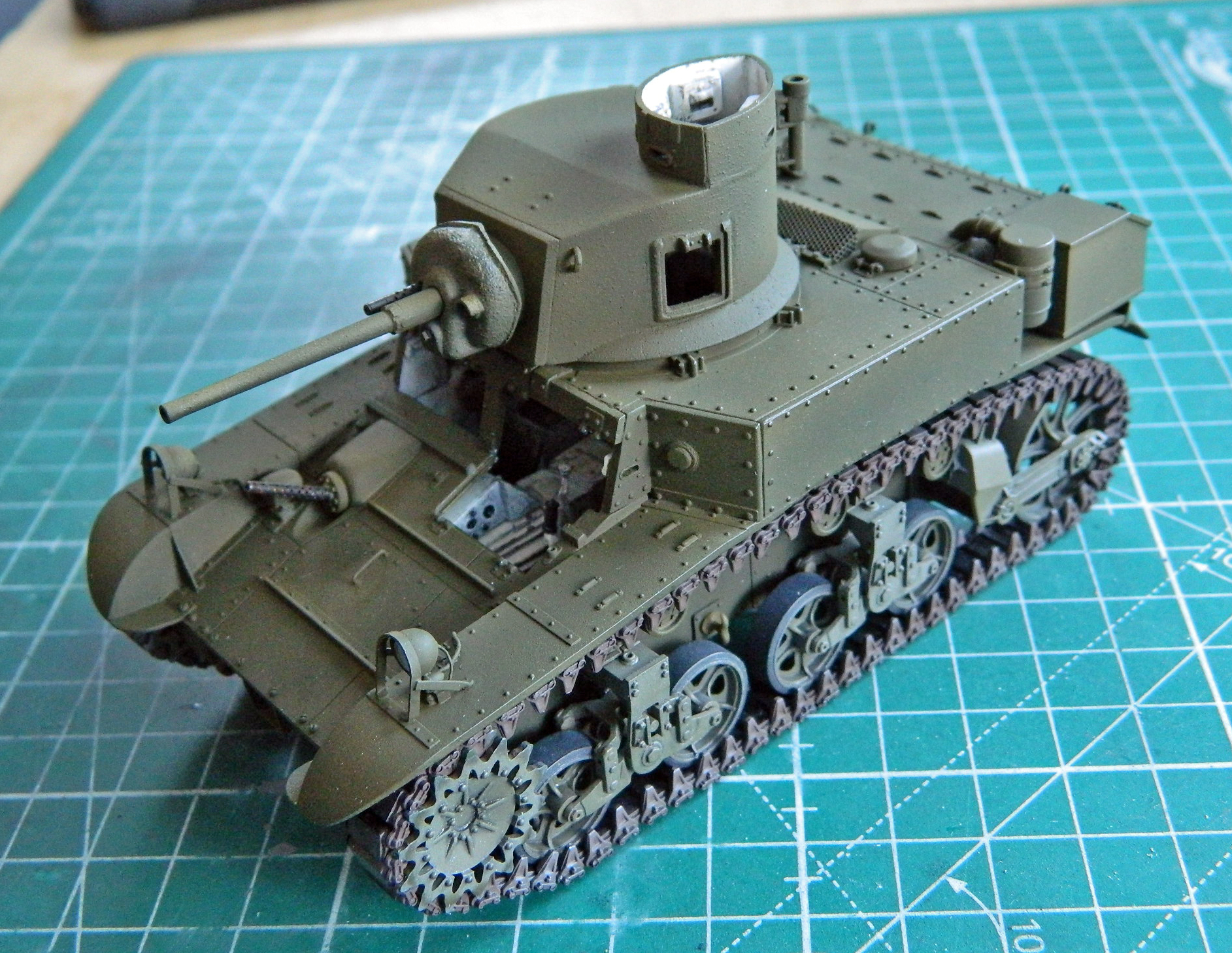
And then I turned the interior light on because after all the sodding tedium, I just wanted to see if it looked as good as I’d thought and hoped for:
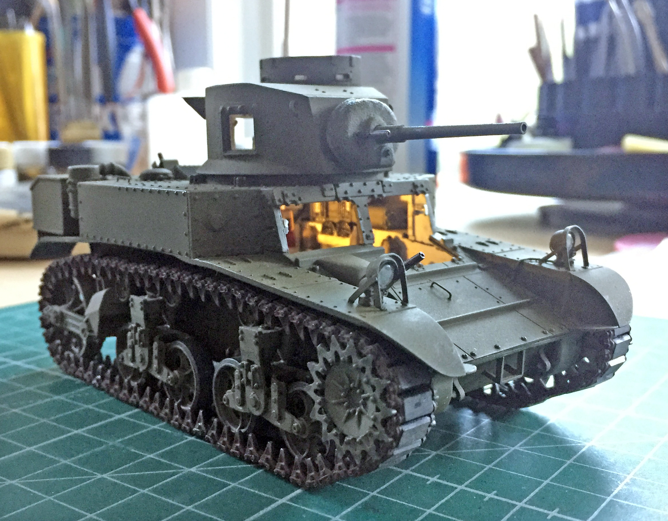
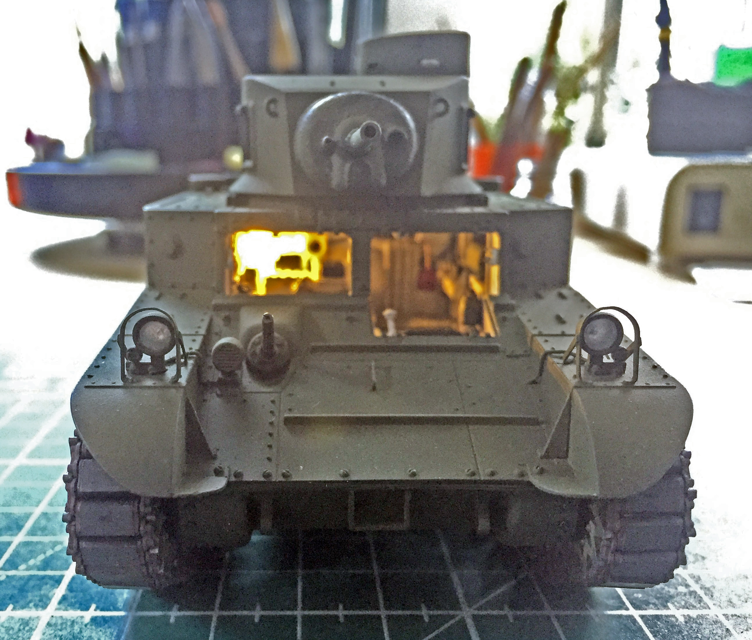
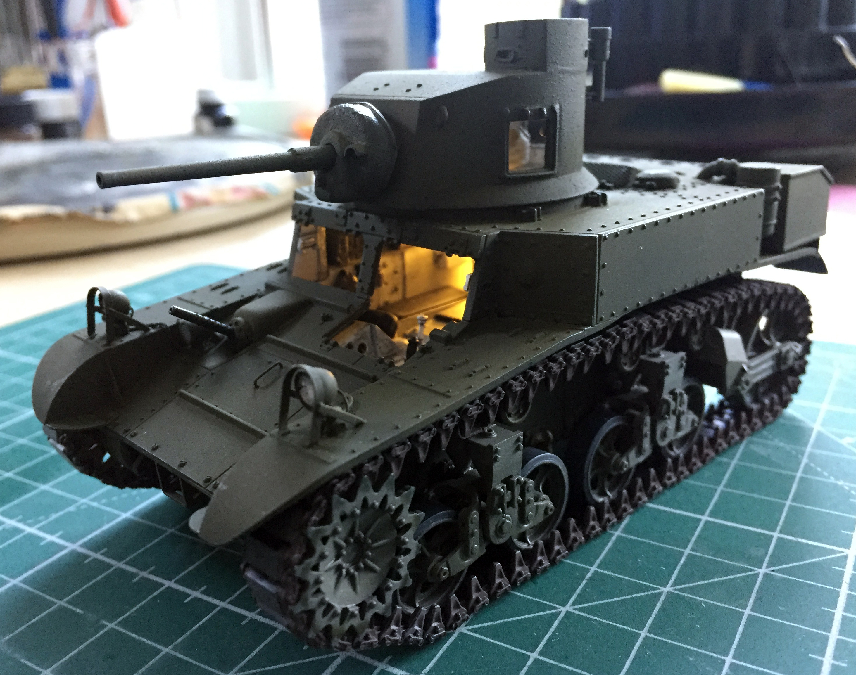
Yup.
Then I added on the front hatches and their support rods…and then all the parts I could dry-fit just because:
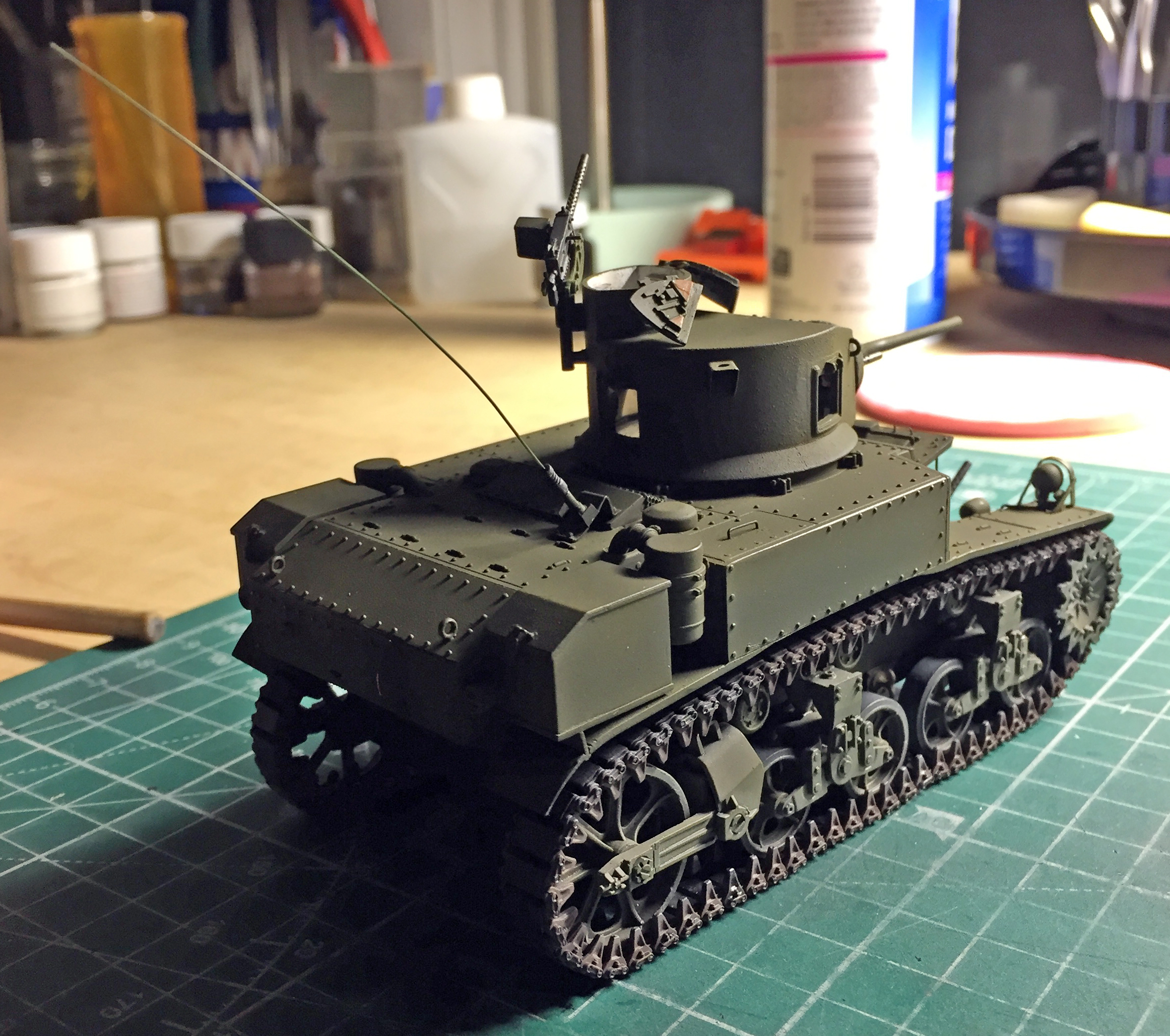
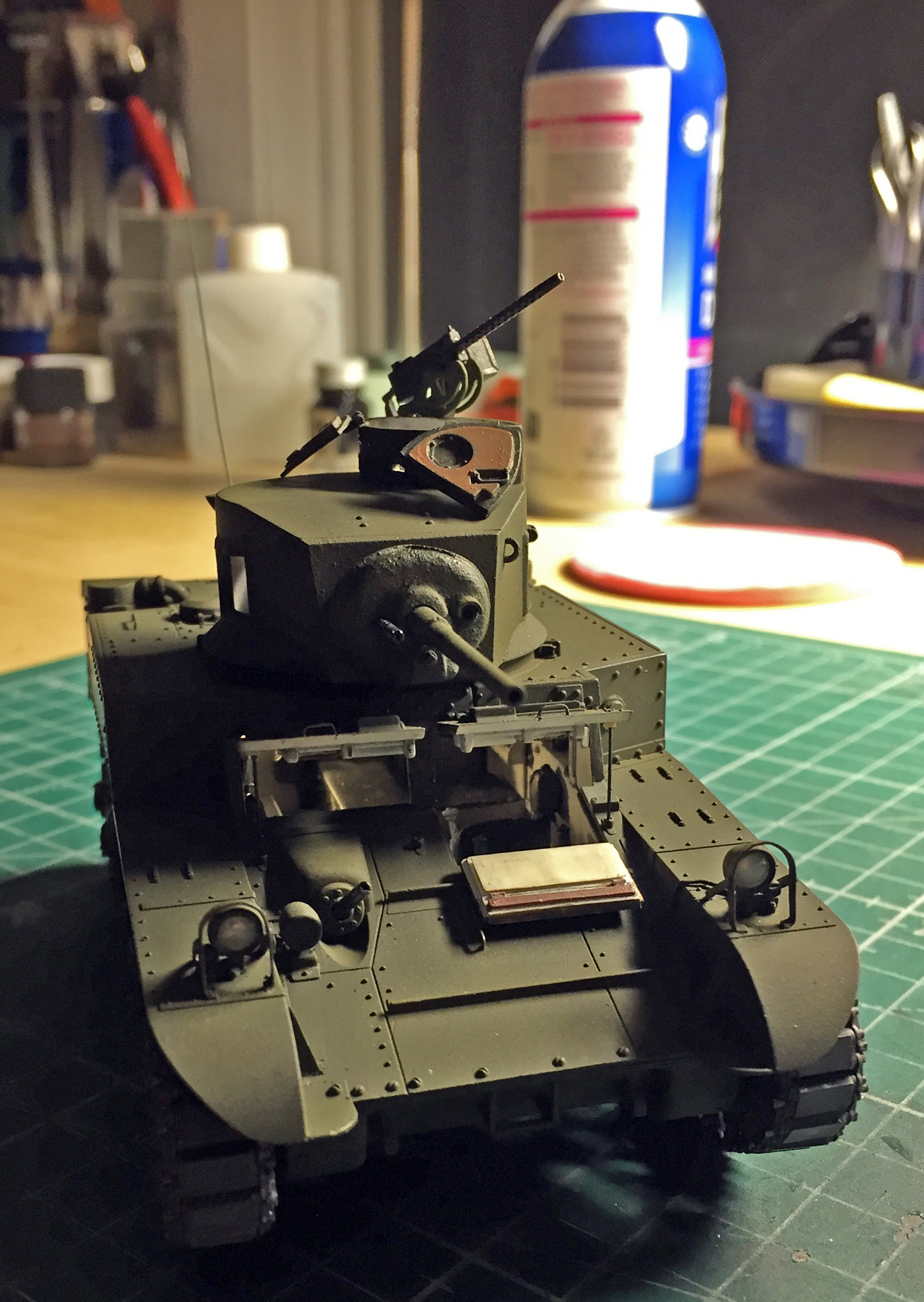
It’s getting there!
When I tried to start adding the markings is when I decided that maybe I’d better wait for the decals (that I just ordered) to arrive. This is what I have, I do NOT like it, and I will be stripping the paint off the turret and doing it over:

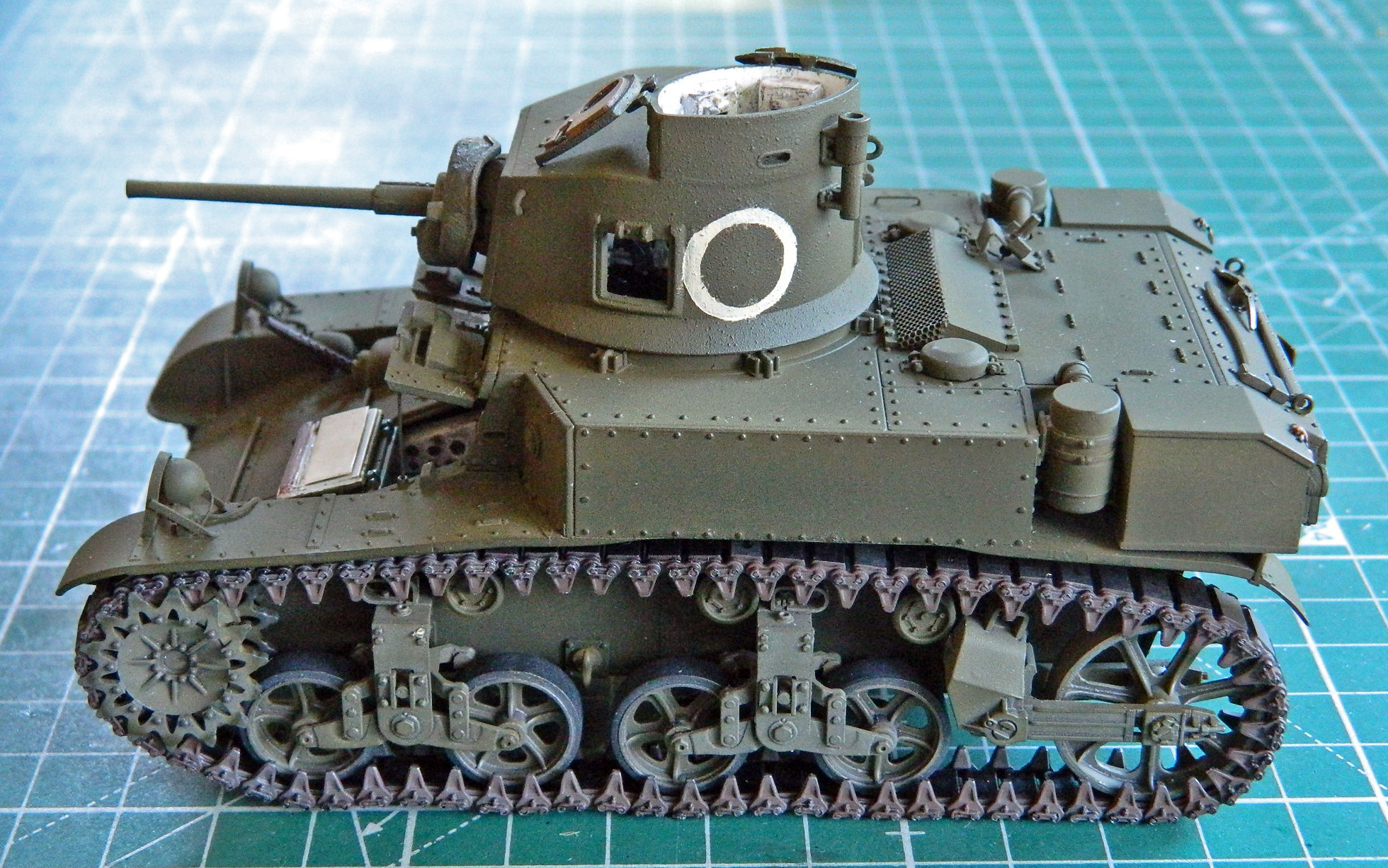
A lot of the early Marine markings were hand-painted over the Army markings (which is where their M3s were sourced), but even the most disinterested Misguided Child would have done a better job than I did.
*See “brain fade” in the glossary
M3 Stuart (Academy) Build #5 – Dealing With Disappointing Fit and Tedious Details
With the crew compartment done, I moved attention and efforts up to the turret. I started putting the main gun, gunner sight, and coaxial .30 caliber (7.62mm) in place (the chipped paint on the gun barrel was from fitting the mantlet):
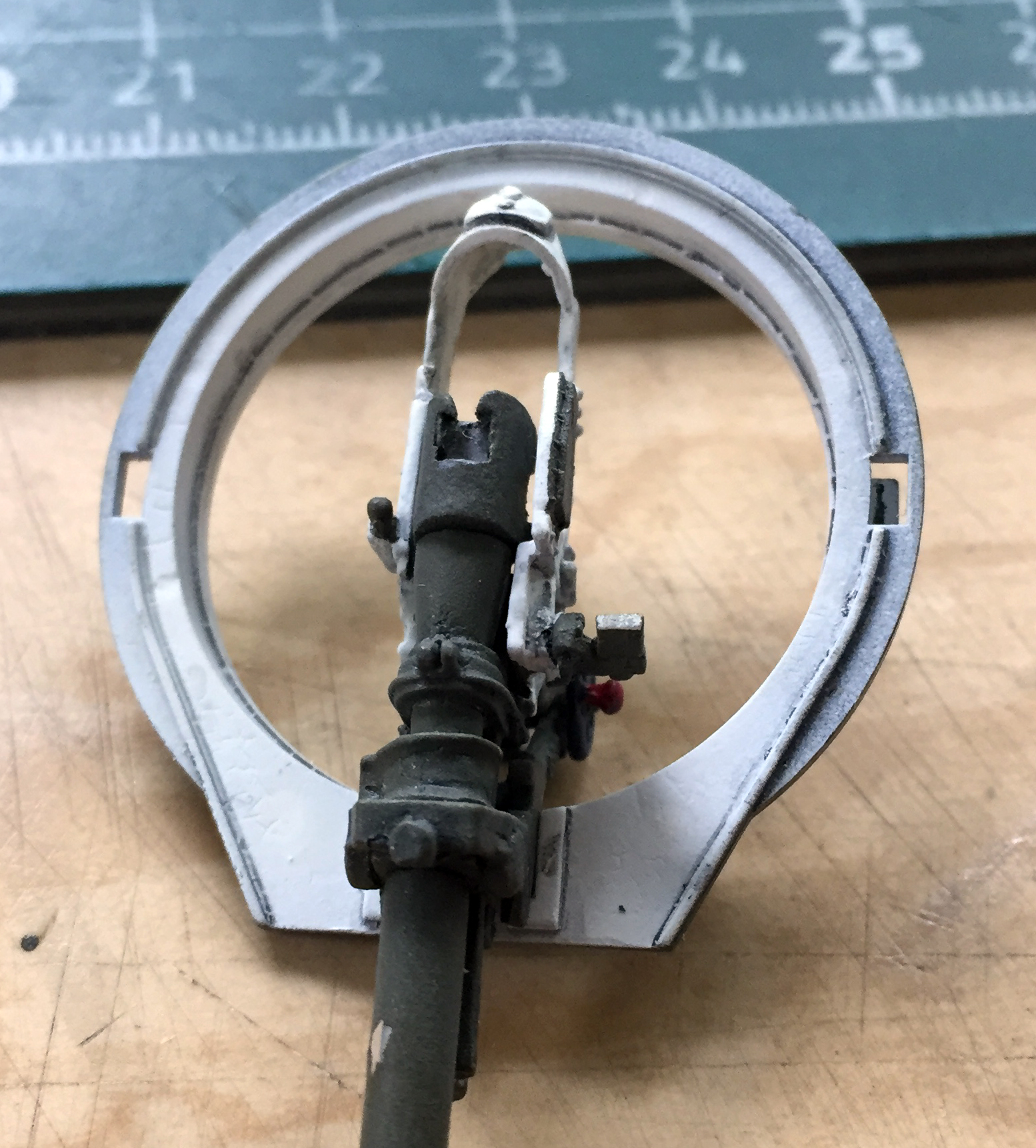
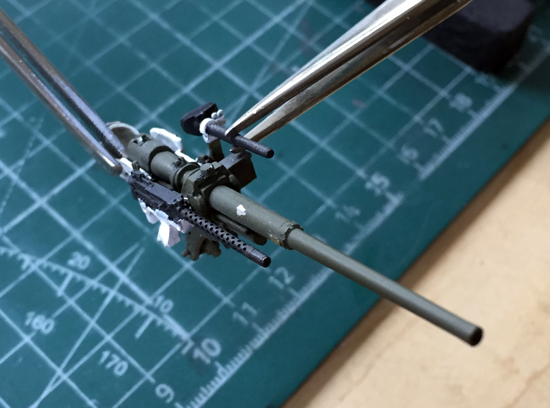
Then I dry-fit the turret bottom in place with the mantlet. I wasn’t quite pleased. The first thing I noticed was that the coaxial machine gun barrel isn’t parallel to the 37mm main gun; it’s closer at the machine gun’s muzzle:

Then I noticed that the resin turret front didn’t sit squarely, further exacerbating the misalignment of the gun mantlet. It’s all rotated slightly counter-clockwise:
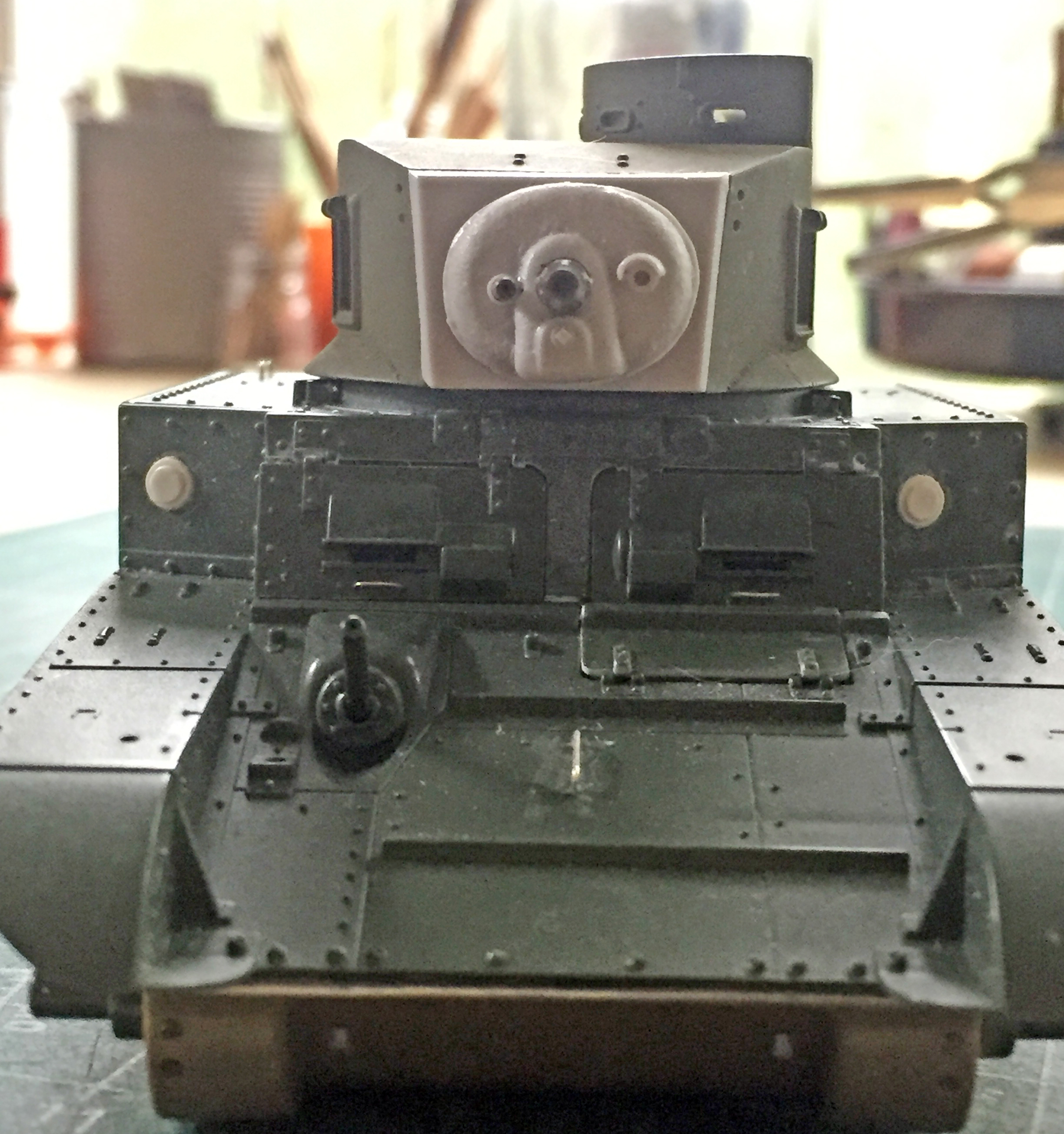
I decided the easiest way to fix that was to shave material off the gun’s receiver (the body of the machine gun for those of you who aren’t gun-savvy). That would allow the gun to rotate and move the muzzle outward from the main gun. I popped the resin turret front off and filed it to fit the turret better:
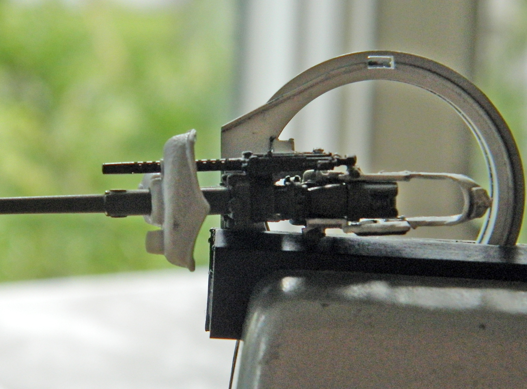
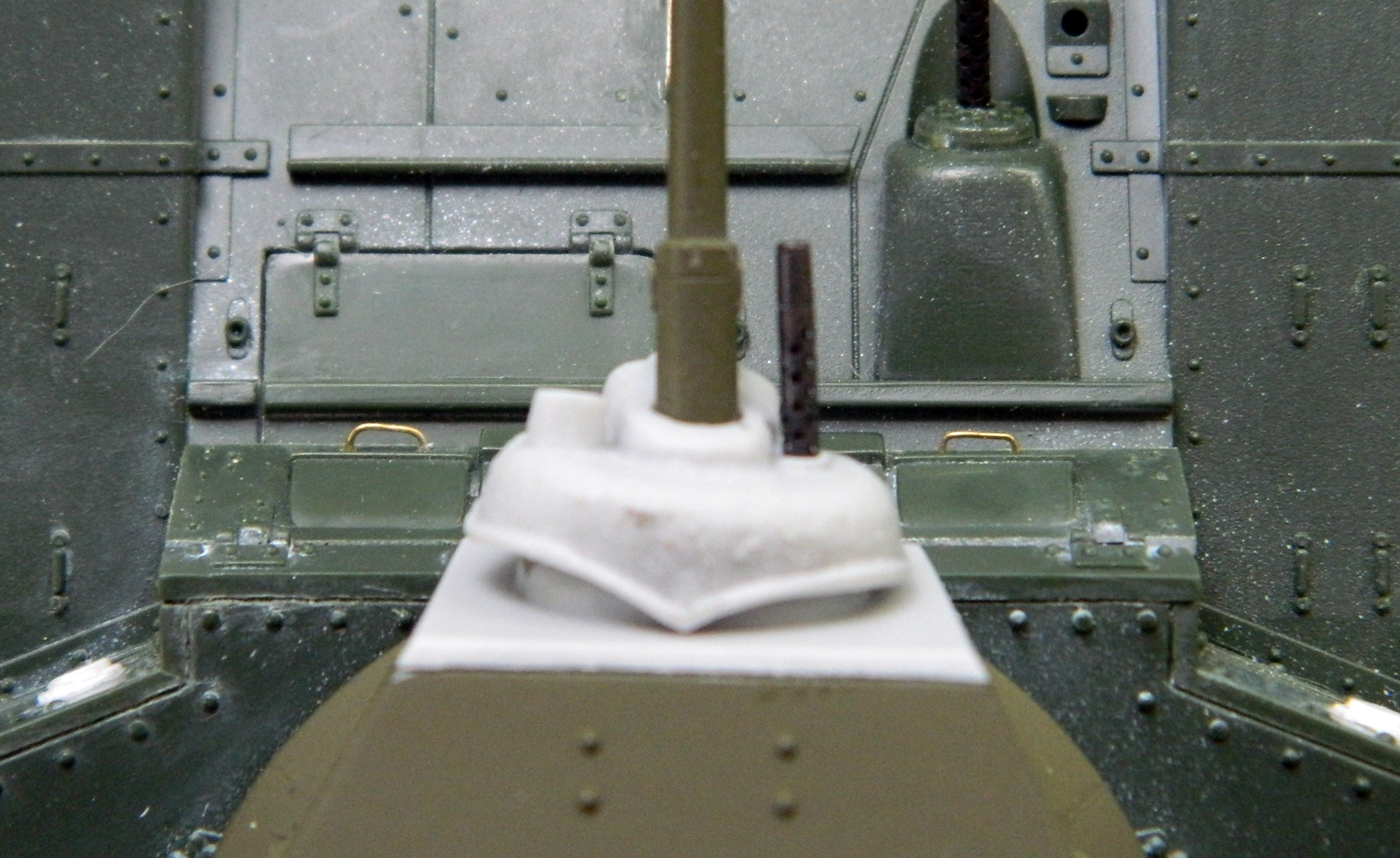
Not perfect but it will suffice.
During the dry-fitting, I noticed that the eyepiece of the gunsight wasn’t sitting correctly. I popped the assembly off, sawed the eyepiece off, and reattached the gun sight’s body:

While the superglue was setting up, I added bolt detail to the air intake assembly on the upper rear hull using Grandt Line bolts (it’s like taking parts of gnats off a sprue and reattaching them…eventually…somewhere else):
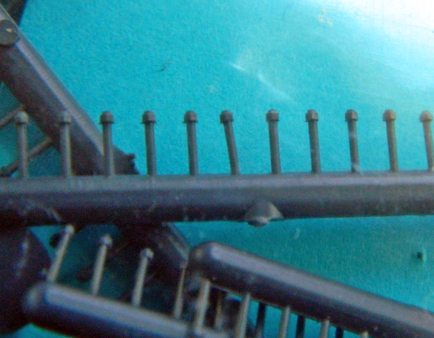
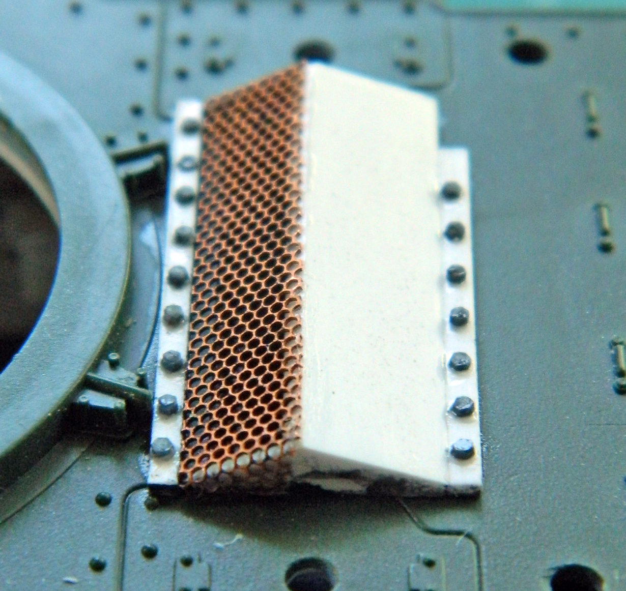
But they look great once they’re in place!
When I went back to dry-fit the mantlet to the gun assembly to make sure the gunsight lined up where it was supposed to, it wasn’t even close. On the inner face of the mantlet facing you, there’s a rounded projection. That’s where the gunsight is supposed to line up…and you can see how close it isn’t:
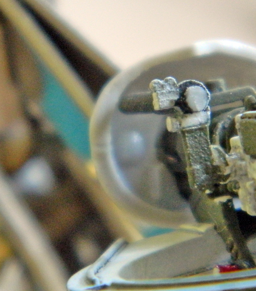
I had first considered that perhaps I’d erred and misaligned the parts as I assembled the gun parts. Nope. I checked the parts, I checked the alignment, and yet that’s where things ended up. (My respect for the person that mastered these parts took another solid hit.) I had to snap the gunsight free and trim the mount a few times before I got an alignment I could accept. That alignment required that the ammunition box for the .30 caliber (7.62mm), which was supposed to mount on the left side of the 37mm to instead be mounted on the turret ring next to the guns (unlike the .50 caliber (12.7mm) machine gun, the .30 caliber (7.62mm) can only be fed from the left side, requiring the ammo box to be mounted on the left side of the main gun with a chute above the 37mm to guide the belted ammo into the feed port).
No…that’s not in there correctly, but the cramped space inside the turret worked in my favor this time. Much of what had to be fudged and worked around cannot be clearly seen. Tight quarters and limited viewing angles can sometimes hide adaptations.
I discovered that the mantlet’s fit was a bit off. As it “fit,” the peak on the rear of the mantlet contacted the turret face while the barrel of the 37mm was mostly level. Well, that would certainly interfere with elevation:
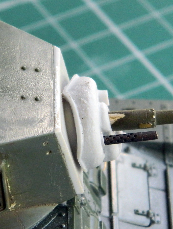
In order to move the mantlet away from the turret face, I needed to add a spacer (about .045″ (1.143mm) of scrap styrene) to its mounting point:
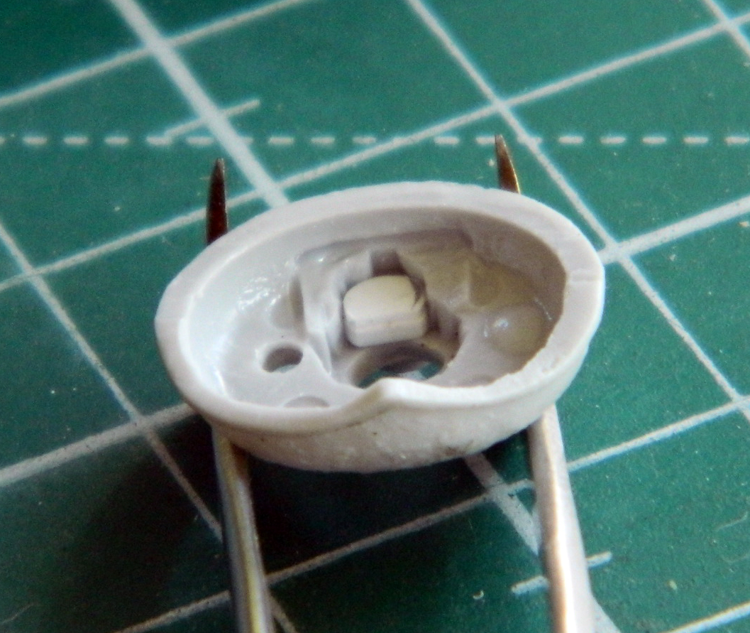
That solved the problem:
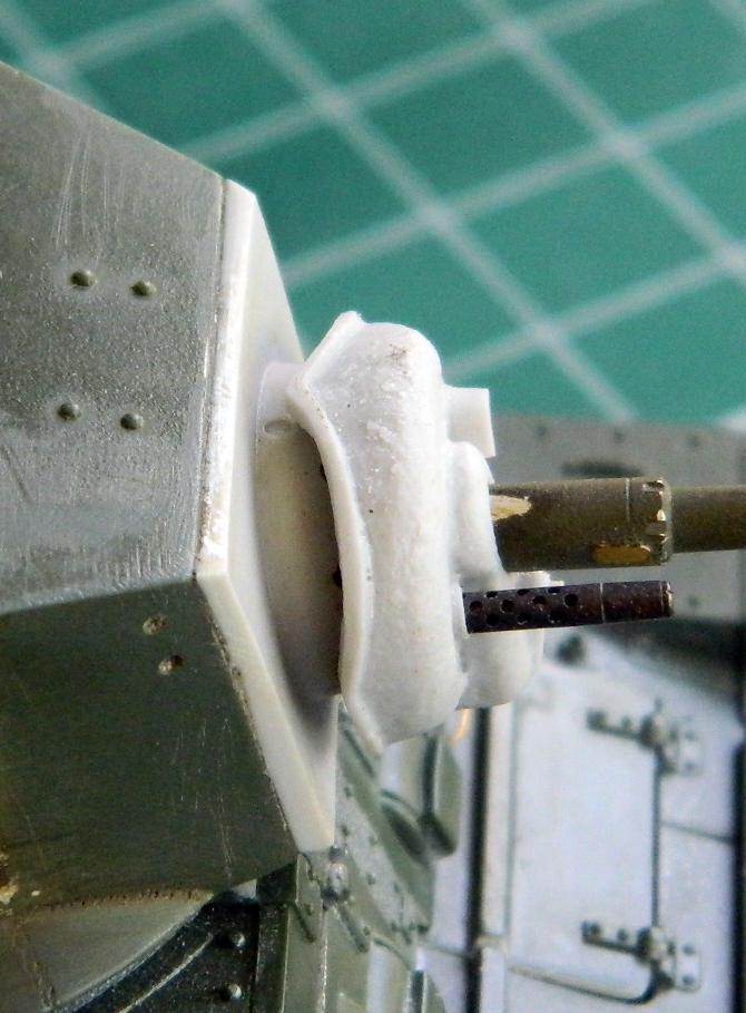
References show that the commander’s .30 caliber (7.62mm) was usually mounted in the Pacific (and at Guadalcanal, which is the locale I’m modeling this tank to represent). That gun is in the line of sight and I wanted to do something a bit more accurate than the kit’s part. I wasn’t especially satisfied with any of my options; the resin guns didn’t really fit the mount and the kit’s gun lacked detail. The easiest problem to fix was the absence of detail. Add some:
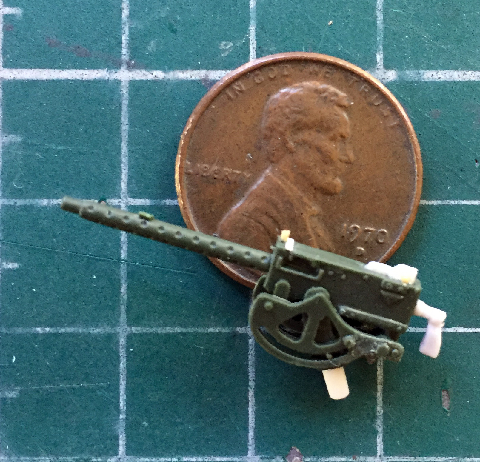
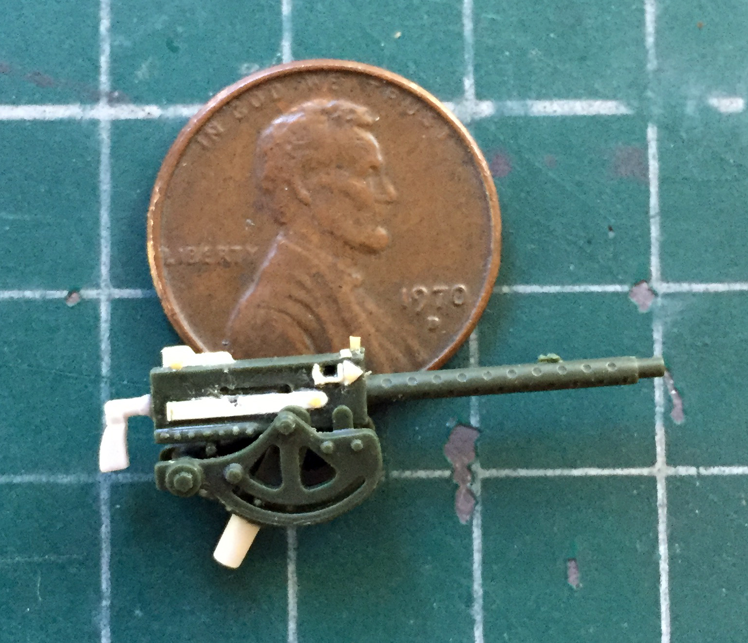


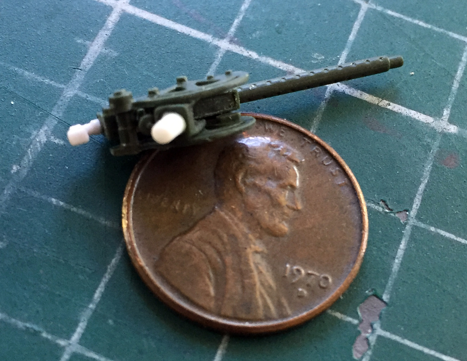
I’ve noticed that earlier in the war there was greater variation in gear than by the end of it. My assumption is that pre-war stock was used up and later in the war, equipment became more standardized for easier manufacture. I have plenty of what became the standard .30 caliber (7.62mm) ammo boxes on hand (500 rounds?), what I did not have was the 250 round box that was being used by the Marines in later summer of ’42. That required me to make one:
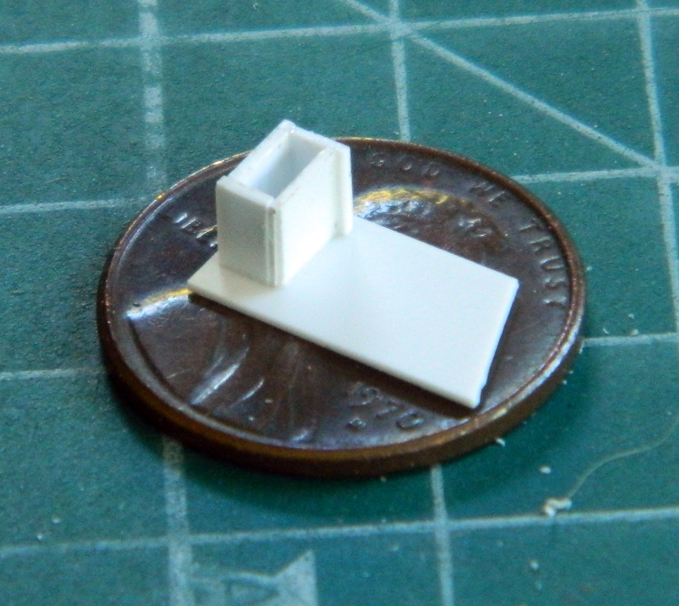
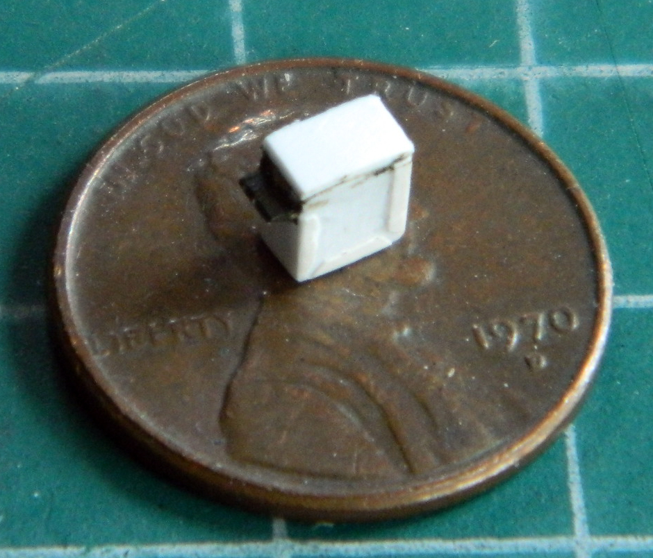
With the gun painted and the brass barrel installed, it just needs to be mounted in place:
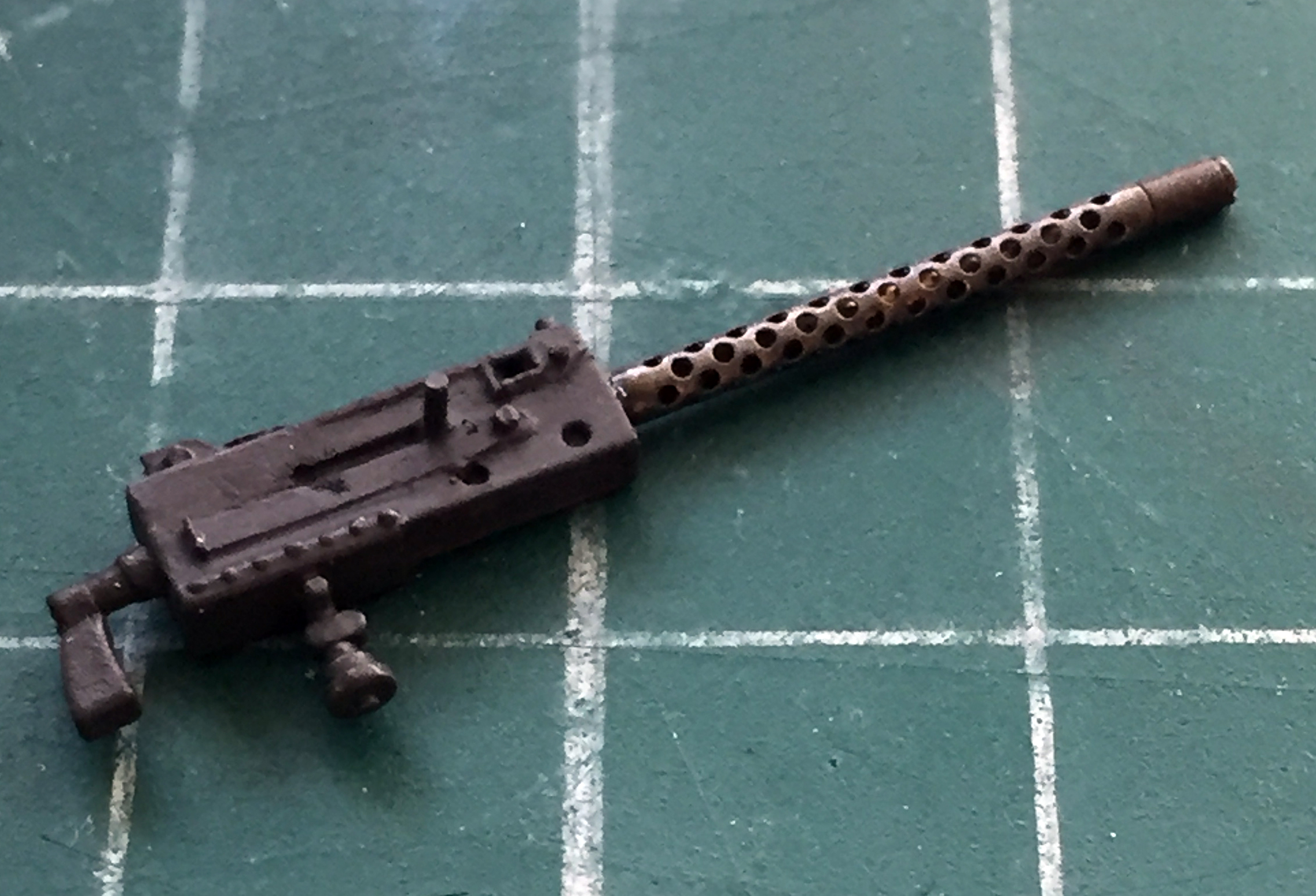
While I was wandering around the outside of the turret, I used .005″ (.127mm) copper shim stock to fold what looks like an unused antenna mount (because where would they put the second radio?!). As you can see, sometimes even something simple like this requires more than one attempt to get what you want:
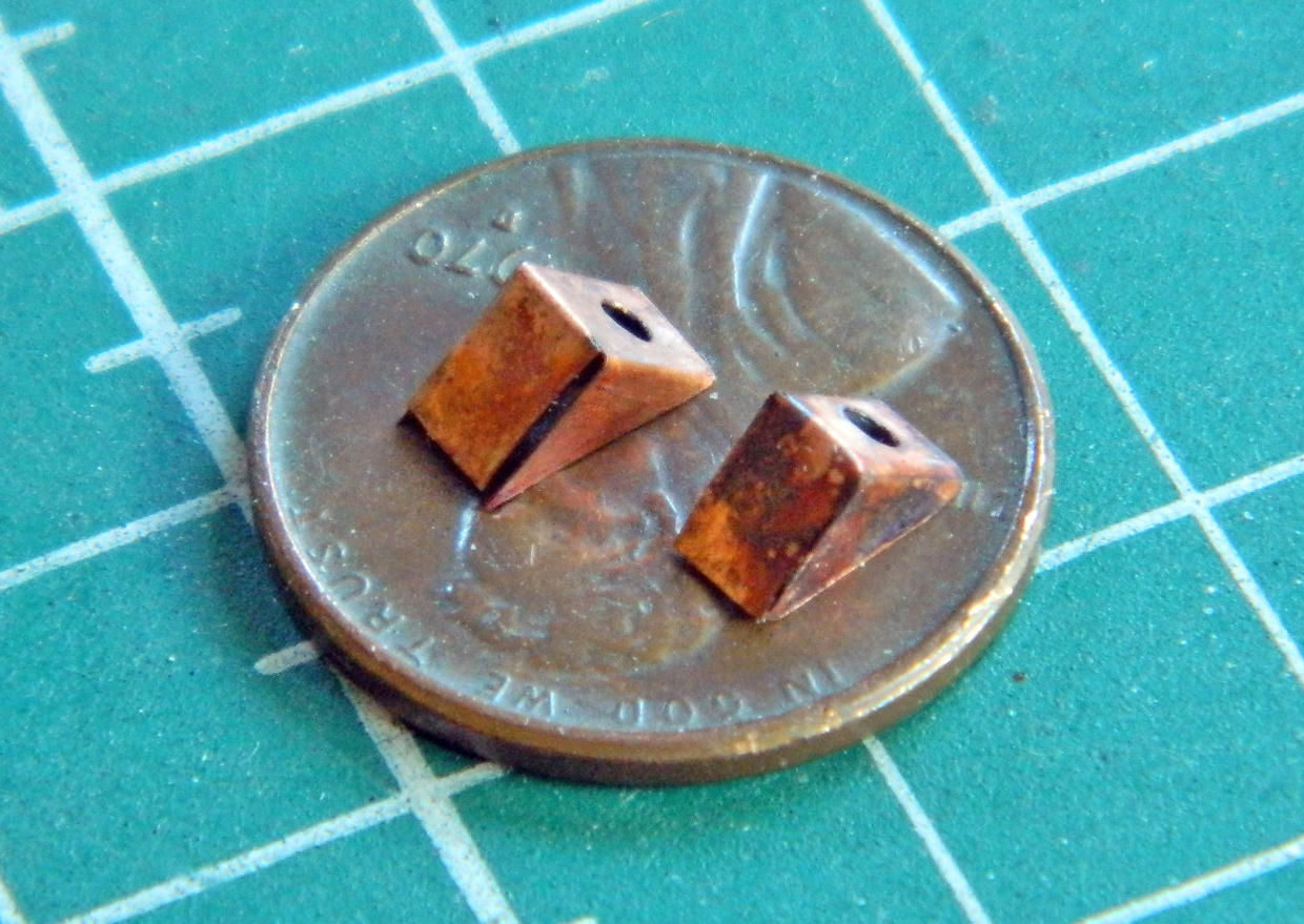
This time when I married the upper hull to the lower hull, I decided that IF I needed to vacuum the fornicating bench, it could sodding wait until it was ass-biting clear:
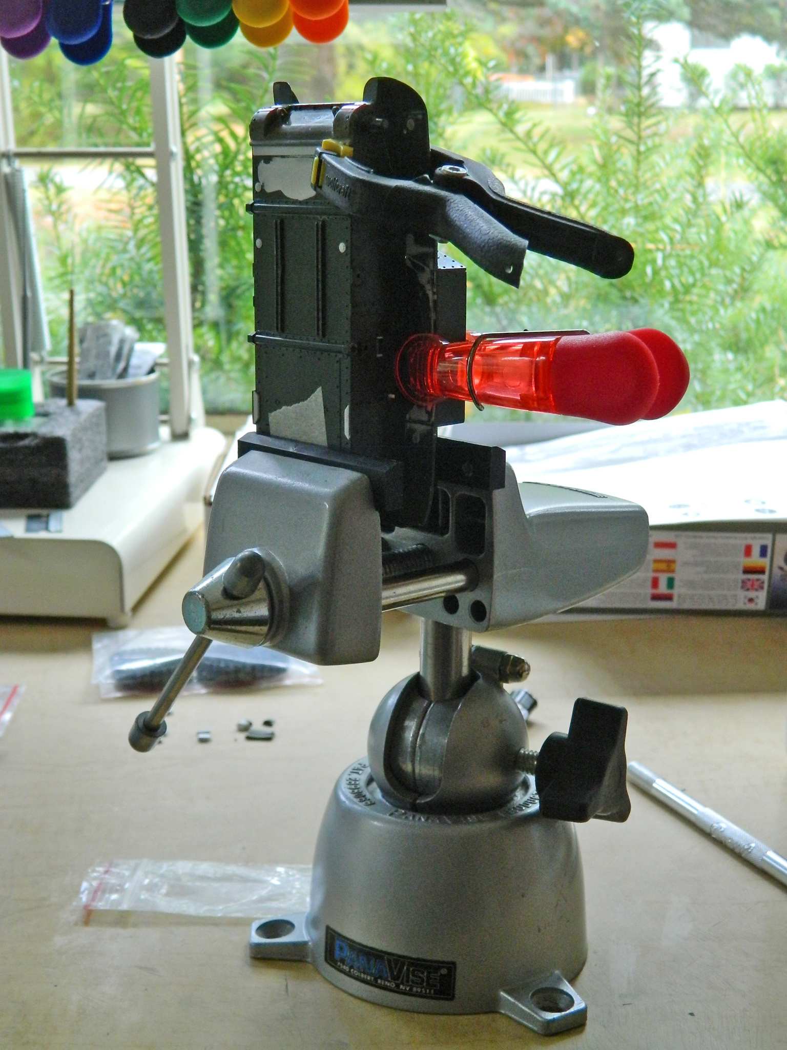
While the glue set up on the hull, I assembled the linkage that opened the pistol ports:
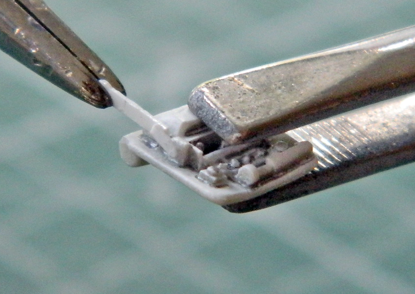

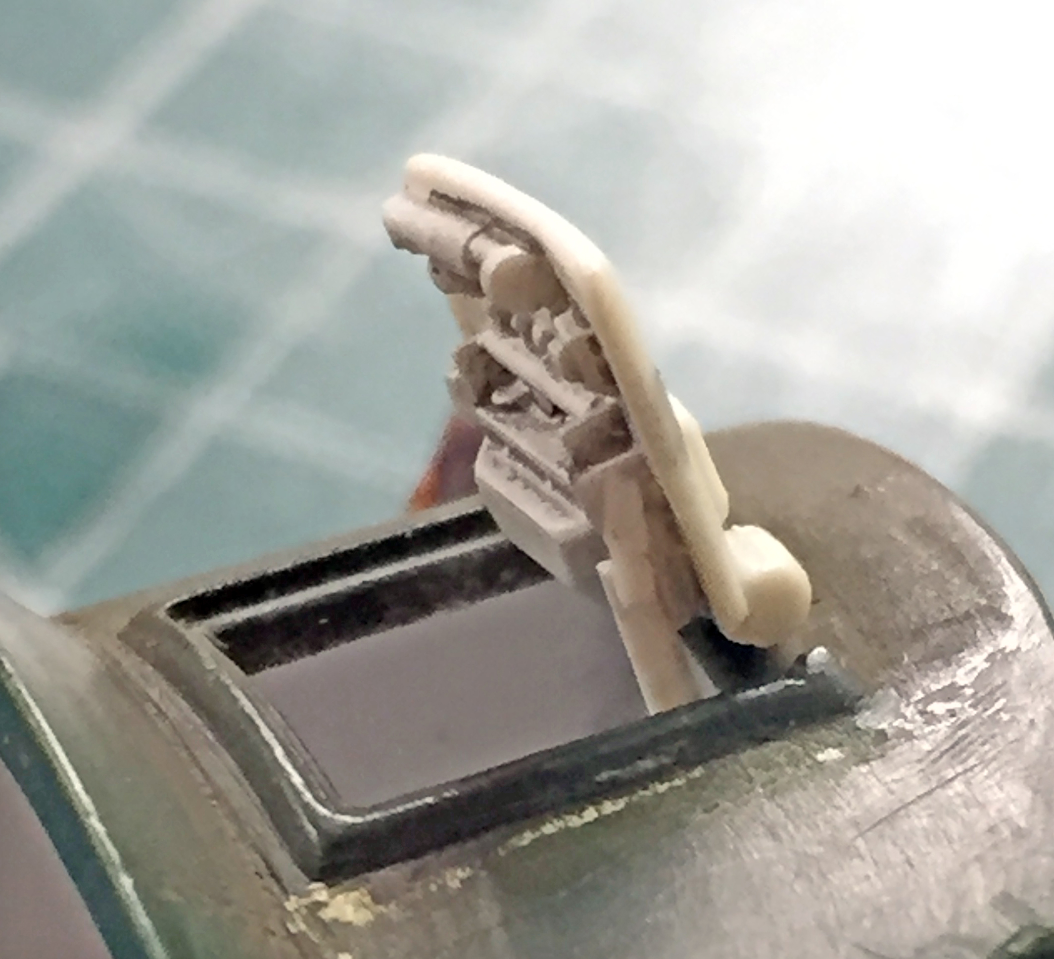
I also added more Grandt Line bolts because the mounts for the M3’s port hatches were bolted on unlike the Sherman’s, which were welded in place:
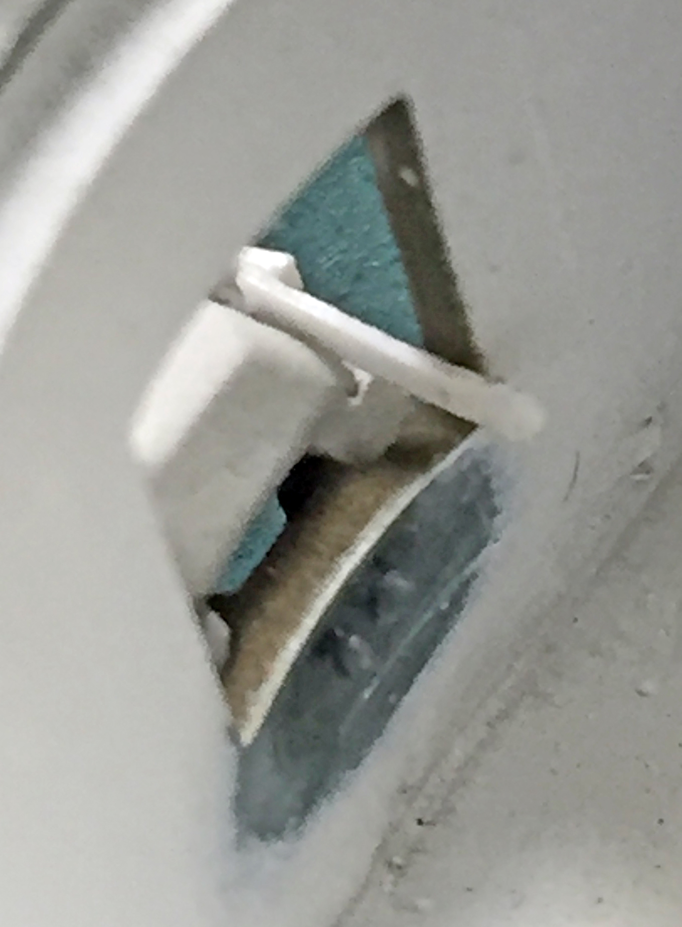
There will be more linkage added to the pistol port hatches later on.
Since I had the upper hull in place finally, I puttied the underside of the sponsons to hide the gaps (again):
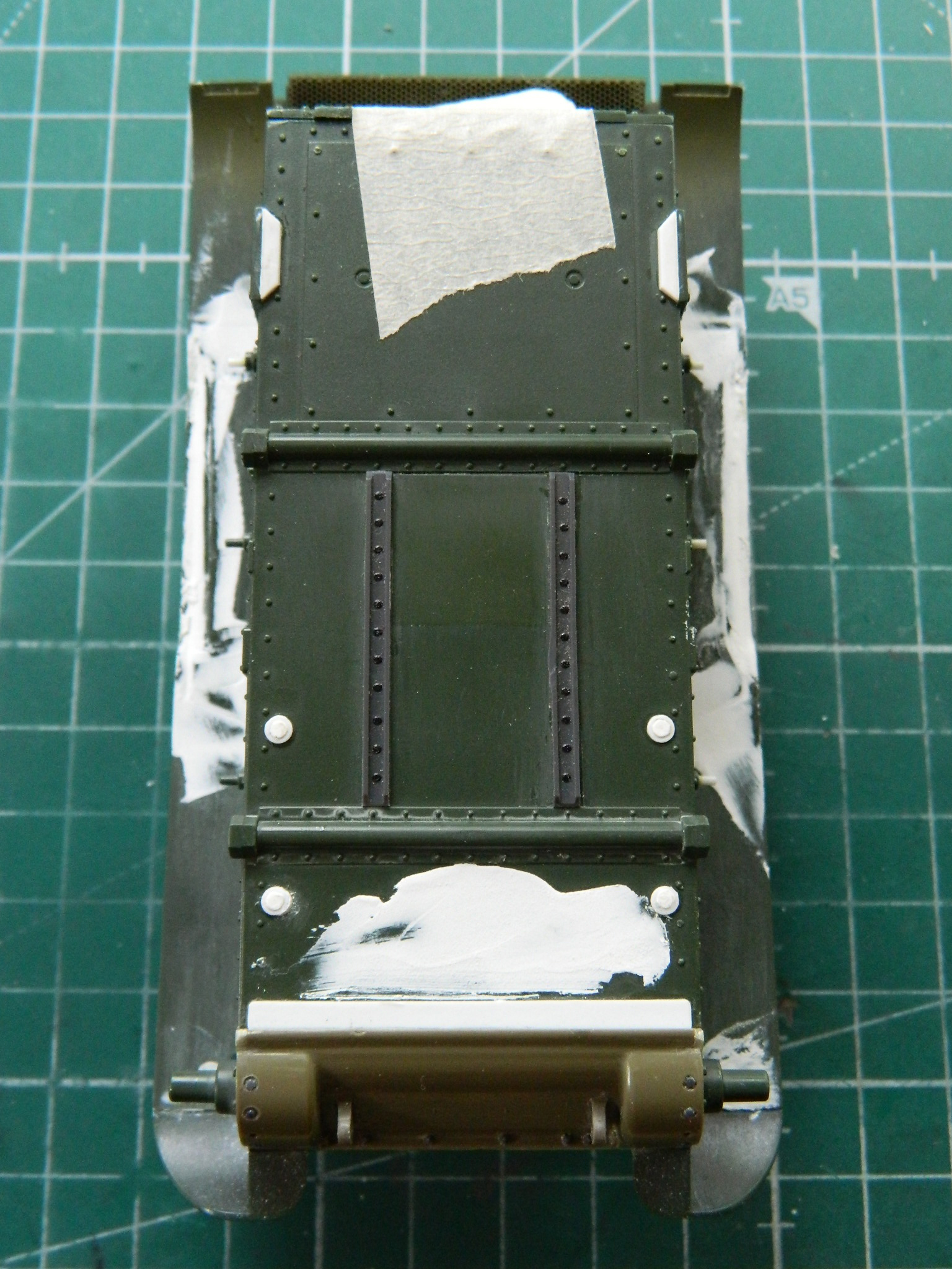
As I build, The Boys in the Back wrestle with various things that are problems in search of a solution. One of the (several) problems with this kit is certain details. It started with the headlight assemblies and then grew to encompass a few other things. The taillights were a bit off as were the air cleaner assemblies. While looking for something online that had nothing to do with modeling (yes…porn, again), somehow I ran across a video review of Tamiya’s new-tool M3 Stuart (because don’t all porn links take you to modeling websites?!). My take-away from that was that it’s a MUCH better kit than the hoary old beast from the early 70s and that due to how the parts were engineered, putting an interior in that kit would be a stone bitch. Fine if a silhouette model is the goal, though. Oh. And Tamiya’s headlights, taillights, and air cleaners were EVER so much nicer than Academy’s representations! In fact, they’re nice enough for me to have bought the kit as a donor kit. (Clearly, I need a life.) (Other than cruising porn.)
For instance… On the left is the mostly-assembled Tamiya air cleaner assembly, on the right is the Academy air cleaner:
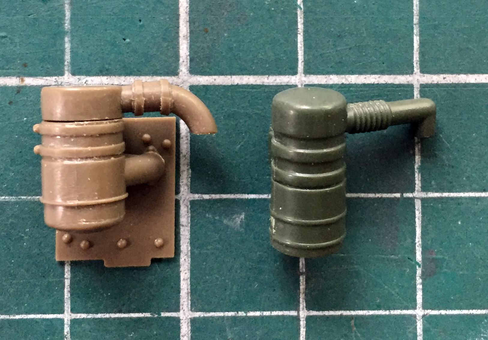
The Tamiya part is more accurate, intake ducting (the lower one on the right) is present whereas the Academy has none (and there’s no detail on the hull where this assembly goes in the Academy kit), the curve to the output ducting is accurate meaning I don’t have to fix the Academy ducts. Nice. But nothing is perfect (except maybe for stupidity) and Tamiya didn’t provide for the rods that keep the bottom of the air filter housing in place, so I added them:
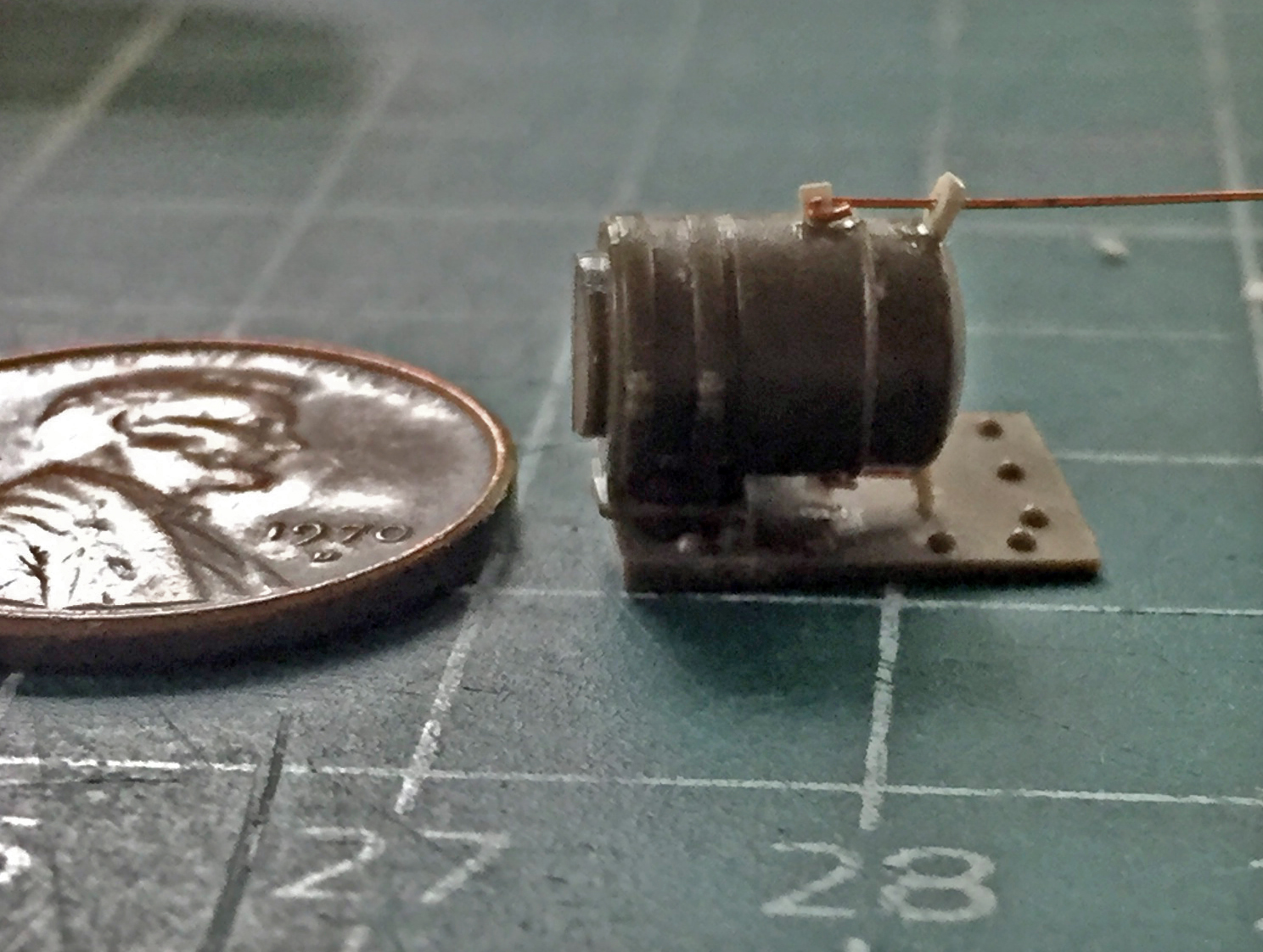
There was a fair amount of fiddling alignment, application of glue, and waiting for the glue to set up so that I could continue. So while that was curing and waiting, I went back to work on the turret.
With the nuts, resin turret face, and the mount for the opening linkages for the pistol ports in place, I repainted the inside, gave it a coat of clear gloss, a dark wash, and a sealing coat of clear flat:
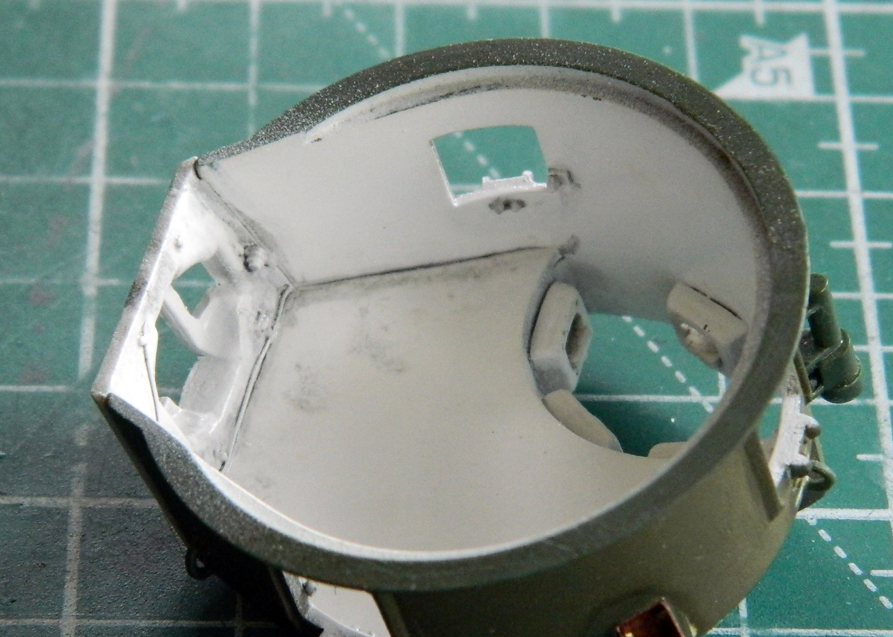
As that set up, I continued fiddling with the air cleaners:

Just those four small additions took enough time that while the glue on all of those additions set up, I populated the interior of the turret:
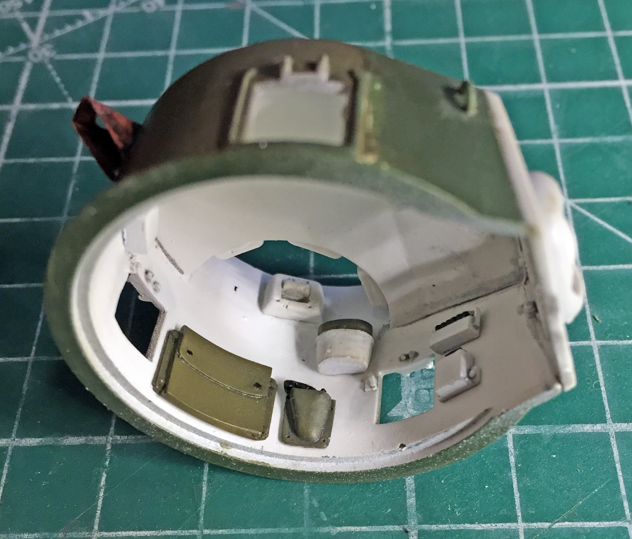
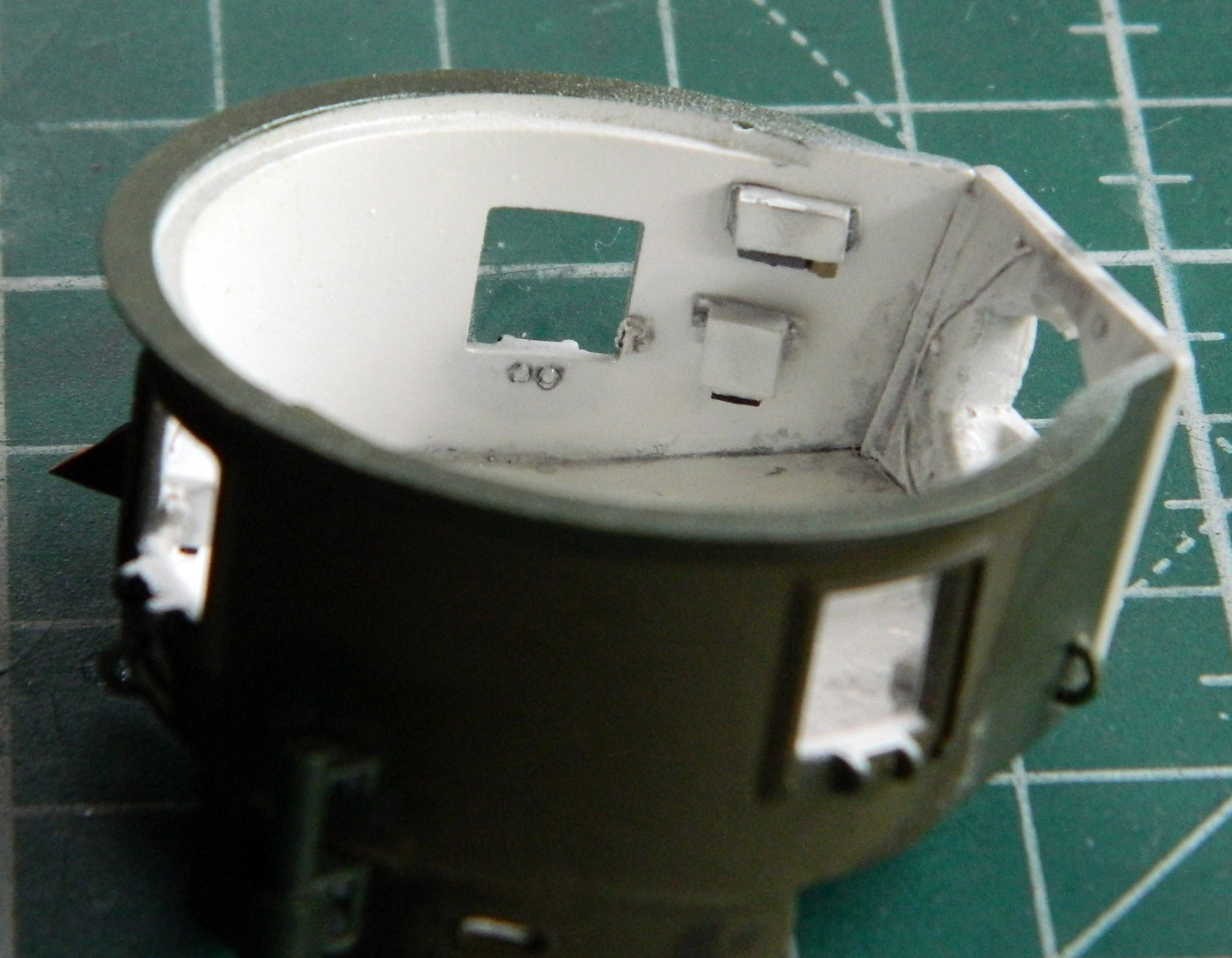
Adding more detailed air cleaners would take a bit of surgery. As you can see, just gluing them in place would result in this section of the hull being far too thick (and later on I would definitely need that missing space for something else):
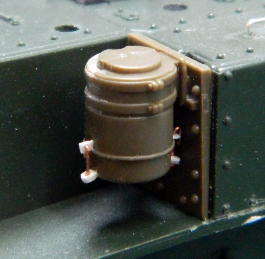
With that just held in place, I traced the edge of the new part on the kit to see how it could fit. If I could excise the plastic between the scribed line and the hull, I figured I could socket the new parts into place without losing the space I’d need to mount the sponson storage boxes (and this photo shows how bereft this area was of details):

First I hogged out the plastic with my Dremel to get it close:

Then I used a freshly sharpened chisel blade to scrape things to a more accurate configuration:
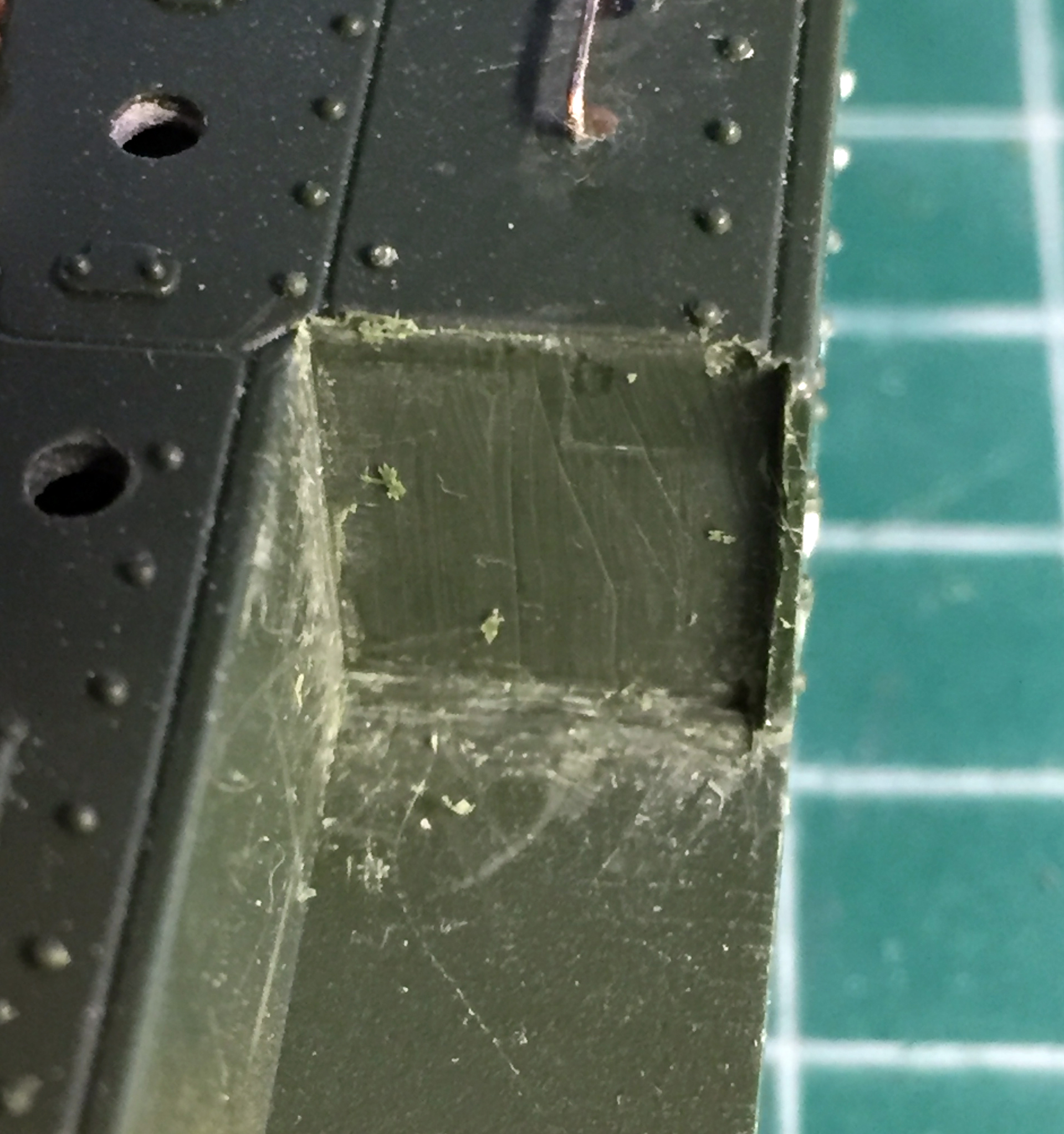
The new part was dry-fit several times with resulting adjustments until a pretty good fit was achieved:
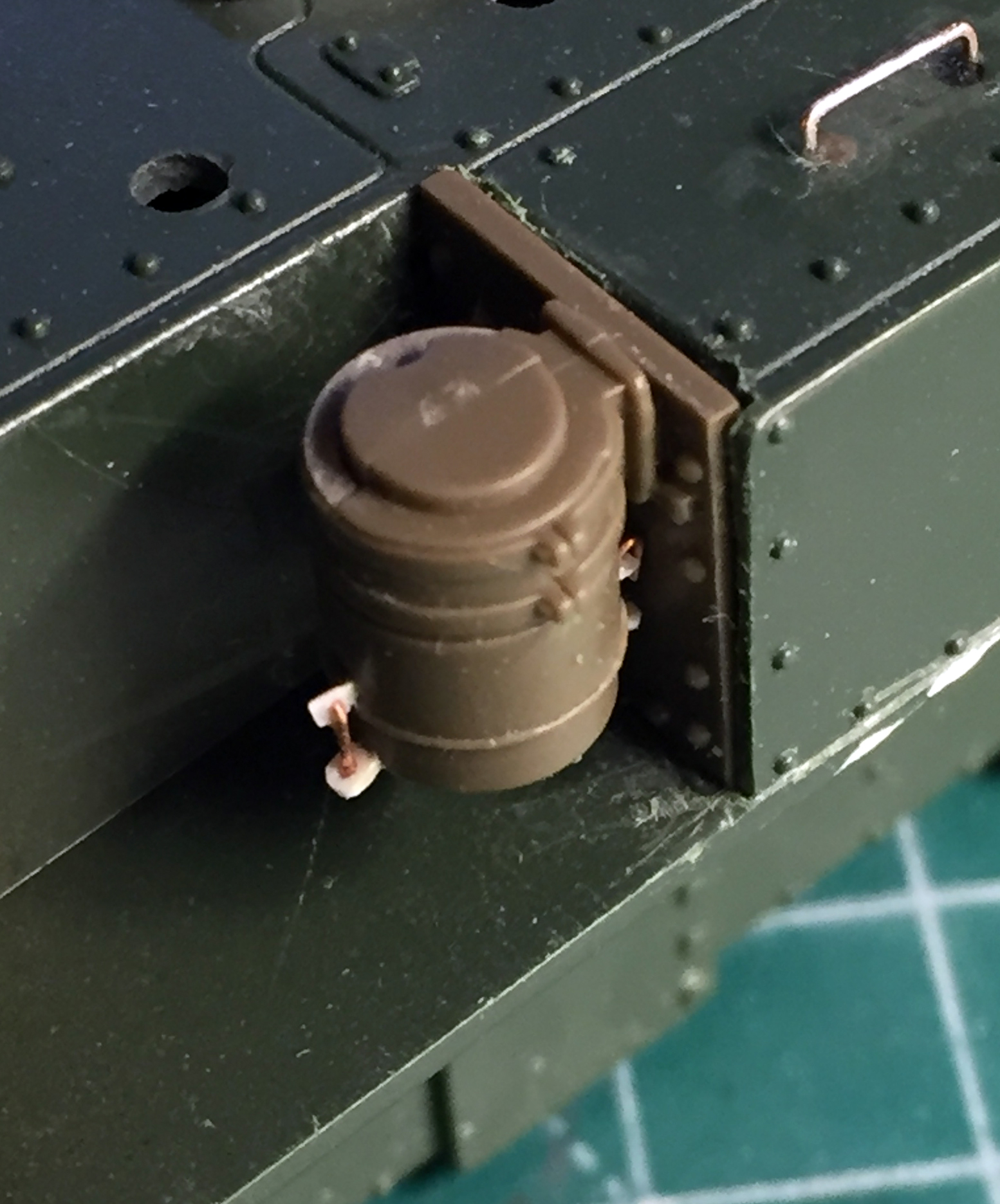
I also checked to see how the new ducting would line up with the hole in the engine cover, which it does not:
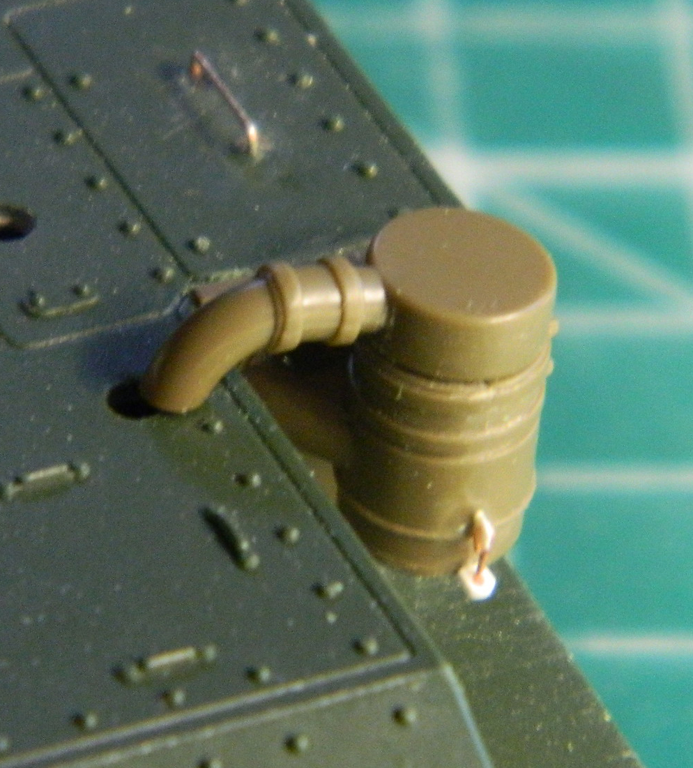
Right, so, that hole got filled. I chucked a piece of sprue into a variable-speed drill and used a file to taper it slightly and then stuffed it into the hole and glued it:

I didn’t know how much of the missing rivets would show so I added some Archer resin decals (great stuff, that!). I discovered later that most of these would never be seen:
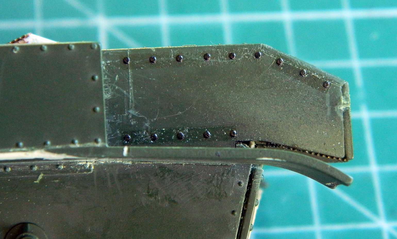
The detail for the mud flaps provided by Tamiya was better than Academy’s so I cut off the rear of the fender to add the Tamiya part:

I dry-fit the air cleaner assembly to determine where the new access holes had to be drilled and then checked alignment. Satisfied, right after this photo was taken I glued both air filters in place:
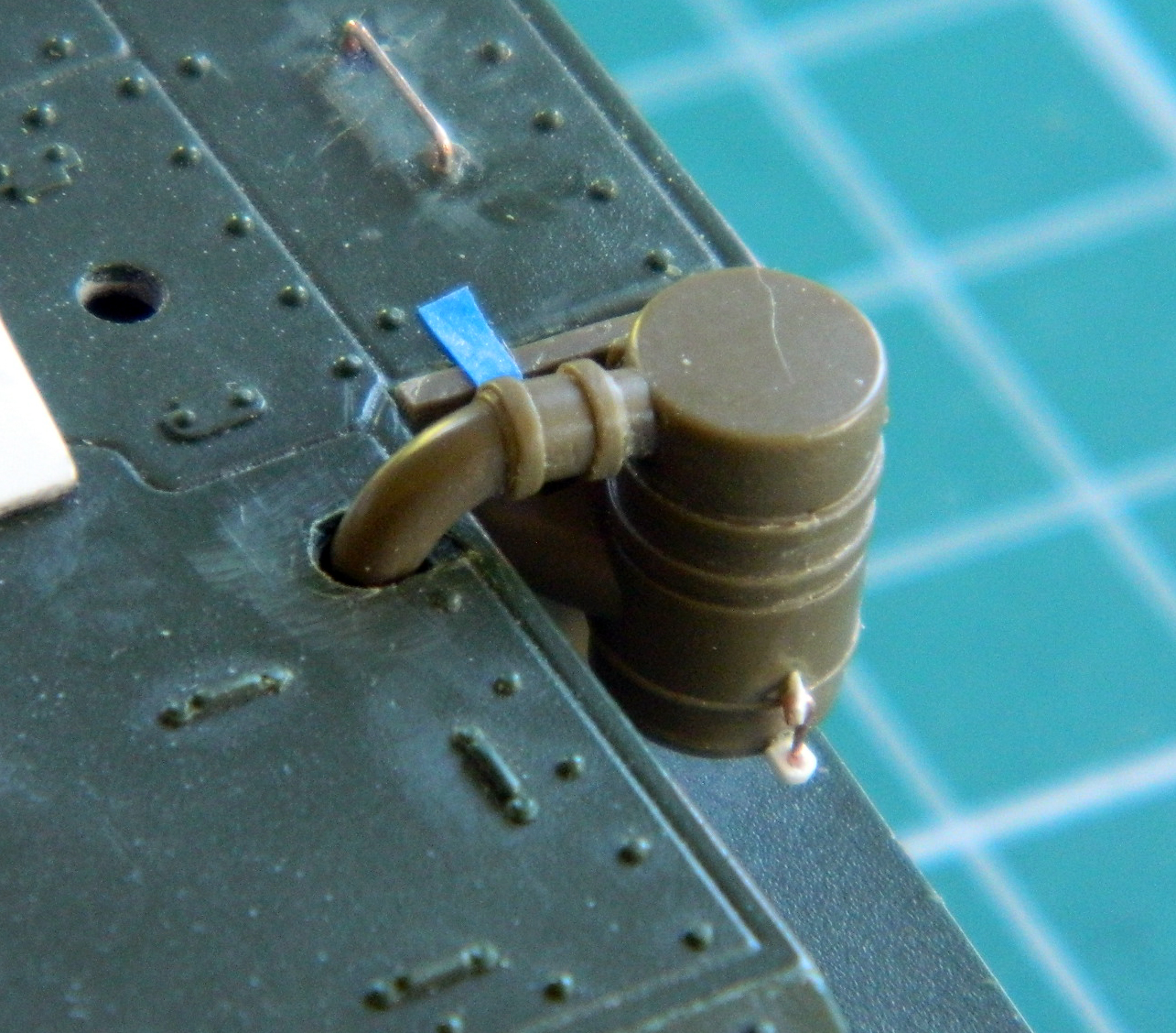
With those permanently attached, I added the sponson storage boxes and the mud flaps:
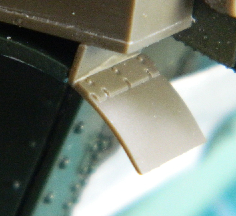
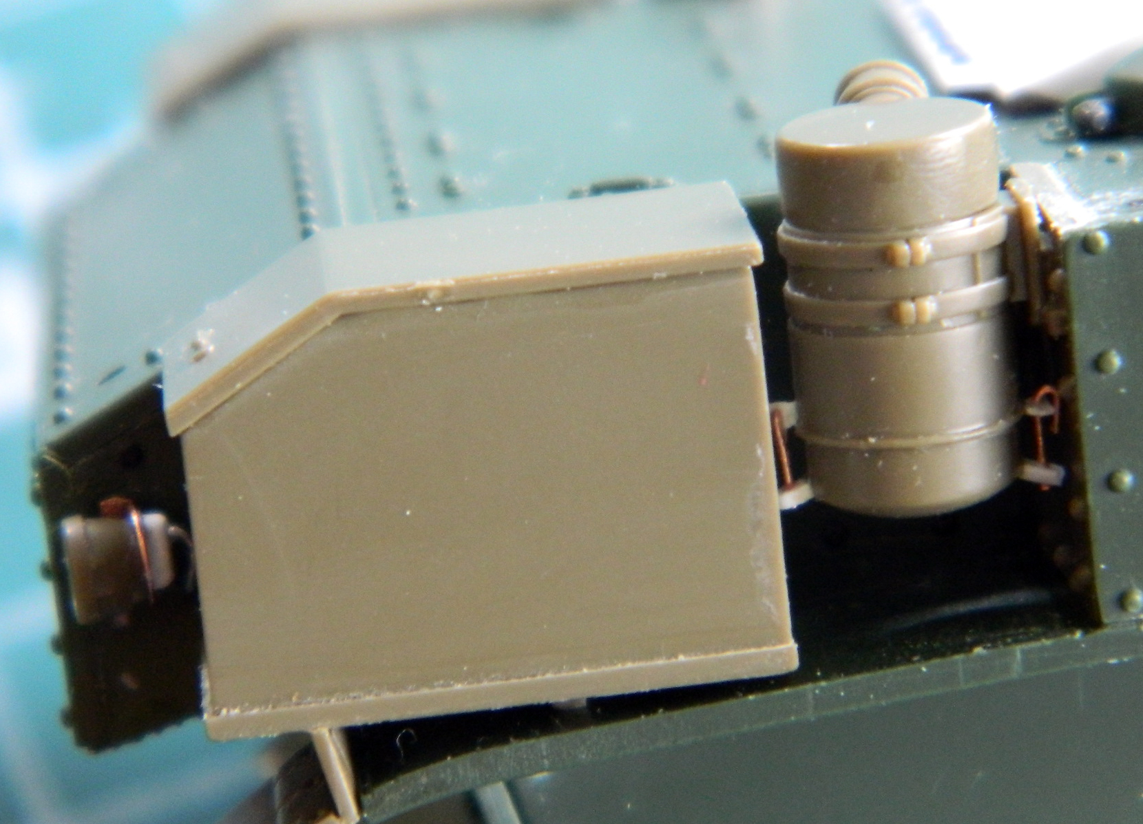
I also removed the kit’s taillights at this point. I used the Tamiya parts, made mounting brackets from .005″ (.157mm) copper shim stock, and added detail to the back of the light and used some .015″ (.381mm) solder as wiring conduit (which can also be seen in the above photo):
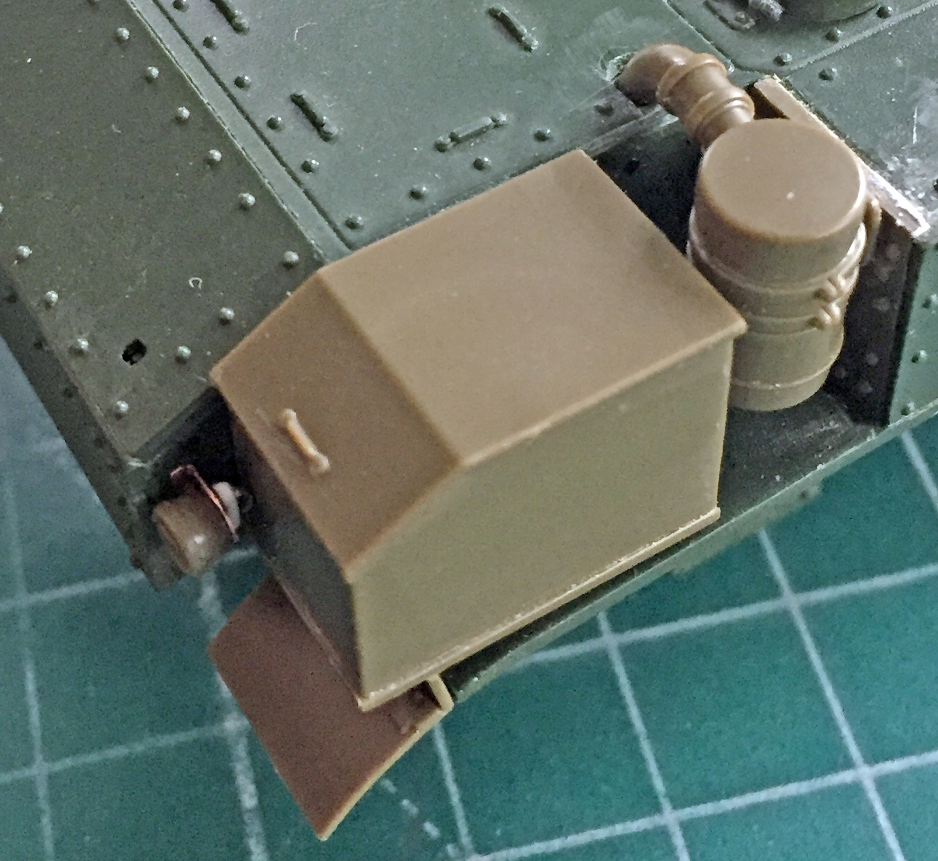
The armored fuel cap covers have distinctive and evident bolts holding them closed. The kit’s covers had the bolt length but no nuts. Once again, Grandt Line to the rescue:

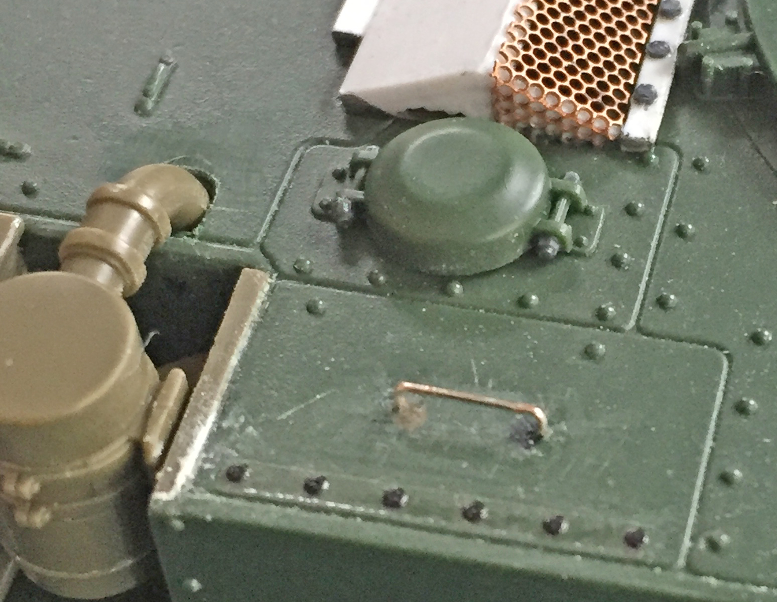
I wanted to improve the detail of the sponson storage box closures. Modern restorations of the M3 seem to favor latches. I don’t know if later variant M3s had them but my references show the earlier ones used straps and buckles.
::sigh::
So I used a buckle from a Verlinden Sherman detail set (did I mention I’m gonna miss that guy yet?) and some lead foil to replicate (TEDIOUSLY) the buckle/strap arrangement. I cut away the molded-in cleats and used small cleats from TMD resin:
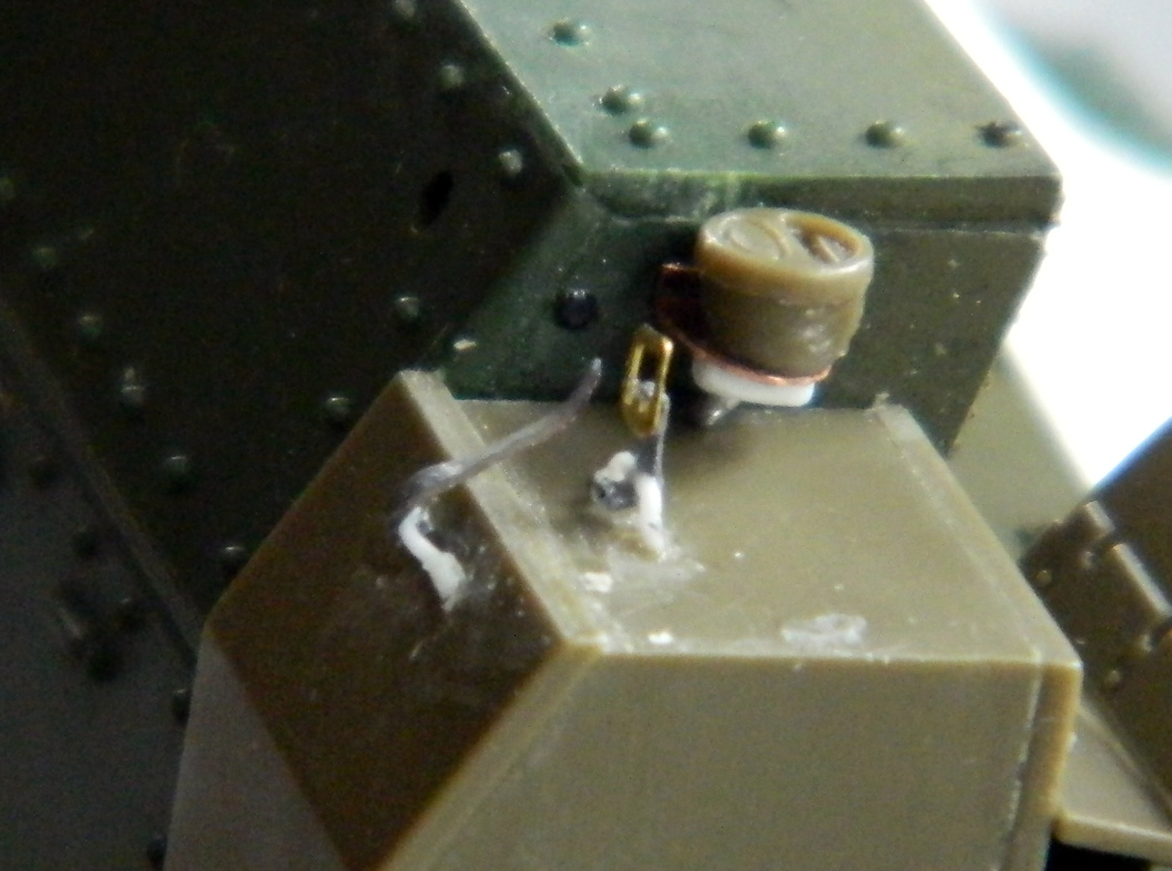
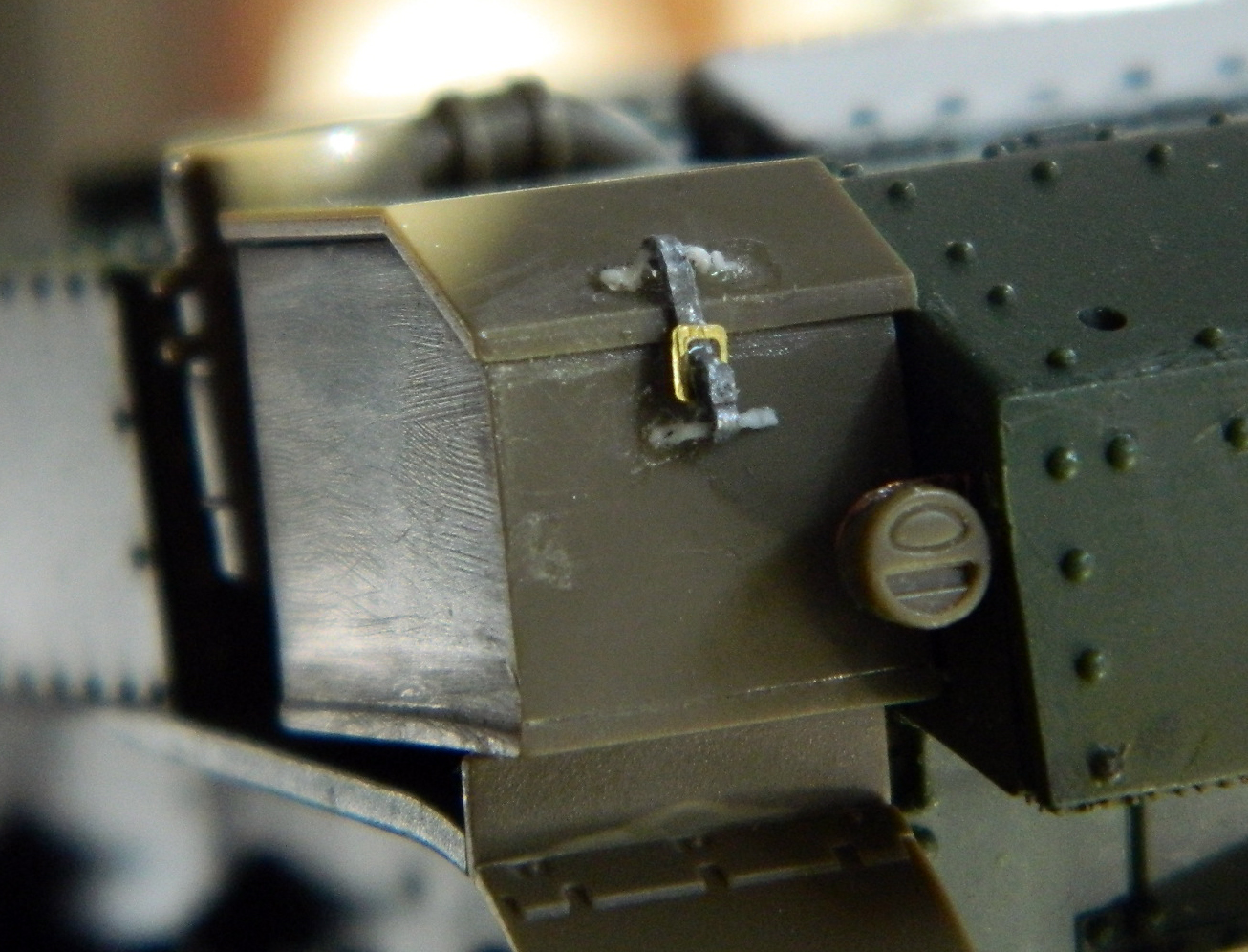
Though FREAKING TEDIOUS to do, I like the result. Now to do the other side…

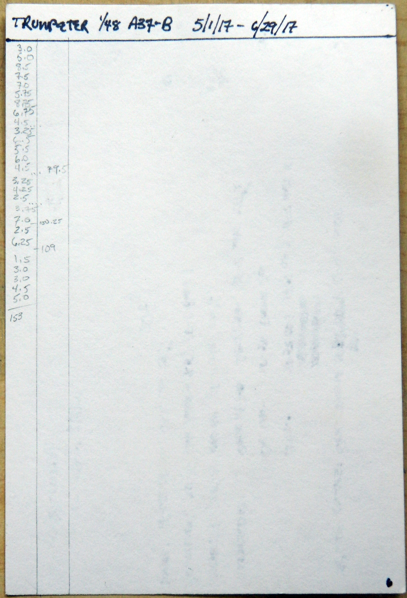