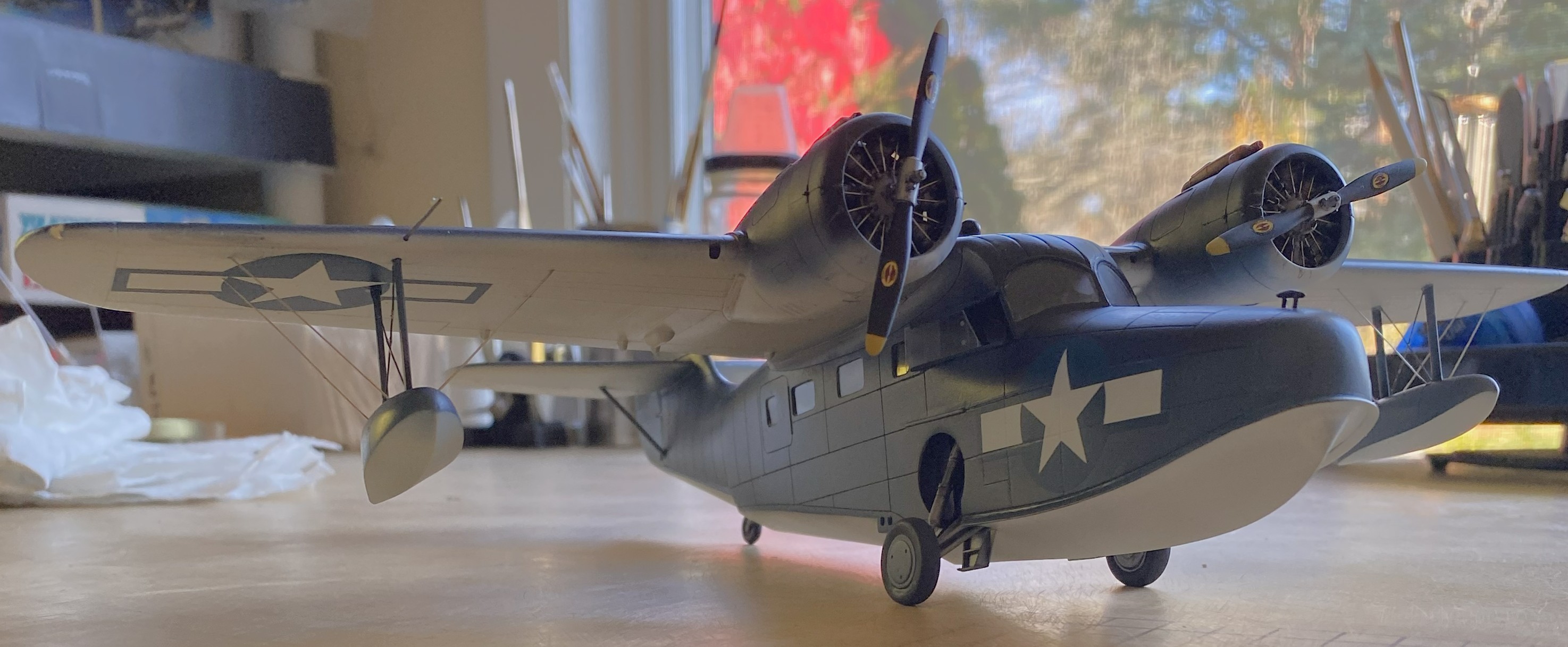
Grumman JRF Goose (Czech Model) 1/48 Scale Build #7 – Staggering Towards the Finish…and Getting There
This is the danger-point for me, being so close to the end that I have to be careful not to rush things. Couple that with the reality that I despise this kit, I have to double the caution.
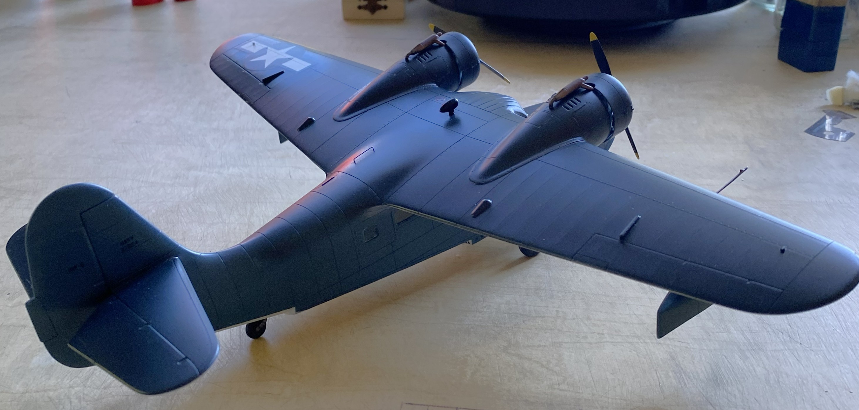
I started with what I perceived would be the biggest hassle and that was getting the wing level, and I wasn’t entirely incorrect. As it sits in this photo, the bubble indicates that the wing isn’t level:

At the center of the model, that bubble isn’t far off. At the wingtips it is. I bent my brain around several corners trying to figure out the best solution. I’m of the opinion that it is not uncommon for a given problem to have more than one solution, except that solutions to problems usually come with new problems (and the solution is enacted if the new problem is less than the old problem). And speaking of problems, here’s a short (I hope) examination as to what the problem is, not what I’d rather it be.
The struts of the landing gear fits into the top of the landing gear bay. The landing gear bays were not molded onto the fuselage sides. As I found out well after I’d added the landing gear bays, the sides of the fuselage do not match dimensionally. Yeah. Who knew that would be a problem. It certainly wasn’t Czech Models. However, with one landing gear bay higher from the bottom than the other, and the landing gear goes there, should I be surprised that once the aircraft is assembled that it doesn’t sit level? I was when I first found the dimensions (and shapes) did not match from side to side, but after I thought about it (a lot), I knew that by the time I got to this point of the build, I’d have this new problem to solve. ::facepalm::
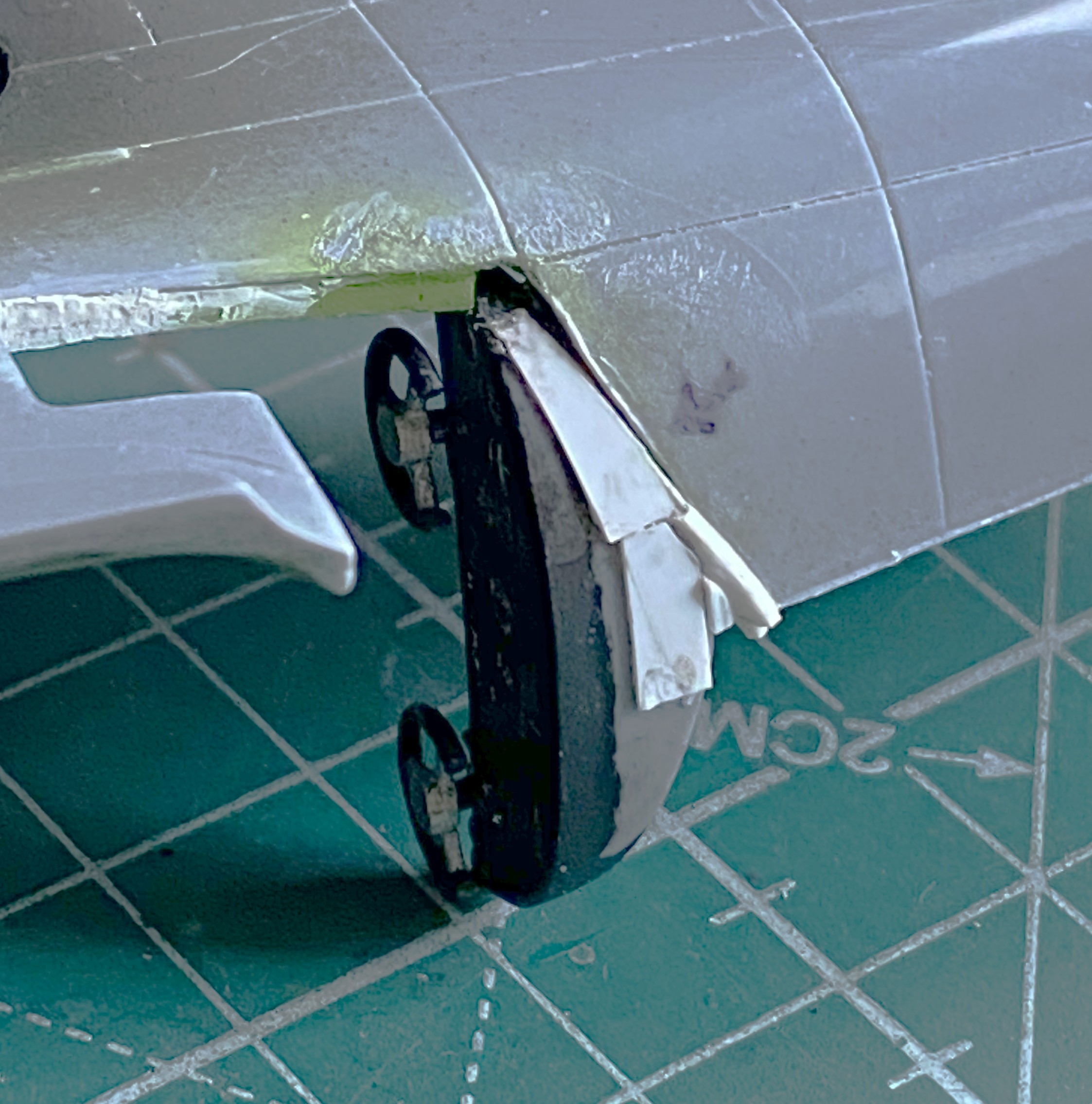
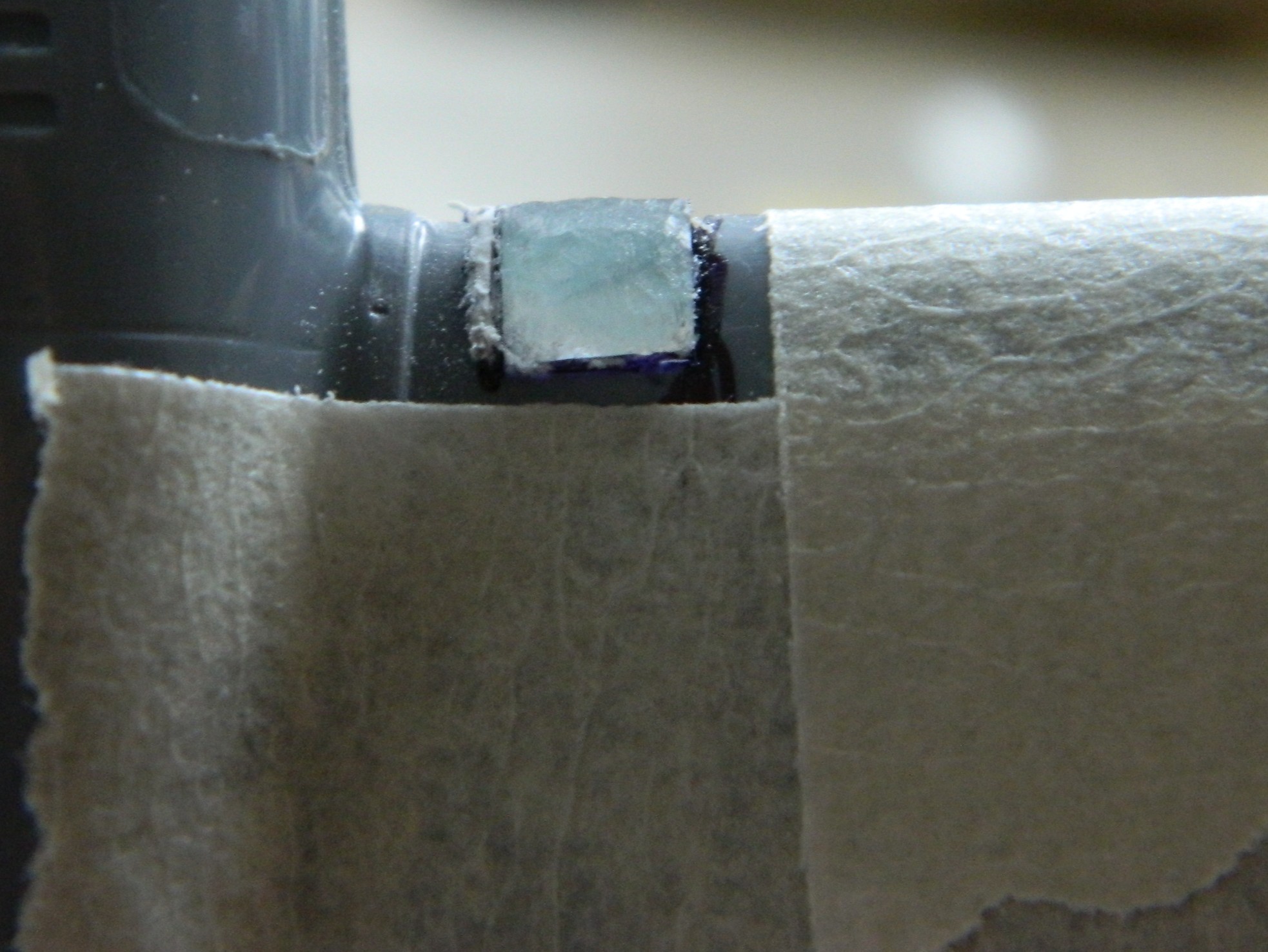
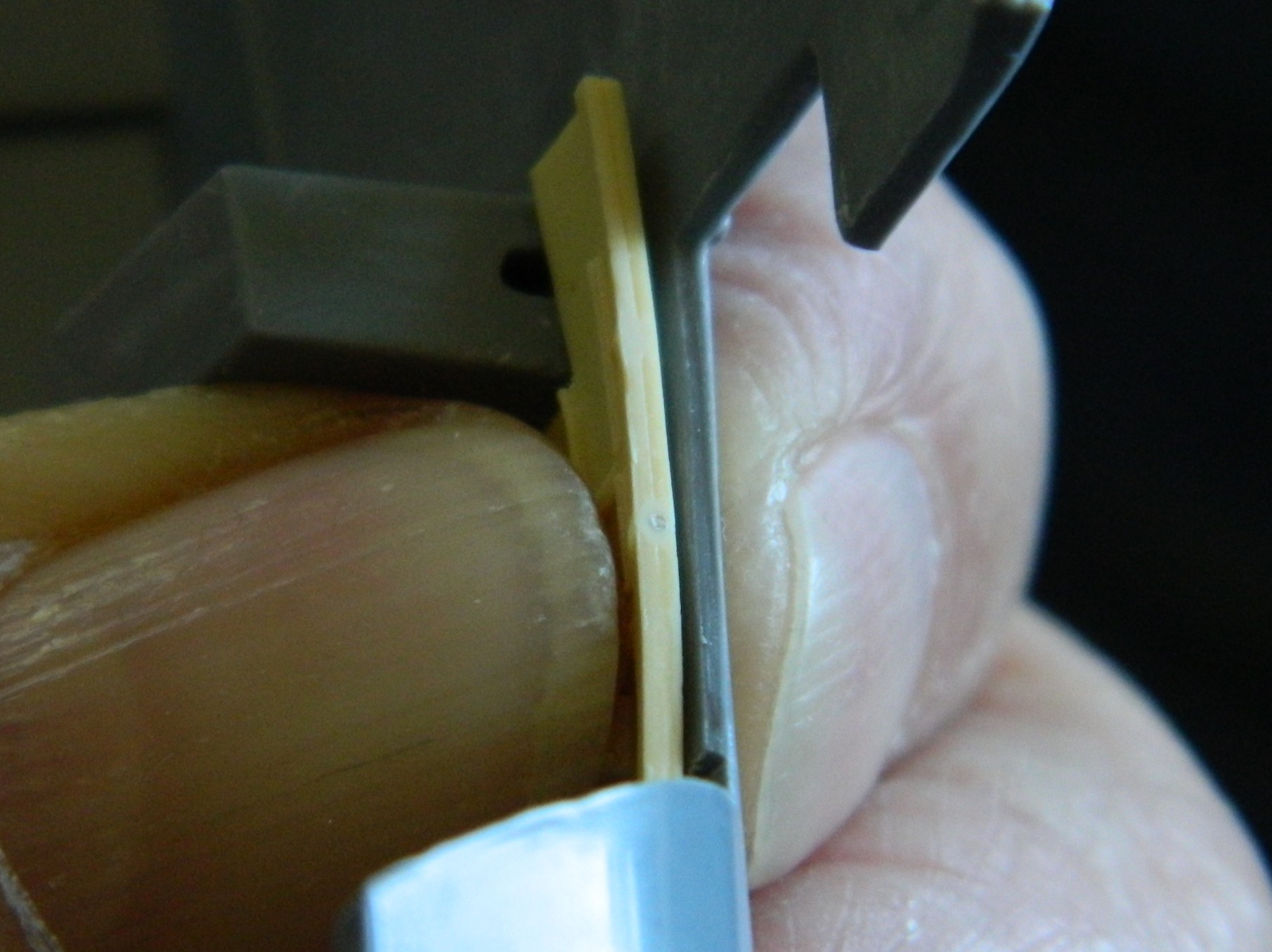
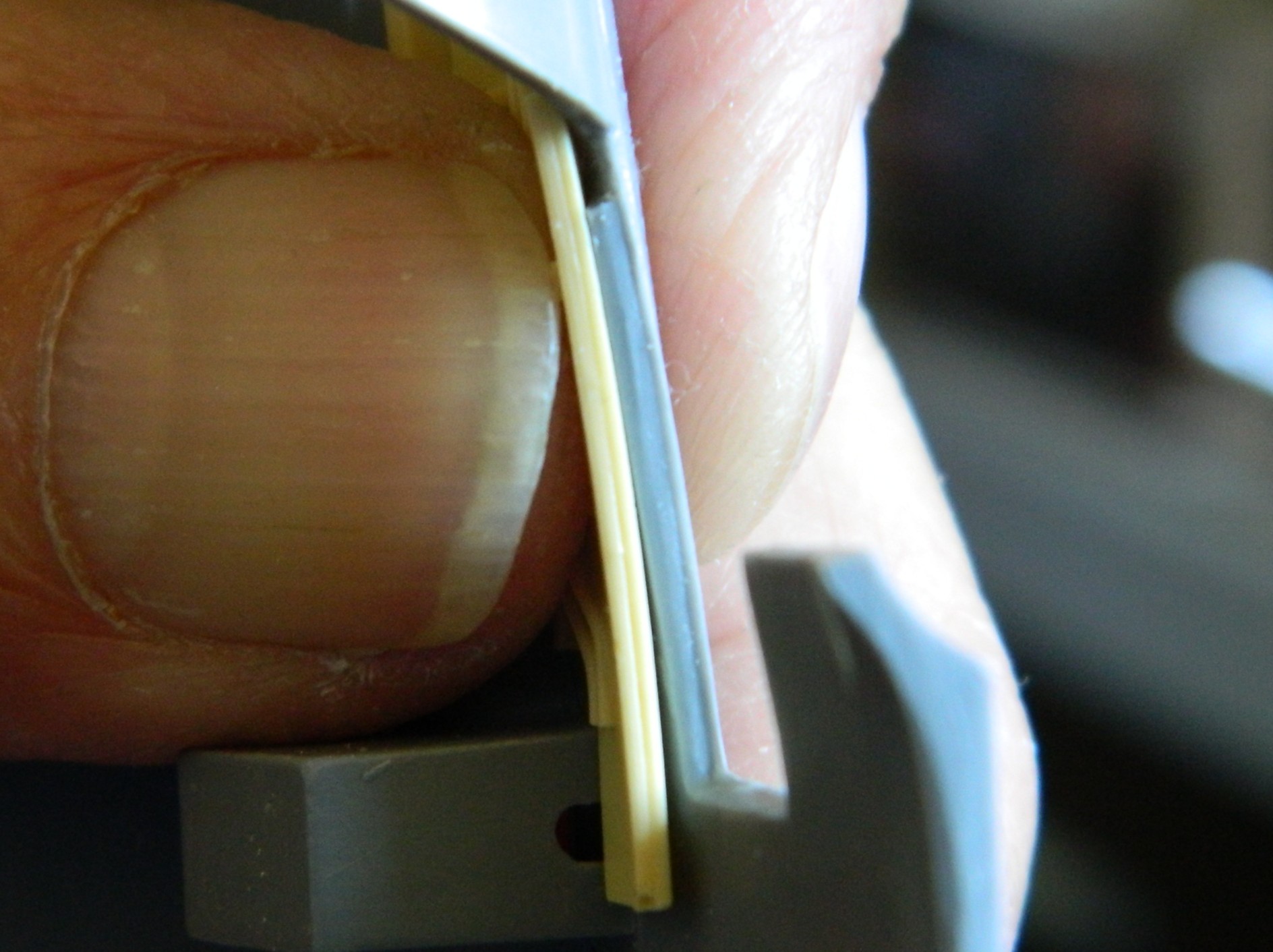
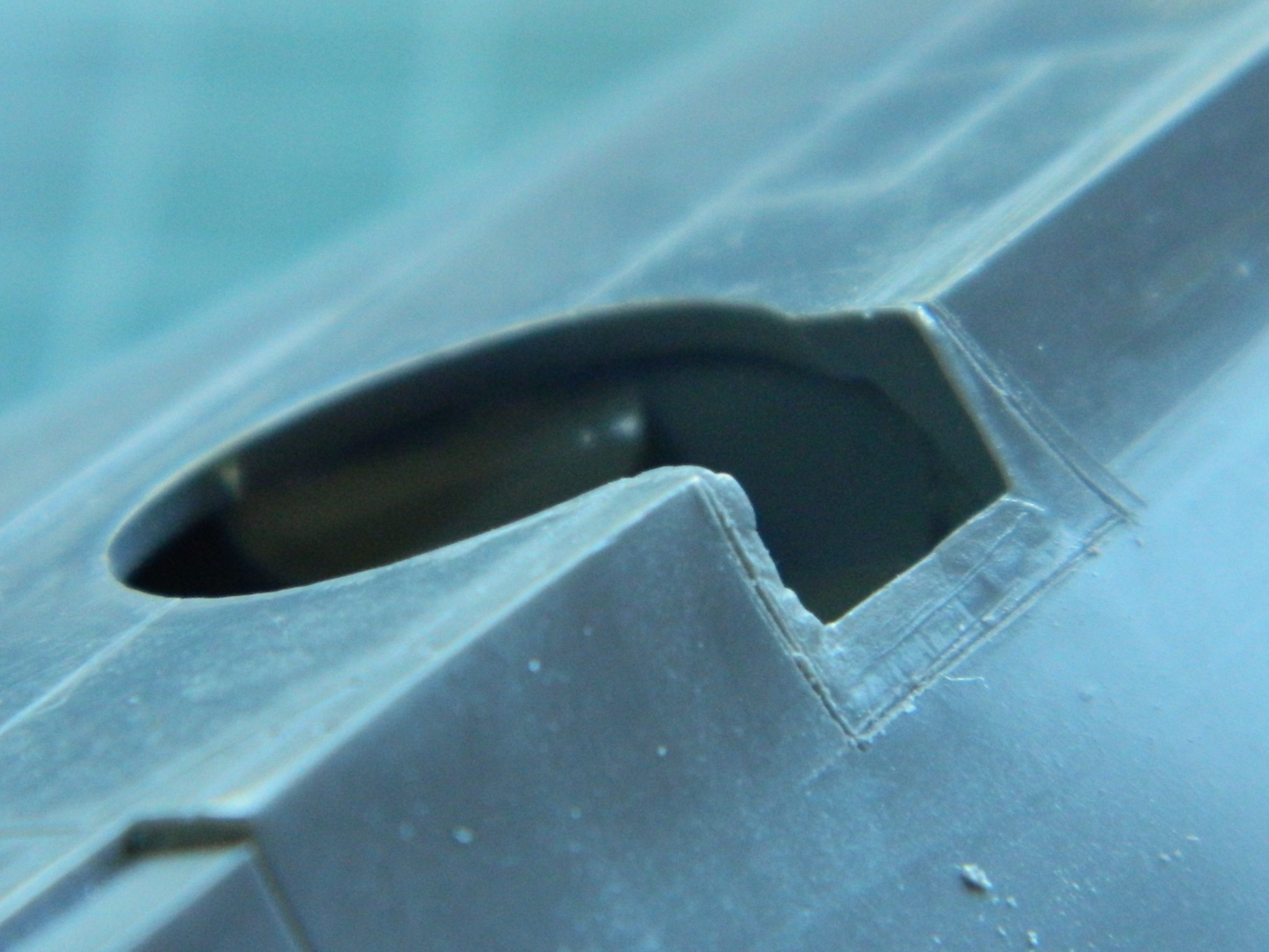
Since I saw this problem as a geometry problem, I looked into the geometry of the landing gear. Being more than a little frustrated at this point, I dry-fit the wheels onto the landing gear and pressed firmly down on top of the model until the bubble was centered. Just as the bubble centered, I heard a soft crack as something broke loose…but the bubble was still level. Took a bit of investigation but I found what broke loose. The blue arrow in the photo below points to where the upper control arm snapped away from the strut leaving this gap:

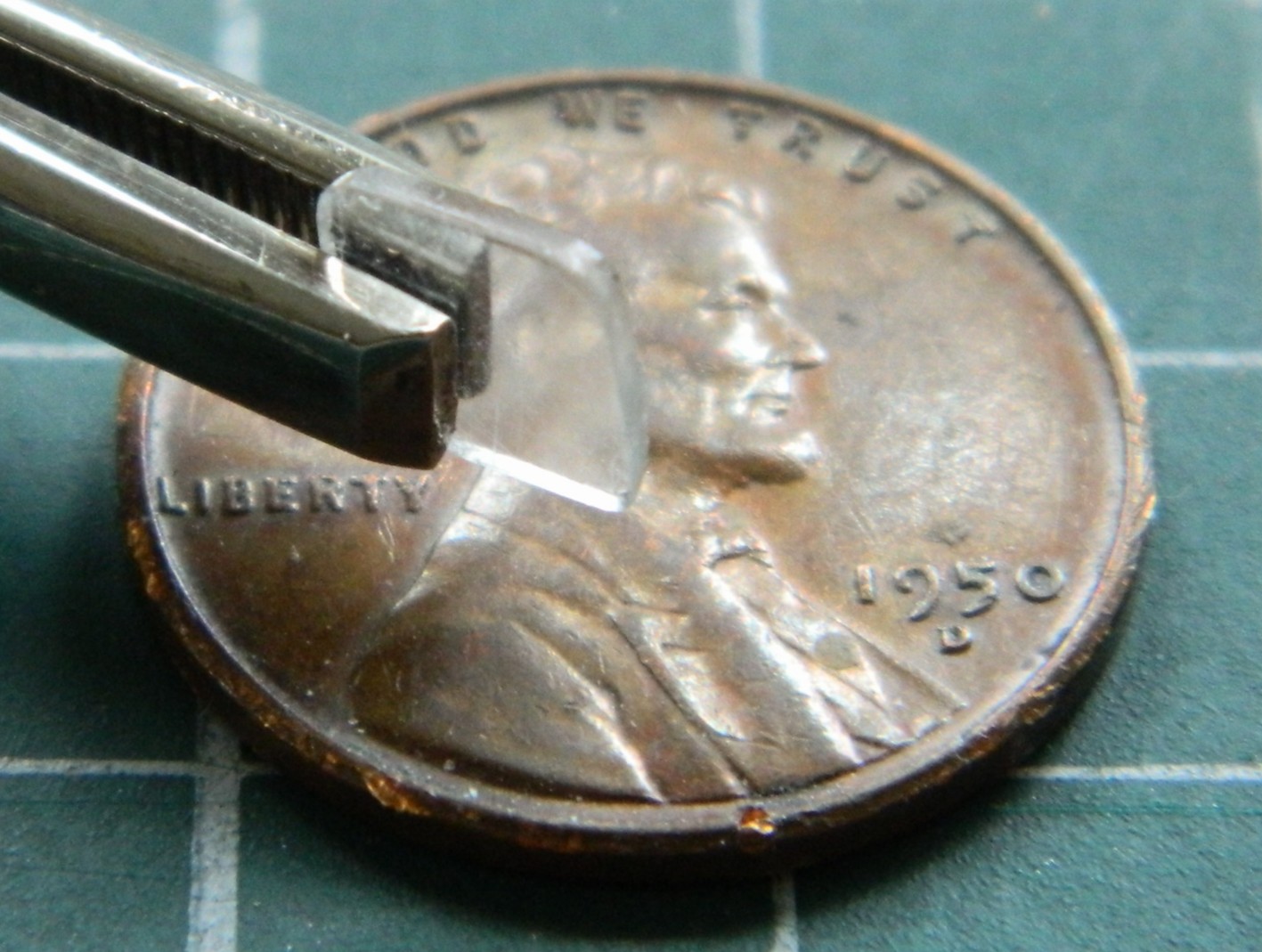
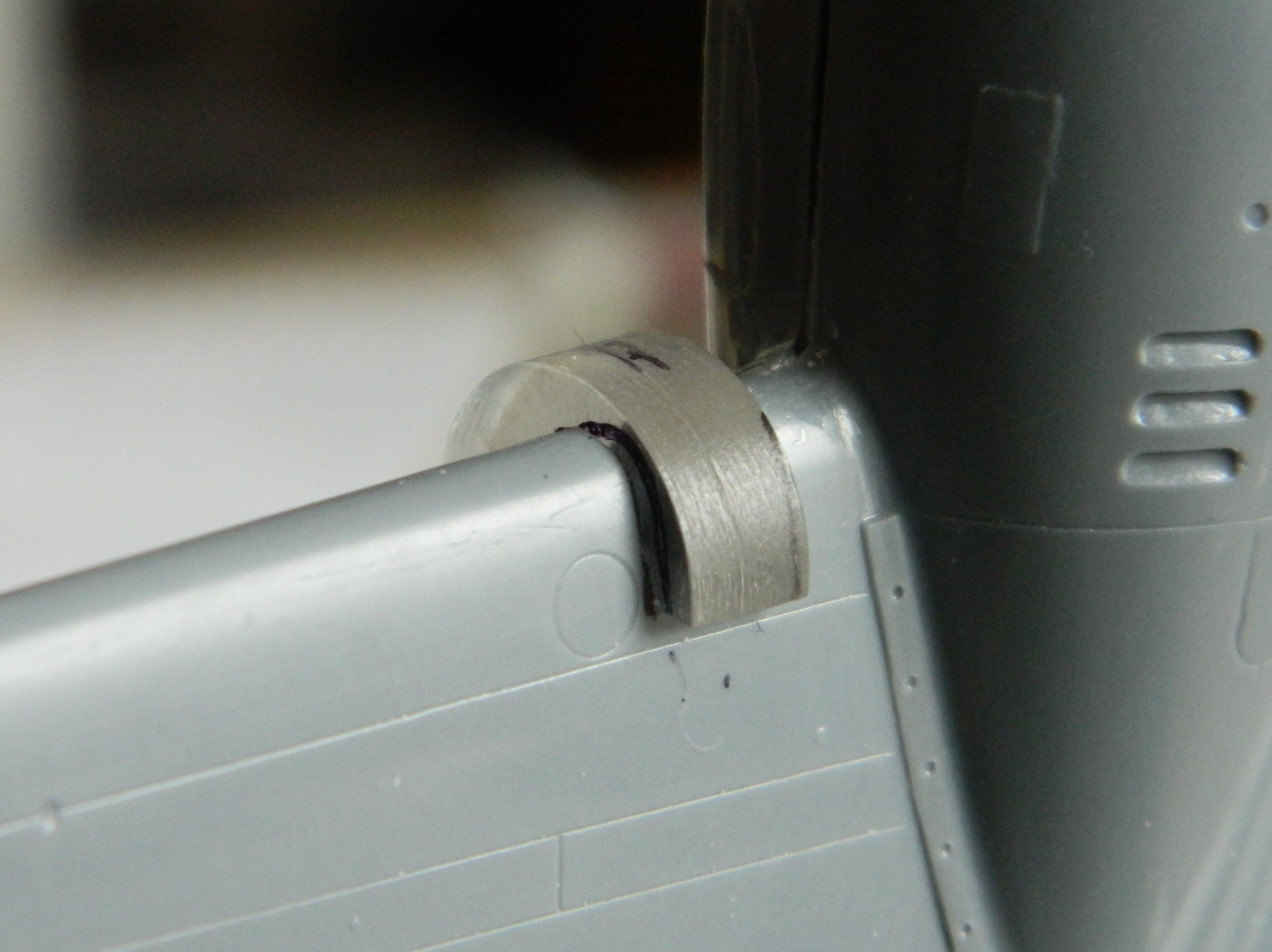
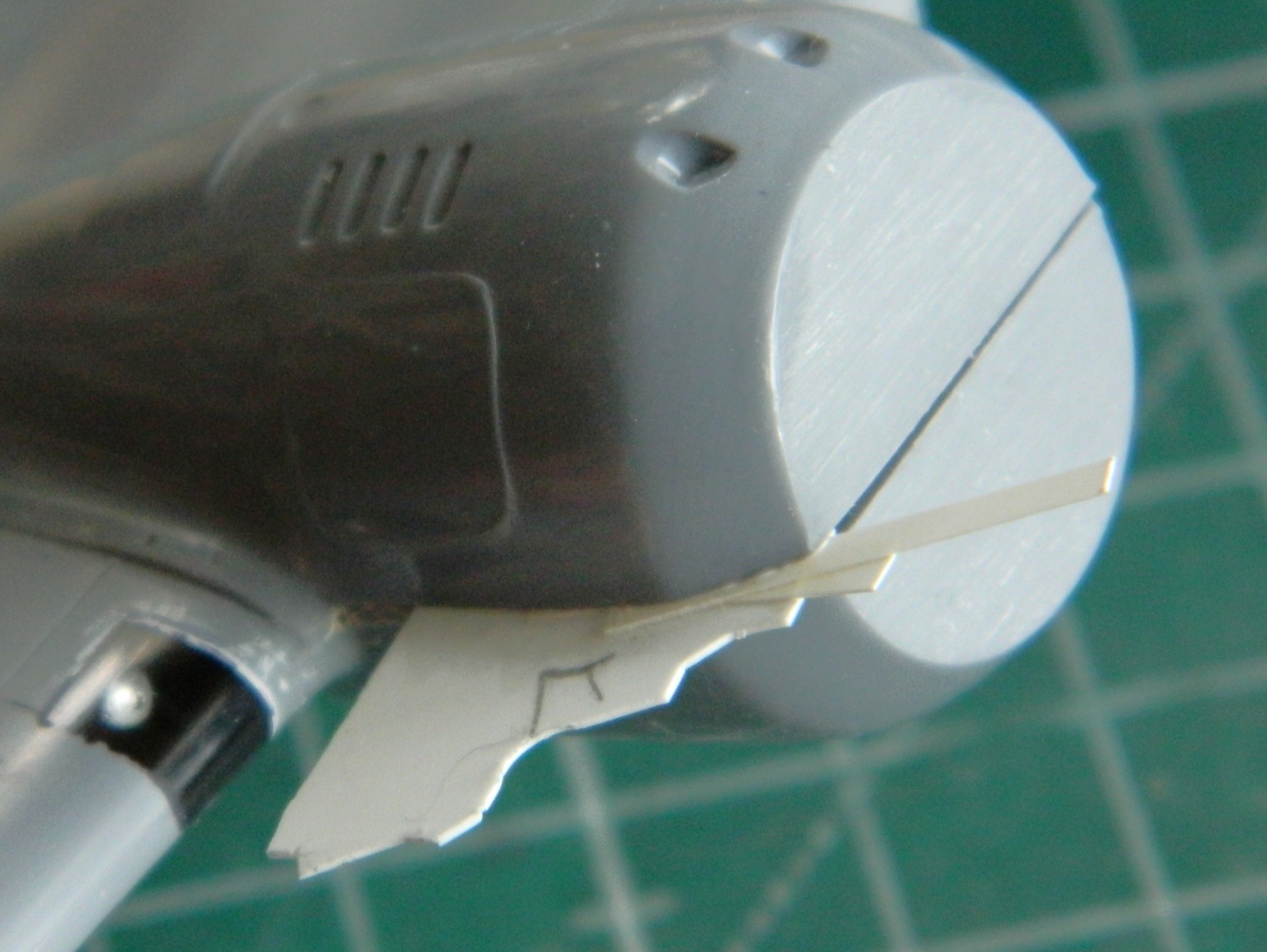
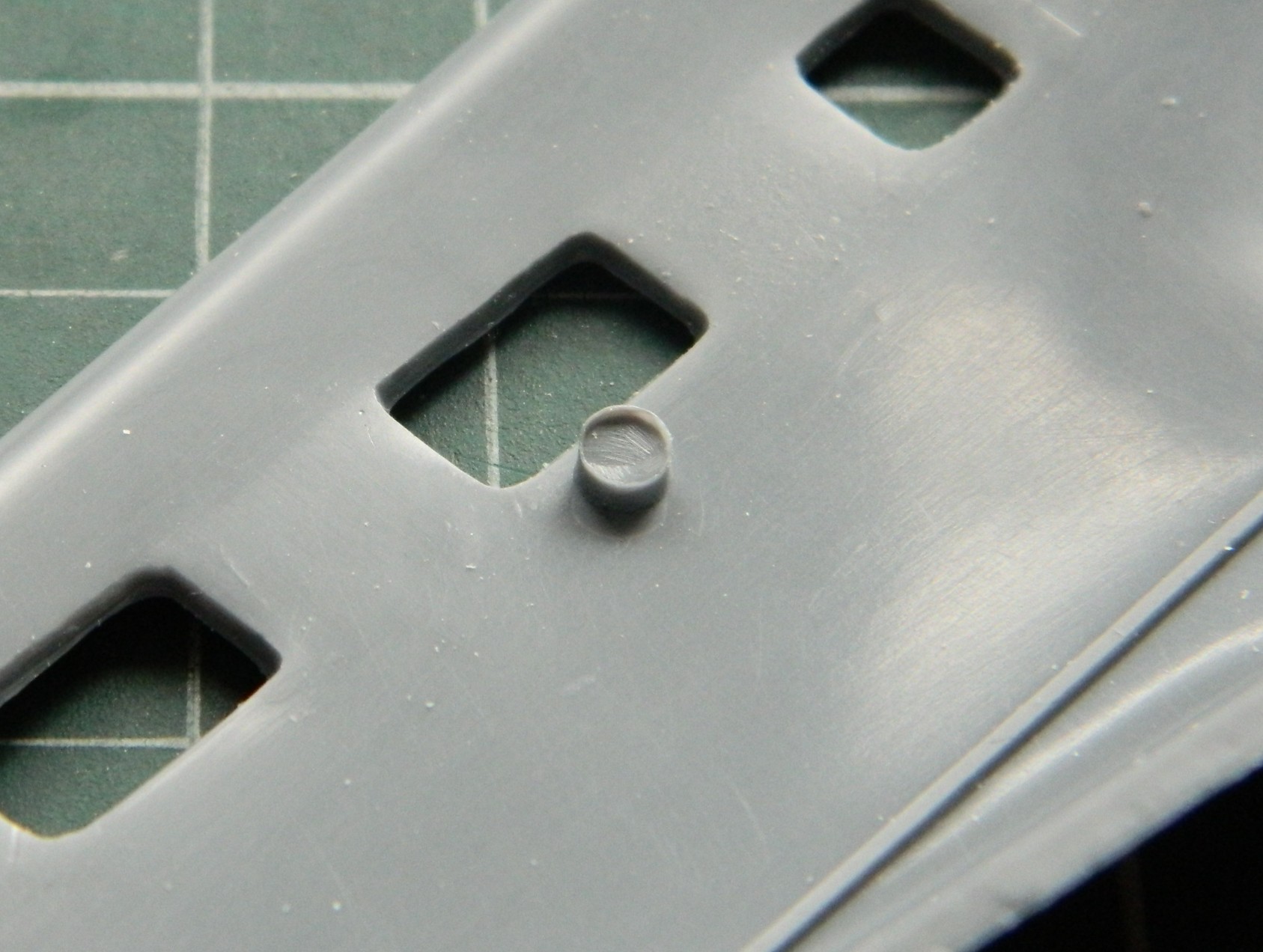
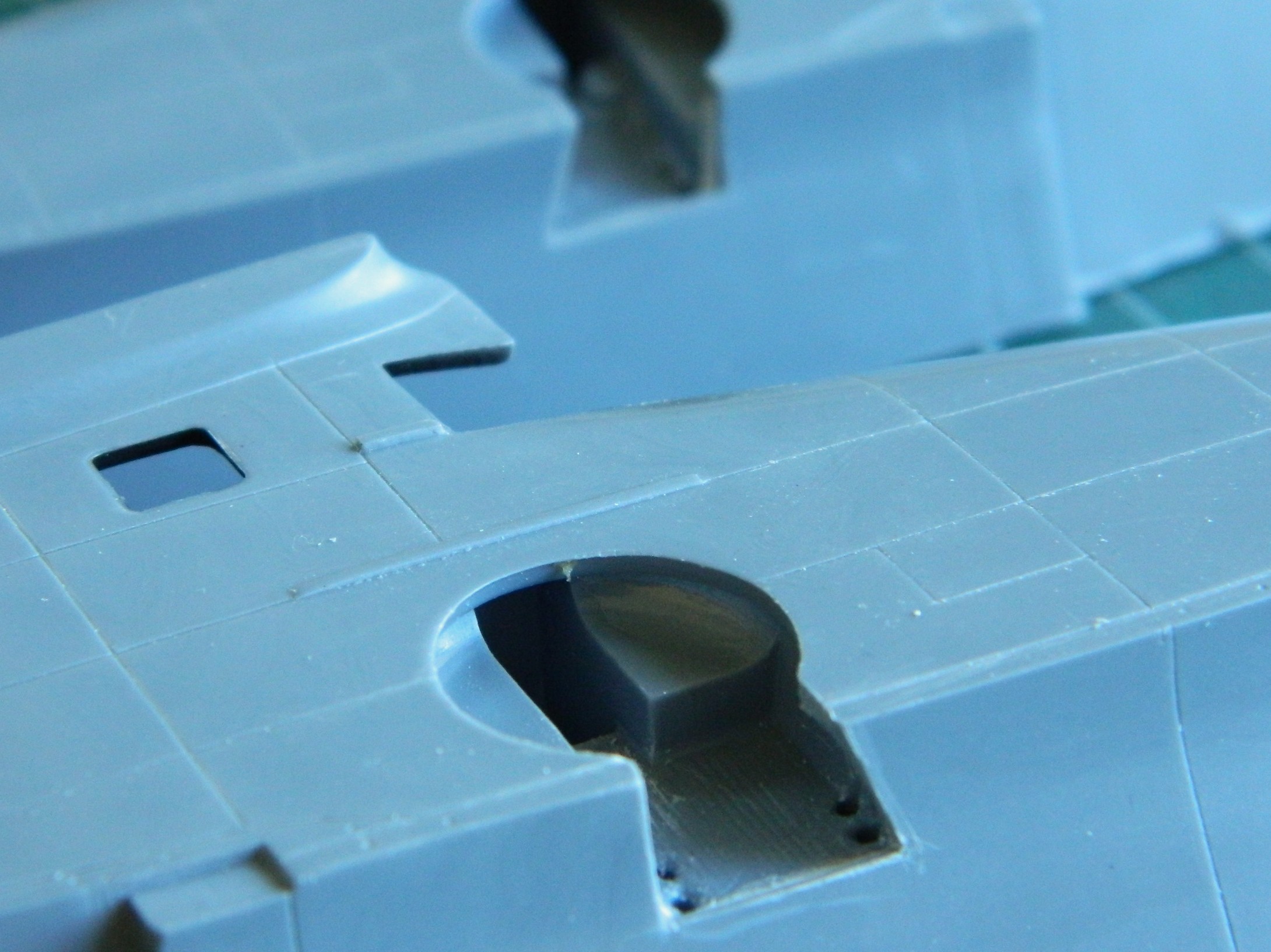
Hmm. So, if I fit a spacer between the strut and control arm, will that make the wing level? The answer was, “mostly”, which I discovered once I’d cut a spacer from 0.030″ (.762mm) and checked:

I trimmed the spacer without gluing it in and checked again. This time I estimated that I needed another 0.005″ (.127mm) more:

And there it sodding is:

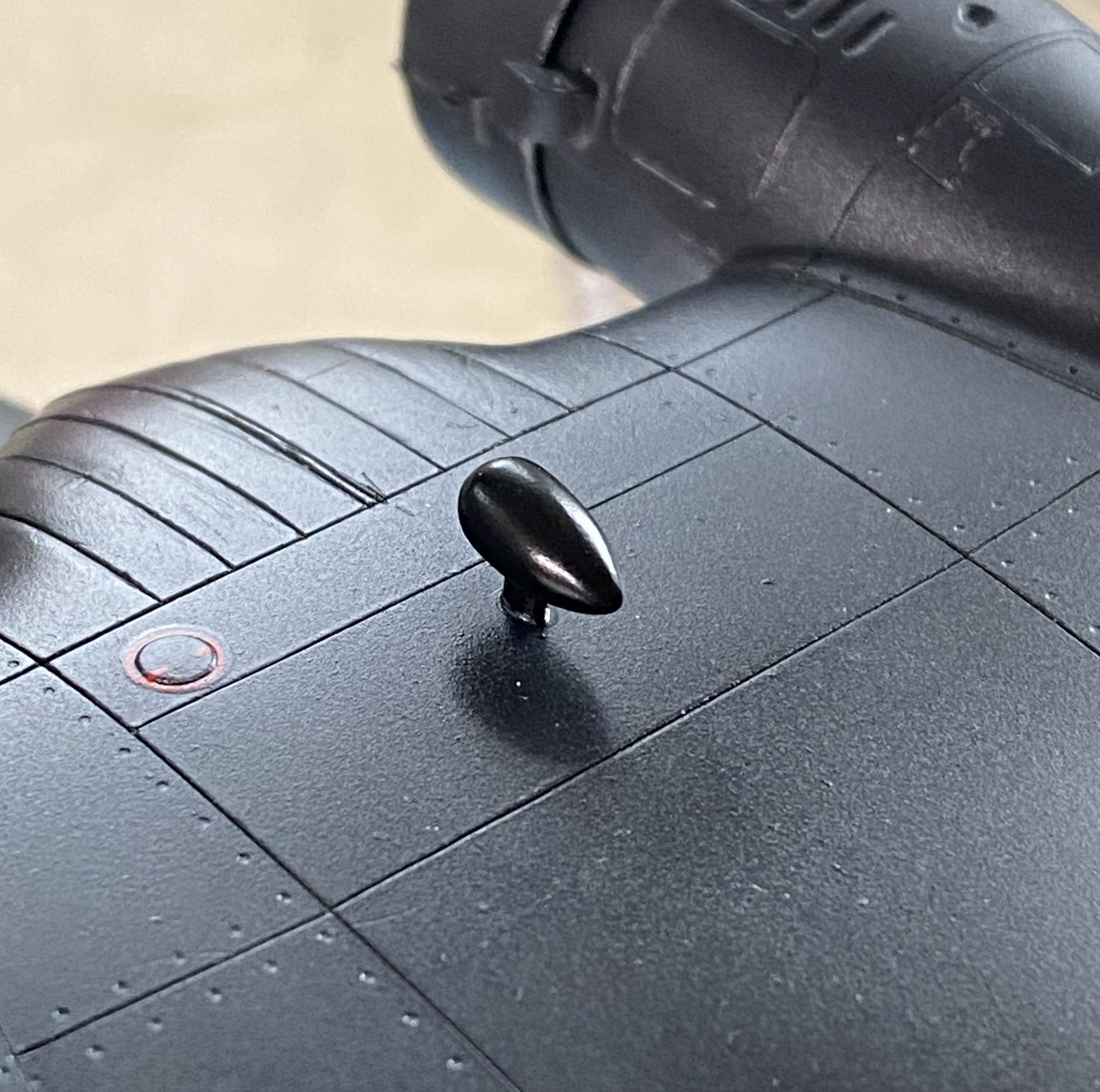
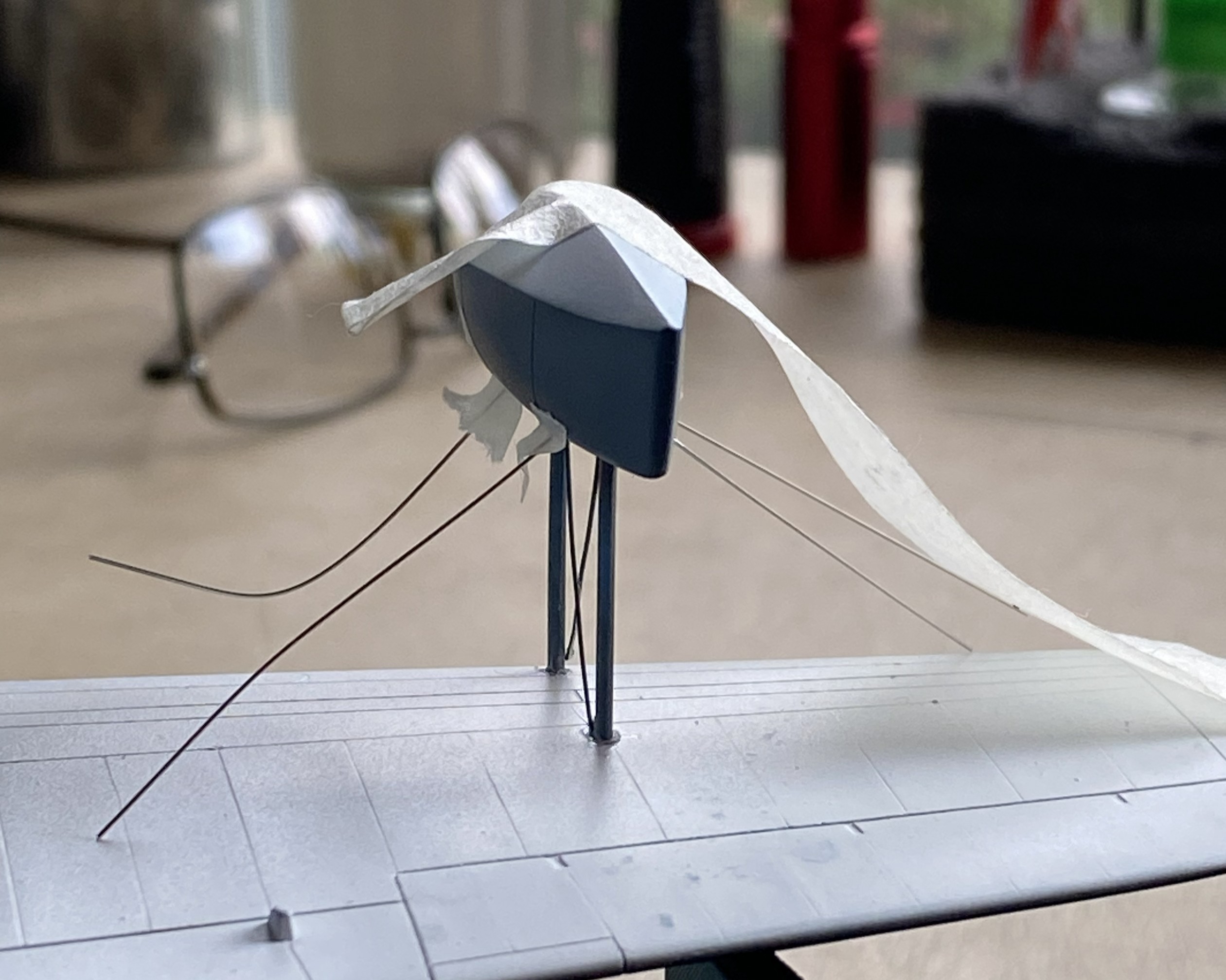
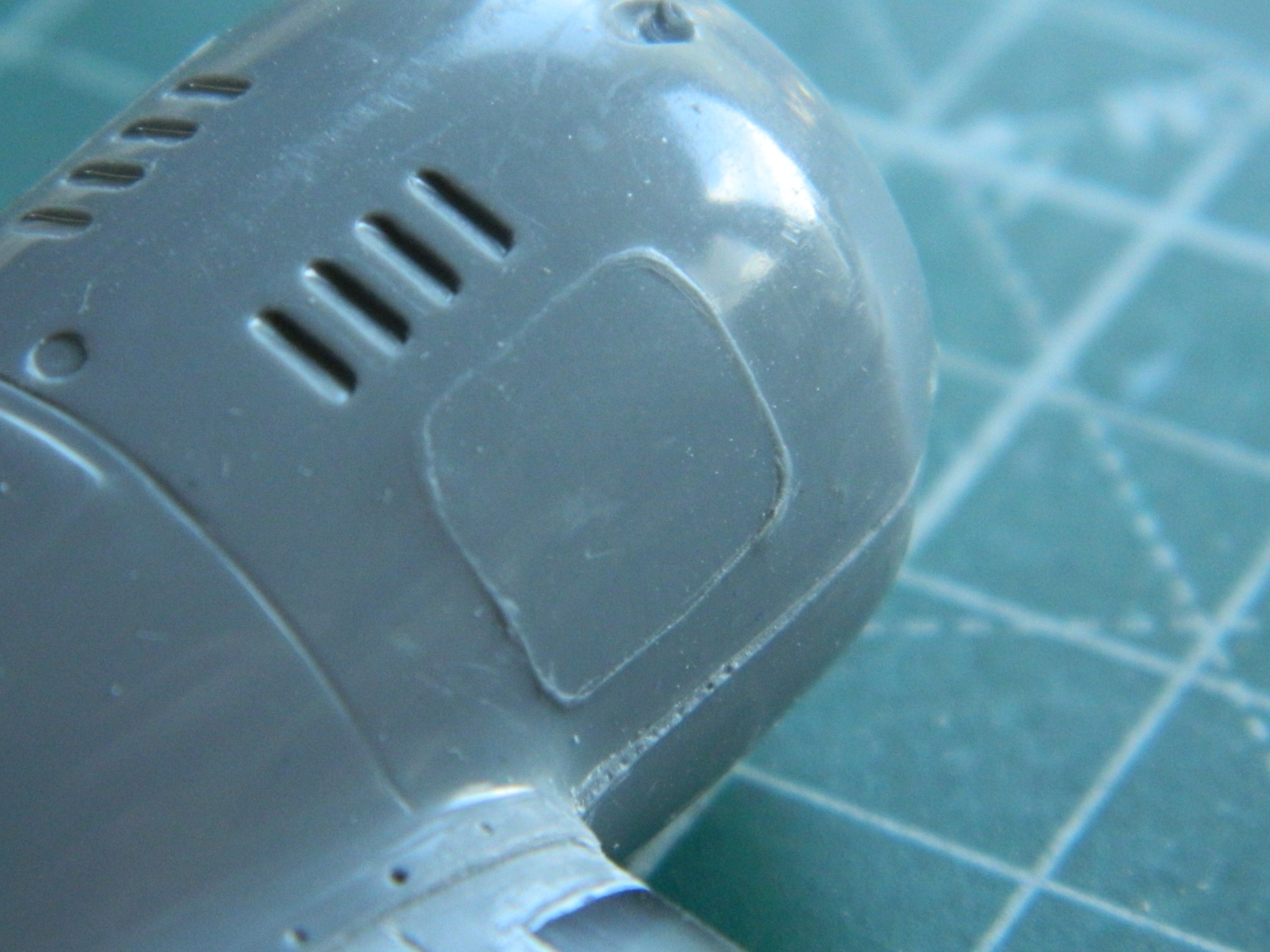
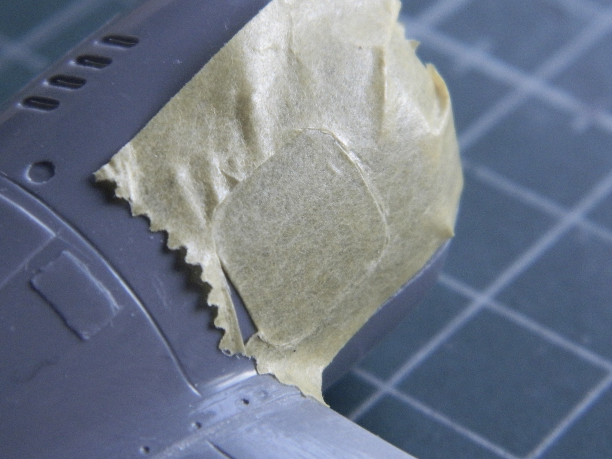
I think it’s the housing for an ADF head, but it needed to be painted semi-gloss black. So it was. I REALLY hate self-inflicted wounds, which is how I view overspray. When I aimed the airbrush at the football, NONE of the other painted surfaces were visible:
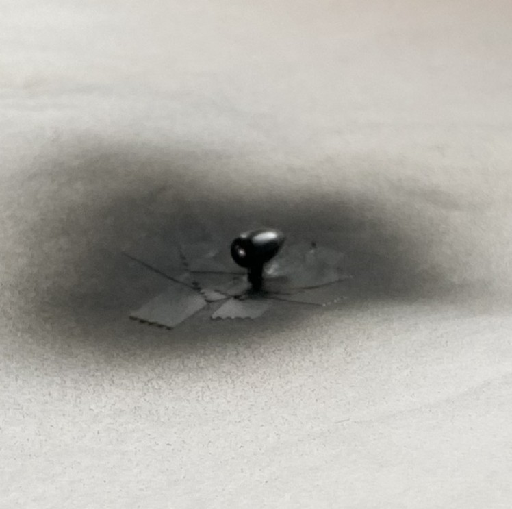
Success! Zero overspray:
I used 0.025″ (.635mm) as brake lines, painted them knowing full well that during the final bending process would cause paint to flake off. It was a lot easier to get at the parts that bent the paint away because there weren’t buried in the landing gear bay. I’ll get to these when touching up the paint happens (the photo’s on its side because I was using gravity to hold the solder where I wanted it to while the superglue set up):
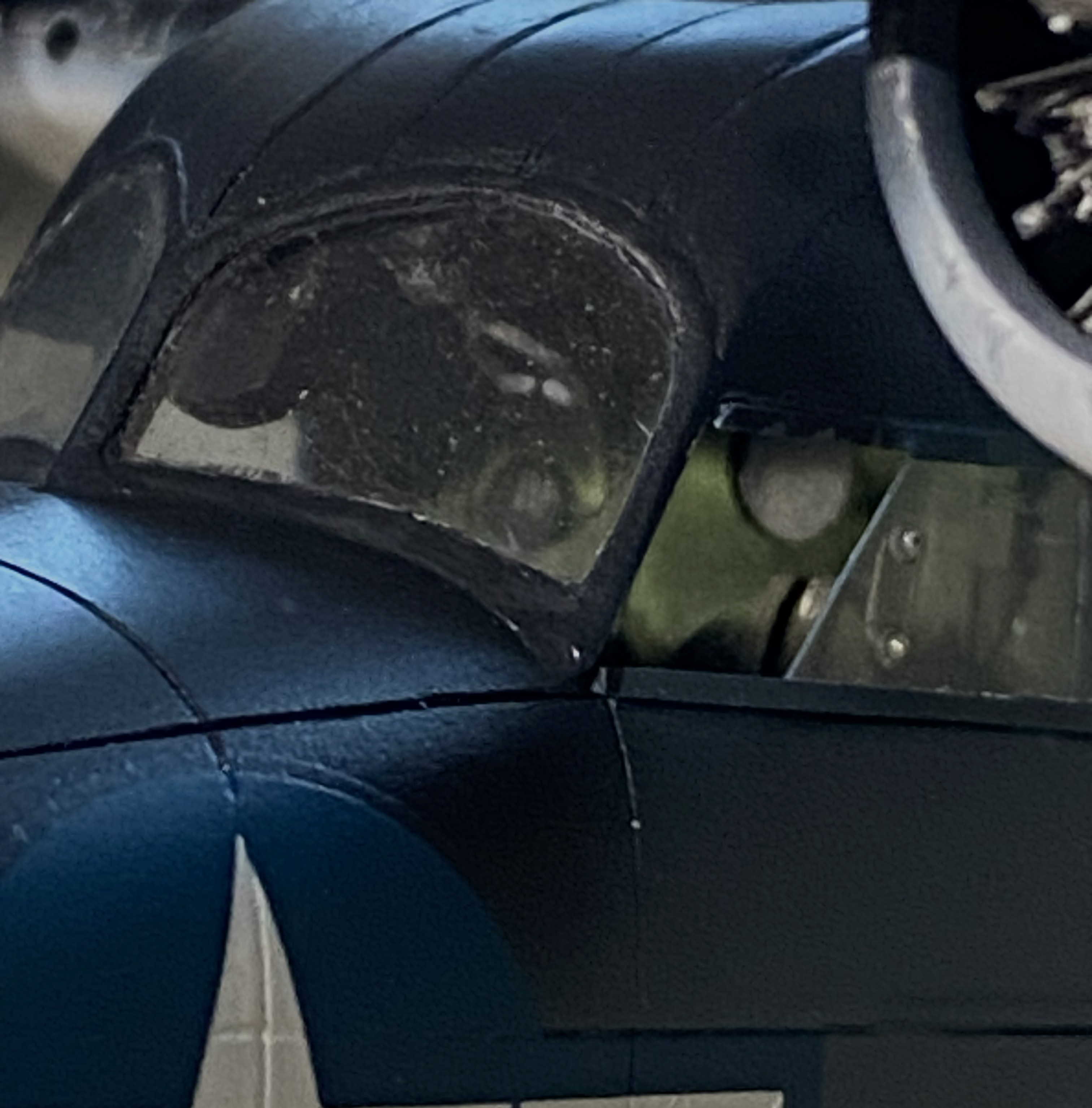
And speaking of paint touch ups, I painted the frames of the cockpit windows off so that I could also paint under them. A solution that created a problem; paints don’t match once assembled. Okay, I’ll be doing touch-ups (with a small brush in these areas…the other side, though not as bad, is the same), just add this to the list:
You’ll also note that the cabin window just behind the flight deck is still masked. This was a problem I let sit as-is. When I tried to pry the masking tape away, three of the four sides of this window broke free. It was hanging on by paint. My memory isn’t what it once was (is anything?), but I DO remember what I had to go through to fix the one that came out already. Carve, fix, fill. Lots of fun when the plastic was unpainted, a no-go zone now that it has been painted. I supplemented the paint holding the window on with liberal applications of superglue. I’m pretty sure it’s going to stay there, now. It’s in a place where it will never be touched.
This one’s pushing the 90-95% accuracy I try to attain. I don’t care. A blocked off window is better than a sodding hole. Moving on…
Speaking of self-inflicted wounds, I noticed a week or so ago that there was blue overspray on the nose. ::adds to touch up list::

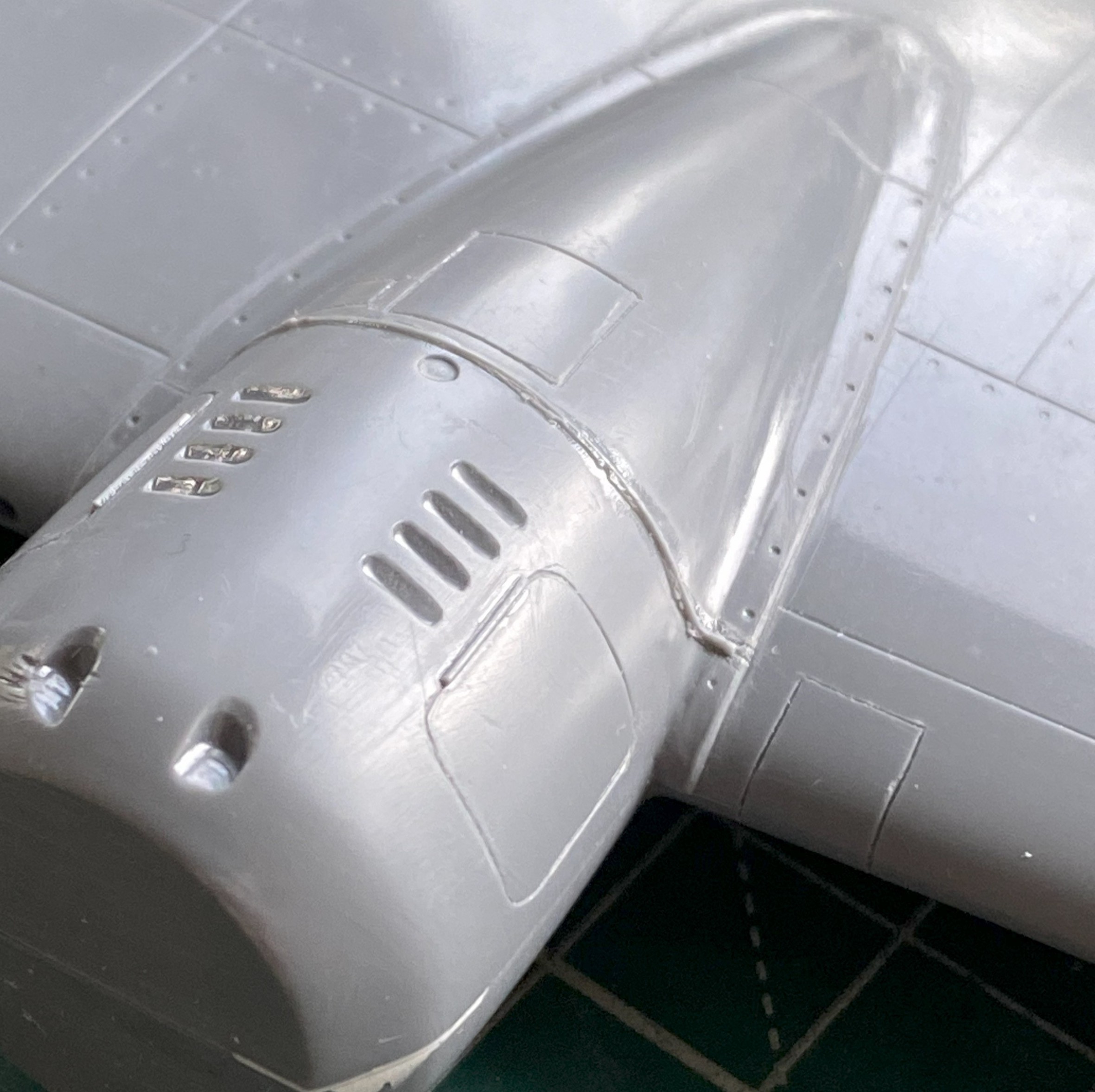
I added the heat exchangers (the brown things over the engine nacelles). Later on I’ll spiff them up a little bit with some pastels:
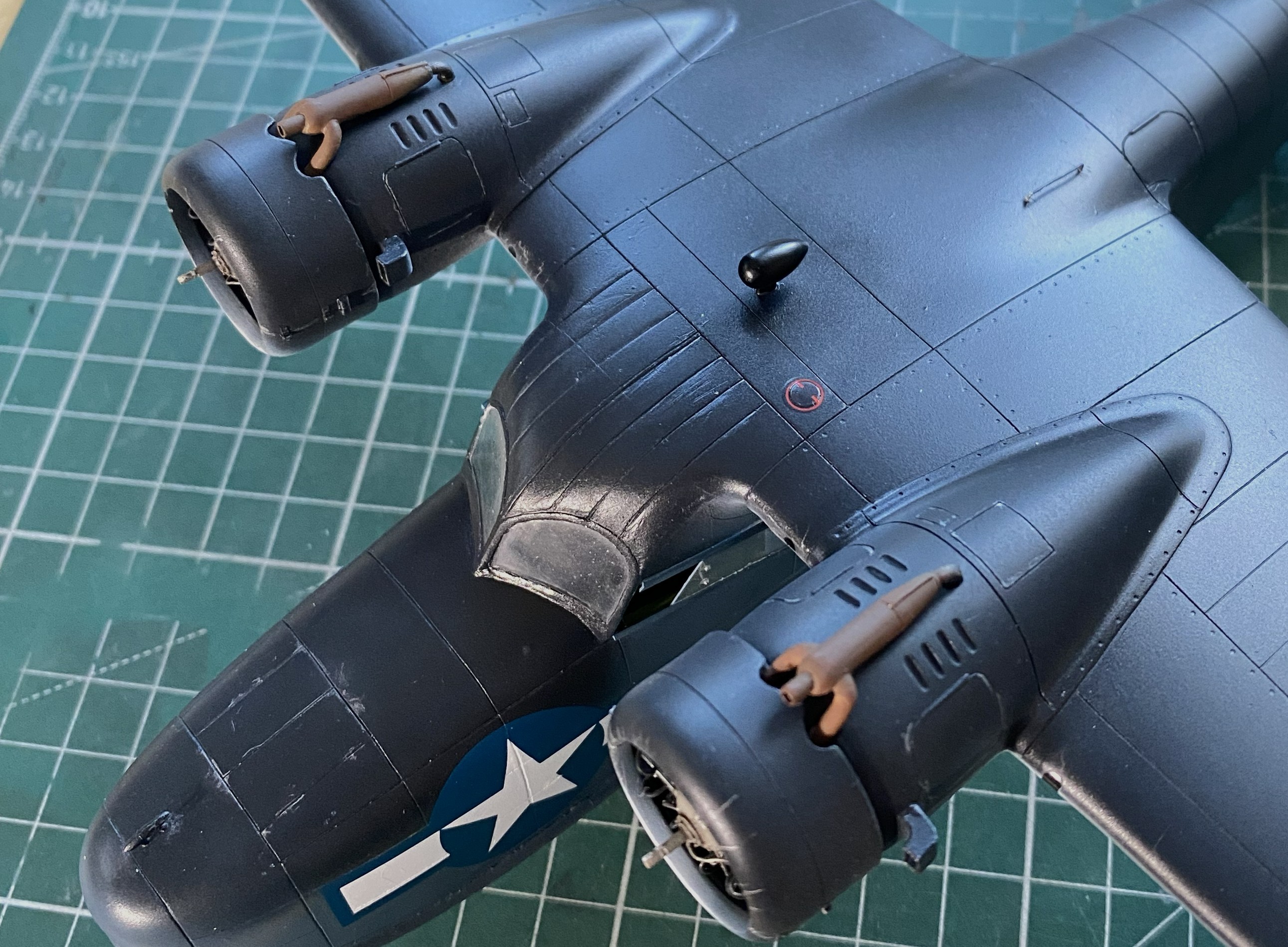
I added one of the landing gear “doors” just before beddy-bye so that the glue would set up; there’s not much gluing surface:

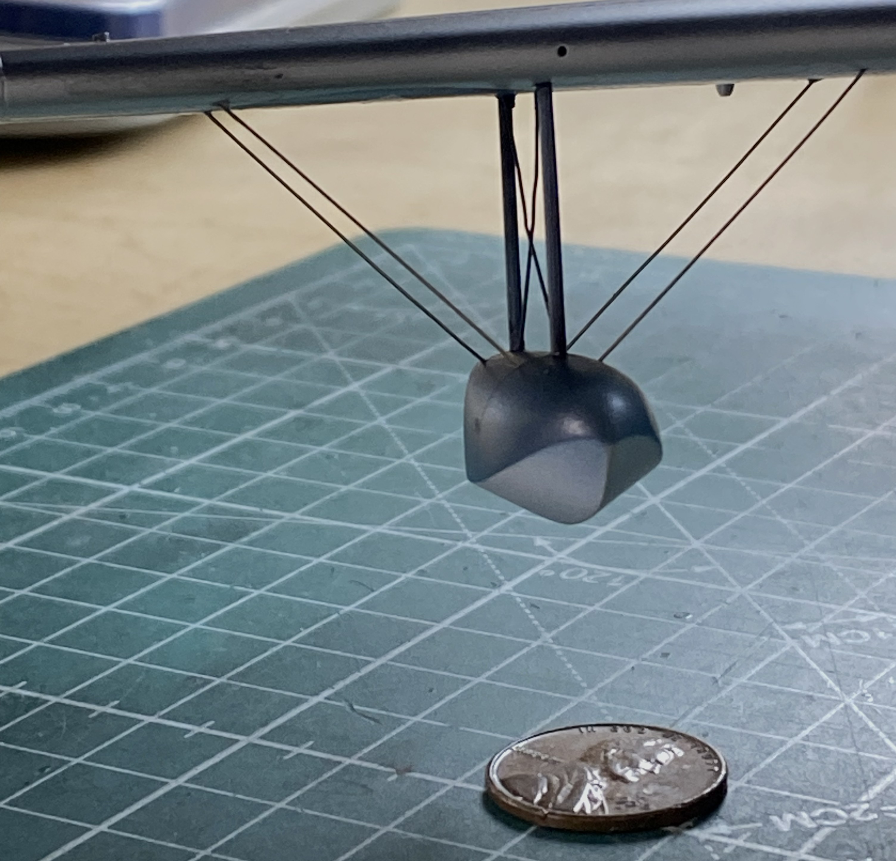
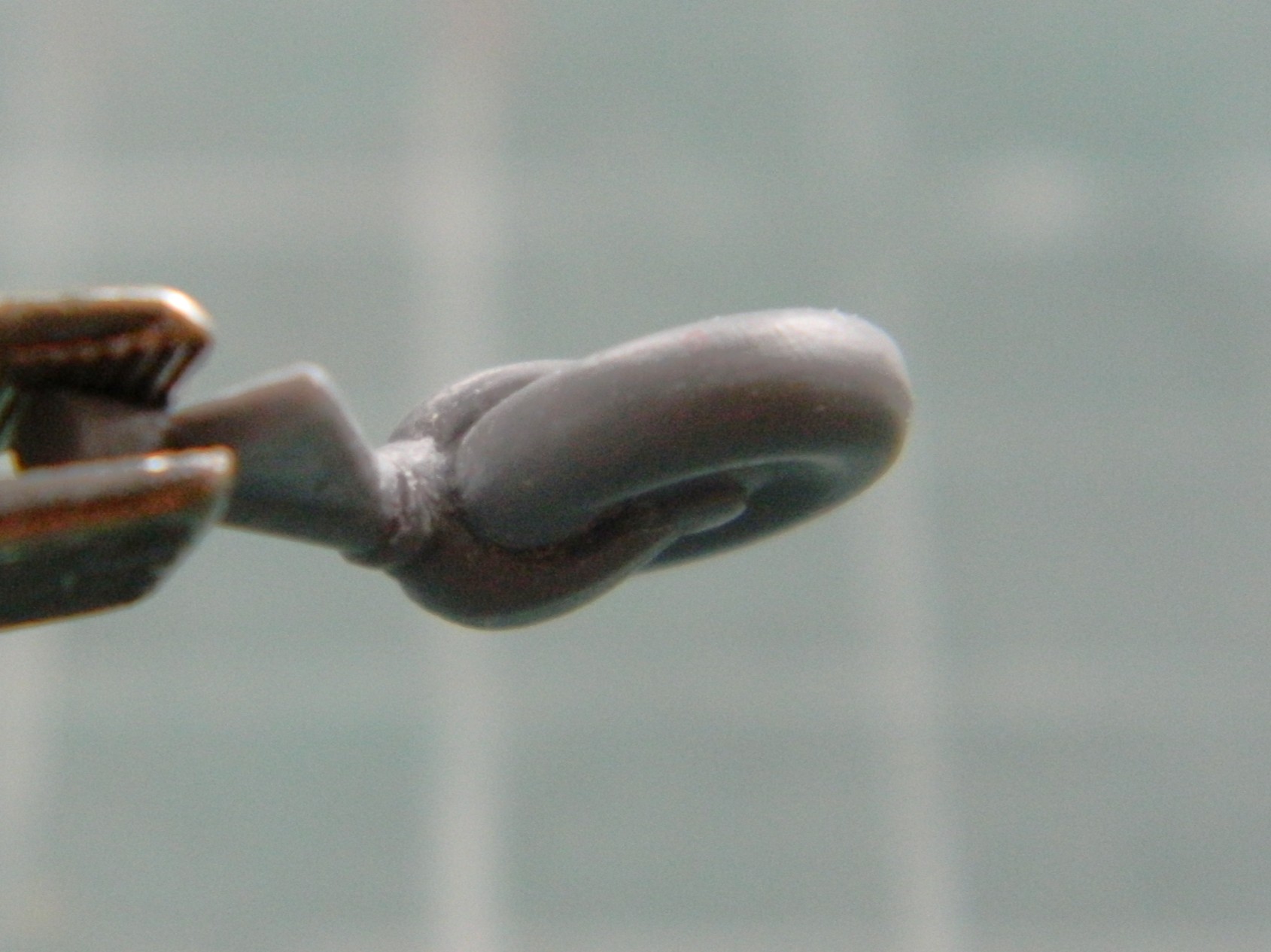
And while I was letting something sit overnight, I got ballsy (considering how late in the evening this happened) and added one of the floats to sit overnight as well:
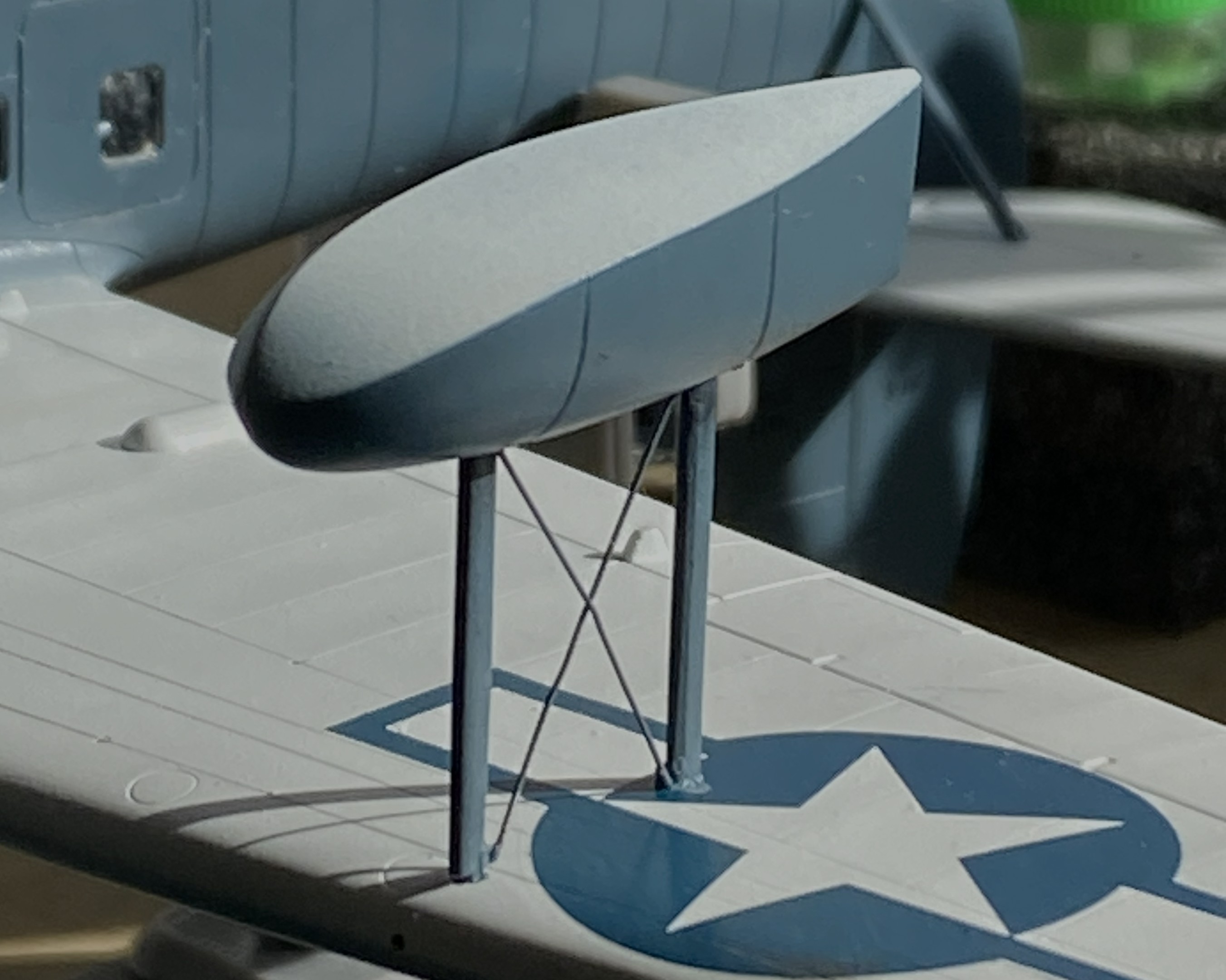
Obviously, with only two small contact patches, this will be easy to knock flat laterally. I added tape to stabilize it while I fed the ends of the braces into the float and wing for gluing (superglue). l cut the wires overlong so that I could be certain I’d be able to adjust them if I needed to (a handy bit of foresight):
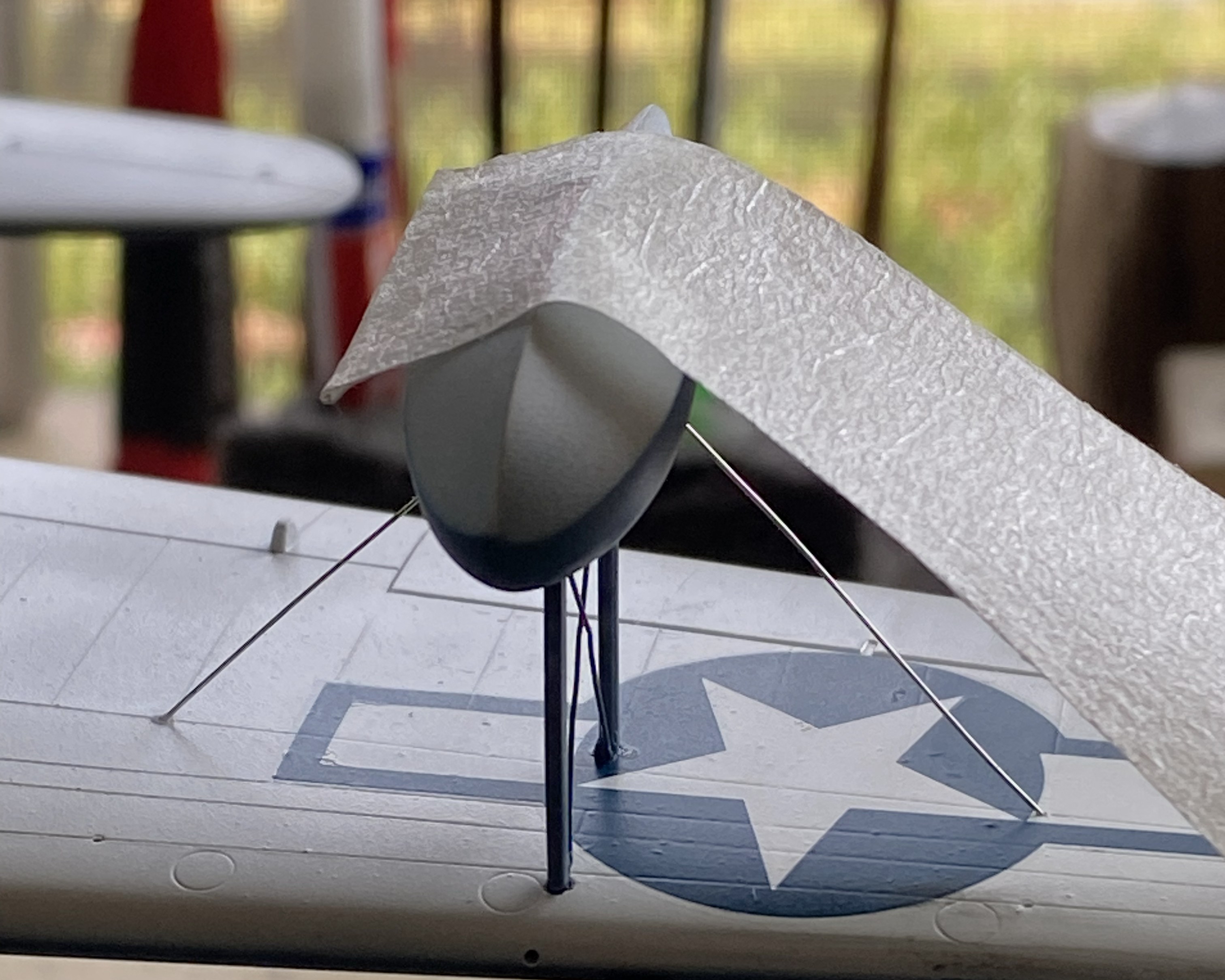
With all the guy wires in place, it looks pretty good:

Getting the guy wires into the pre-drilled holes of both the float and wing took some fiddling. For the next float, I tried inserting one end of the guy wires into the float without cement to see if that would be easier:

It wasn’t. If you look closely where the wires meets the float you can see small bits of masking tape holding them in place:
This didn’t work as well as I’d hoped.I was surprised at how difficult it was to just remove the tape. I had to diddle the tape so much that the float came free (in its defense, it hadn’t sat overnight for the plastic to harden fully at the glued points). After I reattached the float to the wing, when I turned the whole thing up side down, all the wires fell out:
I got that fixed:

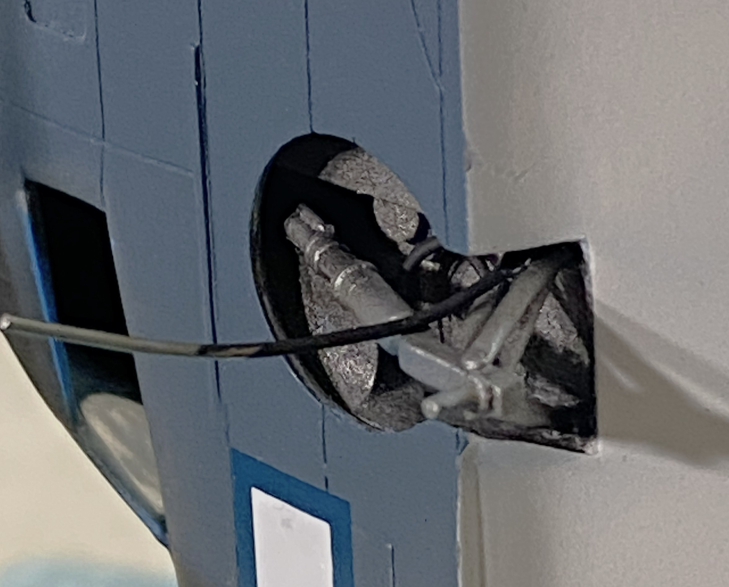
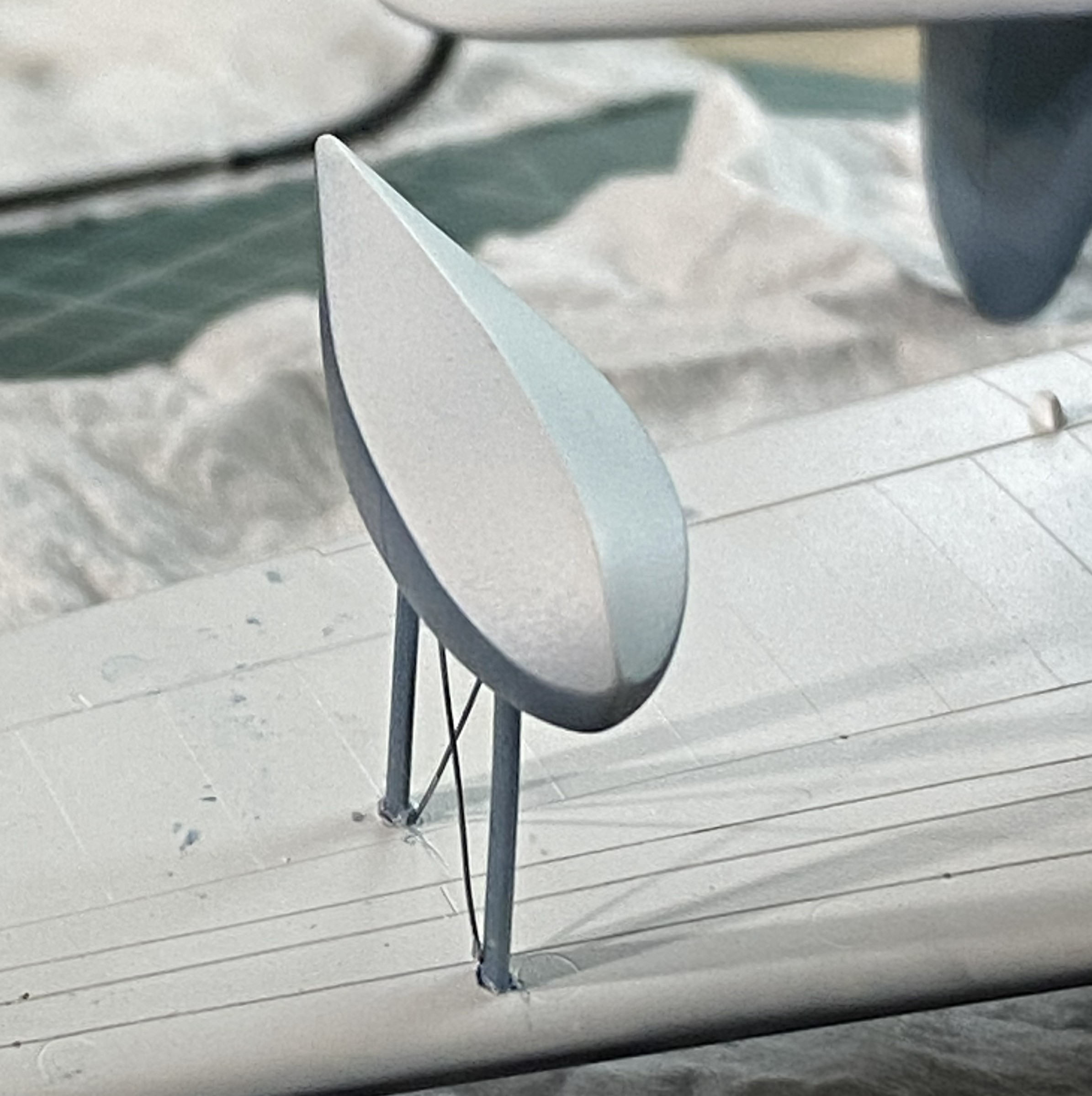
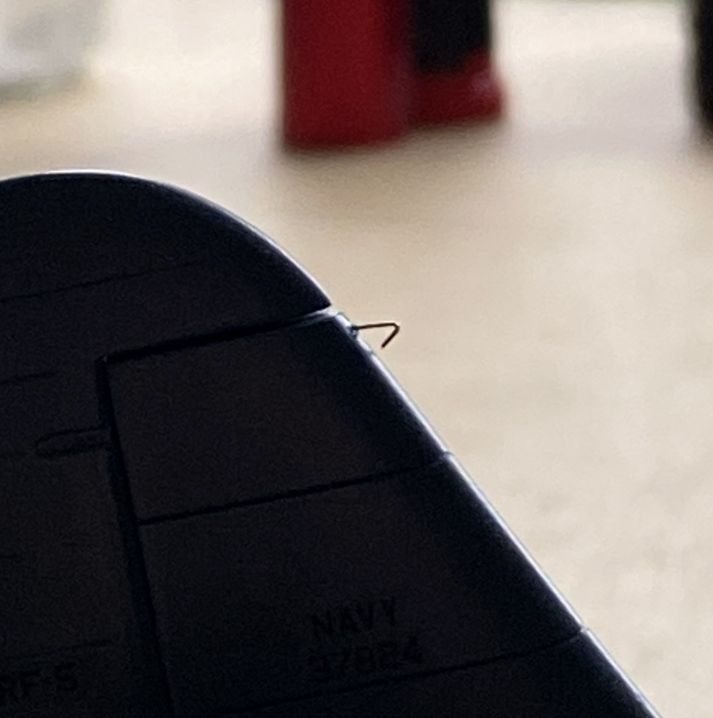
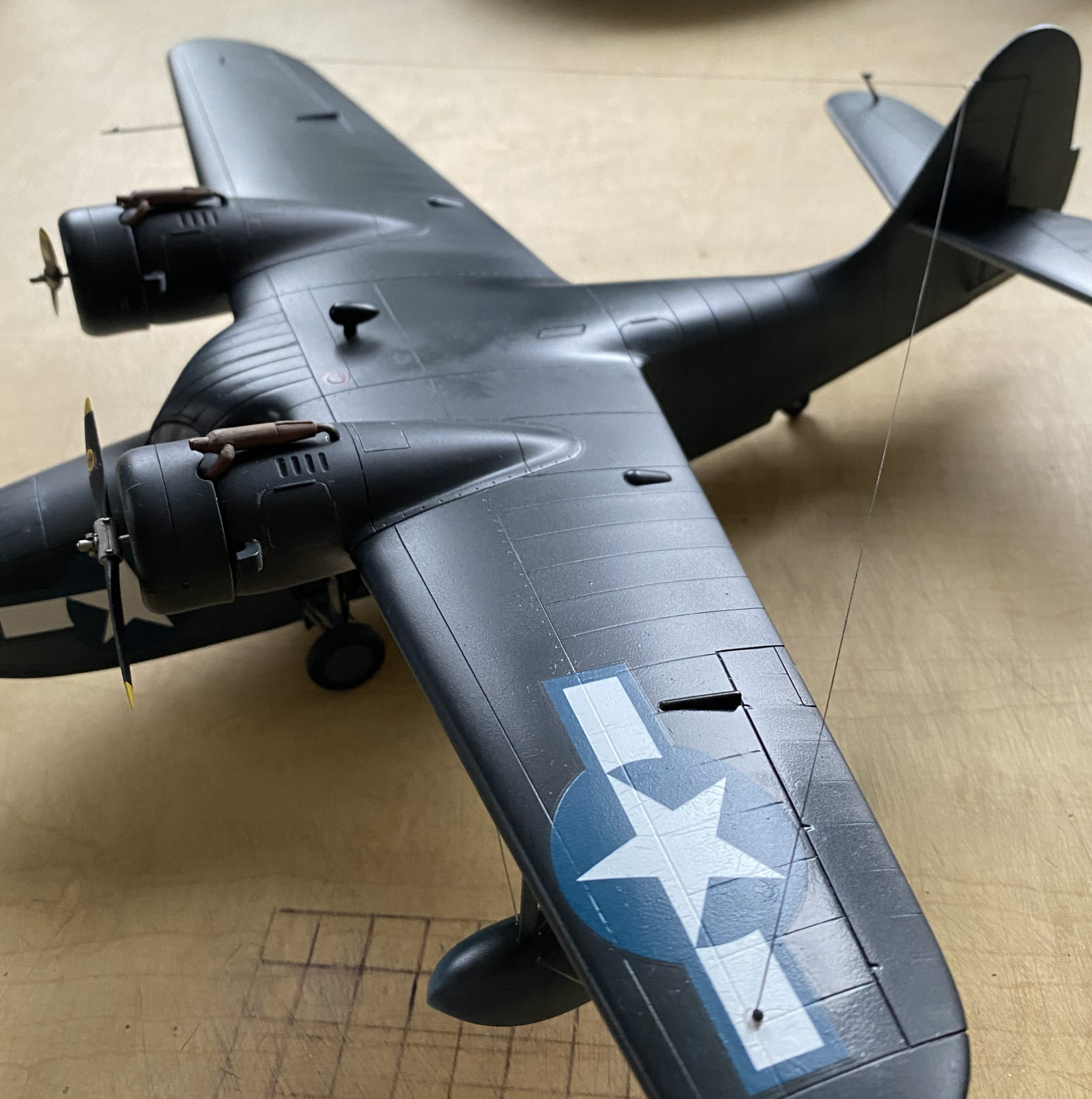
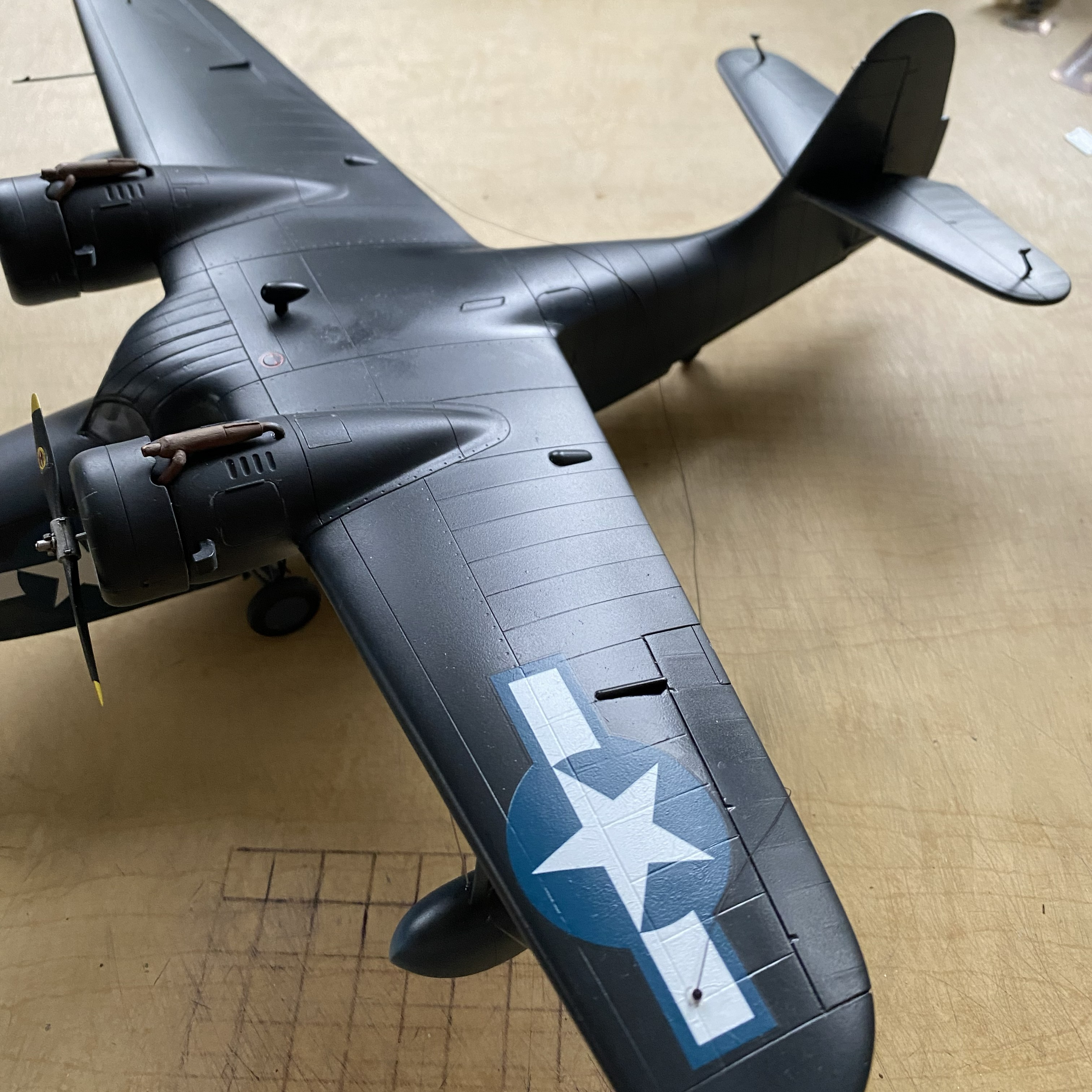
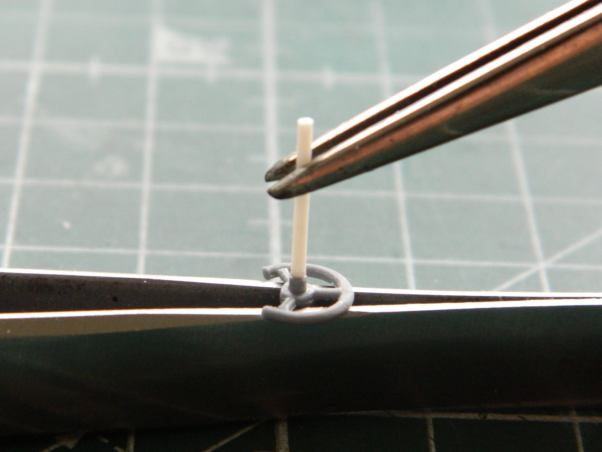
The radio aerials attach at both wing tips and the tip of the vertical stabilizer. I use this for aircraft aerials:
As I’ve been putting this together, obviously the more parts I add the less places I can hold it. For that reason (because these things get handled and transported) I wanted the aerials to be semi-removable; permanently attached at the wing tips, removable at the vertical stabilizer. What would make doing that simple would be to make the attachment point on the vertical stabilizer detachable. Or…I could mount the attachment point permanently and have it be J-shaped so that I can just lift the EZ-Line and let it drop. I like that idea, the major flaw is that even though the EZ-Line’s tension is adjustable, that J-hook has to be small. I didn’t have confidence in copper to hold up over the years. Instead I used the E-string from a guitar (thereby creating the moderately rare 5-string variant). Everything about its dimensions are printed on the pouch:

It’s certainly over-engineered for my purpose, which I think is great:
I’d attached little stubs of styrene rod where they belong and center-drilled them to socket the end of the EZ-Line into:

After gluing the other side in place, I tested the arrangement to see if it would function as desired. It function exactly as desired. Top photo below is with the aerials in place, the bottom photo is with the antennas dismounted (for these photos, I dry-fit all the parts yet to add and realized that none of those dry-fit parts need to be glued so I left them on):
I have one more thing to do (attach the brake lines to the wheels) and DONE!

Grumman JRF Goose (Czech Model) 1/48 Scale Build #3 – Doing What is Necessary to Get the Fuselage Halves Married
This month there was a great deal of fitting required for small parts. This means that this post won’t be quite so long as working small parts eats a lot of time.
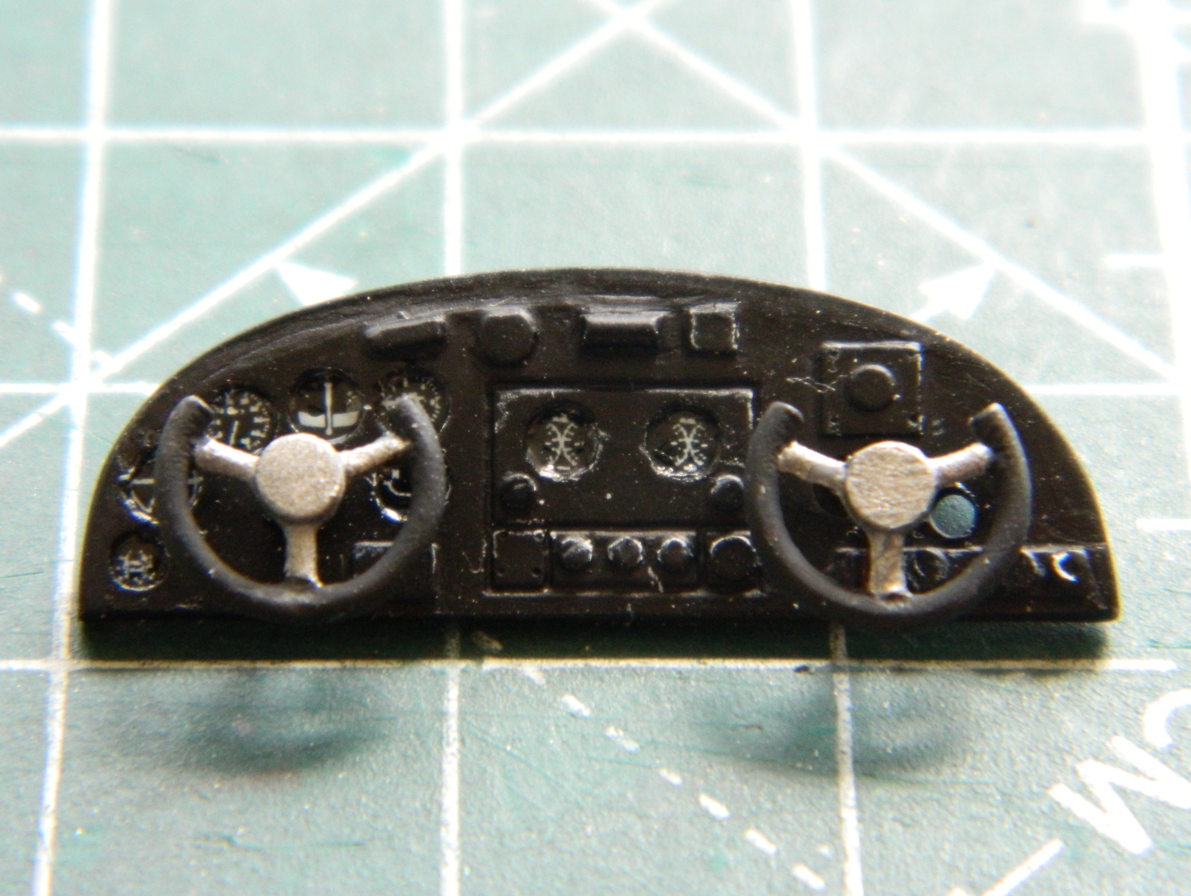
My first task was getting the instrument panel attached. Having painted its face and added instrument decals, it was time to step up and do what’s needed to get the instrument panel to do an excellent “I’m-supposed-to-go-here” imitation. Since I hadn’t painted and added the control yokes, I started there. The face of the panel has raised (and somewhat generic) lumps where someone thought the yokes should mount. Had I looked more closely at those generic lumps, I would have noticed that the “suggested” location for the co-pilot’s yoke was in the wrong place. The last photo in the series below will show those holes where they presently reside.
The stub on the back of the yokes was too short so I added rods (clearly too long, but those will get trimmed once the yokes are in place):

As an aside, subsequent and frequent reattachments showed me that I should have added pins between the rods and yokes. After gluing them back in often, I did that and the problem of knocking those things off ceased. And on to those holes:
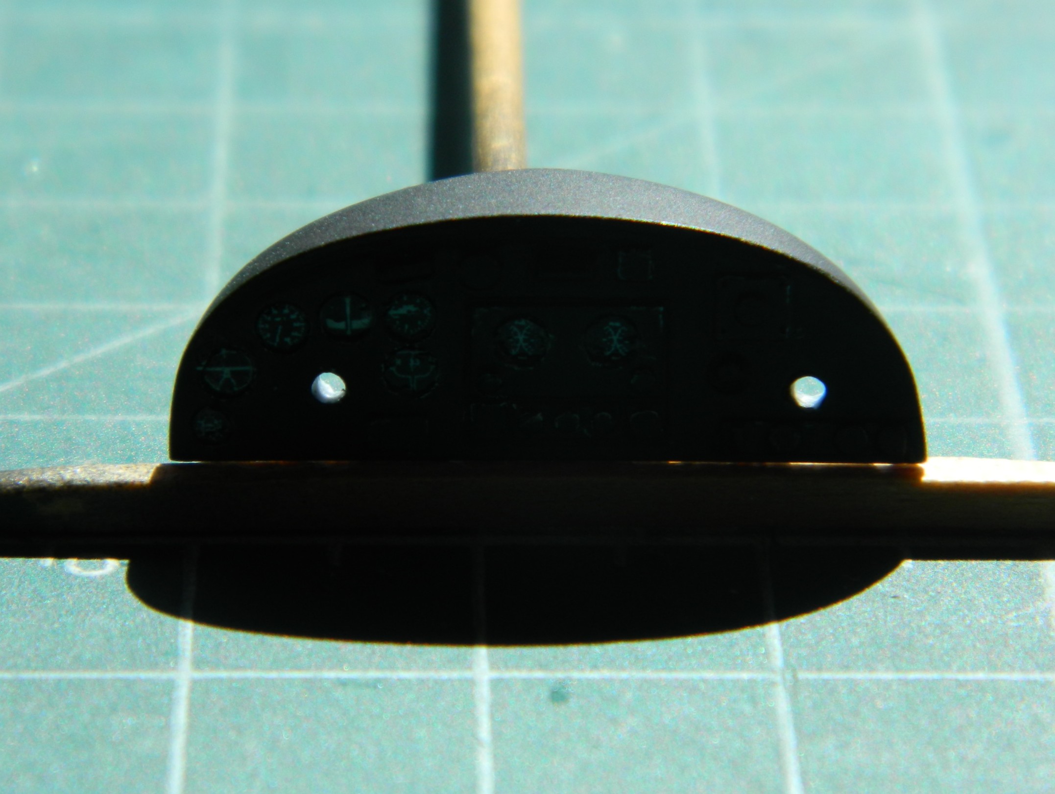
Yeah. I re-drilled the hole on the right and didn’t bother filling the incorrect one for two reasons. The primary reason being that the hole can’t really be seen when the panel is where (I hope) it goes. The second being that I painted the inside of the unused hole flat black and now that hole cannot be seen at all:
The fit of the cockpit’s rear bulkhead showed me that for me, True Details isn’t worth the money. Fit was rotten and the dimensions of the bulkhead are off…as in sides that are supposed to be parallel aren’t parallel. With strategic application of flat black, I doubt that this will be noticed once everything is buttoned up:

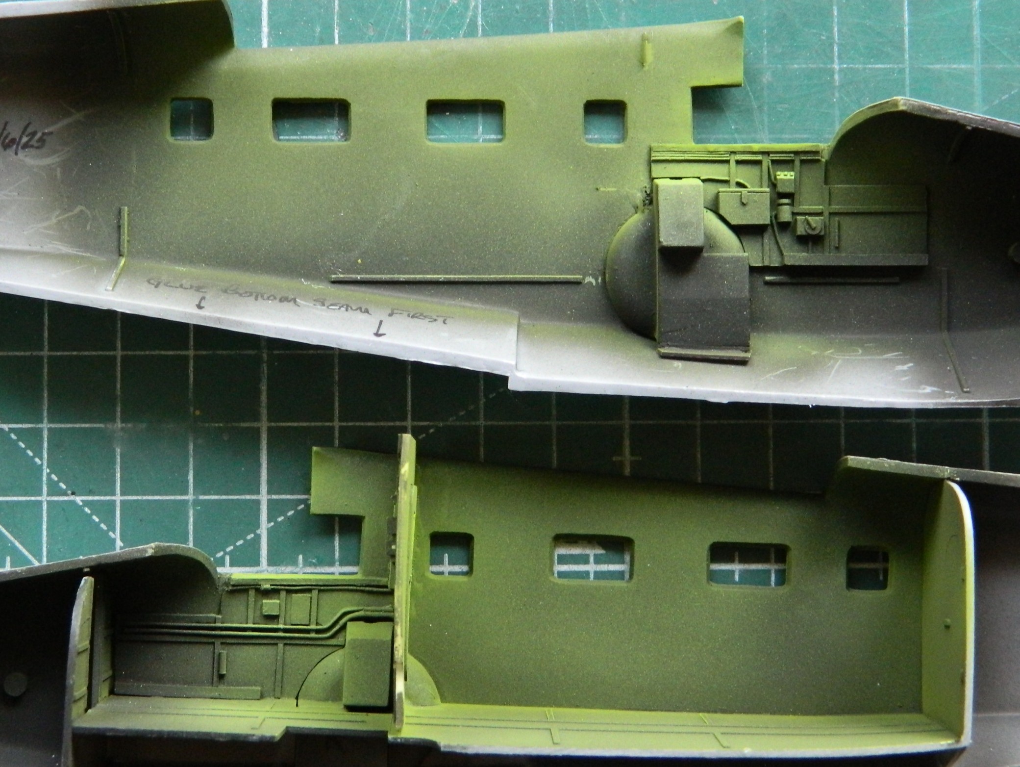
I mixed up some chromate green using Tamiya XF-3 Flat Yellow (2 parts) and X-5 Gloss Green (1 part) and added it to the inner fuselage halves allowing the flat black that was already put down to act as shadows:
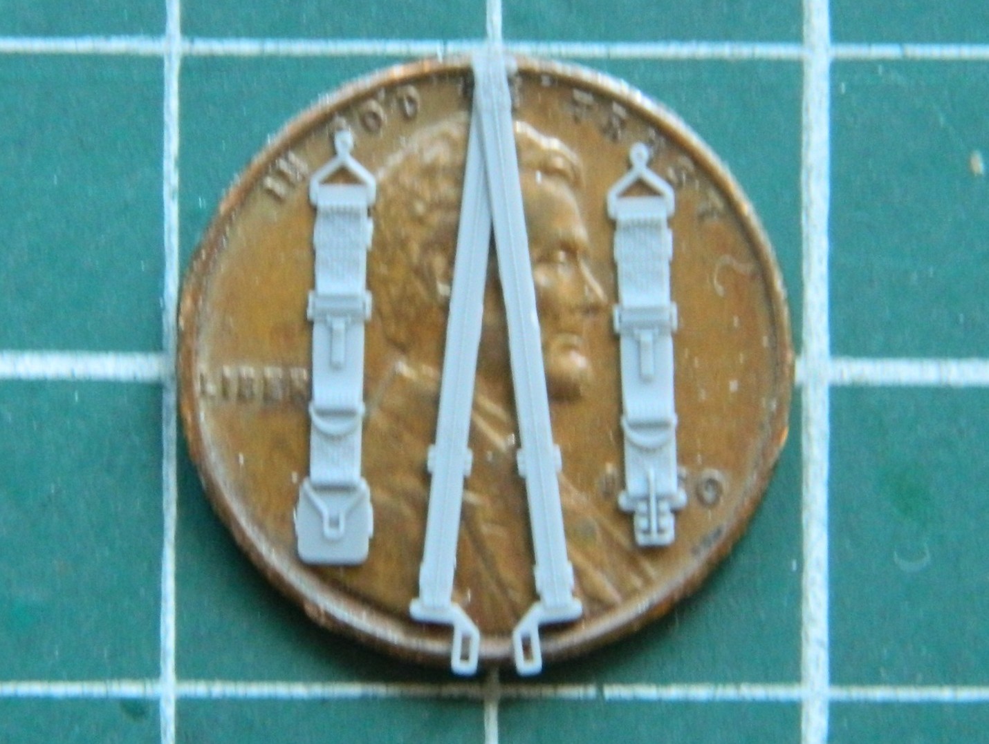
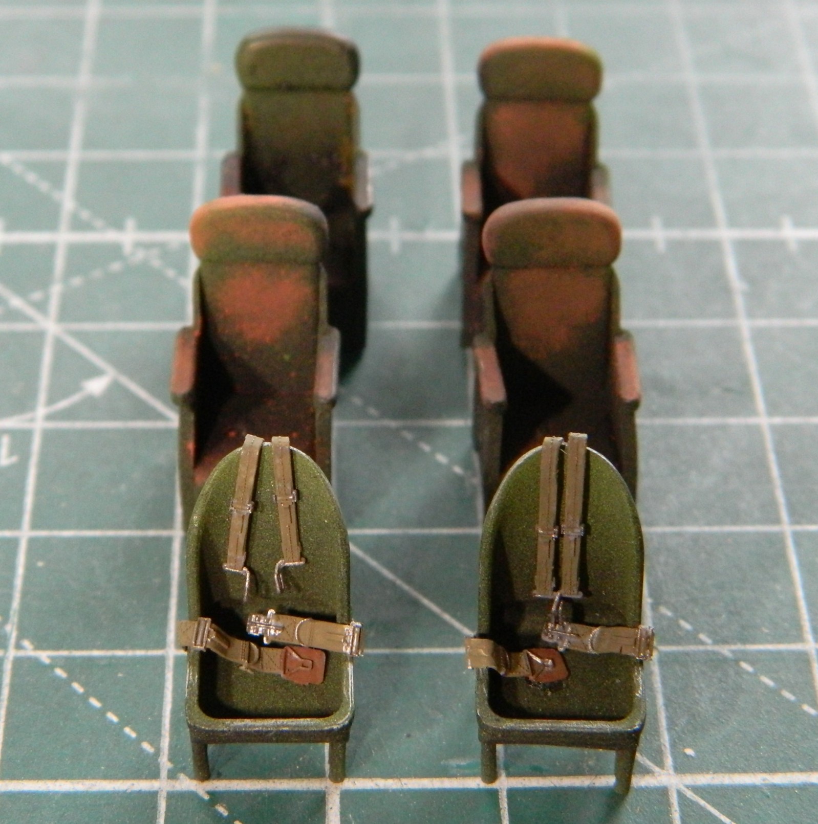
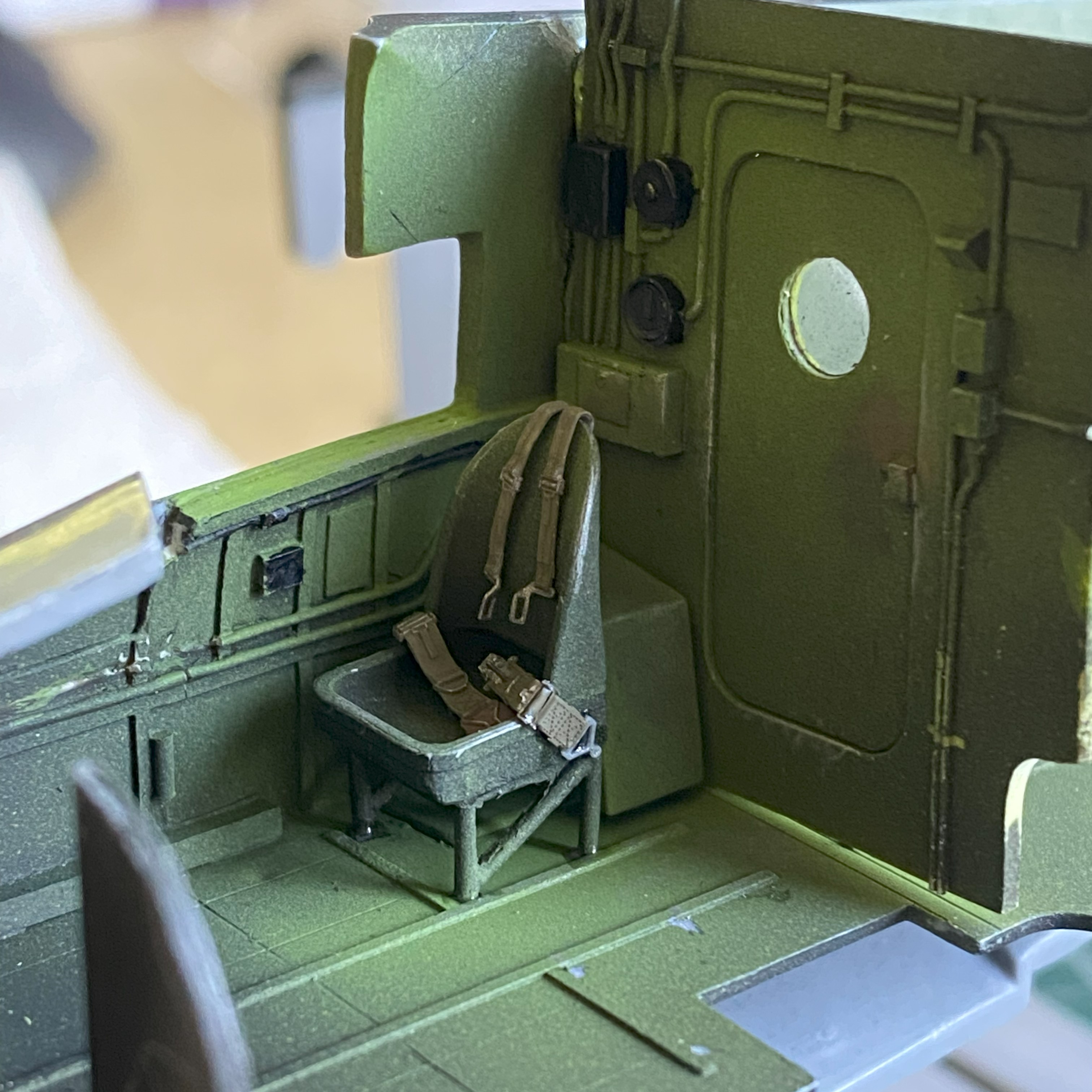
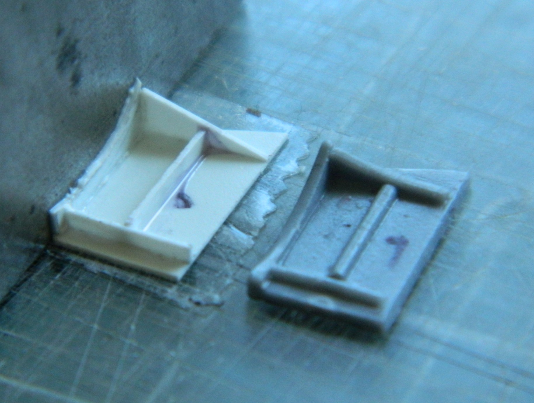
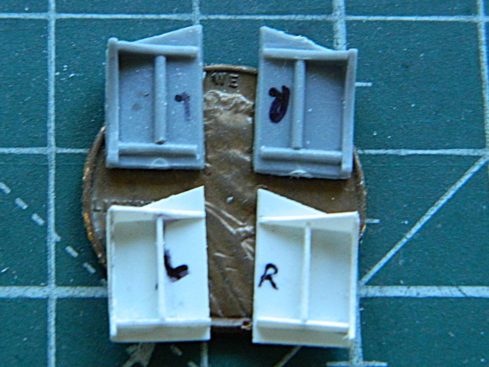
Some time back, I ran across these little beauties. The pilots’ safety harness in delicately molded styrene:
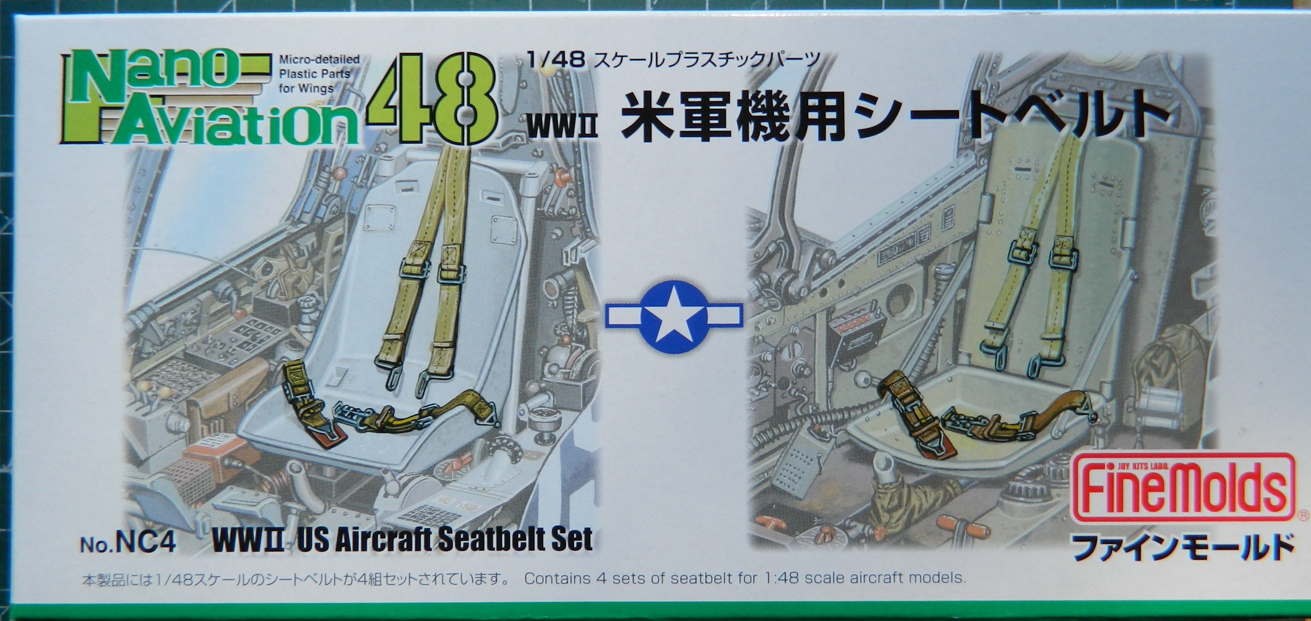
The only vendor I’ve found so far is in Japan. (What with these bullshit “tariffs”, I don’t know how easy they’ll be to get in the future…a problem I’ll deal with in the future.) This is what’s in the box:

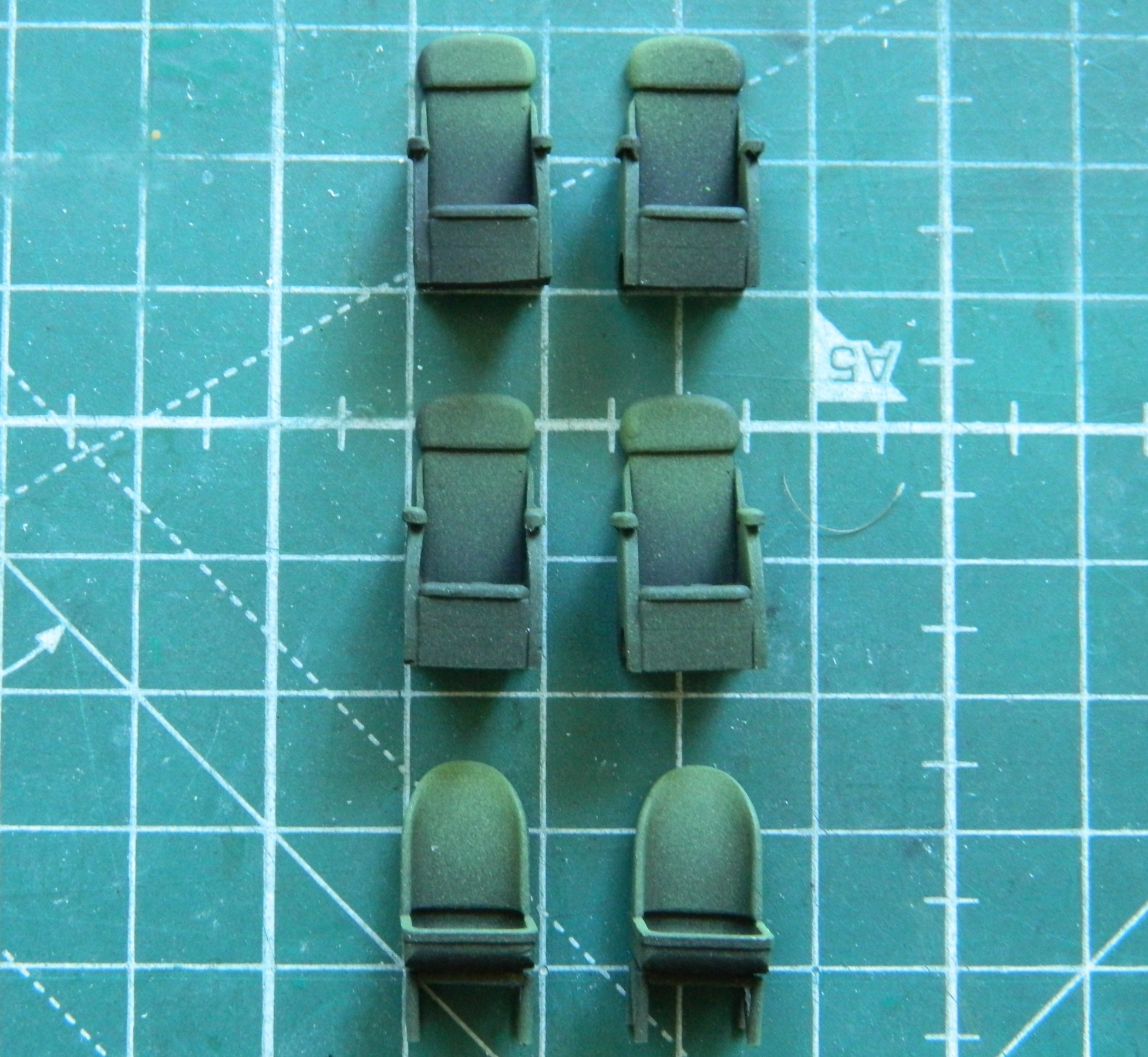
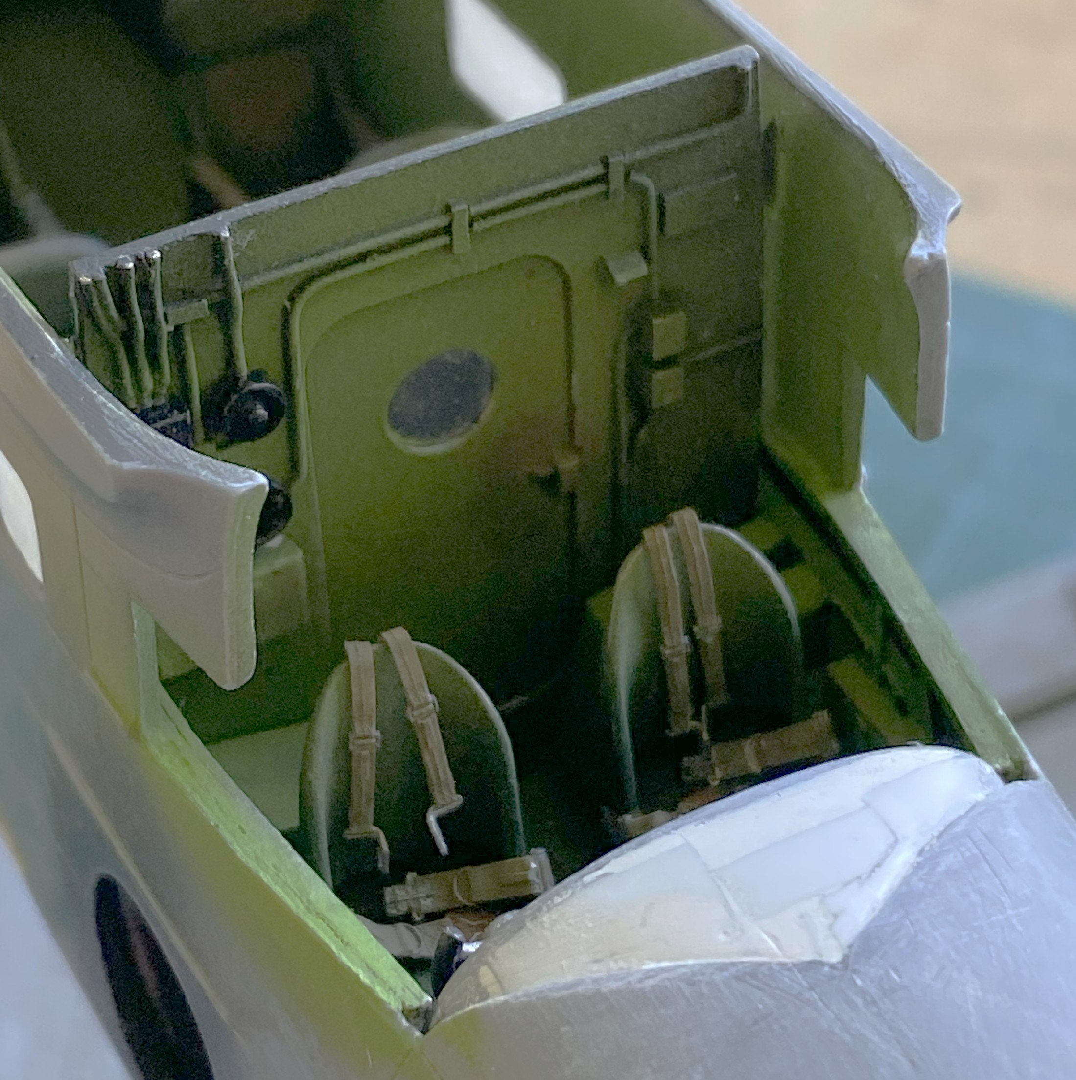
Before I could use those, I wanted to paint all the seats. As typical for me, the first coat of paint was Tamiya XF-1 Flat Black for pre-shading. Then I used my custom-mixed chromate green and painted on the light blooms:
The harnesses were heated and bent to conform to the seats of the pilot and co-pilot:
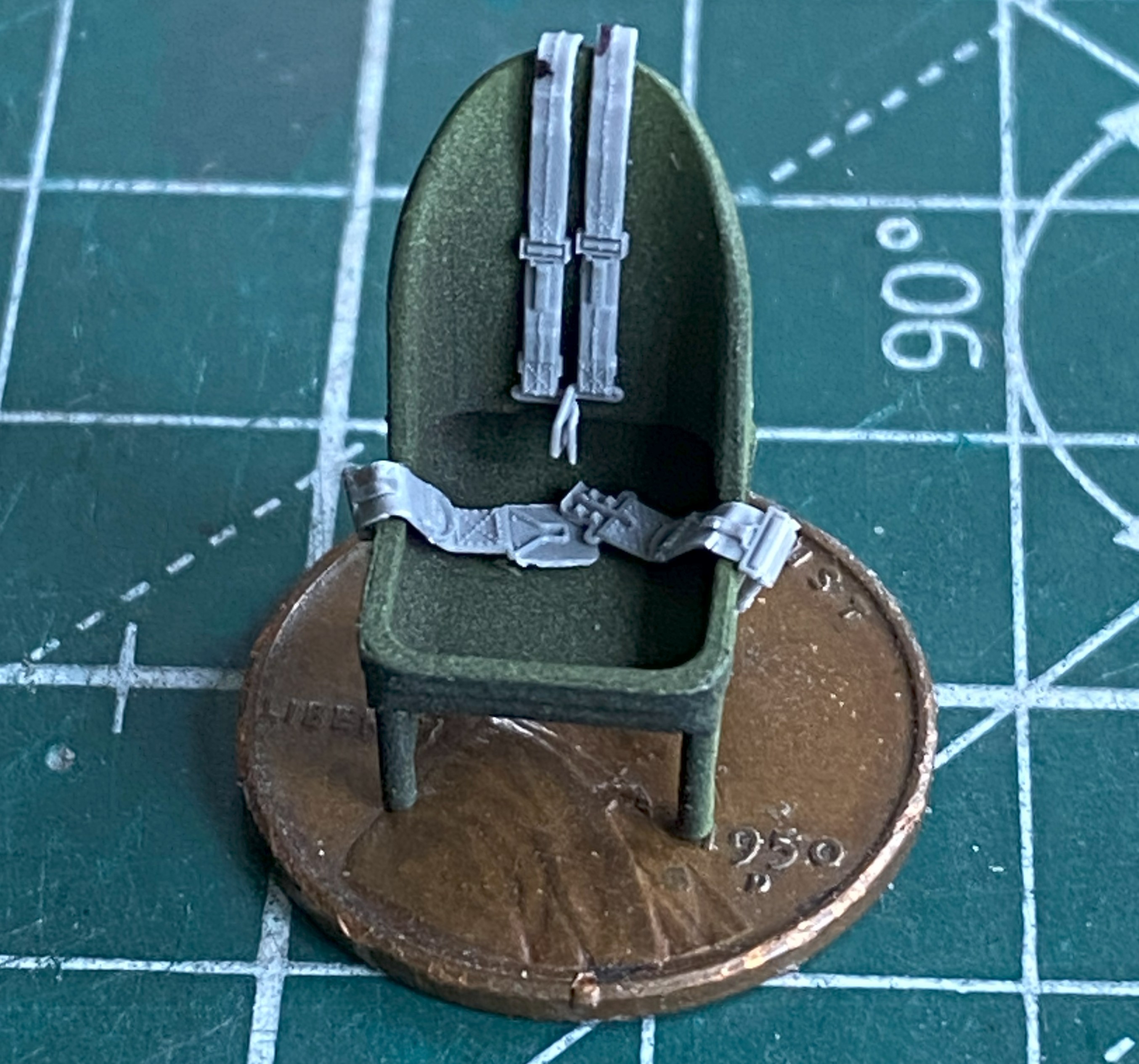
The straps were painted with a mix of Tamiya XF-49 Khaki (3 parts) and XF-64 Red Brown (1 part). The leather pads were painted using tinted XF-64 Red brown (5 parts) and XF-2 Flat White (1 part). The metal bits were painted with X-11 Chrome Silver. XF-51 Khaki Drab (5 parts) and XF-2 Flat White (1 part) color was misted over the areas that would be most highlighted, and then I used a dark orange pastel to replicate wear. I didn’t go crazy on the passenger seats because little of them will be seen. The pilot and co-pilot seats were touched here and there with a silver pencil to replicate wear:
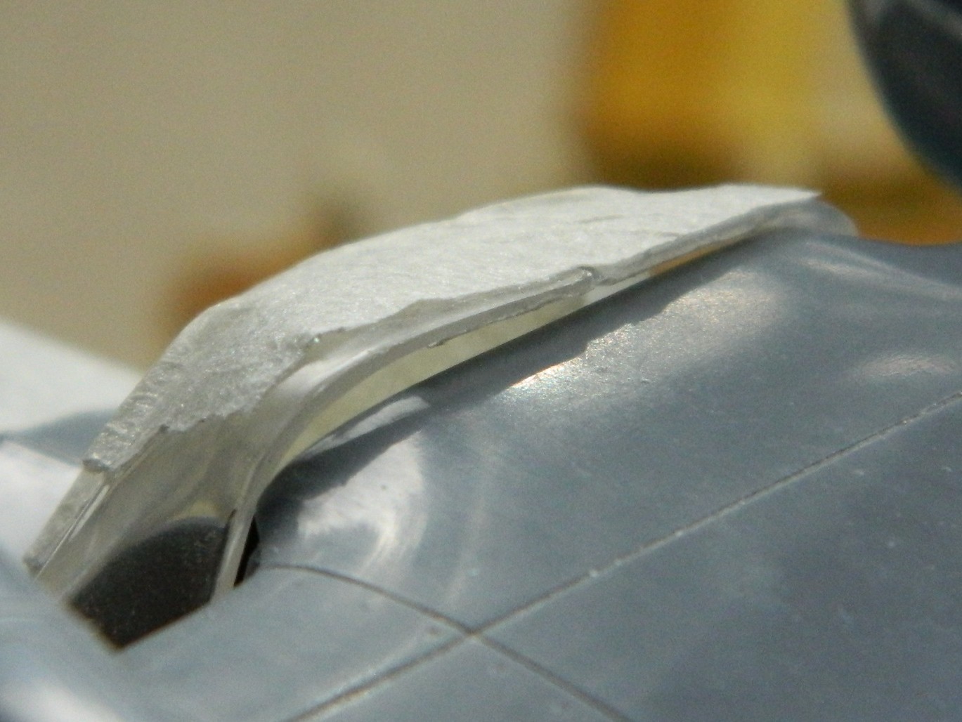
With the fuselage halves taped together, I test-fitted the clear canopy parts (obviously also taped together) to see if my initial assessment held up regarding its fit. Yes…it did. I placed the wings in place to see what had to be diddled with to get a better fit. Check what the arrow is pointed to:
That overhang has to go; those parts are all supposed to conform to the edge of the fuselage. So the plastic above the pencil line was filed to meet the line:

Checking the fit of the clear parts again showed a significant improvement with its fit:

It also showed me that there’s a possibility of having to tweak the attachment areas of the clear parts but I can’t make that determination until the wings are glued down permanently.
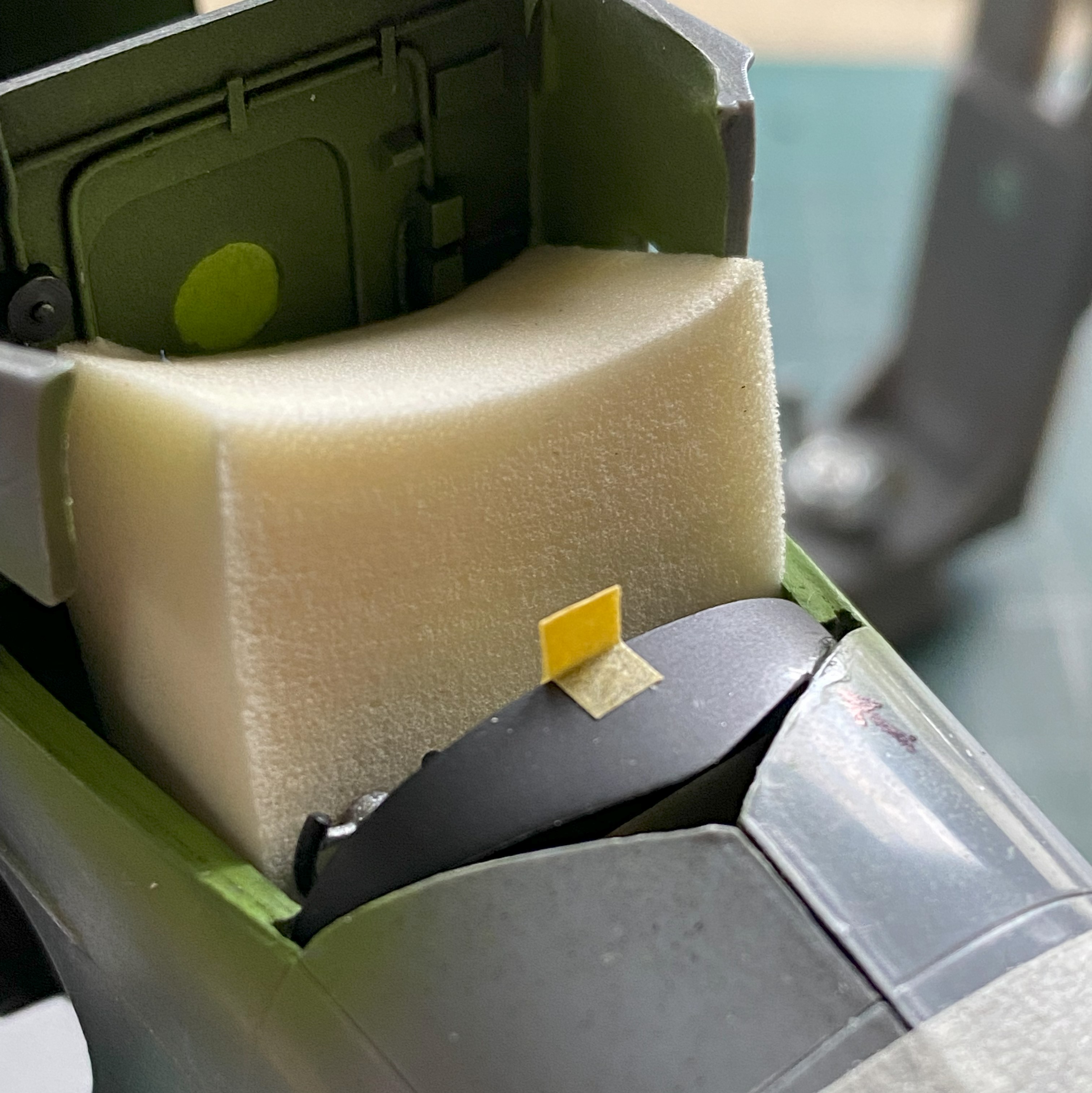
The last thing I had to do before I could marry the fuselage halves was to get the sodding instrument panel to fit (and hopefully not look bad in doing so). I used a foam wedge (sold in drug stores and/or apothecaries) to align the panel to the best of my sometimes-disappointing abilities (the tan square is a loop of masking tape to enable me to move it…and there was no shortage of moving it…without damaging the face of the panel). Where the panel touched the fuselage received a significant amount of styrene cement any place it touched the fuselage half. My brain-fade kicked in and I attached the panel to the left side of the fuselage, where everything else inside the fuselage was attached to the right side. ::facepalm:: It complicated the joining of both halves a little but I didn’t find that out until the trigger was pulled and the Rubicon crossed. As you’ll see, there was no way I could dislodge the panel without damaging things. The bitch is ON there:

After letting it sit overnight to harden fully, I thought that it wasn’t quite firmly attached enough. I used styrene scraps to reinforce the attachment point(s):

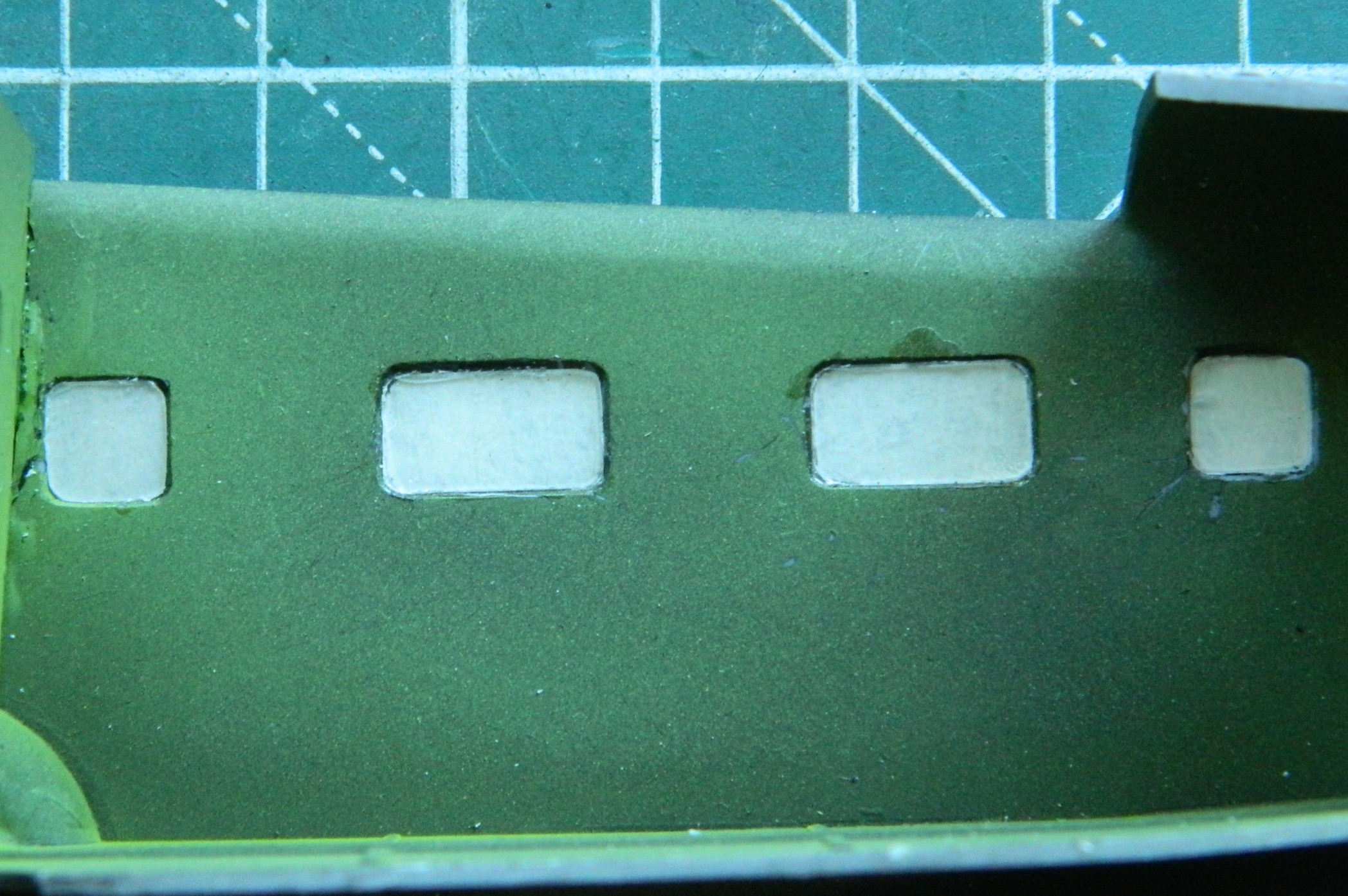
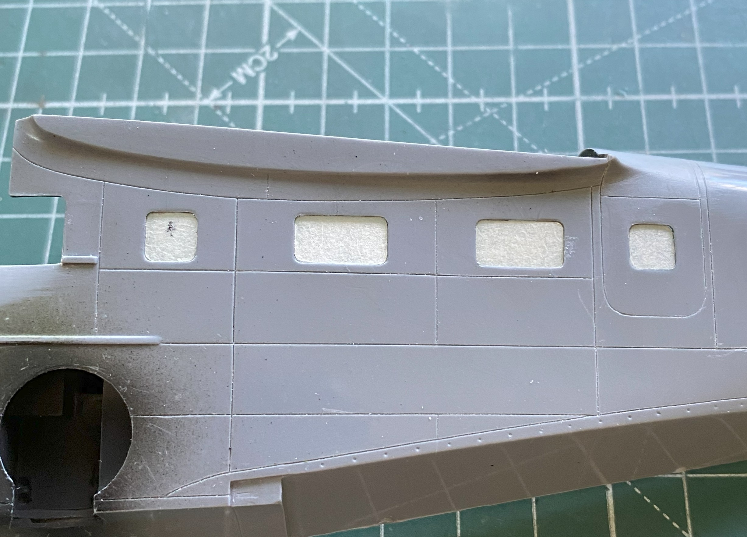
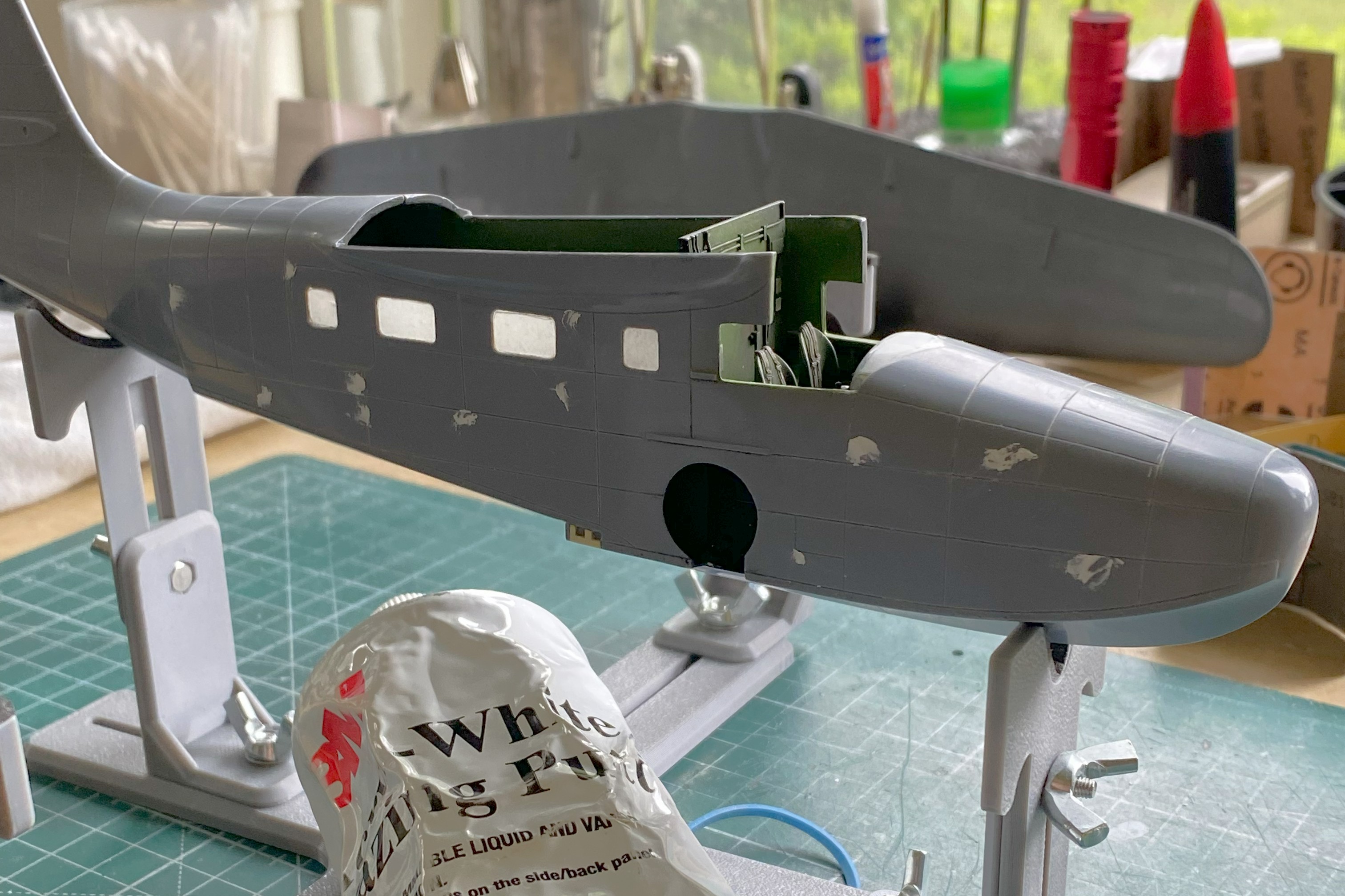
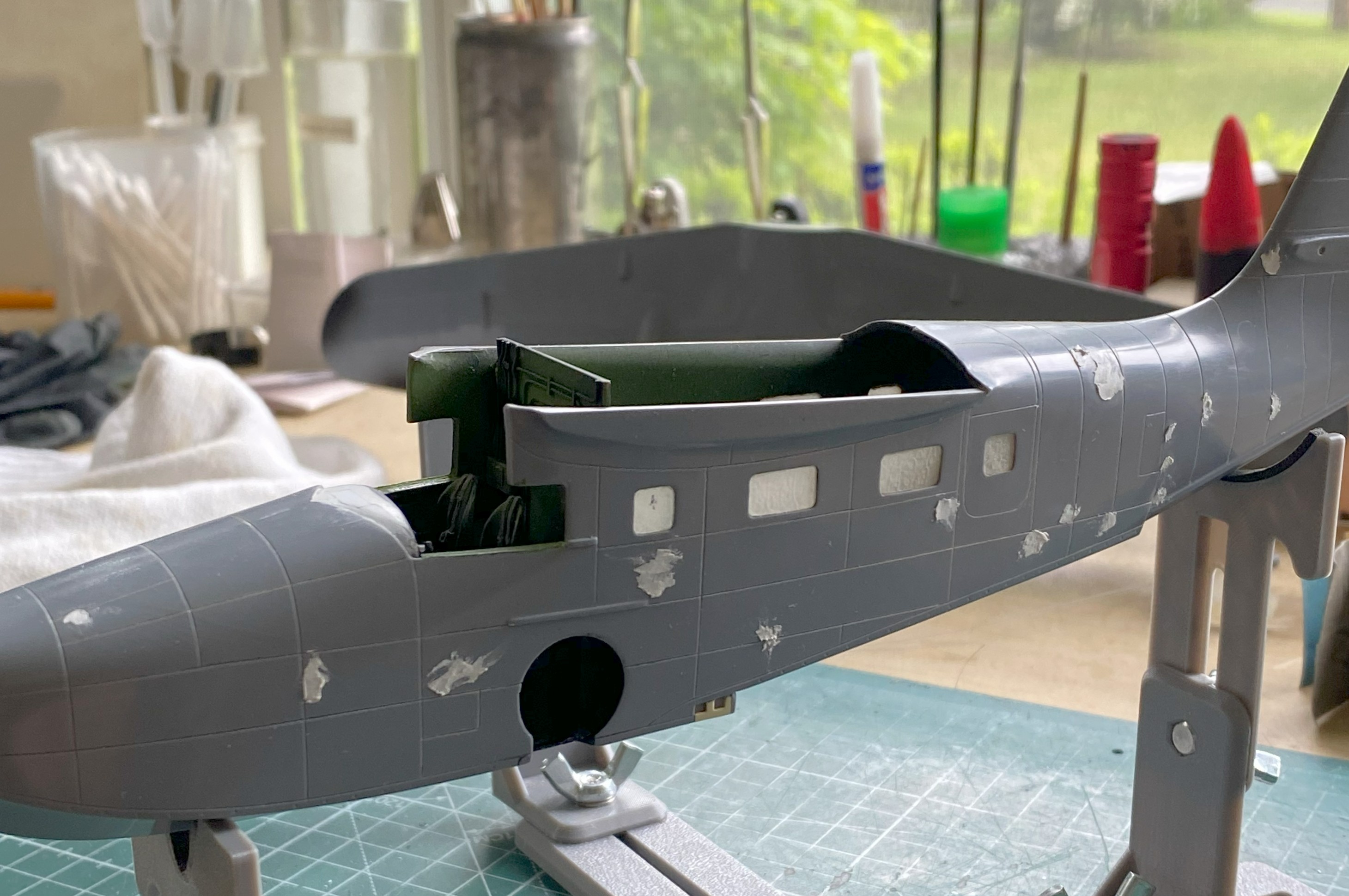
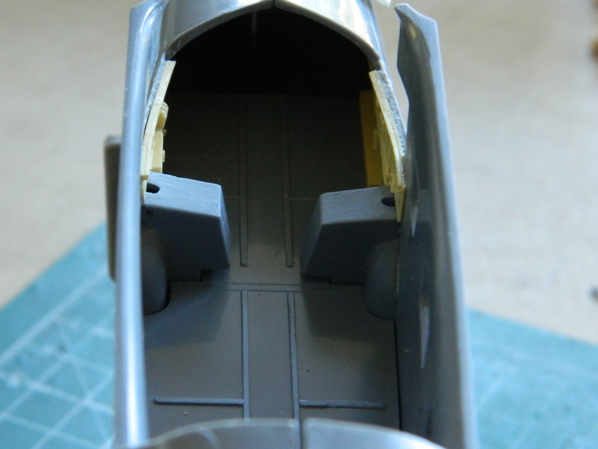
It was time to add the windows to the passenger compartment. Once again, thick plastic:
Earlier US WWII fighters had a plate of armored glass behind the windscreen. I’ll keep these thick clear parts for that use in the future. For now, they need to be replaced. I’d intended on using 0.010″ (.254mm) but though it’s to a more scaled size, I wanted a bit more surface for adhesives to bond with so instead I used 0.015″ (.381mm) clear instead. This gave me a closer-to-scale thickness (the thin piece of plastic isn’t usable other than as a comparison of thickness):

When I did the M4 Sherman with a clear side, I decided that the next time I used clear like that (or for any purpose, really) where it had to be fettled and tweaked to fit, I’d cover both sides of the clear styrene with masking tape. After coating a scrap strip of clear on both sides, I positioned the strip under the fuselage and traced the outlines of the windows:

Yes…the sides of the fuselage are too thick as well. What it would take to fix that isn’t worth the effort so I left it as-is. The windows were trimmed and glued into place using UV-setting resin and the inner masking tape removed:
Time to add the seats to the cockpit:
The pilot’s seat wasn’t added at this time because of fitment problems. I had to shorten one of the legs so that it would sit level(ish) and that would be better done after the fuselage was together. The passenger seats were then glued in:


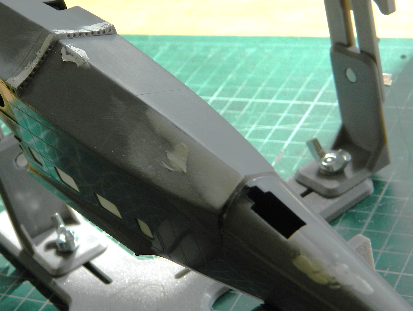
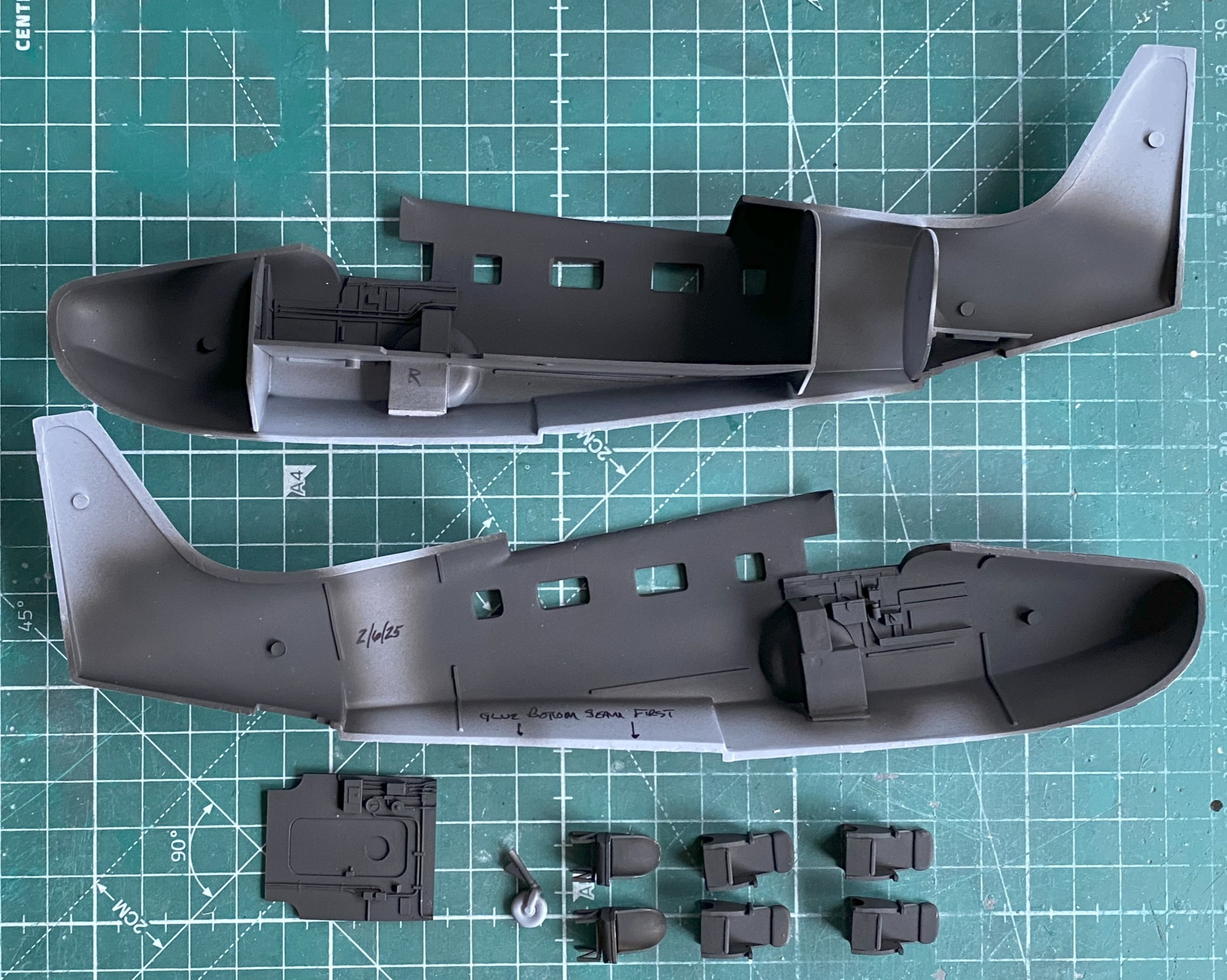
I glued the fuselage halves together. Such a simple sentence to describe a hair-pulling experience (that’s one way to clear out my nose…). Each half of the dies for the fuselage parts was clearly cut by different people. I just wished that they’d communicated with each other. Neither side matched the other in overall dimensions or curvatures. What ended up driving this task was the question, “Which side would be easier to fix than others?” I made my decision to have the top seams match (because those are the ones easier to see) and deal with what happens underneath. The halves were glued together (and most of the filler used to hide the seams, top and bottom, came from 99.9% stretched sprue).
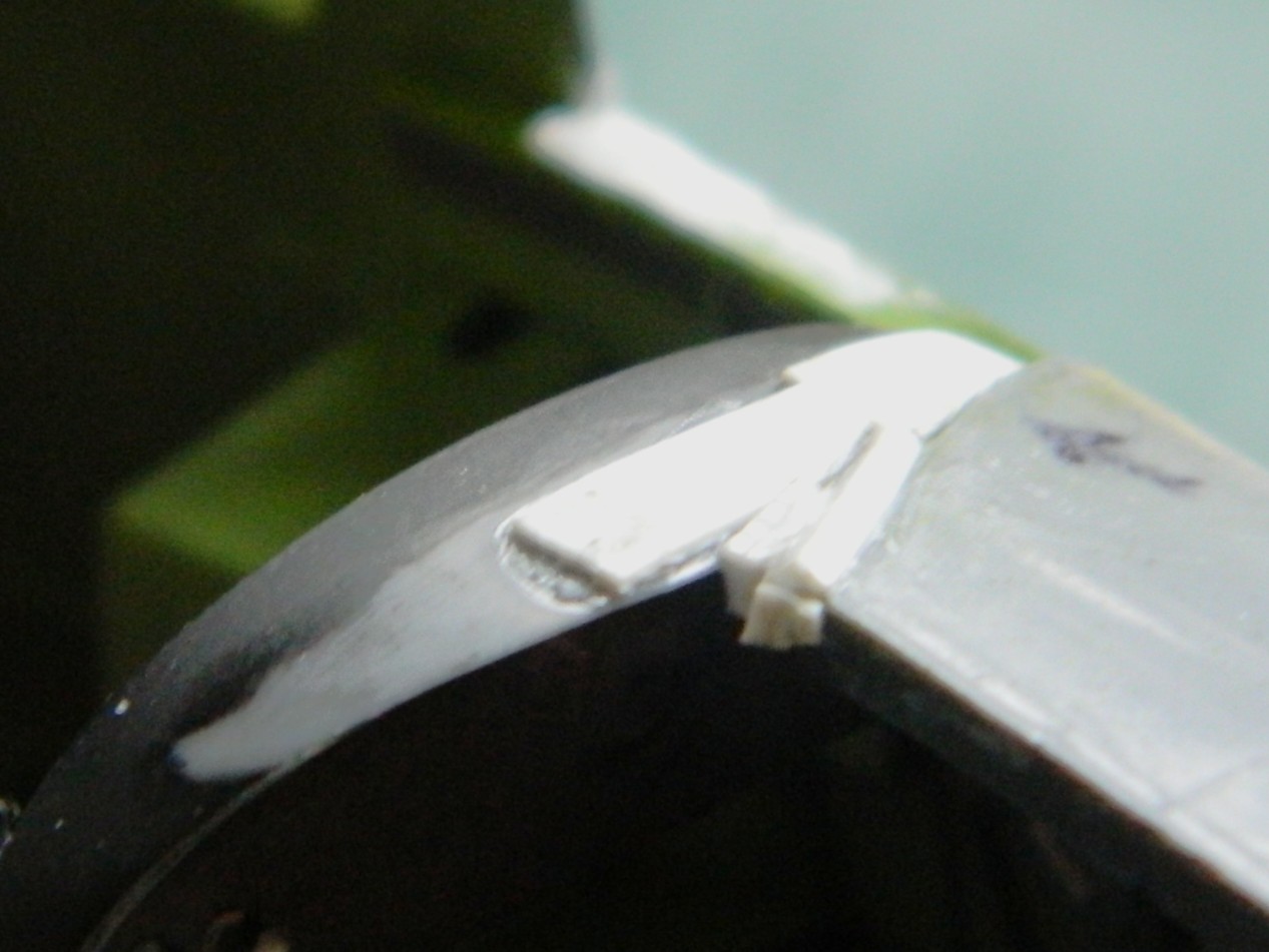
With the halves now joined, it was time to fix the mess underneath. SO much putty would have been needed to do that that I decided to add scrap sheet, mostly 0.010″ (.254mm). While I was doing that, I noticed that things don’t fit (check the arrows):

These photos are included to show you what the good side’s fit was like:


Yeah…filled with sprue.
This is why one should always use photo references from the actual time period being modeled. Most of my references are modern ones, which are okay in general, but it’s in the specifics where they drop the ball. Modern references show the nose hatch to be “proud.” It sticks up. Period references show this hatch fits flush. Can you guess what I didn’t do?:
Back under the fuselage, lot of sanding ensued (and more than a little filing):
With the supports trimmed judiciously, the pilot’s seat is in, as well as the instrument panel top puttied and sanded (though it’s evident that there will be more putty added and followed up by more sanding):
Checking fit (after a LOT of sanding) with the wings shows me that I was correct…most of what’s inside won’t show from the outside, and even less will be visible once the clear parts are in and painted:

I dislike scribing and my results show that. The panel lines with this model were inconsistent with depth and width, so all panel lines had to be rescribed. And then it was three bouts of putty filling where the scriber (me) left lines where there shouldn’t be any lines:
And after doing all that, RE rescribing panel lines often does this:

Fit was so poor that in order to get things the way I want them to be, I ended up with something that looked like a Sub at a BDSM party:

And though it took stretched sprue, scribing, rescribing, and putty, I got the empennage done:
Maybe next month I’ll get to start putting these bits together permanently.
Grumman JRF Goose (Czech Model) 1/48 Scale Build #2 – Fit…Dealing with Lousy Fit and Having Several Fits
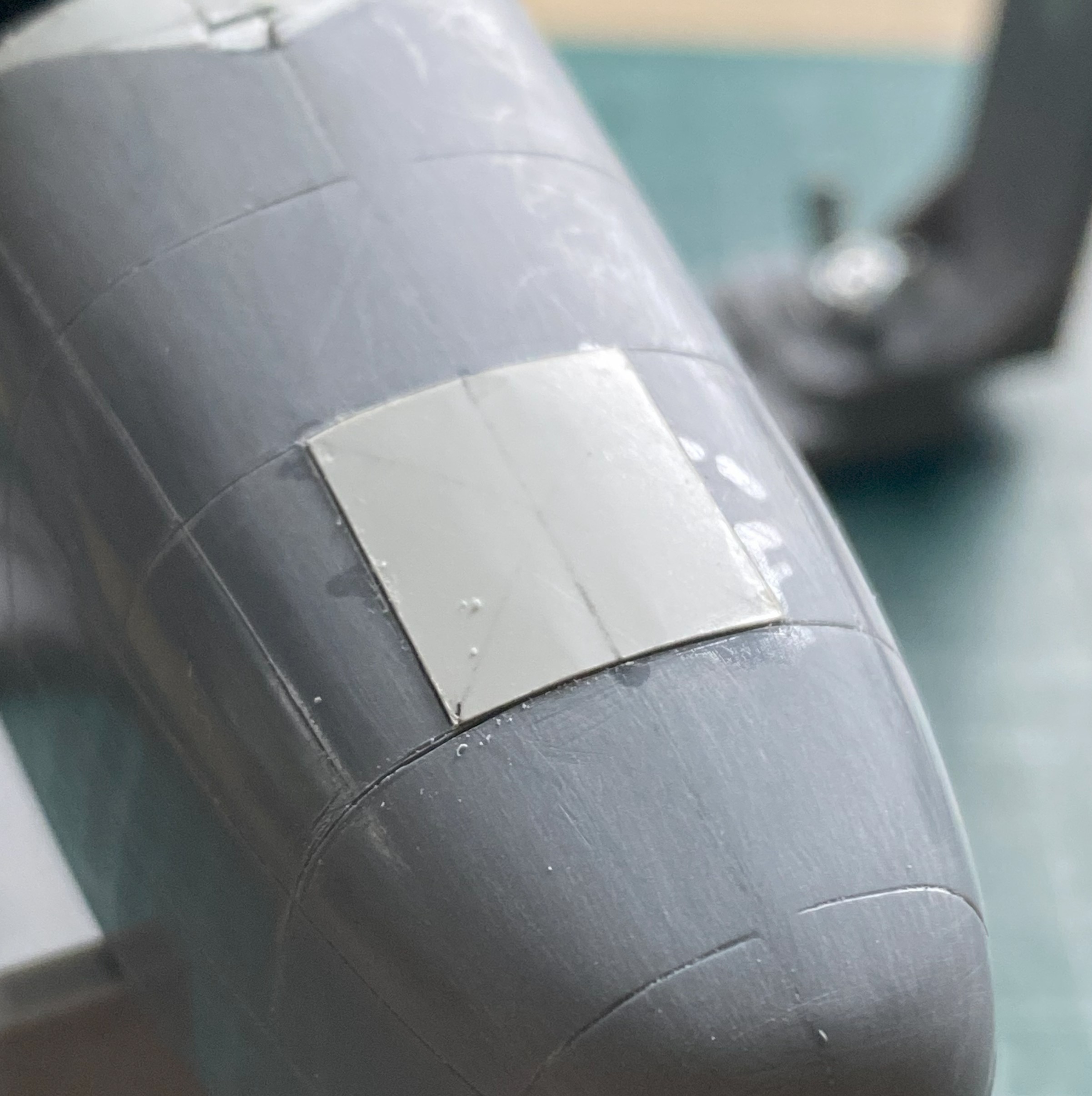
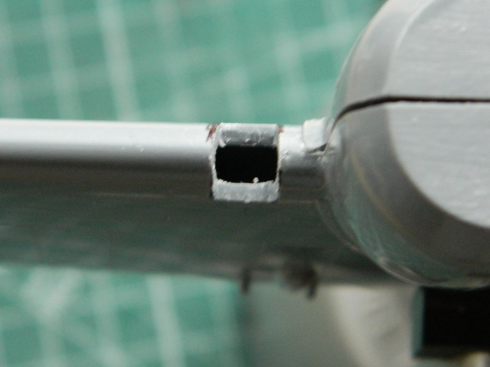
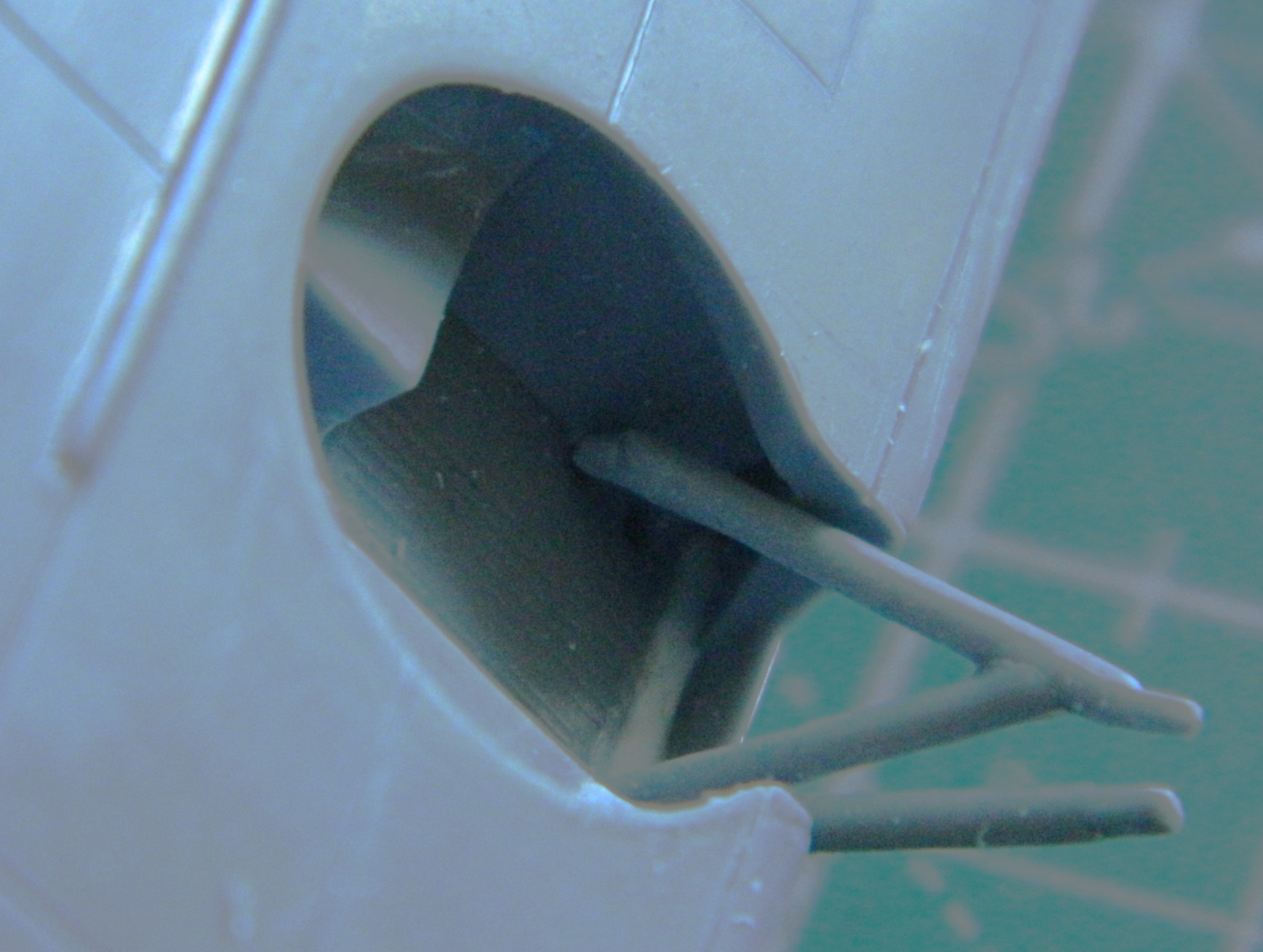
I picked up where I left off last month by working the landing lights. It’s one thing “knowing” that the plastic of this kit is rather thick. And then I get the socket for the landing light cut out and see this…it’s 2mm (okay, 1.96mm) thick here:

And making these cuts only cost me one bent saw blade.
With the acrylic rod cut, I needed to fit it to its socket to mark where the leading edge of the wing is so that I can drill out the “light”:
With the “light” drilled and a tiny drop of black paint to replicate the bulb, the whole depression is hit with chrome:
Then it gets glued in place and shaping begins, starting with a motor-tool, then files, leading to sandpaper(s), and then polishing (Novus Plastic Polish #2):

Some of the choices Czech Models made don’t make sense to me…though I guess it’s got to be easier to produce raised details than recessed details just due to the physical requirements of cutting dies. Dies are negatives of the parts so if the kit has very fine recessed details, that means those very fine details have to be positives, as in not recessed, in the dies. In other words, if it’s recessed in plastic, the dies have to be cut away from the intended line leaving just the fine rib in the die(s). It’s probably MUCH easier to recess the die for raised details…which I don’t want so I decided to sand down the mistaken raised details and scribe that detail instead (because of how much I LOVE scribing lines).
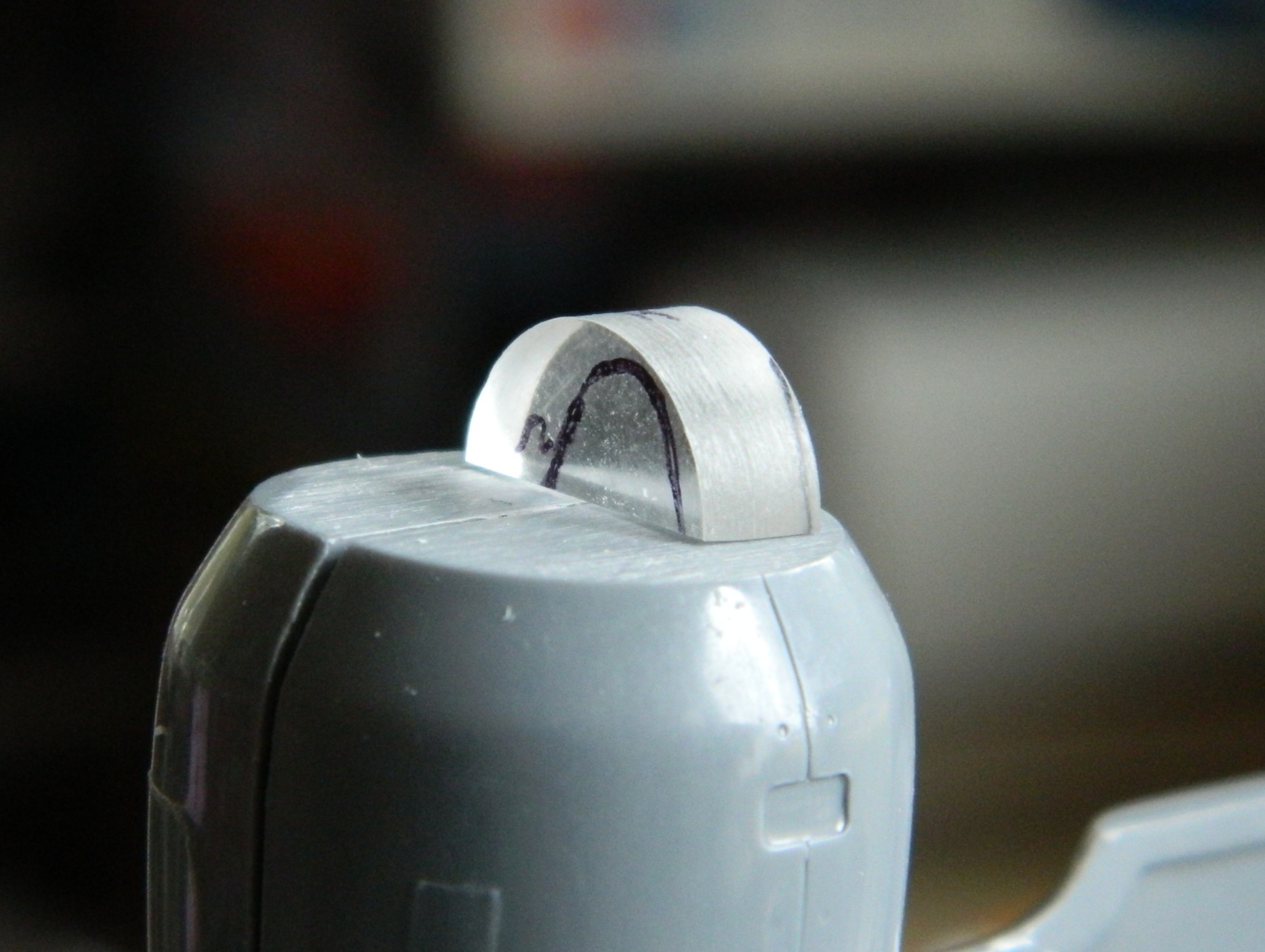
What all that means is that I have a few areas that need scribing. Four of them (of ten) have radiused corners and because I’m SO good at scribing (::giggles::), I decided to make a template. I used .005″ (.127mm) copper shim stock and pressed masking tape over the shape I’m replacing to act as something that I can trace onto the copper. Here’s the progression:
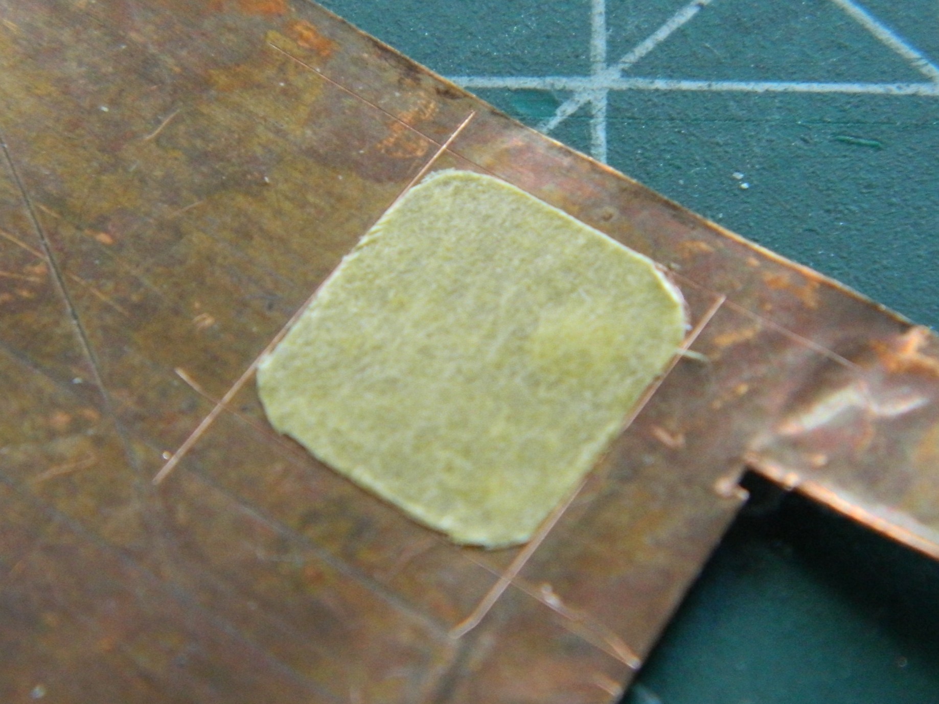

The results were better than I could have done freehand (this access panel has a piano hinge at its top so I replicated that with stretched sprue, which I also used on the nacelle to fill in the HORRIBLE recessed panel line…on both nacelles…and behind the added sprue, you can see other panels that had been raised panels also but easier shapes to rescribe):
And now the surface behind the louvers is ready to be scribed:

There are several gaps like these (and note the nicely polished landing light to the left):
My preferred method of closing large gaps is to start by stuffing them with scrap styrene:
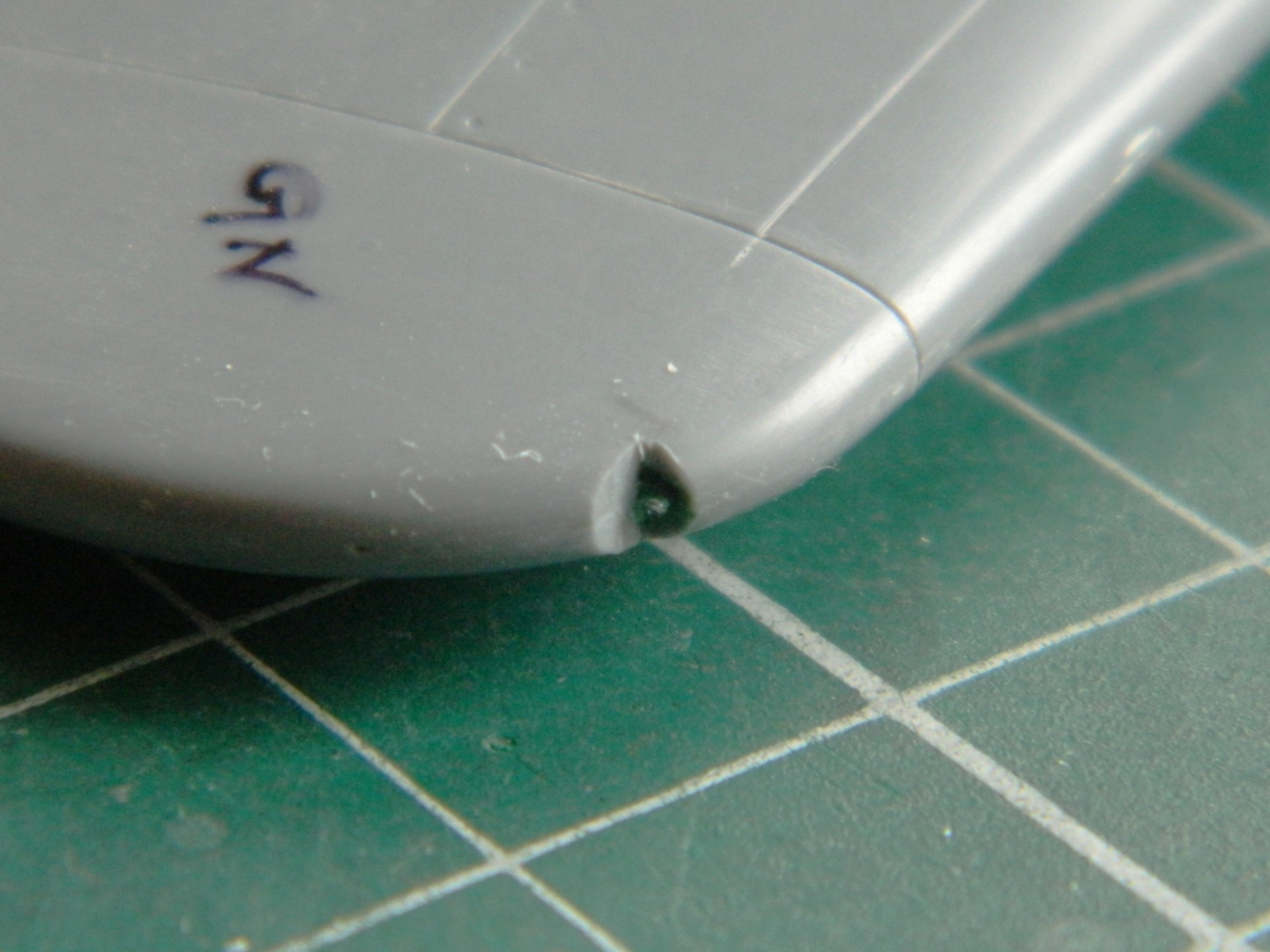
This aircraft has formation lights (if I’ve guessed correctly on the nomenclature) at the leading edges of the wingtips. There are zero indicators of those with this kit. I consulted visual references and played internal logic games and decided that this is pretty much where they go:

Then it was cut out on one side (just in case I somehow got it wrong, it’s half the work to fix one instead of two):

And yes…I marked each wingtip with the color of the formation light because what I have for a memory looks like a sieve.
With the notch cut, I used a small strip of masking tape as a gauge so that the two sides match:

Having cut the notch, I took a section of clear sprue and stretched it. I measured its diameter and cut the appropriate hole on the inner vertical face because that’s how it looks in reference photos. The tip of the stretched sprue was dipped in its appropriate color (red/left, green/right) and glued into place(s):

Many of the recessed panel lines were VERY shallow. So with the explanation of what a recessed panel line is in the die, what I think I’m looking at with these shallow panel lines is someone (or several) got sloppy polishing the dies. While I was working on the wing, I was reminded (like I needed it) of how dissatisfied I was with the paint job on the F7F-3 Tigercat because of too many surface imperfections found too late (because I really, REALLY, didn’t want to strip the paint off of it and start over), I decided that even though self-inflicted wounds are wounds, sometimes I can manage a modicum of control over the Self (always a joyous surprise) and this was one of those times.
This specific kit has obviously been sitting around for a long time. All the parts that are not clear parts were stuffed into the same plastic bag. So for a long time, these parts have rubbed against each other which leaves scuff marks of varying sizes. Doing the Tigercat, I’d mistakenly assumed that those surface imperfections wouldn’t show after painting. As I found out, I was definitely mistaken. I worked the wing, applying 3M Acrylic Glazing Putty to the small scratches and gouges left in the surface after my far from perfect scribing. Once those had been sanded down with 2000 grit, I sanded most of the wing the same way. Once that was all done, I polished the wing, top and bottom, to get a uniform, scratch-free, surface:
Evidence of how well I don’t scribe:


Box wear on the surface before polishing:

And with the box wear polished away (aka, After…the long form):

With construction (hopefully) done on the wing, I turned my attention to the fuselage to check fit. Essentially, there isn’t any.
All these surfaces are supposed to be in contact with each other:

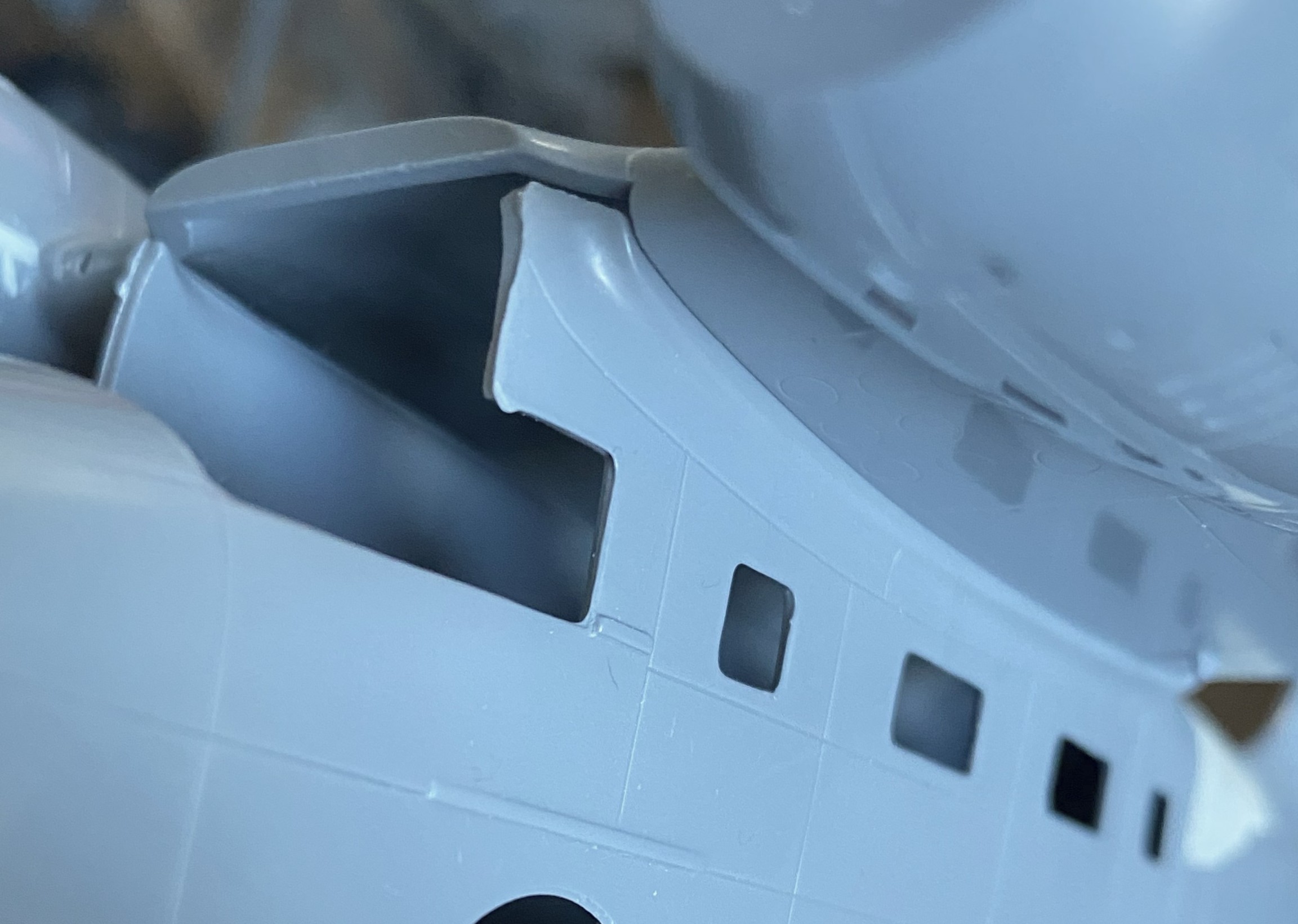
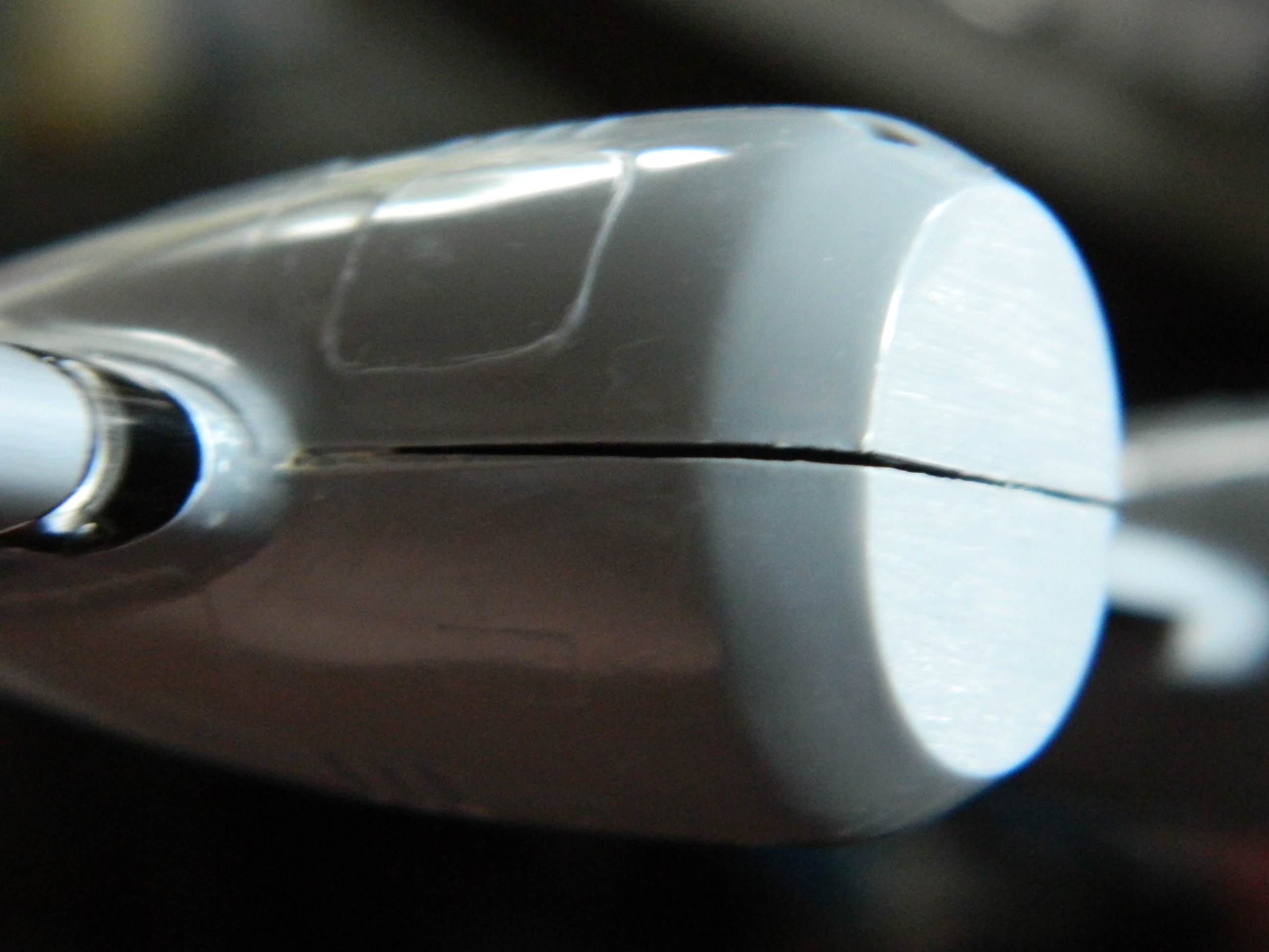
Obviously, not only is the gap between wing and fuselage not supposed to be there, the curve of the lower wing is supposed to match with the curve of the wing root on the fuselage, neither of which are happening here:


Fit is minimally “better” (aka, not as bad) at the rear where the wing blends into the upper fuselage:

If you look closely at the above photo, there is a recessed (sort of) panel line below the fuselage seam. This is what happens when someone polishes away the ridge in the die. There’s a lot of that with this kit.
I can see my stock of scrap styrene dwindling soon.
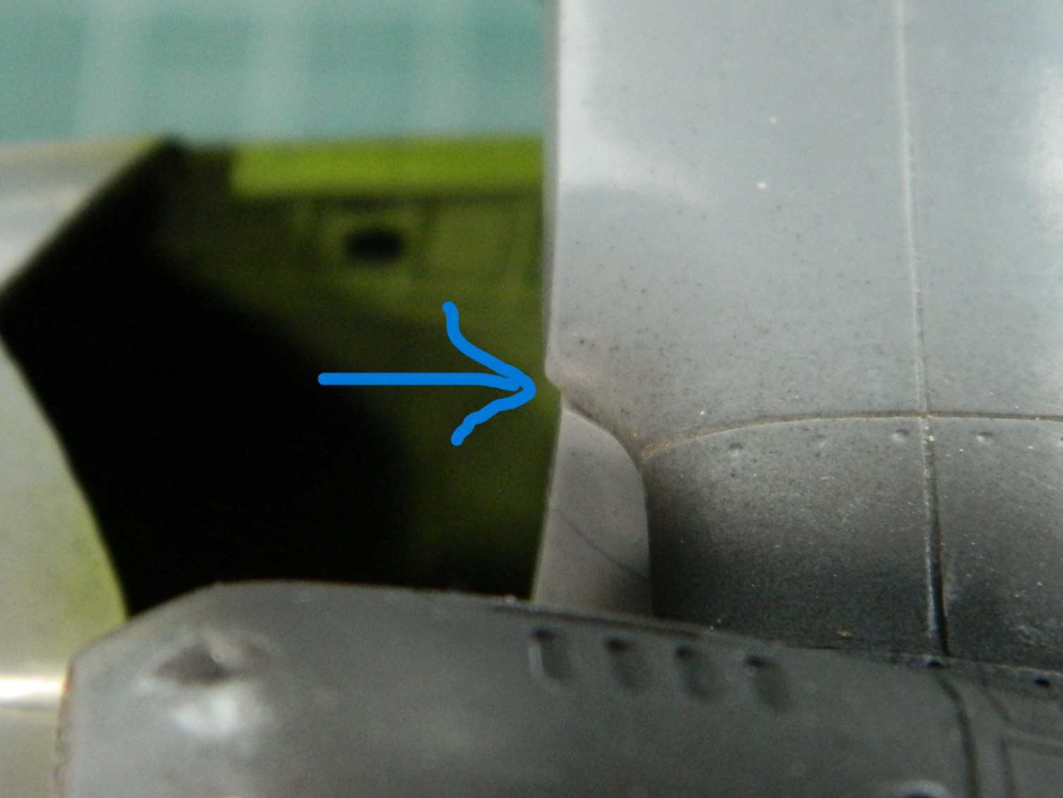
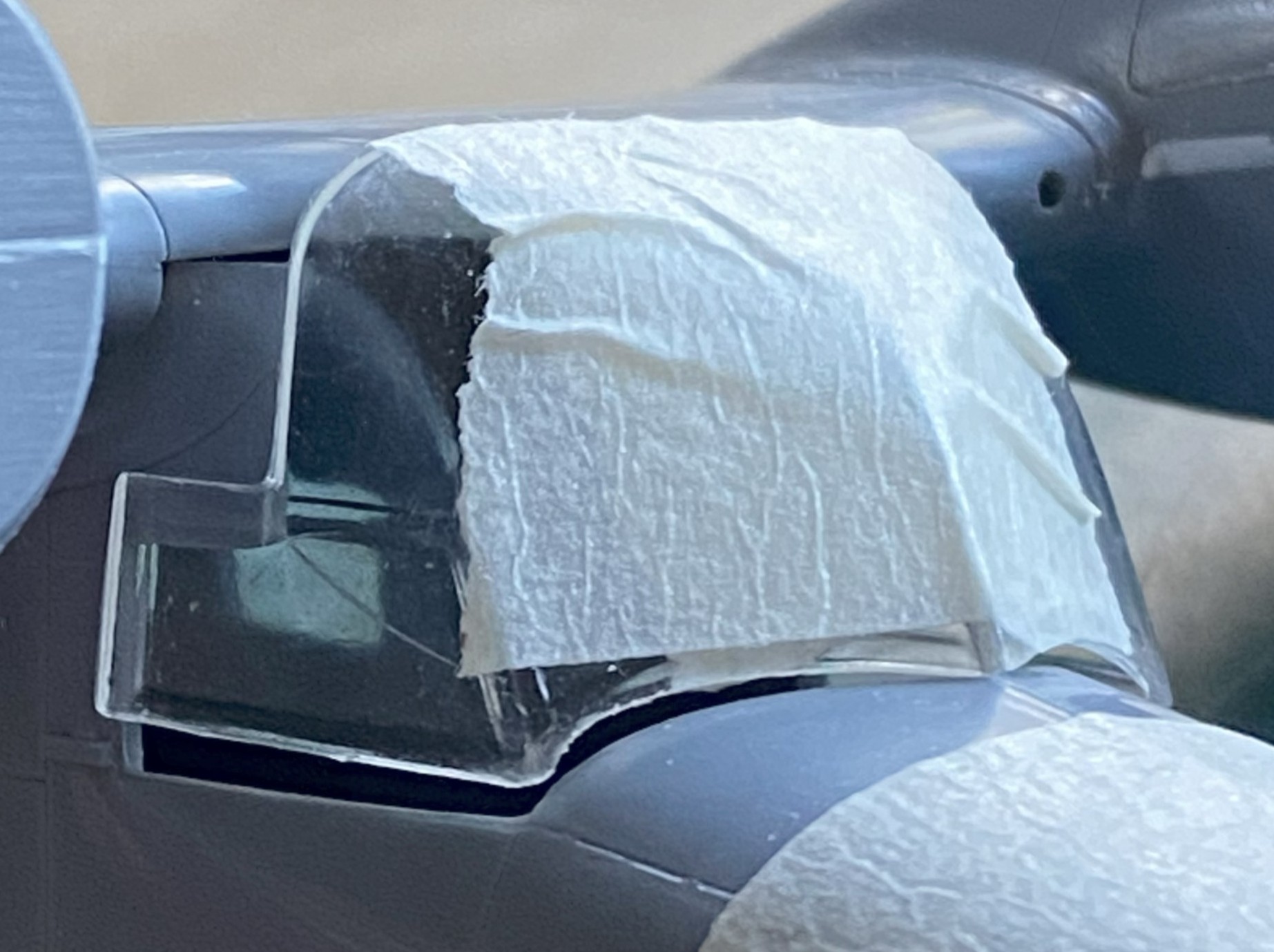
And if I thought that was bad, I checked the (absent) fit of the canopy. It was cast as two pieces (something I think will be a benefit for me when I start making the overhead console), so those pieces were taped together and I tried fitting it. This is the best I managed:
And I figured out why. Look for the blue arrow in the photo below. That shows the overhang of the upper wing. Not only are all these parts supposed to be in contact with each other, the overhang (because that’s what it is, it’s not a parallax view) shouldn’t be there AT ALL:

I won’t know until that overhang is removed but I wouldn’t be surprised if its absence goes some distance to allowing the clear parts to fit (all terms being relative).
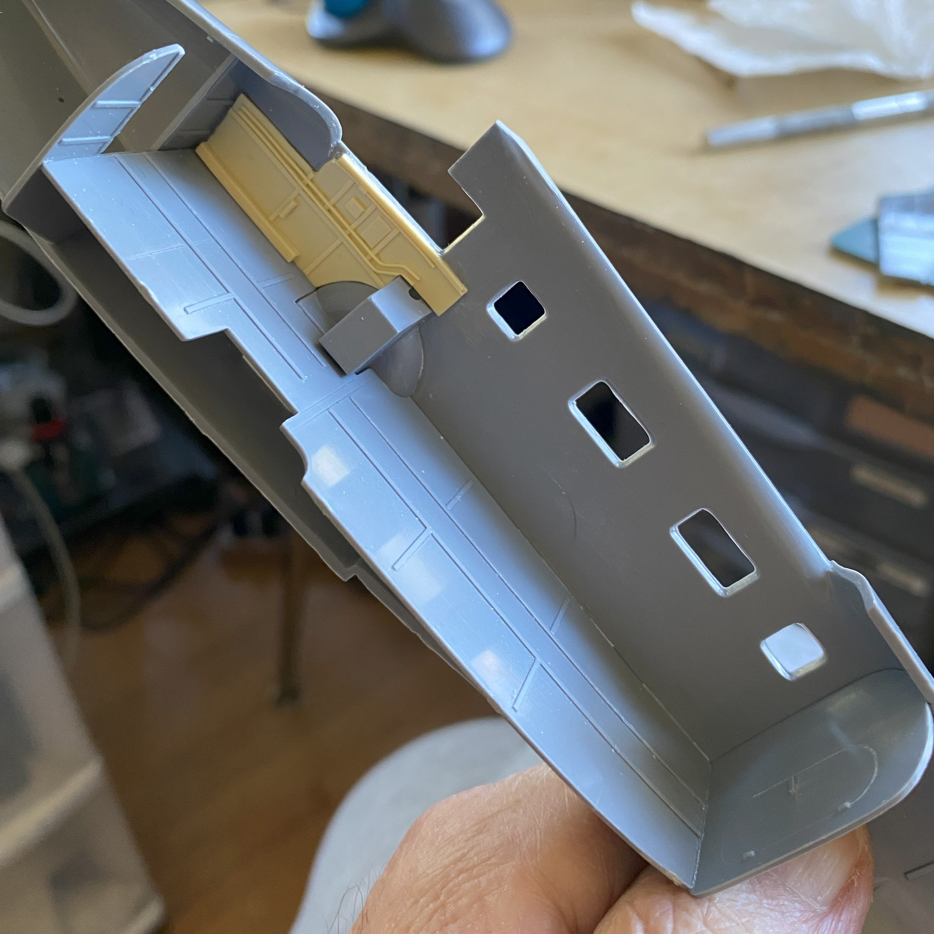
And speaking of clever engineering (in the most sarcastic manner I can), would it have broken someone’s back to put the ejector pin mark on the side without any detail…like the flip side of this part? No…it’s not the most labor intensive part of this build…it’s just unnecessary:

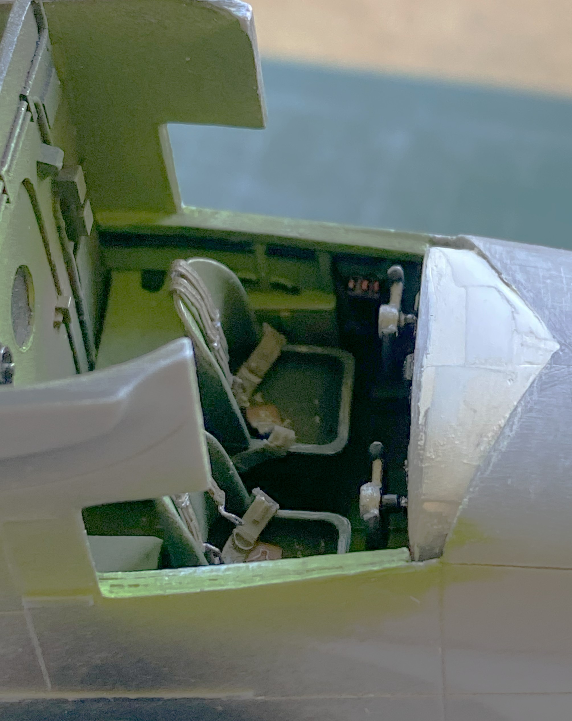
And there was one of each of these on both inside the passenger compartment walls. No…none of them stick out in the view, but how many of you have seen someone look at your build(s) without getting just as close as you’ll let them? I know SOMEbody will crank their head around to look through the windows (a row on both sides) and look in there. If I left these as-is, they’re clearly visible:
::facepalm::
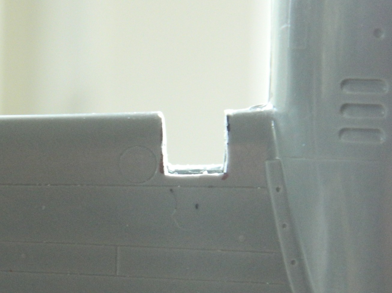
And speaking of fit (which I had shortly after the first time I saw this), these two parts are supposed to MEET. The part on the left is the fuselage just in front of where the windscreen mounts, and the part on the right is the back of the instrument panel. Both have convex meeting surfaces! Gosh…I wonder why there’s a gap!:

The landing gear bays were molded as separate parts so they had to be, well, fit. Yeah. [INSERT REOCCURRING WHINING ABOUT FIT HERE] I got them as good as needed to get them mounted and glued on, figuring whatever tweaking was needed would get done later (and later I will let you know how that went).
The resin parts, with the exceptions of the engines that I used, not the resin engines that came with the kit, were supplied by True Details. I am not a fan of that company. I’ve only ordered something from them three times. Each time I was disappointed when the goods arrived. I can’t recall, though I’m sure there must be, times that I didn’t have to rework their detail parts (and their “bulged” tires? They usually look about half deflated). This time was not an exception.
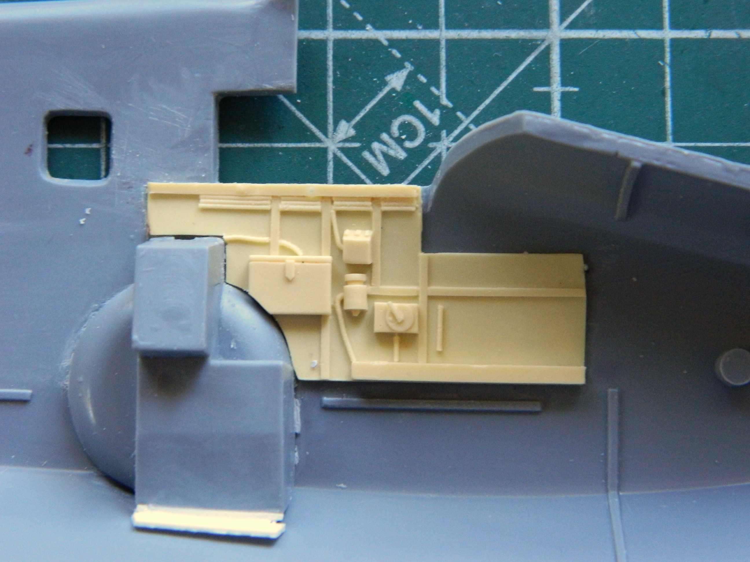
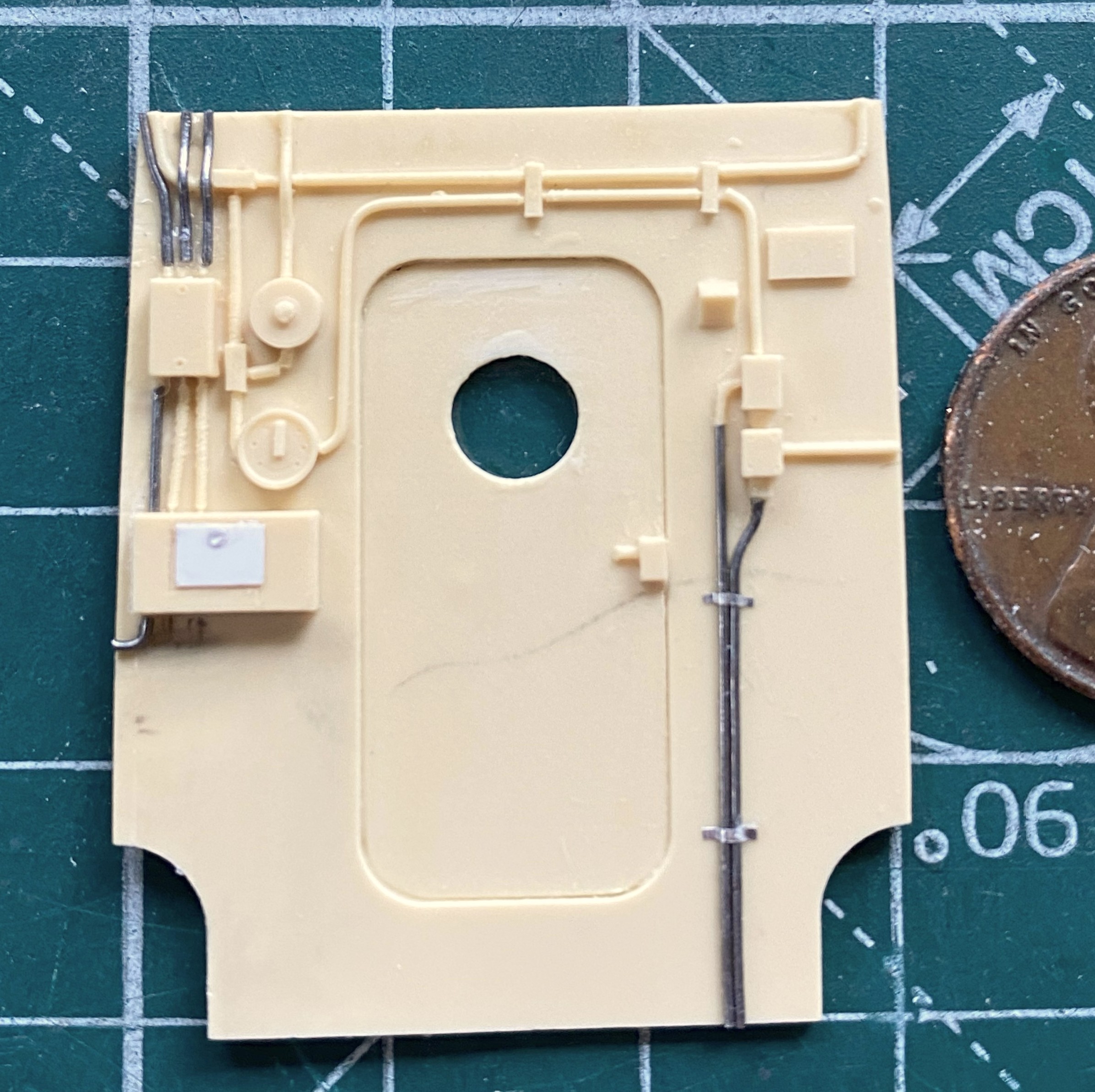
These are the side cockpit details. The thickness that would result if I’d just glued them in like that is even thicker than the armor on a Sturmovik…which this is not:
With such thick plastic in the kit, it made more sense to thin the sidewalls of the kit instead of trying to thin the resin part; I had more to work with. It’s still a bit thick but will have to suffice.
Also note the right end of that resin panel. Where the panel ends is where the bulkhead at the rear of the crew compartment fits. Look closer and you’ll see that the molded-in wiring conduits end well before they should. In fitting the other resin panel in wasn’t much better. See where the box and wheel well arch meet? True Details didn’t mold that box the way you see it. They’d molded it square…which kept it from fitting. That it fits isn’t because of their work:
After much scraping, sanding (100 grit!), more scraping and more sanding, they’re now in there permanently. Next task was to fit the floor, which included the forward bulkhead and the rearmost bulkhead (with the ejection pin gone and the door’s panel line scribed):
True Details also supplied four seats for the passenger compartment as well as the crew’s seats. The passenger seats:

The crew’s seats were molded separately from their mounts. Once all cleaned up and attached to their mounts, I ended up with these:

The tail wheel has its own bulkhead with mount:
Attempting to dry-fit the other fuselage half led me to my next episode of fun. The other half wasn’t even close. It took several days of “fun” to find all the areas of the bulkheads that were keeping the halves from meeting and trim things down so that I can, in fact, attach the other half of the fuselage later. Five hours of sanding, fitting, filing, sanding, filing, fitting ensued. But it all now fits together.
I decided to have more “fun”. I wish I’d remembered to take a “before” photo. The tail wheel is molded as one with the landing gear. Poorly. BADly. Miserably. I spent a couple of hours carefully creating the illusion (I hope…I won’t know until it’s painted) that the two are actually separate:
The rear bulkhead followed the cockpit side panels with their missing details so I fixed that using 0.015″ (.381mm) solder and standard kitchen aluminum foil as retaining straps…because True Details is obviously fine with putting in details that just end somewhere. Also, note the box with the added-on opening. That’s how they molded it. But to get to fit with their own damned parts into the cockpit, the lower left corner had to be modified. I also added 0.010″ (.254mm) clear to the porthole in the hatch:
Notice how the left edge of the partition doesn’t seem quite square? It’s not an illusion or camera artifact. It’s. Not. Square. Another bridge to cross relatively soon.
I got to the next step in my traditional manner. Painting is what’s now driving this bus. Before I can marry the fuselage halves, it must be painted. I prefer pre-shading to post-shading. So before I can shoot any color, I need to throw down the shaded areas. Tamiya XF-1 Flat Black:
I’ve read three different build reviews. Most of my gripes with this build involve things I was forewarned of, though I am surprised at how badly things fit, I wasn’t unaware that FIT SUCKS. Of the three build reviews, only one mentioned the landing gear. The builder called it “finicky.” Talk about understating a situation!!
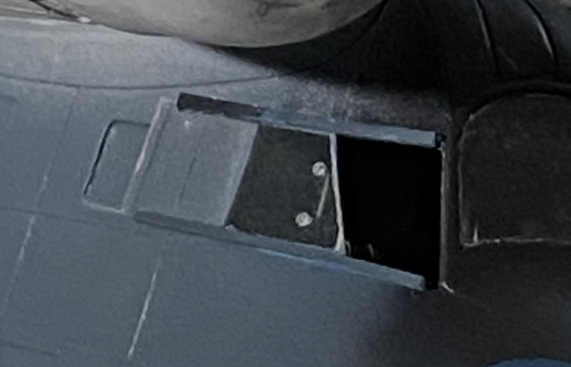
I checked the instructions and references to make sure that the landing gear supports were going to the intended side (because the Tigercat build showed me that knowing right from left is still not my forte), and tried to dry-fit them. Without hyperbole (which I really, really want to indulge in), as molded they can’t fit. I tried everything I could think of (or even suspect) to get these parts to fit. They don’t. Then I did something that saved at least 3mm of stomach lining. I checked the landing gear doors for fit. You know, the part of the aircraft that would fit to fill the openings to the landing gear bays. What I found was wrong…wrong, wrong, wrong. I’ll show you the photos first.
This is what things looked like at the start:
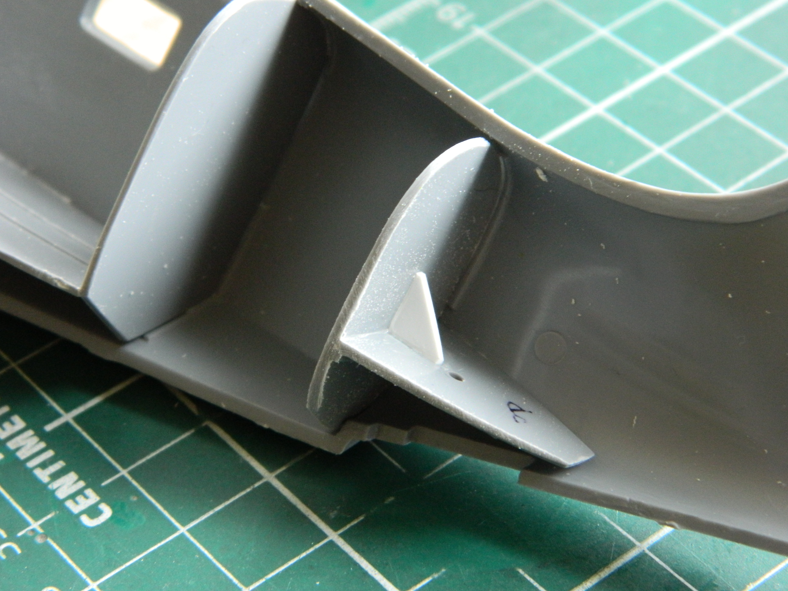
Note the uppermost strut. It’s in contact with the plastic of the fuselage but not one of the very few molded-in attachment points (of the entire kit) where the struts touch the inner landing gear bay. Doesn’t fit. Then I cut away the part from the sprue that would close the side and bottoms of the landing gear bay and compared it to the opening the kit provided for it:

Pencil didn’t last long enough and even the sharpest marker was too thick, so I used a scriber to outline the limits of the hole I had to cut:
See those faint outlines of the fuselage on the bottom (which is in the above photo)? SOMEbody knew that that should have been cut away from the die, just not the guy (or gal because incompetence isn’t gender related) who cut the die.
So I did their job for them (which, really, is for me):
Not only do the parts fit now, in the bottom photo you can now see the attachment points…and the struts fit!
Now the landing gear doors look too thick (because they are too thick). The parts are so small that I knew trying to thin them out to a less out-of-scale state would reclaim those 3mm of stomach lining. I decided to scratchbuild them using 0.010″ (.254mm) scrap (yes…the part I’m making is held in place by double-sided tape):
Next step in marrying fuselage halves is to get the instrument panel to fit. That’s going to be a chore. In order to get it to fit, I have to attach it (where it can be attached, anyway) to a fuselage half to begin filling the gap. But before I can do that, I have to paint it now while it’s easy to get at. I tacked a bamboo skewer to its back and applied the base coat of Tamiya X-18 Semi-Gloss Black:
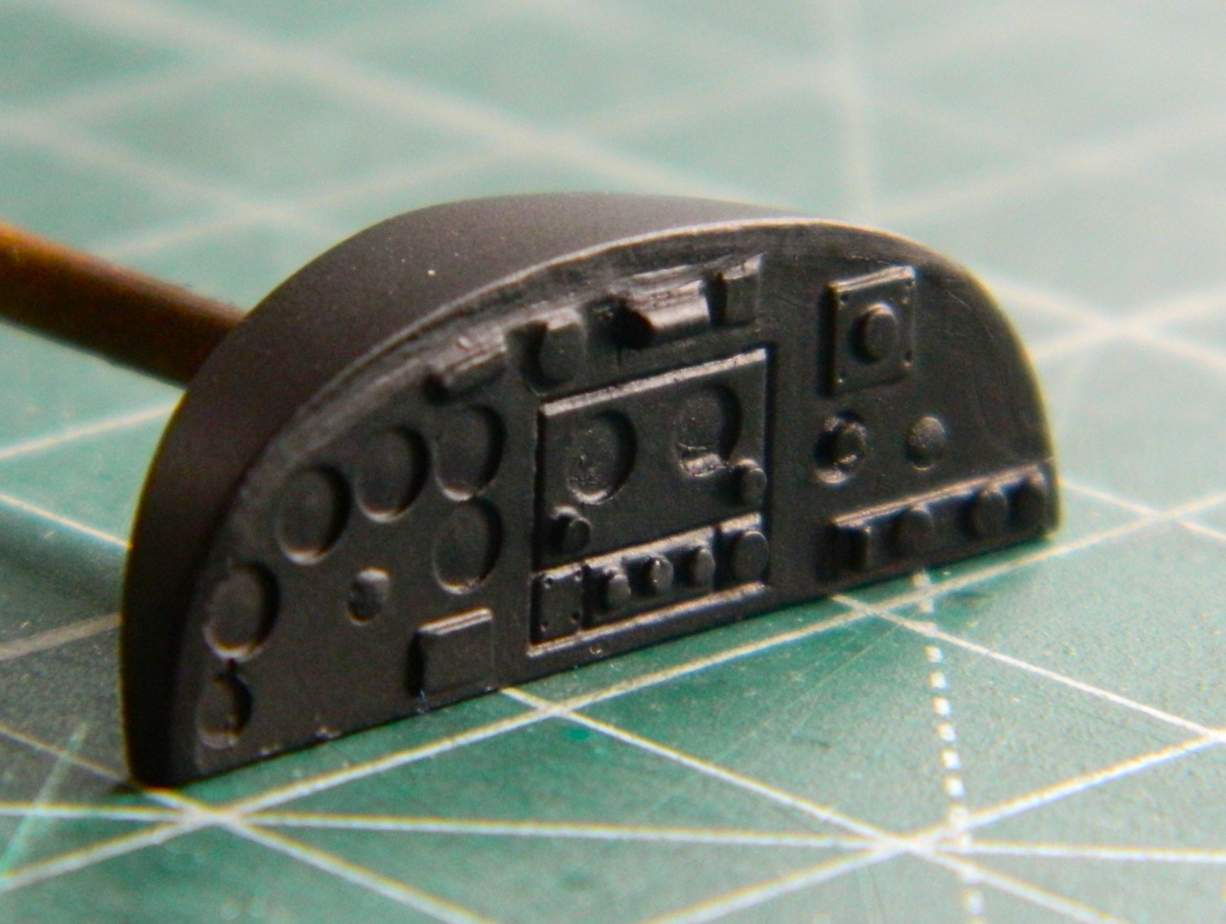
There’s a chance that the uppermost gauges will be visible so next month will also entail me adding either transfers or decals of instrument faces to them…but before that, I think I need to paint what parts/assemblies I have under black with chromate green.
Grumman JRF Goose (Czech Model) 1/48 Scale – A Brief Overview
In 1936 Grumman was approached by a group of businessmen who believed that taking a train or driving from their homes north of New York City was too much of a bother and wanted something…namely an aircraft…that could get them to their offices without having to rub elbows with the Great Unwashed. Grumman designed the Goose in response. Many of those houses were near water and NYC was (and still is) surrounded by water, so it made sense to design something that could land on water (more than once, anyway) or land (ibid), and the Goose was born. It was also the first Grumman design that had less than two wings and more than one engine (a pair of Pratt & Whitney R-985-14 engines rated at 450hp for this aircraft) with the first one going into the air in 1937. It had a range of 700 miles and a flight time of four hours. Several were built and sold and then WWII blew up.
The Navy, oddly enough concerned with something that could land on water (more than once), was interested in an aircraft that could carry a couple of depth charges for anti-submarine patrols, carry several people, put down safely on water to rescue people stuck out there in a flotation-deficient environment, be ruggedly built (probably Grumman’s motto), and reliable (ibid). From what I can find, 345 were built overall and the Navy named the aircraft JRF. I’ve been unable to find any mention of how many were commandeered by the military from civilian owners. Interestingly, it was Canada’s RCAF that put in the first military order to Grumman. The Army Air Corps got in line with an order of 26 which were designated OH-9 and OH-13 (those designations were later used for helicopters) and the Navy and Coast Guard ordered 169 of them.
The Goose also saw war service with several other nations who needed a relatively small amphibian aircraft (operate from both land and water) for search and rescue, patrol duties, and to transport people with enough rank to get their hands on (not limited to other nations in that regard).
Pilots regard this bird well, one comment found online was that on the ground it looked like a big aircraft. In the air it didn’t fly like one.
And yes…my first exposure (he says as if he encounters this aircraft frequently) to the Goose was the 1982 TV program, “Tales of the Gold Monkey”, that ran for one season.


Even the late Jimmy Buffet owned one…
