F7F-3 (AMT/Italeri) 1/48 Scale Build #6 – Starting work the Cockpit…Where Things Get VERY Tedious
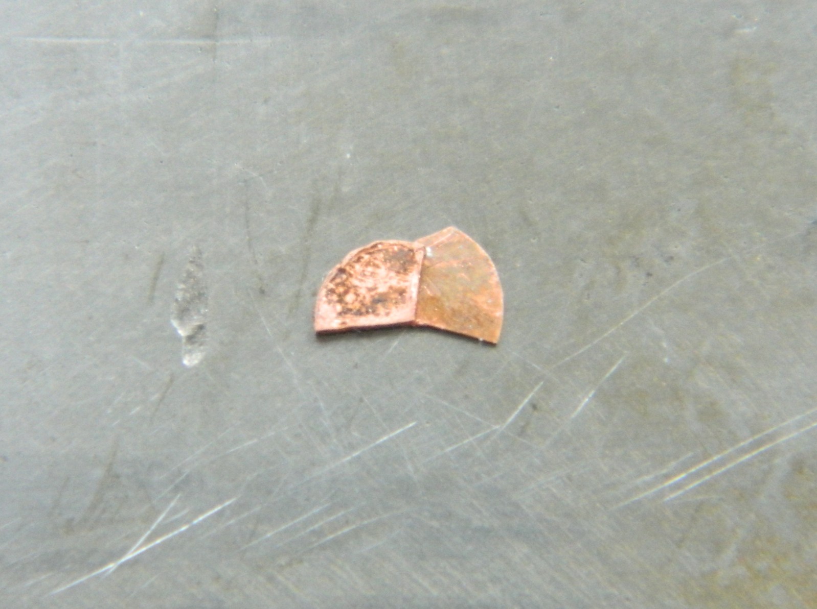
Having a direction for the how I can build the throttle quadrant, it’s important to remember that having a direction isn’t exactly the same thing as going there. This was certainly a reminder! Ascertaining that using styrene certainly wouldn’t work, I broke out my stock of copper shim stock. This part of the job used 0.005″ (.127mm), 0.010″ (.254mm), and 0.020″ (.508mm). I used a piece of the failed parts as a template and then used a sharp needle to outline the template onto shim stock and then used scissors to cut out the parts and then started stacking them. The partial pieces are spacers so that I can end up with the slots for the control levers. I discovered very early that soldering wasn’t the way forward. Superglue is. Lots of stacking and aligning followed:
To keep the larger parts parallel (or as parallel as I can get them), I added a spacer of 0.005″ (.127mm):
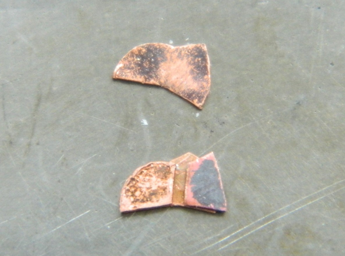
Then I kept stacking parts. Most of them were 0.005″ (127mm) but there was one 0.020″ (.508mm) spacer, which is on the top of the stack below:
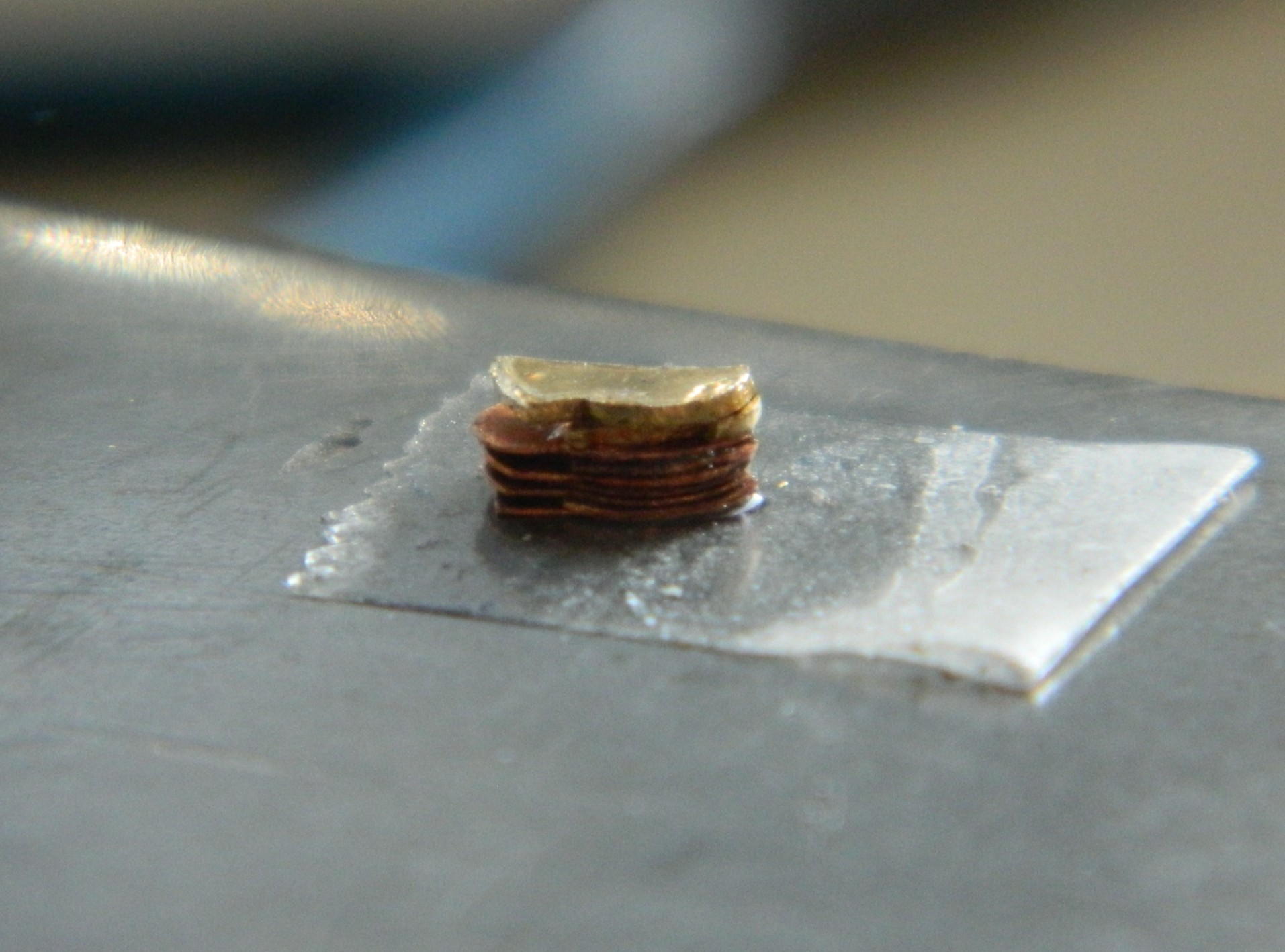
With the parts glued to each other, the next task was to file the stack to more accurate shape and dimension. Let’s hear it for having a vise:

There were still very small gaps between the layers so I laid down some 3M Acrylic Putty and then removed the excess putty:
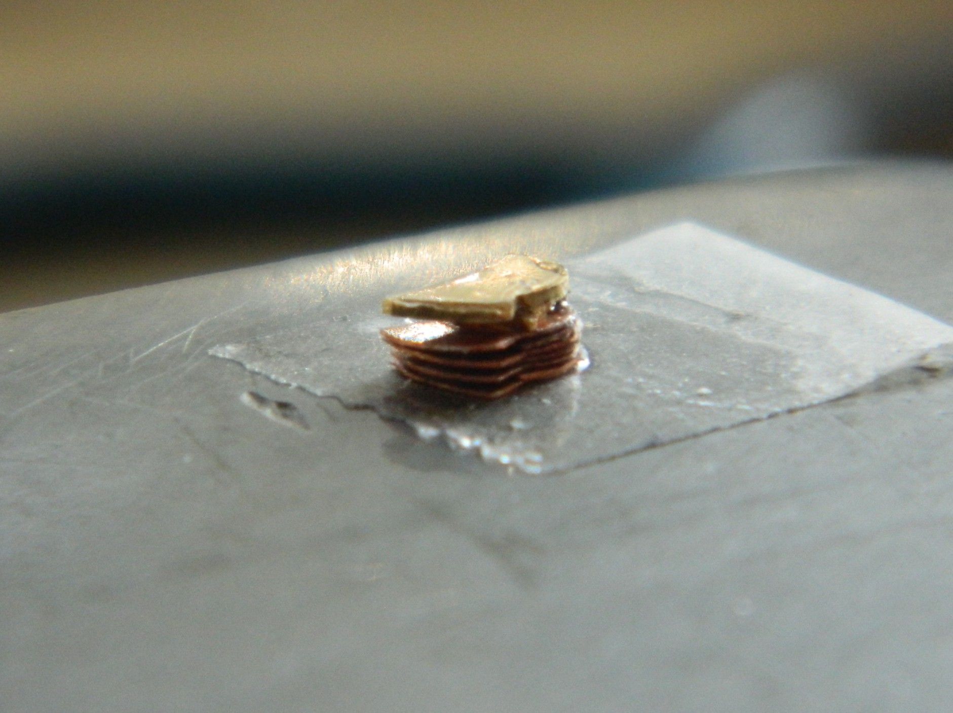
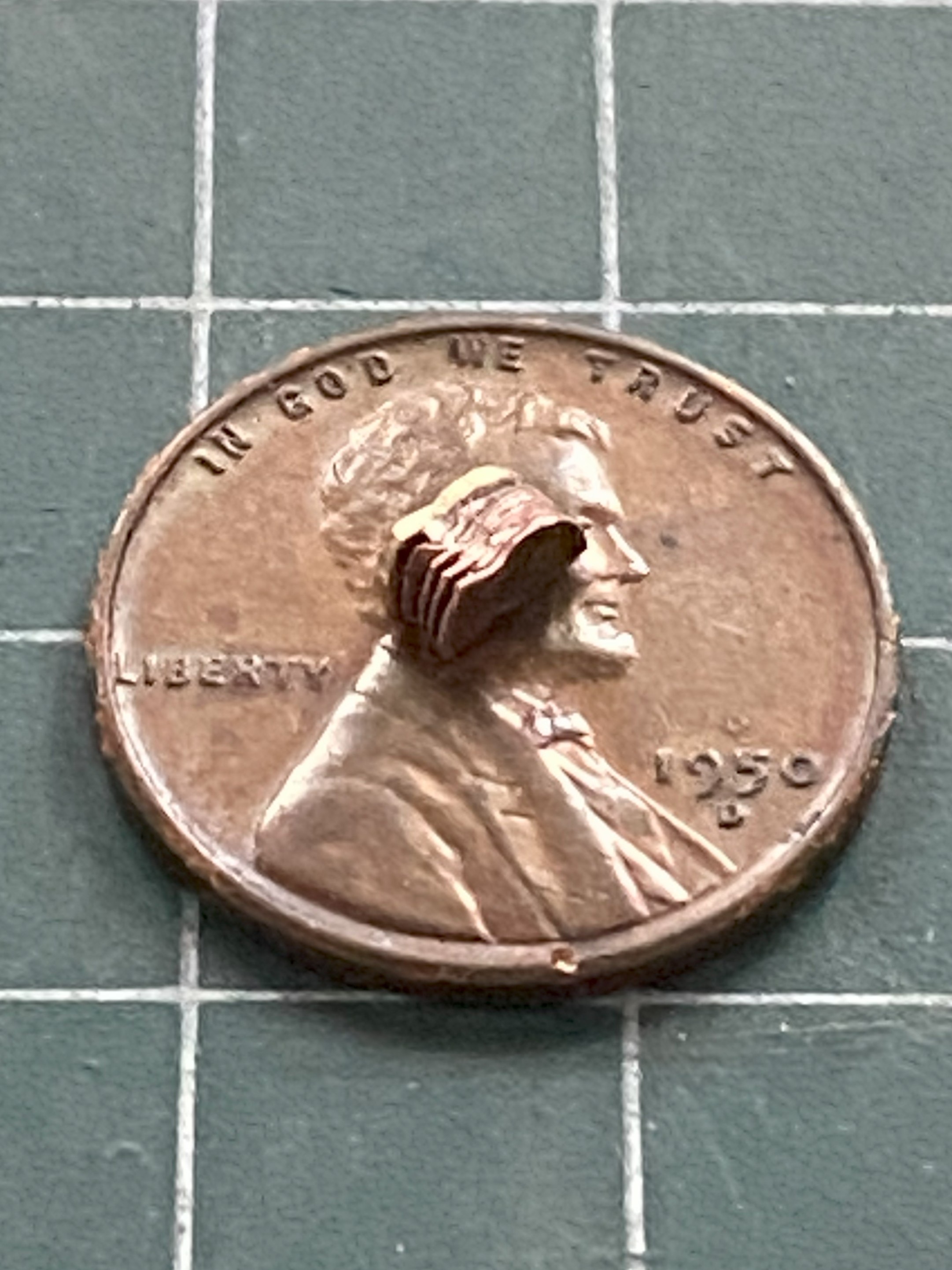
A few pictures, a paragraph or two, to cover TWO WEEKS of diddling with this thing, TWO WEEKS that also includes rebuilding the fornicating thing a few times. ::facepalm:: Probably not a bad idea to check to see how it’s sized…which means redoing it again if I got it wrong:
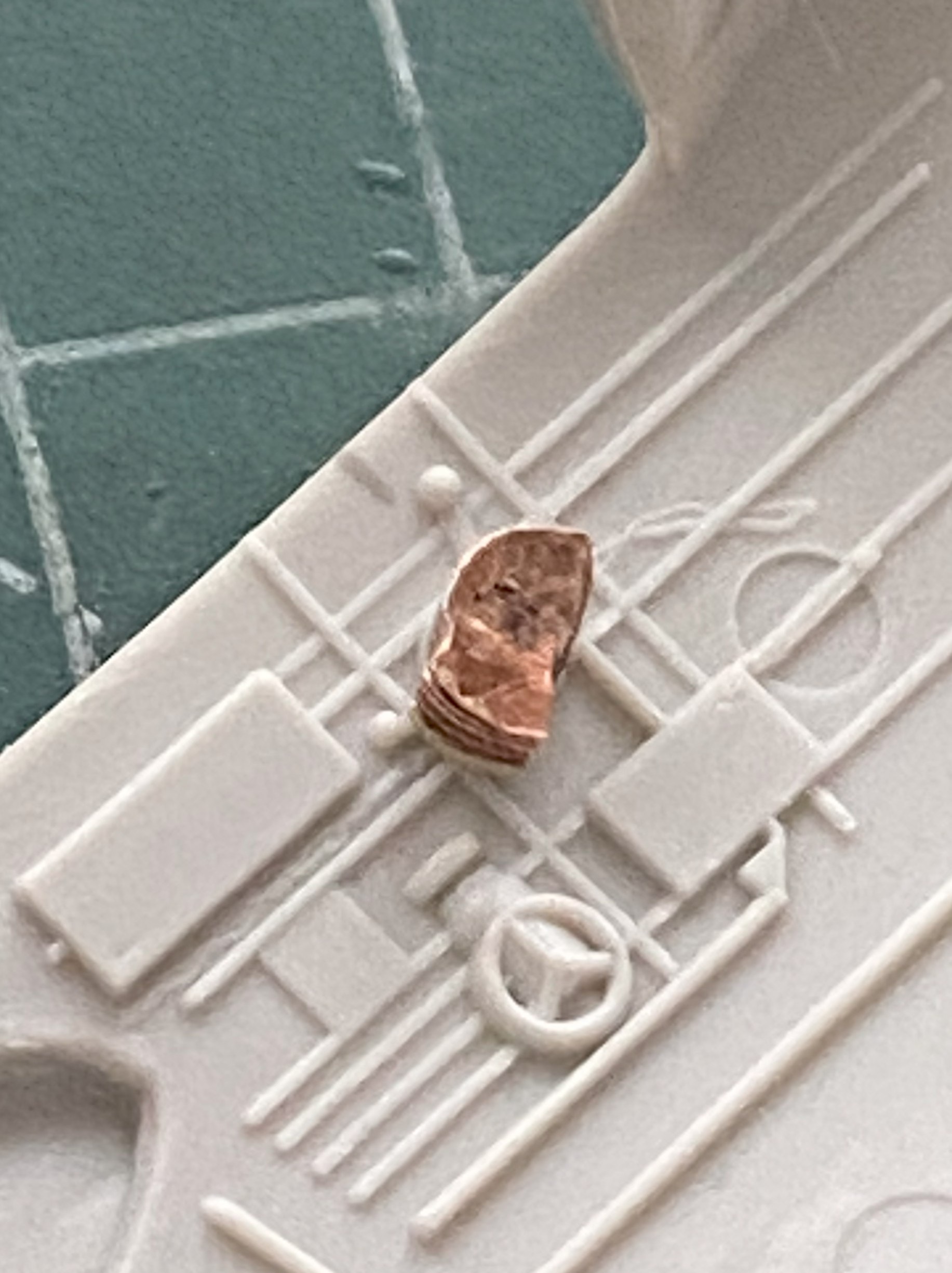
Whew. Unless I mishandle this assembly (always a potential, particularly earlier in any day), it’s ready for levers and paint.
A pivot for the levers and a couple of tensioning knobs were added, then I glued the assembly to a bamboo skewer and painted it with Tamiya X-18 Semi-gloss Black:

Whew…
One of my aphorisms (one of many) is that all solutions create new problems. Having boosted the level-of-detail as far as I have, I needed to boost everything else adjacent to the quadrant to the same level. And then I focused on all the linkages and cam levers that connected the controls to the control surfaces. OMFG. The reason I don’t work in 1/72 scale is because of how stupid-small the parts are in that scale. Here I am working in 1/48 scale and I have to make SIX of everything; primary control rods, the first set of cam levers, secondary control rods, another set of cam levers, and another set of tertiary control rods. All that in a space about 1/12″ (about 5mm) square by about 10/32″ (just under 8mm) tall. Uhm…no. Uhm…FUCKING NO.
Have you ever heard the term, “imagineering”? That’s where something has to go there, but if there’s no reference photos or hard information for what goes there, the builder has to make something that looks right, even though it’s not. When is imagineering needed? Read the paragraph preceding this one. That’s when. Or, as it’s also known whilst in the middle of this situation, NOW.
Okay. I can do this (again, but don’t tell anyone, okay?). I decided to imagineer a pedestal for the quadrant to sit on top of with only six tertiary control rods exiting from that pedestal and vanishing through the cockpit’s rear bulkhead.
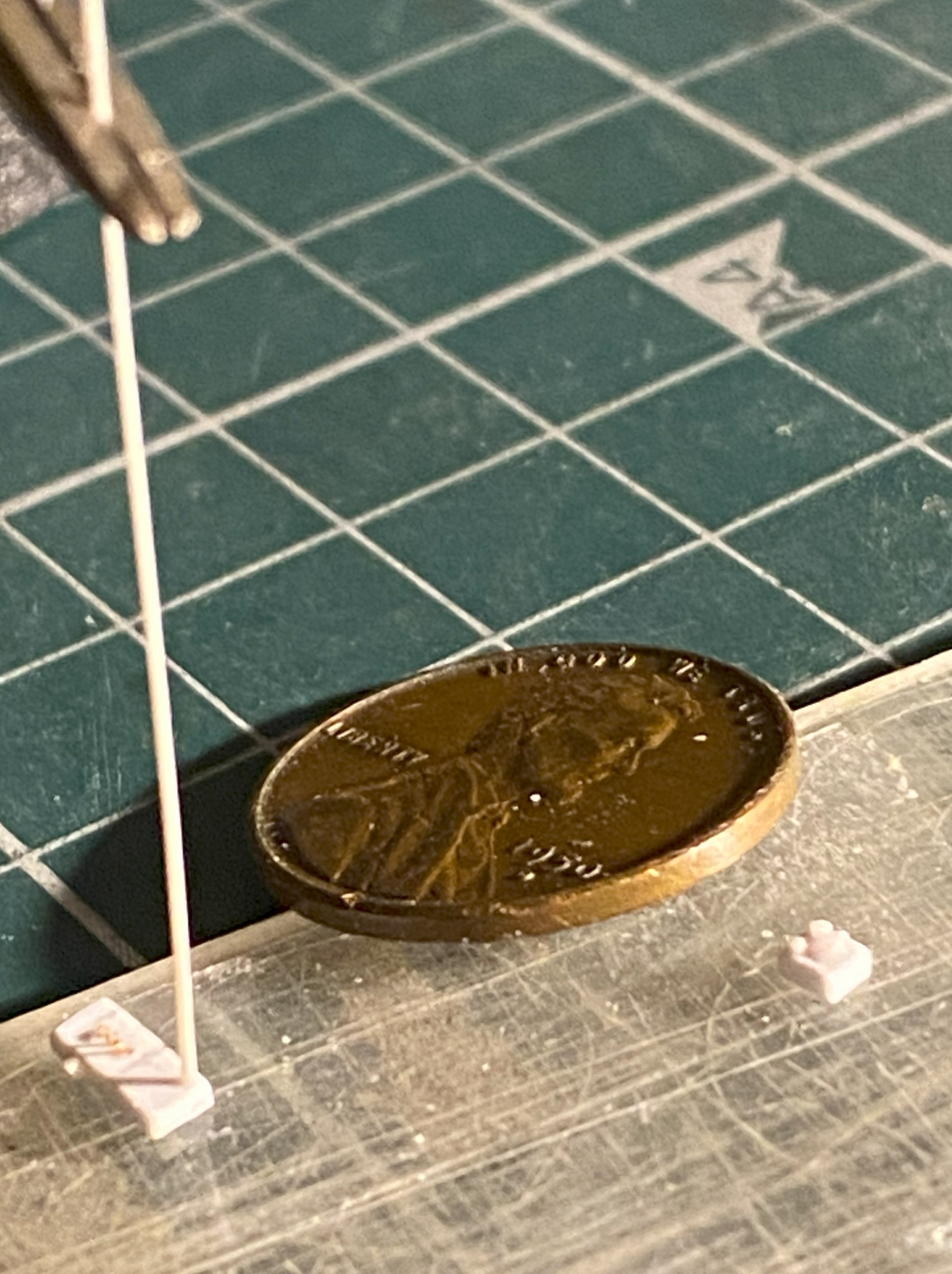
That starts with building the imagineered pedestal. Basic construction was done using 0.015″ (.381mm) scrap:
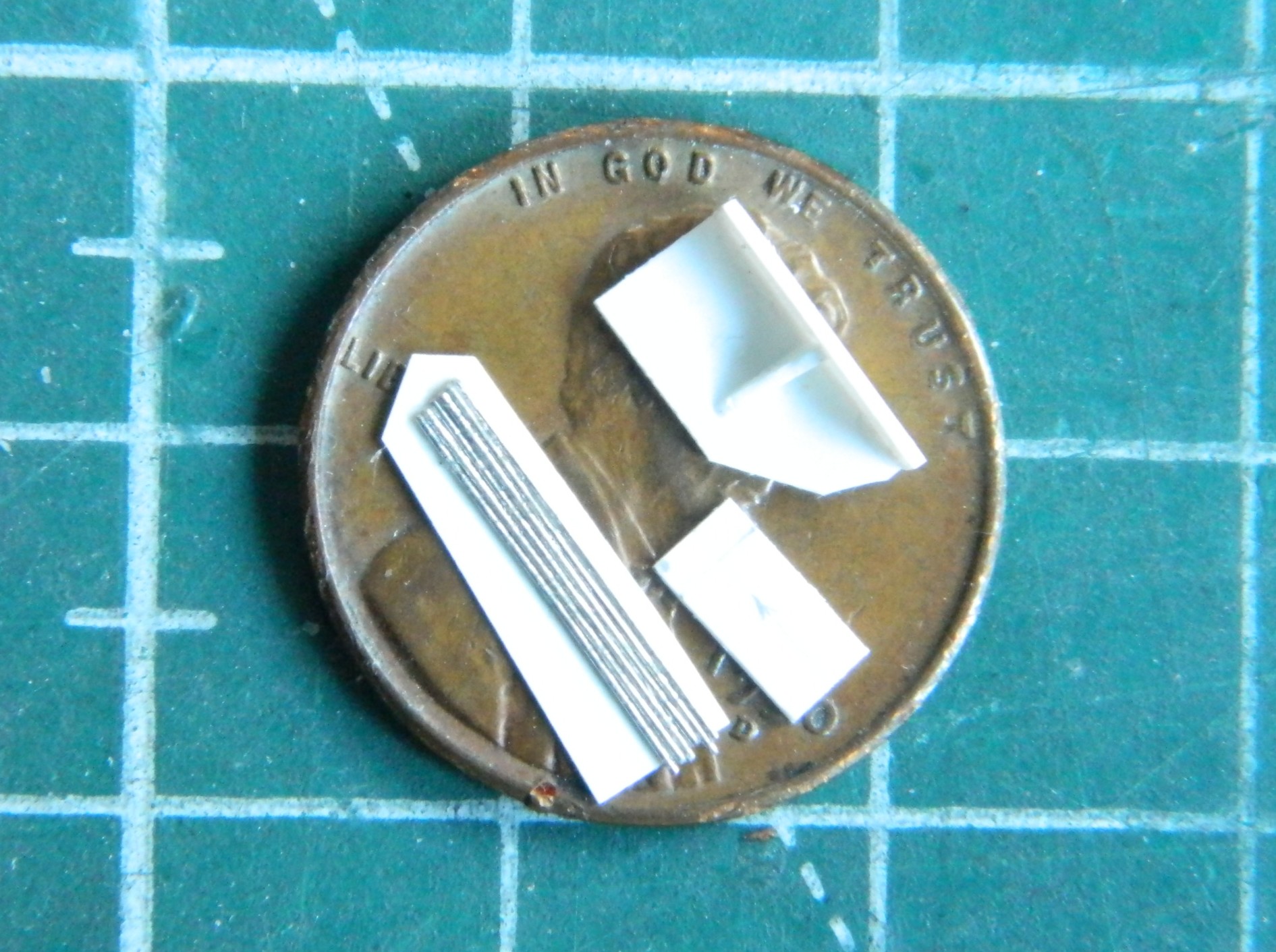
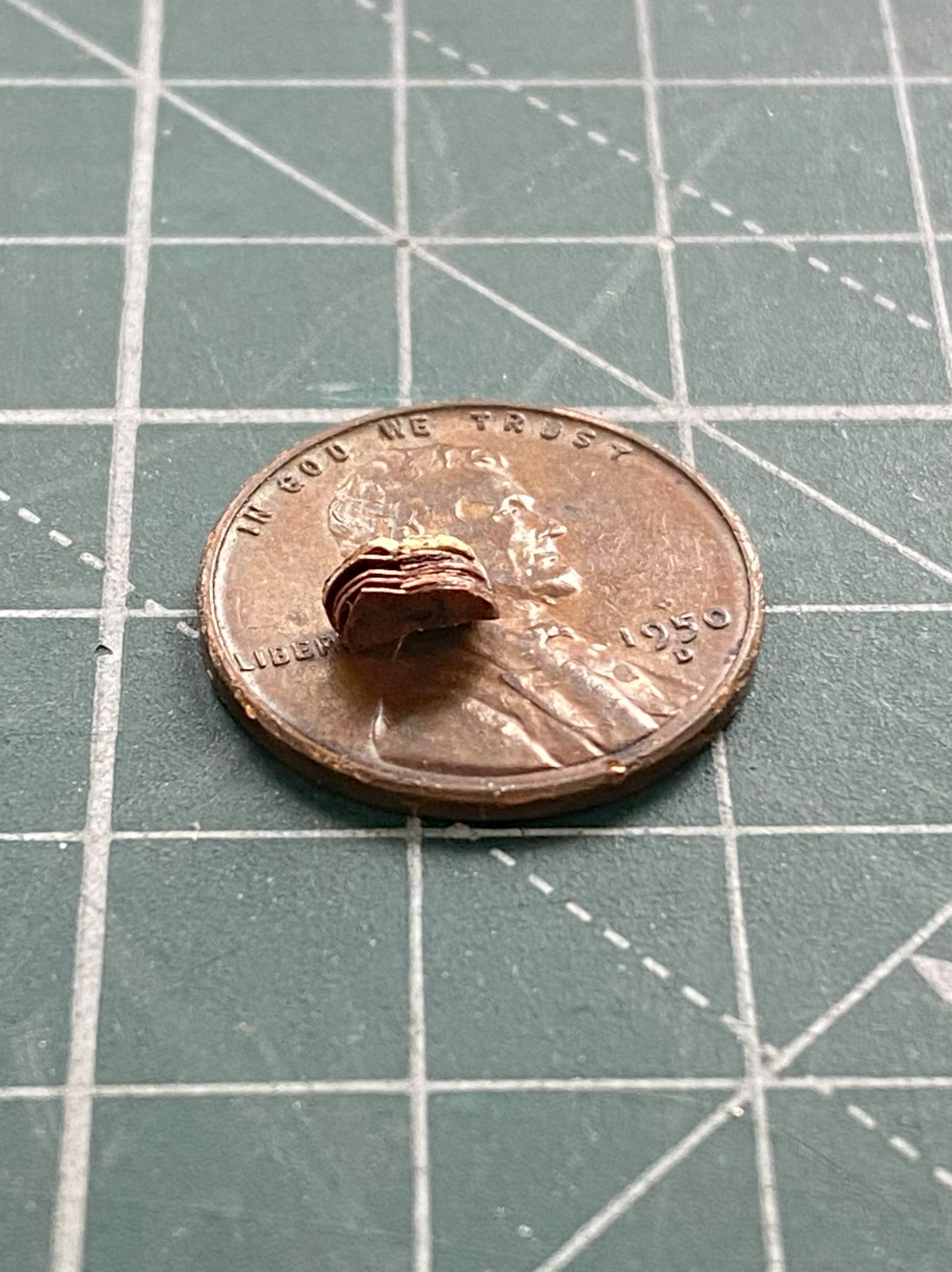
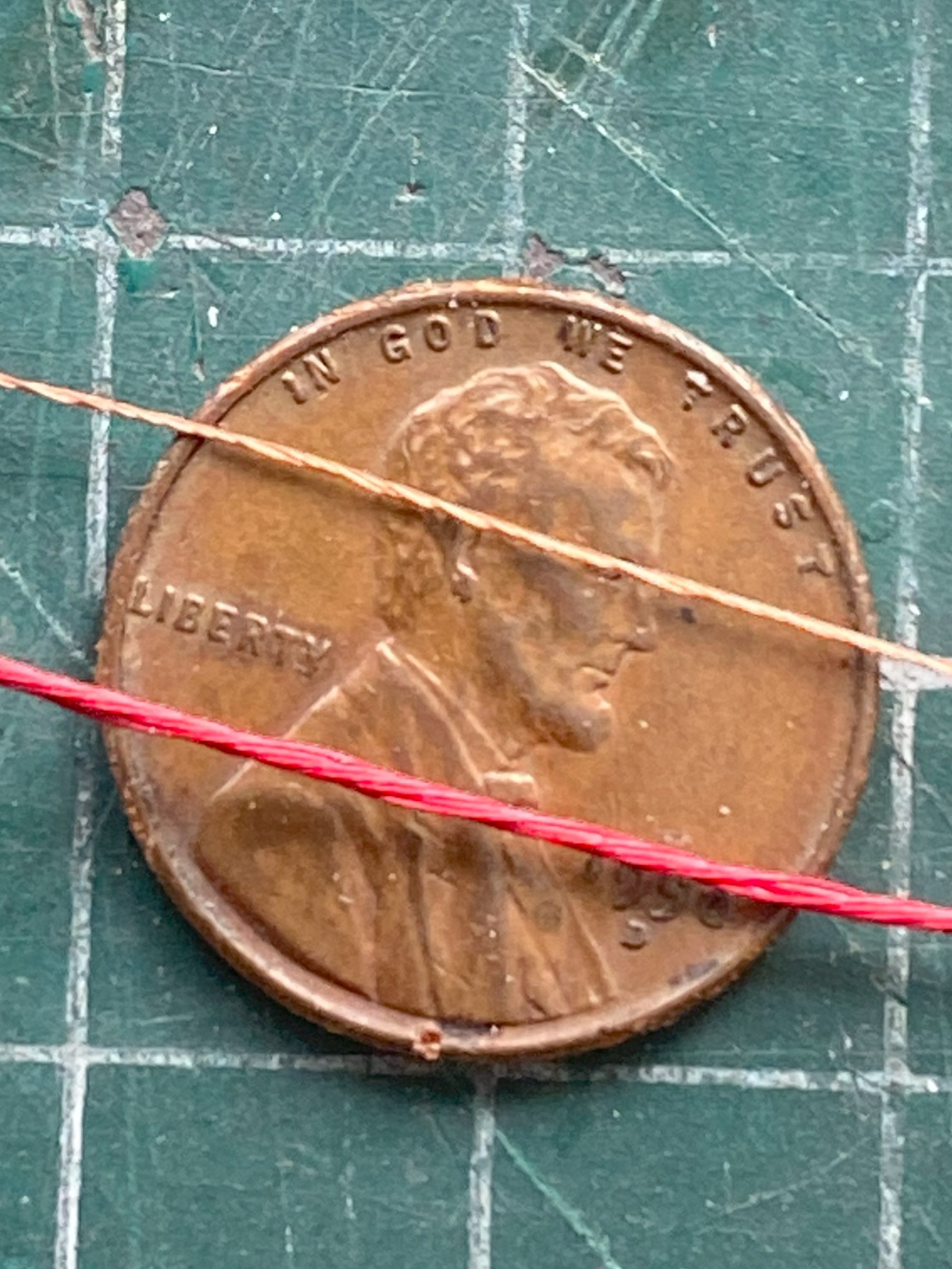
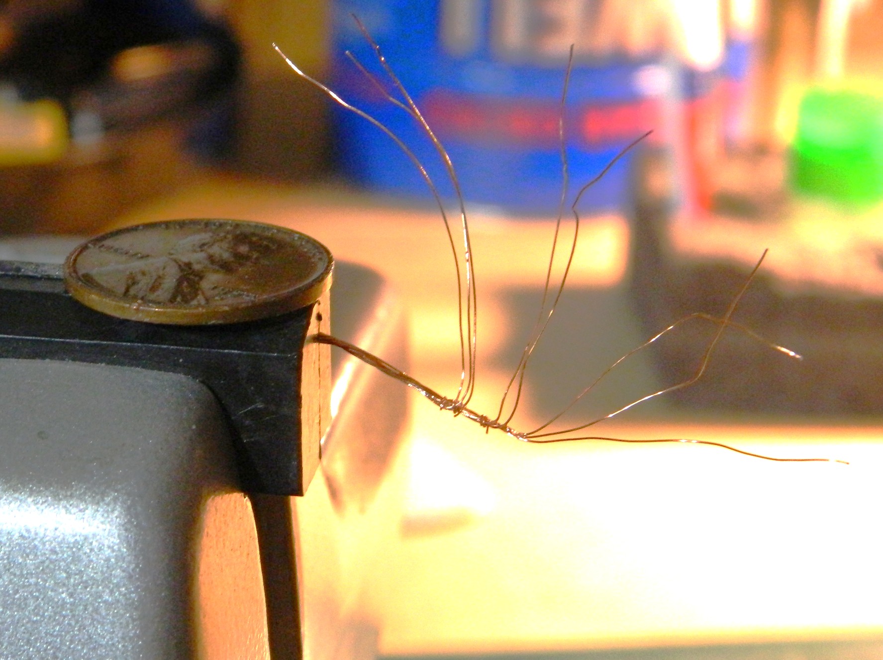
The control rods are to the lower left of the penny. Rather than wrestle with each wire individually, I decided to use a piece of 0.005″ (.127mm) scrap as a backing so that I only had to wrestle with this thing once. I glued all six wires to it and trimmed the excess plastic away.
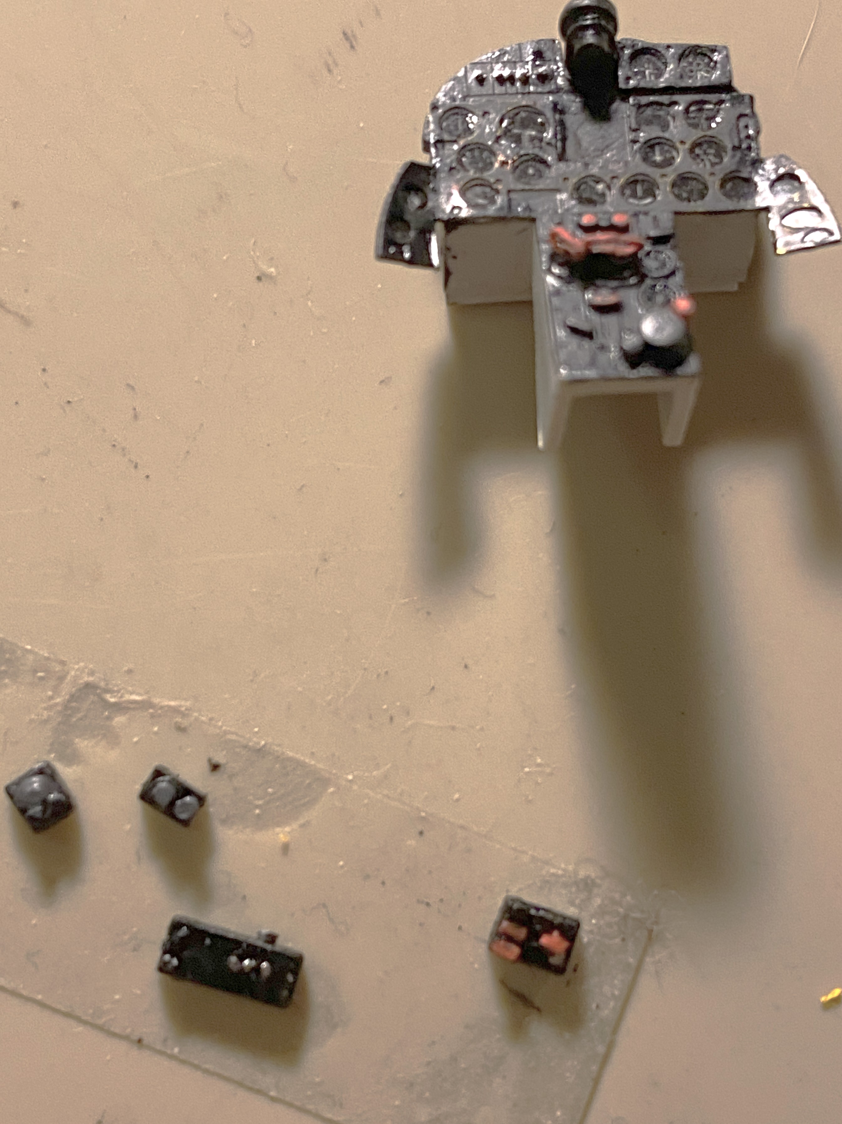
While the glue was setting on the pedestal, I turned attention and effort to the control boxes mounted on the right side of the cockpit. The basic depth, width, and height of the boxes was made using 0.030″ (.762mm) scrap. Toggle switches were replicated with wire and rod and stretched sprue was used to replicate the controls on the boxes:

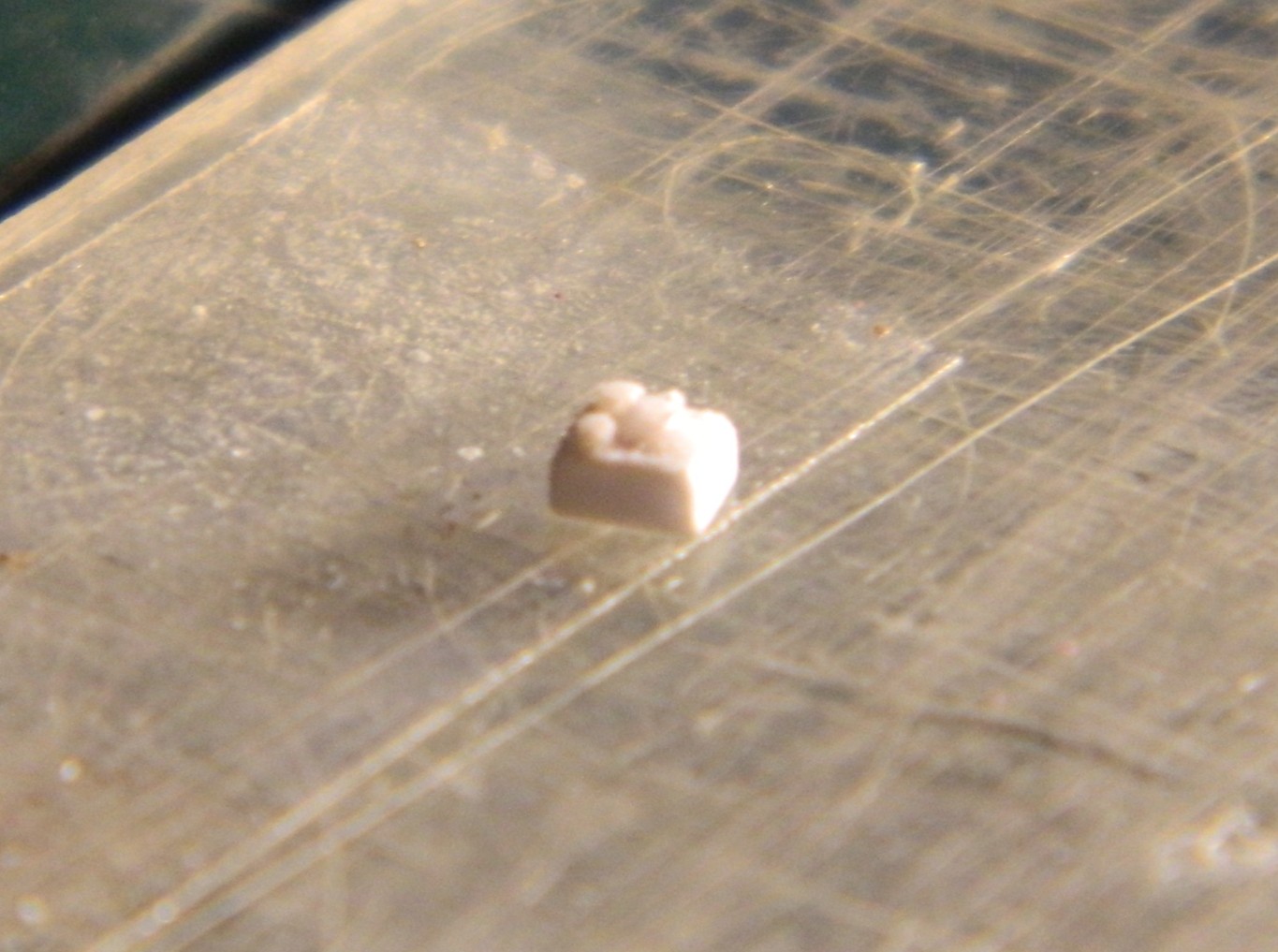
Yeah…pretty small parts:
Four boxes were made in total.
The gun sight was also abysmal, so I used a small piece of 0.093″ (2.362mm) scrap rod as the body of the gun sight. I used a variable-speed drill as a “lathe” and spun the rod slowly and sculpted the body of the sight:

To attach the sight to its forever home, I used .005″ (.127mm) copper shim stock. Drill the appropriate sized hole first, shape later, and it all comes together:

Yeah…SO glad that I don’t work in 1/72 (::giggles::), I kept jumping from job to task while all that was happening and kept detailing the boxes:
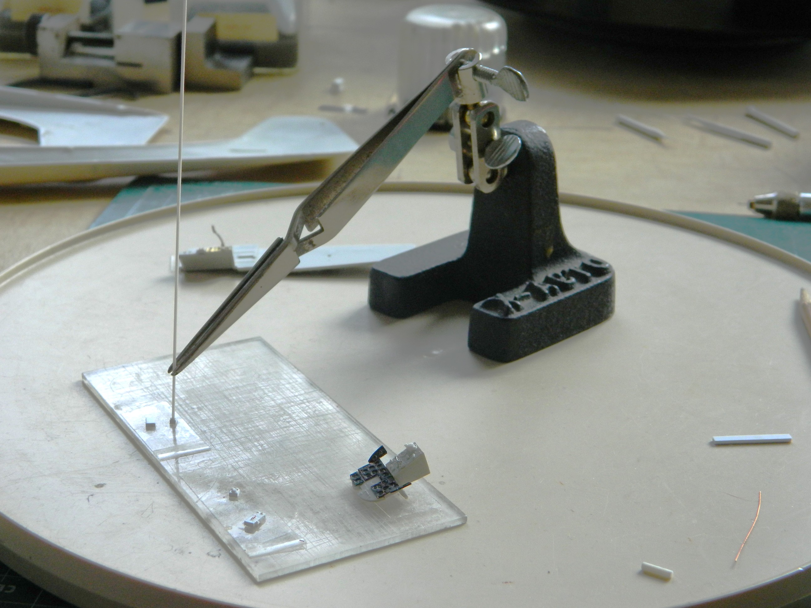
If you do this sort of work, I heartily recommend getting a lazy susan. It makes seeing how alignment is working possible. One can look at the job from (mostly) any angle without disturbing alignment of the parts.
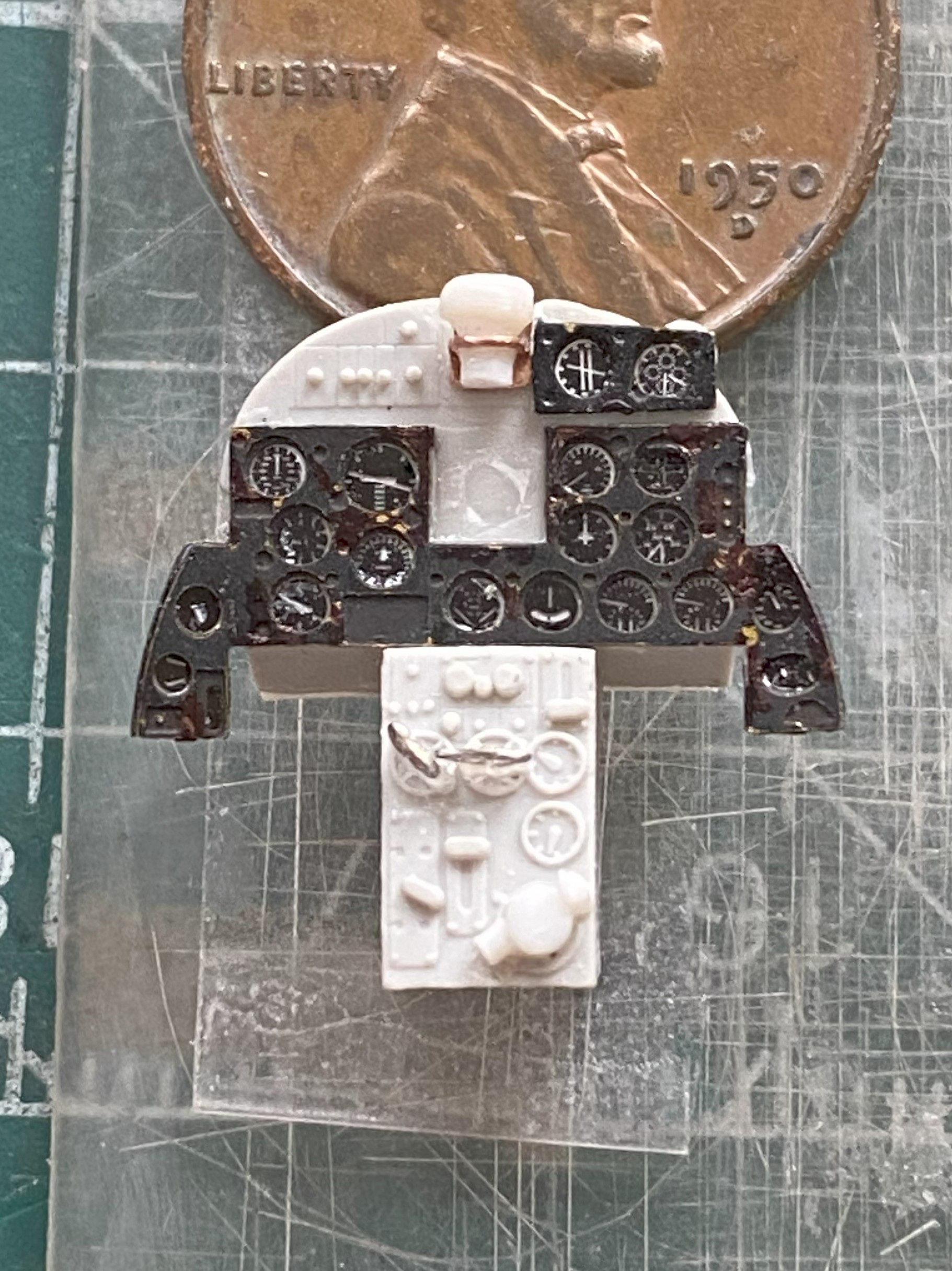
I rechecked dimensions to be certain (::giggles again::) that the parts would fit as intended (which I’m sure hoping is accurately!) and they seem to be just right:
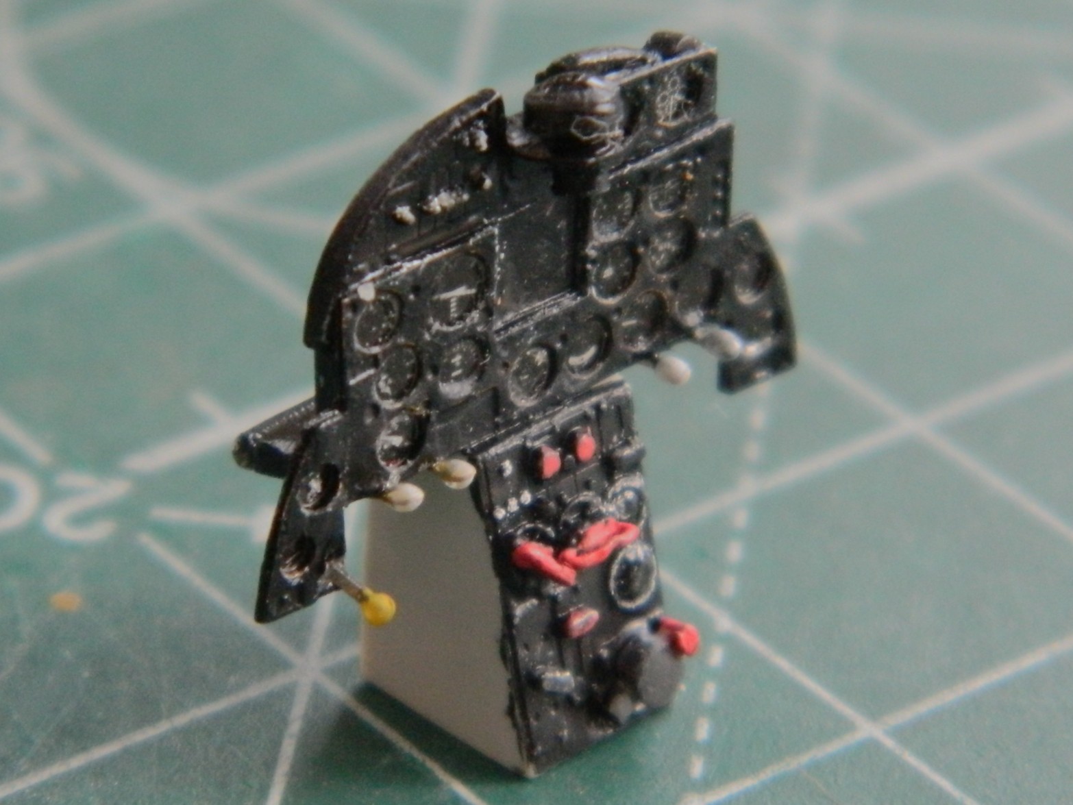
I’d tried using lacquer on the instrument panel fascia to see how it would hold up better to handling than acrylic does. No. Not at all. There were many instances paint touch-ups. This is after one of said touch-ups:

I needed a break so I looked at the canopy. I’ll be able to use the front part from the kit. When I looked closely at the movable section of the canopy, I discovered a casting flaw. There is a significant depression in the part that should not be there at the lower right front of it. I also discovered that the sliding section only fits if it’s modeled closed:


I’m not modeling it closed, so that means the vacuum-molder will be used to pull a thinner replacement.
And now to the casting flaw:
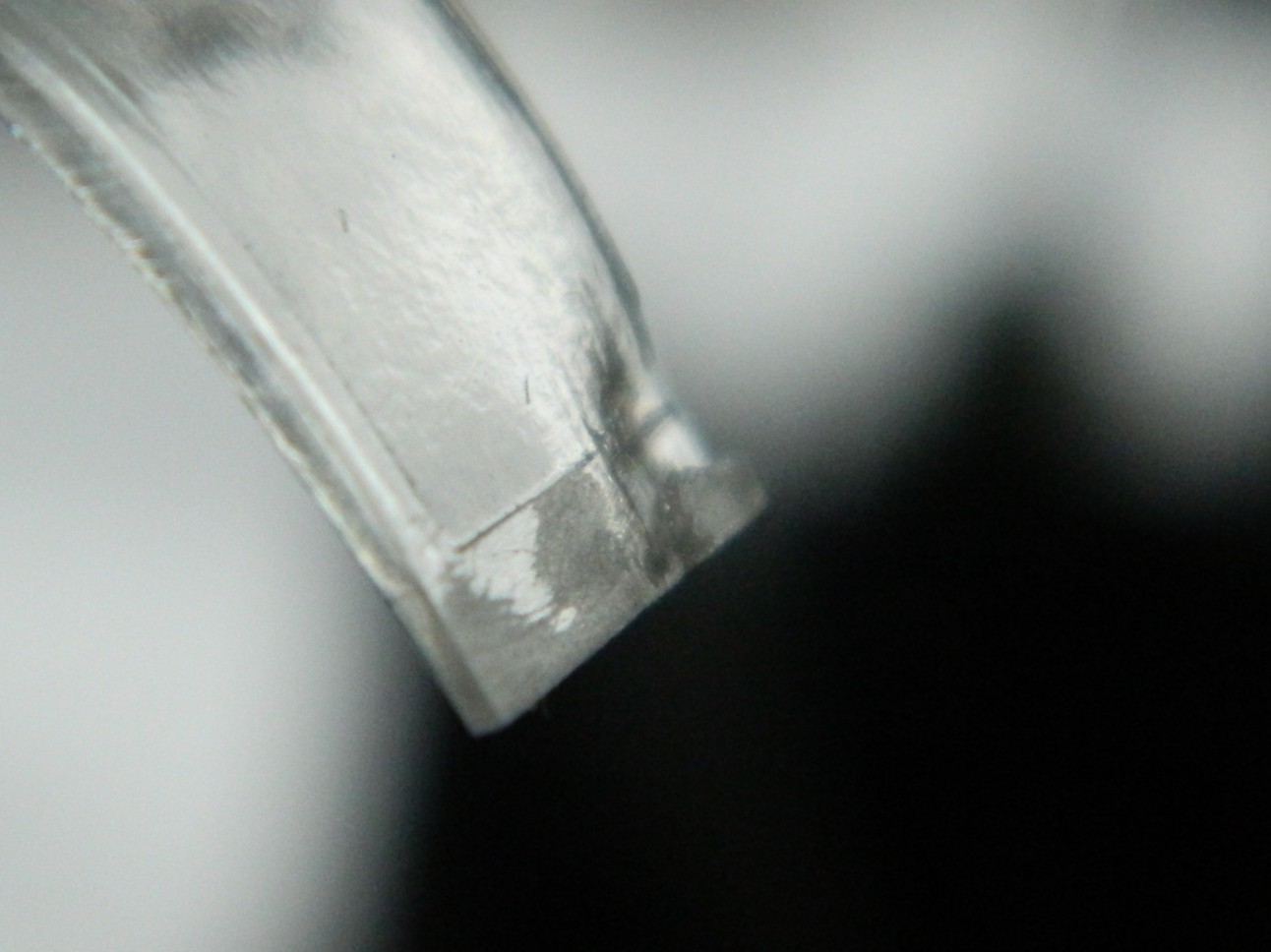

Since the only use I have for this part is as a buck (that which another object is formed over and into it’s desired shape), I’ll fill that depression with scrap sprue before using it as the buck.
I also used the same size scrap to make another control box for the right side panel (with required details added, and you can see where I…mistakenly…put the imagineered pedestal):
Because I’m replacing the molded-on attempt(s) at details, the provided details have to be removed. I got one side done, then did the other:

THAT was freaking annoying…
Since I’m replacing the “details” with something detailed, part of those details includes the wiring. I need a wiring harness of eight strands and I started with 40 gauge magnet wire. Nope. Far too thin. The I tried 34 gauge magnet wire. Nope…this time too thick. (Where is Goldilocks when y’need her?):
I ended up using Mystery Wire. It’s actually a part of a multi-strand (and dead) power cord that turned out to be the correct (ish) size. I laid out the parts that get wired on a piece of double-sided tape and established a rough approximation of where the break outs (technical term of where I wire leaves a loom or cable) need to be:
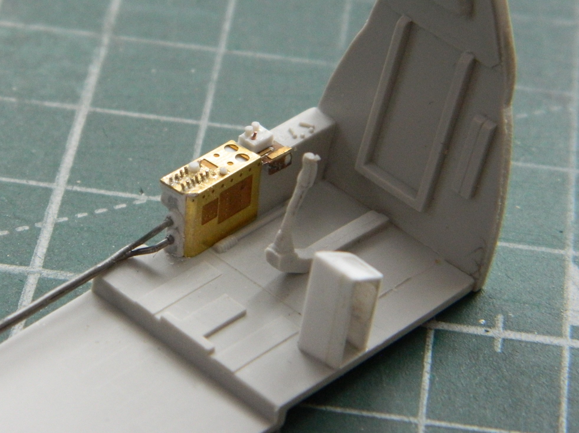
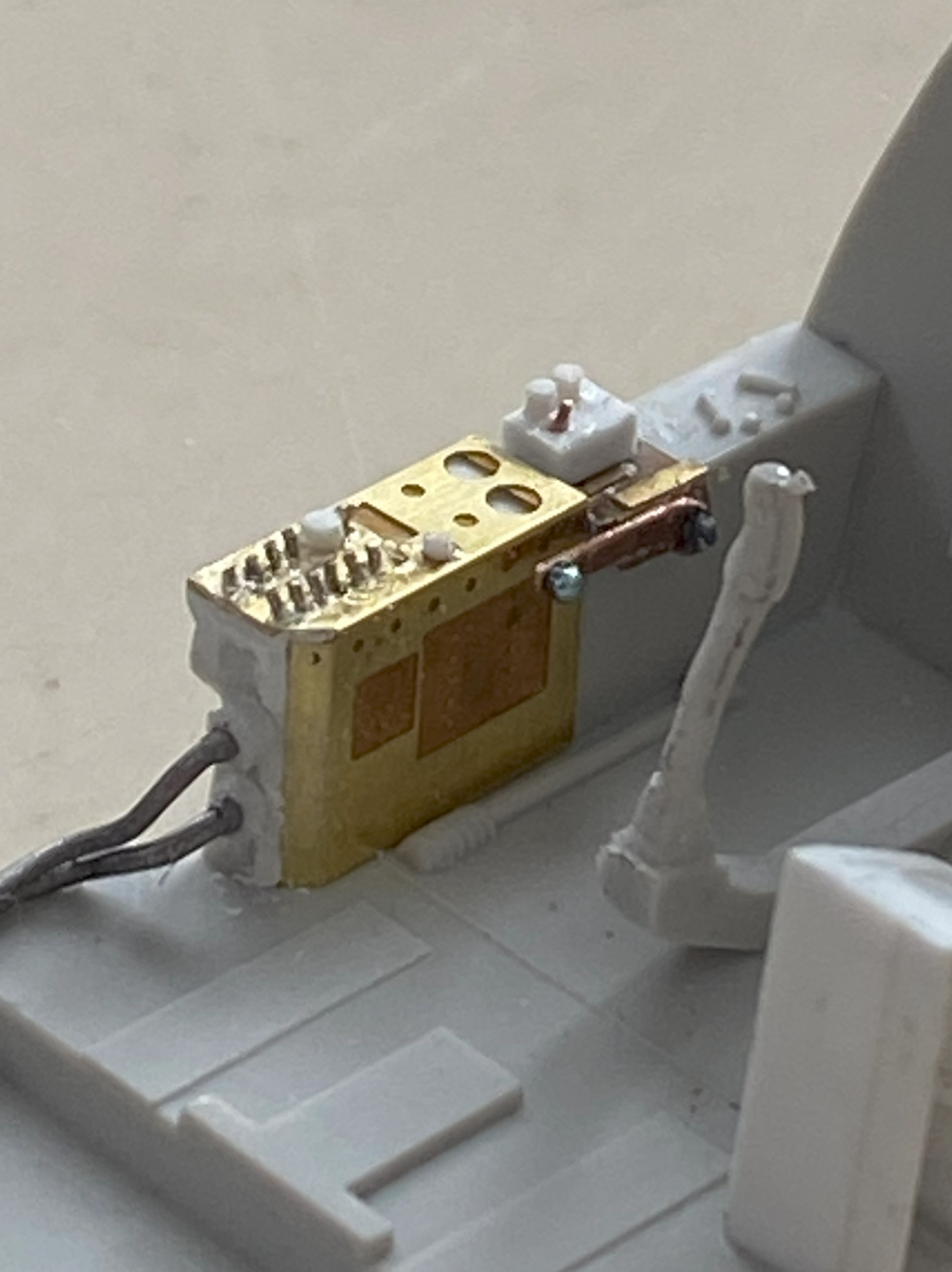
I turned back to the throttle pedestal, glued it in place (properly, I thought…that will be covered next month) and added the tertiary rods:


A little sidetrack, here. I’ll be making seven (if my math’s correct, but since I’m wearing shoes and socks, place no bets on that) control levers, five of which need little round knobs. I’m planning on revisiting a technique I used for the control levers of the P-38F I did:

They’re glass beads that I found online at a crafting site. In the photo, they all look as if they’re the same size. Not even close to reality. Size is not standardized at all. Not one of them are remotely “large”, some of them are EXTREMELY small. I had to pour them out and go through them to find the smallest. I was SO invested in finding the smallest that I knocked the container over and all the little TINY glass beads that I hadn’t already poured out to size them went ALL OVER. Though some made it to the floor, I was “fortunate” that most did not. At this point I most sincerely and in the spirit of true sharing I recommend a better way to spend better than an hour.
Enough on that topic.
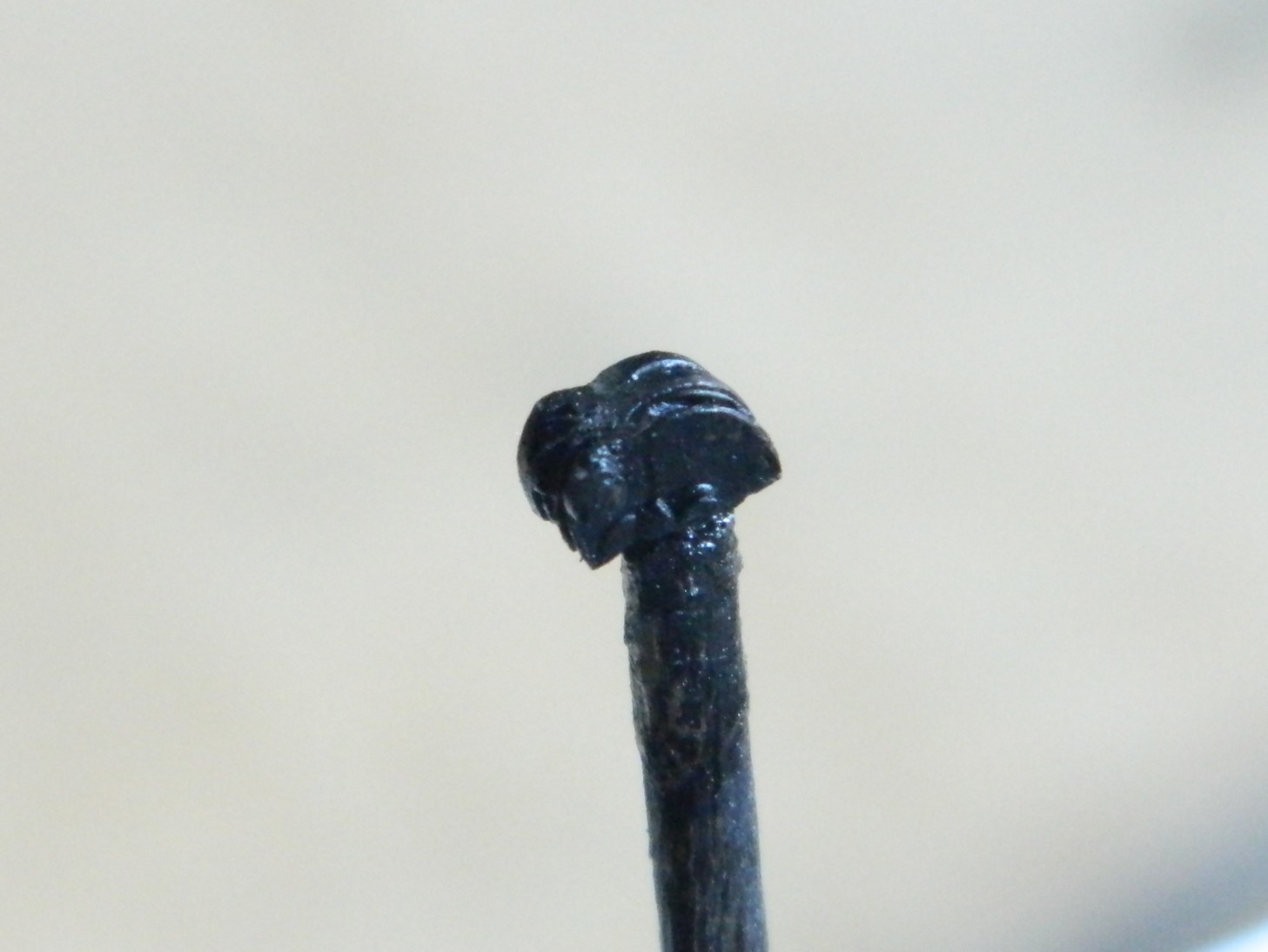
There’s a lever next to the pilot that controls something. I have no idea at all what it controls. But since it’s there and quite visible, I had to make one and install it. Here’s how well those tiny glass beads work as knobs (it’s behind and to the left of the joystick):
It’ll look great under paint. (Hmmm…that would make a good bumper sticker.)
I discovered something else that does a decent job of replicating tiny knobs. UV setting-resin (misleadingly advertised a “glue”, which it’s not). There are five levers attached to the instrument panel (one yellow, four white) and all the knobs are UV-setting resin:
As a build progresses, different tasks fill the driver’s seat. The butt in the seat right now is the need to paint the cockpit, and the first item is throwing flat black over mostly everything so that I can use that as pre-shading. The ultimate goal is to assemble the fuselage sides. And before that can occur, I need to be certain that enough lead has been added to keep this bird on her feet and not be a tail-sitter. The last time I check its balance (no need to check my balance…Eisenhower was President the last time I was in the same area code as “balance”), it very lightly rested on the nosewheel. Too lightly. Since I have plenty (all terms are relative, of course) space in the nose, one of those two places I could put weight will get more lead added.
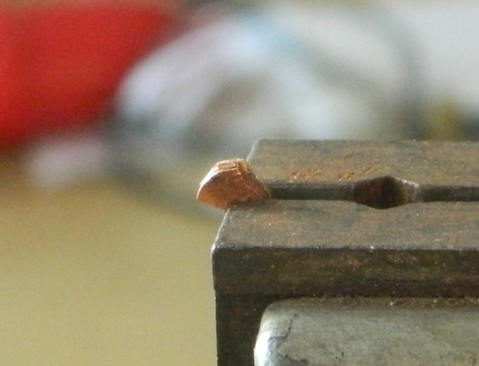
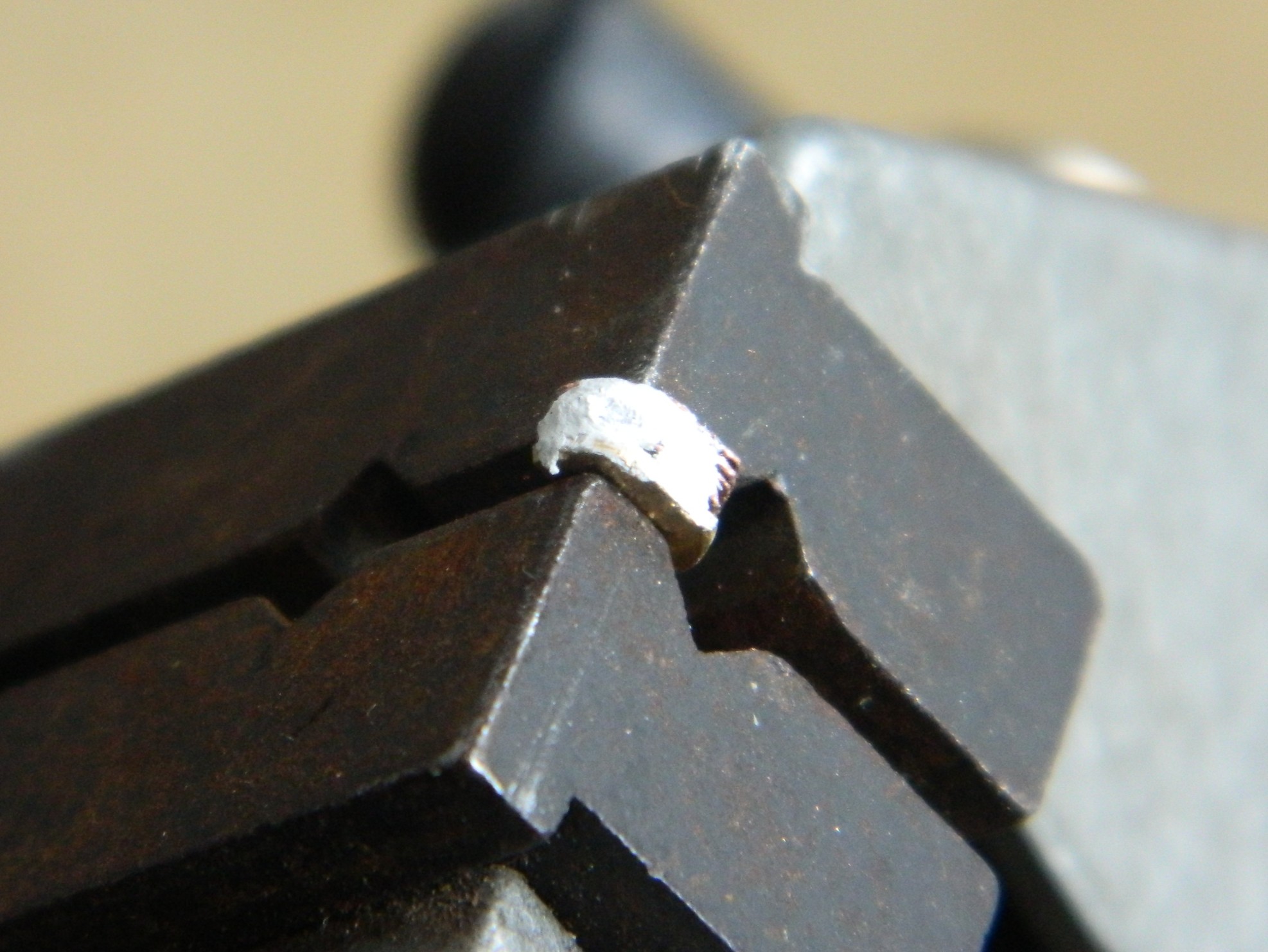
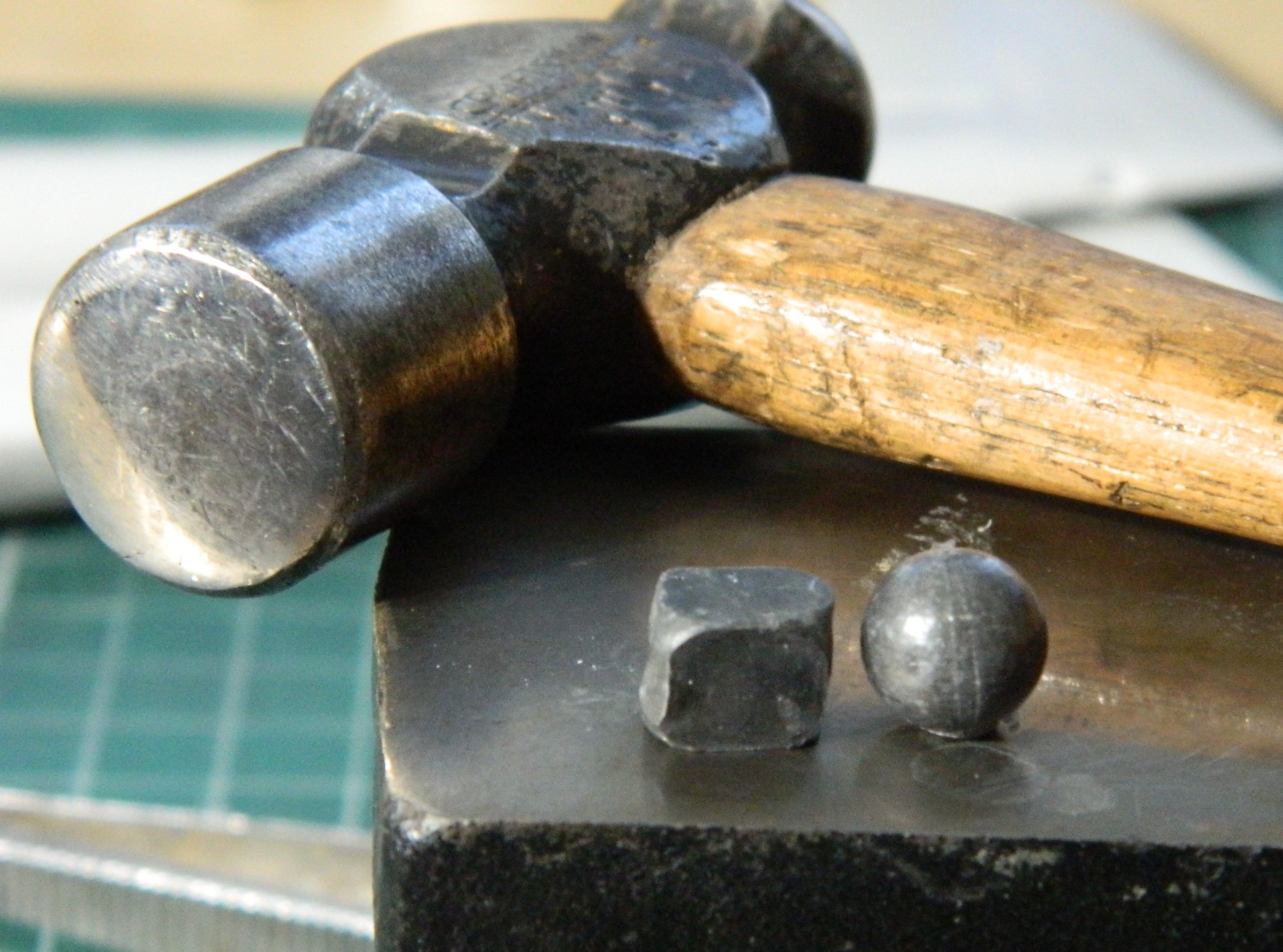
I used .36 caliber lead balls (used long ago for muzzle loading firearms) since I had more of them than the .44 caliber lead balls. Balls, however, aren’t very efficient at filling space (unless it’s round and of the required diameter), so I used a small anvil to shape them into something less round:
Then I glued them into place over where the nosewheel attaches:

So to lay my weight-paranoia to rest, I taped all the major bits that would affect balance (the build’s…not mine):
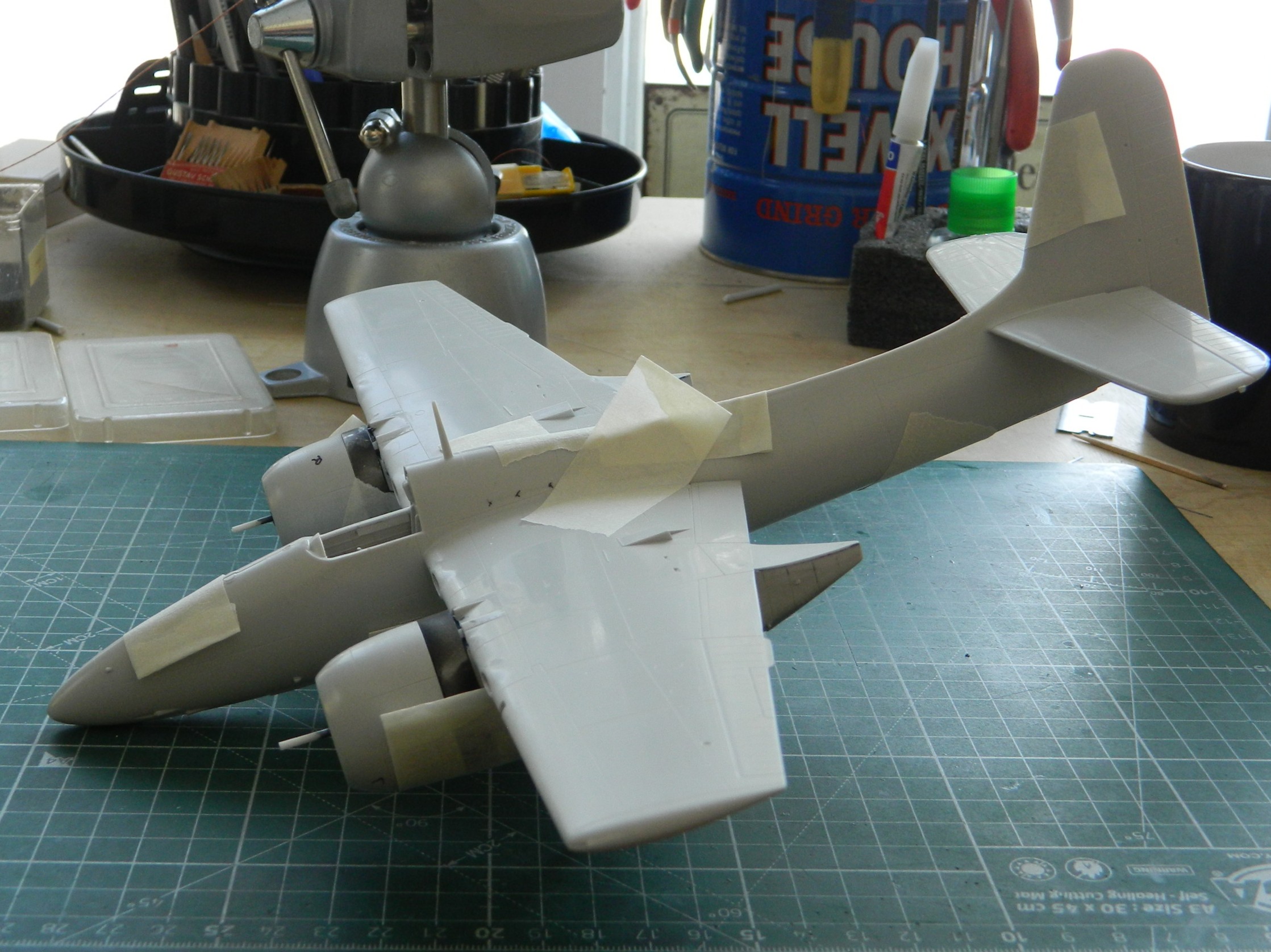
Yes…it will sit level:

But it’s still just a wee bit light in the nose, so more lead will be added before the sides of the fuselage are joined.
I had hoped that I would be able to throw flat black on this thing before this update but time, as it’s reputed to do, fled. Guess that’ll be for next month…
