Colonial Viper MkII (Moebius Models) 1/32 Scale Build #1, Part 1 Conclusion – Making Things Fit Better
I surprised myself with the first Part 1. I didn’t realize that I’d done so much work. That meant (means) that I had (have) to do a continuation so that I don’t fall behind. Again.
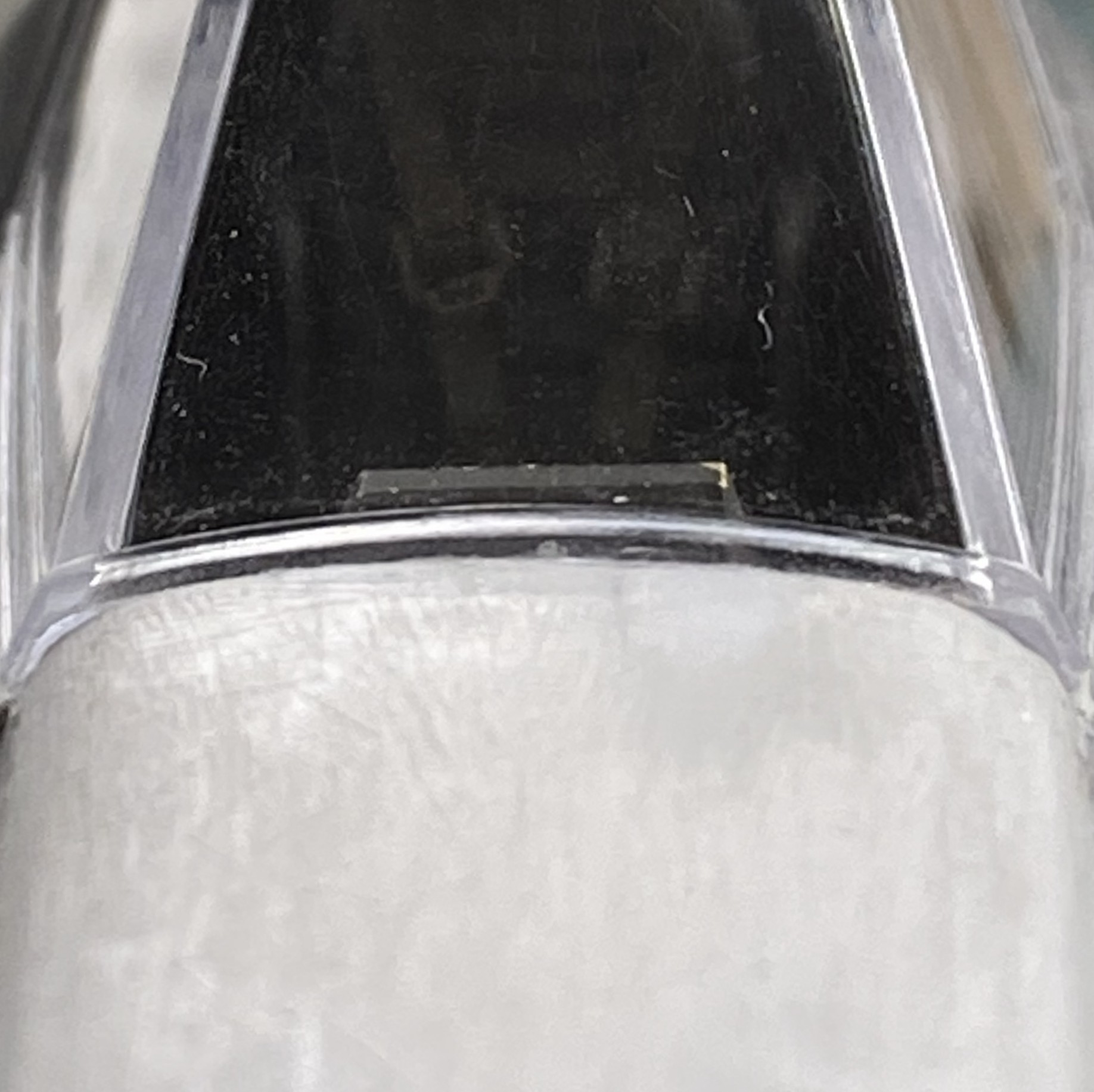
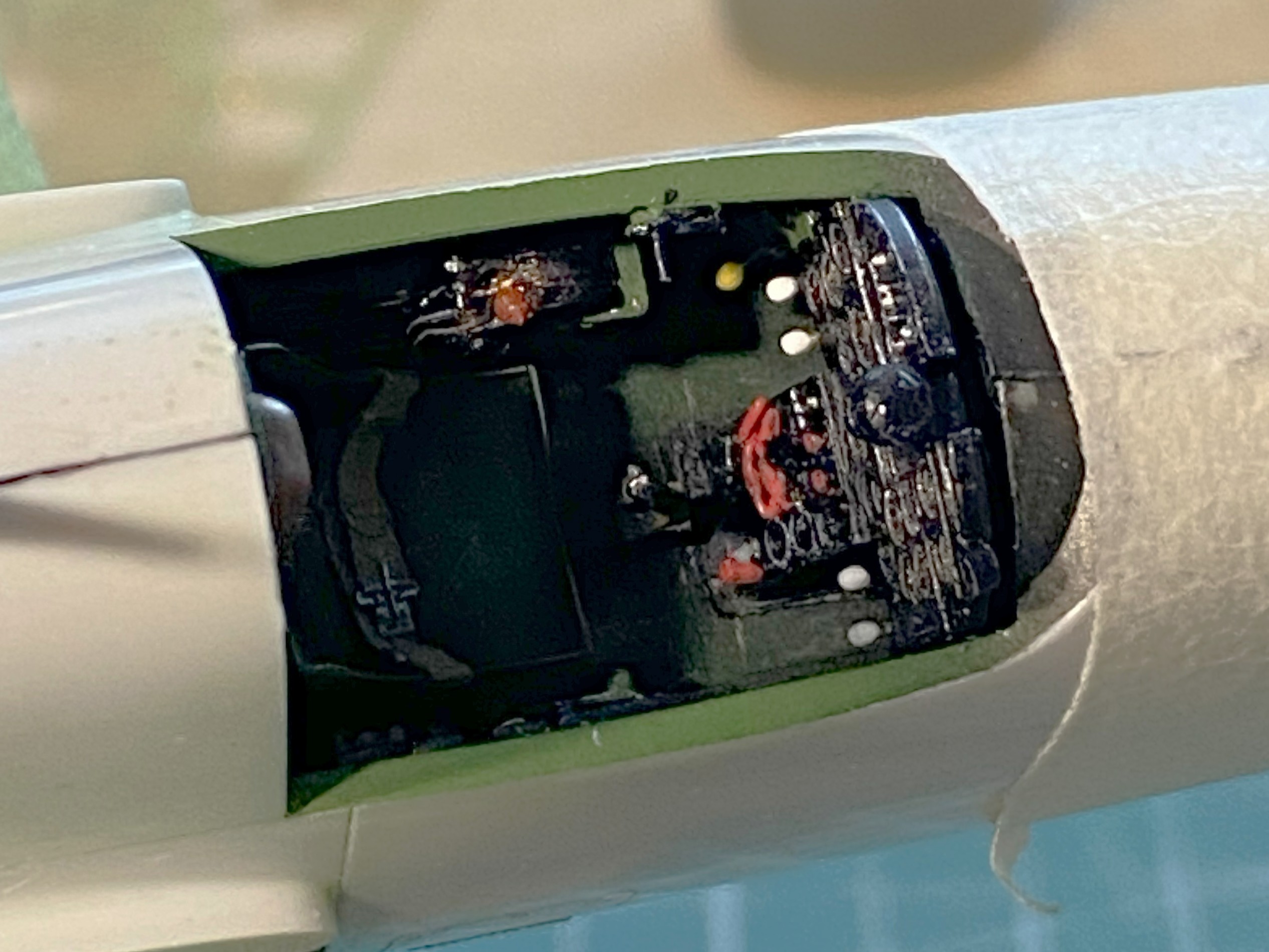
What started the reconstruction of the upper nose was the canopy not fitting well. Now the canopy fits without having to reconstruct the canopy:
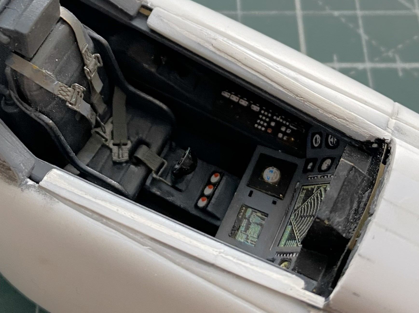
Shims were added to the sides of the cockpit on the fuselage so that the canopy fits well there also (this cockpit is supposed to be sealed, y’know):
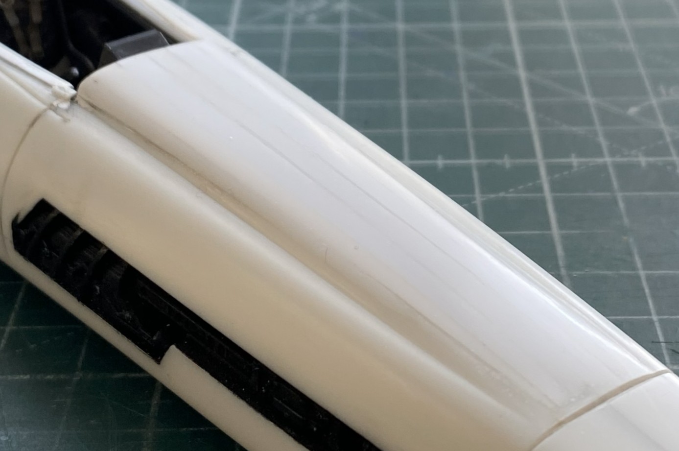
With the nose modification roughed in, I sanded it from 220 grit up to 5000 grit:
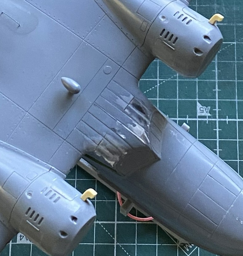
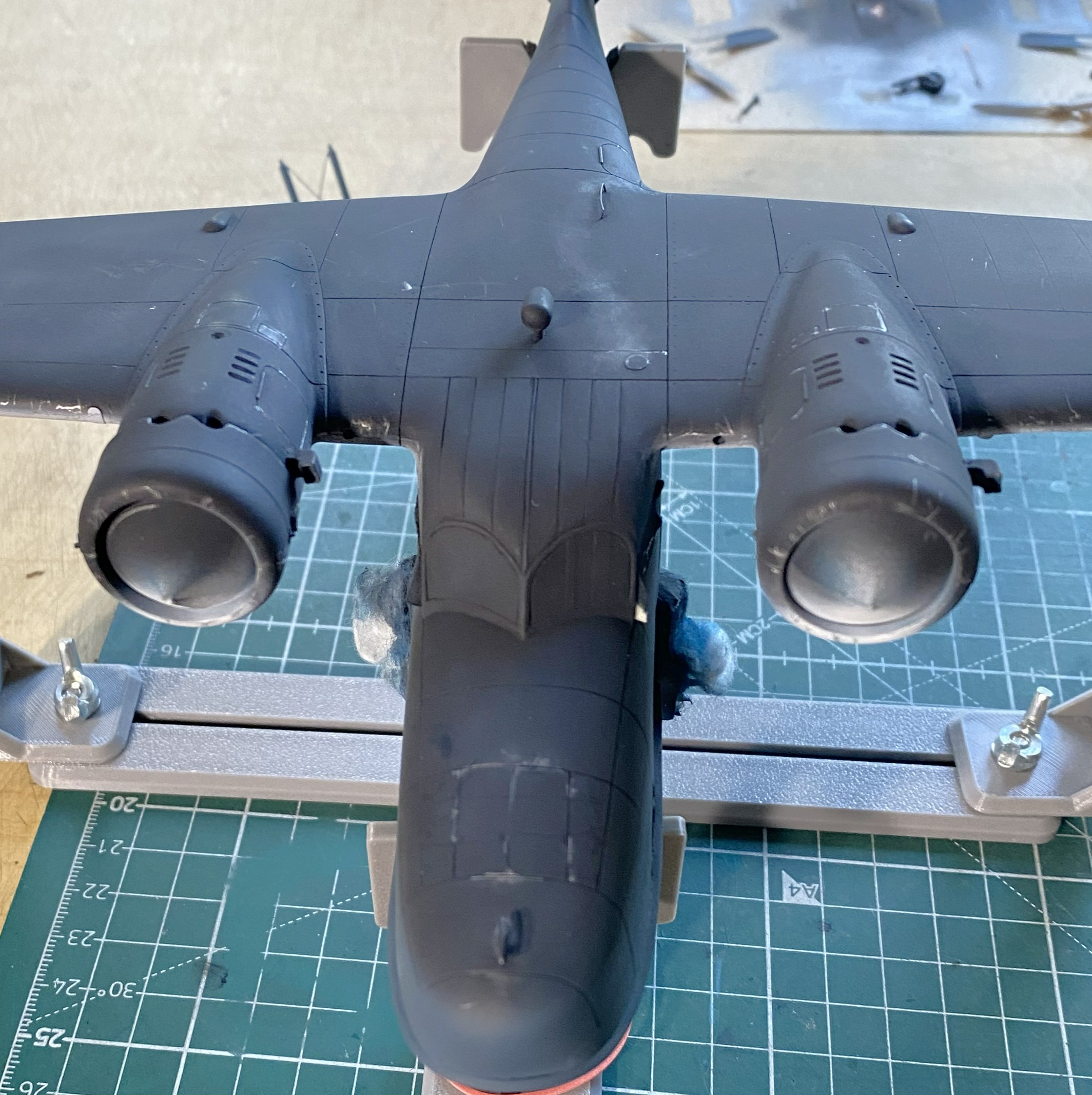
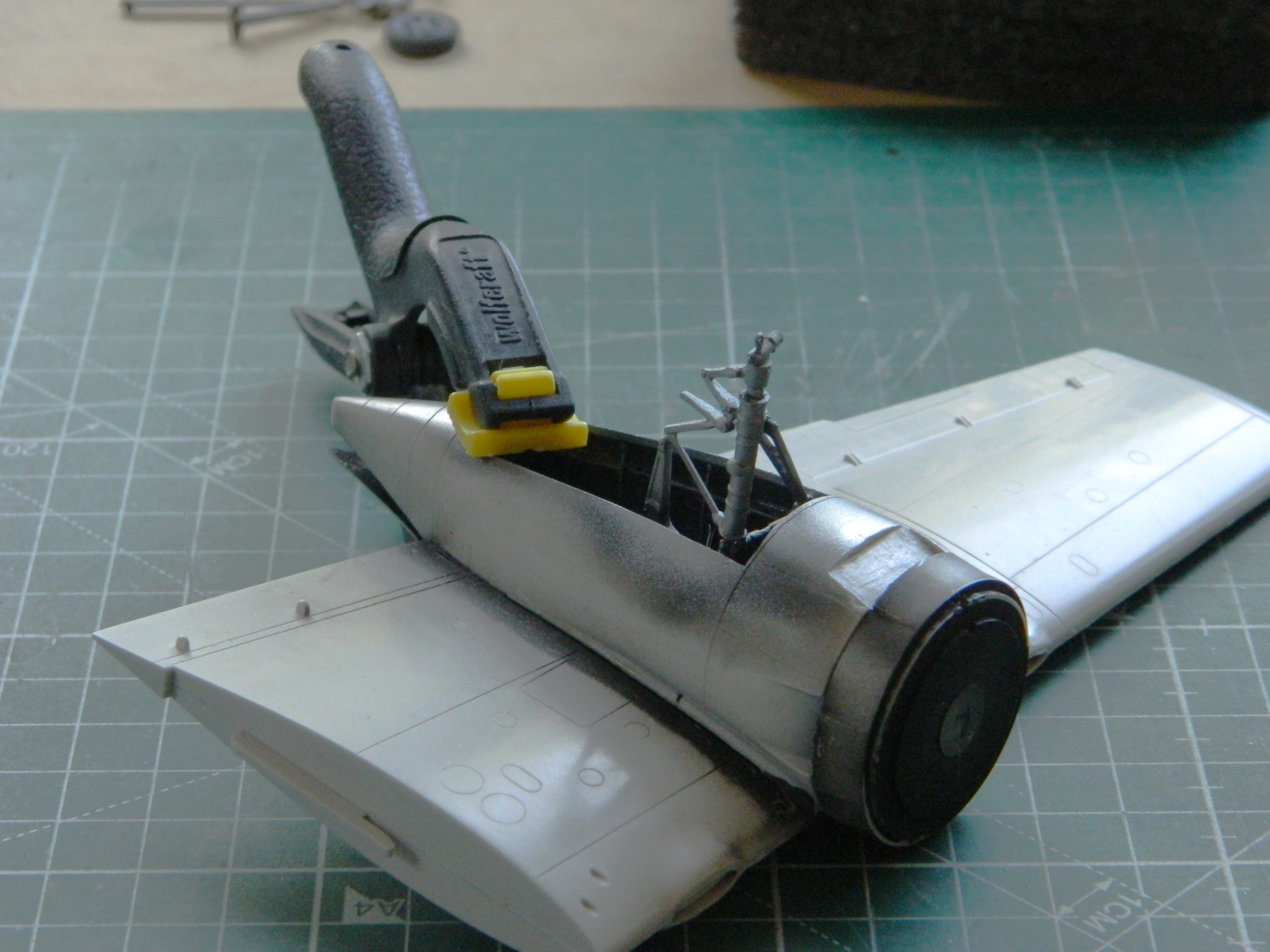
The AM set has a PE box that has to be folded and assembled. It also needs room inside the belly pan. Two sections of excess plastic under the lateral engines had to be cut away:
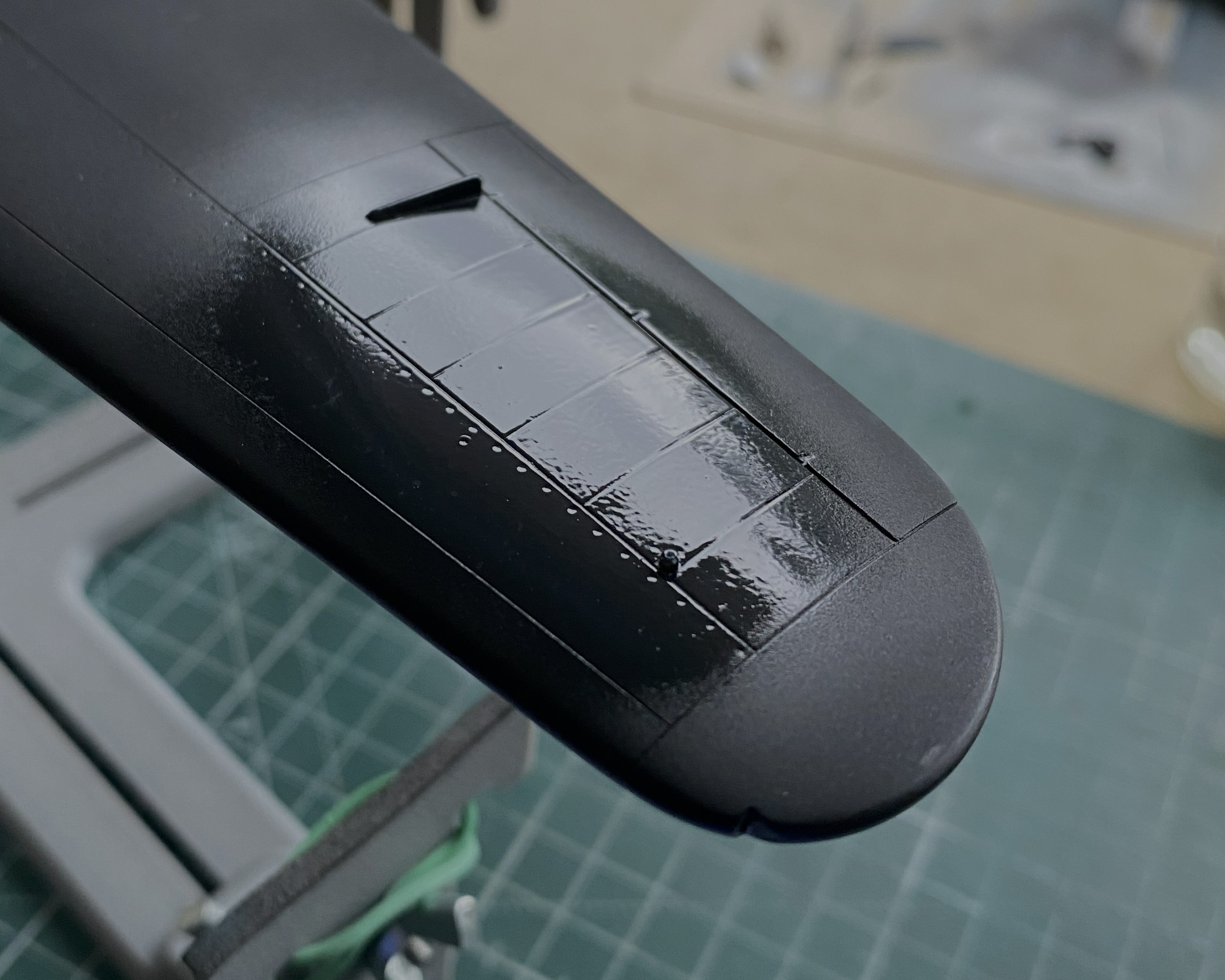
I had pre-shaded the engines with flat black, it was now time to give them their finished color as well as the landing gear legs (same color):

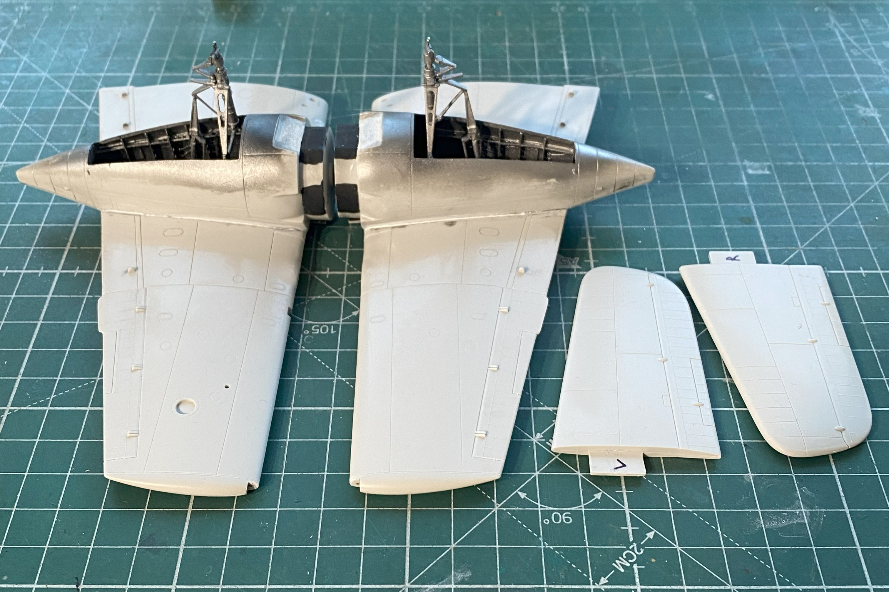
I’ve read accounts of people who either don’t like pre-shading or see no purpose for it. Makes no sense to me. I get great (he says modestly) results from it. I certainly like how they all look when dry-fitted:
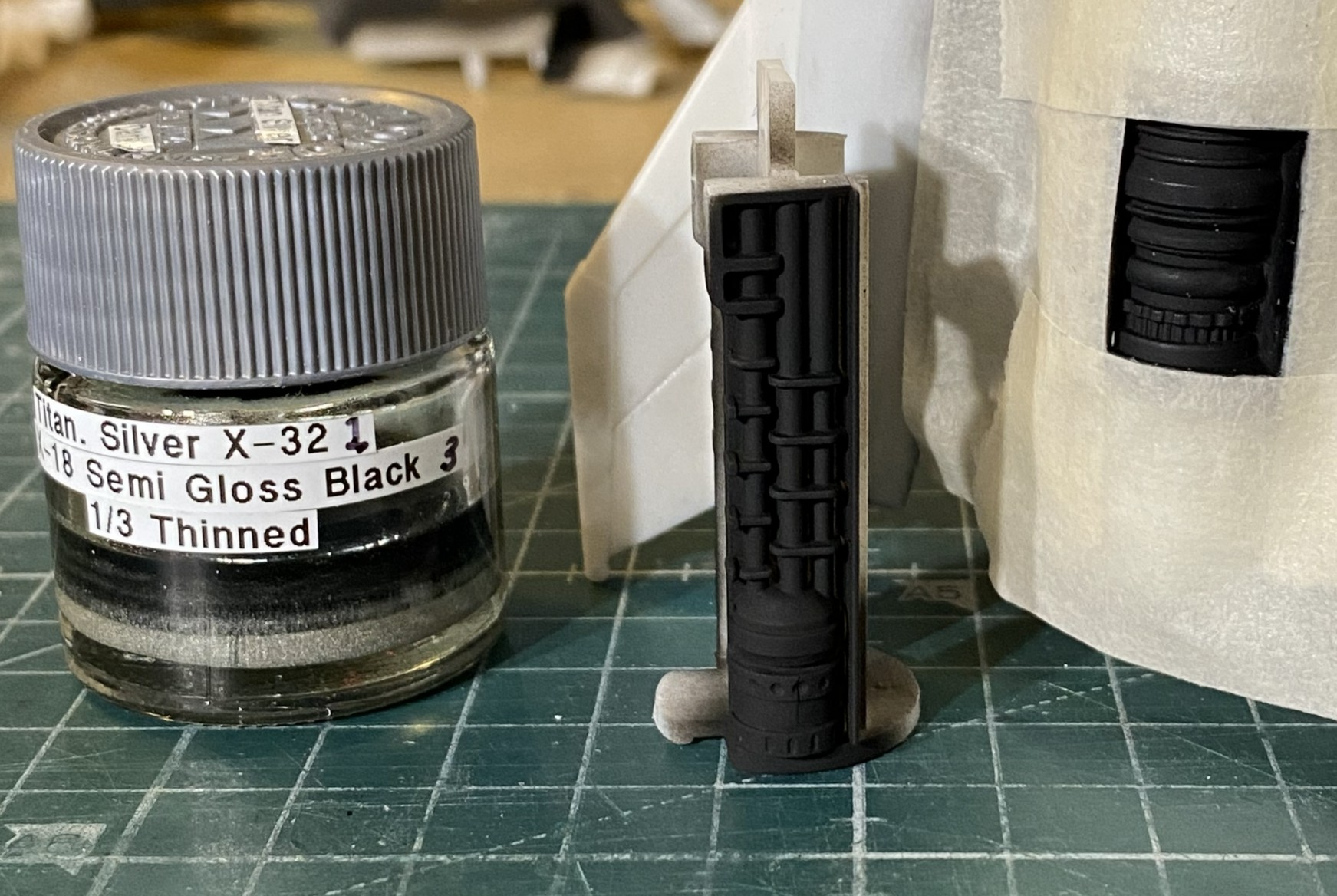
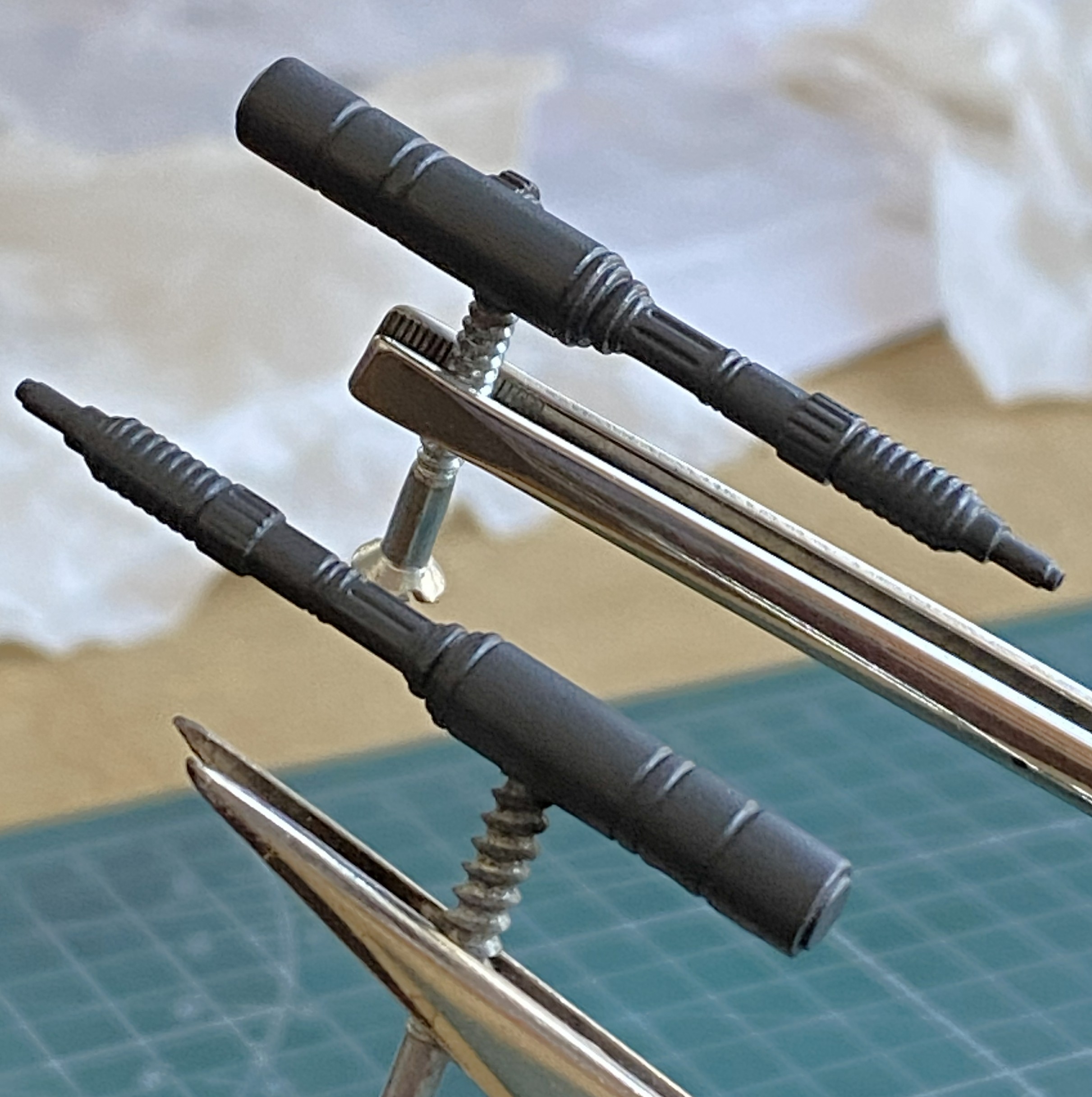
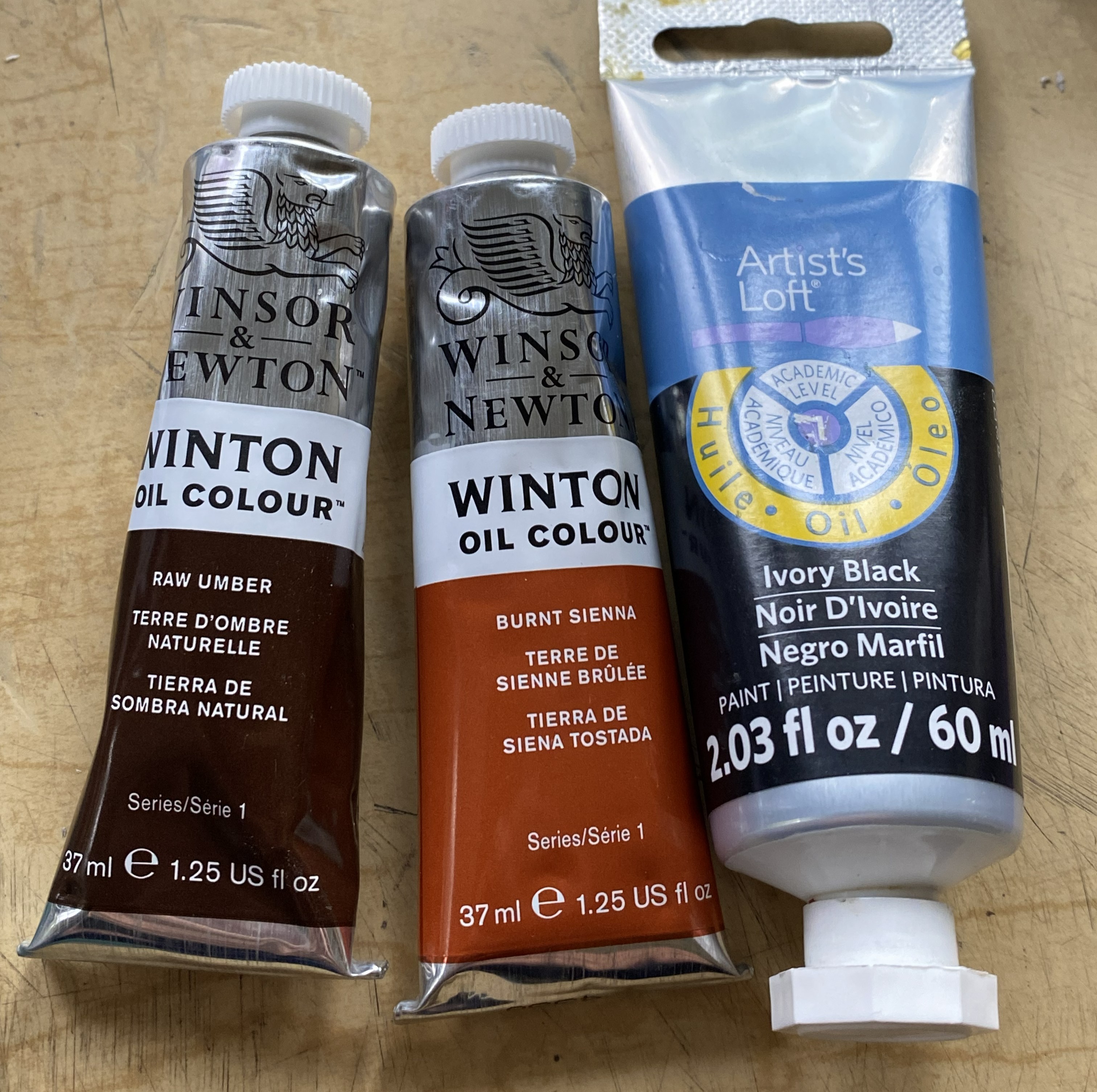
While I had the compressor fired up, I painted the guns with my custom mixed “gunmetal” paint (Tamiya X-18 Semi Gloss Black, 5 parts; XF-20 Medium Gray, 4 parts; thinned 1/3):
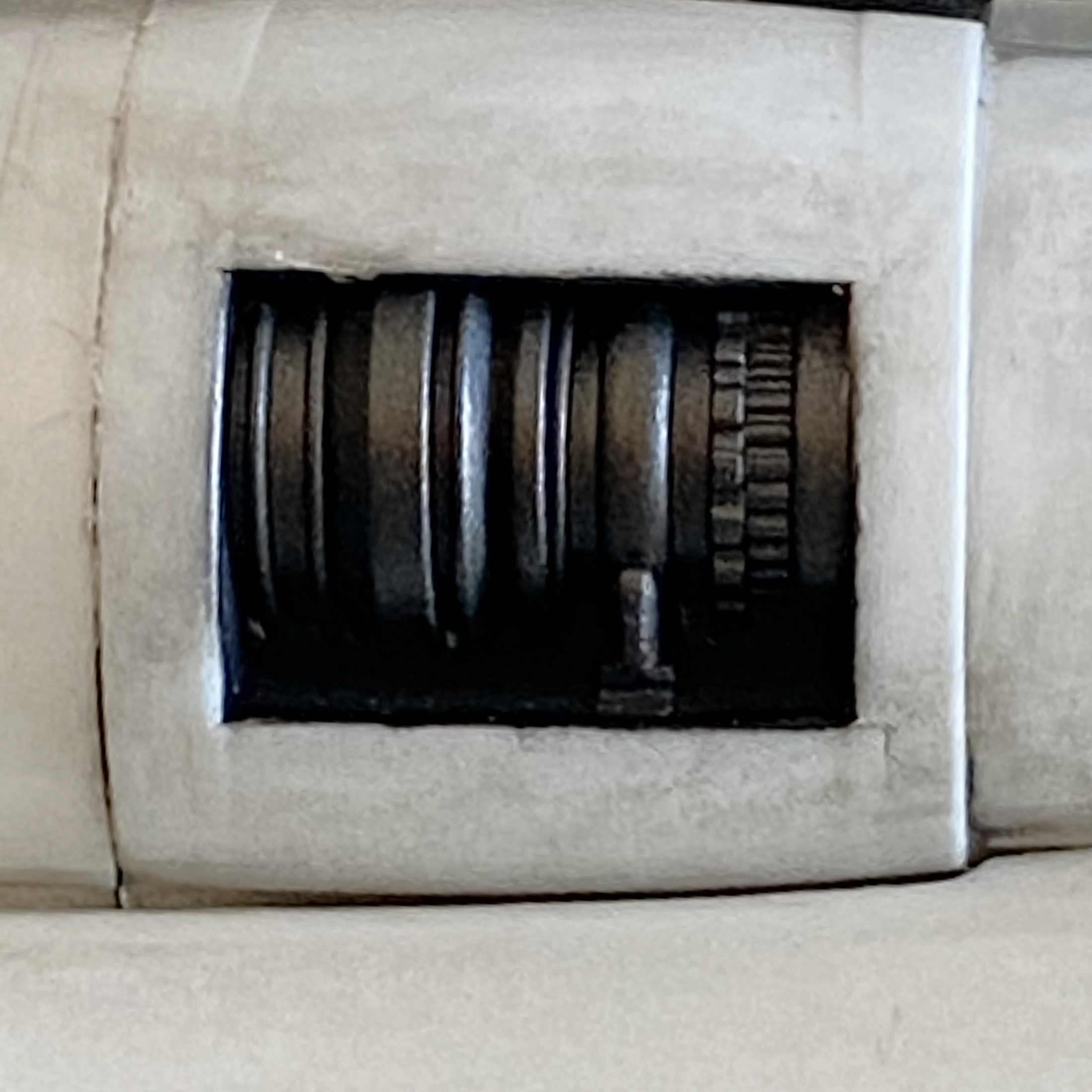
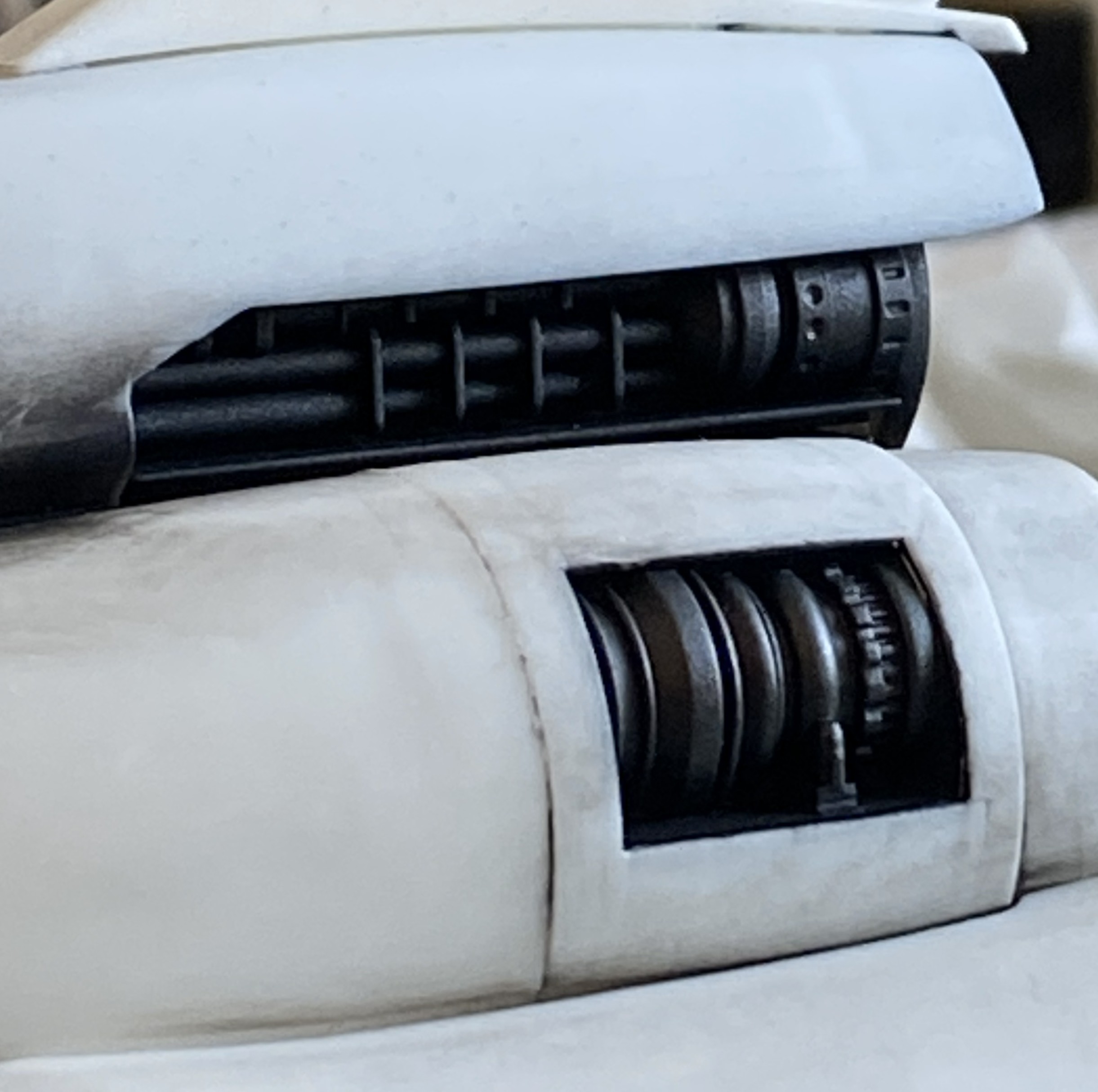
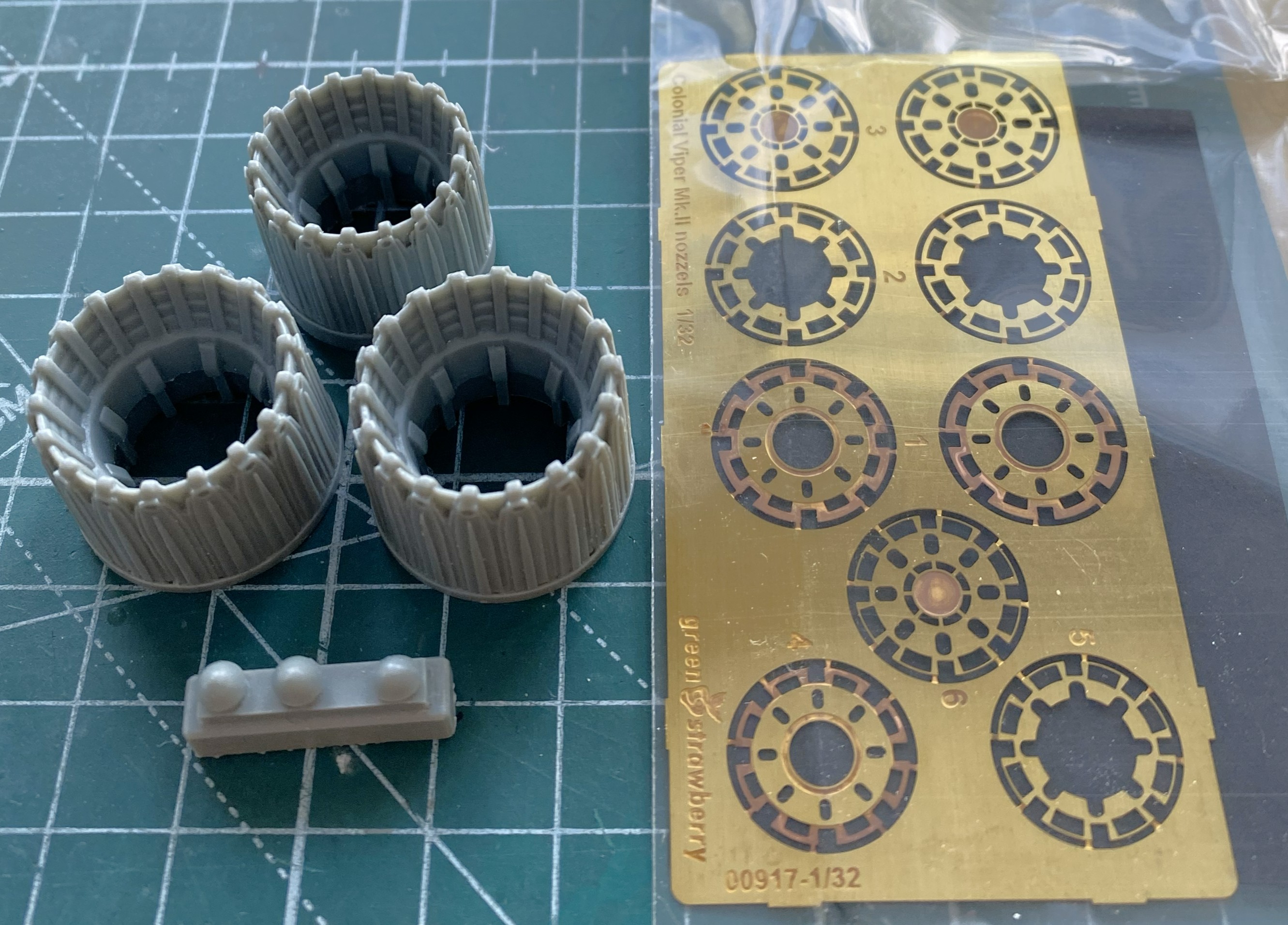
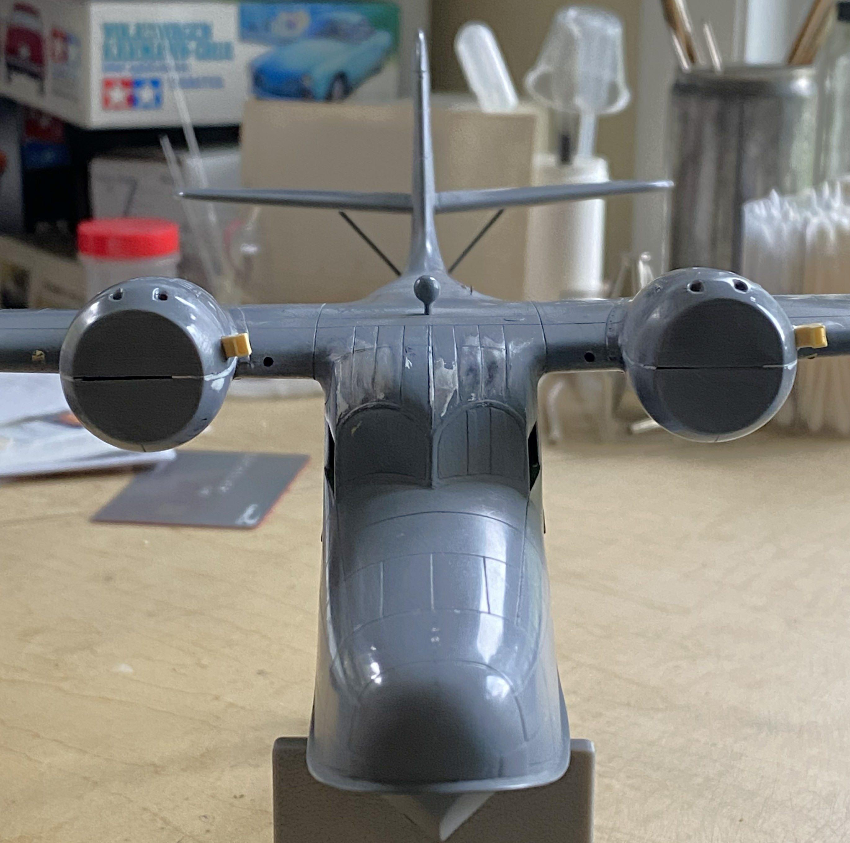
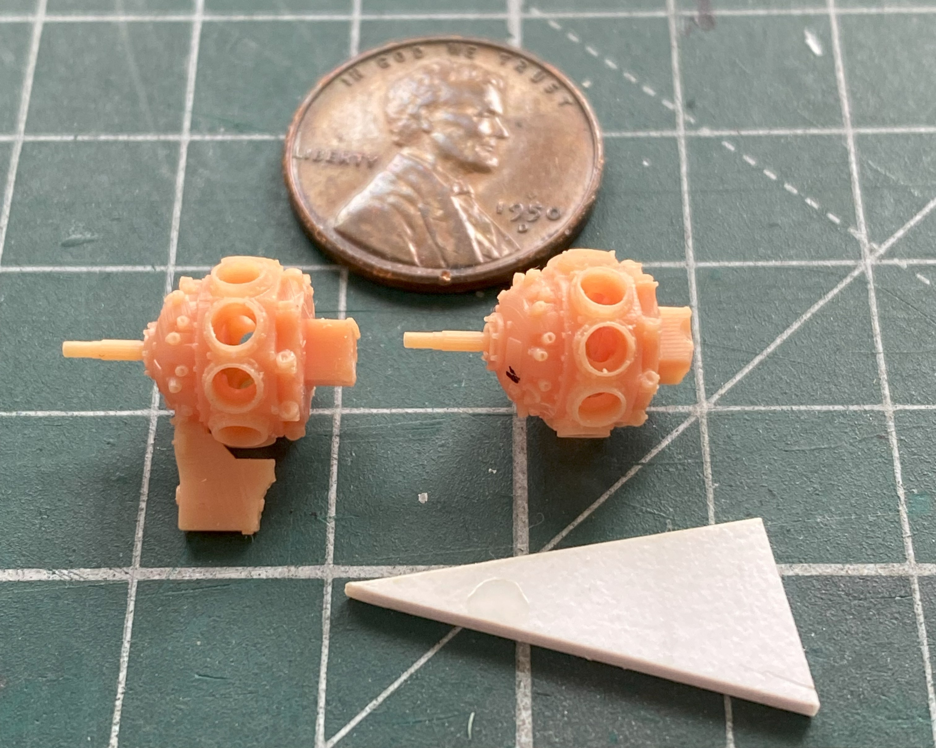
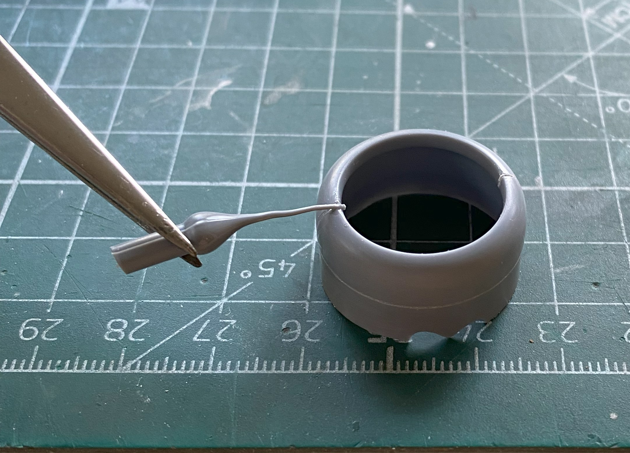
I turned my effort towards the exhaust nozzles. I think the AM parts, resin body and three PE disc inserts, are substantially better:
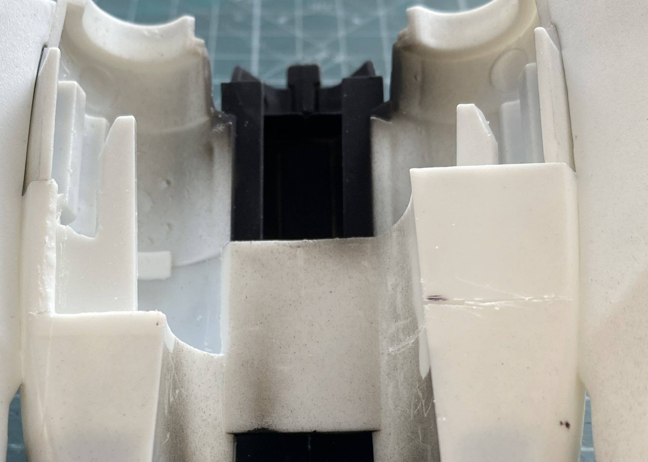
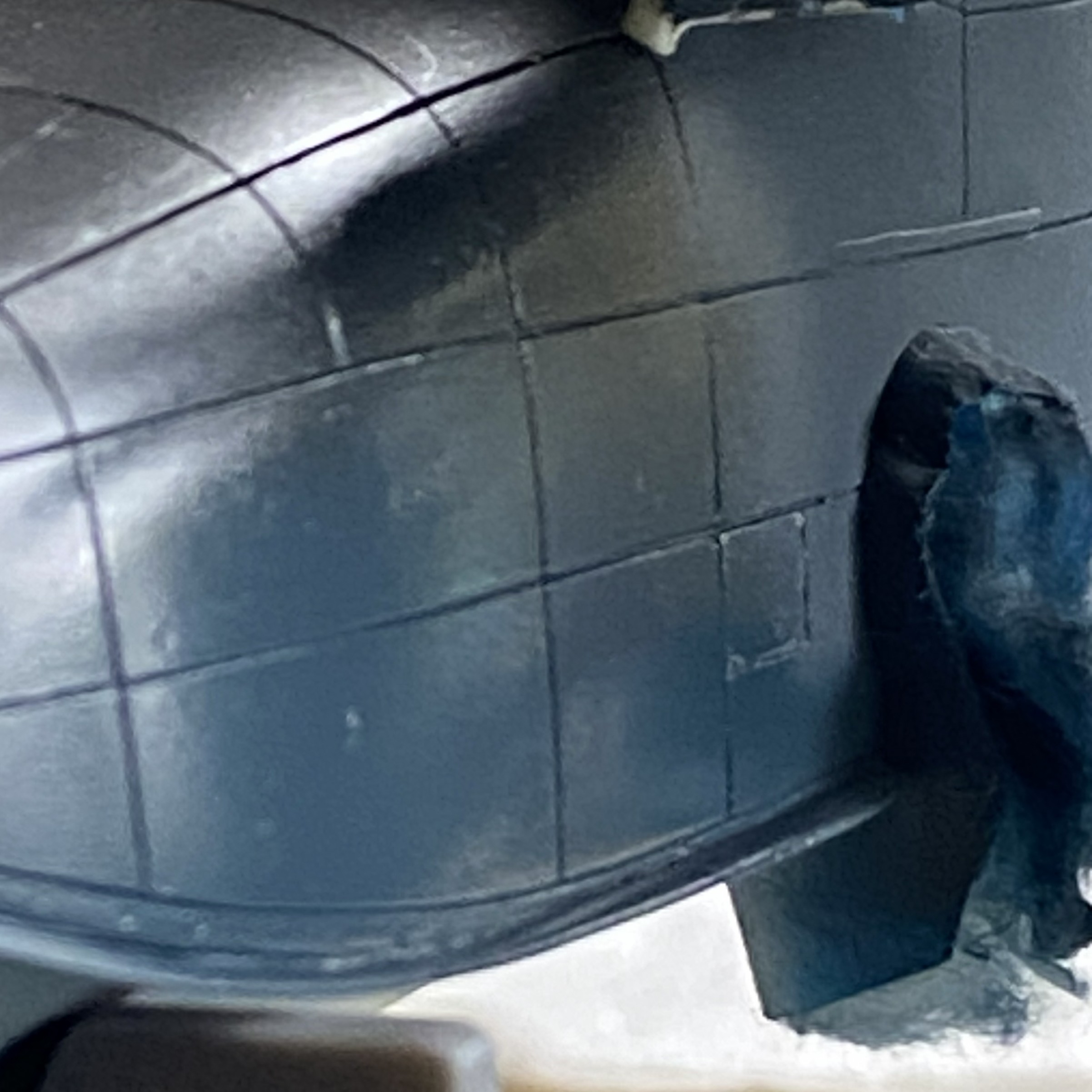
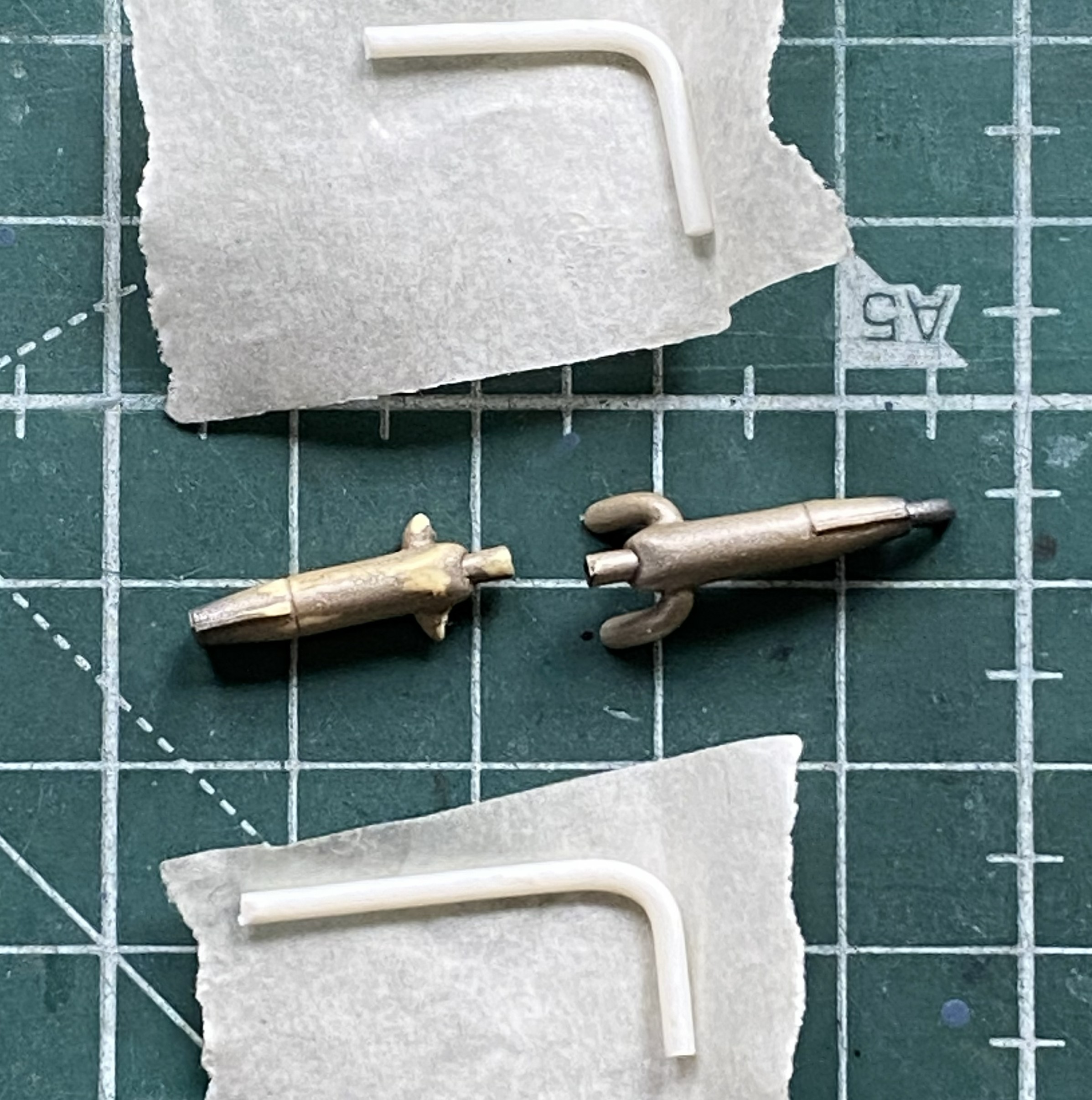
The kit’s nozzles need work. They have to be removed. Note in the below photo the section of the part where all the nozzles attach. Once the nozzles are removed, the center part is what remains:

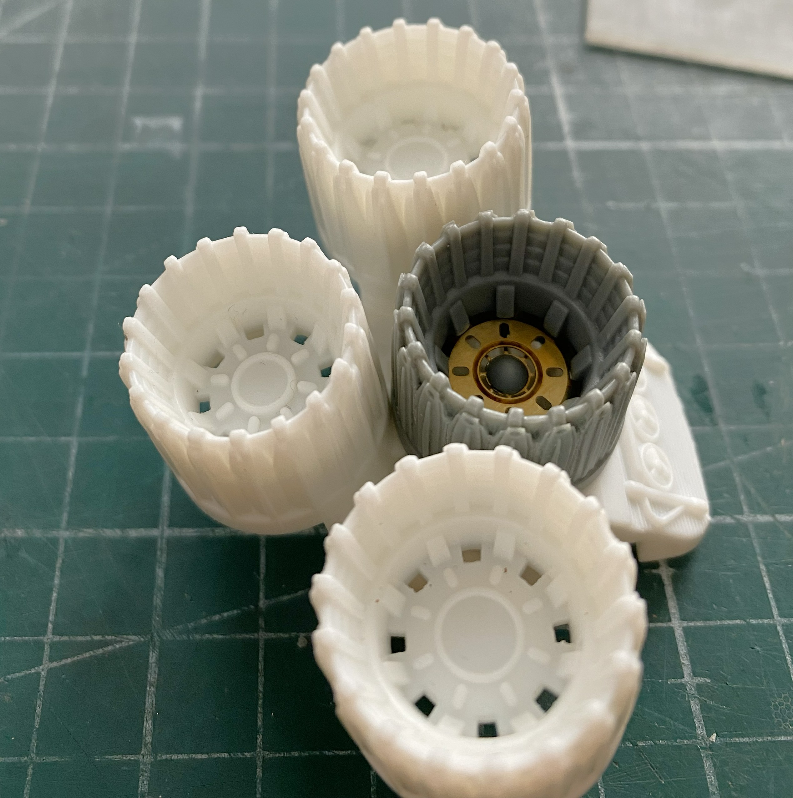
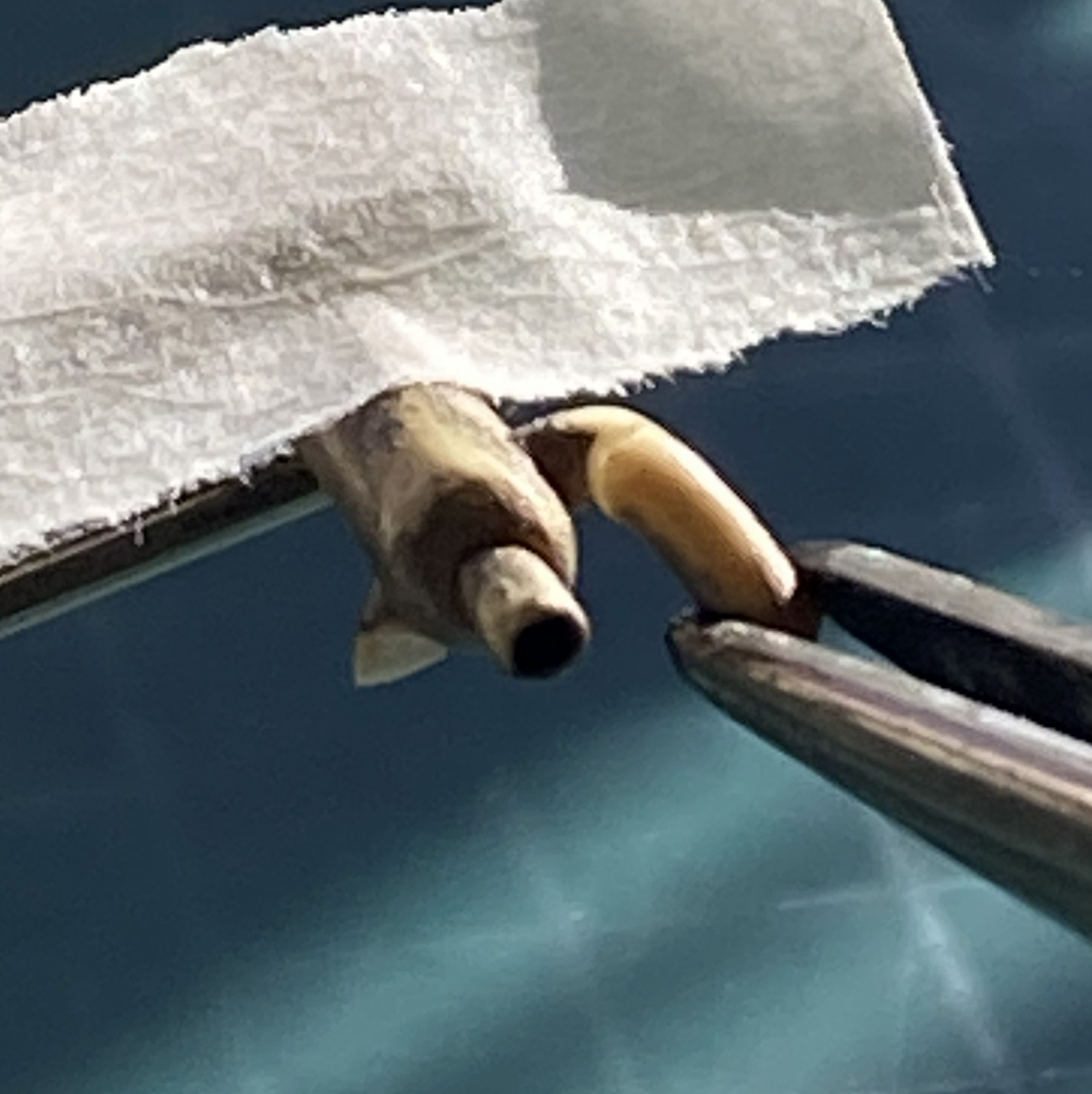
Each of the AM nozzle assemblies has sections where one can see into the hollow fuselage. Easy fix. Cut out discs for the two nozzles that allow that “feature” and paint them black (the upper engine’s rear will get painted black for the same reason):
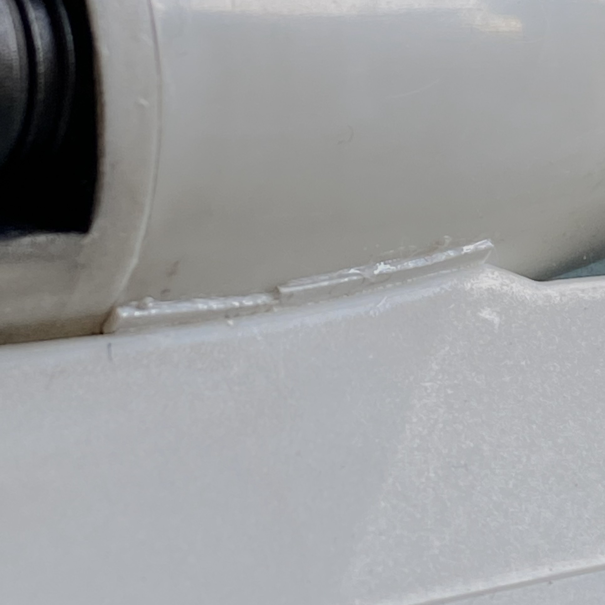
Each wing root has a gap that bothers me. Well, they had gaps but they were filled with scrap styrene. I’ll finish these off before painting:
I’ve had people ask me how I make some of the smaller details I use. I’m going to show you but there are a few steps to the process. If this is of no use to you, just scroll past.
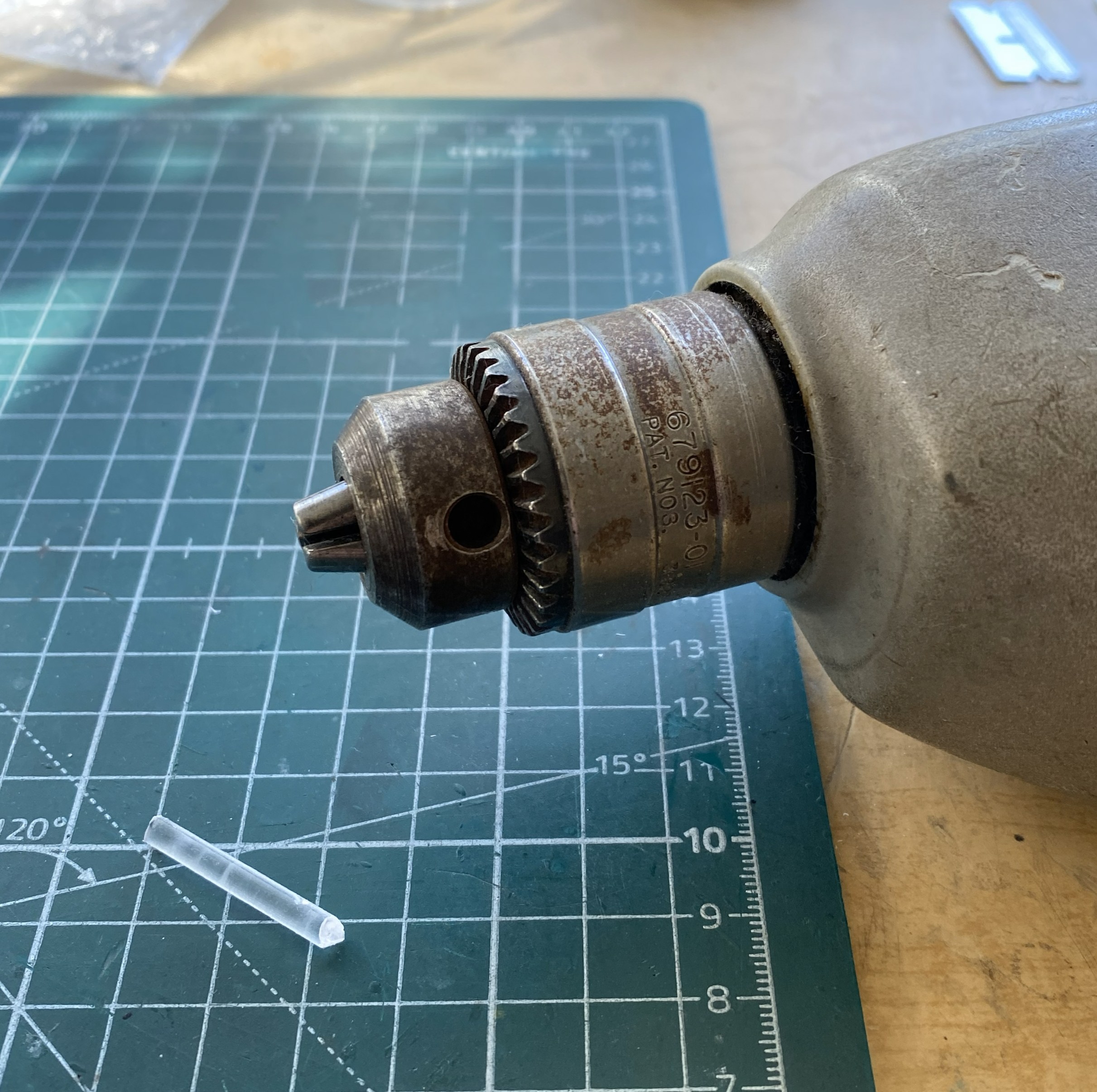
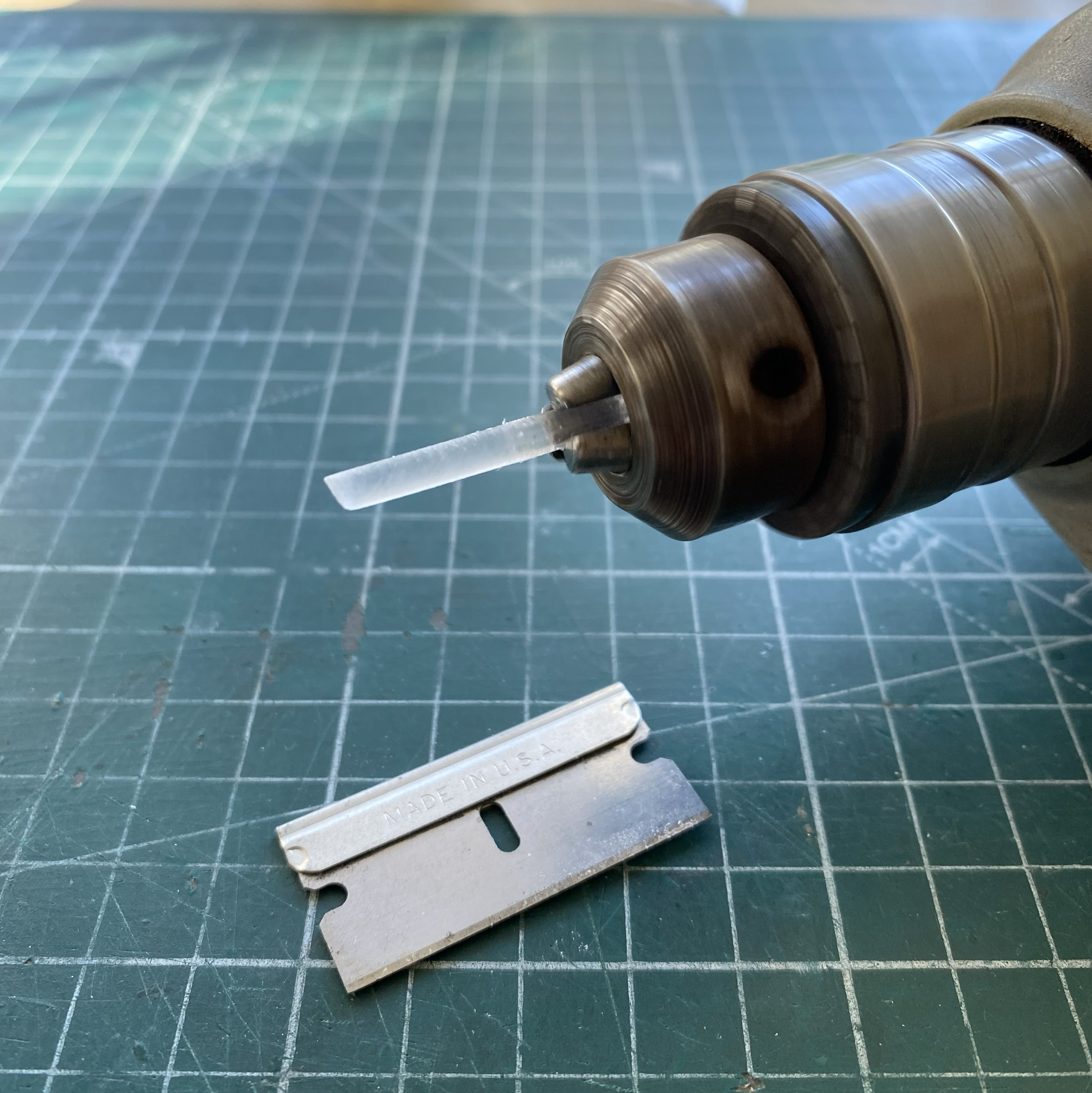
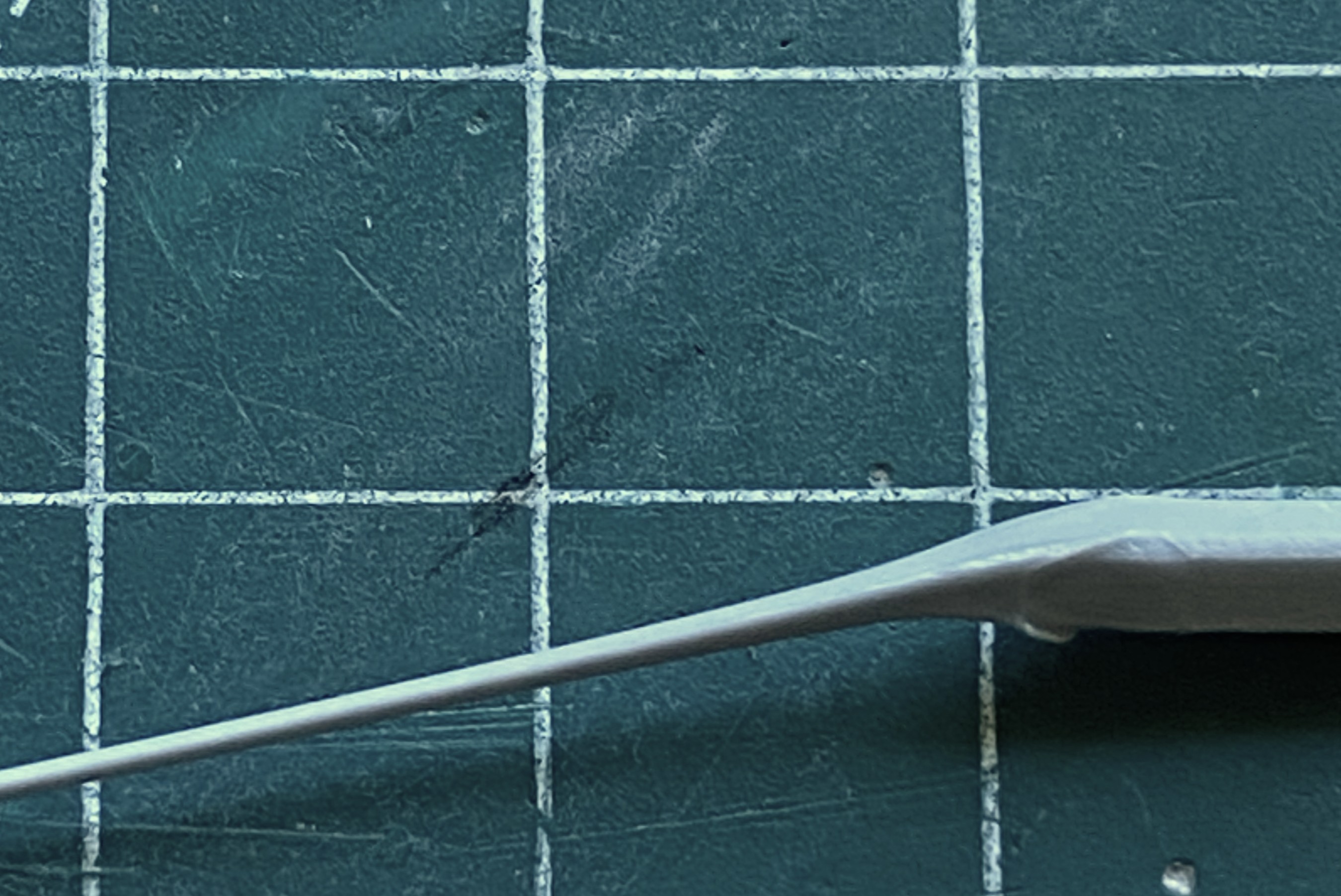
Sometimes I need to make something cylindrical in nature. If dimensions and shape are critical, I have a small bench-top lathe (Harbor Freight, I don’t need anything more accurate and certainly don’t want to pay for more accurate). When the look matters more and it’s a small part I’ll use a variable-speed drill. In this case, all I need is something to hold the stock and spin it.
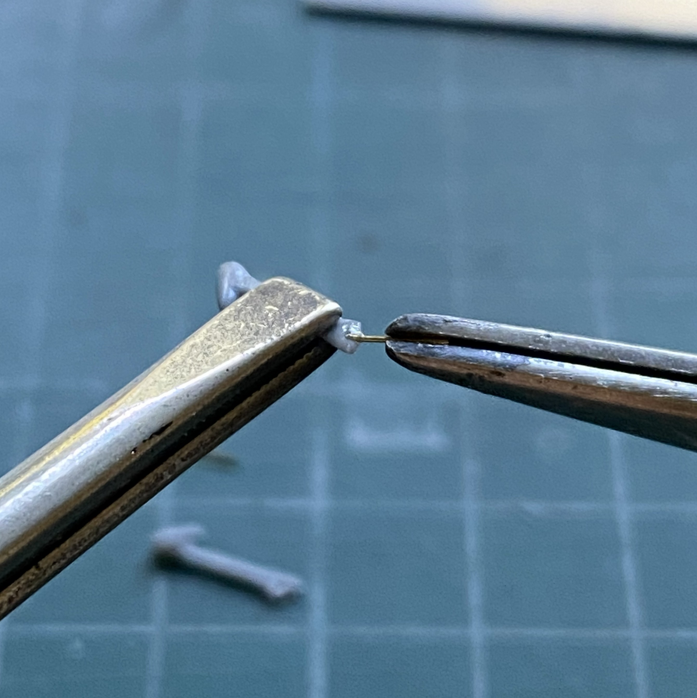
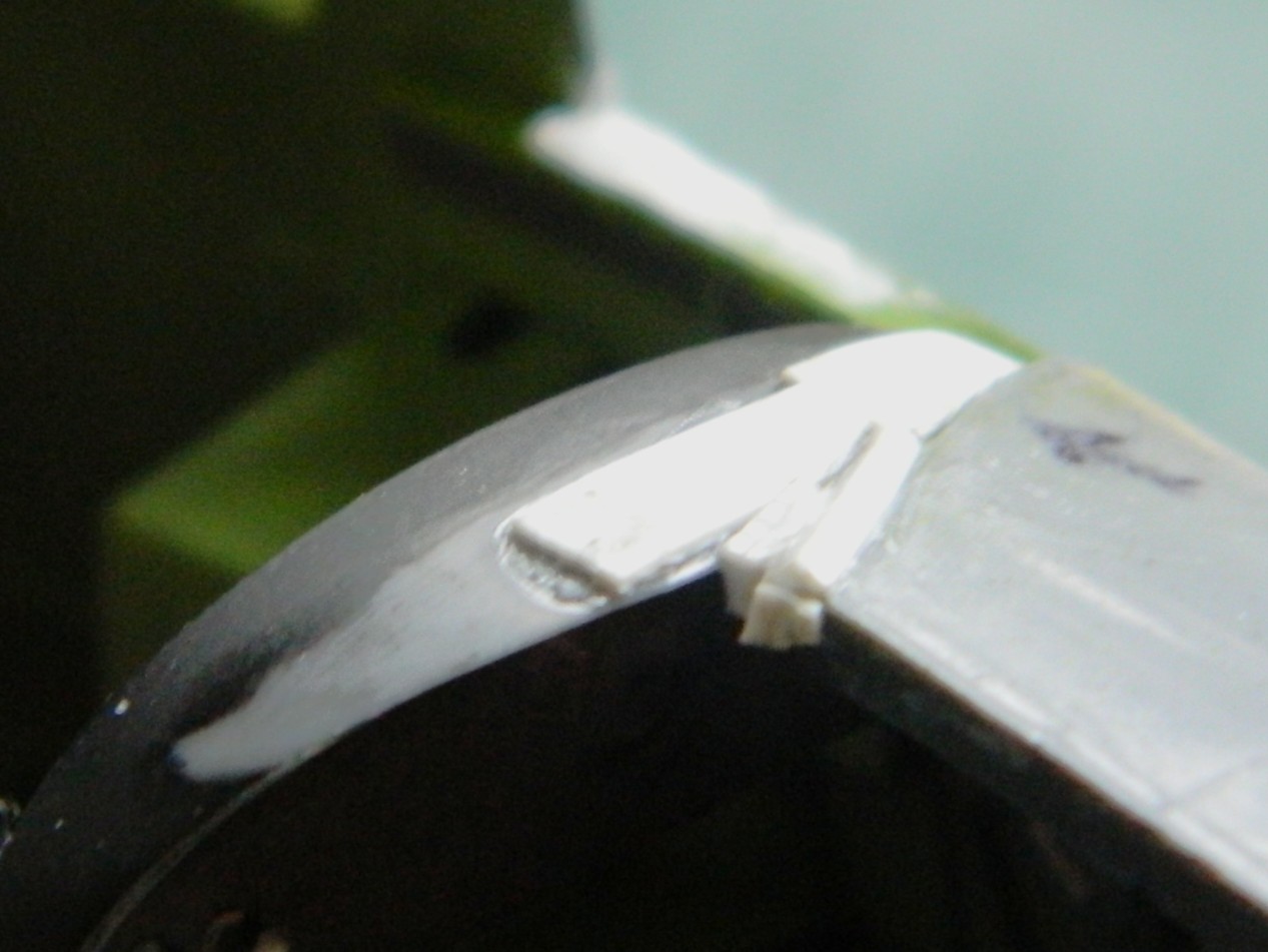
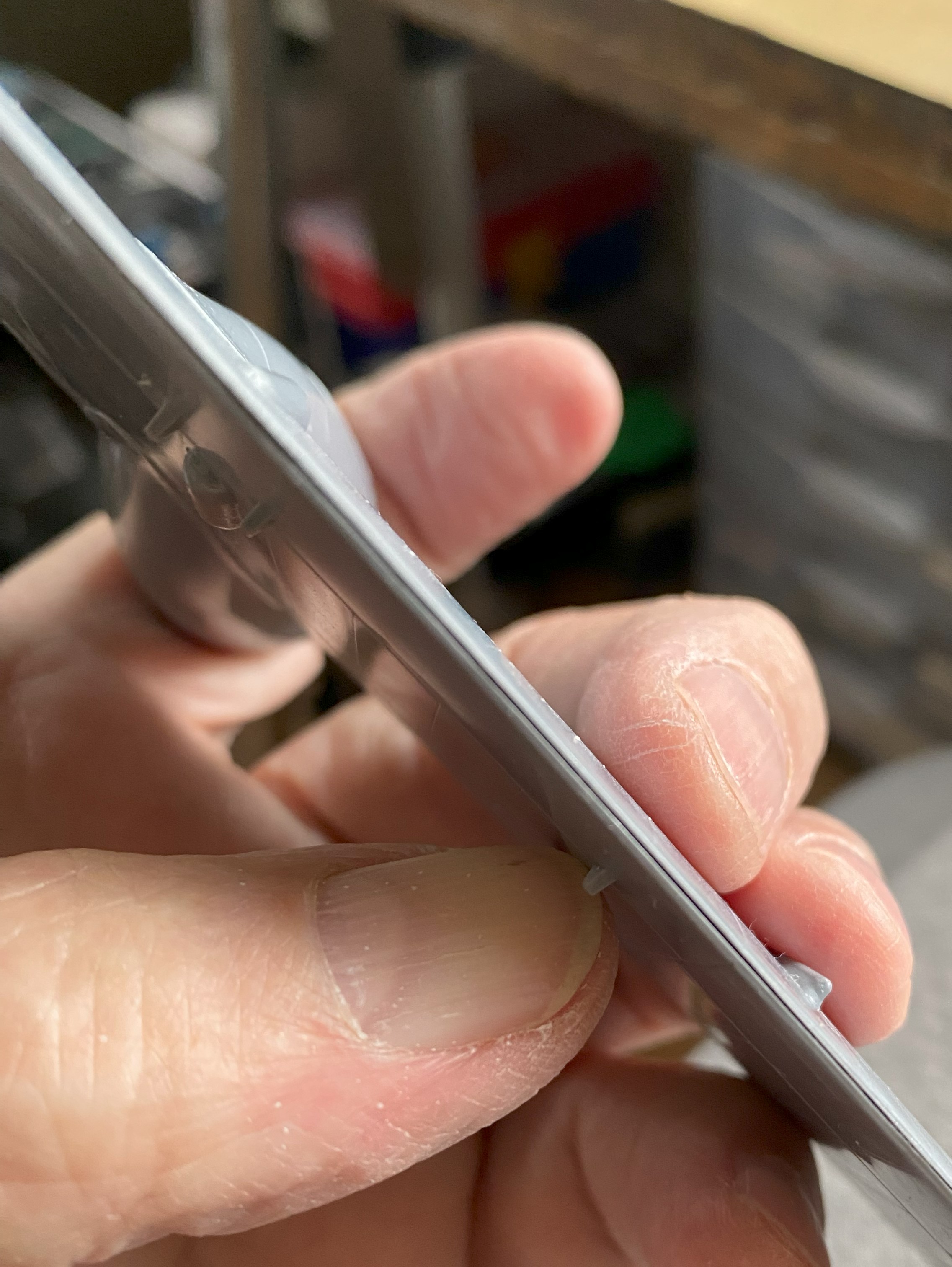
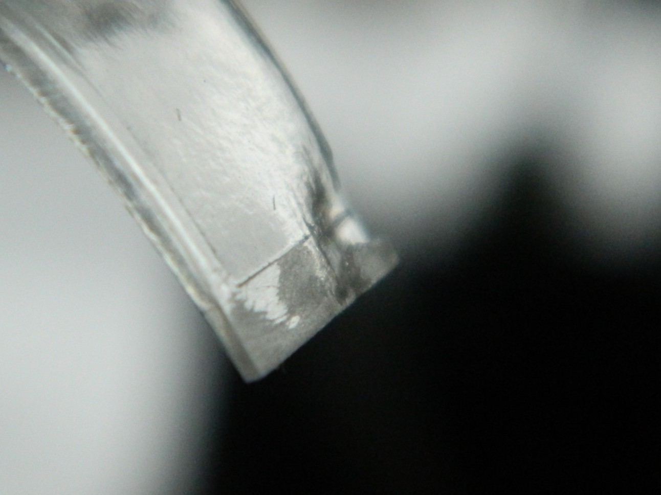
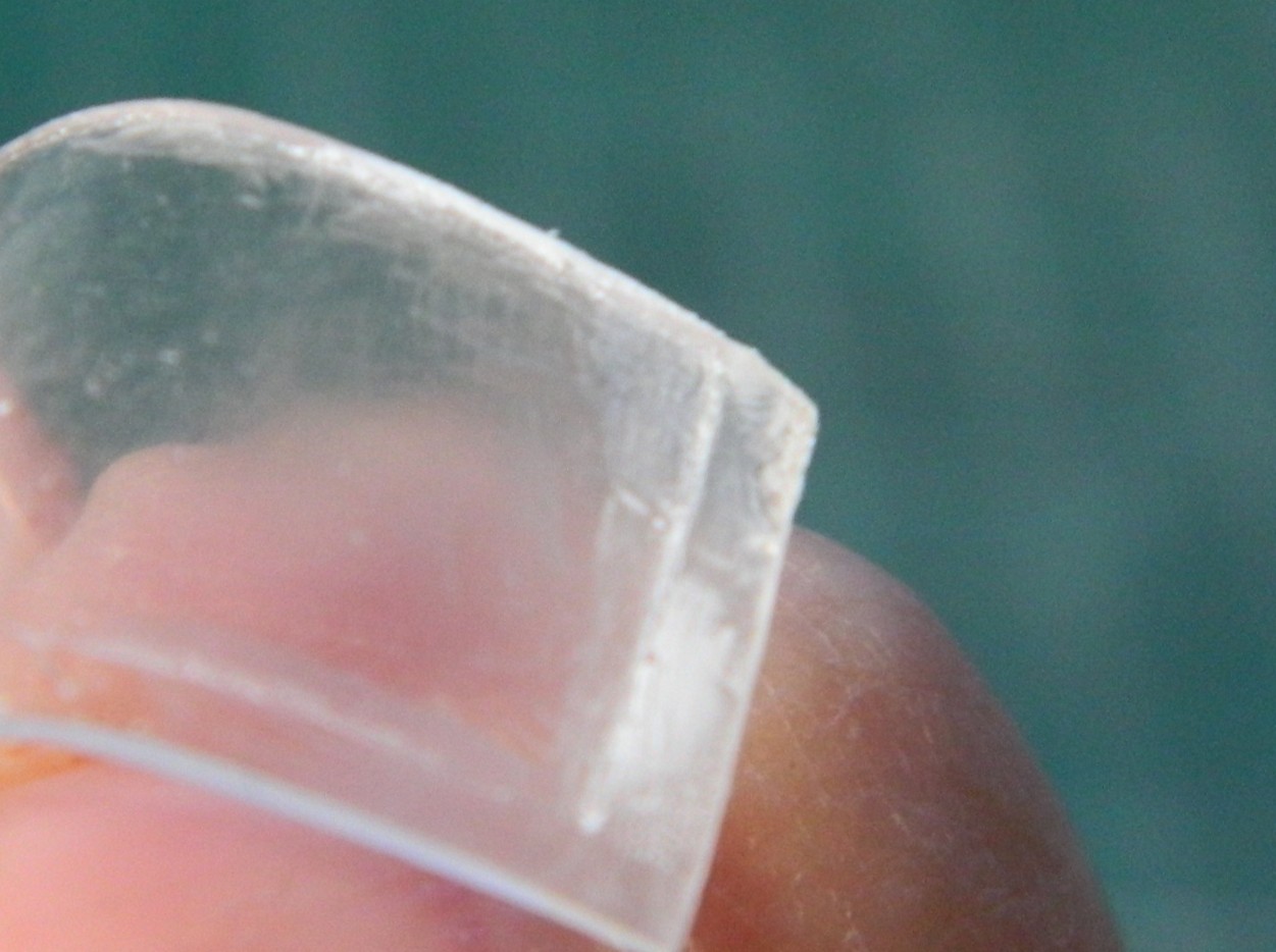
The sensors for the draedus are molded onto the wingtips in opaque plastic. Yes, I could just paint them. (I could also get into stamp collecting as a hobby, too.) Instead, I want to make clear covers for them. So I started with a section of clear sprue and set the drill at a lower speed to keep from melting the work:
My initial thought was to use an abrasive nail shaper:
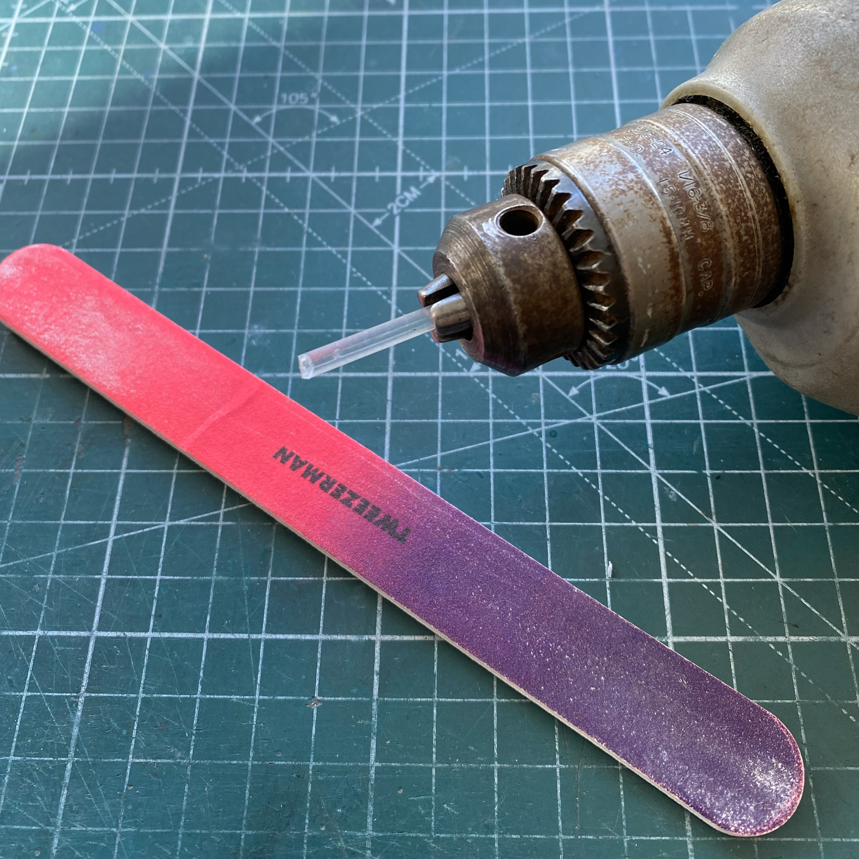
Nope, it doesn’t take enough off. I tried a razor blade next:
Yes, it took more off per spin, but it was unwieldy (and my fingers, being right next to that sharp bit of steel is full of my SACRED B+), so I used a #11 blade:
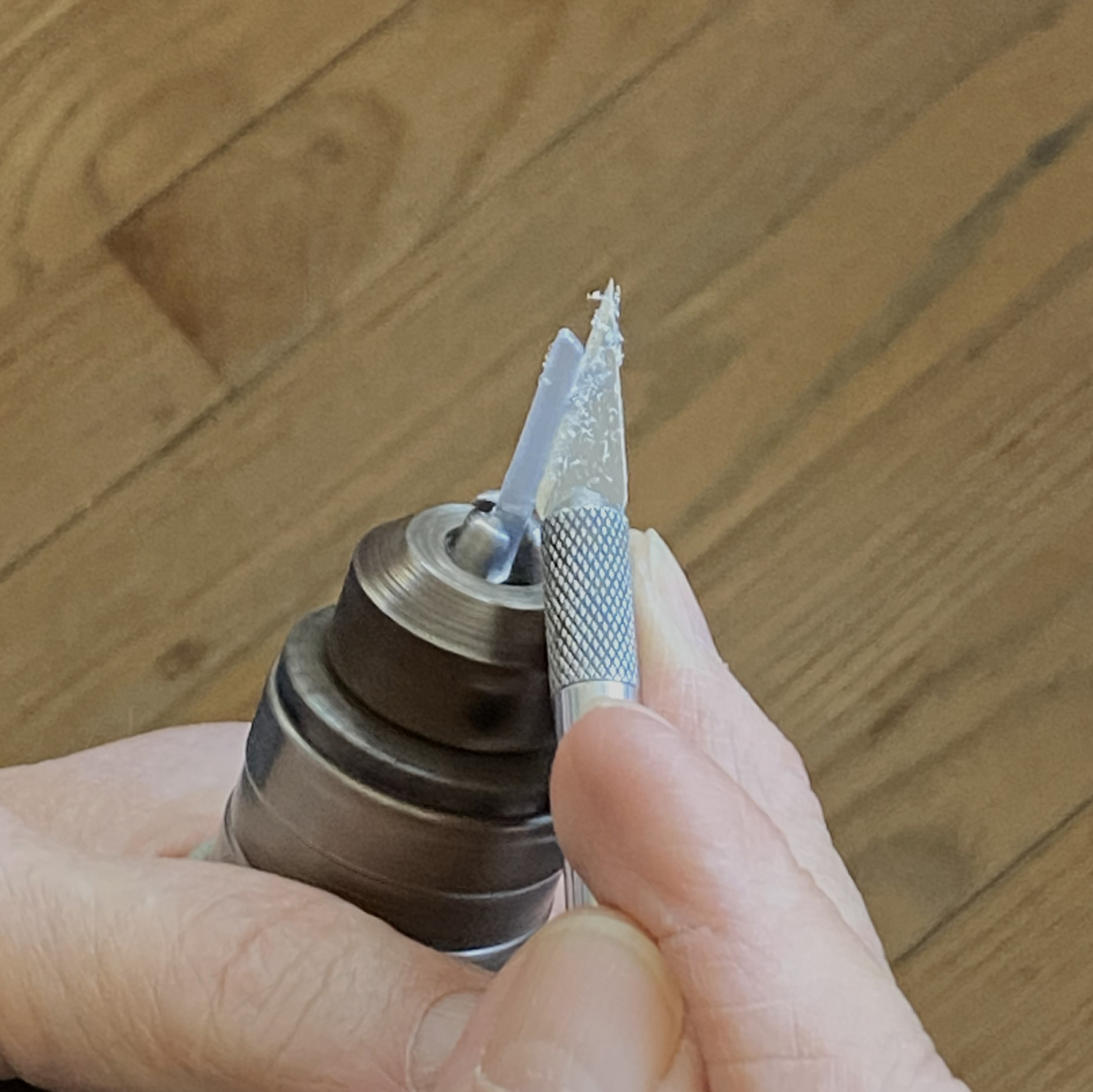
That worked much better! What isn’t evident in the above photo is the angle I’m holding the blade at. I’m holding it at pretty much the same angle that I use to scrape plastic with. Do NOT let the blade bite the work!
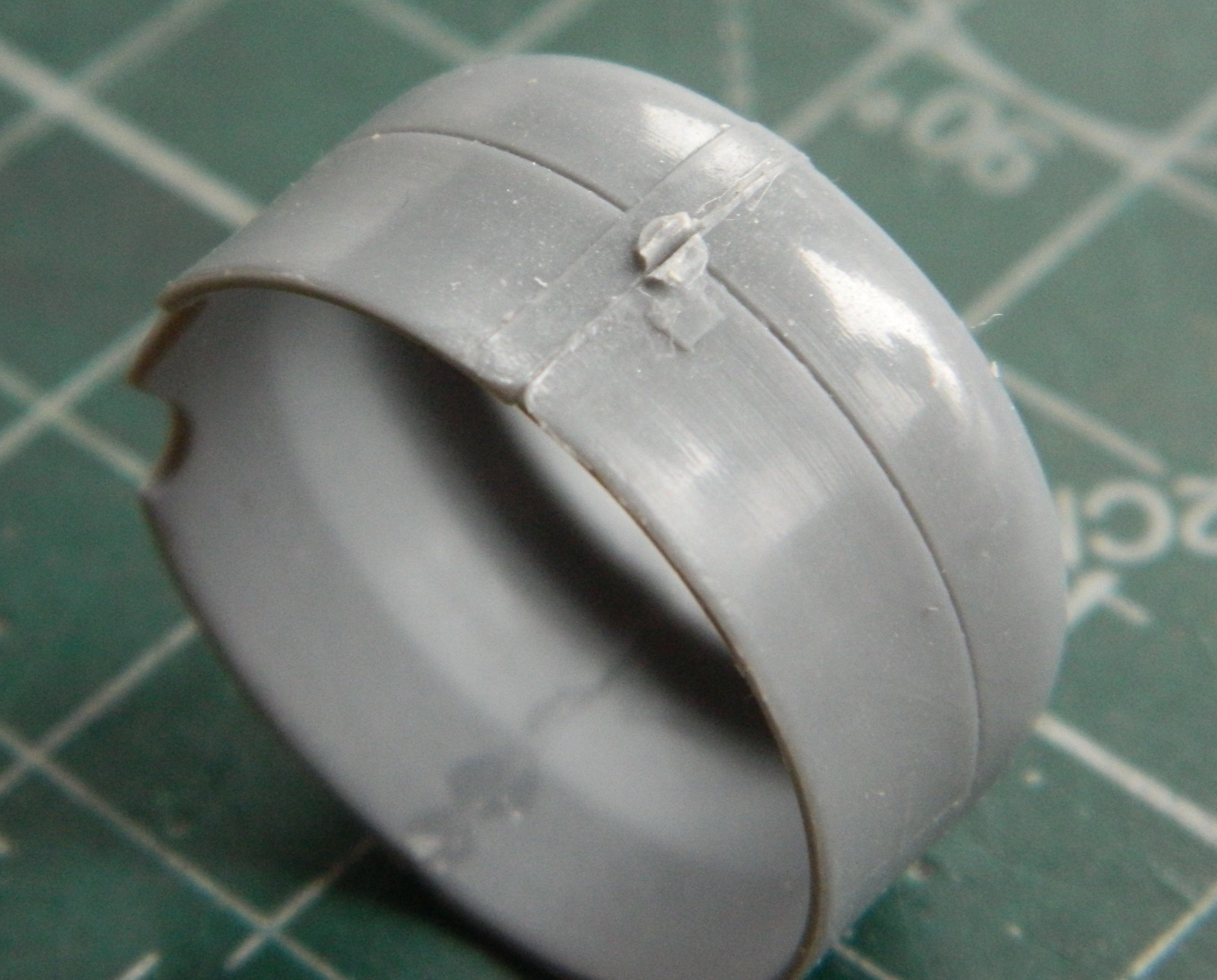
Don’t forget to check the diameter frequently:

Once my Eyecrometer MkI was satisfied, I polished the work:
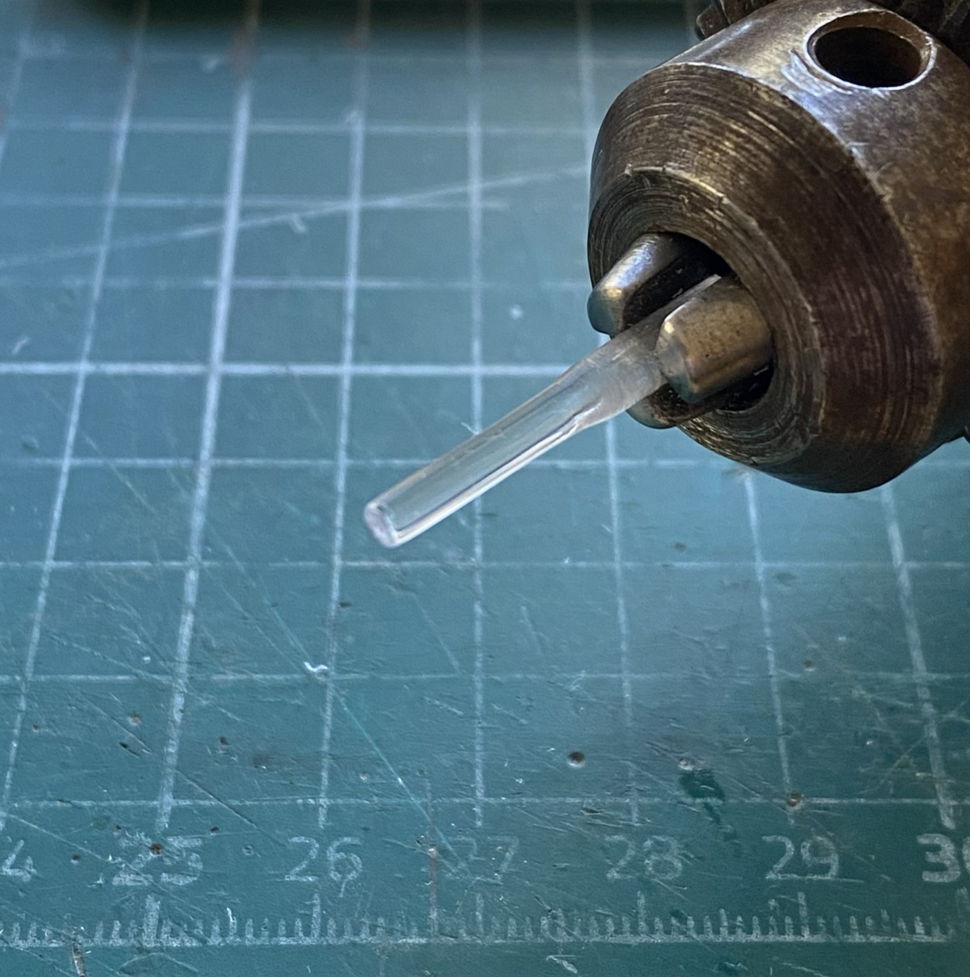
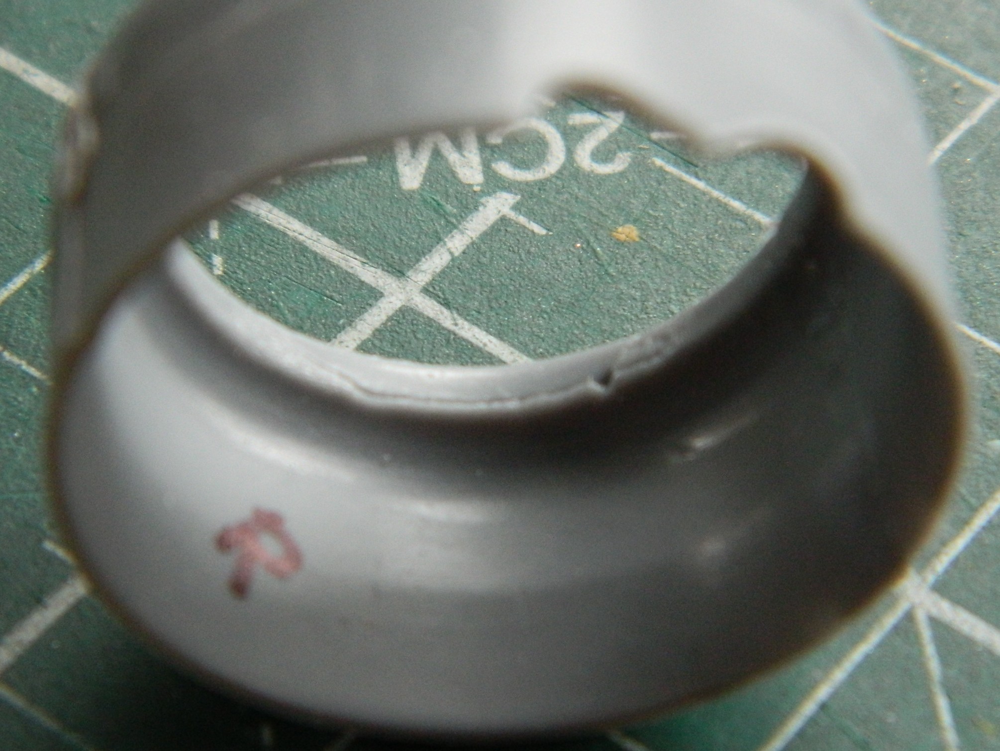
I used the #11 and a VERY narrow file to add surface details:
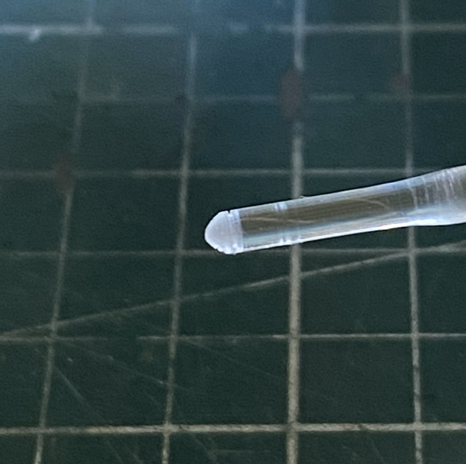
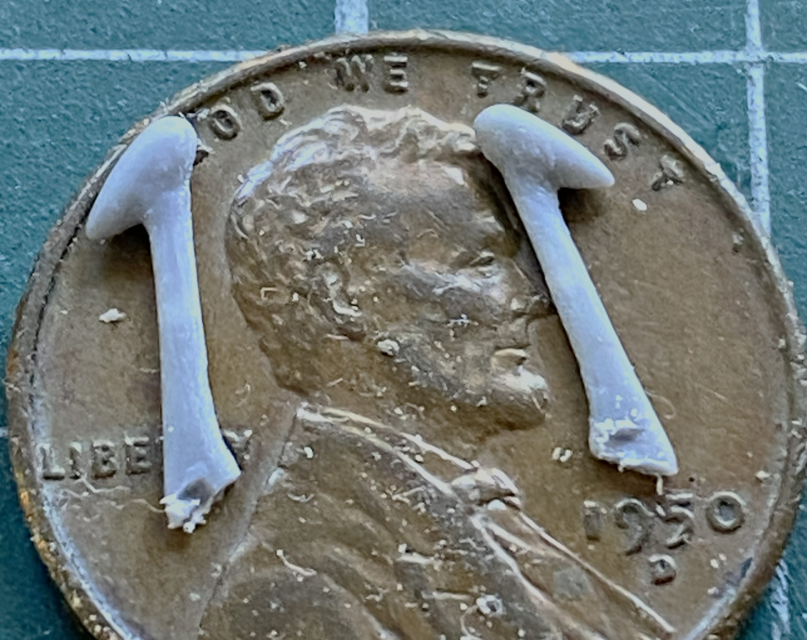
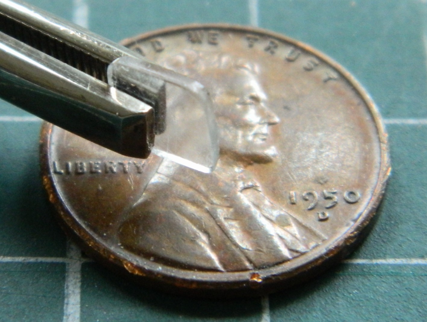
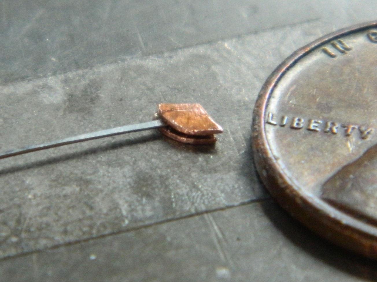
Once that was done, I kept the work spinning and used a razor saw to cut off what I wanted. And yes…this is a small part:
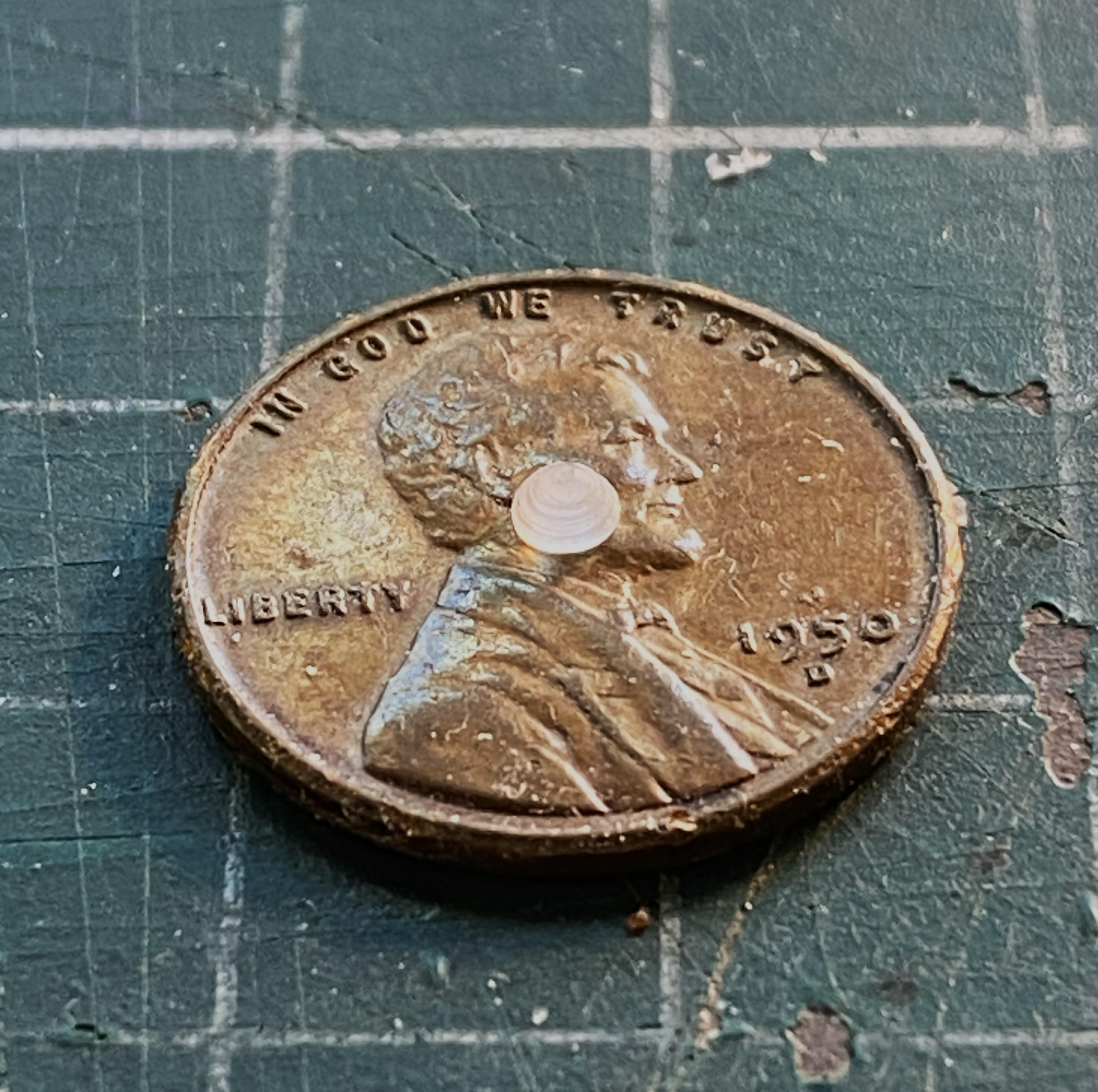
Its size isn’t a problem. The problem is that I have to make three more of them! At my age, I have an understanding of my work process. One of those understandings is that when I have to make multiple parts, I generally nail the first one spot on. The remainders? Well…if I’d followed my process and tried to make three more just like that one, I’d probably would have needed four or five attempts to get the next one. Repeat that process twice more and I’d have a pile of small parts and the task of selecting the best four from that pile. I just didn’t feel like doing it that way.
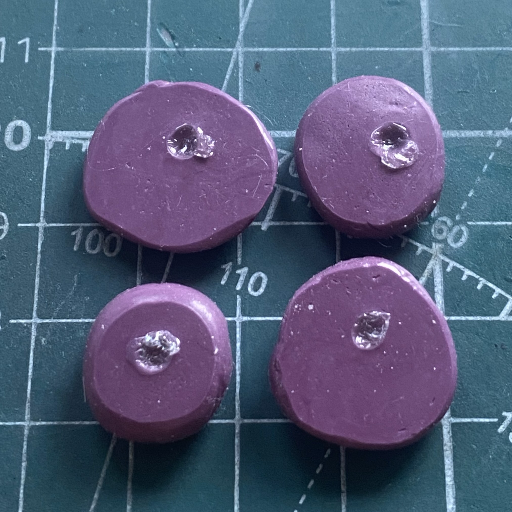
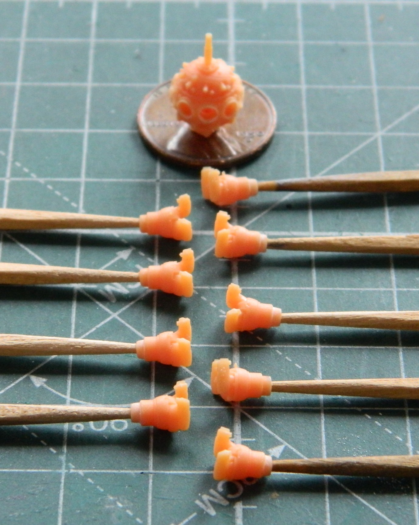
Instead, I used the silicone molding putty and made four molds from the one part already produced:
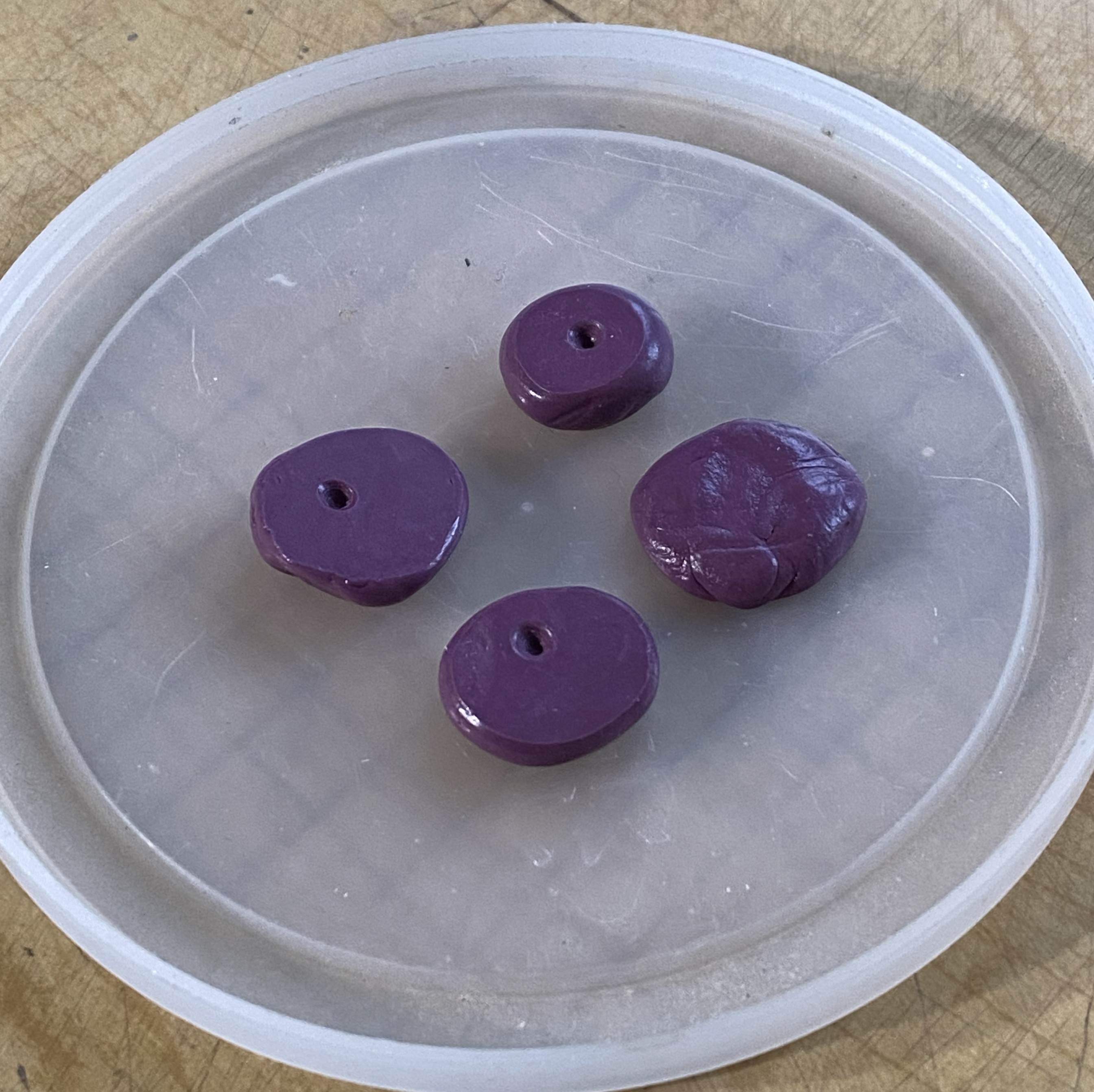
Why four molds? Because it was my intention to make the sensor covers from plue comprised of clear sprue. It takes time for the plue to set up that I didn’t care to wait around for. First, make the plue:
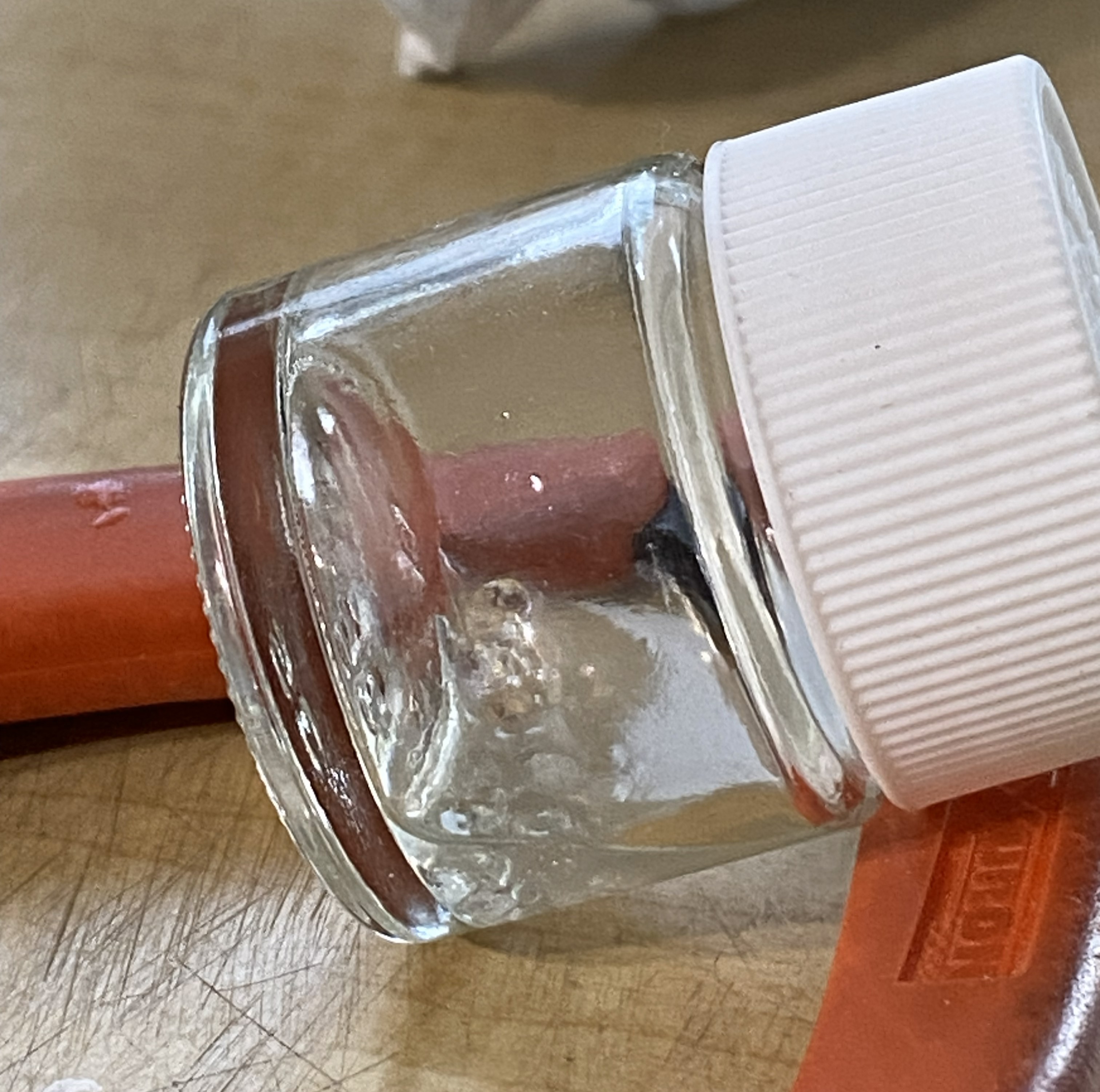
Not easily seen in the above photo are the bubbles that are forming. I use Tamiya Extra Thin to make plue. It’s a solvent that dissolves plastic. The process of hardening is one, essentially, of evaporation. The solvent evaporates and leaves behind shaped plastic. It also leaves behind bubbles. As the solvent out-gasses, it creates bubbles. The bubbles that make it to the surface go away. But as the solvent out-gasses, the plastic returns to its original solid condition and that traps all the bubbles that didn’t get to the surface in the plastic:

Opaque plastic doesn’t show that (them?). I tried several ways of getting plue into the molds in thin layers and without disturbing the plue (and thereby creating more bubbles). That worked, in a manner of speaking, it just didn’t work very well. The parts were VERY THIN. How do these get attached to the tips of the wings? Solvent-based glue. Solvent dissolves plastic. The parts are vert thin plastic and they (or the test piece) do what plastic does when solvent touches it. It dissolved:

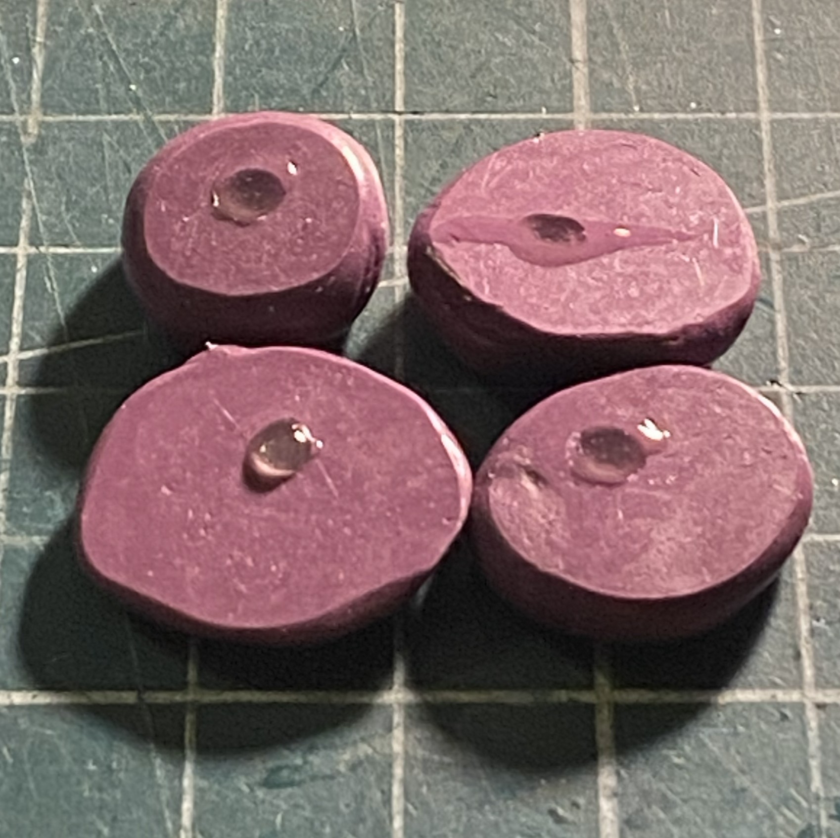
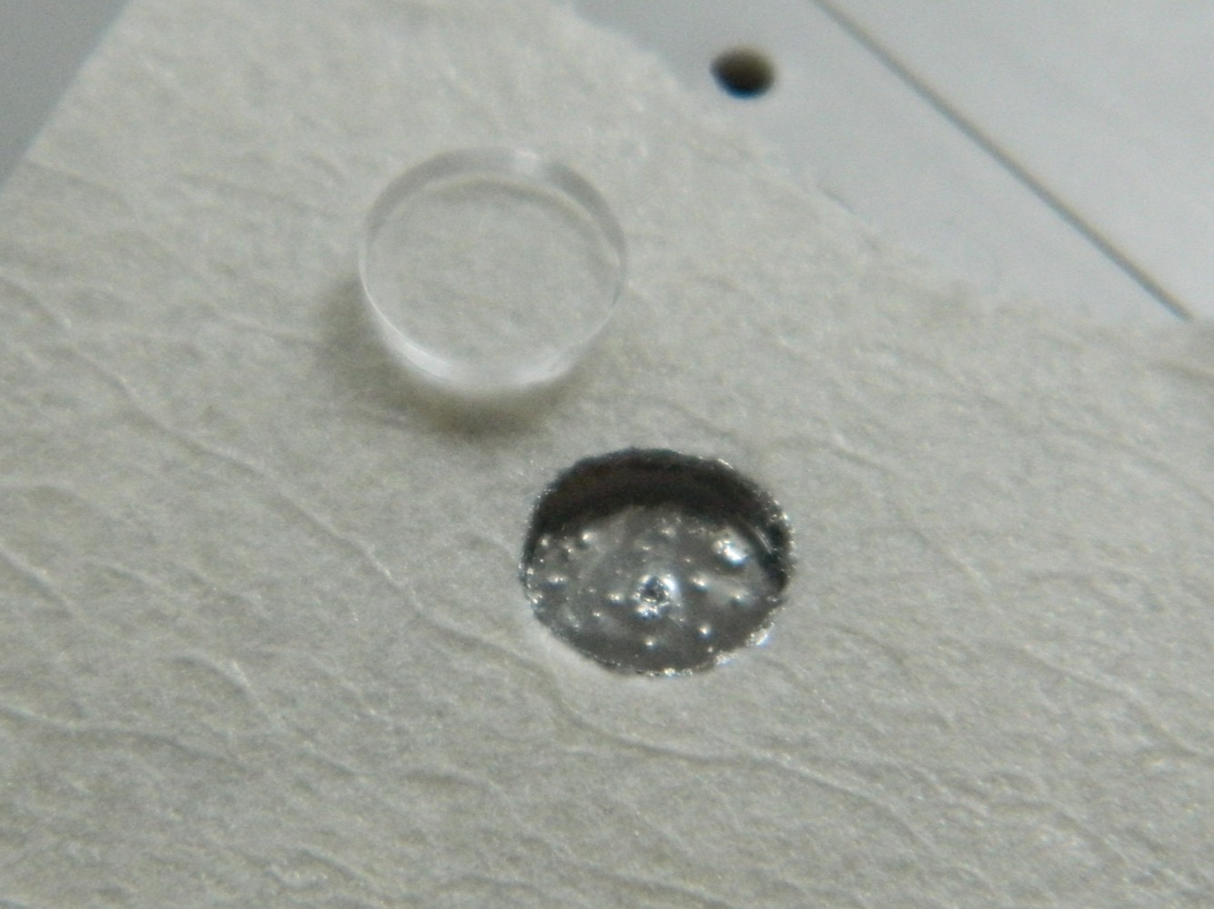
Then I had the incredibly bright (there’s my modesty in play again) idea of using the UV-setting resin to fill the molds. It’s clear, doesn’t react to solvents, and though it can bubble in the mold, that’s more of an application problem. When bubbles were introduced into the mold, I used a needle to move the bubbles away from the part successfully…then forgot to take photos. ::facepalm::
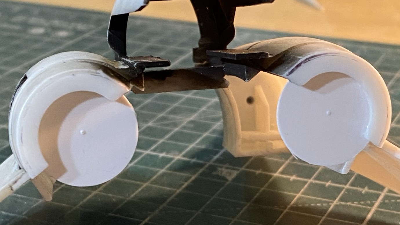
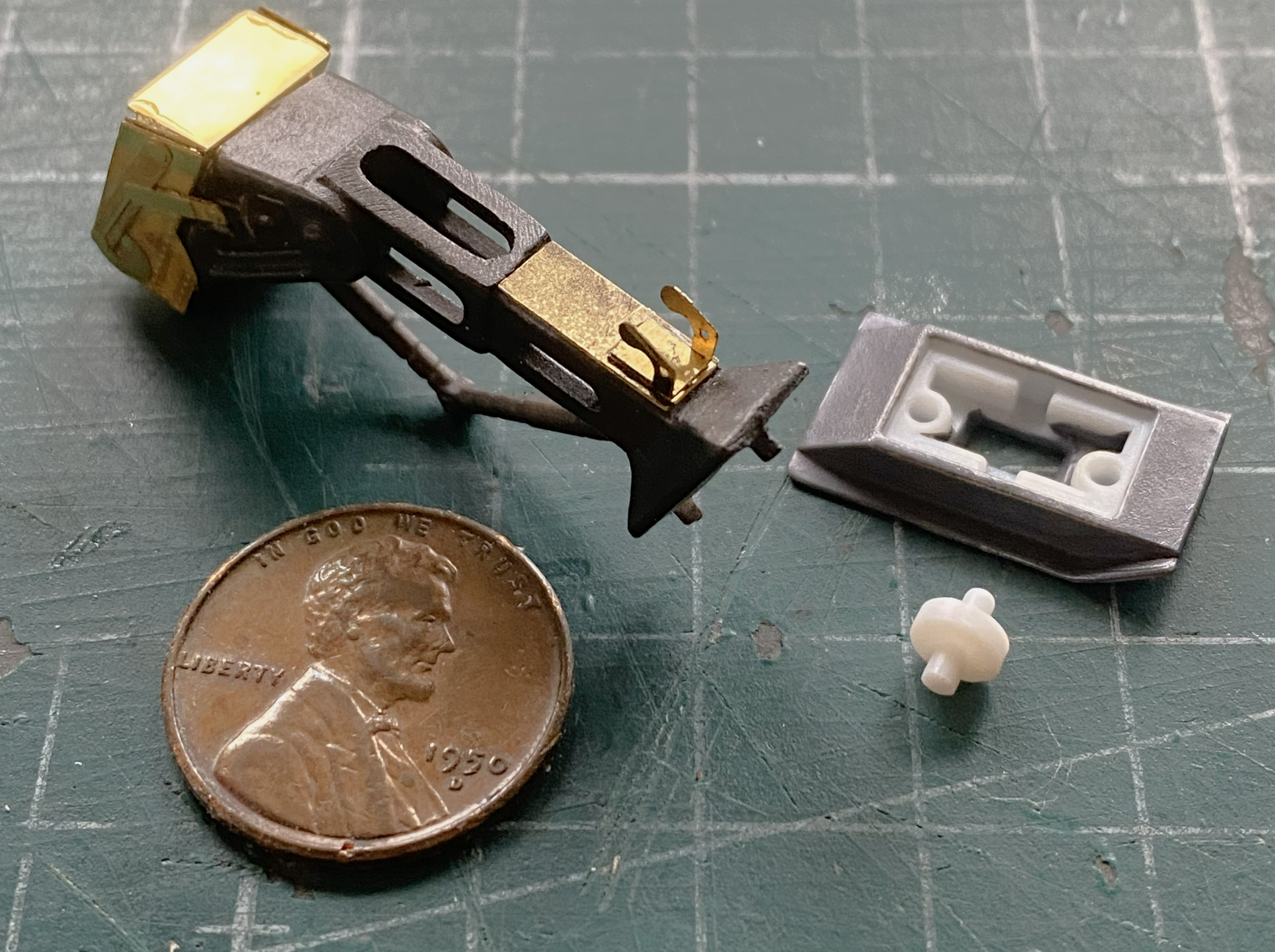
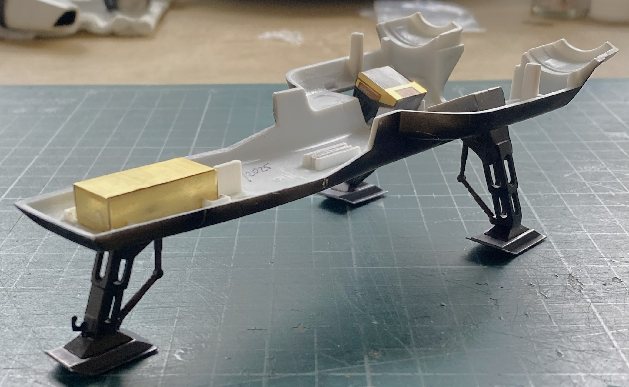
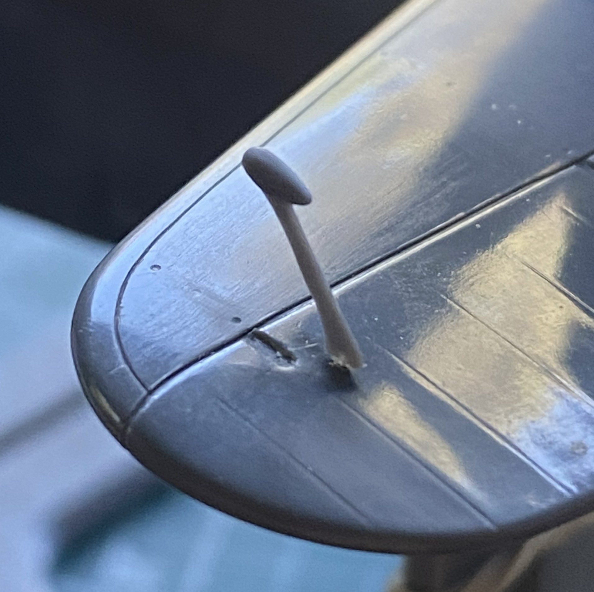
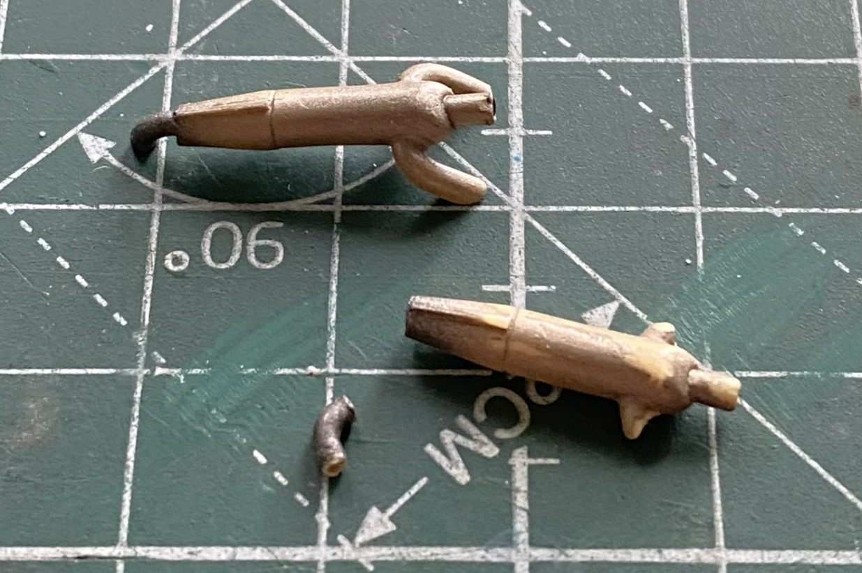
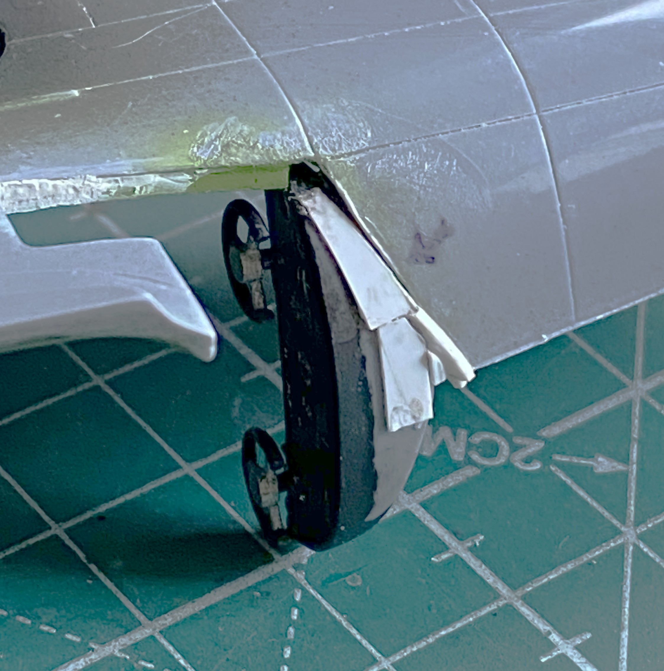
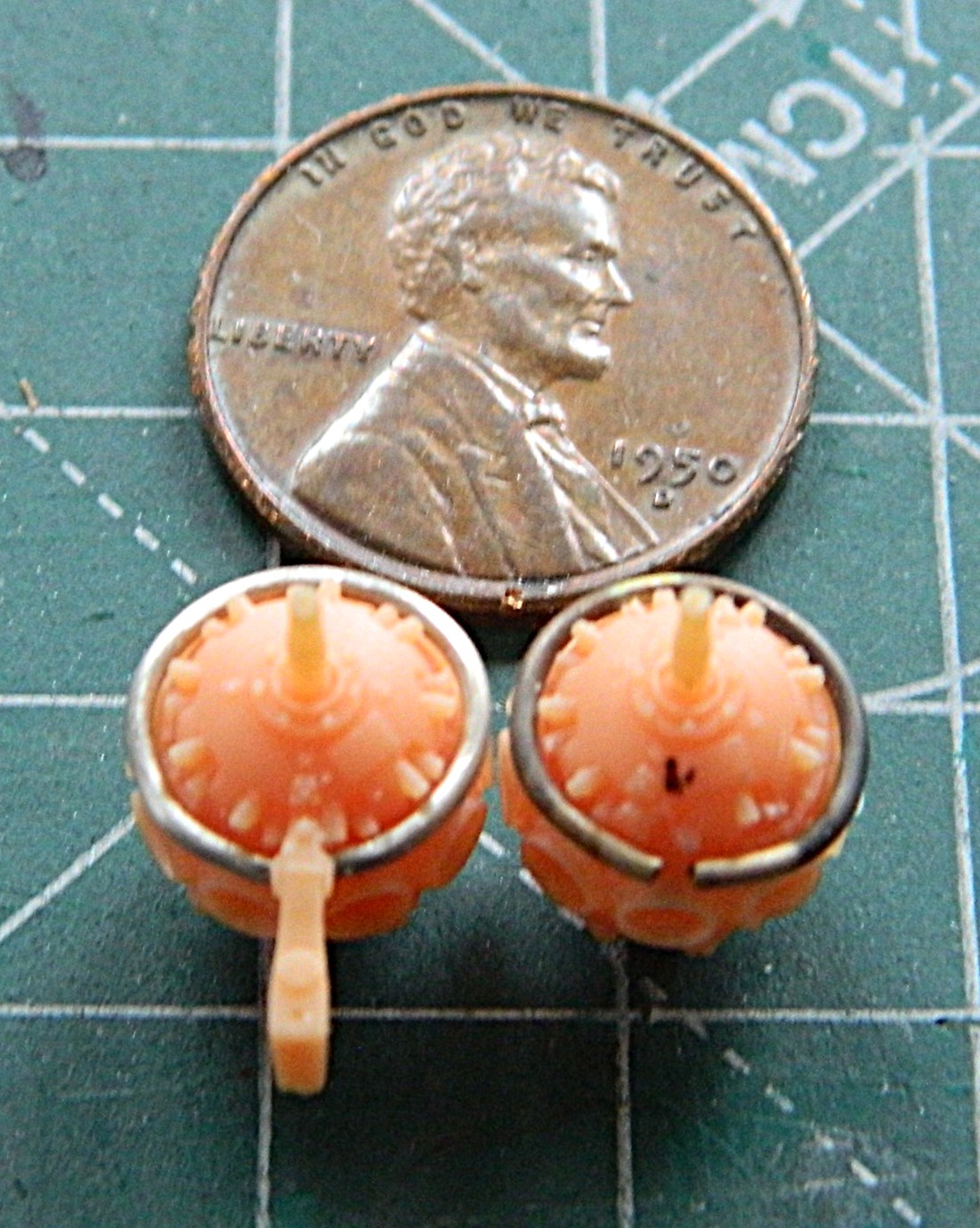
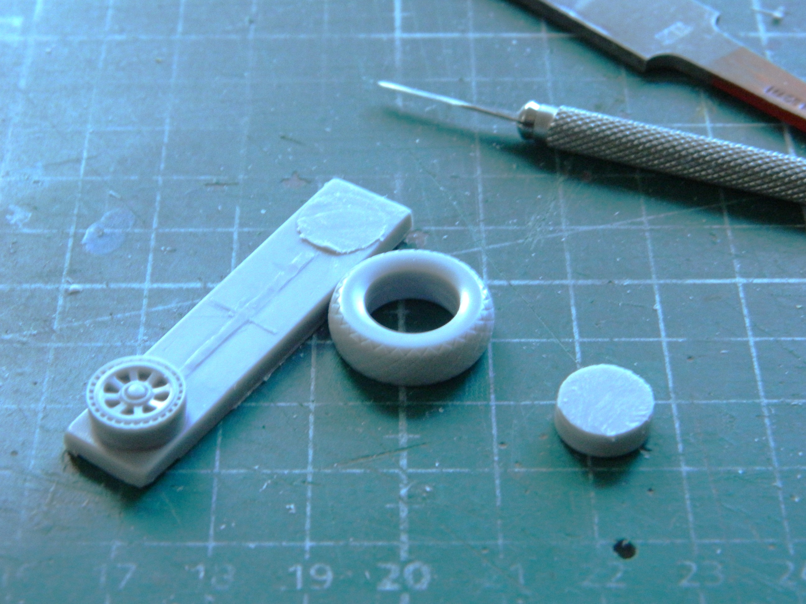
I discovered that I’d neglected to add some PE to the nose landing gear. Fixed that. I also broke out the Humbrol paint (#27003) and painted the feet (because they’re not wheels) buffable steel. (The white plastic part is a wheel that sits in the feet and has yet to be painted, obviously.):
I painted that wheel and PE and assembled the nose strut:
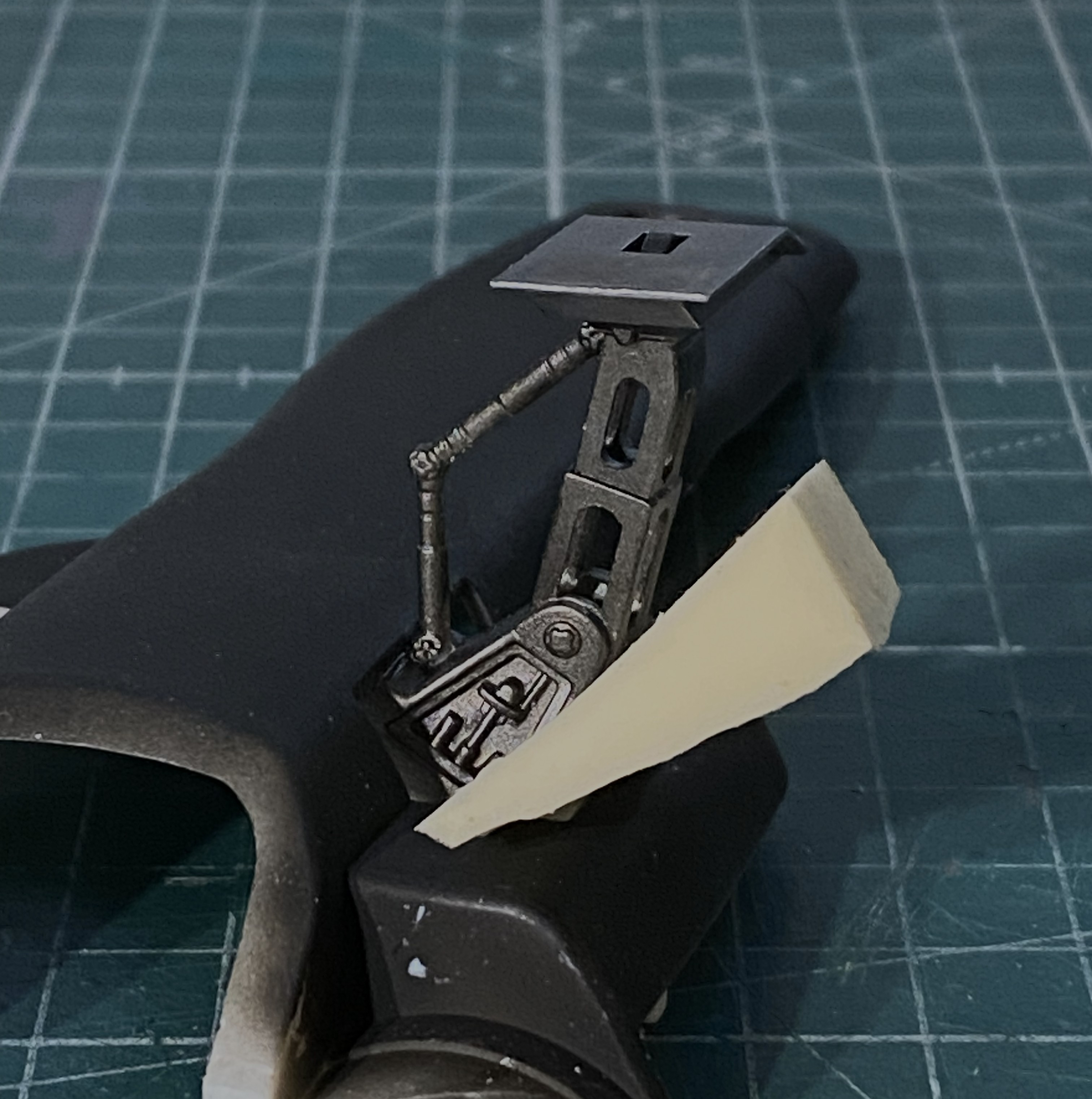
After assembling the main landing gear, I added them to the belly pan. The foam wedge is holding the assembly aligned while the glue sets up:
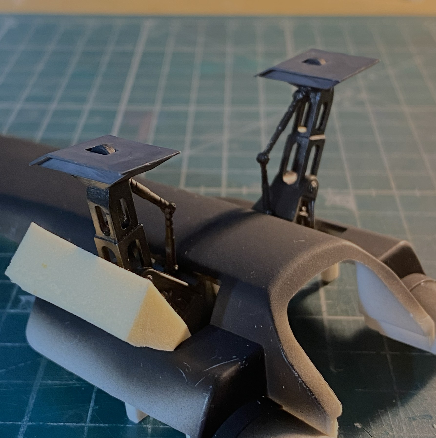
These PE frets are almost entirely landing gear bays. Brass origami shall ensue shortly:

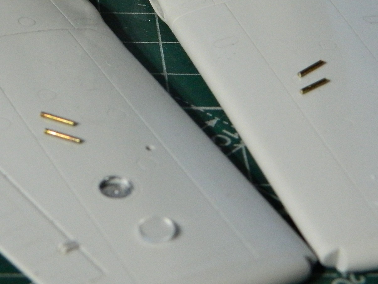
Some of the PE parts from the other PE fret are intended to dress up the engines a bit. The problem with PE is that it’s flat. I used a piece of a D guitar string and three different sized solder (0.020″ [.508mm] is shown but I also used 0.015″ [.381mm] and 0.010″ [.254mm]):
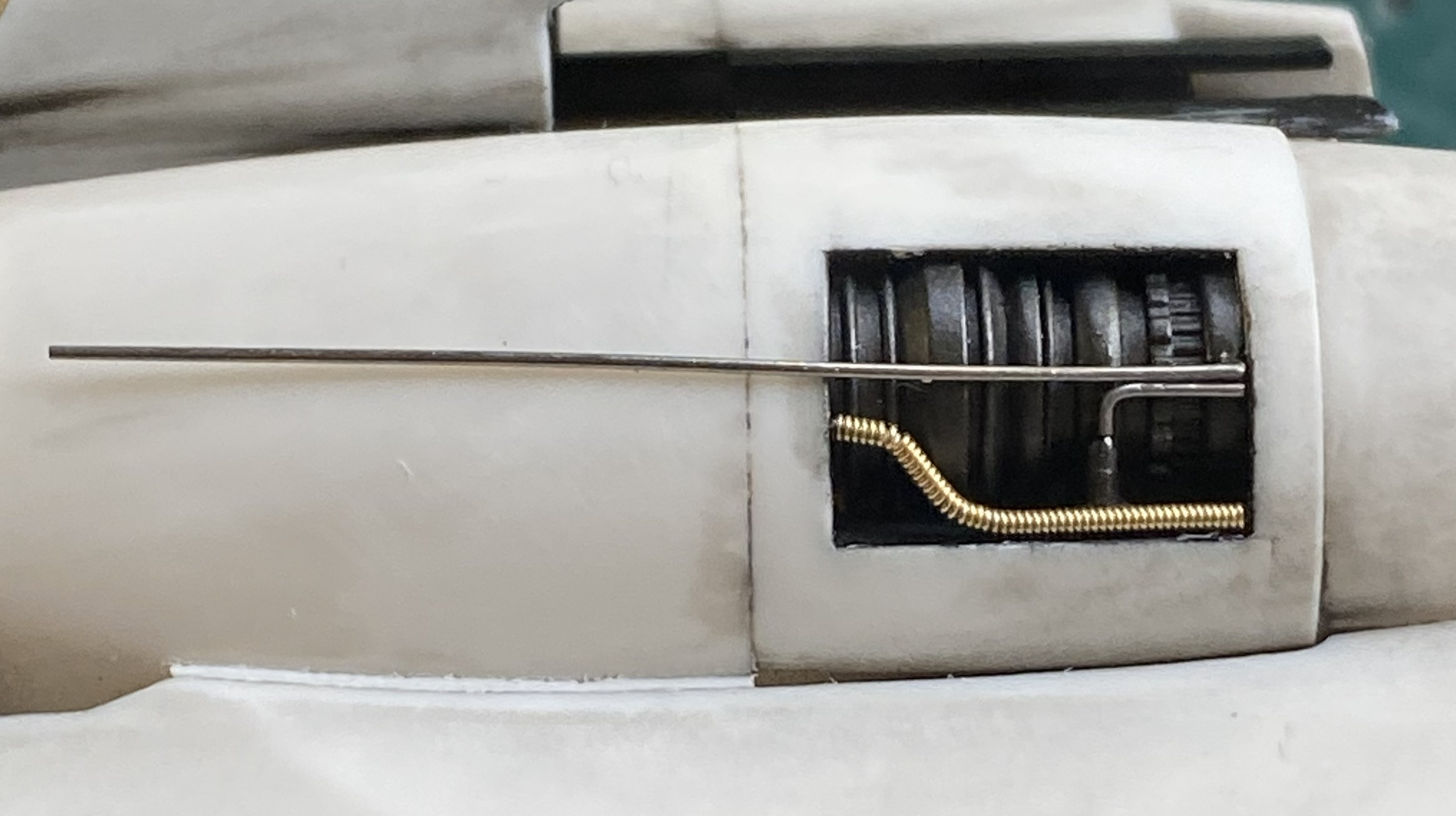
The port engine done:
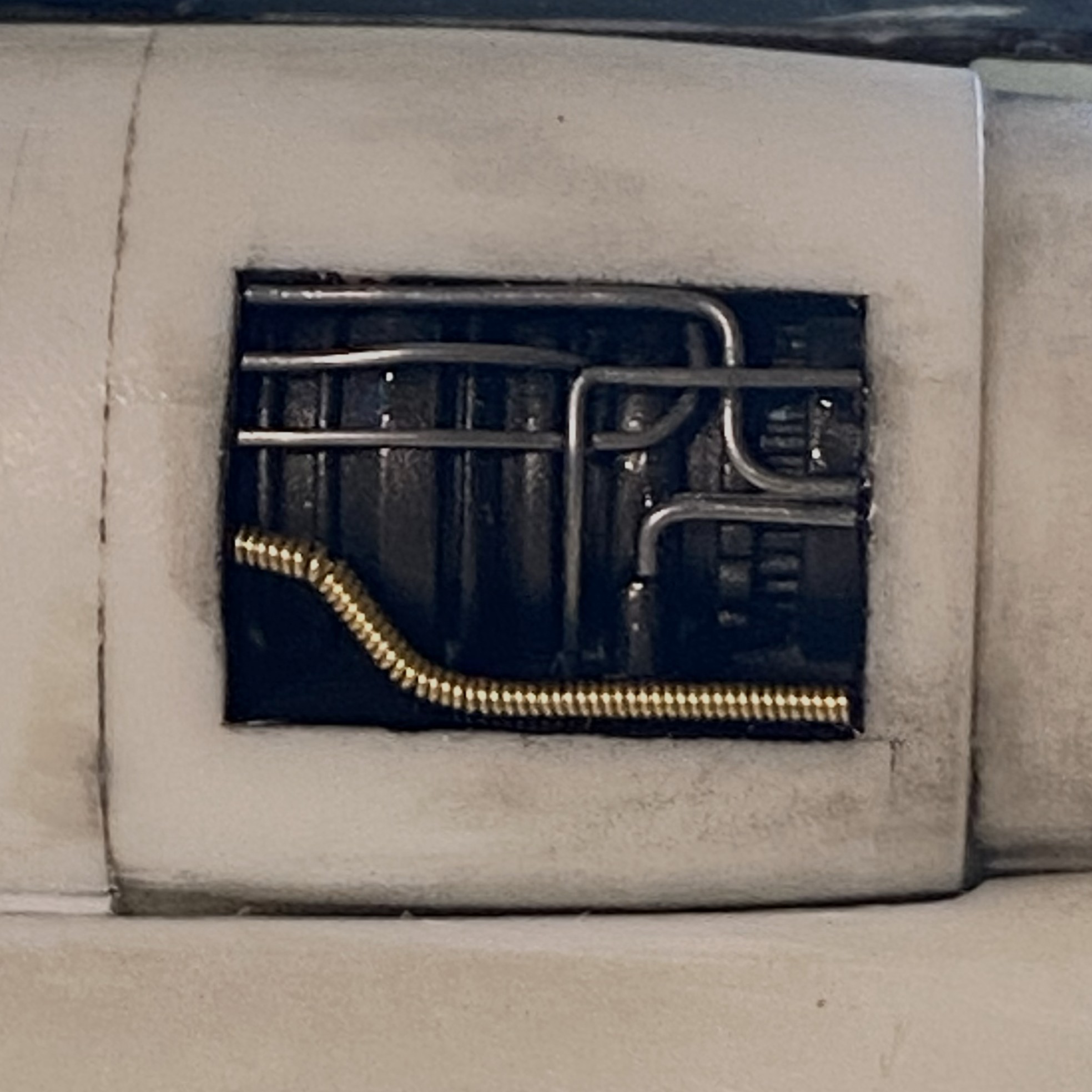
And the starboard engine is done:
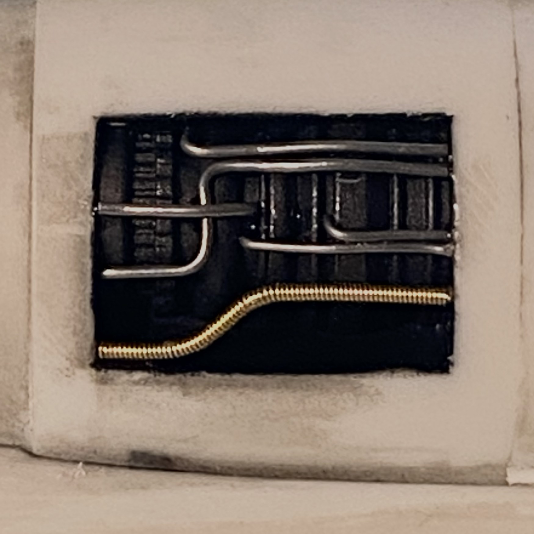
Yeah. I like that, and the pre-shading does exactly what I’d hoped it would do. When it comes time to paint this model, the engine areas will stay as they are now (with the typical paint touch ups).
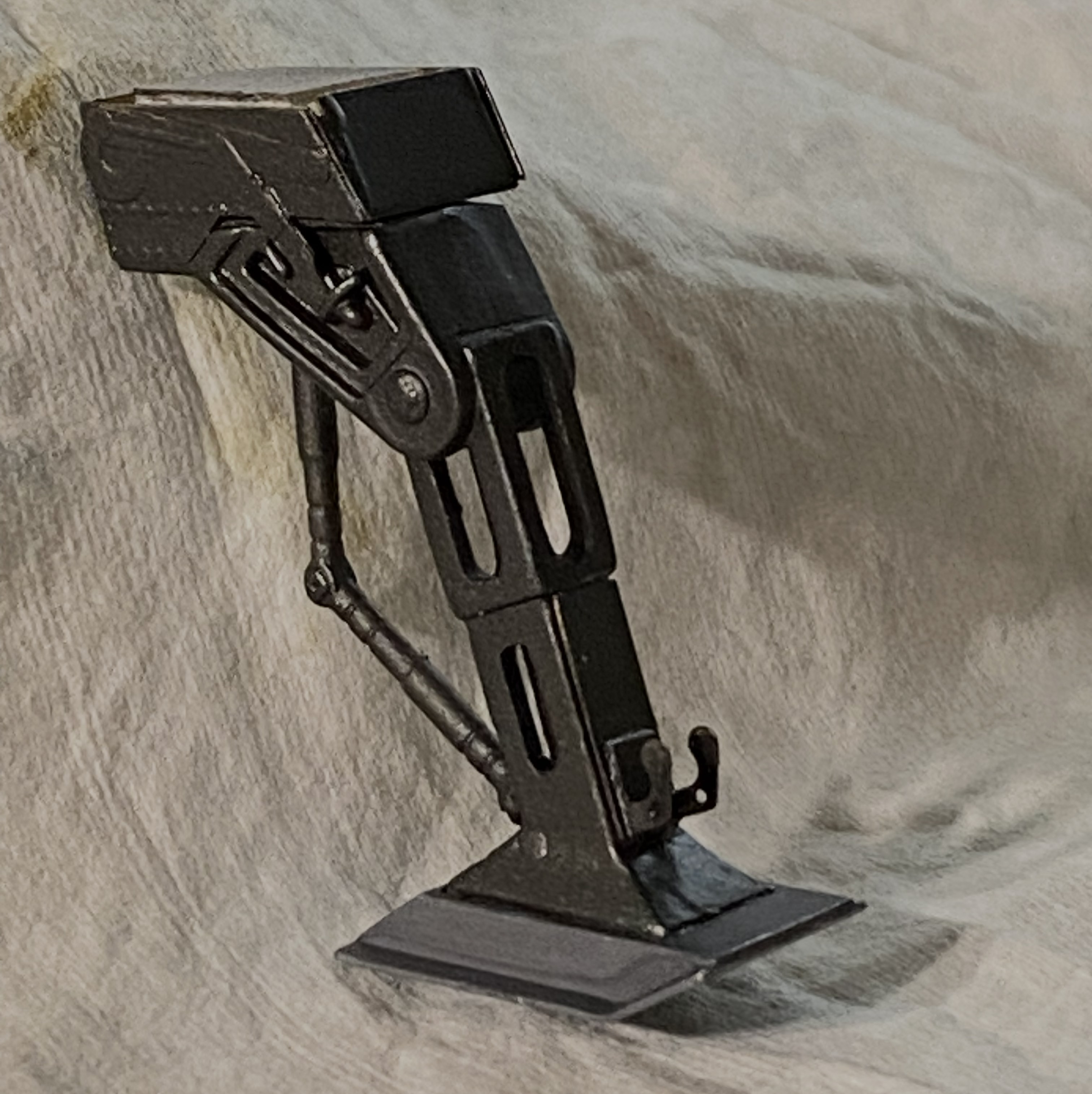
As it gets closer to adding the belly pan, it was time to add the nose gear. It fit like crap. I’m not especially thrilled with how it’s sitting (after much diddling, fiddling, and offering Deities all sorts of things that They’re aware I’ll never do or stop doing, depending on how I’m wheedling them) but short of taking the nose bay out…again…this is how it’s going to stay:
There! All caught up. Next month’s preview? Brass origami.
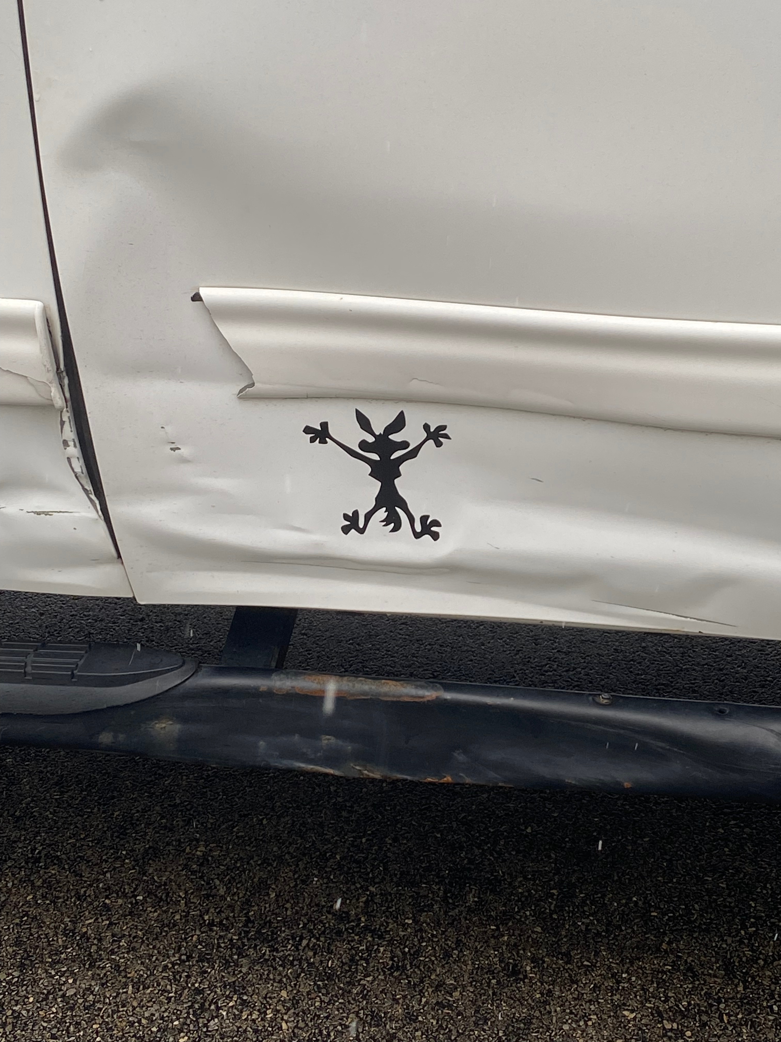
This is a Public Service Announcement.
Be careful where you part your truck! There are miniature coyotes in the neighborhood and they’re obviously in a rush:
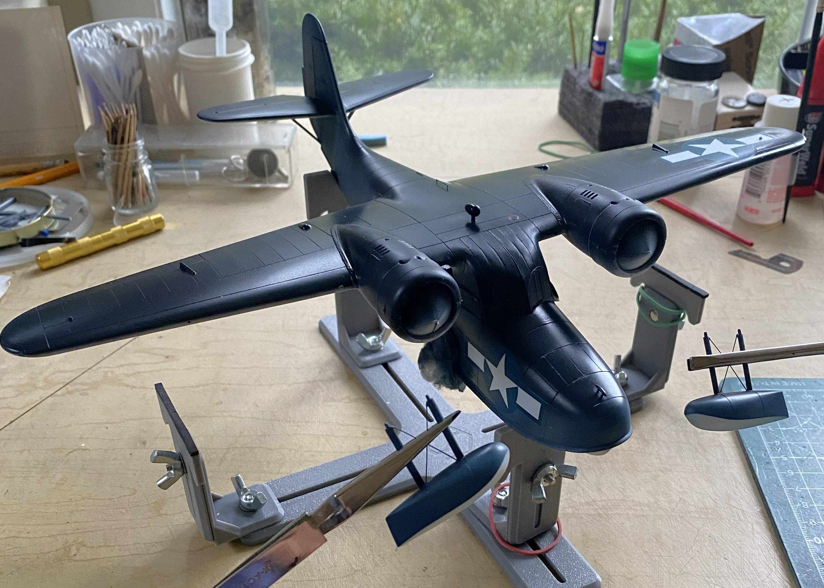
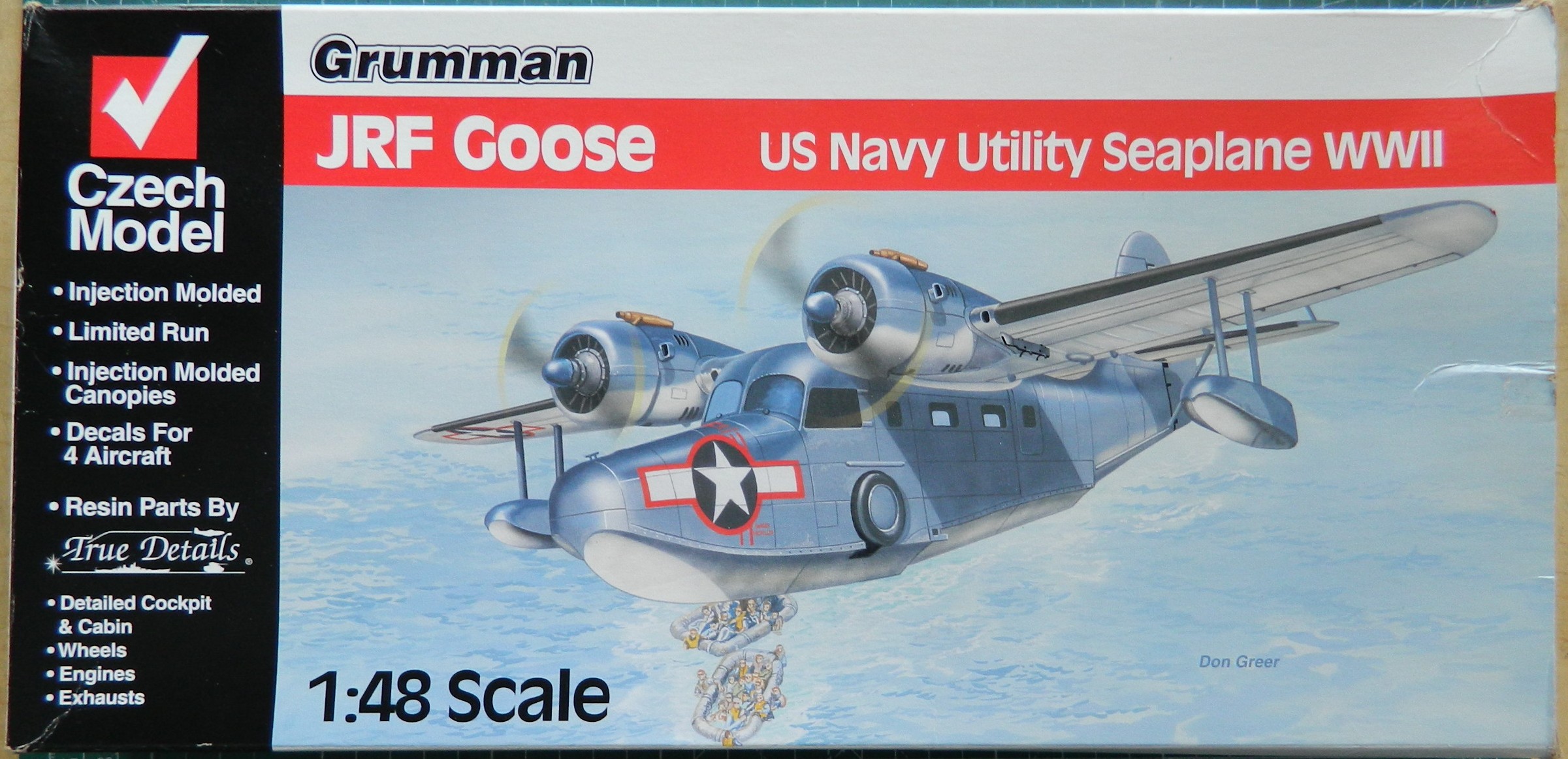
Grumman JRF Goose (Czech Model) 1/48 Scale Build #6 – And This is When Tedium Really Sets In
I generally try to post new material here around the end of the month. Not having posted since August, that seems to have broken down. Seems to. It’s this build of this particular kit. I don’t want to work on it anymore. I recognize that this is an emotional response, not intellectual, so I have pressed on, albeit intermittently. But…here we are!
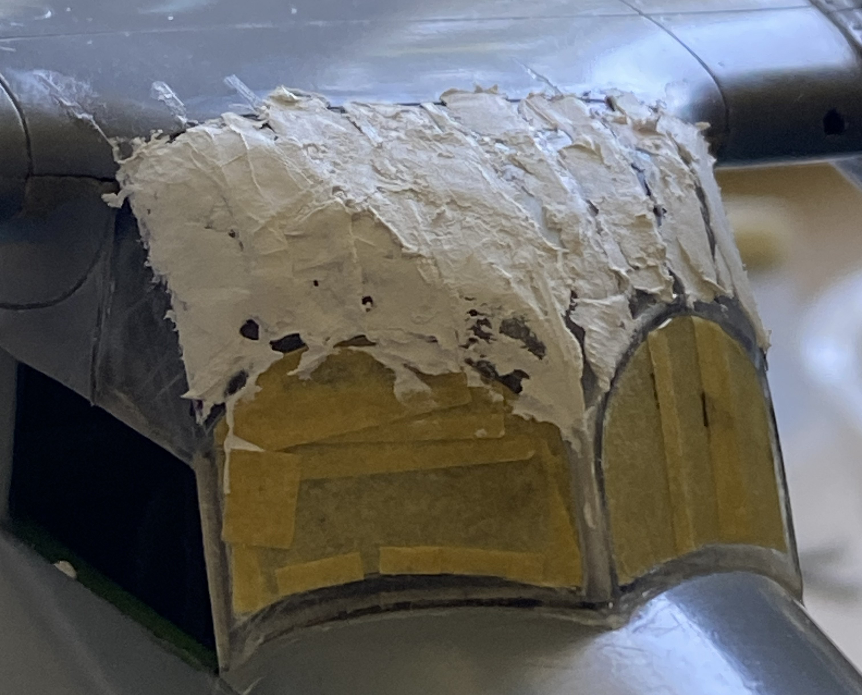
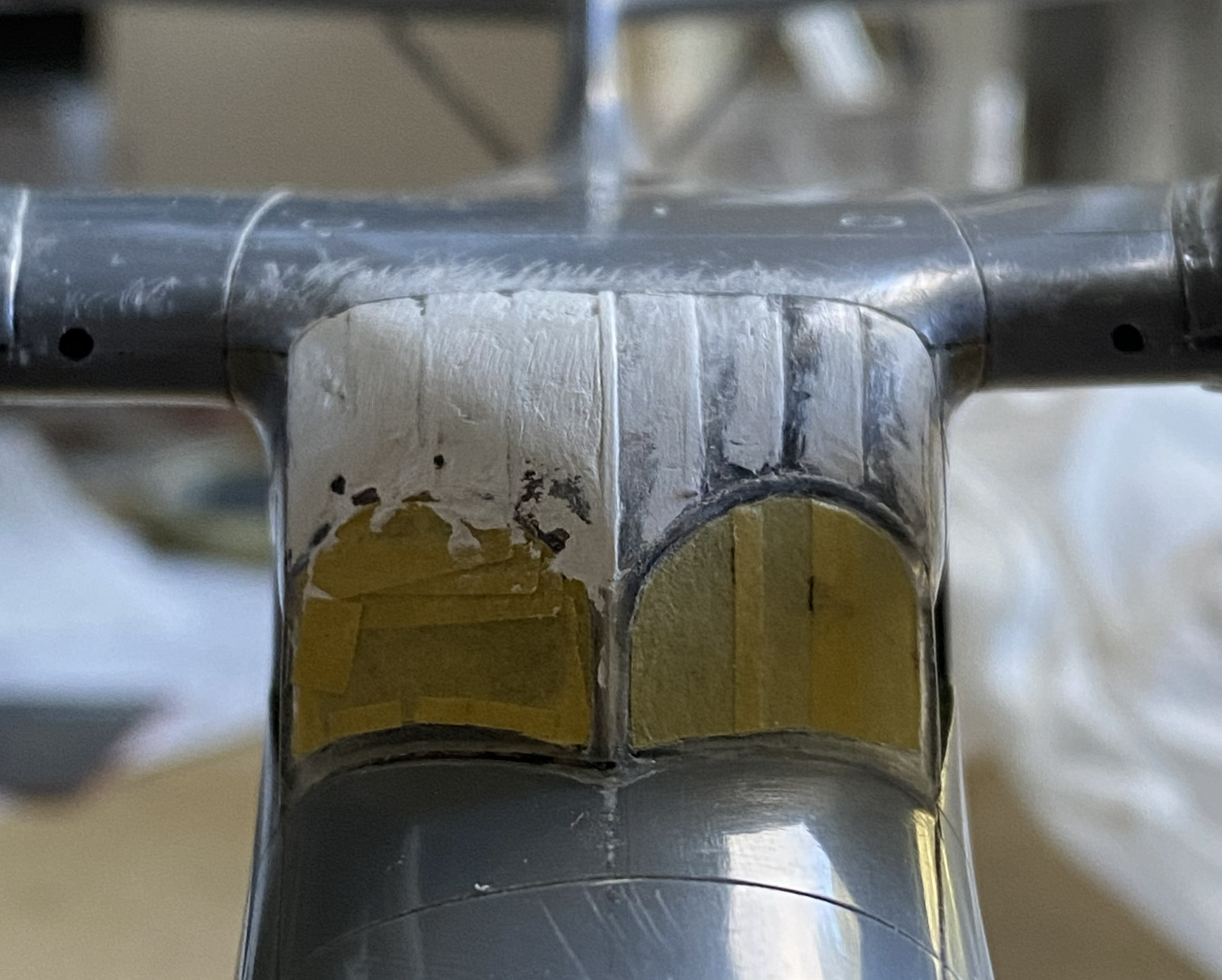
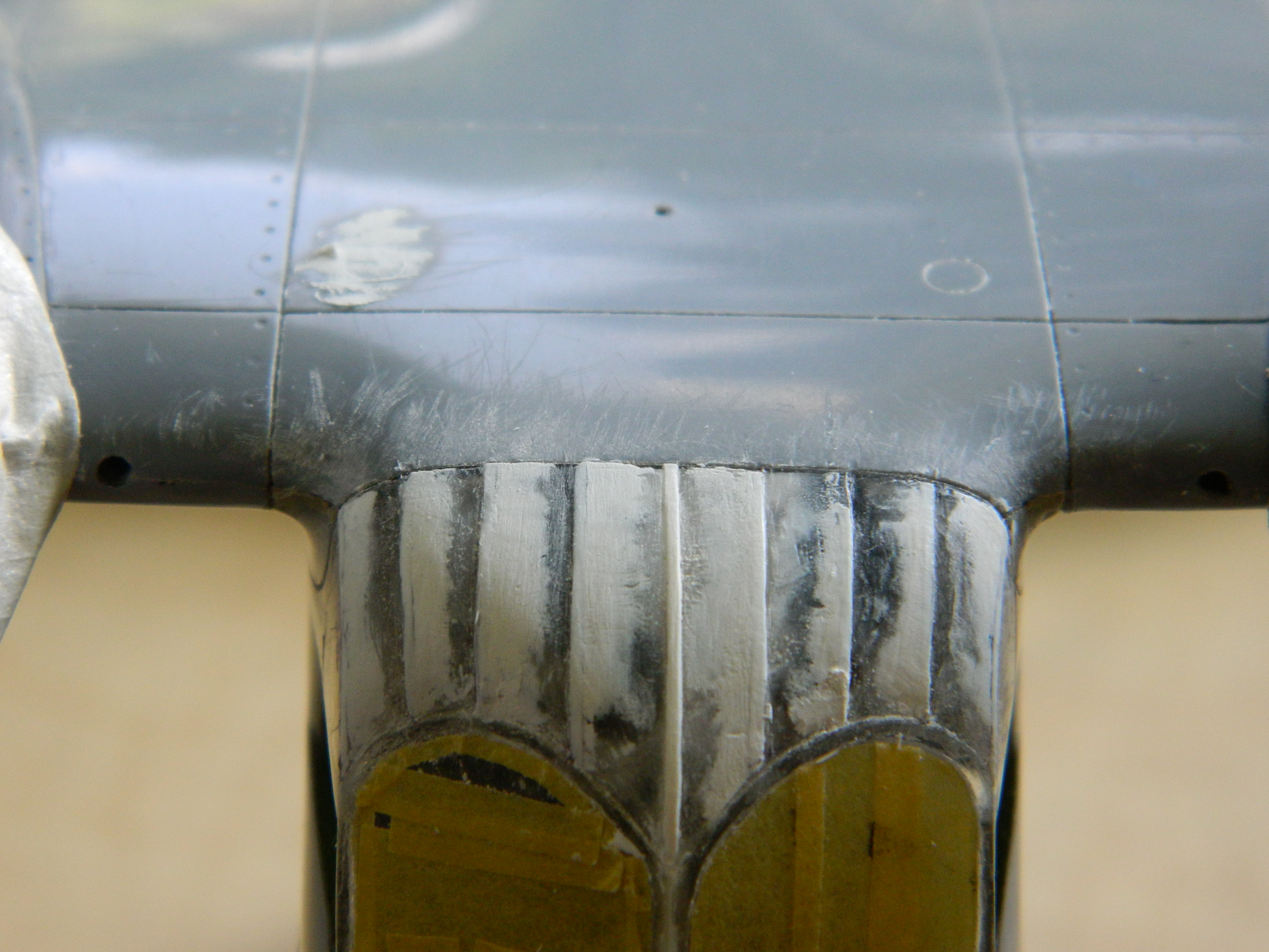
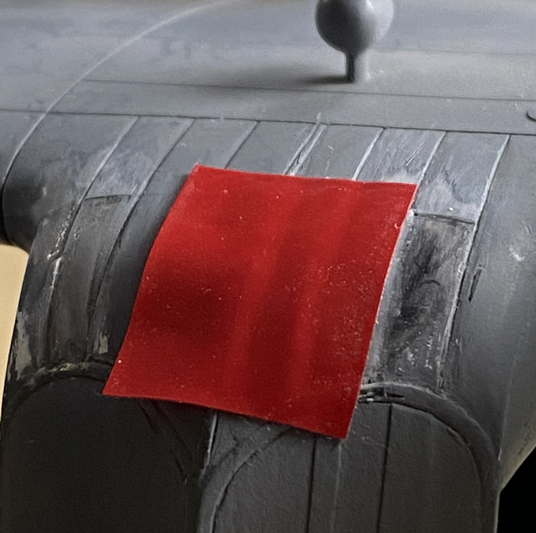
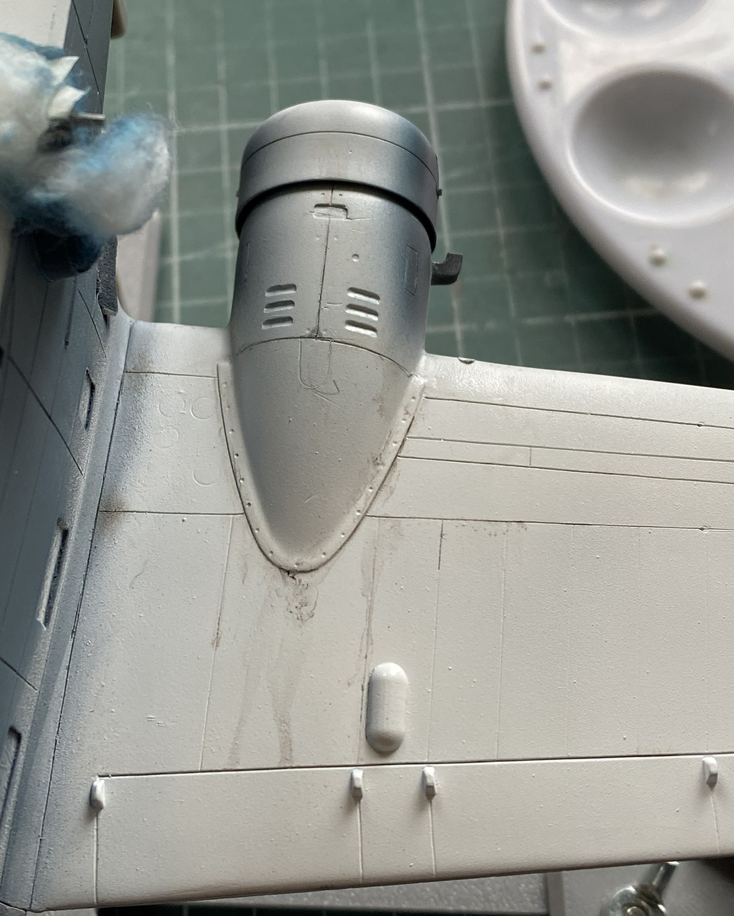
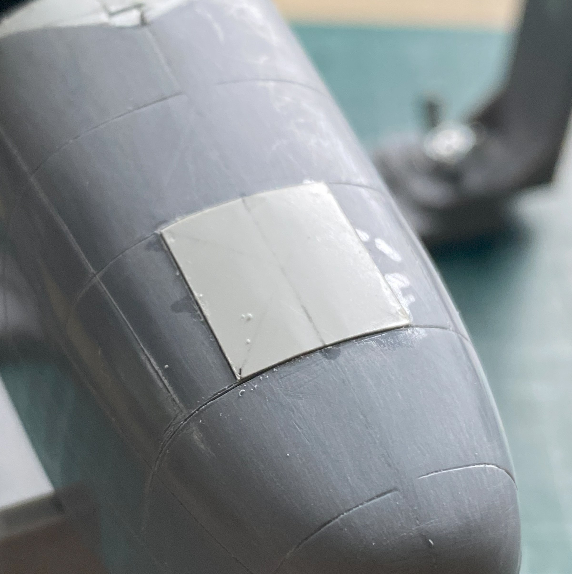
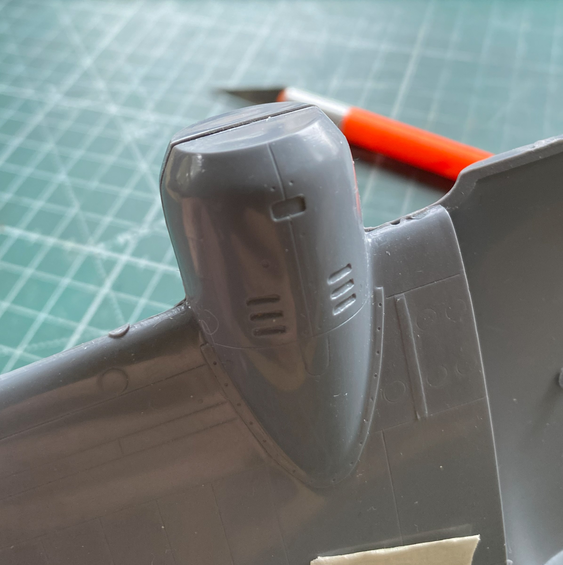
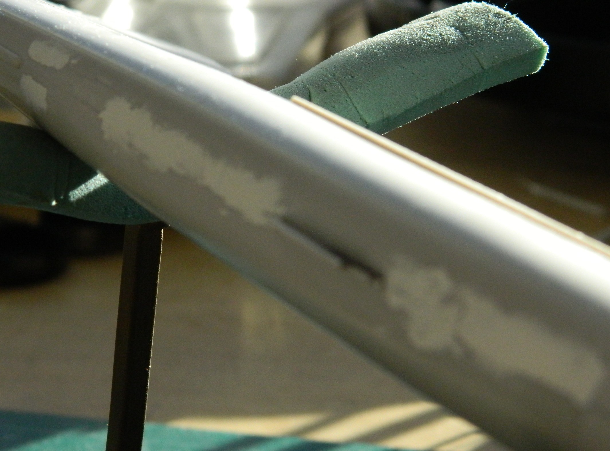
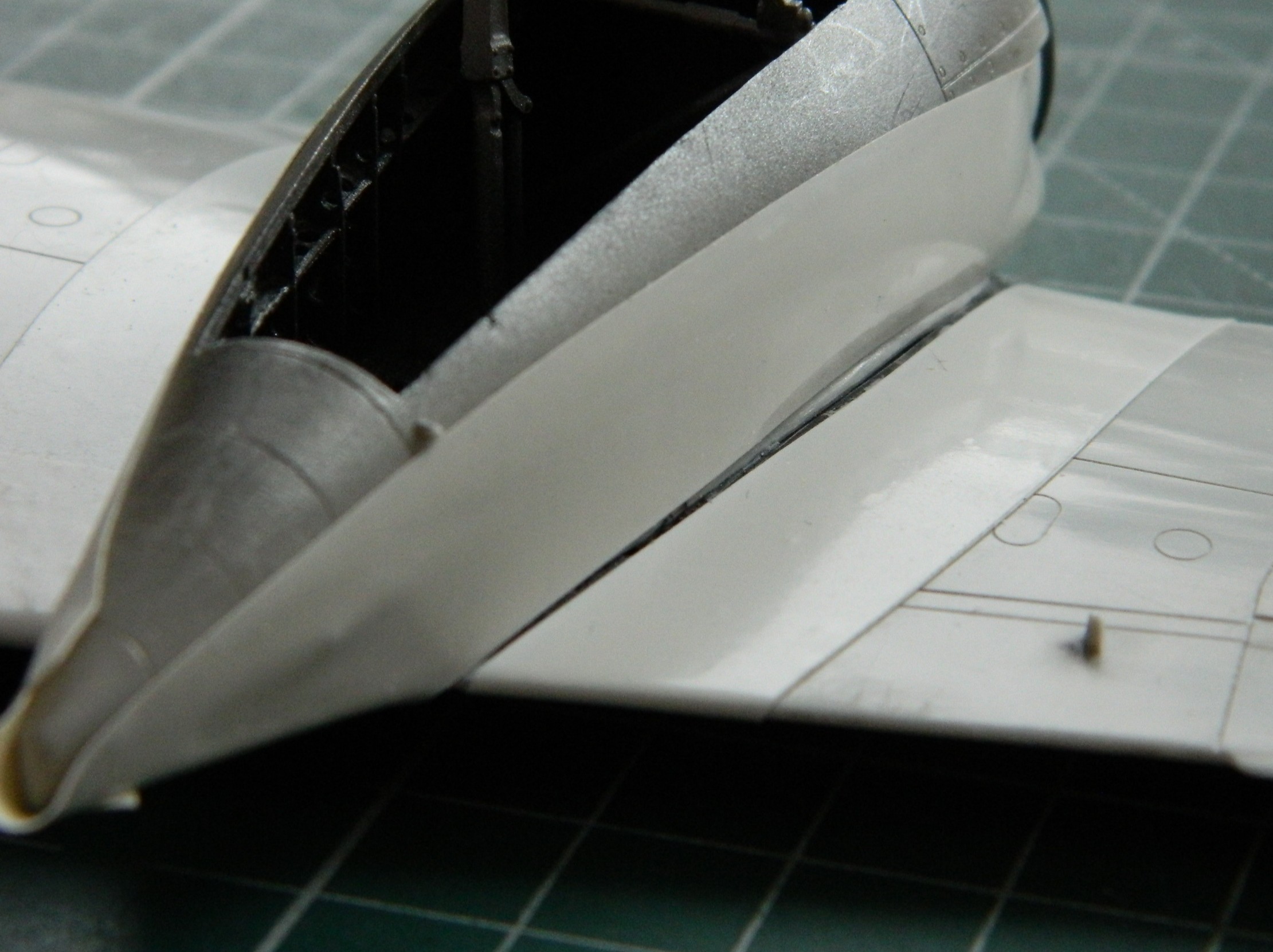
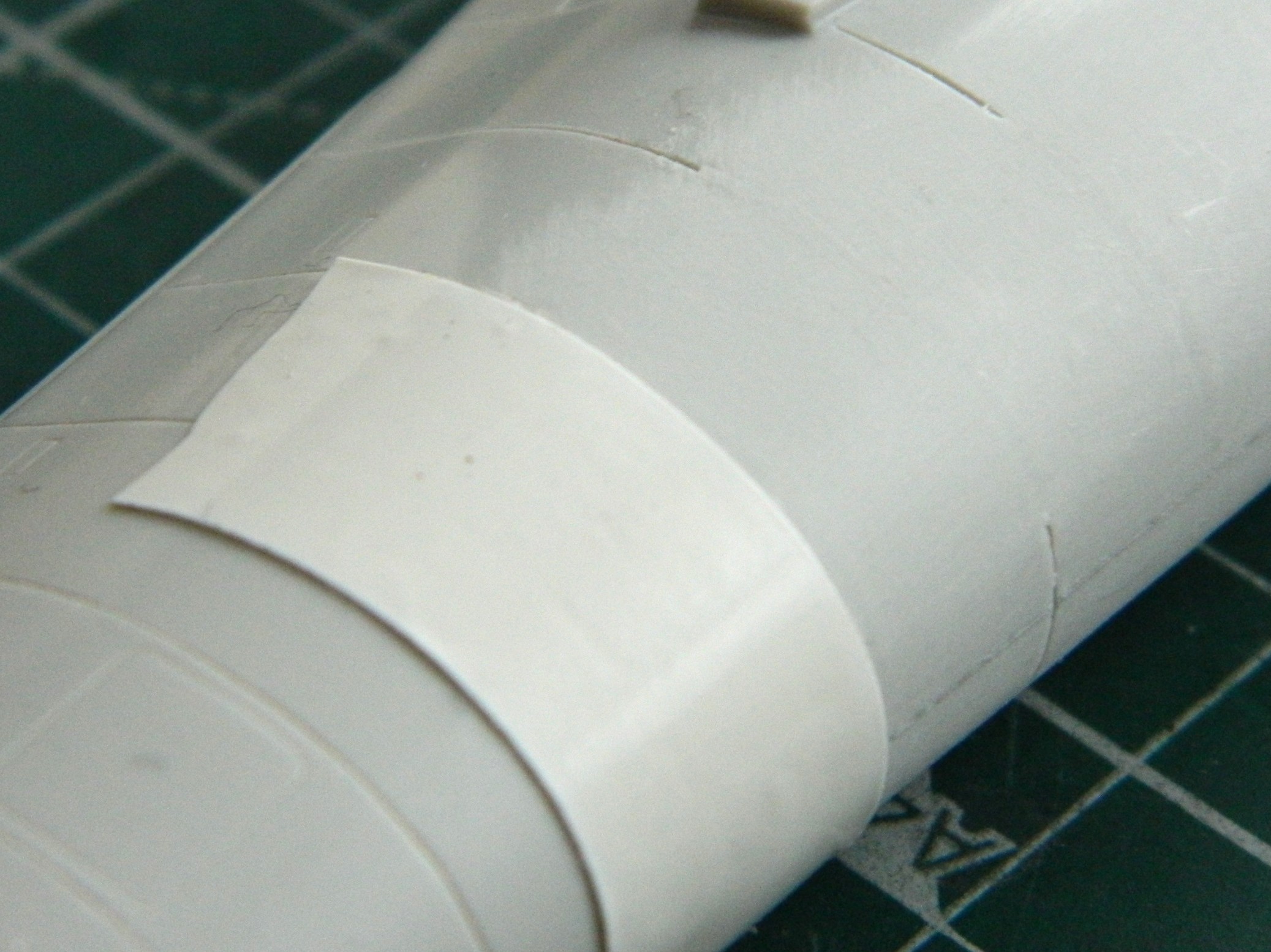
The fuselage over the flight deck (or cockpit, you choose) has a prominent feature. The curved shape is created on the actual aircraft by using flat panels. In some photos the panels appear to be butt-joined (the edge of each panel abutting the next), in some photos they seem to be scaled (where one side of the panel overlaps the next, sitting on top of it), and none of them are definitive. I made my guess (several guesses, really) and decided I’d go with the scaled (overlapped) presentation. I laid down strips of .005″ (.127mm) and then faired them in with 3M Acrylic Putty:
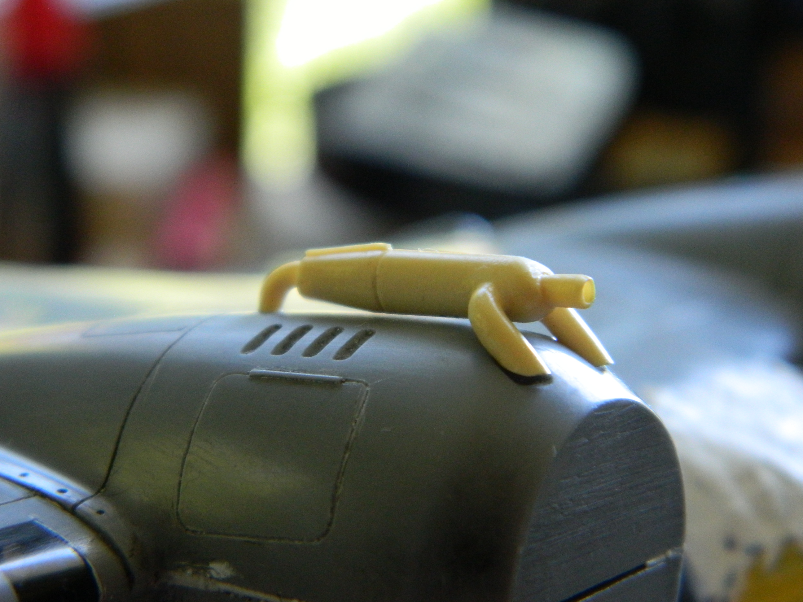
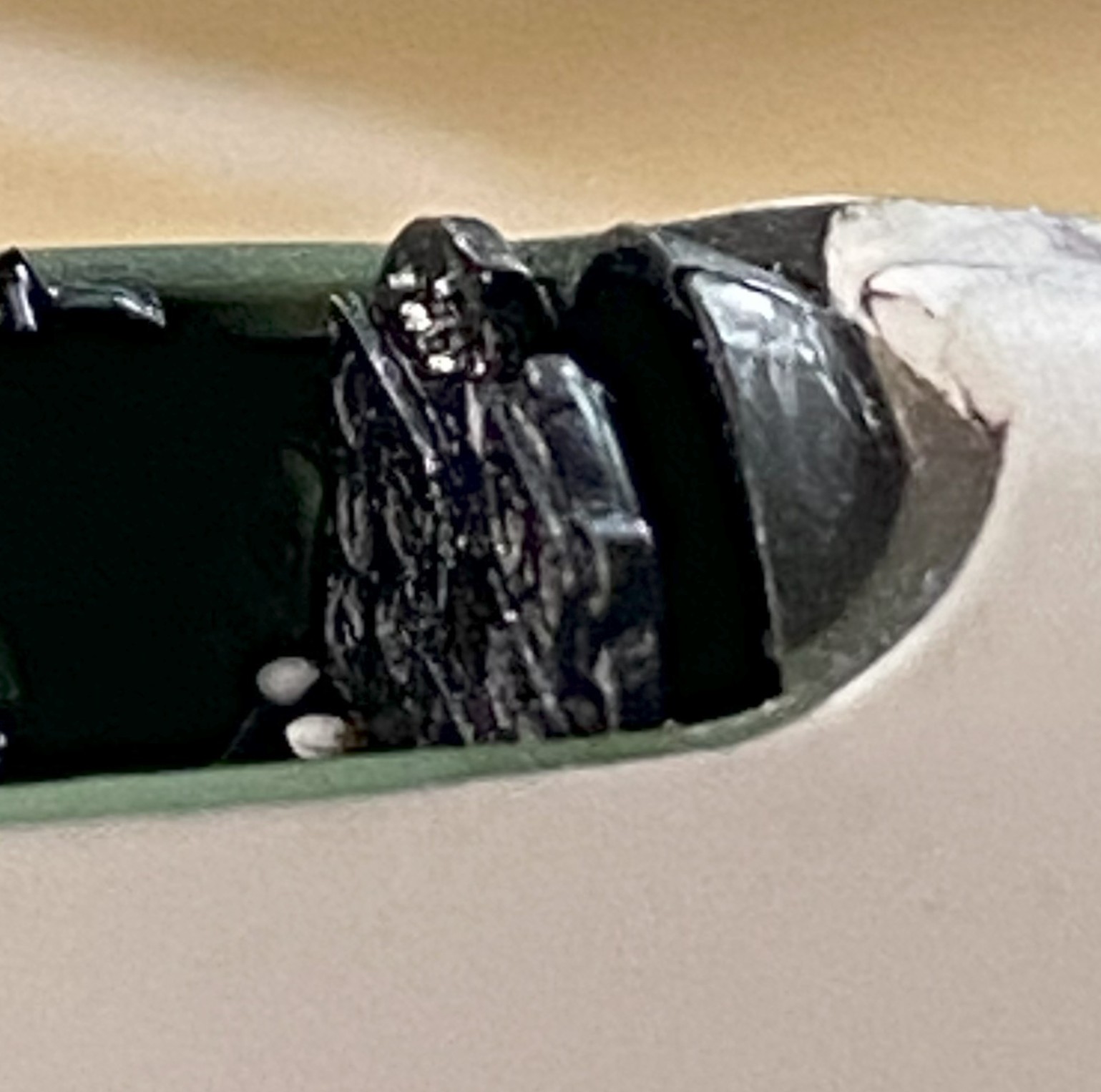
While the putty is drying, I fitted the heat exchangers on top of the engine nacelles. Originally it looked like a small, resin, cat standing on a hot griddle. Way too high off the nacelles. Fiddle, file, sand, cut at they now sit correctly:
EDIT
While I was doing this update, it was at this point in it that I sat here confused (easy place to get to due to how often I go there). I thought I’d taken more photos of the work over the flight deck. I certainly know that a lot of time was spent on it. About an hour ago the mystery (and confusion) dissipated when I found the photos I thought that I’d taken misfiled in a folder that, of course, has nothing to do with modeling (there are minor aspects of my life that have nothing to do with modeling) (honest). It’s at this place in this post that I surreptitiously add them in a manner that I think few will notice my oversight. ::giggles::
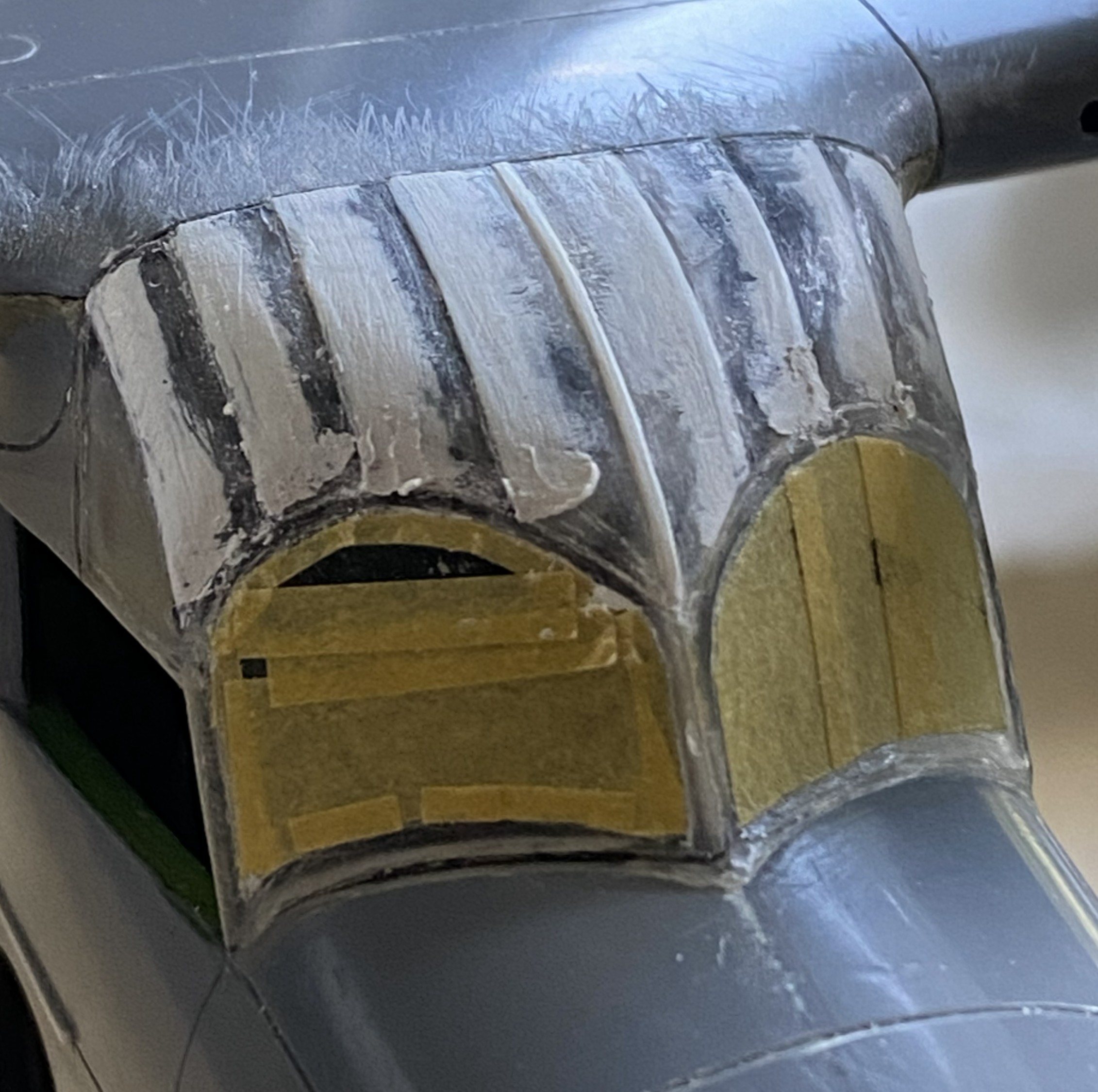
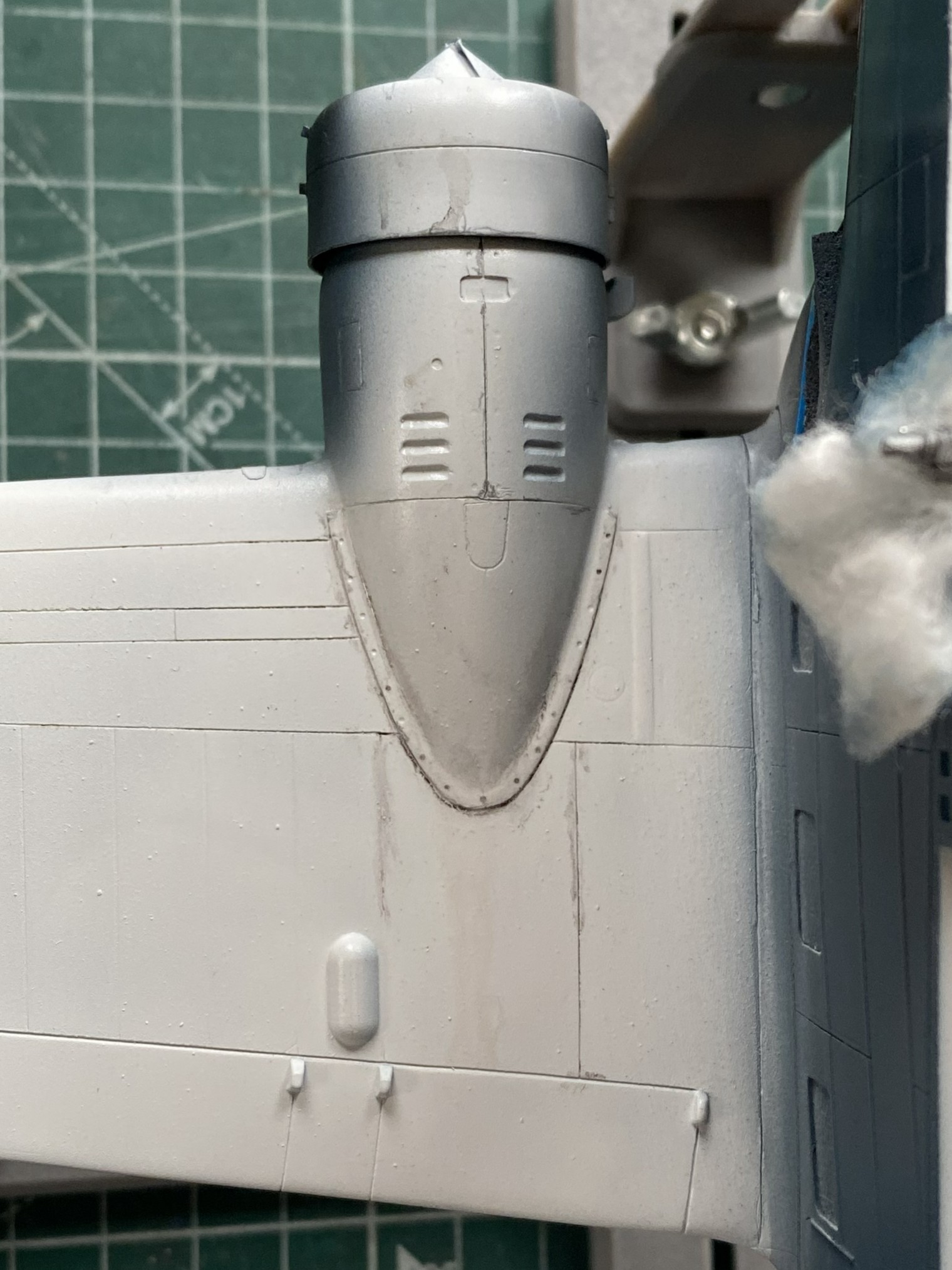
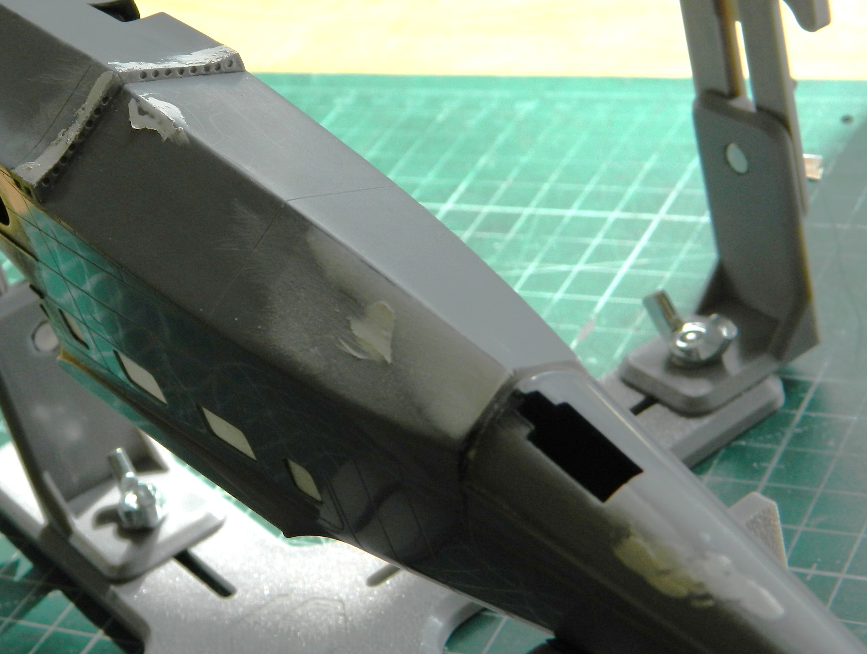
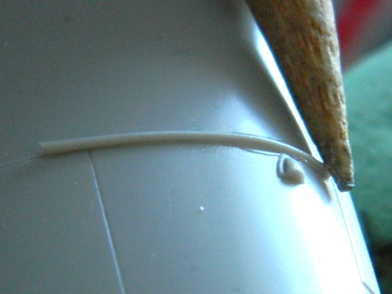
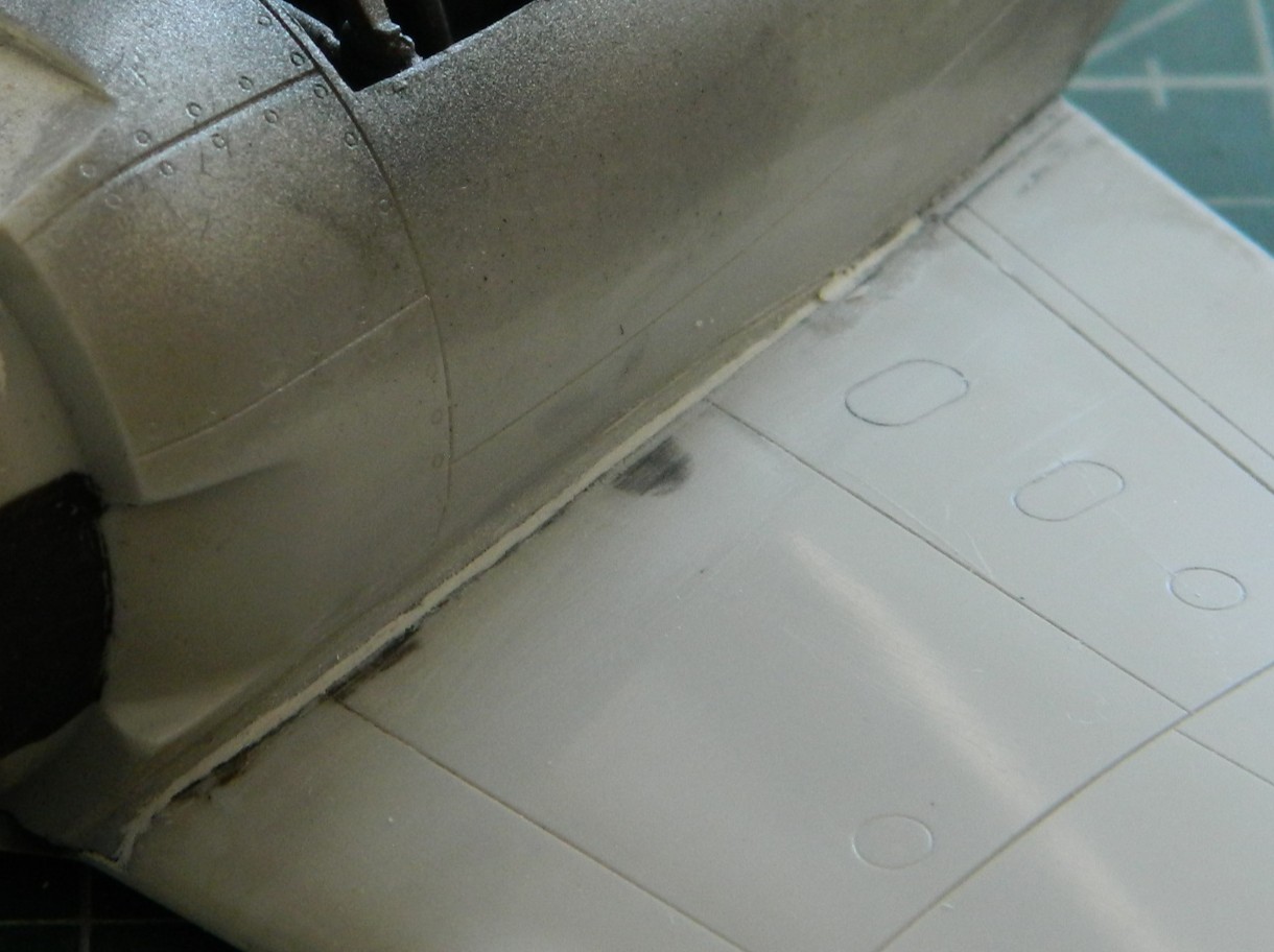
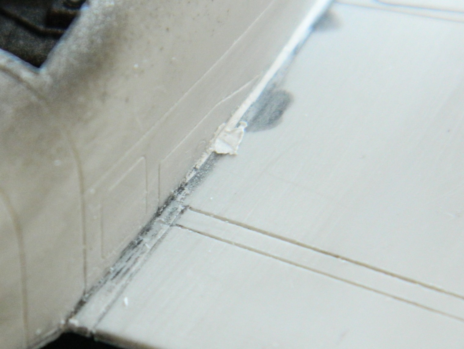
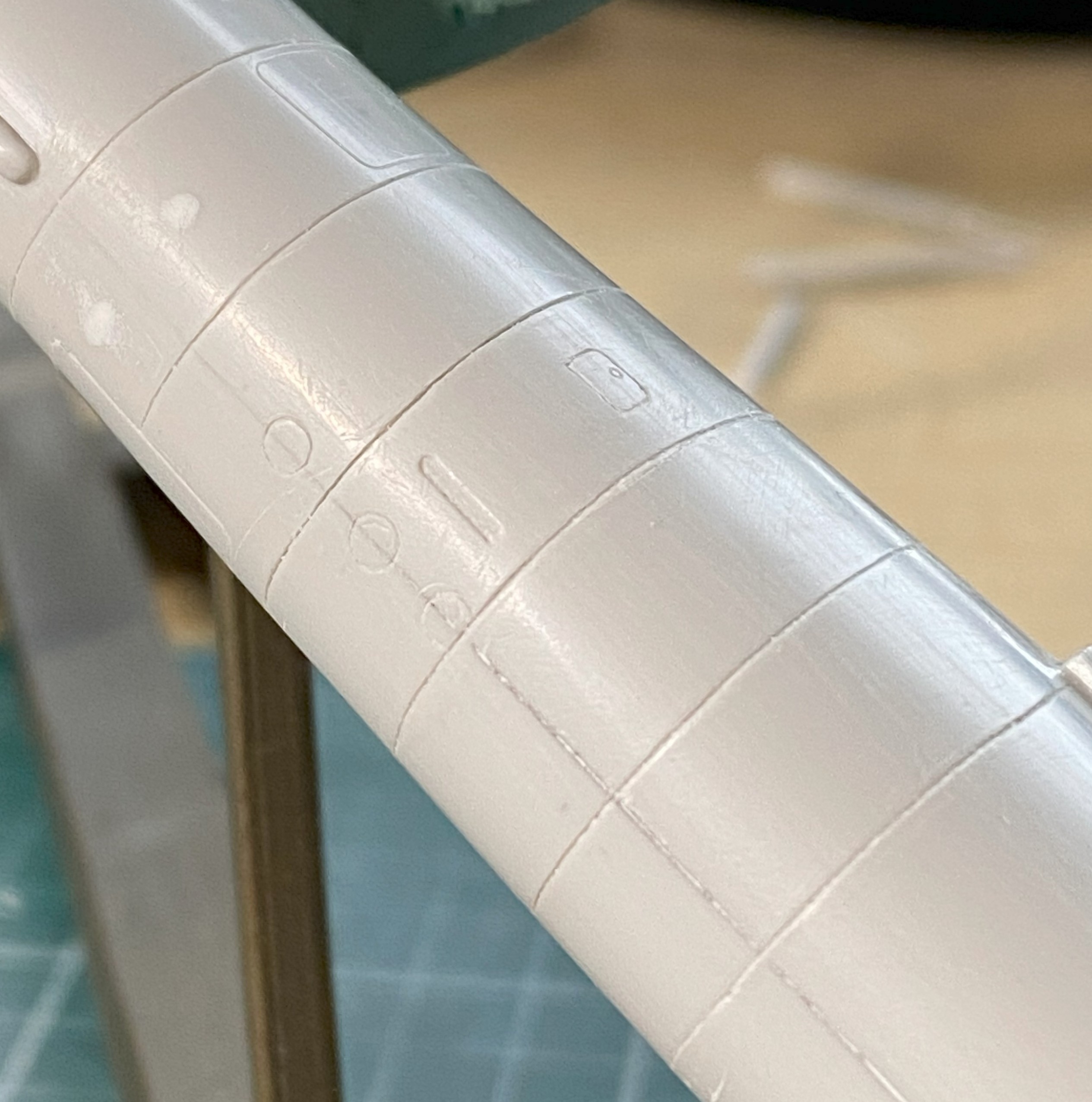
With the putty dry, I went back to the fuselage over the flight deck. ::sighs:: Where to begin… A lot of work ensued. Almost all the putty was sanded away to see if I could (I couldn’t) refine the shapes and lines of this area. As so often happens, once I’ve decided on a method to accomplish whatever oddball thing I’m trying to do, often I have to invent a way to do it (and frequently that is not a hurried process, regardless of how it may look). While doing the work of that invention on the model, it is quite common for me to figure out a different (and hypothetically better) way of accomplishing the task. It’s also not uncommon for that epiphany to come too late to use on what I got the idea from. This was one of those. While removing putty and trying to refine the shapes into something I want, I realized that what I should have done was not add the strips and putty at all. The panel lines should have been scribed and cut away to create the lapped effect. And then I noticed that the lines aren’t just on the clear part, they extend rearward to the pencil line on the main wing, which is how I came to the realization that adding the strips and putty was a total waste of time/effort (and I added the resin scoops to the left sides of the nacelles):
Putty was immediately added whenever I found a void that needed filling:


About this point I realized that I had too many different colors/shades reflecting light and I had lost the surface (visually…if I’m that bad off, I stay in bed). I used Tamiya XF-20 Medium Gray as it most closely matched the plastic’s color so that reflectance would be uniform:

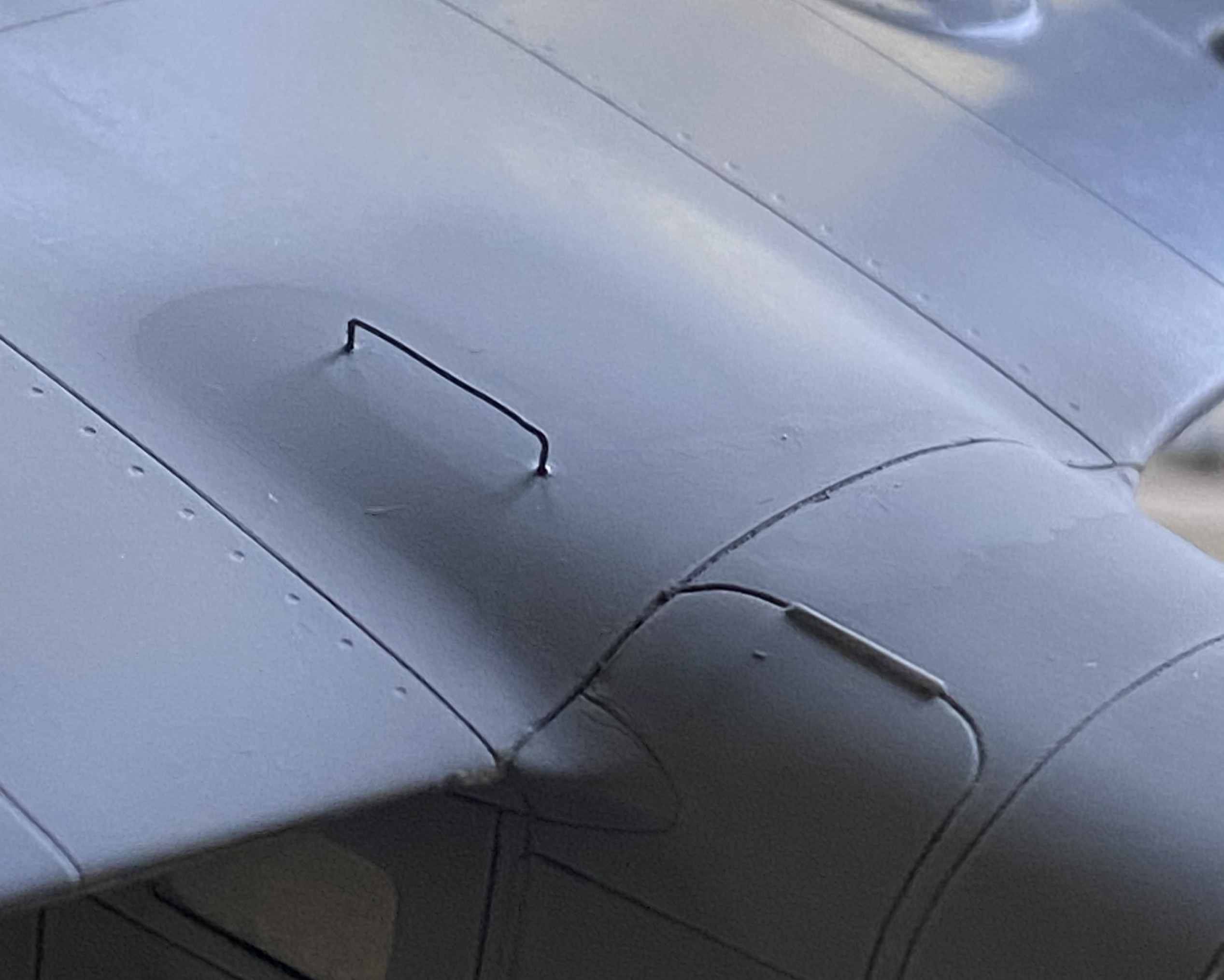
I’ve seen a number of field-expedient grab handles added to aid refueling. The filler port is on top of the wing on the left side. Access was achieved by opening the portside entry and crawling up onto the wing. Then the fueler had to scoot towards the filler port while dragging the fuel hose. (I’m not sure that “ergonomics” was even a word 80 someodd years ago, doesn’t look like “convenience” figure prominently, either.) I picked a photo to replicate and used some 22awg wire and added one setup that appealed to my eye:
Ain’t nuthin quite like applying primer to show you what still needs work. Plenty:


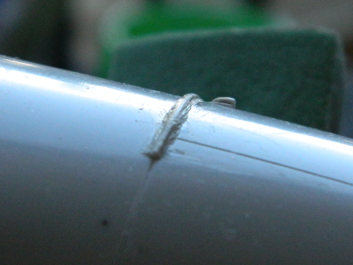
It seems I got too frisky with cutting in the lap lines and took too much off (though, for a change, it was before I’d carved through it) so I used stretched sprue to fill what had been mistakenly removed.
As an aside, if you need preshaped sprue to stretch, shaping the sprue before stretching it will keep the shaped you’ve established (this was shaped triangularly to better stuff the gaps I created):
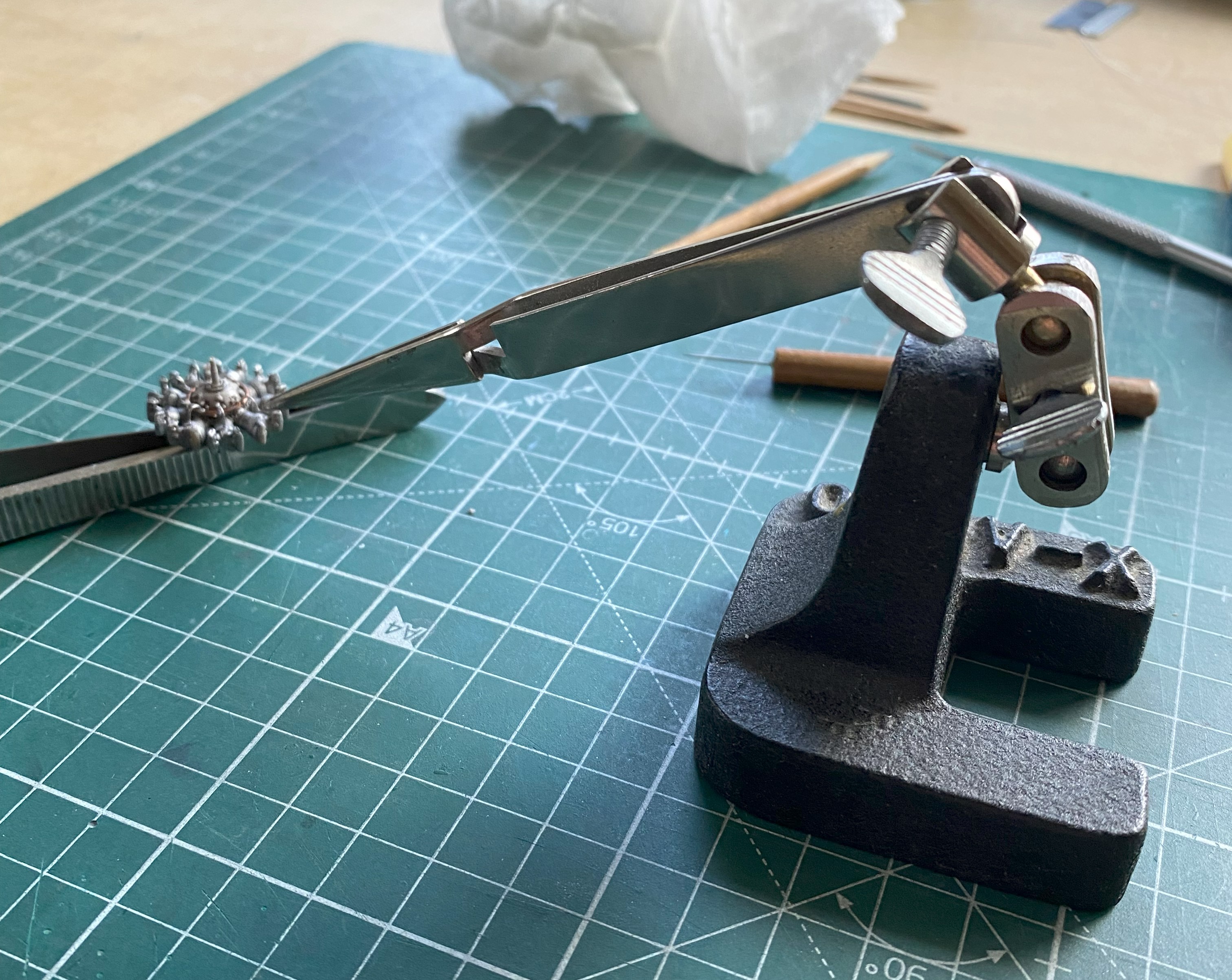
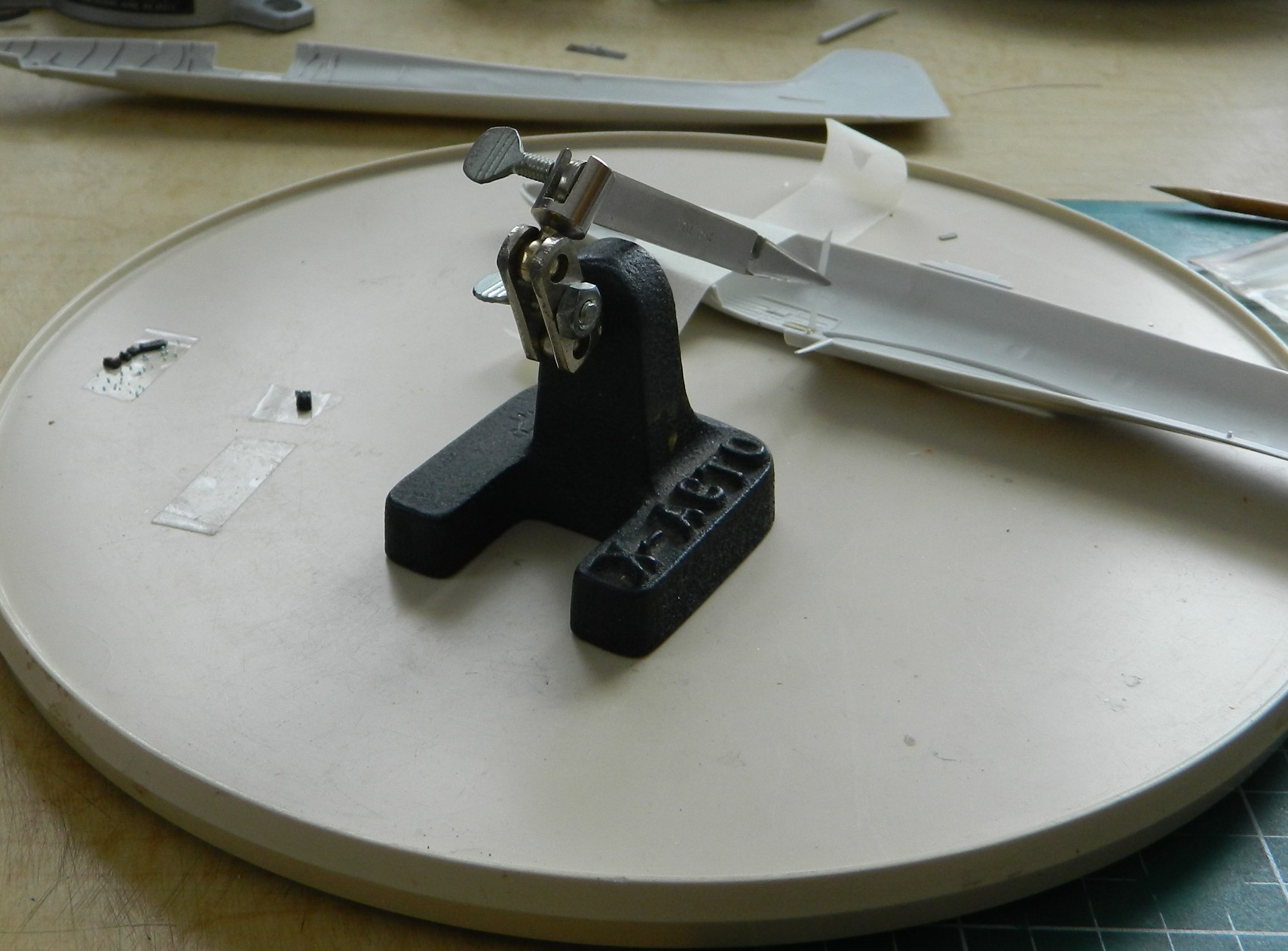
Jeweler’s files. The self-locking tweezers that are attached to stands. If you don’t have any, get two. They are so useful in getting pissy parts aligned, and keep them aligned, while glue sets. I use my pair on every build at some point and it’s time to use them again to keep the stretched sprue in place while the glue sets up:

I’ll generally wait 2-3 minutes after applying the glue before I press the sprue into what I’m filling with it:


Still more work to do straightening out the lines. I spent over a week working on that section and ended up needing a break from that particular task. Since the added sprue needs to sit overnight before it could be worked, I attended to THE most fragile parts off all the fragile parts.
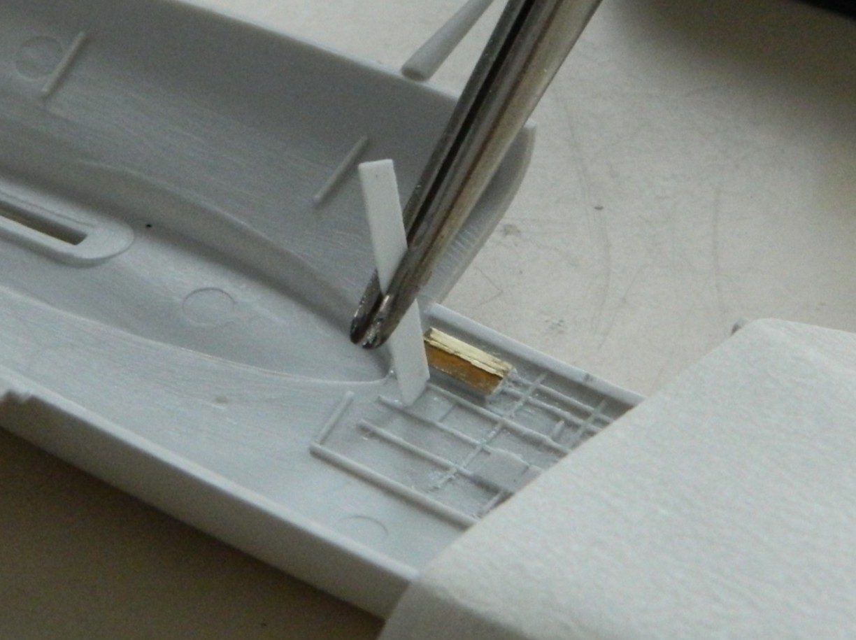
The mass balancers on the elevators. They’re so small that I left them attached to the sprue runners while I cleaned them up. I knew that I was going to make them removable using 22awg wire as pins. I didn’t need magnification to see that the bases are too small. 22awg was the smallest wire I was willing to use (anything smaller would be too flexible), so instead of even trying to get the notch I’d have to cut for the wires centered on the bases, I excised a slot slightly less than halfway through the base to recess the wire into. No…not accurate. Yes…practical:
And to think that I won’t work on anything smaller than 1/48 scale because “it’s too small” is getting really funny.
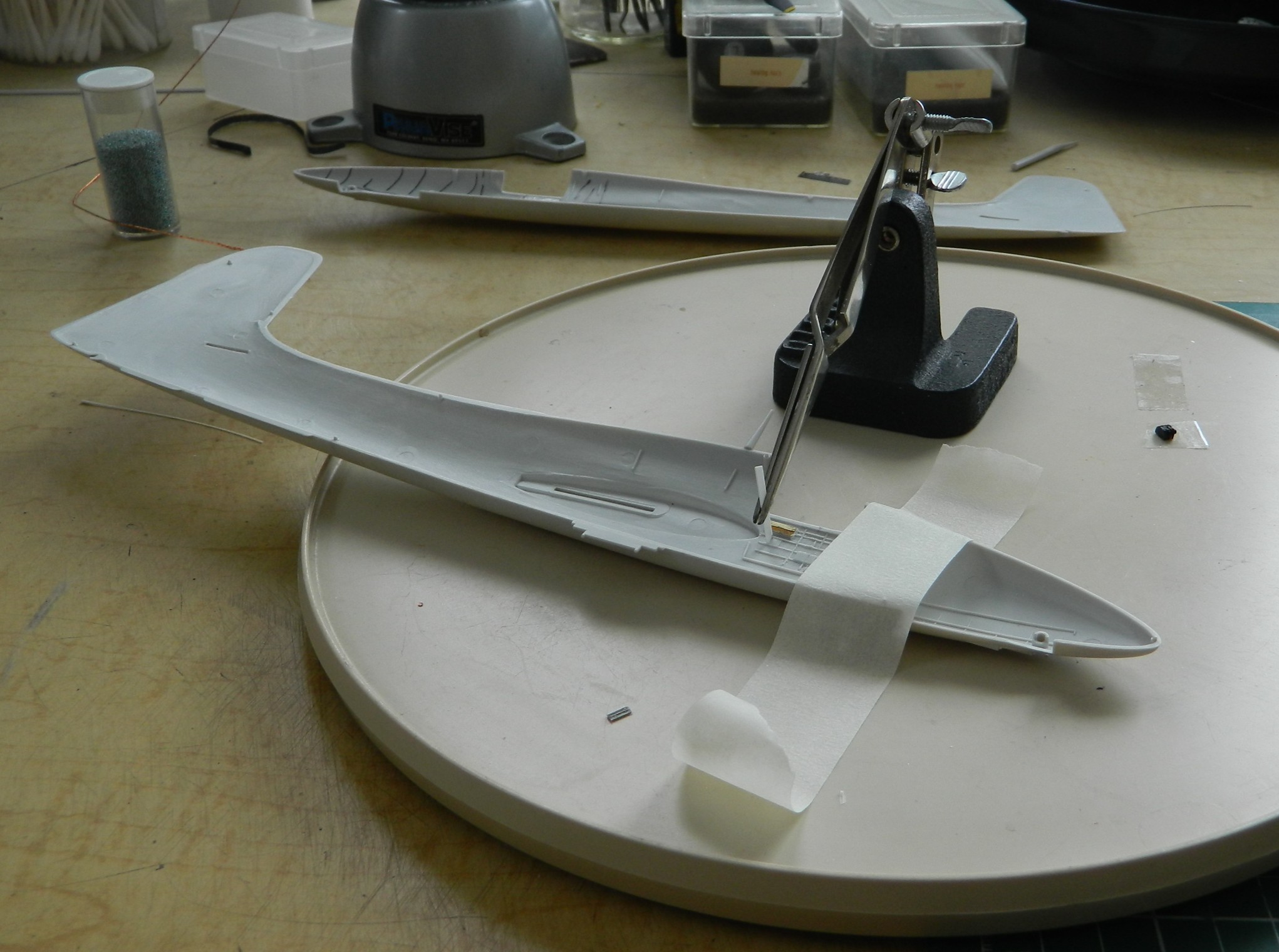
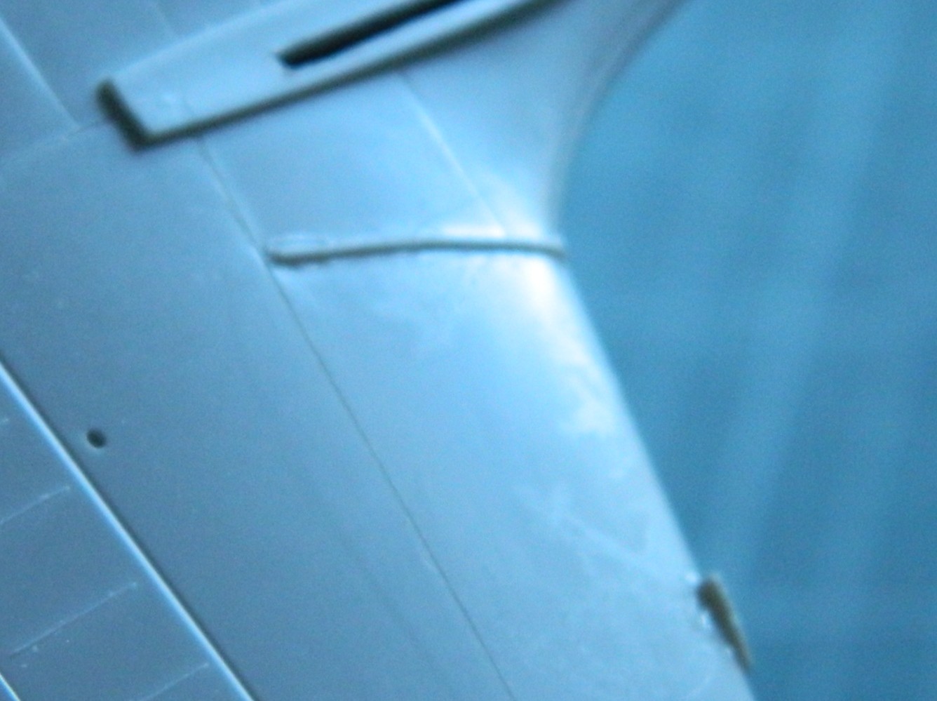
With those ready to paint, it’s back in on my head. My eyecrometer seems to be in need of recalibration. Since eyeballing it wasn’t working, maybe tool use will. The tape is so that the next line is freaking straight:

Next up will be mounting the engines.
While doing initial (hopefully final) fitting of cowls and engines, I realized that the engines are intended to mount to the cowlings! (No mention of that made in the directions. I guess if Czech Models figured if the builder has managed to get this far, they’ve realized that for most of whatever this kit needs, the builder will have to figure it out for themselves.) Okay…I’ll glue them to the cowlings:

I’m glad I had the foresight to remember that however the cowling mounted, where the engines mount would be important. But, seeing as the engines are resin and mounting to plastic, superglue won’t allow me enough time to align them correctly. To get around that limitation, I superglued 0.010″(.254mm) clear styrene to the backs of the engines. This will allow me the to join styrene to styrene and fiddle them into alignment (I used clear plastic so that the added disks would be easier to center over the engines):
Now for the task I’ve been dreading this entire time. It’s time to attach the landing gear.
The kit offers three pieces for each landing gear; the main strut, the upper control arms, and the lower control arms. Three pieces, two hands, and minimal space to work in. I cut down on the parts count by aligning the lower control arms on each strut, then drilled through them and put a wire in there to act as a hinge. Had I not done that, I’ve NO idea how I’d have gotten these things on at all. Even with the parts reduction, the four-letter word I want to use to describe that process isn’t “easy”. Move this into position, attempt to move something else into position and the first piece moves out of position. I’ve seen this kit online where others have built it. They could get the landing gear on, so that means that I can get the fornicating landing gear on. I finally got the strut and lower control arm glued in:

After repeating this lovely task on one side, I did it again on the other side.
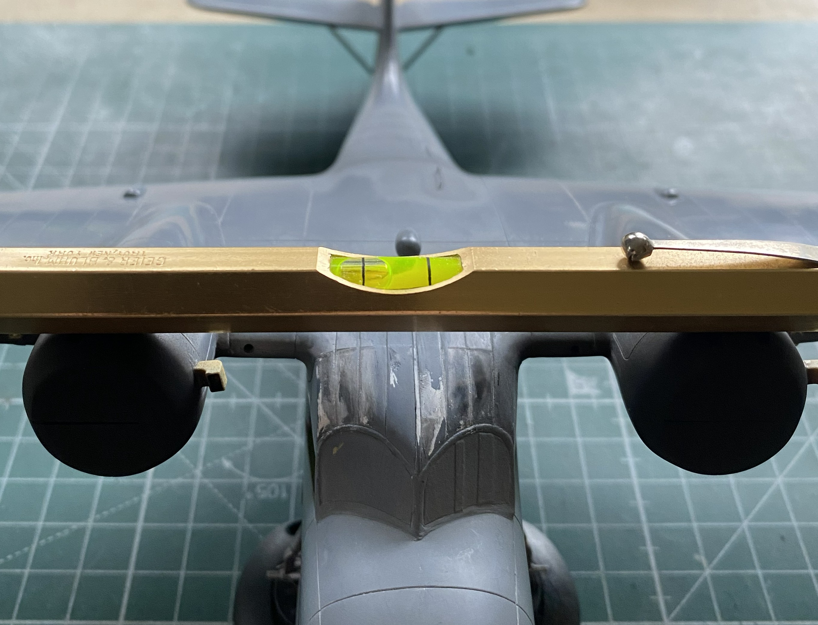
If I thought getting this strut/arm assembly in place was a delight (it wasn’t), then there’s the upper control arm to wiggle into position and trying to align it while making the aircraft sit level was a pleasure that defies description (or sense). I persevered (the process of which was akin to getting a colonoscopy without anesthesia):

Did I get the bird to sit level? Nope:
It’s not time to fix it yet. I’ll pay the toll on that bridge when I get to it.
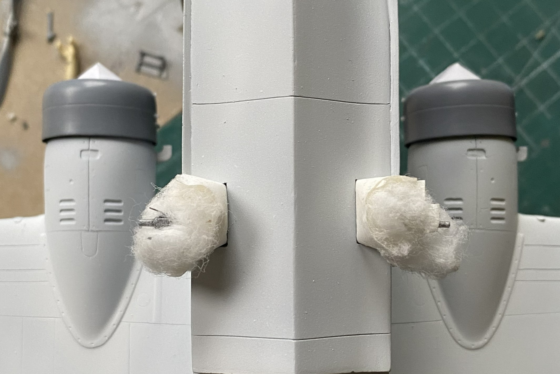
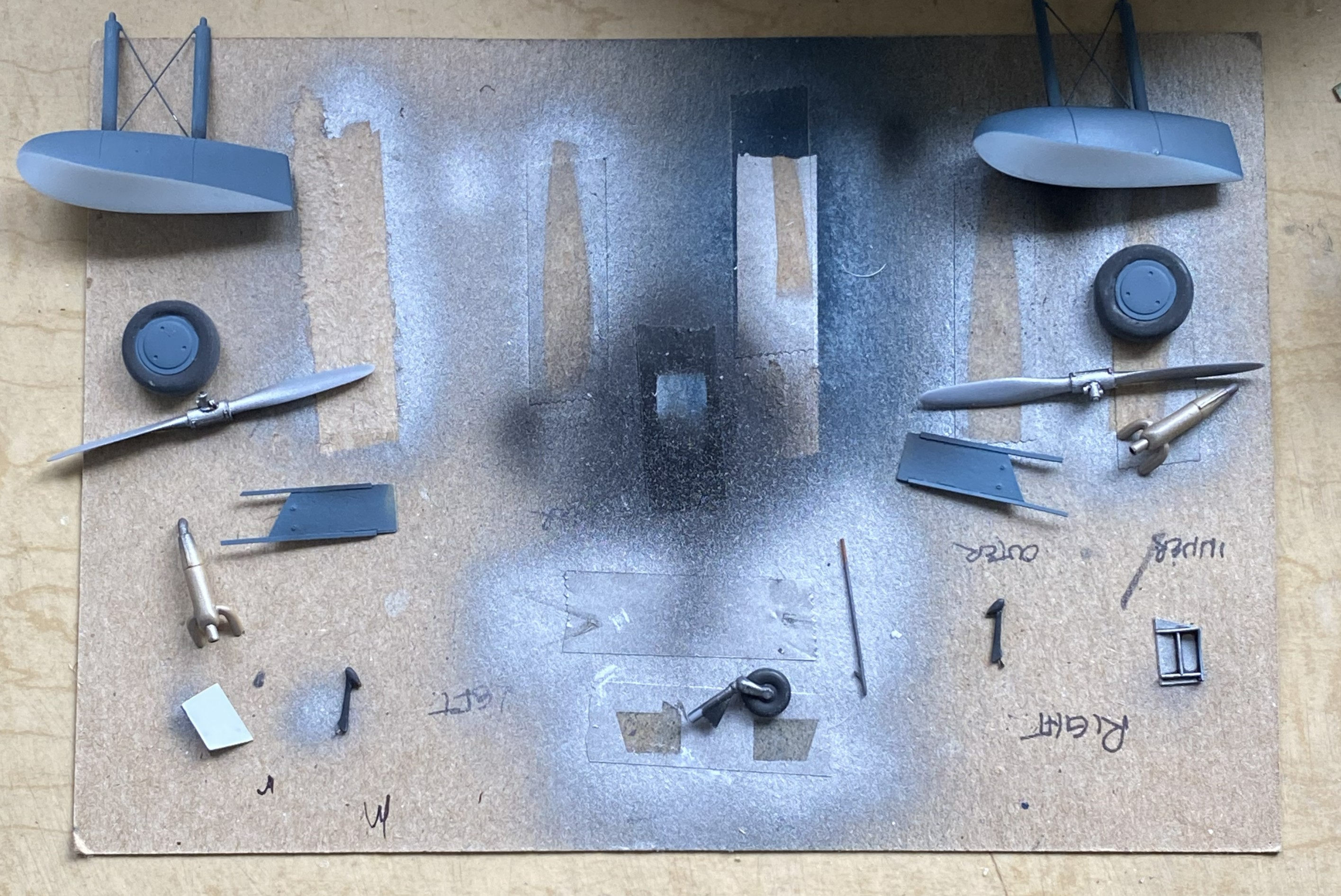
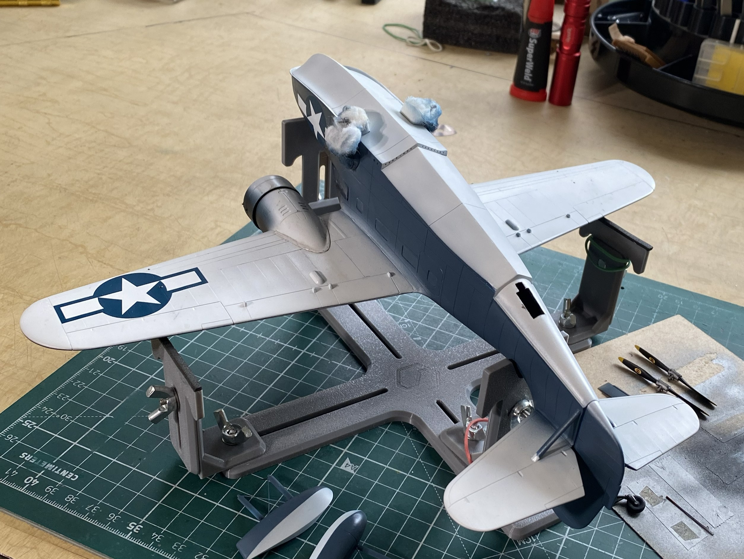
My next task was to start throwing paint at this. Of course I started with the light colors and worked darker, but where I started was figuring out how to mask this using cotton balls for the landing gear, front and rear. For the cockpits, I took foam wedges (nail care section of the drugstore/apothecary) and cut them oversized so that they would hold themselves in position (usually):
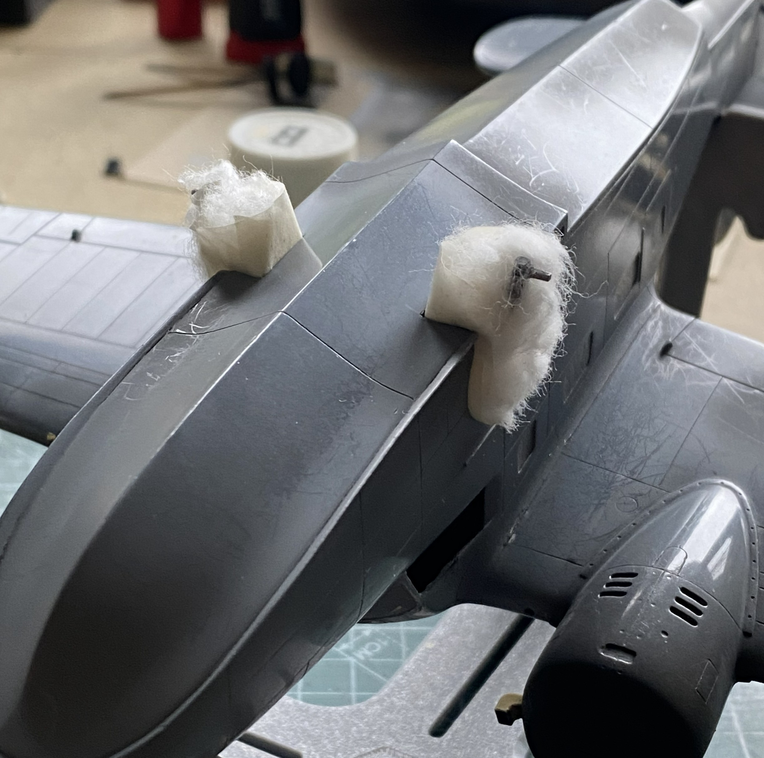
That worked:

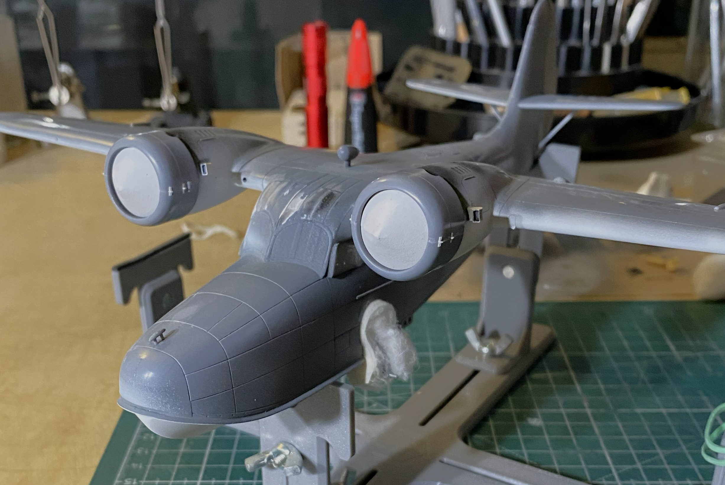
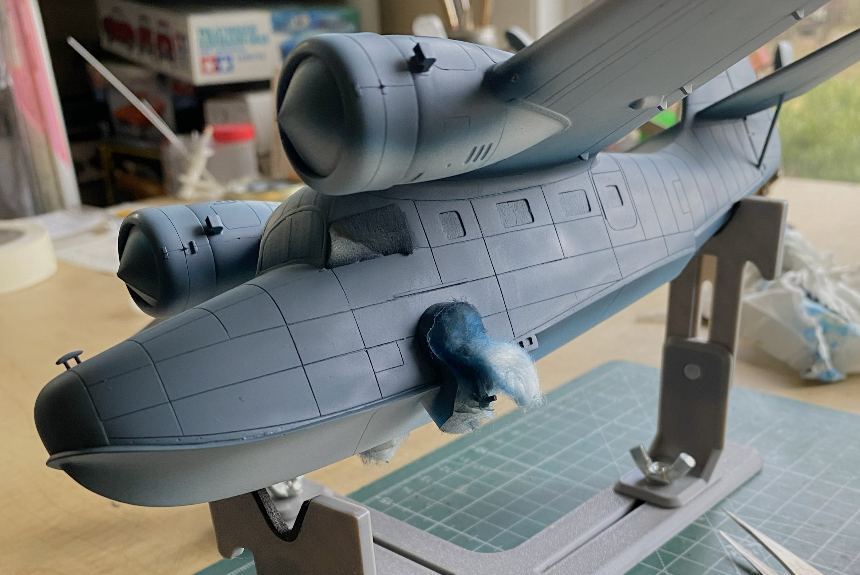
As this will have a three-color paint job, and the nacelles are definitely part of that paint job, I decided that adding the engines now would make all the color demarcations line up later. Before I added the engines, I traced the back of the cowl on paper, traced two circles (one for each engine), and after determining the center of the circles, cut from the center to the edge. This would give me paper cones that would fit in the cowling openings and mask the engines from the incipient painting (and if you look closely behind the engine that’s on the right in the photo, you can see the trimmed foam in the cockpit’s window behind it). With that done, I glued the engine/cowling assemblies in place (shortly after these photos were taken, I painted the undersides of the cowlings white as well):
Figuring that I was on a bagel (which is very similar to being on a roll, just a firmer seat), I got the paints ready. The XF-18 Medium Blue was the correct color, not the XF-8 Flat Blue you see below:

Yeah…wrong color. But…before I had to repaint the sides, I found that Thumbnut McFumbles, here, did not monitor the position of one of those thumbs and did this (hint…check the area that’s not blue…lightly sanded thumb mark on wet acrylic):

Though not precisely pleased, there was something else that fell short of pleasing. When I cut the access open to fix the pilot’s seat, I had to replace the part cut out once I’d fixed the seat. At this point of the build, I was reminded that if I’m not careful (giggle), when the cement finally out-gasses, there can be a visible shrinkage caused by A LOT of glue being used. I used A LOT of glue because there was A LOT of plastic used to fill the edges. This resulted in a clearly evident depression around the patch’s edge once the disco-blue was on. Since I was going to have to repaint the sides (once the correct color arrived), okay…so I’ll fill it in again, only this time I’ll use the UV-setting resin:


Just on a whim, I decided that the heat exchangers could use painting:
Pity…that paint job didn’t last very long as you’ll see later. Too bad. I liked it.
Seeing as I clearly can’t keep track of where my fingers go, I needed a method that would enable me to handle the model as it was being painted. Since I was starting with the bottom, next I would do the sides, and then finally the color on top of the aircraft. And since I want to finish this in a semi-gloss finish, I would also need a painting order for that as well. I let that rattle around inside my wig for now and set about getting that wrong blue covered.
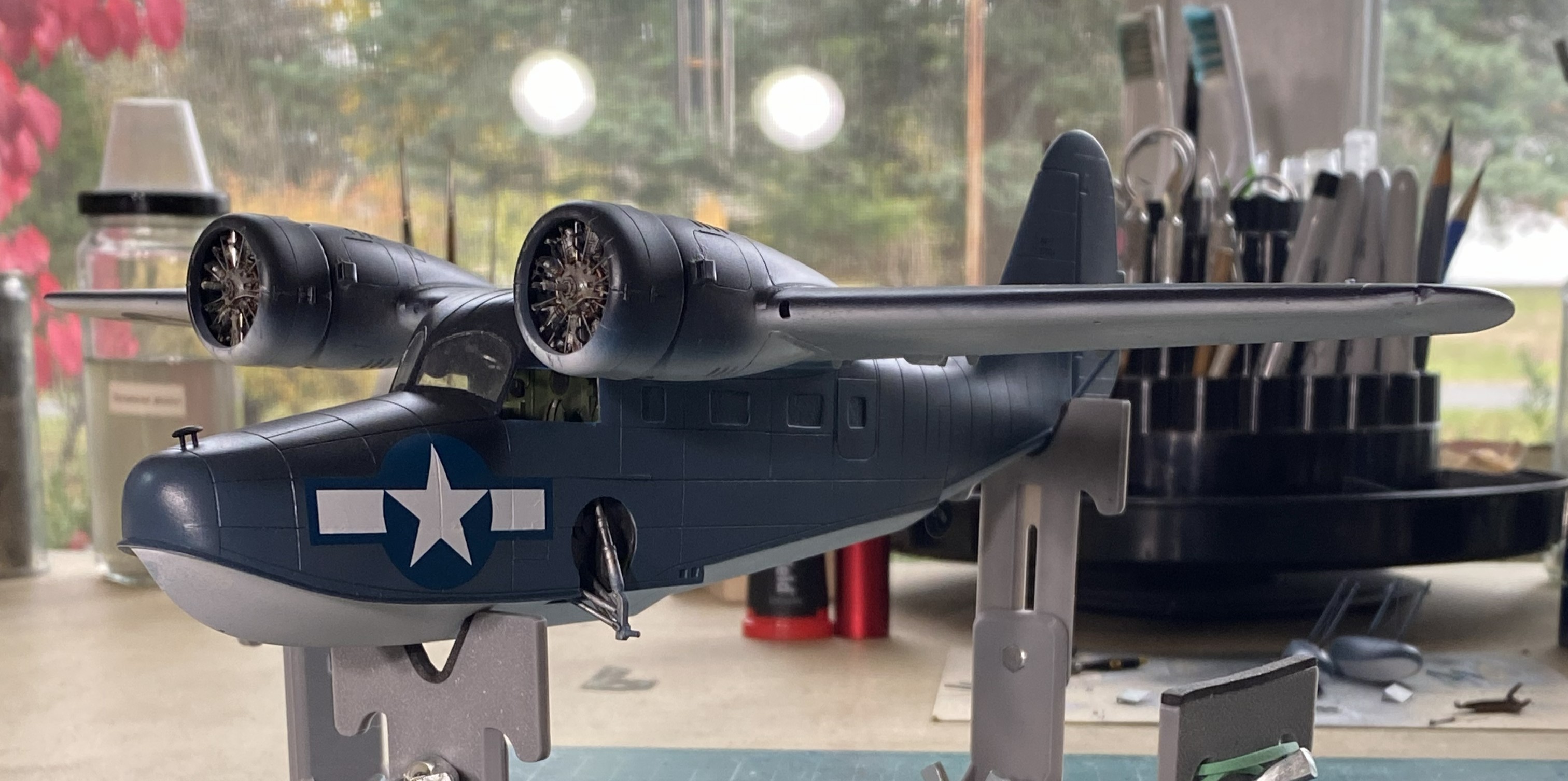
When the paint arrived, XF-18 Medium Blue, I started the repainting with the floats. I’m sure you can figure out which was the before and which is the after:
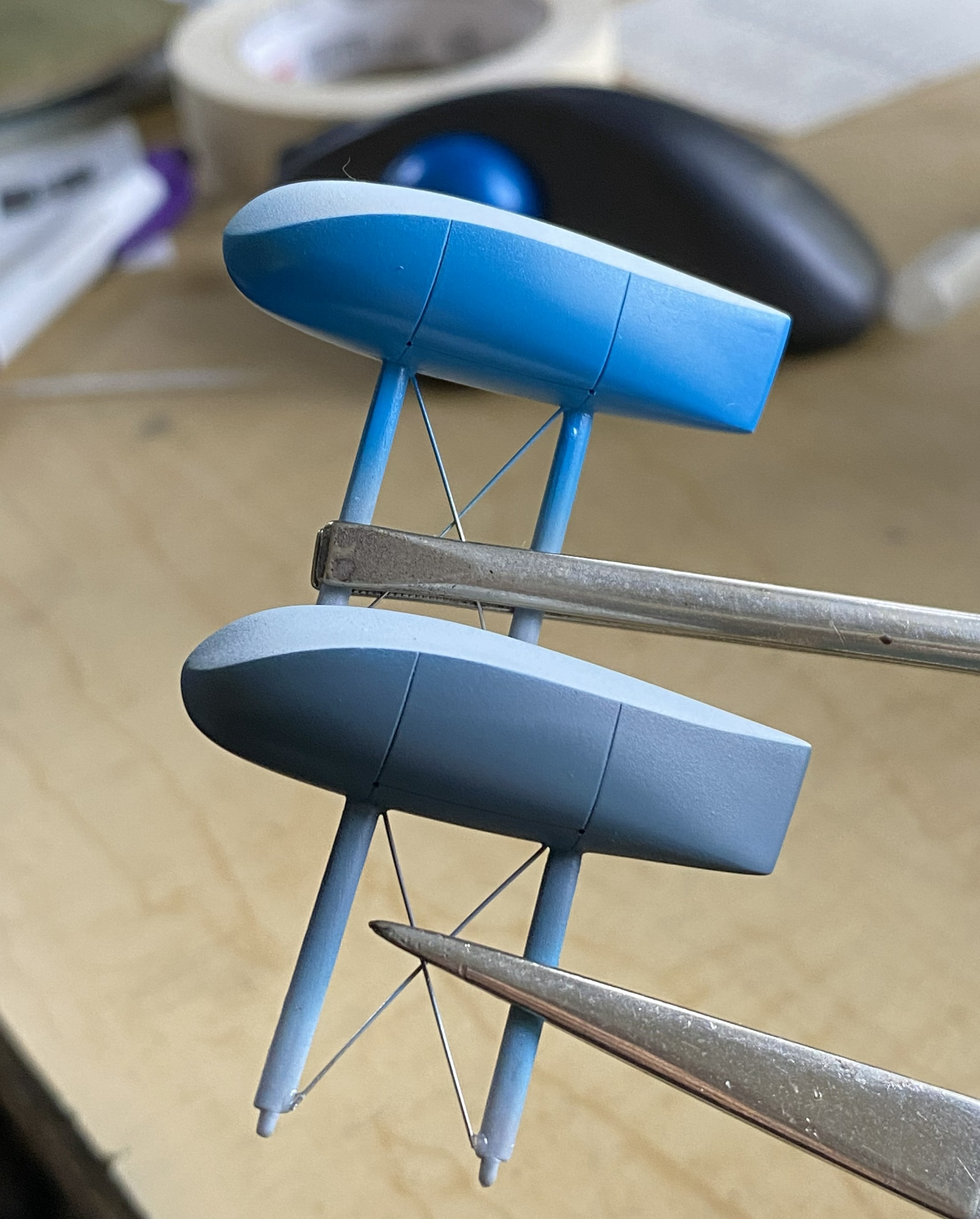
Much better:
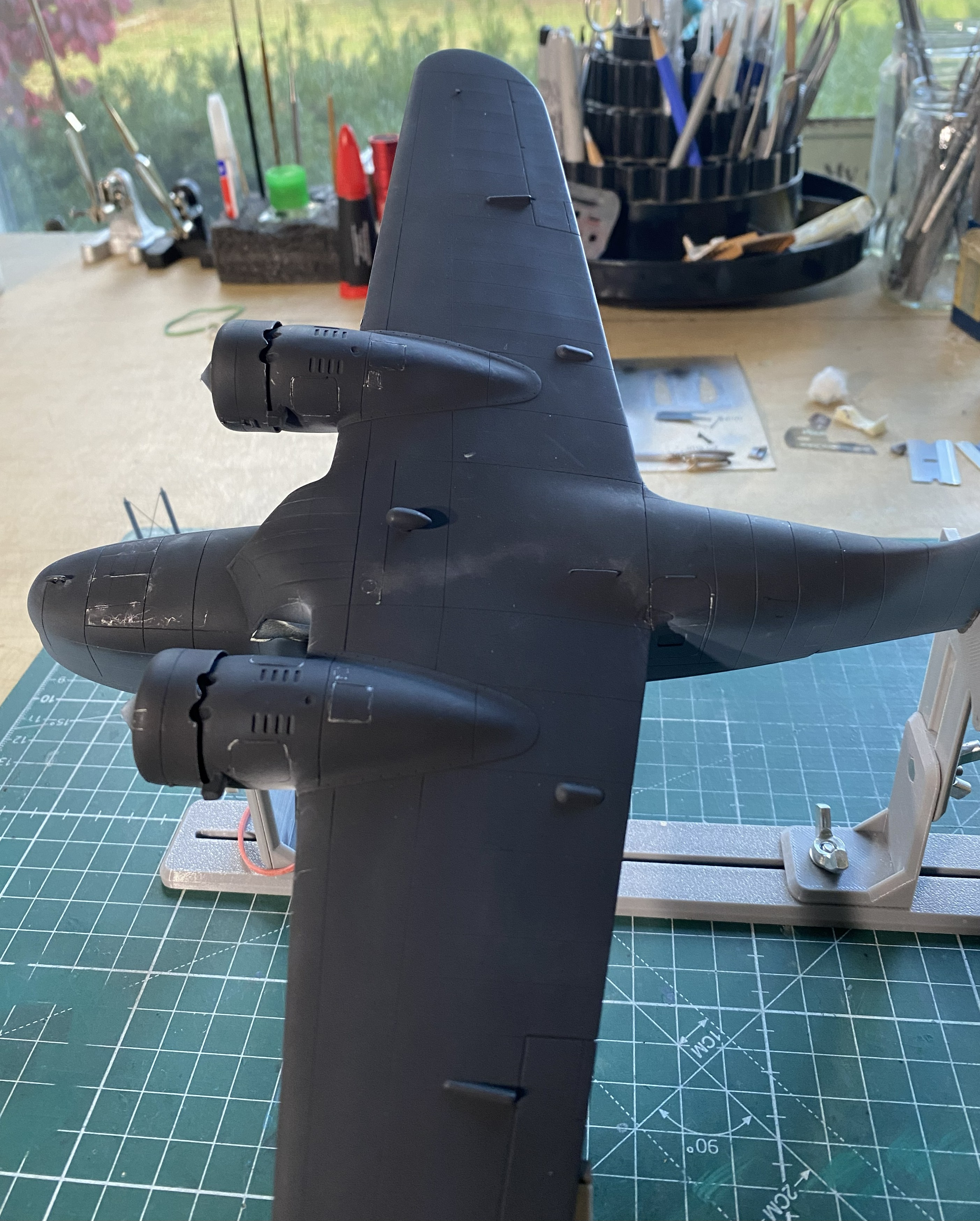
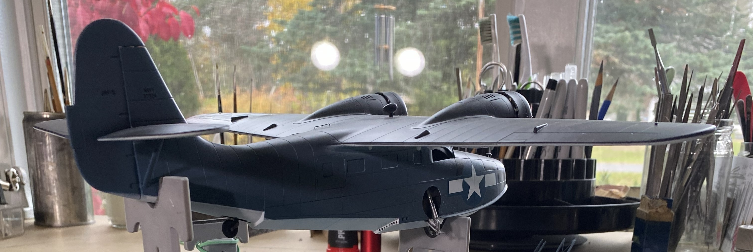
Next up, XF-17 Sea Blue for the upper surfaces:


The overspray of the wings and tail-planes white are how they were painted in WWII.
It was at this point I could take off my polarized sunglasses and resume work.
I like using pencils for some things. At the top of that list is Prismacolor’s PC949 Argent. It’s silver and in small-area applications, it looks enough like aluminum for me. As I’ve discovered, if the surface is slightly rough, the pencil not only goes down easier, amazing things can be done with subtle wear patterns. With the build now under paint, I sharpened my PC949 and went at it. Gently. The Navy doesn’t let its kit get shabby:


With the paint on, the next thing that goes on are decals, so I hit the spots where the minimal decals go with Tamiya’s X-22 Clear Gloss:
Yes, that looks like a lot of paint. However, this paint does self-level:

I had painted the white undersides (Tamiya XF-2 Flat White) a few days before the color and had shot it with clear gloss (Tamiya X-22 Clear Gloss) to prepare it for a wash which meant it was ready for the wash. I figured since the wash was going down over white, I could get away with a more nuanced wash. Pratt and Whitneys leaked oil. The skin panels were not oil tight. Oil leaked on the ground and once the bird was in the air, the oil that had leaked onto the skin streaked back in the airflow. That’s what I was after. I didn’t think an enamel wash would give me the subtlety I thought would work so I broke out the oils:
The last time I did a wash using oil paints (on the engines), I’d used Turpenoid as the base (roommate hates the smell of enamels and turpentine). It took a week to dry. For this wash, I tried using Gamsol as the thinner instead. It was dry the next day.
Yep…looks like engine oil:

Yep…it looks a lot like oil:
At this point, these are all the parts I have yet to add:
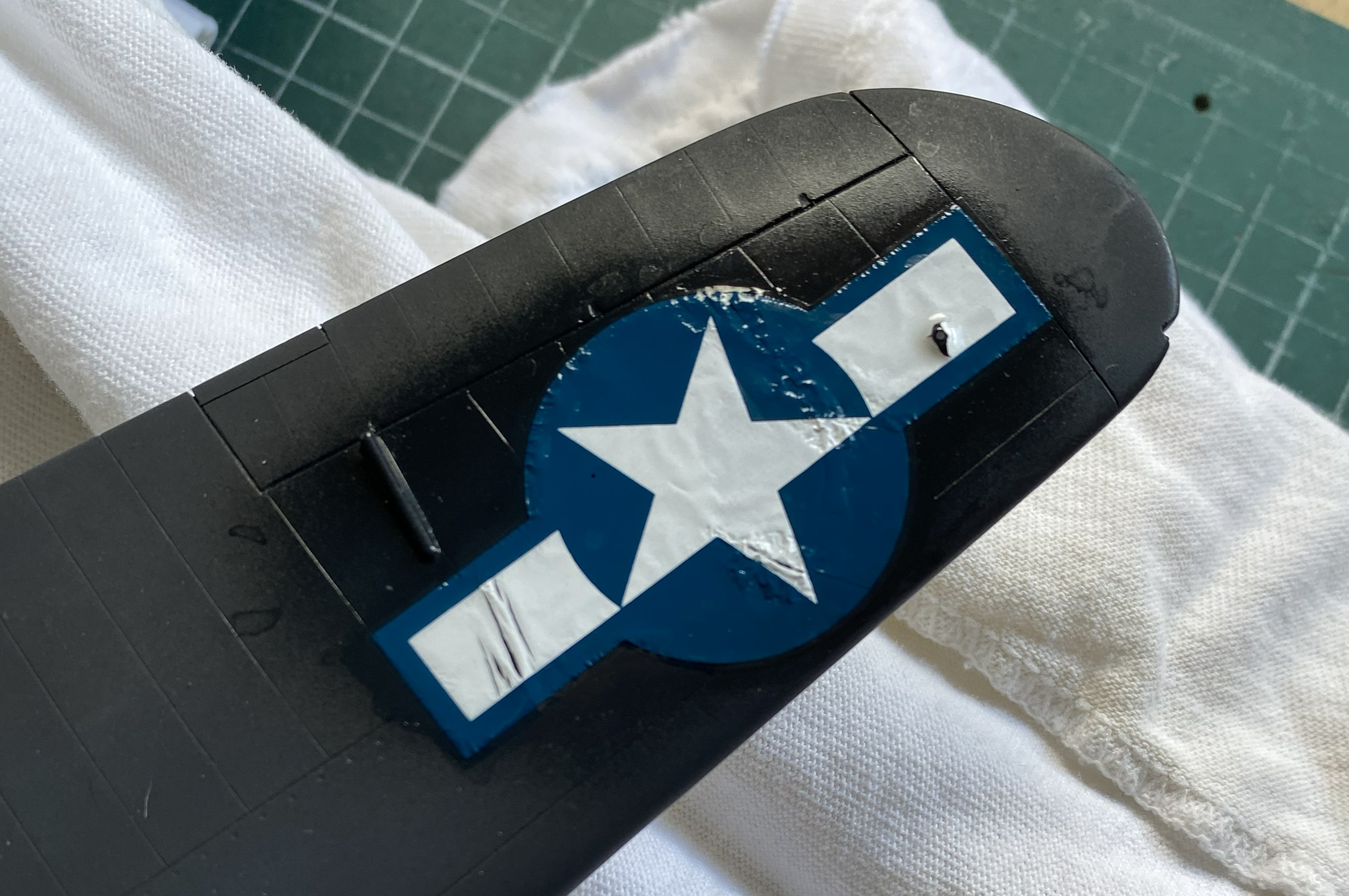
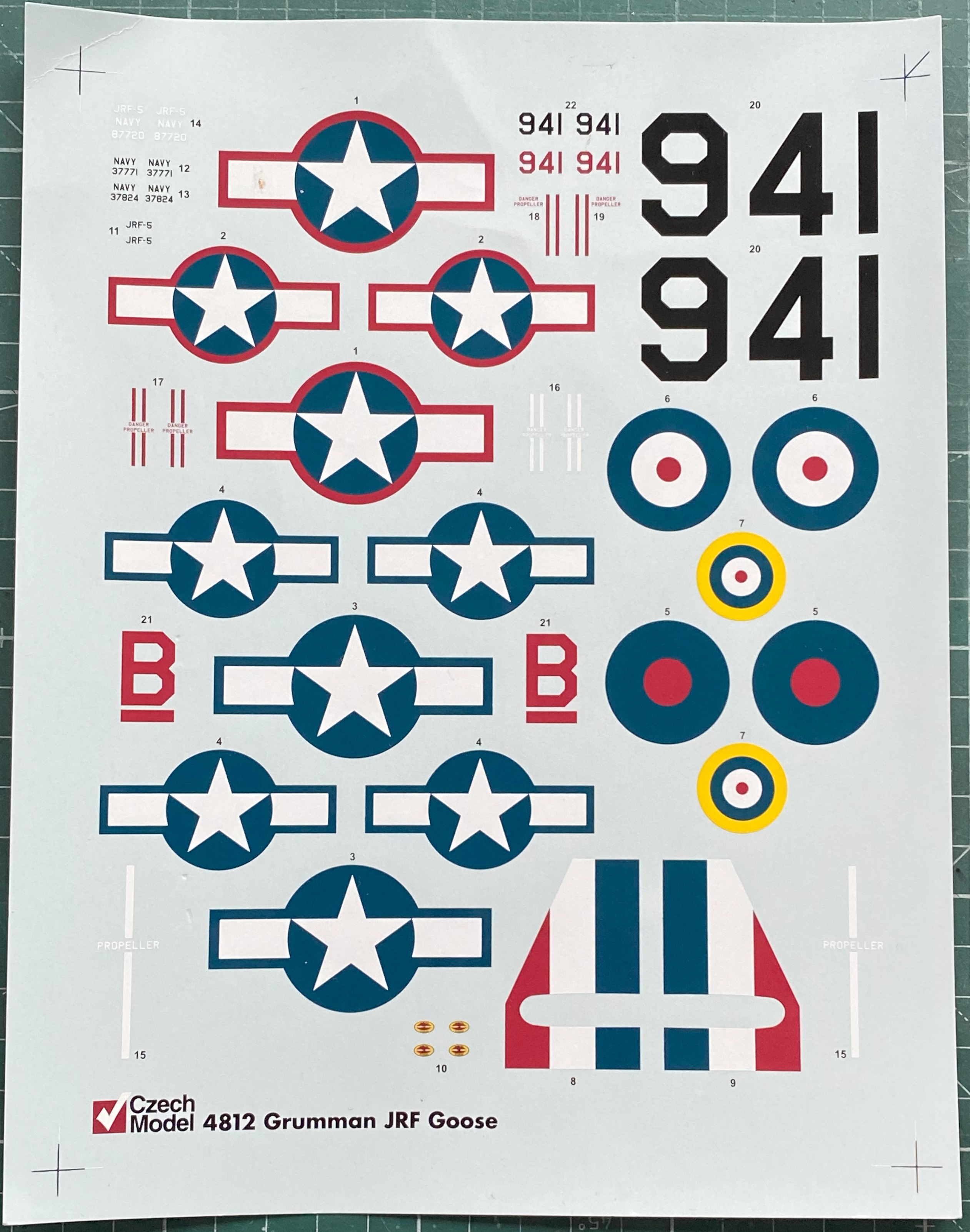
A couple of days later with full knowledge that the clear gloss had set sufficiently for decals, well then…let’s do the decals. And then there were these:


Well, well. Old decals. I decided to see if I could get them off the backing with few enough shards for me to piece them back together on the surfaces (because I’m that kind of nuts). Results were…well…predictable.
This one went on in “only” two-ish pieces and was acceptable:
The one for the upper wing, however, was a cockup:
I broke out Walther’s Solvaset in the hope (another four-letter word) all the shards would play nice with each other. They didn’t. I used more Solvaset to see if perhaps multiple applications would smooth things out. In some spots it worked. However, there was a cost. NO amount of further Solvaset got rid of the wrinkles:
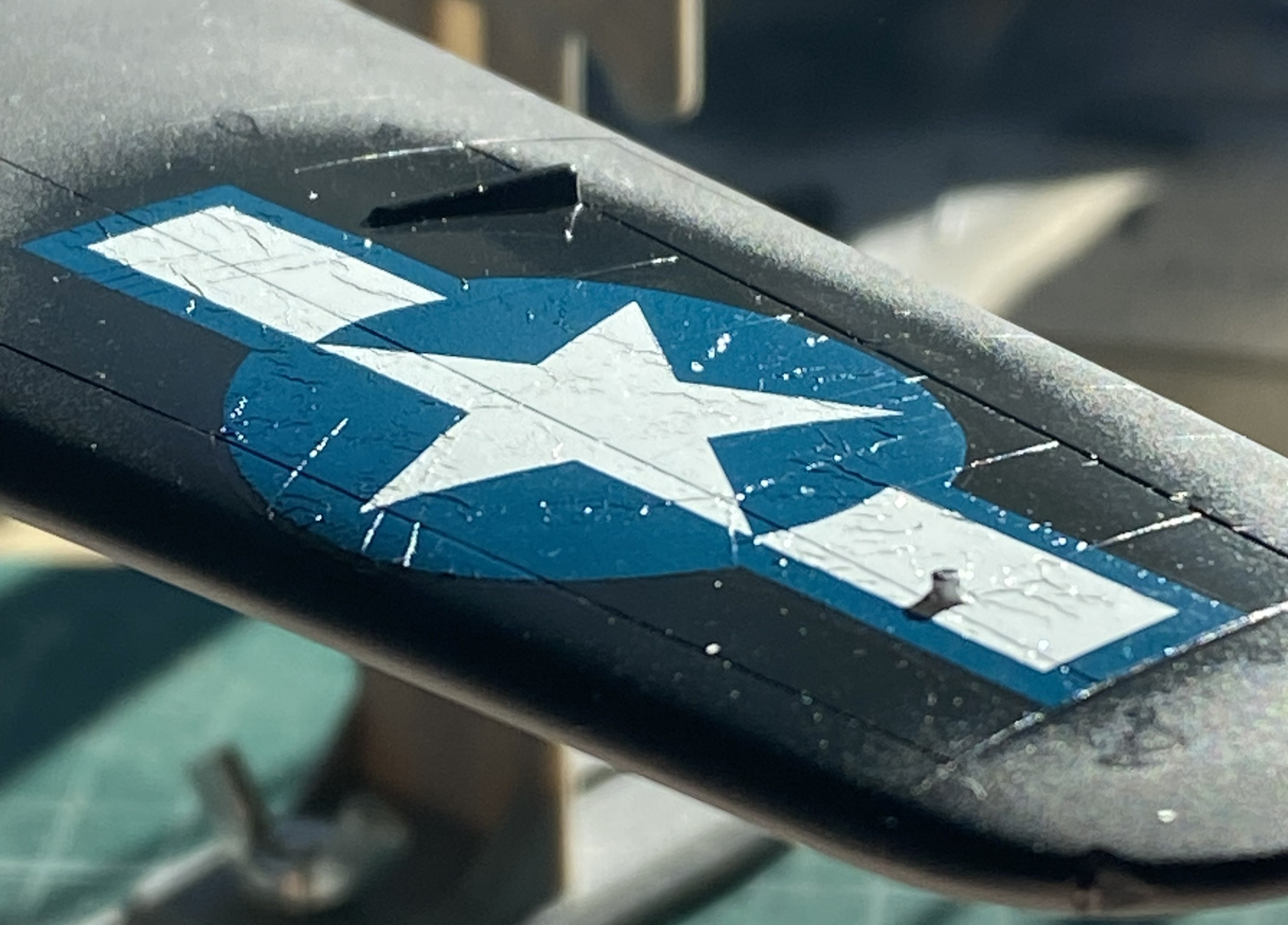

The second photo above was the best Solvaset could manage. Not acceptable. I only know of one way to remove blown decals. Sand them off, reapply paint, and start over:
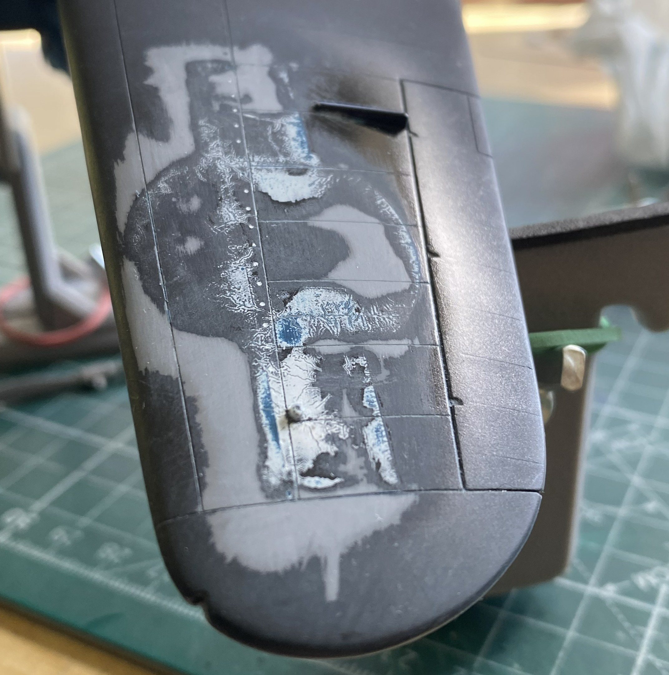


Yes, even through the new paint, the faint outline of the decal’s remnants shows up. Since the new decal would sit right there, I didn’t bother sanding it out.
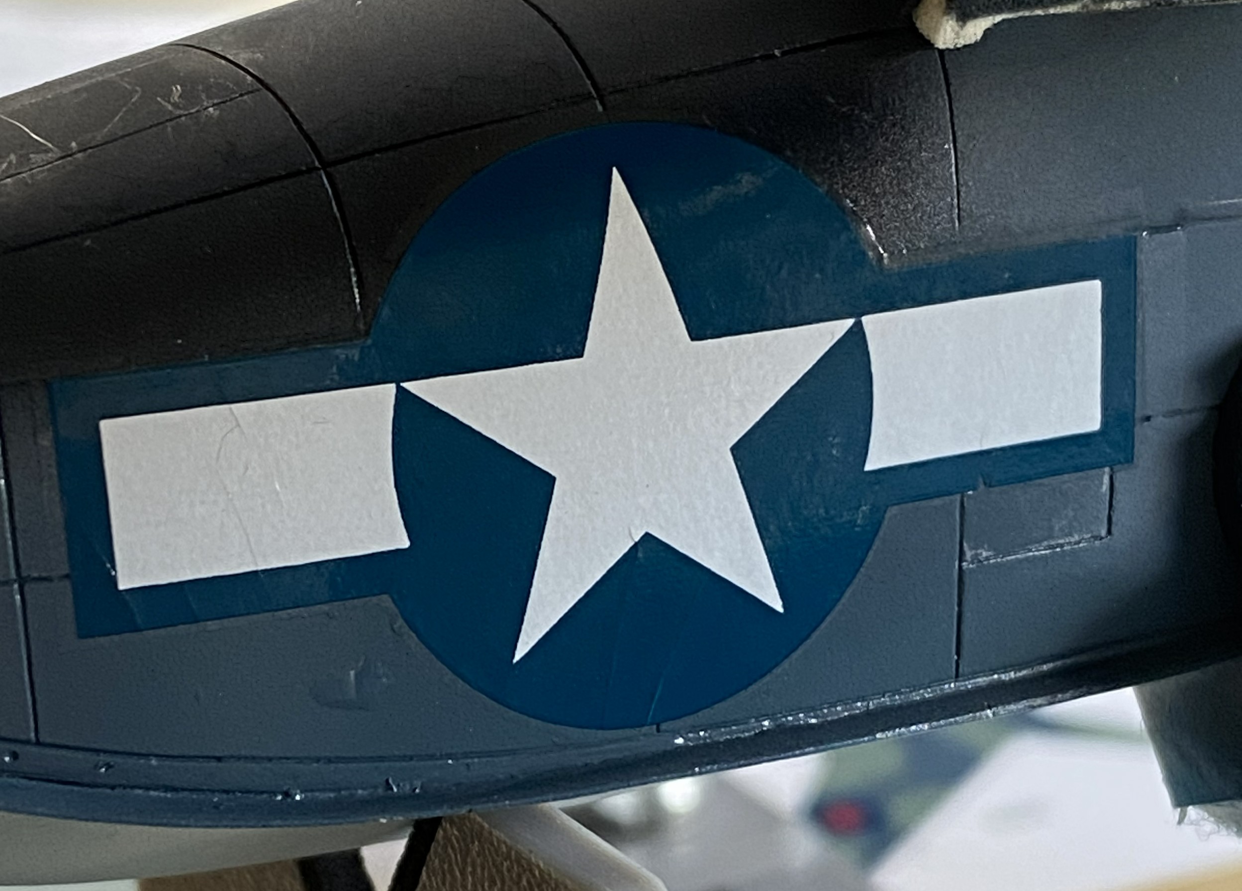
Solvaset worked well (though not perfect, it’s close enough) on the left nose decal:
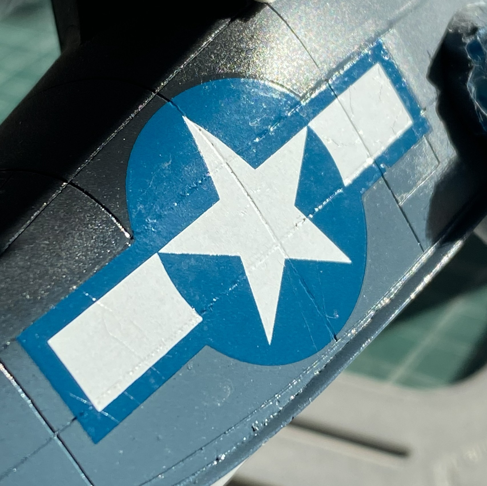
At this point I discovered that I’d salvaged the only two decals from that sheet that could be salvaged; all the rest were garbage. Oh great. This is a limited run kit so the odds of me finding suitable decals weren’t good. Okay, so it’s star ‘n’ bars…I probably have dozens of them on hand. When I went through the decal stash, I discovered that yes…I had lots of star ‘n’ bars. I just don’t have any even approximately properly sized. The big surprise was finding another sheet of the exact same decals for the exact same model. How I managed that, I’ve no idea. But with stars in my eyes, sweat on my forehead, my shaky hands cut out a decal from that sheet to test and it was FINE.
Whew…
Here’s the nose decal from the second sheet, and this time I wondered if Solvaset was too hot for these decals. So, who doesn’t have Micro Sol? I used that instead and though the old decals WERE OLD and shattered, perhaps part of my problem with the upper wing decal was the Solvaset. Micro Sol did the job (in-process in the lower photo):

While I’m fiddle-farting around with sodding decals, I neglected to notice that I’d knocked both heat exchangers off the bench and then stepped on one. I never heard the crunch. I did notice that neither exchanger was on the bench. Found one intact. Whew. Found one sitting in a small pile of resin dust (avec chunks):
::facepalm::
Okay, so I get to reattach the tail and make new arms. I didn’t have the exact diameter styrene rod, but I had styrene rod that was maybe 0.005″ (.127mm) less in diameter and that was close enough. Plastic has a memory so if I wanted a 90-degree bend, I’d have to over-bend them and let them sit overnight to attain their new memory:
At this point, a regular occurrence occurred. I dropped something and realized that the floor between my feet was CRUDDY. Okay, pick up the dropped tool and sweep the floor. Once the detritus was in the dust pan, there was one of the two arms sitting right there. Okay…let’s attach that NOW so I did using UV-setting resin:
That’s good news! I only have to make one arm using the UV-setting resin again:
It’s at this point that I got to see what happens when I get interrupted in the middle of something. I’ll forget the second half of something. I had one propeller all painted and ready. The other? Well, I got the hub painted and washed… Yeah. Let’s fix that before somebody notices:


I’m going to be facepalming so much that my forehead will be calloused and the tendons in my hand will be inflamed.
With the paint curing on the prop, I checked the repaired exchanger for fit. Just right:

With that all fixed, I got back to applying decals:

With all that applied, it sits overnight.
Increasingly, flat finishes on WWII aircraft are looking wrong to my eye. This time, I decided I’d do a semi-gloss (Tamiya X-35 Semi Gloss Clear) instead. This is where painting order becomes important. I have three basic areas to paint (not counting all the smaller details that haven’t been added yet, such as the floats in the photo below), top, bottom, and sides. I held the build by the sides and shot the top with semi-gloss. Once that set overnight, I did the bottom the same way. Doing it in this order meant that I’d have the wings to hold and manipulate the model during painting. The last thing to paint was the sides because now I can hold it by the wings:


The next drill is going to be figuring out how to get this to sit level. It’s about 1/32″ (a little more than 1.5mm) off from side to side. This will be fun to fix. But to get that measurement, I had to have this build standing on its feet. While I had the wheels on, I decided to stick the props on as well to get a notion as to how it will display:

Not badly, methinks. Hopefully next month sees me to the end of this.
Grumman JRF Goose (Czech Model) 1/48 Scale Build #3 – Doing What is Necessary to Get the Fuselage Halves Married
This month there was a great deal of fitting required for small parts. This means that this post won’t be quite so long as working small parts eats a lot of time.
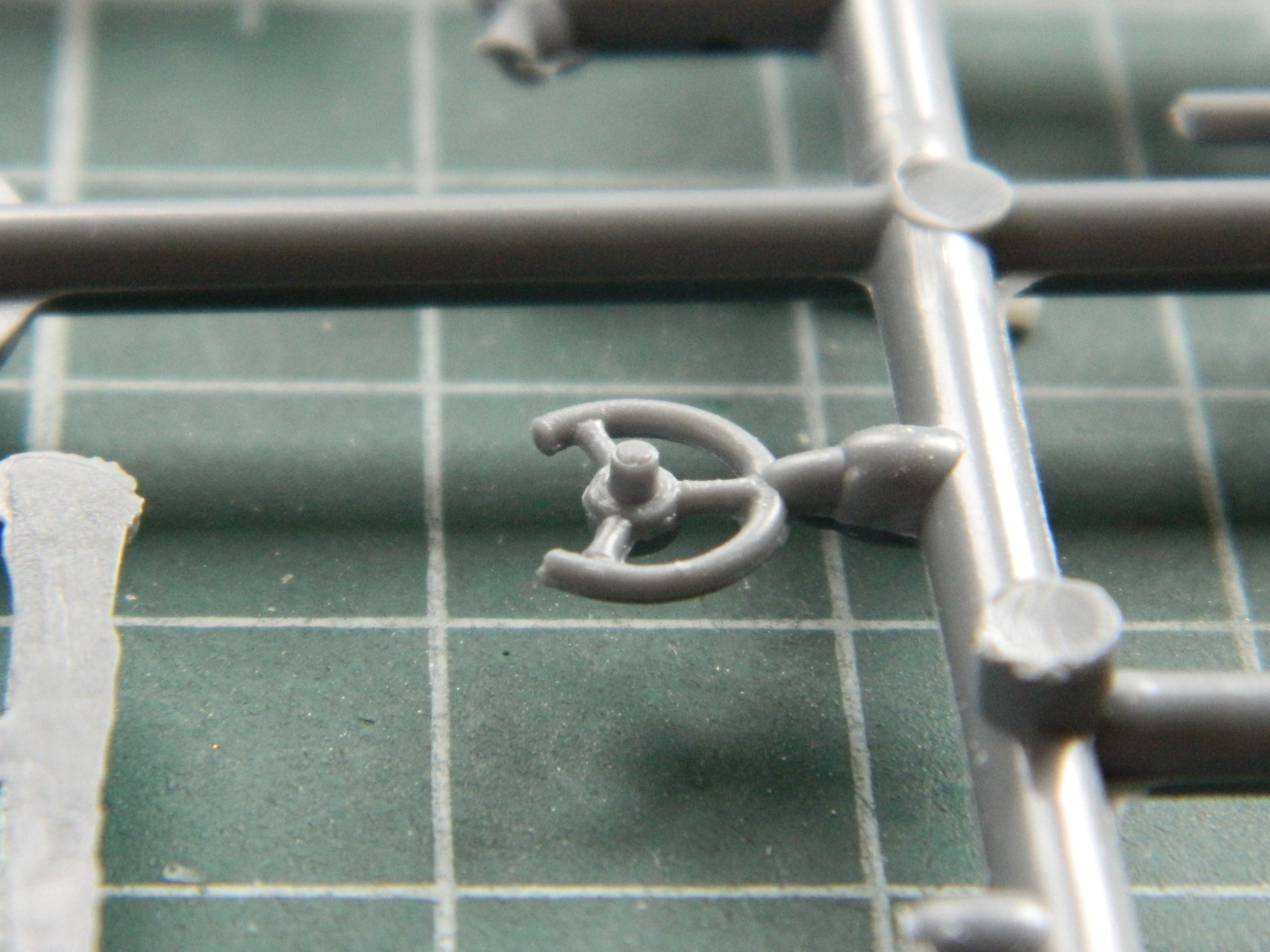
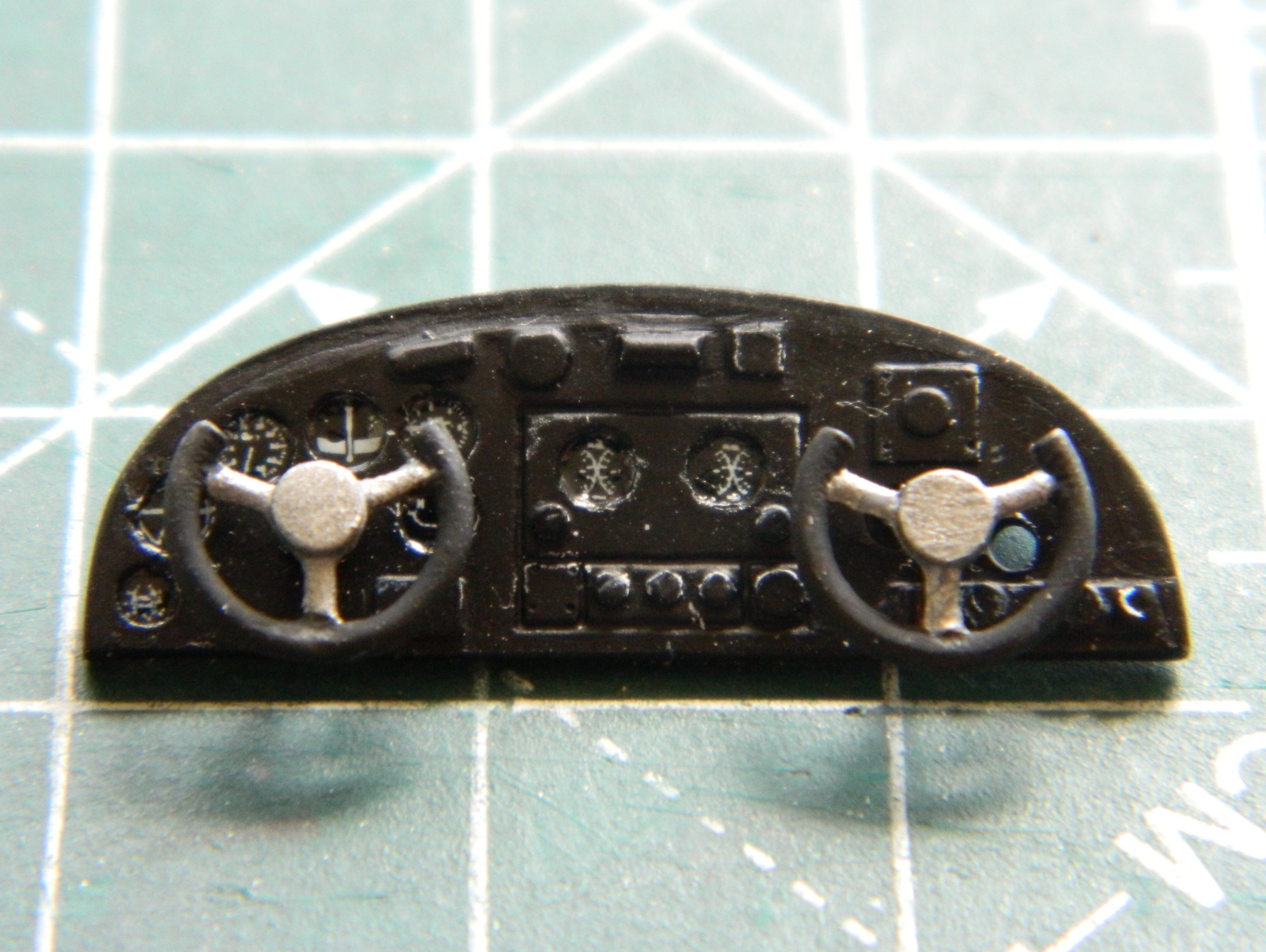
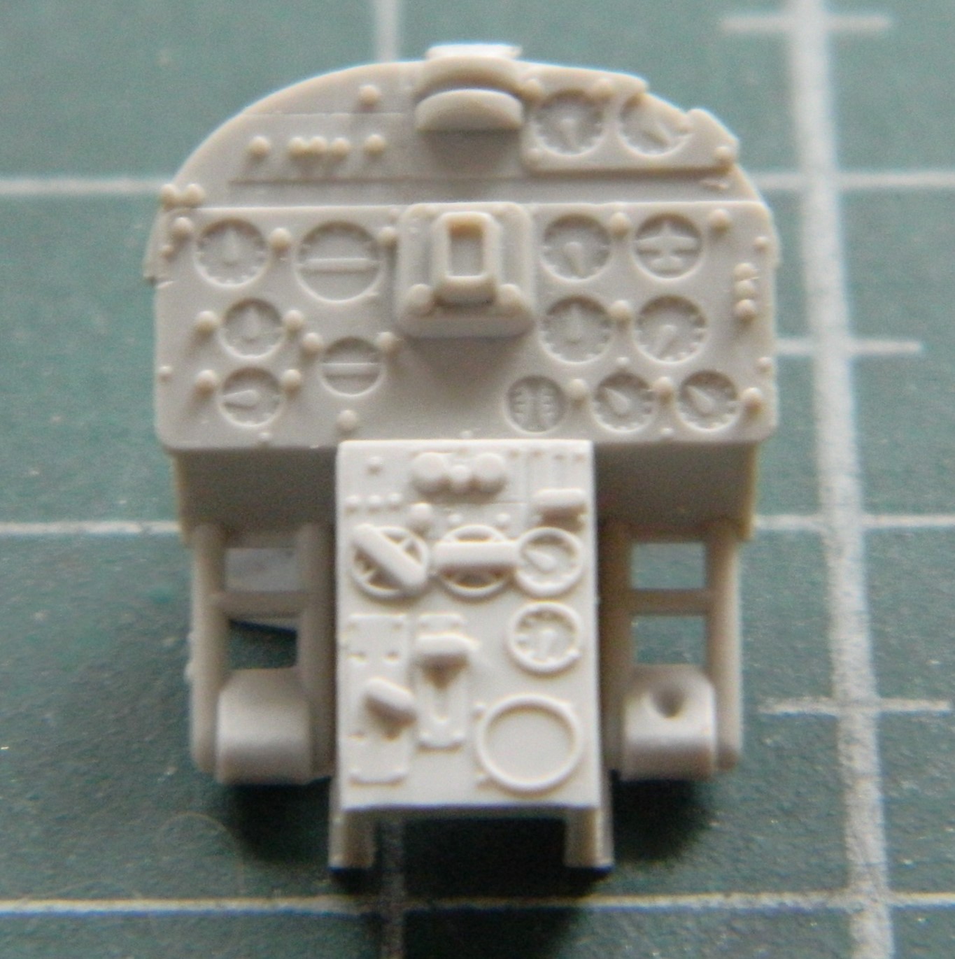
My first task was getting the instrument panel attached. Having painted its face and added instrument decals, it was time to step up and do what’s needed to get the instrument panel to do an excellent “I’m-supposed-to-go-here” imitation. Since I hadn’t painted and added the control yokes, I started there. The face of the panel has raised (and somewhat generic) lumps where someone thought the yokes should mount. Had I looked more closely at those generic lumps, I would have noticed that the “suggested” location for the co-pilot’s yoke was in the wrong place. The last photo in the series below will show those holes where they presently reside.
The stub on the back of the yokes was too short so I added rods (clearly too long, but those will get trimmed once the yokes are in place):
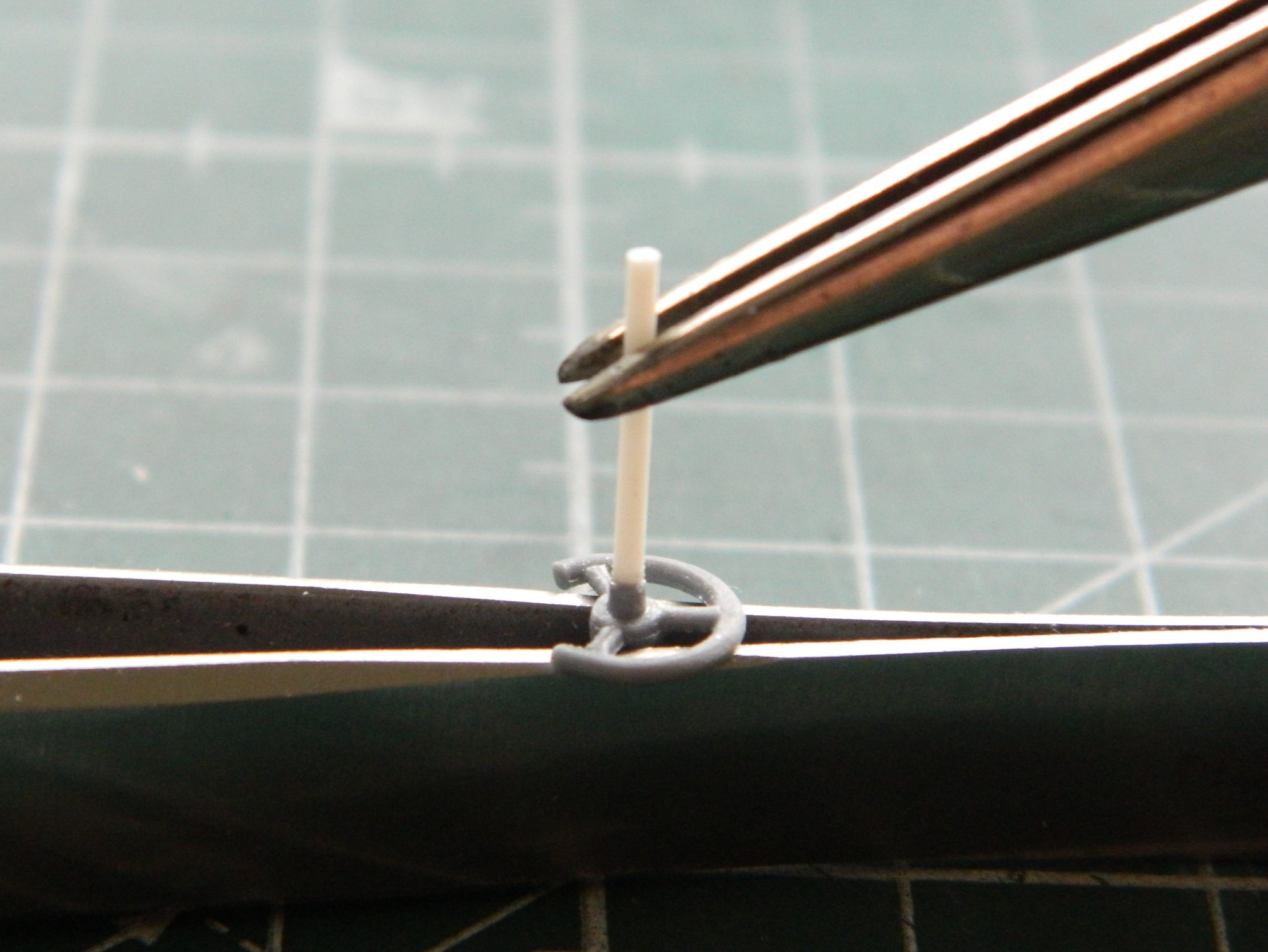

As an aside, subsequent and frequent reattachments showed me that I should have added pins between the rods and yokes. After gluing them back in often, I did that and the problem of knocking those things off ceased. And on to those holes:
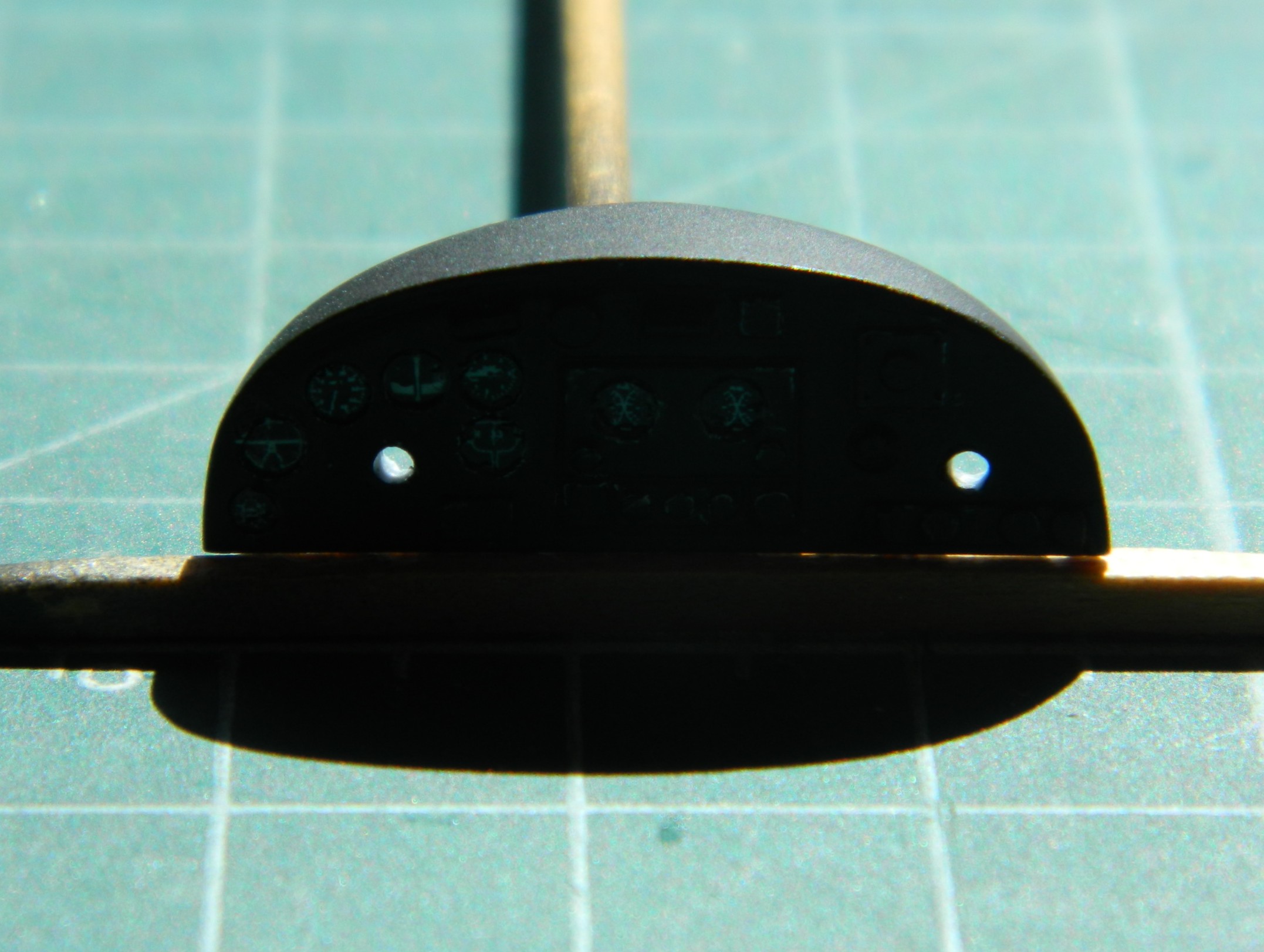
Yeah. I re-drilled the hole on the right and didn’t bother filling the incorrect one for two reasons. The primary reason being that the hole can’t really be seen when the panel is where (I hope) it goes. The second being that I painted the inside of the unused hole flat black and now that hole cannot be seen at all:
The fit of the cockpit’s rear bulkhead showed me that for me, True Details isn’t worth the money. Fit was rotten and the dimensions of the bulkhead are off…as in sides that are supposed to be parallel aren’t parallel. With strategic application of flat black, I doubt that this will be noticed once everything is buttoned up:

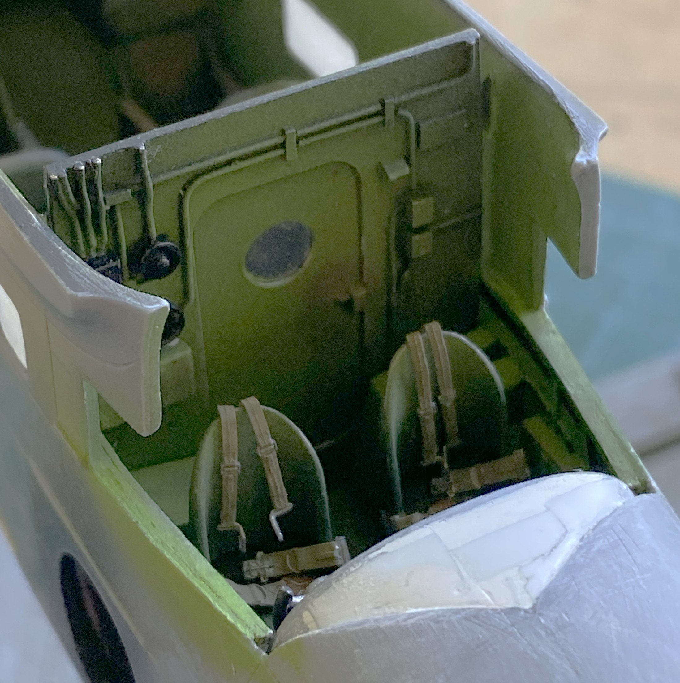
I mixed up some chromate green using Tamiya XF-3 Flat Yellow (2 parts) and X-5 Gloss Green (1 part) and added it to the inner fuselage halves allowing the flat black that was already put down to act as shadows:
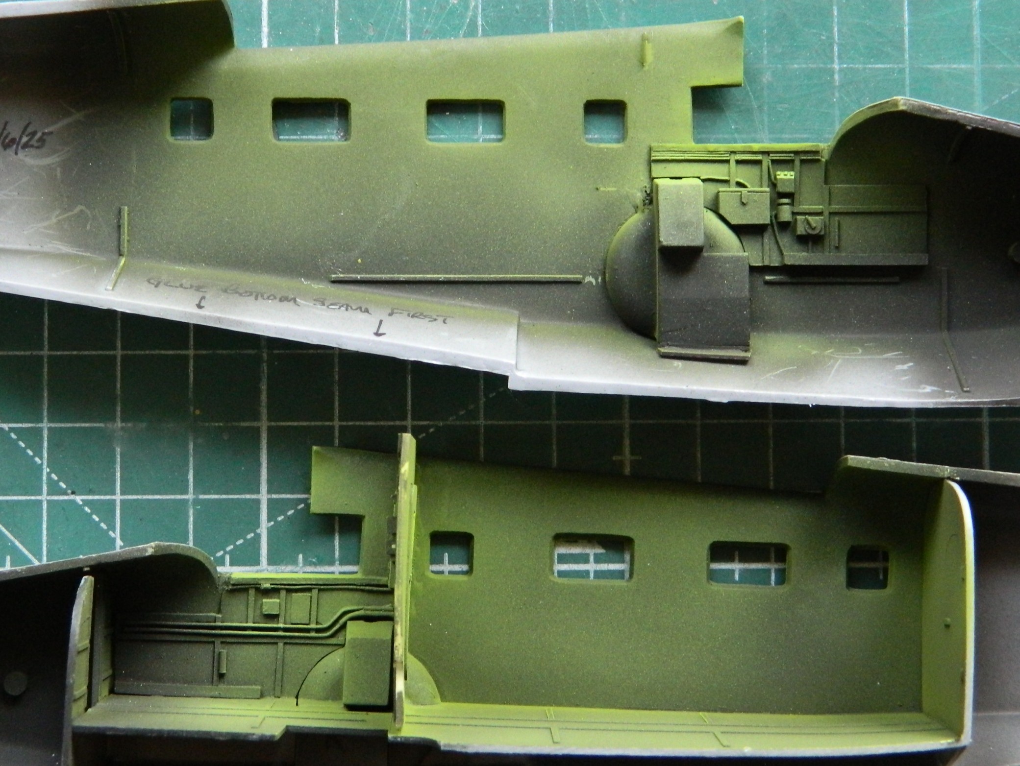
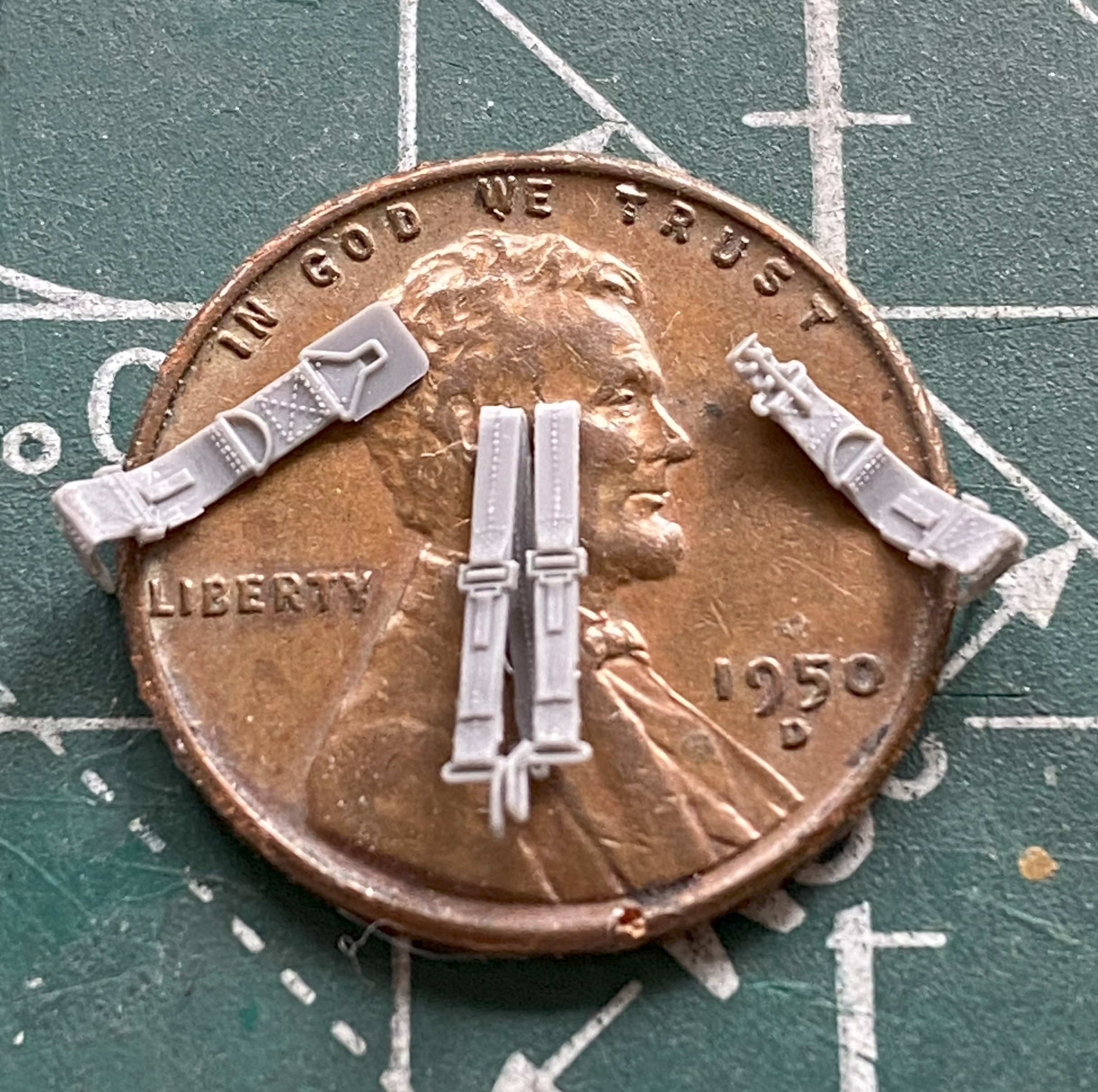
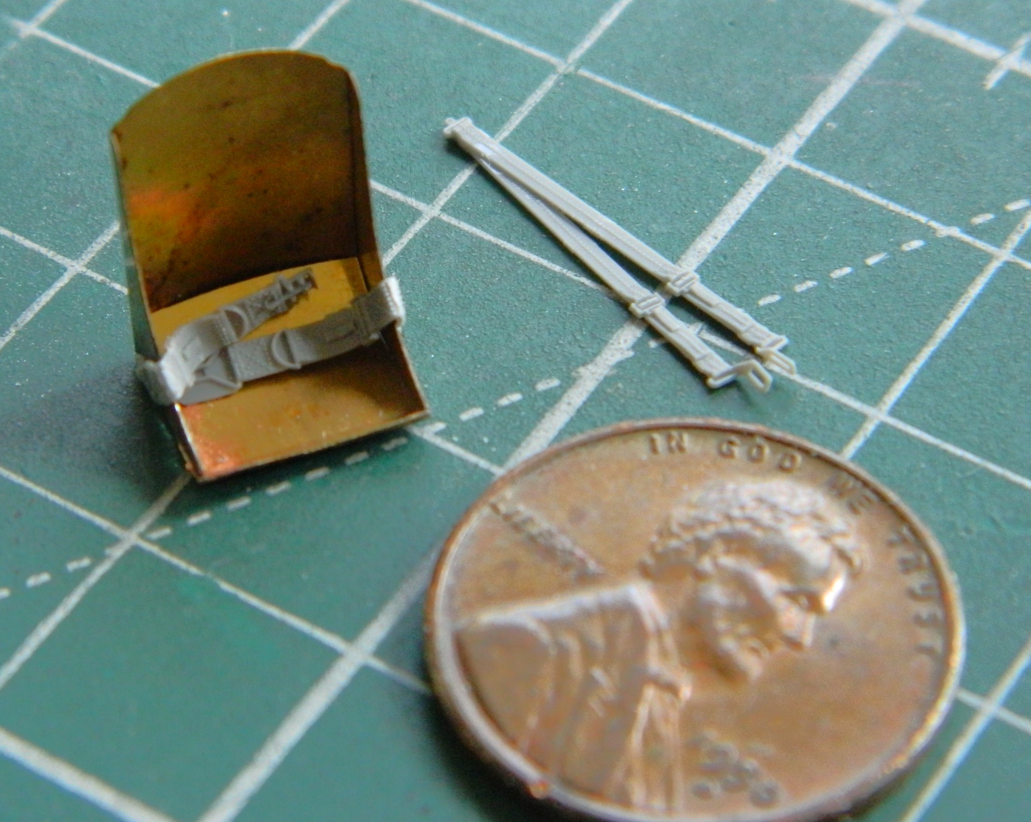
Some time back, I ran across these little beauties. The pilots’ safety harness in delicately molded styrene:
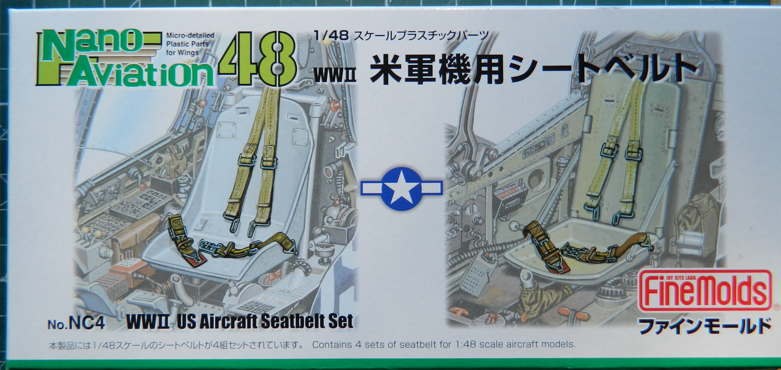
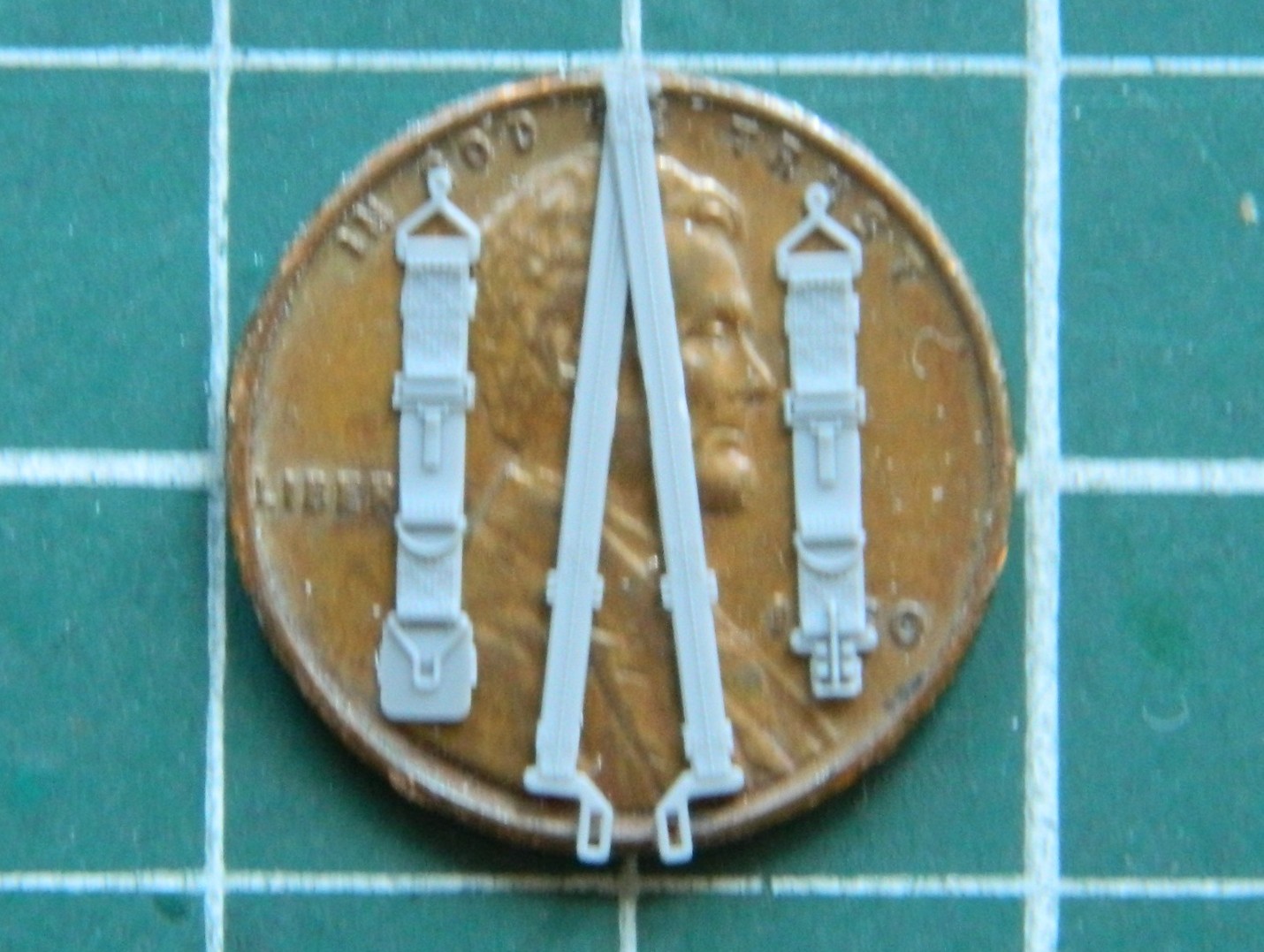
The only vendor I’ve found so far is in Japan. (What with these bullshit “tariffs”, I don’t know how easy they’ll be to get in the future…a problem I’ll deal with in the future.) This is what’s in the box:

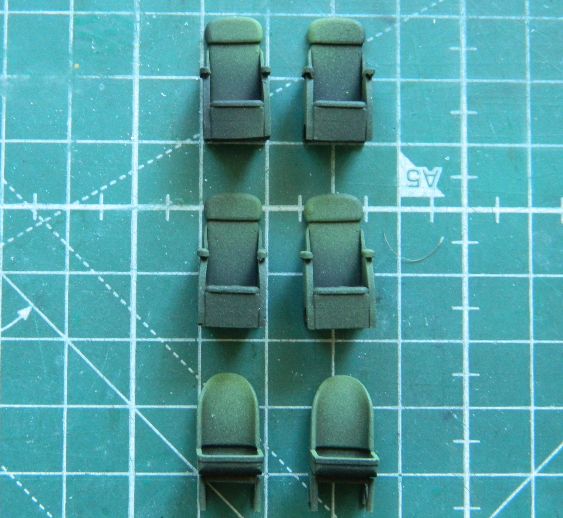
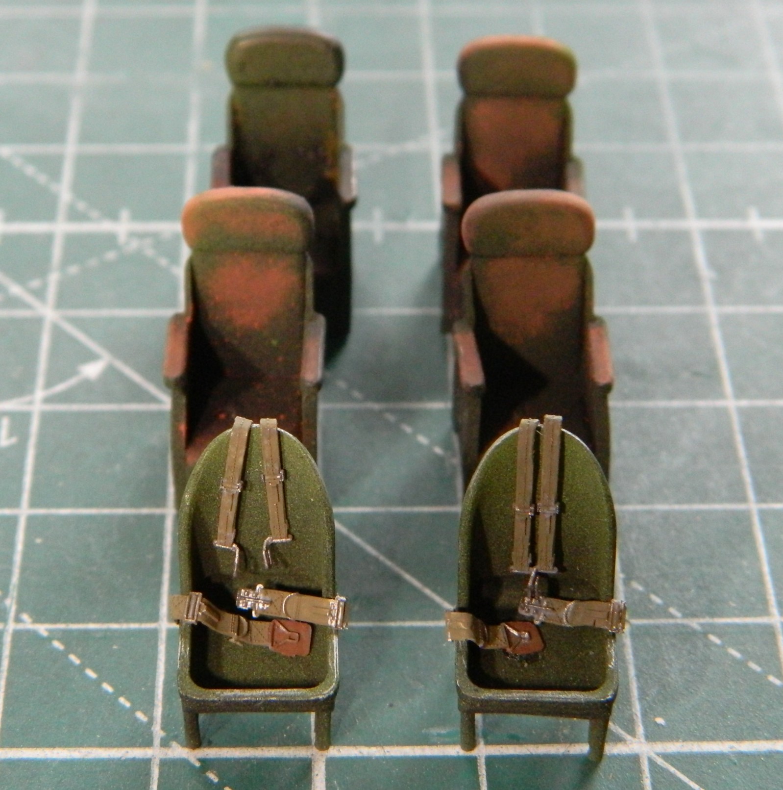
Before I could use those, I wanted to paint all the seats. As typical for me, the first coat of paint was Tamiya XF-1 Flat Black for pre-shading. Then I used my custom-mixed chromate green and painted on the light blooms:
The harnesses were heated and bent to conform to the seats of the pilot and co-pilot:
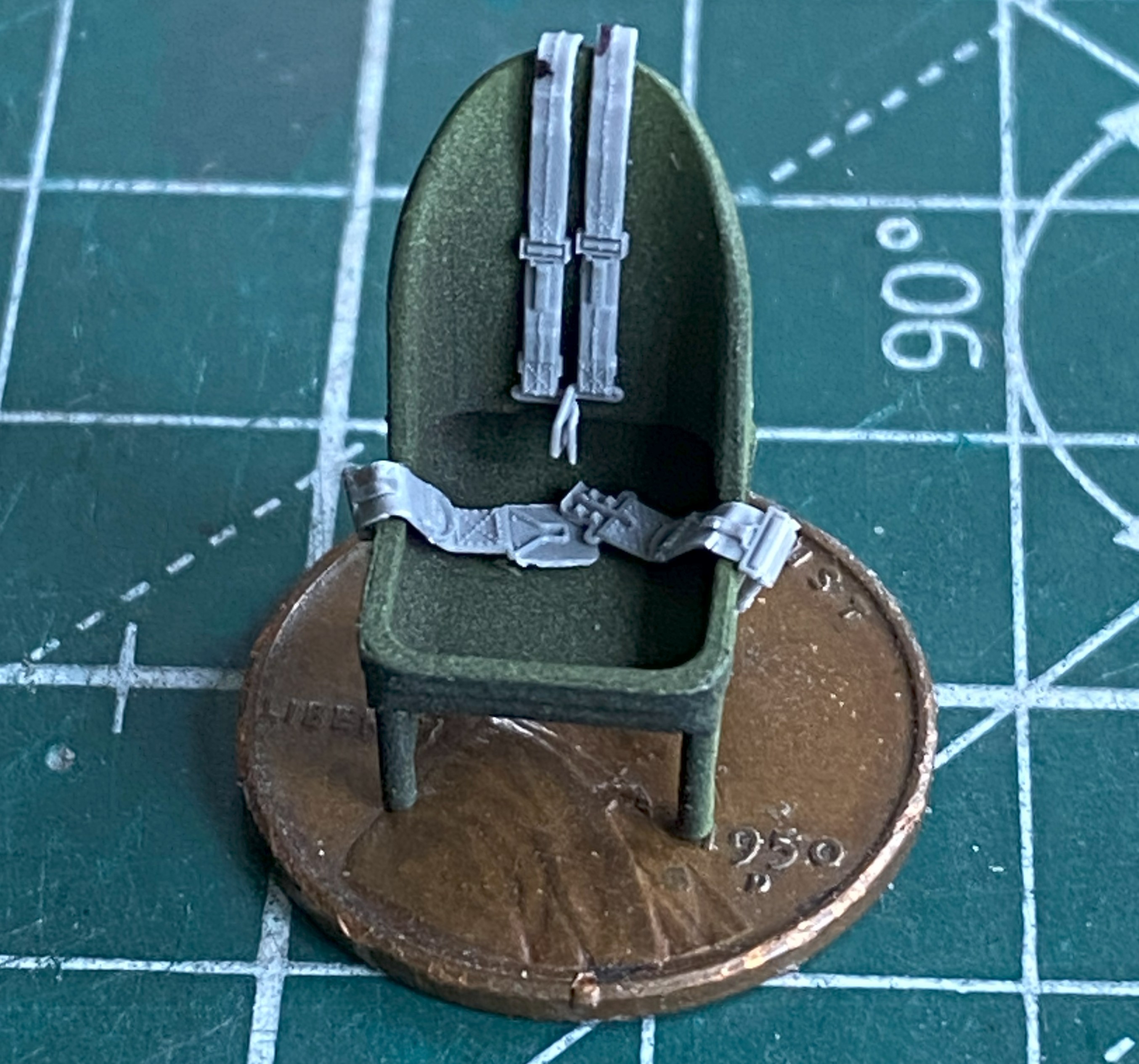
The straps were painted with a mix of Tamiya XF-49 Khaki (3 parts) and XF-64 Red Brown (1 part). The leather pads were painted using tinted XF-64 Red brown (5 parts) and XF-2 Flat White (1 part). The metal bits were painted with X-11 Chrome Silver. XF-51 Khaki Drab (5 parts) and XF-2 Flat White (1 part) color was misted over the areas that would be most highlighted, and then I used a dark orange pastel to replicate wear. I didn’t go crazy on the passenger seats because little of them will be seen. The pilot and co-pilot seats were touched here and there with a silver pencil to replicate wear:
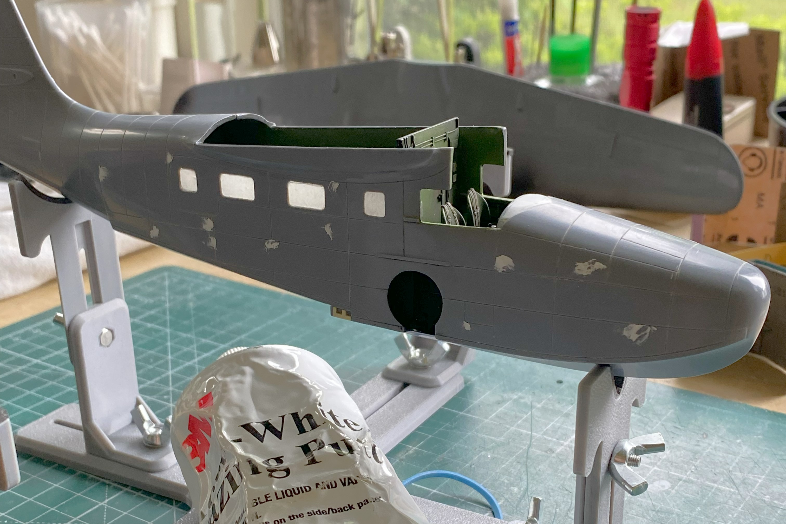
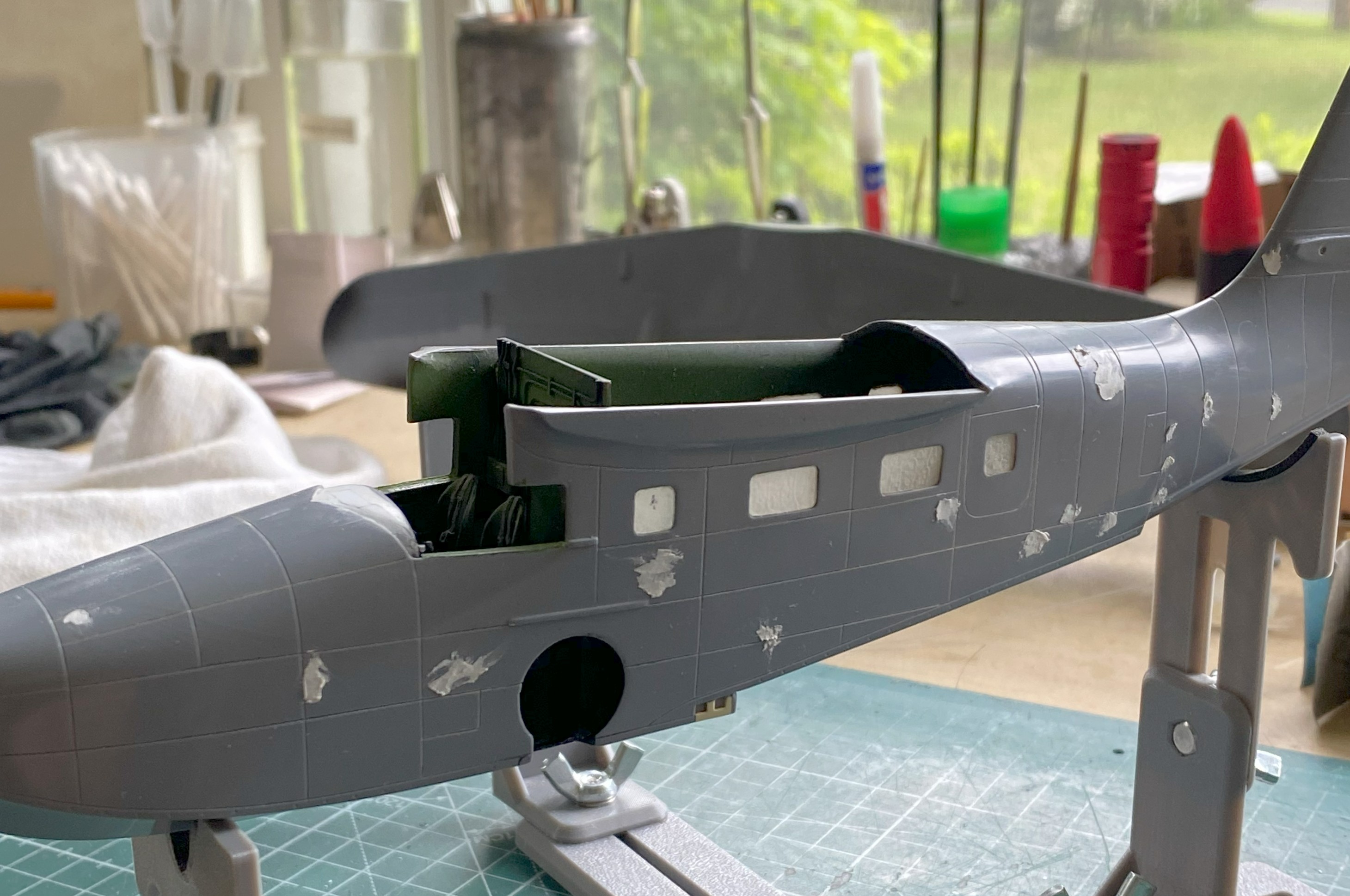
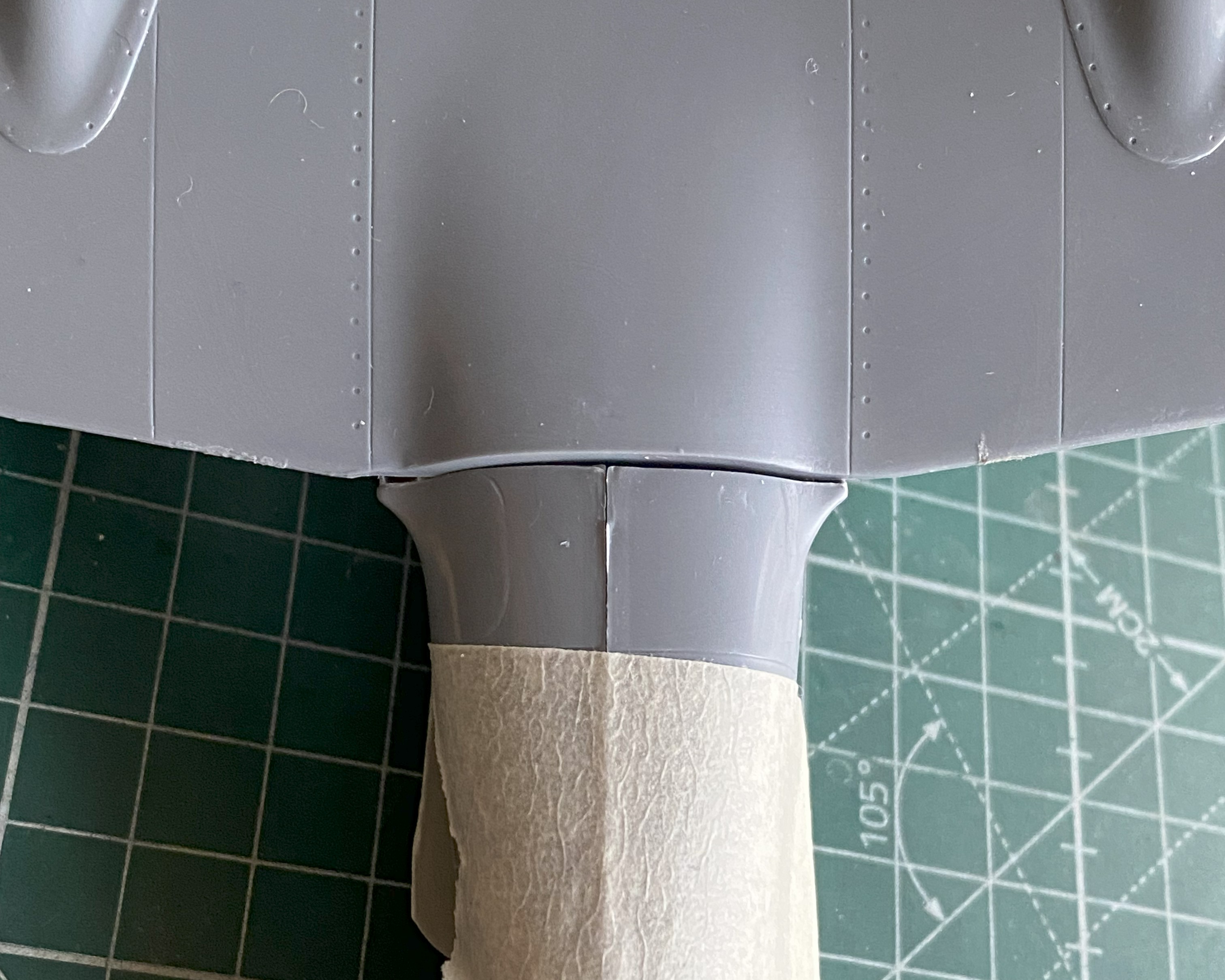
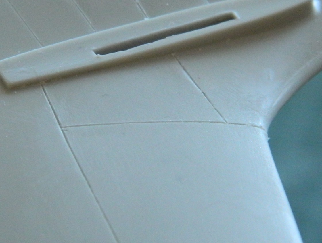
With the fuselage halves taped together, I test-fitted the clear canopy parts (obviously also taped together) to see if my initial assessment held up regarding its fit. Yes…it did. I placed the wings in place to see what had to be diddled with to get a better fit. Check what the arrow is pointed to:
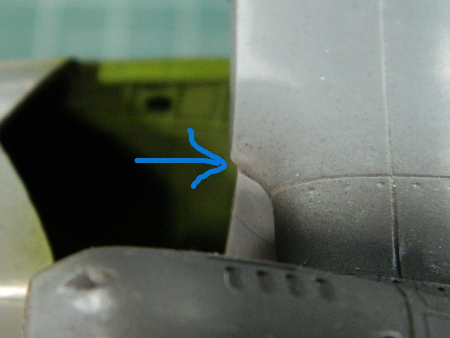
That overhang has to go; those parts are all supposed to conform to the edge of the fuselage. So the plastic above the pencil line was filed to meet the line:

Checking the fit of the clear parts again showed a significant improvement with its fit:

It also showed me that there’s a possibility of having to tweak the attachment areas of the clear parts but I can’t make that determination until the wings are glued down permanently.
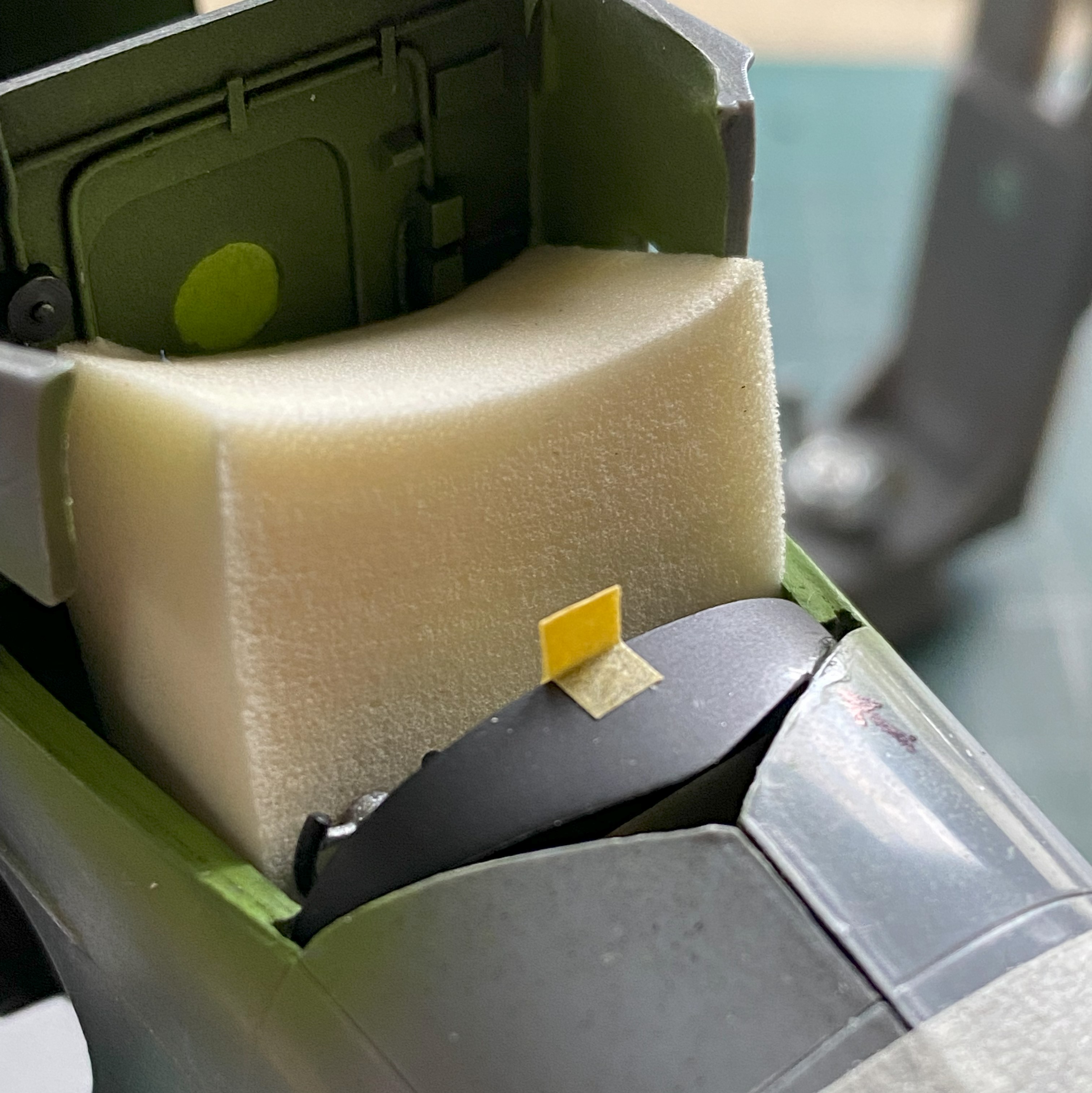
The last thing I had to do before I could marry the fuselage halves was to get the sodding instrument panel to fit (and hopefully not look bad in doing so). I used a foam wedge (sold in drug stores and/or apothecaries) to align the panel to the best of my sometimes-disappointing abilities (the tan square is a loop of masking tape to enable me to move it…and there was no shortage of moving it…without damaging the face of the panel). Where the panel touched the fuselage received a significant amount of styrene cement any place it touched the fuselage half. My brain-fade kicked in and I attached the panel to the left side of the fuselage, where everything else inside the fuselage was attached to the right side. ::facepalm:: It complicated the joining of both halves a little but I didn’t find that out until the trigger was pulled and the Rubicon crossed. As you’ll see, there was no way I could dislodge the panel without damaging things. The bitch is ON there:

After letting it sit overnight to harden fully, I thought that it wasn’t quite firmly attached enough. I used styrene scraps to reinforce the attachment point(s):

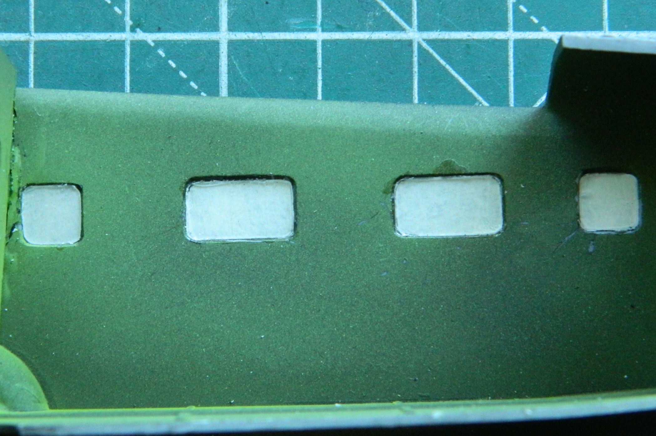
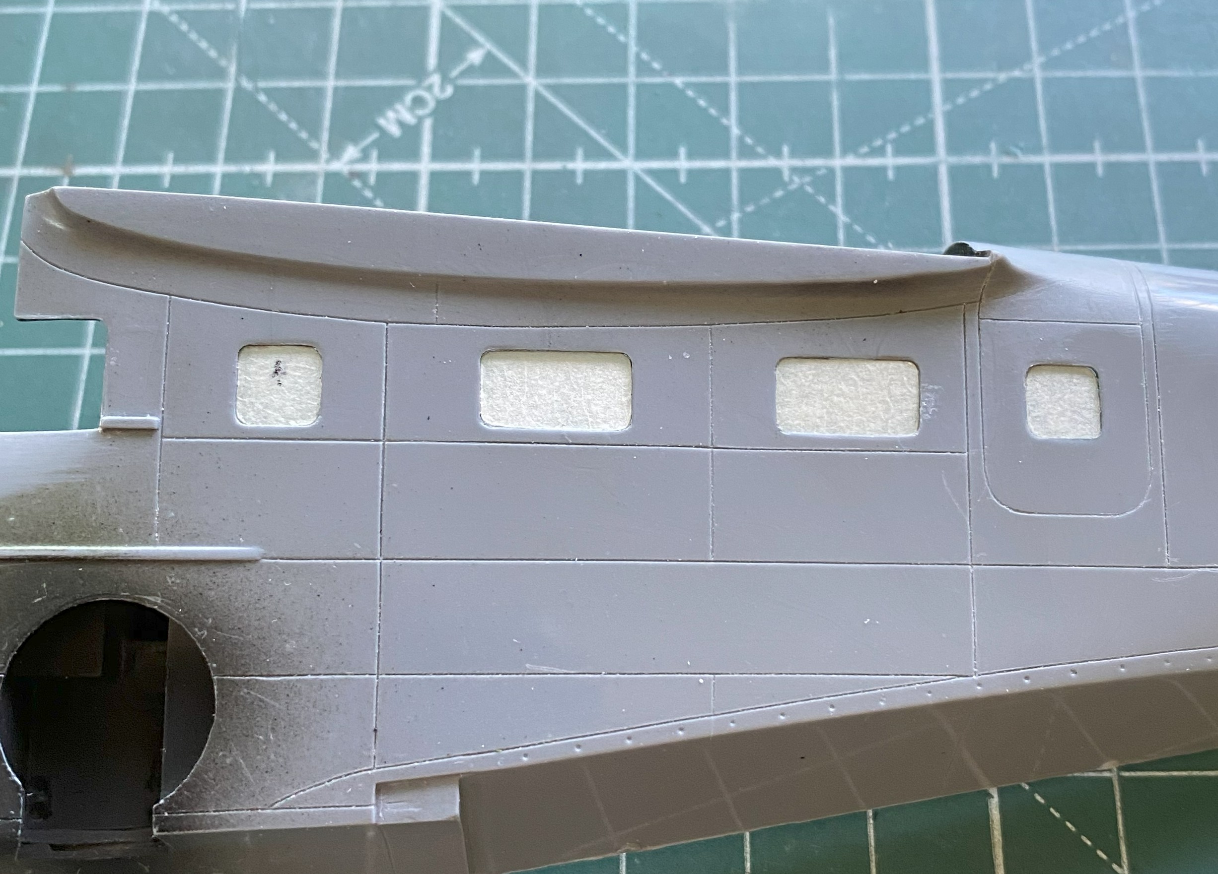
It was time to add the windows to the passenger compartment. Once again, thick plastic:
Earlier US WWII fighters had a plate of armored glass behind the windscreen. I’ll keep these thick clear parts for that use in the future. For now, they need to be replaced. I’d intended on using 0.010″ (.254mm) but though it’s to a more scaled size, I wanted a bit more surface for adhesives to bond with so instead I used 0.015″ (.381mm) clear instead. This gave me a closer-to-scale thickness (the thin piece of plastic isn’t usable other than as a comparison of thickness):

When I did the M4 Sherman with a clear side, I decided that the next time I used clear like that (or for any purpose, really) where it had to be fettled and tweaked to fit, I’d cover both sides of the clear styrene with masking tape. After coating a scrap strip of clear on both sides, I positioned the strip under the fuselage and traced the outlines of the windows:

Yes…the sides of the fuselage are too thick as well. What it would take to fix that isn’t worth the effort so I left it as-is. The windows were trimmed and glued into place using UV-setting resin and the inner masking tape removed:
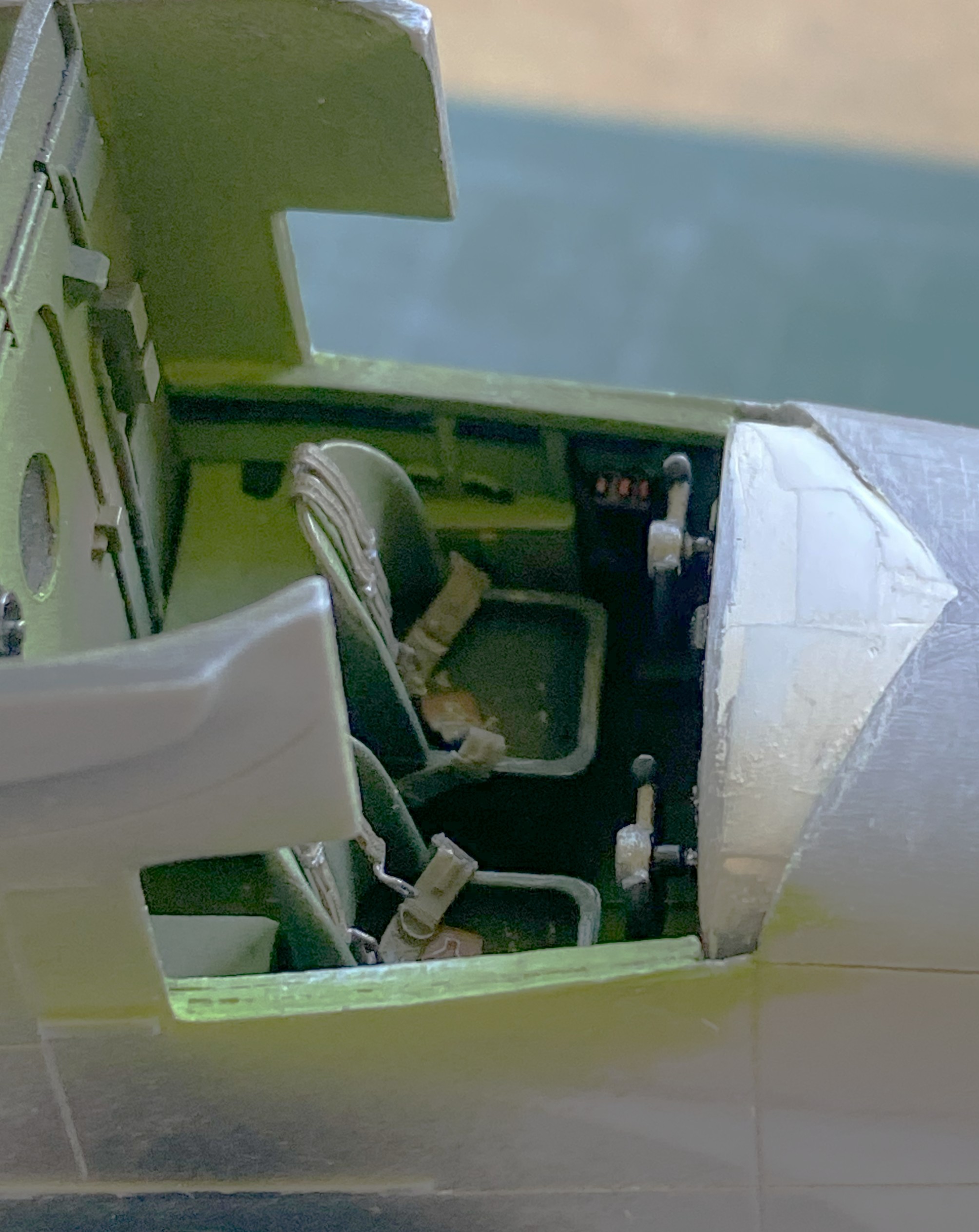
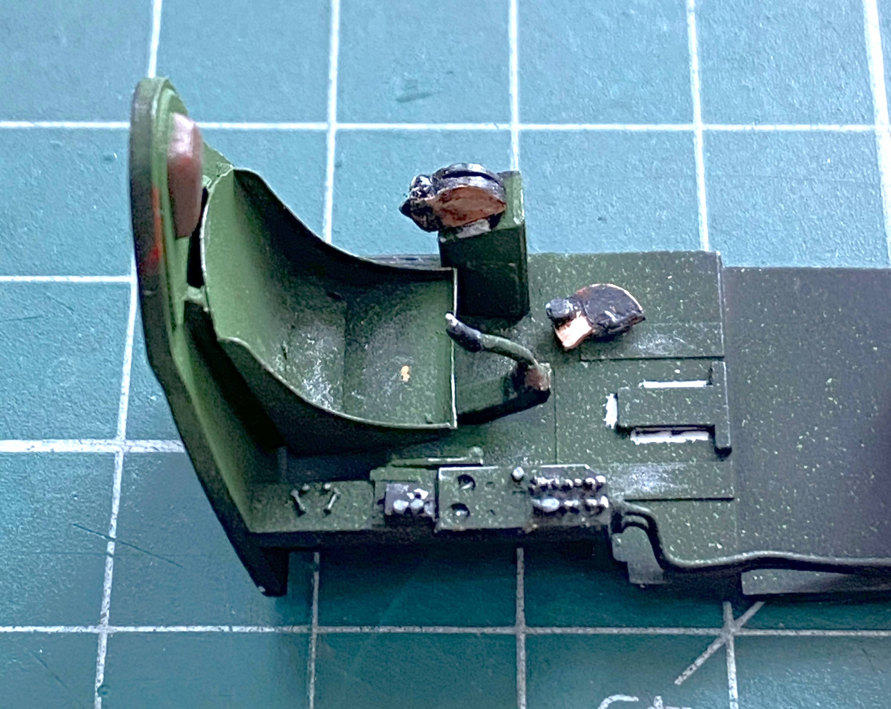
Time to add the seats to the cockpit:
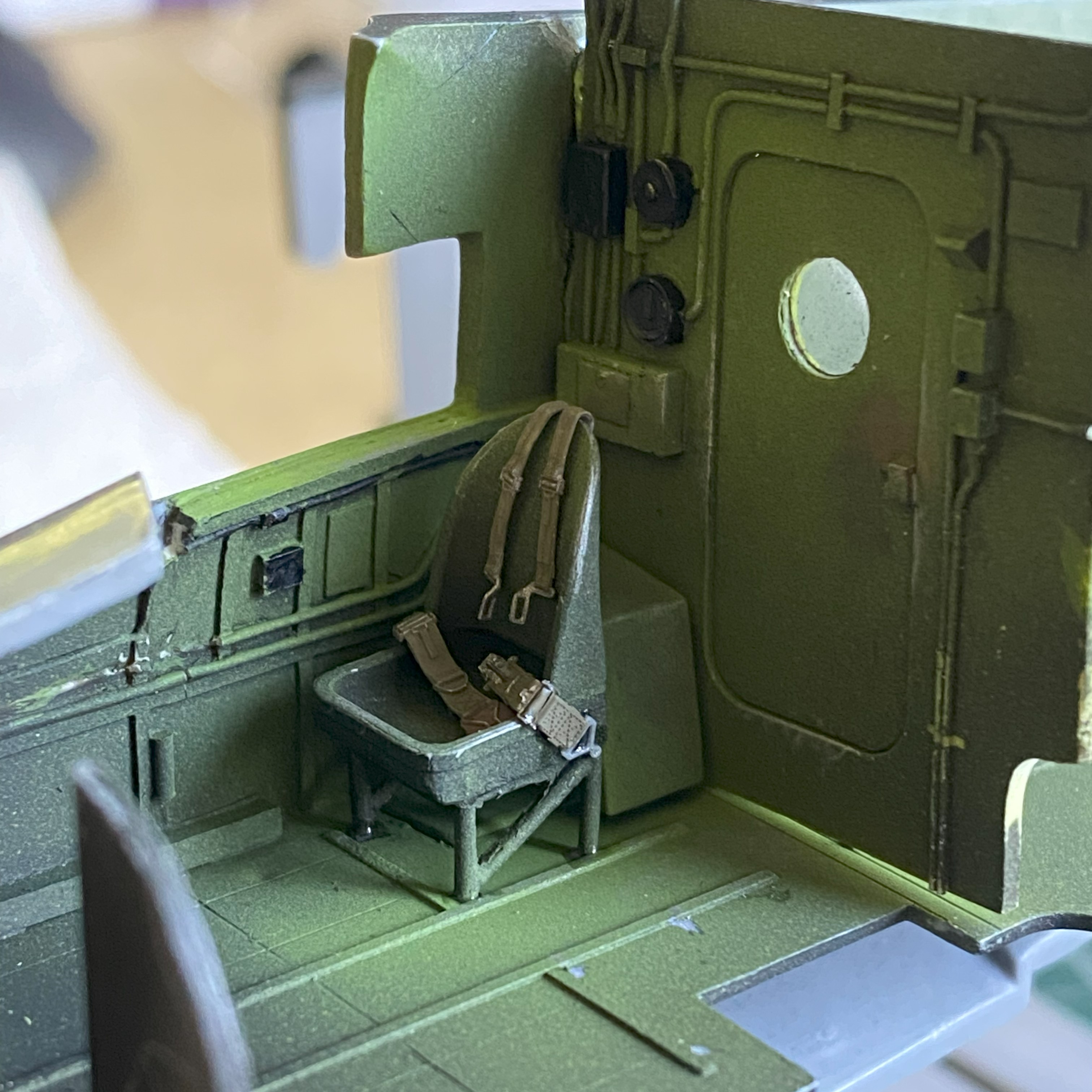
The pilot’s seat wasn’t added at this time because of fitment problems. I had to shorten one of the legs so that it would sit level(ish) and that would be better done after the fuselage was together. The passenger seats were then glued in:


I glued the fuselage halves together. Such a simple sentence to describe a hair-pulling experience (that’s one way to clear out my nose…). Each half of the dies for the fuselage parts was clearly cut by different people. I just wished that they’d communicated with each other. Neither side matched the other in overall dimensions or curvatures. What ended up driving this task was the question, “Which side would be easier to fix than others?” I made my decision to have the top seams match (because those are the ones easier to see) and deal with what happens underneath. The halves were glued together (and most of the filler used to hide the seams, top and bottom, came from 99.9% stretched sprue).
With the halves now joined, it was time to fix the mess underneath. SO much putty would have been needed to do that that I decided to add scrap sheet, mostly 0.010″ (.254mm). While I was doing that, I noticed that things don’t fit (check the arrows):

These photos are included to show you what the good side’s fit was like:


Yeah…filled with sprue.
This is why one should always use photo references from the actual time period being modeled. Most of my references are modern ones, which are okay in general, but it’s in the specifics where they drop the ball. Modern references show the nose hatch to be “proud.” It sticks up. Period references show this hatch fits flush. Can you guess what I didn’t do?:
Back under the fuselage, lot of sanding ensued (and more than a little filing):
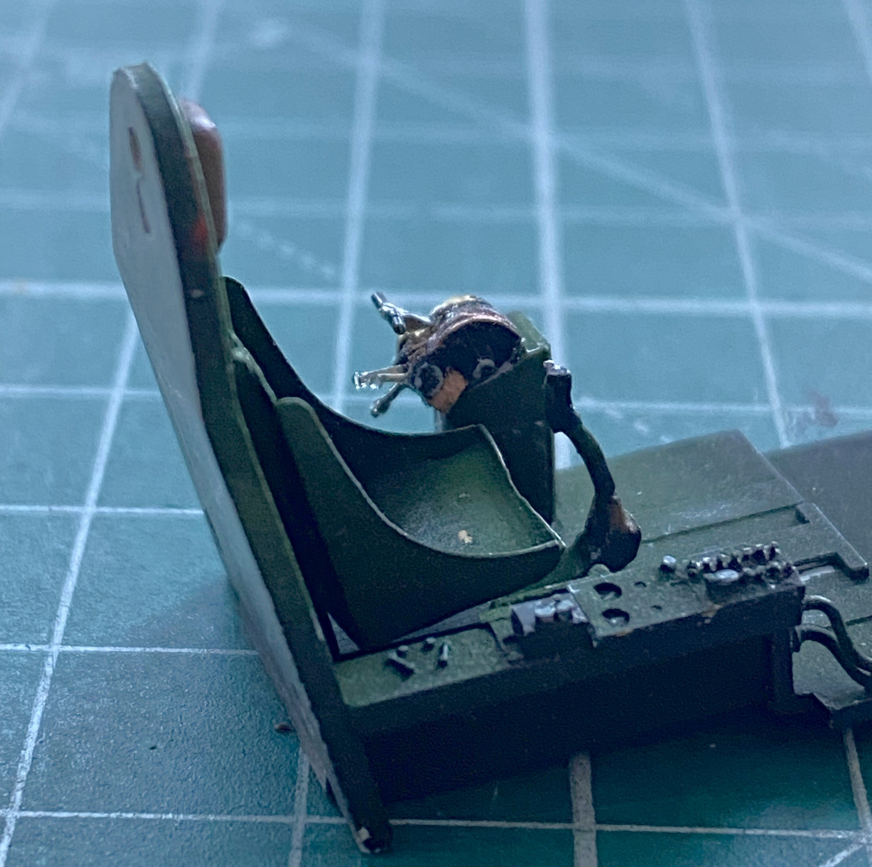
With the supports trimmed judiciously, the pilot’s seat is in, as well as the instrument panel top puttied and sanded (though it’s evident that there will be more putty added and followed up by more sanding):
Checking fit (after a LOT of sanding) with the wings shows me that I was correct…most of what’s inside won’t show from the outside, and even less will be visible once the clear parts are in and painted:

I dislike scribing and my results show that. The panel lines with this model were inconsistent with depth and width, so all panel lines had to be rescribed. And then it was three bouts of putty filling where the scriber (me) left lines where there shouldn’t be any lines:
And after doing all that, RE rescribing panel lines often does this:

Fit was so poor that in order to get things the way I want them to be, I ended up with something that looked like a Sub at a BDSM party:

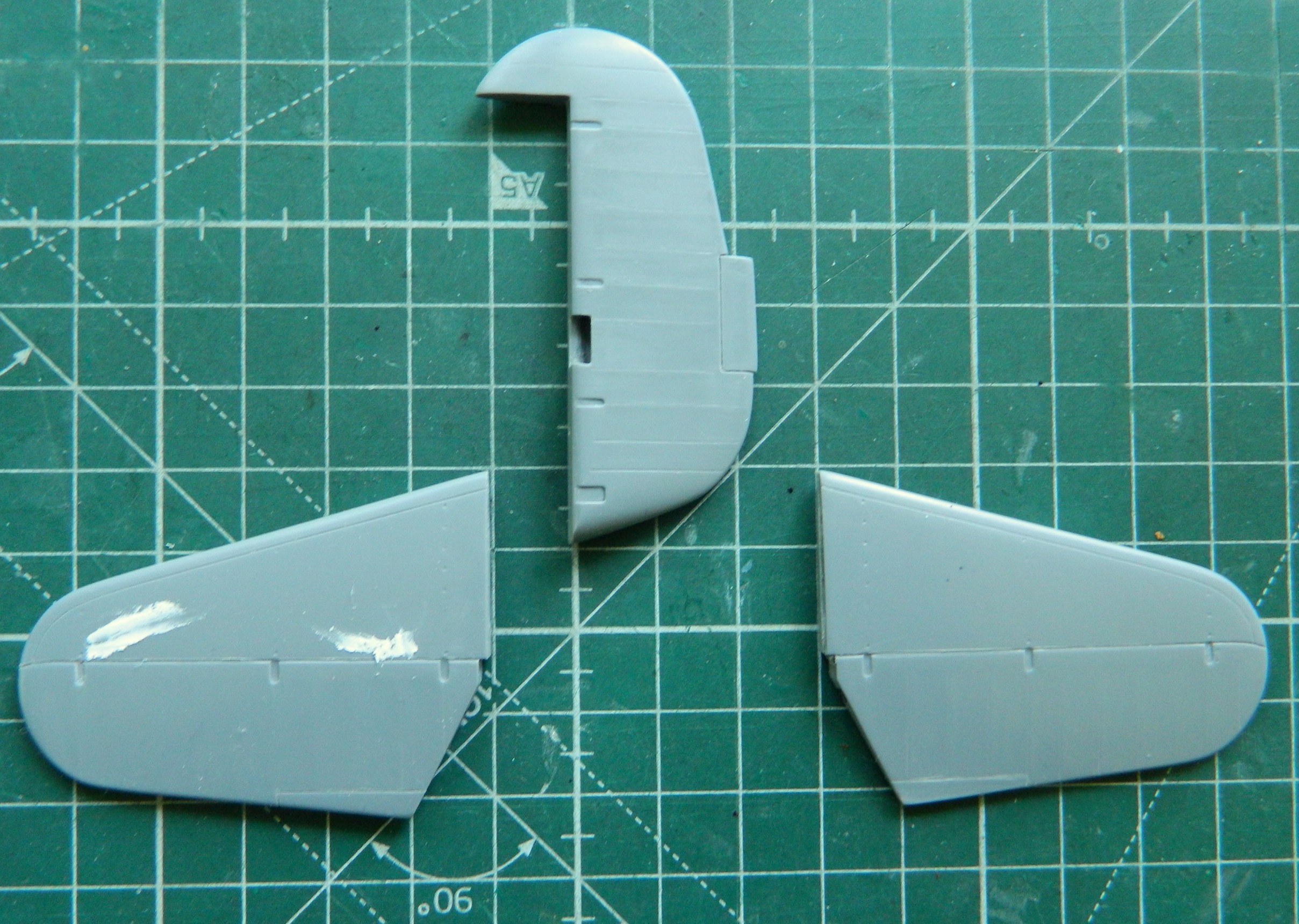
And though it took stretched sprue, scribing, rescribing, and putty, I got the empennage done:
Maybe next month I’ll get to start putting these bits together permanently.
Grumman JRF Goose (Czech Model) 1/48 Scale Build #1 – Parts Layout and the First of Much Work Begins
This was what was in the box:


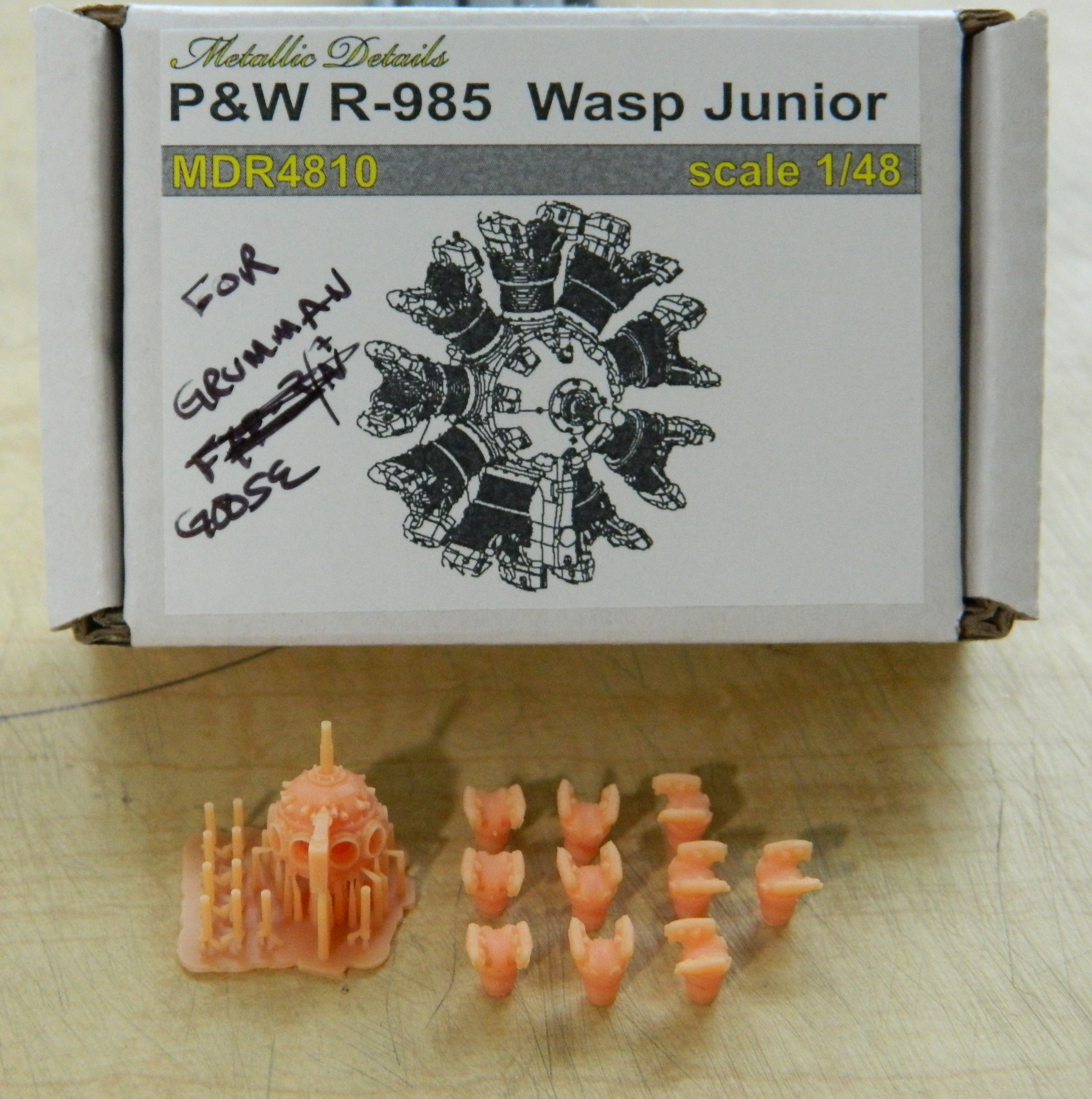
Plus these engines from Metallic Details:
It’s my intention to build this one in its 1944 markings, which means using the national insignia without the red borders. In researching this kit and reading build reviews, the theme here is “limited run” with all that that implies. Thick plastic, subpar fit, and oddly done details. Construction so far has confirmed all that. In one regard I’m getting off with less fiddly work than otherwise would have been the case. Being a high-wing aircraft, that wing gets in the way of seeing the into the cockpit, specifically in this case the instrument panel. So that’s one chore I don’t have to take care of. There were overhead consoles that engine monitoring instrumentation was mounted in as well as throttle and propeller pitch controls. Though the overhead console has to be scratchbuilt, few of the details are necessary since it really can’t be seen. I don’t know how much of the console itself can be seen so the overall shape of it needs to be build, if only to hang the throttle controls from (and maybe the pitch controls as well, which I will find out about later).
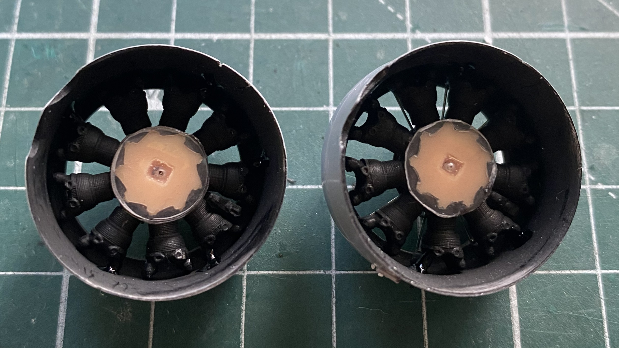
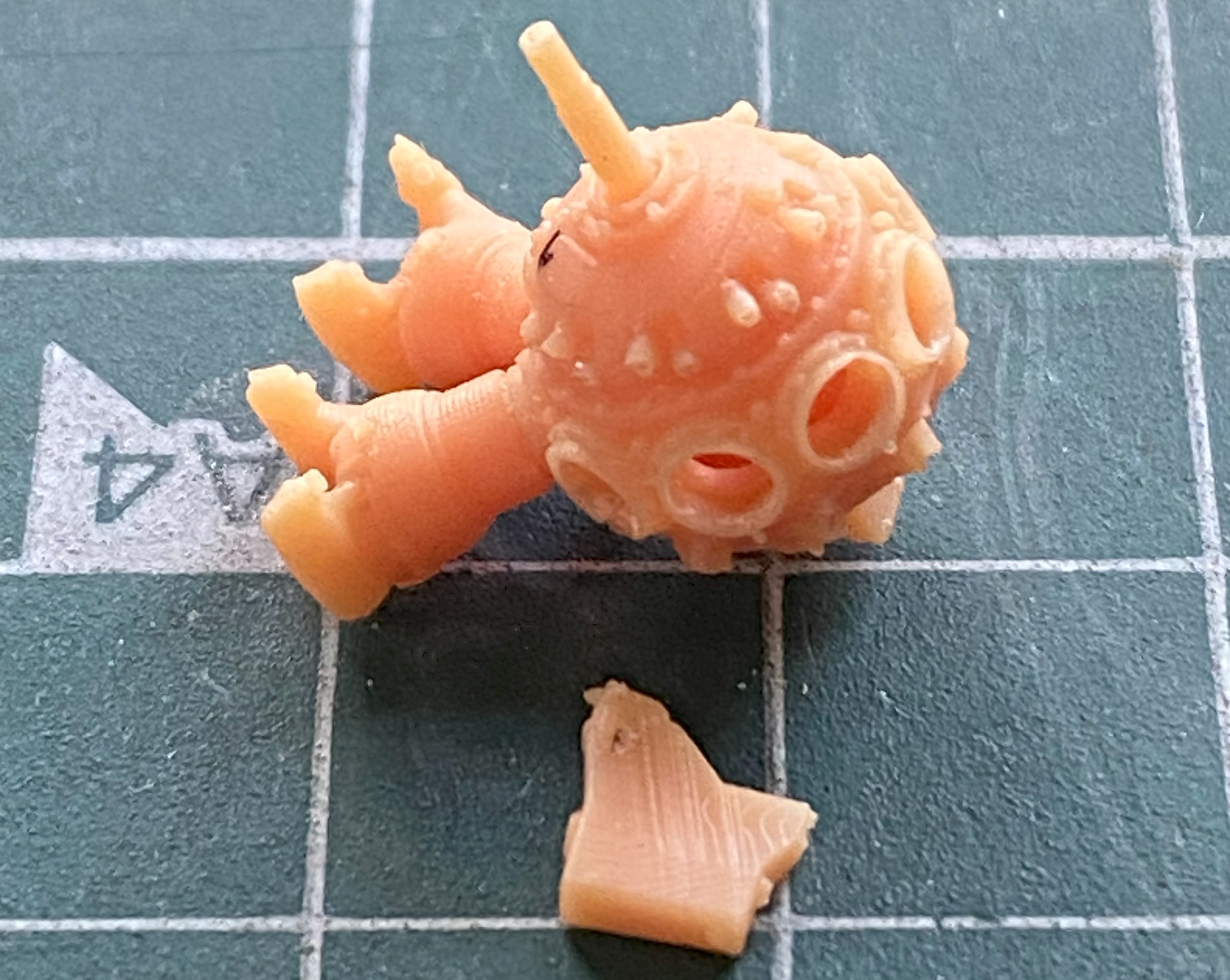
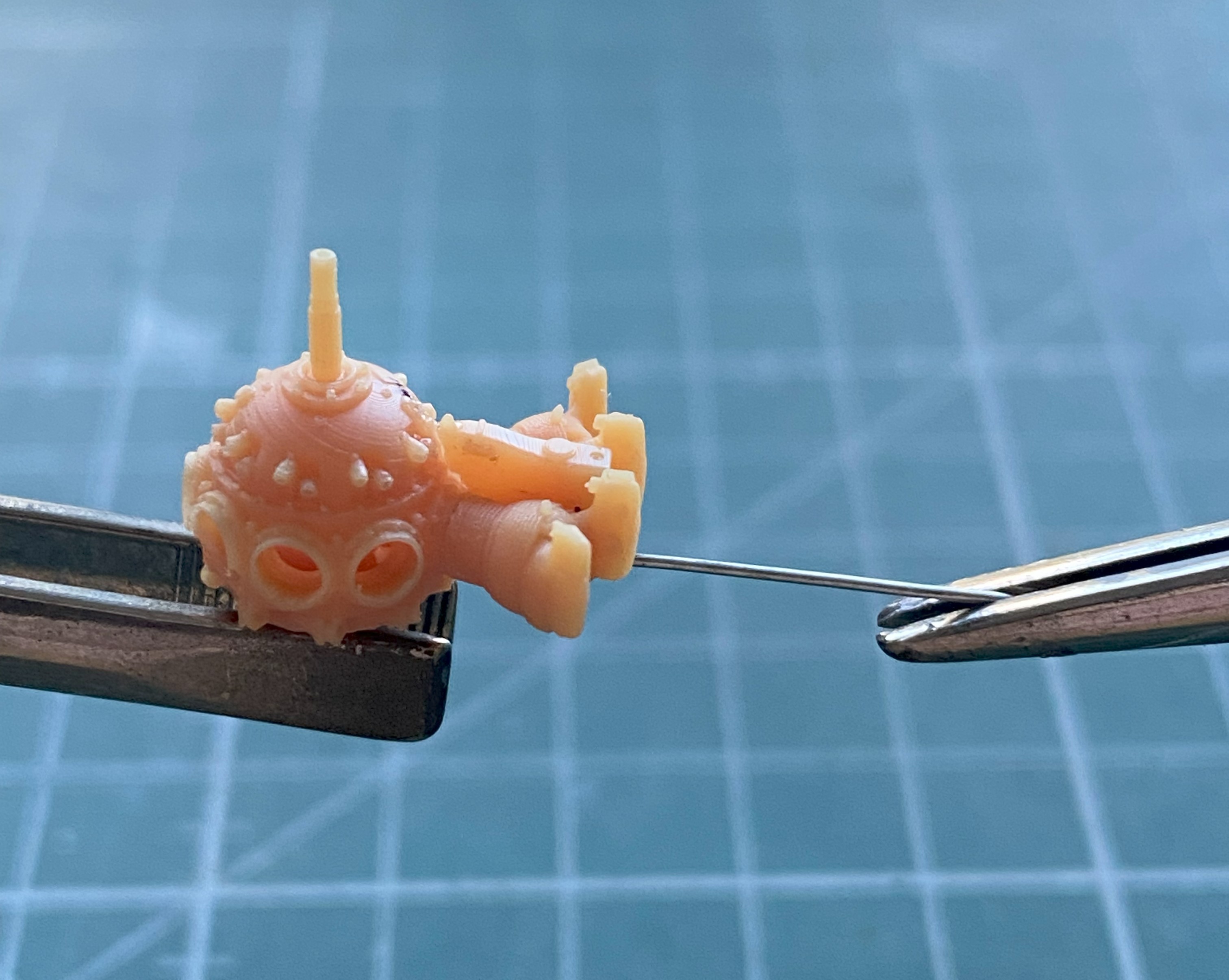
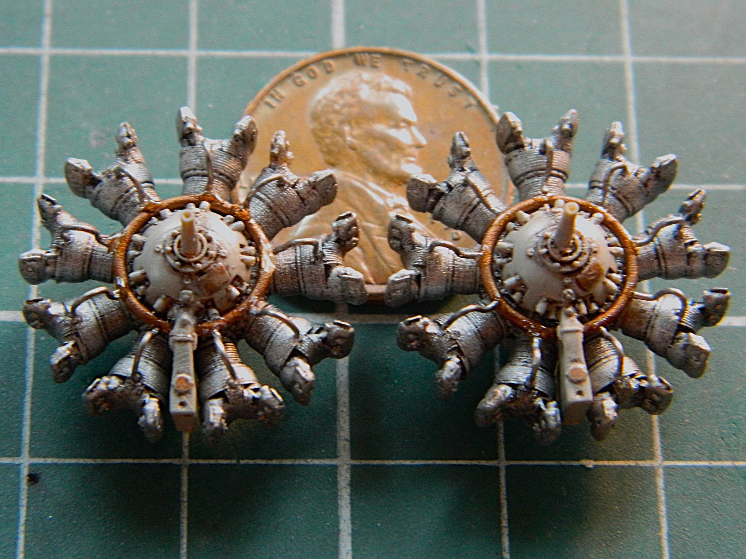
My typical build routine is to start with the cockpit first, but since so little of it can be seen (not the same as none of it since the rear bulkhead of the cockpit will clearly be seen), I decided to start with Metallic Details’ engines. I was about to get a “learning moment” about these particular 3D printed parts…and maybe 3D printed parts in general. If you’ve ever done work on or with as-printed parts, you’ve seen the miniature forest of supports that are necessary for the part to print at all. Those all have to go. I thought I was being careful removing those supports (can you see where this is going?) and for the most part, all went as intended. There is a Mystery Component that is attached to the bottom of the crankcase and hangs straight down. Let’s play a little round of the, “Can you spot the differences between these two things,” game:

If you said, “The Mystery Thing is missing from the one on the right,” you win. While removing the supports underneath the missing Mystery Thing, I discovered that this resin is very brittle. The Mystery Thing just snapped off. And not unusually in my shop, I heard it hit the floor and using my Echo Location ™ ability, I went to where I heard the Mystery Thing hit. Maybe that’s where it hit, but that’s nowhere near where it ended up… I mean, this is my first task and it’s gone sideways. (I never did find out where it ended up.) Fine. I’ll make another one, then:
I was so annoyed at myself for losing a component as part of my first task that I decided that I’d get all the parts of these two engines cleaned up and ready to assemble (or paint…more on that later). That’s when I found out that just because it’s 3D printed, doesn’t mean that the parts that were designed to go together will in fact go to-fucking-gether. The outer diameter of the cylinder jugs (hereafter referred to simply as “jugs”) is exactly the same as the inner diameter of the holes in the crankcases where they’re supposed to go. That means that there isn’t enough space in those holes for the jugs TO go into. [A note to those of you who design and produce these sorts of things: Test fit the goddam parts before you sell the goddam parts.] In order to get the jugs to seat into the crankcases correctly, I had to shorten them (because when I didn’t, each stub at the bottom of the jugs interfered with all the other jugs, preventing any of them from seating properly), and then take my thinnest knife which just fit into the sockets and carve away the GOD DAMNED LIP MOLDED INTO THE BOTTOM OF THE SOCKET! No…not pleased.
Nine jugs per engine and two engines. Holding these small parts with sharp protruding areas right where the fingertips hold them so that the stubs can be shortened and filed to decrease each diameter results in very, VERY, sore fingertips. Once those essentially needless tasks were accomplished (I say, “essentially needless” not because I didn’t have to do the work…because I did…I said it because if whomever had laid out these parts digitally had done their job correctly, none of this work, or sore, VERY sore, fingertips would have been required):
I drilled out the stubs at the bottoms of the jugs so that I could stuff a toothpick into each one to make painting them possible. Sure…I could have assembled the engines and then painted them, but since I’m going through all this supposedly-needless work so that I could assemble them, I’m going to take advantage of that and paint the jugs and crankcase separately and then assemble them. With the jugs good to go, I made the ignition wire ring from copper wires:
So it’s time to make the Mystery Thing. Which means it’s time to drop the scrap styrene I’d intended to use, bend down to pick it up, and then find the very Mystery Thing that I couldn’t find right where I looked for it to begin with. (And I guarantee you that it was not there when I initially looked for it, regardless of where it first landed on the floor):
I used both UV-setting resin and superglue to make damned sodding sure that this thing, Mystery or not, did not take off again. To be absoLUTEly sure, I added a wire support to the back of it to add strength to its location:
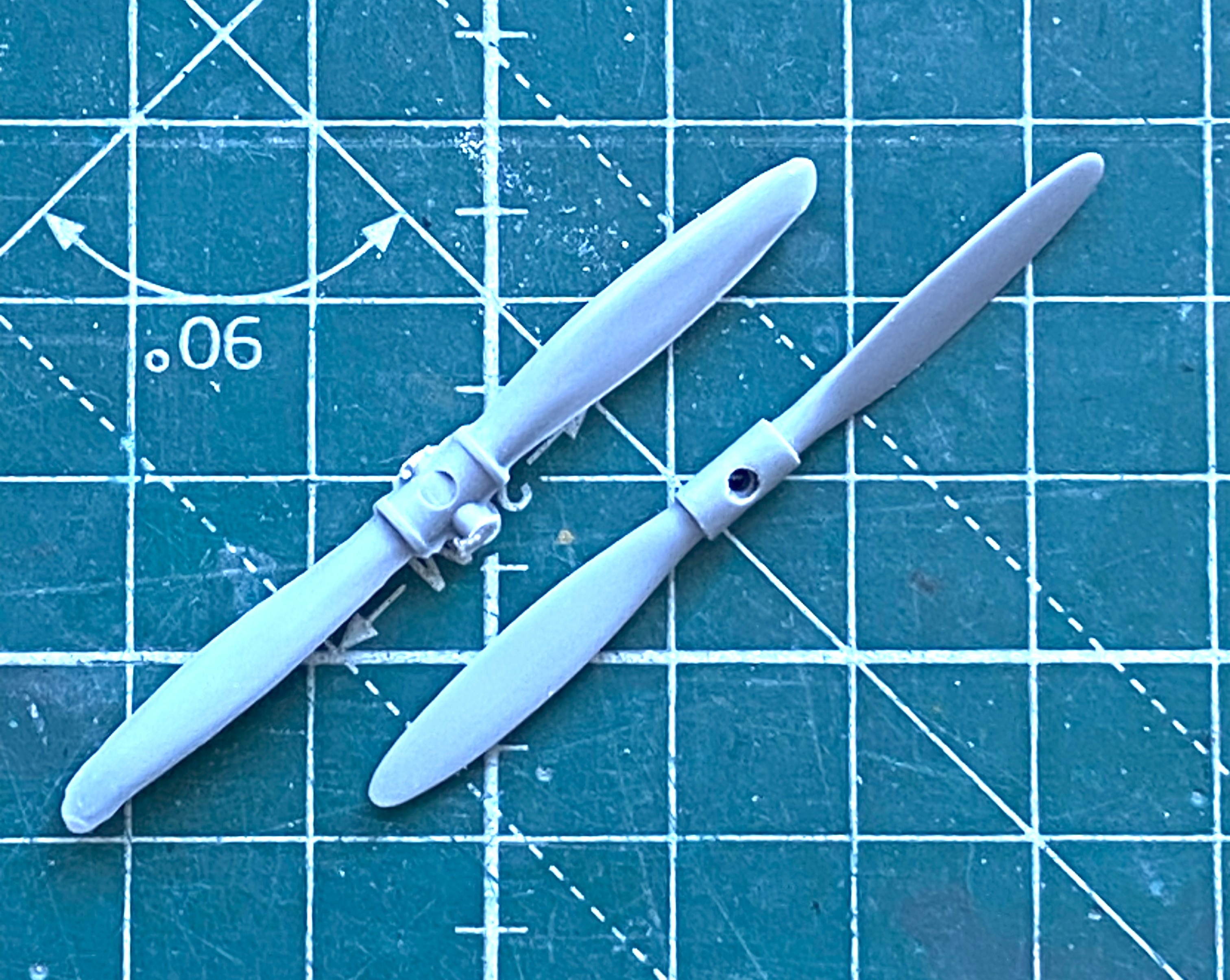
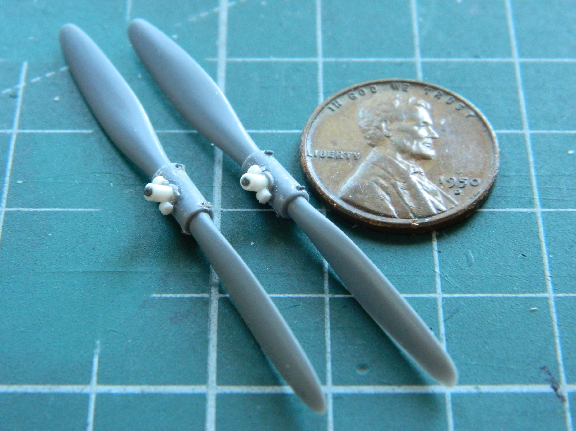
The props on this thing needed some work as well. I haven’t seen any period photos of the prop hubs covered by the shroud the kit provided, so I decided to not add the shrouds but to detail the hubs instead. Obviously, the prop on the right has been started, the one on the left hasn’t been:
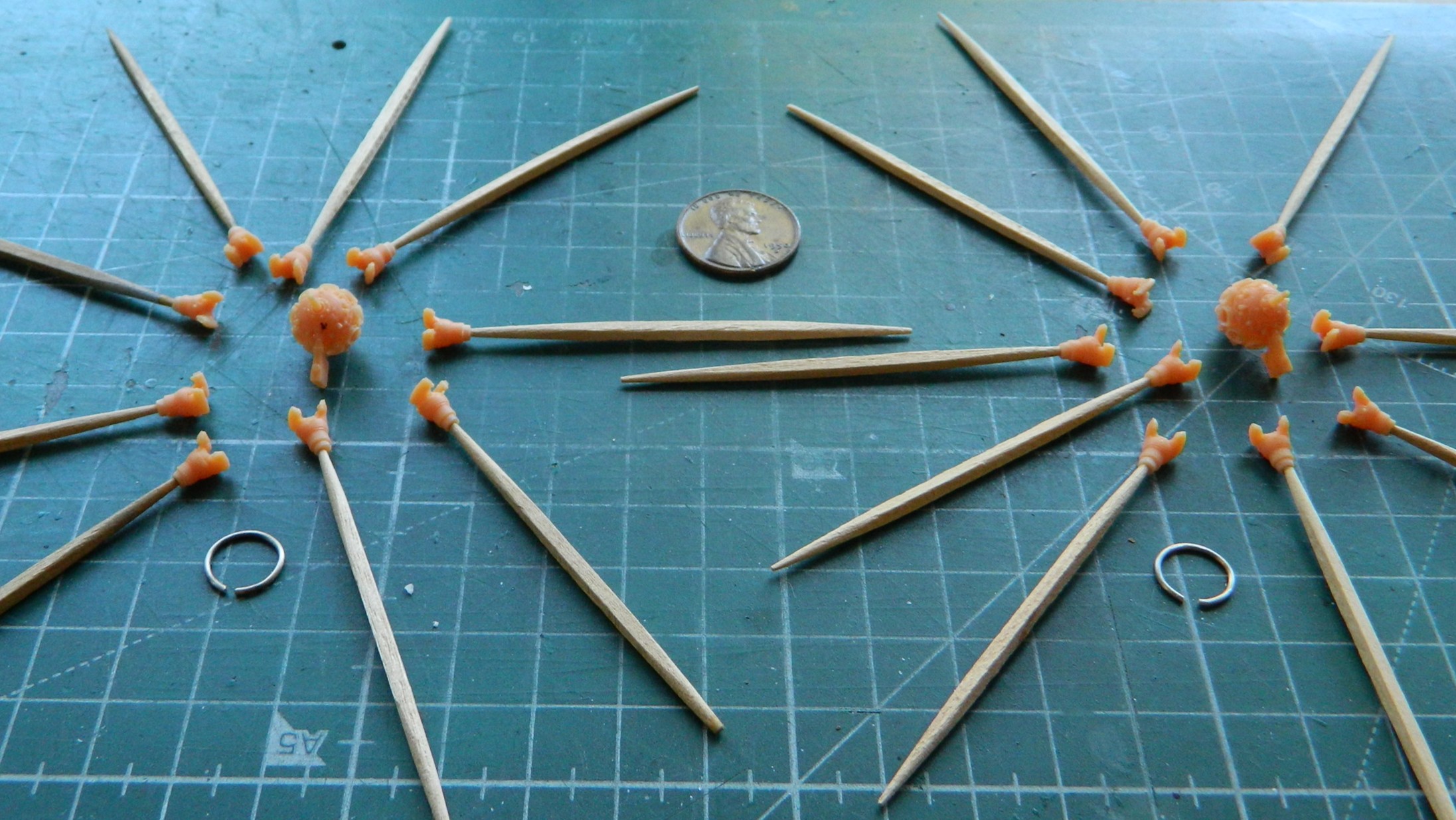
I don’t know if I’ve mentioned this before or not. My life is very strange. Strange things happen to me. All. The. Time. The latest (for now) strange thing to happen to me was while I was salami-slicing the parts to make the pitch mechanism. This is how it landed when I cut one slice and the rod I sliced it from slipped out of my hand just as I made the cut:
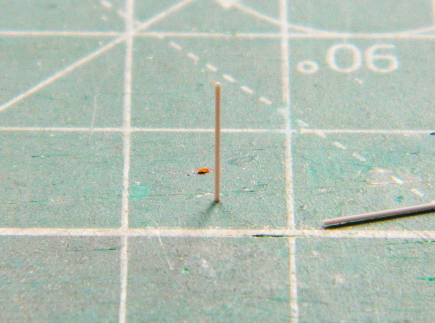
I guess that’s one way of seeing if the cut is square… Seriously. This is my life. ::facepalm::
With the parts all cut out, it’s time to assemble them:
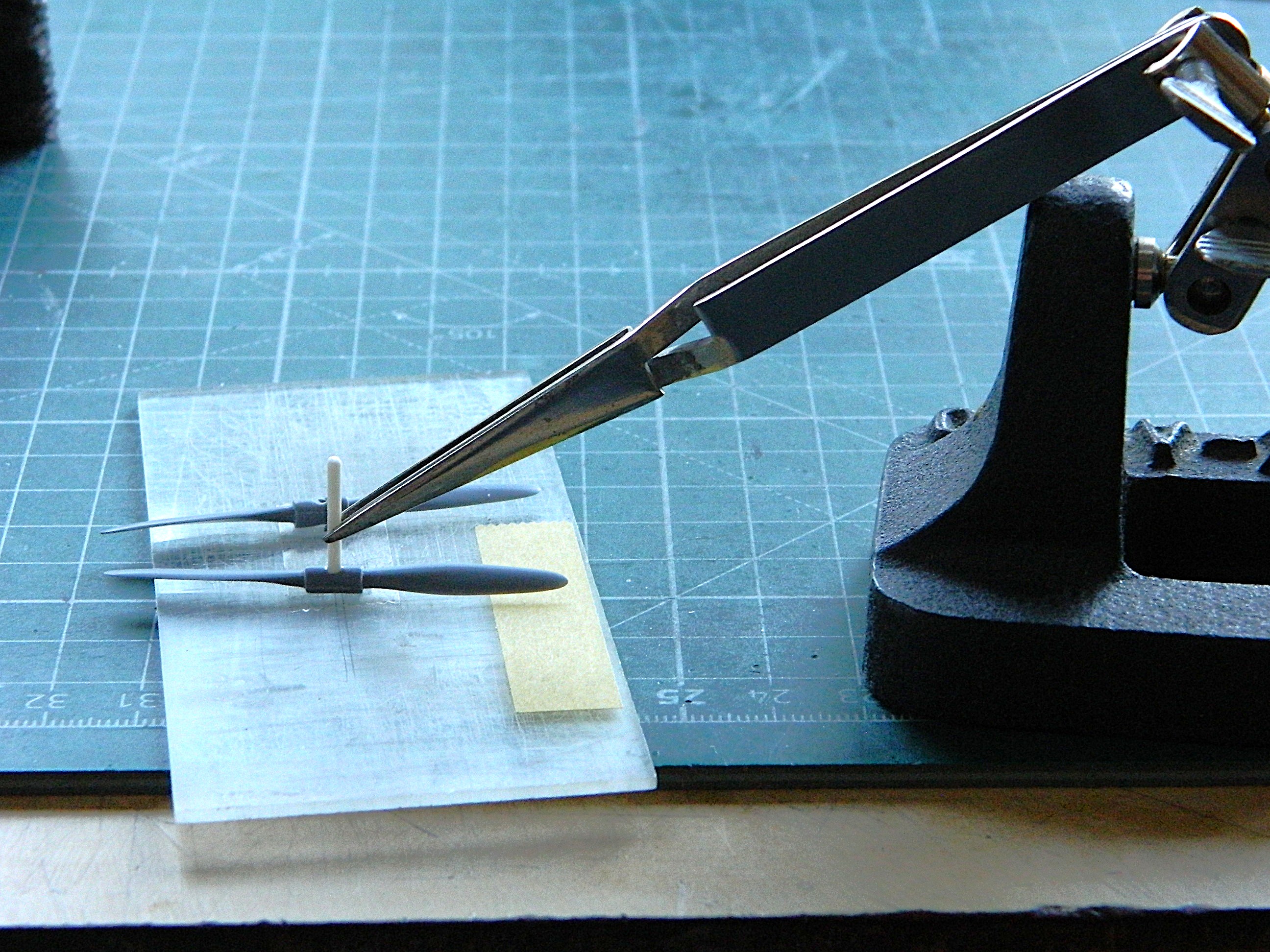
The center of the hub is a two-piece affair but there was no indication on the props to show that. To fix that, I scribed down the center of each side to create the parting line, then added varied scrap styrene to replicate the bolts holding both halves together as well as the pitch mechanisms:
One those were done, it was time to paint these. Aluminum parts were painted with darkened Tamiya XF-16 Flat Aluminum (4 parts) and XF-1 Flat Black (1 part). The crankcases were shot with lightened XF-20 (4 parts) and XF-2 Flat White (1 part):
While the paint was curing, I decided to check fit of the wings. For the most part, they fit well enough…then there was the rest of the parts that didn’t fit so well. This is the case with both engine nacelles:

And once again (some more) I didn’t look closely enough at reference photos to see that this bird has split flaps. When deployed, the flaps only extend from the bottom of the wing; the upper wing over the flaps doesn’t move. I wish I had noticed that before I worked the seams and removed all evidence of seams, because that meant I had to scribe the separation from upper and lower in. I know I’ve mentioned this before (and, no surprise, will no doubt mention it again at some point) but I really do suck at scribing. So let’s scribe a line on a very small, long, and rounded surface:
And while I’m at it, let’s screw it up (of course…it’s scribing) and have to add stretched sprue to fix it (which means leaving the added sprue alone for two days so that all the plastic hardens where the sprue was added):


That add-sprue step was repeated a few times before I arrived at something that fell within the 90%-95% goal, but eventually I got there:

One of the things I was quite curious about was whether or not the completed engines would even fit into the cowlings. I knew that I’d had to wait until the jugs were mated to the crankcases (duh) but I wanted to start assembling the cowlings so that fitting could be checked. These things need some work, too:
Especially this one. I’ve never seen a casting defect like this (with plastic, anyway…it happens more frequently than anyone wants it to when casting metal in a foundry). So that will be puttied into invisibility. Look closely at the inner lip at the bottom:
After examining the wing seams, I realized that I was going to need more stretched sprue to fix gaps:

I use that orange handled saw blade in the above photo to separate parts from sprues. Yes…the sprues are that thick and even though I use a set of very old Huron nippers (often resharpened nippers), I didn’t want the thick attachment points (called “gates” in the casting biz) snapping anything. Yes. Huron. Worried about snapping. Yes…THICK gates, often a feature of limited-production kits.
Moving on.
Seeing that a “good fit” isn’t all that good, I decided to check fit of other parts and I discovered that there was going to be much fitting done before this build is done:

I’m certainly forearmed now…
Gaps show up in the strangest places with this kit. Gaps existed at the wingtips. Sprue has been stretched already, so I used that sprue to fill the gaps:

And done:
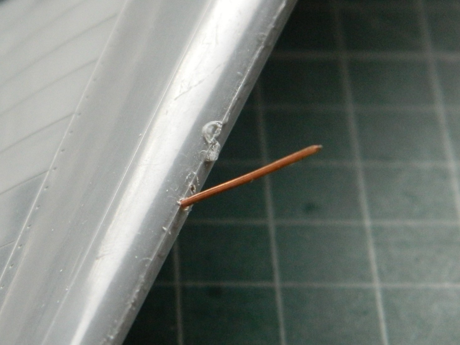
There are also wingtip lights that there’s zero provision for, so I’ll cut the notches for them and add them later on. (Forearmed, y’know.) There’s also no provision for a pitot tube, either. I used a wire and drilled its mounting hole (twice…the one behind where the tube goes is just evident in the photo):
The front of the engine mounts on the nacelles isn’t flat but has a slight dome. A few quick passes over a sheet of 220 grit laid down on the bench took care of that:

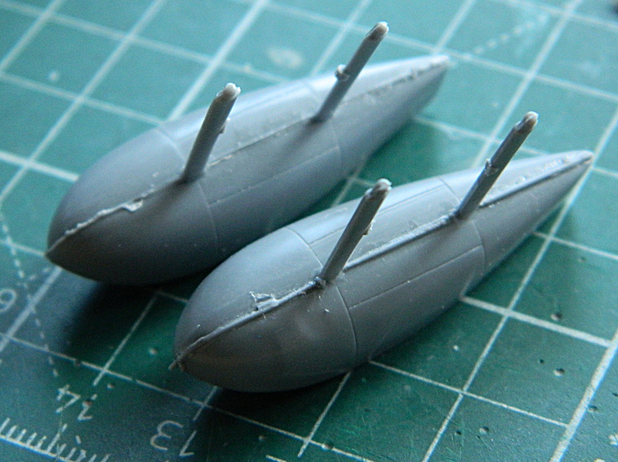
I figured that while I was dealing with the wing, why not assemble the floats? (It made sense to me at the time.) Fit is as expected and since I had plenty of sprue stretched (so far), after assembly sprue was added to fill the gaps:
Oh. A word about limited-production kits. Some things that we’ve grown to expect kits to have, limited-production kits often don’t have. With this kit it’s attachment pins and sockets. So far, I haven’t encountered any of them.
On we move.
Since I won’t be scribing over the added sprue, I don’t have to let it sit for two days to harden. A few hours later I started working the seams and then added 3M Acrylic Putty where needed (masking tape added to keep putty out of panel lines):

They appear to have come out well enough; I’ll know more once paint is thrown at these:

Finishing the seams of the cowlings meant that small sections had to be rescribed. [Insert obligatory whining about my lousy scribing skills here.] And then patched where I screwed it up. And then wait a couple of days before rescribing:

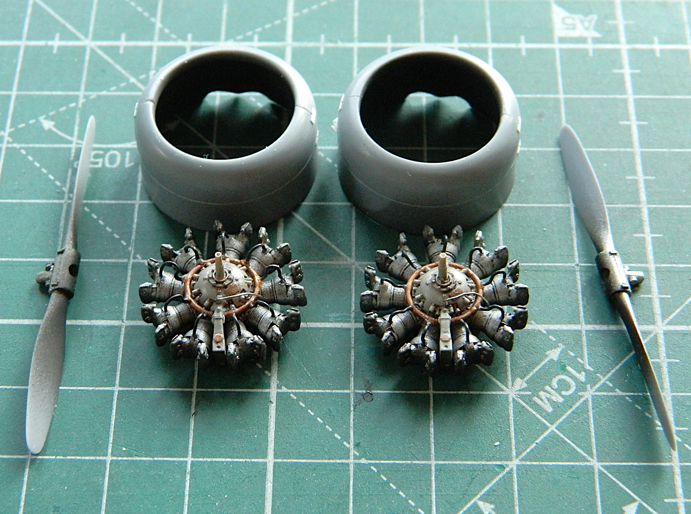
After painting the engine parts and assembling them, they were shot with Tamiya X-22 Clear Gloss, left overnight to cure, and then I mixed some gloss black oil paint with thinner to create an oily finish on the engines (remember…these were working aircraft, not the pristine examples in museums or post-restoration, and as such were seen as consumable resources…meaning that they had an oily surface) (radial engines, y’know…no oil dripping means there’s NO OIL IN THEM). The downside to using oil paints for washes is that they take a long time to dry. In this situation, that “long time” meant seven full days before I could shoot the engines with the sealing coat of Tamiya X-35 Semi-Gloss Clear:

Oh yeah…they do fit inside the cowlings. They had to be adjusted for fit on the depth of them which was done with a medium-sized file (and could probably do with finer fitting when it comes time to glue them to the wings):
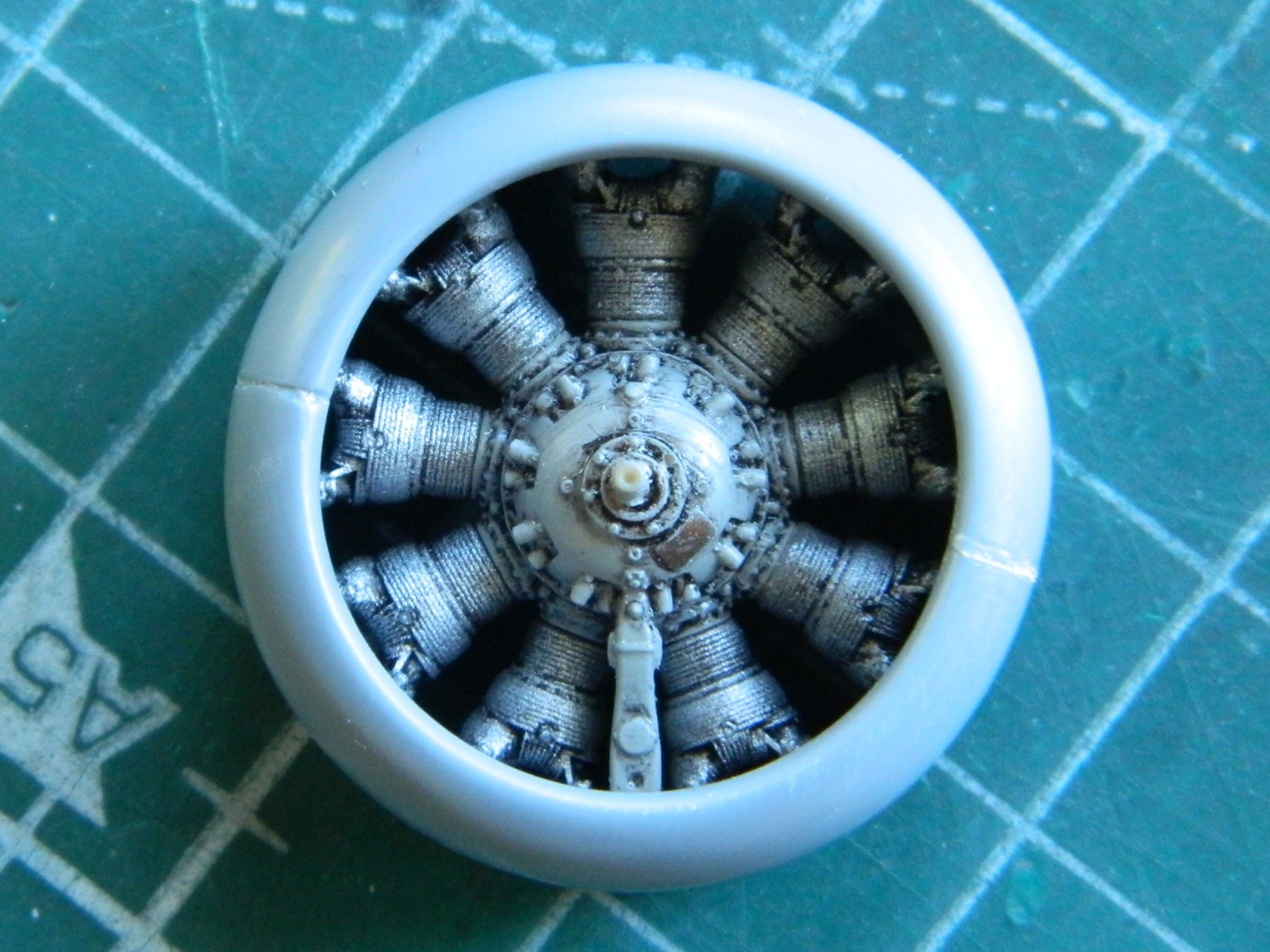
I added the ignition wire ring and painted it a darkened Tamiya XF-6 Copper (4 parts) and Tamiya XF-1 Flat Black (1 part), glued them into position (hindsight indicates I could have used a thinner wire) and started adding spark plug wires using 0.015″ (.381mm) solder:
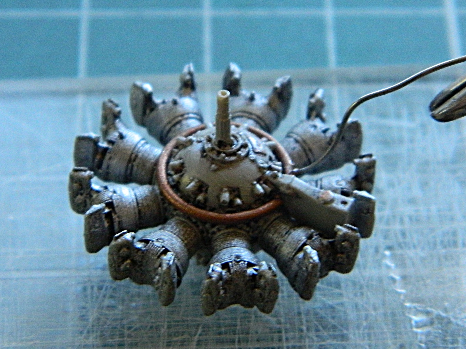
There are other hoses that connect each jug to the next but since they won’t be seen I’m not going to add them.
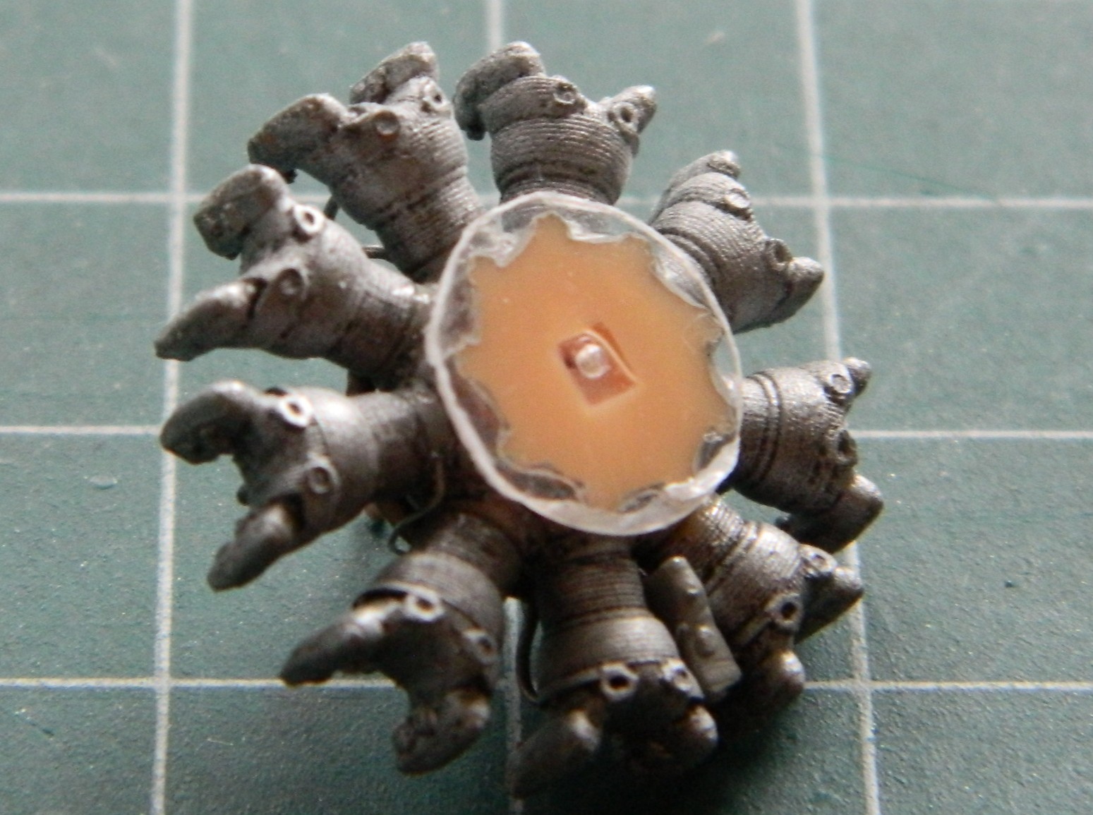
One trick I’ve learned is that when adding some scrap that I want to be centered, I use clear styrene to make that easier. Another trick I’ve learned is a way to avoid the dreaded superglue-sets-up-too-fast-to-properly-align-something. These engines are resin and they’re being attached to styrene, so superglue will be necessary (most of the time, when faced with something like this, I avoid epoxy because I’ve found it’s too thick). A way to avoid hoping that I get the alignment correct (or at least how I want it, should the two be different) is to glue a piece of styrene to the back of the engine. Doing this gives me a styrene-to-styrene join and the ability to tweak alignment in less than 0.00001 seconds:
I painted the spark plug wires using Tamiya XF-85 Rubber and the data plates using the darkened copper paint I’d used on the ignition wire ring. Having already hit both engines with semi-gloss, I painted the backs of them Tamiya XF-1 Flat Black for shading, as well as the inside of the cowlings and the backs of the propeller hubs:

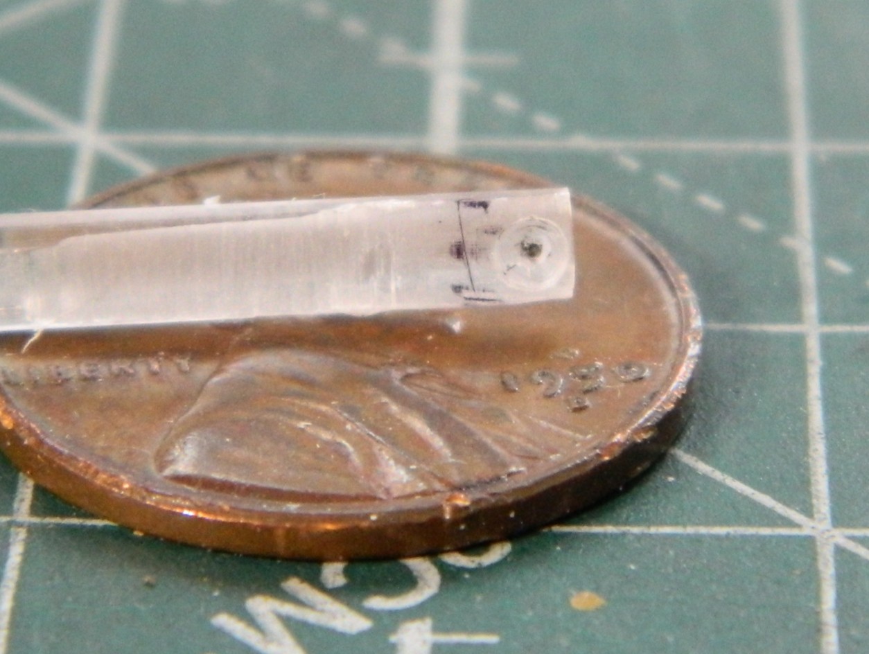
I’ve noticed that on period photos, at the root of the wings where they contact the engine nacelles are what appear to be landing lights. Since there are zero provisions for them in the kit, I’m making my own. I used a scrap of 3/8″ (9.53mm) clear acrylic rod. I sliced off a piece wider than I want to use (for ease of handling…the extra width will be covered by paint), trued the ends (make them perpendicular to the center axis of the rod), and cut them in half so I have one for each “light.” Then they were polished until clear:
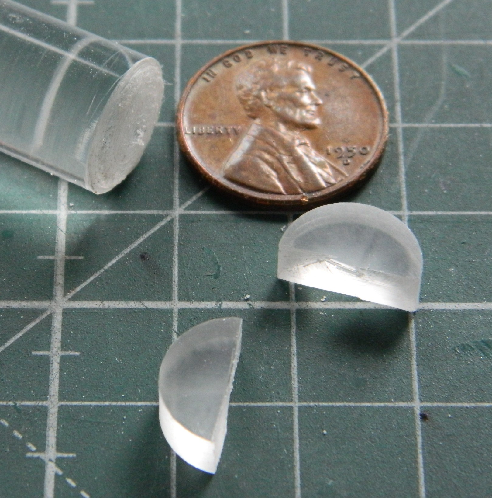

The flat sides will be the insides which will have the “lights” drilled out and painted, then I’ll trace the curvature of the wing’s leading edge on them, rough them in, then glue them in place and finish off the exposed surfaces.
But that’s for next month…
F7F-3 (AMT/Italeri) 1/48 Scale Build #7 – Finishing the Cockpit, Joining Fuselage Halves, and Finally Dealing With Scribing “Fun”
I’m doing something a little different with this update. Typically, I post updates on or about the last weekend of the month. I’m updating early because I saw that I had taken over 50 photos this month so far. Typically, it takes me 6-8 hours to do an update; editing photos and coming up with this snappy commentary (so called because sometimes my commentary can bring me to the point where I’m ready to snap)…and that’s with 30 or so photos to edit. So rather than spend all weekend doing an update if I kept to my typical schedule, because January is only half over and I have more work to do, I decided (obviously) to break January’s update into this part and the one coming on the last weekend of the month.
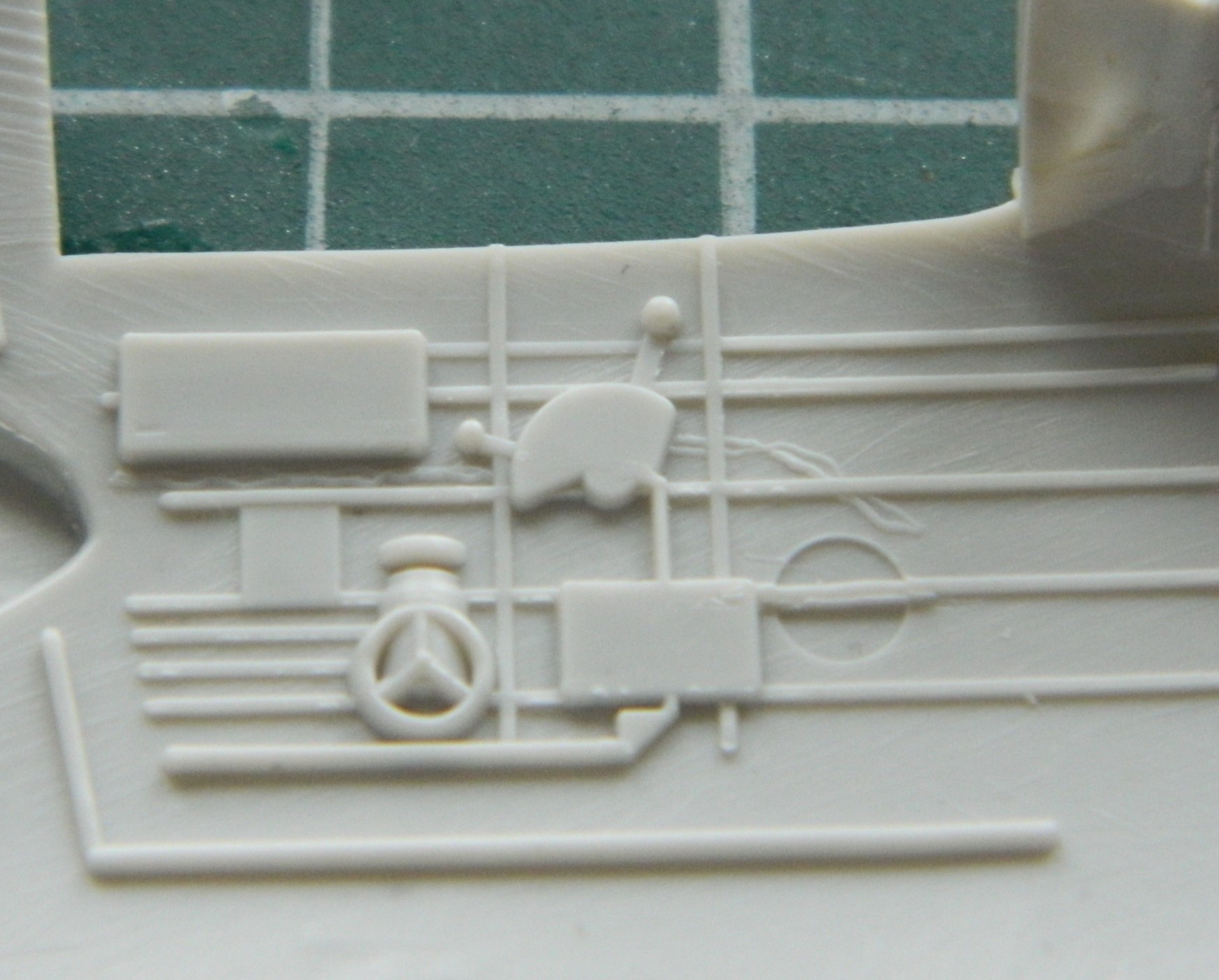
I was still populating the cockpit with scratchbuilt bits. The Tigercat had a parking brake so I added one. That started with making the mount for the T-handle of the brake:
A very handy tool for those of you who scratchbuild is a “lazy Susan,” a platform that will rotate. Working small parts often requires the modeler to have four (or more) hands. I use jeweler’s tweezers to help with that. Alignment of the bit being added or constructed is critical. To get the alignment you want (which is, hopefully, the alignment you need) will require you to look at the join from multiple angles. If the parts and jeweler’s tweezers just sit on your working surface, it can be challenging (or next to impossible) to get the views you need without disturbing what you’re working on. Putting the jeweler’s tweezers and work on a rotating surface allows you to accomplish that. You can rotate them to the view you need to make the construction work correctly:
Last month while dealing with the seemingly never-ending throttle quadrant, dry-fitting showed me that I’d placed the imagineered pedestal too far forward. That got fixed:
I’d placed a small alignment mark on the floor of the cockpit and then promptly forgot that that mark was for the front of the pedestal, not the rear as I had mistakenly thought. Oops. (Again.)
A prominent feature that the kit didn’t provide is the flap actuator lever. Construction-wise, it’s similar to a throttle quadrant but only needed four parts. Wrestling and cursing during the construction of the throttle quadrant made this part easy to build by comparison. I used 0.010″ (.254mm) copper shim stock and a 22 gauge wire for the lever that I flattened with a hammer (the bit coming off to the upper right is just a spacer):

Then I used the jeweler’s tweezers, the lazy-Susan, and a bit of stretched sprue to make the handle (you can see the T-handle, also made of sprue, glued into position as well):

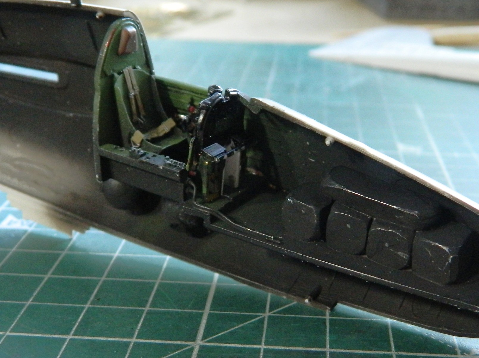
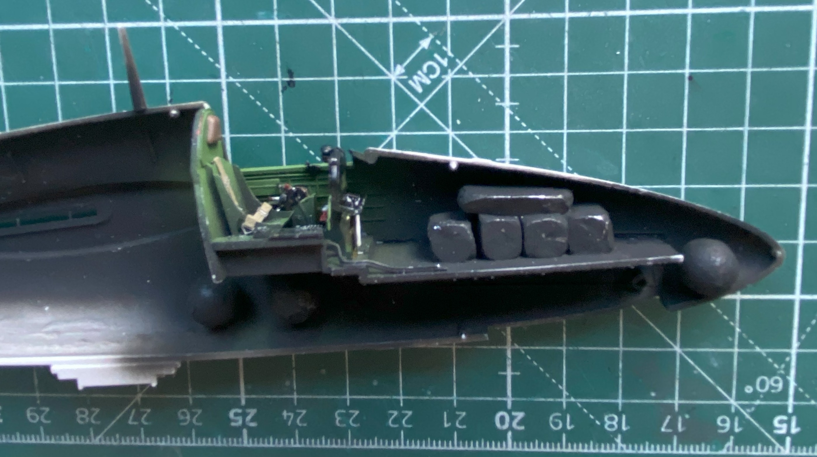
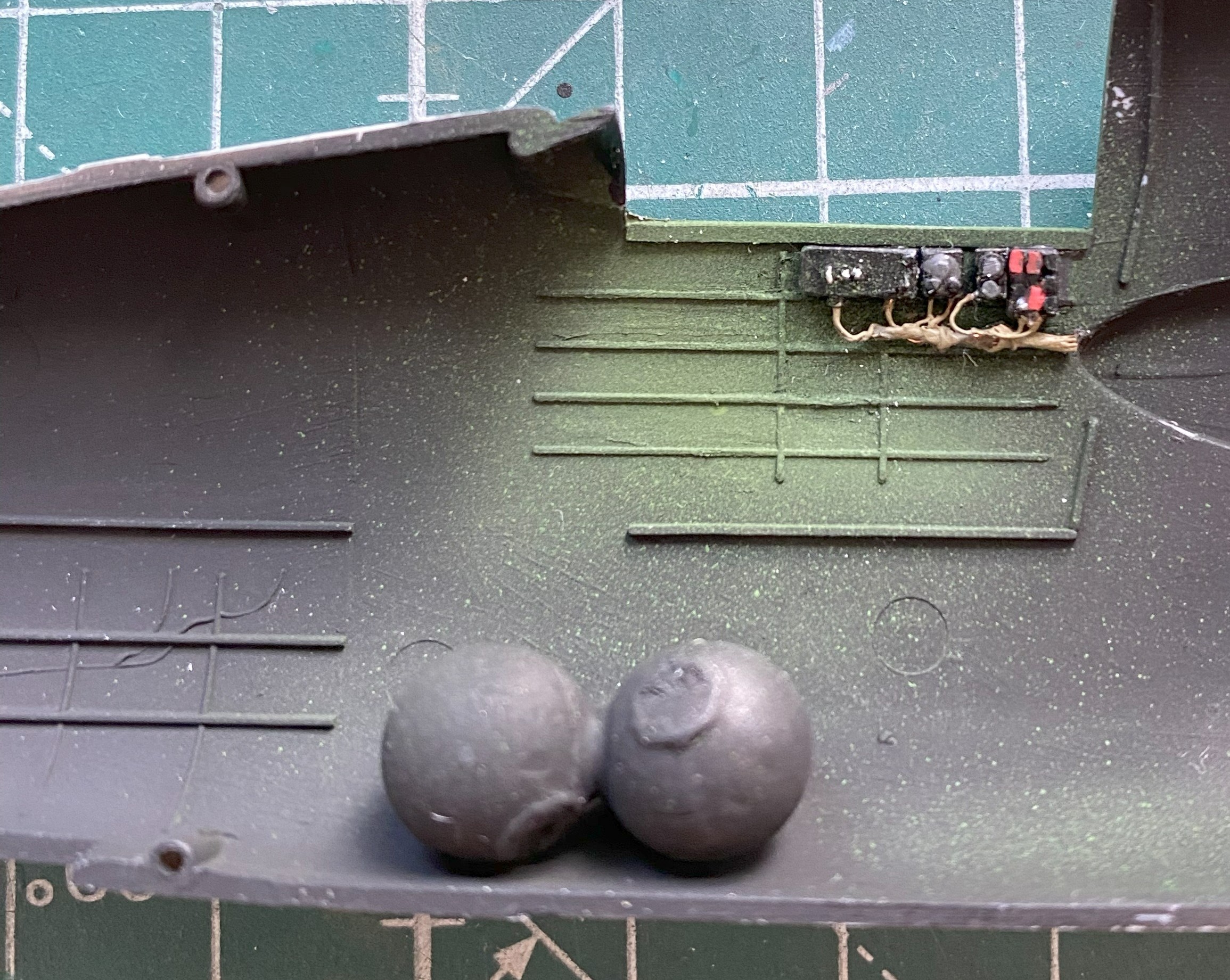
When I did my most recent balance check, though the thing would sit on its nosewheel, I wanted it planted on its nose with more authority. Having checked where I could put more weight, I added more .36 caliber balls (because what says “authority” like balls do?):

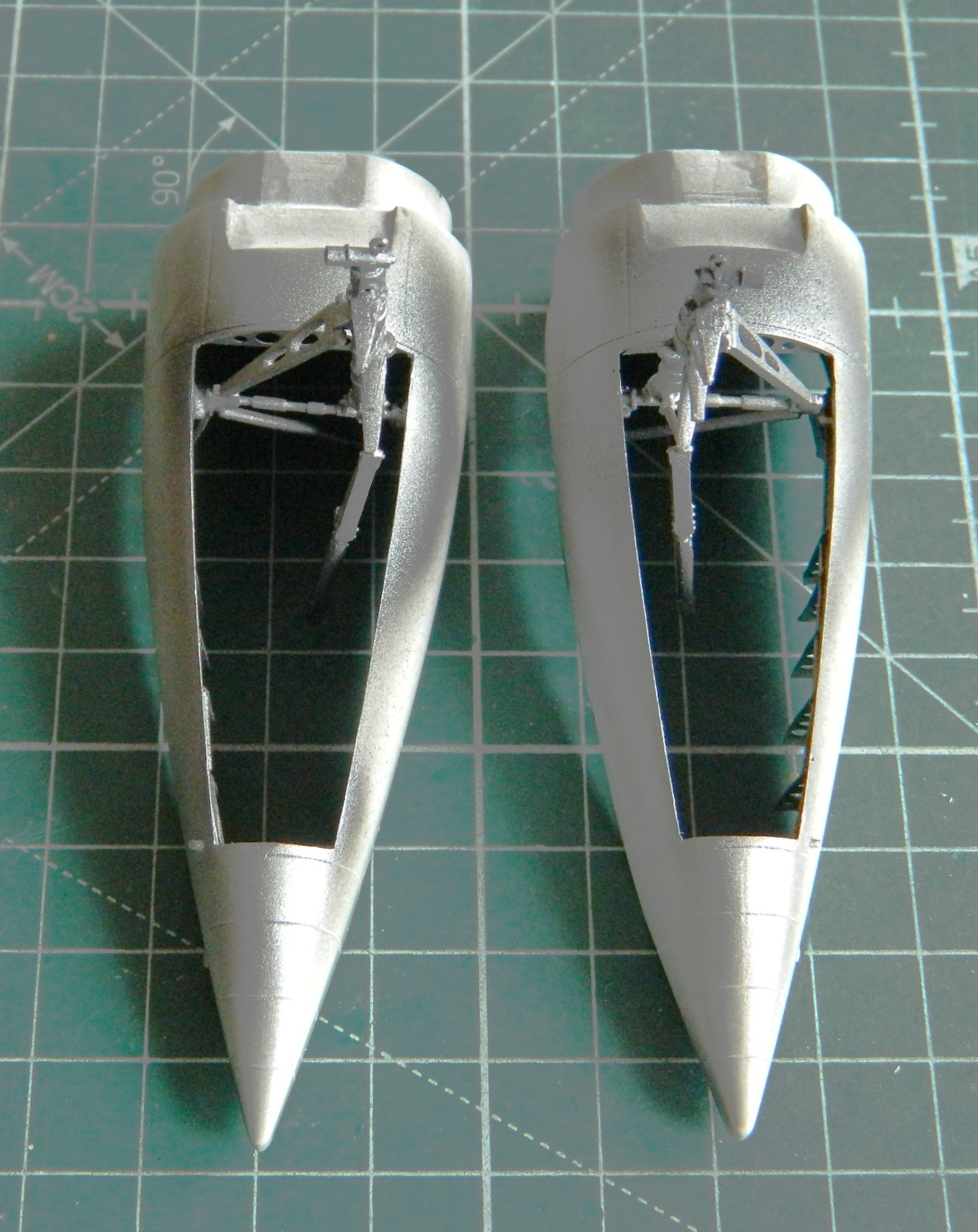
The nosewheel bay has no bulkheads with this kit. I hate matching interior curves. Since I am spending less time on details that won’t be seen or require the observer to pick up the model to see them, I’m not adding those bulkheads. I’m cheaping out by painting everything that could be seen through the front landing bay opening flat black (and the engine cooling flap parts, since they needed more):

Later on during dry-fitting, I realized I needed to extend the flat black further reward, which was attended to.
I held off adding the cockpit to its location because another annoying habit I have is that as soon as I paint something, I am reminded of what I’ve yet to build before I should paint. Here I am, blithely assuming that I’ve gotten all the cockpit parts painted and a little bit of wear added:

Then I remembered the harness…
I’ve been eager to try the molded styrene AM harnesses. I was pretty sure that bending and folding them to fit would cause them to snap. I used HOT water and took my time heating and bending (and even then almost snapped the shoulder harness’ acute bend over the top of the seat’s back):
The straps were painted a mix of Tamiya’s XF-49 Khaki (3 parts) and XF-64 Red Brown (1 part), the metal bits painted with X-11 Chrome Silver, and the leather pad backing the lap strap buckle was done with XF-64 Red Brown:

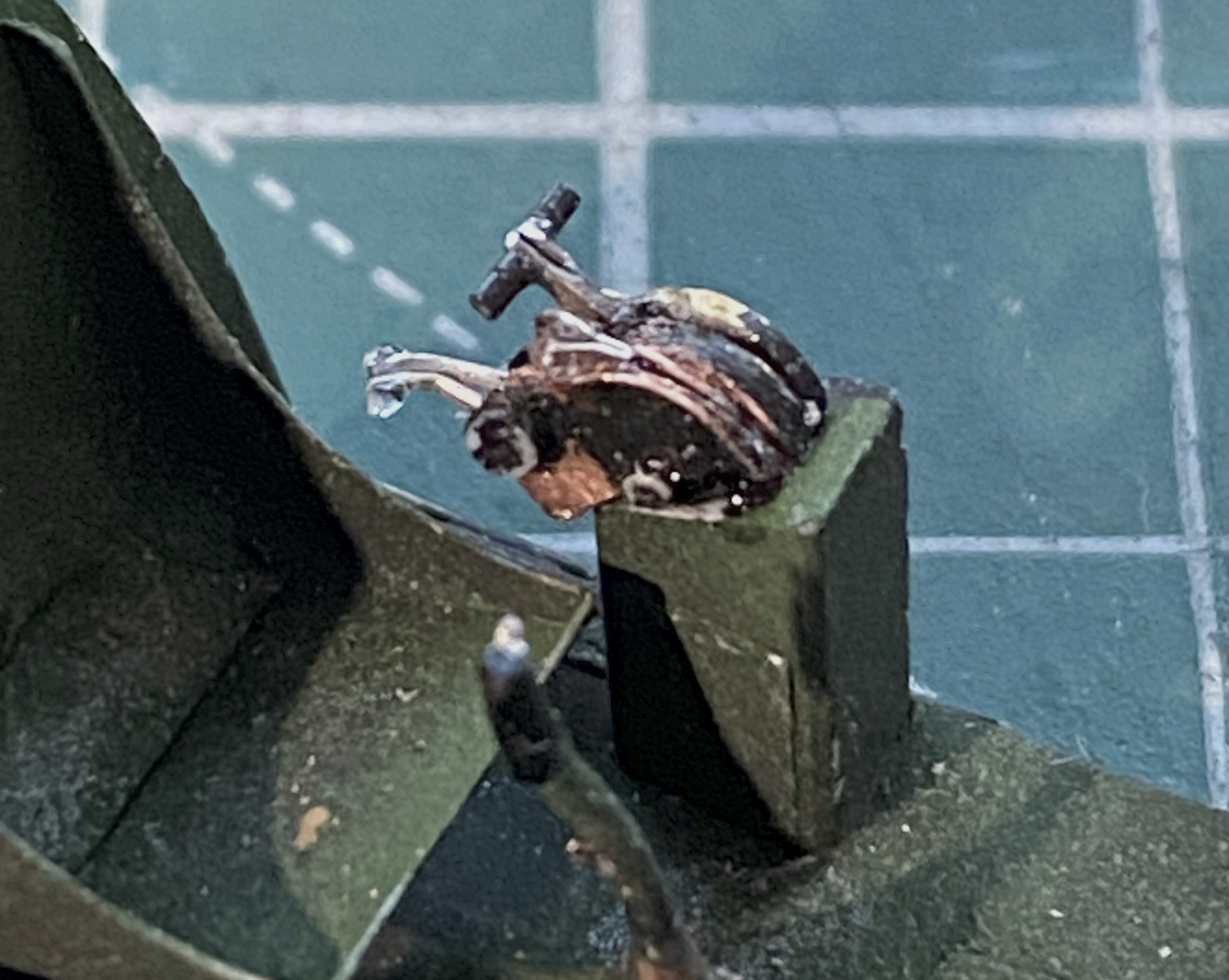
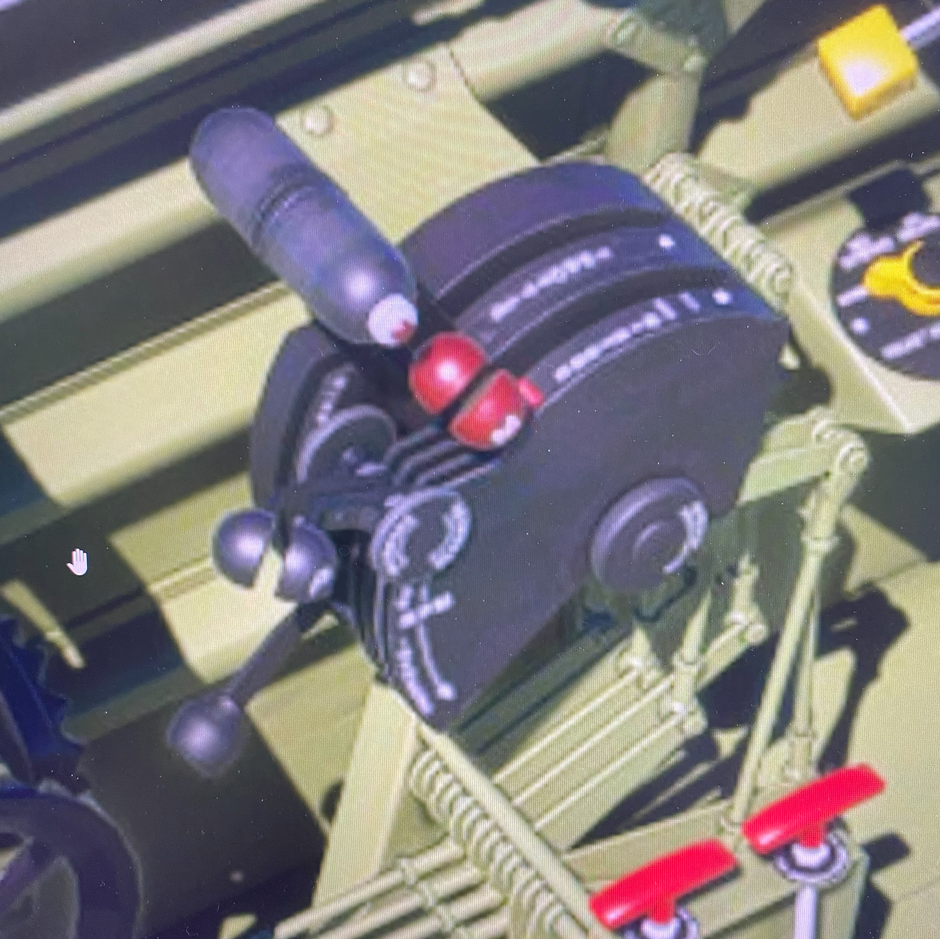
Then it was time to add those tiny control levers to the throttle quadrant. I tried a bunch of things, flattened wire and strips of heavy aluminum foil, none of which worked with a rodent’s rectum. I finally ended up using 0.010″ (.254mm) solder that I flattened out. That worked surprisingly well. Remember those tiny glass balls? Only one was used and none of them for the throttle quadrant control levers. For the latter, I used UV-setting resin, and that worked even better withOUT all the sodding hassle working with tiny balls (no comment, he comments)…and forgot to take pictures. You’ll see later when the instrument panels shows up in a photo because I did the same for the landing gear lever (lower left of the instrument panel with a yellow ball) and gun charging handles (four of them, two on each side at the bottom of the instrument panel with white balls).
I was pleased with how the parking brake T-handle came out. Then realized what I’d really forgotten to add before painting. The trim controls. All of these bits fit into the cockpit of the actual Tigercat. They don’t all fit into a 1/48 scale model of the Tigercat. And thinking like a pilot, I figured trim controls were of more utility than a parking brake handle (because, chocks are a thing), which meant I had to remove the brake handle. The brake handle that’s already been painted on the cockpit side that’s already been painted. (::facepalm::).
I modified the PE part slightly by removing the flat parts that are supposed to represent cylindrical parts by cutting them off and adding 22 awg wires in their place. The pitch trim wheel isn’t at all flat and the PE’s replacement is. I used the UV-setting resin to build up the flat areas that I want rounded and glued them in place, after removing the parking brake first(sorry about the blurred photo):

Being lazy, I didn’t want to repaint the entire cockpit side, so I made a handheld mask to paint just the areas I needed to (the mask is behind and above the cockpit side, the pointed end of which aligned over the rods):

And then a case of brain-fade struck. The throttle quadrant. Again. Some more. As EVER. One of the slots needed just a little bit of adjustment. Just when I had it where I wanted it, the fornicating front half of it snapped off:
I’m starting to get a depression in my forehead in the shape of the heel of my hand from all the facepalming I’m doing. (I’m already on blood pressure medication so my options for physically manifesting “DOH!” are limited to what I assume I can survive.)
Well, it’s not as if I don’t have practice PUTTING THIS INTERCOURSING THING BACK TOGETHER. Preparing the parts took longer than fixing them. The superglue that had been holding this together didn’t vanish because the parts separated. It’s still there. It also interferes with getting the part reattached. CAREfully removing the old superglue (fresh razor blade, sharpened scalpel) took longer than reattaching the detached part back on. But I won (for now, anyway):
Those two photos show the UV-setting resin’s balls. (Go wherever you like with that one.) Those were attached and got painted the required colors, and dry-fitting looks like the cockpit is ready to install):
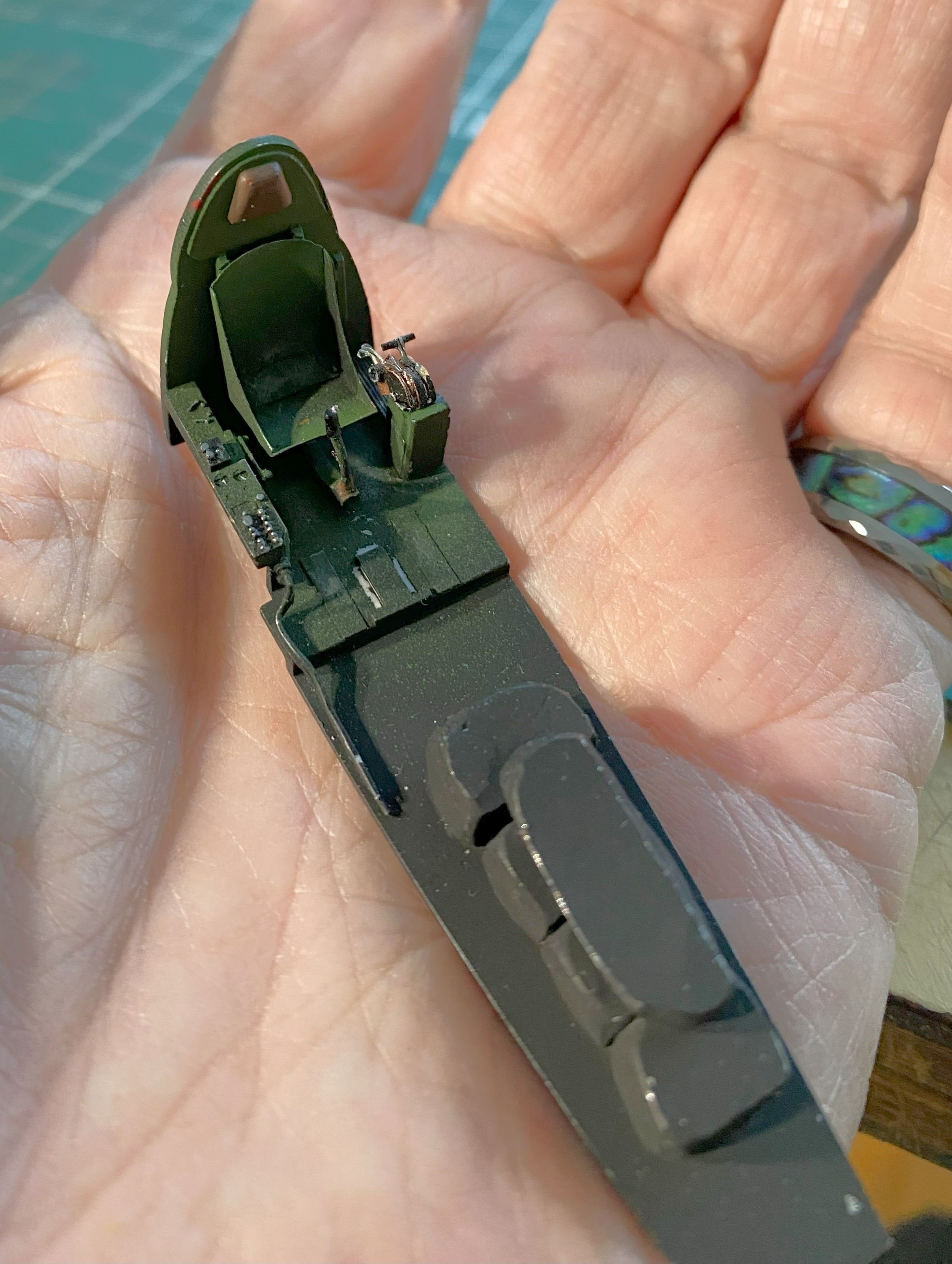

But first, he says smugly because he remembered what he forgot to add to the instrument panel…rudder pedals, I added the rudder pedals. So far, those were the most annoying parts to add because they were as fragile as butterfly wings:
They were added and painted and I went back to putting things together:
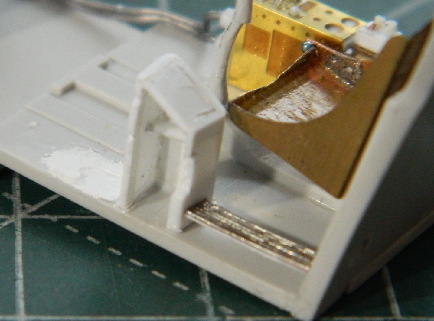
One more bit to add, the wiring harness below the switch/control boxes:
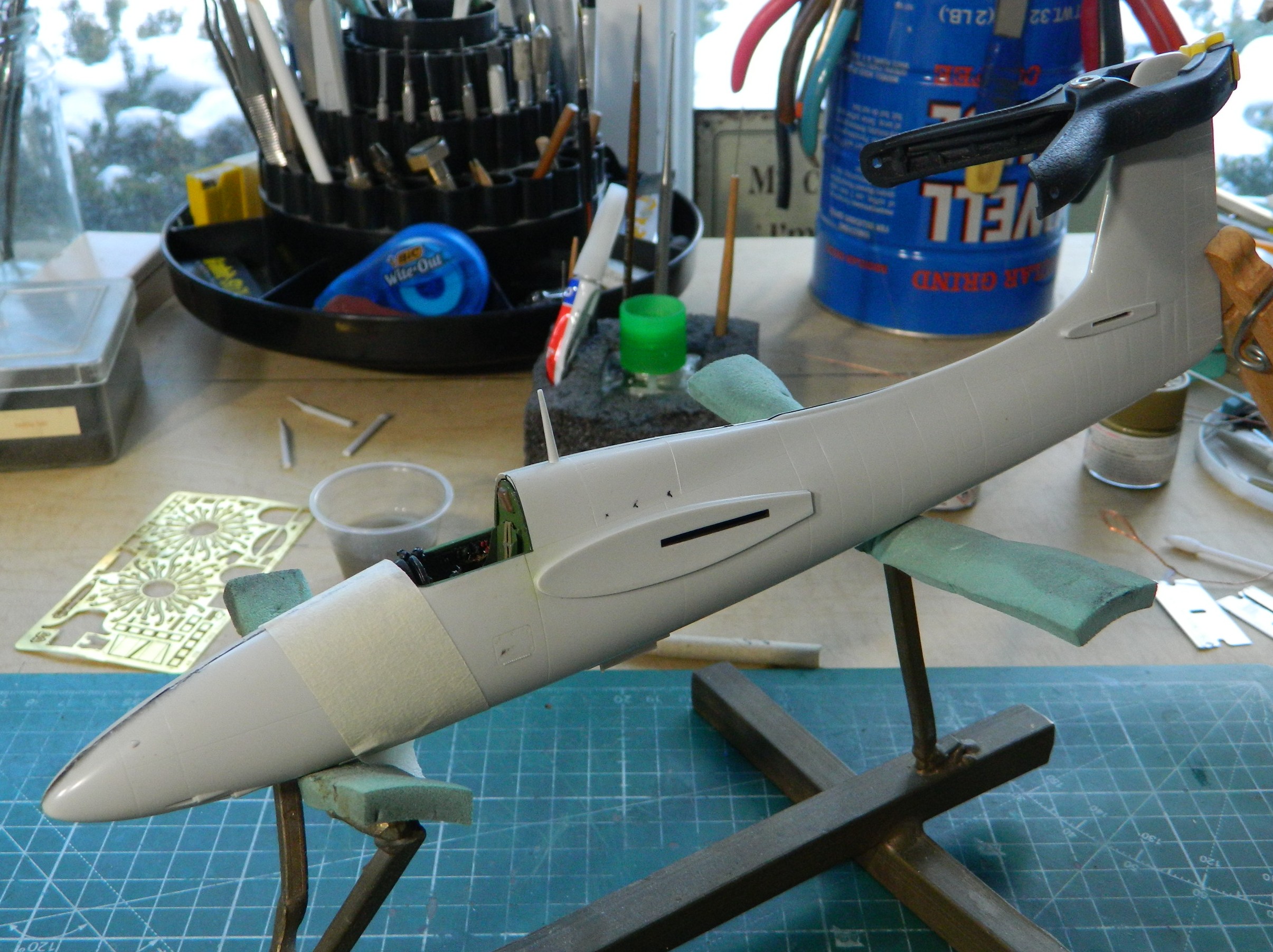
That process wasn’t without its ohgawdammit moments. The fuselage area around the cockpit wouldn’t quite meet. I traced it down to the instrument panel by checking references. The sides of the panel are angled inward. I carefully bent the wings inward, then equally carefully touched up the paint (again) and reattached the fascia of the panel to the film behind it (again). The small bends on either side of the panel allowed the gap to vanish and glue was applied.
Then the two halves were joined:


While that was glued and clamped, I started working on the wings and empennage. There are a few lights that needed to be redone. The leading edge of the port wing has a landing light in it as well as underneath the wing, and both wing tips have formation lights. The area of the wingtip lights are molded solid so those were cut out to allow for clear material to be inserted:
Speaking of lights, there’s a row of three lights under the rear fuselage. The were molded as raised “details” and I knew that they’d be sanded off as the less-than-perfect fit between fuselage halves will need a bit of sanding. I had intended on drilling them out and adding clear sprue inserts instead anyway.
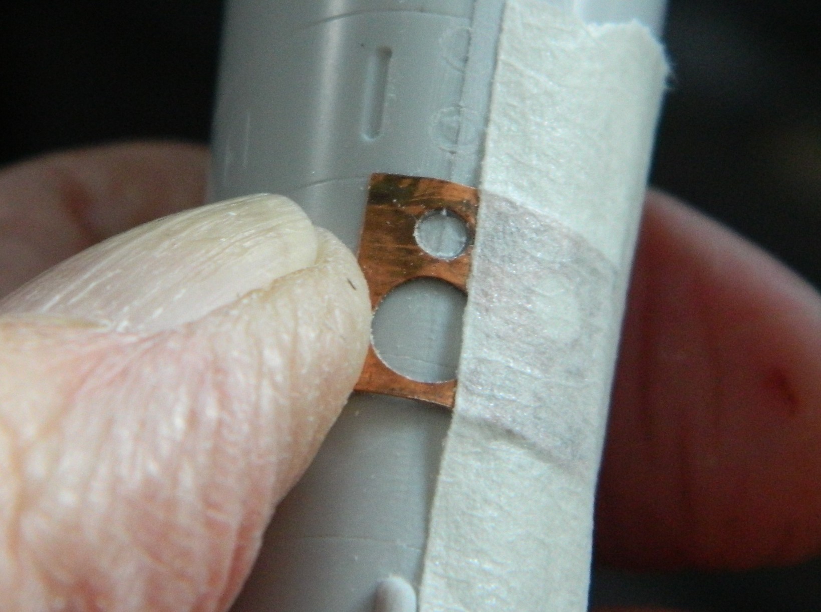
The problem is that I still suck at scribing. Scribing round details would require me to increase my results by a magnitude (at least) to be considered marginal. None of the templates I had offered me the diameter I wanted so I used a punch and die set to punch a correctly sized template from 0.005″ (.127mm) copper shim stock. It worked well enough, particularly since these are just drilling guids:

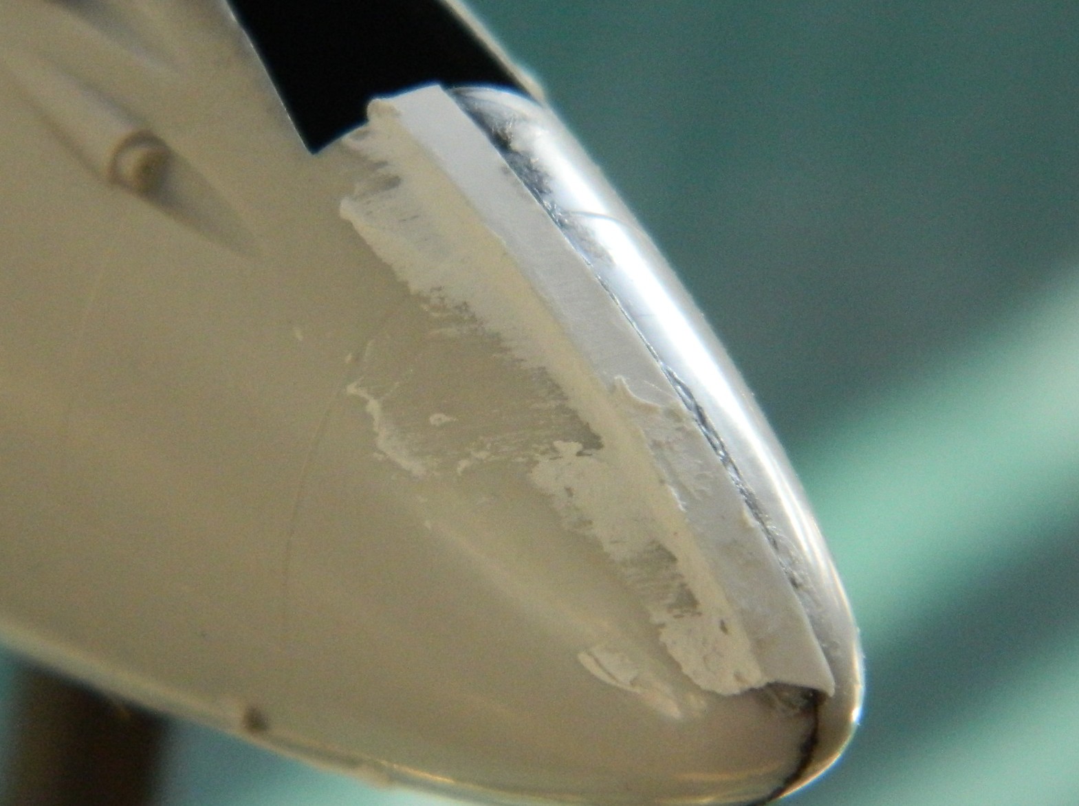
I’m trying to move away from using putty as my default filler, preferring instead to add scrap styrene whenever feasible. Because of adjacent panel lines around and under the nose of the fuselage, sanding to make the surfaces meet would have required a bit of putty. Instead, I added a strip of 0.010″ (.254mm) plastic under the nose for most of the fill with a little bit of putty to smooth the transition into invisibility:
There were other places that needed putty as well and that was applied:
I did mention that I SUCK at panel lines, yeah?:

Once this update is done and posted, I’m going to do a separate tutorial on how to fix errors like the one shown above. If you also SUCK at panel lines, you may find the upcoming tutorial of use.
So I added stretched sprue to fix that one…and all the other ones that I bitched up:


And since I LOVE scribing panel lines, I got to do these twice! How lucky am I… What happened was that I didn’t let these additions cure for two days, only one. When I started hitting these areas with a scriber, adjacent plastic, because it was soaked with Tamiya Extra Thin cement, was also softened. One overnight wait was insufficient for all the cement to utterly evaporate and for the styrene to completely harden. So this was all done again and then sat for two days before I tried working them again. I think that I’ve gotten them as well as I can manage:


Next problem to address is the poor fit between the engine nacelles and the wings. I was undecided as to whether to use putty or add styrene. I tossed a coin and putty won out. I wanted to keep the putty off of surfaces I didn’t want covered in putty. Rather than mask off those areas with masking tape, I ended up using electrical tape instead. Electrical tape will stretch and either conform to curves or outline curves. Try doing this with a paper-based tape:
I let these things sit overnight because I wanted the putty as hard as it can be. Then there was a lot of sanding, filing, scraping…more putty to fill areas that I’d missed (or the putty didn’t adhere well enough) followed by scraping, filing, and sanding. Eventually I arrived at the result that I wanted:

Once I hit these areas with gray paint (probably Tamiya’s XF-20 Medium Gray), I’ll be able to see if the curves where nacelles meet wings are evenly shaped.
While I was working the wings and empennage, I also fixed misaligned, wrong, or missing panel lines (just because I LOVE do this) (spits). This example is looking down at the top of the wing where the flaps are. The line on the left aligns with the line underneath, unlike the line on the right (and no…I wasn’t satisfied with the line I’d scribed, so I filled it with stretched sprue and redid it):

I persevered and ended up with these (the empennage had the same problems and were fixed the same way):

With the repaired panel lines sanded smooth, scribing happened next. Unable to speak for anyone else (and marginally able to speak for myself), trying to scribe long and straight panel lines is impossible without a guide. Being able to scribe straight lines around a curved and tapered surface is so beyond my skill-set that there aren’t words big enough to describe the mess I can make nor how quickly I can make that mess. Since I have to scribe straight lines and scribe straight lines around a curved and tapered surface, guides aren’t optional. Because things are tapered, I used electrical tape again (for long straight lines, I like Dymo Label Tape…adhesive and thick):
A light touch and many, many, light passes with the scriber is necessary because the thing that makes electrical tape good for jobs like this has an inherent uh-oh factor. The tape is flexible. Push against it too hard with the side of the scriber and the line goes wherever it ass-biting wants to go, regardless of what I want. Light passes. Lots of them:

And no…I wasn’t entirely satisfied with how those lines turned out…so I did it again. I got lucky and the next attempt(s) worked.
I. Suck. At. Scribing.
When I have to scribe, I find that I have to handle the model a lot. Rotating (all three axis), pressure, fumbling, all expose the model to risk. I already broke the handle off the flap actuating lever and had to redo it…then I managed to snap off the gun sight, too:
I got lucky. It only took me a little over an hour of crawling around on my belly with a pair of tweezers and a flashlight (or torch, if you prefer) to find it. I’m glad that I don’t have to make another one!
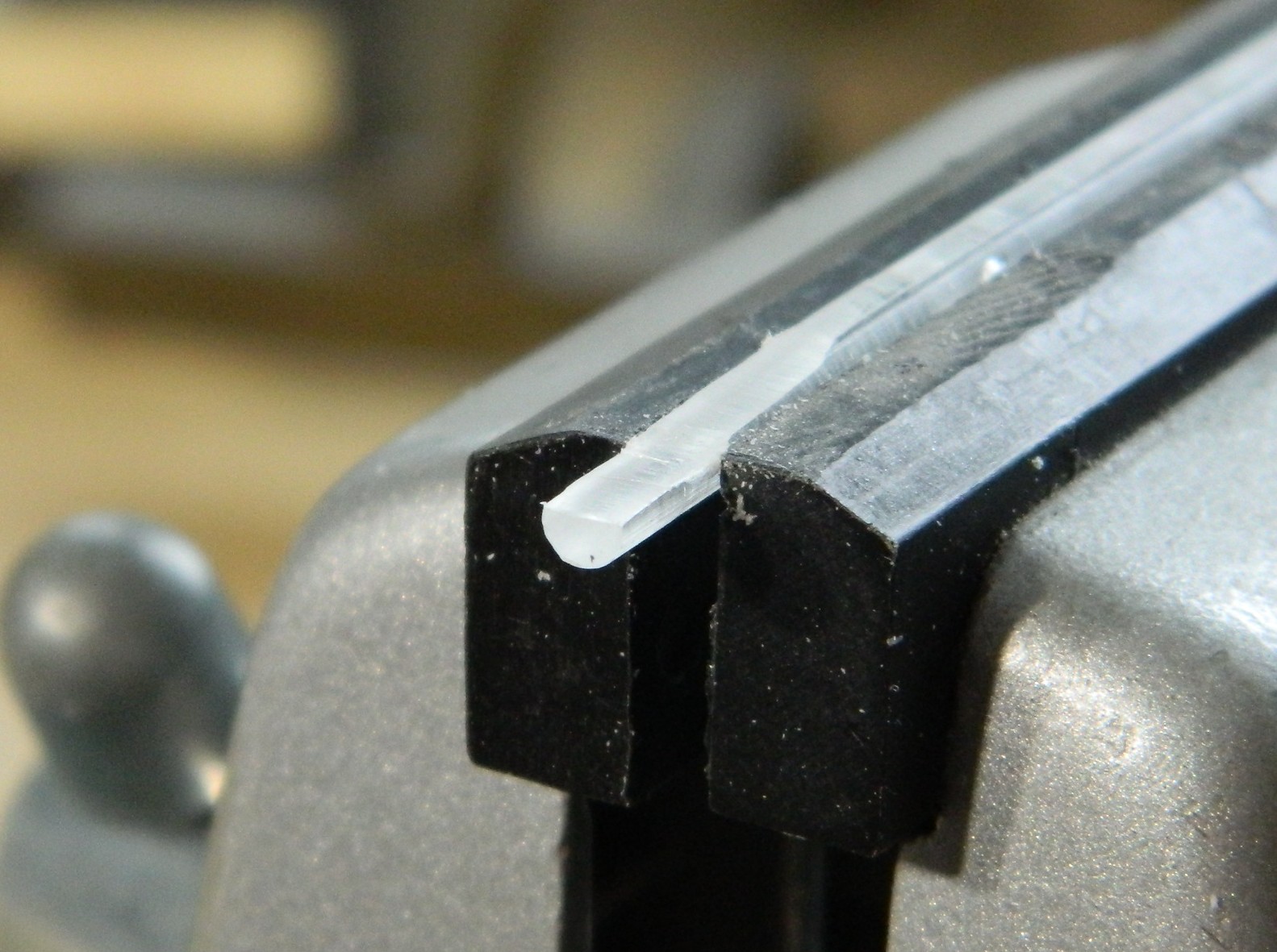
I’ve yet to see a kit that does a good job with landing lights located at the leading edge of a wing. They might be out there, I’ve just never encountered one (1/32 scale, maybe?). This kit isn’t the worst, but it’s certainly neither acceptable nor good. Replacing that requires clear plastic and I just happen to have some. It came with the kit. All I had to do was to shape it and detail it (in reverse order), so I used a vise to hold the stock in place while I filed a flat area that would be deepest in the socket of the wing:
I drilled out what will be taken as the domed section of an incandescent light into the back of the clear plastic. Once done, I used the smallest drill bit I have to make a depression for the “bulb”:
Painting is the opposite of typical. Each layer of paint/color is behind something else. Following that logic trail to its source, the first thing painted is the “bulb”. A touch of black paint. Then the reflector is painted on and for that I used a Molotow Chrome pen. Once it had set up, I gently scraped away whatever chrome was outside the depression and then painted the back of it black.
Then it was a matter of fitting, filing, sanding, and polishing. The “wings” in the photo below are 0.005″ (.127mm) styrene to fill gaps on either side of the insert:
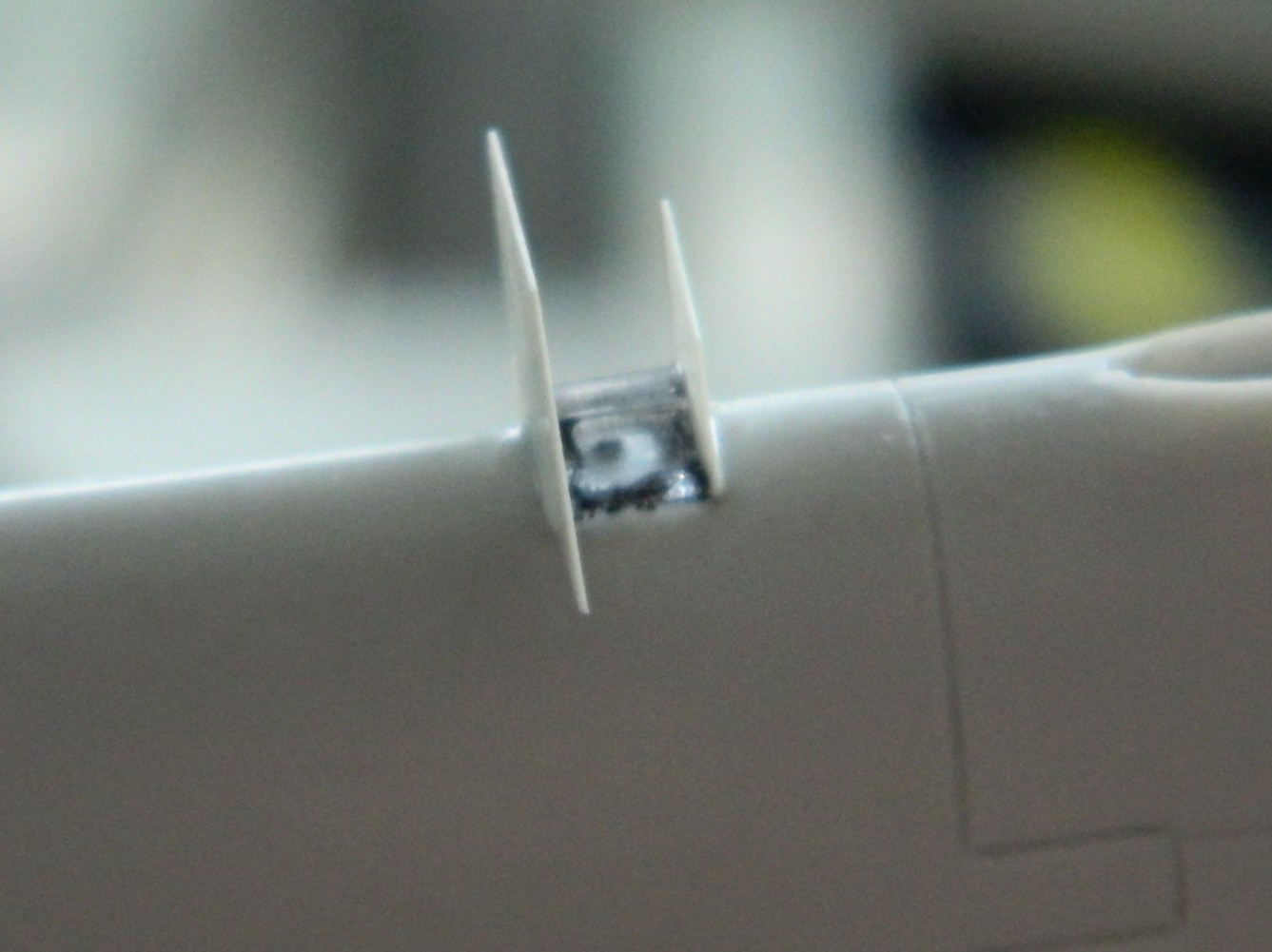
Then it all gets finished (with tape applied to preserve the curvature of the leading edge of the wing):

Not my best effort but certainly good enough (I should have eschewed the drilled “bulb” and used just a needle instead…that’s for the next one I have to do).
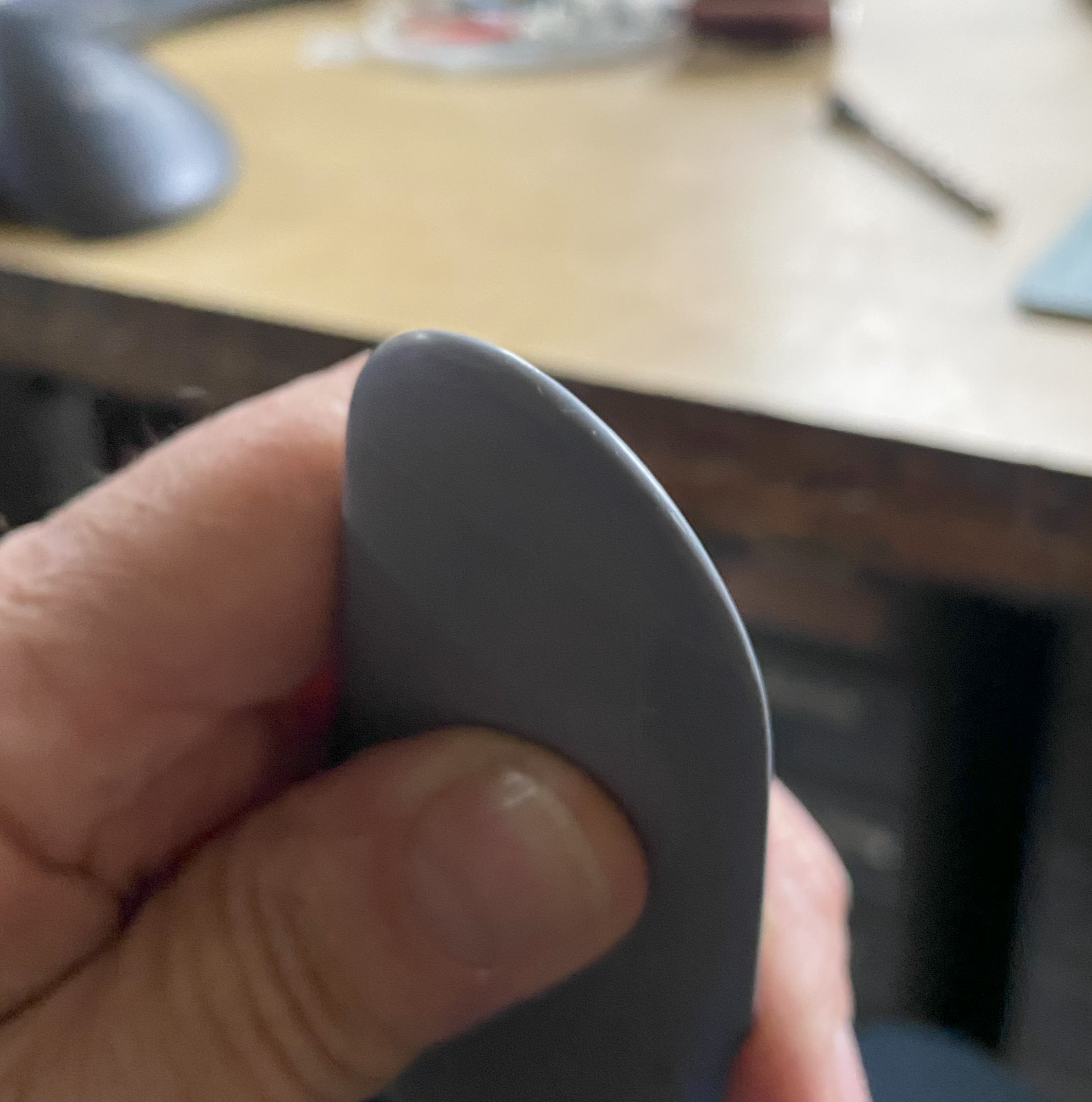
Last update I’d mentioned that the sliding part of the canopy was flawed. Part of it didn’t fill the mold cavity:

Not exactly the end of the world (or build) as I’d not intended on using the kit part in the build. If the canopy is pose open, this part sits far too high to be remotely accurate. My only use for this part is as the buck to vacuform another one over. Since even I know it would be a mistake to try that without fixing the depression, I fixed it. I used the UV-setting resin to build up the missing mass:


That will do.
As an aside, I find that the UV-setting resin is harder than styrene when it’s cured. It also appears to be hard enough to file/sand/polish to clarity. Must remember this the next time I have to repair a canopy that I must use but have just bitched up.
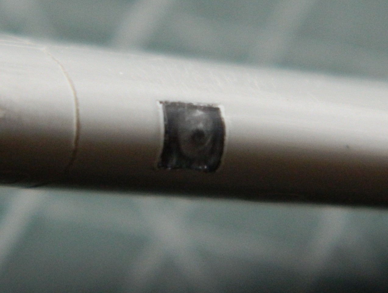
While I was rustling about, I treated the underwing landing light to Molotow Chrome. I used a punch to pop a hole in masking tape, applied it, and didn’t have to worry about slopping the chrome out of the recess:
I also used 0.032″ (just under .890mm) copper tubing to replace the kit’s 20mm “cannons”:
I can just see how many times one of those will get knocked off, so I’ll mount them later. I also managed to snap the antenna mast off as well. I’ll add a pin to the bottom of the mast and drill a socket for it to mount to later.
I’m just happy that I do NOT have to work on that sodding throttle quadrant anymore!
F7F-3 (AMT/Italeri) 1/48 Scale Build #5 – Finishing the Engine Nacelles, Landing Gear, and Starting the Cockpit…Where Things Get Tedious
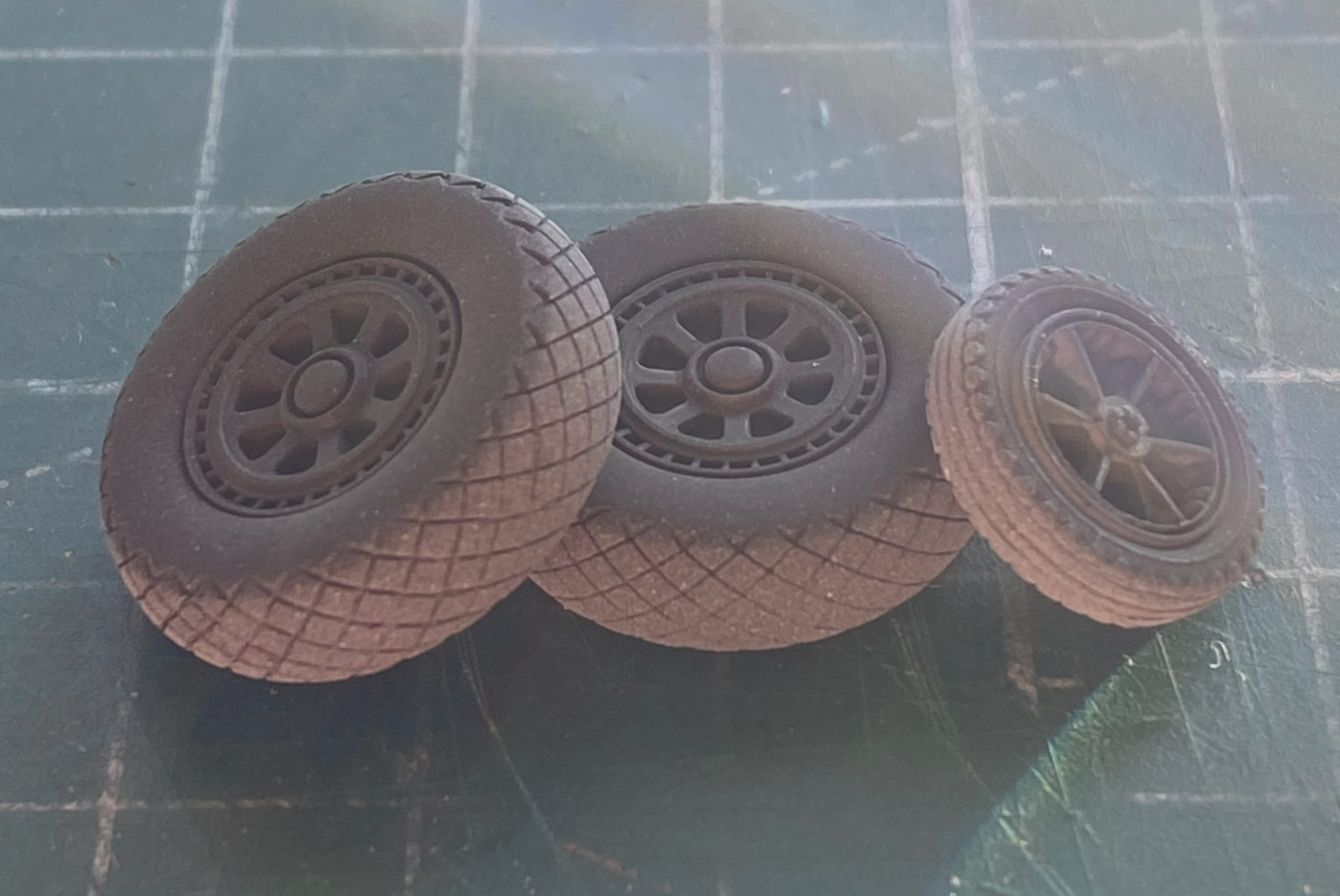
With the main landing gear installed, I wanted to finish painting and working the tires. Scale Model Accessories resin wheels (part #CAT_R48018) will take the place of those HIDEOUS vinyl tires. I’m eagerly awaiting the news that kit manufacturers freakin’ stop making these things. They dissolve styrene so sure…let’s include them in a styrene kit! Gotta say, the corporate mentality (though using “mentality” to describe corporate decisions and policy really takes my sense of sarcasm to new heights…or depths, you choose) continues to baffle me. The vinyl doughnuts get replaced by these:
Once the pouring blocks were separated from the tires, I discovered that the wheels were just slightly smaller than the openings in the tires (for all three):

The wheels were also too thick from one side to the other. That was easily remedied by just sanding them a bit more. Still, the masters for these parts were clearly 3D printed. So…the digital doctor didn’t know how to dimension things correctly? ::facepalm::
After jiggling the tires on the wheels in the attempt to minimize the mismatched wheels and tires, I used Tamiya’s XF-85 Rubber Black for the tires (though Tamiya’s XF-69 NATO Black works just as well). Then I misted Tamiya XF-2 Flat White onto the treads to replicate wear:
The wheels will get treated with a mix of Tamiya XF-16 Flat Aluminum (4 parts) with Tamiya XF-1 Flat Black (1 part) to tone down the brightness of the aluminum. These were set aside until I was ready to paint some darkened aluminum.
To complete the engines, I needed to add the props. I’ve read build reviews of this kite and about half of them complained about the shape of the blades. I didn’t see it. I trust my eyes (in spite of their many deficiencies) so I didn’t reshape them. I did see, however, that deployed Tigercats had the tips of the blades squared off for more ground clearance. Evidently the tips of the props would hit the ground under certain circumstances so it wasn’t uncommon for them to be trimmed back (I’ve seen period reference photos showing the blades in both states, trimmed and original). I marked the tips where I would trim them back to:

I’m going to be mixing some custom colors. An empty Tamiya paint jar is excellent for mixing custom colors that I use frequently enough to want to have premixed and on hand:

When painting dark and light colors adjacently, it’s best to put down the light color, mask it off, and then the dark color. I think that Tamiya’s XF-3 Flat Yellow is far too bright (unlike your humble…sometimes…author) so I used three parts of the XF-3 and one part of Tamiya XF-60 Dark Yellow. After spraying the tips, I let the props sit overnight before masking off the yellow and using a rattlecan of Tamiya Lacquer TS-6 Matt Black, which actually is more of a semi-gloss once it’s cured:

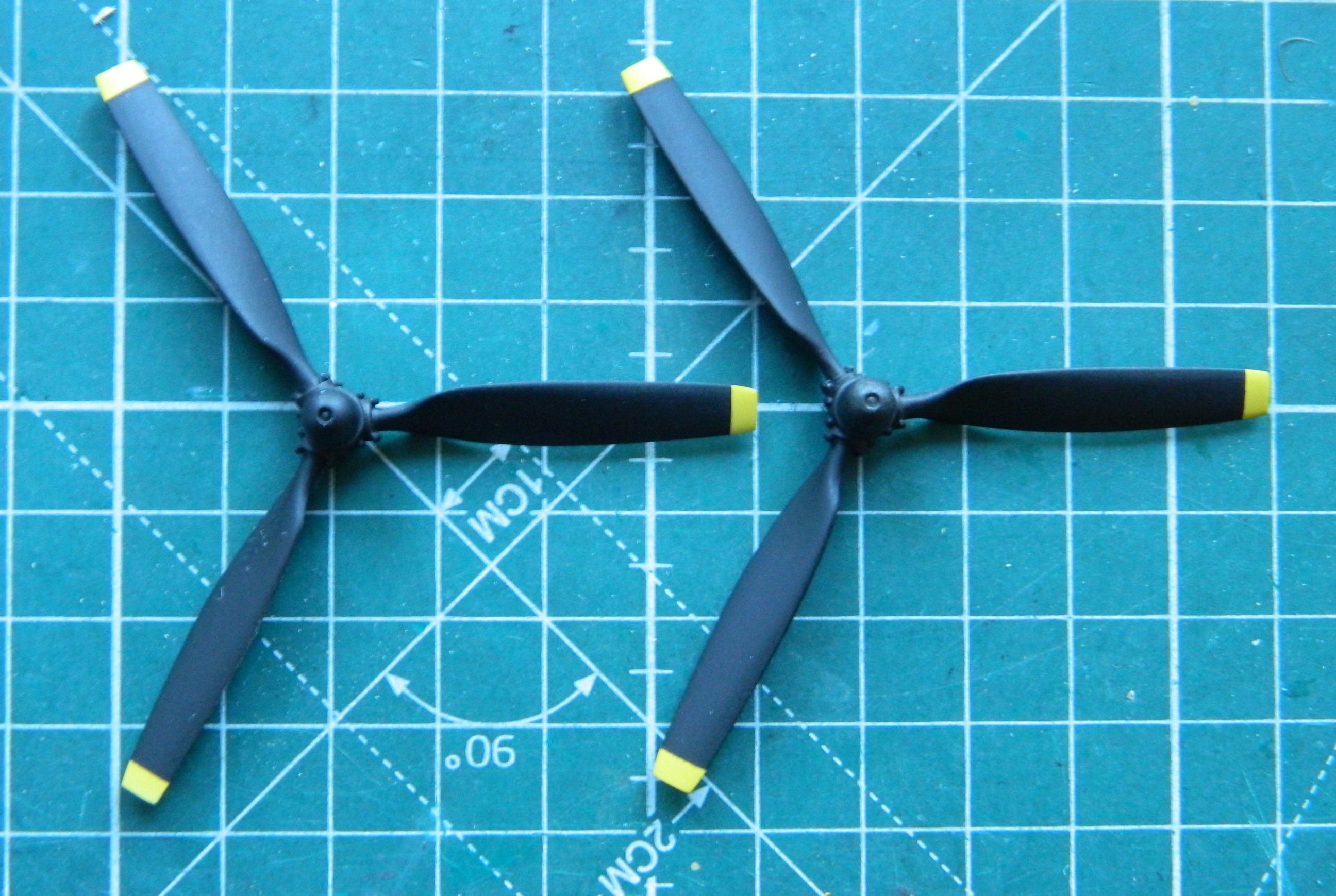
Only one more color to add to the props and that’s to paint the hubs aluminum, and yes…I used the darkened aluminum for that. And since I was loading the airbrush with darkened aluminum, I painted the parts already assembled that require that paint:


The wings were assembled:
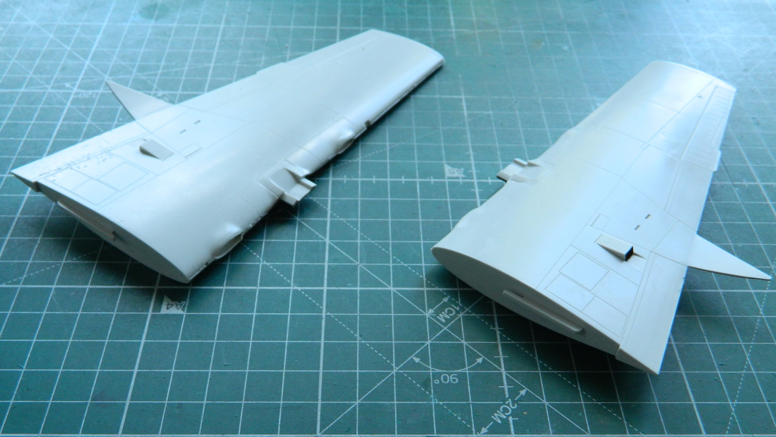
Having dry-fitted the nacelles to the wings previously, I knew that the upper rear of the nacelles molded onto the wings both sported massive gaps. Anyone who thinks force never solves anything has never been a mechanic or carpenter (and there are no doubt many other trades in this category). This time the force was supplied by clamps (clamps…isn’t that what Chinese women get every 28 days or so?):

With the subassemblies of wings/nacelles mostly done (I’m trying to decide which putty to use where the nacelles attach to the wings…too much for 3M Acrylic Putty or should I use Aves Apoxie Sculpt? You’ll figure out which trigger I pulled in a subsequent post), attention turned to the office. The cockpit.
I took the few cockpit parts…:

…and tacked them together with white glue. I wanted to dry-fit them to see how they fit (sorta) and how much room I had to stuff even more lead into. Remember, the start of the previous post showed that what I’d already stuffed with lead (and tungsten…for its price, let’s not forget the tungsten) was just enough for this kit to stay on all three tires. I want more. Once the white glue dried, I placed the floor/instrument panel/bulkhead in place to see what space was left.
Plenty:

Every surface with a line on it is forward of where the main wheels sit (the balance point). And I accept that every review I’ve read has either not put enough weight in or has just enough weight in…but a bump would make the model sit on its tail. With all this space I’m not really sure why that problem reoccurred enough for it to be A PROBLEM. But regardless, forewarned is forearmed. Before I join fuselage halves I’ll be stuffing lead into the spaces marked.
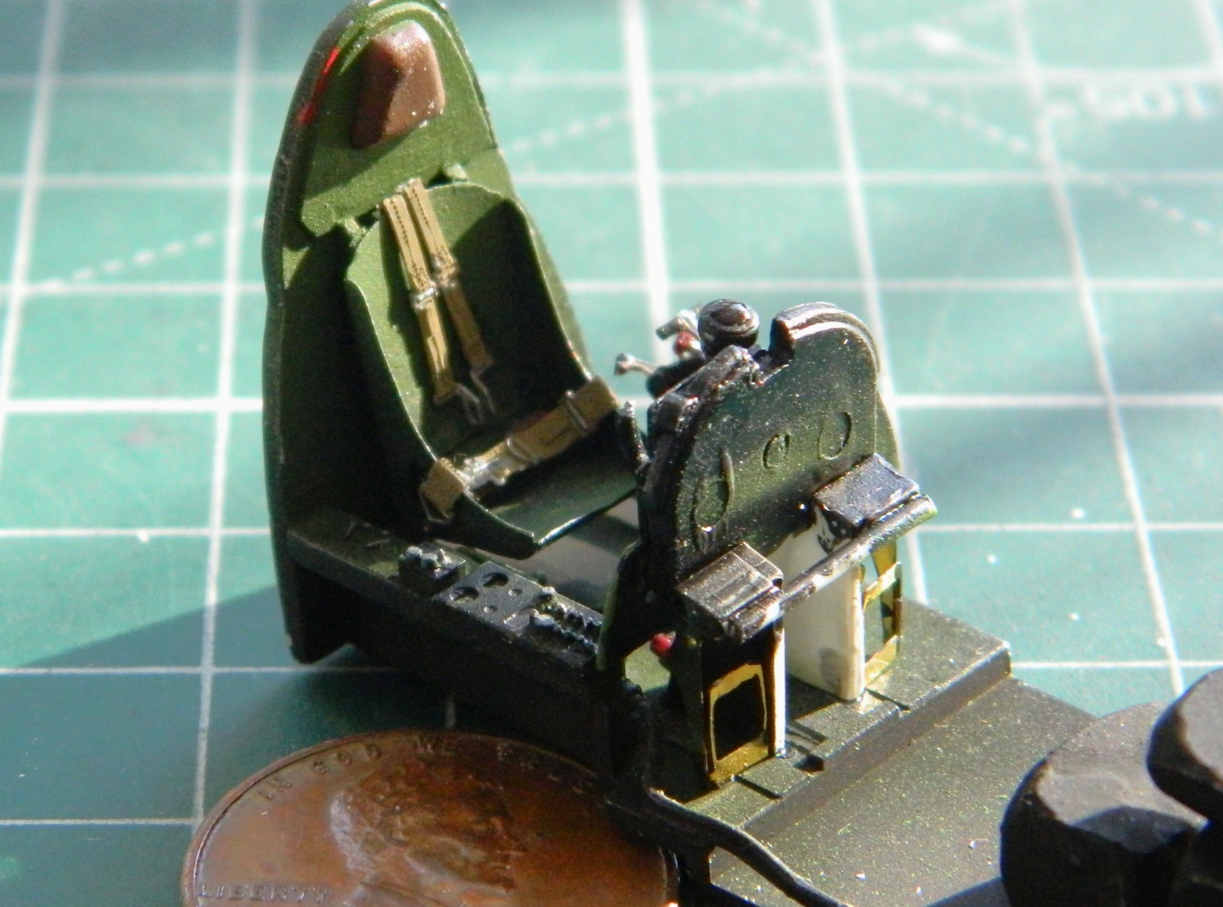
I recently got into a conversation about, “I don’t think PE is worth the hassle.” I get it. Sometimes I use the PE parts as a template and make a plastic copy. So far, PE can only do flat parts and some of the parts that PE is supposed to replace isn’t flat and that’s frequently noticeable. But there are those times when PE is well worth the hassle. I think that this is one of those times:

Yes…there is a gap in the PE part where the back of the seat angles up to meet the back. I intend on filling that gap (and the required finishing to make it look correct) with UV-setting resin.
So far I think that the styrene harness will probably end up looking pretty good. This is just my initial attempt. There may be more tweaking (the shoulder harness will be formed over the seat back later):
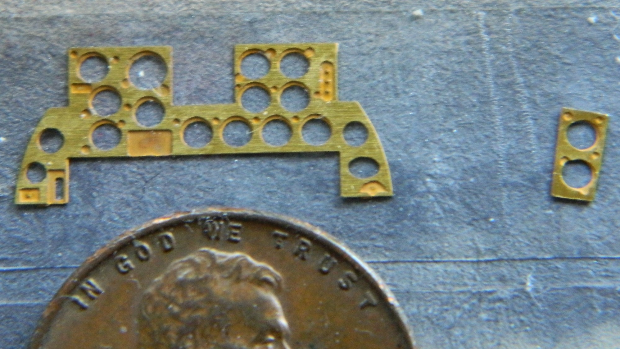
I get that it’s nosebleed expensive to cut the molds for a model. In the attempt not to make one basic kit with different parts trees for different variants, manufacturers will often paint with a broad brush. This model shows that in a couple of places and the most obvious is the instrument panel.
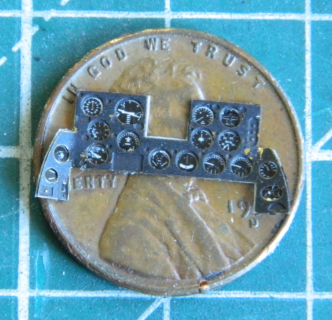
The F7F-3 that I’m building is the fighter variant and was the least utilized of the three variants. The -3P was the photo-recon variant and the 3N was the night-fighter variant. The-3N had a slightly different instrument panel. There was a prominent radar display in the center of it (I’ll bet you can spot it):
At the top center of the instrument panel, that semi-circular protrusion is supposed to be the gun sight. Uhm…no. I’ll cut that out and build a better one. But the radar display and all other raised detail on the face of the panel has to be removed so that the film/PE replacement will sit flat:

This is a much better rendition of that panel:
I used Tamiya’s rattlecan TS-6 Flat Black to see how well it would adhere to the brass. I already knew how Tamiya XF-1 Flat Black and X-18 Semi-Gloss Black adhered (not well) and I wanted to try lacquer to see if that would work better:

While that was curing, I used Testor’s White Gloss enamel (yes…the one in the little square bottle) to act as a backing for the film-gauges so that they would be visible:
Not bad, though just from very minimal handling I can see that lacquer didn’t hold up better than acrylics did. As part of the retouching process, I will also go around the edges of the panel with black so that the backing film with the gauges won’t jump out in the eyes…and the panel needed even more retouching than what’s showing here:
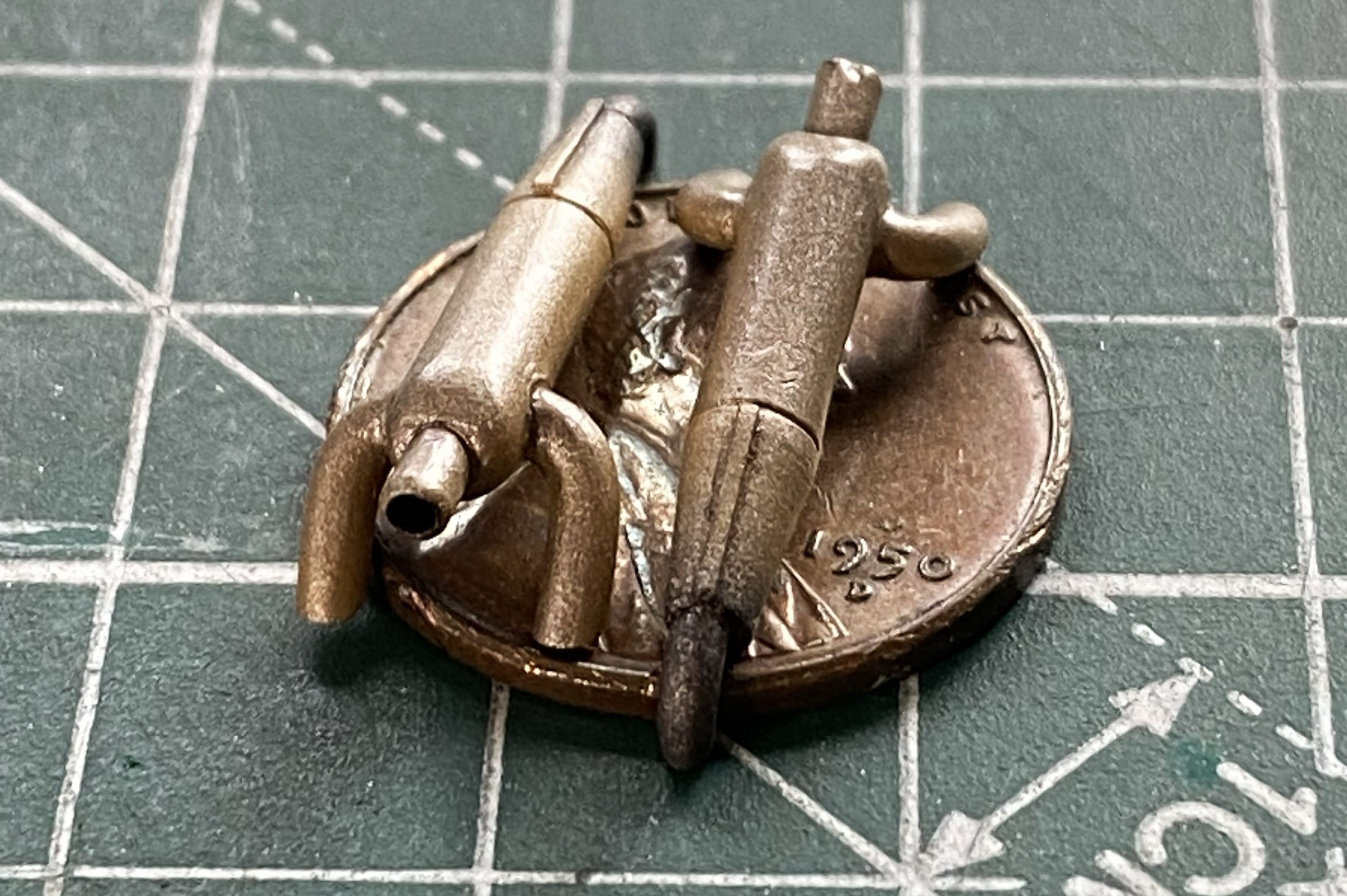
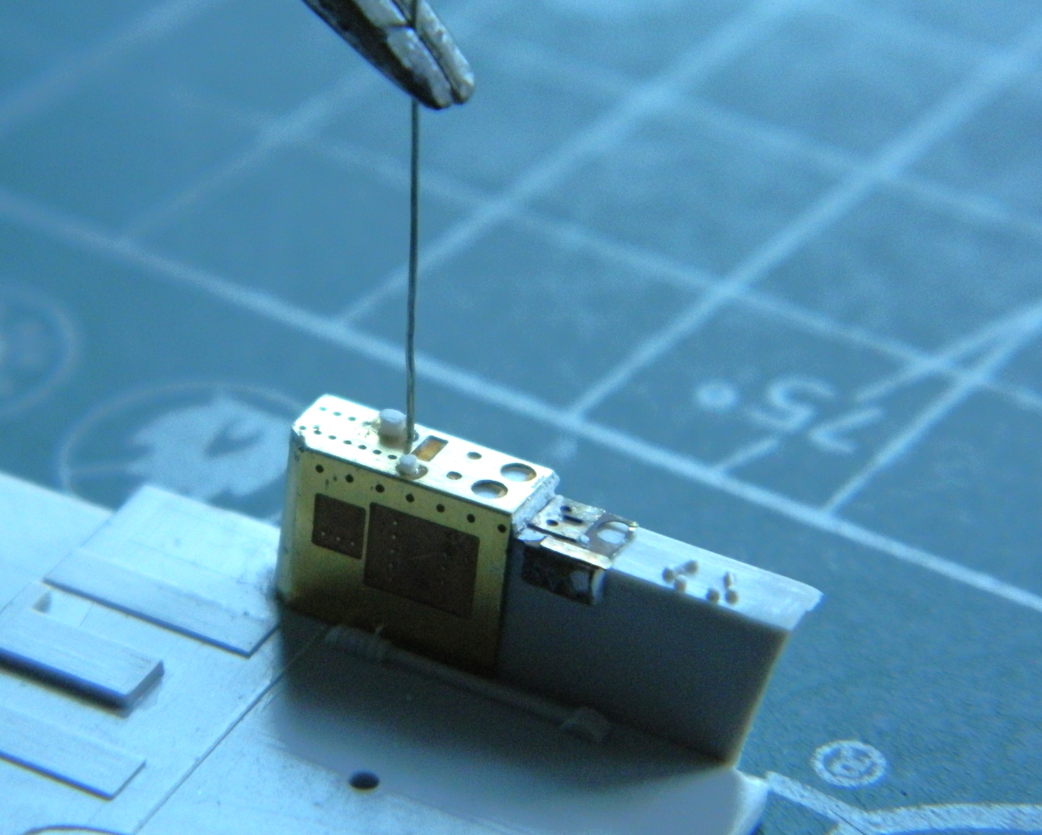
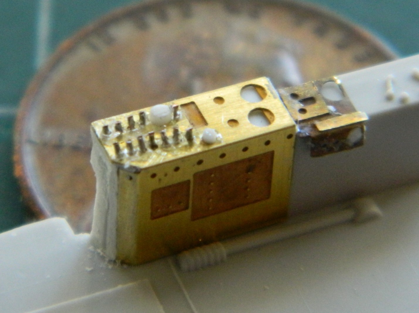
I can’t imagine two things (okay…much more than merely two but this isn’t the forum for my general ignorance). The first being how the die (mold) makers can get something so wrong. Or. How does a die wear so that it’s no longer aligned with its counterpart. But this happens often:
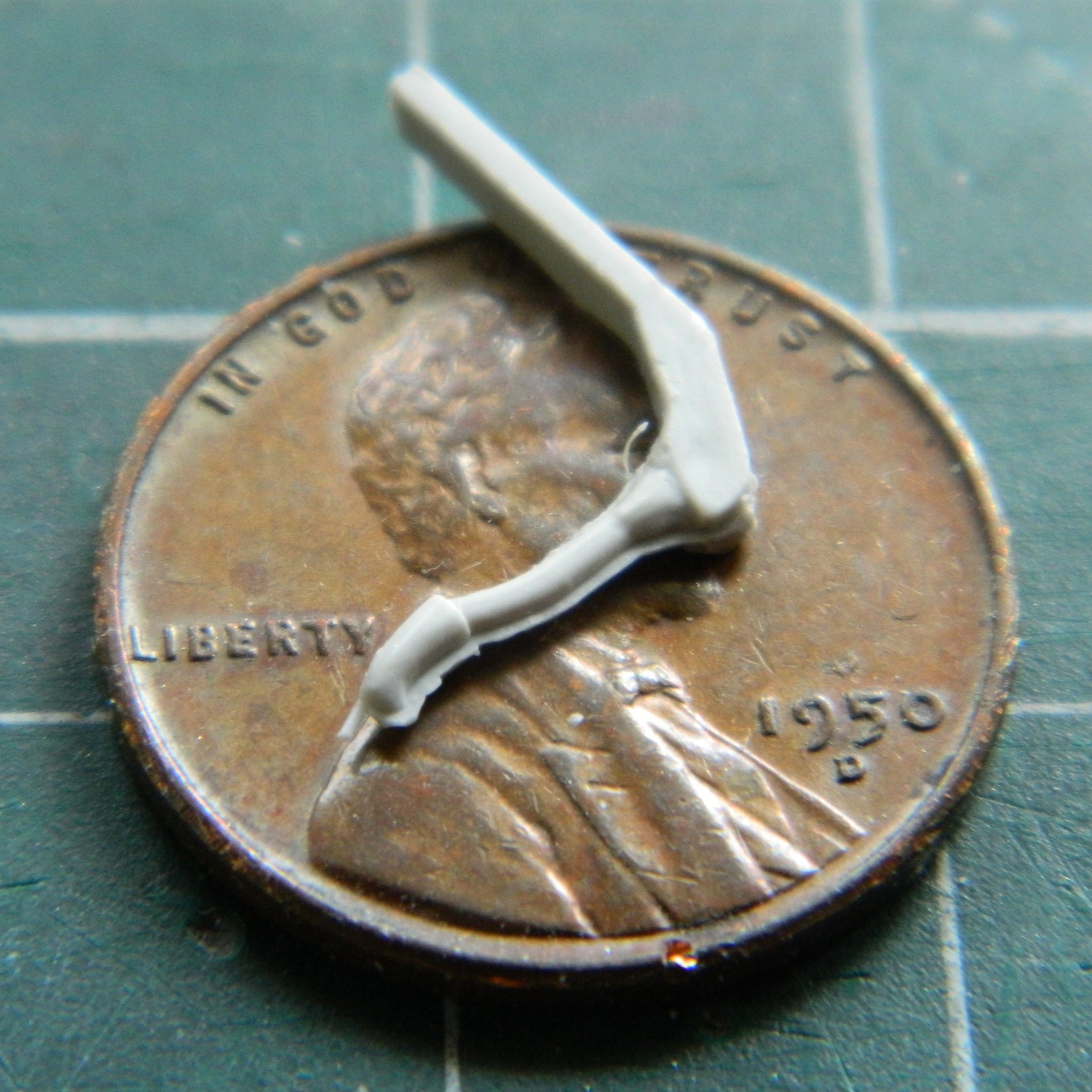
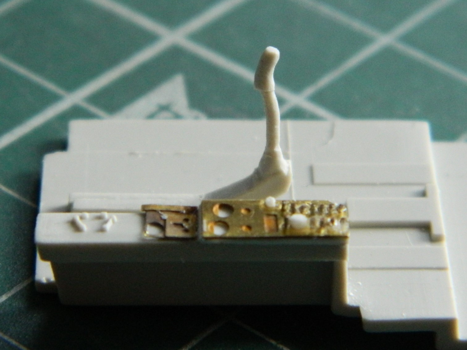
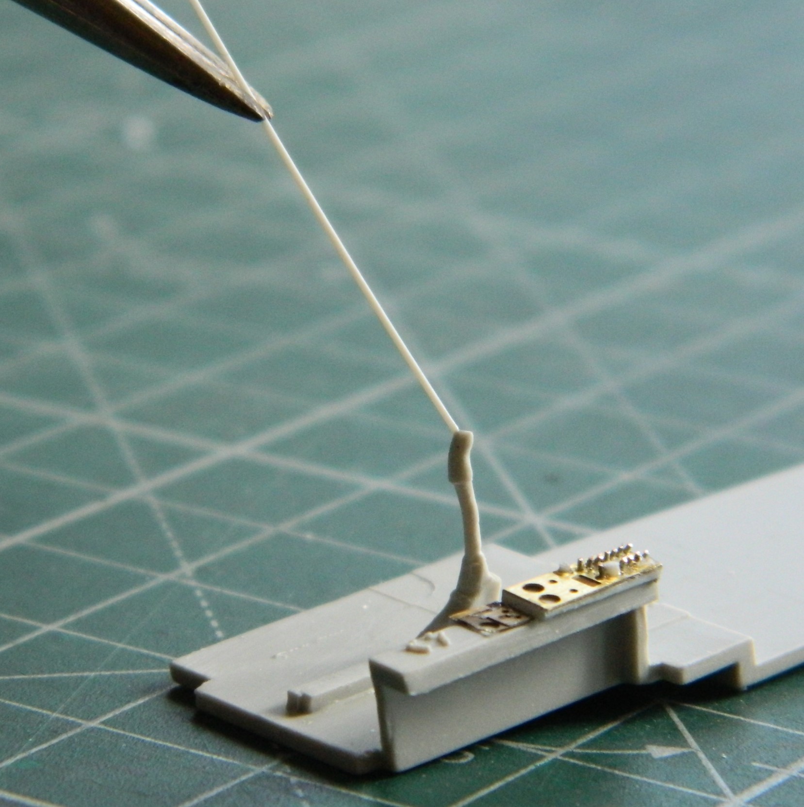
This presents a conundrum. Which half do I make conform to the other? Well…to be picky about it (a modeler picky?!) the answer is “both”. I’d be fine with that if the entire part didn’t fit on top of a penny. If I try to make the misalignment go away, I’ll break the joystick. (Don’t ask me how I know.) Okay, then the determining factor is the answer to this question: “Which side will be visible?” Easy answer. The part of the part that the pilot would see. If the pilot would see it, so will you. I decided to stretch sprue as thinly as I could (success!) and then lay it along the misalignment:


Yeah…this one is going to be delicate. I set the part aside for a couple of days so that the glue (my go-to is Tamiya Extra Thin green cap) out-gasses totally.
This is what the kit supplied for the control panel to the right of the pilot. All the raised details from the center to the left has to be removed:
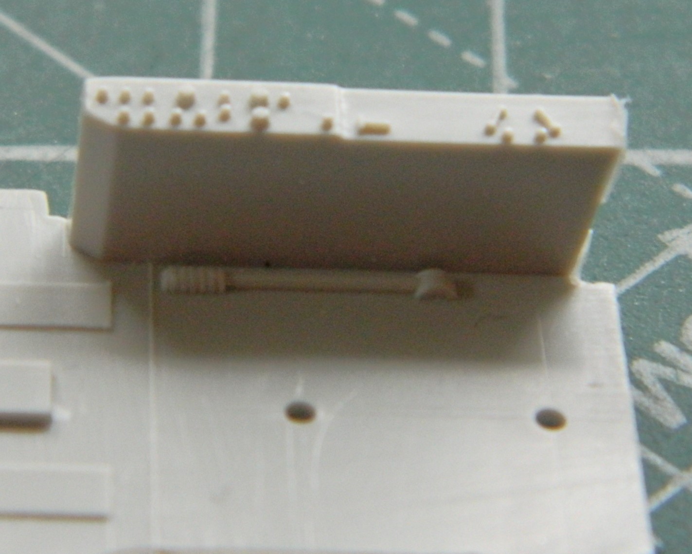
This time PE does what it does best:
I forgot to take a photo of it initially. The forward vertical edges didn’t fit snugly (surprised me, Eduard!). 3M Acrylic Putty filled them. And what you see in the above photo is the beginning of the 11 or so toggle switches that “have to” be added. (The white knobs were added from stretched sprue.) In this photo you see all the toggle bats added:
Yes…the ends of the bats aren’t supposed to be chisel-shaped. The size of them keep those ends from being noticeable.
With the cement out-gassed, I very gently sanded away the added sprue and (also delicately) reshaped the grip:
There is also a push-button off-center to the left. I don’t know what it’s for but it can be seen, so I added one:
Twin engine prop aircraft have doubled engine, prop pitch, and mixture levers. This kite also has one supercharger control. That’s seven levers (puts shoes back on). This is what the kit provided:
And this is what the Eduard PE fret thought would be better:
Not in the least bit usable. Maybe I’ll be able to use it for something else later on but it’s just ridiculously inaccurate for this build.
Hmmm…two divided by seven means that less than 29% of the controls that should be there are there. Fine (he says petulantly), I’ll make one and it should look just like this:
I mean, really… how hard could it be?
Yeah, well, one of these days I really must stop asking that question because I always, ALWAYS, find out. Oh. And the answer this time is…
Very, very, very. VERY.
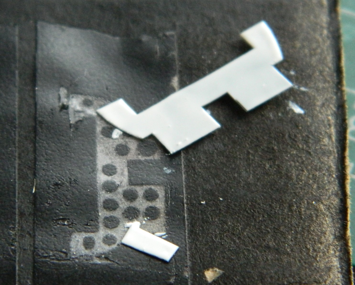
For the first attempt (the words “first” and “attempt” should inform you how well it didn’t go) I tried using 0.010″ (.254mm) styrene. I would normally skip a few steps here but I recently had someone ask, “How do you actually scratch-build something?” So I’m going to show you.
I used the kit’s throttle quadrant as my scale. Clearly it fits, there just isn’t enough of it. I found a piece of .187″ (4.74mm) styrene tube that conformed to the arc of the kit’s offering. It didn’t take me long to realize that there are seven slots for the levers to travel in. And this part is very small. Even with my hands as steady as they were 50 years ago, they were never that steady, and there just isn’t enough room to cut them into the body of the quadrant. But all that said, here’s the process I used… (And I’m not going to put dimensions in the description because this didn’t work so if you try to replicate it, it’s not going to work for you either.)
I went into my plastic stock and picked a piece that would be larger than I need (makes trimming things much easier that adding things because the result is too small). I guesstimated the angle of the main body and drew it onto the plastic:
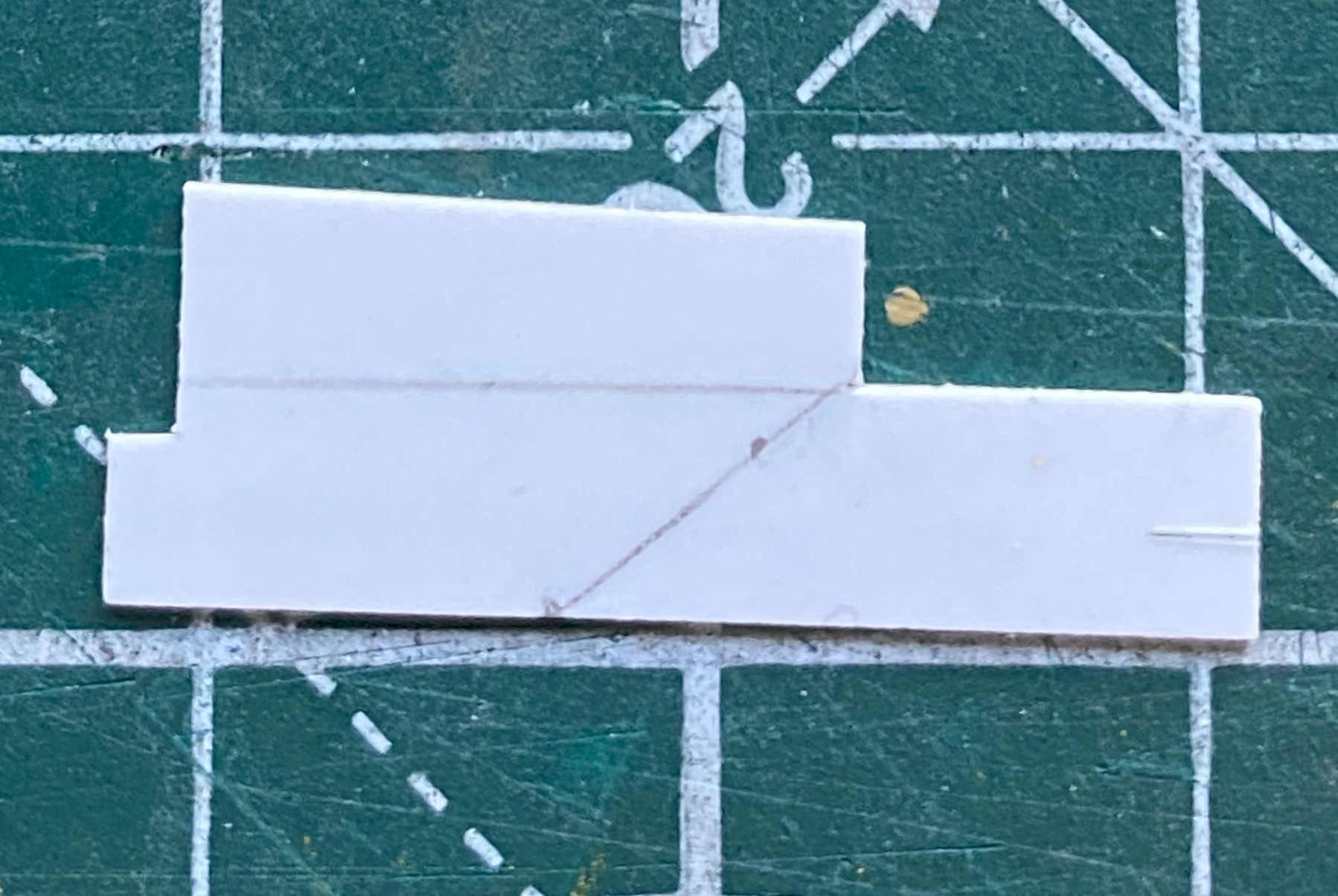
Then I salami-sliced a short section of the tubing I would be using and diddled with its placement until I had what I wanted (which I certainly hope is correct):
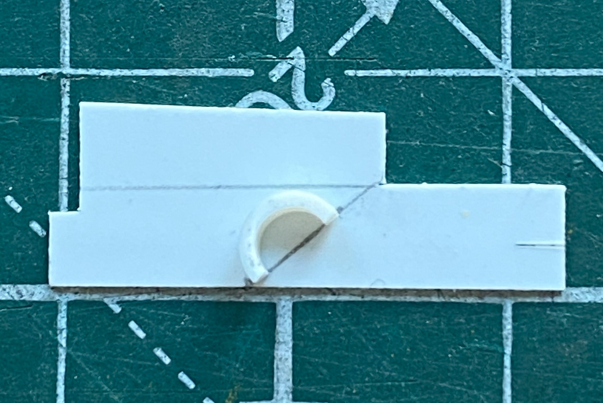

Then I sketched in the outline (it wasn’t until later that I realized that I’d gotten the arc on the left a bit off center…which was addressed later):

Then I trimmed it coarsely:
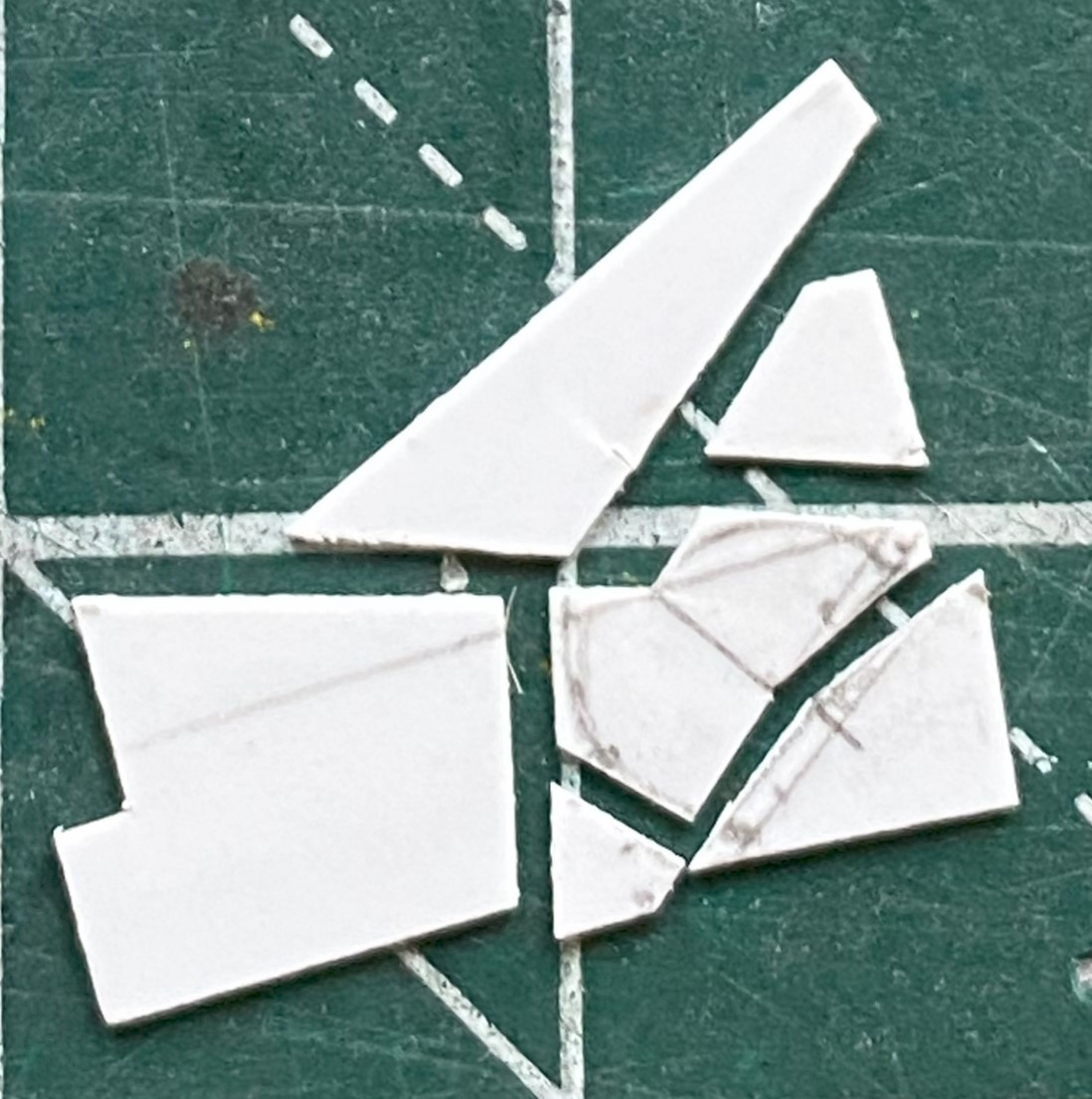
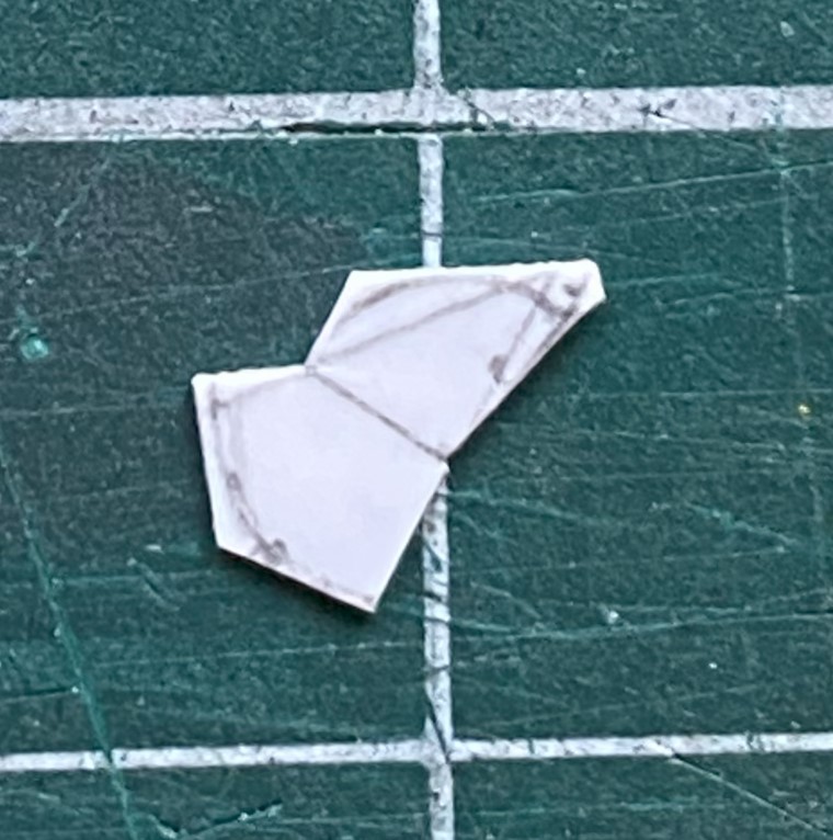
320 grit sandpaper finished the edges:
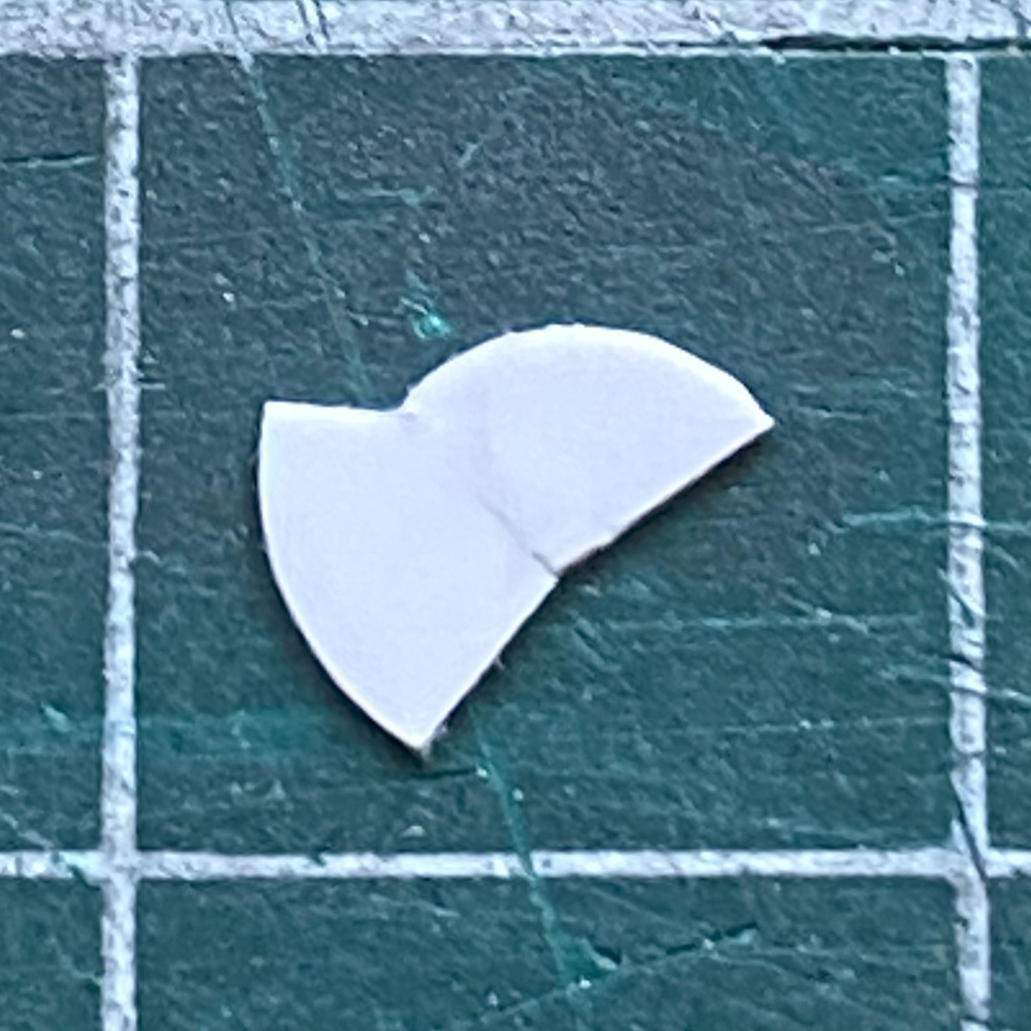
Would that that was all there was to it. Remember, I need slots, too! That meant I needed spacers between each of the follow-on parts. In the following photo, the parts are actually upside down, but hey…
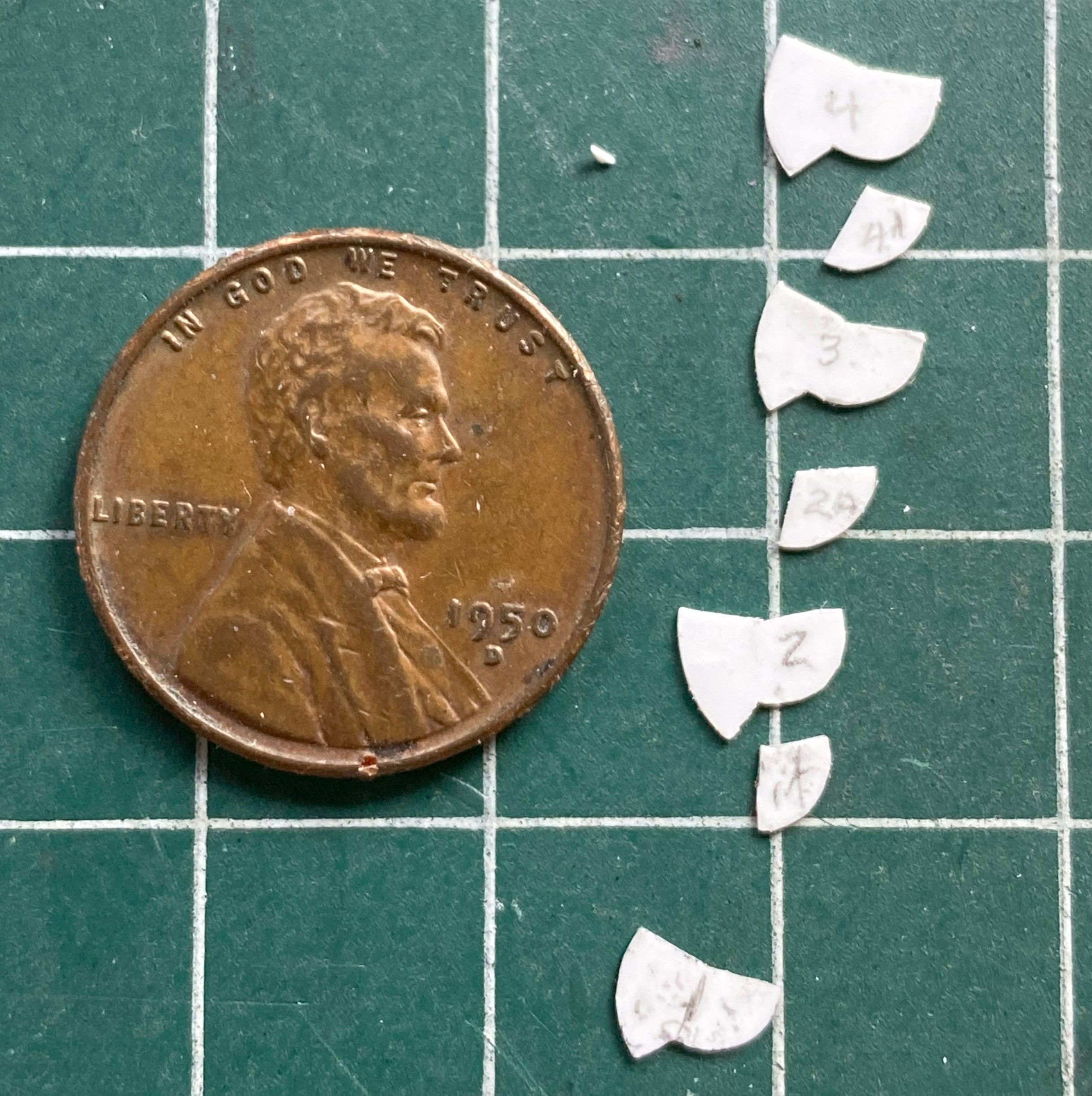
So that’s some of the parts, with the spacers in between the sides. These are very small parts. The smaller the parts, the longer the time to make/fiddle them. This took what seemed like an eternity (made eternal because the fingers of my left hand just kept cramping). Before I kept at it even further, I decided to assemble what I already had just to see if this idea would work:

What you can see in the above photo are V1 and V2. V1 is on the right and is the correct width overall. You’ll note that the part on the left is wider…and that’s only half of what has to be built.
Well, bugger…
Okay, cue V3!
It took me a bit to figure out what V3 could be, but I arrived at a notion that I think will work. On V2, everything was made from 0.10″ (.254mm). The easiest way to halve the construction would be to halve the thickness of what it’s made from. 0.005″ (.127mm). However, trying to work styrene that thin is akin to trying origami using butterfly wings. Ain’t doing that! Oh! I have that size copper shim stock! Okay…V3 here we go!
I filed and sanded V2 to a less inaccurate profile, salami-sliced that, and used the part as my template. I traced around it onto the shim stock with a needle and used scissors to cut the part away from the rest of the stock. Those two sentences took the better part of the week because in addition to having a glacially slow build speed, my fingers kept cramping. And at this point, I have all the parts in copper that I had in styrene. (A couple of the spacers are 0.020″ (.508mm) because of the spacing required.):
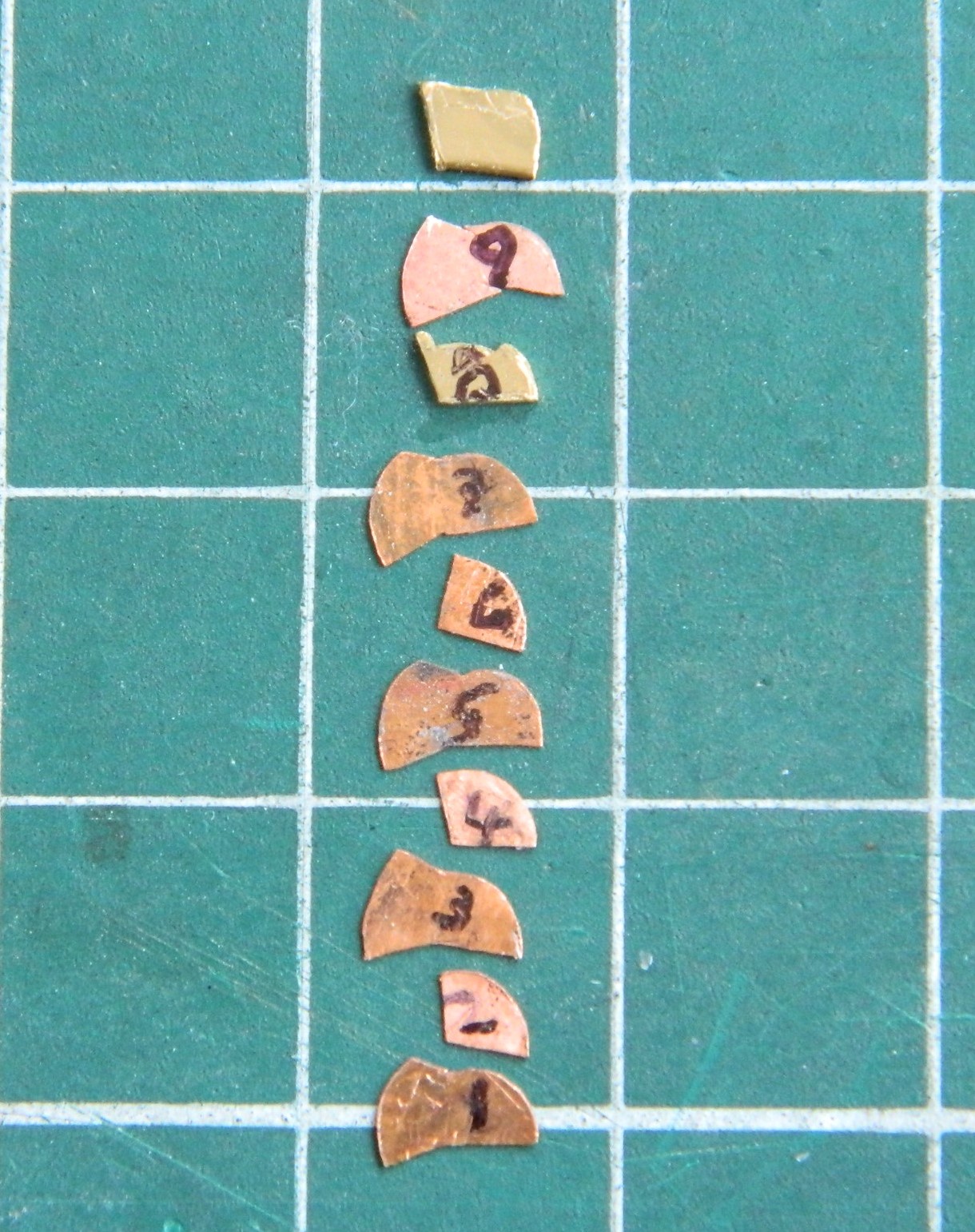
Whew… I guess next month will start where this one left off. Not just cutting out the parts but figuring out some way to put them all together. Once I have, I can then file them to their final shape and dimension.
Oh. In case you’re thinking that I need more “fun” in this build, all seven levers have little knobs atop them. I’ll be using some of these, which are glass beads I got online from a crafting store:
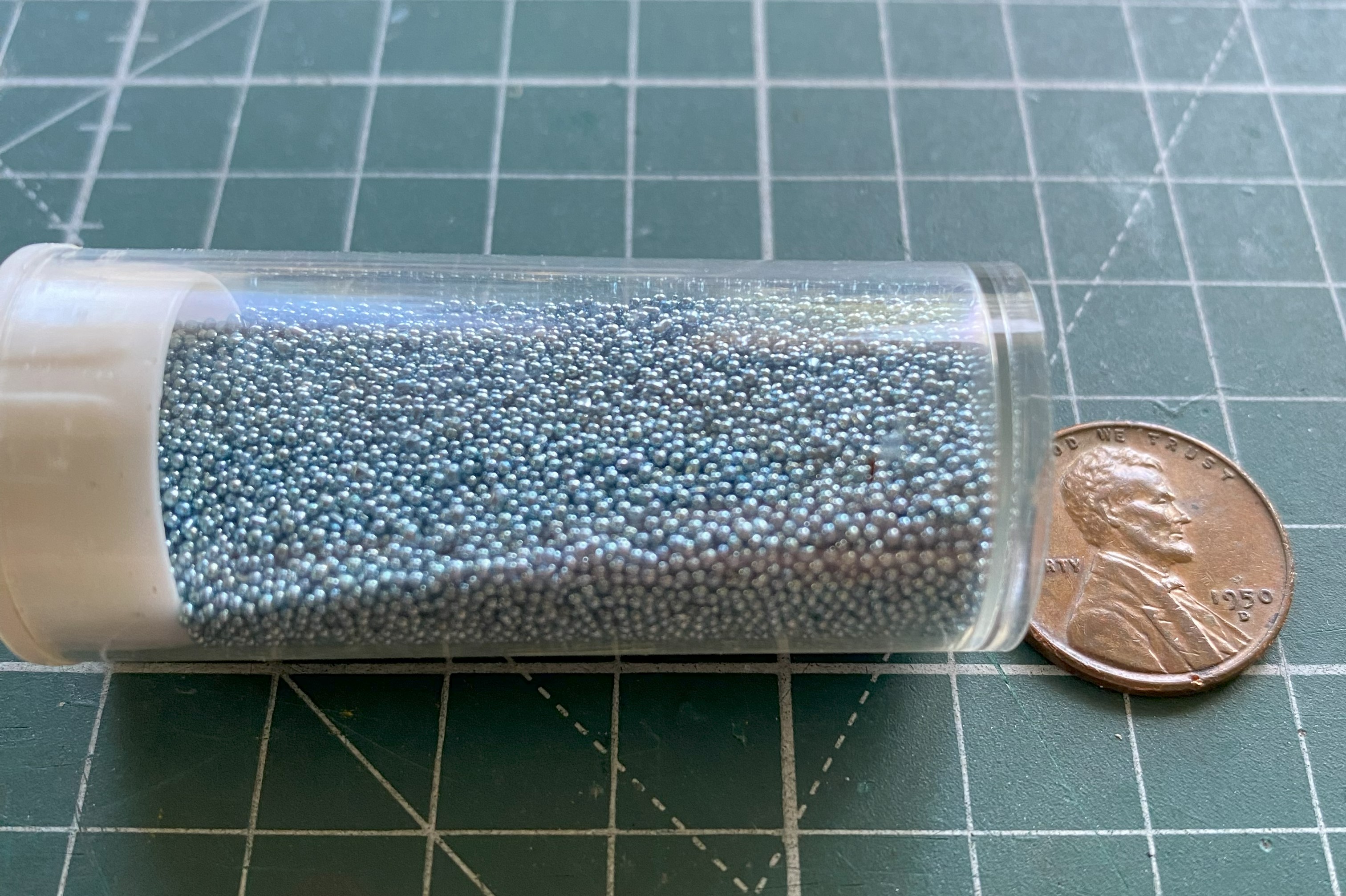
My experience using these beads on the P-38F showed me that they are an absoLUTE ass-pain but the results are so worth the effort.
