Grumman JRF Goose (Czech Model) 1/48 Scale Build #5 – I Pick Up Where I Left Off
There was no real update here since June. July was miserable on the personal front and having to deal with the profoundly rotten fit of everything was just enough to put me to redline. I needed to walk away from this for a bit, and the kit needed me to walk away for it to survive.
[I am also starting to bore myself with continually carping about how lousy this kit is. So take it as a baseline that this kit is a turd…a large and foul-smelling turd. More than enough said about that.]
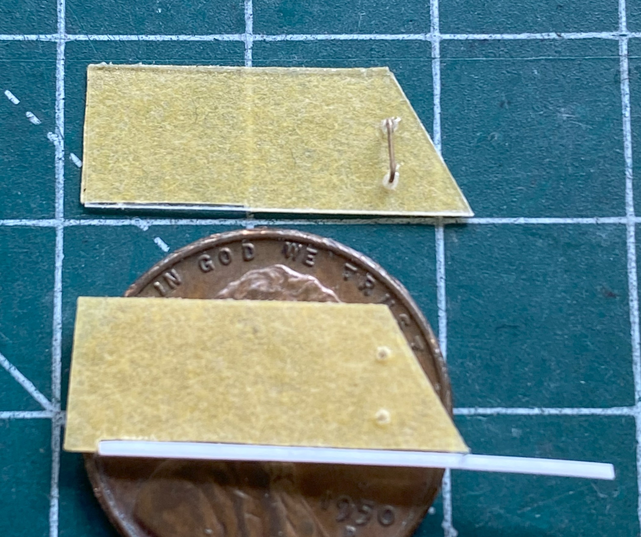
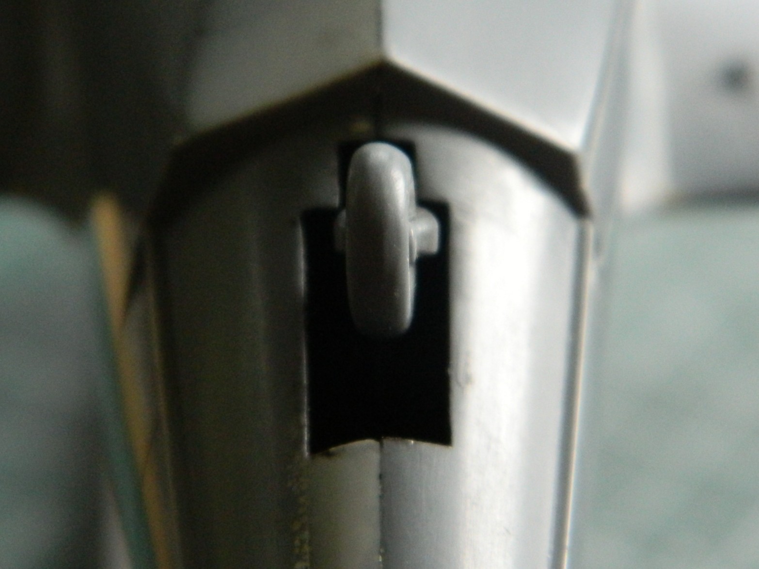
After cutting away the side windows of the clear part, I needed to make something more accurate. I used 0.010″ (.25mm) flat clear styrene. The side windows of the cockpit on the actual aircraft are flat and slide in L-shaped tracks (one of which is at the bottom of the following photo) with handholds inside. To keep from scratching the clear plastic, it was covered in masking tape, and the handholds were made from 24awg wire:

This is how I made the L-channels. I used scrap 0.010″ (254mm), aligned them to be perpendicular, and then glued the hell out of the join. After letting it sit for a few days, I started by cutting the plastic (and it’s made from so much plastic to enable me to grab hold of it) back and then using an emery board to straighten out the sides of it:

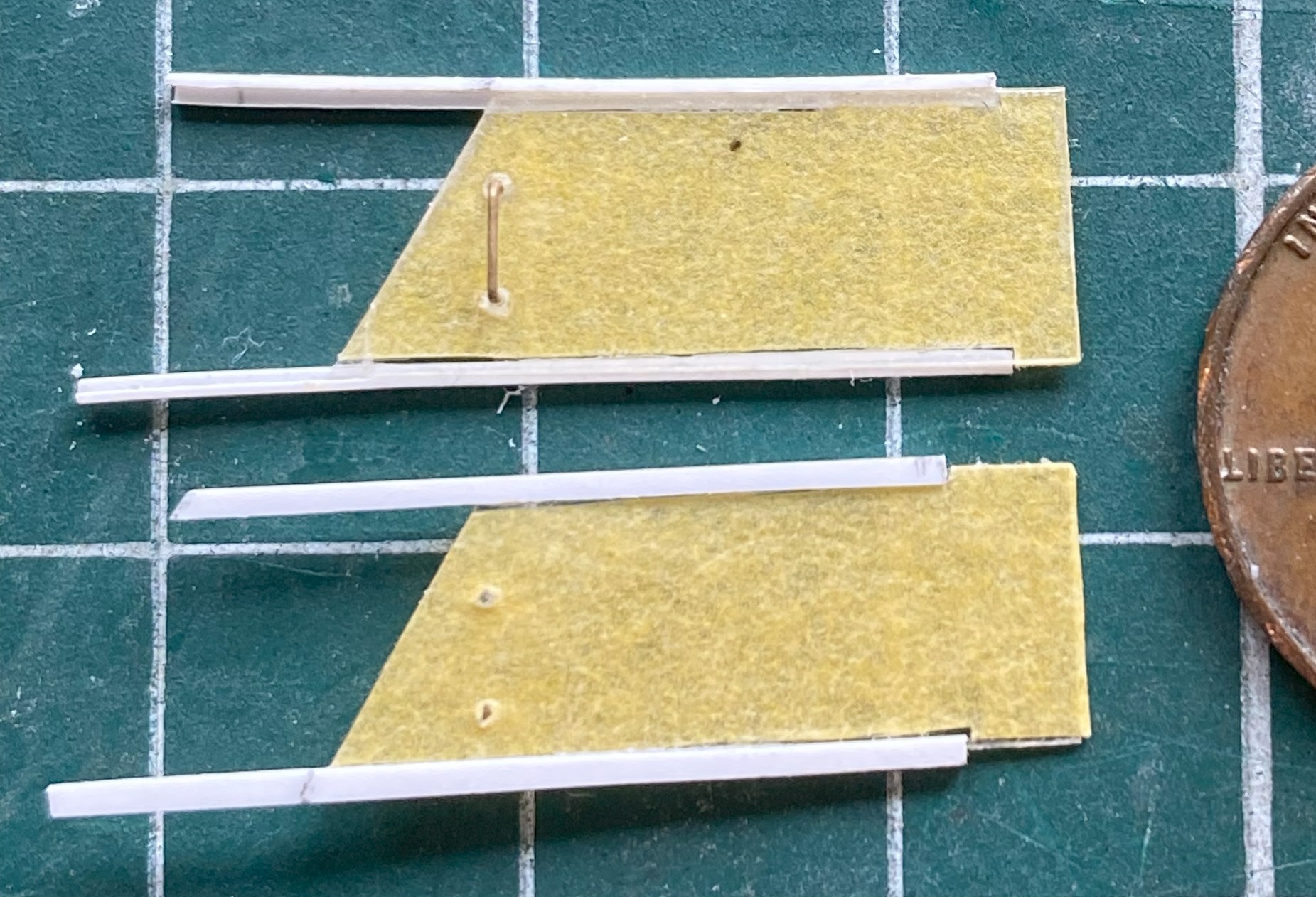
Instead of mounting the tracks and figuring out how to paint everything and then get the windows into place without scratching paint, I decided instead to figure out how far back the sliding windows were on the actual aircraft, trim the length of the tracks appropriately, and then trim the masking tape from the outside of the windows and then glue the tracks in place (one is shown above):
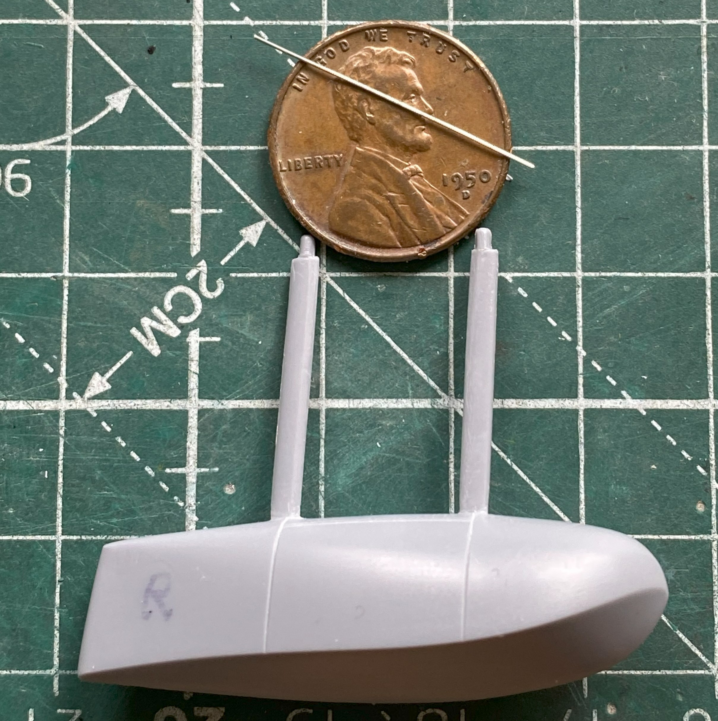
I’d played around with the floats earlier on and now it’s time to start adding the braces. (The stainless steel wire was sourced from a closed dental practice and it’s come in quite handy!) I drilled holes where the struts meet the tanks and UV-setting resin was used to attach the wires:


Then I started dealing with the nightmarish landing gear. In order to have even a slight chance of having enough hands to hold three parts in very specific locations, I aligned the major control arms to the suspension upright and then drilled through control arm and strut so that I could use a bit of wire to hold them in place and yet still allow enough movement to align everything without scattering parts by dropping them frequently:

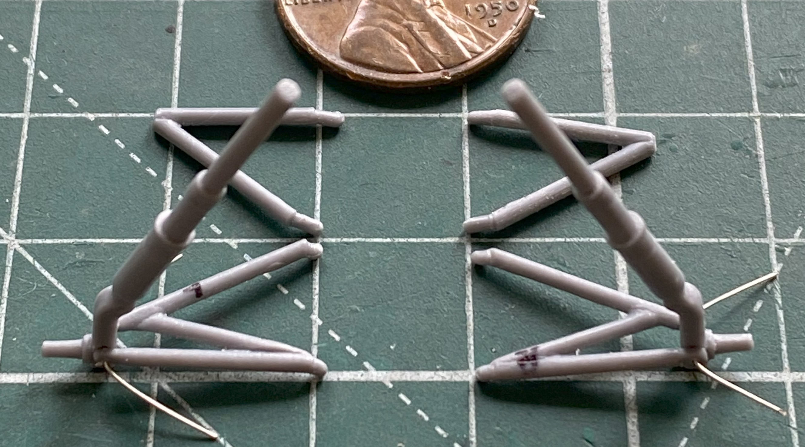
Getting all the landing gear parts to align was SO frustrating that I came within a hair of hanging this model from a tree so that I can see how many shots of 00 buckshot it would take to powderize this styrene cunt. It took several days to figure out how all these parts will fit (or, made to fit) and I think I finally have. I don’t think it’s time to add these frail things, but install now or later, I’ll figure out exactly how to do this. Stay tune for colorful (if anatomically impossible) invective when that process starts.
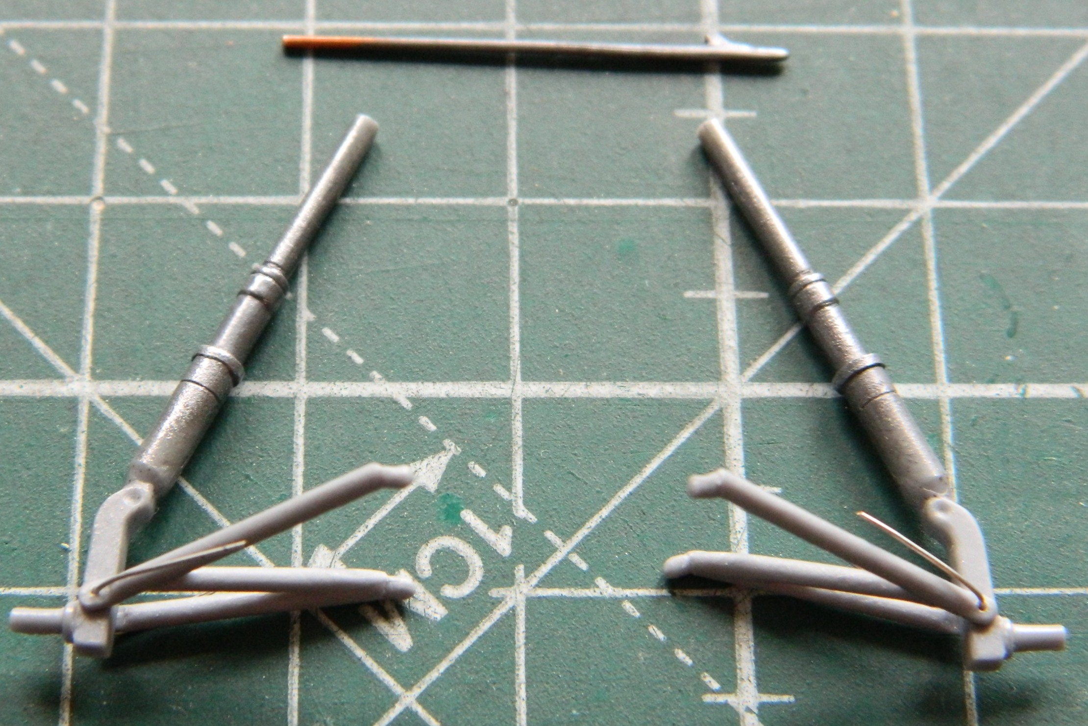
One part of the strut assembly is the oleo. It’s the part of the landing gear that functions as an oscillation damper (or, as we mistakenly call it in the States, a “shock” absorber). I’ve so HAD IT with this build that I didn’t even consider replacing the styrene rod with steel. Fuck it, in other words. But since it’s steel, I used Humbrol’s Metal Cote Steel #27003. While the airbrush was loaded with this paint, I also painted the pitot tube as well:
Since I was working with landing gear, I went back to the tail wheel. The next thing I’m going to load the air brush with will be aluminum, so I wanted to get all the parts that I need painted aluminum (at least right now) ready to paint. And then I encountered a surprise…
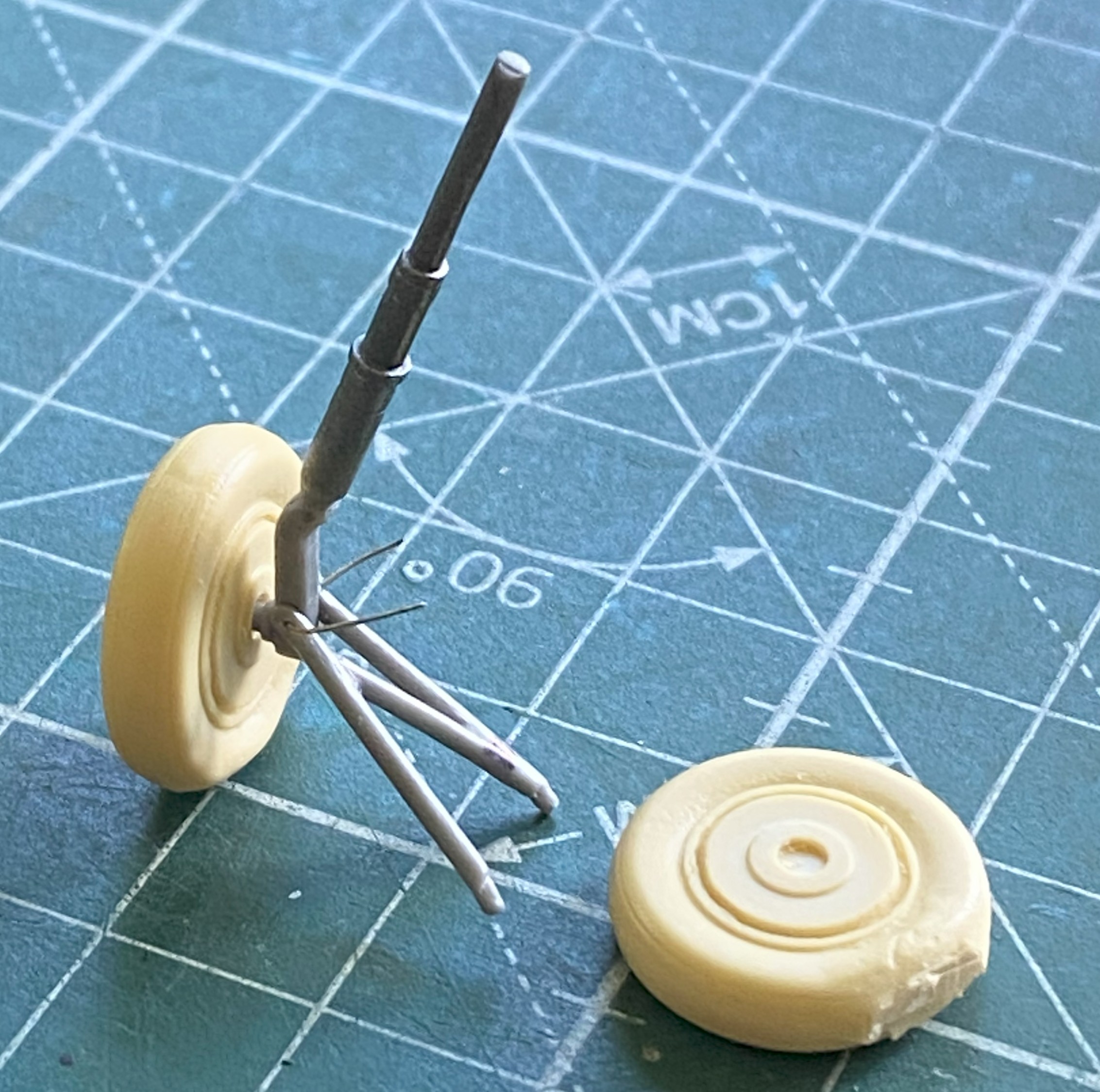
I worked this little part over for a while. Unsurprisingly, it was poorly molded, which was why I’d done some delicate knife-work to clean up the part. It was glaringly obvious that the wheel and strut were molded one piece…and not very well molded. What surprised me was discovering that the part, as molded, is twisted. The mounting pin is vertical to the camera. The yoke is bent to the right, and the tire is also bent to the right as well as being twisted:

After overcomplicating things but only in my head this time, I decided to see if I could diddle how it’s mounted sufficiently enough for the bent and twisted tail wheel assembly to appear as if it’s in there straight, which it is not. The bulk of the model combined with how close to the ground the tail will be combine to make this cheap fix possible. I’ll spend more time when it’s mounted to get this seeming as close to correct as I can without spending a week of surgery on it to correct it (modeling…it just has to look correct):

I’ve made no secret of the fact that I really dislike True Details’ items. Characteristic of that firm, their “flattened” tires look more like “underinflated” tires…and that’s only on their (relatively) “good” examples. The tires with this kit aren’t in that class. Even for True Details, these things look hastily done. Note how pitted the surface of the right wheel/tire are…and some of those pits are bubbles in the resin (of which I’m NOT a fan). The one on the left has been worked a bit to reduce the bulges on the side and I’m considering working them more before black paint is shot at them:
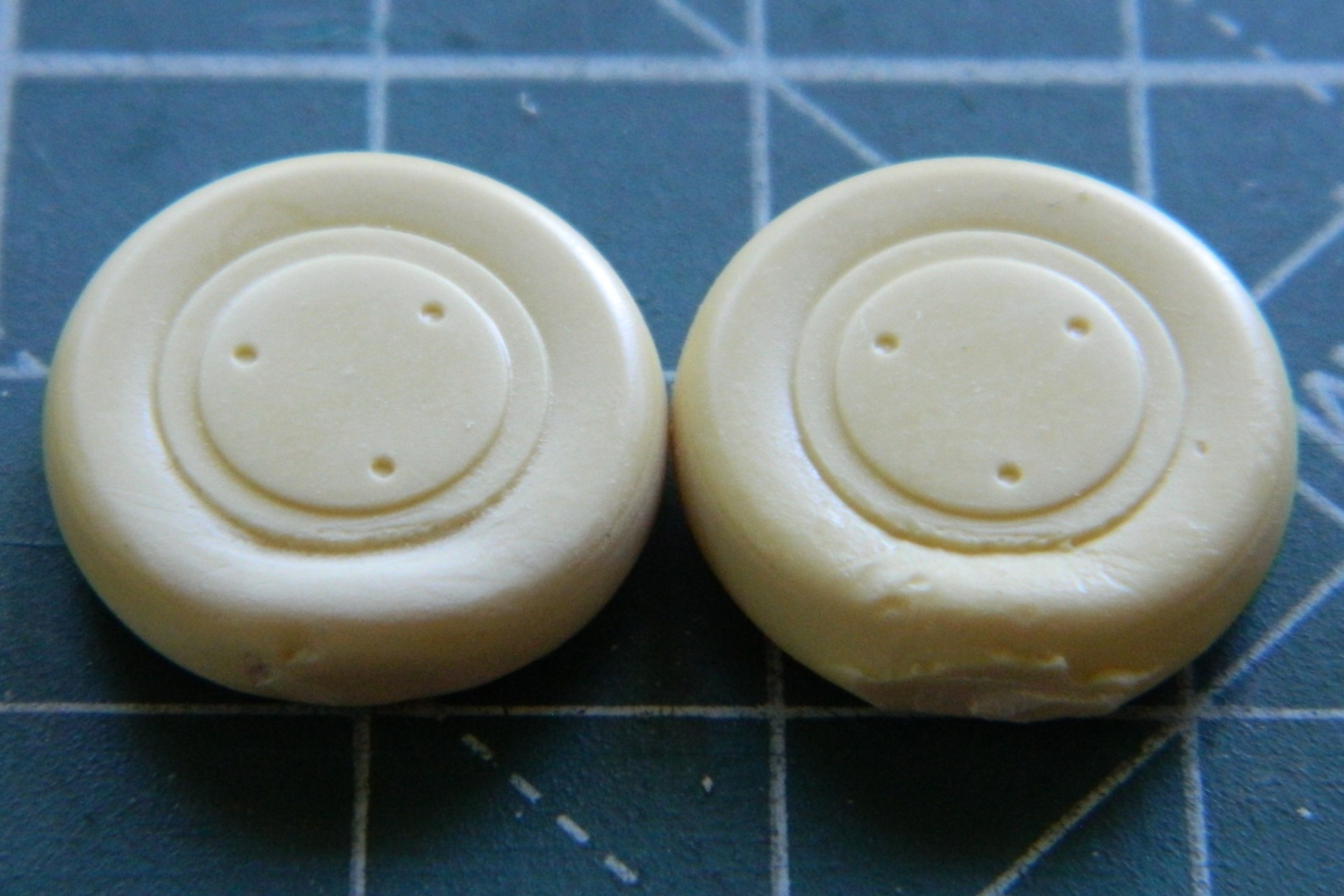
The backs had to be drilled to accept the mounting stub and since this bird had drum brakes, I used a tiny piece of styrene scrap to (not shown in this photo) replicate the mounting lug for the brake lines I’ll be adding later:
There are prominent heat-exchangers (for cabin heating) that mount externally on top of the engine nacelles. What’s provided is another True Detail bit of (disappointing) resin. I worked the one in the bottom of the next photo, the top part is as it came off the pouring block (they’re upside down in the photo):

My next adventure in annoyance was the splash shield on the nose. It was too thick and too wide. It was also very fragile, so I put off thinning and shaping it until it was glued in place. Of course it didn’t fit and I had to add a little piece of scrap to enable it to fit:

I set that aside for the glue to thoroughly set and started fitting the landing gear into the space provided. It was during this process that I almost lost my shit and, again, had to walk away for a few days. It doesn’t fit where the spot that was provided for it is. That’s, “wrong mount locations”, the long form. Once I calmed down, I decided that where they would fit is where I’m going to put them. From my efforts so far, SO much work is going to be required to get the entire landing gear in place that I will probably forego my usual practice of adding landing gear as late as possible. If I do that, I suspect that I’m really going to damage the color coats, so I’m thinking that the landing gear will get added prior to painting because I’m really quite tired of redoing and redoing and redoing to get the damned thing as accurate as I can. In the following photo, whereas the lower control arms are where they’re supposed to go, the strut is not. And I have less than no idea how the upper control arms are going to mount:
So with that set of problems hovering just out of sight, it was time to throw some aluminum paint (Tamiya XF-16 Flat Aluminum) onto these parts which are main and tail landing gear parts, the backs of the wheels, and the inside of the lower landing gear doors (the parts that the airbrush would launch into the next county are held down with double-sided tape):

And while I had the airbrush loaded with aluminum, I misted some into the landing gear bays:

And of course I had to touch up a fair amount of scribing and when tools skated across the surfaces:


There were more than just the two above.
The clear part over the flight deck wasn’t cooperating. I kept having to add more putty, more plastic, MORE putty, and more plastic:
Going back to the splash shield on the nose, the fin was thinned out and narrowed, and it looks much better. There was a gap in places where the shield attaches that needed to go away. More (and frequently added to) putty:


The splash shield is so thin that I ended up having to reinforce a spot using sprue; I didn’t have enough contact surface of the fin-to-fuselage join for it to stay attached:
And then I dropped the damned thing. I had to reattach the pilot’s seat, put the tail-planes back on, and hit a few spots where the sides of the V of the hull meet to form the apex of the V.
::sighs::
The tail-planes went back on easily:
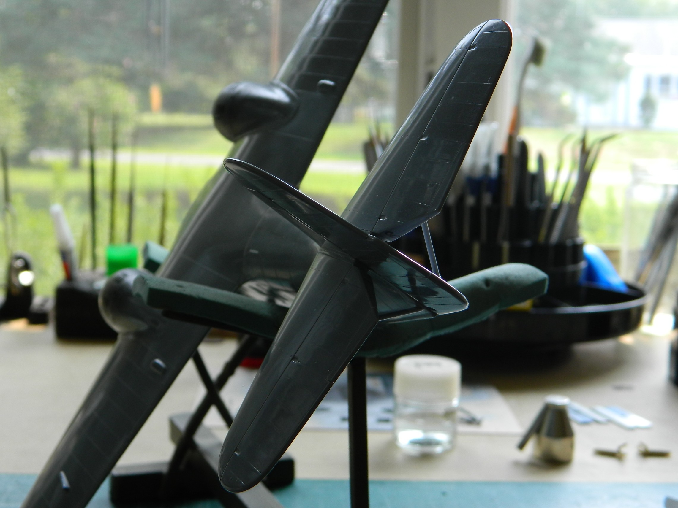
And at this point, it was the only damage I’d seen. As I was rolling the fuselage around to align each tail-plane correctly, I heard a very, very, faint rattle from the cockpit. Investigation showed me that the pilot’s seat was 95% dislodged. It’s the seat in the next photo that looks like it’s tilted forward (because it’s tilted forward):

There are no words that will adequately express how I reacted. “Not well” doesn’t begin to cover it.
Okay, so I have to get in there to reattach it. No, in my wildest fantasy (and it’s pretty wild) can I access the base of that seat through the open windows. No, cutting open the top won’t work either. I’d put that seat in with the entire clear part absent and you see what that got me. I let it sit for a few days (or more) while I figured out the least-bad way to get at the base of that seat.
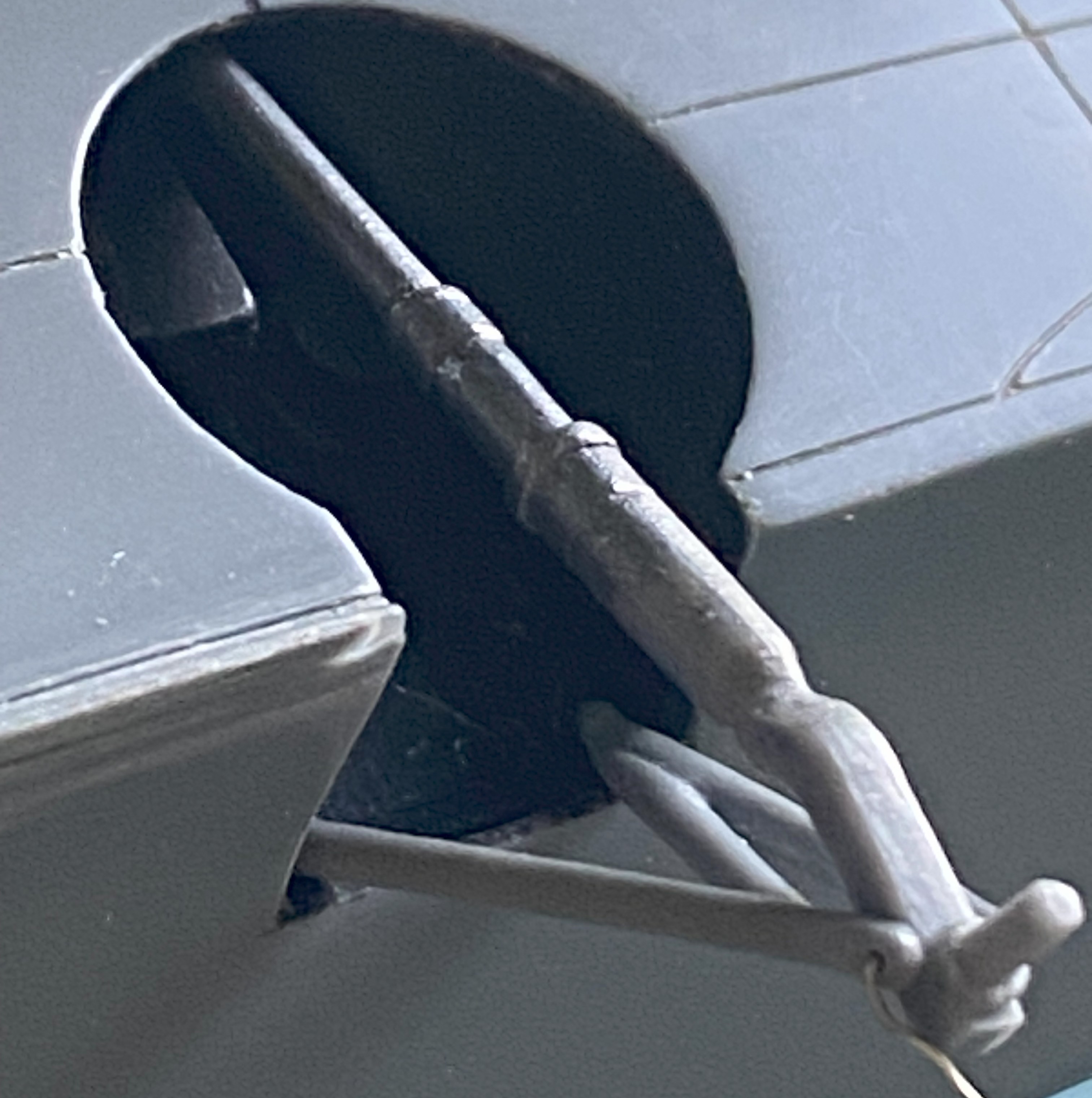
I have to cut the side open to get at it. As a guide for the scriber(s) that start the cut, I used a piece of Dymo label tape as a guide:
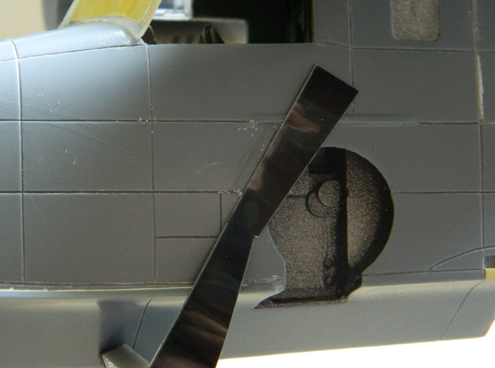
I kept the cuts along the panel lines whenever possible. The speckles on the seat are plastic and resin bits (because by going through the side, I also went through the resin detail panel attached to the side (the arrow points to one of the legs that has to be reattached):

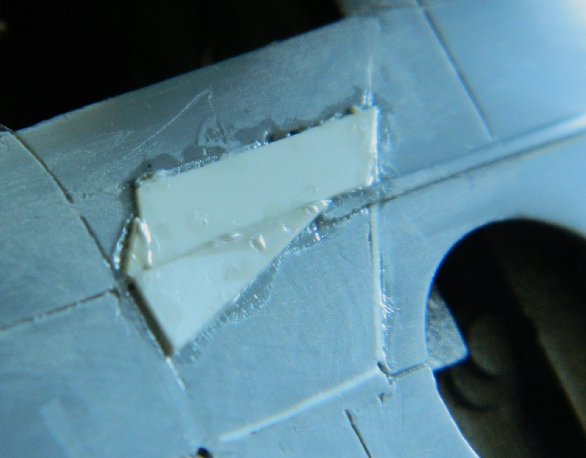
But the cutaway allowed me access to three of the four attachment points, all of which were glued THOROUGHLY to the floor. The fix probably took 3-4 minutes, then the excised panel had to go back. In most places, I added 0.010″ (.254mm) scrap to replace the kerf, and most of the cut areas also received stretched sprue over the top of the styrene:

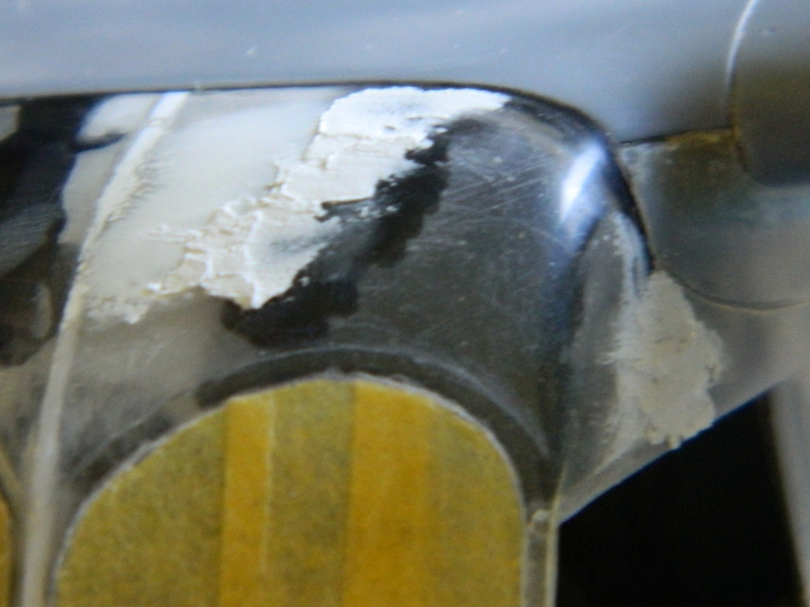
However. It seems that before the glue had cured completely, I’d pressed on the top of the excision and failed to notice. When I started removing excess plastic is when I saw that the top and top-left corner needed to be raised up. I used 0.010″ (.254mm) instead of putty to do that:
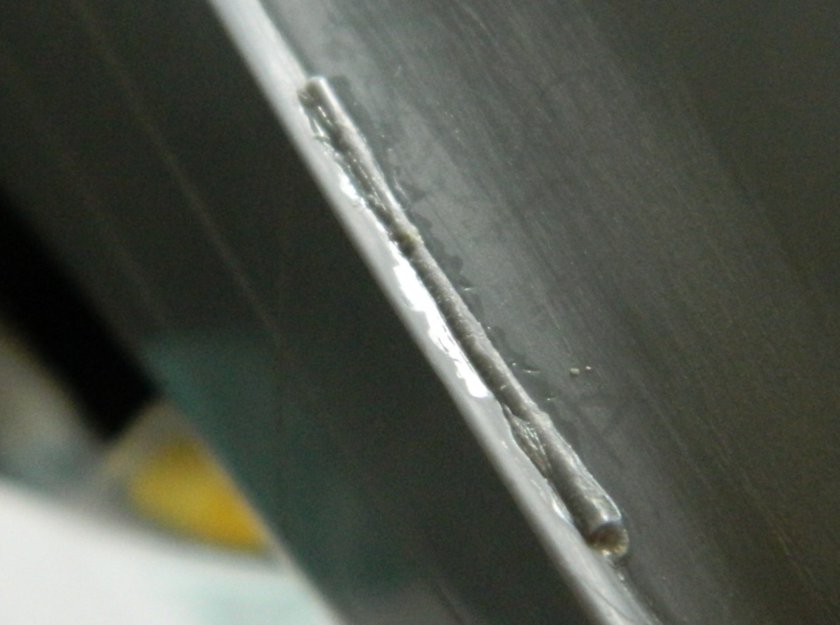
By this point I’ve noticed that the edge of the V hull had cracked. I stretched some sprue with the intent of filling in the fix while the filler plastic next to the cockpit cured:


So with that repaired, I finished off (mostly…there’s a detail I have to add back) the excision:
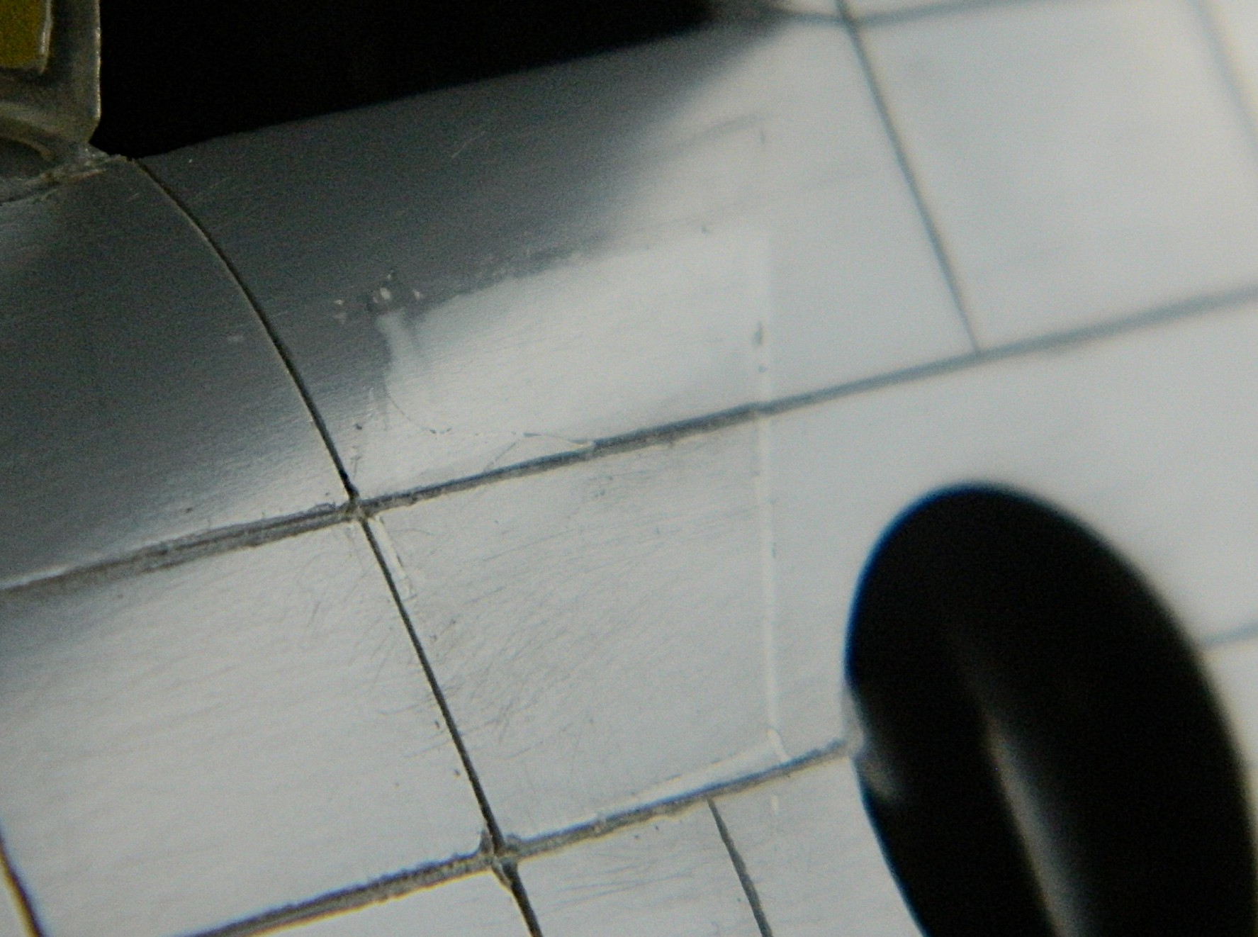
And now that I’m at the middle of this month, I’ve spent most of the past two and a half weeks getting back to where I was when the month started:
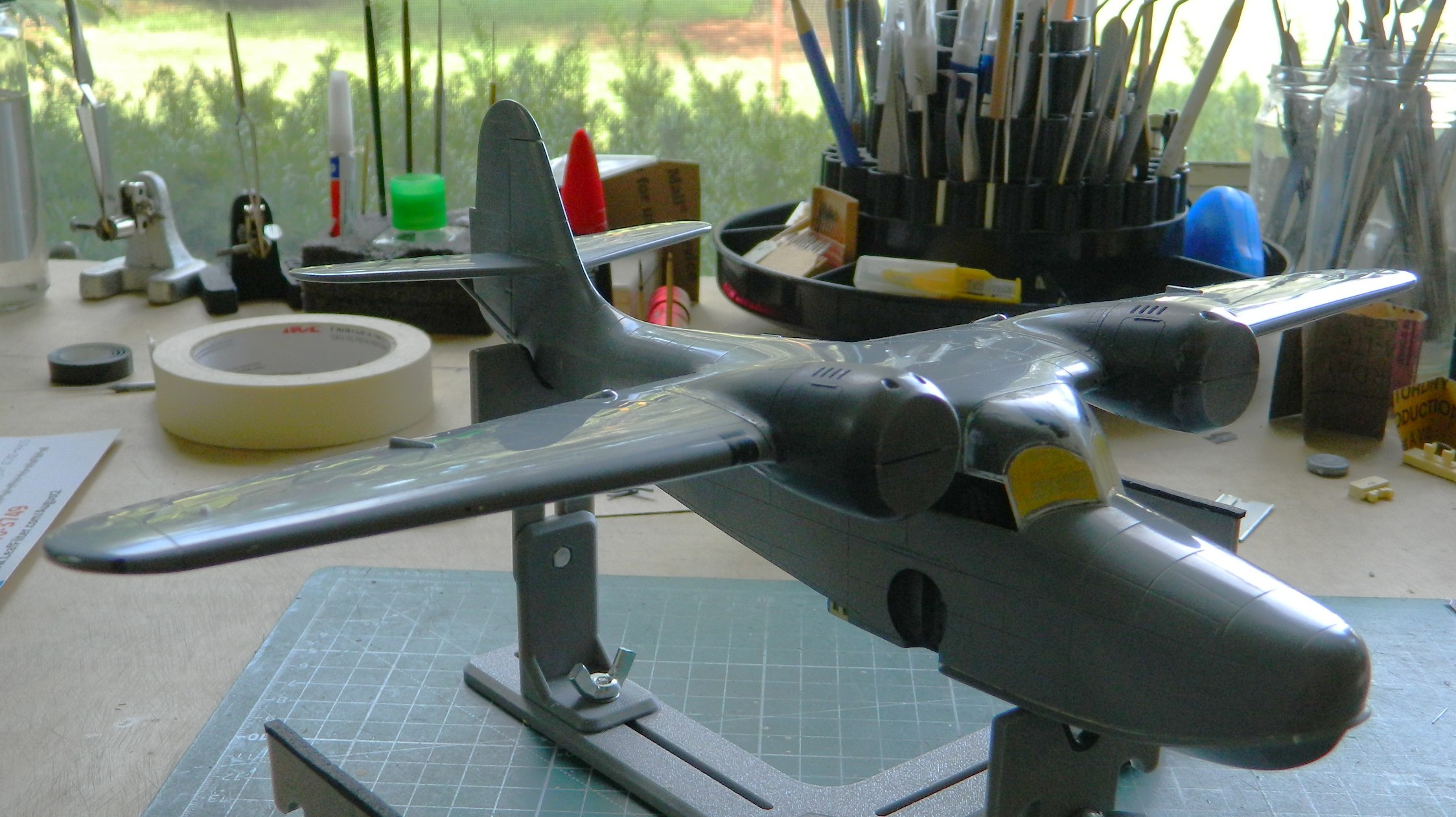
Unless I drop the model…again…next month should see me get this thing under paint and on the way with attaching all the stuff that is too fragile to attach sooner.
