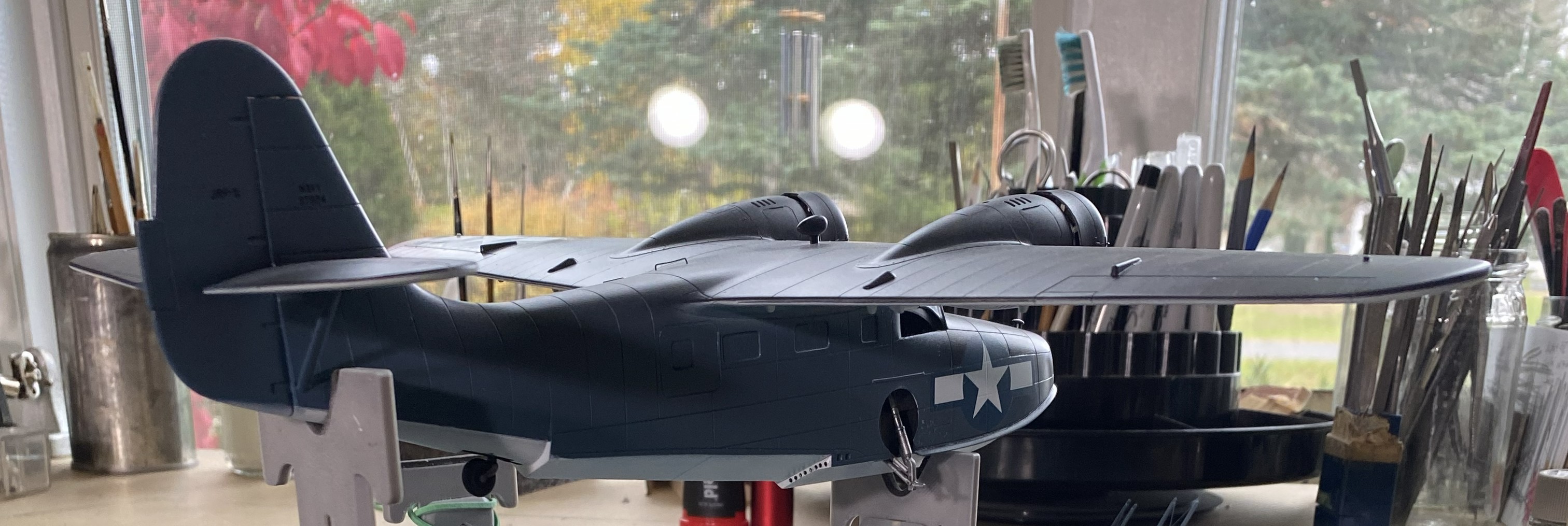
Grumman JRF Goose (Czech Model) 1/48 Scale Build #7 – Staggering Towards the Finish…and Getting There
This is the danger-point for me, being so close to the end that I have to be careful not to rush things. Couple that with the reality that I despise this kit, I have to double the caution.
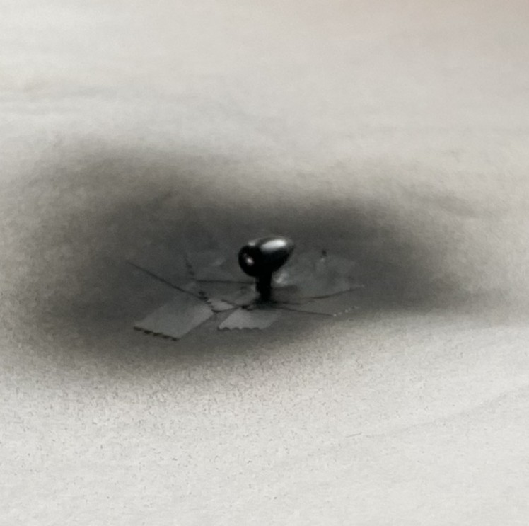
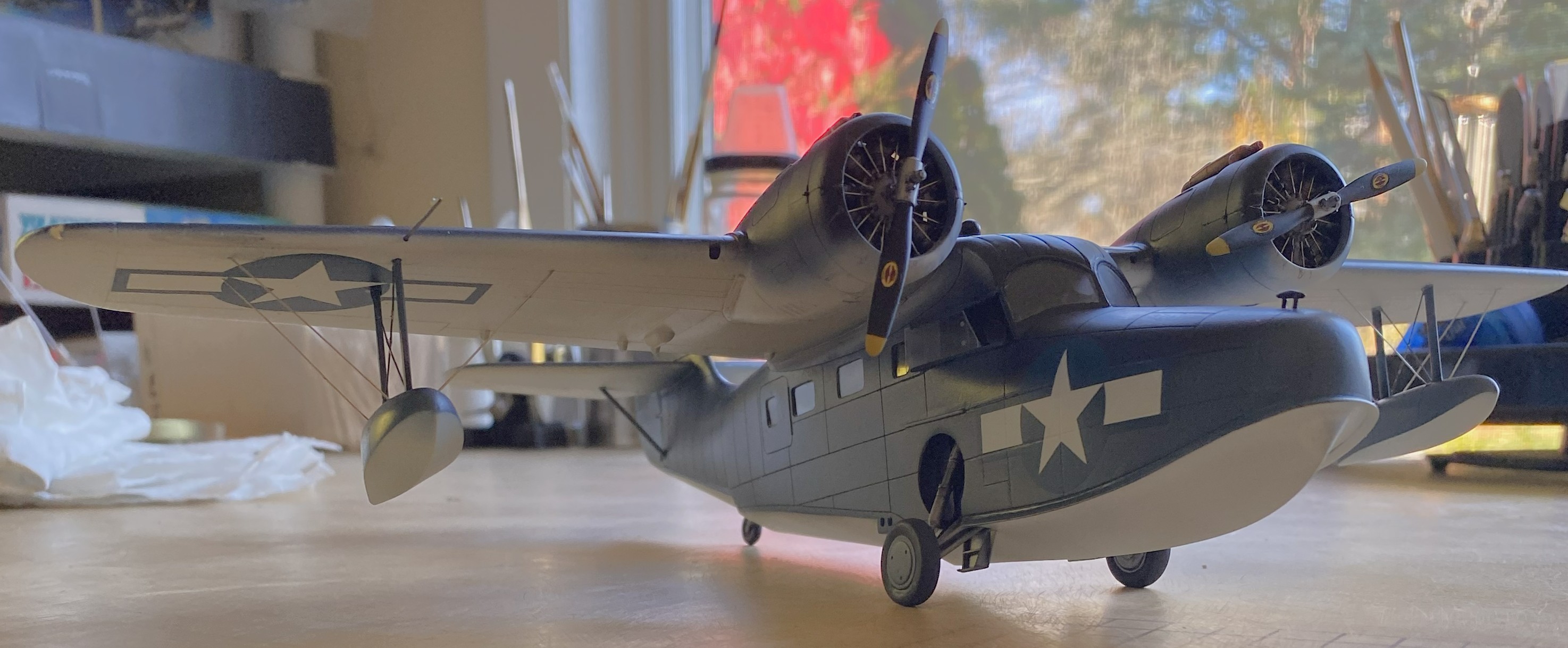
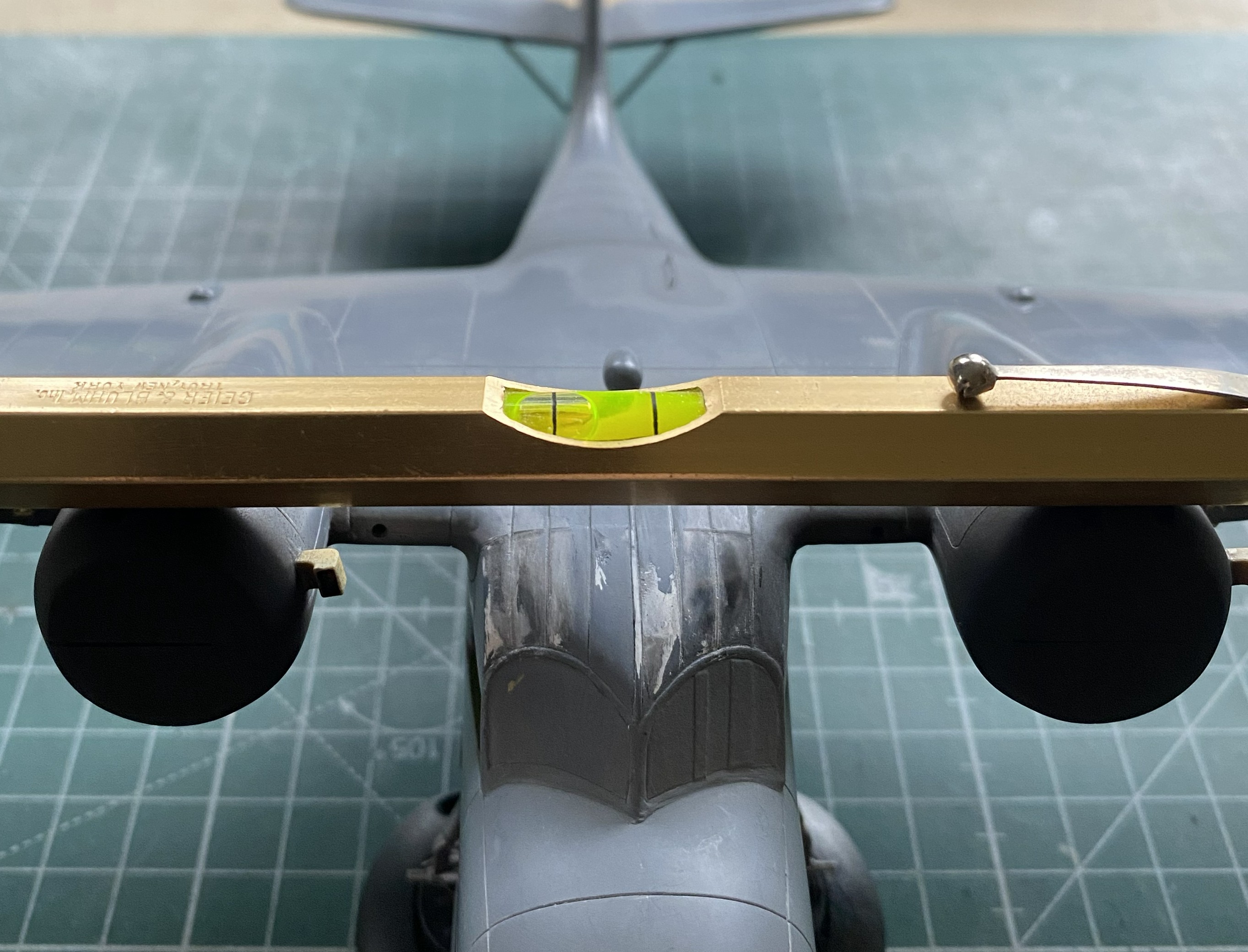
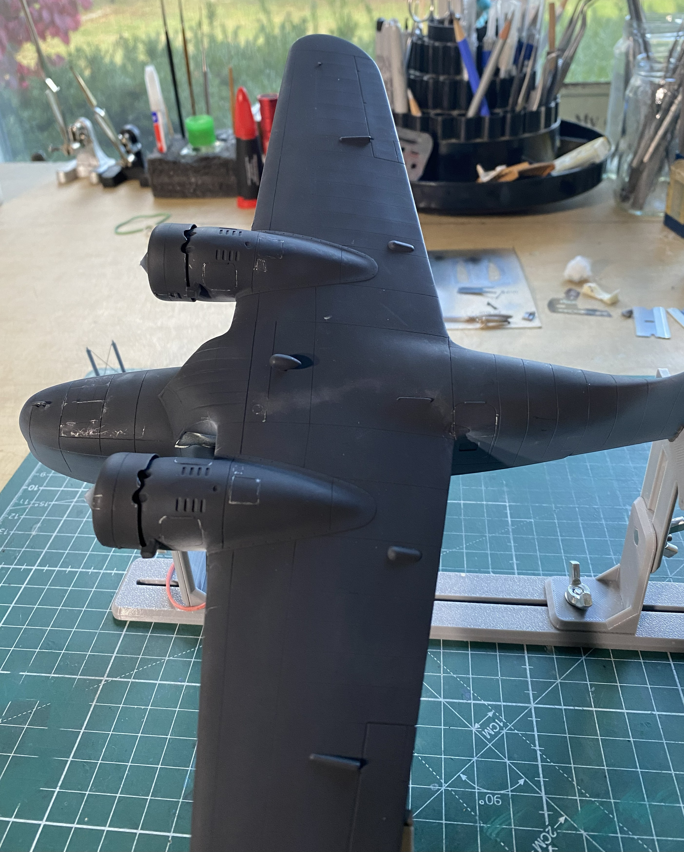
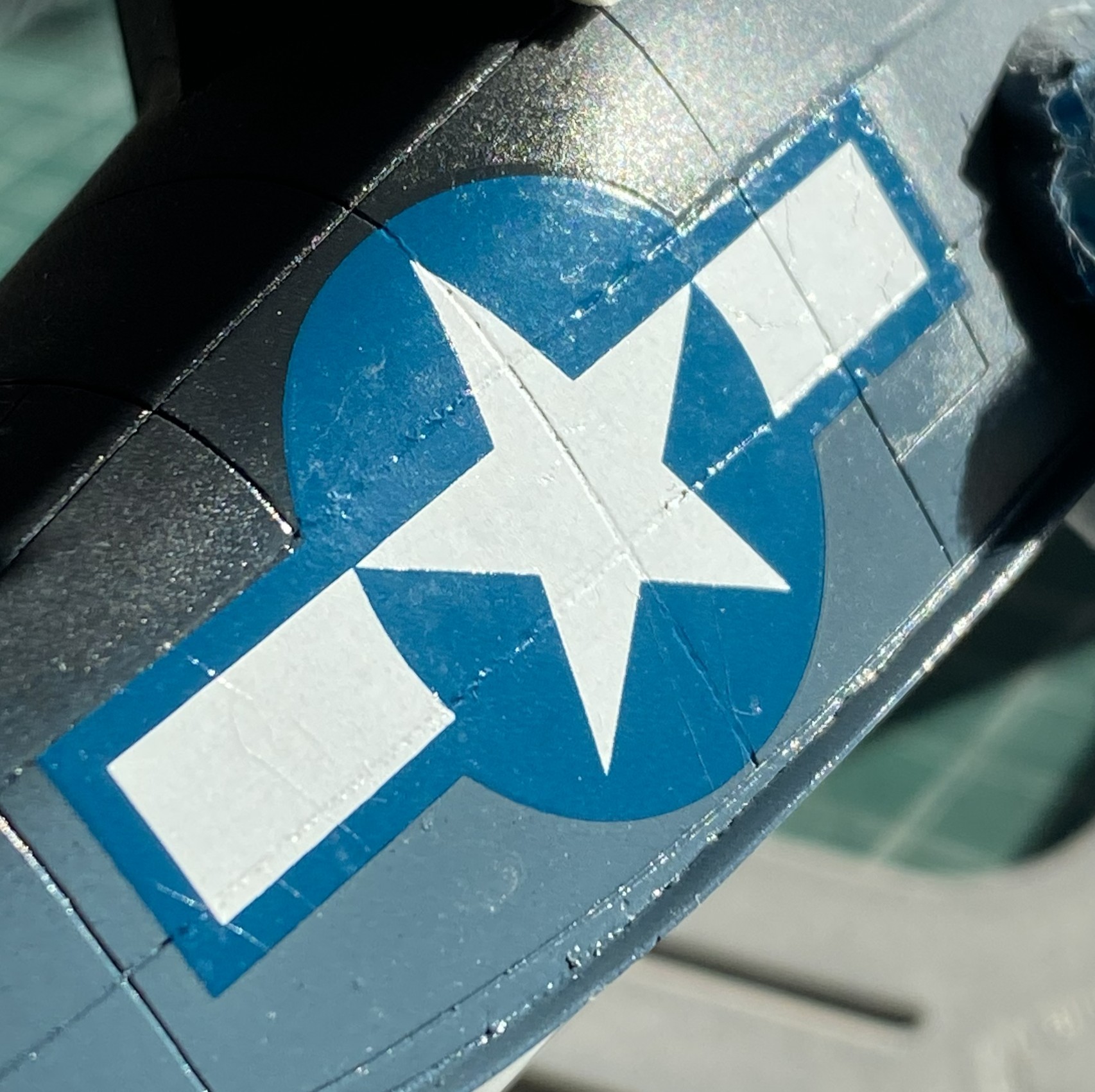
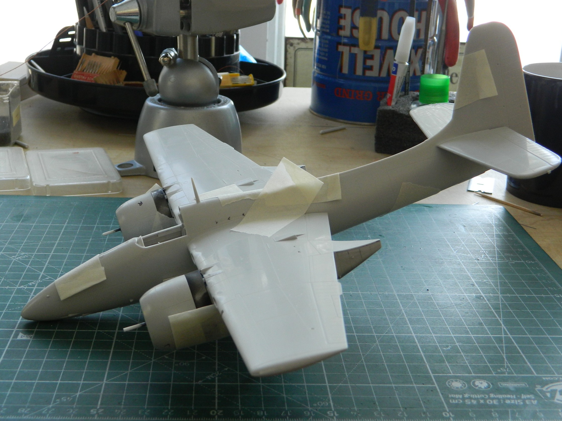
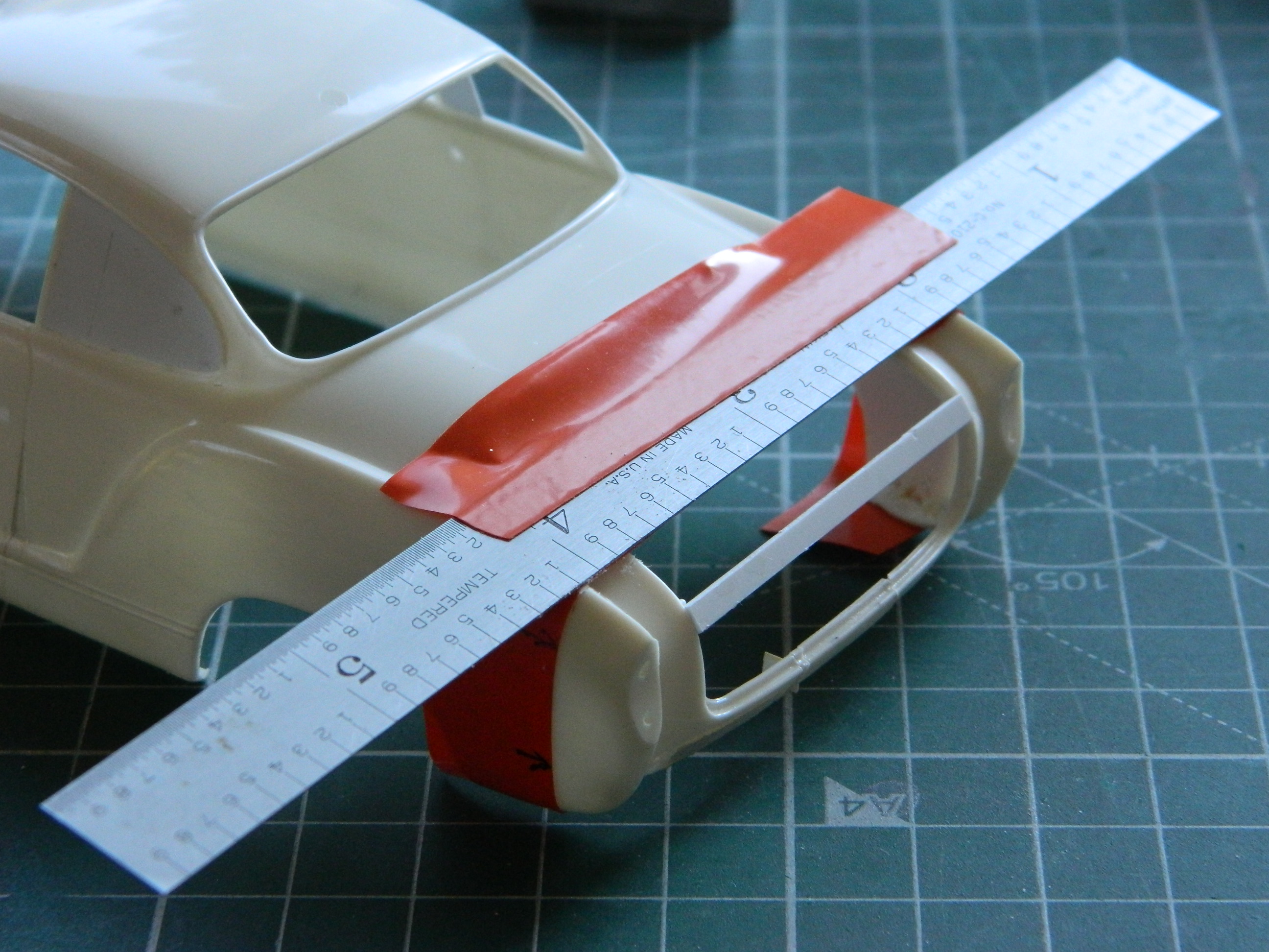
I started with what I perceived would be the biggest hassle and that was getting the wing level, and I wasn’t entirely incorrect. As it sits in this photo, the bubble indicates that the wing isn’t level:

At the center of the model, that bubble isn’t far off. At the wingtips it is. I bent my brain around several corners trying to figure out the best solution. I’m of the opinion that it is not uncommon for a given problem to have more than one solution, except that solutions to problems usually come with new problems (and the solution is enacted if the new problem is less than the old problem). And speaking of problems, here’s a short (I hope) examination as to what the problem is, not what I’d rather it be.
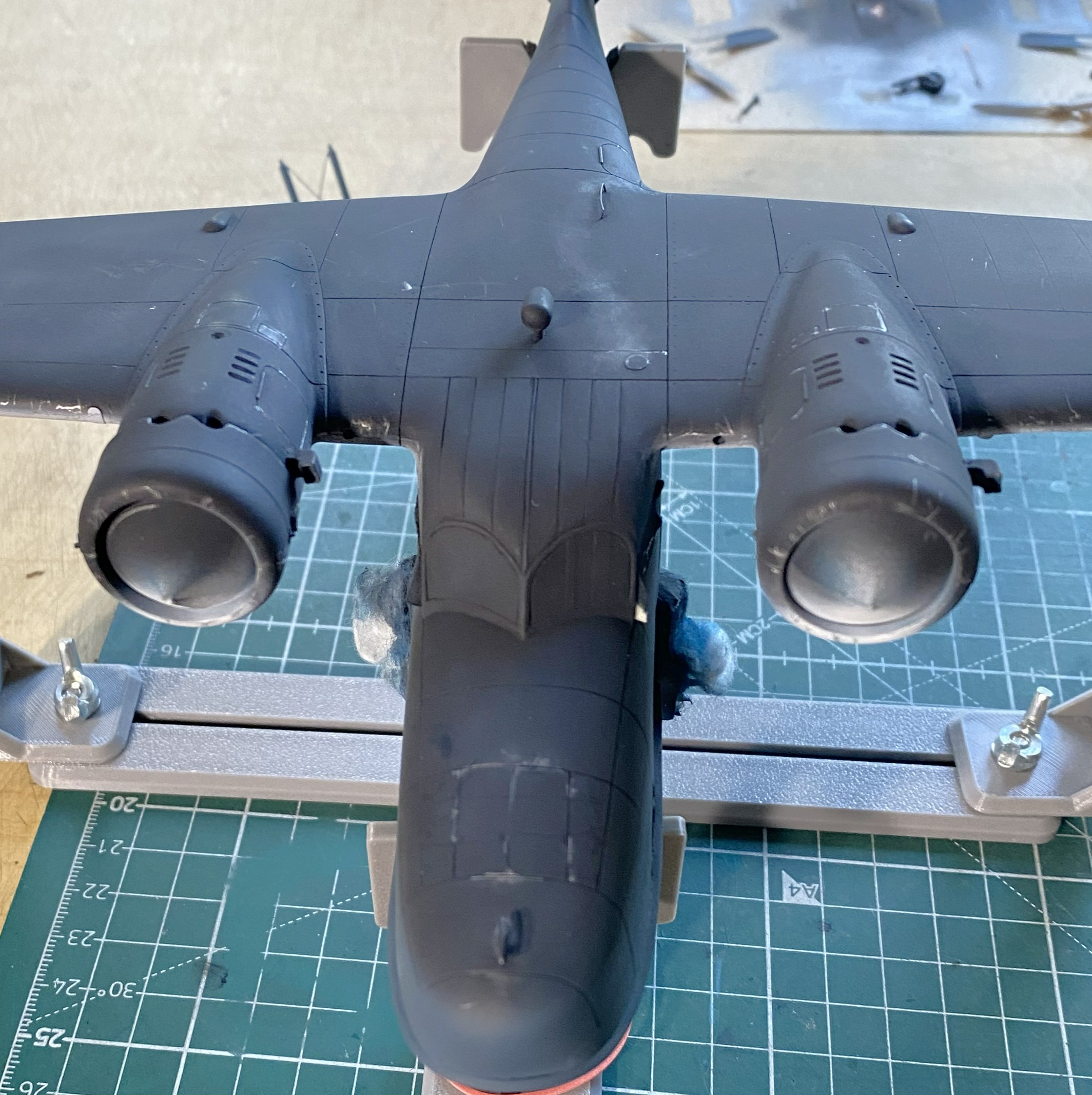
The struts of the landing gear fits into the top of the landing gear bay. The landing gear bays were not molded onto the fuselage sides. As I found out well after I’d added the landing gear bays, the sides of the fuselage do not match dimensionally. Yeah. Who knew that would be a problem. It certainly wasn’t Czech Models. However, with one landing gear bay higher from the bottom than the other, and the landing gear goes there, should I be surprised that once the aircraft is assembled that it doesn’t sit level? I was when I first found the dimensions (and shapes) did not match from side to side, but after I thought about it (a lot), I knew that by the time I got to this point of the build, I’d have this new problem to solve. ::facepalm::
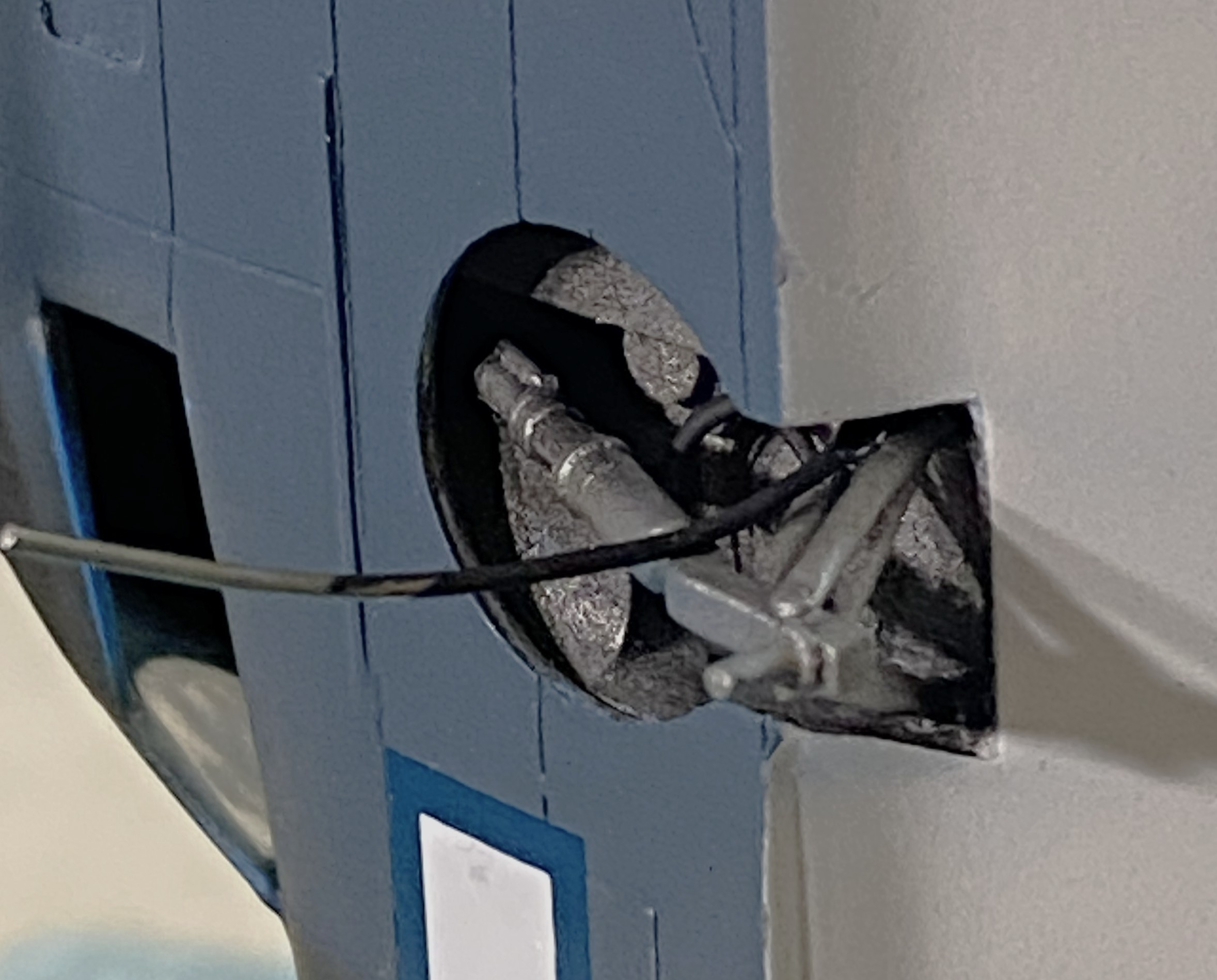
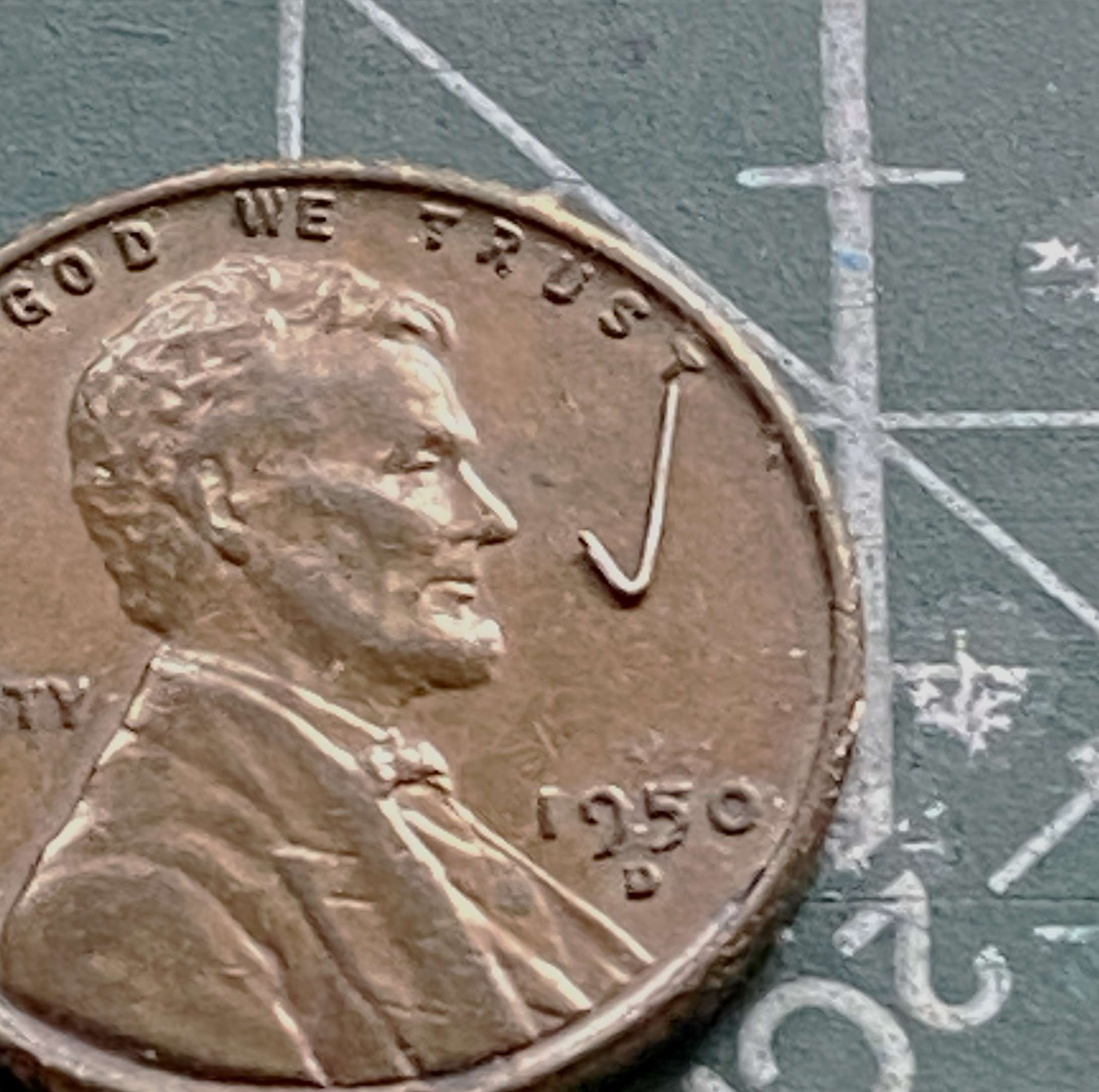
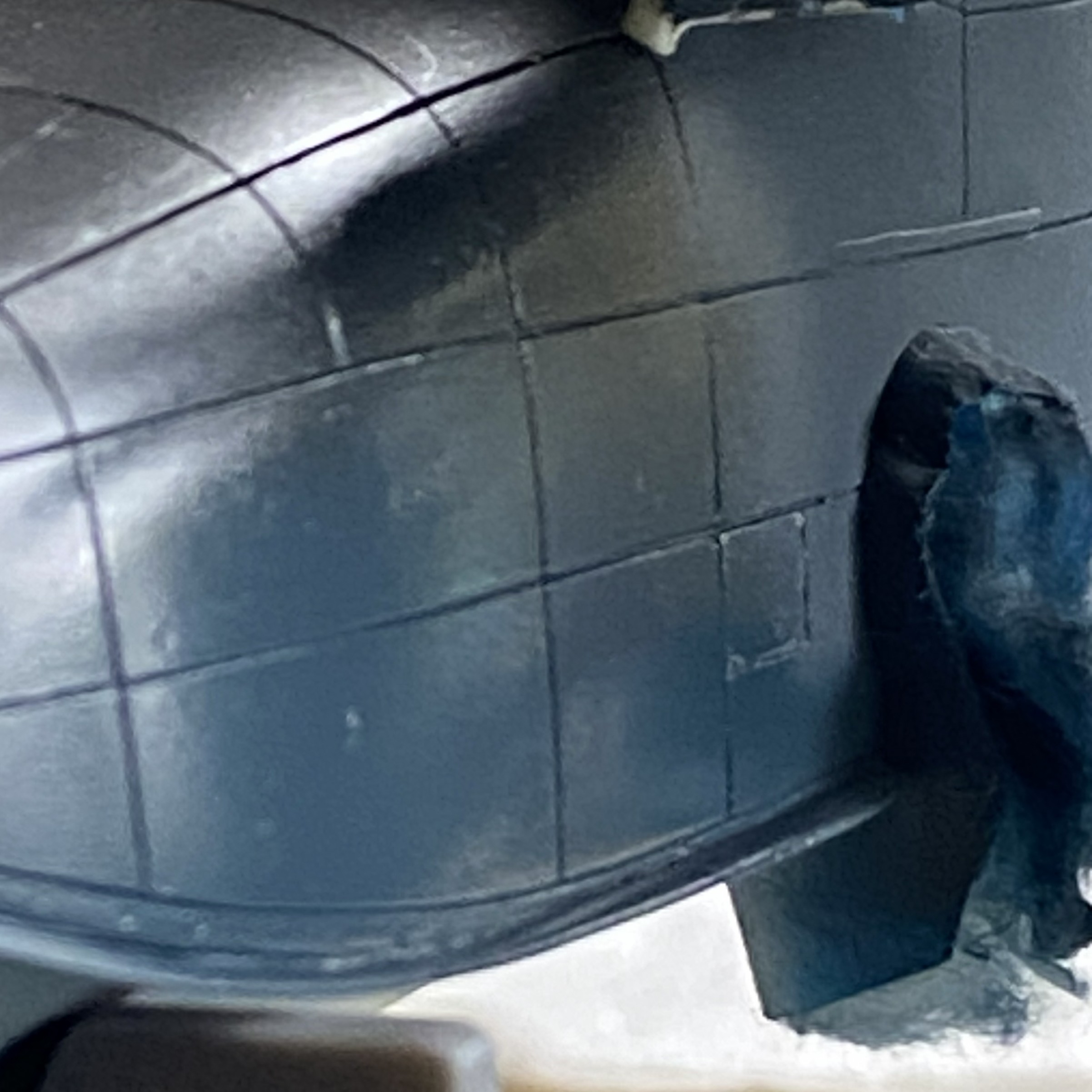
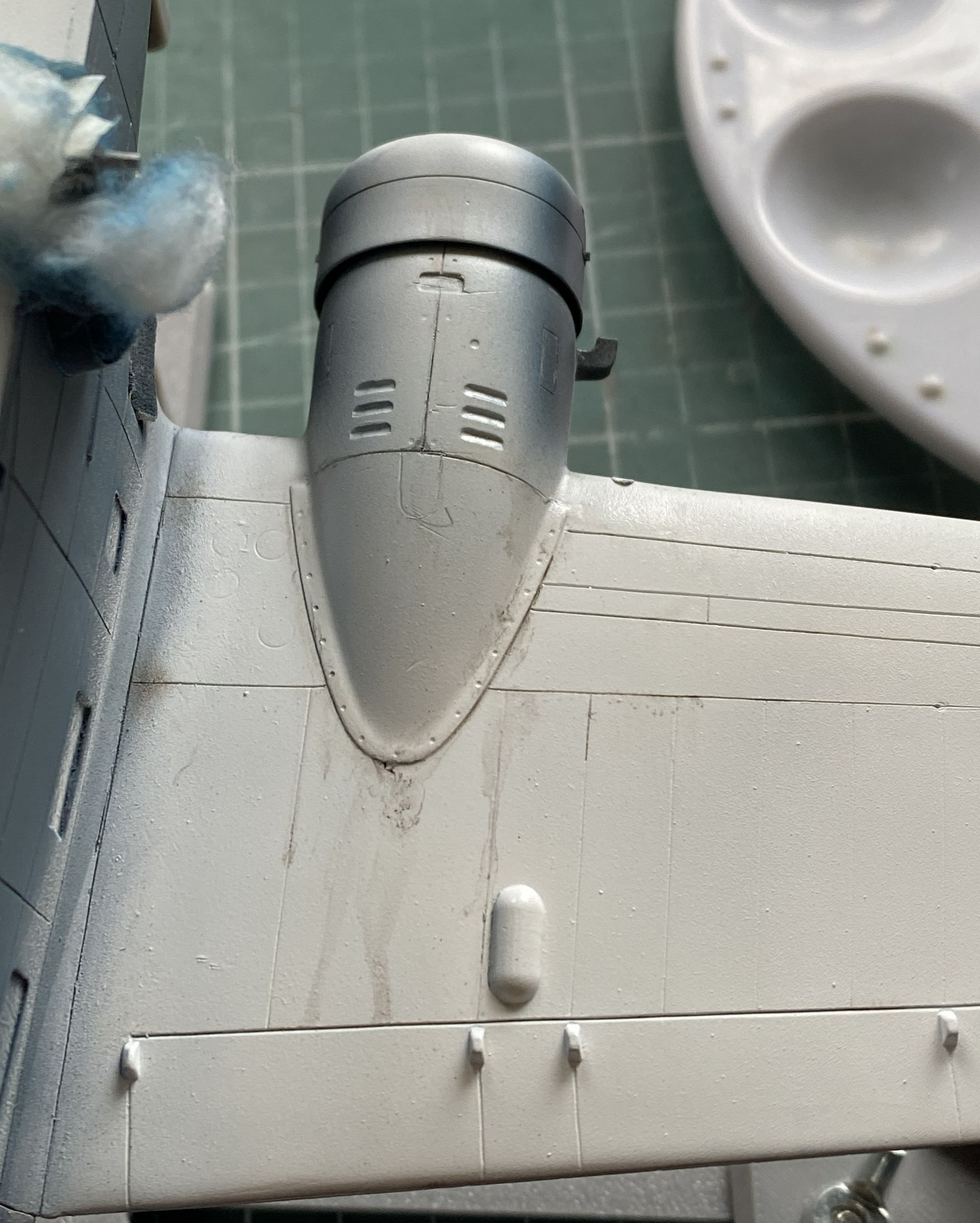
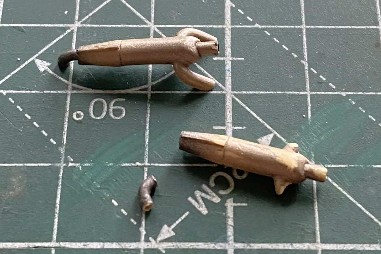
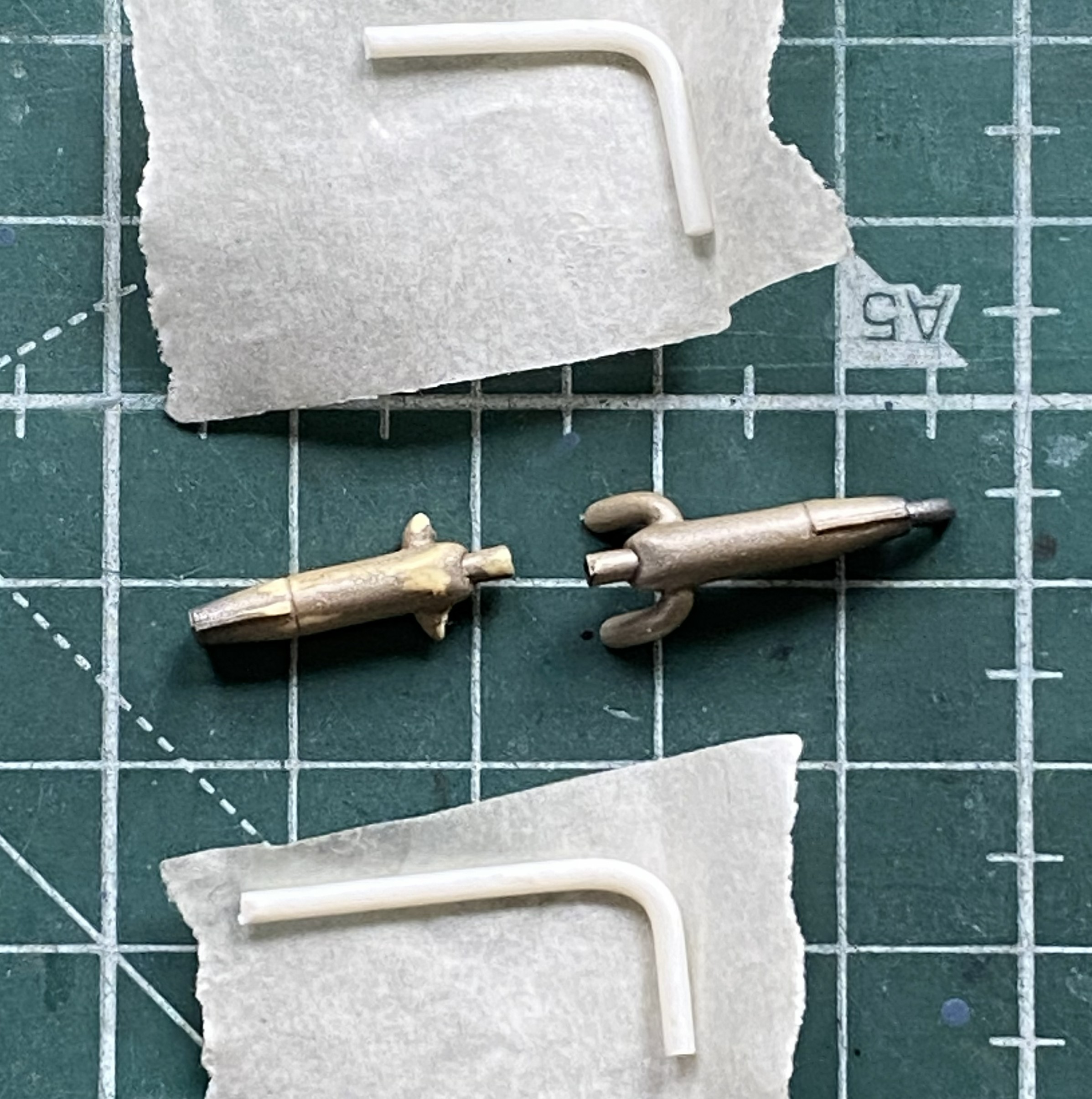
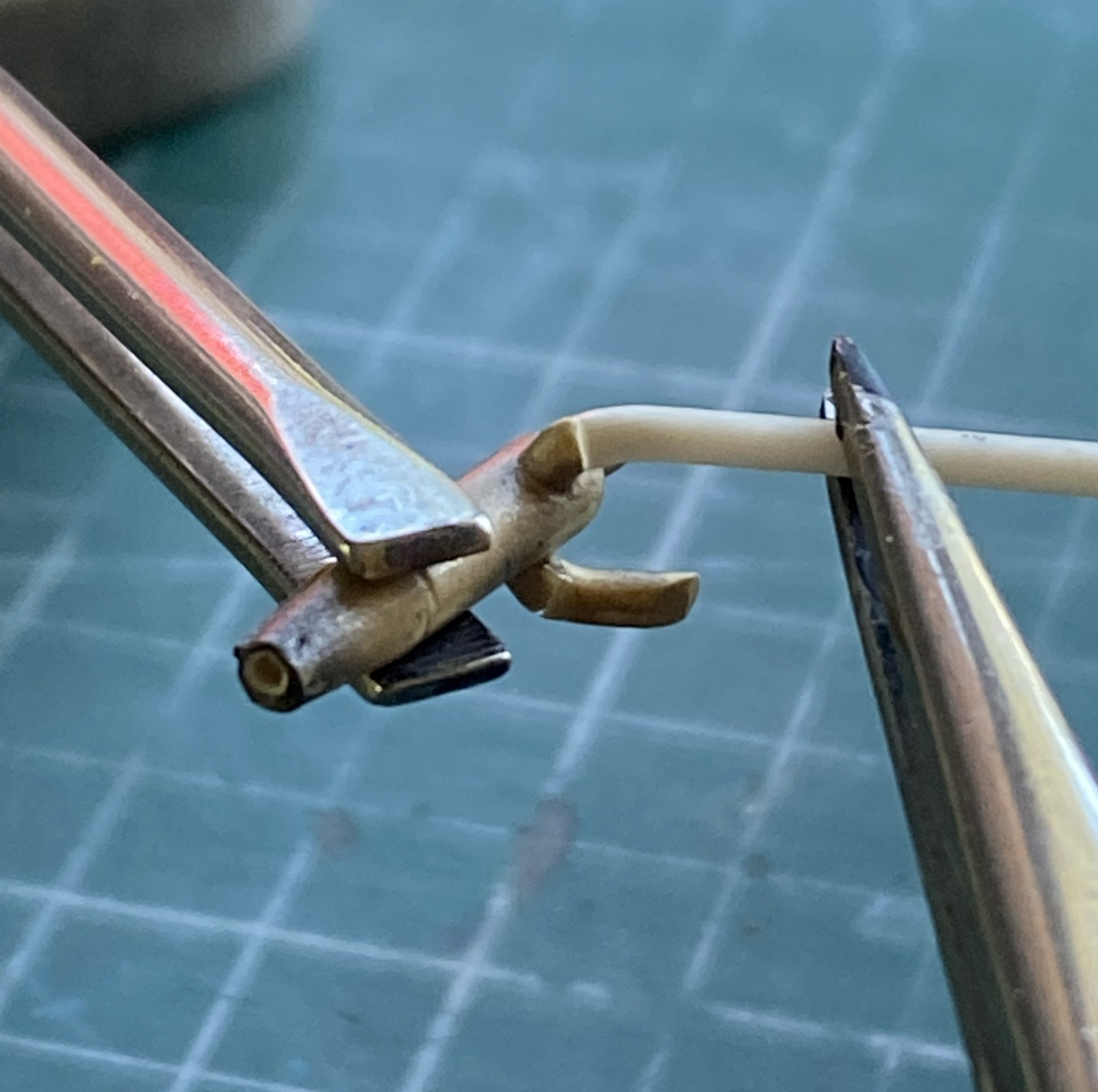
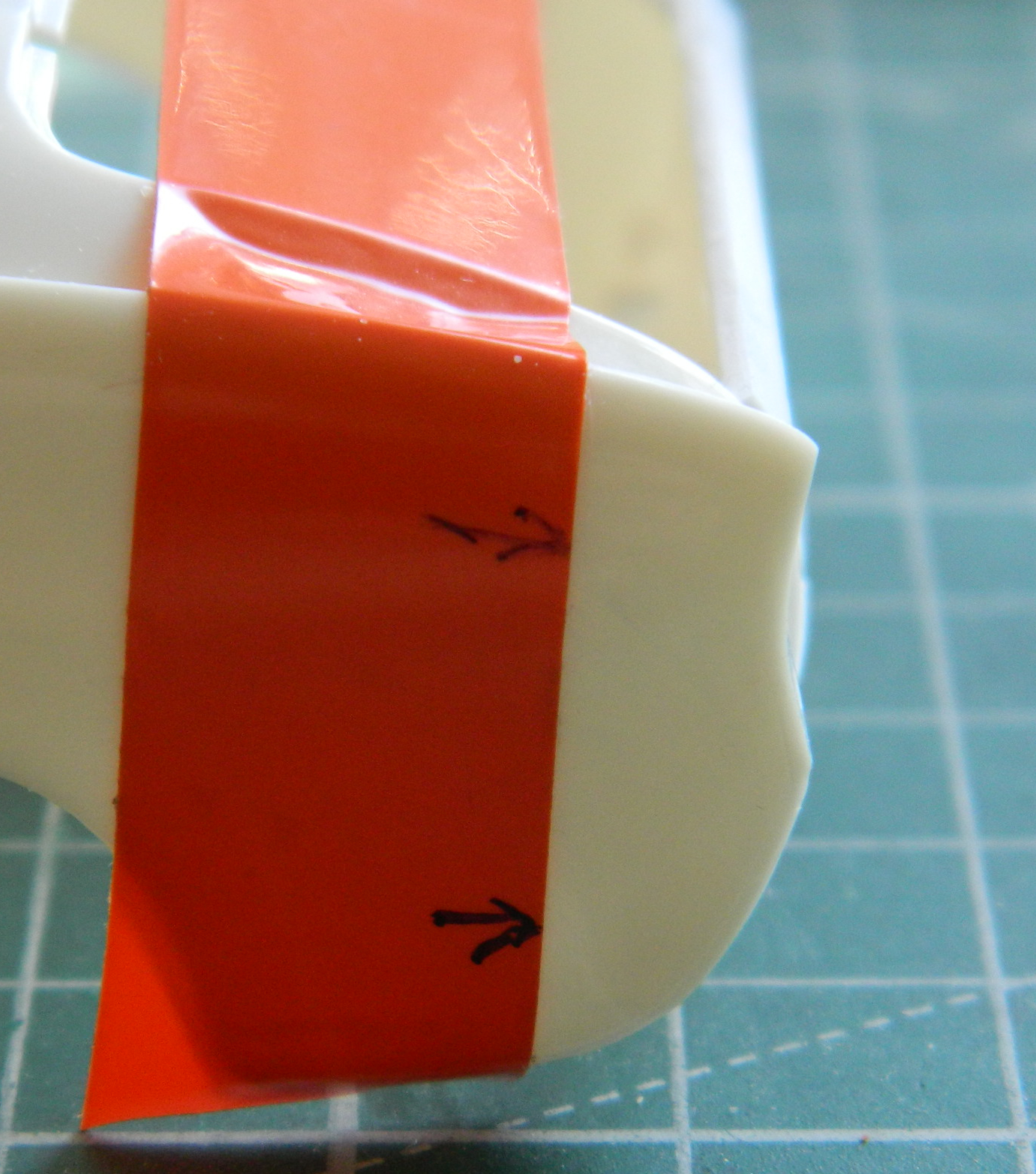
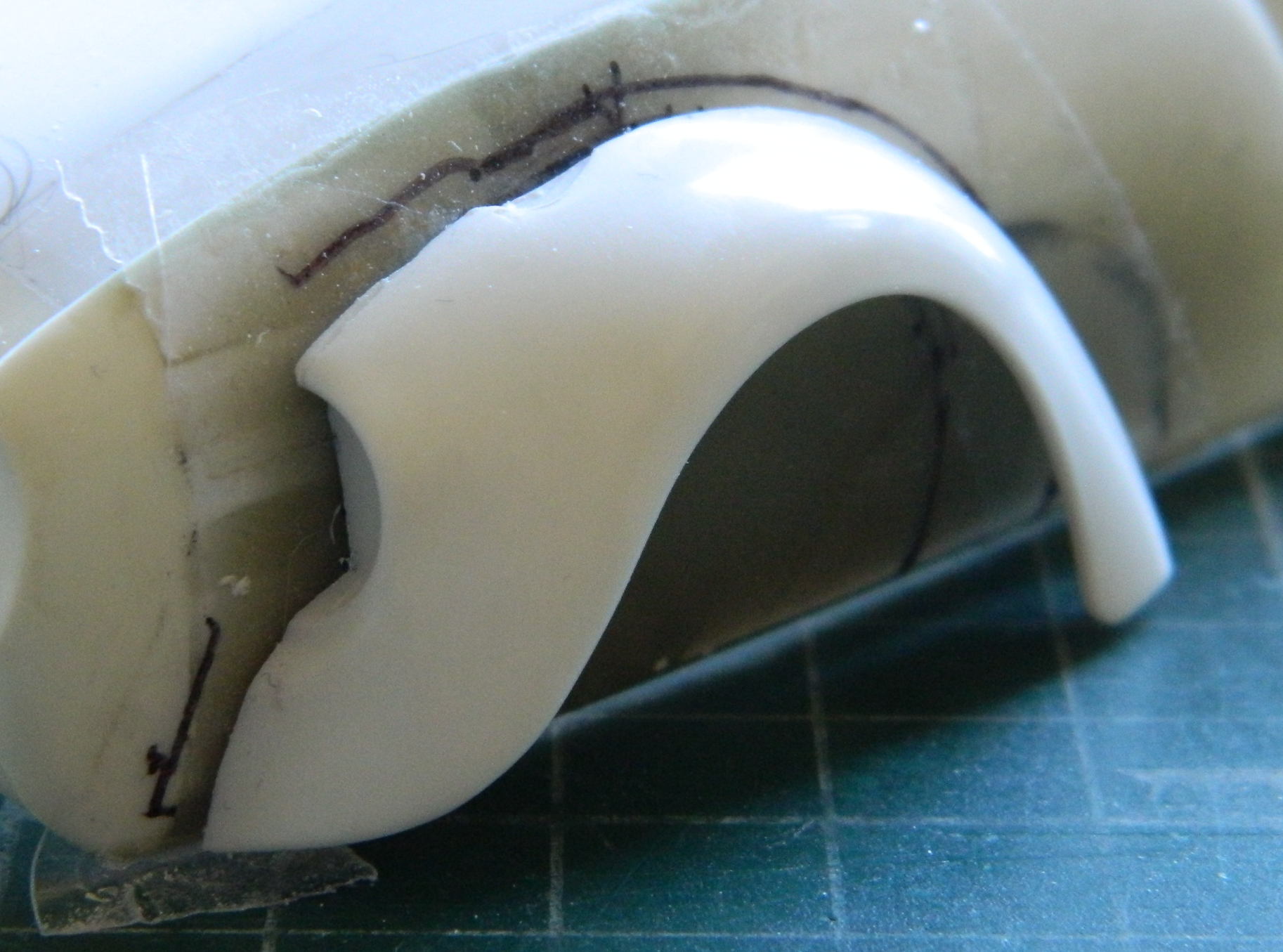
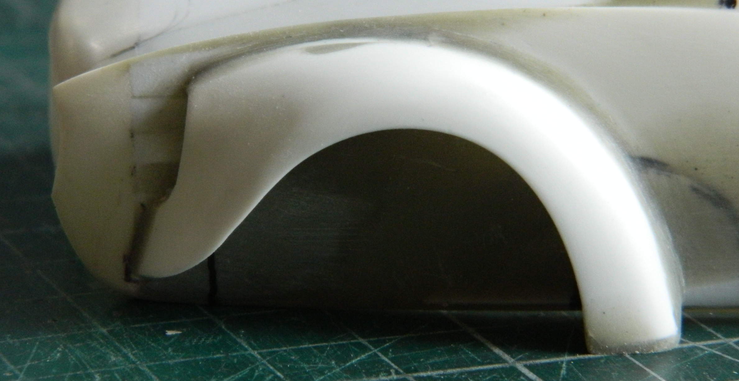
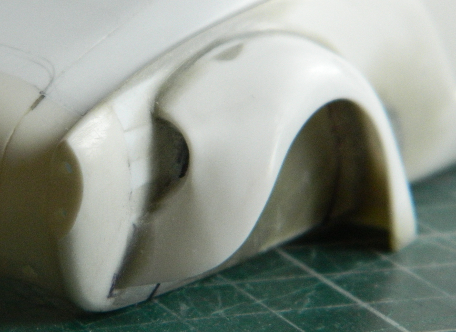
Since I saw this problem as a geometry problem, I looked into the geometry of the landing gear. Being more than a little frustrated at this point, I dry-fit the wheels onto the landing gear and pressed firmly down on top of the model until the bubble was centered. Just as the bubble centered, I heard a soft crack as something broke loose…but the bubble was still level. Took a bit of investigation but I found what broke loose. The blue arrow in the photo below points to where the upper control arm snapped away from the strut leaving this gap:

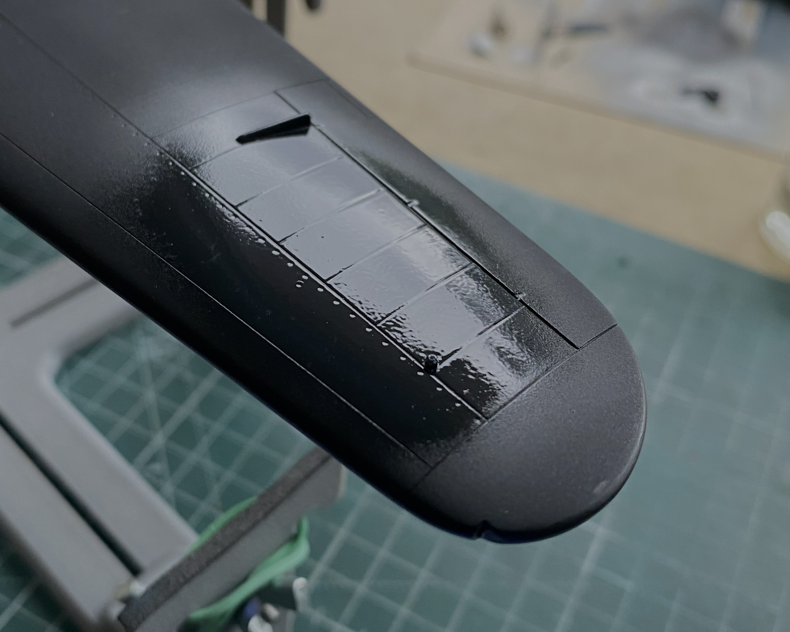
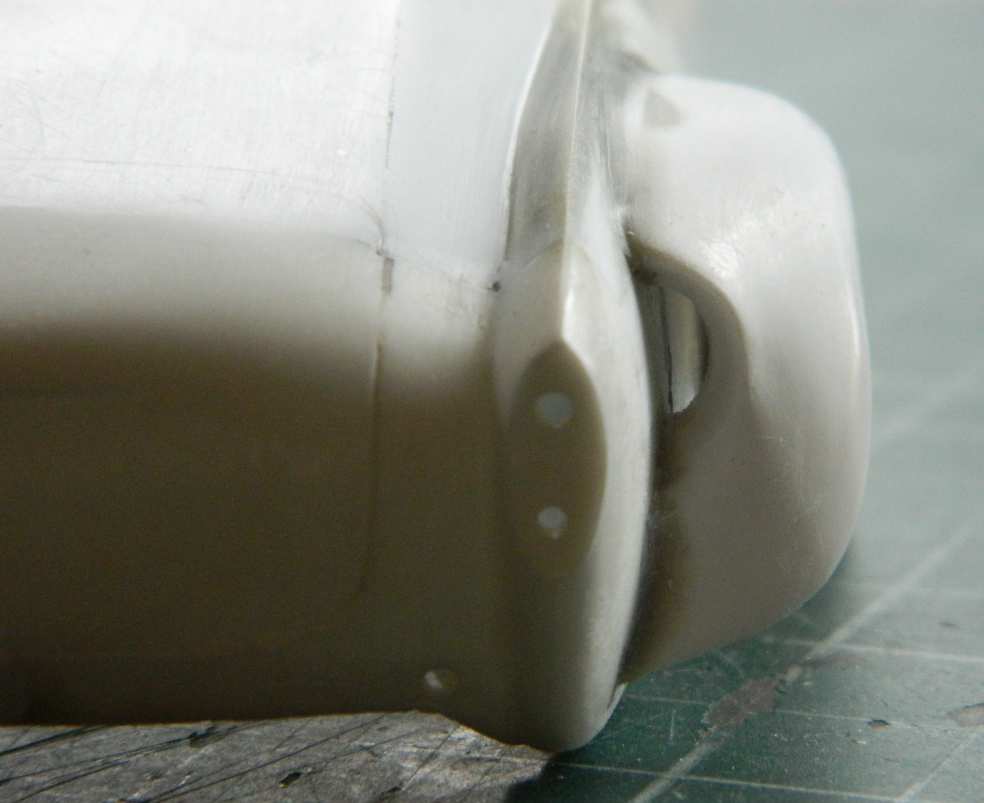
Hmm. So, if I fit a spacer between the strut and control arm, will that make the wing level? The answer was, “mostly”, which I discovered once I’d cut a spacer from 0.030″ (.762mm) and checked:

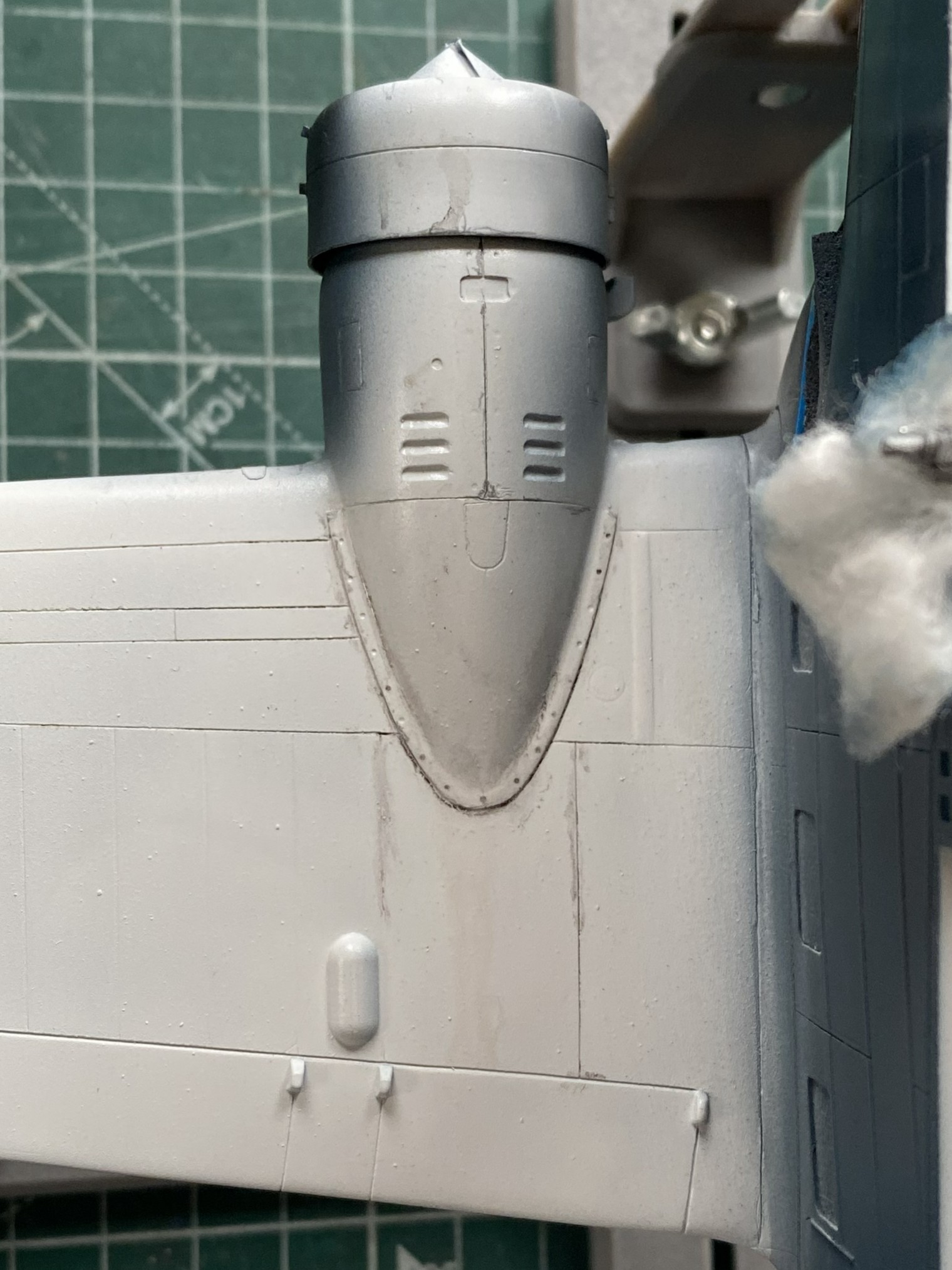
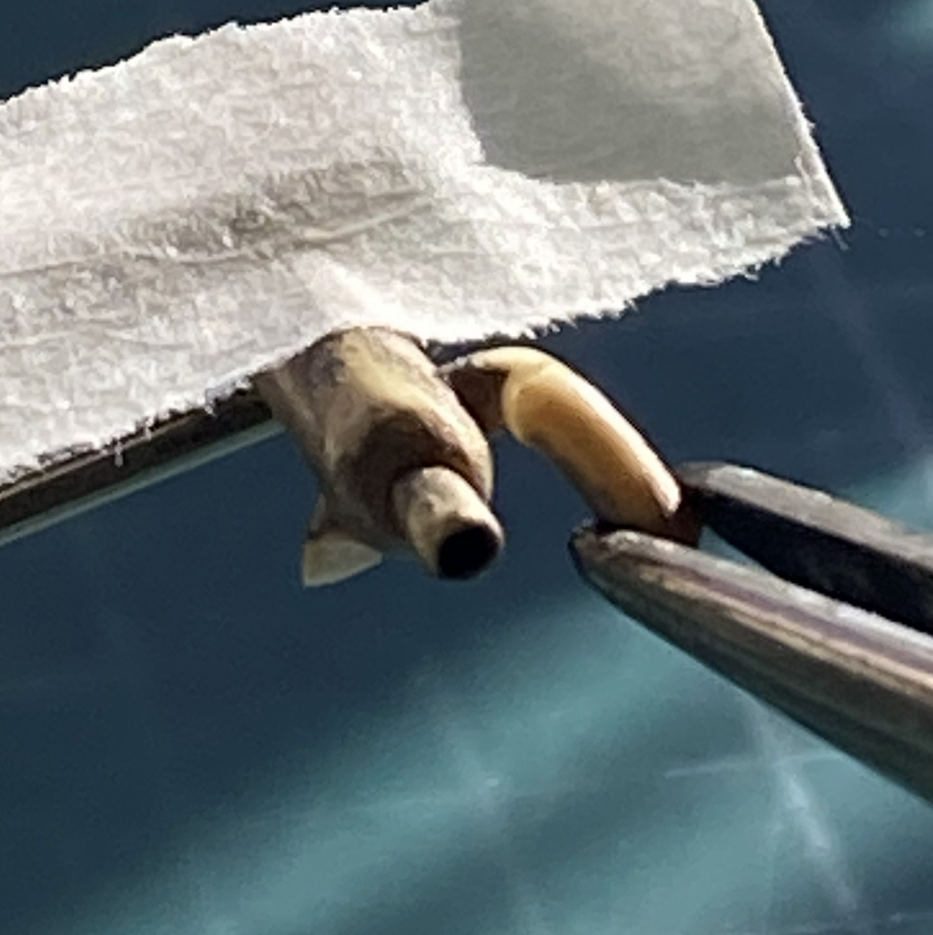
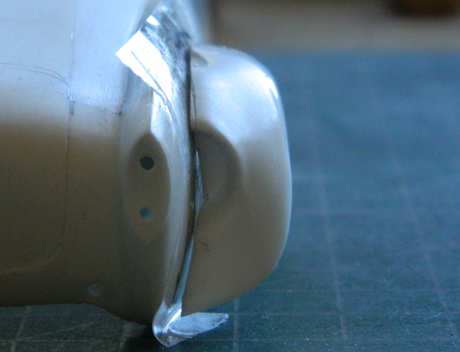
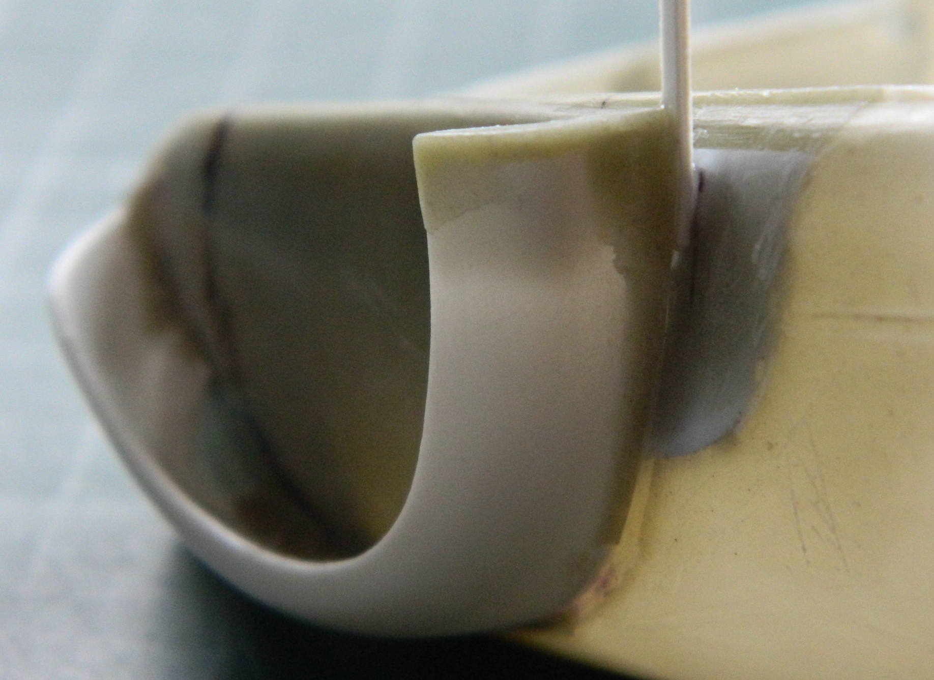
I trimmed the spacer without gluing it in and checked again. This time I estimated that I needed another 0.005″ (.127mm) more:

And there it sodding is:

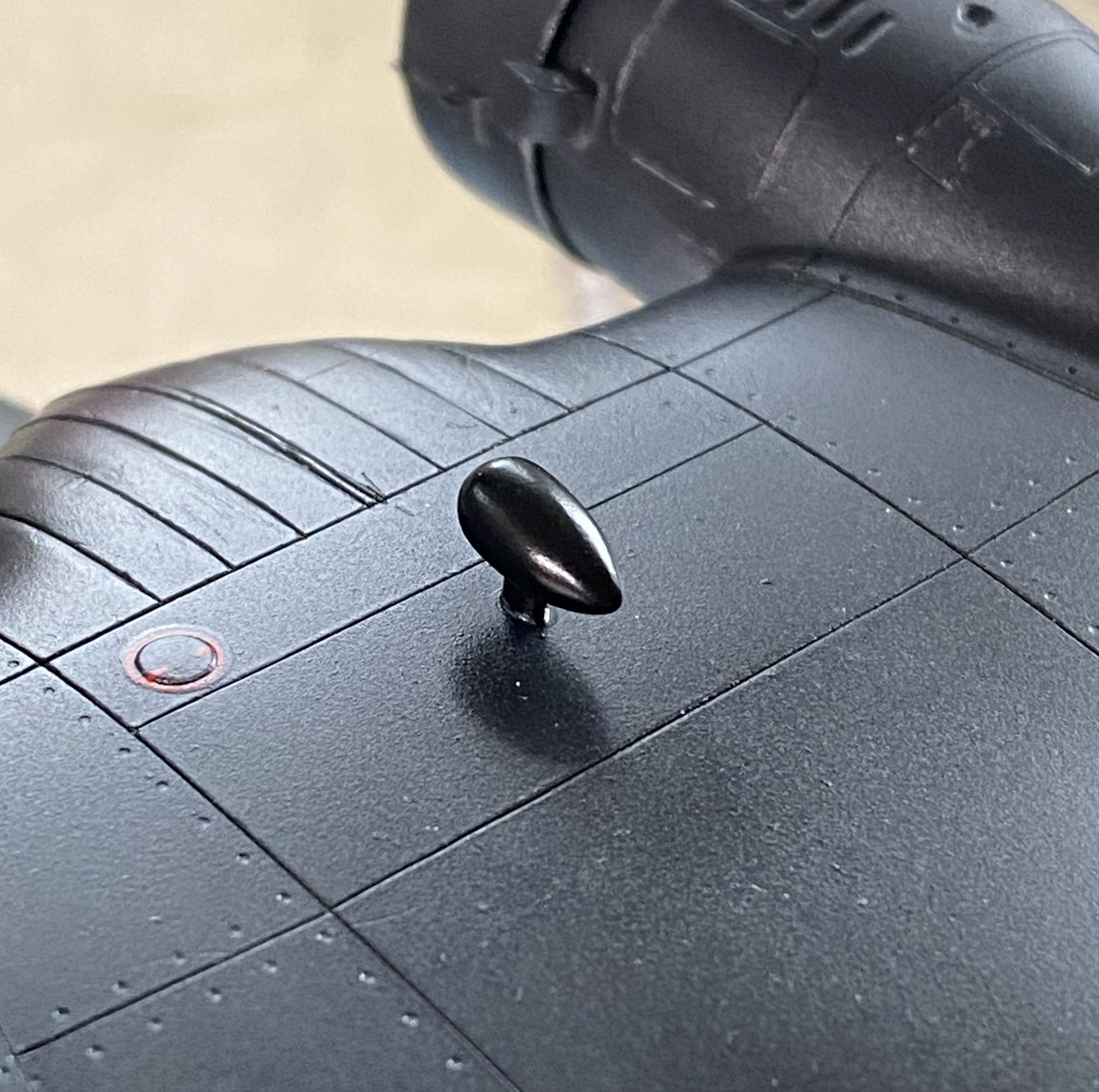
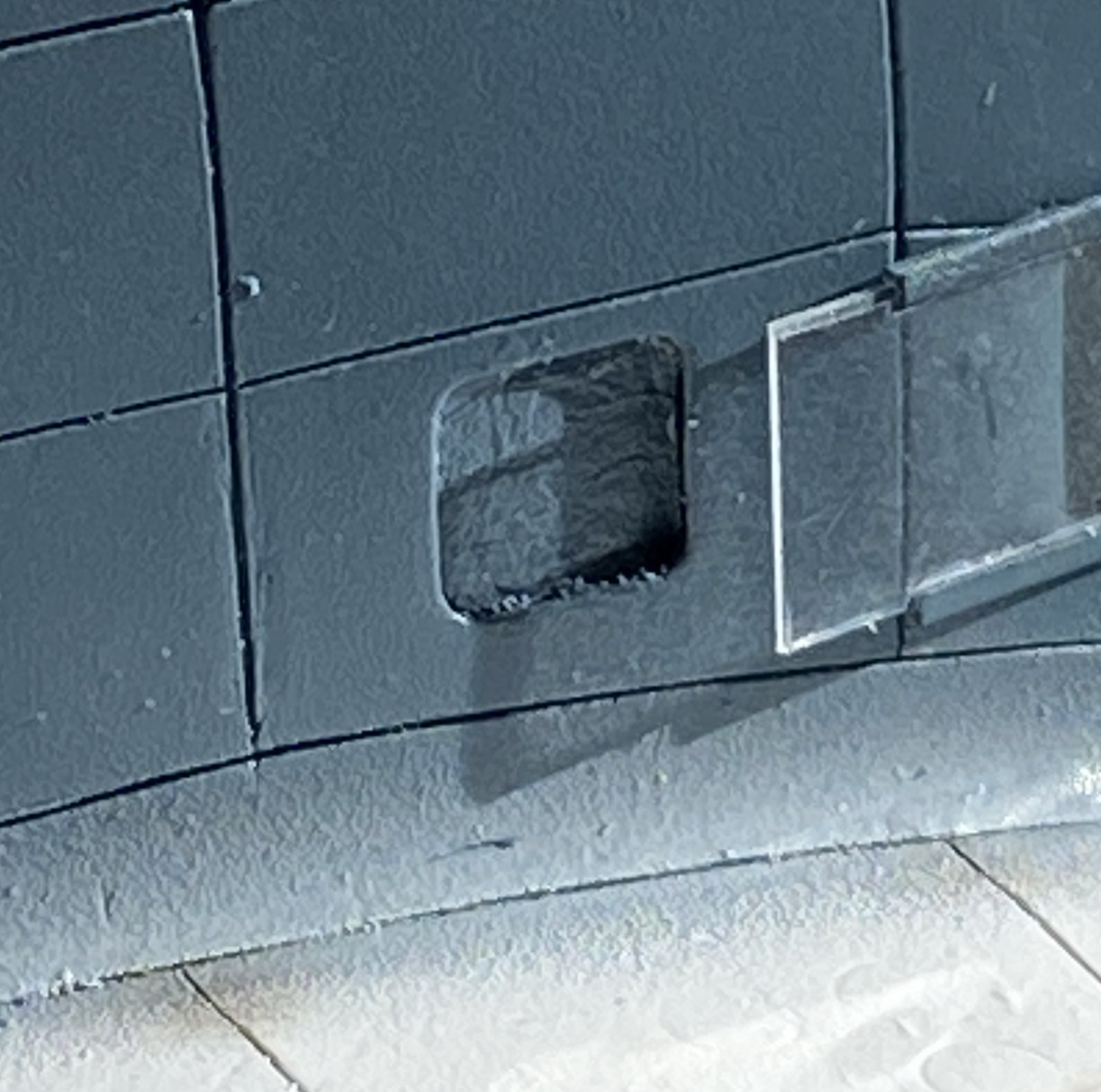
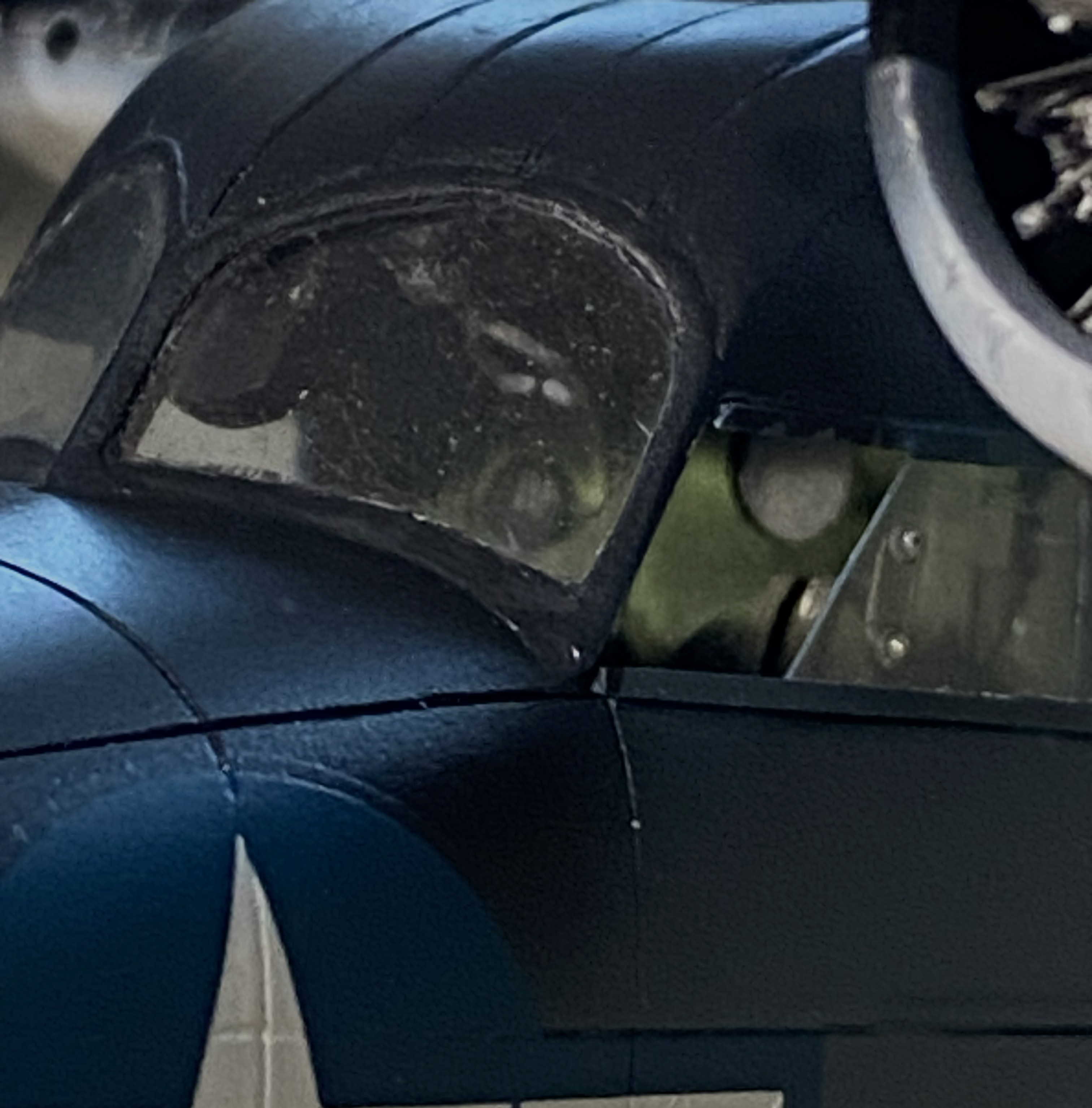
I think it’s the housing for an ADF head, but it needed to be painted semi-gloss black. So it was. I REALLY hate self-inflicted wounds, which is how I view overspray. When I aimed the airbrush at the football, NONE of the other painted surfaces were visible:
Success! Zero overspray:
I used 0.025″ (.635mm) as brake lines, painted them knowing full well that during the final bending process would cause paint to flake off. It was a lot easier to get at the parts that bent the paint away because there weren’t buried in the landing gear bay. I’ll get to these when touching up the paint happens (the photo’s on its side because I was using gravity to hold the solder where I wanted it to while the superglue set up):
And speaking of paint touch ups, I painted the frames of the cockpit windows off so that I could also paint under them. A solution that created a problem; paints don’t match once assembled. Okay, I’ll be doing touch-ups (with a small brush in these areas…the other side, though not as bad, is the same), just add this to the list:
You’ll also note that the cabin window just behind the flight deck is still masked. This was a problem I let sit as-is. When I tried to pry the masking tape away, three of the four sides of this window broke free. It was hanging on by paint. My memory isn’t what it once was (is anything?), but I DO remember what I had to go through to fix the one that came out already. Carve, fix, fill. Lots of fun when the plastic was unpainted, a no-go zone now that it has been painted. I supplemented the paint holding the window on with liberal applications of superglue. I’m pretty sure it’s going to stay there, now. It’s in a place where it will never be touched.
This one’s pushing the 90-95% accuracy I try to attain. I don’t care. A blocked off window is better than a sodding hole. Moving on…
Speaking of self-inflicted wounds, I noticed a week or so ago that there was blue overspray on the nose. ::adds to touch up list::

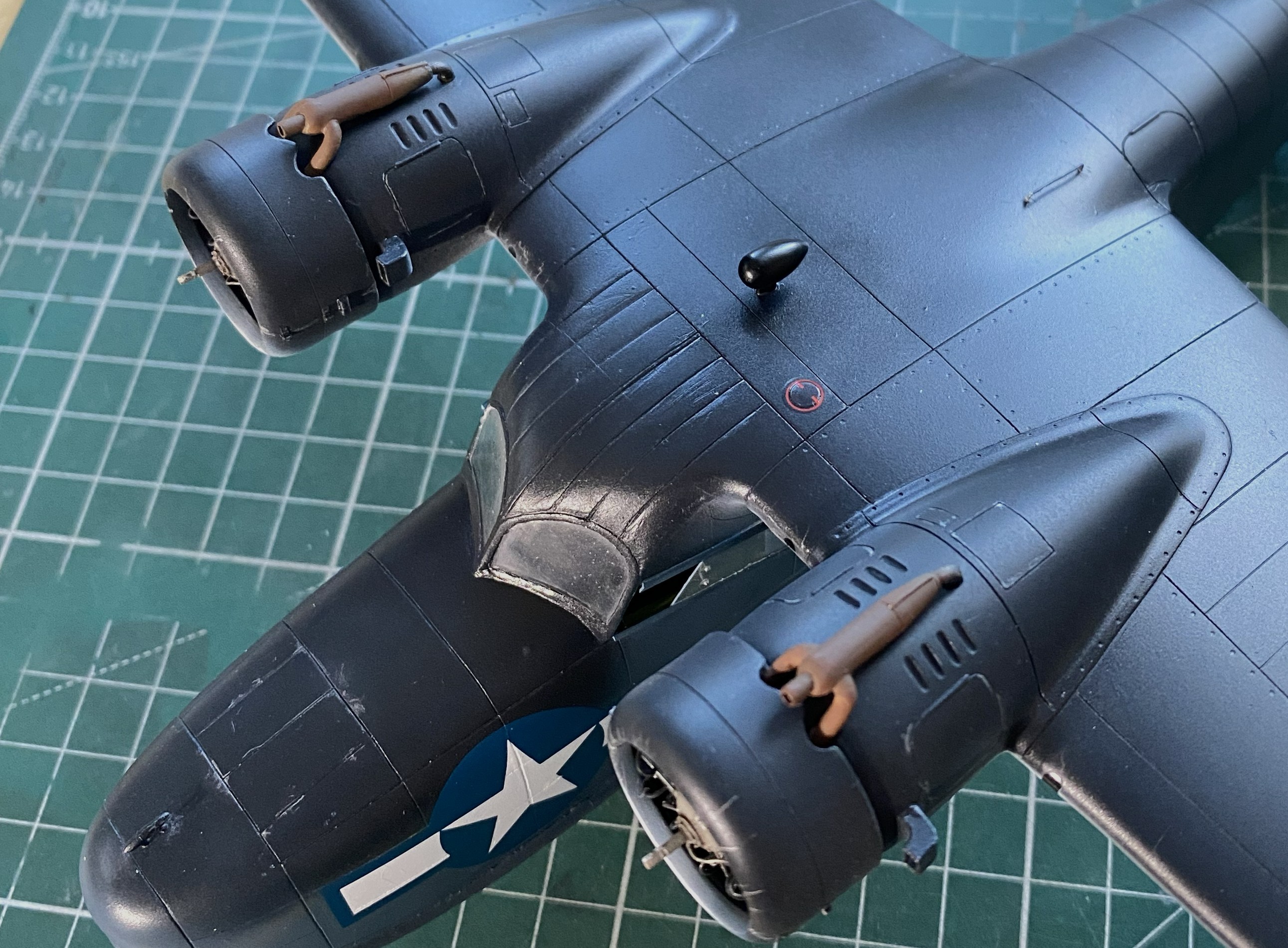
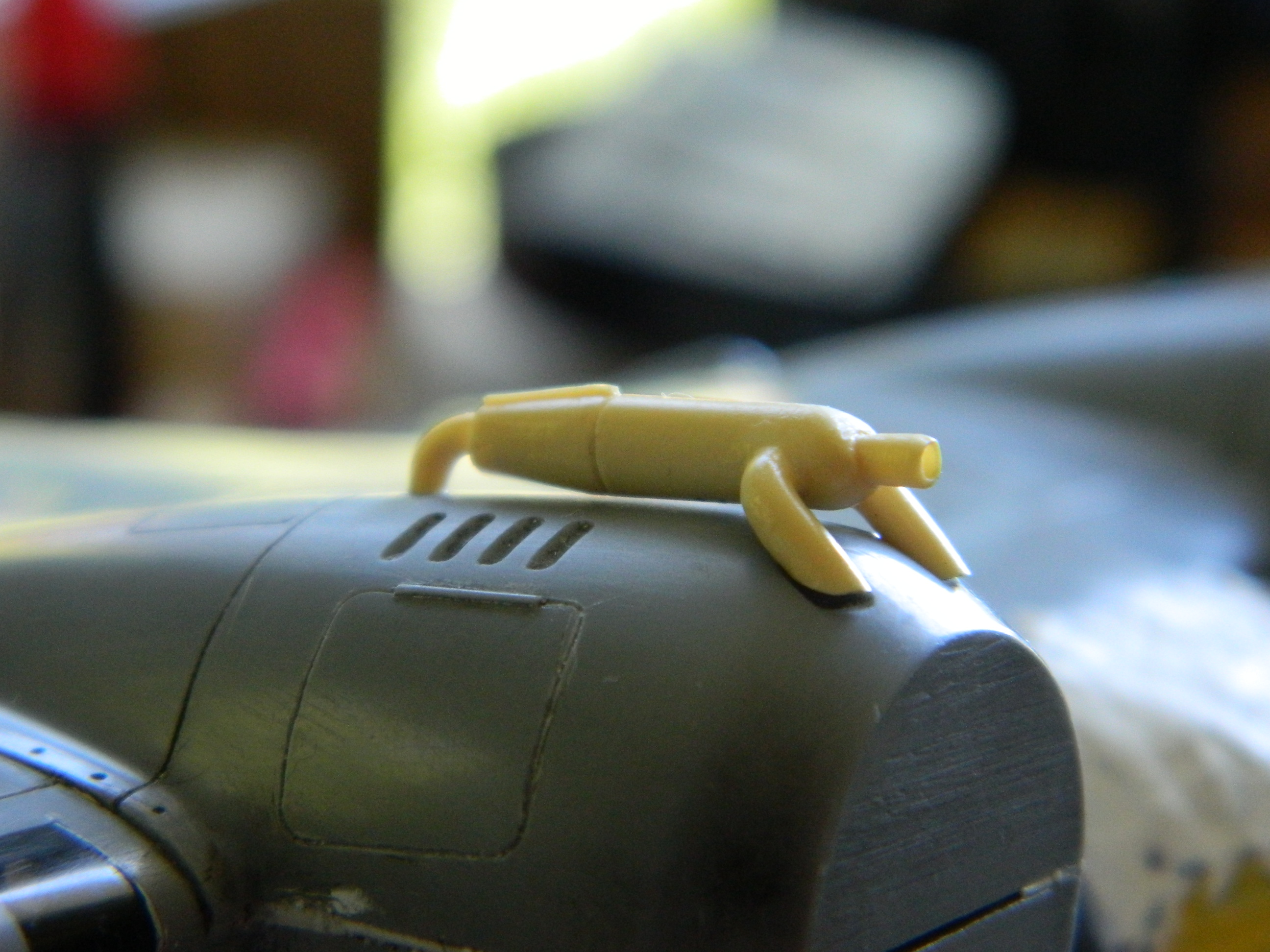
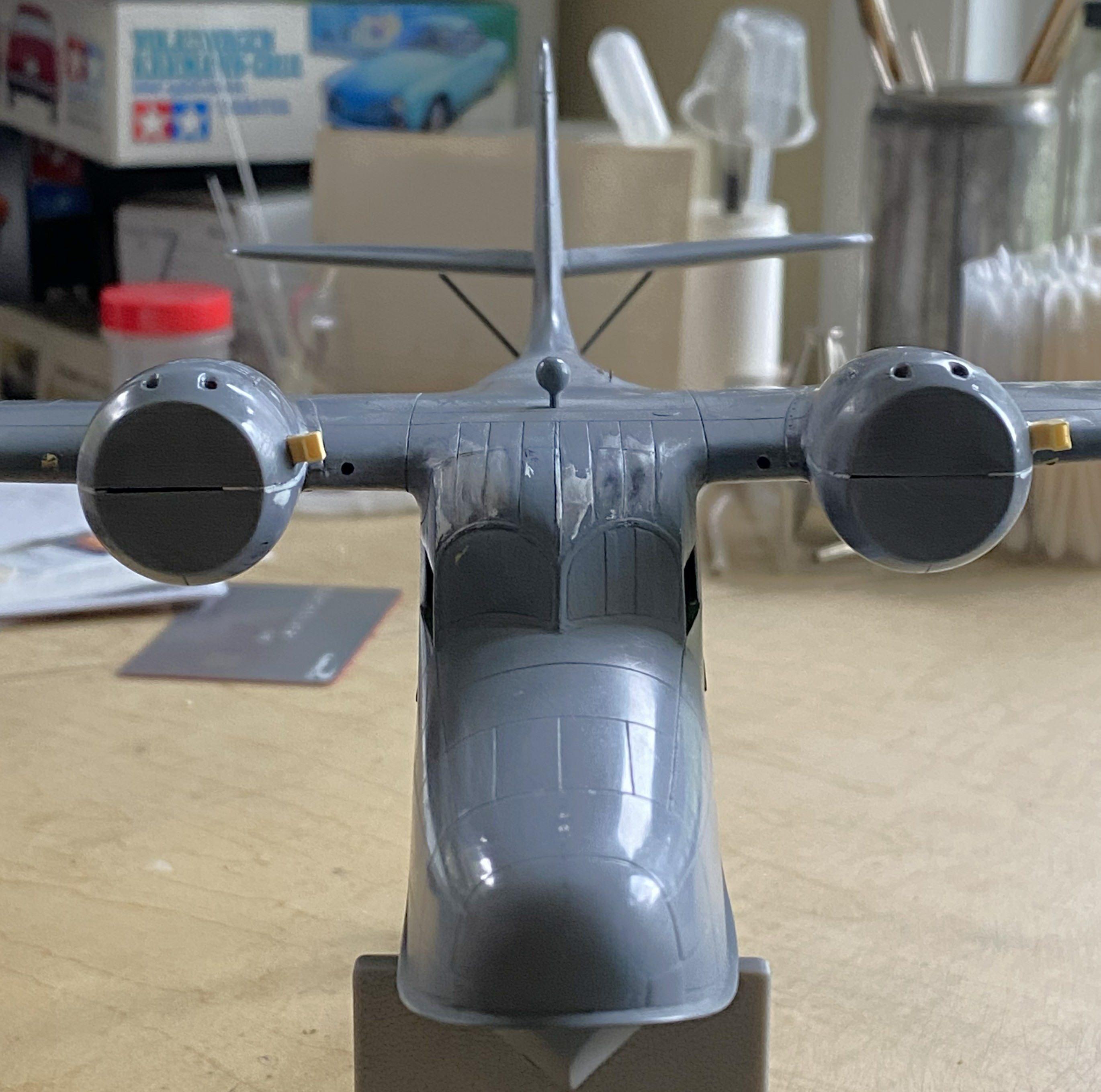
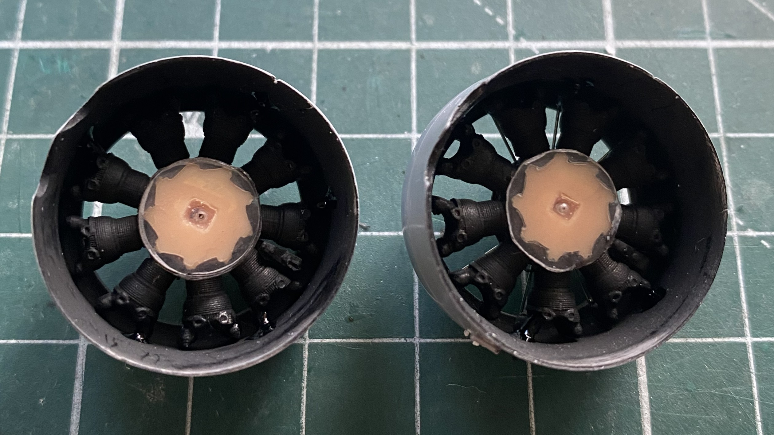
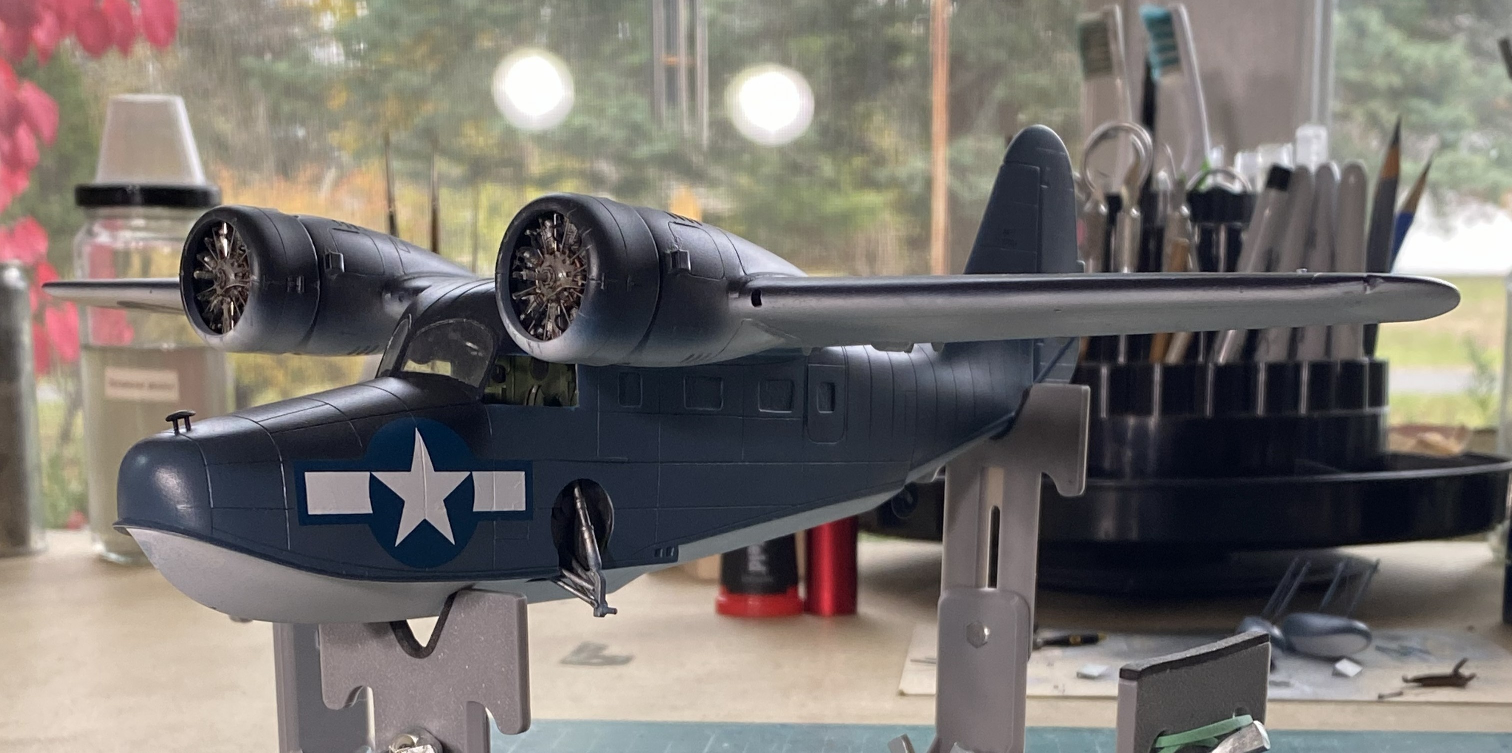
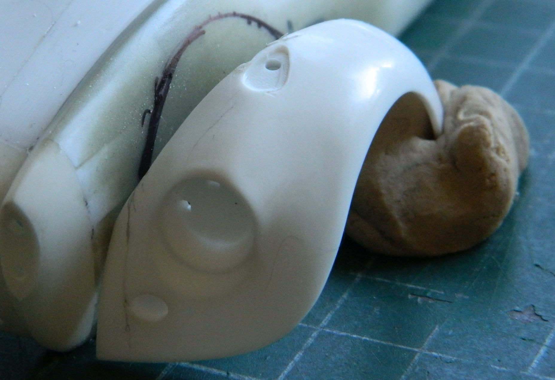
I added the heat exchangers (the brown things over the engine nacelles). Later on I’ll spiff them up a little bit with some pastels:
I added one of the landing gear “doors” just before beddy-bye so that the glue would set up; there’s not much gluing surface:

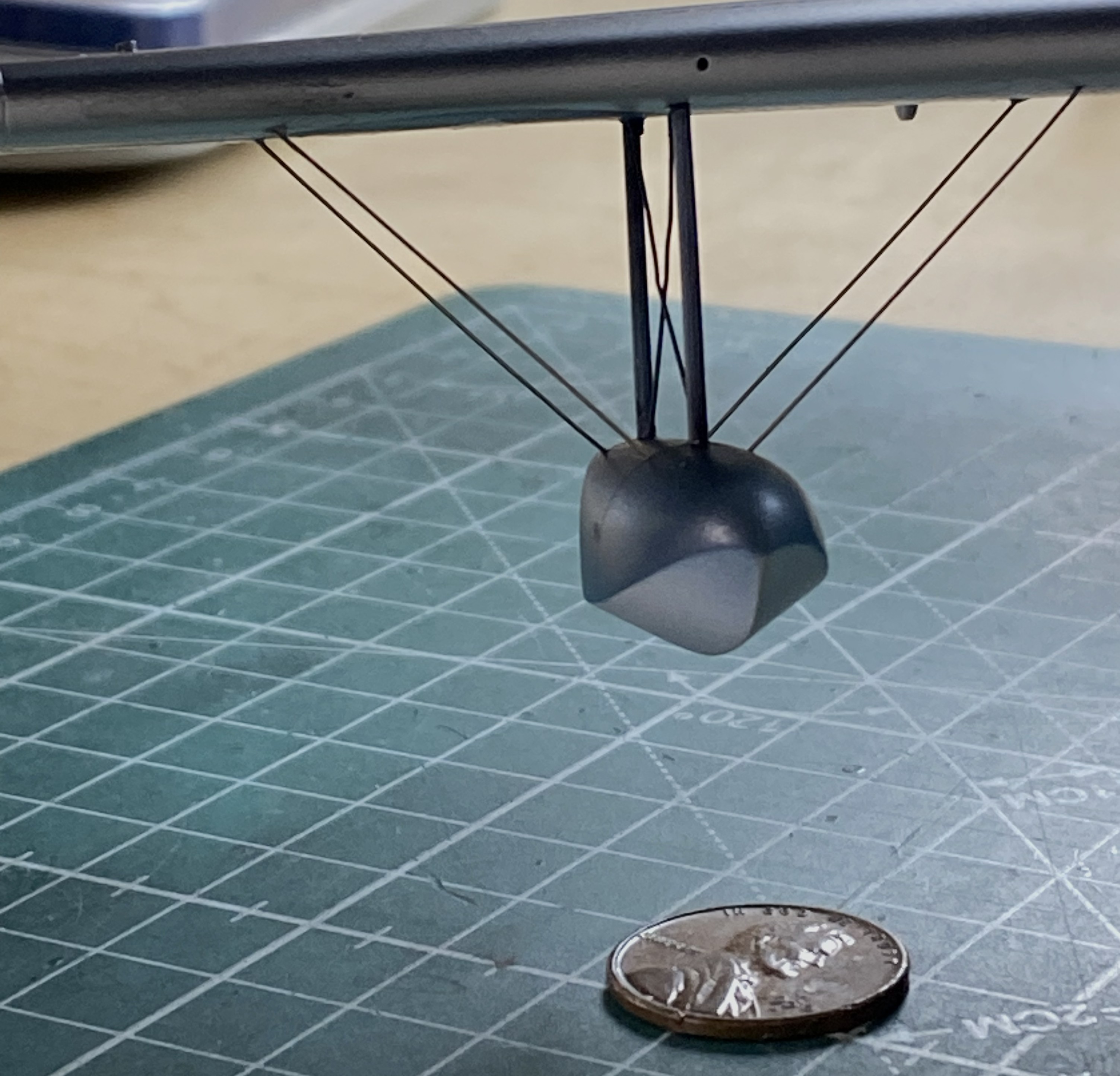
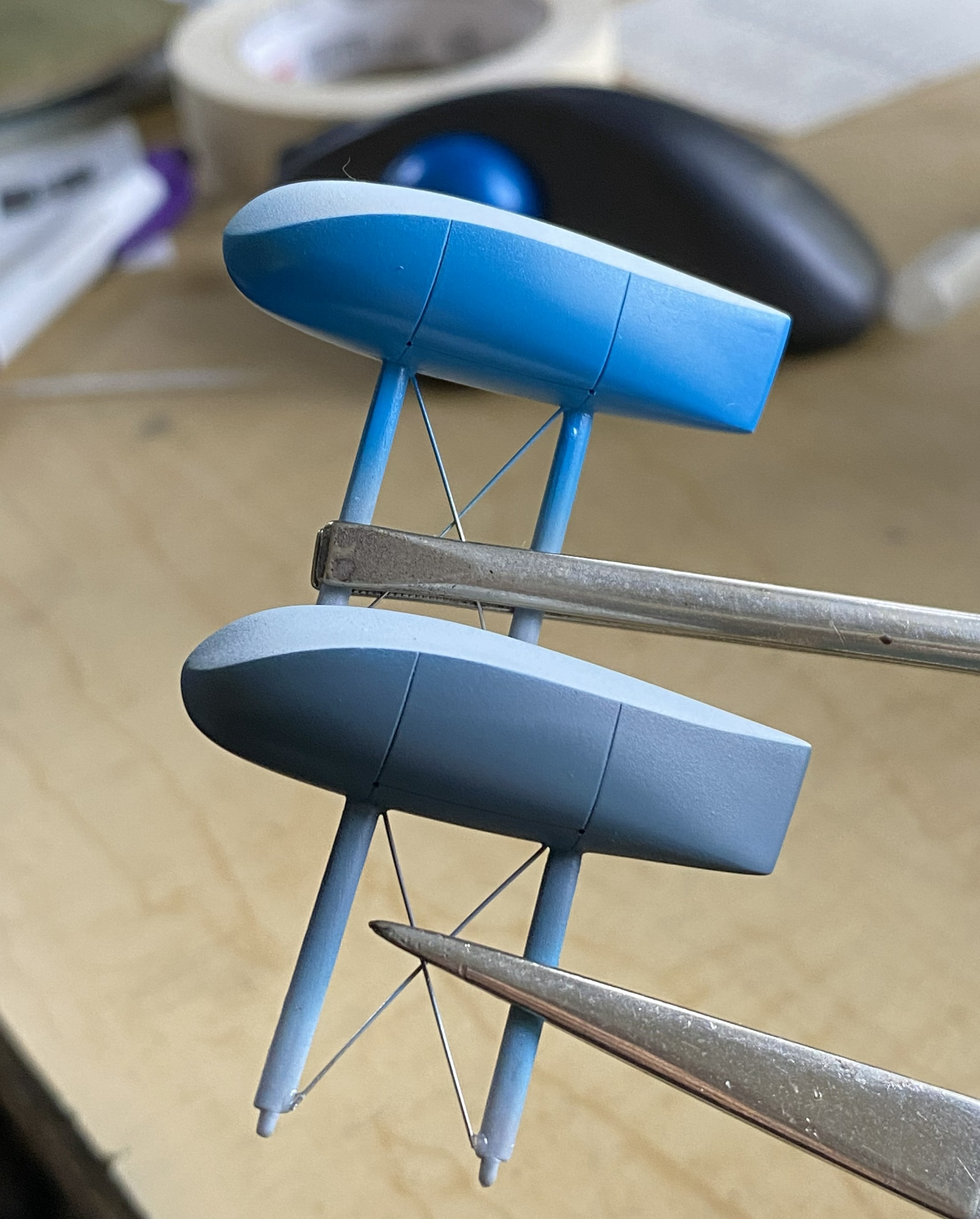
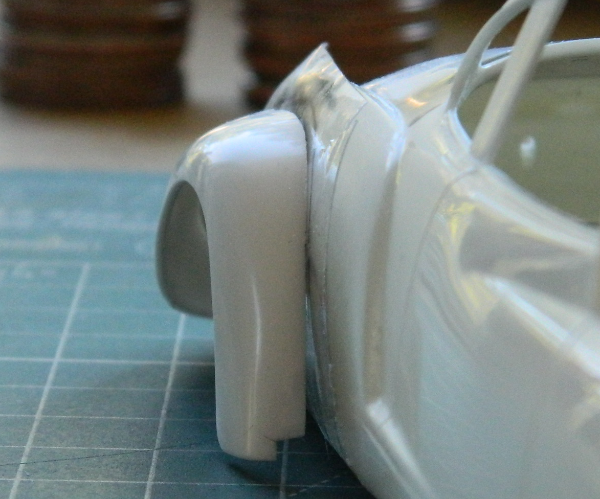
And while I was letting something sit overnight, I got ballsy (considering how late in the evening this happened) and added one of the floats to sit overnight as well:
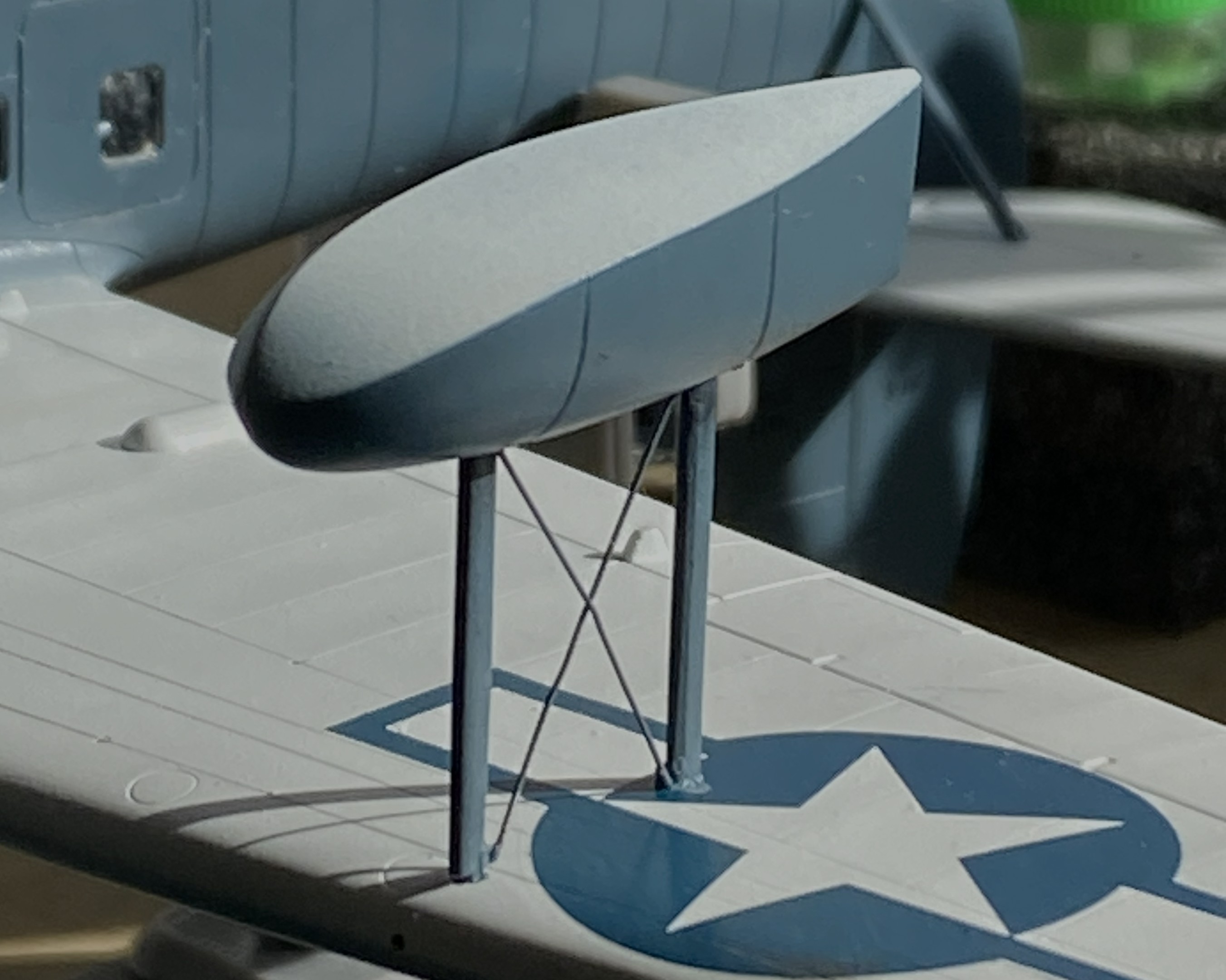
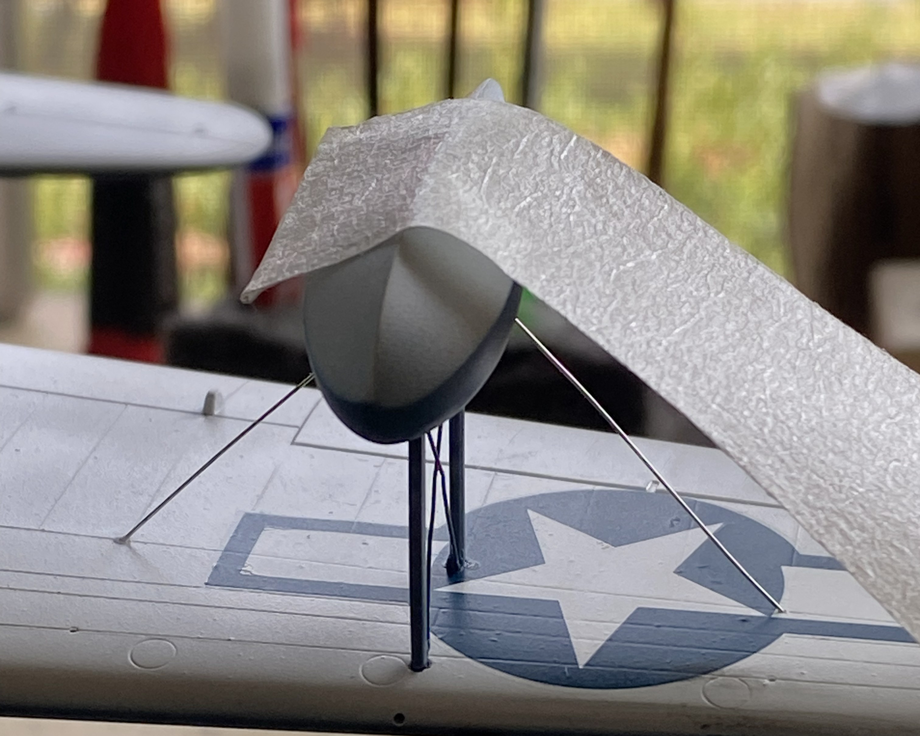
Obviously, with only two small contact patches, this will be easy to knock flat laterally. I added tape to stabilize it while I fed the ends of the braces into the float and wing for gluing (superglue). l cut the wires overlong so that I could be certain I’d be able to adjust them if I needed to (a handy bit of foresight):
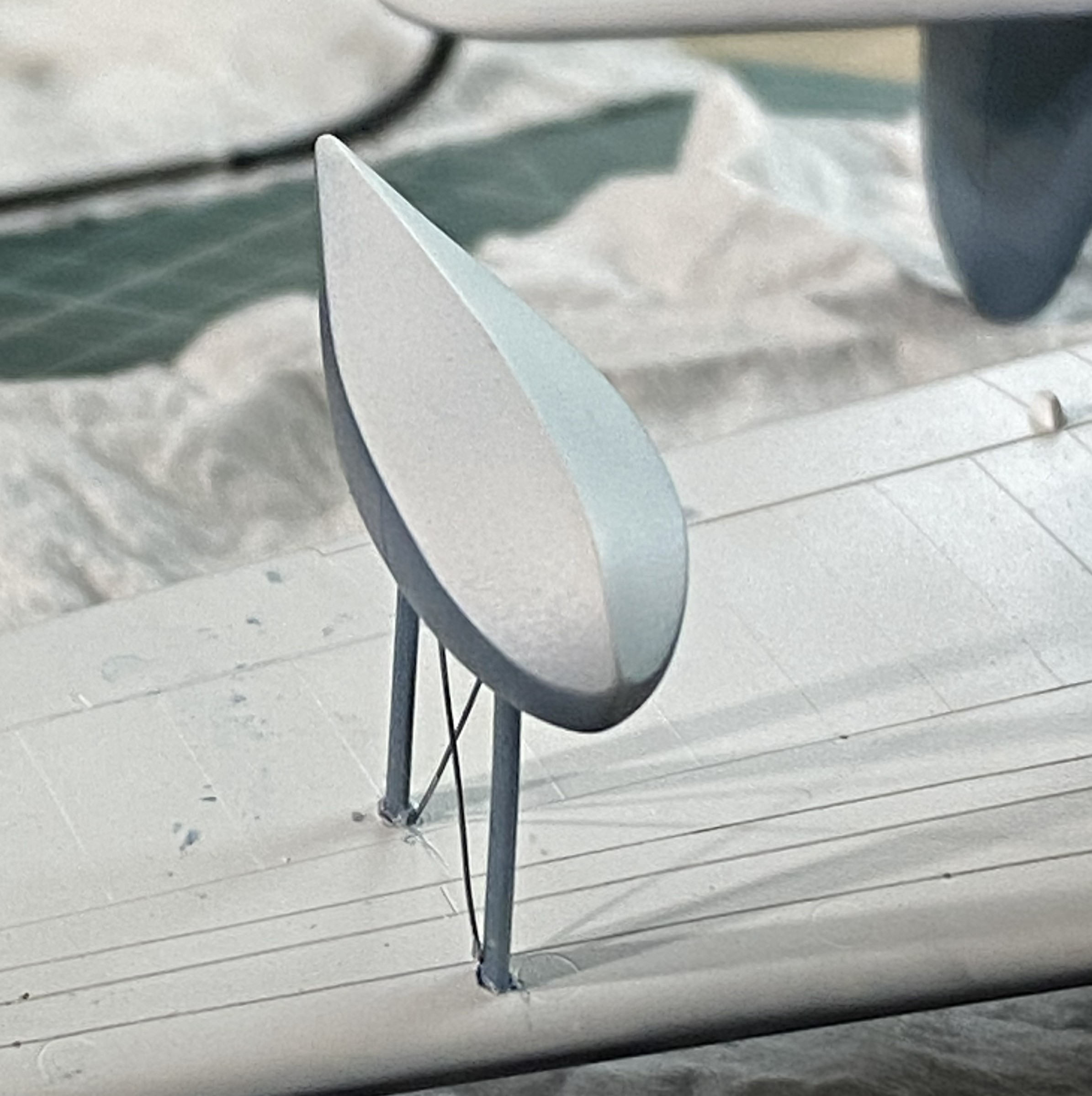
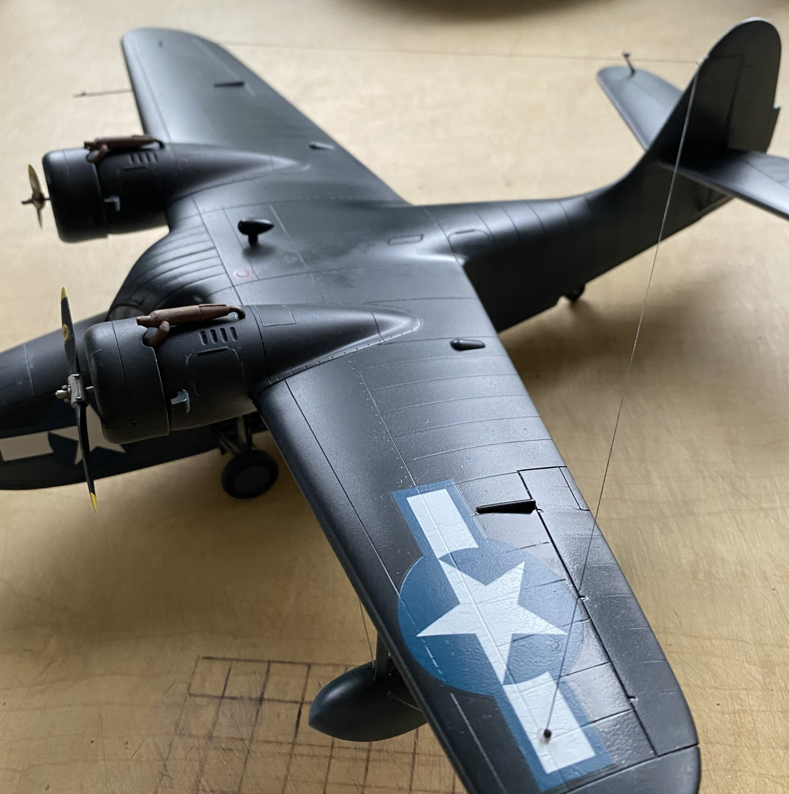
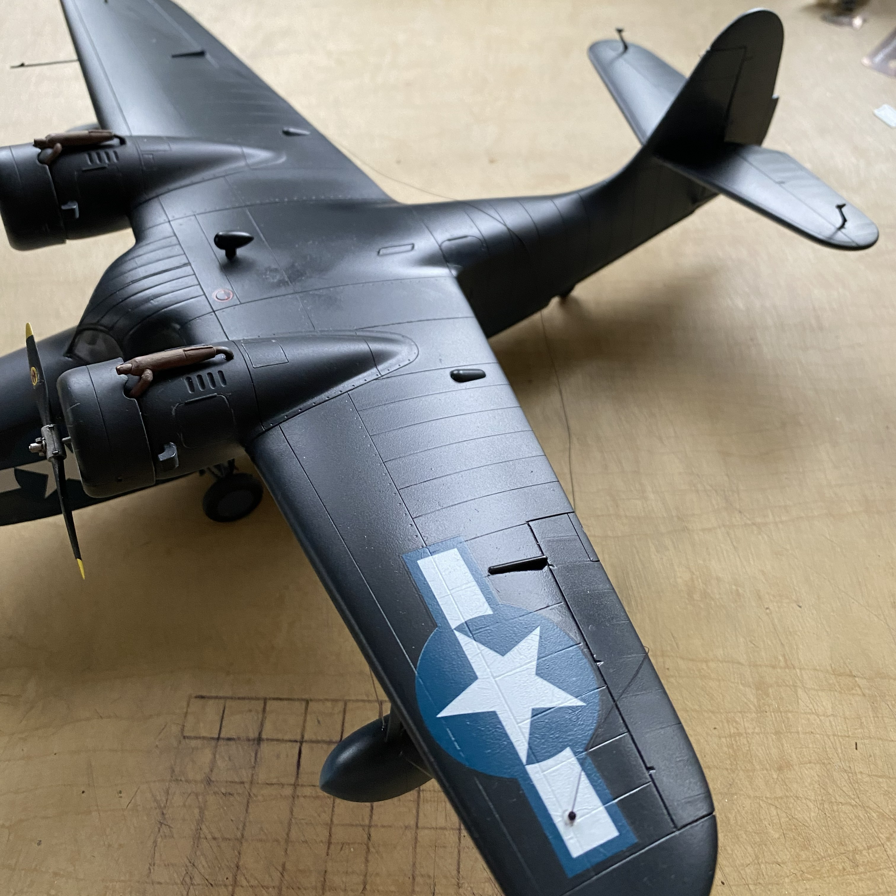
With all the guy wires in place, it looks pretty good:

Getting the guy wires into the pre-drilled holes of both the float and wing took some fiddling. For the next float, I tried inserting one end of the guy wires into the float without cement to see if that would be easier:

It wasn’t. If you look closely where the wires meets the float you can see small bits of masking tape holding them in place:
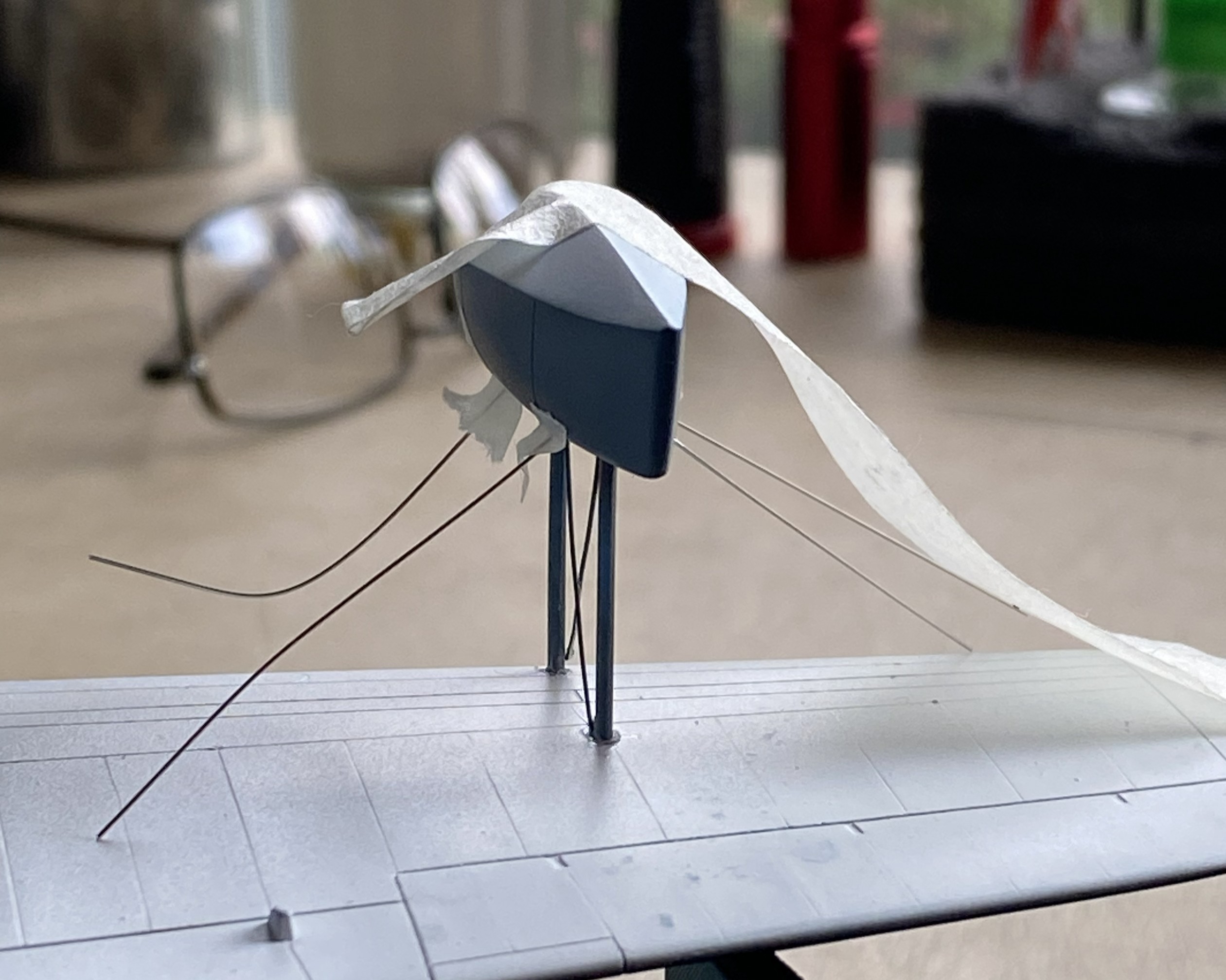
This didn’t work as well as I’d hoped.I was surprised at how difficult it was to just remove the tape. I had to diddle the tape so much that the float came free (in its defense, it hadn’t sat overnight for the plastic to harden fully at the glued points). After I reattached the float to the wing, when I turned the whole thing up side down, all the wires fell out:
I got that fixed:

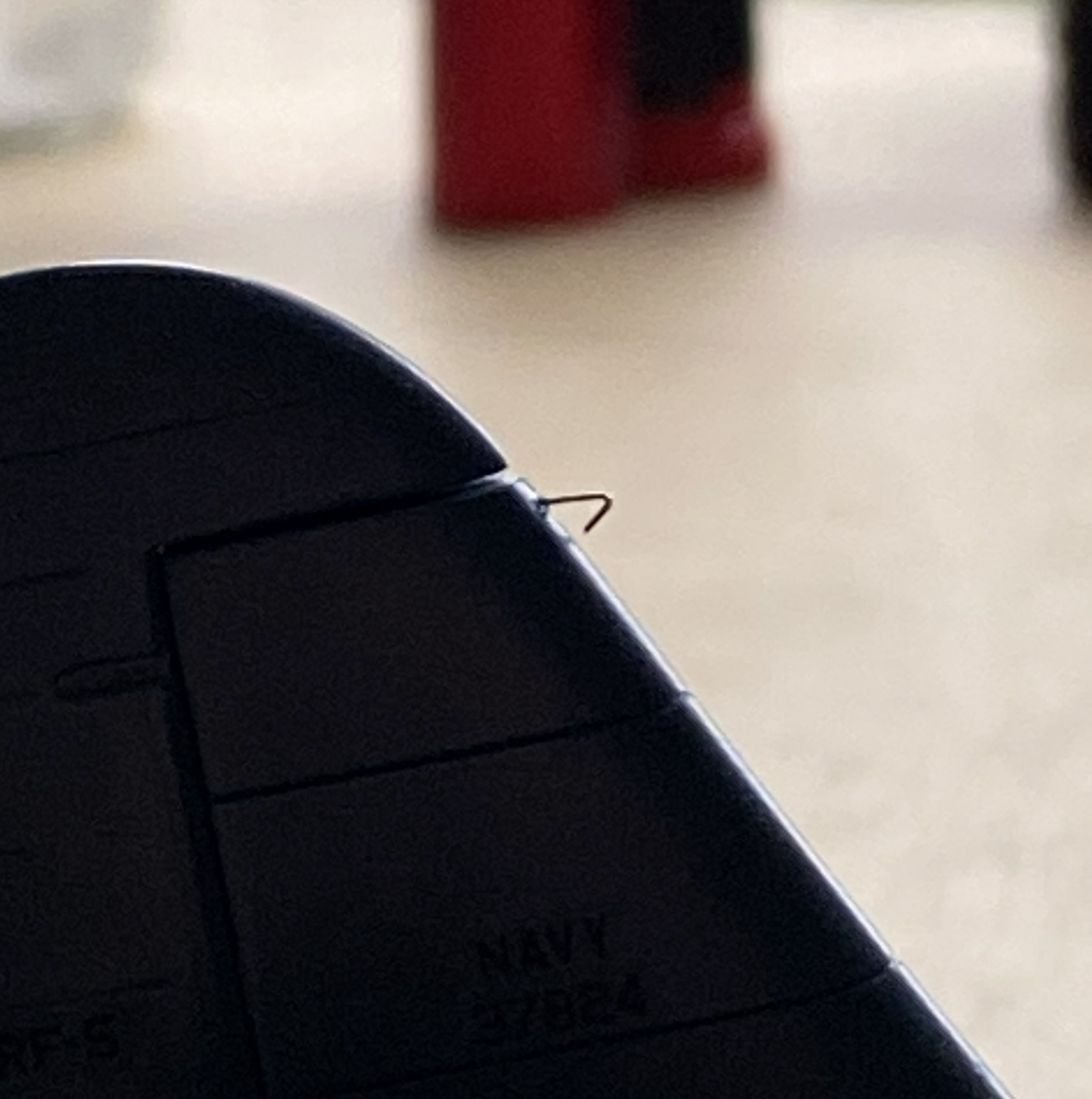
The radio aerials attach at both wing tips and the tip of the vertical stabilizer. I use this for aircraft aerials:
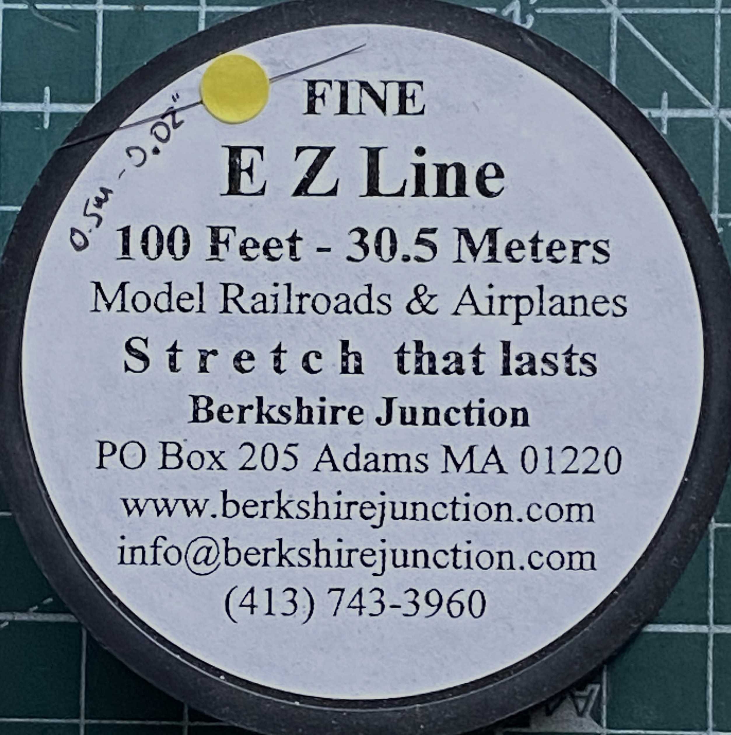
As I’ve been putting this together, obviously the more parts I add the less places I can hold it. For that reason (because these things get handled and transported) I wanted the aerials to be semi-removable; permanently attached at the wing tips, removable at the vertical stabilizer. What would make doing that simple would be to make the attachment point on the vertical stabilizer detachable. Or…I could mount the attachment point permanently and have it be J-shaped so that I can just lift the EZ-Line and let it drop. I like that idea, the major flaw is that even though the EZ-Line’s tension is adjustable, that J-hook has to be small. I didn’t have confidence in copper to hold up over the years. Instead I used the E-string from a guitar (thereby creating the moderately rare 5-string variant). Everything about its dimensions are printed on the pouch:

It’s certainly over-engineered for my purpose, which I think is great:
I’d attached little stubs of styrene rod where they belong and center-drilled them to socket the end of the EZ-Line into:

After gluing the other side in place, I tested the arrangement to see if it would function as desired. It function exactly as desired. Top photo below is with the aerials in place, the bottom photo is with the antennas dismounted (for these photos, I dry-fit all the parts yet to add and realized that none of those dry-fit parts need to be glued so I left them on):
I have one more thing to do (attach the brake lines to the wheels) and DONE!

Grumman JRF Goose (Czech Model) 1/48 Scale Build #6 – And This is When Tedium Really Sets In
I generally try to post new material here around the end of the month. Not having posted since August, that seems to have broken down. Seems to. It’s this build of this particular kit. I don’t want to work on it anymore. I recognize that this is an emotional response, not intellectual, so I have pressed on, albeit intermittently. But…here we are!
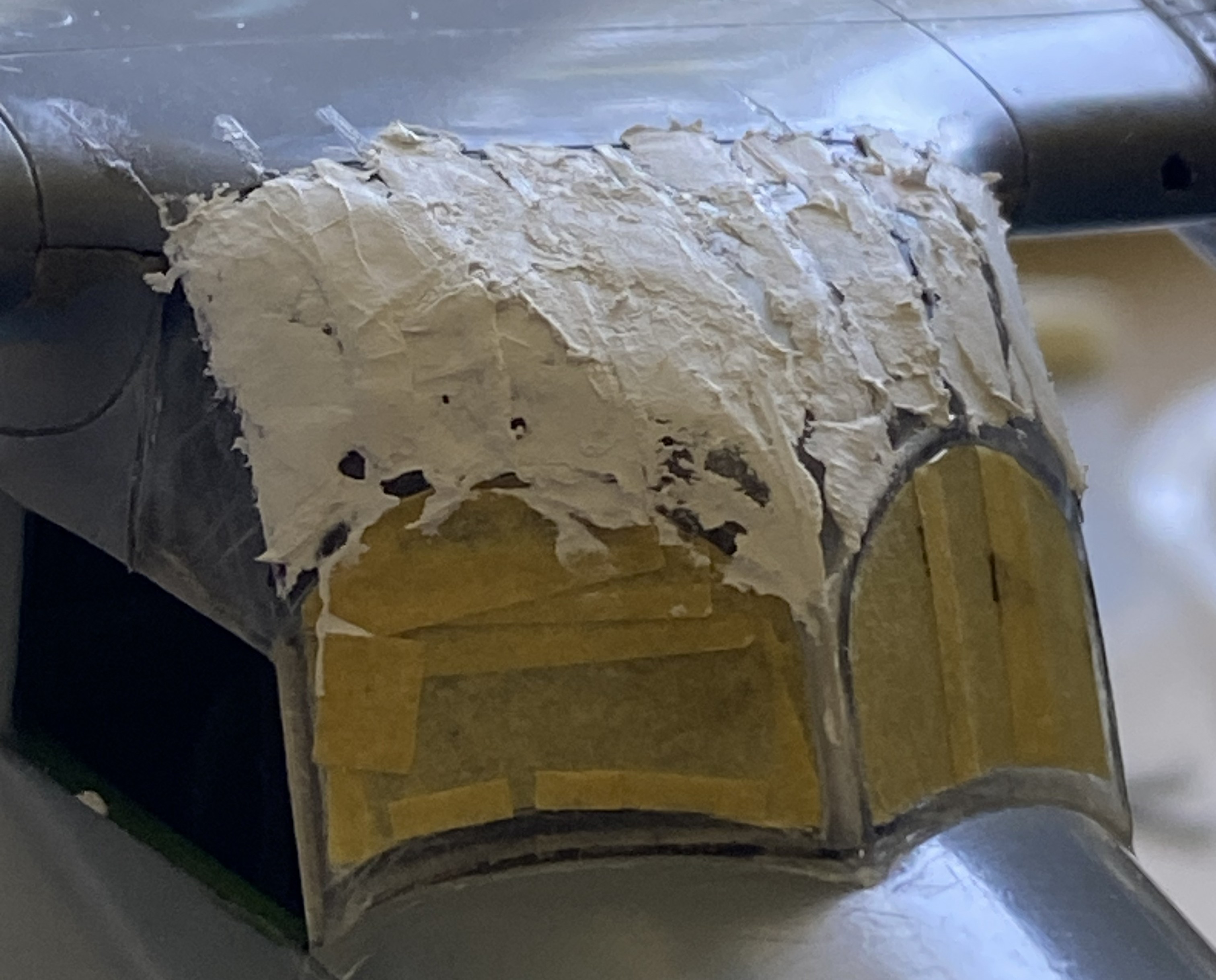
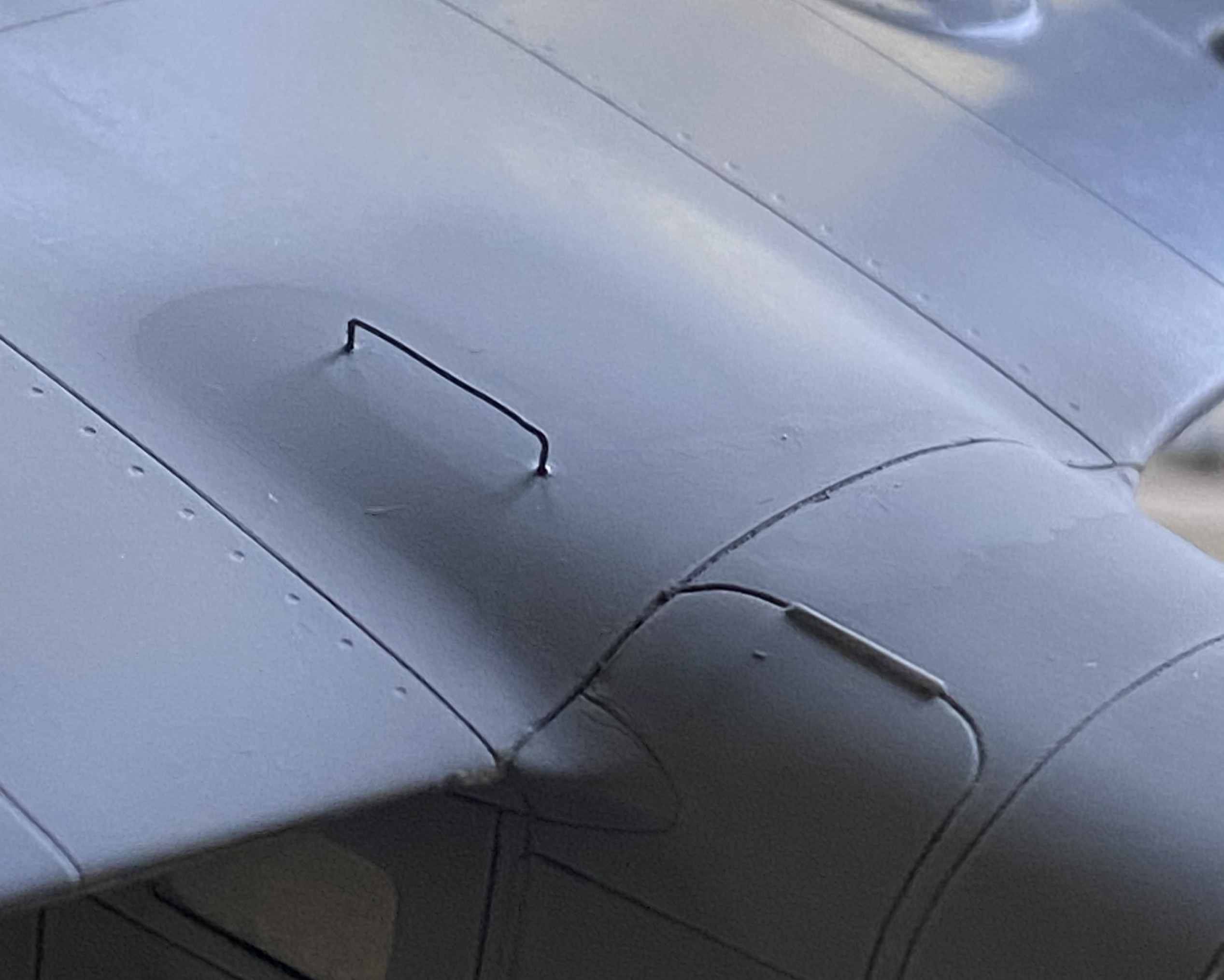
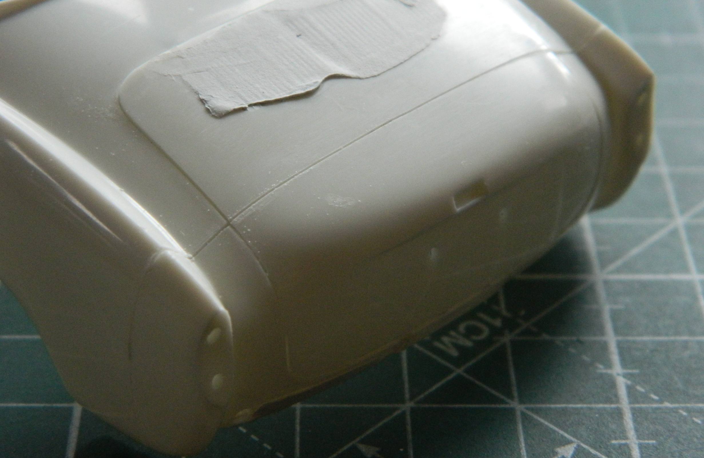
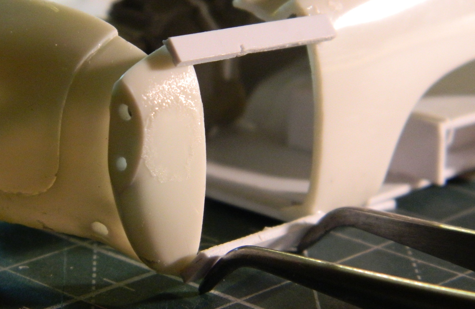
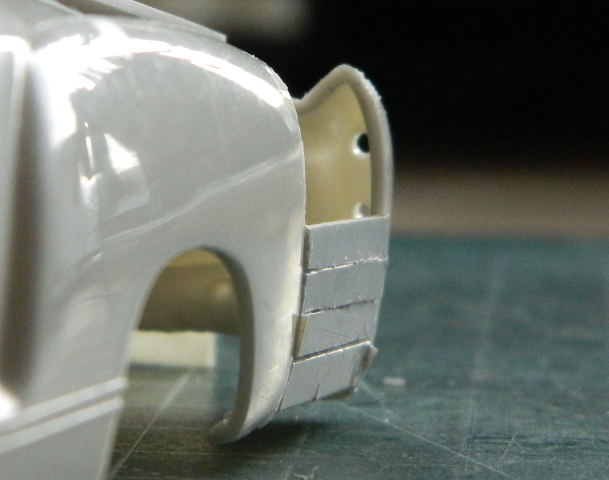
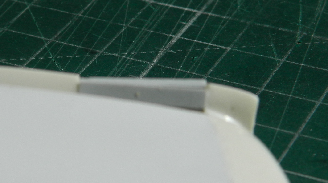
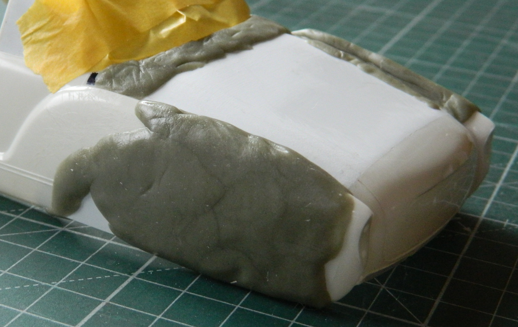
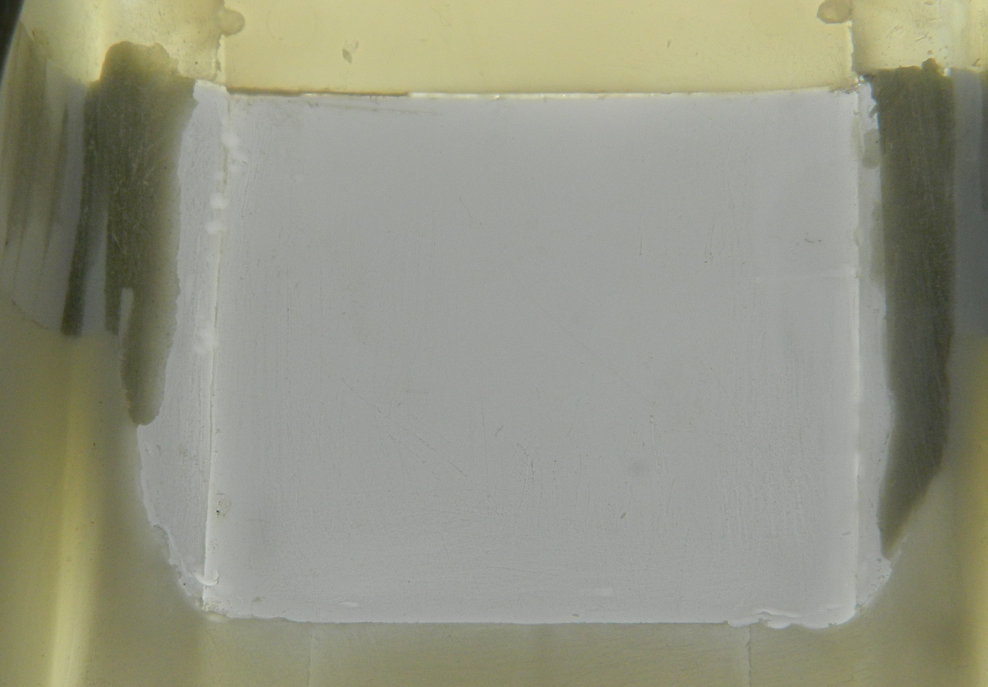
The fuselage over the flight deck (or cockpit, you choose) has a prominent feature. The curved shape is created on the actual aircraft by using flat panels. In some photos the panels appear to be butt-joined (the edge of each panel abutting the next), in some photos they seem to be scaled (where one side of the panel overlaps the next, sitting on top of it), and none of them are definitive. I made my guess (several guesses, really) and decided I’d go with the scaled (overlapped) presentation. I laid down strips of .005″ (.127mm) and then faired them in with 3M Acrylic Putty:
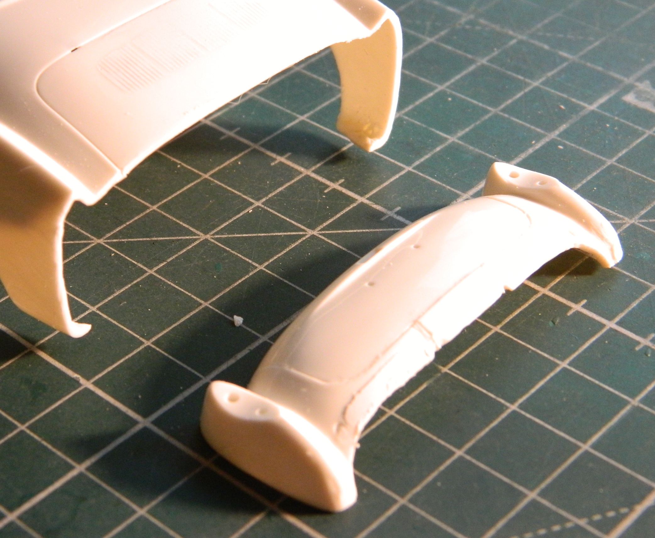
While the putty is drying, I fitted the heat exchangers on top of the engine nacelles. Originally it looked like a small, resin, cat standing on a hot griddle. Way too high off the nacelles. Fiddle, file, sand, cut at they now sit correctly:
EDIT
While I was doing this update, it was at this point in it that I sat here confused (easy place to get to due to how often I go there). I thought I’d taken more photos of the work over the flight deck. I certainly know that a lot of time was spent on it. About an hour ago the mystery (and confusion) dissipated when I found the photos I thought that I’d taken misfiled in a folder that, of course, has nothing to do with modeling (there are minor aspects of my life that have nothing to do with modeling) (honest). It’s at this place in this post that I surreptitiously add them in a manner that I think few will notice my oversight. ::giggles::
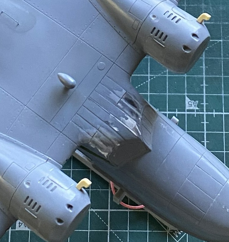
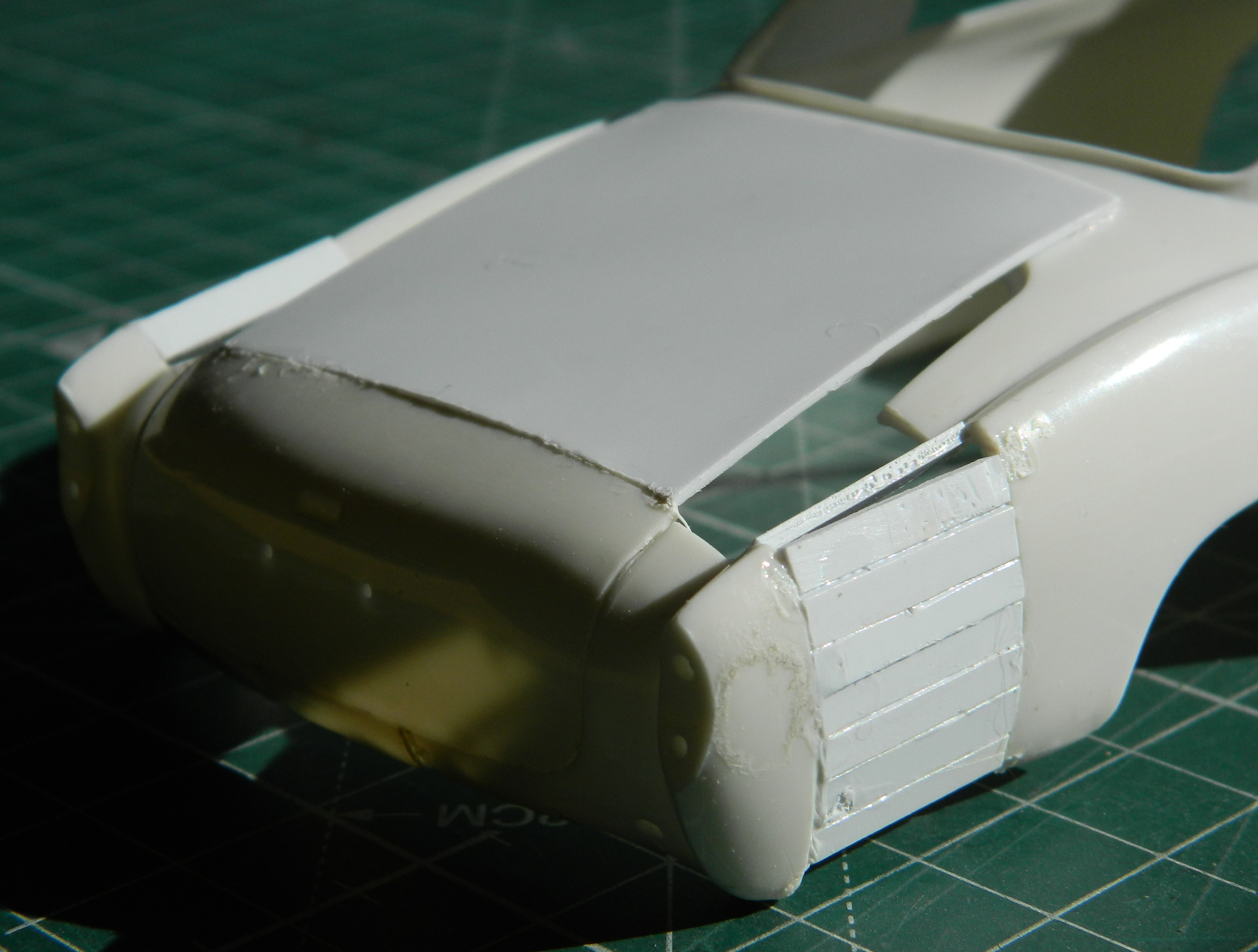
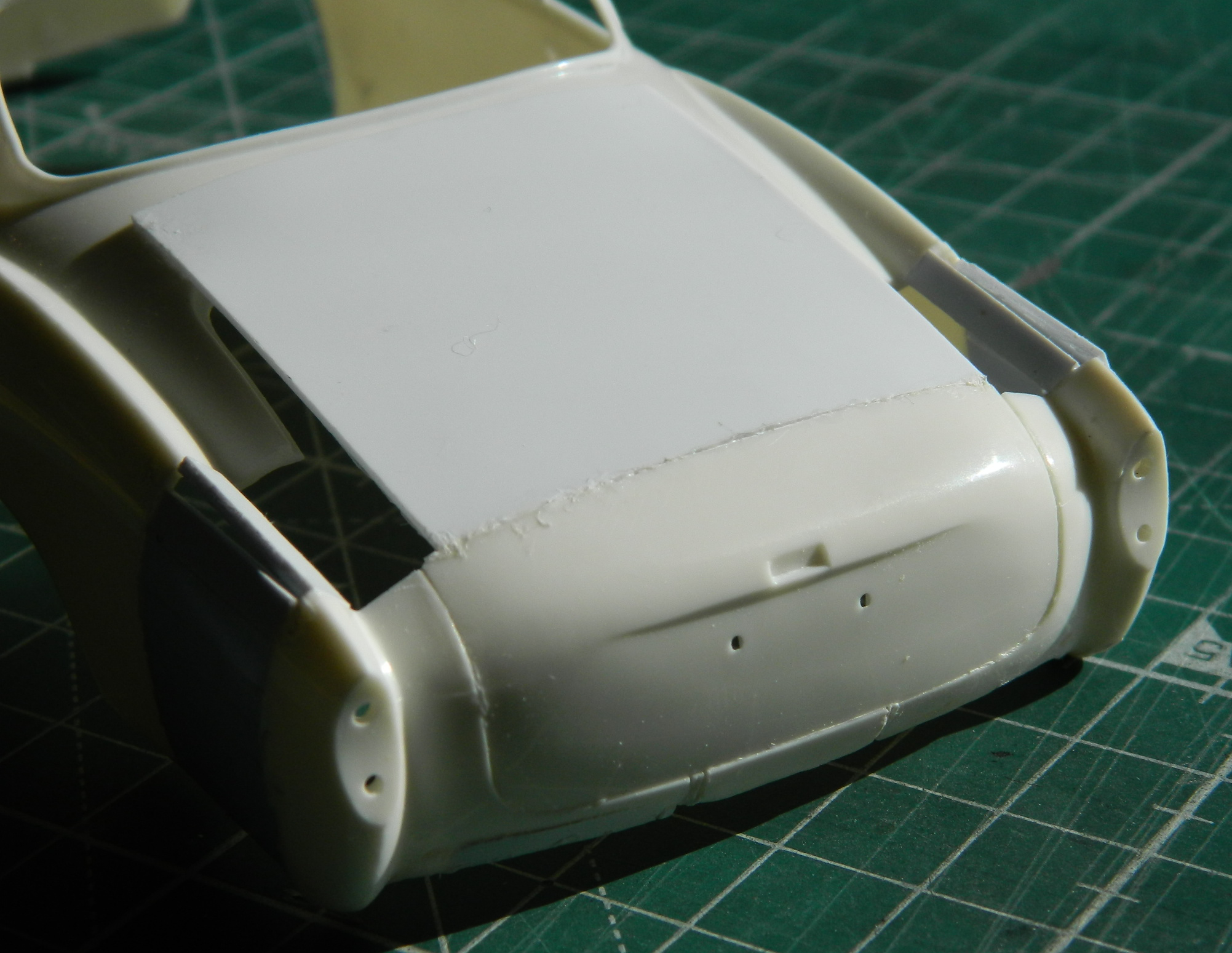
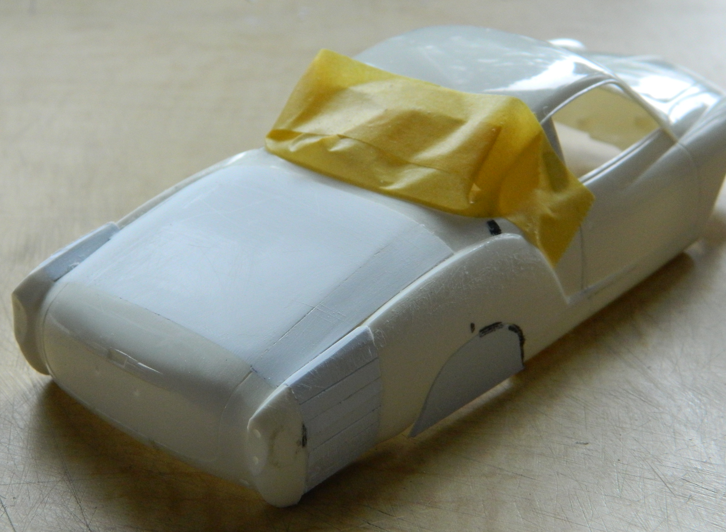
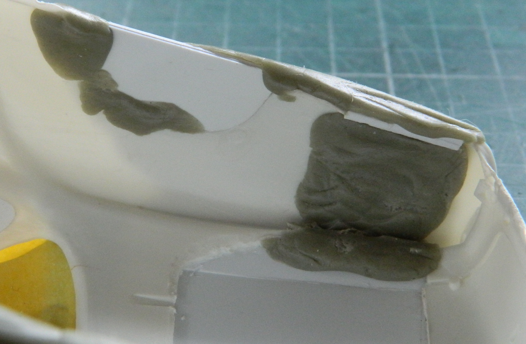
With the putty dry, I went back to the fuselage over the flight deck. ::sighs:: Where to begin… A lot of work ensued. Almost all the putty was sanded away to see if I could (I couldn’t) refine the shapes and lines of this area. As so often happens, once I’ve decided on a method to accomplish whatever oddball thing I’m trying to do, often I have to invent a way to do it (and frequently that is not a hurried process, regardless of how it may look). While doing the work of that invention on the model, it is quite common for me to figure out a different (and hypothetically better) way of accomplishing the task. It’s also not uncommon for that epiphany to come too late to use on what I got the idea from. This was one of those. While removing putty and trying to refine the shapes into something I want, I realized that what I should have done was not add the strips and putty at all. The panel lines should have been scribed and cut away to create the lapped effect. And then I noticed that the lines aren’t just on the clear part, they extend rearward to the pencil line on the main wing, which is how I came to the realization that adding the strips and putty was a total waste of time/effort (and I added the resin scoops to the left sides of the nacelles):
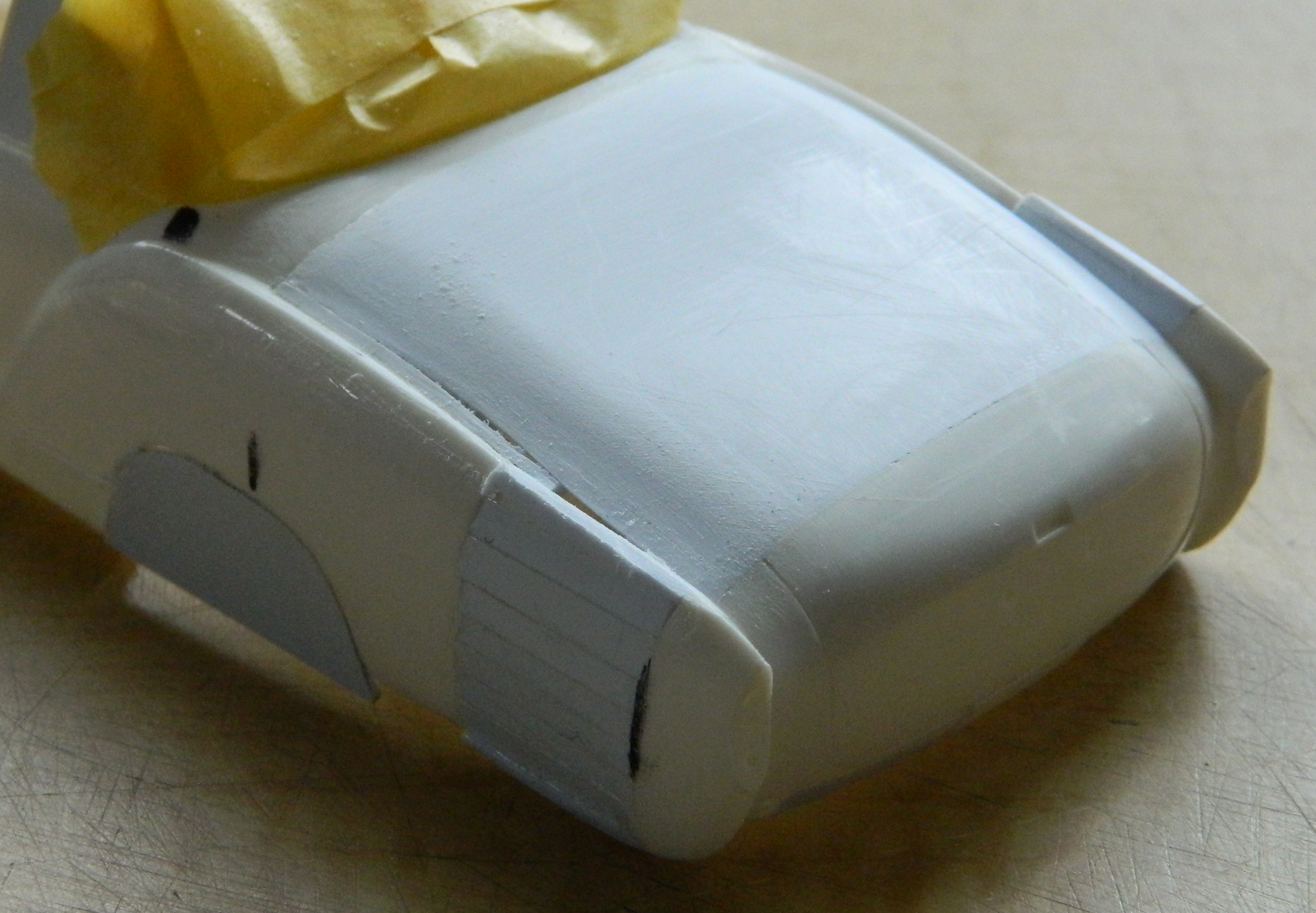
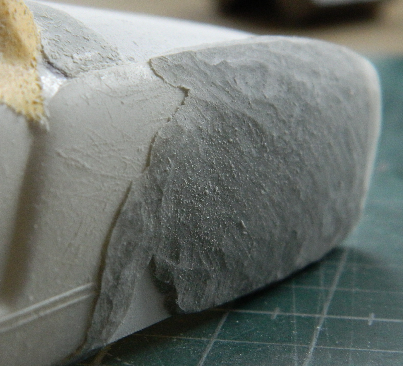
Putty was immediately added whenever I found a void that needed filling:


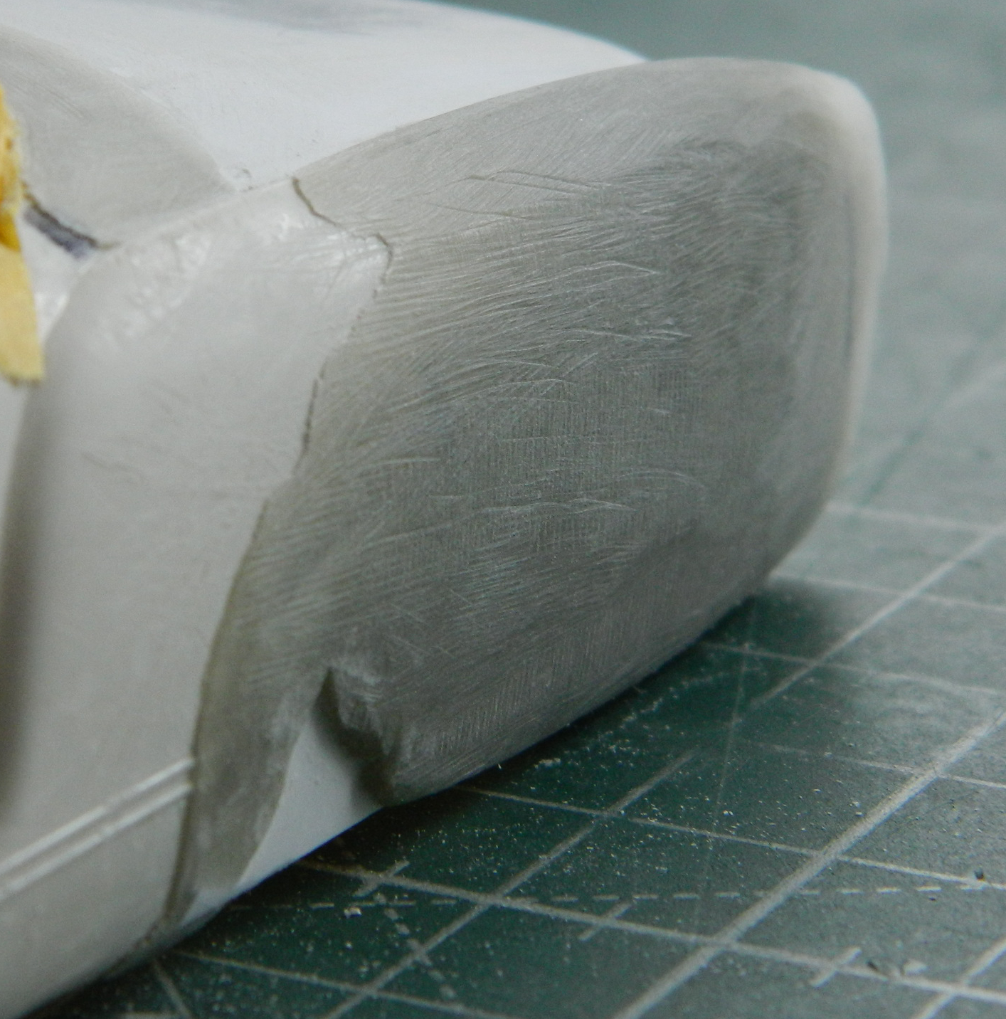
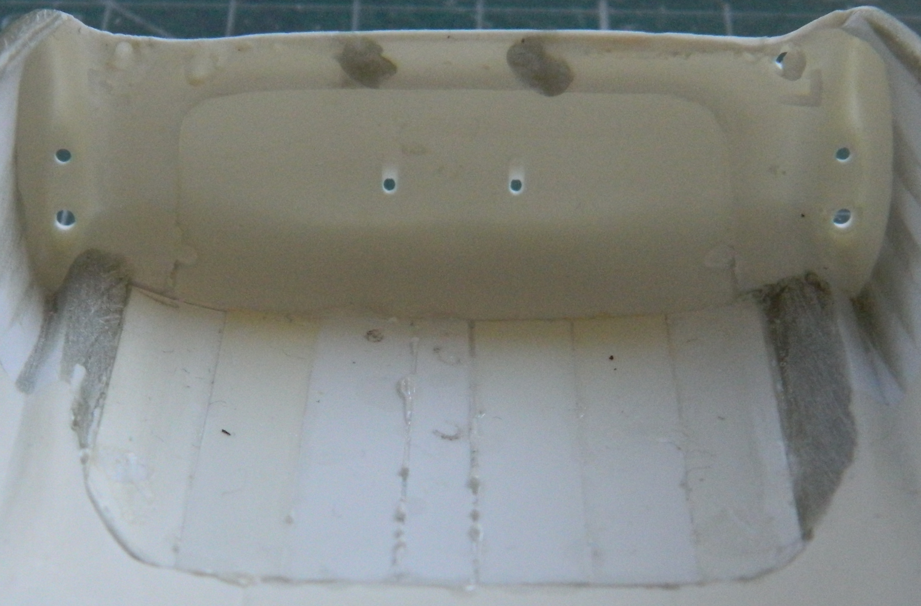
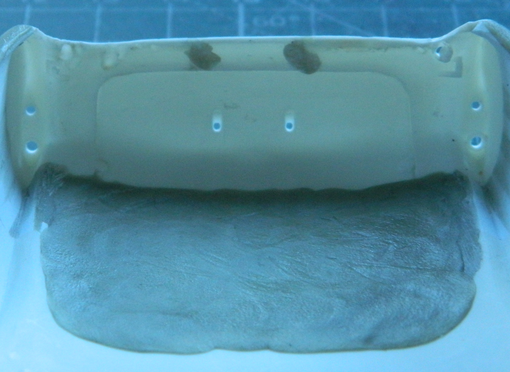
About this point I realized that I had too many different colors/shades reflecting light and I had lost the surface (visually…if I’m that bad off, I stay in bed). I used Tamiya XF-20 Medium Gray as it most closely matched the plastic’s color so that reflectance would be uniform:

I’ve seen a number of field-expedient grab handles added to aid refueling. The filler port is on top of the wing on the left side. Access was achieved by opening the portside entry and crawling up onto the wing. Then the fueler had to scoot towards the filler port while dragging the fuel hose. (I’m not sure that “ergonomics” was even a word 80 someodd years ago, doesn’t look like “convenience” figure prominently, either.) I picked a photo to replicate and used some 22awg wire and added one setup that appealed to my eye:
Ain’t nuthin quite like applying primer to show you what still needs work. Plenty:


It seems I got too frisky with cutting in the lap lines and took too much off (though, for a change, it was before I’d carved through it) so I used stretched sprue to fill what had been mistakenly removed.
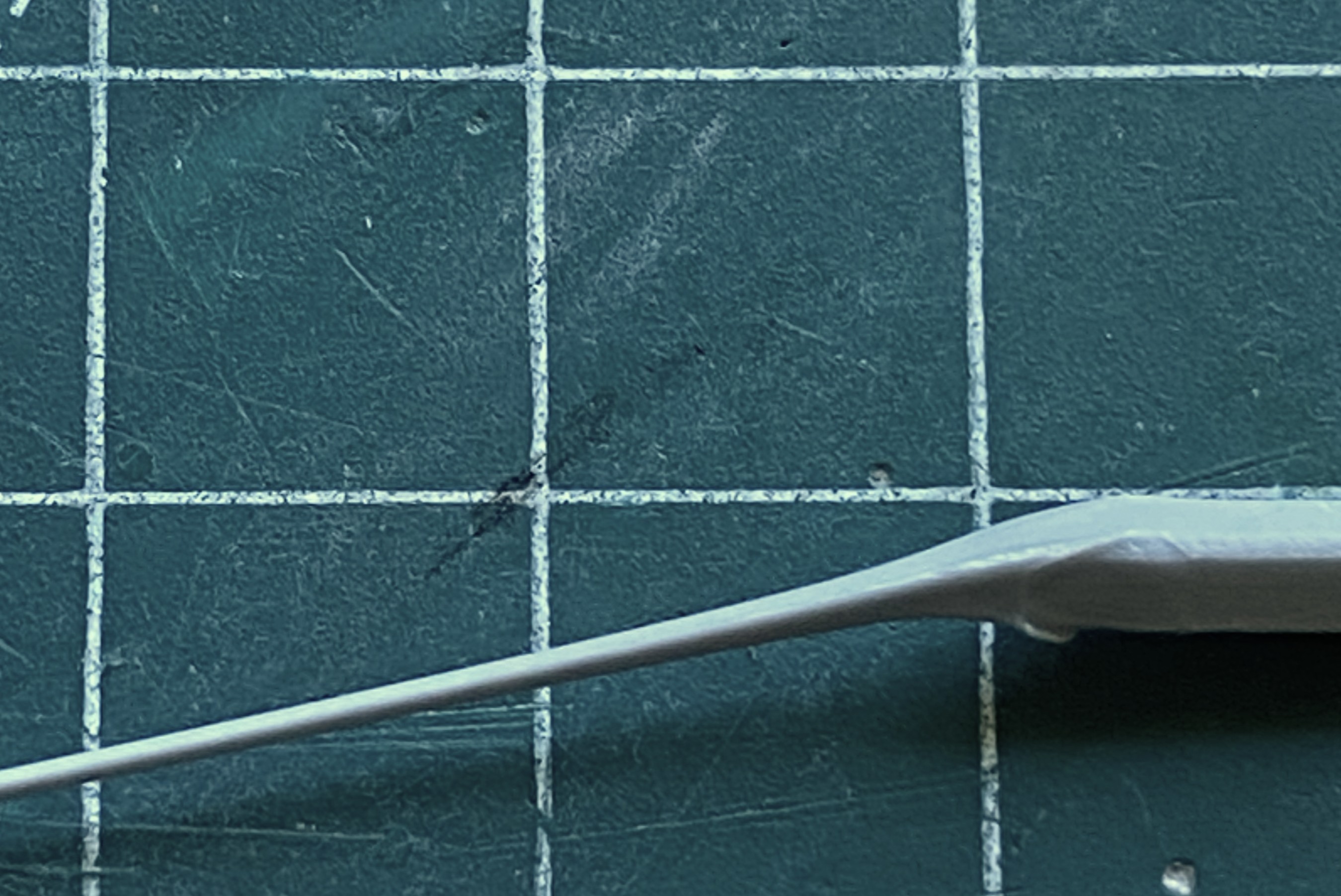
As an aside, if you need preshaped sprue to stretch, shaping the sprue before stretching it will keep the shaped you’ve established (this was shaped triangularly to better stuff the gaps I created):
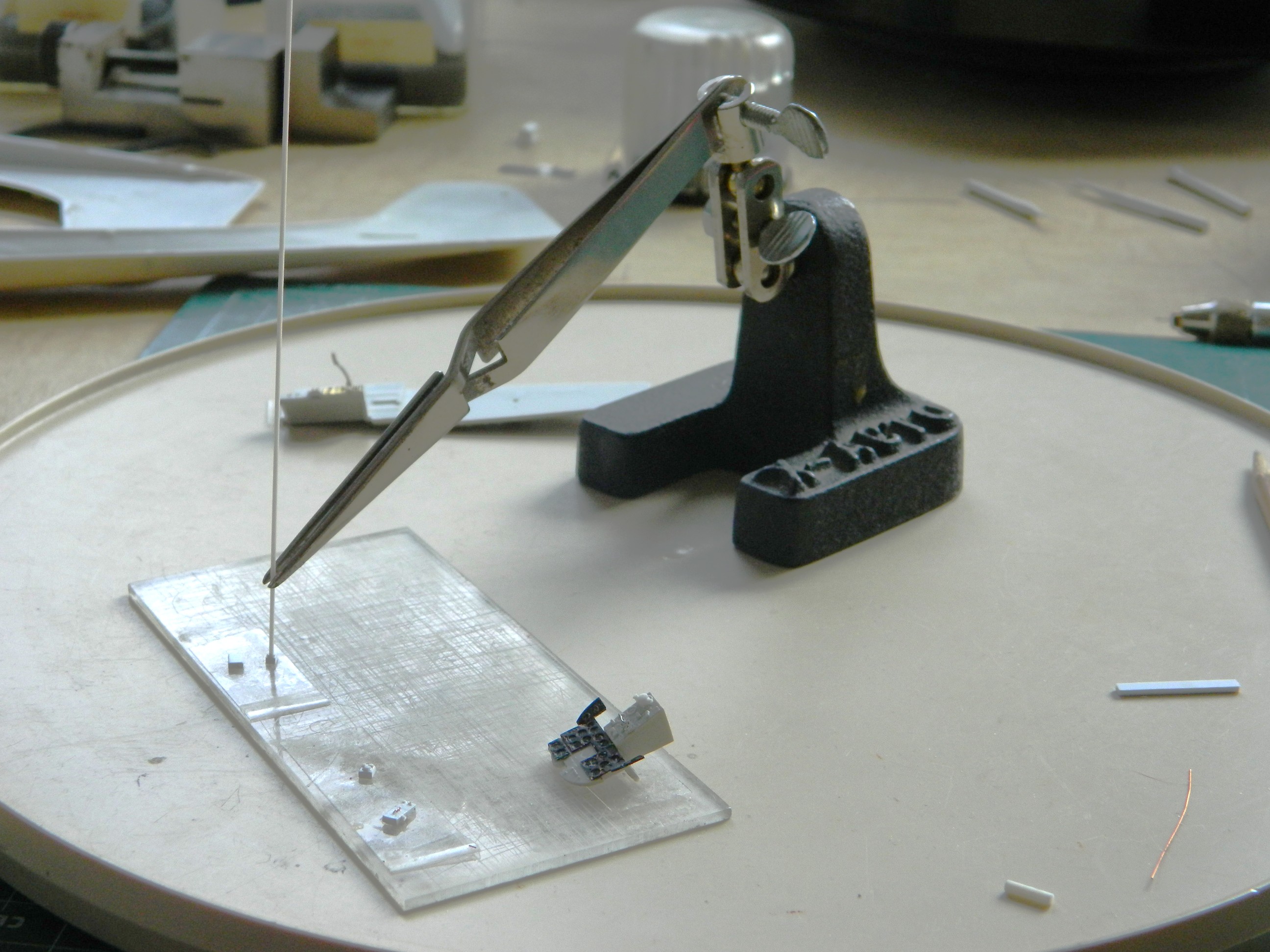
Jeweler’s files. The self-locking tweezers that are attached to stands. If you don’t have any, get two. They are so useful in getting pissy parts aligned, and keep them aligned, while glue sets. I use my pair on every build at some point and it’s time to use them again to keep the stretched sprue in place while the glue sets up:

I’ll generally wait 2-3 minutes after applying the glue before I press the sprue into what I’m filling with it:


Still more work to do straightening out the lines. I spent over a week working on that section and ended up needing a break from that particular task. Since the added sprue needs to sit overnight before it could be worked, I attended to THE most fragile parts off all the fragile parts.
The mass balancers on the elevators. They’re so small that I left them attached to the sprue runners while I cleaned them up. I knew that I was going to make them removable using 22awg wire as pins. I didn’t need magnification to see that the bases are too small. 22awg was the smallest wire I was willing to use (anything smaller would be too flexible), so instead of even trying to get the notch I’d have to cut for the wires centered on the bases, I excised a slot slightly less than halfway through the base to recess the wire into. No…not accurate. Yes…practical:
And to think that I won’t work on anything smaller than 1/48 scale because “it’s too small” is getting really funny.
With those ready to paint, it’s back in on my head. My eyecrometer seems to be in need of recalibration. Since eyeballing it wasn’t working, maybe tool use will. The tape is so that the next line is freaking straight:

Next up will be mounting the engines.
While doing initial (hopefully final) fitting of cowls and engines, I realized that the engines are intended to mount to the cowlings! (No mention of that made in the directions. I guess if Czech Models figured if the builder has managed to get this far, they’ve realized that for most of whatever this kit needs, the builder will have to figure it out for themselves.) Okay…I’ll glue them to the cowlings:

I’m glad I had the foresight to remember that however the cowling mounted, where the engines mount would be important. But, seeing as the engines are resin and mounting to plastic, superglue won’t allow me enough time to align them correctly. To get around that limitation, I superglued 0.010″(.254mm) clear styrene to the backs of the engines. This will allow me the to join styrene to styrene and fiddle them into alignment (I used clear plastic so that the added disks would be easier to center over the engines):
Now for the task I’ve been dreading this entire time. It’s time to attach the landing gear.
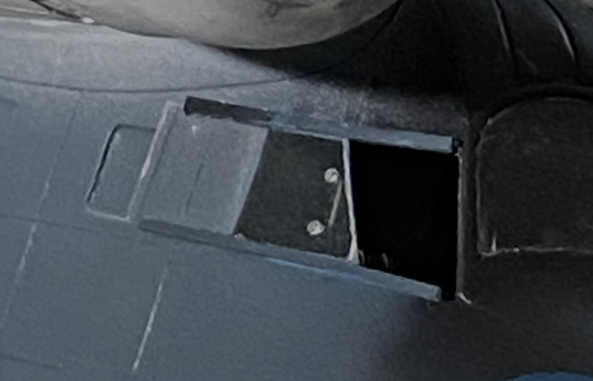
The kit offers three pieces for each landing gear; the main strut, the upper control arms, and the lower control arms. Three pieces, two hands, and minimal space to work in. I cut down on the parts count by aligning the lower control arms on each strut, then drilled through them and put a wire in there to act as a hinge. Had I not done that, I’ve NO idea how I’d have gotten these things on at all. Even with the parts reduction, the four-letter word I want to use to describe that process isn’t “easy”. Move this into position, attempt to move something else into position and the first piece moves out of position. I’ve seen this kit online where others have built it. They could get the landing gear on, so that means that I can get the fornicating landing gear on. I finally got the strut and lower control arm glued in:

After repeating this lovely task on one side, I did it again on the other side.
If I thought getting this strut/arm assembly in place was a delight (it wasn’t), then there’s the upper control arm to wiggle into position and trying to align it while making the aircraft sit level was a pleasure that defies description (or sense). I persevered (the process of which was akin to getting a colonoscopy without anesthesia):

Did I get the bird to sit level? Nope:
It’s not time to fix it yet. I’ll pay the toll on that bridge when I get to it.
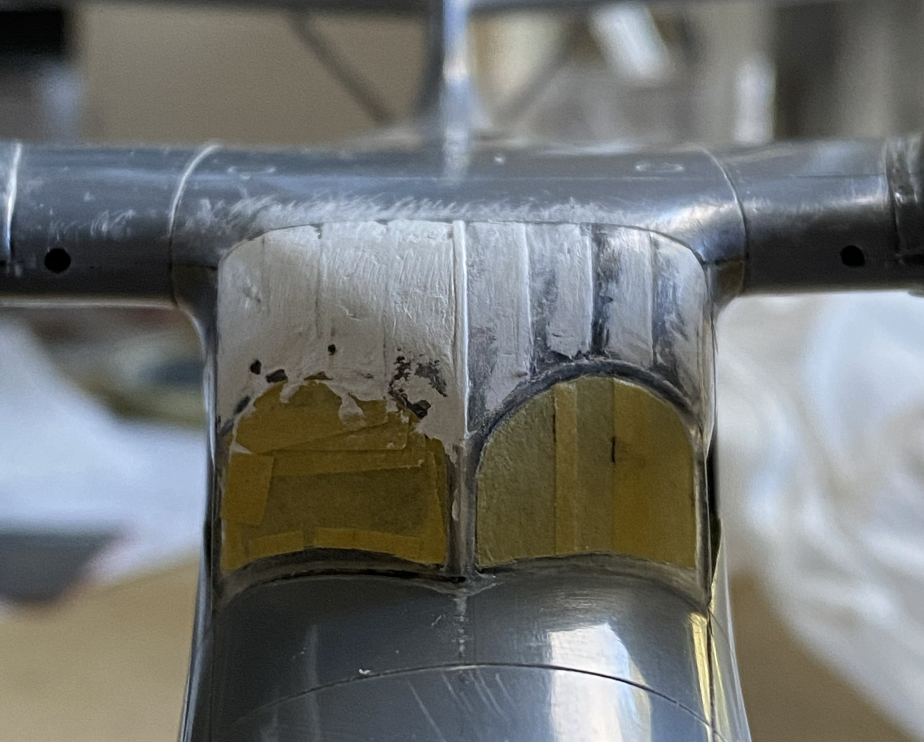
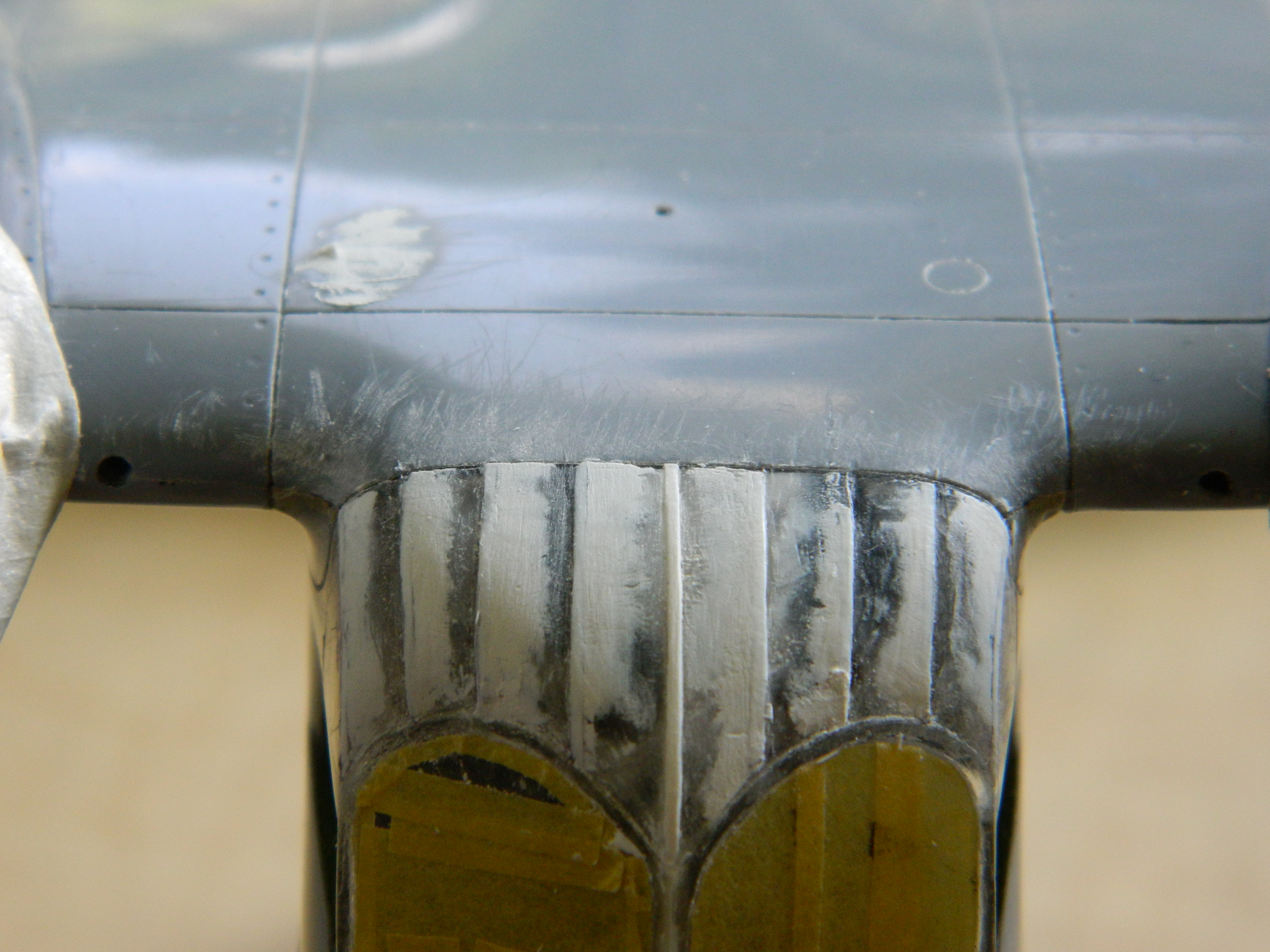
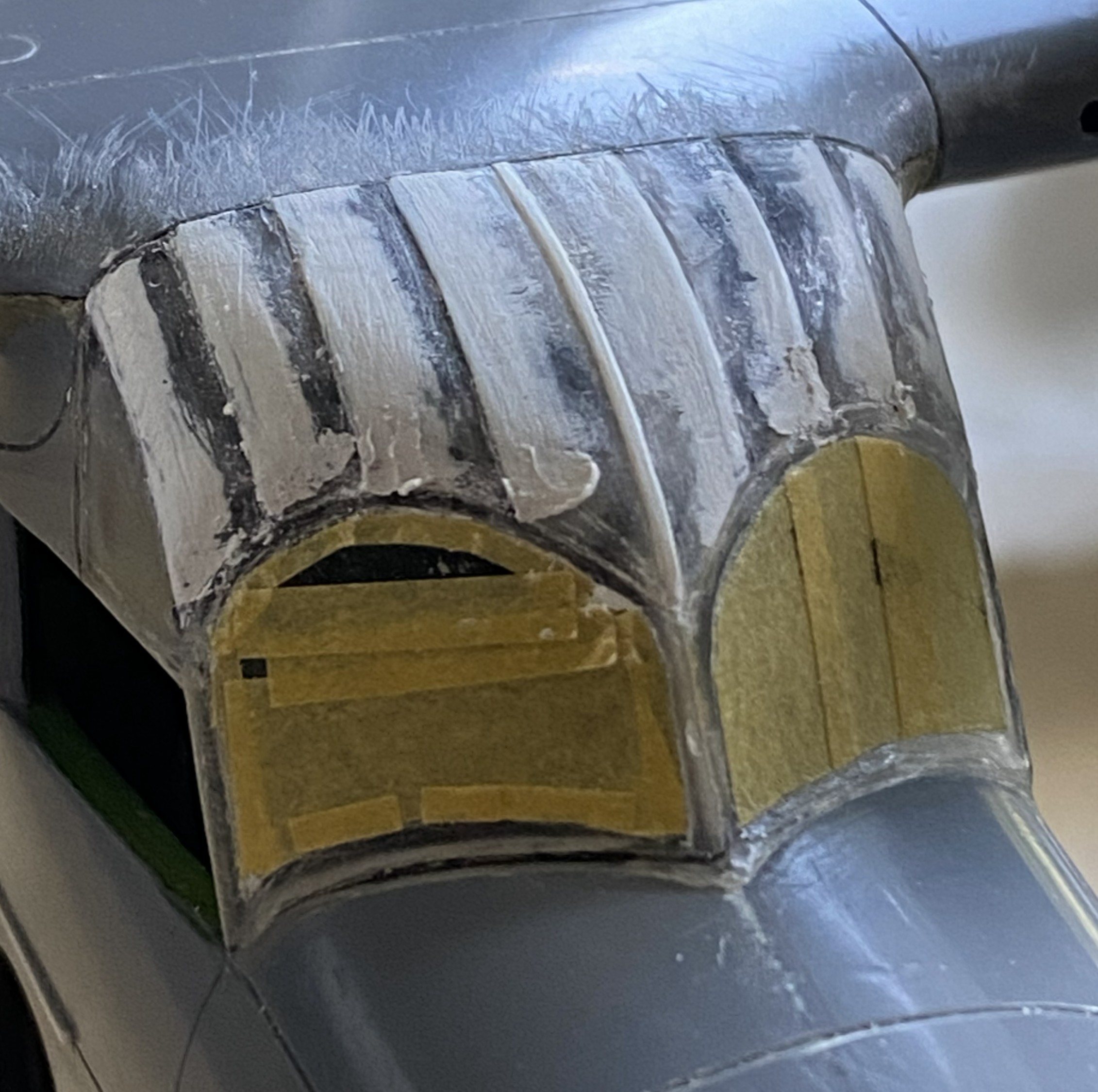
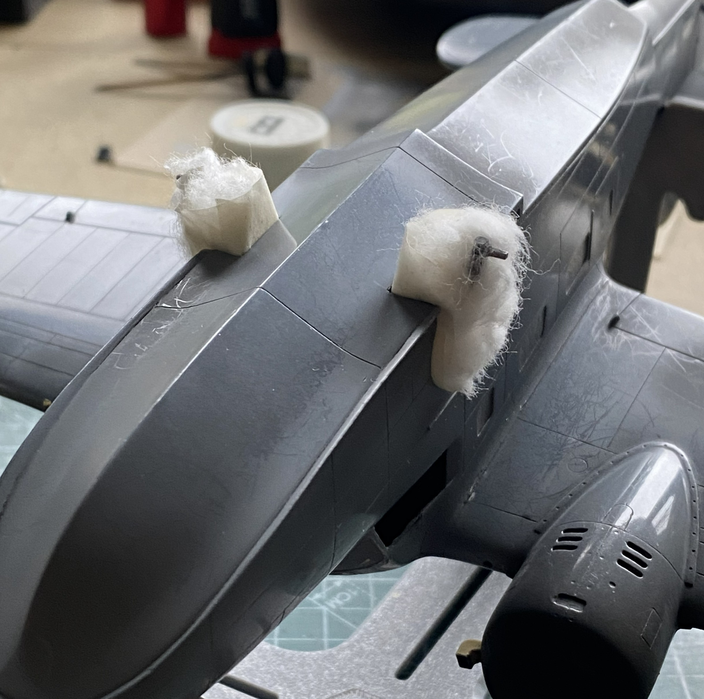
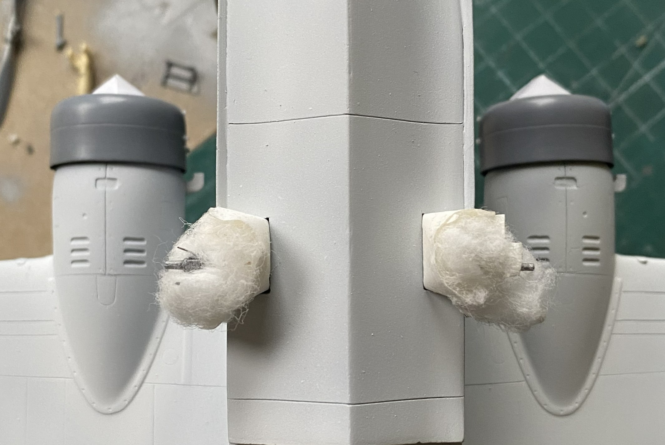
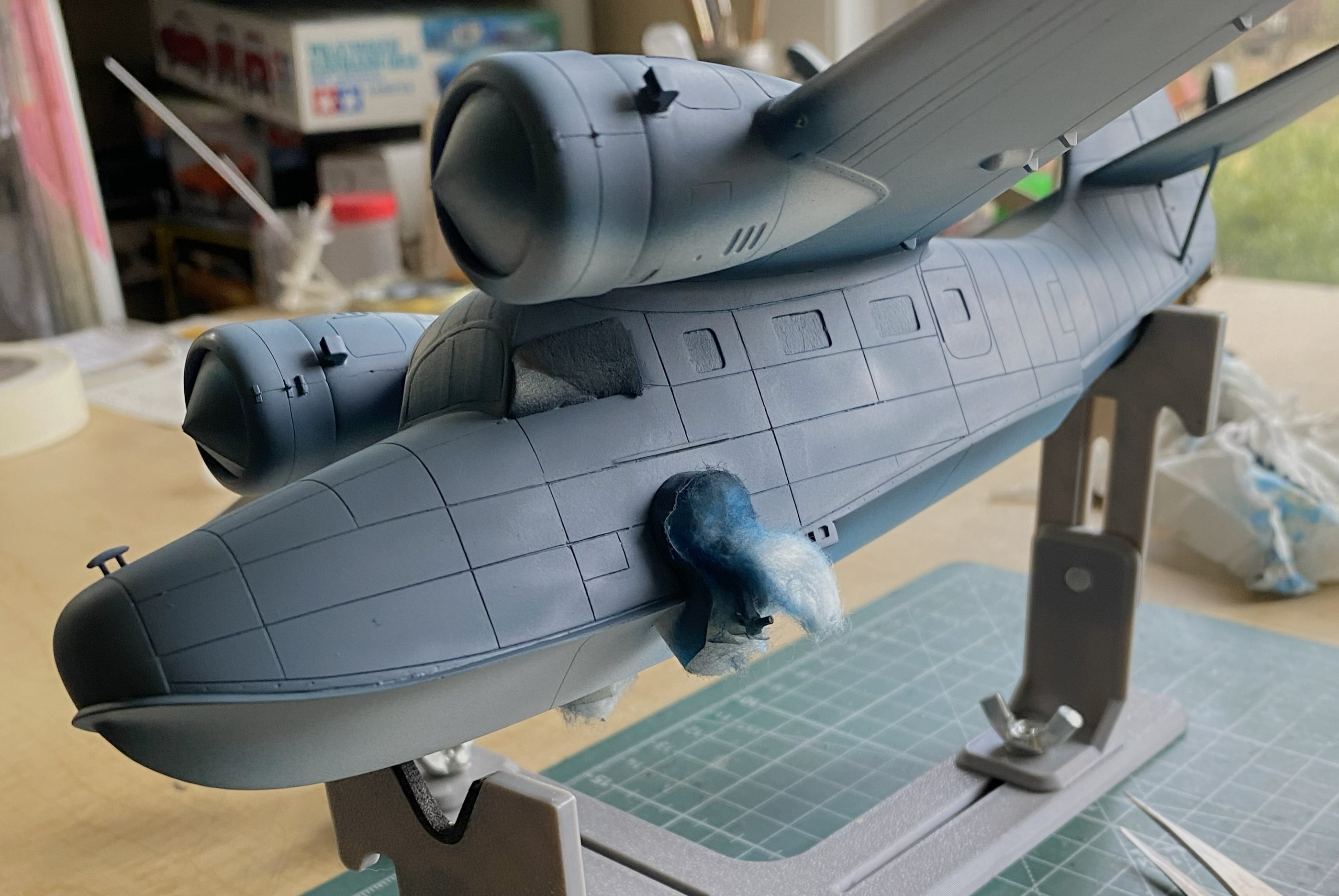
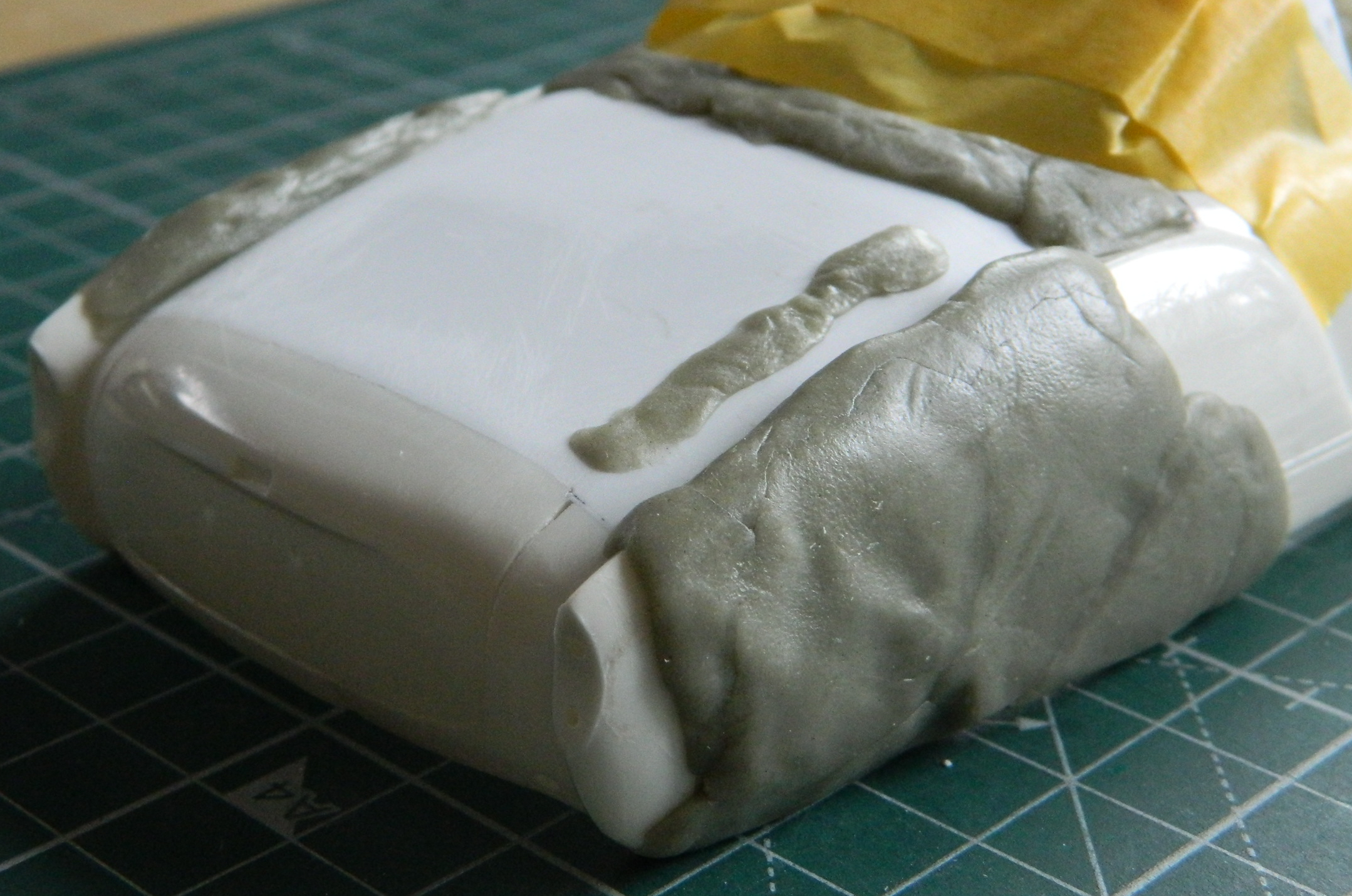
My next task was to start throwing paint at this. Of course I started with the light colors and worked darker, but where I started was figuring out how to mask this using cotton balls for the landing gear, front and rear. For the cockpits, I took foam wedges (nail care section of the drugstore/apothecary) and cut them oversized so that they would hold themselves in position (usually):
That worked:

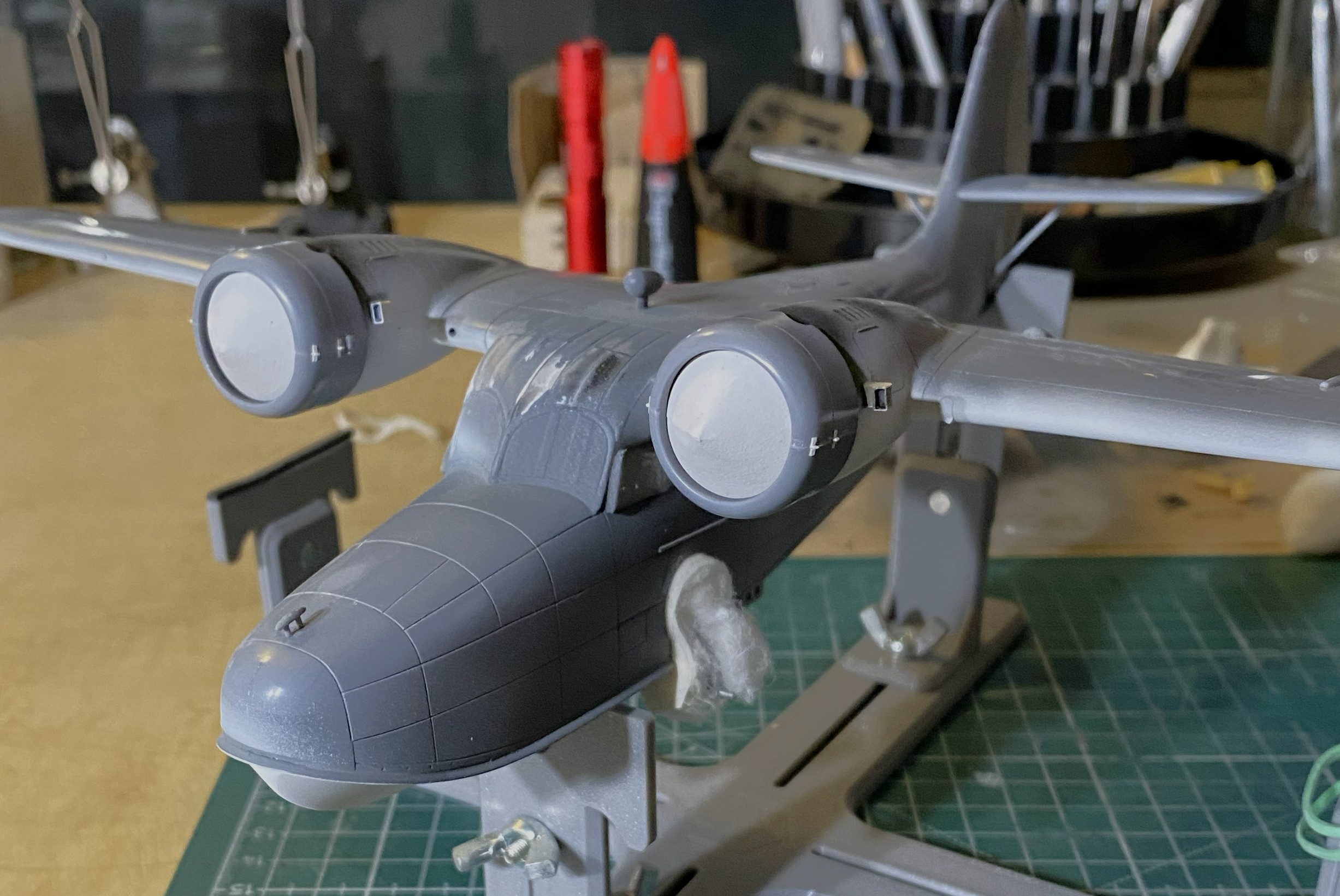
As this will have a three-color paint job, and the nacelles are definitely part of that paint job, I decided that adding the engines now would make all the color demarcations line up later. Before I added the engines, I traced the back of the cowl on paper, traced two circles (one for each engine), and after determining the center of the circles, cut from the center to the edge. This would give me paper cones that would fit in the cowling openings and mask the engines from the incipient painting (and if you look closely behind the engine that’s on the right in the photo, you can see the trimmed foam in the cockpit’s window behind it). With that done, I glued the engine/cowling assemblies in place (shortly after these photos were taken, I painted the undersides of the cowlings white as well):
Figuring that I was on a bagel (which is very similar to being on a roll, just a firmer seat), I got the paints ready. The XF-18 Medium Blue was the correct color, not the XF-8 Flat Blue you see below:

Yeah…wrong color. But…before I had to repaint the sides, I found that Thumbnut McFumbles, here, did not monitor the position of one of those thumbs and did this (hint…check the area that’s not blue…lightly sanded thumb mark on wet acrylic):

Though not precisely pleased, there was something else that fell short of pleasing. When I cut the access open to fix the pilot’s seat, I had to replace the part cut out once I’d fixed the seat. At this point of the build, I was reminded that if I’m not careful (giggle), when the cement finally out-gasses, there can be a visible shrinkage caused by A LOT of glue being used. I used A LOT of glue because there was A LOT of plastic used to fill the edges. This resulted in a clearly evident depression around the patch’s edge once the disco-blue was on. Since I was going to have to repaint the sides (once the correct color arrived), okay…so I’ll fill it in again, only this time I’ll use the UV-setting resin:


Just on a whim, I decided that the heat exchangers could use painting:
Pity…that paint job didn’t last very long as you’ll see later. Too bad. I liked it.
Seeing as I clearly can’t keep track of where my fingers go, I needed a method that would enable me to handle the model as it was being painted. Since I was starting with the bottom, next I would do the sides, and then finally the color on top of the aircraft. And since I want to finish this in a semi-gloss finish, I would also need a painting order for that as well. I let that rattle around inside my wig for now and set about getting that wrong blue covered.
When the paint arrived, XF-18 Medium Blue, I started the repainting with the floats. I’m sure you can figure out which was the before and which is the after:
Much better:
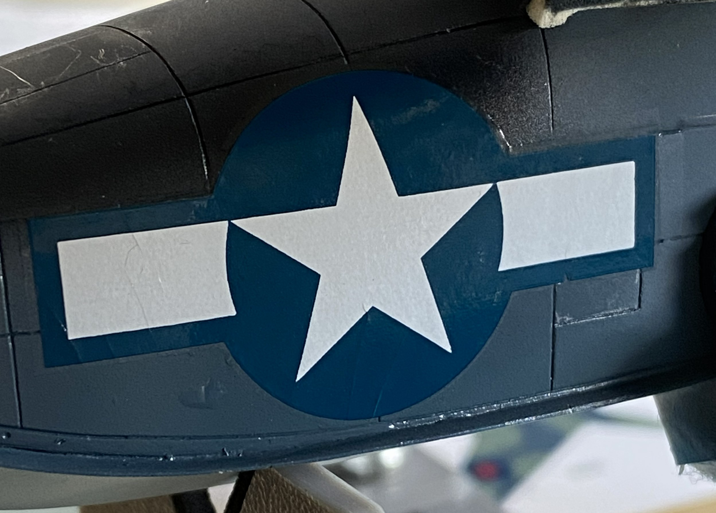
Next up, XF-17 Sea Blue for the upper surfaces:


The overspray of the wings and tail-planes white are how they were painted in WWII.
It was at this point I could take off my polarized sunglasses and resume work.
I like using pencils for some things. At the top of that list is Prismacolor’s PC949 Argent. It’s silver and in small-area applications, it looks enough like aluminum for me. As I’ve discovered, if the surface is slightly rough, the pencil not only goes down easier, amazing things can be done with subtle wear patterns. With the build now under paint, I sharpened my PC949 and went at it. Gently. The Navy doesn’t let its kit get shabby:


With the paint on, the next thing that goes on are decals, so I hit the spots where the minimal decals go with Tamiya’s X-22 Clear Gloss:
Yes, that looks like a lot of paint. However, this paint does self-level:

I had painted the white undersides (Tamiya XF-2 Flat White) a few days before the color and had shot it with clear gloss (Tamiya X-22 Clear Gloss) to prepare it for a wash which meant it was ready for the wash. I figured since the wash was going down over white, I could get away with a more nuanced wash. Pratt and Whitneys leaked oil. The skin panels were not oil tight. Oil leaked on the ground and once the bird was in the air, the oil that had leaked onto the skin streaked back in the airflow. That’s what I was after. I didn’t think an enamel wash would give me the subtlety I thought would work so I broke out the oils:
The last time I did a wash using oil paints (on the engines), I’d used Turpenoid as the base (roommate hates the smell of enamels and turpentine). It took a week to dry. For this wash, I tried using Gamsol as the thinner instead. It was dry the next day.
Yep…looks like engine oil:

Yep…it looks a lot like oil:
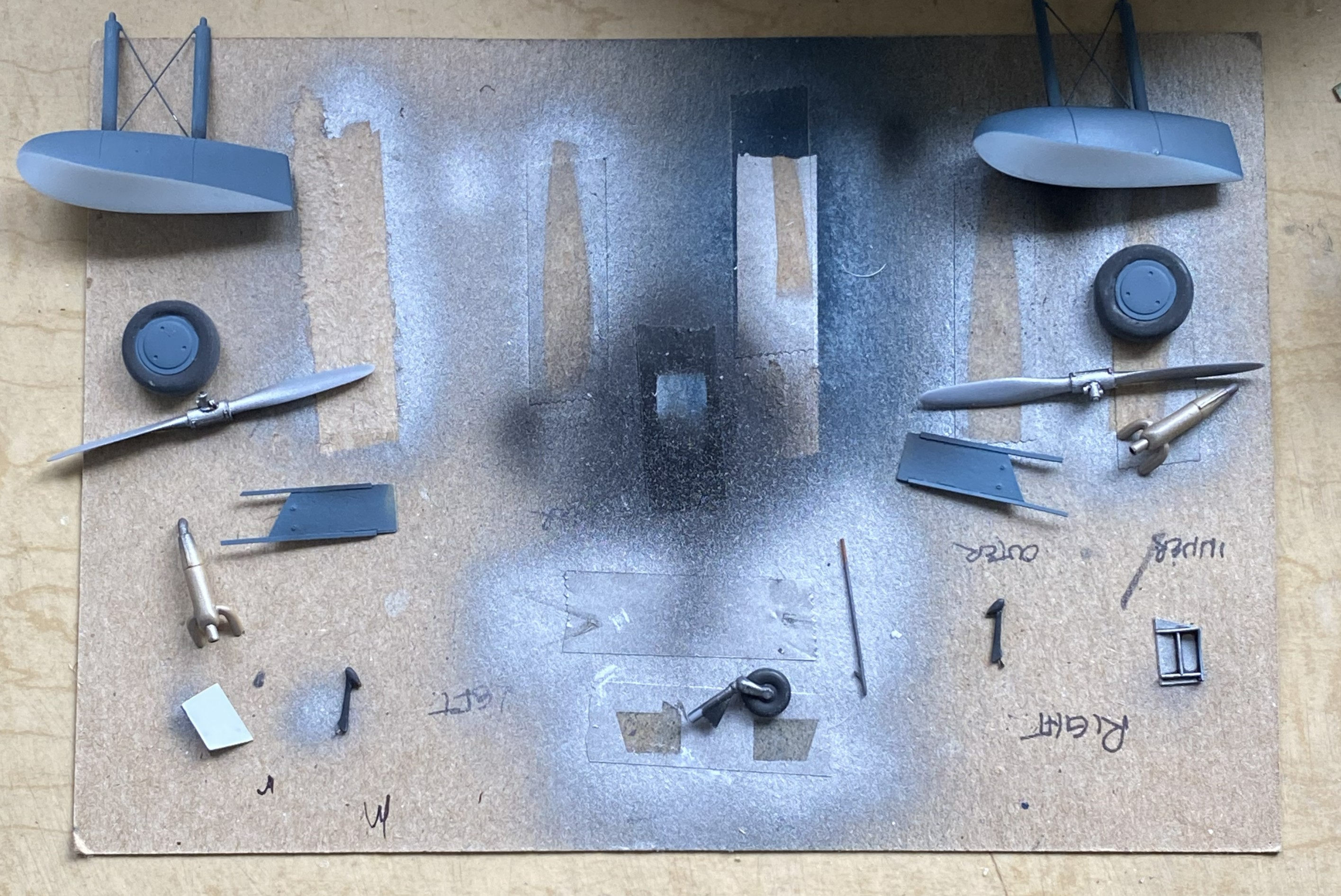
At this point, these are all the parts I have yet to add:
A couple of days later with full knowledge that the clear gloss had set sufficiently for decals, well then…let’s do the decals. And then there were these:


Well, well. Old decals. I decided to see if I could get them off the backing with few enough shards for me to piece them back together on the surfaces (because I’m that kind of nuts). Results were…well…predictable.
This one went on in “only” two-ish pieces and was acceptable:
The one for the upper wing, however, was a cockup:
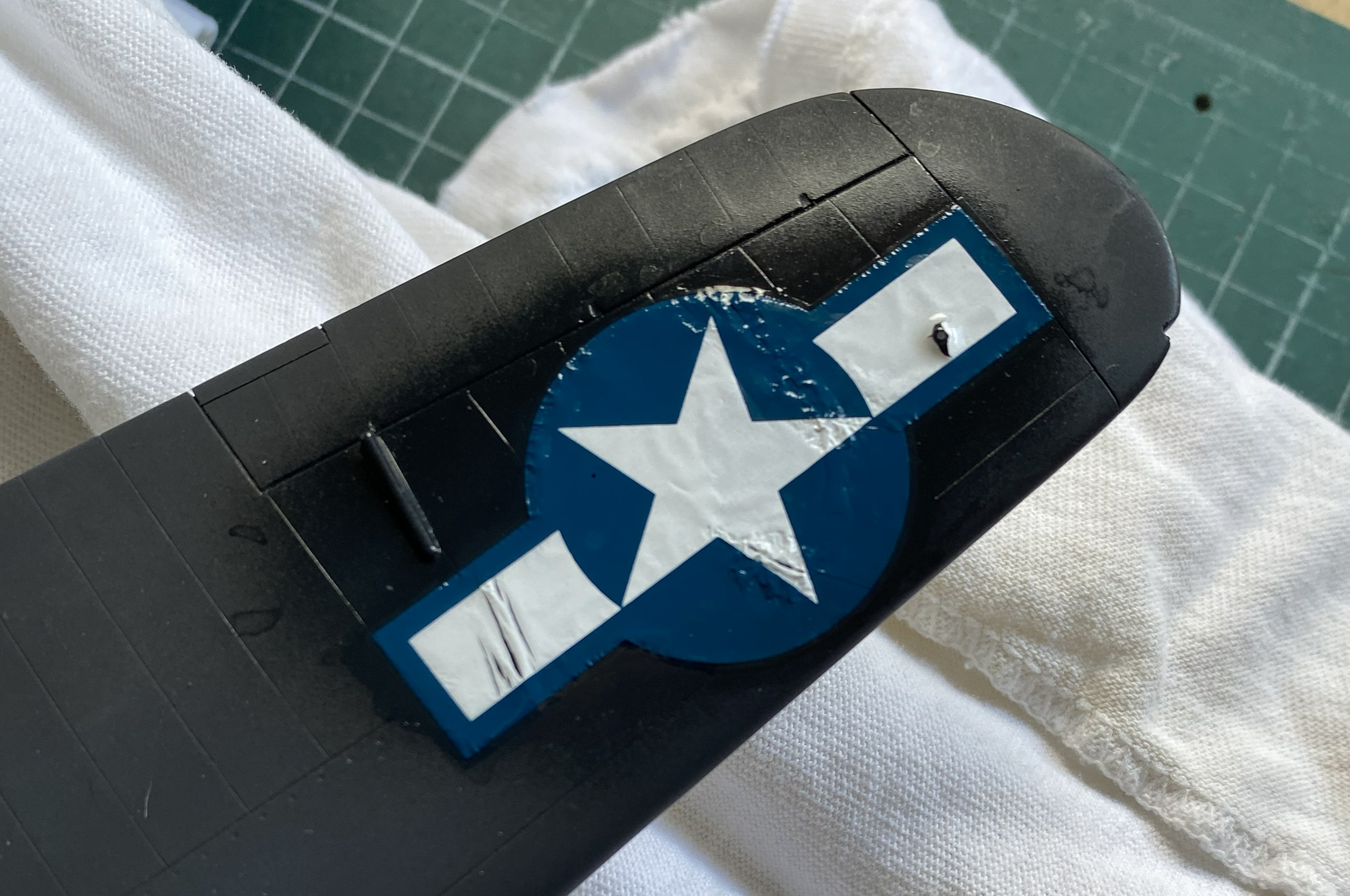
I broke out Walther’s Solvaset in the hope (another four-letter word) all the shards would play nice with each other. They didn’t. I used more Solvaset to see if perhaps multiple applications would smooth things out. In some spots it worked. However, there was a cost. NO amount of further Solvaset got rid of the wrinkles:
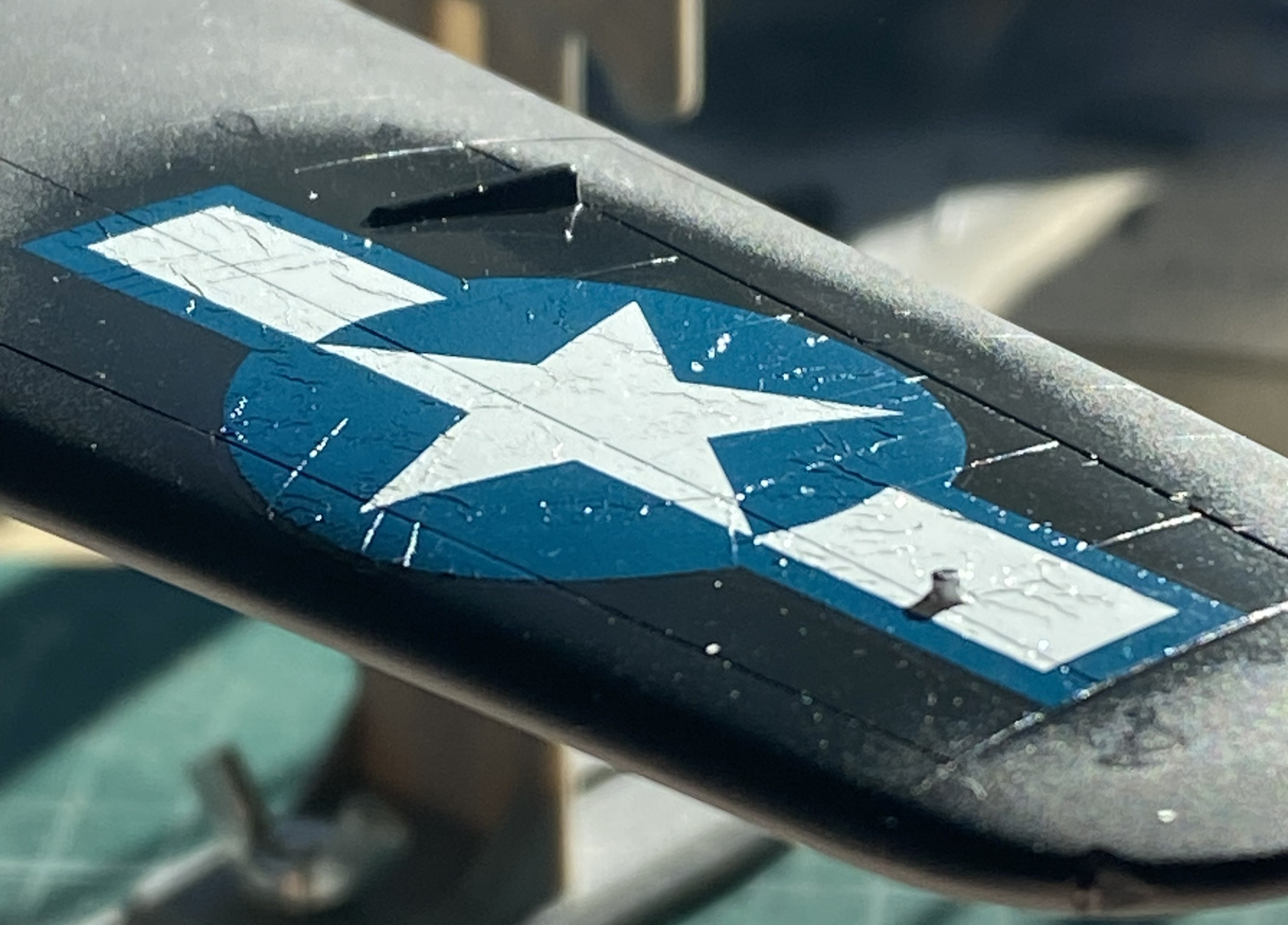

The second photo above was the best Solvaset could manage. Not acceptable. I only know of one way to remove blown decals. Sand them off, reapply paint, and start over:
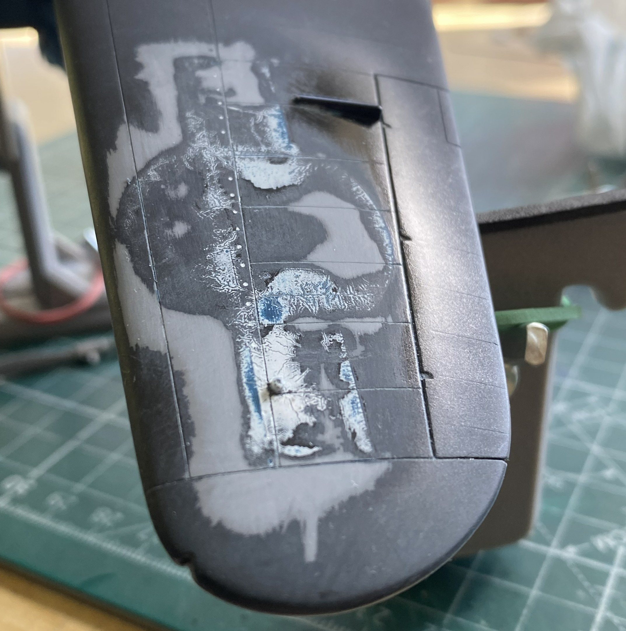


Yes, even through the new paint, the faint outline of the decal’s remnants shows up. Since the new decal would sit right there, I didn’t bother sanding it out.
Solvaset worked well (though not perfect, it’s close enough) on the left nose decal:
At this point I discovered that I’d salvaged the only two decals from that sheet that could be salvaged; all the rest were garbage. Oh great. This is a limited run kit so the odds of me finding suitable decals weren’t good. Okay, so it’s star ‘n’ bars…I probably have dozens of them on hand. When I went through the decal stash, I discovered that yes…I had lots of star ‘n’ bars. I just don’t have any even approximately properly sized. The big surprise was finding another sheet of the exact same decals for the exact same model. How I managed that, I’ve no idea. But with stars in my eyes, sweat on my forehead, my shaky hands cut out a decal from that sheet to test and it was FINE.
Whew…
Here’s the nose decal from the second sheet, and this time I wondered if Solvaset was too hot for these decals. So, who doesn’t have Micro Sol? I used that instead and though the old decals WERE OLD and shattered, perhaps part of my problem with the upper wing decal was the Solvaset. Micro Sol did the job (in-process in the lower photo):

While I’m fiddle-farting around with sodding decals, I neglected to notice that I’d knocked both heat exchangers off the bench and then stepped on one. I never heard the crunch. I did notice that neither exchanger was on the bench. Found one intact. Whew. Found one sitting in a small pile of resin dust (avec chunks):
::facepalm::
Okay, so I get to reattach the tail and make new arms. I didn’t have the exact diameter styrene rod, but I had styrene rod that was maybe 0.005″ (.127mm) less in diameter and that was close enough. Plastic has a memory so if I wanted a 90-degree bend, I’d have to over-bend them and let them sit overnight to attain their new memory:
At this point, a regular occurrence occurred. I dropped something and realized that the floor between my feet was CRUDDY. Okay, pick up the dropped tool and sweep the floor. Once the detritus was in the dust pan, there was one of the two arms sitting right there. Okay…let’s attach that NOW so I did using UV-setting resin:
That’s good news! I only have to make one arm using the UV-setting resin again:
It’s at this point that I got to see what happens when I get interrupted in the middle of something. I’ll forget the second half of something. I had one propeller all painted and ready. The other? Well, I got the hub painted and washed… Yeah. Let’s fix that before somebody notices:


I’m going to be facepalming so much that my forehead will be calloused and the tendons in my hand will be inflamed.
With the paint curing on the prop, I checked the repaired exchanger for fit. Just right:

With that all fixed, I got back to applying decals:

With all that applied, it sits overnight.
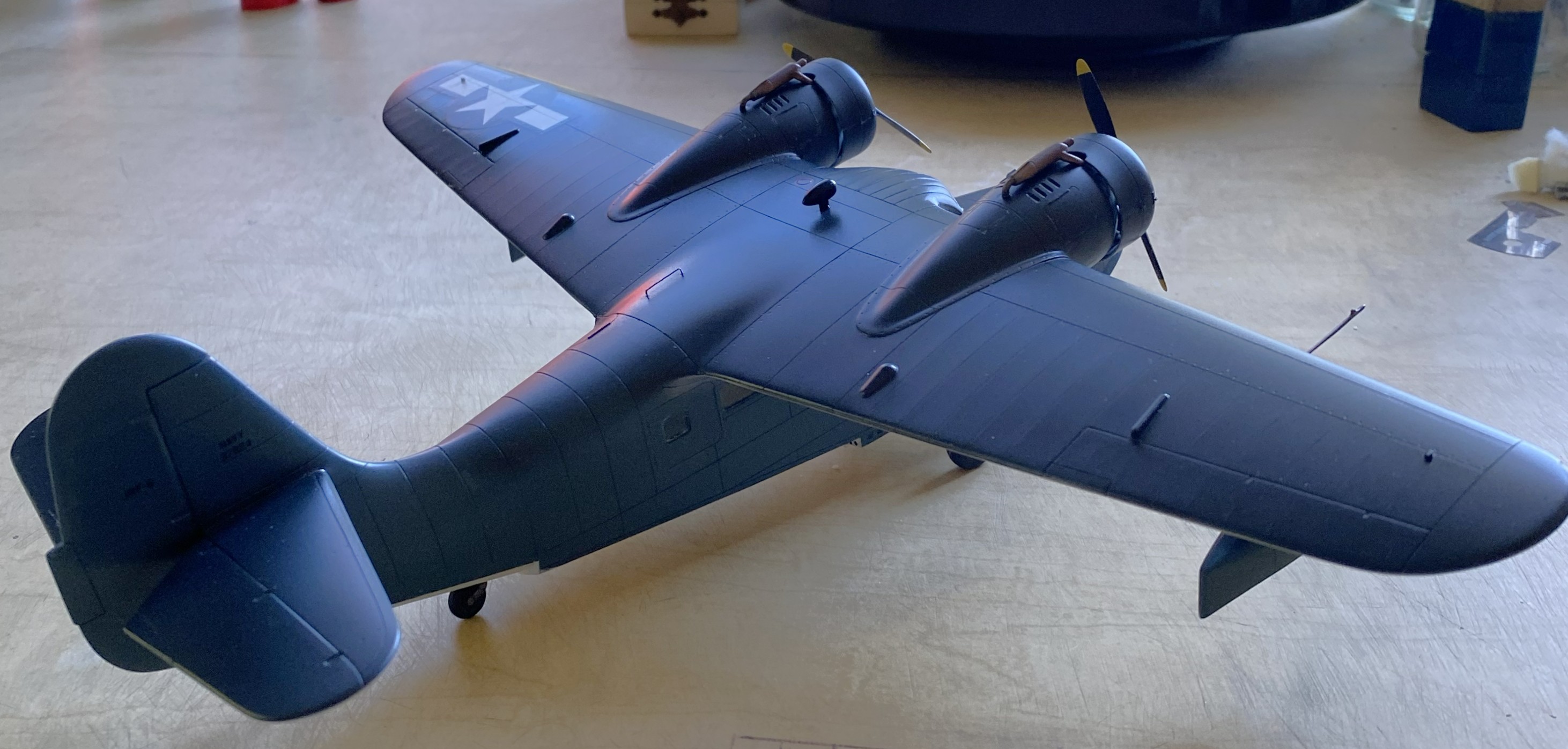
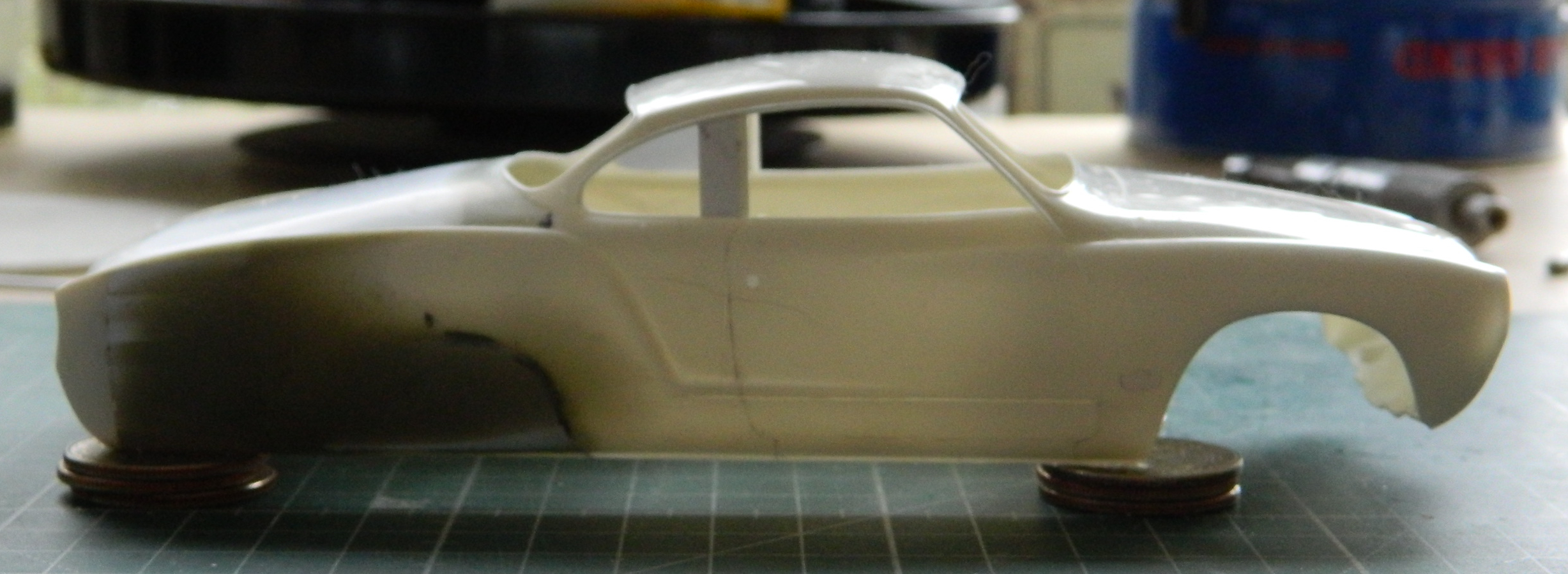
Increasingly, flat finishes on WWII aircraft are looking wrong to my eye. This time, I decided I’d do a semi-gloss (Tamiya X-35 Semi Gloss Clear) instead. This is where painting order becomes important. I have three basic areas to paint (not counting all the smaller details that haven’t been added yet, such as the floats in the photo below), top, bottom, and sides. I held the build by the sides and shot the top with semi-gloss. Once that set overnight, I did the bottom the same way. Doing it in this order meant that I’d have the wings to hold and manipulate the model during painting. The last thing to paint was the sides because now I can hold it by the wings:
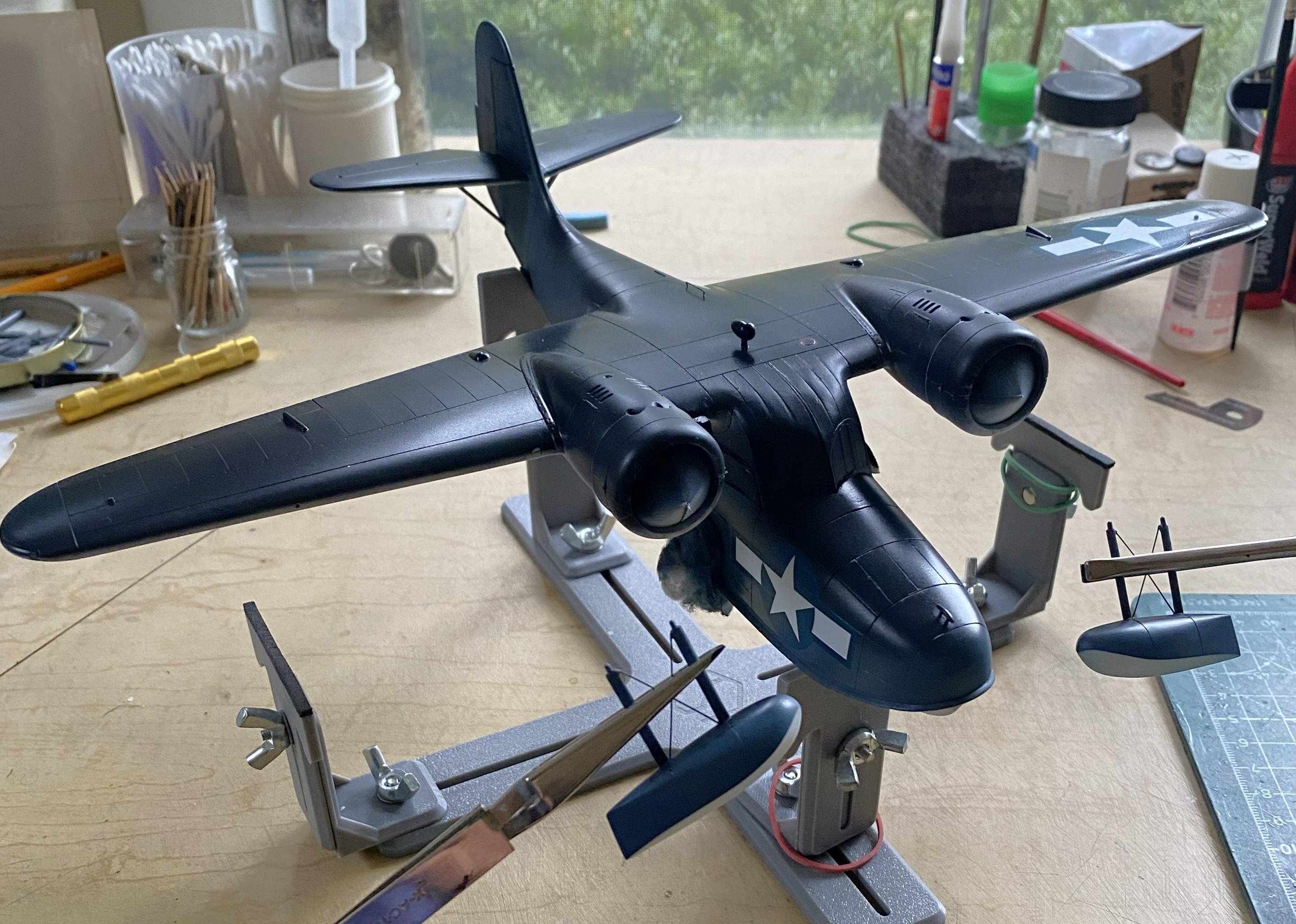
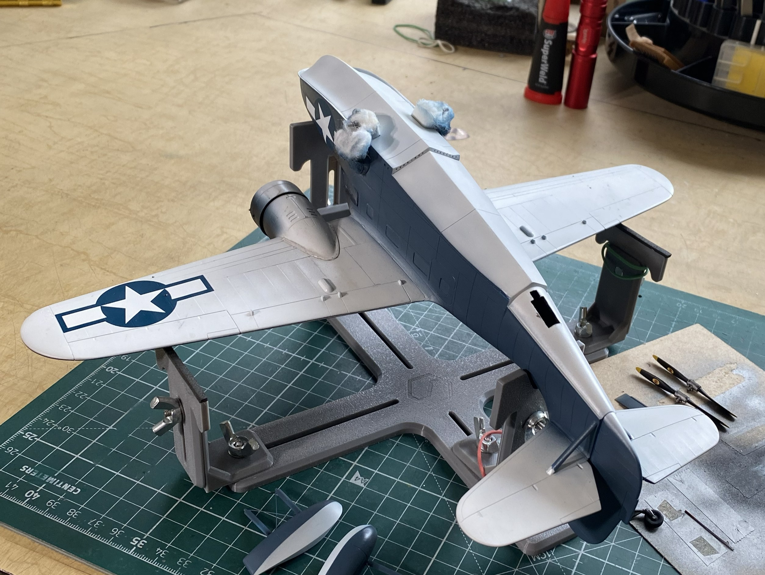


The next drill is going to be figuring out how to get this to sit level. It’s about 1/32″ (a little more than 1.5mm) off from side to side. This will be fun to fix. But to get that measurement, I had to have this build standing on its feet. While I had the wheels on, I decided to stick the props on as well to get a notion as to how it will display:

Not badly, methinks. Hopefully next month sees me to the end of this.
F7F-3 (AMT/Italeri) 1/48 Scale Build #6 – Starting work the Cockpit…Where Things Get VERY Tedious
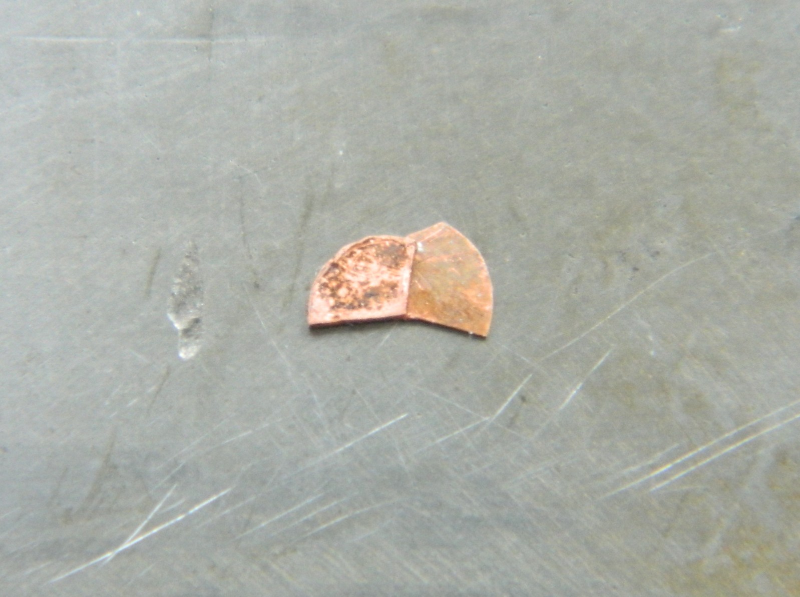
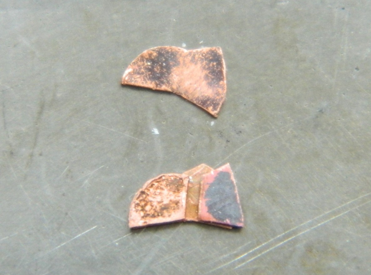
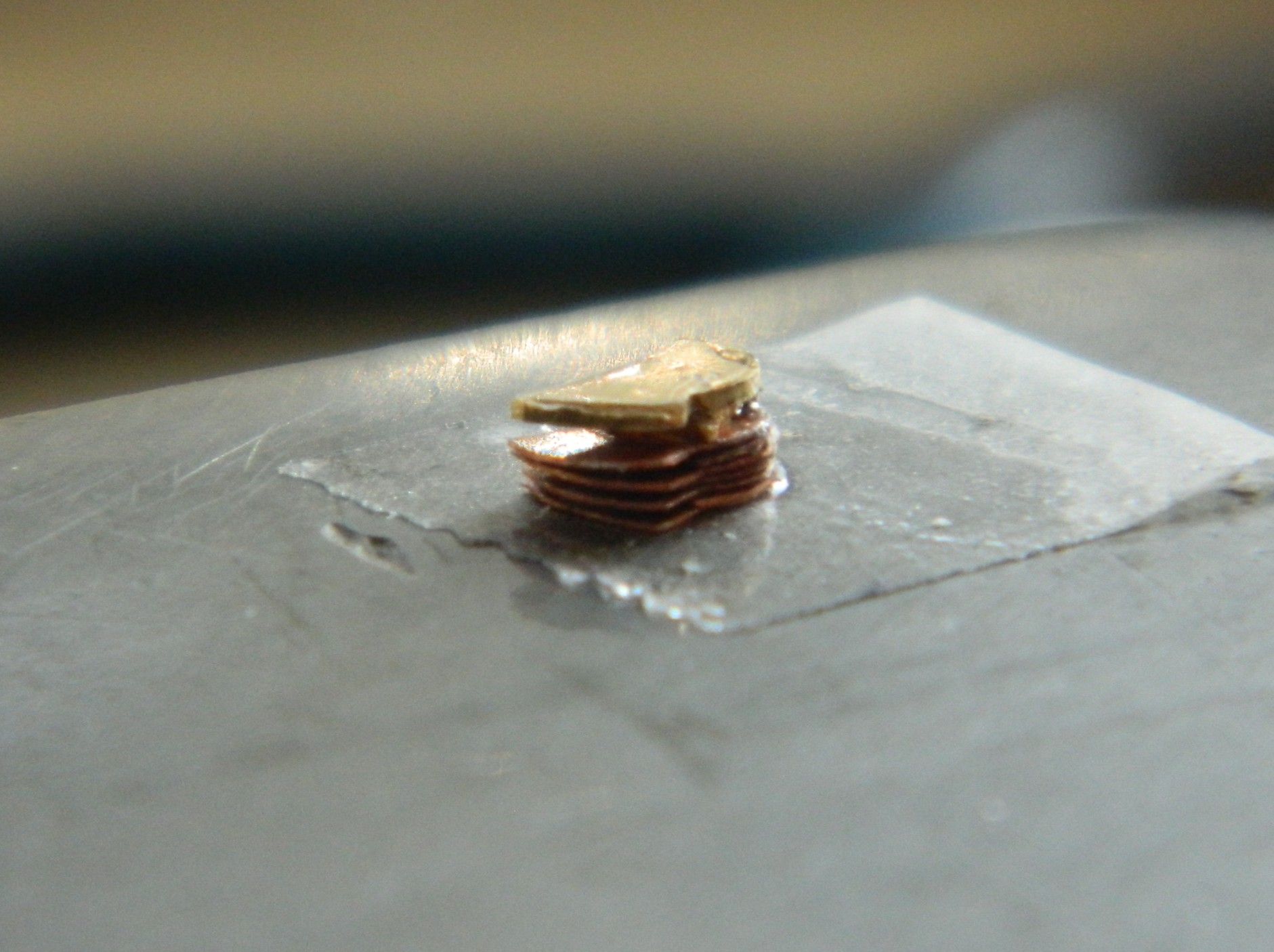
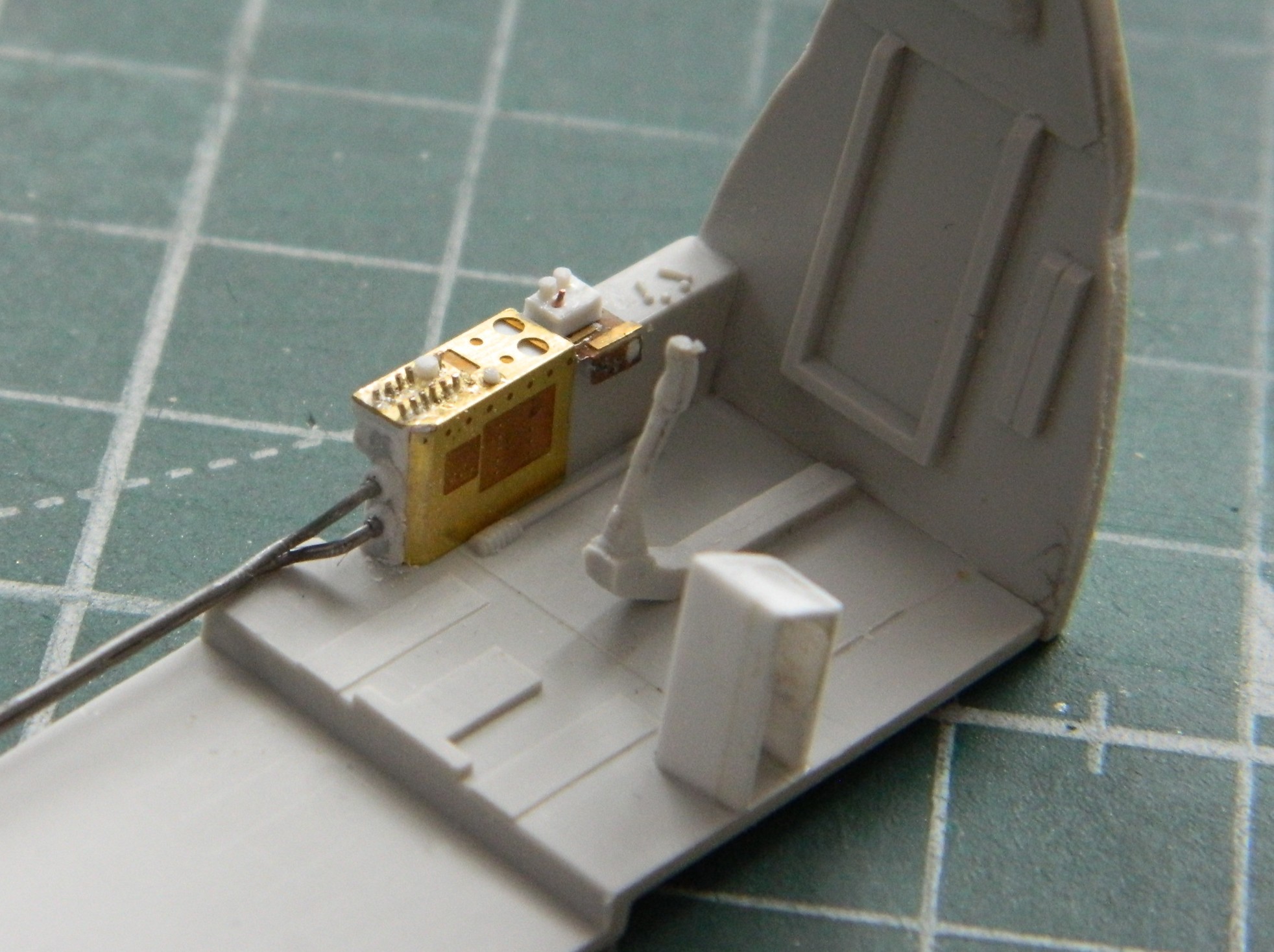
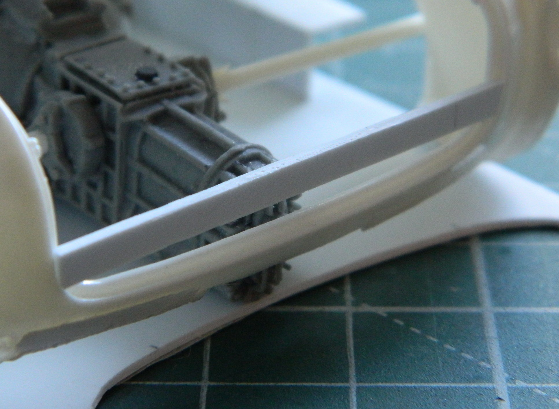
Having a direction for the how I can build the throttle quadrant, it’s important to remember that having a direction isn’t exactly the same thing as going there. This was certainly a reminder! Ascertaining that using styrene certainly wouldn’t work, I broke out my stock of copper shim stock. This part of the job used 0.005″ (.127mm), 0.010″ (.254mm), and 0.020″ (.508mm). I used a piece of the failed parts as a template and then used a sharp needle to outline the template onto shim stock and then used scissors to cut out the parts and then started stacking them. The partial pieces are spacers so that I can end up with the slots for the control levers. I discovered very early that soldering wasn’t the way forward. Superglue is. Lots of stacking and aligning followed:
To keep the larger parts parallel (or as parallel as I can get them), I added a spacer of 0.005″ (.127mm):
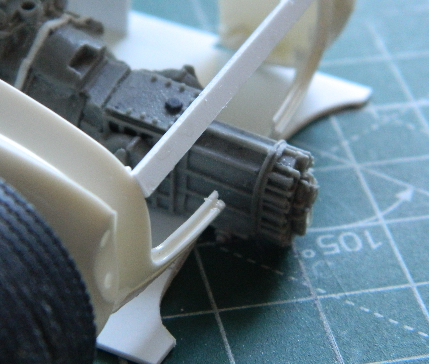
Then I kept stacking parts. Most of them were 0.005″ (127mm) but there was one 0.020″ (.508mm) spacer, which is on the top of the stack below:
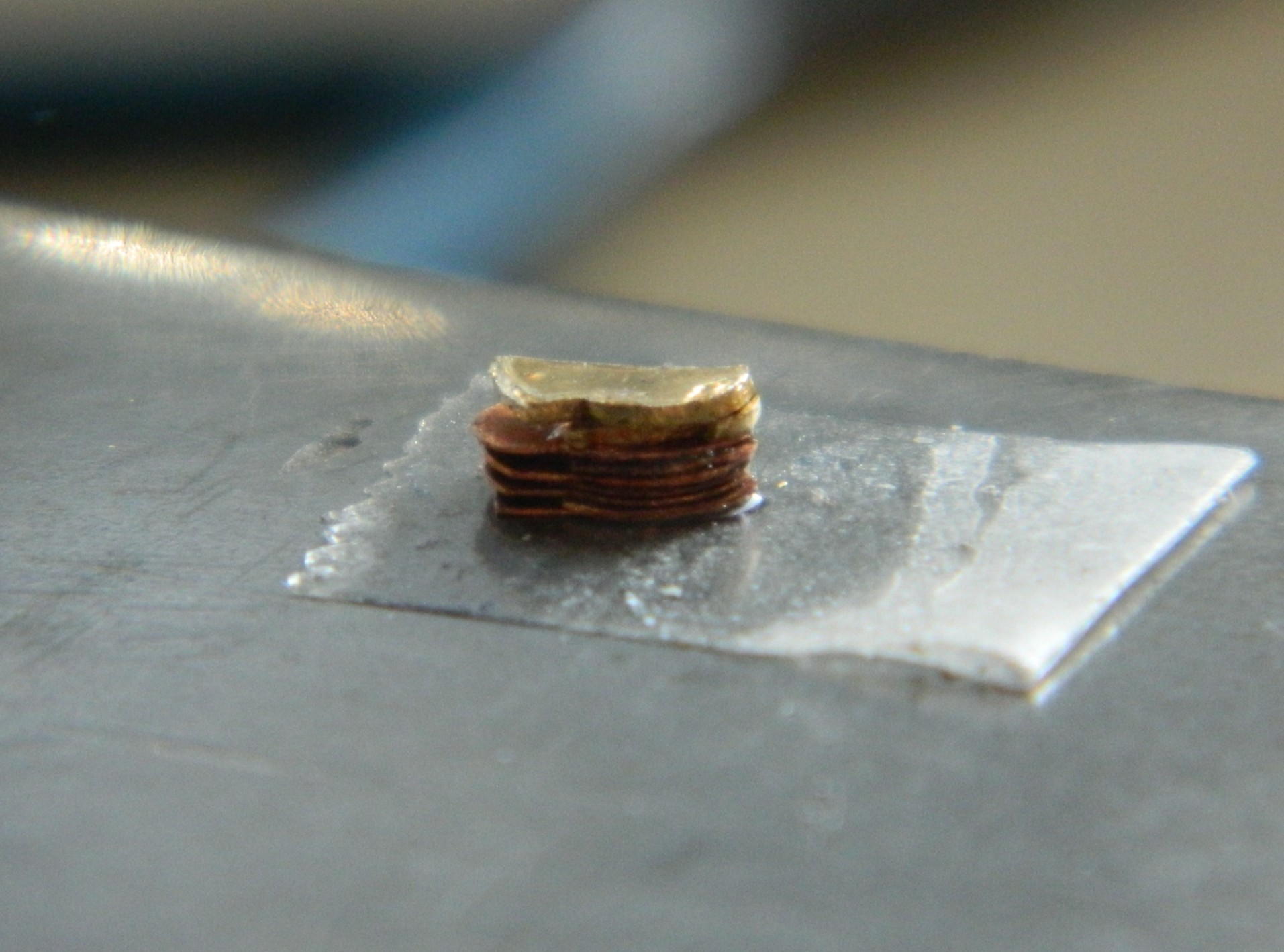
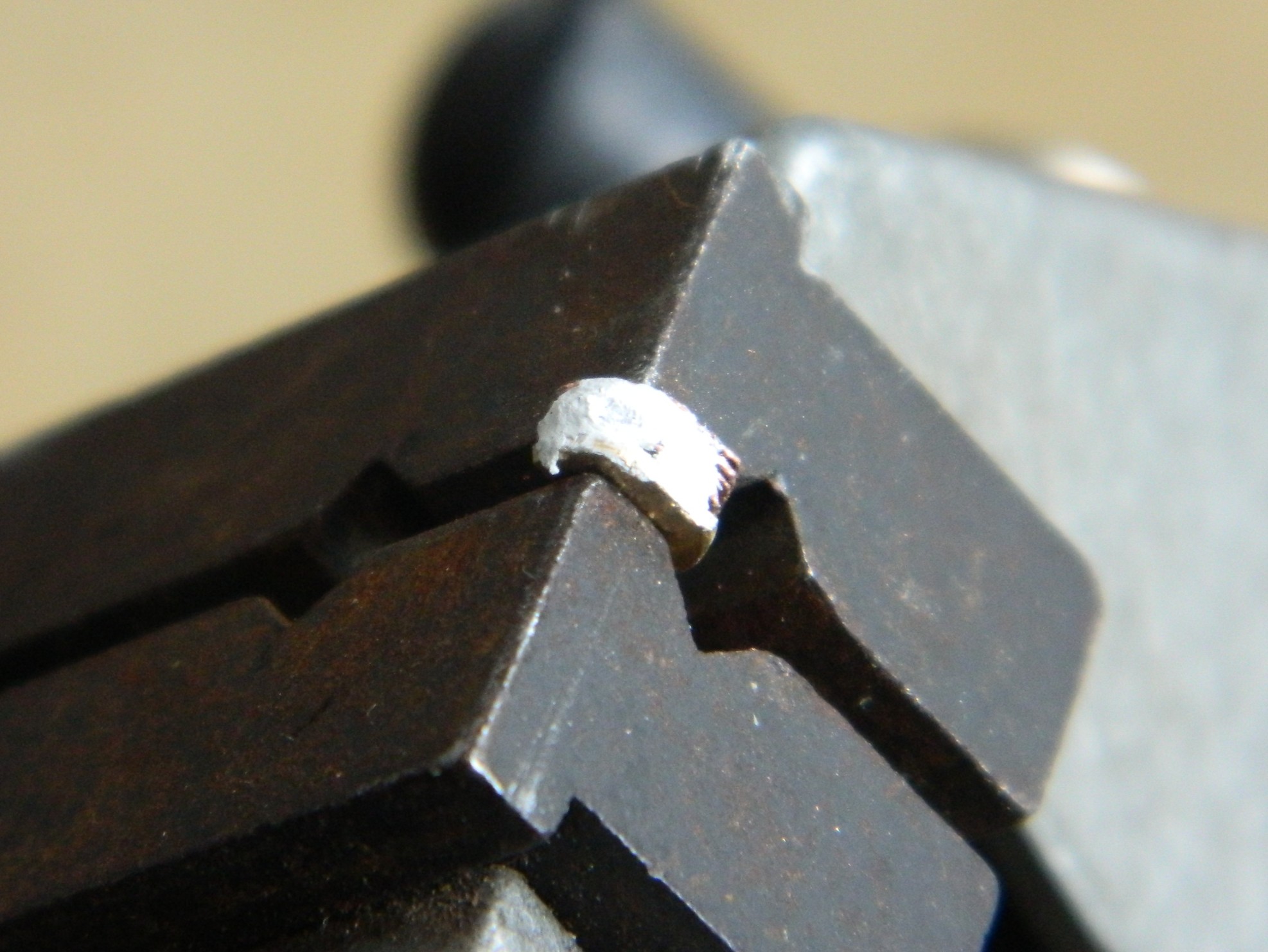
With the parts glued to each other, the next task was to file the stack to more accurate shape and dimension. Let’s hear it for having a vise:

There were still very small gaps between the layers so I laid down some 3M Acrylic Putty and then removed the excess putty:
A few pictures, a paragraph or two, to cover TWO WEEKS of diddling with this thing, TWO WEEKS that also includes rebuilding the fornicating thing a few times. ::facepalm:: Probably not a bad idea to check to see how it’s sized…which means redoing it again if I got it wrong:
Whew. Unless I mishandle this assembly (always a potential, particularly earlier in any day), it’s ready for levers and paint.
A pivot for the levers and a couple of tensioning knobs were added, then I glued the assembly to a bamboo skewer and painted it with Tamiya X-18 Semi-gloss Black:

Whew…
One of my aphorisms (one of many) is that all solutions create new problems. Having boosted the level-of-detail as far as I have, I needed to boost everything else adjacent to the quadrant to the same level. And then I focused on all the linkages and cam levers that connected the controls to the control surfaces. OMFG. The reason I don’t work in 1/72 scale is because of how stupid-small the parts are in that scale. Here I am working in 1/48 scale and I have to make SIX of everything; primary control rods, the first set of cam levers, secondary control rods, another set of cam levers, and another set of tertiary control rods. All that in a space about 1/12″ (about 5mm) square by about 10/32″ (just under 8mm) tall. Uhm…no. Uhm…FUCKING NO.
Have you ever heard the term, “imagineering”? That’s where something has to go there, but if there’s no reference photos or hard information for what goes there, the builder has to make something that looks right, even though it’s not. When is imagineering needed? Read the paragraph preceding this one. That’s when. Or, as it’s also known whilst in the middle of this situation, NOW.
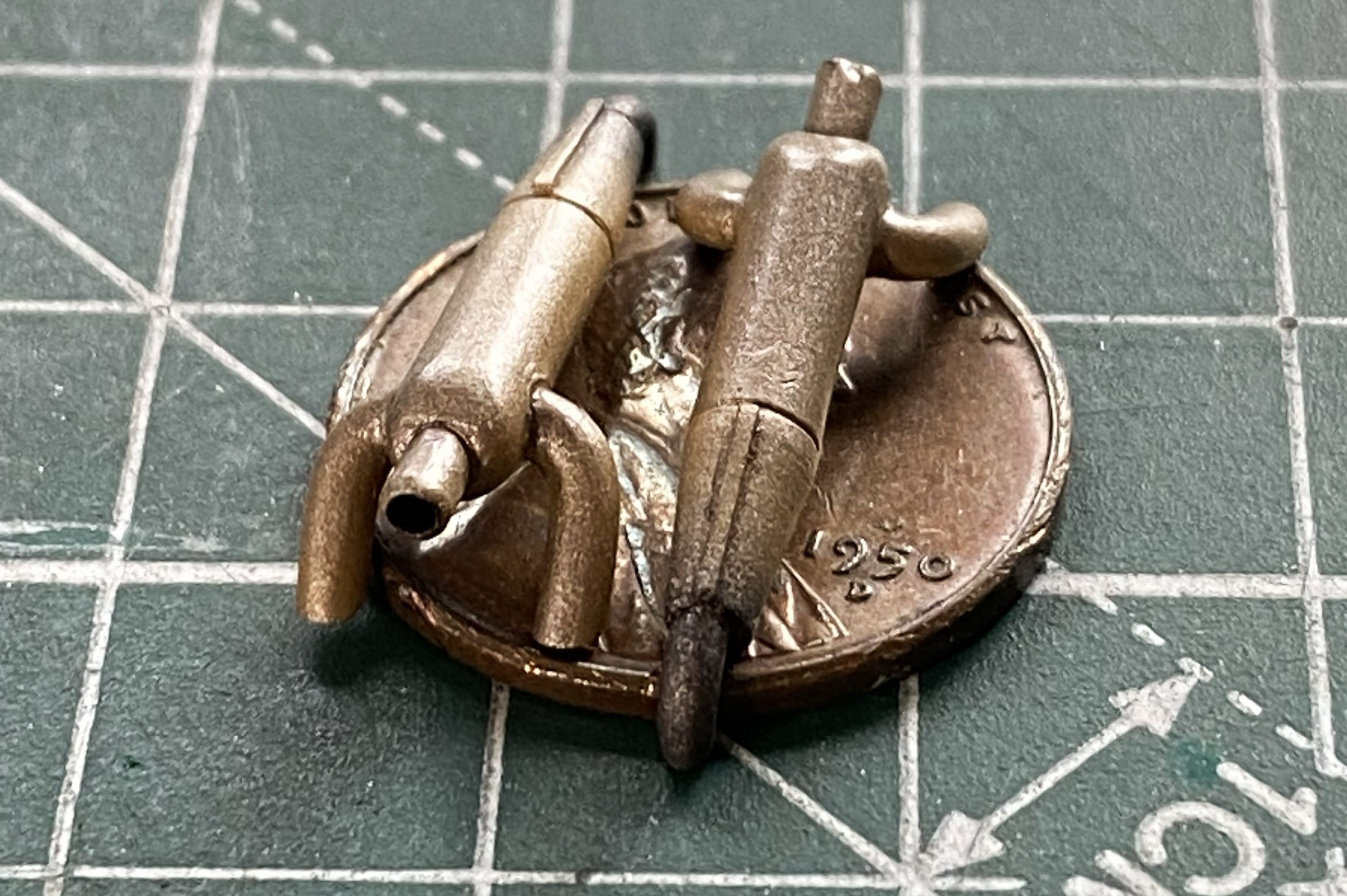
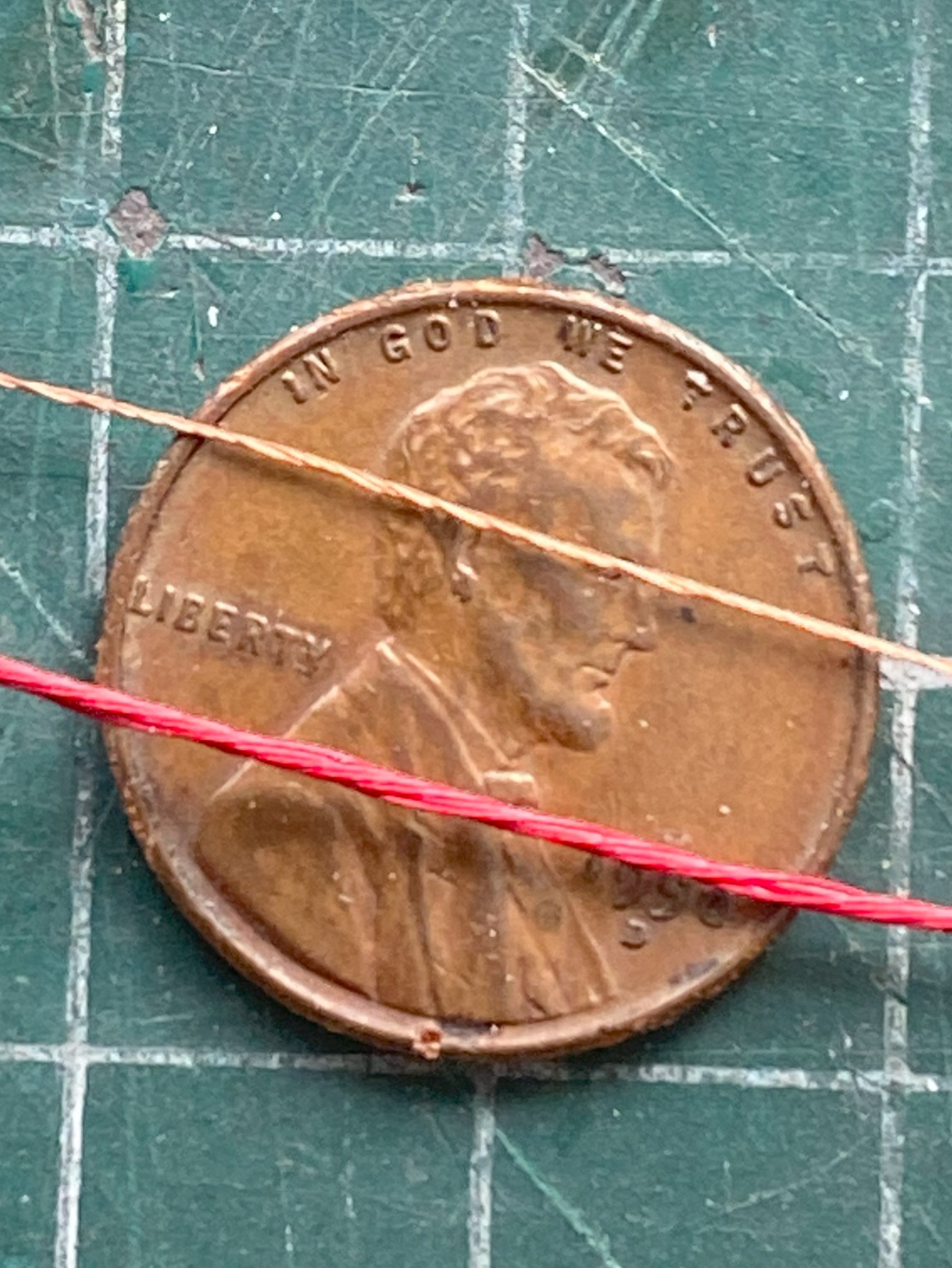
Okay. I can do this (again, but don’t tell anyone, okay?). I decided to imagineer a pedestal for the quadrant to sit on top of with only six tertiary control rods exiting from that pedestal and vanishing through the cockpit’s rear bulkhead.
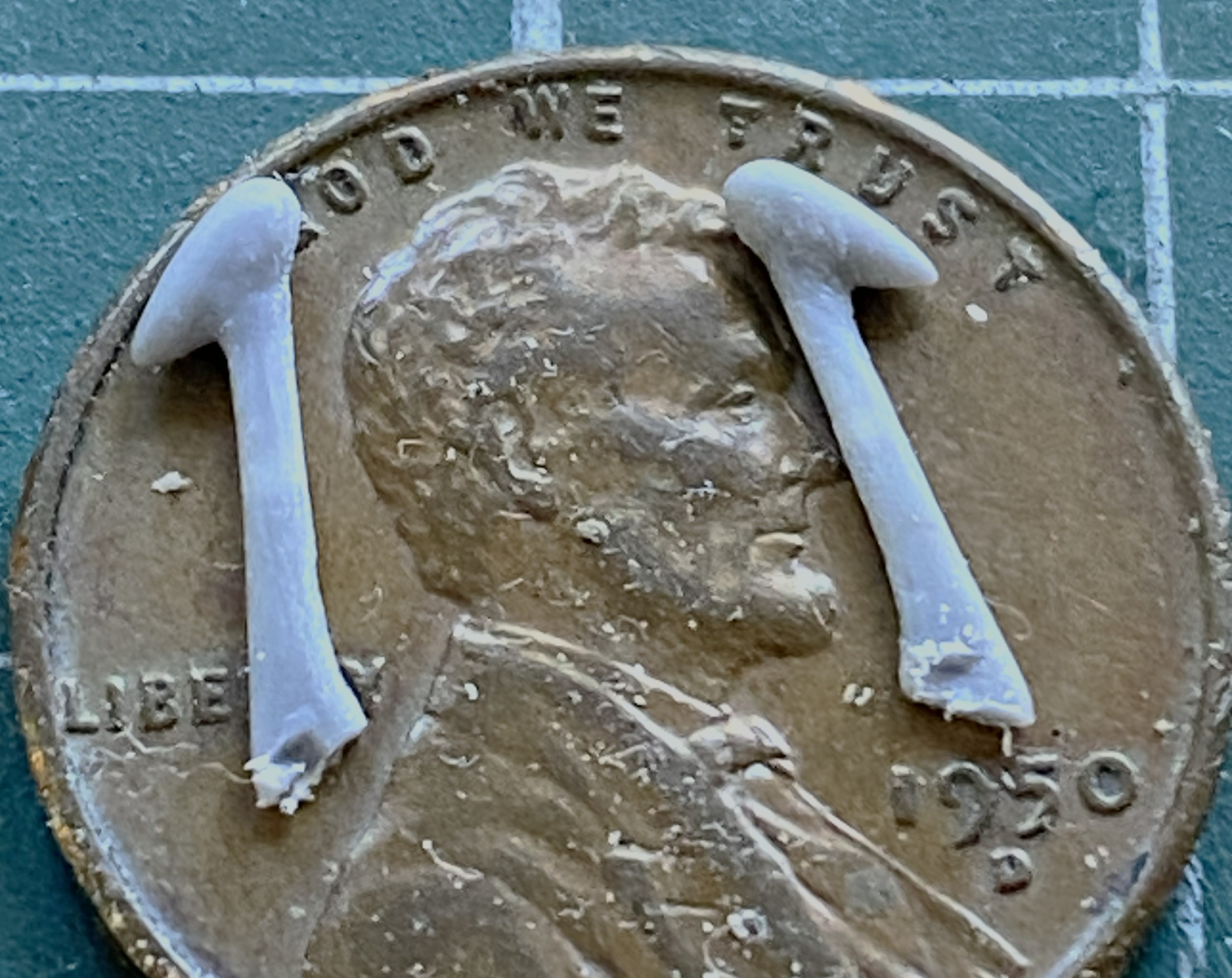
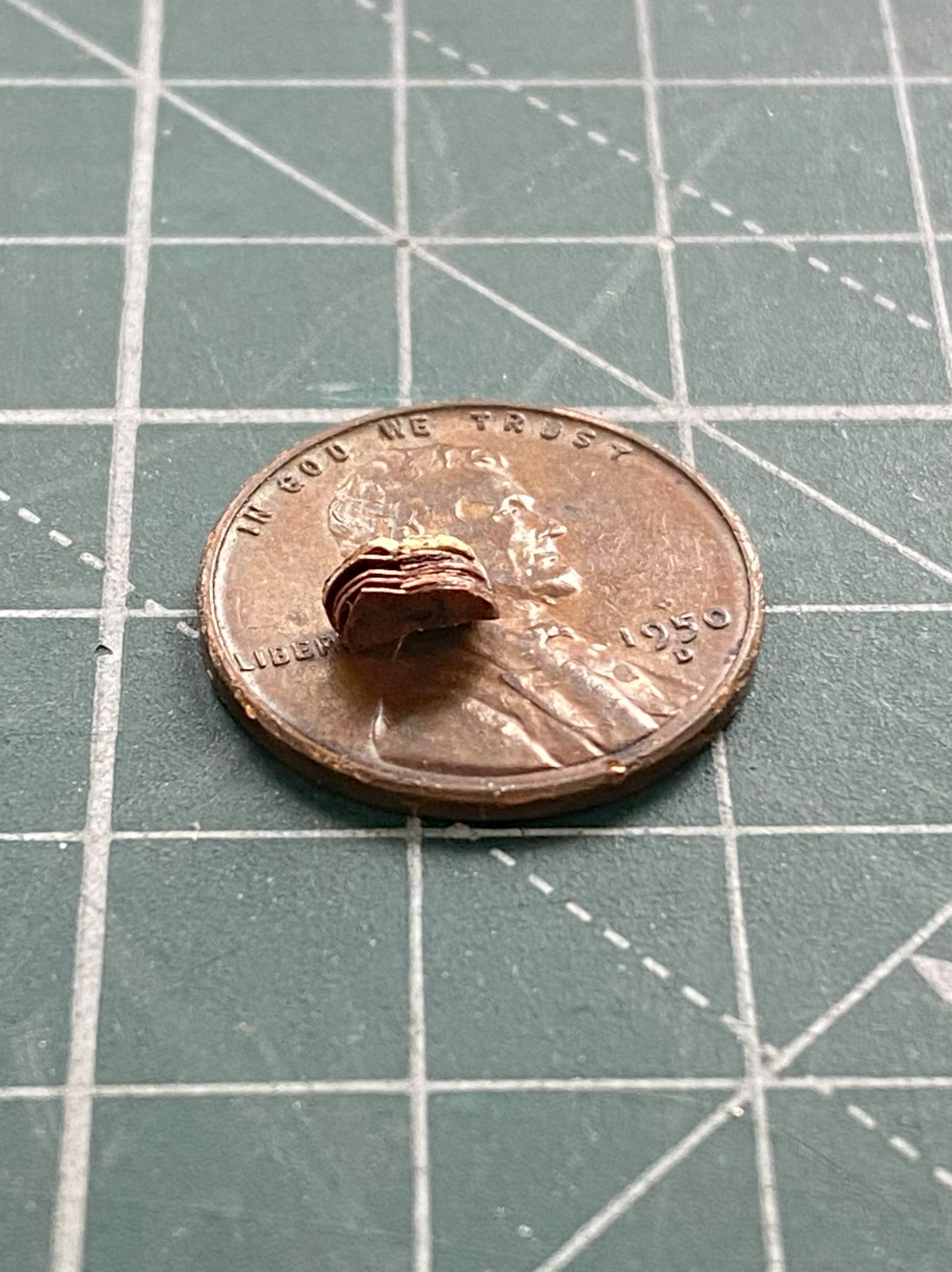
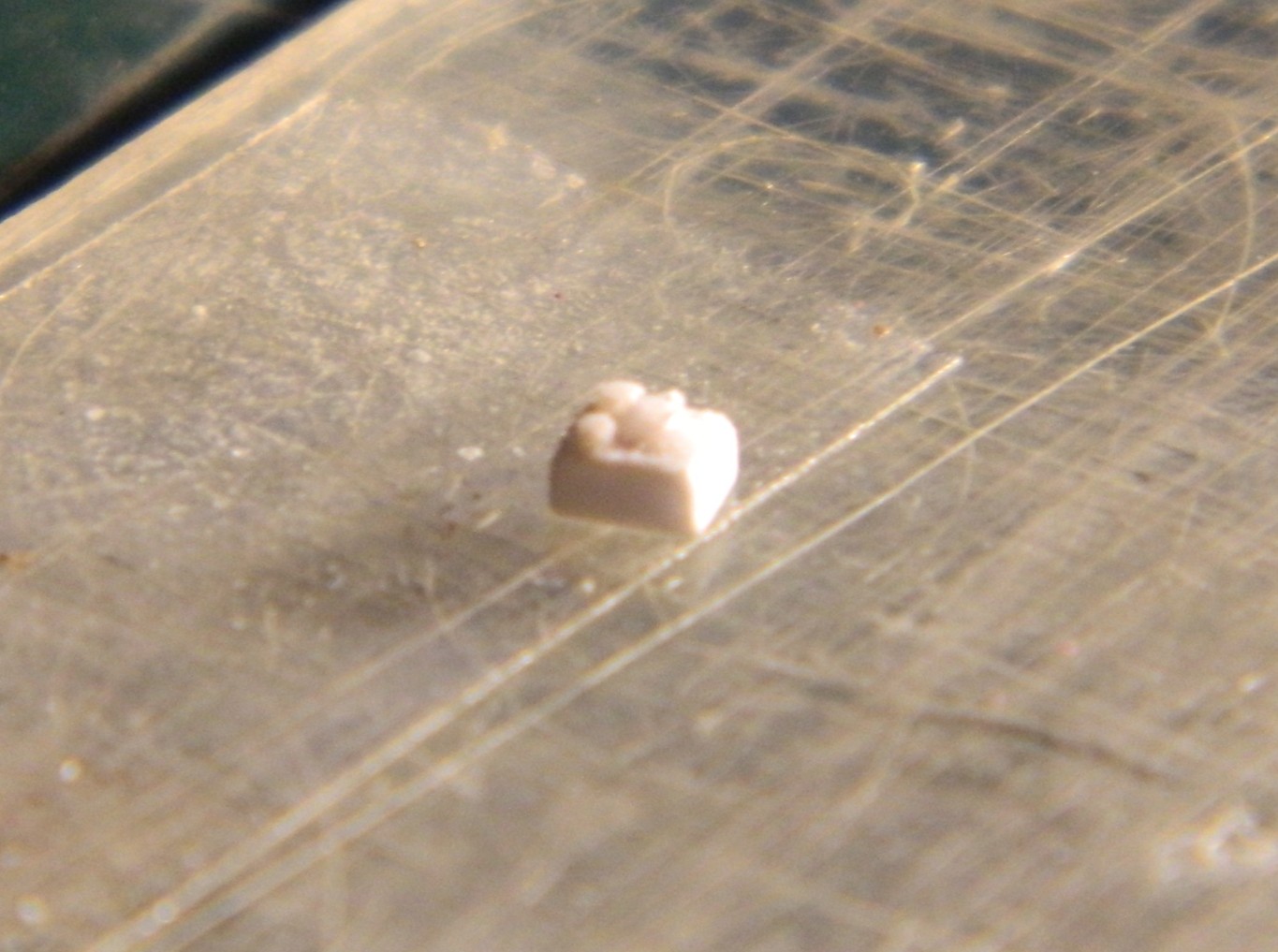
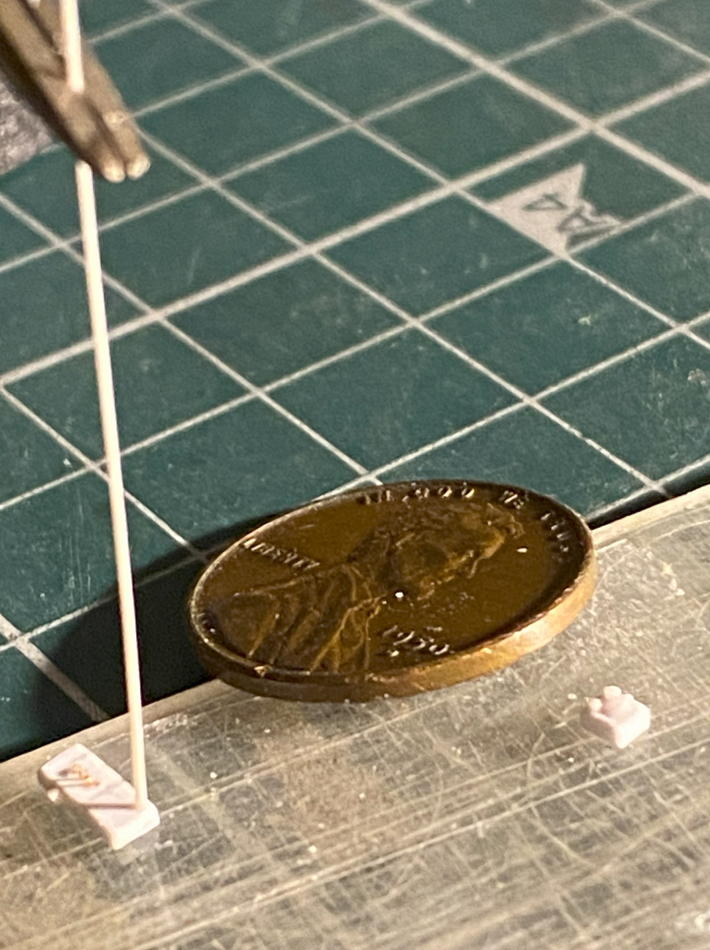
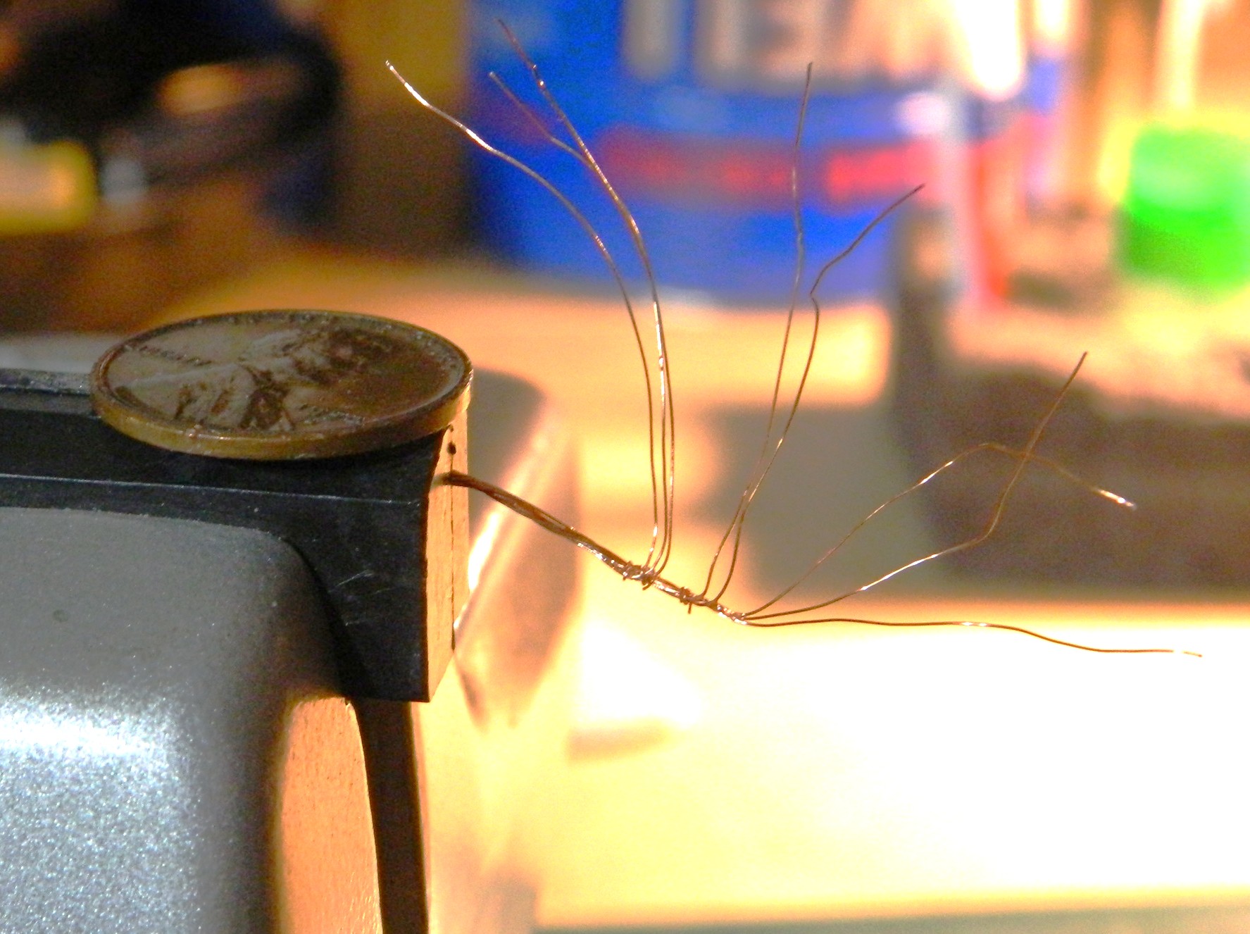
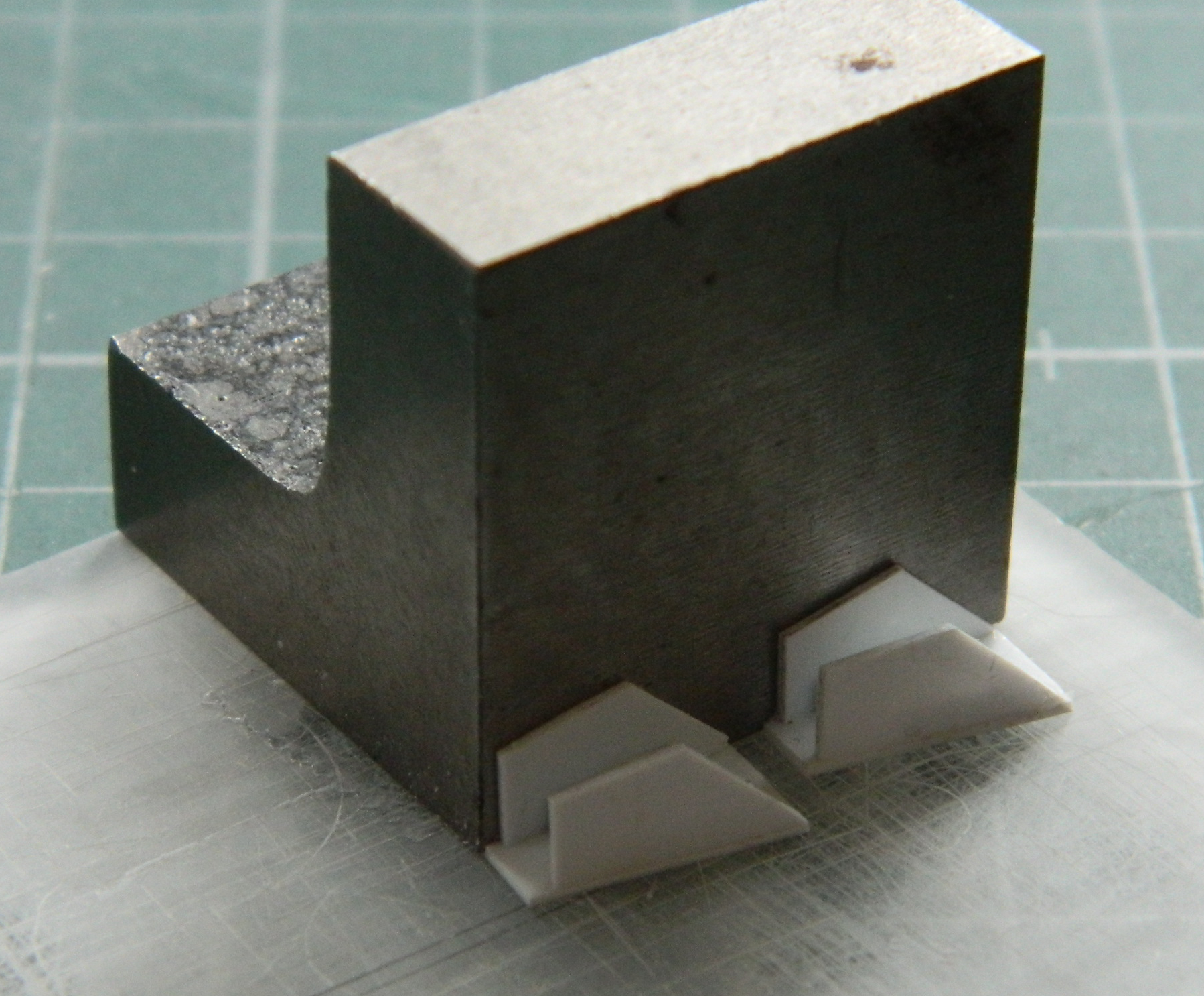
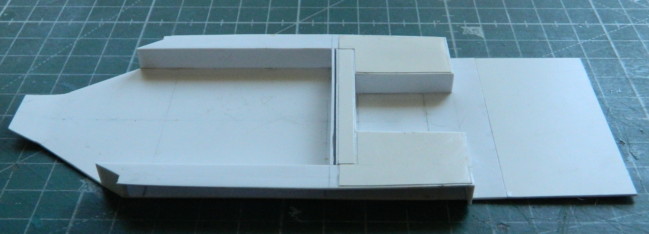
That starts with building the imagineered pedestal. Basic construction was done using 0.015″ (.381mm) scrap:
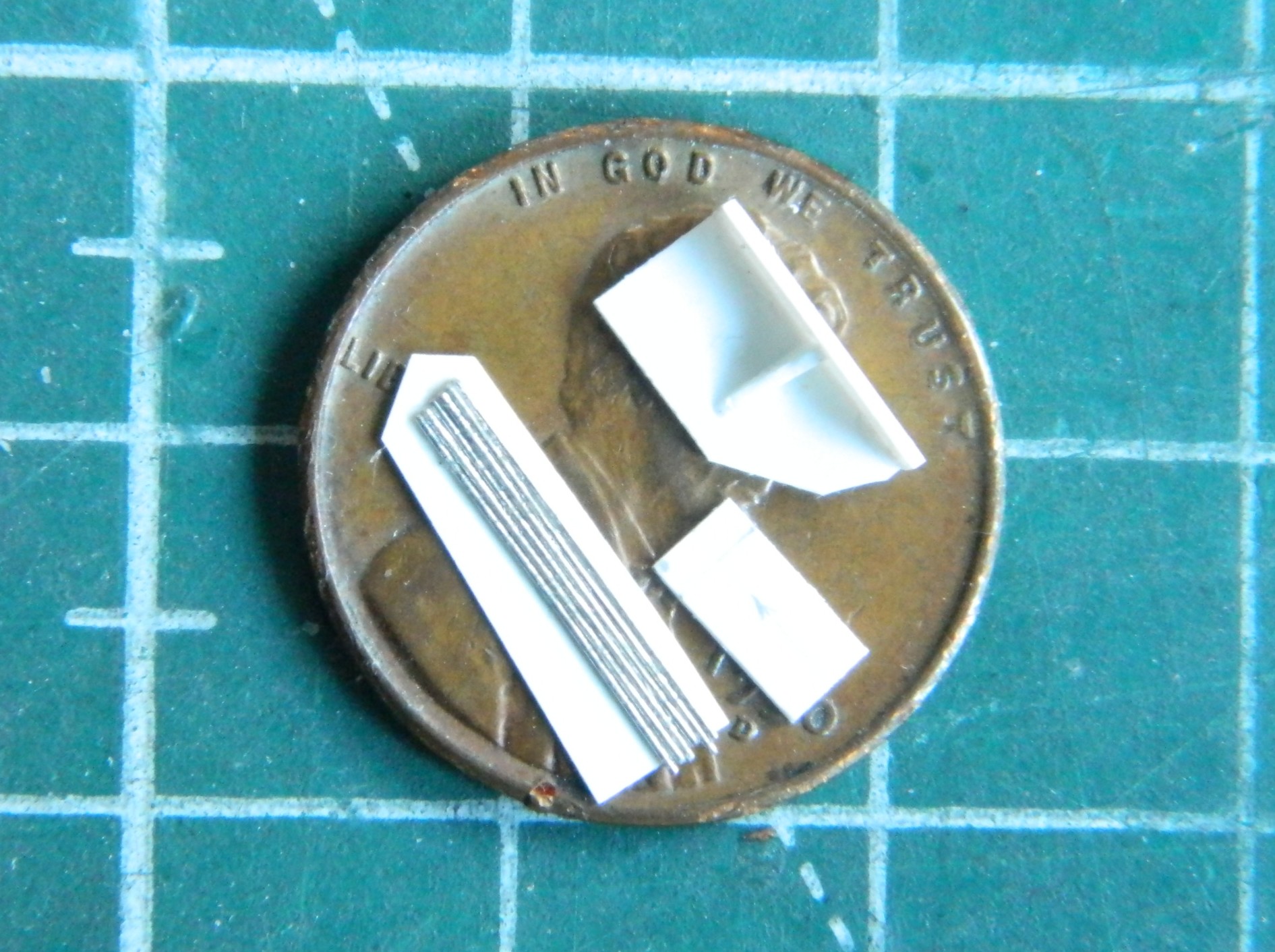
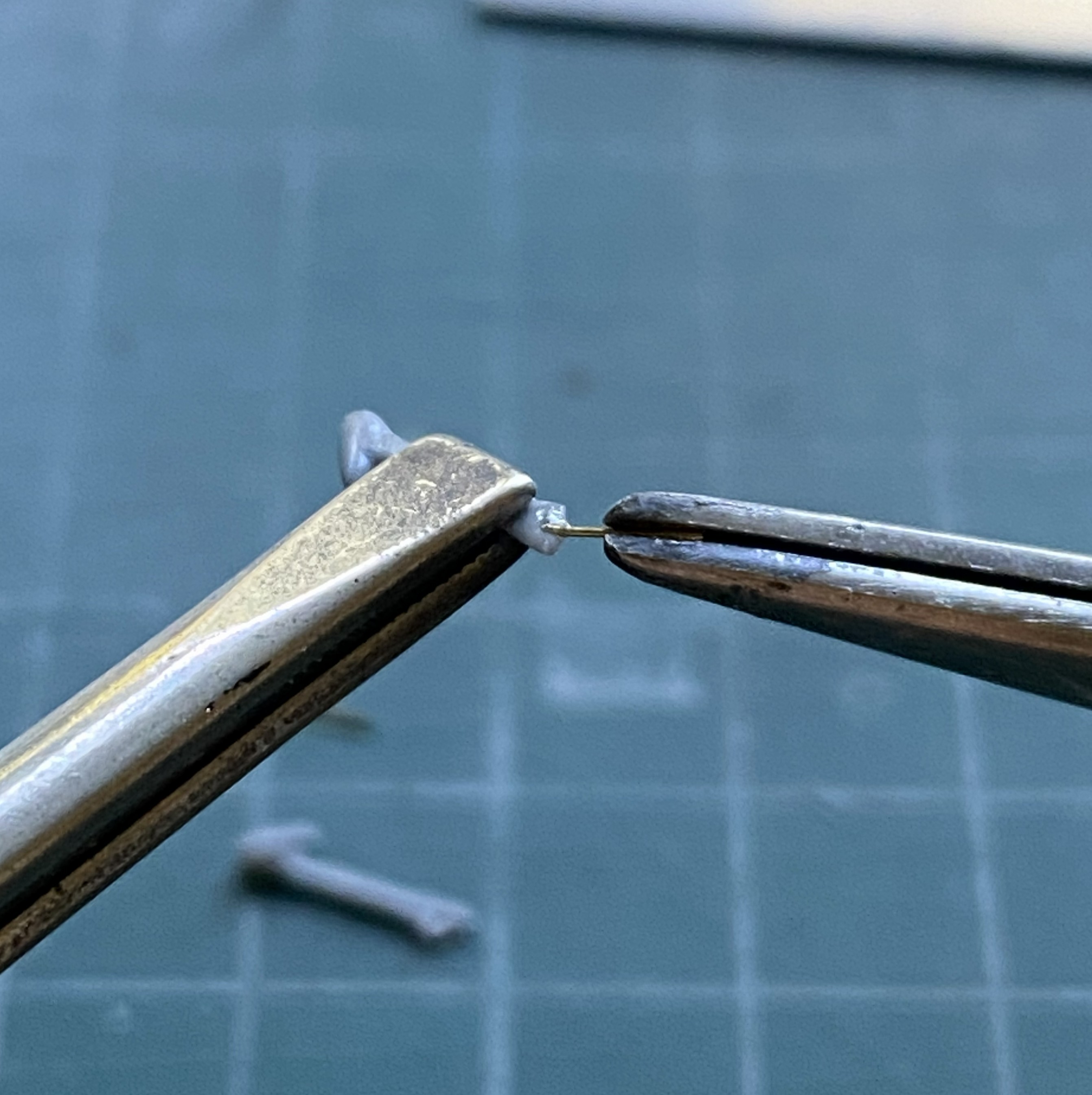
The control rods are to the lower left of the penny. Rather than wrestle with each wire individually, I decided to use a piece of 0.005″ (.127mm) scrap as a backing so that I only had to wrestle with this thing once. I glued all six wires to it and trimmed the excess plastic away.
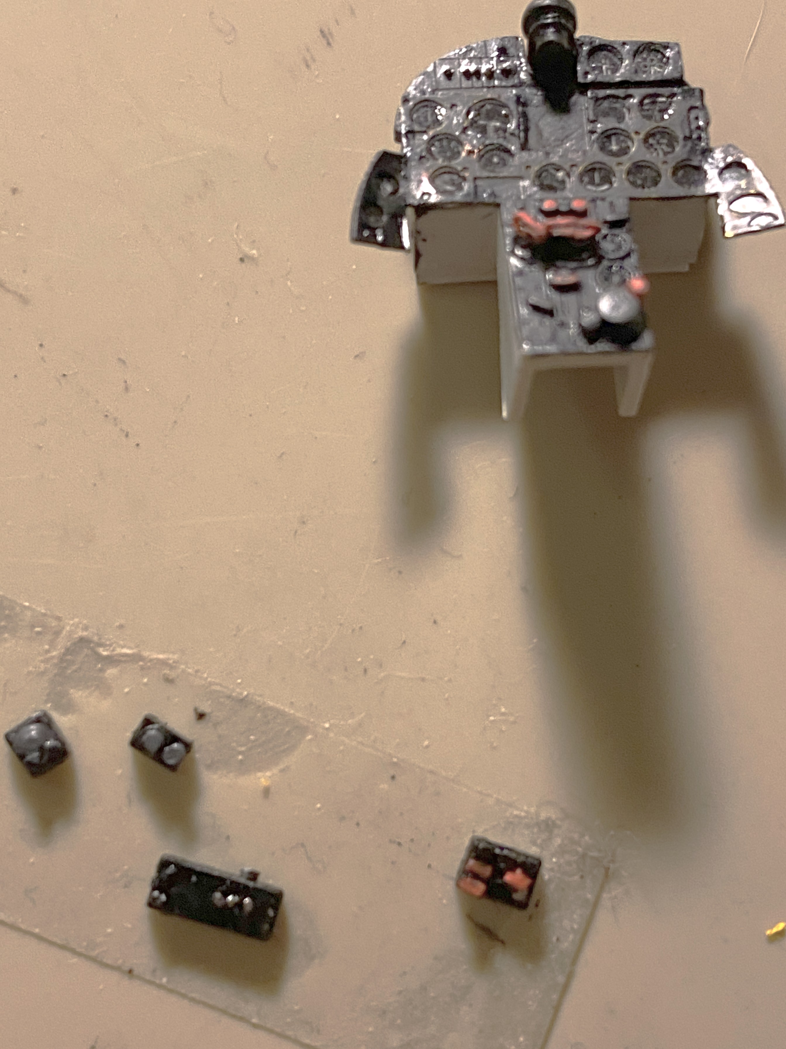
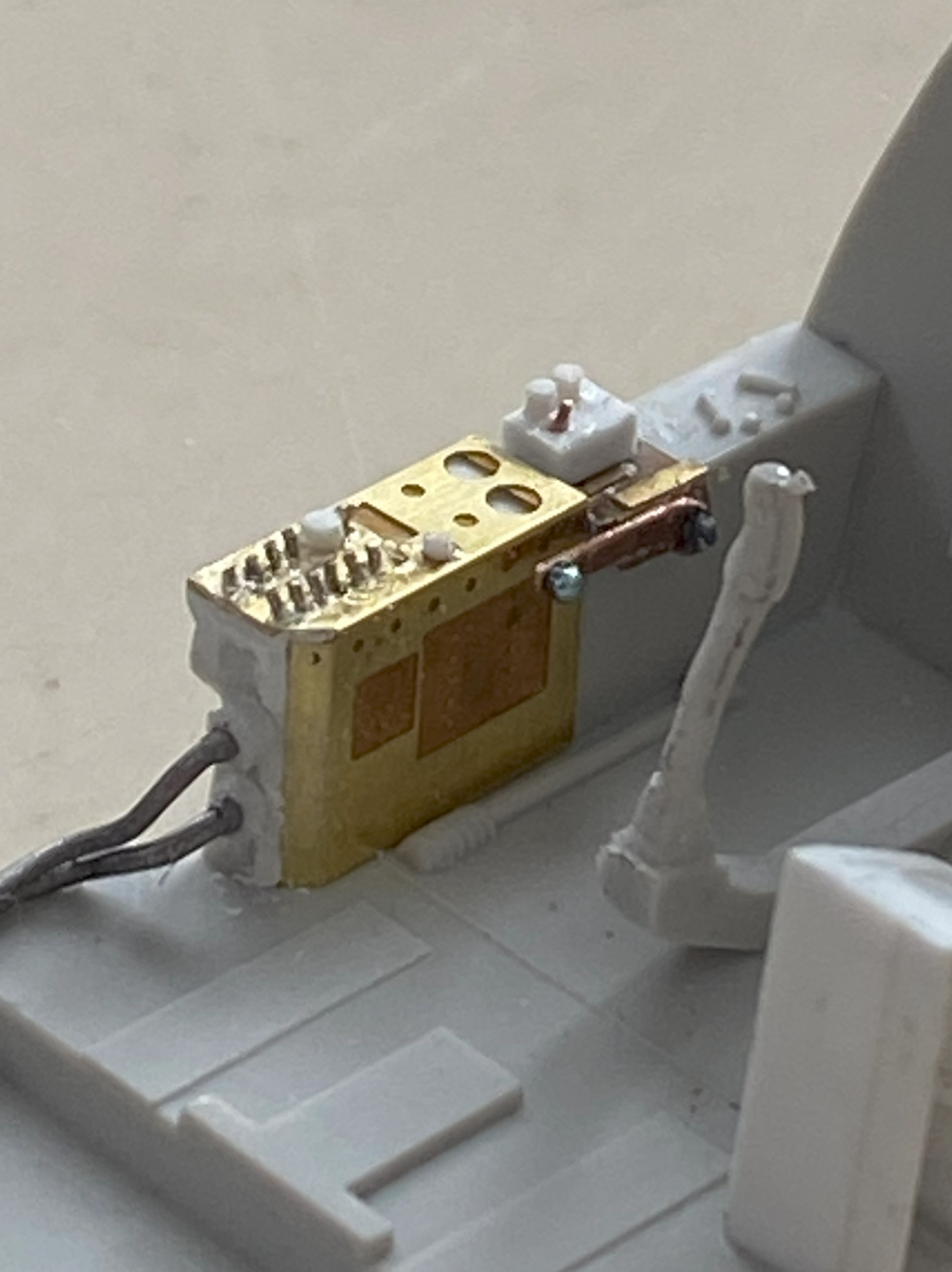
While the glue was setting on the pedestal, I turned attention and effort to the control boxes mounted on the right side of the cockpit. The basic depth, width, and height of the boxes was made using 0.030″ (.762mm) scrap. Toggle switches were replicated with wire and rod and stretched sprue was used to replicate the controls on the boxes:

Yeah…pretty small parts:
Four boxes were made in total.
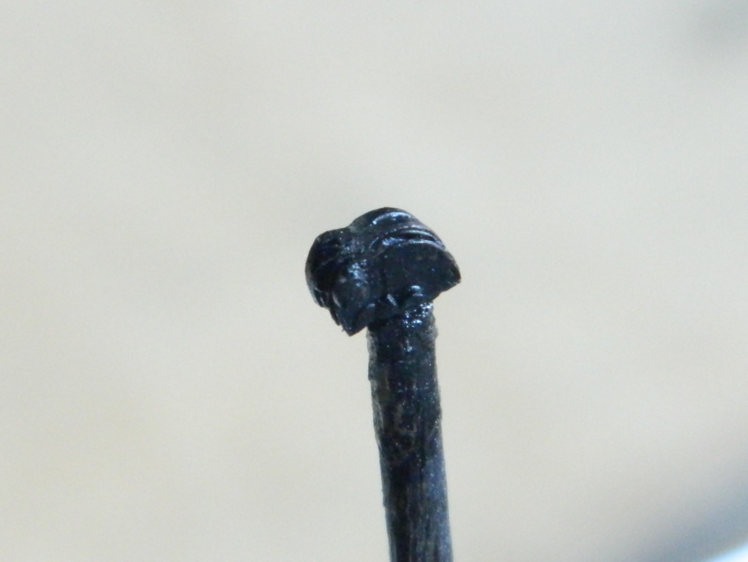
The gun sight was also abysmal, so I used a small piece of 0.093″ (2.362mm) scrap rod as the body of the gun sight. I used a variable-speed drill as a “lathe” and spun the rod slowly and sculpted the body of the sight:

To attach the sight to its forever home, I used .005″ (.127mm) copper shim stock. Drill the appropriate sized hole first, shape later, and it all comes together:

Yeah…SO glad that I don’t work in 1/72 (::giggles::), I kept jumping from job to task while all that was happening and kept detailing the boxes:
If you do this sort of work, I heartily recommend getting a lazy susan. It makes seeing how alignment is working possible. One can look at the job from (mostly) any angle without disturbing alignment of the parts.
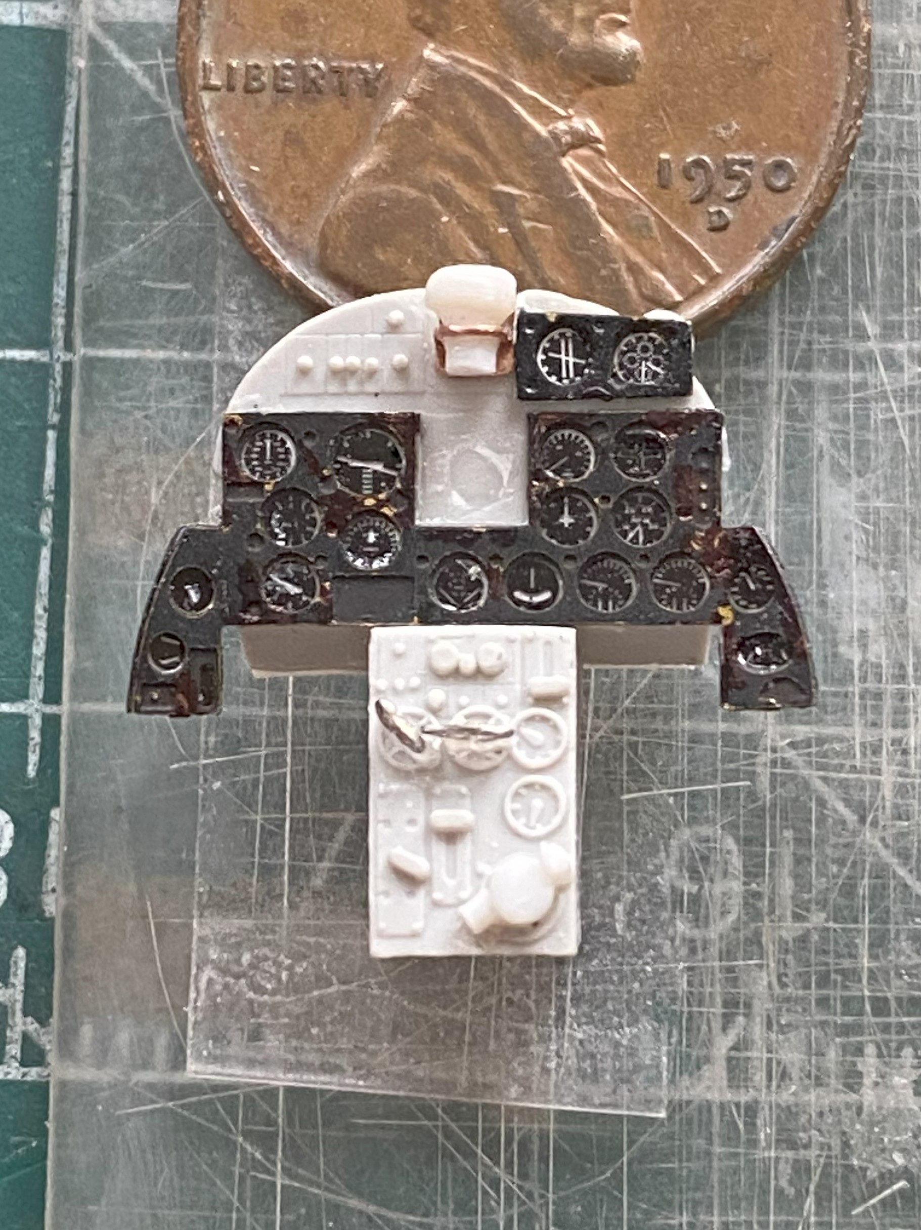
I rechecked dimensions to be certain (::giggles again::) that the parts would fit as intended (which I’m sure hoping is accurately!) and they seem to be just right:
I’d tried using lacquer on the instrument panel fascia to see how it would hold up better to handling than acrylic does. No. Not at all. There were many instances paint touch-ups. This is after one of said touch-ups:

I needed a break so I looked at the canopy. I’ll be able to use the front part from the kit. When I looked closely at the movable section of the canopy, I discovered a casting flaw. There is a significant depression in the part that should not be there at the lower right front of it. I also discovered that the sliding section only fits if it’s modeled closed:


I’m not modeling it closed, so that means the vacuum-molder will be used to pull a thinner replacement.
And now to the casting flaw:
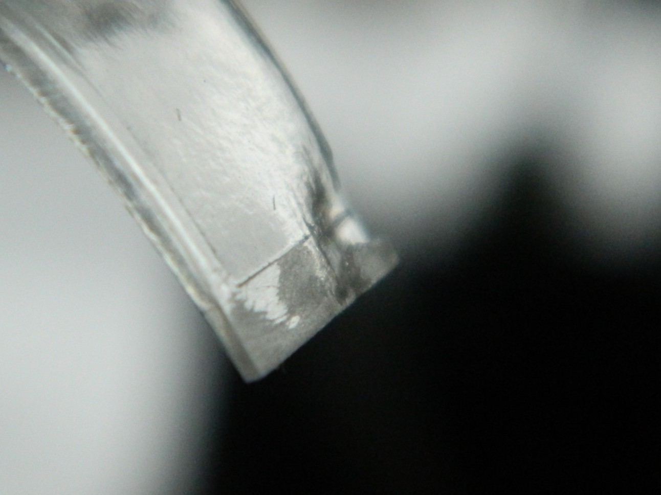

Since the only use I have for this part is as a buck (that which another object is formed over and into it’s desired shape), I’ll fill that depression with scrap sprue before using it as the buck.
I also used the same size scrap to make another control box for the right side panel (with required details added, and you can see where I…mistakenly…put the imagineered pedestal):
Because I’m replacing the molded-on attempt(s) at details, the provided details have to be removed. I got one side done, then did the other:

THAT was freaking annoying…
Since I’m replacing the “details” with something detailed, part of those details includes the wiring. I need a wiring harness of eight strands and I started with 40 gauge magnet wire. Nope. Far too thin. The I tried 34 gauge magnet wire. Nope…this time too thick. (Where is Goldilocks when y’need her?):
I ended up using Mystery Wire. It’s actually a part of a multi-strand (and dead) power cord that turned out to be the correct (ish) size. I laid out the parts that get wired on a piece of double-sided tape and established a rough approximation of where the break outs (technical term of where I wire leaves a loom or cable) need to be:
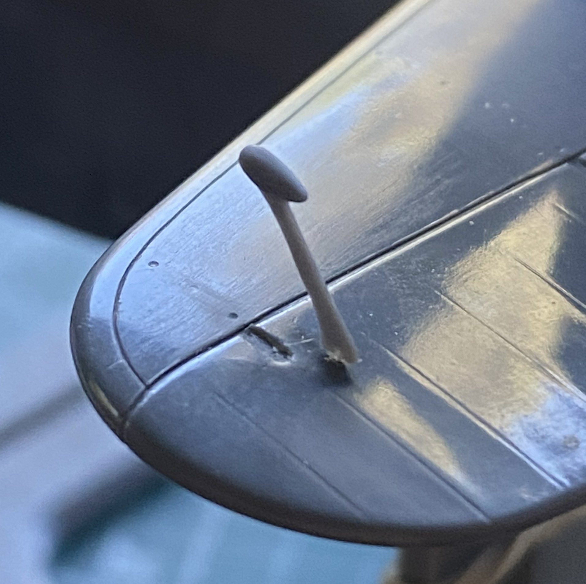
I turned back to the throttle pedestal, glued it in place (properly, I thought…that will be covered next month) and added the tertiary rods:


A little sidetrack, here. I’ll be making seven (if my math’s correct, but since I’m wearing shoes and socks, place no bets on that) control levers, five of which need little round knobs. I’m planning on revisiting a technique I used for the control levers of the P-38F I did:

They’re glass beads that I found online at a crafting site. In the photo, they all look as if they’re the same size. Not even close to reality. Size is not standardized at all. Not one of them are remotely “large”, some of them are EXTREMELY small. I had to pour them out and go through them to find the smallest. I was SO invested in finding the smallest that I knocked the container over and all the little TINY glass beads that I hadn’t already poured out to size them went ALL OVER. Though some made it to the floor, I was “fortunate” that most did not. At this point I most sincerely and in the spirit of true sharing I recommend a better way to spend better than an hour.
Enough on that topic.
There’s a lever next to the pilot that controls something. I have no idea at all what it controls. But since it’s there and quite visible, I had to make one and install it. Here’s how well those tiny glass beads work as knobs (it’s behind and to the left of the joystick):
It’ll look great under paint. (Hmmm…that would make a good bumper sticker.)
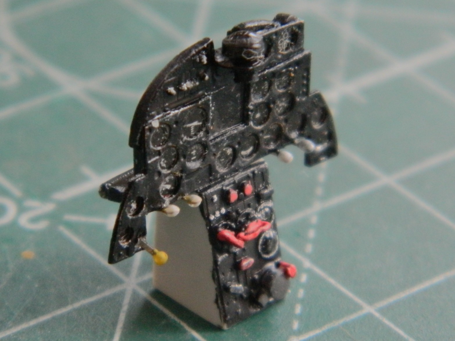
I discovered something else that does a decent job of replicating tiny knobs. UV setting-resin (misleadingly advertised a “glue”, which it’s not). There are five levers attached to the instrument panel (one yellow, four white) and all the knobs are UV-setting resin:
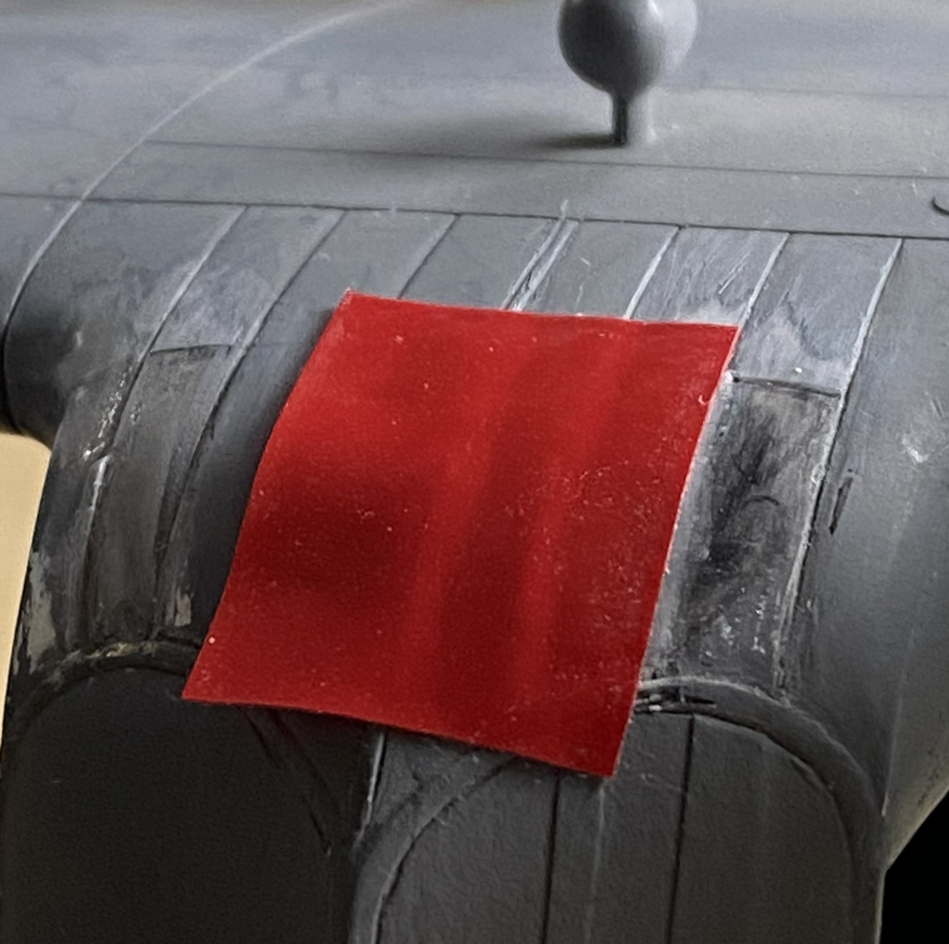
As a build progresses, different tasks fill the driver’s seat. The butt in the seat right now is the need to paint the cockpit, and the first item is throwing flat black over mostly everything so that I can use that as pre-shading. The ultimate goal is to assemble the fuselage sides. And before that can occur, I need to be certain that enough lead has been added to keep this bird on her feet and not be a tail-sitter. The last time I check its balance (no need to check my balance…Eisenhower was President the last time I was in the same area code as “balance”), it very lightly rested on the nosewheel. Too lightly. Since I have plenty (all terms are relative, of course) space in the nose, one of those two places I could put weight will get more lead added.
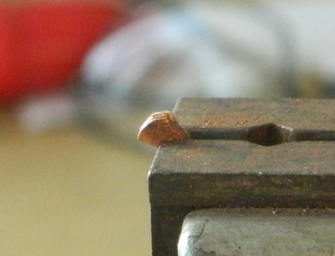
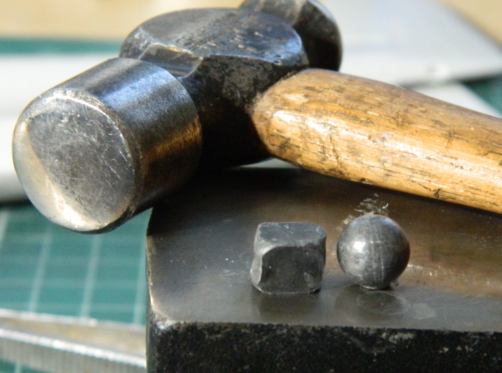
I used .36 caliber lead balls (used long ago for muzzle loading firearms) since I had more of them than the .44 caliber lead balls. Balls, however, aren’t very efficient at filling space (unless it’s round and of the required diameter), so I used a small anvil to shape them into something less round:
Then I glued them into place over where the nosewheel attaches:

So to lay my weight-paranoia to rest, I taped all the major bits that would affect balance (the build’s…not mine):
Yes…it will sit level:

But it’s still just a wee bit light in the nose, so more lead will be added before the sides of the fuselage are joined.
I had hoped that I would be able to throw flat black on this thing before this update but time, as it’s reputed to do, fled. Guess that’ll be for next month…
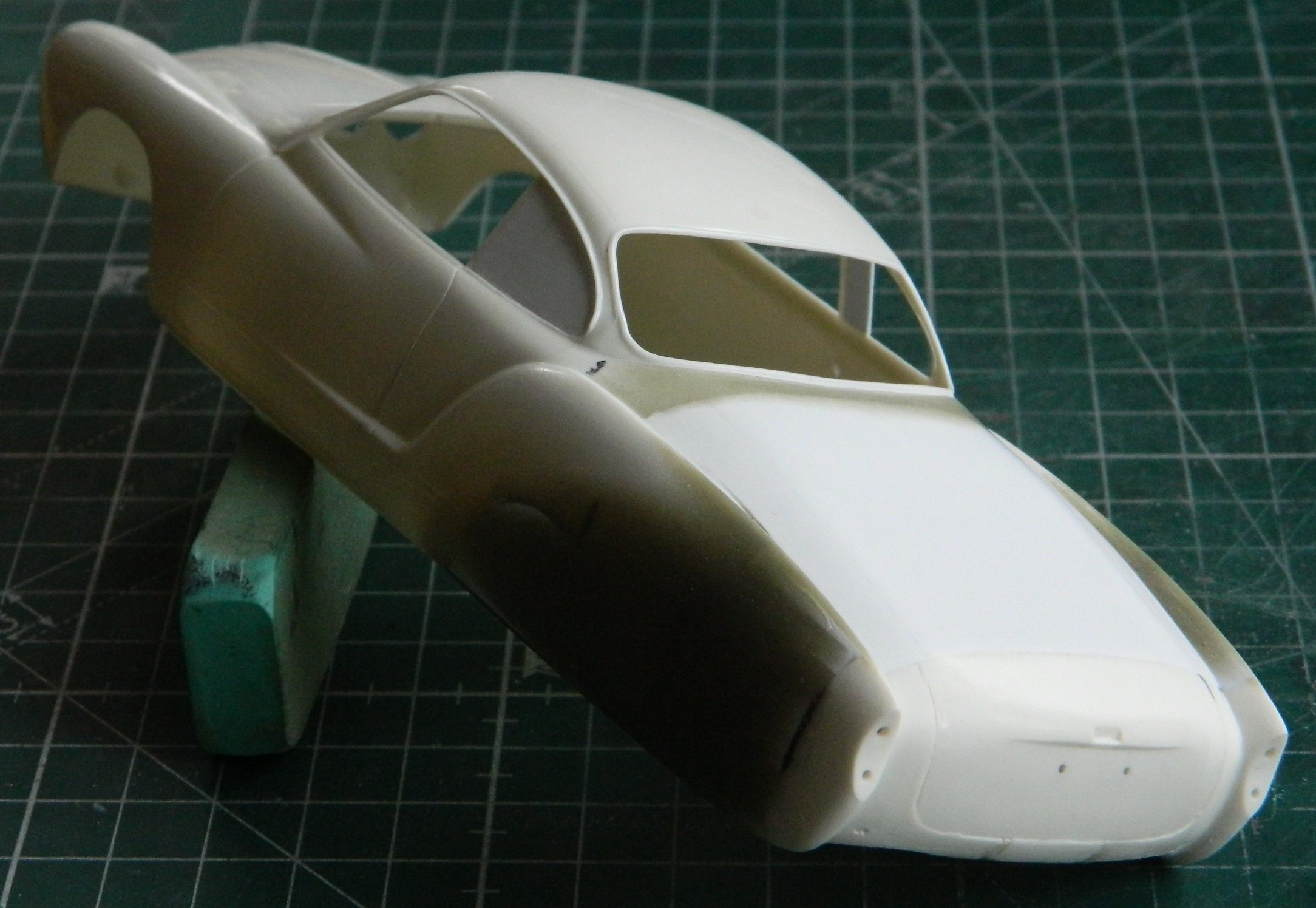
Crankenstein – 1/25 Scale Kitbash Build #3 Extending the Body and Coming to a New Understanding of the Scope of This
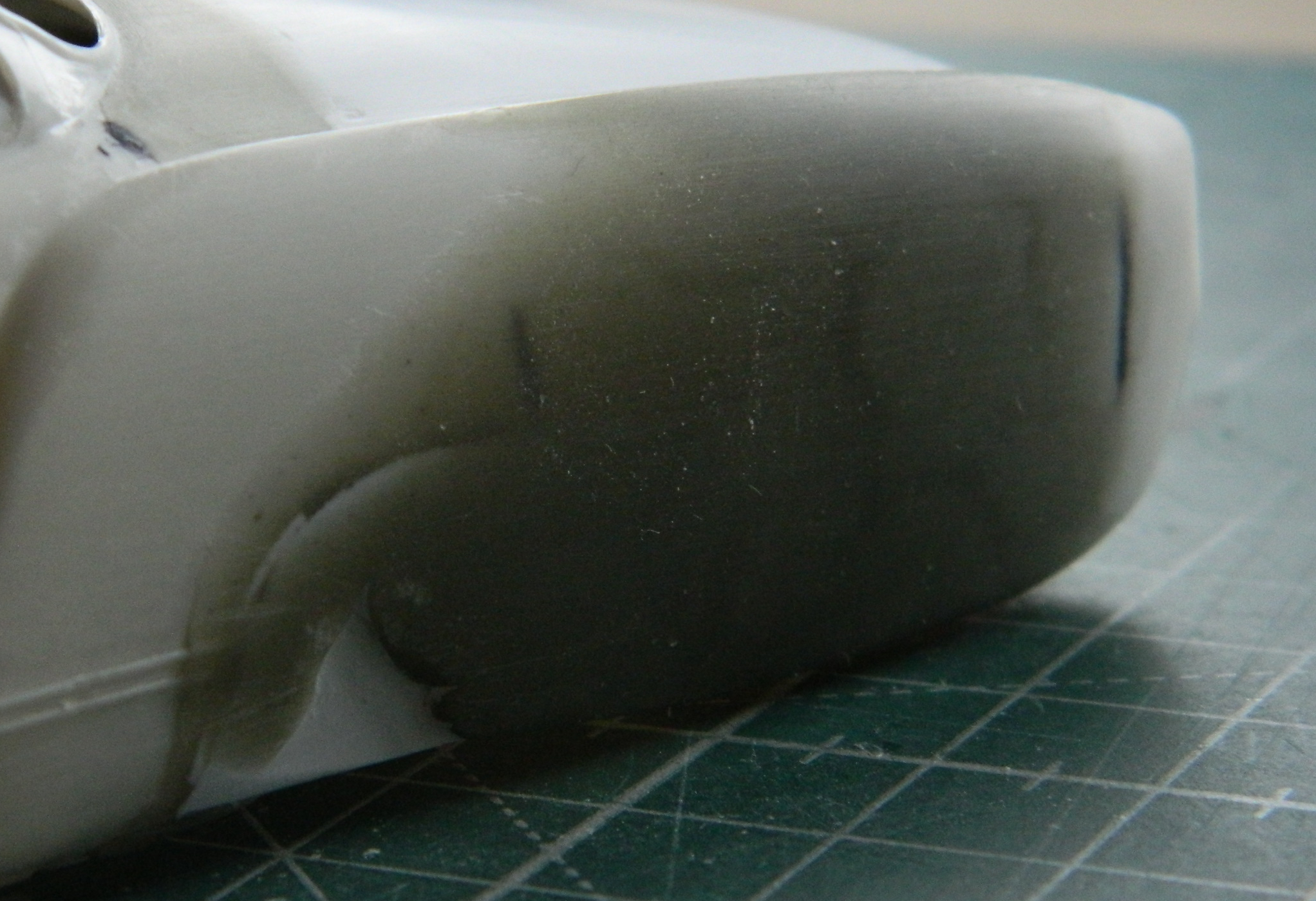
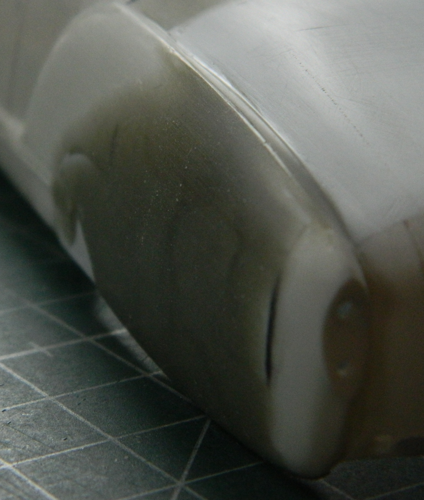
This month’s work was mostly bodywork, specifically coming to the realization that I really am going to have to extend the rear coachwork. This awareness was finalized as a plan once I had enough constructed to lessen the degree of guesswork about where the power-train goes, which determines where the axles go, leading to the understanding of where the wheels and tires will be and thus the rear fender flares. Initially I’d thought that I could just do a speed-hump (no…not at my age I can’t) and cover the rear of the transaxle where it protrudes beyond the body. I added a bit of .040″ (1.016mm) bracing so that the bodywork would be dimensionally stable:
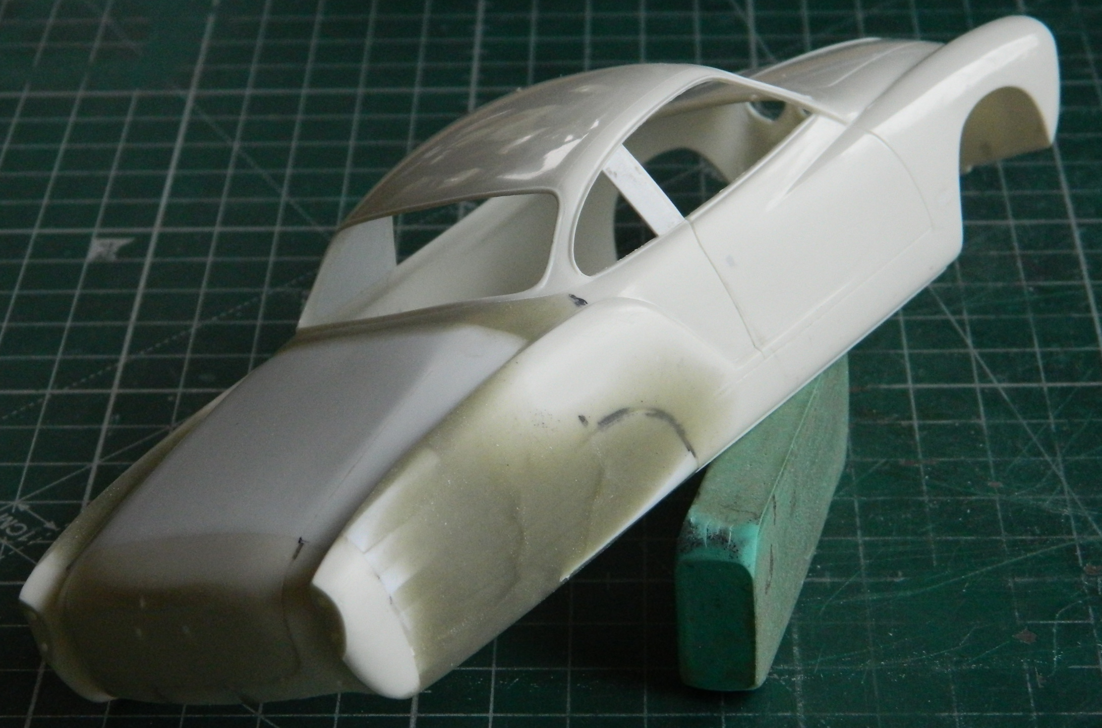
But once I estimated the location of the rear wheels, and subsequently the fender flares, I realized that the rear of the flares extended well past the rear of the body and would end up removing the sense of “Karman-Ghia” that I’m trying not to obliterate:
The brace was removed and the section of body that I’d removed was glued back into place.
I had initially considered making the cut much further forward, and I’d also considered making a couple (or more) cuts to blend the compound curves. I decided that I was, once again, overcomplicating things. Since I just need the back of the bodywork to extend past the end of the transaxle, I decided I’d just cut the end of the body off. I glued the stock engine cover in place for structural stability, only gluing the part that would be removed with the body (because as this point I still have the notion of having the former engine cover hinged separately from the rest of the hinged rear body to have a small load-carrying space that could be accessed without having to open the whole back of the car to get to it). I laid out the line and made the cut:
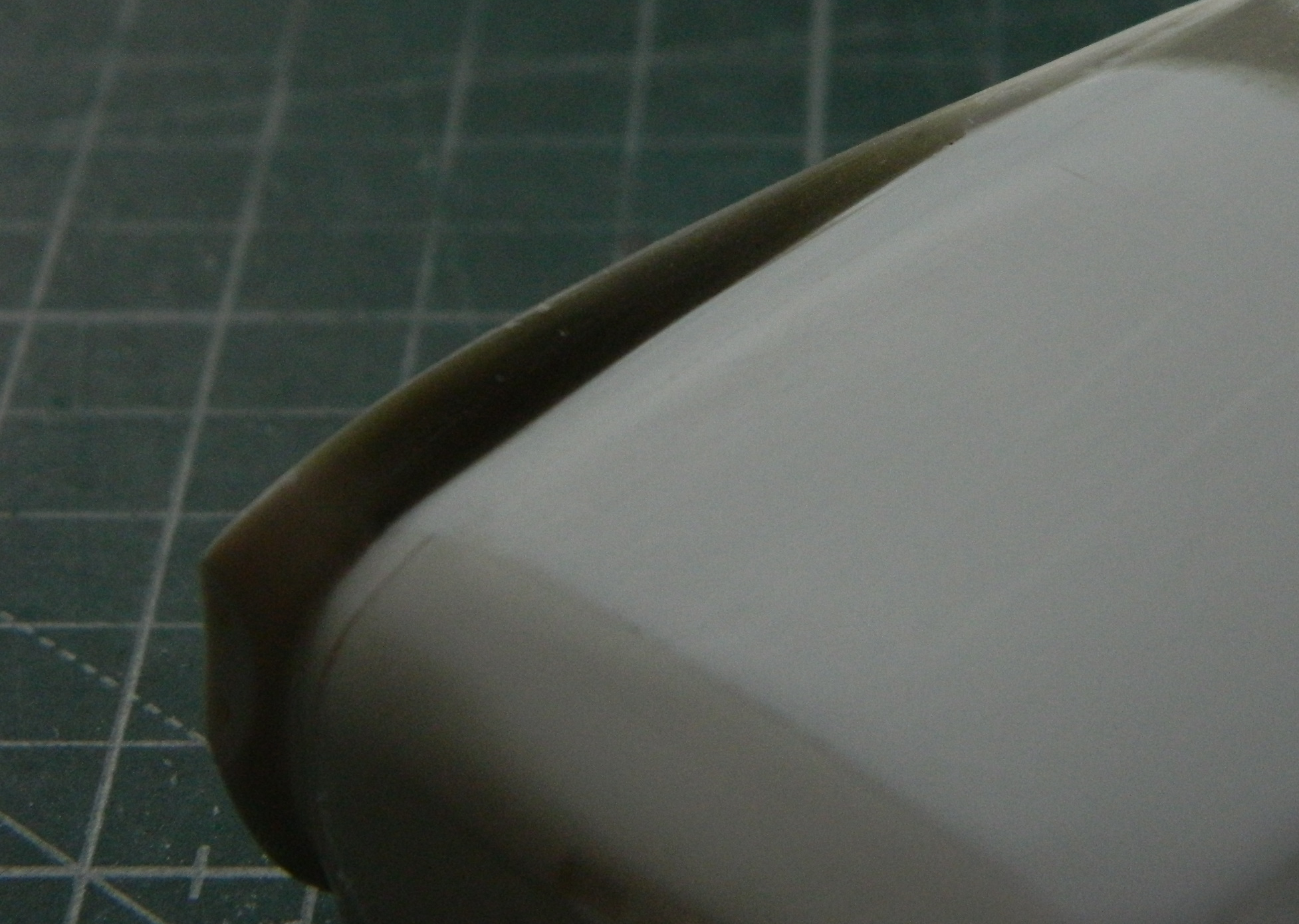
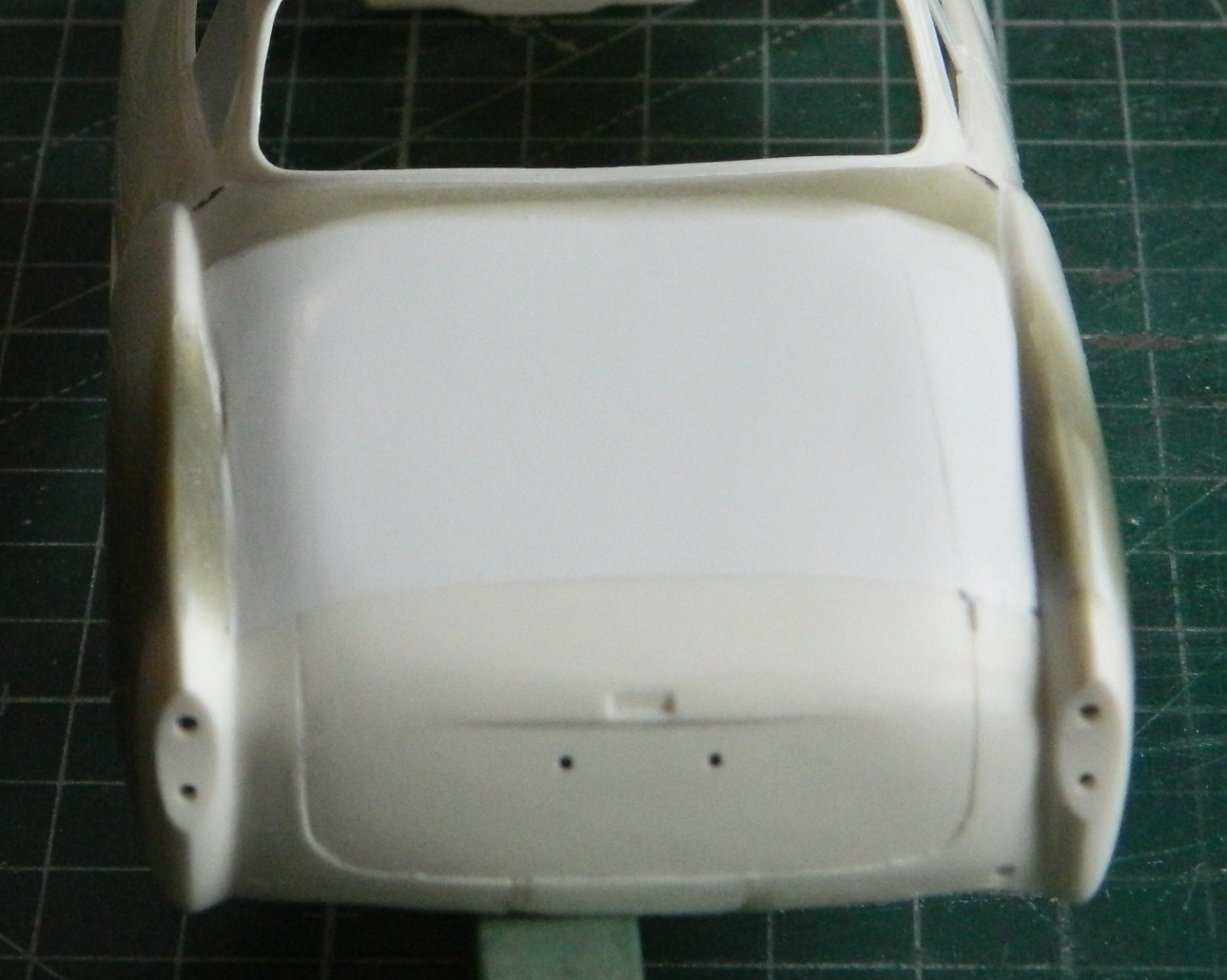
Not only did I move the section that was cut off back 5/8″ (15.88mm), I also moved it down in order to maintain the arc of the upper curves of the rear fenders. Once I figured out where I wanted it, I added .040″ (1.016mm) braces to hold it there (and managed to superglue my thumb to the rear of the fender, as you can see in the photos):

Having positioned the rear of the body, I checked to see if I could just add a piece of flat styrene sheet for the upper body. Looks like I can:

That obviously left large areas that need to be filled. Rather than drive myself crazy(er) by trying to make a single-piece fill section, I opted to use more .040″ (1.016mm) strips as structural filler as well as gluing a flat piece of the same thickness styrene on top. For the ridge at the top of the fenders, I filled the odd shaped gap with .080″ (2.032mm) scrap:


l used more .040″ (1.016mm) to fill the gaps on either side of the top addition and then roughly sanded the additions to shape as well as filling the stock wheel openings using .020″ (.508mm):
Much putty was needed to smooth the surfaces. Rather than lay down several layers of putty putty, I opted instead to use Aves Apoxie Sculpt (great stuff if you ever need a structural filler!) and waited overnight for it to harden. The join of the top of the rear deck and the side sections started to show gaps after minimal sanding so I added the Apoxie Sculpt there as well:
Since the rear of the body will be hinged, I needed to add Apoxie Sculpt inside as well:

After letting the putty cure overnight, I used my Dremel to roughly shape the putty (and created a metric TON of dust):
The first shaping was done with a file:
Then it was all sanded. I started with 220 grit and went through the grades up to 2000 grit:
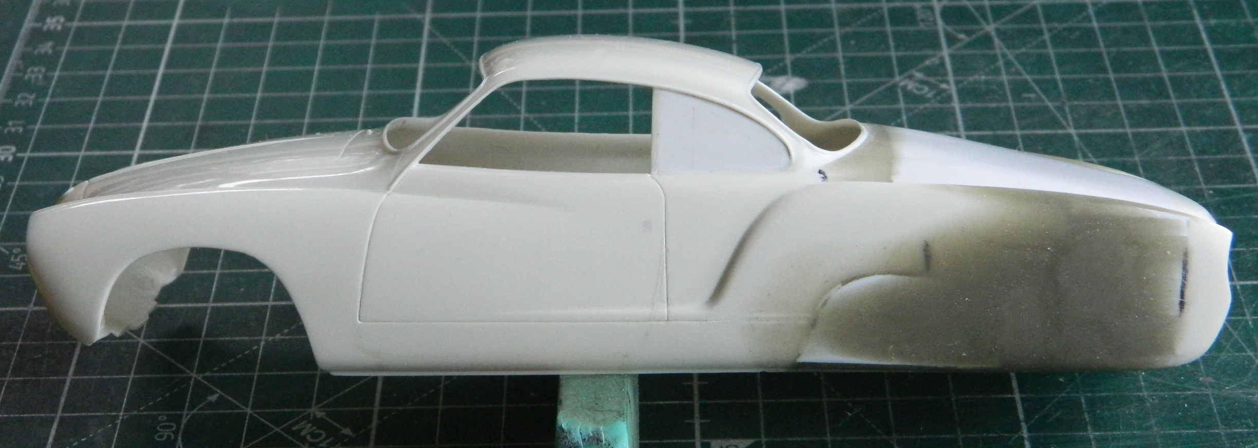
My goal of creating a gradual curve on top of the fenders worked well:
I knew as I was doing all of this that a large area would be cut away on both sides to accommodate the wheels/tires. I also knew that I was going to have to fit the fender flares to the body so I wanted the surfaces to be properly shaped before I started that.
Though it looked odd at first, I rather like the extended body:
To know where the openings need to be cut out, I needed to know where the wheels/tires would be more accurately. Since it’s the engine/transaxle that determine where the rear wheels/tires will be, I needed something better than tape or white glue to determine where the engine will sit. The next task was to build the engine mounts so that I could dry-fit the engine/transaxle to where it will be attached. I knew that not only were these parts need to be sturdy enough to handle being moved around a lot, using .020″ (.508mm) styrene wouldn’t provide much gluing surface, so I reinforced the joins with Evergreen’s L-shaped extrusions:
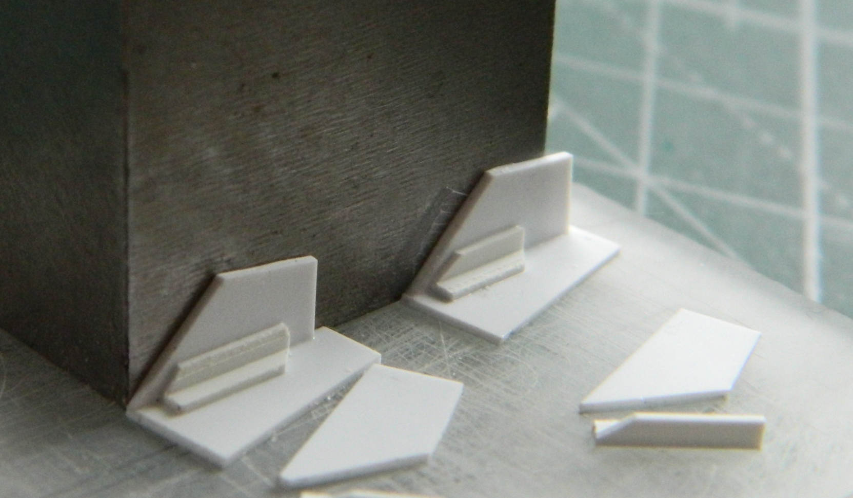
These parts did what I want them to, locate the engine, but they’re too clunky. I’ll make another set of them later:


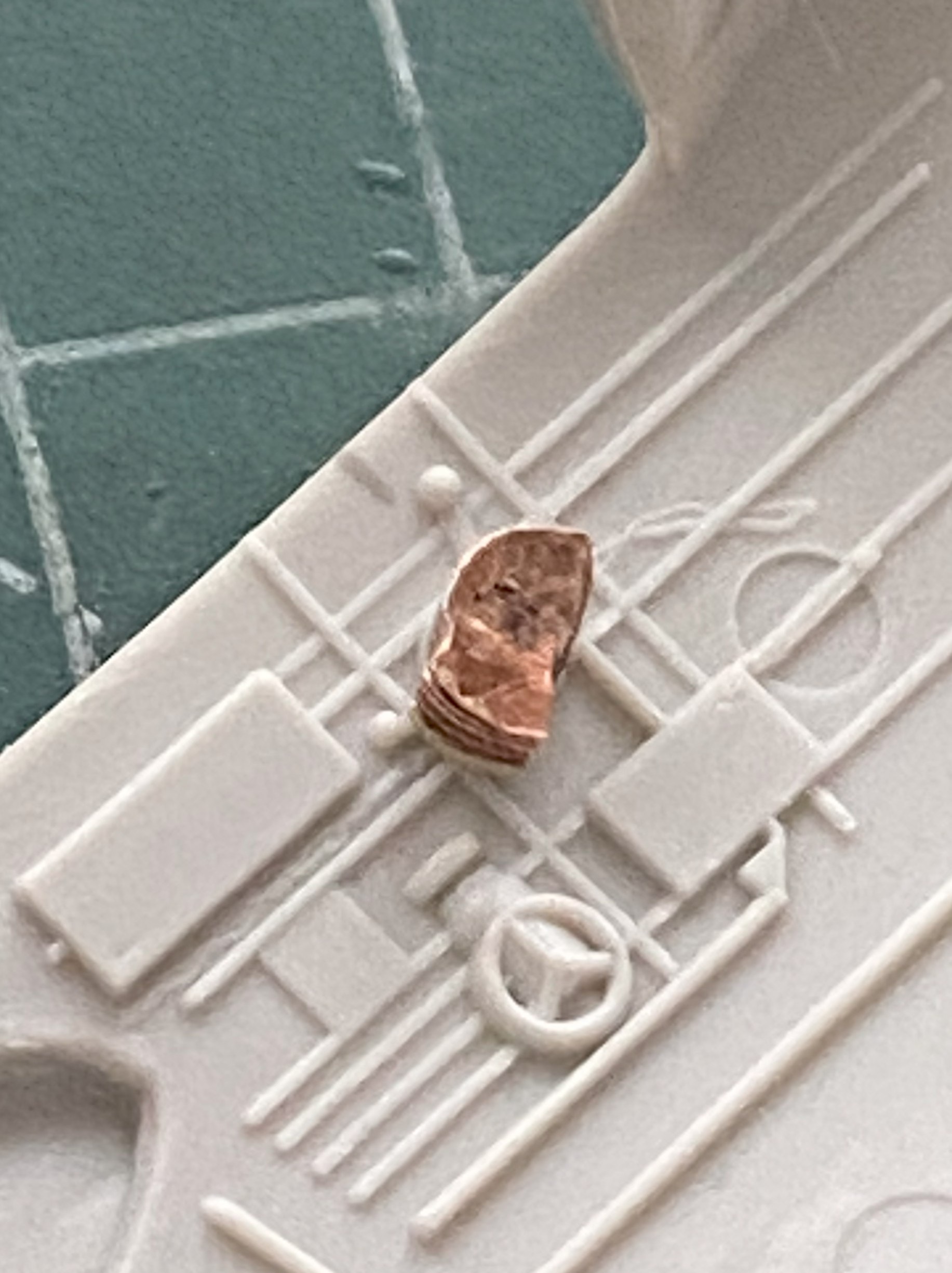
I also needed to fit the rear engine and suspension mount so that I have the angles for the driveshafts at the correct height. While that part is still free and the surface of it easily accessed, there was something I needed to fix first. For whatever reason, the resin copy has these two depressions that shouldn’t be there :

Once I added the putty (deciding to finish the surface later), I was able to put the engine where it will end up being (the plastic underneath the transaxle is just there as a spacer to maintain the correct height):


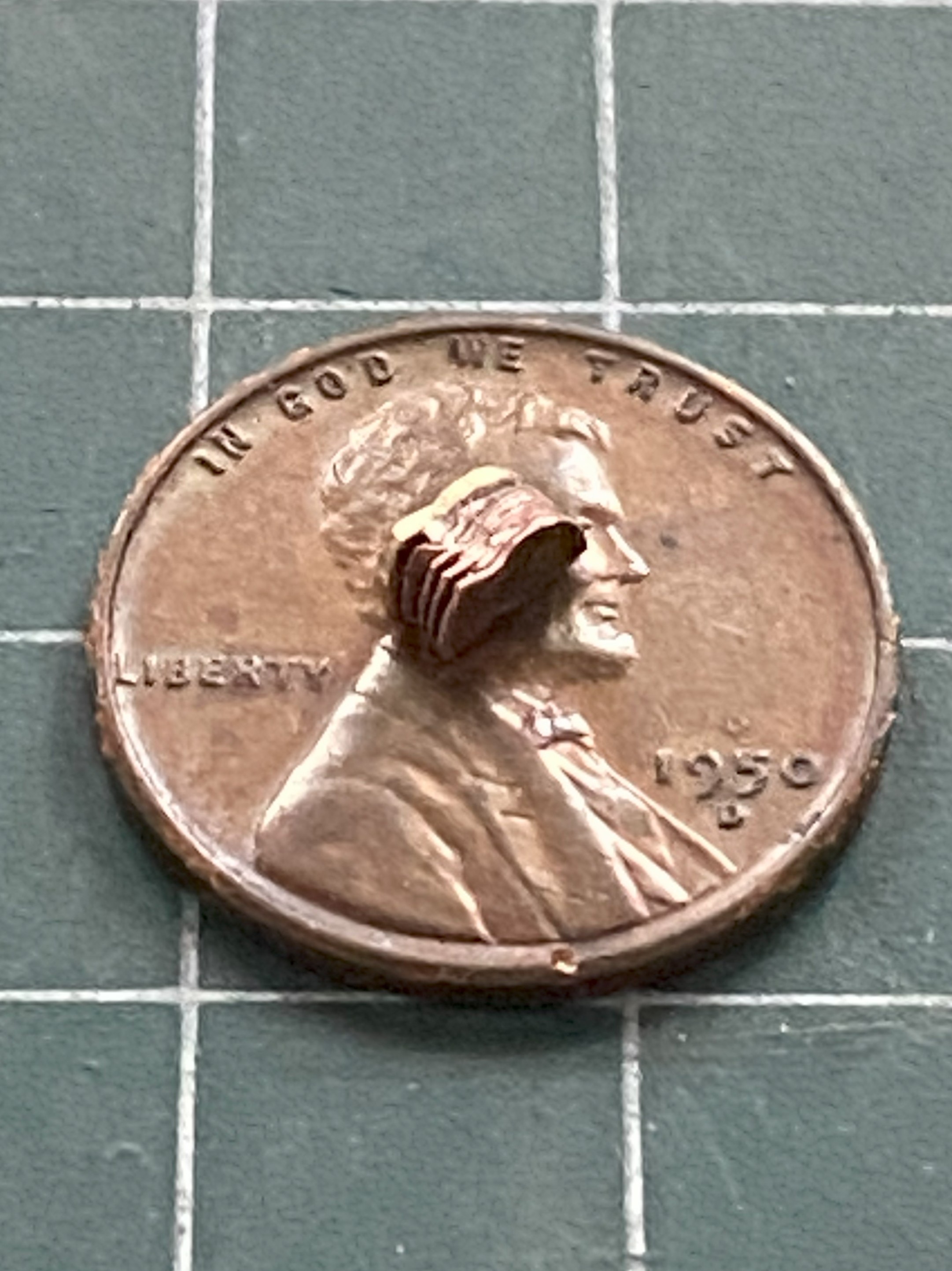
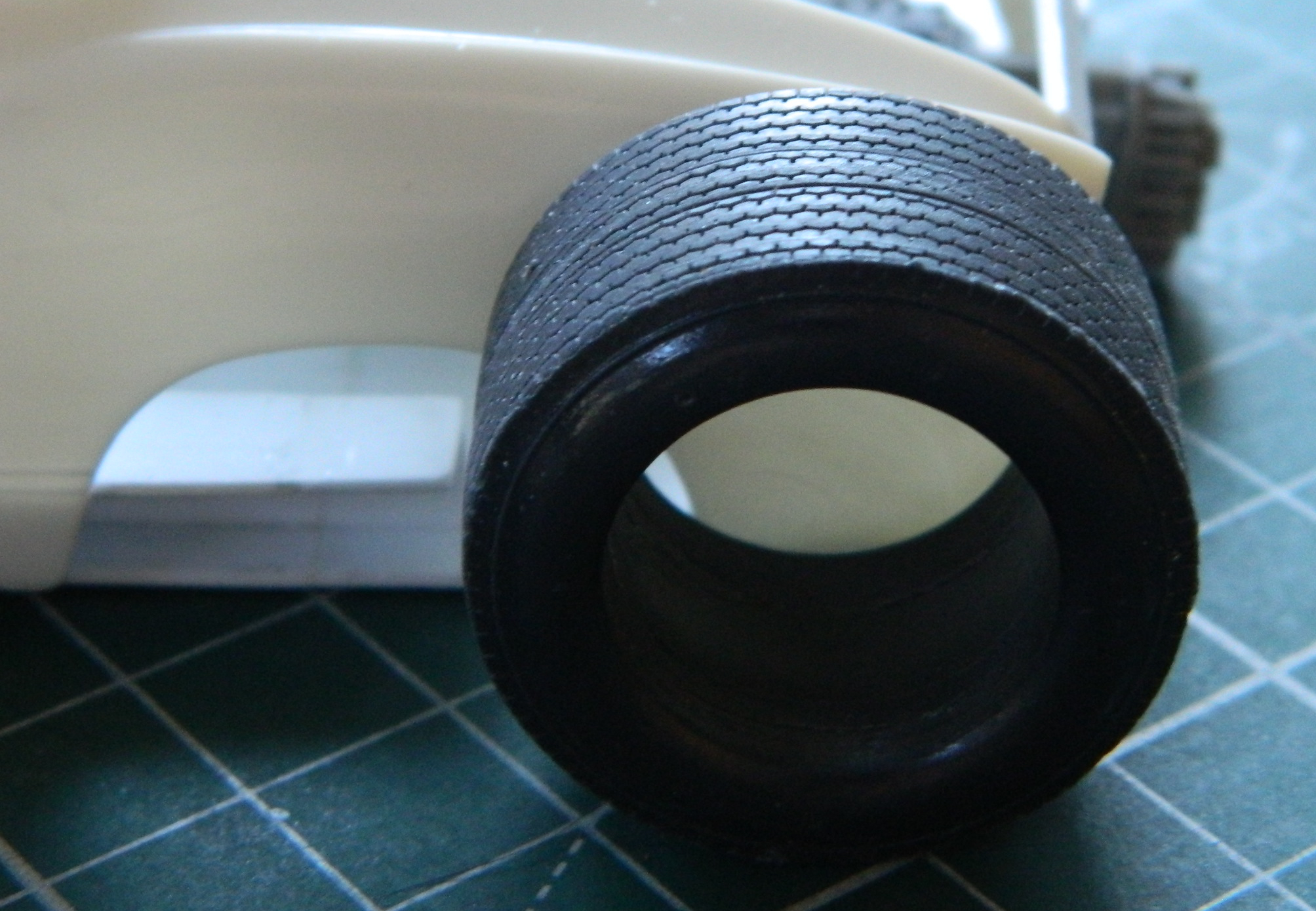
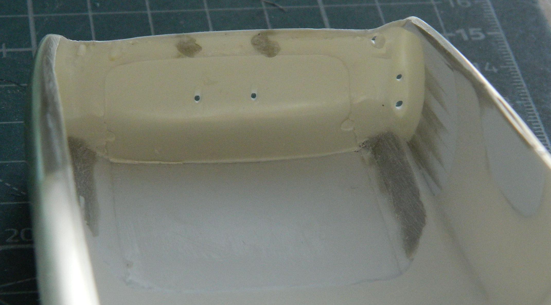
I wanted to determine the ride height of the car. Seeing as it’s a street car, it couldn’t be as low as a custom or race car. The streets are much rougher on a car than a track (or trailer), having things like potholes, speed-bumps, driveways with steep approaches, and all the other wonderful things that street cars have to cope with. I wanted to shim the car and monocoque at a ride height I thought to be realistic. For that I used quarters and now I call this my “seventy-five cent clearance” because three quarters gave me just what I wanted, or about 6″ (152.4mm) scale inches:
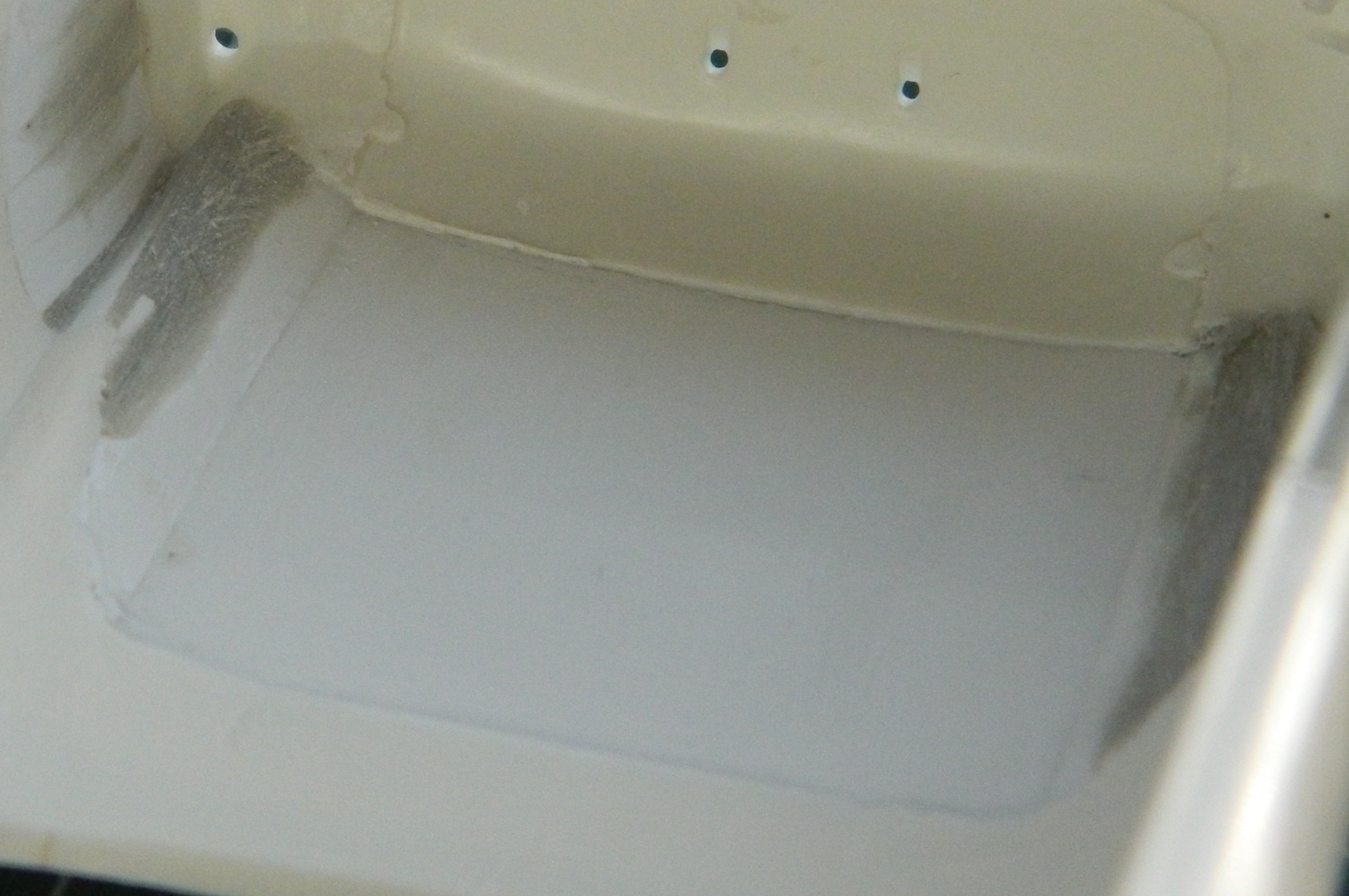
With ride height figured out, I dry-fit the engine, aligned things, and traced around the tire to determine the size, shape, and placement of the rear wheel openings. I did this while both the body and the monocoque were sitting flat on the bench instead of at ride height to allow for suspension compression:

Once the putty had cured, I sanded down the putty inside the bodywork:
At this point there has been a lot of sanding of plastic that wasn’t too thick to start with. I wanted to check how thick or thin it was, especially where the seams are. I held the body up to a bright light (the sun) to see where it was getting too thin:
Answer…where the plastic lets the most light through. I knew that I was going to have to thicken this entire area a bit and decided that there was no point to waiting. I laid down strips of .020″ (.508mm) scrap styrene and then another coat of putty:
While that was curing, I did a little work on the monocoque which gave me more room for fuel tanks. I haven’t done the numbers yet but I estimate that I’m probably at the 25 gallon (94.6L) target, perhaps more, and now that I have a better idea of how long the chassis needs to be, I added an extension to the rear and made a less-clunky set of engine mounts:

Having ascertained where things go, it’s time to put some things there. The rear fender flares. If I could design a body for an inveterate modeler, I’d design someone with variable-magnification eyes and four arms so that I could have four hands. I think the second pair of hands would be really small for handling really small parts. Since my body doesn’t have those features (or many other ones lost over the decades), I figure out how to make do with what’s left after the Sands of Time have scoured thoroughly.
I need to hold the Bug fenders in place while holding the body in place while outlining where I (possibly) need to cut the Bug fenders. Lacking the genetic and physical modifications that I so ardently desire (hmm…buying shirts could pose another challenge), I used a lump of Plasticine to hold the fender in place so that I could mark it:
Once marked (sorta), the cutting, filing, sanding, and fitting began (double-sided tape stuck the flare to the body to allow me to step back and look at how it went):
Well, it didn’t go as I’d hoped (but expected) and some plastic had to be added back and I used various thicknesses of scrap to do that:

This was followed by more sanding, scraping, and filing. Eventually I got things close enough so that I was confident that the Apoxie Sculpt could bring it home:

The I got to do it again on the other side, hopefully (more on that shortly) matching what I had just done. This process was repeated on the other side and all of the putty was filed and sanded:

And…no. I didn’t get both sides identical. I also didn’t notice the difference immediately (the second flare was a bit wider than the first). I worked (snapped, more accurately) the forward half of the second flare loose, figured out how much I had to remove, and started cutting:

I thought it would be easier if I took a little bit more off than I needed because in this manner I could adjust the width easier (and this time I was correct…I’m not getting accustomed to that and neither should you):
That almost did it. Once the front of the flare was narrowed, it showed that the rear of it was also too wide (go figure) and I took care of that in the same manner. Finally satisfied that the flares were as close to identical as I could make them, more epoxy putty was applied. Then the putty was ground, filed, and sanded:


My original intent was to be able to use what had been the headlight sockets as brake lights and the original brake light locations used as backup lights instead. Since lengthening the body meant that the rears of the fender flares wouldn’t match up with the rear of the car’s body, that notion got tossed. Instead I’ll be using what’s left of the headlight sockets as vents to allow air that gets pulled into the engine bay to have an easy exit.
I’m stopping (briefly, I hope) at this point because though I know what I have to do, I’ve less than no idea as to what the build sequence should (and will) be. I think what I’ll do instead is to add the front fender flares while the BitB work on it and hopefully come up with a workable plan because right now I am utterly bereft of having one.
