F7F-3 (AMT/Italeri) 1/48 Scale Build #5 – Finishing the Engine Nacelles, Landing Gear, and Starting the Cockpit…Where Things Get Tedious
With the main landing gear installed, I wanted to finish painting and working the tires. Scale Model Accessories resin wheels (part #CAT_R48018) will take the place of those HIDEOUS vinyl tires. I’m eagerly awaiting the news that kit manufacturers freakin’ stop making these things. They dissolve styrene so sure…let’s include them in a styrene kit! Gotta say, the corporate mentality (though using “mentality” to describe corporate decisions and policy really takes my sense of sarcasm to new heights…or depths, you choose) continues to baffle me. The vinyl doughnuts get replaced by these:
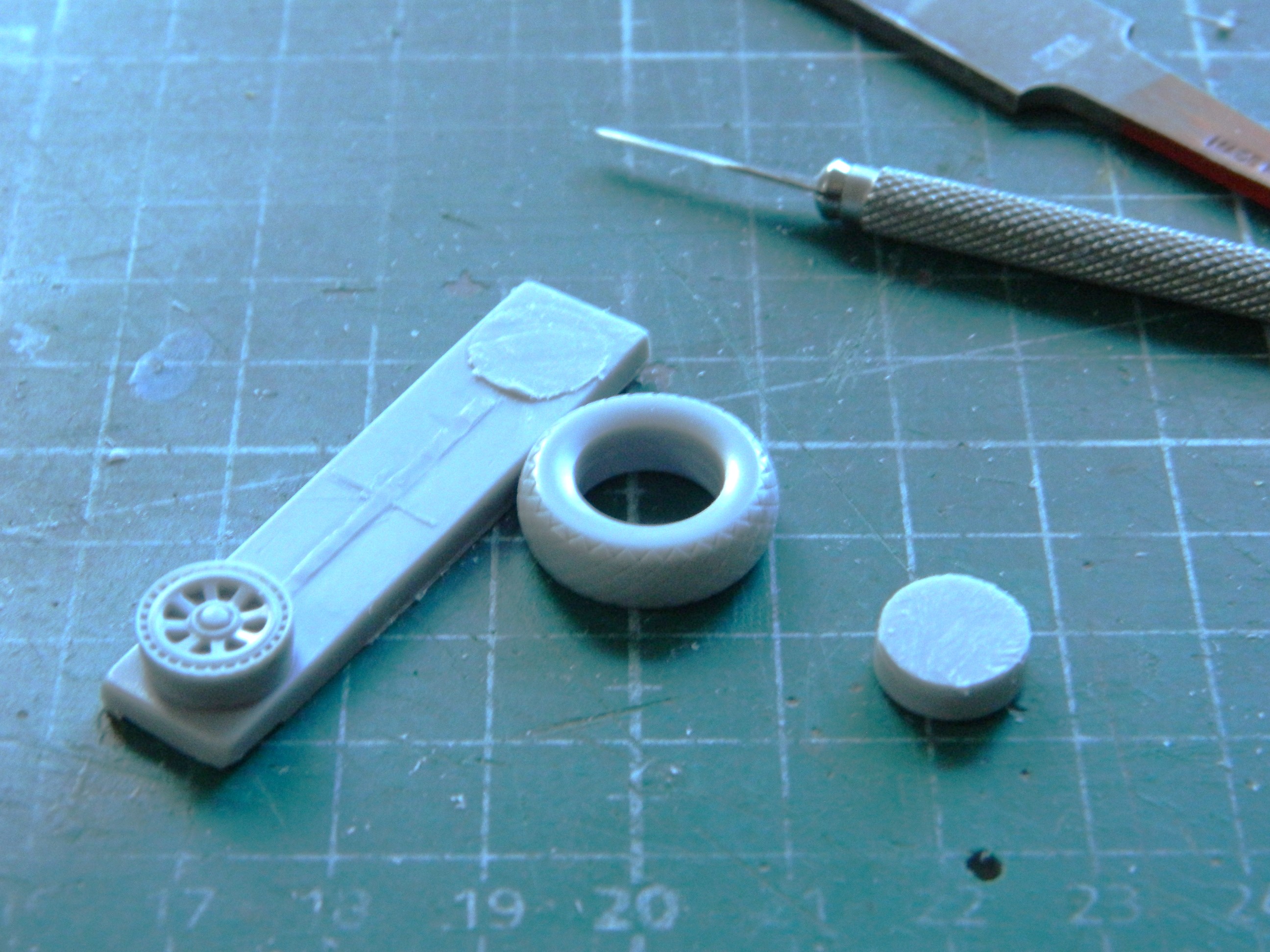
Once the pouring blocks were separated from the tires, I discovered that the wheels were just slightly smaller than the openings in the tires (for all three):

The wheels were also too thick from one side to the other. That was easily remedied by just sanding them a bit more. Still, the masters for these parts were clearly 3D printed. So…the digital doctor didn’t know how to dimension things correctly? ::facepalm::
After jiggling the tires on the wheels in the attempt to minimize the mismatched wheels and tires, I used Tamiya’s XF-85 Rubber Black for the tires (though Tamiya’s XF-69 NATO Black works just as well). Then I misted Tamiya XF-2 Flat White onto the treads to replicate wear:
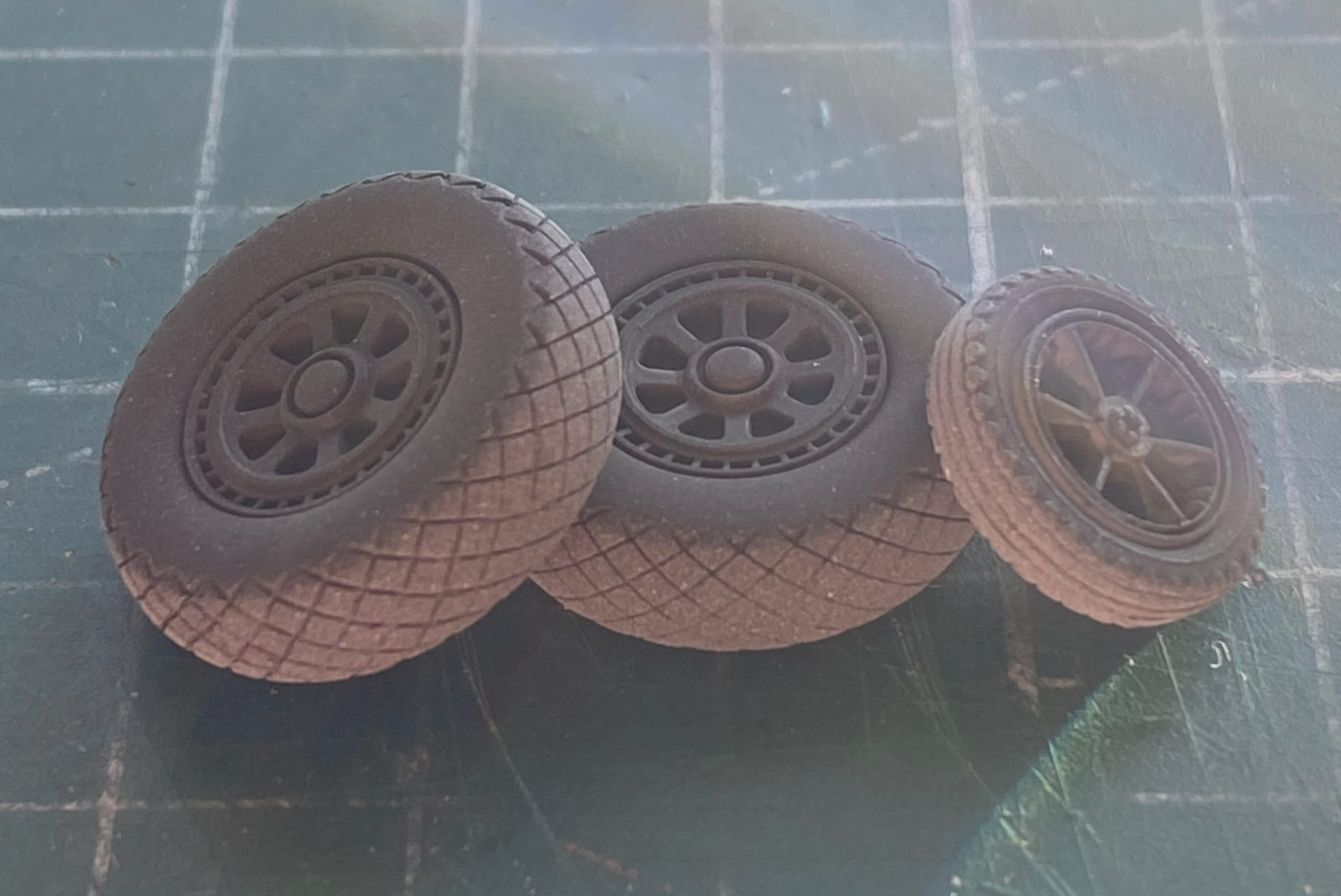
The wheels will get treated with a mix of Tamiya XF-16 Flat Aluminum (4 parts) with Tamiya XF-1 Flat Black (1 part) to tone down the brightness of the aluminum. These were set aside until I was ready to paint some darkened aluminum.
To complete the engines, I needed to add the props. I’ve read build reviews of this kite and about half of them complained about the shape of the blades. I didn’t see it. I trust my eyes (in spite of their many deficiencies) so I didn’t reshape them. I did see, however, that deployed Tigercats had the tips of the blades squared off for more ground clearance. Evidently the tips of the props would hit the ground under certain circumstances so it wasn’t uncommon for them to be trimmed back (I’ve seen period reference photos showing the blades in both states, trimmed and original). I marked the tips where I would trim them back to:

I’m going to be mixing some custom colors. An empty Tamiya paint jar is excellent for mixing custom colors that I use frequently enough to want to have premixed and on hand:

When painting dark and light colors adjacently, it’s best to put down the light color, mask it off, and then the dark color. I think that Tamiya’s XF-3 Flat Yellow is far too bright (unlike your humble…sometimes…author) so I used three parts of the XF-3 and one part of Tamiya XF-60 Dark Yellow. After spraying the tips, I let the props sit overnight before masking off the yellow and using a rattlecan of Tamiya Lacquer TS-6 Matt Black, which actually is more of a semi-gloss once it’s cured:

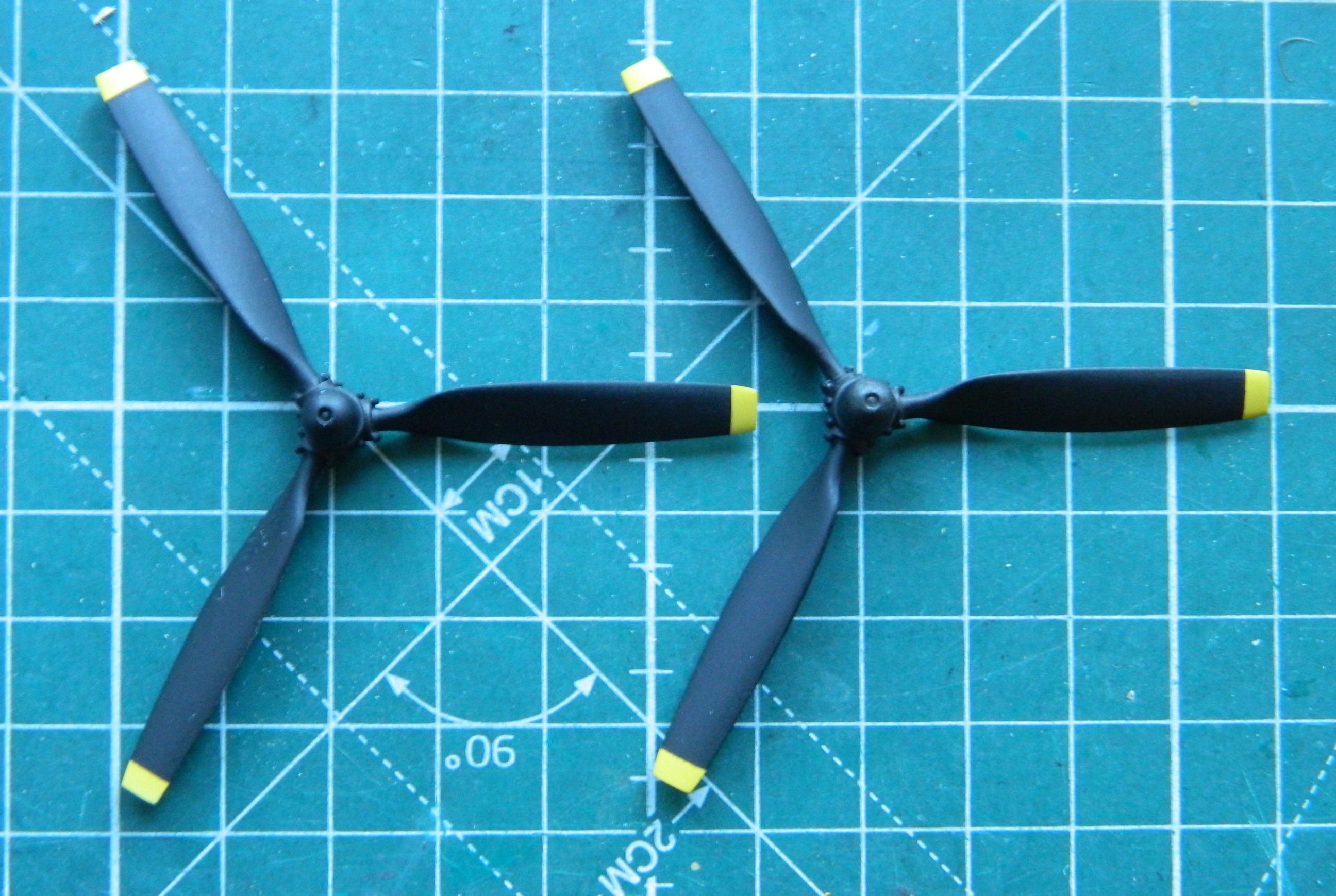
Only one more color to add to the props and that’s to paint the hubs aluminum, and yes…I used the darkened aluminum for that. And since I was loading the airbrush with darkened aluminum, I painted the parts already assembled that require that paint:


The wings were assembled:
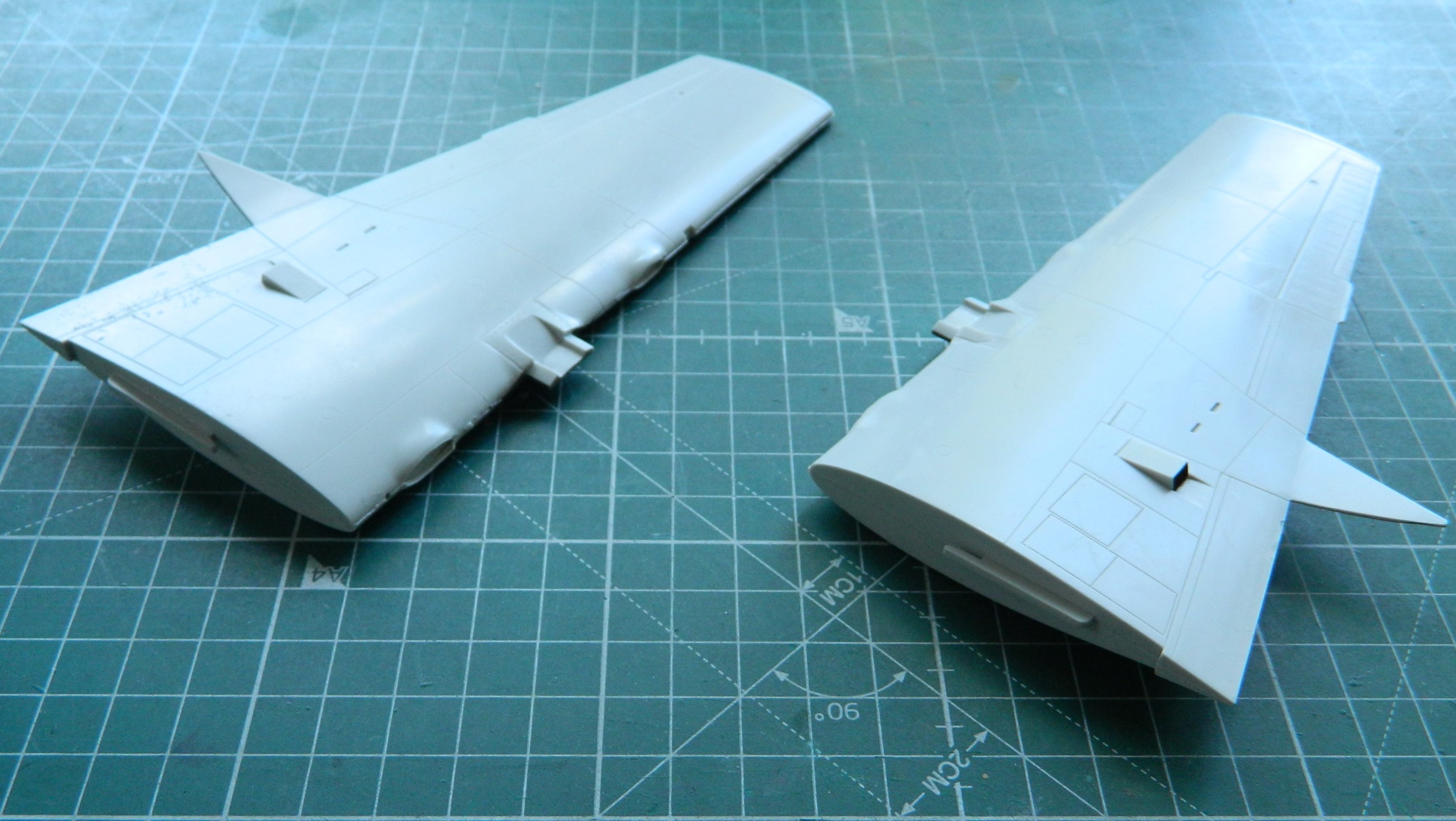
Having dry-fitted the nacelles to the wings previously, I knew that the upper rear of the nacelles molded onto the wings both sported massive gaps. Anyone who thinks force never solves anything has never been a mechanic or carpenter (and there are no doubt many other trades in this category). This time the force was supplied by clamps (clamps…isn’t that what Chinese women get every 28 days or so?):

With the subassemblies of wings/nacelles mostly done (I’m trying to decide which putty to use where the nacelles attach to the wings…too much for 3M Acrylic Putty or should I use Aves Apoxie Sculpt? You’ll figure out which trigger I pulled in a subsequent post), attention turned to the office. The cockpit.
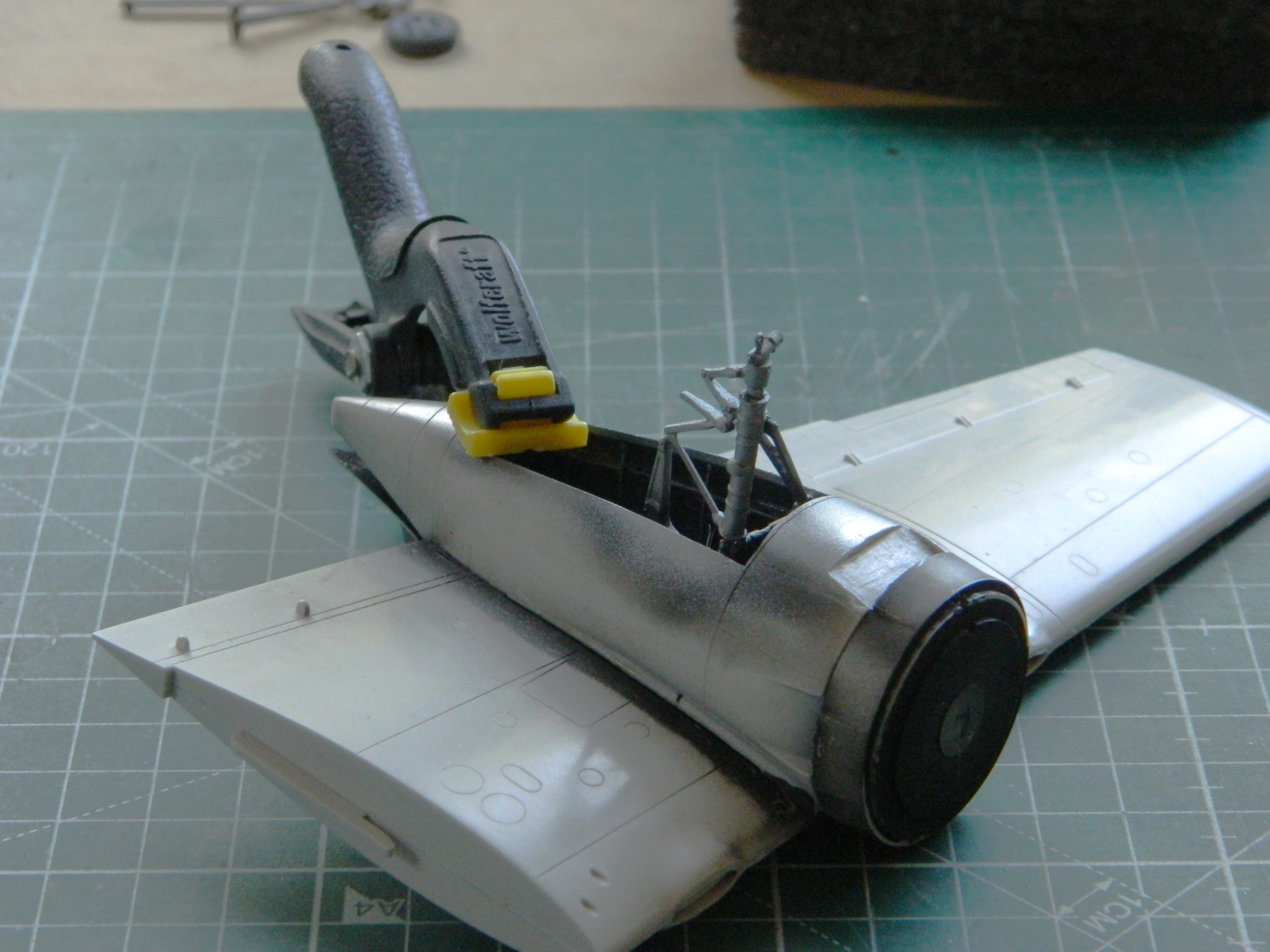
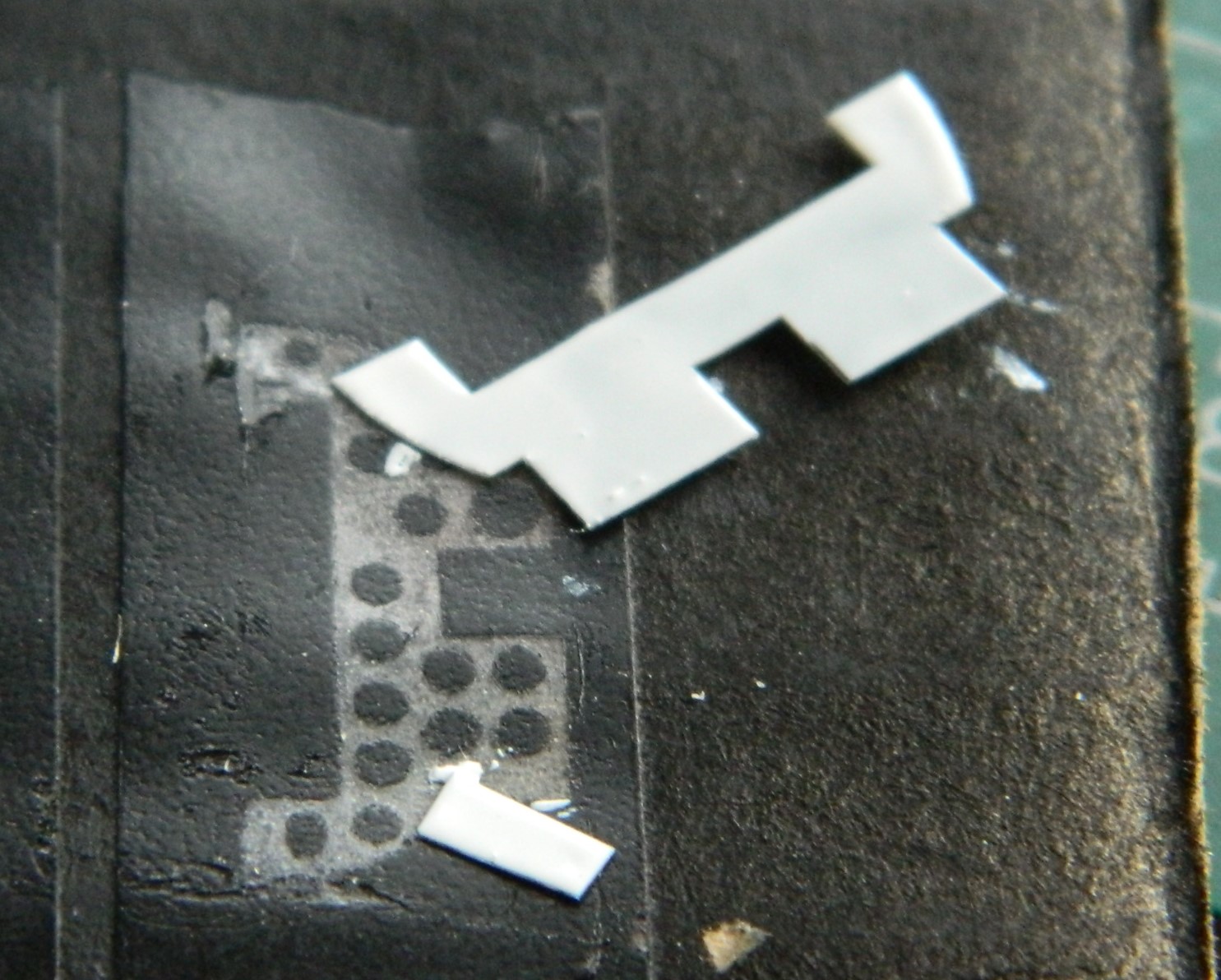
I took the few cockpit parts…:

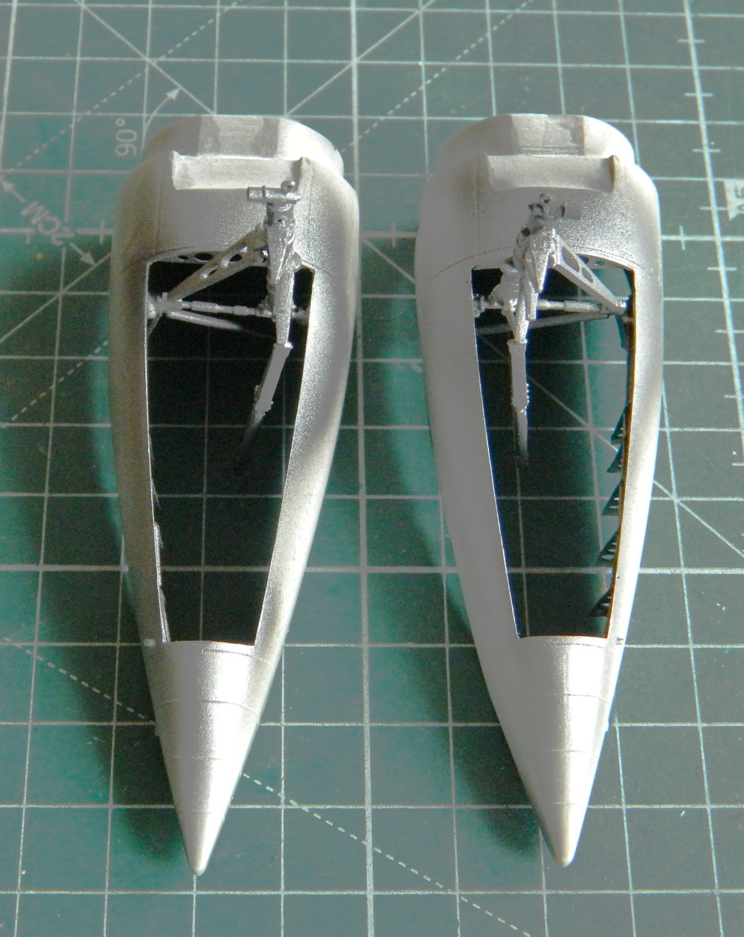
…and tacked them together with white glue. I wanted to dry-fit them to see how they fit (sorta) and how much room I had to stuff even more lead into. Remember, the start of the previous post showed that what I’d already stuffed with lead (and tungsten…for its price, let’s not forget the tungsten) was just enough for this kit to stay on all three tires. I want more. Once the white glue dried, I placed the floor/instrument panel/bulkhead in place to see what space was left.
Plenty:

Every surface with a line on it is forward of where the main wheels sit (the balance point). And I accept that every review I’ve read has either not put enough weight in or has just enough weight in…but a bump would make the model sit on its tail. With all this space I’m not really sure why that problem reoccurred enough for it to be A PROBLEM. But regardless, forewarned is forearmed. Before I join fuselage halves I’ll be stuffing lead into the spaces marked.
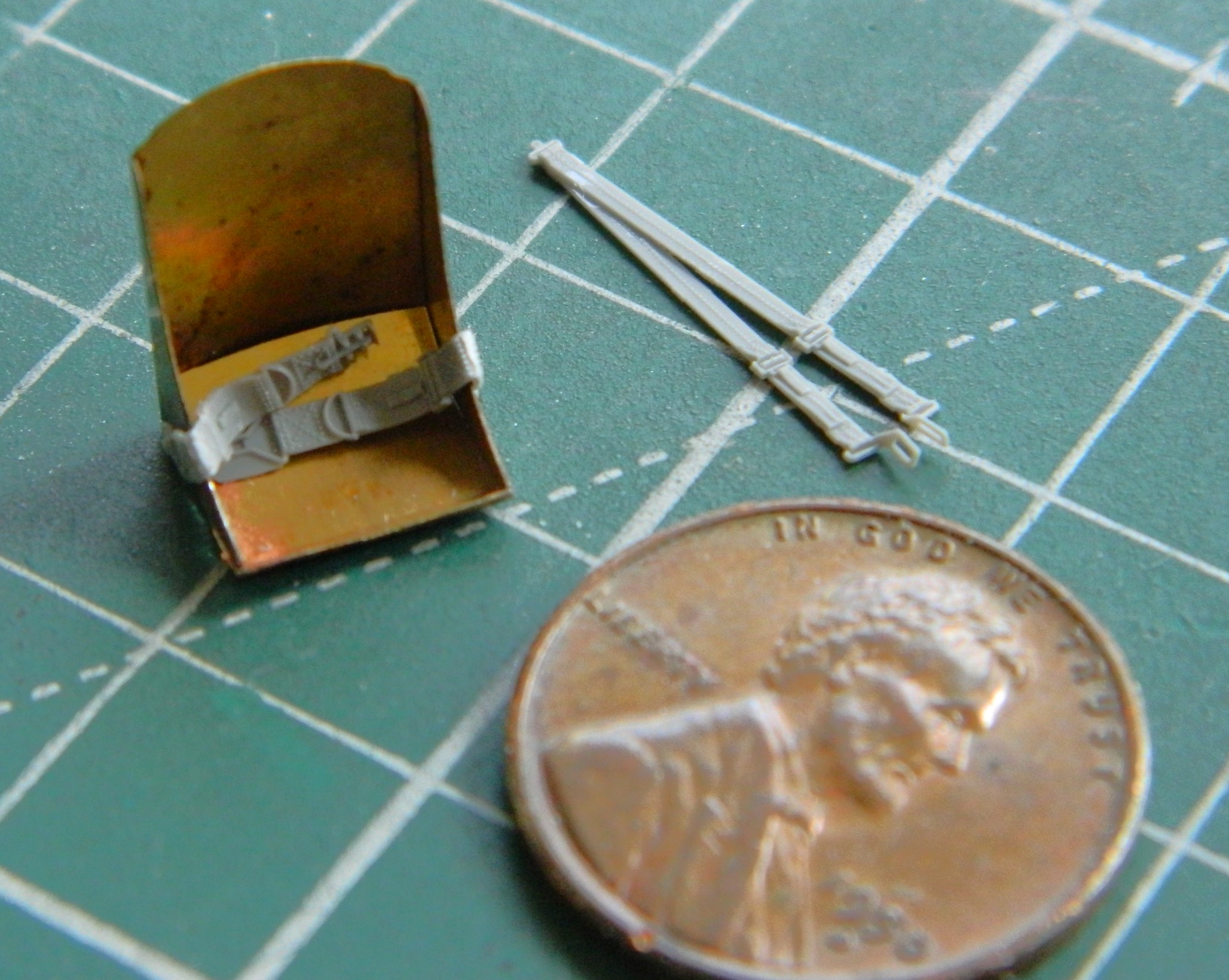
I recently got into a conversation about, “I don’t think PE is worth the hassle.” I get it. Sometimes I use the PE parts as a template and make a plastic copy. So far, PE can only do flat parts and some of the parts that PE is supposed to replace isn’t flat and that’s frequently noticeable. But there are those times when PE is well worth the hassle. I think that this is one of those times:

Yes…there is a gap in the PE part where the back of the seat angles up to meet the back. I intend on filling that gap (and the required finishing to make it look correct) with UV-setting resin.
So far I think that the styrene harness will probably end up looking pretty good. This is just my initial attempt. There may be more tweaking (the shoulder harness will be formed over the seat back later):
I get that it’s nosebleed expensive to cut the molds for a model. In the attempt not to make one basic kit with different parts trees for different variants, manufacturers will often paint with a broad brush. This model shows that in a couple of places and the most obvious is the instrument panel.
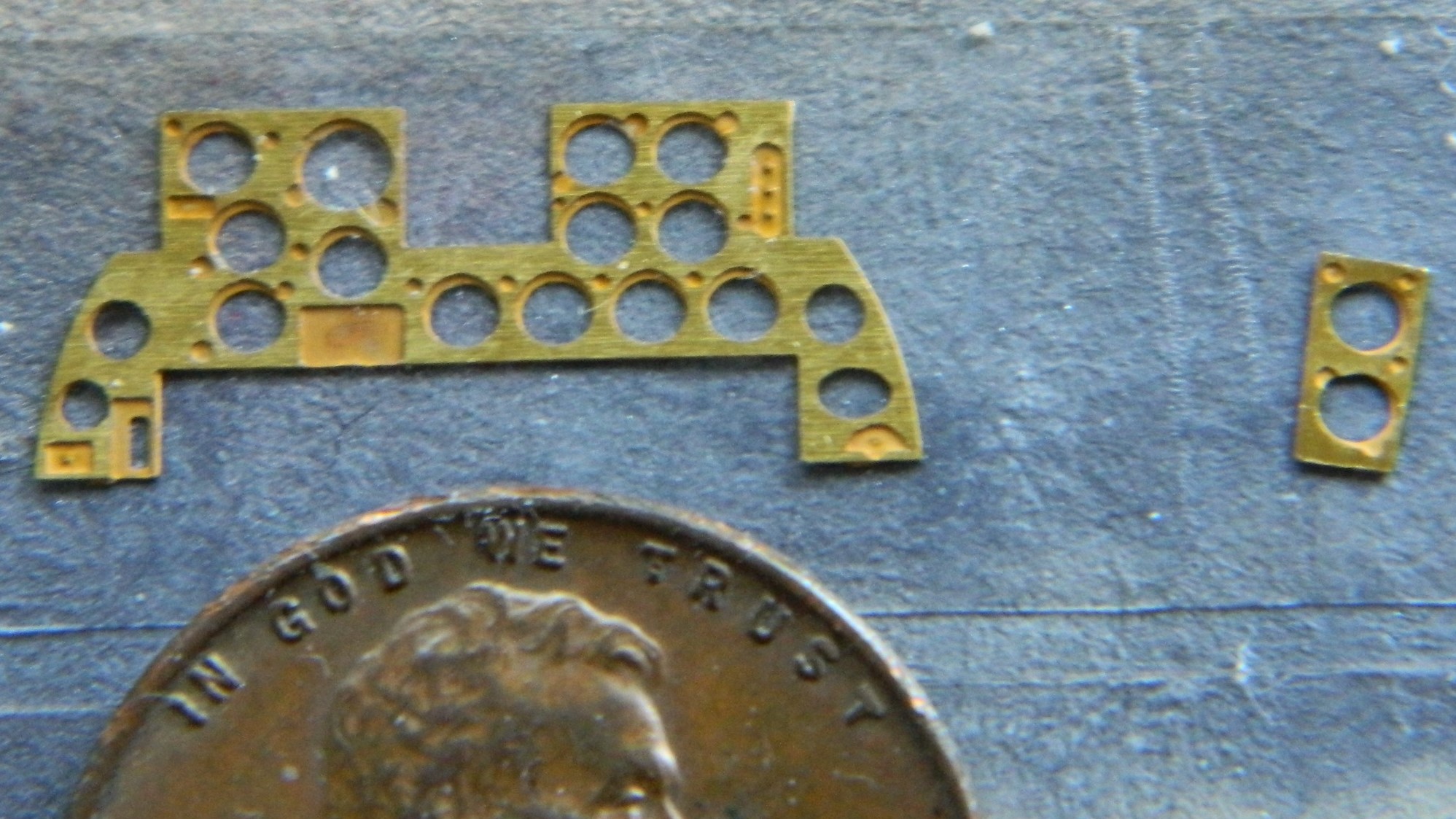
The F7F-3 that I’m building is the fighter variant and was the least utilized of the three variants. The -3P was the photo-recon variant and the 3N was the night-fighter variant. The-3N had a slightly different instrument panel. There was a prominent radar display in the center of it (I’ll bet you can spot it):
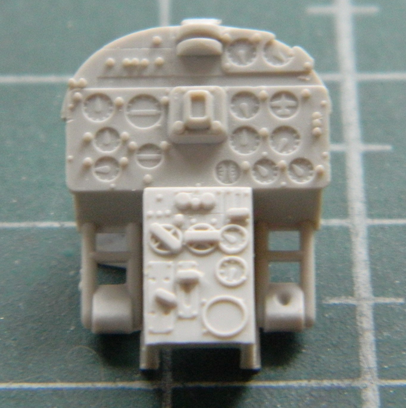
At the top center of the instrument panel, that semi-circular protrusion is supposed to be the gun sight. Uhm…no. I’ll cut that out and build a better one. But the radar display and all other raised detail on the face of the panel has to be removed so that the film/PE replacement will sit flat:

This is a much better rendition of that panel:
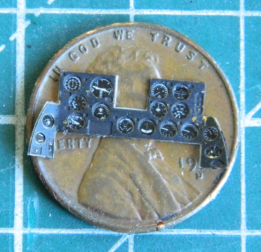
I used Tamiya’s rattlecan TS-6 Flat Black to see how well it would adhere to the brass. I already knew how Tamiya XF-1 Flat Black and X-18 Semi-Gloss Black adhered (not well) and I wanted to try lacquer to see if that would work better:

While that was curing, I used Testor’s White Gloss enamel (yes…the one in the little square bottle) to act as a backing for the film-gauges so that they would be visible:
Not bad, though just from very minimal handling I can see that lacquer didn’t hold up better than acrylics did. As part of the retouching process, I will also go around the edges of the panel with black so that the backing film with the gauges won’t jump out in the eyes…and the panel needed even more retouching than what’s showing here:
I can’t imagine two things (okay…much more than merely two but this isn’t the forum for my general ignorance). The first being how the die (mold) makers can get something so wrong. Or. How does a die wear so that it’s no longer aligned with its counterpart. But this happens often:
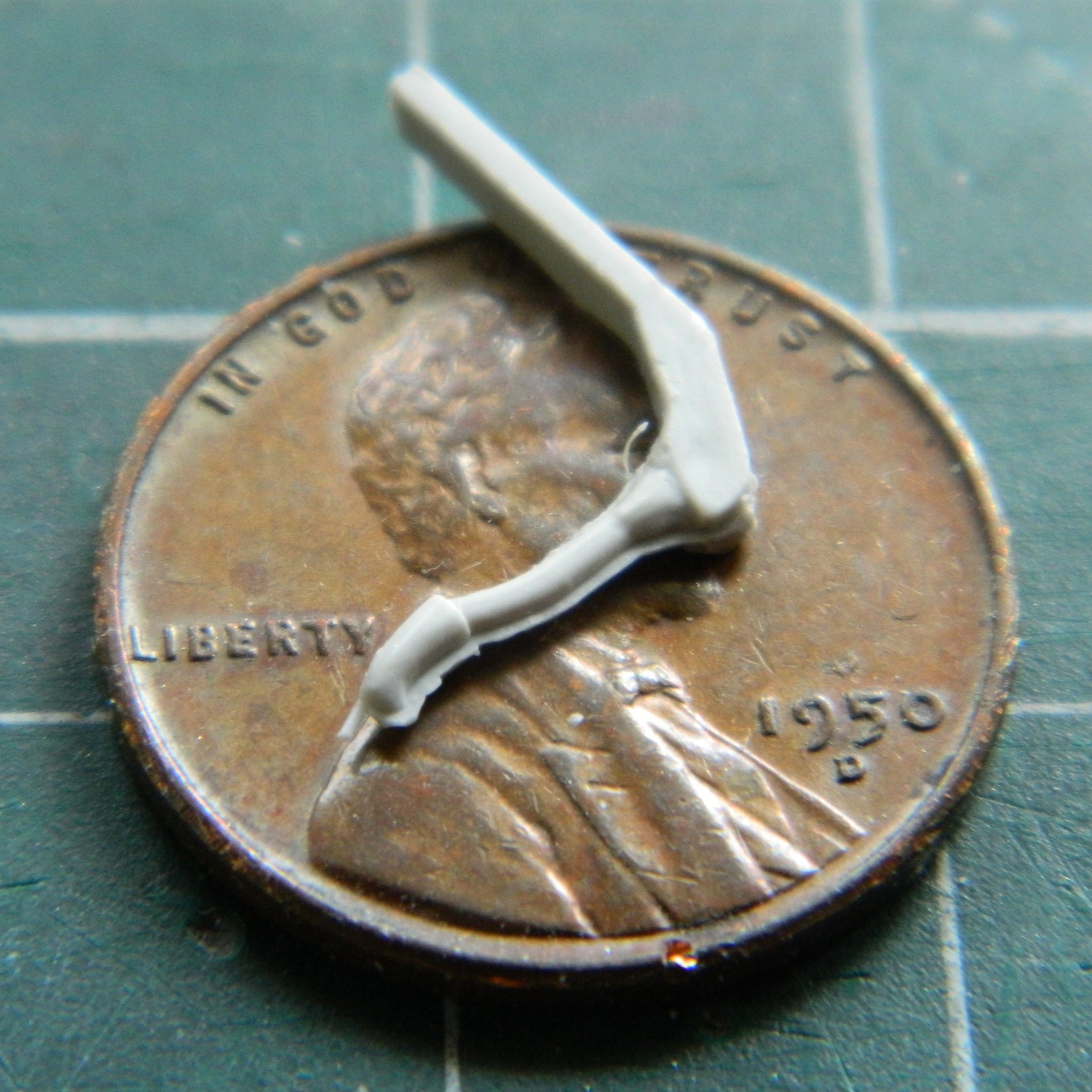
This presents a conundrum. Which half do I make conform to the other? Well…to be picky about it (a modeler picky?!) the answer is “both”. I’d be fine with that if the entire part didn’t fit on top of a penny. If I try to make the misalignment go away, I’ll break the joystick. (Don’t ask me how I know.) Okay, then the determining factor is the answer to this question: “Which side will be visible?” Easy answer. The part of the part that the pilot would see. If the pilot would see it, so will you. I decided to stretch sprue as thinly as I could (success!) and then lay it along the misalignment:


Yeah…this one is going to be delicate. I set the part aside for a couple of days so that the glue (my go-to is Tamiya Extra Thin green cap) out-gasses totally.
This is what the kit supplied for the control panel to the right of the pilot. All the raised details from the center to the left has to be removed:
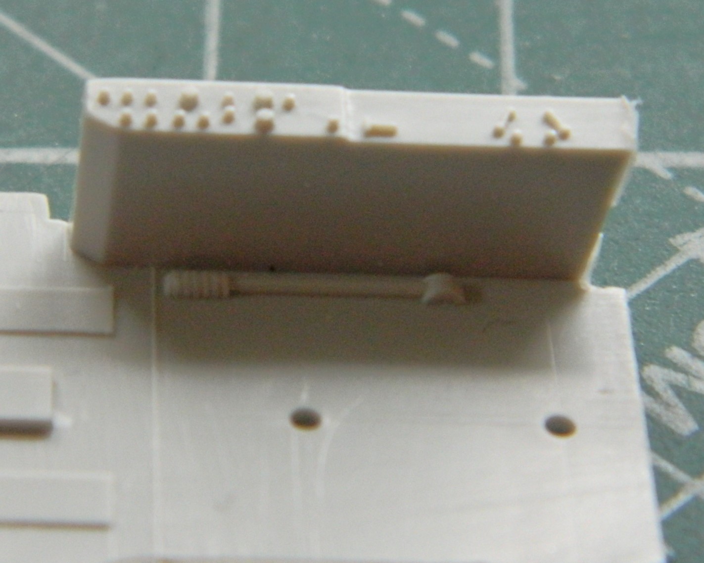
This time PE does what it does best:
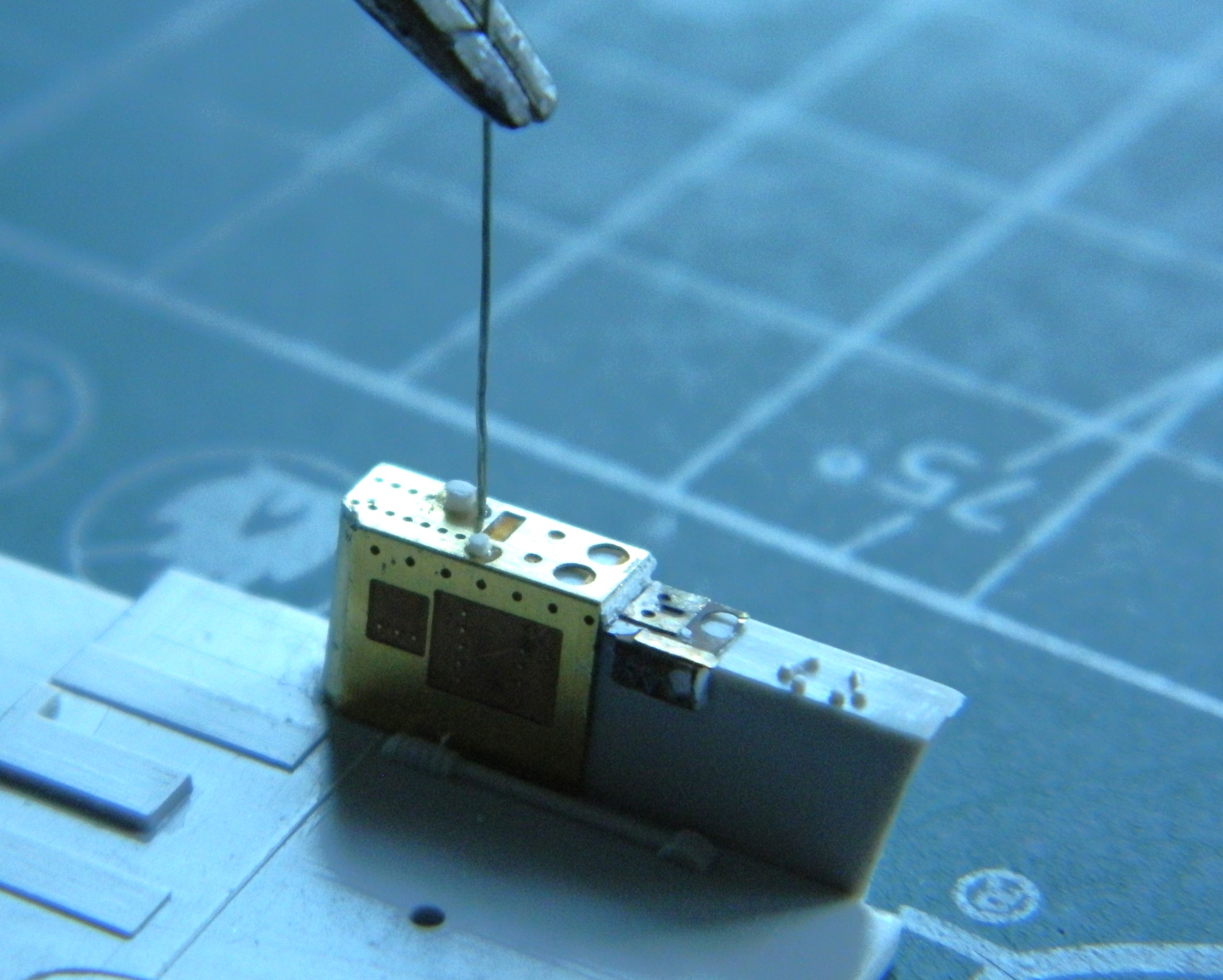
I forgot to take a photo of it initially. The forward vertical edges didn’t fit snugly (surprised me, Eduard!). 3M Acrylic Putty filled them. And what you see in the above photo is the beginning of the 11 or so toggle switches that “have to” be added. (The white knobs were added from stretched sprue.) In this photo you see all the toggle bats added:
Yes…the ends of the bats aren’t supposed to be chisel-shaped. The size of them keep those ends from being noticeable.
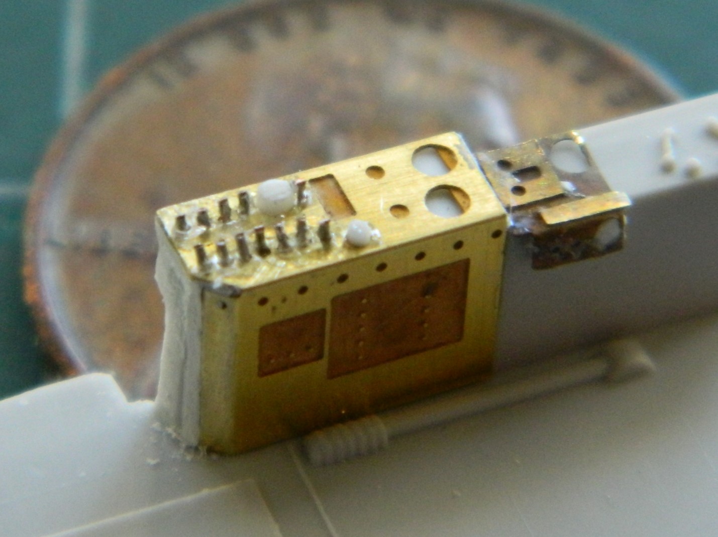
With the cement out-gassed, I very gently sanded away the added sprue and (also delicately) reshaped the grip:
There is also a push-button off-center to the left. I don’t know what it’s for but it can be seen, so I added one:
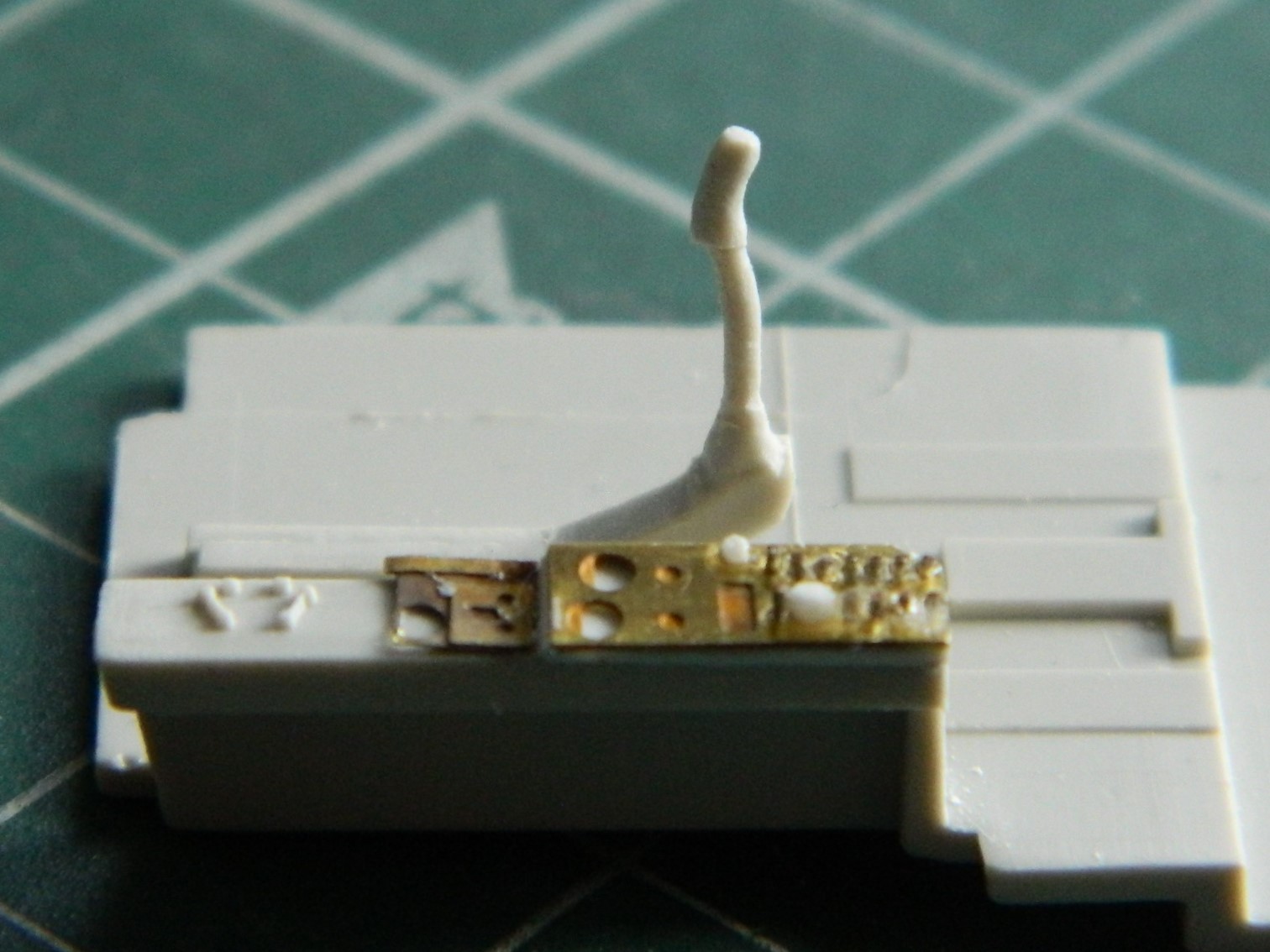
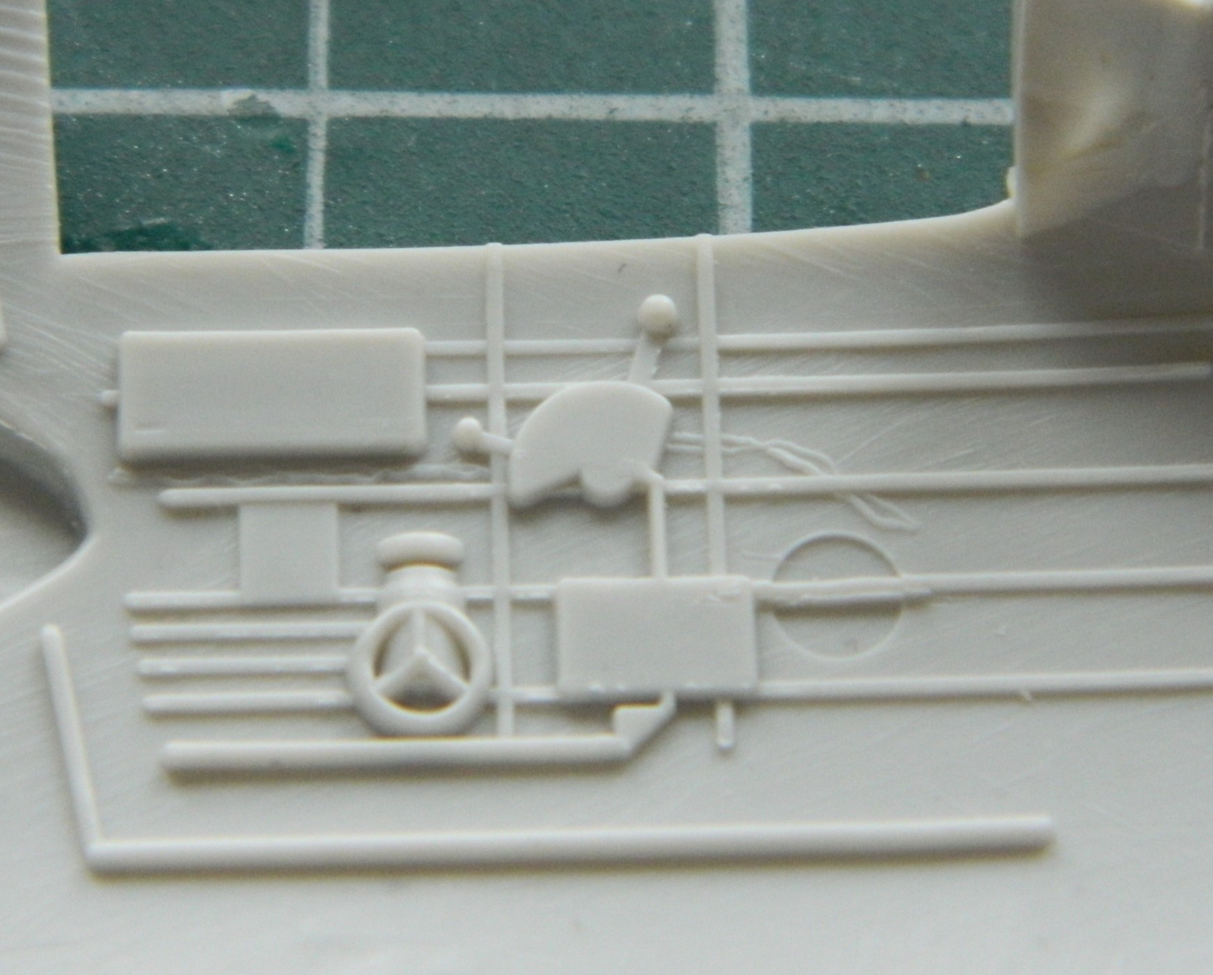
Twin engine prop aircraft have doubled engine, prop pitch, and mixture levers. This kite also has one supercharger control. That’s seven levers (puts shoes back on). This is what the kit provided:
And this is what the Eduard PE fret thought would be better:
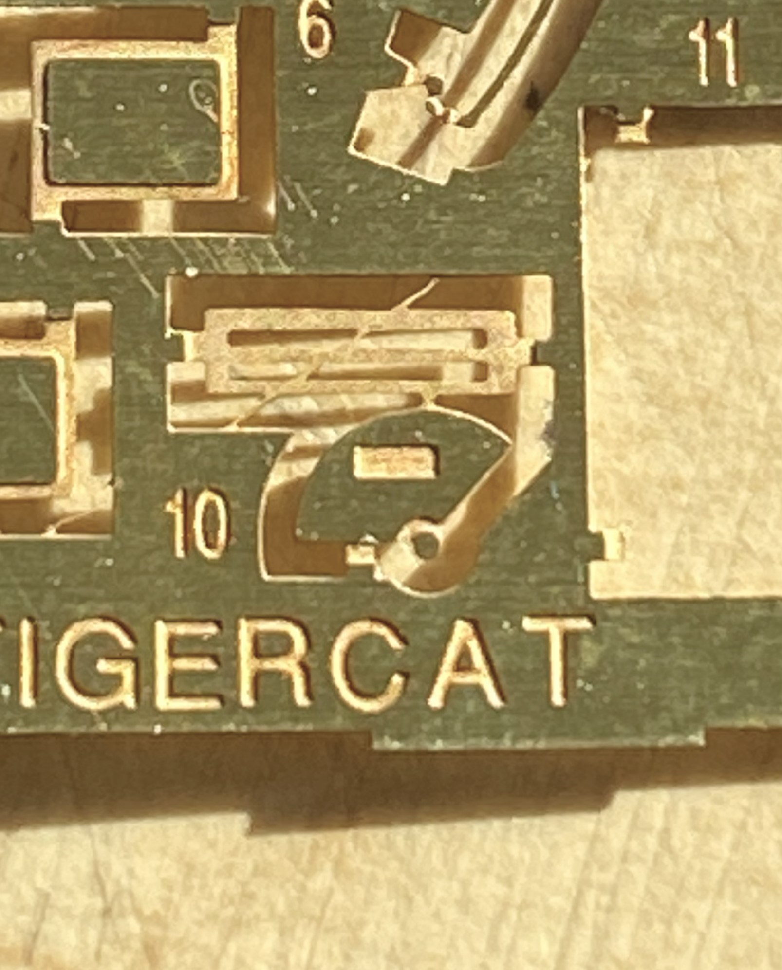
Not in the least bit usable. Maybe I’ll be able to use it for something else later on but it’s just ridiculously inaccurate for this build.
Hmmm…two divided by seven means that less than 29% of the controls that should be there are there. Fine (he says petulantly), I’ll make one and it should look just like this:
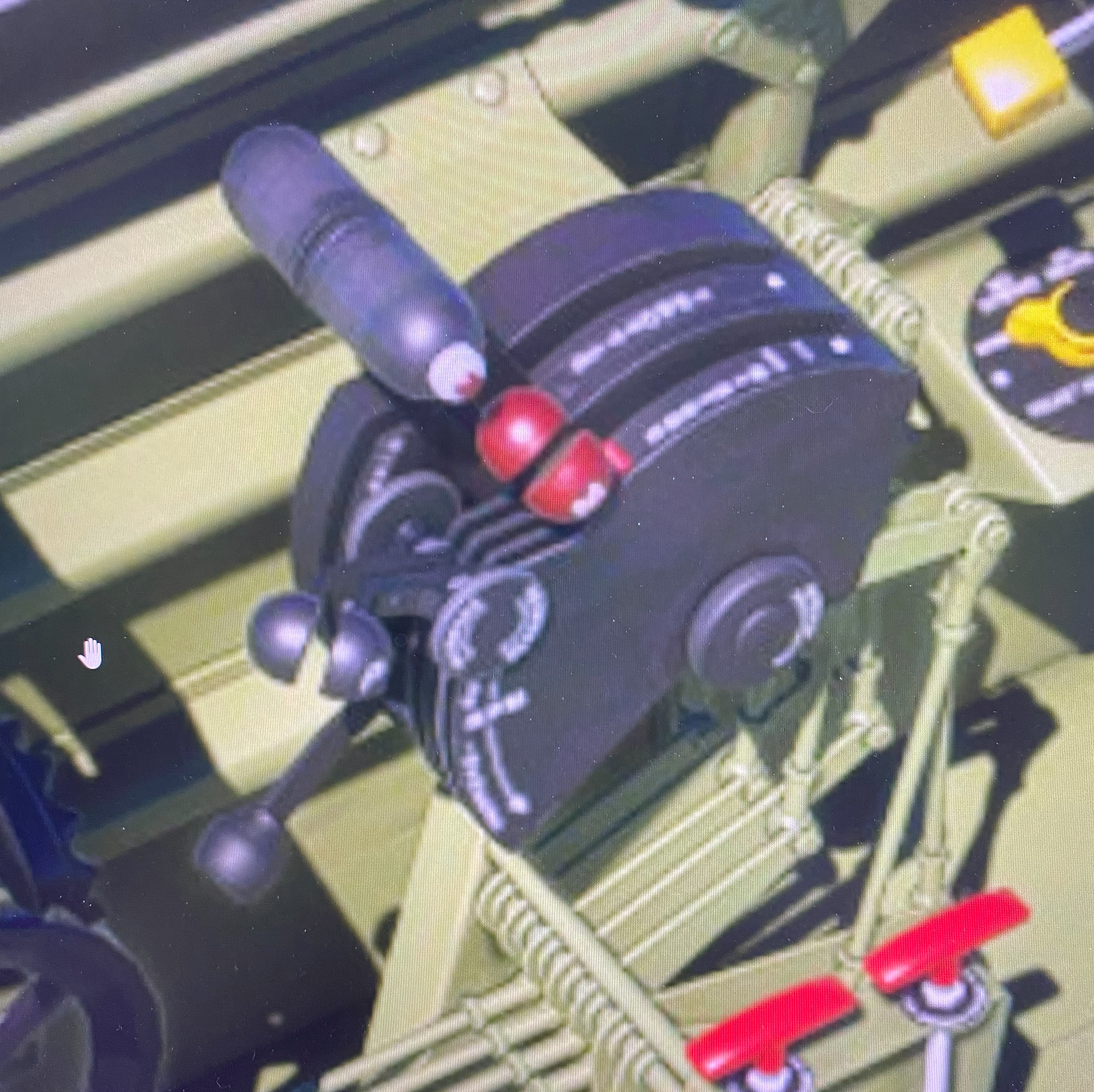
I mean, really… how hard could it be?
Yeah, well, one of these days I really must stop asking that question because I always, ALWAYS, find out. Oh. And the answer this time is…
Very, very, very. VERY.
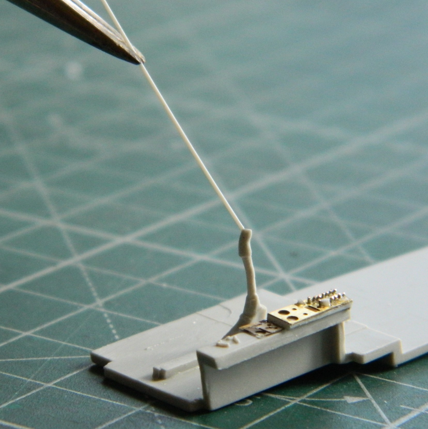
For the first attempt (the words “first” and “attempt” should inform you how well it didn’t go) I tried using 0.010″ (.254mm) styrene. I would normally skip a few steps here but I recently had someone ask, “How do you actually scratch-build something?” So I’m going to show you.
I used the kit’s throttle quadrant as my scale. Clearly it fits, there just isn’t enough of it. I found a piece of .187″ (4.74mm) styrene tube that conformed to the arc of the kit’s offering. It didn’t take me long to realize that there are seven slots for the levers to travel in. And this part is very small. Even with my hands as steady as they were 50 years ago, they were never that steady, and there just isn’t enough room to cut them into the body of the quadrant. But all that said, here’s the process I used… (And I’m not going to put dimensions in the description because this didn’t work so if you try to replicate it, it’s not going to work for you either.)
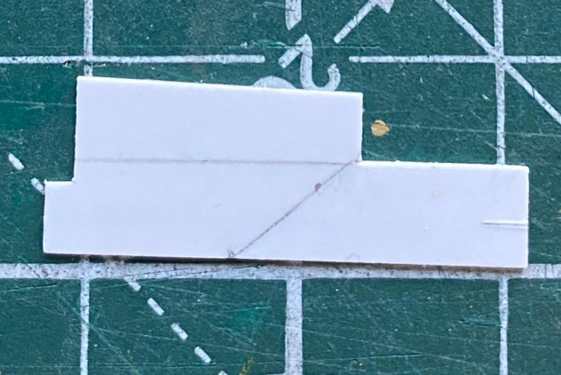
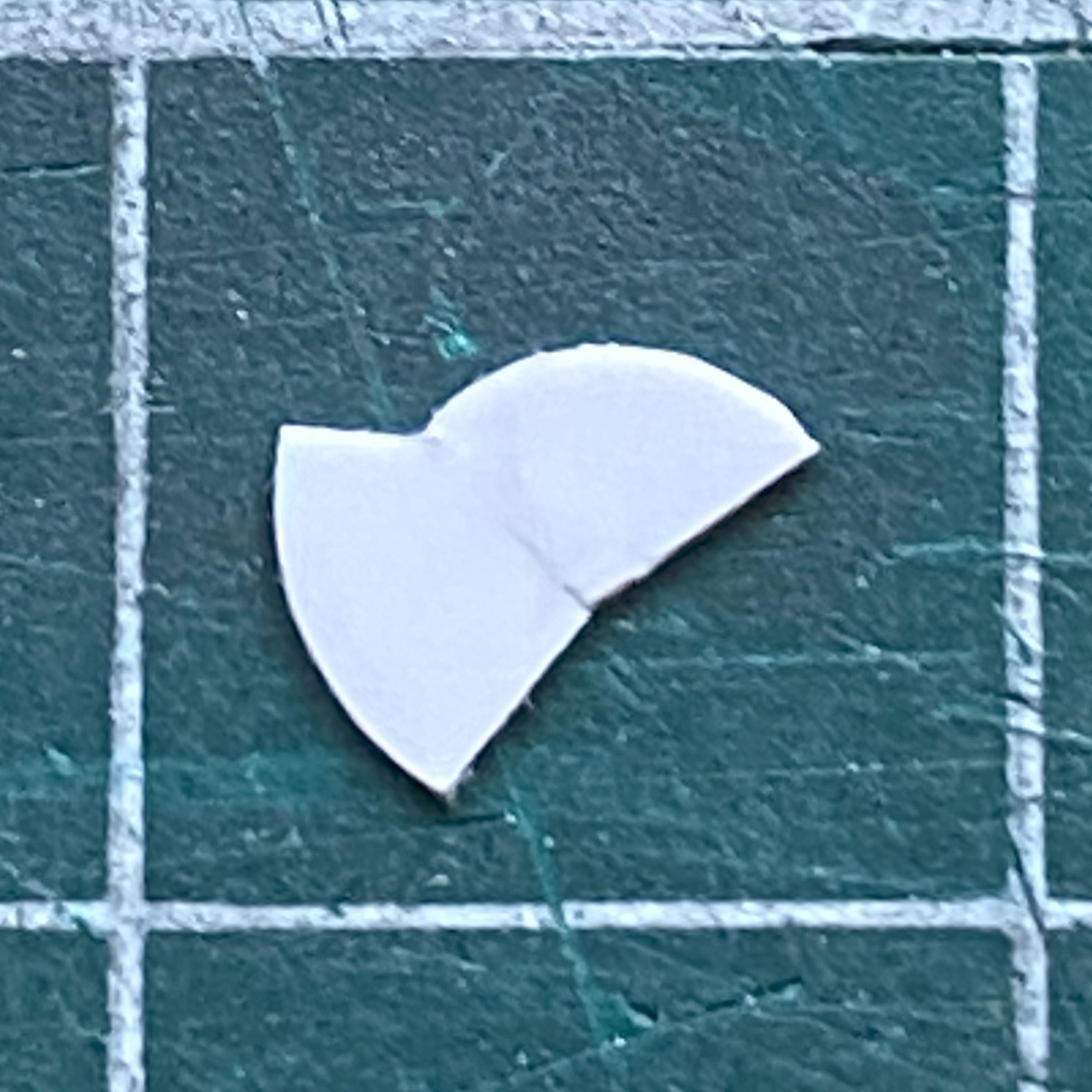
I went into my plastic stock and picked a piece that would be larger than I need (makes trimming things much easier that adding things because the result is too small). I guesstimated the angle of the main body and drew it onto the plastic:
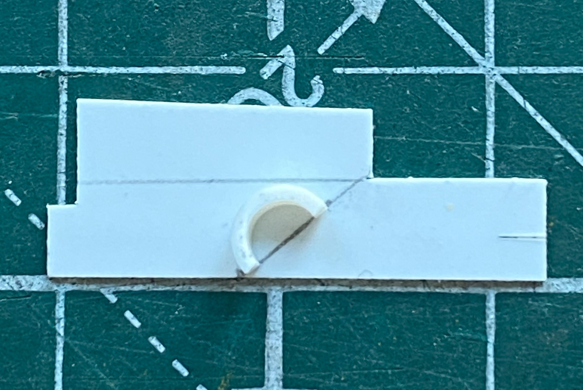
Then I salami-sliced a short section of the tubing I would be using and diddled with its placement until I had what I wanted (which I certainly hope is correct):

Then I sketched in the outline (it wasn’t until later that I realized that I’d gotten the arc on the left a bit off center…which was addressed later):

Then I trimmed it coarsely:
320 grit sandpaper finished the edges:
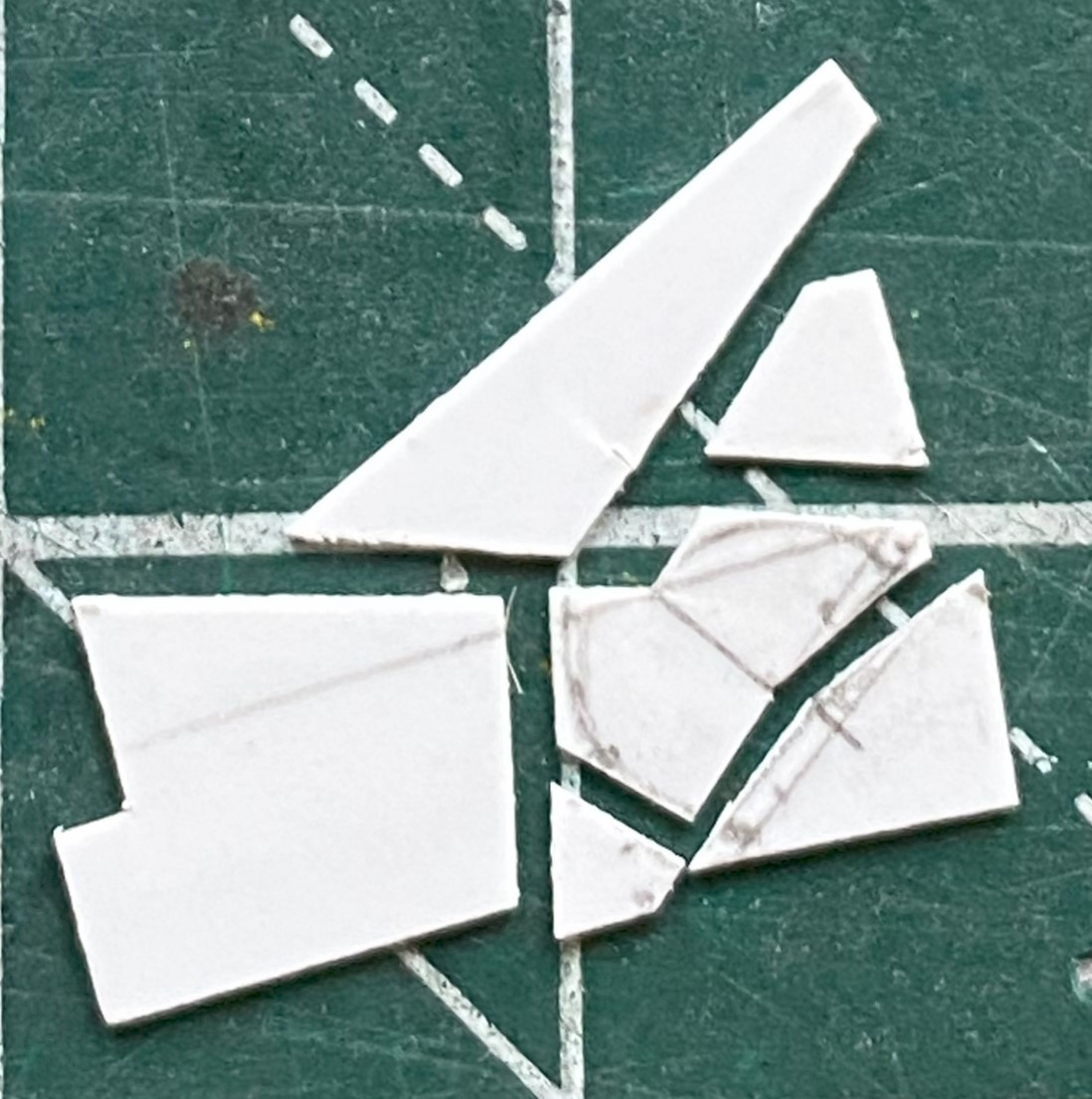
Would that that was all there was to it. Remember, I need slots, too! That meant I needed spacers between each of the follow-on parts. In the following photo, the parts are actually upside down, but hey…
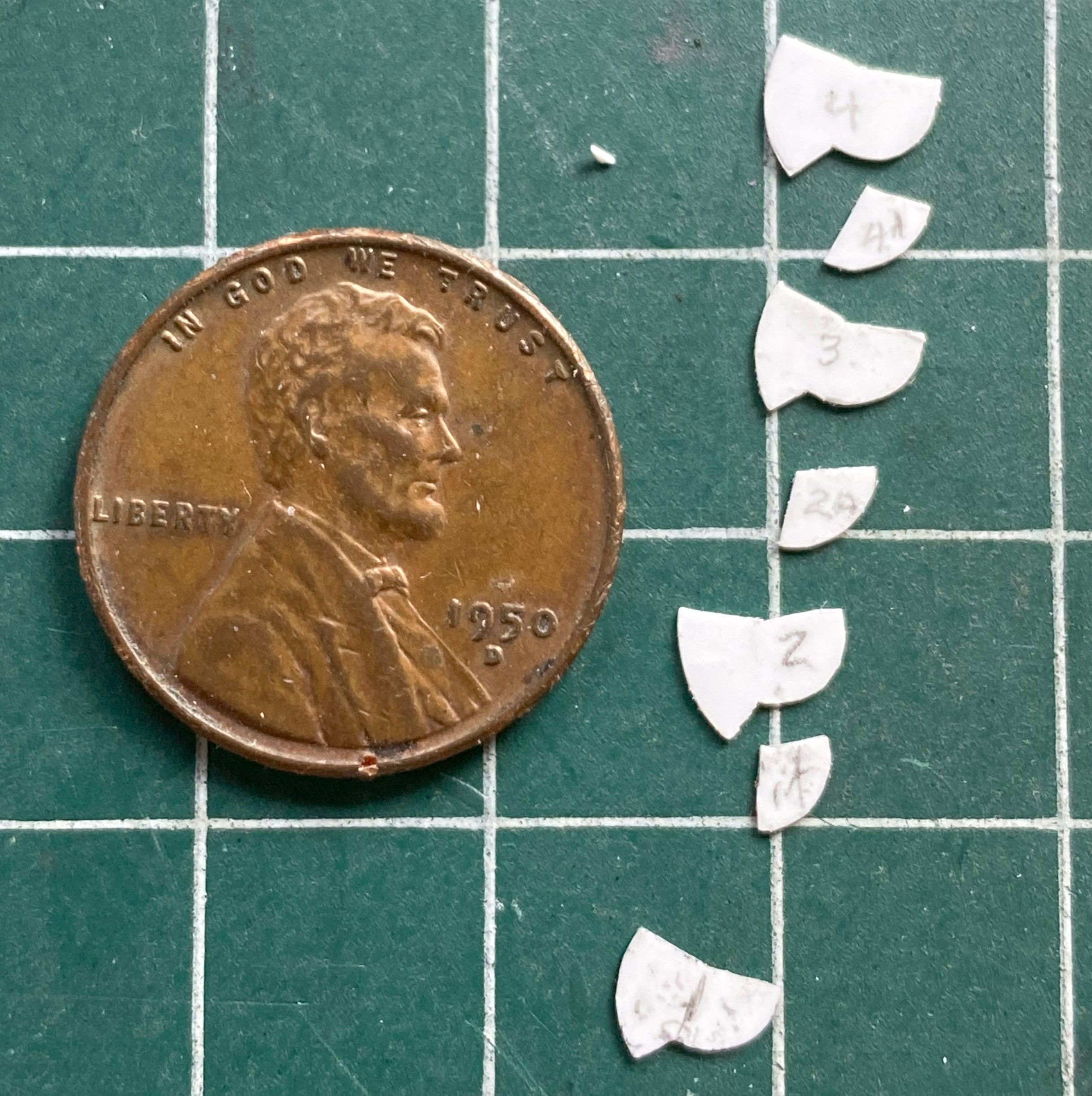
So that’s some of the parts, with the spacers in between the sides. These are very small parts. The smaller the parts, the longer the time to make/fiddle them. This took what seemed like an eternity (made eternal because the fingers of my left hand just kept cramping). Before I kept at it even further, I decided to assemble what I already had just to see if this idea would work:

What you can see in the above photo are V1 and V2. V1 is on the right and is the correct width overall. You’ll note that the part on the left is wider…and that’s only half of what has to be built.
Well, bugger…
Okay, cue V3!
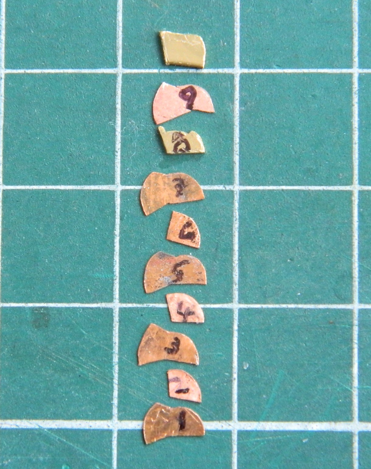
It took me a bit to figure out what V3 could be, but I arrived at a notion that I think will work. On V2, everything was made from 0.10″ (.254mm). The easiest way to halve the construction would be to halve the thickness of what it’s made from. 0.005″ (.127mm). However, trying to work styrene that thin is akin to trying origami using butterfly wings. Ain’t doing that! Oh! I have that size copper shim stock! Okay…V3 here we go!
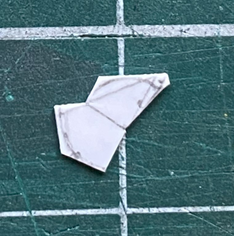
I filed and sanded V2 to a less inaccurate profile, salami-sliced that, and used the part as my template. I traced around it onto the shim stock with a needle and used scissors to cut the part away from the rest of the stock. Those two sentences took the better part of the week because in addition to having a glacially slow build speed, my fingers kept cramping. And at this point, I have all the parts in copper that I had in styrene. (A couple of the spacers are 0.020″ (.508mm) because of the spacing required.):
Whew… I guess next month will start where this one left off. Not just cutting out the parts but figuring out some way to put them all together. Once I have, I can then file them to their final shape and dimension.
Oh. In case you’re thinking that I need more “fun” in this build, all seven levers have little knobs atop them. I’ll be using some of these, which are glass beads I got online from a crafting store:
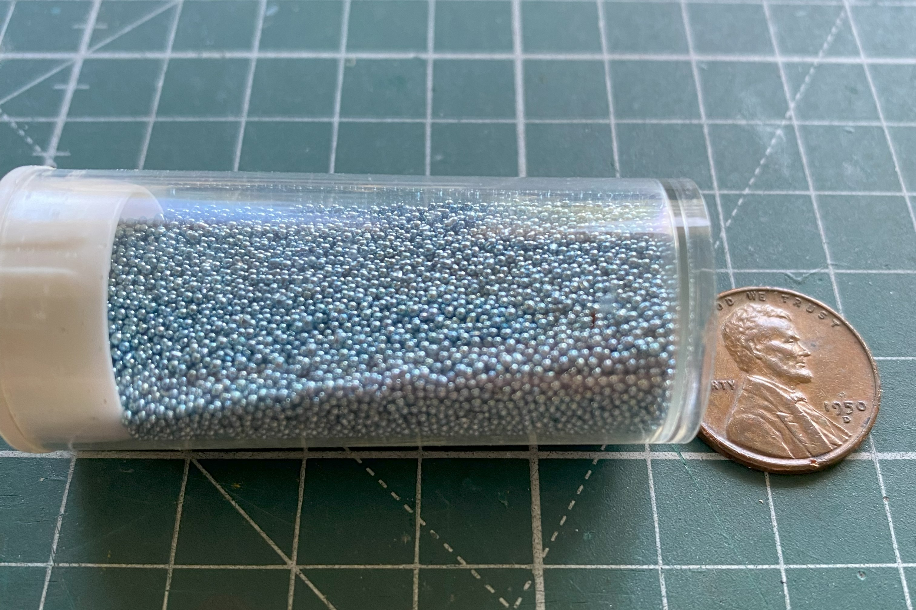
My experience using these beads on the P-38F showed me that they are an absoLUTE ass-pain but the results are so worth the effort.
