Grumman JRF Goose (Czech Model) 1/48 Scale Build #7 – Staggering Towards the Finish…and Getting There
This is the danger-point for me, being so close to the end that I have to be careful not to rush things. Couple that with the reality that I despise this kit, I have to double the caution.
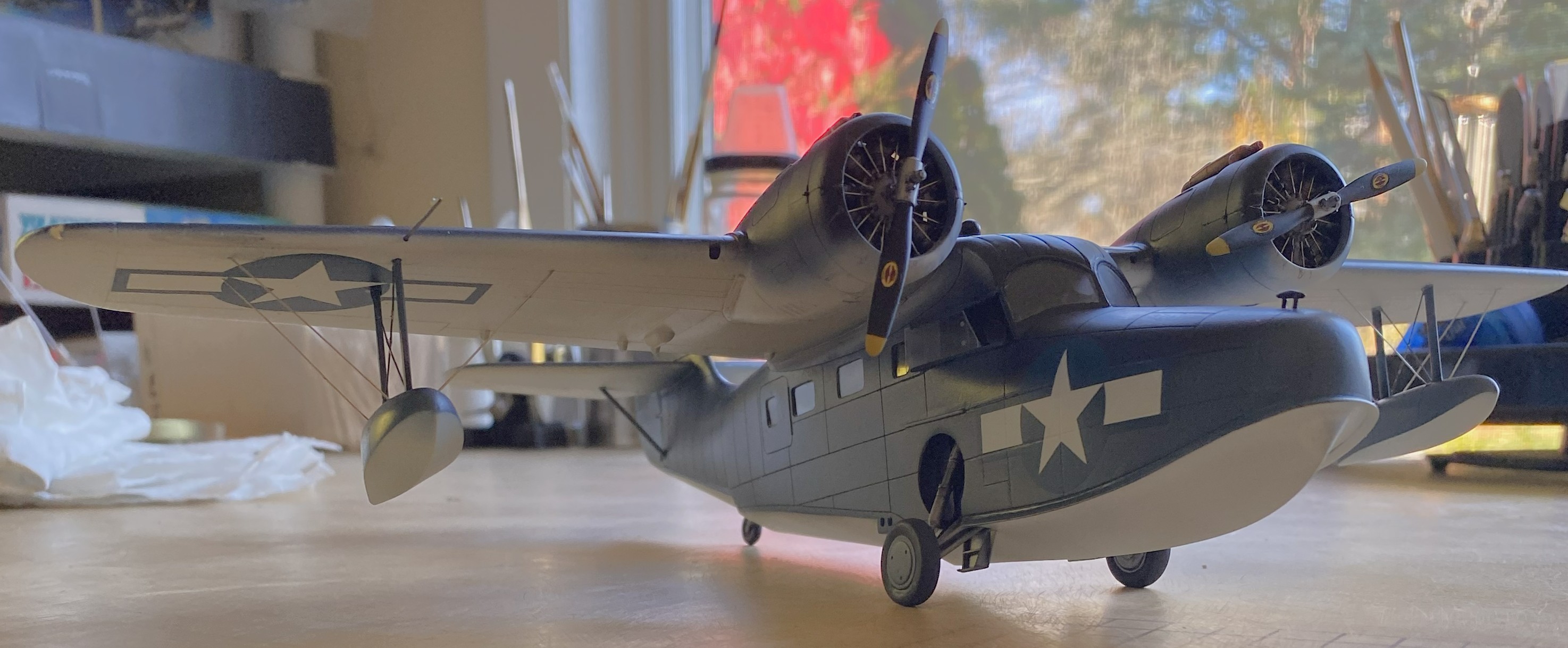
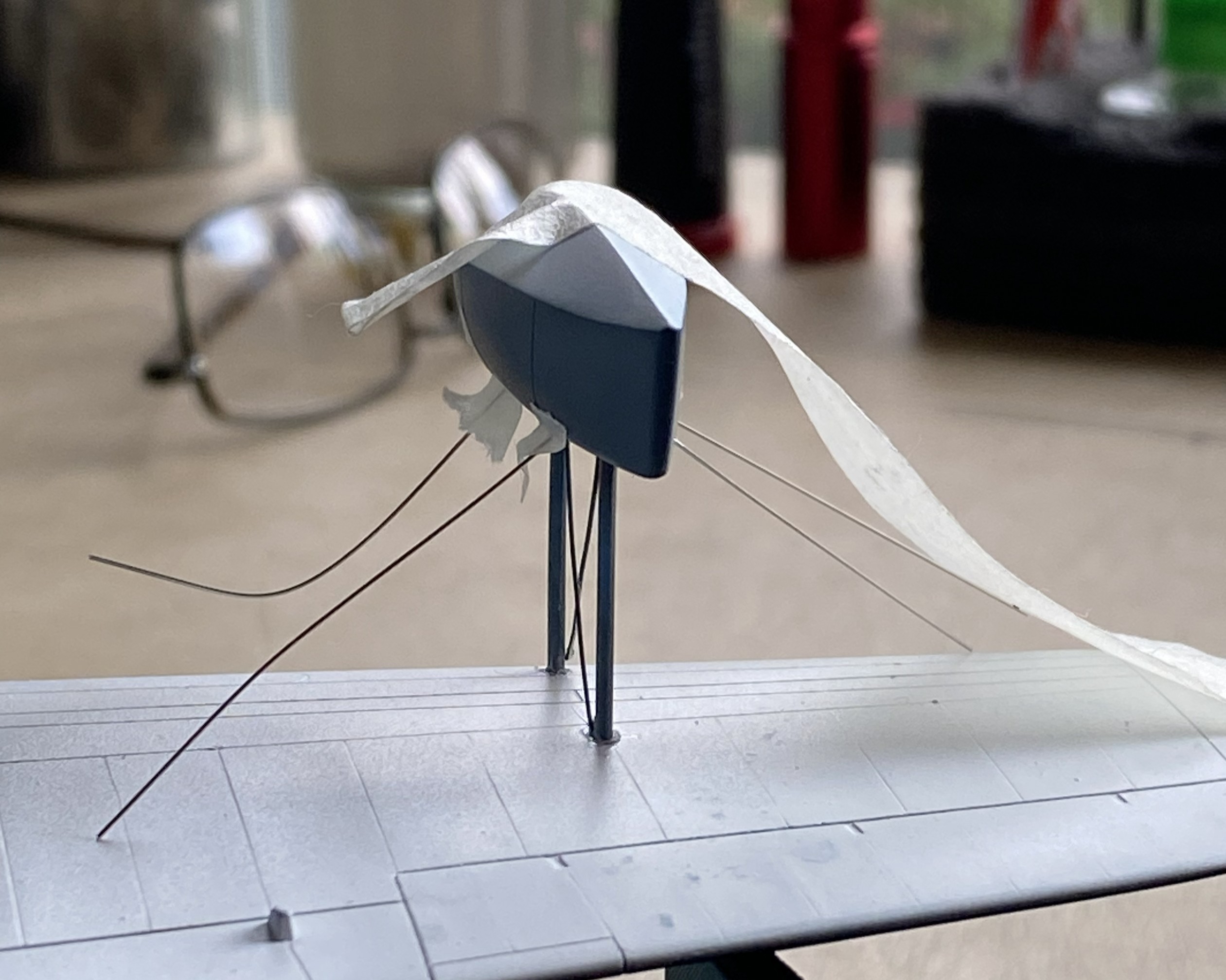
I started with what I perceived would be the biggest hassle and that was getting the wing level, and I wasn’t entirely incorrect. As it sits in this photo, the bubble indicates that the wing isn’t level:

At the center of the model, that bubble isn’t far off. At the wingtips it is. I bent my brain around several corners trying to figure out the best solution. I’m of the opinion that it is not uncommon for a given problem to have more than one solution, except that solutions to problems usually come with new problems (and the solution is enacted if the new problem is less than the old problem). And speaking of problems, here’s a short (I hope) examination as to what the problem is, not what I’d rather it be.
The struts of the landing gear fits into the top of the landing gear bay. The landing gear bays were not molded onto the fuselage sides. As I found out well after I’d added the landing gear bays, the sides of the fuselage do not match dimensionally. Yeah. Who knew that would be a problem. It certainly wasn’t Czech Models. However, with one landing gear bay higher from the bottom than the other, and the landing gear goes there, should I be surprised that once the aircraft is assembled that it doesn’t sit level? I was when I first found the dimensions (and shapes) did not match from side to side, but after I thought about it (a lot), I knew that by the time I got to this point of the build, I’d have this new problem to solve. ::facepalm::
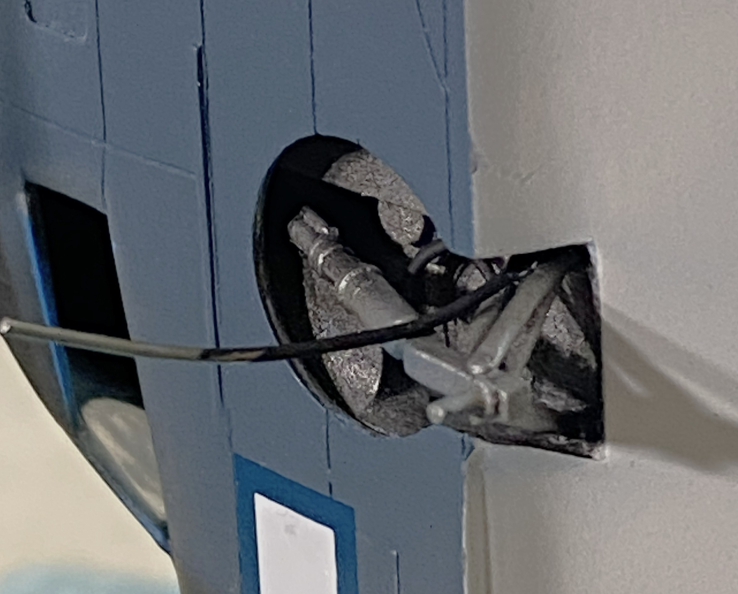
Since I saw this problem as a geometry problem, I looked into the geometry of the landing gear. Being more than a little frustrated at this point, I dry-fit the wheels onto the landing gear and pressed firmly down on top of the model until the bubble was centered. Just as the bubble centered, I heard a soft crack as something broke loose…but the bubble was still level. Took a bit of investigation but I found what broke loose. The blue arrow in the photo below points to where the upper control arm snapped away from the strut leaving this gap:

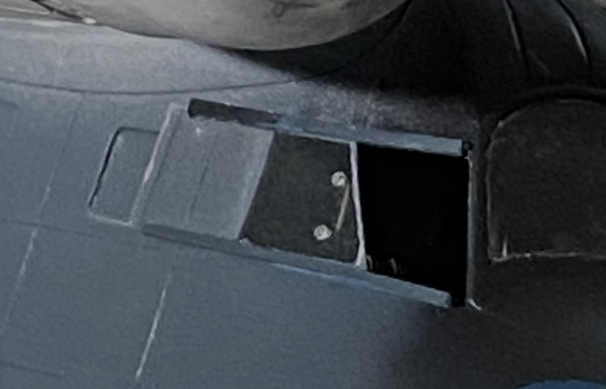
Hmm. So, if I fit a spacer between the strut and control arm, will that make the wing level? The answer was, “mostly”, which I discovered once I’d cut a spacer from 0.030″ (.762mm) and checked:

I trimmed the spacer without gluing it in and checked again. This time I estimated that I needed another 0.005″ (.127mm) more:

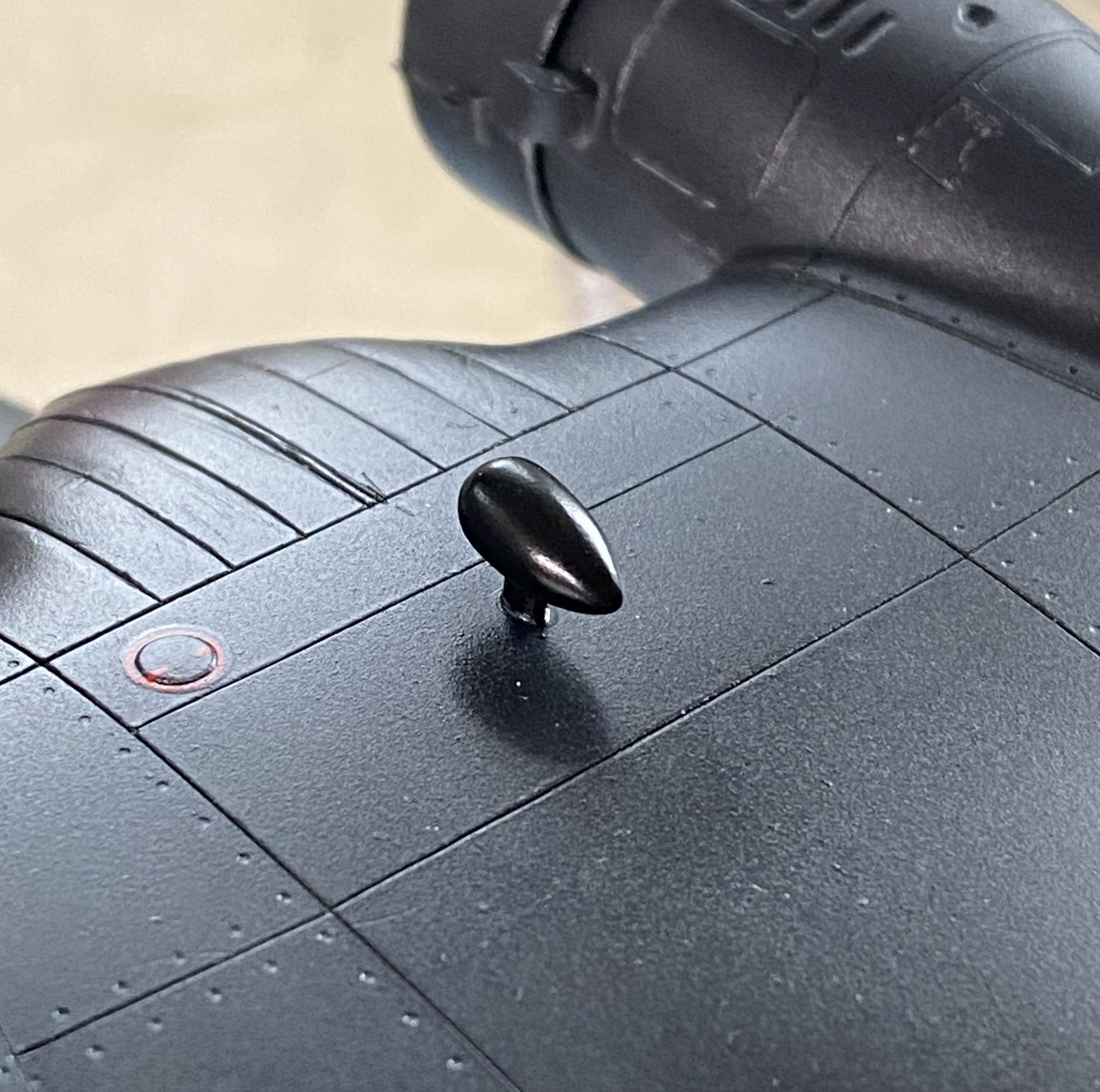
And there it sodding is:

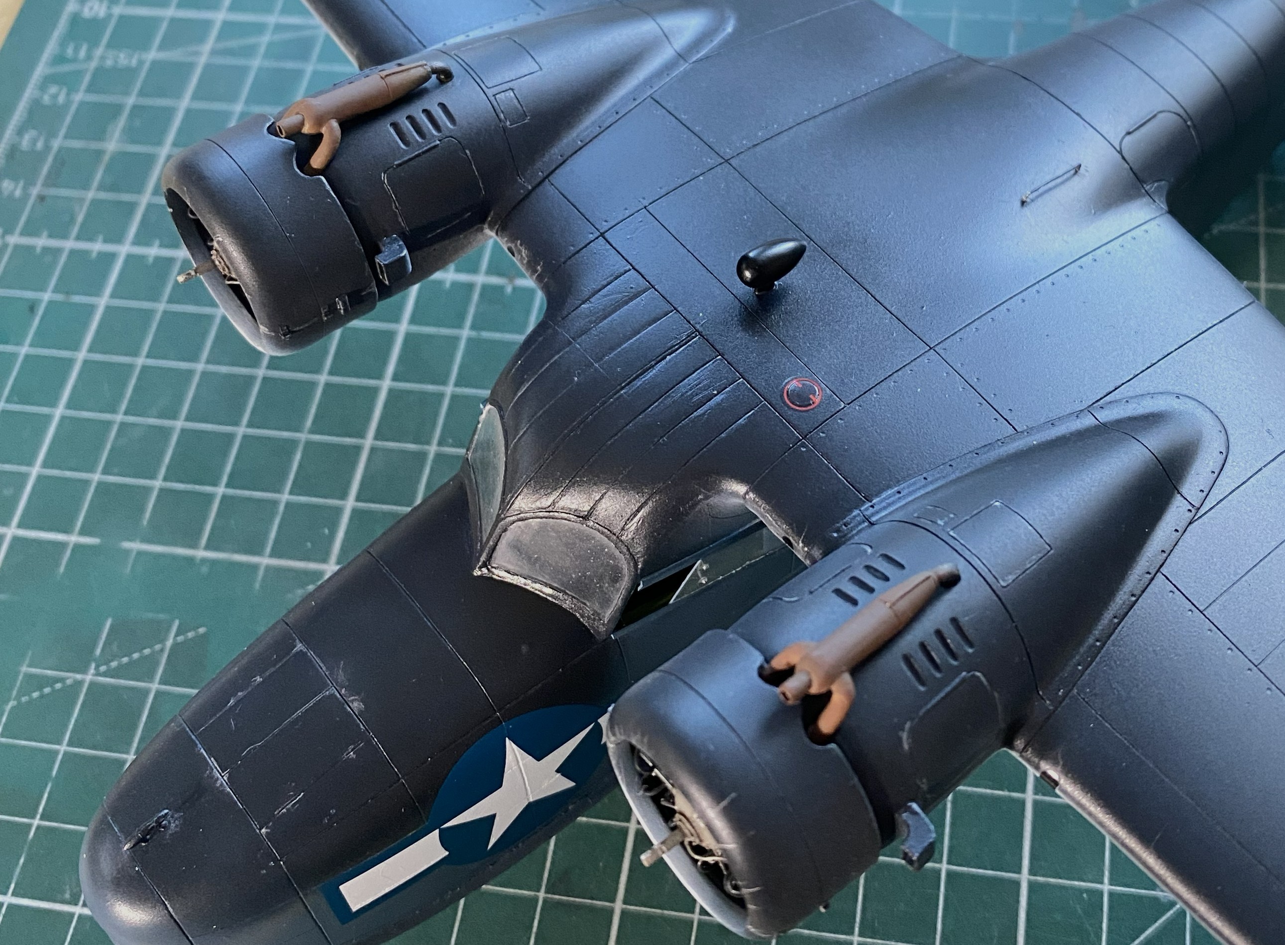
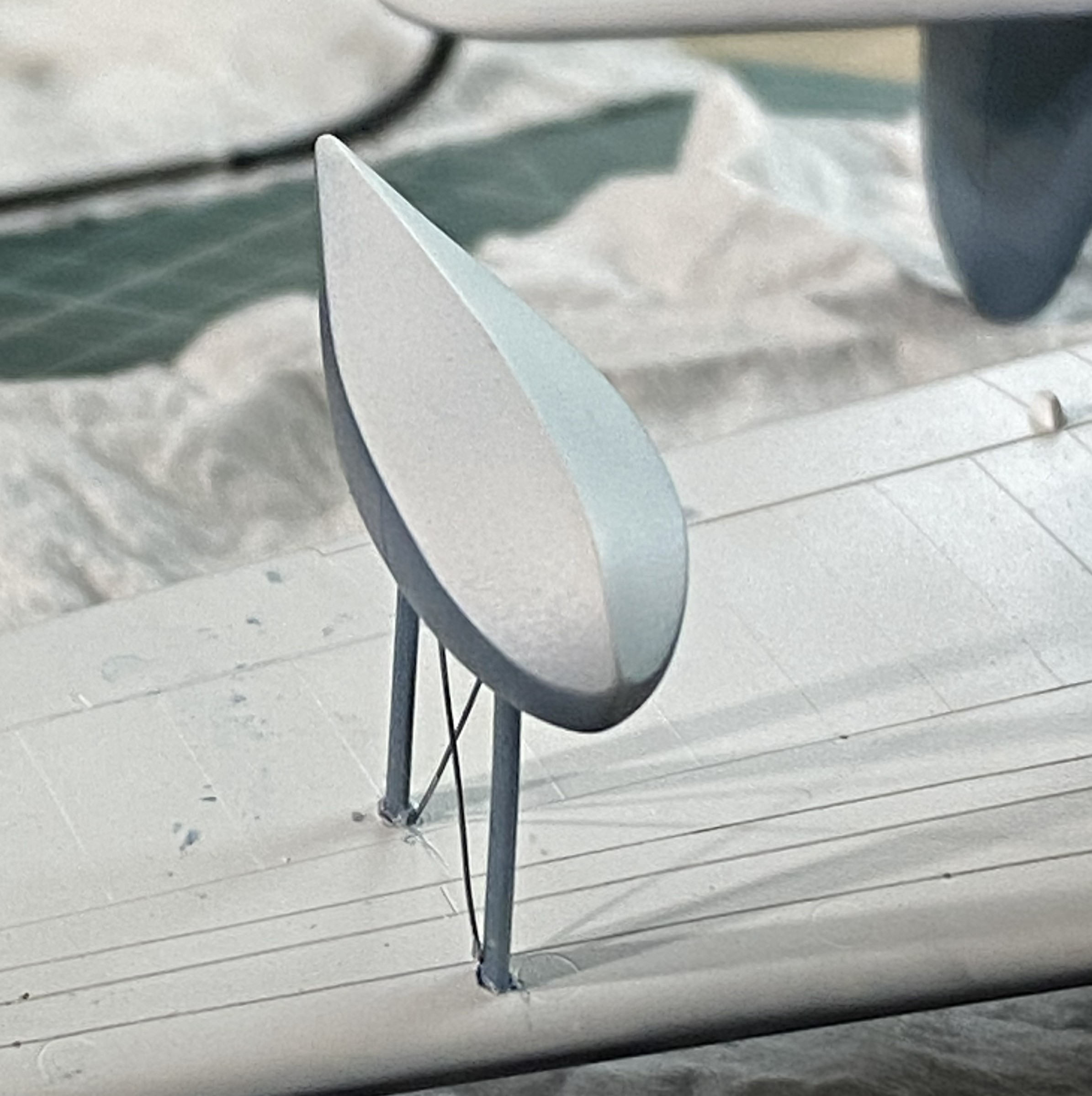
I think it’s the housing for an ADF head, but it needed to be painted semi-gloss black. So it was. I REALLY hate self-inflicted wounds, which is how I view overspray. When I aimed the airbrush at the football, NONE of the other painted surfaces were visible:
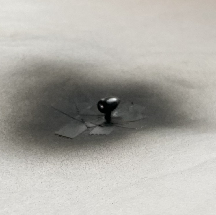
Success! Zero overspray:
I used 0.025″ (.635mm) as brake lines, painted them knowing full well that during the final bending process would cause paint to flake off. It was a lot easier to get at the parts that bent the paint away because there weren’t buried in the landing gear bay. I’ll get to these when touching up the paint happens (the photo’s on its side because I was using gravity to hold the solder where I wanted it to while the superglue set up):
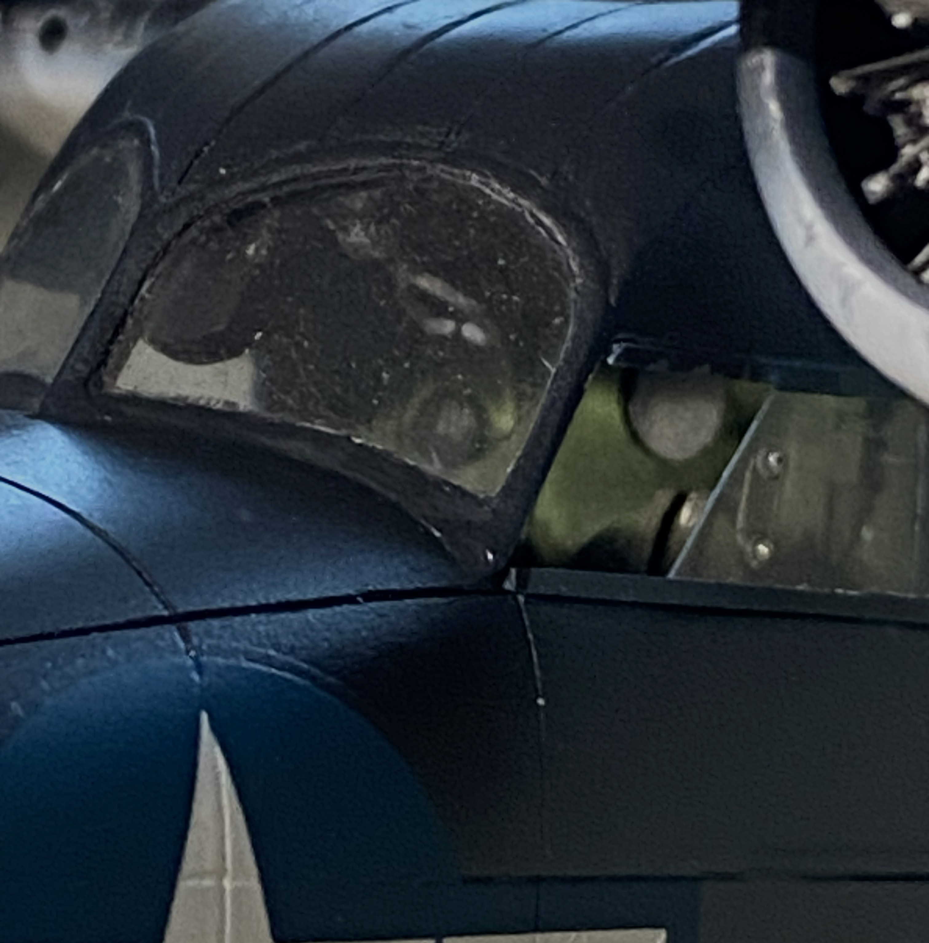
And speaking of paint touch ups, I painted the frames of the cockpit windows off so that I could also paint under them. A solution that created a problem; paints don’t match once assembled. Okay, I’ll be doing touch-ups (with a small brush in these areas…the other side, though not as bad, is the same), just add this to the list:
You’ll also note that the cabin window just behind the flight deck is still masked. This was a problem I let sit as-is. When I tried to pry the masking tape away, three of the four sides of this window broke free. It was hanging on by paint. My memory isn’t what it once was (is anything?), but I DO remember what I had to go through to fix the one that came out already. Carve, fix, fill. Lots of fun when the plastic was unpainted, a no-go zone now that it has been painted. I supplemented the paint holding the window on with liberal applications of superglue. I’m pretty sure it’s going to stay there, now. It’s in a place where it will never be touched.
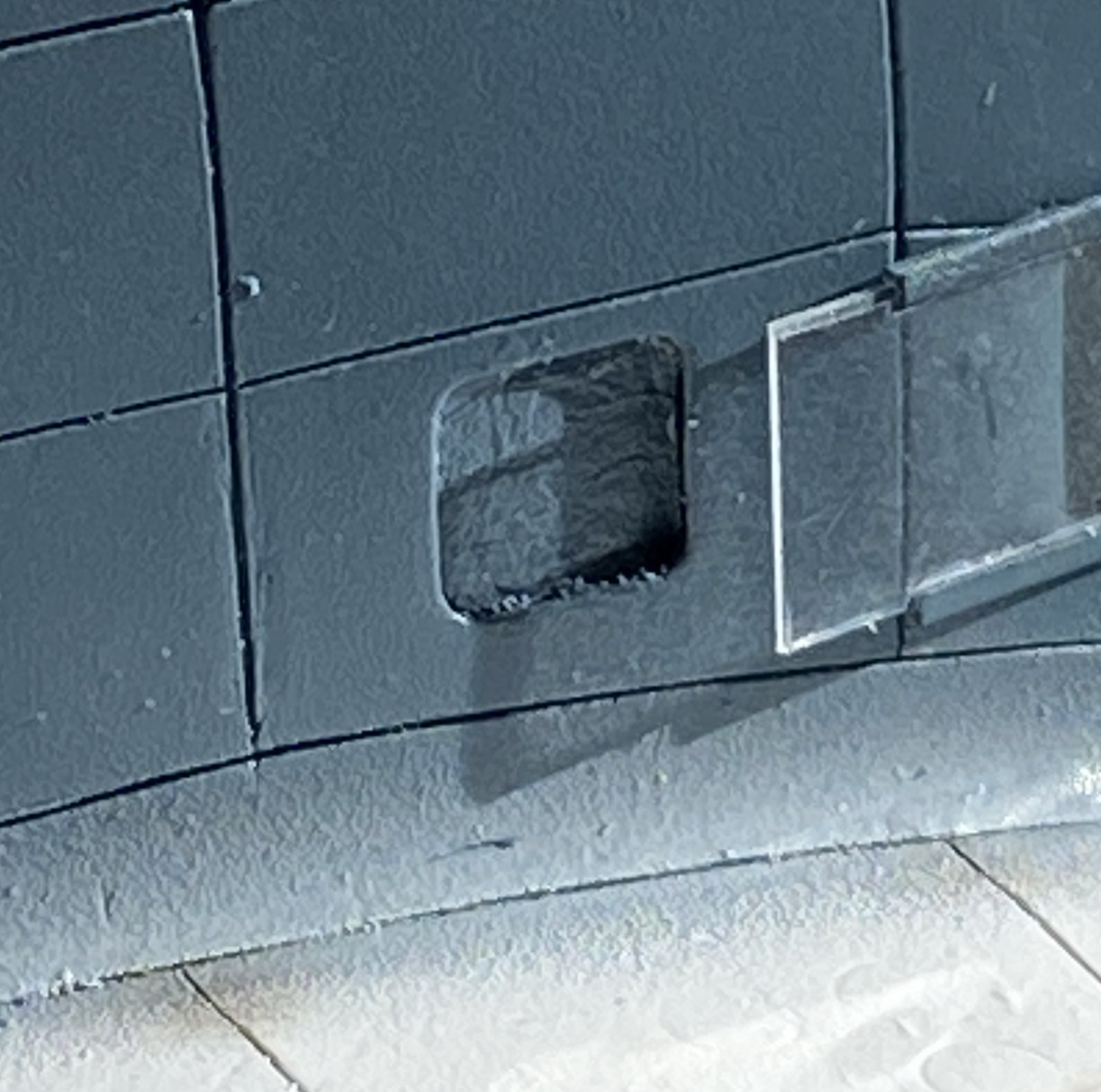
This one’s pushing the 90-95% accuracy I try to attain. I don’t care. A blocked off window is better than a sodding hole. Moving on…
Speaking of self-inflicted wounds, I noticed a week or so ago that there was blue overspray on the nose. ::adds to touch up list::

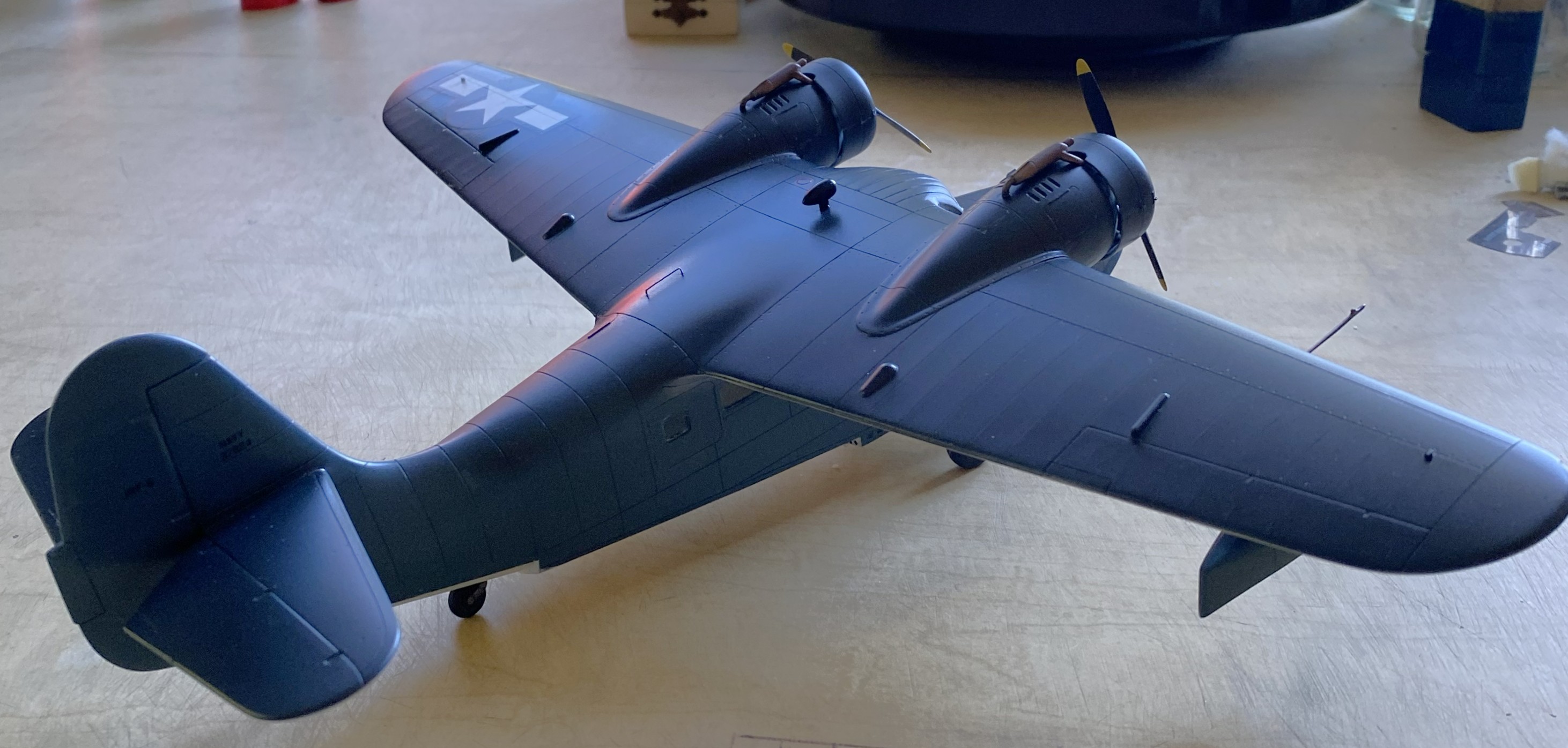
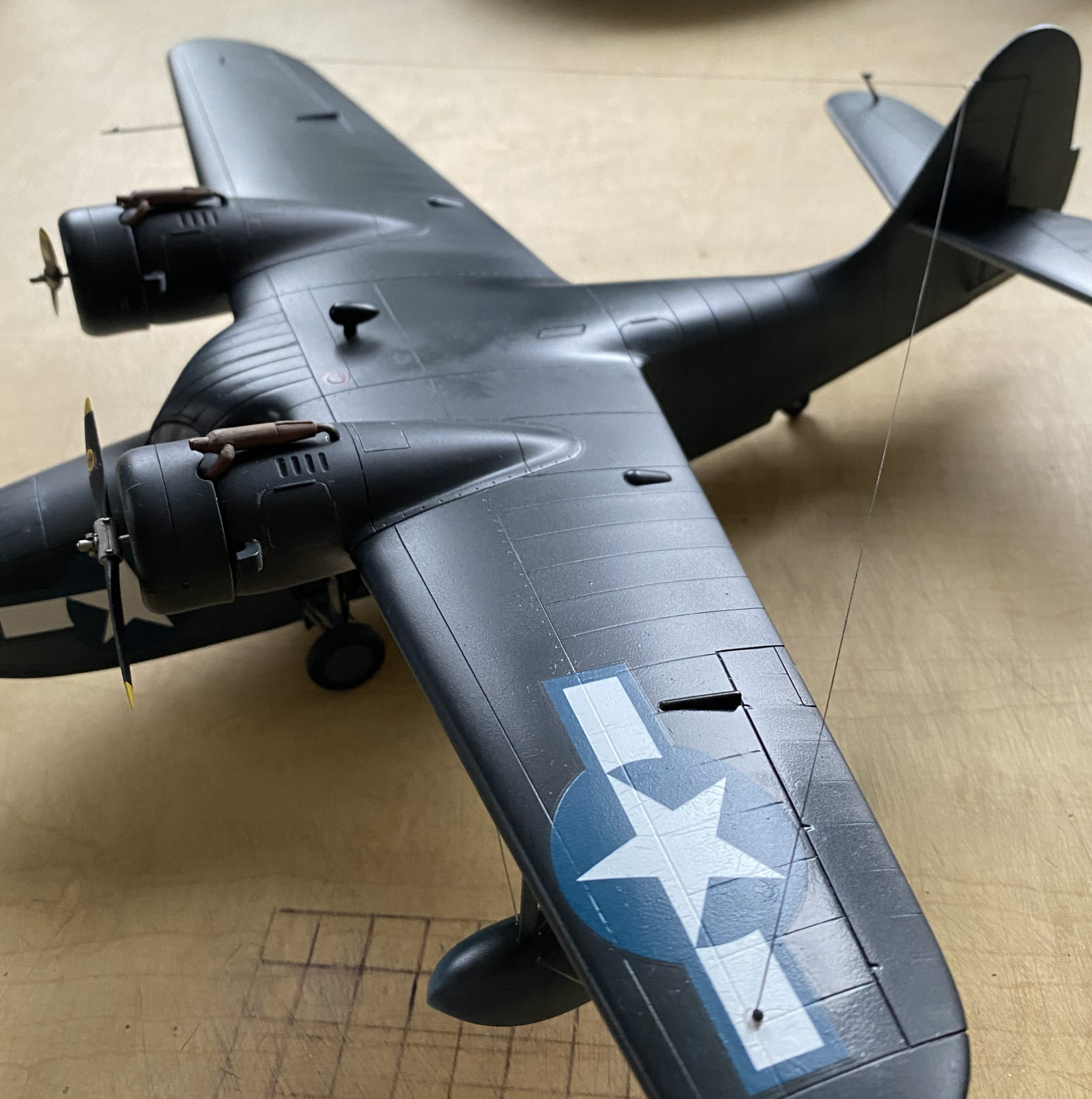
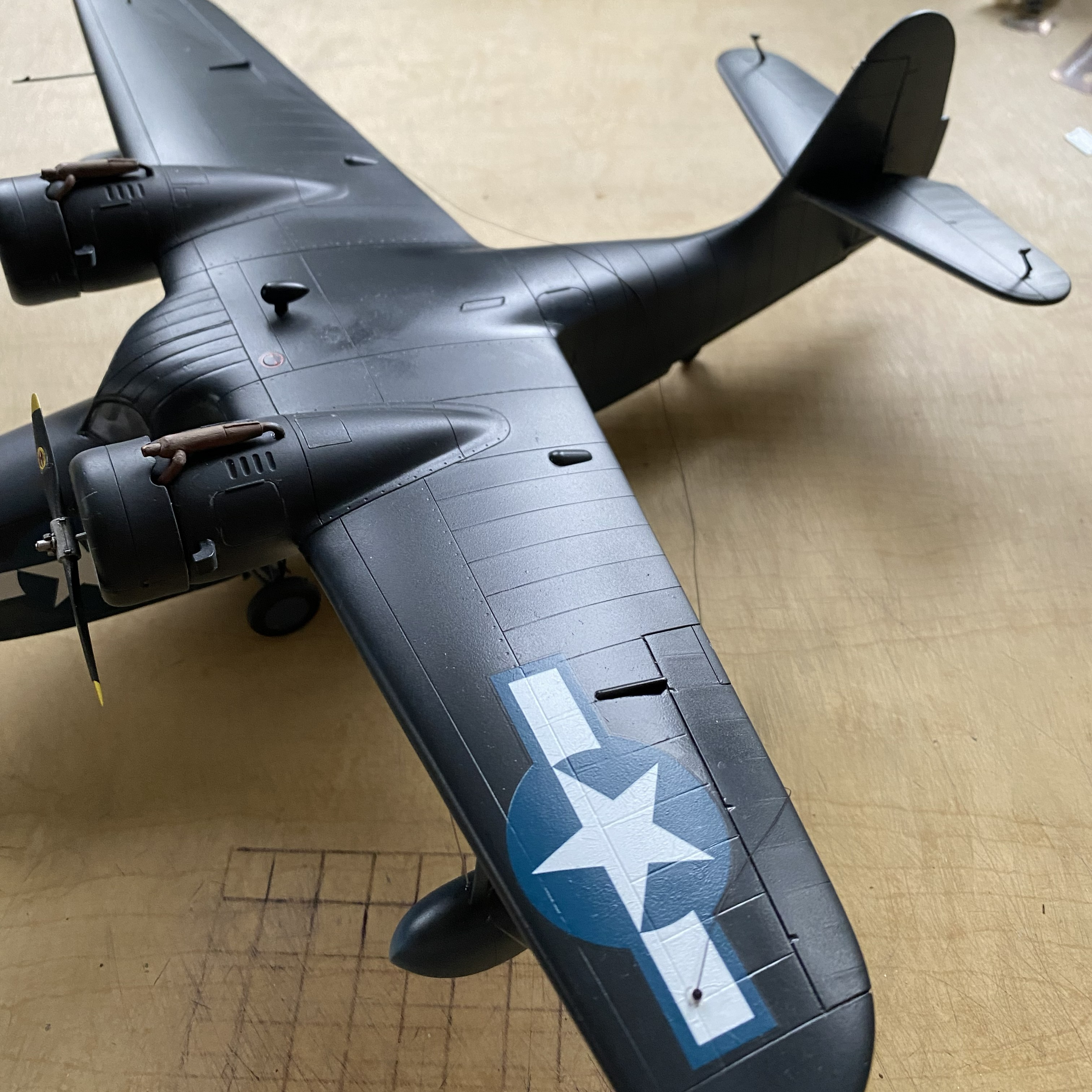
I added the heat exchangers (the brown things over the engine nacelles). Later on I’ll spiff them up a little bit with some pastels:
I added one of the landing gear “doors” just before beddy-bye so that the glue would set up; there’s not much gluing surface:

And while I was letting something sit overnight, I got ballsy (considering how late in the evening this happened) and added one of the floats to sit overnight as well:
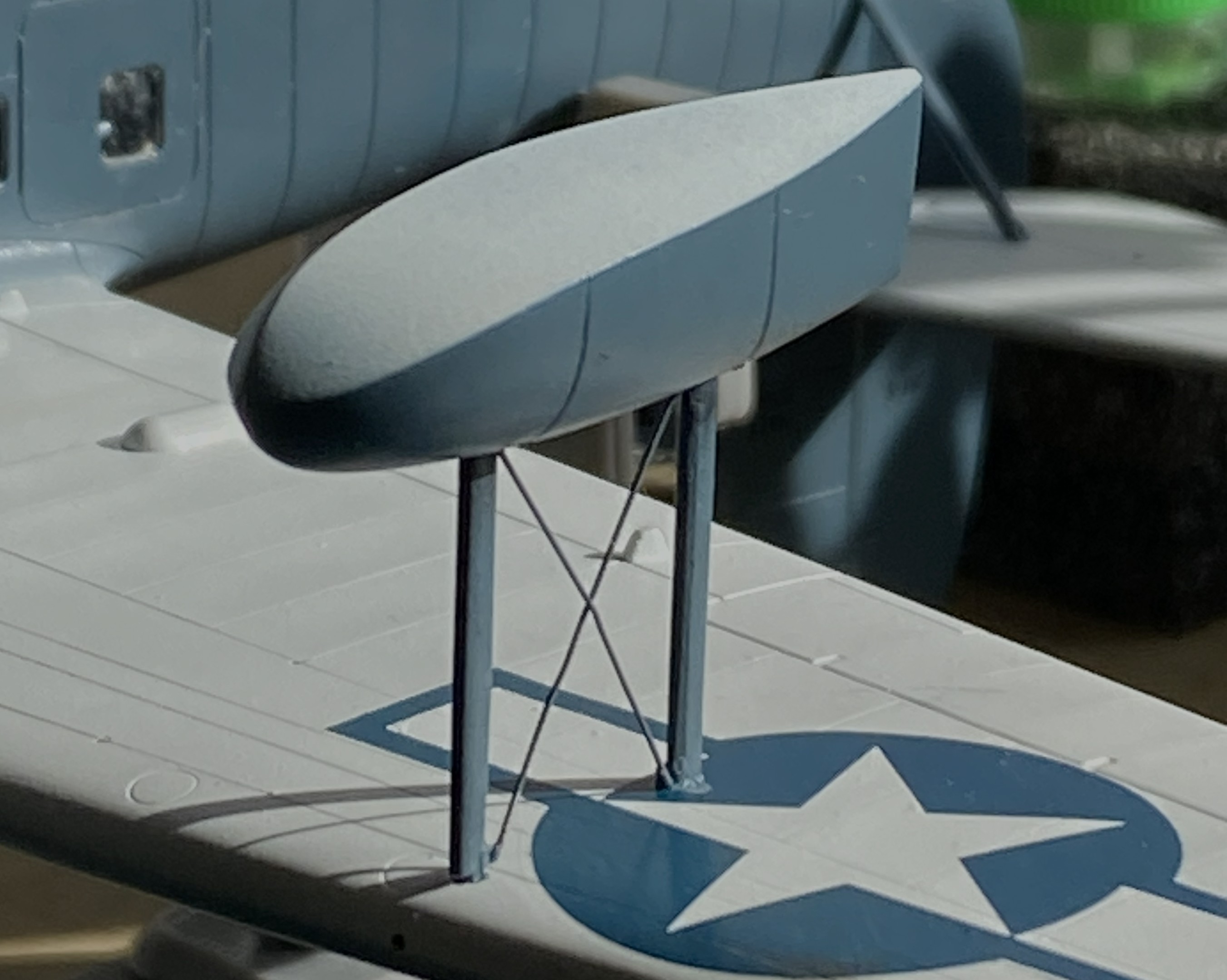
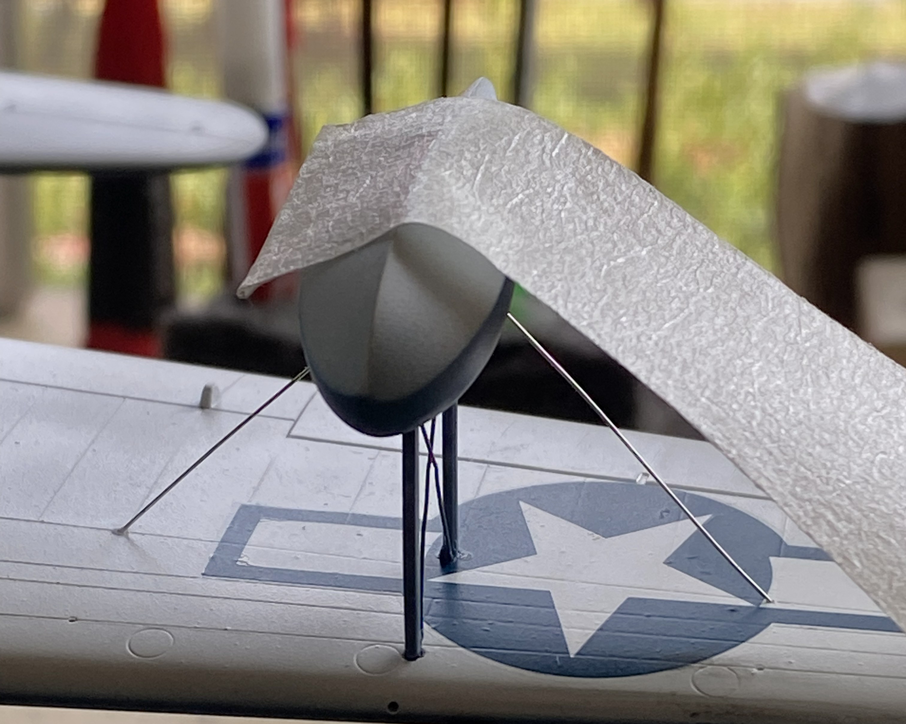
Obviously, with only two small contact patches, this will be easy to knock flat laterally. I added tape to stabilize it while I fed the ends of the braces into the float and wing for gluing (superglue). l cut the wires overlong so that I could be certain I’d be able to adjust them if I needed to (a handy bit of foresight):
With all the guy wires in place, it looks pretty good:

Getting the guy wires into the pre-drilled holes of both the float and wing took some fiddling. For the next float, I tried inserting one end of the guy wires into the float without cement to see if that would be easier:

It wasn’t. If you look closely where the wires meets the float you can see small bits of masking tape holding them in place:
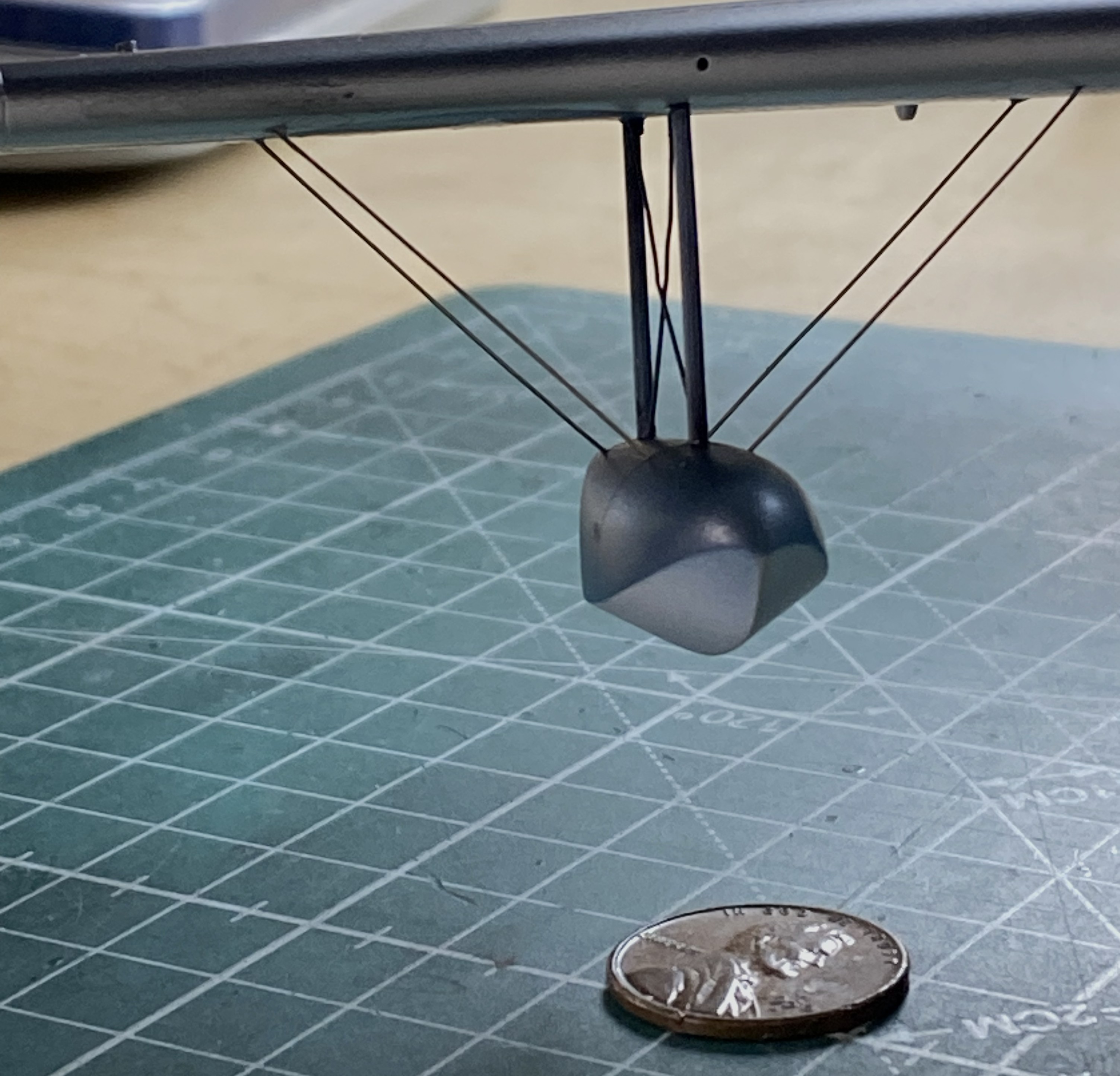
This didn’t work as well as I’d hoped.I was surprised at how difficult it was to just remove the tape. I had to diddle the tape so much that the float came free (in its defense, it hadn’t sat overnight for the plastic to harden fully at the glued points). After I reattached the float to the wing, when I turned the whole thing up side down, all the wires fell out:
I got that fixed:

The radio aerials attach at both wing tips and the tip of the vertical stabilizer. I use this for aircraft aerials:
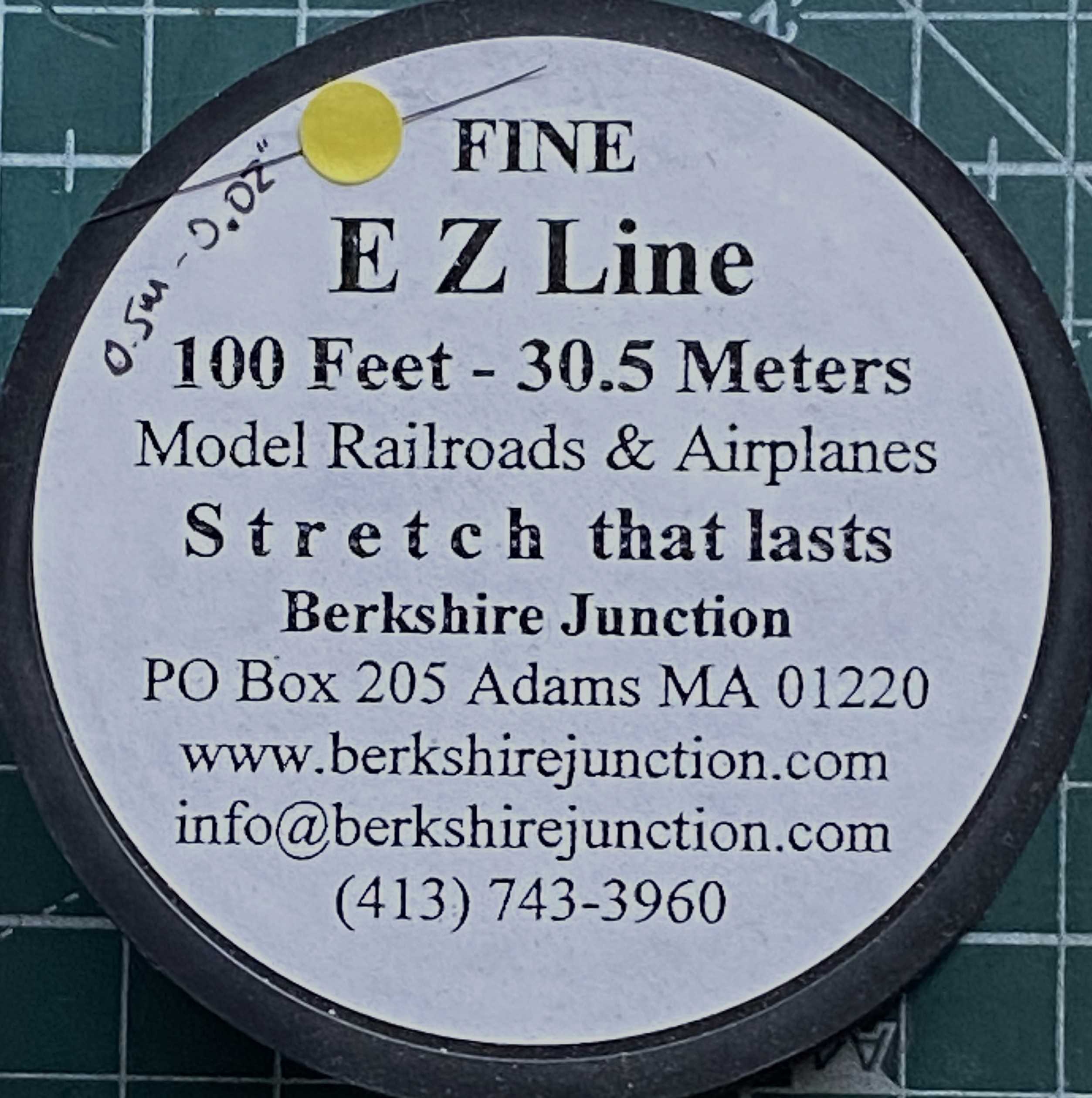
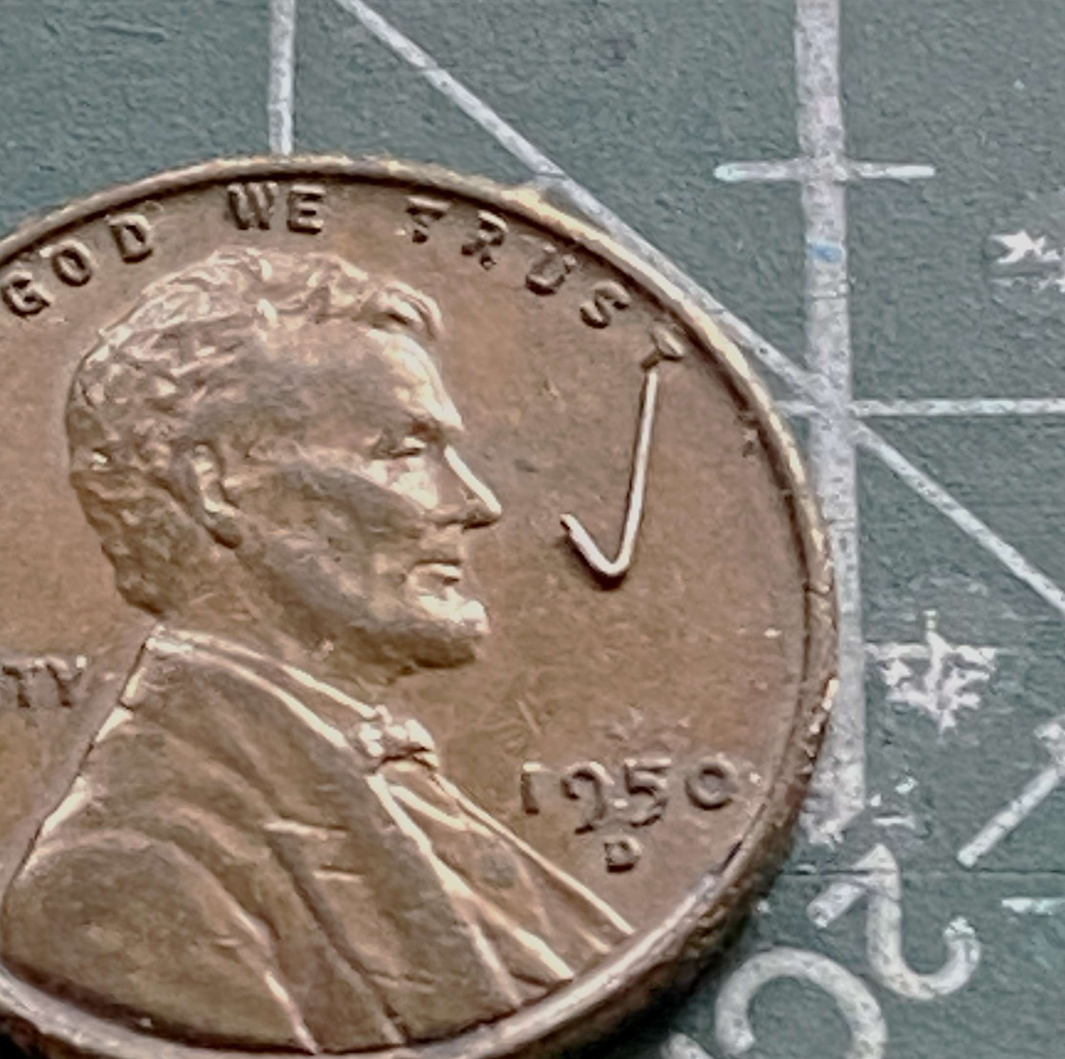
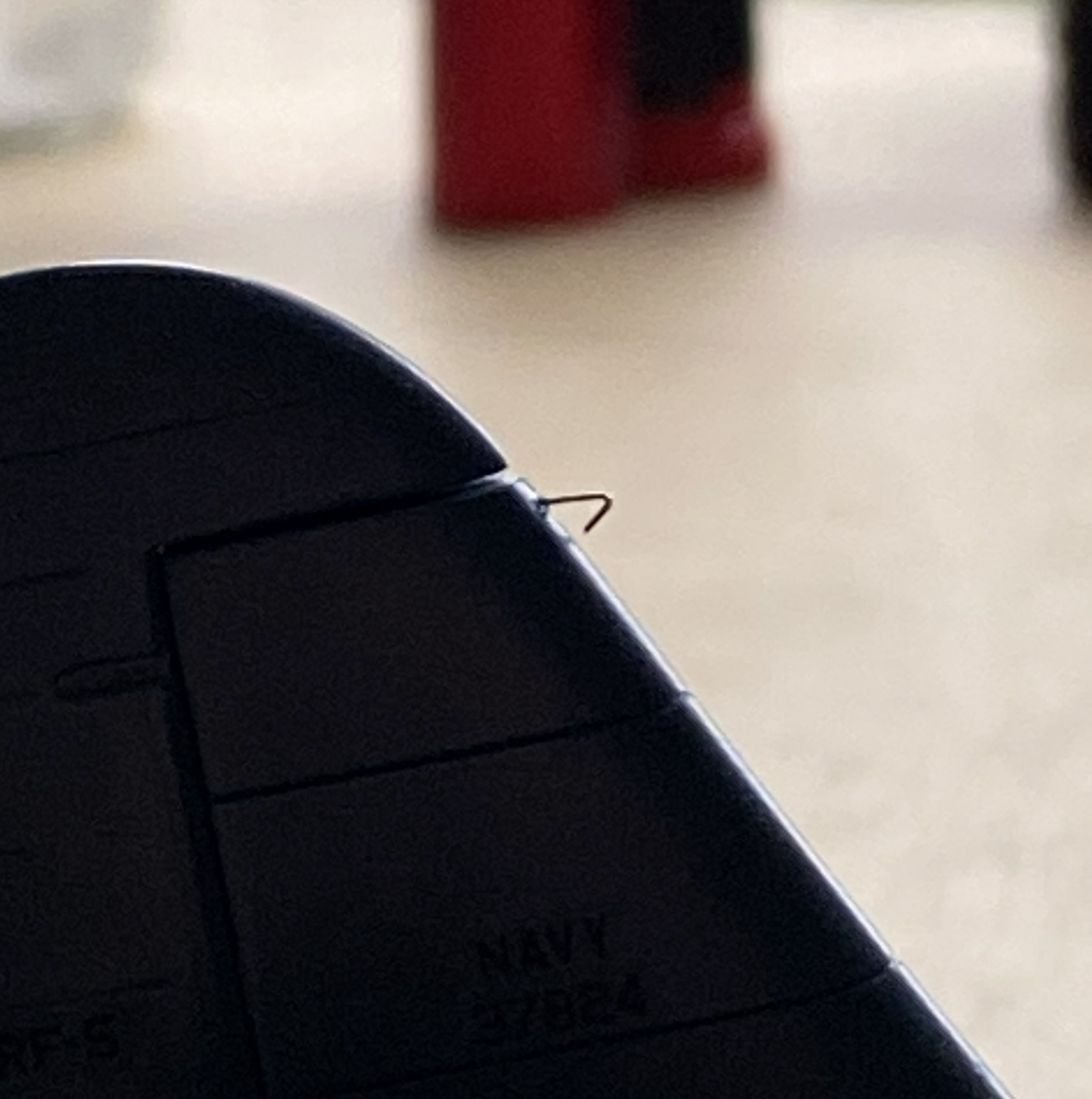
As I’ve been putting this together, obviously the more parts I add the less places I can hold it. For that reason (because these things get handled and transported) I wanted the aerials to be semi-removable; permanently attached at the wing tips, removable at the vertical stabilizer. What would make doing that simple would be to make the attachment point on the vertical stabilizer detachable. Or…I could mount the attachment point permanently and have it be J-shaped so that I can just lift the EZ-Line and let it drop. I like that idea, the major flaw is that even though the EZ-Line’s tension is adjustable, that J-hook has to be small. I didn’t have confidence in copper to hold up over the years. Instead I used the E-string from a guitar (thereby creating the moderately rare 5-string variant). Everything about its dimensions are printed on the pouch:

It’s certainly over-engineered for my purpose, which I think is great:
I’d attached little stubs of styrene rod where they belong and center-drilled them to socket the end of the EZ-Line into:

After gluing the other side in place, I tested the arrangement to see if it would function as desired. It function exactly as desired. Top photo below is with the aerials in place, the bottom photo is with the antennas dismounted (for these photos, I dry-fit all the parts yet to add and realized that none of those dry-fit parts need to be glued so I left them on):
I have one more thing to do (attach the brake lines to the wheels) and DONE!