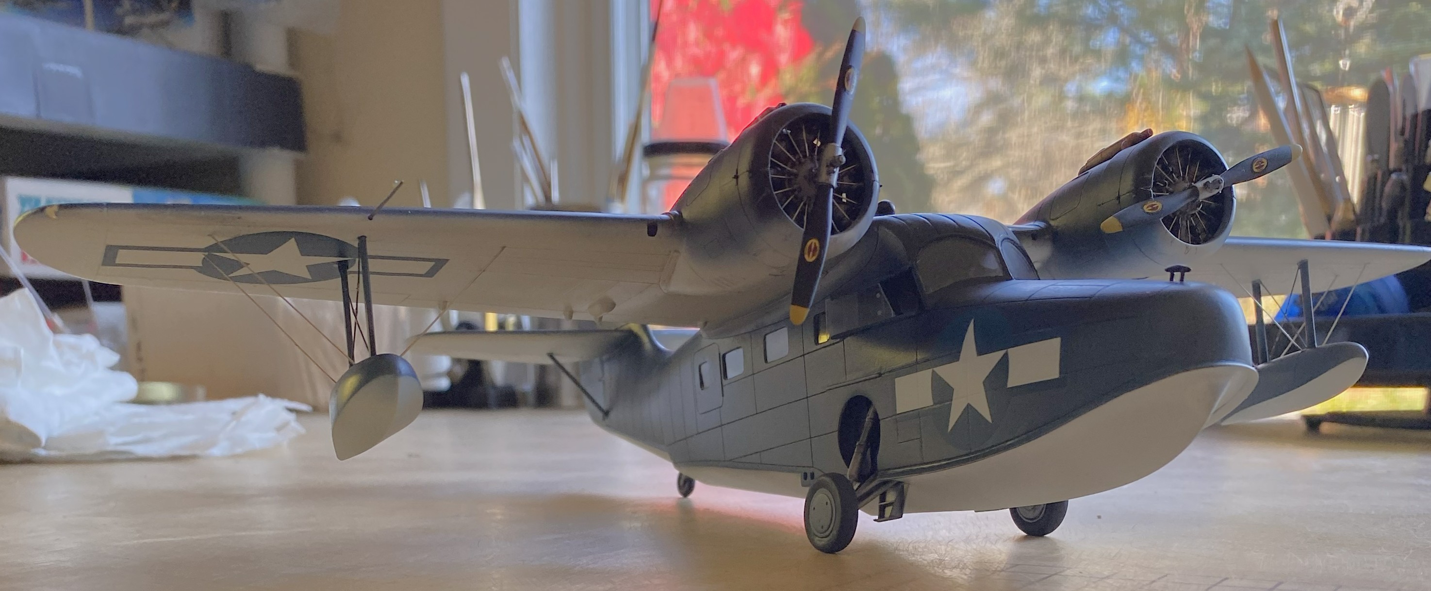
Grumman JRF Goose (Czech Model) 1/48 Scale Build #7 – Staggering Towards the Finish…and Getting There
This is the danger-point for me, being so close to the end that I have to be careful not to rush things. Couple that with the reality that I despise this kit, I have to double the caution.
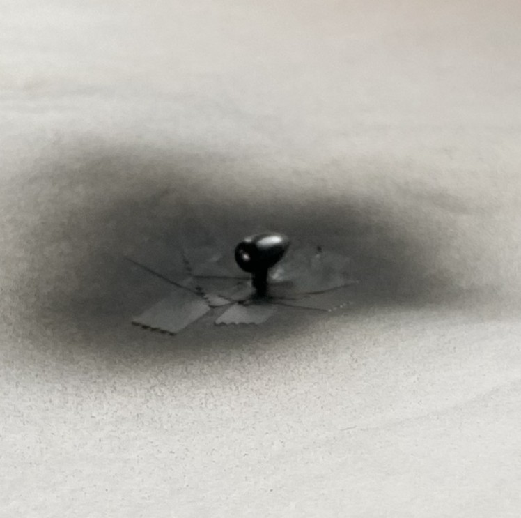
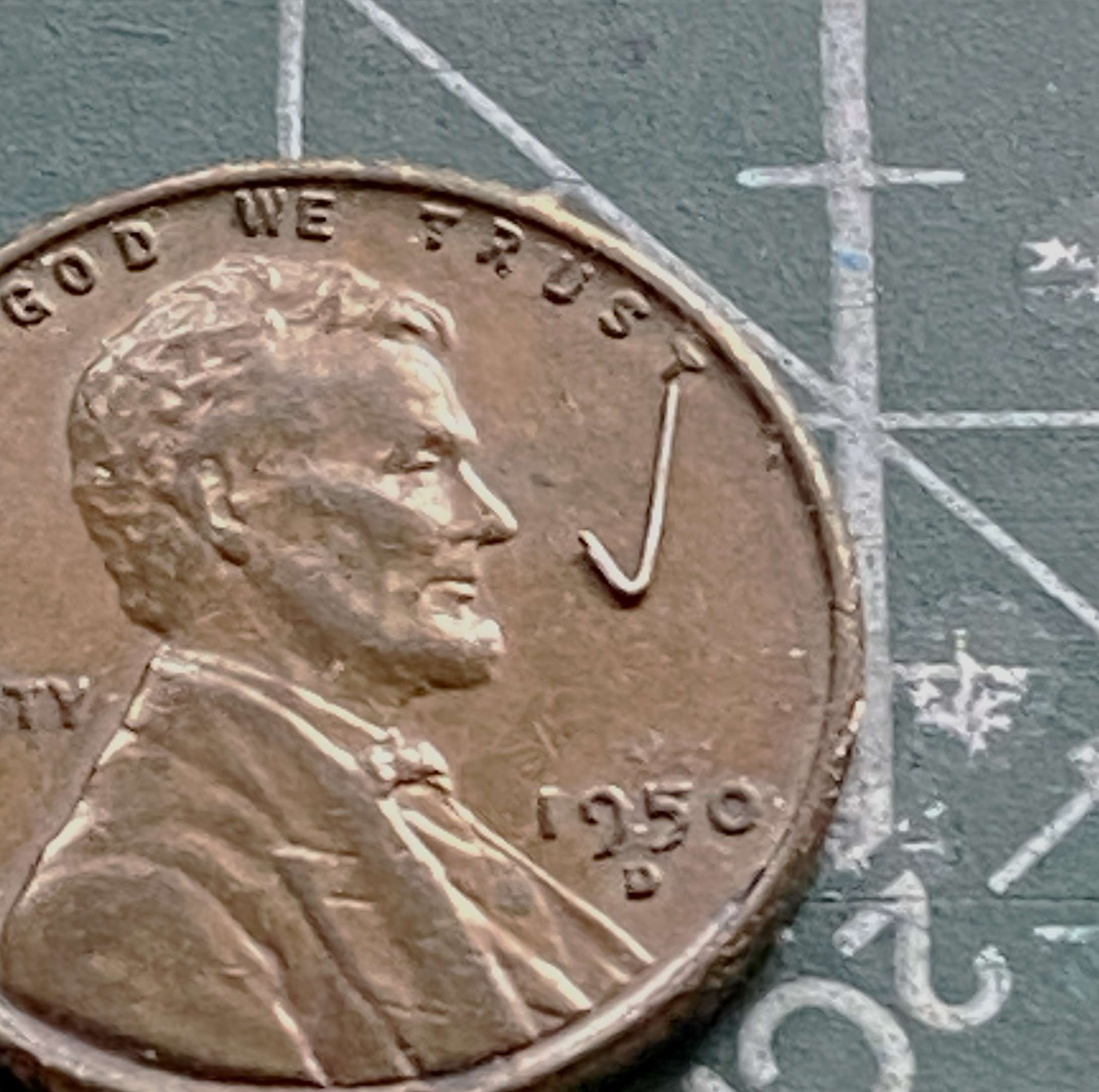
I started with what I perceived would be the biggest hassle and that was getting the wing level, and I wasn’t entirely incorrect. As it sits in this photo, the bubble indicates that the wing isn’t level:

At the center of the model, that bubble isn’t far off. At the wingtips it is. I bent my brain around several corners trying to figure out the best solution. I’m of the opinion that it is not uncommon for a given problem to have more than one solution, except that solutions to problems usually come with new problems (and the solution is enacted if the new problem is less than the old problem). And speaking of problems, here’s a short (I hope) examination as to what the problem is, not what I’d rather it be.
The struts of the landing gear fits into the top of the landing gear bay. The landing gear bays were not molded onto the fuselage sides. As I found out well after I’d added the landing gear bays, the sides of the fuselage do not match dimensionally. Yeah. Who knew that would be a problem. It certainly wasn’t Czech Models. However, with one landing gear bay higher from the bottom than the other, and the landing gear goes there, should I be surprised that once the aircraft is assembled that it doesn’t sit level? I was when I first found the dimensions (and shapes) did not match from side to side, but after I thought about it (a lot), I knew that by the time I got to this point of the build, I’d have this new problem to solve. ::facepalm::
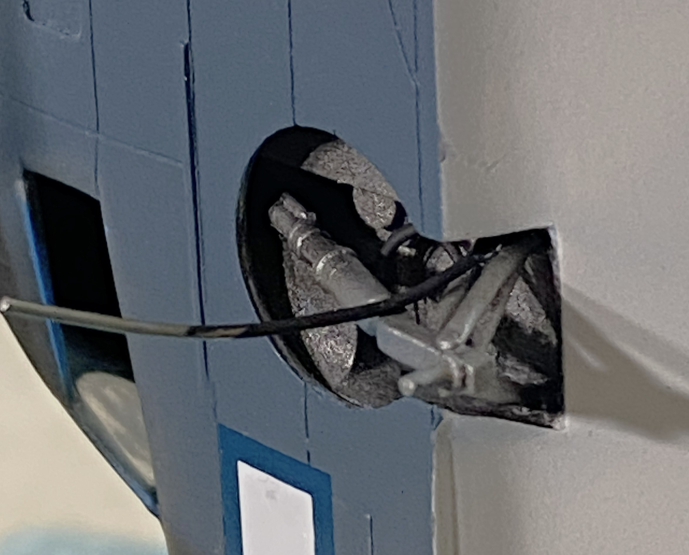
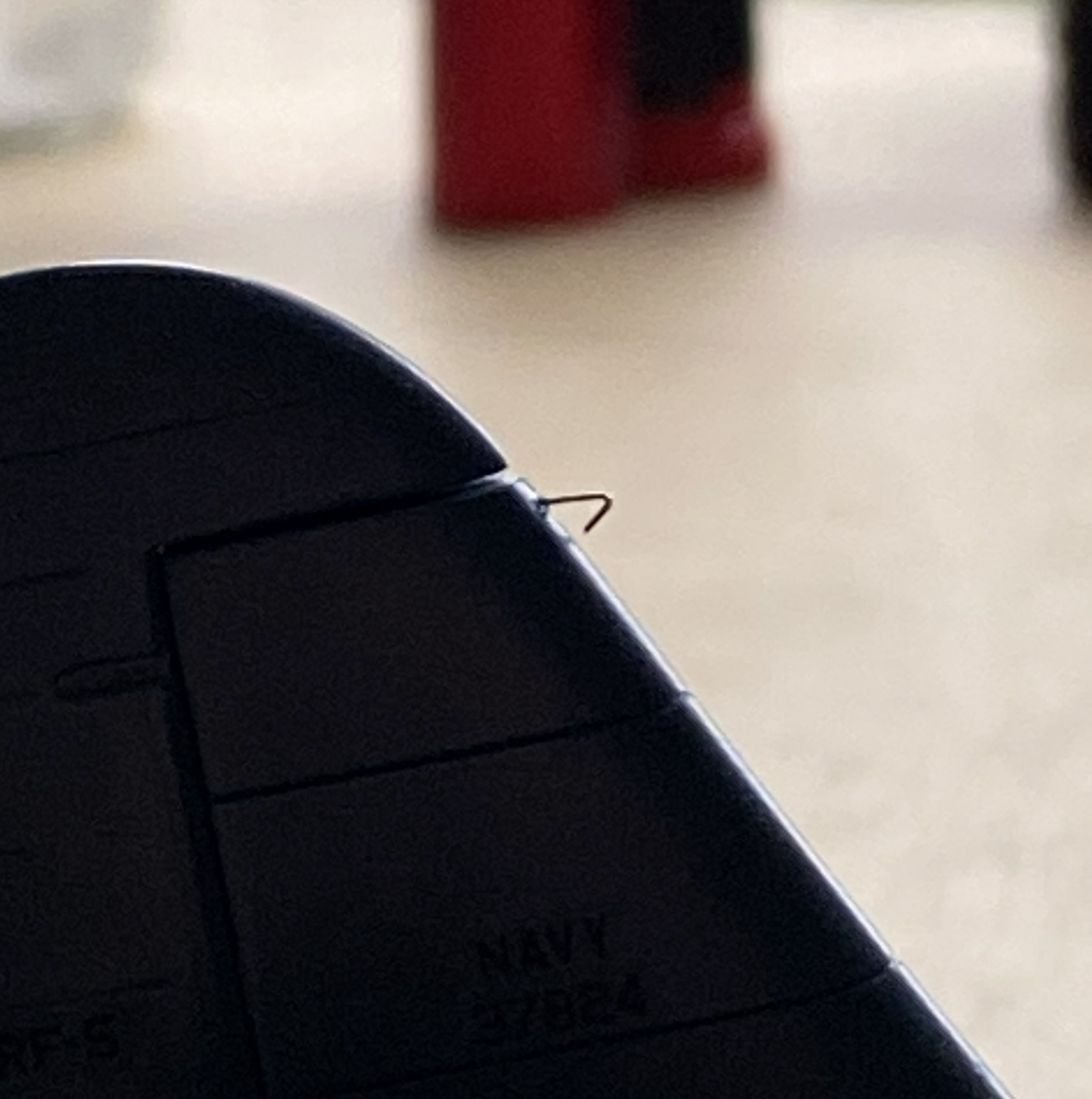
Since I saw this problem as a geometry problem, I looked into the geometry of the landing gear. Being more than a little frustrated at this point, I dry-fit the wheels onto the landing gear and pressed firmly down on top of the model until the bubble was centered. Just as the bubble centered, I heard a soft crack as something broke loose…but the bubble was still level. Took a bit of investigation but I found what broke loose. The blue arrow in the photo below points to where the upper control arm snapped away from the strut leaving this gap:

Hmm. So, if I fit a spacer between the strut and control arm, will that make the wing level? The answer was, “mostly”, which I discovered once I’d cut a spacer from 0.030″ (.762mm) and checked:

I trimmed the spacer without gluing it in and checked again. This time I estimated that I needed another 0.005″ (.127mm) more:

And there it sodding is:

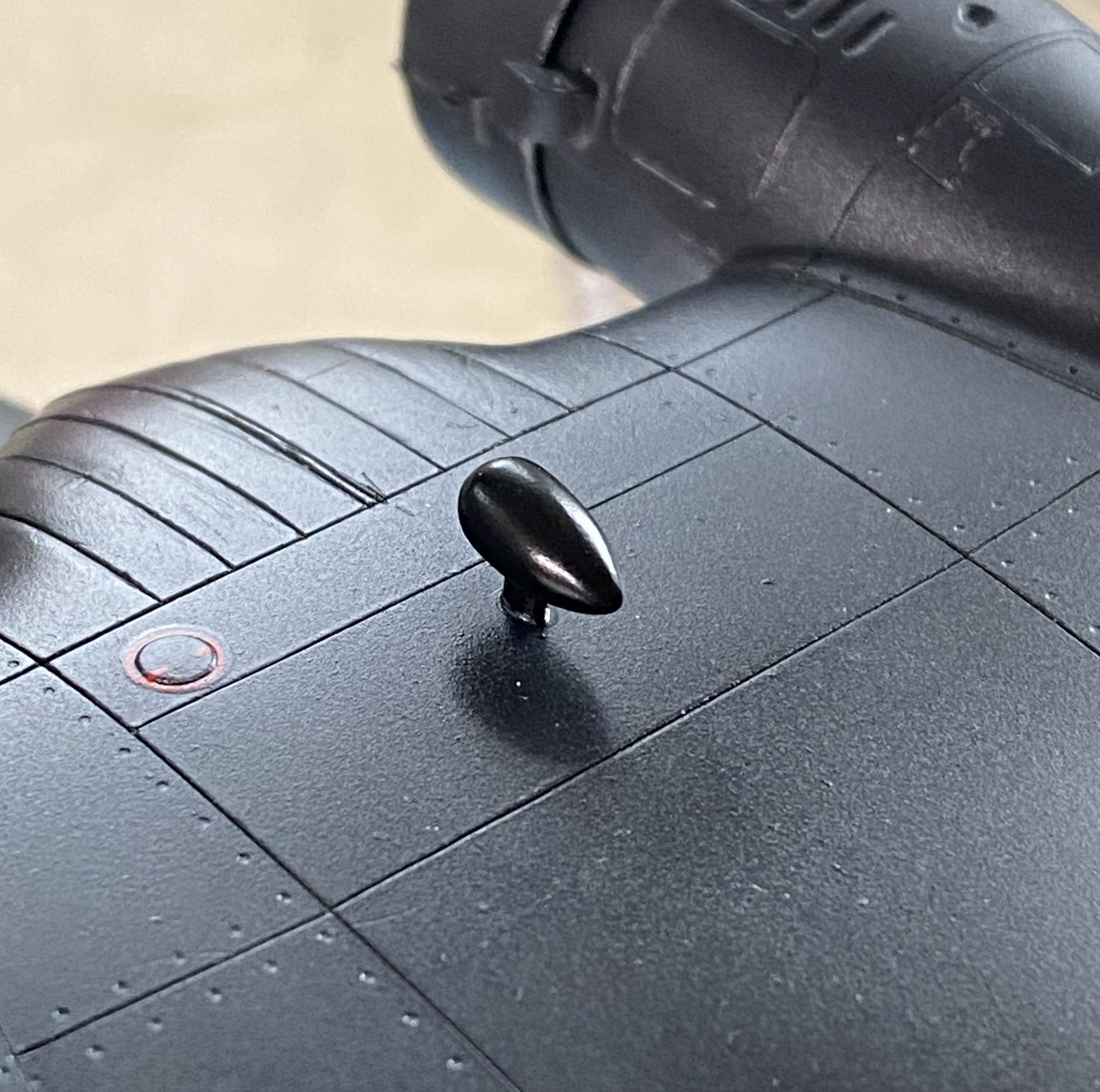
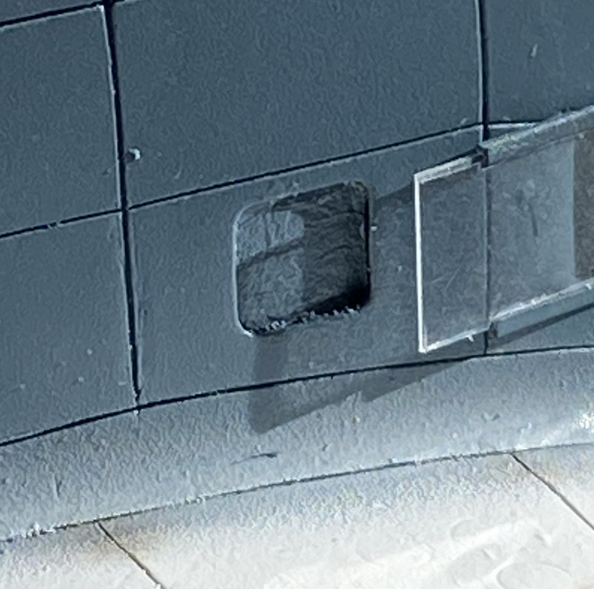
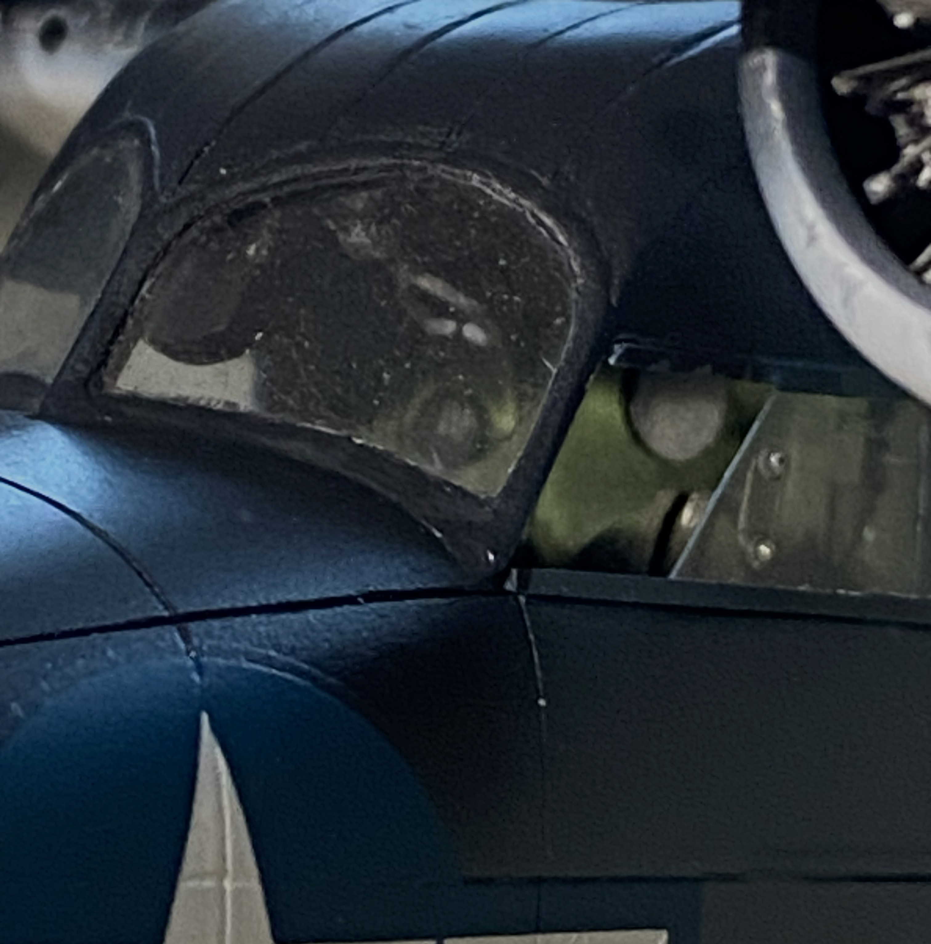
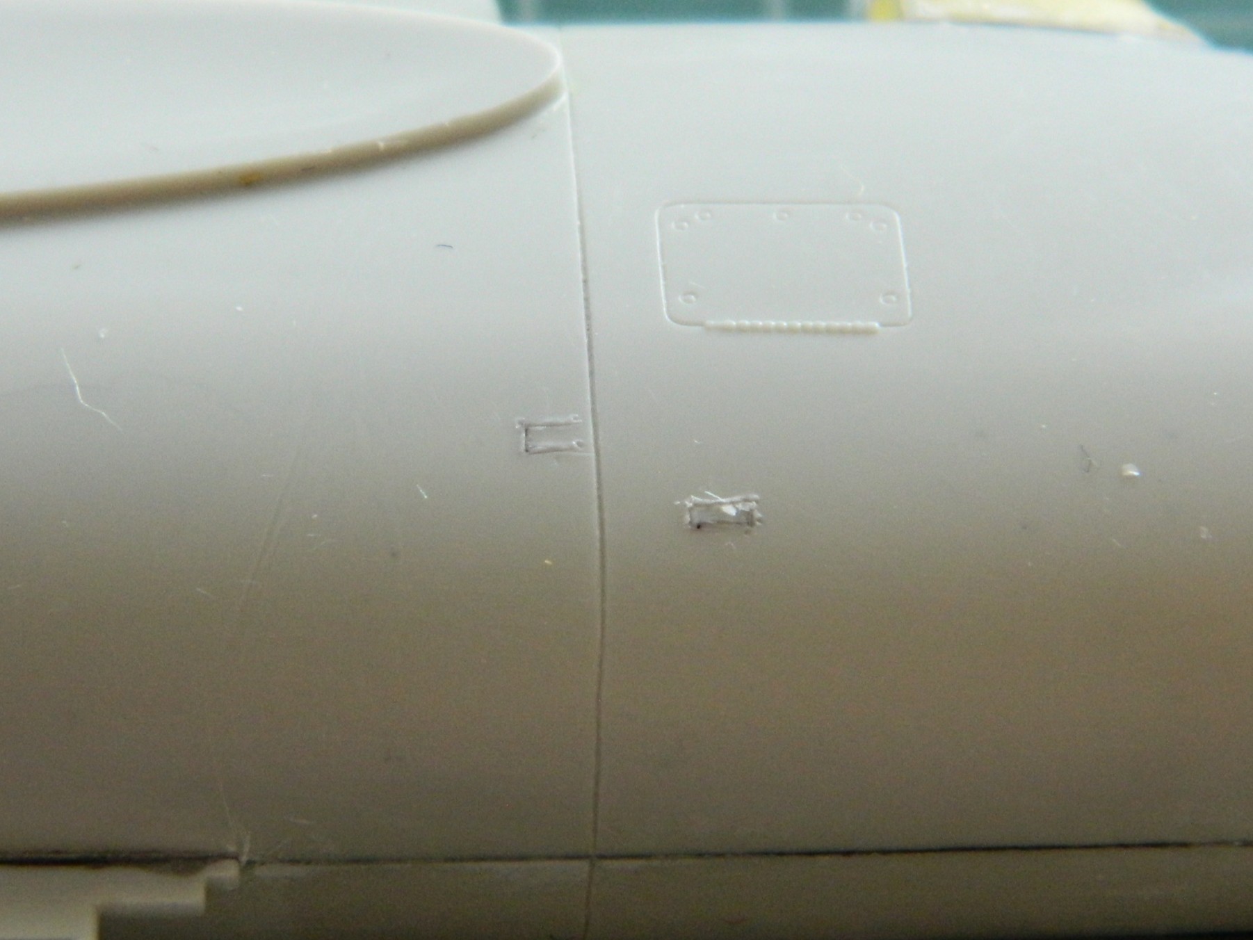
I think it’s the housing for an ADF head, but it needed to be painted semi-gloss black. So it was. I REALLY hate self-inflicted wounds, which is how I view overspray. When I aimed the airbrush at the football, NONE of the other painted surfaces were visible:
Success! Zero overspray:
I used 0.025″ (.635mm) as brake lines, painted them knowing full well that during the final bending process would cause paint to flake off. It was a lot easier to get at the parts that bent the paint away because there weren’t buried in the landing gear bay. I’ll get to these when touching up the paint happens (the photo’s on its side because I was using gravity to hold the solder where I wanted it to while the superglue set up):
And speaking of paint touch ups, I painted the frames of the cockpit windows off so that I could also paint under them. A solution that created a problem; paints don’t match once assembled. Okay, I’ll be doing touch-ups (with a small brush in these areas…the other side, though not as bad, is the same), just add this to the list:
You’ll also note that the cabin window just behind the flight deck is still masked. This was a problem I let sit as-is. When I tried to pry the masking tape away, three of the four sides of this window broke free. It was hanging on by paint. My memory isn’t what it once was (is anything?), but I DO remember what I had to go through to fix the one that came out already. Carve, fix, fill. Lots of fun when the plastic was unpainted, a no-go zone now that it has been painted. I supplemented the paint holding the window on with liberal applications of superglue. I’m pretty sure it’s going to stay there, now. It’s in a place where it will never be touched.
This one’s pushing the 90-95% accuracy I try to attain. I don’t care. A blocked off window is better than a sodding hole. Moving on…
Speaking of self-inflicted wounds, I noticed a week or so ago that there was blue overspray on the nose. ::adds to touch up list::

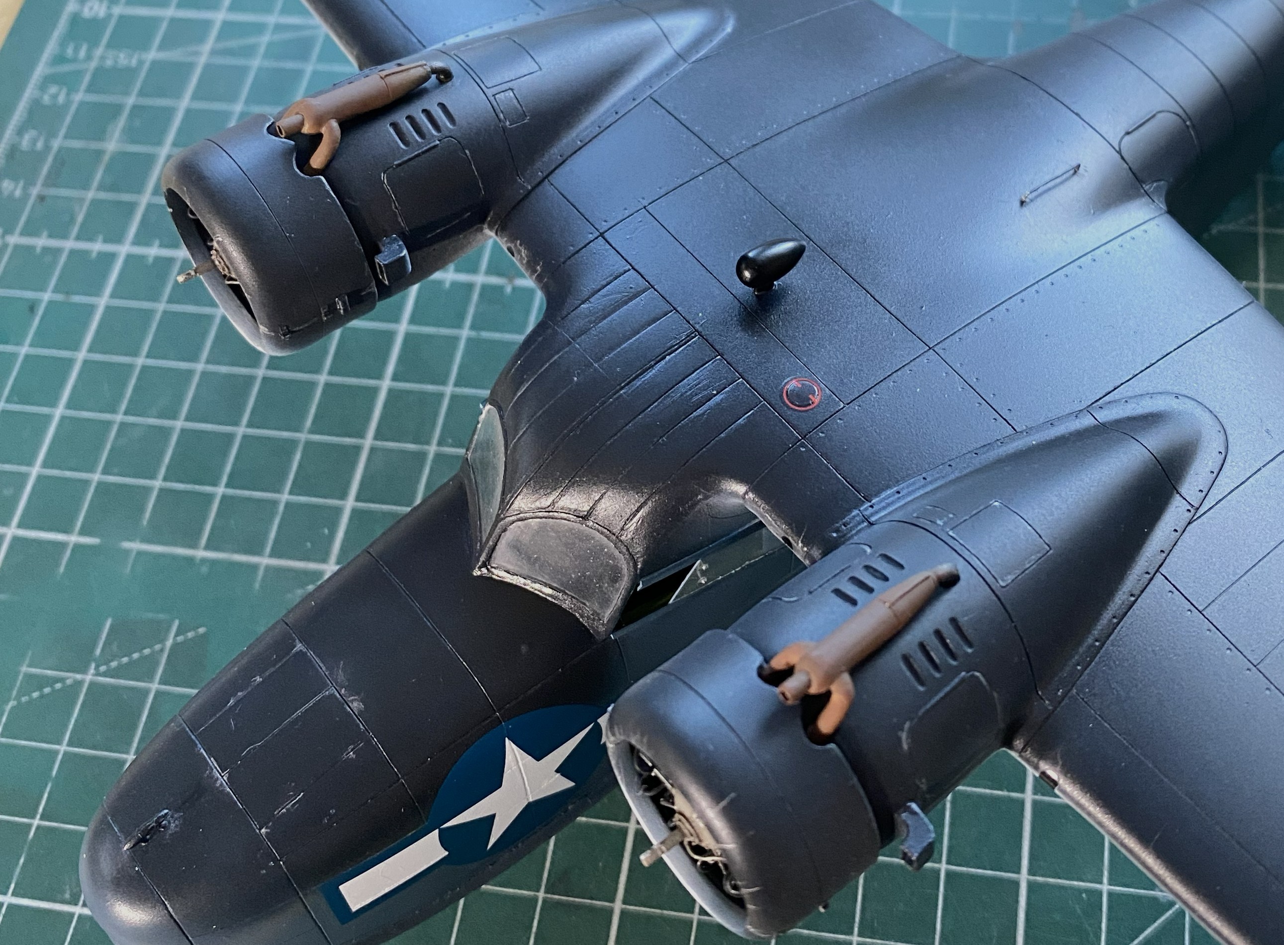
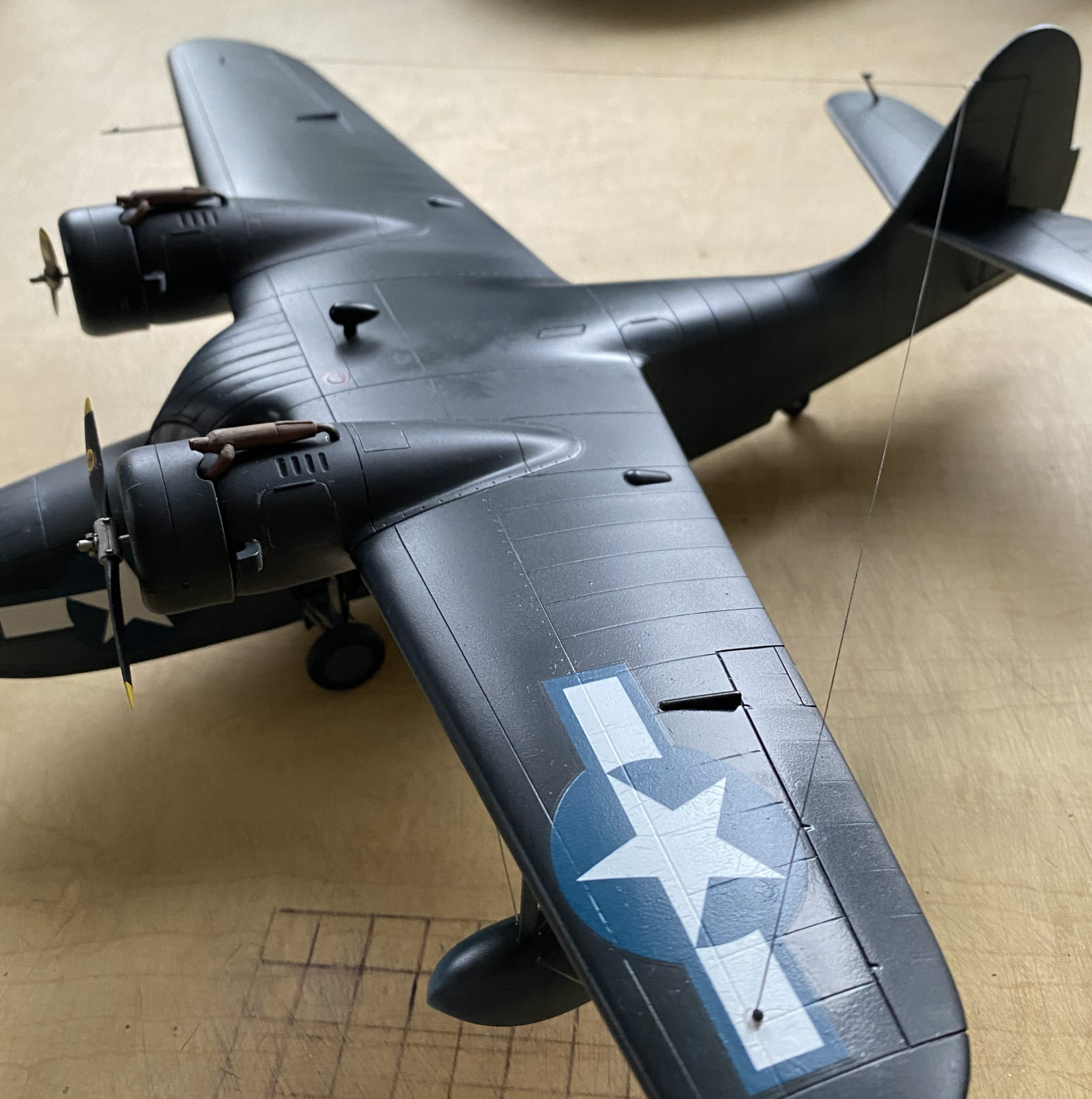
I added the heat exchangers (the brown things over the engine nacelles). Later on I’ll spiff them up a little bit with some pastels:
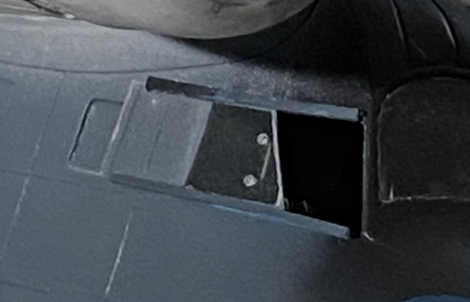
I added one of the landing gear “doors” just before beddy-bye so that the glue would set up; there’s not much gluing surface:

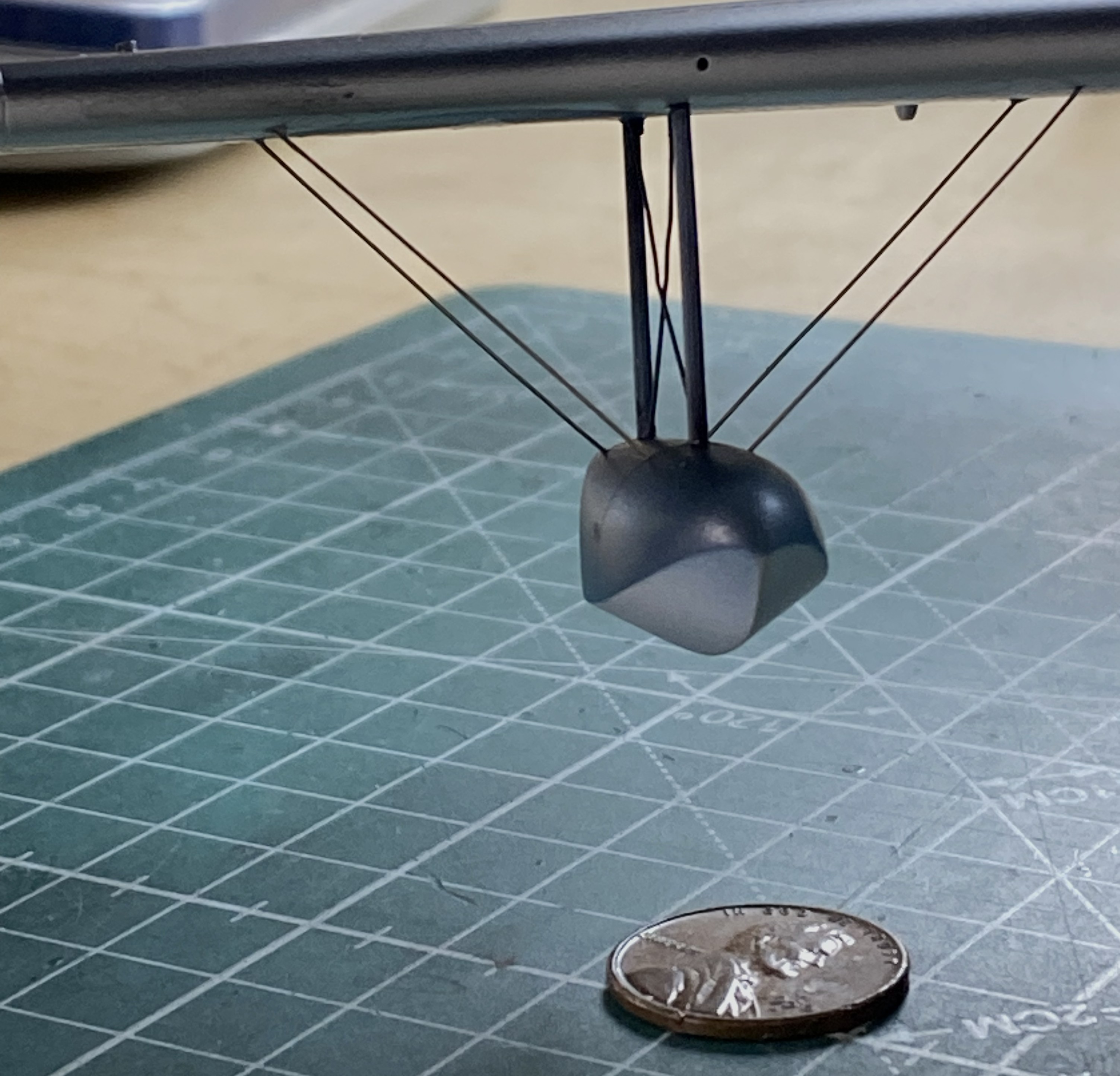
And while I was letting something sit overnight, I got ballsy (considering how late in the evening this happened) and added one of the floats to sit overnight as well:
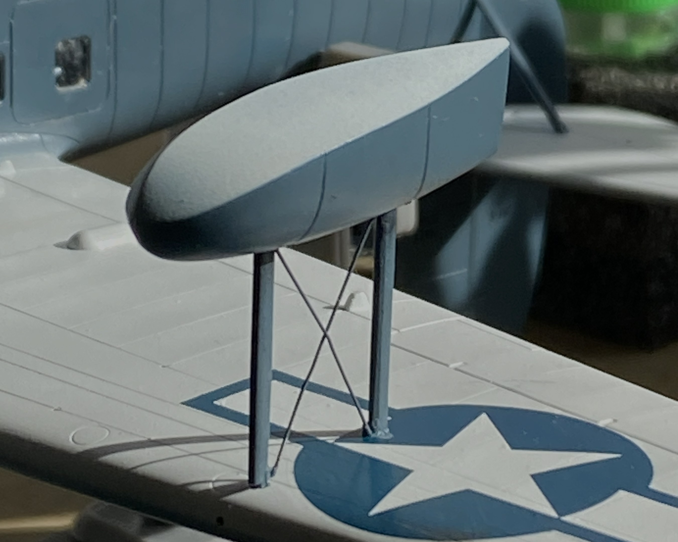
Obviously, with only two small contact patches, this will be easy to knock flat laterally. I added tape to stabilize it while I fed the ends of the braces into the float and wing for gluing (superglue). l cut the wires overlong so that I could be certain I’d be able to adjust them if I needed to (a handy bit of foresight):
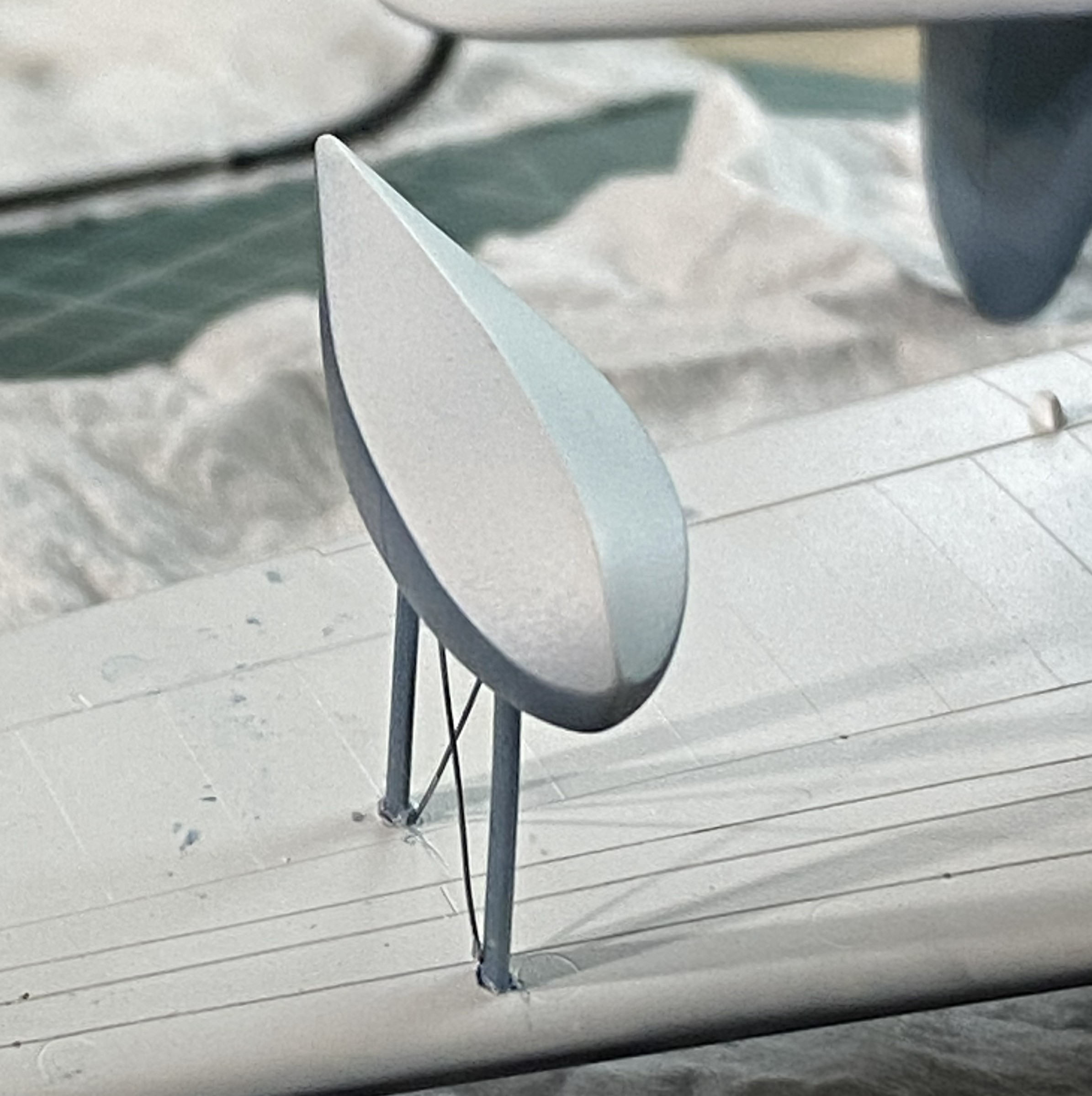
With all the guy wires in place, it looks pretty good:

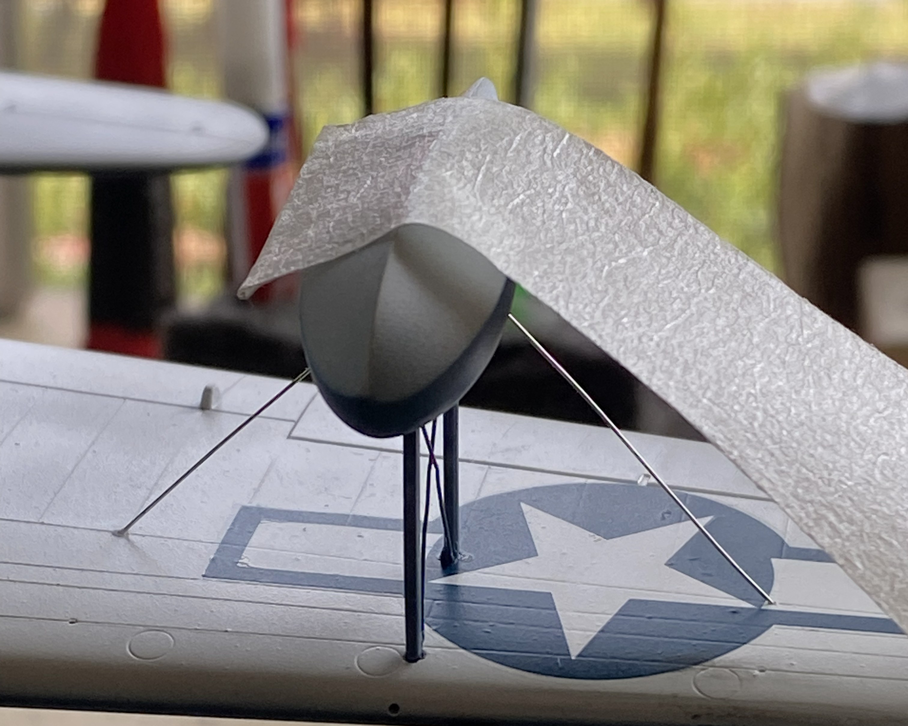
Getting the guy wires into the pre-drilled holes of both the float and wing took some fiddling. For the next float, I tried inserting one end of the guy wires into the float without cement to see if that would be easier:

It wasn’t. If you look closely where the wires meets the float you can see small bits of masking tape holding them in place:
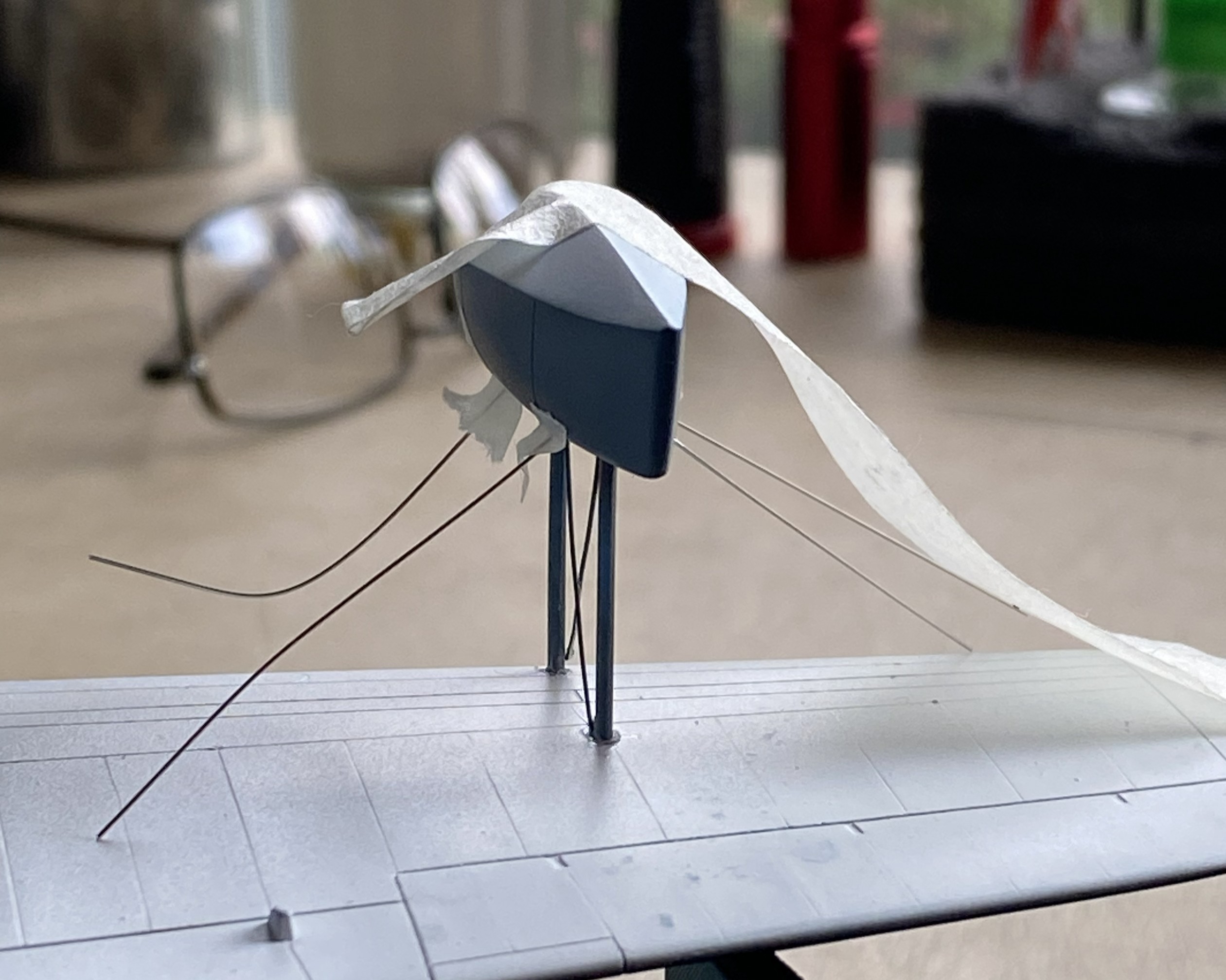
This didn’t work as well as I’d hoped.I was surprised at how difficult it was to just remove the tape. I had to diddle the tape so much that the float came free (in its defense, it hadn’t sat overnight for the plastic to harden fully at the glued points). After I reattached the float to the wing, when I turned the whole thing up side down, all the wires fell out:
I got that fixed:

The radio aerials attach at both wing tips and the tip of the vertical stabilizer. I use this for aircraft aerials:
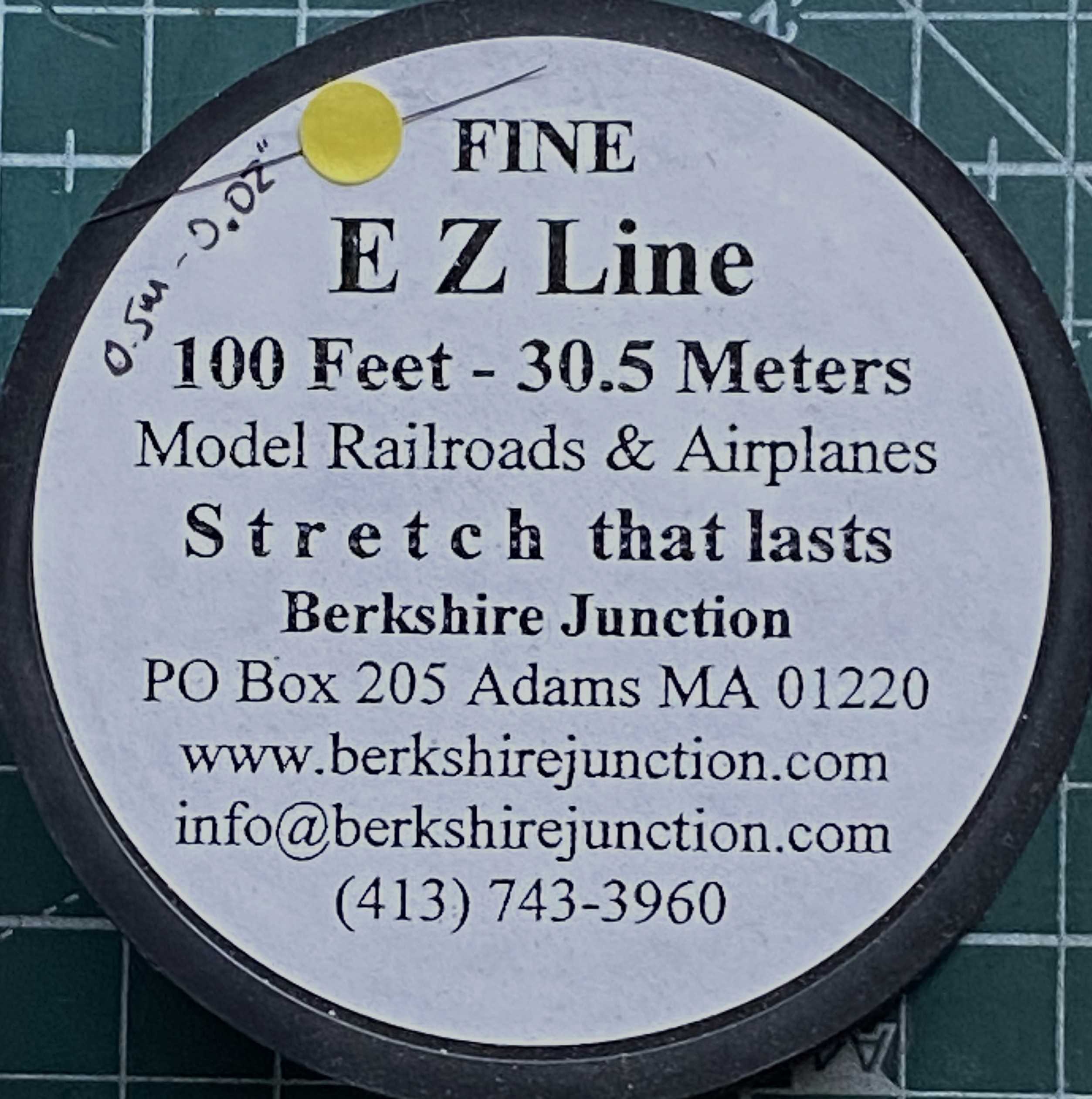
As I’ve been putting this together, obviously the more parts I add the less places I can hold it. For that reason (because these things get handled and transported) I wanted the aerials to be semi-removable; permanently attached at the wing tips, removable at the vertical stabilizer. What would make doing that simple would be to make the attachment point on the vertical stabilizer detachable. Or…I could mount the attachment point permanently and have it be J-shaped so that I can just lift the EZ-Line and let it drop. I like that idea, the major flaw is that even though the EZ-Line’s tension is adjustable, that J-hook has to be small. I didn’t have confidence in copper to hold up over the years. Instead I used the E-string from a guitar (thereby creating the moderately rare 5-string variant). Everything about its dimensions are printed on the pouch:

It’s certainly over-engineered for my purpose, which I think is great:
I’d attached little stubs of styrene rod where they belong and center-drilled them to socket the end of the EZ-Line into:

After gluing the other side in place, I tested the arrangement to see if it would function as desired. It function exactly as desired. Top photo below is with the aerials in place, the bottom photo is with the antennas dismounted (for these photos, I dry-fit all the parts yet to add and realized that none of those dry-fit parts need to be glued so I left them on):
I have one more thing to do (attach the brake lines to the wheels) and DONE!

F7F-3 (AMT/Ertl) After-action Report

Total time building 281.75 hours.
Begin date May 11, 2024; end date February 24, 2025.
Vendors:
AMT/Ertl
F7F-3 Kit #8843 1/48 scale
Eduard
Photo Etch Set #48178
Quickboost
F7F Tigercat Engines #QB 48 142
FineMolds Nano Aviation 48
WWII US Aircraft Seatbelt Set #NC4
Scale Model Accessories
F7F-3/3N Tigercat Wheels #CAT4_R48018
Scale Aircraft Conversions
Metal landing gear #48008
EZ Line
Fine black
My Opinion
This kit was produced in 1995 and I had assumed that it was a rebox of something like Italeri but it’s not. According to Scalemates, this was a new-tool kit produced by AMT/Ertl. When I first opened the box I had high hopes for this until construction started. The build became more and more annoying as I progressed; so much so that I doubt I’d spend the money on another AMT/Ertl kit unless it’s in the category of this kit, which is “I really want to build one of these but it’s the only one in 1/48 scale”…which is what this one is. I’ve always liked this rare bird and when I saw this kit was available, I jumped at it. There were many opportunities for this to be an outstanding kit, even by 1995 standards, the company just took too many shortcuts for my liking. It’s a 3 of 5 star kit and good for someone who’s just getting into modeling and doesn’t want to invest a lot of money into it and won’t be showing it at contests. To build OOB will require a newcomer to stretch to produce a decent build, which is what newcomers need (in my less than humble opinion).
What I ended up with is not contest-worthy.
Too many parts broke off after construction. Granted…I have not been at my best this year and some of that could be my own inability to connect the dots of late. But engineering and fit needed attention and sometimes a lot of it. And each time something breaks off, it’s got to be reattached. Each time it’s glued back on, there’s the old glue and the new glue and it builds up when something breaks off a half-dozen times. Yes…I could have removed the old glue. I didn’t because experience has shown me that that often requires a repaint which, given the nature of rattlecans and the locations of where things had to be reattached, I wasn’t interested in doing. This is a three-foot model. It looks really good from 36″ away but loses its allure the closer the viewer gets. Speaking of paint…
I learned a lot from painting this one. Yeah, orange peel is a thing. Yeah, I figured out how to mitigate that effect by sanding and polishing (the other fix is to strip all the paint off and start over). My major mistake was thinking that Tamiya’s X-22 Clear would self-level, which it does do. It seems the line between orange peel and self-leveling is invisibly (at least to me) small. I also learned that if one is doing a dark and glossy finish, one canNOT over prepare the surface. Prepare the surface as if you’re going to do a natural metal finish because I was very surprised to discover that a line left behind from sanding with 600 grit will show up when the gloss arrives on the dark paint. Lesson learned.
F7F-3 (AMT/Italeri) 1/48 Scale Build #8 – Finishing the Fuselage, Making Clear lights, and Attending to the Final Details Before Assembly Starts
Sometimes all the seam-filling goes, well, seamlessly…and sometimes not so much. This time was the not so much category. I had to go over the fuselage seam a few times, searching out those tiny areas that either show the seam or air pockets in the putty. Since the window in the shop faces east, having that bright morning sunlight (unlike myself, who’s not very bright at the best of my times, and certainly not in the morning) enables me to see things that usually don’t show up for me until it’s painting time. So all that got done.
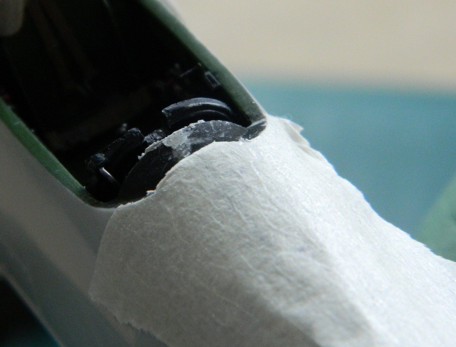
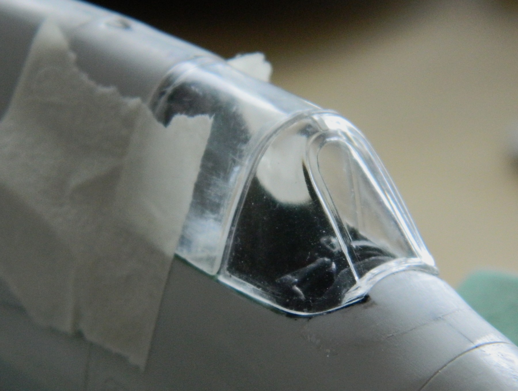
Since I generally don’t start a build that I know how to finish, there’s always that particular thing floating around my consciousness just waiting for its turn to enliven my day (because don’t all inanimate and insensate objects just float around waiting to enliven with our days?). Checking how well or not things fit is to see which of those aspects of the work will need attention as well as how much attention. I’ve known for awhile that the canopy, the forward and fixed part as well as the part that slides back to open the cockpit, doesn’t fit well at all. I also intend to model this aircraft with the canopy open, except that the kit part is too thick and sits ridiculously and unrealistically high. That means I’ll need to vacuform something thinner. But at the beginning of it all, the forward canopy is too narrow. And ever since I added the few details to the landing gear bays that I did where I used UV-setting resin, I’ve been planning on using this medium to attach the canopy. But all that gets to wait while I finish the last seam, the one going across the inside of the canopy:

Given the proximity of the instrument panel, I wanted to protect if from the work. Since there are several really small parts that could be dislodged if I used tape (and the fact that returning them to where I want them will be quite annoying because of lack of access), instead I made a “portable” mask from pressed paper:
That will drop into the gap between the instrument panel and the edge of the fuselage:
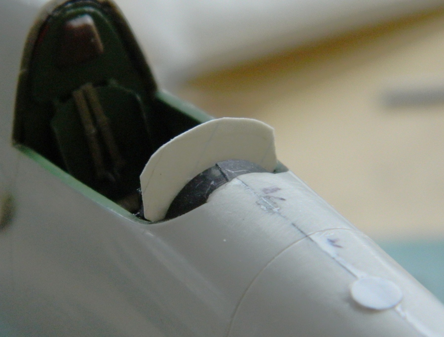
The mask worked as hoped for.
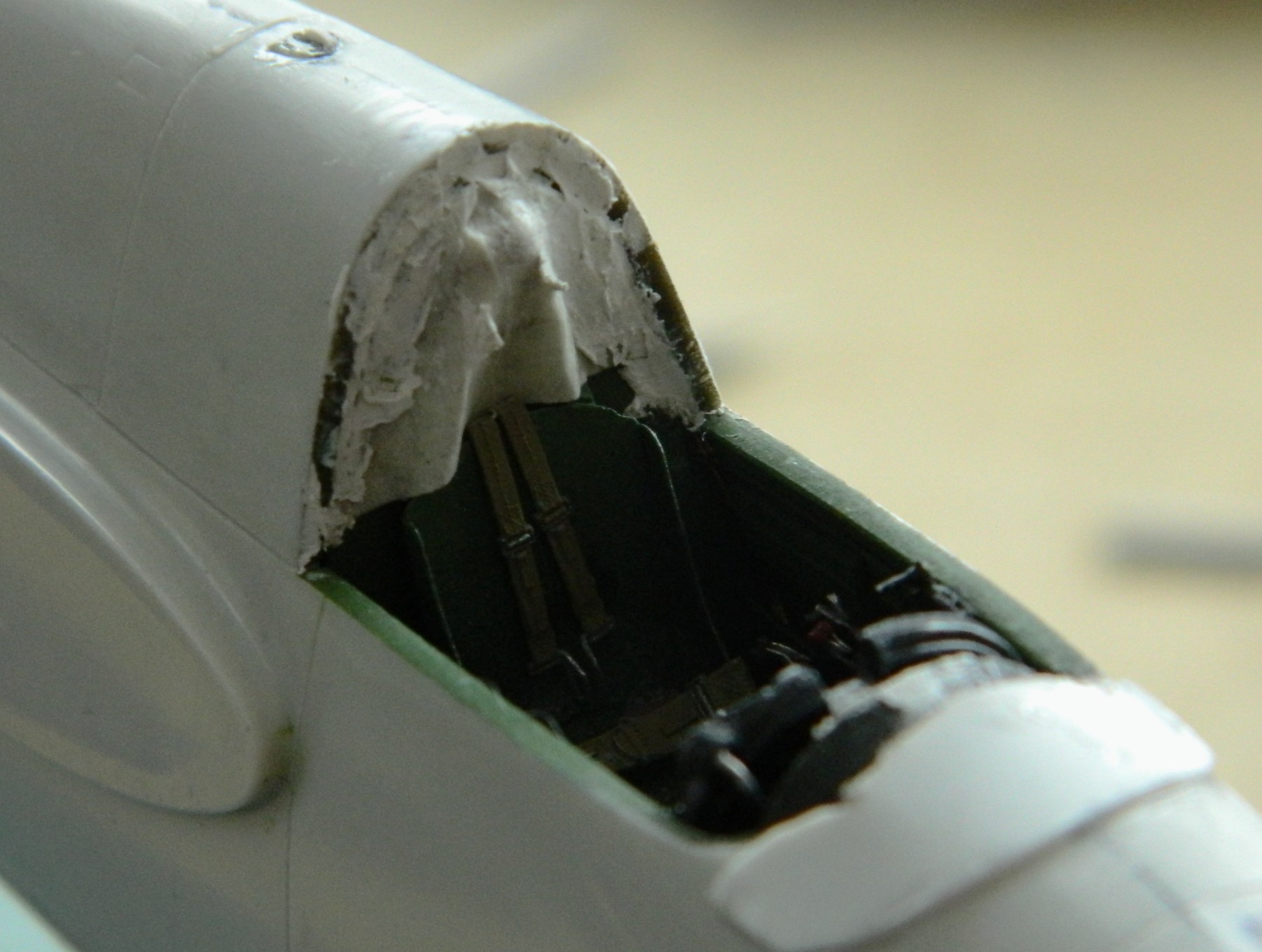
The rear of the cockpit’s interior is flush with the sides of the cockpit opening on the actual aircraft and because of where the cockpit assembly fit, there was a gap around that bulkhead (fit problem, obviously) I’d intended to putty that. But in order to fit the bulkhead where it should go, I’d need a time machine to talk (loudly) to the engineers. Since that’s not possible, I did the best I could with what I had to work with:

I masked off as much of the bulkhead as I could and got creative:

Once the mask was removed and the putty worked, I guess it’s better, but it’s not accurate. It’s just the best that could be done short of splitting the fuselage halves and starting this part over. Nope. Not doing any deconstruction that I don’t have to. Best part of being good is knowing (or guessing correctly) when to stop. So I stopped here (of course finishing down the putty and repainting the affected areas, which were minor).
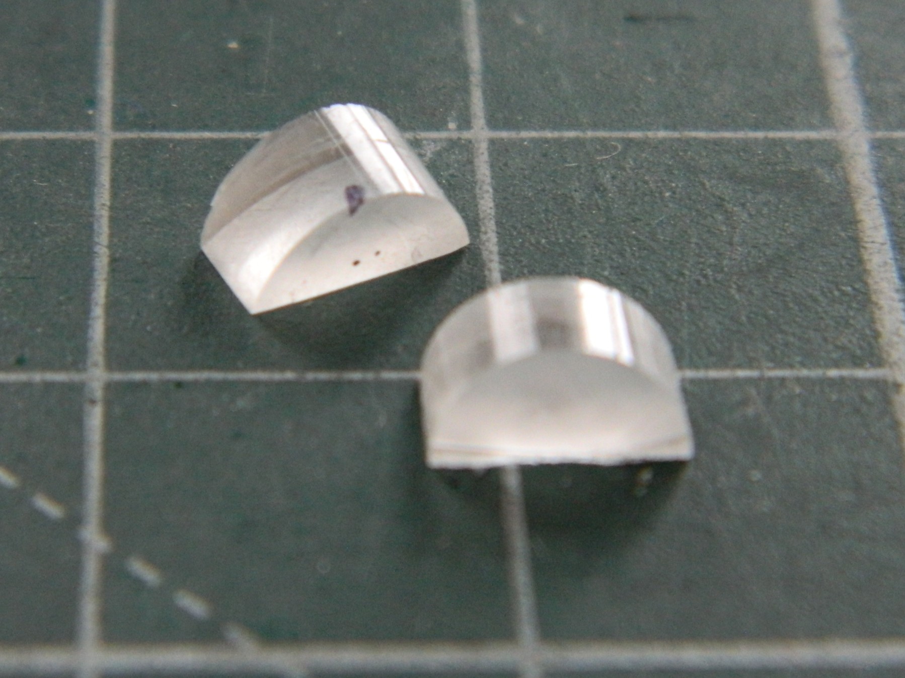
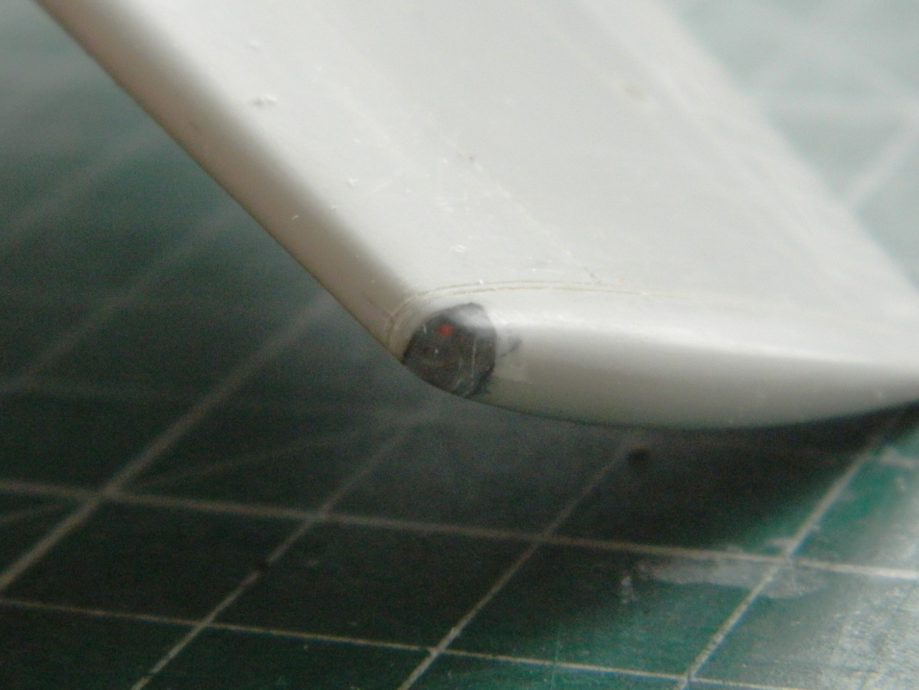
One on my peeves is using opaque paint to replicate things that are clear or translucent. I have two wingtip lights and two landing lights to do, and only the landing light located under the starboard wing was acceptable (relatively speaking because of…wait for it…fit problems). So three of the four landing lights needed to be redone using clear plastic or acrylic. I’ve already shown you how I dealt with the light located in the leading edge of that wing by using clear sprue. The wingtip lights are too large for any clear sprue I have on hand so I ended up using a quarter inch (.635mm) section of a clear acrylic rod.
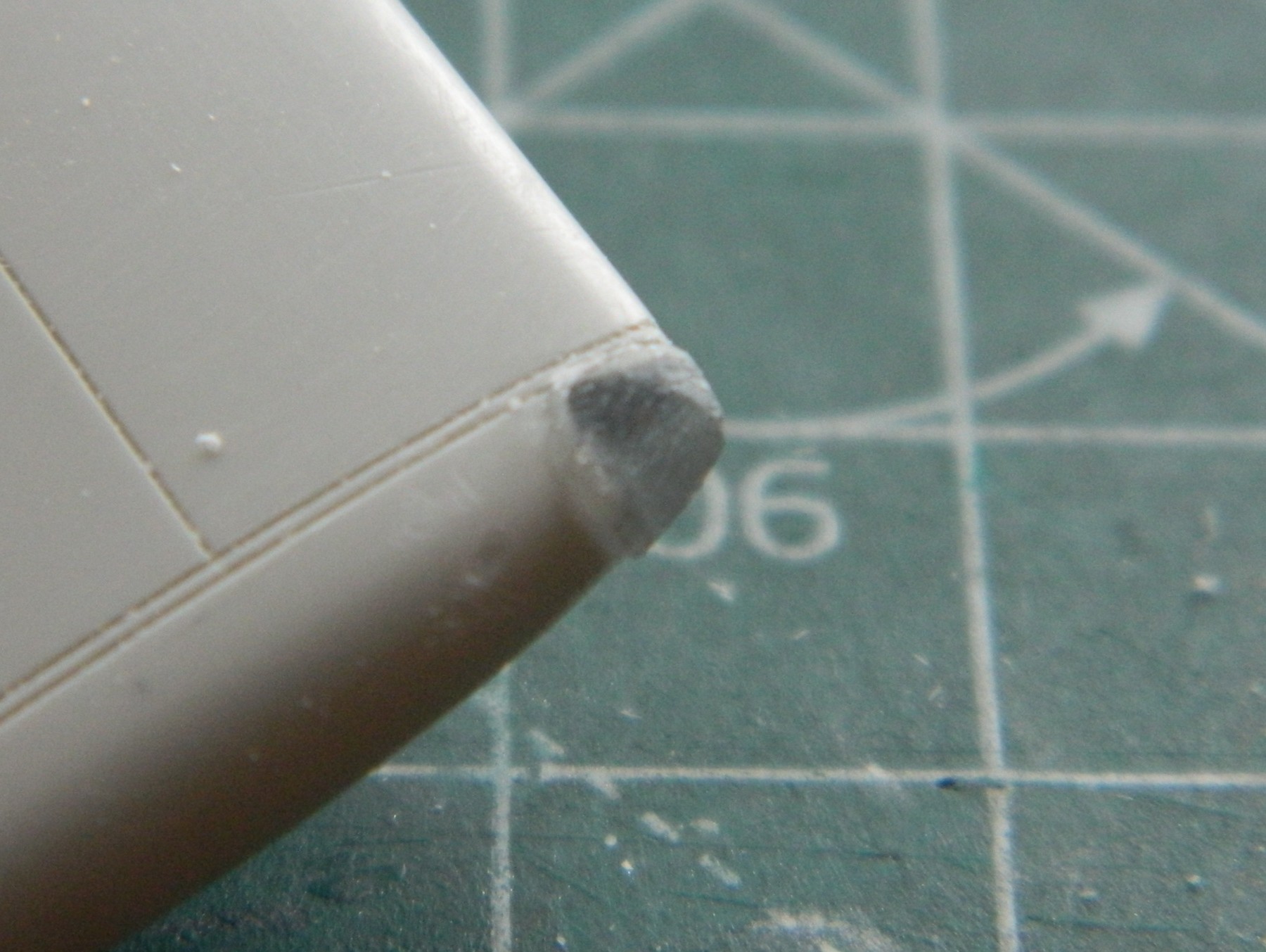
That process started by cutting away the opaque plastic where the lights go. This let me ascertain how big the replacements had to be:

I used a razor saw to cut a slot in the end of the rod:

And then sliced across the cut to get two pieces:
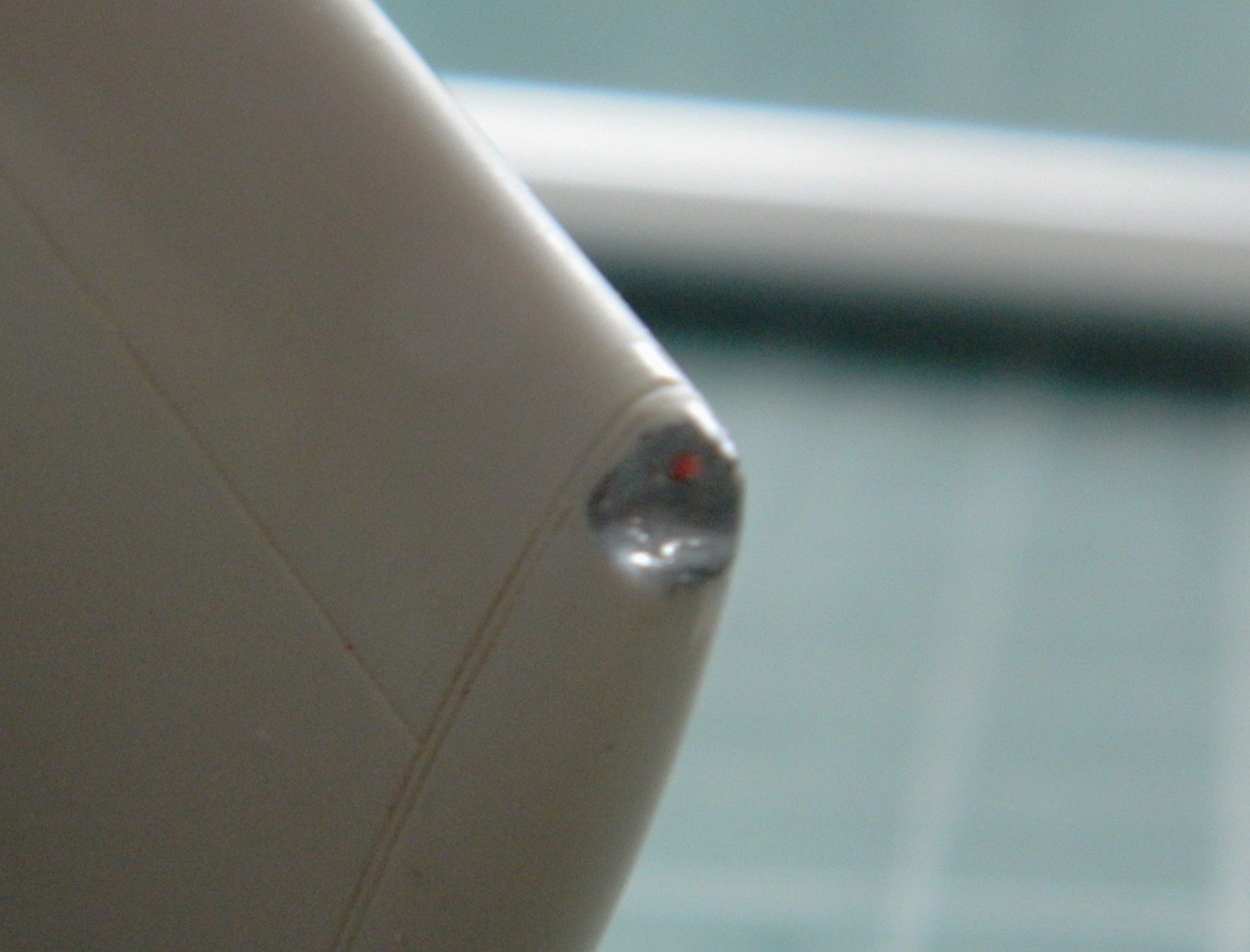
References show that the actual bulb comes in from the side of the wing. Red is used on the left, green on the right, so I drilled a very small depression that I added the appropriate color to (sorry about the blurred photo, the camera clearly needed caffeine as well), then I sanded and polished the faces of the acrylic that will be in contact with the wing before gluing the acrylic (with the properly painted “bulbs) to the wing. Usually I would use superglue for this. This time I decided to see if the UV-setting resin would work…it would certainly give me MUCH more time to get the acrylic correctly positioned and it worked great:
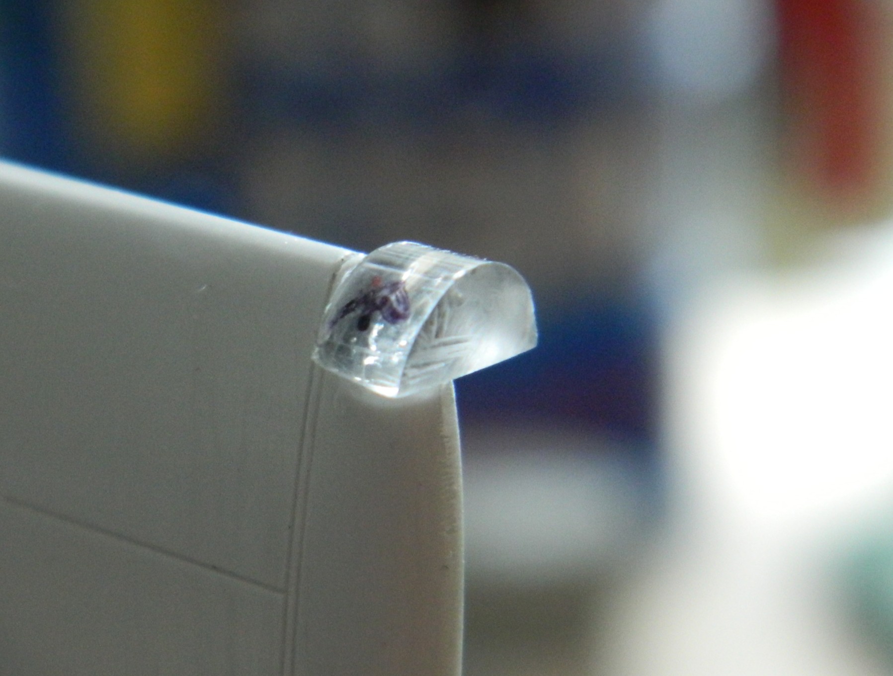
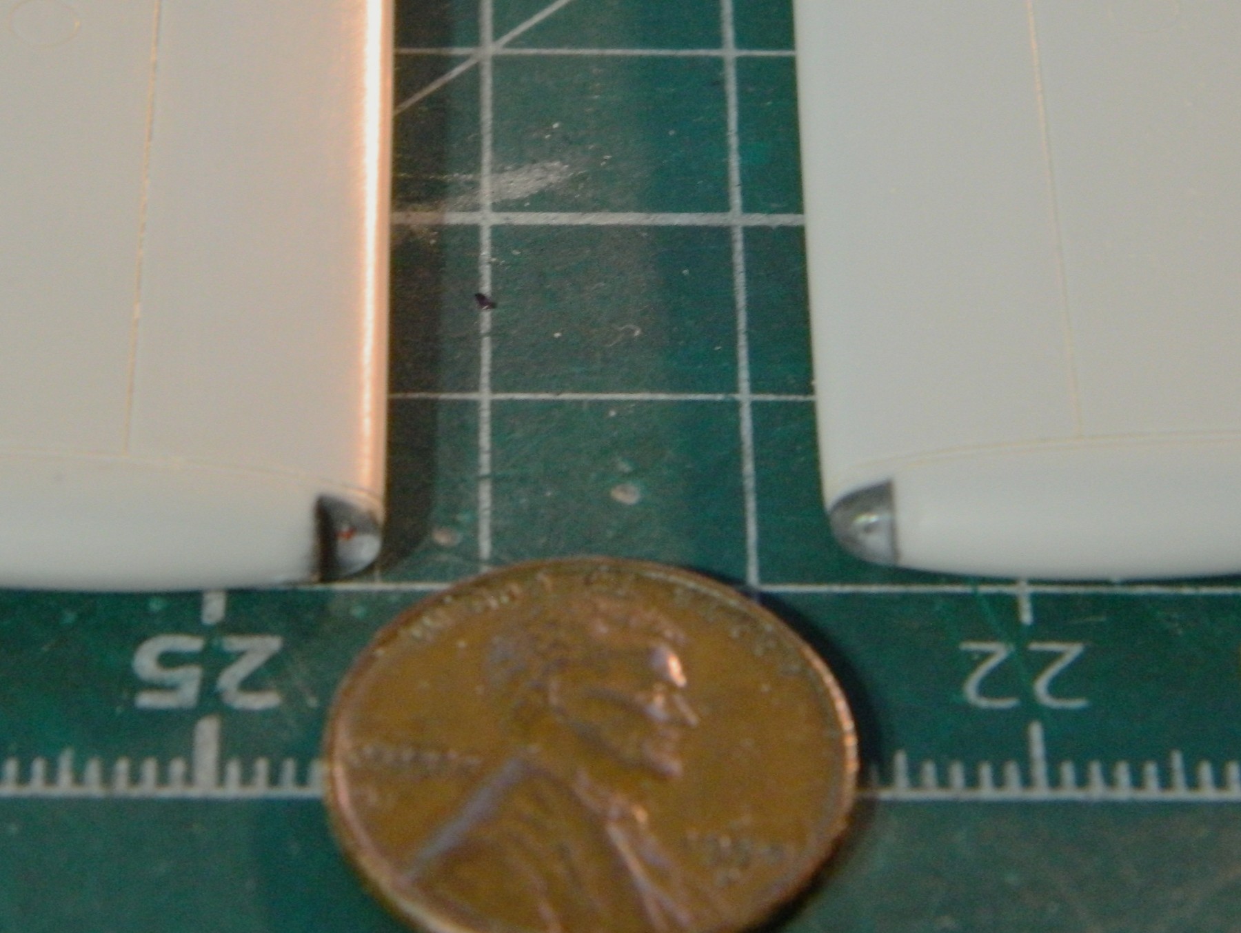
Most of the excess acrylic was ground away:
Then sanded through grits of 320, 400,600,1200, and 2500, before being polished with Novus #2 Plastic Polish:
I liked it, enough so that I did it again for the other wingtip:
Attention shifted back to the canopy. One small part of the bracing wasn’t cast into the part. I used 0.005″ (.127mm) scrap styrene and (nerve-wrackingly) added it:

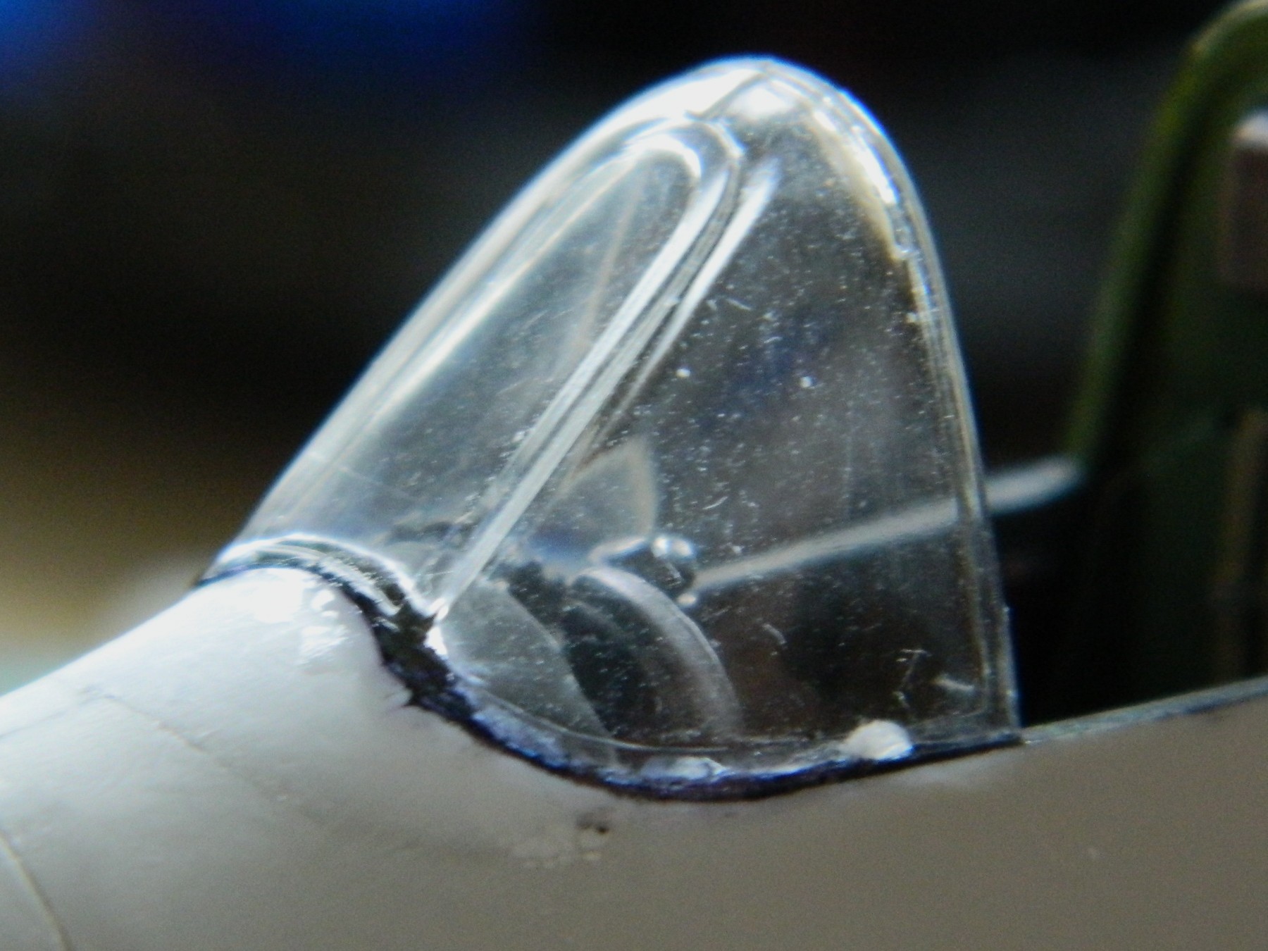
When I test fitted it, it didn’t fit well. (How odd!) Not only was it too narrow to fit the fuselage correctly, the front bottom didn’t fit the curve well, either. Part of that was my responsibility because somehow I sanded away a section of the fuselage where the canopy meets it. Rather than trowel on the putty, I took a section of 0.030″ (.762mm) scrap and added more than enough to fair this into the fuselage without a gap:
Then followed much sanding, filing, and fitting until it finally fit correctly (or at least the way I want it to fit, which I’m hoping is the same thing) (the sliding part of the canopy was also fitted and filed; it’s only use for it is to pull plastic over with the vacuum mold and in place to confirm that I had the front of the canopy correctly fitted):
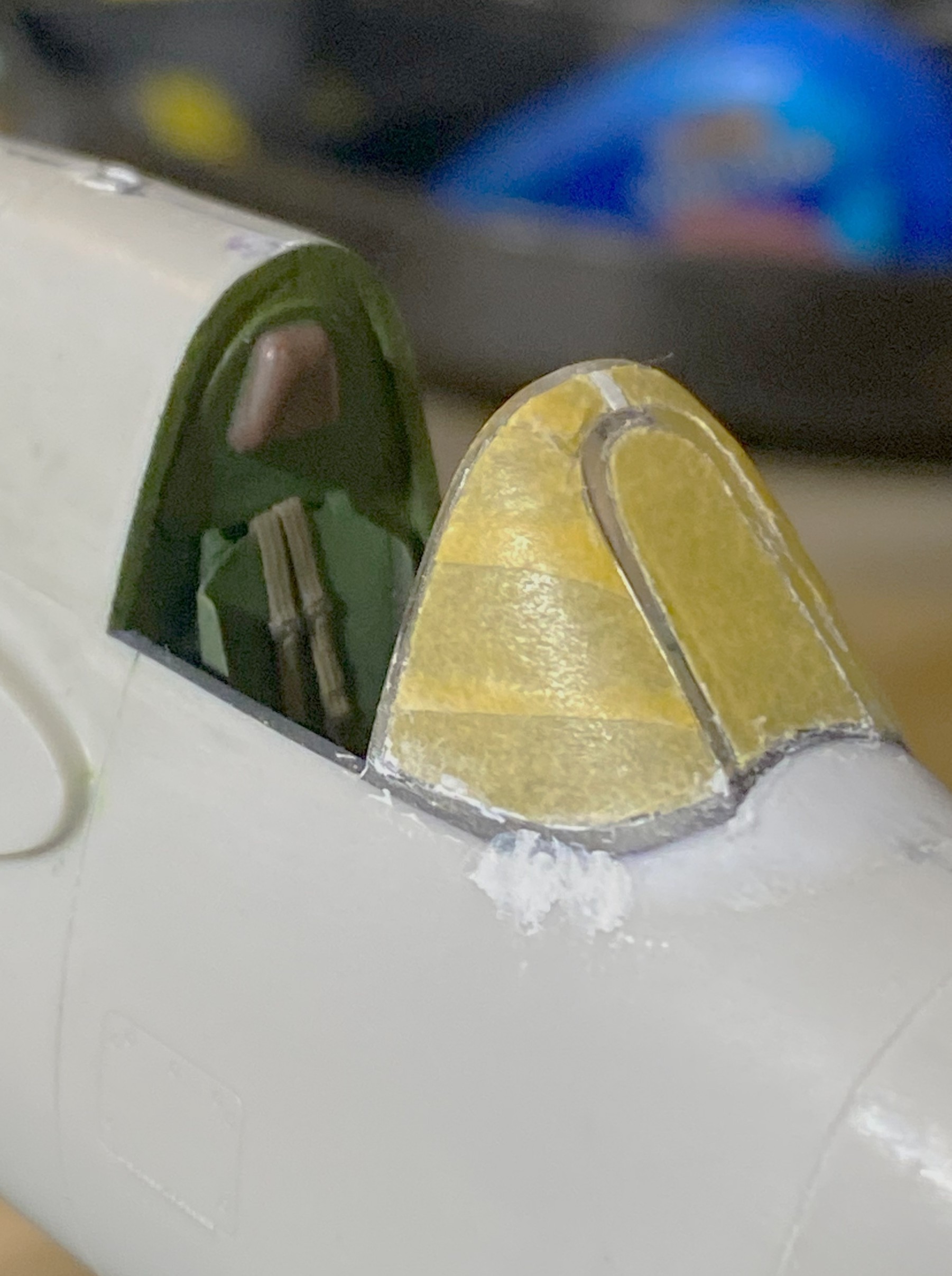
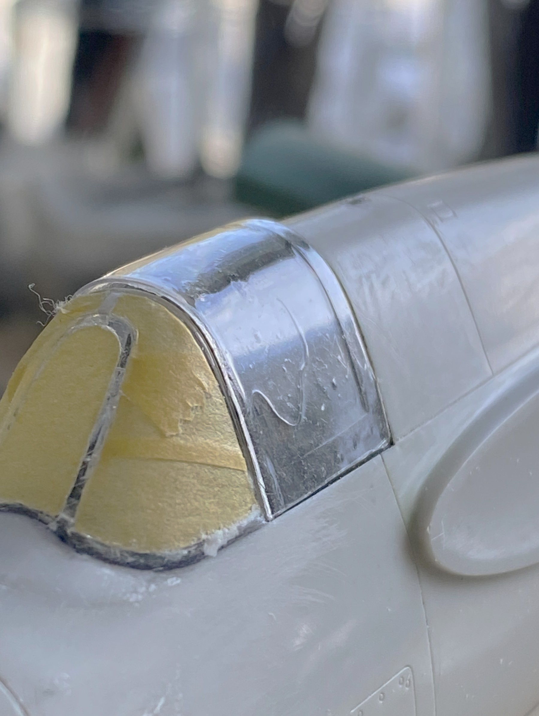
I decided that since I’m using a new-to-me tool, UV-setting resin, that I was going to decrease my ignorance of this material by seeing what I can do with it. Before I started, I used a permanent marker on the areas of the forward canopy that contact the fuselage. This would keep the plastic from looking like, well, plastic. To spread the canopy to the desired width, I started by tacking one side of this part in correct alignment:
Then I spread the part to fit the other side of the fuselage with a fingertip (using the base of the finger is painful and bloody). Considerable pressure outward was applied and I kept waiting for the attached side to snap free. It didn’t move at all! I filled in (most of) depressions left by applying multiple coats of resin so that I would have enough to sand down to invisibility. But before I did that, I masked the sections I want to remain clear because brain-fade can strike at any time. I have this one part that must be used, and I wanted to protect it from being scratched. Once masked, files and sandpaper blended the canopy to the fuselage. There were a few areas that needed minuscule amounts of putty, but so does the rest of it so putty was applied:
And putty reapplied for the couple of spots that I’d missed:
And it worked wonderfully! It’s looking like I have my new go-to process for adding canopies or any clear parts!
With that out of the “hanging over my head” category, the sliding canopy needed work as well. I tweaked its fit a little, then dealt with the fact that it’s too narrow also. I figured out how much I needed to move it and then used 0.040″ (1.016mm) styrene as a spreader to push the plastic to where I wanted it:

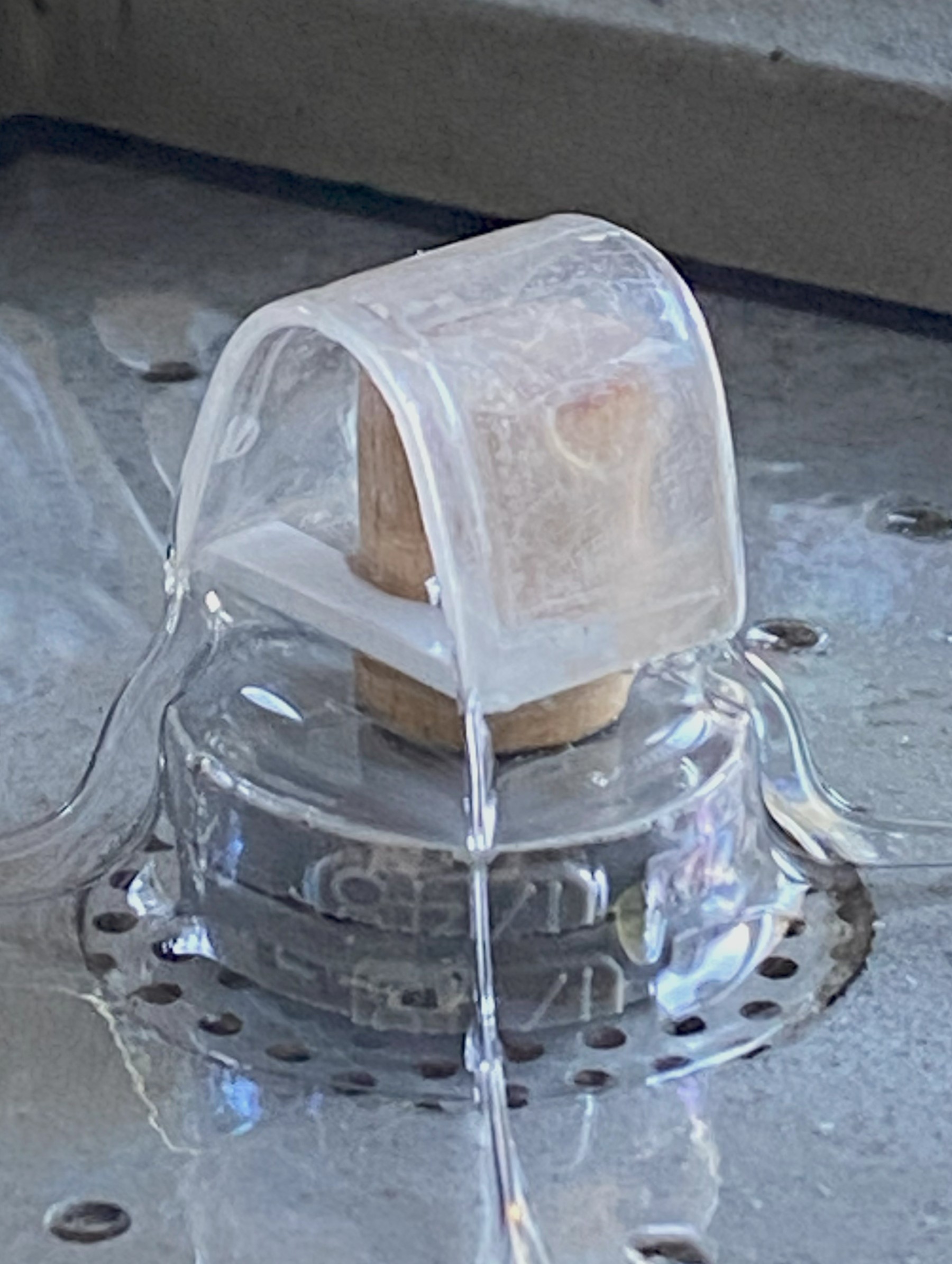
I set up the vacuum molder and mounted the buck on a stand (replacing the superglue I’d usually use for this and used the UV-setting resin instead and had at it):
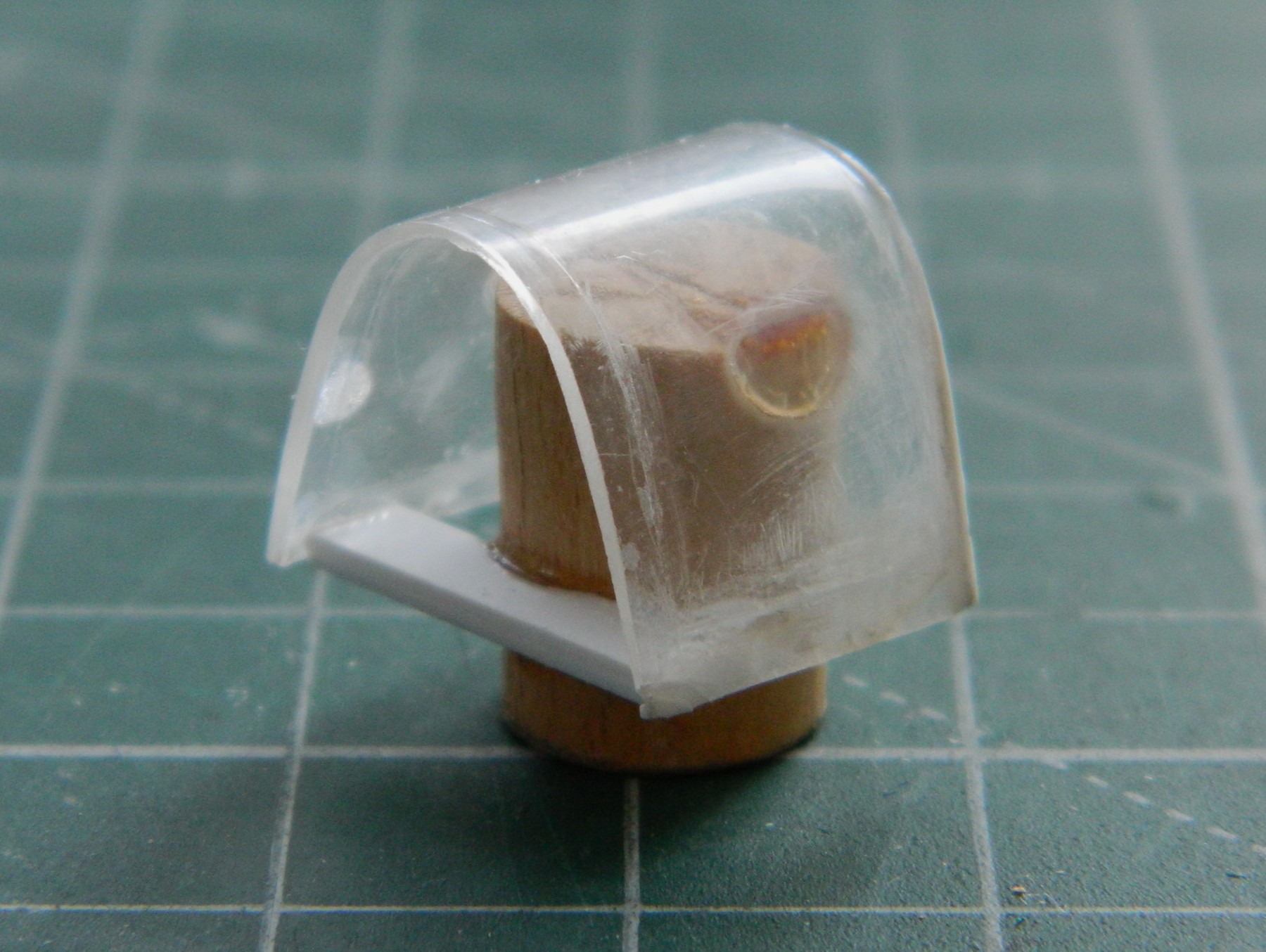
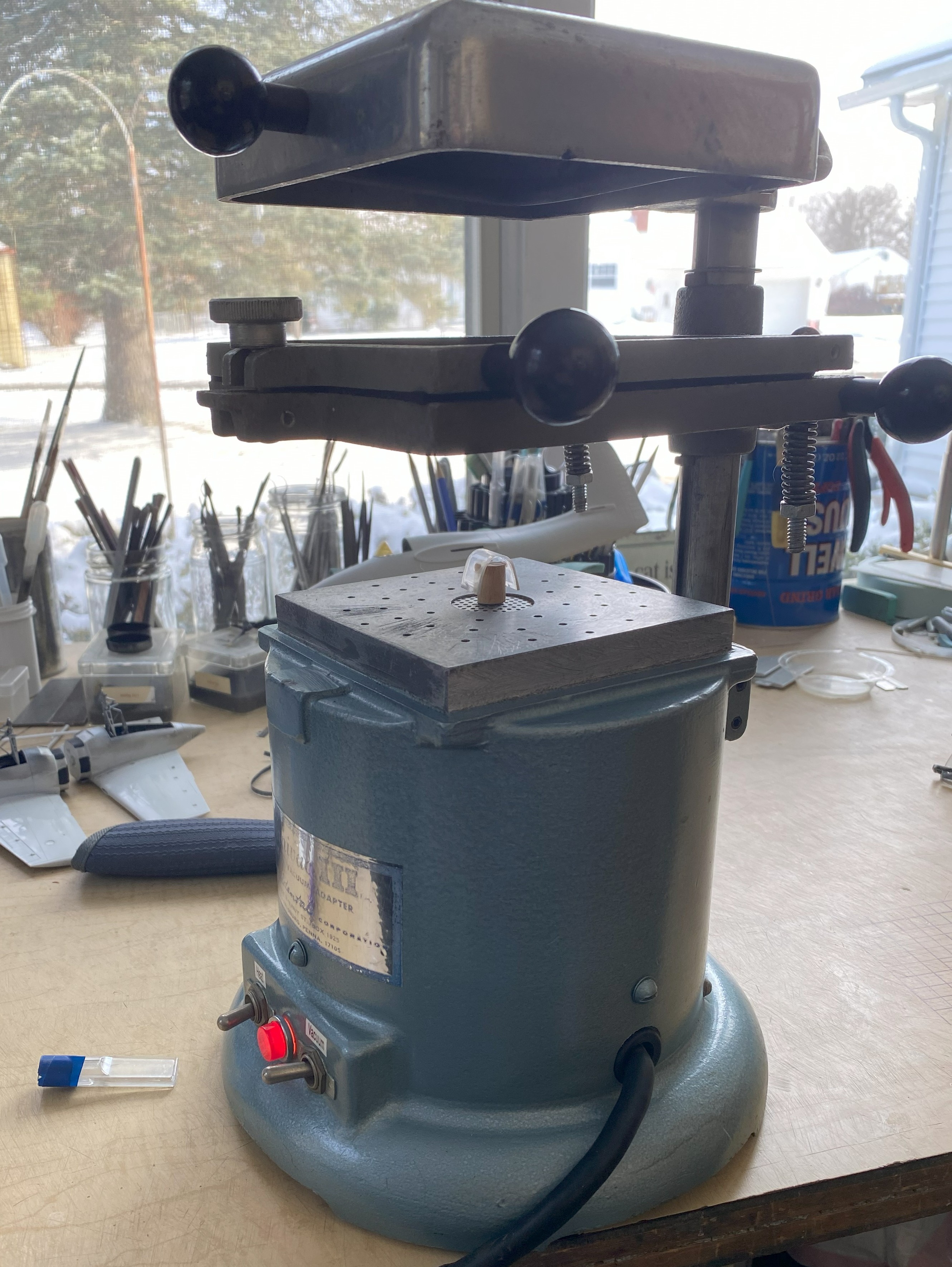

Using a vacuum molder to copy parts is called “a pull.” Set the buck, heat the plastic, turn on the vacuum motor, and it pulls the plastic down and around the buck. Then the new part is painstakingly cut away from the excess and the buck. It’s not uncommon (for me, anyway) for multiple pulls to be necessary (and waste a lot of material) to get a usable copy. This time I thought I’d done it on the first pull!
Silly me.
In the following photo, you’ll notice that on the side of the canopy, it looks like a paint drip/run. Hmm…but there’s no paint on it! I wonder what…on…well…guess there was a freaking hair on the part (or plastic, I dunno) and it showed up:
::facepalm::
While I had it on the model (temporarily), I checked to see if it would do what I was pretty certain it would do, which is slide back as far as it needs to and sit as low as it has to:

Yes…I know it looks as if it’s only partially open. I’ve seen another modeler’s build of this kit and he thought the same thing, going so far as to remove the antenna mast and move it towards the tail of the aircraft. That is a mistake. Looking at references shows that this is normal for this bird. What’s also normal for this bird is how that sliding section of the canopy fits, now. I just have to make one without hair!
Challenge met:
For this pull, in addition to being sure no hair was included, I wasn’t especially thrilled with how the folds of the hot plastic came up too close to the canopy for me with the last pull. I added a pedestal (made from scrap resin that the engines were cut off of) and that little bit of difference gave me a part that was substantially easier to work:

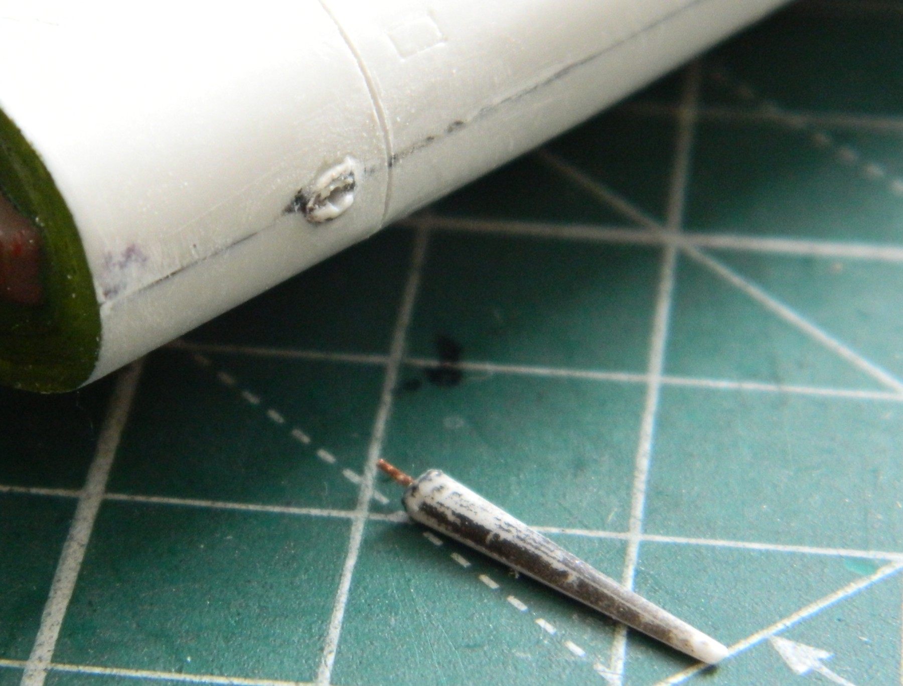
There were a few more little things to do before painting. One of which was adding brake lines to the main landing gear. I used 0.025″ (.635mm) solder. While I was doing that, I managed to drop one of the wings. One part fell, two parts were picked off the floor. The part that broke off was the section of the landing gear strut at the bottom of the oleo. Okay, annoying, but not the worst part of that day…until I tried to glue it back on. It wouldn’t stay correctly aligned long enough for the “instant setting” (::snarks::) superglue to set. Finally I figured out how to balance the part, correctly aligned, long enough to put a SMALL touch of superglue in place to hold the part there long enough for me to add more superglue. This turned into an example of, “tools are what you need, not necessarily what you think they are”:
Cut to the point…it worked.
And speaking of “cuts” and “points”, this aircraft had four weapons (not counting rockets or bombs), four 20mm cannons and four .50 caliber machine guns. What the kit didn’t have was any shell ejection ports. So references showed me where they’d go, they were marked, and much annoying cutting with sharp points added them:


With all the handling and mishandling (I plead caffeine deficiency), the antenna mast broke off. This was the standard fix-it, add a pin and drill a mounting hole:

After seeing another builder reposition this mast, I checked references, particularly period-correct references, to see if this was correct or if it should stay where it had been molded. Even though it looks wrong, especially with the canopy open, it’s not. This is what Grumman sold the Navy.
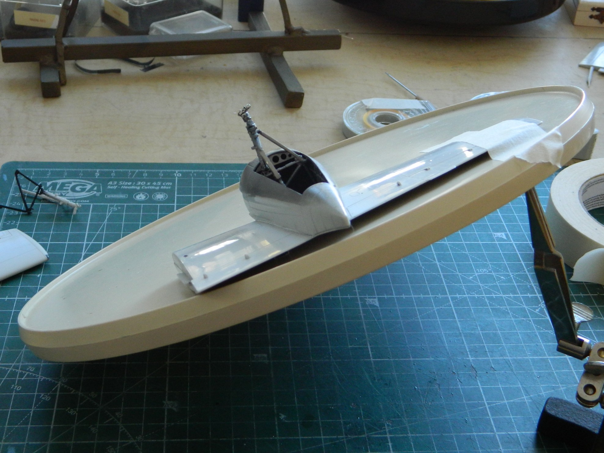
As I’ve mentioned in other places, the thing that drives a build changes as the build knocks them off the list. What’s been driving the build since the last update was having all the subassemblies ready to attach so that I can get down to painting this kite.
Mission accomplished (I think…see the next post, here, to see how incorrect I probably am):

Hell…I just might have this done by the end of February!
