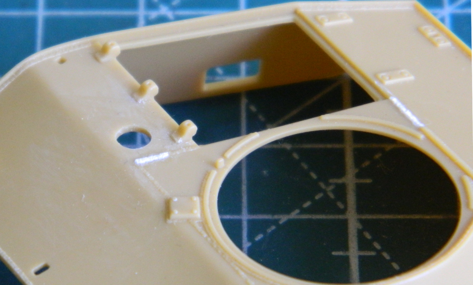
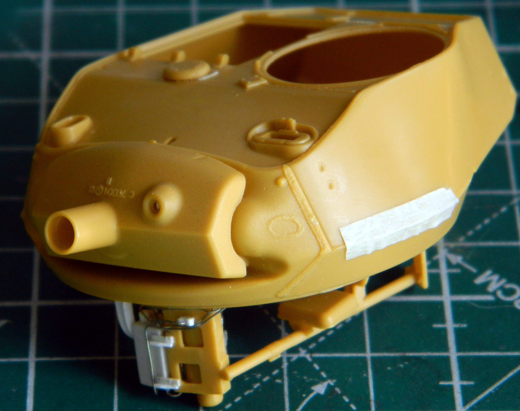
There are a couple of minor errors on top of this turret (I said “this” turret because the early kit production turrets had the welding seams incorrectly placed; later production kits, as well as some aftermarket companies, issued the correctly configured turrets). The small hole in front of the hatch openings is where the vent cap goes. Early production M24s didn’t have the bullet splash ring around the opening so that has to go. Once it’s gone, the weld seams have to be reworked to accurately reflect what rolled off the assembly lines. The weld seams at the rear of the large round hatch opening were incorrect so I used .005″ (.127mm) strip styrene, half dissolved them with styrene cement, and then used a toothpick sharpened to a chisel tip to replicate weld beads:

Once I’d carved away the bullet splash ring, I added more .005″ (.127mm) styrene to fix the missing weld beads:
I suspect they will need more blending in but the difference in plastic color hides that from me presently. This area will get hit with primer and the weld beads adjusted accordingly.
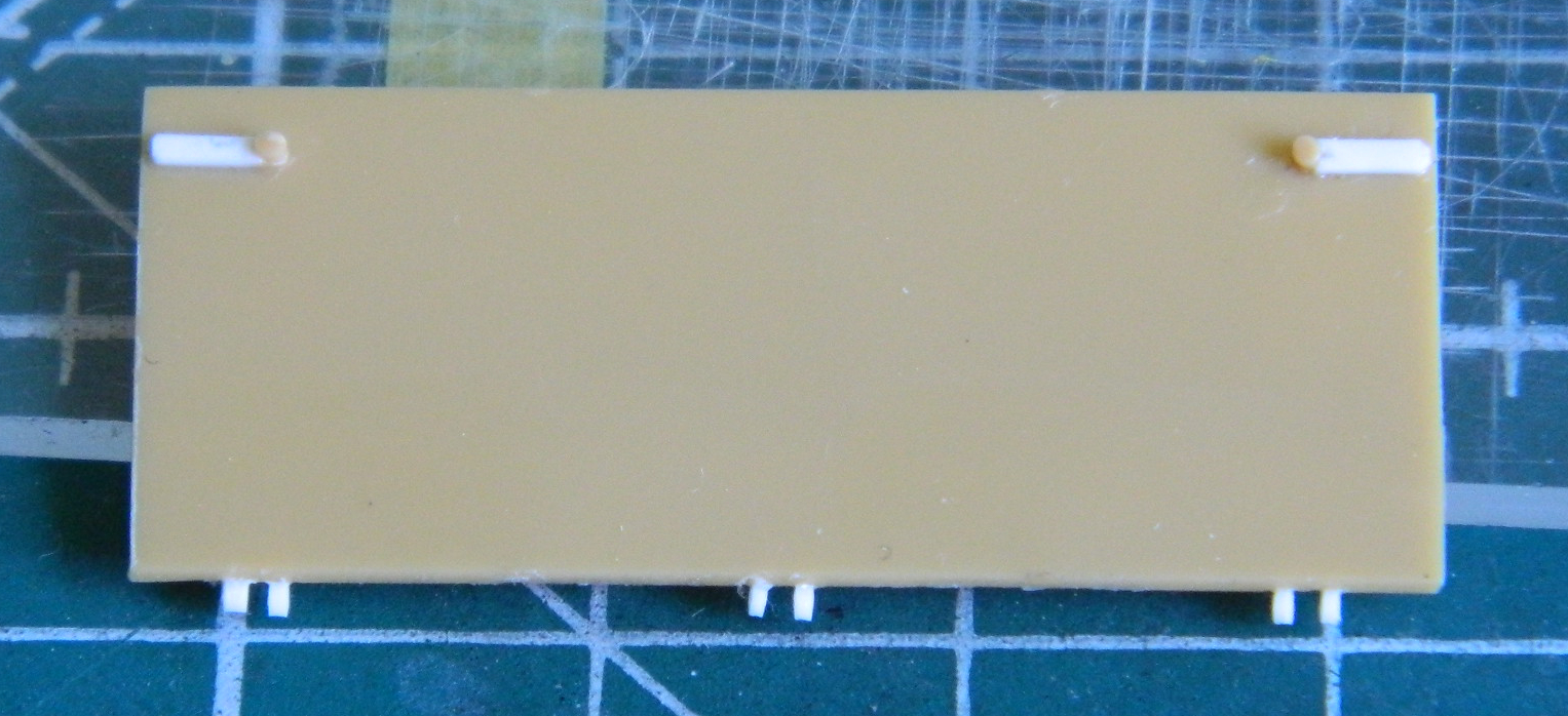
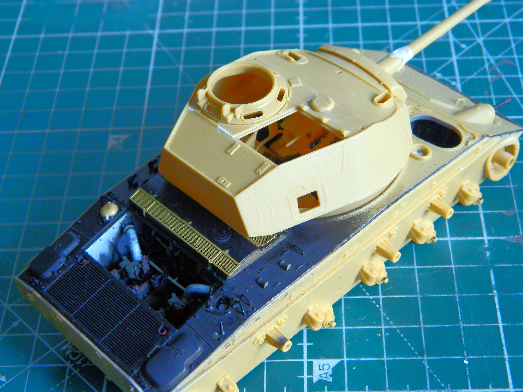
At this point I kept trimming the sides of the engine cover so that it would settle into the space provided for it. I have no intention of modeling this cover closed, it just annoys me to know that it wouldn’t fit if I did. So 400 grit sandpaper on a flat surface with a lot of rubbing and checking removed said annoyance.
The engine cover is molded to scale in thickness as well as hinges. That means the hinges will snap off if a mosquito (the insect, not the DeHavilland) blows its landing. Several bugs landed on those hinges and they all needed to be replaced. I used thin slices of .025″ (.635mm) styrene rod to replace them:
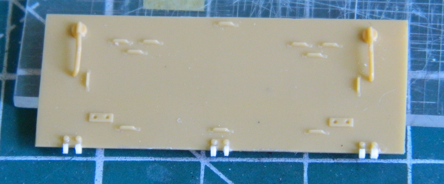
Since this will be modeled in the open position, I had to add the latching tongues to the underside. I used stretched sprue for the shafts and .010″ (.254mm) scrap as the tongues:
There are PE screens that go over the air inlet vents. There are also VERY small parts that get added to them. It took patience but I managed to get the straps that hold the screens in place where they were supposed to be. Then I noticed that of the M24s that still had the screens mounted, almost all of them were deformed from weighty objects being placed on them. Once I had the PE parts in place, I waited overnight for the superglue to cure more completely and then GENTLY pressed down with a fingertip to give the screens’ surfaces the bowed appearance:
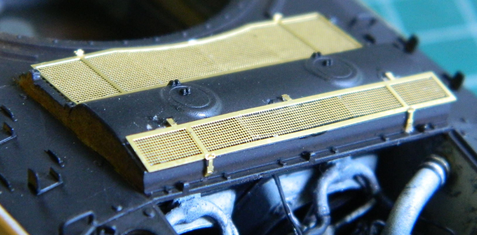
There are a couple more items that get added to the screens but I’ll wait until later to lessen the chances of knocking them off.
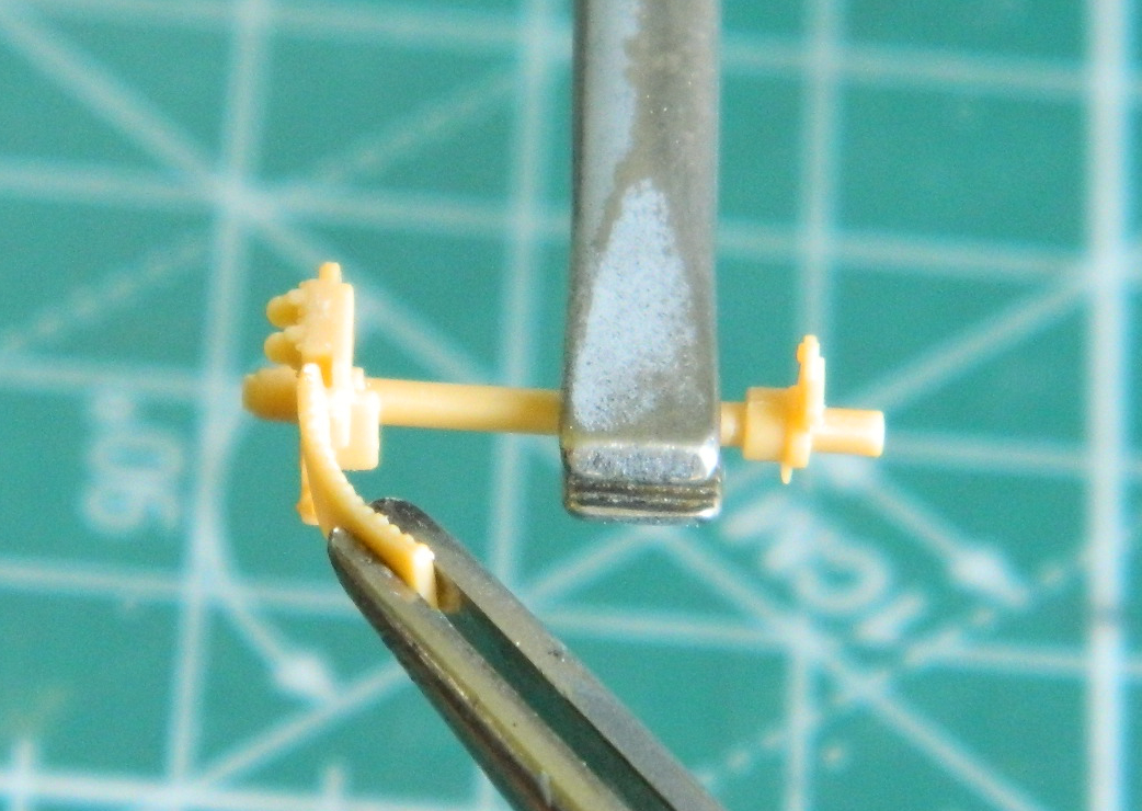
Brain fade struck again. I removed the armored gas cap covers from the sprue, and then mistakenly removed the parts that were supposed to stay on and left the sprue attachment points instead. Of course I didn’t realize the error until it already happened, so those parts get replaced:
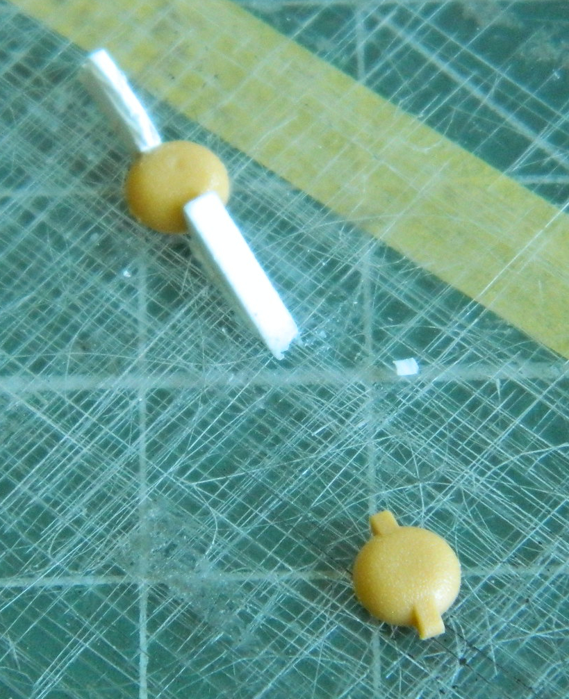
::rolls eyes::
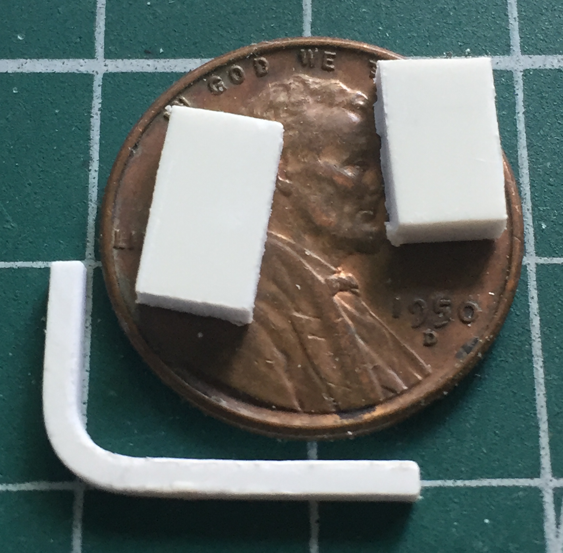
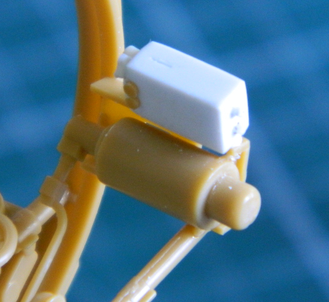
There are some details in the turret that Bronco didn’t provide and they should have. The control box that sits under the turret doesn’t have a turret basket to mount to. Instead, it’s mounted on a pedestal and has an arm to attach it to the turret. The arm turns the control box with the turret as well as providing a conduit for wiring. It should be there. I started making it by approximating dimensions and cutting its profile from .060″ (1.524mm) styrene (that’s the L-shaped part in the photo below). The turret rotates by electrically pressurized hydraulic fluid. Bronco added most of the turret’s rotation hardware but left out the hydraulic oil reservoir (those are the two rectangular pieces in the photo below). So I’m going to make them:
Scratch-building seems to intimidate modelers and I don’t think it should. Plastic is inexpensive and it’s not difficult to work. Scratch-building something just takes time and looking at pictures…lots of pictures. If one screws the thing up, it can either be fixed or tossed and the project started over. Remember, this isn’t engineering where things have to be correct. This is modeling where things just have to look correct. Keep working the part until it looks correct to your level of acceptance. When scratch-building, sometimes a person simply cannot get it 100% accurate, largely due to size (though with the dropping prices of 3D printers, I expect that’s changing even as I sit here typing…and if I were twenty years younger I’d git me one).
So I decided to scratch-build the oil reservoir, and here’s how I did it.
These are the parts that Bronco provided (mostly already assembled):
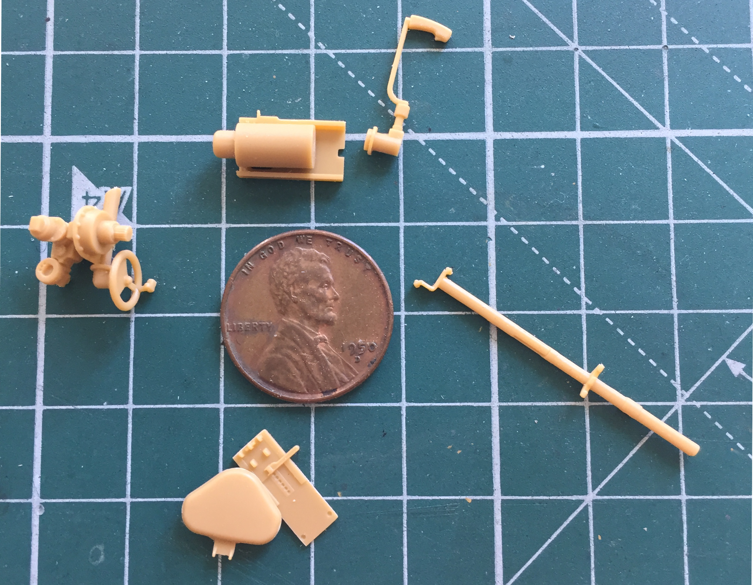
When glued into place, they give me the dimensions and space that my scratch-built part has to conform to (and of course I didn’t take a photo of this area with these parts in place before I started working). Putting these parts together was a very Chinese interesting due to an almost TOTAL ABSENCE of indicators showing where things are supposed to go. (And as it turned out, that notion is something I needed to get used to because I found that lack in other places.)
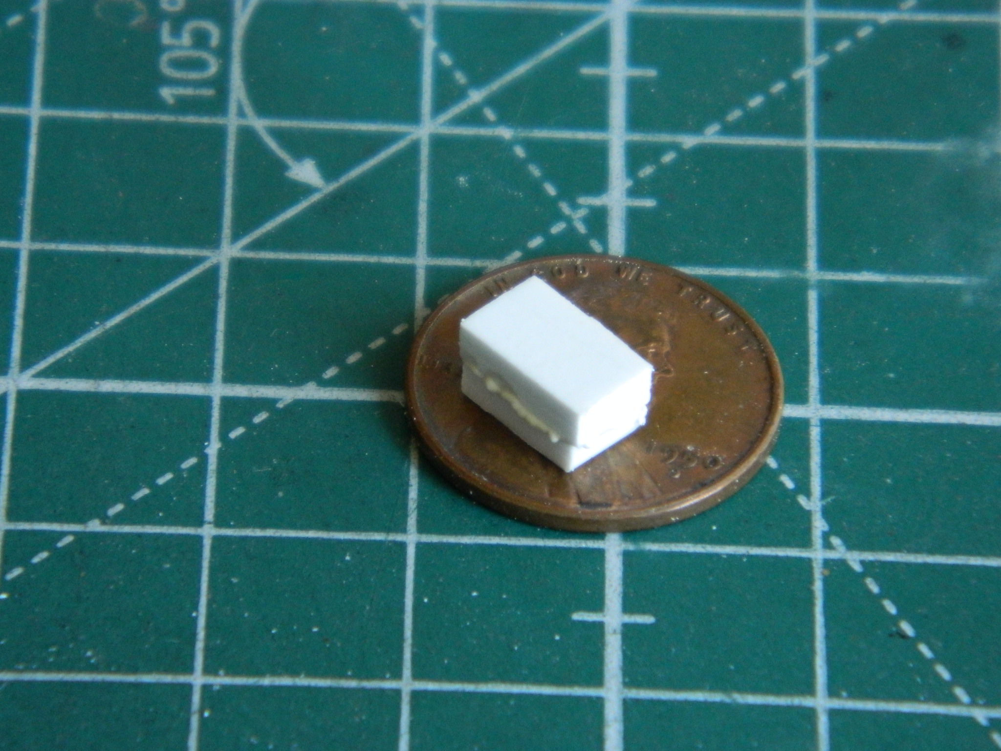
I took those two pieces of rectangular plastic in the above photo and glued them solidly together because I didn’t have anything thick enough to use as is. I smeared glue liberally over one part, aligned the other one on top of the glued surface:
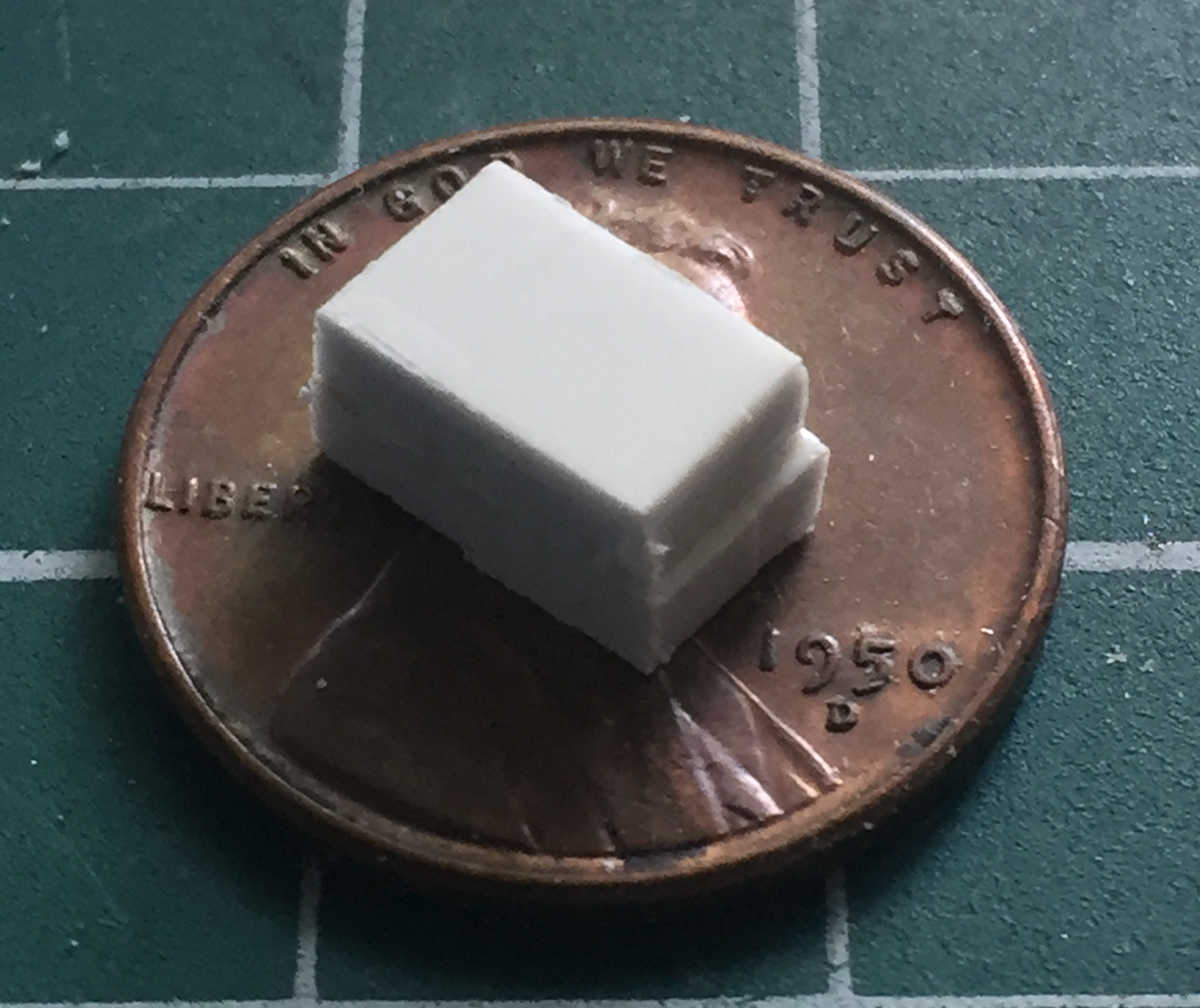
Then after waiting a couple of minutes for the glue to dissolve the faces, clamped them together in my vice until the squidge oozed out. The goal is to make these two pieces ONE piece:

I left this assembly in the vice overnight to insure the two bonded into one. The next day I took the bonded plastic out of the vice and started truing up the sides so that everything was square (in a rectangular sort of way) and perpendicular (in a 90-degree sort of way):
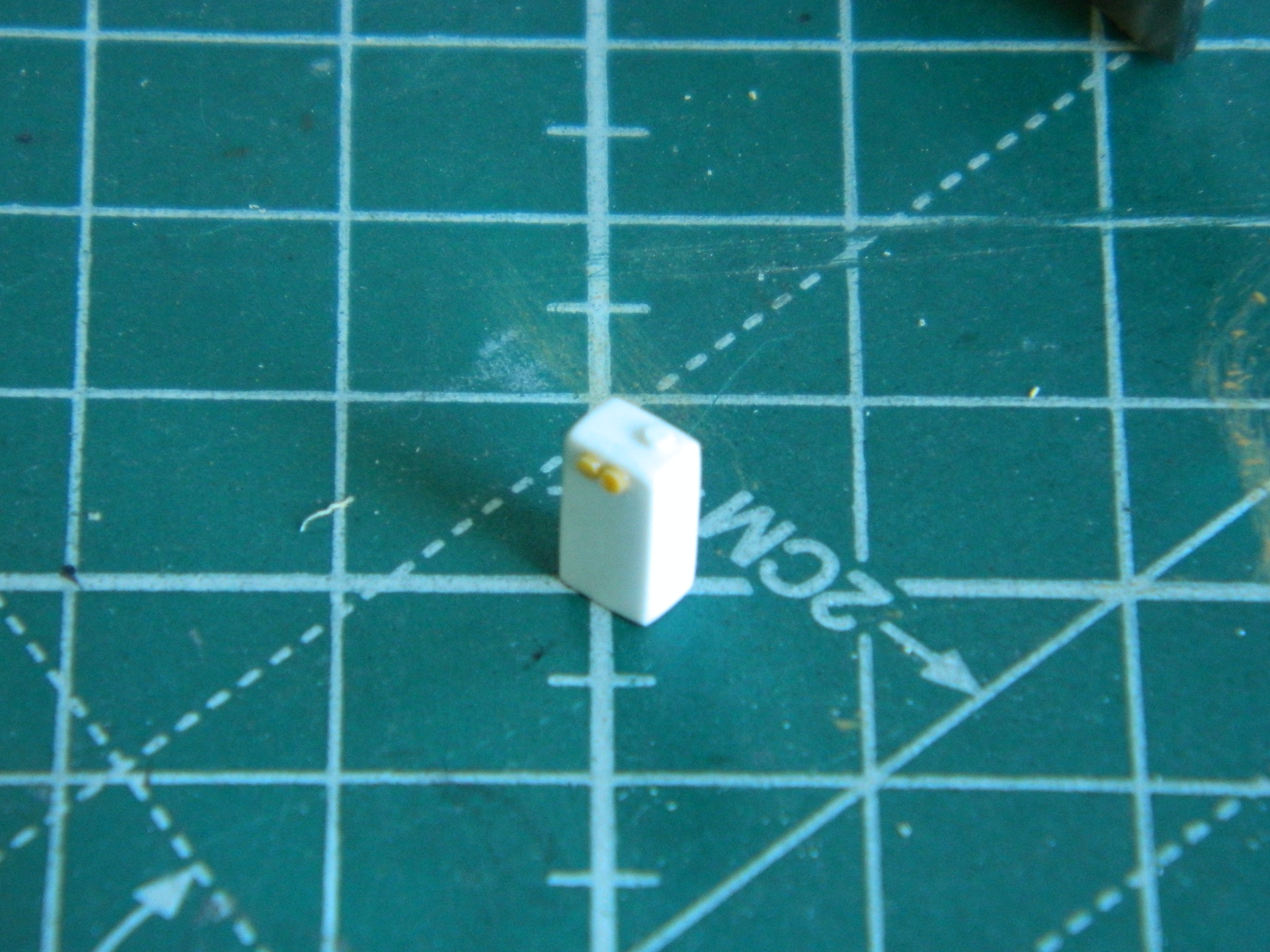
Then I used the assembled (but unphotographed so far) gunner parts to determine how tall, wide, and deep the reservoir had to be. Once I was satisfied with the dimensions, I rounded all the edges and corners as the actual reservoir has them. There are two large nuts on the upper front of the reservoir. I scraped some sprue into an octagonal shaped, stretched them slowly (ends up with a thicker result, which is what I wanted), then sliced them and glued the slices onto the front of the reservoir:


While the glue was curing, I started making part of the brackets that mount the reservoir to the motor’s mount:
There is a fill port that I replicated by using two different sized styrene rods. The smaller one made the filler tube, the larger one made the cap; I rounded the edges of the cap to match the original. Then I started adding stubs of styrene rod to replicate the fittings where hydraulic lines are attached. Once the glue cured overnight, I drilled out the stubs. Most of them were drilled for .010″ (.254mm) solder or wire (haven’t decided yet which to use):

With the fittings in place and the side of the reservoir scribed to replicate the oil level window (that will never be seen once built), the part gets mounted in place:
Because there is SUCH a small contact area for glue and the fact that the brackets are cosmetic, not structural, there is a small wedge of styrene between the reservoir and the motor mounting bracket. No, it’s not there on the actual tank. But since this will all get pre-shaded black and it’s under the gun (so to speak), nobody will ever see it.
And aside from paint, that’s a scratch-built hydraulic oil reservoir. As you can see, it’s not difficult or really very complicated. Don’t let your apprehension hold you back! (This seems to happen often when dealing with PE parts…and just because the kit supplies PE parts, doesn’t mean you have to use them. As you’ll see shortly, sometimes PE parts are just stupid; use them as templates to replace them with plastic.)
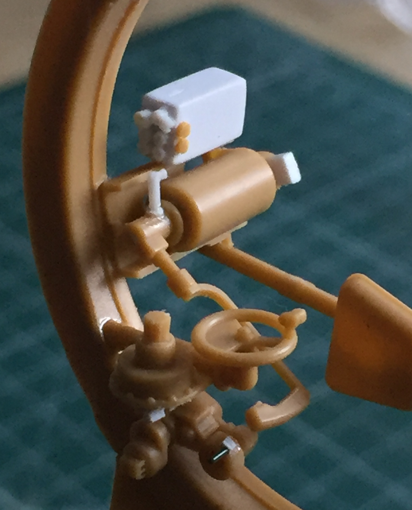
With the fluid reservoir done and in place, it’s time to add other tiny parts where the hydraulic lines and electrical conduits attach:
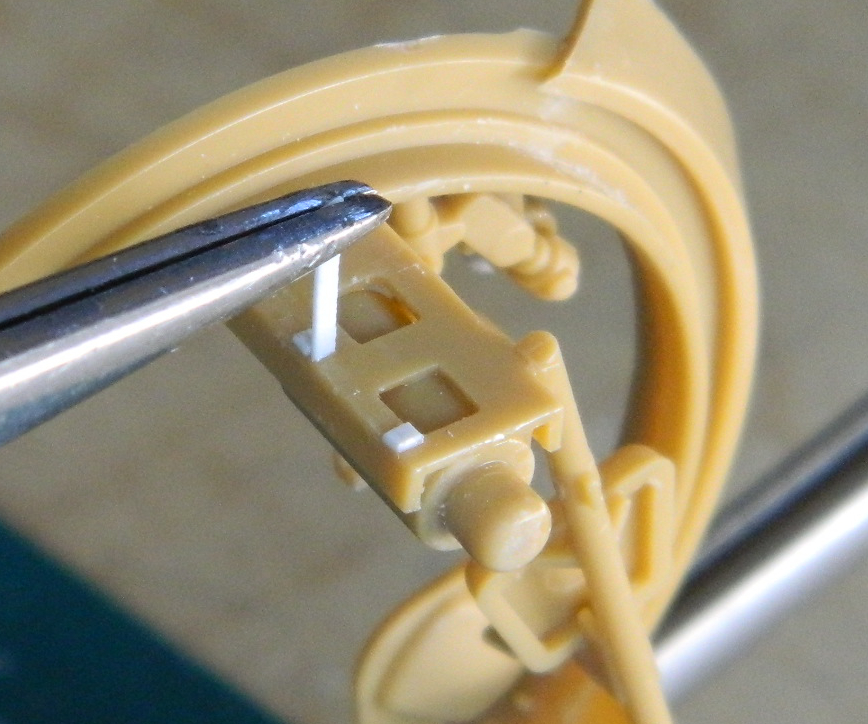
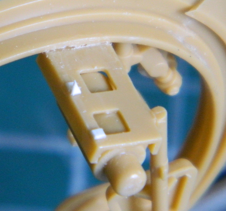
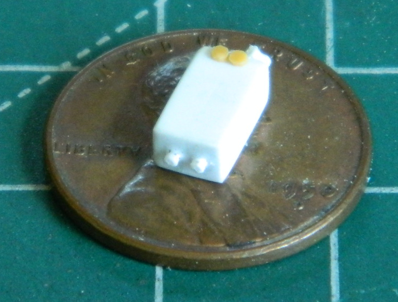
Speaking of PE parts, Bronco decided that the feed chute for the coaxial .30 caliber (7.62mm) machine gun needed to be PE (parts 33 a and b). Note the penny behind the PE fret. These parts are stupid small! I just imagined how much expletive-filled fun bending the bottom of the chute to conform to those really small J-shaped sides would be:

My imagination was good enough to decide not to play Bronco’s stupid-ass game. Instead, I used these PE parts as templates (and didn’t even remove them from the fret, because you remove them and then try to trace them onto plastic) and traced them onto .005″ (.127mm) scrap, then glued the pieces together:

MUCH EASIER!
A large part of July was spent wondering just how I was going to mount the coaxial machine gun to the place it was supposed to go. Bronco does not supply much in the way of attachment points (less in the way of indicators). And though I’m all for scale sizes, there comes a point where practicality has to replace scale “purity.” The solution to the conundrum of how to get this subassembly correctly positioned (because it’s not just the gun, there’s also the ammo tray/box, link chute, and mounting plate) on such an incredibly TINY mounting point stalled me for a couple of weeks. Finally I realized the obvious. I couldn’t use just the mounting point because it really was too small. In dry-fitting the machine gun, I discovered that the cooling jacket of the barrel just fits through the mantle. Well, duh! GLUE IT TO THE MANTLE. This photo is of the dry-fit:

And this photo is with all the other parts added to the machine gun to see if it still fit:
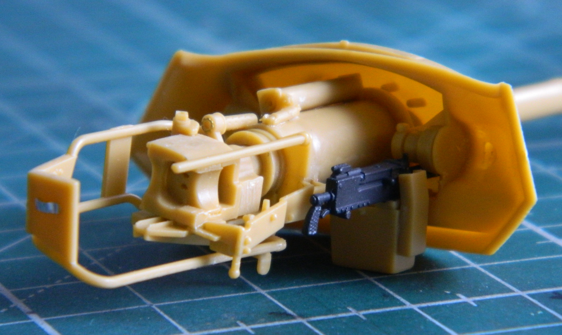
Not a lot of extra room, but that’s how they built these things…and enough is enough.
A recurring problem with this kit (and only time will tell if that’s typical of Bronco’s kits) is a lack of definitive attachment points. That problem is compounded by the knowledge that some of these vague subassemblies determine where subsequent parts can go and fit later on. (No pressure!) And Bronco seems to be totally committed to the maximum amount of individual parts to make any subassembly. Getting the gear quadrant correctly attached to the gunsight parts took more effort than it should…except that there was no clear indication as to the proper location for the parts:

All that for one relatively inconsequential part, and when it came time to add these subassemblies into the turret, I still managed to get the quadrant mounted in the wrong place. Thanks, Bronco. Next time have the engineers that decide what goes where and how, they should build the sodding thing so they have SOME DAMNED IDEA as to how to do it…and then modify things so things can be done.
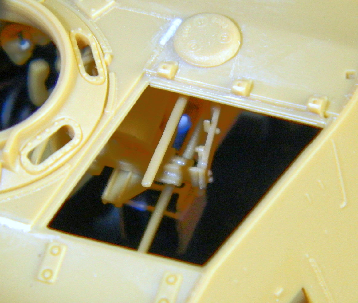
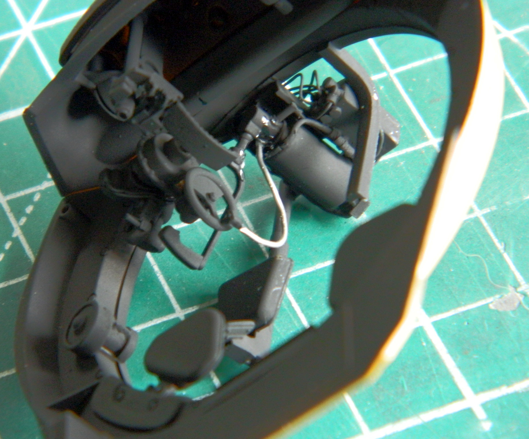
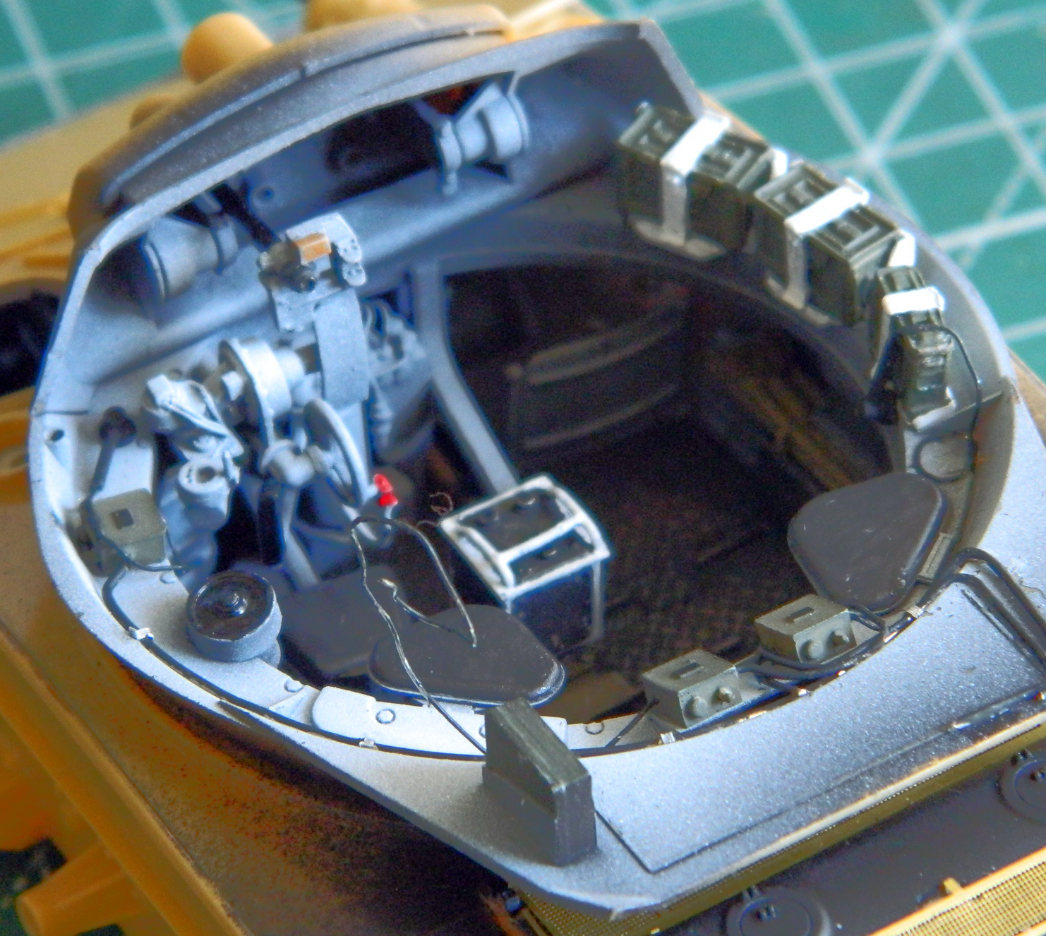
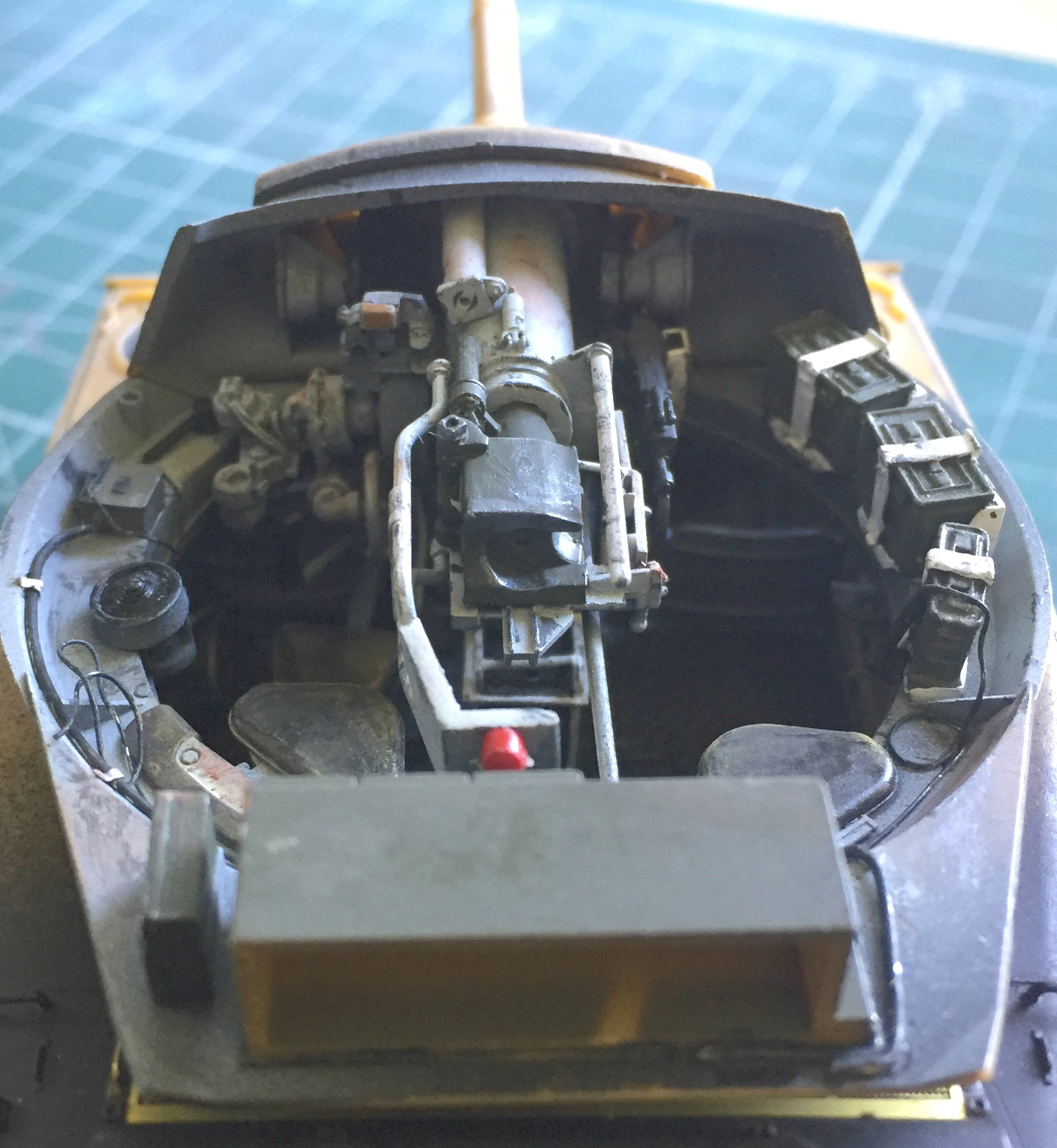
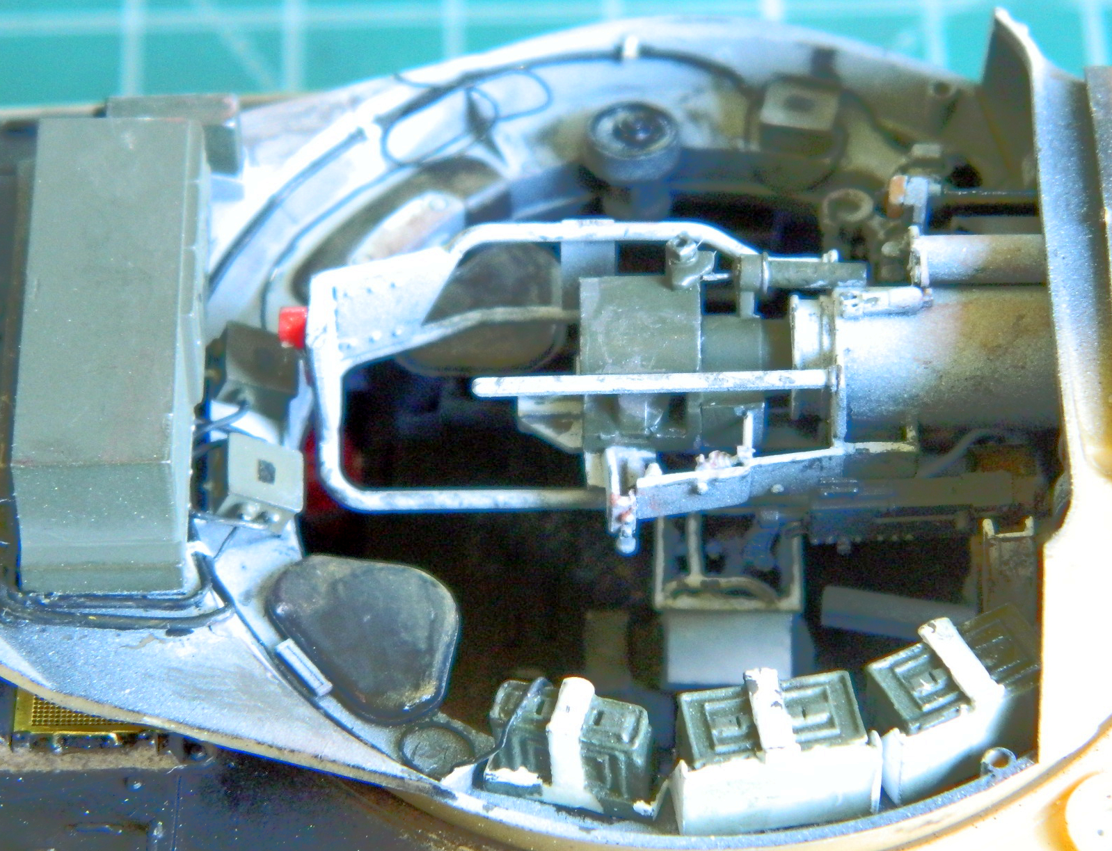
With the scratch-building done at the gunner’s station, it was time to start running hydraulic lines and electrical conduits. Solder of a few different sizes were used, from .010″ (.254mm) to .020″ (.508mm), depending:
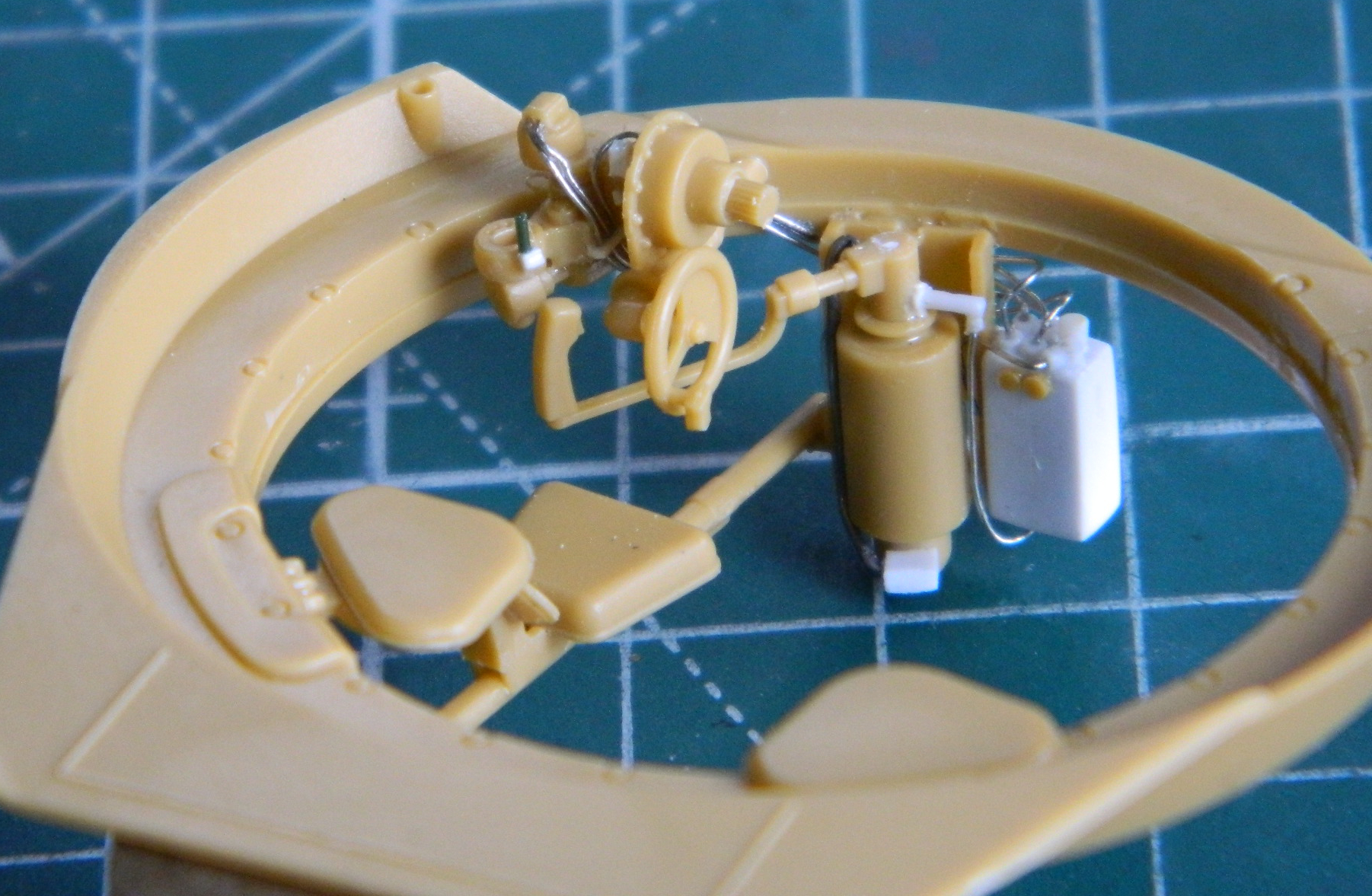
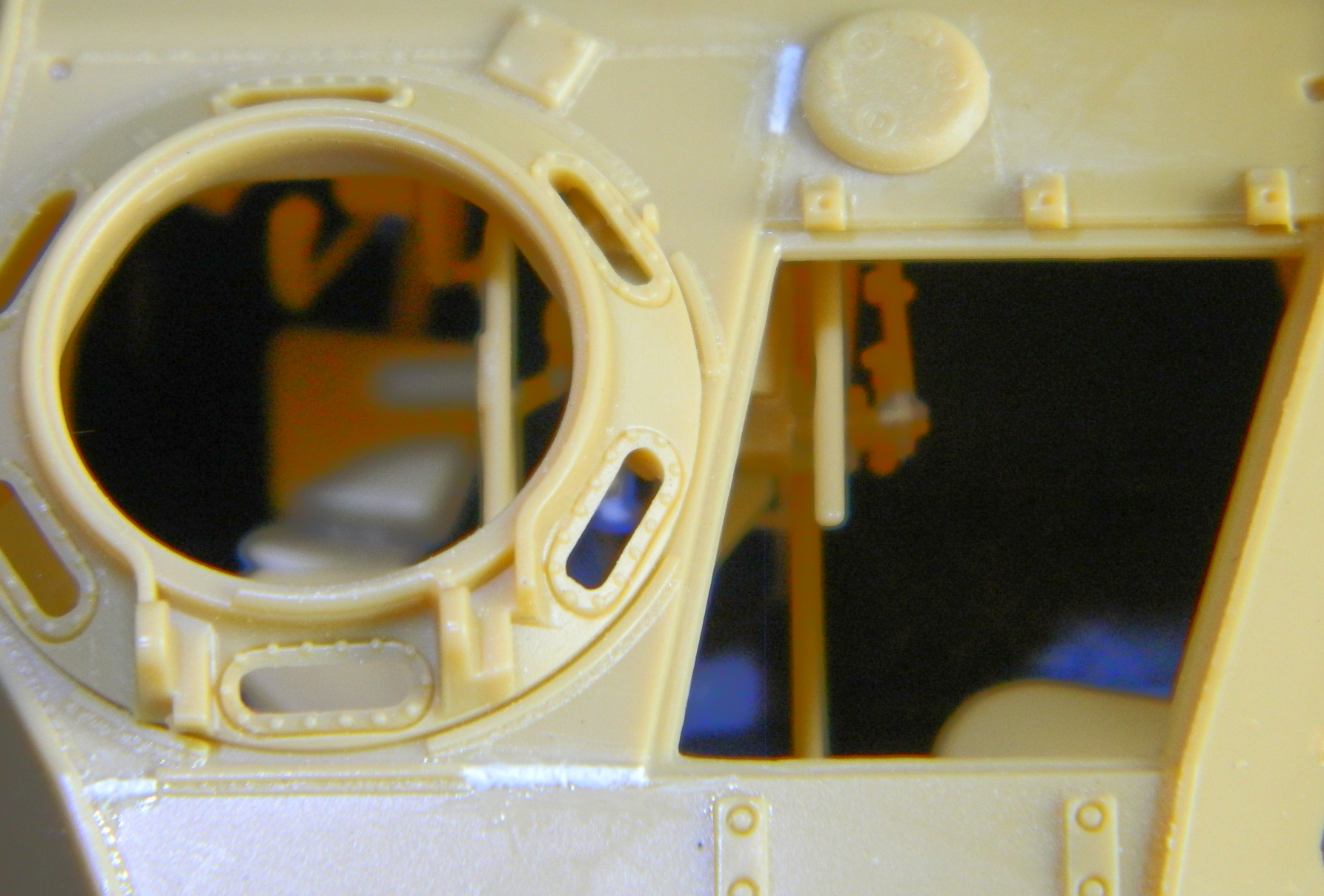
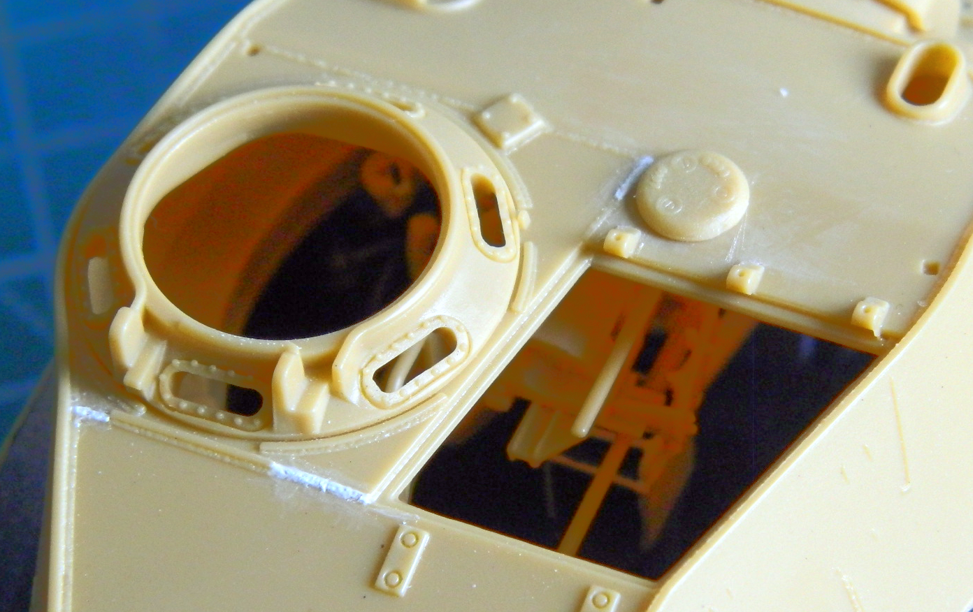
Belatedly it occurred to me to actually check to see what could even be seen. As it turned out, not everything I added would be:

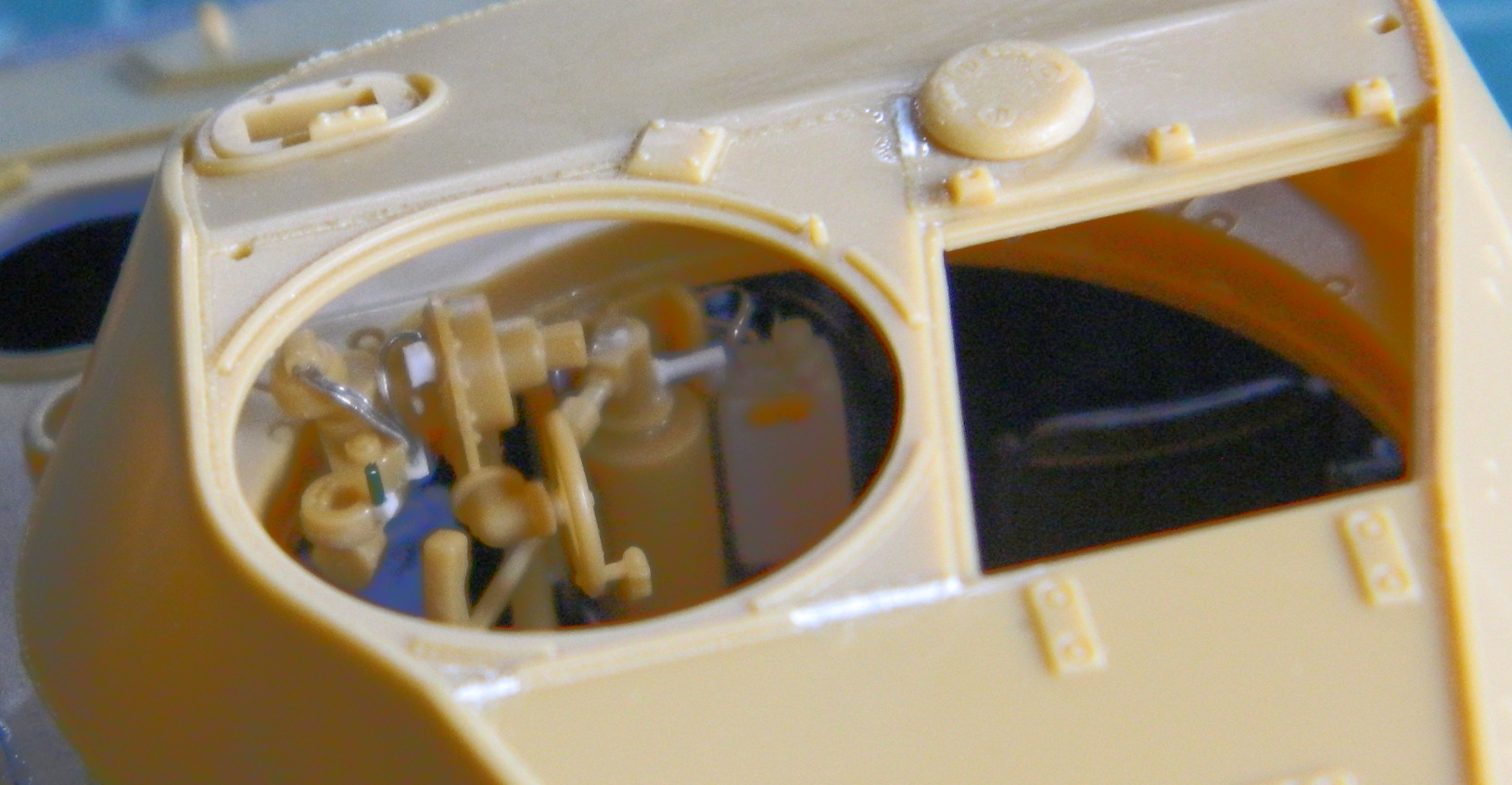
It looks as if most of it will be seen, but these views are without the main gun and that blocks most of it. See the nice details I added to the front of the gunner’s controls? The only way they will ever be seen again after this is built is if the turret is taken off:
So all that was an utter waste of time. Yes…I’ve heard comments to the effect of, “Well, you will know it’s there.” Why yes I will! And I’ll know how much time I wasted putting it there. I really must stop doing that! These builds take long enough without spending time on things that will never be seen.
The L-shaped bracket that attaches the turret/gun control box to the turret so that everything rotates as a unit needed to be fitted and then detailed. I’d originally hoped that I could attach the control box to the L-bracket and then everything would turn as a unit. Uhm…no. Things are really snug in terms of space at the forward edge of the turret ring. So tight that it showed me that I had mistakenly put the driver and co-driver’s seats too far rearward. Unfortunately trying to dislodge the seats and move them would result in lots of broken resin parts and no easy way to replace them (big difference in working room once that upper hull is on, y’know?):

Checking how much I can see of the L-bracket saved me a lot of work. Not much can be seen. There is a metal panel that attaches the control box to the bracket on the actual tank. Had I added that, kiss goodbye the ability to ever remove the turret without breaking things. So I checked to see if it was visible:
Nope. Not easily seen at all. So I moved on to something that would be seen…
There are easily seen gussets around the base of the turret that Bronco didn’t provide or mold on. I used .030″ (.762mm) scraps to make them and used .010″ (.254mm) scraps to make the shelf in front of the dry-fit radio as intercom junction boxes get mounted there:

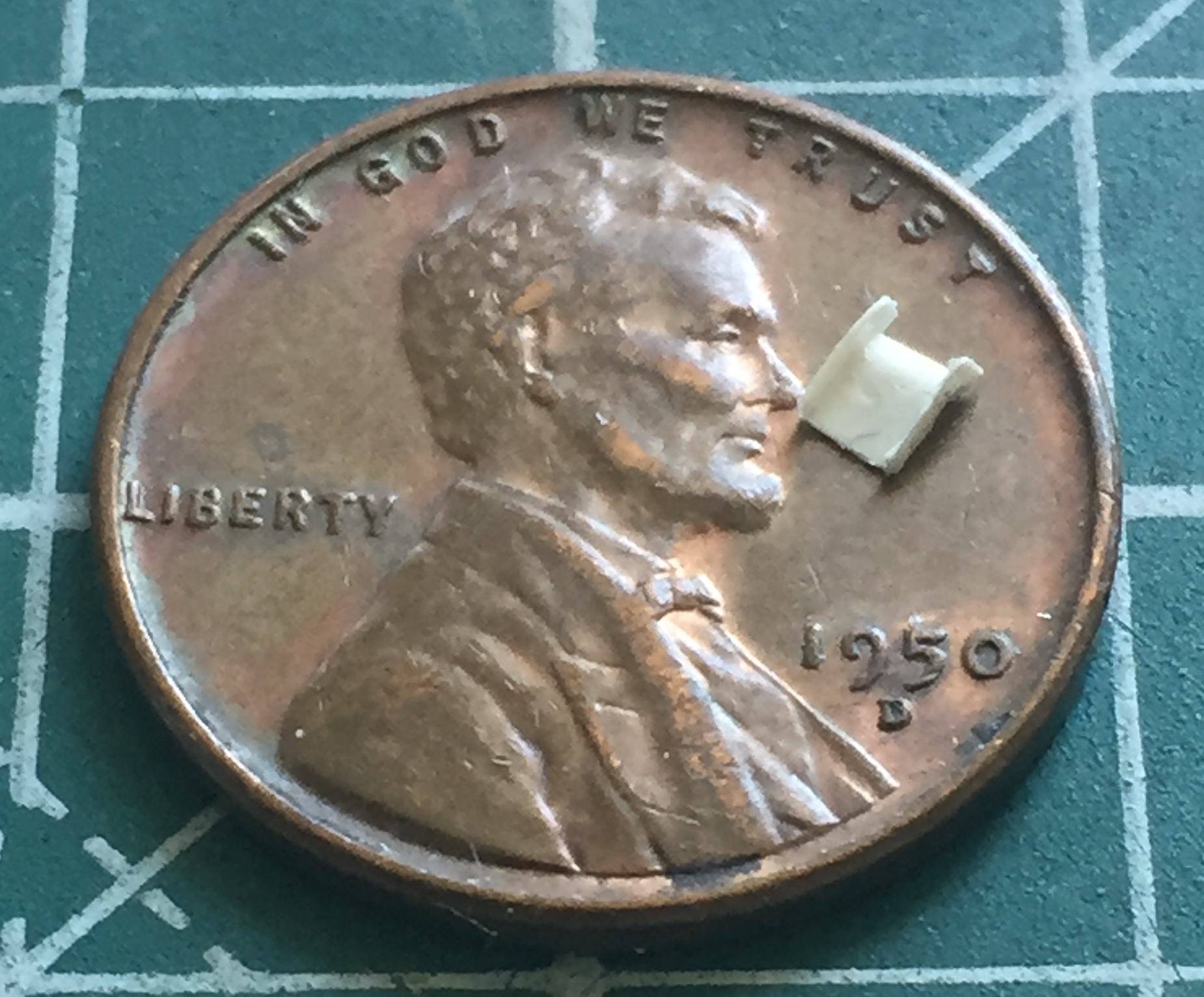
I also glued the gunsight assembly in place (which is actually incorrectly done; the mounting bracket was molded at the wrong angle but that’s one of those things that will never be seen). And yes…there is a pad for the gunner’s forehead that Bronco decided needed to be a separate part. In this case, it’s white plastic because the kit’s part departed (no pun intended, this time) for sections of the shop that are also unseen:

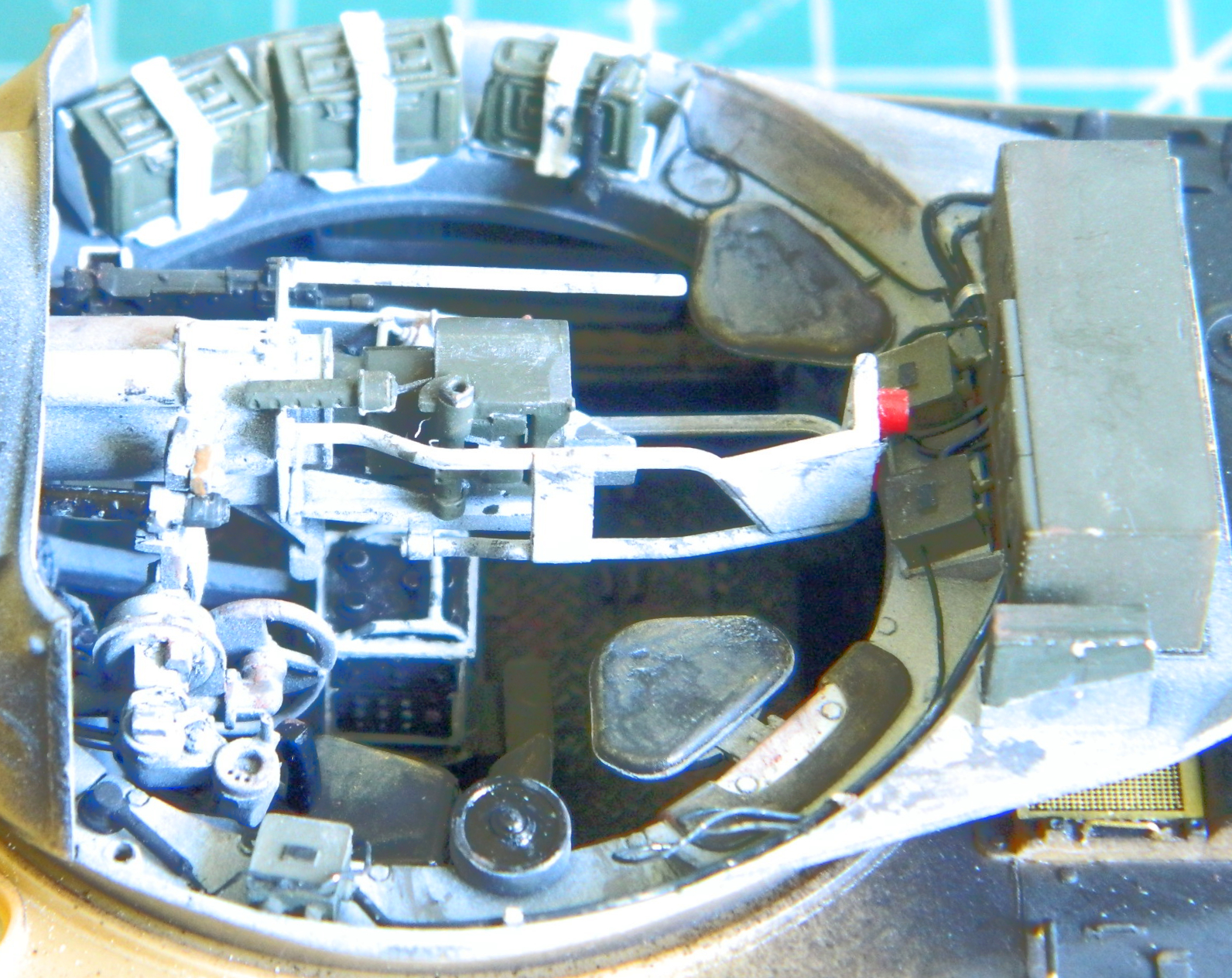
There were a number of things I had to do before I started populating the turret interior with bits. I thought I’d taken care of adding them, however I have discovered a sure method of discovering what I forgot to add. Paint it. In the spirit of discovery (snark), I put down the pre-shade Tamiya XF-1 Flat Black and painted the radio and intercom junctions Tamiya XF-62 Olive Drab:

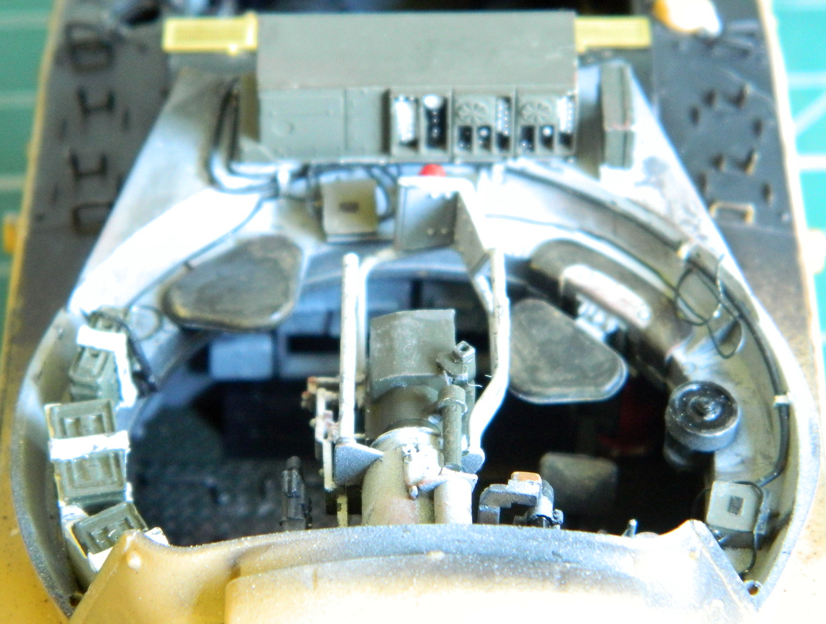
Worked like a charm! I immediately discovered I’d forgotten to add the conduit that runs from the elevation wheel to some Mysterious Place under the main gun. It’s the only thing not black in the following photo:
With the pre-shading done and the forgotten part discovered and installed, it was time to mist the color coat, Tamiya XF-2 Flat White, on the highlighted areas and then start populating the turret ring with AM resin, run the electrical lines, and touch things up and/or paint little details. Speaking of little details, there is a first aid box on the bustle floor next to the radio. Neither the kit nor the AM set provided it, so I scratch-built it and its mounting bracket:
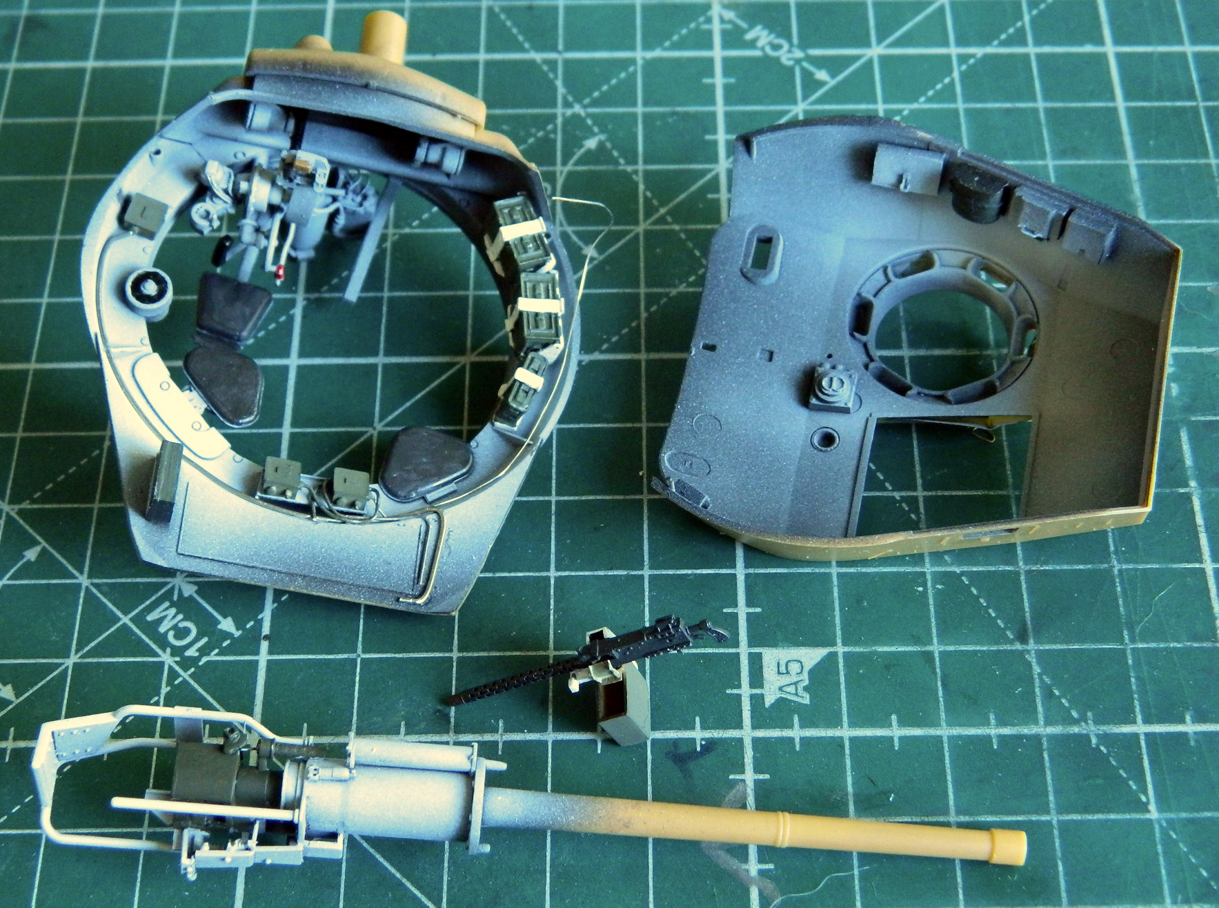

Before the radio could be fitted, the main gun and coaxial machine gun needed to go in next. The territory where the radio sits wouldn’t allow room or the necessary angle for the main gun to be added. I also discovered that, for whatever reason and also not showing at all any time I dry-fit the gun, once the gun is in place, it’s in place. And good sodding luck getting in there to glue the face of the gun to the mantle. This one is held in place with only one gluing point! Once I had the main gun (precariously) mounted, I applied chipping, wear, and dirt (Humbrol Metal Kote #27003 for anything that was exposed steel, a silver pencil for where edges of small things rubbed through, and pastels for the grunge):

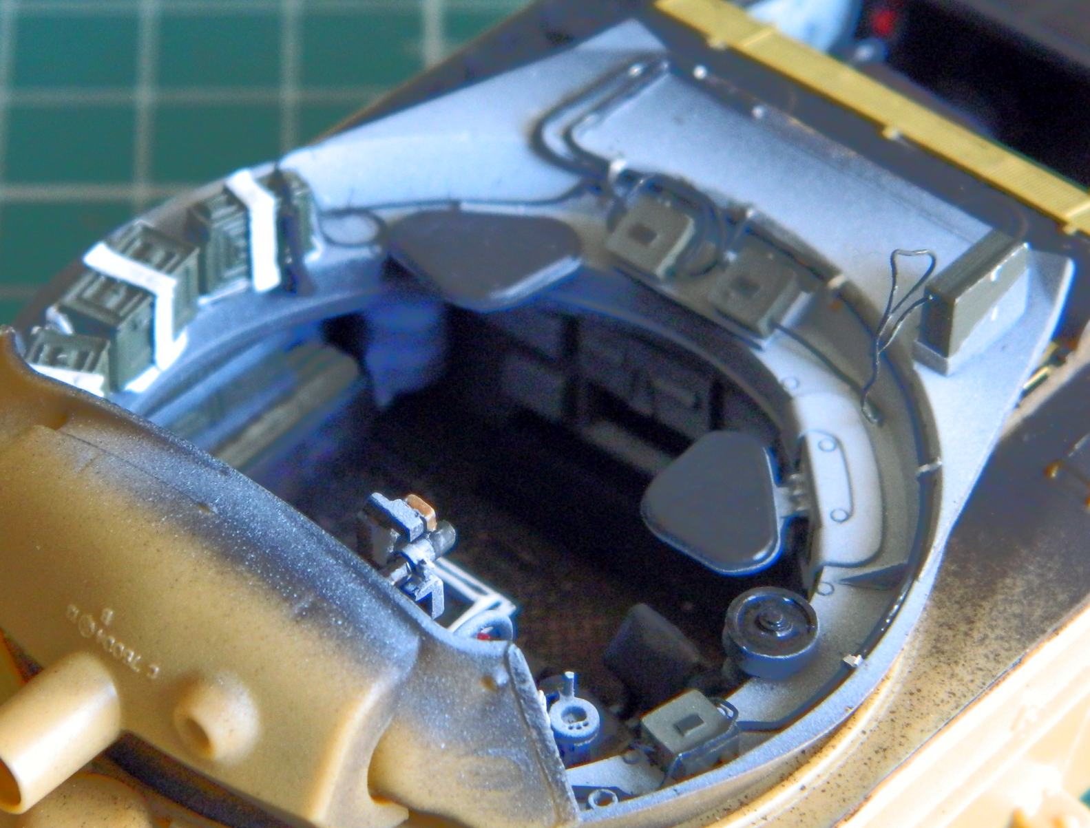
Various boxes, canteens, and holders populated the interior of the upper turret as well as the gunner’s periscope. I taped over the hatch openings from within the turret to keep subsequent painting sessions from intruding into where it (they) are unwanted. With all that painted, stained, and worn, it was time to glue the turret (with the bustle box added) top to the turret bottom:

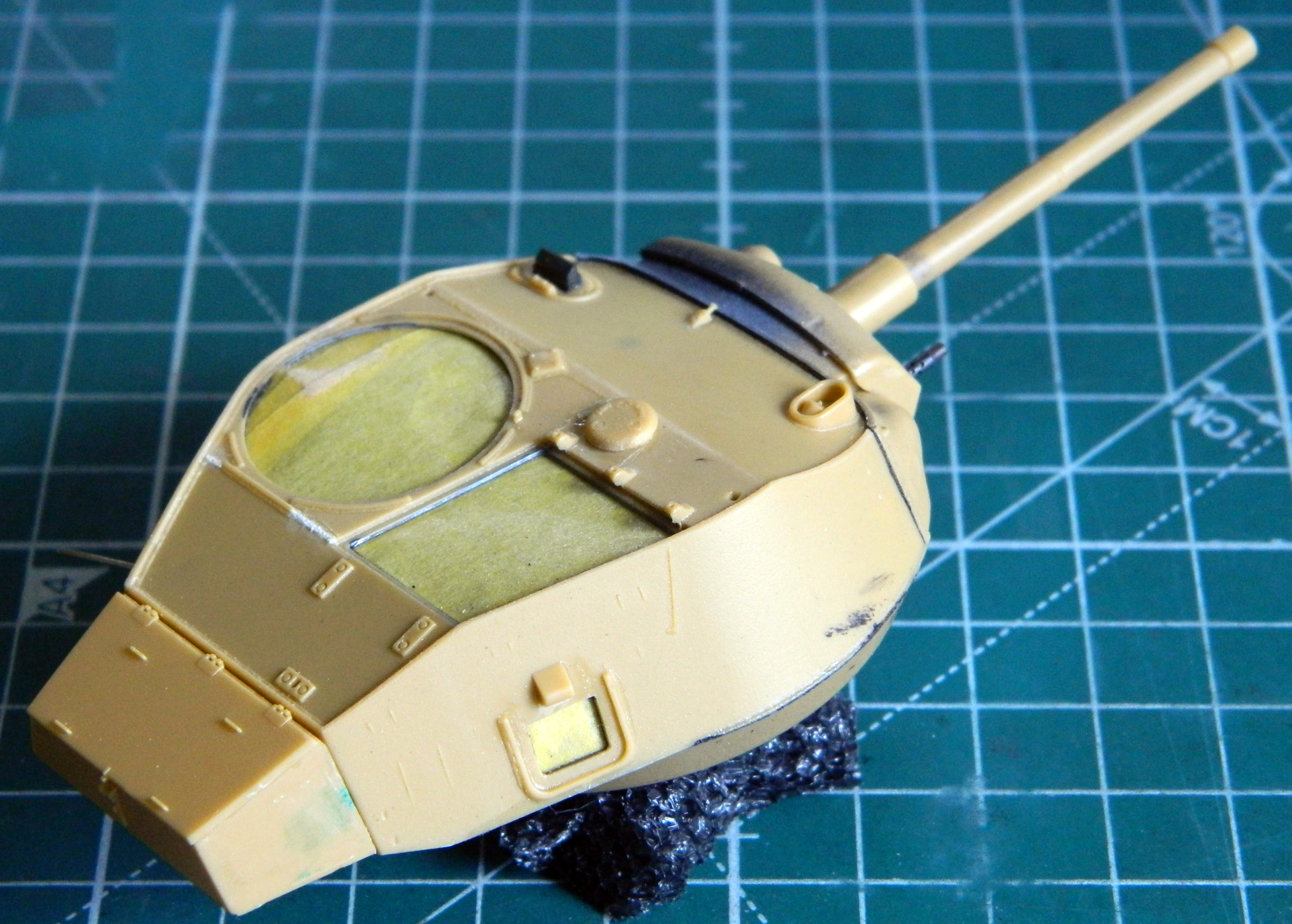
Having completed that milestone, I detailed the commander’s cupola a bit. There is a pad that goes around the inside of the cupola so that the commander doesn’t brain himself looking out of the view ports while the tank is bouncing across terrain. I used two pieces of .020″ (.508mm) scrap for the pad. The kit provides clear parts for periscopes, headlights/spotlight lenses, and the view ports for the commander’s cupola. That was a very nice touch and the parts fit so snugly that they make the south end of a north-bound bull in fly season seem loose:
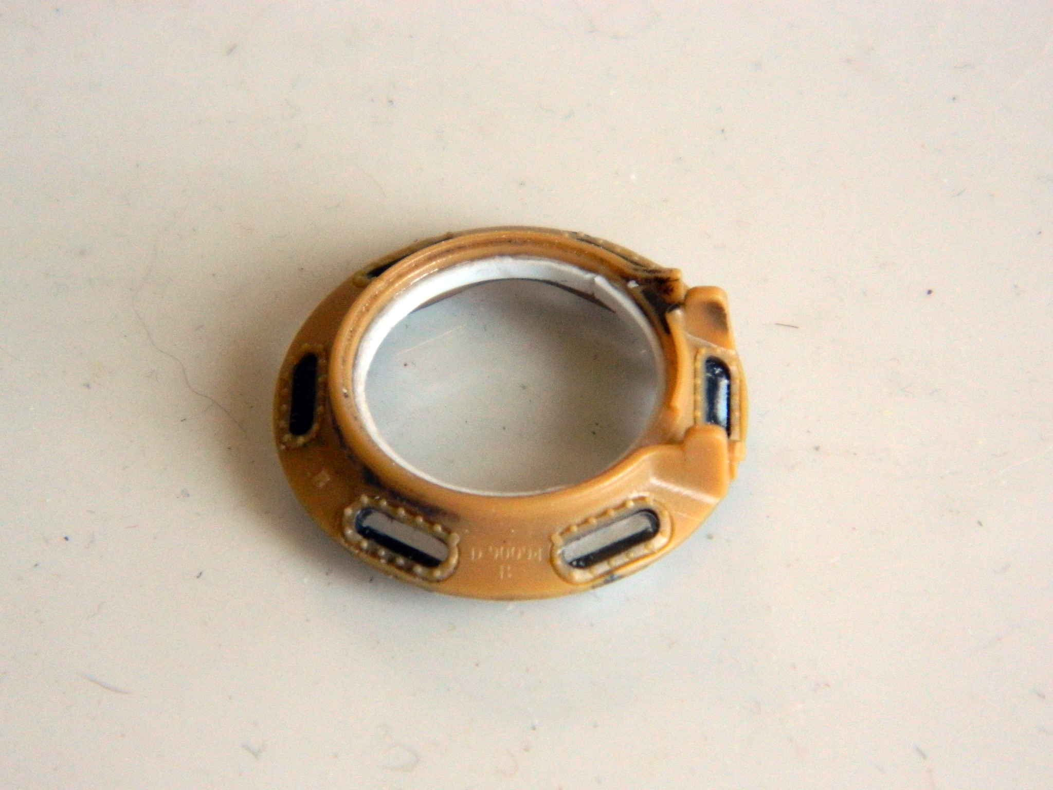
That will get painted OD on the outside, white on the inside, with the pad painted “black” leather (the color is in quotes because it’s two parts semi-gloss black, two parts flat brown, and one part gloss white).
But I’ve been dodging this next step as long as I can. It’s time to paint and attach the suspension, road wheels, idlers, return wheels, and sprockets.
Should be a fun month…

HI! How the heck are ya?
I was bemused by the fact that you added the oil level window, even though it couldn’t be seen, then added a structural support because it couldn’t be seen. No explanation is necessary, I just wanted to say that.
And I agree 100% that engineers should use the products they design! How else would they (we) klnow that our design is any good?
On Sat, Aug 22, 2020, 4:53 PM Scale Modeling Mania wrote:
> rapierfighter posted: “There are a couple of minor errors on top of this > turret (I said “this” turret because the early kit production turrets had > the welding seams incorrectly placed; later production kits, as well as > some aftermarket companies, issued the correctly configured” >
LikeLike
Hiya! I’m about as colorful as ever. Many think I’m crazy, but they lack the context. And since I mentioned context…
A continual problem for me is micro-focus and macro-focus. My default mode is micro-focus, and for many things, that works just fine. But few modalities work across the board. It’s a continual struggle for me to pull back and see my work in context. So yeah. I added the oil level window and the structural support, but not *because* they wouldn’t be seen. I failed to check and determine IF they would be seen. Had I checked, I would not have spent the time on them.
Once again, perfection eludes me.
LikeLike