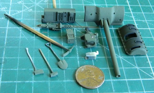
I needed a .30 caliber (7.62mm) machine gun for the coaxial mount. I figured it would be easy enough (yeah, silly me) since I have several of them in my spare parts cache. Yeah, well, what I was reminded of rather quickly was that though I needed a machine gun for the coaxial mount, the mount was much narrower than the gun(s) I was trying to fit into it. More searching (not restricted to spare parts) showed me that TMD did one that fit perfectly and that’s the one I used. I wasn’t thrilled with the grip that was provided with it so I cobbled one together using scrap styrene and then used 0.010″ (.254mm) solder to add the trigger. That’s when I noticed that the mounting bracket wasn’t molded with a clear channel for the barrel of the gun to slip through. I drilled it out and dry-fitted the gun to see how it worked and it did:


In the picture above, you can see how little of the barrel is visible; none from inside and just a bit outside. Usually I replace molded machine gun barrels with RB Products’ beautiful brass machined parts. In this case I can’t get behind the notion of wasting a finely detailed product when so little of it will be seen so I decided that I would use a small drill bit to clean up the round openings in the cooling jacket that can be seen and use the resin part entirely. The gunner operated both the main gun and the coaxial machine gun, the triggers of which were activated by solenoids wired to a foot switch. That mean I needed to make the solenoid. I used 0.035″ (.890mm) styrene rod for the body of the solenoid and stretched sprue for the plunger:

I didn’t trim the body of the solenoid at this point. That will be easier once it’s time to glue it in place and can see how much has to be removed. Once glued in, I will add 0.010″ (.254mm) solder for the wiring.
I switched to the other side of the main gun to add the gun sight. There was an inordinate amount of fettling required to get the sodding mount correct…or what I thought was correct. I also took an inordinate amount of photos of the ridiculously small part that I won’t bother including (if you want that level of excitement, go to an auto recycling yard and watch bumpers rust). Once completed, I used a spot of PVA to hold the sight in place and let it sit overnight before I put the breech assembly in place to check fit. Yeah, well, it neither fit nor aligned correctly. The sight tube is far too short and the sight mount (which was a very tedious process to get to work as poorly as it did) was way off. The first photo shows this part’s complete lack of alignment (the tube of the sight is supposed to go through the oval opening to its left) and the second shows that it’s too short. It’s supposed to extend to the mantlet:


This is a simple part to fix. I used 0.047″ (about 1.143mm) to extend it and cut the molded section just in front of the clamp. This resulted in a very small contact area for adhesive. I fixed that by drilling the resin part and and added a pin of copper wire (if you look at where the resin and styrene meet, you can see the pin in the translucent resin part):

Again, I left the styrene rod untrimmed to be shortened to the correct length later, which will result in the end of the sight terminating just inside the mantlet as it’s supposed to do. The important thing is that the sight now aligns with the opening and is long enough:


I thought I had fixed the turret basket so that it wouldn’t hit any of the items in the hull and I was just slightly incorrect. With the screens in place, the damned thing hits again. Repeating the process of moving the items the basket hits wouldn’t work this time because one of those items can’t be moved from where it is. I mean, it could, but I’d have to deconstruct the whole of the area around the driver’s position. To do that I’d have to take the upper hull off of the lower hull. No. That upper hull won’t ever come off of the lower hull in any sort of manner that wouldn’t render the upper or lower hull (more likely both) unusable. I needed a different approach so this time I looked at the turret basket to see what I could change. Once I did, I realized the real problem. The supports that attach the basket floor to the turret ring are in the wrong places. I know I got those buggers in where CMK (the producer of this AM set) intended them to be because there are pins on the ends of the supports and holes in the flange of the basket floor. It’s the supports that have been causing all the sodding fitting problem(s) (the black Xs show where the fit problem is):


So I went a played Zelda for a few days…
Refreshed (and CALMED DOWN), I went back at it. I used chisel blades to carefully pop the screens from the basket assembly and cautiously started thinning the supports where they extended past the basket’s flange. The screens were glued back to the trimmed supports and the fit tested. This time it all fits. (Nope…forgot to take photos of it.)
Yeah, so, masking tape. The adhesive of masking tape expires. If it’s left alone long enough, the adhesive of the tape de-bonds from the paper of the tape. The clear panel in the turret has been masked off for quite some time and when I checked it, the de-bonding had just started. Okay…got to it in time. I pulled the old tape off the inside of the panel, used lighter fluid on the couple of very small spots where the adhesive didn’t want to leave, and started to mask again. While doing so, I was using a toothpick I’d carved and angled chisel face on and evidently though I didn’t break the toothpick, I did press hard enough to snap one of the thinner sections of the panel free from the turret and that left a gap. Using denatured alcohol, I removed the paint to facilitate putty sticking, realized the gap needed plastic before putty, then added the plastic. After sitting overnight to cure completely, I trimmed down the excess and then started filing (to maintain the correct curves on the surface), sanding, and then polishing. Once it was all fixed, I used Mr. Surfacer 500 to replace the casting texture. Again:


I didn’t take any photos of it, but for the .50 caliber (12.7mm) gun on top of the turret, I didn’t really like anything I had on hand. I decided to try Tasca’s .50 which is available as a stand-alone product. It’s beautifully molded (and if you ever want to model a Ma Deuce with an open breech, this is the part to use!) and for the price you’ll get two of them as well as ammo belts, three different barrels, and two different ammo can mounts (early and late). Fit is excellent. You’ll see it later once it’s painted.
I’m at the point where I’ve been adding things to the main gun assembly so that I can get it painted and installed. CMK clearly intends for builders to use the front gun mount that comes with the kit. What they didn’t mention was that the kit part where the trunnions fit is off. The trunnion caps require that the kit’s part has to be cut down, so I did. During the fitting process, that small arm I made for the gun stabilizer had to come off. There simply wasn’t room for it to stay. The elevation control was assembled and the elevation wheel was cut carefully from the pouring block, cleaned up, and then it fell onto the floor…whereupon it vanished. Well. That’s a necessary part (unlike the gizmo for the gun stabilizer that I’m still pouting over) so I had to make another one.
Experience has shown me that trying to form a styrene rod into a good-enough circle is a frustrating process that results in something worthless. This time I decided to use solder. 0.040″ (1.016mm) is noticeably too small. 0.062″ (1.57mm) is just a wee bit too large. I decided to go with the 0.062″ (1.57mm) diameter because I think that once it’s in place, shaded and painted, that won’t be all that noticeable. I started making the rings by using a piece of copper tubing of the appropriate diameter as a mandrel and wrapped solder around it:

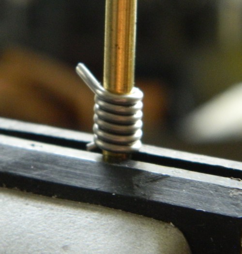
Once I had it wrapped as tightly as possible, I used a fresh razor blade to make a cut down one side through all the loops:

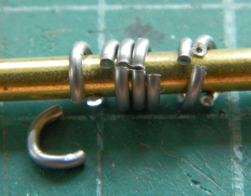

With the loops cut free, they were flattened and then the ends pressed together:

I chose the two that I thought were the best of the lot and used one:

Then it was a matter of making the spokes for the wheel:


Since I could see that the ends of the loop had a slight gap, that’s where I decided I’d put the handle. The superglue would fill the gap and the handle itself would help hide it. Once completed, it was glued onto the elevation housing:


Though not perfect, it worked well enough.
Since it was getting late, I decided that I’d had enough “fun” for one day and cleaned the bench, put stuff away, and went to read before (hopefully, if only for the novelty of it) going to sleep. The next day, after coffee of course, I went into the shop, sat down, and promptly dropped my tweezers. Gravity being a law, it fell onto the floor. It landed right next to the resin wheel I dropped yesterday. It landed in the first place I looked for that resin wheel and there was NO resin wheel anywhere on the floor of the shop. Fine. I pried the wheel I’d fabricated from the elevation mechanism and used the part I’d WANTED to use all along:

::sighs::
At this point, there was painting that had to be done before I could proceed. There are a number of items that I want to show as steel. I use Humbrol’s # 27003 whenever I want a steel surface and it’s an extended period of mixing whenever I do, so I tried (later on I’ll know what I forgot) to paint everything I could think of that would require that steel appearance:

Then I broke out Tamiya’s XF-1 Flat Black and laid down the preshading coat:

One thing that I’ve seen in a number of earlier M4s is the commander’s turret traverse override lever. Neither the kit nor the AM set have that part so I made one from various bits of scrap styrene and added a (former, since they sold their business…or at least this aspect of it) Grandt Line bolt and some 0.020″ (.508mm) solder for the control cable:


Then I glued it in place:

With the Humbrol Steel having cured and then buffed, I hit many of the parts with Tamiya’s XF-62 Olive Drab where light would splash:

Then I rubbed and scraped the OD away to expose the “steel” underneath (and doesn’t that Ma Deuce look great? I’m using the earlier version of the ammo can):
Next month will no doubt feature even more small stuff. With a bit of good fortune I could maybe even start assembling things!

Incredible work. You ought to treat yourself to a SLA 3D resin printer.
LikeLike
Thanks. I looked into 3D printing last year and decided that it wasn’t for me. I can sum up why in one word. Blender. After a week of watching one of three one-hour tutorials, I *still* couldn’t make a simple box. I spent quite some time building my skill-set…which can make a box.
LikeLike