Next on the bench is this:
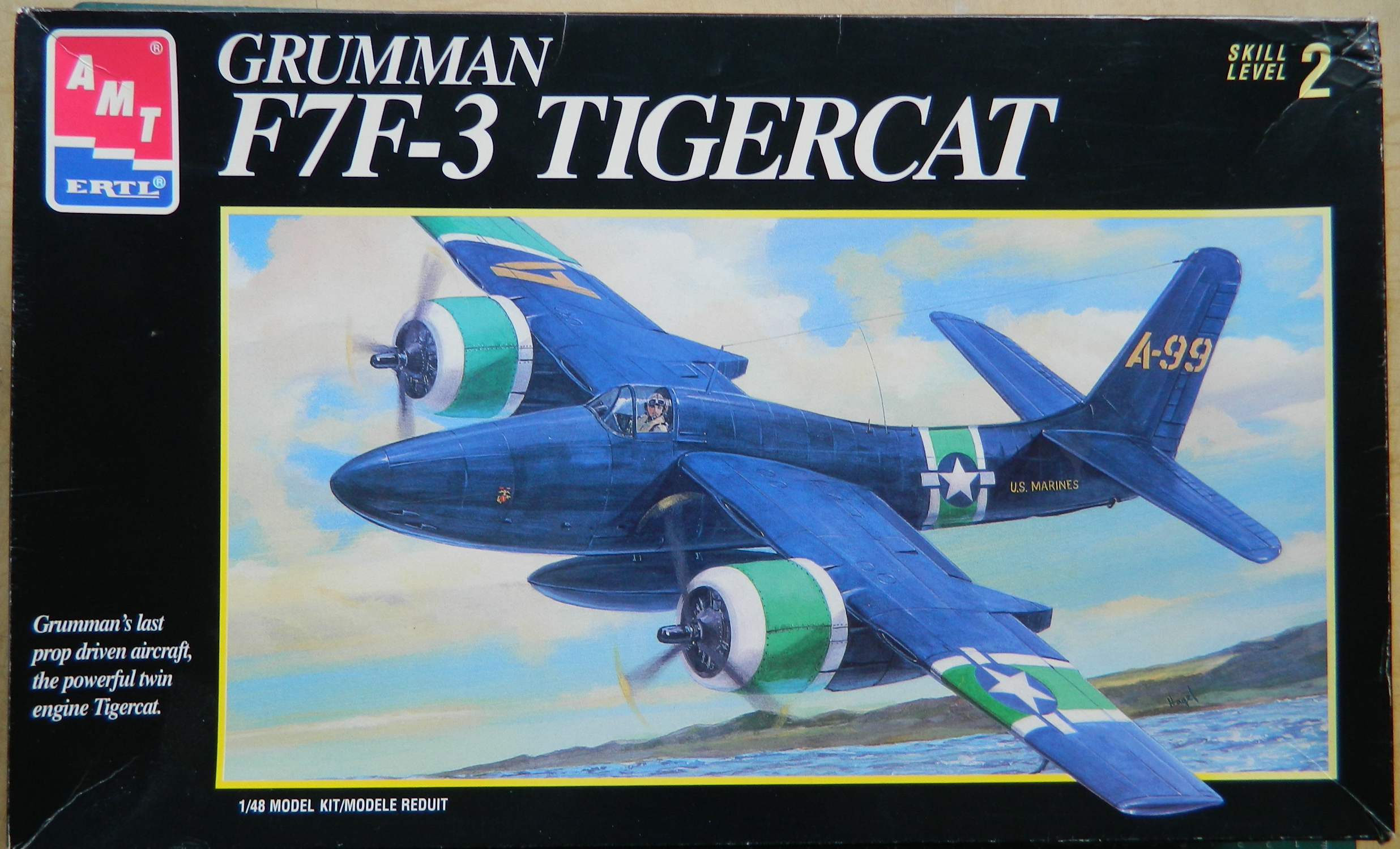

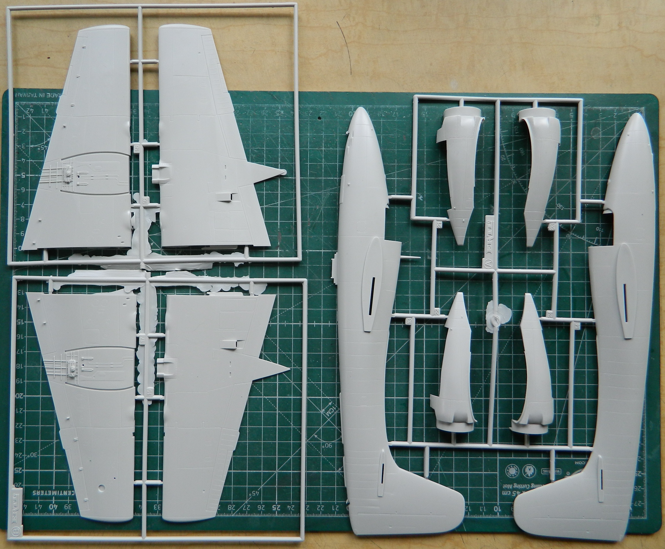
Not a lot of parts (for a change), though I’ve no doubt that I can increase the parts count (not at all a change). There isn’t a lot of AM bits available for this kit. I did get lucky, however. The kit comes with “rubber” tires (::retching noises in background::) and I’ll be able to replace them with CAT 4 resin. Eduard also makes a PE set for this kit which I’ve acquired. Quickboost also makes a pair of P&W R2800 engines specifically for this kit and also acquired (the vial of little shiny beads is to supply control knobs that PE “represents” as flat parts):

I’ve read several build reviews of the F7F (in a couple of other variants) and each builder says essentially the same thing: “I wish I’d put more weight in it!” My initial eyeballing of the kit shows why…there aren’t that many place to put weight. I went into my bits inventory and pulled out all the lead anything I have:

See that tungsten tape? It’s over $20! I was going to get lead tape instead because it was about a quarter of the cost and then I thought. Once I recovered from the novelty of that, I decided to go with the tungsten tape because tungsten is heavier, and that decision was encouraged by the thought that I spend substantially more than $20 for a tank of gas that I intend to burn. Since I’m going to be adding a lot of weight, I decided to try metal landing gear as a replacement for the plastic equivalent:
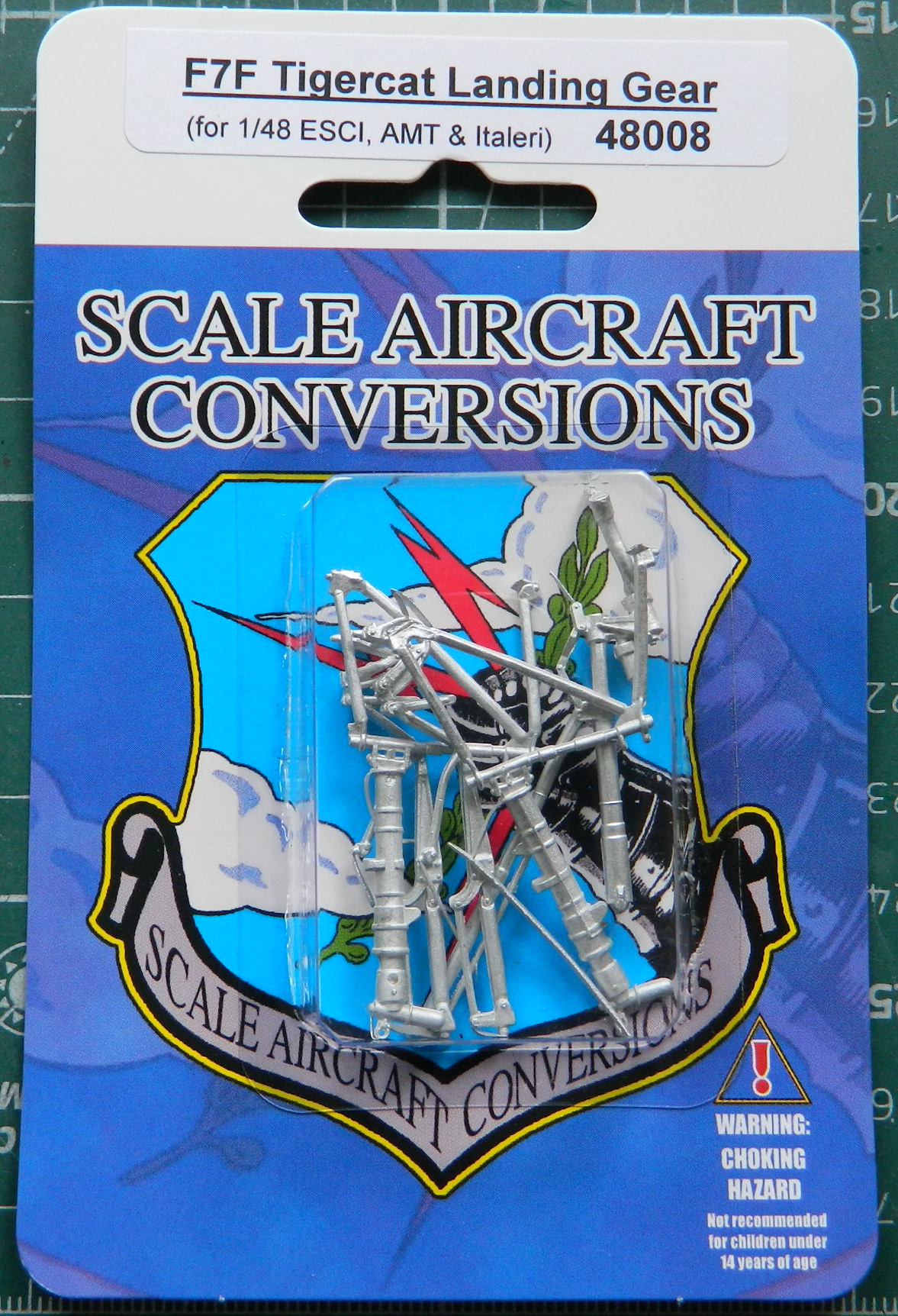
SAC produces these parts by taking a copy of the kits’ parts and then casting them in metal. The problem with that is that they don’t clean up the originals to my level of clean up. But since I’m going to have to clean something, I prefer to clean up landing gear that will support the added weight I intend to add. I don’t want this thing to look like a giraffe getting a drink in a few years. How likely would that be to happen if I used the styrene landing gear? Don’t know and don’t want to find out.
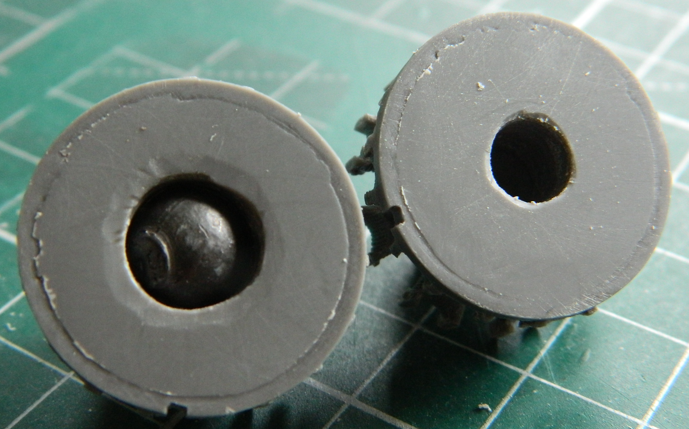
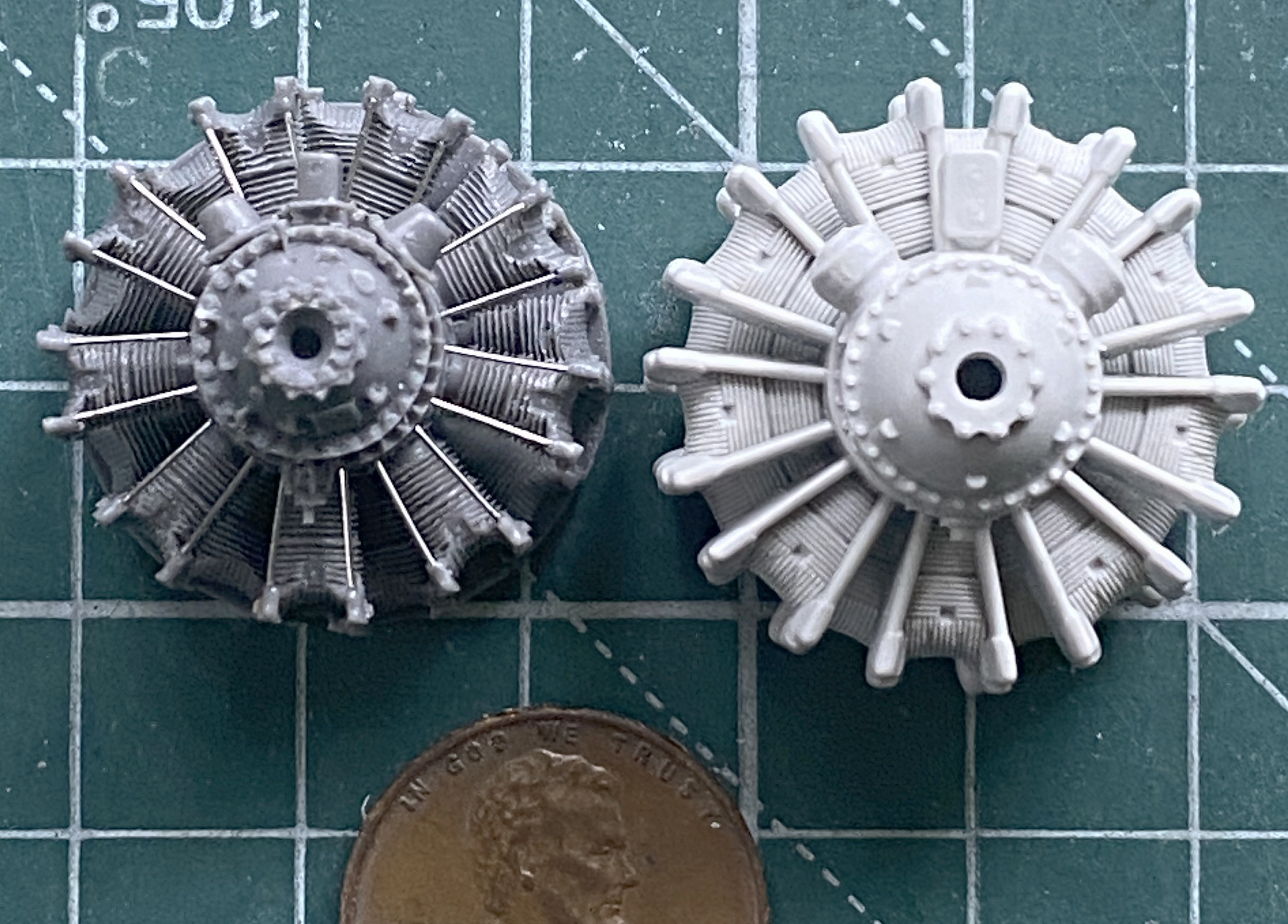
Typically when I’m doing something with wings, I start with the task(s) that enable me to close up the fuselage, so that usually means I start with the cockpit. Not this time. Not having this be a tail-sitter is weighing on (what’s left of) my mind (yes…puns are still intentional). Since I’m planning to stuff Weighty Bits anyplace I can fit them, I decided to start with the engines and I even have a reason. ANY place in front of where the main landing gear touches the surface will be stuffed with whatever Weighty Bit will fit. I intended on drilling out the backs of them to accept lead balls. The .44 caliber are too large but the .36 calibers are (almost) just right… that all starts by assembling the engines:

I found out that the .36 caliber balls are just a wee bit too large when the drill bit started biting away the engine cases. I certainly stopped that as soon as I saw what I was doing! I’d hoped to fit two balls (don’t go there) (which of course you have) into each engine but there isn’t quite enough room for both:
I can’t get the ball out so I spoodged it thoroughly with superglue and the other one I stuffed with lead wool. The glued ball holds the engine together well enough to obviate my Olympic-grade whining.
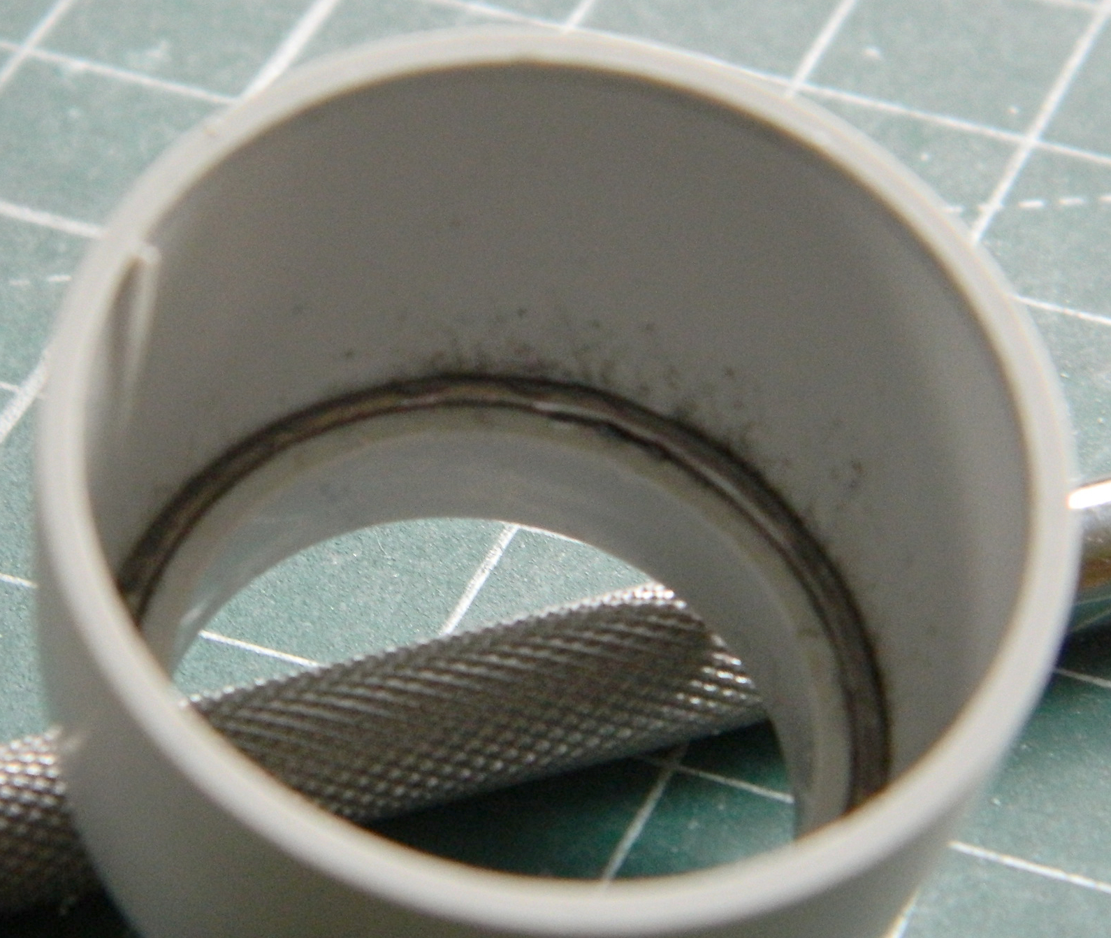
While I was in a lead-stuffing state of mind, I noticed that the cowlings have a little space at the inner front that I can stuff with solder:
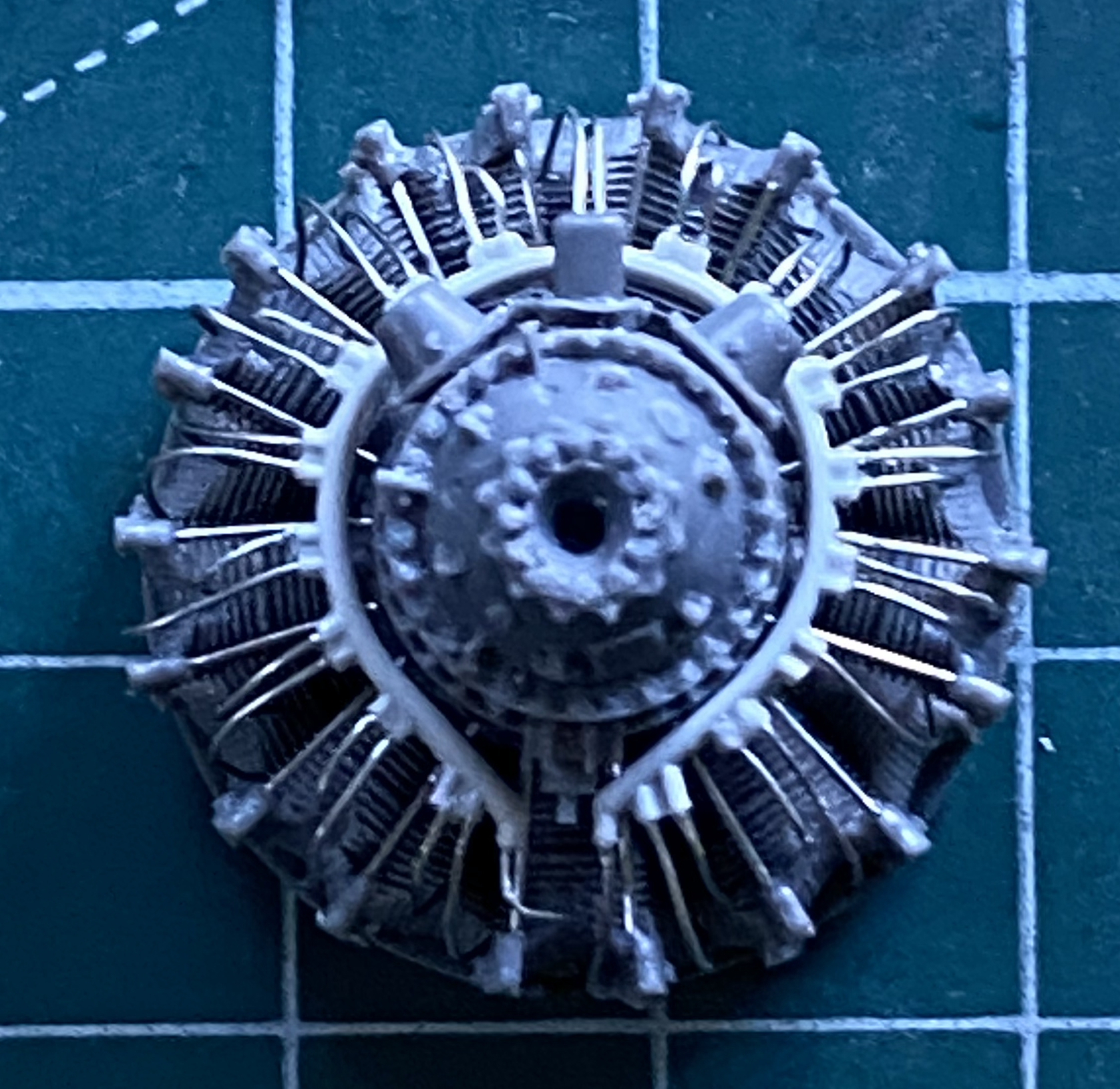
While letting the BitB work on this aircraft’s weight balance problem, I decided that since each of the 18 cylinders of each of the two engines need pushrod covers, I figured out the length I needed and started snipping wires for them:
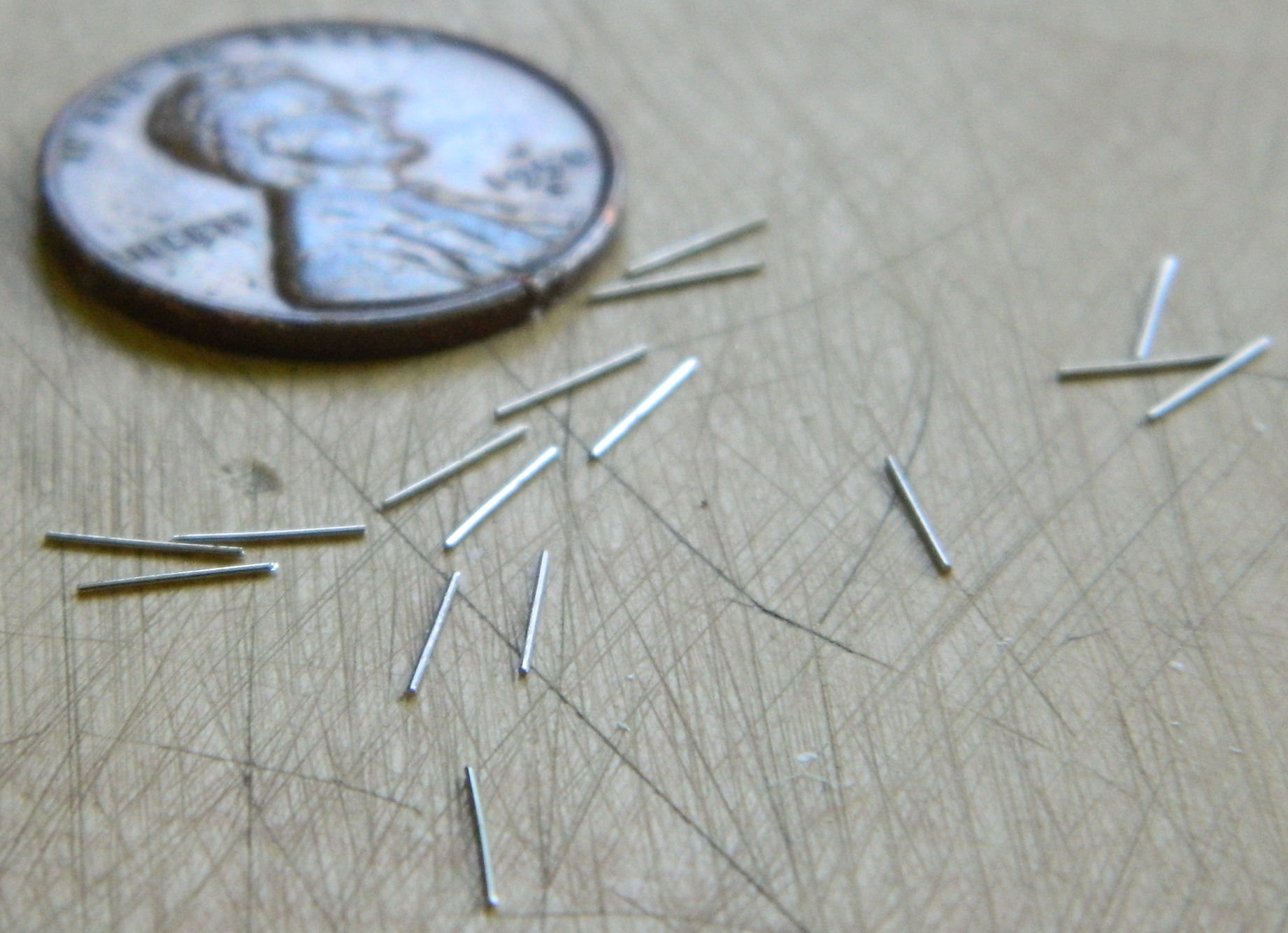
And once I had the 36 wires cut, might as well glue them into place before I lose most of them:

Once I’d added all the pushrods to the first engine, I added the last bits to the front engine cover because I wanted to see just how much room I have inside the cowlings with the engine where it will be, approximately:
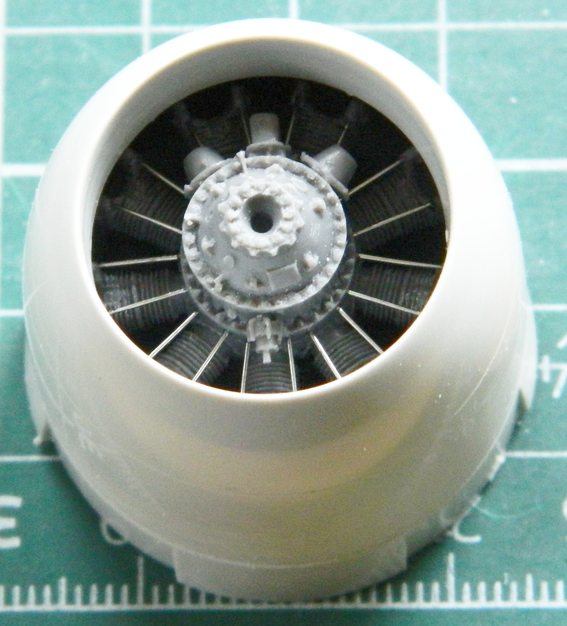
Enough room for the tungsten tape!
And once I had one done, there was the other:
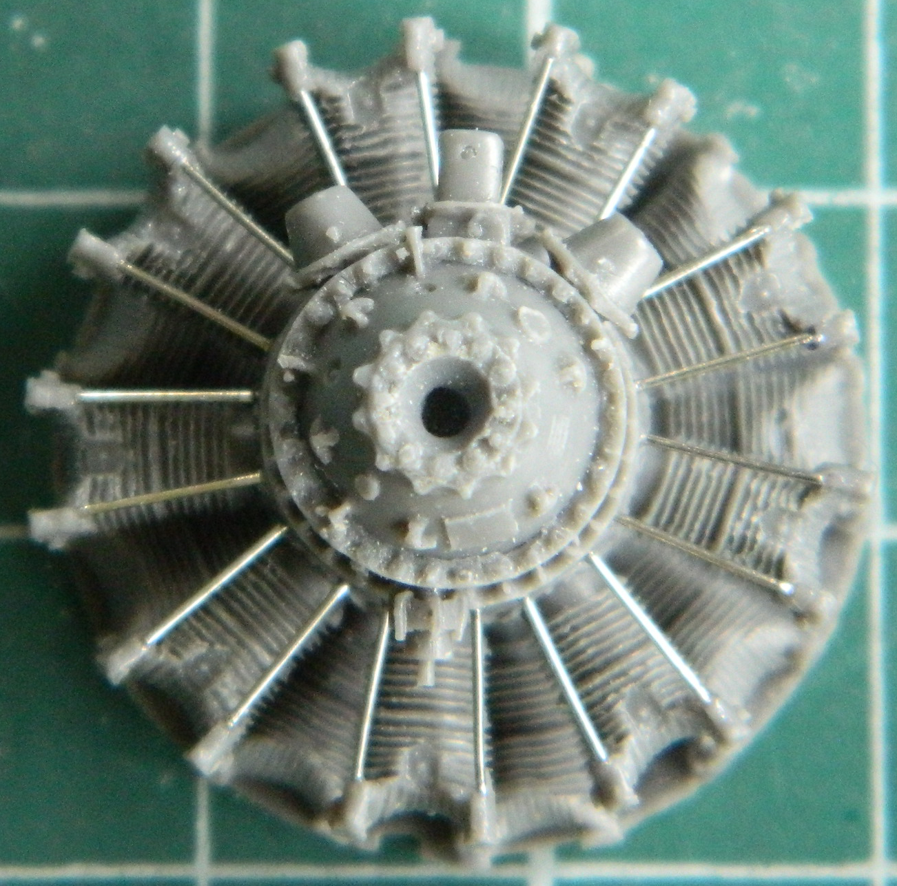
Looks much better than the supplied engines for a LOT less effort:

And just for a change, I thought I’d work on something really fiddly and annoying…getting the ignition wires conduits drilled out (to accept 0.010″ [.245mm] solder spark plug wires). Two of them, one for each engine:

You can see in the above photo where the bit broke through the side on a few (one is down near the bottom and there were a few others). Though annoying, it’s not a deal-ender. The breakouts will be filled with superglue and are really tiny. Once I’d done both conduits, they were glued to the engines and then I started adding the plug wires:


And in a curiously funny reveal, it wasn’t until I’d edited the photos a couple of hours ago that I noticed that I’d missed one wire…on each engine! Those were just taken care of. ::facepalm:: This is how I can see such TINY things with such OLD eyes:

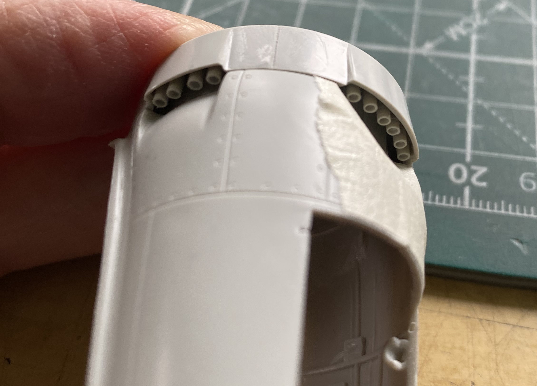
While dry-fitting things, the exhaust stacks jumped up into my attention and since it was an easy fix, the fact that they’re way too thick, I just drilled them out to a less inappropriate wall thickness. Check the difference of the bottom six. The three on the right have been drilled out:

This:

Isn’t as good as this:
Having dry-fitted the engine nacelle together, I saw that in the area right behind the engine yet inside the nacelle, would be a good place to fit lead! It’s in front of where the main gear touches the surface and in a space where, once painted flat black, would probably never be seen. I have my big anvil downstairs in the basement so I took one nacelle and the bag of .36 caliber balls (because I more of them than the .44 caliber balls) downstairs.
Pro modeling tip: If it has a pulse, do NOT wail on it with a hammer:
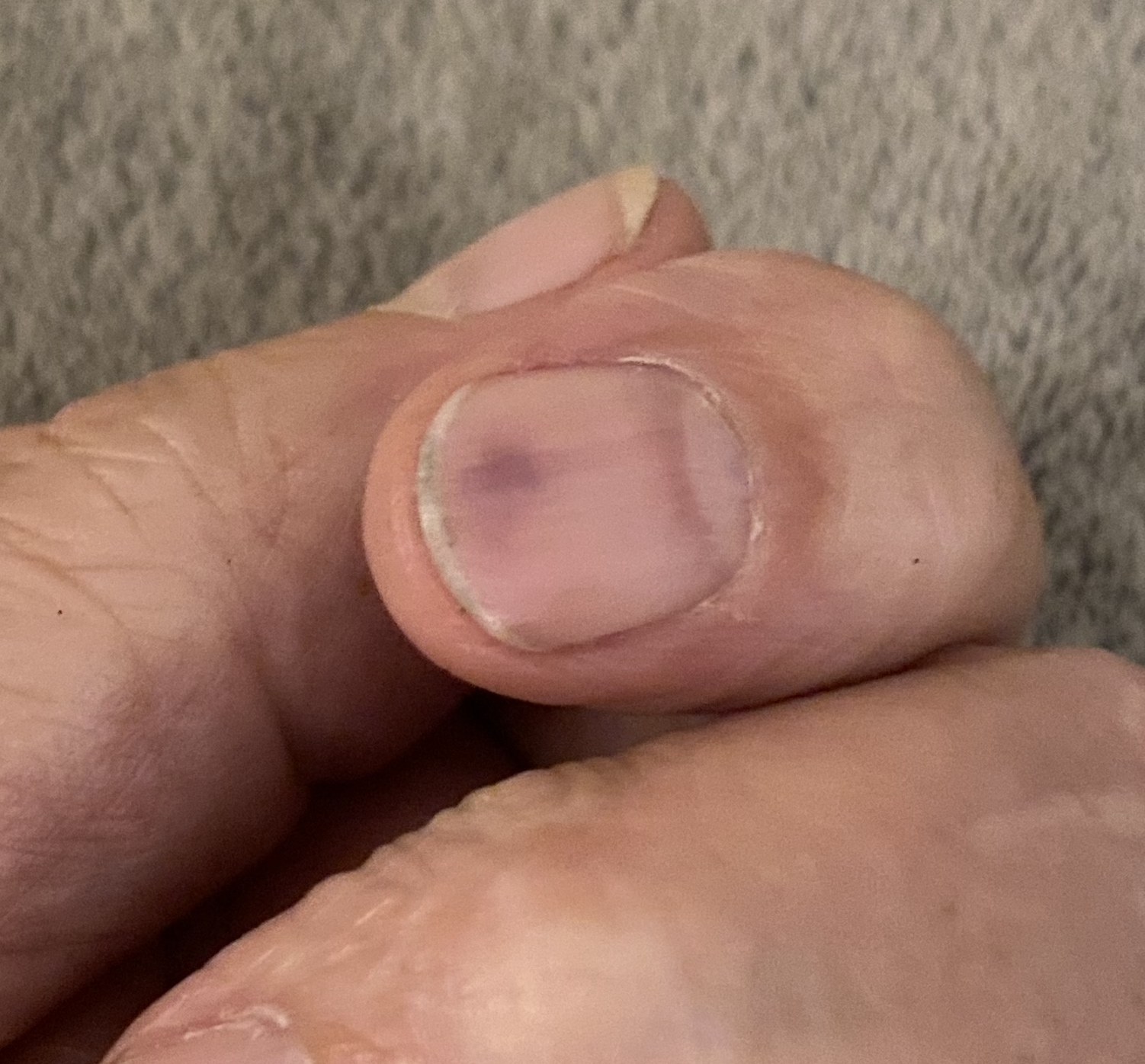
And of course I did that on the last of eight:
Since I’m still in stuffing mode, I started lining the cowlings with tungsten tape:
The above photo shows three layers of tape but since I had the room, I added one more. Then I weighed the engine and cowling together and came up with a total weight of 19.6g. Double that and I’ve added 39.2g. I wish that it was further forward for the mechanical advantage of leverage, but more is still more.
While manipulating the nacelles, I noticed that the landing gear openings aren’t exactly square at either the front or rear:
I fixed that by adding a bit of .020″ (.508mm) styrene scrap to the faces of the openings and let it sit overnight for the styrene cement to cure totally…twice, because the other side had the same problem:

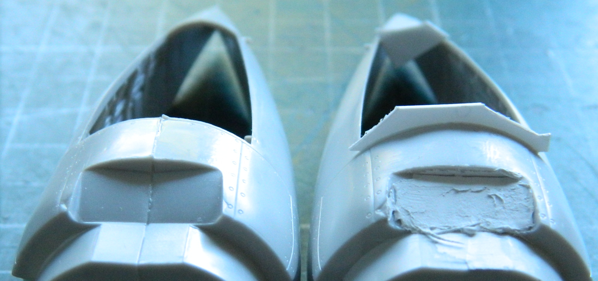
You’ll also note that the nacelle on the right in the above photo has had putty applied. It’s been applied to an area that’s supposed to be flat, not angled.
While they were sitting for the putty to harden, I turned my efforts to cleaning up the SAC metal landing gear struts. ::sighs:: I’m no stranger to working metal. I worked as a metal finisher in a couple of art-casting foundrys. Though working on aluminum, bronze, steel, and stainless steel requires different tools because of their respective hardnesses, working pot-metal (likely tin and antimony, but don’t quote me) is magnitudes worse.
I have a hypothesis (he humorously states as if he’s got just one) that all solutions create new problems. Often the strength of anything is also its liability. Pot-metal does not contradict this hypothesis. Its ability is that it’s soft and bends easily. Its liability is that IT’S SOFT AND BENDS EASILY. And since it’s also a metal, bending it too much introduces stress cracks and that leads to the sodding thing breaking off. So…after I broke the end of one of the main struts off, I got to deal with drilling out the metal, adding a pin (wire), and gluing it back together. Seamless.
Unfortunately I can’t say that about the parts themselves. It’s clear that the molds were taken from the kit parts. Asset: they’ll fit the kit about as well as any other kit part fits. Liability: minimal clean up was done before the molds were taken and the little that was done was poorly done. As you aircraft modelers are well aware of, there’s a portion of the landing gear that moves up and down (it’s called the oleo strut) and since it slides within a seal, that part of the landing gear is very shiny. The “poorly done” verdict was levied because the little clean up that was done was done on the shiny part. Badly. Badly enough that I’m going to cut the struts apart, all three of them, and replace the oleo with steel. For the nosewheel I’ll be using stainless steel welding rod, and for the mains I’ll be using part of a paperclip:
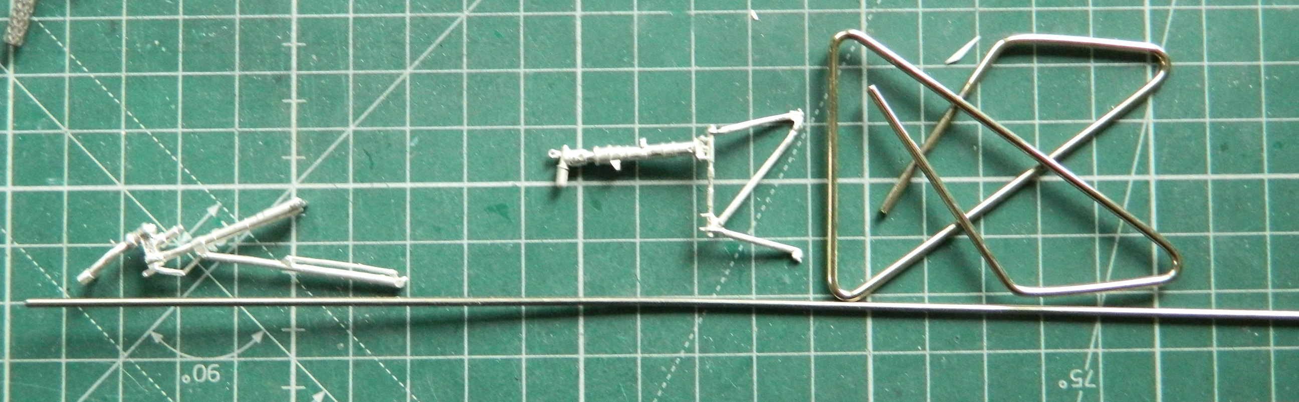
Zoom in on the oleo sections…you’ll see what I mean.
But those parts needed to be cleaned up so that’s what I’ve done (and as further support of my thesis, check out how thin the metal oleo is down near the bottom, and how thick the kit’s oleo is):

Yeah…drilling all that out. We’ll see how that worked (or didn’t) next month.

I can’t wait to see this finished. It’s going to be great.
LikeLike
That makes two of us! It’s going to be the best that I can make it. Vote of confidence is appreciated.
LikeLike