I started this month by asking (and getting an answer) to the question that has been obvious to me. Will this thing sit on its landing gear or will I be another modeler who needs to use something under the tail to keep it off the table. By this point, I’ve stuffed lead and tungsten into any space they’ll fit, so I taped all the major components together to see if I’m even close. I placed the taped-together parts on my fuselage stand with the horizontal supports in touch with the model in line with where the landing gear struts mount:

Yes! It will indeed sit on all three of its tires, though the balance as the nose tire resting ever so gently on the surface. And this is done with zero weight in the nose (not much space but lead will obey the hammer and can be coerced into the shape I need), so since I will be adding more weight to the nose and the forward section of the drop tank (because it extends forward of where the main tires touch the surface). I don’t want an errant breeze having this thing squat like a dog having a slash.
Hammer time:
With the Big Question answered, hammer time segued into airbrush time. The engines were pre-shaded with Tamiya XF-1 Flat Black. The crankcase and its bits were brush-painted Tamiya XF-53 Neutral Grey, the ignition tube surrounding the crankcase was painted a mixture of Tamiya XF-6 Copper (two parts) and XF-1 Flat Black (one part), and the wires were done with a mix of Tamiya XF-57 Buff (three parts), and XF-10 Flat Brown (one part). The front of the rocker arm covers were lightly dry-brushed with Tamiya XF-16 Flat Aluminum. The cooling fins were lightly touched with a silver pencil. Then I took a round toothpick with a chisel tip cut onto it to scrape the flat black off the pushrod shrouds:

The kit’s pins to mount the propellers didn’t come close to fitting the engines, so I drilled the engines out to accept sections of 0.062″ (1.57mm) instead. (Pain in the thing I’m sitting on that isn’t a chair getting them perpendicular to the crankcases!):
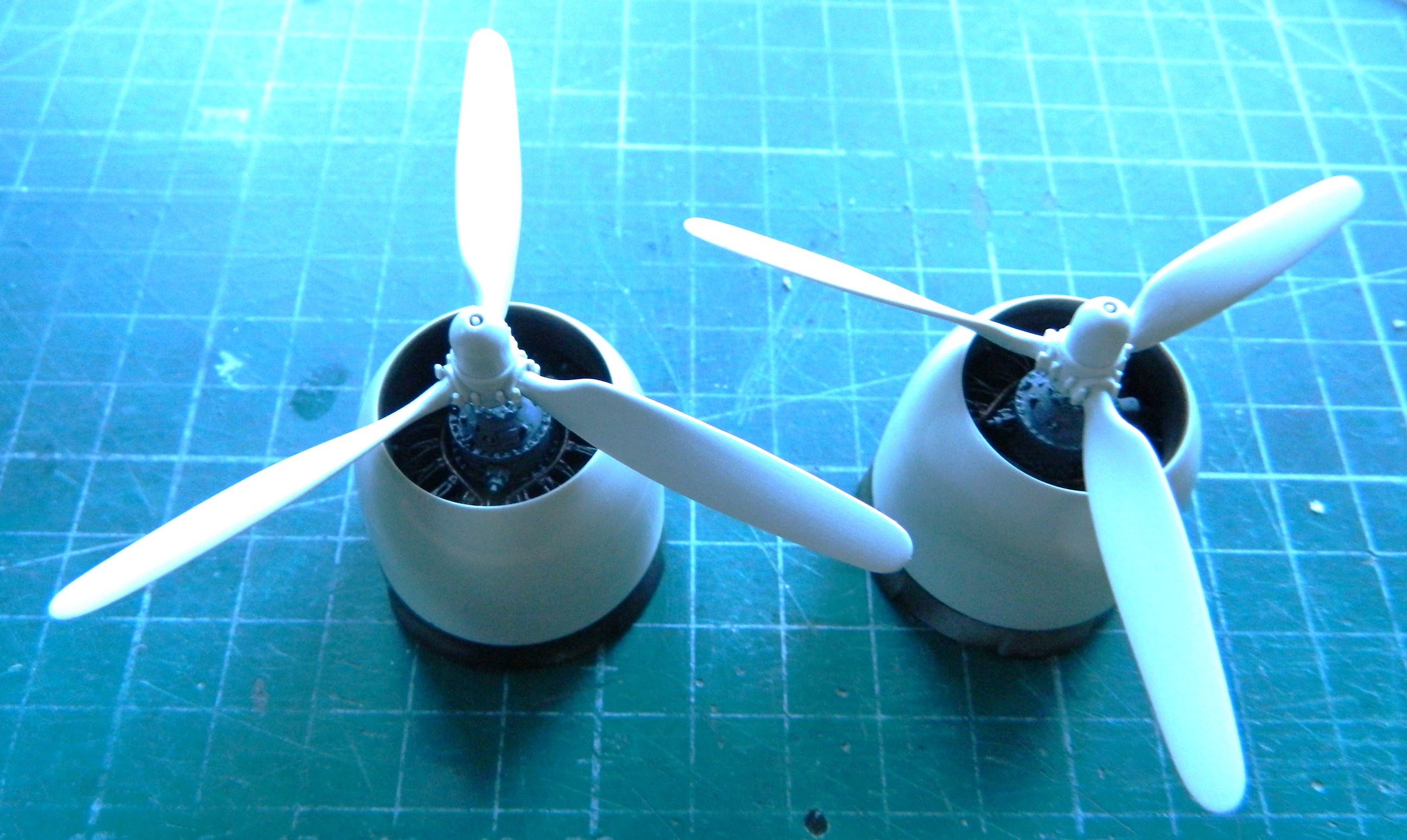

Not a lot showing but that’s as it’s supposed to be.
Then it was time to fart around…forever…with the landing gear. My initial notion of using the metal parts was set aside because the alloy is so malleable that working them was akin to trying to work the surface of cooked spaghetti (okay…maybe not that flexible, but after far too many times having to straighten something out I considered going to get tomato sauce and grated cheese) (couldn’t find the cheese and by the time I had, I’d sobered up, so…). I still had the plastic parts from the kit (which I’d assembled to act as a form so that I knew how far to bend the spag…er…metal parts), so I decided to use them instead and hope that this thing didn’t squat over time. I finished off almost all the parts when I found this:

Most of you probably knows what a “short shot” is (and no…it doesn’t mean that). For those of you who don’t (or think it does mean that), it’s when the liquid plastic pumped into the molds doesn’t fill the void completely. That’s what happened (or didn’t happen) to the lower part in the above photo.
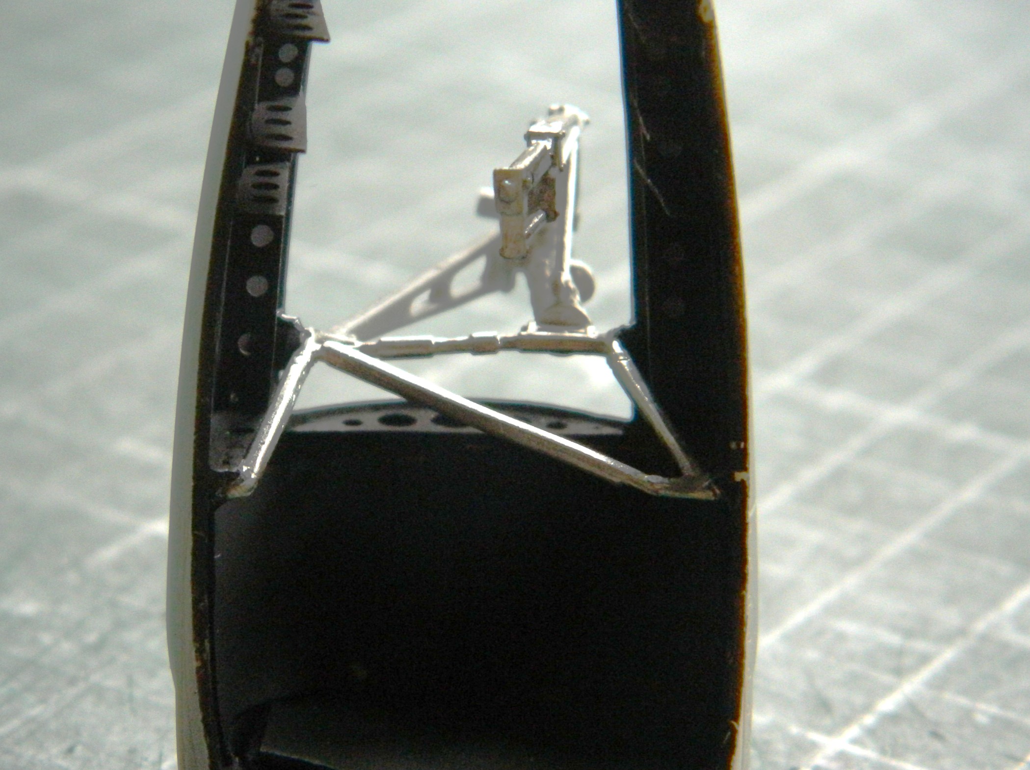
Fine. I’ll use the damned metal parts, then. (And yes…I pouted.) (Probably more because I did sober up but some of the lower lip extension was because I had to change my mind back.):

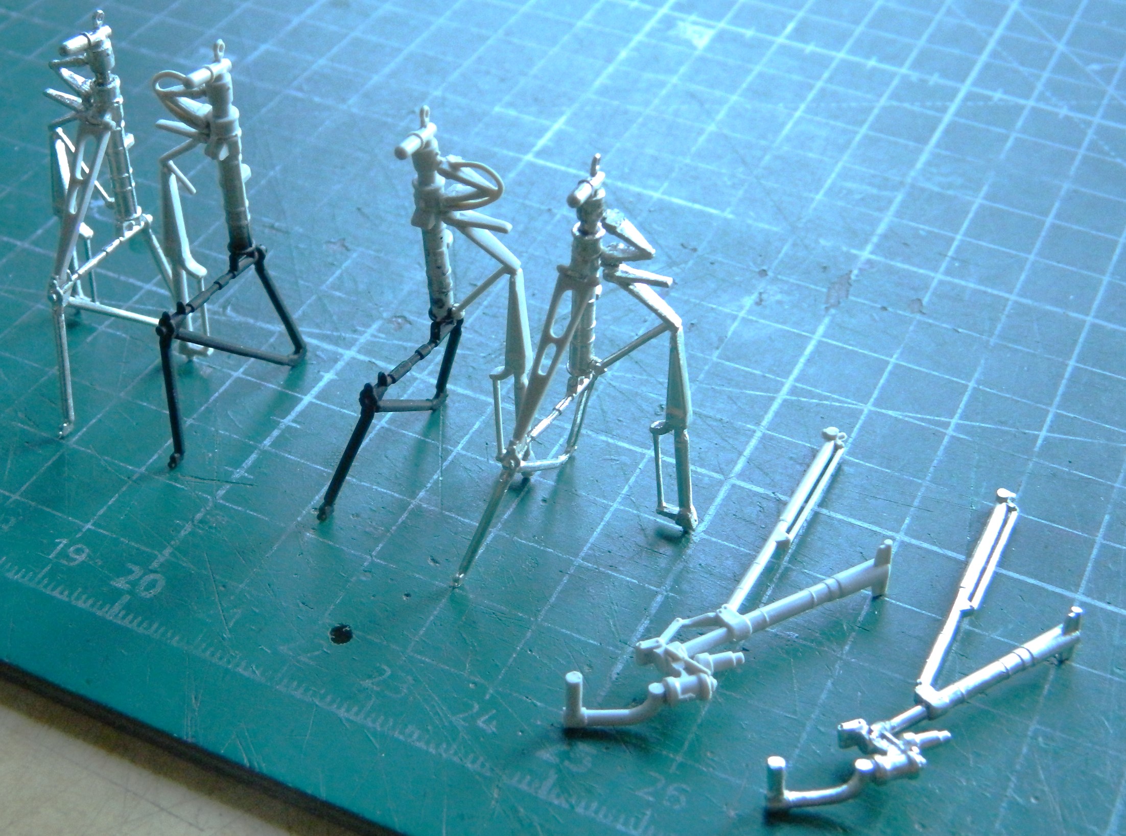
I can be pretty funny sometimes. When I took the above photo, I thought I had everything finally aligned.
I used the kit’s oleo extension arms on the main gear, but used the arms from the PE set for the nose landing gear (that’s the brass-colored part):

And just as an aside (and because I don’t have a lot to show here for this month, so it’s filler), a few years ago I heard about these, bought a set (which comprises four separate sets of what’s pictured below), and plan to use them on this build (which, with my typical aplomb, I totally forgot that I had until I was looking for something else):
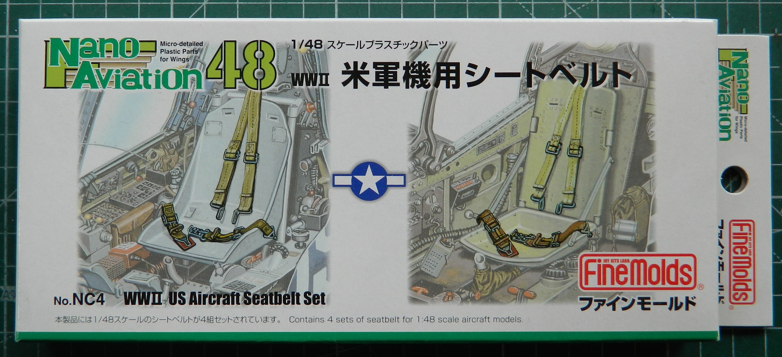

They’re nicely molded with good detail. I’m probably going to have so much fun bending and shaping what needs to be bent and shaped. We’ll see if the effort is worth the result.
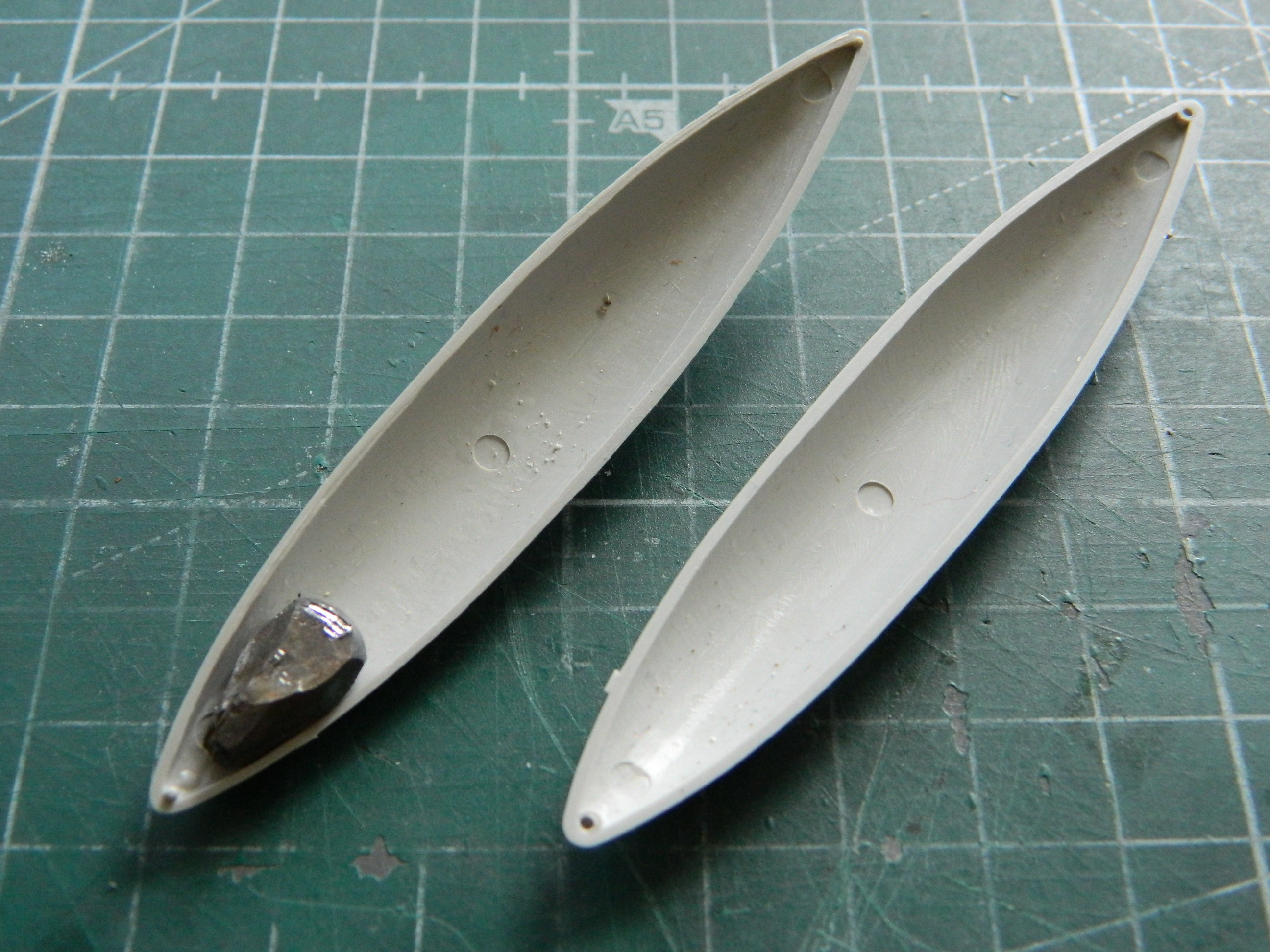
There are outlets for the oil coolers and the covers for the outlets are variable. The PE set offered replacements for what’s molded onto the wing tops but I decided to see if I could thin out what’s there sufficiently:
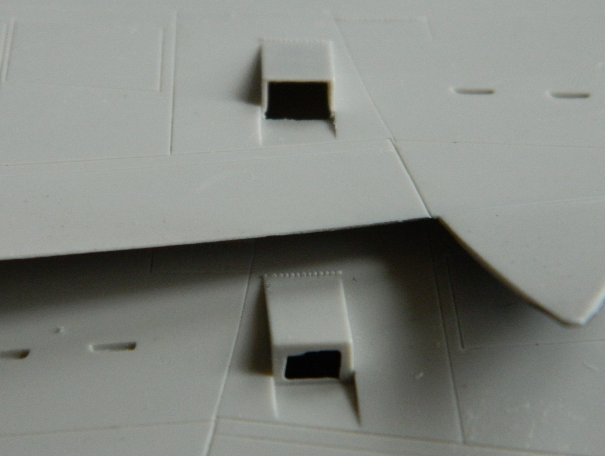
Yeah. That’s sufficient.
While doing the skull sweat regarding when the landing gear is permanently attached, I realized that trying to get the stupidly flexible metal landing gear inside the bays, things were going to be bent and badly so. Though I prefer to add things as delicate as these are as close to the end of the build as I can, that’s not going to work this time. Initially I thought it was because they’re so sodding bendable. Then when I tried to feed them into the bays from underneath, which is how they’d get attached later on, I discovered that they didn’t fit through the opening. ::sighs:: Okay, I’ll add them now:

Firmly glued in, out came the flat black again to pre-shade everything:
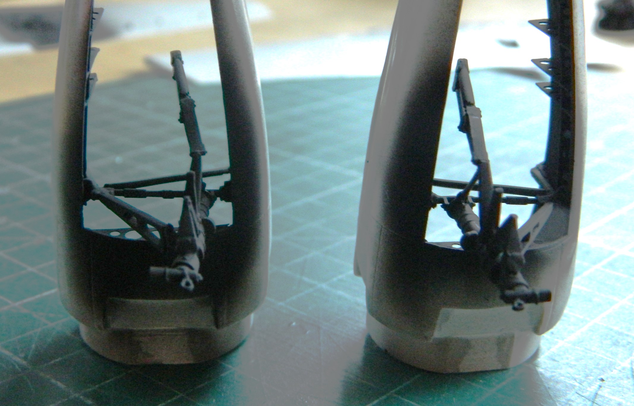

Next month these will all be painted aluminum. Who knows…I might even do other things as well.

What made you choose the Tigercat?
LikeLike
A *pair* of R2800s hanging off, a fuselage about as wide as a Honda Z700, and faster than a Mustang, four .50 calibers and four 20mm cannons…what’s not to like?
LikeLike