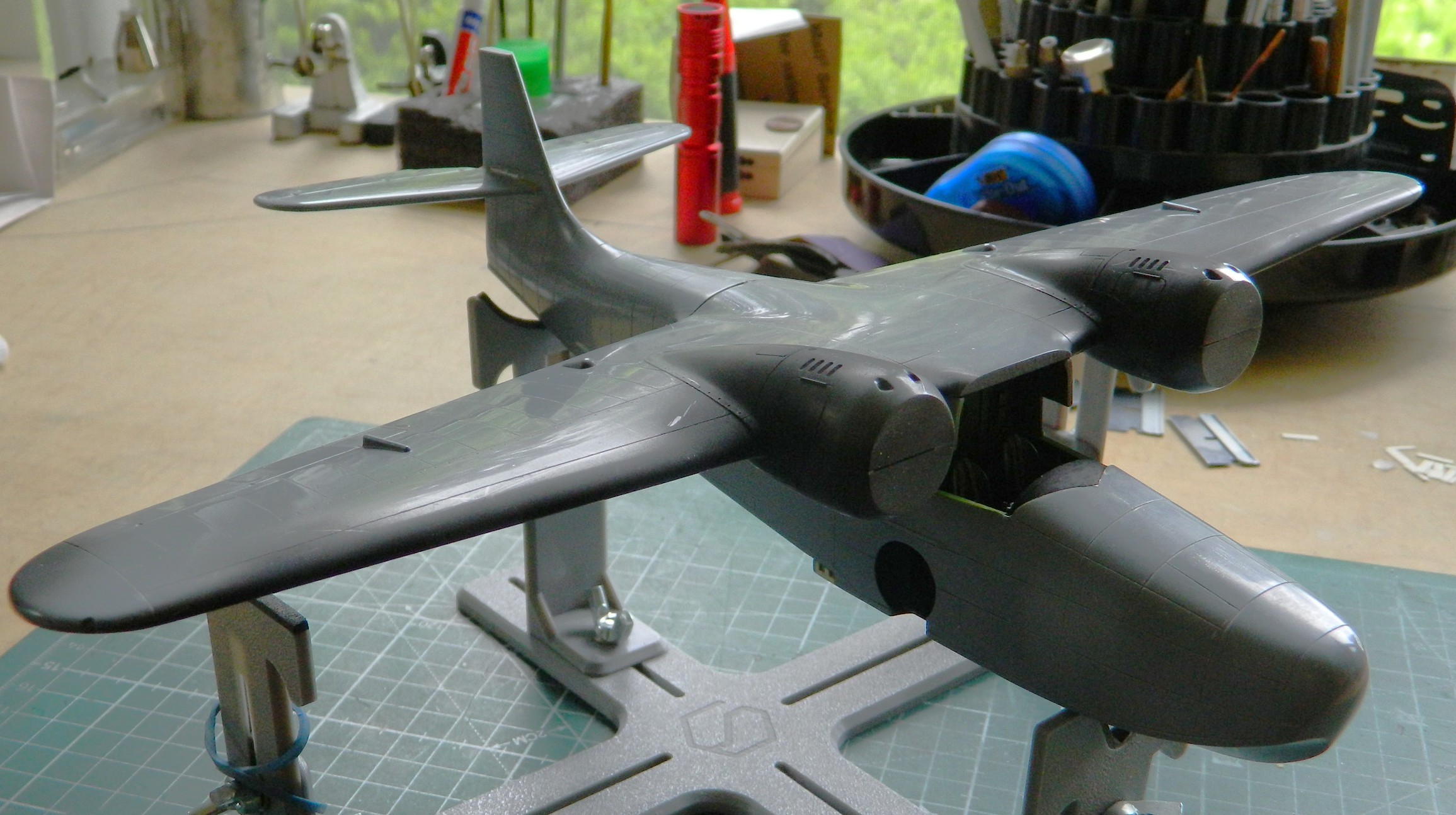
Colonial Viper MkII (Moebius Models) 1/32 Scale Build #1, Part 1 Conclusion – Making Things Fit Better
I surprised myself with the first Part 1. I didn’t realize that I’d done so much work. That meant (means) that I had (have) to do a continuation so that I don’t fall behind. Again.
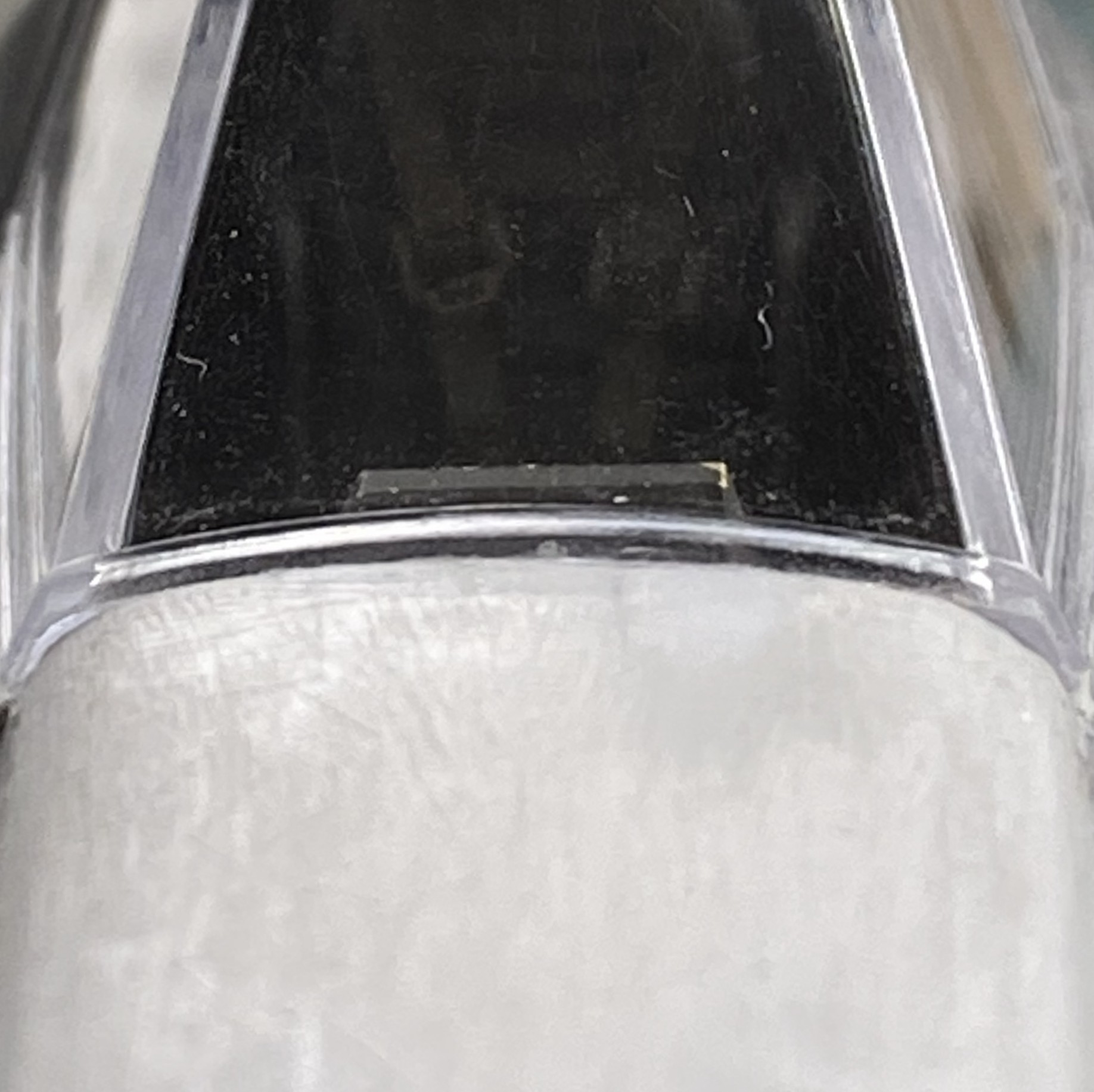
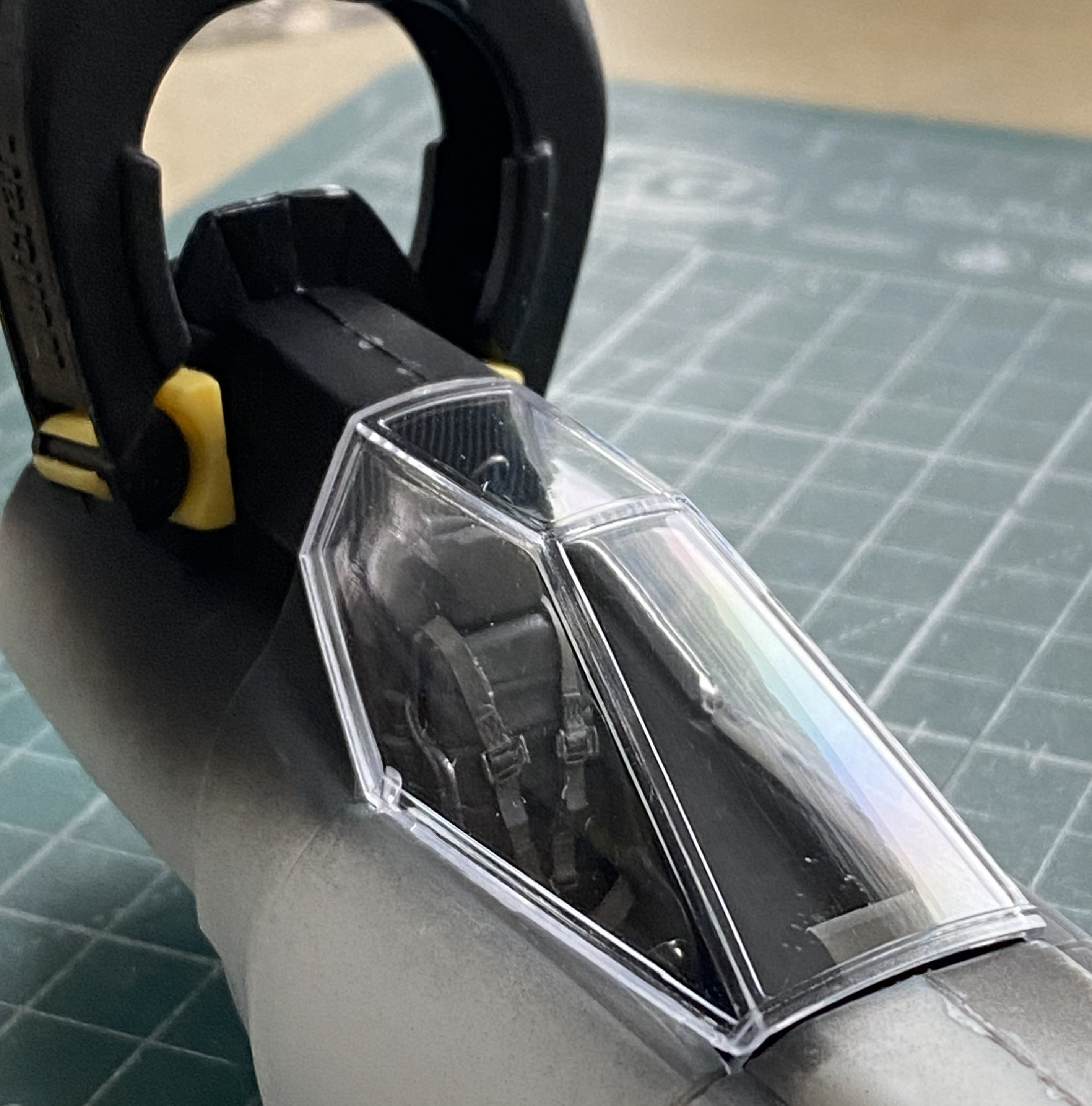
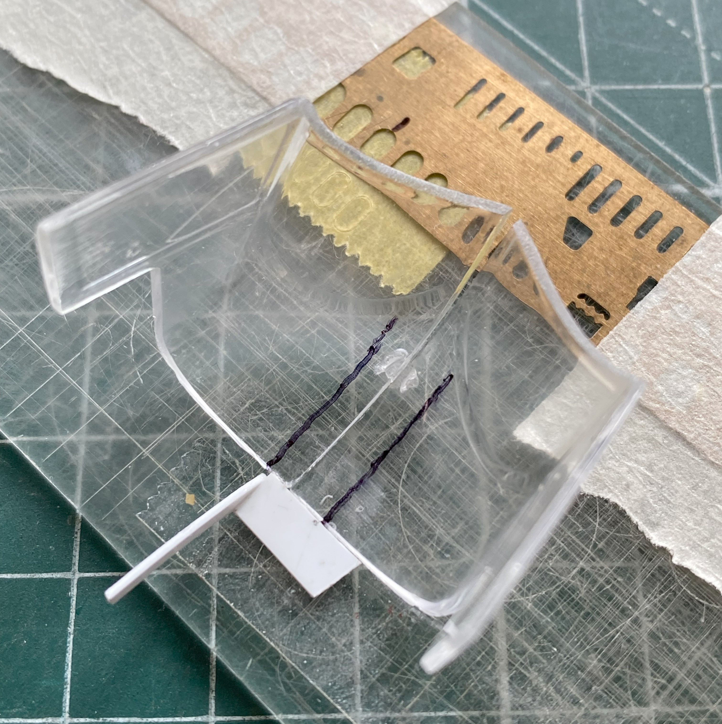
What started the reconstruction of the upper nose was the canopy not fitting well. Now the canopy fits without having to reconstruct the canopy:
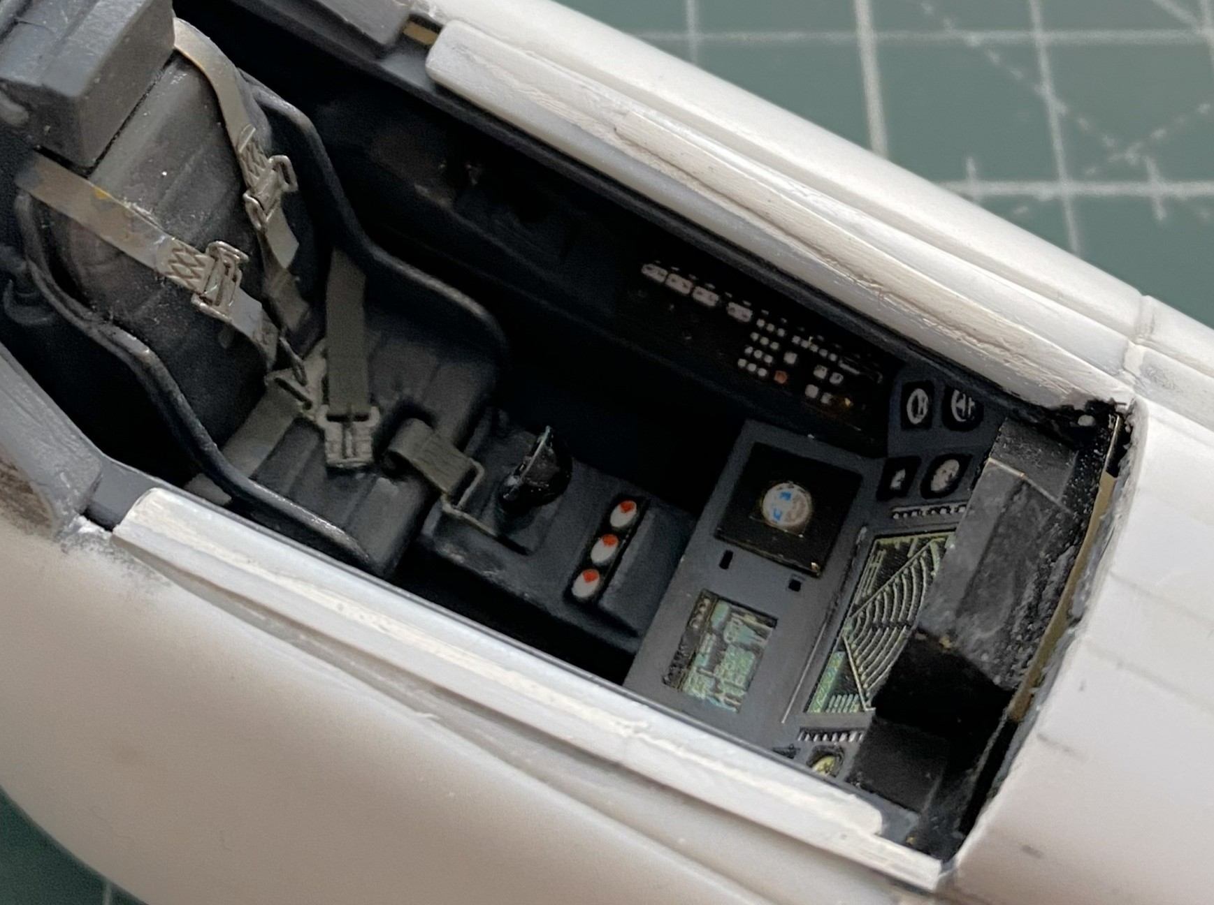
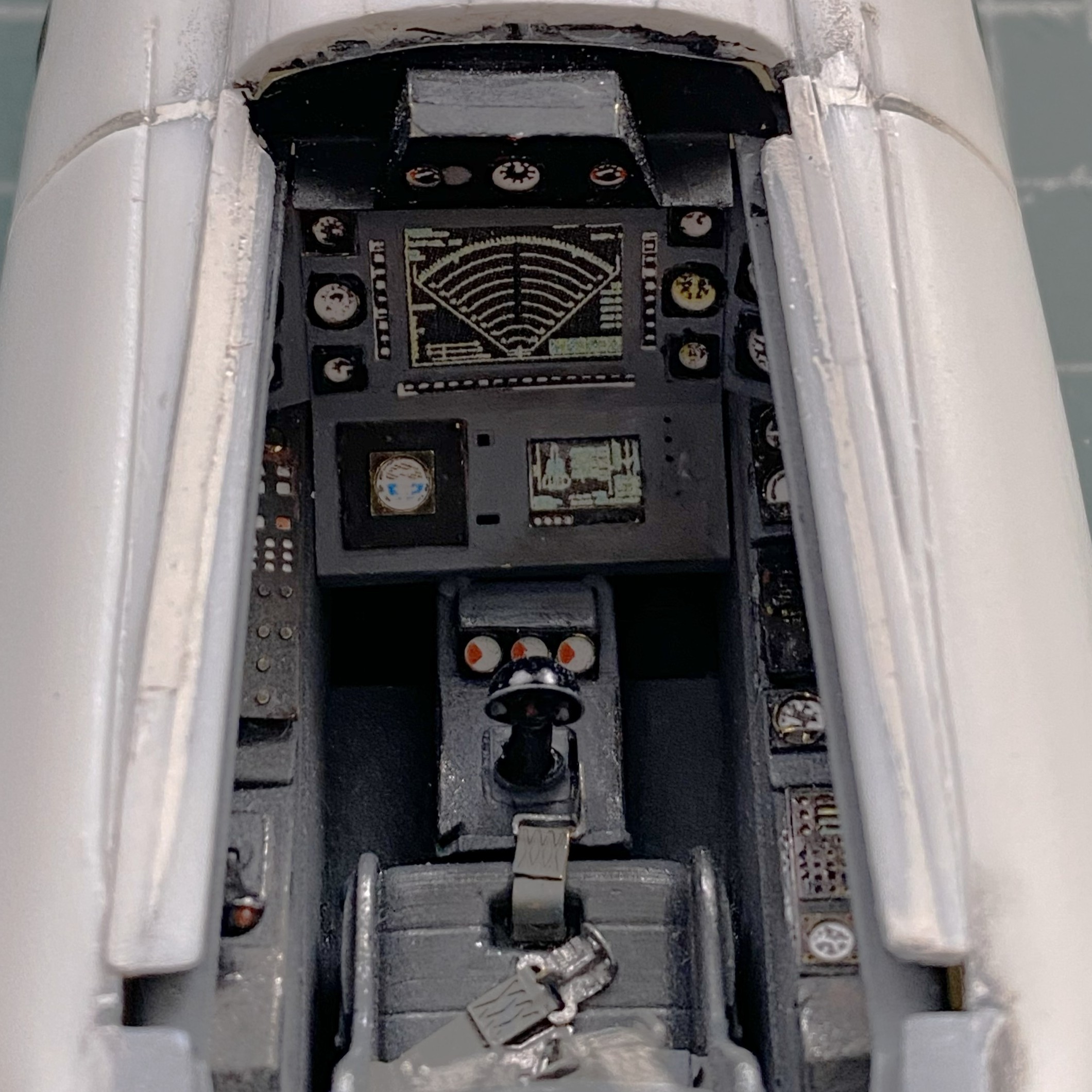
Shims were added to the sides of the cockpit on the fuselage so that the canopy fits well there also (this cockpit is supposed to be sealed, y’know):
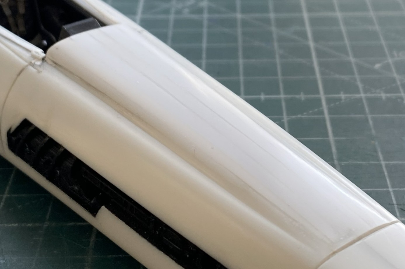
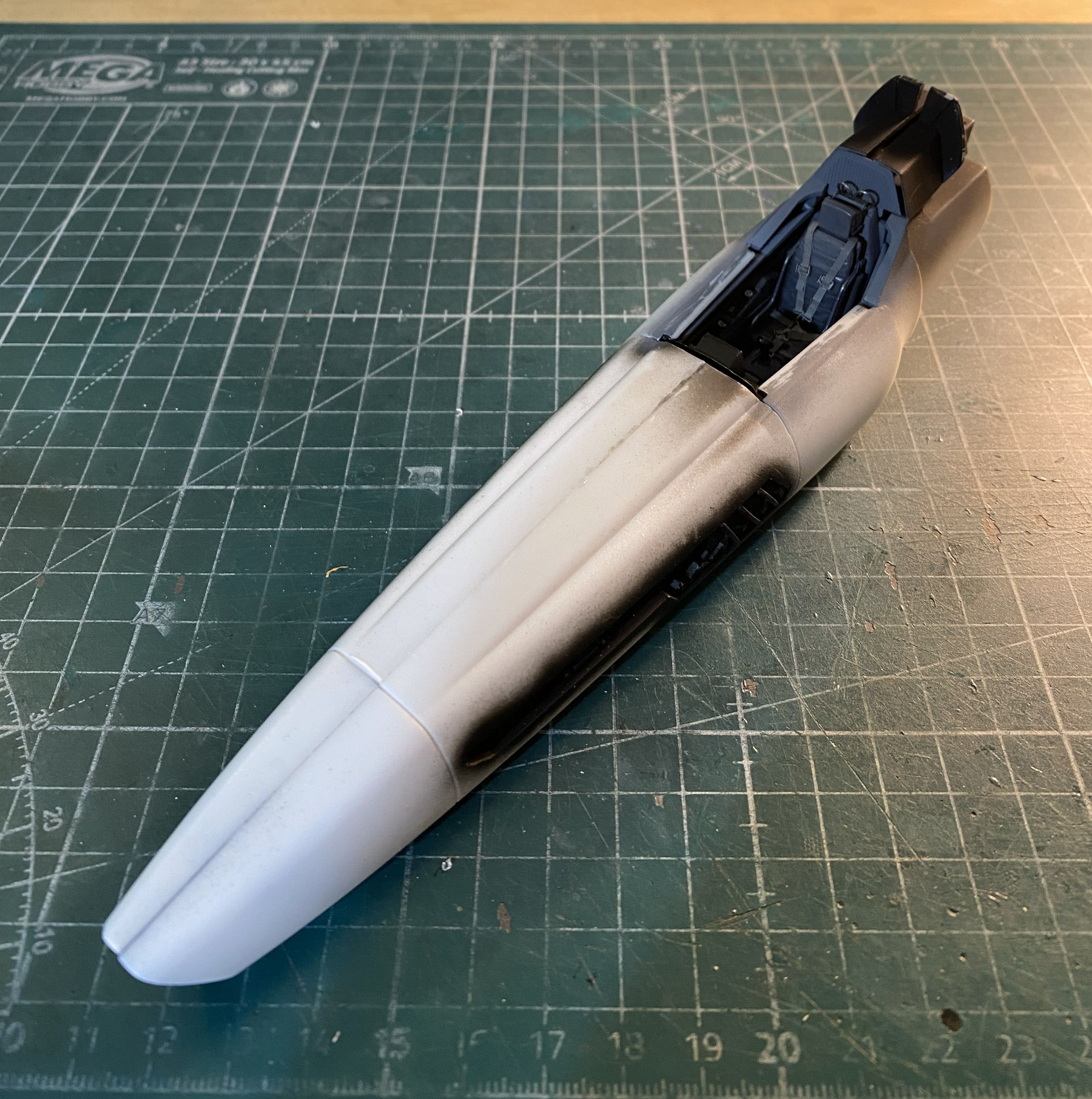
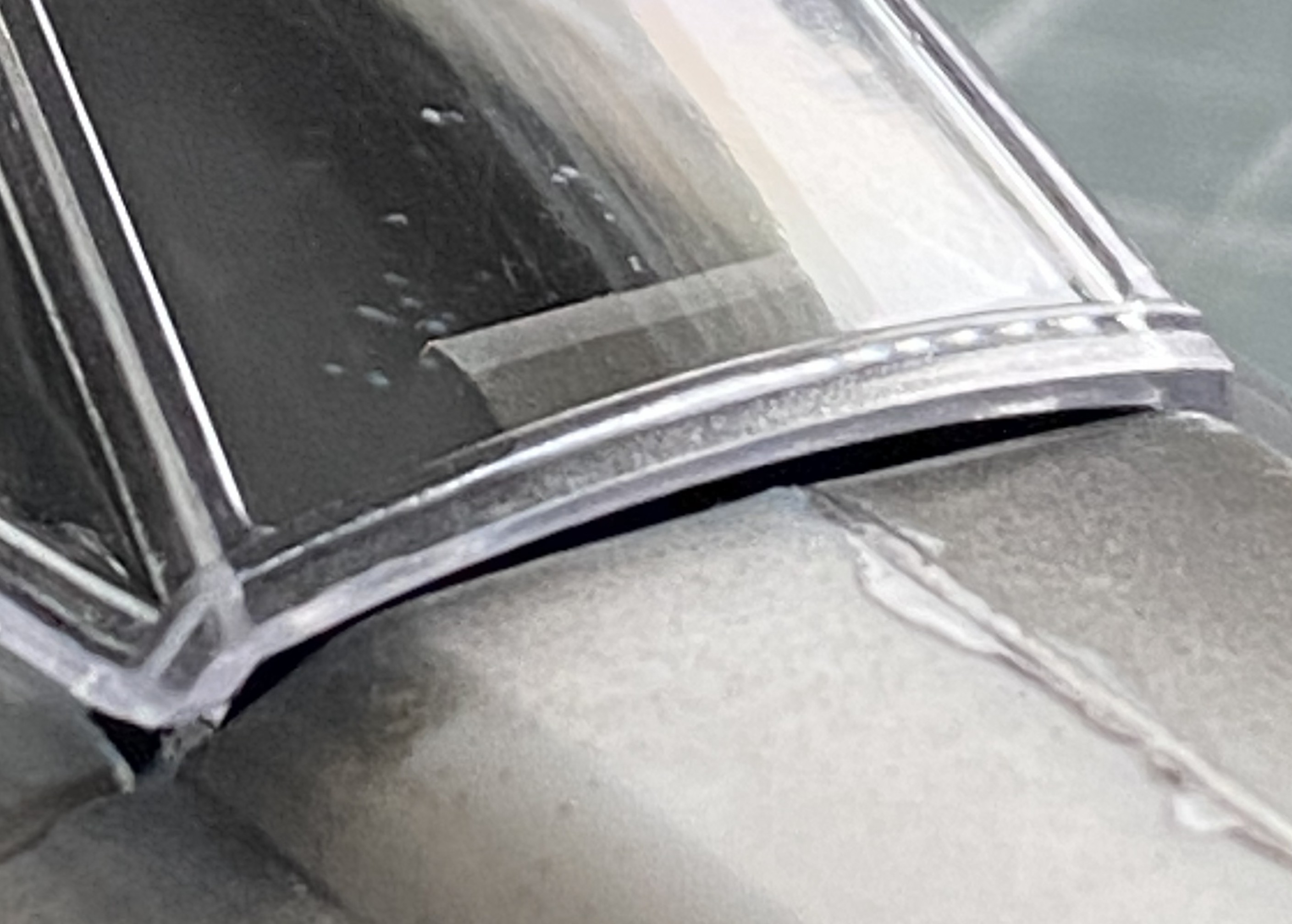
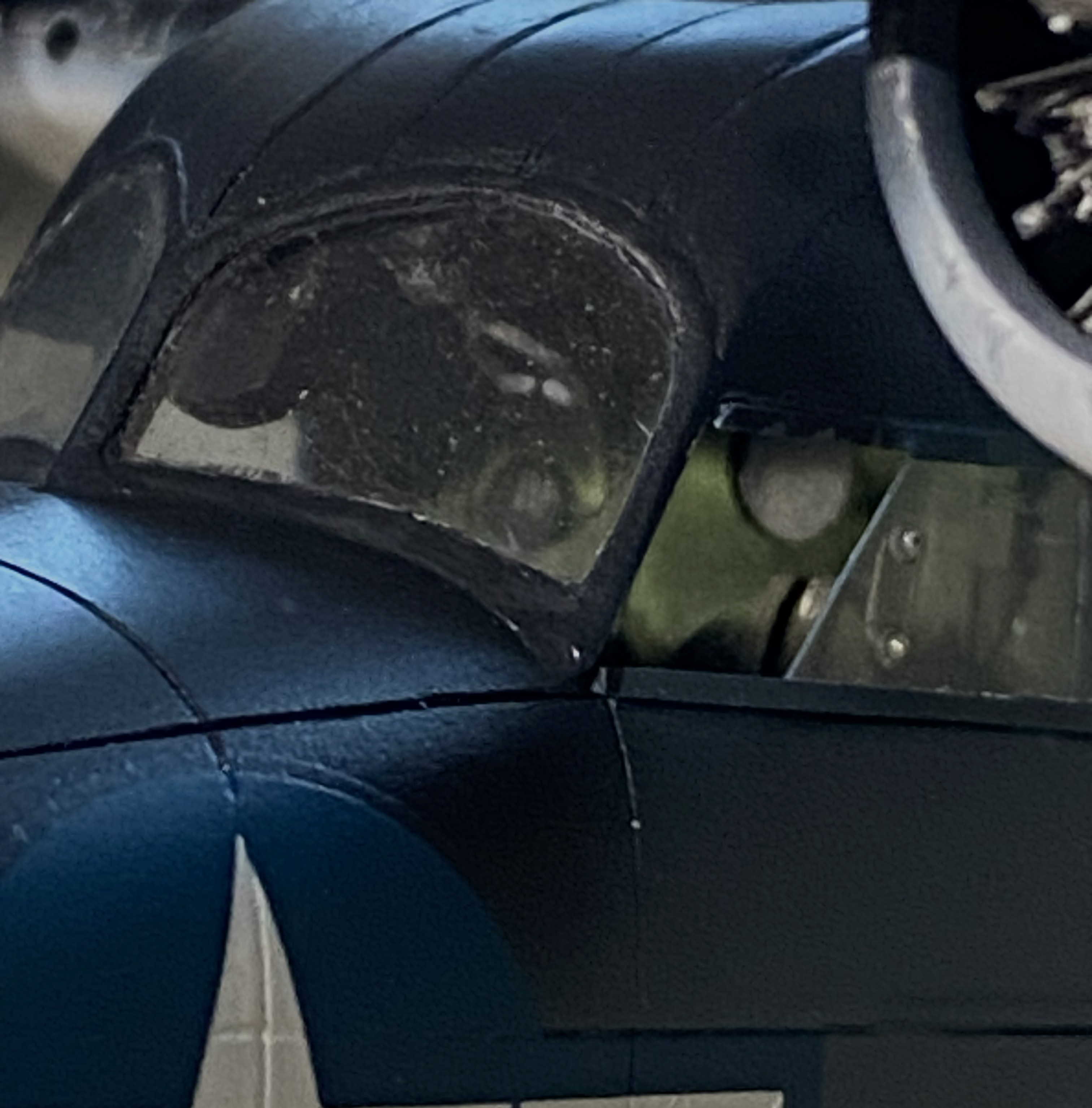
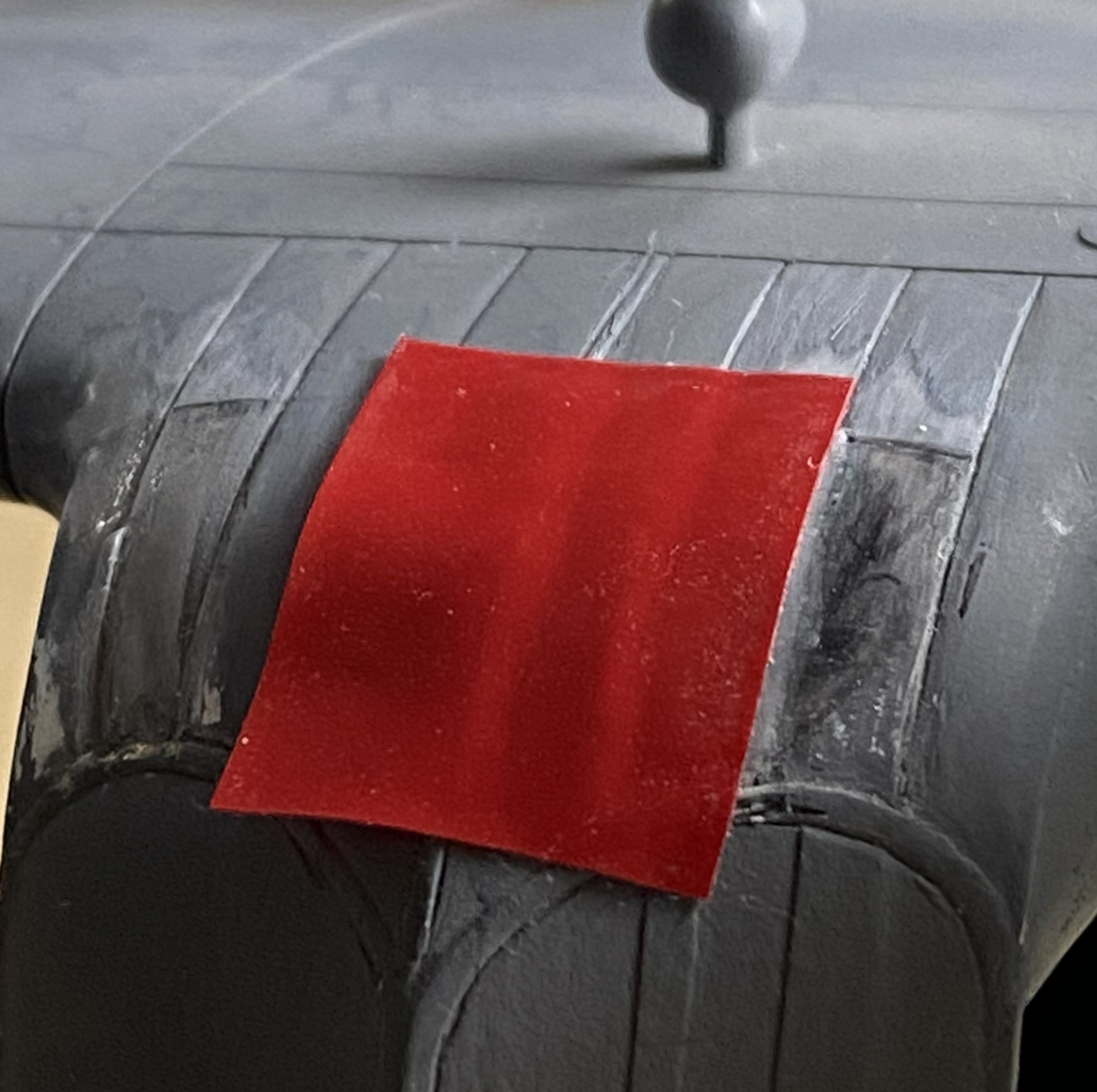
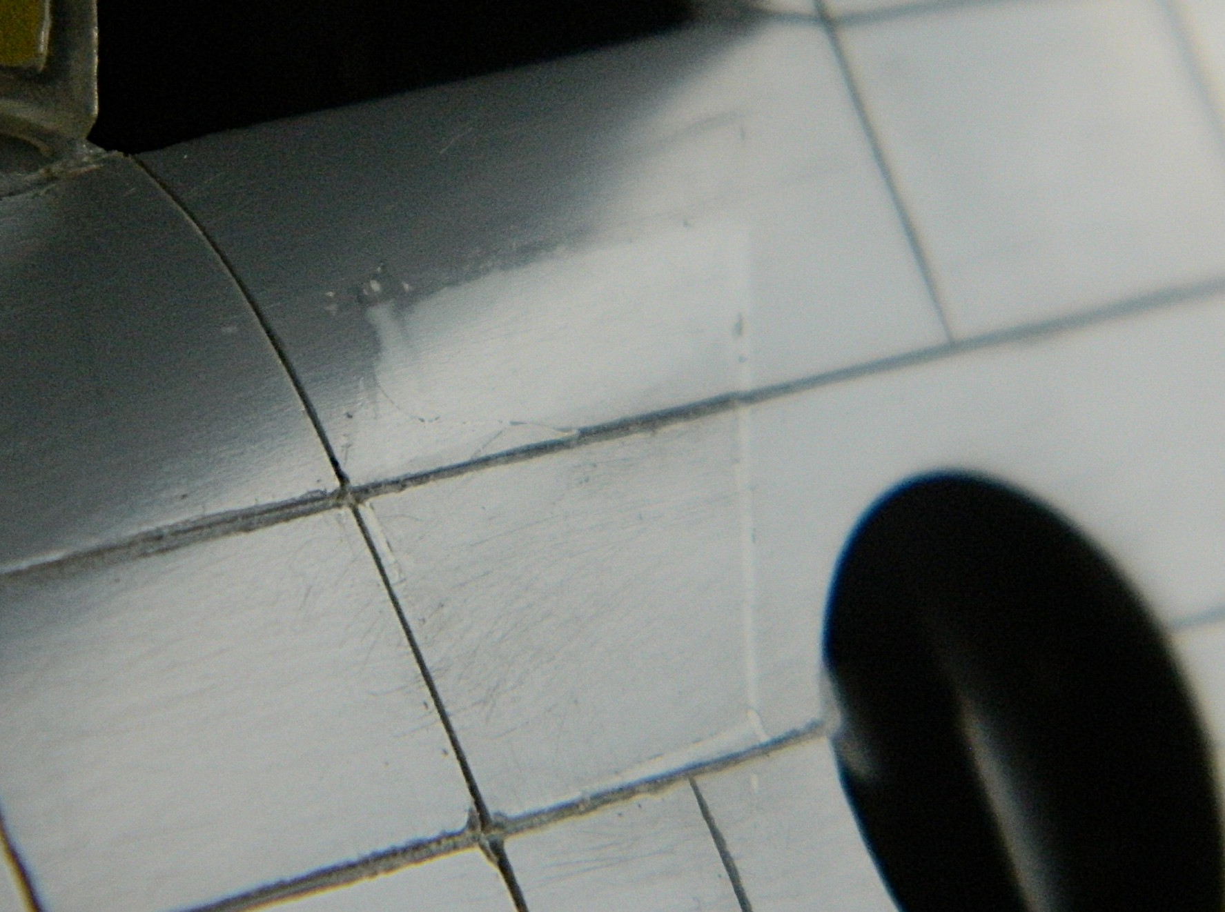
With the nose modification roughed in, I sanded it from 220 grit up to 5000 grit:
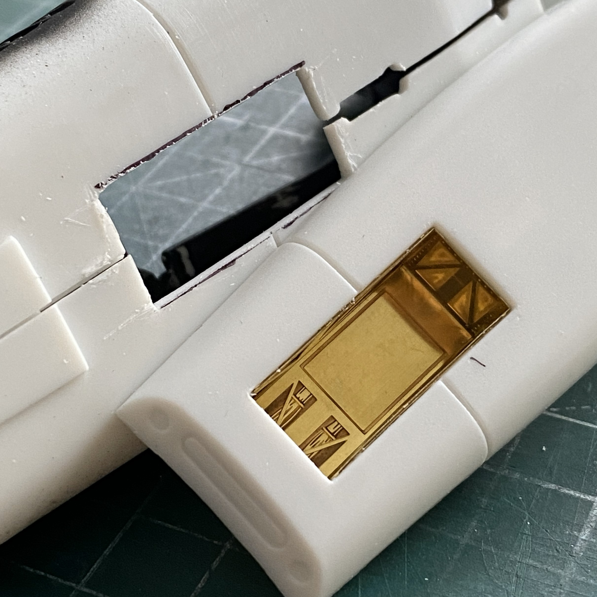
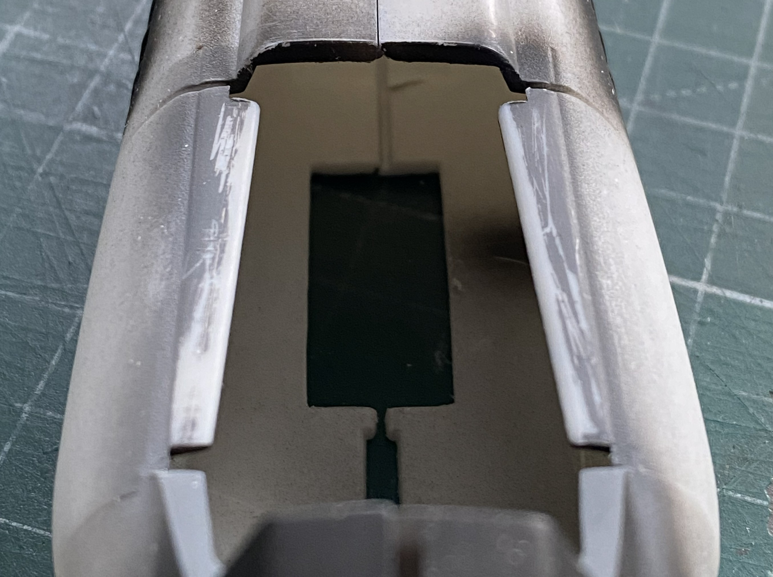
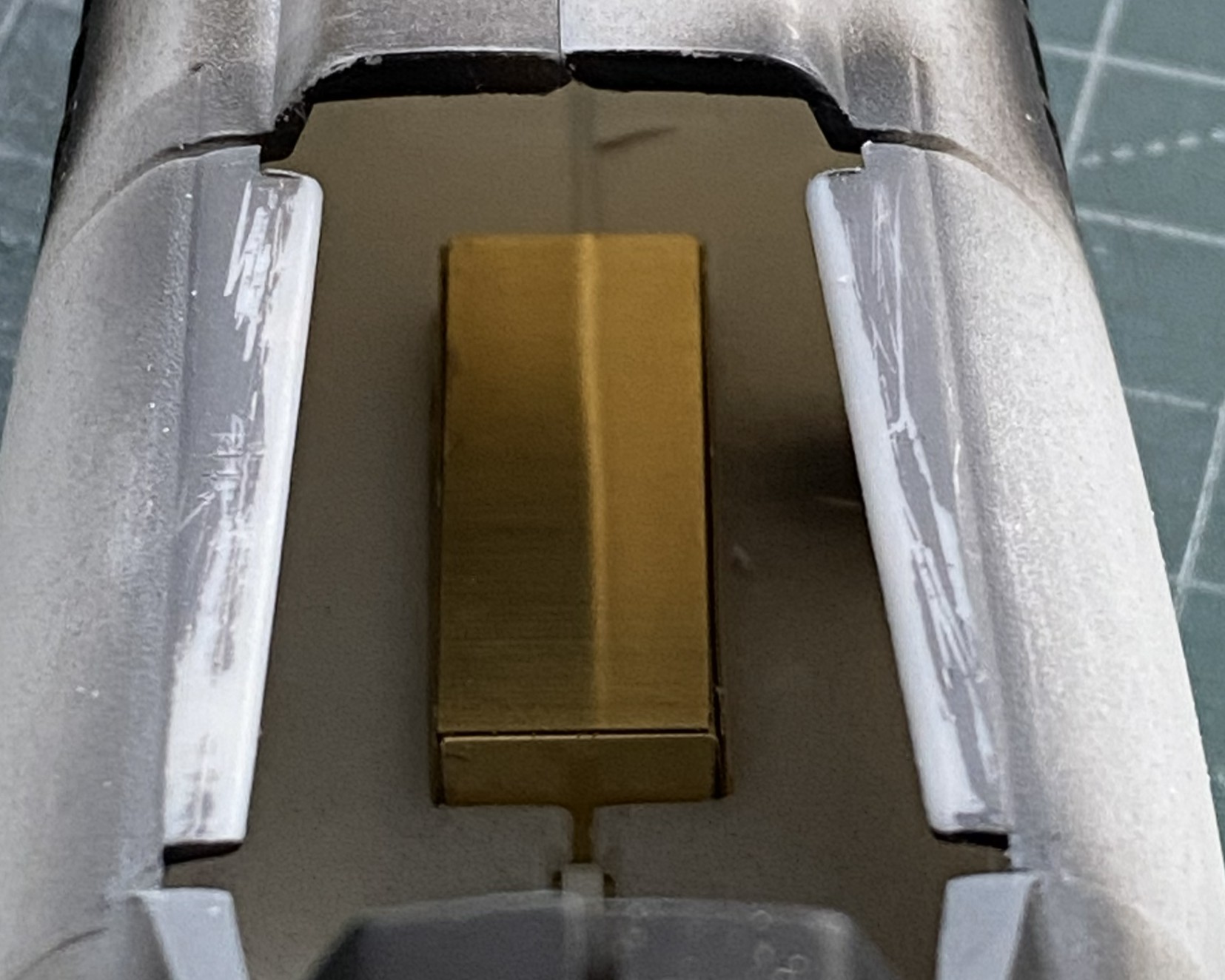
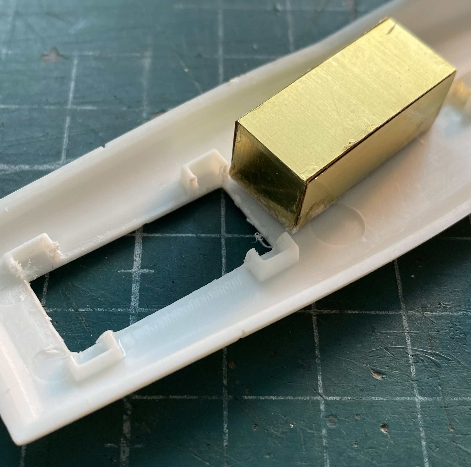
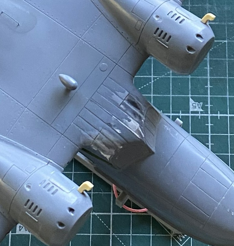
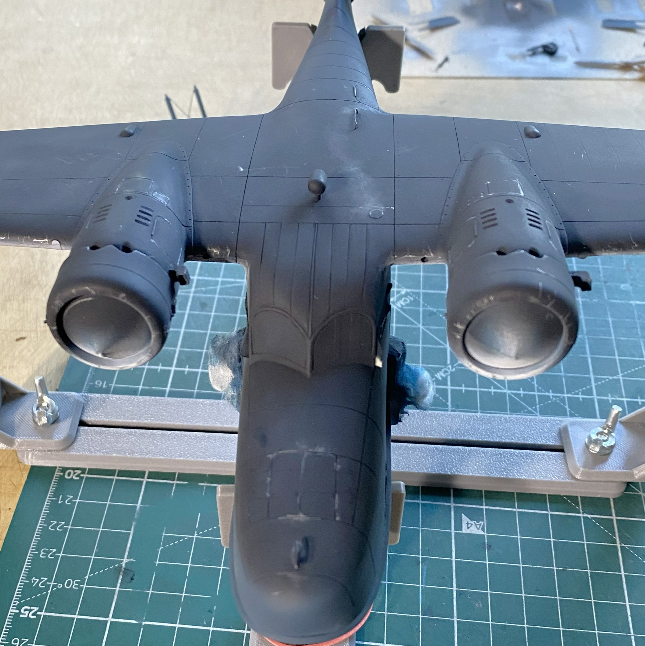
The AM set has a PE box that has to be folded and assembled. It also needs room inside the belly pan. Two sections of excess plastic under the lateral engines had to be cut away:
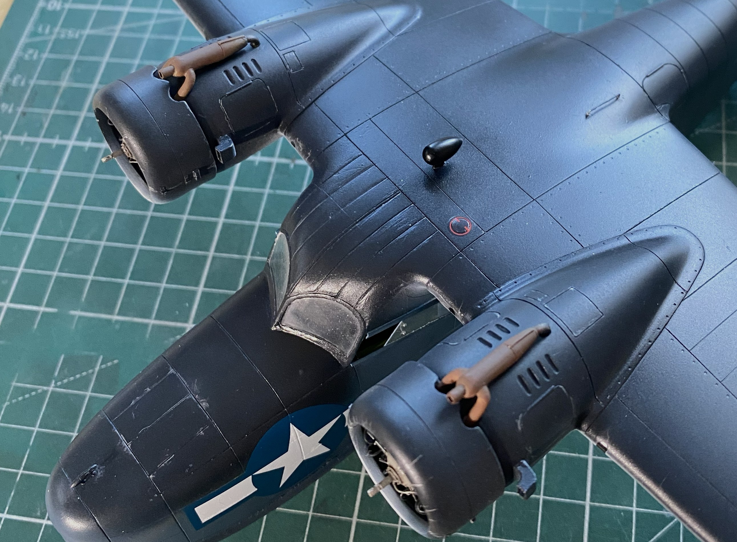
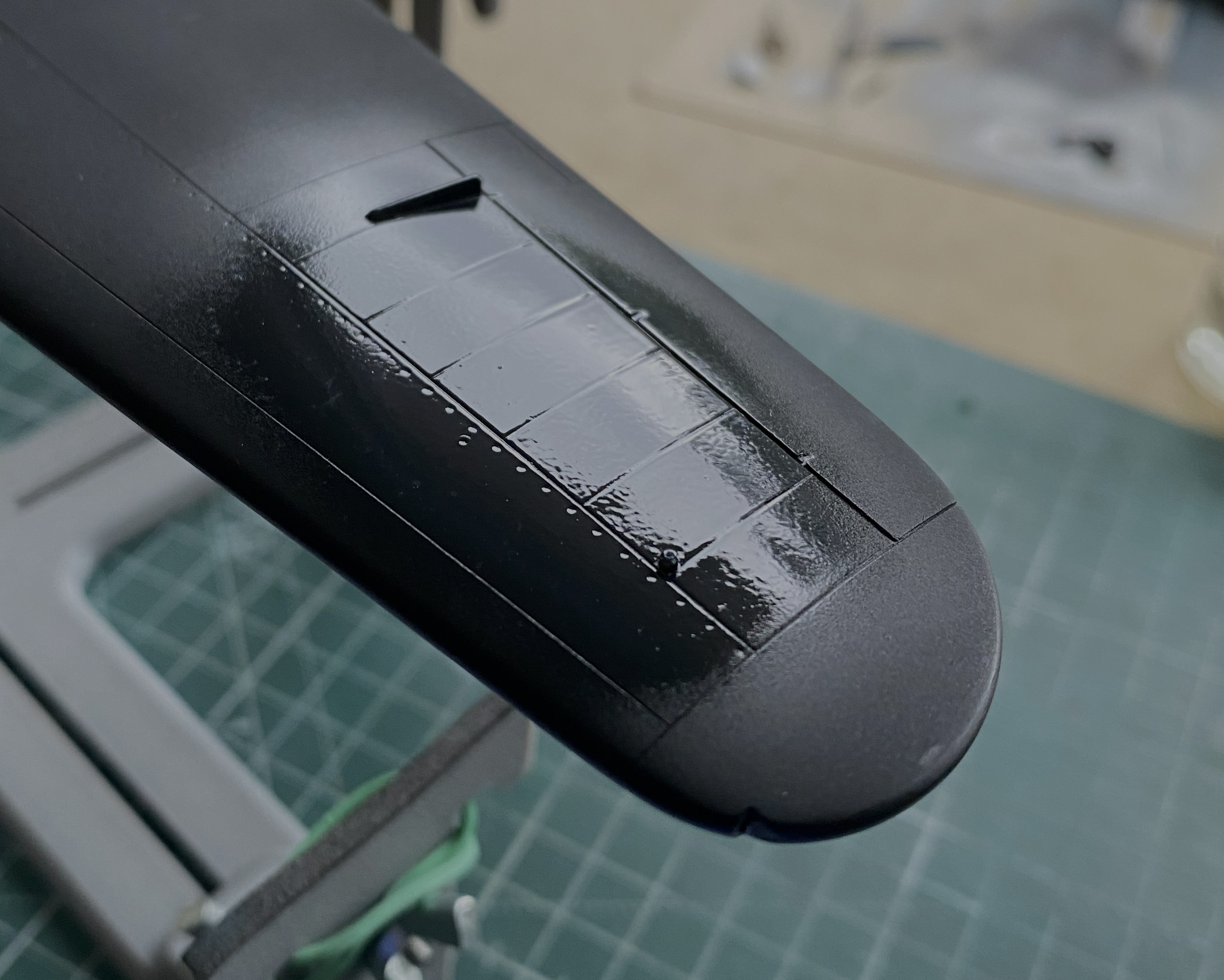
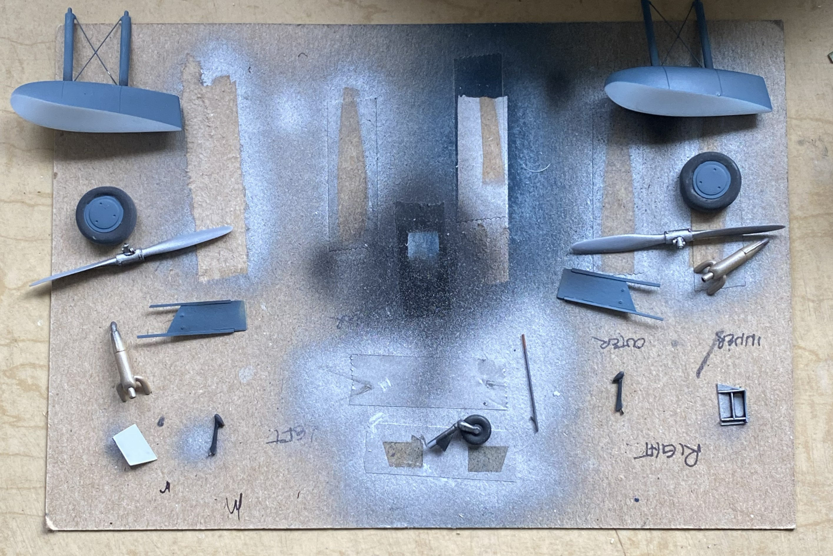
I had pre-shaded the engines with flat black, it was now time to give them their finished color as well as the landing gear legs (same color):

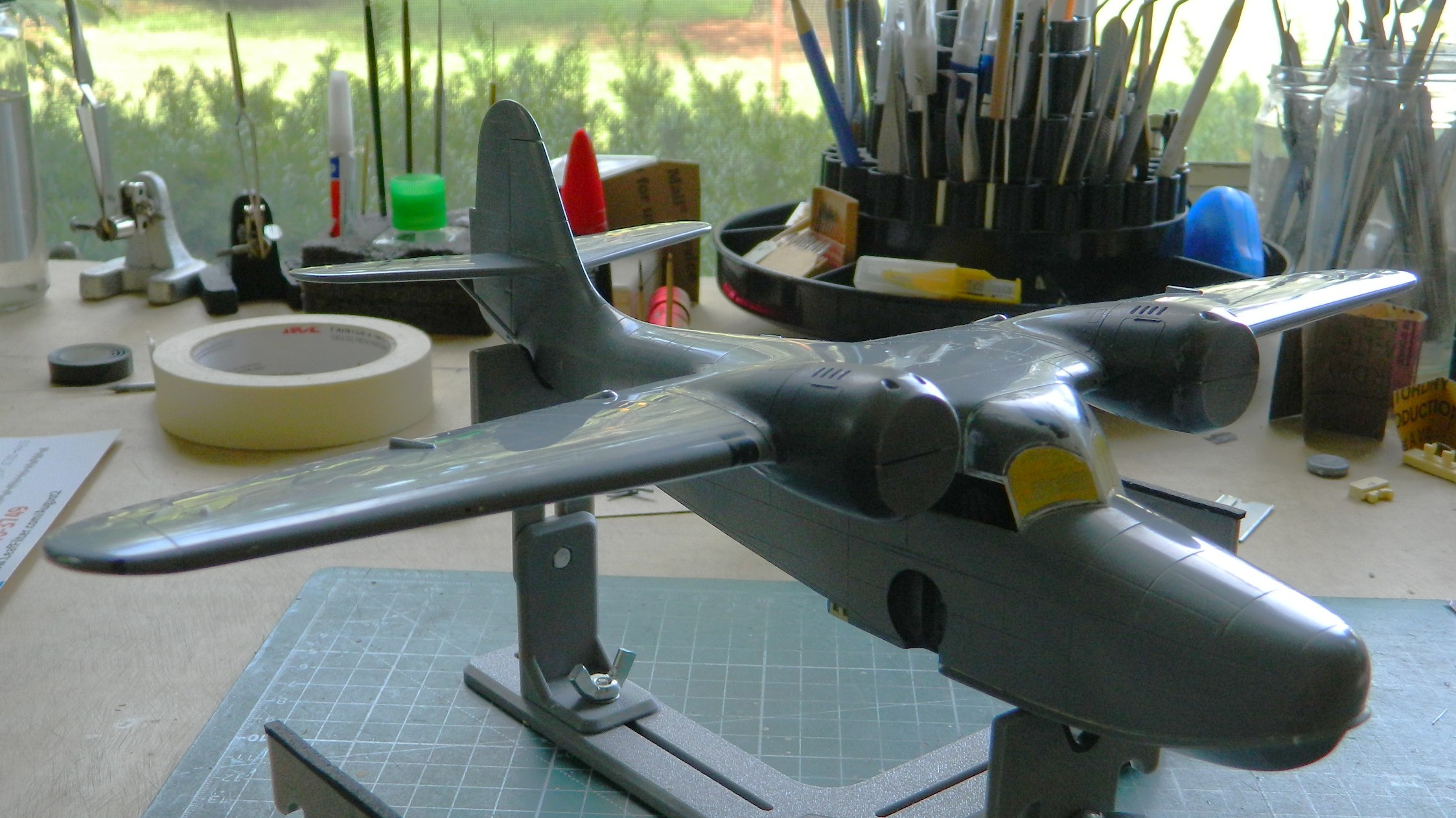
I’ve read accounts of people who either don’t like pre-shading or see no purpose for it. Makes no sense to me. I get great (he says modestly) results from it. I certainly like how they all look when dry-fitted:
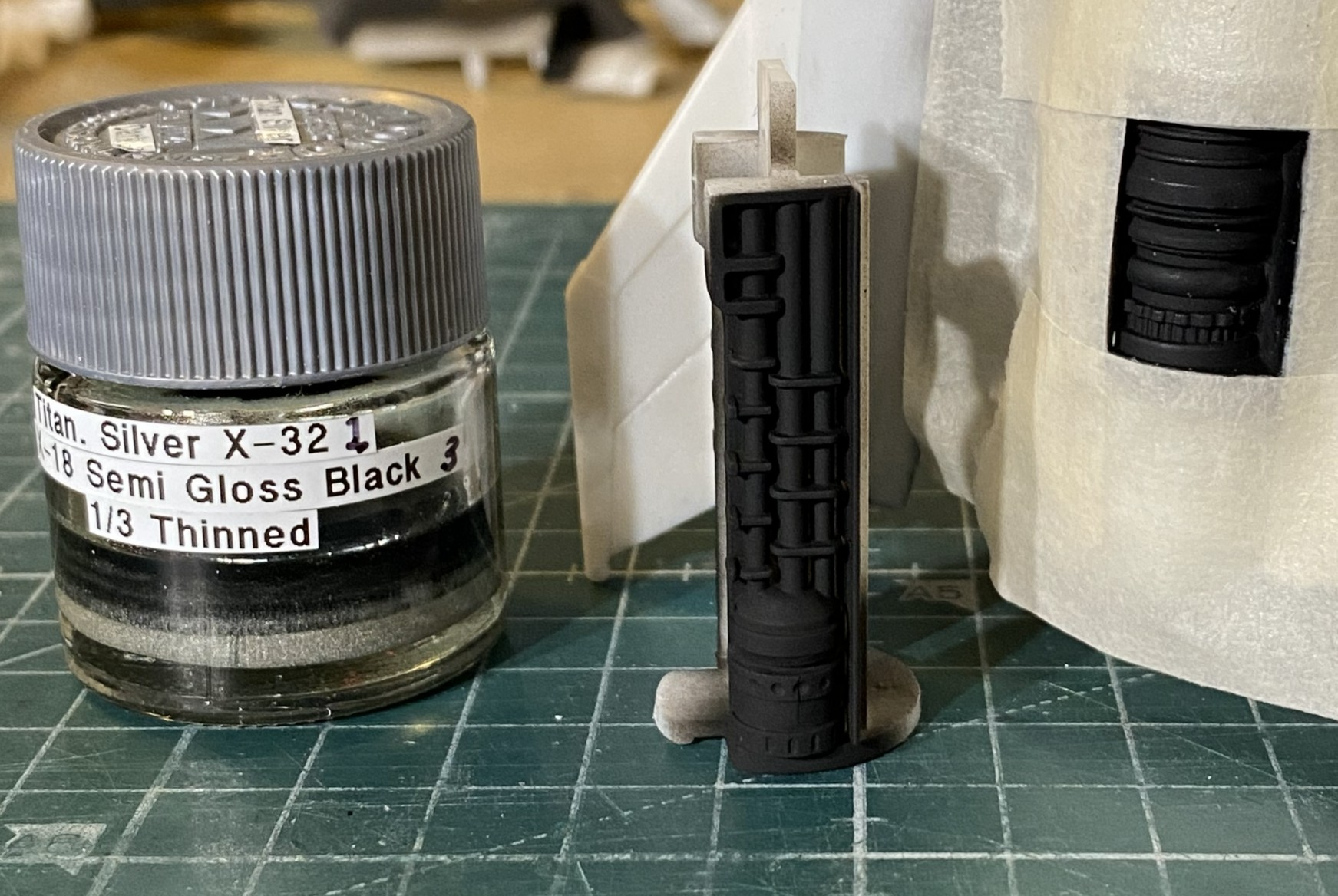
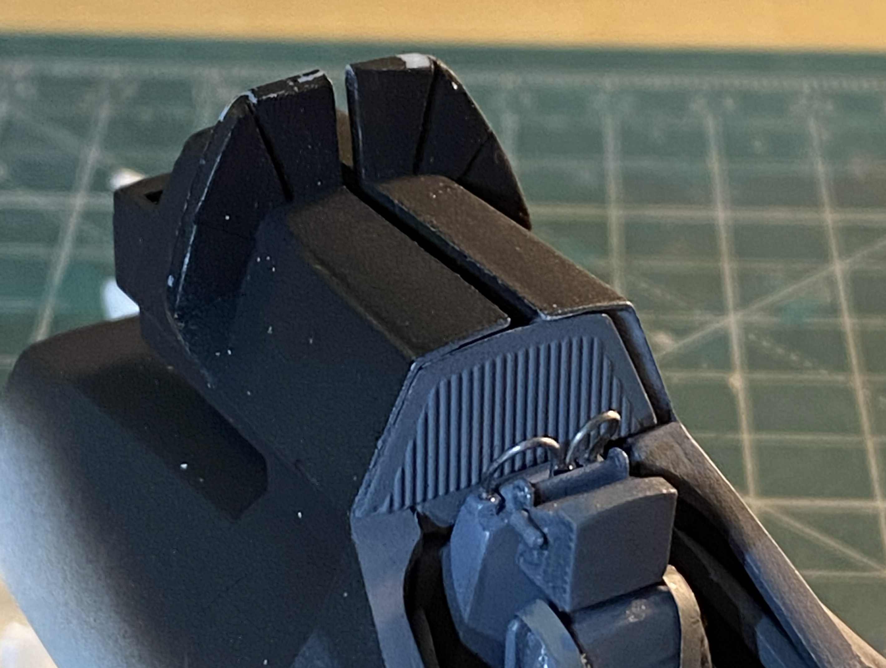
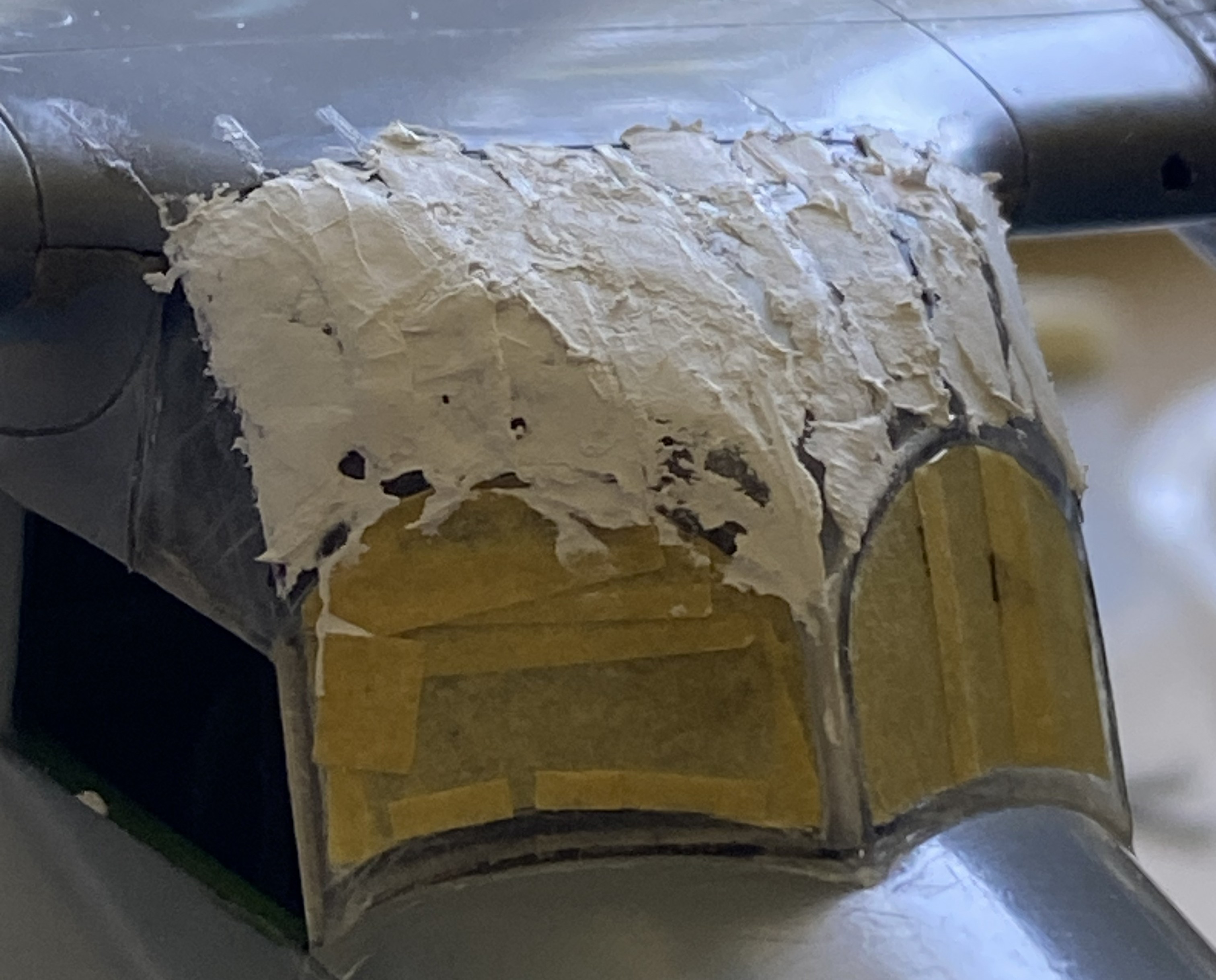
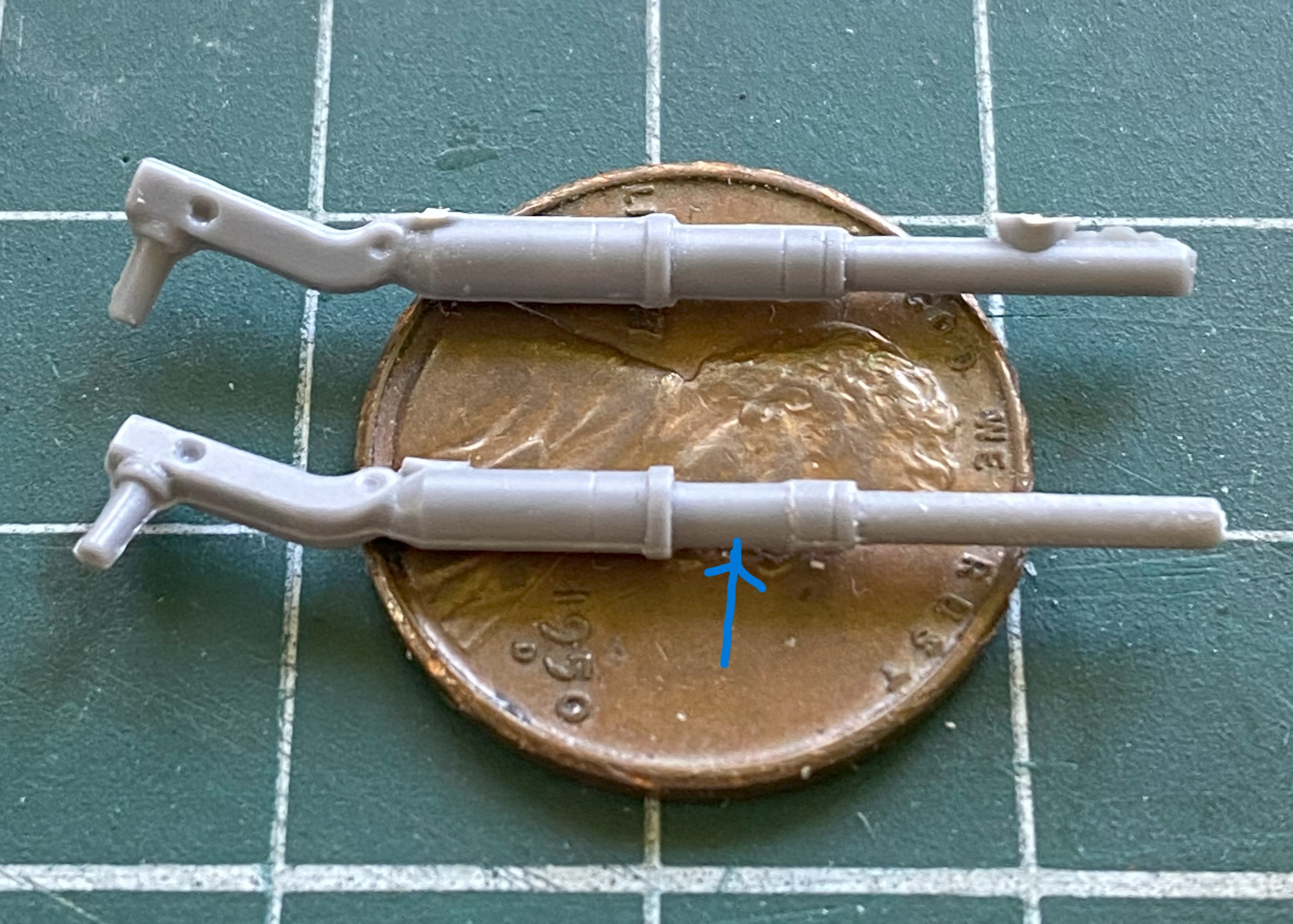
While I had the compressor fired up, I painted the guns with my custom mixed “gunmetal” paint (Tamiya X-18 Semi Gloss Black, 5 parts; XF-20 Medium Gray, 4 parts; thinned 1/3):
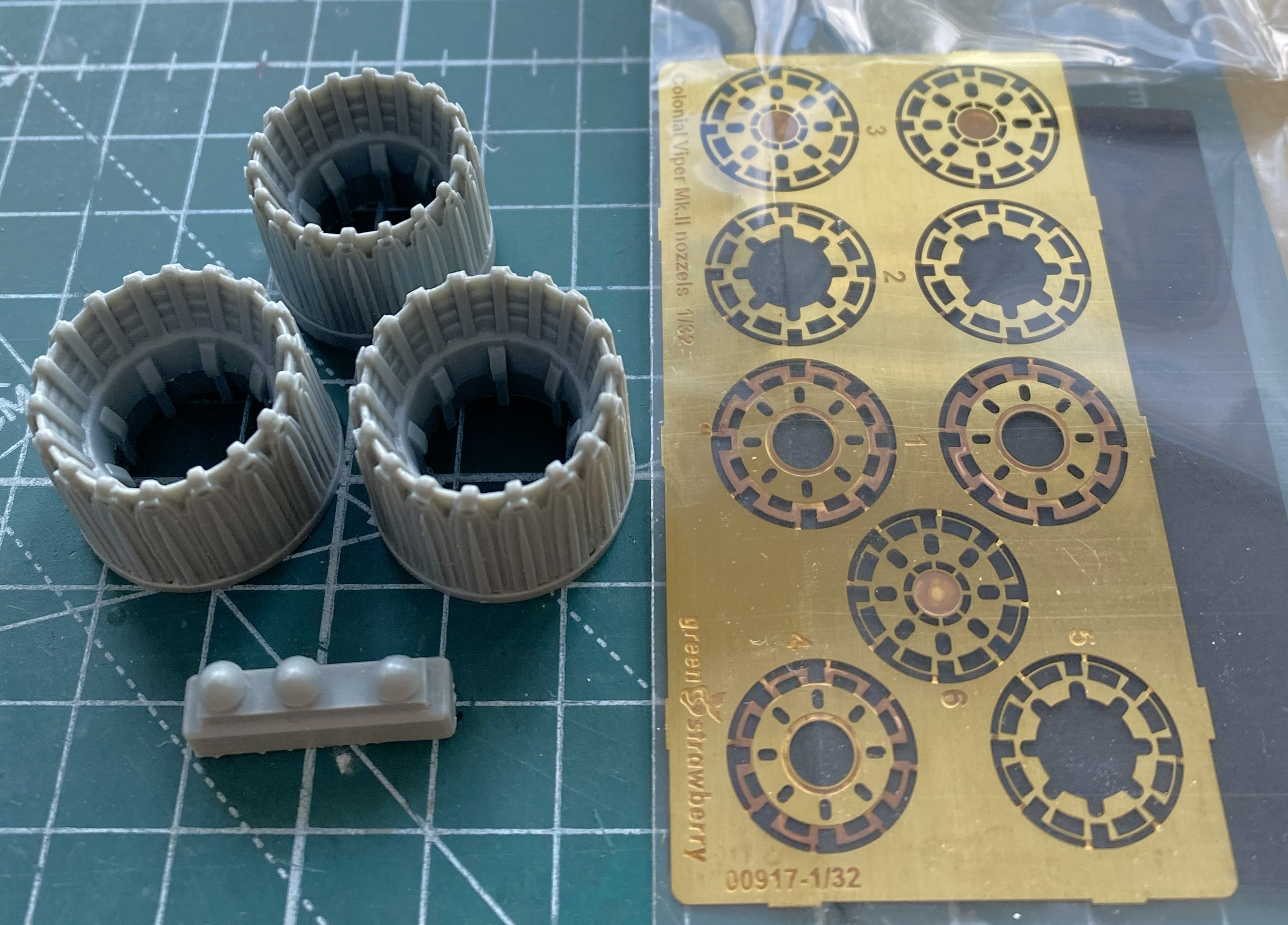
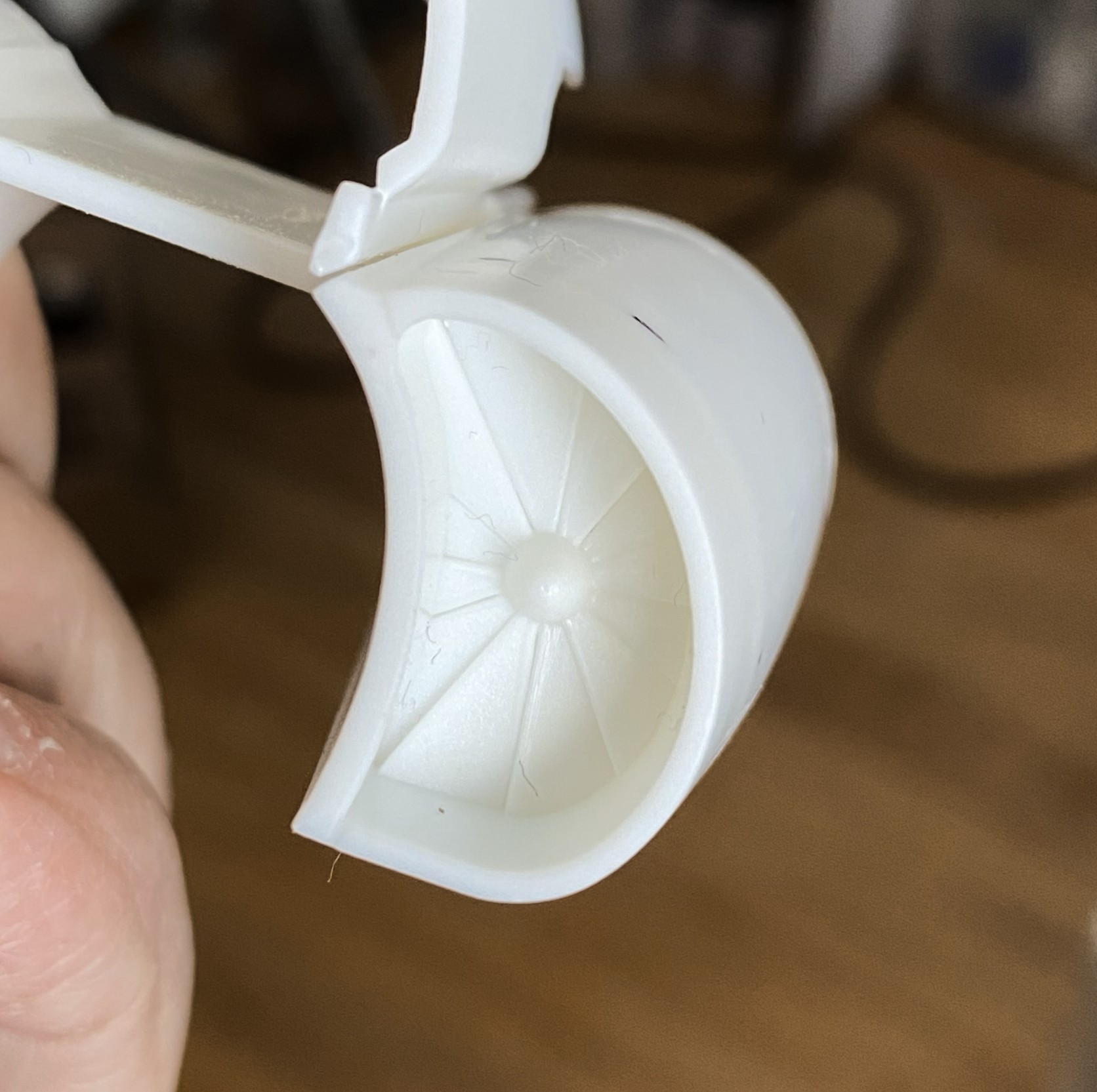
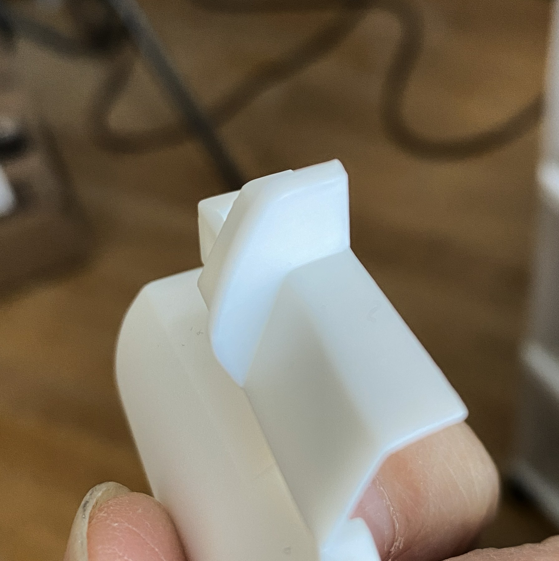
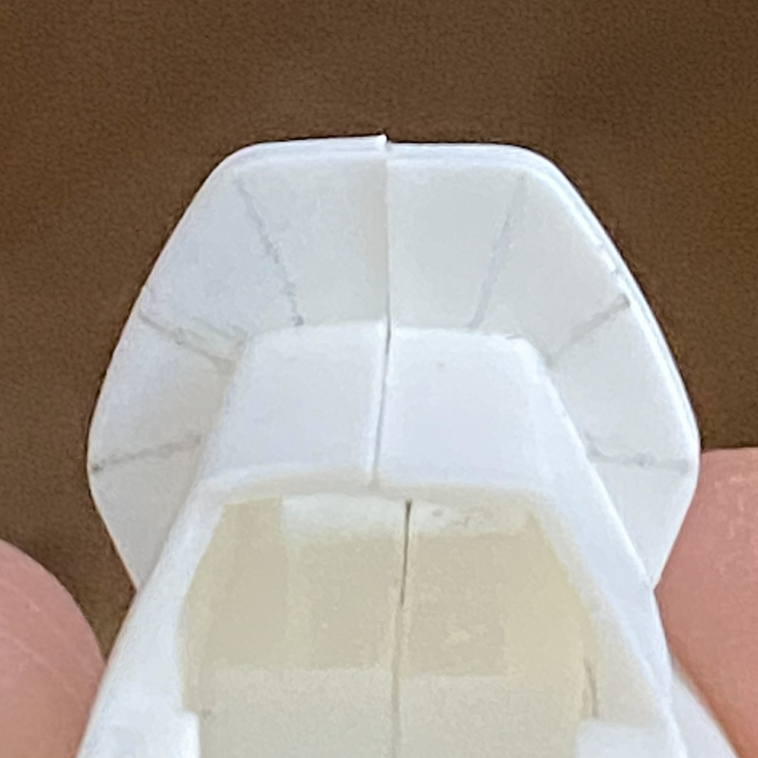
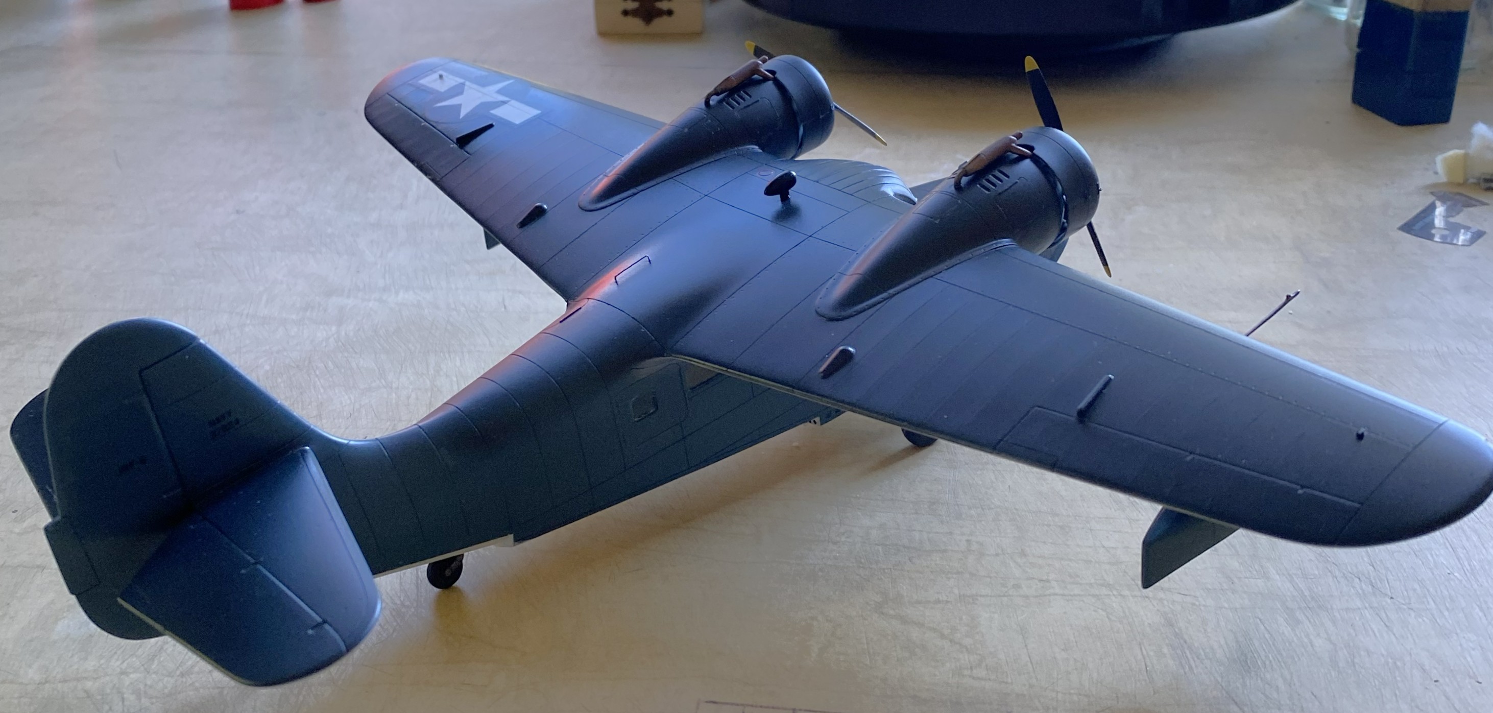
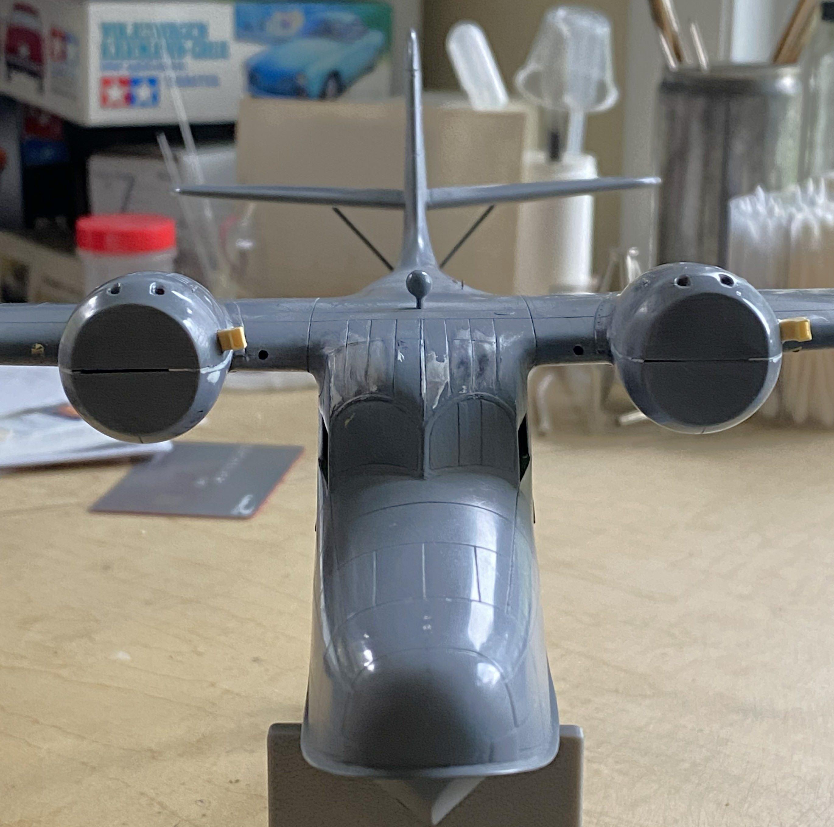
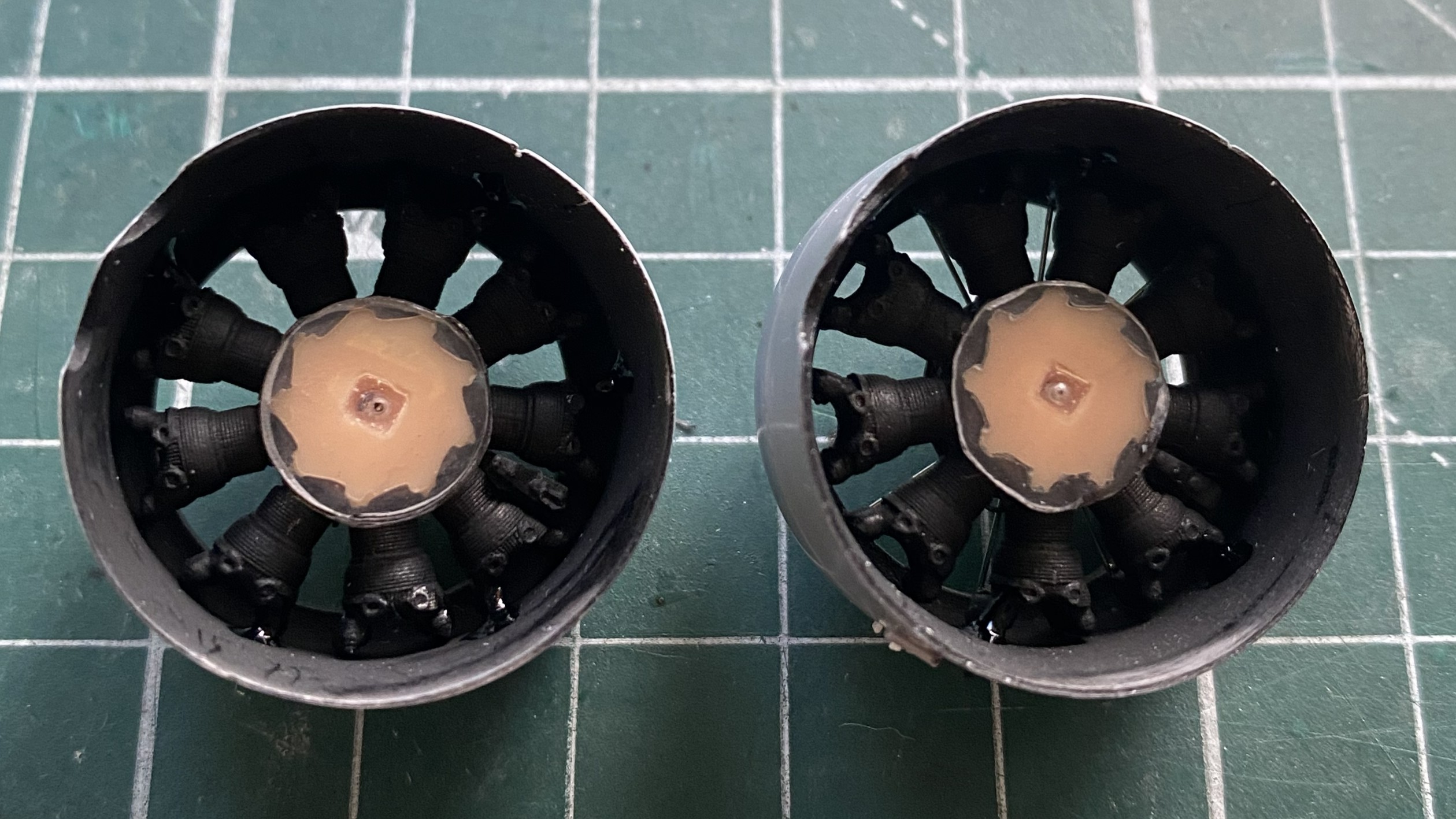
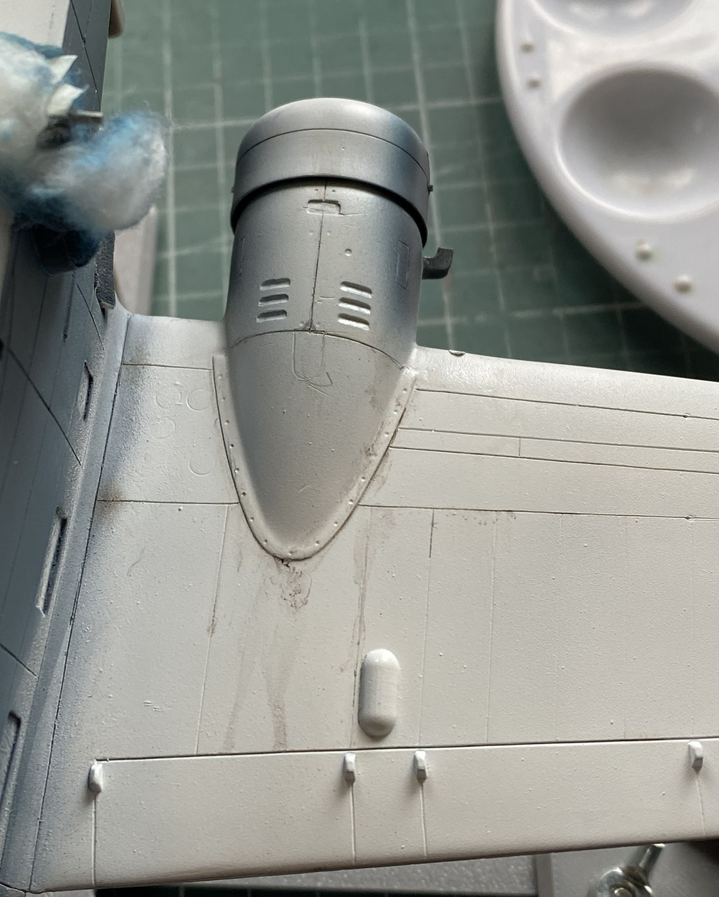
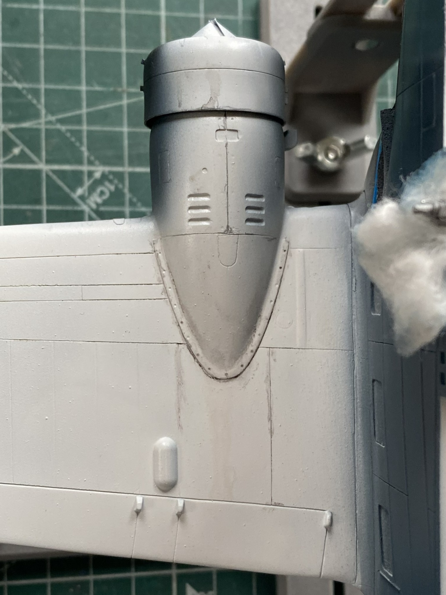
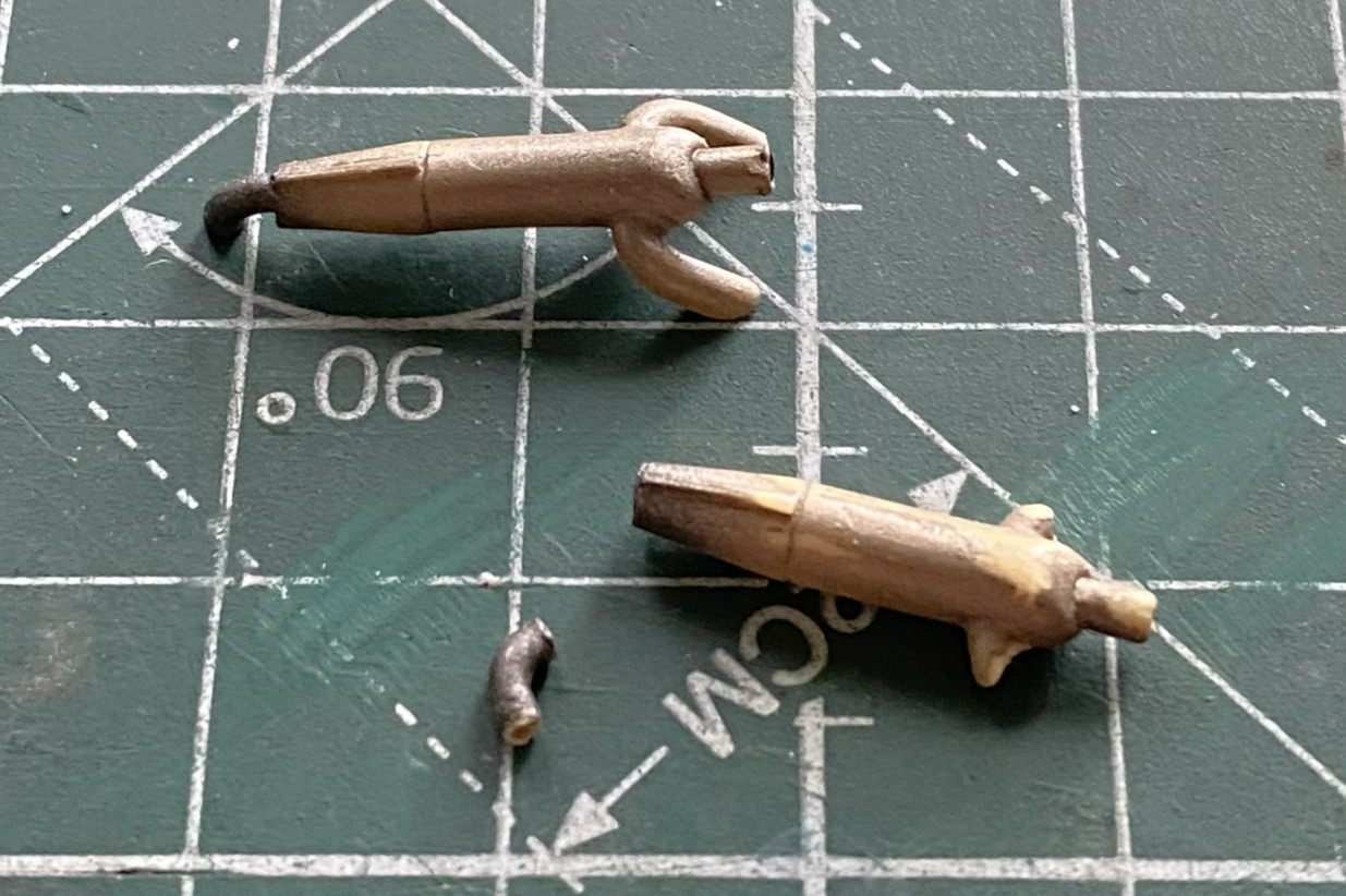
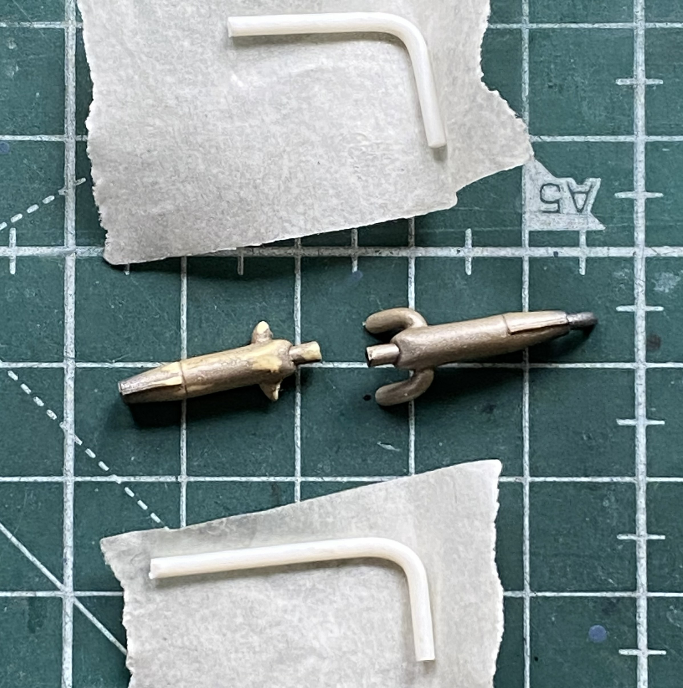
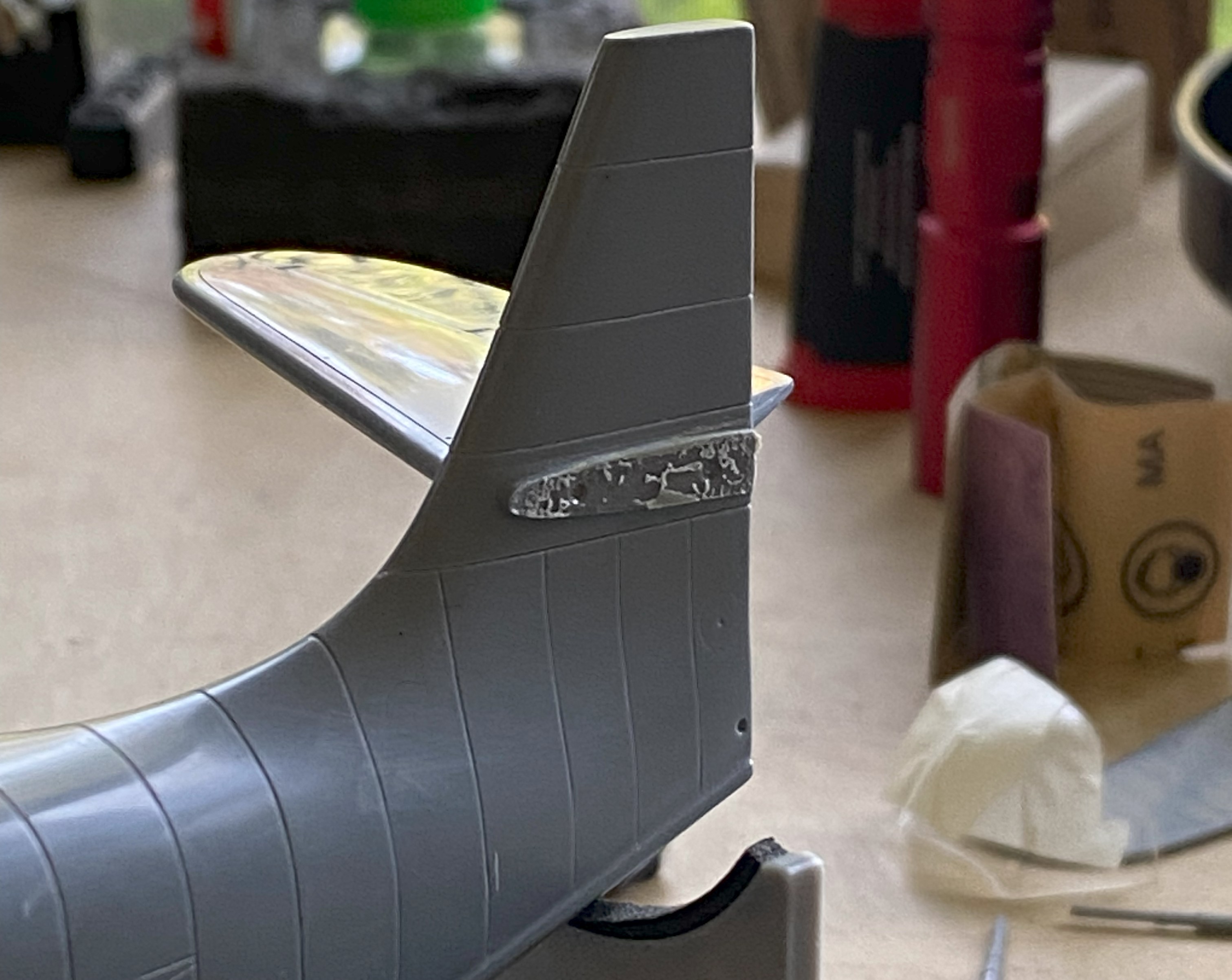
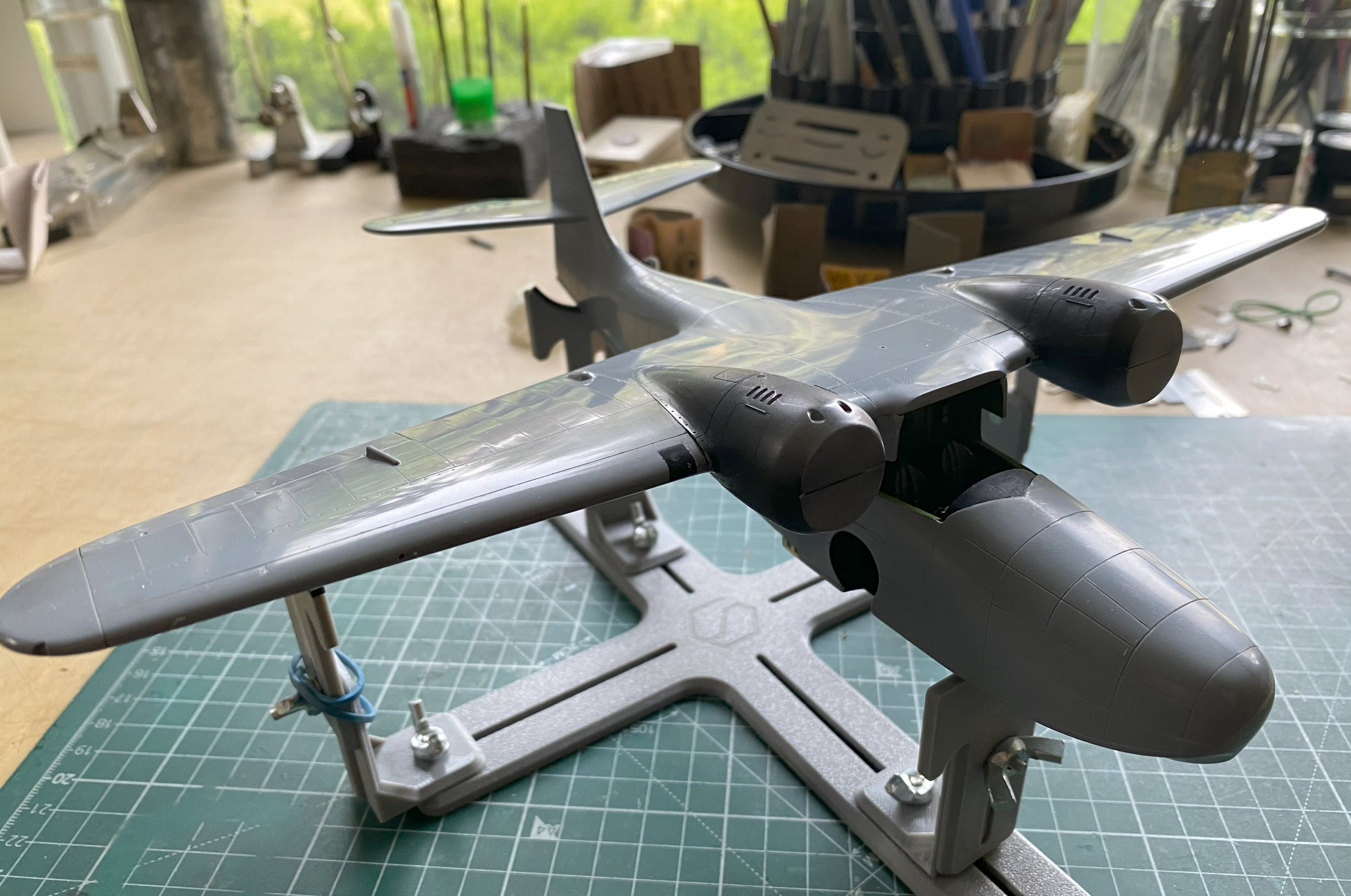
I turned my effort towards the exhaust nozzles. I think the AM parts, resin body and three PE disc inserts, are substantially better:

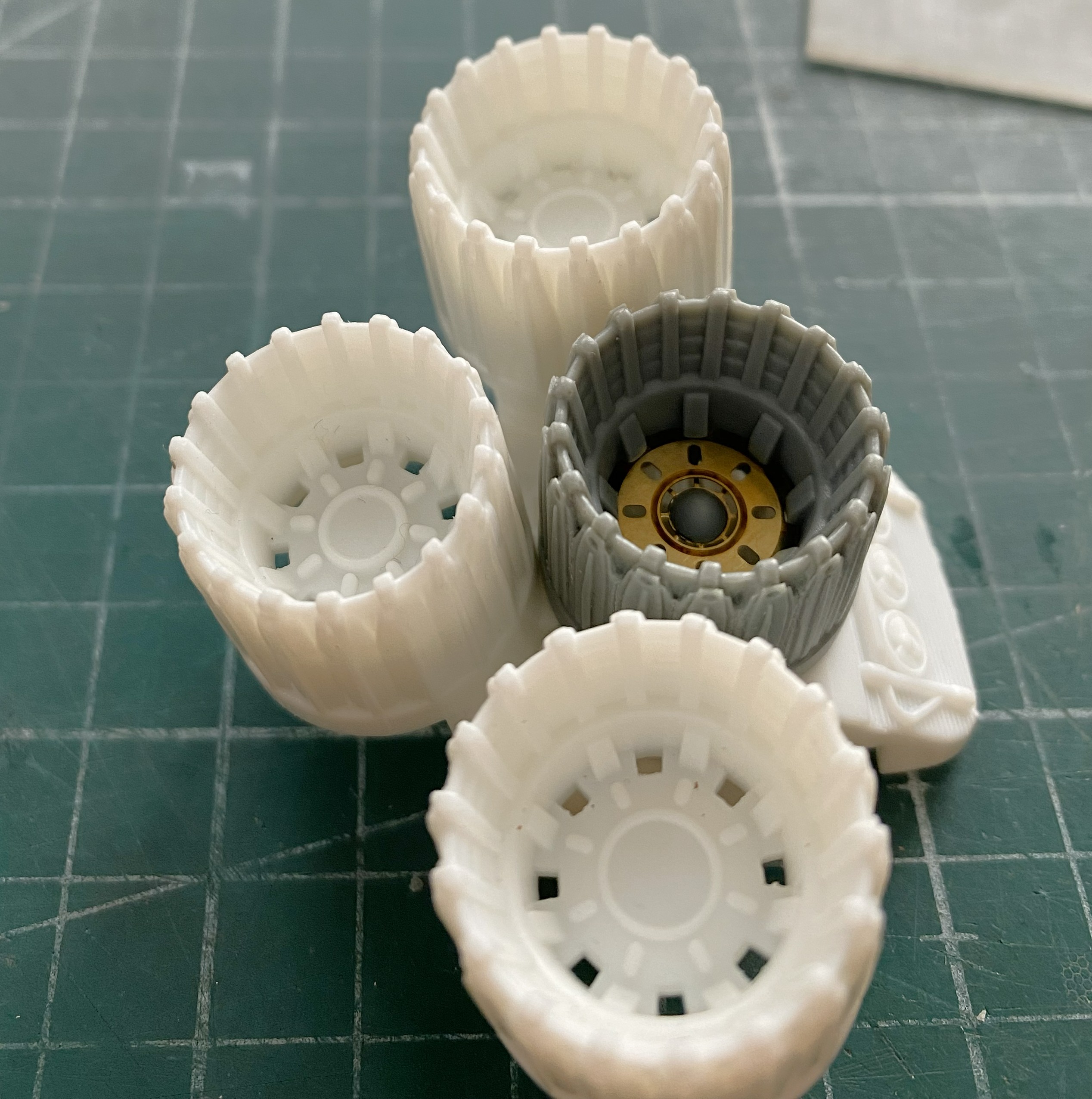
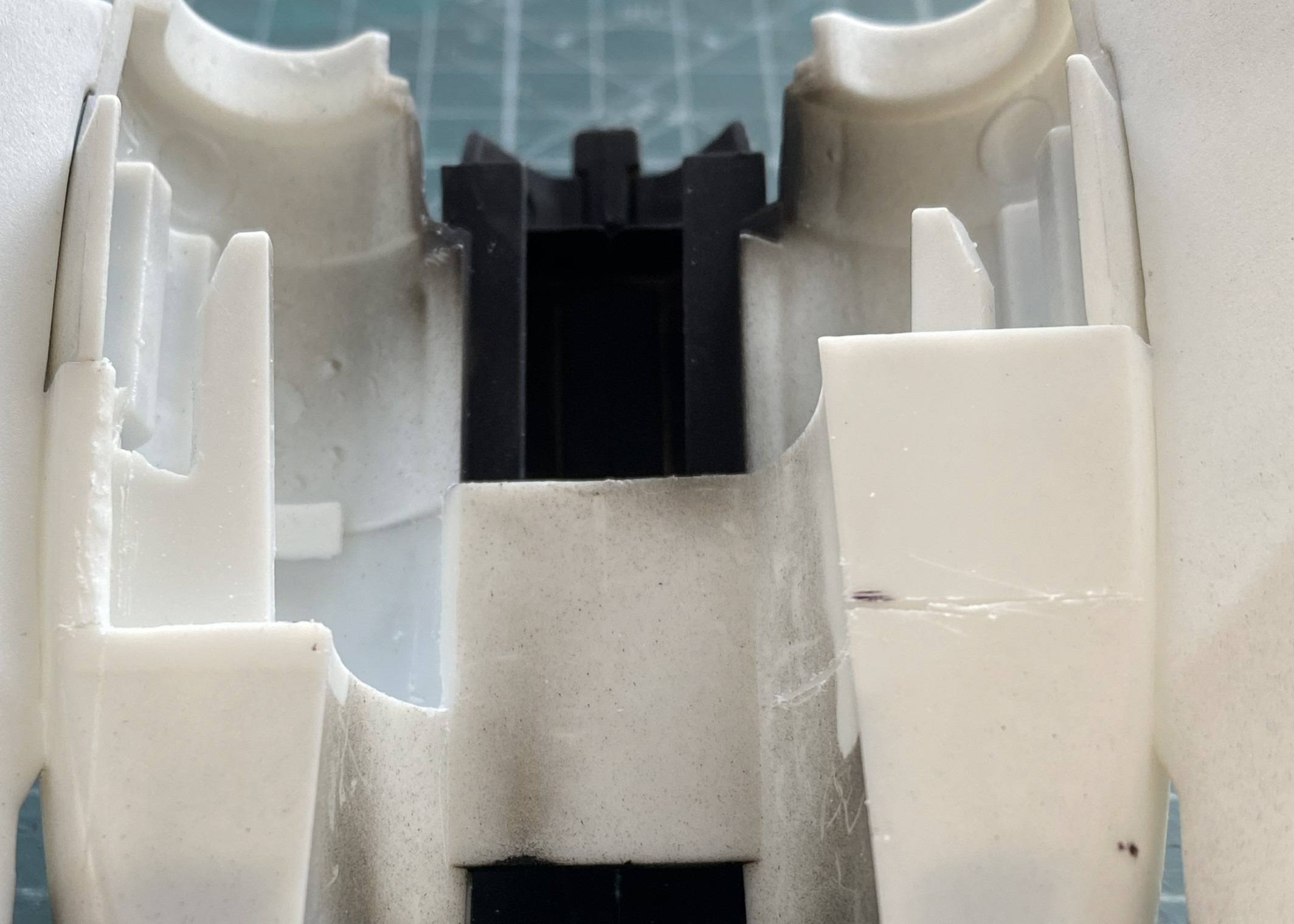
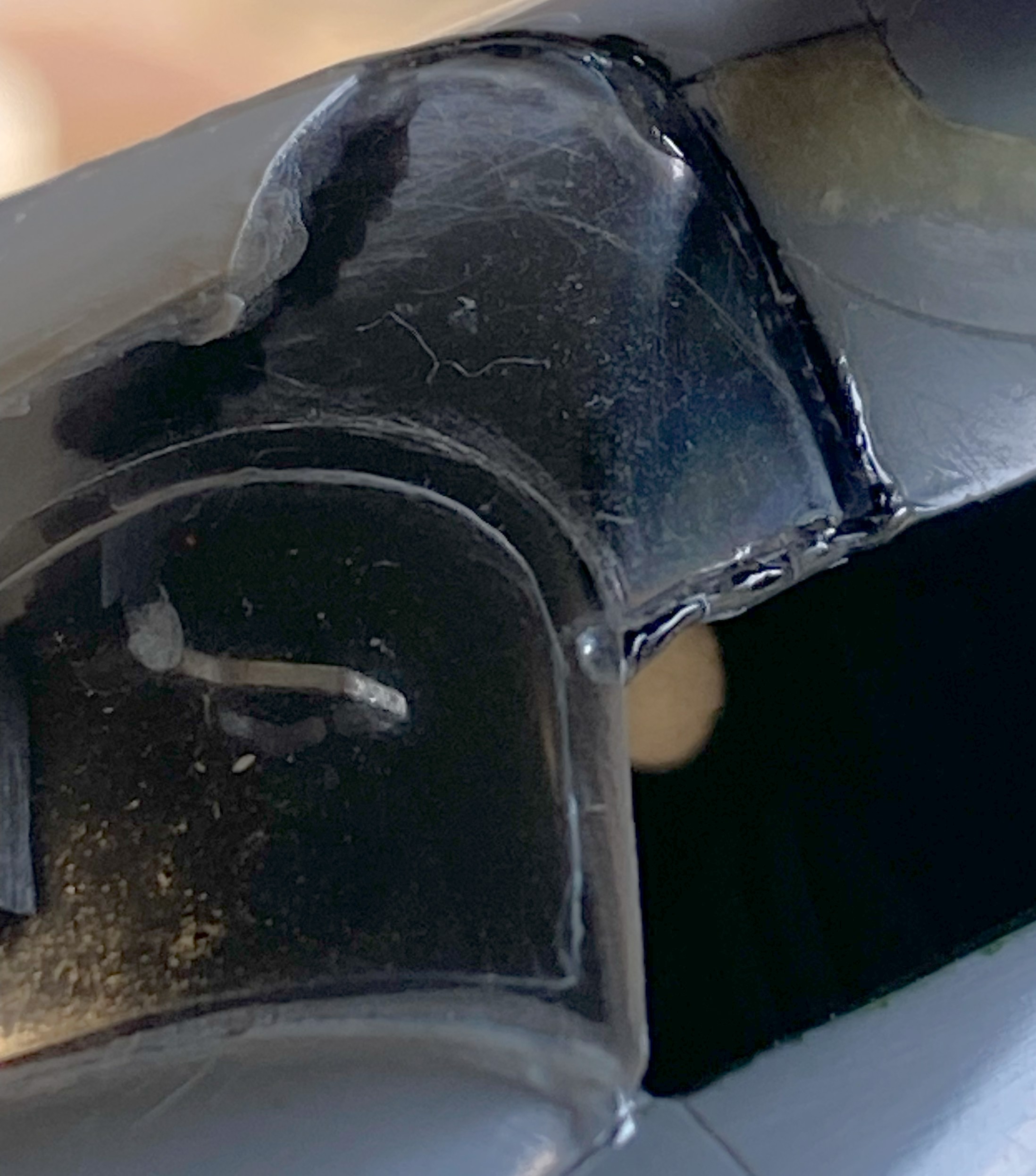
The kit’s nozzles need work. They have to be removed. Note in the below photo the section of the part where all the nozzles attach. Once the nozzles are removed, the center part is what remains:

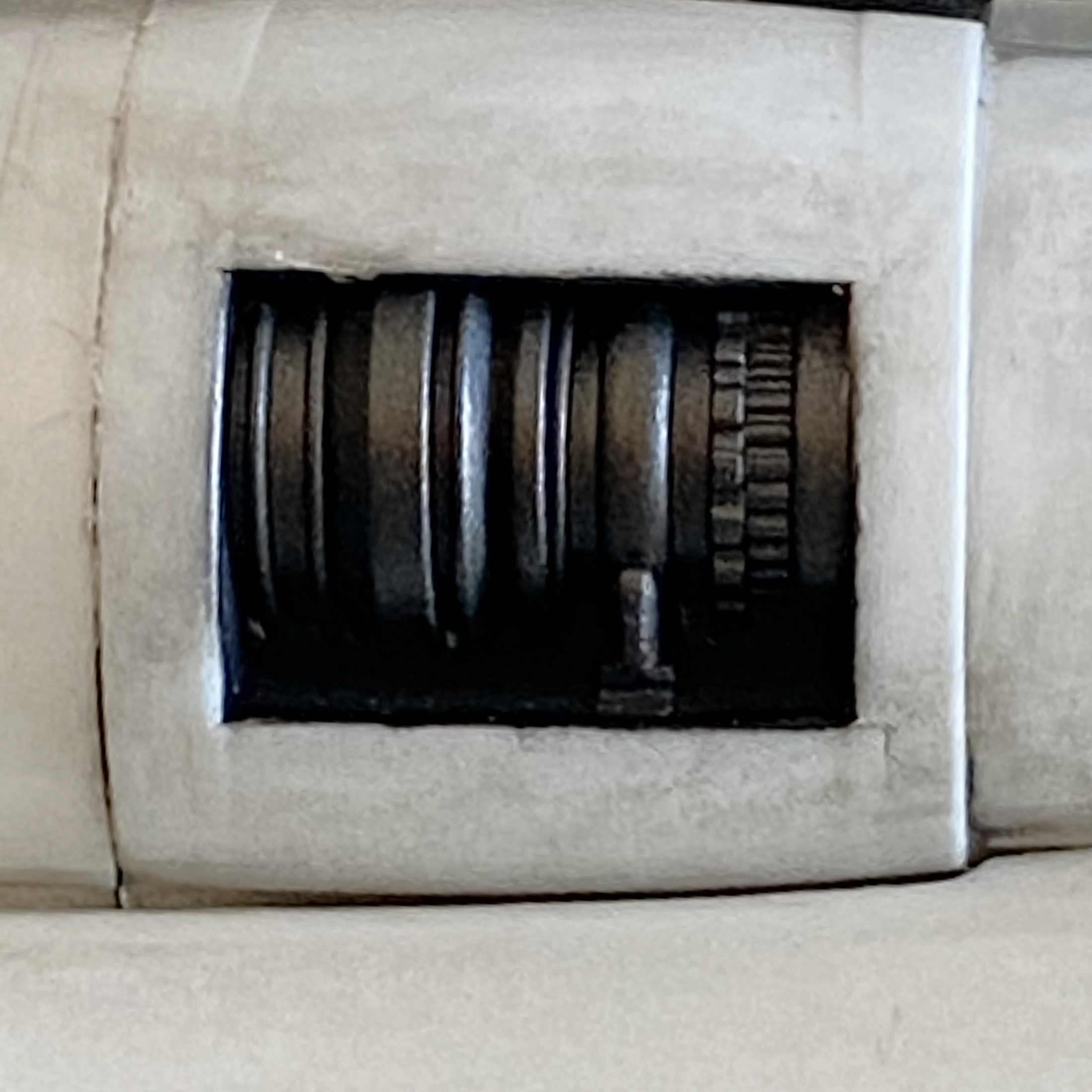
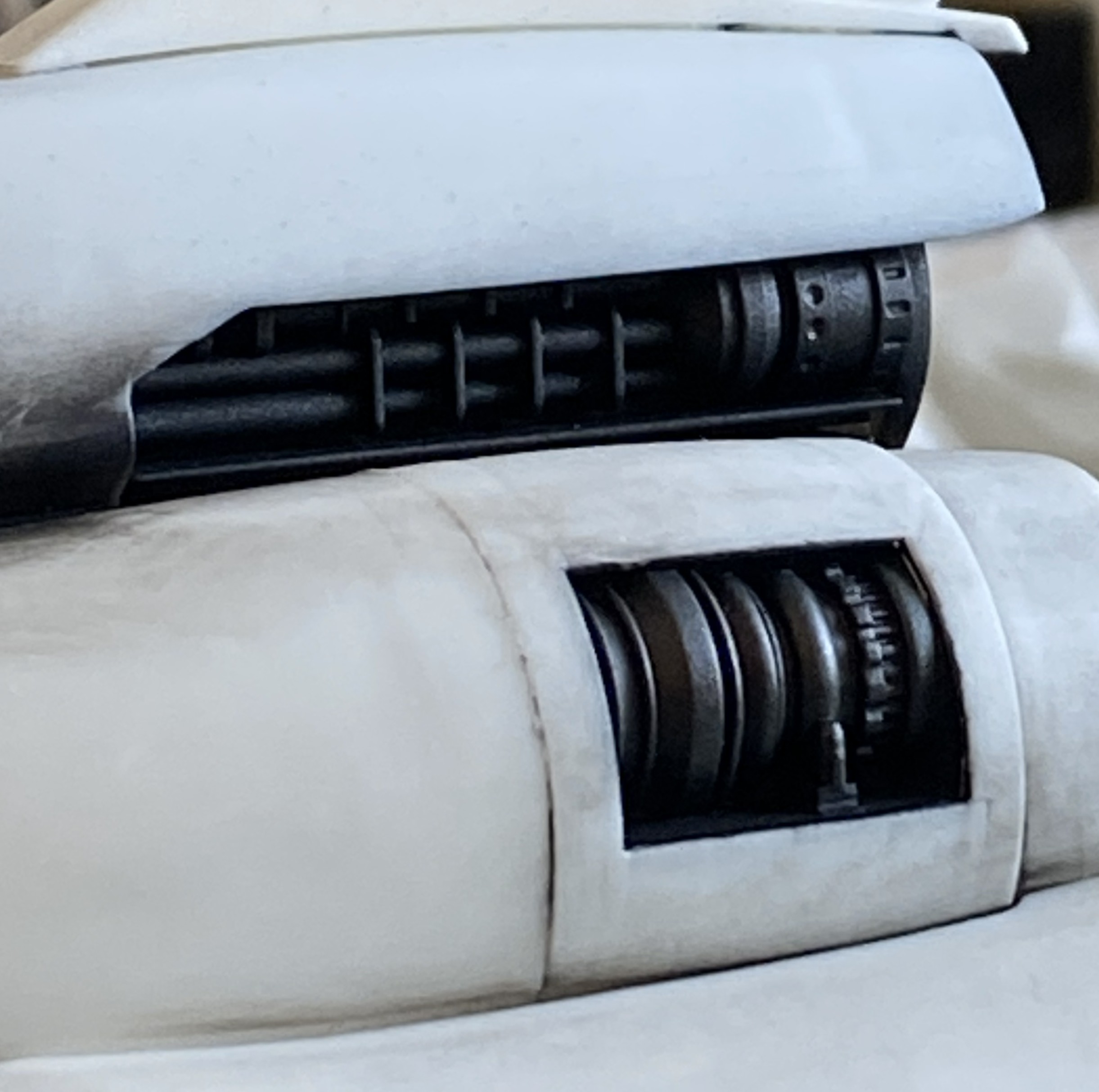
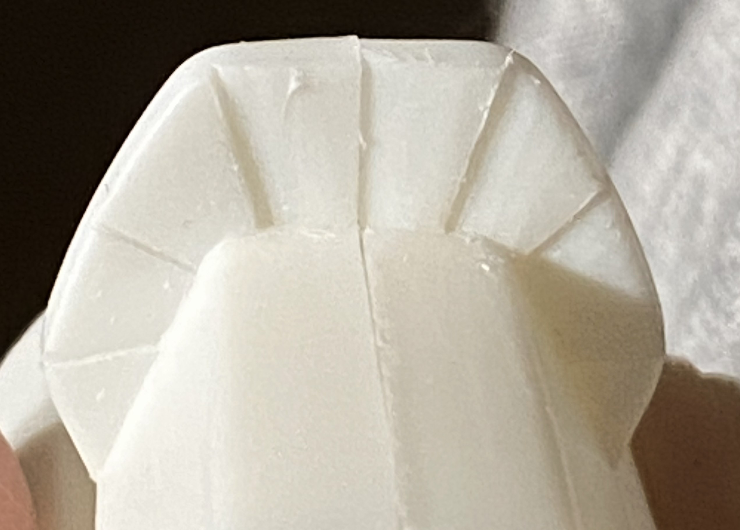
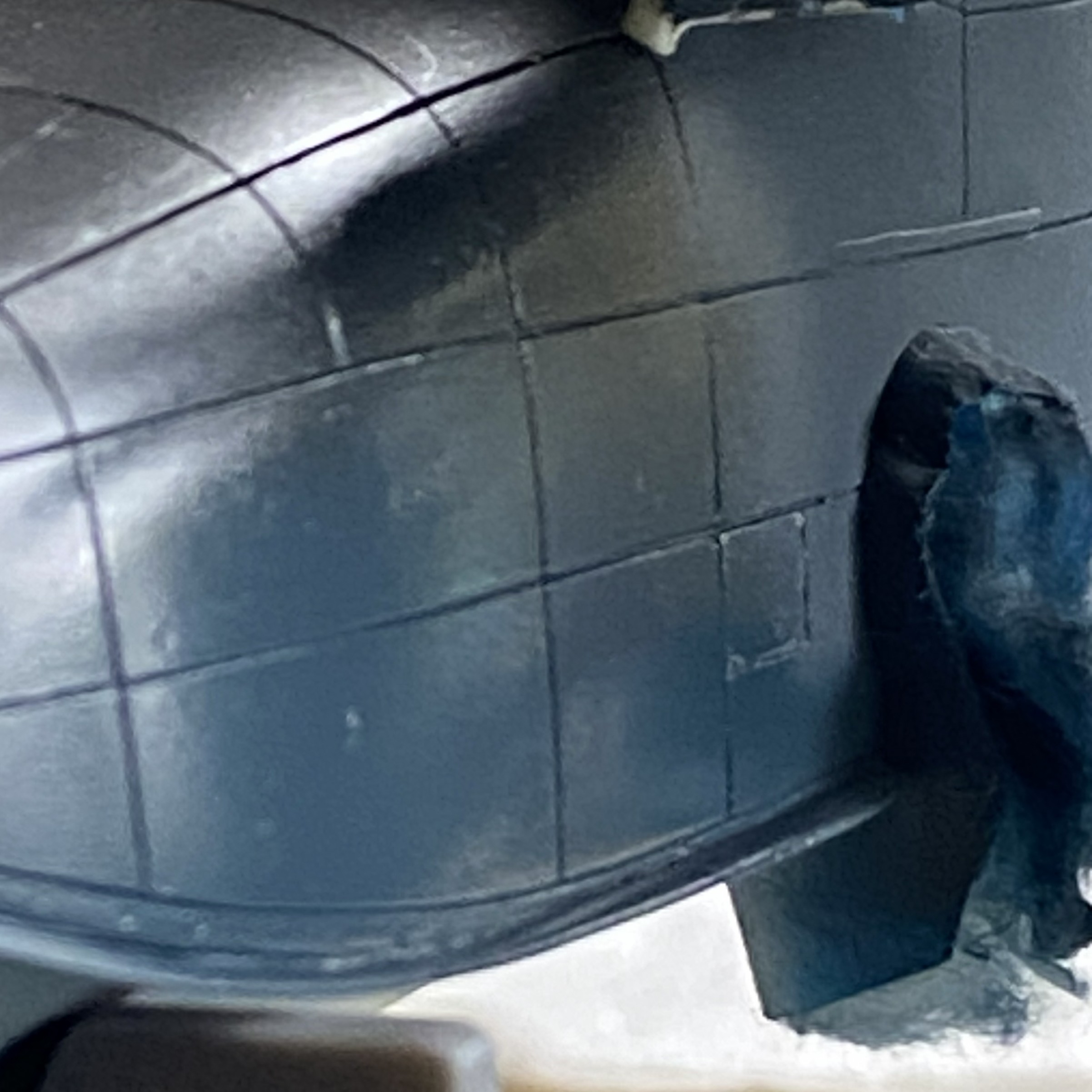
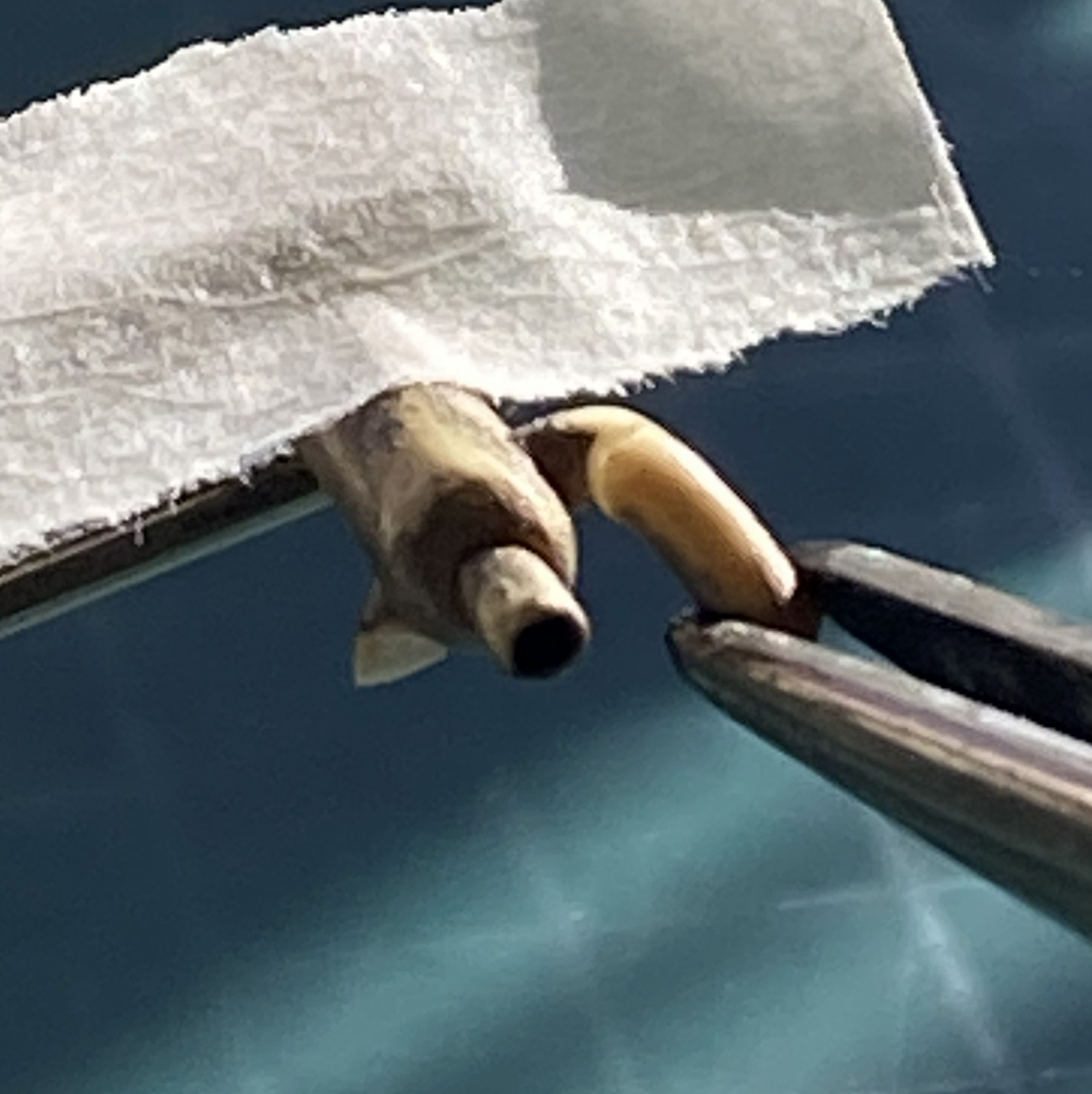
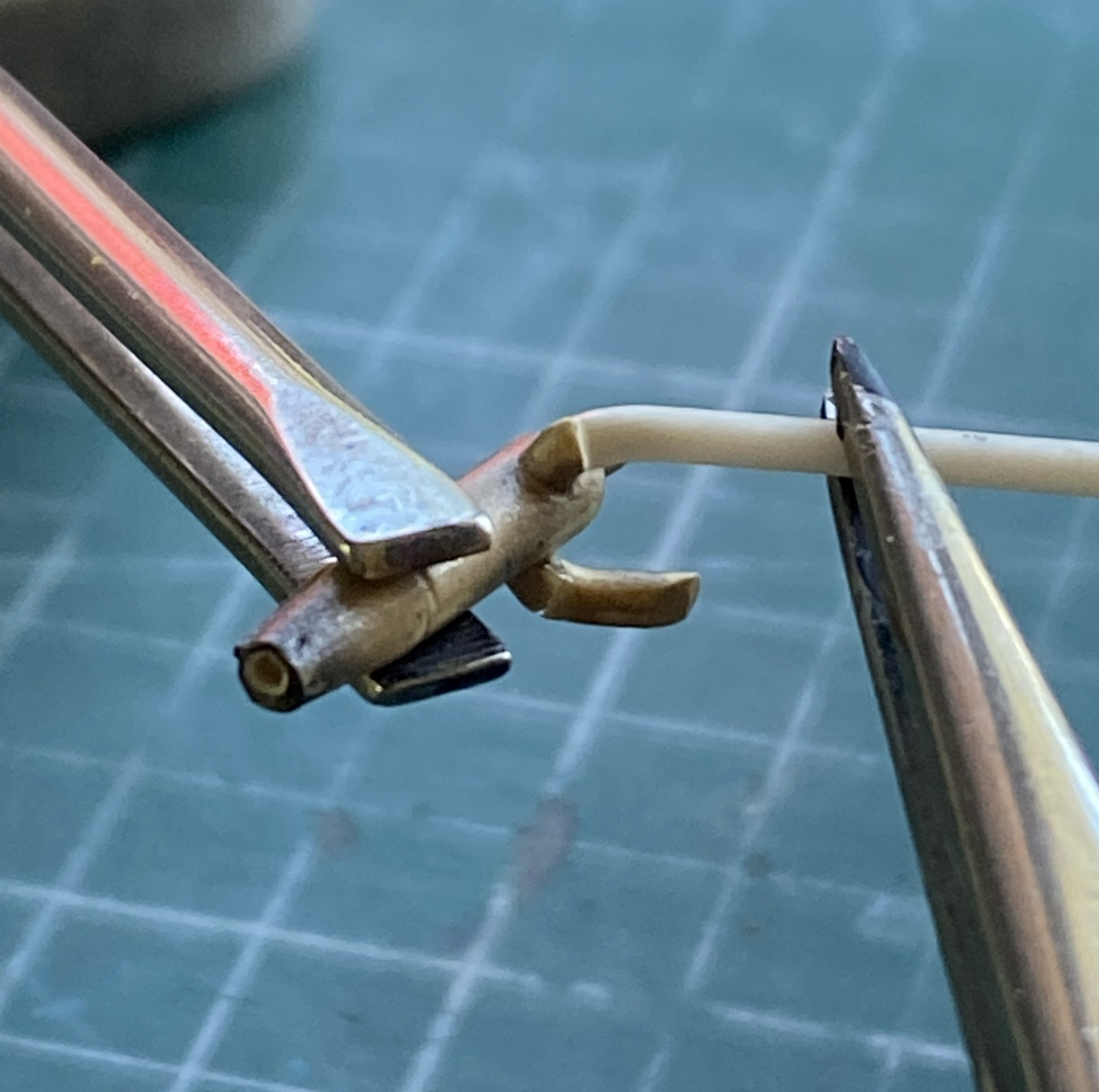
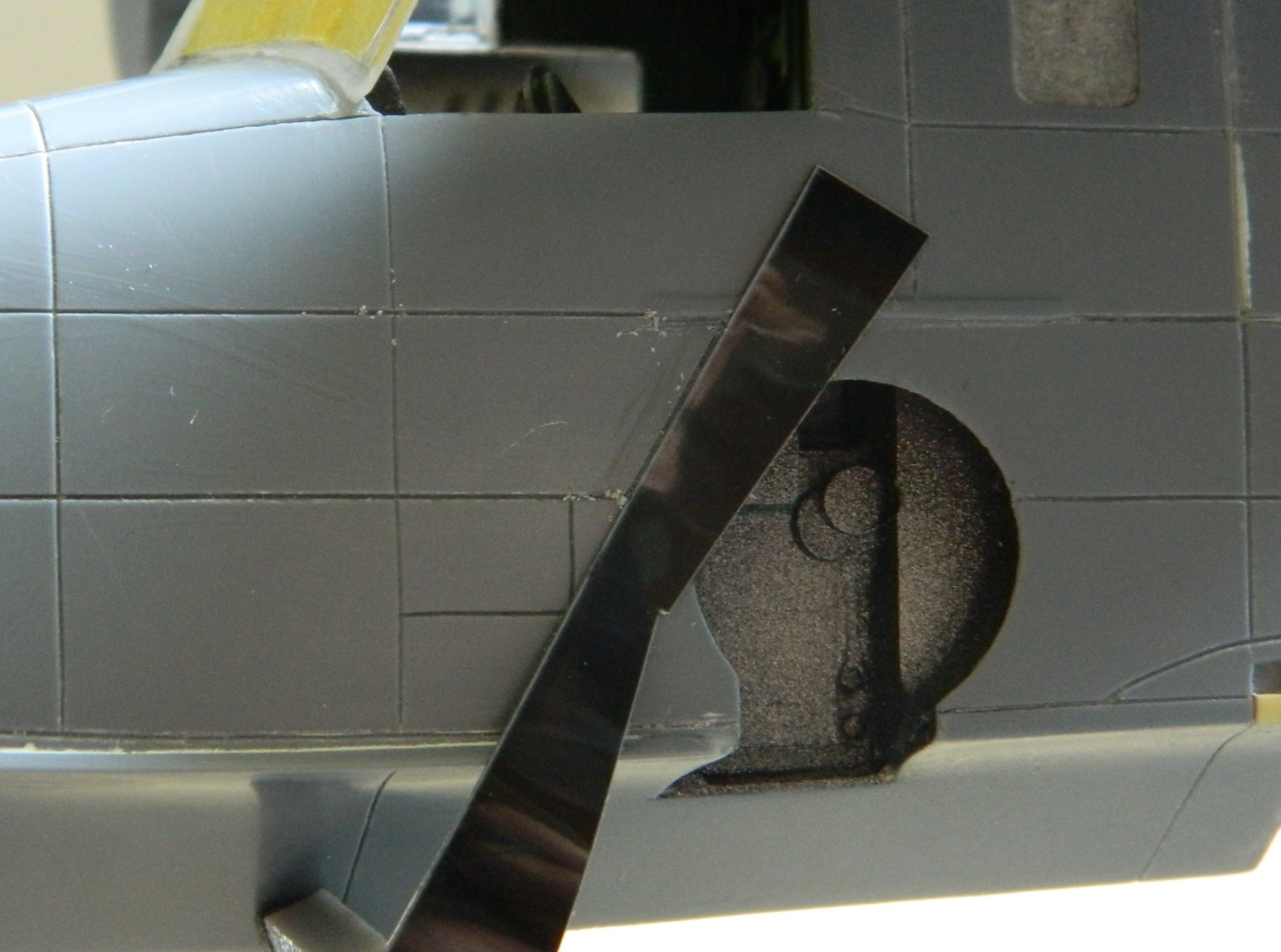
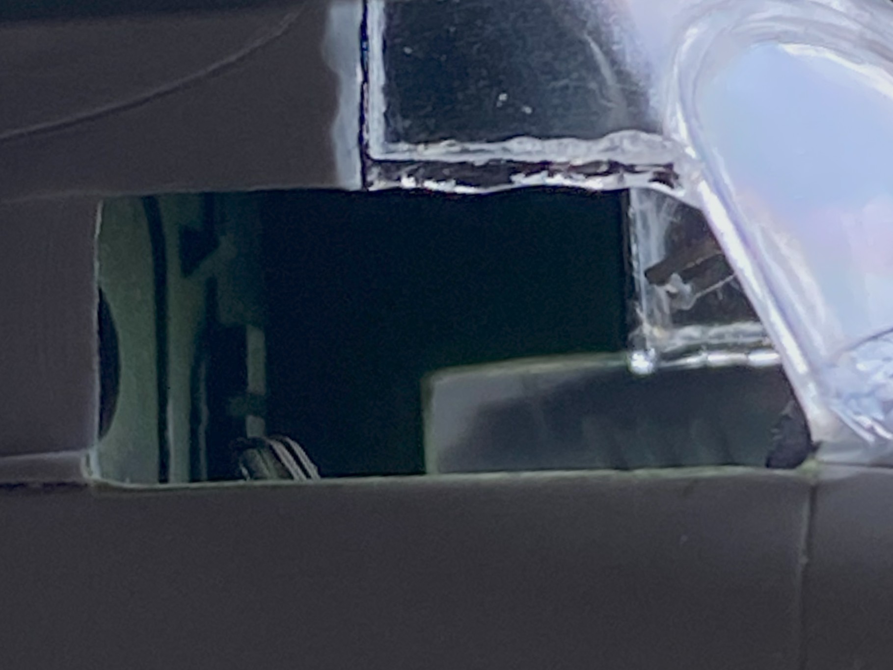
Each of the AM nozzle assemblies has sections where one can see into the hollow fuselage. Easy fix. Cut out discs for the two nozzles that allow that “feature” and paint them black (the upper engine’s rear will get painted black for the same reason):
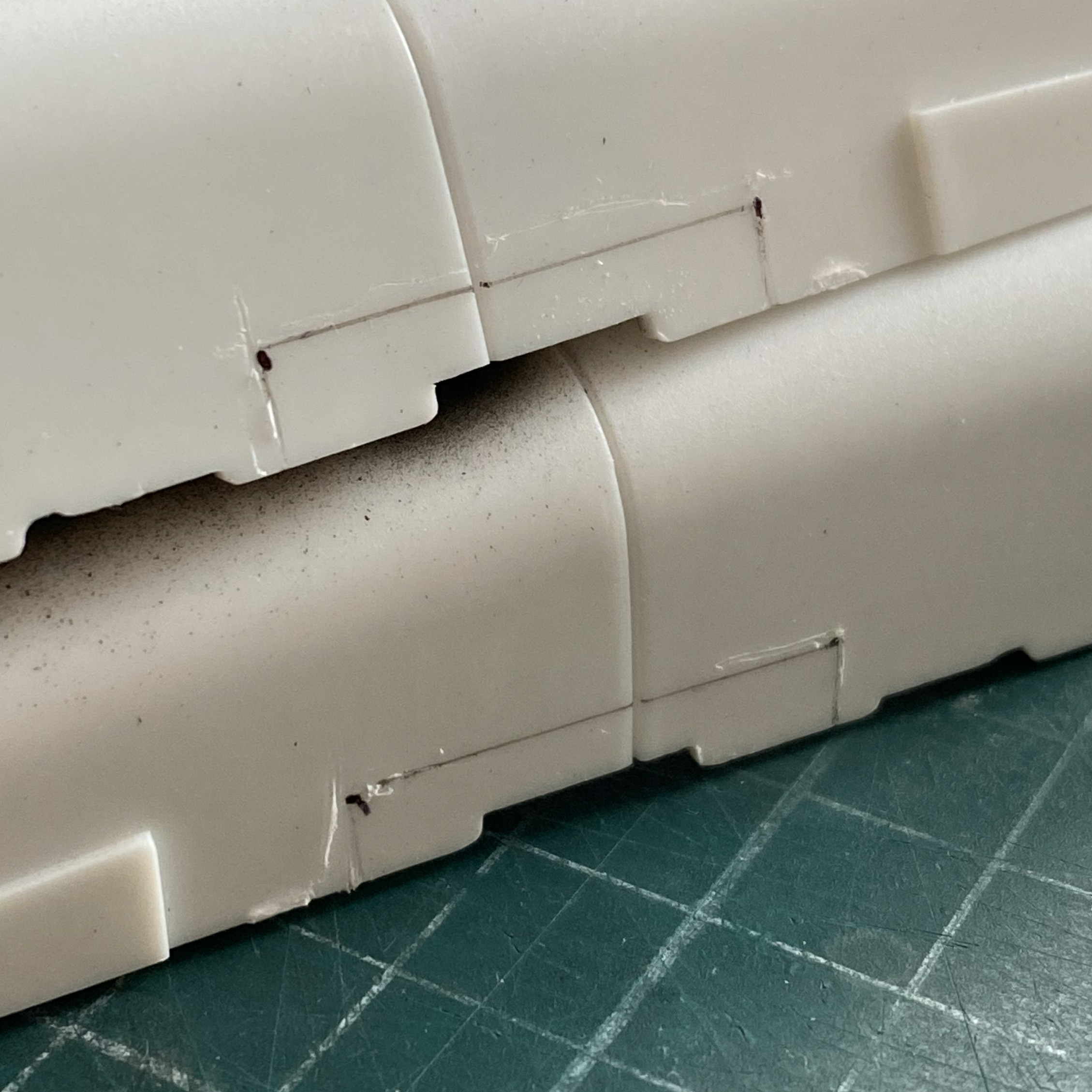
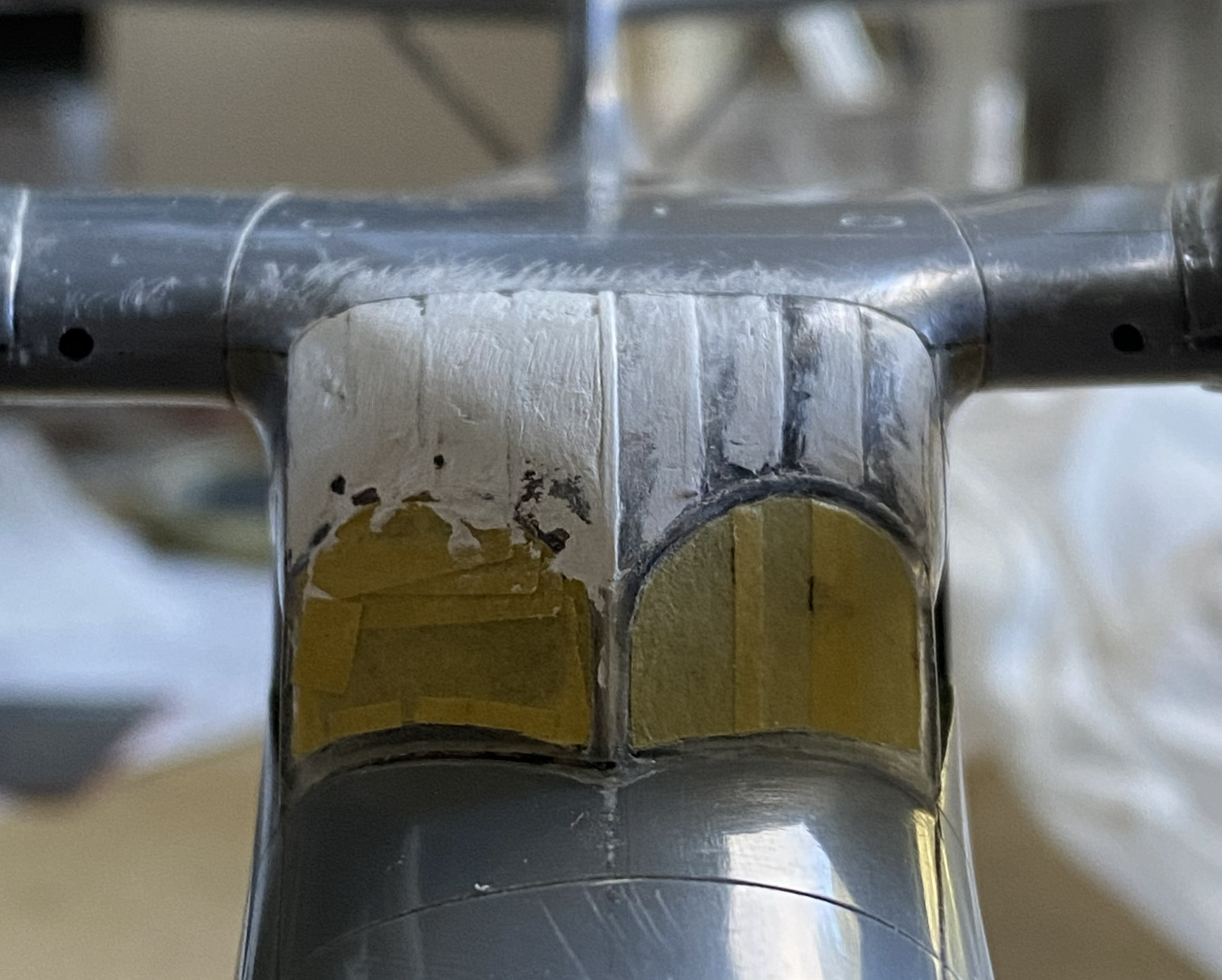
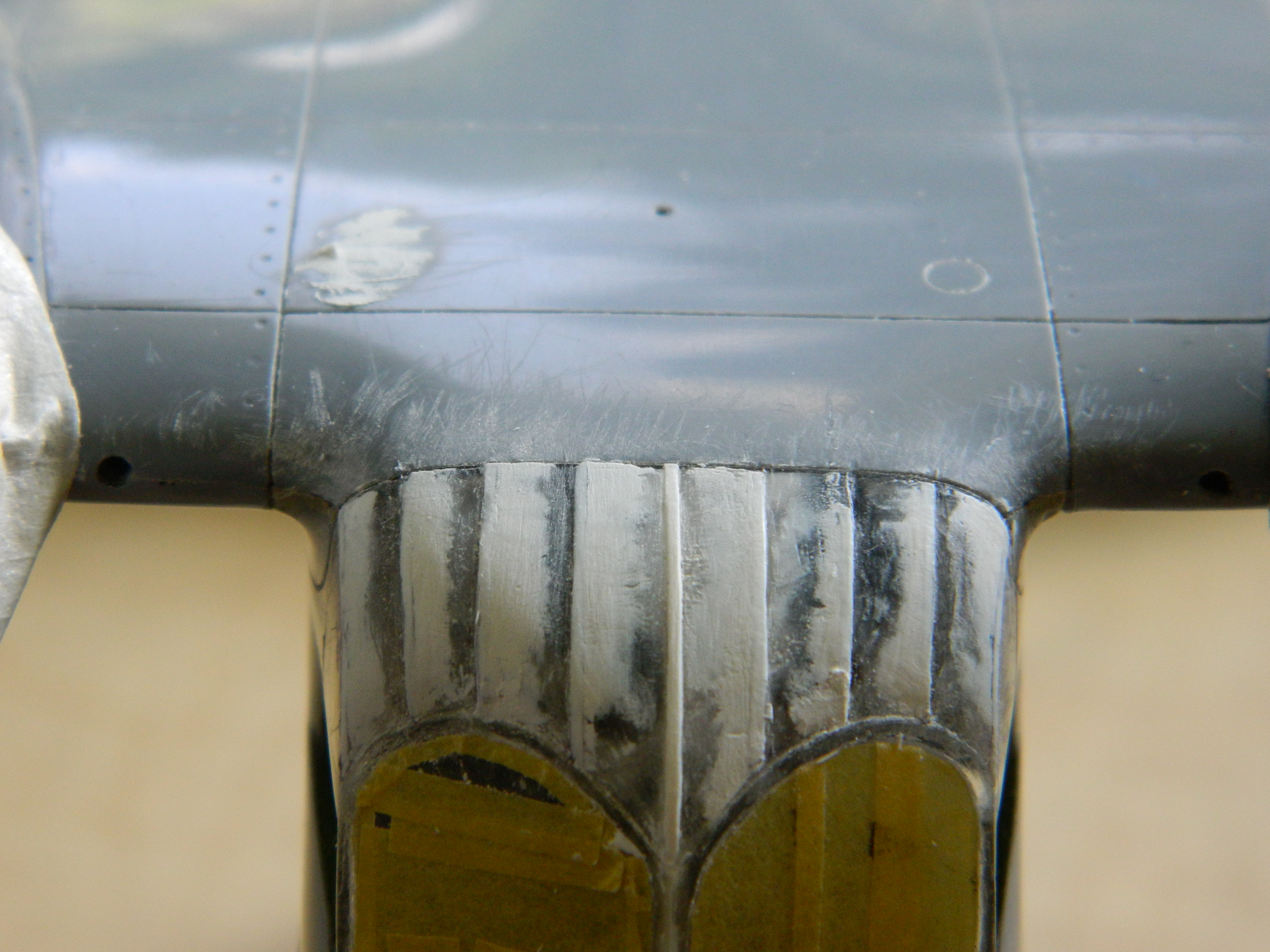
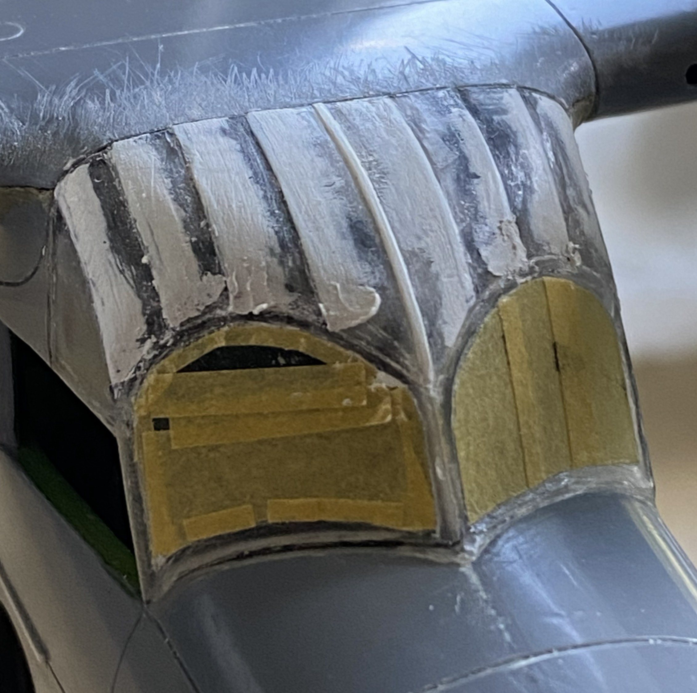
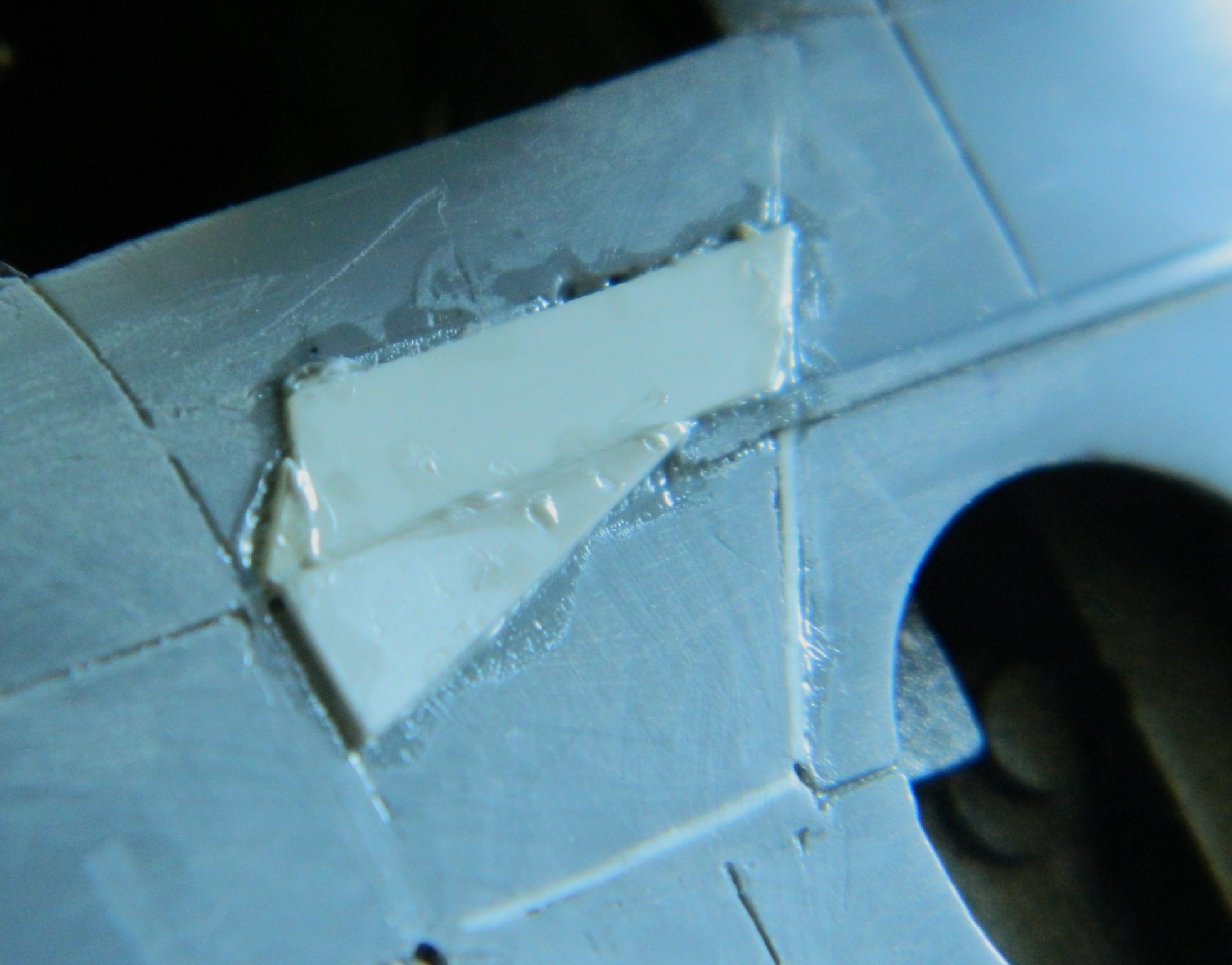
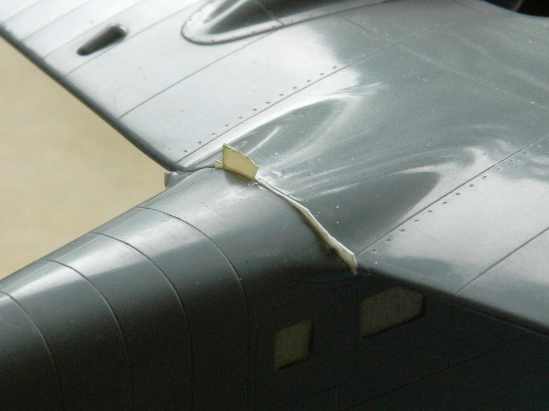
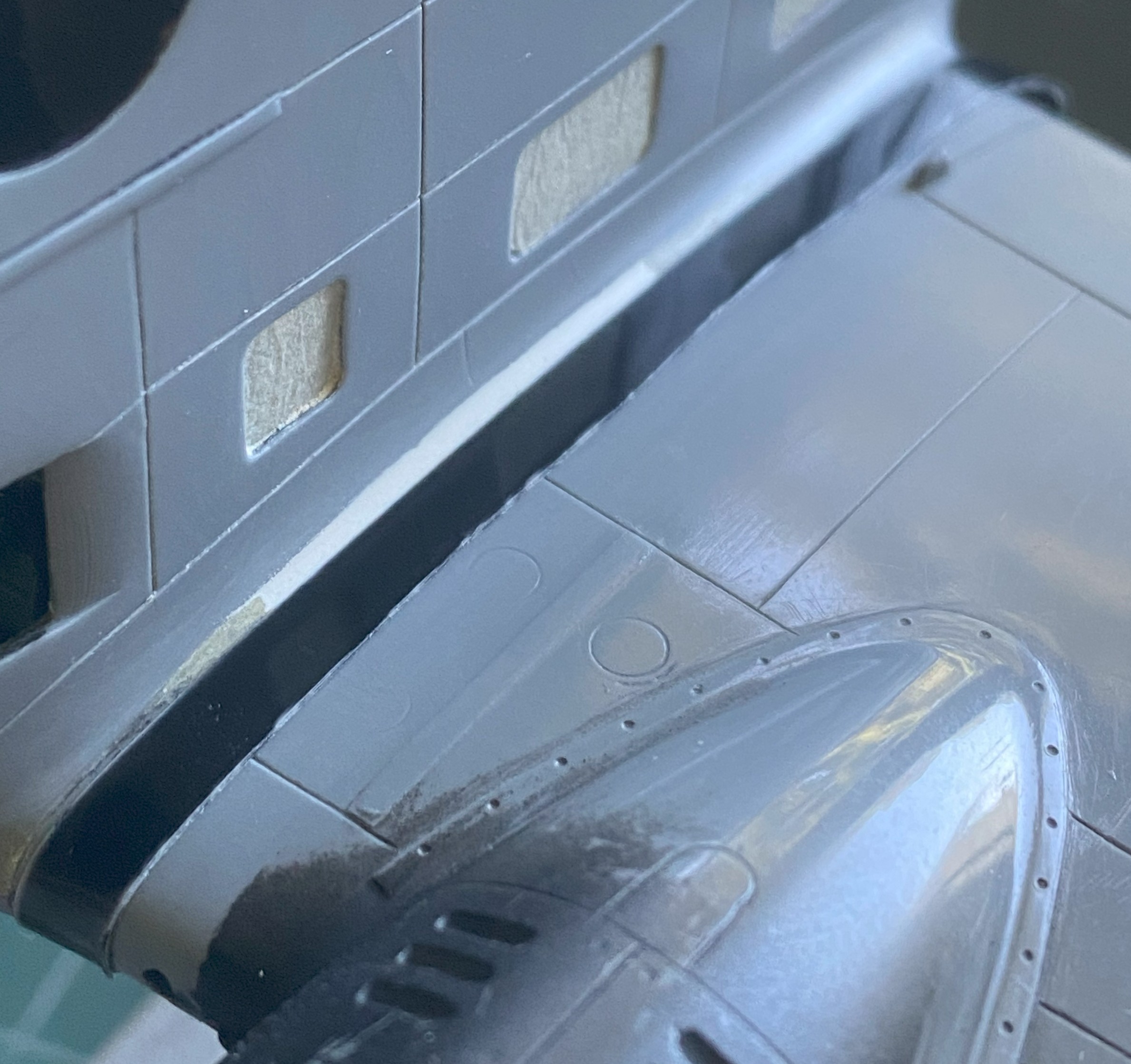
Each wing root has a gap that bothers me. Well, they had gaps but they were filled with scrap styrene. I’ll finish these off before painting:
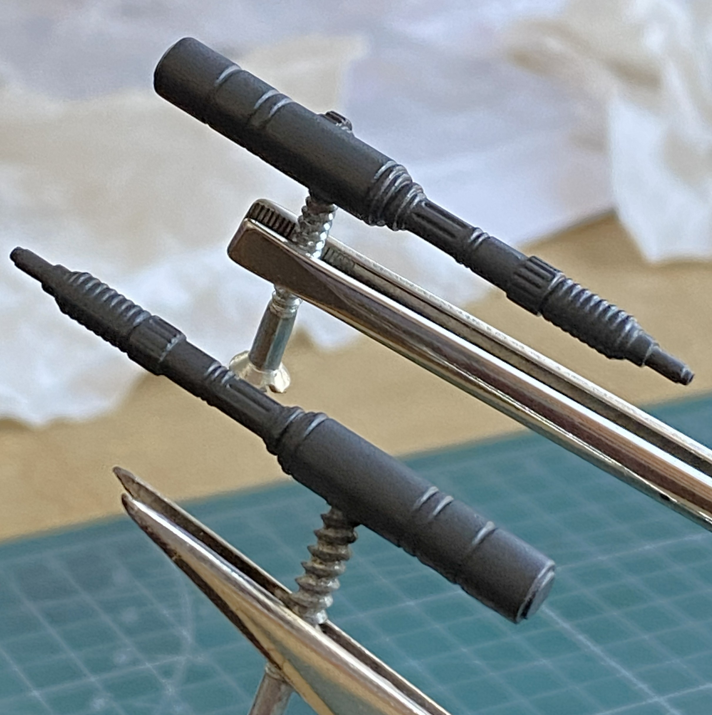
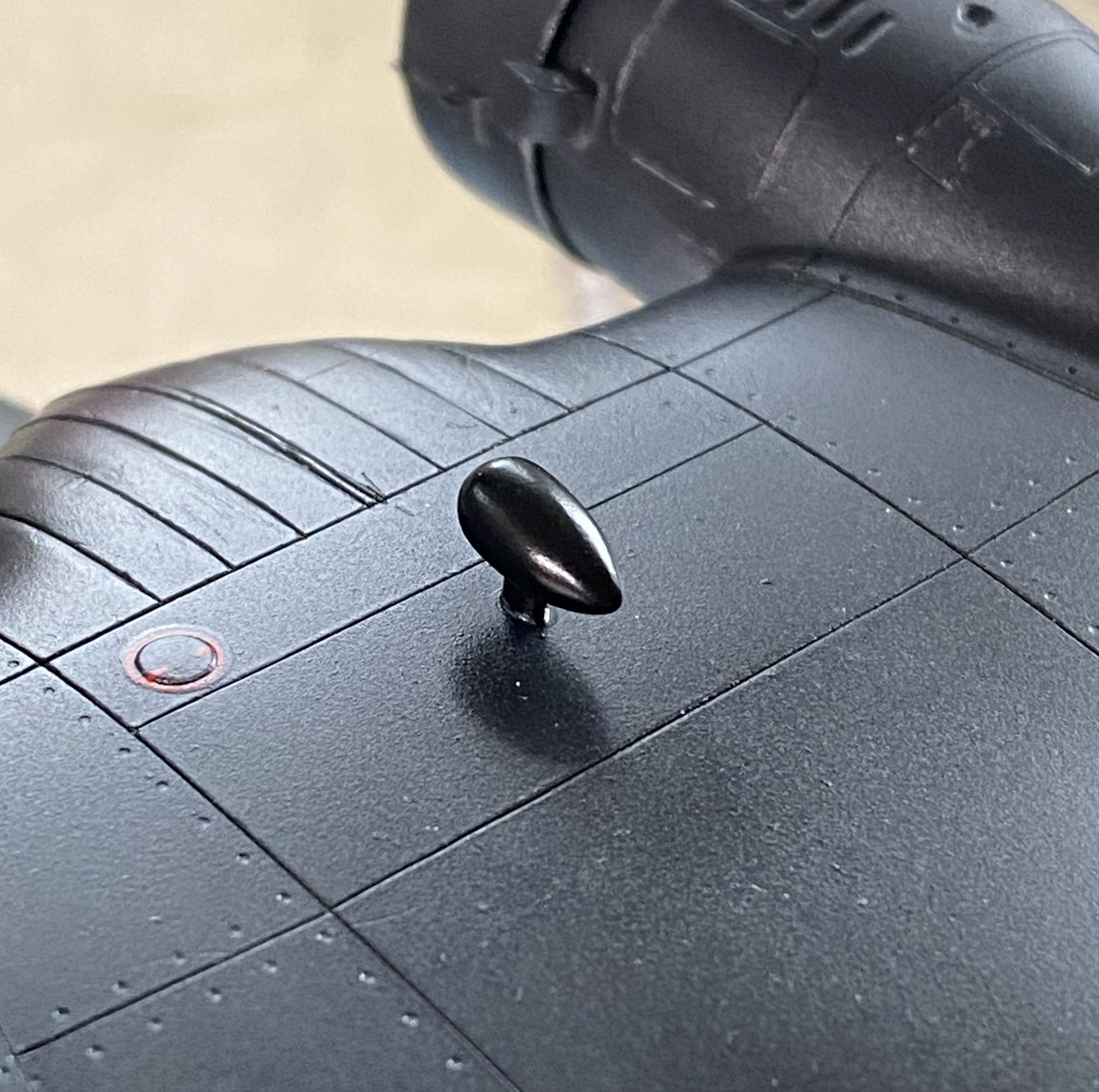
I’ve had people ask me how I make some of the smaller details I use. I’m going to show you but there are a few steps to the process. If this is of no use to you, just scroll past.
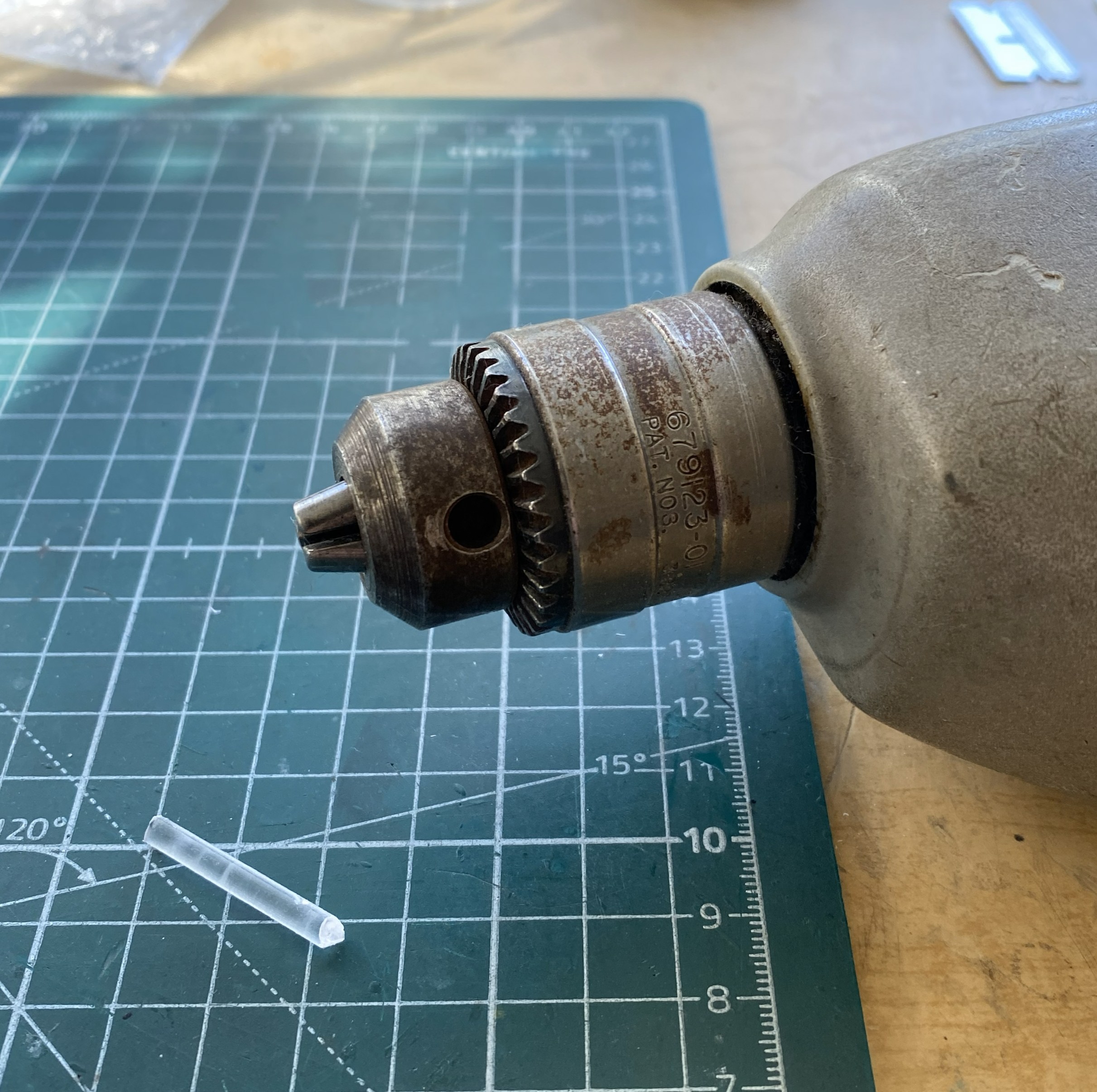
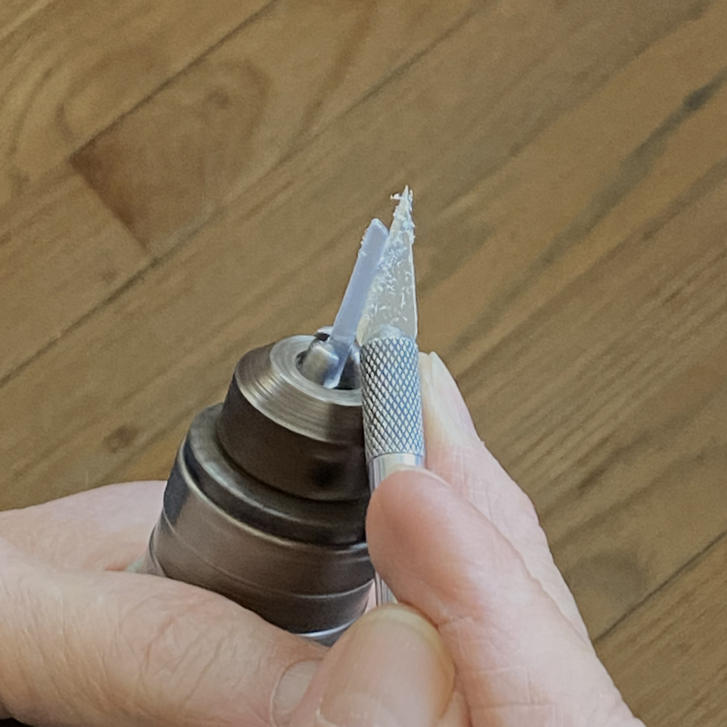
Sometimes I need to make something cylindrical in nature. If dimensions and shape are critical, I have a small bench-top lathe (Harbor Freight, I don’t need anything more accurate and certainly don’t want to pay for more accurate). When the look matters more and it’s a small part I’ll use a variable-speed drill. In this case, all I need is something to hold the stock and spin it.
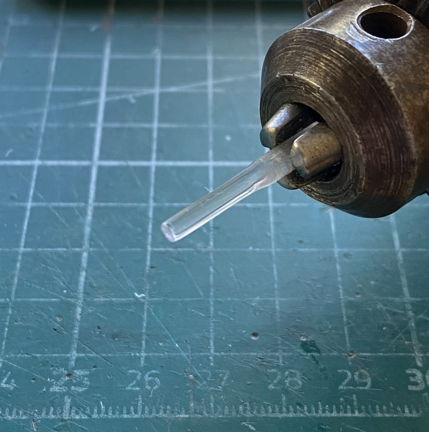
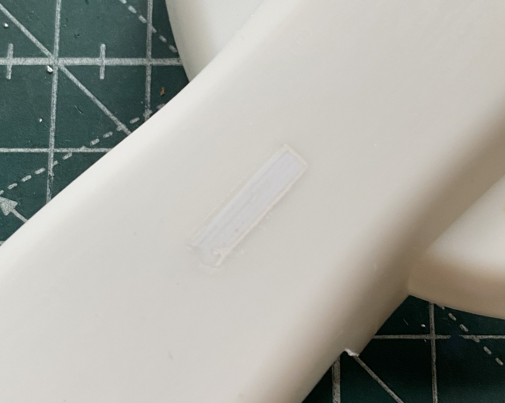
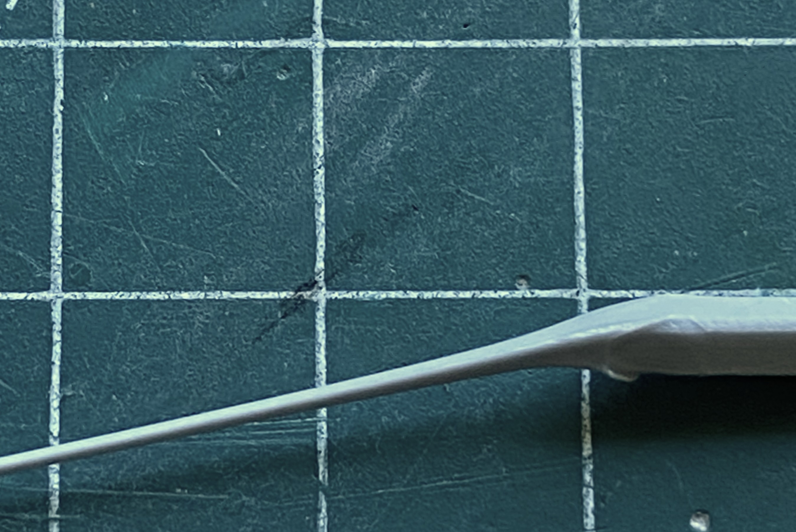
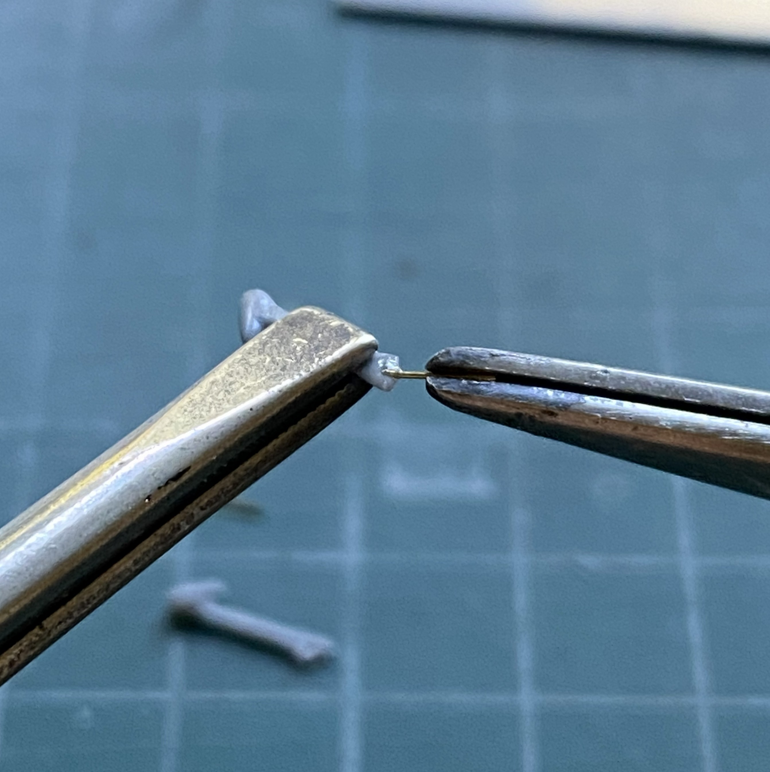
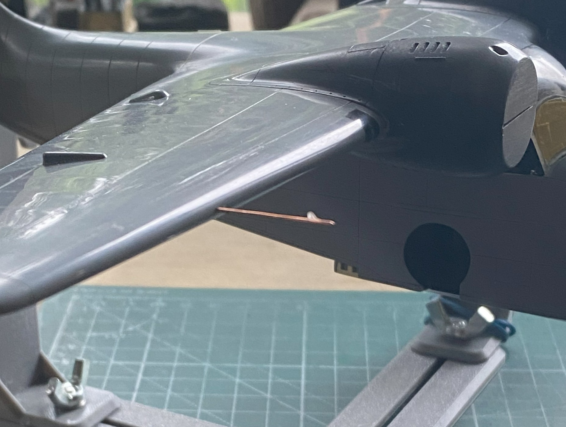
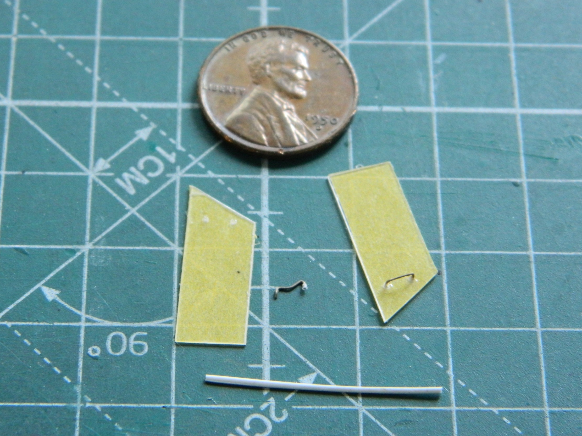
The sensors for the draedus are molded onto the wingtips in opaque plastic. Yes, I could just paint them. (I could also get into stamp collecting as a hobby, too.) Instead, I want to make clear covers for them. So I started with a section of clear sprue and set the drill at a lower speed to keep from melting the work:
My initial thought was to use an abrasive nail shaper:
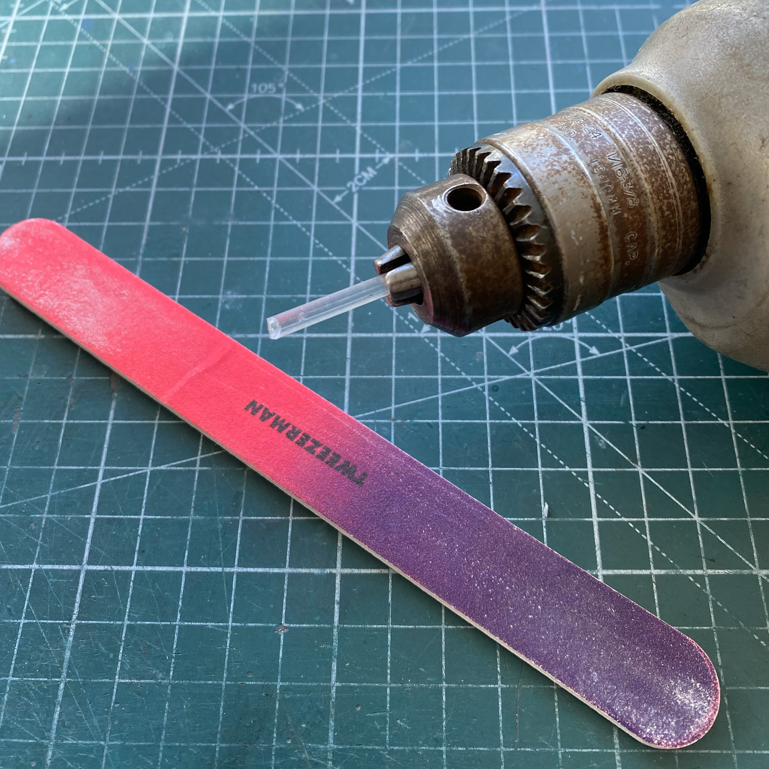
Nope, it doesn’t take enough off. I tried a razor blade next:
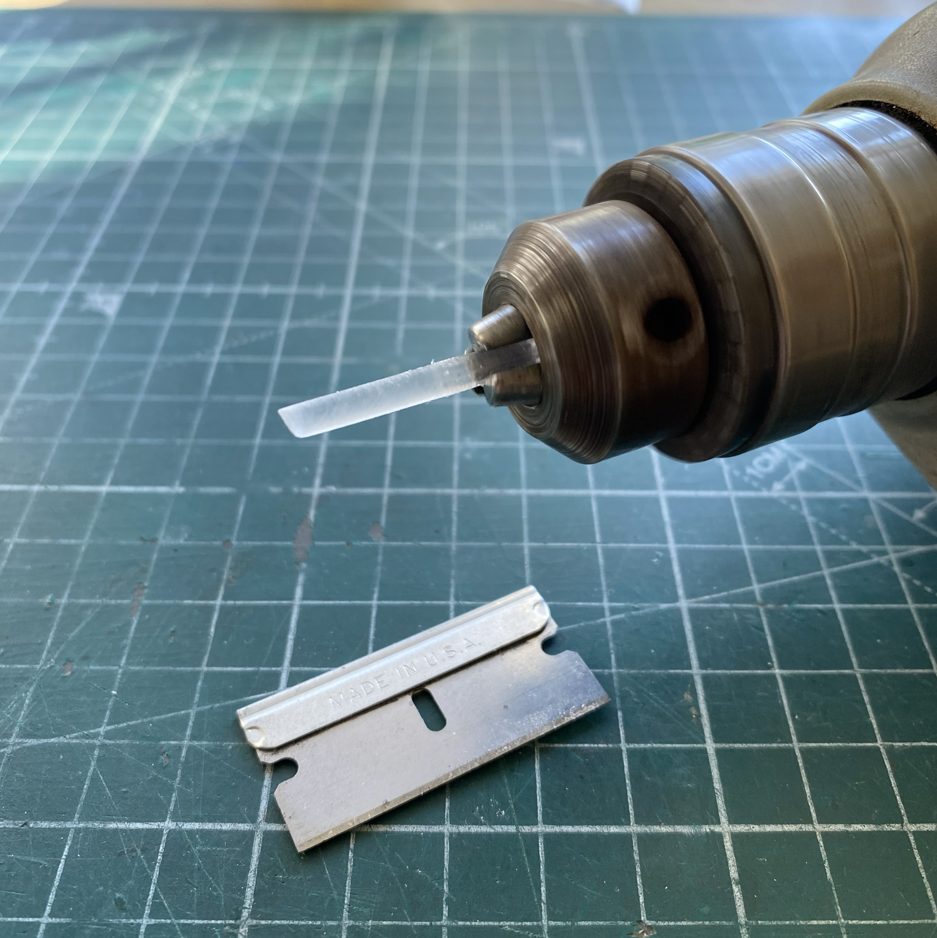
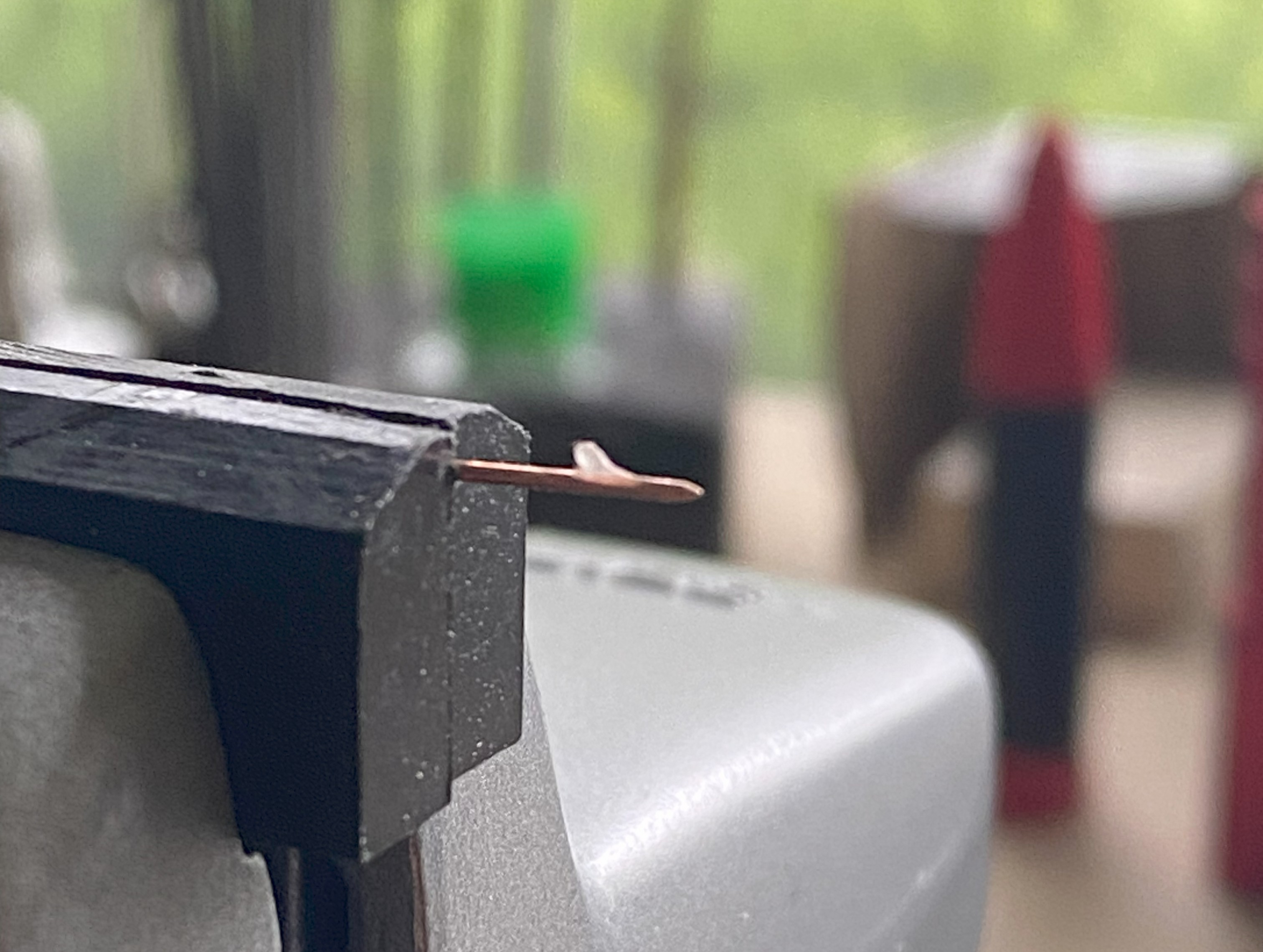
Yes, it took more off per spin, but it was unwieldy (and my fingers, being right next to that sharp bit of steel is full of my SACRED B+), so I used a #11 blade:
That worked much better! What isn’t evident in the above photo is the angle I’m holding the blade at. I’m holding it at pretty much the same angle that I use to scrape plastic with. Do NOT let the blade bite the work!
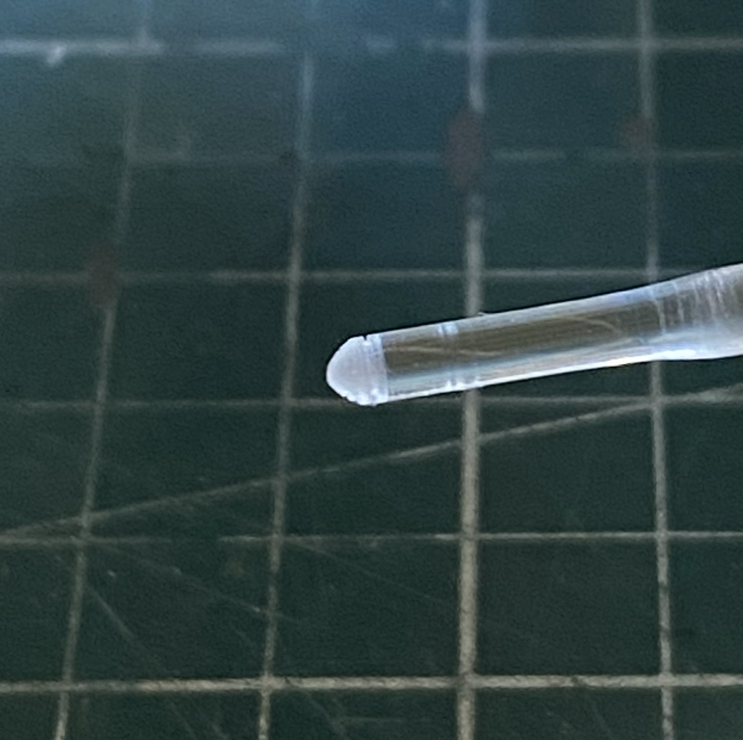
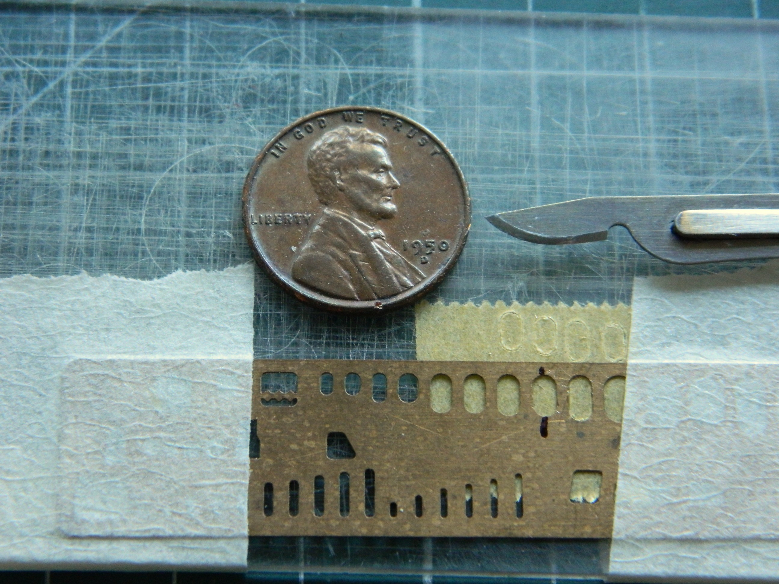
Don’t forget to check the diameter frequently:

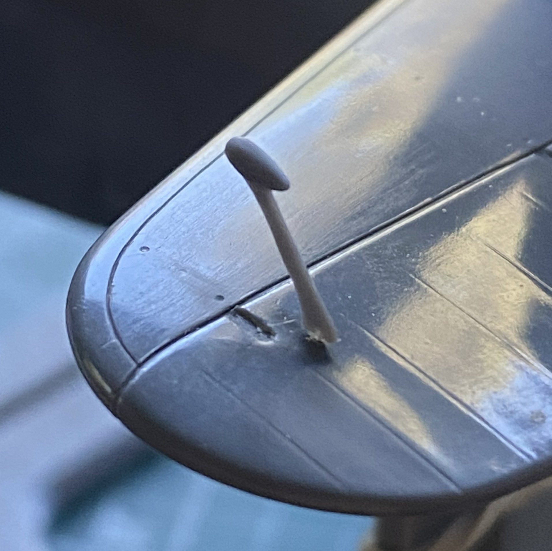
Once my Eyecrometer MkI was satisfied, I polished the work:
I used the #11 and a VERY narrow file to add surface details:
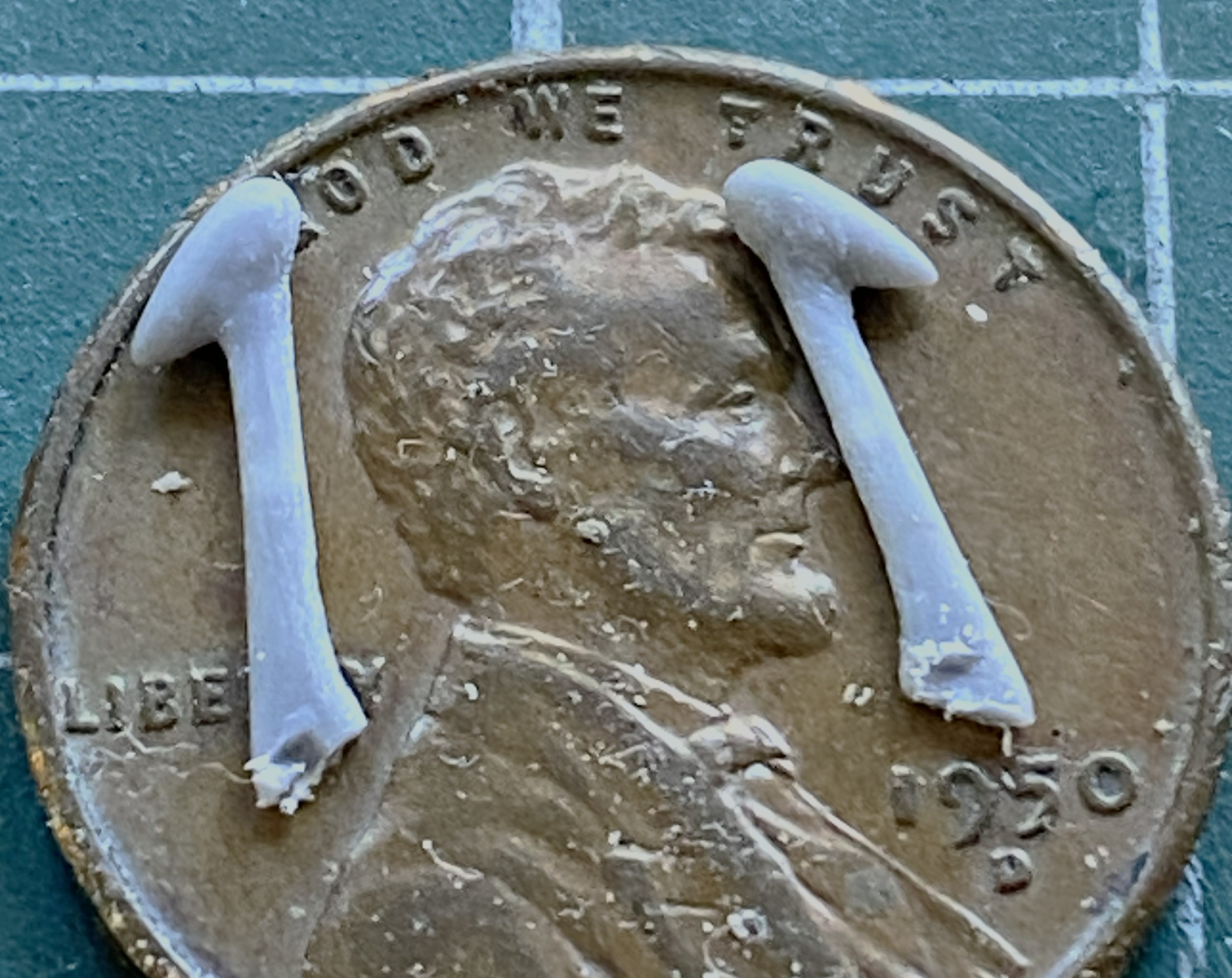
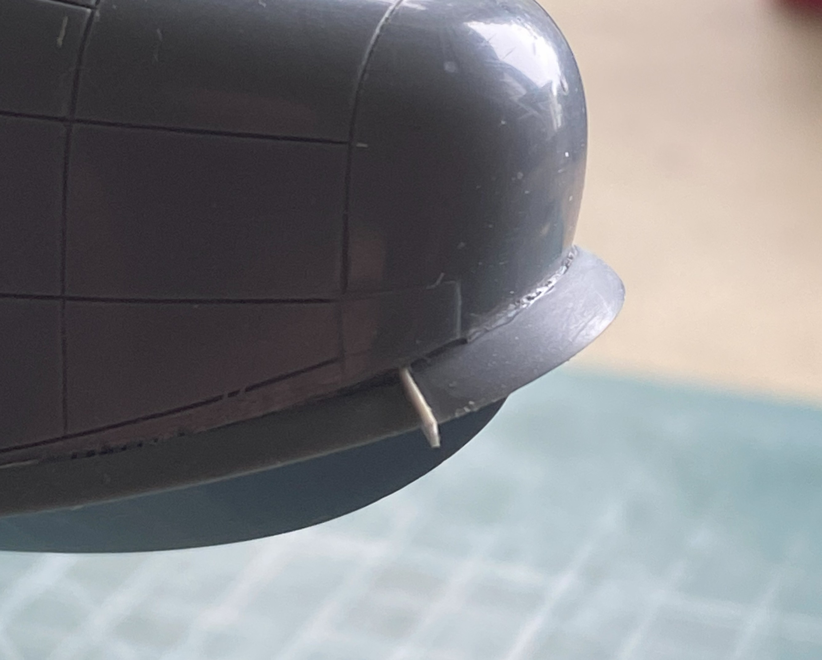
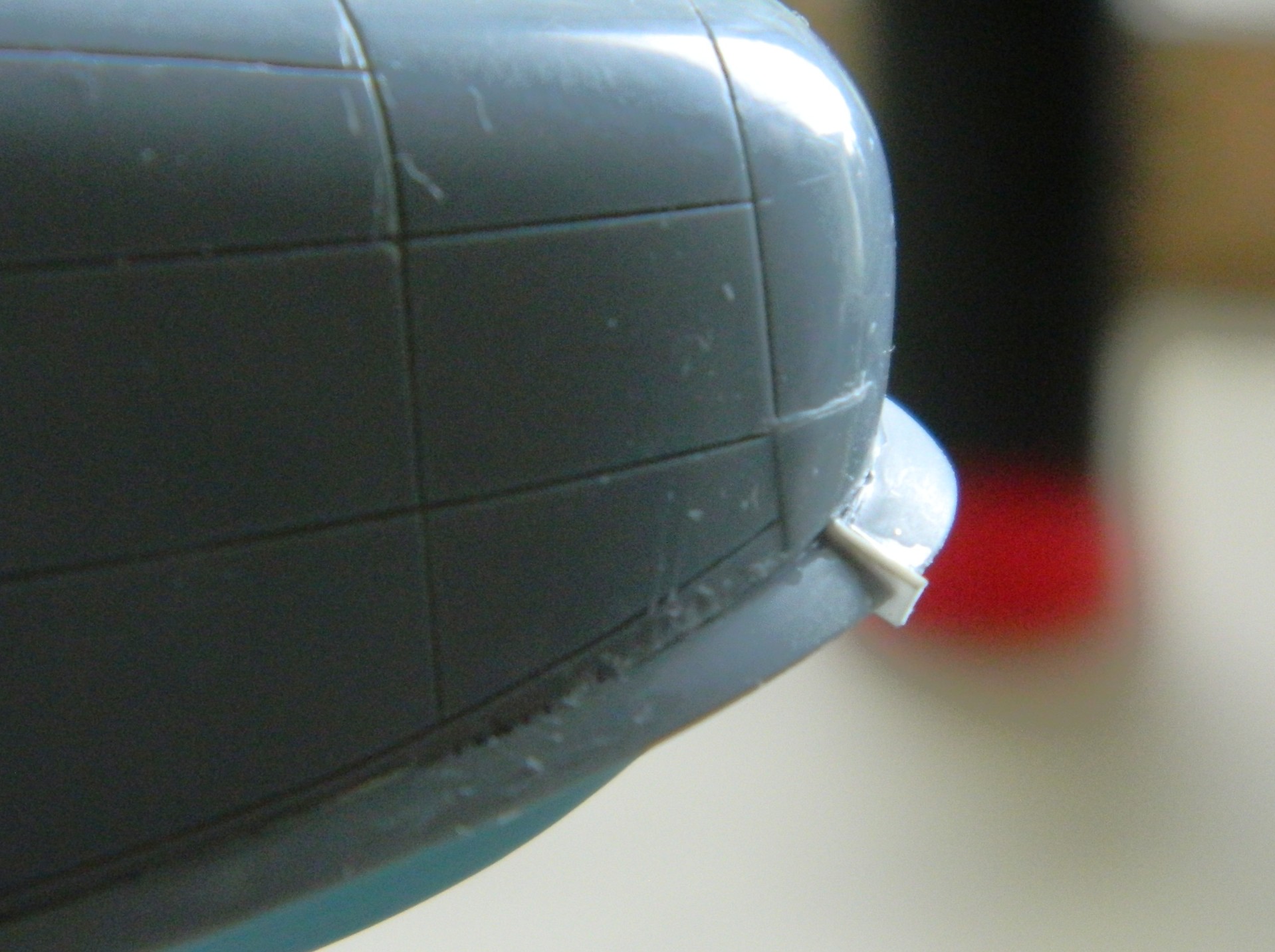
Once that was done, I kept the work spinning and used a razor saw to cut off what I wanted. And yes…this is a small part:
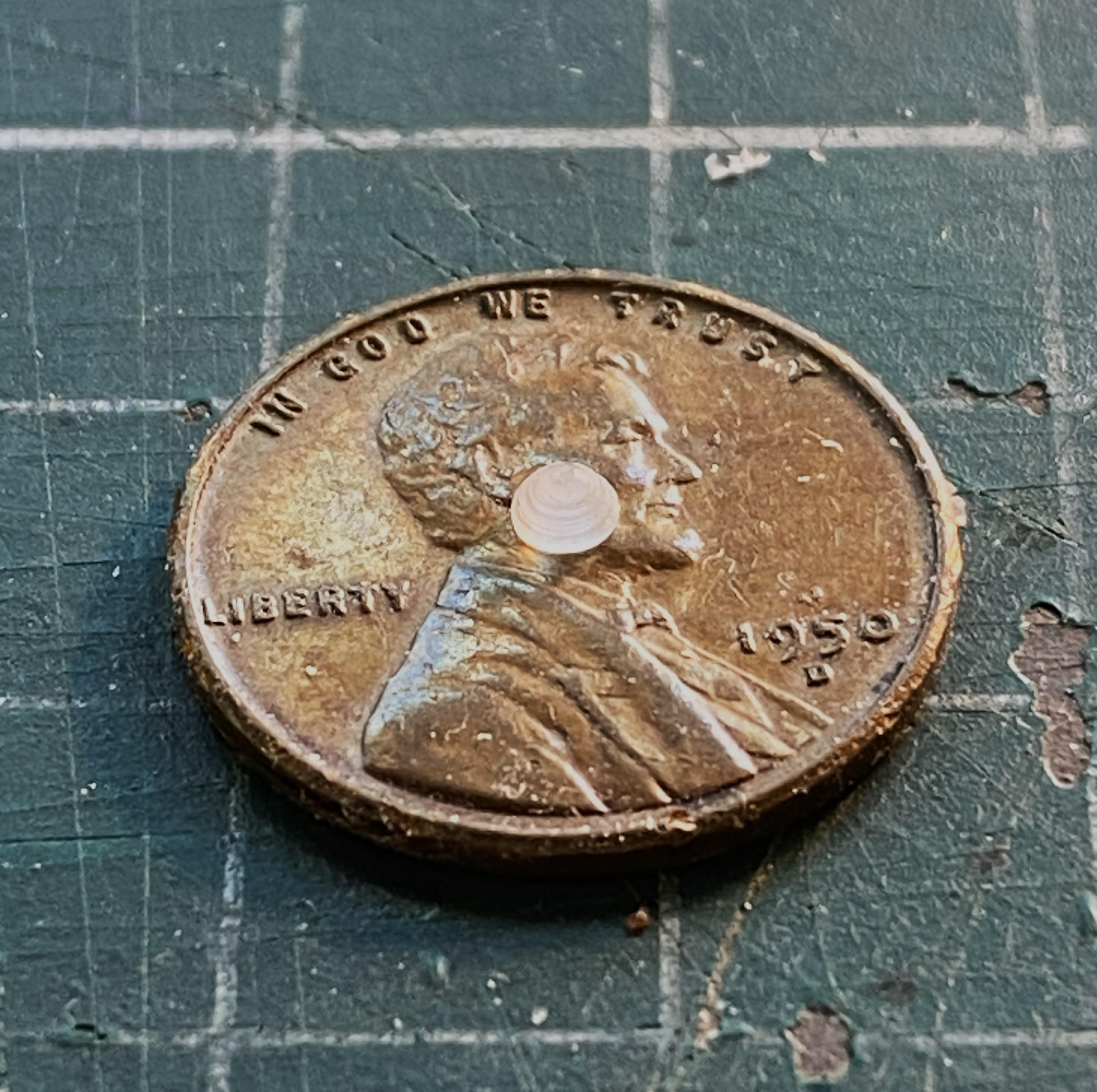
Its size isn’t a problem. The problem is that I have to make three more of them! At my age, I have an understanding of my work process. One of those understandings is that when I have to make multiple parts, I generally nail the first one spot on. The remainders? Well…if I’d followed my process and tried to make three more just like that one, I’d probably would have needed four or five attempts to get the next one. Repeat that process twice more and I’d have a pile of small parts and the task of selecting the best four from that pile. I just didn’t feel like doing it that way.
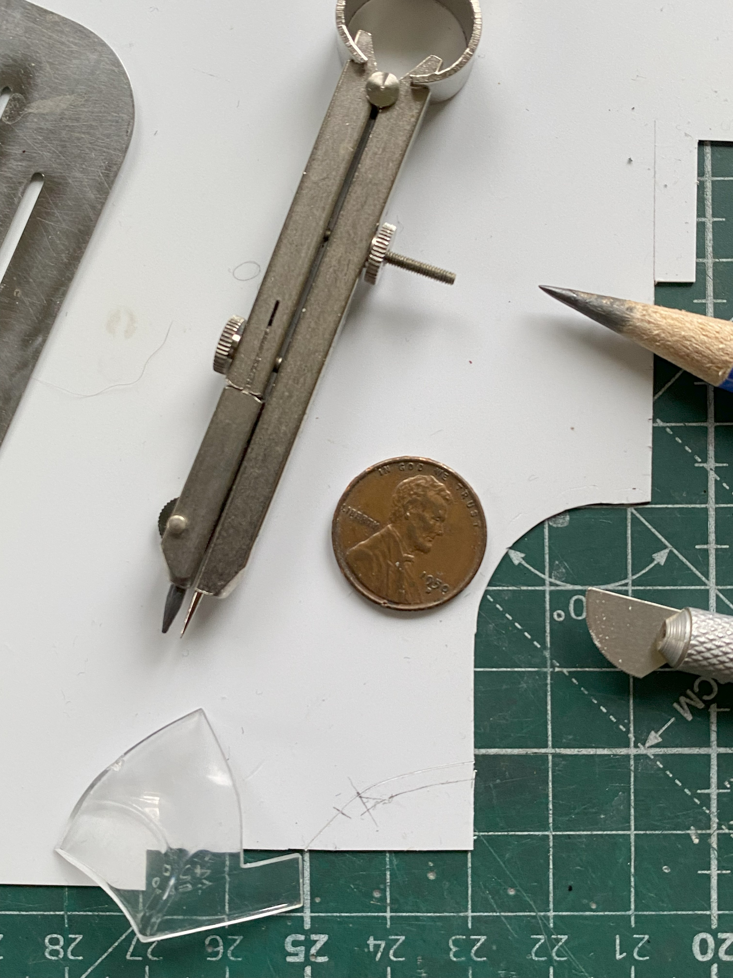
Instead, I used the silicone molding putty and made four molds from the one part already produced:
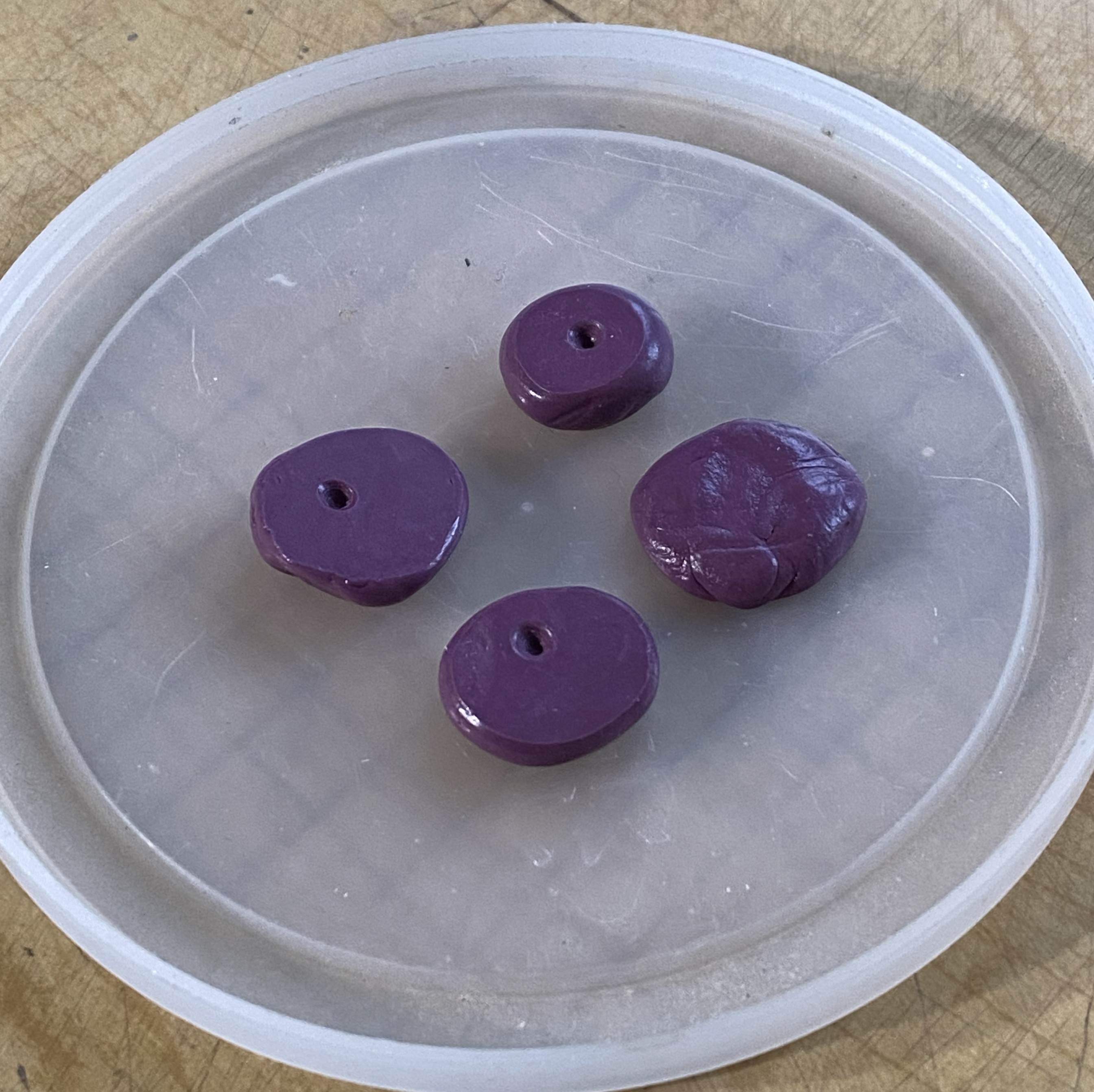
Why four molds? Because it was my intention to make the sensor covers from plue comprised of clear sprue. It takes time for the plue to set up that I didn’t care to wait around for. First, make the plue:
Not easily seen in the above photo are the bubbles that are forming. I use Tamiya Extra Thin to make plue. It’s a solvent that dissolves plastic. The process of hardening is one, essentially, of evaporation. The solvent evaporates and leaves behind shaped plastic. It also leaves behind bubbles. As the solvent out-gasses, it creates bubbles. The bubbles that make it to the surface go away. But as the solvent out-gasses, the plastic returns to its original solid condition and that traps all the bubbles that didn’t get to the surface in the plastic:

Opaque plastic doesn’t show that (them?). I tried several ways of getting plue into the molds in thin layers and without disturbing the plue (and thereby creating more bubbles). That worked, in a manner of speaking, it just didn’t work very well. The parts were VERY THIN. How do these get attached to the tips of the wings? Solvent-based glue. Solvent dissolves plastic. The parts are vert thin plastic and they (or the test piece) do what plastic does when solvent touches it. It dissolved:
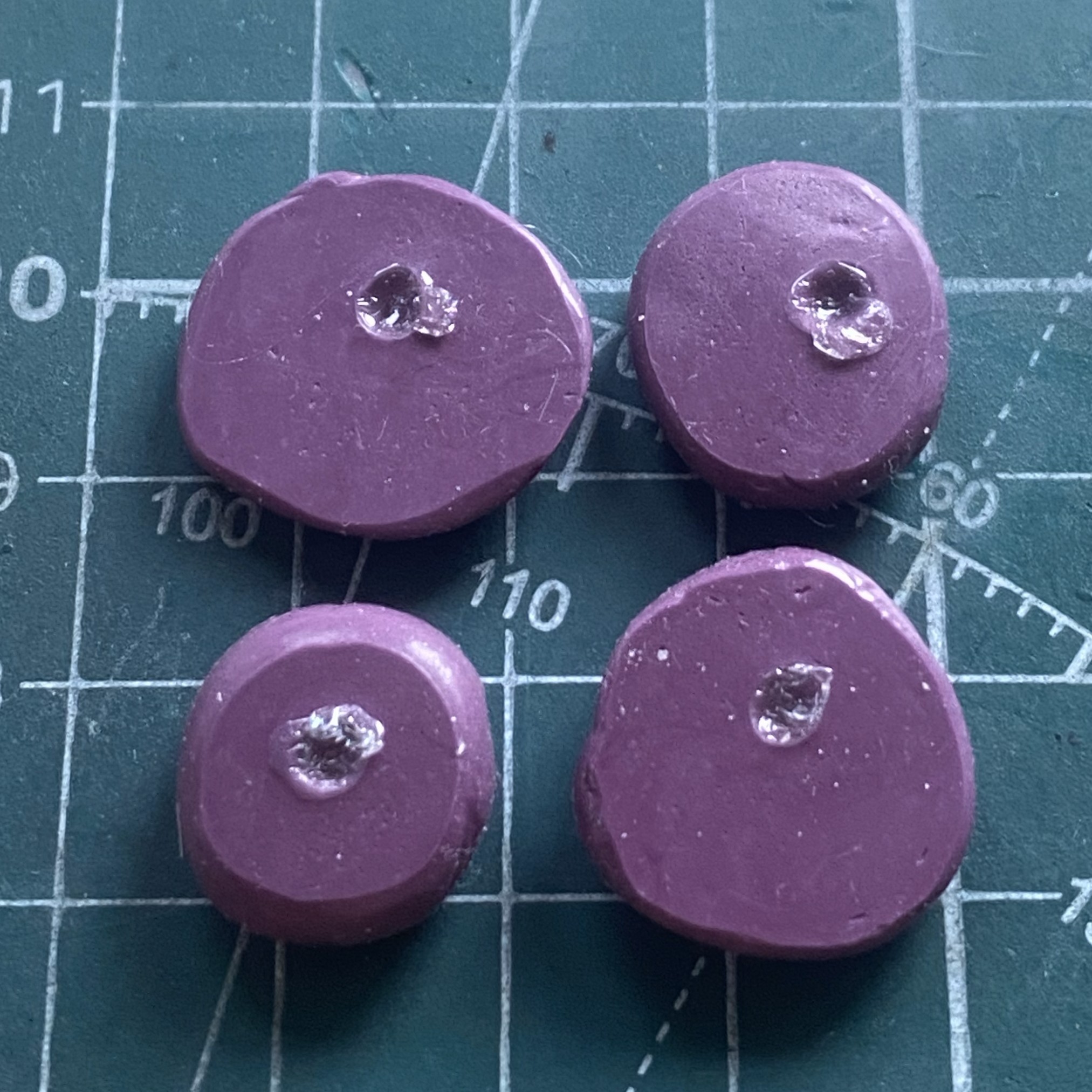

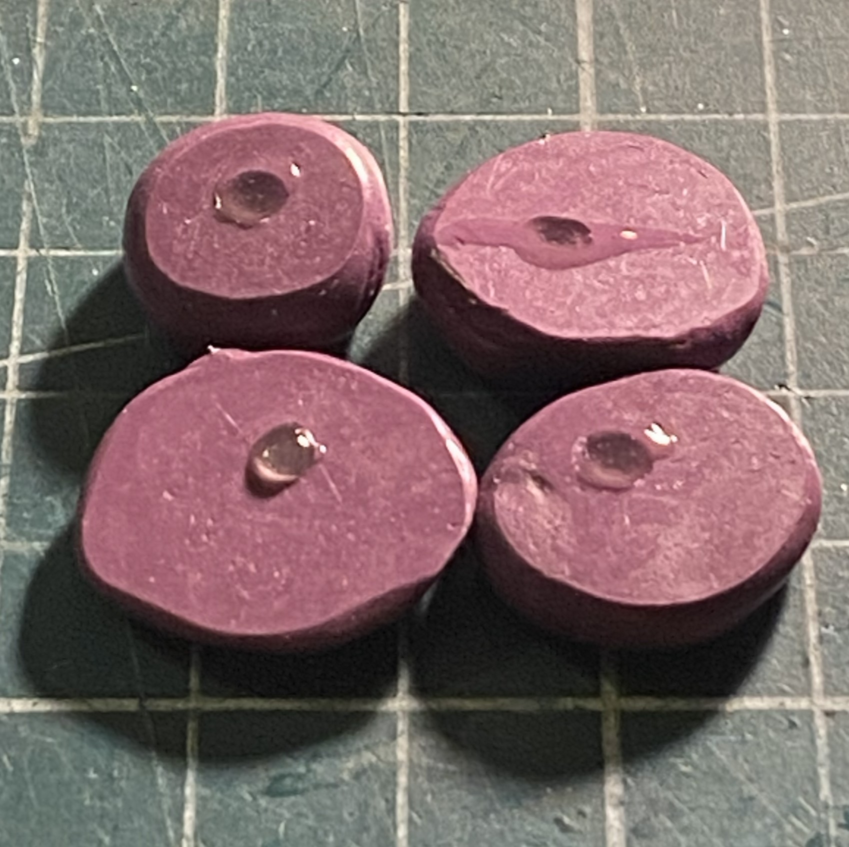
Then I had the incredibly bright (there’s my modesty in play again) idea of using the UV-setting resin to fill the molds. It’s clear, doesn’t react to solvents, and though it can bubble in the mold, that’s more of an application problem. When bubbles were introduced into the mold, I used a needle to move the bubbles away from the part successfully…then forgot to take photos. ::facepalm::
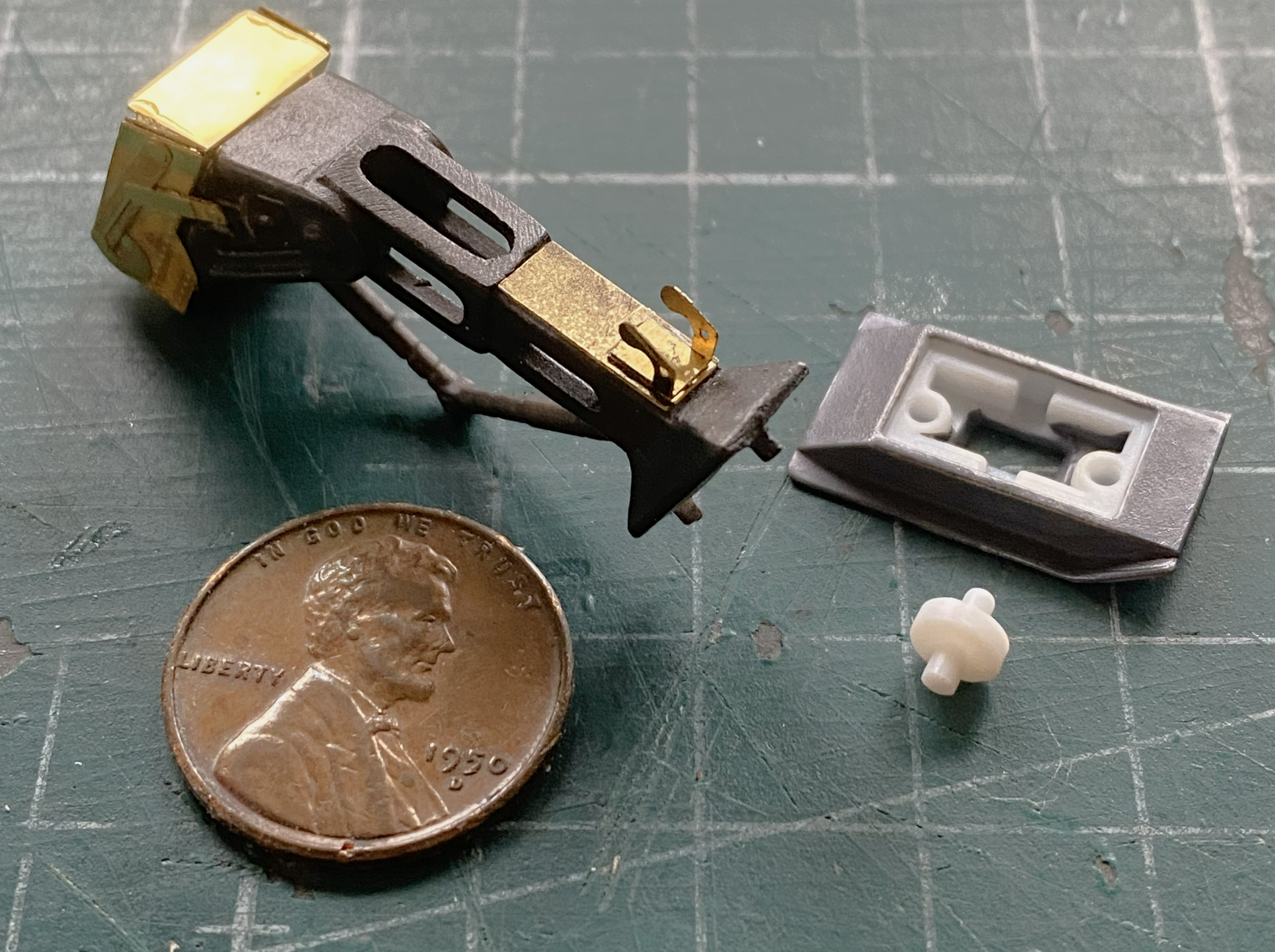
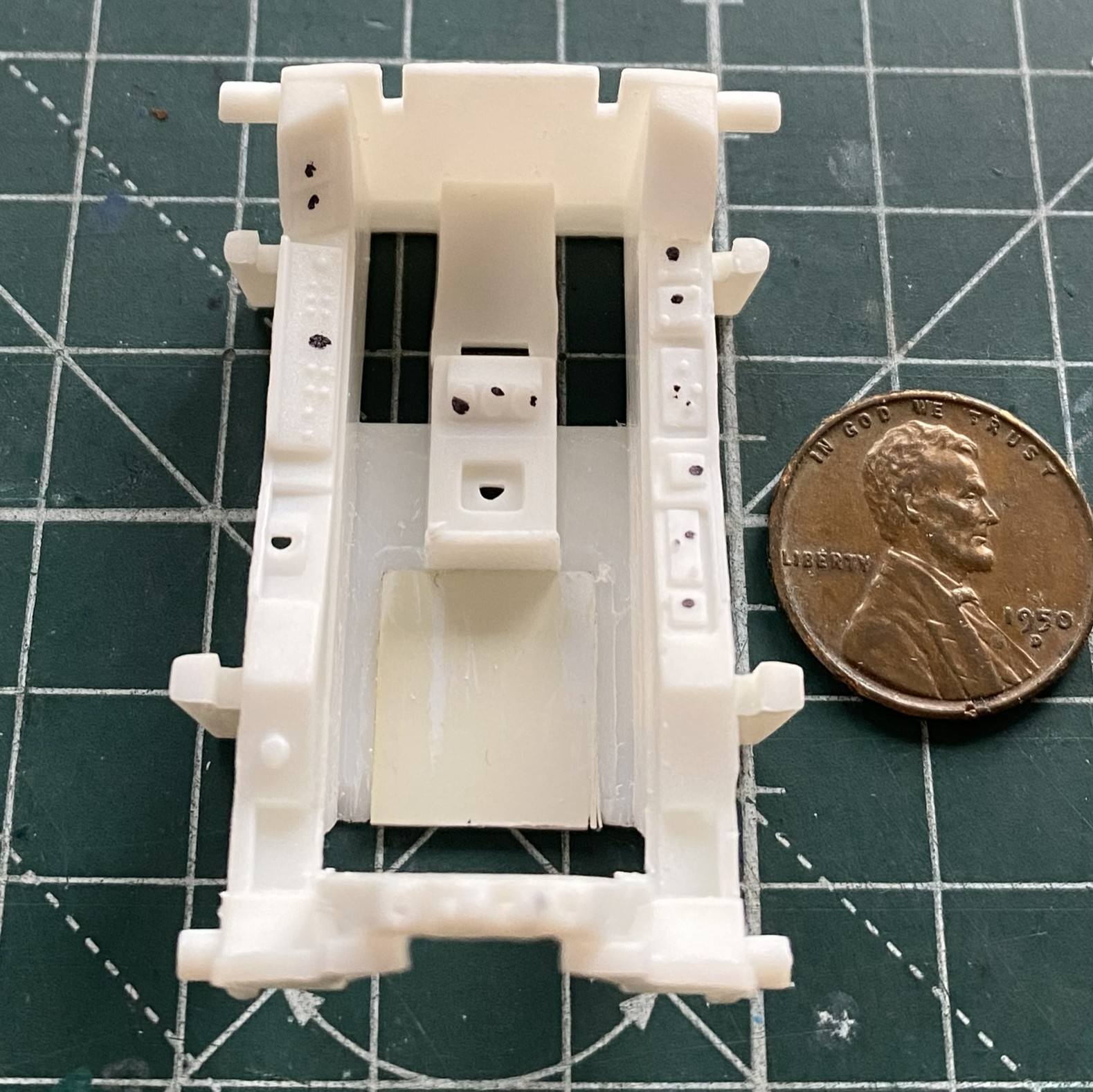
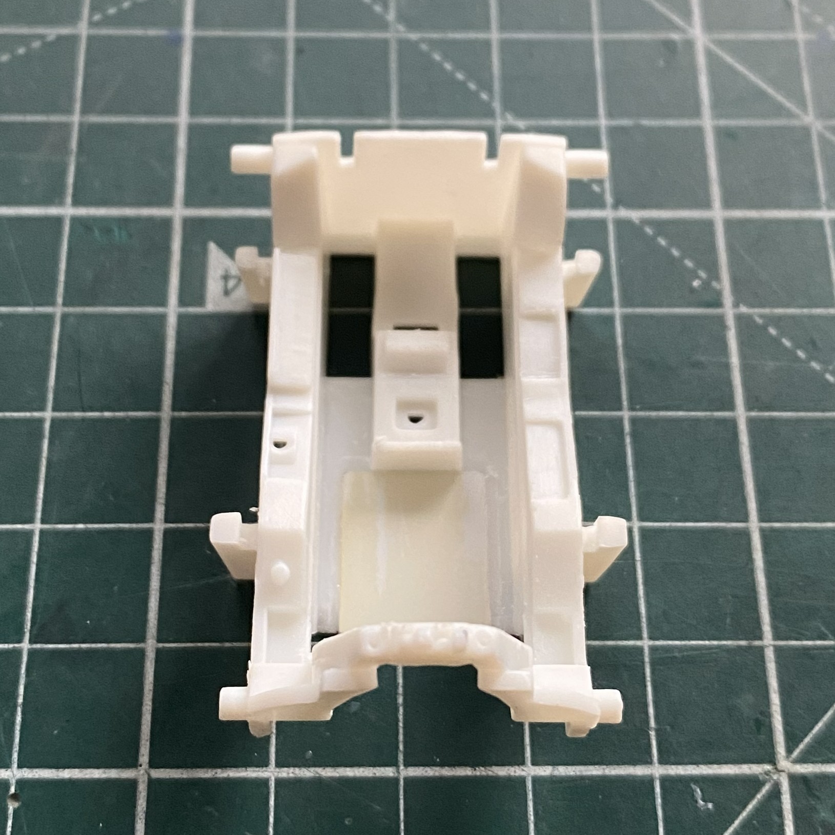
I discovered that I’d neglected to add some PE to the nose landing gear. Fixed that. I also broke out the Humbrol paint (#27003) and painted the feet (because they’re not wheels) buffable steel. (The white plastic part is a wheel that sits in the feet and has yet to be painted, obviously.):
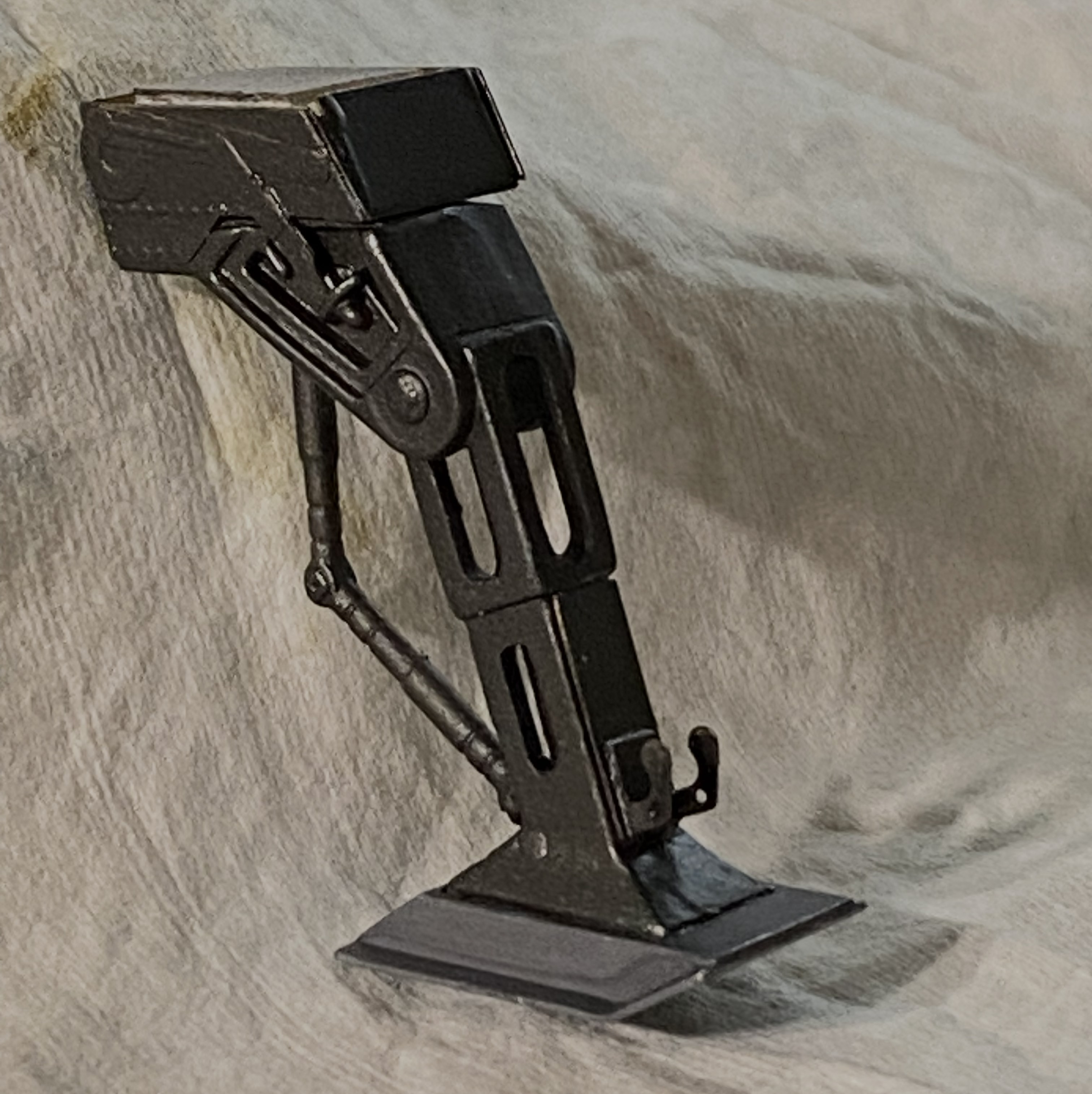
I painted that wheel and PE and assembled the nose strut:
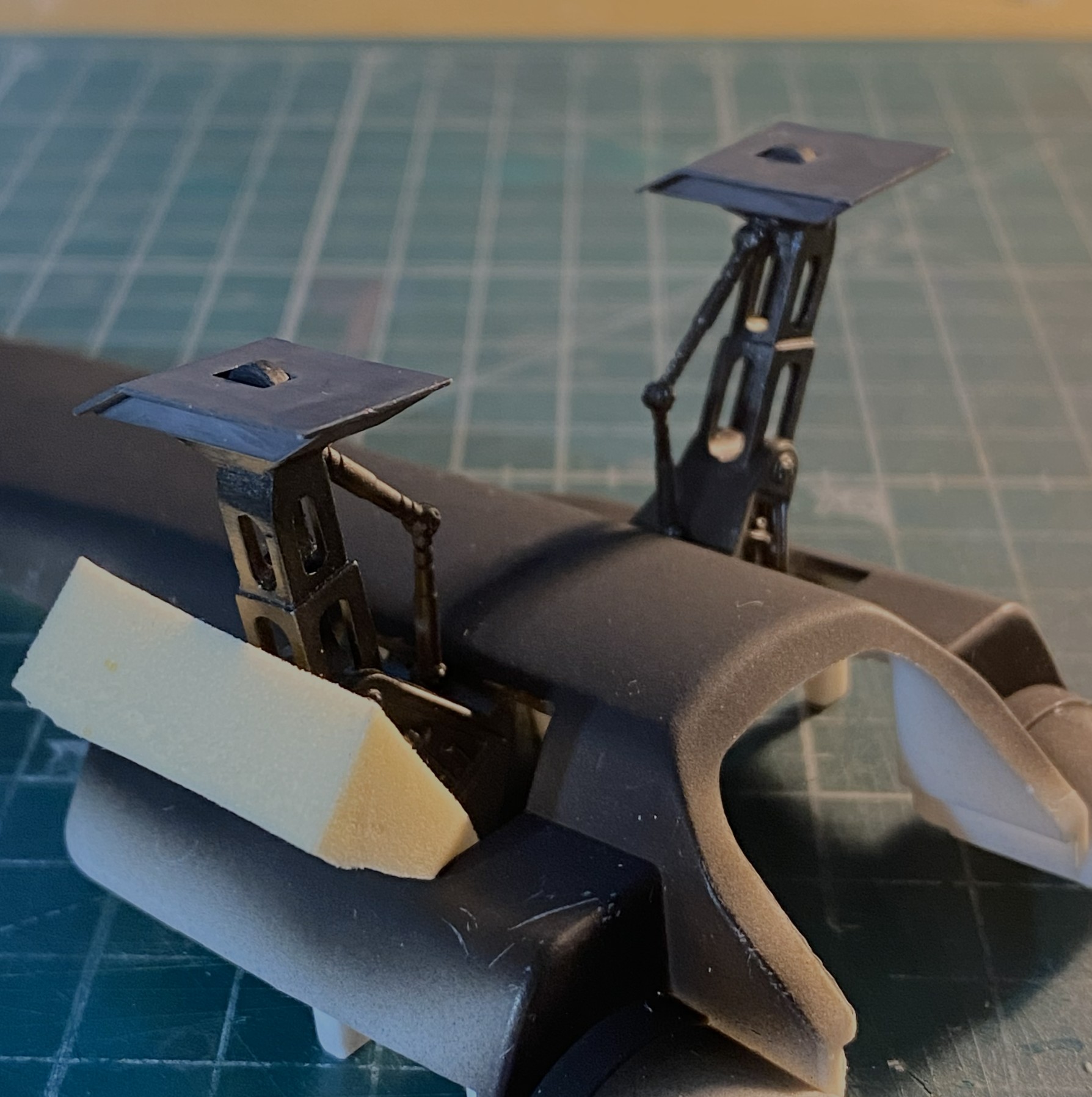
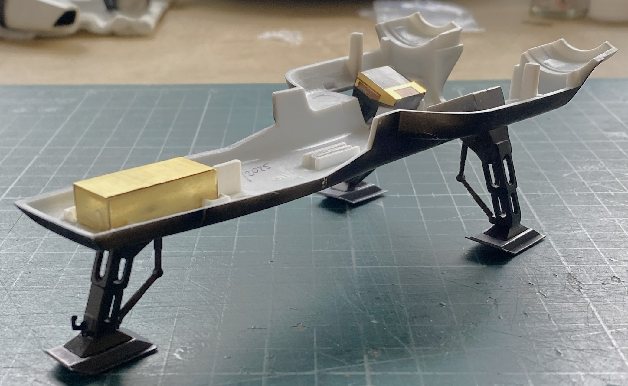
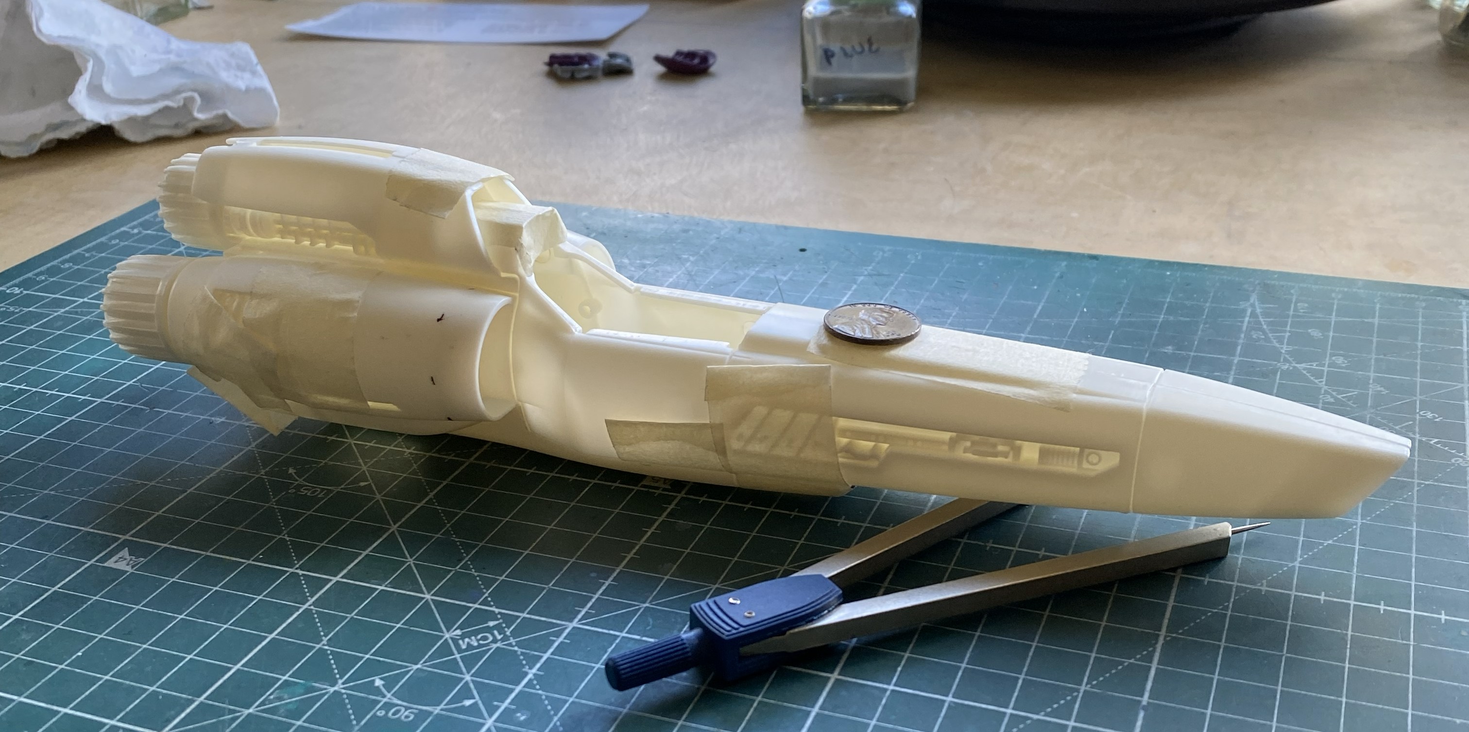
After assembling the main landing gear, I added them to the belly pan. The foam wedge is holding the assembly aligned while the glue sets up:
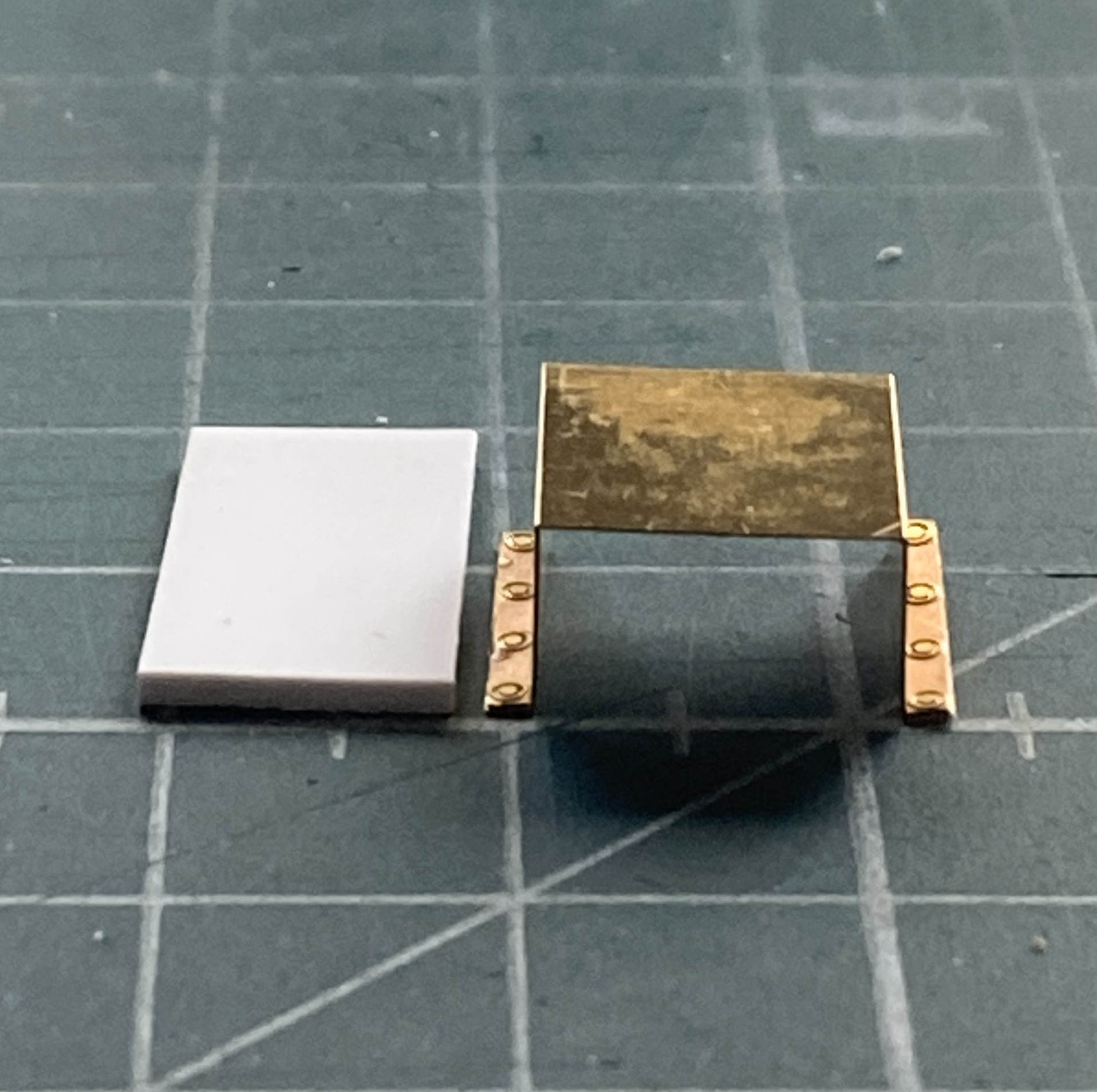
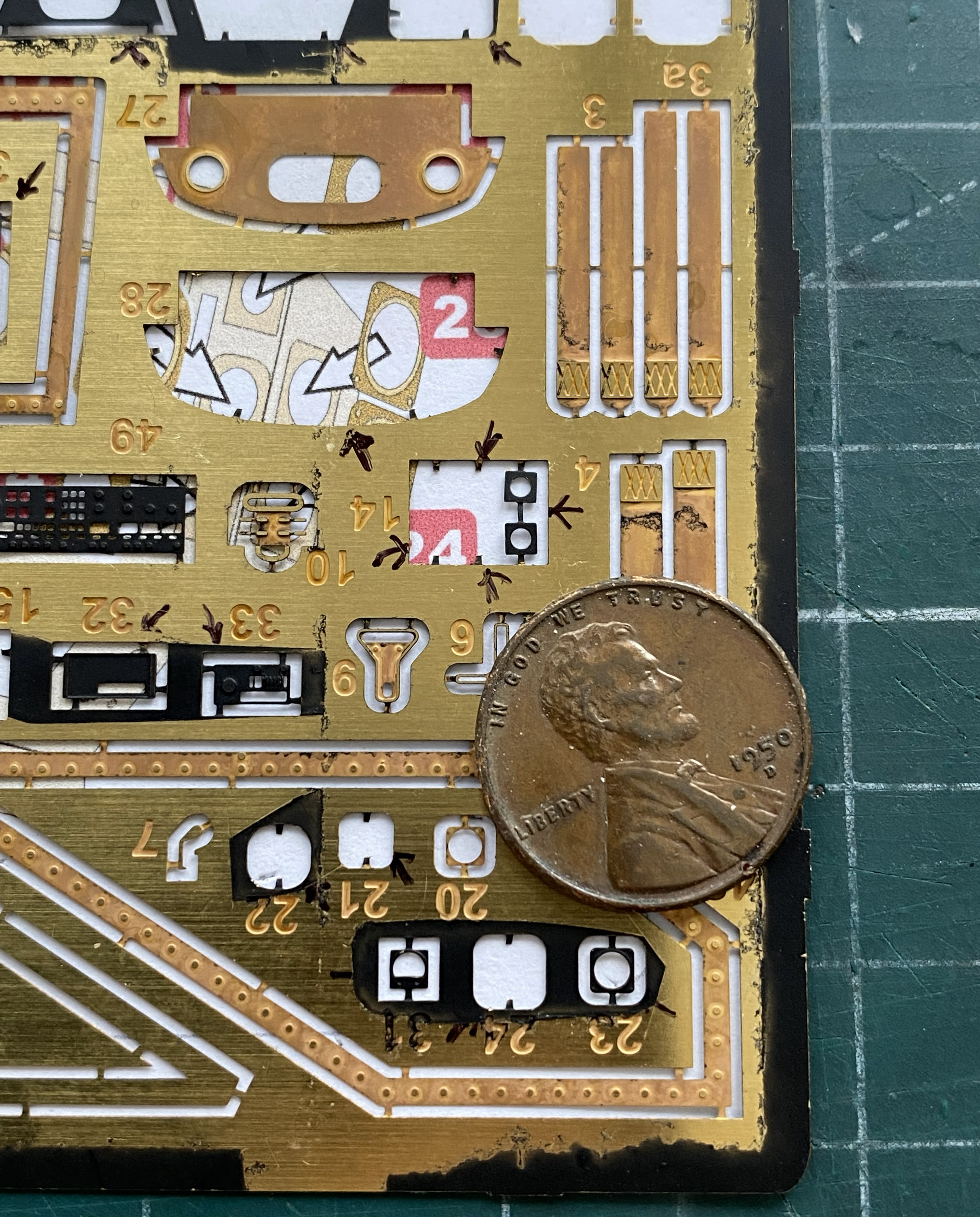
These PE frets are almost entirely landing gear bays. Brass origami shall ensue shortly:

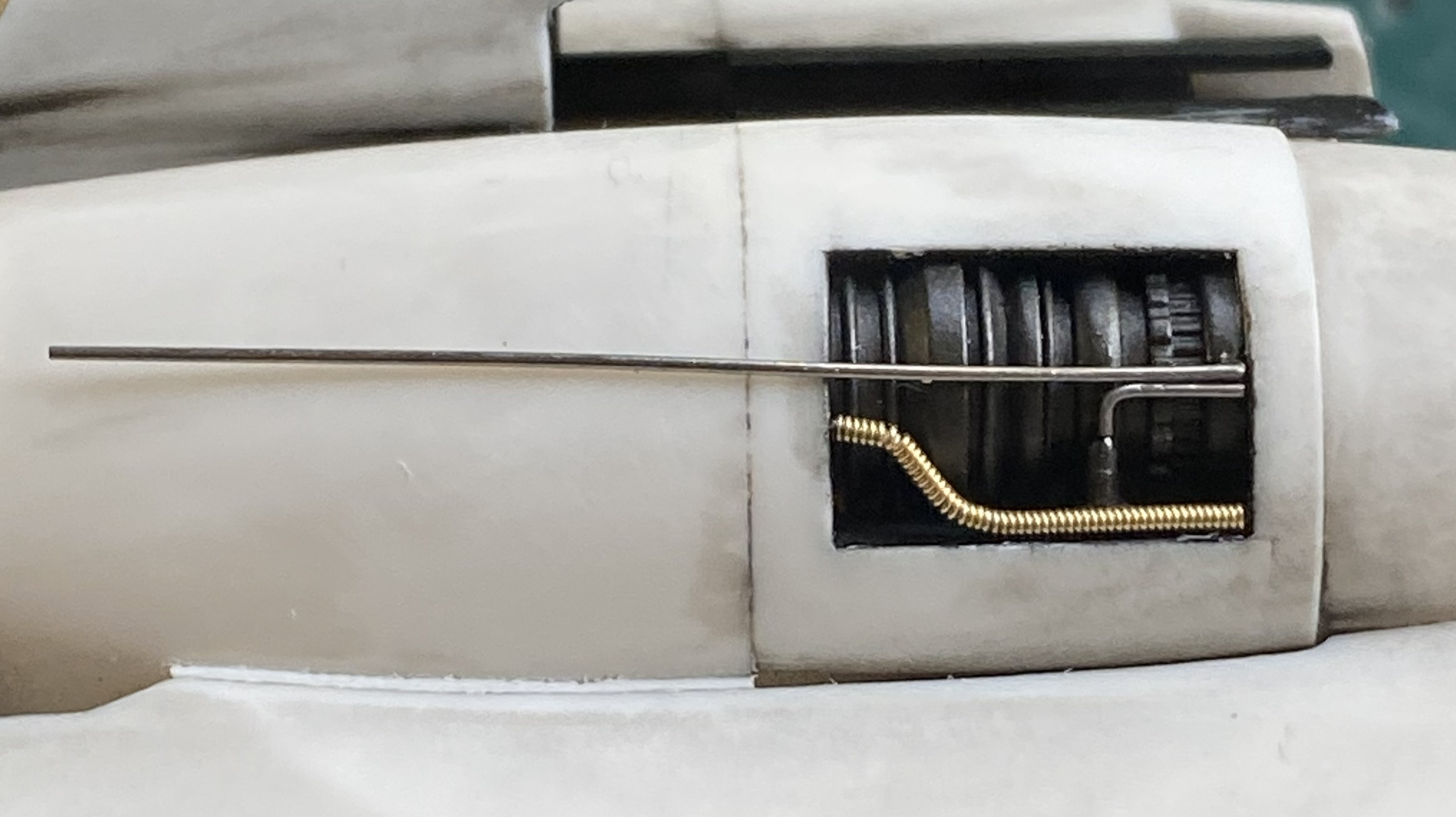
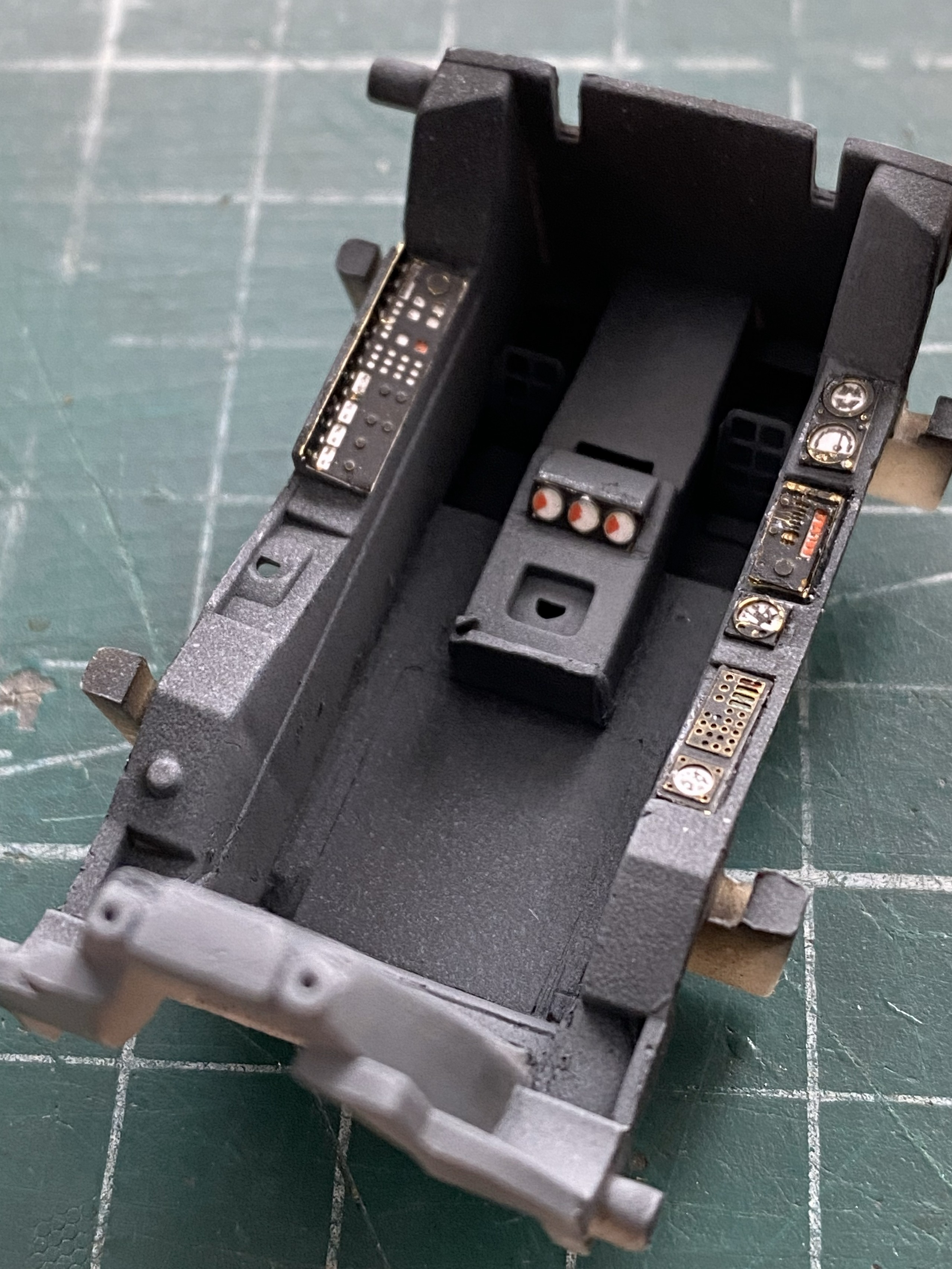
Some of the PE parts from the other PE fret are intended to dress up the engines a bit. The problem with PE is that it’s flat. I used a piece of a D guitar string and three different sized solder (0.020″ [.508mm] is shown but I also used 0.015″ [.381mm] and 0.010″ [.254mm]):
The port engine done:
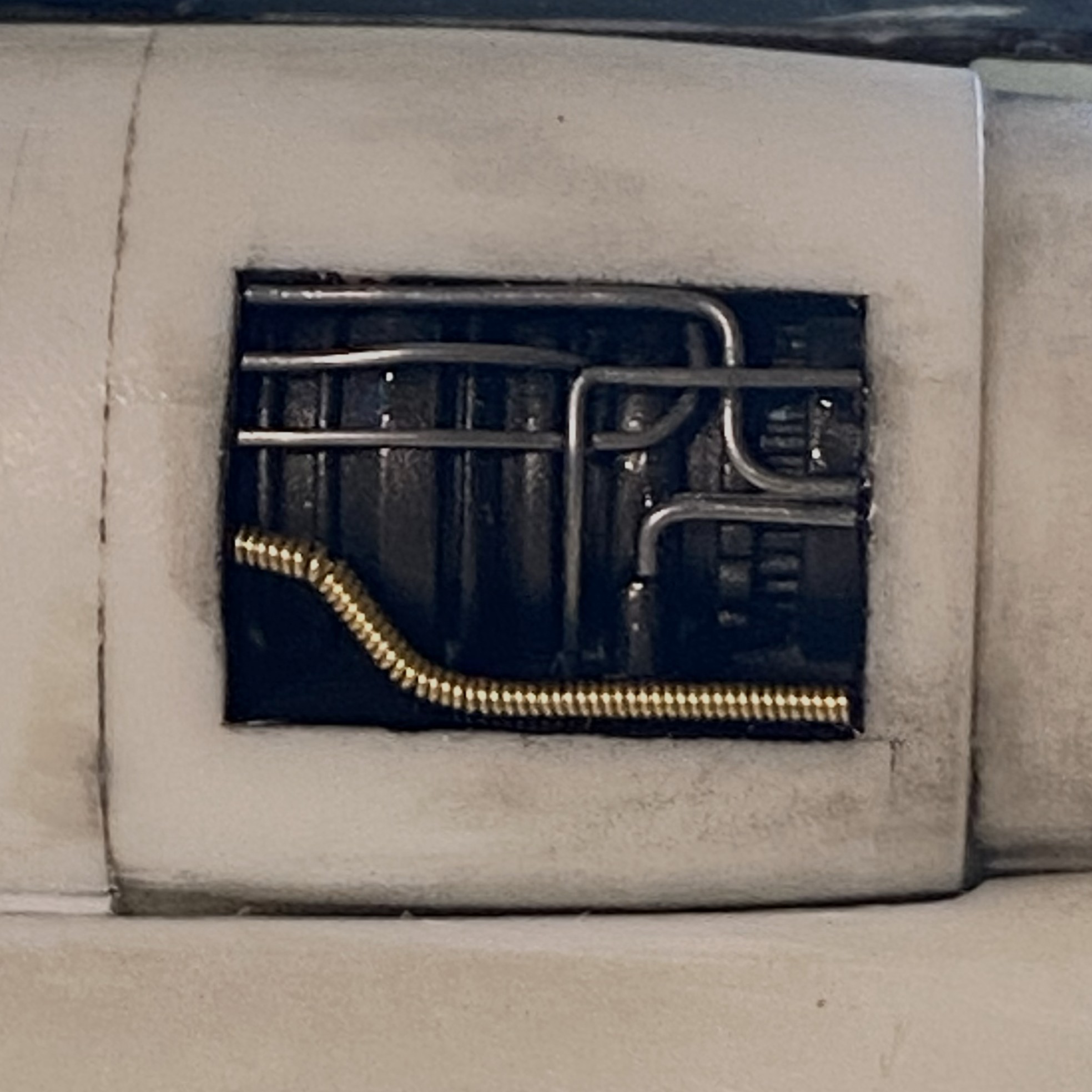
And the starboard engine is done:
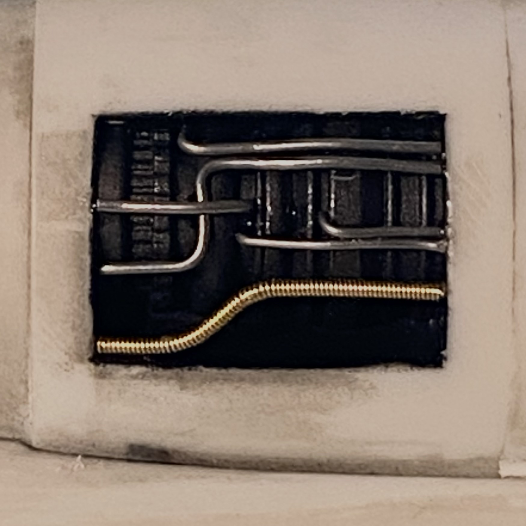
Yeah. I like that, and the pre-shading does exactly what I’d hoped it would do. When it comes time to paint this model, the engine areas will stay as they are now (with the typical paint touch ups).
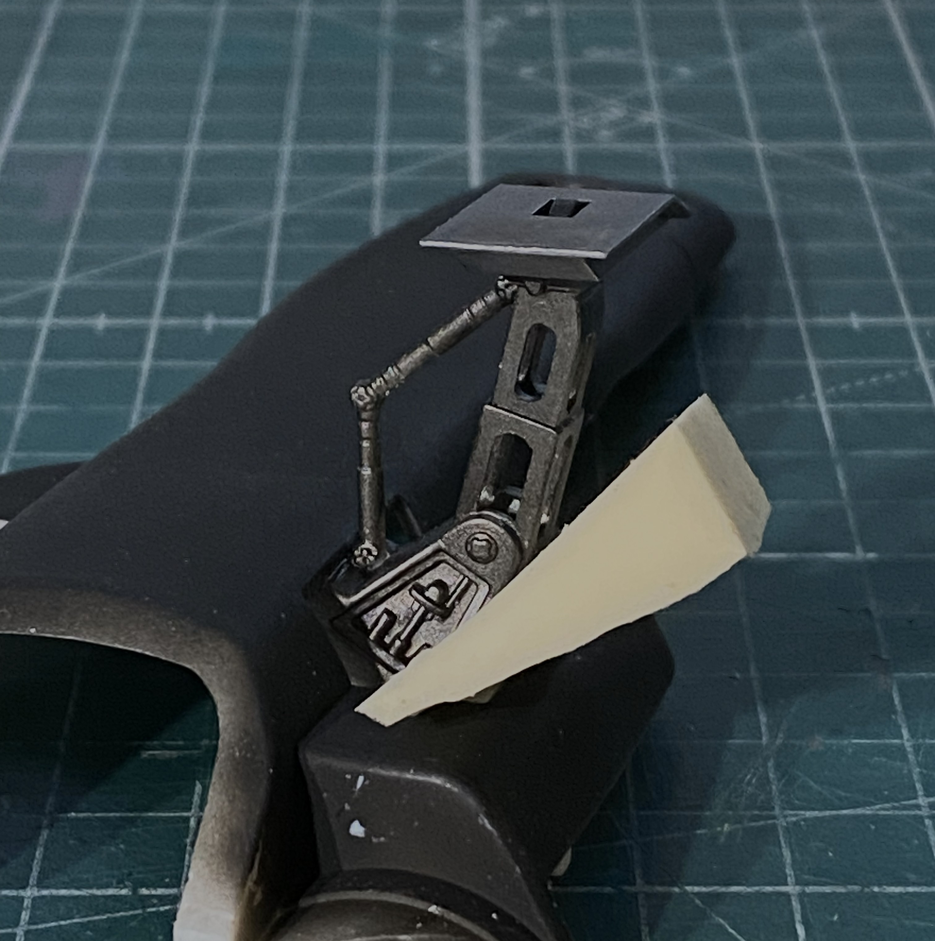
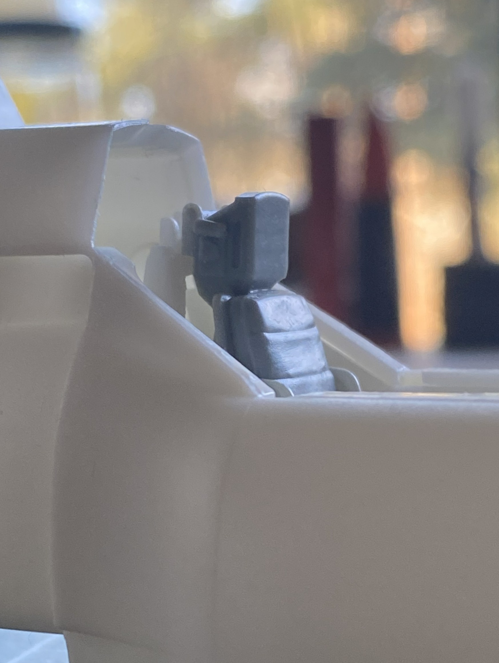
As it gets closer to adding the belly pan, it was time to add the nose gear. It fit like crap. I’m not especially thrilled with how it’s sitting (after much diddling, fiddling, and offering Deities all sorts of things that They’re aware I’ll never do or stop doing, depending on how I’m wheedling them) but short of taking the nose bay out…again…this is how it’s going to stay:
There! All caught up. Next month’s preview? Brass origami.
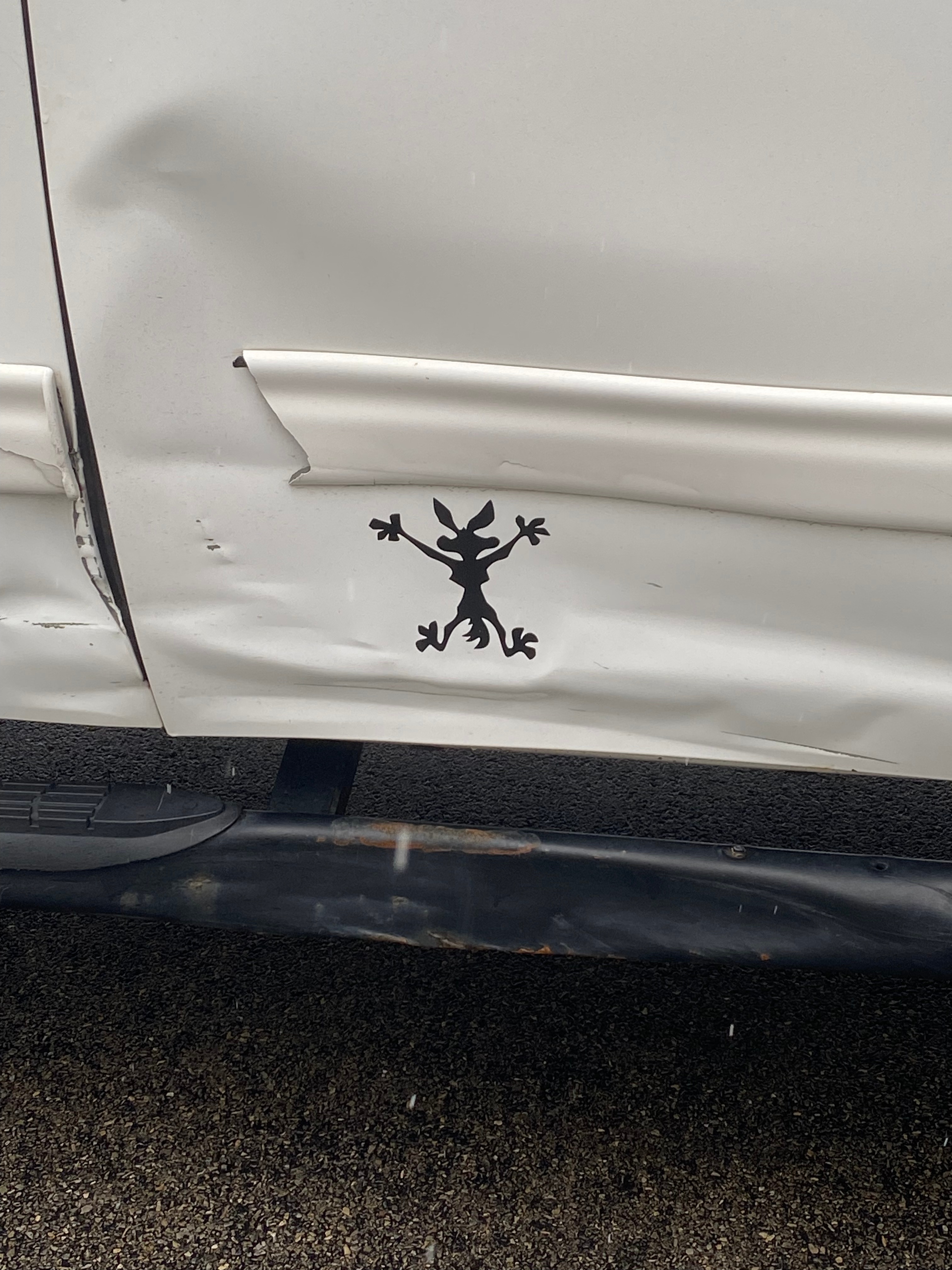
This is a Public Service Announcement.
Be careful where you part your truck! There are miniature coyotes in the neighborhood and they’re obviously in a rush:
Colonial Viper MkII (Moebius Models) 1/32 Scale Build #1, Part 1 – Parts Layout and the Start
This is going to be interesting (hopefully not in the Chinese sense). I’ve never done fictional spacecraft before. My initial intent was to model this as realistically as possible, but that balloon was popped almost immediately. Nothing about this is realistic, or as a friend of mine said, “Science by magic.” Okay, then what am I actually building here? It’s a movie prop that existed in two forms; digital (CGI) and practical (something real). That’s made the build easier and more difficult at the same time. The easier aspect is the availability of primary sources. Just watch the show and when a bit of detail flashes past, take screen captures of pertinent scenes. The difficult part is internal. As designed, this thing could never move under its own power and it irks a part of me. The rest of this thing should be fun!
Science by magic.
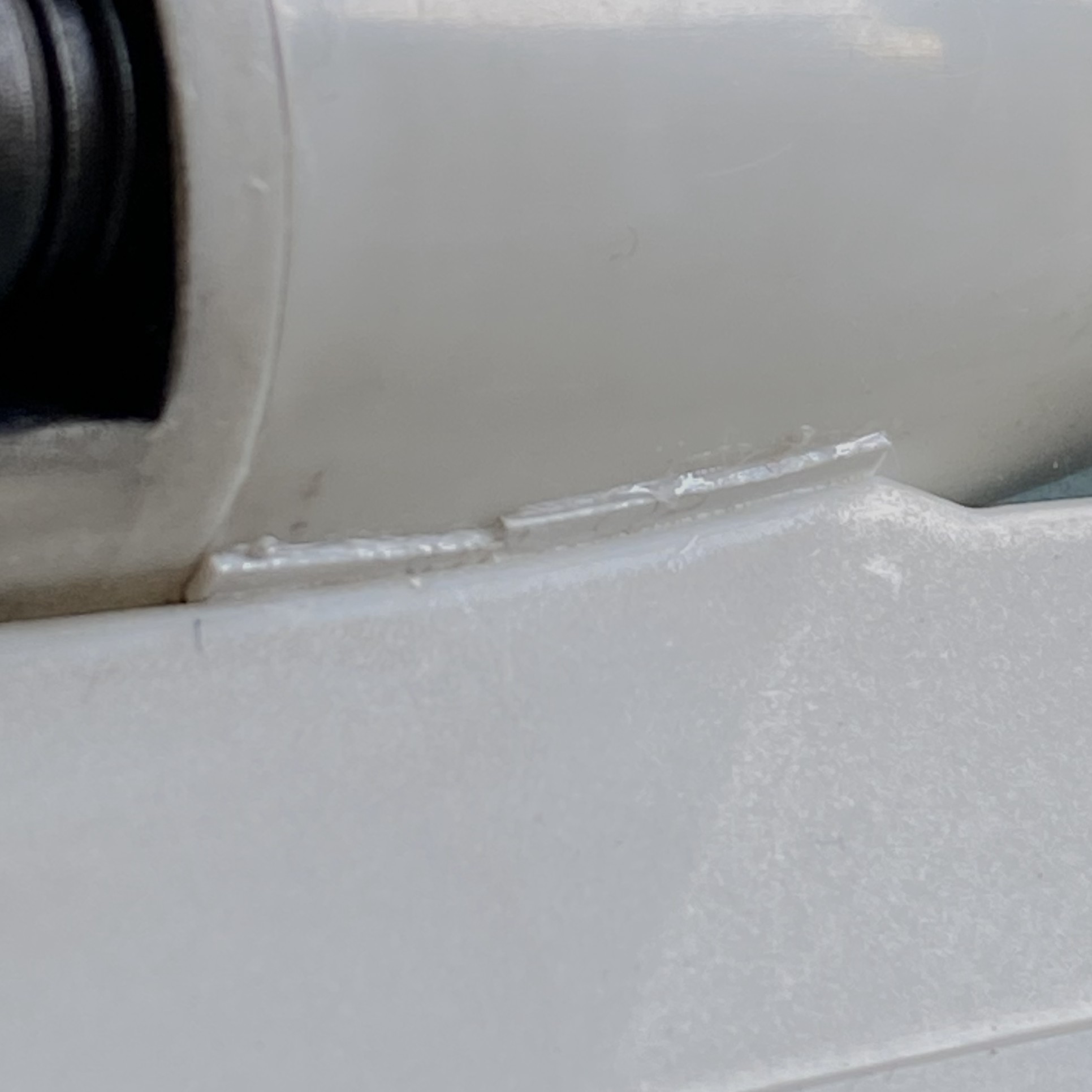
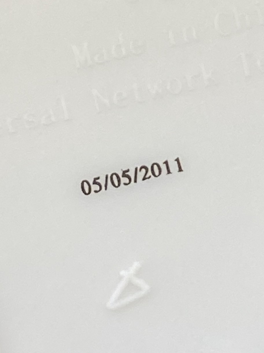
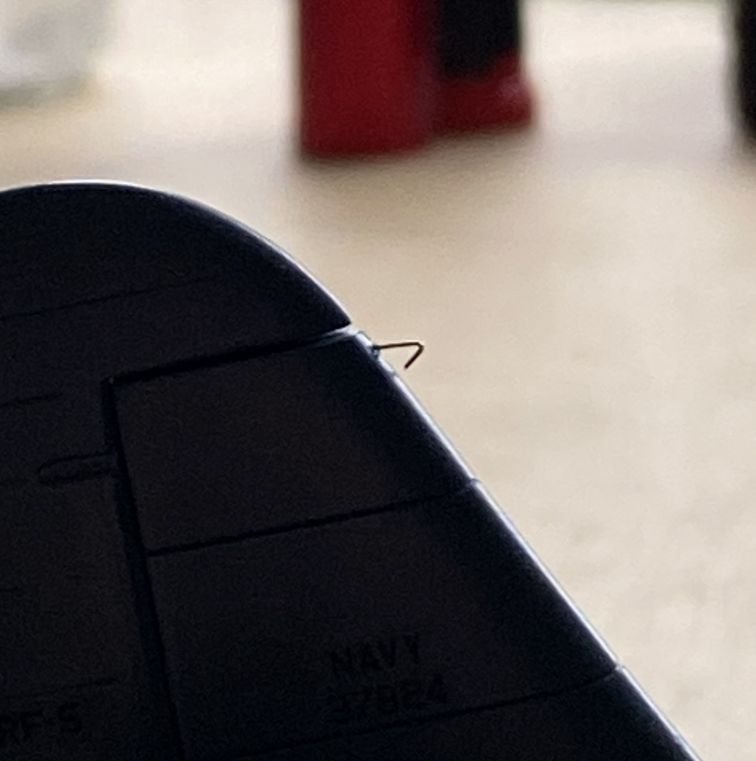
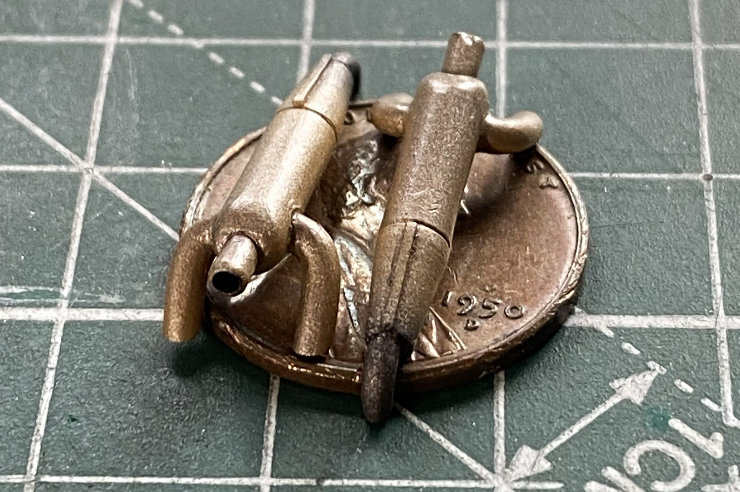
This is what I have to start with. This is the first time I’ve seen the manufacturing date (I assume, anyway) printed on kit parts (inside of the wing):
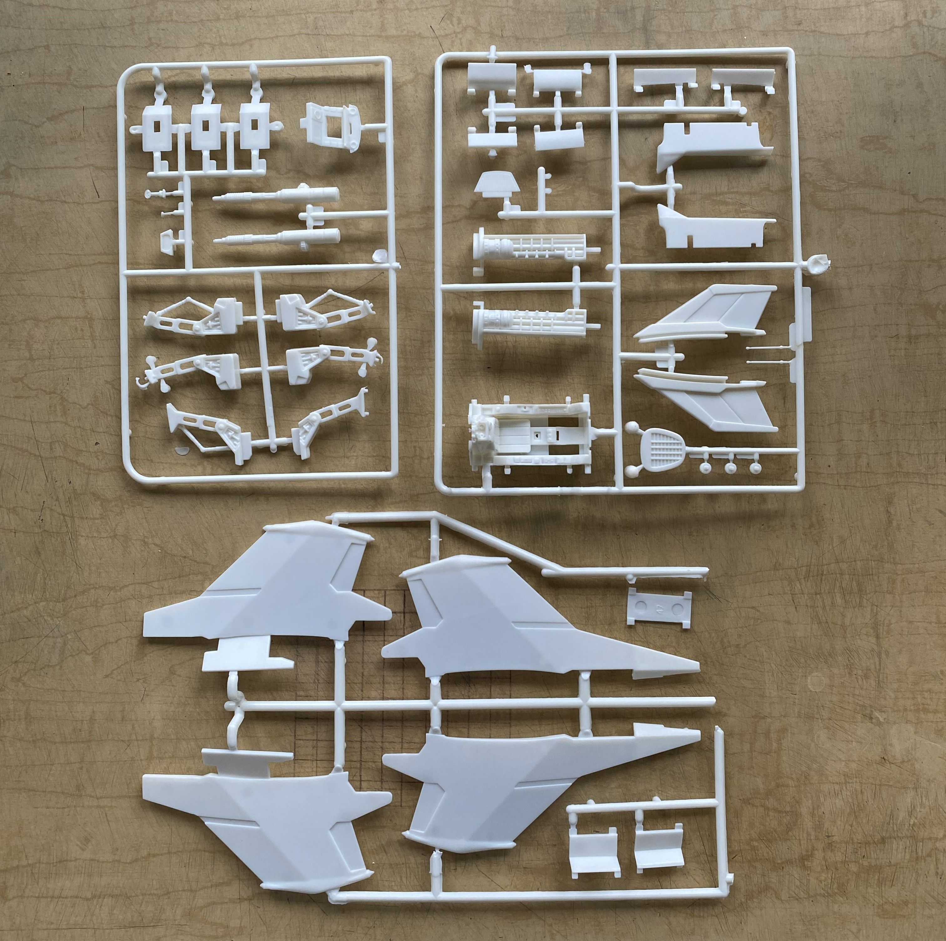
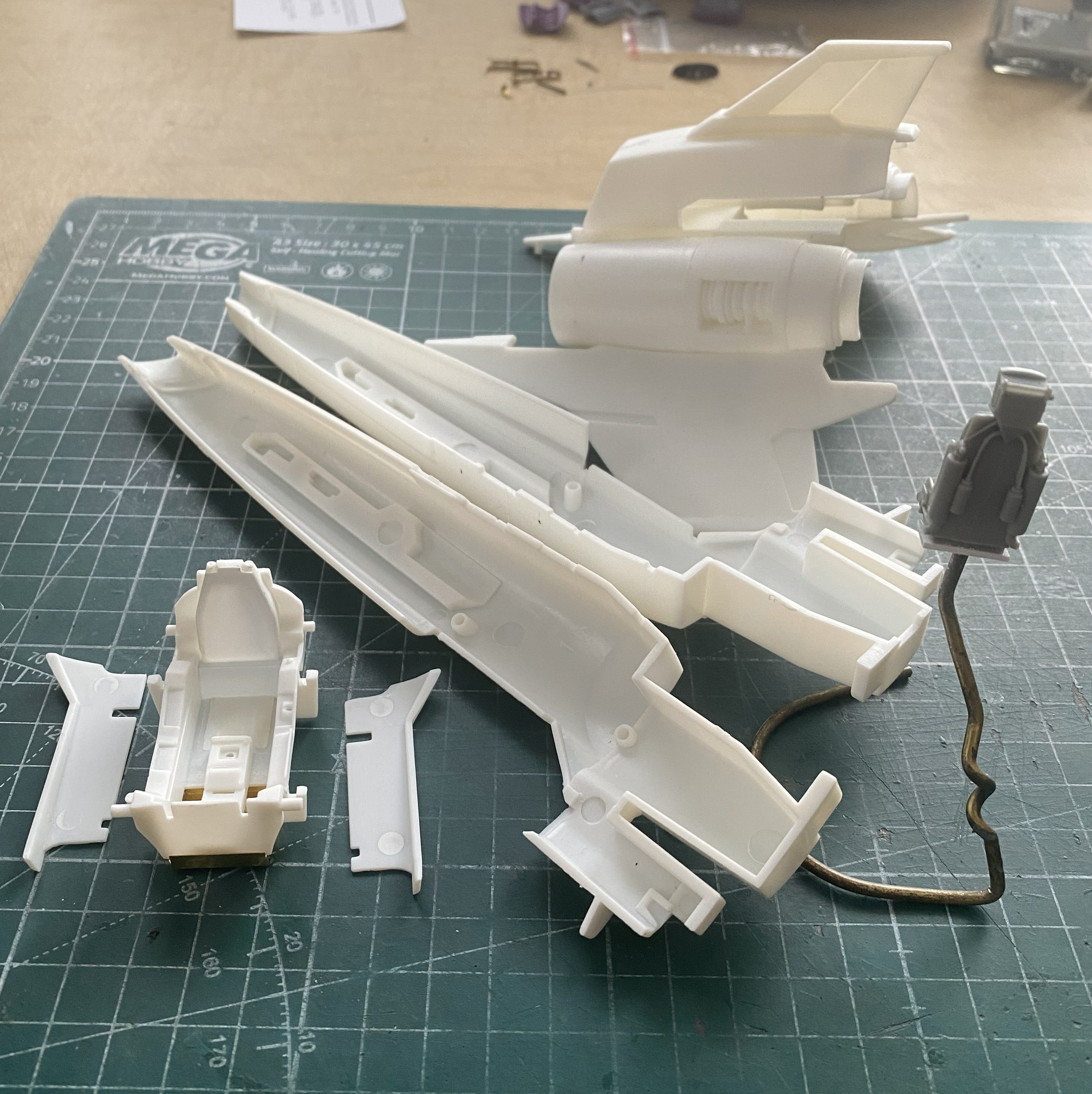
That noted, here’s what’s in the box:
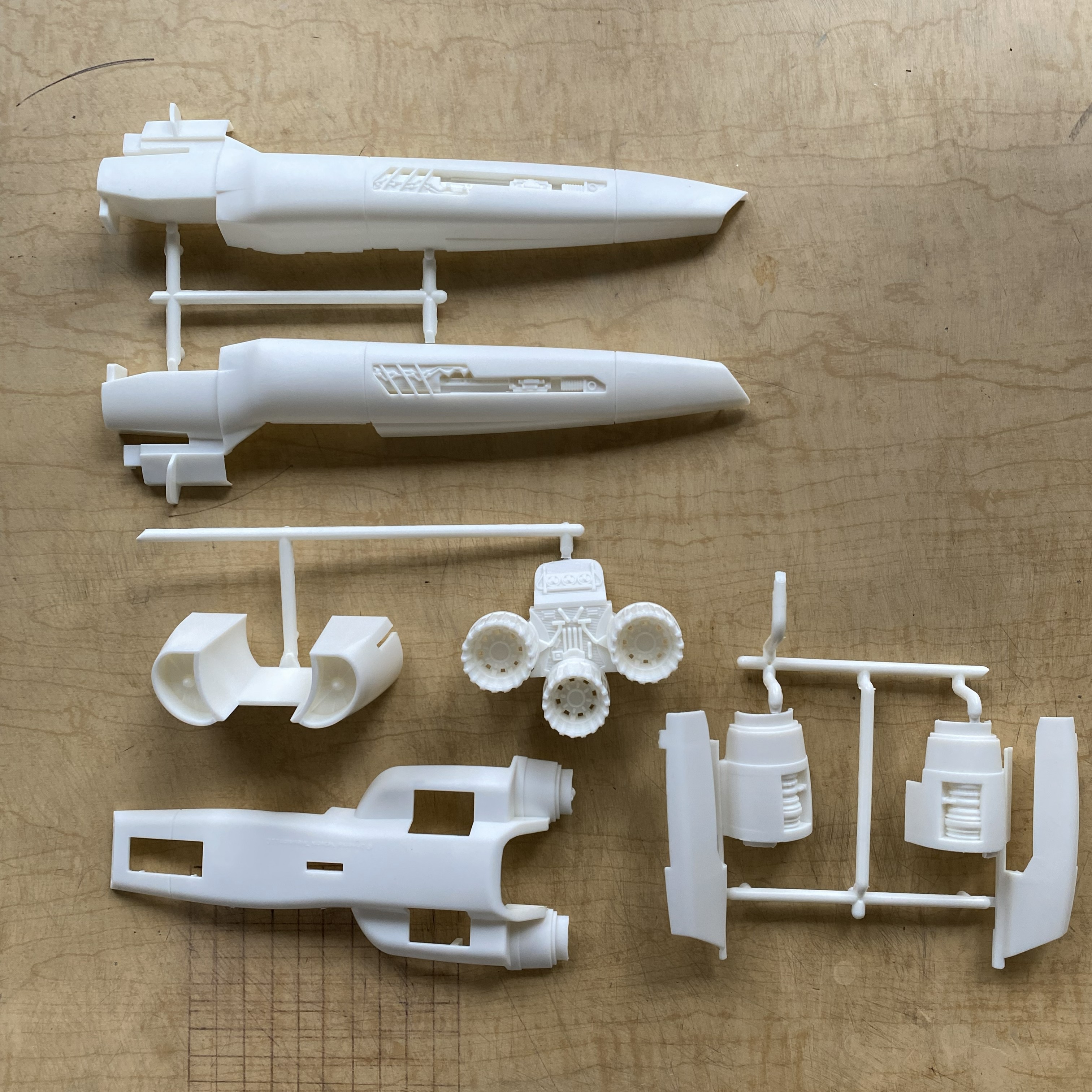
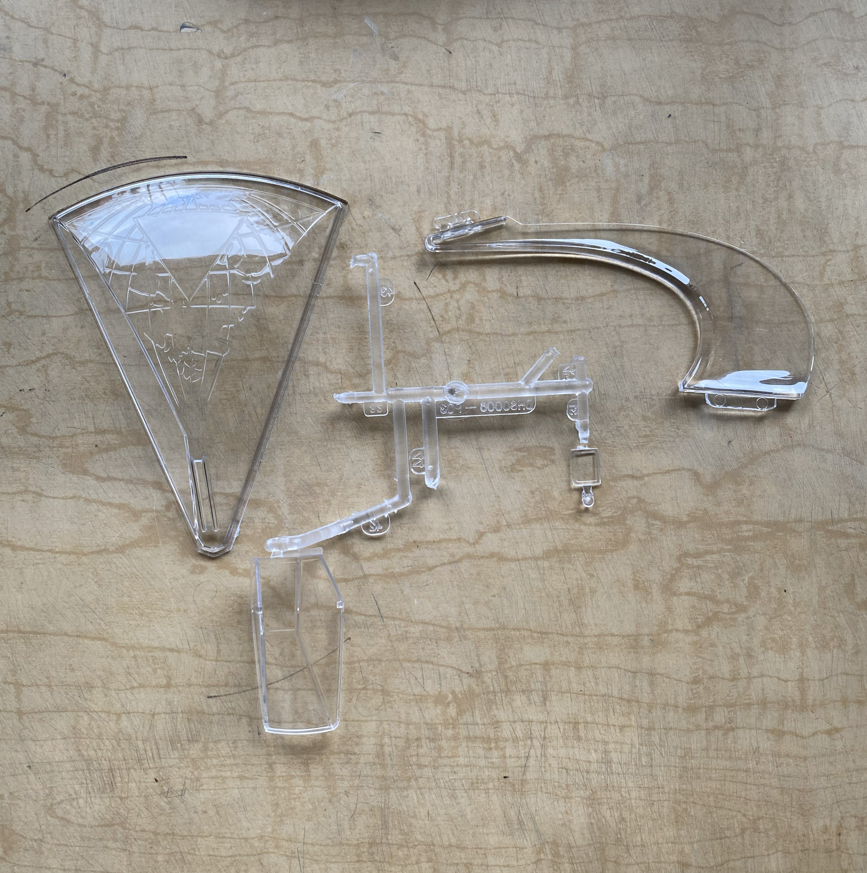

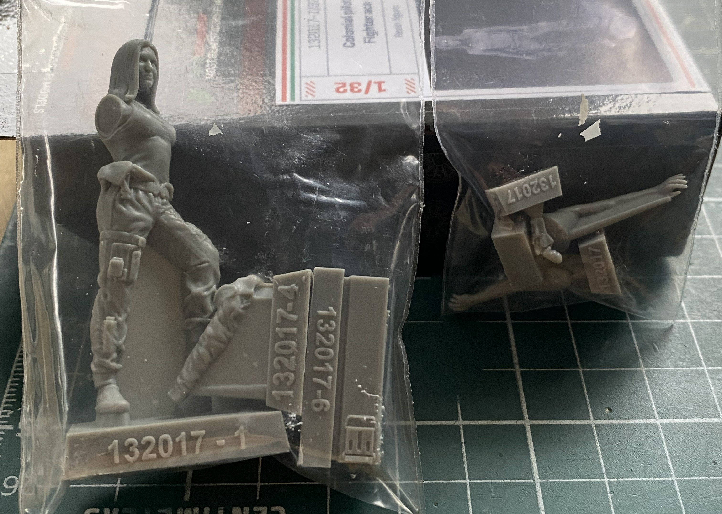
The first thing that caught my attention was the quality of the clear parts, in particular the canopy. Thin, clear, and mostly well done (more about that in more detail than you’d believe later). The second attention-getter was the resin figure. Overall, it’s nicely done. However. If you intend on using it, the joystick the right arm is holding (the unattached arm) is way too high. If you’re using the figure, you’ll have to deal with that (but since I’m not, I don’t have to deal with that).
As you can see, it’s not a kit with a high parts count. It’s simple. Oh, yeah?! Well I can fix that. I’ll fix that by seeing how many of these bits I can shoehorn into it.
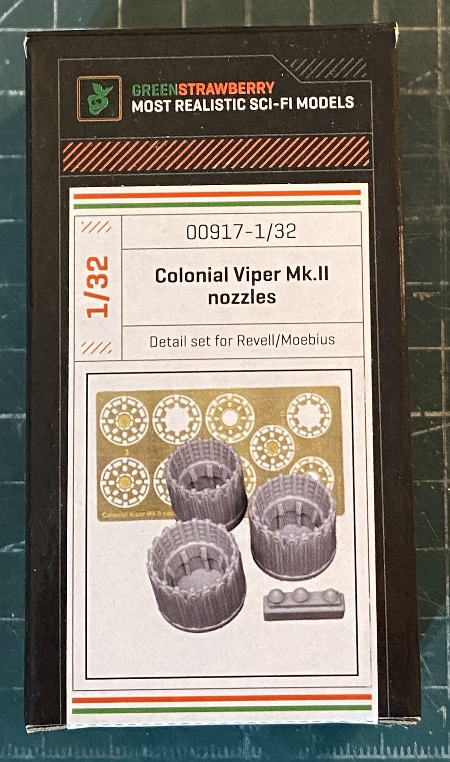
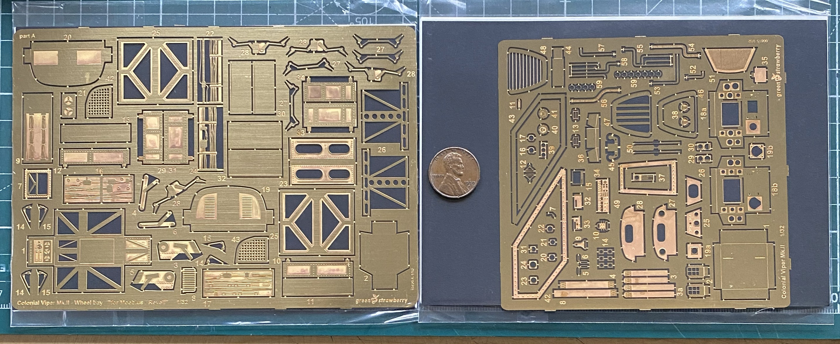
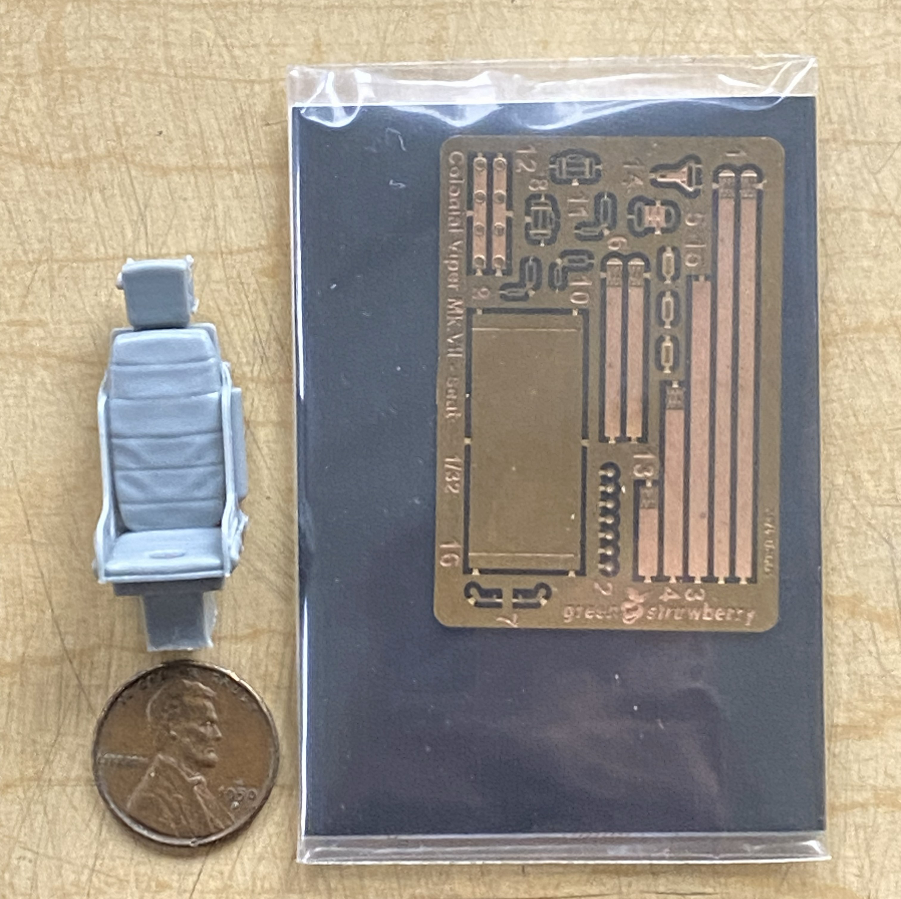
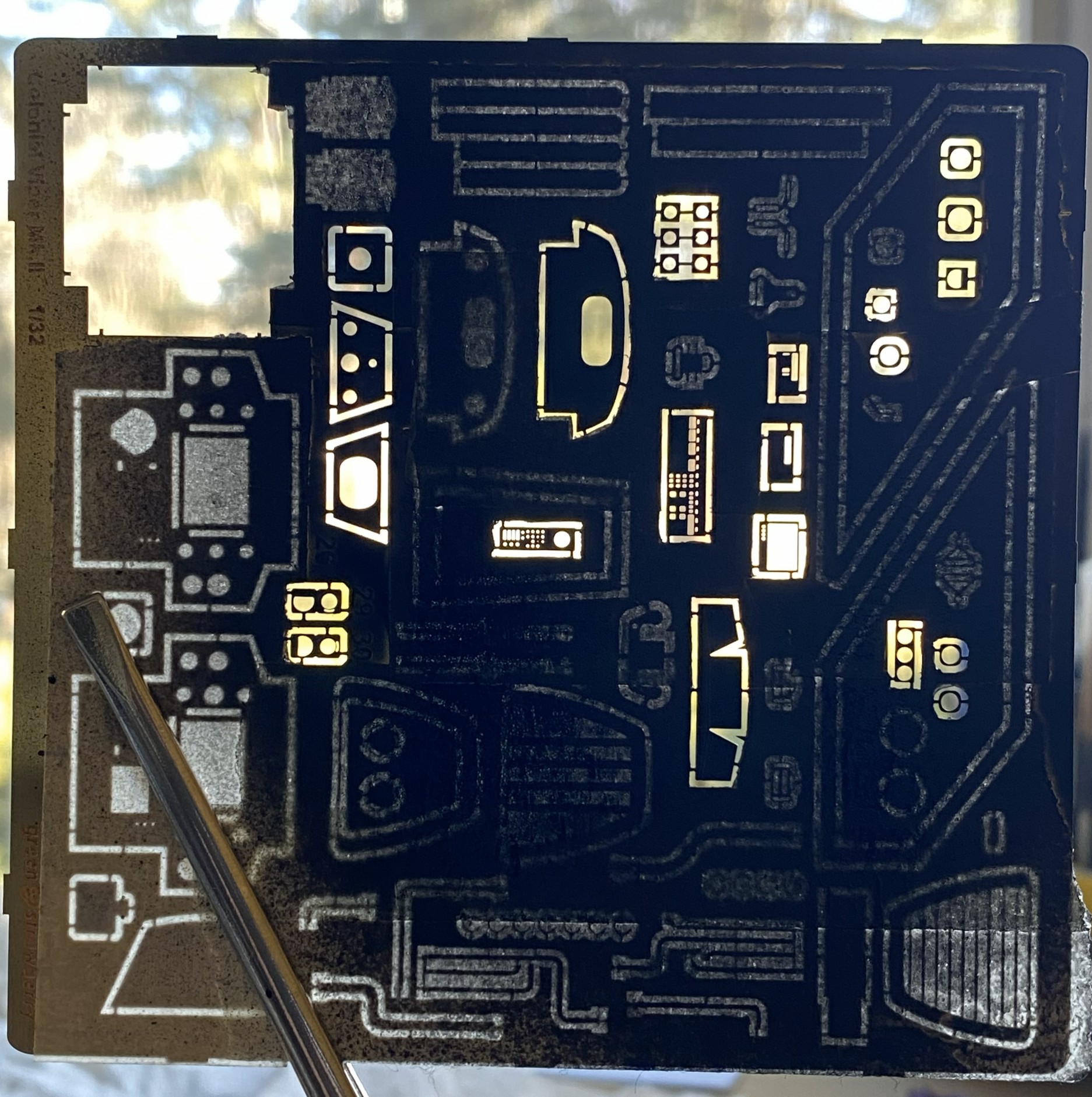
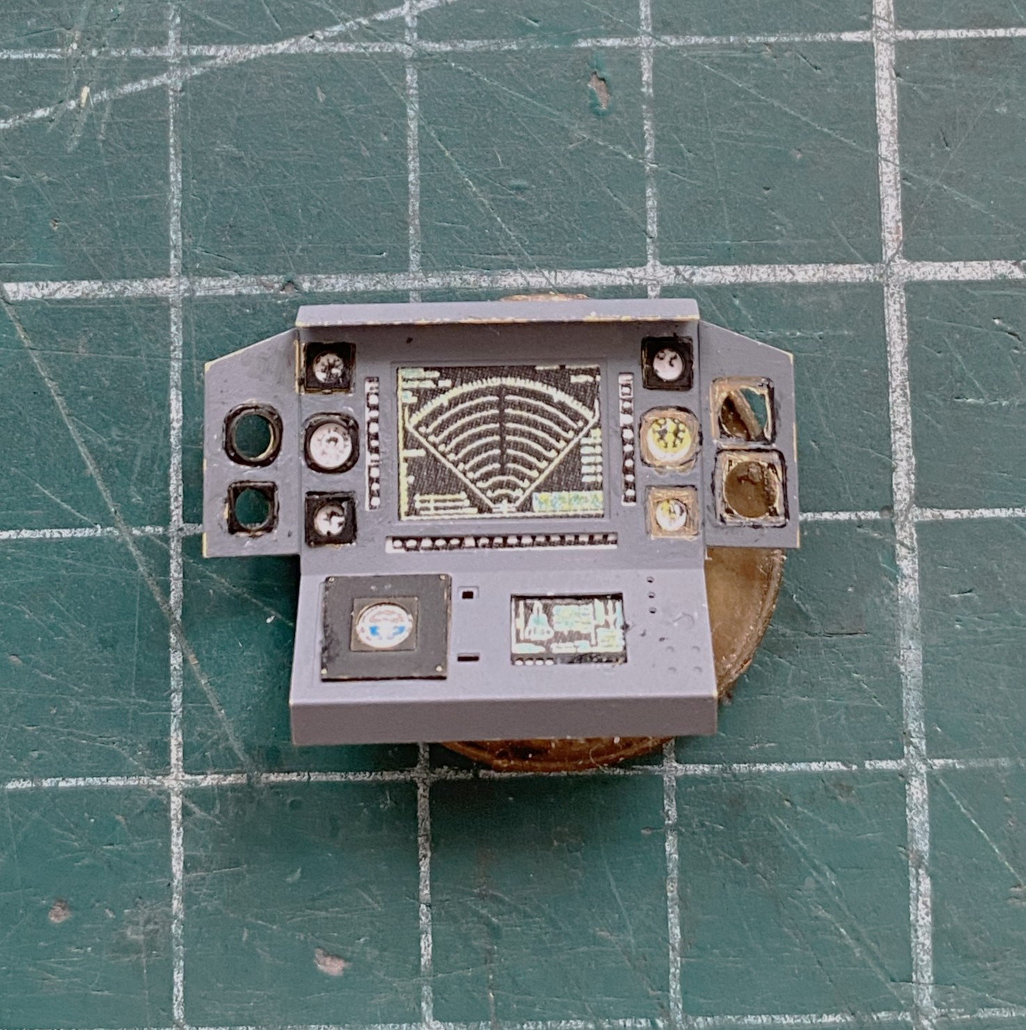
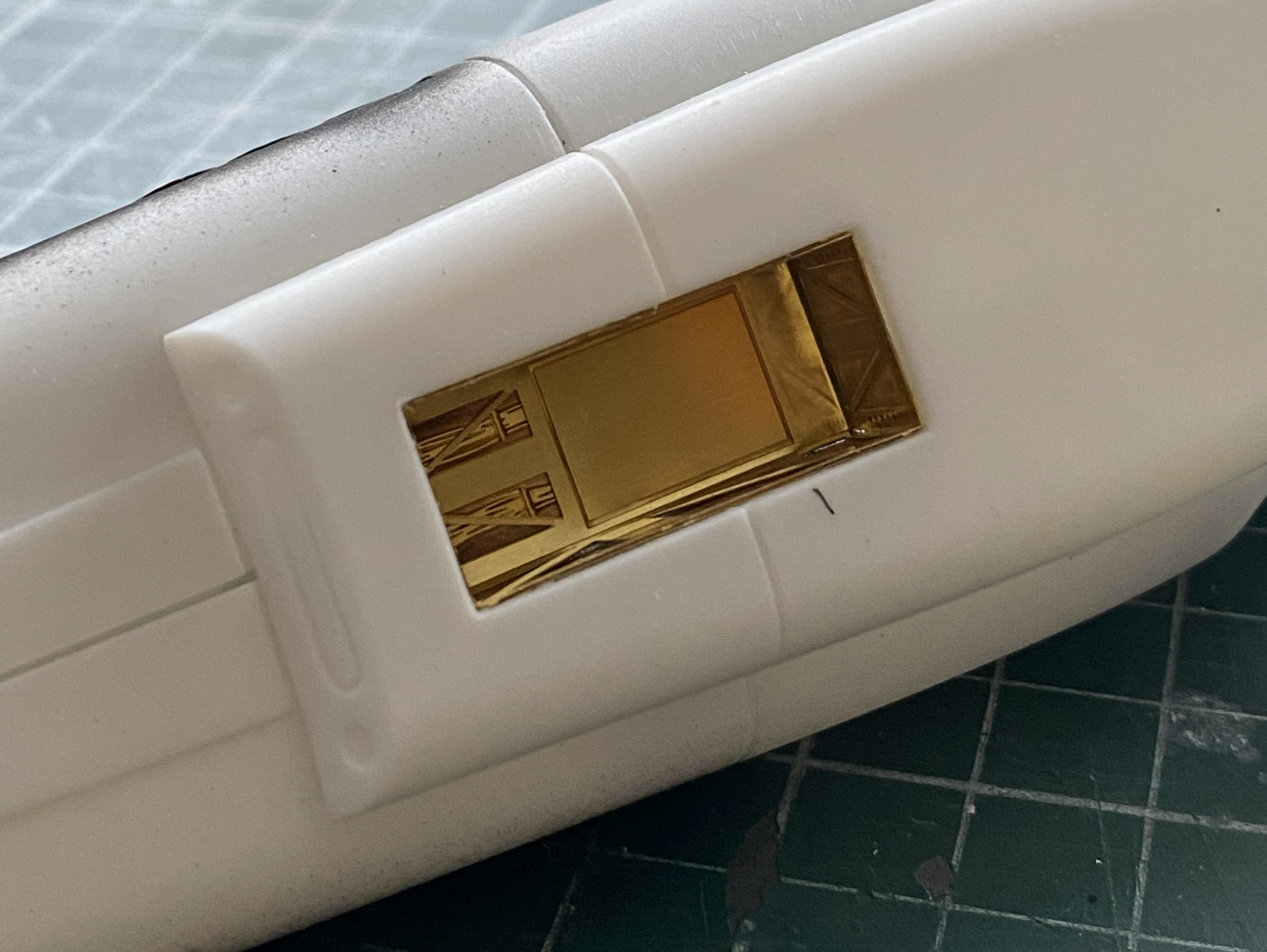
Green Strawberry (available from Moebius) makes all of the AM bits I’ll be using. One set supplies the resin seat, PE parts for the panels, etc., and photo-reduced images for all screens and instruments. And a word about that… The AM set for the cockpit offers two sets of gauge faces. One set is for a standard build, the other set is for those of you who like to add lighting. The kit is designed to allow the forward instrument panels to be back-lit. The set of gauge faces with a black surround are for illumination, the white (which are the ones I’m using since I’m not building this with lighting) are for a typical build. All of them are excellent and fit well. The other PE set is for landing gear bays. There is a resin/PE ejection seat, also nicely done. Since I have a profound appreciation for the character of Kara “Starbuck” Thrace, and the kit offers decals of her specific ship, I’ll also be adding Starbuck. Green Strawberry (or whomever did the sculpting) did a great job with this resin figure; it even looks like her. And since I just can’t seem to resist throwing everything at a kit, I’m also replacing the kit’s exhaust nozzles with resin/PE aftermarket parts:
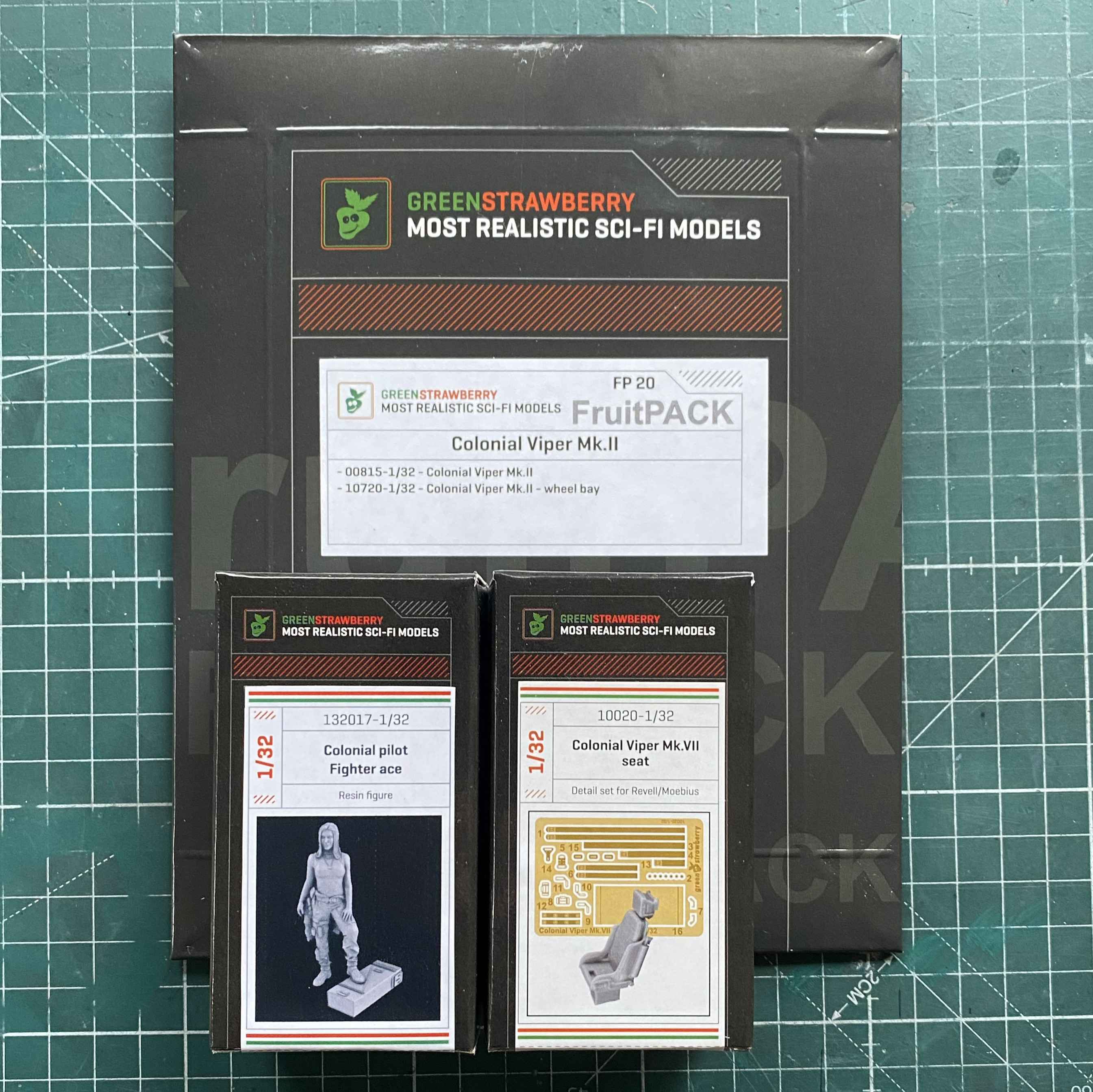
It’s true…there isn’t anything that I can’t complicate. It’s a talent.
At this point of the build, all of the AM parts had yet to arrive and I was still thinking that I’d be able to make the engines more realistic. My intent was to open a panel on top of the engines (after creating one, but to fit canon, it would be an inspection panel, not an inspection cavern as the kit has them) and perhaps extend a bit at each end. Had I looked just a bit further, I’d have noticed that any attempt to expand on the engines wouldn’t work. There isn’t enough room to create engine extensions and fit canon. But I didn’t look further and I went down this empty rabbit hole.
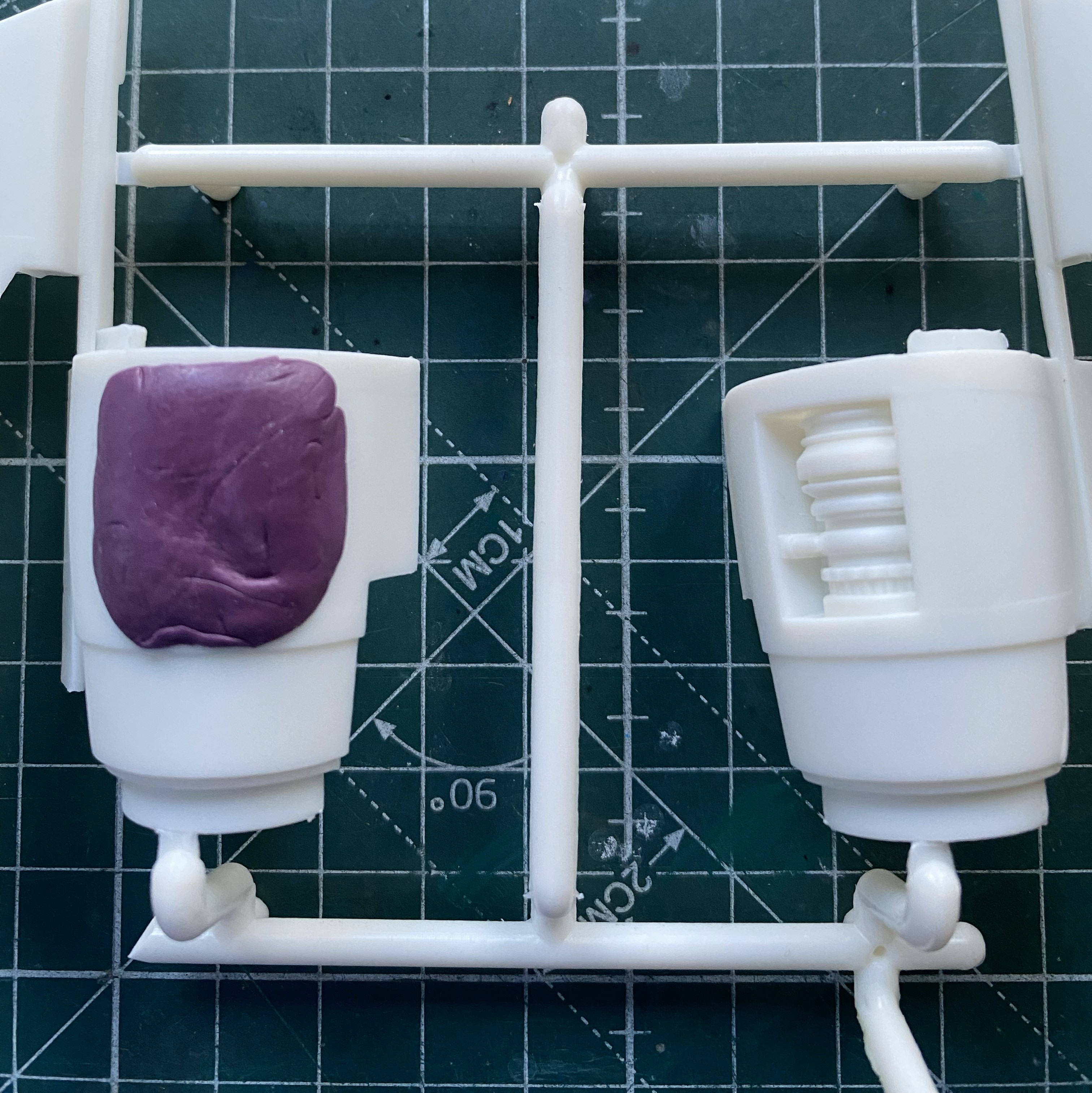
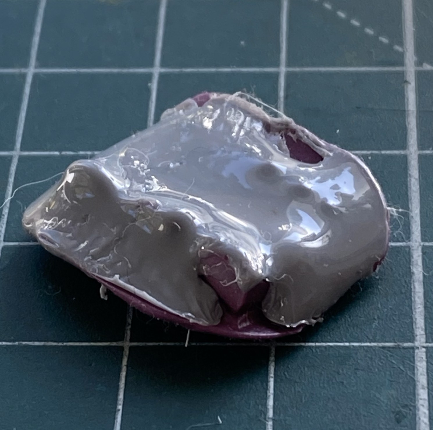
Rather than scratchbuild every addition, I’d thought that I could copy what detail was provided and then work it into an overall acceptable engine. To get molds, I used silicone molding putty:
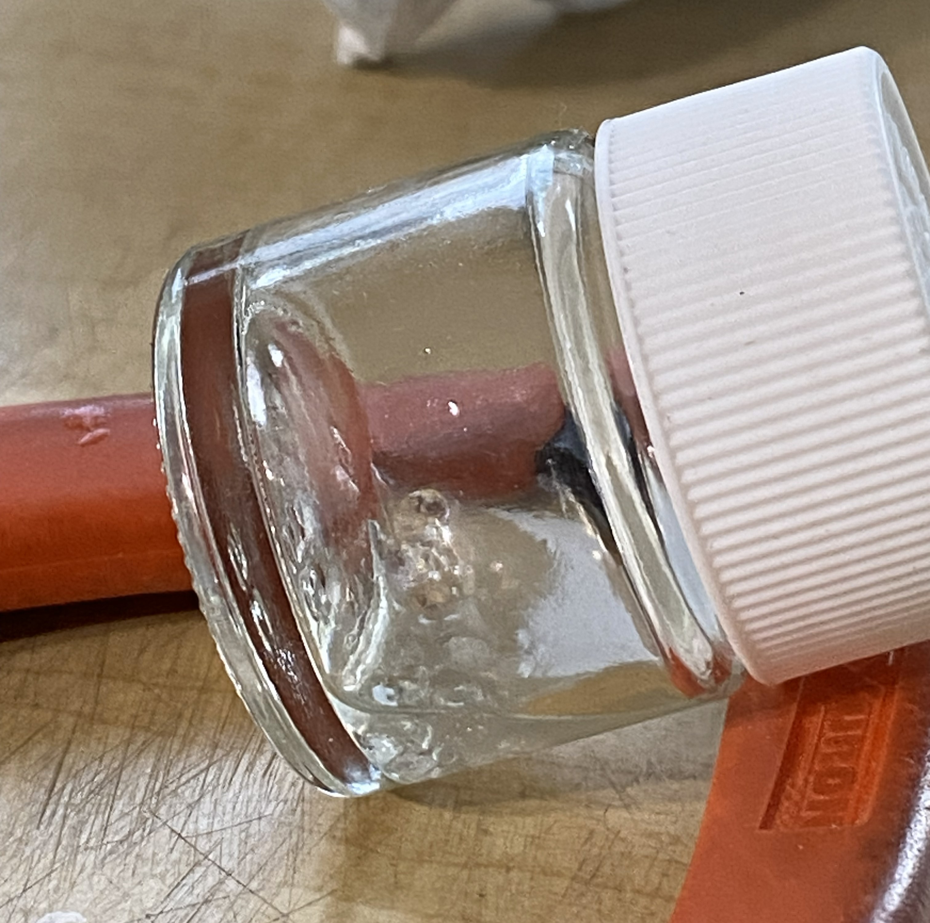
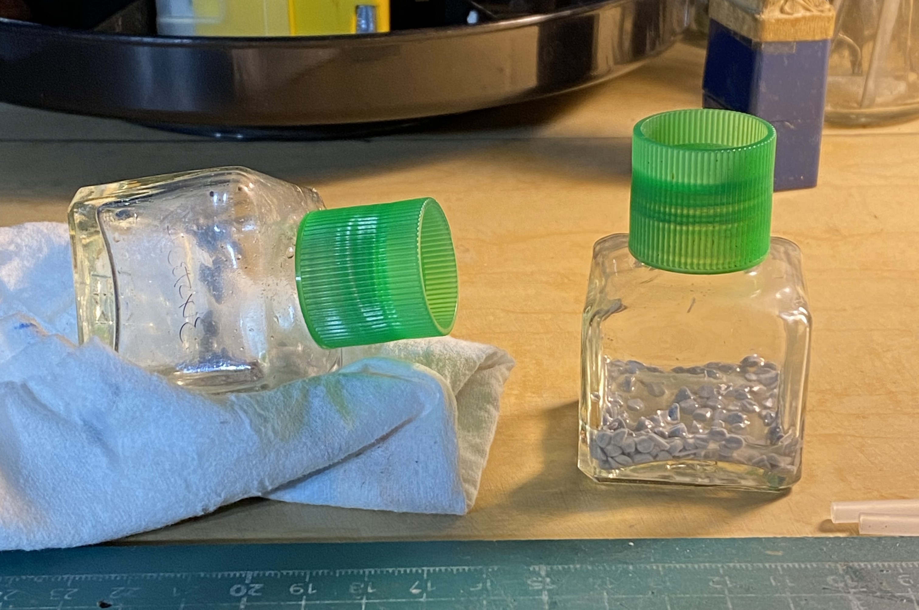
While the putty was curing, I investigated which would make “plue” (plastic and glue) to fill the molds. What would work better, acetone or Tamiya Extra Thin cement? I used two empty glue bottles, placing cut plastic pieces in each bottle and then putting enough acetone/glue in to cover the pieces. The tilted bottle has acetone (tilted so that the acetone would cover all the plastic) and the other has cement:
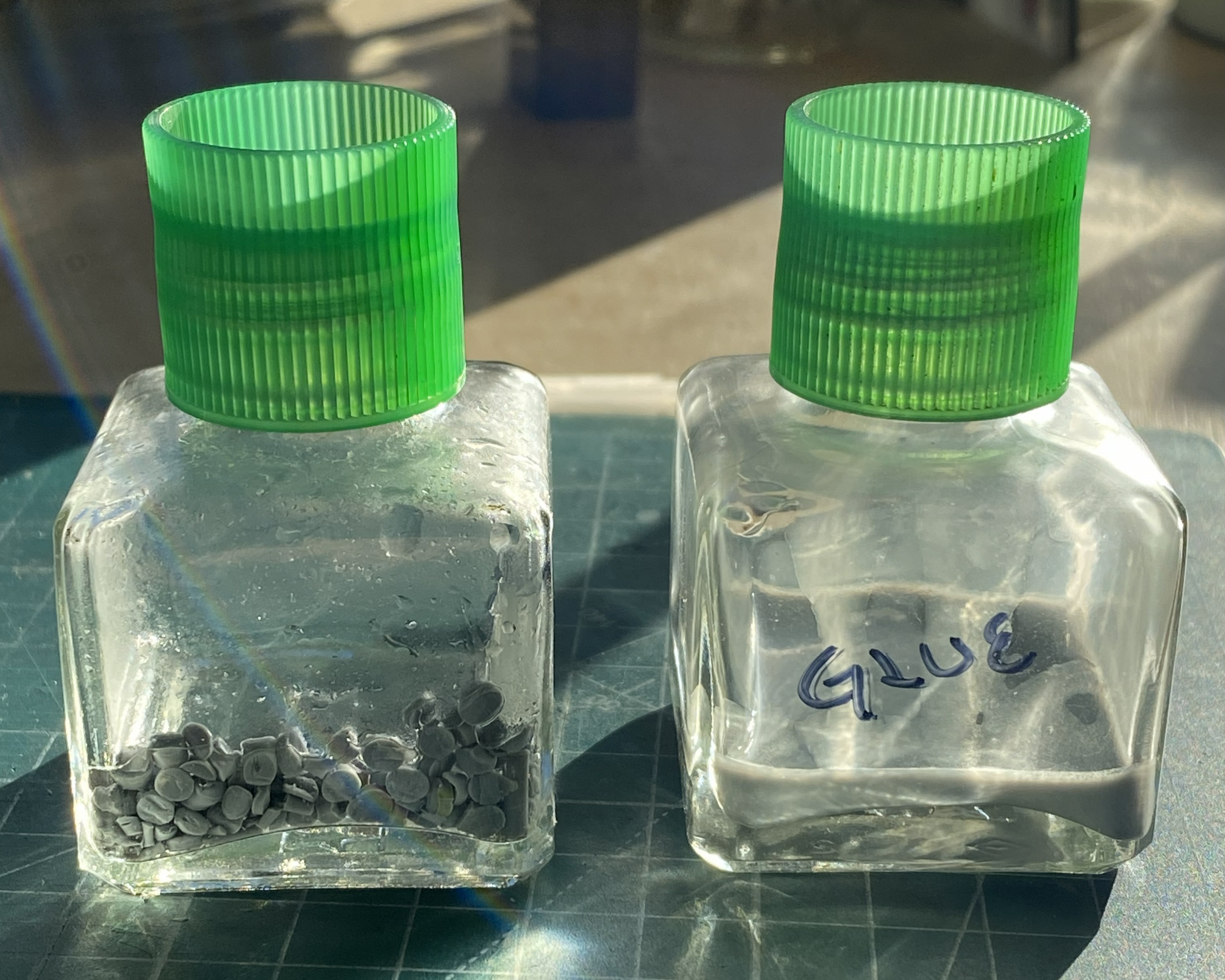
After sitting overnight, the clear winner is the glue. The only affect the acetone had on the styrene was to make the surfaces slightly tacky…that was it:
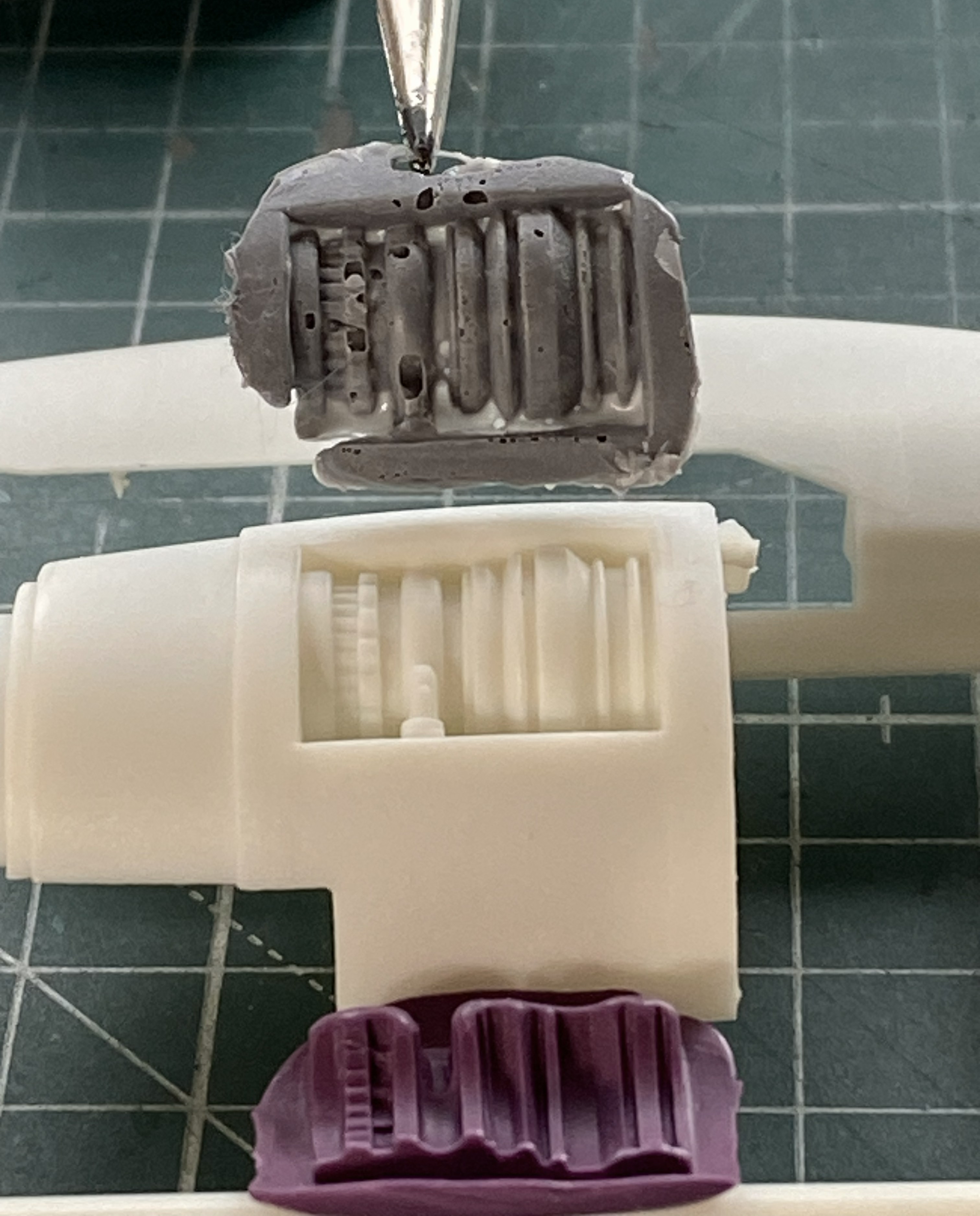
By then the mold was ready to fill:
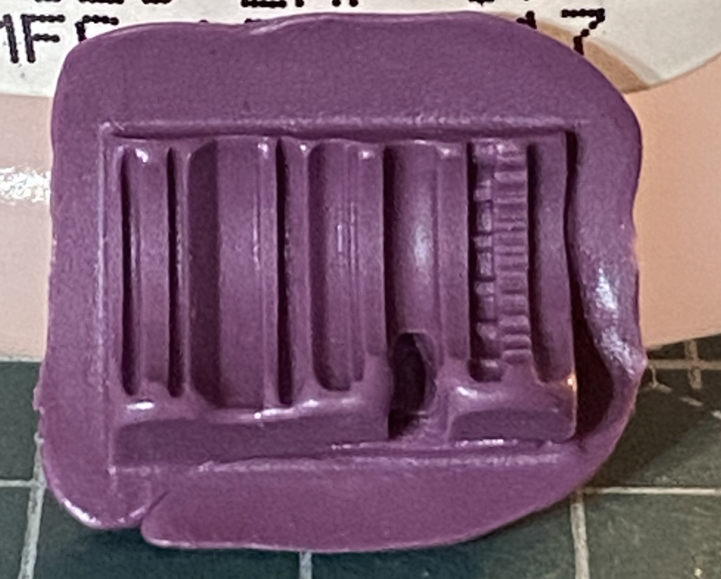
It’s been a while since I’ve used plue and the mold in the above photo shows it. I put on much heavier a coat than I needed to. Several thin coats works best. Another “interesting” trait is that the more the plue is manipulated in/on the mold, the more bubbles created, which this little lovely reminded me of:
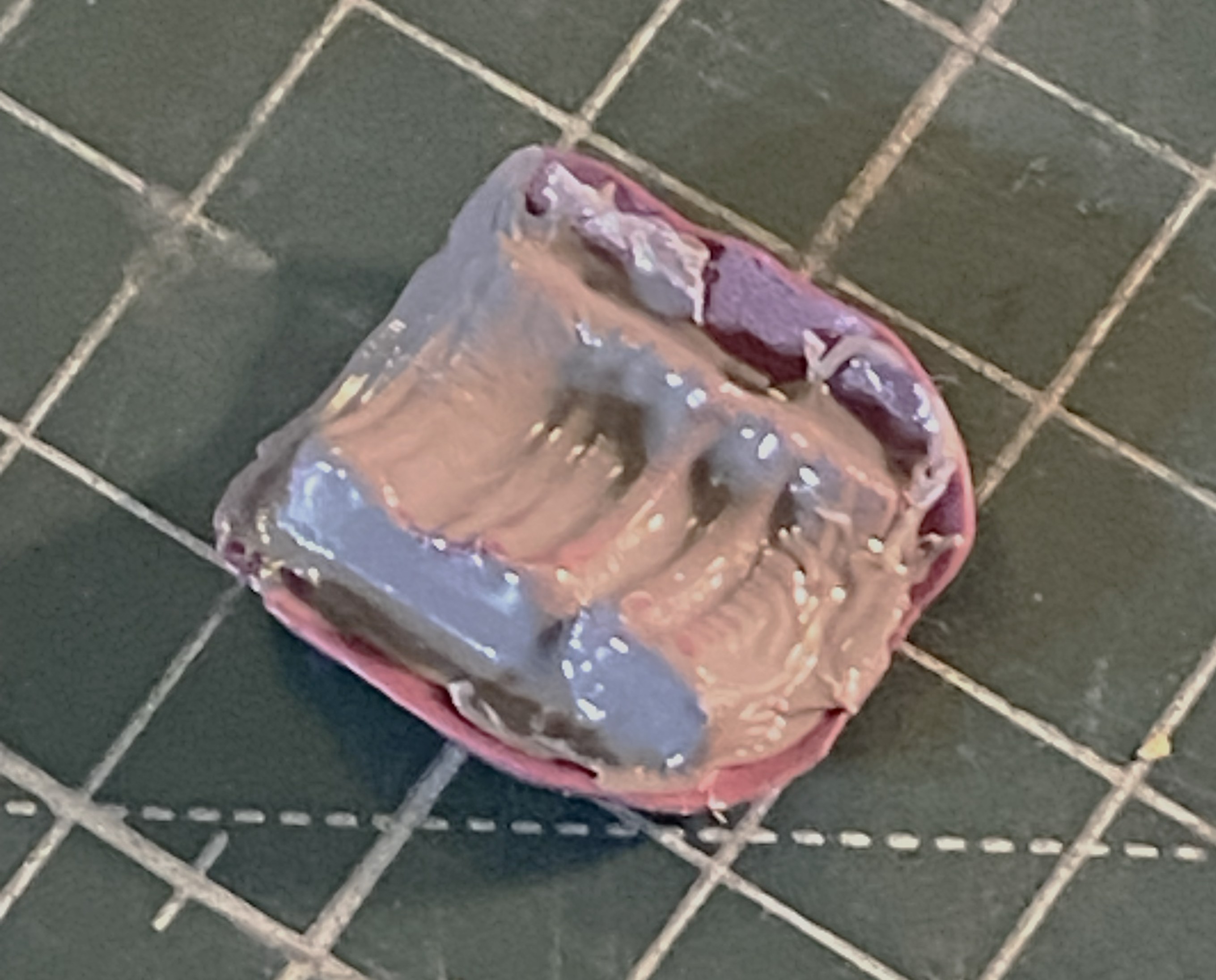
Next attempt using thinner coats worked better:
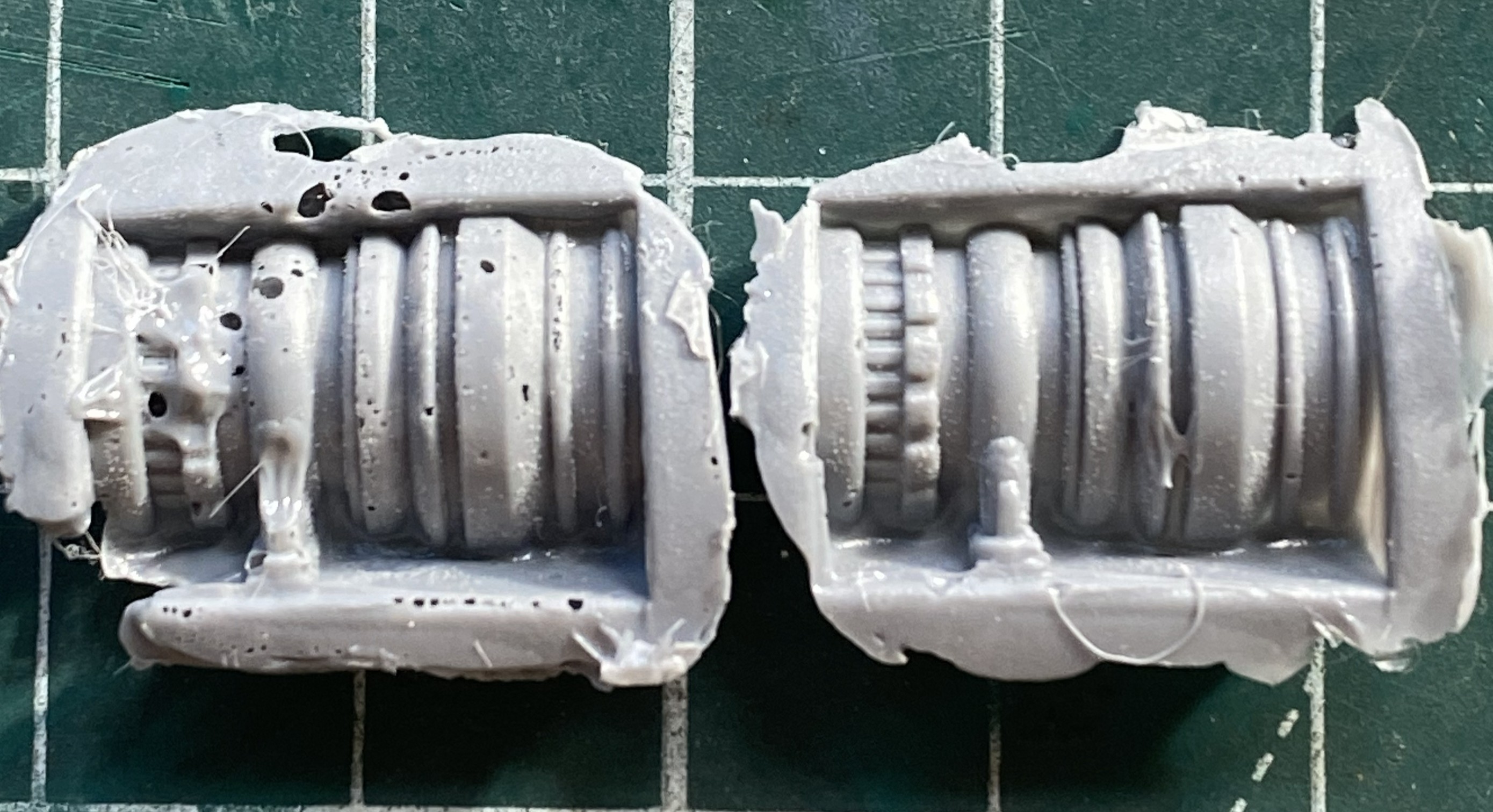
Of course I had to have a go at fixing the first casting (on the left above) but that solution created more problems than it solved. In fact, once I had acceptable castings for both sides is when I realized that the whole engine idea was a waste of time. They be what they is (relatively).
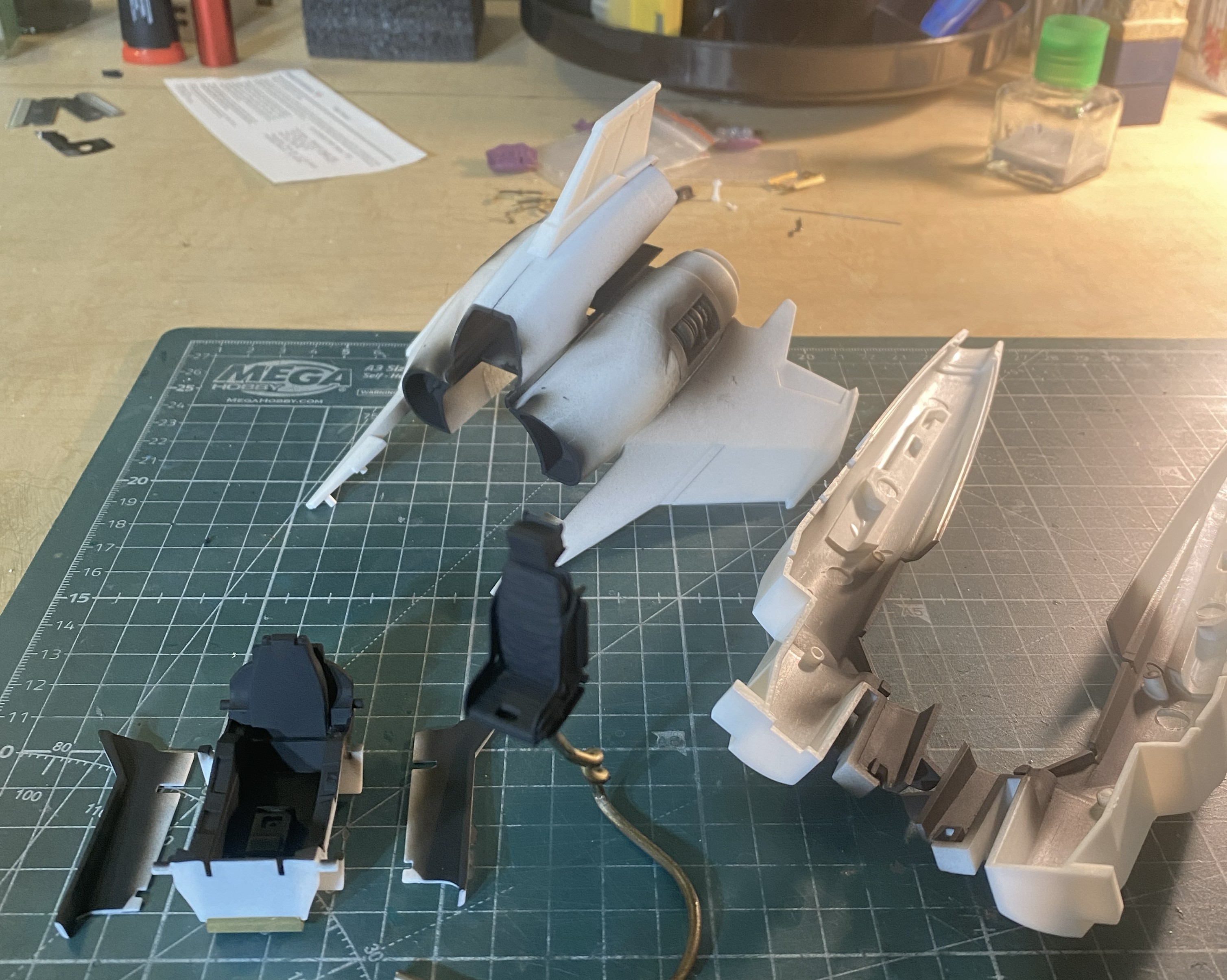
Since this was my first wake-up call (most of my builds have at least one), I decided to tape the major components together to check fit:
That will require some work. It’s not horrible, but it ain’t Tamiya, either.
Since this thing doesn’t have a leg to stand on, I decided to start putting them together. Nose gear is on the right:
Seams are variable. Some good, some not good, some just freaking annoying. I’m moving away from putty as my default void filler towards scabbing in plastic instead. These landing struts/gear seams need it:
See what I mean:

While all the added plastic was setting up, I started putting together wing halves. This was an area that needed help. So I helped it:
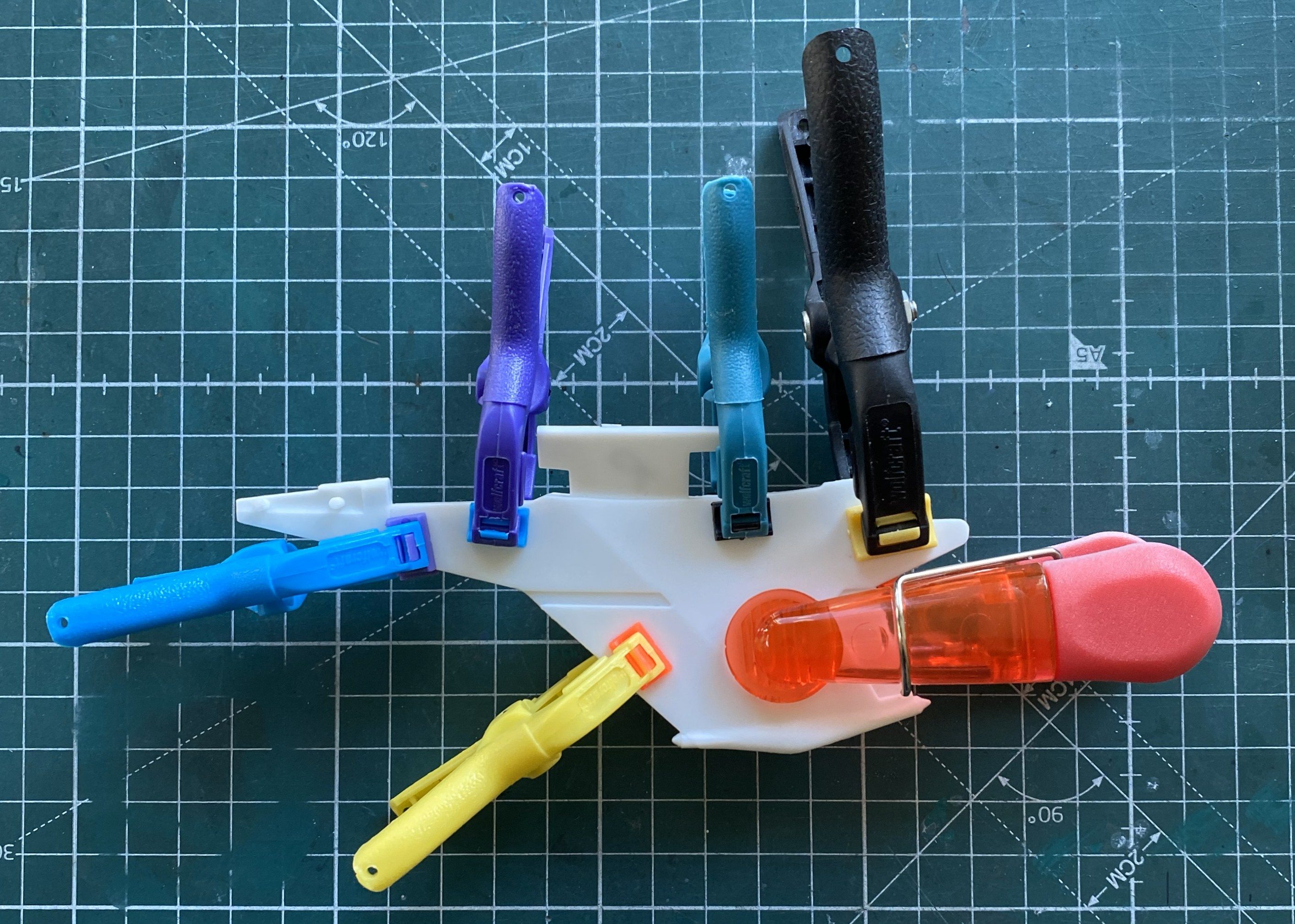
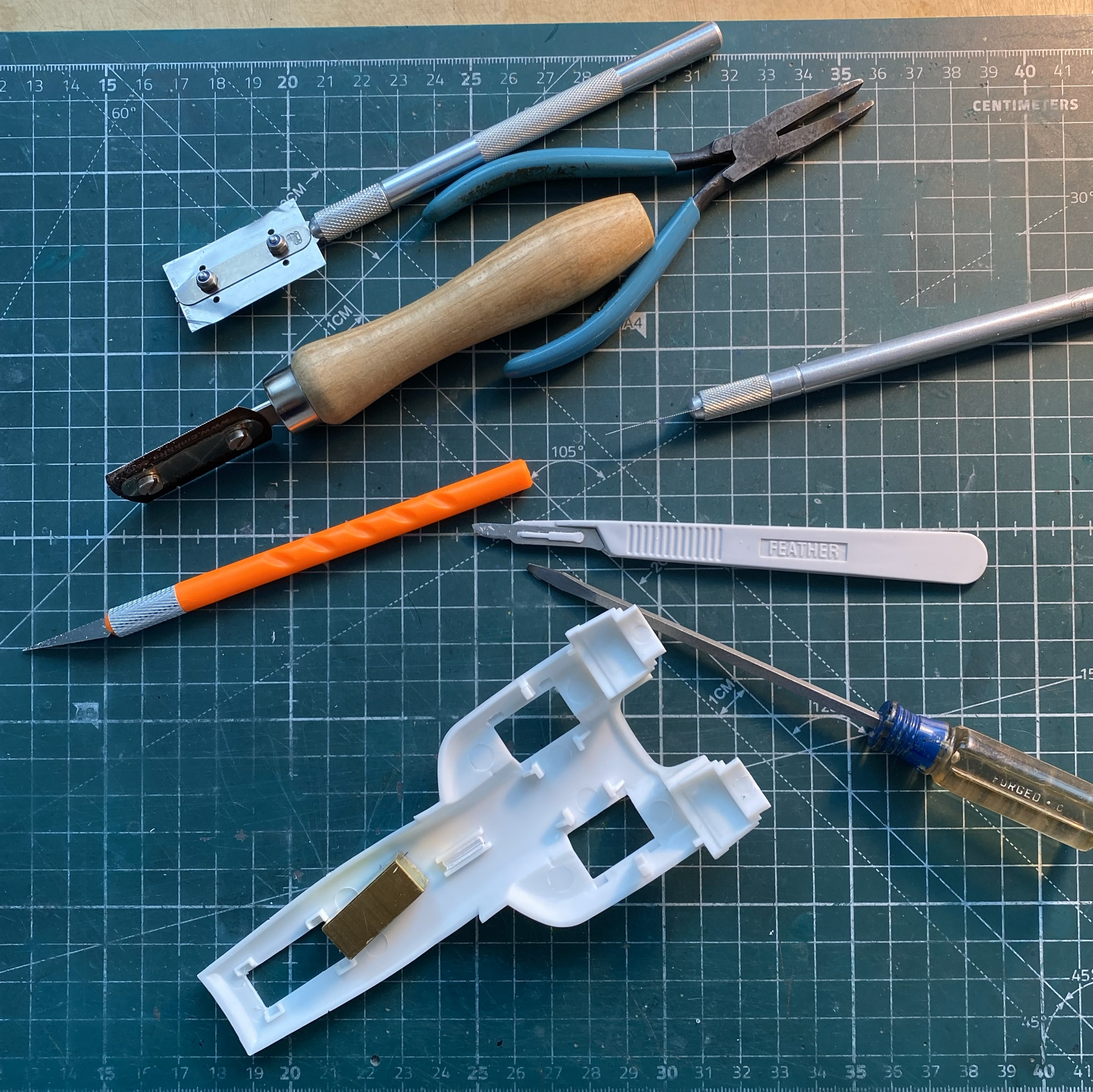
“Why is your work bench so cluttered and messy? Doesn’t that get in the way of working?” No, dear, it is working. These are the tools needed to clean up parts that are essentially simple:
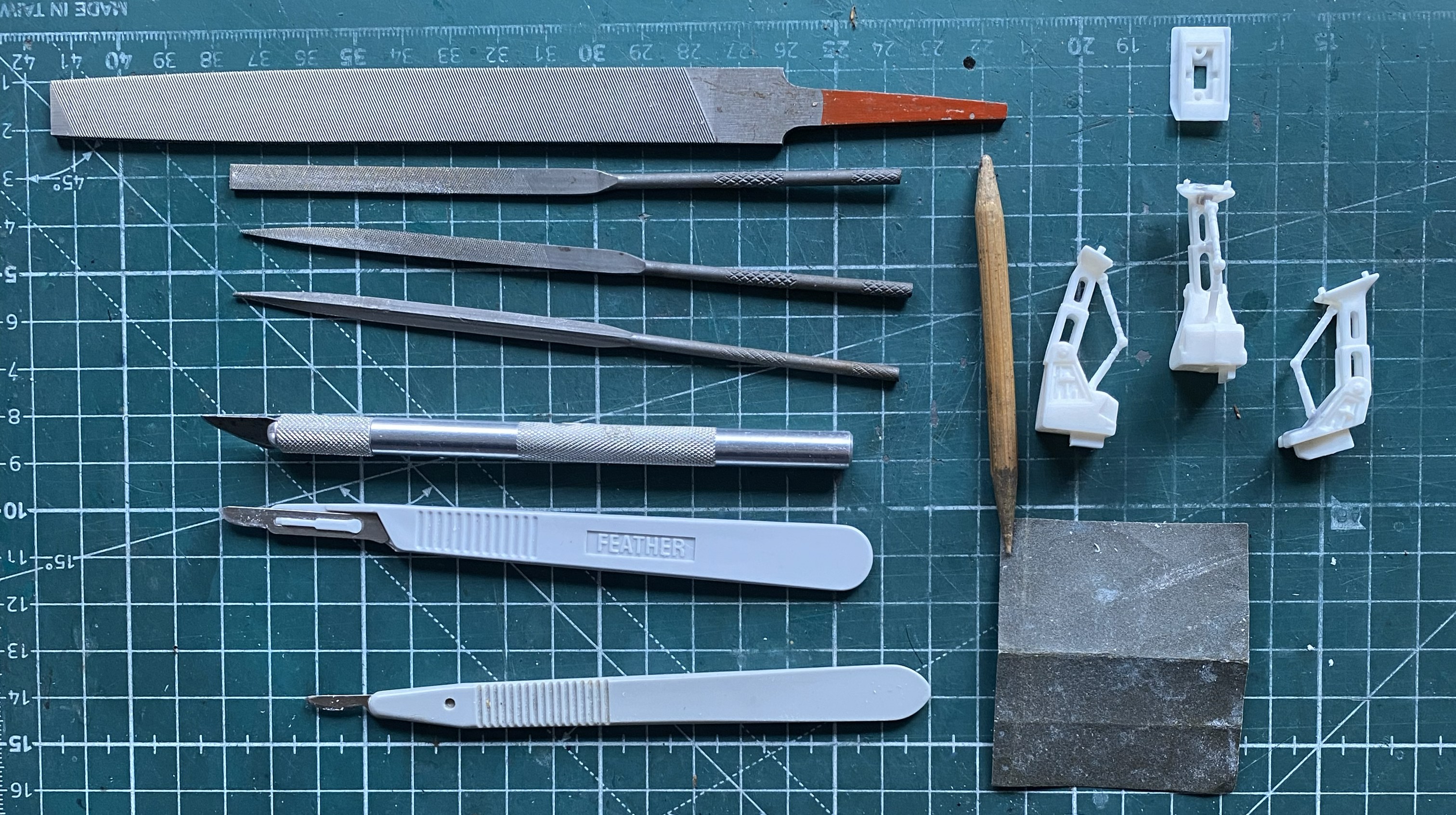
Simple. Right?
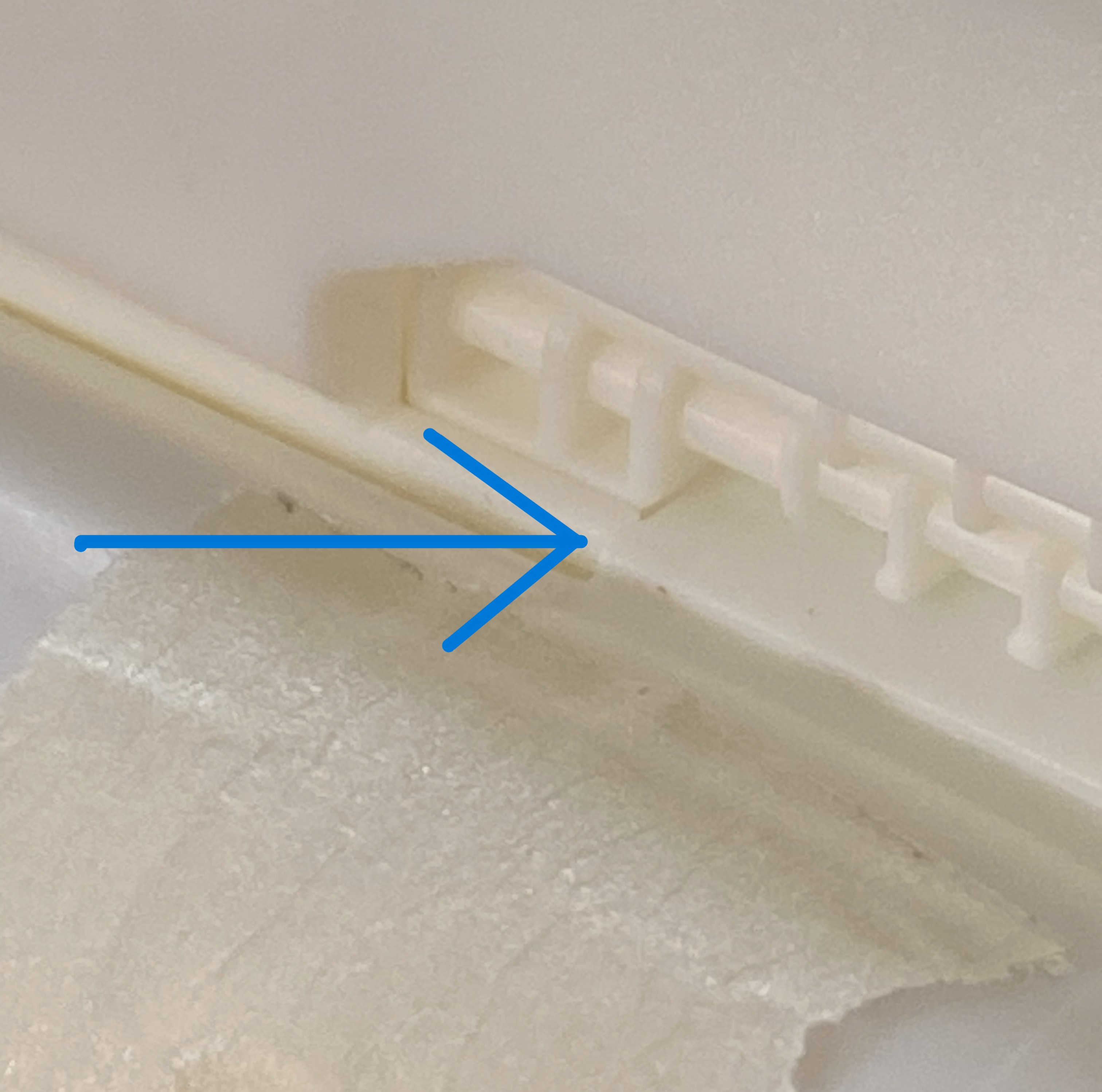
While removing the tape from where I’d dry-fit the major components together, an ohgoddammit moment arrived. The blue arrow shows you where a part came apart:
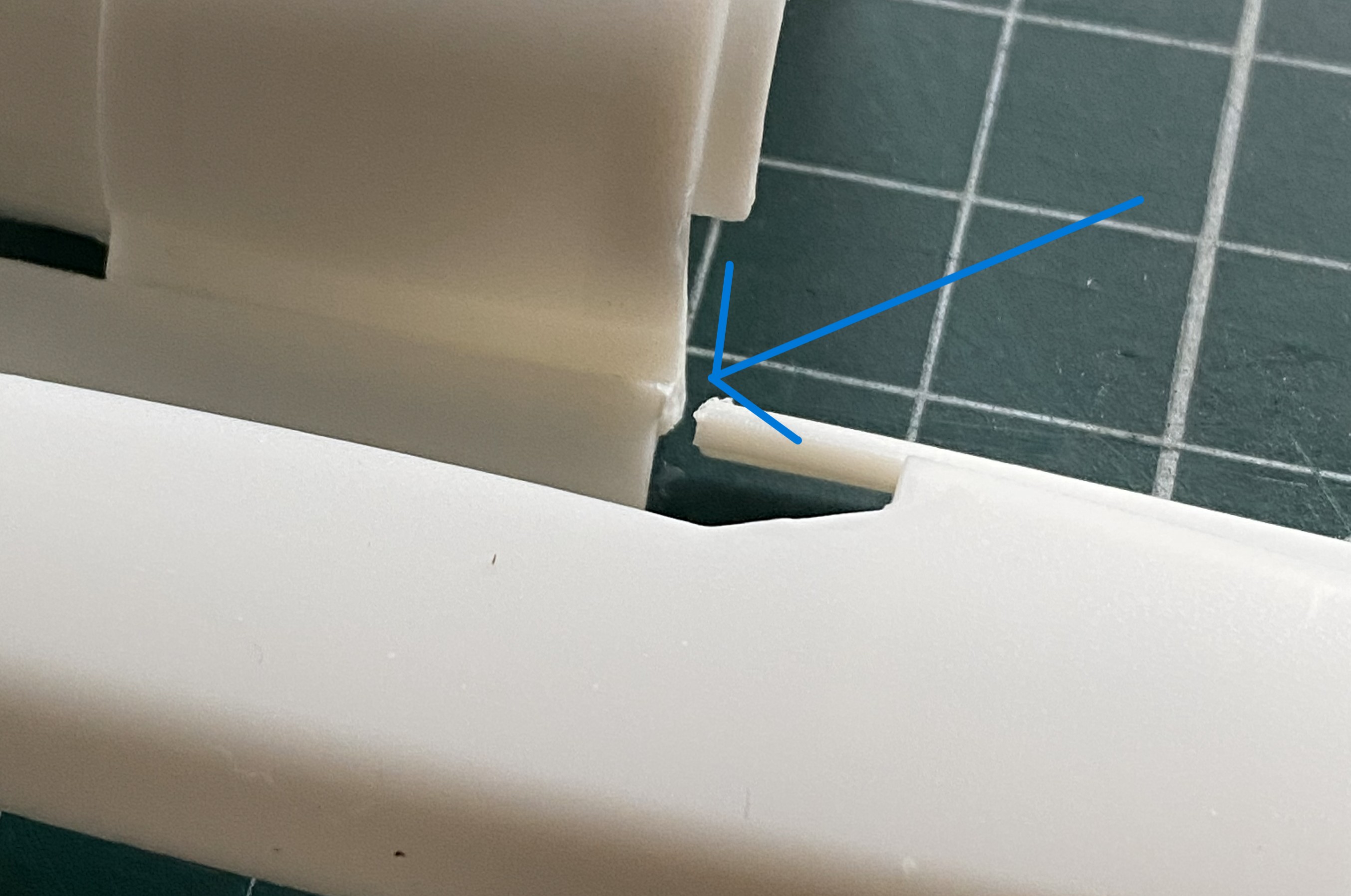
The way this is engineered, I decided that I’d use the model itself as a gluing jig (the break is on the left half of the engine area). The flat areas on either side of where the upper engine goes served well as an alignment guide:
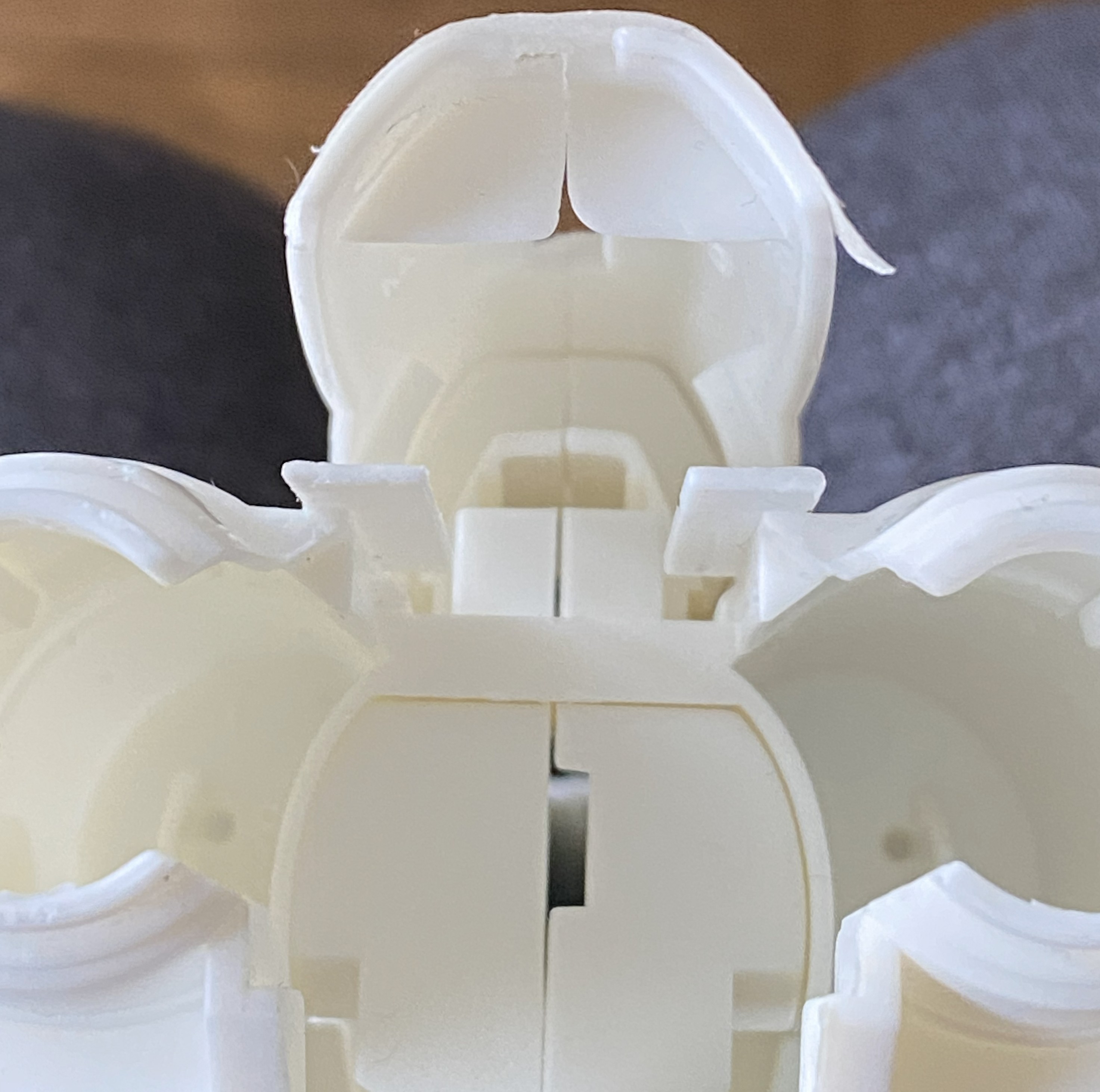
Good illustration of fit, eh?

While I was there, I filled the slot for the supplied stand since I’m not going to use it:
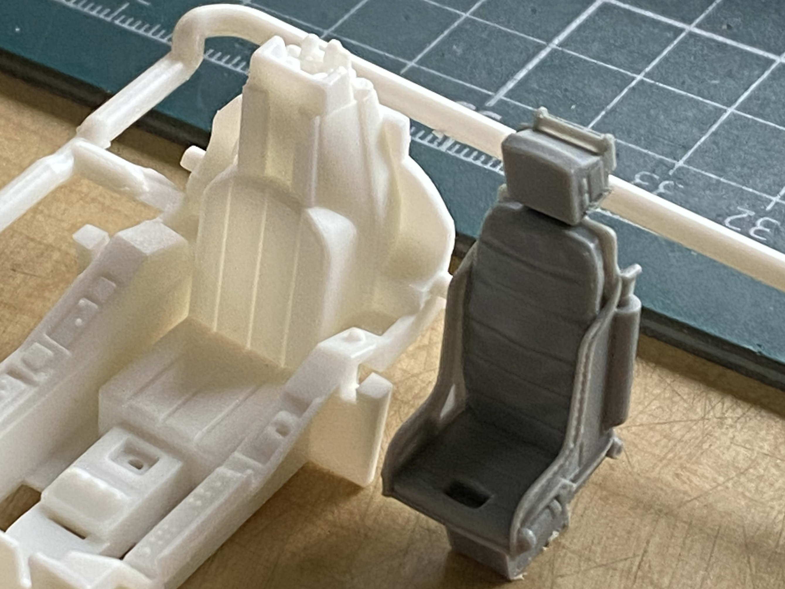
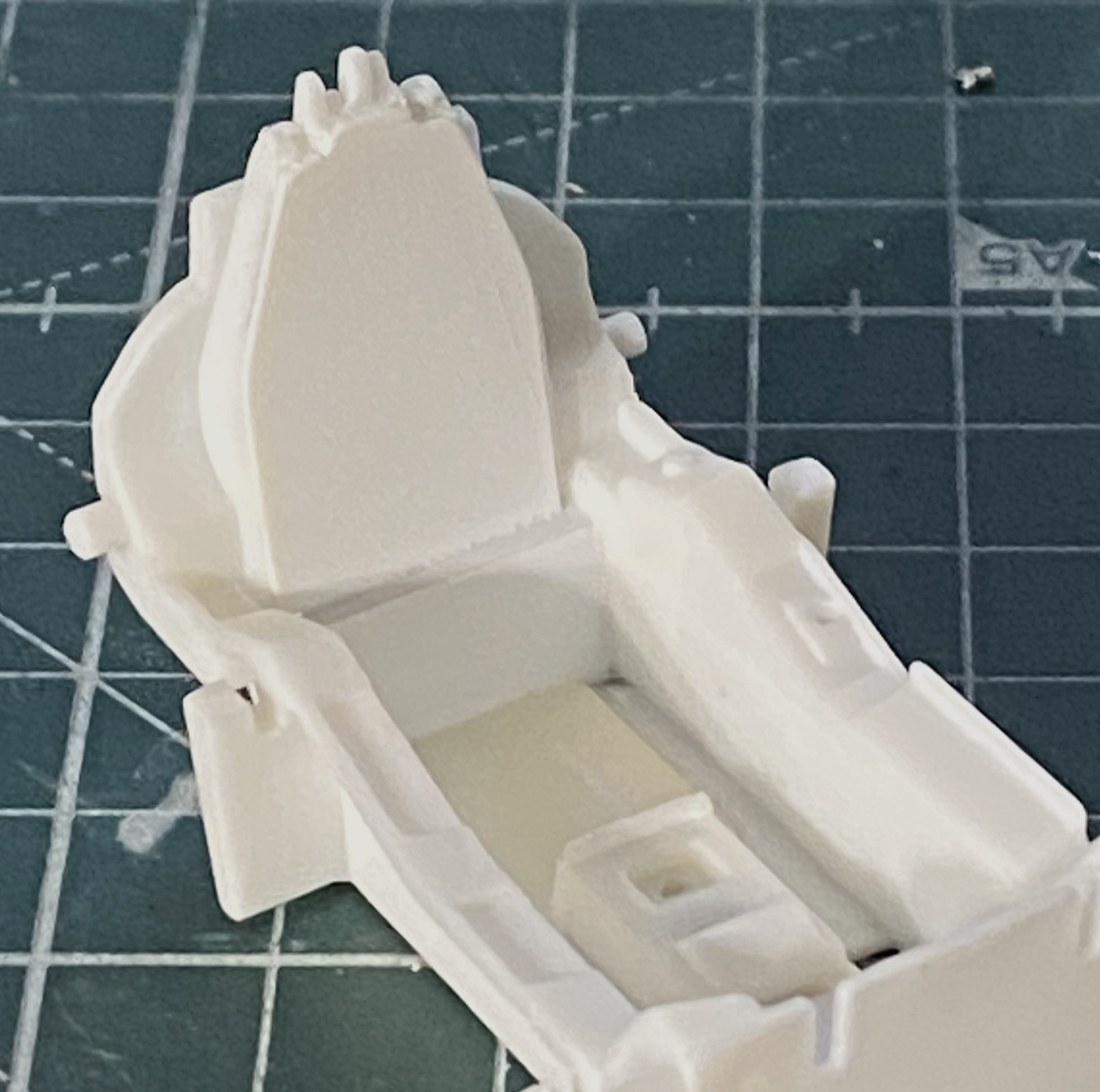
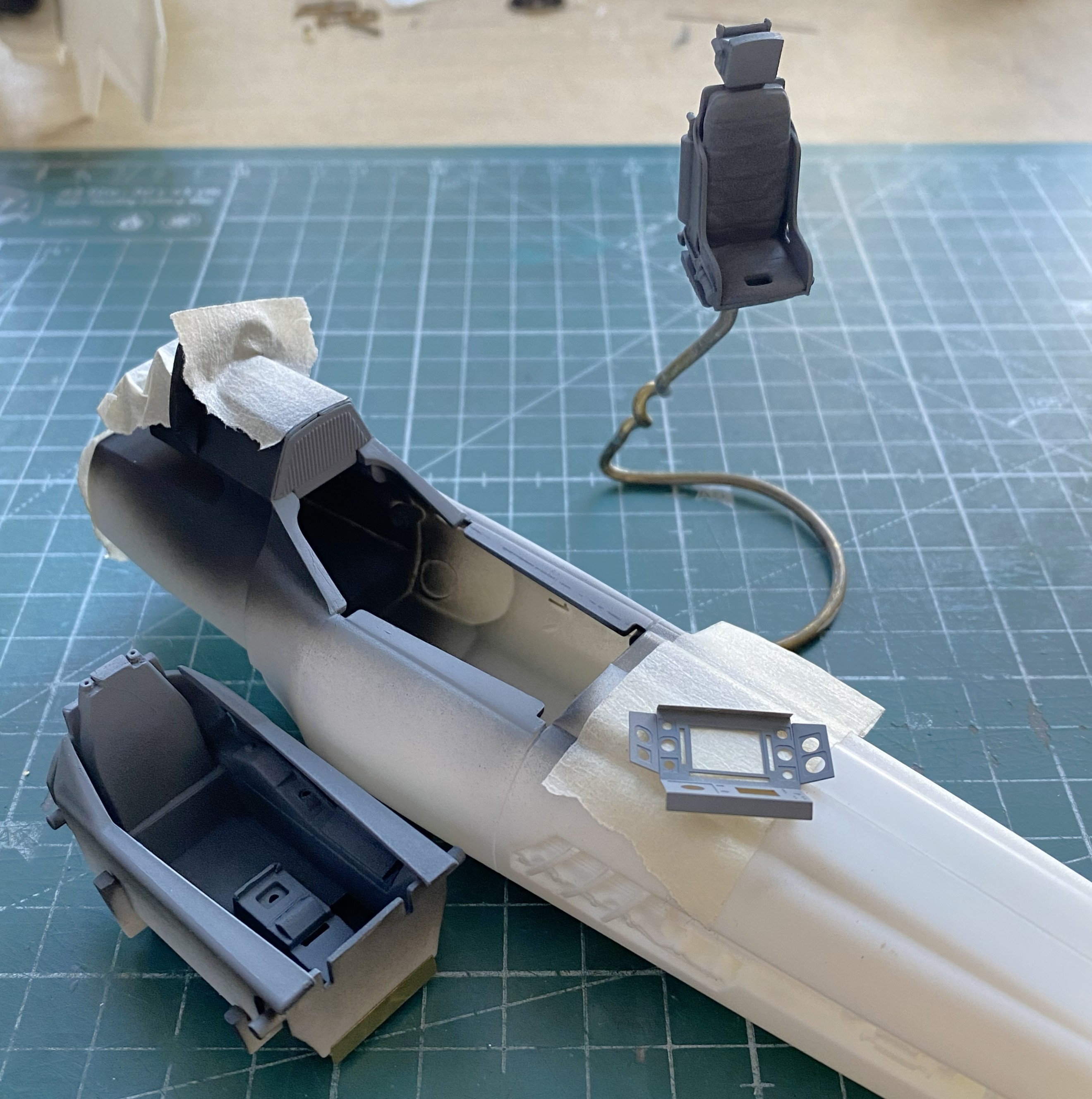
At this point the AM parts arrived so I changed focus to doing the cockpit. For the resin seat to fit, the molded-in seat has to come out:
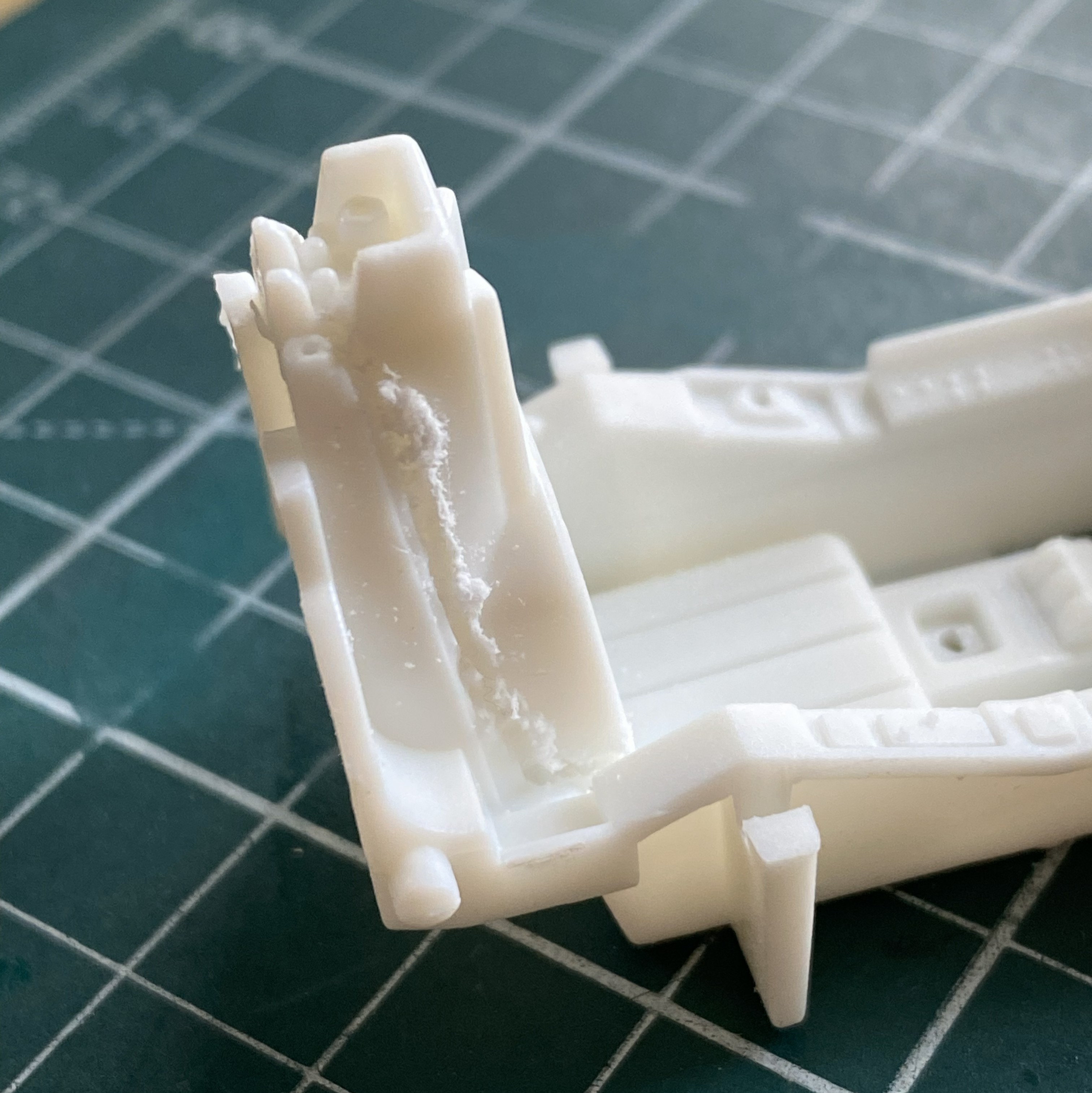
Once the kit’s seat was gone, I assembled the pedestal for the seat:
Then I checked the fit:


Nope. Sits too high. The fix was to remove the pedestal and glue the seat directly to the floor (you can see the fit of the fuselage behind the seat, which will require some inflexible persuasion on my part), which lowers the seat to the correct height:

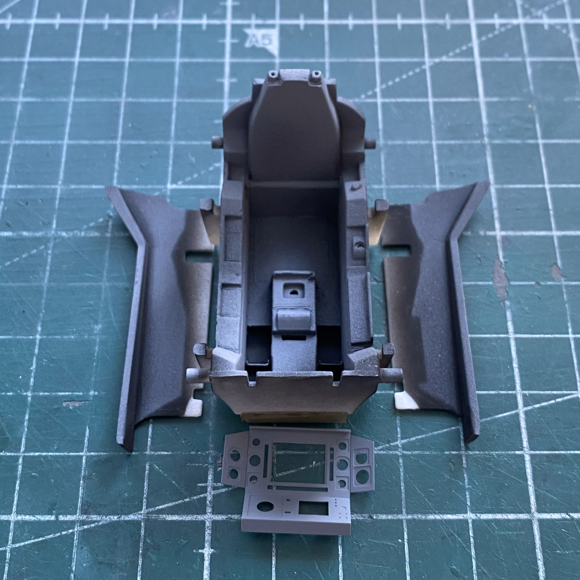
To apply the PE I have to remove the molded-on details. That with the round black dot has to be removed, the one on the left that looks like a D laying on its face is where the throttle goes. The insert in the floor is to fill the gap left after removing the molded seat (and to give me something to glue the resin seat to):
Done:
The structure behind the seat needs to be filled. I used 0.020″ (.508mm) for that:
Where the back joins the tub is evident at the edges. I used a little putty to make the added back look as if it belonged.
With unwanted details removed, PE moved to the front of the line. Surprising no one who’s worked with PE, acrylic paints don’t adhere well. They’re fine once painted if they aren’t stressed. I was curious to see if lacquer would hold up any better. I masked off what I didn’t want to paint and then sprayed the fret with Tamiya’s TS-6 Matt Black from a rattlecan and let it sit overnight:
The next day I used my MkIII Thumbnail to see if lacquer is more resistant to wear. It is. It still wore a bit as I was working things but NOwhere near as much as acrylic wears.
In general, I’m not a fan of PE harness straps. The PE fret has them so I decided to have another go at them. I started by annealing them so that they behave less like the strip of brass that they are:
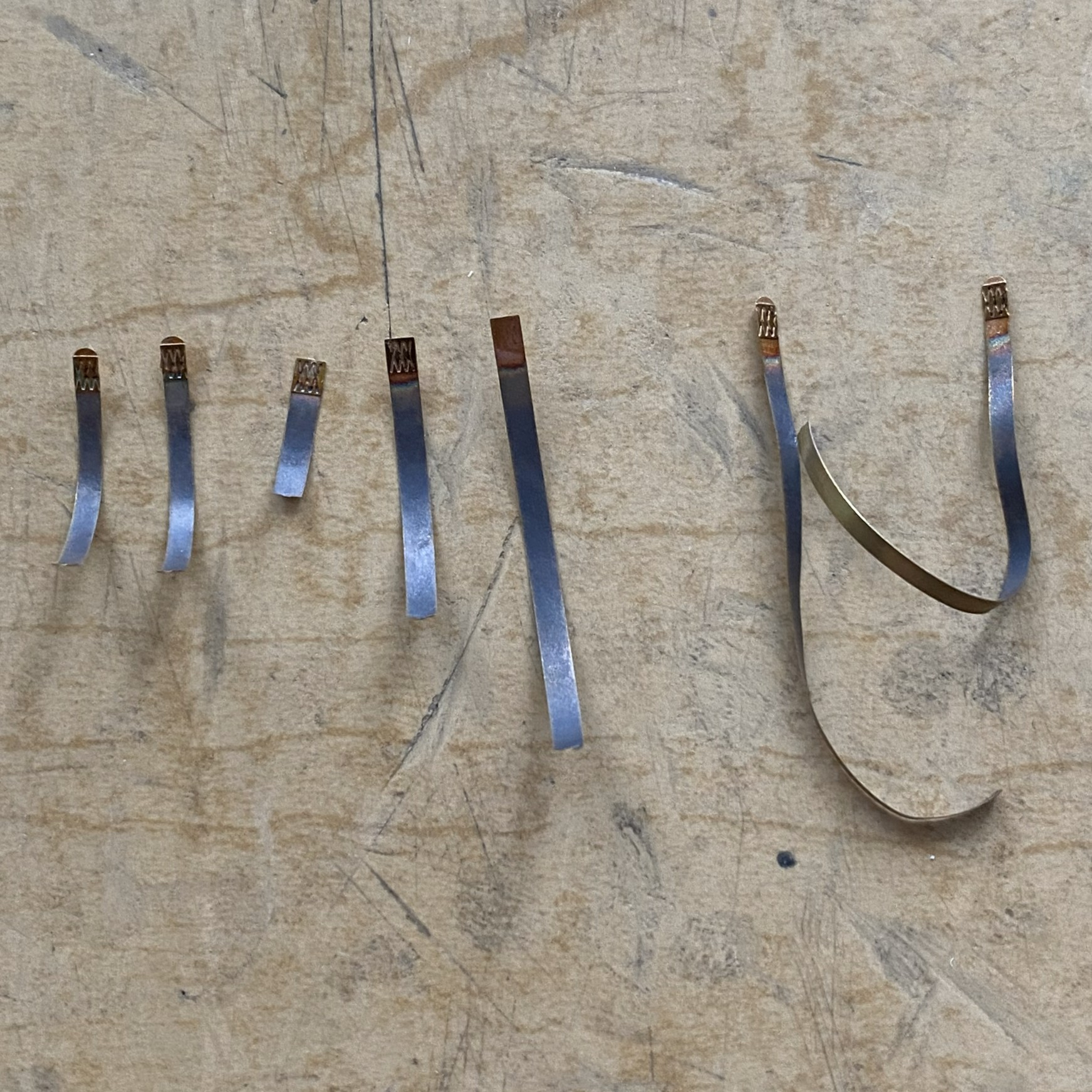
During annealing, I managed to scare myself. I use a butane torch to anneal. It’s hot. It’s hot enough to melt little brass strips! I came far too close to melting one of them, but since I’m not a grenadier…
Next I fed the straps through the hardware of sliders, tabs, and locks:
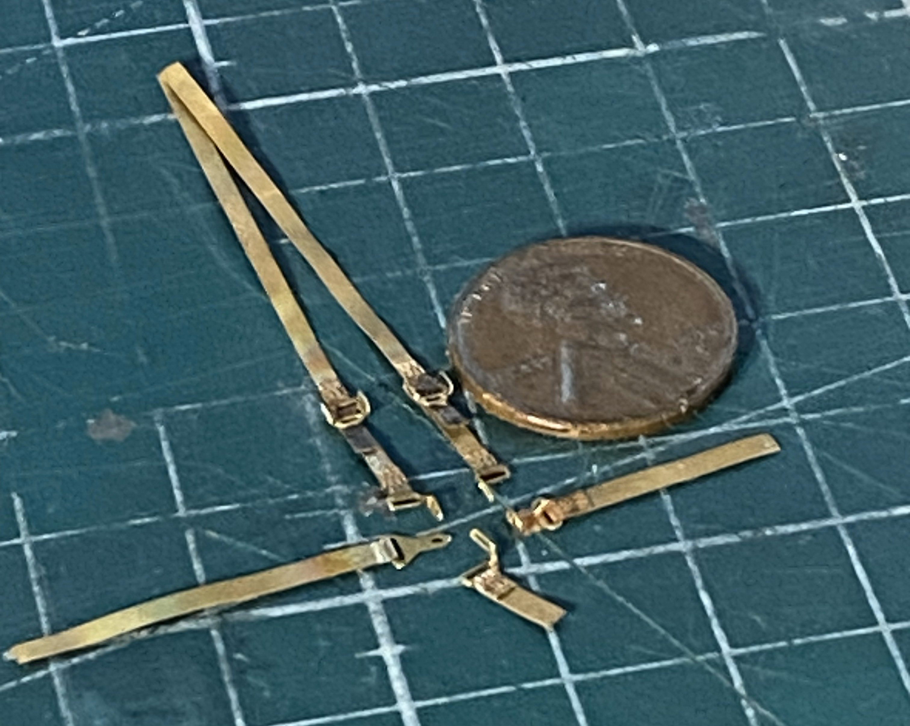
Annealing them made it magnitudes easier to feed the straps through the hardware! Now to see how they go on:
Annealing is definitely the way to go with PE harnesses.
I don’t know what this little panel is for, I just know it’s there so now was a good time (or even not a bad time) to see how the lacquer holds up to bending and gluing:
The lacquer holds up to being manipulated much better than acrylic does.
The main panel is basically formed, dry-fit, and checked for fit (good):
The engine intakes have blades for the intakes. Well, two out of three intakes. They look cool but are utterly unrealistic (and foundational theme for this build). The third intake is just a flat surface and of course it’s right up there in ones’ face(s), so I carved (another set of utterly unrealistic) fan blades into it. What the kit offers (one on both sides and the two of three intakes with fan blades):
I started with this:
Drew the leading edges of the blades and checked appearance:

Then I sharpened all my scalpels and knives and started carving:

I cleaned up the edges/surfaces after taking the above photo.
First paint. These are the parts that get shot with Tamiya XF-1 Flat Black because I like the effects I get from pre-shading:
There:
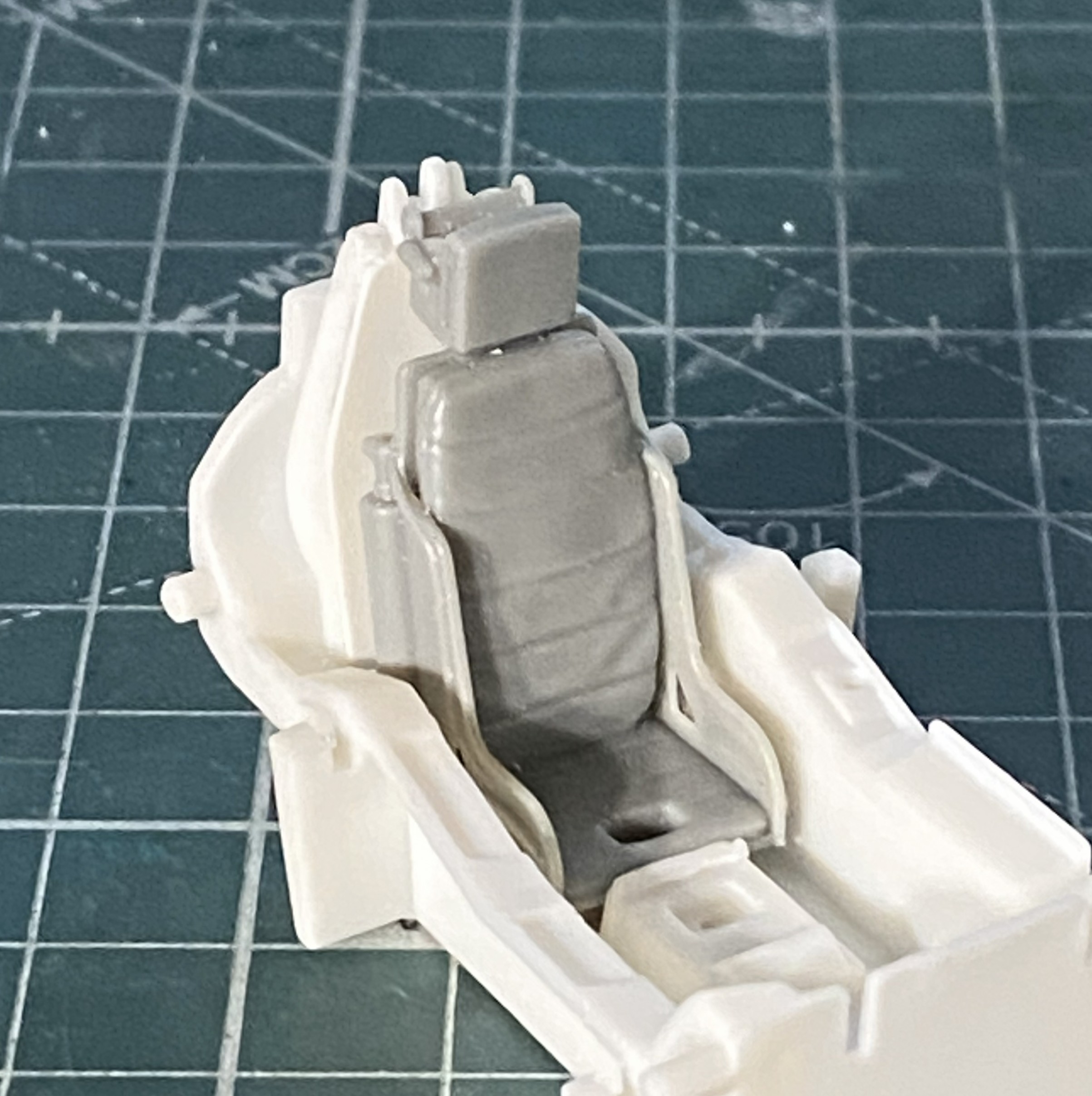
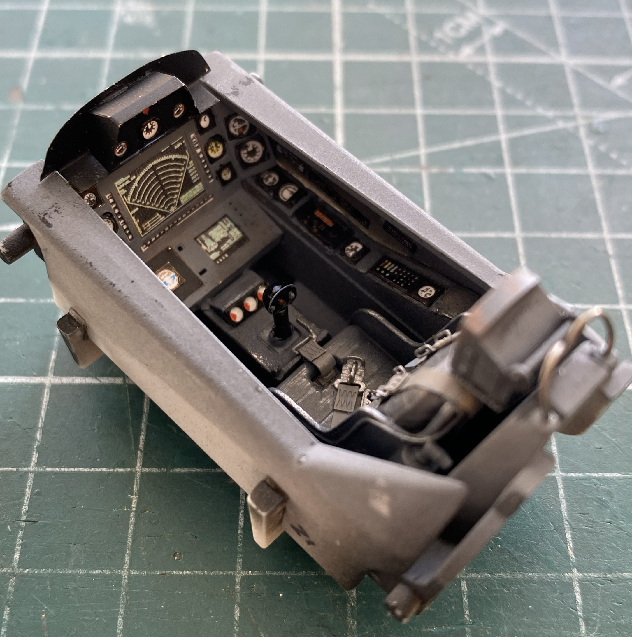
For the overall cockpit color I used Tamiya’s XF-53 Neutral Gray, no scale color correction, and just misted it on:
Set that to the side and started work on the main panel:

I continued to do the side panels of the cockpit:
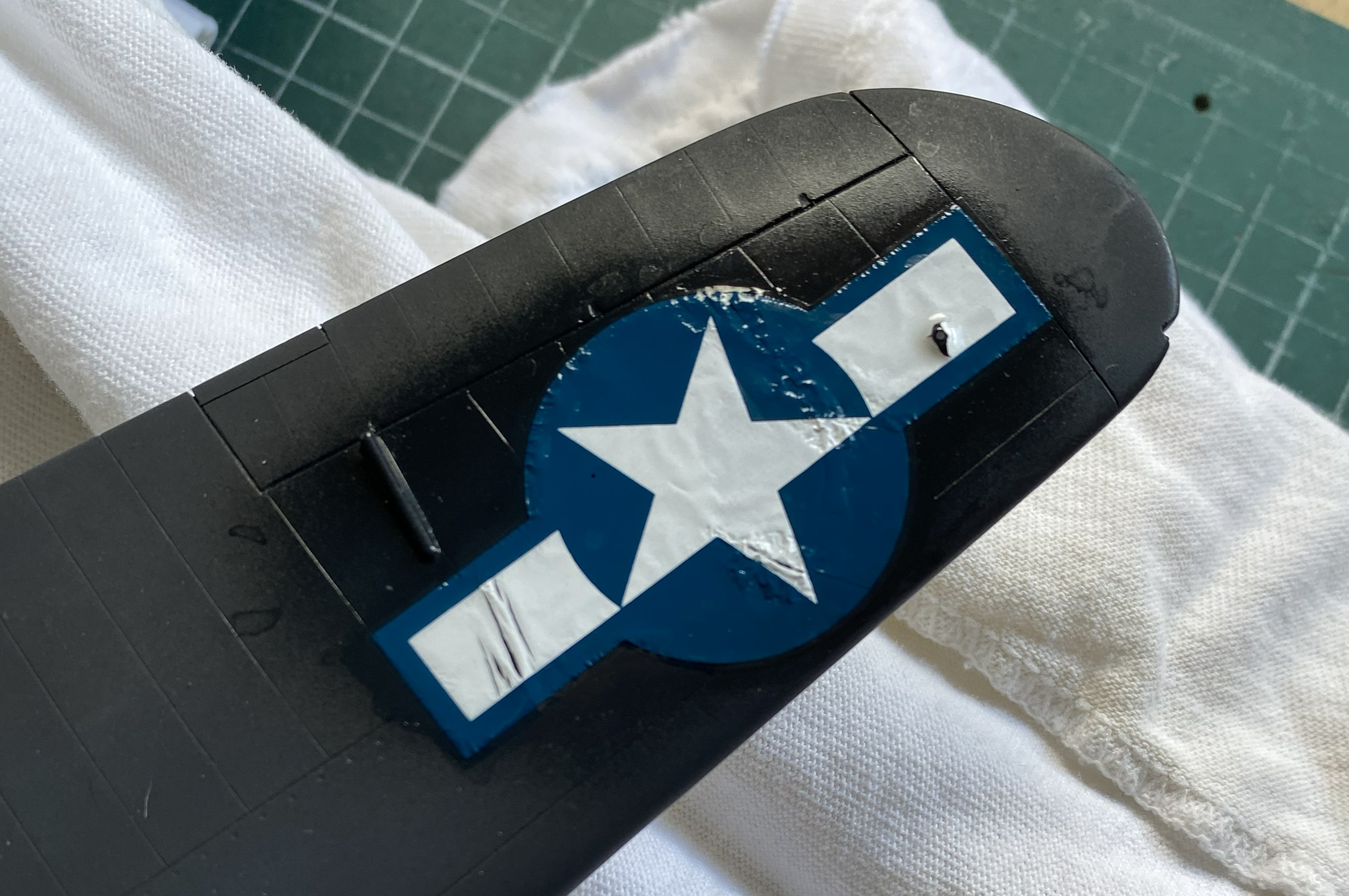
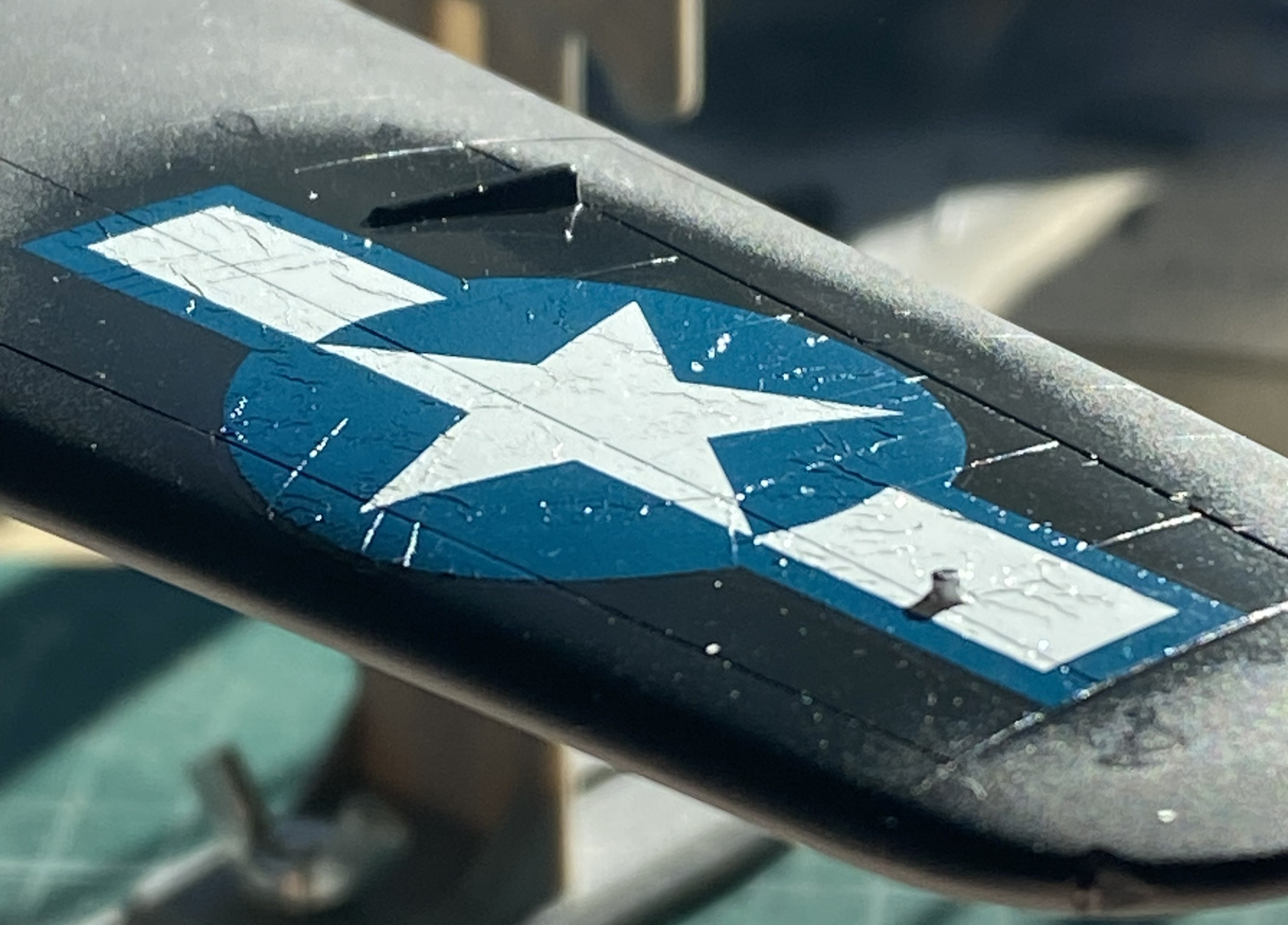
Preparatory to finishing the cockpit tub, I had to add decal data-plates to the sides and this is the first major uh-oh of the build. The first decal did not want to release from the backing paper. At. All. I let it sit in the (warm) water until the sodding thing just floated off. How I managed to fish it out of the water without folding it is one of Life’s Mysteries ™. Since I was pretty sure that whatever adhesive used to be on the decal was also floating in the water, I used Micro Set to convince them that this was their new home. That’s when I encountered the second uh-oh…the decal broke while I was trying to move it into a less inaccurate location (see the blue arrow):
Not only did it break, it broke because the left side of that decal, once it hit the surface, would not move at all. Instead, it tore. This isn’t boding well for the other decals. I hope I’m just being an alarmist.
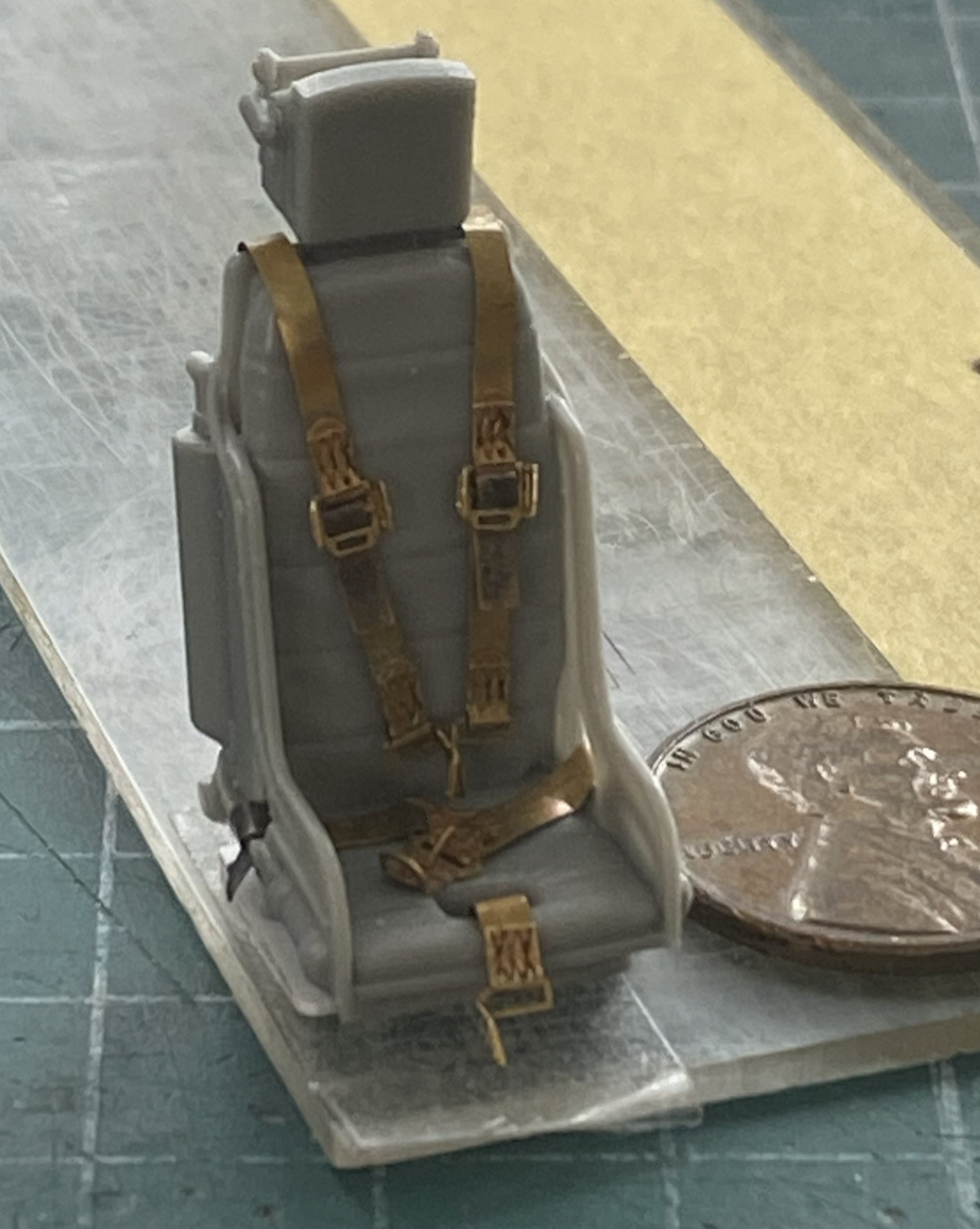
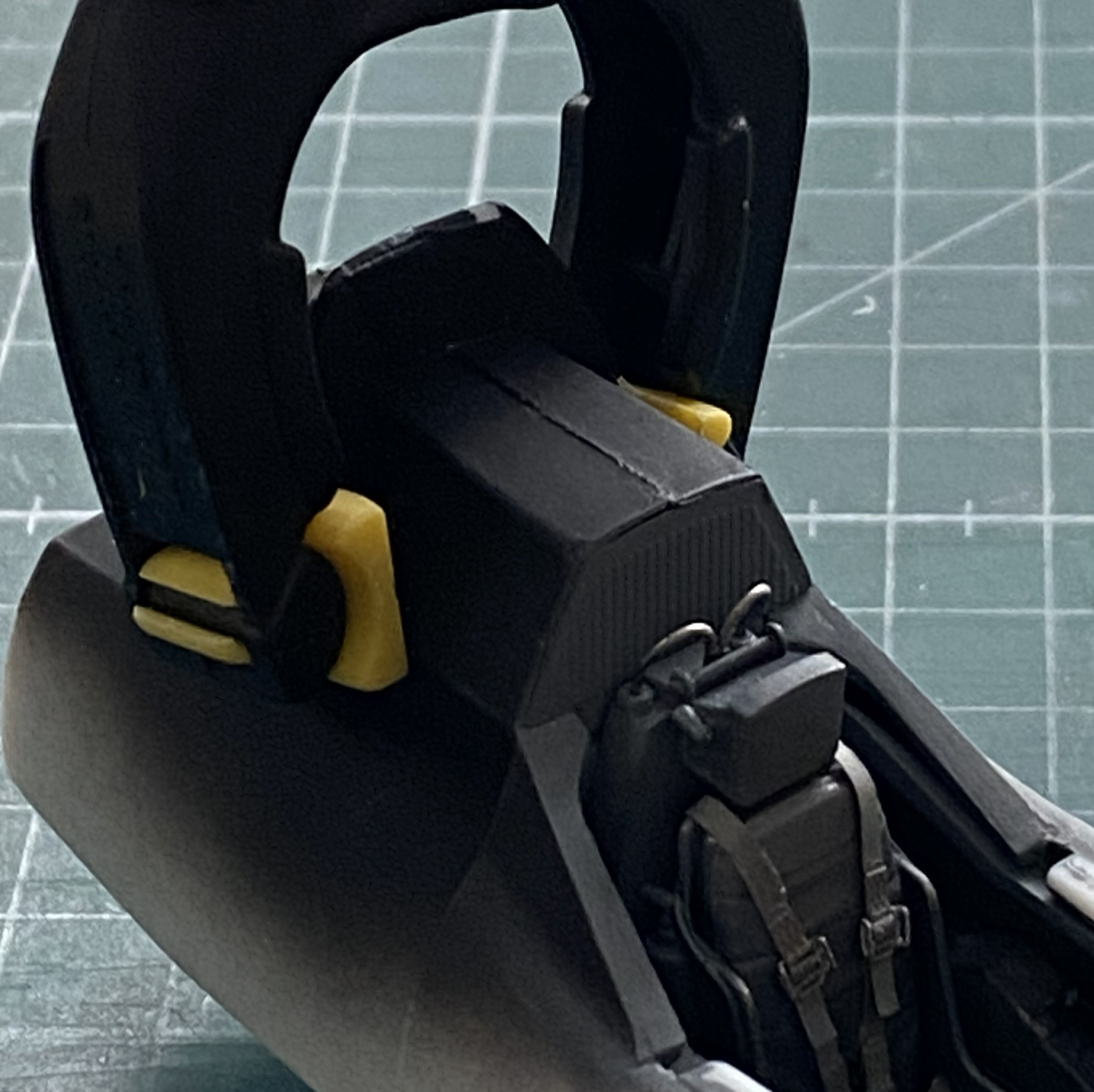
I didn’t have any trouble at all painting and installing the harness:
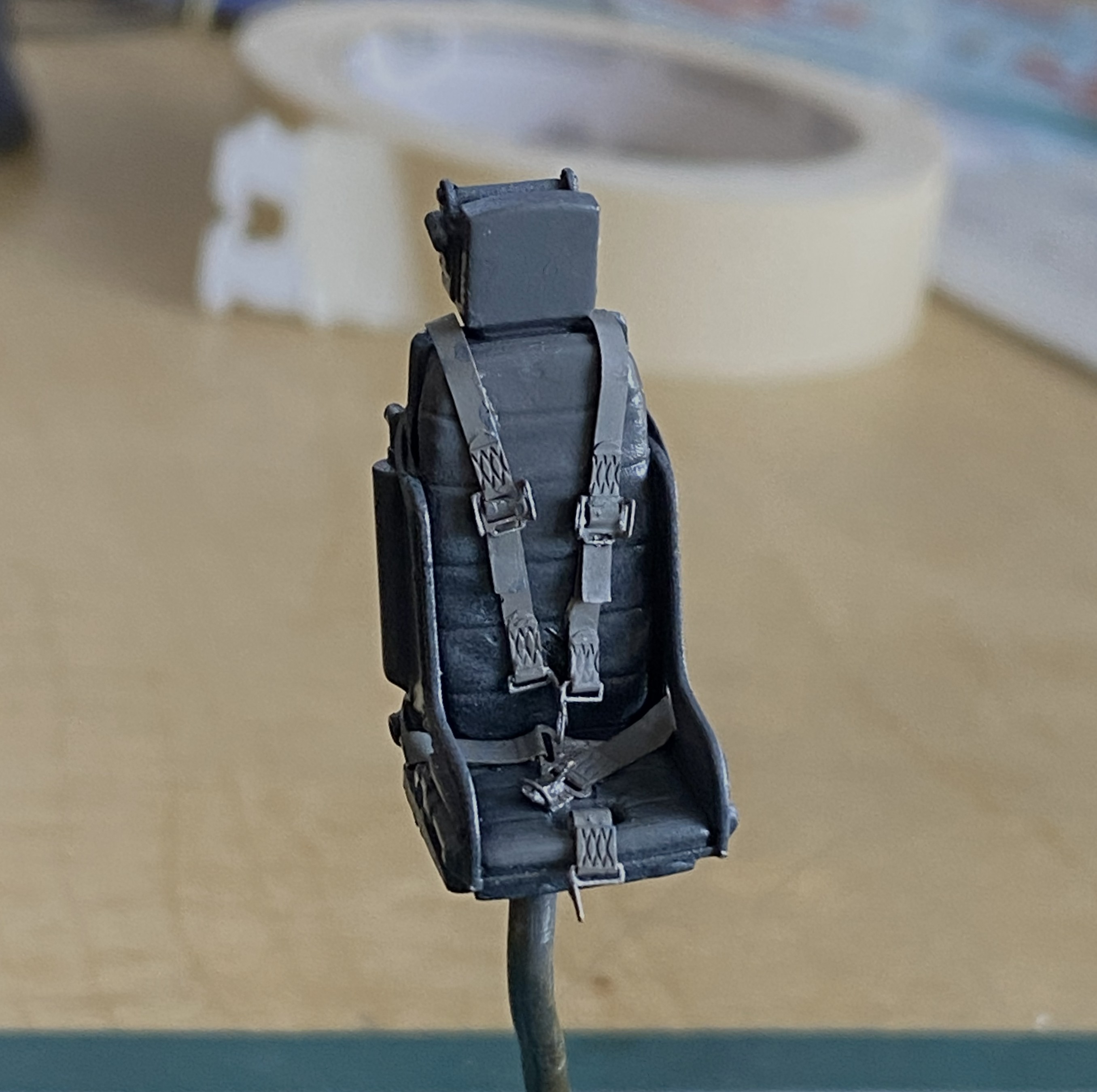
The first step to applying wear and staining was judicious use of the silver pencil. I added friction-wear (as opposed to impact-wear) marks as well as some pastels to make the office looked lived-in (and the sharper-eyed amongst you will note that I also affixed the throttle and joystick as well as the mystery loops behind the headrest, using 0.020″ (.508mm) solder) :
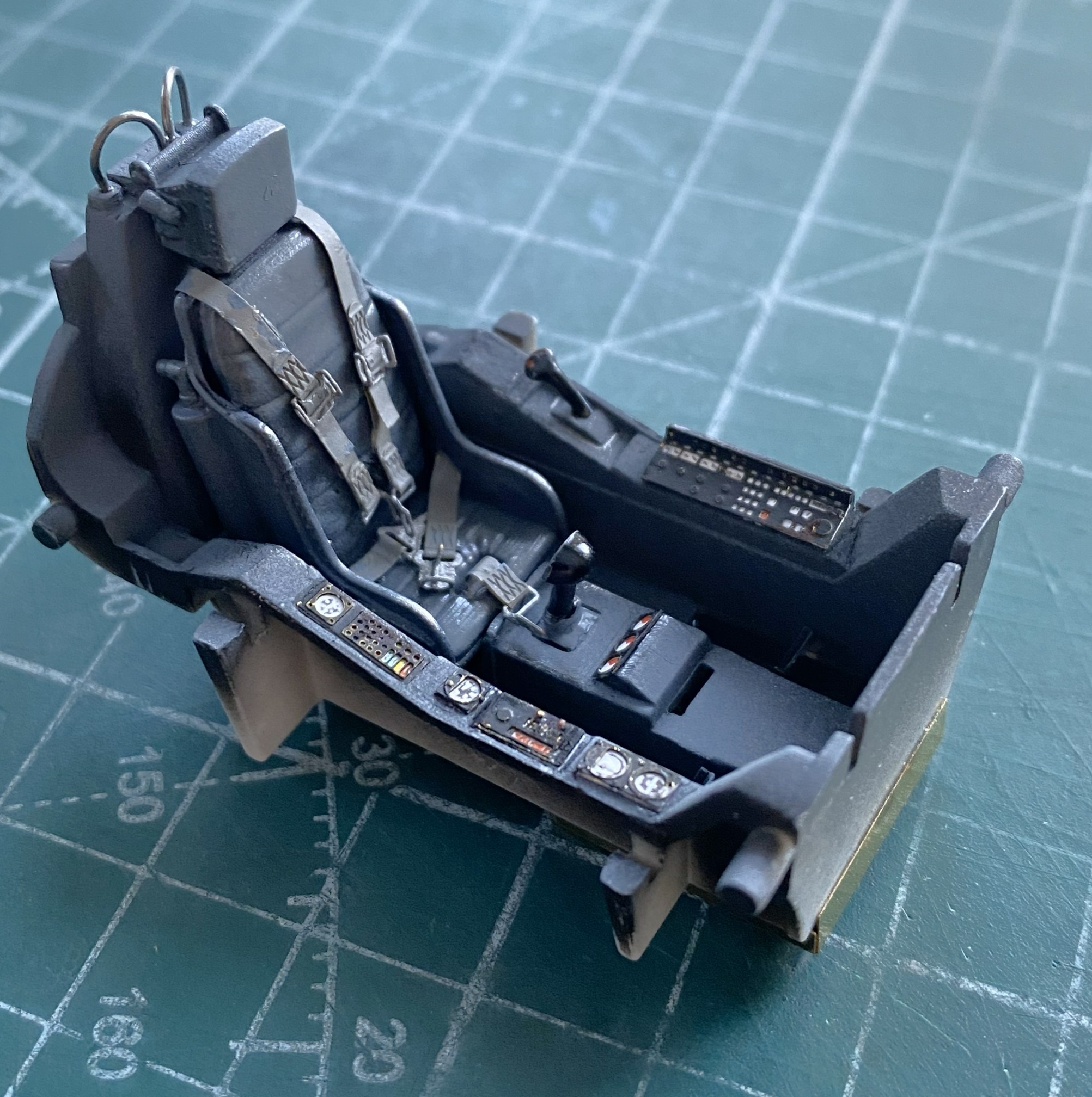

The side rails are just dry-fitted to get a sense of what stains show, where wear goes, and how much of it looks correct:
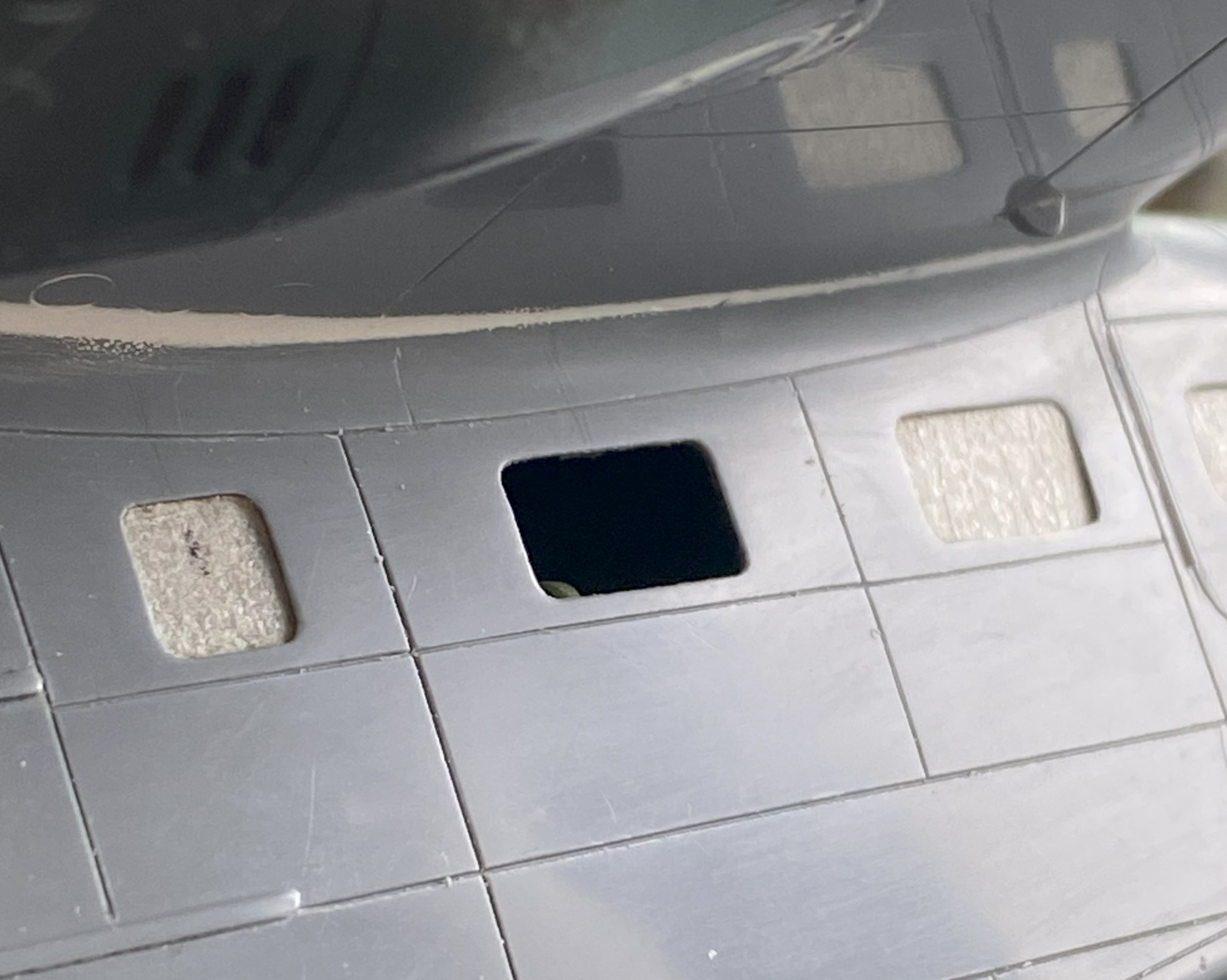
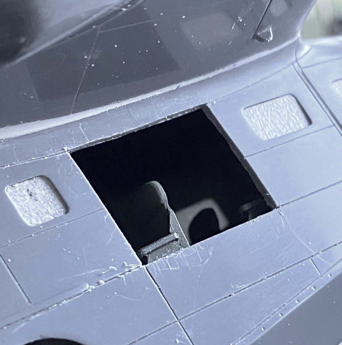
The belly of the fuselage is molded separately from the sides. Clever. It obviates most of the belly seam. To add the AM details, the main fuselage has to be cut away to allow the AM space (more on that later, too) to socket in place:
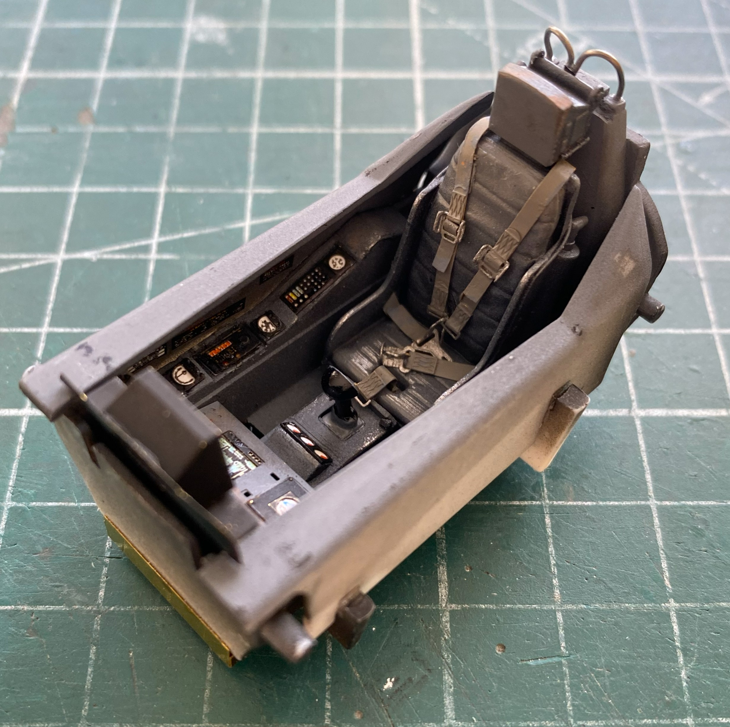
Since the cockpit was done, all detailed, painted, worn, and dirtied, I added it to the fuselage and glued the fuselage halves together:
Then I put the belly in place (almost) and noticed that the top of the gear bay impacts the front floor of the cockpit (which is also an AM part from the same manufacturer for the same kit…guess nobody checked to see if it would fit) (again, check the blue arrow):

And speaking of fit, force will be required here (again torpedoing the notion that force never solves anything) to get these two parts to meet:
And while I was checking the fit of things, I took that beautifully cast canopy, put it in place, and realized that it didn’t fit well, either:

While I’m here and looking at the lousy join of this seam, I clamped it most puissantly:
The sides don’t fit either. They’re supposed to seal the cockpit, which will require the surfaces of the canopy to touch the places of the fuselage it should touch:
And note how well the leading contact edge of the canopy meets the fuselage:
I decided to make the nose gear and belly pan fit first. That required me to cut free the PE part from all the glue I used to hold it there (because, since the nose landing gear attaches to the PE part, it had to be securely glued), which took the better part of an hour (didn’t want to damage the delicate PE, y’know). It also took a few tools to accomplish as well:
After cleaning the dead glue off of surfaces, it was time to refit it only this time accounting for the intrusion of the cockpit floor. The belly was taped in place and then the gear bay stuffed into the hole until it would go no further:

Since there was going to be cutting and filing of the exposed areas, I glued that PE part in securely and started work until the edges were flush with the fuselage:

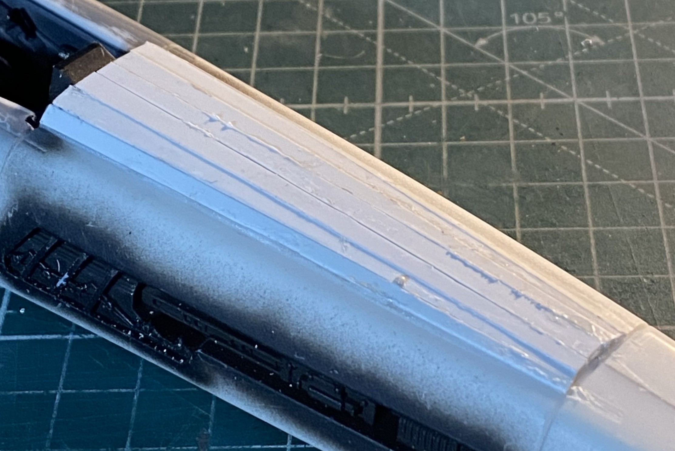
Having put the sword o’ Damocles back into its sheath, I turned my attention to fixing the canopy’s fit. What do I fix? All references show that the upper fuselage in front of the canopy is flat. Do I rework the canopy to fit? Or… The canopy is clear and fairly delicate. Could I rework the clear part? Yep. (The Goose build taught me that.) Do I want to do significant surgery on a part I can’t replace? (Okay, sure. I could replace it. But what a freaking job that would be and the canopy would be at risk throughout the process.) No. So that means that I have to build up the nose to match it and do it in such a manner as to be unnoticed. Okay, that seems like a grand idea!
That grand idea started with me laying down strips of styrene from 0.040″ (1.016mm) to 0.020″ (.508mm) with liberal applications of glue:
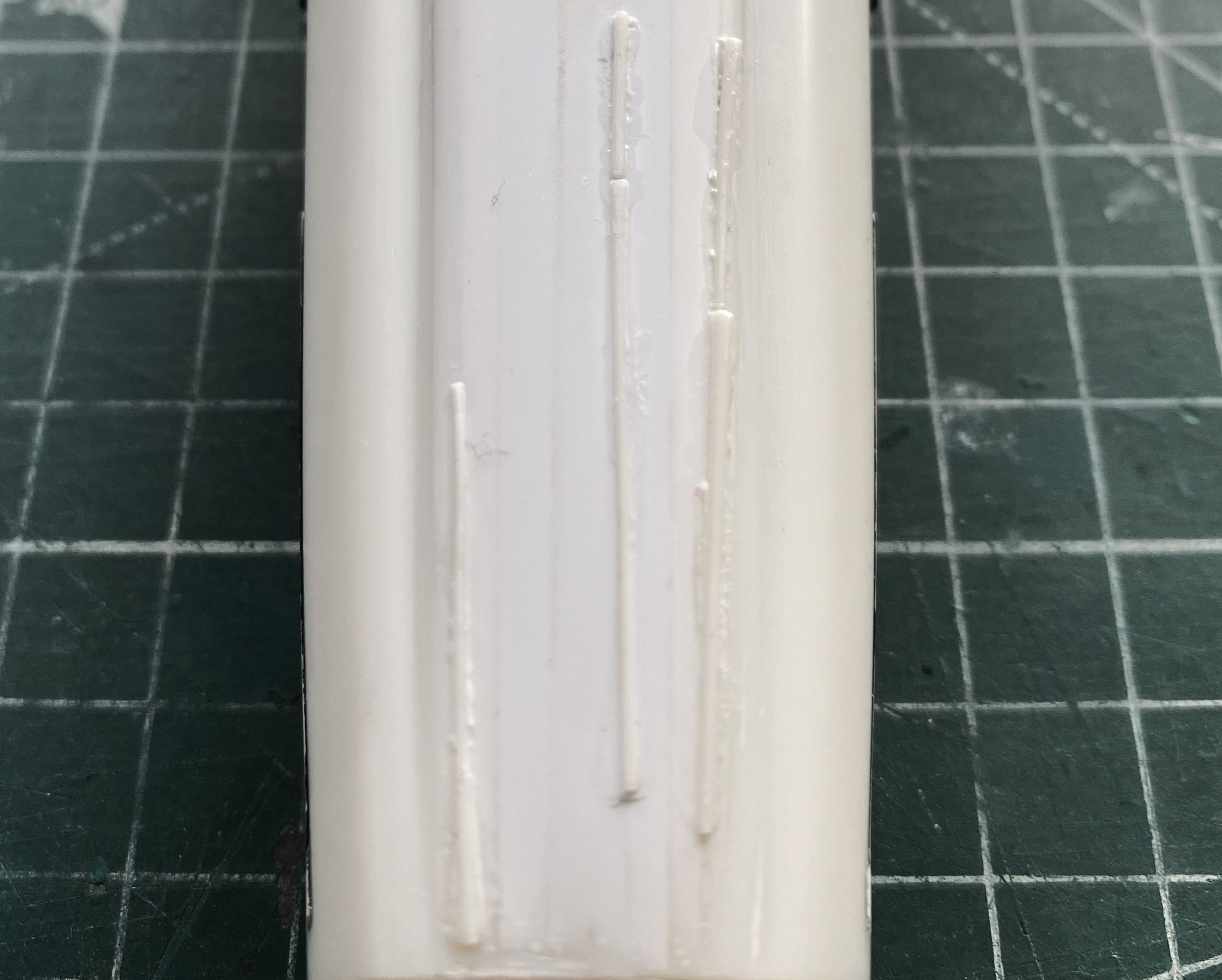
I let it sit overnight before starting to shape it. I started with 50 grit and worked my way past 100 grit and down to 220 grit, at which point gaps started to open up. Stretched sprue to the rescue:
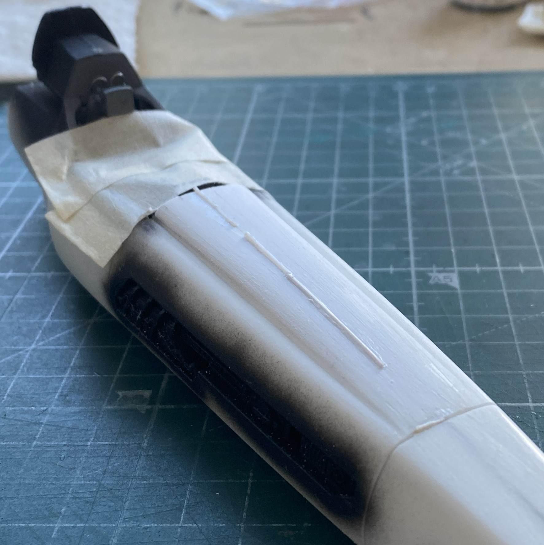
Making a curved surface with flat panels means that each panel will be thicker in the center than at the edges (arcs, y’know). As the surface is removed and shaped correctly, the thin edges of those flat panels start showing gaps. That’s okay. I knew it would most likely happen and I have a lot of sprue I can stretch:
While those were curing, I started fitting the canopy. I added small bits of scrap plastic, putties, and got the two edges to meet at the front:
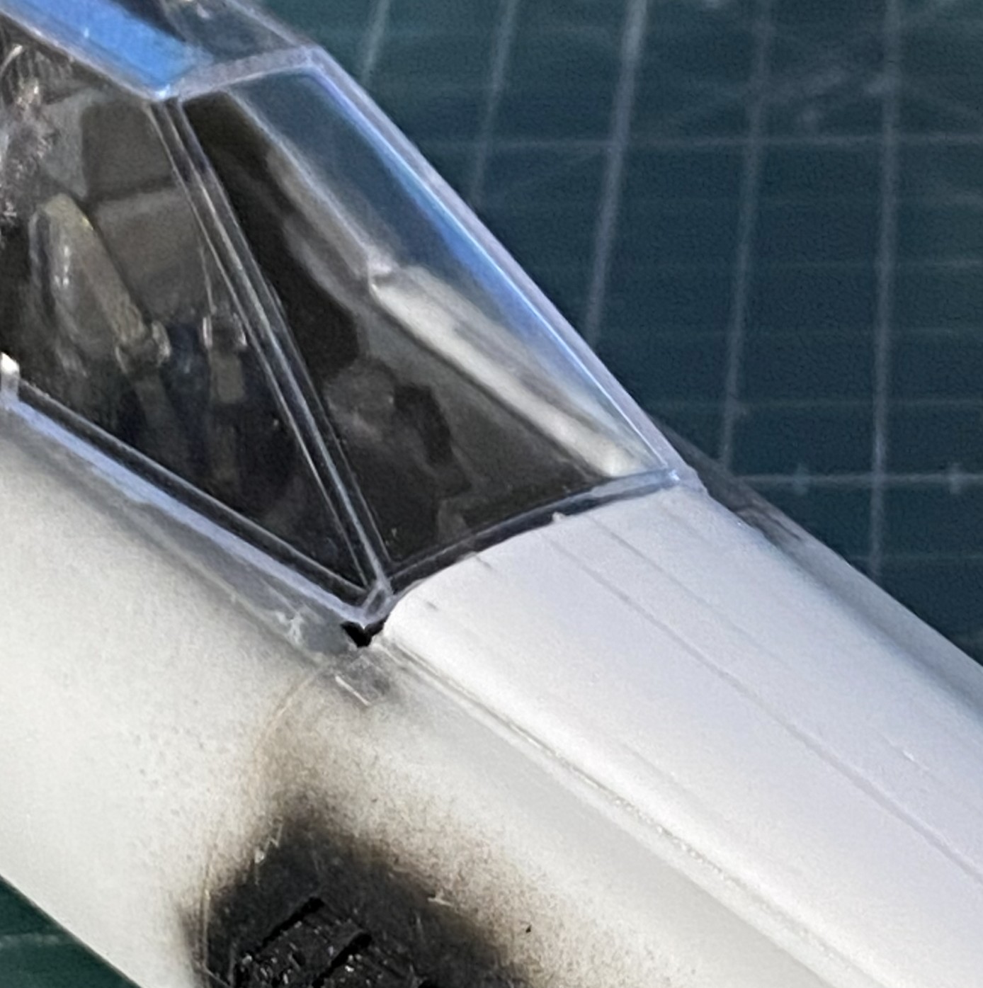
In the above photo, at the lower edge where the canopy meets the fuselage, you can see a 0.020″ (.205mm) spacer that I’m using to start filling the gaps at the sides of the canopy. Once the gaps are established, it’s just the sometimes-tedious job of filling them with scrap (mostly 0.010″ .254mm) and a bit of 0.020″ (.205mm)):
This post surprised me. It wasn’t until I started working on this post that I realized how much work I’ve done on this; it certainly didn’t feel like it. Anyway, I’m going to stop here. Yes, there’s more. I think I’ve already stuffed enough into one post. I’ll finish this one up (edit checks) and start the next one tomorrow.
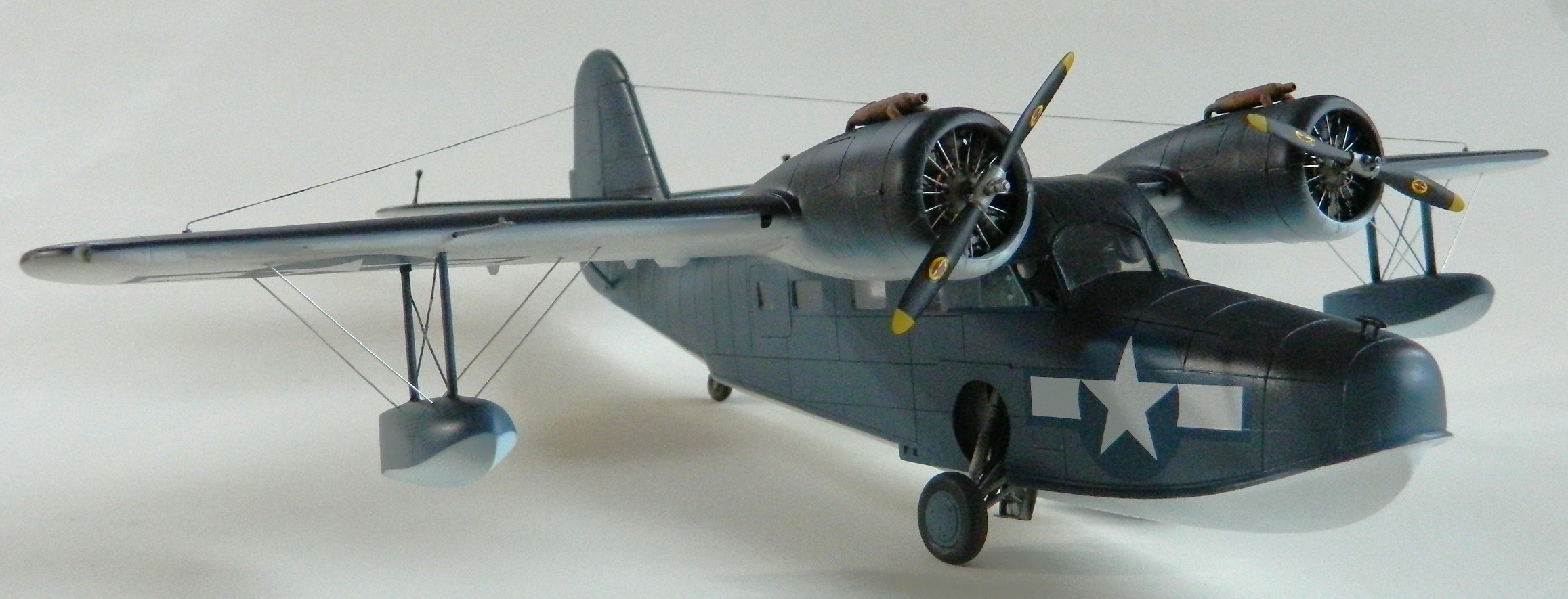
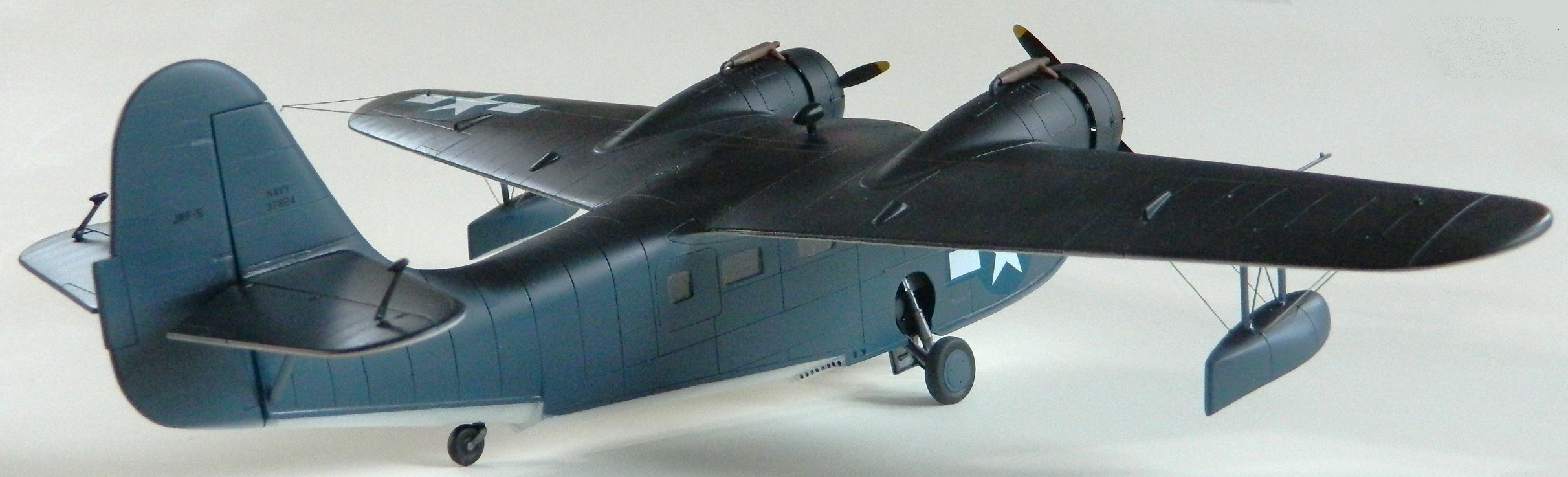
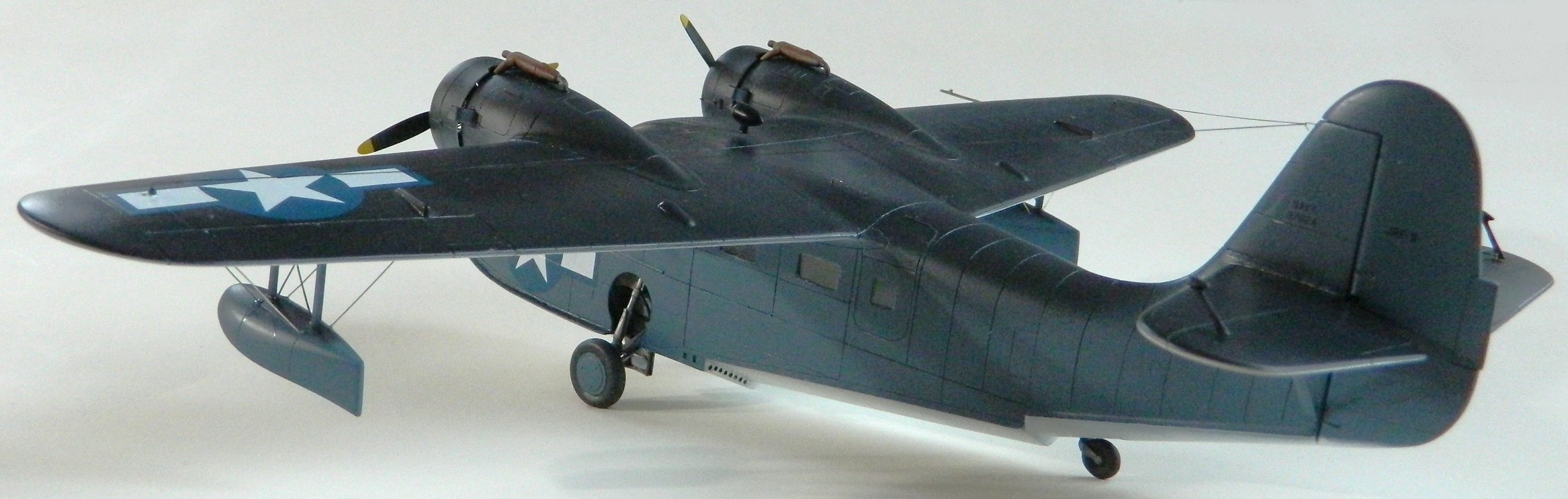
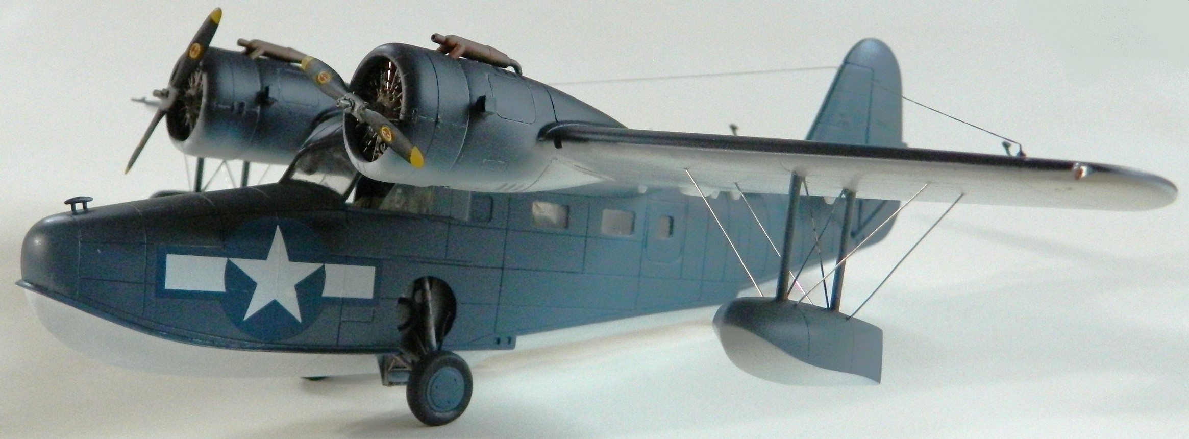
Grumman JRF Goose (Czech Model) After-Action Report

If I followed my mother’s advice (and shocking her into incontinence thereby), “If you have nothing good to say, say nothing,” this would be a very short post. I’ve rarely followed her advice, I’m not going to follow it this time.
Total time building 345.75 hours (that’s about 14.4 24 hour days, 2.05 work weeks). For such a seemingly simple kit, that’s a long time.
Begin date February 6, 2025, end date November 9, 2025.
Vendors:
Czech Models
Grumman JRF Goose #4812 1/48 scale
Metallic Details
P&W R-985 #MDR4810
EZ Line
Fine black
My Opinion
I do not recommend this kit. It’s bad. It sucks. I wish I’d not spent the money or time on it.
Fit is about as poor as I expect small-run manufacturers. This is about the only thing I expected that was borne out in reality. Example: The fuselage was split in halves as typical for an aircraft kit. Neither side matched the other. Dimensions were off, curves of radii had different dimensions from side to side. Who does that?!
Czech Models did. Everywhere they could. By the time I was into this build, I didn’t want to build it anymore. From June until I declared this turd finished, I have been reminding myself that if I polished this thing with a sledgehammer, I’d lose all the nice work I did on the flight deck’s overhead console (and other places). The quality of the work shows my UTTER lack of involvement in building this one. I’m not proud of it, just happy it’s nothing I have to concern myself about ever again. I am so glad that I no longer have to think, plot, and plan how to counter the “engineering” of this kit. The build process was many things, “enjoyable” is not on the list. My only feeling at this point is I’m VERY glad this thing will require no more investment…of anything…on my part.
In all fairness, the finished product displays well. If you’re determined to build this turd, that’s the only kind thing I can say about it. And if you take them, keep your blood pressure medications handy. You’re going to need them.


Grumman JRF Goose (Czech Model) 1/48 Scale Build #7 – Staggering Towards the Finish…and Getting There
This is the danger-point for me, being so close to the end that I have to be careful not to rush things. Couple that with the reality that I despise this kit, I have to double the caution.
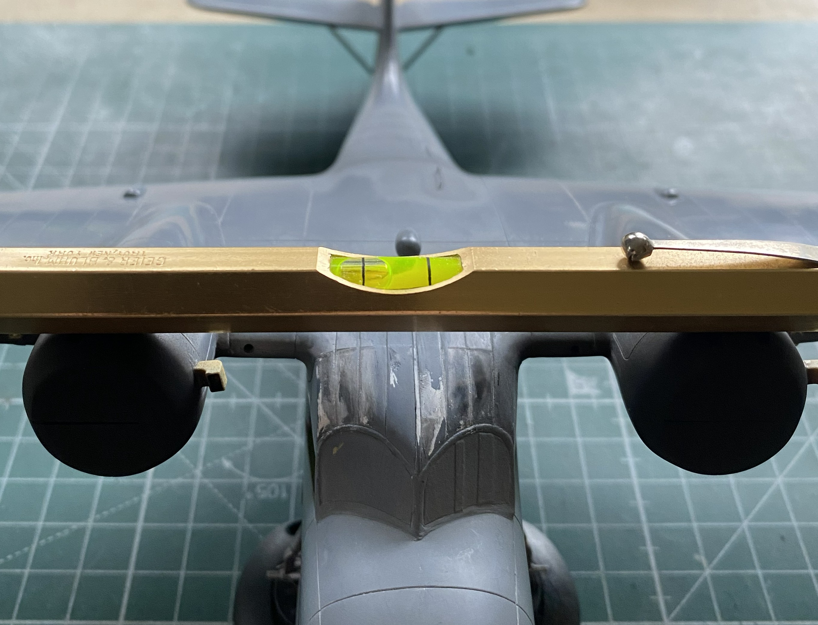
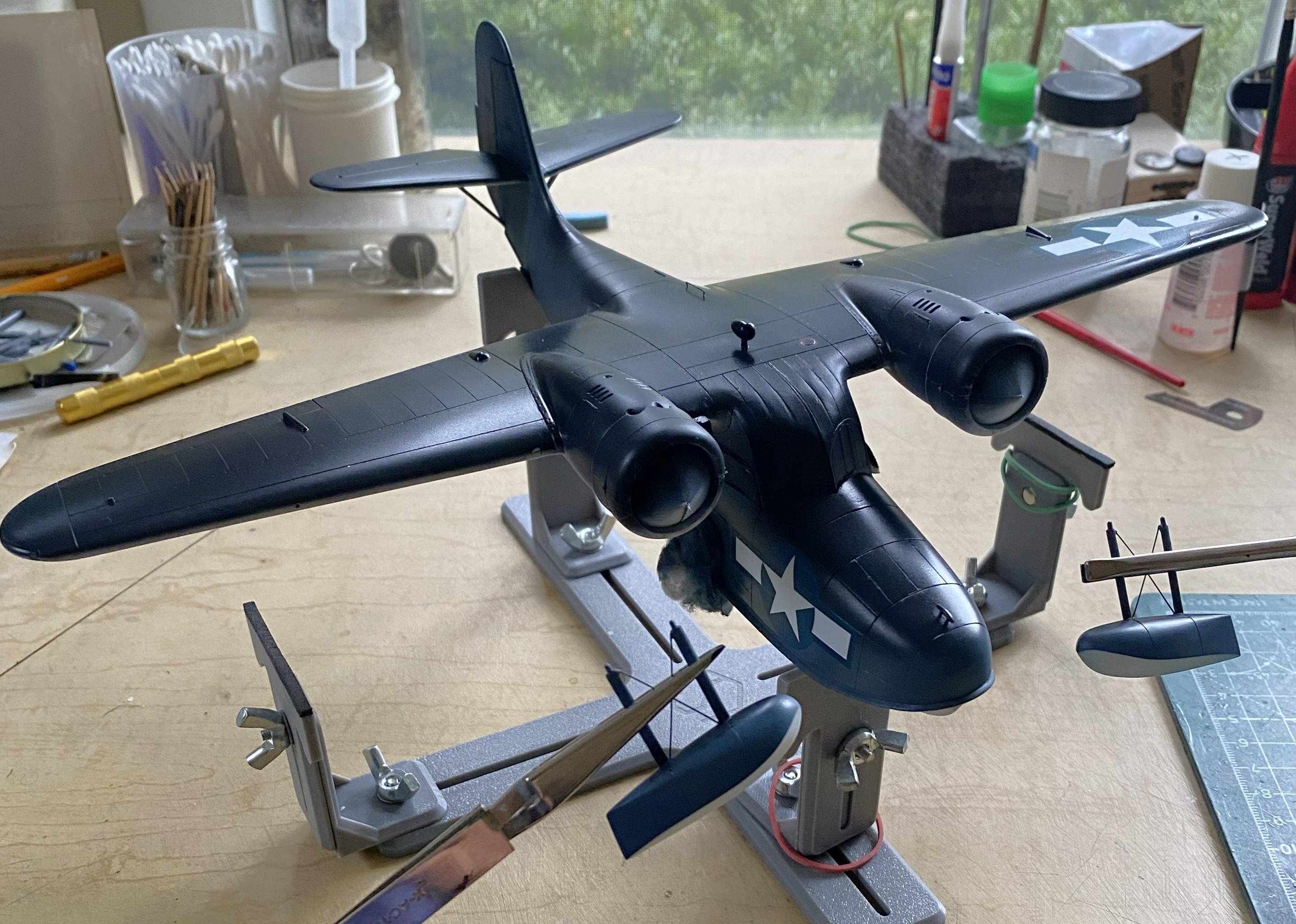
I started with what I perceived would be the biggest hassle and that was getting the wing level, and I wasn’t entirely incorrect. As it sits in this photo, the bubble indicates that the wing isn’t level:

At the center of the model, that bubble isn’t far off. At the wingtips it is. I bent my brain around several corners trying to figure out the best solution. I’m of the opinion that it is not uncommon for a given problem to have more than one solution, except that solutions to problems usually come with new problems (and the solution is enacted if the new problem is less than the old problem). And speaking of problems, here’s a short (I hope) examination as to what the problem is, not what I’d rather it be.
The struts of the landing gear fits into the top of the landing gear bay. The landing gear bays were not molded onto the fuselage sides. As I found out well after I’d added the landing gear bays, the sides of the fuselage do not match dimensionally. Yeah. Who knew that would be a problem. It certainly wasn’t Czech Models. However, with one landing gear bay higher from the bottom than the other, and the landing gear goes there, should I be surprised that once the aircraft is assembled that it doesn’t sit level? I was when I first found the dimensions (and shapes) did not match from side to side, but after I thought about it (a lot), I knew that by the time I got to this point of the build, I’d have this new problem to solve. ::facepalm::
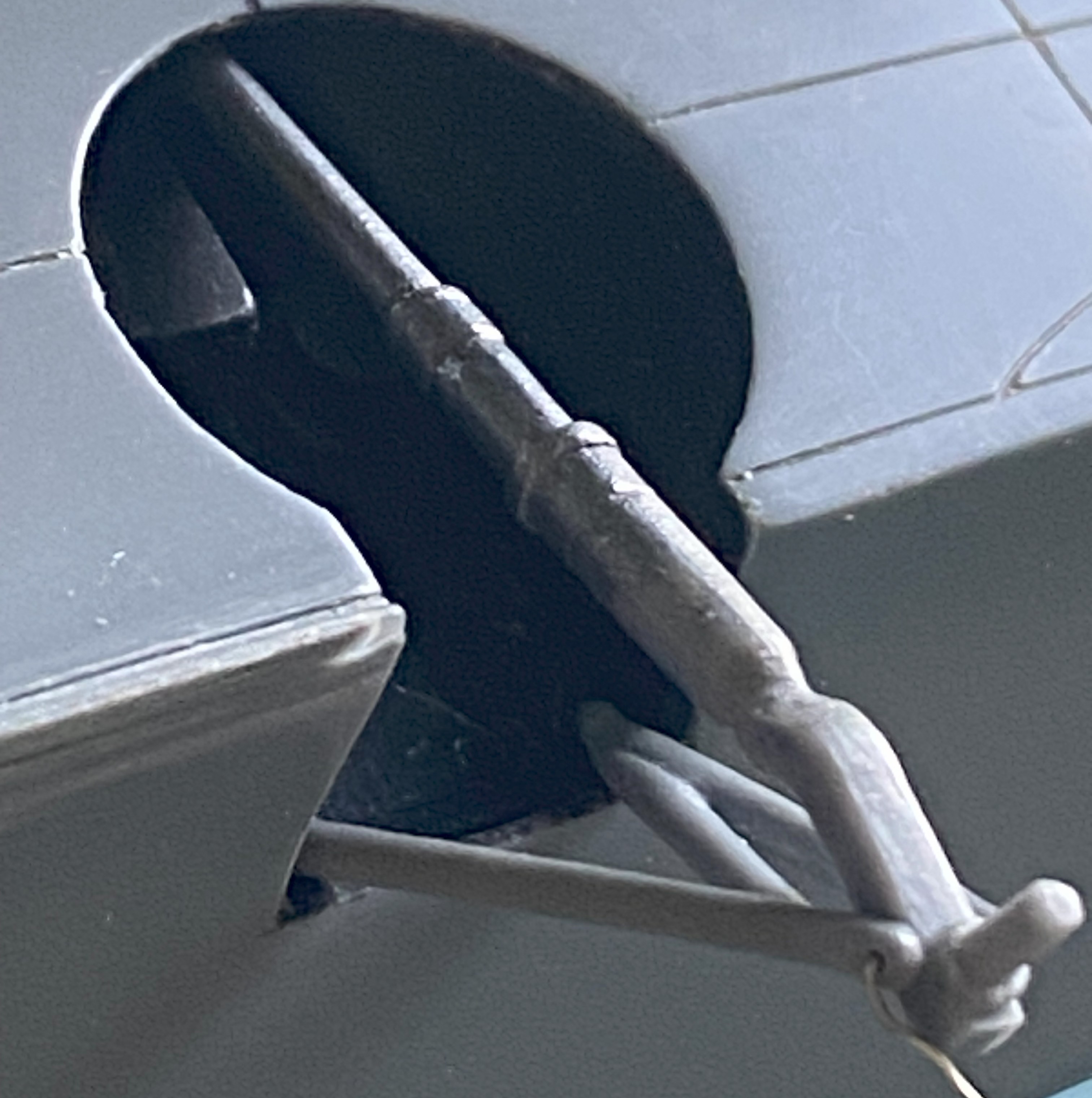
Since I saw this problem as a geometry problem, I looked into the geometry of the landing gear. Being more than a little frustrated at this point, I dry-fit the wheels onto the landing gear and pressed firmly down on top of the model until the bubble was centered. Just as the bubble centered, I heard a soft crack as something broke loose…but the bubble was still level. Took a bit of investigation but I found what broke loose. The blue arrow in the photo below points to where the upper control arm snapped away from the strut leaving this gap:

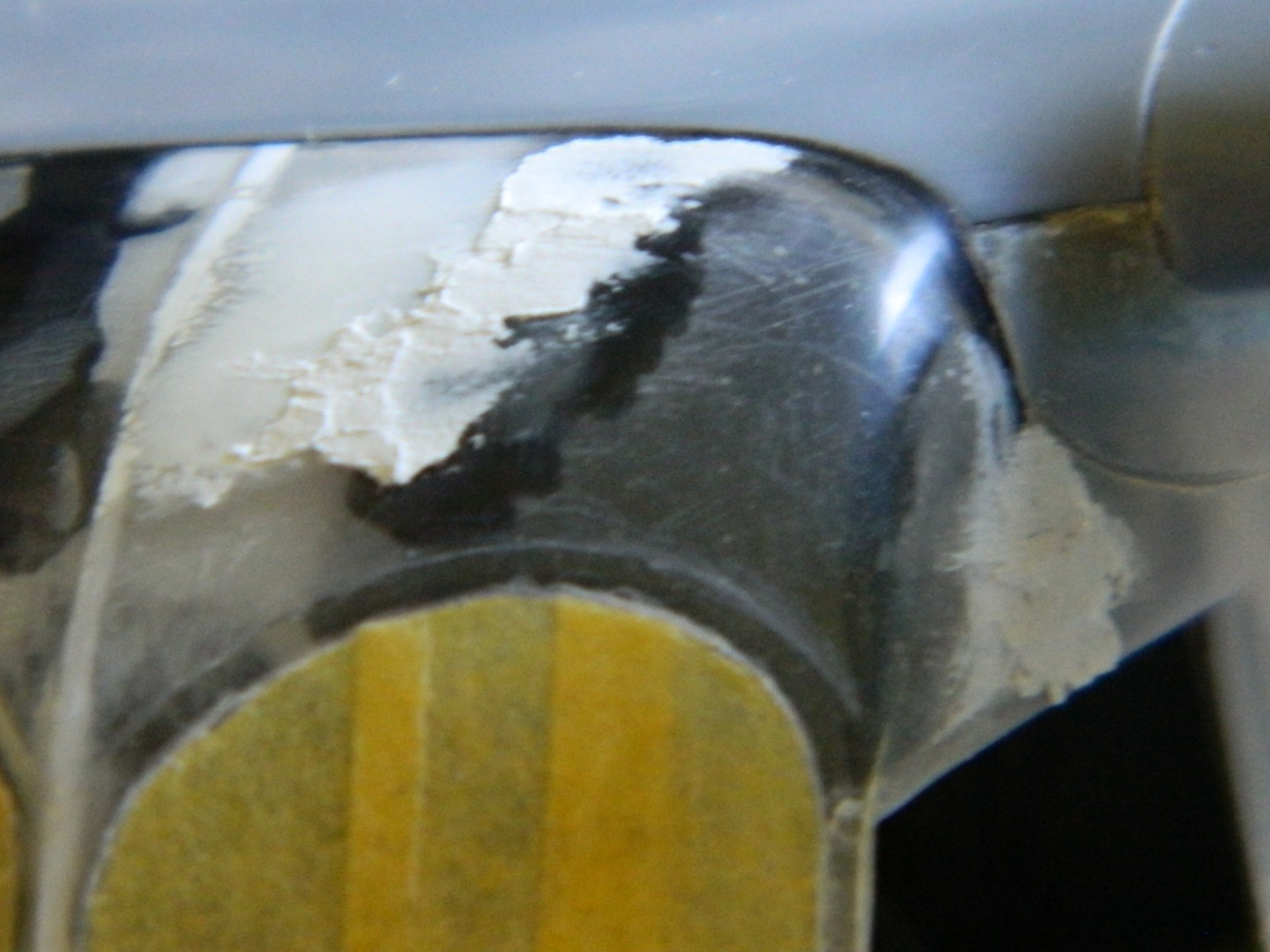
Hmm. So, if I fit a spacer between the strut and control arm, will that make the wing level? The answer was, “mostly”, which I discovered once I’d cut a spacer from 0.030″ (.762mm) and checked:

I trimmed the spacer without gluing it in and checked again. This time I estimated that I needed another 0.005″ (.127mm) more:

And there it sodding is:

I think it’s the housing for an ADF head, but it needed to be painted semi-gloss black. So it was. I REALLY hate self-inflicted wounds, which is how I view overspray. When I aimed the airbrush at the football, NONE of the other painted surfaces were visible:
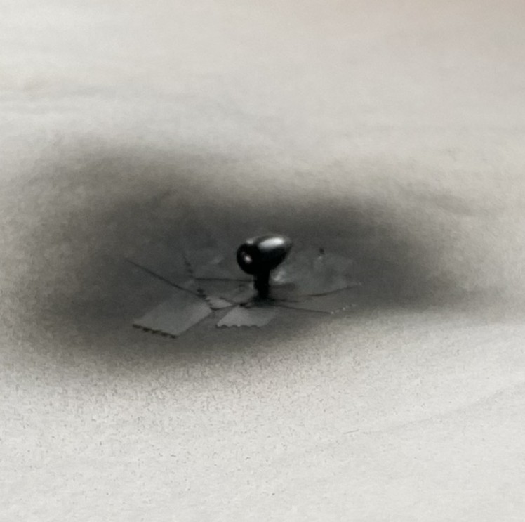
Success! Zero overspray:
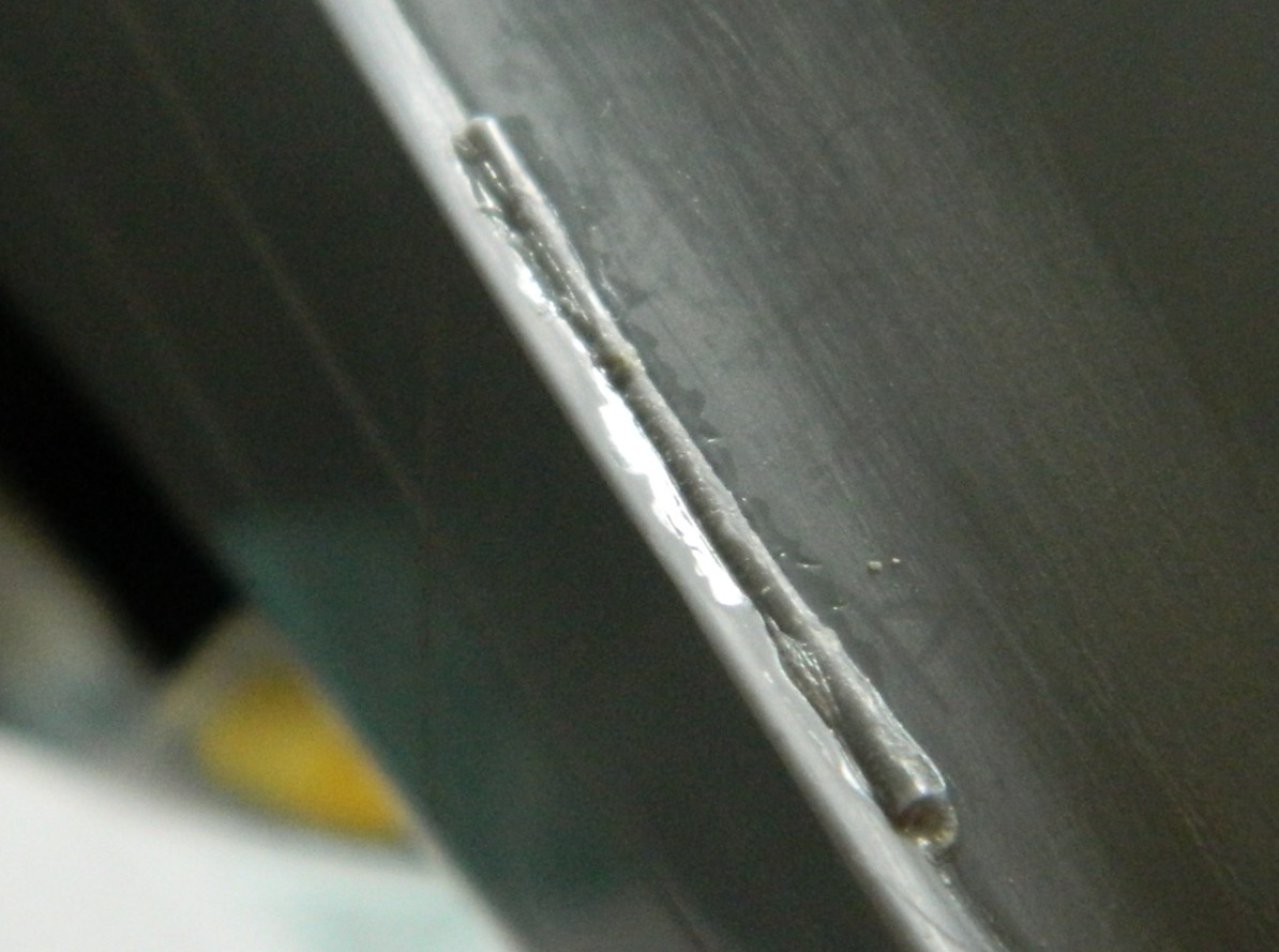
I used 0.025″ (.635mm) as brake lines, painted them knowing full well that during the final bending process would cause paint to flake off. It was a lot easier to get at the parts that bent the paint away because there weren’t buried in the landing gear bay. I’ll get to these when touching up the paint happens (the photo’s on its side because I was using gravity to hold the solder where I wanted it to while the superglue set up):
And speaking of paint touch ups, I painted the frames of the cockpit windows off so that I could also paint under them. A solution that created a problem; paints don’t match once assembled. Okay, I’ll be doing touch-ups (with a small brush in these areas…the other side, though not as bad, is the same), just add this to the list:
You’ll also note that the cabin window just behind the flight deck is still masked. This was a problem I let sit as-is. When I tried to pry the masking tape away, three of the four sides of this window broke free. It was hanging on by paint. My memory isn’t what it once was (is anything?), but I DO remember what I had to go through to fix the one that came out already. Carve, fix, fill. Lots of fun when the plastic was unpainted, a no-go zone now that it has been painted. I supplemented the paint holding the window on with liberal applications of superglue. I’m pretty sure it’s going to stay there, now. It’s in a place where it will never be touched.
This one’s pushing the 90-95% accuracy I try to attain. I don’t care. A blocked off window is better than a sodding hole. Moving on…
Speaking of self-inflicted wounds, I noticed a week or so ago that there was blue overspray on the nose. ::adds to touch up list::

I added the heat exchangers (the brown things over the engine nacelles). Later on I’ll spiff them up a little bit with some pastels:
I added one of the landing gear “doors” just before beddy-bye so that the glue would set up; there’s not much gluing surface:

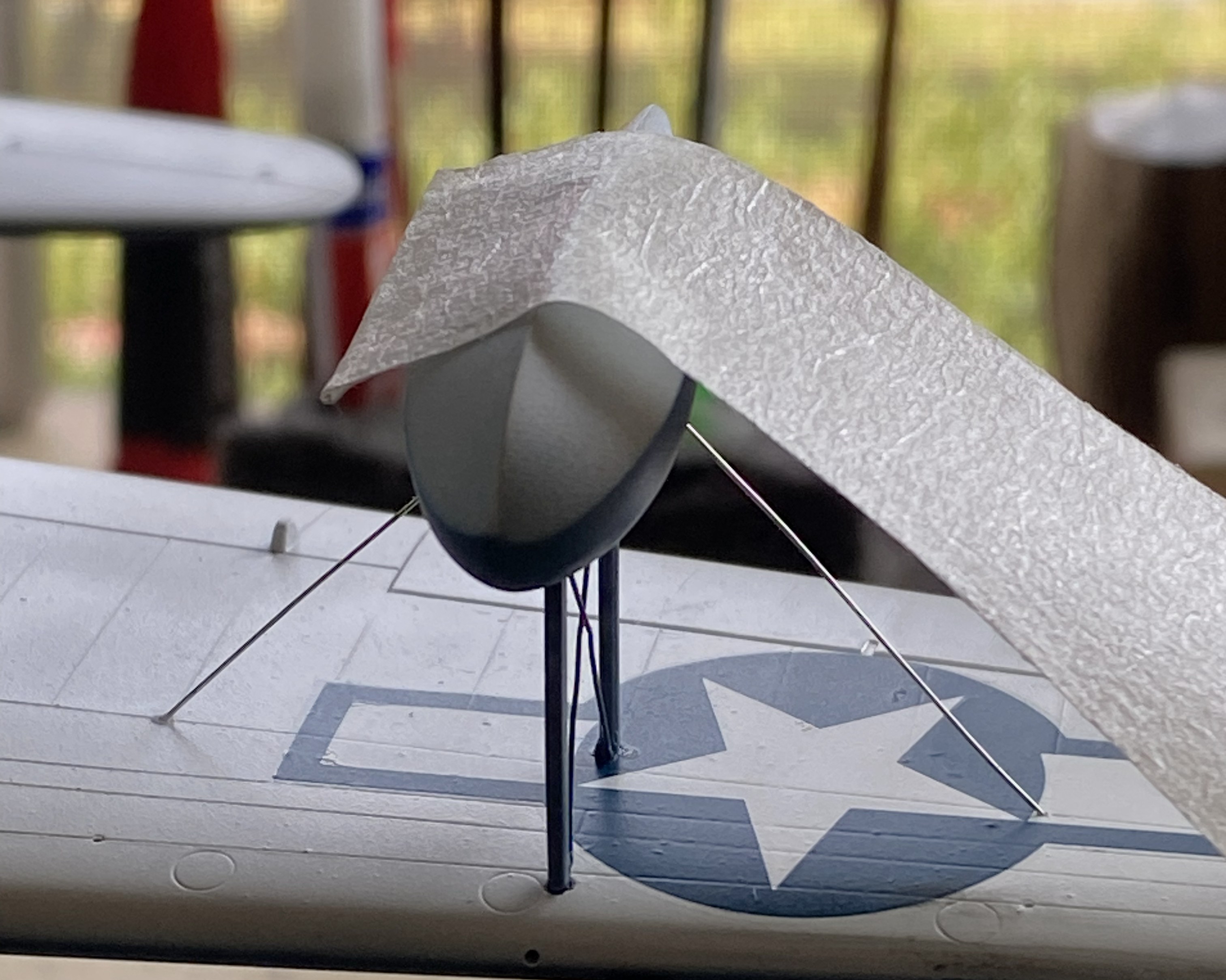
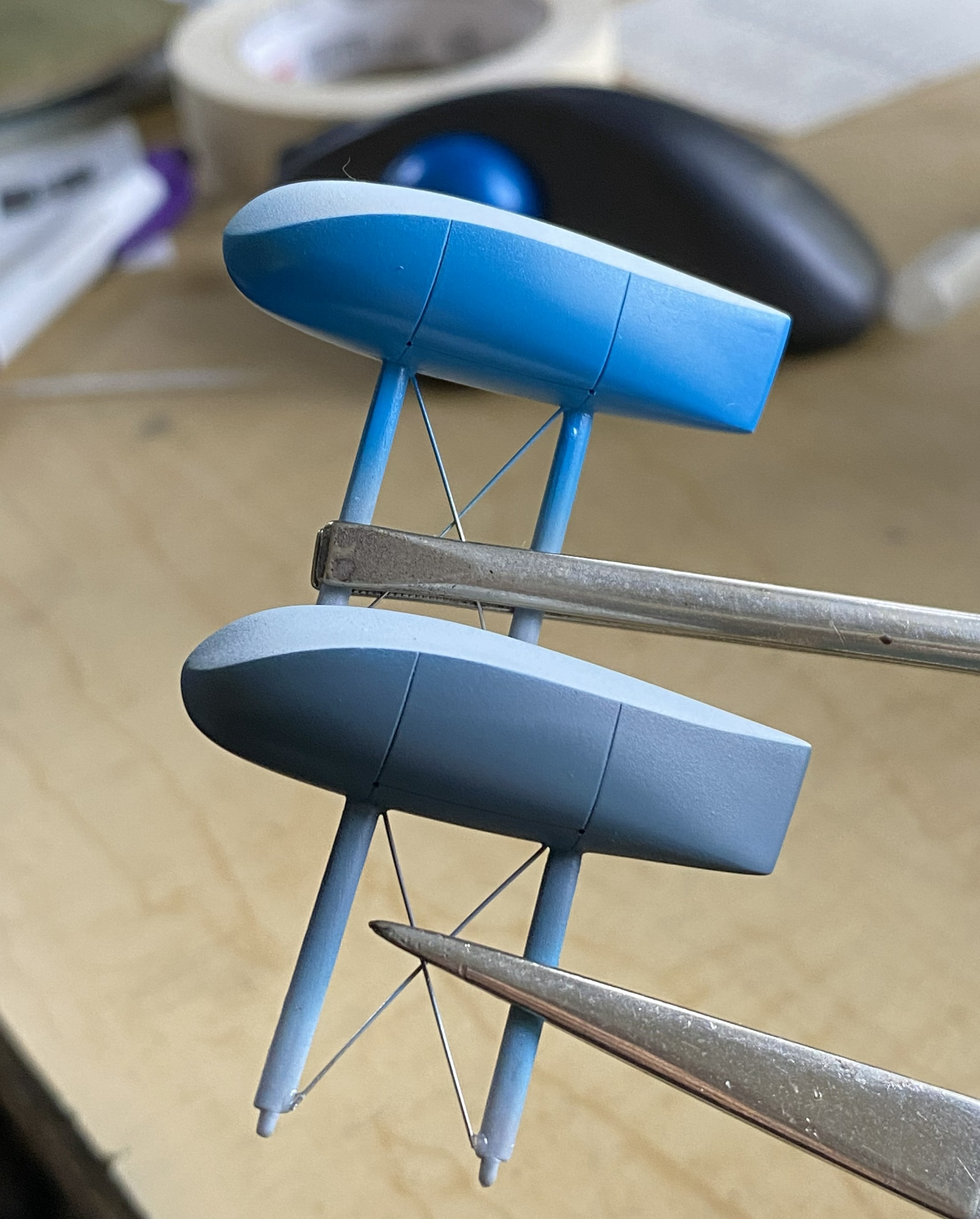
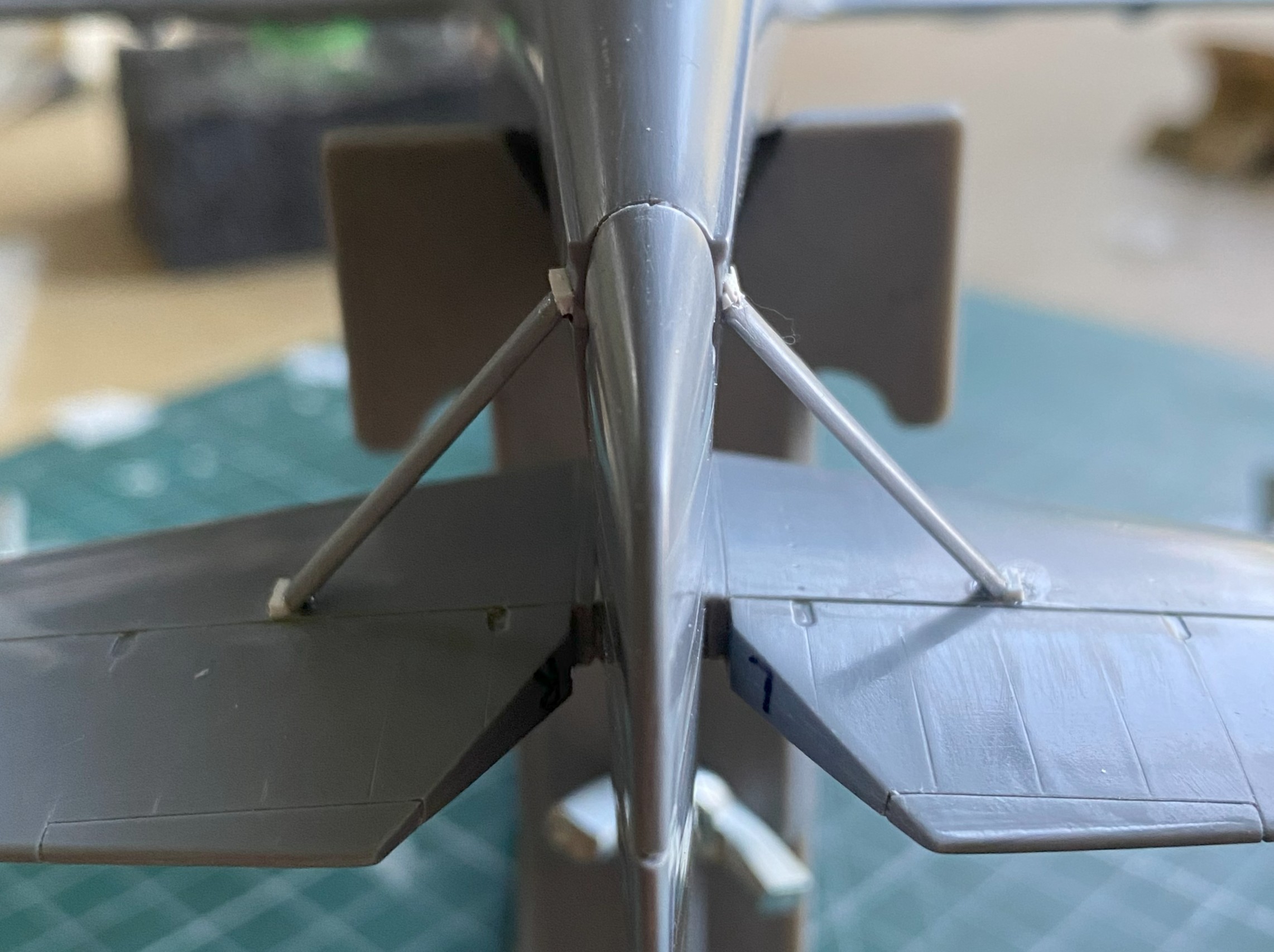
And while I was letting something sit overnight, I got ballsy (considering how late in the evening this happened) and added one of the floats to sit overnight as well:
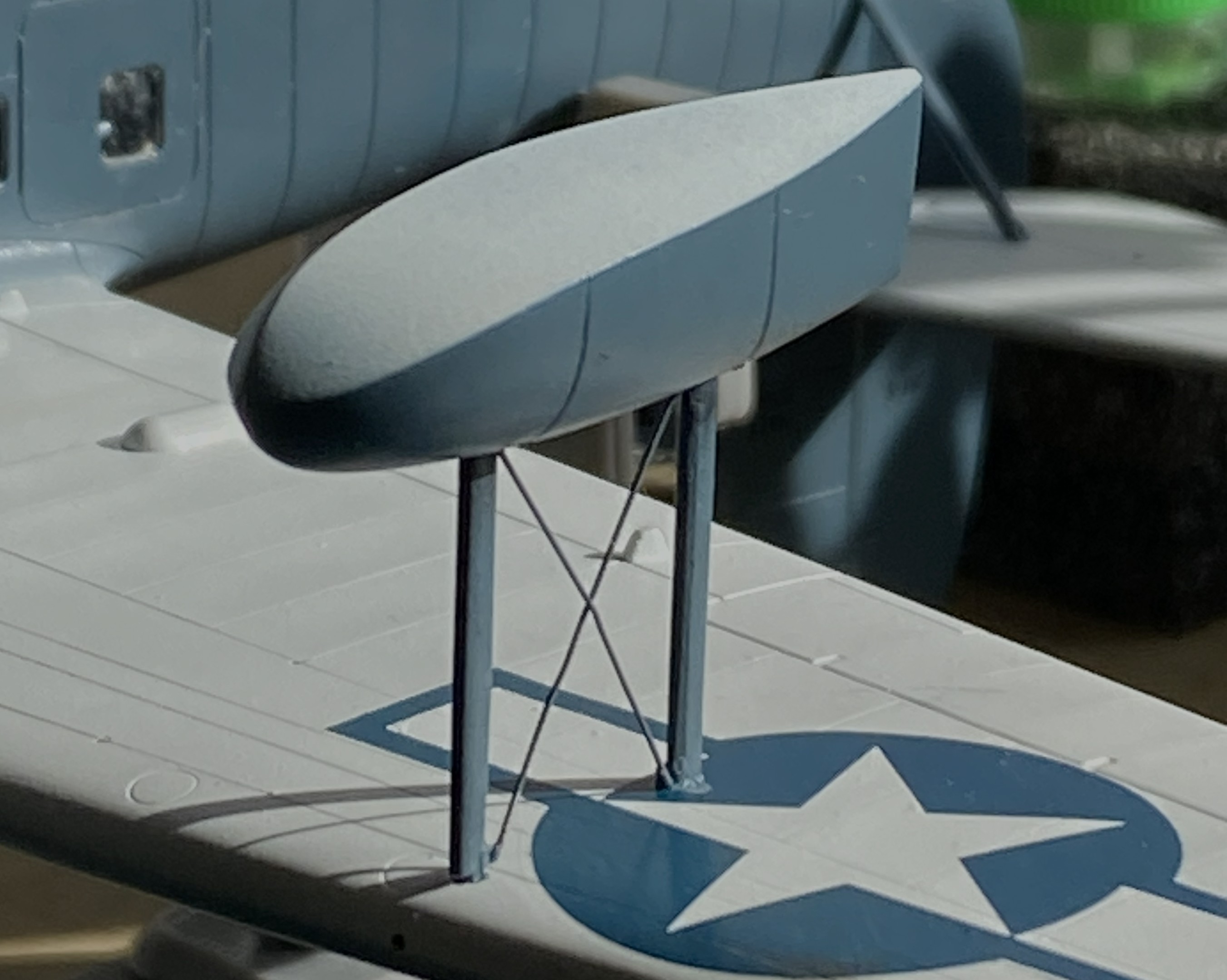
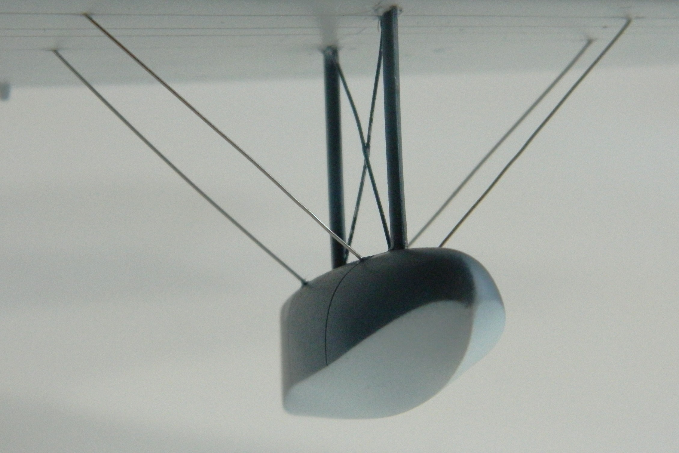
Obviously, with only two small contact patches, this will be easy to knock flat laterally. I added tape to stabilize it while I fed the ends of the braces into the float and wing for gluing (superglue). l cut the wires overlong so that I could be certain I’d be able to adjust them if I needed to (a handy bit of foresight):
With all the guy wires in place, it looks pretty good:

Getting the guy wires into the pre-drilled holes of both the float and wing took some fiddling. For the next float, I tried inserting one end of the guy wires into the float without cement to see if that would be easier:

It wasn’t. If you look closely where the wires meets the float you can see small bits of masking tape holding them in place:
This didn’t work as well as I’d hoped.I was surprised at how difficult it was to just remove the tape. I had to diddle the tape so much that the float came free (in its defense, it hadn’t sat overnight for the plastic to harden fully at the glued points). After I reattached the float to the wing, when I turned the whole thing up side down, all the wires fell out:
I got that fixed:

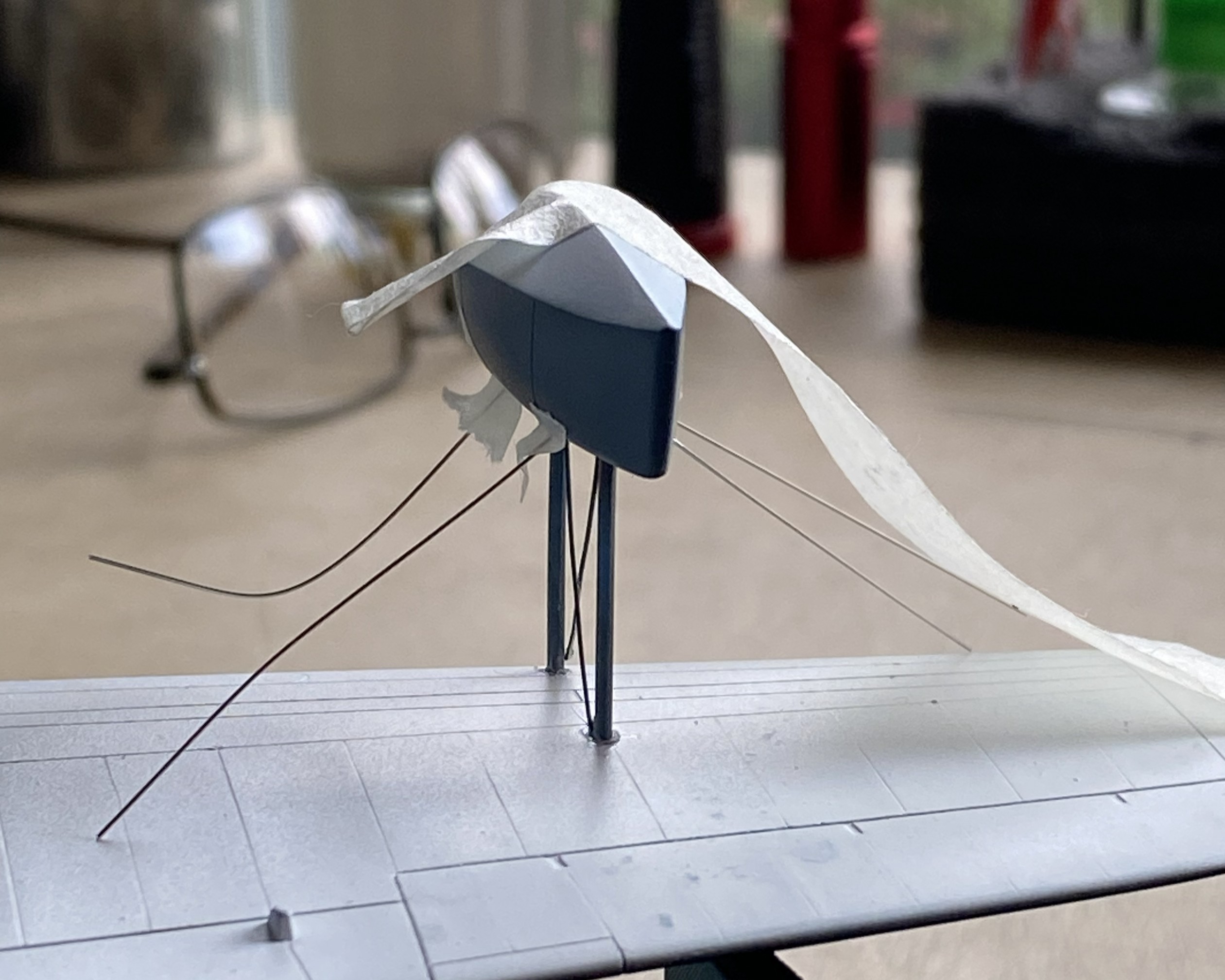
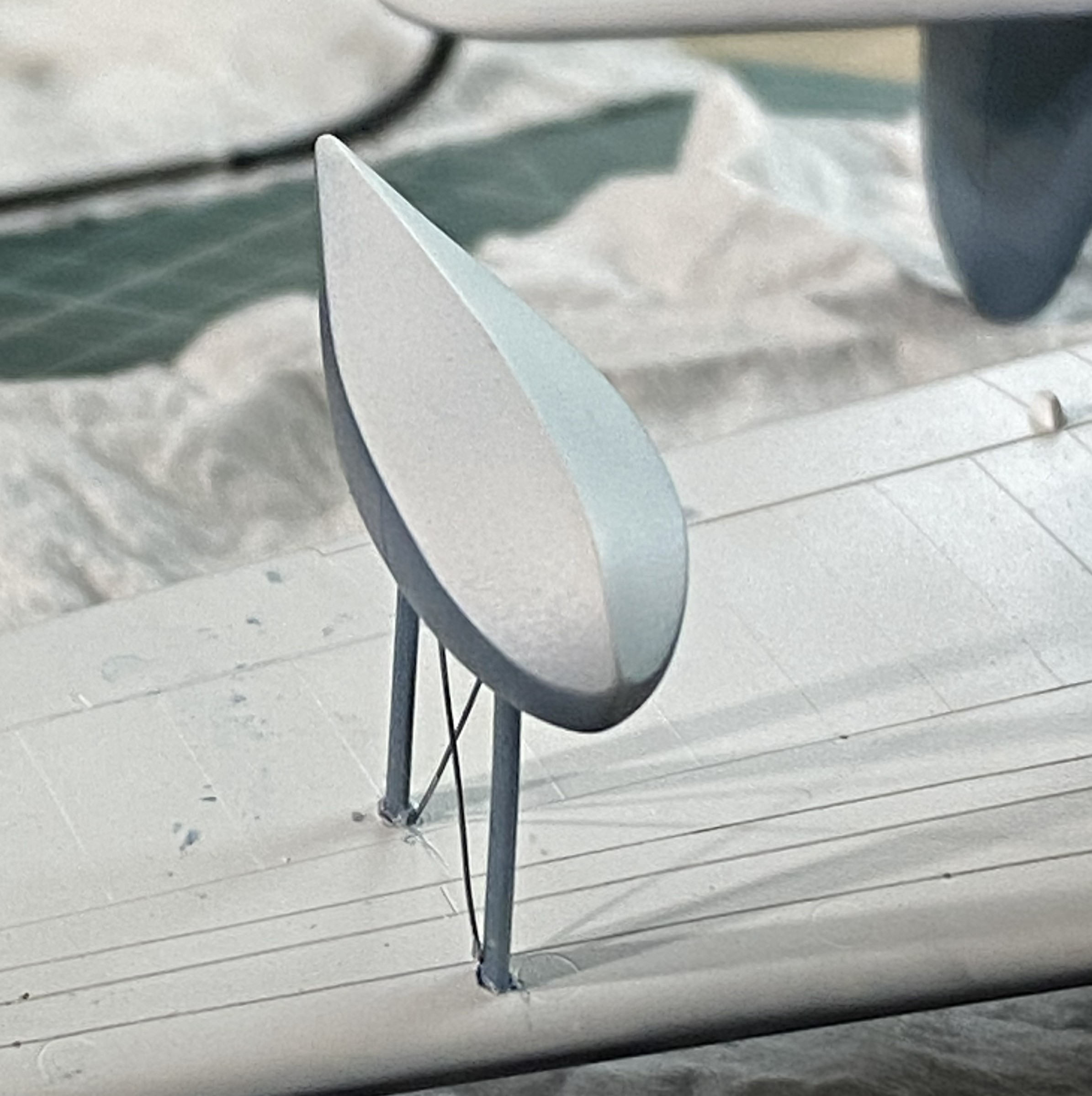
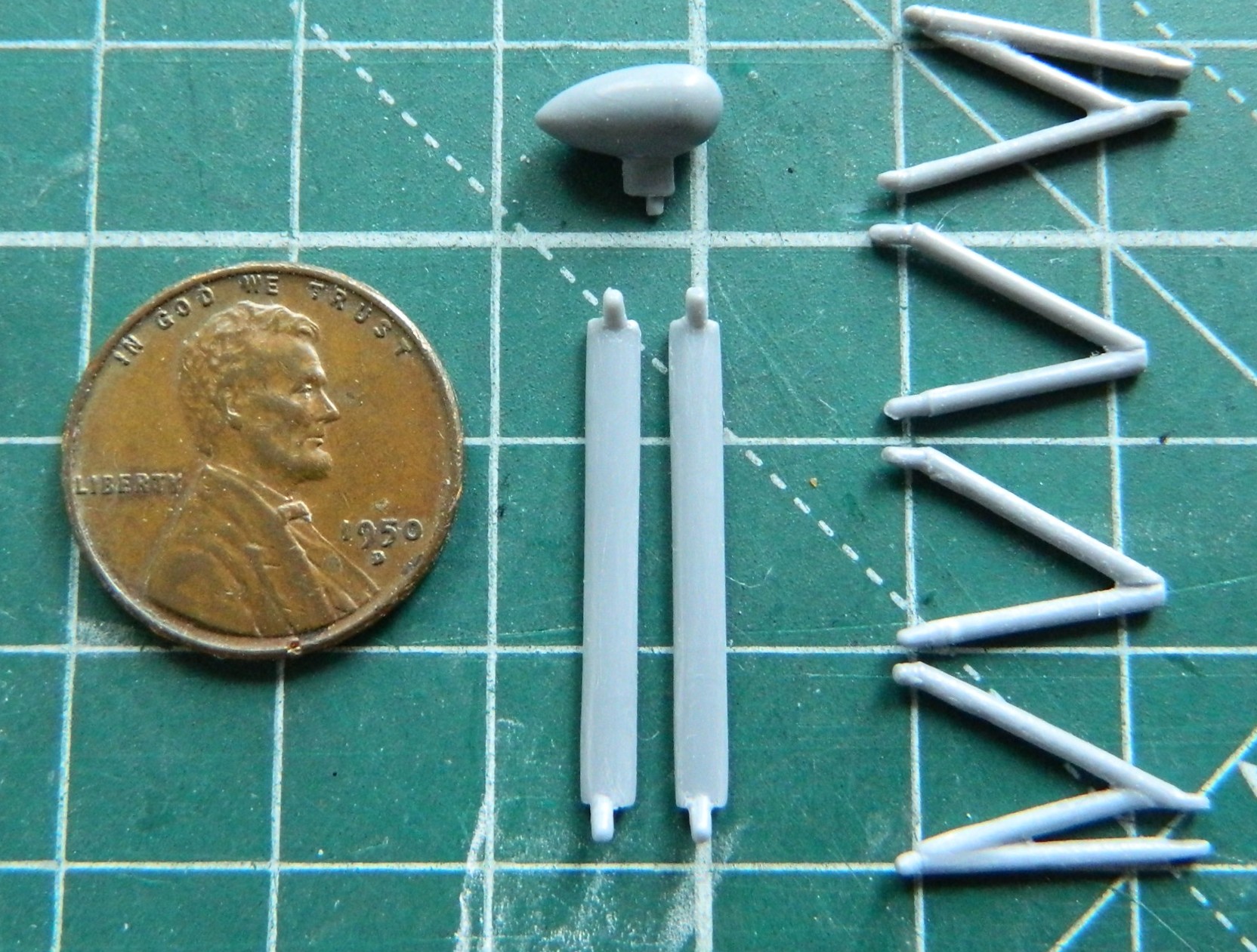
The radio aerials attach at both wing tips and the tip of the vertical stabilizer. I use this for aircraft aerials:
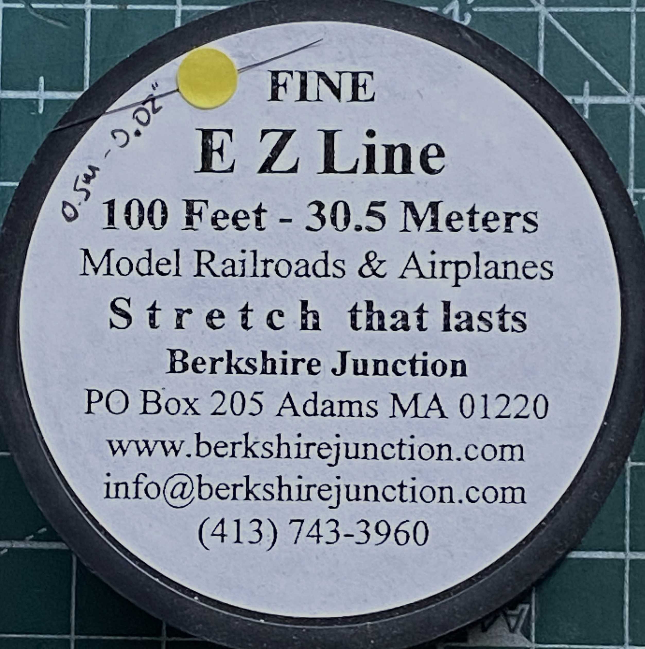
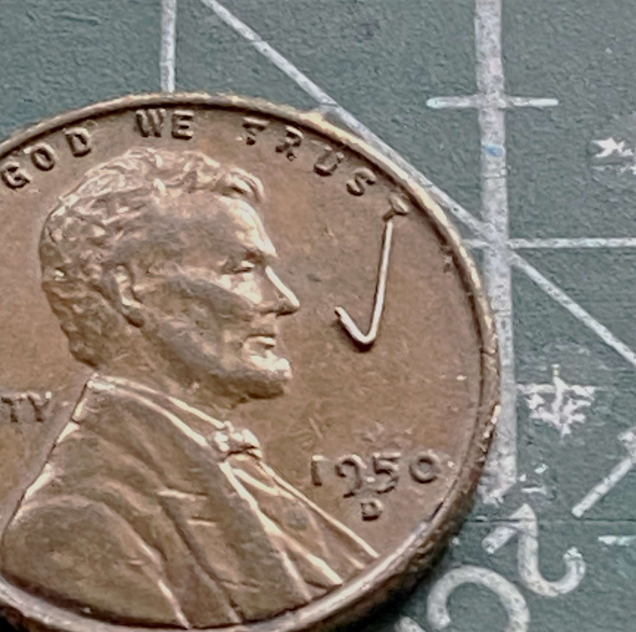
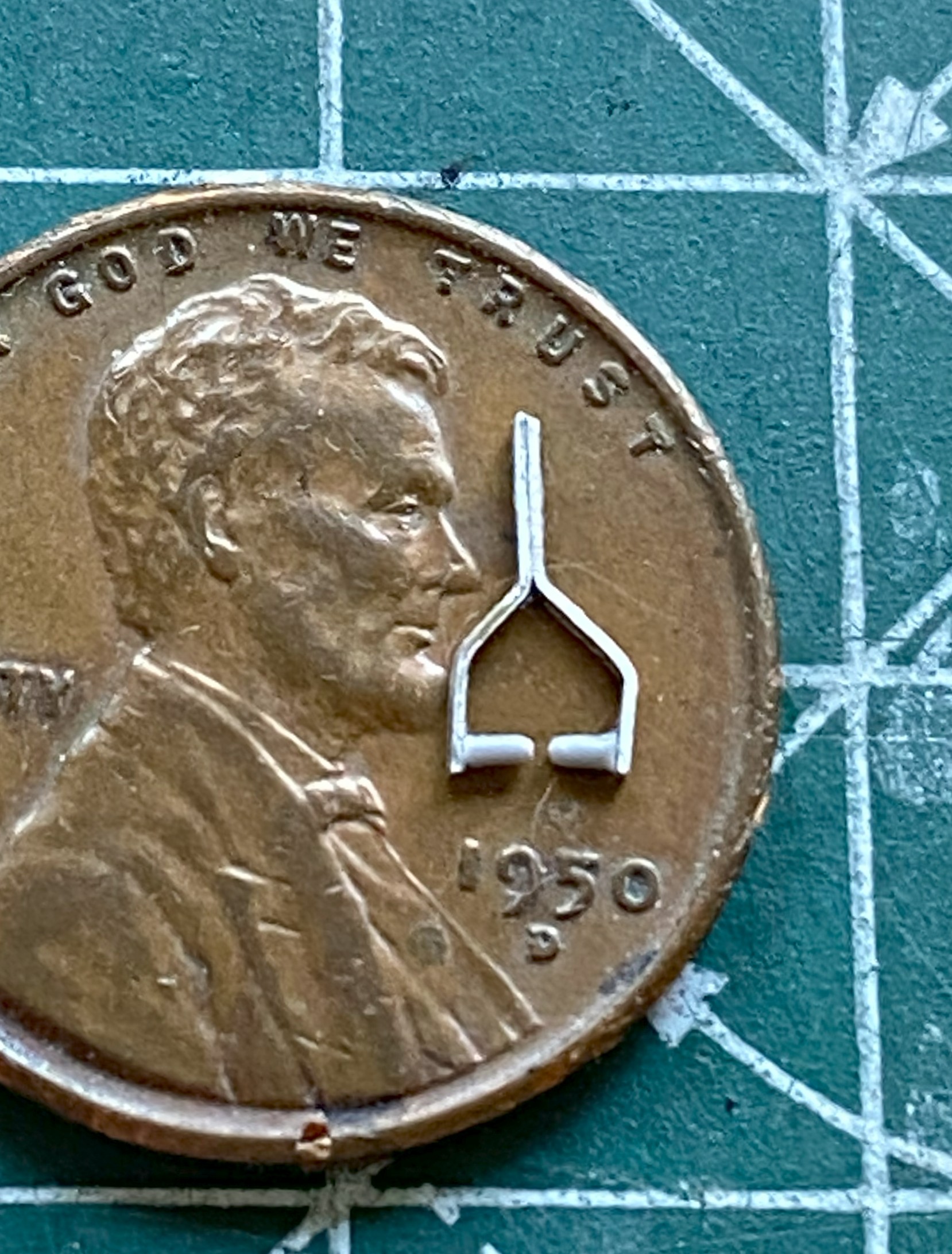
As I’ve been putting this together, obviously the more parts I add the less places I can hold it. For that reason (because these things get handled and transported) I wanted the aerials to be semi-removable; permanently attached at the wing tips, removable at the vertical stabilizer. What would make doing that simple would be to make the attachment point on the vertical stabilizer detachable. Or…I could mount the attachment point permanently and have it be J-shaped so that I can just lift the EZ-Line and let it drop. I like that idea, the major flaw is that even though the EZ-Line’s tension is adjustable, that J-hook has to be small. I didn’t have confidence in copper to hold up over the years. Instead I used the E-string from a guitar (thereby creating the moderately rare 5-string variant). Everything about its dimensions are printed on the pouch:

It’s certainly over-engineered for my purpose, which I think is great:
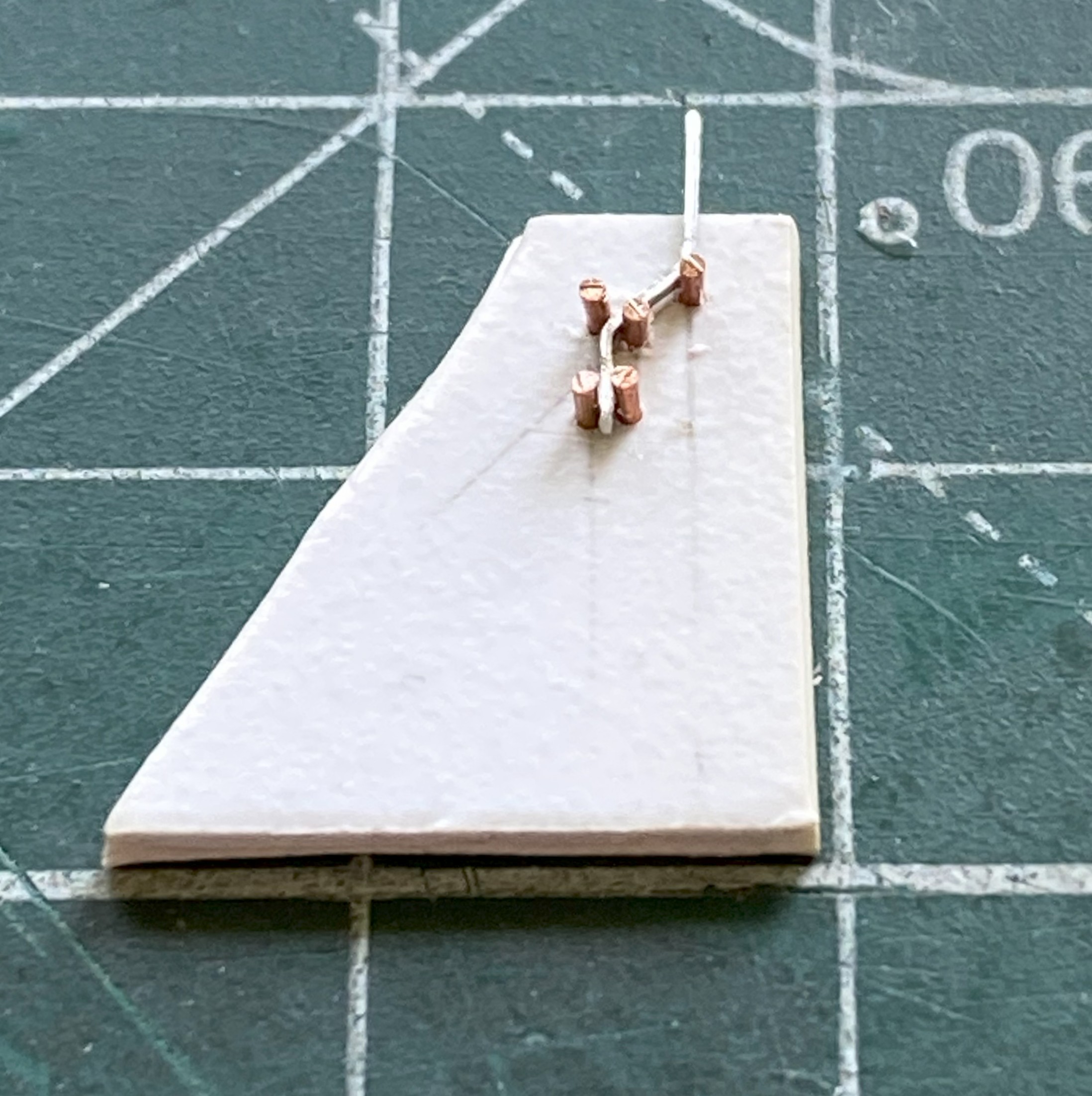
I’d attached little stubs of styrene rod where they belong and center-drilled them to socket the end of the EZ-Line into:

After gluing the other side in place, I tested the arrangement to see if it would function as desired. It function exactly as desired. Top photo below is with the aerials in place, the bottom photo is with the antennas dismounted (for these photos, I dry-fit all the parts yet to add and realized that none of those dry-fit parts need to be glued so I left them on):
I have one more thing to do (attach the brake lines to the wheels) and DONE!

Grumman JRF Goose (Czech Model) 1/48 Scale Build #6 – And This is When Tedium Really Sets In
I generally try to post new material here around the end of the month. Not having posted since August, that seems to have broken down. Seems to. It’s this build of this particular kit. I don’t want to work on it anymore. I recognize that this is an emotional response, not intellectual, so I have pressed on, albeit intermittently. But…here we are!
The fuselage over the flight deck (or cockpit, you choose) has a prominent feature. The curved shape is created on the actual aircraft by using flat panels. In some photos the panels appear to be butt-joined (the edge of each panel abutting the next), in some photos they seem to be scaled (where one side of the panel overlaps the next, sitting on top of it), and none of them are definitive. I made my guess (several guesses, really) and decided I’d go with the scaled (overlapped) presentation. I laid down strips of .005″ (.127mm) and then faired them in with 3M Acrylic Putty:
While the putty is drying, I fitted the heat exchangers on top of the engine nacelles. Originally it looked like a small, resin, cat standing on a hot griddle. Way too high off the nacelles. Fiddle, file, sand, cut at they now sit correctly:
EDIT
While I was doing this update, it was at this point in it that I sat here confused (easy place to get to due to how often I go there). I thought I’d taken more photos of the work over the flight deck. I certainly know that a lot of time was spent on it. About an hour ago the mystery (and confusion) dissipated when I found the photos I thought that I’d taken misfiled in a folder that, of course, has nothing to do with modeling (there are minor aspects of my life that have nothing to do with modeling) (honest). It’s at this place in this post that I surreptitiously add them in a manner that I think few will notice my oversight. ::giggles::
With the putty dry, I went back to the fuselage over the flight deck. ::sighs:: Where to begin… A lot of work ensued. Almost all the putty was sanded away to see if I could (I couldn’t) refine the shapes and lines of this area. As so often happens, once I’ve decided on a method to accomplish whatever oddball thing I’m trying to do, often I have to invent a way to do it (and frequently that is not a hurried process, regardless of how it may look). While doing the work of that invention on the model, it is quite common for me to figure out a different (and hypothetically better) way of accomplishing the task. It’s also not uncommon for that epiphany to come too late to use on what I got the idea from. This was one of those. While removing putty and trying to refine the shapes into something I want, I realized that what I should have done was not add the strips and putty at all. The panel lines should have been scribed and cut away to create the lapped effect. And then I noticed that the lines aren’t just on the clear part, they extend rearward to the pencil line on the main wing, which is how I came to the realization that adding the strips and putty was a total waste of time/effort (and I added the resin scoops to the left sides of the nacelles):
Putty was immediately added whenever I found a void that needed filling:


About this point I realized that I had too many different colors/shades reflecting light and I had lost the surface (visually…if I’m that bad off, I stay in bed). I used Tamiya XF-20 Medium Gray as it most closely matched the plastic’s color so that reflectance would be uniform:

I’ve seen a number of field-expedient grab handles added to aid refueling. The filler port is on top of the wing on the left side. Access was achieved by opening the portside entry and crawling up onto the wing. Then the fueler had to scoot towards the filler port while dragging the fuel hose. (I’m not sure that “ergonomics” was even a word 80 someodd years ago, doesn’t look like “convenience” figure prominently, either.) I picked a photo to replicate and used some 22awg wire and added one setup that appealed to my eye:
Ain’t nuthin quite like applying primer to show you what still needs work. Plenty:


It seems I got too frisky with cutting in the lap lines and took too much off (though, for a change, it was before I’d carved through it) so I used stretched sprue to fill what had been mistakenly removed.
As an aside, if you need preshaped sprue to stretch, shaping the sprue before stretching it will keep the shaped you’ve established (this was shaped triangularly to better stuff the gaps I created):
Jeweler’s files. The self-locking tweezers that are attached to stands. If you don’t have any, get two. They are so useful in getting pissy parts aligned, and keep them aligned, while glue sets. I use my pair on every build at some point and it’s time to use them again to keep the stretched sprue in place while the glue sets up:

I’ll generally wait 2-3 minutes after applying the glue before I press the sprue into what I’m filling with it:


Still more work to do straightening out the lines. I spent over a week working on that section and ended up needing a break from that particular task. Since the added sprue needs to sit overnight before it could be worked, I attended to THE most fragile parts off all the fragile parts.
The mass balancers on the elevators. They’re so small that I left them attached to the sprue runners while I cleaned them up. I knew that I was going to make them removable using 22awg wire as pins. I didn’t need magnification to see that the bases are too small. 22awg was the smallest wire I was willing to use (anything smaller would be too flexible), so instead of even trying to get the notch I’d have to cut for the wires centered on the bases, I excised a slot slightly less than halfway through the base to recess the wire into. No…not accurate. Yes…practical:
And to think that I won’t work on anything smaller than 1/48 scale because “it’s too small” is getting really funny.
With those ready to paint, it’s back in on my head. My eyecrometer seems to be in need of recalibration. Since eyeballing it wasn’t working, maybe tool use will. The tape is so that the next line is freaking straight:

Next up will be mounting the engines.
While doing initial (hopefully final) fitting of cowls and engines, I realized that the engines are intended to mount to the cowlings! (No mention of that made in the directions. I guess if Czech Models figured if the builder has managed to get this far, they’ve realized that for most of whatever this kit needs, the builder will have to figure it out for themselves.) Okay…I’ll glue them to the cowlings:

I’m glad I had the foresight to remember that however the cowling mounted, where the engines mount would be important. But, seeing as the engines are resin and mounting to plastic, superglue won’t allow me enough time to align them correctly. To get around that limitation, I superglued 0.010″(.254mm) clear styrene to the backs of the engines. This will allow me the to join styrene to styrene and fiddle them into alignment (I used clear plastic so that the added disks would be easier to center over the engines):
Now for the task I’ve been dreading this entire time. It’s time to attach the landing gear.
The kit offers three pieces for each landing gear; the main strut, the upper control arms, and the lower control arms. Three pieces, two hands, and minimal space to work in. I cut down on the parts count by aligning the lower control arms on each strut, then drilled through them and put a wire in there to act as a hinge. Had I not done that, I’ve NO idea how I’d have gotten these things on at all. Even with the parts reduction, the four-letter word I want to use to describe that process isn’t “easy”. Move this into position, attempt to move something else into position and the first piece moves out of position. I’ve seen this kit online where others have built it. They could get the landing gear on, so that means that I can get the fornicating landing gear on. I finally got the strut and lower control arm glued in:

After repeating this lovely task on one side, I did it again on the other side.
If I thought getting this strut/arm assembly in place was a delight (it wasn’t), then there’s the upper control arm to wiggle into position and trying to align it while making the aircraft sit level was a pleasure that defies description (or sense). I persevered (the process of which was akin to getting a colonoscopy without anesthesia):

Did I get the bird to sit level? Nope:
It’s not time to fix it yet. I’ll pay the toll on that bridge when I get to it.
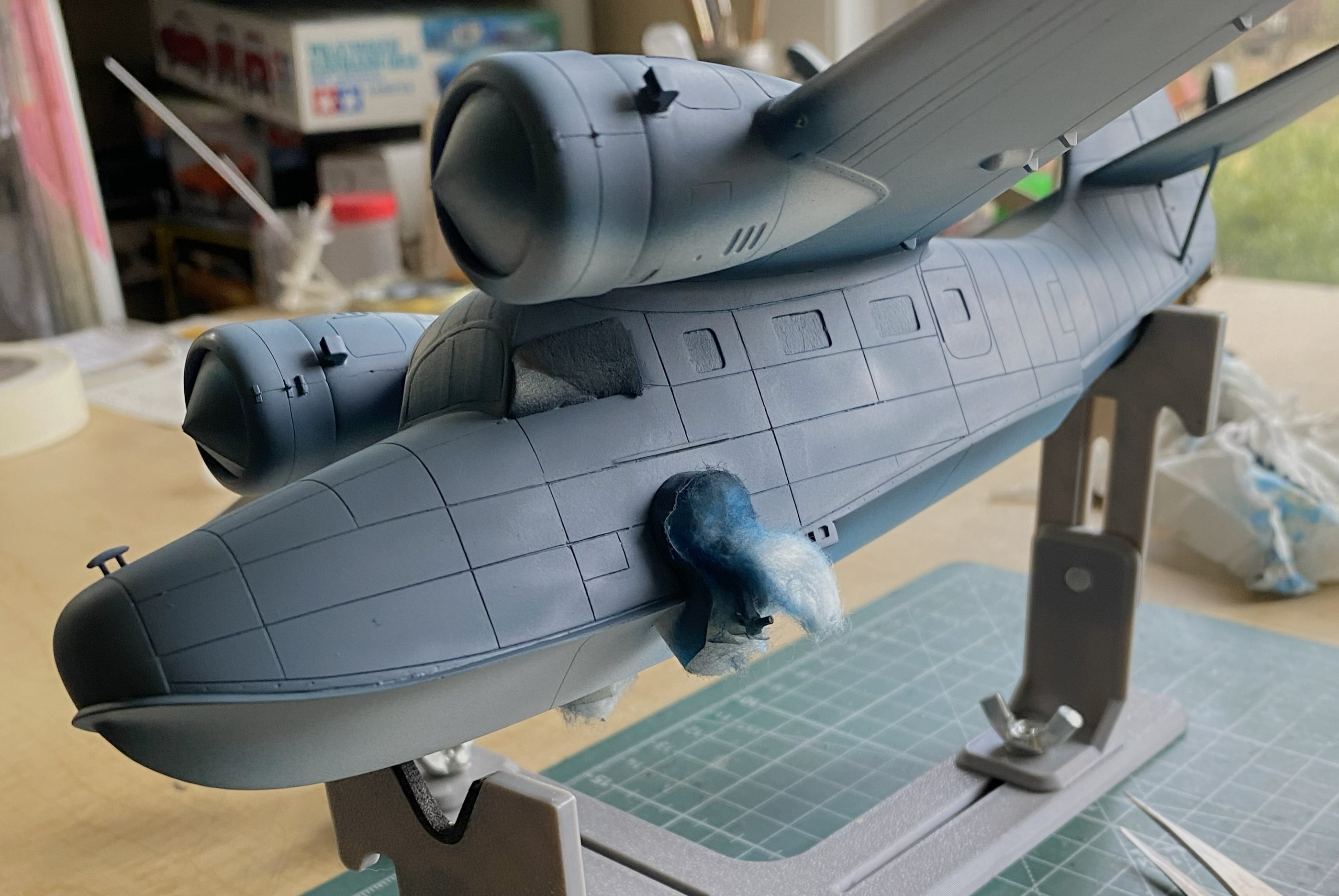
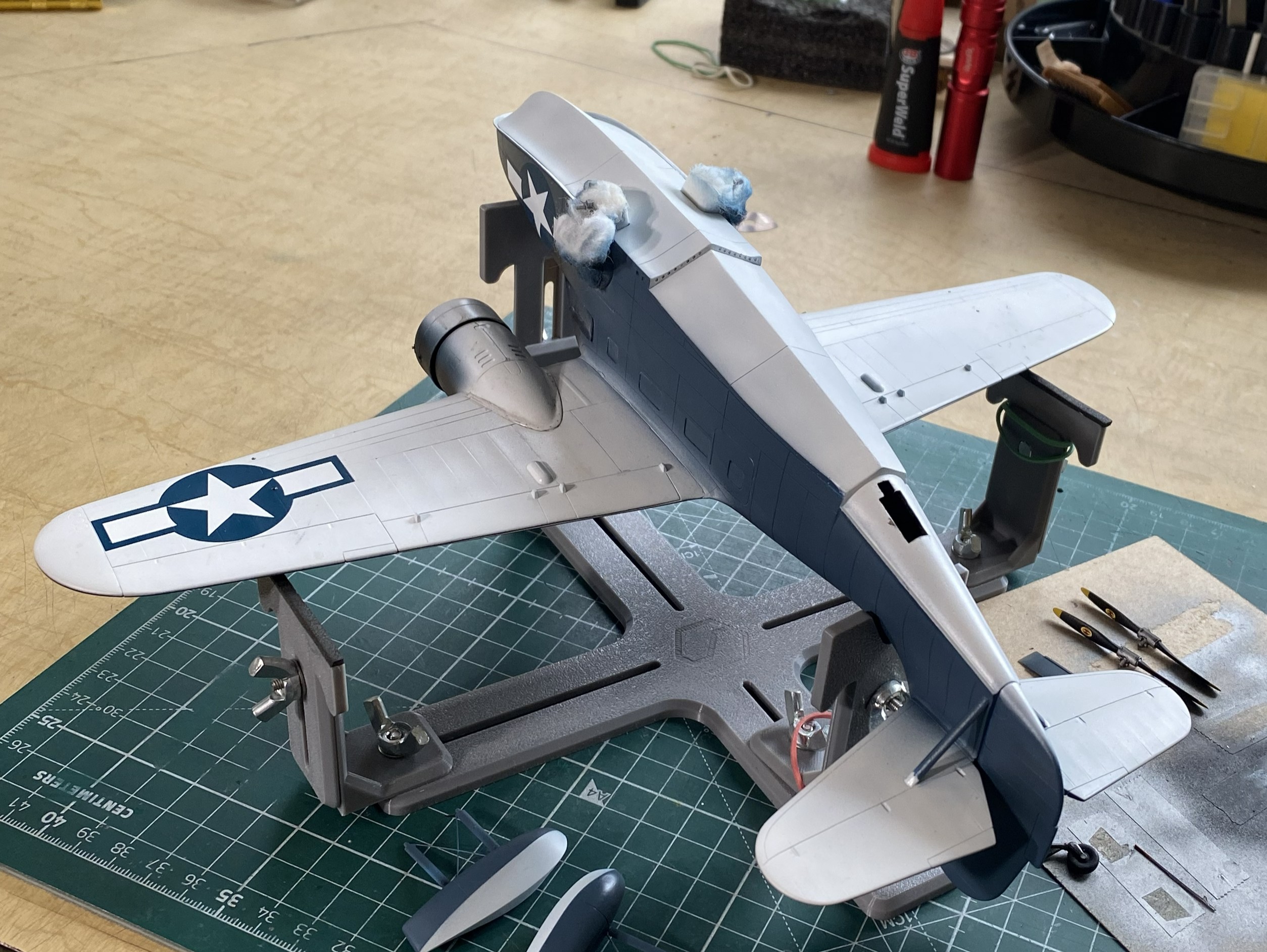
My next task was to start throwing paint at this. Of course I started with the light colors and worked darker, but where I started was figuring out how to mask this using cotton balls for the landing gear, front and rear. For the cockpits, I took foam wedges (nail care section of the drugstore/apothecary) and cut them oversized so that they would hold themselves in position (usually):
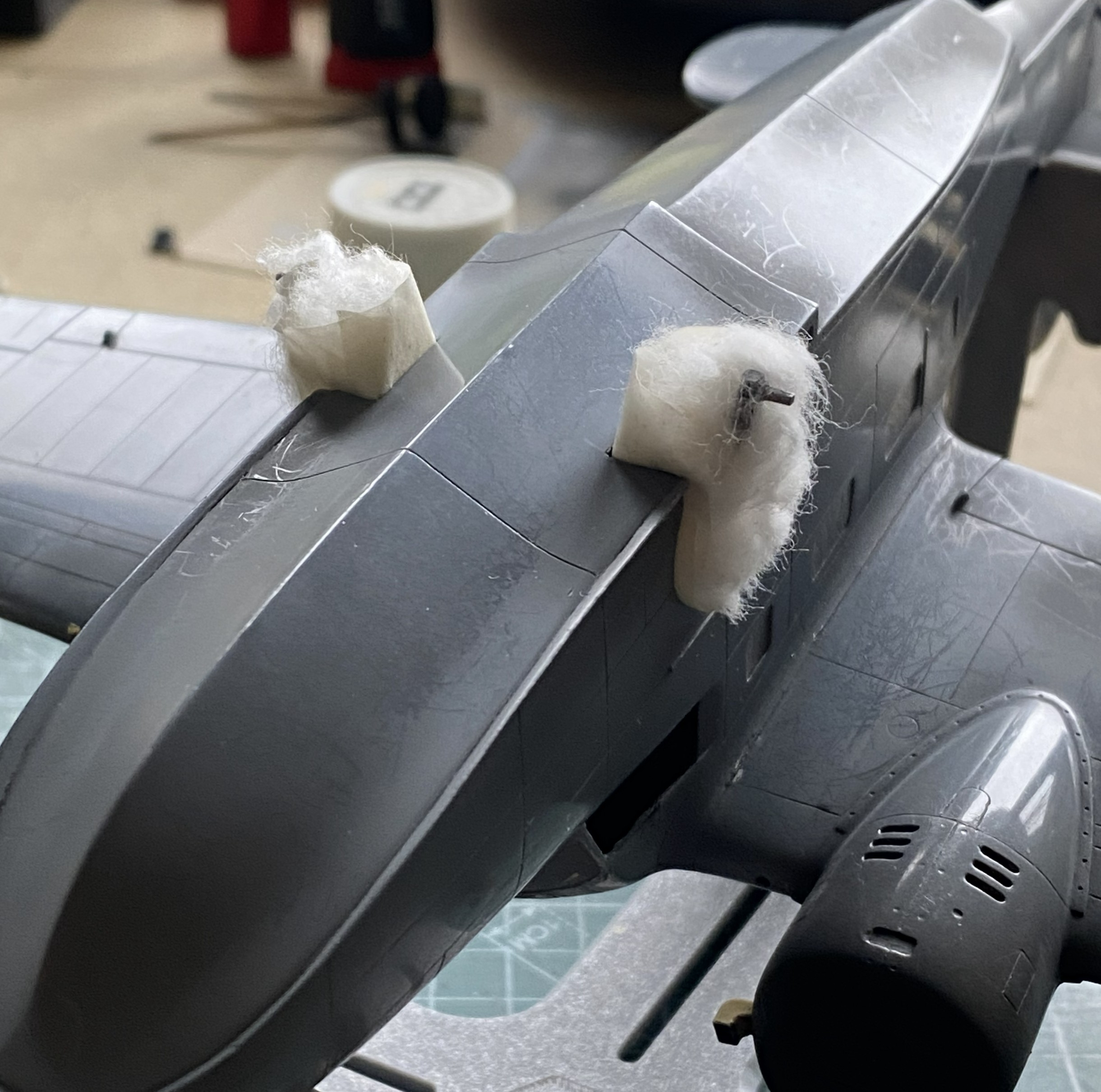
That worked:

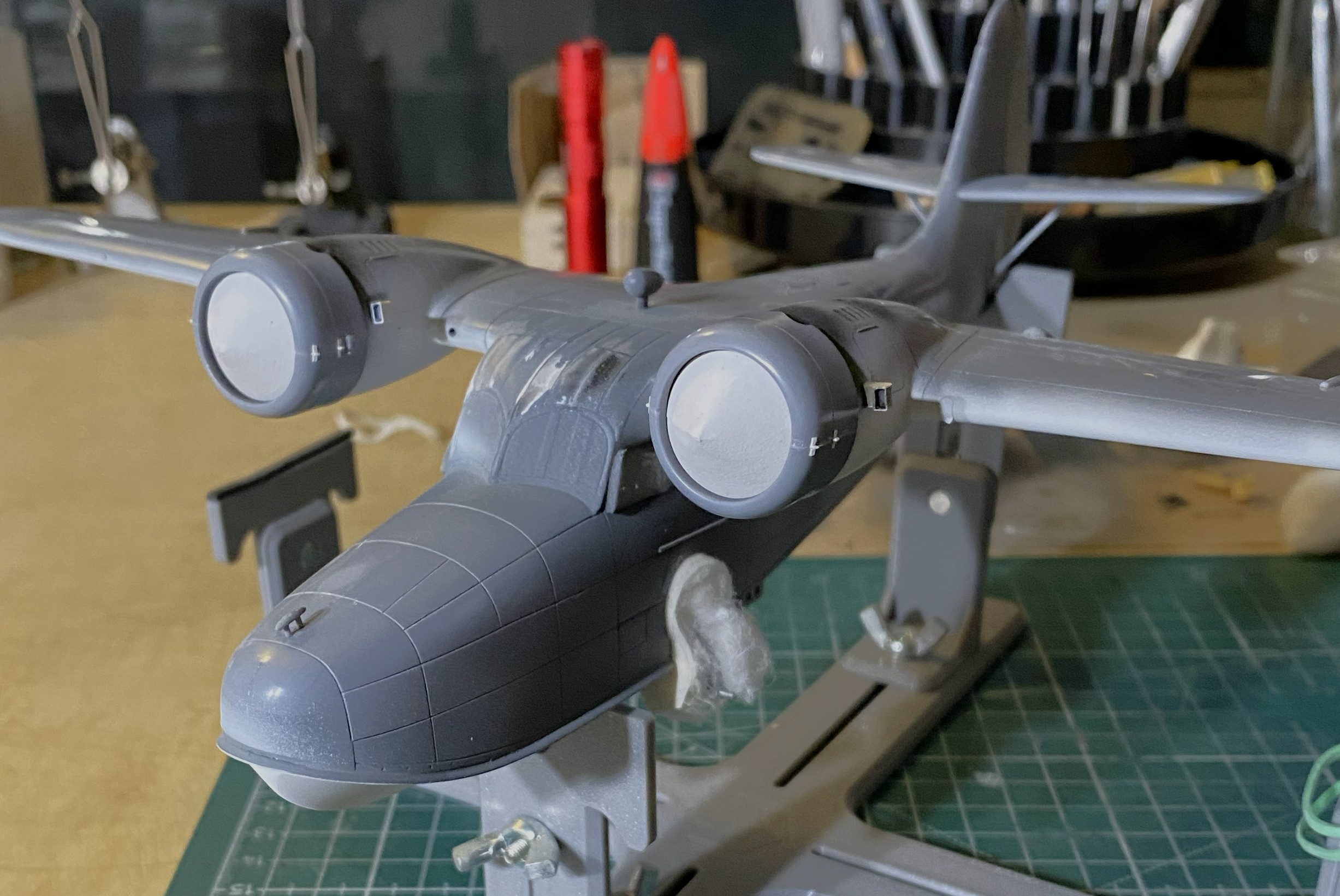
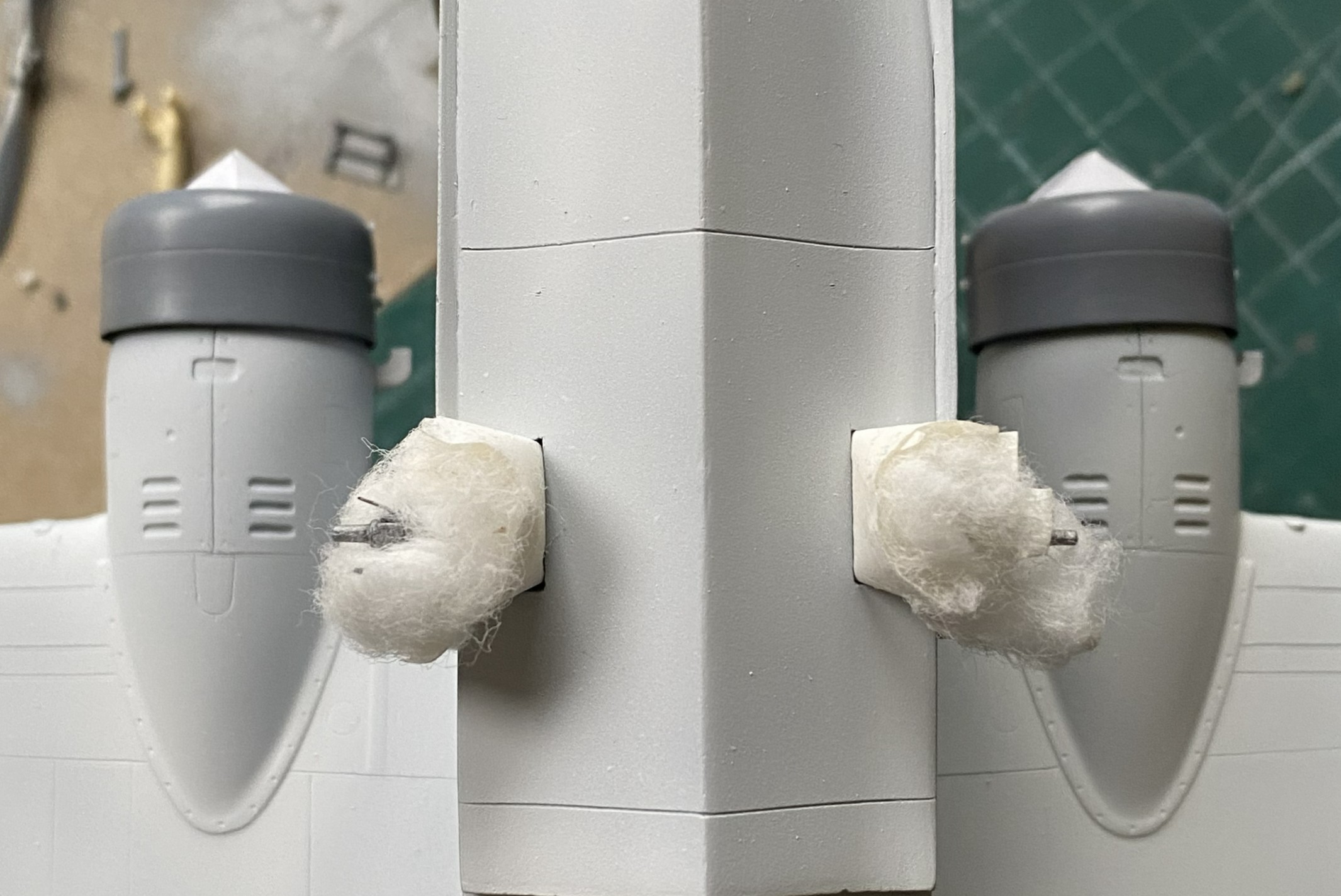
As this will have a three-color paint job, and the nacelles are definitely part of that paint job, I decided that adding the engines now would make all the color demarcations line up later. Before I added the engines, I traced the back of the cowl on paper, traced two circles (one for each engine), and after determining the center of the circles, cut from the center to the edge. This would give me paper cones that would fit in the cowling openings and mask the engines from the incipient painting (and if you look closely behind the engine that’s on the right in the photo, you can see the trimmed foam in the cockpit’s window behind it). With that done, I glued the engine/cowling assemblies in place (shortly after these photos were taken, I painted the undersides of the cowlings white as well):
Figuring that I was on a bagel (which is very similar to being on a roll, just a firmer seat), I got the paints ready. The XF-18 Medium Blue was the correct color, not the XF-8 Flat Blue you see below:

Yeah…wrong color. But…before I had to repaint the sides, I found that Thumbnut McFumbles, here, did not monitor the position of one of those thumbs and did this (hint…check the area that’s not blue…lightly sanded thumb mark on wet acrylic):

Though not precisely pleased, there was something else that fell short of pleasing. When I cut the access open to fix the pilot’s seat, I had to replace the part cut out once I’d fixed the seat. At this point of the build, I was reminded that if I’m not careful (giggle), when the cement finally out-gasses, there can be a visible shrinkage caused by A LOT of glue being used. I used A LOT of glue because there was A LOT of plastic used to fill the edges. This resulted in a clearly evident depression around the patch’s edge once the disco-blue was on. Since I was going to have to repaint the sides (once the correct color arrived), okay…so I’ll fill it in again, only this time I’ll use the UV-setting resin:


Just on a whim, I decided that the heat exchangers could use painting:
Pity…that paint job didn’t last very long as you’ll see later. Too bad. I liked it.
Seeing as I clearly can’t keep track of where my fingers go, I needed a method that would enable me to handle the model as it was being painted. Since I was starting with the bottom, next I would do the sides, and then finally the color on top of the aircraft. And since I want to finish this in a semi-gloss finish, I would also need a painting order for that as well. I let that rattle around inside my wig for now and set about getting that wrong blue covered.
When the paint arrived, XF-18 Medium Blue, I started the repainting with the floats. I’m sure you can figure out which was the before and which is the after:
Much better:
Next up, XF-17 Sea Blue for the upper surfaces:


The overspray of the wings and tail-planes white are how they were painted in WWII.
It was at this point I could take off my polarized sunglasses and resume work.
I like using pencils for some things. At the top of that list is Prismacolor’s PC949 Argent. It’s silver and in small-area applications, it looks enough like aluminum for me. As I’ve discovered, if the surface is slightly rough, the pencil not only goes down easier, amazing things can be done with subtle wear patterns. With the build now under paint, I sharpened my PC949 and went at it. Gently. The Navy doesn’t let its kit get shabby:


With the paint on, the next thing that goes on are decals, so I hit the spots where the minimal decals go with Tamiya’s X-22 Clear Gloss:
Yes, that looks like a lot of paint. However, this paint does self-level:

I had painted the white undersides (Tamiya XF-2 Flat White) a few days before the color and had shot it with clear gloss (Tamiya X-22 Clear Gloss) to prepare it for a wash which meant it was ready for the wash. I figured since the wash was going down over white, I could get away with a more nuanced wash. Pratt and Whitneys leaked oil. The skin panels were not oil tight. Oil leaked on the ground and once the bird was in the air, the oil that had leaked onto the skin streaked back in the airflow. That’s what I was after. I didn’t think an enamel wash would give me the subtlety I thought would work so I broke out the oils:
The last time I did a wash using oil paints (on the engines), I’d used Turpenoid as the base (roommate hates the smell of enamels and turpentine). It took a week to dry. For this wash, I tried using Gamsol as the thinner instead. It was dry the next day.
Yep…looks like engine oil:

Yep…it looks a lot like oil:
At this point, these are all the parts I have yet to add:
A couple of days later with full knowledge that the clear gloss had set sufficiently for decals, well then…let’s do the decals. And then there were these:


Well, well. Old decals. I decided to see if I could get them off the backing with few enough shards for me to piece them back together on the surfaces (because I’m that kind of nuts). Results were…well…predictable.
This one went on in “only” two-ish pieces and was acceptable:
The one for the upper wing, however, was a cockup:
I broke out Walther’s Solvaset in the hope (another four-letter word) all the shards would play nice with each other. They didn’t. I used more Solvaset to see if perhaps multiple applications would smooth things out. In some spots it worked. However, there was a cost. NO amount of further Solvaset got rid of the wrinkles:

The second photo above was the best Solvaset could manage. Not acceptable. I only know of one way to remove blown decals. Sand them off, reapply paint, and start over:


Yes, even through the new paint, the faint outline of the decal’s remnants shows up. Since the new decal would sit right there, I didn’t bother sanding it out.
Solvaset worked well (though not perfect, it’s close enough) on the left nose decal:
At this point I discovered that I’d salvaged the only two decals from that sheet that could be salvaged; all the rest were garbage. Oh great. This is a limited run kit so the odds of me finding suitable decals weren’t good. Okay, so it’s star ‘n’ bars…I probably have dozens of them on hand. When I went through the decal stash, I discovered that yes…I had lots of star ‘n’ bars. I just don’t have any even approximately properly sized. The big surprise was finding another sheet of the exact same decals for the exact same model. How I managed that, I’ve no idea. But with stars in my eyes, sweat on my forehead, my shaky hands cut out a decal from that sheet to test and it was FINE.
Whew…
Here’s the nose decal from the second sheet, and this time I wondered if Solvaset was too hot for these decals. So, who doesn’t have Micro Sol? I used that instead and though the old decals WERE OLD and shattered, perhaps part of my problem with the upper wing decal was the Solvaset. Micro Sol did the job (in-process in the lower photo):

While I’m fiddle-farting around with sodding decals, I neglected to notice that I’d knocked both heat exchangers off the bench and then stepped on one. I never heard the crunch. I did notice that neither exchanger was on the bench. Found one intact. Whew. Found one sitting in a small pile of resin dust (avec chunks):
::facepalm::
Okay, so I get to reattach the tail and make new arms. I didn’t have the exact diameter styrene rod, but I had styrene rod that was maybe 0.005″ (.127mm) less in diameter and that was close enough. Plastic has a memory so if I wanted a 90-degree bend, I’d have to over-bend them and let them sit overnight to attain their new memory:
At this point, a regular occurrence occurred. I dropped something and realized that the floor between my feet was CRUDDY. Okay, pick up the dropped tool and sweep the floor. Once the detritus was in the dust pan, there was one of the two arms sitting right there. Okay…let’s attach that NOW so I did using UV-setting resin:
That’s good news! I only have to make one arm using the UV-setting resin again:
It’s at this point that I got to see what happens when I get interrupted in the middle of something. I’ll forget the second half of something. I had one propeller all painted and ready. The other? Well, I got the hub painted and washed… Yeah. Let’s fix that before somebody notices:


I’m going to be facepalming so much that my forehead will be calloused and the tendons in my hand will be inflamed.
With the paint curing on the prop, I checked the repaired exchanger for fit. Just right:

With that all fixed, I got back to applying decals:

With all that applied, it sits overnight.
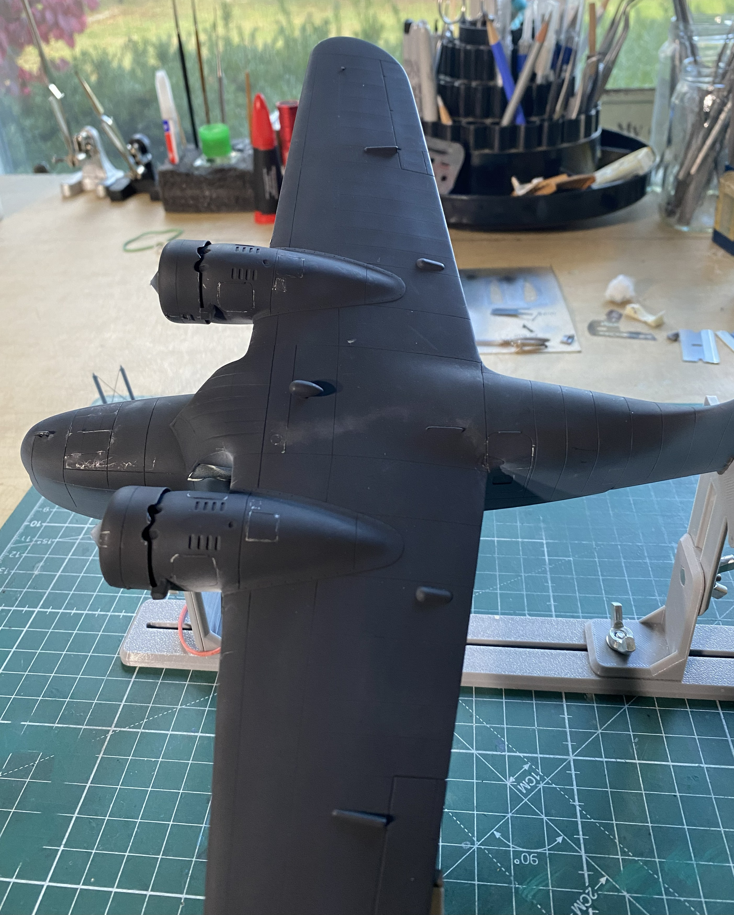
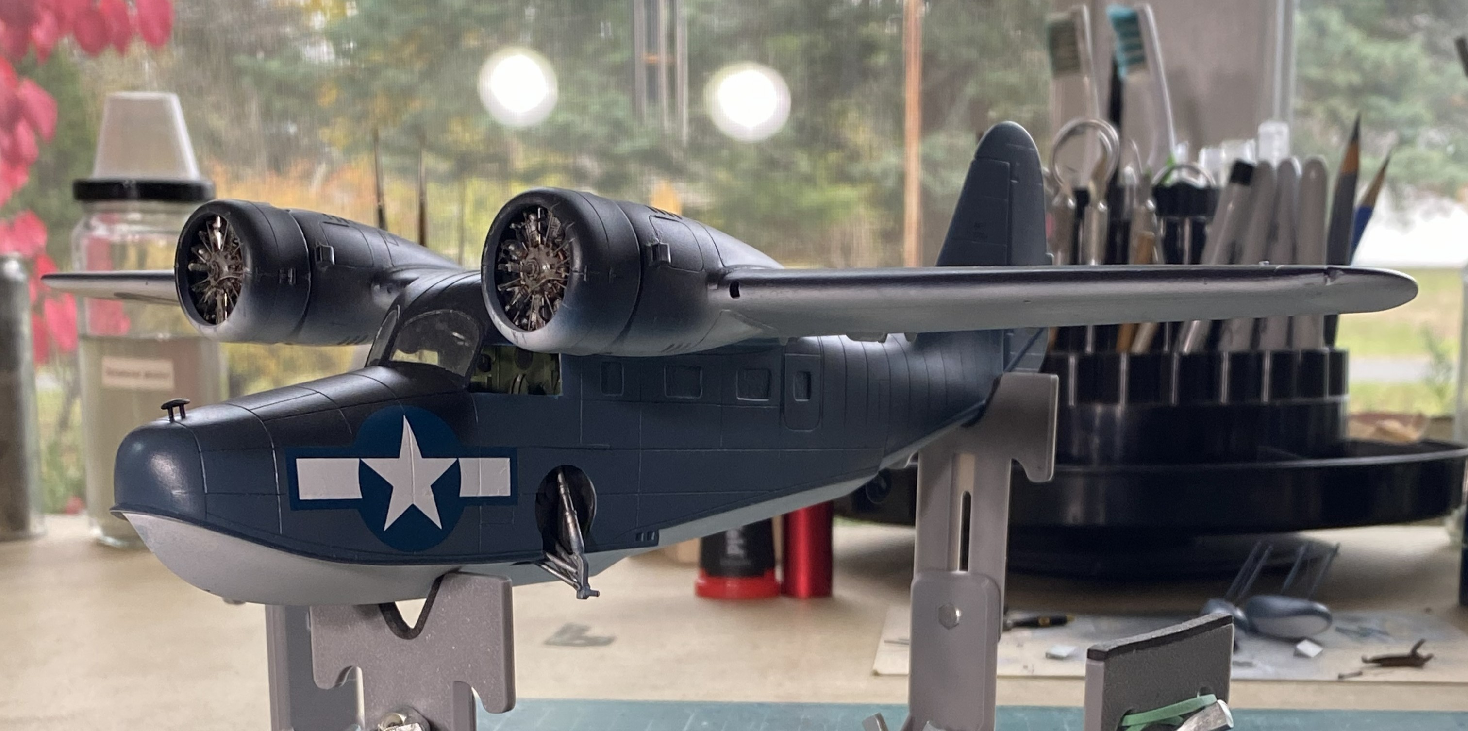
Increasingly, flat finishes on WWII aircraft are looking wrong to my eye. This time, I decided I’d do a semi-gloss (Tamiya X-35 Semi Gloss Clear) instead. This is where painting order becomes important. I have three basic areas to paint (not counting all the smaller details that haven’t been added yet, such as the floats in the photo below), top, bottom, and sides. I held the build by the sides and shot the top with semi-gloss. Once that set overnight, I did the bottom the same way. Doing it in this order meant that I’d have the wings to hold and manipulate the model during painting. The last thing to paint was the sides because now I can hold it by the wings:


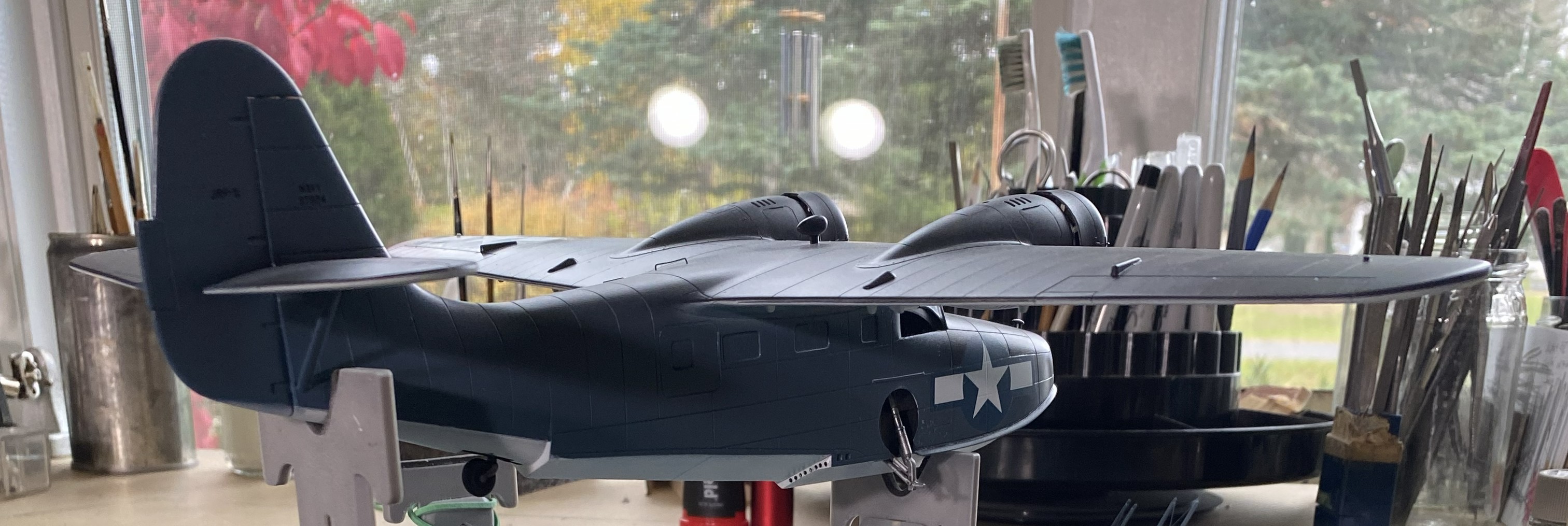


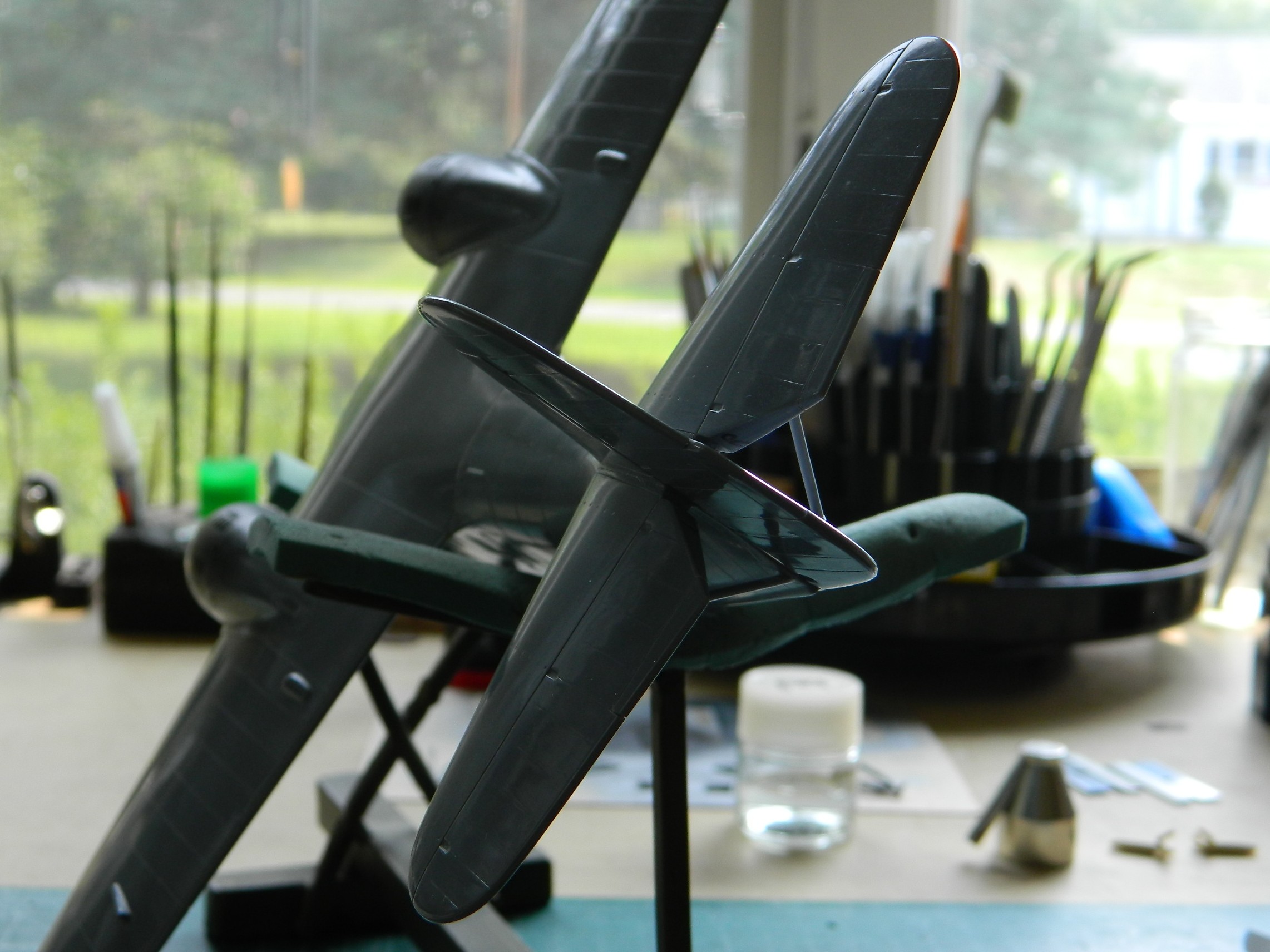
The next drill is going to be figuring out how to get this to sit level. It’s about 1/32″ (a little more than 1.5mm) off from side to side. This will be fun to fix. But to get that measurement, I had to have this build standing on its feet. While I had the wheels on, I decided to stick the props on as well to get a notion as to how it will display:

Not badly, methinks. Hopefully next month sees me to the end of this.
Grumman JRF Goose (Czech Model) 1/48 Scale Build #5 – I Pick Up Where I Left Off
There was no real update here since June. July was miserable on the personal front and having to deal with the profoundly rotten fit of everything was just enough to put me to redline. I needed to walk away from this for a bit, and the kit needed me to walk away for it to survive.
[I am also starting to bore myself with continually carping about how lousy this kit is. So take it as a baseline that this kit is a turd…a large and foul-smelling turd. More than enough said about that.]
After cutting away the side windows of the clear part, I needed to make something more accurate. I used 0.010″ (.25mm) flat clear styrene. The side windows of the cockpit on the actual aircraft are flat and slide in L-shaped tracks (one of which is at the bottom of the following photo) with handholds inside. To keep from scratching the clear plastic, it was covered in masking tape, and the handholds were made from 24awg wire:

This is how I made the L-channels. I used scrap 0.010″ (254mm), aligned them to be perpendicular, and then glued the hell out of the join. After letting it sit for a few days, I started by cutting the plastic (and it’s made from so much plastic to enable me to grab hold of it) back and then using an emery board to straighten out the sides of it:

Instead of mounting the tracks and figuring out how to paint everything and then get the windows into place without scratching paint, I decided instead to figure out how far back the sliding windows were on the actual aircraft, trim the length of the tracks appropriately, and then trim the masking tape from the outside of the windows and then glue the tracks in place (one is shown above):
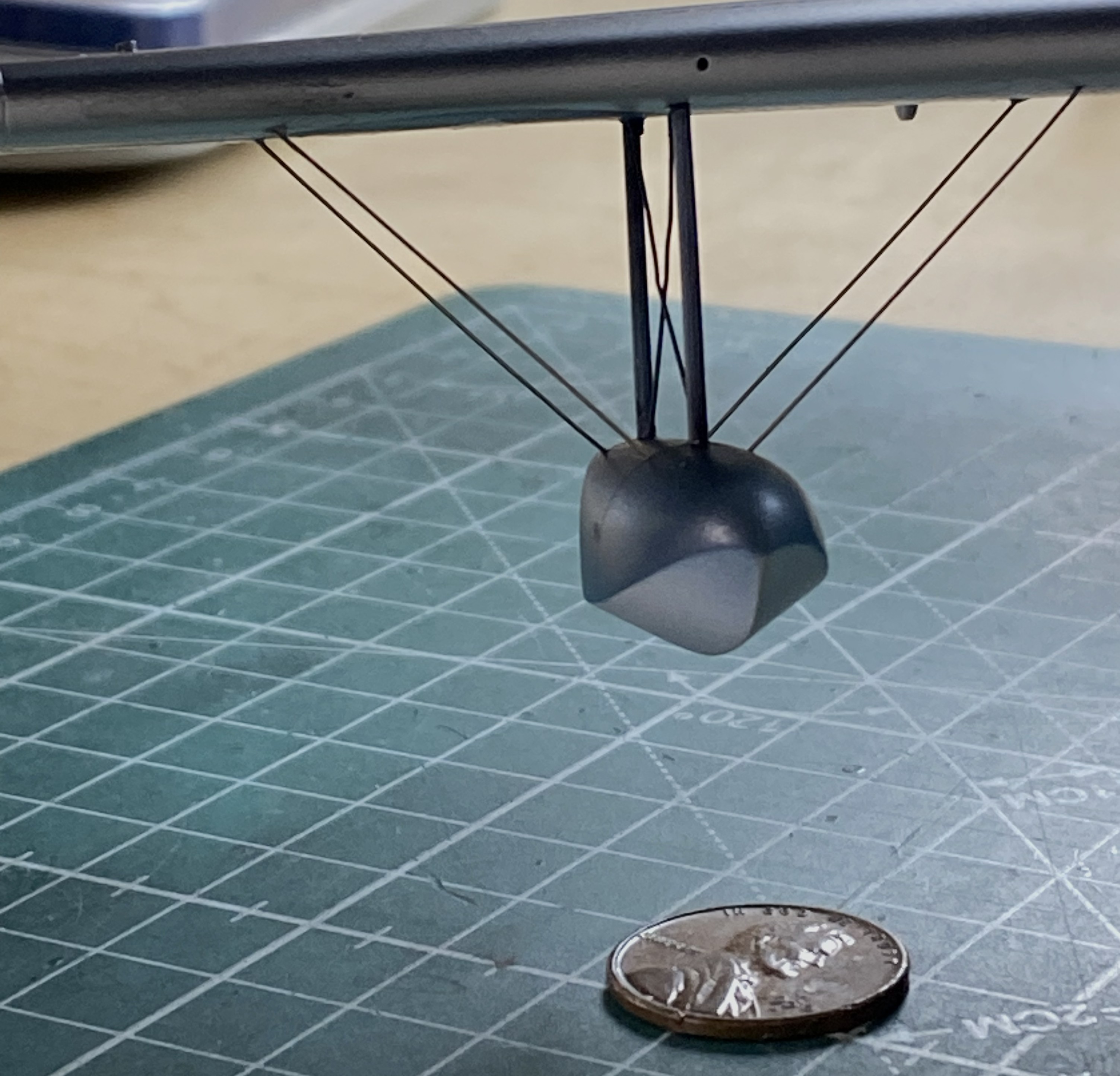
I’d played around with the floats earlier on and now it’s time to start adding the braces. (The stainless steel wire was sourced from a closed dental practice and it’s come in quite handy!) I drilled holes where the struts meet the tanks and UV-setting resin was used to attach the wires:


Then I started dealing with the nightmarish landing gear. In order to have even a slight chance of having enough hands to hold three parts in very specific locations, I aligned the major control arms to the suspension upright and then drilled through control arm and strut so that I could use a bit of wire to hold them in place and yet still allow enough movement to align everything without scattering parts by dropping them frequently:

Getting all the landing gear parts to align was SO frustrating that I came within a hair of hanging this model from a tree so that I can see how many shots of 00 buckshot it would take to powderize this styrene cunt. It took several days to figure out how all these parts will fit (or, made to fit) and I think I finally have. I don’t think it’s time to add these frail things, but install now or later, I’ll figure out exactly how to do this. Stay tune for colorful (if anatomically impossible) invective when that process starts.
One part of the strut assembly is the oleo. It’s the part of the landing gear that functions as an oscillation damper (or, as we mistakenly call it in the States, a “shock” absorber). I’ve so HAD IT with this build that I didn’t even consider replacing the styrene rod with steel. Fuck it, in other words. But since it’s steel, I used Humbrol’s Metal Cote Steel #27003. While the airbrush was loaded with this paint, I also painted the pitot tube as well:
Since I was working with landing gear, I went back to the tail wheel. The next thing I’m going to load the air brush with will be aluminum, so I wanted to get all the parts that I need painted aluminum (at least right now) ready to paint. And then I encountered a surprise…
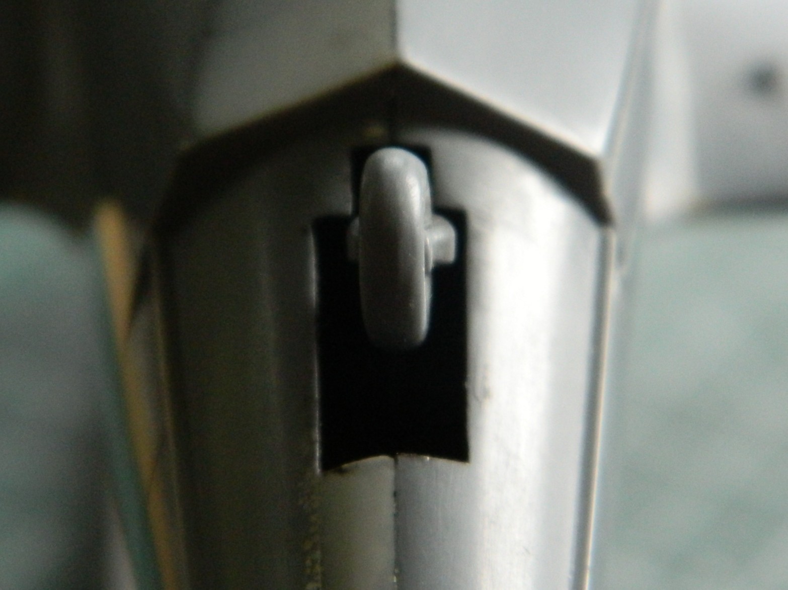
I worked this little part over for a while. Unsurprisingly, it was poorly molded, which was why I’d done some delicate knife-work to clean up the part. It was glaringly obvious that the wheel and strut were molded one piece…and not very well molded. What surprised me was discovering that the part, as molded, is twisted. The mounting pin is vertical to the camera. The yoke is bent to the right, and the tire is also bent to the right as well as being twisted:

After overcomplicating things but only in my head this time, I decided to see if I could diddle how it’s mounted sufficiently enough for the bent and twisted tail wheel assembly to appear as if it’s in there straight, which it is not. The bulk of the model combined with how close to the ground the tail will be combine to make this cheap fix possible. I’ll spend more time when it’s mounted to get this seeming as close to correct as I can without spending a week of surgery on it to correct it (modeling…it just has to look correct):

I’ve made no secret of the fact that I really dislike True Details’ items. Characteristic of that firm, their “flattened” tires look more like “underinflated” tires…and that’s only on their (relatively) “good” examples. The tires with this kit aren’t in that class. Even for True Details, these things look hastily done. Note how pitted the surface of the right wheel/tire are…and some of those pits are bubbles in the resin (of which I’m NOT a fan). The one on the left has been worked a bit to reduce the bulges on the side and I’m considering working them more before black paint is shot at them:
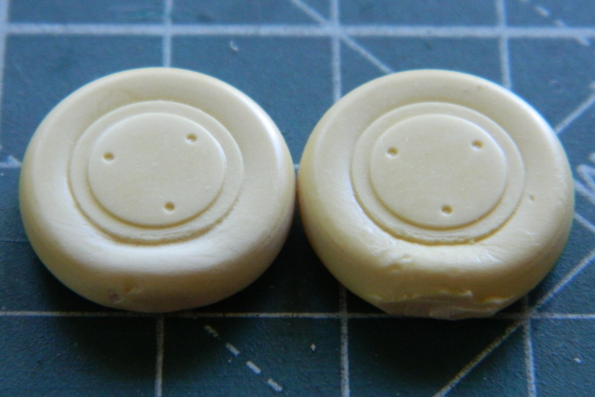
The backs had to be drilled to accept the mounting stub and since this bird had drum brakes, I used a tiny piece of styrene scrap to (not shown in this photo) replicate the mounting lug for the brake lines I’ll be adding later:
There are prominent heat-exchangers (for cabin heating) that mount externally on top of the engine nacelles. What’s provided is another True Detail bit of (disappointing) resin. I worked the one in the bottom of the next photo, the top part is as it came off the pouring block (they’re upside down in the photo):

My next adventure in annoyance was the splash shield on the nose. It was too thick and too wide. It was also very fragile, so I put off thinning and shaping it until it was glued in place. Of course it didn’t fit and I had to add a little piece of scrap to enable it to fit:

I set that aside for the glue to thoroughly set and started fitting the landing gear into the space provided. It was during this process that I almost lost my shit and, again, had to walk away for a few days. It doesn’t fit where the spot that was provided for it is. That’s, “wrong mount locations”, the long form. Once I calmed down, I decided that where they would fit is where I’m going to put them. From my efforts so far, SO much work is going to be required to get the entire landing gear in place that I will probably forego my usual practice of adding landing gear as late as possible. If I do that, I suspect that I’m really going to damage the color coats, so I’m thinking that the landing gear will get added prior to painting because I’m really quite tired of redoing and redoing and redoing to get the damned thing as accurate as I can. In the following photo, whereas the lower control arms are where they’re supposed to go, the strut is not. And I have less than no idea how the upper control arms are going to mount:
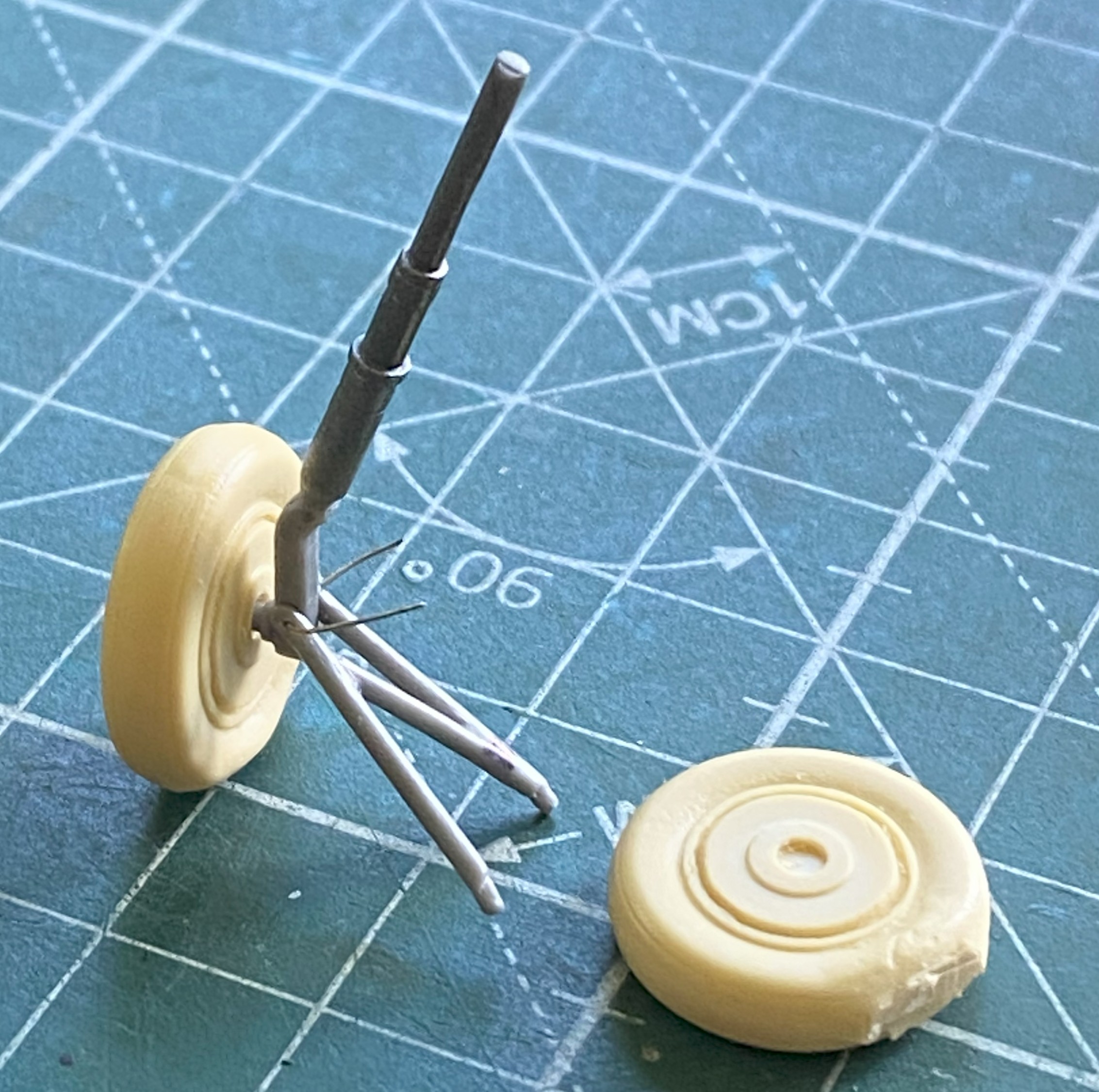
So with that set of problems hovering just out of sight, it was time to throw some aluminum paint (Tamiya XF-16 Flat Aluminum) onto these parts which are main and tail landing gear parts, the backs of the wheels, and the inside of the lower landing gear doors (the parts that the airbrush would launch into the next county are held down with double-sided tape):

And while I had the airbrush loaded with aluminum, I misted some into the landing gear bays:

And of course I had to touch up a fair amount of scribing and when tools skated across the surfaces:


There were more than just the two above.
The clear part over the flight deck wasn’t cooperating. I kept having to add more putty, more plastic, MORE putty, and more plastic:
Going back to the splash shield on the nose, the fin was thinned out and narrowed, and it looks much better. There was a gap in places where the shield attaches that needed to go away. More (and frequently added to) putty:


The splash shield is so thin that I ended up having to reinforce a spot using sprue; I didn’t have enough contact surface of the fin-to-fuselage join for it to stay attached:
And then I dropped the damned thing. I had to reattach the pilot’s seat, put the tail-planes back on, and hit a few spots where the sides of the V of the hull meet to form the apex of the V.
::sighs::
The tail-planes went back on easily:
And at this point, it was the only damage I’d seen. As I was rolling the fuselage around to align each tail-plane correctly, I heard a very, very, faint rattle from the cockpit. Investigation showed me that the pilot’s seat was 95% dislodged. It’s the seat in the next photo that looks like it’s tilted forward (because it’s tilted forward):

There are no words that will adequately express how I reacted. “Not well” doesn’t begin to cover it.
Okay, so I have to get in there to reattach it. No, in my wildest fantasy (and it’s pretty wild) can I access the base of that seat through the open windows. No, cutting open the top won’t work either. I’d put that seat in with the entire clear part absent and you see what that got me. I let it sit for a few days (or more) while I figured out the least-bad way to get at the base of that seat.
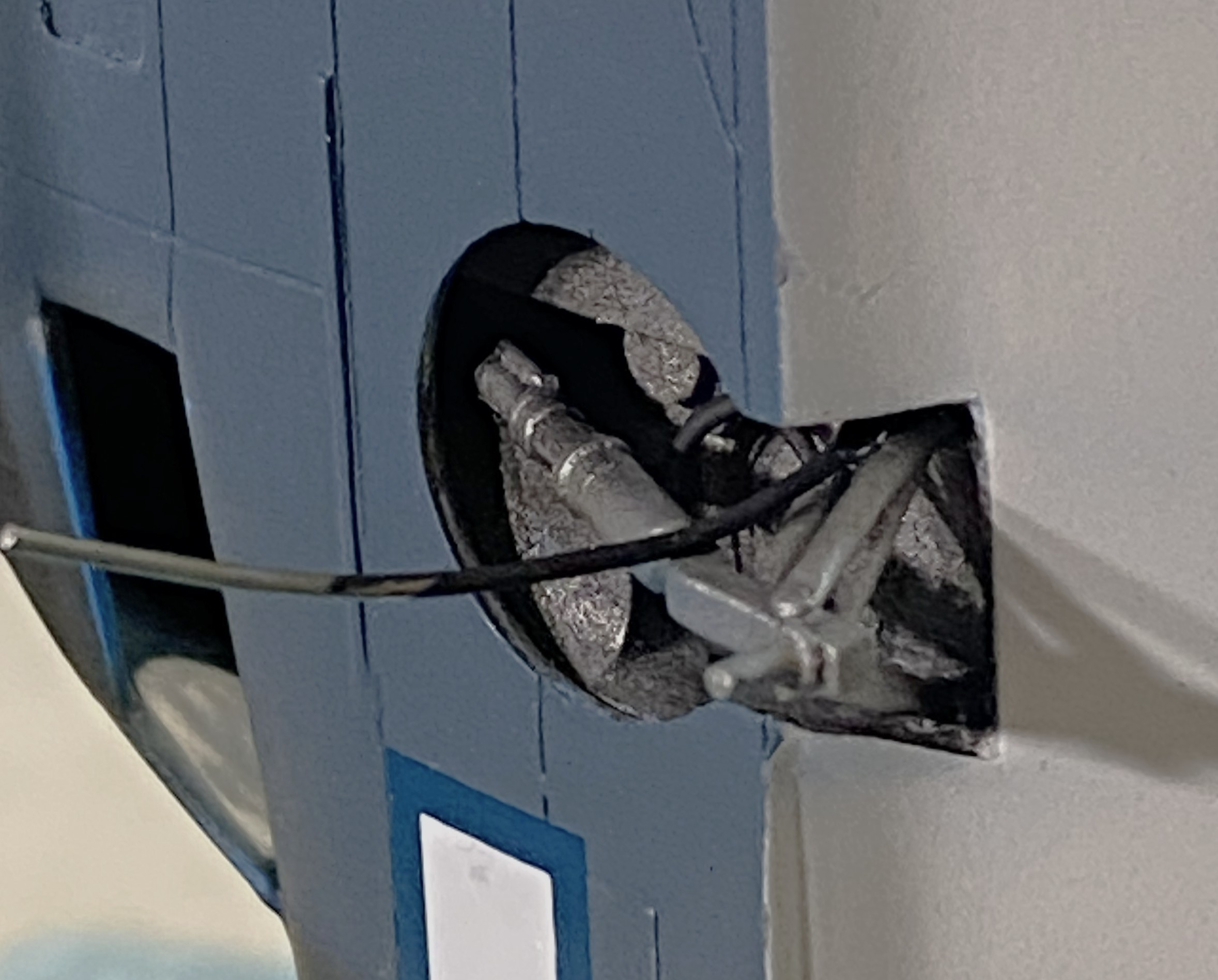
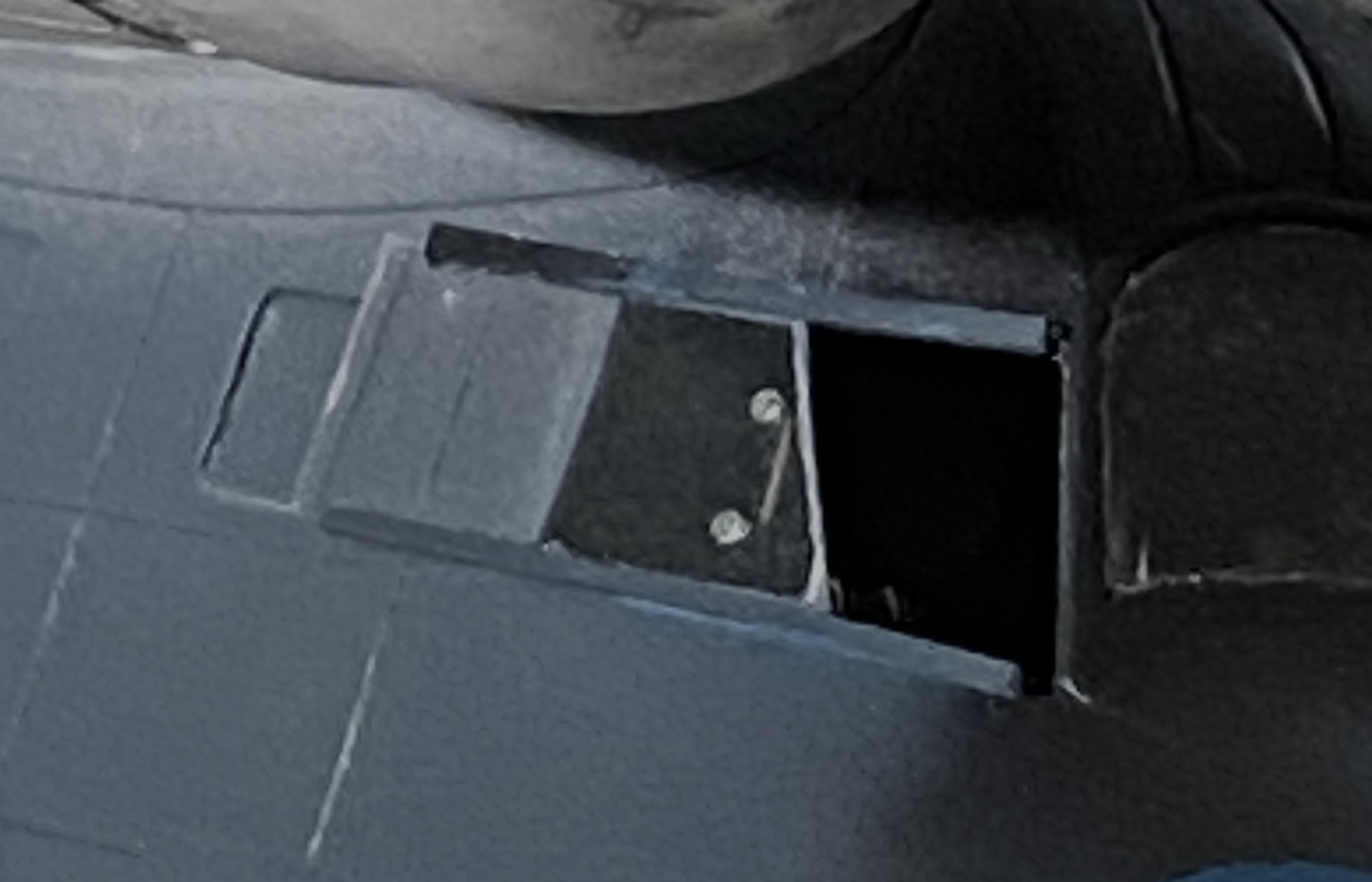
I have to cut the side open to get at it. As a guide for the scriber(s) that start the cut, I used a piece of Dymo label tape as a guide:
I kept the cuts along the panel lines whenever possible. The speckles on the seat are plastic and resin bits (because by going through the side, I also went through the resin detail panel attached to the side (the arrow points to one of the legs that has to be reattached):

But the cutaway allowed me access to three of the four attachment points, all of which were glued THOROUGHLY to the floor. The fix probably took 3-4 minutes, then the excised panel had to go back. In most places, I added 0.010″ (.254mm) scrap to replace the kerf, and most of the cut areas also received stretched sprue over the top of the styrene:

However. It seems that before the glue had cured completely, I’d pressed on the top of the excision and failed to notice. When I started removing excess plastic is when I saw that the top and top-left corner needed to be raised up. I used 0.010″ (.254mm) instead of putty to do that:
By this point I’ve noticed that the edge of the V hull had cracked. I stretched some sprue with the intent of filling in the fix while the filler plastic next to the cockpit cured:


So with that repaired, I finished off (mostly…there’s a detail I have to add back) the excision:
And now that I’m at the middle of this month, I’ve spent most of the past two and a half weeks getting back to where I was when the month started:
Unless I drop the model…again…next month should see me get this thing under paint and on the way with attaching all the stuff that is too fragile to attach sooner.
Grumman JRF Goose (Czech Model) 1/48 Scale Build #4 – I Get to See Just How Poorly this All Fits Together
If you’ve been to this website before and checked out my building process, I’m confident you’ve noticed that I build subassemblies and once there aren’t any that I can build, I start putting them together (though there are those tasks that have to wait until later…think “small bits that want to snap off during normal handling”). In general, I’m usually surprised that once I get to the install-subassemblies stage, “suddenly” the build is done. It’s much like being an overnight success. There is rarely any sort of “suddenly” to the successful. There are usually years of perseverance, varied and continual emotional stress, and luck that support the “success” part. It’s not “suddenly” for the person who succeeds, and I think the same thing is true about my being surprised that it’s all coming together seemingly quickly. With my builds taking MONTHS to complete (or longer), “seemingly quickly” doesn’t seem very quick from where I’m sitting.
This month was much like that.
I ended last month’s post with cleaning up the empennage. So I started this month attaching the empennage. My. Goodness. It was very fiddly and easier to get incorrect than it was to get it correct:

It’s at this point that I state that the elevator bits were an utter ass-pain. They have a dihedral and the kit offers absolutely zero help in getting them aligned. After the above was glued on, I glued the other one on immediately, intending on using the mutability/movability property of freshly glued parts. What enabled me to get it done as well as I did (I hope) was using the support struts to achieve whatever degree of accuracy I managed to attain (they weren’t glued on at this point). This end of the strut goes here and the other end of the strut goes there. I hadn’t cleaned up the struts at this point, they were just used as jigs to at least get within sight of this thing called “accuracy”.
While the glued parts were sitting for the glue to set completely (more on that in a bit), I decided to pull another trigger and glue the wing on:

If you look at where the trailing edge of the wing crosses the top of the fuselage, you will see a gap. Since this gap is directly on top of the model and consequently easily seen, I decided that rather than putty the gap I would stuff it with scrap styrene (of various sizes):
Even though I had to squeeze the fuselage sides together in order for the wing to fit into place, there were still gaps at the wing-roots. More scrap styrene stuffed in to fill those gaps:

3M Acrylic Putty was laid down over all of these gaps and set aside to dry.
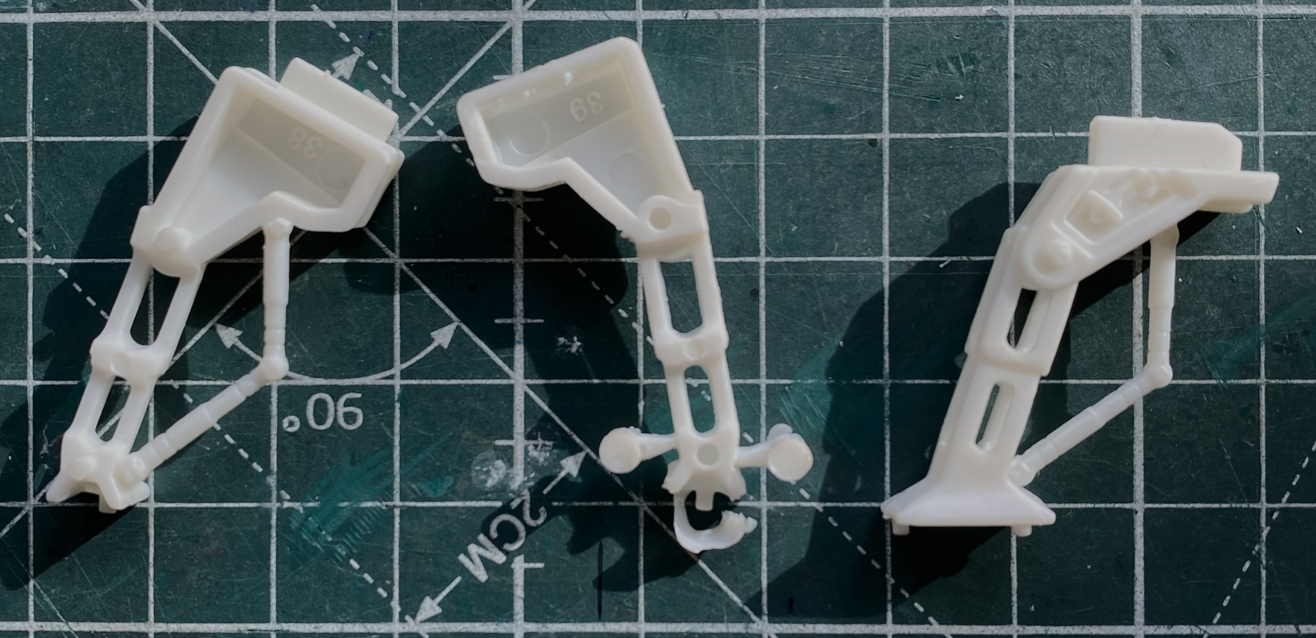
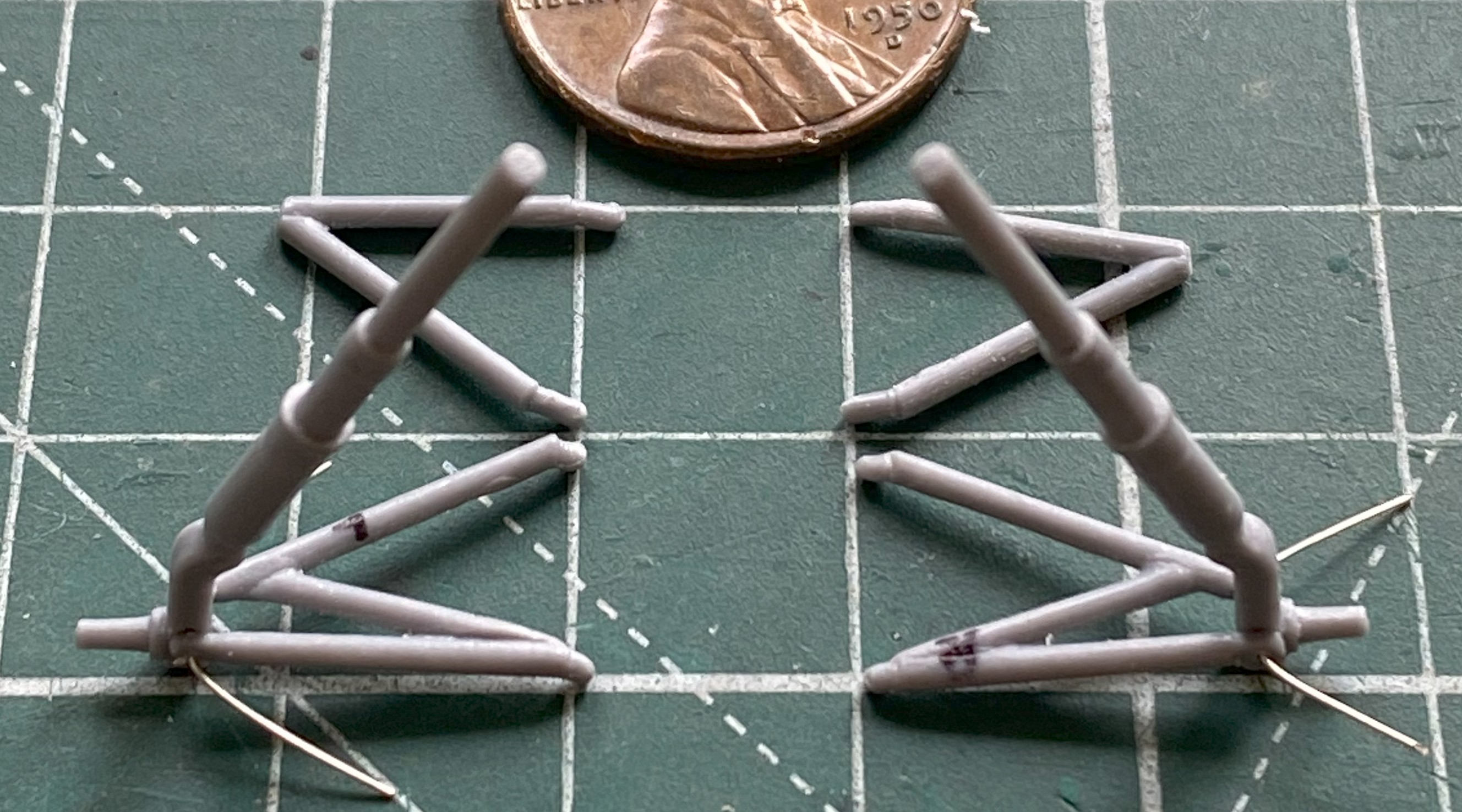
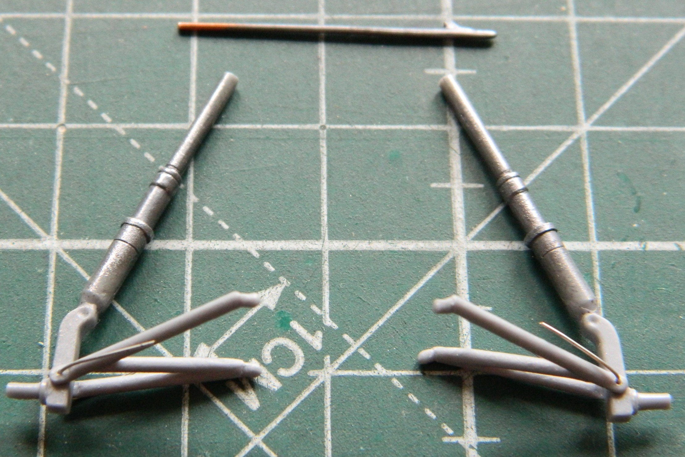
I was sort of dreading working on the landing gear. I think that whoever cut the dies for these parts did it from memory because they’re wrong. The main struts generally are also the main shock absorbers and as such have a certain look and, in the real kites, a definite purpose…and on this kit they’re just wrong. My initial thought (rare as those are) was to just scratchbuild the struts and move on. But once I had the part in my hand and my readers on, I realized that if I just could reduced the diameter of one section of the strut, that would suffice. No…it’s not 100% accurate. Yes…it does end up within the 90%-95% goal I’ve set for myself. In the next photo, the upper strut is a virgin (complete with parting lines). I used one strut as my trial, figuring that if I totally bitch it up, I can revert to my initial plan and “just” scratchbuild it. My goal, however, was to clean the part up well enough so that I could use the top of the struts (to the right in the lower photo) in my lathe if I managed to get the struts centered in the lathe chuck well enough then I’d be able to turn down the area I needed to. The blue arrow in the lower strut shows you where I managed that:
That machined area will be painted steel as it’s the section that compresses downward into the lower portion of the strut. I managed to get them both done without having to scratchbuild.
We’re at the “more in a bit” part. There was so little surface areas that could meet when I attached the empennage that, probably not surprisingly, during handling, one broke off:
Normally I used Tamiya Extra Thin to get these bits to stay attached. When I saw how poor the mating surfaces fit, I instead dropped back to an old standard, Tamiya Cement (white label, white cap), hoping that that would work in a poor-fit situation. The photo above is more proof that perfection continues to elude me. So that was reattached:

Back on the path, I spent A LOT of time blending the roots of the empennage to the fuselage, as well as bringing down the added styrene on top of the wing:

While I still had the wing on my mind, I decided which template I’ll use to cut the masks for the wing-mounted landing lights:
Which was then set aside because there’s a lot of work to do before the airbrush becomes the tool I need.
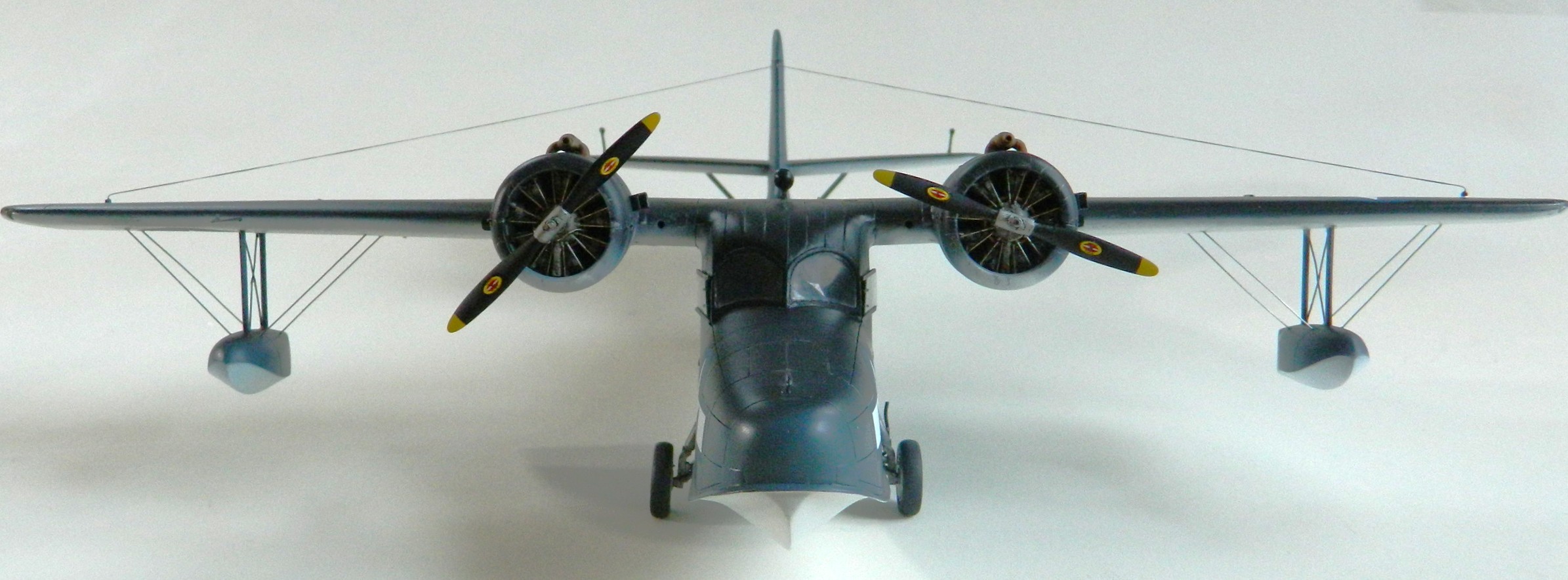
Having disappointed myself with how the paint job came out on the F7F-3 Tigercat, this time I decided that I would polish the surfaces to see if that resulted in something more satisfactory (as well as adding the rudder):


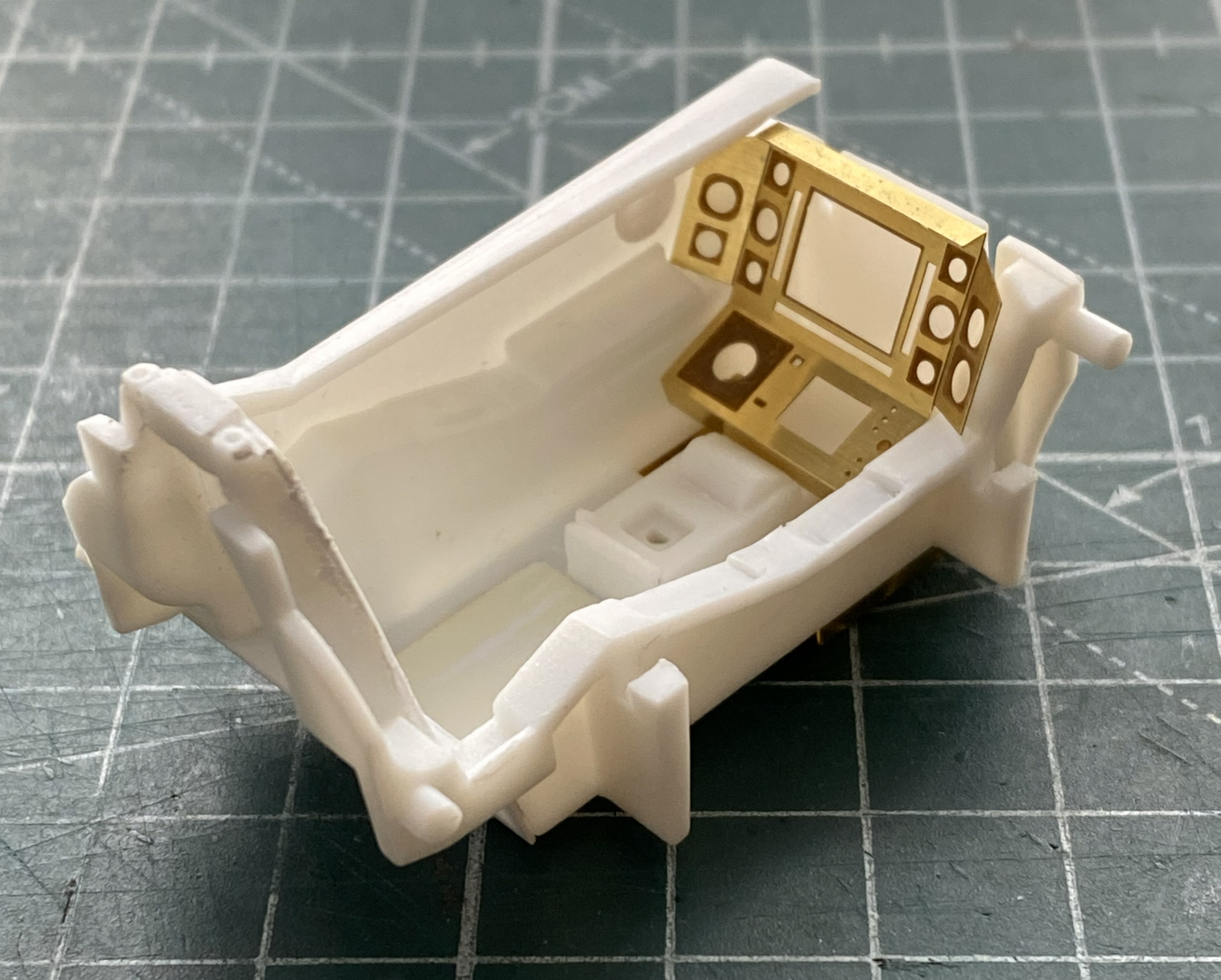
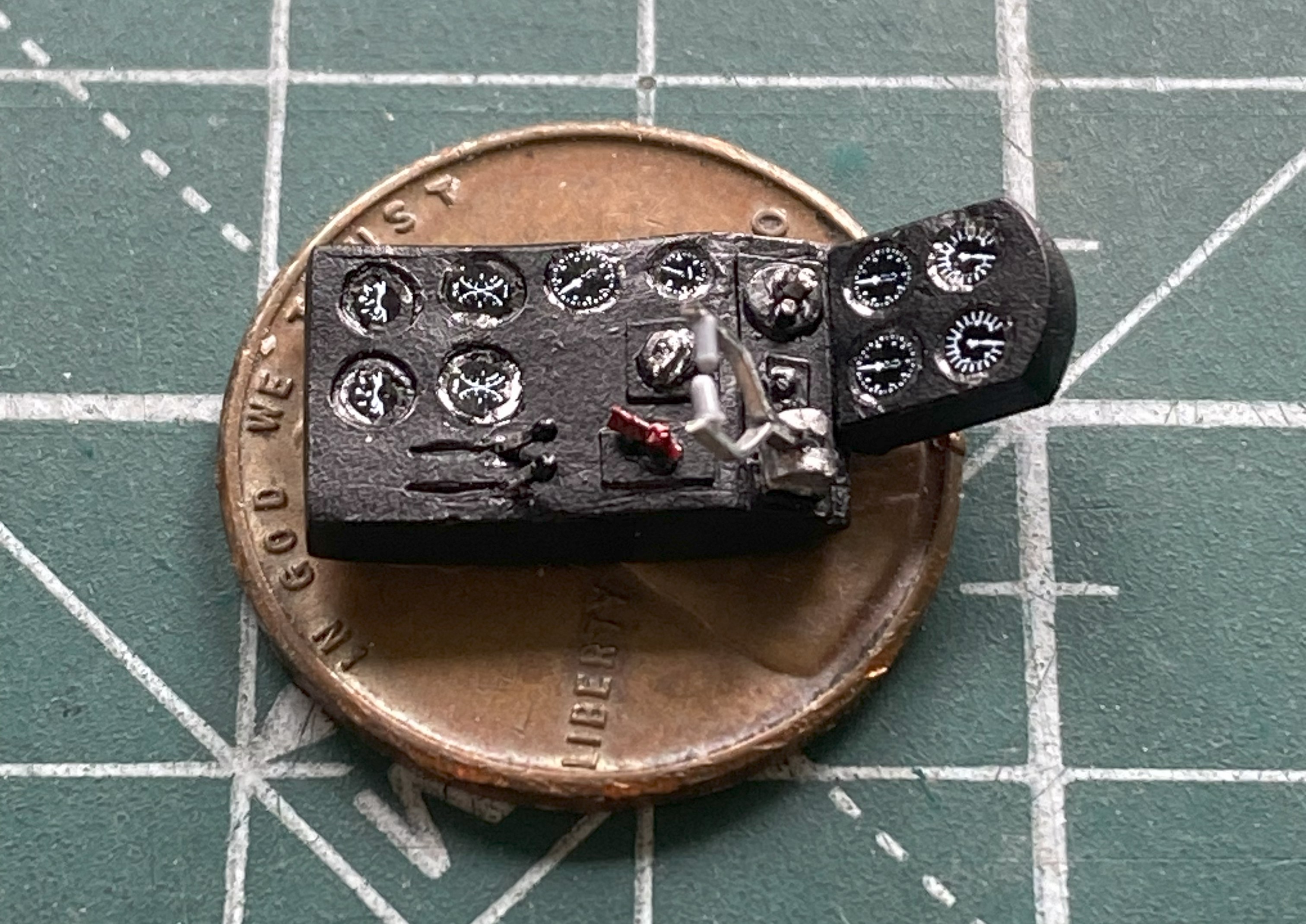
As I closed in on attaching the clear parts (normally I would call this “the canopy”, but most of it isn’t the “canopy” at all but structure of the fuselage over the cockpit. Hanging (okay, not hanging but attached) from the roof of the cockpit is a console with gauges, switches, and throttles. No way around it, I’ve got to build all that. And since I’m SO bad at matching interior curves (bad enough that comparing my…ahem…”skill” at scribing to matching interior curves makes my skill at scribing look decent), I decided that I would take advantage of the fact that the clear parts were molded in halves. I don’t have to match the interior curves, I can just trace them. Much inside the cockpit will never be seen. However, the throttle levers are quite visible, and if one turns the model just so, the face of the overhead can also be seen…so I have to build all that:
Having decided how wide I wanted the overhead, I used 0.020″ (.508mm) to fashion the sides and then 0.040″ (1.016mm) scrap as both ends:

While checking fit and keeping an eye on what needs to go on and into that overhead, I realized that maybe all those details would fit on an actual overhead console, there’s no way that the initial width of my construct would. I fixed that by adding 0.060″ (1.524mm) to both sides and added the face of the overhead with a piece of 1.010″ (.254mm) styrene:


After trimming everything to fit, I used a punch and die set to knock out the gauge locations on a bit of 0.005″ (.127mm) fascia:

Once I’d laid out the gauge locations, I glued the fascia on and added bits ‘n’ bobs to start filling in the details:


Yeah…a bit sloppy. What needed to be cleaned up was attended to.
While the glue was curing, I cleaned up landing gear arms, empennage struts, and the ADF (I think) antenna:
With the empennage struts all cured, this is the fit of them (note what the blue arrow is pointing at if you want a notion as to how ALL these parts so far have “fit”):

Of course that required filling, and though putty would be easier (all terms are relative), I didn’t know how it would hold up over time so instead of putty, I stuffed little bits of scrap styrene in to build up structure that later on I could trim to actually fit:

With the glue cured on the overhead console, I had to make the throttle levers. The body of them are made from 0.010″ (.254mm) aluminum for structural reasons. My first step was to lay out the angles on a scrap hunk of 0.040″ (1.016mm) styrene, drilled where the bends needed to be, and stuck 18awg wire into the holes:


Then a couple of tiny bits of stretched sprue for the grips:
Those were glued to the overhead as were a couple of other levers (UV-setting resin…great for making those infinitesimal knobs on the ends):
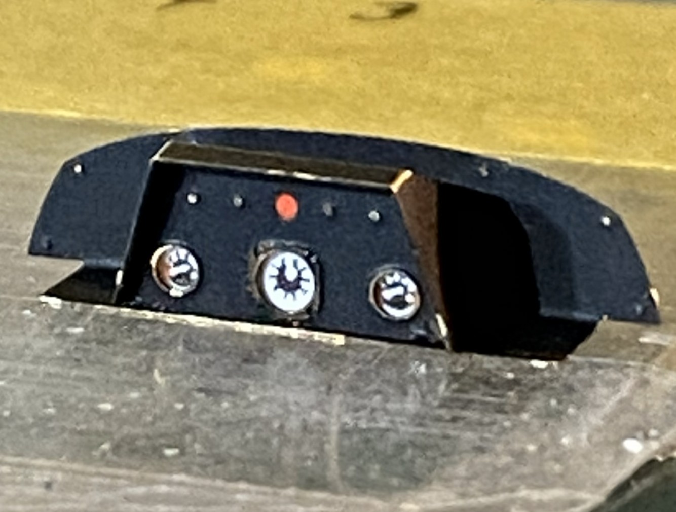
Time to paint it. The overall color is Tamiya X-18 Semi Gloss. Details were brought out by using red and silver paint on some of the switches and levers and Airscale “Instrument Dials, Generic WWII USAAF, item #AS48 USA”:
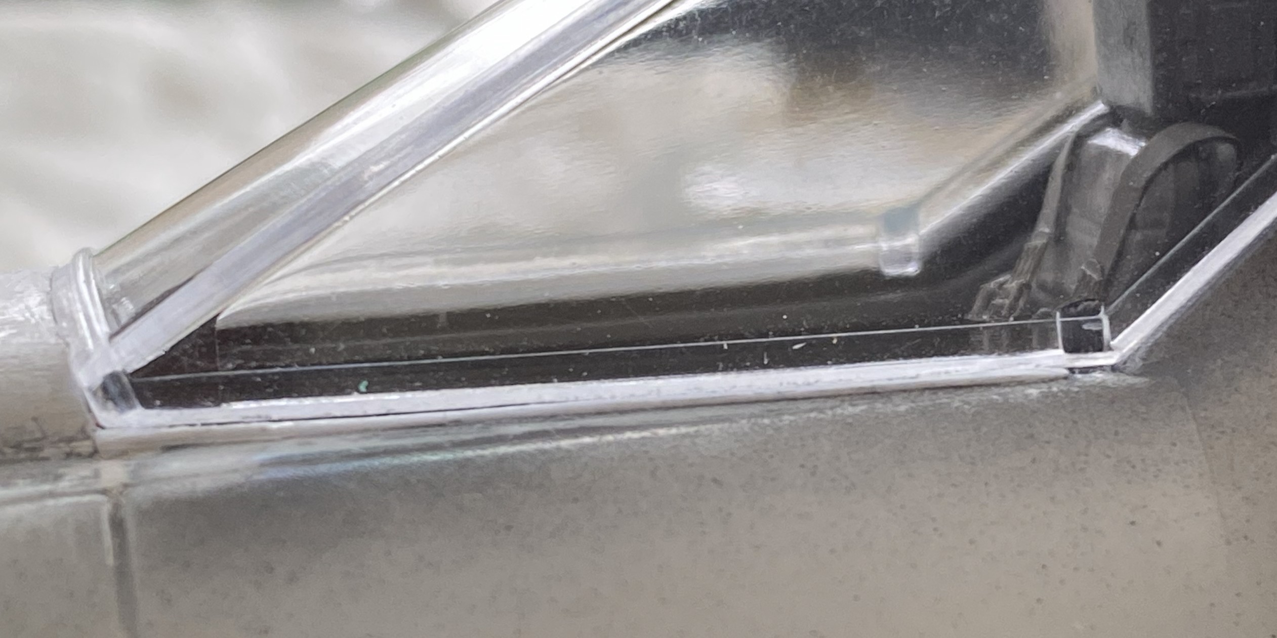
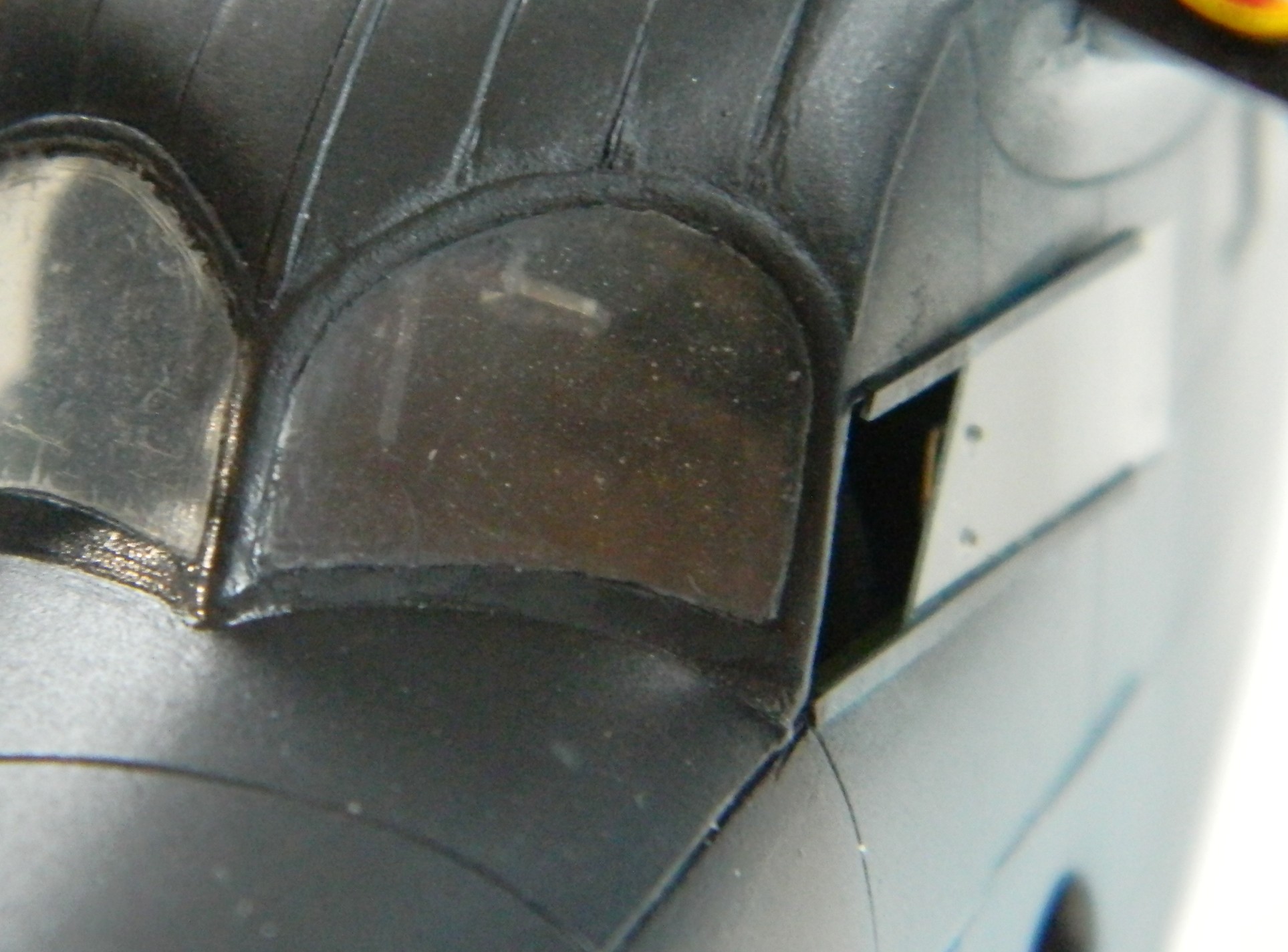
I don’t know if the dies were sloppily cut or if they’re old. Either way, at the windscreen area where the clear panel meets what will be opaque after painting, there is a radius. A soft corner. I didn’t want that. I know how to fix that with opaque plastic, but doing it that way will totally screw up the areas that need to be clear. I already had 1200 and 2000 grit sandpaper, but I didn’t think that would be enough to return the windscreens to unscratched clear. I went online and picked up 3000, 5000, and 8000 grit to fix this. The panel on the left has been sharpened but not sanded, the panel on the right is as-cast:
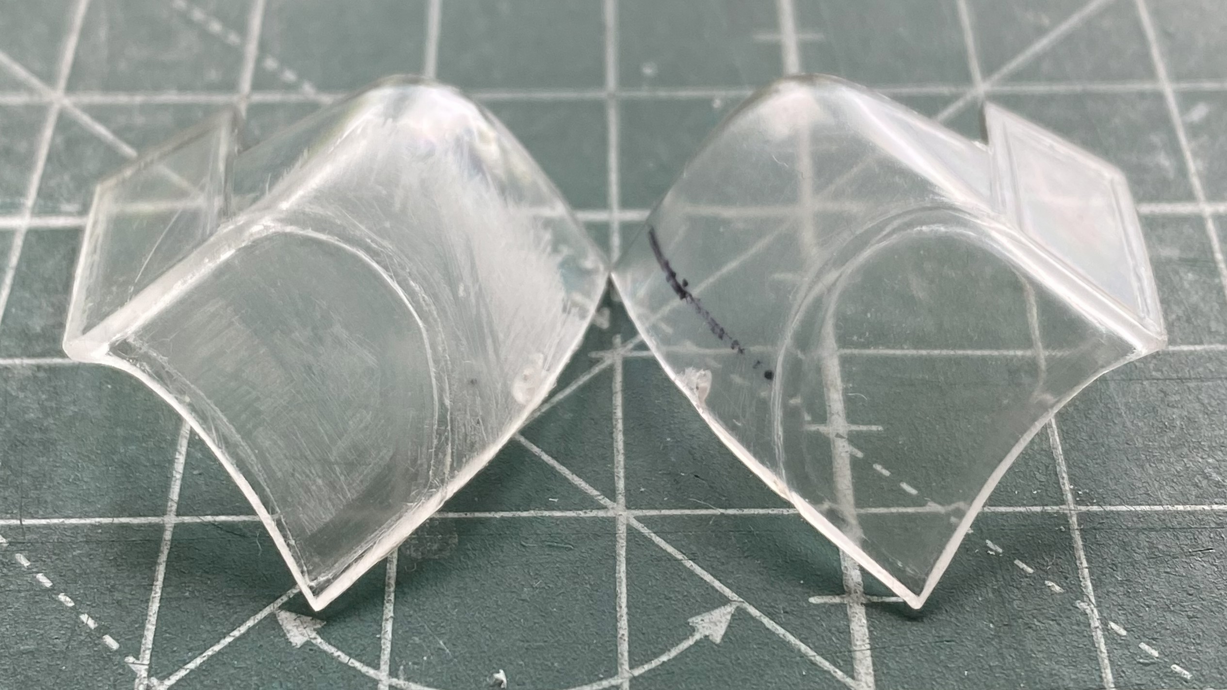
After doing left and right sides and then removing scratches with this progression: 320 grit, 400 grit, 600 grit, 1200 grit, 2000 grit, 3000 grit, 5000 grit, I polished with Novus #2 plastic polish. I was pleased with how clear and blemish-free that left the plastic:

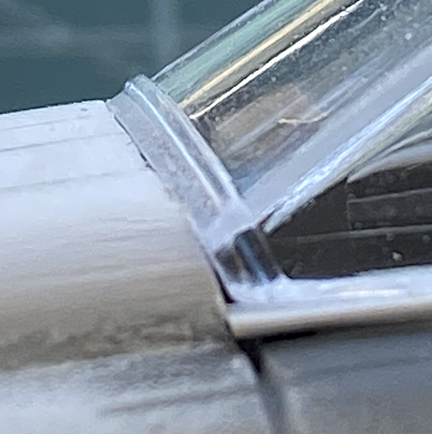
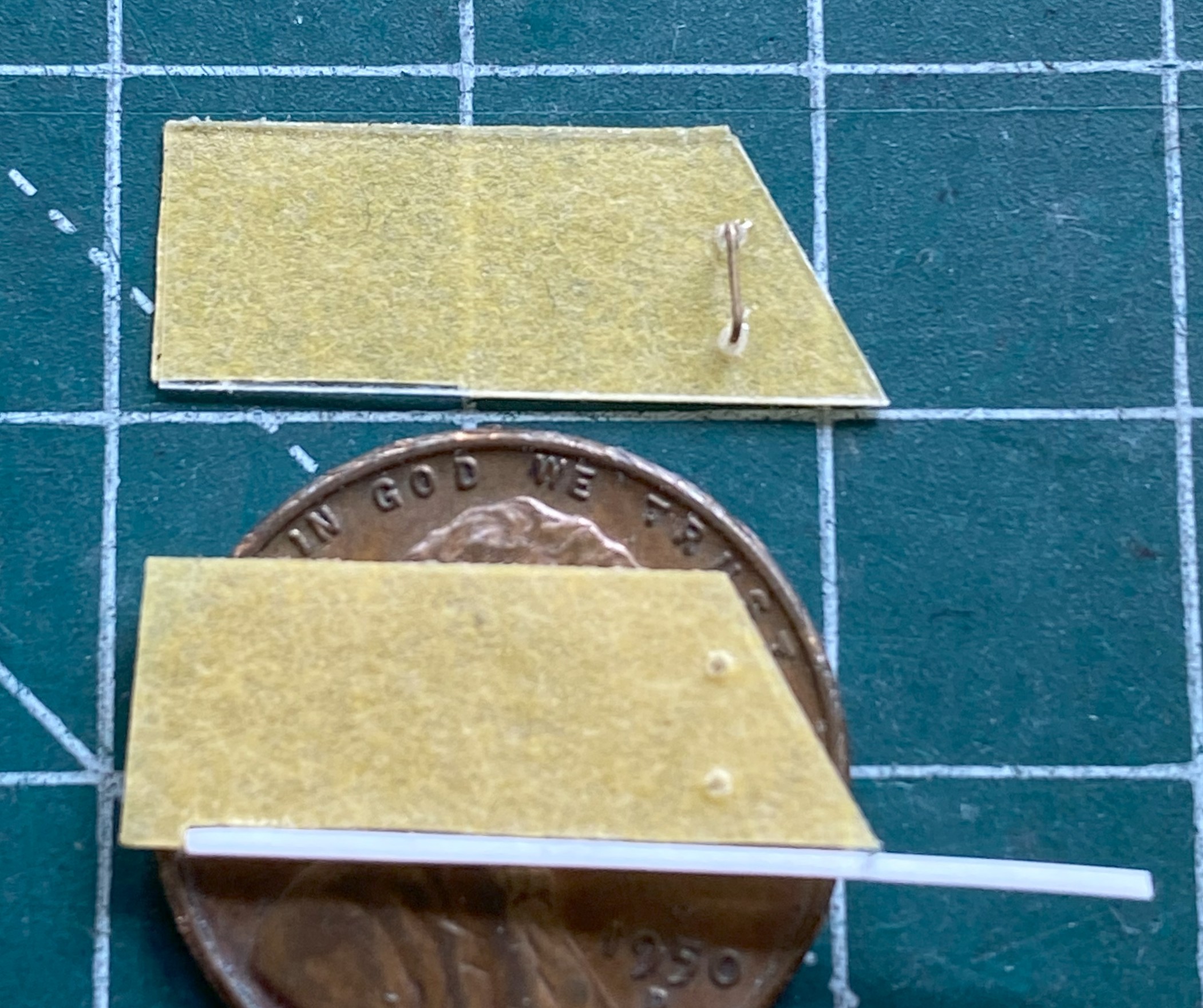
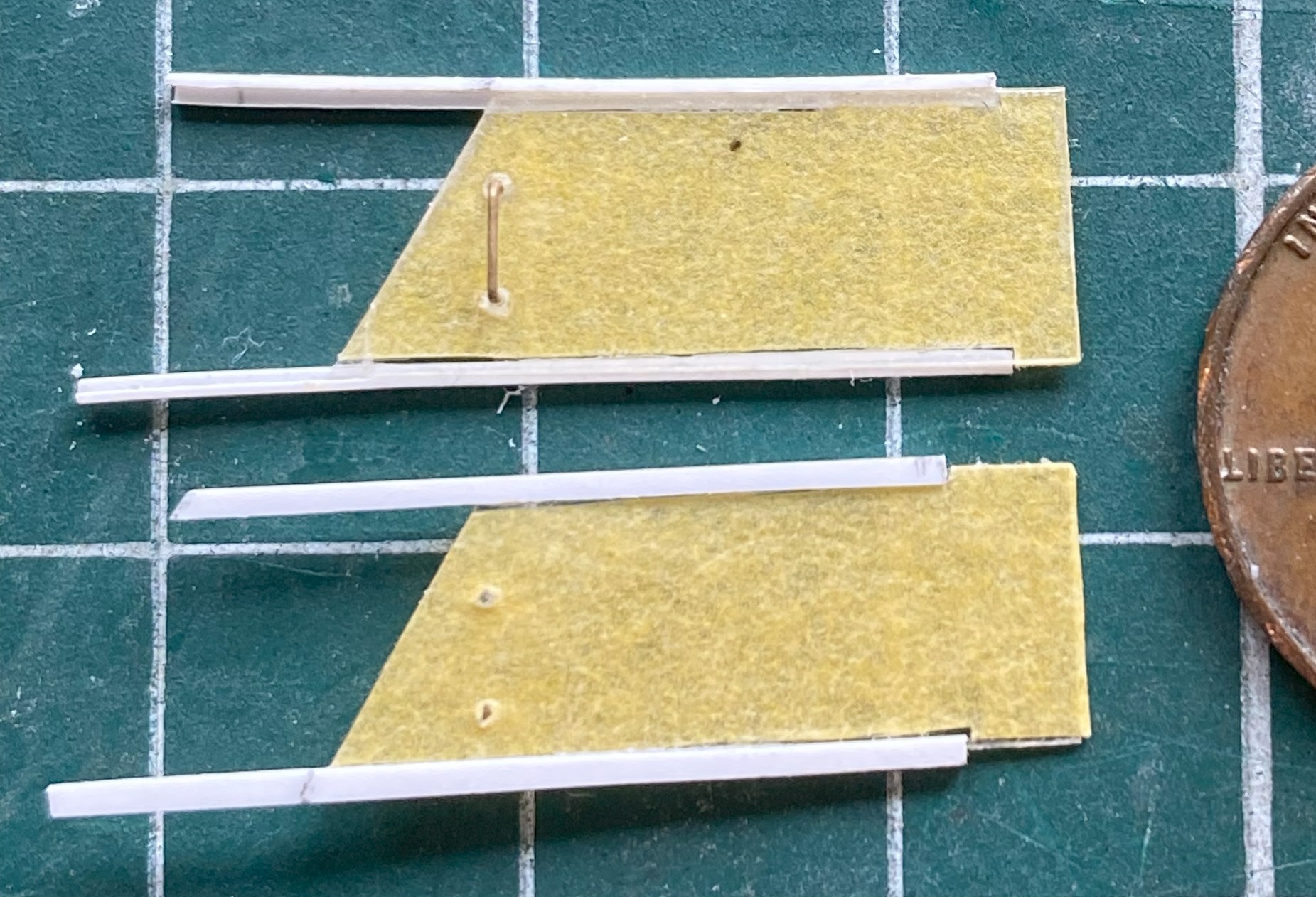
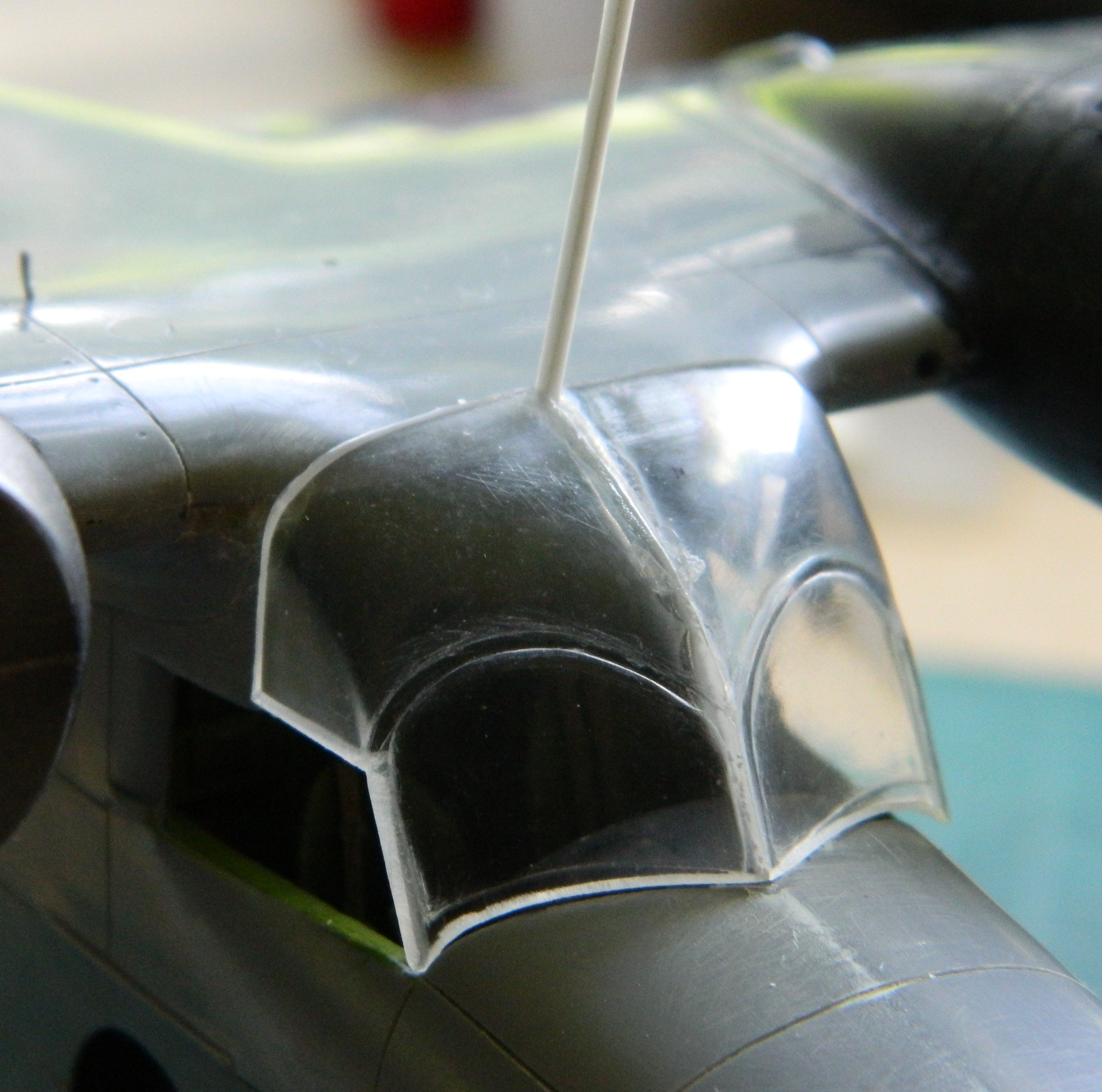
Part of why this clear part fits SO poorly is because of the “wings” on either side. These are actually sliding panels that allow the side windows to slide open rearward. In order to fit this to the fuselage, those have to come off. I intend on making replacements for them (the prototype for which is at the bottom of the photo and covered in masking tape to minimize scratching):

With the overhead console done and the sliding windows removed, it was time to join the two clear parts. When I started that, I didn’t glue the entire join. I figured that since everything else fits so wonderfully (I sure hope you know that’s sarcasm), I wanted to leave enough room where the clear part attaches to the canopy just in case the fit was off (I know that it looks like the join has been completely glues…which it was…and then I realized that I was probably going to need to adjust the fit so I spread the two apart down to the post between the two windscreens before the glue could set up):

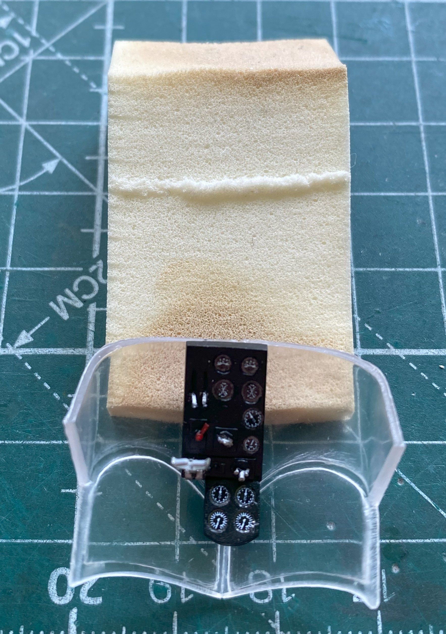
I am certainly glad that I made that allowance! The strip of plastic inserted at the rear of the clear piece(s) is 0.040″ (1.016mm) wide. Subsequent work showed me that I could have done with 0.020″ (.508mm) more:
I filled in the gap and sanded it down on both sides before I permanently attached the overhead console (the foam wedge is there to prop the clear part in the most supportive angle while the glue cure):
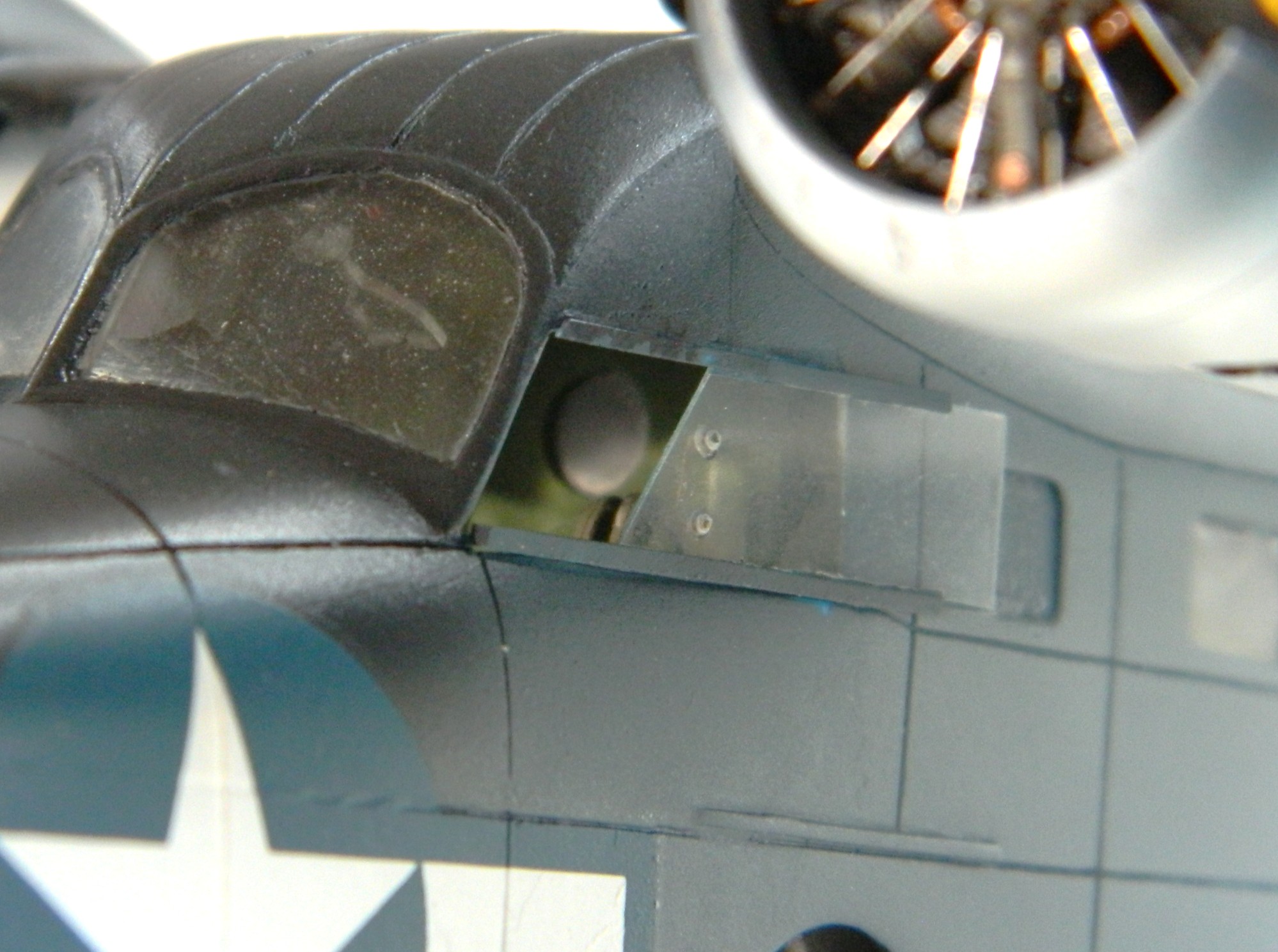
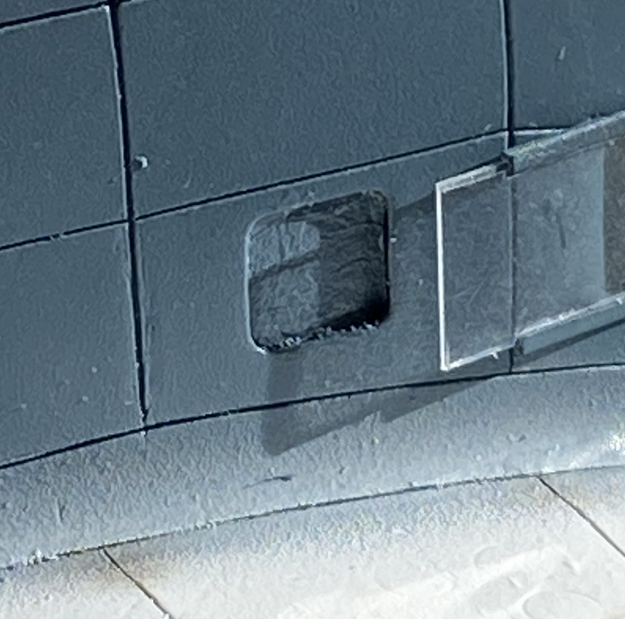
While I was yanking and cranking on the fit of the clear part, I heard an odd “click”. Investigation showed that I had pushed one of the passenger’s windows inside the fuselage:
This window can only be installed from the inside. ::face palm::
After much deliberation (read that as kicking, screaming, and threatening Dire Consequences), I decided that cutting out the section of the window between the panel lines would let me get at it to fix it:
I thought that I’d be able to get the window that popped out (or in) but I rattled that thing like it was a rattle can of rare paint that I hadn’t touched in a couple of years. Nope…not coming out. Okay, easy fix. Get another piece of clear…so I did:


Self-inflicted injuries are still injuries…only without anyone else to blame for it. Moving on.
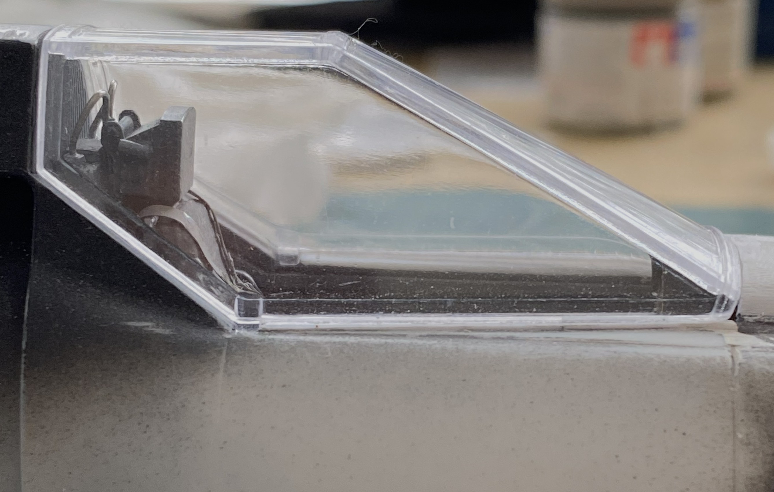
With that delightful sidetrack, I got the clear part glued on. Note where the blue arrow is pointing. That’s the closest I could get it, mostly. Yes…I could have diddled it into a better fit, but the V shape of the windscreens has to match the V shape where it joins the fuselage. Fixing the poor fit on the sides was the easiest path:

I used UV-setting resin to build up the places I needed to so that the edges matched up:
As you’ve probably noticed, I also added a couple on panels of 0.005″ (.127mm) scrap to build up areas to meet the fuselage and wing. Sanding would have removed too much and altered the correct curve at the top. I also added more UV-setting resin to the top join to fill gaps and give me a firm surface to scribe a panel line into:

I also used UV-setting resin to attach the V at the front of the windscreens to the fuselage:

The additional UV-setting resin fixed the problem nicely:


Whew…and it gives me the look I wanted:

Now that painting this is driving the build, I started going over the surface to see what I’d missed. Little things like scribing the underside of the wing root. Dymo label tape is my go-to when I have to scribe a long, straight, scribe (and even then I can screw it up):
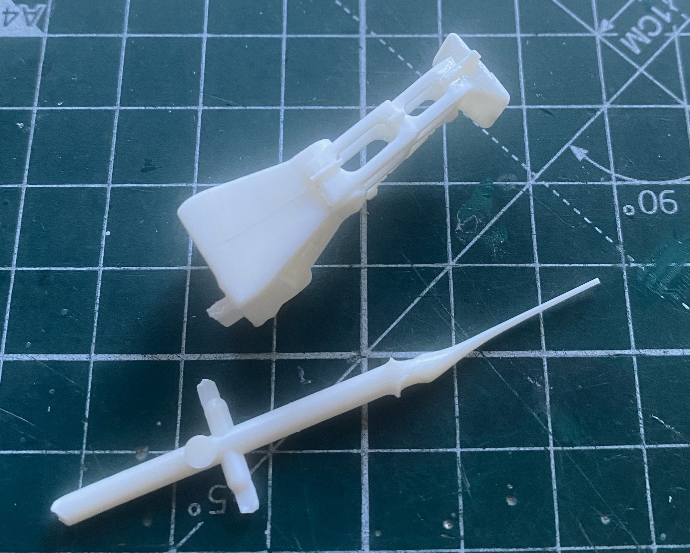
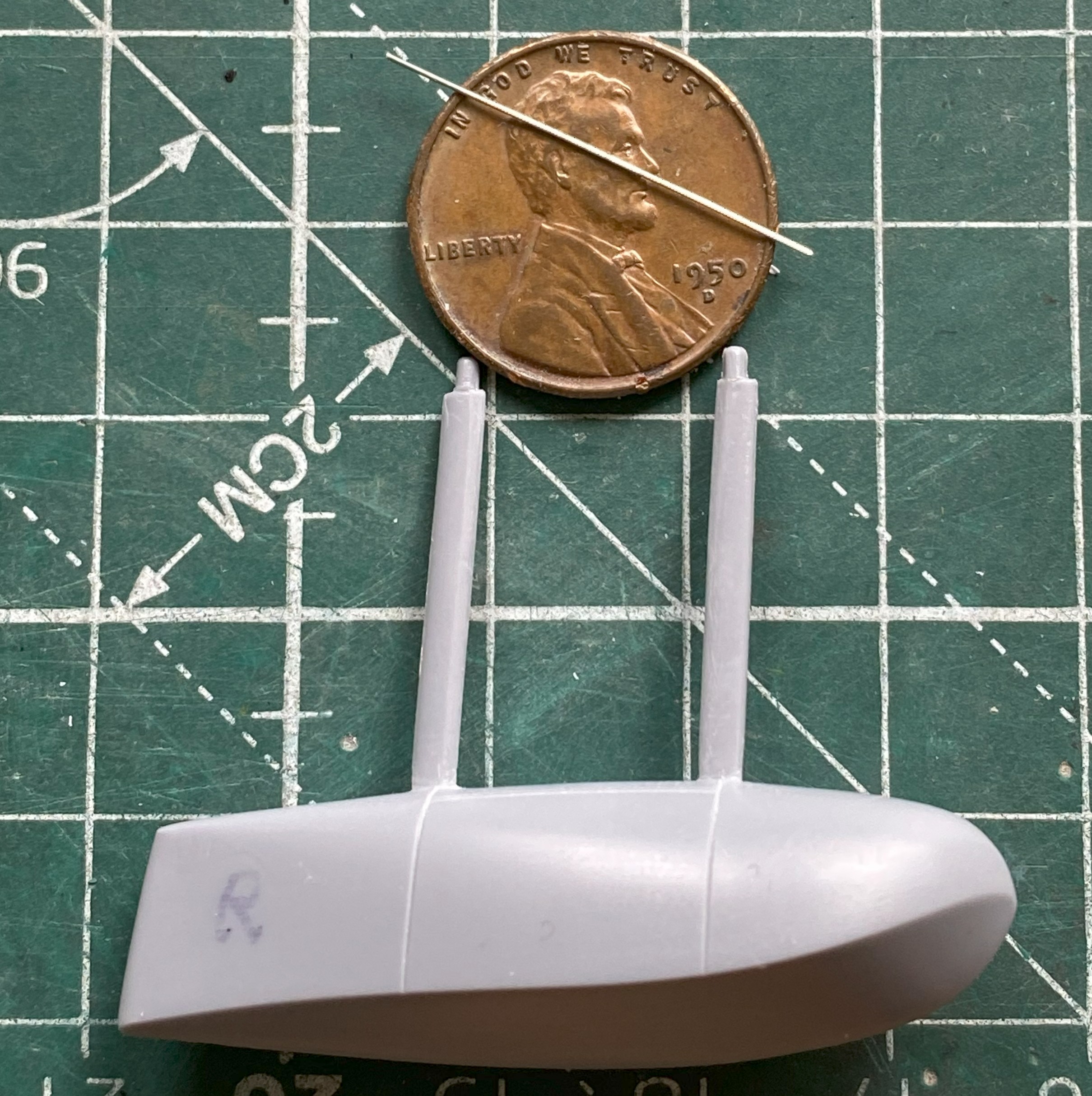
The kit provided no pitot tube (thankfully!) so I made one using 18awg wire and built up the fin that this one had using drops of UV-setting resin, curing it, adding more drops, curing that, until I had enough mass to shape correctly:

The pitot tube is removable so that I don’t have to make another one later on.
The Goose had a splash shield fitted around the nose and down the sides to the landing gear. This part was far too thick so I thinned it out, and it fit about as well as nothing else has fitted, resulting in me having to snap a section to allow curves to match and sides to extend backward:
While that glue was curing, I started going over the entire surface again, noting new scratches and the sort for near future attention(s), and then I dropped the whole sodding thing. Few things are so bad that things cannot get worse. This time, I dodged major reconstruction. This is the only damage that happened; the splash shield got dinged:
Fine, I’ll fix that too:

I started building the sliding windows for the cockpit. I was doing okay until, once again, I dropped one…and then stepped on it because a simple fix cannot be relied upon repeating itself. Thankfully, these are really simple parts and fixing them won’t present insurmountable obstacles:
But that’s for next month.
Grumman JRF Goose (Czech Model) 1/48 Scale Build #3 – Doing What is Necessary to Get the Fuselage Halves Married
This month there was a great deal of fitting required for small parts. This means that this post won’t be quite so long as working small parts eats a lot of time.
My first task was getting the instrument panel attached. Having painted its face and added instrument decals, it was time to step up and do what’s needed to get the instrument panel to do an excellent “I’m-supposed-to-go-here” imitation. Since I hadn’t painted and added the control yokes, I started there. The face of the panel has raised (and somewhat generic) lumps where someone thought the yokes should mount. Had I looked more closely at those generic lumps, I would have noticed that the “suggested” location for the co-pilot’s yoke was in the wrong place. The last photo in the series below will show those holes where they presently reside.
The stub on the back of the yokes was too short so I added rods (clearly too long, but those will get trimmed once the yokes are in place):

As an aside, subsequent and frequent reattachments showed me that I should have added pins between the rods and yokes. After gluing them back in often, I did that and the problem of knocking those things off ceased. And on to those holes:
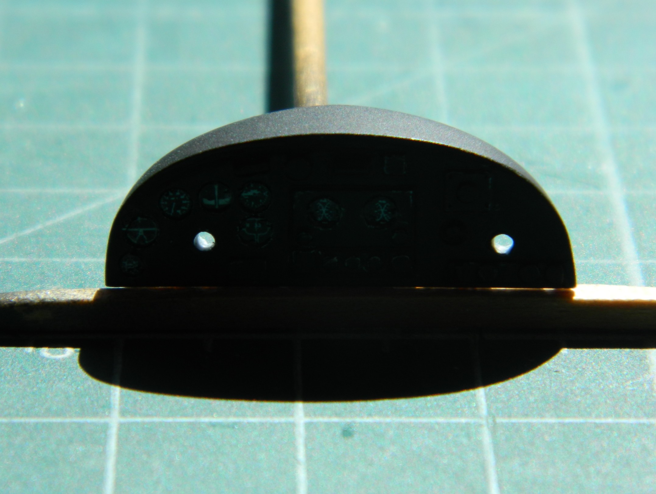
Yeah. I re-drilled the hole on the right and didn’t bother filling the incorrect one for two reasons. The primary reason being that the hole can’t really be seen when the panel is where (I hope) it goes. The second being that I painted the inside of the unused hole flat black and now that hole cannot be seen at all:
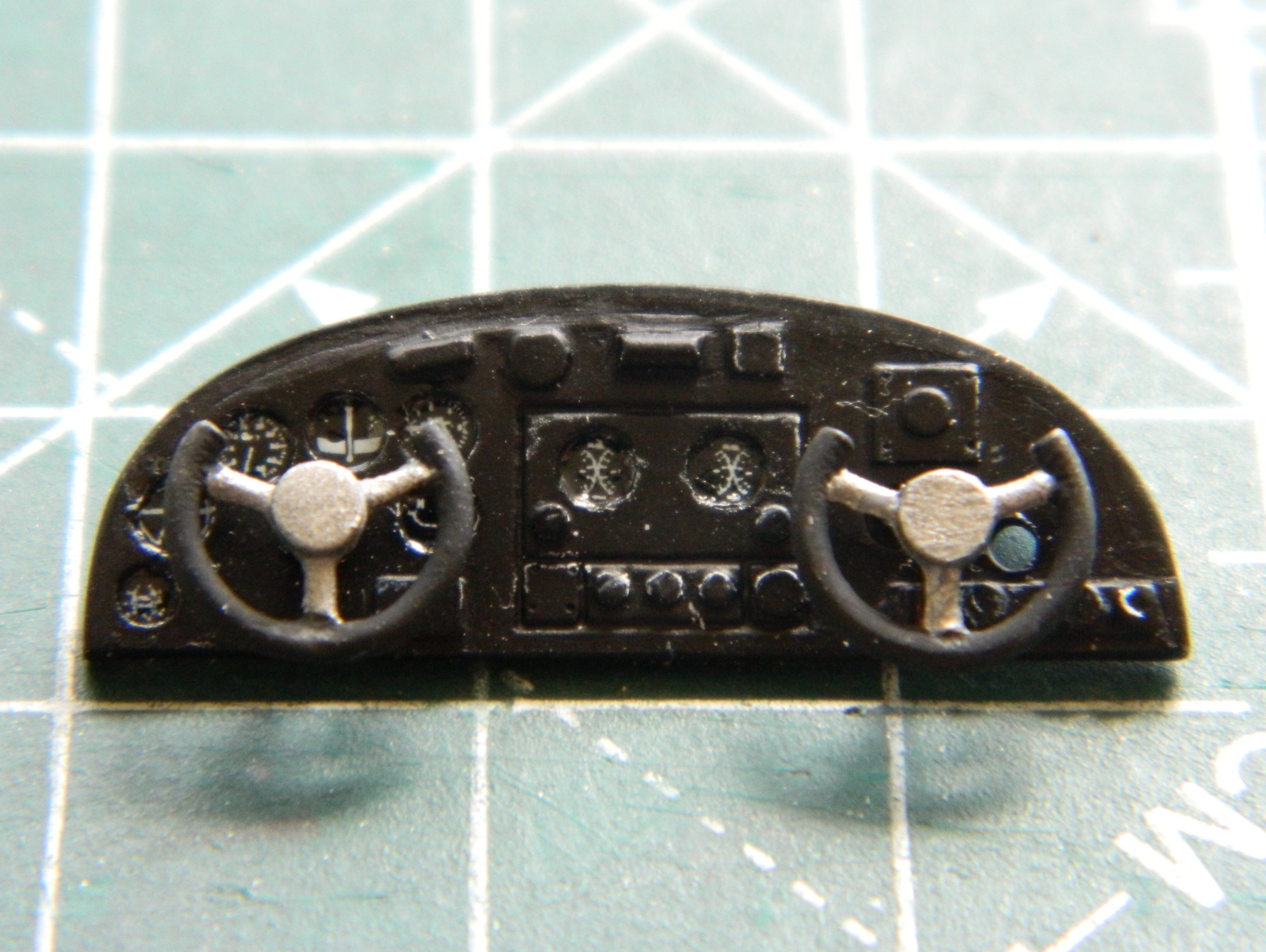
The fit of the cockpit’s rear bulkhead showed me that for me, True Details isn’t worth the money. Fit was rotten and the dimensions of the bulkhead are off…as in sides that are supposed to be parallel aren’t parallel. With strategic application of flat black, I doubt that this will be noticed once everything is buttoned up:

I mixed up some chromate green using Tamiya XF-3 Flat Yellow (2 parts) and X-5 Gloss Green (1 part) and added it to the inner fuselage halves allowing the flat black that was already put down to act as shadows:
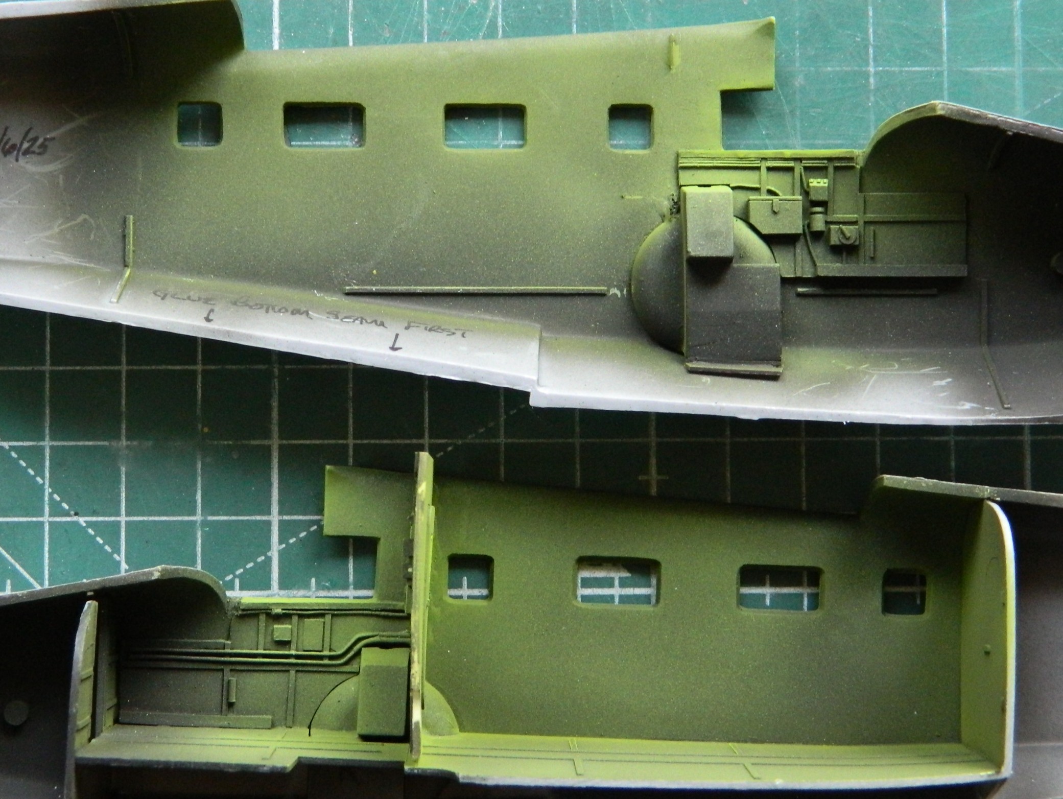
Some time back, I ran across these little beauties. The pilots’ safety harness in delicately molded styrene:
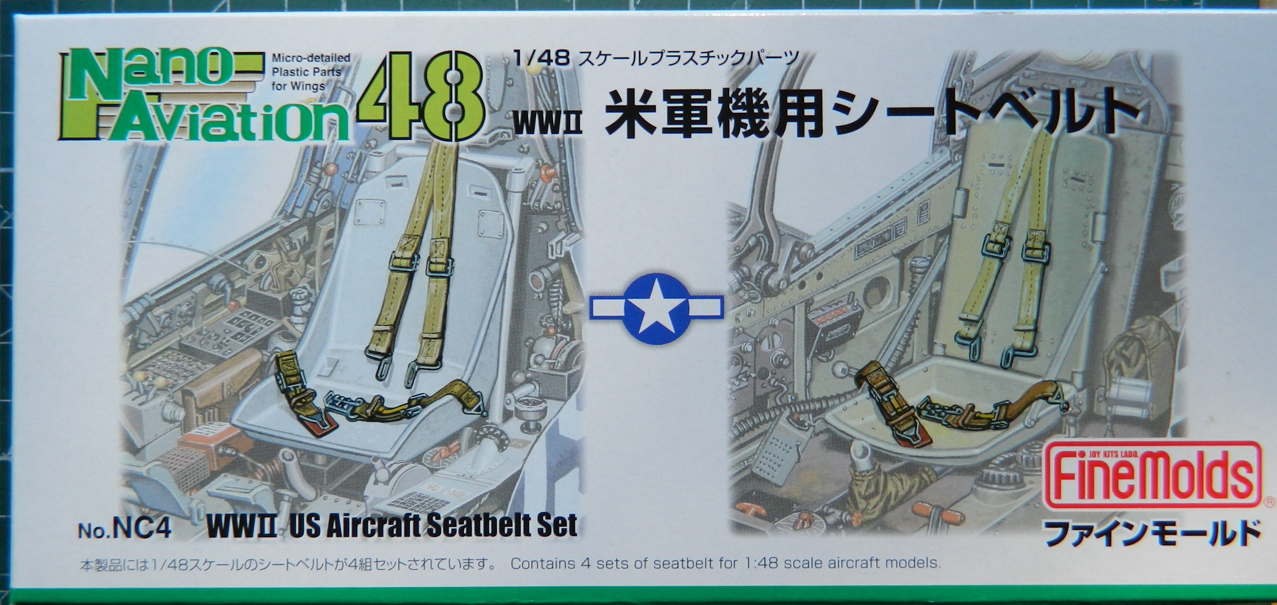
The only vendor I’ve found so far is in Japan. (What with these bullshit “tariffs”, I don’t know how easy they’ll be to get in the future…a problem I’ll deal with in the future.) This is what’s in the box:

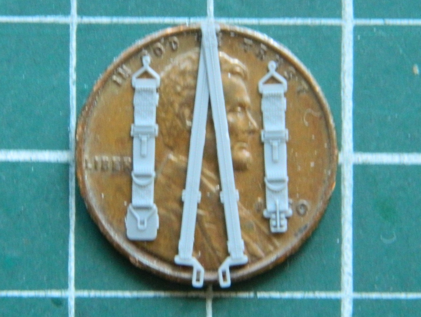
Before I could use those, I wanted to paint all the seats. As typical for me, the first coat of paint was Tamiya XF-1 Flat Black for pre-shading. Then I used my custom-mixed chromate green and painted on the light blooms:
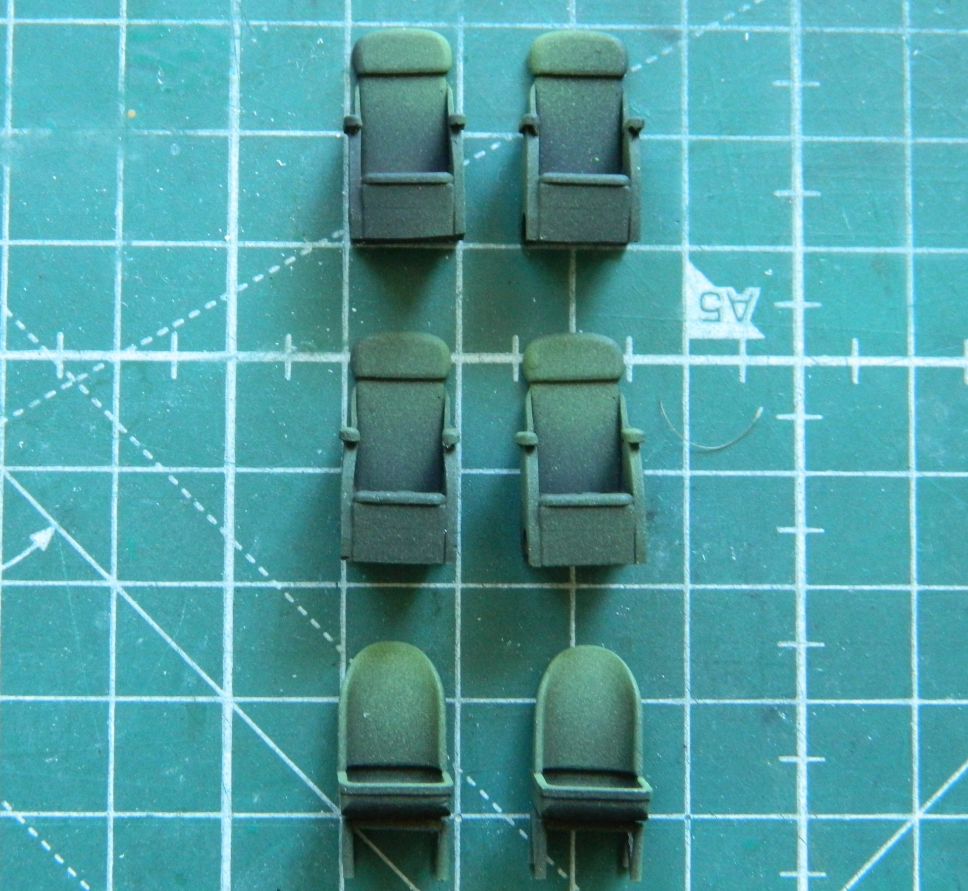
The harnesses were heated and bent to conform to the seats of the pilot and co-pilot:
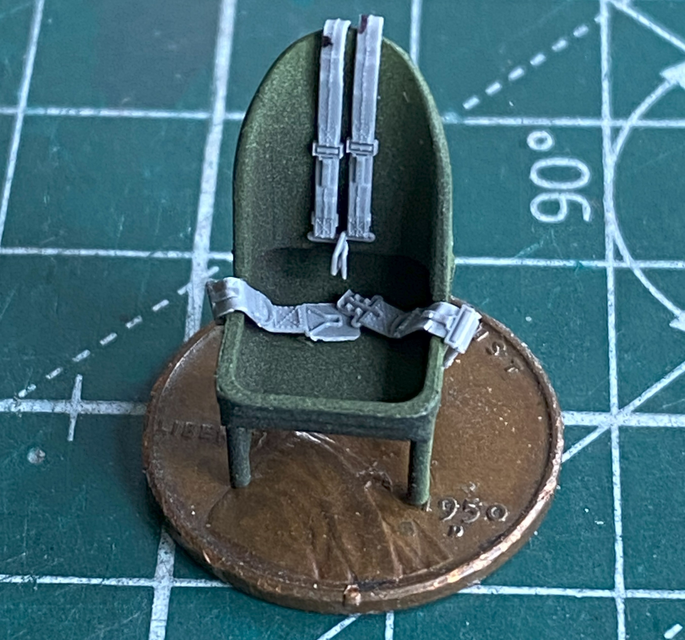
The straps were painted with a mix of Tamiya XF-49 Khaki (3 parts) and XF-64 Red Brown (1 part). The leather pads were painted using tinted XF-64 Red brown (5 parts) and XF-2 Flat White (1 part). The metal bits were painted with X-11 Chrome Silver. XF-51 Khaki Drab (5 parts) and XF-2 Flat White (1 part) color was misted over the areas that would be most highlighted, and then I used a dark orange pastel to replicate wear. I didn’t go crazy on the passenger seats because little of them will be seen. The pilot and co-pilot seats were touched here and there with a silver pencil to replicate wear:
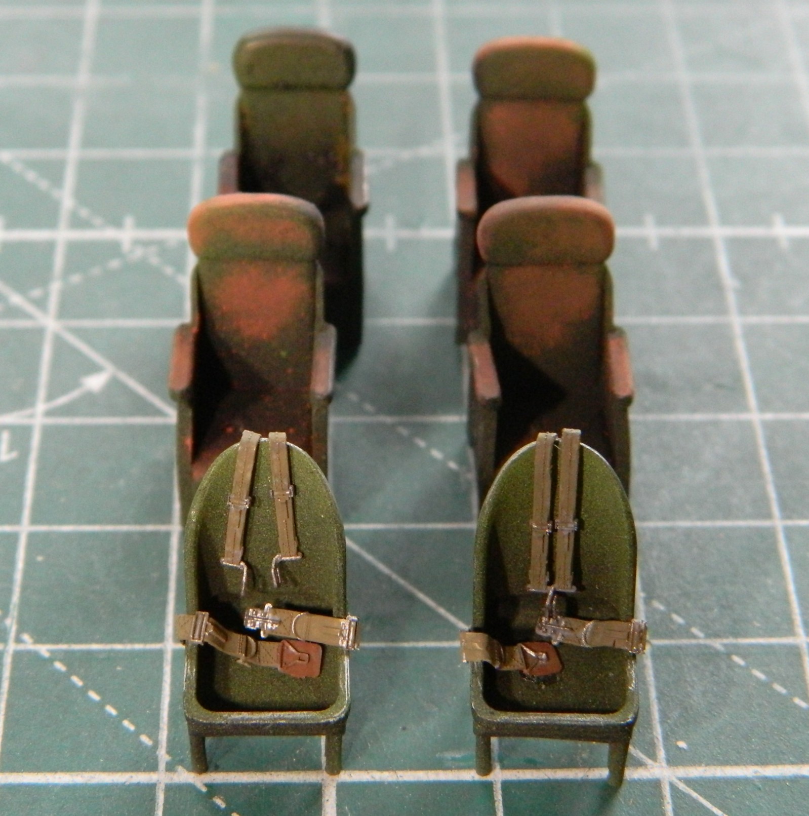
With the fuselage halves taped together, I test-fitted the clear canopy parts (obviously also taped together) to see if my initial assessment held up regarding its fit. Yes…it did. I placed the wings in place to see what had to be diddled with to get a better fit. Check what the arrow is pointed to:
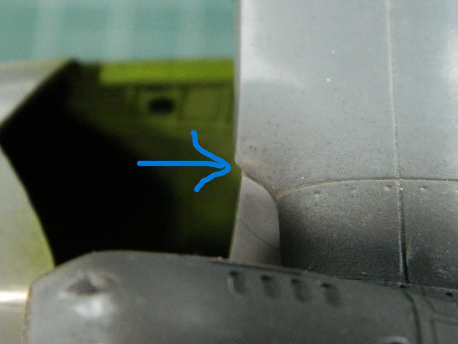
That overhang has to go; those parts are all supposed to conform to the edge of the fuselage. So the plastic above the pencil line was filed to meet the line:

Checking the fit of the clear parts again showed a significant improvement with its fit:

It also showed me that there’s a possibility of having to tweak the attachment areas of the clear parts but I can’t make that determination until the wings are glued down permanently.
The last thing I had to do before I could marry the fuselage halves was to get the sodding instrument panel to fit (and hopefully not look bad in doing so). I used a foam wedge (sold in drug stores and/or apothecaries) to align the panel to the best of my sometimes-disappointing abilities (the tan square is a loop of masking tape to enable me to move it…and there was no shortage of moving it…without damaging the face of the panel). Where the panel touched the fuselage received a significant amount of styrene cement any place it touched the fuselage half. My brain-fade kicked in and I attached the panel to the left side of the fuselage, where everything else inside the fuselage was attached to the right side. ::facepalm:: It complicated the joining of both halves a little but I didn’t find that out until the trigger was pulled and the Rubicon crossed. As you’ll see, there was no way I could dislodge the panel without damaging things. The bitch is ON there:
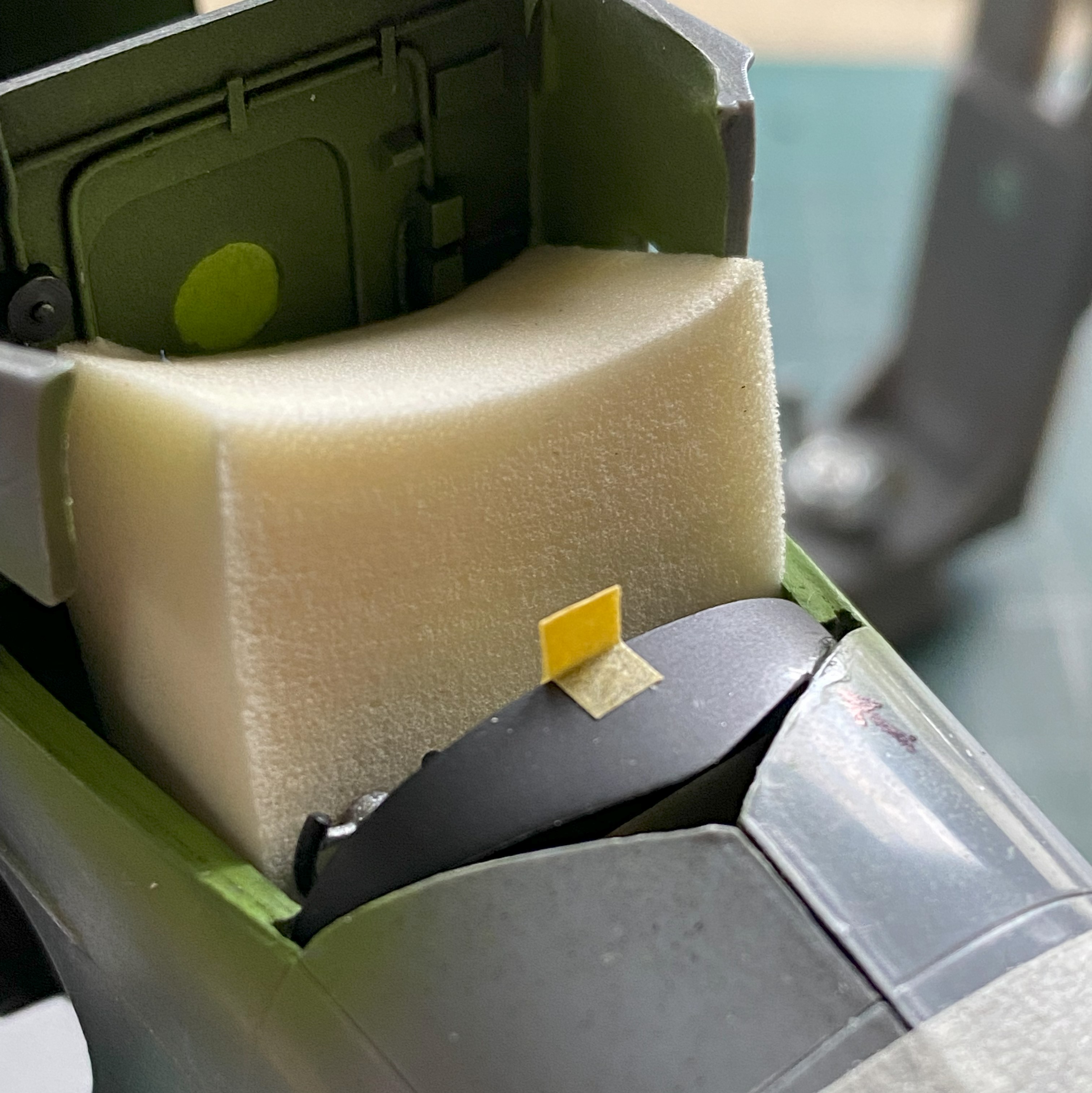

After letting it sit overnight to harden fully, I thought that it wasn’t quite firmly attached enough. I used styrene scraps to reinforce the attachment point(s):
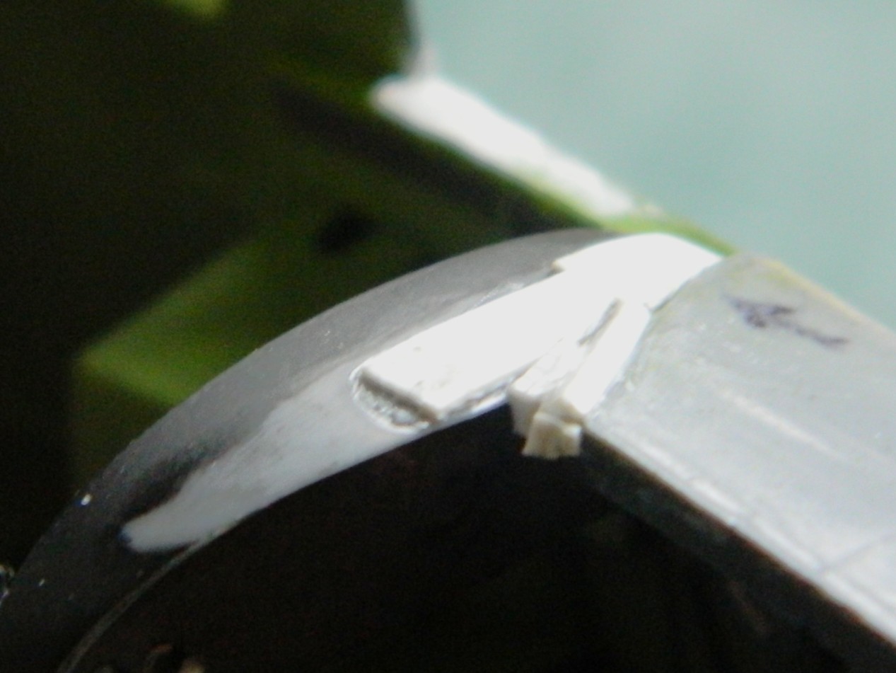
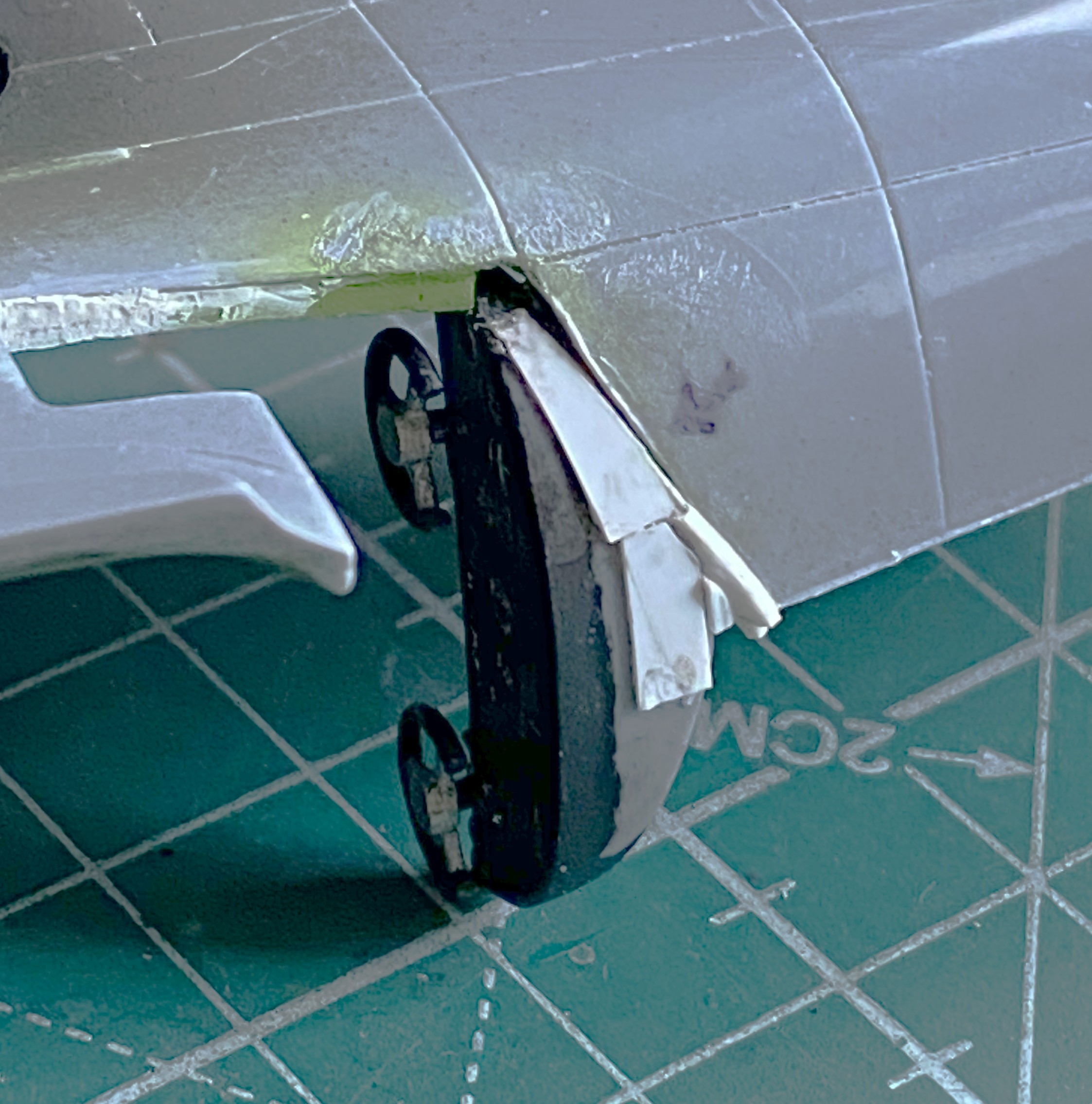

It was time to add the windows to the passenger compartment. Once again, thick plastic:
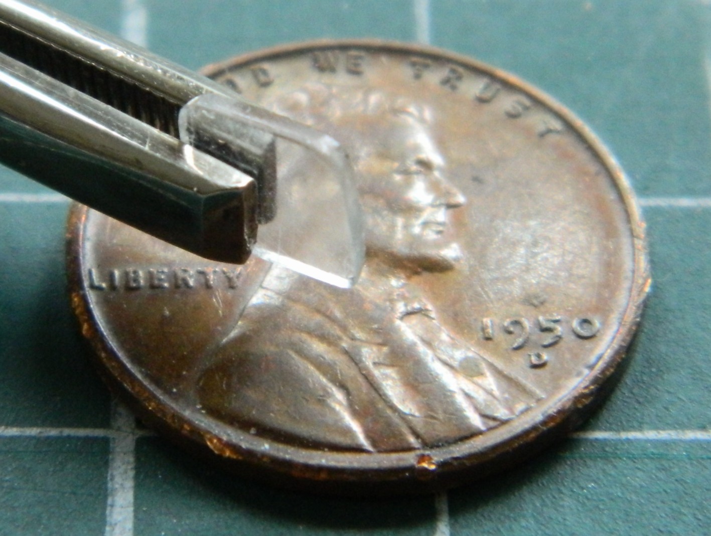
Earlier US WWII fighters had a plate of armored glass behind the windscreen. I’ll keep these thick clear parts for that use in the future. For now, they need to be replaced. I’d intended on using 0.010″ (.254mm) but though it’s to a more scaled size, I wanted a bit more surface for adhesives to bond with so instead I used 0.015″ (.381mm) clear instead. This gave me a closer-to-scale thickness (the thin piece of plastic isn’t usable other than as a comparison of thickness):

When I did the M4 Sherman with a clear side, I decided that the next time I used clear like that (or for any purpose, really) where it had to be fettled and tweaked to fit, I’d cover both sides of the clear styrene with masking tape. After coating a scrap strip of clear on both sides, I positioned the strip under the fuselage and traced the outlines of the windows:

Yes…the sides of the fuselage are too thick as well. What it would take to fix that isn’t worth the effort so I left it as-is. The windows were trimmed and glued into place using UV-setting resin and the inner masking tape removed:
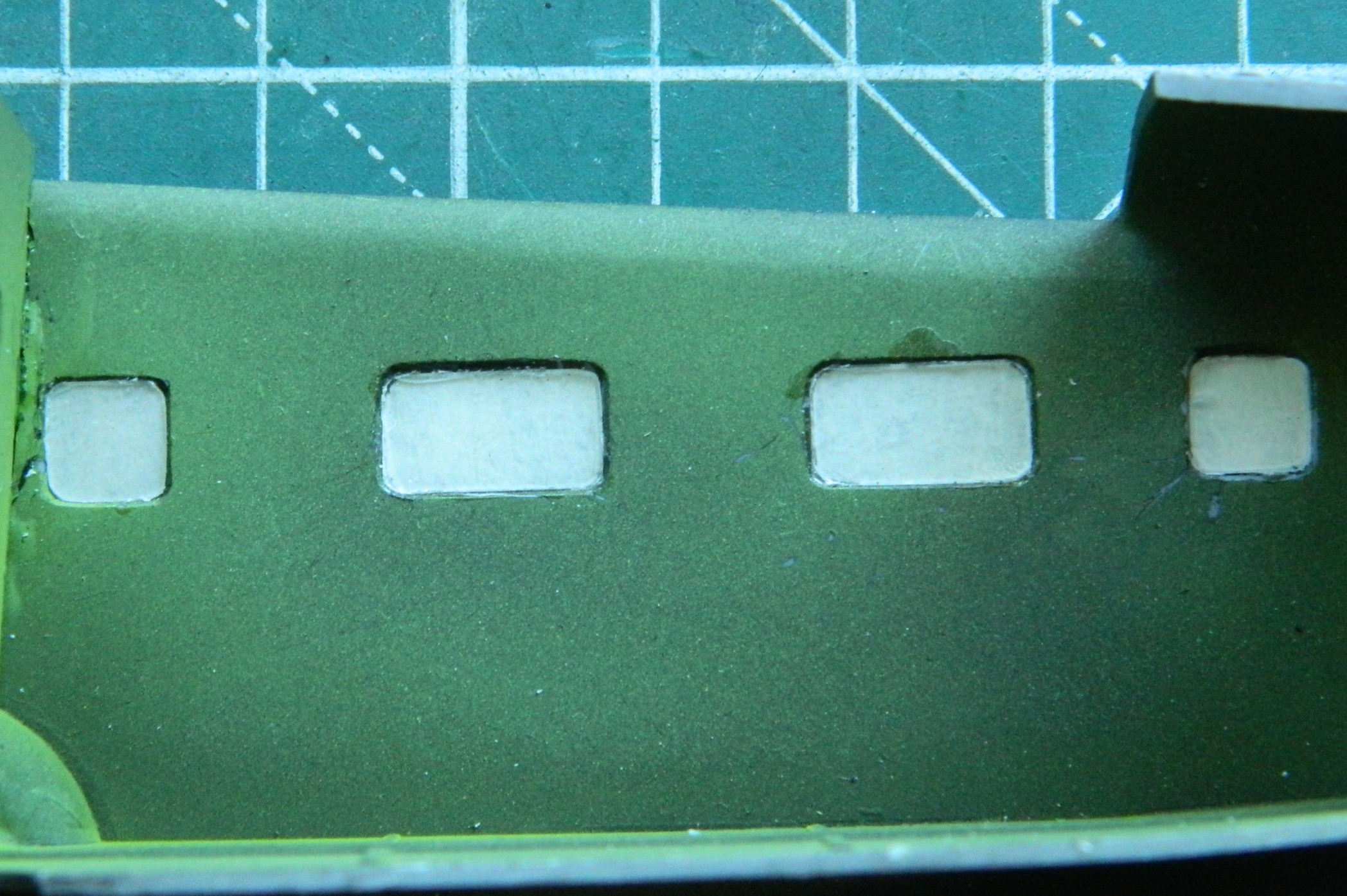
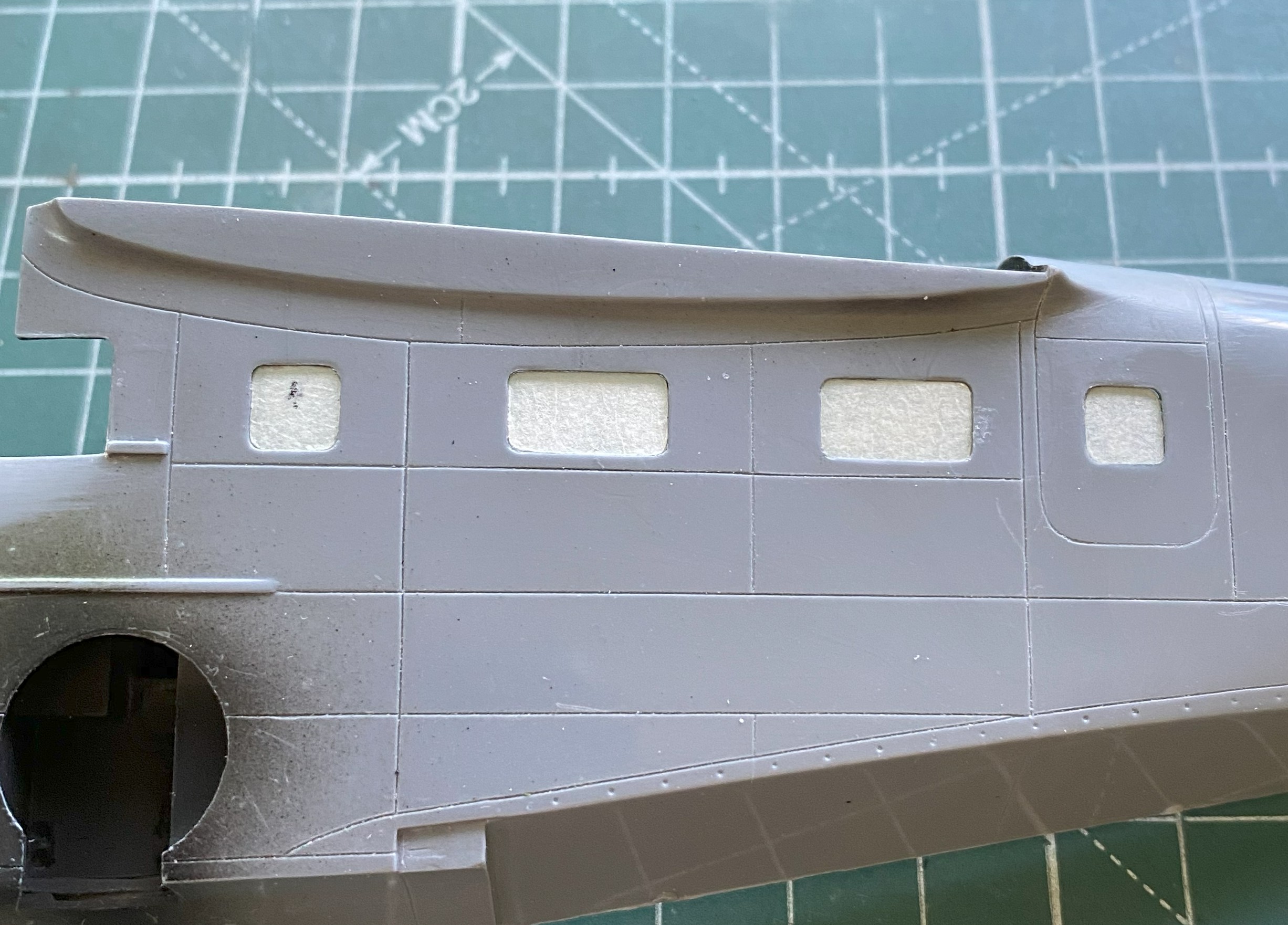
Time to add the seats to the cockpit:
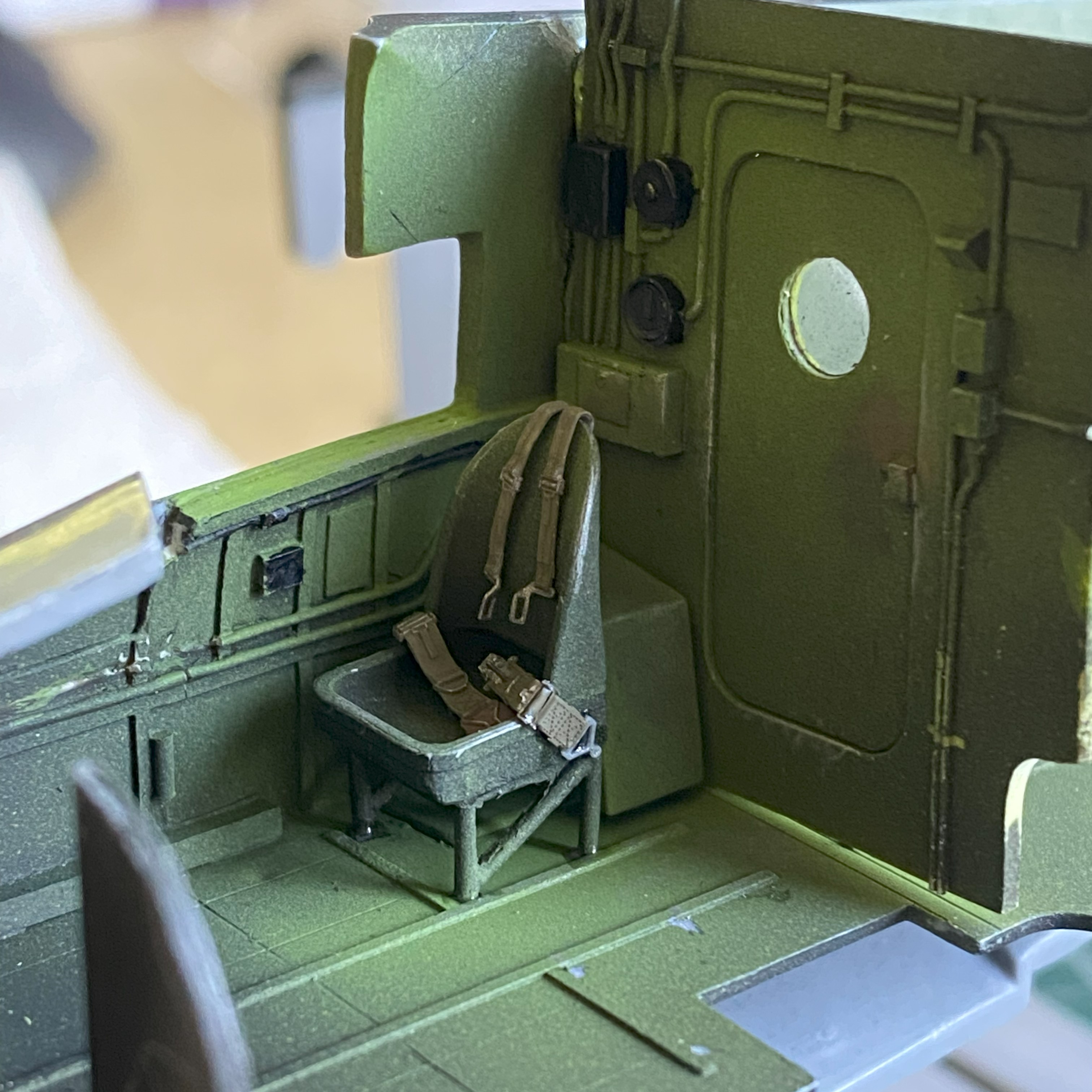
The pilot’s seat wasn’t added at this time because of fitment problems. I had to shorten one of the legs so that it would sit level(ish) and that would be better done after the fuselage was together. The passenger seats were then glued in:


I glued the fuselage halves together. Such a simple sentence to describe a hair-pulling experience (that’s one way to clear out my nose…). Each half of the dies for the fuselage parts was clearly cut by different people. I just wished that they’d communicated with each other. Neither side matched the other in overall dimensions or curvatures. What ended up driving this task was the question, “Which side would be easier to fix than others?” I made my decision to have the top seams match (because those are the ones easier to see) and deal with what happens underneath. The halves were glued together (and most of the filler used to hide the seams, top and bottom, came from 99.9% stretched sprue).
With the halves now joined, it was time to fix the mess underneath. SO much putty would have been needed to do that that I decided to add scrap sheet, mostly 0.010″ (.254mm). While I was doing that, I noticed that things don’t fit (check the arrows):

These photos are included to show you what the good side’s fit was like:


Yeah…filled with sprue.
This is why one should always use photo references from the actual time period being modeled. Most of my references are modern ones, which are okay in general, but it’s in the specifics where they drop the ball. Modern references show the nose hatch to be “proud.” It sticks up. Period references show this hatch fits flush. Can you guess what I didn’t do?:
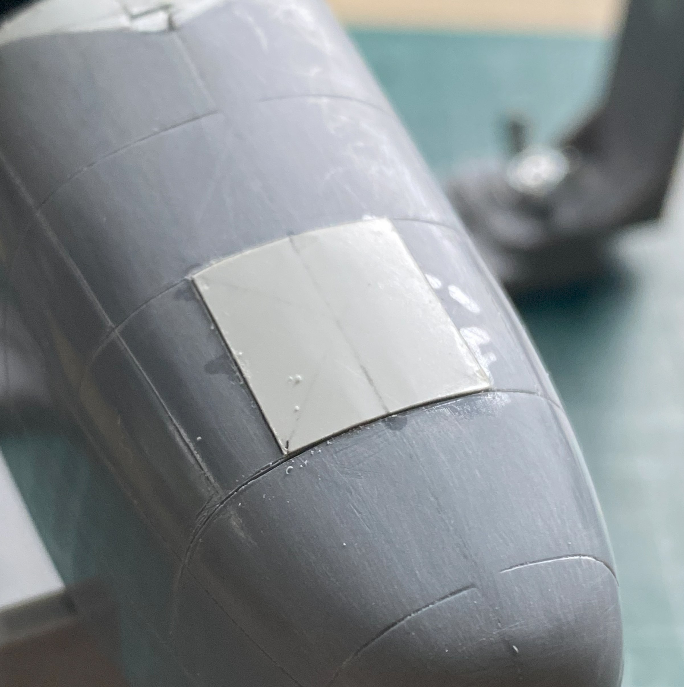
Back under the fuselage, lot of sanding ensued (and more than a little filing):
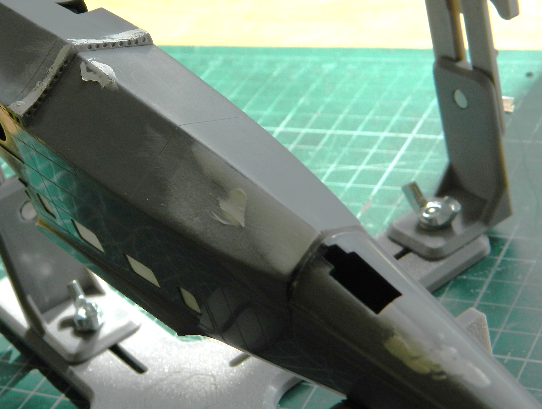
With the supports trimmed judiciously, the pilot’s seat is in, as well as the instrument panel top puttied and sanded (though it’s evident that there will be more putty added and followed up by more sanding):
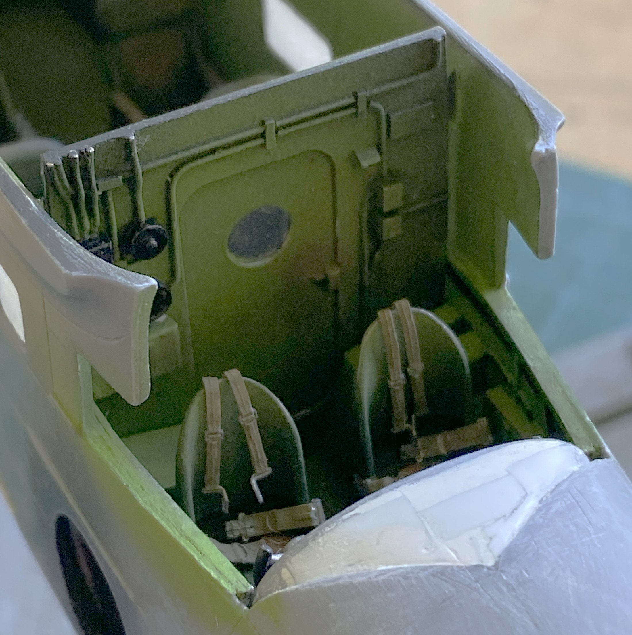
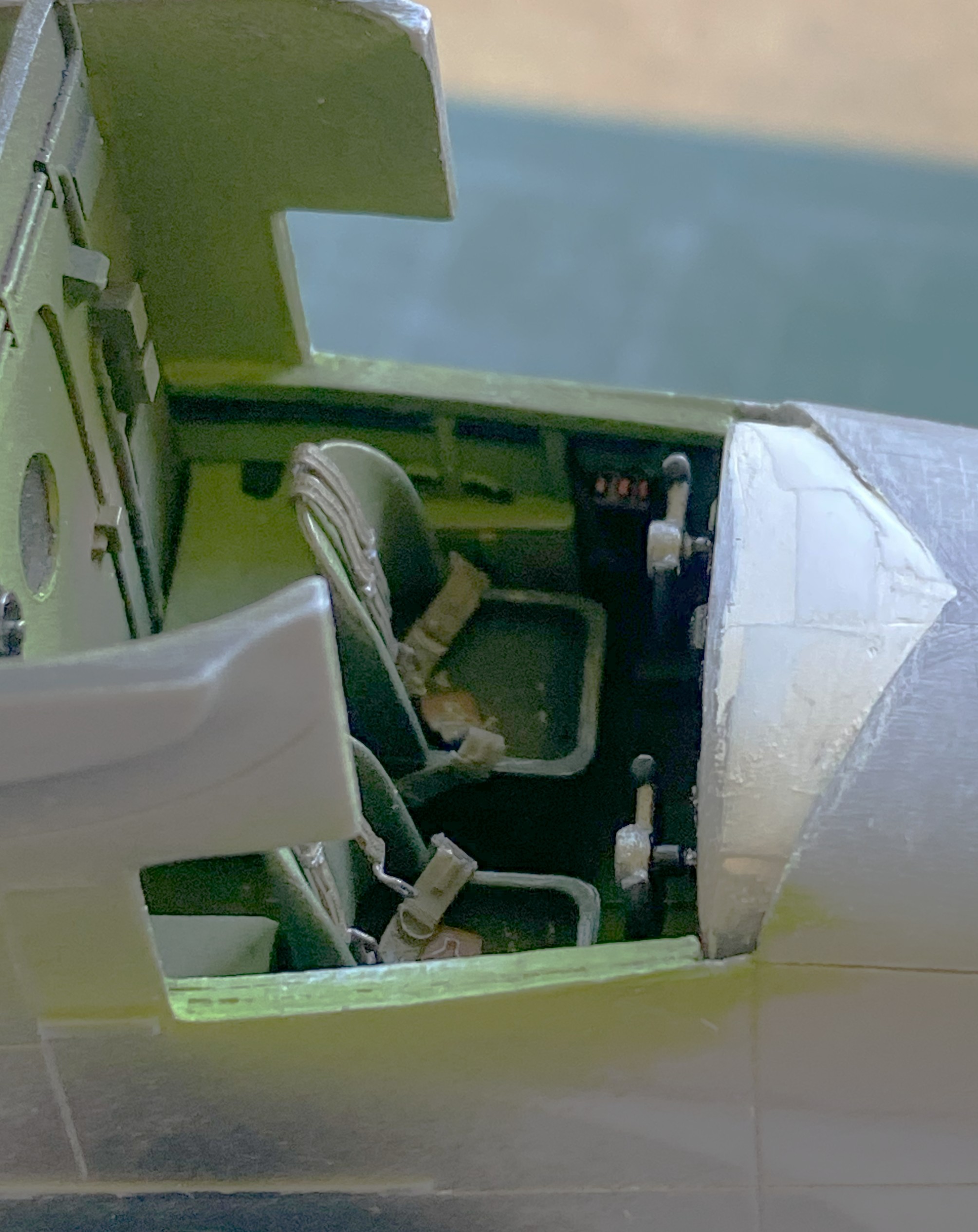
Checking fit (after a LOT of sanding) with the wings shows me that I was correct…most of what’s inside won’t show from the outside, and even less will be visible once the clear parts are in and painted:

I dislike scribing and my results show that. The panel lines with this model were inconsistent with depth and width, so all panel lines had to be rescribed. And then it was three bouts of putty filling where the scriber (me) left lines where there shouldn’t be any lines:
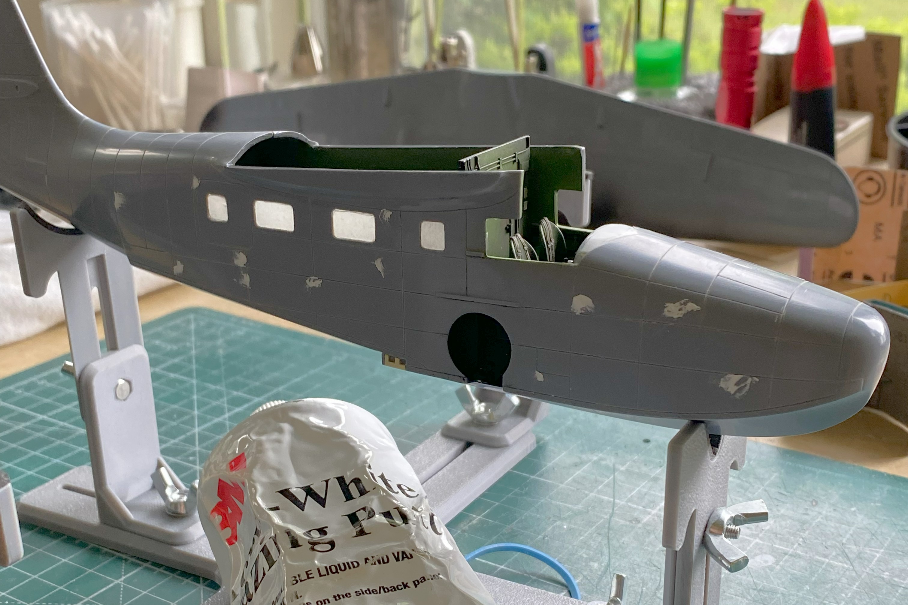
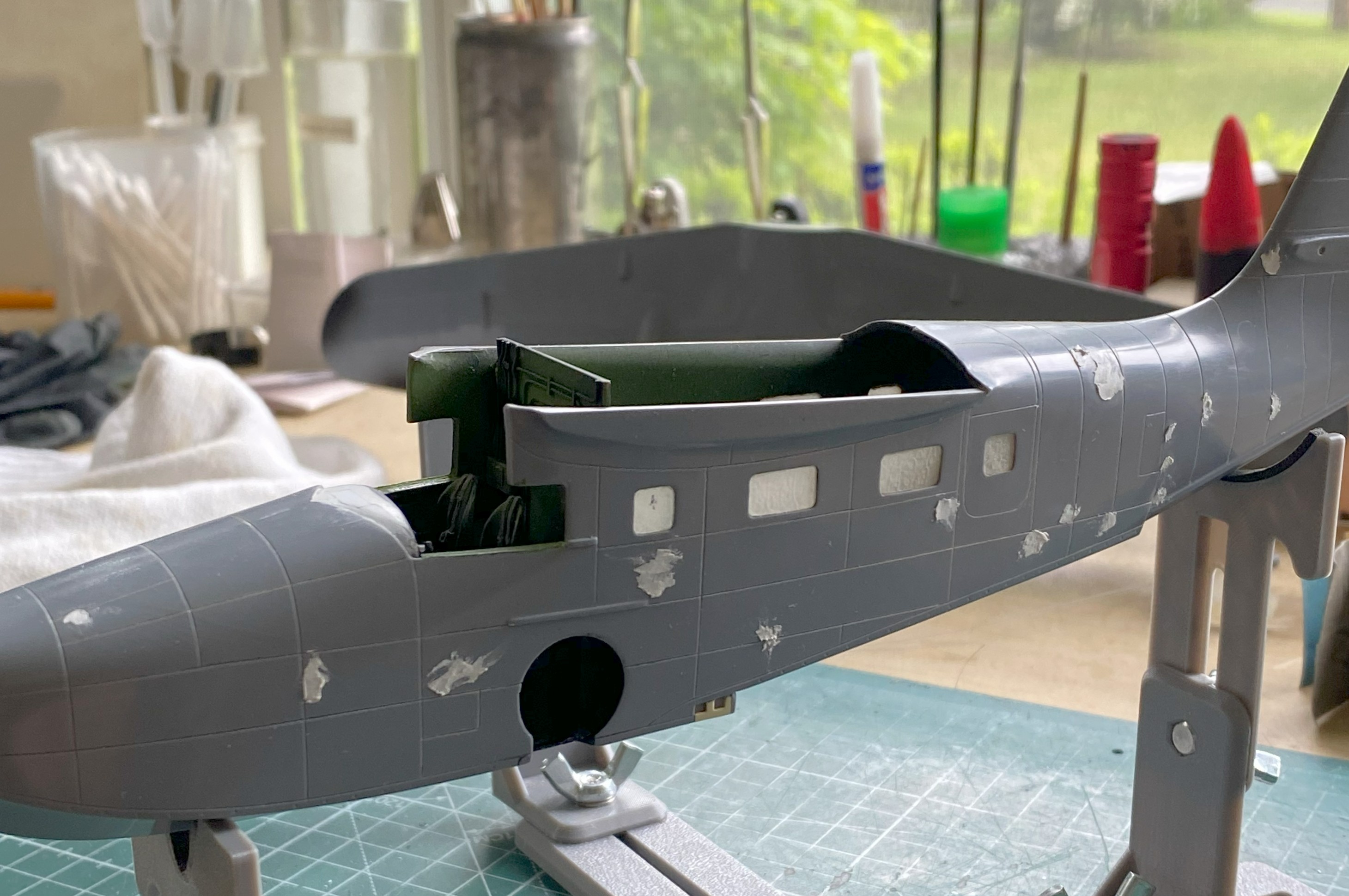
And after doing all that, RE rescribing panel lines often does this:

Fit was so poor that in order to get things the way I want them to be, I ended up with something that looked like a Sub at a BDSM party:

And though it took stretched sprue, scribing, rescribing, and putty, I got the empennage done:
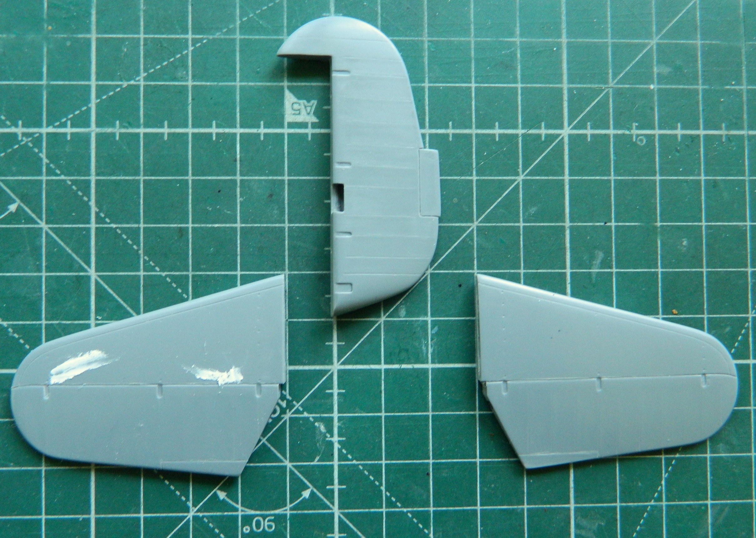
Maybe next month I’ll get to start putting these bits together permanently.
Grumman JRF Goose (Czech Model) 1/48 Scale Build #2 – Fit…Dealing with Lousy Fit and Having Several Fits
I picked up where I left off last month by working the landing lights. It’s one thing “knowing” that the plastic of this kit is rather thick. And then I get the socket for the landing light cut out and see this…it’s 2mm (okay, 1.96mm) thick here:
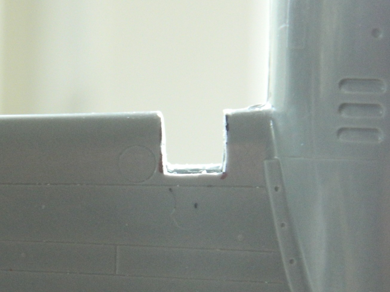

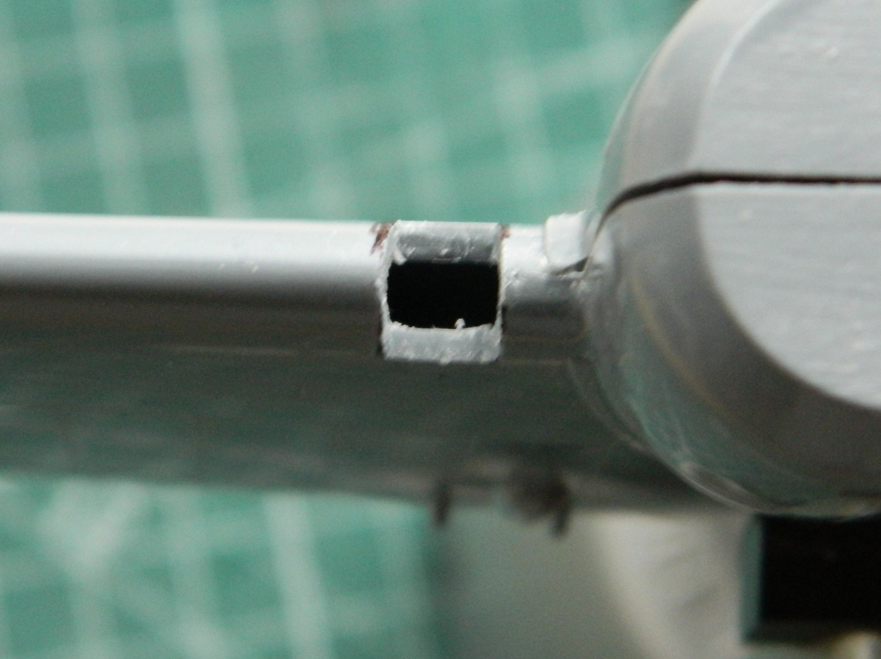
And making these cuts only cost me one bent saw blade.
With the acrylic rod cut, I needed to fit it to its socket to mark where the leading edge of the wing is so that I can drill out the “light”:
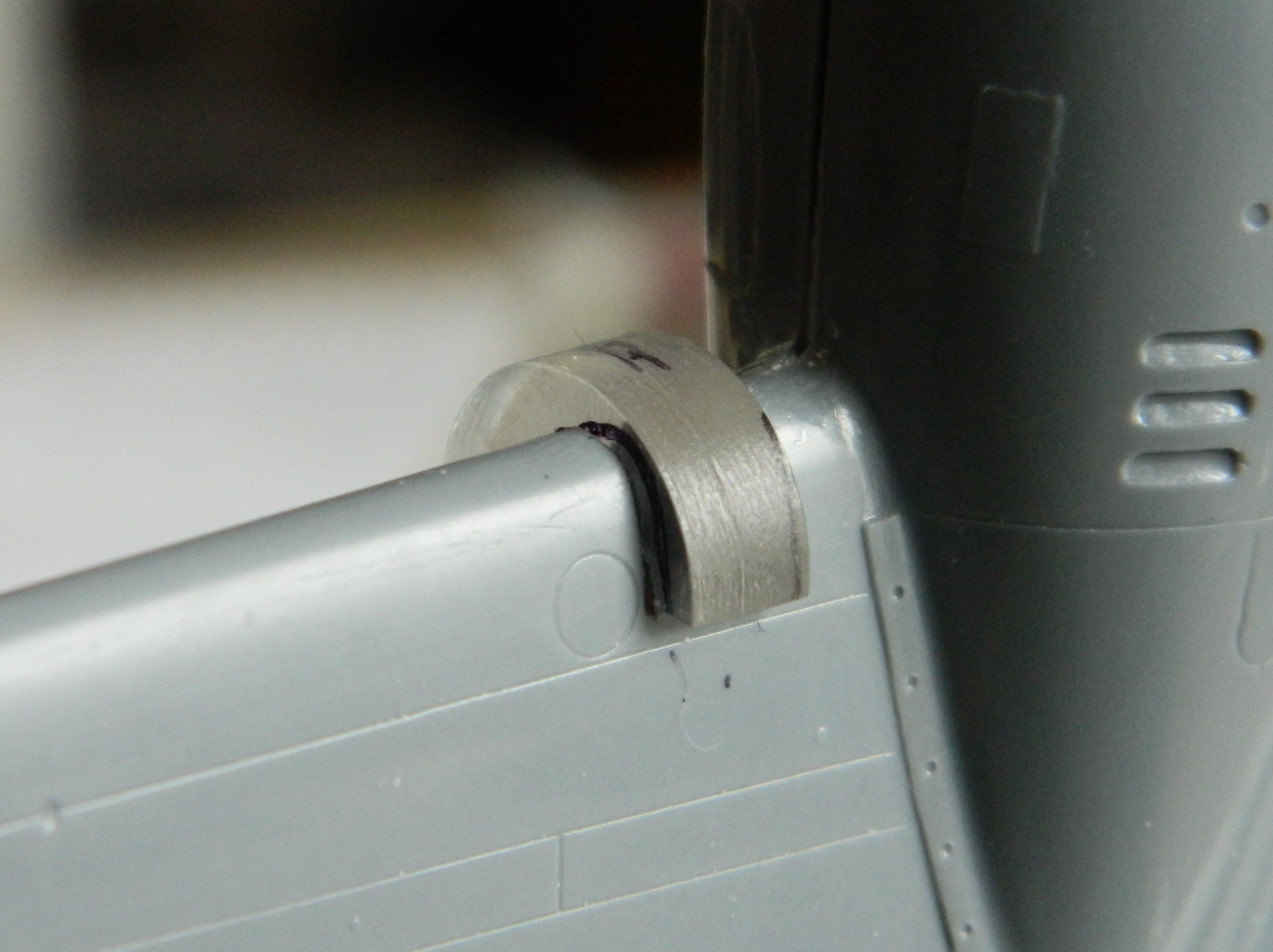
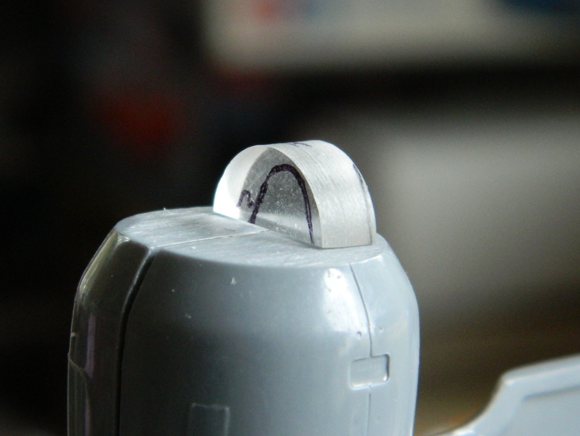
With the “light” drilled and a tiny drop of black paint to replicate the bulb, the whole depression is hit with chrome:
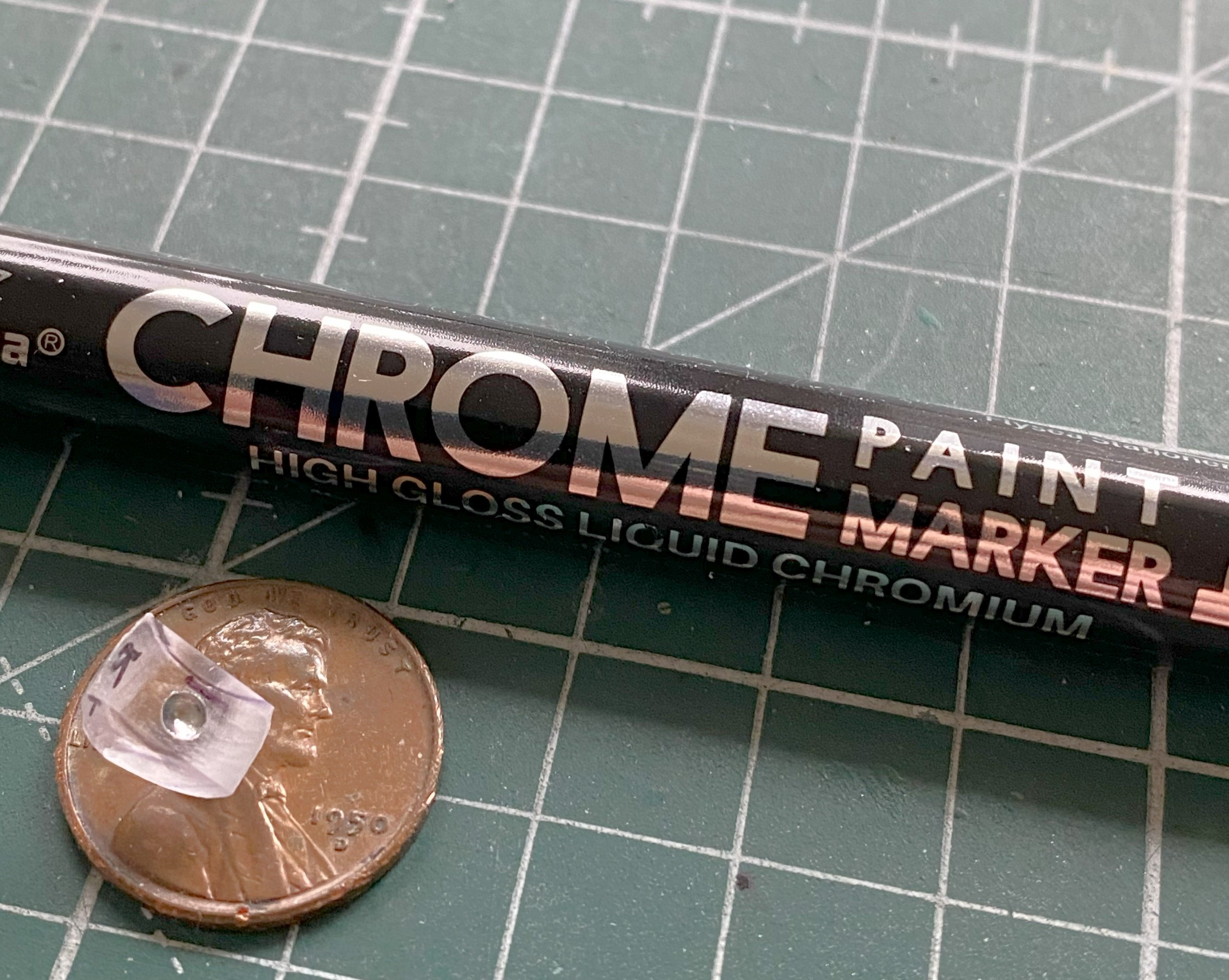
Then it gets glued in place and shaping begins, starting with a motor-tool, then files, leading to sandpaper(s), and then polishing (Novus Plastic Polish #2):

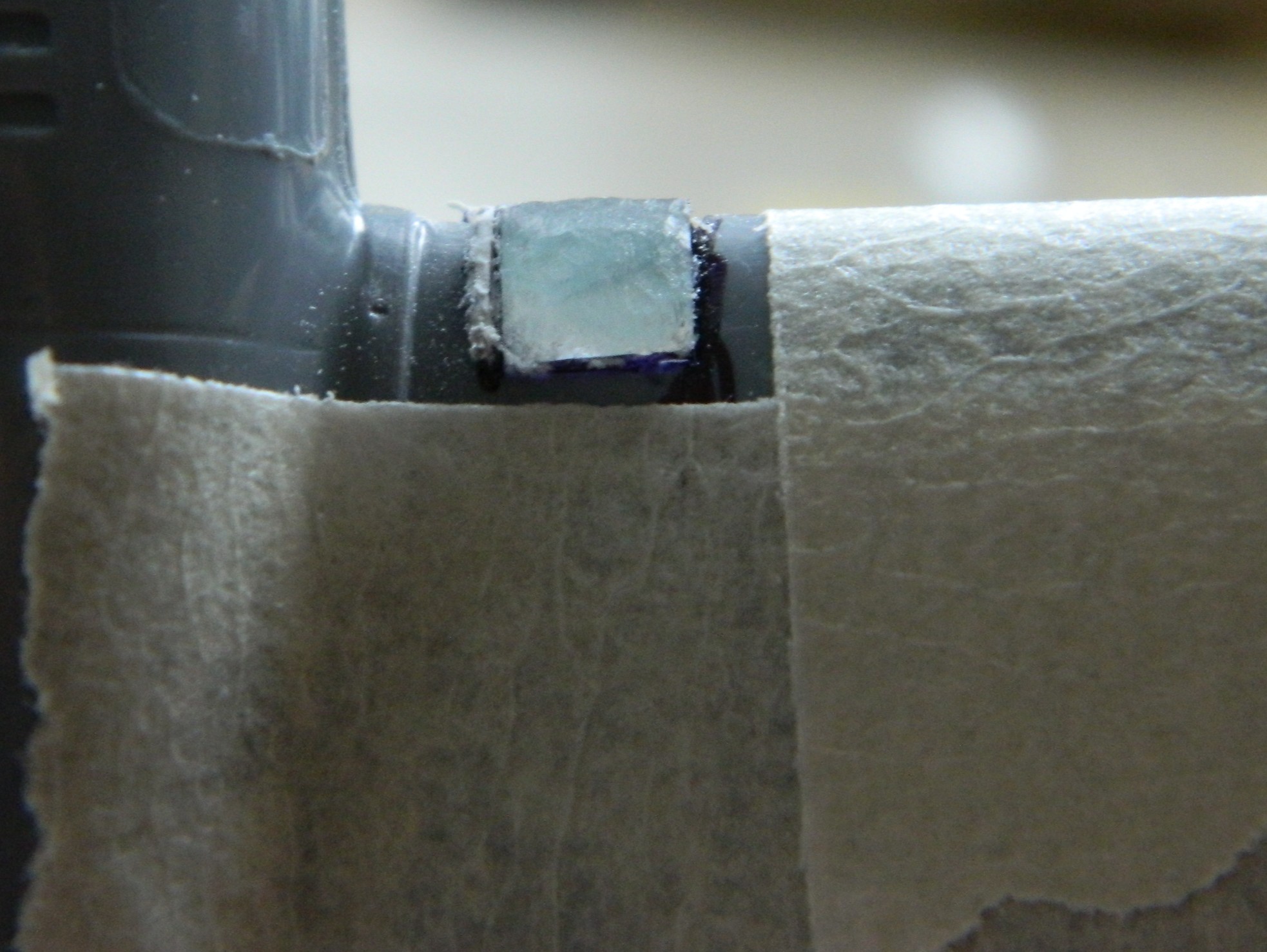
Some of the choices Czech Models made don’t make sense to me…though I guess it’s got to be easier to produce raised details than recessed details just due to the physical requirements of cutting dies. Dies are negatives of the parts so if the kit has very fine recessed details, that means those very fine details have to be positives, as in not recessed, in the dies. In other words, if it’s recessed in plastic, the dies have to be cut away from the intended line leaving just the fine rib in the die(s). It’s probably MUCH easier to recess the die for raised details…which I don’t want so I decided to sand down the mistaken raised details and scribe that detail instead (because of how much I LOVE scribing lines).
What all that means is that I have a few areas that need scribing. Four of them (of ten) have radiused corners and because I’m SO good at scribing (::giggles::), I decided to make a template. I used .005″ (.127mm) copper shim stock and pressed masking tape over the shape I’m replacing to act as something that I can trace onto the copper. Here’s the progression:
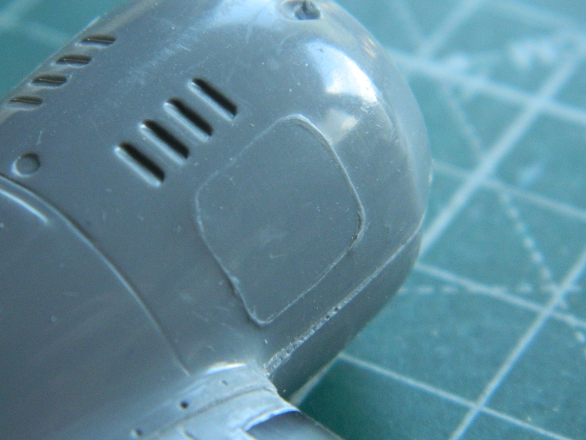
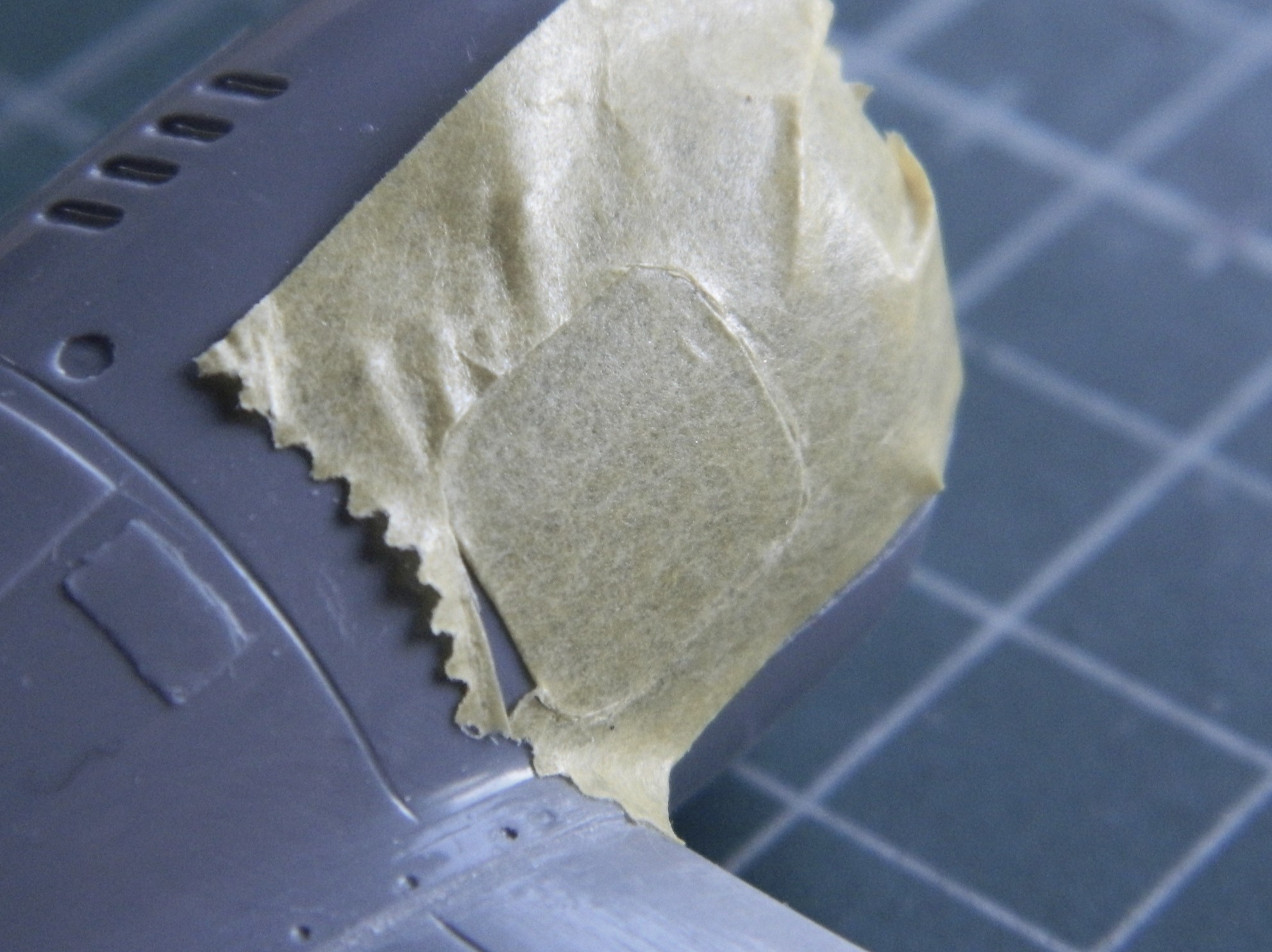
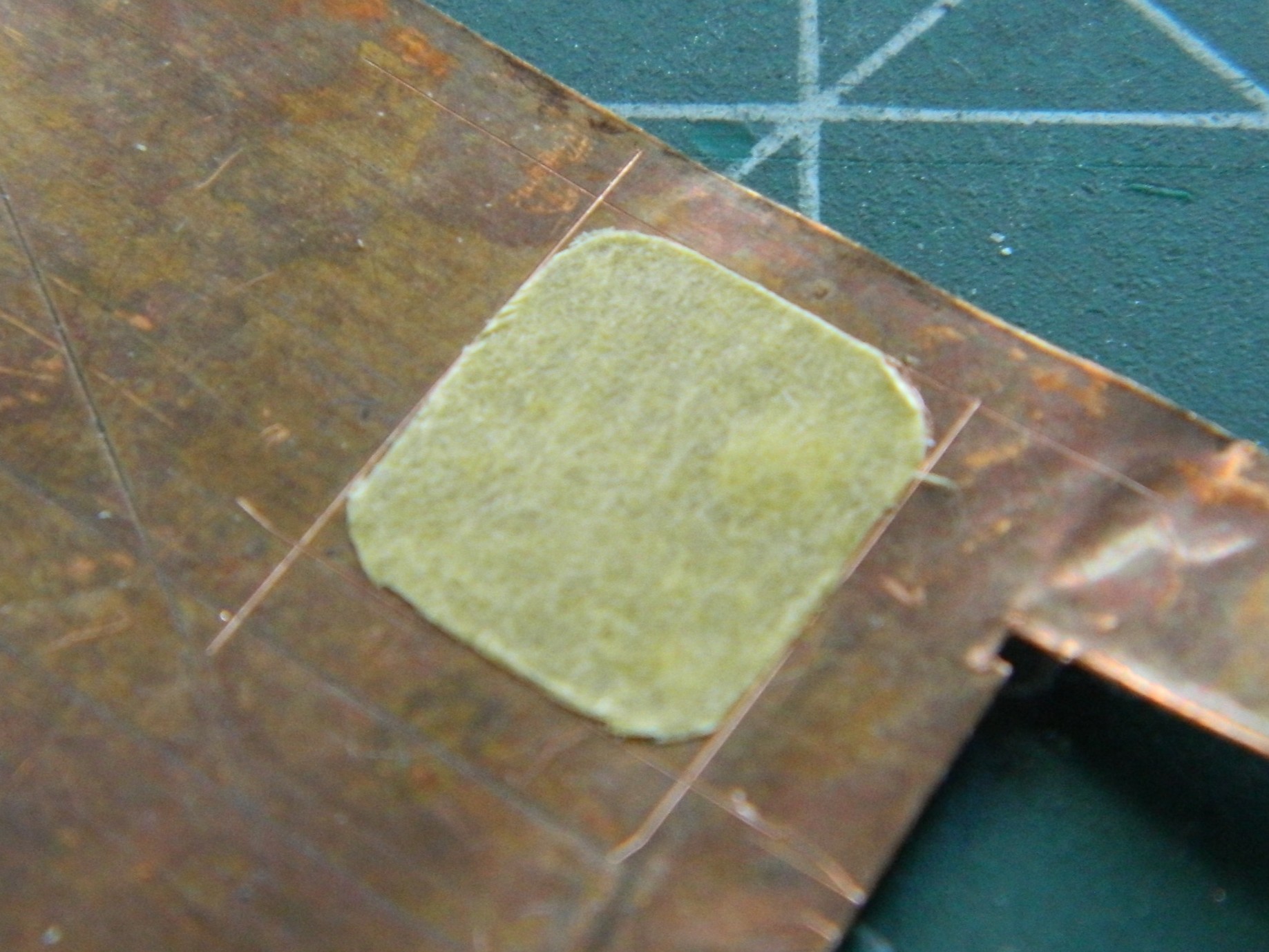

The results were better than I could have done freehand (this access panel has a piano hinge at its top so I replicated that with stretched sprue, which I also used on the nacelle to fill in the HORRIBLE recessed panel line…on both nacelles…and behind the added sprue, you can see other panels that had been raised panels also but easier shapes to rescribe):
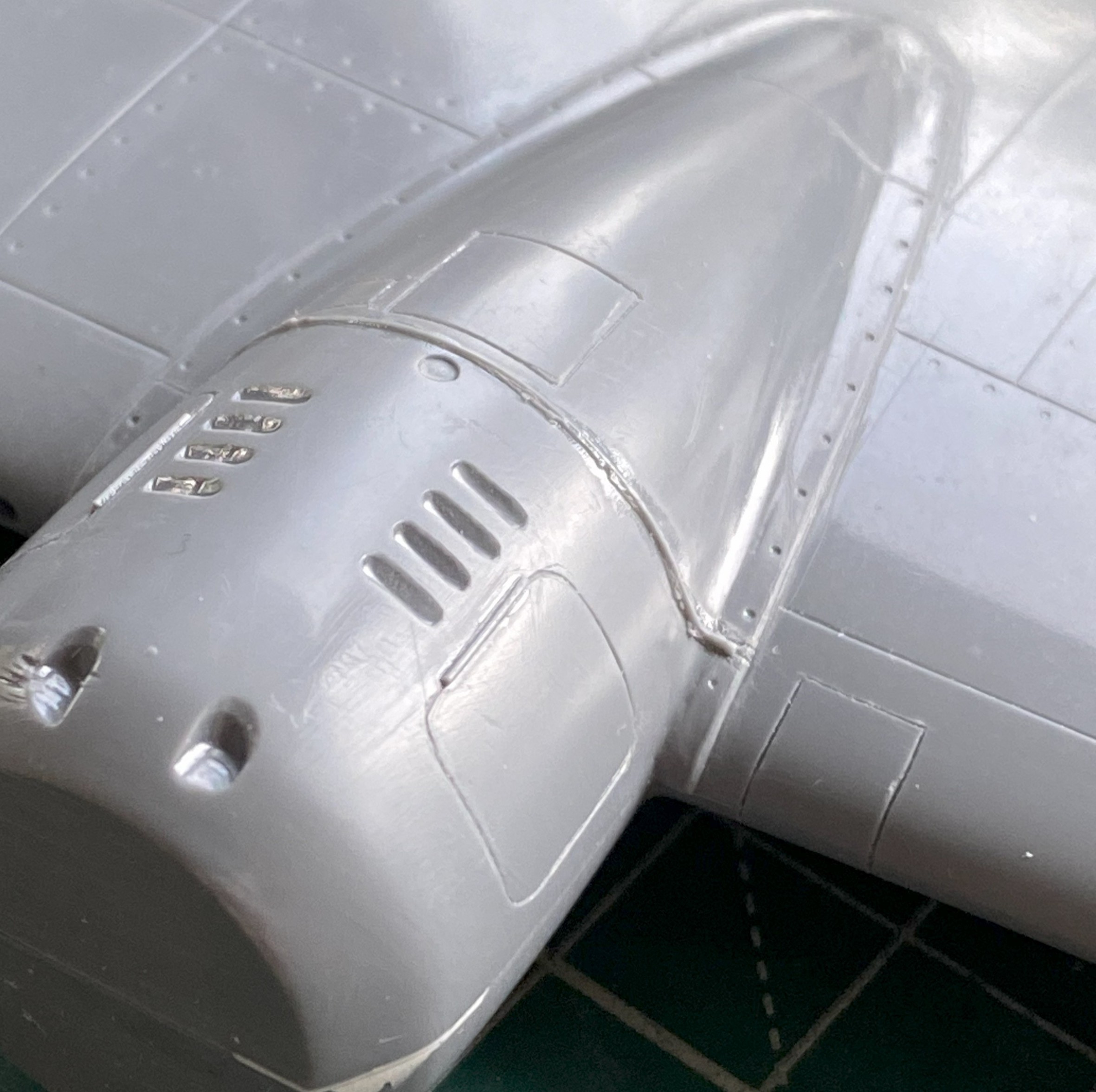
And now the surface behind the louvers is ready to be scribed:

There are several gaps like these (and note the nicely polished landing light to the left):
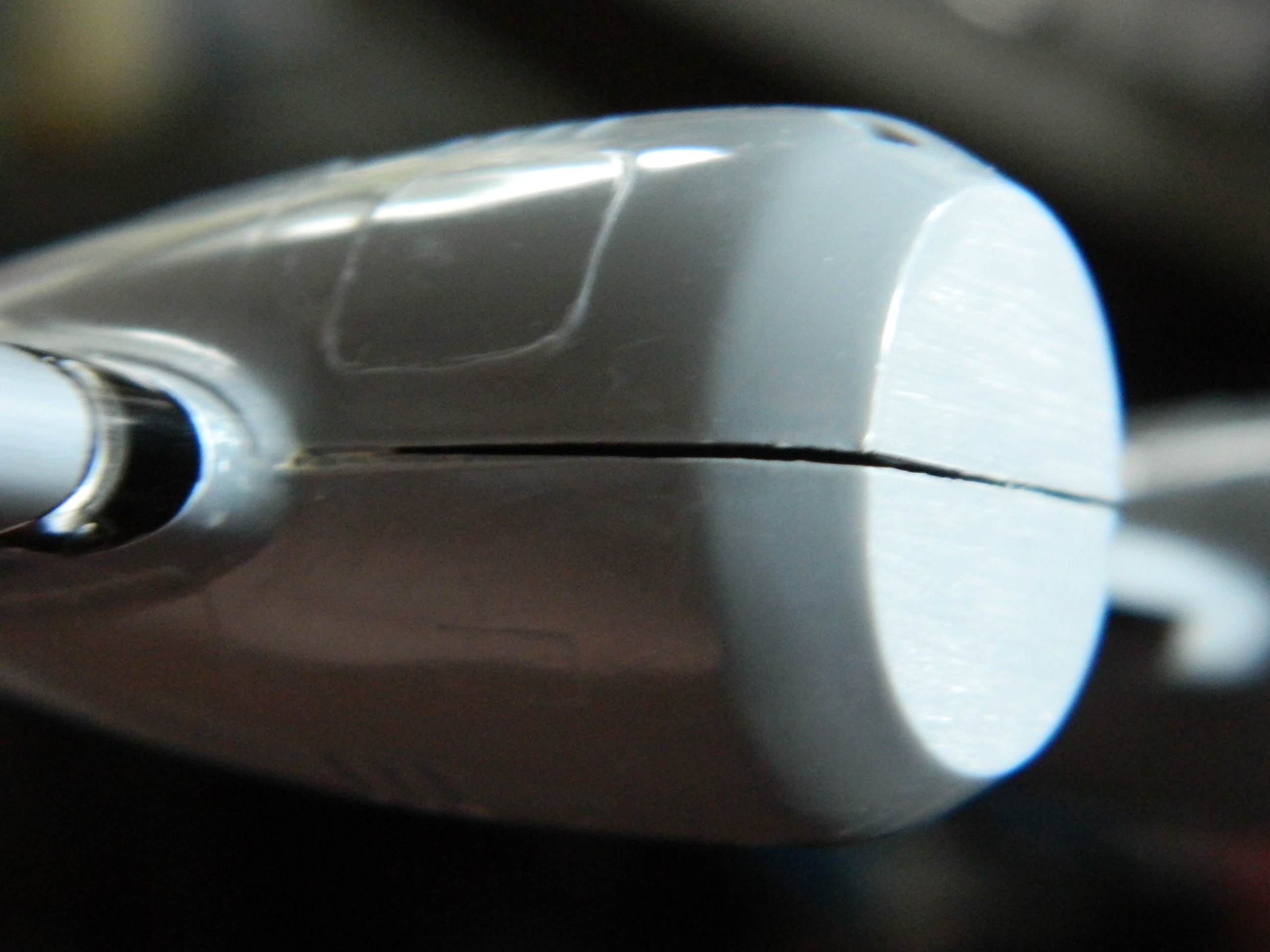
My preferred method of closing large gaps is to start by stuffing them with scrap styrene:
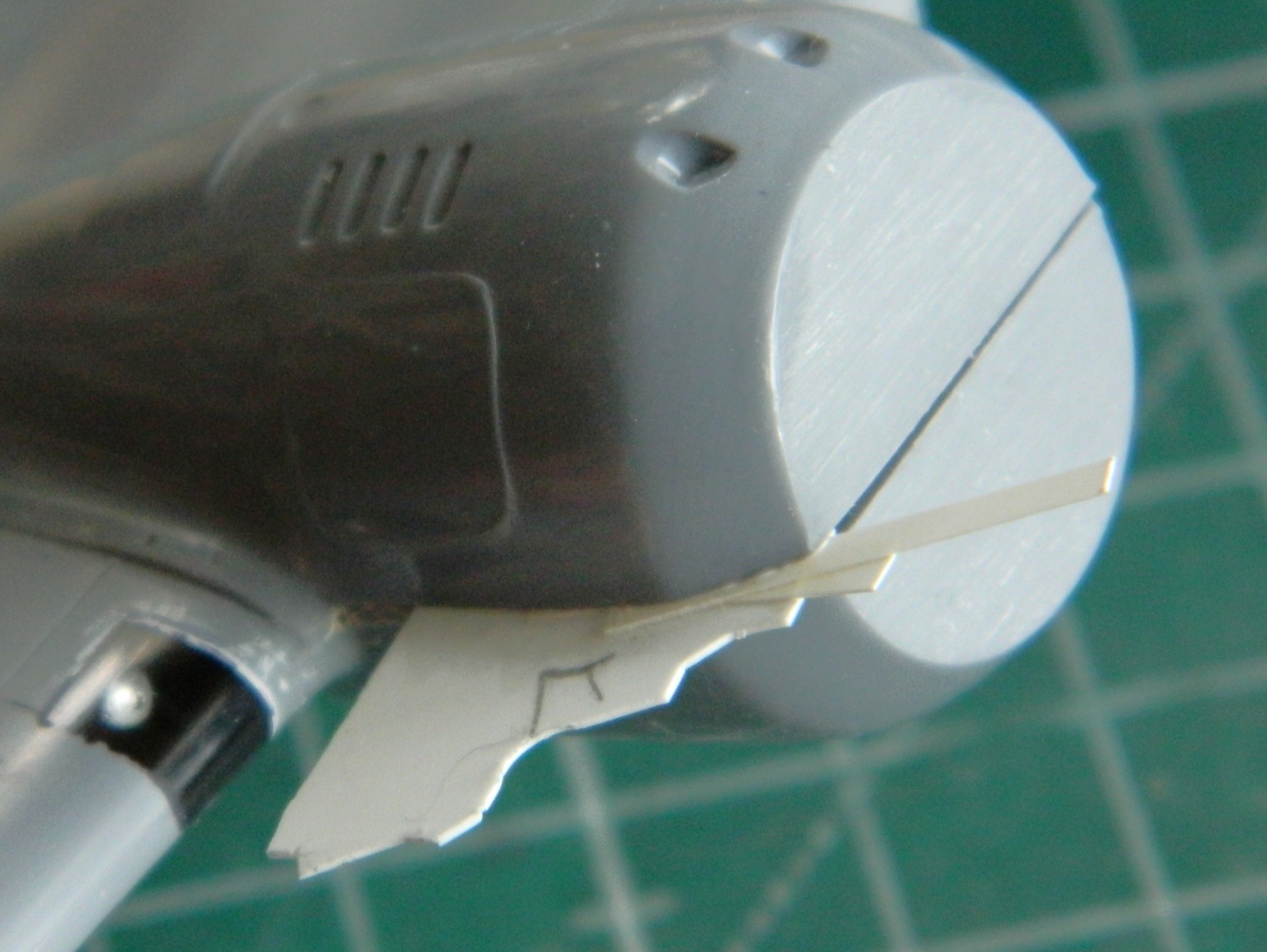
This aircraft has formation lights (if I’ve guessed correctly on the nomenclature) at the leading edges of the wingtips. There are zero indicators of those with this kit. I consulted visual references and played internal logic games and decided that this is pretty much where they go:

Then it was cut out on one side (just in case I somehow got it wrong, it’s half the work to fix one instead of two):

And yes…I marked each wingtip with the color of the formation light because what I have for a memory looks like a sieve.
With the notch cut, I used a small strip of masking tape as a gauge so that the two sides match:

Having cut the notch, I took a section of clear sprue and stretched it. I measured its diameter and cut the appropriate hole on the inner vertical face because that’s how it looks in reference photos. The tip of the stretched sprue was dipped in its appropriate color (red/left, green/right) and glued into place(s):

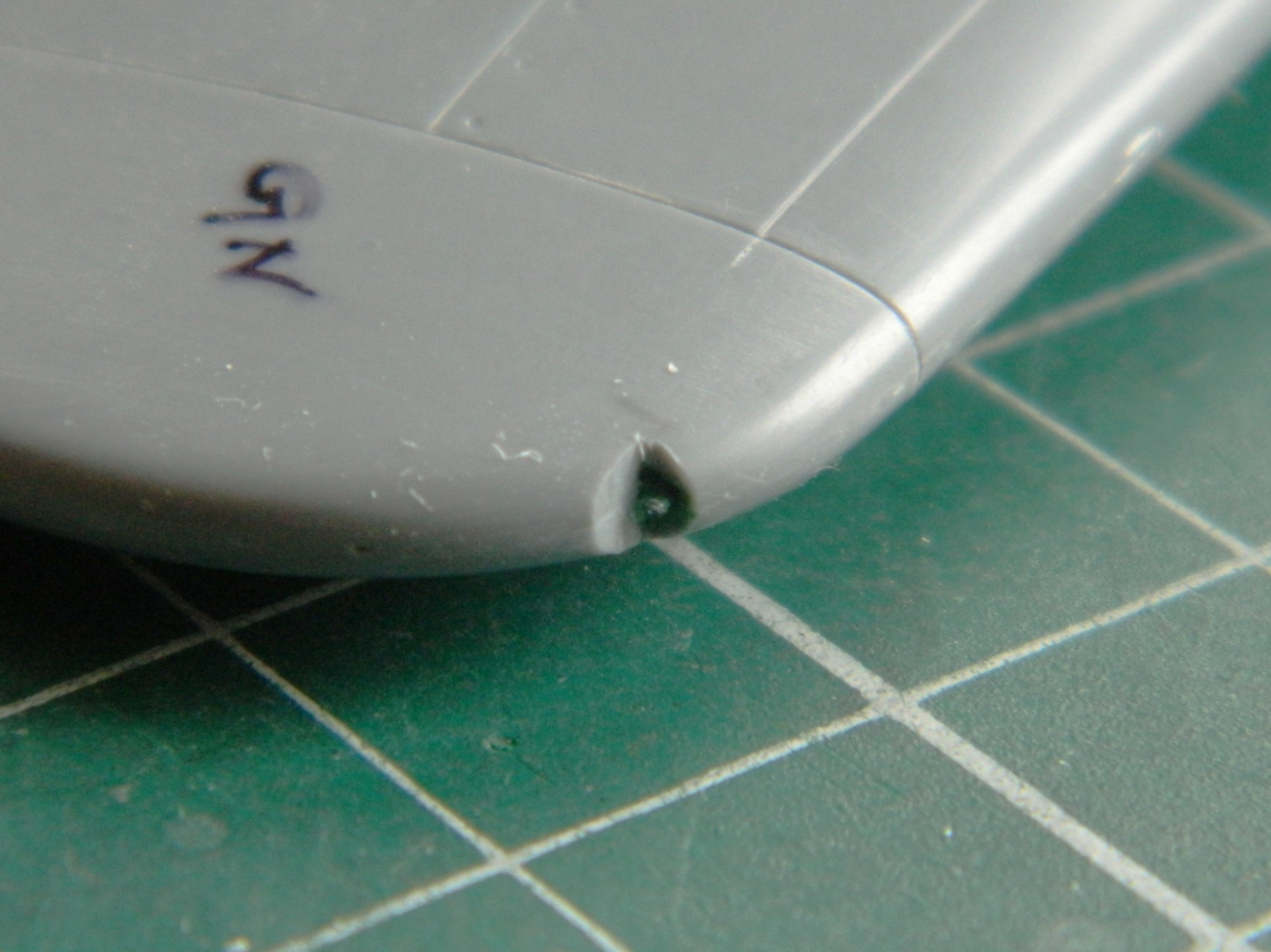
Many of the recessed panel lines were VERY shallow. So with the explanation of what a recessed panel line is in the die, what I think I’m looking at with these shallow panel lines is someone (or several) got sloppy polishing the dies. While I was working on the wing, I was reminded (like I needed it) of how dissatisfied I was with the paint job on the F7F-3 Tigercat because of too many surface imperfections found too late (because I really, REALLY, didn’t want to strip the paint off of it and start over), I decided that even though self-inflicted wounds are wounds, sometimes I can manage a modicum of control over the Self (always a joyous surprise) and this was one of those times.
This specific kit has obviously been sitting around for a long time. All the parts that are not clear parts were stuffed into the same plastic bag. So for a long time, these parts have rubbed against each other which leaves scuff marks of varying sizes. Doing the Tigercat, I’d mistakenly assumed that those surface imperfections wouldn’t show after painting. As I found out, I was definitely mistaken. I worked the wing, applying 3M Acrylic Glazing Putty to the small scratches and gouges left in the surface after my far from perfect scribing. Once those had been sanded down with 2000 grit, I sanded most of the wing the same way. Once that was all done, I polished the wing, top and bottom, to get a uniform, scratch-free, surface:
Evidence of how well I don’t scribe:


Box wear on the surface before polishing:

And with the box wear polished away (aka, After…the long form):

With construction (hopefully) done on the wing, I turned my attention to the fuselage to check fit. Essentially, there isn’t any.
All these surfaces are supposed to be in contact with each other:

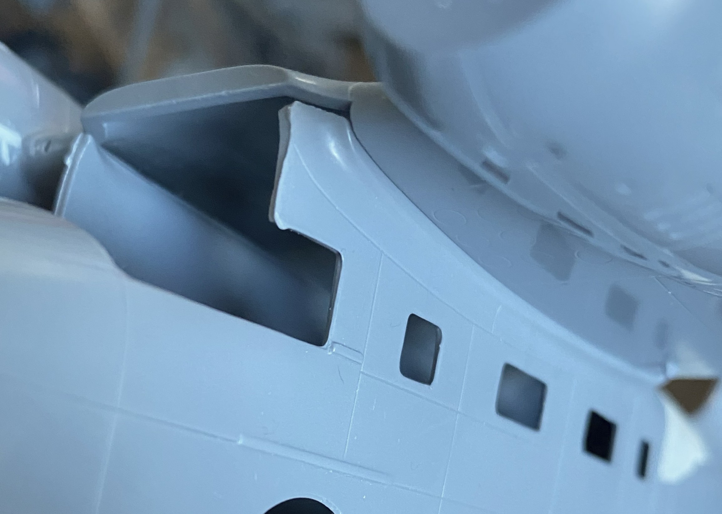
Obviously, not only is the gap between wing and fuselage not supposed to be there, the curve of the lower wing is supposed to match with the curve of the wing root on the fuselage, neither of which are happening here:


Fit is minimally “better” (aka, not as bad) at the rear where the wing blends into the upper fuselage:

If you look closely at the above photo, there is a recessed (sort of) panel line below the fuselage seam. This is what happens when someone polishes away the ridge in the die. There’s a lot of that with this kit.
I can see my stock of scrap styrene dwindling soon.
And if I thought that was bad, I checked the (absent) fit of the canopy. It was cast as two pieces (something I think will be a benefit for me when I start making the overhead console), so those pieces were taped together and I tried fitting it. This is the best I managed:
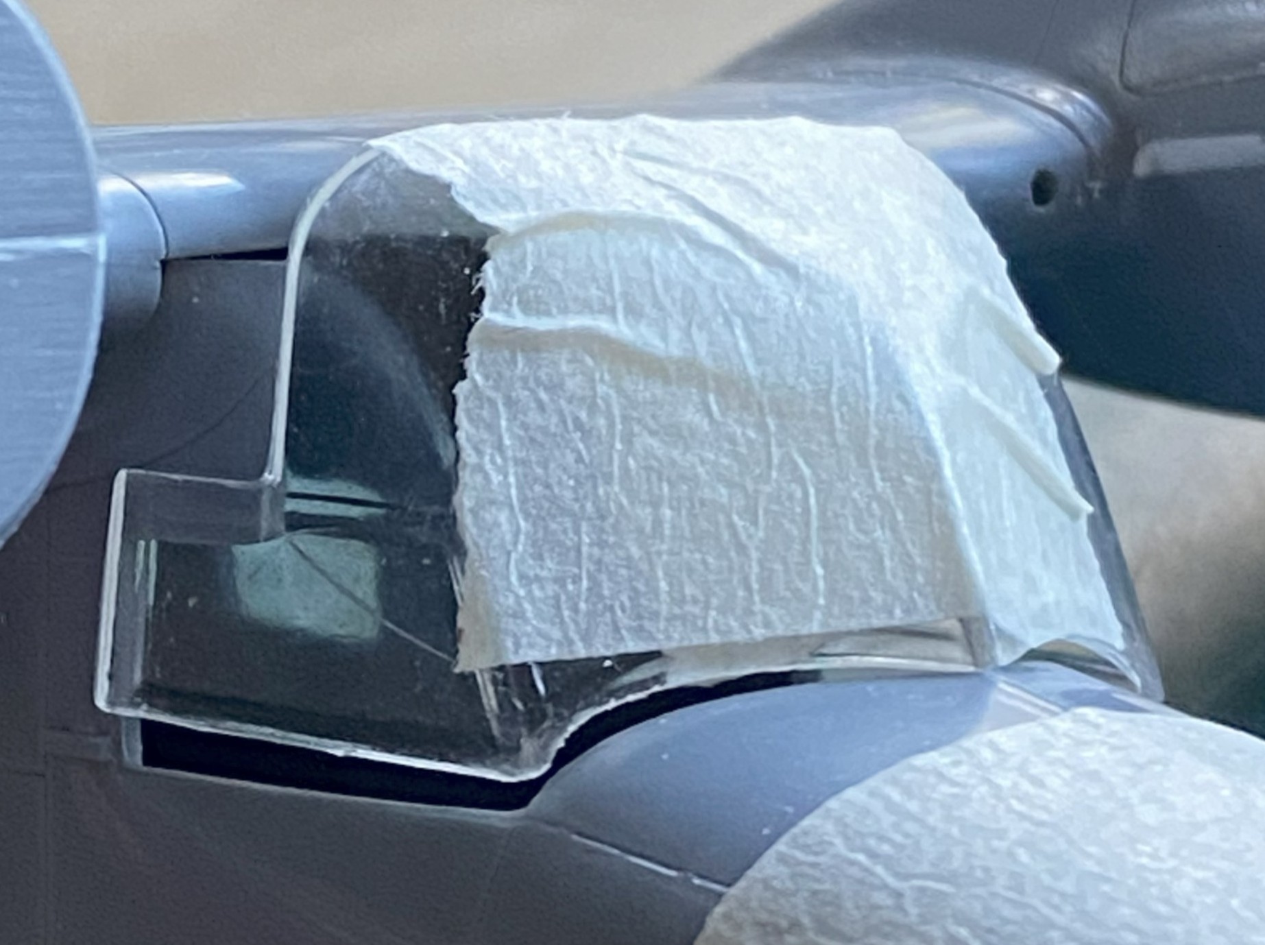
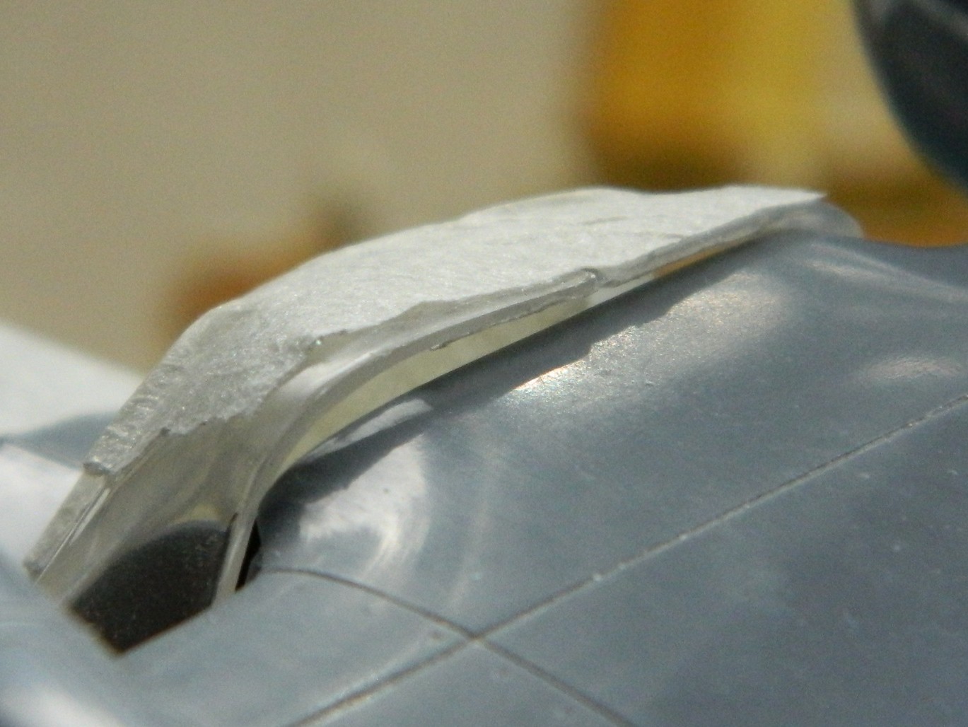
And I figured out why. Look for the blue arrow in the photo below. That shows the overhang of the upper wing. Not only are all these parts supposed to be in contact with each other, the overhang (because that’s what it is, it’s not a parallax view) shouldn’t be there AT ALL:

I won’t know until that overhang is removed but I wouldn’t be surprised if its absence goes some distance to allowing the clear parts to fit (all terms being relative).
And speaking of clever engineering (in the most sarcastic manner I can), would it have broken someone’s back to put the ejector pin mark on the side without any detail…like the flip side of this part? No…it’s not the most labor intensive part of this build…it’s just unnecessary:

And there was one of each of these on both inside the passenger compartment walls. No…none of them stick out in the view, but how many of you have seen someone look at your build(s) without getting just as close as you’ll let them? I know SOMEbody will crank their head around to look through the windows (a row on both sides) and look in there. If I left these as-is, they’re clearly visible:
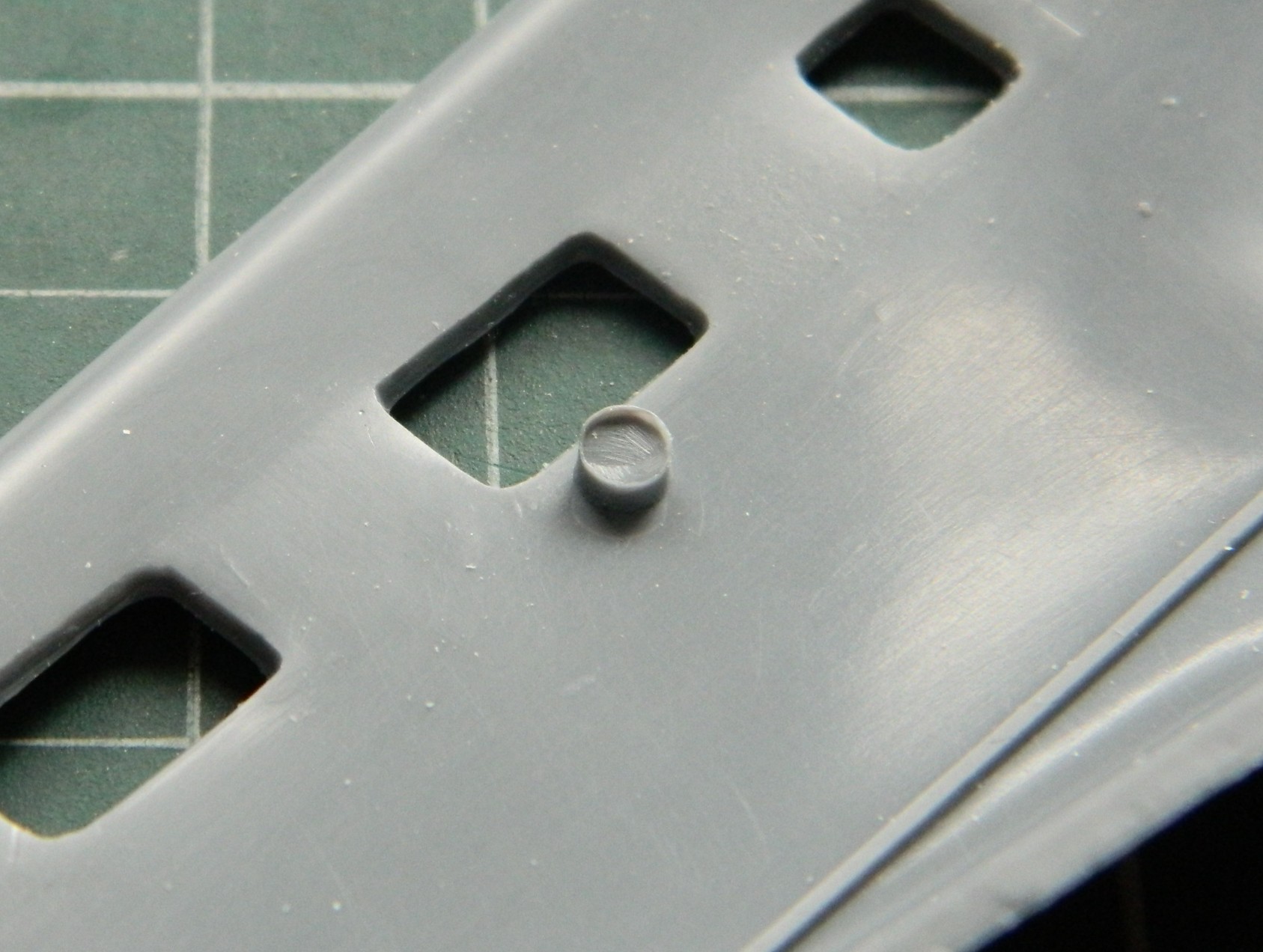
::facepalm::
And speaking of fit (which I had shortly after the first time I saw this), these two parts are supposed to MEET. The part on the left is the fuselage just in front of where the windscreen mounts, and the part on the right is the back of the instrument panel. Both have convex meeting surfaces! Gosh…I wonder why there’s a gap!:

The landing gear bays were molded as separate parts so they had to be, well, fit. Yeah. [INSERT REOCCURRING WHINING ABOUT FIT HERE] I got them as good as needed to get them mounted and glued on, figuring whatever tweaking was needed would get done later (and later I will let you know how that went).
The resin parts, with the exceptions of the engines that I used, not the resin engines that came with the kit, were supplied by True Details. I am not a fan of that company. I’ve only ordered something from them three times. Each time I was disappointed when the goods arrived. I can’t recall, though I’m sure there must be, times that I didn’t have to rework their detail parts (and their “bulged” tires? They usually look about half deflated). This time was not an exception.
These are the side cockpit details. The thickness that would result if I’d just glued them in like that is even thicker than the armor on a Sturmovik…which this is not:
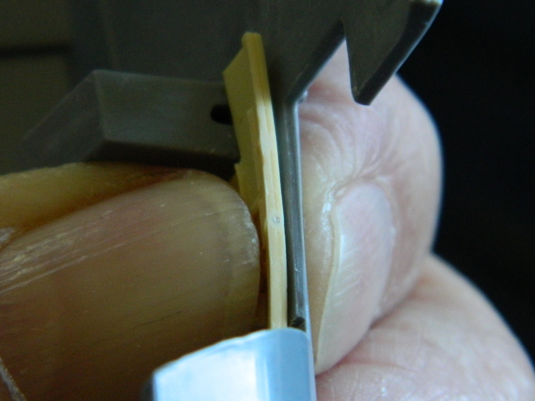
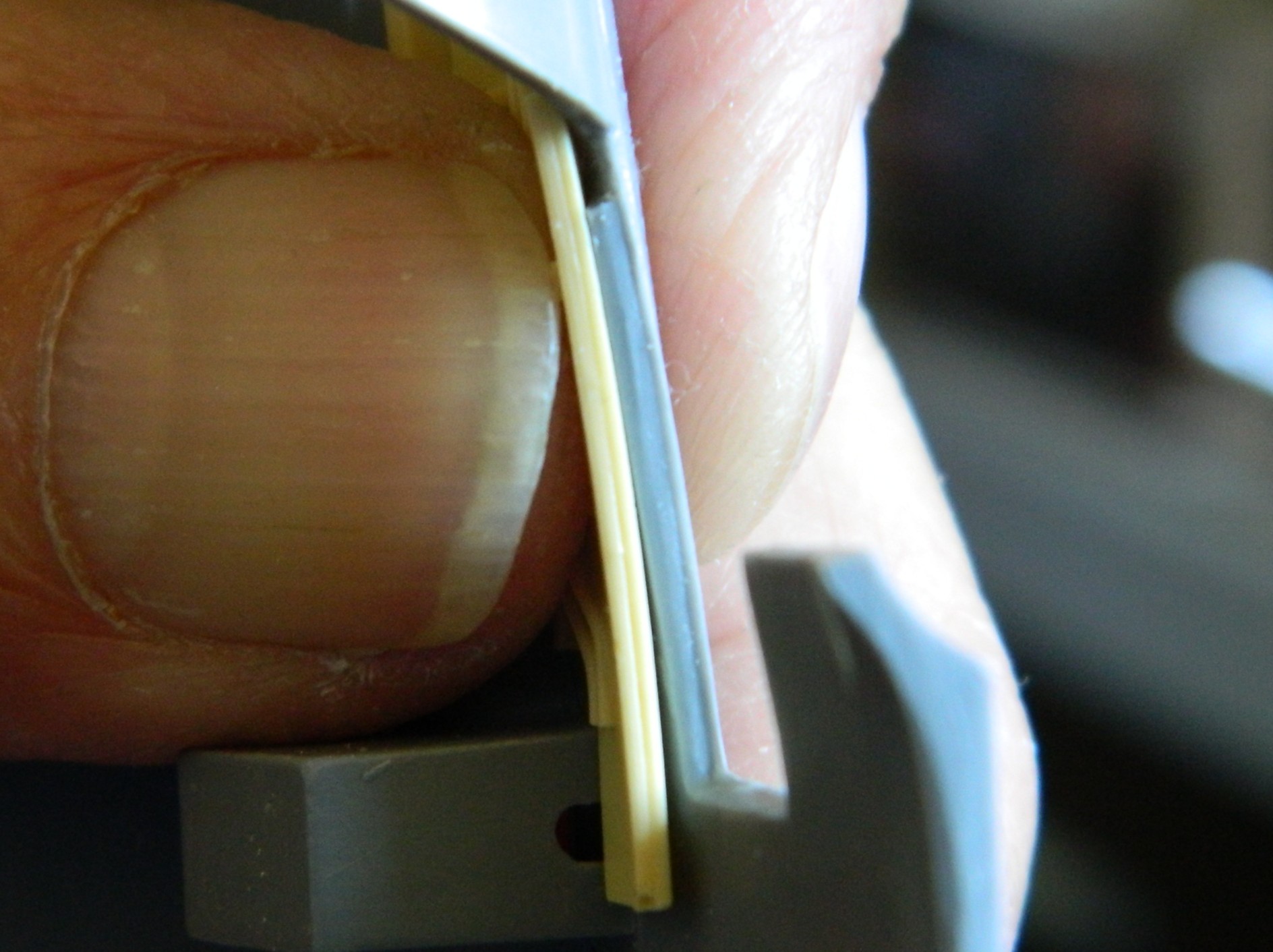
With such thick plastic in the kit, it made more sense to thin the sidewalls of the kit instead of trying to thin the resin part; I had more to work with. It’s still a bit thick but will have to suffice.
Also note the right end of that resin panel. Where the panel ends is where the bulkhead at the rear of the crew compartment fits. Look closer and you’ll see that the molded-in wiring conduits end well before they should. In fitting the other resin panel in wasn’t much better. See where the box and wheel well arch meet? True Details didn’t mold that box the way you see it. They’d molded it square…which kept it from fitting. That it fits isn’t because of their work:
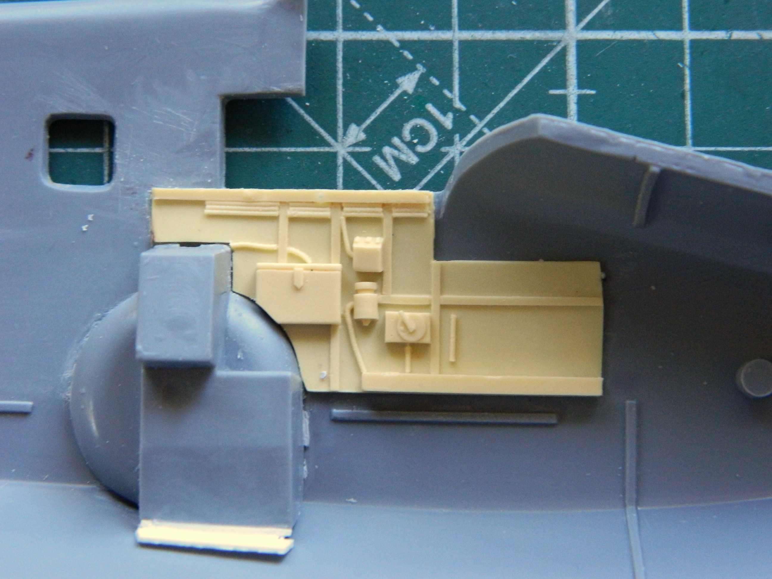
After much scraping, sanding (100 grit!), more scraping and more sanding, they’re now in there permanently. Next task was to fit the floor, which included the forward bulkhead and the rearmost bulkhead (with the ejection pin gone and the door’s panel line scribed):
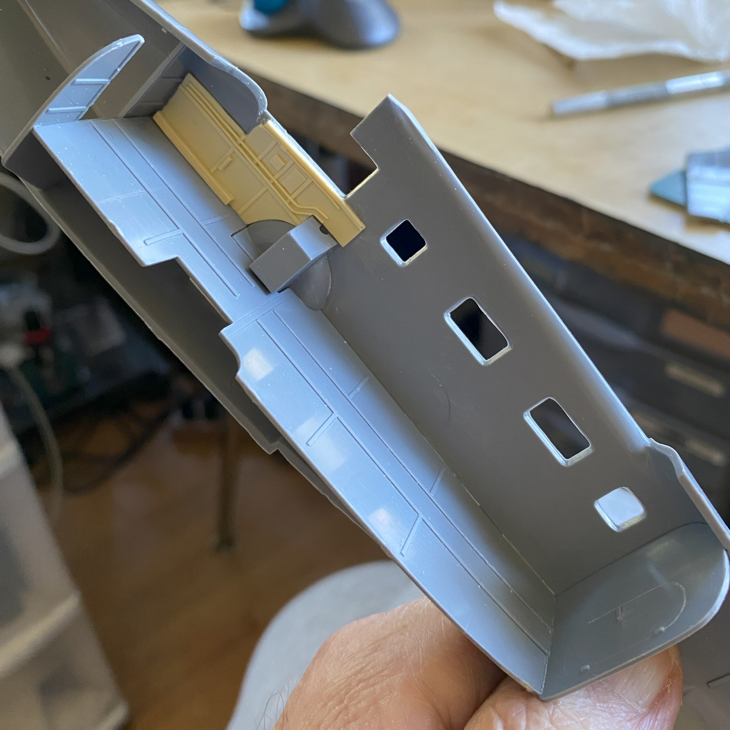
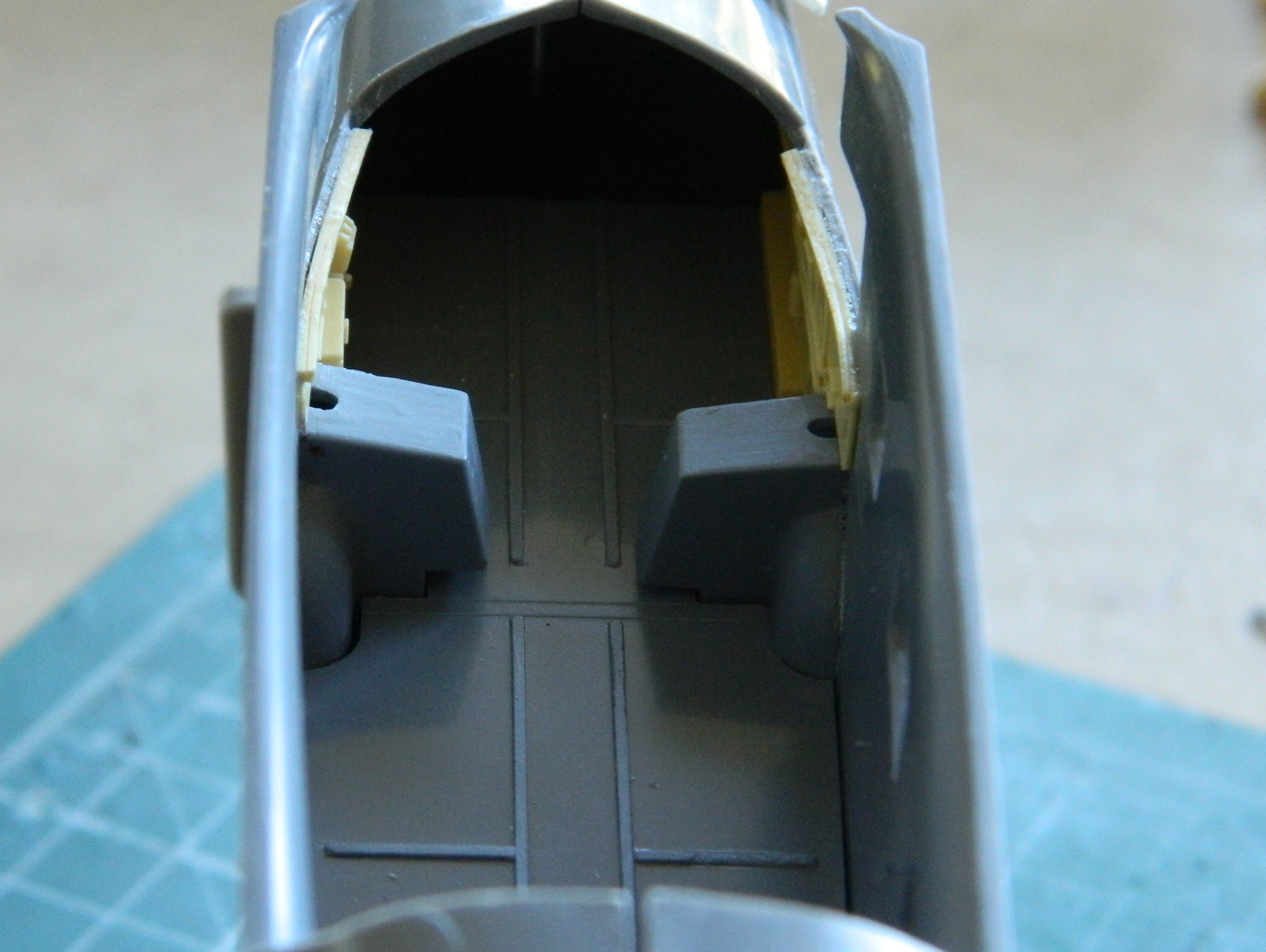
True Details also supplied four seats for the passenger compartment as well as the crew’s seats. The passenger seats:

The crew’s seats were molded separately from their mounts. Once all cleaned up and attached to their mounts, I ended up with these:

The tail wheel has its own bulkhead with mount:
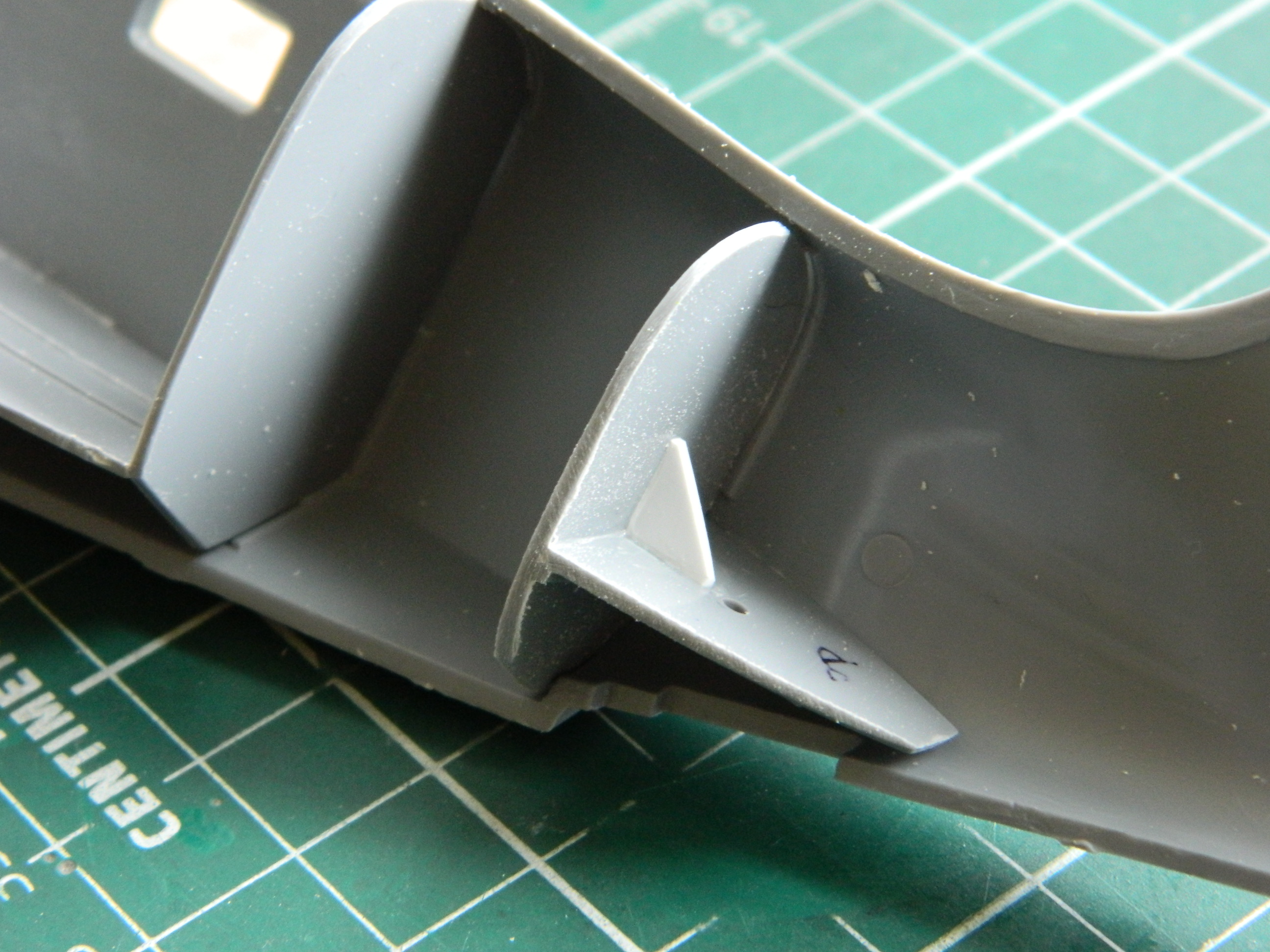
Attempting to dry-fit the other fuselage half led me to my next episode of fun. The other half wasn’t even close. It took several days of “fun” to find all the areas of the bulkheads that were keeping the halves from meeting and trim things down so that I can, in fact, attach the other half of the fuselage later. Five hours of sanding, fitting, filing, sanding, filing, fitting ensued. But it all now fits together.
I decided to have more “fun”. I wish I’d remembered to take a “before” photo. The tail wheel is molded as one with the landing gear. Poorly. BADly. Miserably. I spent a couple of hours carefully creating the illusion (I hope…I won’t know until it’s painted) that the two are actually separate:
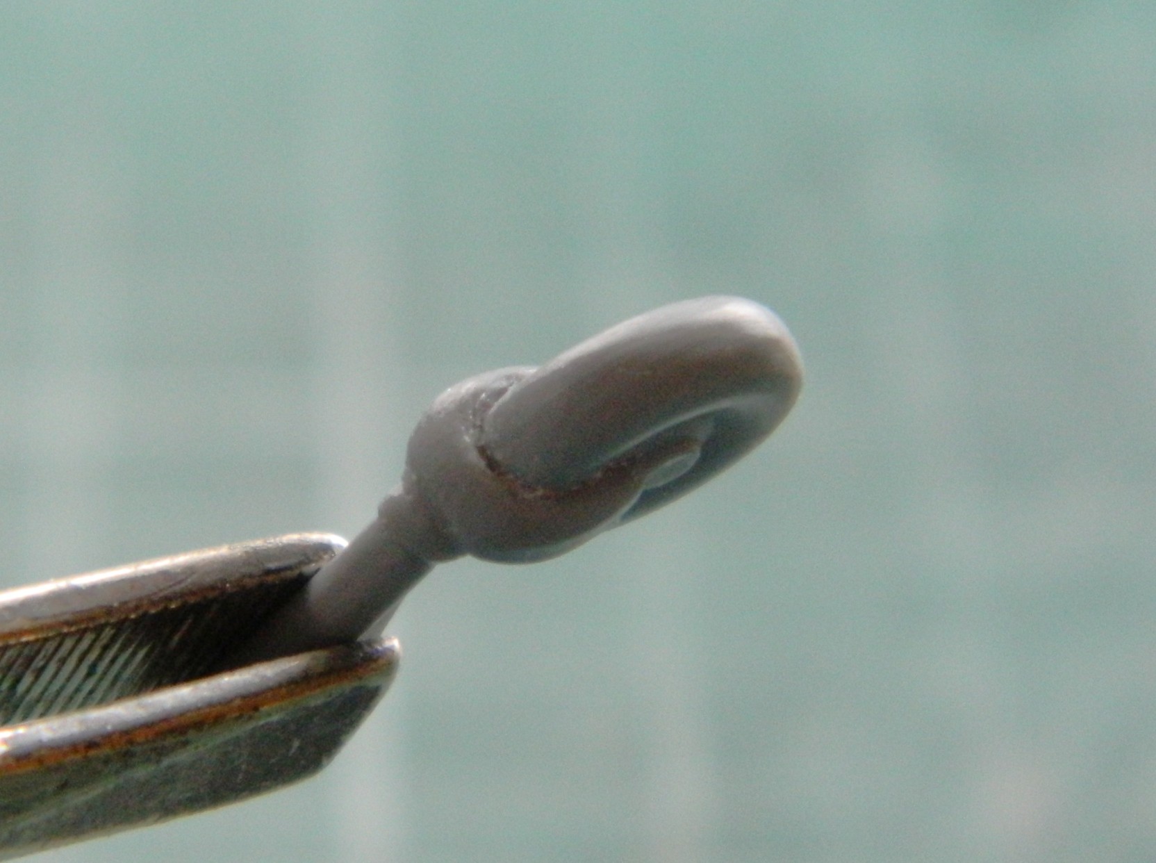
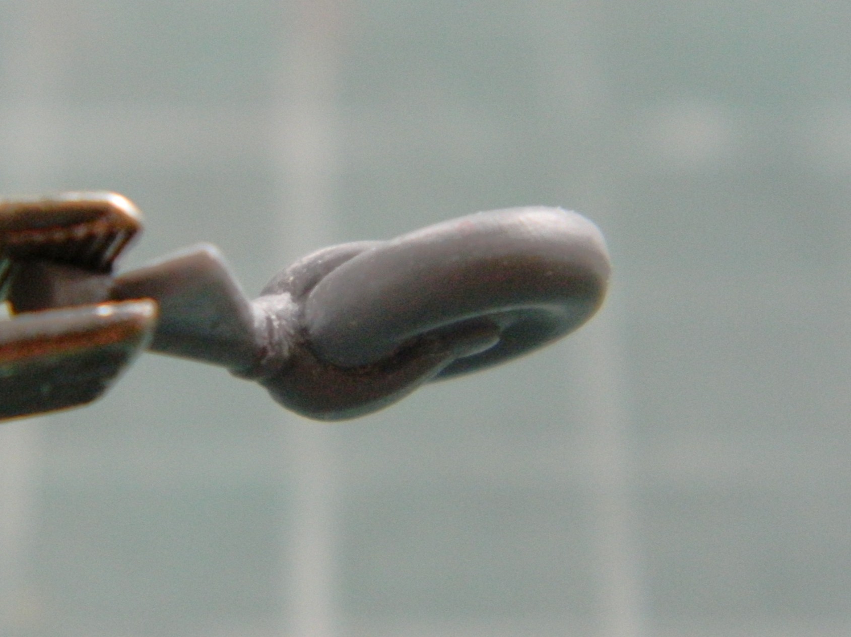
The rear bulkhead followed the cockpit side panels with their missing details so I fixed that using 0.015″ (.381mm) solder and standard kitchen aluminum foil as retaining straps…because True Details is obviously fine with putting in details that just end somewhere. Also, note the box with the added-on opening. That’s how they molded it. But to get to fit with their own damned parts into the cockpit, the lower left corner had to be modified. I also added 0.010″ (.254mm) clear to the porthole in the hatch:
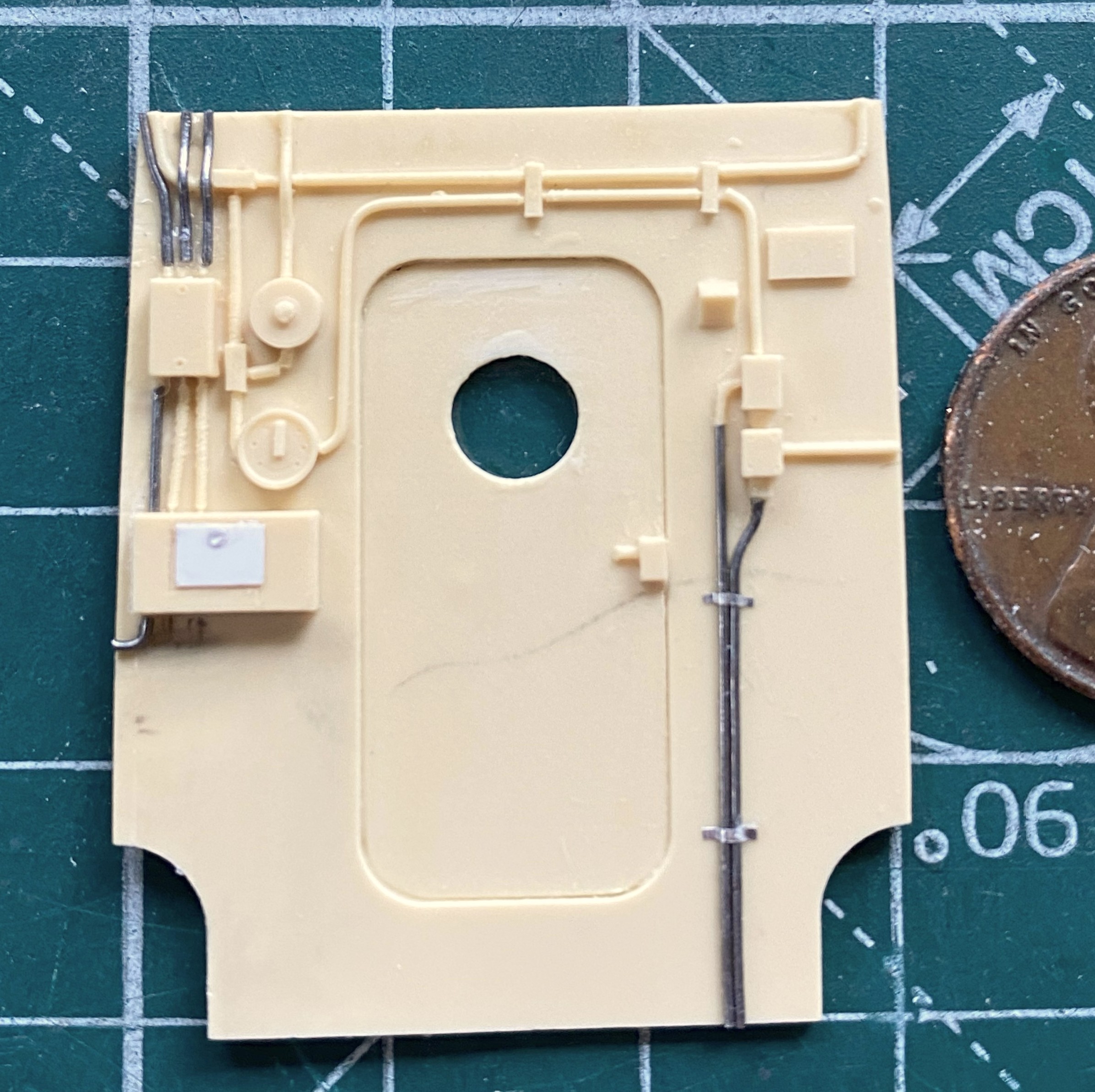
Notice how the left edge of the partition doesn’t seem quite square? It’s not an illusion or camera artifact. It’s. Not. Square. Another bridge to cross relatively soon.
I got to the next step in my traditional manner. Painting is what’s now driving this bus. Before I can marry the fuselage halves, it must be painted. I prefer pre-shading to post-shading. So before I can shoot any color, I need to throw down the shaded areas. Tamiya XF-1 Flat Black:
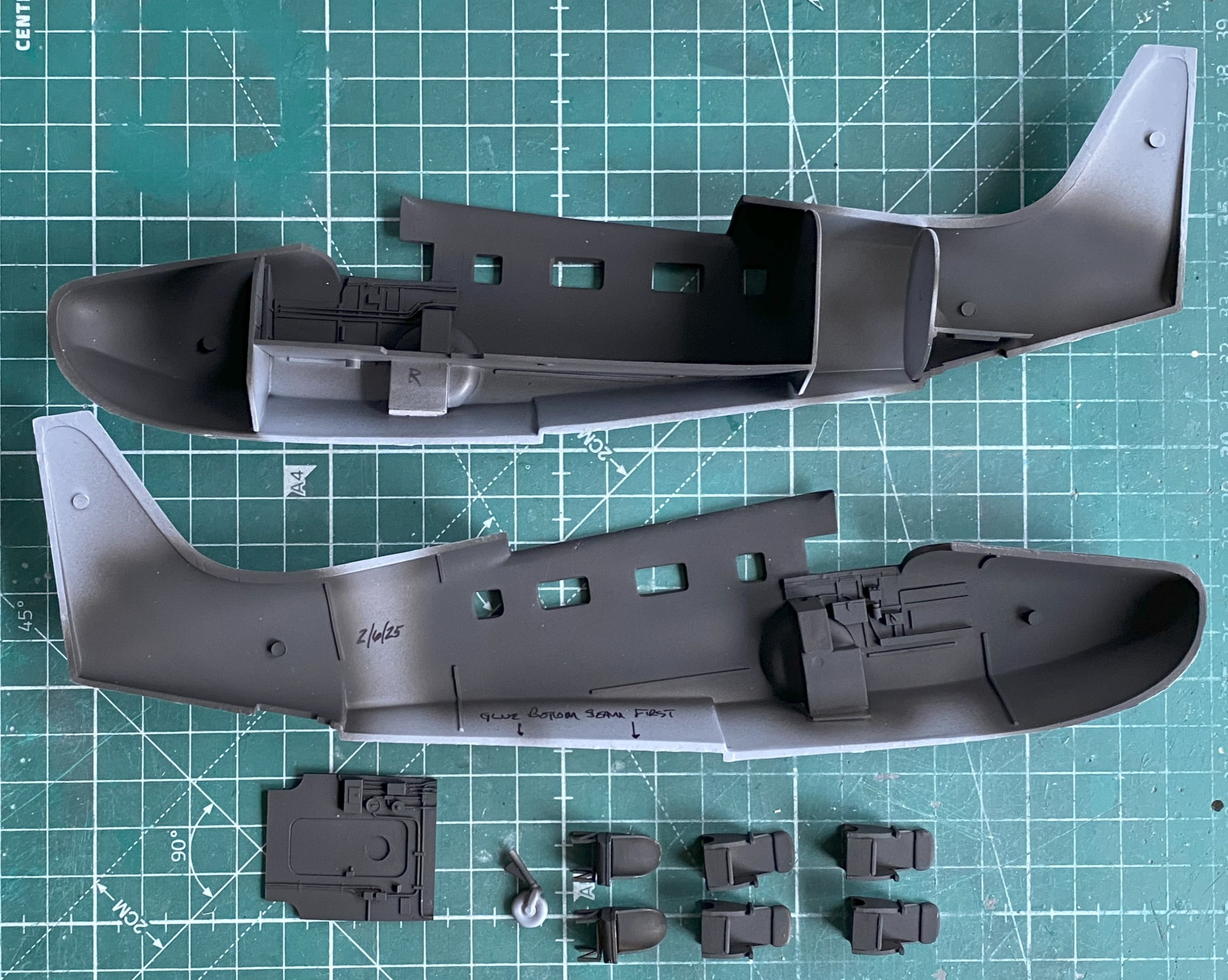
I’ve read three different build reviews. Most of my gripes with this build involve things I was forewarned of, though I am surprised at how badly things fit, I wasn’t unaware that FIT SUCKS. Of the three build reviews, only one mentioned the landing gear. The builder called it “finicky.” Talk about understating a situation!!
I checked the instructions and references to make sure that the landing gear supports were going to the intended side (because the Tigercat build showed me that knowing right from left is still not my forte), and tried to dry-fit them. Without hyperbole (which I really, really want to indulge in), as molded they can’t fit. I tried everything I could think of (or even suspect) to get these parts to fit. They don’t. Then I did something that saved at least 3mm of stomach lining. I checked the landing gear doors for fit. You know, the part of the aircraft that would fit to fill the openings to the landing gear bays. What I found was wrong…wrong, wrong, wrong. I’ll show you the photos first.
This is what things looked like at the start:
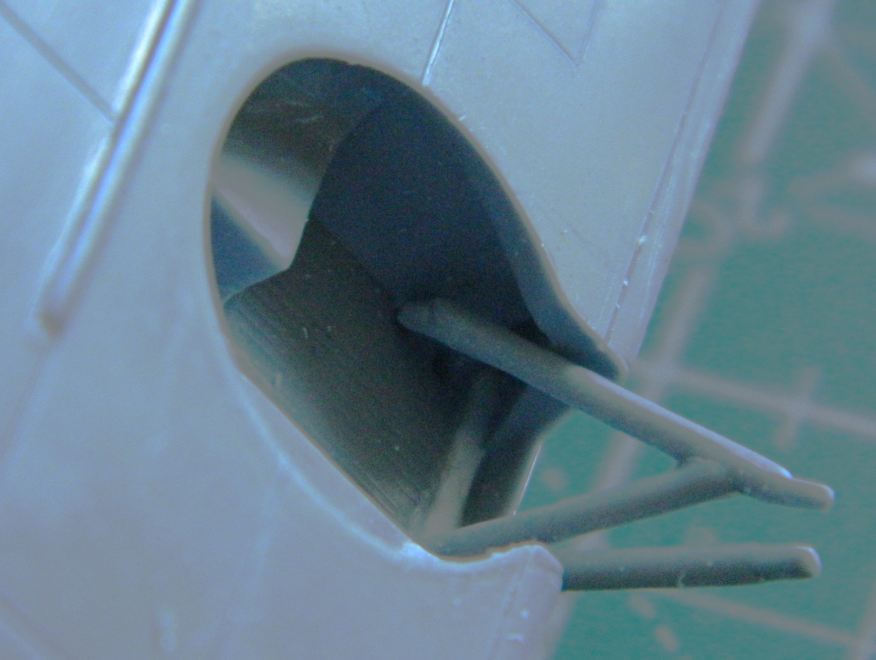
Note the uppermost strut. It’s in contact with the plastic of the fuselage but not one of the very few molded-in attachment points (of the entire kit) where the struts touch the inner landing gear bay. Doesn’t fit. Then I cut away the part from the sprue that would close the side and bottoms of the landing gear bay and compared it to the opening the kit provided for it:

Pencil didn’t last long enough and even the sharpest marker was too thick, so I used a scriber to outline the limits of the hole I had to cut:
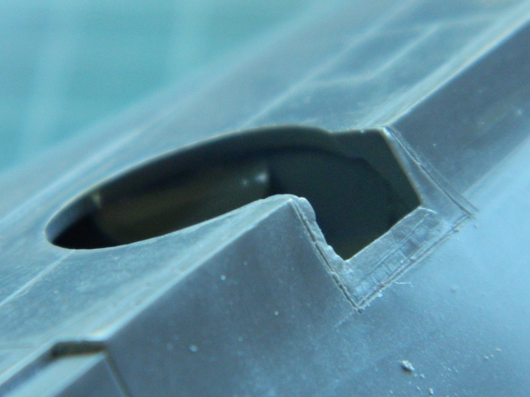
See those faint outlines of the fuselage on the bottom (which is in the above photo)? SOMEbody knew that that should have been cut away from the die, just not the guy (or gal because incompetence isn’t gender related) who cut the die.
So I did their job for them (which, really, is for me):
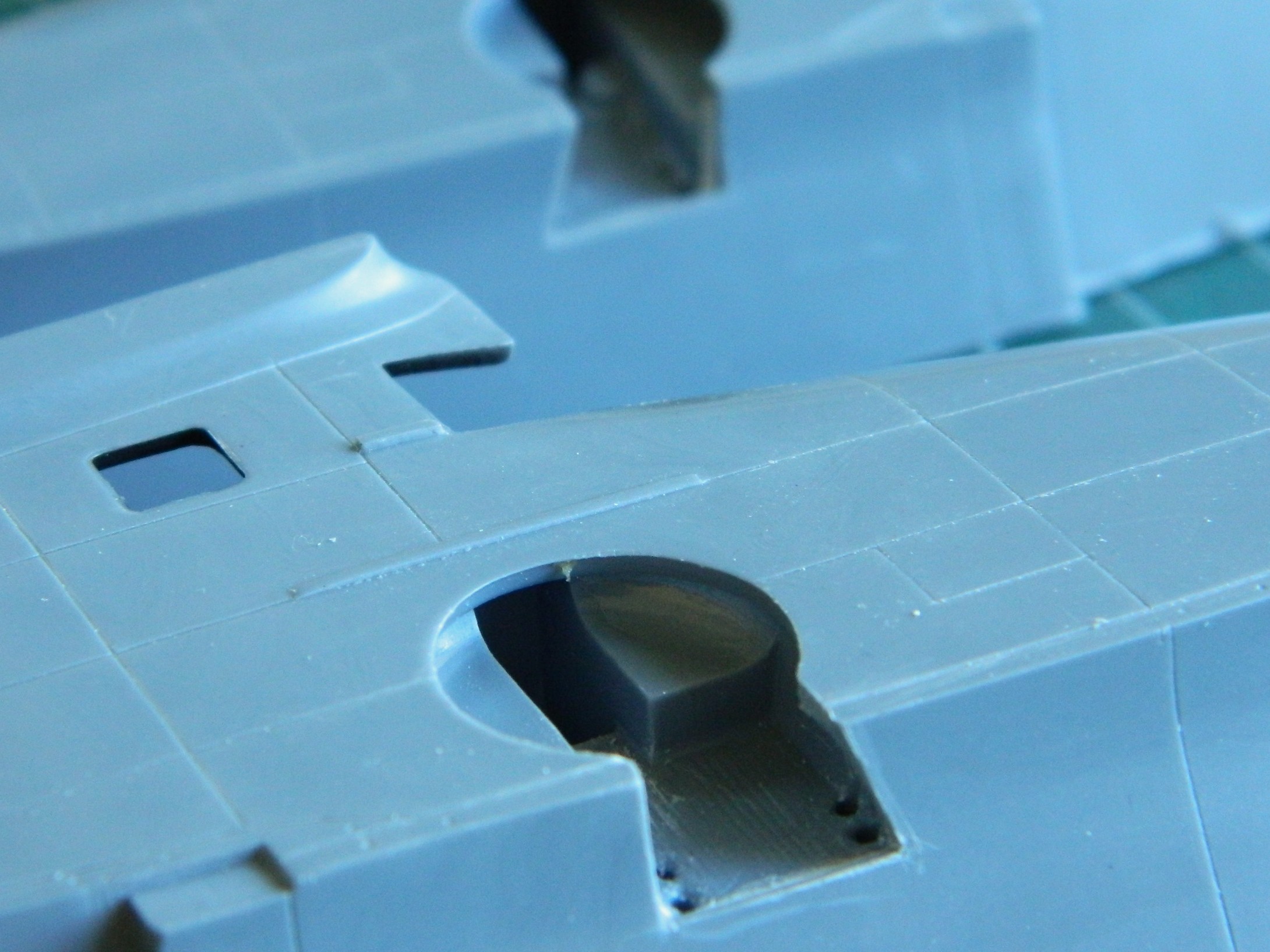
Not only do the parts fit now, in the bottom photo you can now see the attachment points…and the struts fit!
Now the landing gear doors look too thick (because they are too thick). The parts are so small that I knew trying to thin them out to a less out-of-scale state would reclaim those 3mm of stomach lining. I decided to scratchbuild them using 0.010″ (.254mm) scrap (yes…the part I’m making is held in place by double-sided tape):
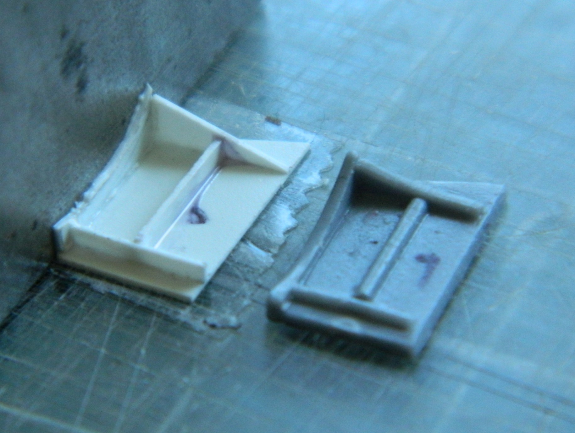
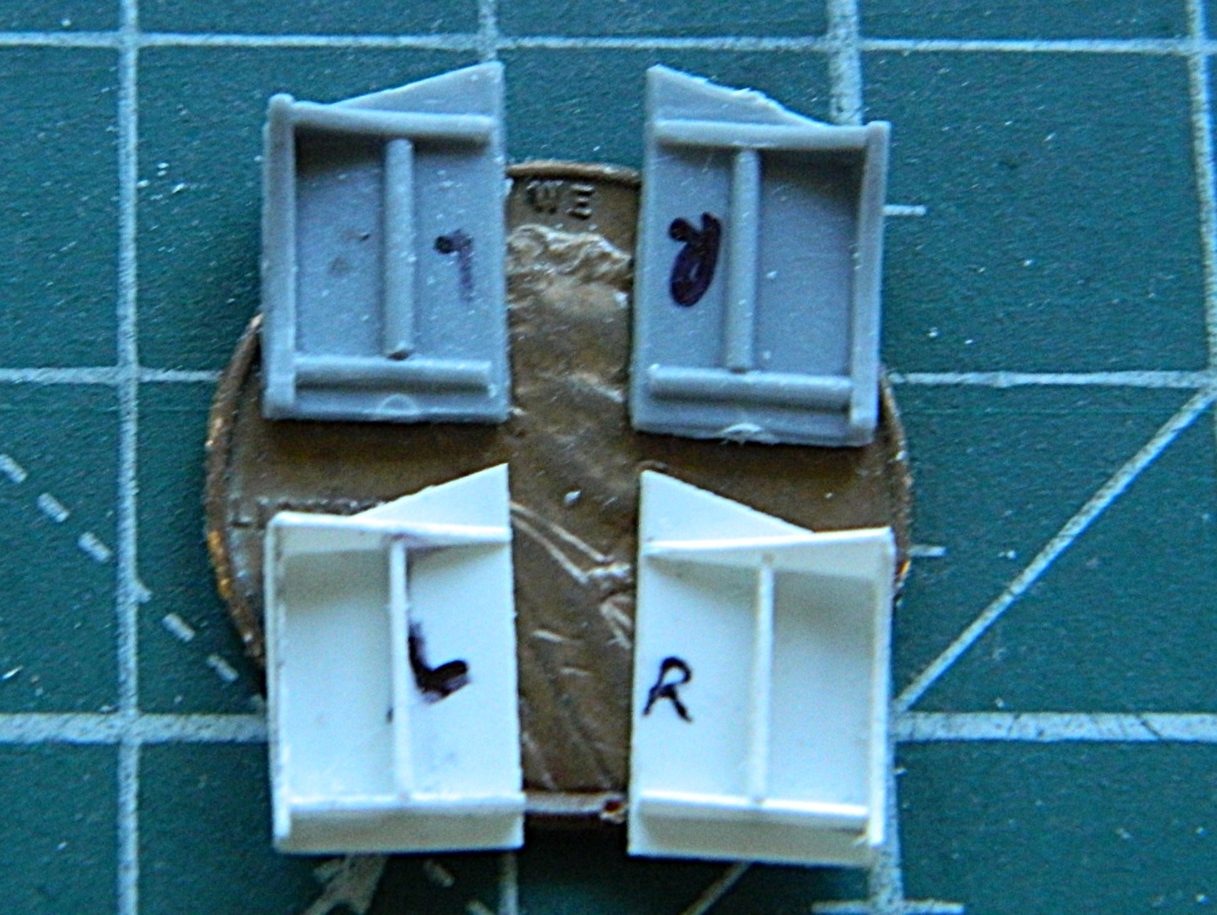
Next step in marrying fuselage halves is to get the instrument panel to fit. That’s going to be a chore. In order to get it to fit, I have to attach it (where it can be attached, anyway) to a fuselage half to begin filling the gap. But before I can do that, I have to paint it now while it’s easy to get at. I tacked a bamboo skewer to its back and applied the base coat of Tamiya X-18 Semi-Gloss Black:
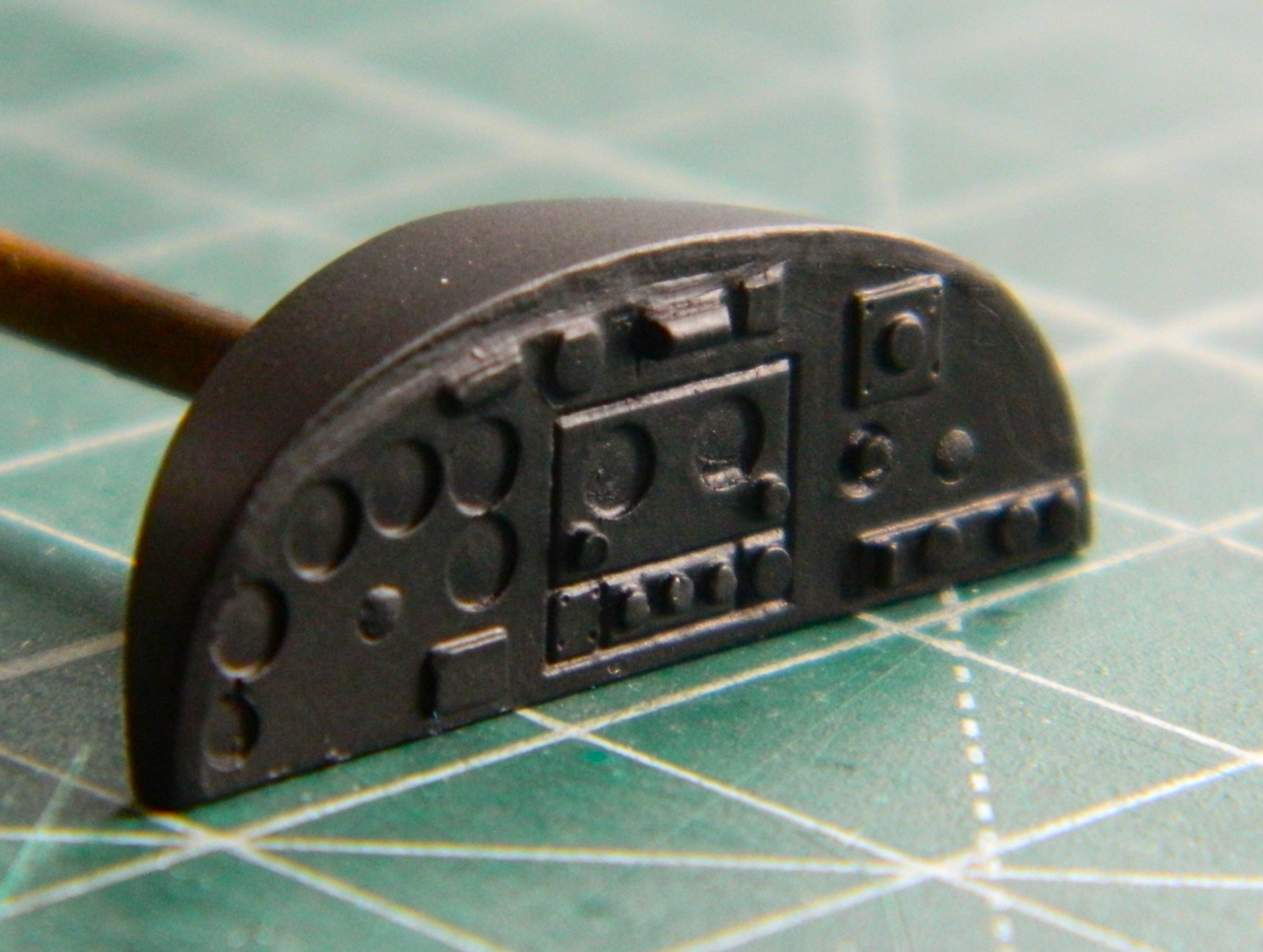
There’s a chance that the uppermost gauges will be visible so next month will also entail me adding either transfers or decals of instrument faces to them…but before that, I think I need to paint what parts/assemblies I have under black with chromate green.
Grumman JRF Goose (Czech Model) 1/48 Scale Build #1 – Parts Layout and the First of Much Work Begins
This was what was in the box:
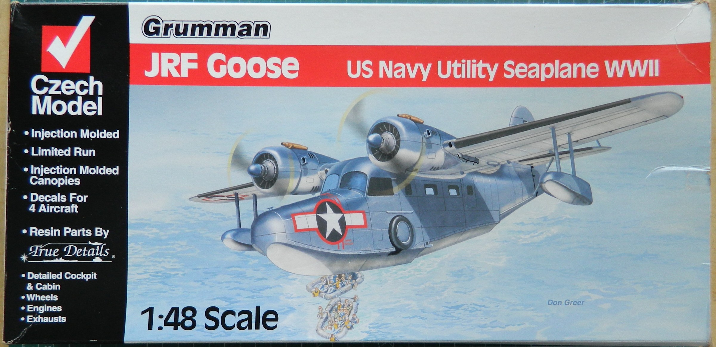


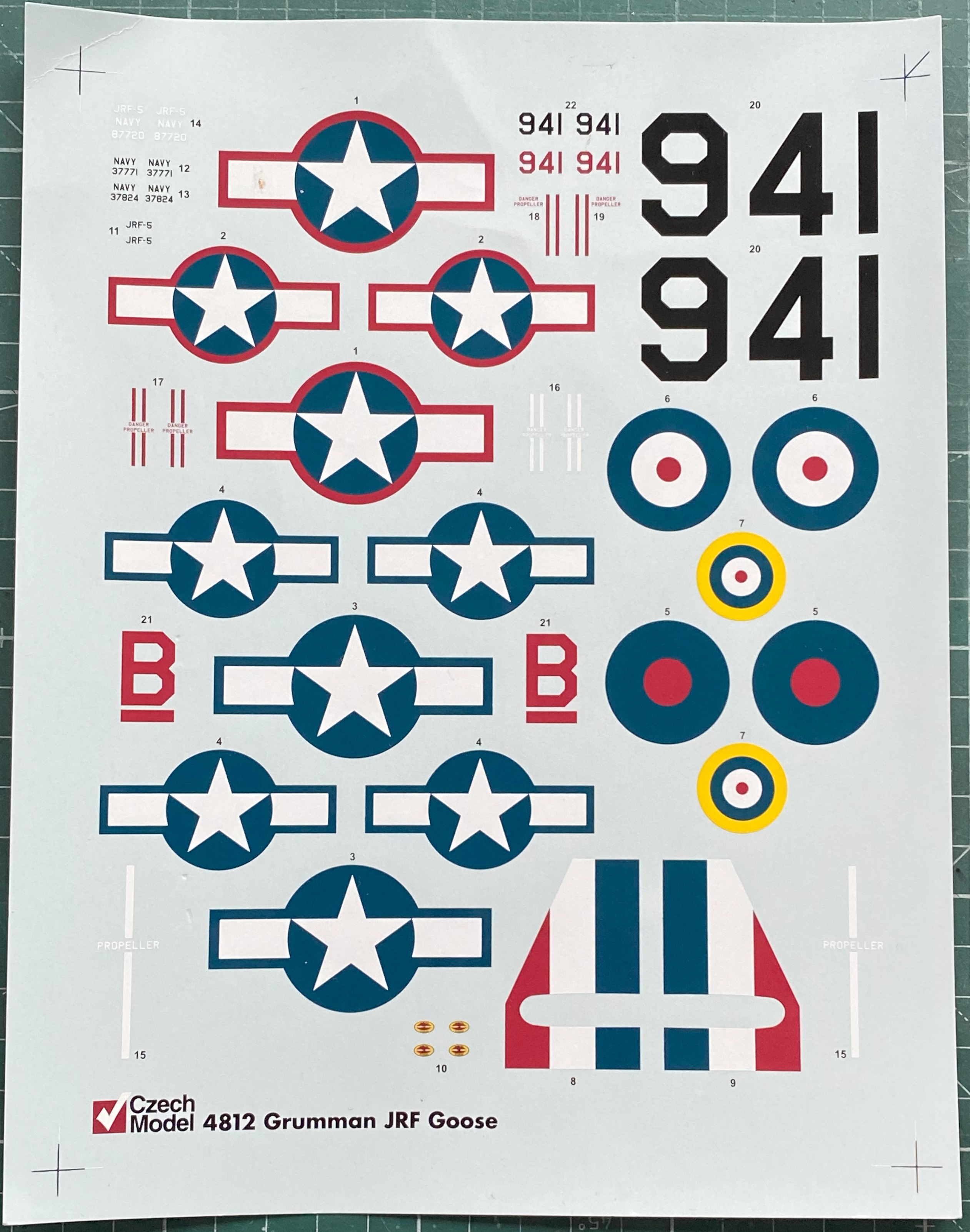
Plus these engines from Metallic Details:
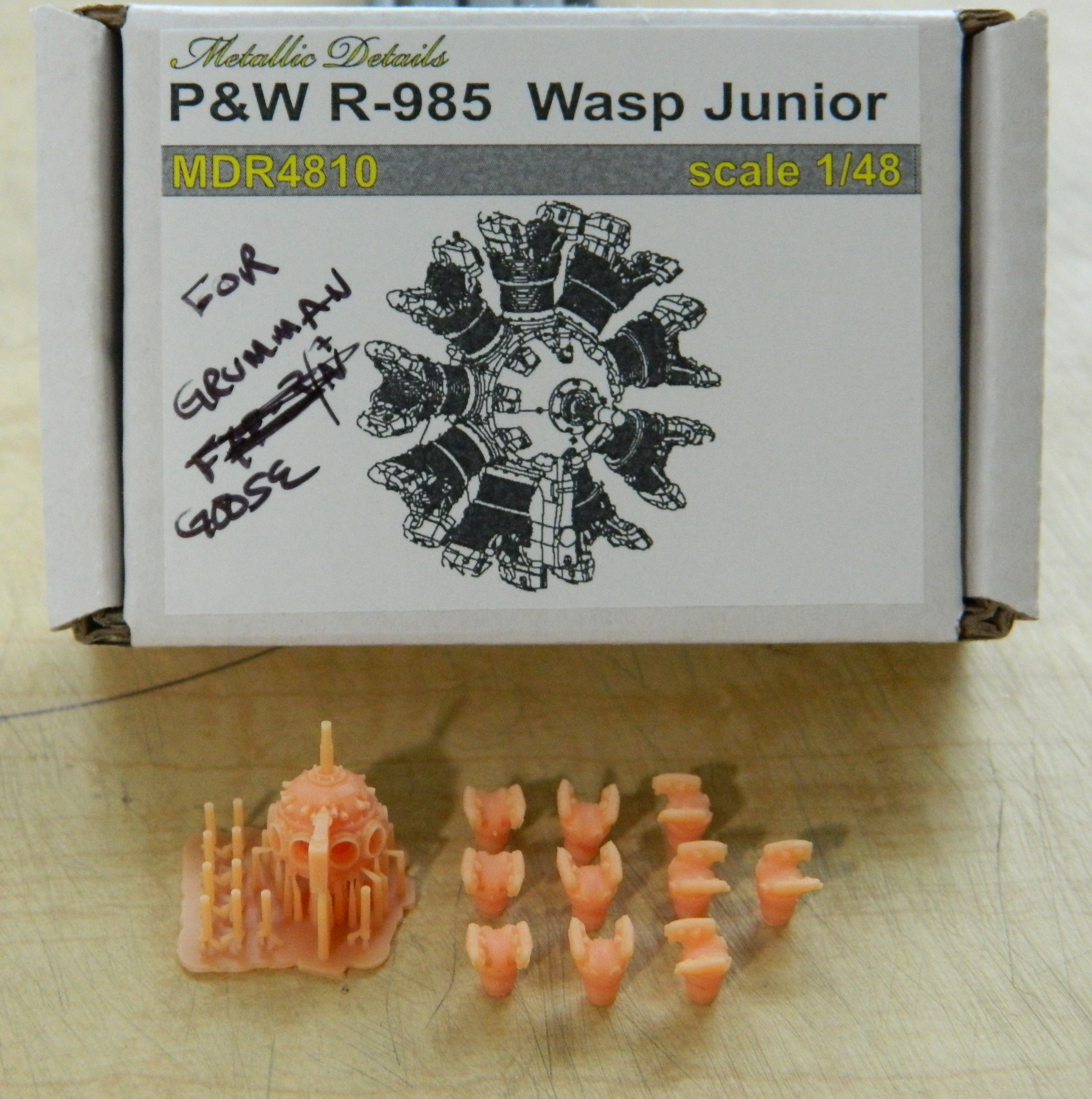
It’s my intention to build this one in its 1944 markings, which means using the national insignia without the red borders. In researching this kit and reading build reviews, the theme here is “limited run” with all that that implies. Thick plastic, subpar fit, and oddly done details. Construction so far has confirmed all that. In one regard I’m getting off with less fiddly work than otherwise would have been the case. Being a high-wing aircraft, that wing gets in the way of seeing the into the cockpit, specifically in this case the instrument panel. So that’s one chore I don’t have to take care of. There were overhead consoles that engine monitoring instrumentation was mounted in as well as throttle and propeller pitch controls. Though the overhead console has to be scratchbuilt, few of the details are necessary since it really can’t be seen. I don’t know how much of the console itself can be seen so the overall shape of it needs to be build, if only to hang the throttle controls from (and maybe the pitch controls as well, which I will find out about later).
My typical build routine is to start with the cockpit first, but since so little of it can be seen (not the same as none of it since the rear bulkhead of the cockpit will clearly be seen), I decided to start with Metallic Details’ engines. I was about to get a “learning moment” about these particular 3D printed parts…and maybe 3D printed parts in general. If you’ve ever done work on or with as-printed parts, you’ve seen the miniature forest of supports that are necessary for the part to print at all. Those all have to go. I thought I was being careful removing those supports (can you see where this is going?) and for the most part, all went as intended. There is a Mystery Component that is attached to the bottom of the crankcase and hangs straight down. Let’s play a little round of the, “Can you spot the differences between these two things,” game:

If you said, “The Mystery Thing is missing from the one on the right,” you win. While removing the supports underneath the missing Mystery Thing, I discovered that this resin is very brittle. The Mystery Thing just snapped off. And not unusually in my shop, I heard it hit the floor and using my Echo Location ™ ability, I went to where I heard the Mystery Thing hit. Maybe that’s where it hit, but that’s nowhere near where it ended up… I mean, this is my first task and it’s gone sideways. (I never did find out where it ended up.) Fine. I’ll make another one, then:
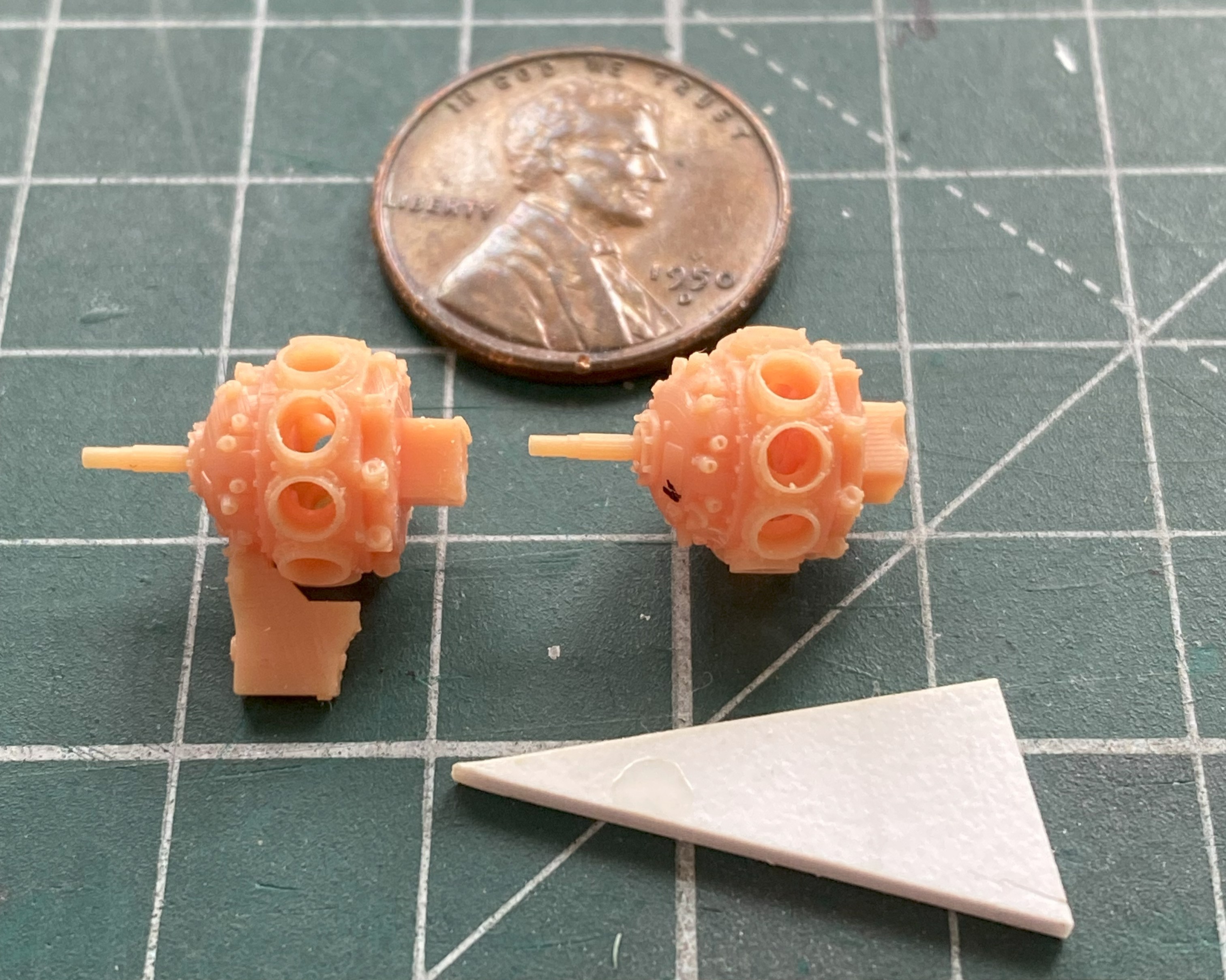
I was so annoyed at myself for losing a component as part of my first task that I decided that I’d get all the parts of these two engines cleaned up and ready to assemble (or paint…more on that later). That’s when I found out that just because it’s 3D printed, doesn’t mean that the parts that were designed to go together will in fact go to-fucking-gether. The outer diameter of the cylinder jugs (hereafter referred to simply as “jugs”) is exactly the same as the inner diameter of the holes in the crankcases where they’re supposed to go. That means that there isn’t enough space in those holes for the jugs TO go into. [A note to those of you who design and produce these sorts of things: Test fit the goddam parts before you sell the goddam parts.] In order to get the jugs to seat into the crankcases correctly, I had to shorten them (because when I didn’t, each stub at the bottom of the jugs interfered with all the other jugs, preventing any of them from seating properly), and then take my thinnest knife which just fit into the sockets and carve away the GOD DAMNED LIP MOLDED INTO THE BOTTOM OF THE SOCKET! No…not pleased.
Nine jugs per engine and two engines. Holding these small parts with sharp protruding areas right where the fingertips hold them so that the stubs can be shortened and filed to decrease each diameter results in very, VERY, sore fingertips. Once those essentially needless tasks were accomplished (I say, “essentially needless” not because I didn’t have to do the work…because I did…I said it because if whomever had laid out these parts digitally had done their job correctly, none of this work, or sore, VERY sore, fingertips would have been required):
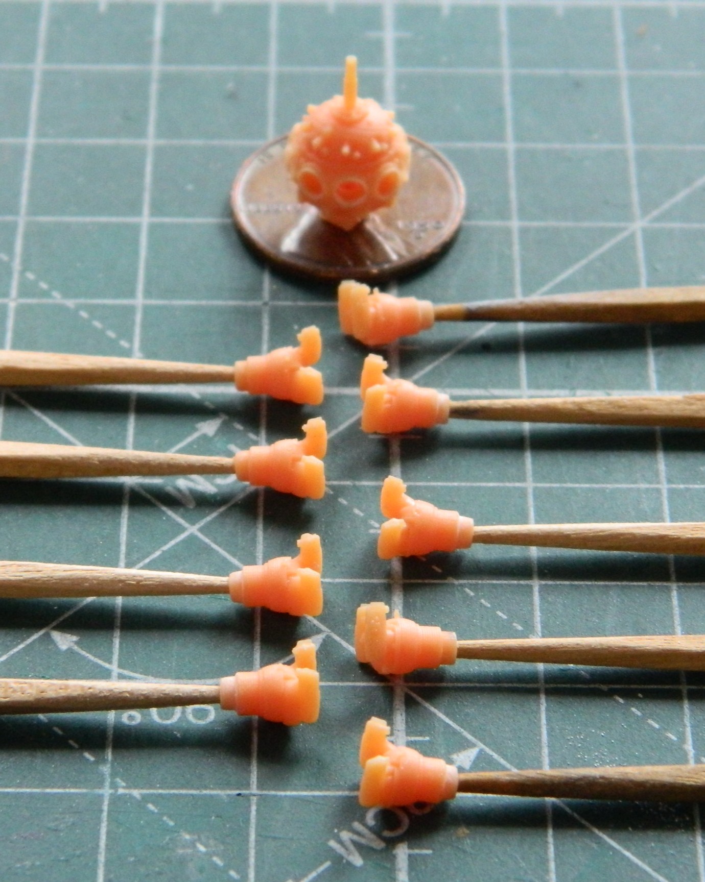
I drilled out the stubs at the bottoms of the jugs so that I could stuff a toothpick into each one to make painting them possible. Sure…I could have assembled the engines and then painted them, but since I’m going through all this supposedly-needless work so that I could assemble them, I’m going to take advantage of that and paint the jugs and crankcase separately and then assemble them. With the jugs good to go, I made the ignition wire ring from copper wires:
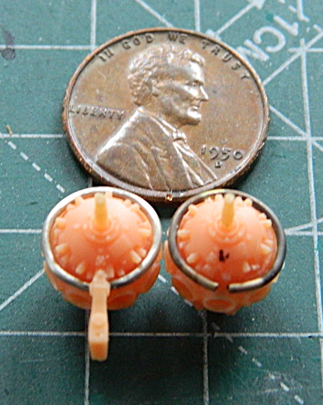
So it’s time to make the Mystery Thing. Which means it’s time to drop the scrap styrene I’d intended to use, bend down to pick it up, and then find the very Mystery Thing that I couldn’t find right where I looked for it to begin with. (And I guarantee you that it was not there when I initially looked for it, regardless of where it first landed on the floor):
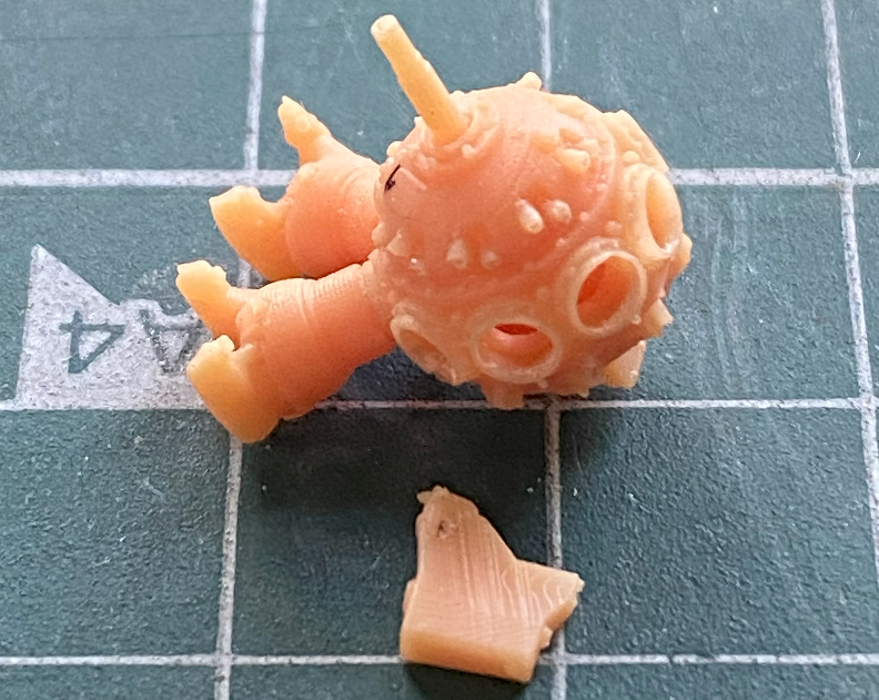
I used both UV-setting resin and superglue to make damned sodding sure that this thing, Mystery or not, did not take off again. To be absoLUTEly sure, I added a wire support to the back of it to add strength to its location:
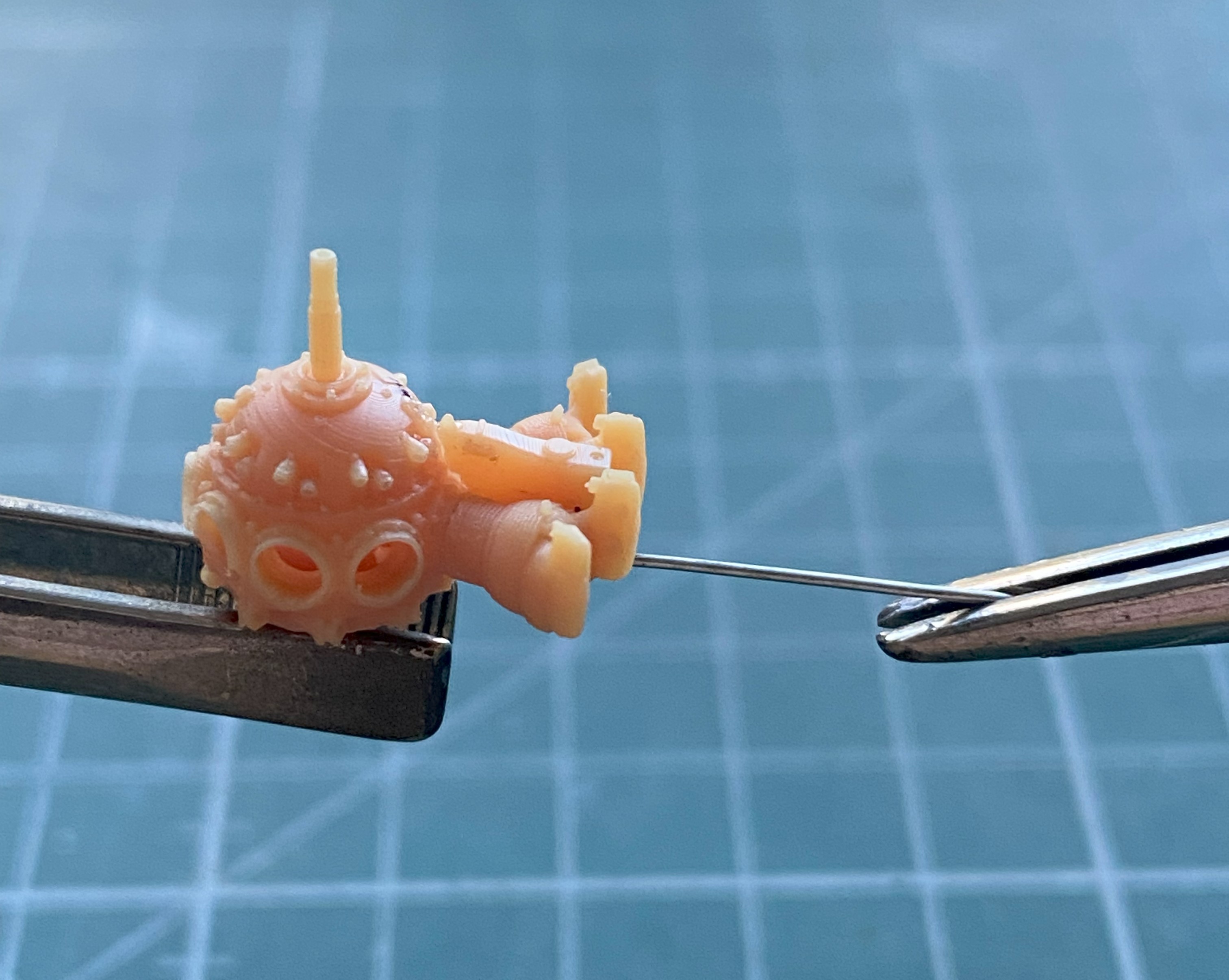
The props on this thing needed some work as well. I haven’t seen any period photos of the prop hubs covered by the shroud the kit provided, so I decided to not add the shrouds but to detail the hubs instead. Obviously, the prop on the right has been started, the one on the left hasn’t been:
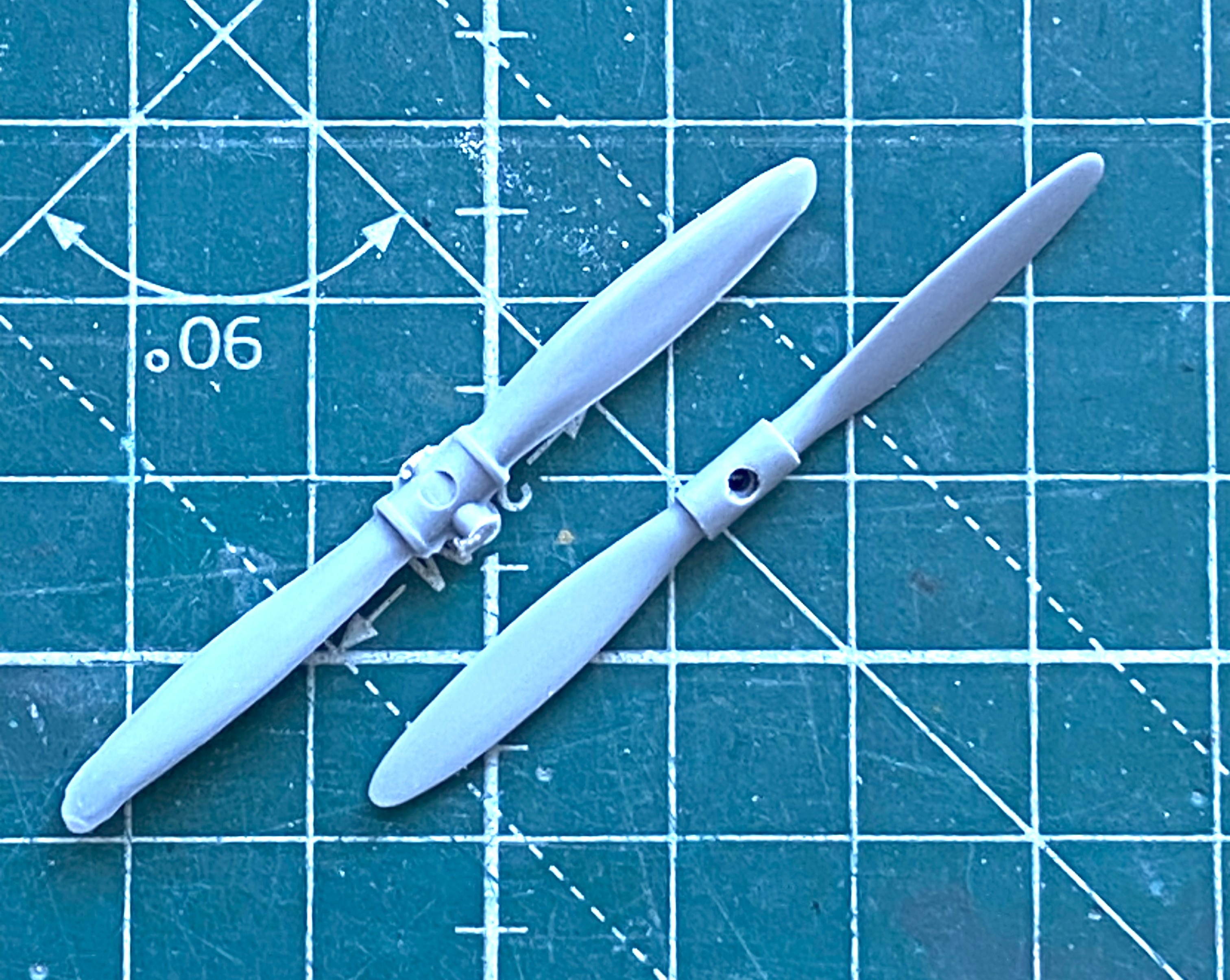
I don’t know if I’ve mentioned this before or not. My life is very strange. Strange things happen to me. All. The. Time. The latest (for now) strange thing to happen to me was while I was salami-slicing the parts to make the pitch mechanism. This is how it landed when I cut one slice and the rod I sliced it from slipped out of my hand just as I made the cut:
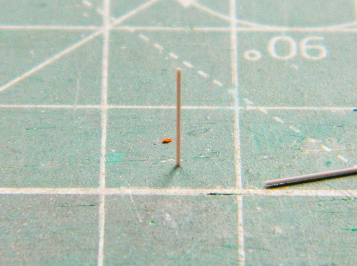
I guess that’s one way of seeing if the cut is square… Seriously. This is my life. ::facepalm::
With the parts all cut out, it’s time to assemble them:
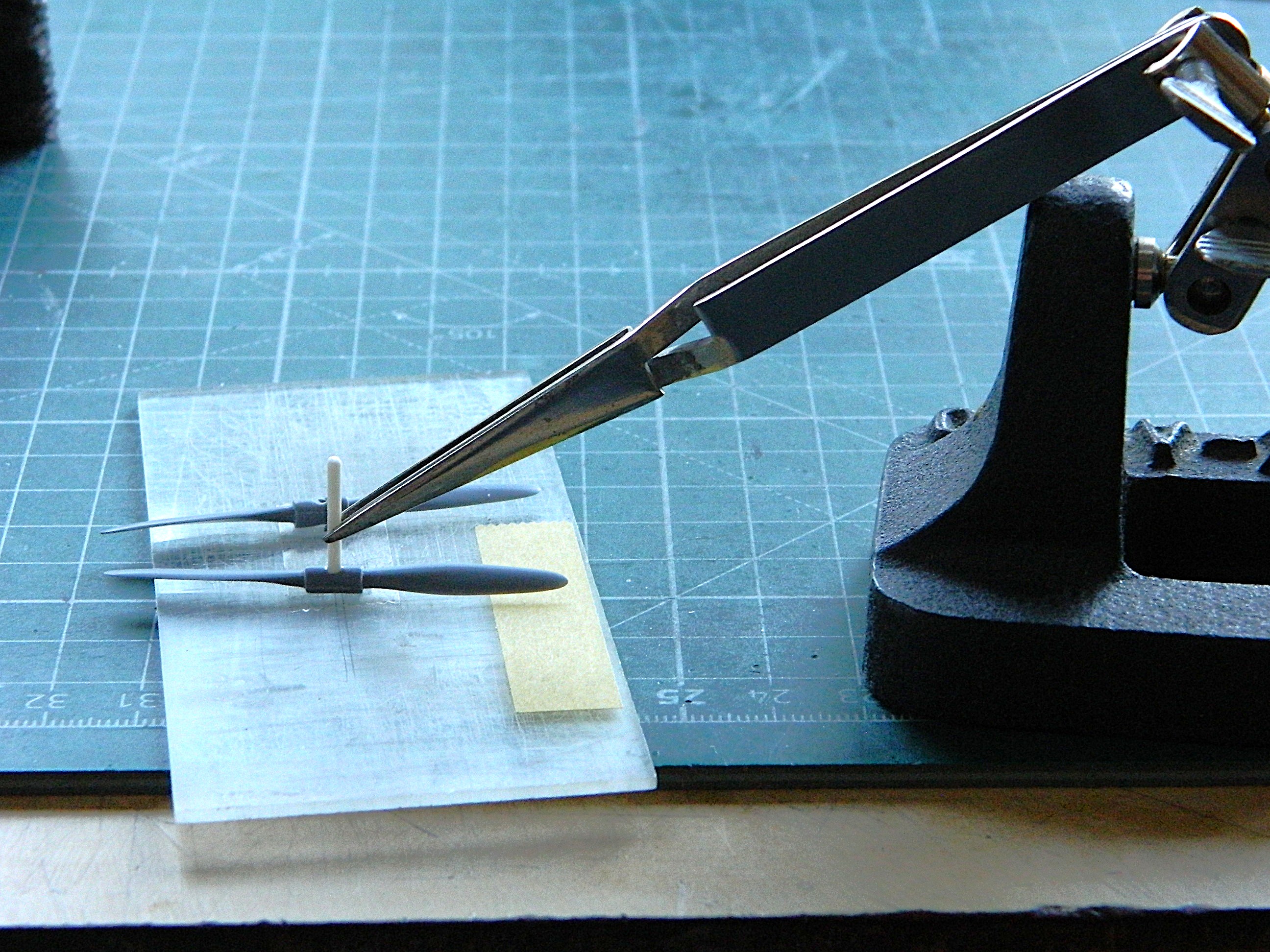
The center of the hub is a two-piece affair but there was no indication on the props to show that. To fix that, I scribed down the center of each side to create the parting line, then added varied scrap styrene to replicate the bolts holding both halves together as well as the pitch mechanisms:
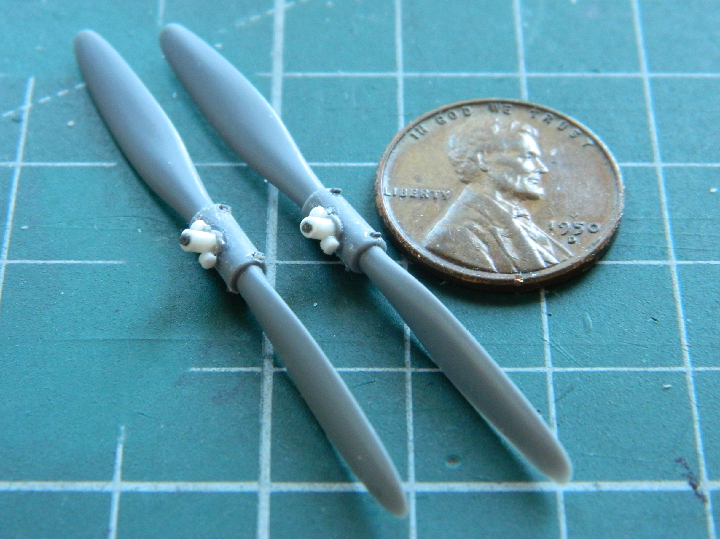
One those were done, it was time to paint these. Aluminum parts were painted with darkened Tamiya XF-16 Flat Aluminum (4 parts) and XF-1 Flat Black (1 part). The crankcases were shot with lightened XF-20 (4 parts) and XF-2 Flat White (1 part):
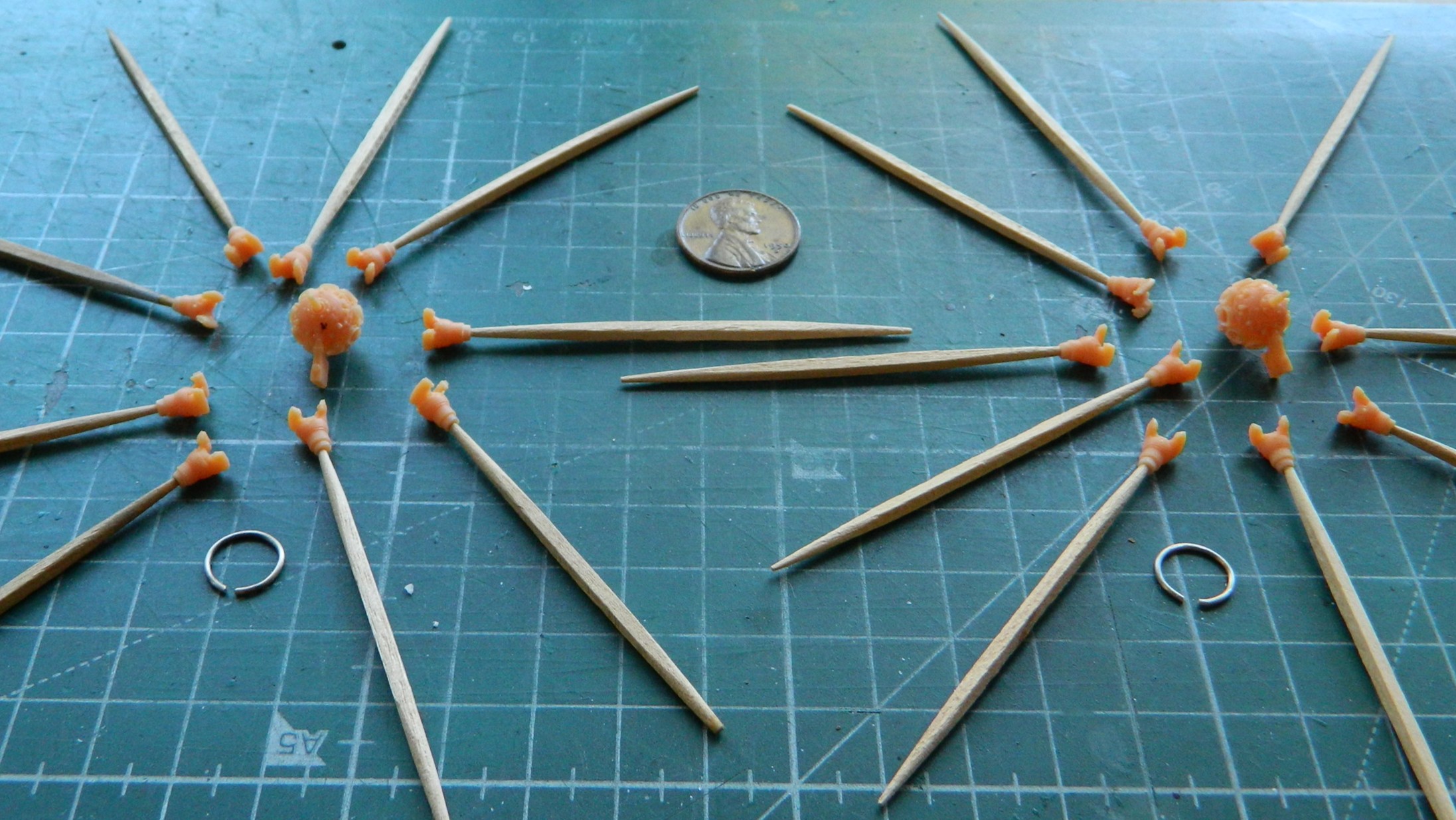
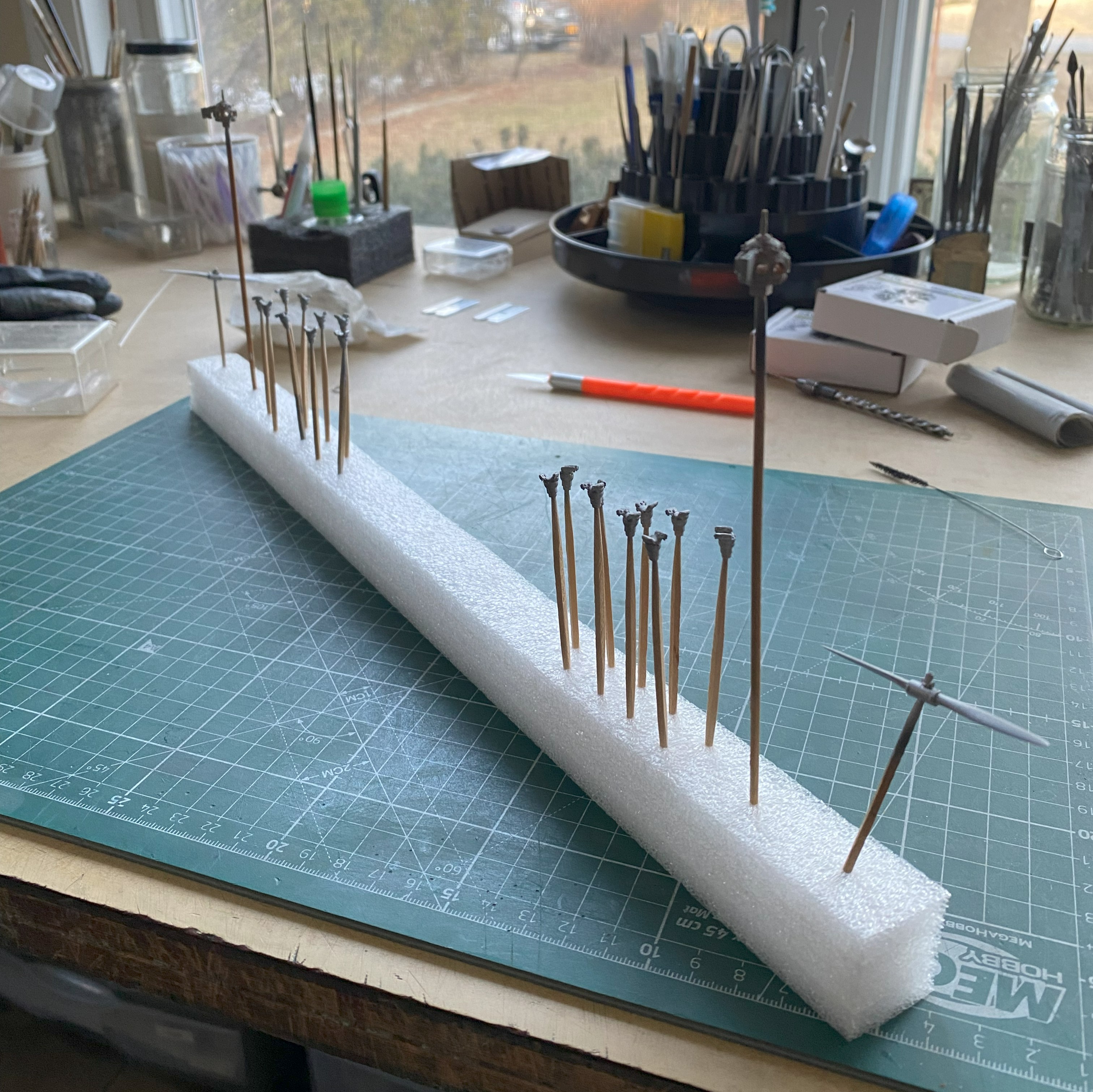
While the paint was curing, I decided to check fit of the wings. For the most part, they fit well enough…then there was the rest of the parts that didn’t fit so well. This is the case with both engine nacelles:

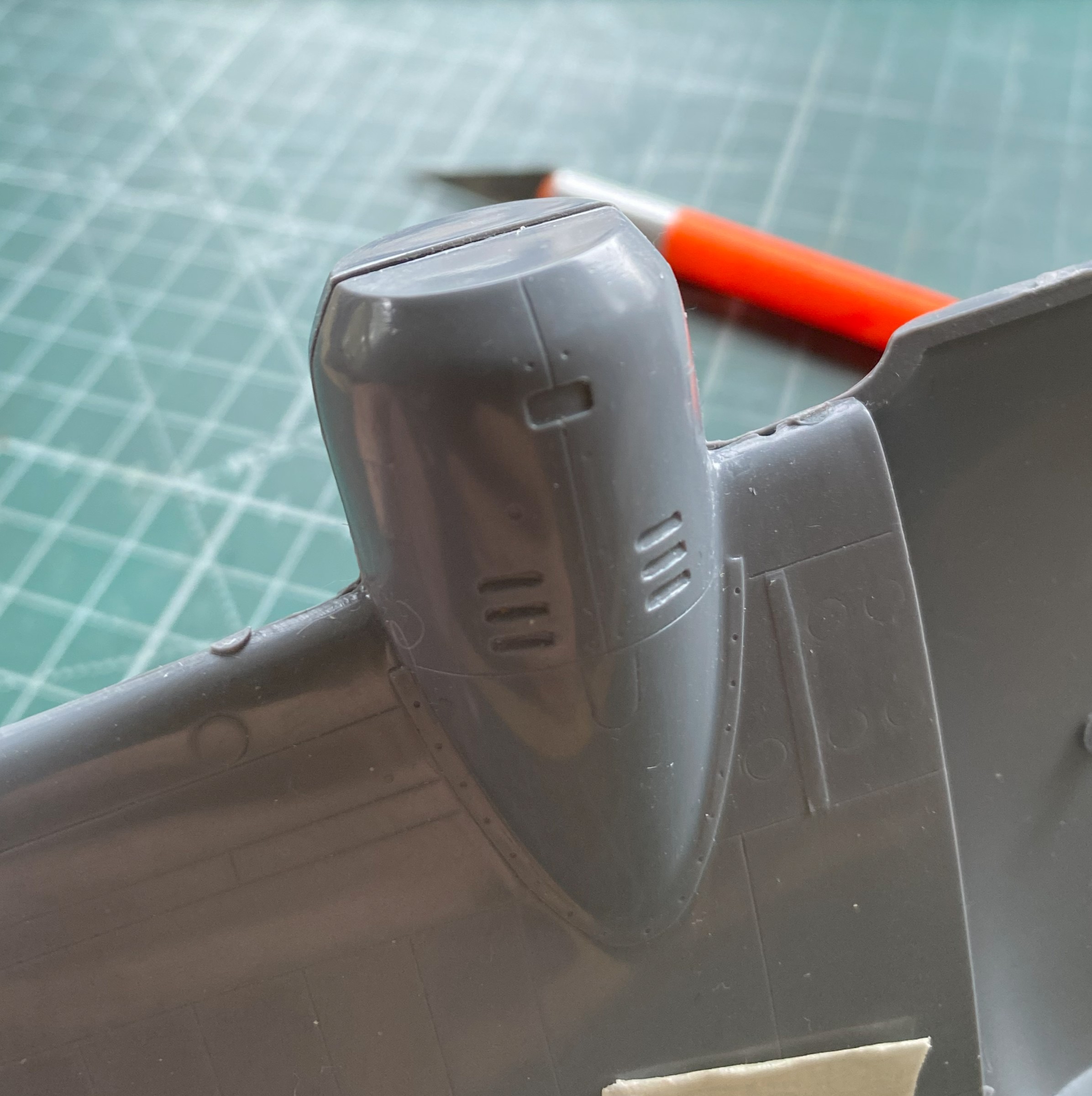
And once again (some more) I didn’t look closely enough at reference photos to see that this bird has split flaps. When deployed, the flaps only extend from the bottom of the wing; the upper wing over the flaps doesn’t move. I wish I had noticed that before I worked the seams and removed all evidence of seams, because that meant I had to scribe the separation from upper and lower in. I know I’ve mentioned this before (and, no surprise, will no doubt mention it again at some point) but I really do suck at scribing. So let’s scribe a line on a very small, long, and rounded surface:
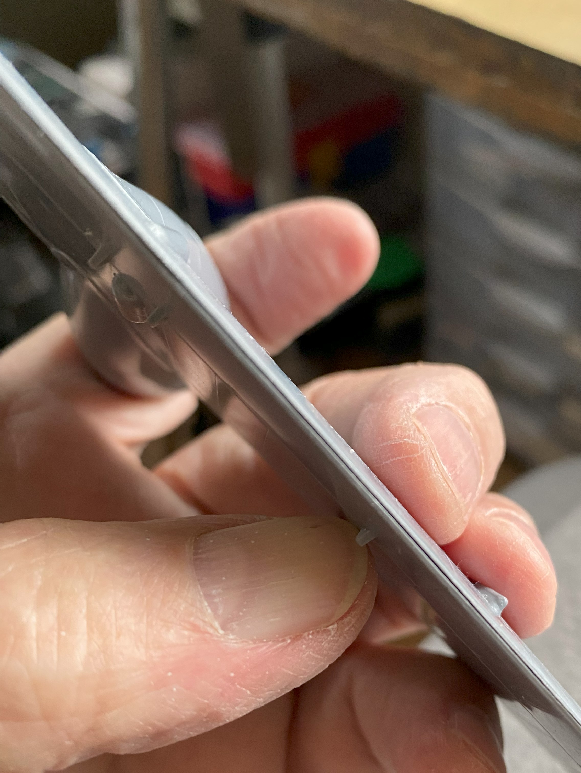
And while I’m at it, let’s screw it up (of course…it’s scribing) and have to add stretched sprue to fix it (which means leaving the added sprue alone for two days so that all the plastic hardens where the sprue was added):


That add-sprue step was repeated a few times before I arrived at something that fell within the 90%-95% goal, but eventually I got there:

One of the things I was quite curious about was whether or not the completed engines would even fit into the cowlings. I knew that I’d had to wait until the jugs were mated to the crankcases (duh) but I wanted to start assembling the cowlings so that fitting could be checked. These things need some work, too:
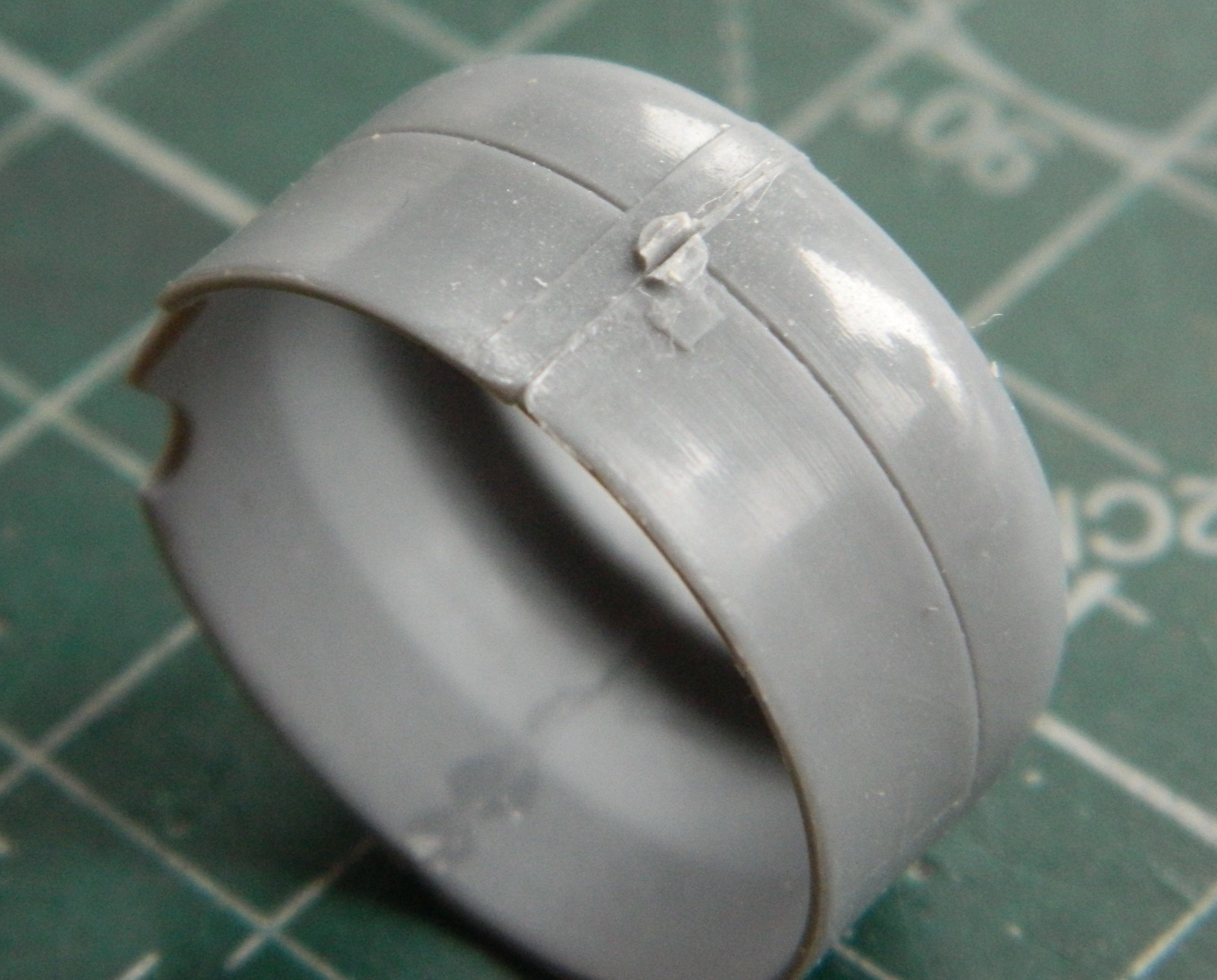
Especially this one. I’ve never seen a casting defect like this (with plastic, anyway…it happens more frequently than anyone wants it to when casting metal in a foundry). So that will be puttied into invisibility. Look closely at the inner lip at the bottom:
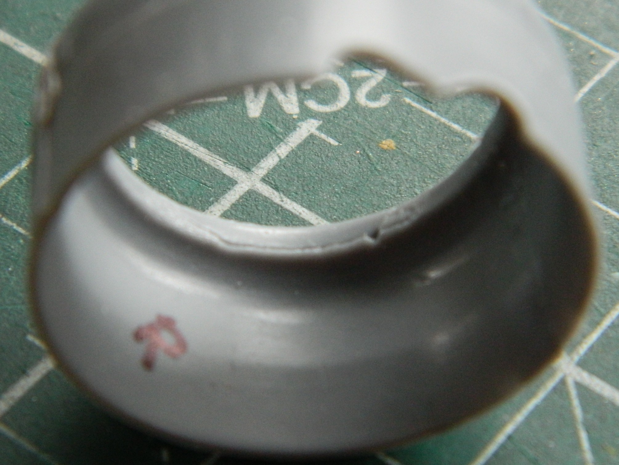
After examining the wing seams, I realized that I was going to need more stretched sprue to fix gaps:

I use that orange handled saw blade in the above photo to separate parts from sprues. Yes…the sprues are that thick and even though I use a set of very old Huron nippers (often resharpened nippers), I didn’t want the thick attachment points (called “gates” in the casting biz) snapping anything. Yes. Huron. Worried about snapping. Yes…THICK gates, often a feature of limited-production kits.
Moving on.
Seeing that a “good fit” isn’t all that good, I decided to check fit of other parts and I discovered that there was going to be much fitting done before this build is done:

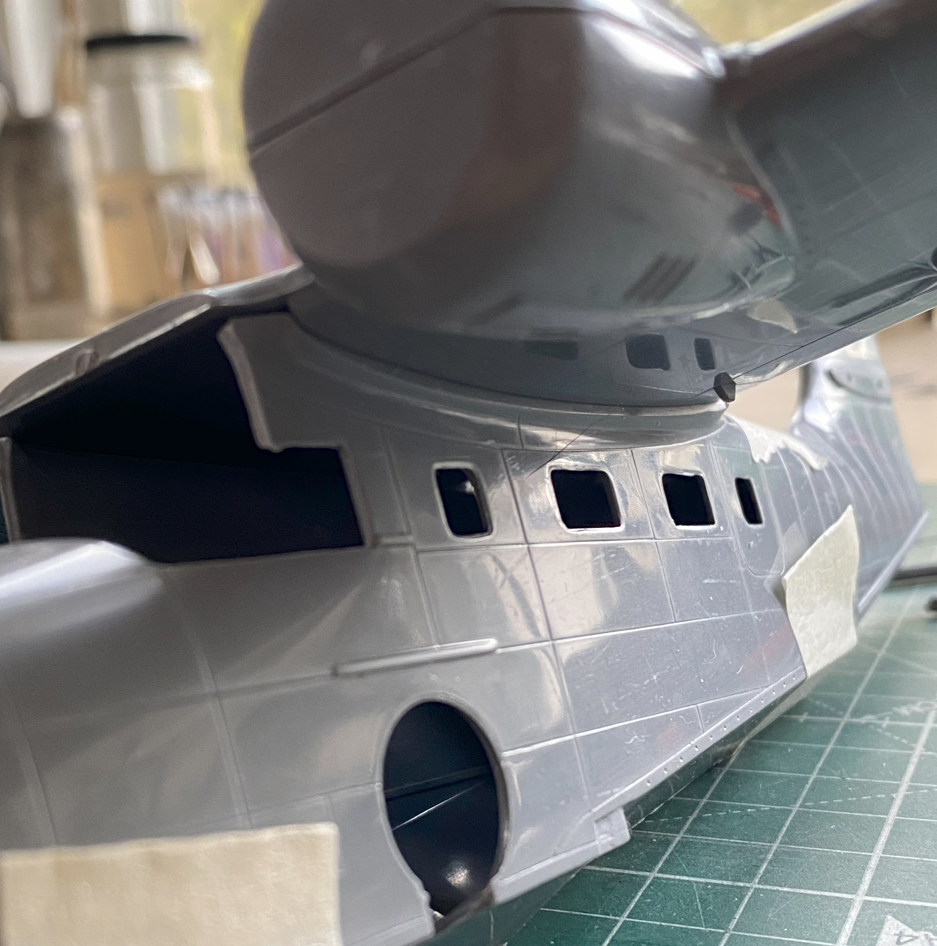
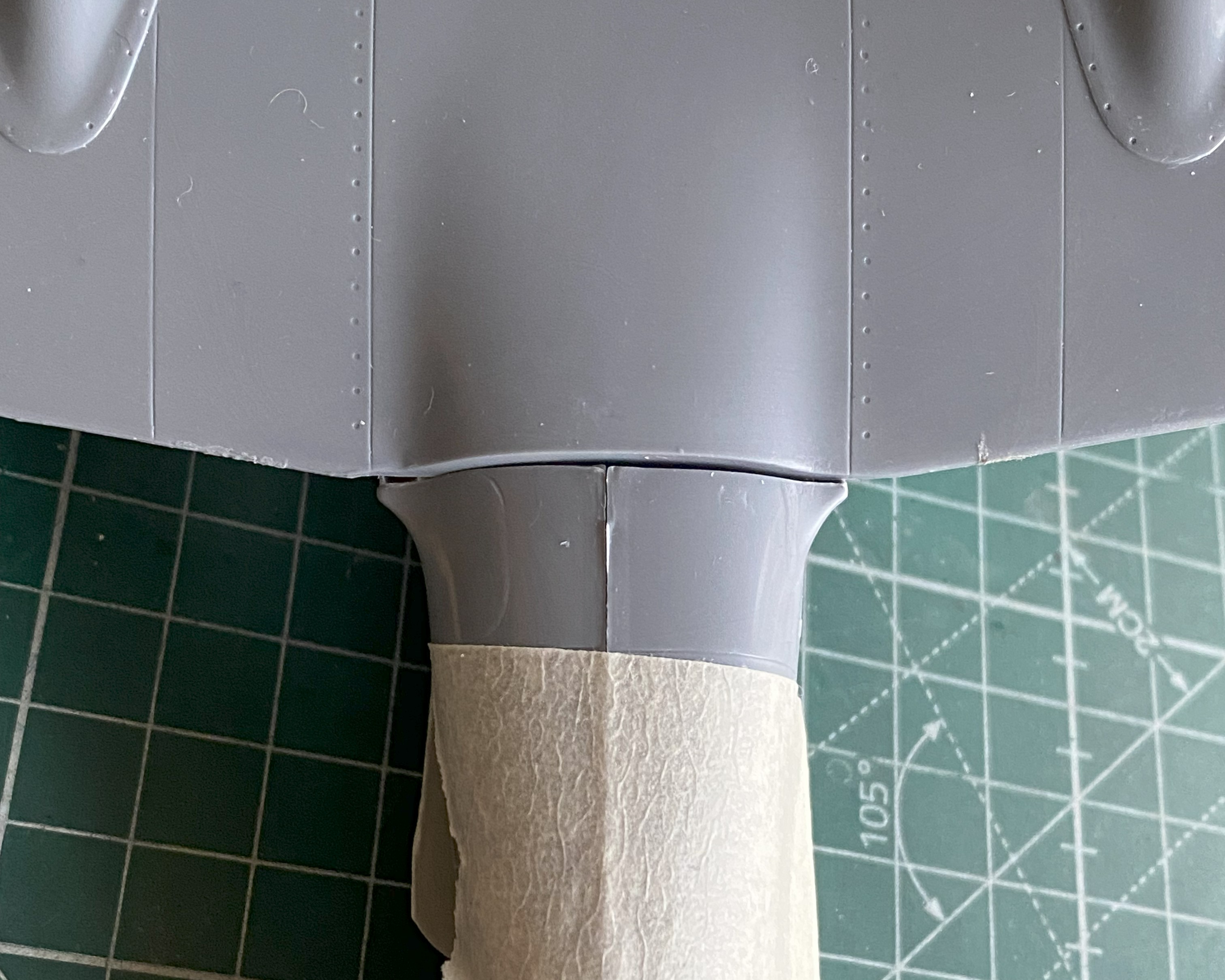
I’m certainly forearmed now…
Gaps show up in the strangest places with this kit. Gaps existed at the wingtips. Sprue has been stretched already, so I used that sprue to fill the gaps:

And done:
There are also wingtip lights that there’s zero provision for, so I’ll cut the notches for them and add them later on. (Forearmed, y’know.) There’s also no provision for a pitot tube, either. I used a wire and drilled its mounting hole (twice…the one behind where the tube goes is just evident in the photo):
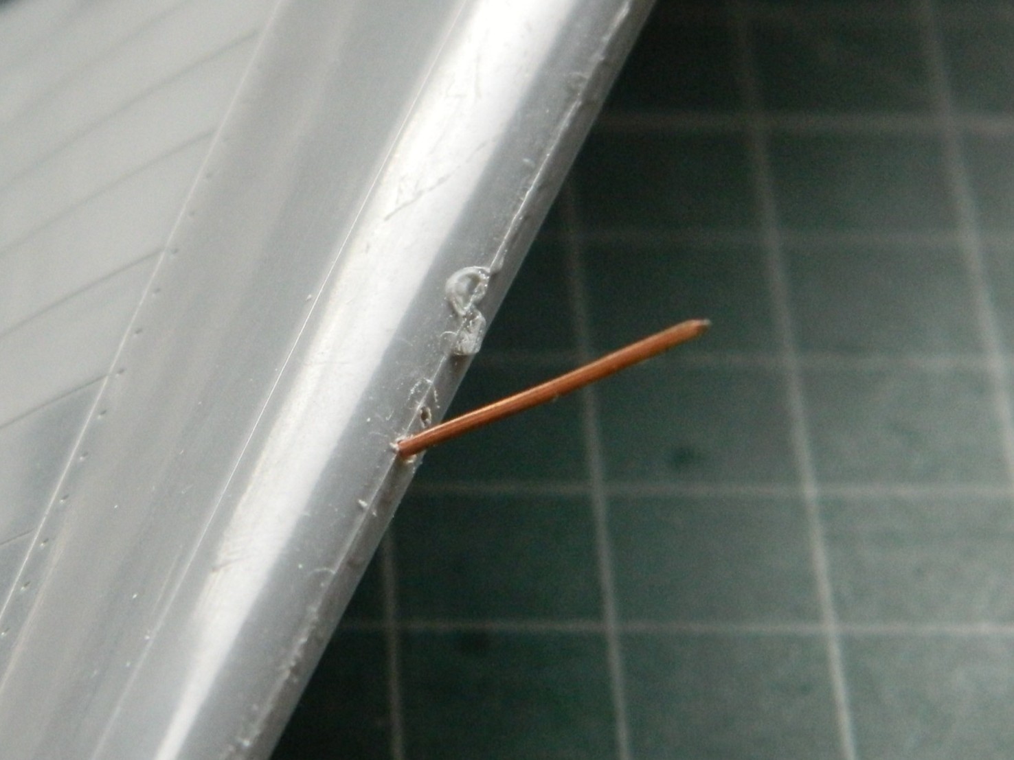
The front of the engine mounts on the nacelles isn’t flat but has a slight dome. A few quick passes over a sheet of 220 grit laid down on the bench took care of that:

I figured that while I was dealing with the wing, why not assemble the floats? (It made sense to me at the time.) Fit is as expected and since I had plenty of sprue stretched (so far), after assembly sprue was added to fill the gaps:
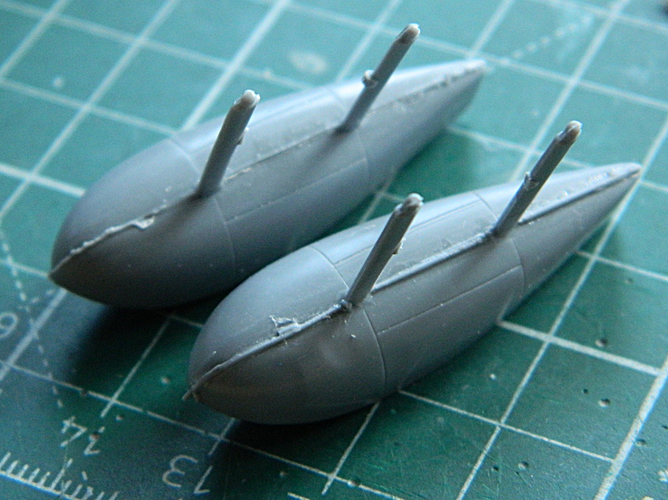
Oh. A word about limited-production kits. Some things that we’ve grown to expect kits to have, limited-production kits often don’t have. With this kit it’s attachment pins and sockets. So far, I haven’t encountered any of them.
On we move.
Since I won’t be scribing over the added sprue, I don’t have to let it sit for two days to harden. A few hours later I started working the seams and then added 3M Acrylic Putty where needed (masking tape added to keep putty out of panel lines):

They appear to have come out well enough; I’ll know more once paint is thrown at these:

Finishing the seams of the cowlings meant that small sections had to be rescribed. [Insert obligatory whining about my lousy scribing skills here.] And then patched where I screwed it up. And then wait a couple of days before rescribing:
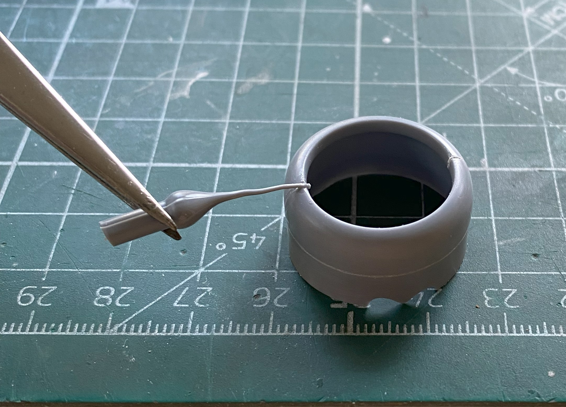

After painting the engine parts and assembling them, they were shot with Tamiya X-22 Clear Gloss, left overnight to cure, and then I mixed some gloss black oil paint with thinner to create an oily finish on the engines (remember…these were working aircraft, not the pristine examples in museums or post-restoration, and as such were seen as consumable resources…meaning that they had an oily surface) (radial engines, y’know…no oil dripping means there’s NO OIL IN THEM). The downside to using oil paints for washes is that they take a long time to dry. In this situation, that “long time” meant seven full days before I could shoot the engines with the sealing coat of Tamiya X-35 Semi-Gloss Clear:

Oh yeah…they do fit inside the cowlings. They had to be adjusted for fit on the depth of them which was done with a medium-sized file (and could probably do with finer fitting when it comes time to glue them to the wings):
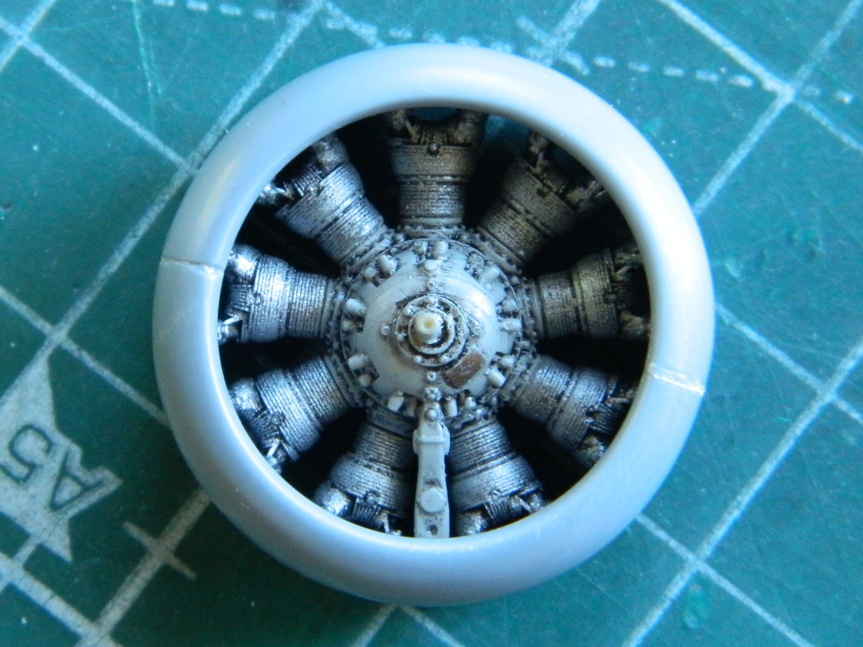
I added the ignition wire ring and painted it a darkened Tamiya XF-6 Copper (4 parts) and Tamiya XF-1 Flat Black (1 part), glued them into position (hindsight indicates I could have used a thinner wire) and started adding spark plug wires using 0.015″ (.381mm) solder:
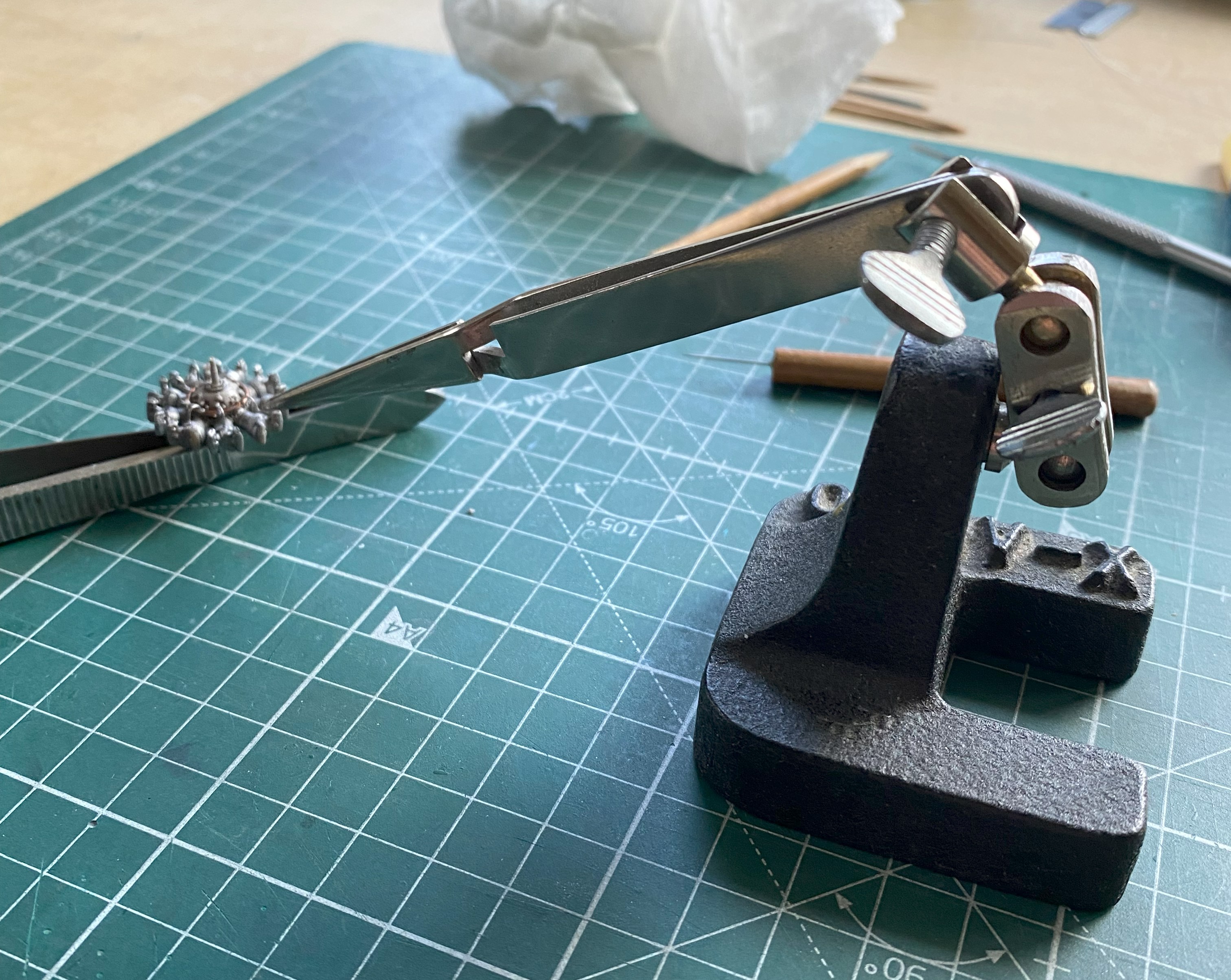
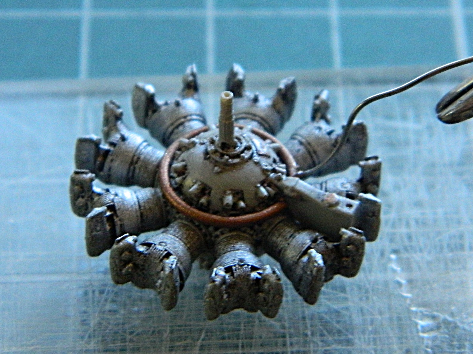
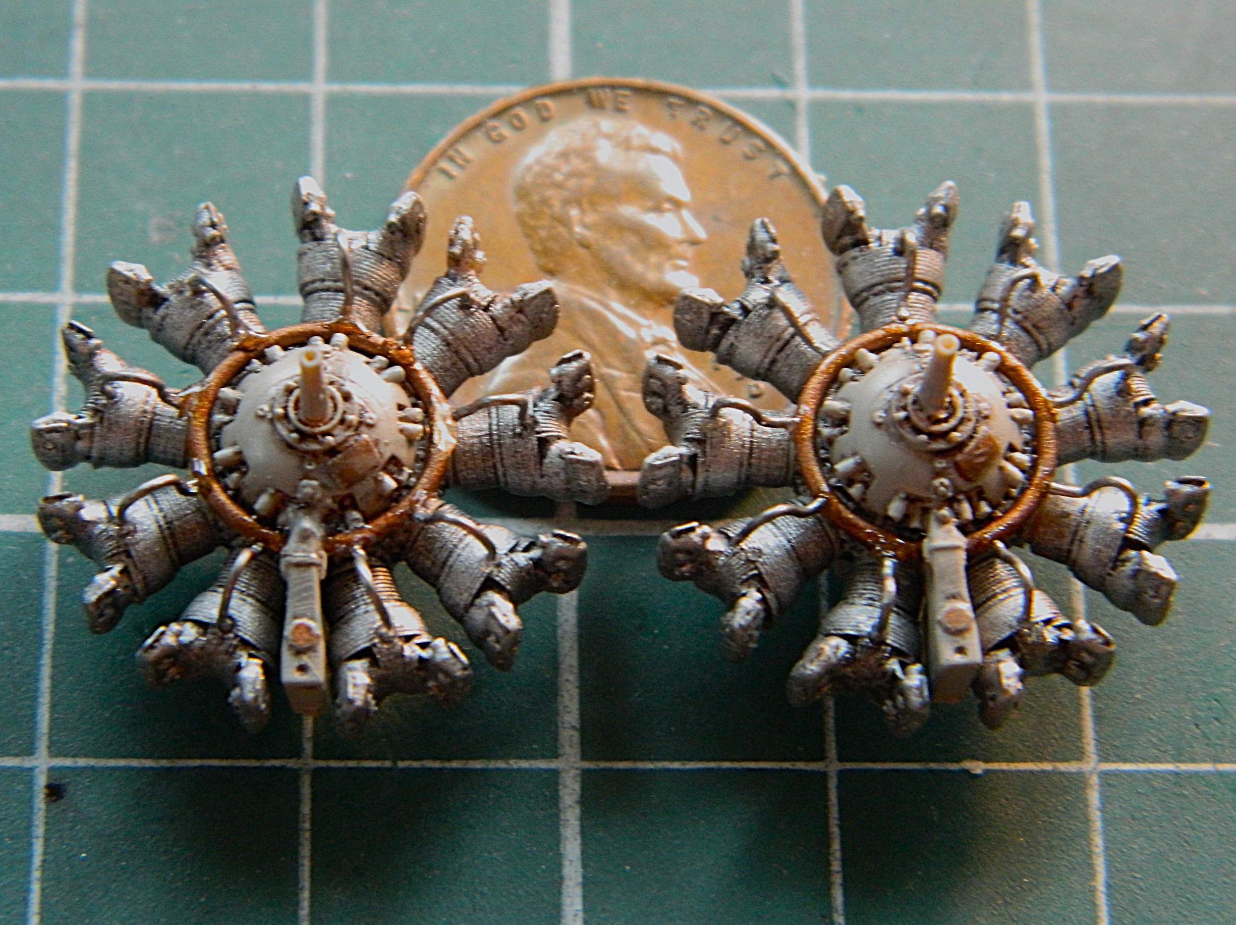
There are other hoses that connect each jug to the next but since they won’t be seen I’m not going to add them.
One trick I’ve learned is that when adding some scrap that I want to be centered, I use clear styrene to make that easier. Another trick I’ve learned is a way to avoid the dreaded superglue-sets-up-too-fast-to-properly-align-something. These engines are resin and they’re being attached to styrene, so superglue will be necessary (most of the time, when faced with something like this, I avoid epoxy because I’ve found it’s too thick). A way to avoid hoping that I get the alignment correct (or at least how I want it, should the two be different) is to glue a piece of styrene to the back of the engine. Doing this gives me a styrene-to-styrene join and the ability to tweak alignment in less than 0.00001 seconds:
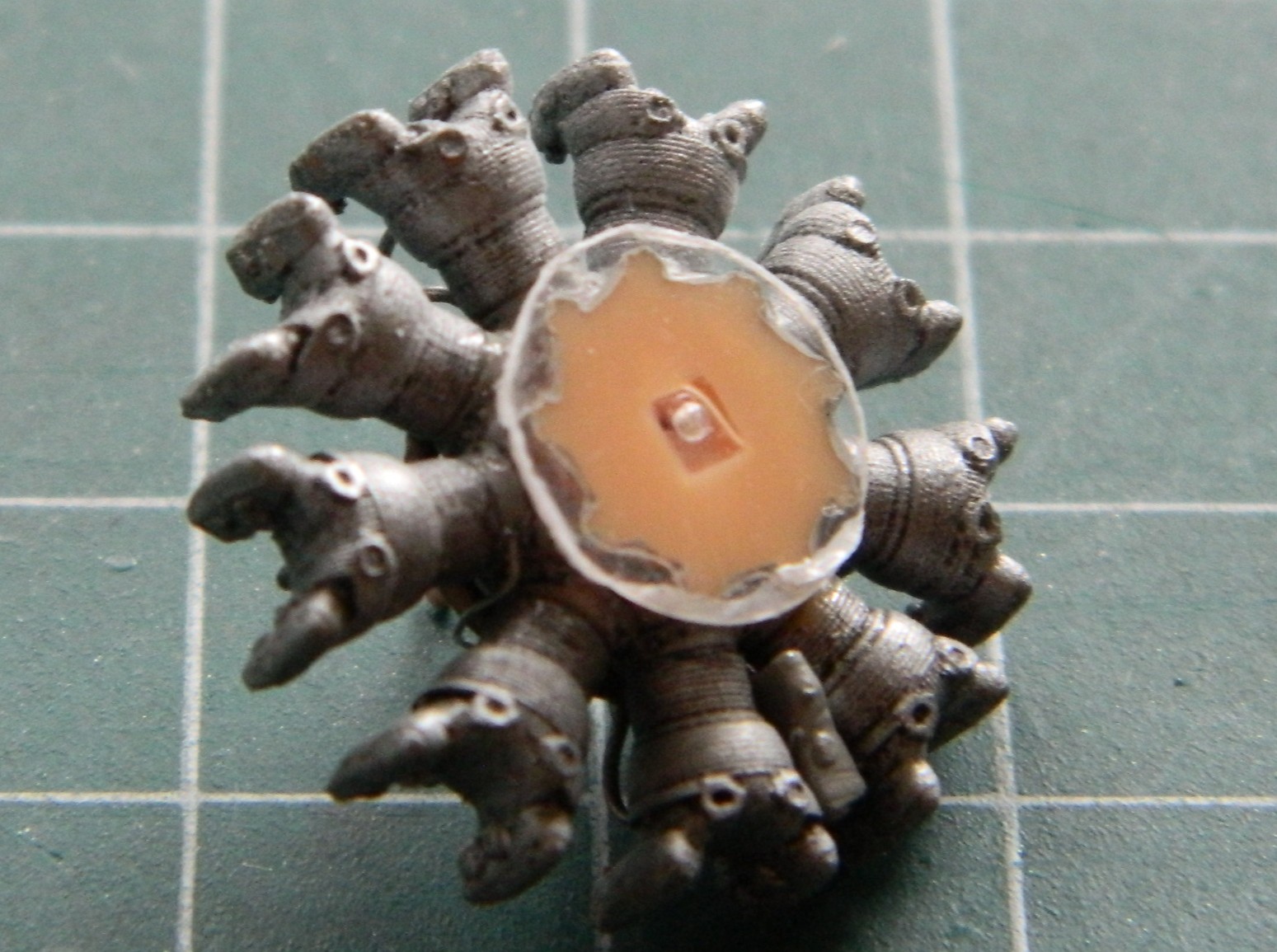
I painted the spark plug wires using Tamiya XF-85 Rubber and the data plates using the darkened copper paint I’d used on the ignition wire ring. Having already hit both engines with semi-gloss, I painted the backs of them Tamiya XF-1 Flat Black for shading, as well as the inside of the cowlings and the backs of the propeller hubs:
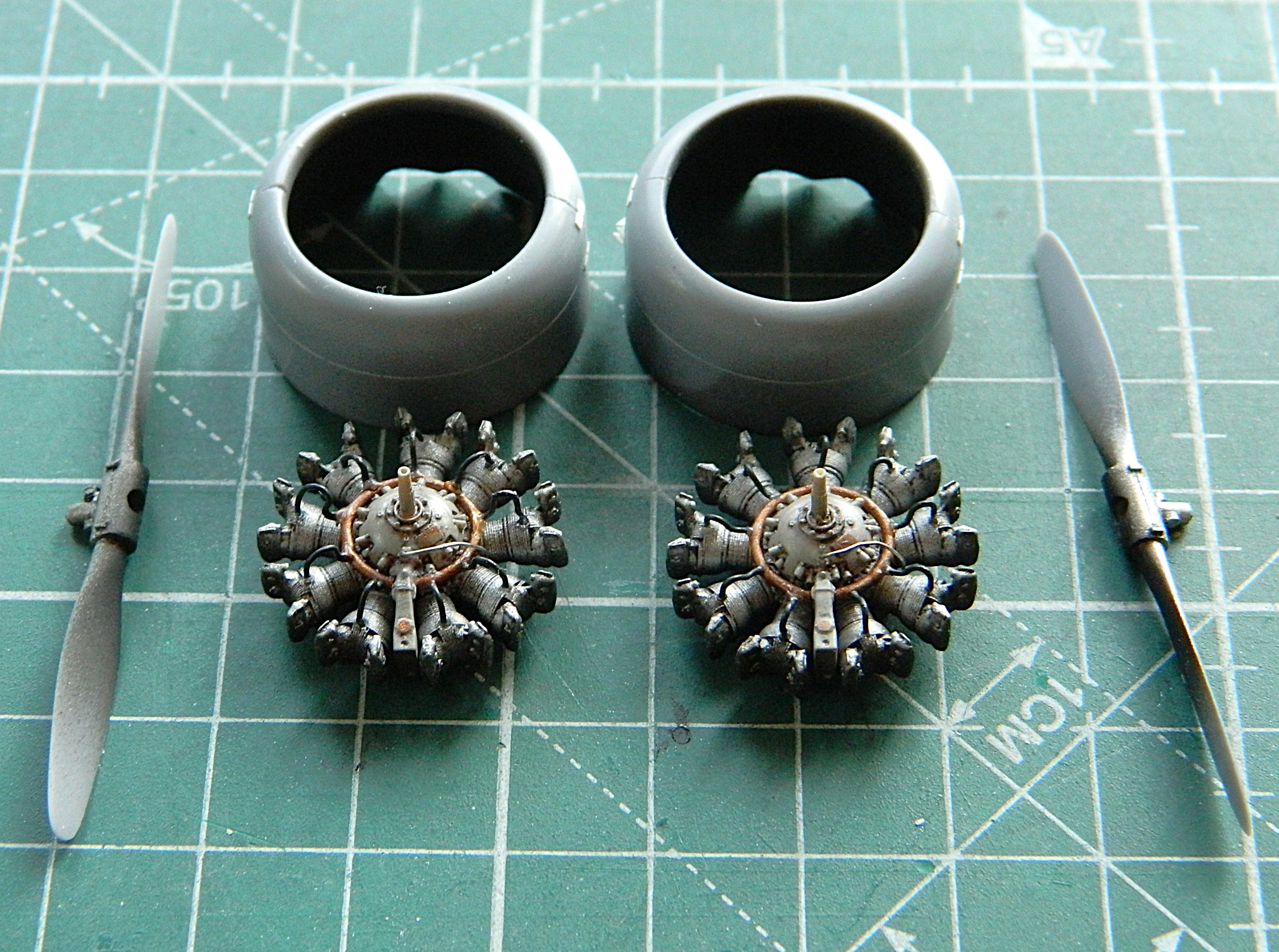

I’ve noticed that on period photos, at the root of the wings where they contact the engine nacelles are what appear to be landing lights. Since there are zero provisions for them in the kit, I’m making my own. I used a scrap of 3/8″ (9.53mm) clear acrylic rod. I sliced off a piece wider than I want to use (for ease of handling…the extra width will be covered by paint), trued the ends (make them perpendicular to the center axis of the rod), and cut them in half so I have one for each “light.” Then they were polished until clear:
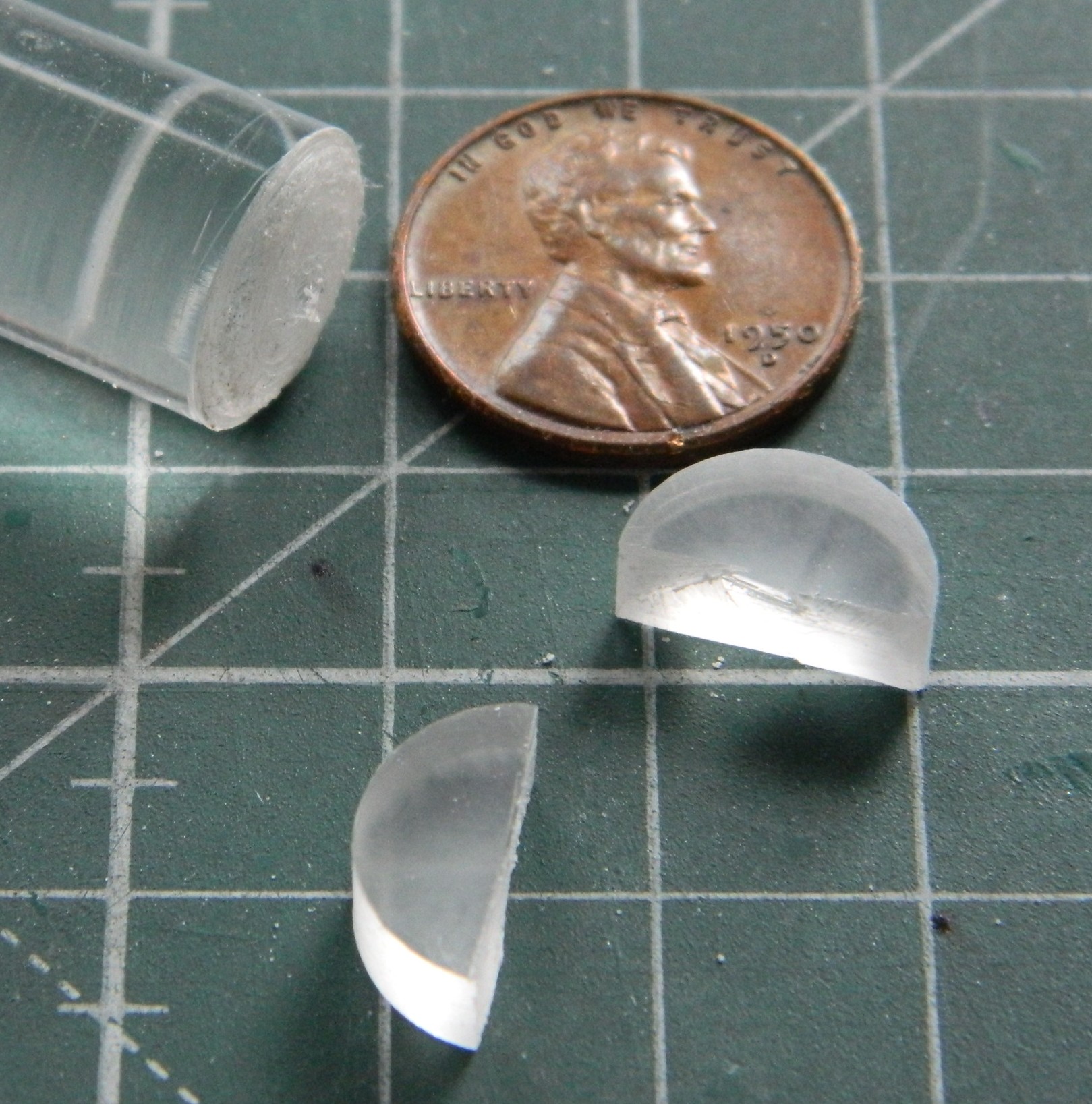

The flat sides will be the insides which will have the “lights” drilled out and painted, then I’ll trace the curvature of the wing’s leading edge on them, rough them in, then glue them in place and finish off the exposed surfaces.
But that’s for next month…
Grumman JRF Goose (Czech Model) 1/48 Scale – A Brief Overview
In 1936 Grumman was approached by a group of businessmen who believed that taking a train or driving from their homes north of New York City was too much of a bother and wanted something…namely an aircraft…that could get them to their offices without having to rub elbows with the Great Unwashed. Grumman designed the Goose in response. Many of those houses were near water and NYC was (and still is) surrounded by water, so it made sense to design something that could land on water (more than once, anyway) or land (ibid), and the Goose was born. It was also the first Grumman design that had less than two wings and more than one engine (a pair of Pratt & Whitney R-985-14 engines rated at 450hp for this aircraft) with the first one going into the air in 1937. It had a range of 700 miles and a flight time of four hours. Several were built and sold and then WWII blew up.
The Navy, oddly enough concerned with something that could land on water (more than once), was interested in an aircraft that could carry a couple of depth charges for anti-submarine patrols, carry several people, put down safely on water to rescue people stuck out there in a flotation-deficient environment, be ruggedly built (probably Grumman’s motto), and reliable (ibid). From what I can find, 345 were built overall and the Navy named the aircraft JRF. I’ve been unable to find any mention of how many were commandeered by the military from civilian owners. Interestingly, it was Canada’s RCAF that put in the first military order to Grumman. The Army Air Corps got in line with an order of 26 which were designated OH-9 and OH-13 (those designations were later used for helicopters) and the Navy and Coast Guard ordered 169 of them.
The Goose also saw war service with several other nations who needed a relatively small amphibian aircraft (operate from both land and water) for search and rescue, patrol duties, and to transport people with enough rank to get their hands on (not limited to other nations in that regard).
Pilots regard this bird well, one comment found online was that on the ground it looked like a big aircraft. In the air it didn’t fly like one.
And yes…my first exposure (he says as if he encounters this aircraft frequently) to the Goose was the 1982 TV program, “Tales of the Gold Monkey”, that ran for one season.


Even the late Jimmy Buffet owned one…
F7F-3 (AMT/Ertl) After-action Report

Total time building 281.75 hours.
Begin date May 11, 2024; end date February 24, 2025.
Vendors:
AMT/Ertl
F7F-3 Kit #8843 1/48 scale
Eduard
Photo Etch Set #48178
Quickboost
F7F Tigercat Engines #QB 48 142
FineMolds Nano Aviation 48
WWII US Aircraft Seatbelt Set #NC4
Scale Model Accessories
F7F-3/3N Tigercat Wheels #CAT4_R48018
Scale Aircraft Conversions
Metal landing gear #48008
EZ Line
Fine black
My Opinion
This kit was produced in 1995 and I had assumed that it was a rebox of something like Italeri but it’s not. According to Scalemates, this was a new-tool kit produced by AMT/Ertl. When I first opened the box I had high hopes for this until construction started. The build became more and more annoying as I progressed; so much so that I doubt I’d spend the money on another AMT/Ertl kit unless it’s in the category of this kit, which is “I really want to build one of these but it’s the only one in 1/48 scale”…which is what this one is. I’ve always liked this rare bird and when I saw this kit was available, I jumped at it. There were many opportunities for this to be an outstanding kit, even by 1995 standards, the company just took too many shortcuts for my liking. It’s a 3 of 5 star kit and good for someone who’s just getting into modeling and doesn’t want to invest a lot of money into it and won’t be showing it at contests. To build OOB will require a newcomer to stretch to produce a decent build, which is what newcomers need (in my less than humble opinion).
What I ended up with is not contest-worthy.
Too many parts broke off after construction. Granted…I have not been at my best this year and some of that could be my own inability to connect the dots of late. But engineering and fit needed attention and sometimes a lot of it. And each time something breaks off, it’s got to be reattached. Each time it’s glued back on, there’s the old glue and the new glue and it builds up when something breaks off a half-dozen times. Yes…I could have removed the old glue. I didn’t because experience has shown me that that often requires a repaint which, given the nature of rattlecans and the locations of where things had to be reattached, I wasn’t interested in doing. This is a three-foot model. It looks really good from 36″ away but loses its allure the closer the viewer gets. Speaking of paint…
I learned a lot from painting this one. Yeah, orange peel is a thing. Yeah, I figured out how to mitigate that effect by sanding and polishing (the other fix is to strip all the paint off and start over). My major mistake was thinking that Tamiya’s X-22 Clear would self-level, which it does do. It seems the line between orange peel and self-leveling is invisibly (at least to me) small. I also learned that if one is doing a dark and glossy finish, one canNOT over prepare the surface. Prepare the surface as if you’re going to do a natural metal finish because I was very surprised to discover that a line left behind from sanding with 600 grit will show up when the gloss arrives on the dark paint. Lesson learned.
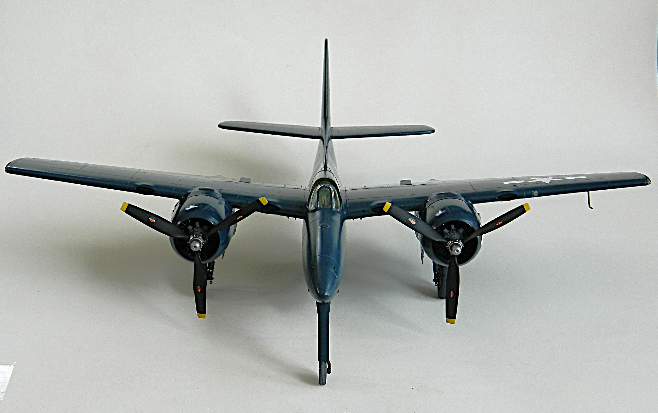
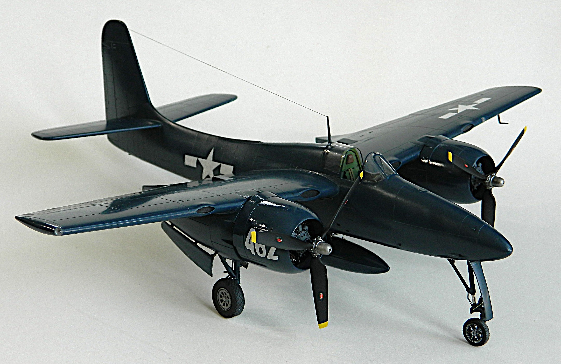
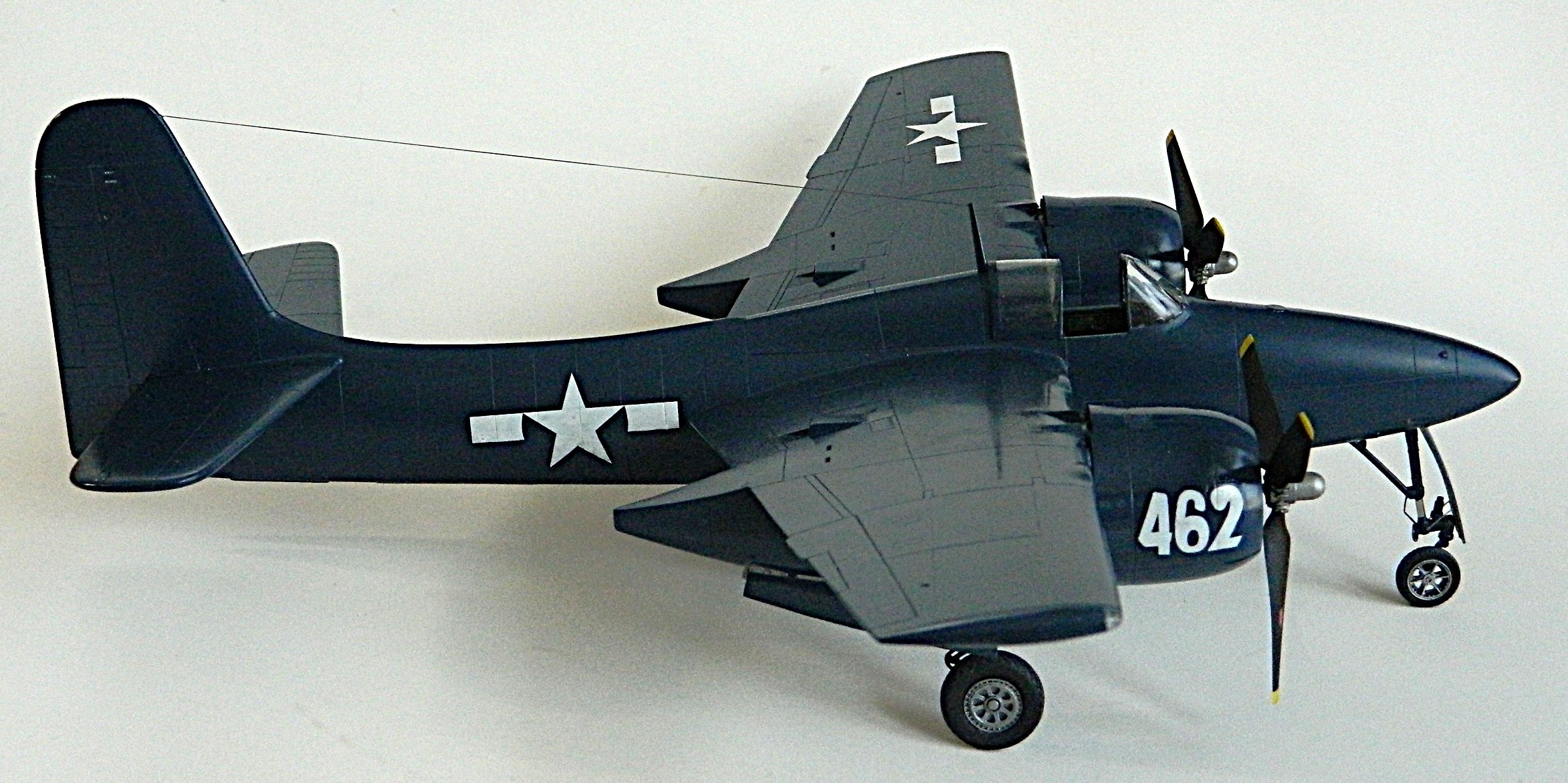

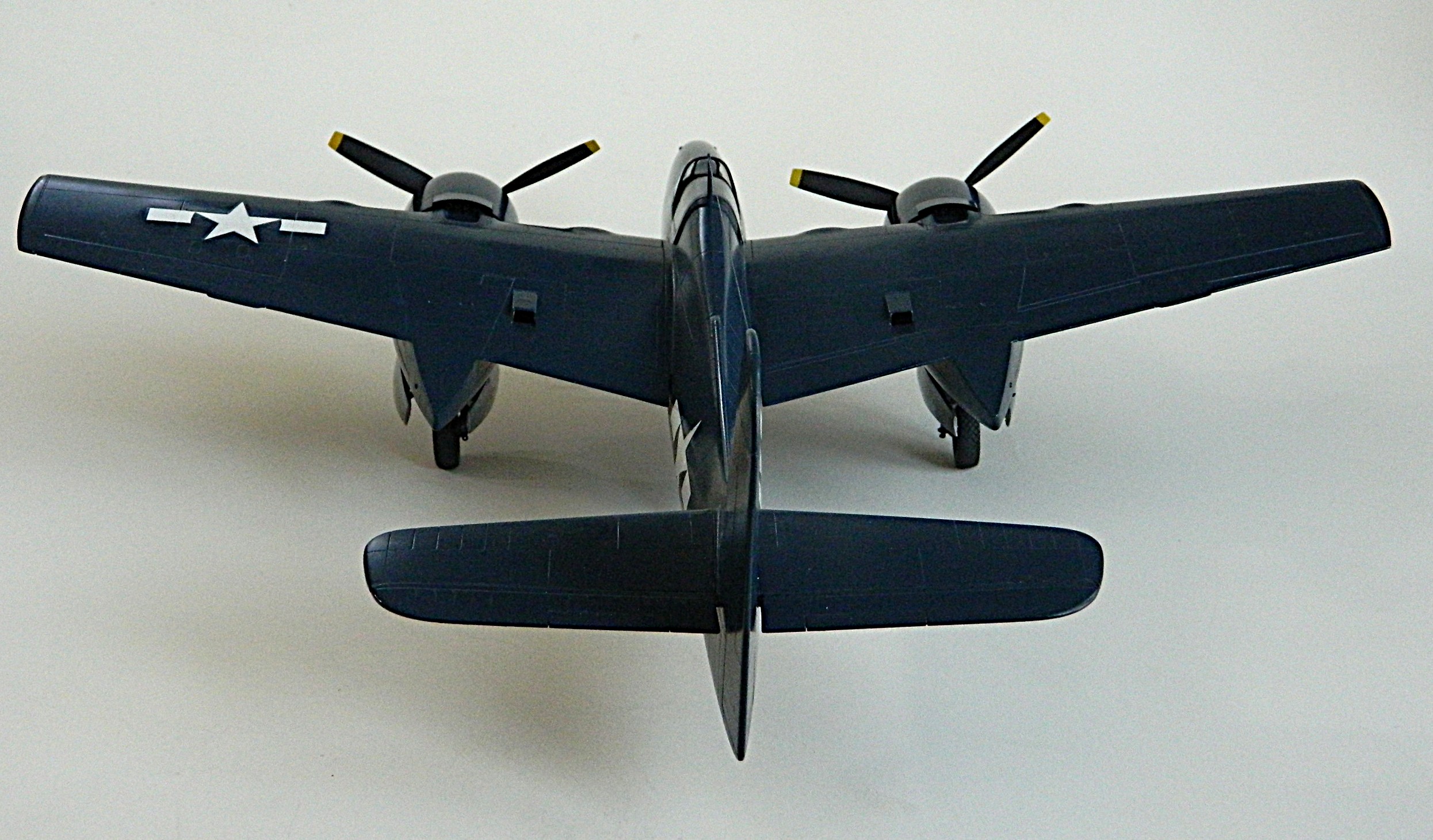


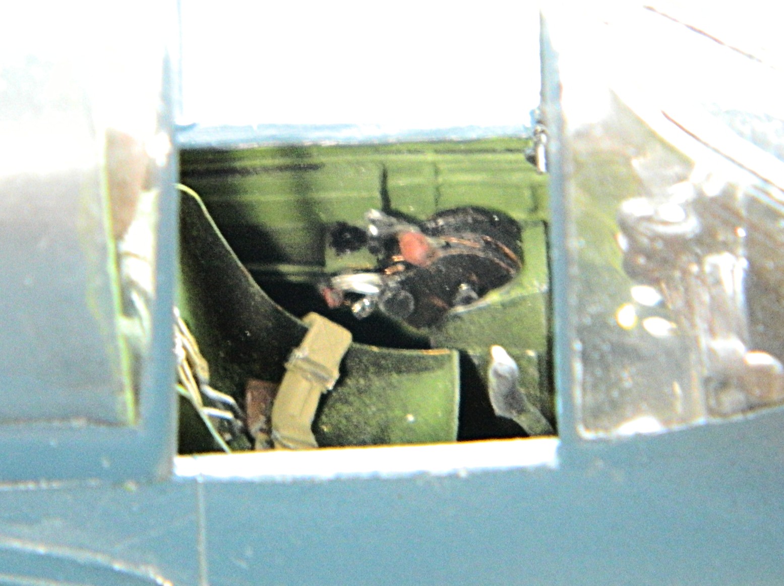

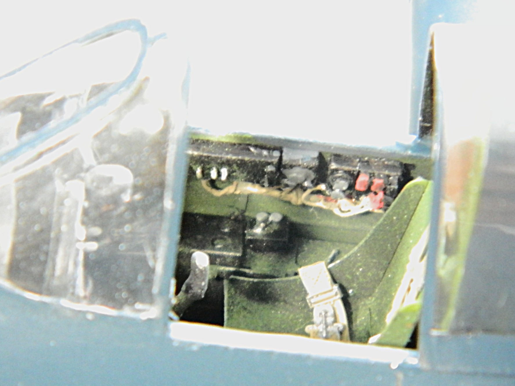

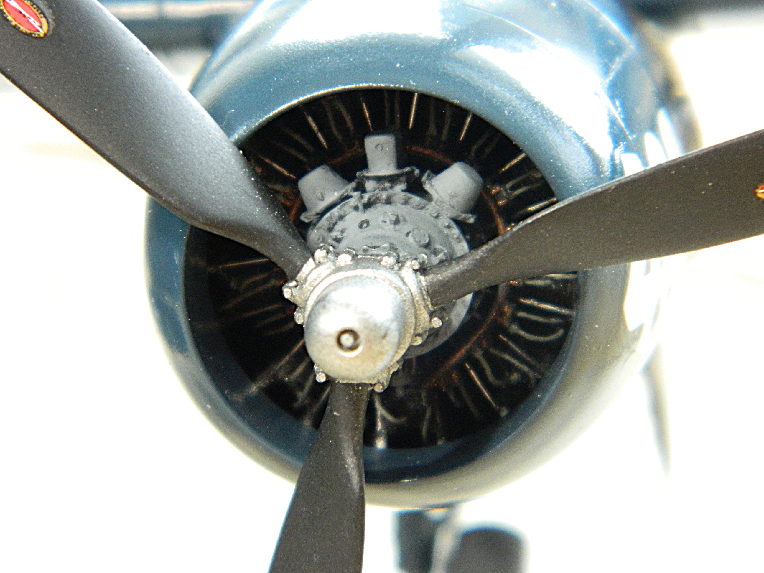


F7F-3 (AMT/Italeri) 1/48 Scale Build #9 – Whereby I Learn Things That I thought I Already Knew, Then Chasing Myself, Then Fixing Far Too Many Things…a Lot…and Assembly Wraps up and DONE
The theme for this month’s post could also be “hubris”. Over the years, I’ve collected a lot of tricks and procedures, and I rely on them. Turns out what I thought was a Fortress of Knowledge ™ turned out to be a sandcastle built at water’s edge at low tide. This month the tide came in and the sandcastle crumbled (along with a part or two) (okay…I’m being dramatic with the whole “crumble” thing but still…this month was a massive ass pain).
The opening salvo for hammering my hubris flat came when I left the brass tubing that I used to replace the kit’s offering for the 20mm cannons in the blackening solution overnight and went to bed so that I could get an early start on laying there for a couple (or three) (or more) of hours before getting some sleep. As I planted myself into the chair the following morning, my eyes (at least one of them) saw this:
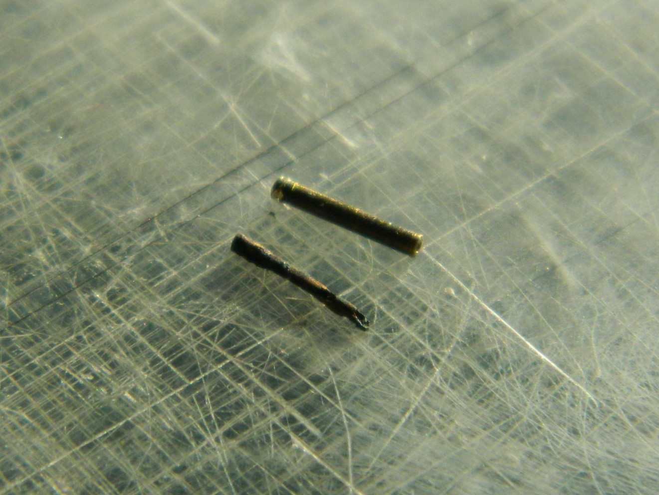
The tube at the top hasn’t been immersed yet in the Brass Black. The…remnant…at the bottom is what happens to brass after it’s been immersed in Brass Black overnight. Okay…now I know.
I worked on attaching the wings. Fit is vague, allowing the dihedral to be flat (wingtips at equal height from the ground) to almost U-shaped. I wasn’t taken aback by this because dry-fitting had shown that this would be a problem as the gaps at the wing-roots would be as well. I did the best that I could with getting the first one, my reference as it turned out, glued on with the correct(ish) angle to the fuselage (not that easily seen because I was clever enough to have something behind it that would obscure vision):
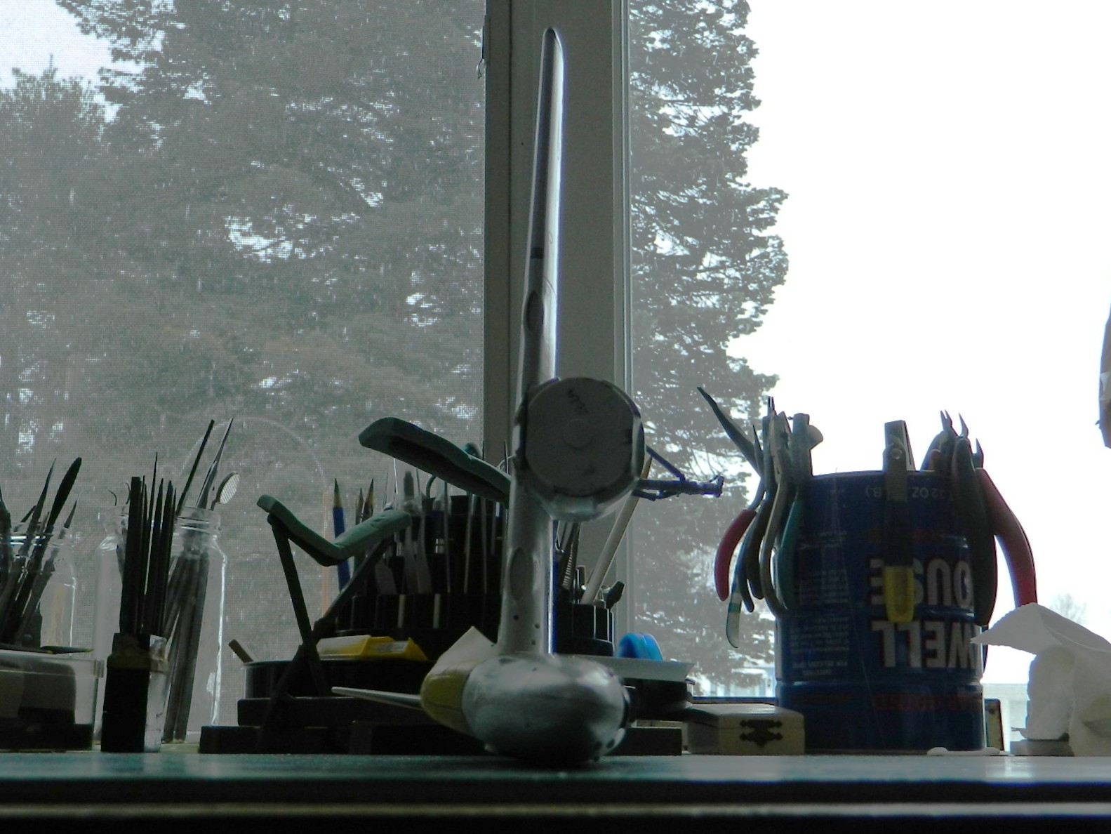
At this point I realized that there was a task I wanted to do that would be much easier to accomplish before the wings were attached. Shell ejection ports for both the .50 caliber machine guns and the 20mm cannons. The kit didn’t mold them in so I had to excavate a bit. Step one was to mark where they should go:

Then I started digging (using a sewing needle converted to a chisel point because everything else I had was much too large):

During the process of excavating the ejection ports, I managed to snap off the radio antenna mast that had been molded as part of one of the fuselage halves. I was waiting for that to happen (because some things I can see coming…sometimes) so I added a pin to the mast and drilled out the hole where I thought it should go (I found out otherwise later) and set it aside for later addition:
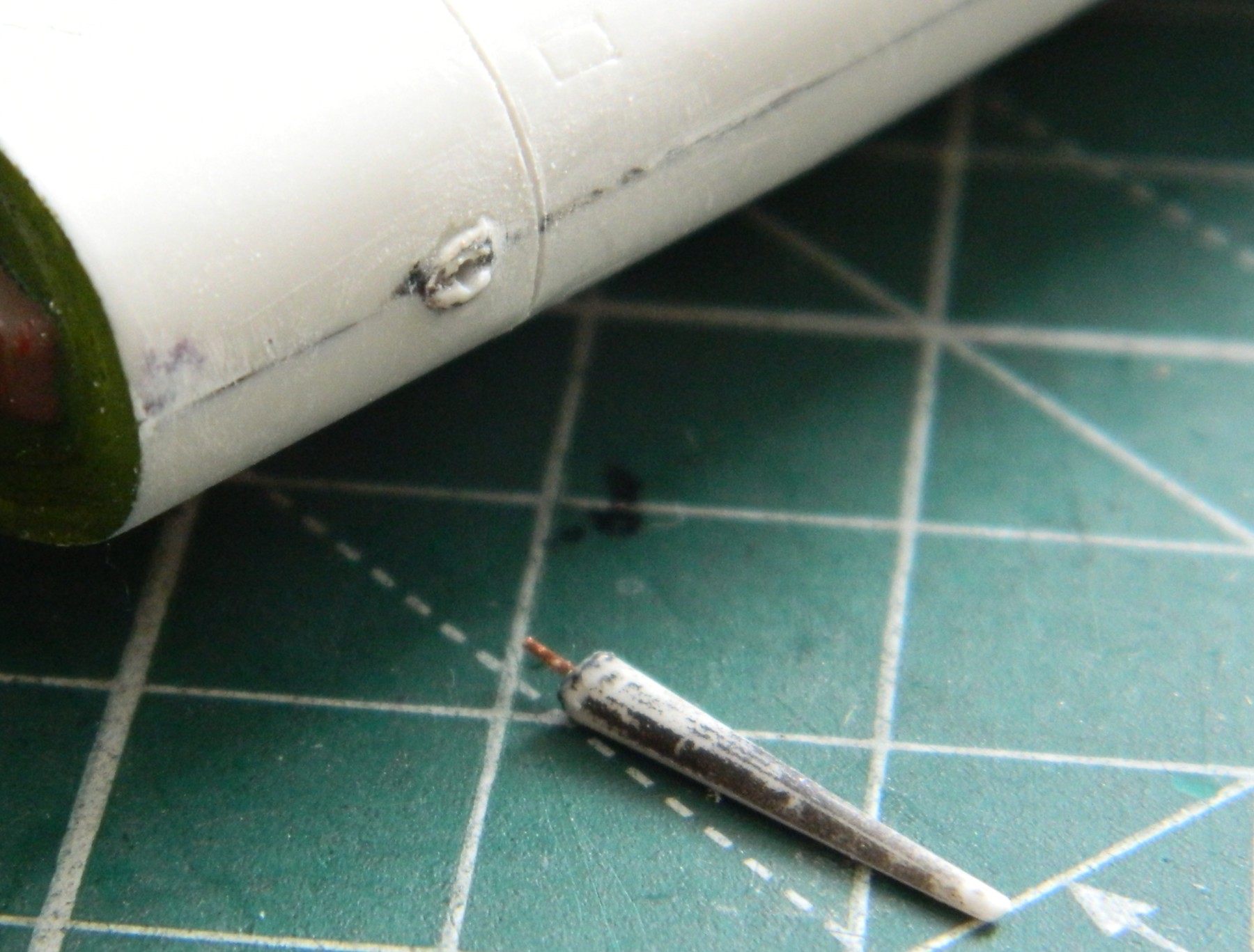

Then I glued the port (left, if I’m not trying to impress) wing and its space/filler added 0.010″ (.254mm) styrene as filler to position the wing to (what I hope is) the correct angle:

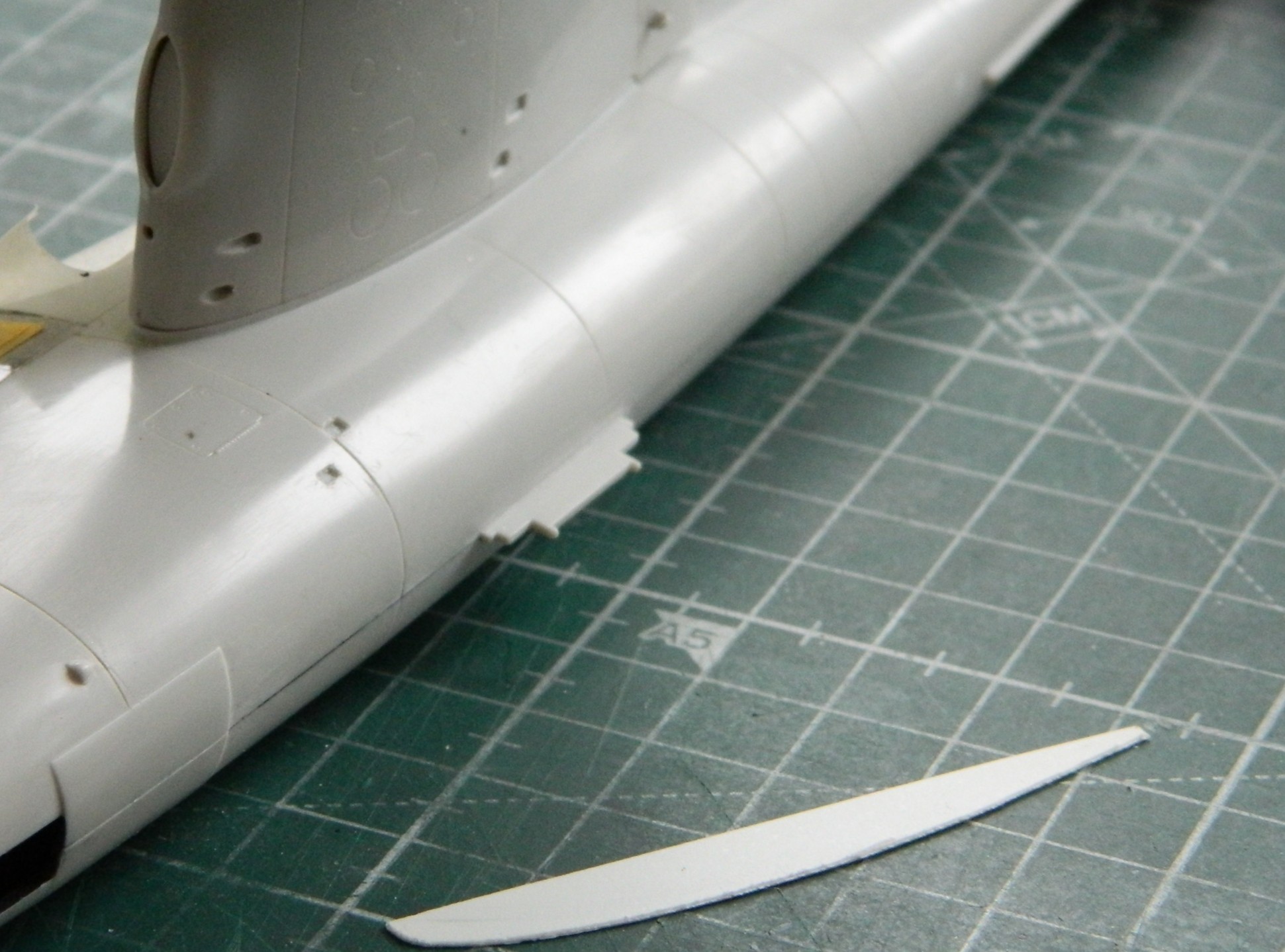
Then I added the other wing and used more styrene as a gap filling spacer:
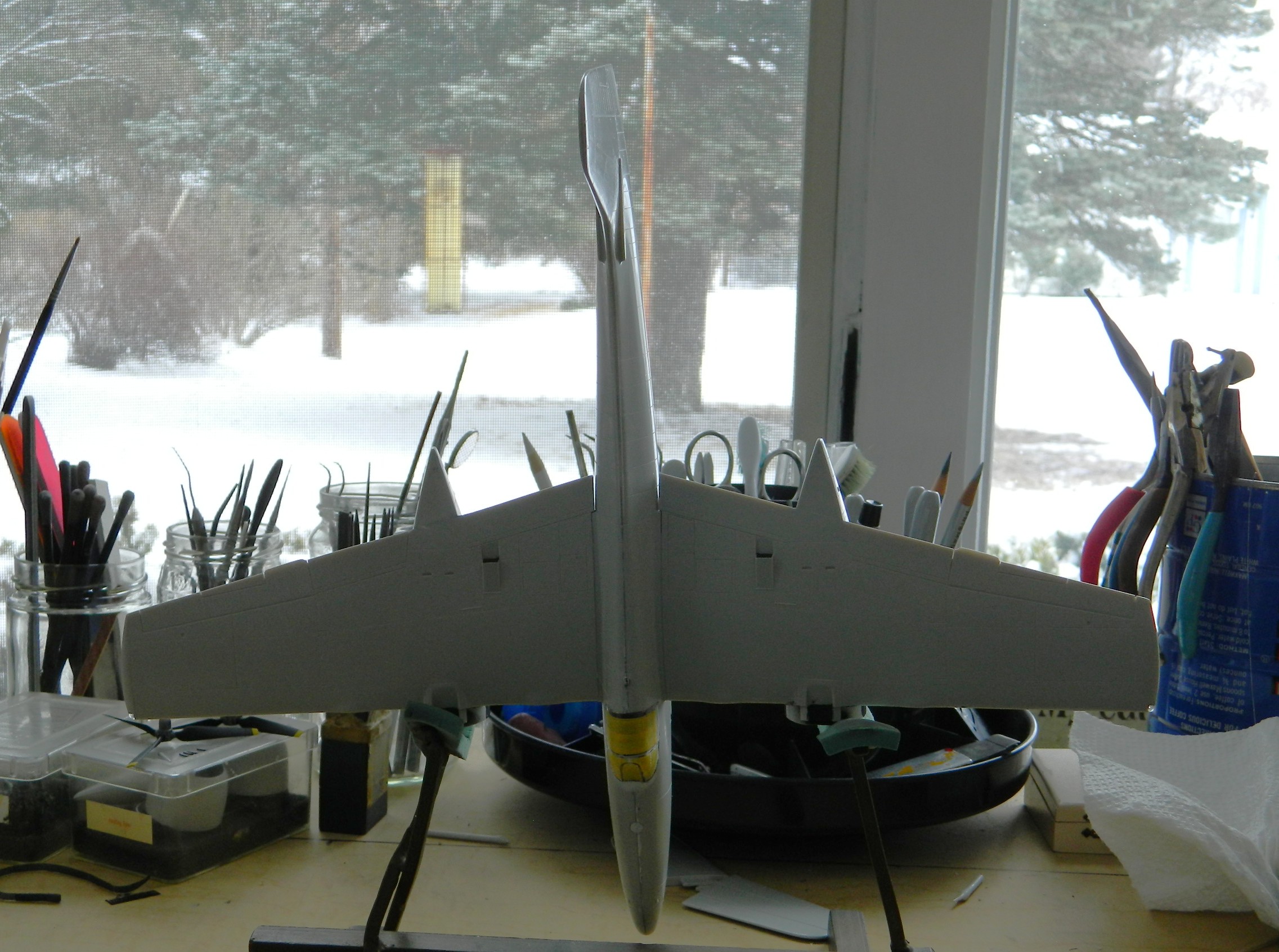
I diddled with the dihedral until my eyeballs dried out. At some point, one must accept that this is the best that they can do. Plastic can only be worked so many times before things break and/or wear out (including, or perhaps especially, my nerves). So the trigger was pulled and things were glued on. Then both 0.010″ (.254mm) strip styrene and 3M Acrylic Putty added to get things to meet and join as they’re supposed to (or, more accurately, as I want them to…and hopefully “supposed to” and “as I want them to” are the same thing):
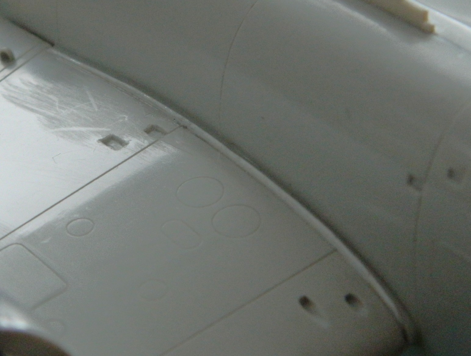
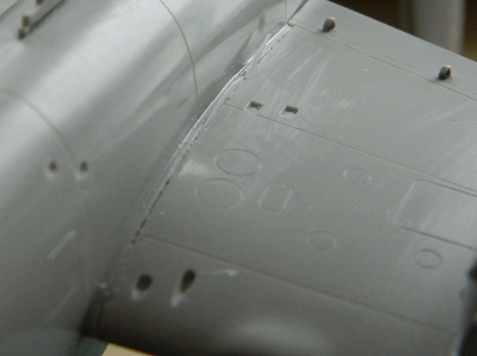
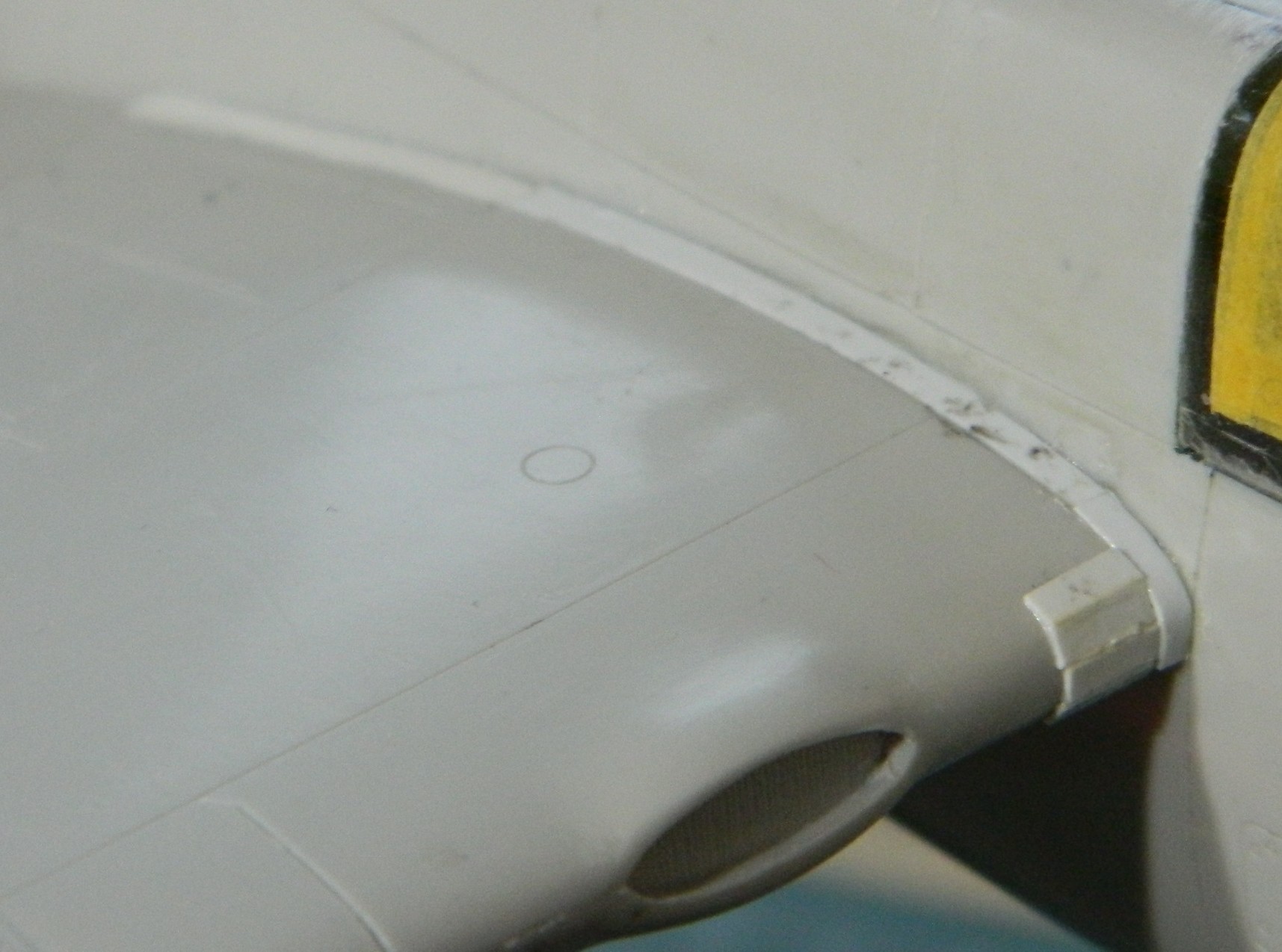

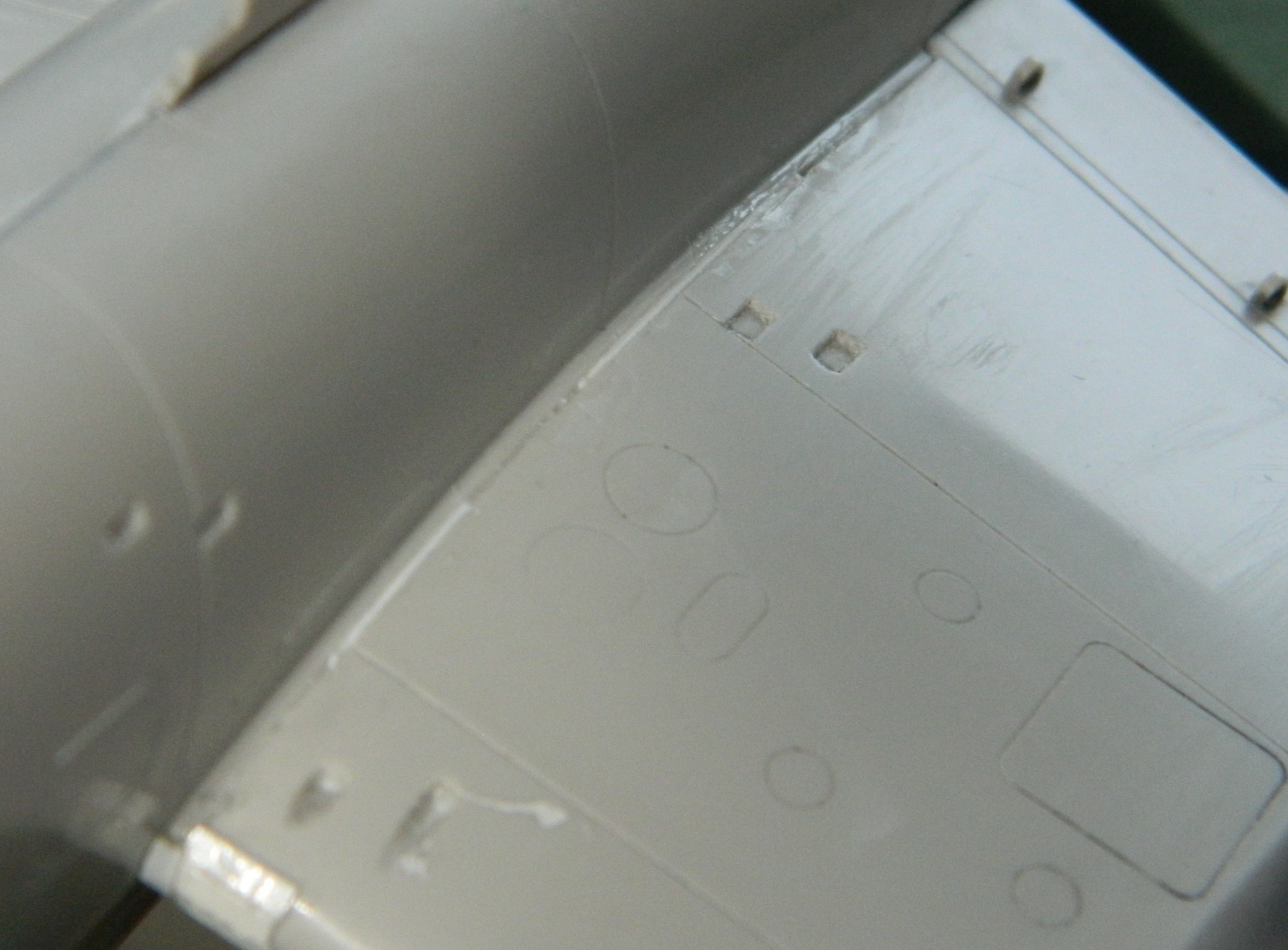
That followed up with filing, sanding, and cursing until the wings looked the way they were supposed to look all along (perhaps):

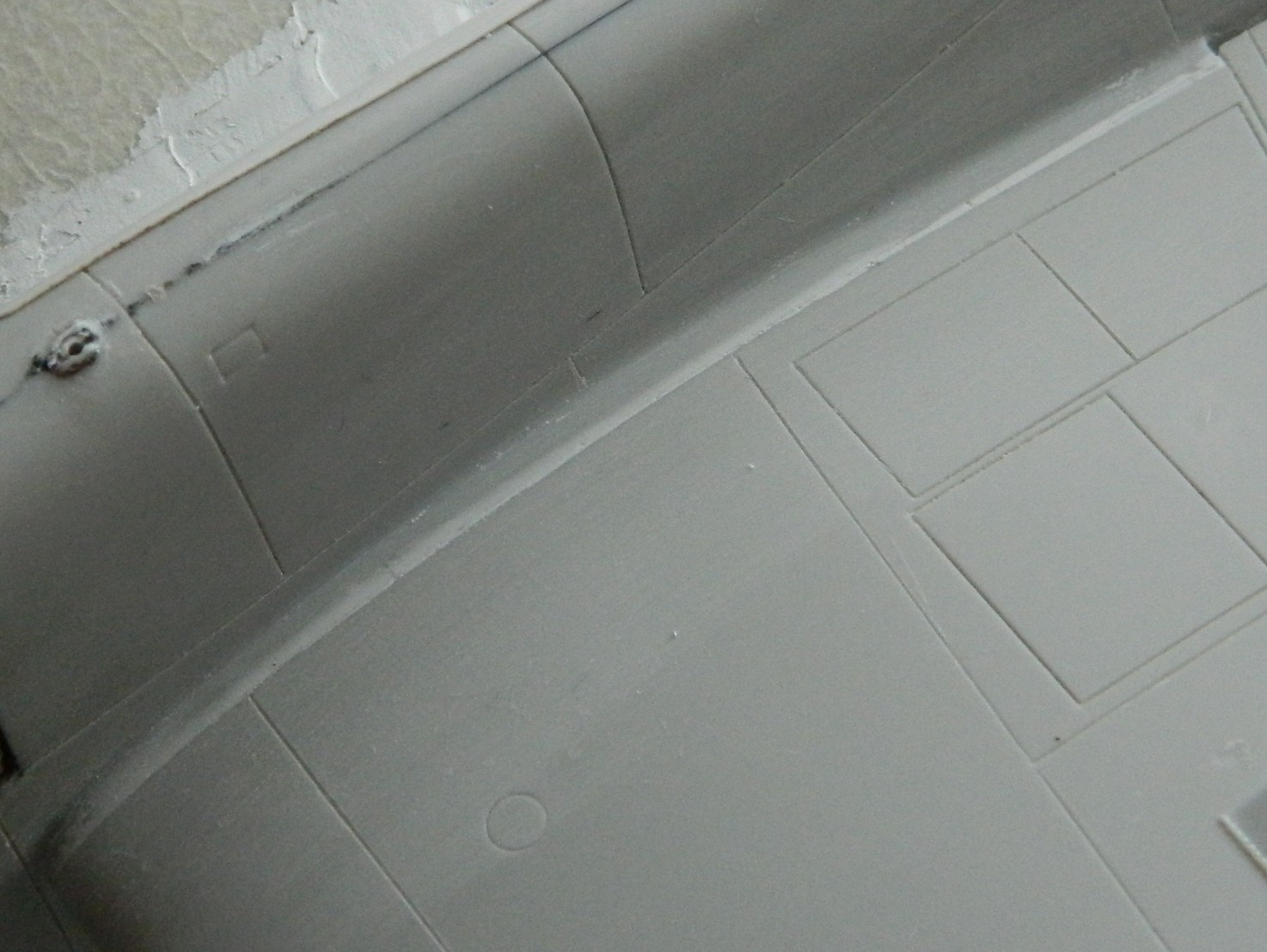
I had to reapply more putty, as one frequently must, to get the spots that were missed. I masked off the recessed lines to cut down on the amount of recovery those recessions would need had I not masked them off:
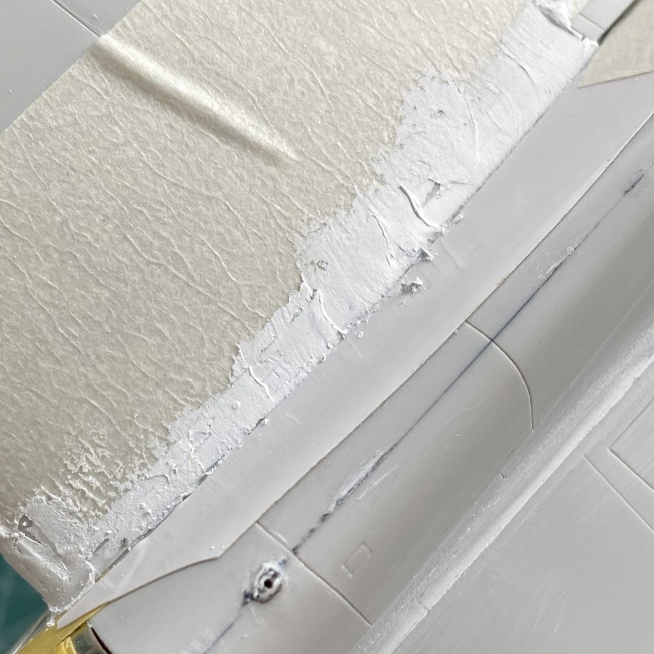
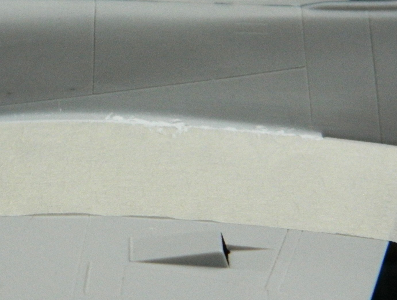
A word about masking… In the uppermost of the above photos, to the lower right of the white putty is a strip of white tape. I used electrical tape to do that because it will stretch. I used its stretching property to curve the tape to match the curve of where the top of the wing meets the fuselage. Handy trick to know as the electrical tape can be cut into narrower strips if you need it that way.
At this point I decided to recheck the fit of the vacu-formed canopy and I decided that it sat too far forward because the radio mast was too far forward. Well…how fortuitous that the bastid already snapped off! I figured out where I wanted the mast to mount and drilled its mounting hole for later attention and attachment (the hole to the left in the photo below is the new mounting location):
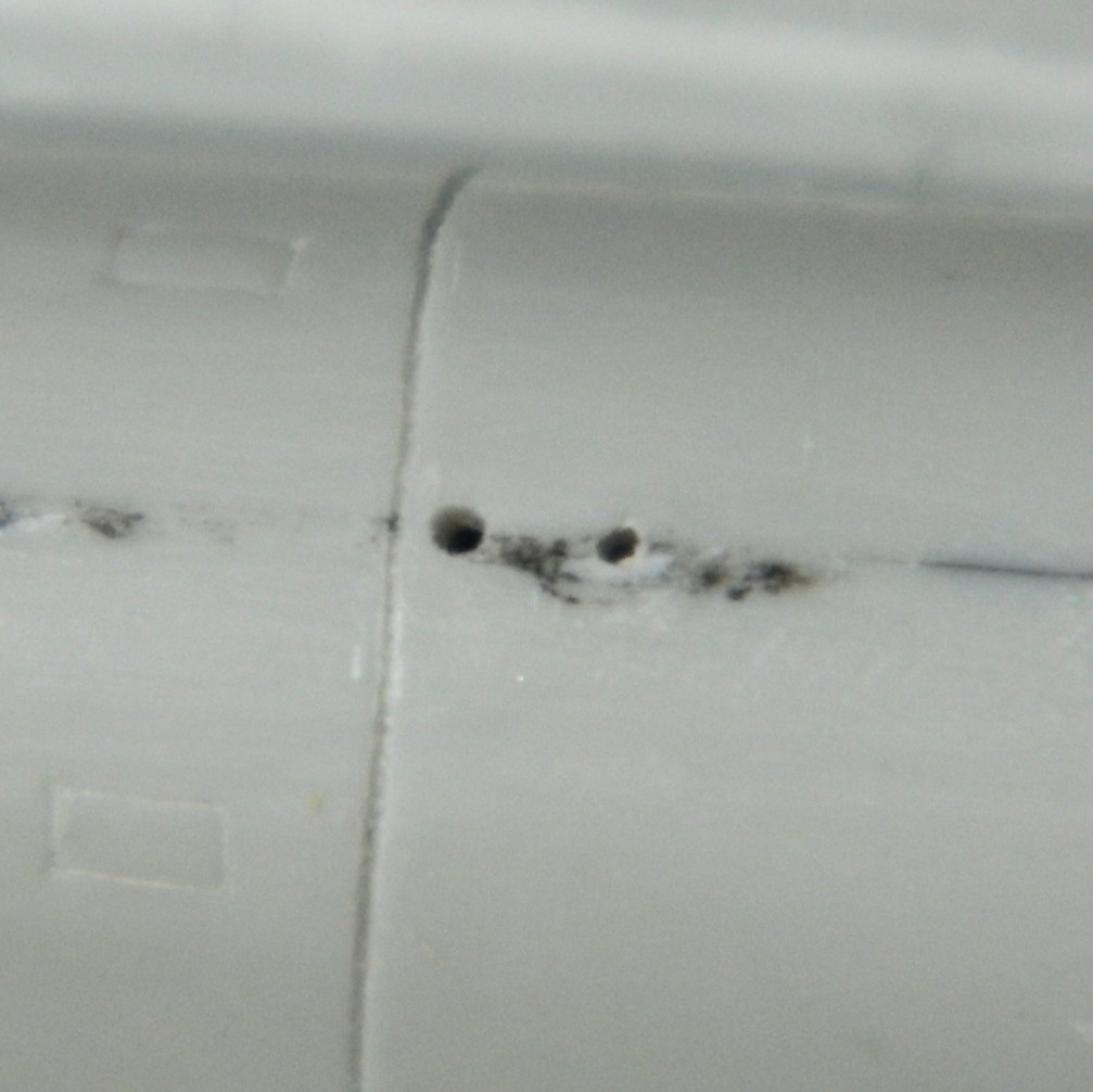
The empennage didn’t locate any more accurately that the wings did, but it was sneaky about it. The wings just slid into the slots, the empennage fit very snugly, leading to the MISTAKEN impression that that was where they belonged. And then one compared the plane of the wings and the plane of the empennage and it wasn’t even close. I spent a fair amount of time getting this part of the build to match the wings. The right side went on and align with a bit of fiddling. The left side did not want to go in, then it didn’t want to be at the correct angle. I used masking tape to hold the left side at the angle I wanted:
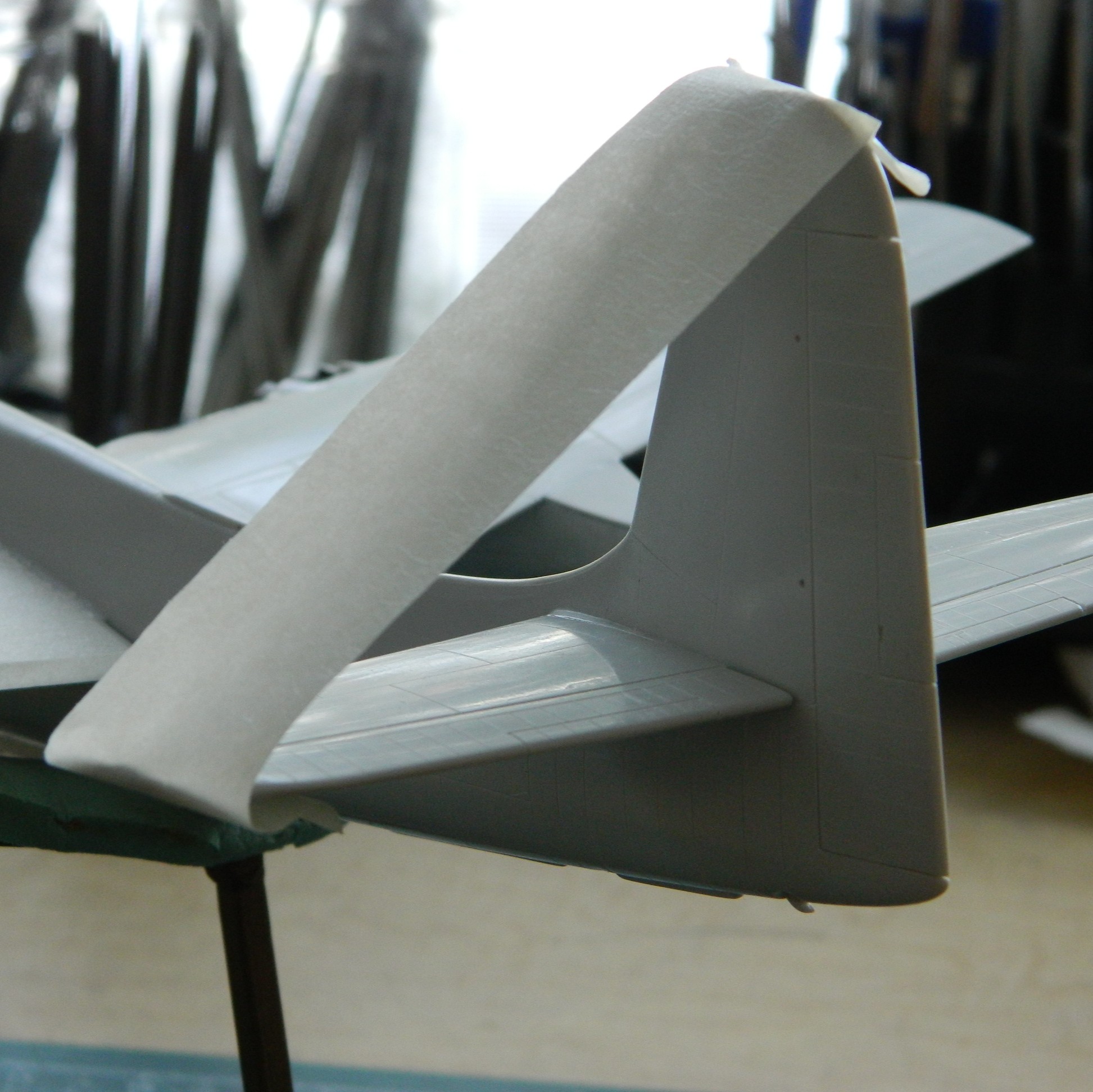
I loaded the airbrush (Badger 200 single-action) with Tamiya XF-1 Flat Black and hit the outside of the front canopy (which, due to its transparency, will present as the inside of the front canopy as black. I also did the intakes for the oil coolers and intercoolers (which, as events later showed, was a waste of time and paint):

Having acquired the correct color blue, I shot the engine cowlings. These were painted when they were off so that I could make a valiant attempt at applying kit-supplied decals while it was easy to get at them. They were painted Tamiya’s AS-8 Navy Blue which is a lacquer (more on that later). Not having worked with this type of paint before, I let it sit for a couple of days before overshooting it with Tamiya X-22 Clear and had no problems:

Time to apply the decals and see how bad they actually are:
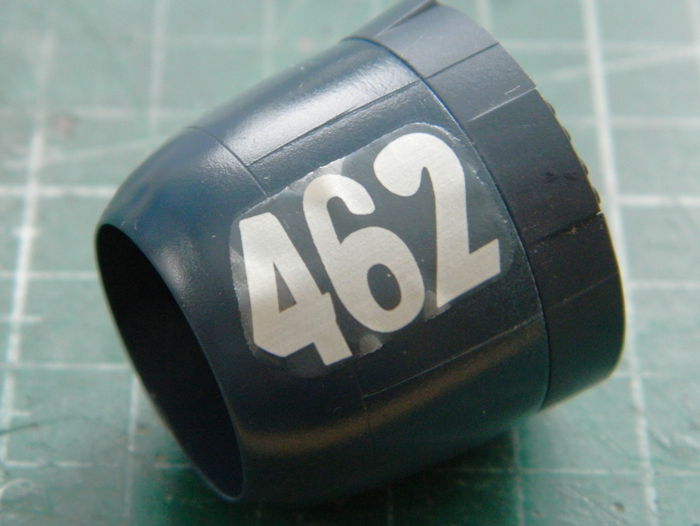
Bad.
Note the carrier film of that decal. Does it look like tissue paper to you? It really looked like tissue paper to me! Having read a few build reviews, that came as no surprise. And because the lower rungs of ladders are there for a reason, I started with Microscale’s Microset and Microsol. Zero effect. I stopped asking and instead went to the top of my ladder and used Walthers Solvaset. (Solvaset is HOT and has been said to dissolve modern decals and I can believe that! Don’t start out with Solvaset, start instead with Microsol because it’s the easiest mistake to rectify should you need to.) It took several applications of Solvaset to eventually conform the decal to the surface.
Did I mention that Solvaset is hot? Sure hope so. I’d rolled the cowling so that the decal was on top which would allow the Solvaset to pool and do its work. It was when I realized that the paper towel was stuck to the cowling that I discovered that Solvaset will and does dissolve the compound that Tamiya used on their paints. If that part is sitting on a paper towel, when the solvent evaporates, the towel stays…and it stays stuck to the surface.
The fix was to sand away the paper and marred paint. I started with 600 grit and worked through 1200 grit to 2000 grit and then used Novus Plastic Polish #2 to finish:

I was very relieved when that worked out fine and shot the Navy Blue and clear gloss again:

Having dodged that self-inflicted wound, I overshot both cowlings with X-22 clear and set them aside for later.
This was a big fighter and sat well off the ground. To get into it, there was a retractable boarding ladder in the lower right fuselage behind the wing. Ever been around an airfield where the aircraft are worked on? Let’s see…an aluminum tube ladder extending downward. I wonder if anyone’s ever backed a truck or tug into one and damage the snot out of the ladder and its mounts? Probably. So instead of mounting the ladder extended, I decided to model it in its stowed position. I clipped the ladder away from the part that attaches to the fuselage and then filed and sanded it down and scribed the panel lines:
The drop tank needed a little bit of detail. I used the punch/die set to knock out a disc that I could use as the filler cap. A piece of 0.010″ (.254mm) was used for it. Once it was mounted, a small amount of 3M Acrylic Putty filled in the edges of the disc that didn’t match the curve of the drop tank:
And while it was in my notice, I used a piece of 22 gauge wire and fashioned a painting handle for it and then set it aside:
When the tank is hung from its pylon, anti-sway braces are used to keep if from flapping around (always a good idea with an aluminum cigar filled with highly flammable stuff). And though the kit provided the braces, I thought they were out-of-scale. I used more 22 gauge wire to make more scale-appropriate braces:

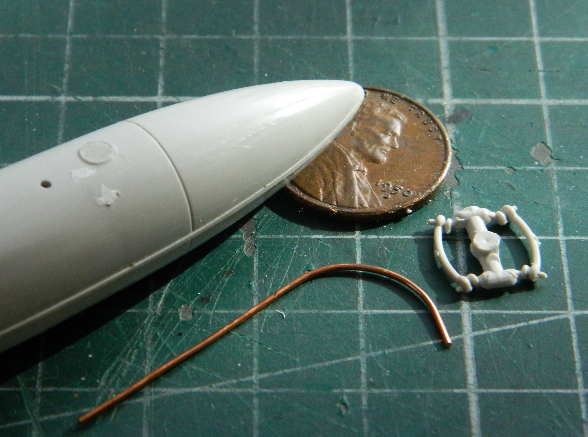
As you can see, the ends of the wires are square cut, but the ends of the braces are rounded. I used a file and pliers to round off the ends of the wires. Once done, I have flat-jawed pliers (not textured for grip) (or her pleasure) that I held the wire with while I filed the ends round. The next step was to take the same flat-jawed pliers and grabbed just the ends of the wire and SQUEEZED to create the flat ends, which I then drilled out for the adjusting bolts:
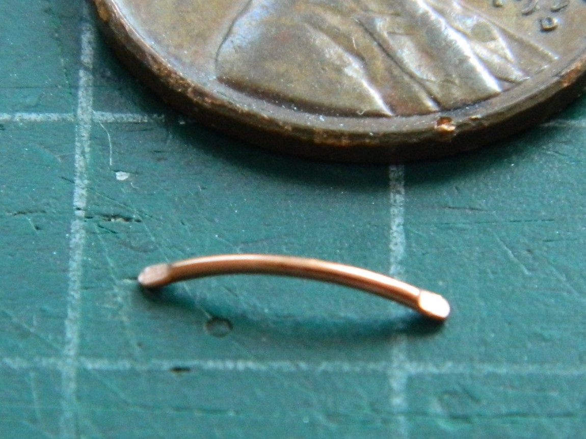
After drilling, I used Grandt Line bolts as the adjusters:
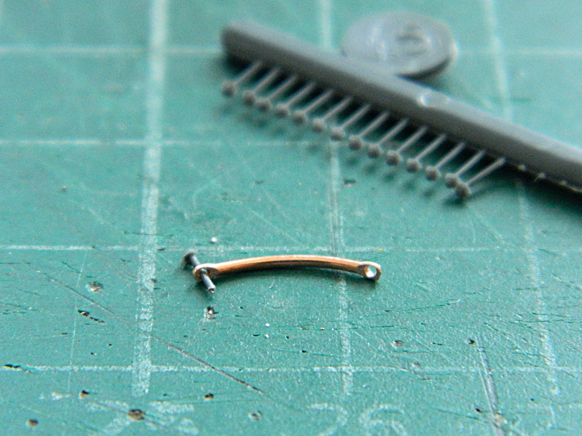

Those were set aside until later.
Having painted and applied decals to the engine cowlings, it was time to mount the engines. The engines are AM resin, so fitting them into the cowlings and keeping them centered was going to be the traditional superglue race. I decided not to run that race this time because I RARELY win it. Instead, I used superglue to attach a square of 0.015″ (.381mm) to the resin engines. This way I could do what I did…gob of styrene cement and then take my time getting them centered. (In fact, I was so thrilled with my cleverness that I made a mistake here. I’ll show you that mistake shortly.):
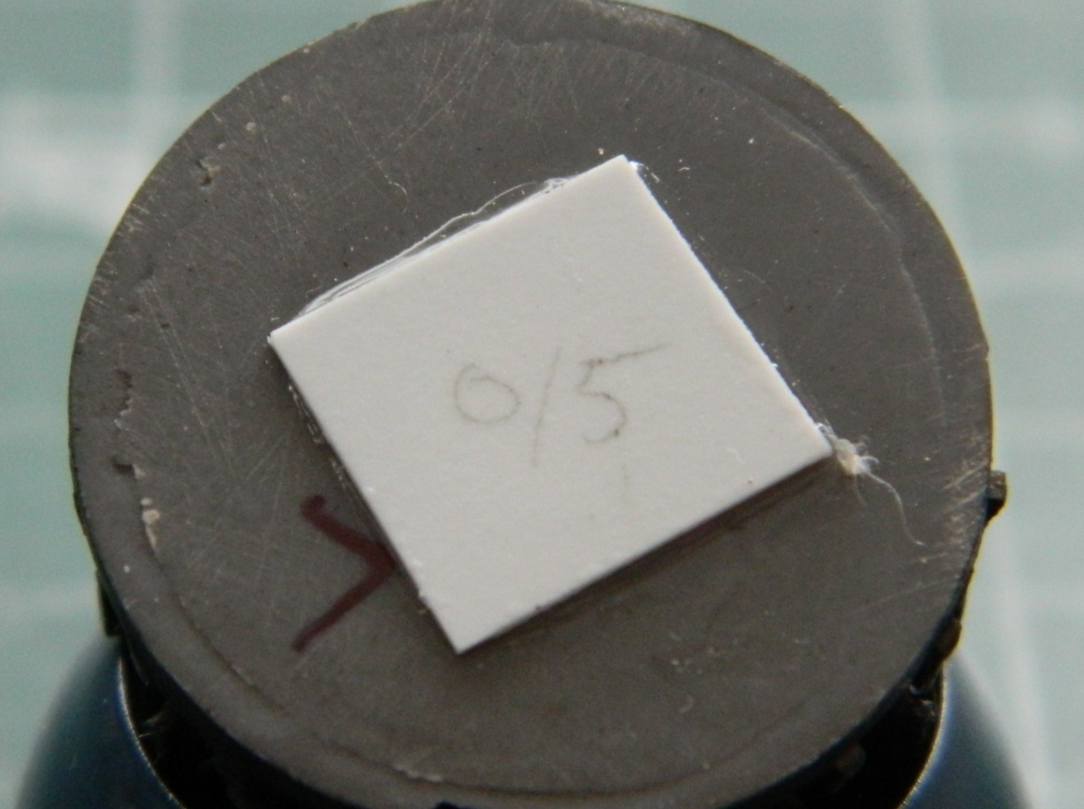
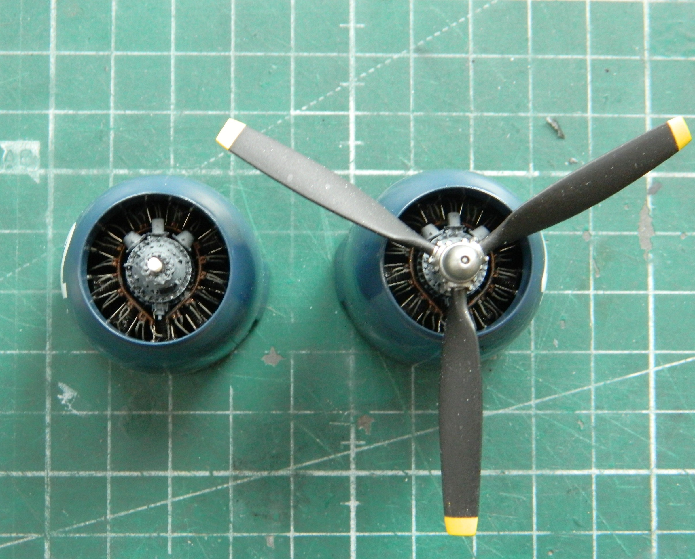
I laid out the landing gear bay doors to paint them:
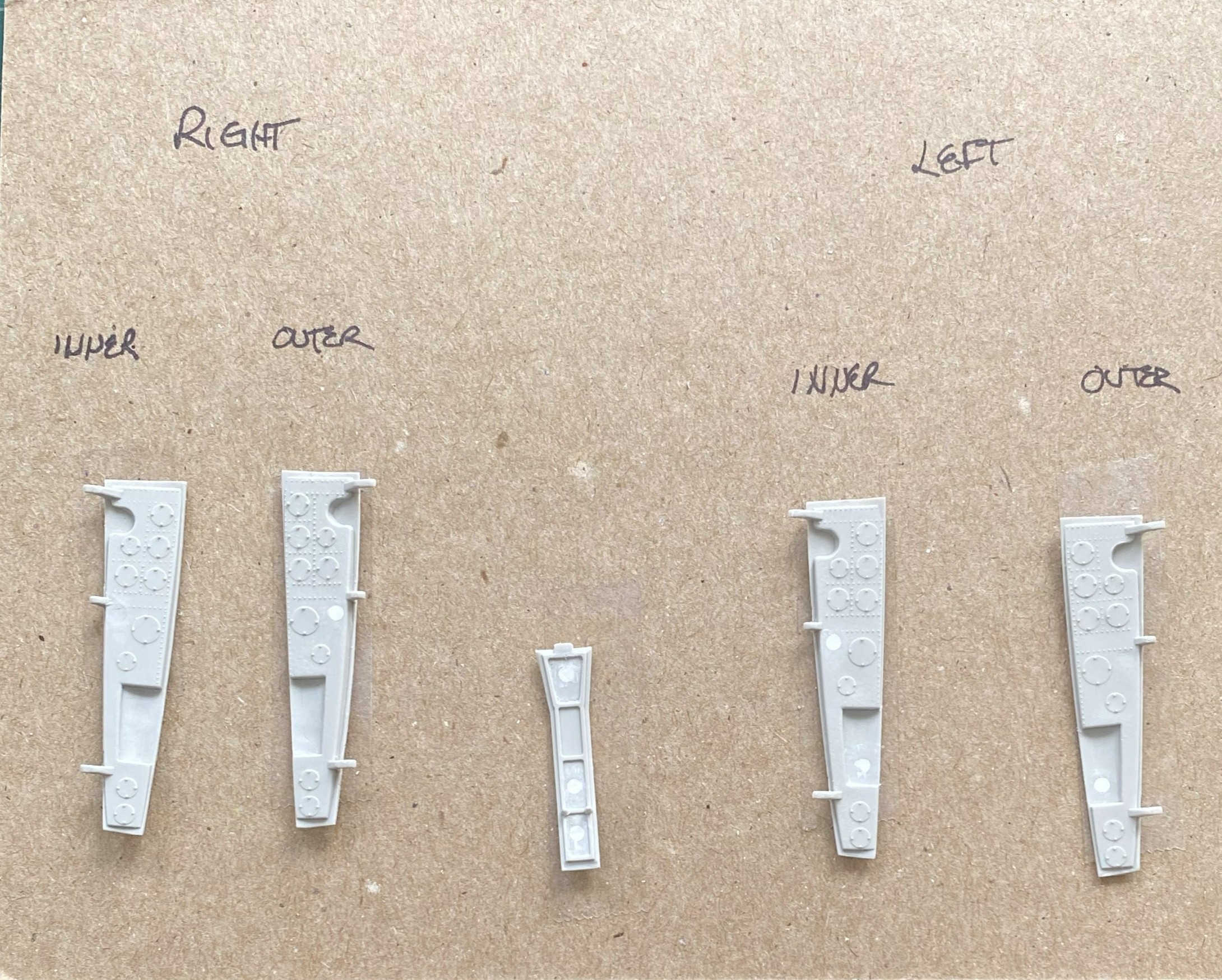
Then painted them using Tamiya XF-16 Flat Aluminum and then a black oil paint wash (now that it’s too late to fix it, I really should have used my darkened aluminum paint instead). Double-sided tape was used to keep the airbrush from blowing the parts into oblivion:

My roommate is very bothered by the smell of rattle-can paint and turpentine (no…I don’t have a spray booth). The AS-8 Navy Blue, being lacquer, has a pervasive odor so that means I won’t spray it indoors. I bring the model and the rattle-can into the garage and spray quickly before the temperatures of the paint and plastic approach ambient temperature (because this month has be single-digit cold here). In looking at this photo, can you tell where I was holding when I put down the first color coat?:
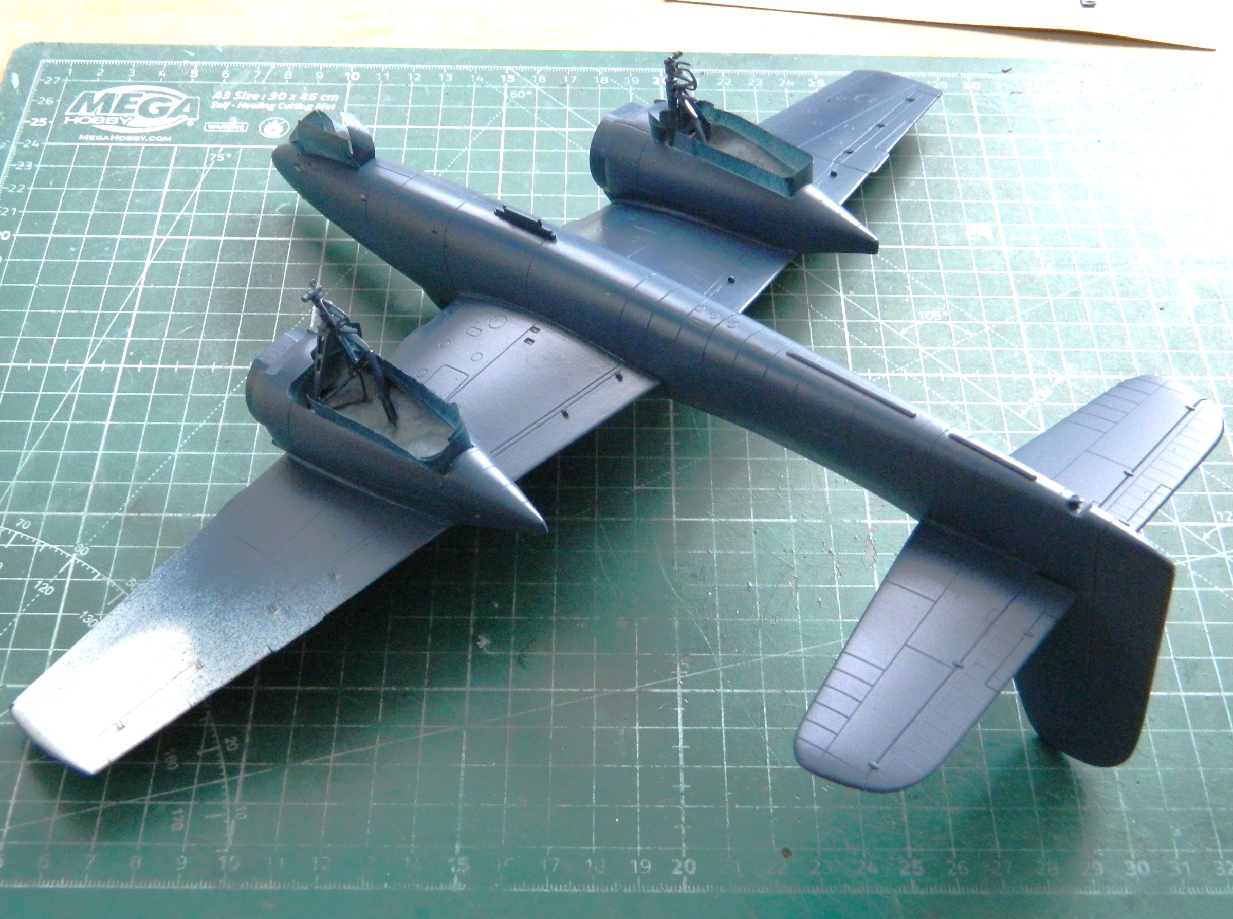
After sitting a couple of hours, I held it by the other wing and painted the other side:
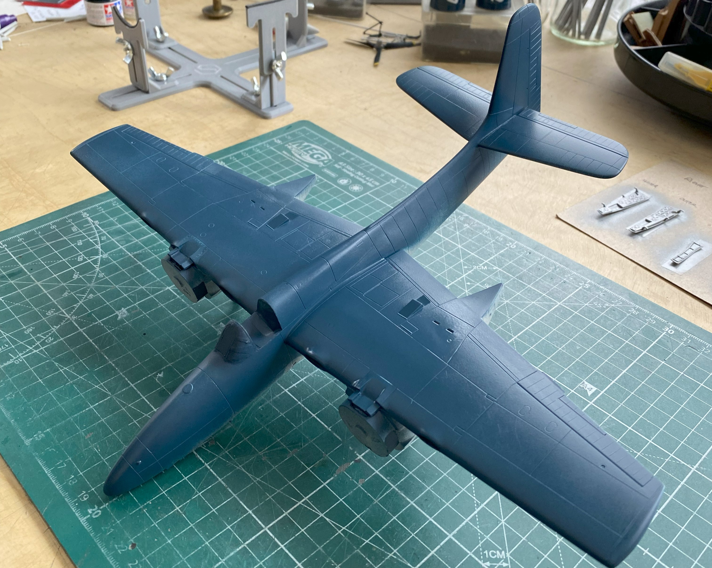
AND I have confirmation that this will not be a tail-sitter…I still have the 27g engines/cowlings to add. Once the paint had dried to touch, I flipped it back over and painted the wing where I’d held it during the first pass with the ‘can.
Once the paint had dried (the next day, in other words), I gave it a look-over and saw that the seams still needed some attention in a couple of places:

And I also noticed that I hadn’t been quite as effective as removing scratches from the surface(s) as I thought I’d been, so those needed attention as well:

I don’t know why, but I also decided to check the lights. When I paint with acrylics, I’ve discovered that the acrylic paint is so easy to remove that I don’t bother masking at all. I do my painting, take a fresh toothpick and carve a chisel tip to it, and simply remove the paint with it that’s where I don’t want it. Here’s where I discovered that not only does lacquer smell, it’s not possible to do that toothpick trick with, so all the landing and formation lights were sanded and polished and then masked off using tape:
When taping really small things, I’ve learned that cutting masking tape into really thin strips helps a lot. For the wingtip lights, I masked the borders of the clear covers with tape and then filled in the rest of it with PVA:


I started to mount the engine/cowling assemblies, only to find that they didn’t fit. Okay…they fit when I dry-fitted them, what’s changed. A two word question. “What’s changed.” It took me several hours over a couple of days to find out what the problem was. I was utterly unsurprised when I found the source of the problem.
Me.
I looked and diddled and removed the plastic that I thought was in the way:

Nope…didn’t fix it. And then I figured out what the problem (with its foundation in me) was…
The R2800 series of engines are double rows of nine cylinders. The way Grumman did the exhausts, each cylinder has their own exhaust and they’re clustered in four groups. All but the bottom exhausts have four ends and the bottom exhausts have six. Y’know, if you mount the engines upside down, THERE WILL BE FIT PROBLEMS. Somehow, I mounted the sodding engines upside fucking down. There was no way that I’d be able to dismantle the engine/cowling assemblies without destroying all of it (glue’s cheap, y’know). Okay. So the problem is that I’m trying to stuff six things (exhaust pipe ends) into a space intended for four things and anyone whose age comprises two digits should know that. Normally I know that. If I knew how I made such a basic error, I’d not have made the error. (And I debated if I’d even bring you…plural, I hope…into the sphere of my oversight. But my deal with myself was to make this site as real as I can, and that, lads and ladies, means showing you my errors as well as my accomplishments. ::facepalm::)
With the mistake “fixed,” the cowlings fit the wings.
At this point, I’m getting to all the things that inhabit my “I’ll do that later” roster. One of them is the antenna. I’m going to use EZ-Line, 0.02″ (.127mm) for the aerial. I’d drilled out a socket for it at the tip of the vertical stabilizer, so I had to figure out how to mount the other end to the mast. Almost immediately (because it’s become clear to me that the only things I can do immediately is break something or attach it upside down) I realized that the tip of the mast is too thin to drill out. Instead, I used a very sharp scalpel to cut a V-shaped groove near the tip of the mast so that I could lay the line in, apply the UV-setting resin, and see if that worked. It did:


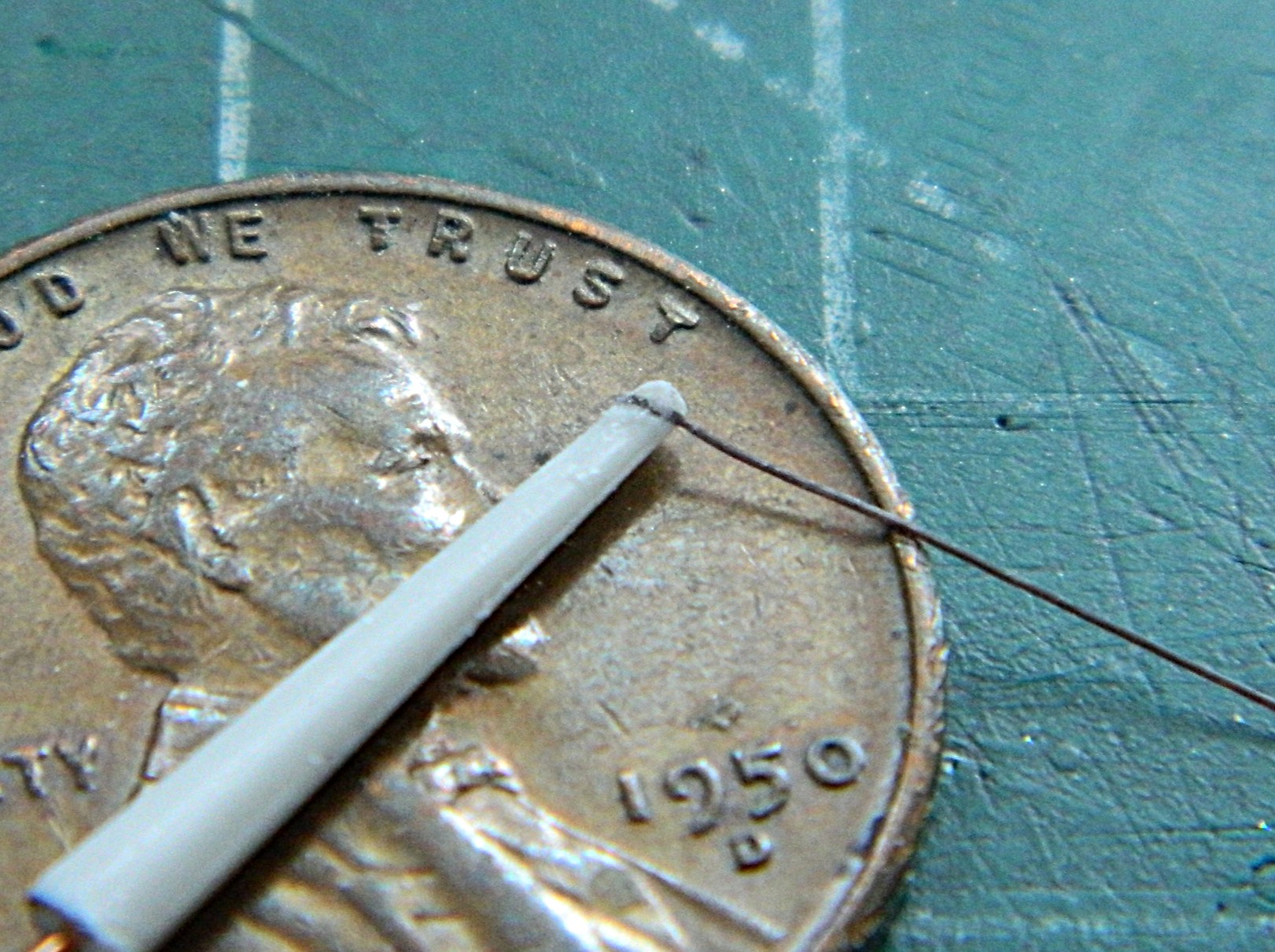
The other thing I did (which I didn’t take photos of) was shoot the whole bird with Tamiya X-22 clear. Well, that’s not all I did. I also managed to cover most of the thing in orange peel. Orange peel is that pebbled surface (much like an American football) that one gets when one totally cocks up a paint job. In my defense (should such a thing actually exist), I was trying to put enough clear down that it would self level. Looks like the line between self level and orange peel is vanishingly small. Some places that worked, and other places it did not. How does one fix orange peel? Well, one can strip the paint down to the bare surface and do it again correctly, but that’s the last resort. If one is lazy (and I am), and one has enough paint already thrown down (oh boy did I), it can “simply” be sanded flat. Of course, since all solutions create new problems, I had to be careful not to sand through the clear AND the color (which I did in a few places). Sand paint away, add more paint, sand to the correct depth, rinse the sandpaper and repeat (which I also did in a few places). The color coat, though, couldn’t be shot with an airbrush as it was in a rattle-can. I decanted a bit of it into an empty Tamiya paint jar (“just in case” he sarcastically muttered at the time) for touch ups. Since there isn’t any fine control with a rattle-can, I made CERTAIN to mask off areas around the vertical stabilizer when I had to redo the lacquer:
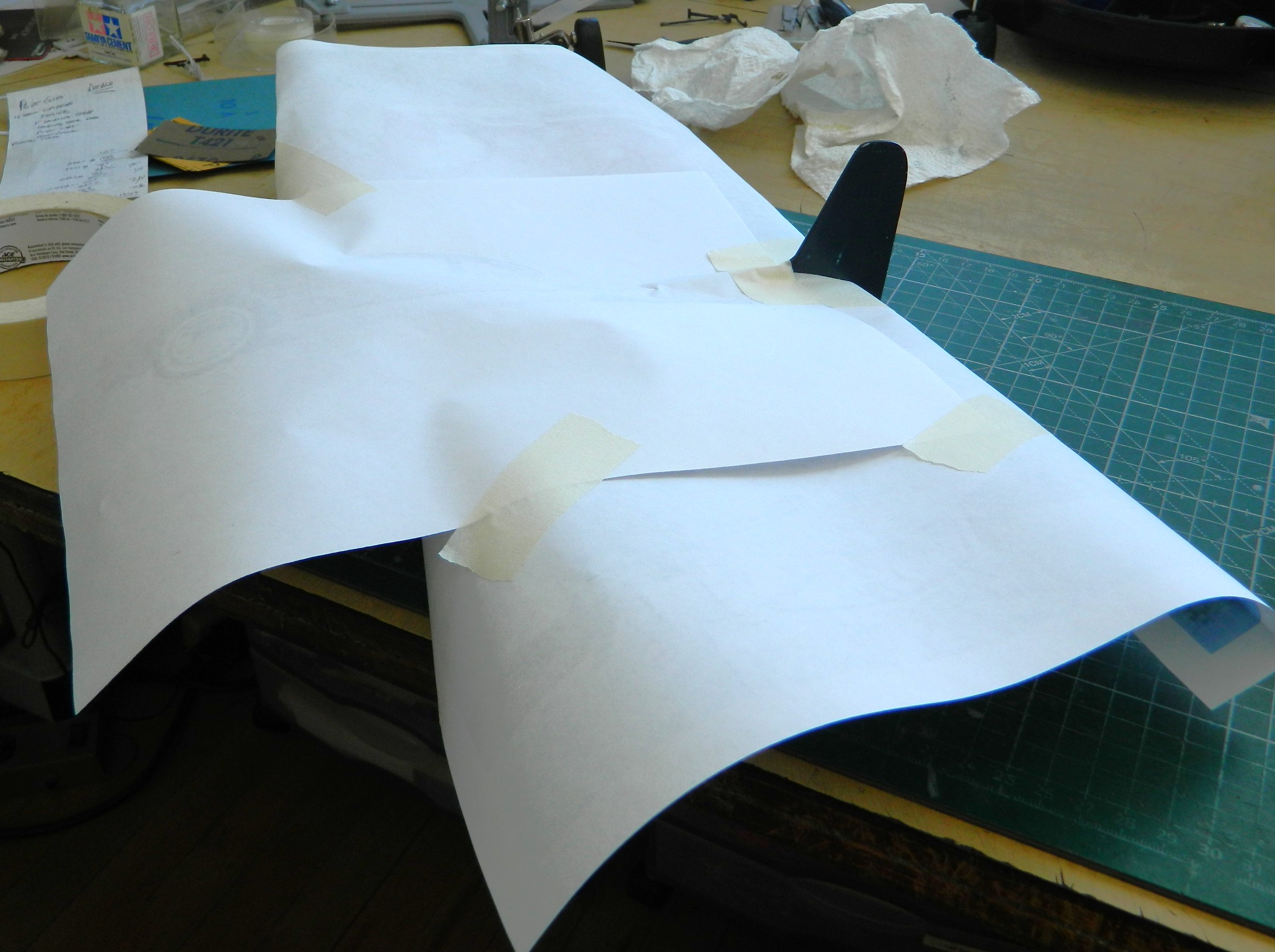

Recovery of the surfaces that I didn’t repaint started with a pass of 1200 grit sandpaper. If I wanted to spend a month sanding, that would have worked. I didn’t. Instead I used 600 grit where the orange peel was really bad. Then I used the 1200, 2000, and plastic polish. That worked.
But eventually I ended up here…all the parts ready to assemble:
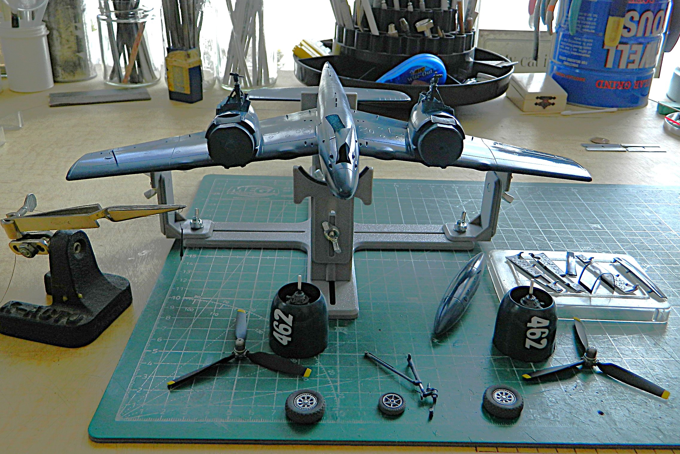
From here, anything and everything I added was subject to breaking off…which all of them did several times, so it was a week and a half of three steps forward, two steps backward. My favorite.
I attached the landing gear doors…the first time. There were several other “attachments” made:
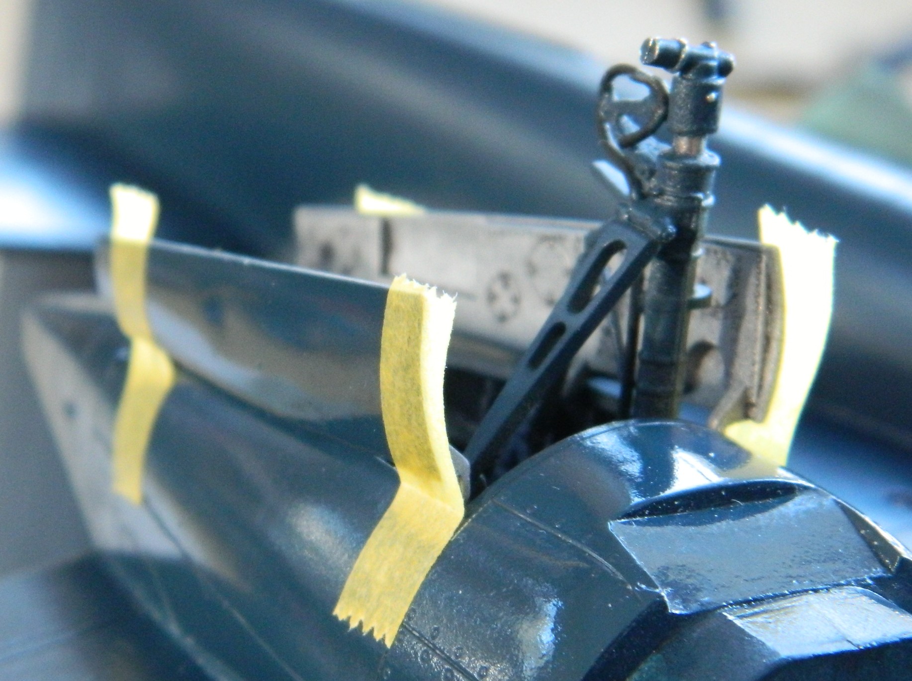
Then I started applying the kit’s decals. By now I was familiar working with these decals. I applied the Solvaset, and then used a cotton swab soaked in Solvaset to flatten a bubble. Big. Mistake:
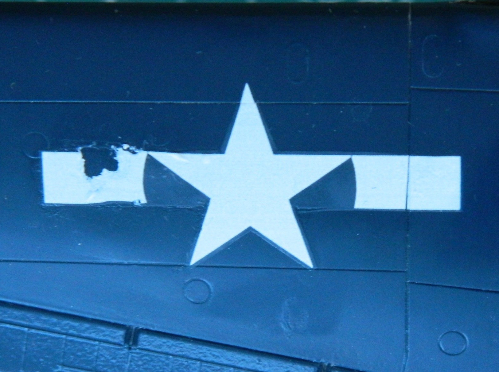
If I’d had another set of decals for this, the one I bitched up would have been sanded off, paint reapplied, and the new decal applied. But I didn’t have any new ones so this one had to be fixed. I masked off most of it and lightly sanded with 1200 and 2000 to bring the texture down and then painted the mistake:
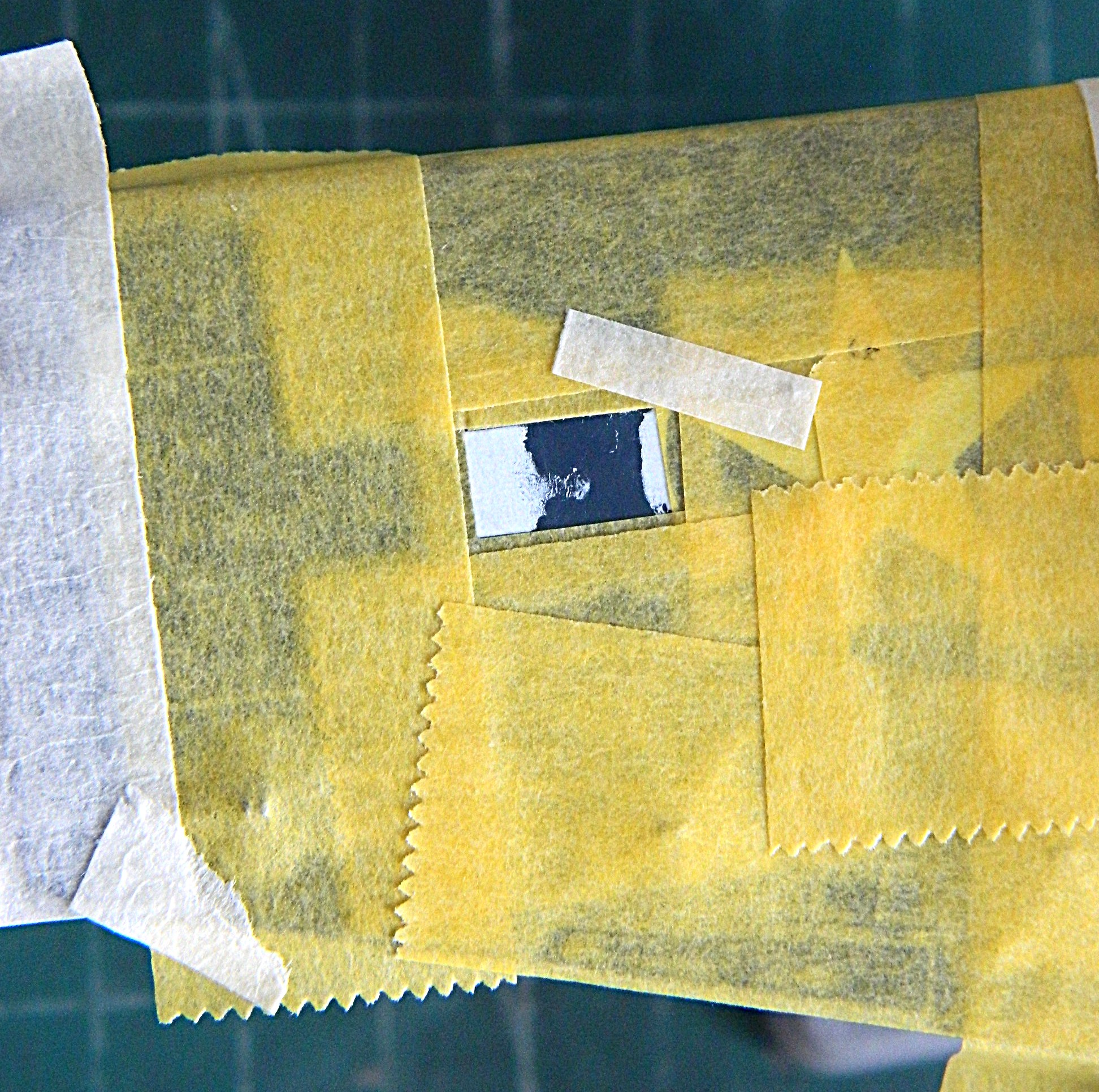

Not exactly show worthy, y’know? Not the clearest shot of it because I was just really annoyed at what I did but this shot shows that from a distance, it doesn’t jump out in the eye. An improvement, if still a botched job:
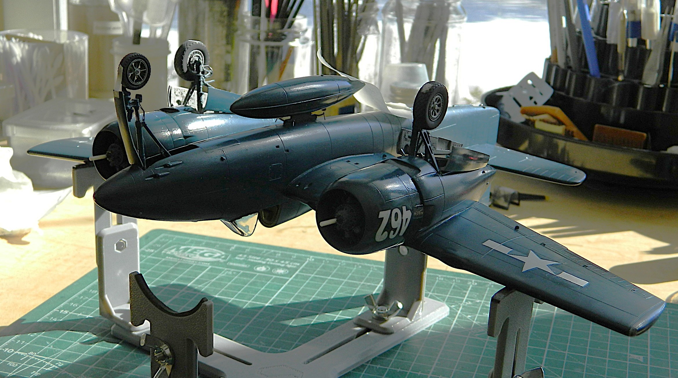
I added the other decals, of which there weren’t many. I also managed to botch the stars ‘n’ bars on the upper wing on the other side as well as the fuselage markings on the left side. I got one star on without mishap as well as the small production identification markings on either side of the vertical stabilizer. Yay.
Adding small details and closing in on being done, I added the 20mm cannons:
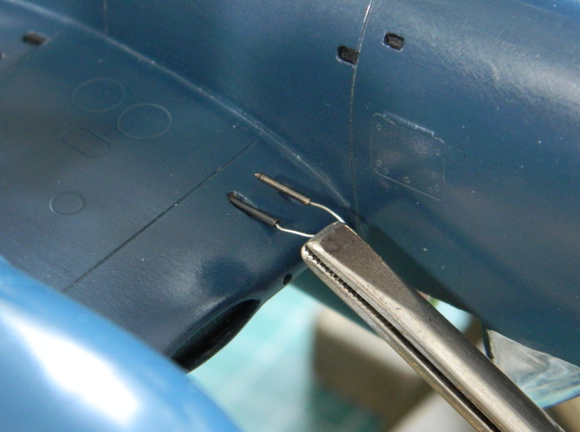
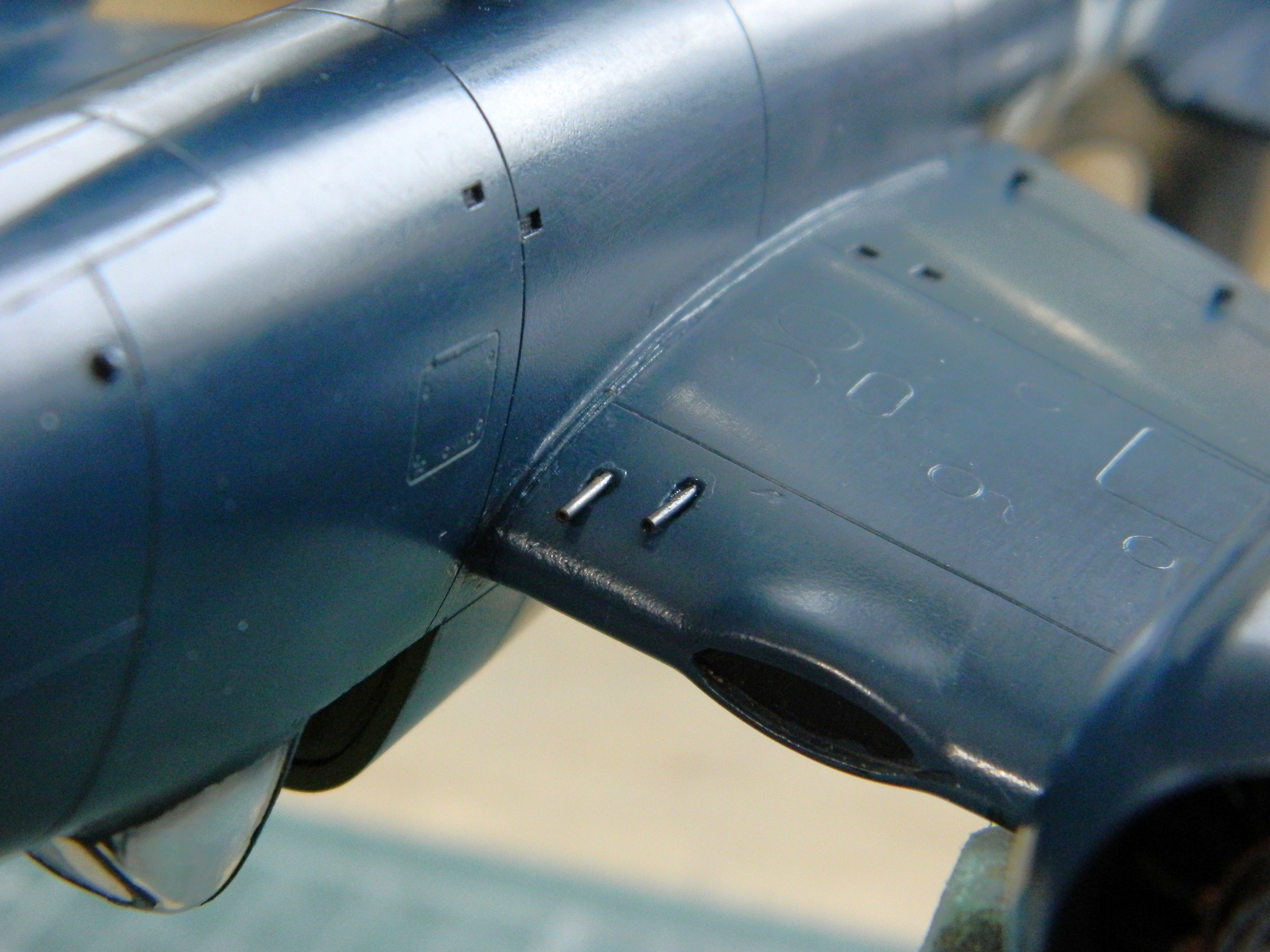
Having painted the oil cooler and intercoolers black (again, as the rattle-can covered what I’d already done), I added the canopy in the open position and used small dabs of UV-setting resin to hold it there, glued the antenna mast into place, and then trimmed the EZ-Line and glued it into the vertical stabilizer, and like that, it’s done:


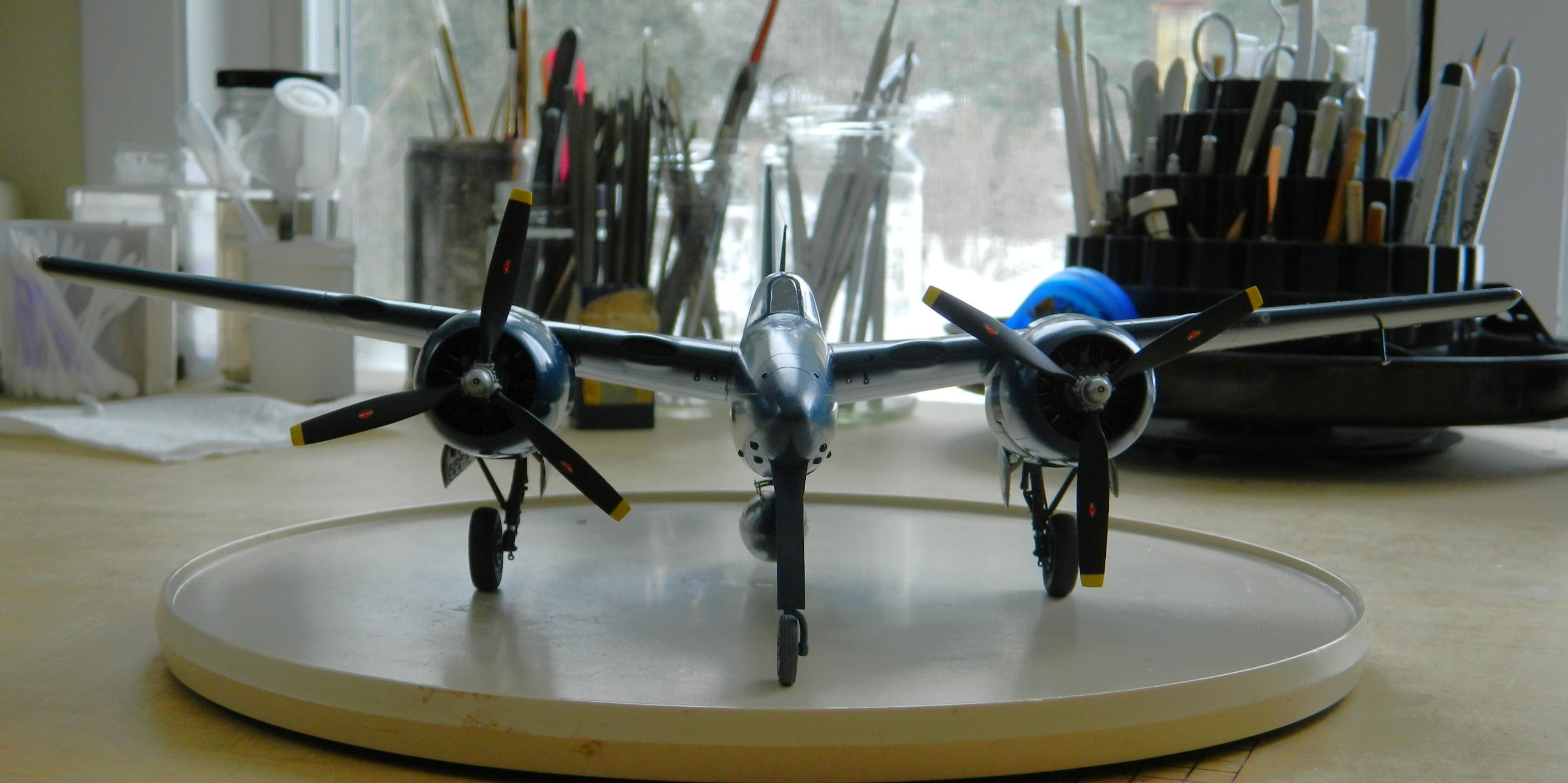
F7F-3 (AMT/Italeri) 1/48 Scale Build #8 – Finishing the Fuselage, Making Clear lights, and Attending to the Final Details Before Assembly Starts
Sometimes all the seam-filling goes, well, seamlessly…and sometimes not so much. This time was the not so much category. I had to go over the fuselage seam a few times, searching out those tiny areas that either show the seam or air pockets in the putty. Since the window in the shop faces east, having that bright morning sunlight (unlike myself, who’s not very bright at the best of my times, and certainly not in the morning) enables me to see things that usually don’t show up for me until it’s painting time. So all that got done.
Since I generally don’t start a build that I know how to finish, there’s always that particular thing floating around my consciousness just waiting for its turn to enliven my day (because don’t all inanimate and insensate objects just float around waiting to enliven with our days?). Checking how well or not things fit is to see which of those aspects of the work will need attention as well as how much attention. I’ve known for awhile that the canopy, the forward and fixed part as well as the part that slides back to open the cockpit, doesn’t fit well at all. I also intend to model this aircraft with the canopy open, except that the kit part is too thick and sits ridiculously and unrealistically high. That means I’ll need to vacuform something thinner. But at the beginning of it all, the forward canopy is too narrow. And ever since I added the few details to the landing gear bays that I did where I used UV-setting resin, I’ve been planning on using this medium to attach the canopy. But all that gets to wait while I finish the last seam, the one going across the inside of the canopy:

Given the proximity of the instrument panel, I wanted to protect if from the work. Since there are several really small parts that could be dislodged if I used tape (and the fact that returning them to where I want them will be quite annoying because of lack of access), instead I made a “portable” mask from pressed paper:
That will drop into the gap between the instrument panel and the edge of the fuselage:
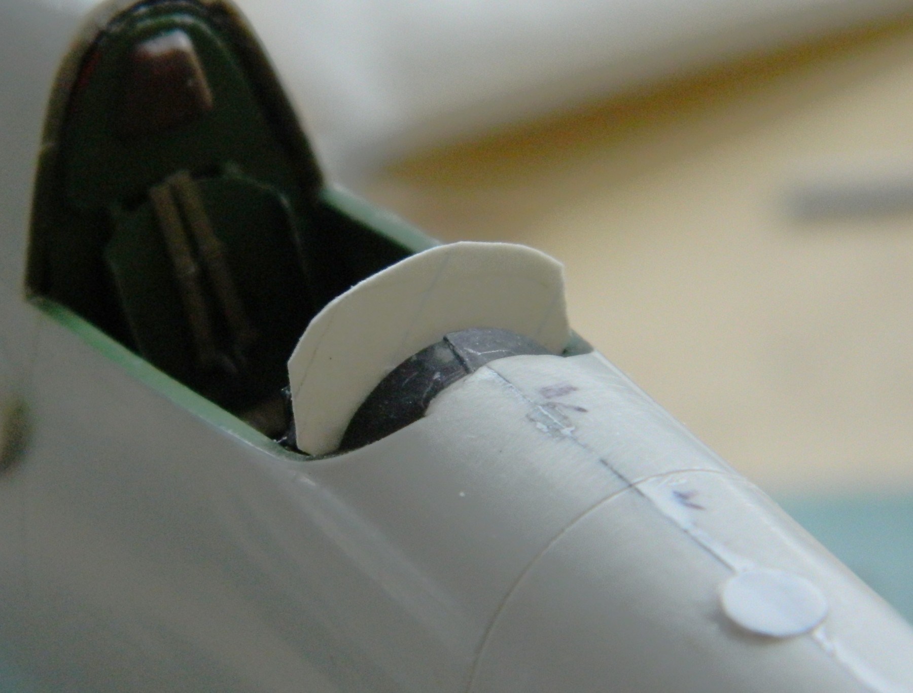
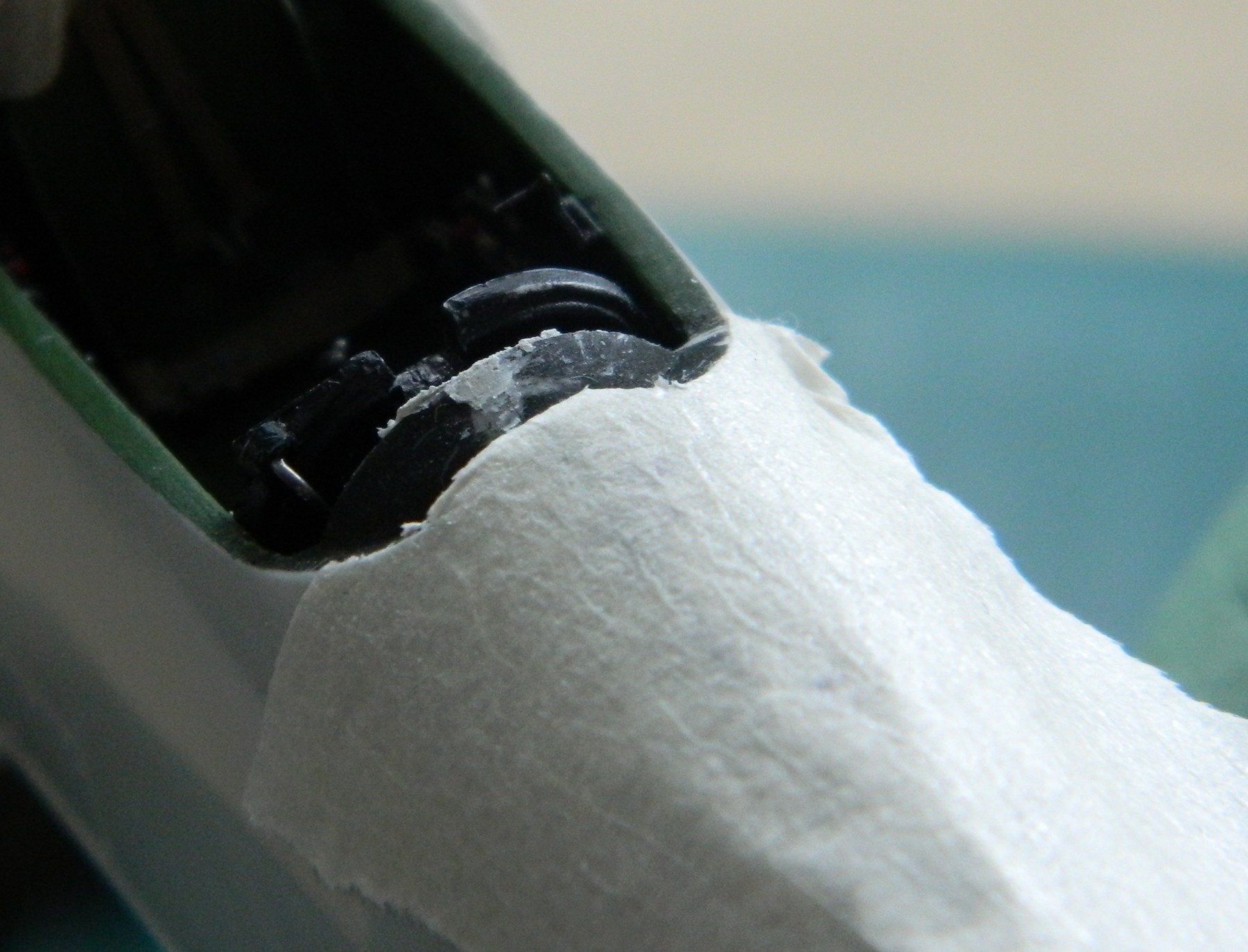
The mask worked as hoped for.
The rear of the cockpit’s interior is flush with the sides of the cockpit opening on the actual aircraft and because of where the cockpit assembly fit, there was a gap around that bulkhead (fit problem, obviously) I’d intended to putty that. But in order to fit the bulkhead where it should go, I’d need a time machine to talk (loudly) to the engineers. Since that’s not possible, I did the best I could with what I had to work with:

I masked off as much of the bulkhead as I could and got creative:

Once the mask was removed and the putty worked, I guess it’s better, but it’s not accurate. It’s just the best that could be done short of splitting the fuselage halves and starting this part over. Nope. Not doing any deconstruction that I don’t have to. Best part of being good is knowing (or guessing correctly) when to stop. So I stopped here (of course finishing down the putty and repainting the affected areas, which were minor).
One on my peeves is using opaque paint to replicate things that are clear or translucent. I have two wingtip lights and two landing lights to do, and only the landing light located under the starboard wing was acceptable (relatively speaking because of…wait for it…fit problems). So three of the four landing lights needed to be redone using clear plastic or acrylic. I’ve already shown you how I dealt with the light located in the leading edge of that wing by using clear sprue. The wingtip lights are too large for any clear sprue I have on hand so I ended up using a quarter inch (.635mm) section of a clear acrylic rod.
That process started by cutting away the opaque plastic where the lights go. This let me ascertain how big the replacements had to be:

I used a razor saw to cut a slot in the end of the rod:

And then sliced across the cut to get two pieces:
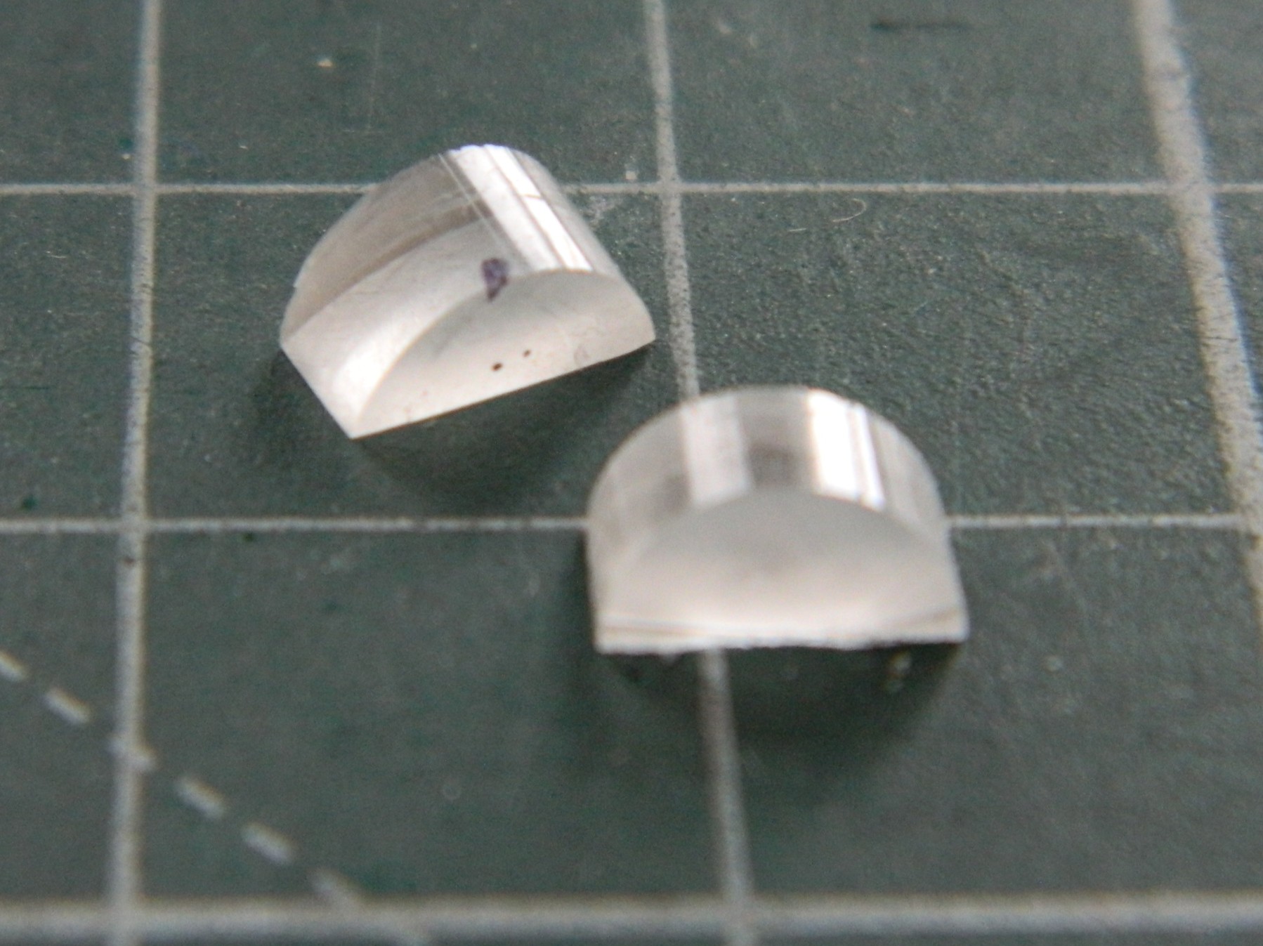
References show that the actual bulb comes in from the side of the wing. Red is used on the left, green on the right, so I drilled a very small depression that I added the appropriate color to (sorry about the blurred photo, the camera clearly needed caffeine as well), then I sanded and polished the faces of the acrylic that will be in contact with the wing before gluing the acrylic (with the properly painted “bulbs) to the wing. Usually I would use superglue for this. This time I decided to see if the UV-setting resin would work…it would certainly give me MUCH more time to get the acrylic correctly positioned and it worked great:
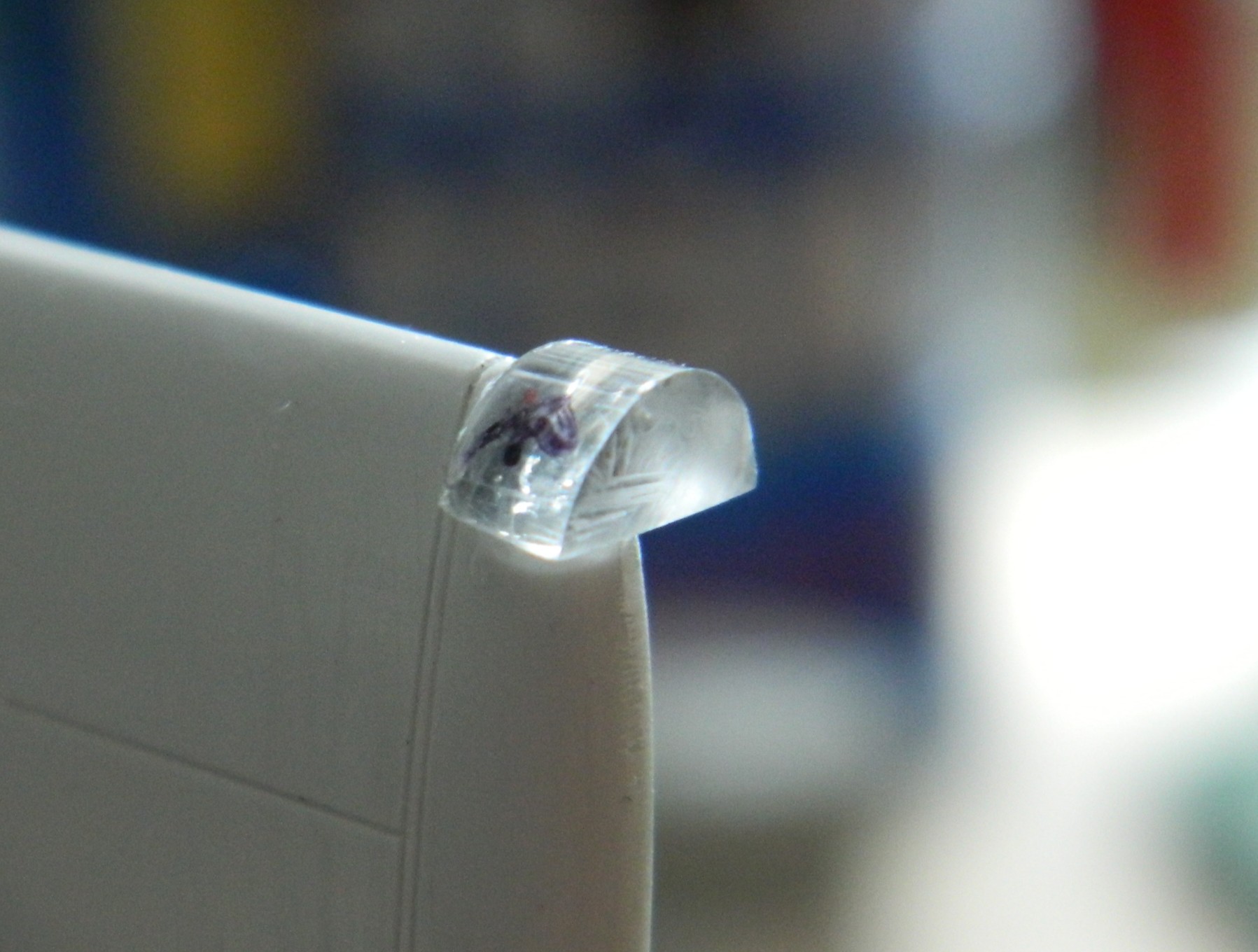
Most of the excess acrylic was ground away:
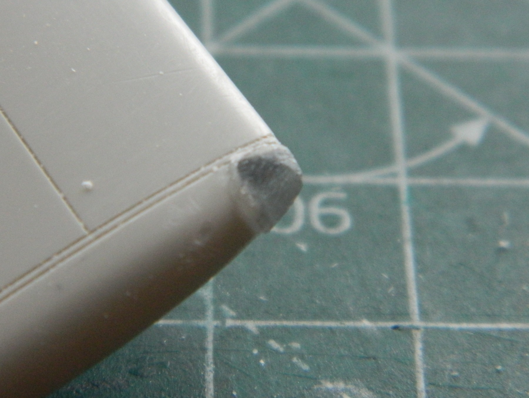
Then sanded through grits of 320, 400,600,1200, and 2500, before being polished with Novus #2 Plastic Polish:
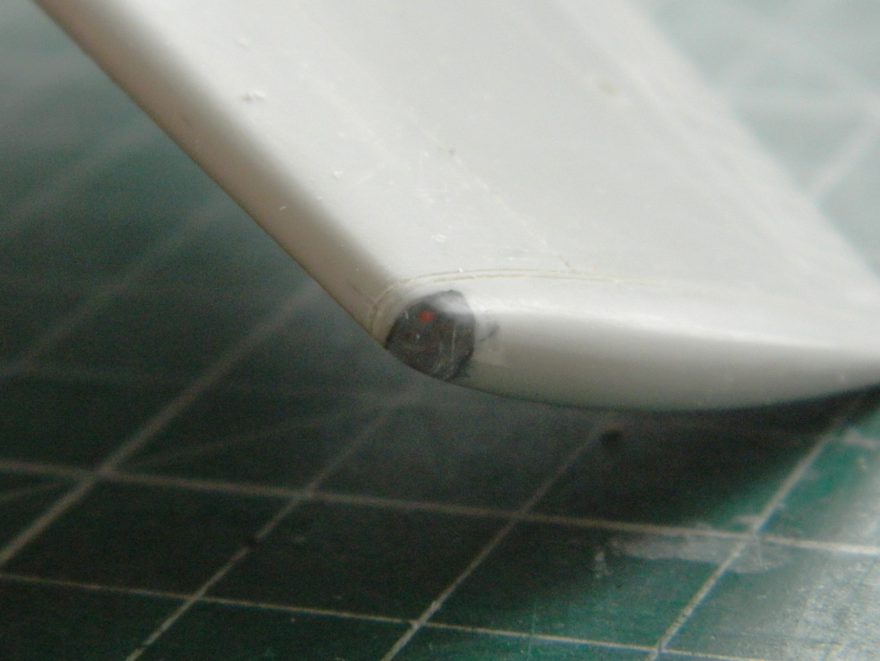
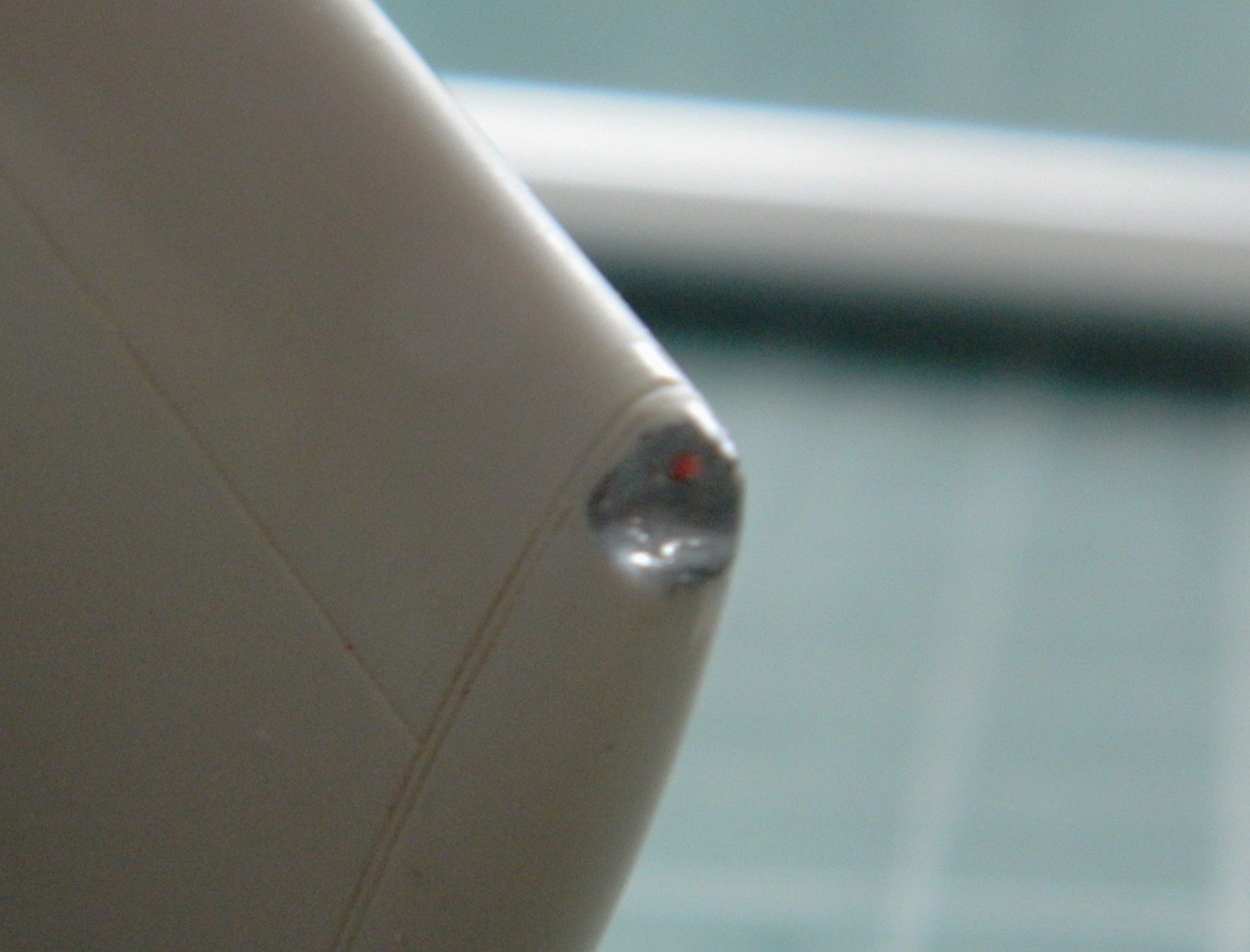
I liked it, enough so that I did it again for the other wingtip:
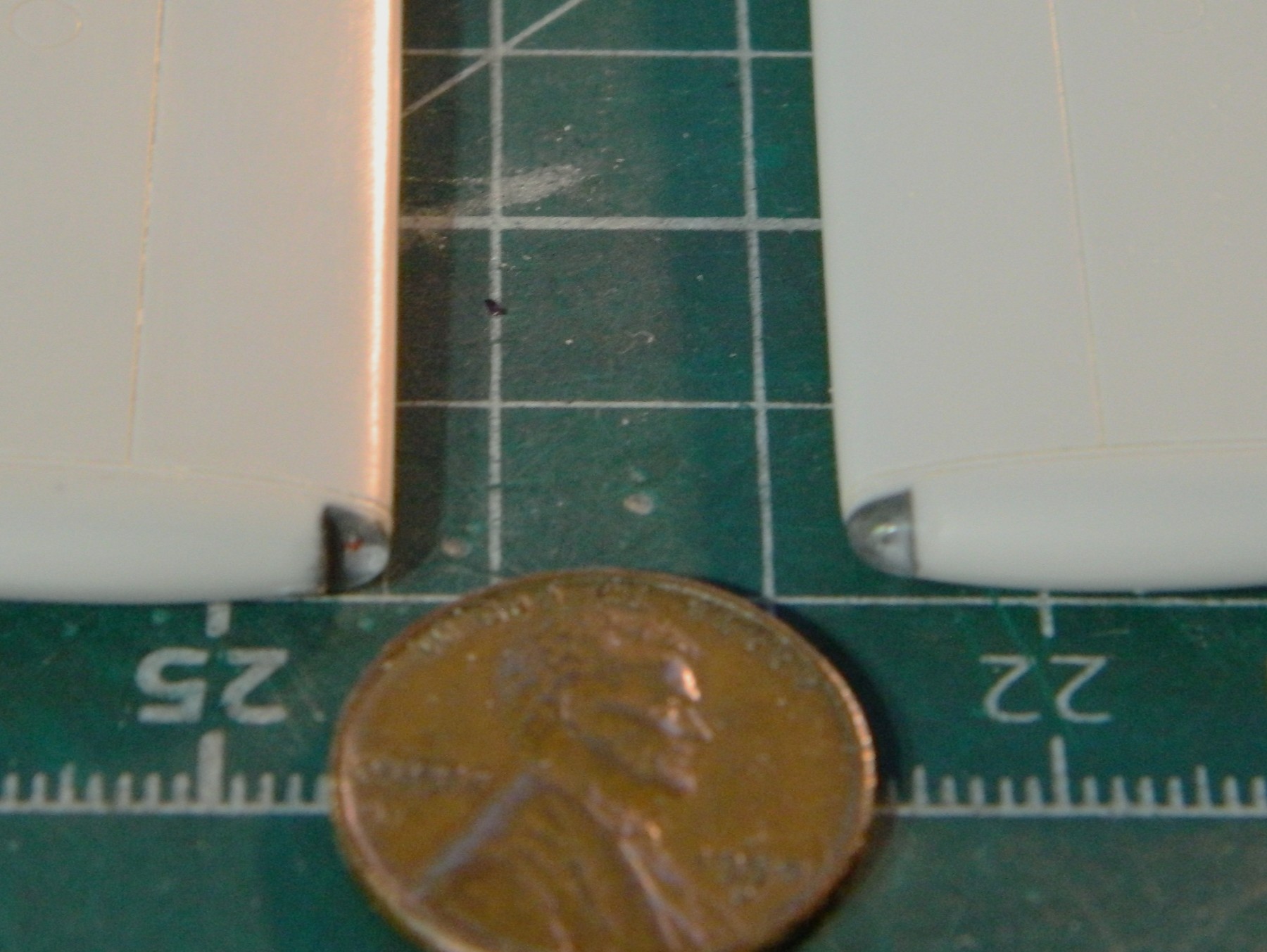
Attention shifted back to the canopy. One small part of the bracing wasn’t cast into the part. I used 0.005″ (.127mm) scrap styrene and (nerve-wrackingly) added it:

When I test fitted it, it didn’t fit well. (How odd!) Not only was it too narrow to fit the fuselage correctly, the front bottom didn’t fit the curve well, either. Part of that was my responsibility because somehow I sanded away a section of the fuselage where the canopy meets it. Rather than trowel on the putty, I took a section of 0.030″ (.762mm) scrap and added more than enough to fair this into the fuselage without a gap:
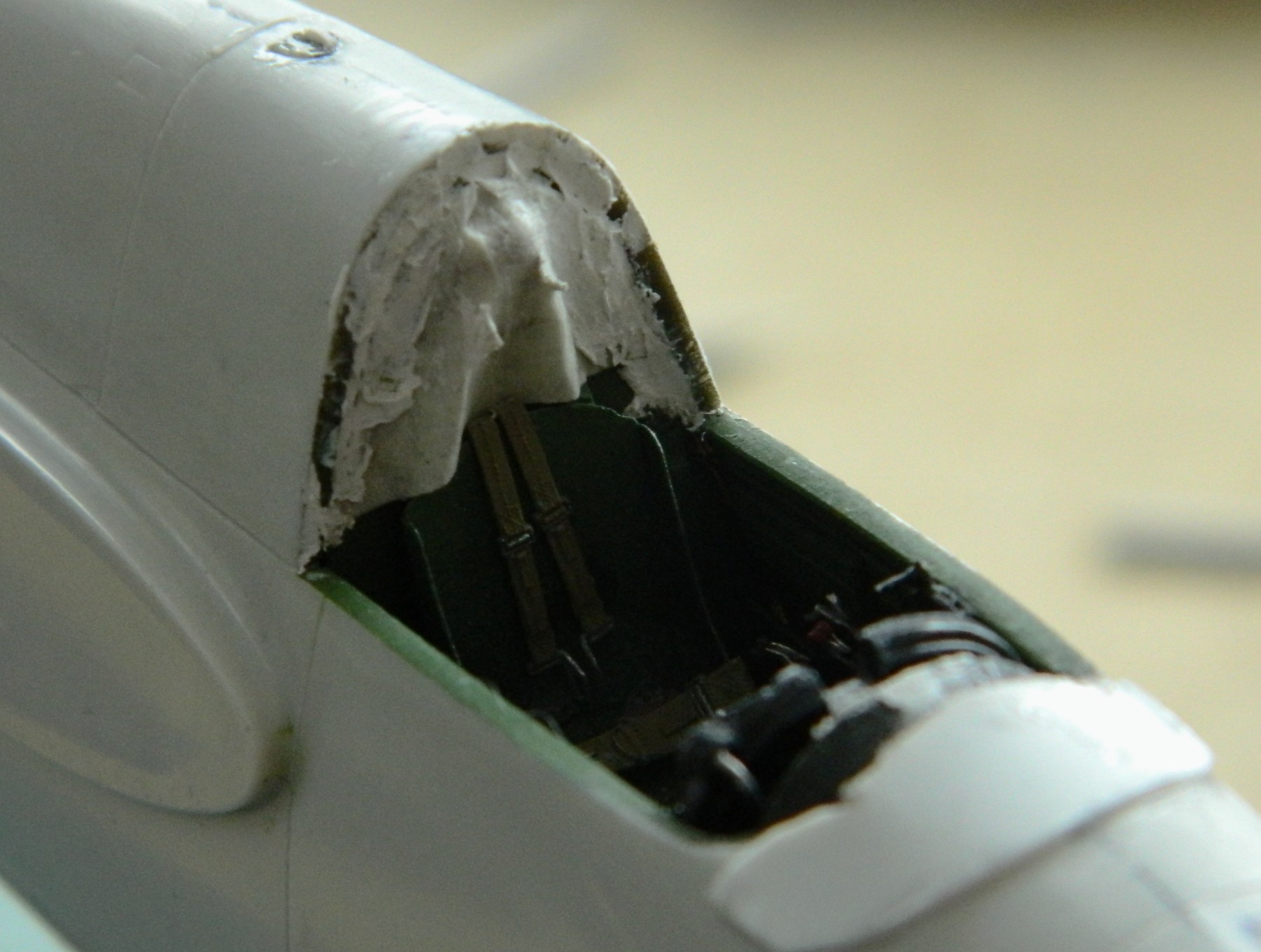
Then followed much sanding, filing, and fitting until it finally fit correctly (or at least the way I want it to fit, which I’m hoping is the same thing) (the sliding part of the canopy was also fitted and filed; it’s only use for it is to pull plastic over with the vacuum mold and in place to confirm that I had the front of the canopy correctly fitted):
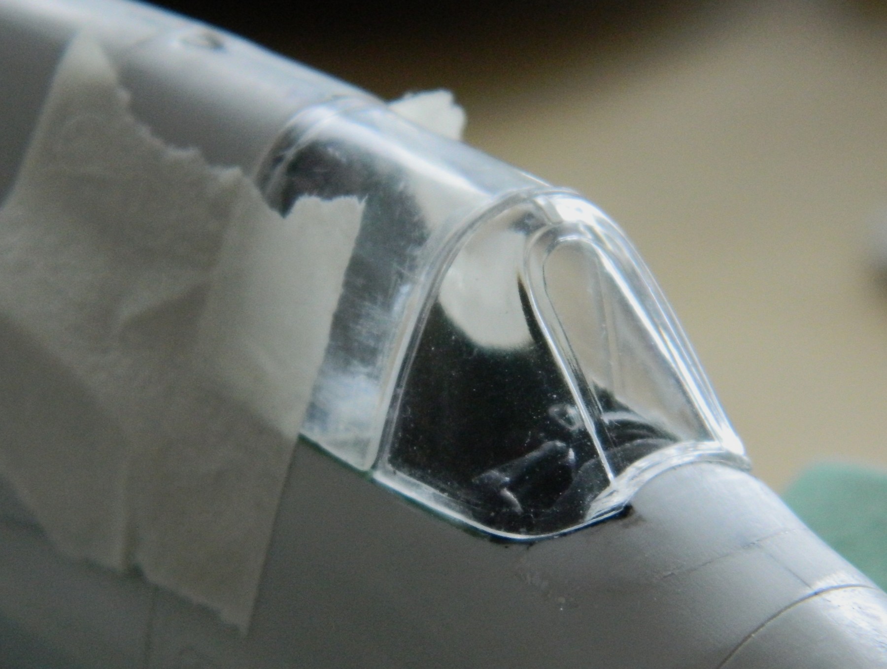
I decided that since I’m using a new-to-me tool, UV-setting resin, that I was going to decrease my ignorance of this material by seeing what I can do with it. Before I started, I used a permanent marker on the areas of the forward canopy that contact the fuselage. This would keep the plastic from looking like, well, plastic. To spread the canopy to the desired width, I started by tacking one side of this part in correct alignment:
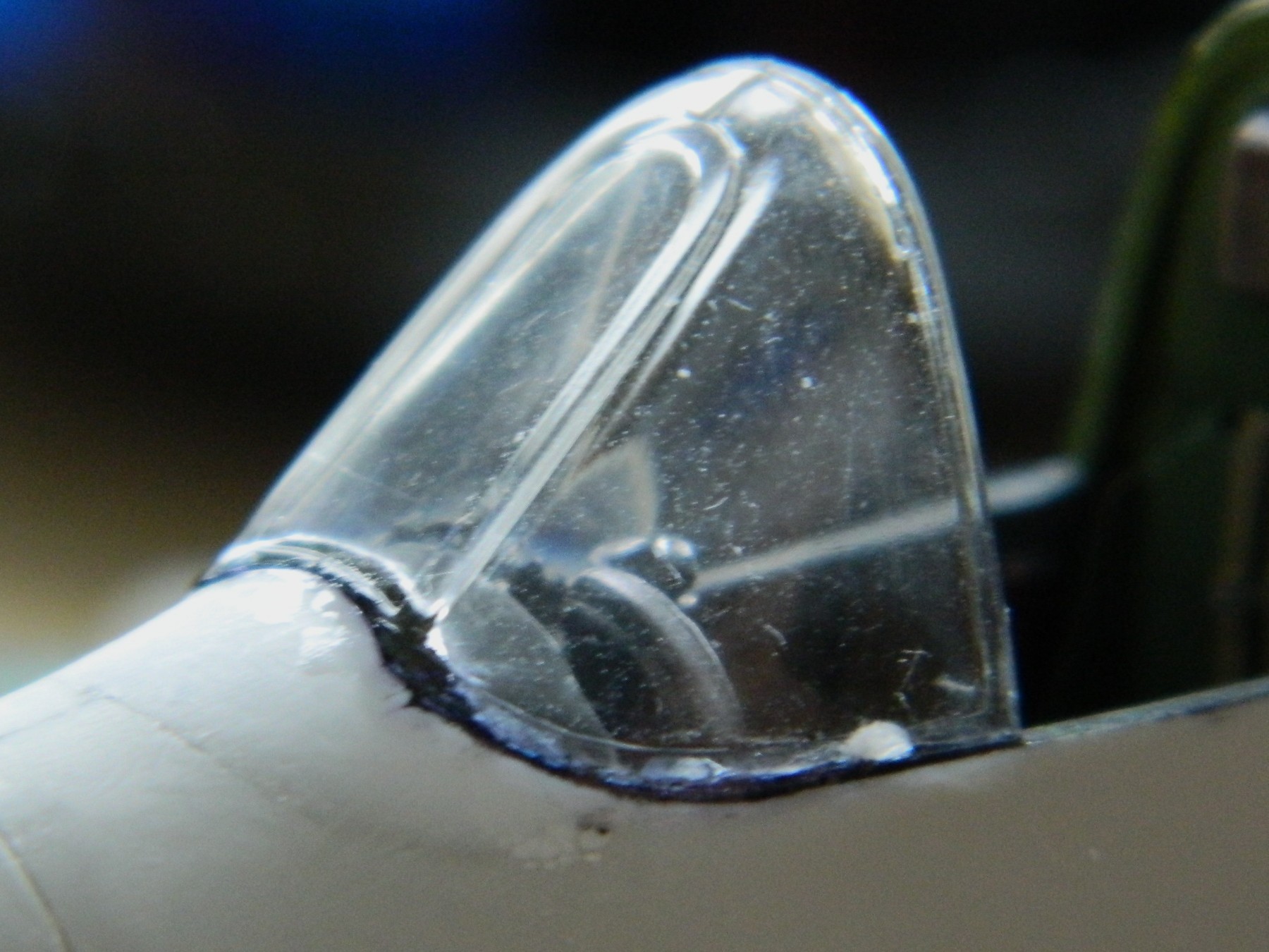
Then I spread the part to fit the other side of the fuselage with a fingertip (using the base of the finger is painful and bloody). Considerable pressure outward was applied and I kept waiting for the attached side to snap free. It didn’t move at all! I filled in (most of) depressions left by applying multiple coats of resin so that I would have enough to sand down to invisibility. But before I did that, I masked the sections I want to remain clear because brain-fade can strike at any time. I have this one part that must be used, and I wanted to protect it from being scratched. Once masked, files and sandpaper blended the canopy to the fuselage. There were a few areas that needed minuscule amounts of putty, but so does the rest of it so putty was applied:
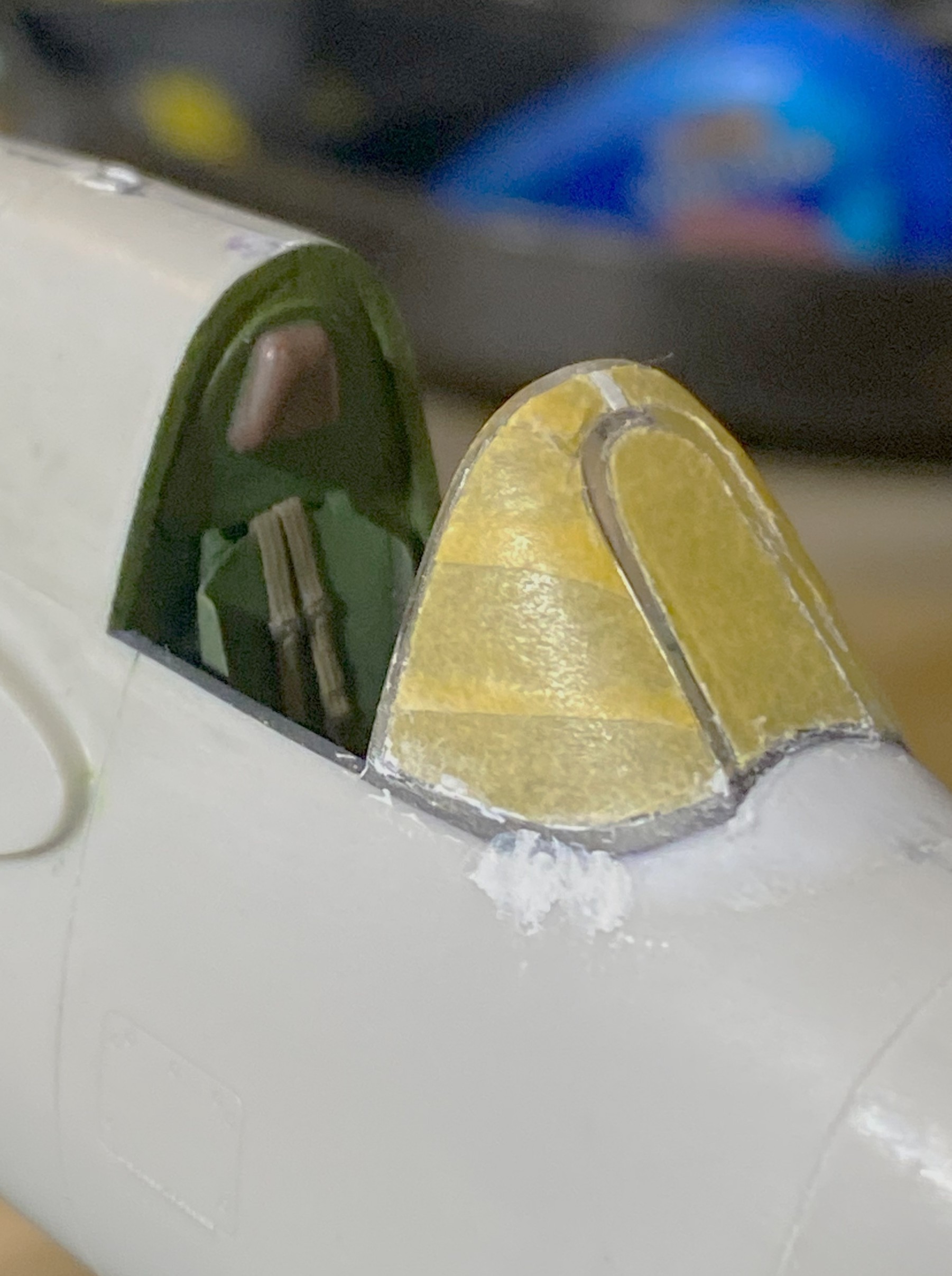
And putty reapplied for the couple of spots that I’d missed:
And it worked wonderfully! It’s looking like I have my new go-to process for adding canopies or any clear parts!
With that out of the “hanging over my head” category, the sliding canopy needed work as well. I tweaked its fit a little, then dealt with the fact that it’s too narrow also. I figured out how much I needed to move it and then used 0.040″ (1.016mm) styrene as a spreader to push the plastic to where I wanted it:

I set up the vacuum molder and mounted the buck on a stand (replacing the superglue I’d usually use for this and used the UV-setting resin instead and had at it):
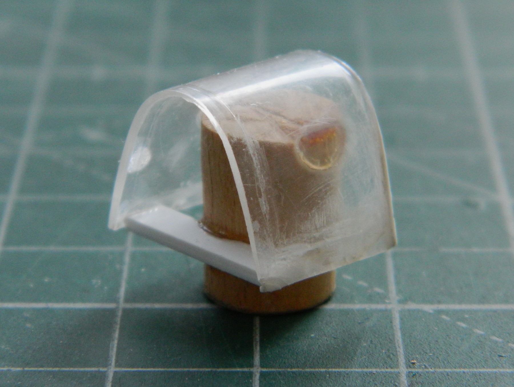
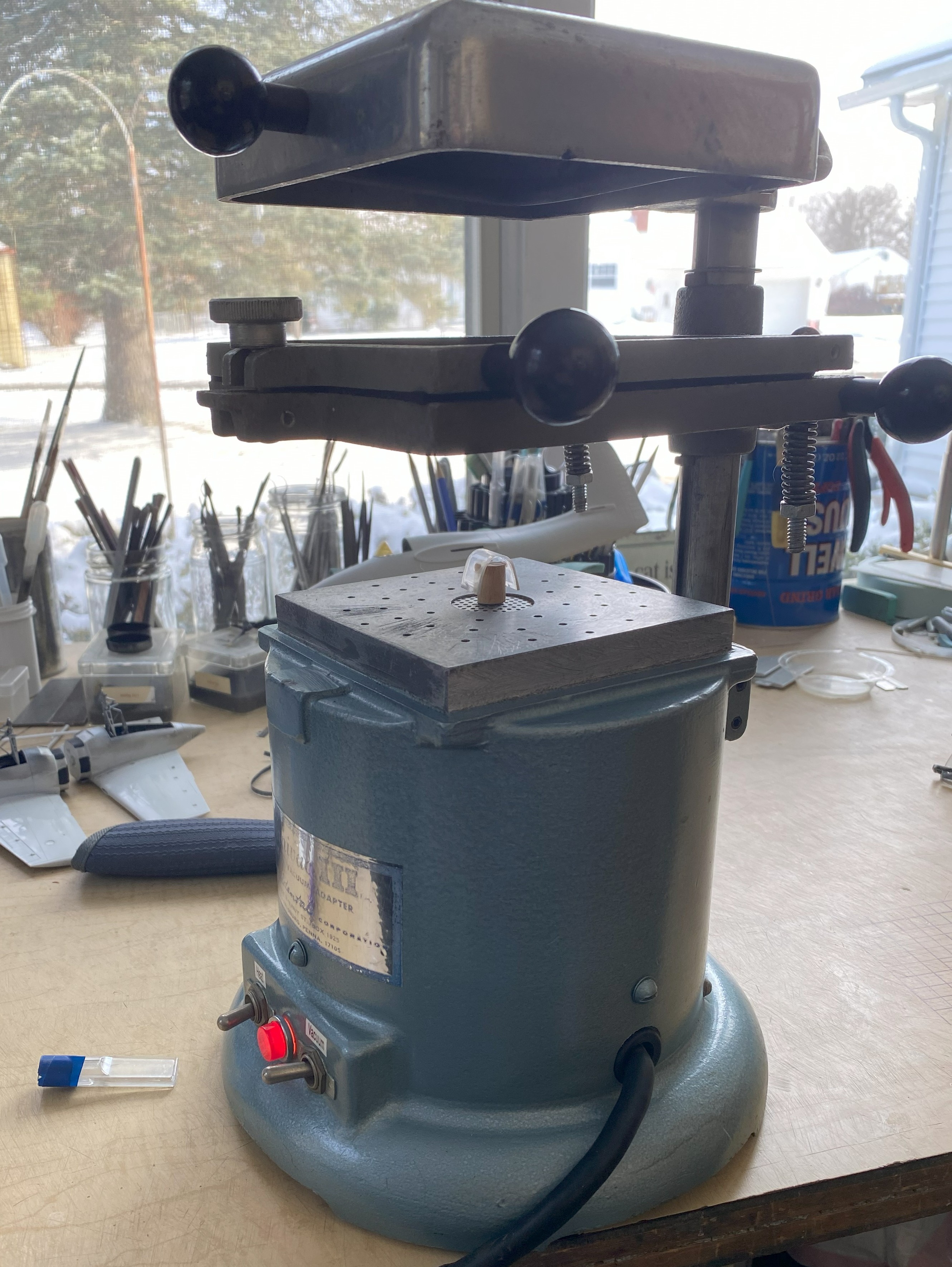

Using a vacuum molder to copy parts is called “a pull.” Set the buck, heat the plastic, turn on the vacuum motor, and it pulls the plastic down and around the buck. Then the new part is painstakingly cut away from the excess and the buck. It’s not uncommon (for me, anyway) for multiple pulls to be necessary (and waste a lot of material) to get a usable copy. This time I thought I’d done it on the first pull!
Silly me.
In the following photo, you’ll notice that on the side of the canopy, it looks like a paint drip/run. Hmm…but there’s no paint on it! I wonder what…on…well…guess there was a freaking hair on the part (or plastic, I dunno) and it showed up:
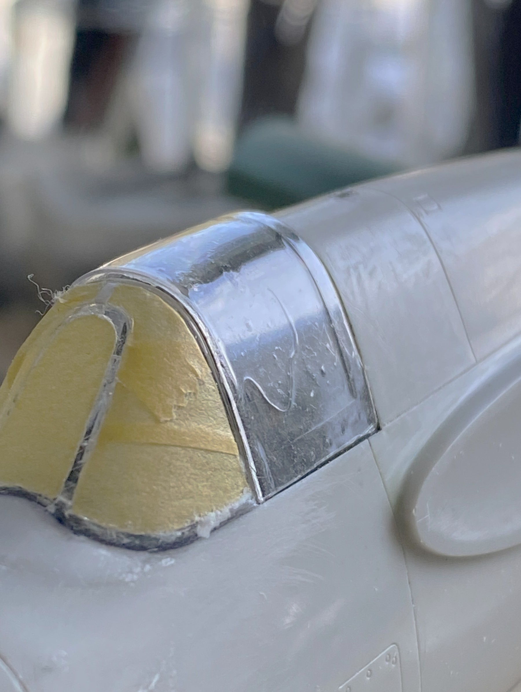
::facepalm::
While I had it on the model (temporarily), I checked to see if it would do what I was pretty certain it would do, which is slide back as far as it needs to and sit as low as it has to:

Yes…I know it looks as if it’s only partially open. I’ve seen another modeler’s build of this kit and he thought the same thing, going so far as to remove the antenna mast and move it towards the tail of the aircraft. That is a mistake. Looking at references shows that this is normal for this bird. What’s also normal for this bird is how that sliding section of the canopy fits, now. I just have to make one without hair!
Challenge met:
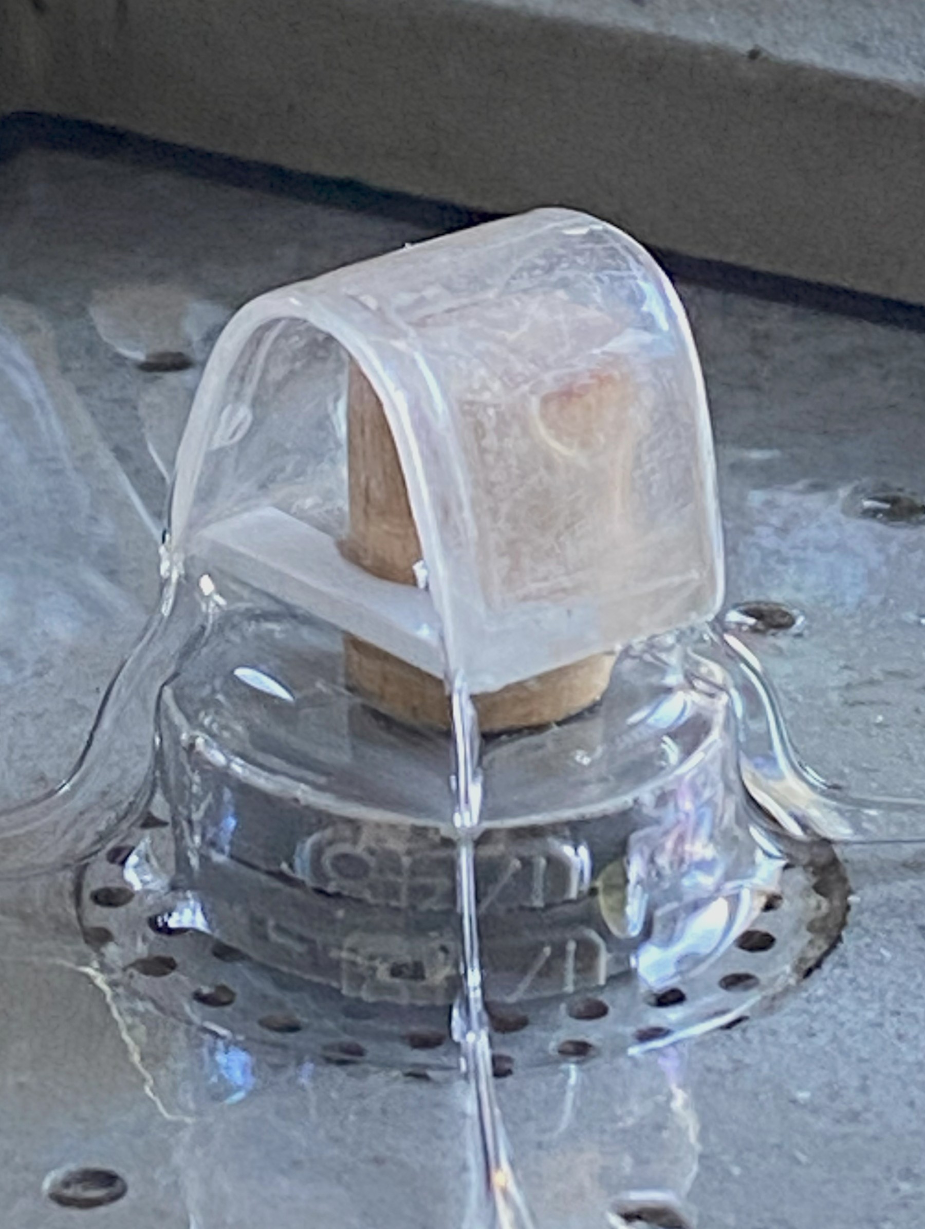
For this pull, in addition to being sure no hair was included, I wasn’t especially thrilled with how the folds of the hot plastic came up too close to the canopy for me with the last pull. I added a pedestal (made from scrap resin that the engines were cut off of) and that little bit of difference gave me a part that was substantially easier to work:

There were a few more little things to do before painting. One of which was adding brake lines to the main landing gear. I used 0.025″ (.635mm) solder. While I was doing that, I managed to drop one of the wings. One part fell, two parts were picked off the floor. The part that broke off was the section of the landing gear strut at the bottom of the oleo. Okay, annoying, but not the worst part of that day…until I tried to glue it back on. It wouldn’t stay correctly aligned long enough for the “instant setting” (::snarks::) superglue to set. Finally I figured out how to balance the part, correctly aligned, long enough to put a SMALL touch of superglue in place to hold the part there long enough for me to add more superglue. This turned into an example of, “tools are what you need, not necessarily what you think they are”:
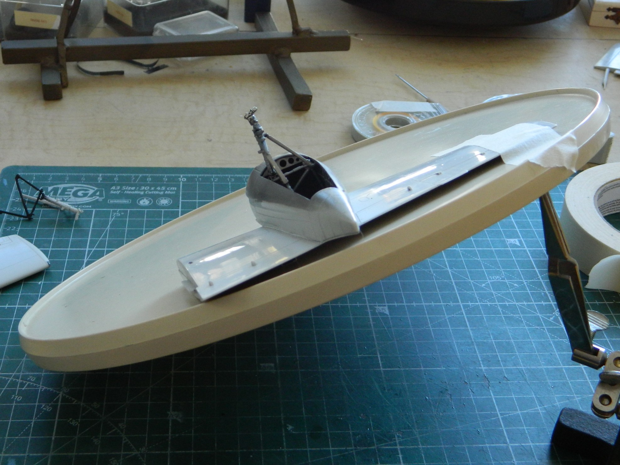
Cut to the point…it worked.
And speaking of “cuts” and “points”, this aircraft had four weapons (not counting rockets or bombs), four 20mm cannons and four .50 caliber machine guns. What the kit didn’t have was any shell ejection ports. So references showed me where they’d go, they were marked, and much annoying cutting with sharp points added them:

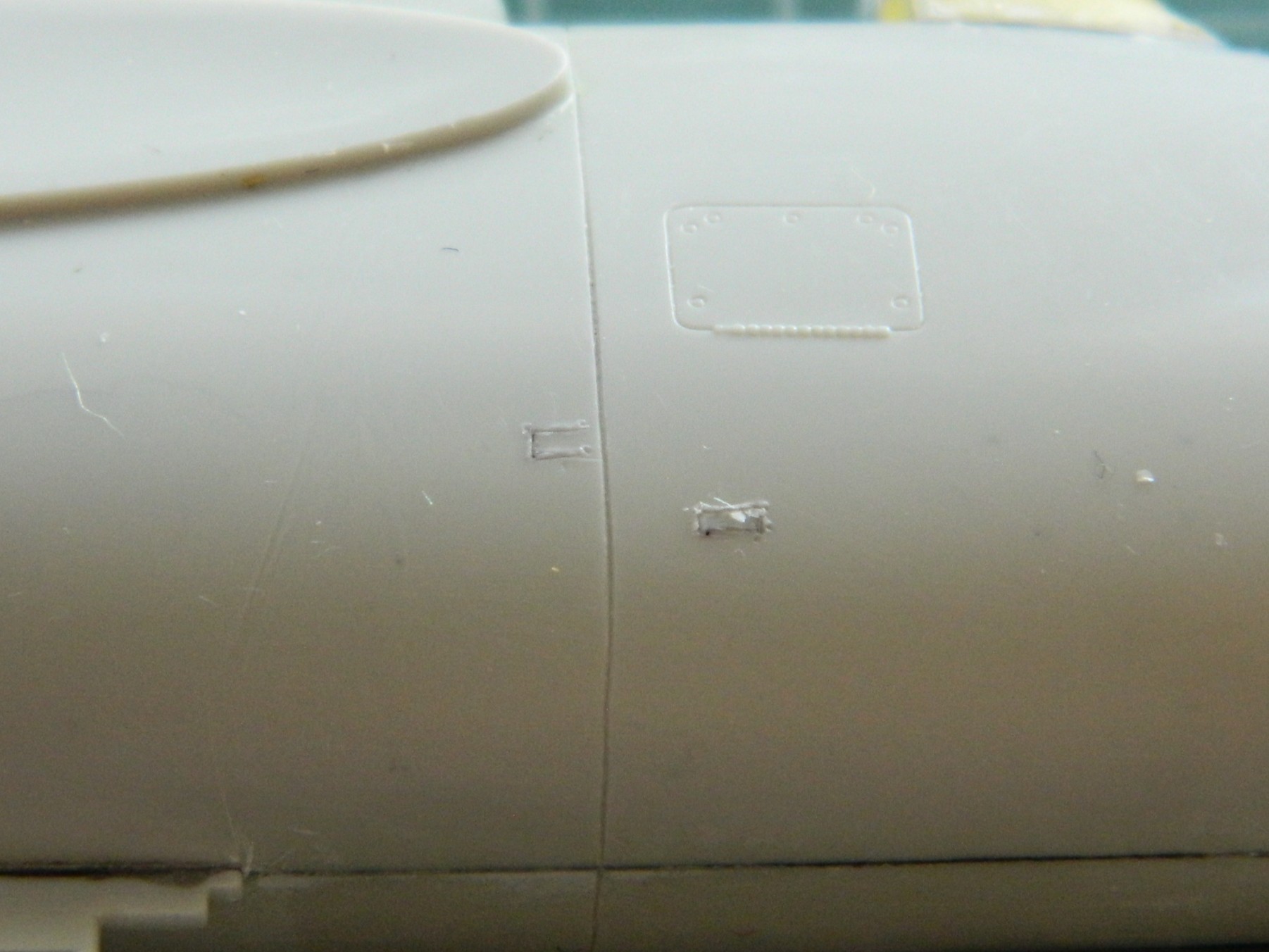
With all the handling and mishandling (I plead caffeine deficiency), the antenna mast broke off. This was the standard fix-it, add a pin and drill a mounting hole:
After seeing another builder reposition this mast, I checked references, particularly period-correct references, to see if this was correct or if it should stay where it had been molded. Even though it looks wrong, especially with the canopy open, it’s not. This is what Grumman sold the Navy.
As I’ve mentioned in other places, the thing that drives a build changes as the build knocks them off the list. What’s been driving the build since the last update was having all the subassemblies ready to attach so that I can get down to painting this kite.
Mission accomplished (I think…see the next post, here, to see how incorrect I probably am):

Hell…I just might have this done by the end of February!
F7F-3 (AMT/Italeri) 1/48 Scale Build #7 – Finishing the Cockpit, Joining Fuselage Halves, and Finally Dealing With Scribing “Fun”
I’m doing something a little different with this update. Typically, I post updates on or about the last weekend of the month. I’m updating early because I saw that I had taken over 50 photos this month so far. Typically, it takes me 6-8 hours to do an update; editing photos and coming up with this snappy commentary (so called because sometimes my commentary can bring me to the point where I’m ready to snap)…and that’s with 30 or so photos to edit. So rather than spend all weekend doing an update if I kept to my typical schedule, because January is only half over and I have more work to do, I decided (obviously) to break January’s update into this part and the one coming on the last weekend of the month.
I was still populating the cockpit with scratchbuilt bits. The Tigercat had a parking brake so I added one. That started with making the mount for the T-handle of the brake:
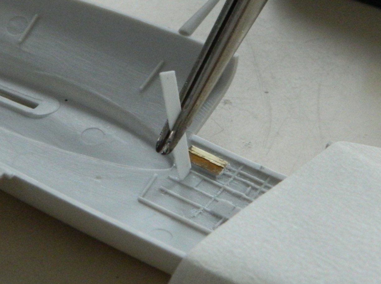
A very handy tool for those of you who scratchbuild is a “lazy Susan,” a platform that will rotate. Working small parts often requires the modeler to have four (or more) hands. I use jeweler’s tweezers to help with that. Alignment of the bit being added or constructed is critical. To get the alignment you want (which is, hopefully, the alignment you need) will require you to look at the join from multiple angles. If the parts and jeweler’s tweezers just sit on your working surface, it can be challenging (or next to impossible) to get the views you need without disturbing what you’re working on. Putting the jeweler’s tweezers and work on a rotating surface allows you to accomplish that. You can rotate them to the view you need to make the construction work correctly:
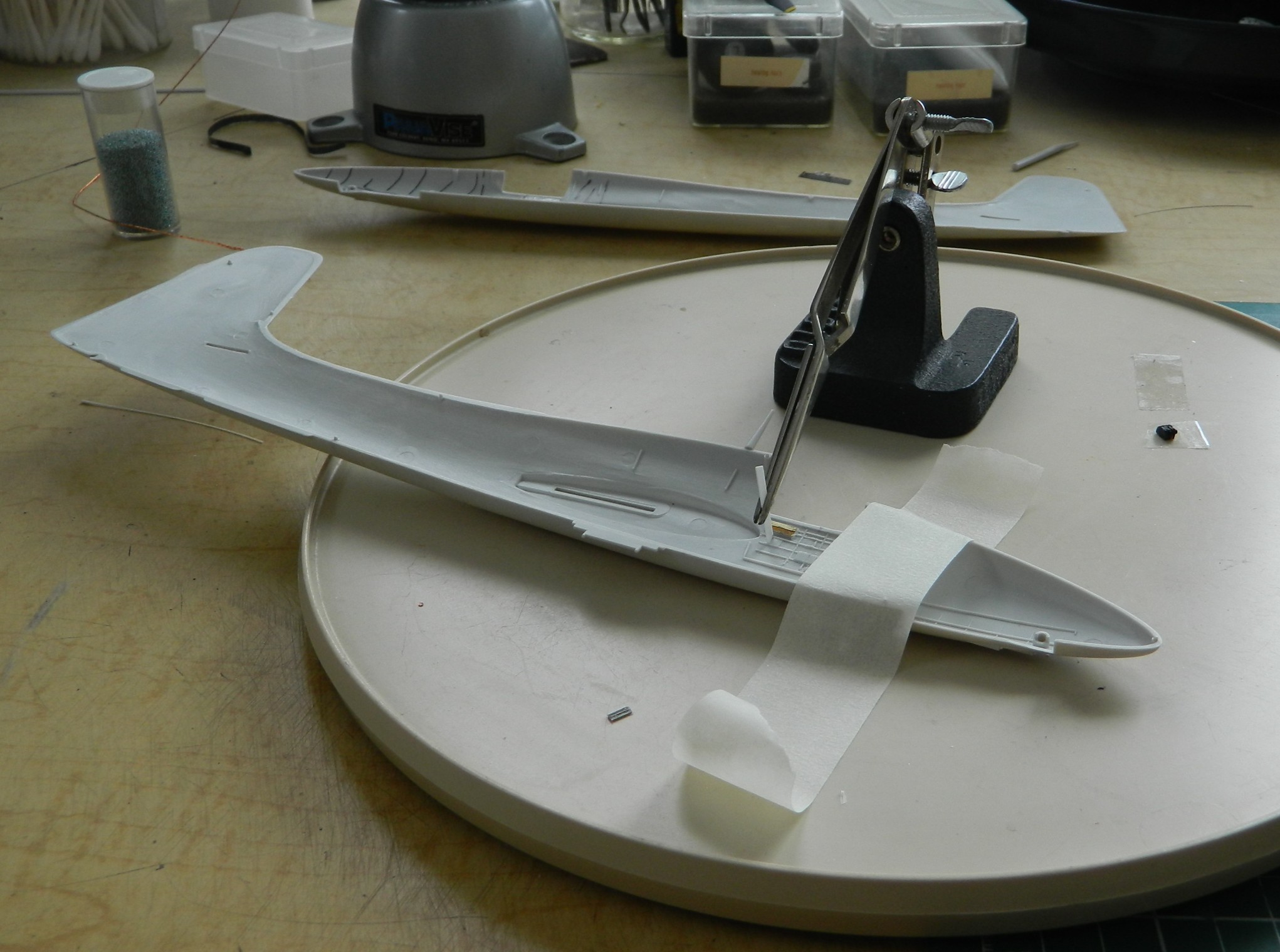
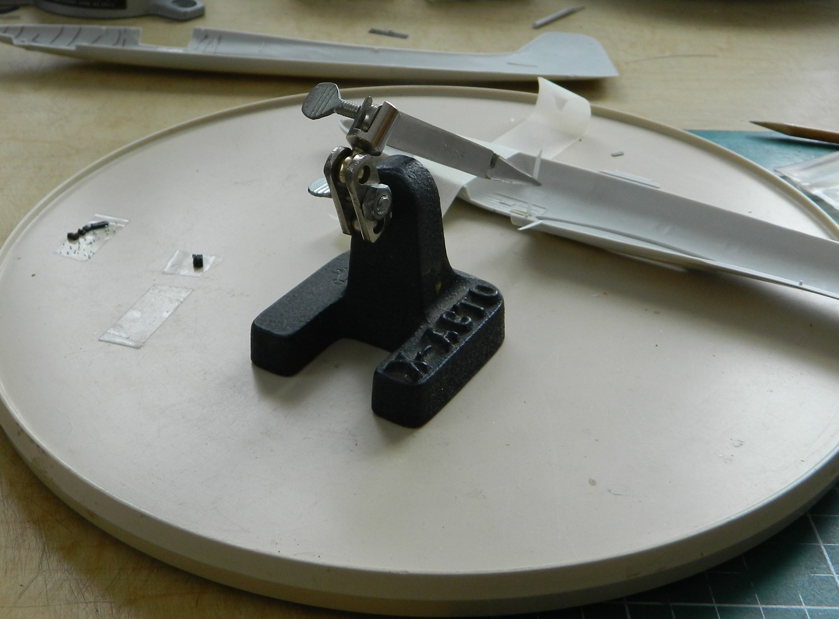
Last month while dealing with the seemingly never-ending throttle quadrant, dry-fitting showed me that I’d placed the imagineered pedestal too far forward. That got fixed:
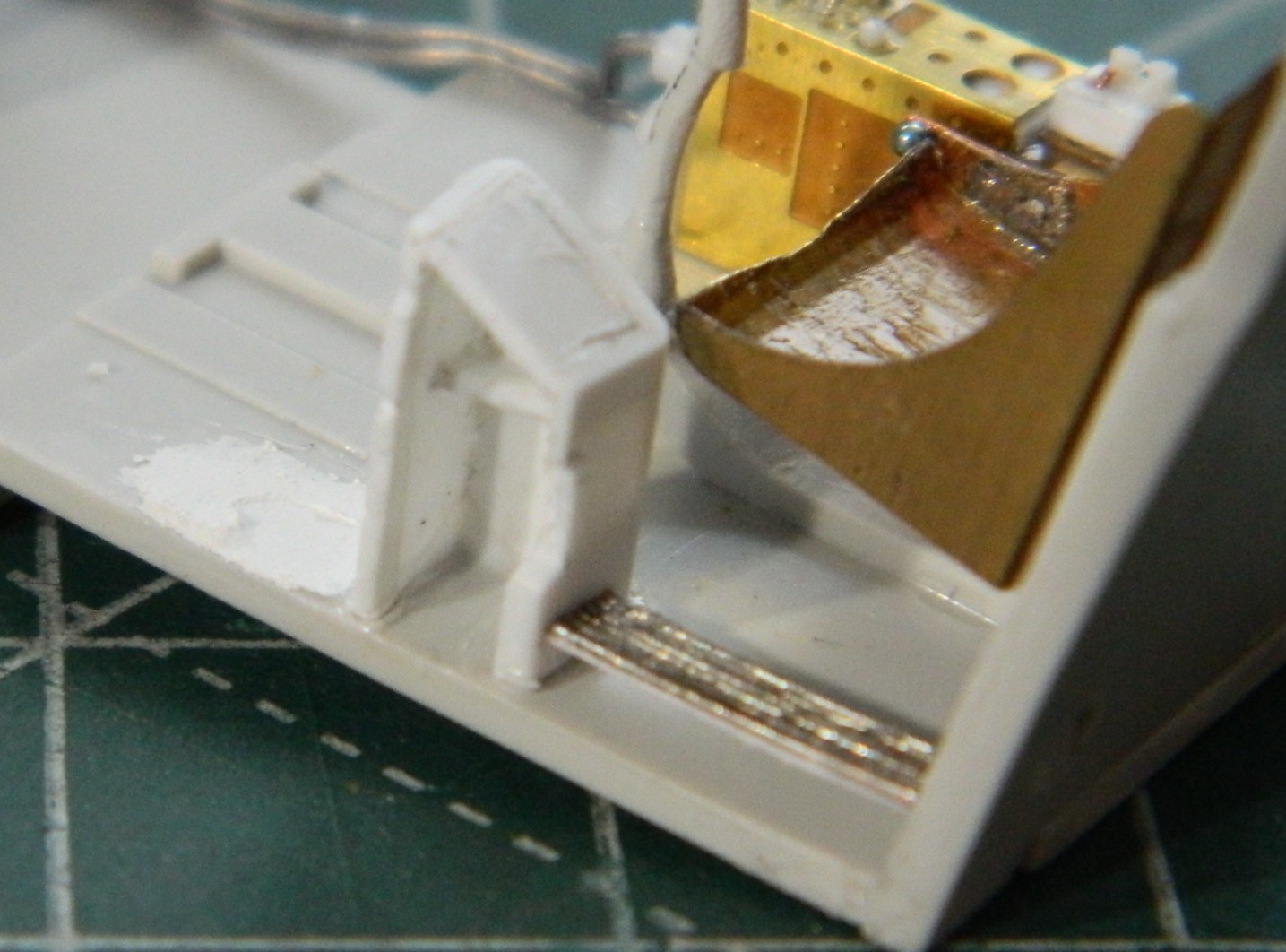
I’d placed a small alignment mark on the floor of the cockpit and then promptly forgot that that mark was for the front of the pedestal, not the rear as I had mistakenly thought. Oops. (Again.)
A prominent feature that the kit didn’t provide is the flap actuator lever. Construction-wise, it’s similar to a throttle quadrant but only needed four parts. Wrestling and cursing during the construction of the throttle quadrant made this part easy to build by comparison. I used 0.010″ (.254mm) copper shim stock and a 22 gauge wire for the lever that I flattened with a hammer (the bit coming off to the upper right is just a spacer):

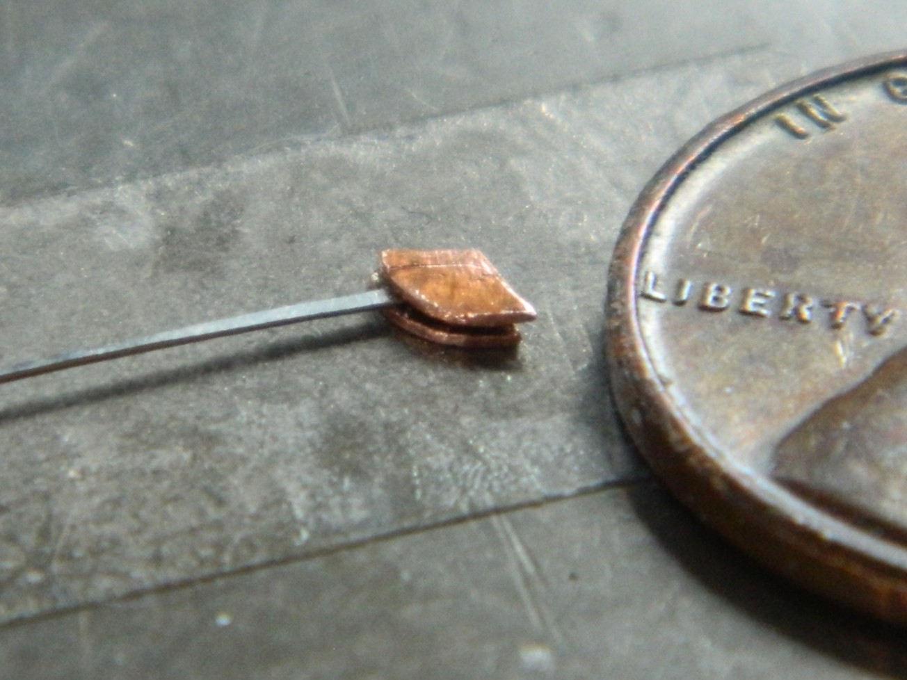
Then I used the jeweler’s tweezers, the lazy-Susan, and a bit of stretched sprue to make the handle (you can see the T-handle, also made of sprue, glued into position as well):

When I did my most recent balance check, though the thing would sit on its nosewheel, I wanted it planted on its nose with more authority. Having checked where I could put more weight, I added more .36 caliber balls (because what says “authority” like balls do?):

The nosewheel bay has no bulkheads with this kit. I hate matching interior curves. Since I am spending less time on details that won’t be seen or require the observer to pick up the model to see them, I’m not adding those bulkheads. I’m cheaping out by painting everything that could be seen through the front landing bay opening flat black (and the engine cooling flap parts, since they needed more):

Later on during dry-fitting, I realized I needed to extend the flat black further reward, which was attended to.
I held off adding the cockpit to its location because another annoying habit I have is that as soon as I paint something, I am reminded of what I’ve yet to build before I should paint. Here I am, blithely assuming that I’ve gotten all the cockpit parts painted and a little bit of wear added:

Then I remembered the harness…
I’ve been eager to try the molded styrene AM harnesses. I was pretty sure that bending and folding them to fit would cause them to snap. I used HOT water and took my time heating and bending (and even then almost snapped the shoulder harness’ acute bend over the top of the seat’s back):
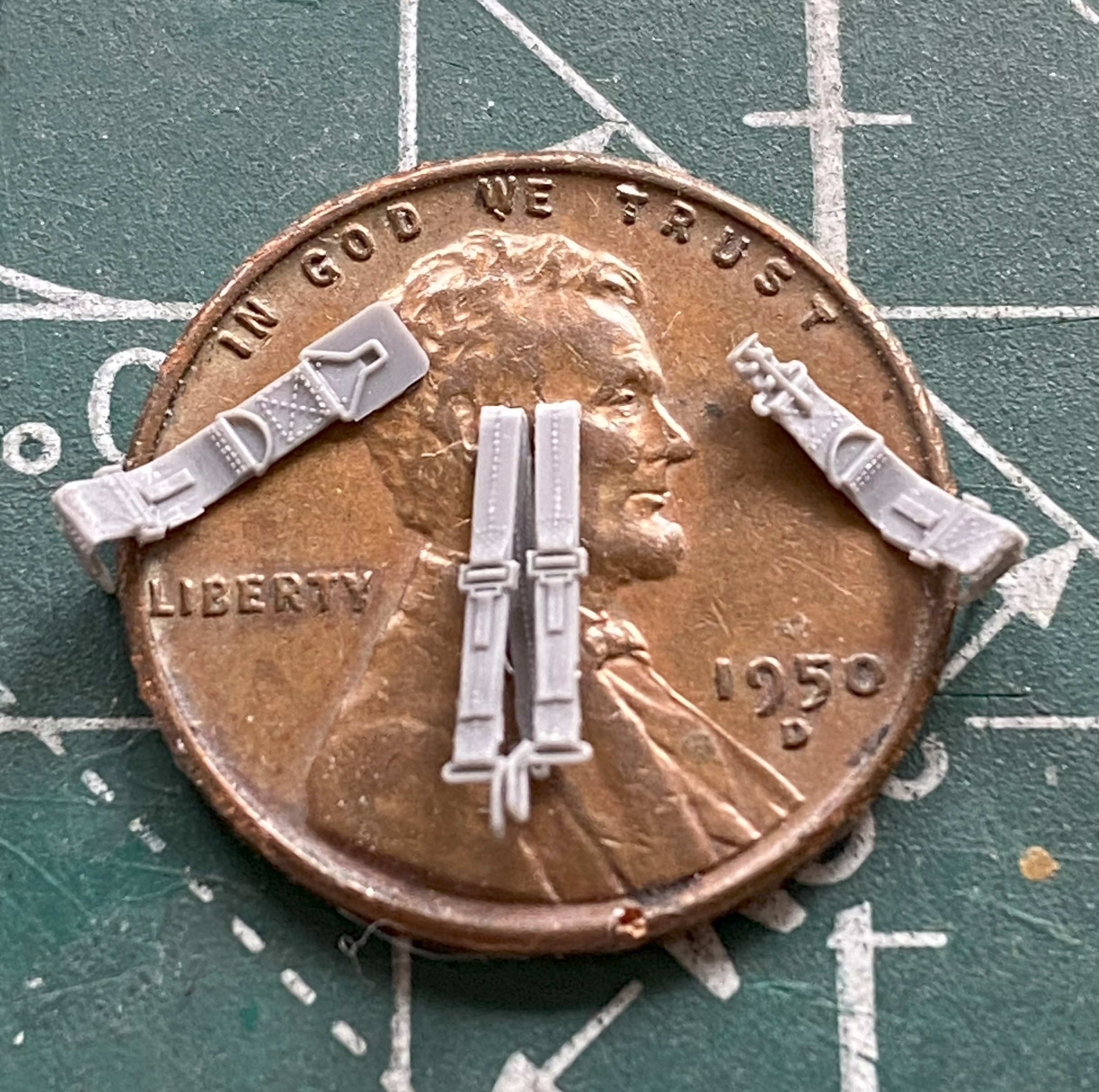
The straps were painted a mix of Tamiya’s XF-49 Khaki (3 parts) and XF-64 Red Brown (1 part), the metal bits painted with X-11 Chrome Silver, and the leather pad backing the lap strap buckle was done with XF-64 Red Brown:

Then it was time to add those tiny control levers to the throttle quadrant. I tried a bunch of things, flattened wire and strips of heavy aluminum foil, none of which worked with a rodent’s rectum. I finally ended up using 0.010″ (.254mm) solder that I flattened out. That worked surprisingly well. Remember those tiny glass balls? Only one was used and none of them for the throttle quadrant control levers. For the latter, I used UV-setting resin, and that worked even better withOUT all the sodding hassle working with tiny balls (no comment, he comments)…and forgot to take pictures. You’ll see later when the instrument panels shows up in a photo because I did the same for the landing gear lever (lower left of the instrument panel with a yellow ball) and gun charging handles (four of them, two on each side at the bottom of the instrument panel with white balls).
I was pleased with how the parking brake T-handle came out. Then realized what I’d really forgotten to add before painting. The trim controls. All of these bits fit into the cockpit of the actual Tigercat. They don’t all fit into a 1/48 scale model of the Tigercat. And thinking like a pilot, I figured trim controls were of more utility than a parking brake handle (because, chocks are a thing), which meant I had to remove the brake handle. The brake handle that’s already been painted on the cockpit side that’s already been painted. (::facepalm::).
I modified the PE part slightly by removing the flat parts that are supposed to represent cylindrical parts by cutting them off and adding 22 awg wires in their place. The pitch trim wheel isn’t at all flat and the PE’s replacement is. I used the UV-setting resin to build up the flat areas that I want rounded and glued them in place, after removing the parking brake first(sorry about the blurred photo):

Being lazy, I didn’t want to repaint the entire cockpit side, so I made a handheld mask to paint just the areas I needed to (the mask is behind and above the cockpit side, the pointed end of which aligned over the rods):

And then a case of brain-fade struck. The throttle quadrant. Again. Some more. As EVER. One of the slots needed just a little bit of adjustment. Just when I had it where I wanted it, the fornicating front half of it snapped off:
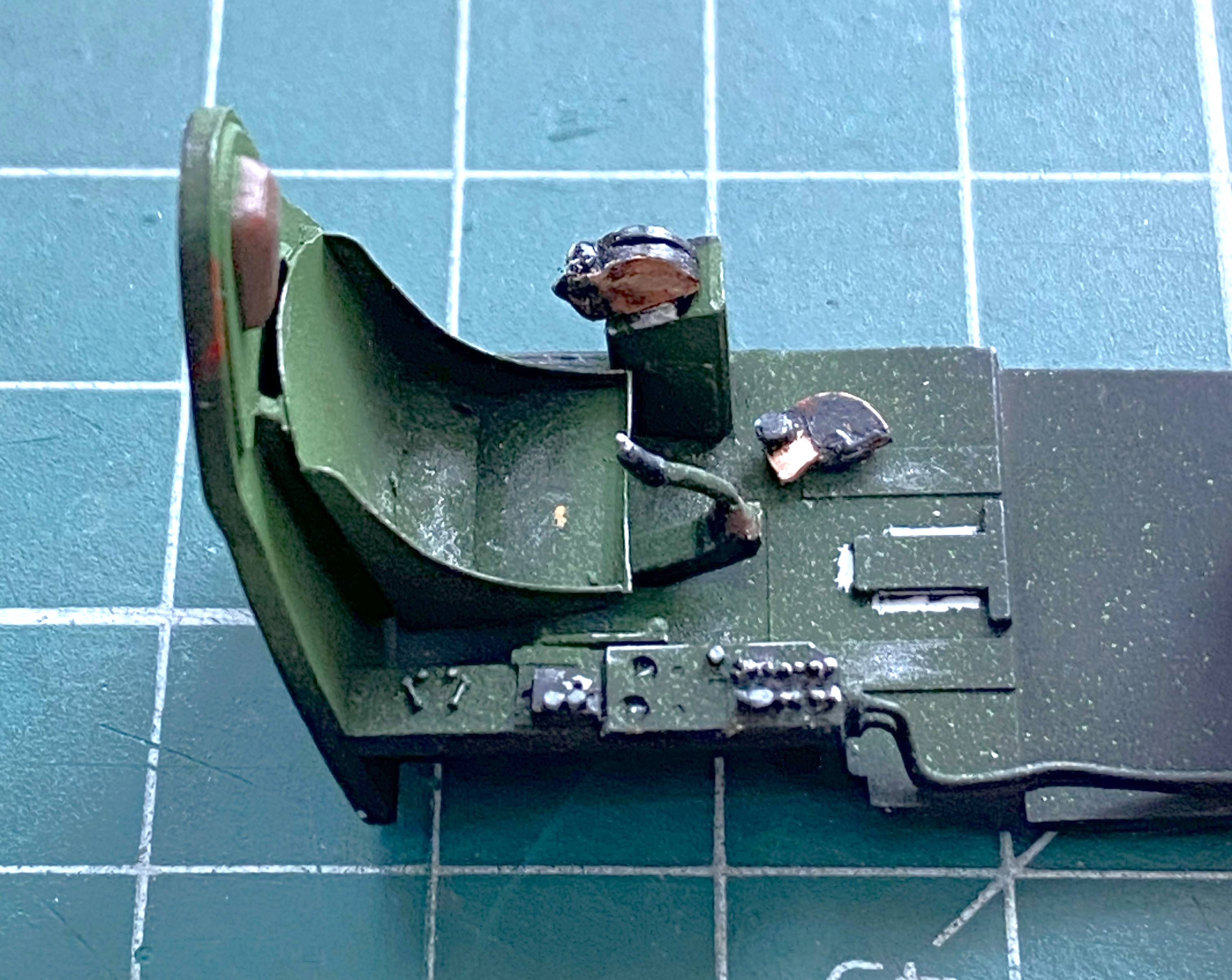
I’m starting to get a depression in my forehead in the shape of the heel of my hand from all the facepalming I’m doing. (I’m already on blood pressure medication so my options for physically manifesting “DOH!” are limited to what I assume I can survive.)
Well, it’s not as if I don’t have practice PUTTING THIS INTERCOURSING THING BACK TOGETHER. Preparing the parts took longer than fixing them. The superglue that had been holding this together didn’t vanish because the parts separated. It’s still there. It also interferes with getting the part reattached. CAREfully removing the old superglue (fresh razor blade, sharpened scalpel) took longer than reattaching the detached part back on. But I won (for now, anyway):
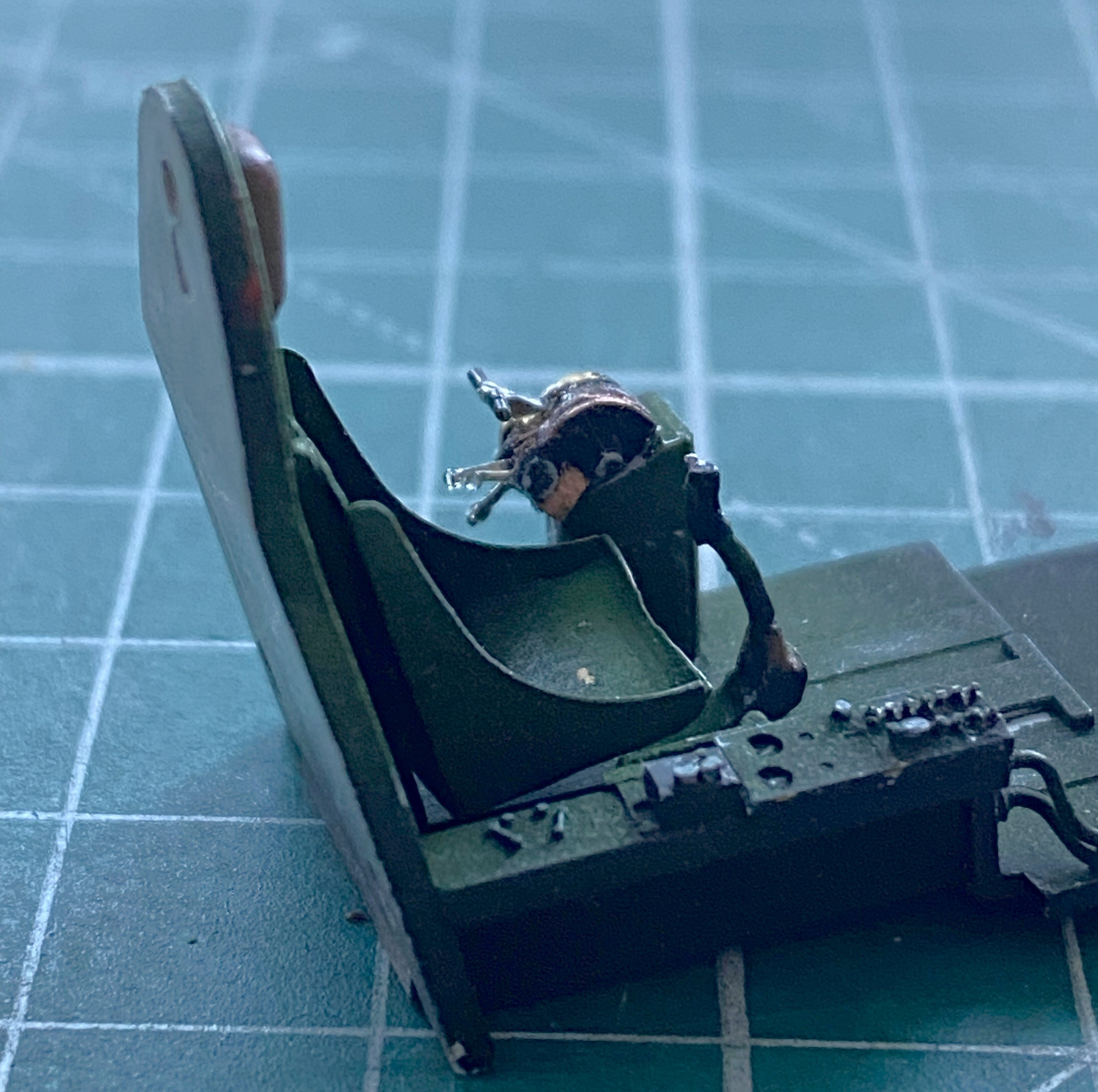
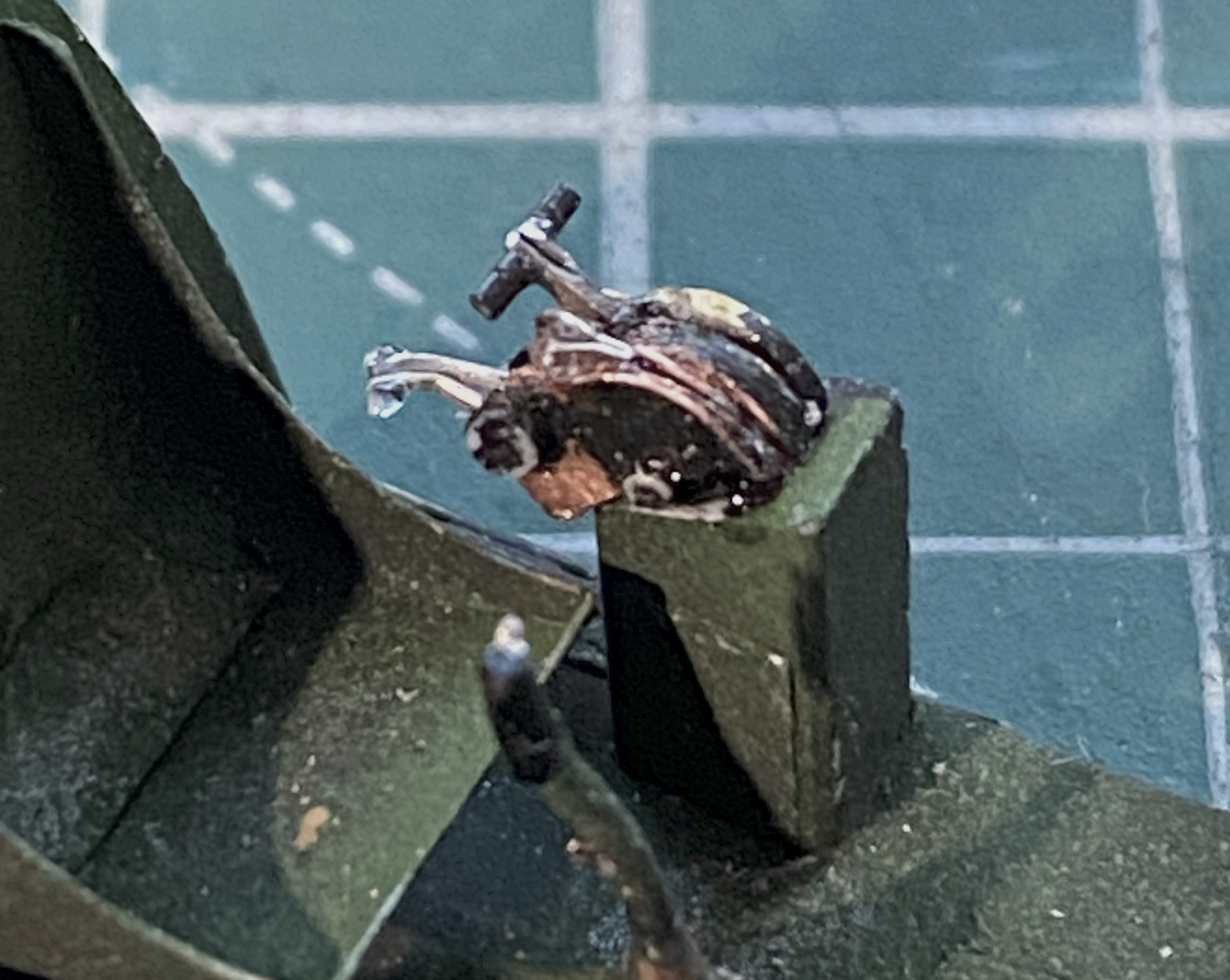
Those two photos show the UV-setting resin’s balls. (Go wherever you like with that one.) Those were attached and got painted the required colors, and dry-fitting looks like the cockpit is ready to install):
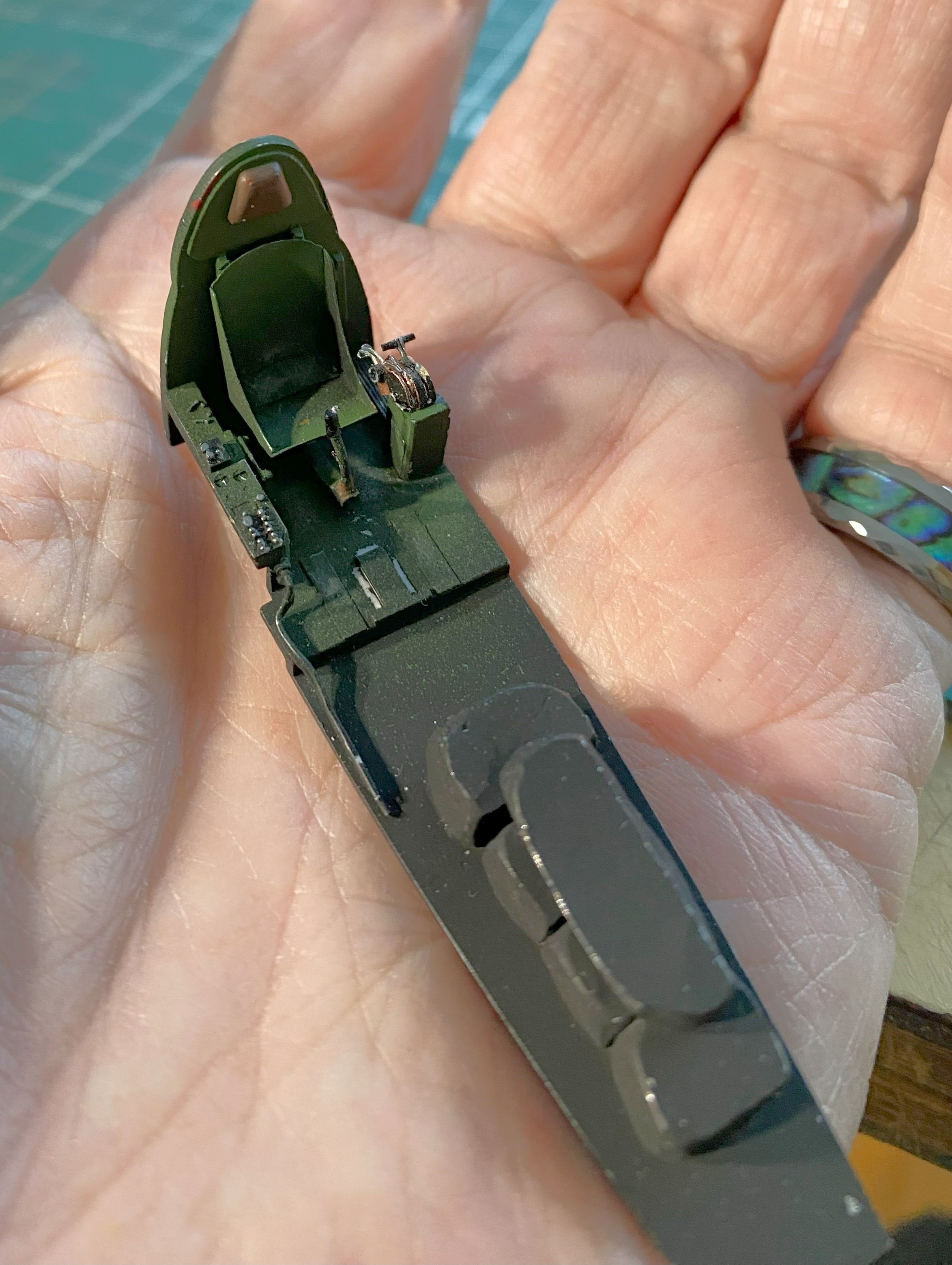

But first, he says smugly because he remembered what he forgot to add to the instrument panel…rudder pedals, I added the rudder pedals. So far, those were the most annoying parts to add because they were as fragile as butterfly wings:
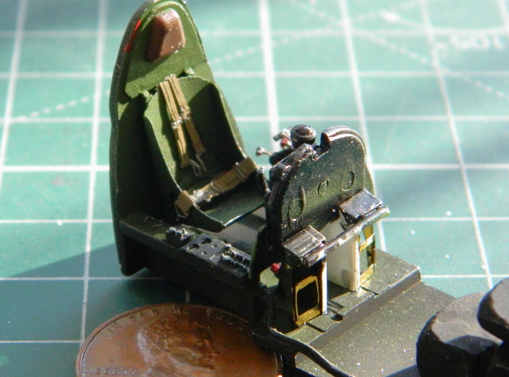
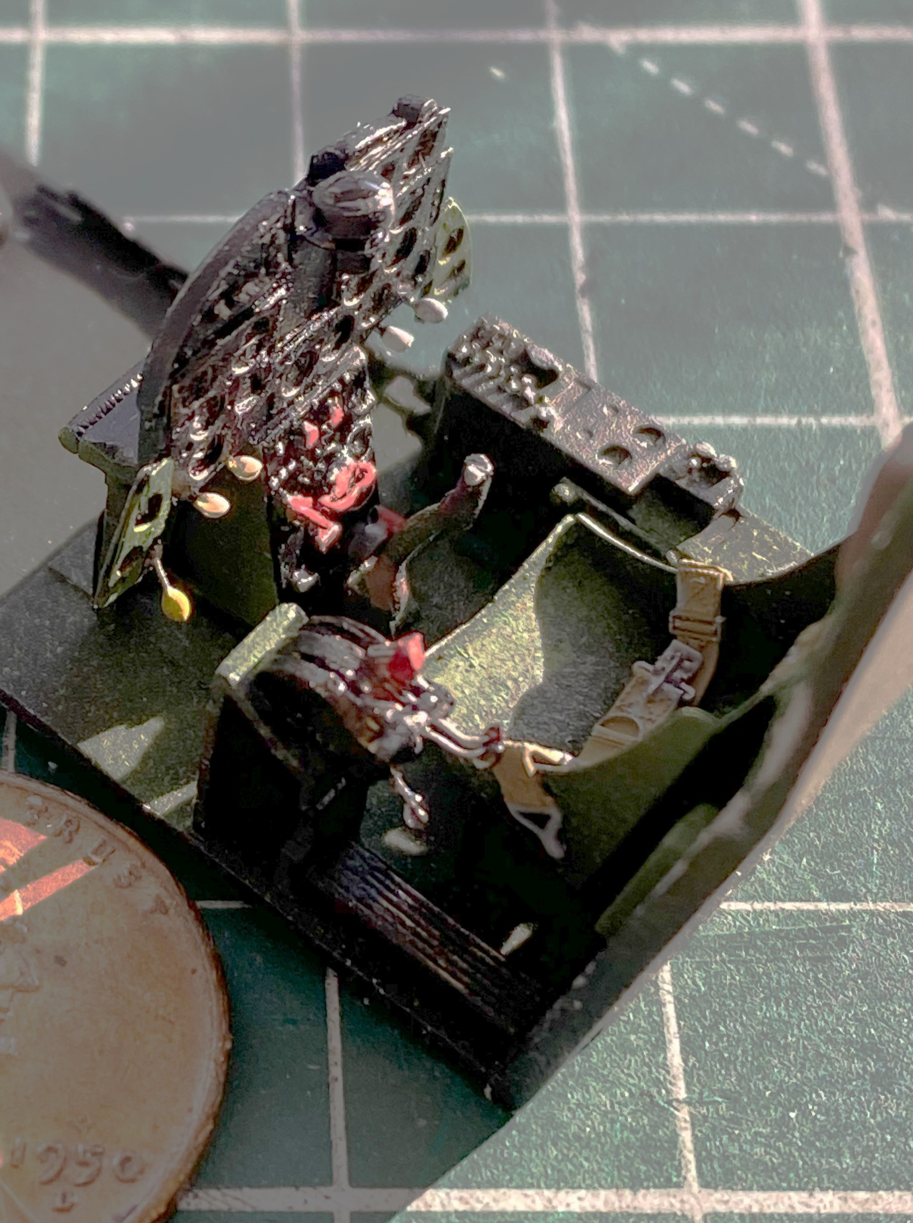
They were added and painted and I went back to putting things together:
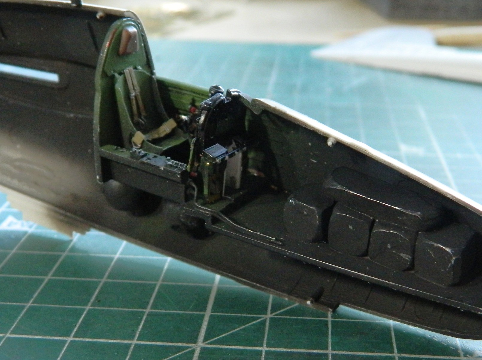
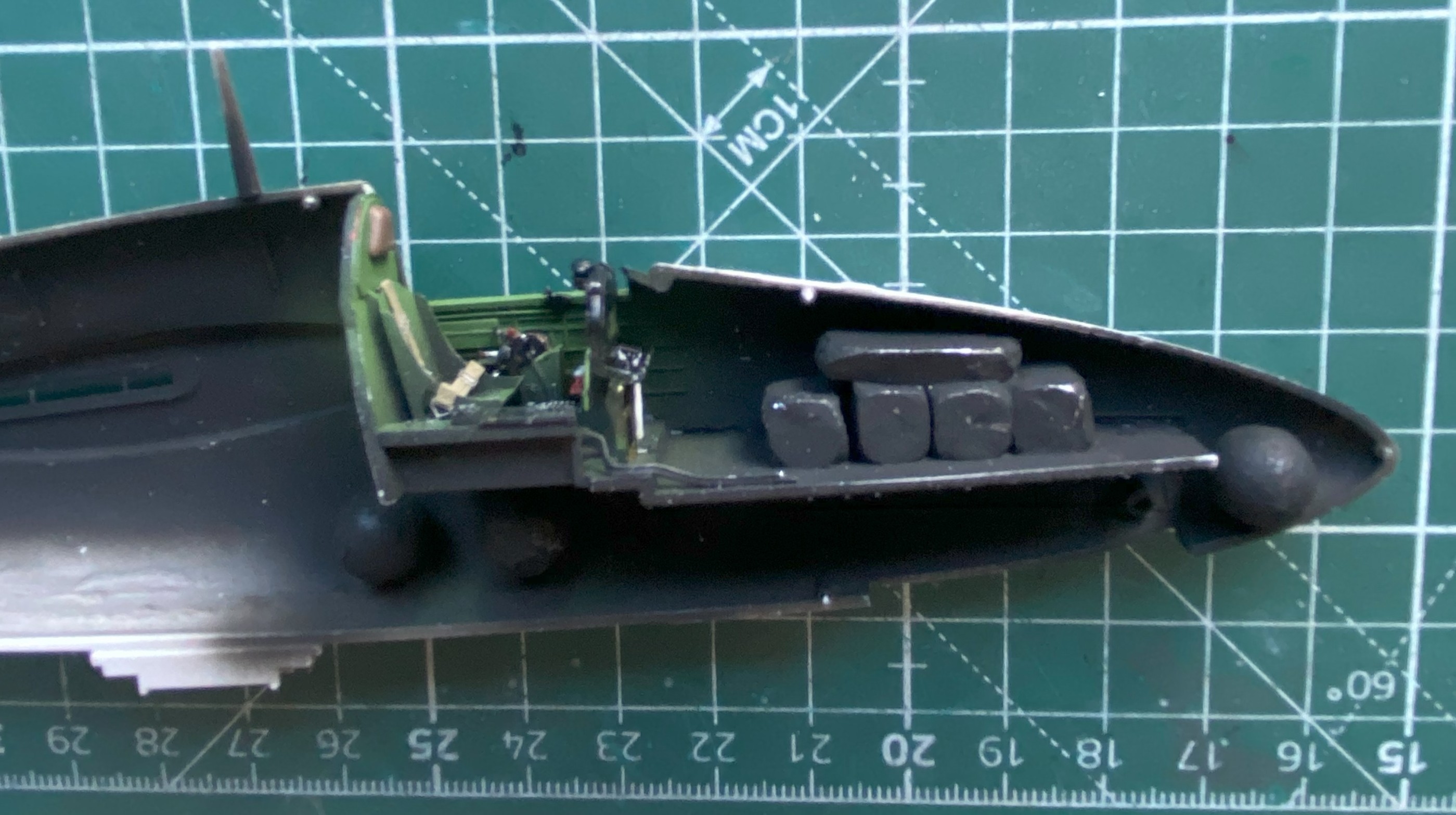
One more bit to add, the wiring harness below the switch/control boxes:
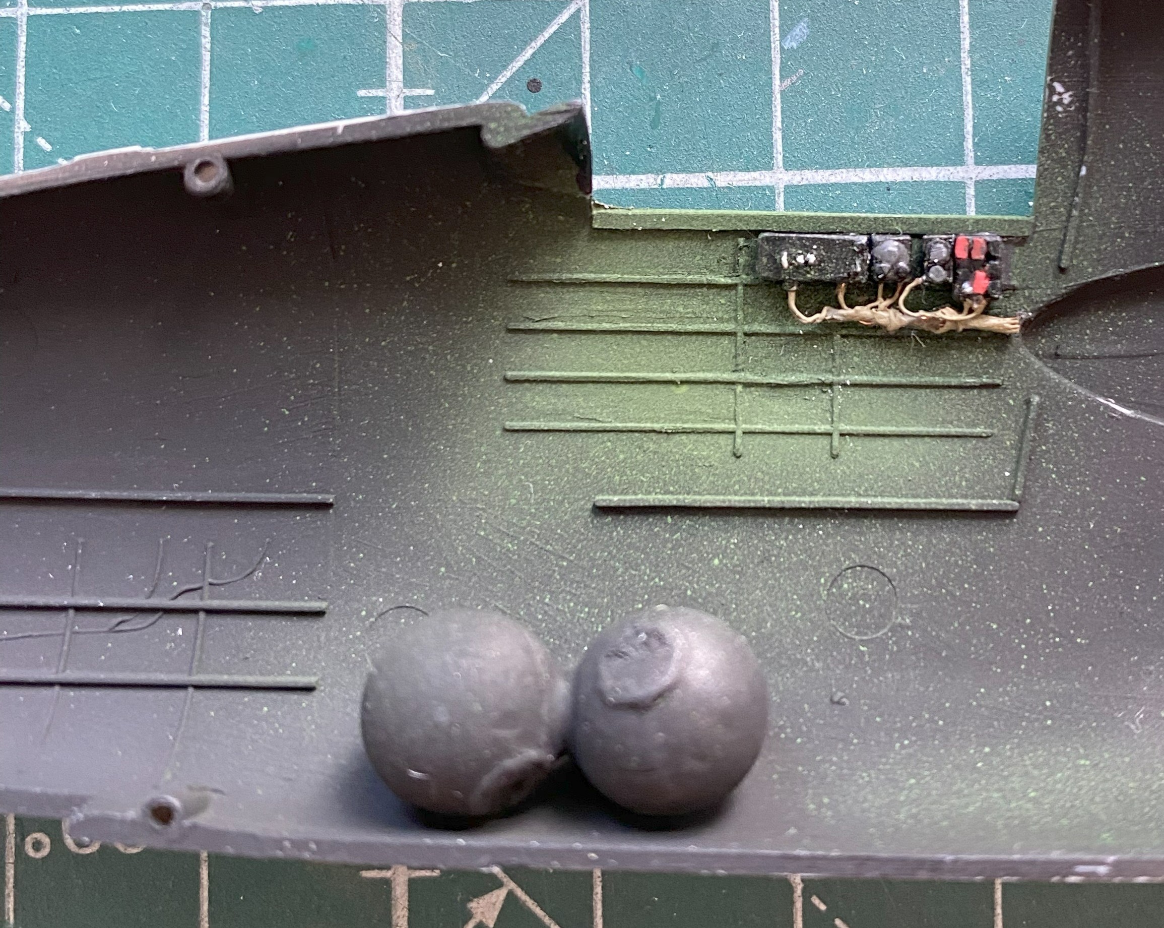
That process wasn’t without its ohgawdammit moments. The fuselage area around the cockpit wouldn’t quite meet. I traced it down to the instrument panel by checking references. The sides of the panel are angled inward. I carefully bent the wings inward, then equally carefully touched up the paint (again) and reattached the fascia of the panel to the film behind it (again). The small bends on either side of the panel allowed the gap to vanish and glue was applied.
Then the two halves were joined:
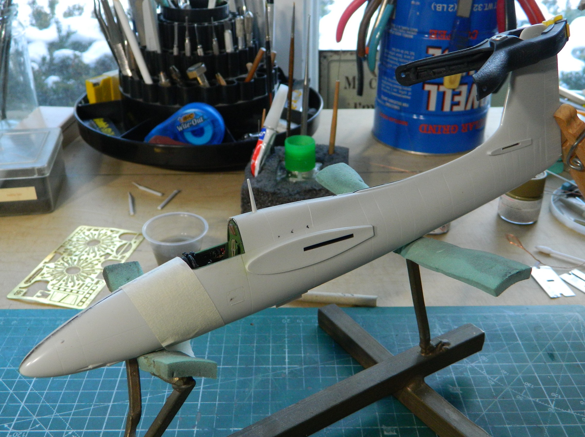


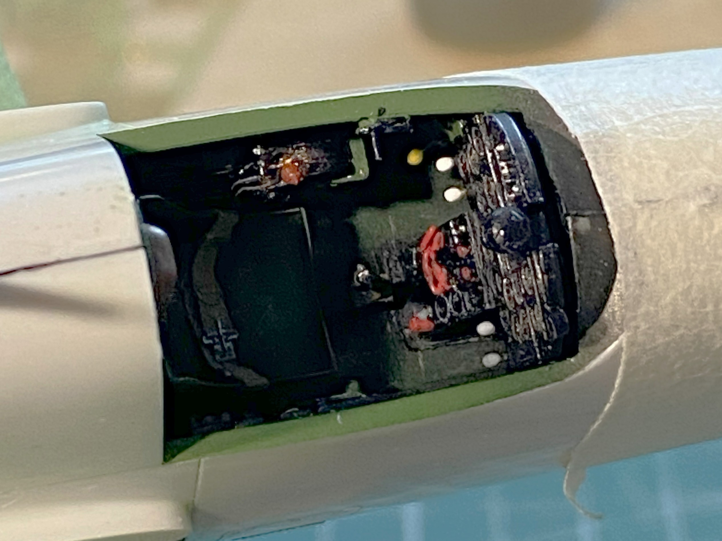
While that was glued and clamped, I started working on the wings and empennage. There are a few lights that needed to be redone. The leading edge of the port wing has a landing light in it as well as underneath the wing, and both wing tips have formation lights. The area of the wingtip lights are molded solid so those were cut out to allow for clear material to be inserted:
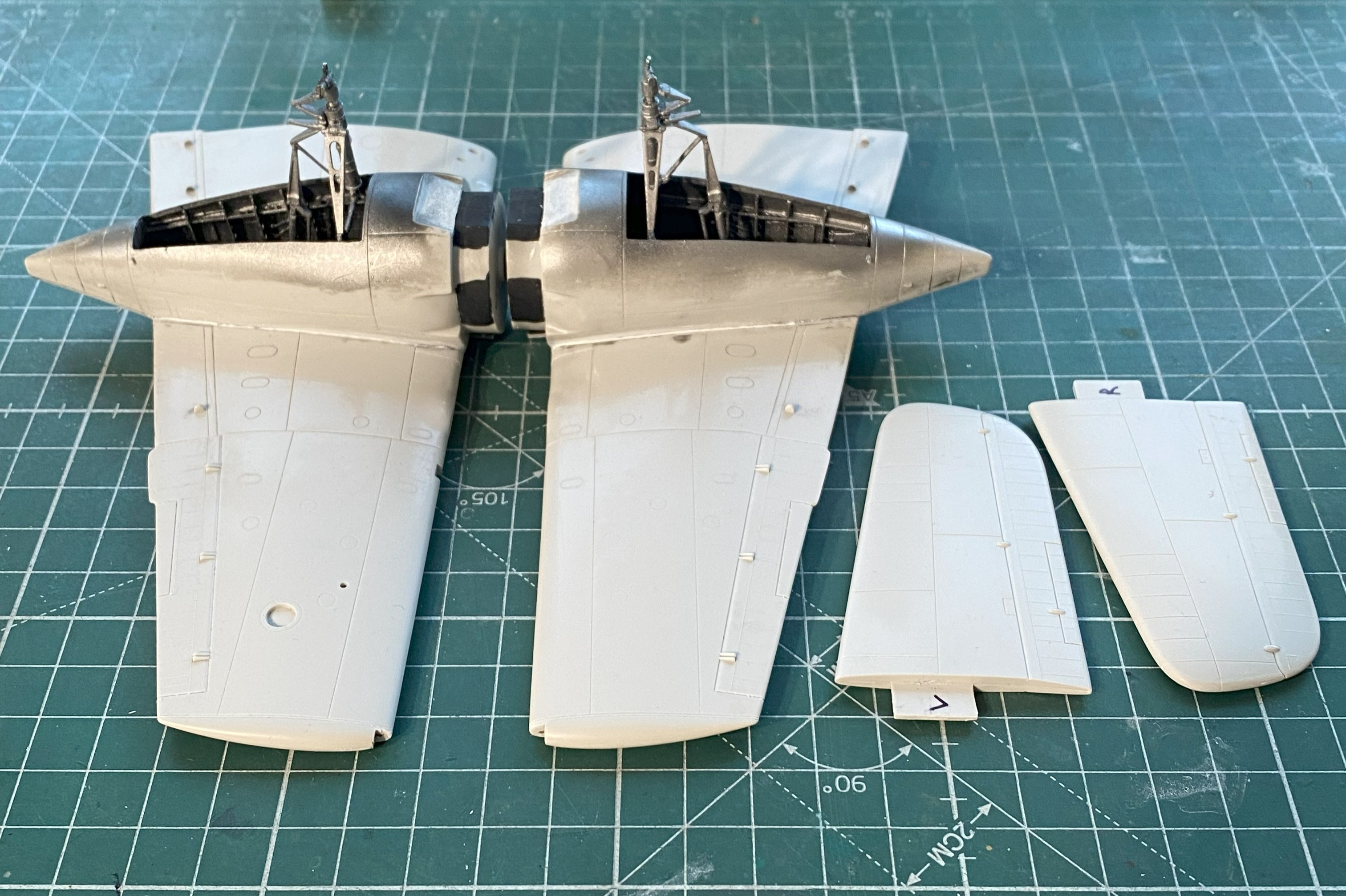
Speaking of lights, there’s a row of three lights under the rear fuselage. The were molded as raised “details” and I knew that they’d be sanded off as the less-than-perfect fit between fuselage halves will need a bit of sanding. I had intended on drilling them out and adding clear sprue inserts instead anyway.
The problem is that I still suck at scribing. Scribing round details would require me to increase my results by a magnitude (at least) to be considered marginal. None of the templates I had offered me the diameter I wanted so I used a punch and die set to punch a correctly sized template from 0.005″ (.127mm) copper shim stock. It worked well enough, particularly since these are just drilling guids:
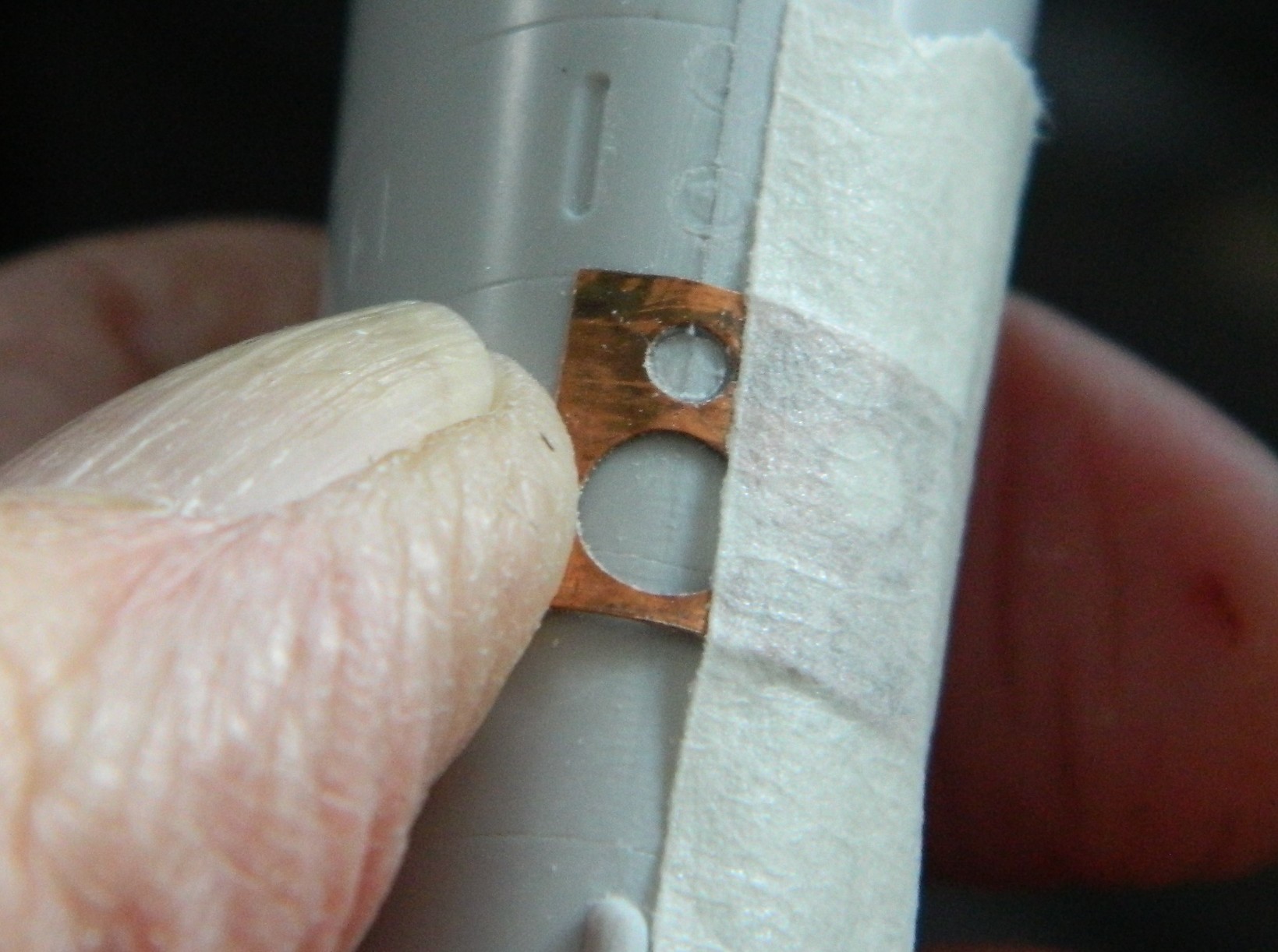

I’m trying to move away from using putty as my default filler, preferring instead to add scrap styrene whenever feasible. Because of adjacent panel lines around and under the nose of the fuselage, sanding to make the surfaces meet would have required a bit of putty. Instead, I added a strip of 0.010″ (.254mm) plastic under the nose for most of the fill with a little bit of putty to smooth the transition into invisibility:
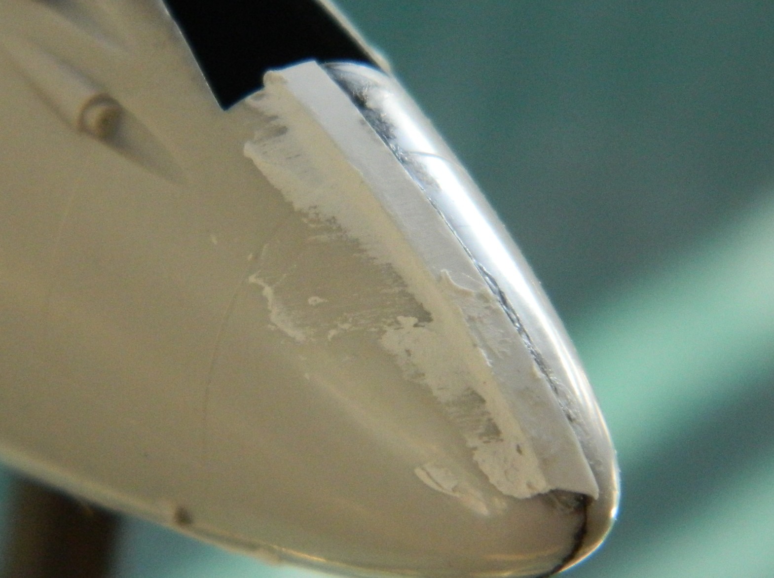
There were other places that needed putty as well and that was applied:
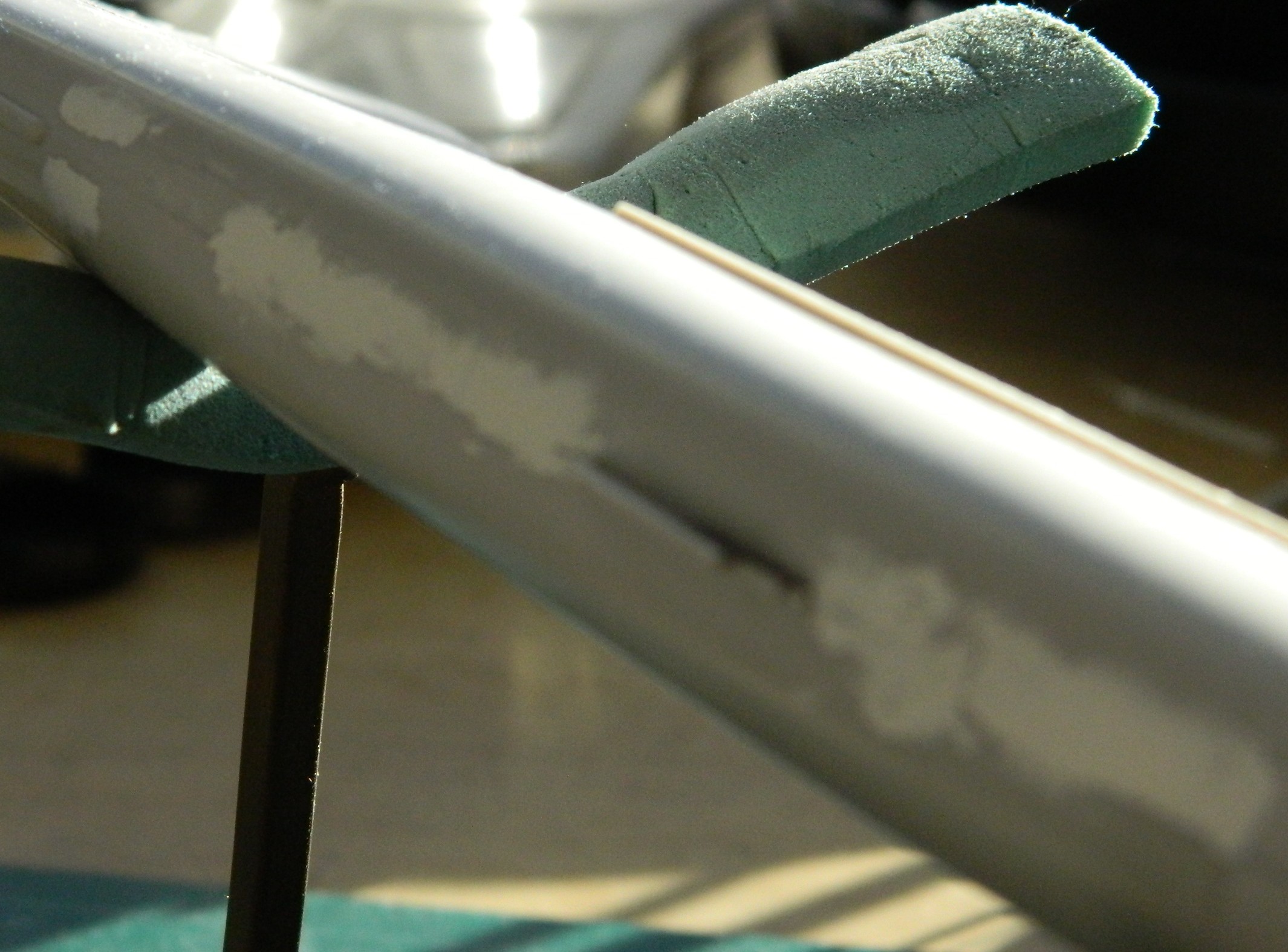
I did mention that I SUCK at panel lines, yeah?:

Once this update is done and posted, I’m going to do a separate tutorial on how to fix errors like the one shown above. If you also SUCK at panel lines, you may find the upcoming tutorial of use.
So I added stretched sprue to fix that one…and all the other ones that I bitched up:
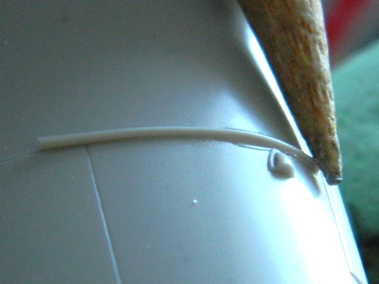
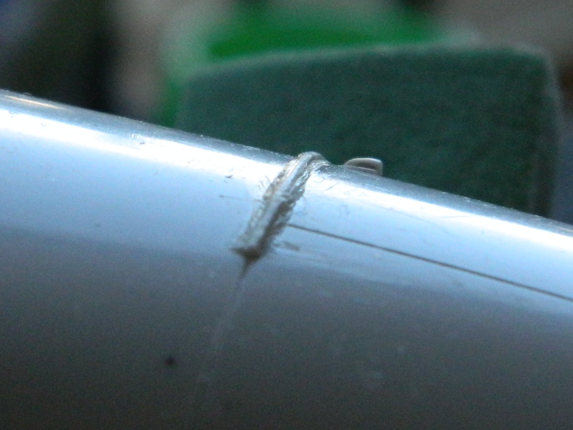


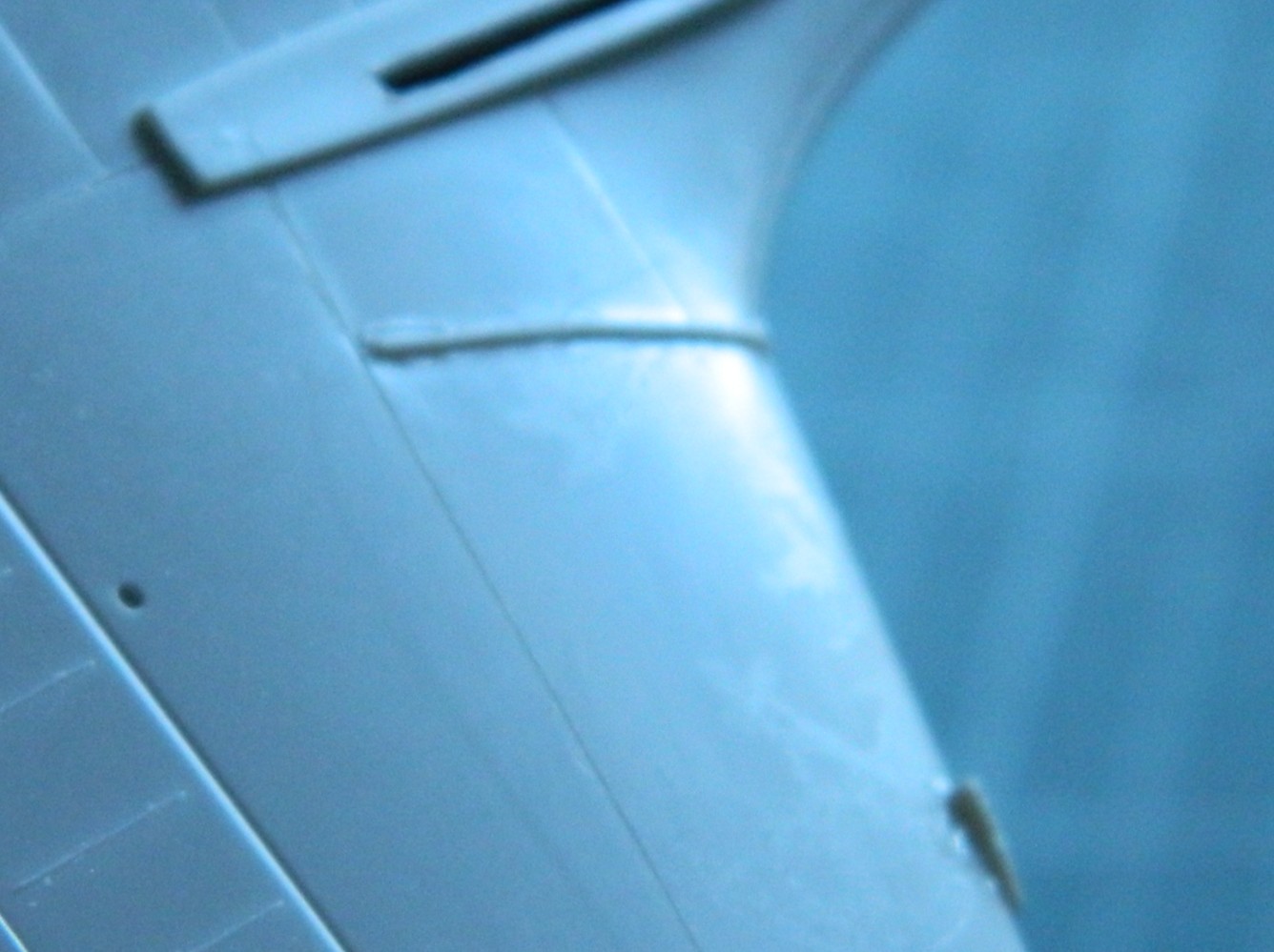
And since I LOVE scribing panel lines, I got to do these twice! How lucky am I… What happened was that I didn’t let these additions cure for two days, only one. When I started hitting these areas with a scriber, adjacent plastic, because it was soaked with Tamiya Extra Thin cement, was also softened. One overnight wait was insufficient for all the cement to utterly evaporate and for the styrene to completely harden. So this was all done again and then sat for two days before I tried working them again. I think that I’ve gotten them as well as I can manage:

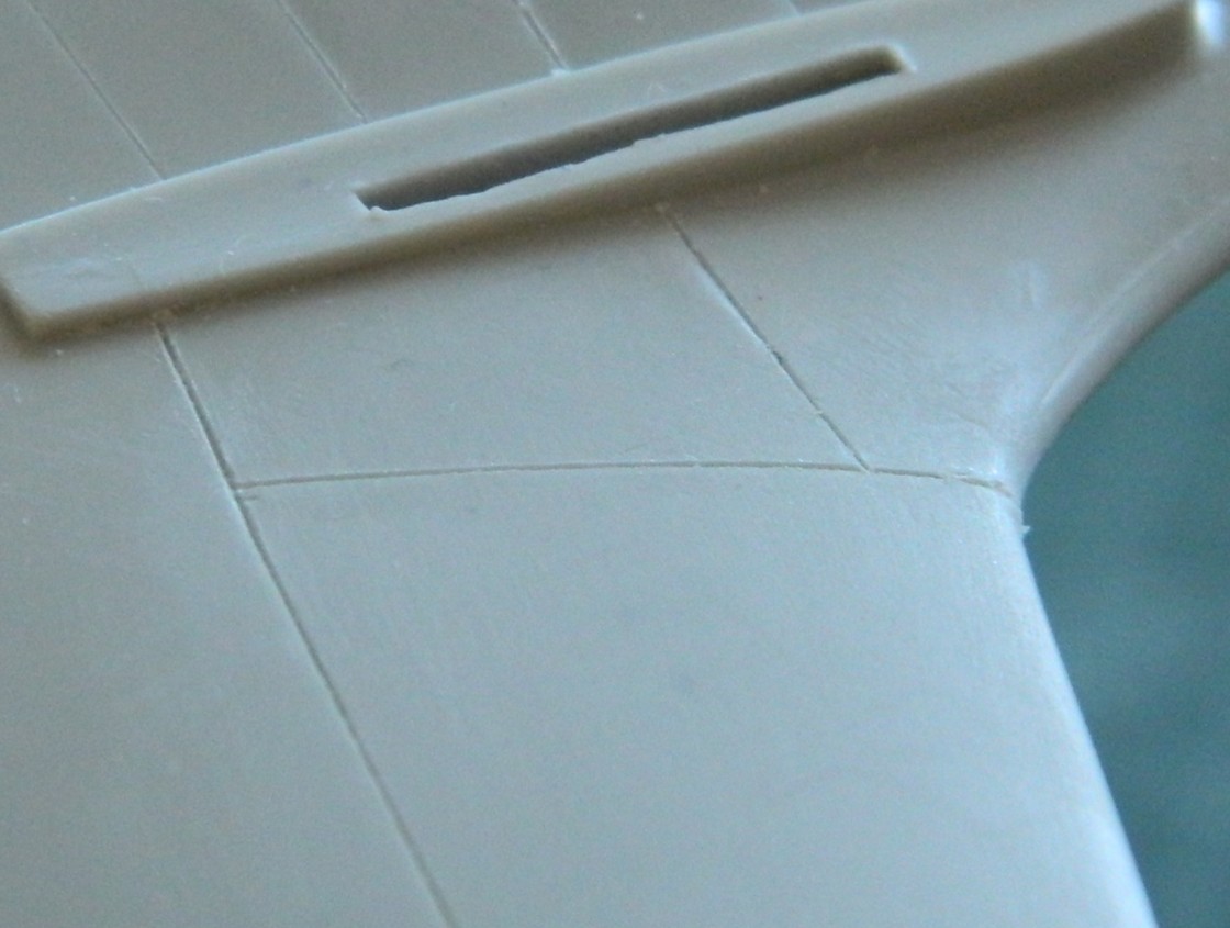

Next problem to address is the poor fit between the engine nacelles and the wings. I was undecided as to whether to use putty or add styrene. I tossed a coin and putty won out. I wanted to keep the putty off of surfaces I didn’t want covered in putty. Rather than mask off those areas with masking tape, I ended up using electrical tape instead. Electrical tape will stretch and either conform to curves or outline curves. Try doing this with a paper-based tape:
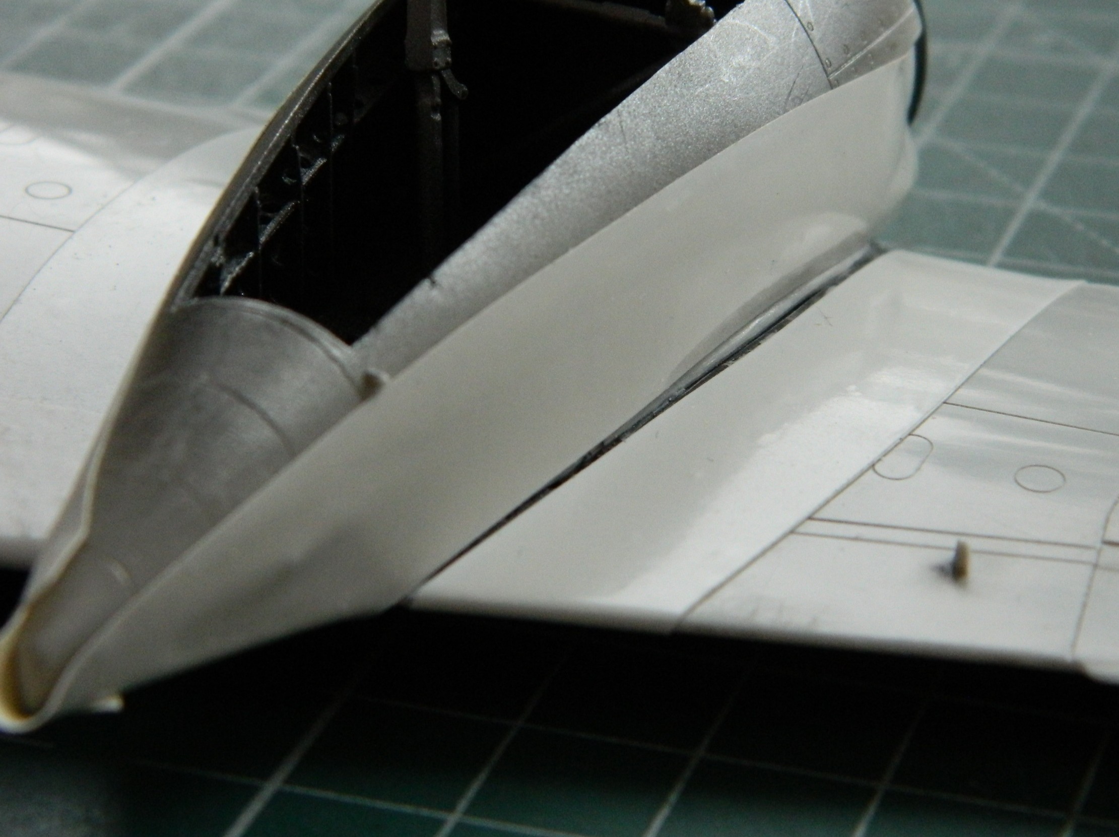
I let these things sit overnight because I wanted the putty as hard as it can be. Then there was a lot of sanding, filing, scraping…more putty to fill areas that I’d missed (or the putty didn’t adhere well enough) followed by scraping, filing, and sanding. Eventually I arrived at the result that I wanted:
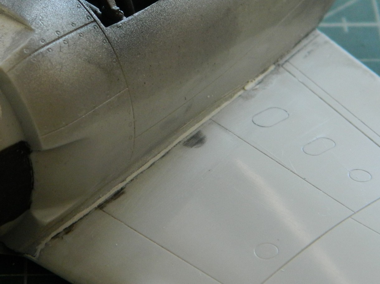

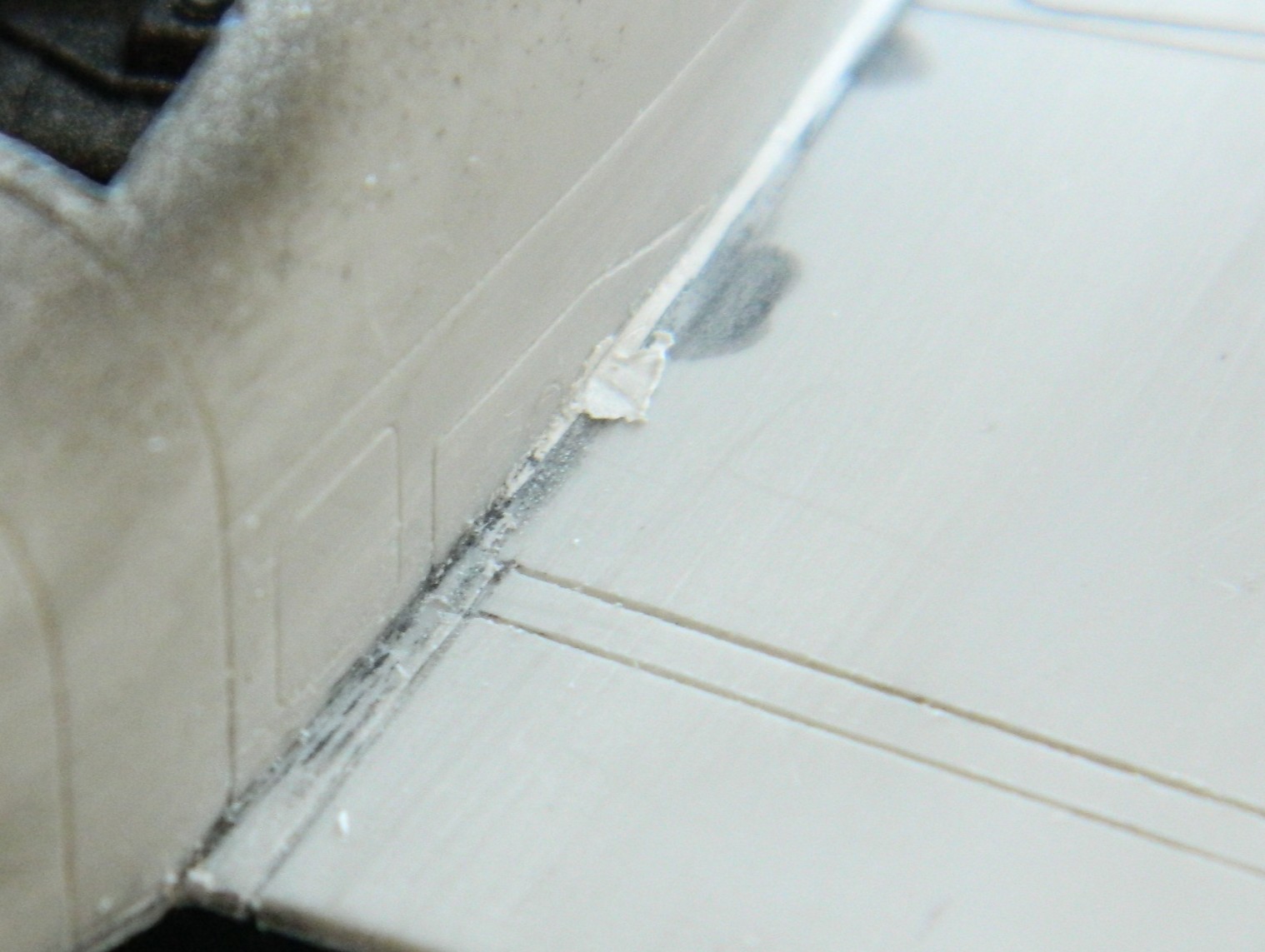
Once I hit these areas with gray paint (probably Tamiya’s XF-20 Medium Gray), I’ll be able to see if the curves where nacelles meet wings are evenly shaped.
While I was working the wings and empennage, I also fixed misaligned, wrong, or missing panel lines (just because I LOVE do this) (spits). This example is looking down at the top of the wing where the flaps are. The line on the left aligns with the line underneath, unlike the line on the right (and no…I wasn’t satisfied with the line I’d scribed, so I filled it with stretched sprue and redid it):

I persevered and ended up with these (the empennage had the same problems and were fixed the same way):

With the repaired panel lines sanded smooth, scribing happened next. Unable to speak for anyone else (and marginally able to speak for myself), trying to scribe long and straight panel lines is impossible without a guide. Being able to scribe straight lines around a curved and tapered surface is so beyond my skill-set that there aren’t words big enough to describe the mess I can make nor how quickly I can make that mess. Since I have to scribe straight lines and scribe straight lines around a curved and tapered surface, guides aren’t optional. Because things are tapered, I used electrical tape again (for long straight lines, I like Dymo Label Tape…adhesive and thick):
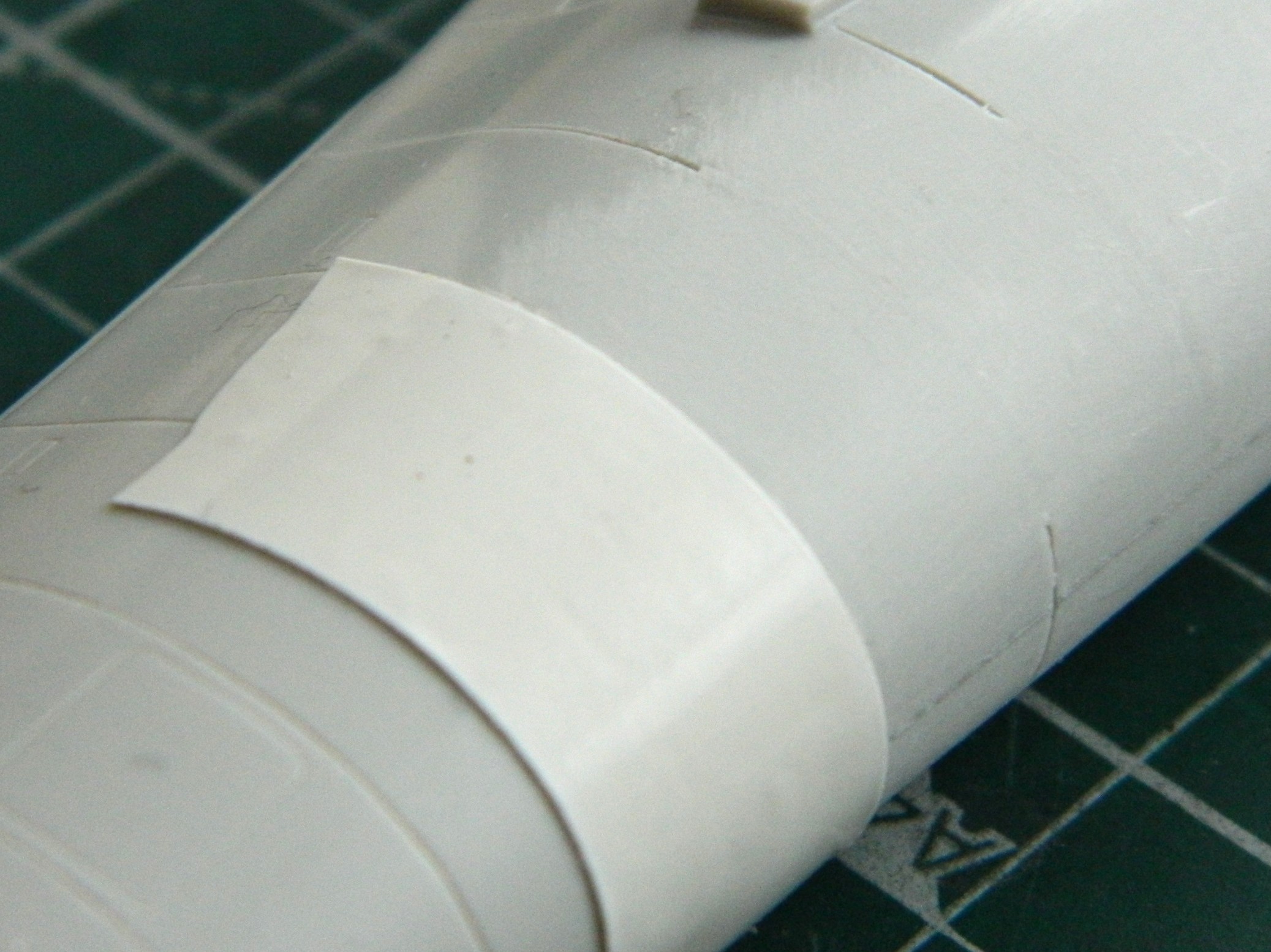
A light touch and many, many, light passes with the scriber is necessary because the thing that makes electrical tape good for jobs like this has an inherent uh-oh factor. The tape is flexible. Push against it too hard with the side of the scriber and the line goes wherever it ass-biting wants to go, regardless of what I want. Light passes. Lots of them:

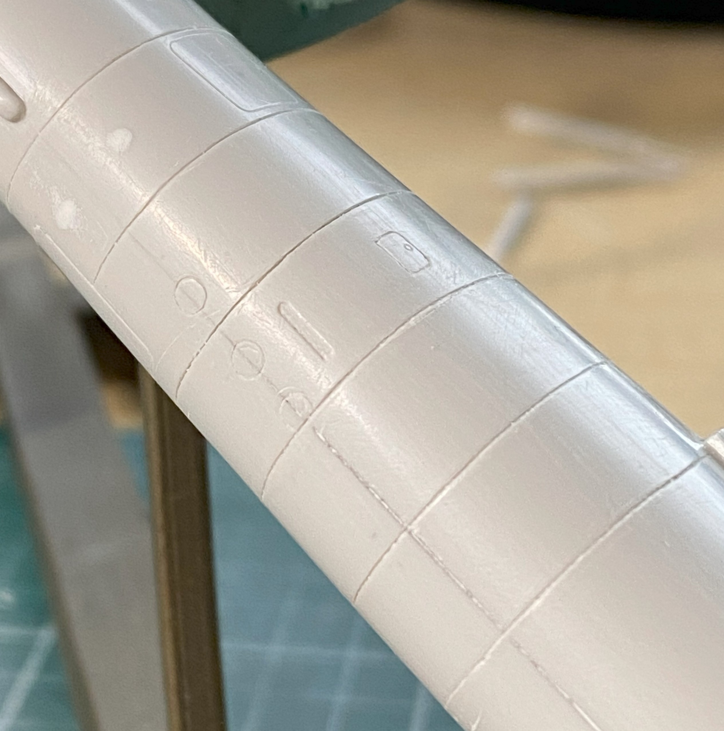
And no…I wasn’t entirely satisfied with how those lines turned out…so I did it again. I got lucky and the next attempt(s) worked.
I. Suck. At. Scribing.
When I have to scribe, I find that I have to handle the model a lot. Rotating (all three axis), pressure, fumbling, all expose the model to risk. I already broke the handle off the flap actuating lever and had to redo it…then I managed to snap off the gun sight, too:
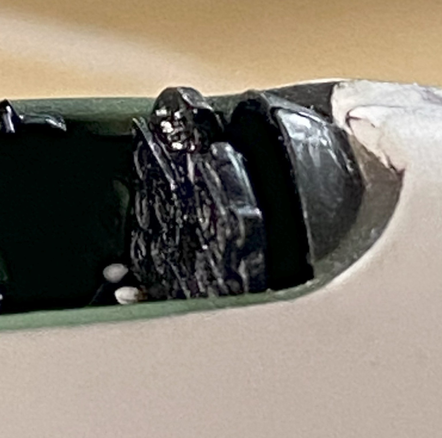
I got lucky. It only took me a little over an hour of crawling around on my belly with a pair of tweezers and a flashlight (or torch, if you prefer) to find it. I’m glad that I don’t have to make another one!
I’ve yet to see a kit that does a good job with landing lights located at the leading edge of a wing. They might be out there, I’ve just never encountered one (1/32 scale, maybe?). This kit isn’t the worst, but it’s certainly neither acceptable nor good. Replacing that requires clear plastic and I just happen to have some. It came with the kit. All I had to do was to shape it and detail it (in reverse order), so I used a vise to hold the stock in place while I filed a flat area that would be deepest in the socket of the wing:
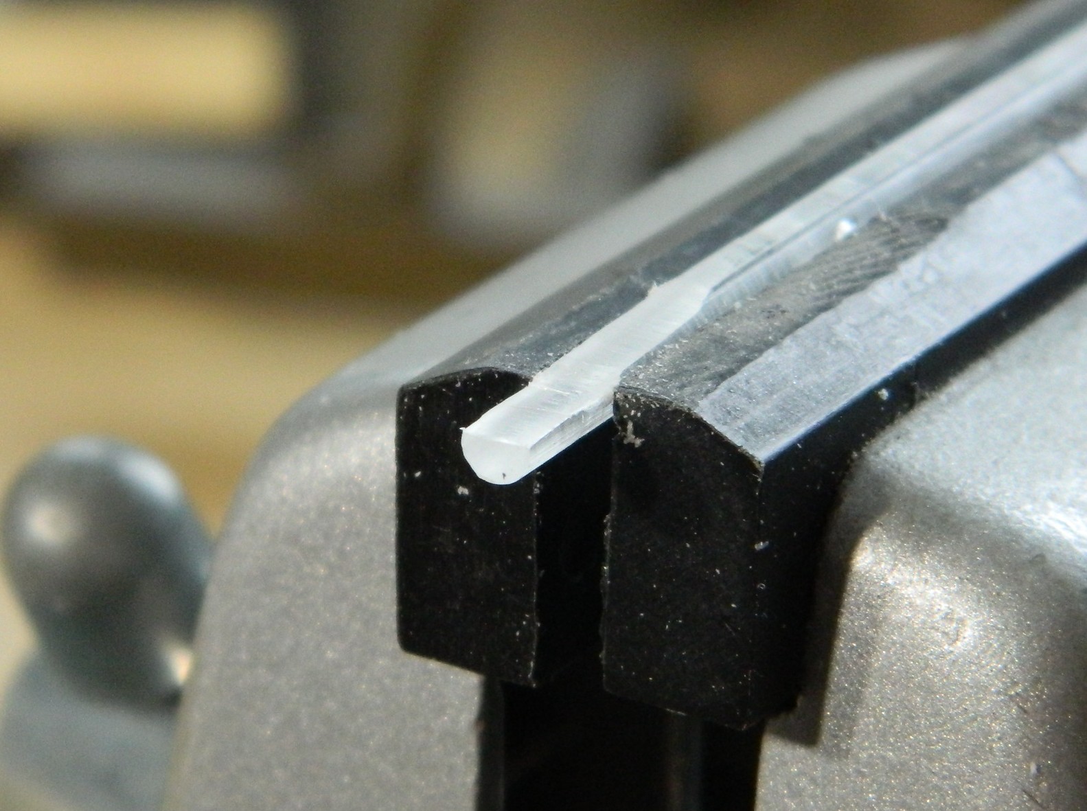
I drilled out what will be taken as the domed section of an incandescent light into the back of the clear plastic. Once done, I used the smallest drill bit I have to make a depression for the “bulb”:
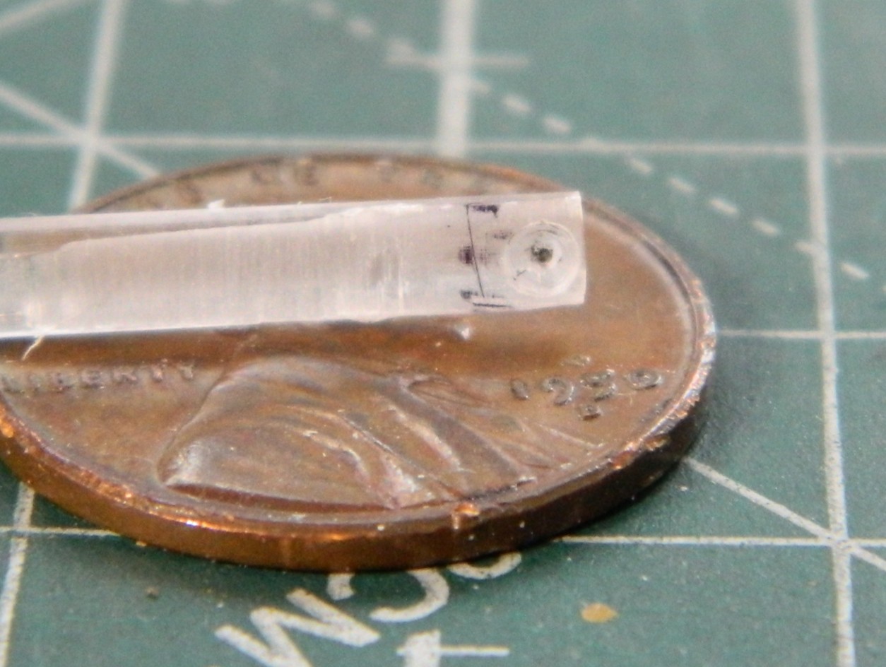
Painting is the opposite of typical. Each layer of paint/color is behind something else. Following that logic trail to its source, the first thing painted is the “bulb”. A touch of black paint. Then the reflector is painted on and for that I used a Molotow Chrome pen. Once it had set up, I gently scraped away whatever chrome was outside the depression and then painted the back of it black.
Then it was a matter of fitting, filing, sanding, and polishing. The “wings” in the photo below are 0.005″ (.127mm) styrene to fill gaps on either side of the insert:
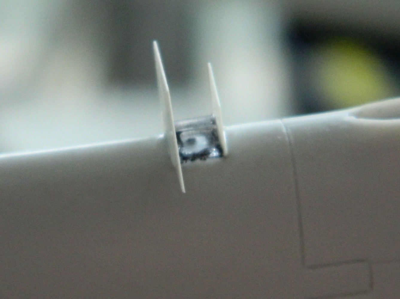
Then it all gets finished (with tape applied to preserve the curvature of the leading edge of the wing):

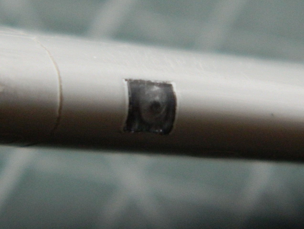
Not my best effort but certainly good enough (I should have eschewed the drilled “bulb” and used just a needle instead…that’s for the next one I have to do).
Last update I’d mentioned that the sliding part of the canopy was flawed. Part of it didn’t fill the mold cavity:
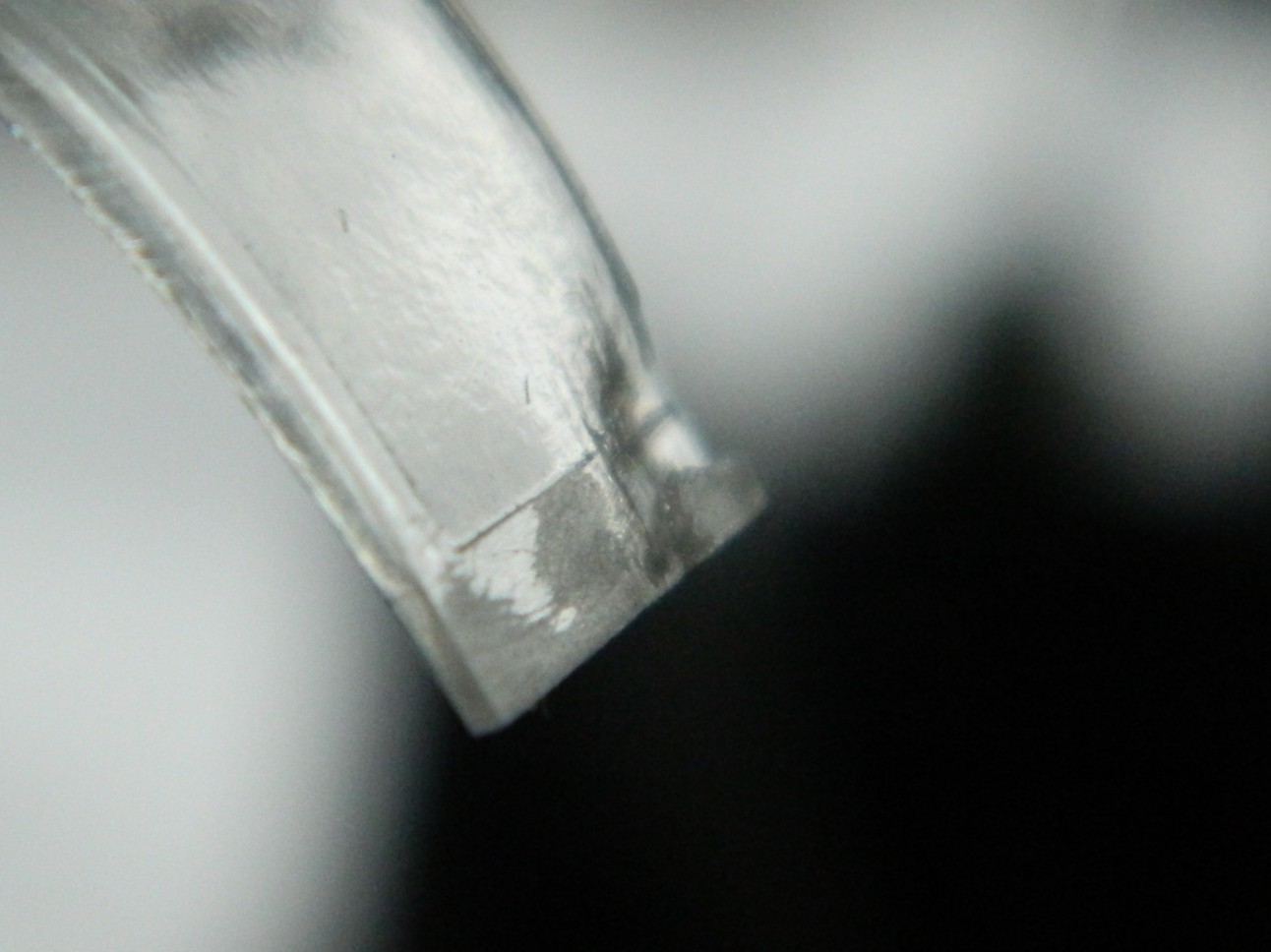

Not exactly the end of the world (or build) as I’d not intended on using the kit part in the build. If the canopy is pose open, this part sits far too high to be remotely accurate. My only use for this part is as the buck to vacuform another one over. Since even I know it would be a mistake to try that without fixing the depression, I fixed it. I used the UV-setting resin to build up the missing mass:

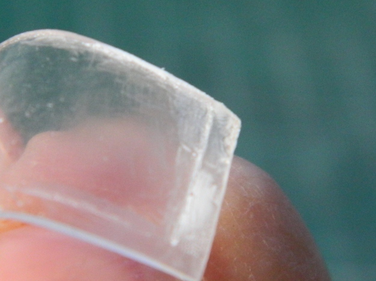

That will do.
As an aside, I find that the UV-setting resin is harder than styrene when it’s cured. It also appears to be hard enough to file/sand/polish to clarity. Must remember this the next time I have to repair a canopy that I must use but have just bitched up.
While I was rustling about, I treated the underwing landing light to Molotow Chrome. I used a punch to pop a hole in masking tape, applied it, and didn’t have to worry about slopping the chrome out of the recess:
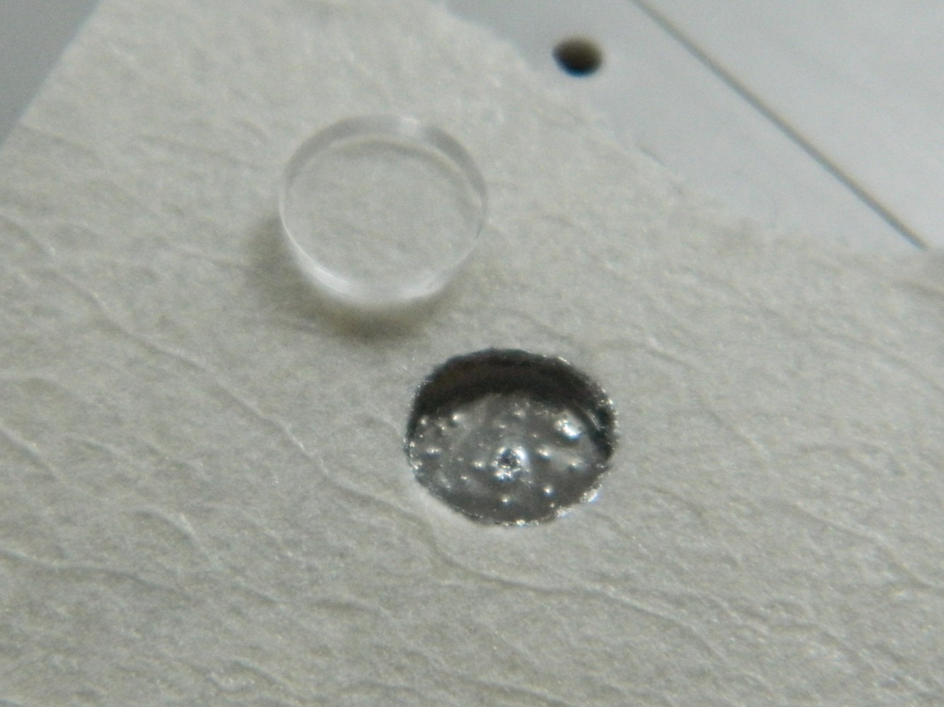
I also used 0.032″ (just under .890mm) copper tubing to replace the kit’s 20mm “cannons”:
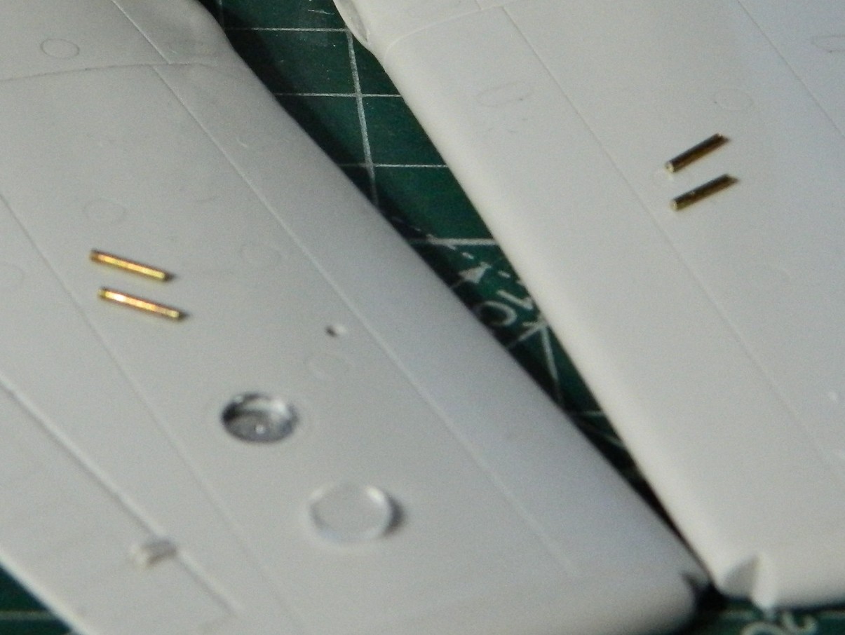
I can just see how many times one of those will get knocked off, so I’ll mount them later. I also managed to snap the antenna mast off as well. I’ll add a pin to the bottom of the mast and drill a socket for it to mount to later.
I’m just happy that I do NOT have to work on that sodding throttle quadrant anymore!
Needs versus Wants
There are many steps when building a model. Open the box, get the first look at all that plastic. Start the research to see how accurate the model is, see what the model got wrong, and start figuring out what must be done to diminish the errors/commercial decisions. See what aftermarket bits are available and decide which, if any, to get for it. Notes get made on the instruction sheet. Paints are sometimes purchased (but only if someone is looking). It’s at this point that needs vs wants starts to pop up in my mind. I want to do this thing…whatever the thing is. Things like upgrade the instrument panel on an aircraft model. I want to do that, and I need to do that. (That sentence refers to what I see in my mind as the finished build.)
Work starts.
Notes are referred to frequently. As the work moves into the “yeah, I need to fix that” part of the process that is directly related to “I want this to be accurate” that’s driving the project. Needs vs wants align. It’s at this point that I often question my decisions. It’s a lot easier to scribble something on paper than it is to transfer that intention to the plastic, resin, photoetch, copper, brass, and so forth. Sometimes transferring a want into a three-dimensional presentation ends up at a choke point. (“Sometimes.” That’s funny.)
I suspect that all builders (and probably even assemblers) have aspects of a build that they dread having to deal with (PE comes to mind as does clear parts), so pretty much anything that’s not the dreaded chores gets done instead, but there’s only so much at any particular point that can be done and eventually (or sooner) there’s nothing to do but THAT THING I HATE TO DO. For some it’s painting, for some it’s decals, but there’s always SOMEthing in a build that I just don’t want to do. Yet in order to get this thing to look the way that I want it to, that thing indeed must be done and now everything else that could be done instead now has been done.
This is a choke point.
Before anything else can be done, THIS damned thing has to be done first and the build abruptly stops until THIS damned thing is taken care of. Every modeler I know has a shelf of doom. This is where builds go when the builder doesn’t get past that choke point. And when asked about why that build stopped, the modeler doesn’t even need to open the box(s) to answer it because each box on the shelf of doom is there for usually just one reason and the builder knows exactly what that reason is. The builder just doesn’t want to do it. (Might also be why some modelers have multiple projects in process.)
I’m lucky enough to have a dedicated space for my modeling shop. It’s at one end of the house and my roommate is frequently at the other end of the house. My colorful and obscene invective carries clearly the length of the house when something goes wrong in the shop. So far I have managed to restrain myself from dropping the offending project onto the floor and stomping it until it’s unrecognizable dust…but I am quite vocal about my desire. Sometimes things get so loud and obscene that the roomie will stick her head in the door, and in passing (because she’s not dumb enough to stand there and wait for my reaction) will say things like, “And you do this because it’s enjoyable?”
Well, no. This part of it is something substantially less than “enjoyable”.
Just in case it’s not evident to you yet, I deal with AMS. AMS stands for “advanced modeler’s syndrome”. (Some call it “aftermarket syndrome”.) I work in 1/48 scale or 1/35 scale because the work is larger and easier to see. (Old eyes.) That’s the benefit. Benefit, however, also brings with it liability. The liability of working in larger scales is the flip side of the benefit because things ARE easier to see. One of my inner guidelines is that if I can see it, the viewer can as well. That means that since it’s visible, I have to address it and make it as accurate as possible. Aftermarket, scratch-building, and often prayer (from an atheist*), are frequently involved in getting from where I am with the build to where I want to be with the build. Y’k’now…finished.
But I don’t kid myself into thinking that just because I have to break through the choke point (like, writing about this incredibly annoying choke point) and get on with the build that there isn’t another choke point waiting.
I have no shelf of doom. I don’t work on multiple projects. The real problem is the choke point and the only way to solve it is to SOLVE IT.
Or write about it…
*I’m figuring that I will exit this mortal plane when I invoke gods that I don’t believe in and one of them gets sick of my shit and nails me with a bolt of lighting, probably out of a clear sky.
F7F-3 (AMT/Italeri) 1/48 Scale Build #6 – Starting work the Cockpit…Where Things Get VERY Tedious
Having a direction for the how I can build the throttle quadrant, it’s important to remember that having a direction isn’t exactly the same thing as going there. This was certainly a reminder! Ascertaining that using styrene certainly wouldn’t work, I broke out my stock of copper shim stock. This part of the job used 0.005″ (.127mm), 0.010″ (.254mm), and 0.020″ (.508mm). I used a piece of the failed parts as a template and then used a sharp needle to outline the template onto shim stock and then used scissors to cut out the parts and then started stacking them. The partial pieces are spacers so that I can end up with the slots for the control levers. I discovered very early that soldering wasn’t the way forward. Superglue is. Lots of stacking and aligning followed:
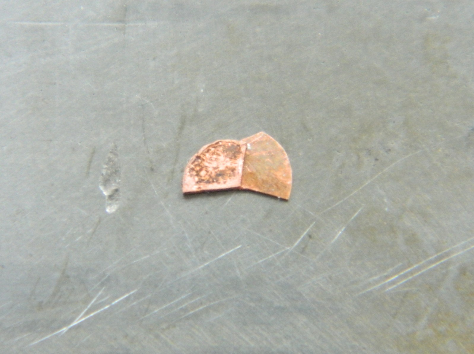
To keep the larger parts parallel (or as parallel as I can get them), I added a spacer of 0.005″ (.127mm):
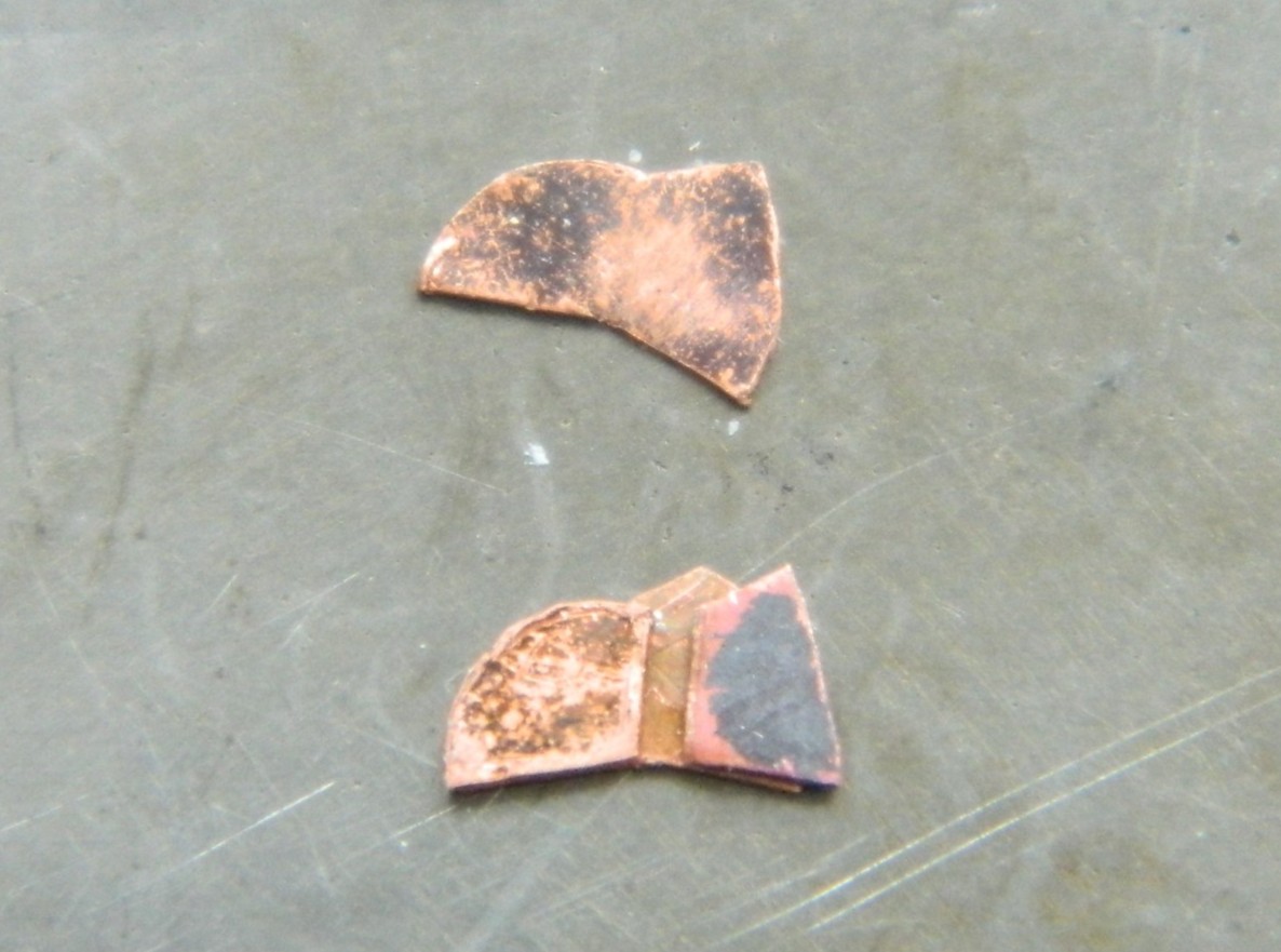
Then I kept stacking parts. Most of them were 0.005″ (127mm) but there was one 0.020″ (.508mm) spacer, which is on the top of the stack below:
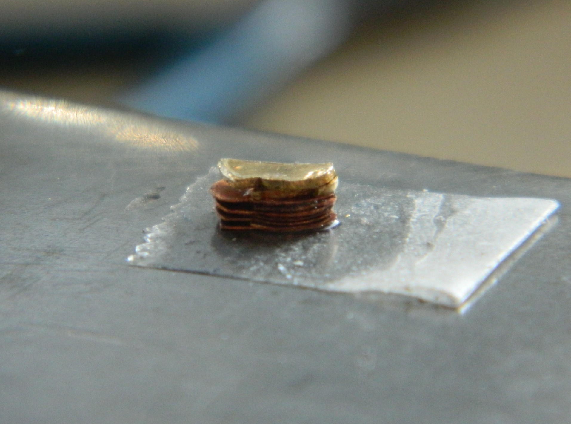
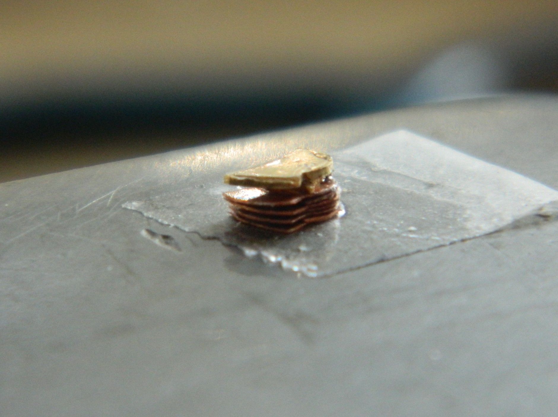
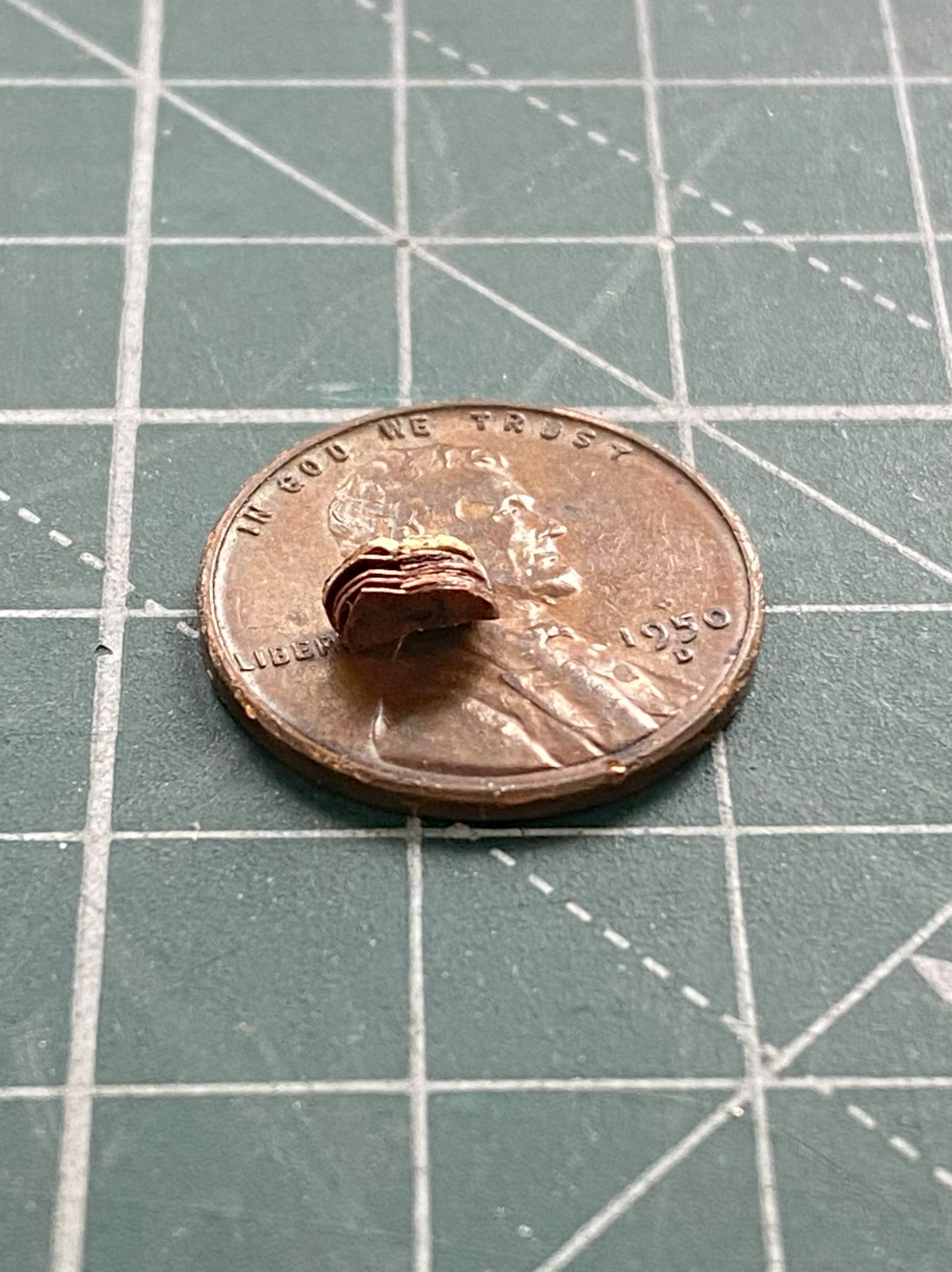
With the parts glued to each other, the next task was to file the stack to more accurate shape and dimension. Let’s hear it for having a vise:
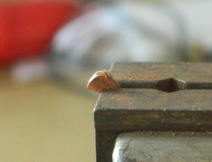

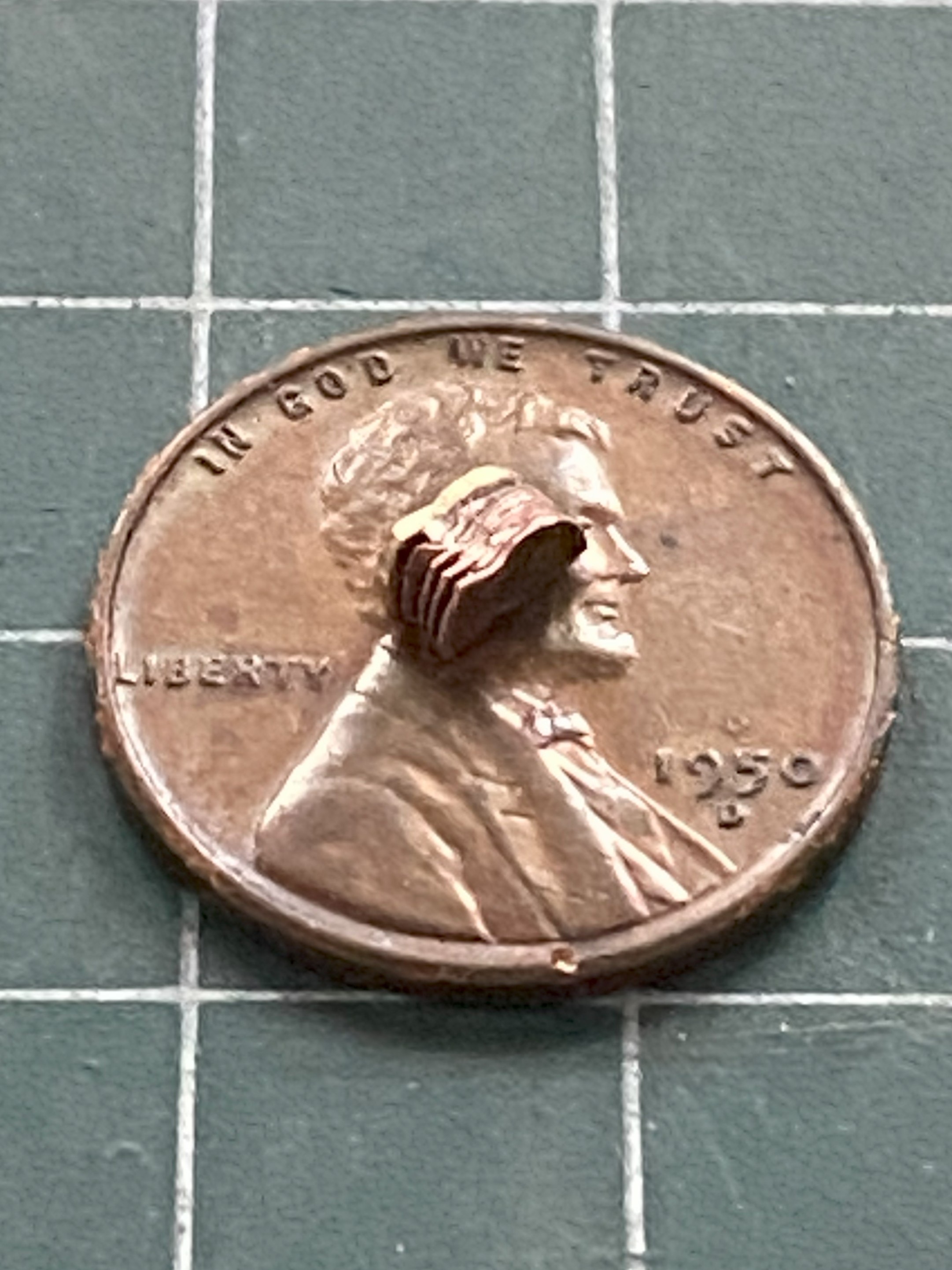
There were still very small gaps between the layers so I laid down some 3M Acrylic Putty and then removed the excess putty:
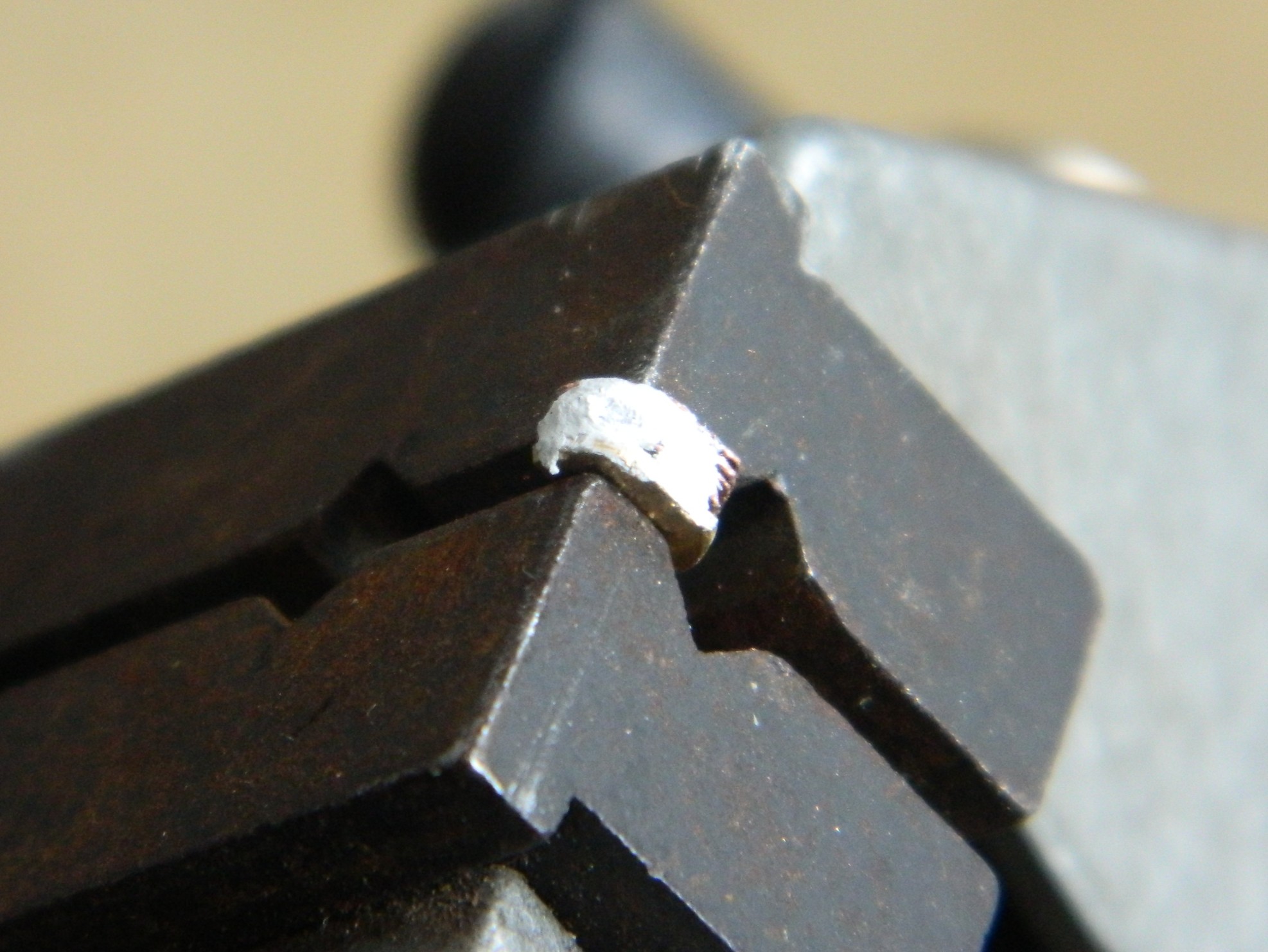
A few pictures, a paragraph or two, to cover TWO WEEKS of diddling with this thing, TWO WEEKS that also includes rebuilding the fornicating thing a few times. ::facepalm:: Probably not a bad idea to check to see how it’s sized…which means redoing it again if I got it wrong:
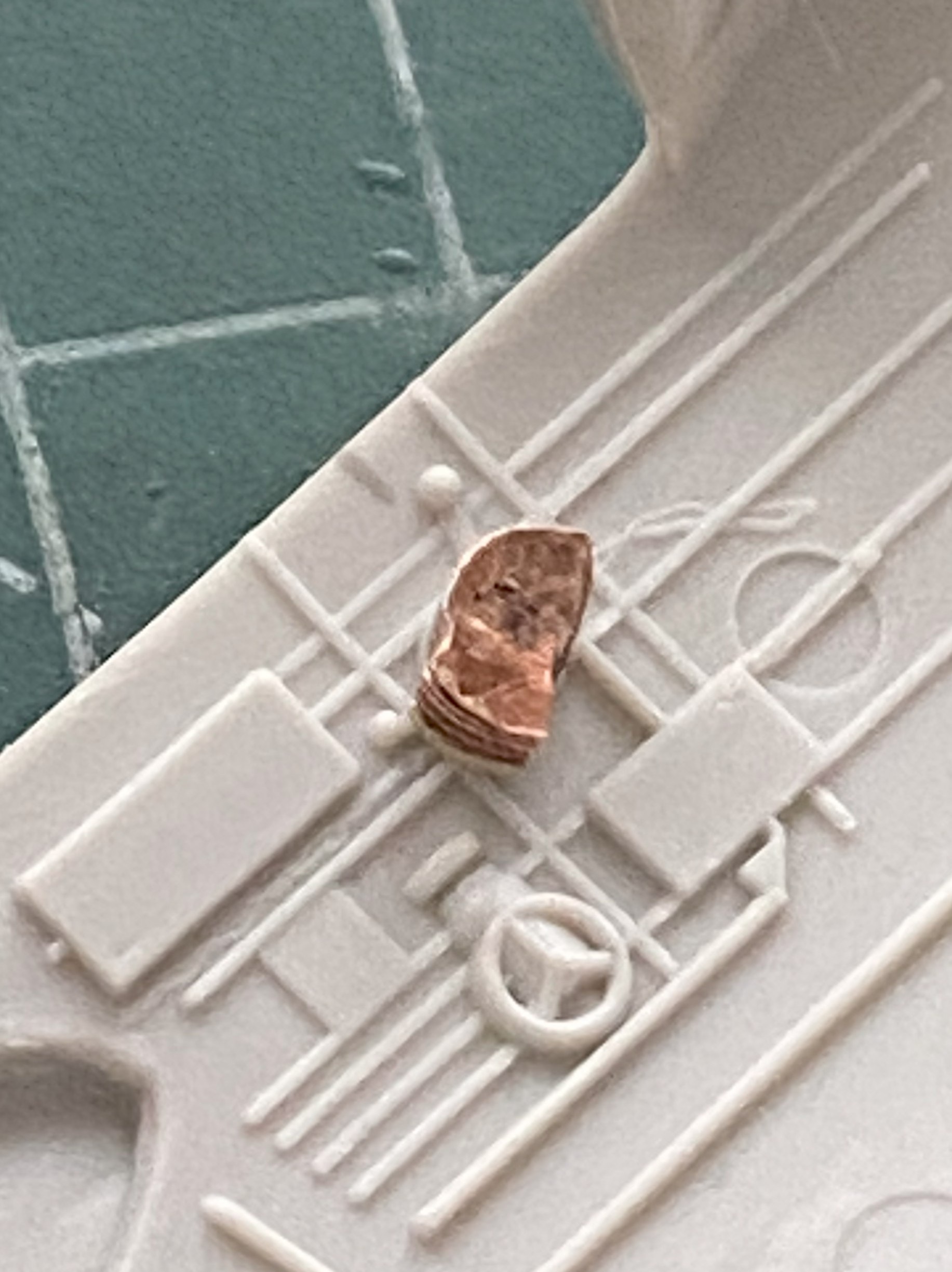
Whew. Unless I mishandle this assembly (always a potential, particularly earlier in any day), it’s ready for levers and paint.
A pivot for the levers and a couple of tensioning knobs were added, then I glued the assembly to a bamboo skewer and painted it with Tamiya X-18 Semi-gloss Black:

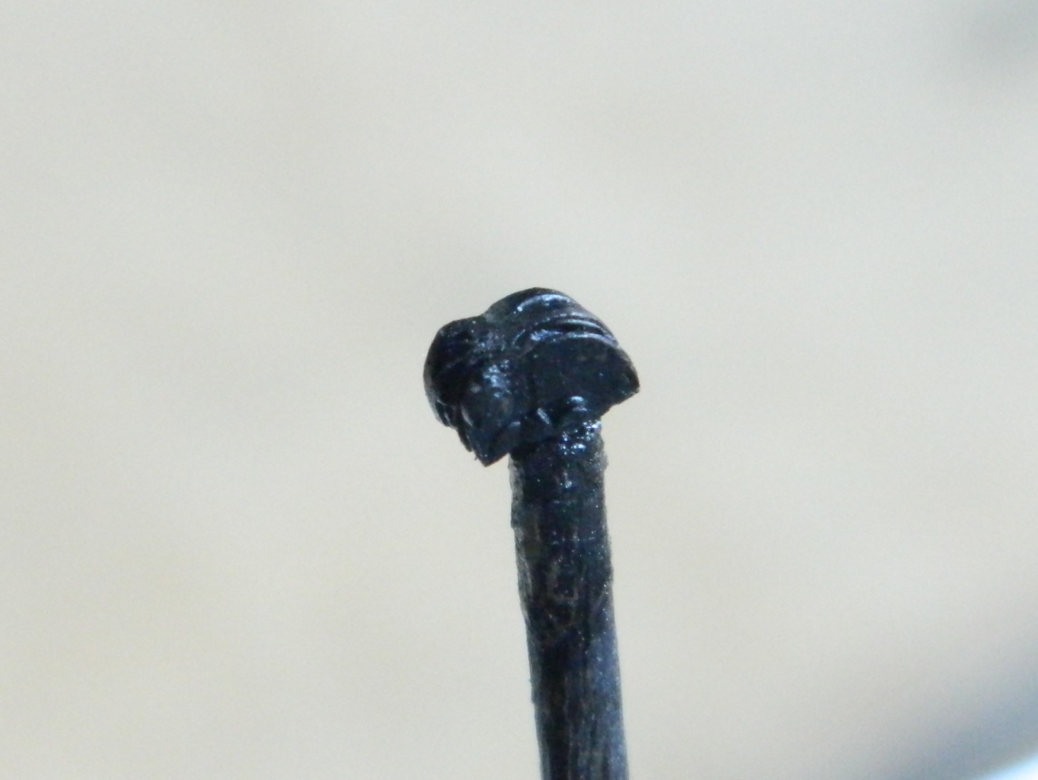
Whew…
One of my aphorisms (one of many) is that all solutions create new problems. Having boosted the level-of-detail as far as I have, I needed to boost everything else adjacent to the quadrant to the same level. And then I focused on all the linkages and cam levers that connected the controls to the control surfaces. OMFG. The reason I don’t work in 1/72 scale is because of how stupid-small the parts are in that scale. Here I am working in 1/48 scale and I have to make SIX of everything; primary control rods, the first set of cam levers, secondary control rods, another set of cam levers, and another set of tertiary control rods. All that in a space about 1/12″ (about 5mm) square by about 10/32″ (just under 8mm) tall. Uhm…no. Uhm…FUCKING NO.
Have you ever heard the term, “imagineering”? That’s where something has to go there, but if there’s no reference photos or hard information for what goes there, the builder has to make something that looks right, even though it’s not. When is imagineering needed? Read the paragraph preceding this one. That’s when. Or, as it’s also known whilst in the middle of this situation, NOW.
Okay. I can do this (again, but don’t tell anyone, okay?). I decided to imagineer a pedestal for the quadrant to sit on top of with only six tertiary control rods exiting from that pedestal and vanishing through the cockpit’s rear bulkhead.
That starts with building the imagineered pedestal. Basic construction was done using 0.015″ (.381mm) scrap:
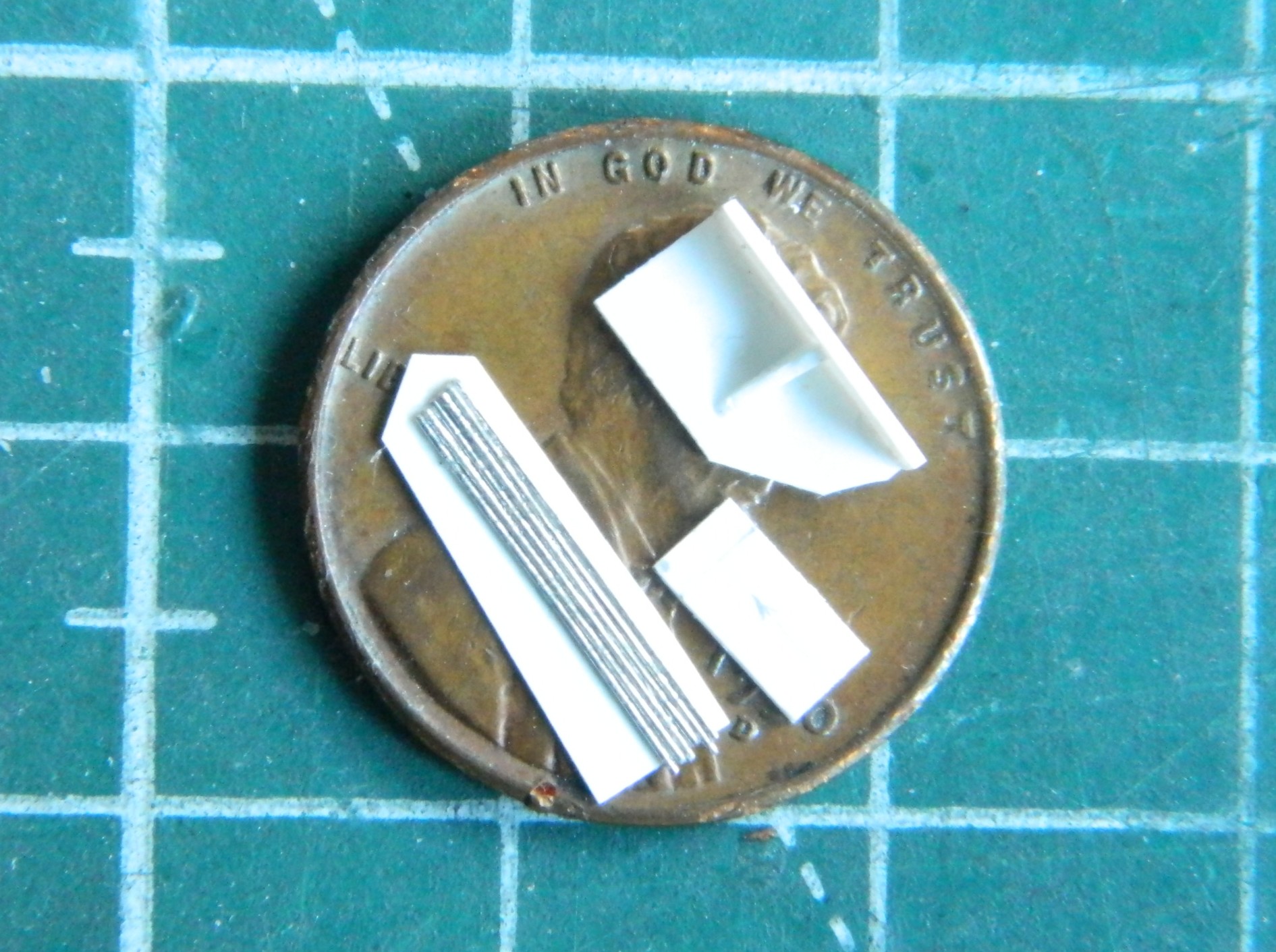
The control rods are to the lower left of the penny. Rather than wrestle with each wire individually, I decided to use a piece of 0.005″ (.127mm) scrap as a backing so that I only had to wrestle with this thing once. I glued all six wires to it and trimmed the excess plastic away.
While the glue was setting on the pedestal, I turned attention and effort to the control boxes mounted on the right side of the cockpit. The basic depth, width, and height of the boxes was made using 0.030″ (.762mm) scrap. Toggle switches were replicated with wire and rod and stretched sprue was used to replicate the controls on the boxes:

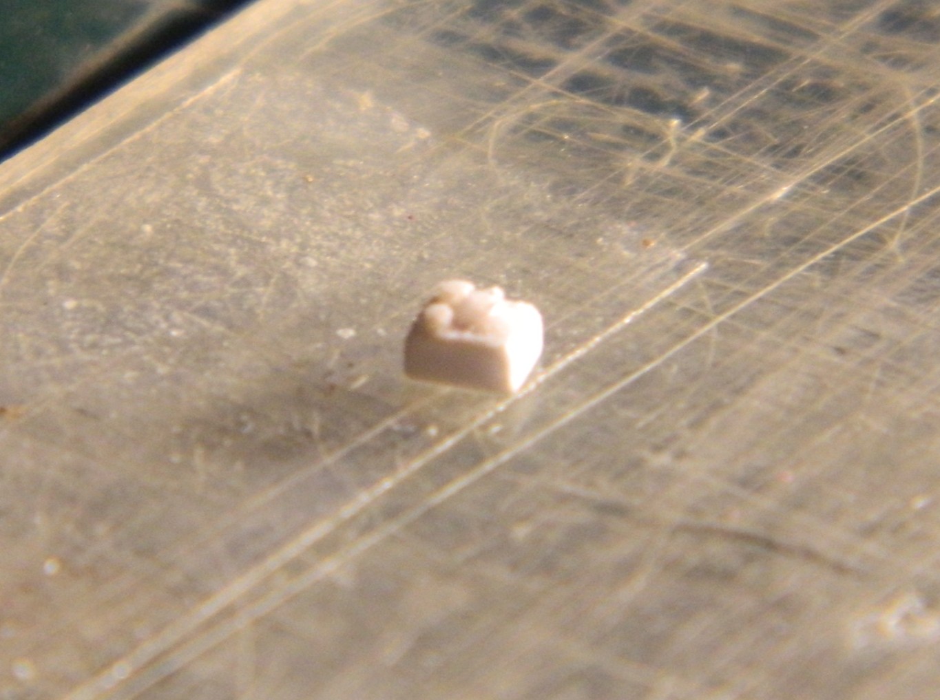
Yeah…pretty small parts:
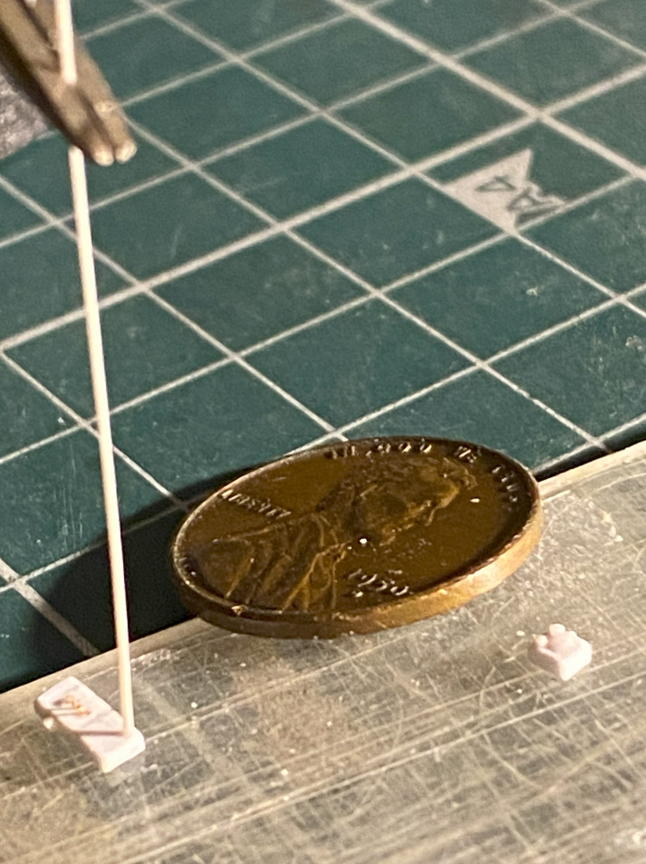
Four boxes were made in total.
The gun sight was also abysmal, so I used a small piece of 0.093″ (2.362mm) scrap rod as the body of the gun sight. I used a variable-speed drill as a “lathe” and spun the rod slowly and sculpted the body of the sight:

To attach the sight to its forever home, I used .005″ (.127mm) copper shim stock. Drill the appropriate sized hole first, shape later, and it all comes together:
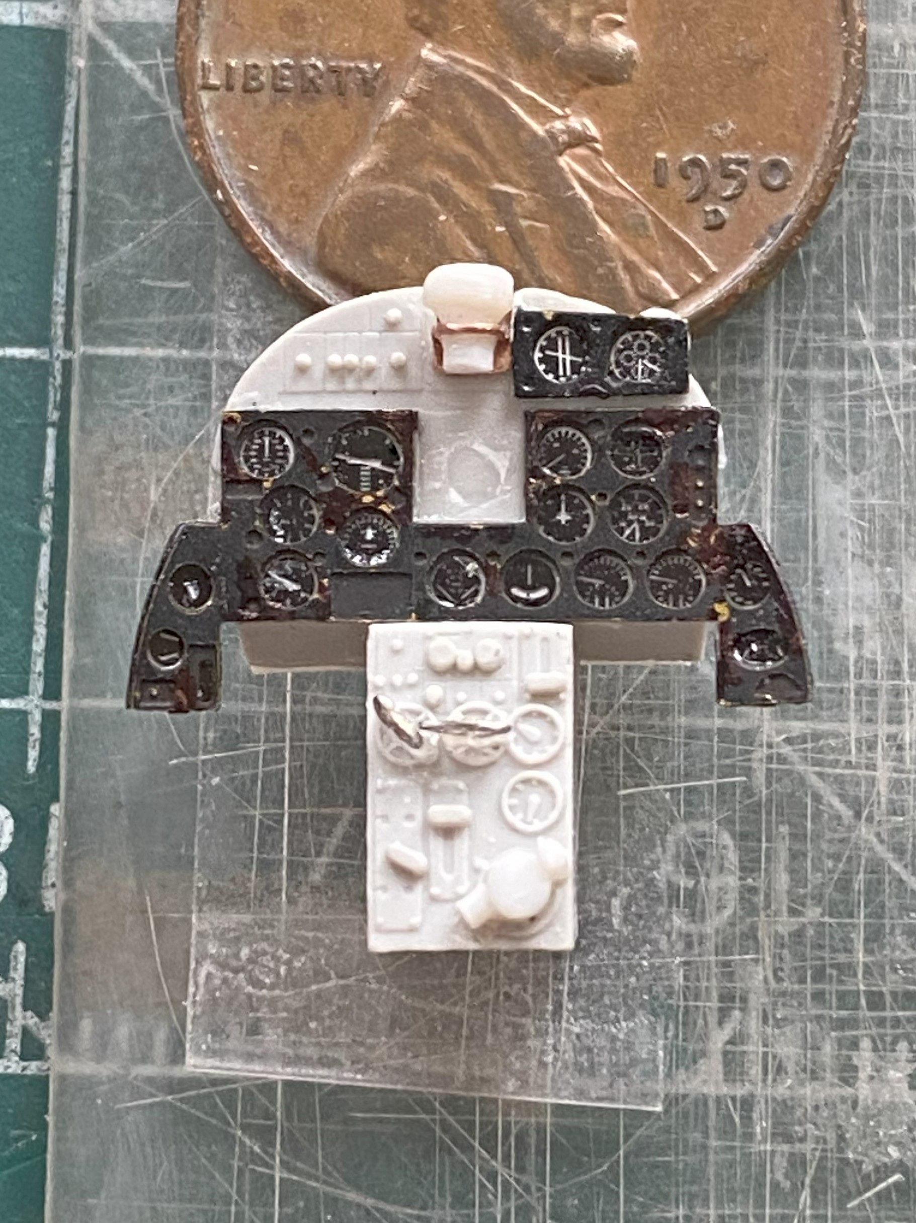

Yeah…SO glad that I don’t work in 1/72 (::giggles::), I kept jumping from job to task while all that was happening and kept detailing the boxes:
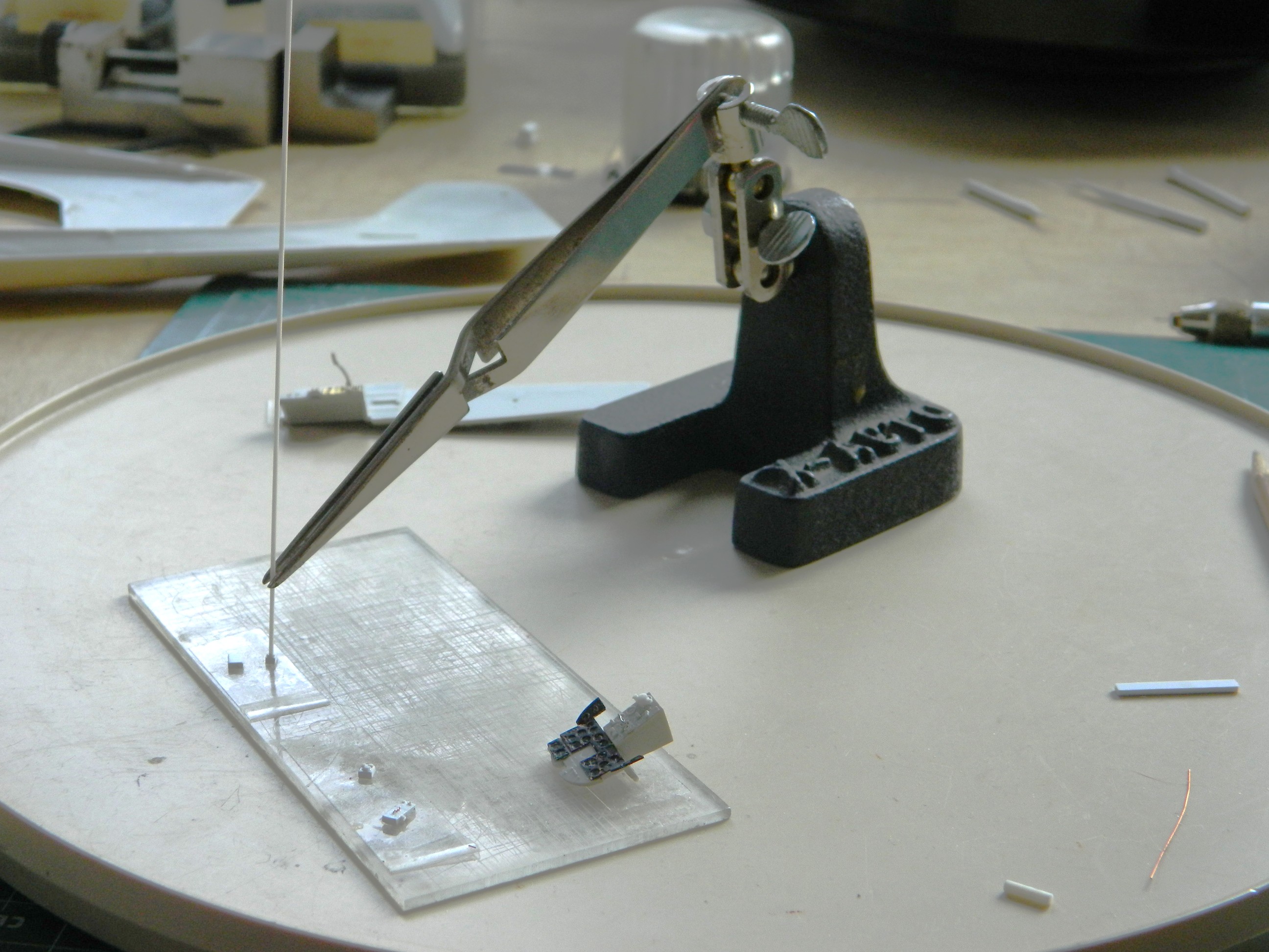
If you do this sort of work, I heartily recommend getting a lazy susan. It makes seeing how alignment is working possible. One can look at the job from (mostly) any angle without disturbing alignment of the parts.
I rechecked dimensions to be certain (::giggles again::) that the parts would fit as intended (which I’m sure hoping is accurately!) and they seem to be just right:
I’d tried using lacquer on the instrument panel fascia to see how it would hold up better to handling than acrylic does. No. Not at all. There were many instances paint touch-ups. This is after one of said touch-ups:
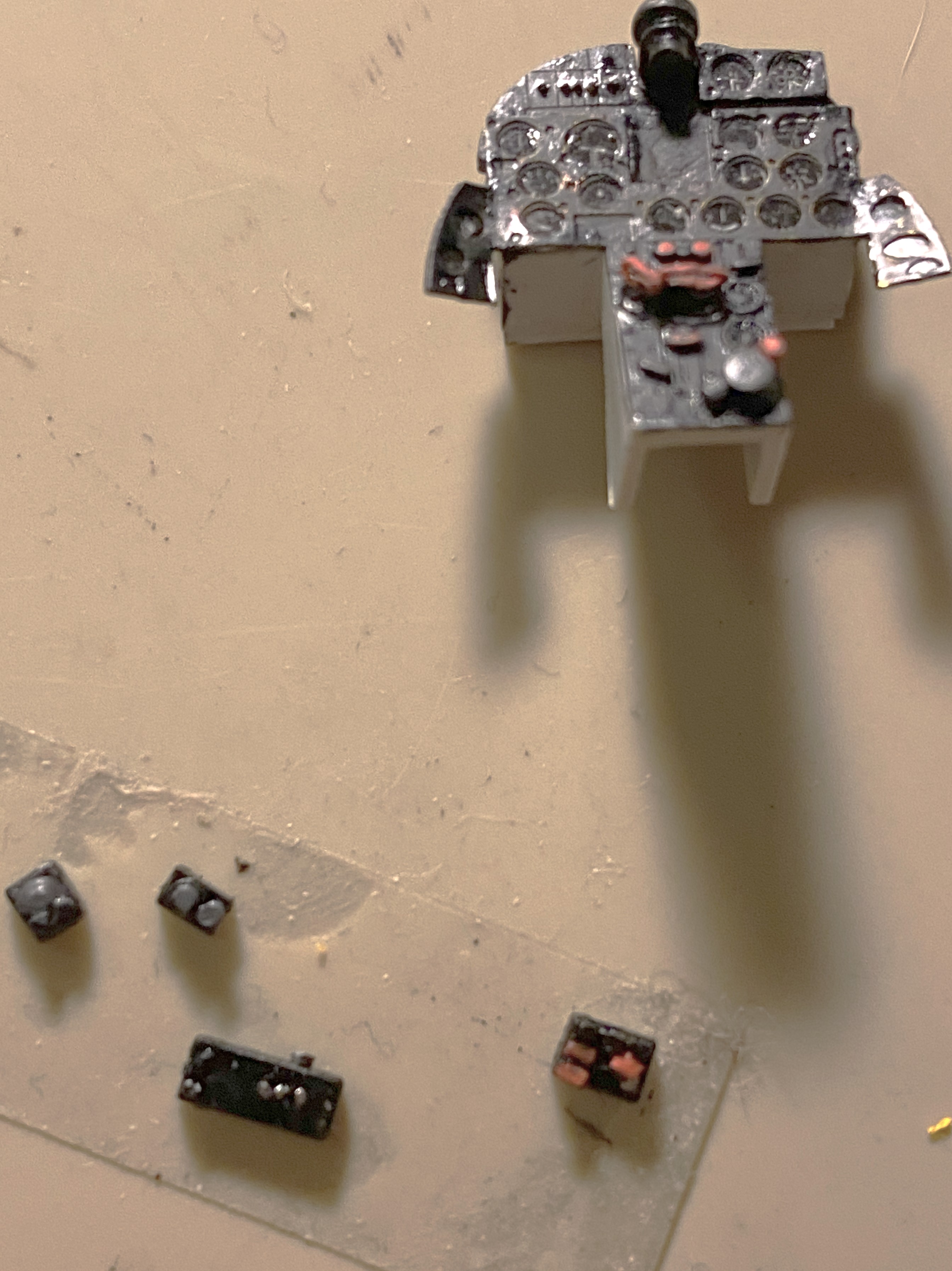

I needed a break so I looked at the canopy. I’ll be able to use the front part from the kit. When I looked closely at the movable section of the canopy, I discovered a casting flaw. There is a significant depression in the part that should not be there at the lower right front of it. I also discovered that the sliding section only fits if it’s modeled closed:


I’m not modeling it closed, so that means the vacuum-molder will be used to pull a thinner replacement.
And now to the casting flaw:
Since the only use I have for this part is as a buck (that which another object is formed over and into it’s desired shape), I’ll fill that depression with scrap sprue before using it as the buck.
I also used the same size scrap to make another control box for the right side panel (with required details added, and you can see where I…mistakenly…put the imagineered pedestal):
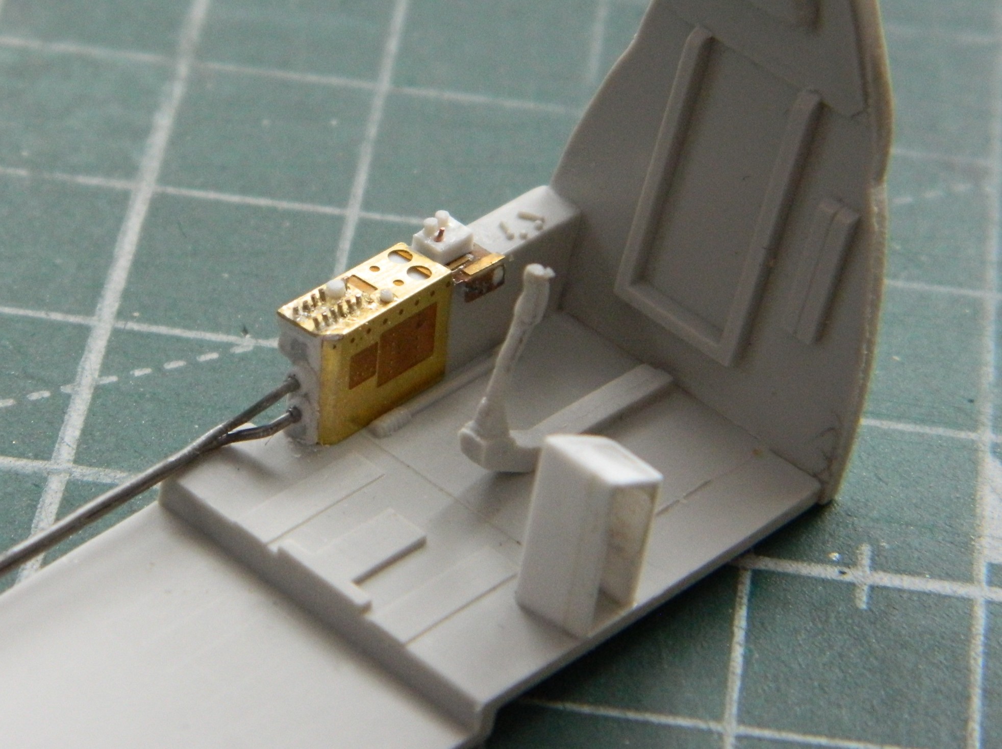
Because I’m replacing the molded-on attempt(s) at details, the provided details have to be removed. I got one side done, then did the other:

THAT was freaking annoying…
Since I’m replacing the “details” with something detailed, part of those details includes the wiring. I need a wiring harness of eight strands and I started with 40 gauge magnet wire. Nope. Far too thin. The I tried 34 gauge magnet wire. Nope…this time too thick. (Where is Goldilocks when y’need her?):
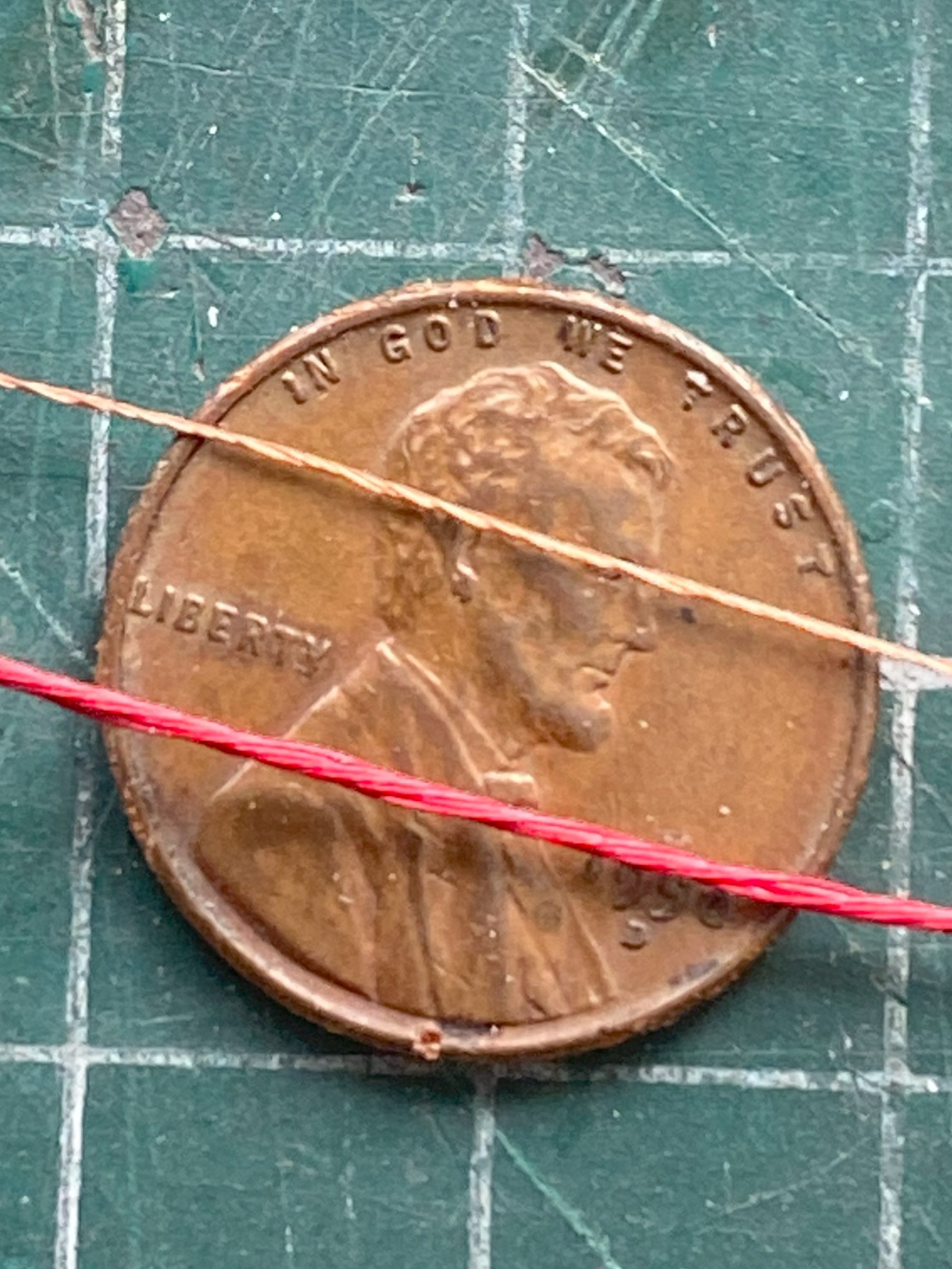
I ended up using Mystery Wire. It’s actually a part of a multi-strand (and dead) power cord that turned out to be the correct (ish) size. I laid out the parts that get wired on a piece of double-sided tape and established a rough approximation of where the break outs (technical term of where I wire leaves a loom or cable) need to be:
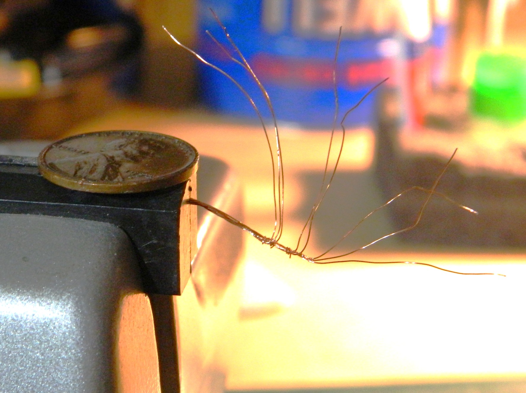
I turned back to the throttle pedestal, glued it in place (properly, I thought…that will be covered next month) and added the tertiary rods:


A little sidetrack, here. I’ll be making seven (if my math’s correct, but since I’m wearing shoes and socks, place no bets on that) control levers, five of which need little round knobs. I’m planning on revisiting a technique I used for the control levers of the P-38F I did:

They’re glass beads that I found online at a crafting site. In the photo, they all look as if they’re the same size. Not even close to reality. Size is not standardized at all. Not one of them are remotely “large”, some of them are EXTREMELY small. I had to pour them out and go through them to find the smallest. I was SO invested in finding the smallest that I knocked the container over and all the little TINY glass beads that I hadn’t already poured out to size them went ALL OVER. Though some made it to the floor, I was “fortunate” that most did not. At this point I most sincerely and in the spirit of true sharing I recommend a better way to spend better than an hour.
Enough on that topic.
There’s a lever next to the pilot that controls something. I have no idea at all what it controls. But since it’s there and quite visible, I had to make one and install it. Here’s how well those tiny glass beads work as knobs (it’s behind and to the left of the joystick):
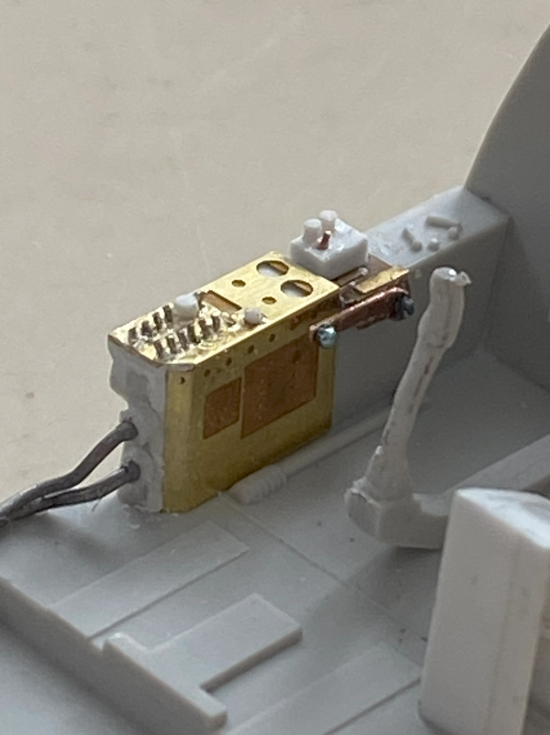
It’ll look great under paint. (Hmmm…that would make a good bumper sticker.)
I discovered something else that does a decent job of replicating tiny knobs. UV setting-resin (misleadingly advertised a “glue”, which it’s not). There are five levers attached to the instrument panel (one yellow, four white) and all the knobs are UV-setting resin:
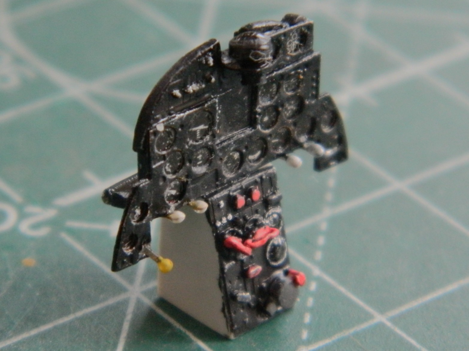
As a build progresses, different tasks fill the driver’s seat. The butt in the seat right now is the need to paint the cockpit, and the first item is throwing flat black over mostly everything so that I can use that as pre-shading. The ultimate goal is to assemble the fuselage sides. And before that can occur, I need to be certain that enough lead has been added to keep this bird on her feet and not be a tail-sitter. The last time I check its balance (no need to check my balance…Eisenhower was President the last time I was in the same area code as “balance”), it very lightly rested on the nosewheel. Too lightly. Since I have plenty (all terms are relative, of course) space in the nose, one of those two places I could put weight will get more lead added.
I used .36 caliber lead balls (used long ago for muzzle loading firearms) since I had more of them than the .44 caliber lead balls. Balls, however, aren’t very efficient at filling space (unless it’s round and of the required diameter), so I used a small anvil to shape them into something less round:
Then I glued them into place over where the nosewheel attaches:

So to lay my weight-paranoia to rest, I taped all the major bits that would affect balance (the build’s…not mine):
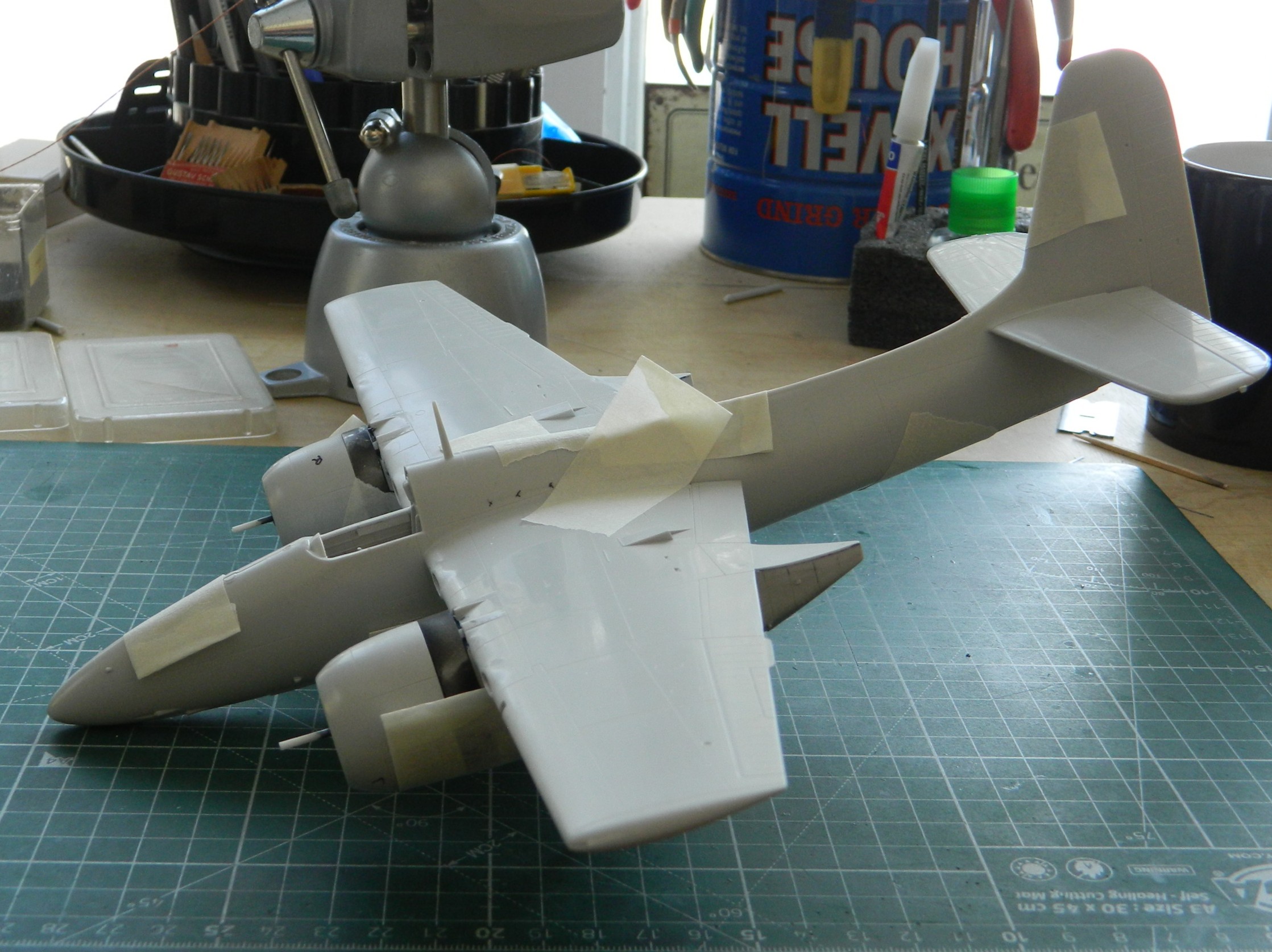
Yes…it will sit level:

But it’s still just a wee bit light in the nose, so more lead will be added before the sides of the fuselage are joined.
I had hoped that I would be able to throw flat black on this thing before this update but time, as it’s reputed to do, fled. Guess that’ll be for next month…
F7F-3 (AMT/Italeri) 1/48 Scale Build #5 – Finishing the Engine Nacelles, Landing Gear, and Starting the Cockpit…Where Things Get Tedious
With the main landing gear installed, I wanted to finish painting and working the tires. Scale Model Accessories resin wheels (part #CAT_R48018) will take the place of those HIDEOUS vinyl tires. I’m eagerly awaiting the news that kit manufacturers freakin’ stop making these things. They dissolve styrene so sure…let’s include them in a styrene kit! Gotta say, the corporate mentality (though using “mentality” to describe corporate decisions and policy really takes my sense of sarcasm to new heights…or depths, you choose) continues to baffle me. The vinyl doughnuts get replaced by these:
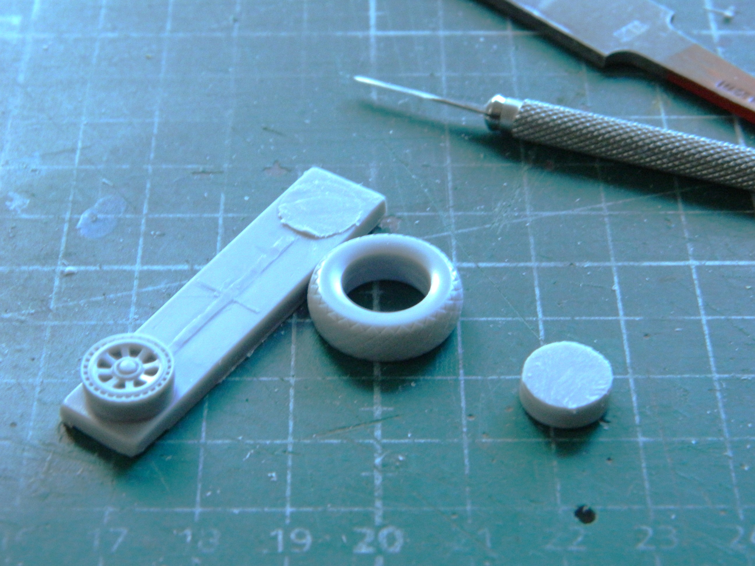
Once the pouring blocks were separated from the tires, I discovered that the wheels were just slightly smaller than the openings in the tires (for all three):

The wheels were also too thick from one side to the other. That was easily remedied by just sanding them a bit more. Still, the masters for these parts were clearly 3D printed. So…the digital doctor didn’t know how to dimension things correctly? ::facepalm::
After jiggling the tires on the wheels in the attempt to minimize the mismatched wheels and tires, I used Tamiya’s XF-85 Rubber Black for the tires (though Tamiya’s XF-69 NATO Black works just as well). Then I misted Tamiya XF-2 Flat White onto the treads to replicate wear:
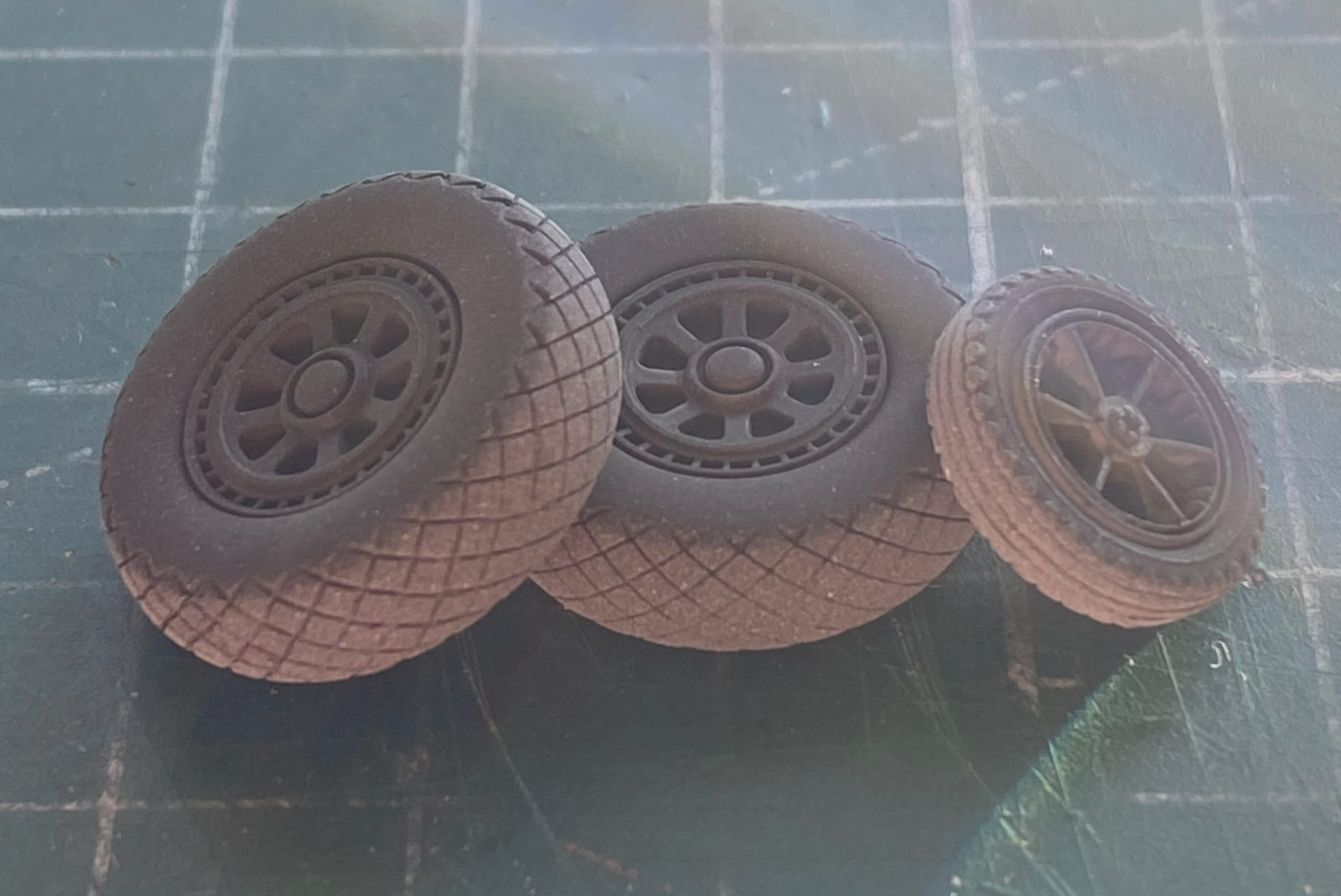
The wheels will get treated with a mix of Tamiya XF-16 Flat Aluminum (4 parts) with Tamiya XF-1 Flat Black (1 part) to tone down the brightness of the aluminum. These were set aside until I was ready to paint some darkened aluminum.
To complete the engines, I needed to add the props. I’ve read build reviews of this kite and about half of them complained about the shape of the blades. I didn’t see it. I trust my eyes (in spite of their many deficiencies) so I didn’t reshape them. I did see, however, that deployed Tigercats had the tips of the blades squared off for more ground clearance. Evidently the tips of the props would hit the ground under certain circumstances so it wasn’t uncommon for them to be trimmed back (I’ve seen period reference photos showing the blades in both states, trimmed and original). I marked the tips where I would trim them back to:

I’m going to be mixing some custom colors. An empty Tamiya paint jar is excellent for mixing custom colors that I use frequently enough to want to have premixed and on hand:

When painting dark and light colors adjacently, it’s best to put down the light color, mask it off, and then the dark color. I think that Tamiya’s XF-3 Flat Yellow is far too bright (unlike your humble…sometimes…author) so I used three parts of the XF-3 and one part of Tamiya XF-60 Dark Yellow. After spraying the tips, I let the props sit overnight before masking off the yellow and using a rattlecan of Tamiya Lacquer TS-6 Matt Black, which actually is more of a semi-gloss once it’s cured:

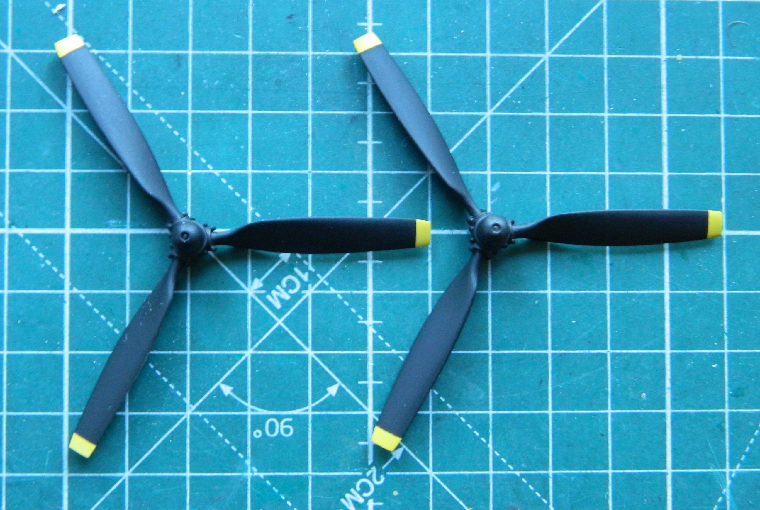
Only one more color to add to the props and that’s to paint the hubs aluminum, and yes…I used the darkened aluminum for that. And since I was loading the airbrush with darkened aluminum, I painted the parts already assembled that require that paint:

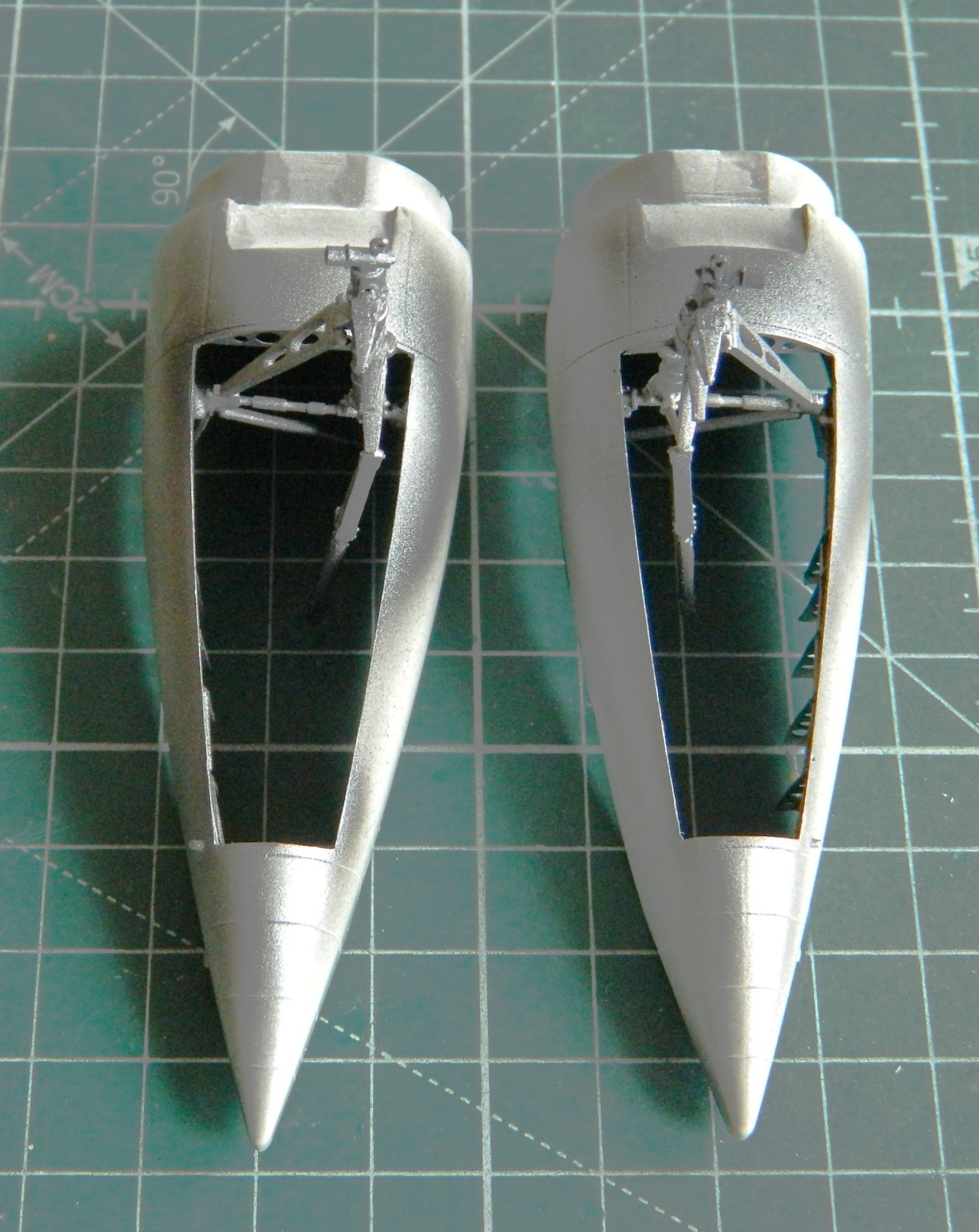

The wings were assembled:
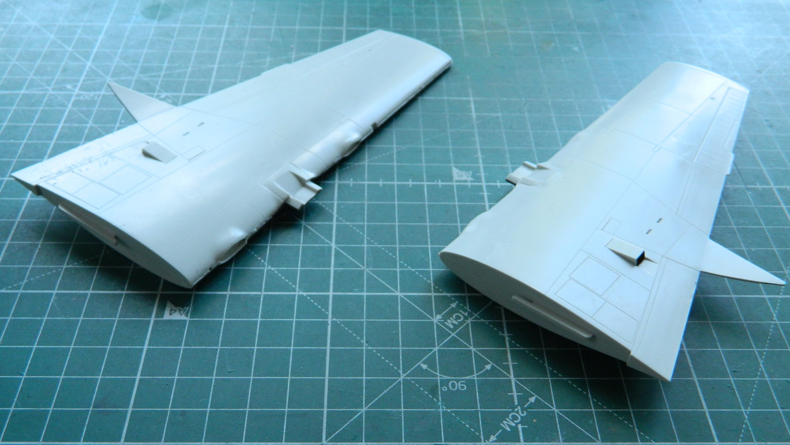
Having dry-fitted the nacelles to the wings previously, I knew that the upper rear of the nacelles molded onto the wings both sported massive gaps. Anyone who thinks force never solves anything has never been a mechanic or carpenter (and there are no doubt many other trades in this category). This time the force was supplied by clamps (clamps…isn’t that what Chinese women get every 28 days or so?):
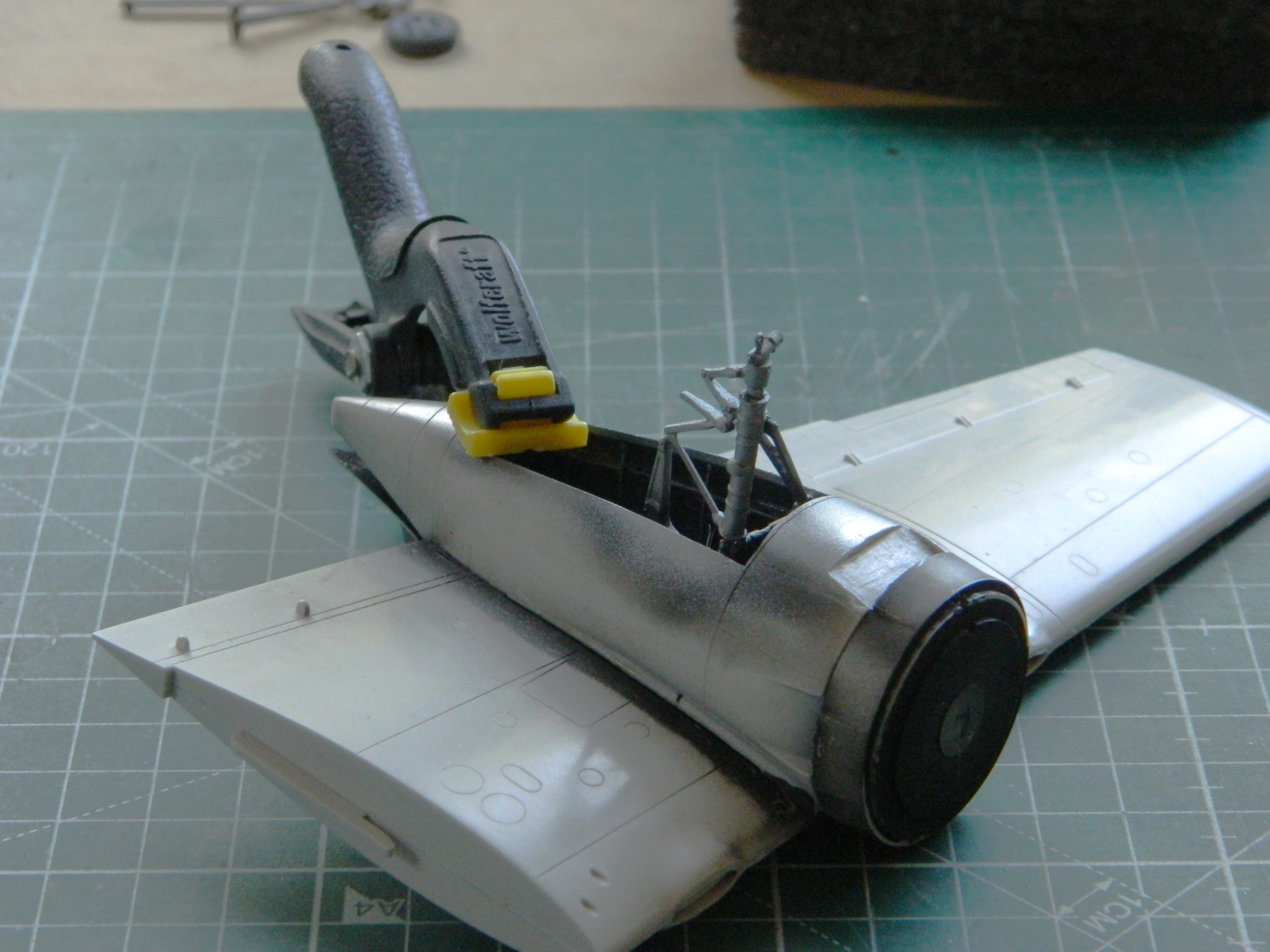

With the subassemblies of wings/nacelles mostly done (I’m trying to decide which putty to use where the nacelles attach to the wings…too much for 3M Acrylic Putty or should I use Aves Apoxie Sculpt? You’ll figure out which trigger I pulled in a subsequent post), attention turned to the office. The cockpit.
I took the few cockpit parts…:

…and tacked them together with white glue. I wanted to dry-fit them to see how they fit (sorta) and how much room I had to stuff even more lead into. Remember, the start of the previous post showed that what I’d already stuffed with lead (and tungsten…for its price, let’s not forget the tungsten) was just enough for this kit to stay on all three tires. I want more. Once the white glue dried, I placed the floor/instrument panel/bulkhead in place to see what space was left.
Plenty:

Every surface with a line on it is forward of where the main wheels sit (the balance point). And I accept that every review I’ve read has either not put enough weight in or has just enough weight in…but a bump would make the model sit on its tail. With all this space I’m not really sure why that problem reoccurred enough for it to be A PROBLEM. But regardless, forewarned is forearmed. Before I join fuselage halves I’ll be stuffing lead into the spaces marked.
I recently got into a conversation about, “I don’t think PE is worth the hassle.” I get it. Sometimes I use the PE parts as a template and make a plastic copy. So far, PE can only do flat parts and some of the parts that PE is supposed to replace isn’t flat and that’s frequently noticeable. But there are those times when PE is well worth the hassle. I think that this is one of those times:

Yes…there is a gap in the PE part where the back of the seat angles up to meet the back. I intend on filling that gap (and the required finishing to make it look correct) with UV-setting resin.
So far I think that the styrene harness will probably end up looking pretty good. This is just my initial attempt. There may be more tweaking (the shoulder harness will be formed over the seat back later):
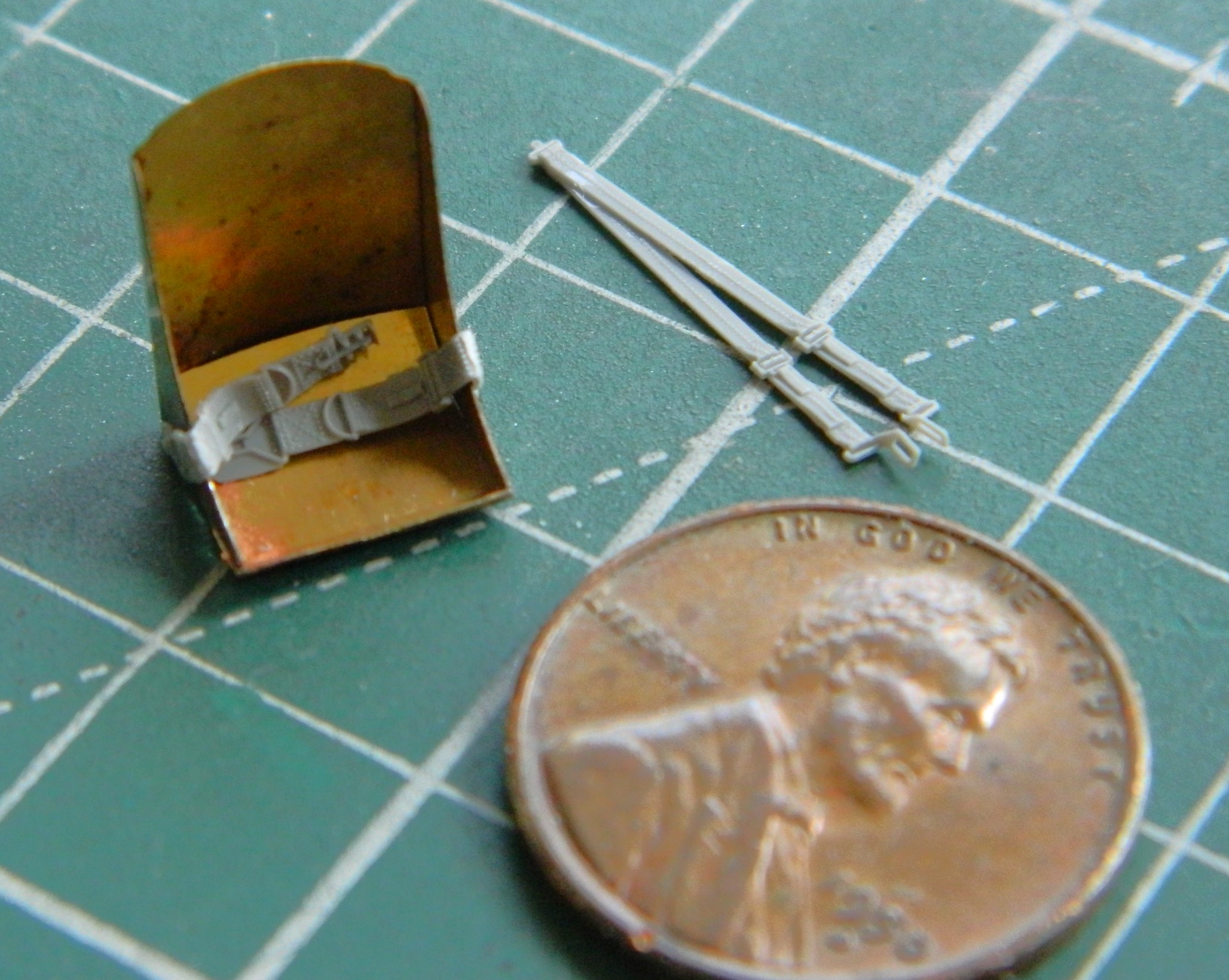
I get that it’s nosebleed expensive to cut the molds for a model. In the attempt not to make one basic kit with different parts trees for different variants, manufacturers will often paint with a broad brush. This model shows that in a couple of places and the most obvious is the instrument panel.
The F7F-3 that I’m building is the fighter variant and was the least utilized of the three variants. The -3P was the photo-recon variant and the 3N was the night-fighter variant. The-3N had a slightly different instrument panel. There was a prominent radar display in the center of it (I’ll bet you can spot it):
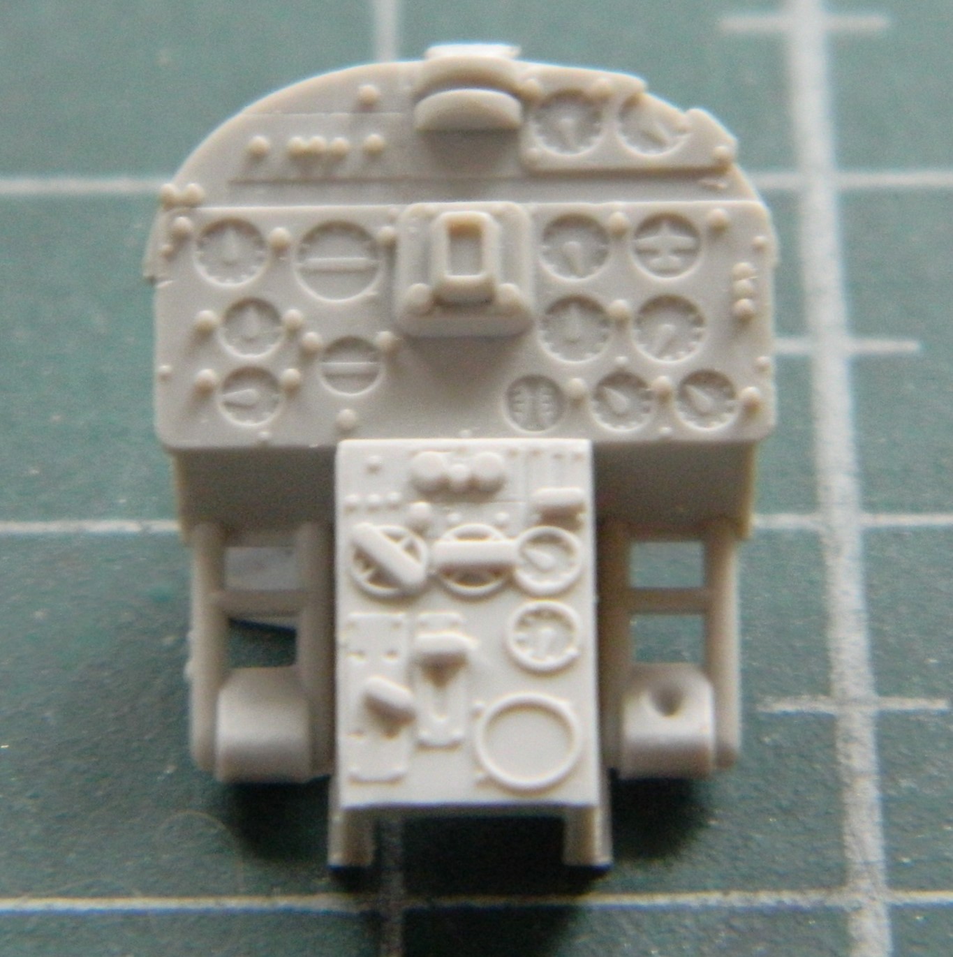
At the top center of the instrument panel, that semi-circular protrusion is supposed to be the gun sight. Uhm…no. I’ll cut that out and build a better one. But the radar display and all other raised detail on the face of the panel has to be removed so that the film/PE replacement will sit flat:

This is a much better rendition of that panel:
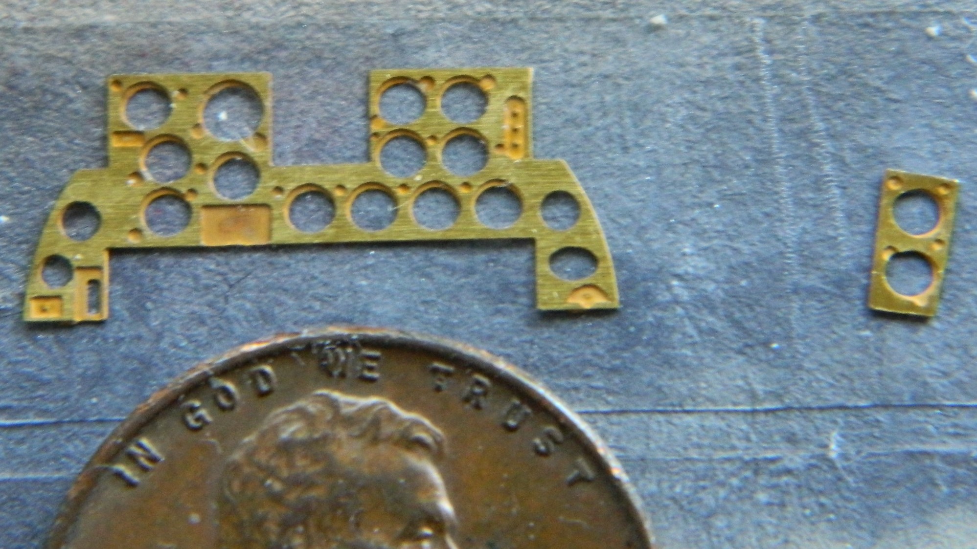
I used Tamiya’s rattlecan TS-6 Flat Black to see how well it would adhere to the brass. I already knew how Tamiya XF-1 Flat Black and X-18 Semi-Gloss Black adhered (not well) and I wanted to try lacquer to see if that would work better:

While that was curing, I used Testor’s White Gloss enamel (yes…the one in the little square bottle) to act as a backing for the film-gauges so that they would be visible:
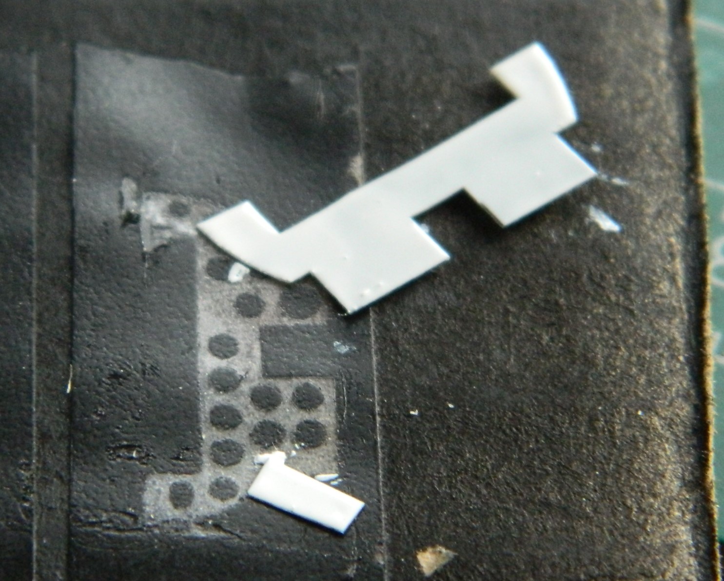
Not bad, though just from very minimal handling I can see that lacquer didn’t hold up better than acrylics did. As part of the retouching process, I will also go around the edges of the panel with black so that the backing film with the gauges won’t jump out in the eyes…and the panel needed even more retouching than what’s showing here:
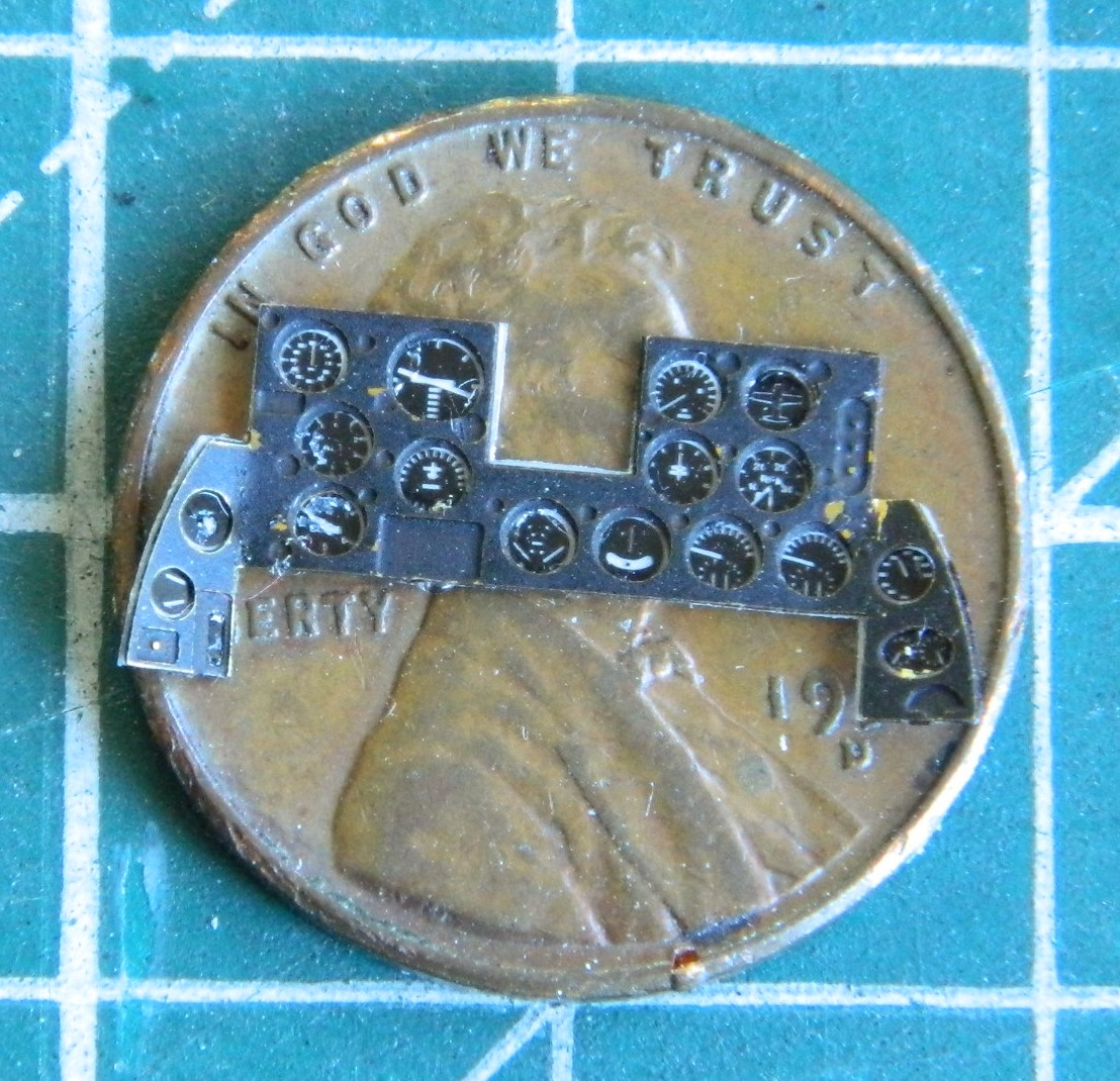
I can’t imagine two things (okay…much more than merely two but this isn’t the forum for my general ignorance). The first being how the die (mold) makers can get something so wrong. Or. How does a die wear so that it’s no longer aligned with its counterpart. But this happens often:
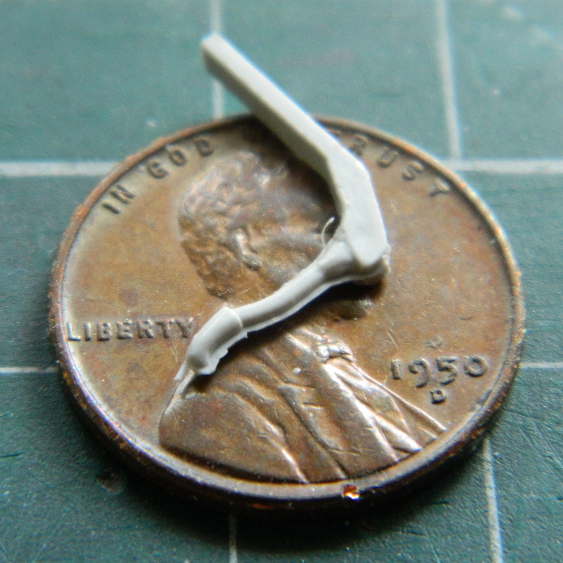
This presents a conundrum. Which half do I make conform to the other? Well…to be picky about it (a modeler picky?!) the answer is “both”. I’d be fine with that if the entire part didn’t fit on top of a penny. If I try to make the misalignment go away, I’ll break the joystick. (Don’t ask me how I know.) Okay, then the determining factor is the answer to this question: “Which side will be visible?” Easy answer. The part of the part that the pilot would see. If the pilot would see it, so will you. I decided to stretch sprue as thinly as I could (success!) and then lay it along the misalignment:


Yeah…this one is going to be delicate. I set the part aside for a couple of days so that the glue (my go-to is Tamiya Extra Thin green cap) out-gasses totally.
This is what the kit supplied for the control panel to the right of the pilot. All the raised details from the center to the left has to be removed:
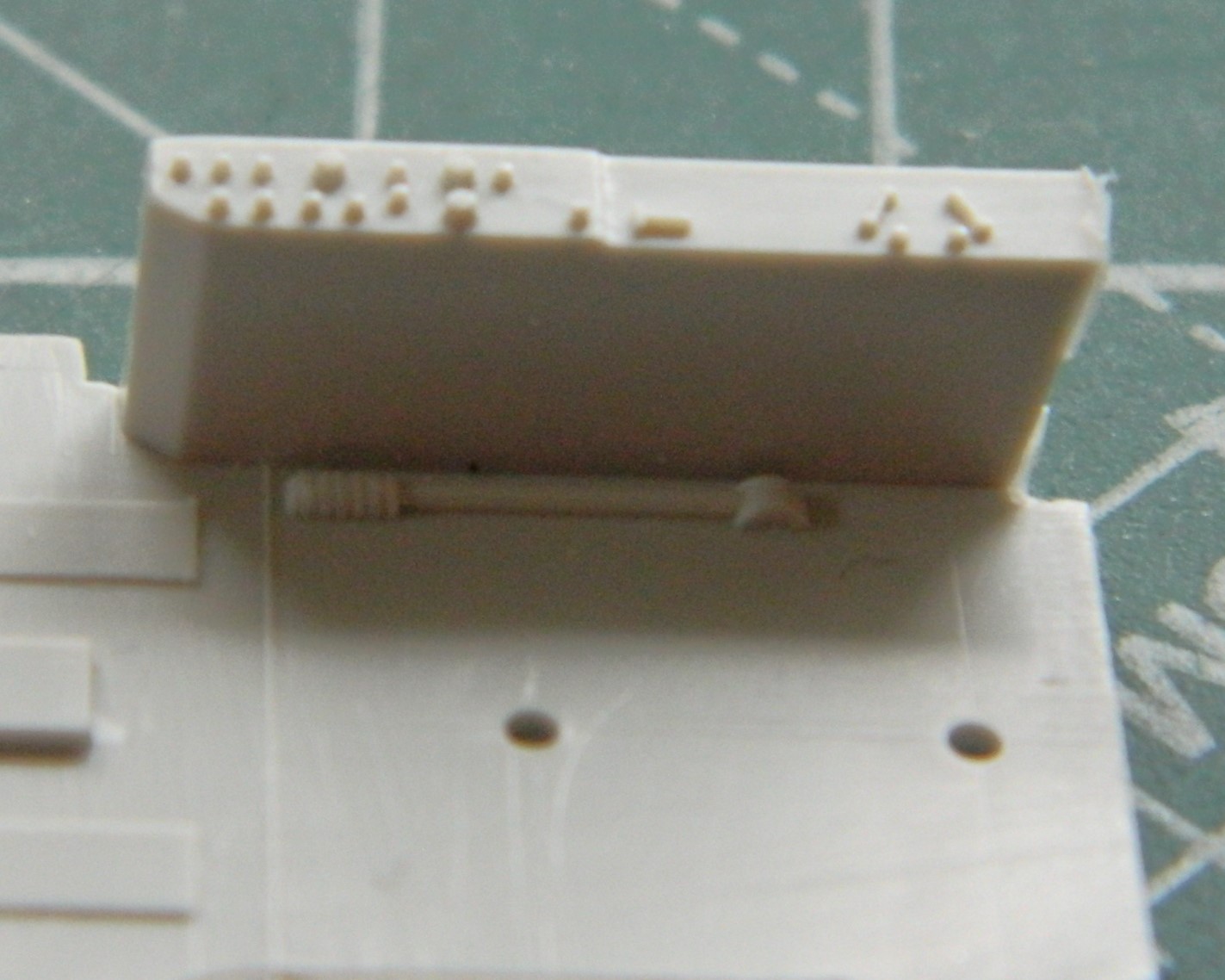
This time PE does what it does best:
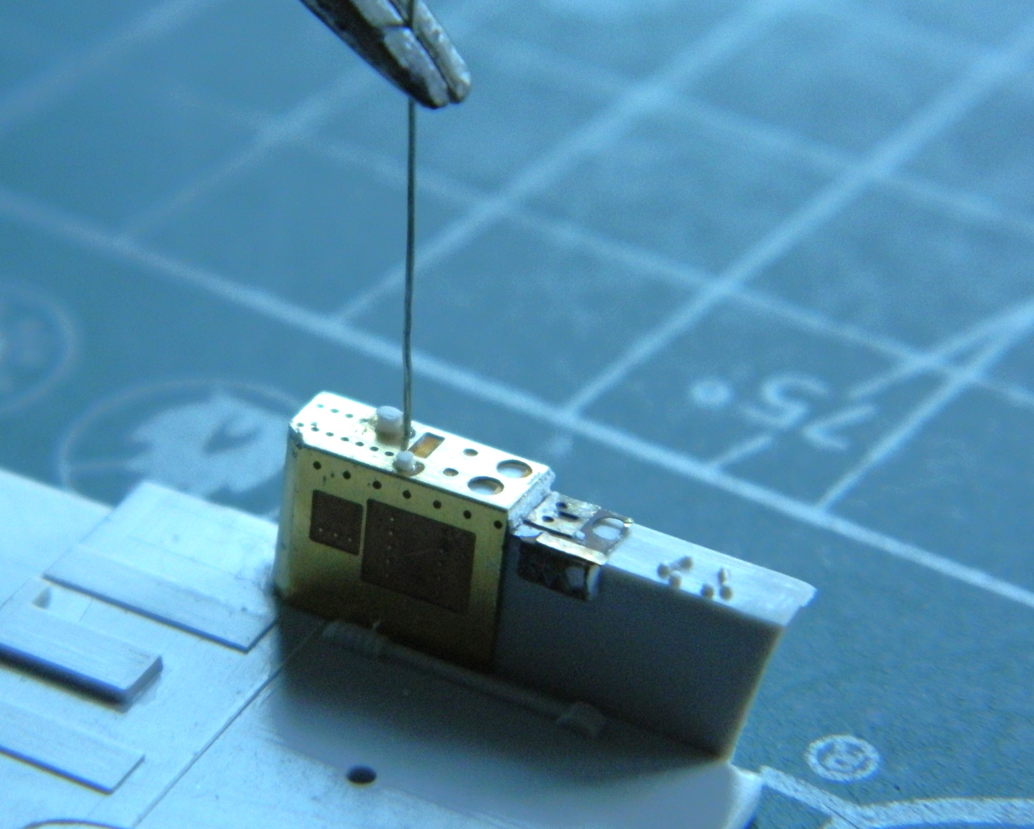
I forgot to take a photo of it initially. The forward vertical edges didn’t fit snugly (surprised me, Eduard!). 3M Acrylic Putty filled them. And what you see in the above photo is the beginning of the 11 or so toggle switches that “have to” be added. (The white knobs were added from stretched sprue.) In this photo you see all the toggle bats added:
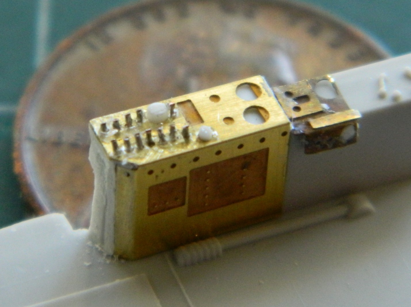
Yes…the ends of the bats aren’t supposed to be chisel-shaped. The size of them keep those ends from being noticeable.
With the cement out-gassed, I very gently sanded away the added sprue and (also delicately) reshaped the grip:
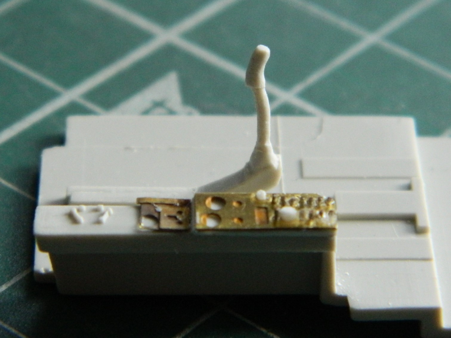
There is also a push-button off-center to the left. I don’t know what it’s for but it can be seen, so I added one:
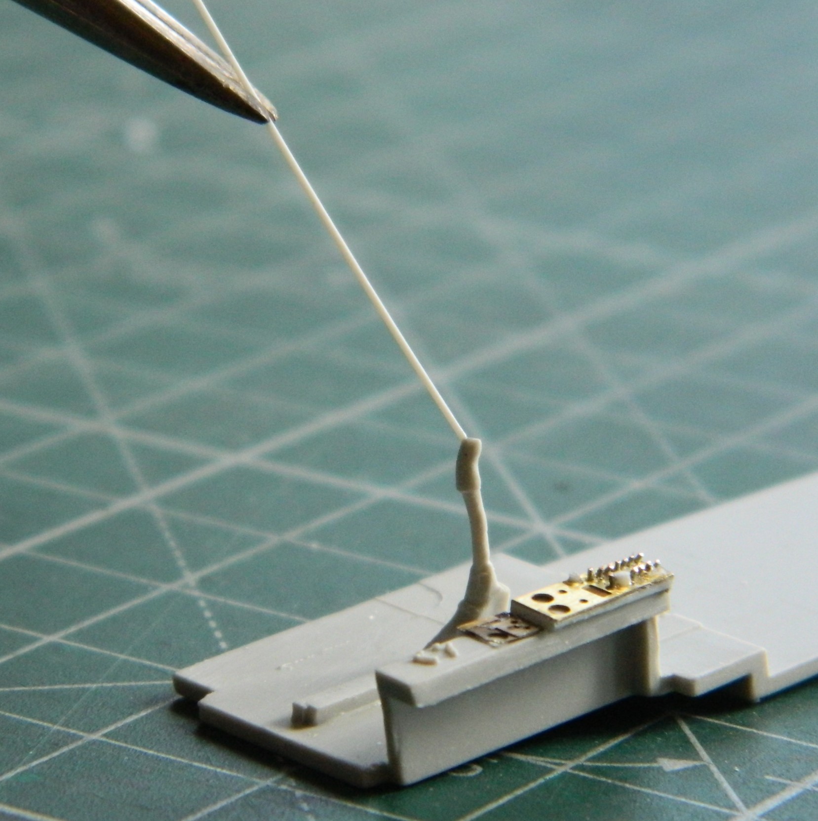
Twin engine prop aircraft have doubled engine, prop pitch, and mixture levers. This kite also has one supercharger control. That’s seven levers (puts shoes back on). This is what the kit provided:
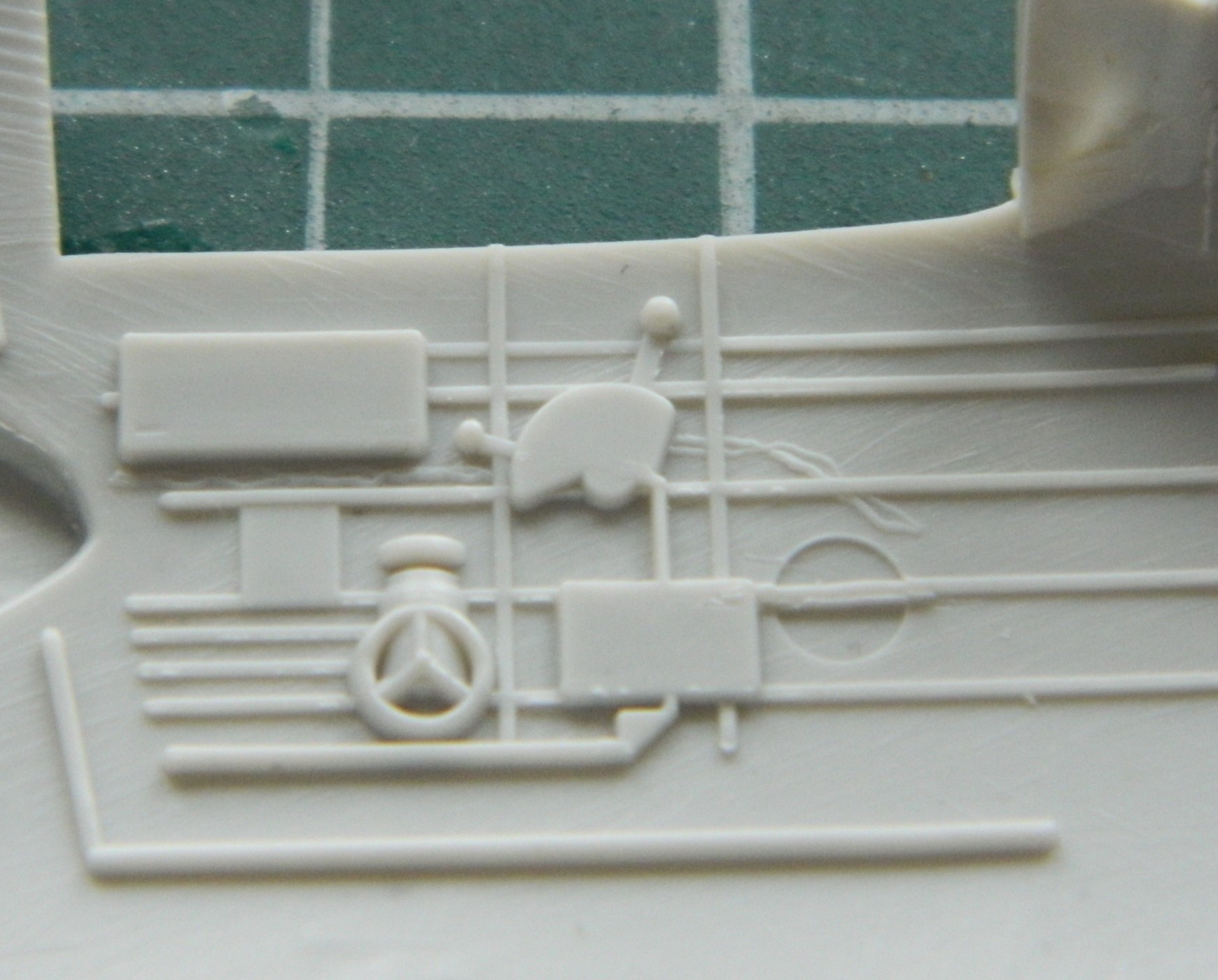
And this is what the Eduard PE fret thought would be better:
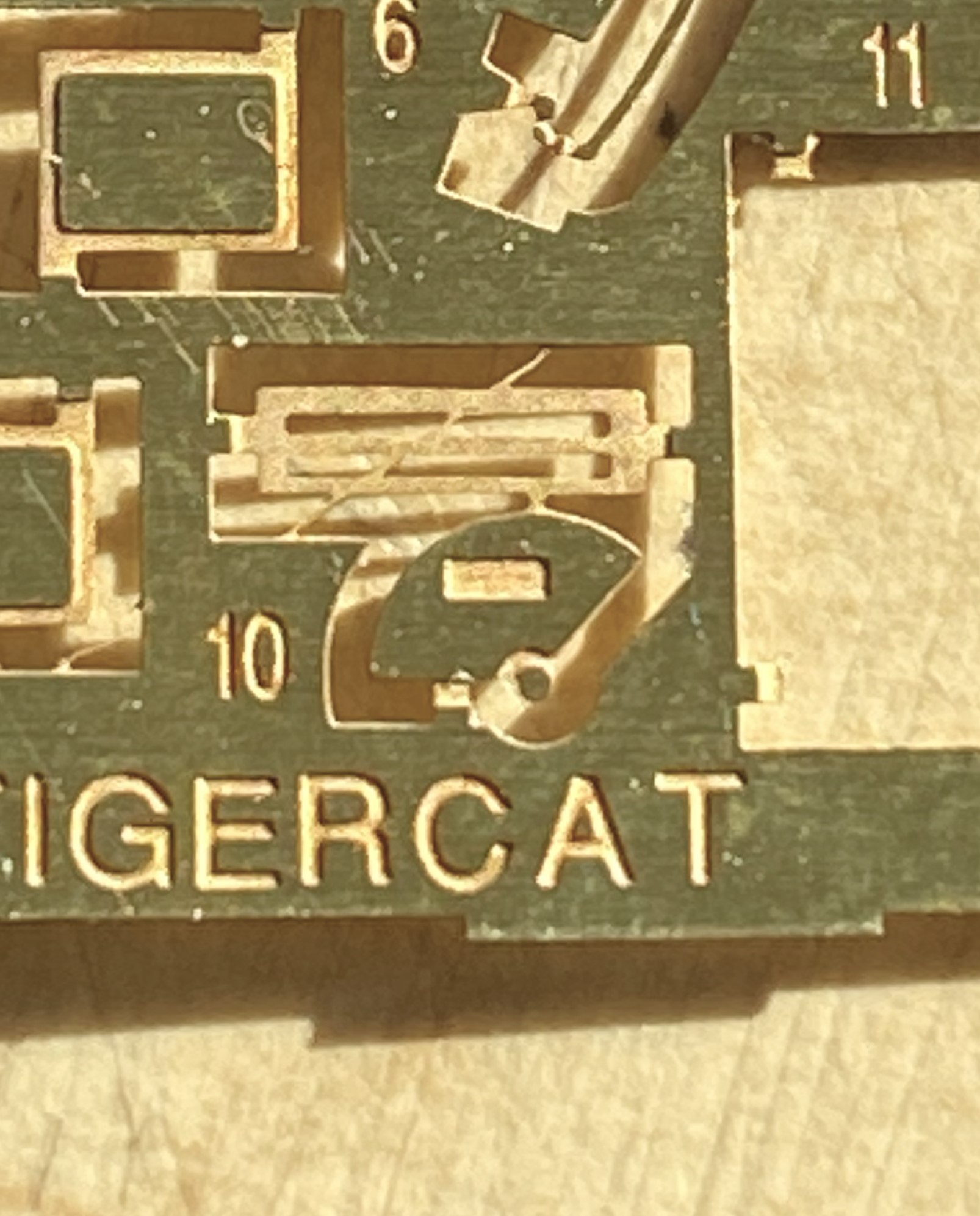
Not in the least bit usable. Maybe I’ll be able to use it for something else later on but it’s just ridiculously inaccurate for this build.
Hmmm…two divided by seven means that less than 29% of the controls that should be there are there. Fine (he says petulantly), I’ll make one and it should look just like this:
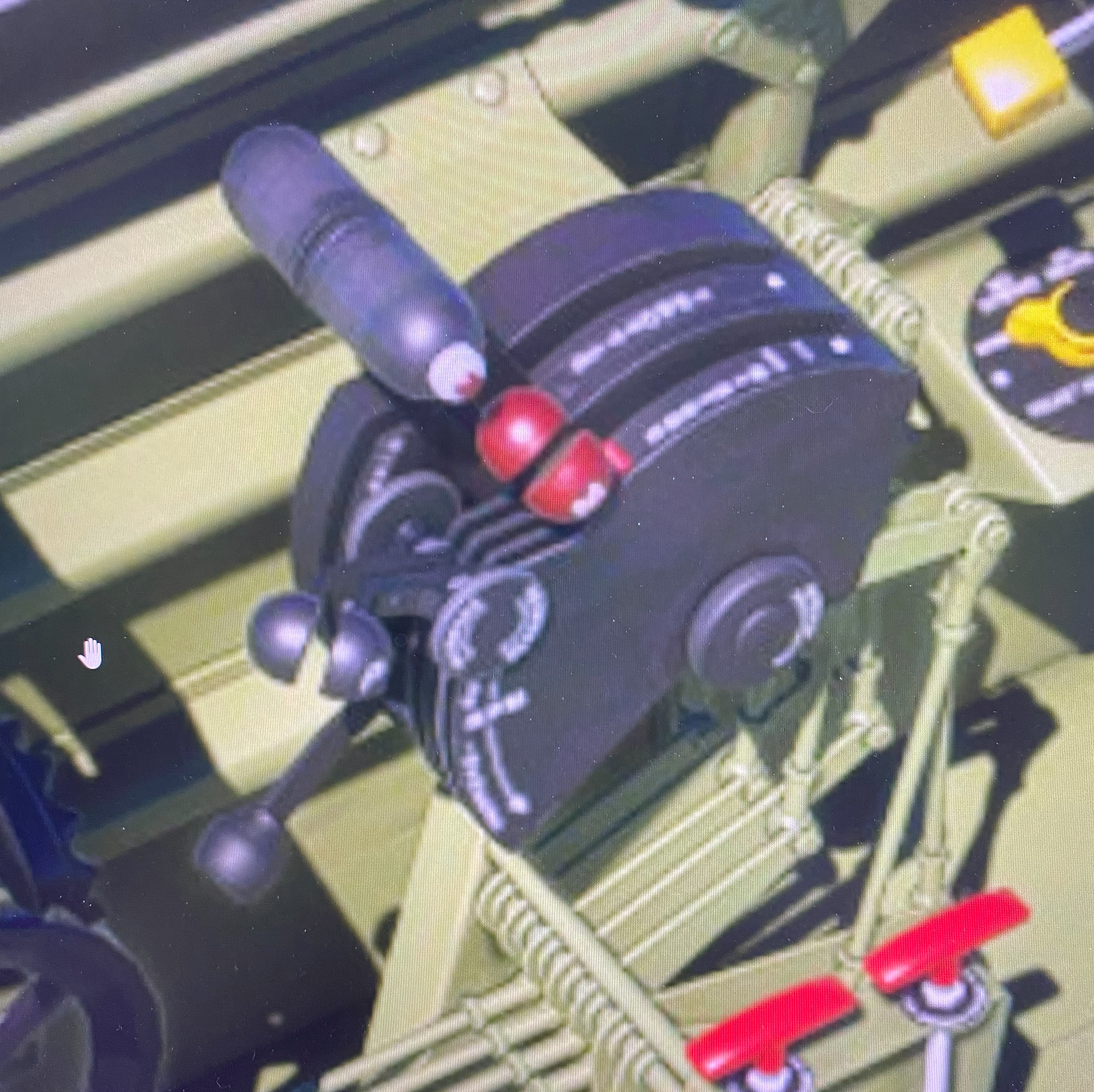
I mean, really… how hard could it be?
Yeah, well, one of these days I really must stop asking that question because I always, ALWAYS, find out. Oh. And the answer this time is…
Very, very, very. VERY.
For the first attempt (the words “first” and “attempt” should inform you how well it didn’t go) I tried using 0.010″ (.254mm) styrene. I would normally skip a few steps here but I recently had someone ask, “How do you actually scratch-build something?” So I’m going to show you.
I used the kit’s throttle quadrant as my scale. Clearly it fits, there just isn’t enough of it. I found a piece of .187″ (4.74mm) styrene tube that conformed to the arc of the kit’s offering. It didn’t take me long to realize that there are seven slots for the levers to travel in. And this part is very small. Even with my hands as steady as they were 50 years ago, they were never that steady, and there just isn’t enough room to cut them into the body of the quadrant. But all that said, here’s the process I used… (And I’m not going to put dimensions in the description because this didn’t work so if you try to replicate it, it’s not going to work for you either.)
I went into my plastic stock and picked a piece that would be larger than I need (makes trimming things much easier that adding things because the result is too small). I guesstimated the angle of the main body and drew it onto the plastic:
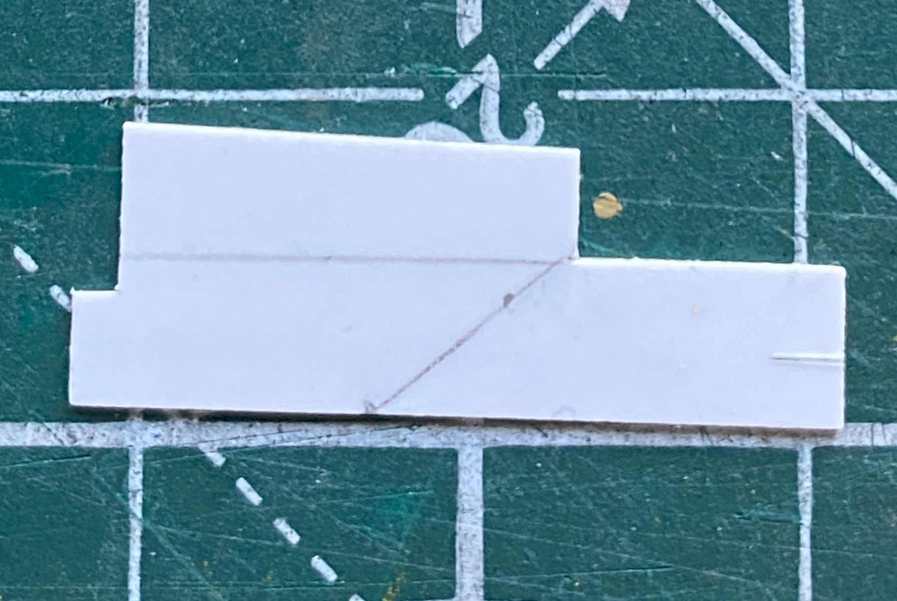
Then I salami-sliced a short section of the tubing I would be using and diddled with its placement until I had what I wanted (which I certainly hope is correct):
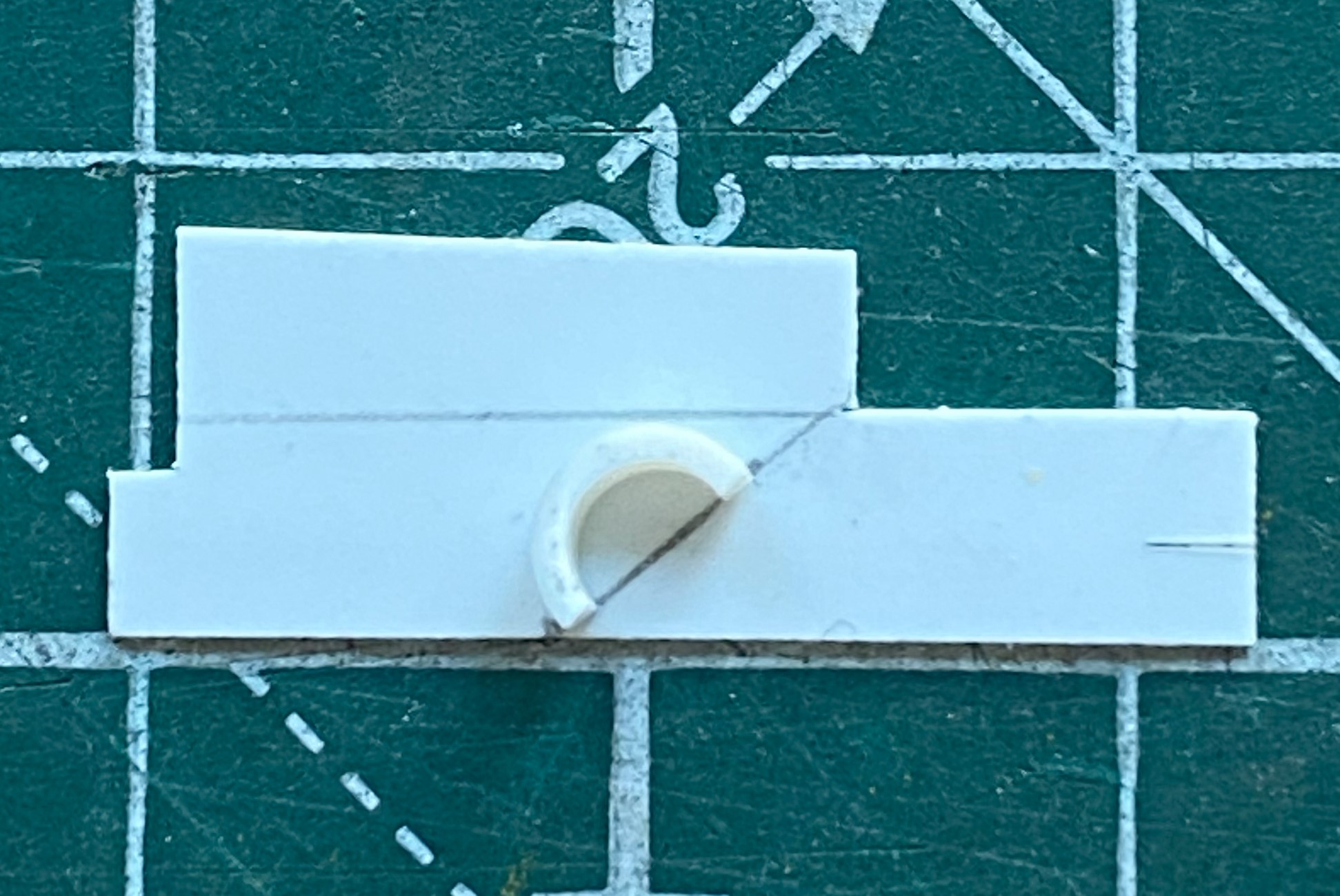

Then I sketched in the outline (it wasn’t until later that I realized that I’d gotten the arc on the left a bit off center…which was addressed later):

Then I trimmed it coarsely:
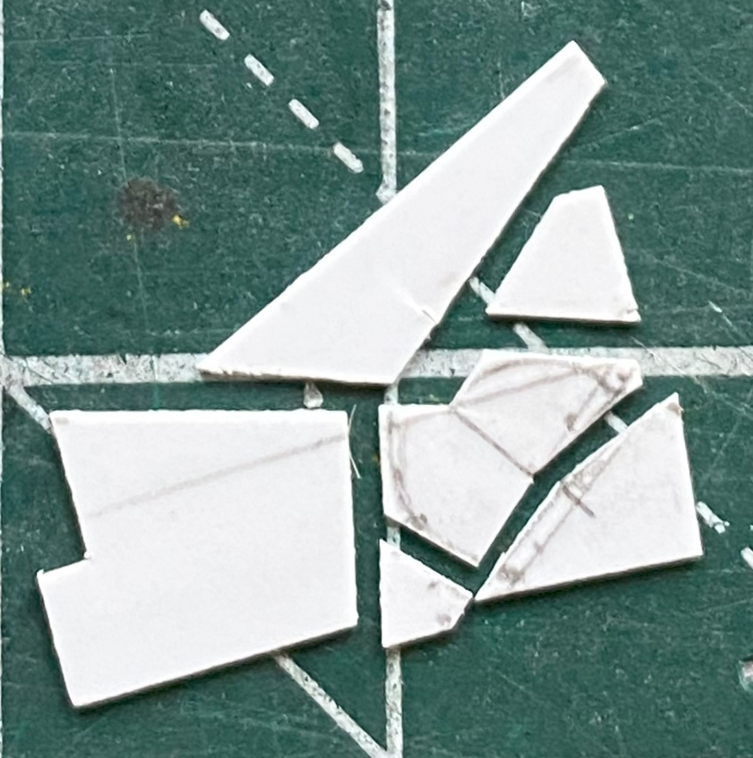
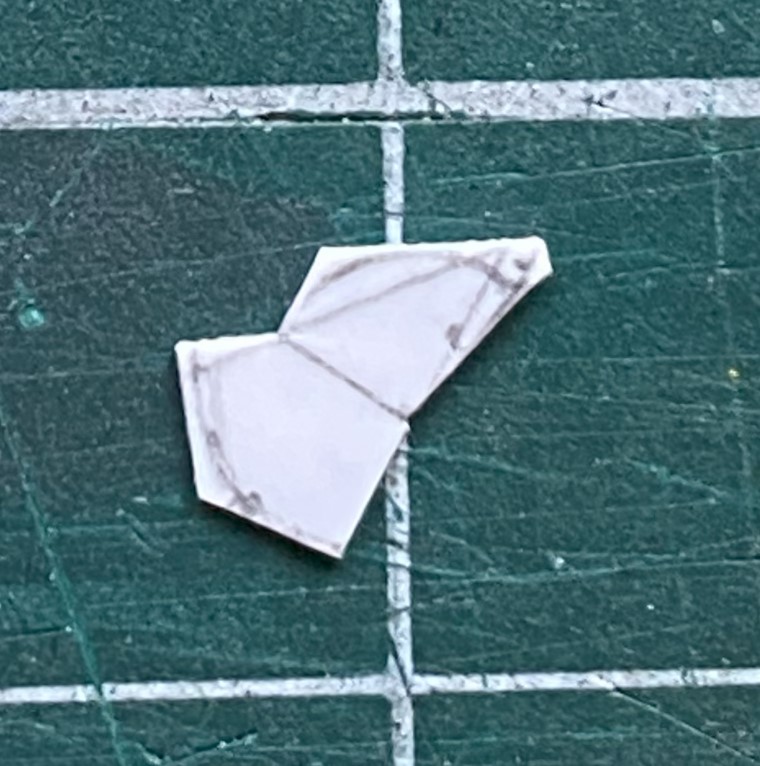
320 grit sandpaper finished the edges:
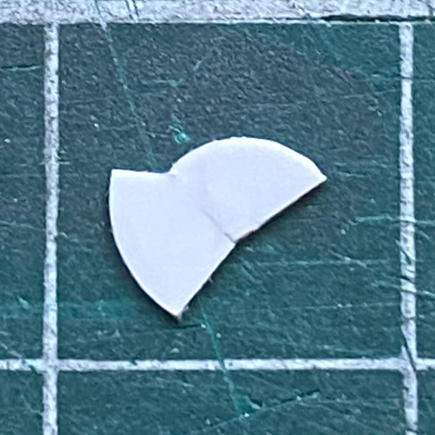
Would that that was all there was to it. Remember, I need slots, too! That meant I needed spacers between each of the follow-on parts. In the following photo, the parts are actually upside down, but hey…
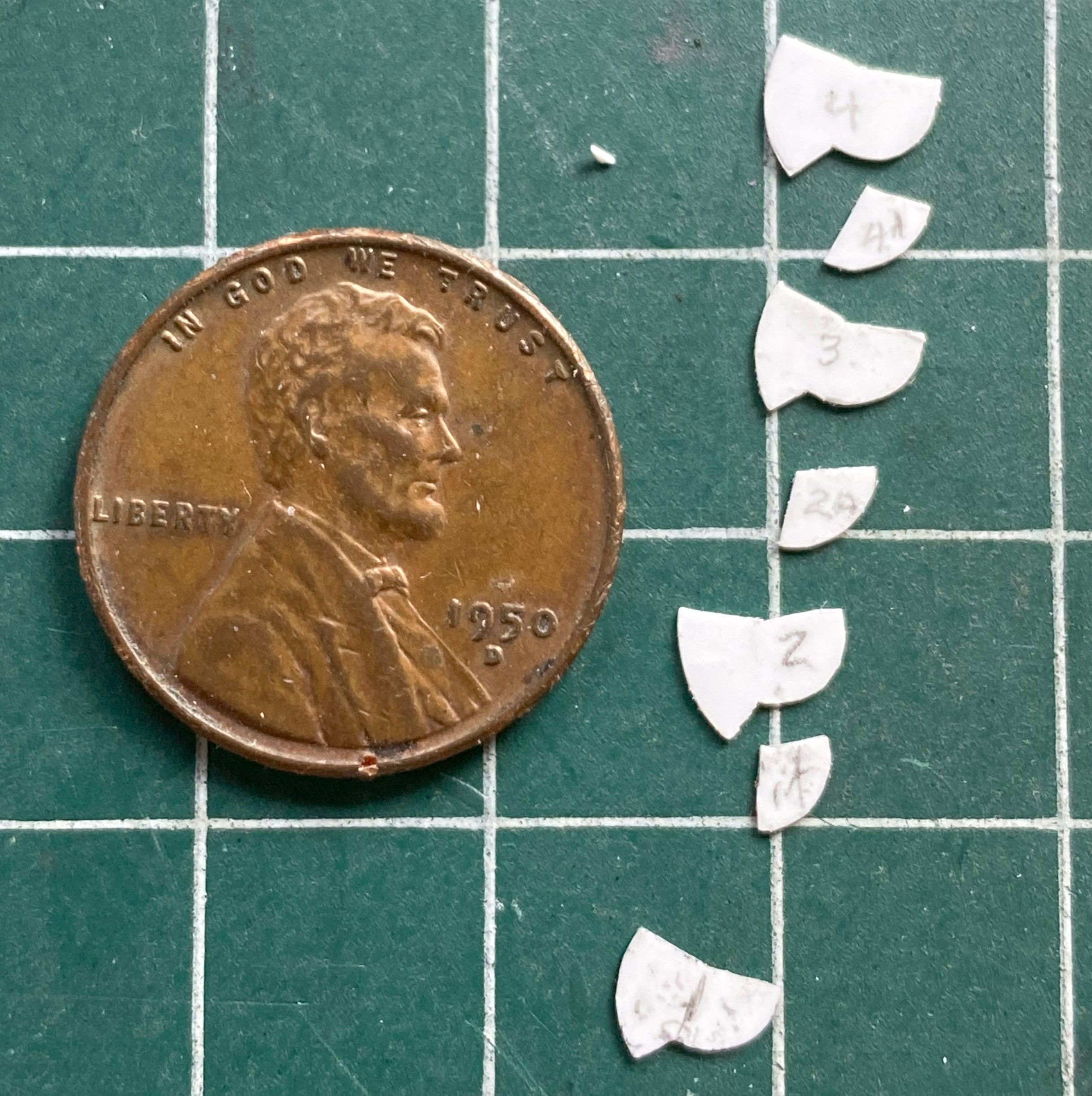
So that’s some of the parts, with the spacers in between the sides. These are very small parts. The smaller the parts, the longer the time to make/fiddle them. This took what seemed like an eternity (made eternal because the fingers of my left hand just kept cramping). Before I kept at it even further, I decided to assemble what I already had just to see if this idea would work:

What you can see in the above photo are V1 and V2. V1 is on the right and is the correct width overall. You’ll note that the part on the left is wider…and that’s only half of what has to be built.
Well, bugger…
Okay, cue V3!
It took me a bit to figure out what V3 could be, but I arrived at a notion that I think will work. On V2, everything was made from 0.10″ (.254mm). The easiest way to halve the construction would be to halve the thickness of what it’s made from. 0.005″ (.127mm). However, trying to work styrene that thin is akin to trying origami using butterfly wings. Ain’t doing that! Oh! I have that size copper shim stock! Okay…V3 here we go!
I filed and sanded V2 to a less inaccurate profile, salami-sliced that, and used the part as my template. I traced around it onto the shim stock with a needle and used scissors to cut the part away from the rest of the stock. Those two sentences took the better part of the week because in addition to having a glacially slow build speed, my fingers kept cramping. And at this point, I have all the parts in copper that I had in styrene. (A couple of the spacers are 0.020″ (.508mm) because of the spacing required.):
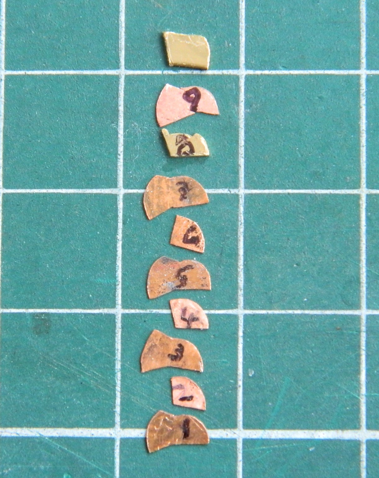
Whew… I guess next month will start where this one left off. Not just cutting out the parts but figuring out some way to put them all together. Once I have, I can then file them to their final shape and dimension.
Oh. In case you’re thinking that I need more “fun” in this build, all seven levers have little knobs atop them. I’ll be using some of these, which are glass beads I got online from a crafting store:
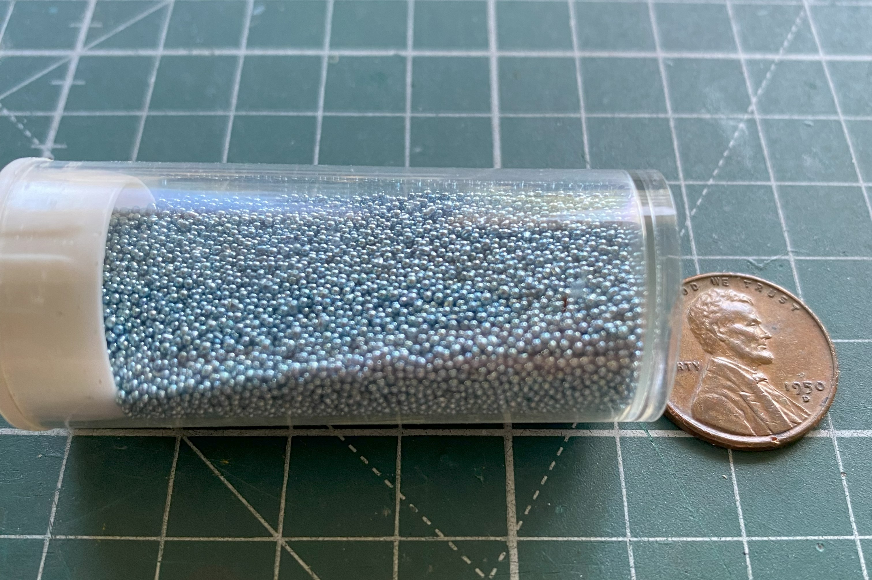
My experience using these beads on the P-38F showed me that they are an absoLUTE ass-pain but the results are so worth the effort.
