Colonial Viper MkII (Moebius Models) 1/32 Scale Build #3, Completing Most of the Construction Leading to Paint
So much of our Reality is formed within our skulls. In my skull in 2026 is that I have done fuck-all in the shop. In May, the coin came up heads and that informed me that I was “ready” to get back at it. May. One month. I thought. Well, once into the folders where I keep the raw photos before editing them, one of the things I do is start the name of a file with the year. My goodness, I was quite surprised that I had photos from March. I was very surprised that I had over a hundred of them total from the end of March through today.
So much for my connection to Reality (he says, surprising no one who knows him).
Moving on.
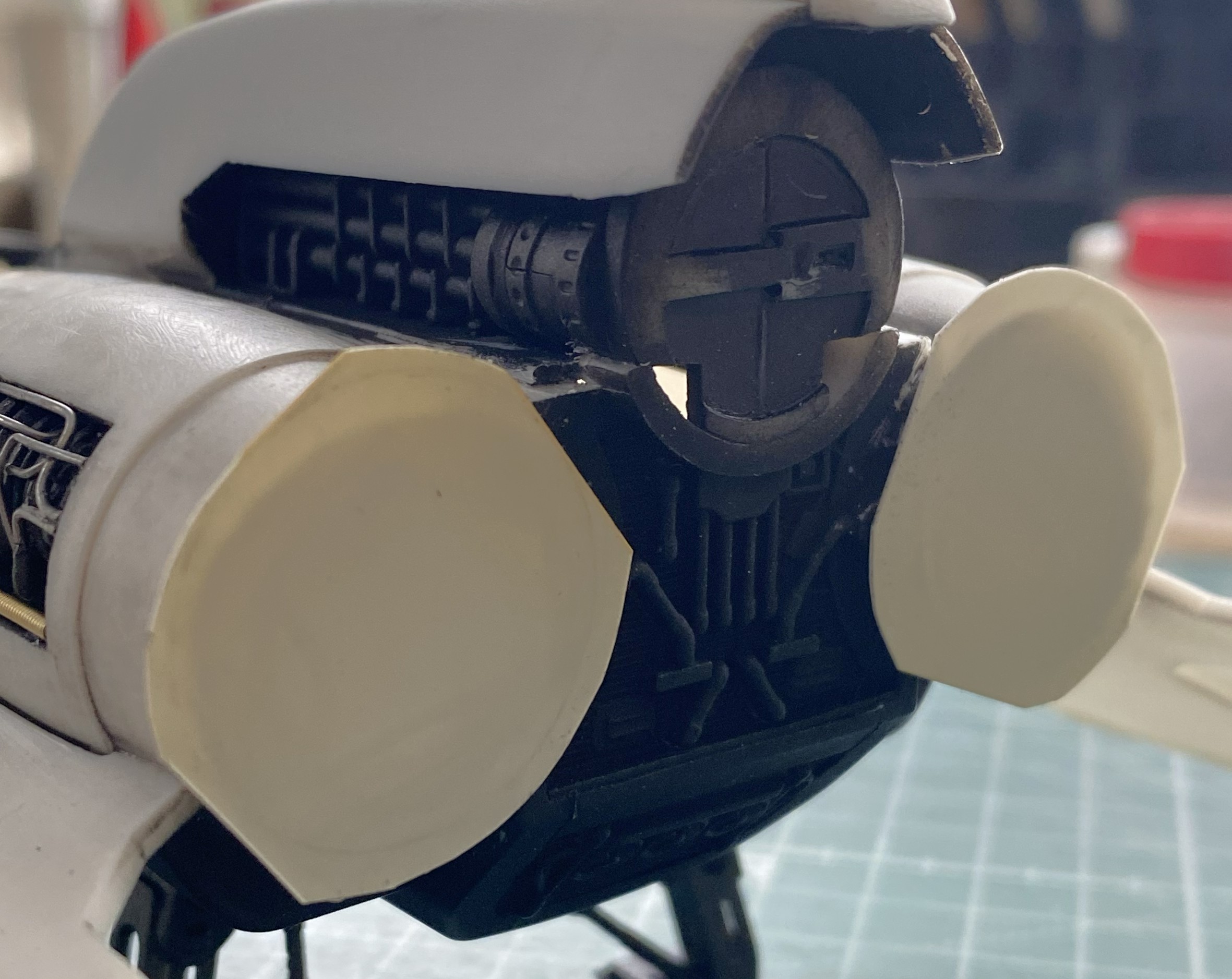
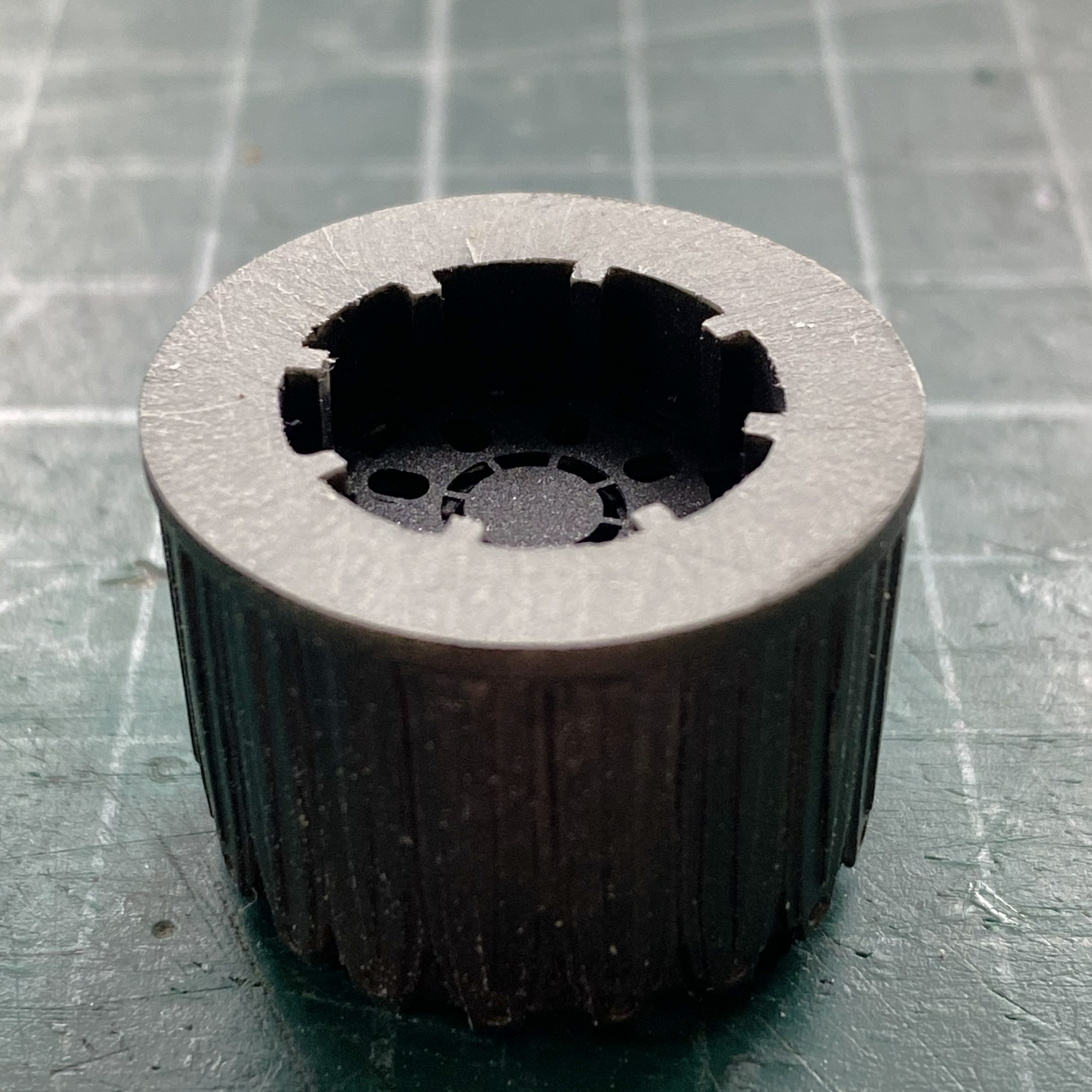
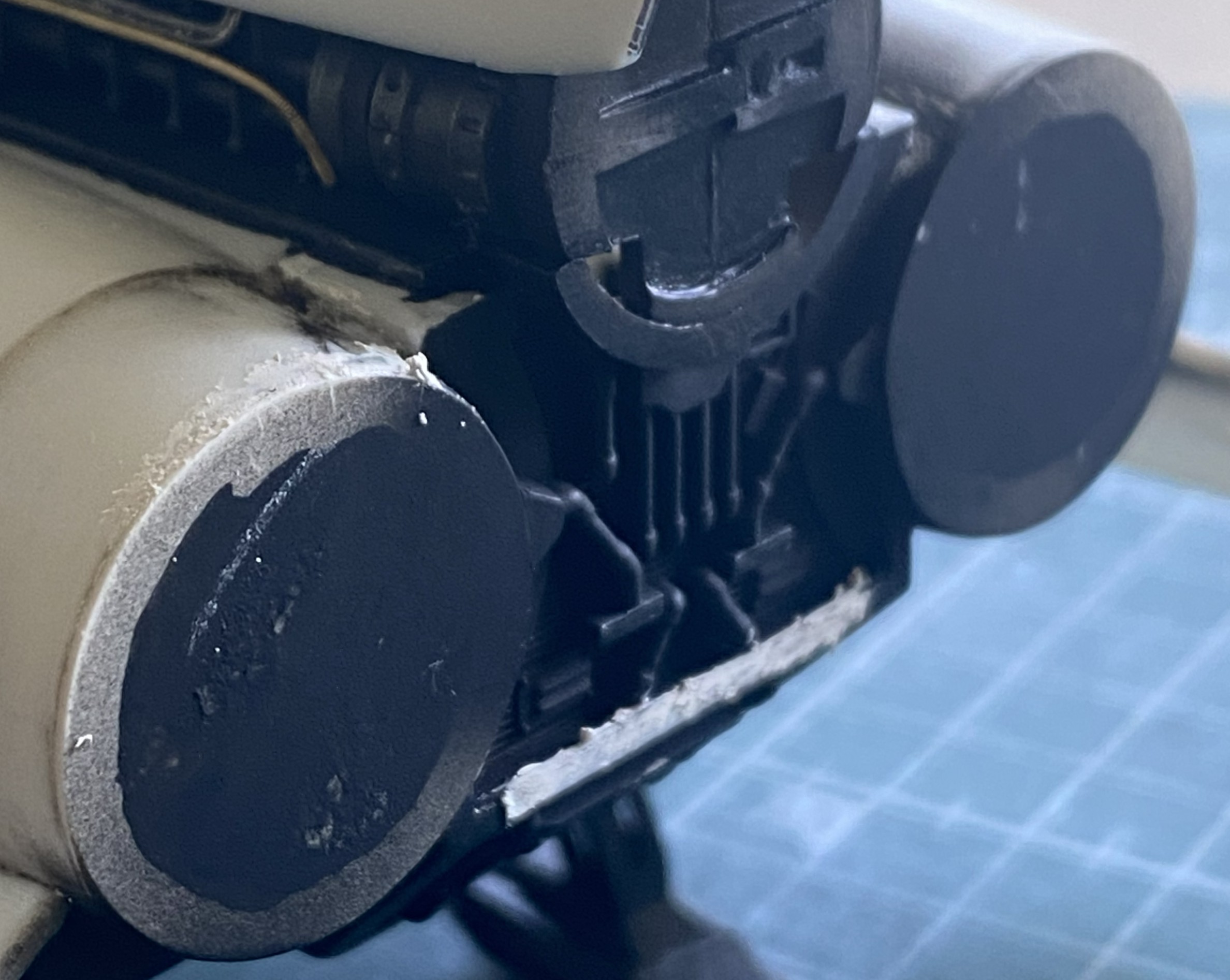
Having gotten the stern of the Viper ready for the AM nozzles, probably not a bad idea to get the nozzles ready for the stern. My initial thought was to add a disc of styrene to the back of these resin nozzles. Doing so would allow me more time to get the alignment correct if it was Tamiya Extra Thin I had to deal with rather than CA:
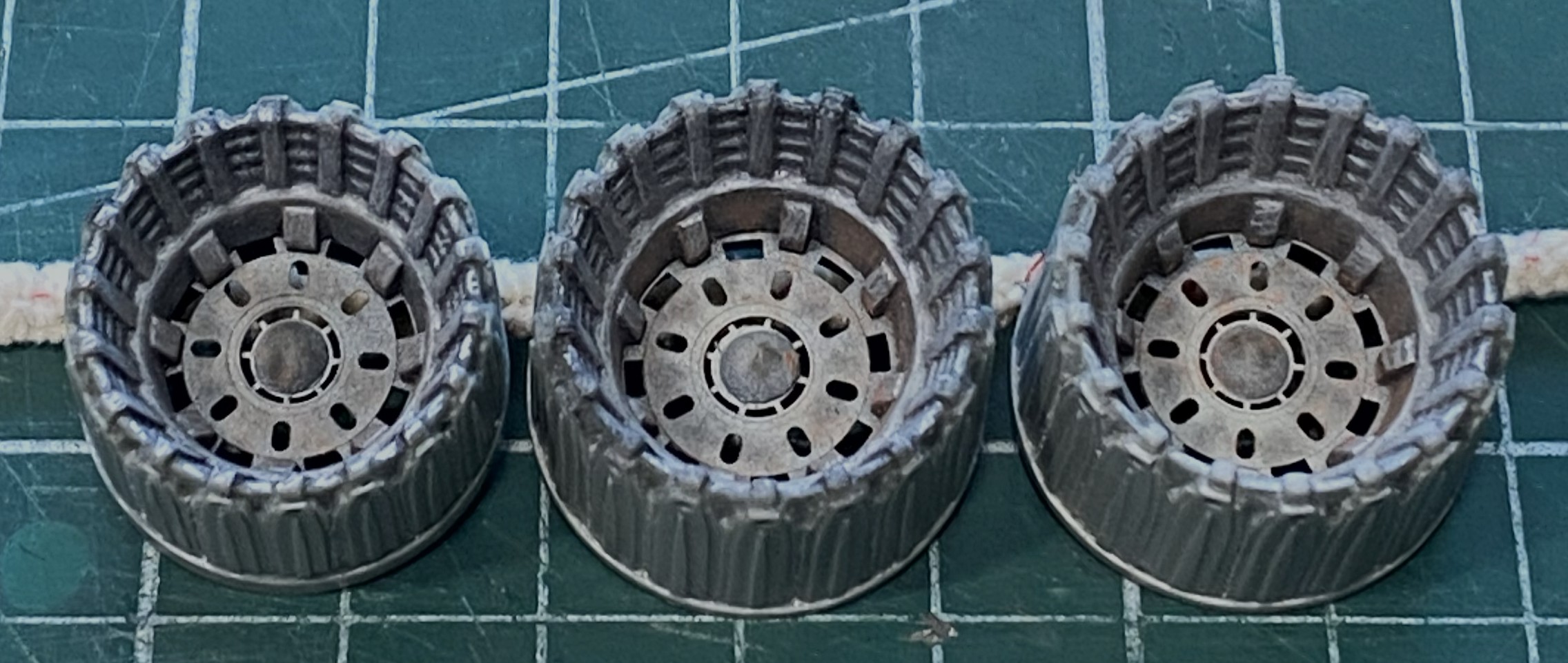
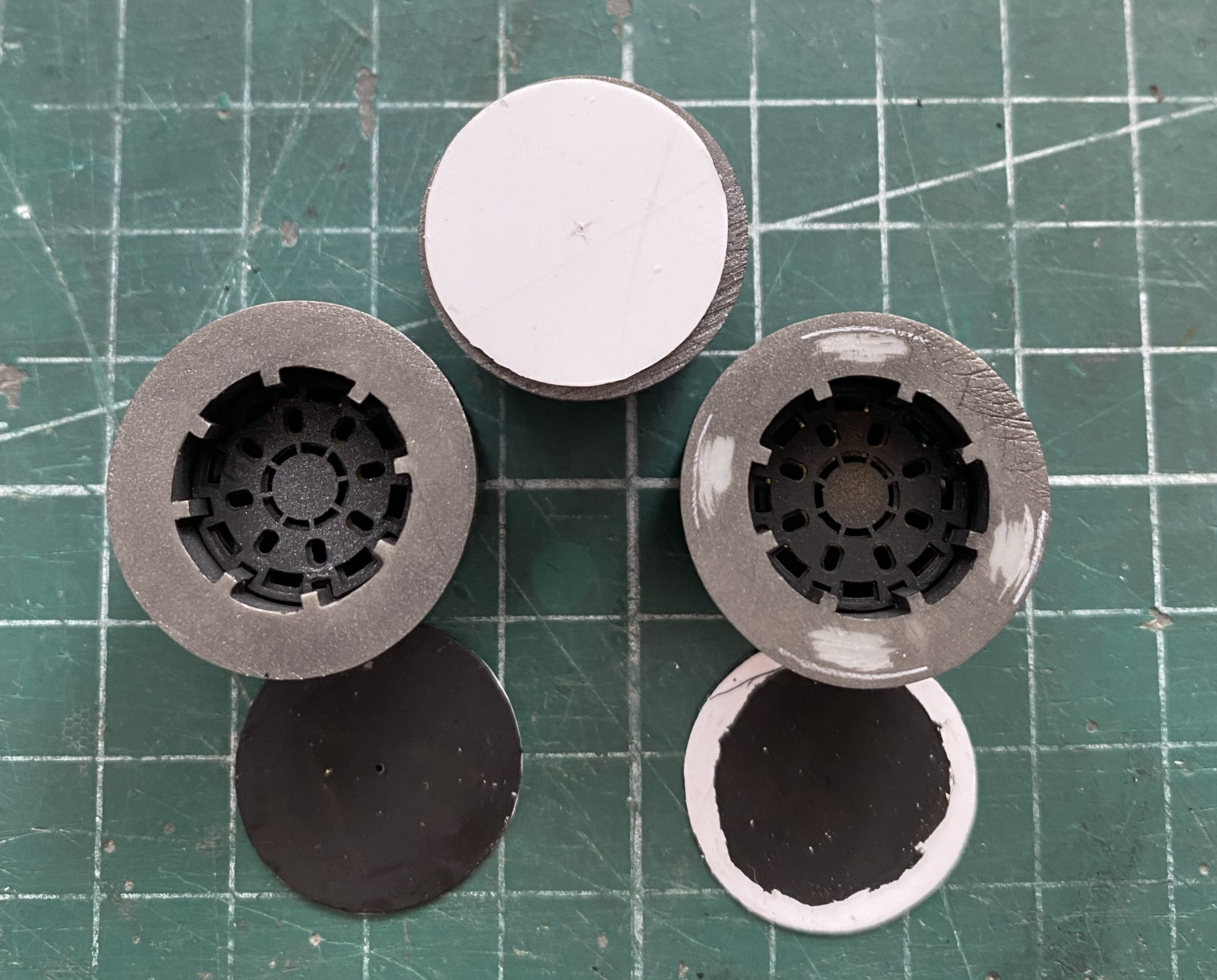
As it turned out later, this was the latest example of me being too clever for my Reality.
An ongoing thorn in my flank at this point was the top of the nose of this. I had managed (somehow) to get most the slats that I added to build up the nose so that I could match the curve of the nose to the curve of the canopy to play nice with each other. Those areas needed no work. However, there were a few places on the nose that the more work I did on them, the more work I needed to do on them. Adding sprue worked a bit. Adding flat scrap that had been trimmed into “planks” and then the corner jammed AND SINCERELY GLUED into the problem areas:
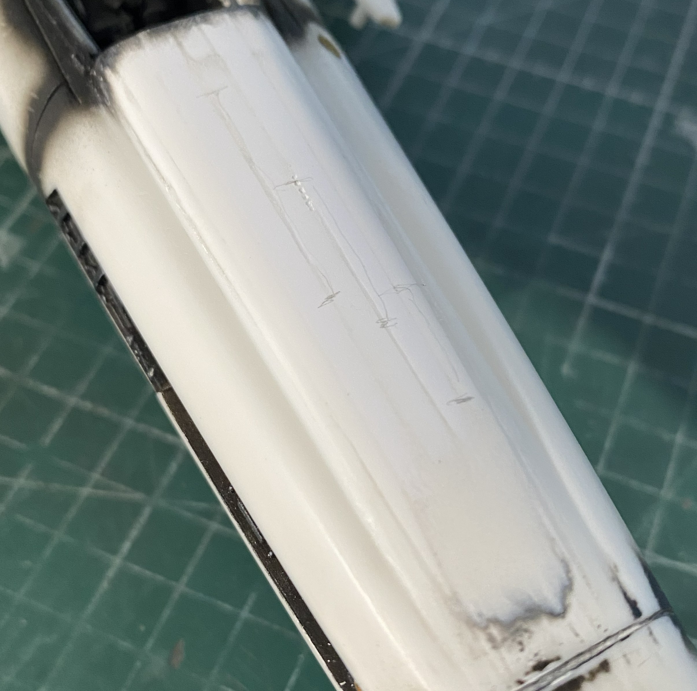
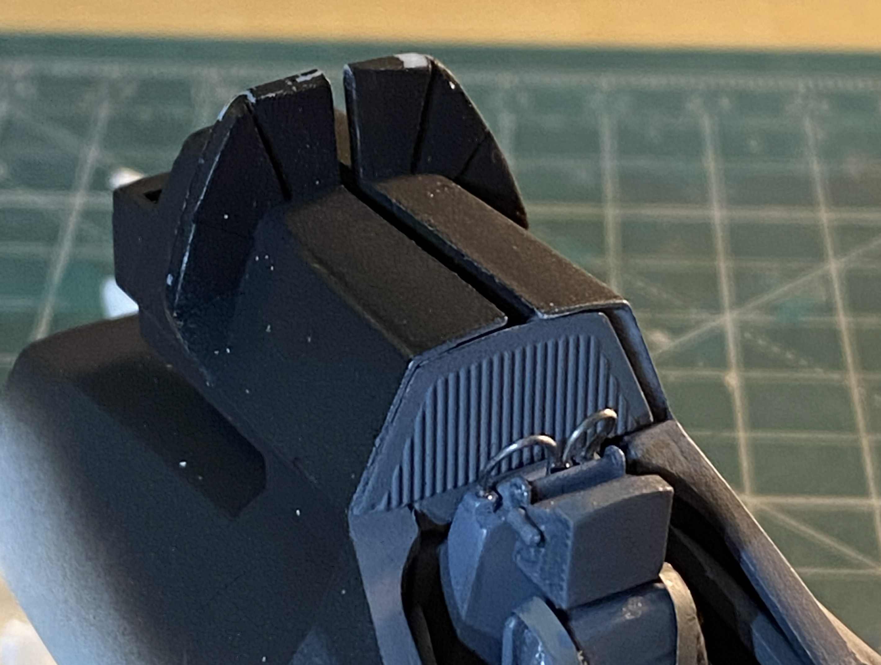
While waiting for the glue to cure on the nose, I attended to a few tasks. I started to fit the nozzles to the rear. Where the fuselage and shroud meet is uneven and there were gaps that had to be worked:
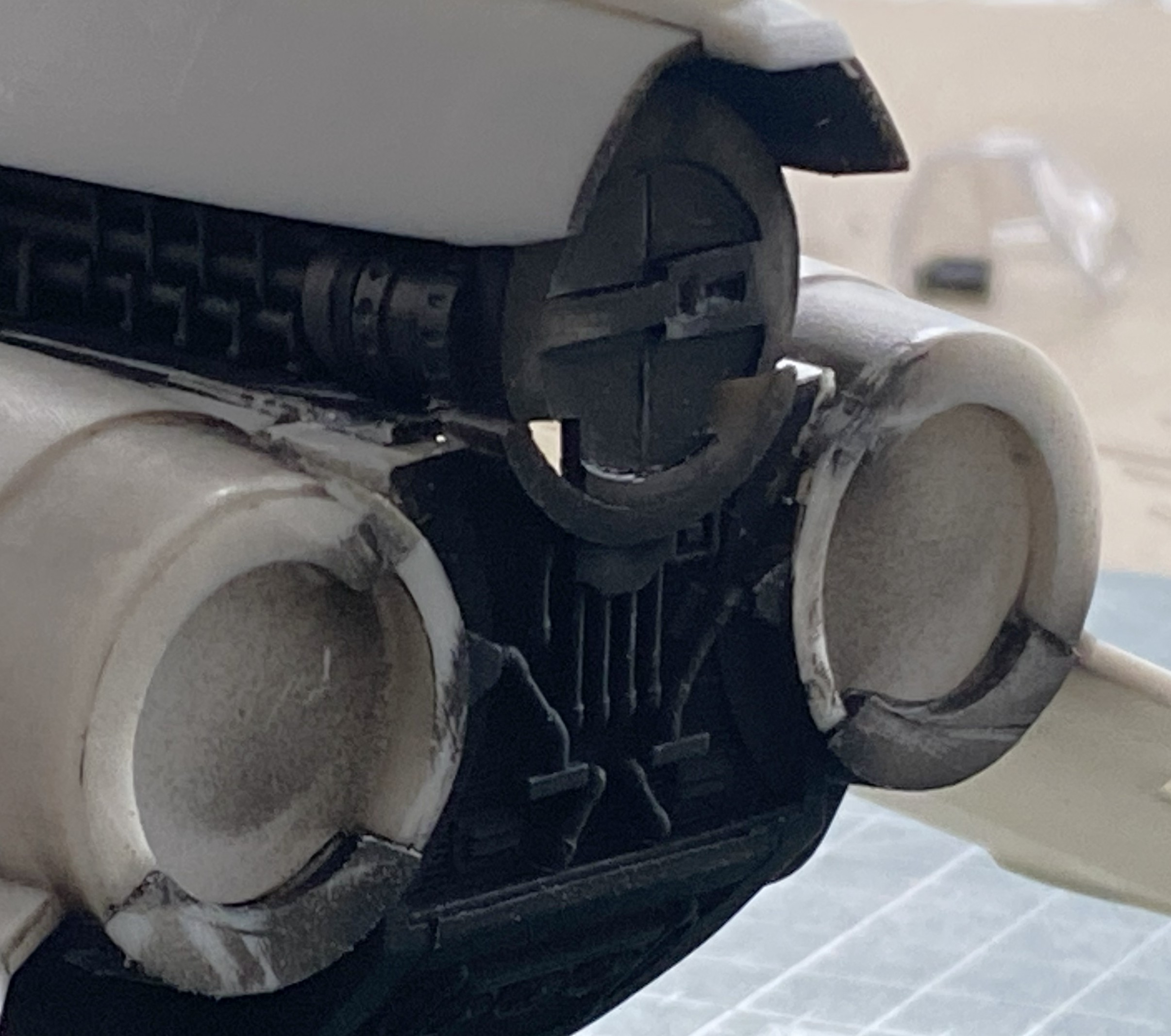
Simple (this time), just trim the circumferences to fit:
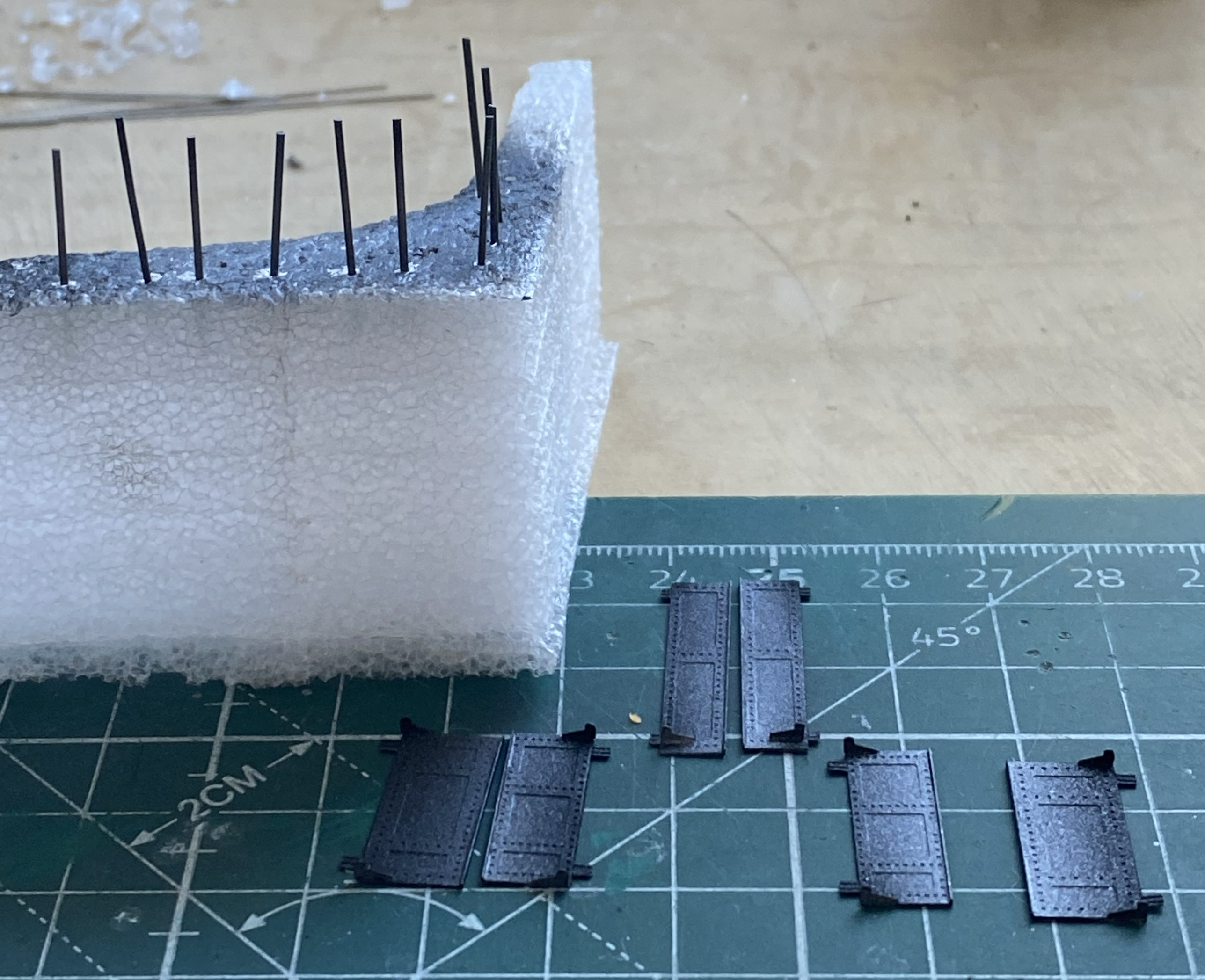
I decided that I should get the landing gear doors assembled and painted:
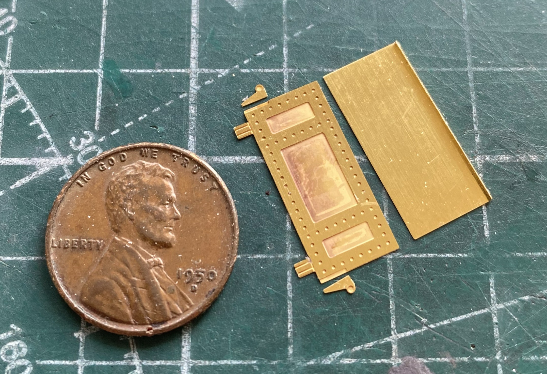
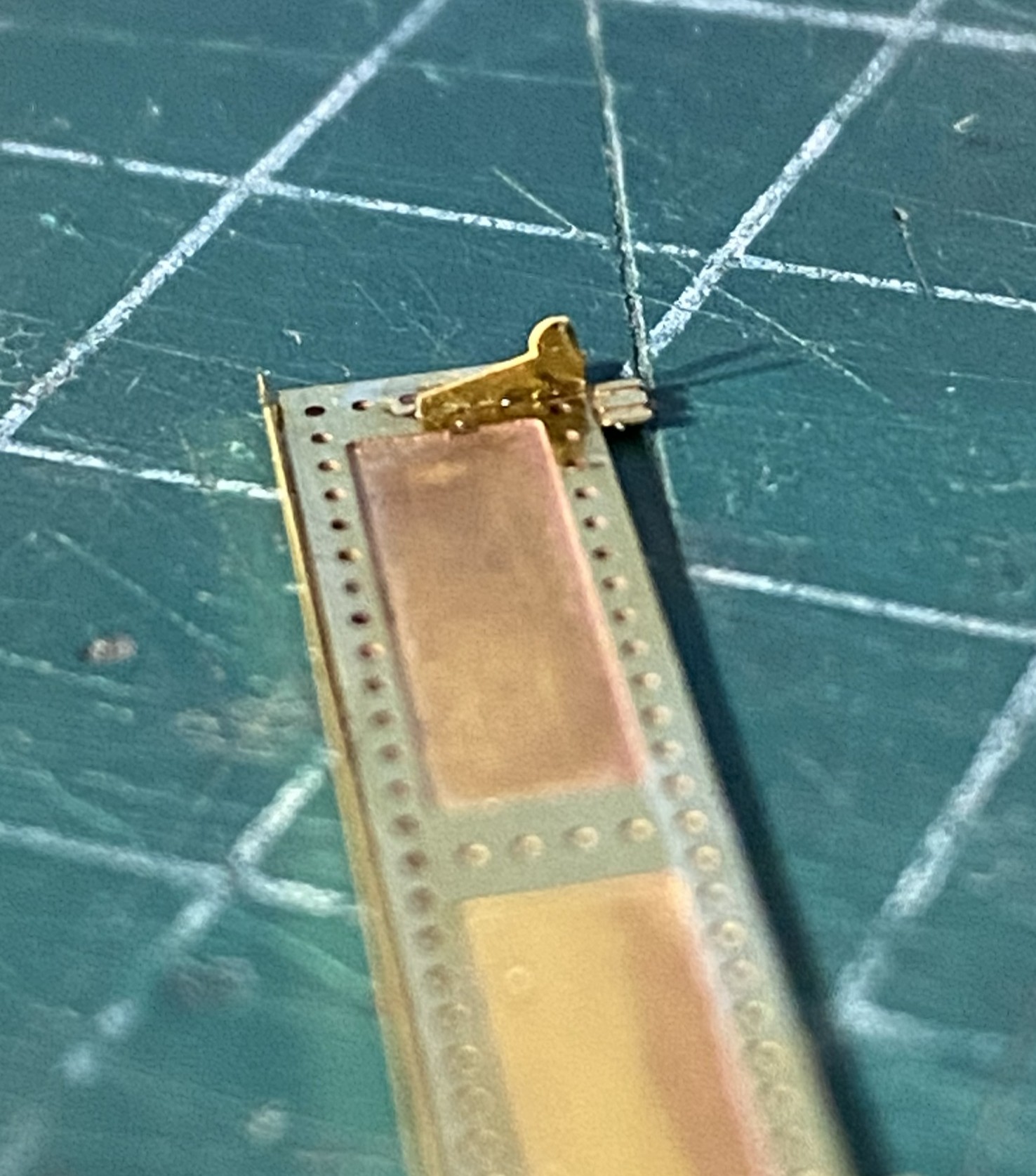
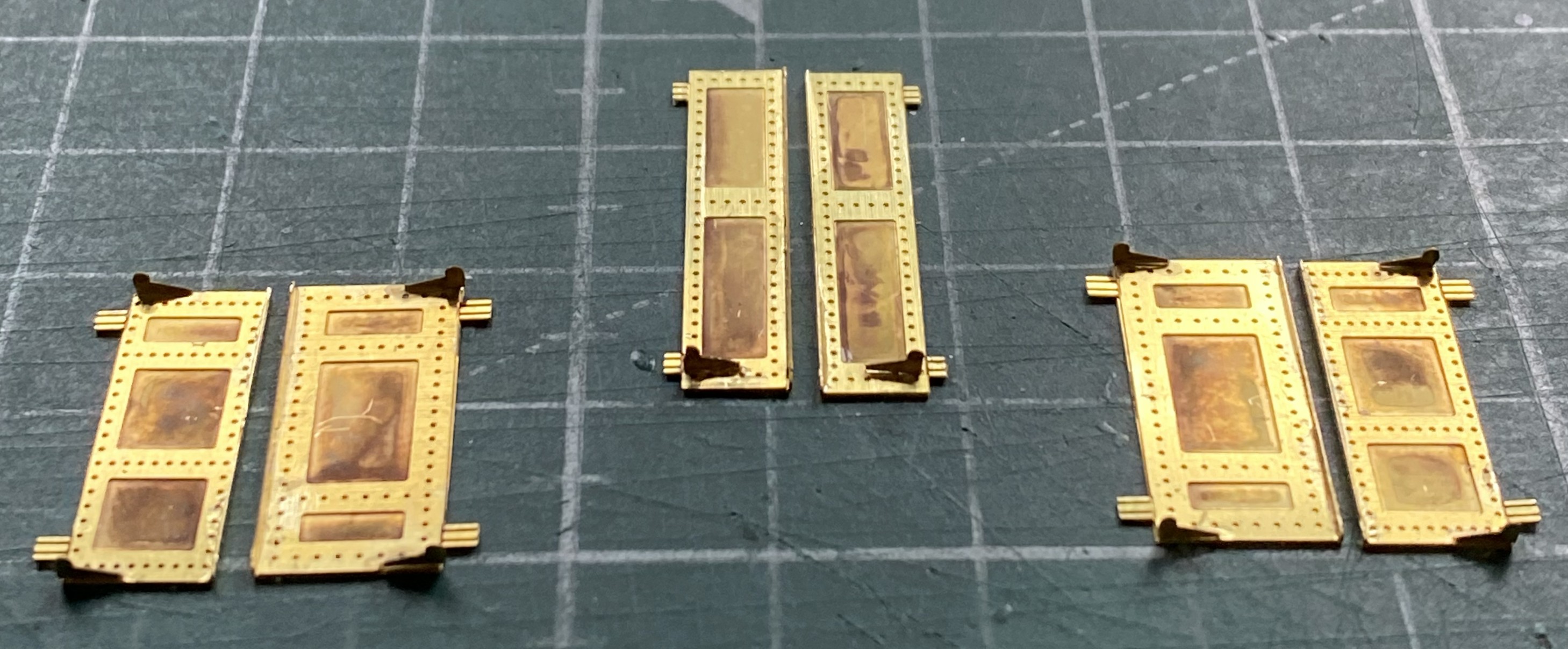
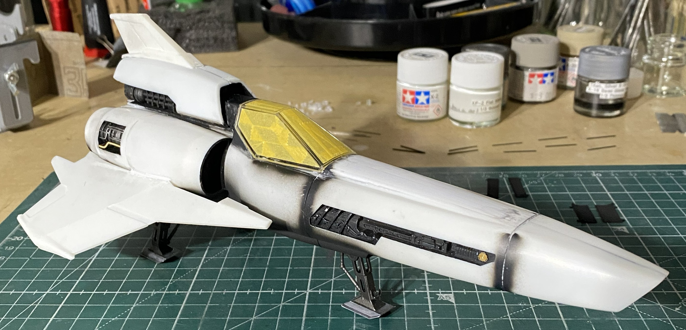
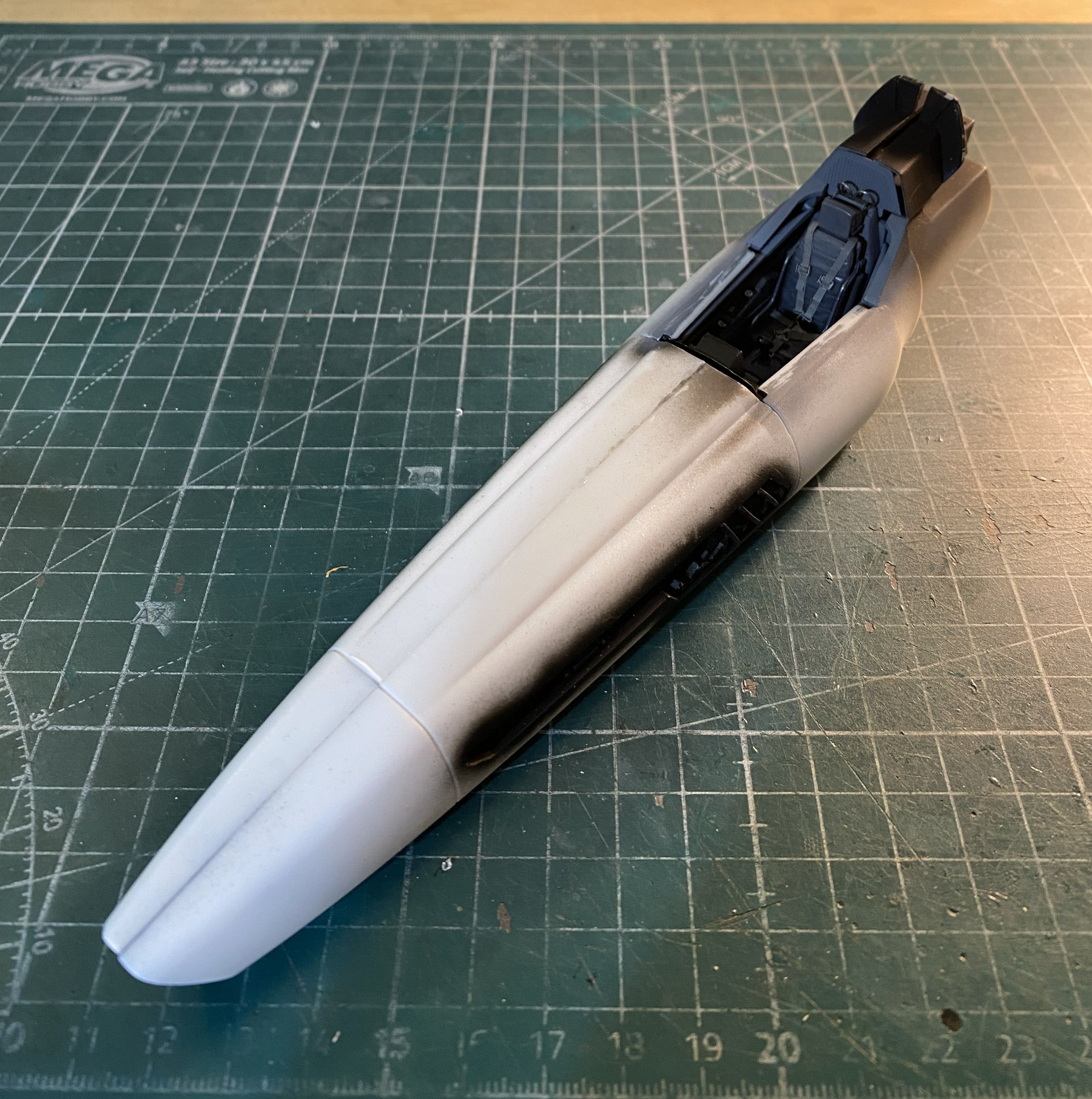
With the main fuselage components assembled and finished, painting time is getting nearer. Rather than attempt stuffing the cockpit with sponge or cotton (too many fragile PE edges and corners to snag on), I masked the canopy and attached it temporarily with PVA (which, to be honest, is my generally preferred method of keeping errant paint out of the cockpit):
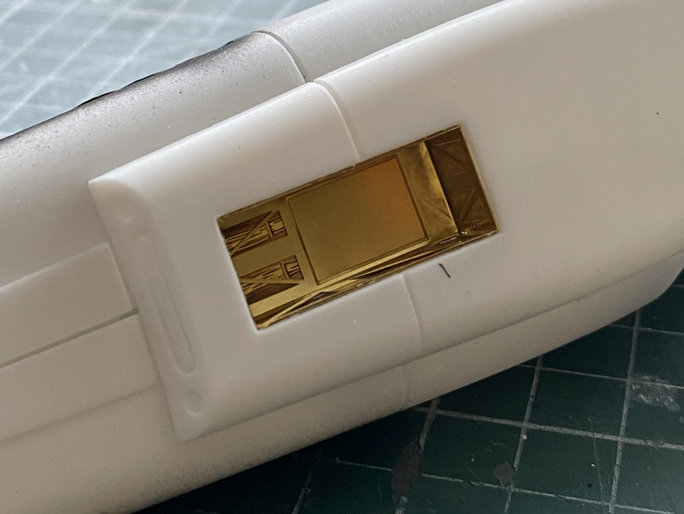
From what I can tell from references, there’s not supposed to be a gap at the wing root, only under the engine panel, so I filled it in with scrap sheet and finished it down:

I also painted the actuator arms Humbrol Steel:
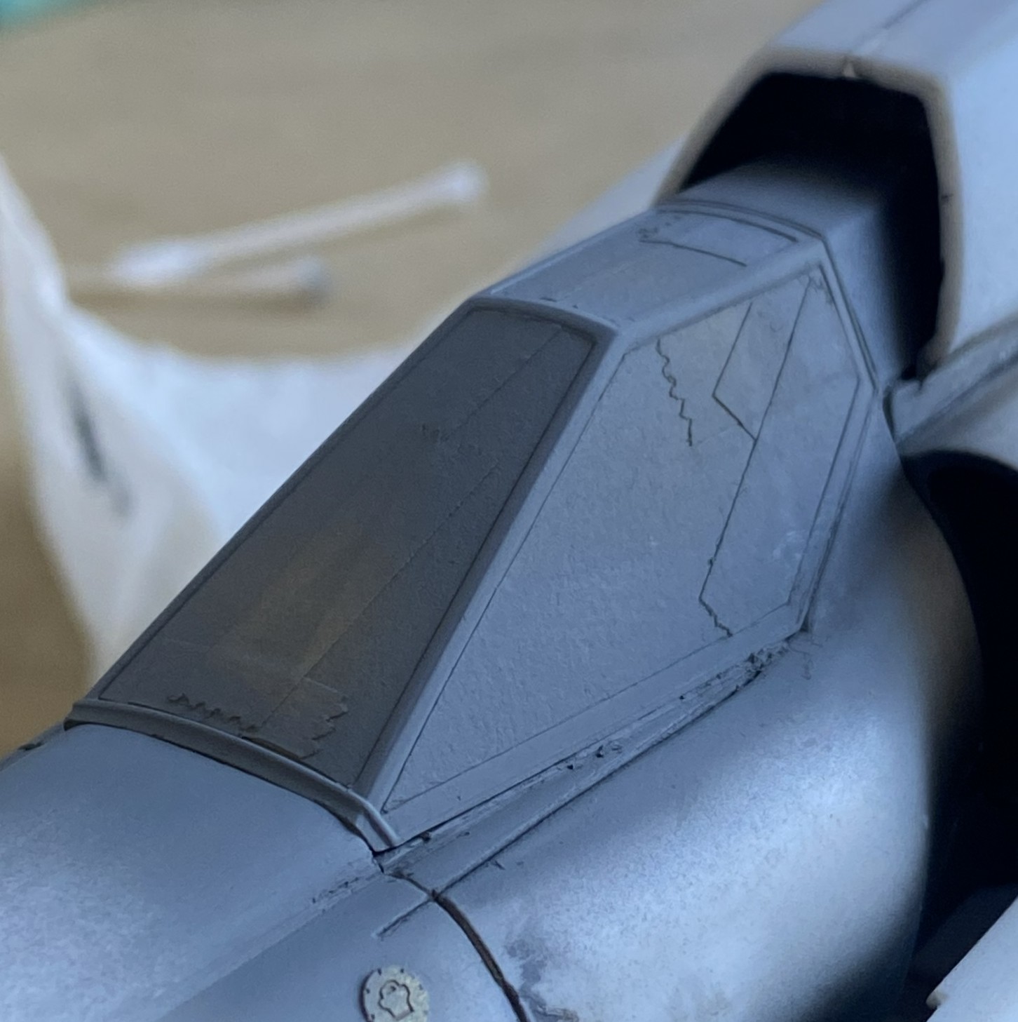
With the canopy temporarily affixed, the framework had to be painted the cockpit color:
Back to work on the nose, I brought down the added scraps and I still wasn’t pleased with the result. The last thing I could think of (that was acceptable, anyway) was plue, so I painted the problem areas with it and waited:
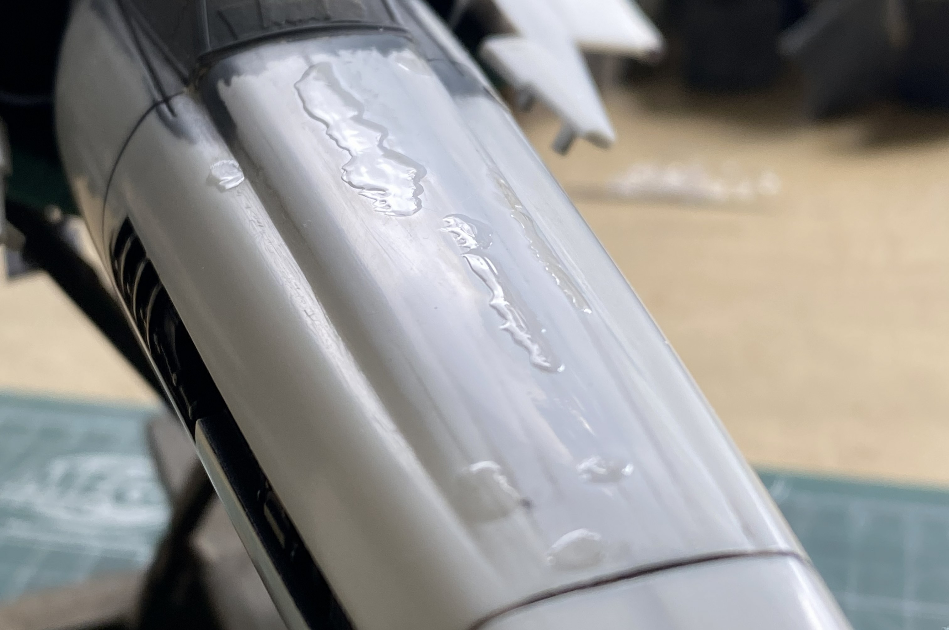
While the plue cures, I started adding details to the center engine:
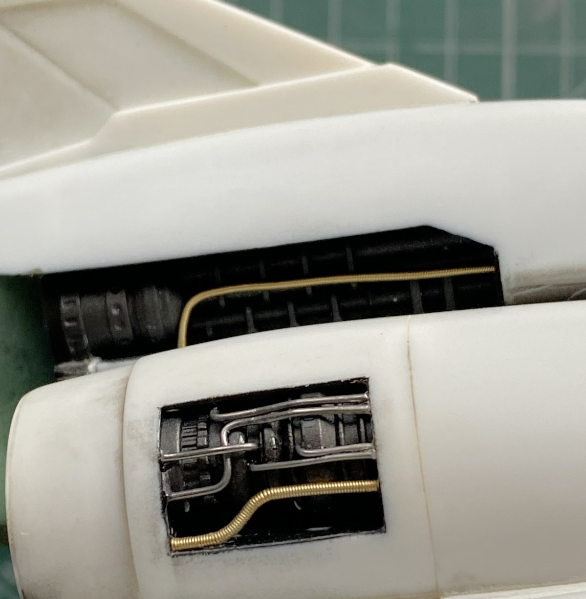
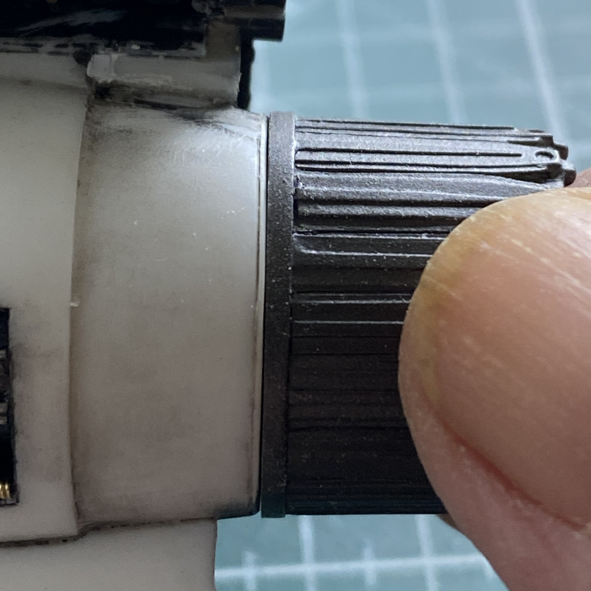
I’d added discs to the back of the nozzles so that I had a styrene to styrene join. I decided that maybe I should check and see how that would look. Too much of a gap between fuselage and nozzle, indicating that I’d outsmarted myself. Again:
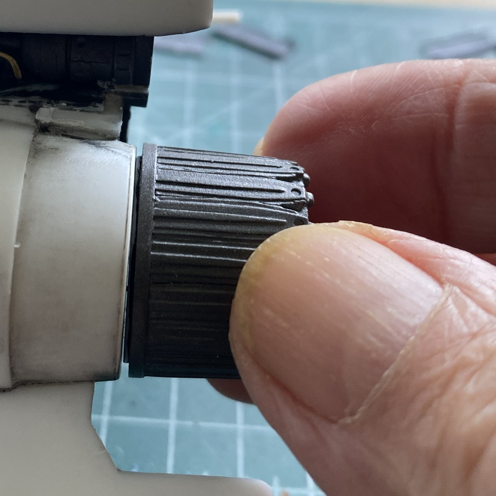
I have plenty of sandpaper and this was an easy fix:
With the plue cured, more sanding was done on the nose:
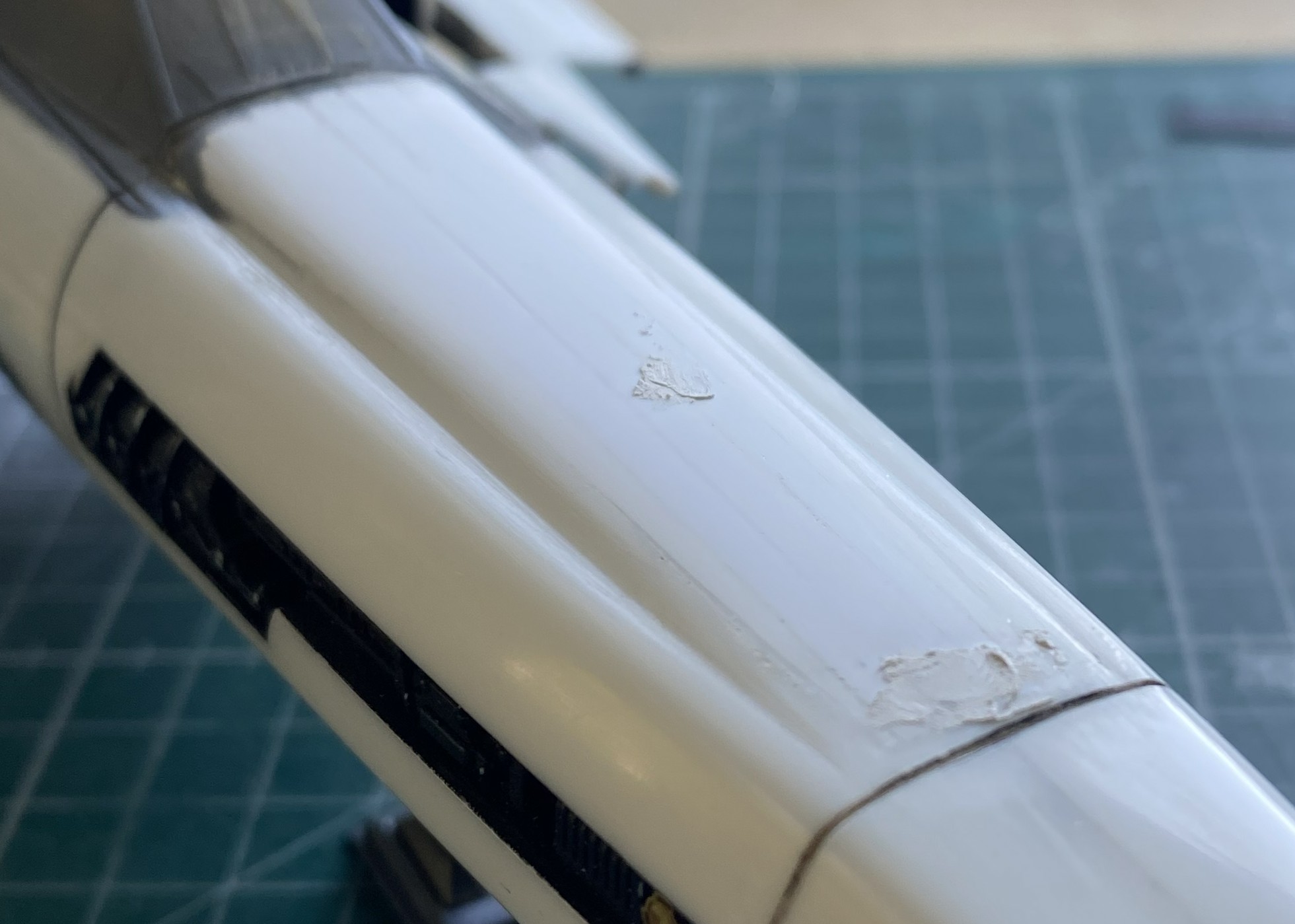
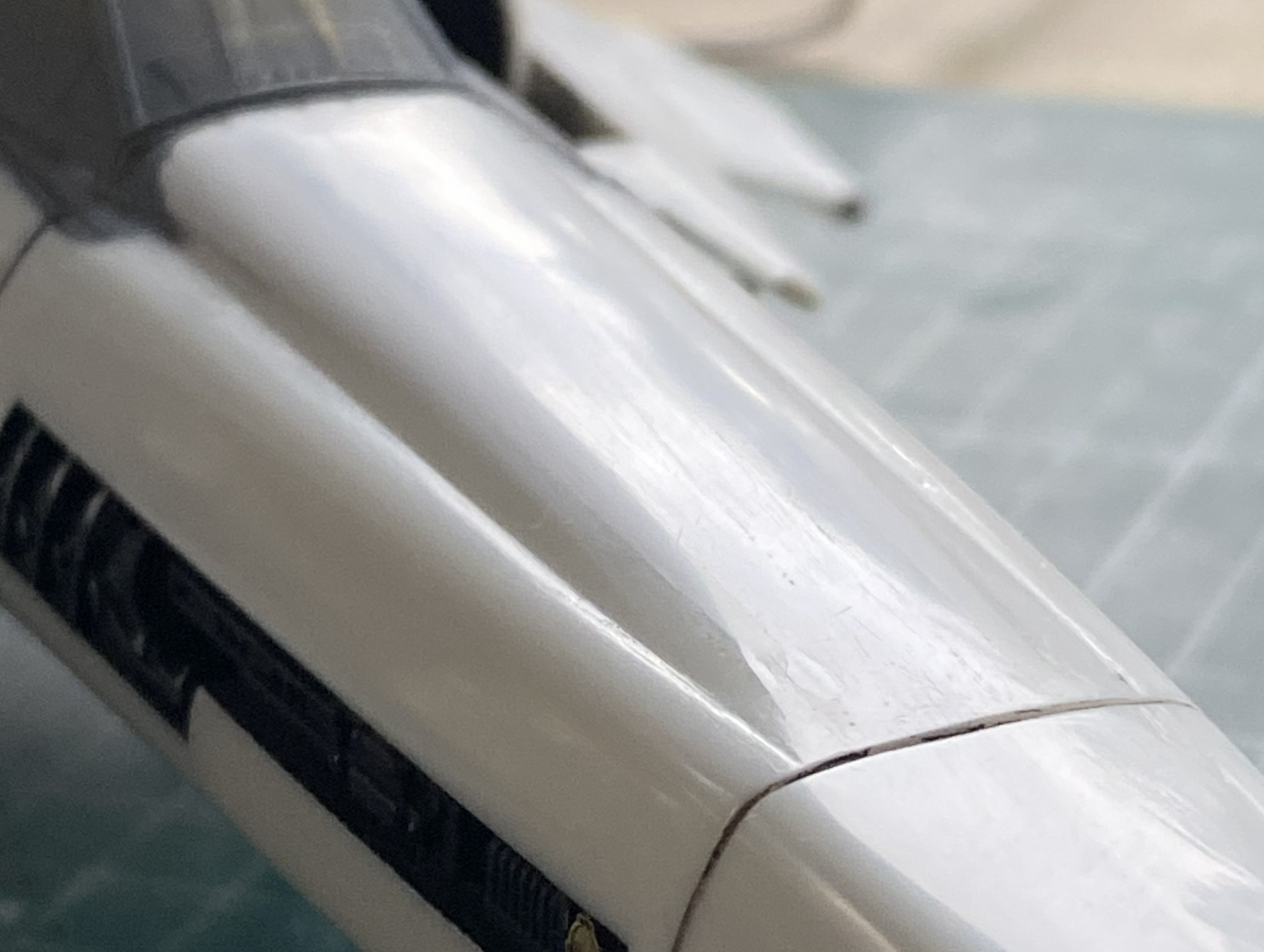
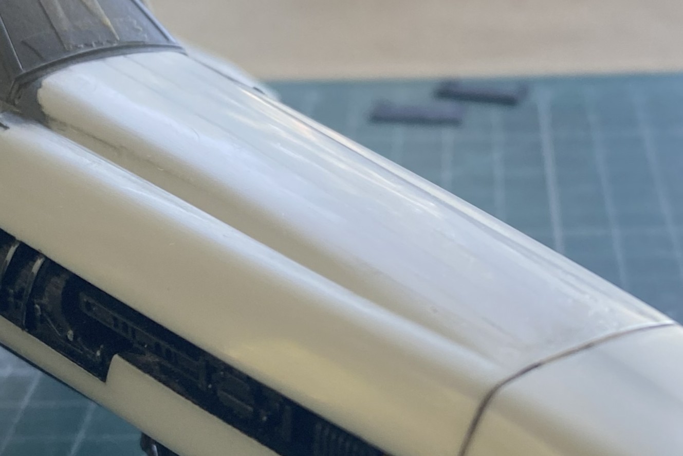
Still not entirely pleased but the best part of being good is knowing when to stop. I don’t know when to stop so the above is me guessing. Paint will inform me if I’ve guessed correctly.
The rear section needs to be worked next, adding putty and scrap to smooth and connect things:
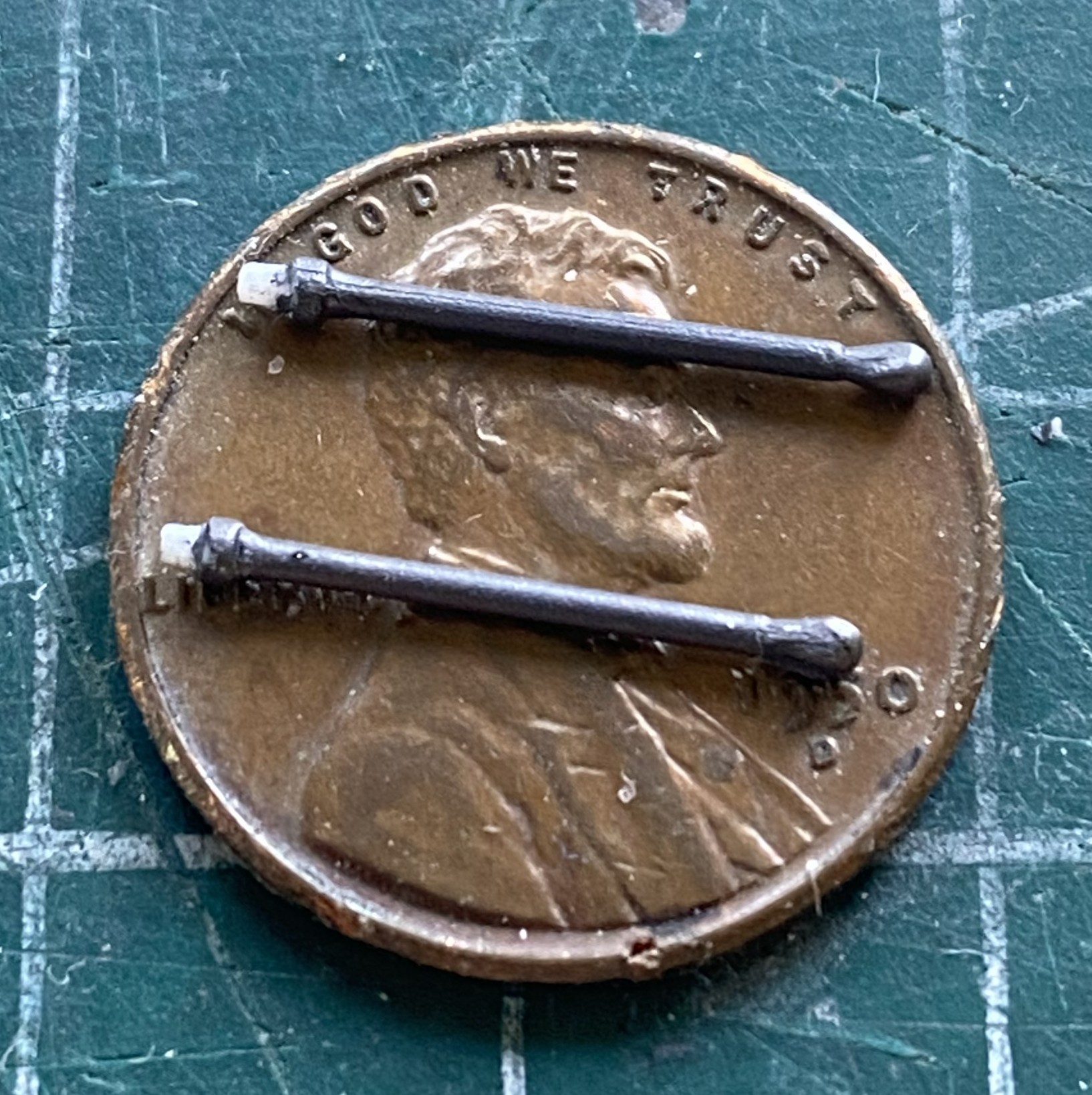
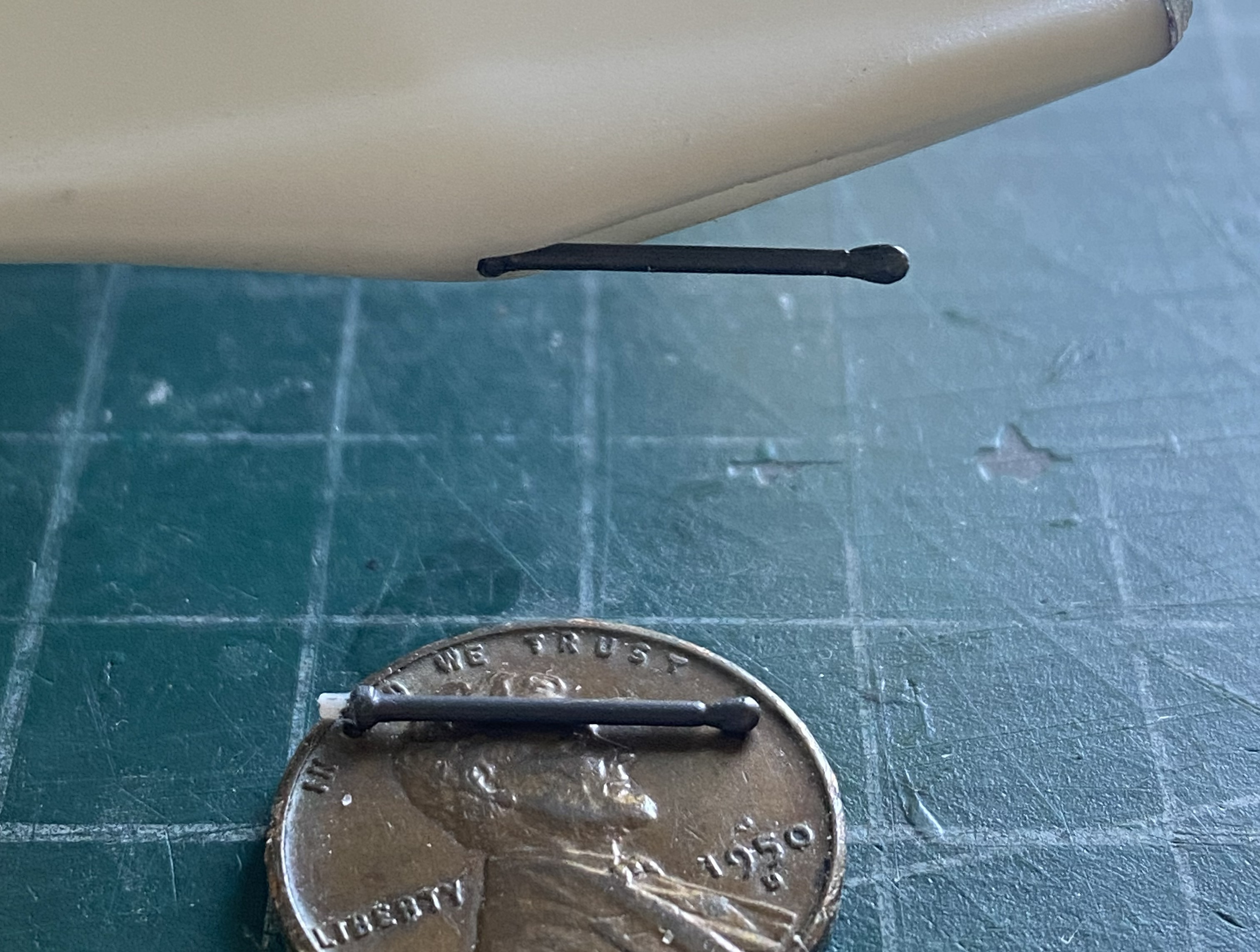
I was surprised to see a bit of an actual aircraft’s kit included with this model. Static discharge antennae. I thought it more than a little odd that the designers of this prop would add a piece of gear that’s intended for atmospheric flight. And yeah, sure. This thing was supposed to be able to operate in an atmosphere, so, okay. I just found it odd that the designers would add that piece of realism and yet make the engines utterly unrealistic.
Anyway, I painted them Humbrol Steel, and dry-fitted them (sans glue) to see how they’d look. I’m not impressed and am considering doing something else but have yet to decide:
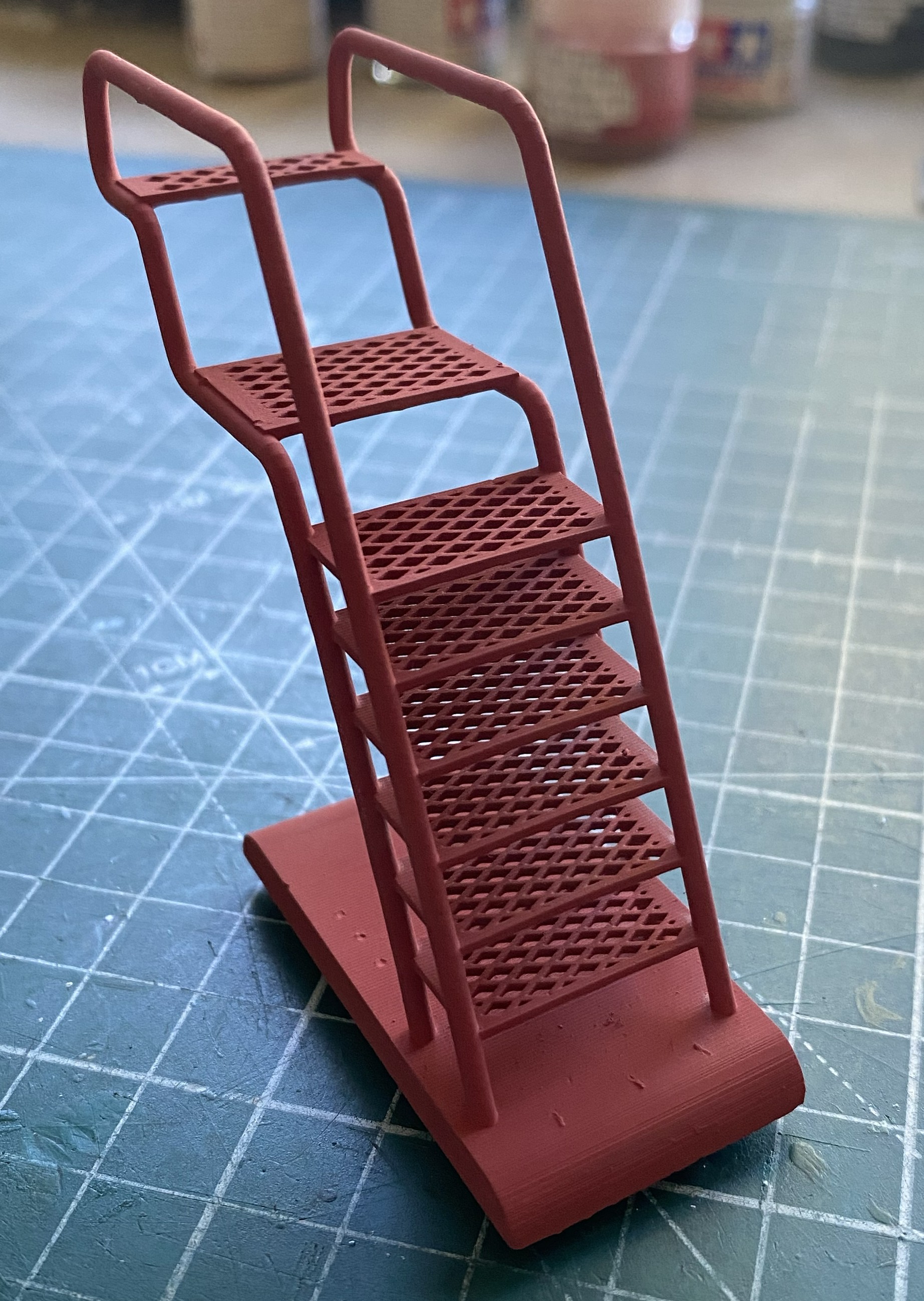
I’m intending to make a vignette for this and my plans require a boarding ladder. Revell’s issue of this kit provides a ladder, Moebius’ kit (the one I’m working) did not. After several hours of wrestling with floral wire (correct diameter and easy to bend) to profoundly underwhelming results, I went online to find one and what I found is resin. It won’t be without its challenges but it’s magnitudes better than the garbage I was producing:
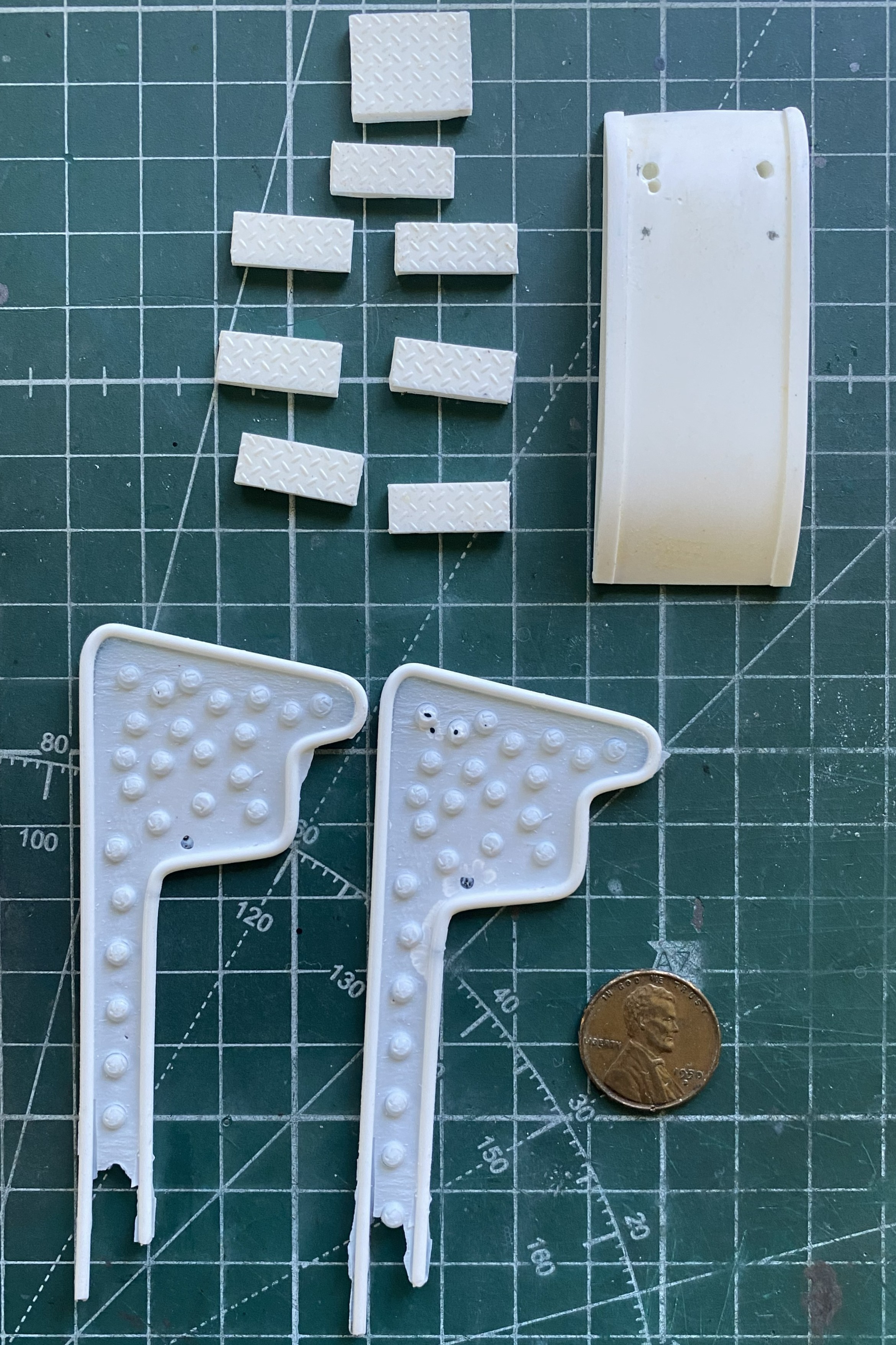
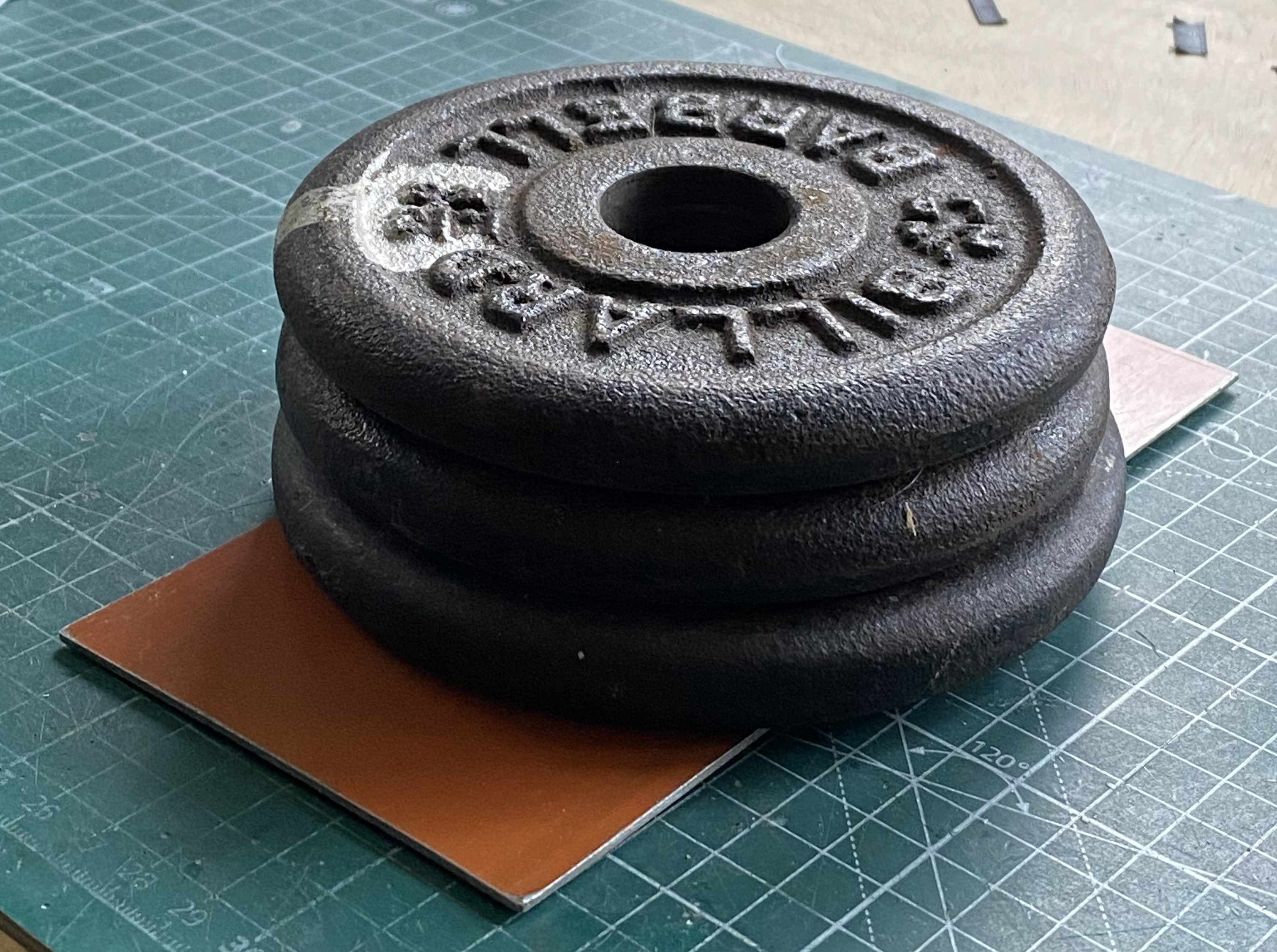
The handrails are warped so I decided to start gently reshaping them using weight:
Then I went online and continued searching for a boarding ladder and found one in Britain (cozmicscalemodels.com) that just knocks the first one out of consideration:
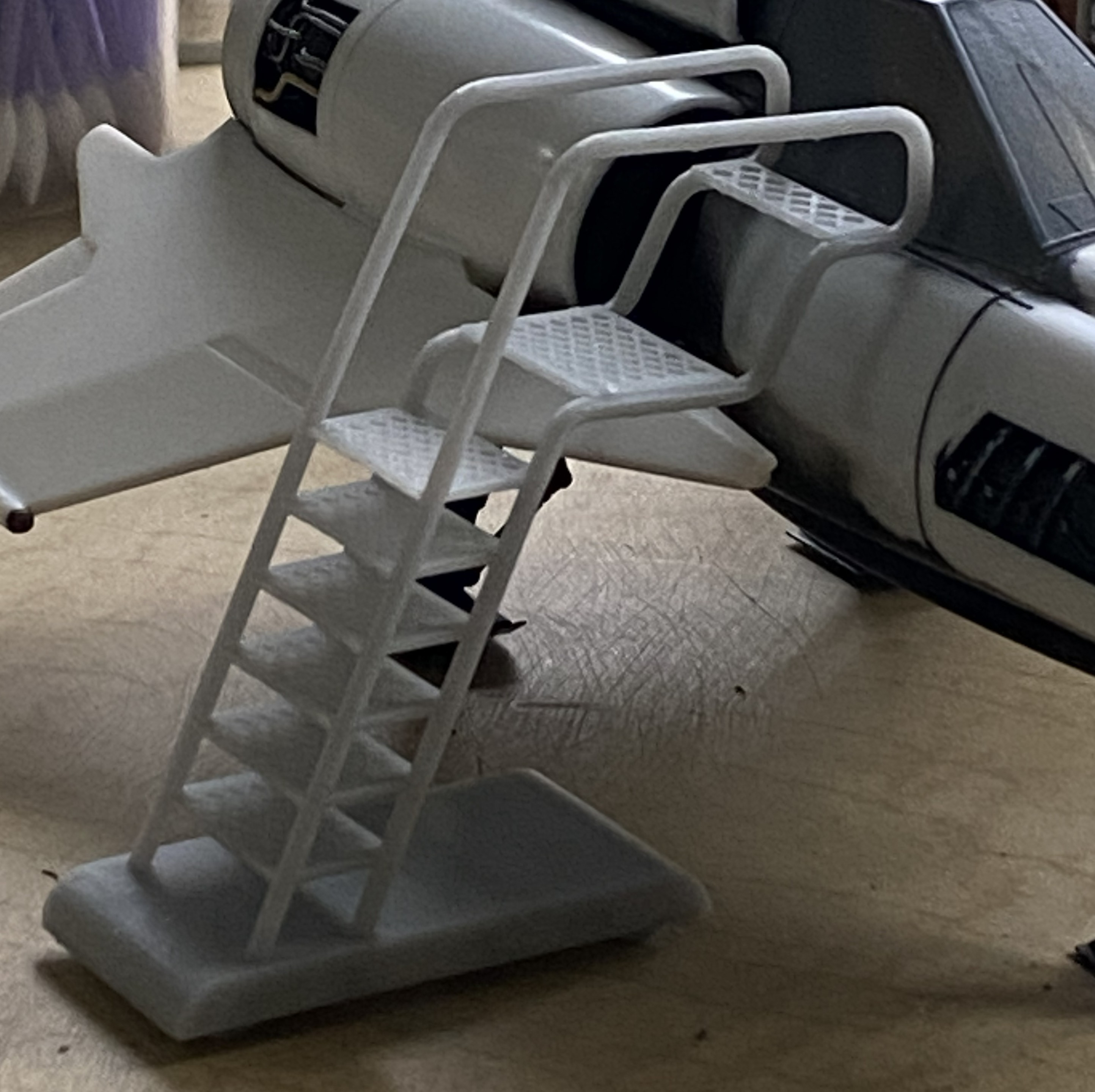
That’s a 3D print, complete, and just requires a little cleanup:
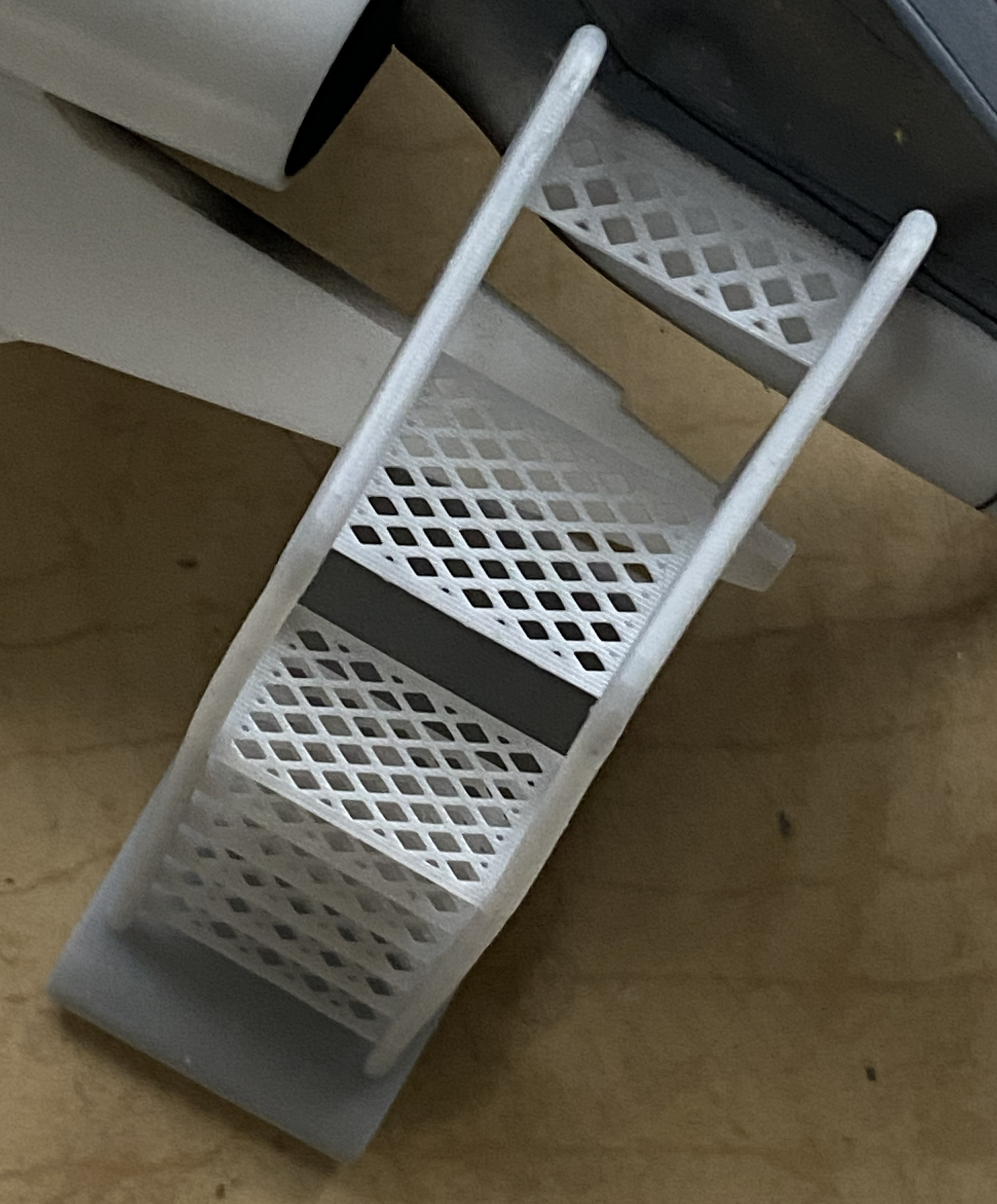
Perfection is rare and this ladder isn’t perfect. The handrails require a little persuasion to be parallel at the top:
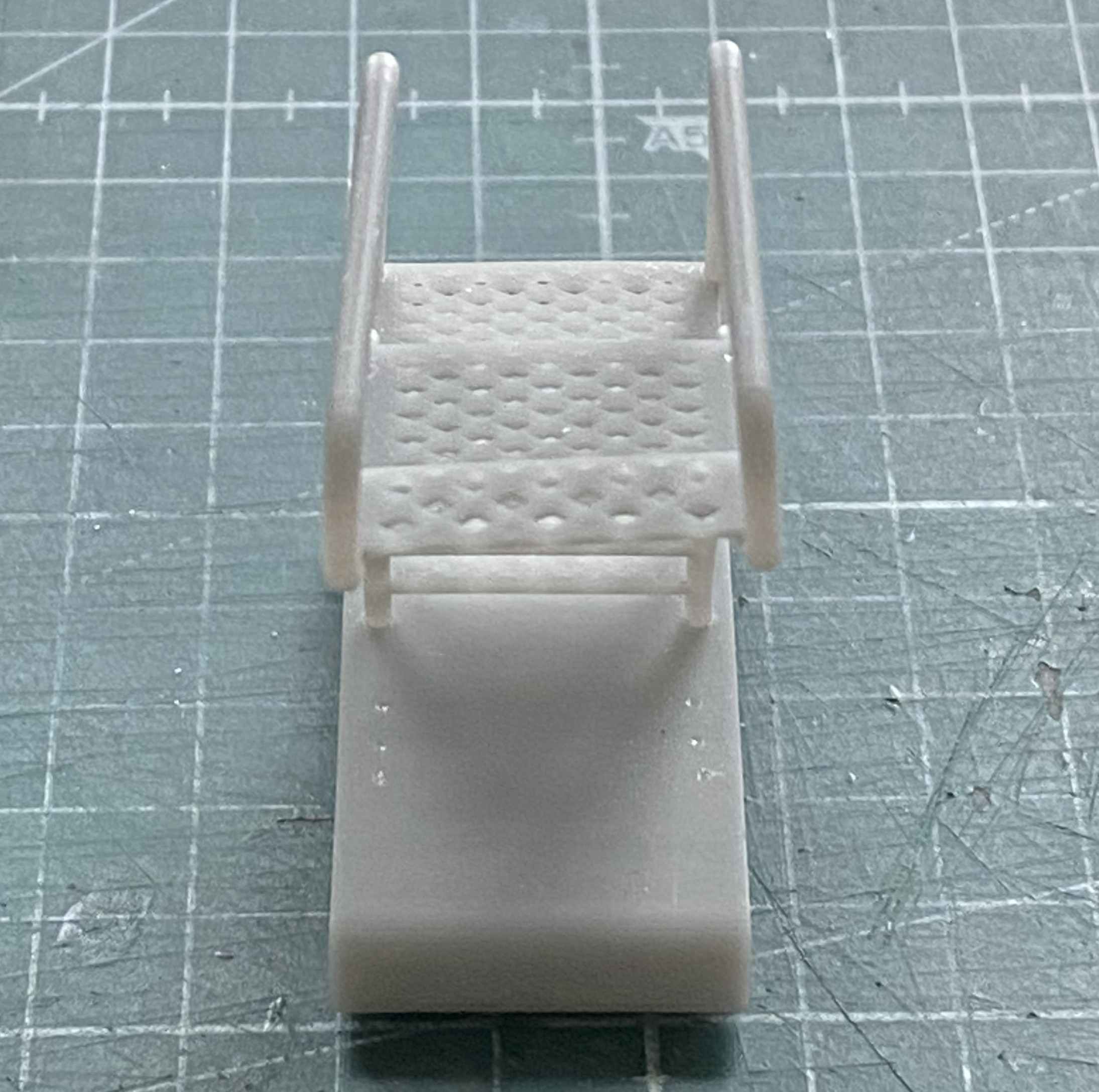
I used a piece of styrofoam to lift and separate (oops…wrong commercial). But you get it:
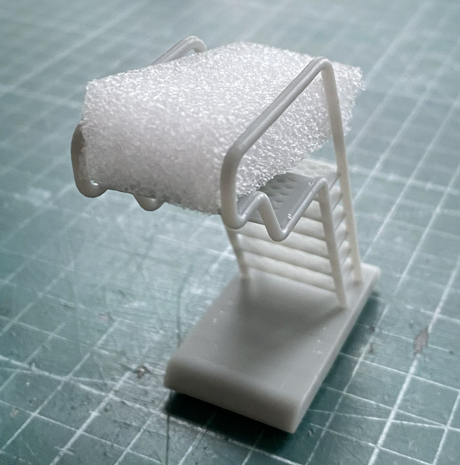
After an hour or so, I checked to see if it would work. Yup:
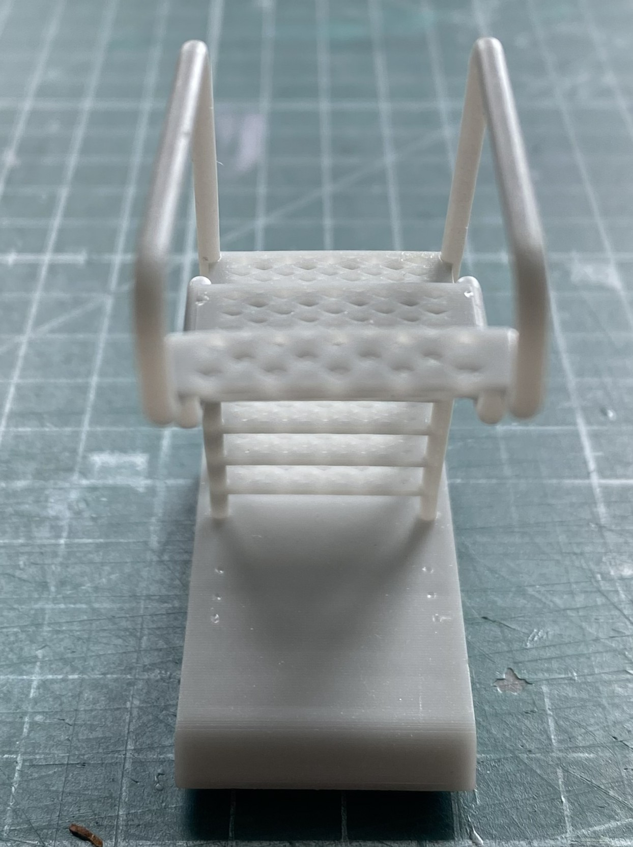
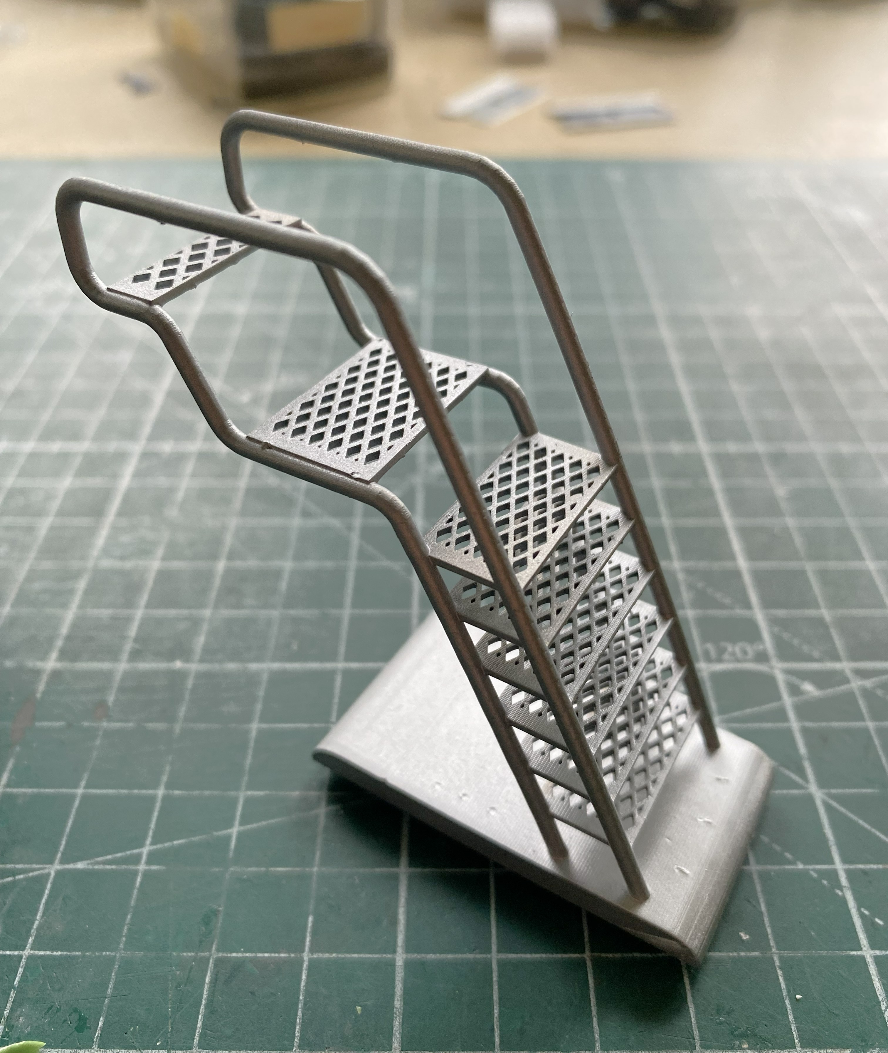
Yes, I can see that the top of the ladder is twisted slightly. I’m leaving it. Fixing it is too much work for too little result. I stuffed the styrofoam back into place and let it sit until it was time to paint, which again was Humbrol Steel:
Before I move on, a shout-out to Cozmic Scale Models (cozmicscalemodels.com). When I purchase something, I expect that what I’m buying was accurately portrayed prior to valuta changing hands. Cozmic nailed it. What I didn’t expect was a free gift. And you know free gifts are generally binned upon discovery. Not this time. This is Cozmic’s idea of a free gift:
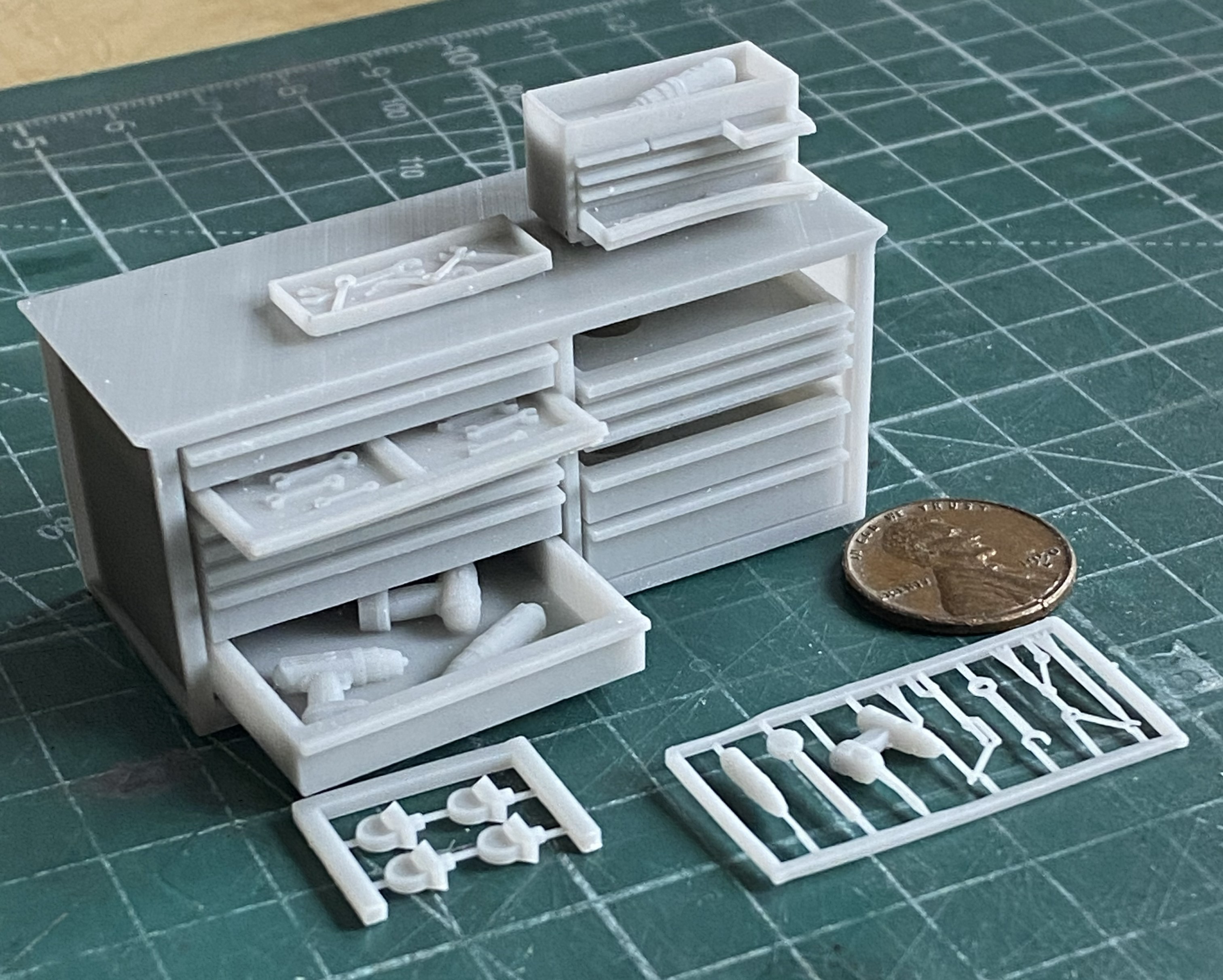
Did not see that one coming! A USEFUL free gift! (What a pleasant surprise.) Cosmic Models has moved to the top of my can-I-find-something-better list.
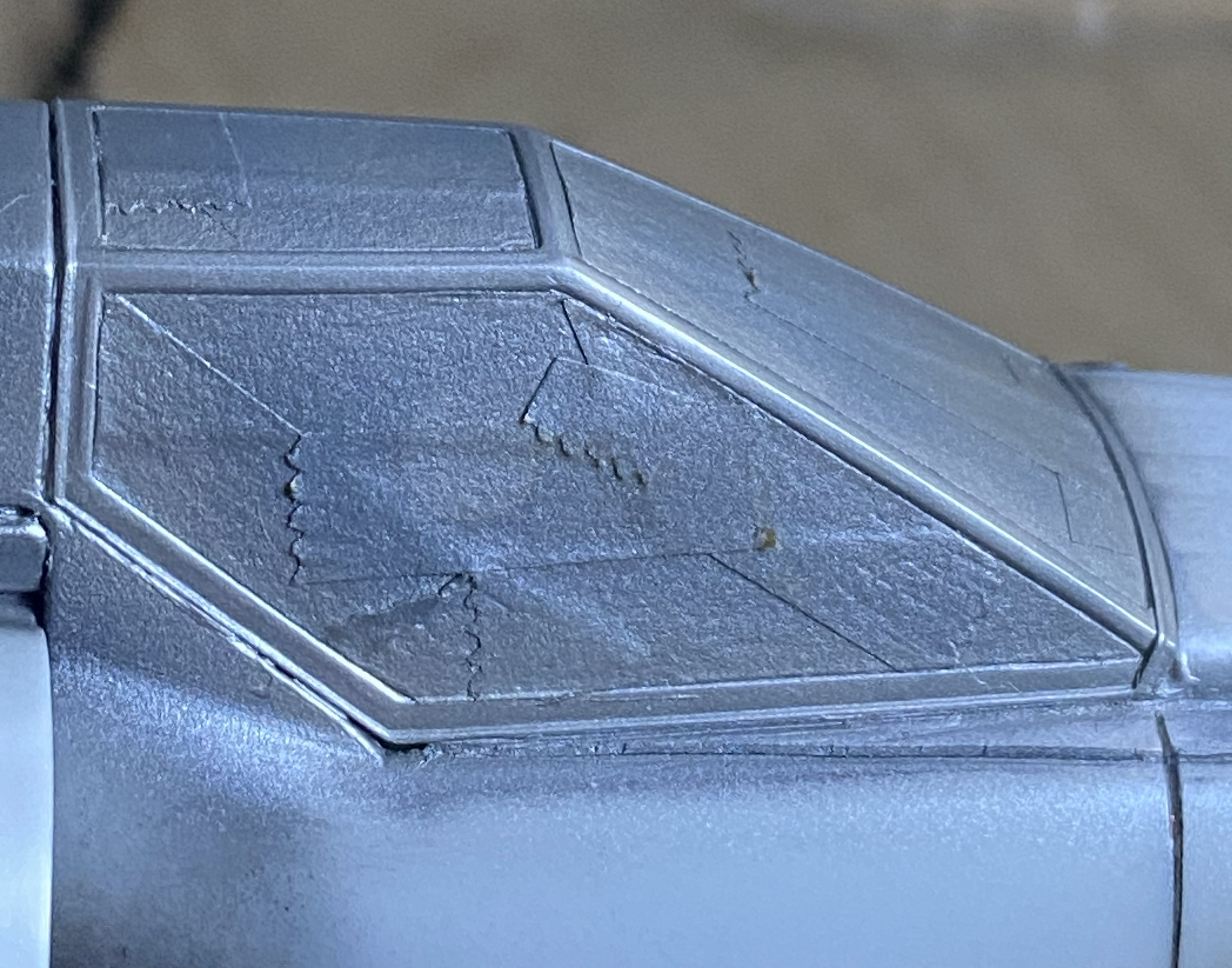
Since the next major job is painting, a supporting job is masking. The canopy frame isn’t itself masked off yet. I wanted to paint it Tamiya X-32 Titanium silver, so I did:
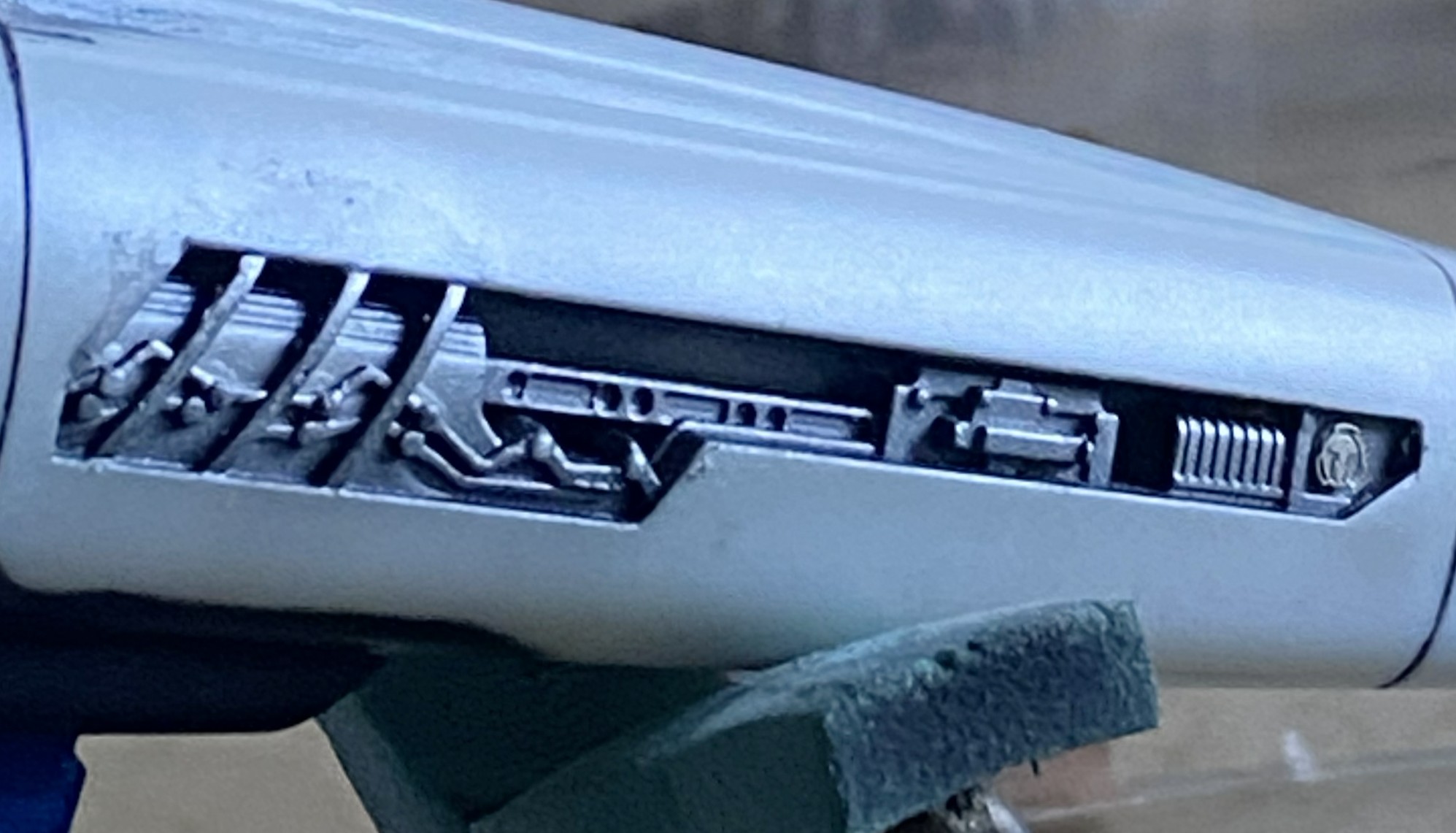
I also did the “whateveritis” side details the same color:
All of which was masked off:
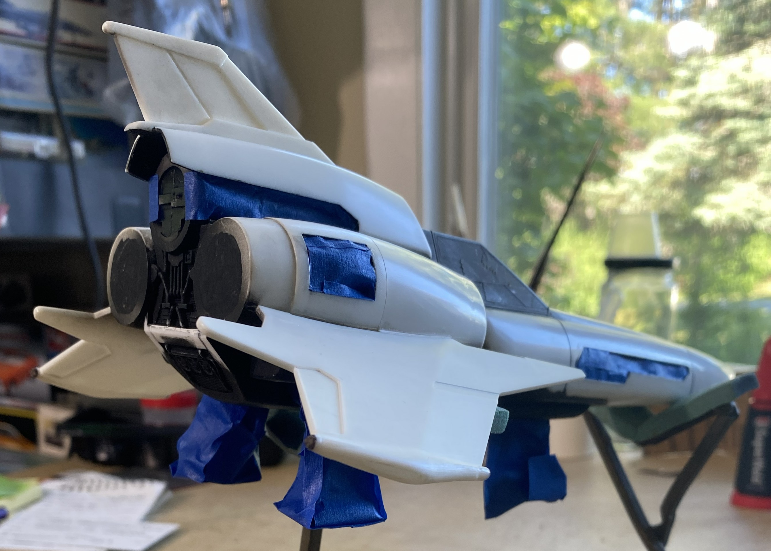
I masked over the canopy rails that I’d painted and started preshading:
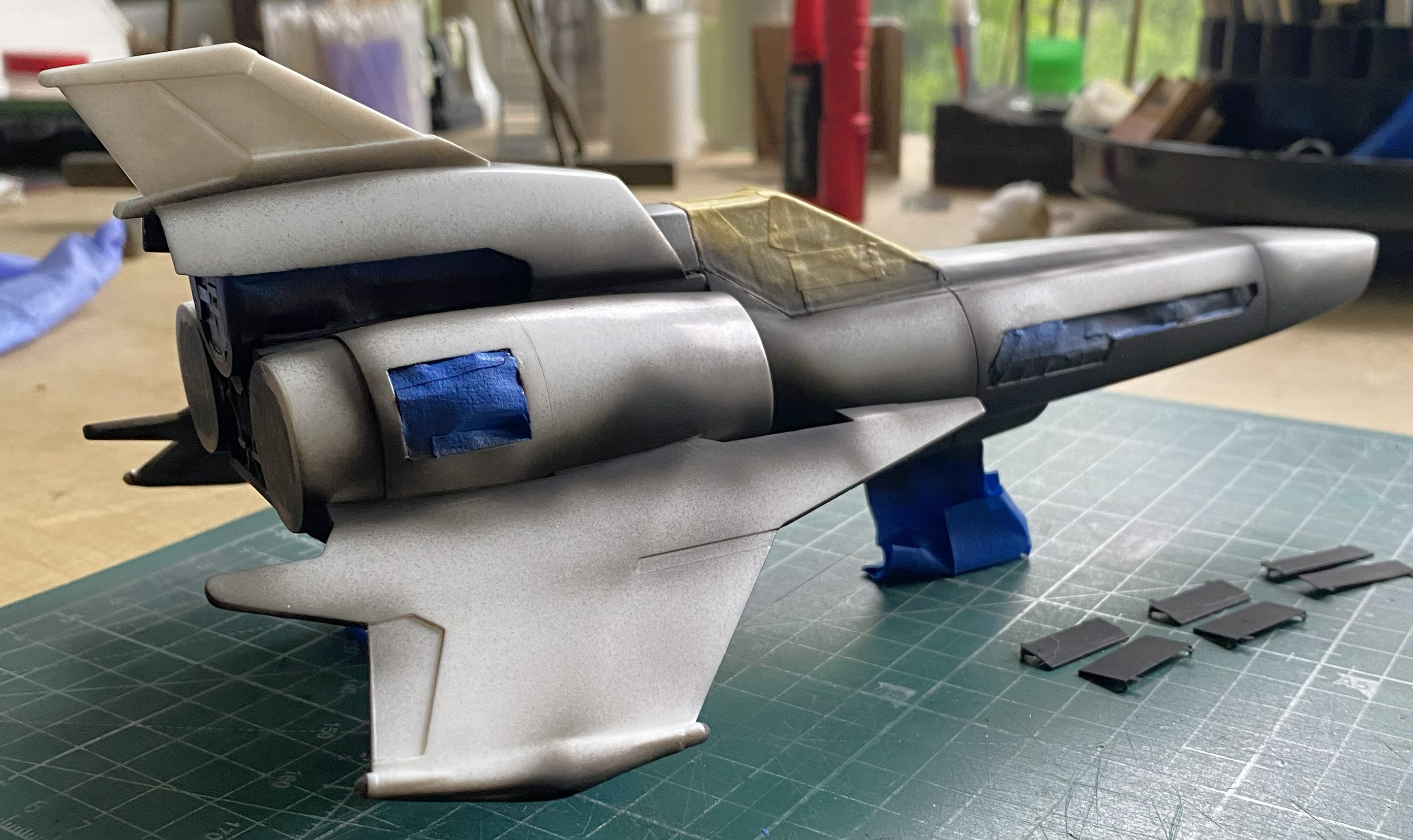
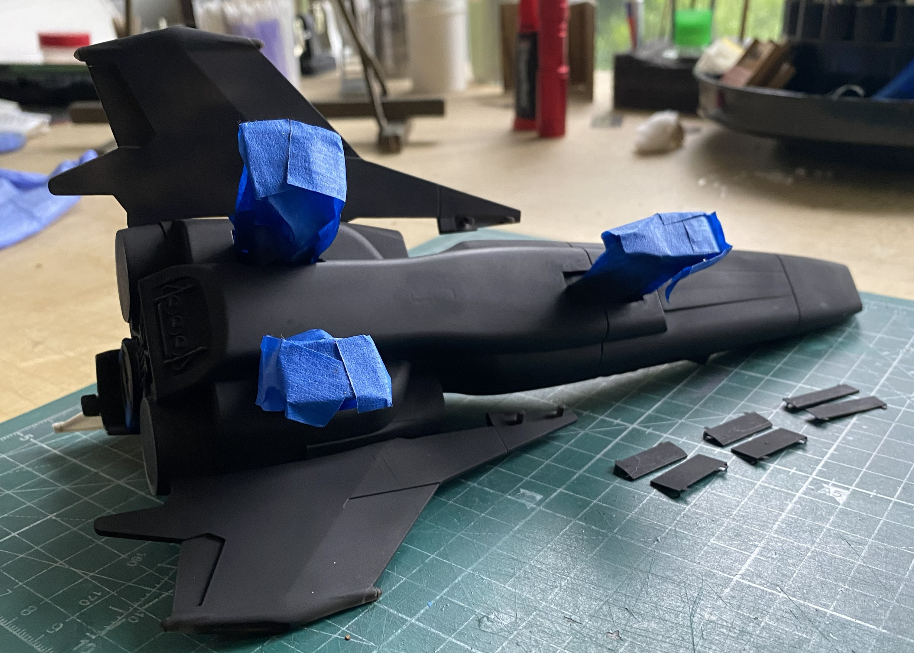
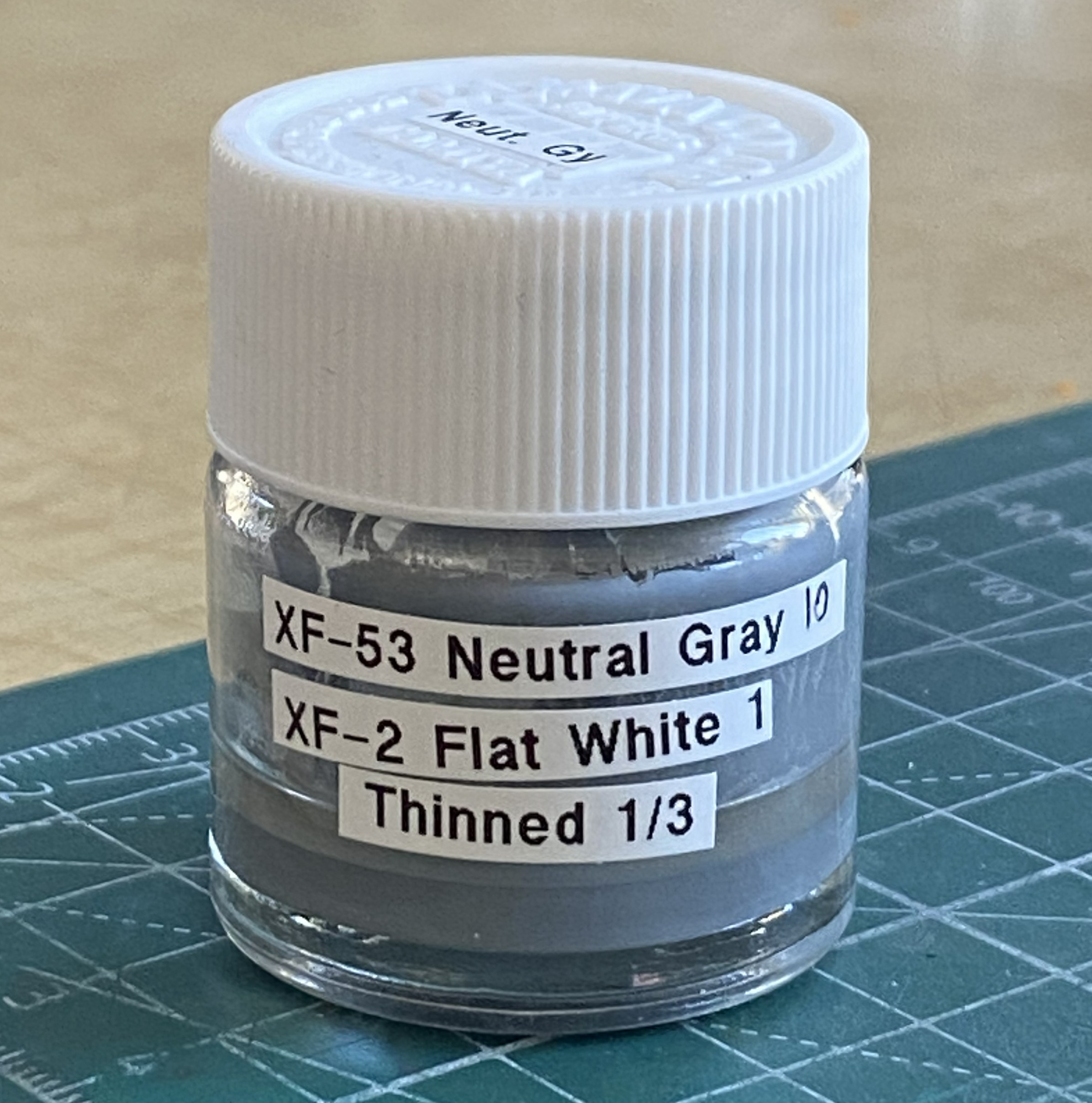
With that done, I loaded the airbrush with Tamiya XF-2 flat white and started tossing it:
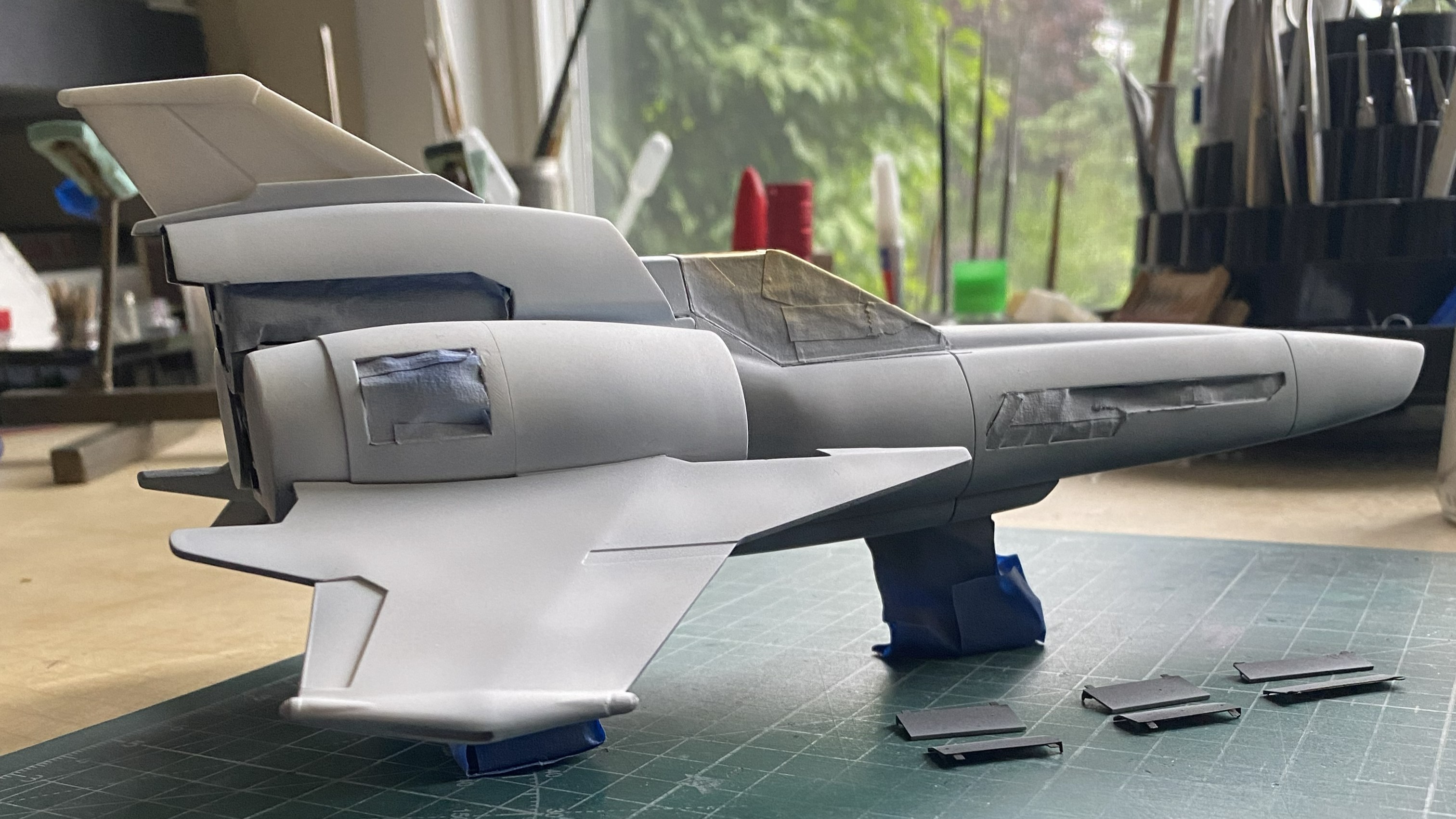
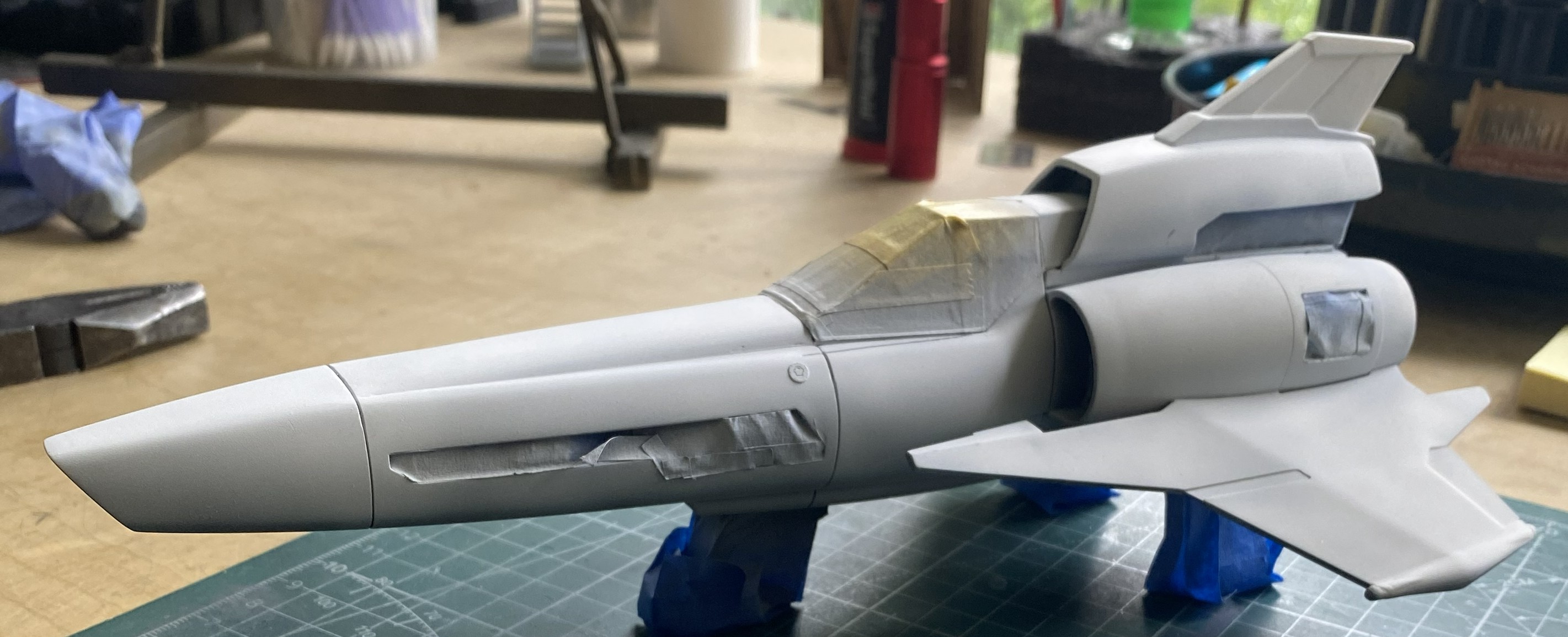
With few exceptions, those being parts that will easily break off, it’s decaling time and man am I nervous. The only decals I’d done at this point with this build had one of four break. 25% decal failure is not confidence inspiring. There are decals for stripes. Big ones. Having had freakin’ lousy experience with shattering decals, l was dreading this part.
A LONG time ago, probably back in the late 60s, I did someone a favor that I don’t remember doing. How can I recall something I can’t recall? Logic. Something SO GREAT just happened to me that it must be payback for that LOOONG forgotten favor. What am I prattling on about? This stuff:
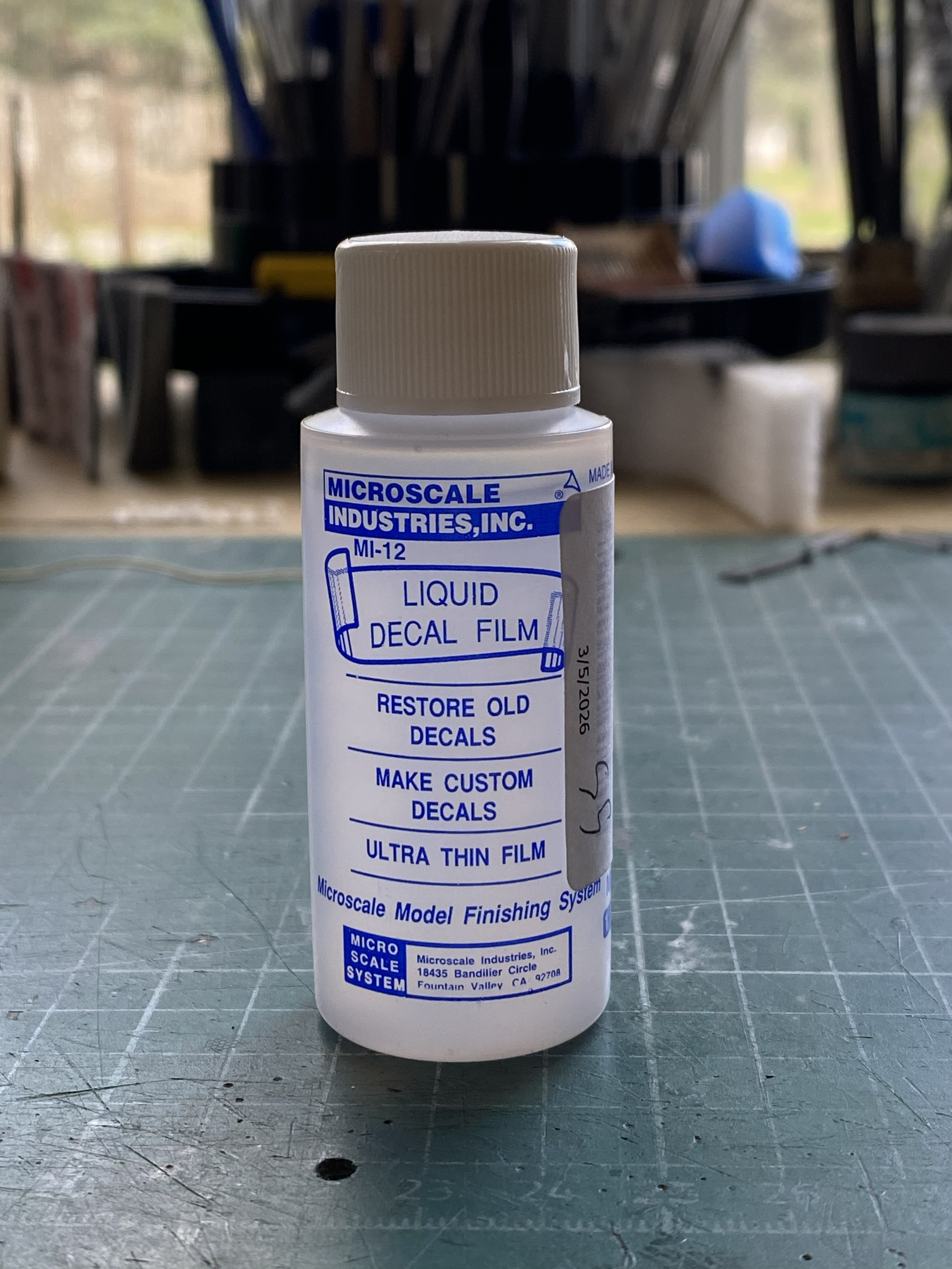
I wish I’d found this product when I was doing both the F7F-3 and the Goose. Okay, one level of dread dispersed. Next level of dread. Painting the stripes. Had the decals been perfect, I’d still want to paint the stripes. Getting large decals positioned accurately is a special version of tedium that I could do without. But, with the notion that all solutions create new problems, painting the stripes mean I have to mix a color that will match. A red color. Well…the Y-chromosome I was issued is defective (in so many ways) and in this situation, that defect means that I generally don’t see red. Or green. And the colors I do see, aren’t the colors that are there; we just use the same labels for them.
My roommate has two X-chromosomes. Likely good color vision. I have a friend (he of the Blackbird fame) who has perfect color vision and he spent many years mixing dyes for the leather trade. Not only can he see color, he also has the knowledge of what colors to add to the base color to move the results in the desired direction.
Much consulting ensued:
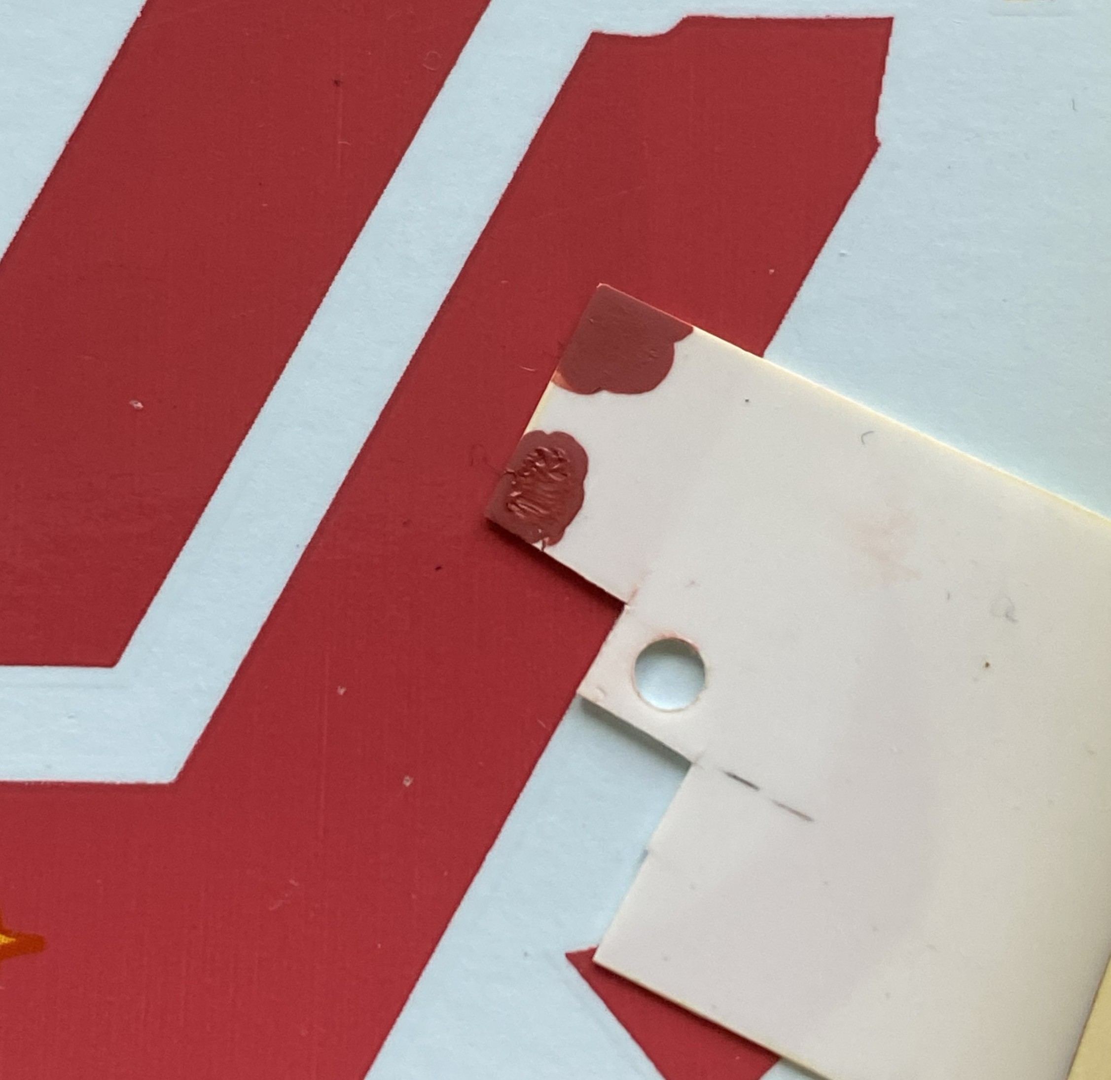
The lower color is a match (I’m told) and here’s the formula for it if you need it for your build:
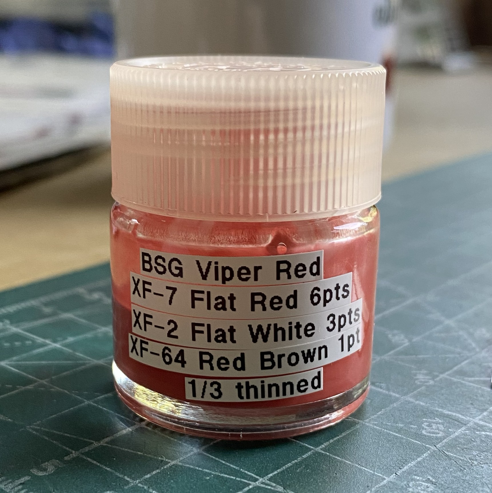
Right. Now that this problem has been solved, it’s time to mask! If you’re building this and would rather use pre-cut masks for it, this is what I used:
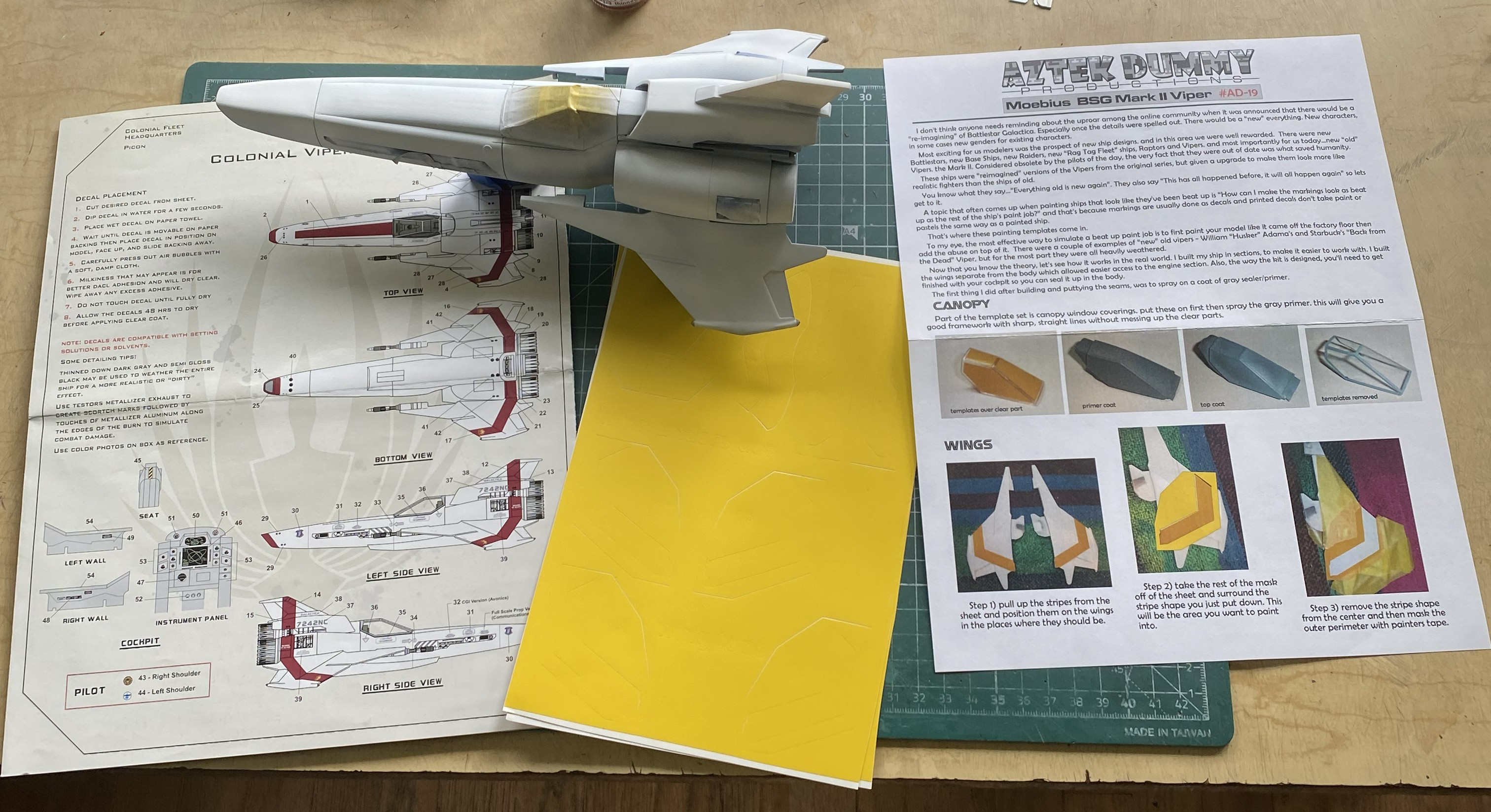
And this is the Viper, all wrapped up like a Sub at a Dom’s birthday party:
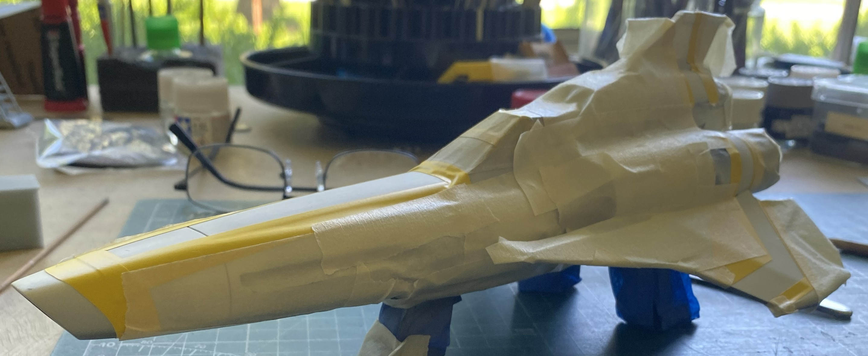
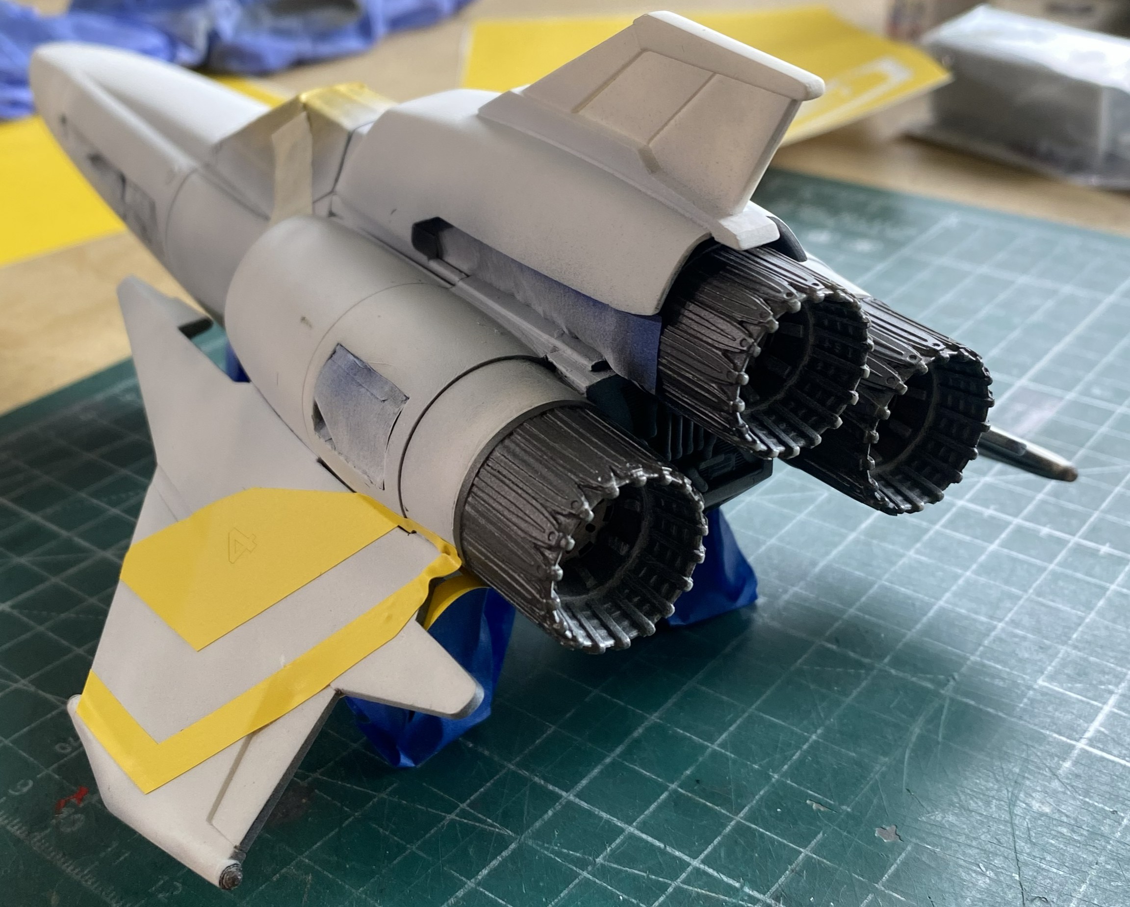
In order to have enough surface for masking tape to hang onto, the exhaust nozzles had to be added before the wrap party:
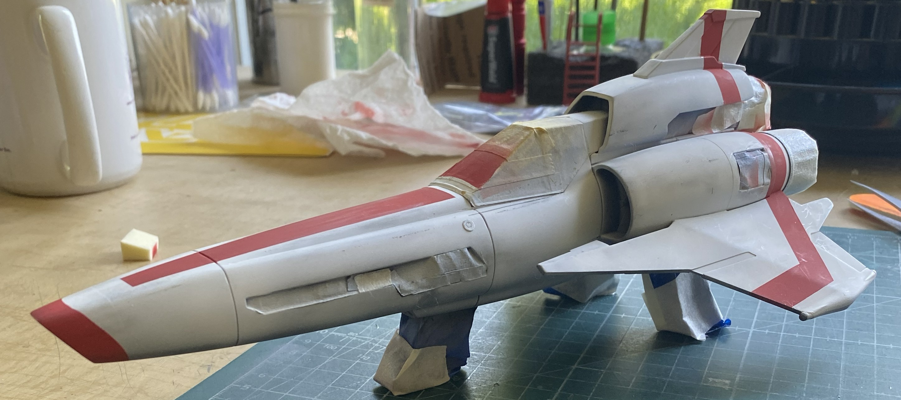
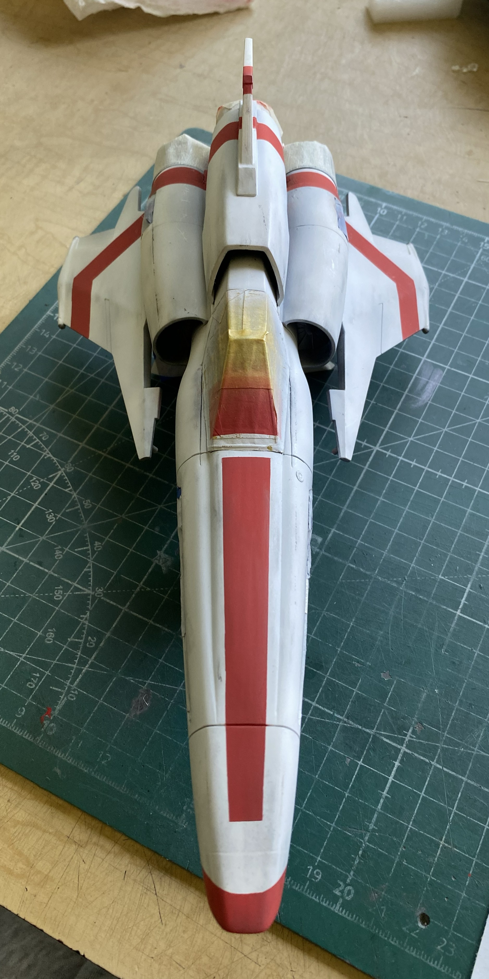
Painted and unwrapped:
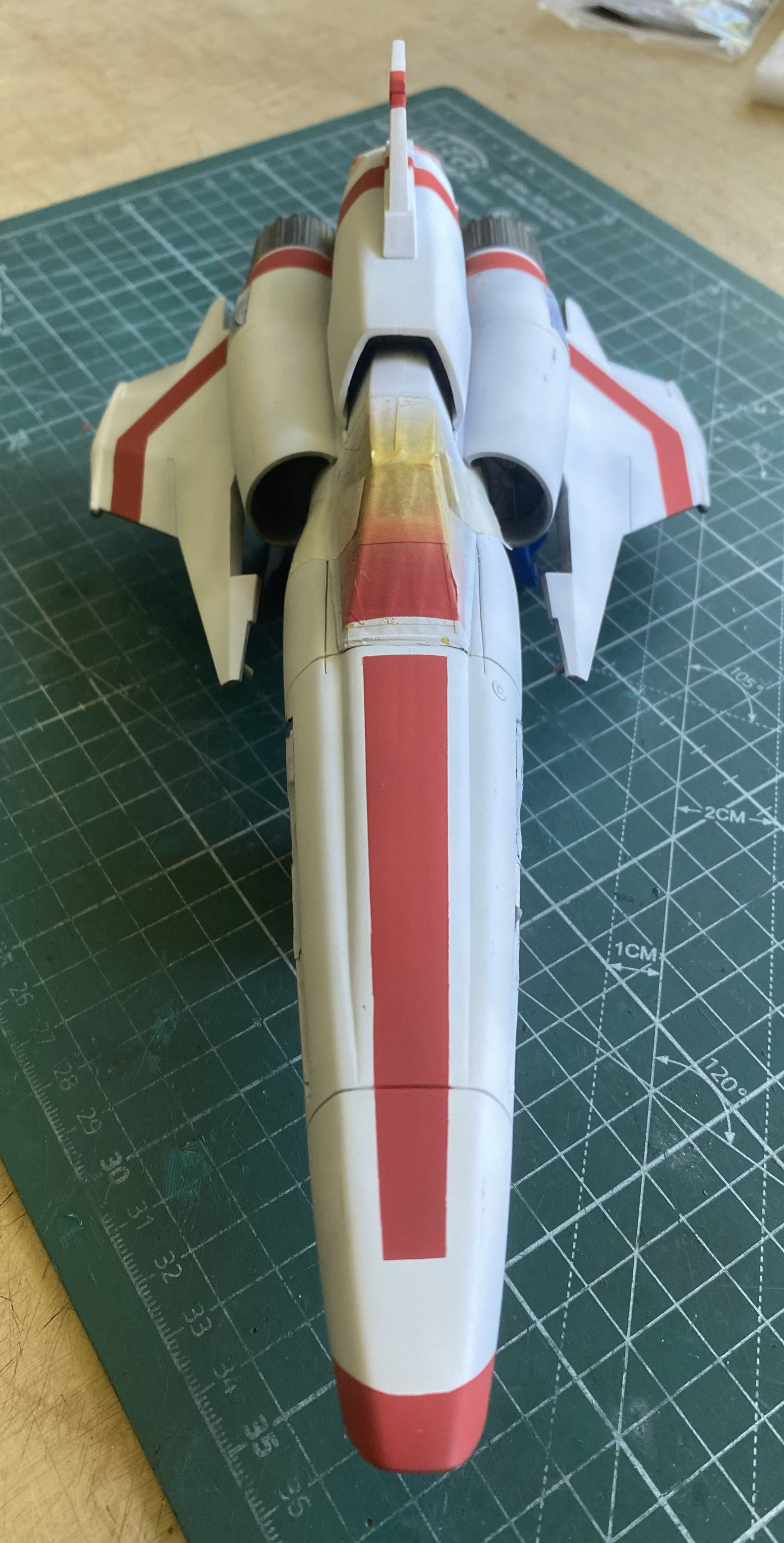
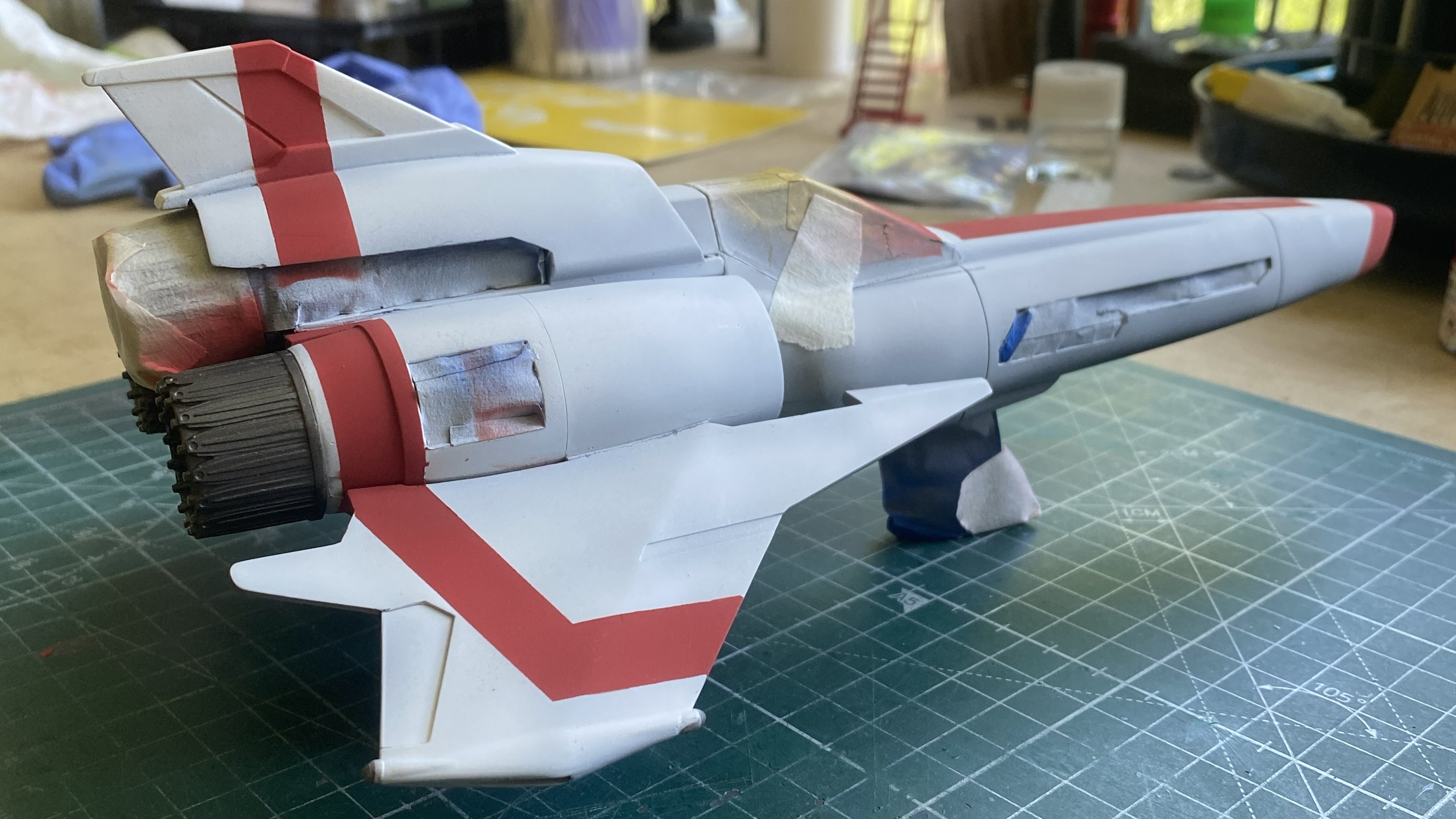
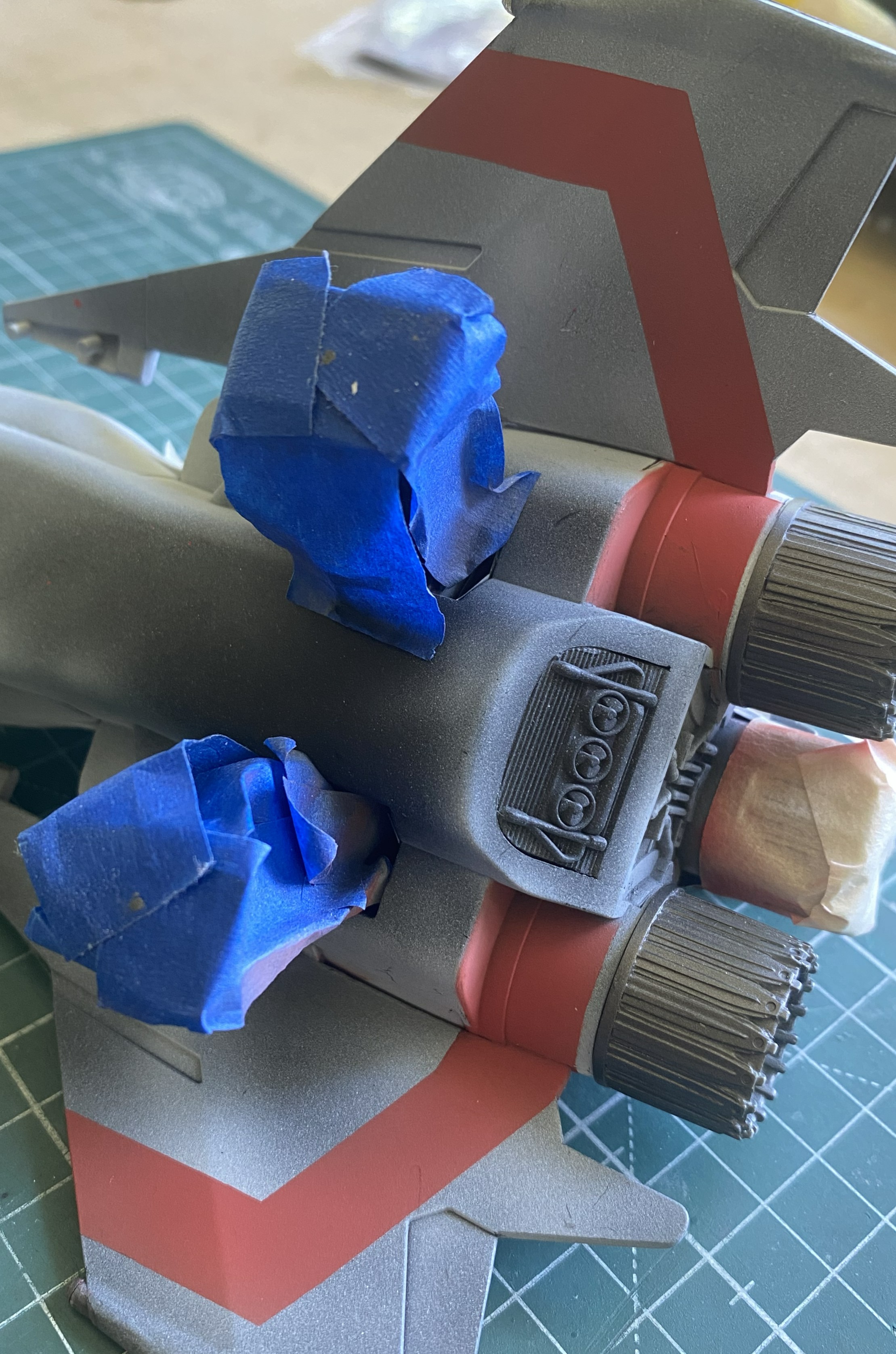
Whew…and yea the apprehension doth wane.
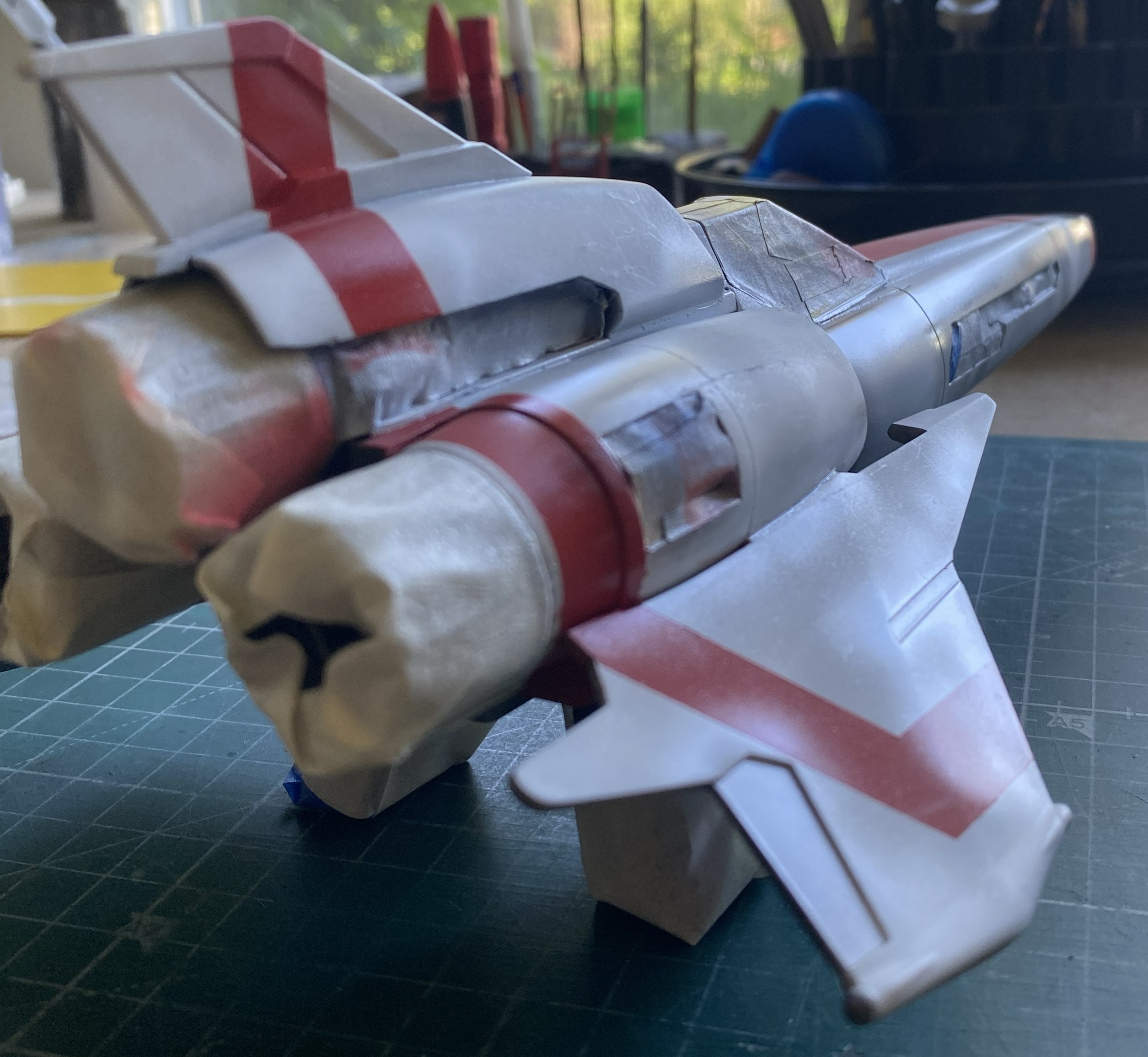
Time to start adding stains and wear. Usually at this stage, I break out the pastels. Not this time. There will be clear paint over the pastels. Because of how pastels work (reflected light), clear paint profoundly diminishes their effect. I scrubbed a standard pencil over paper until I had a fair amount of graphite there. Using a cotton swab, I started adding dirt smudges:
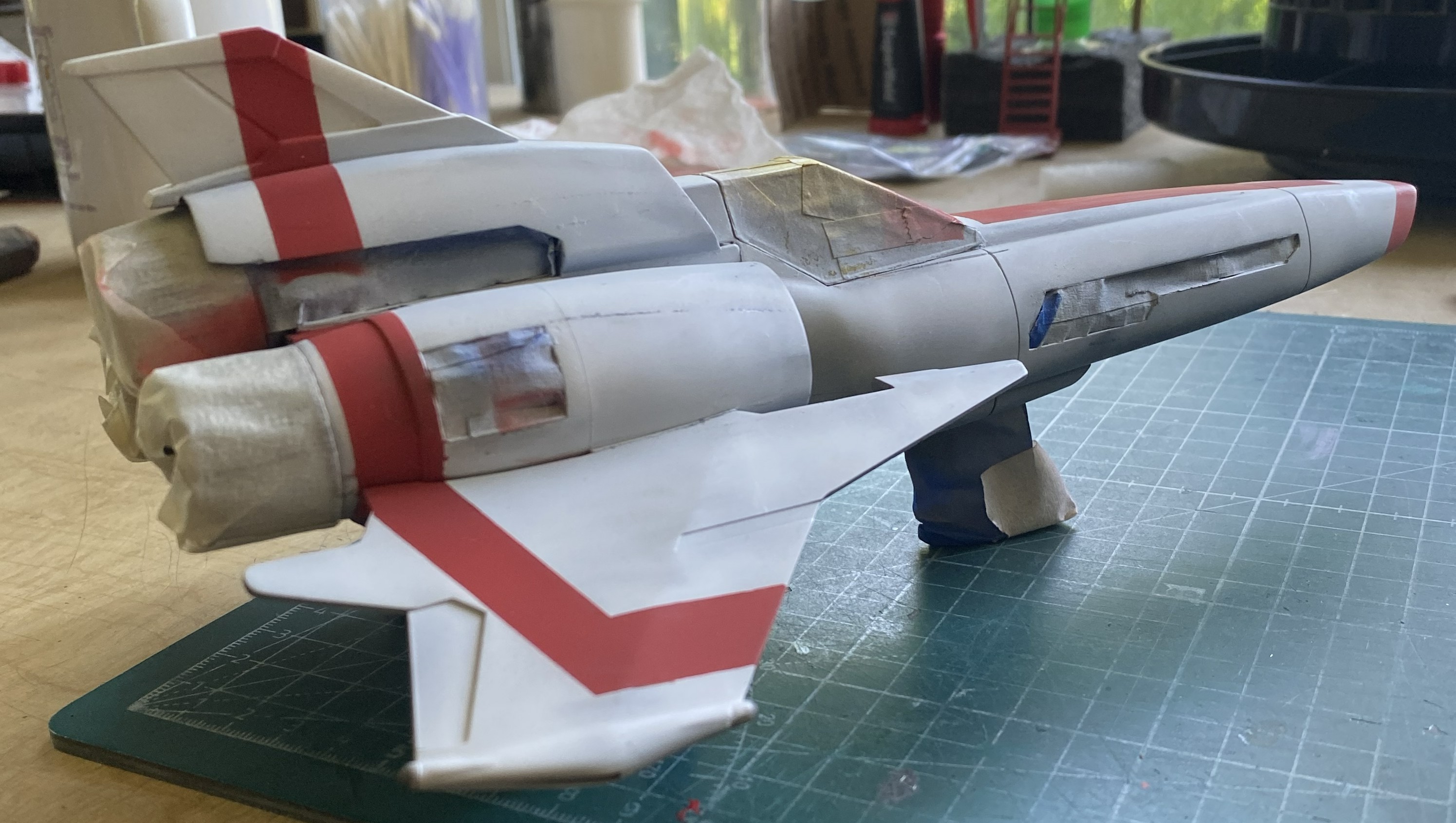
Basic dirt applied, I hit (mostly) all the areas with clear gloss that will get decals:
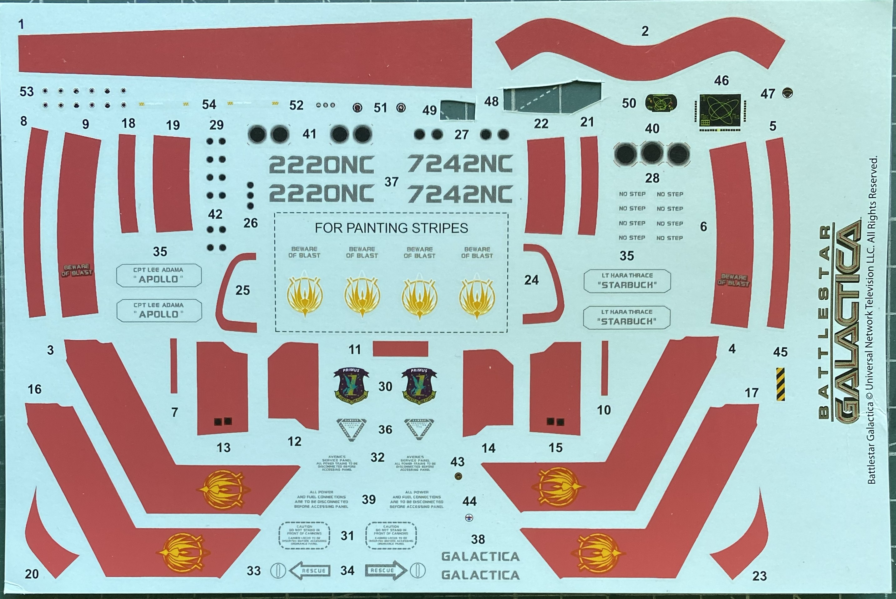
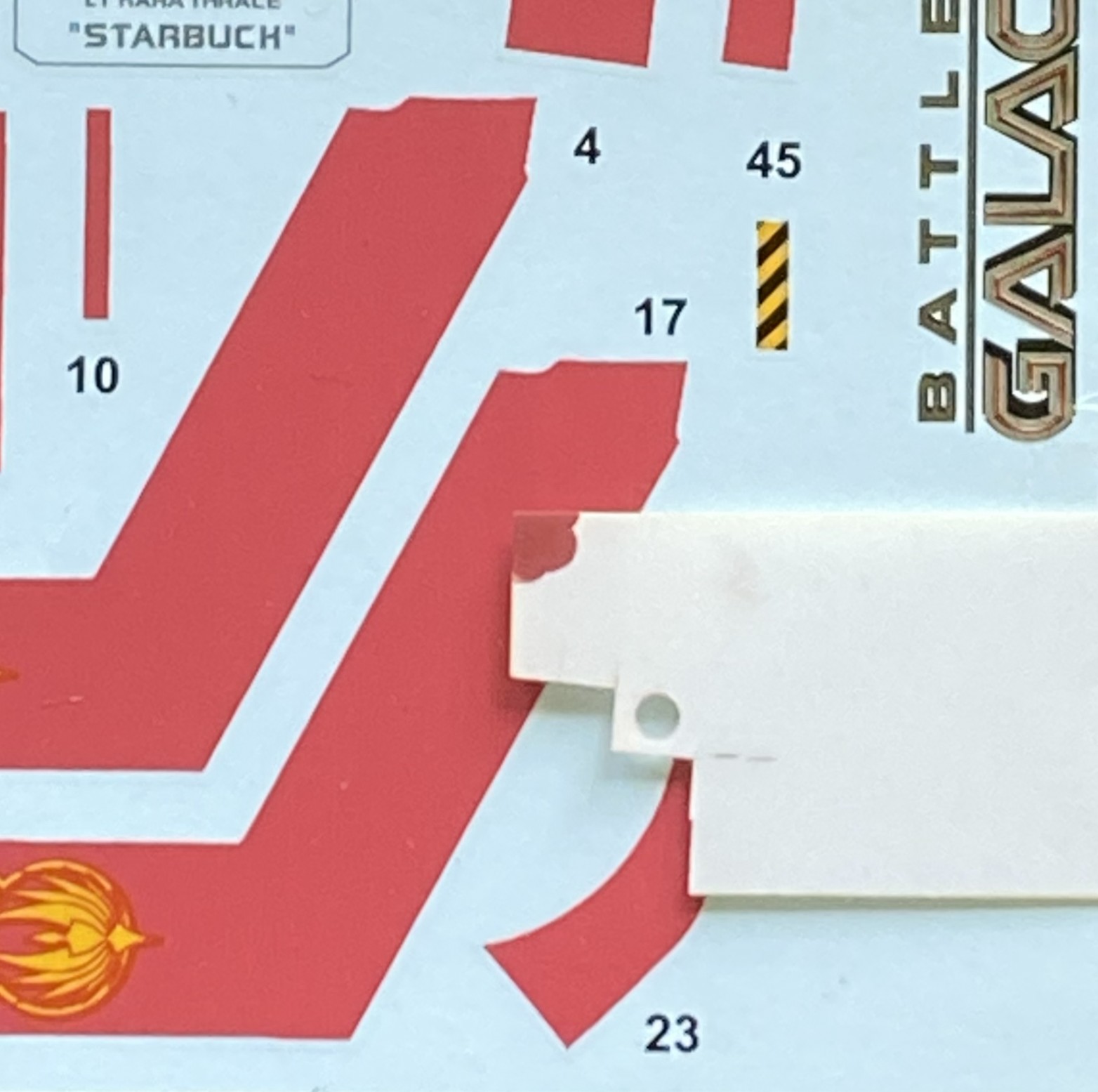
At this point, it’s time to address the big boogieperson, the decals themselves. Having painted the stripes, that left a stripe decal available for testing. How do the decals react to the decal film? Cue the paint mule. Put one down. You can see the edge of the decal saver around the graphic:
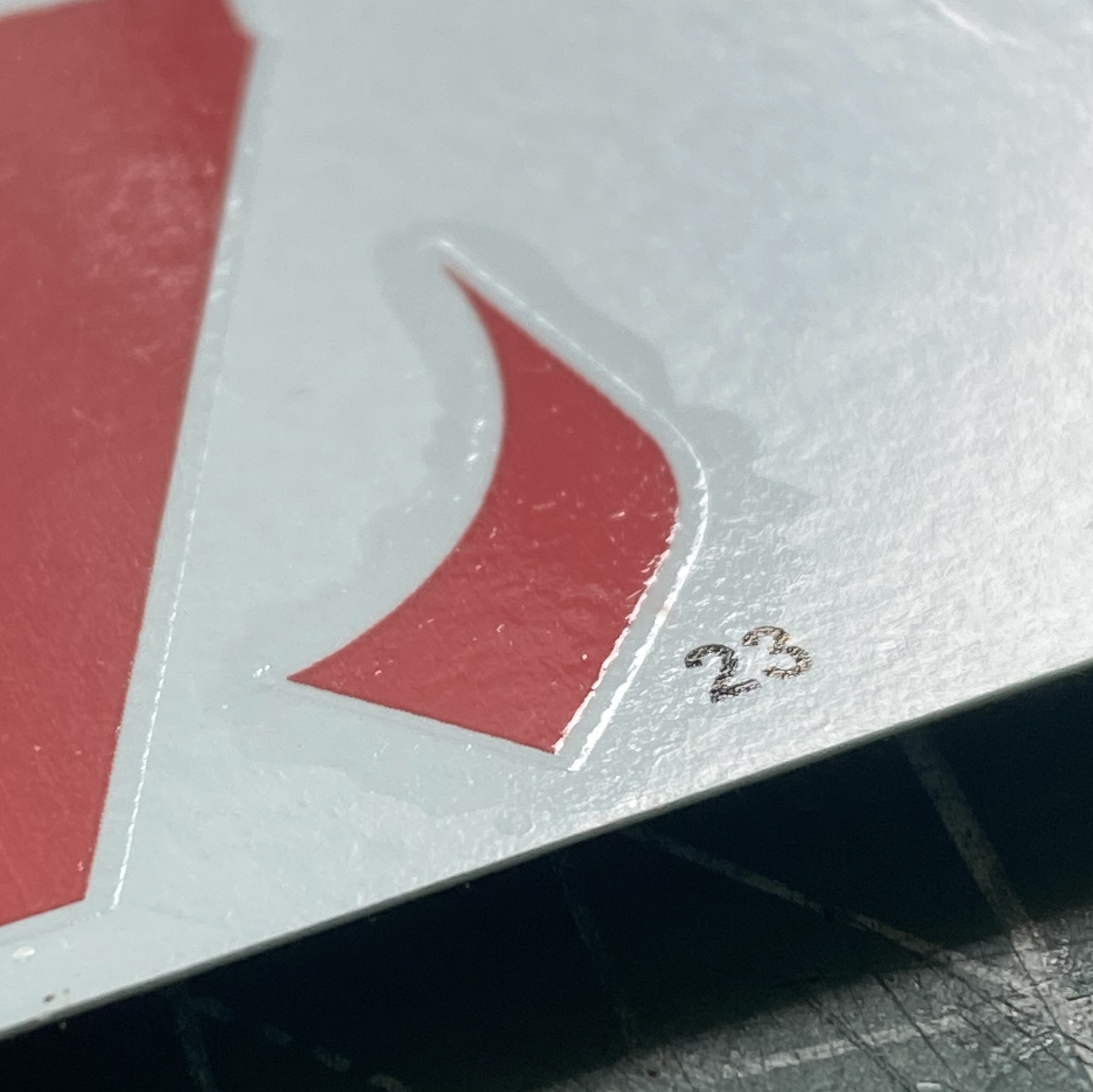
I also wanted to see how decal solvent affects this added film so when I put the sacrifice down, I made sure one area of it spanned a panel line:
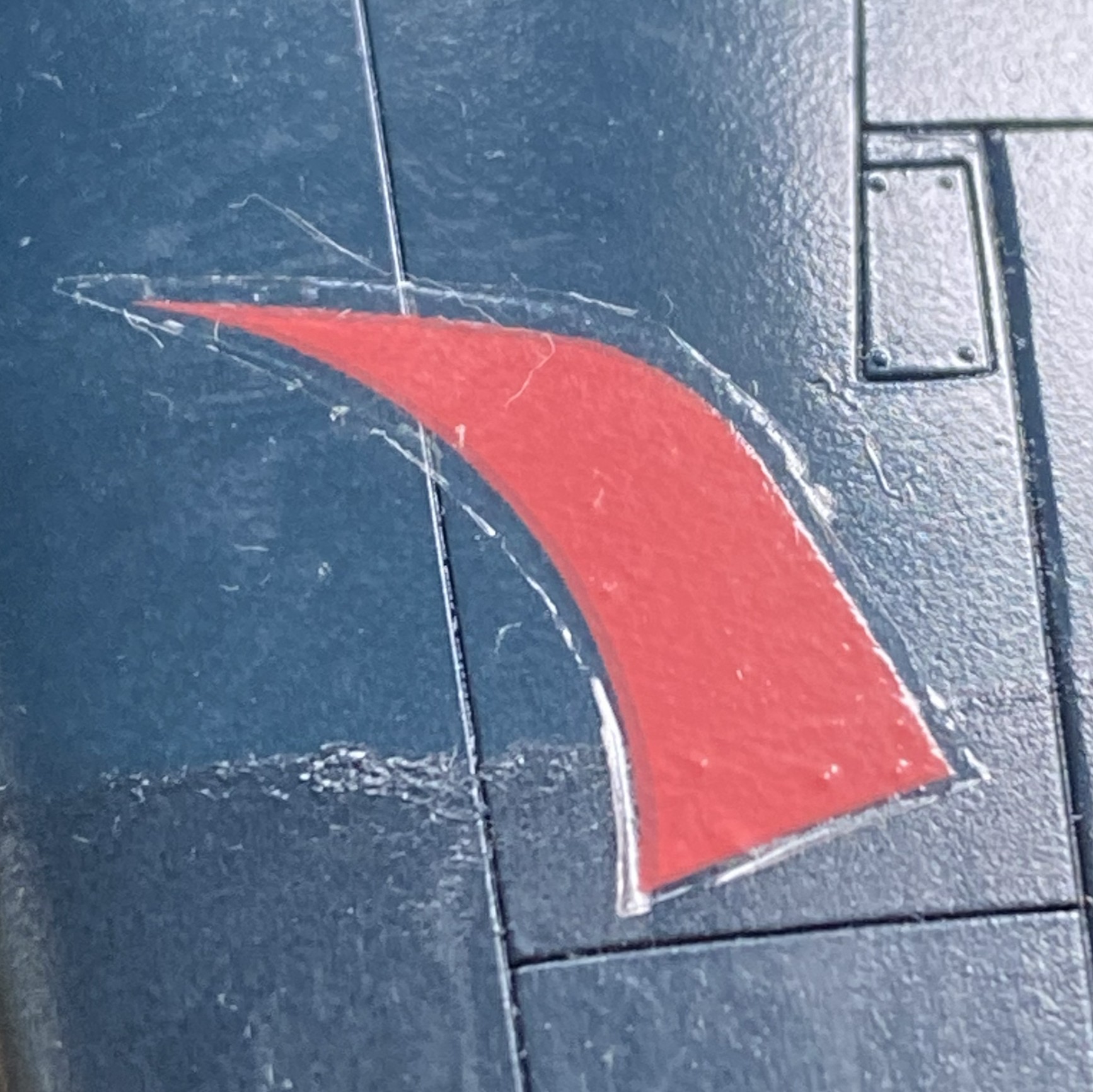
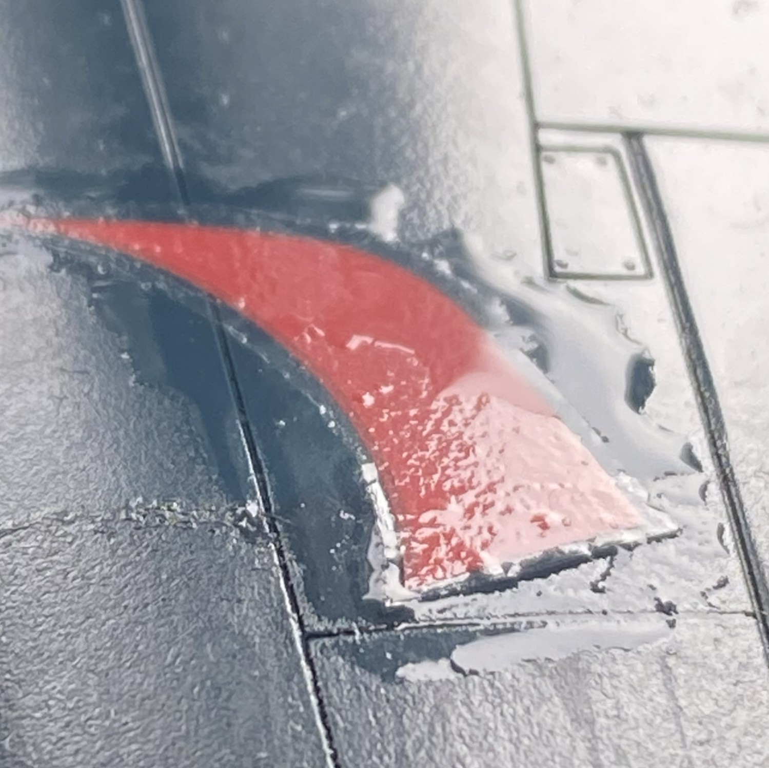
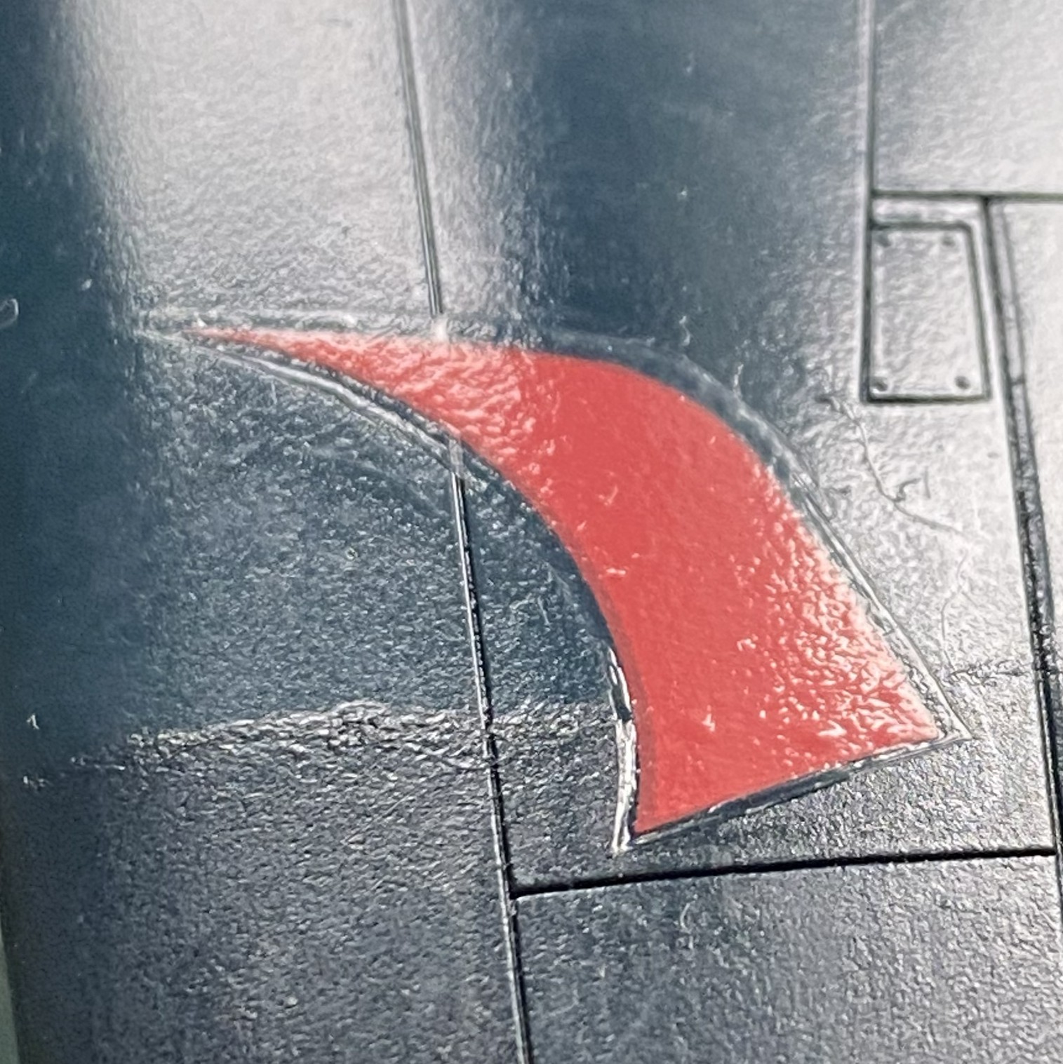
Neither MicroSol nor Solvaset had any affect. If you need to go this route and must put a reinforced decal over a panel line, you can use a sharp blade to make a cut over the panel line.
With all decal-base trepidation calmed, next month the decals go on.
Colonial Viper MkII (Moebius Models) 1/32 Scale Build #1, Parts Layout and the Start
This is going to be interesting (hopefully not in the Chinese sense). I’ve never done fictional spacecraft before. My initial intent was to model this as realistically as possible, but that balloon was popped almost immediately. Nothing about this is realistic, or as a friend of mine said, “Science by magic.” Okay, then what am I actually building here? It’s a movie prop that existed in two forms; digital (CGI) and practical (something real). That’s made the build easier and more difficult at the same time. The easier aspect is the availability of primary sources. Just watch the show and when a bit of detail flashes past, take screen captures of pertinent scenes. The difficult part is internal. As designed, this thing could never move under its own power and it irks a part of me. The rest of this thing should be fun!
Science by magic.
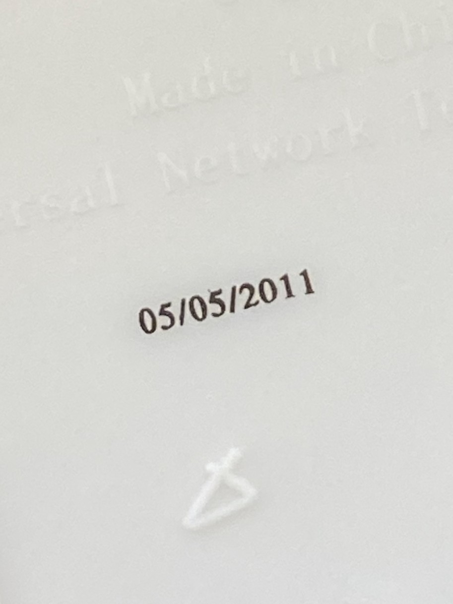
This is what I have to start with. This is the first time I’ve seen the manufacturing date (I assume, anyway) printed on kit parts (inside of the wing):
That noted, here’s what’s in the box:
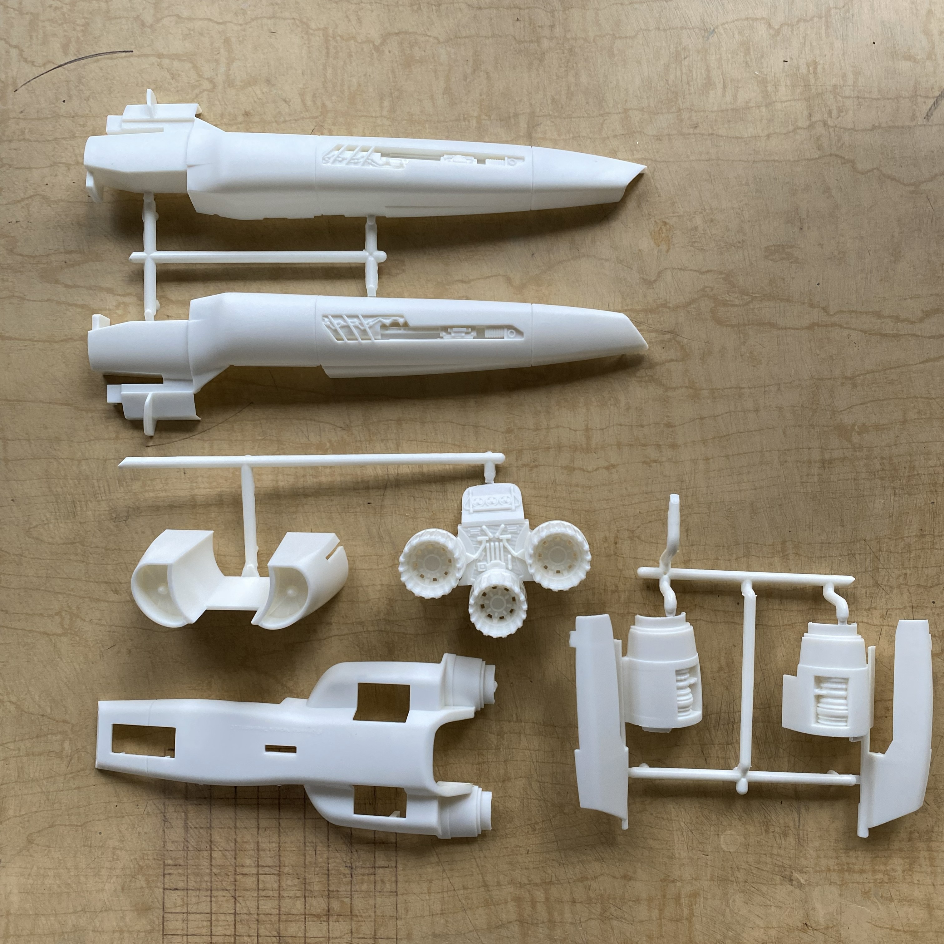
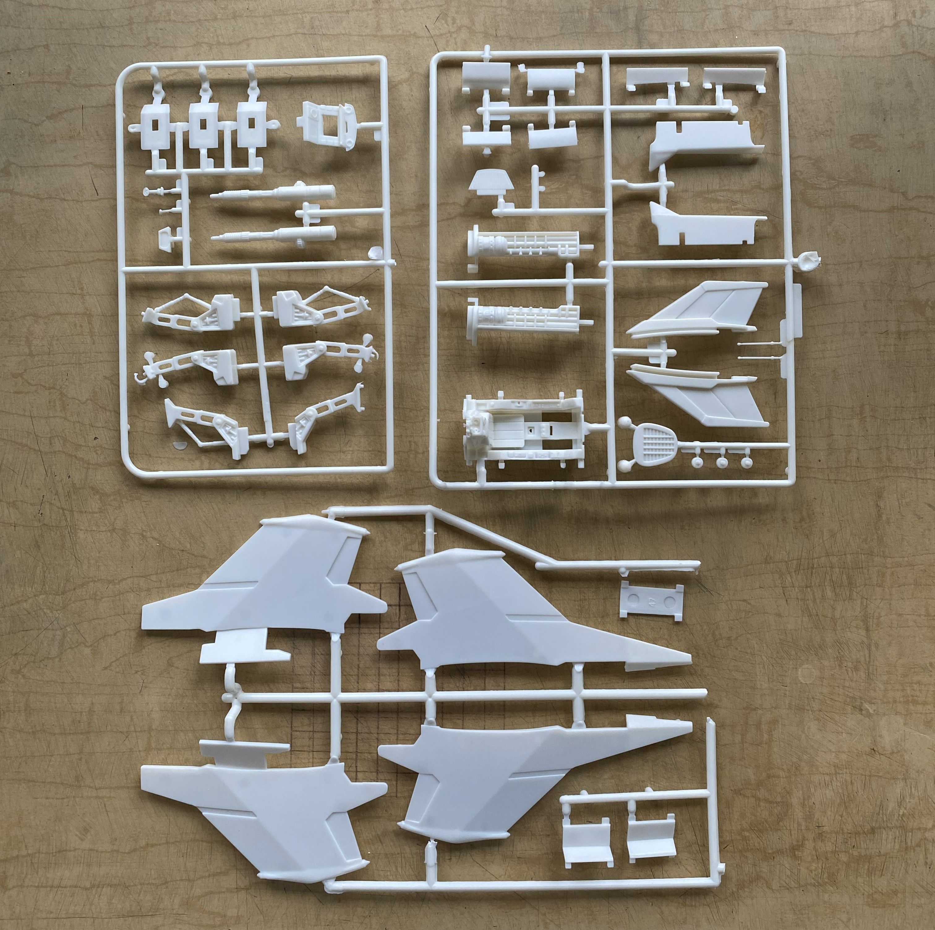
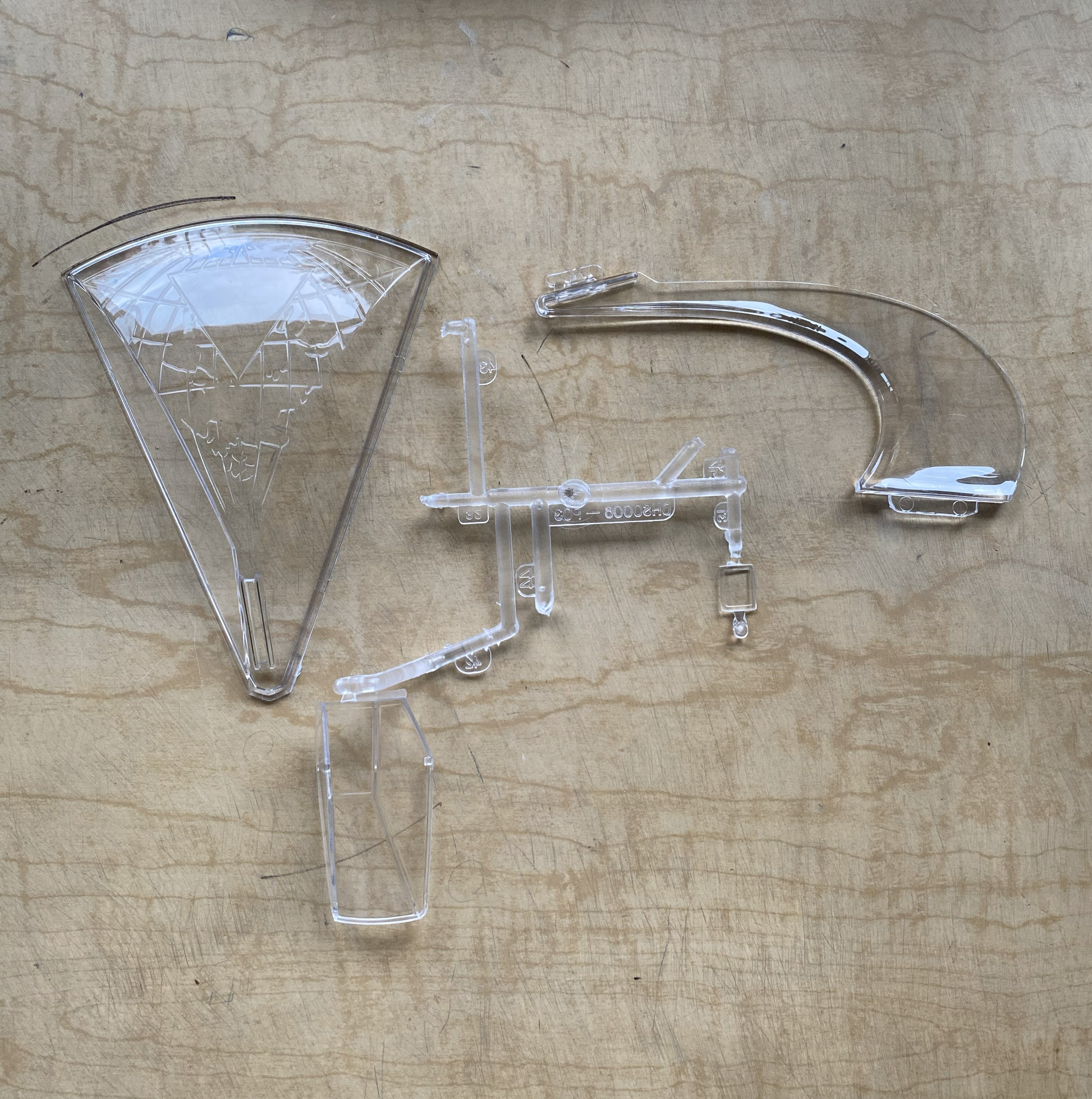

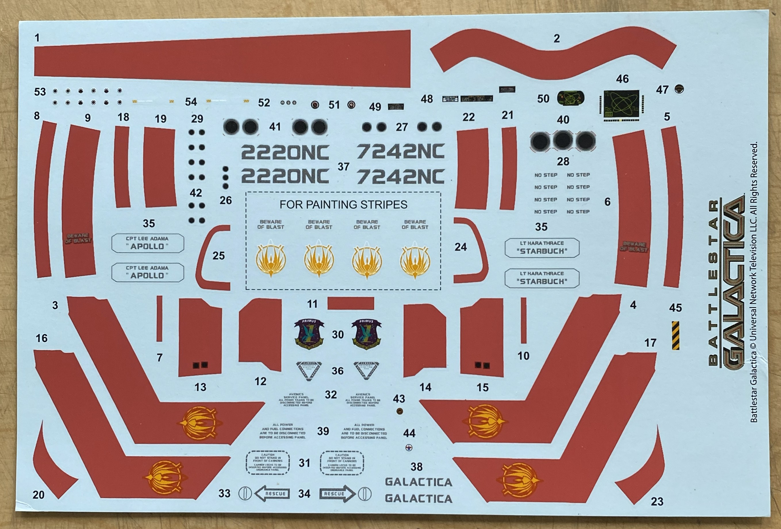
The first thing that caught my attention was the quality of the clear parts, in particular the canopy. Thin, clear, and mostly well done (more about that in more detail than you’d believe later). The second attention-getter was the resin figure. Overall, it’s nicely done. However. If you intend on using it, the joystick the right arm is holding (the unattached arm) is way too high. If you’re using the figure, you’ll have to deal with that (but since I’m not, I don’t have to deal with that).
As you can see, it’s not a kit with a high parts count. It’s simple. Oh, yeah?! Well I can fix that. I’ll fix that by seeing how many of these bits I can shoehorn into it.
Green Strawberry (available from Moebius) makes all of the AM bits I’ll be using. One set supplies the resin seat, PE parts for the panels, etc., and photo-reduced images for all screens and instruments. And a word about that… The AM set for the cockpit offers two sets of gauge faces. One set is for a standard build, the other set is for those of you who like to add lighting. The kit is designed to allow the forward instrument panels to be back-lit. The set of gauge faces with a black surround are for illumination, the white (which are the ones I’m using since I’m not building this with lighting) are for a typical build. All of them are excellent and fit well. The other PE set is for landing gear bays. There is a resin/PE ejection seat, also nicely done. Since I have a profound appreciation for the character of Kara “Starbuck” Thrace, and the kit offers decals of her specific ship, I’ll also be adding Starbuck. Green Strawberry (or whomever did the sculpting) did a great job with this resin figure; it even looks like her. And since I just can’t seem to resist throwing everything at a kit, I’m also replacing the kit’s exhaust nozzles with resin/PE aftermarket parts:
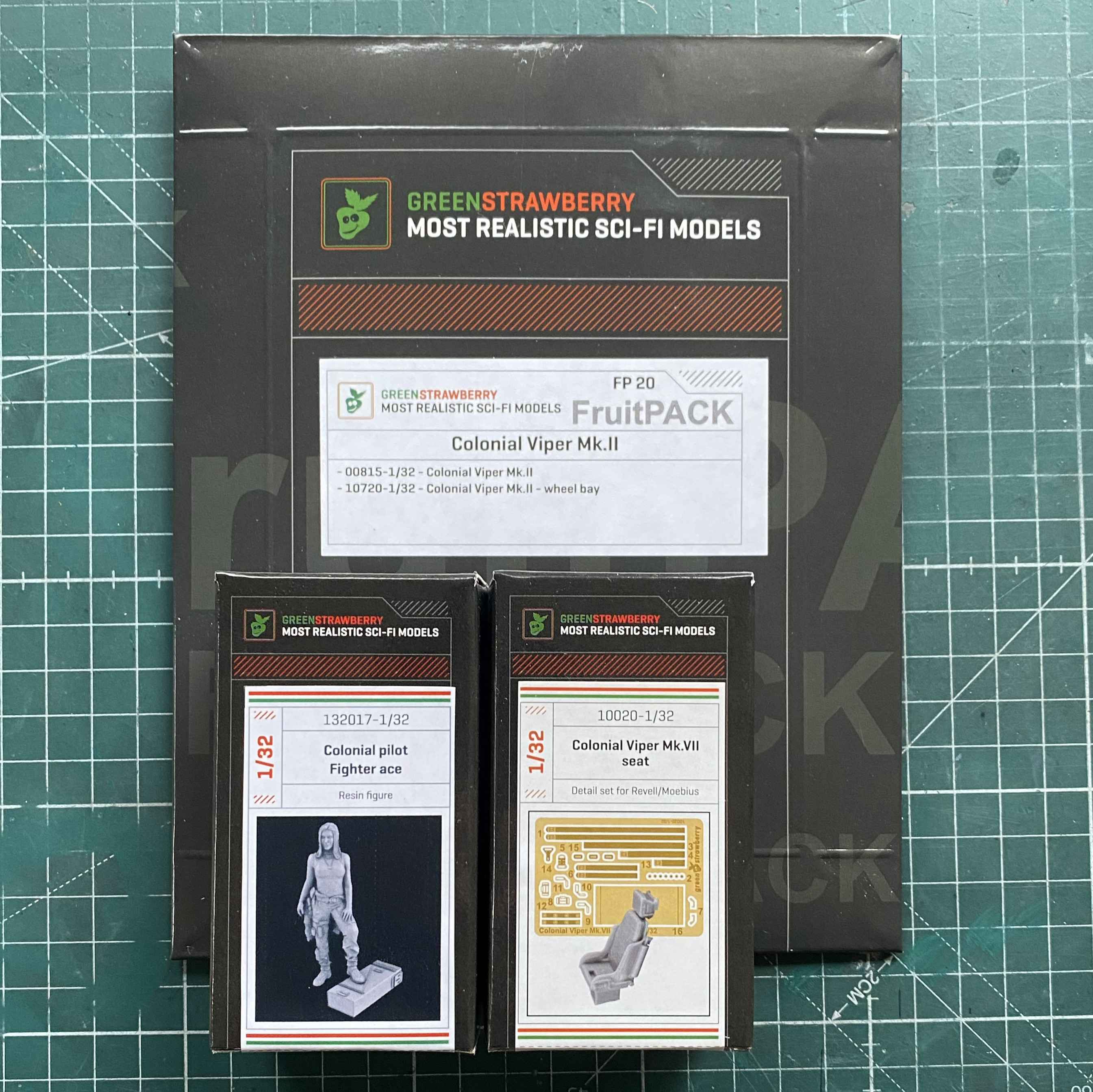
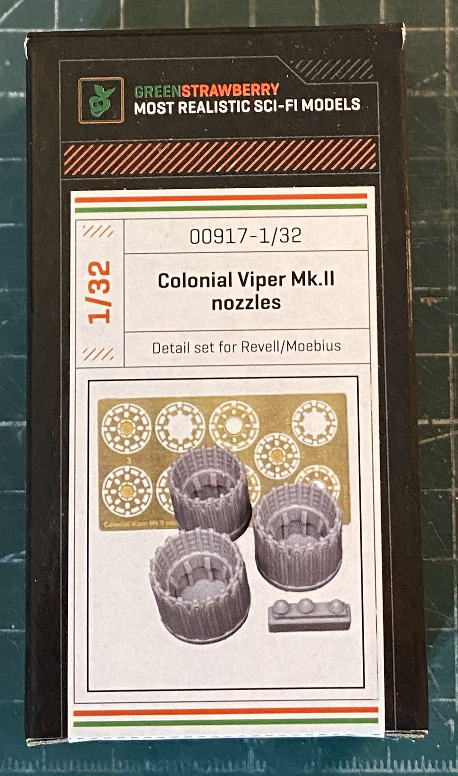
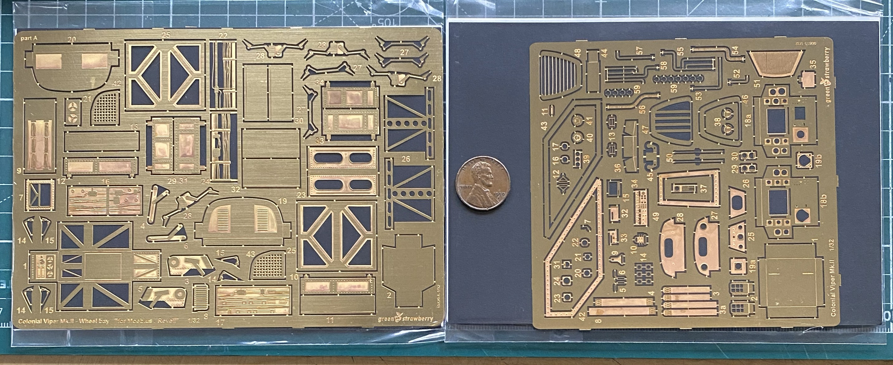
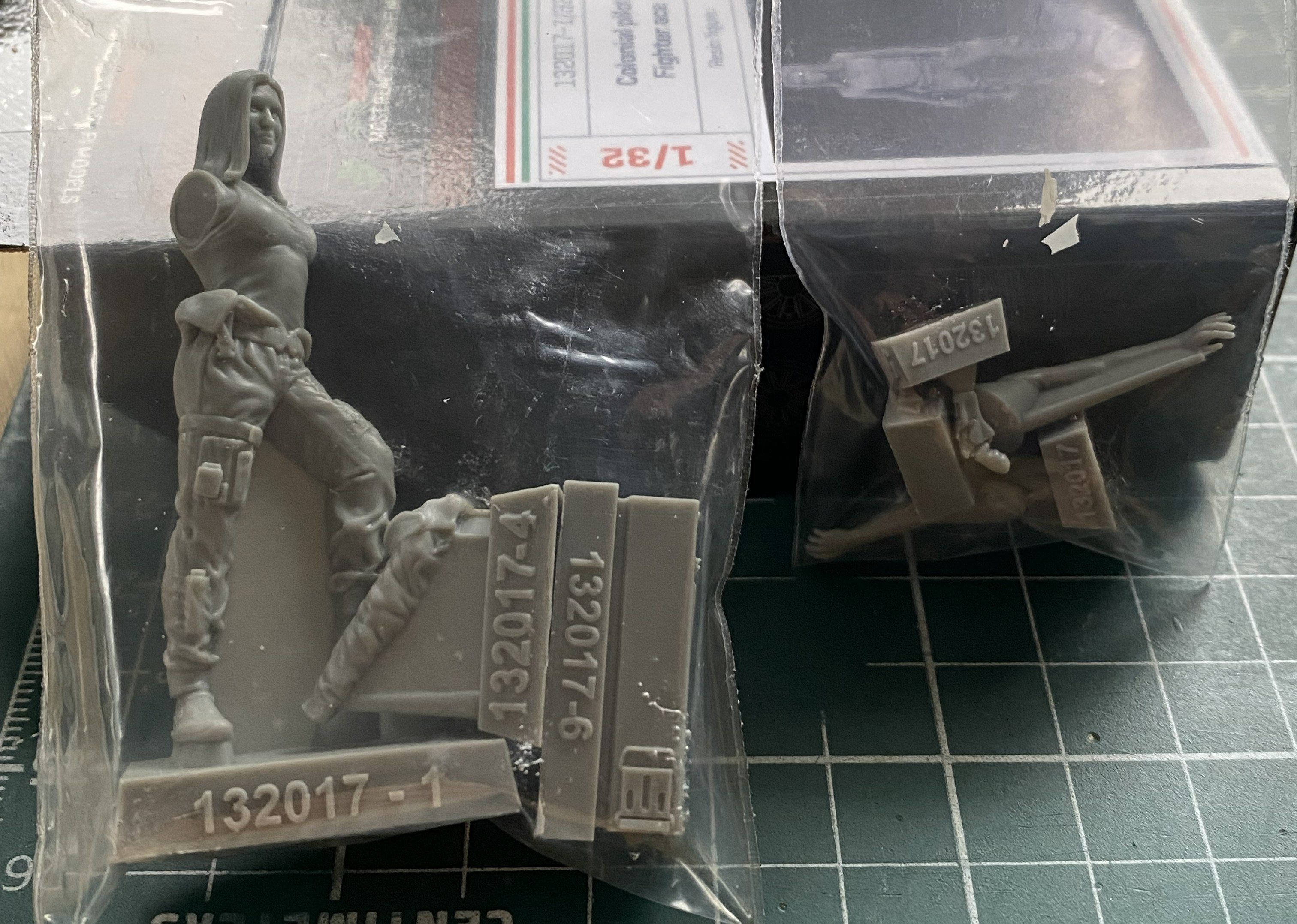
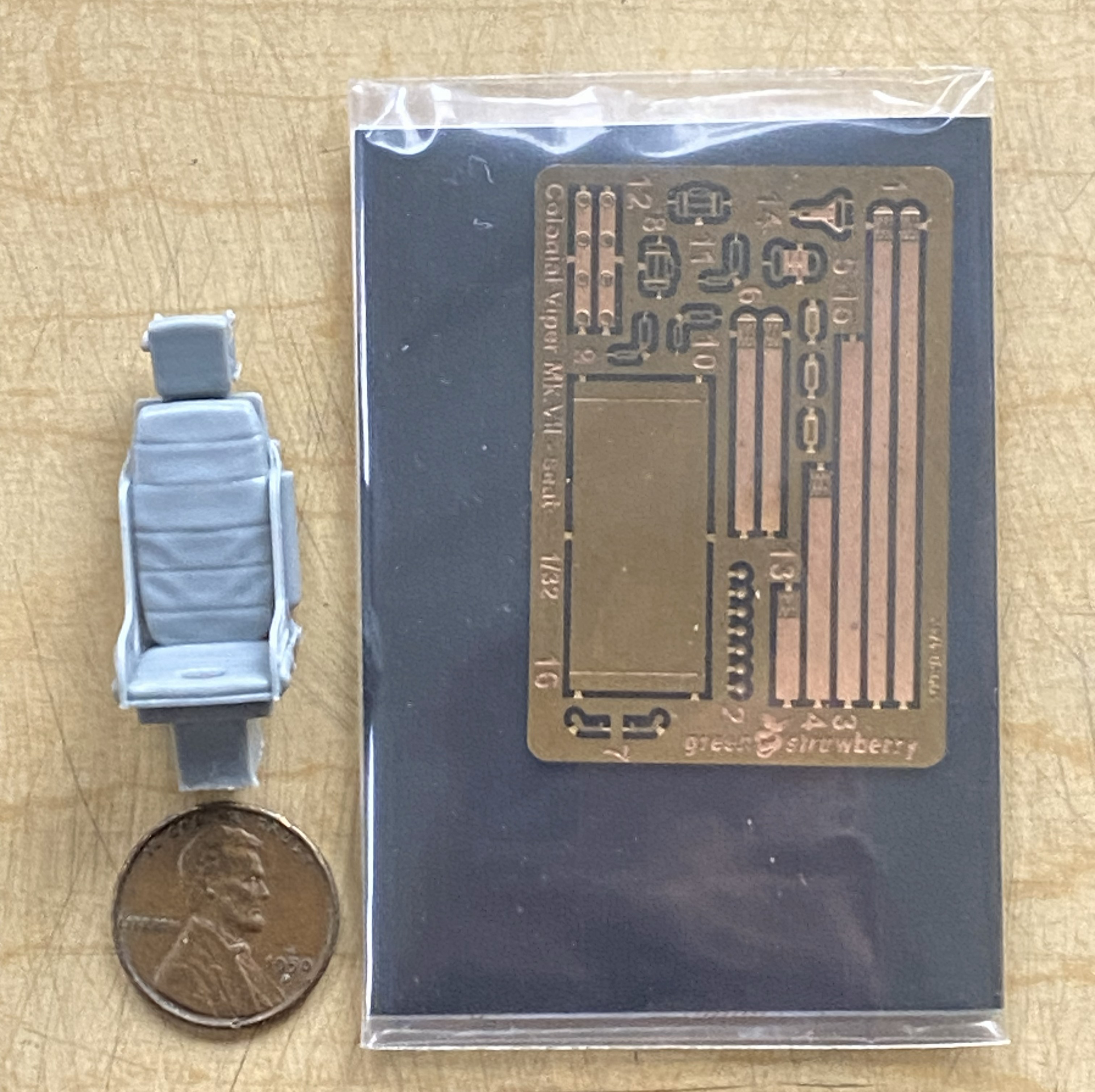
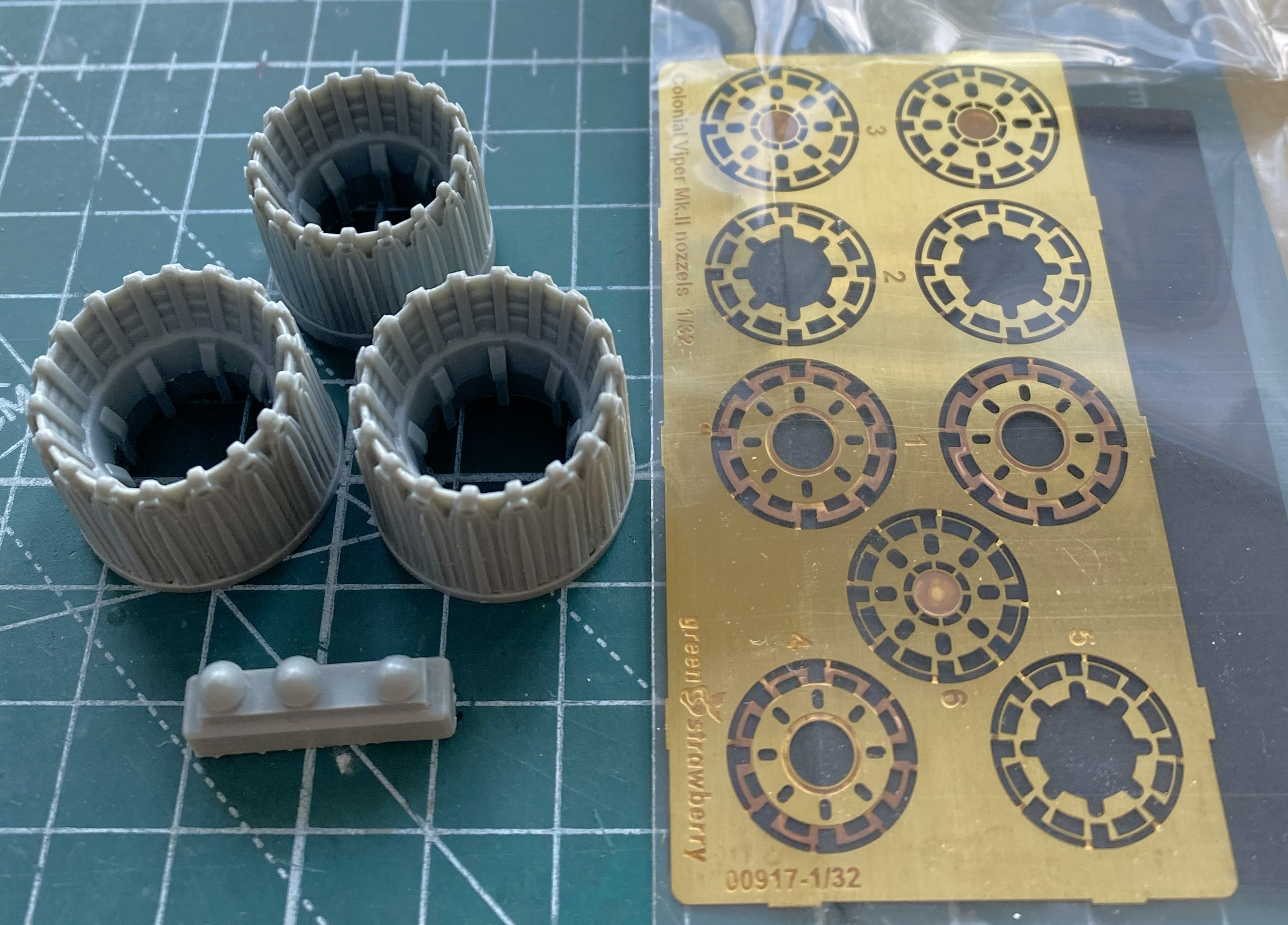
It’s true…there isn’t anything that I can’t complicate. It’s a talent.
At this point of the build, all of the AM parts had yet to arrive and I was still thinking that I’d be able to make the engines more realistic. My intent was to open a panel on top of the engines (after creating one, but to fit canon, it would be an inspection panel, not an inspection cavern as the kit has them) and perhaps extend a bit at each end. Had I looked just a bit further, I’d have noticed that any attempt to expand on the engines wouldn’t work. There isn’t enough room to create engine extensions and fit canon. But I didn’t look further and I went down this empty rabbit hole.
Rather than scratchbuild every addition, I’d thought that I could copy what detail was provided and then work it into an overall acceptable engine. To get molds, I used silicone molding putty:
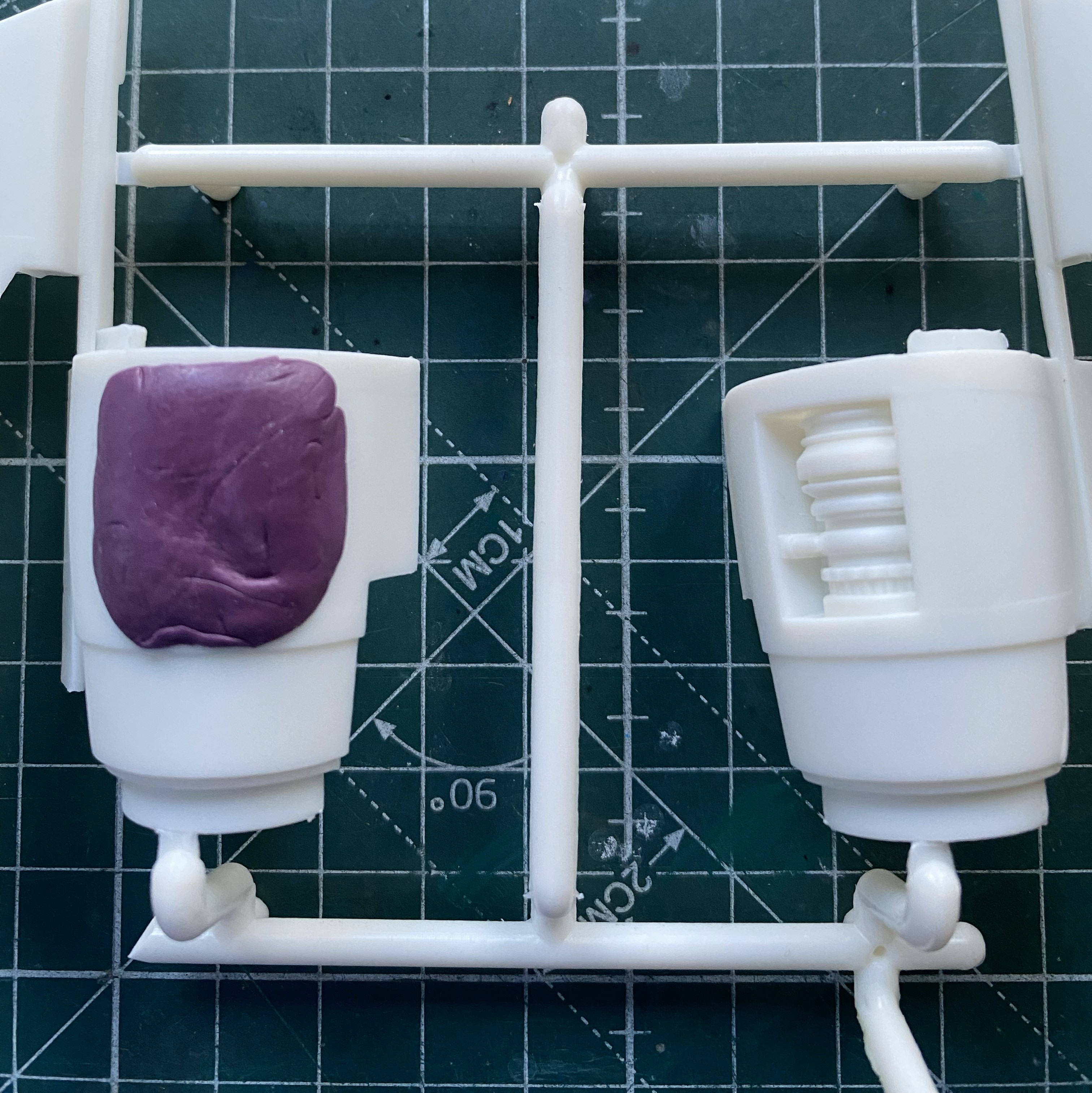
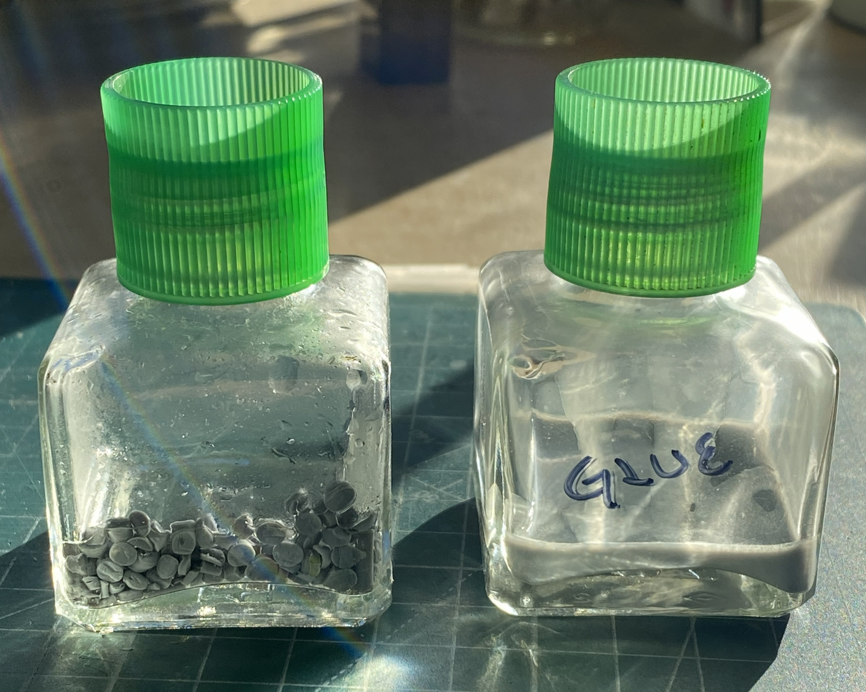
While the putty was curing, I investigated which would make “plue” (plastic and glue) to fill the molds. What would work better, acetone or Tamiya Extra Thin cement? I used two empty glue bottles, placing cut plastic pieces in each bottle and then putting enough acetone/glue in to cover the pieces. The tilted bottle has acetone (tilted so that the acetone would cover all the plastic) and the other has cement:
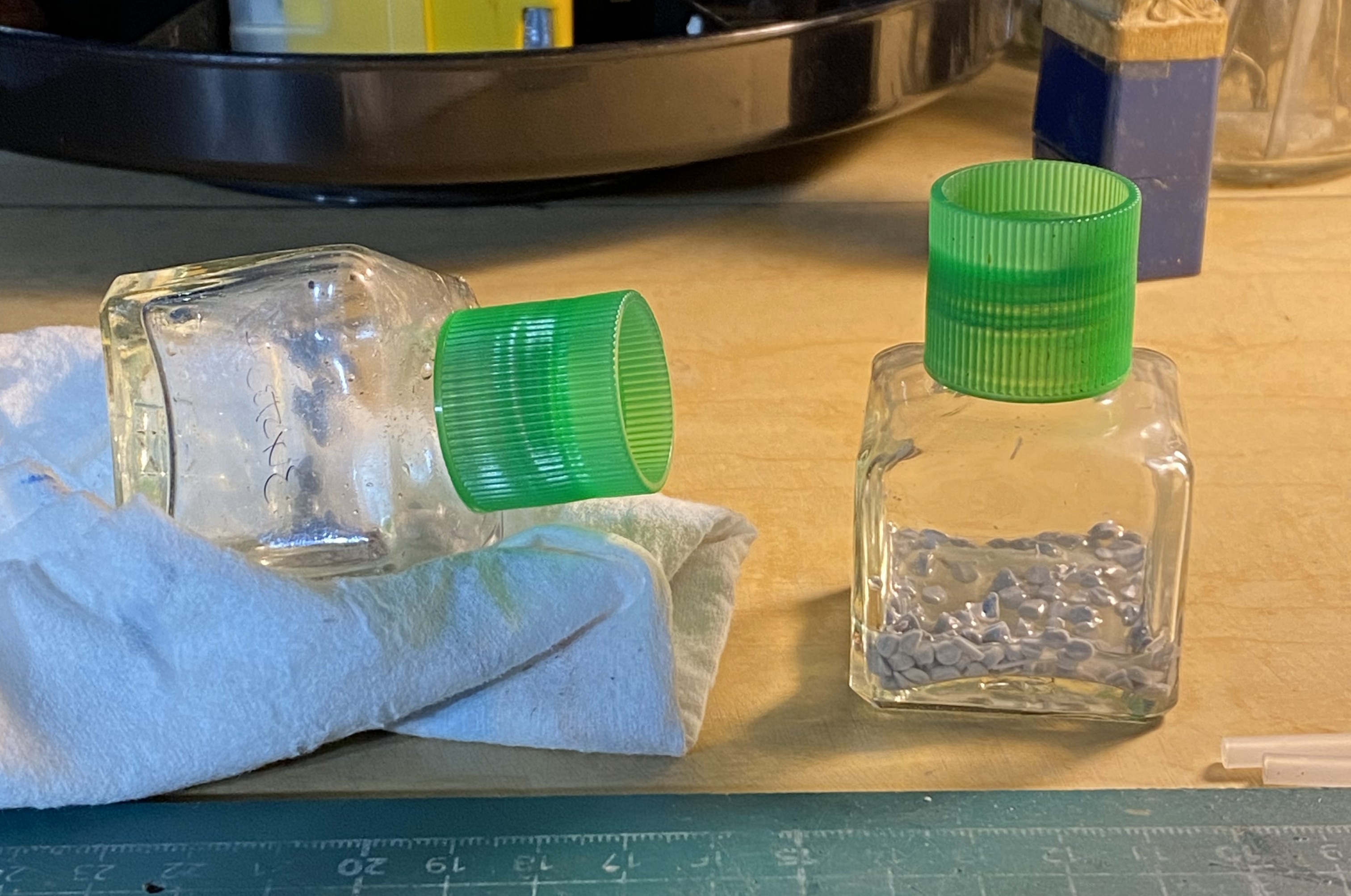
After sitting overnight, the clear winner is the glue. The only affect the acetone had on the styrene was to make the surfaces slightly tacky…that was it:
By then the mold was ready to fill:
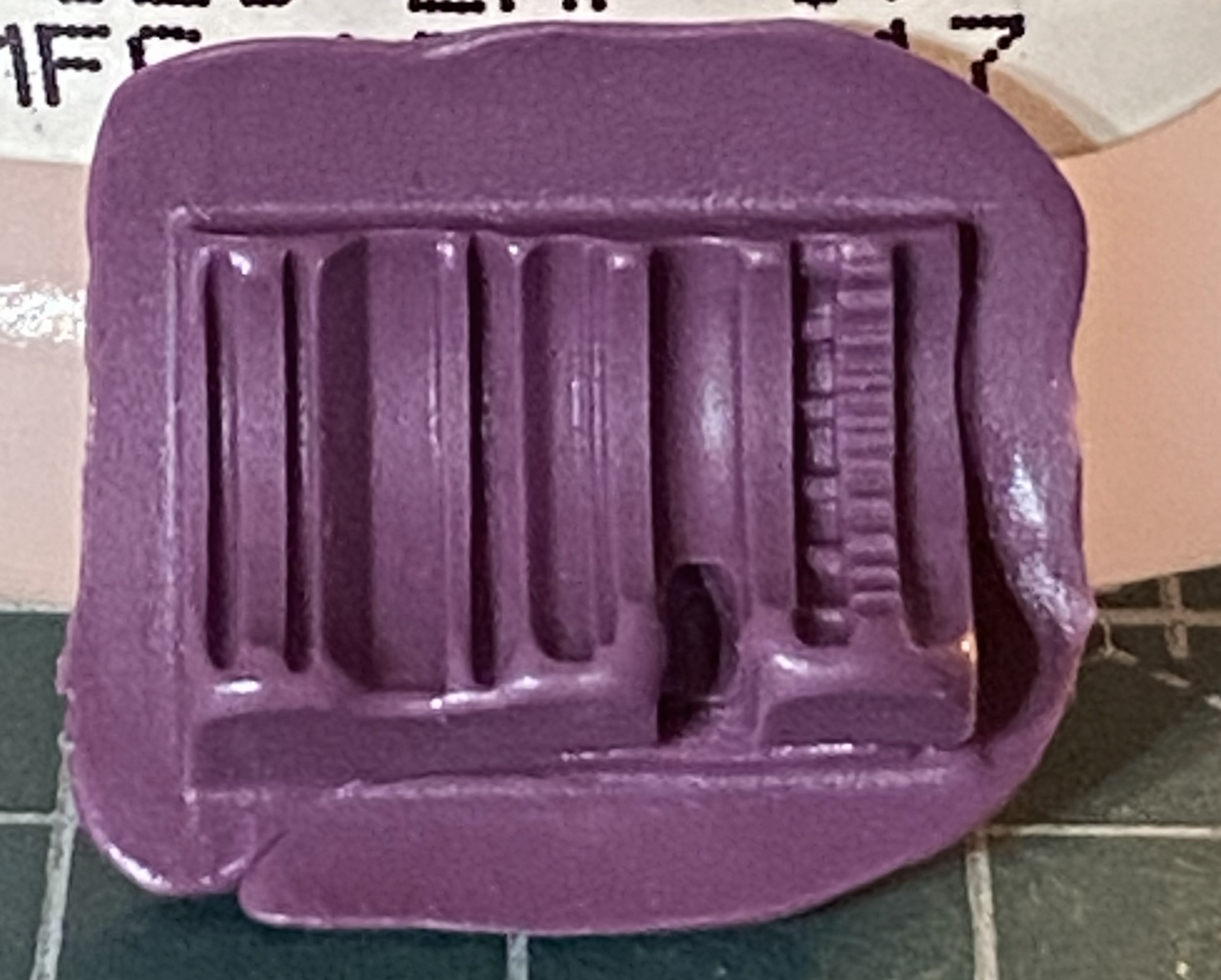
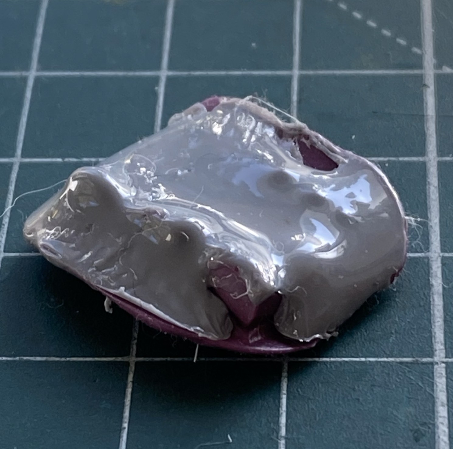
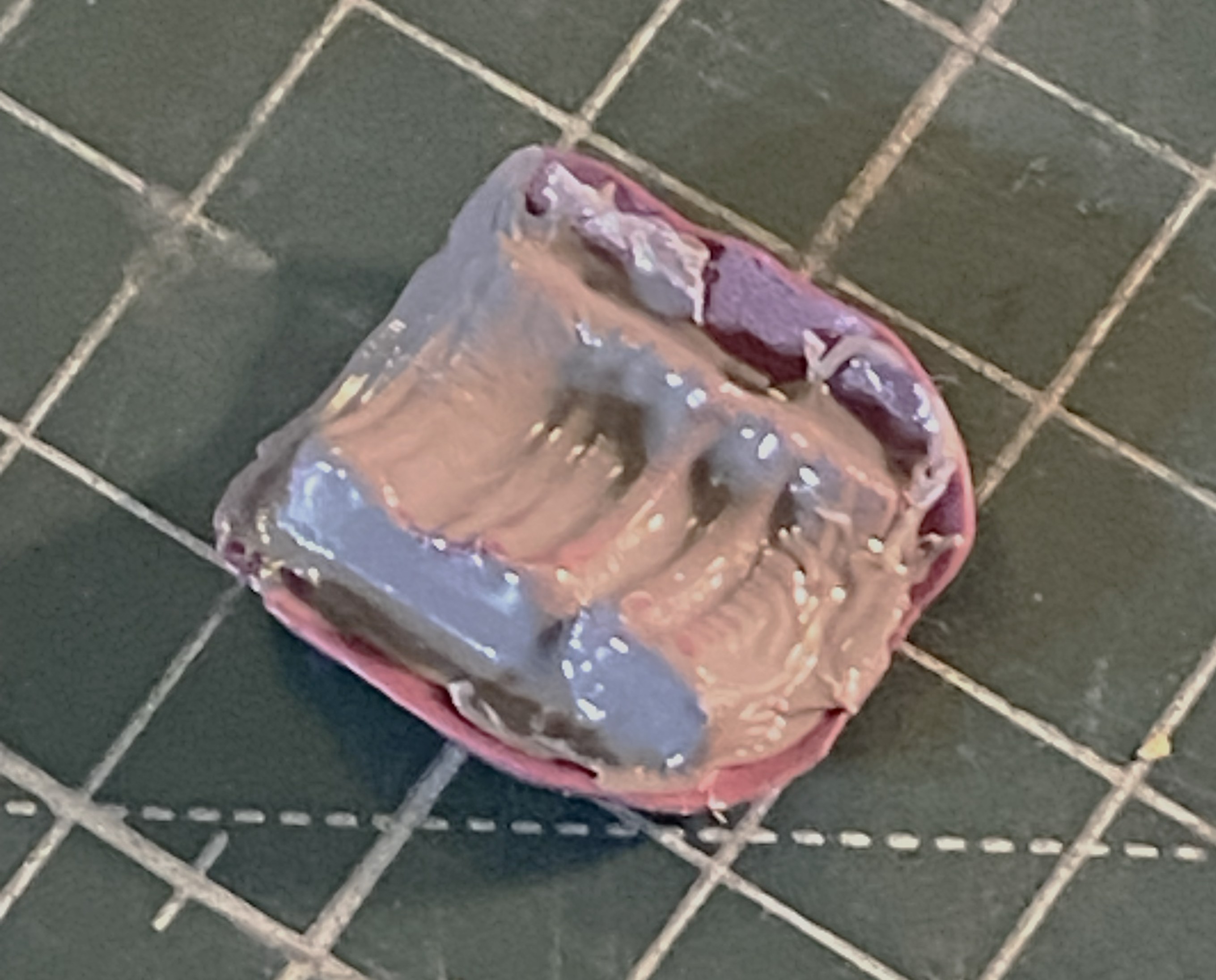
It’s been a while since I’ve used plue and the mold in the above photo shows it. I put on much heavier a coat than I needed to. Several thin coats works best. Another “interesting” trait is that the more the plue is manipulated in/on the mold, the more bubbles created, which this little lovely reminded me of:
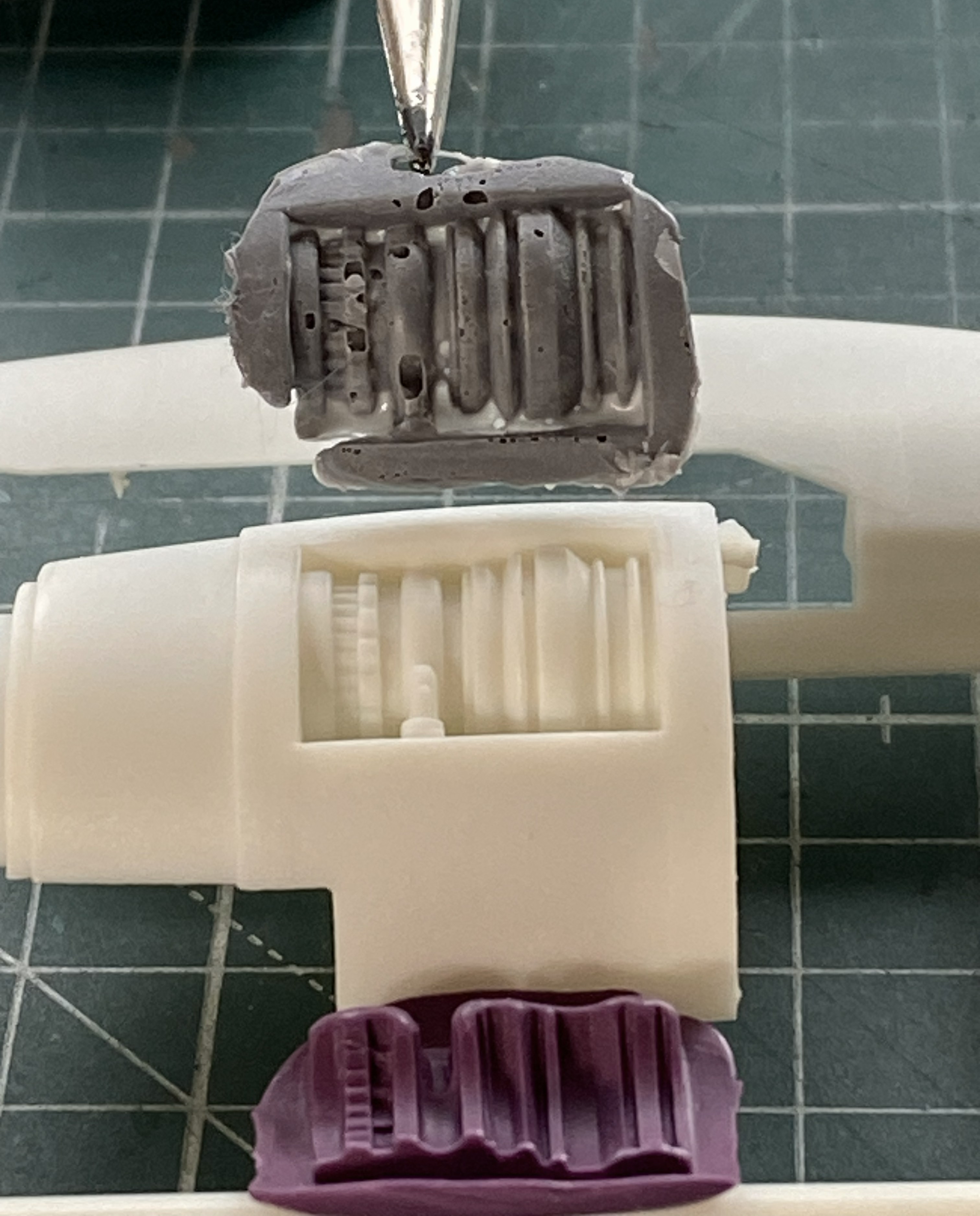
Next attempt using thinner coats worked better:
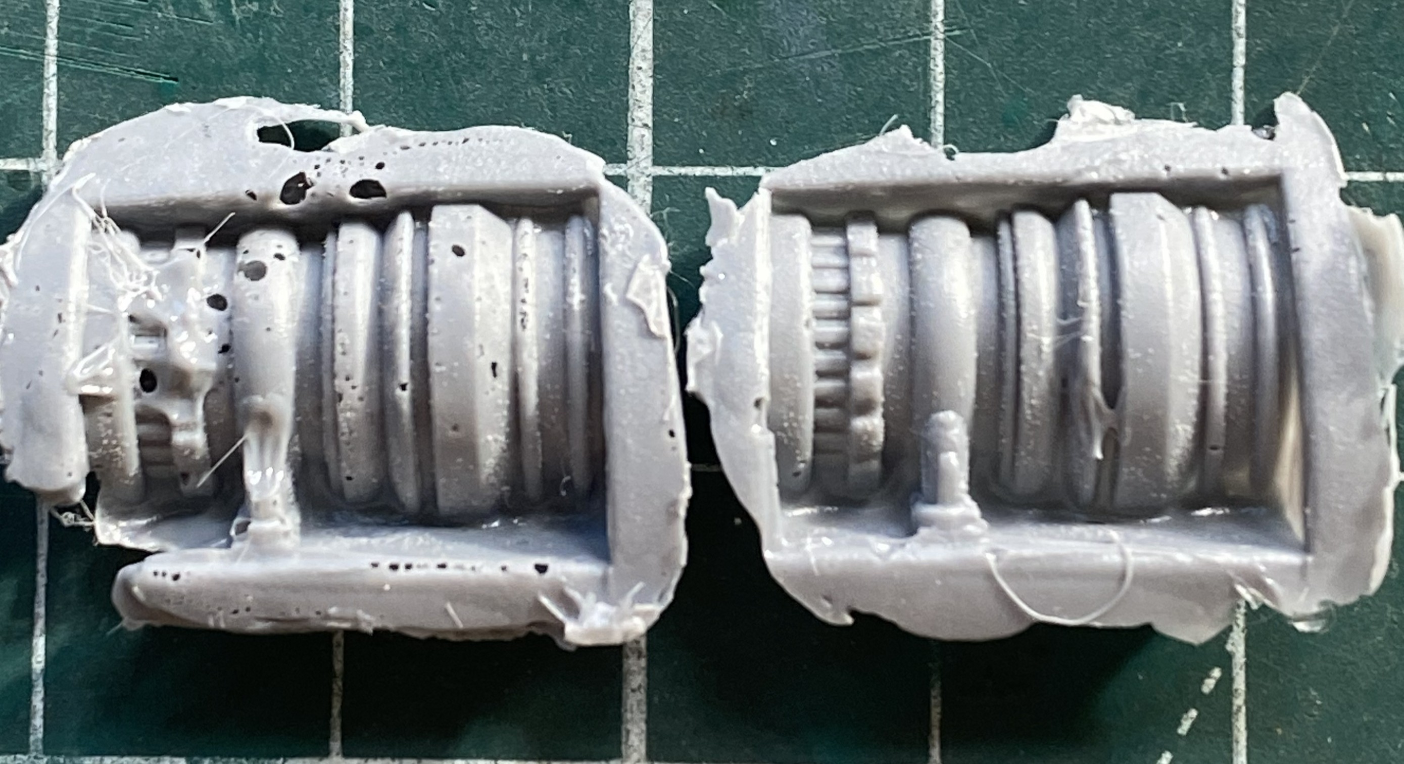
Of course I had to have a go at fixing the first casting (on the left above) but that solution created more problems than it solved. In fact, once I had acceptable castings for both sides is when I realized that the whole engine idea was a waste of time. They be what they is (relatively).
Since this was my first wake-up call (most of my builds have at least one), I decided to tape the major components together to check fit:
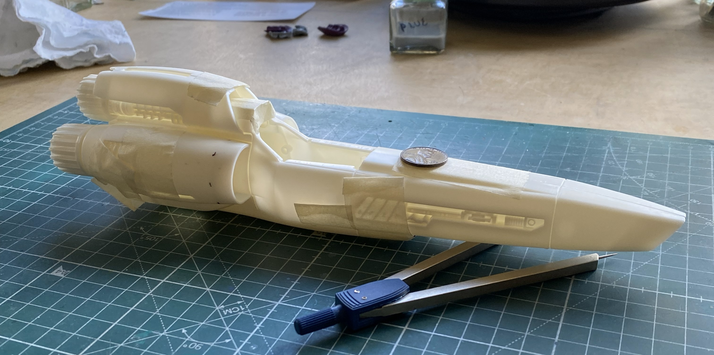
That will require some work. It’s not horrible, but it ain’t Tamiya, either.
Since this thing doesn’t have a leg to stand on, I decided to start putting them together. Nose gear is on the right:
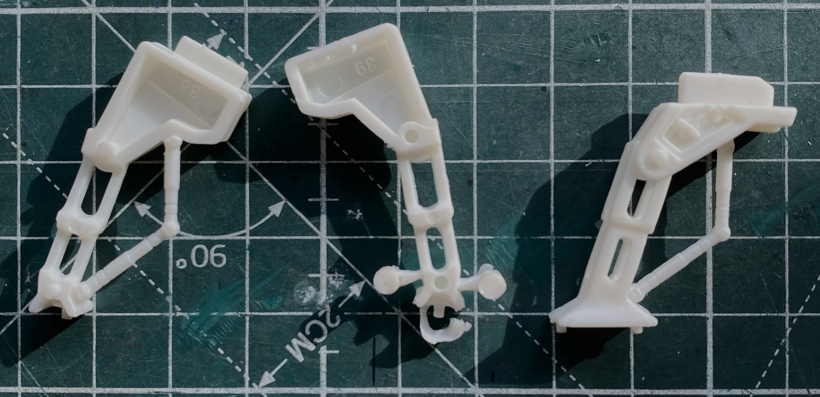
Seams are variable. Some good, some not good, some just freaking annoying. I’m moving away from putty as my default void filler towards scabbing in plastic instead. These landing struts/gear seams need it:
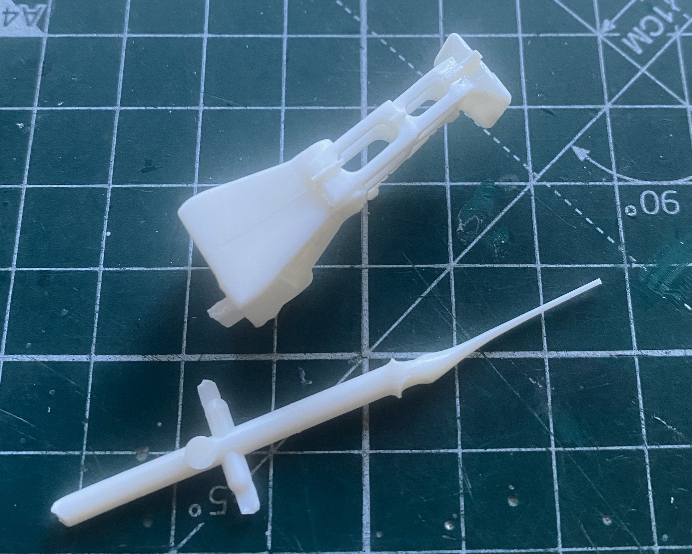
See what I mean:
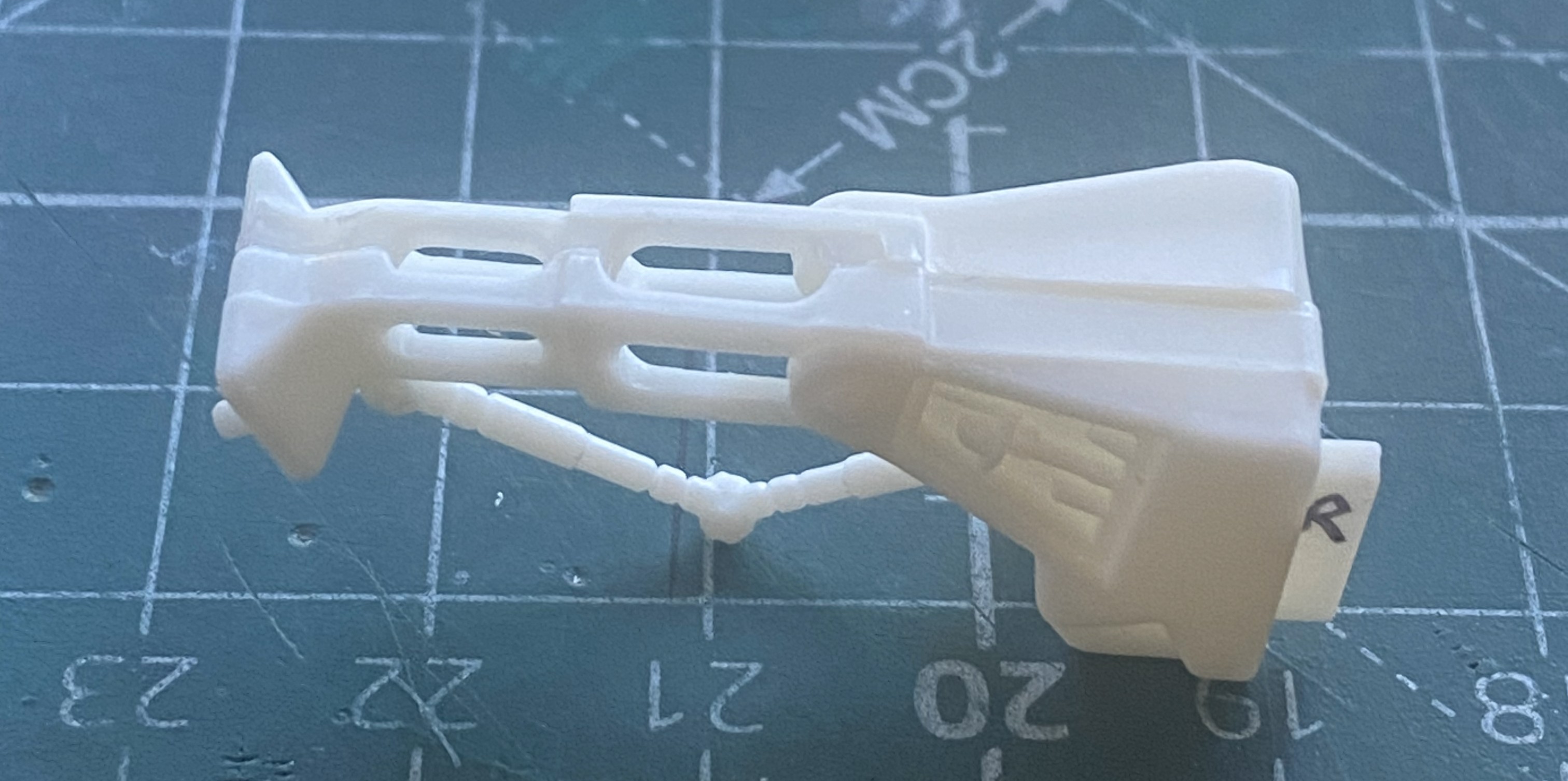

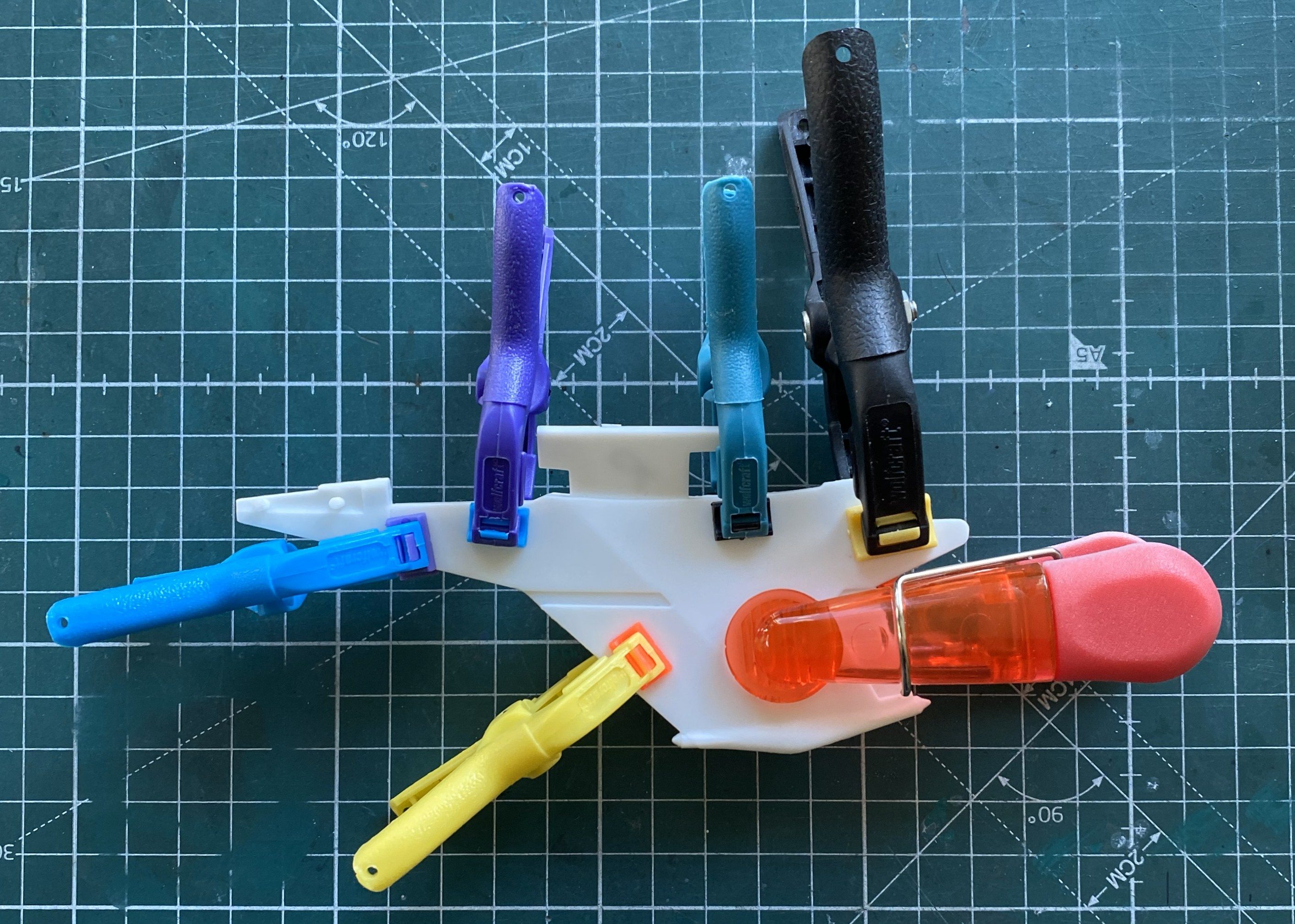
While all the added plastic was setting up, I started putting together wing halves. This was an area that needed help. So I helped it:
“Why is your work bench so cluttered and messy? Doesn’t that get in the way of working?” No, dear, it is working. These are the tools needed to clean up parts that are essentially simple:
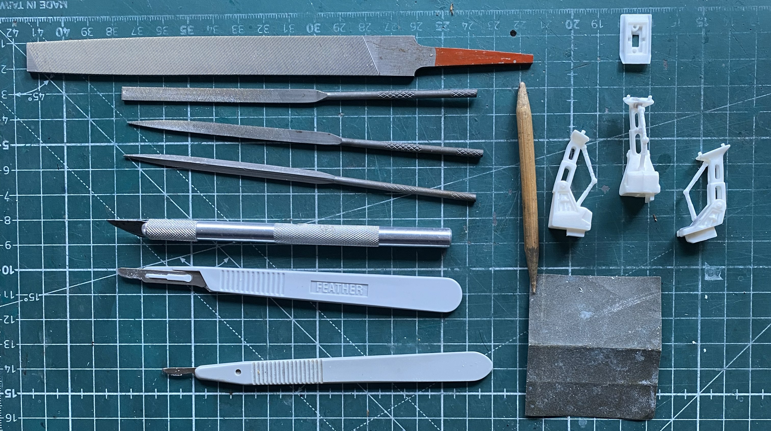
Simple. Right?
While removing the tape from where I’d dry-fit the major components together, an ohgoddammit moment arrived. The blue arrow shows you where a part came apart:
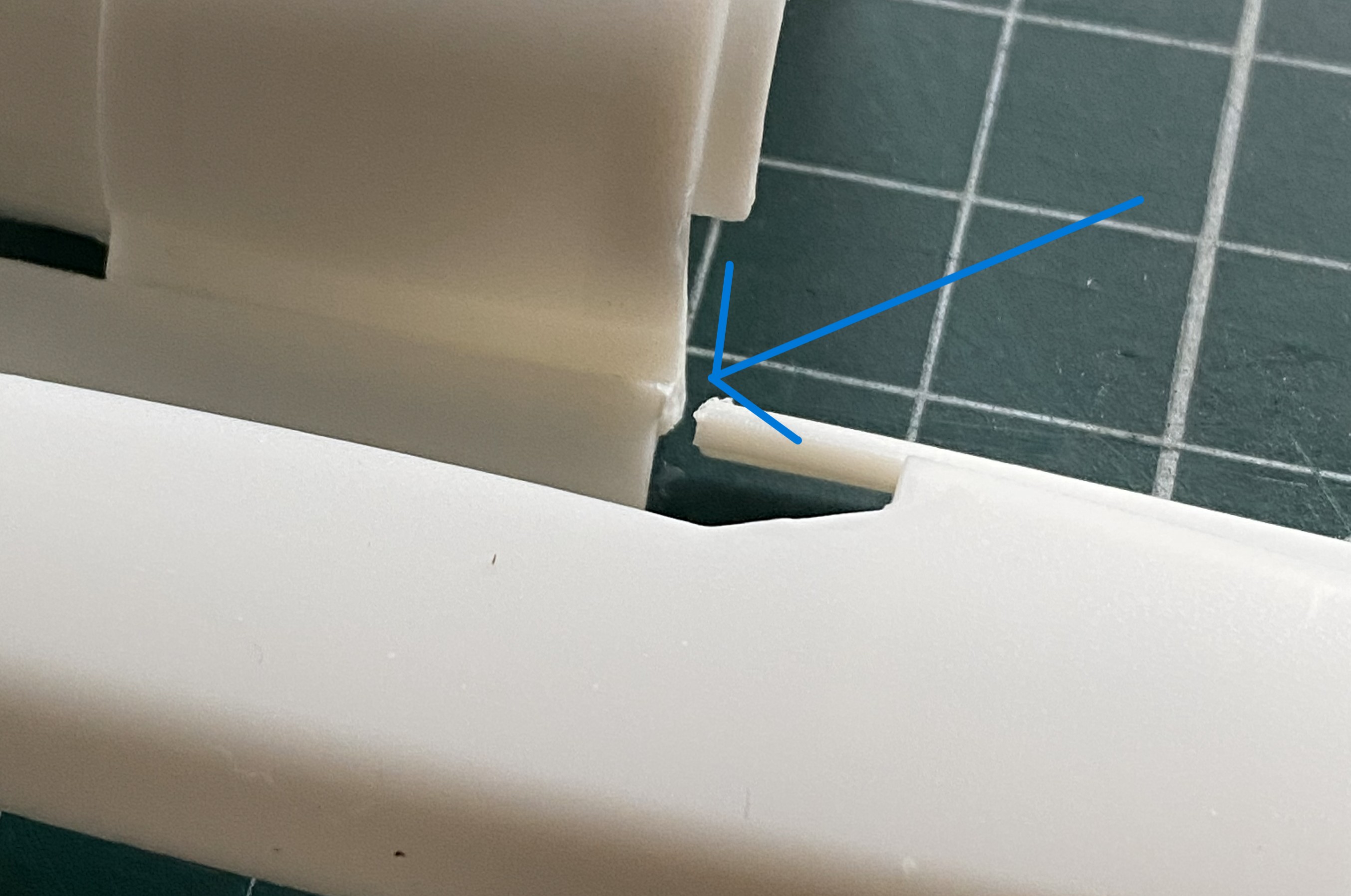
The way this is engineered, I decided that I’d use the model itself as a gluing jig (the break is on the left half of the engine area). The flat areas on either side of where the upper engine goes served well as an alignment guide:
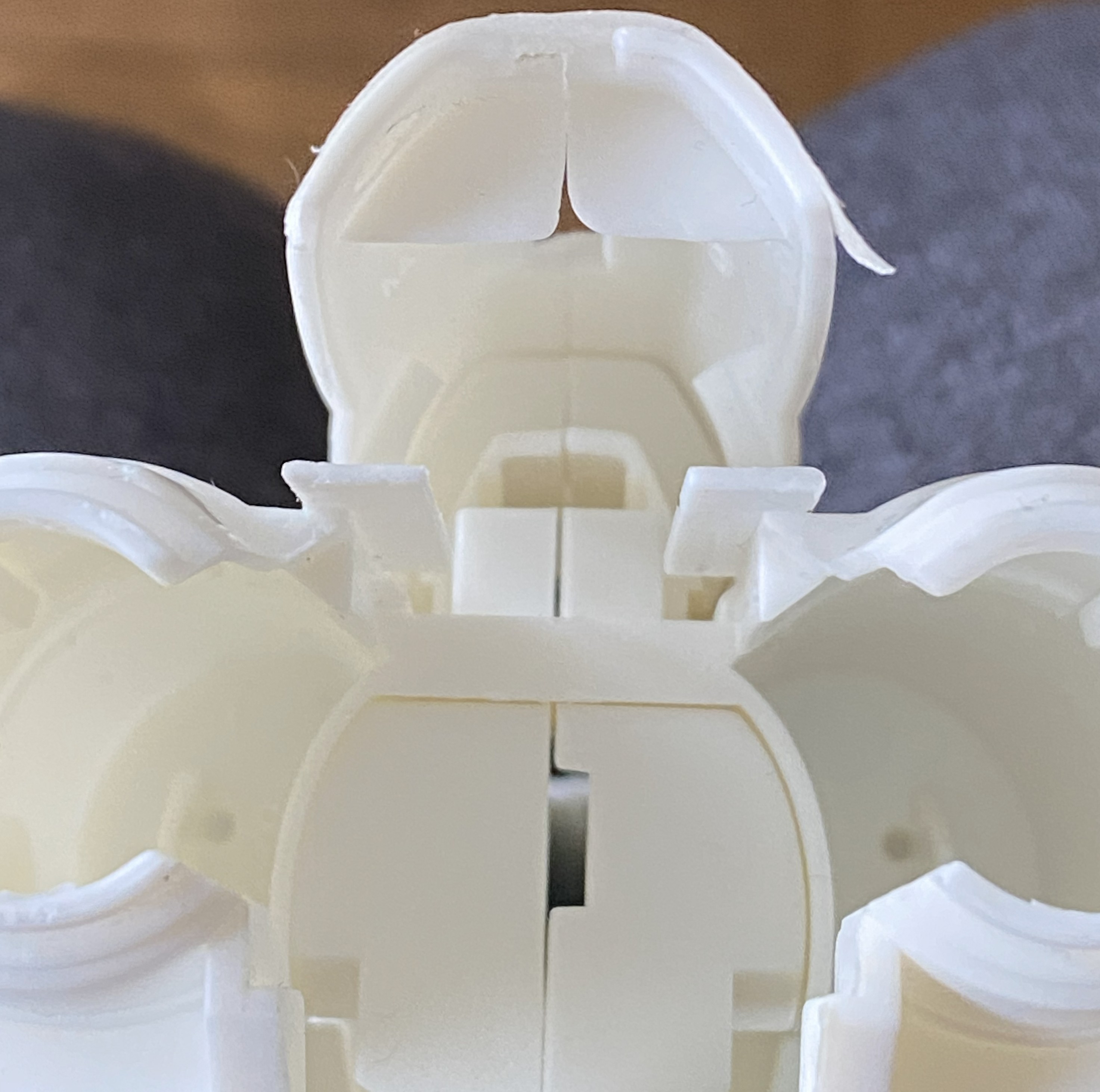
Good illustration of fit, eh?
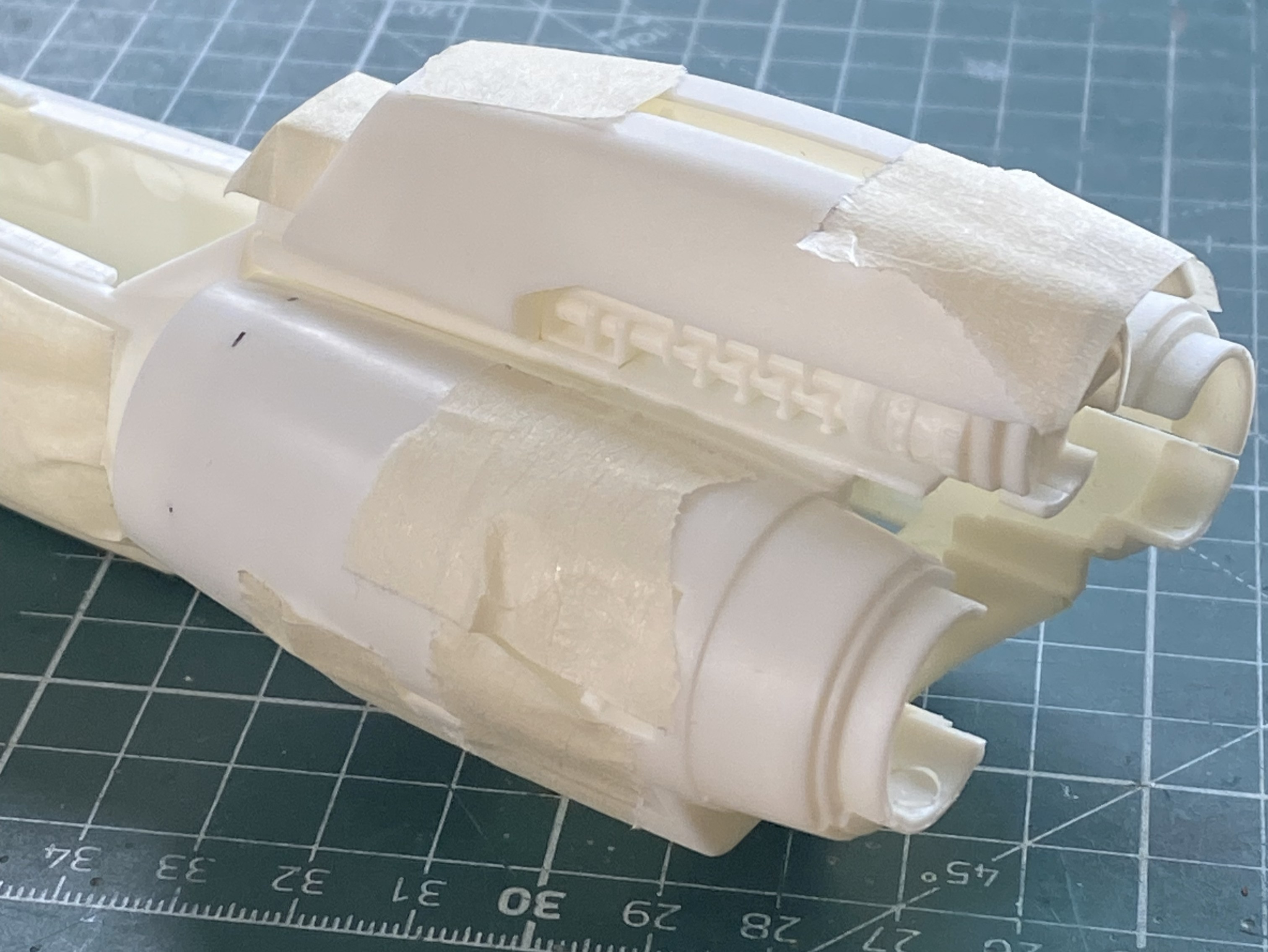
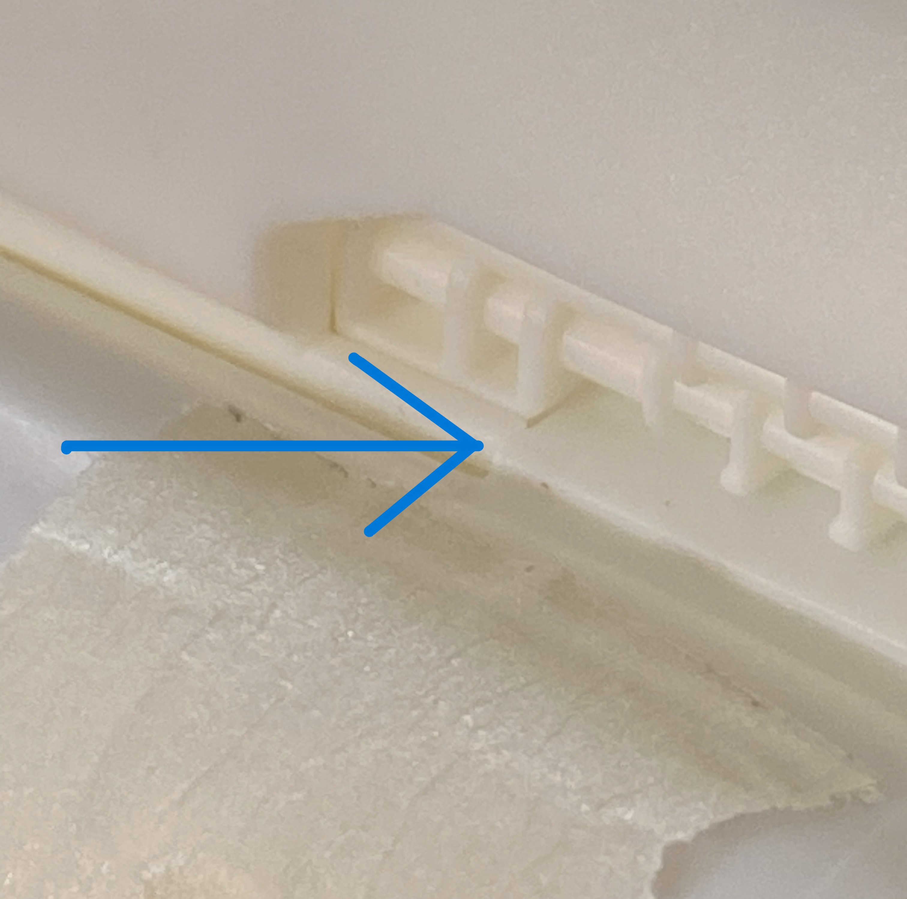
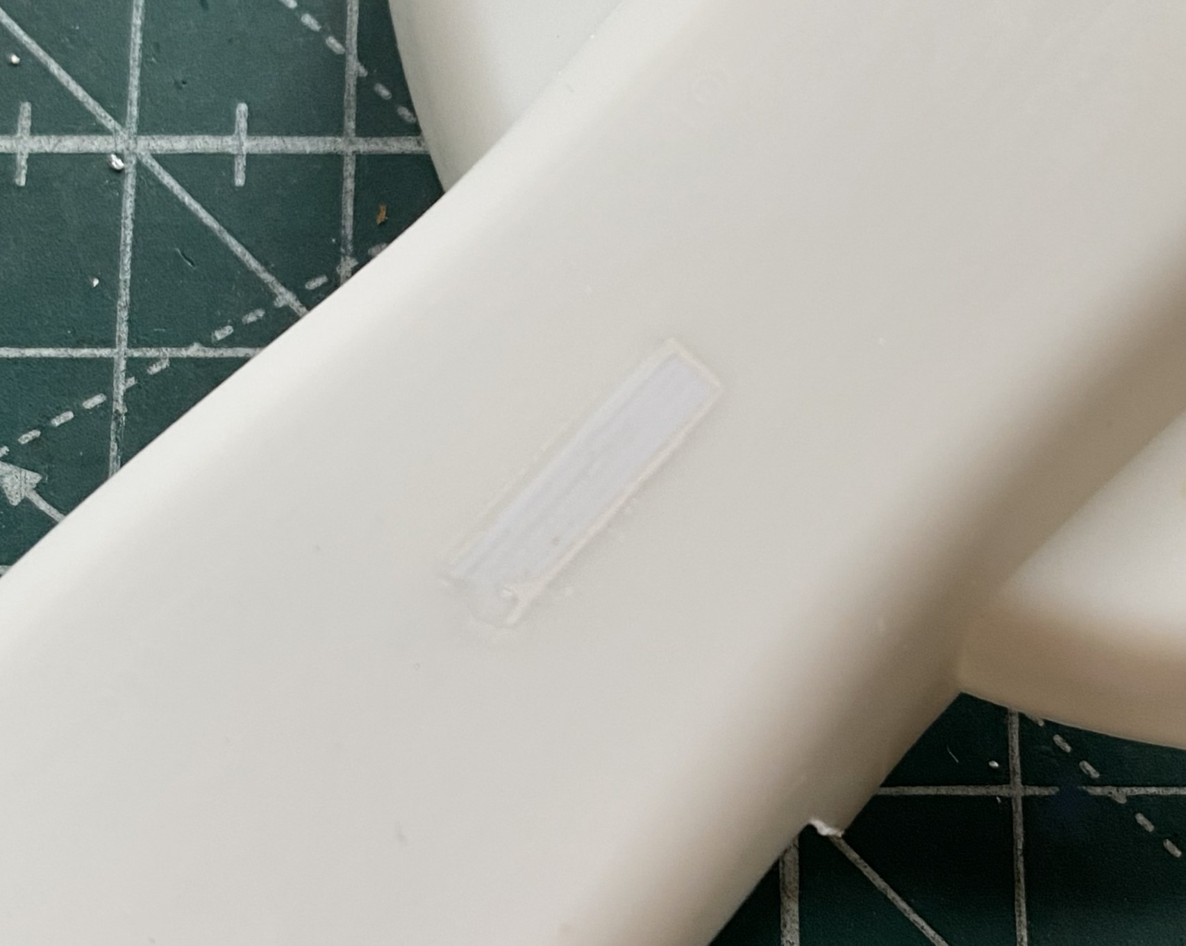
While I was there, I filled the slot for the supplied stand since I’m not going to use it:
At this point the AM parts arrived so I changed focus to doing the cockpit. For the resin seat to fit, the molded-in seat has to come out:
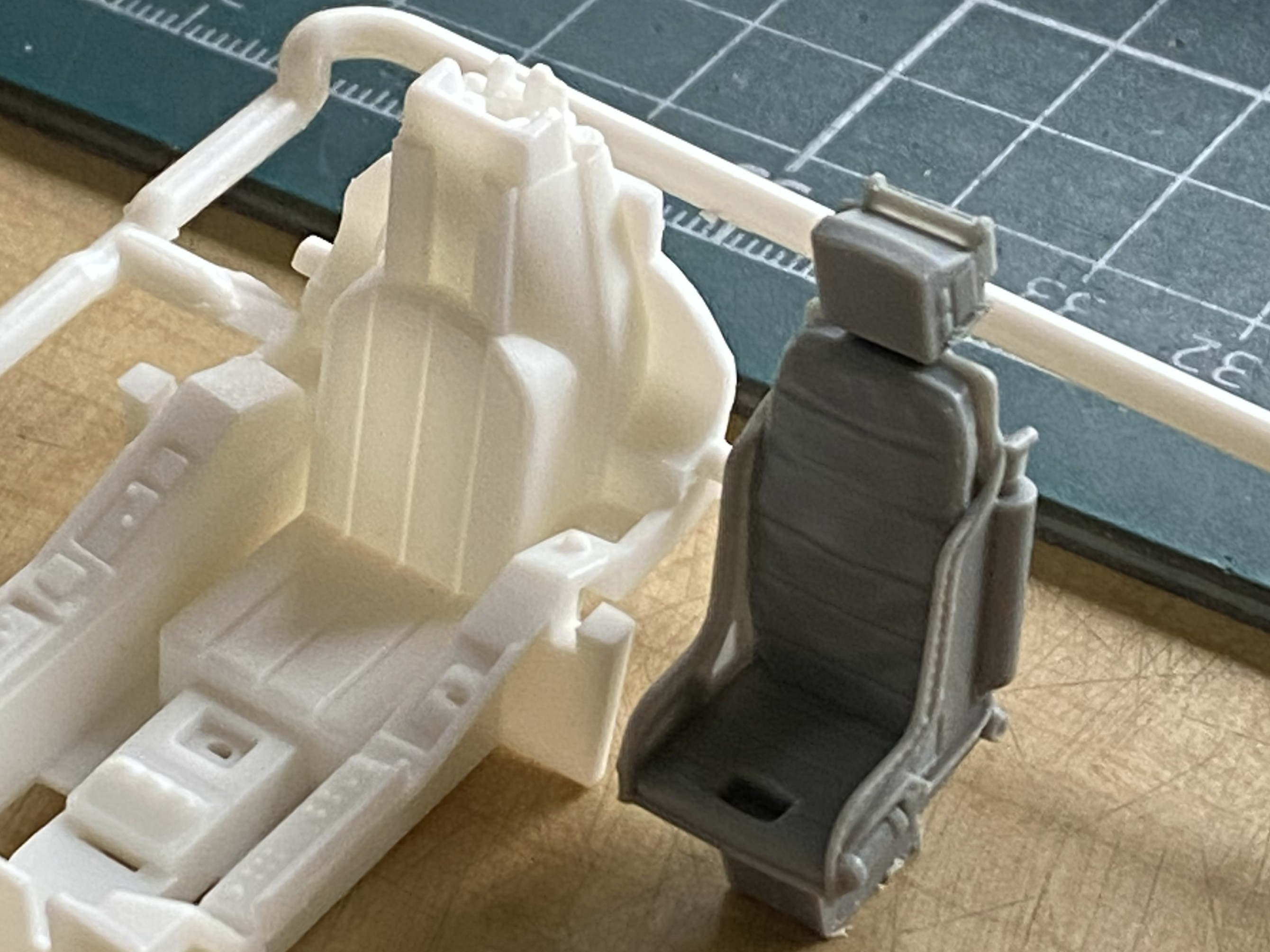
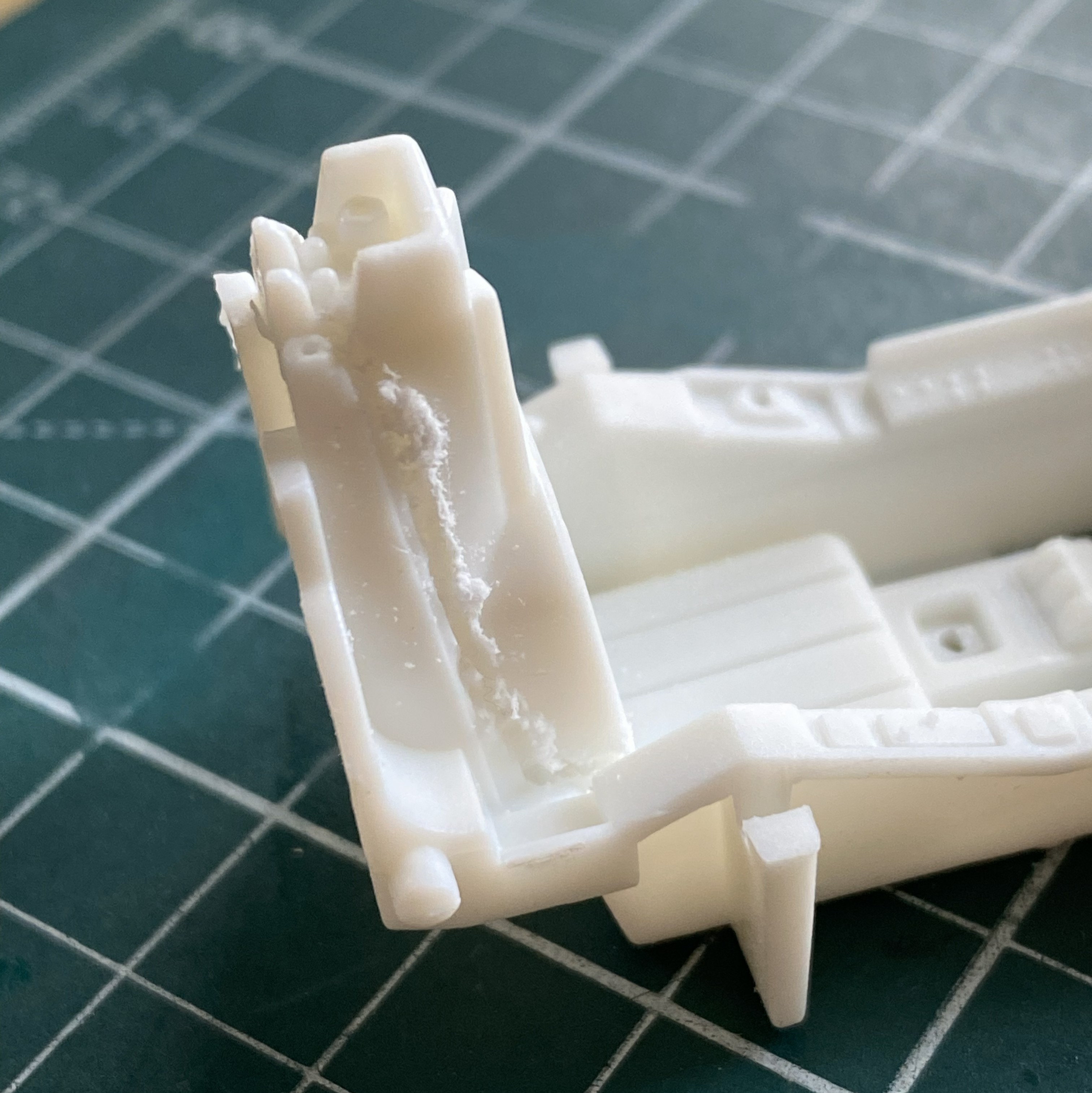
Once the kit’s seat was gone, I assembled the pedestal for the seat:
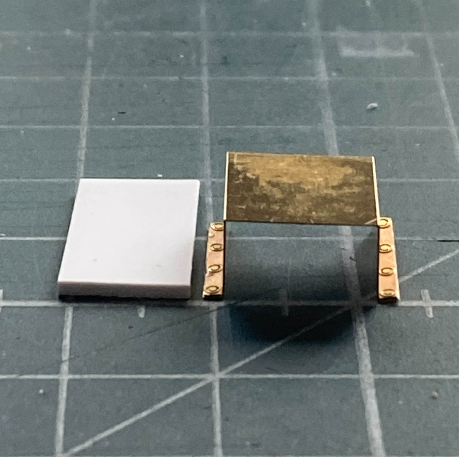
Then I checked the fit:


Nope. Sits too high. The fix was to remove the pedestal and glue the seat directly to the floor (you can see the fit of the fuselage behind the seat, which will require some inflexible persuasion on my part), which lowers the seat to the correct height:

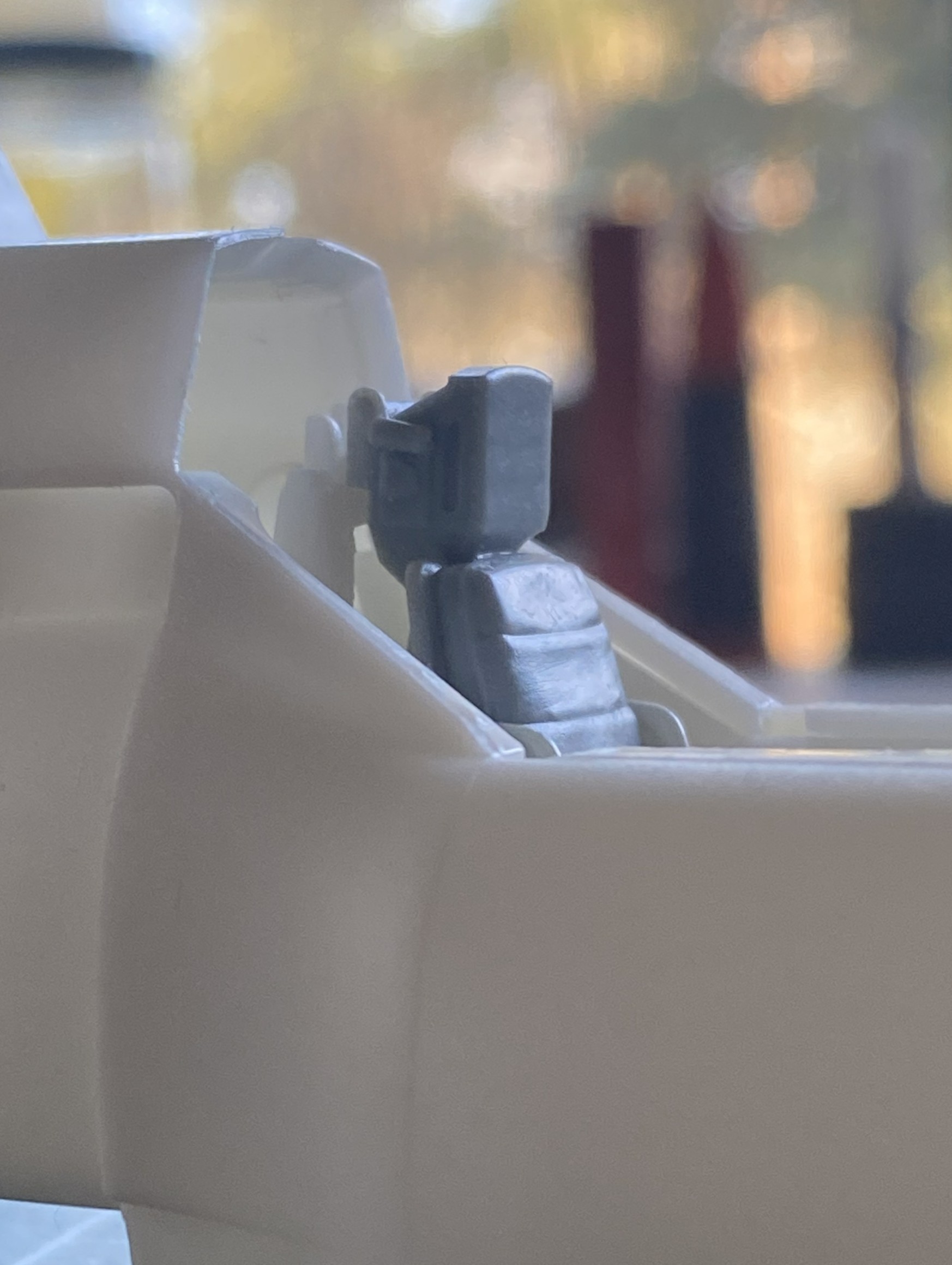
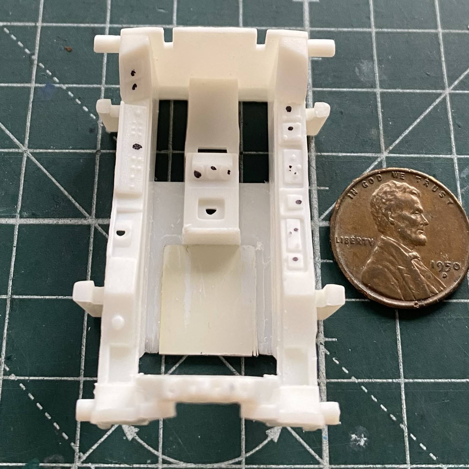
To apply the PE I have to remove the molded-on details. That with the round black dot has to be removed, the one on the left that looks like a D laying on its face is where the throttle goes. The insert in the floor is to fill the gap left after removing the molded seat (and to give me something to glue the resin seat to):
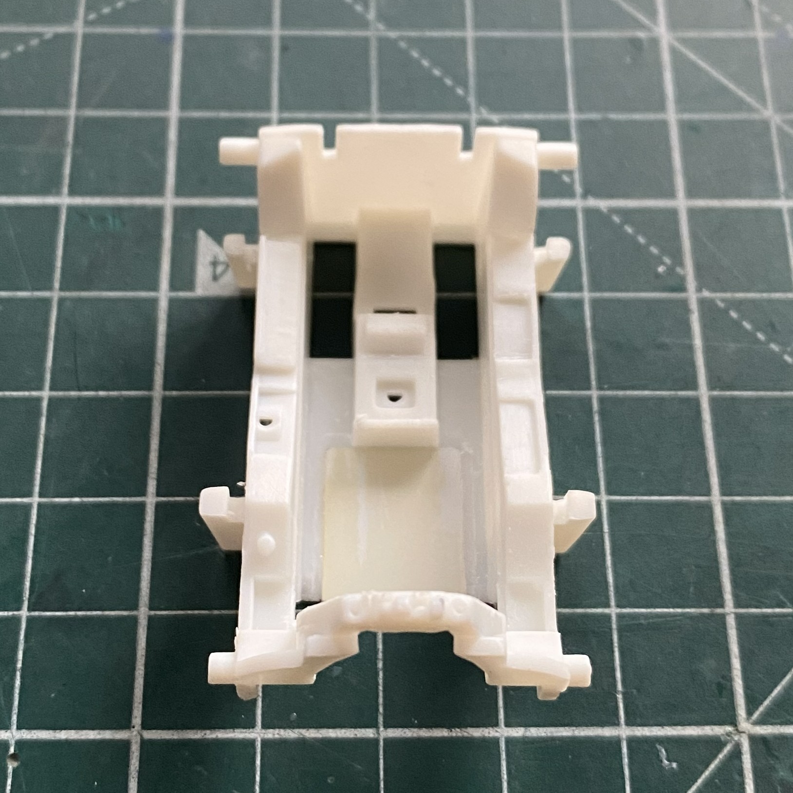
Done:
The structure behind the seat needs to be filled. I used 0.020″ (.508mm) for that:
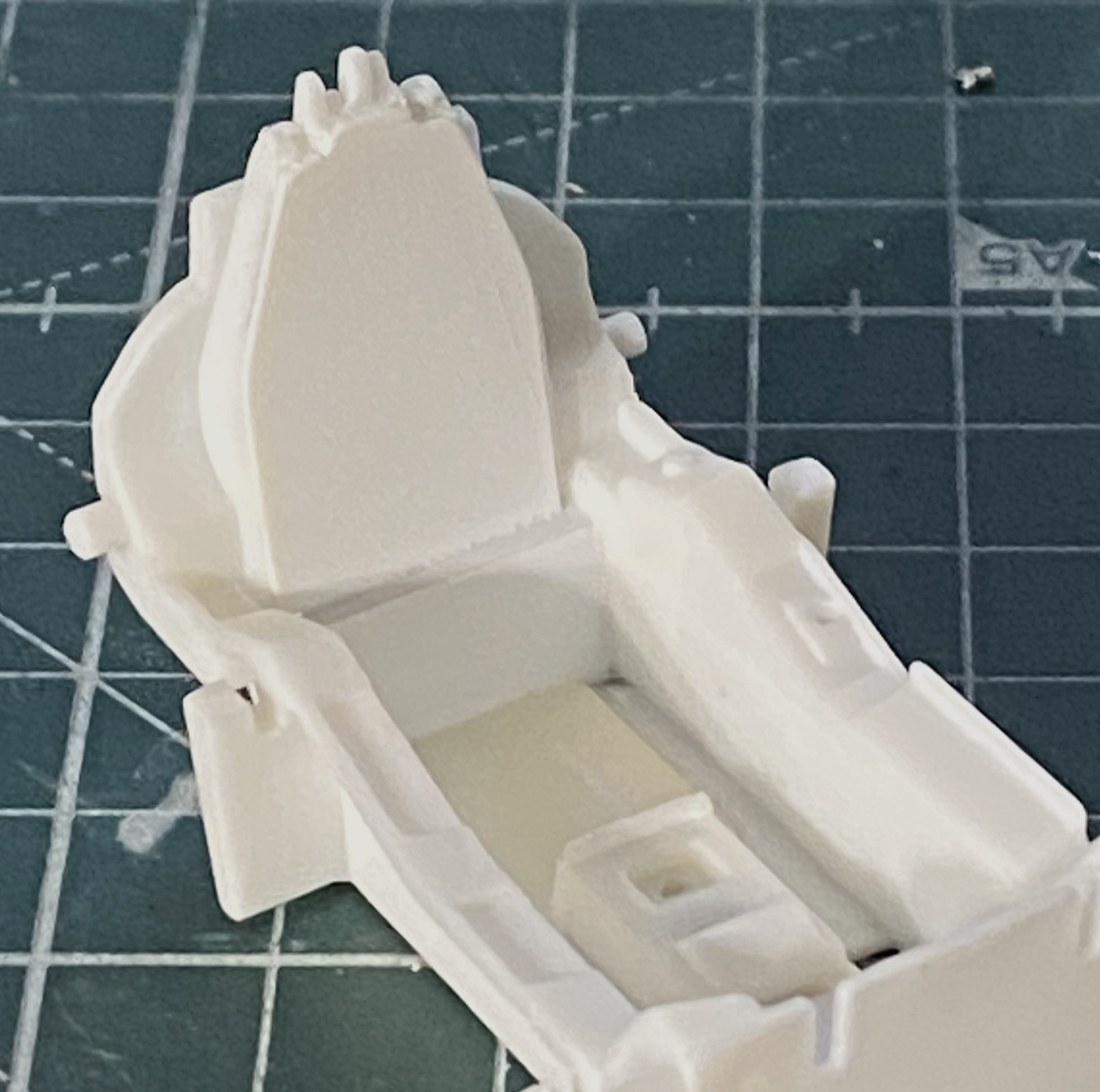
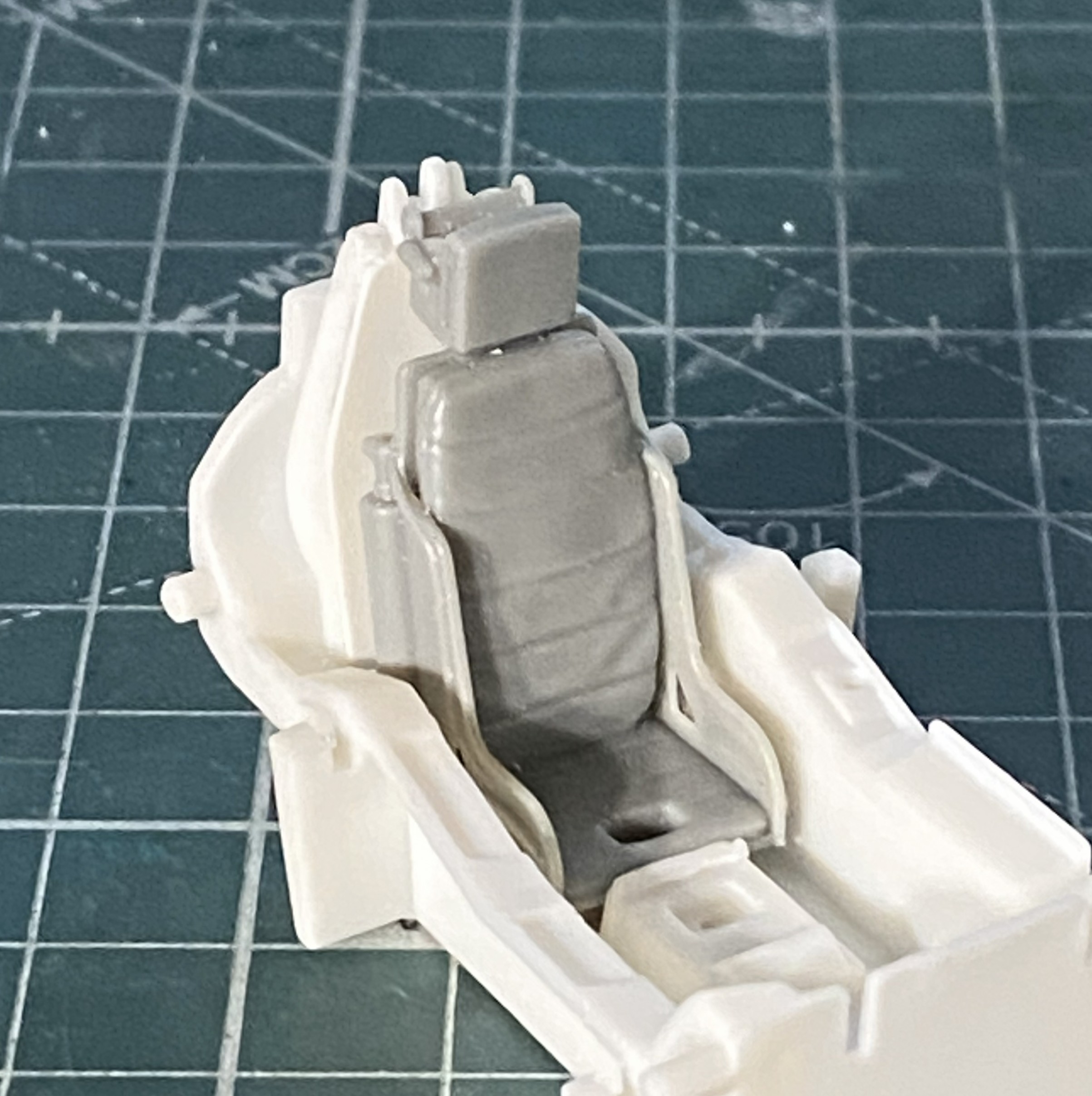
Where the back joins the tub is evident at the edges. I used a little putty to make the added back look as if it belonged.
With unwanted details removed, PE moved to the front of the line. Surprising no one who’s worked with PE, acrylic paints don’t adhere well. They’re fine once painted if they aren’t stressed. I was curious to see if lacquer would hold up any better. I masked off what I didn’t want to paint and then sprayed the fret with Tamiya’s TS-6 Matt Black from a rattlecan and let it sit overnight:
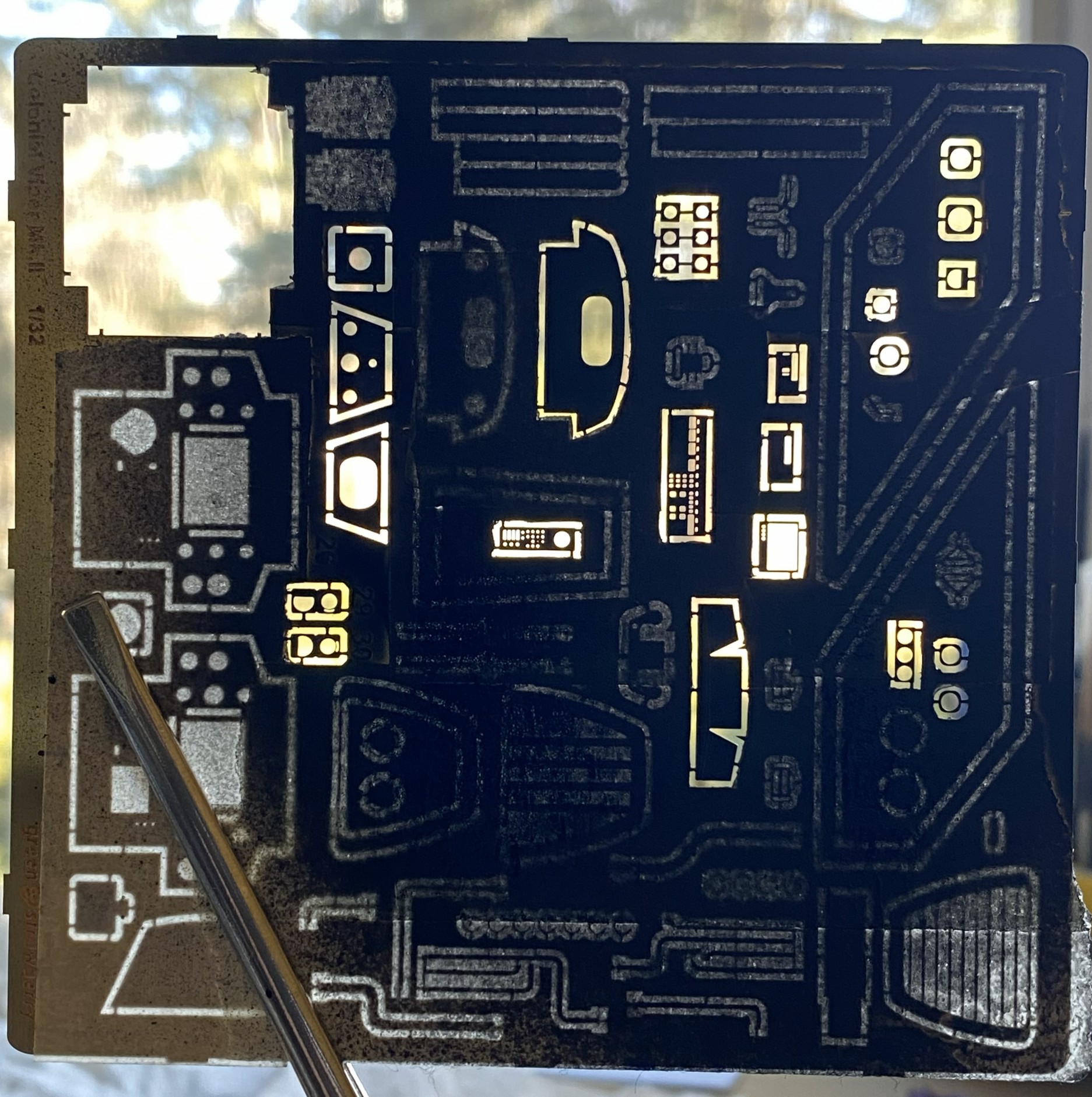
The next day I used my MkIII Thumbnail to see if lacquer is more resistant to wear. It is. It still wore a bit as I was working things but NOwhere near as much as acrylic wears.
In general, I’m not a fan of PE harness straps. The PE fret has them so I decided to have another go at them. I started by annealing them so that they behave less like the strip of brass that they are:
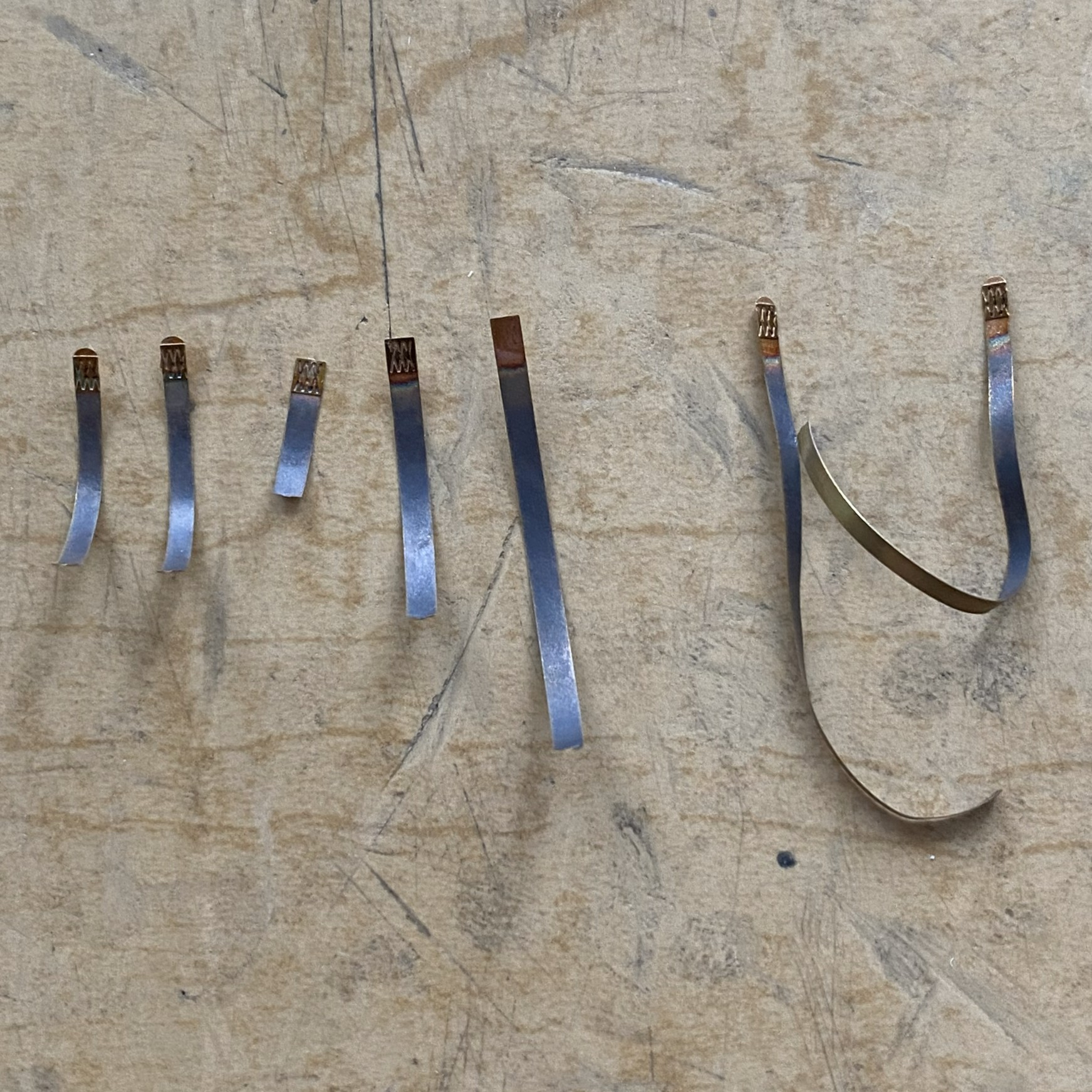
During annealing, I managed to scare myself. I use a butane torch to anneal. It’s hot. It’s hot enough to melt little brass strips! I came far too close to melting one of them, but since I’m not a grenadier…
Next I fed the straps through the hardware of sliders, tabs, and locks:
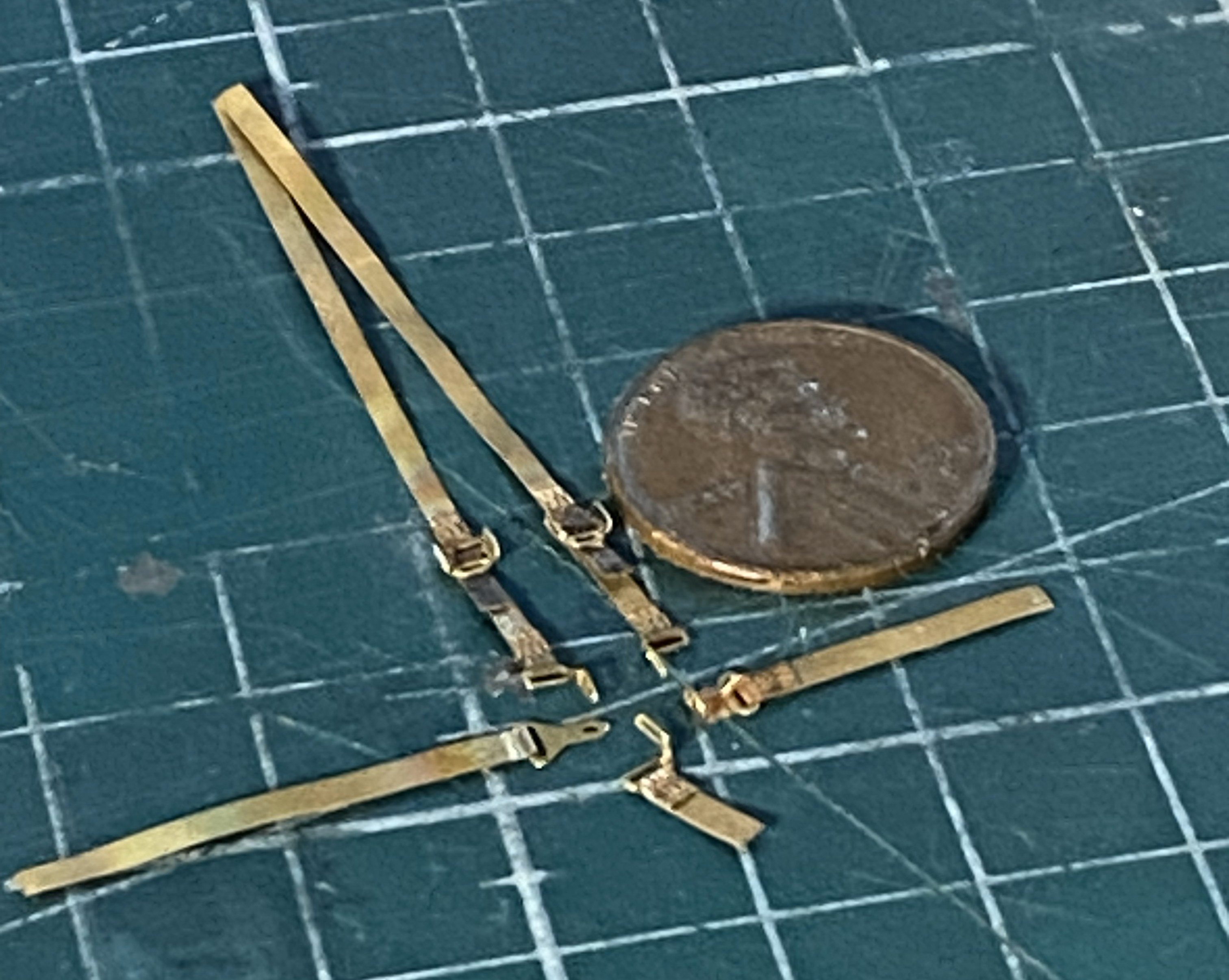
Annealing them made it magnitudes easier to feed the straps through the hardware! Now to see how they go on:
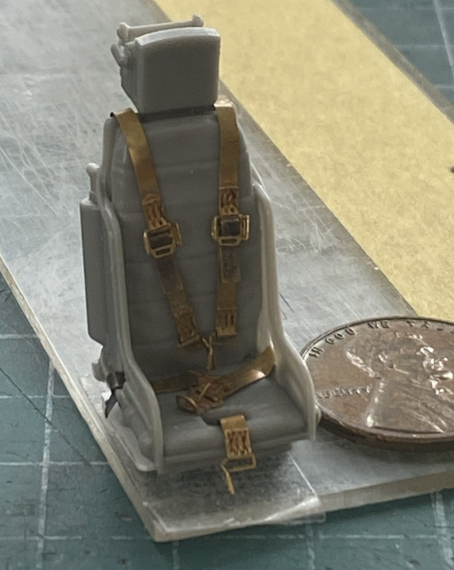
Annealing is definitely the way to go with PE harnesses.
I don’t know what this little panel is for, I just know it’s there so now was a good time (or even not a bad time) to see how the lacquer holds up to bending and gluing:
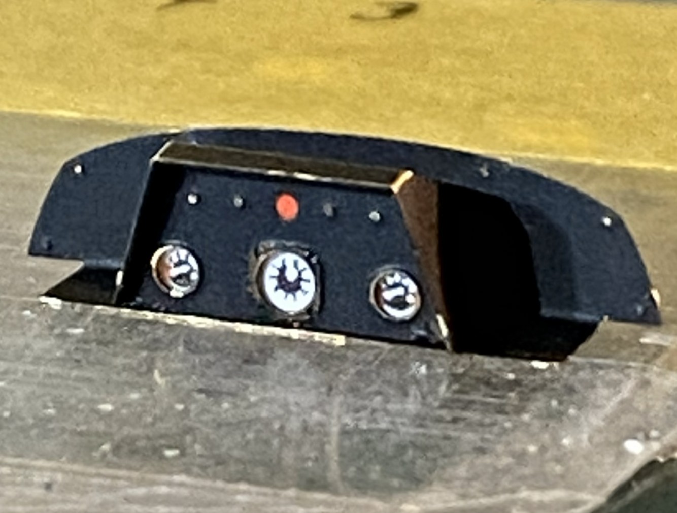
The lacquer holds up to being manipulated much better than acrylic does.
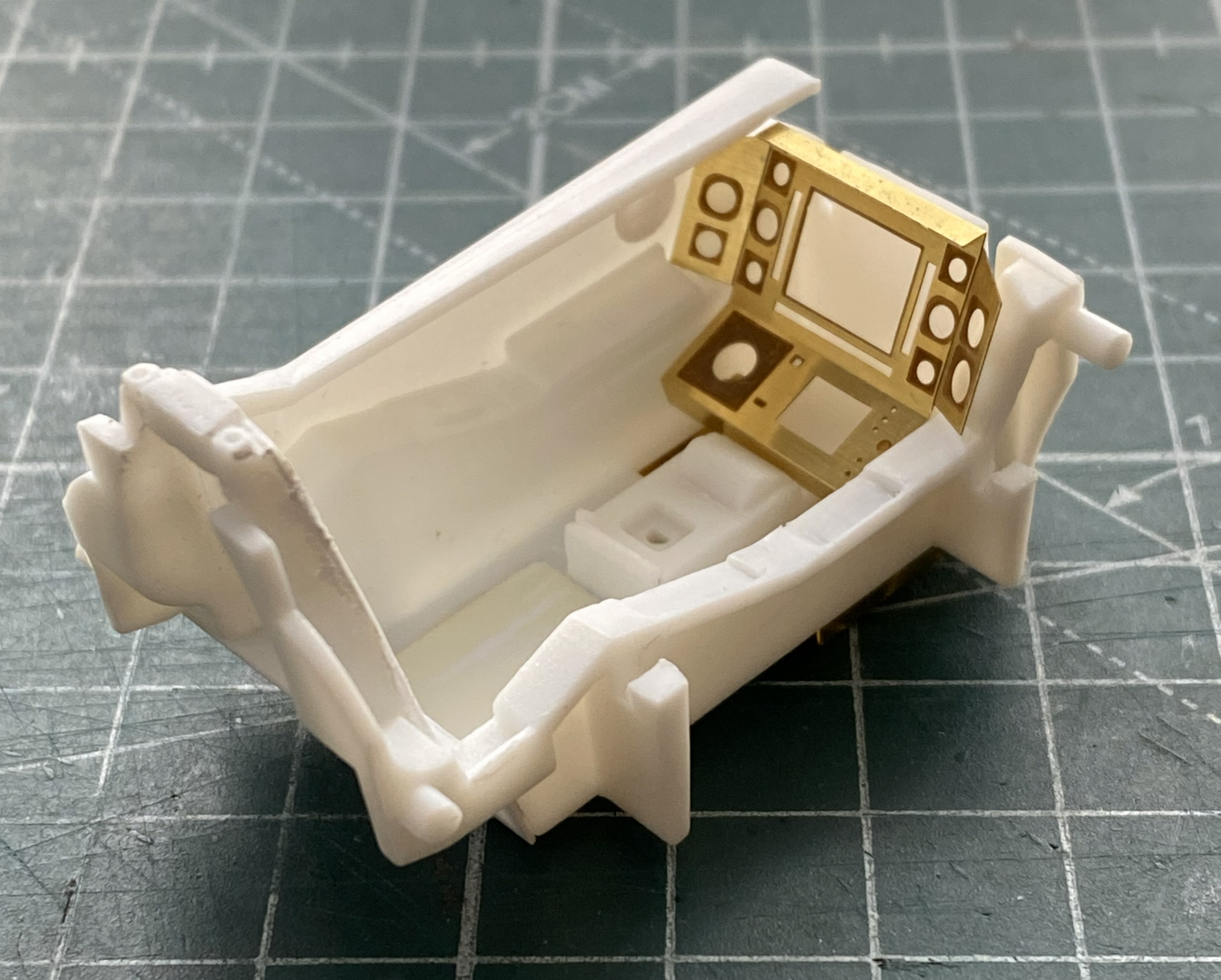
The main panel is basically formed, dry-fit, and checked for fit (good):
The engine intakes have blades for the intakes. Well, two out of three intakes. They look cool but are utterly unrealistic (and foundational theme for this build). The third intake is just a flat surface and of course it’s right up there in ones’ face(s), so I carved (another set of utterly unrealistic) fan blades into it. What the kit offers (one on both sides and the two of three intakes with fan blades):
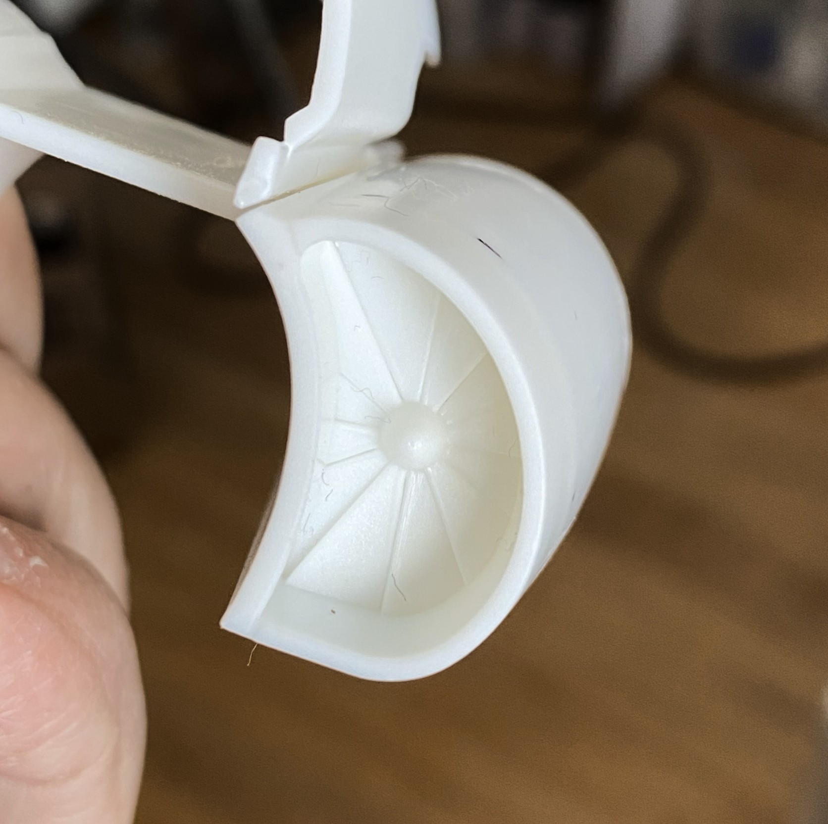
I started with this:
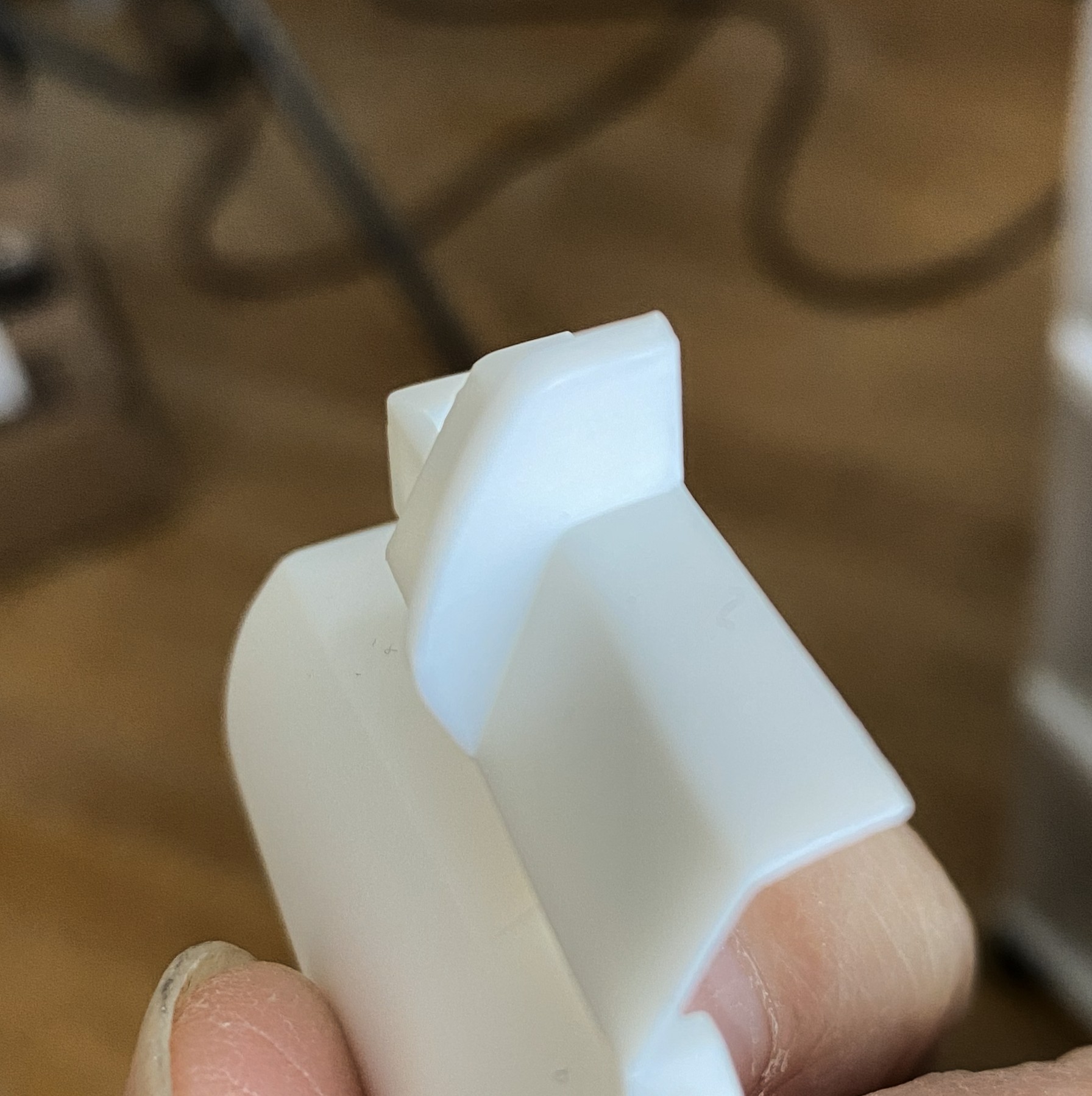
Drew the leading edges of the blades and checked appearance:
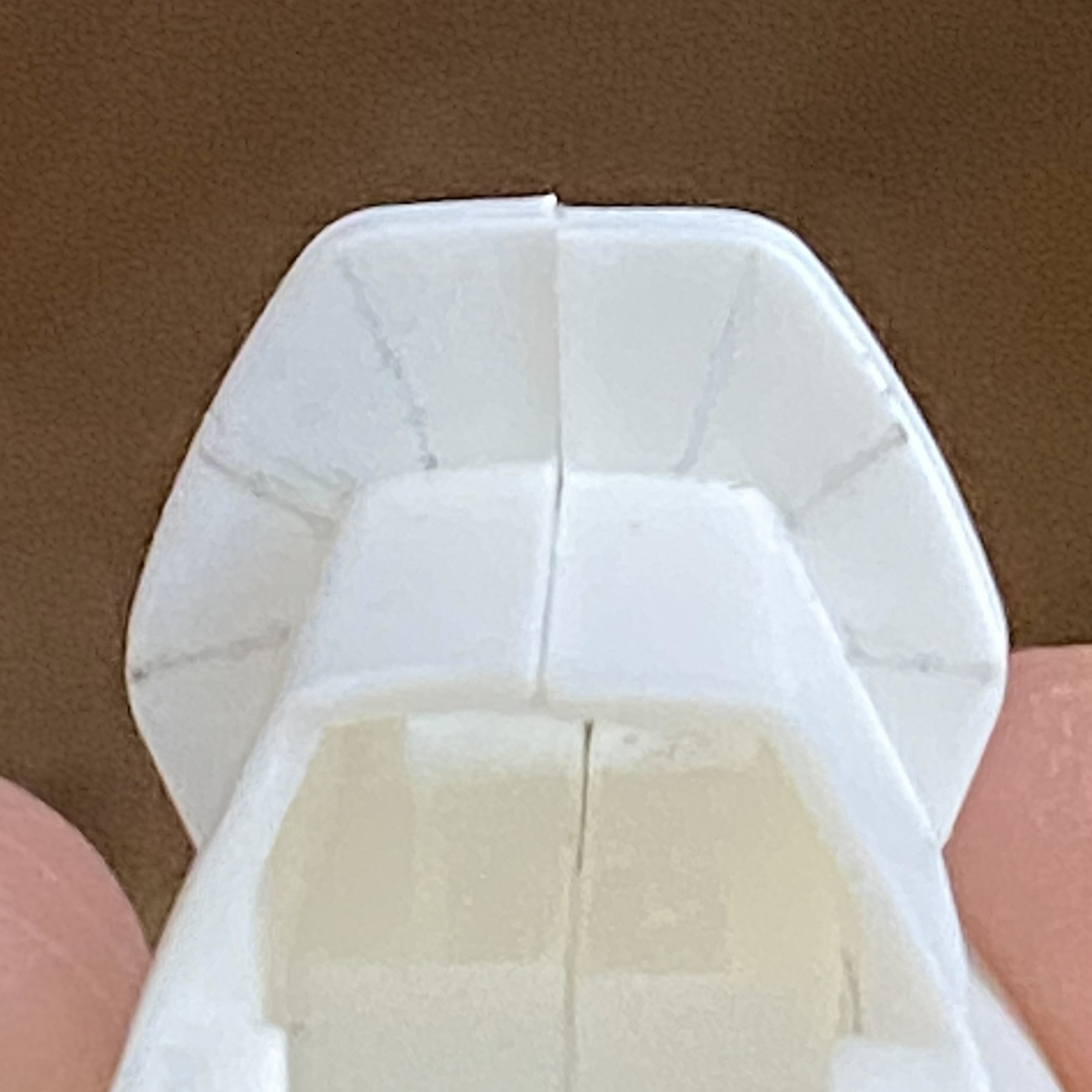
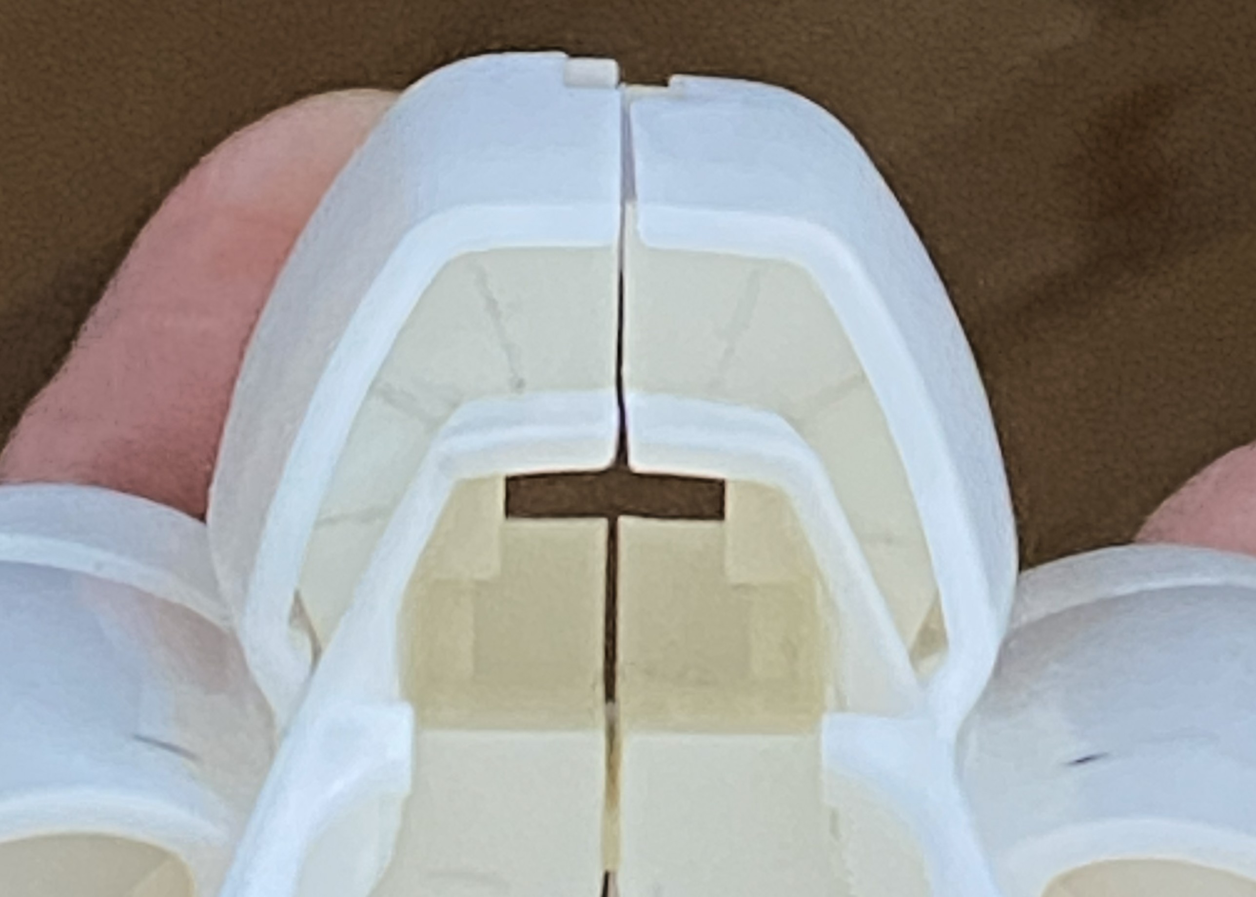
Then I sharpened all my scalpels and knives and started carving:

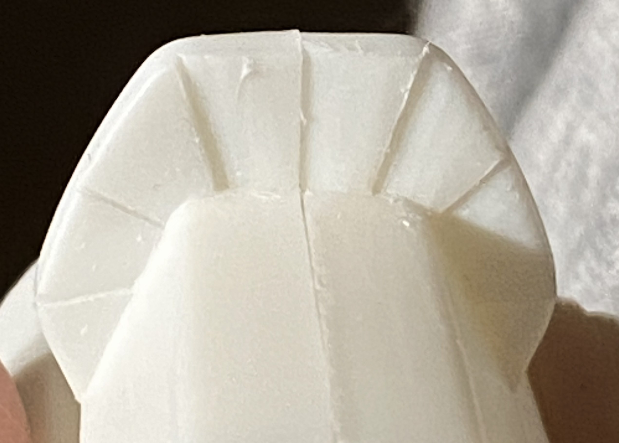
I cleaned up the edges/surfaces after taking the above photo.
First paint. These are the parts that get shot with Tamiya XF-1 Flat Black because I like the effects I get from pre-shading:
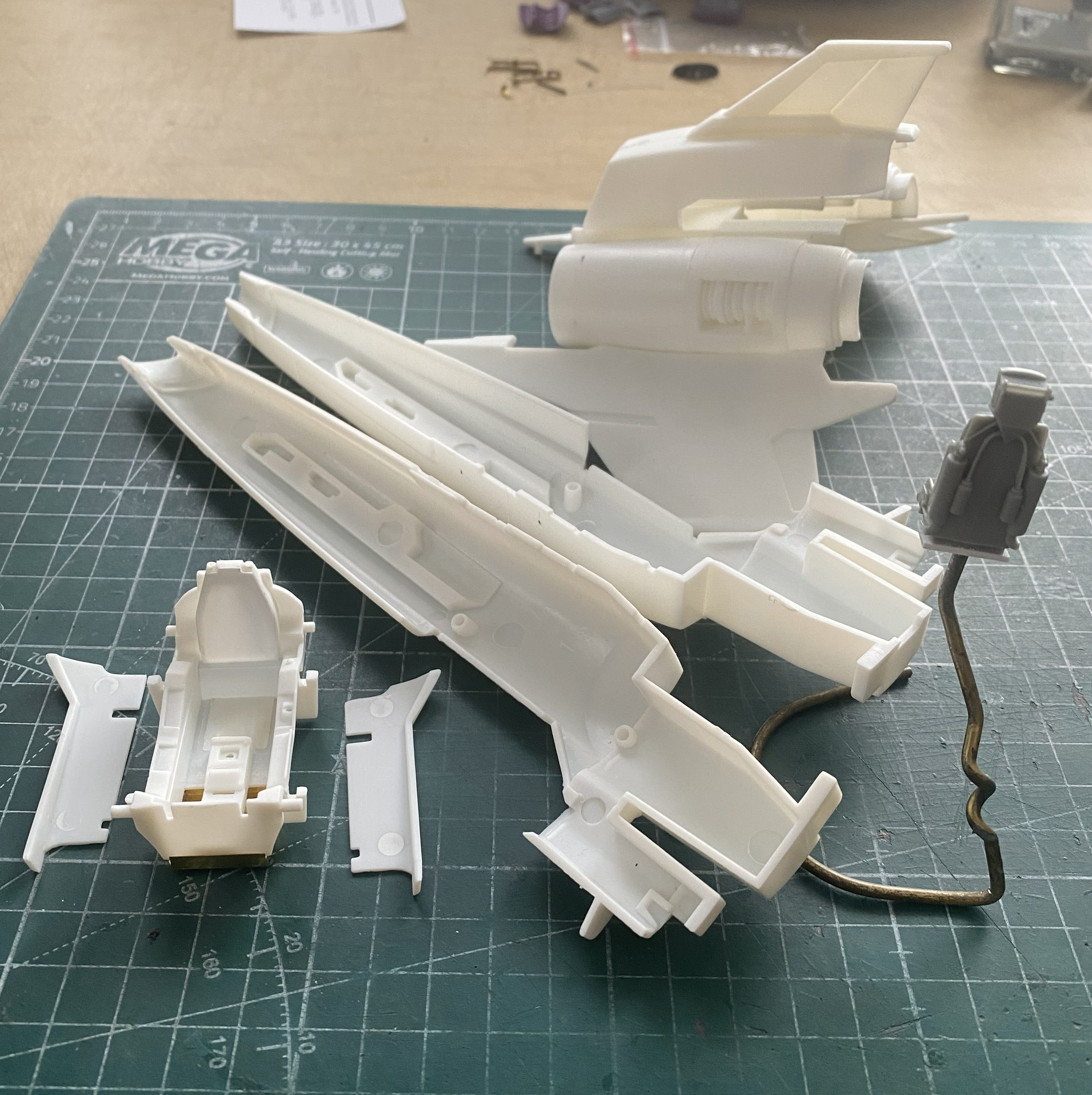
There:
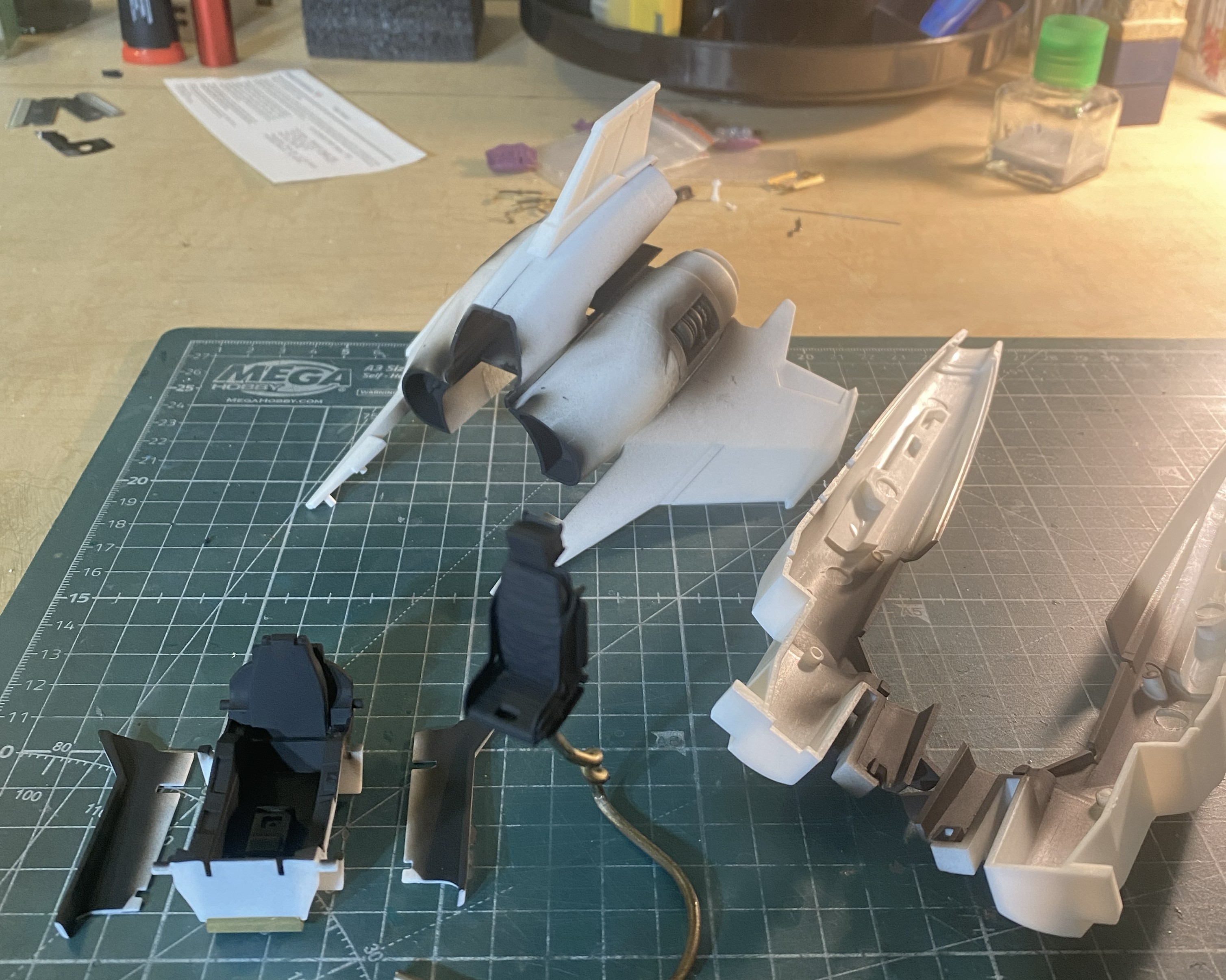
For the overall cockpit color I used Tamiya’s XF-53 Neutral Gray, no scale color correction, and just misted it on:
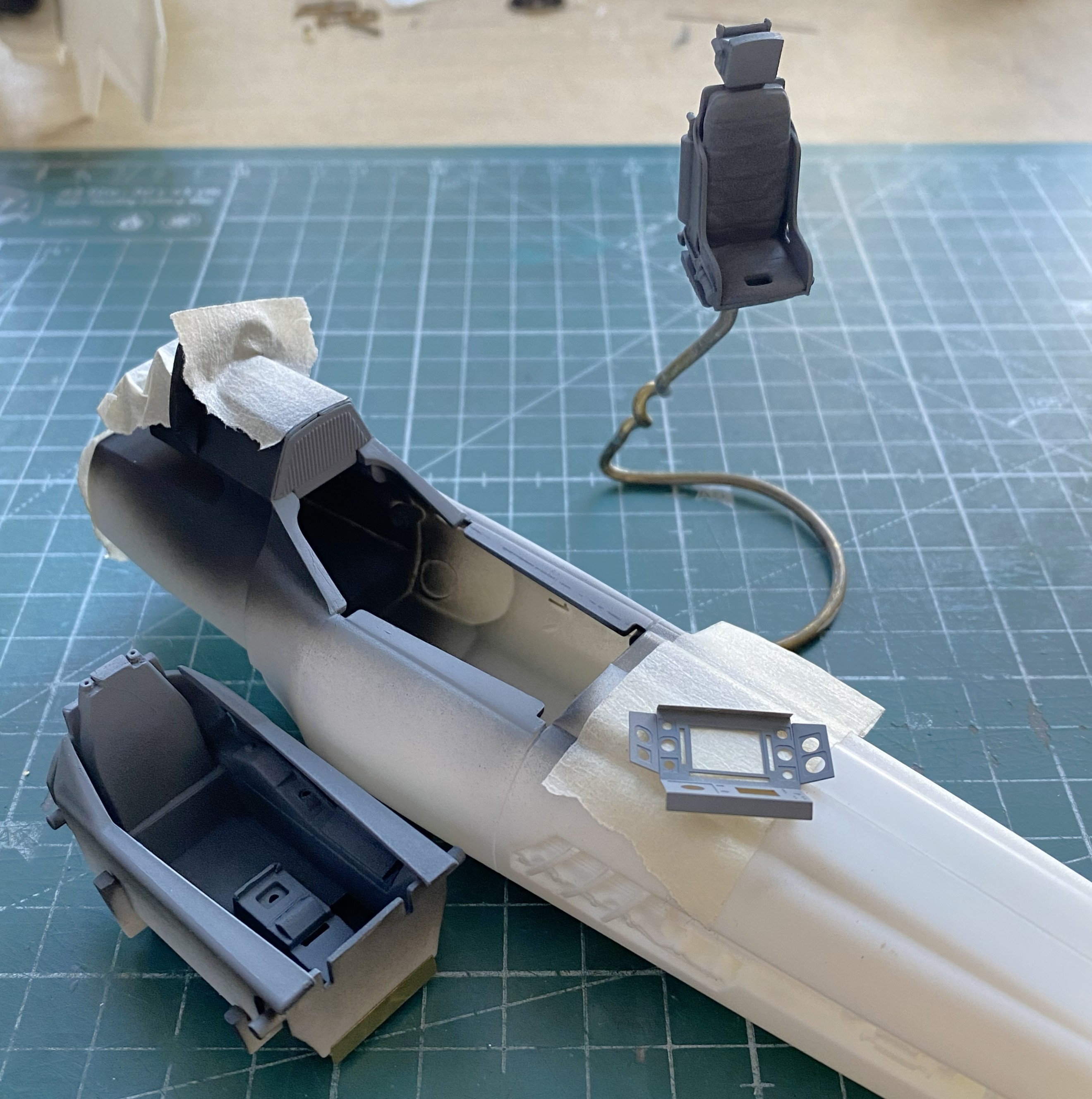
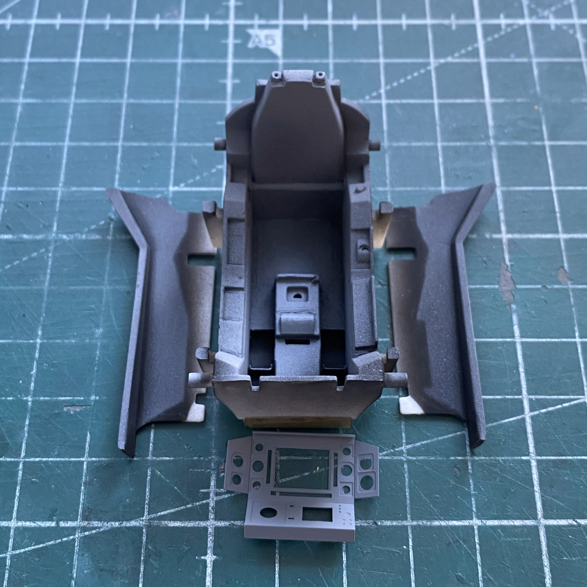
Set that to the side and started work on the main panel:
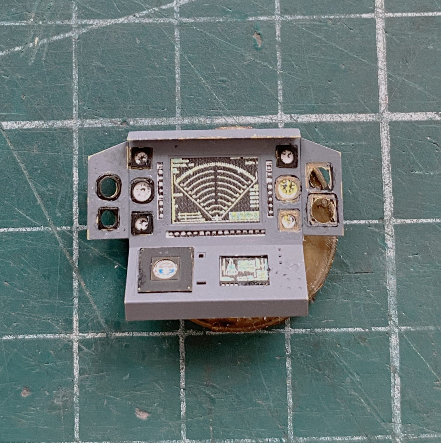
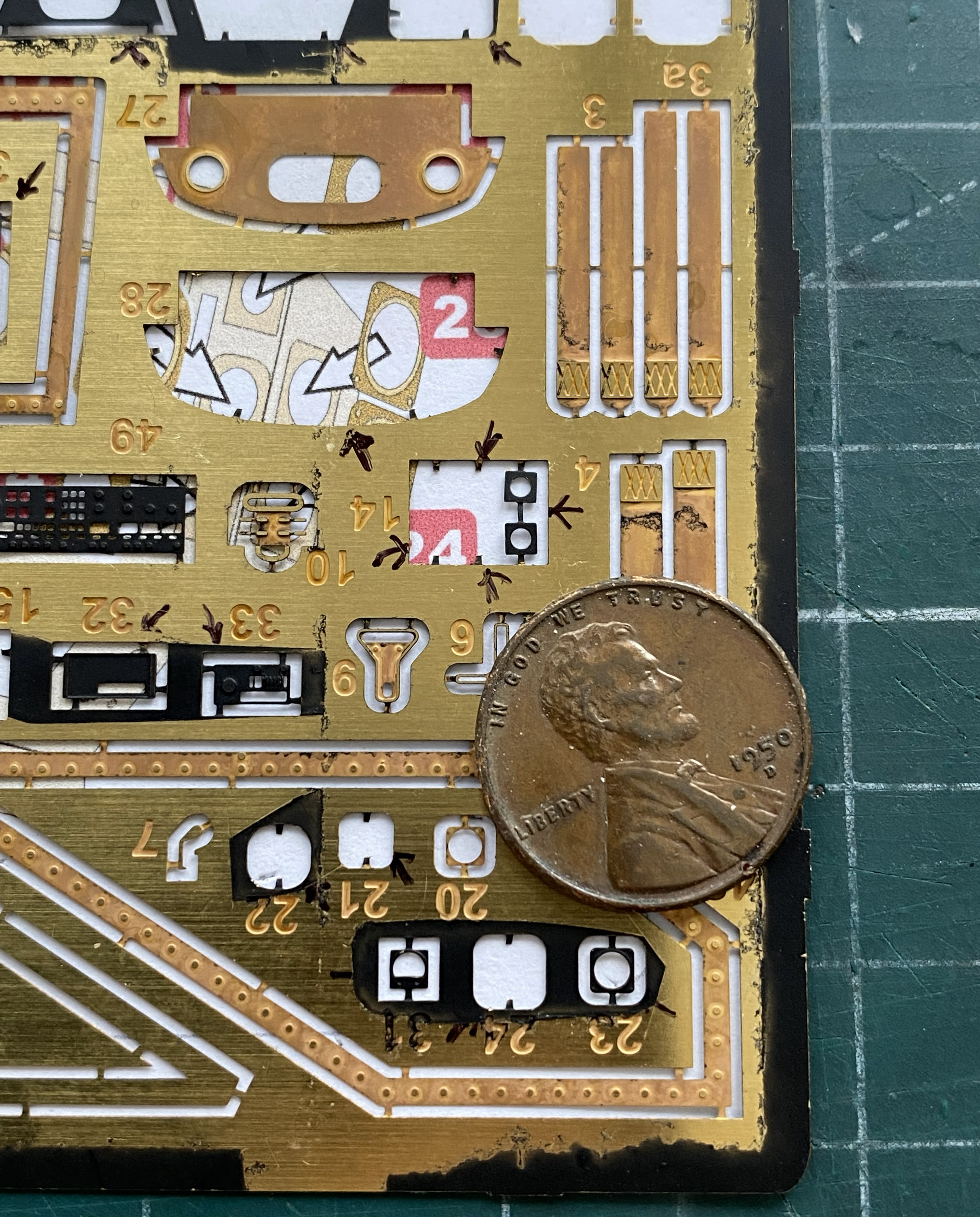

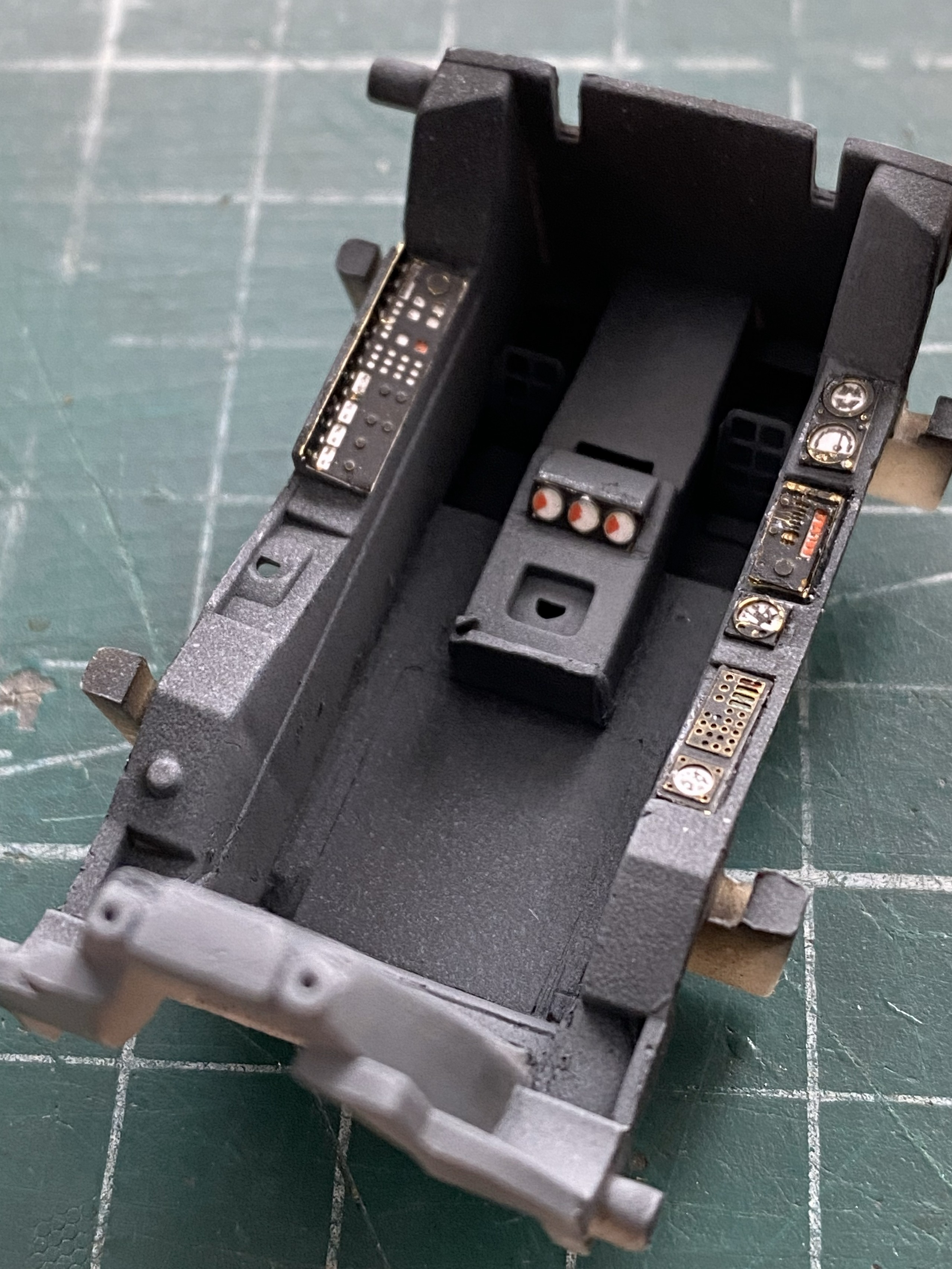
I continued to do the side panels of the cockpit:
Preparatory to finishing the cockpit tub, I had to add decal data-plates to the sides and this is the first major uh-oh of the build. The first decal did not want to release from the backing paper. At. All. I let it sit in the (warm) water until the sodding thing just floated off. How I managed to fish it out of the water without folding it is one of Life’s Mysteries ™. Since I was pretty sure that whatever adhesive used to be on the decal was also floating in the water, I used Micro Set to convince them that this was their new home. That’s when I encountered the second uh-oh…the decal broke while I was trying to move it into a less inaccurate location (see the blue arrow):
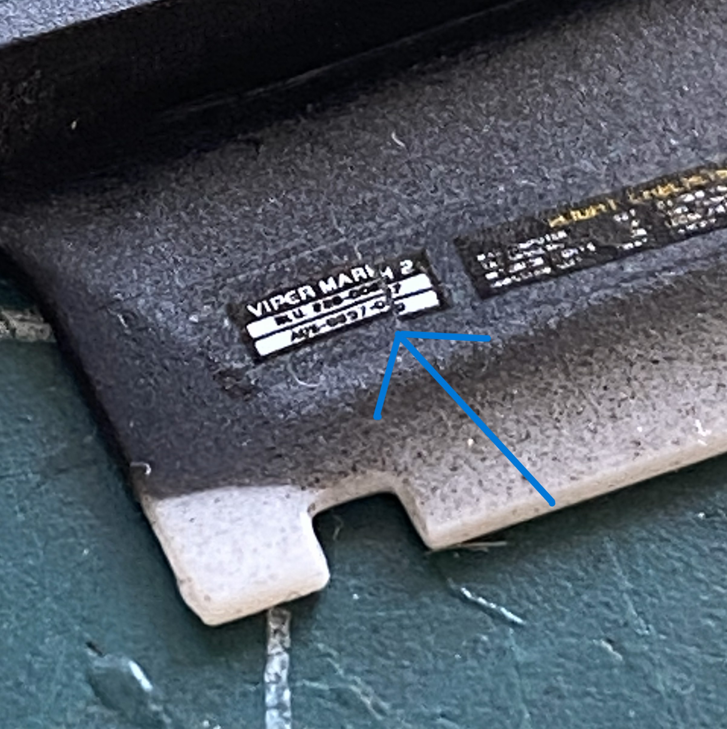
Not only did it break, it broke because the left side of that decal, once it hit the surface, would not move at all. Instead, it tore. This isn’t boding well for the other decals. I hope I’m just being an alarmist.
I didn’t have any trouble at all painting and installing the harness:
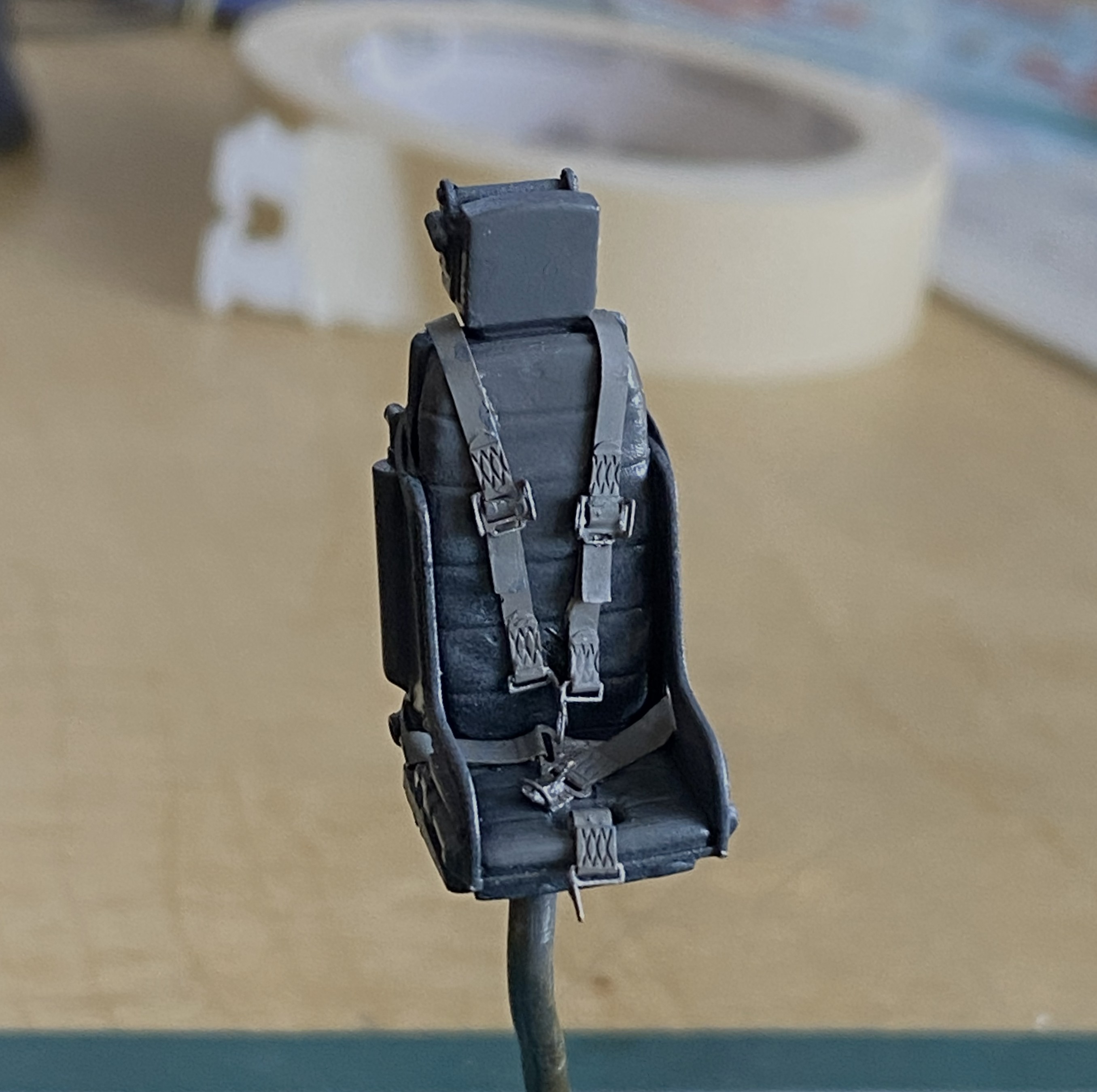
The first step to applying wear and staining was judicious use of the silver pencil. I added friction-wear (as opposed to impact-wear) marks as well as some pastels to make the office looked lived-in (and the sharper-eyed amongst you will note that I also affixed the throttle and joystick as well as the mystery loops behind the headrest, using 0.020″ (.508mm) solder) :
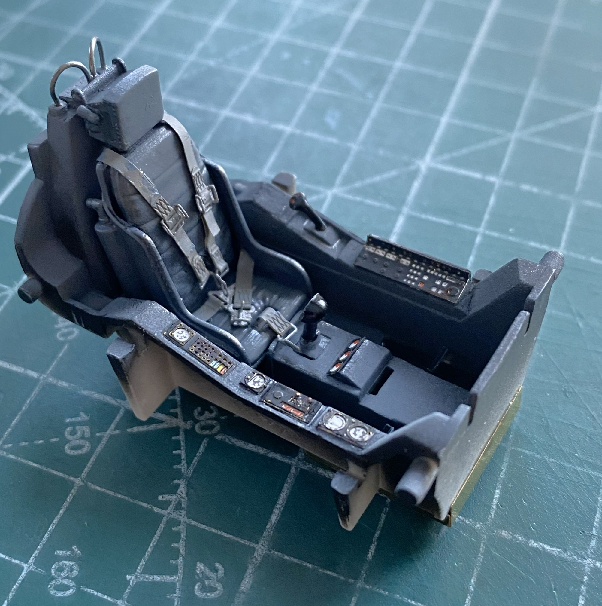

The side rails are just dry-fitted to get a sense of what stains show, where wear goes, and how much of it looks correct:
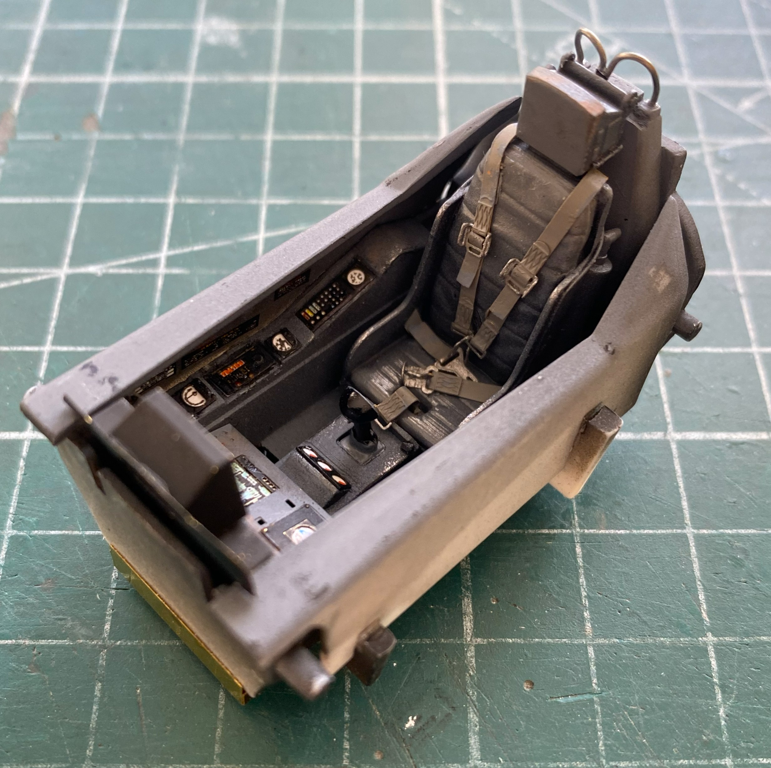
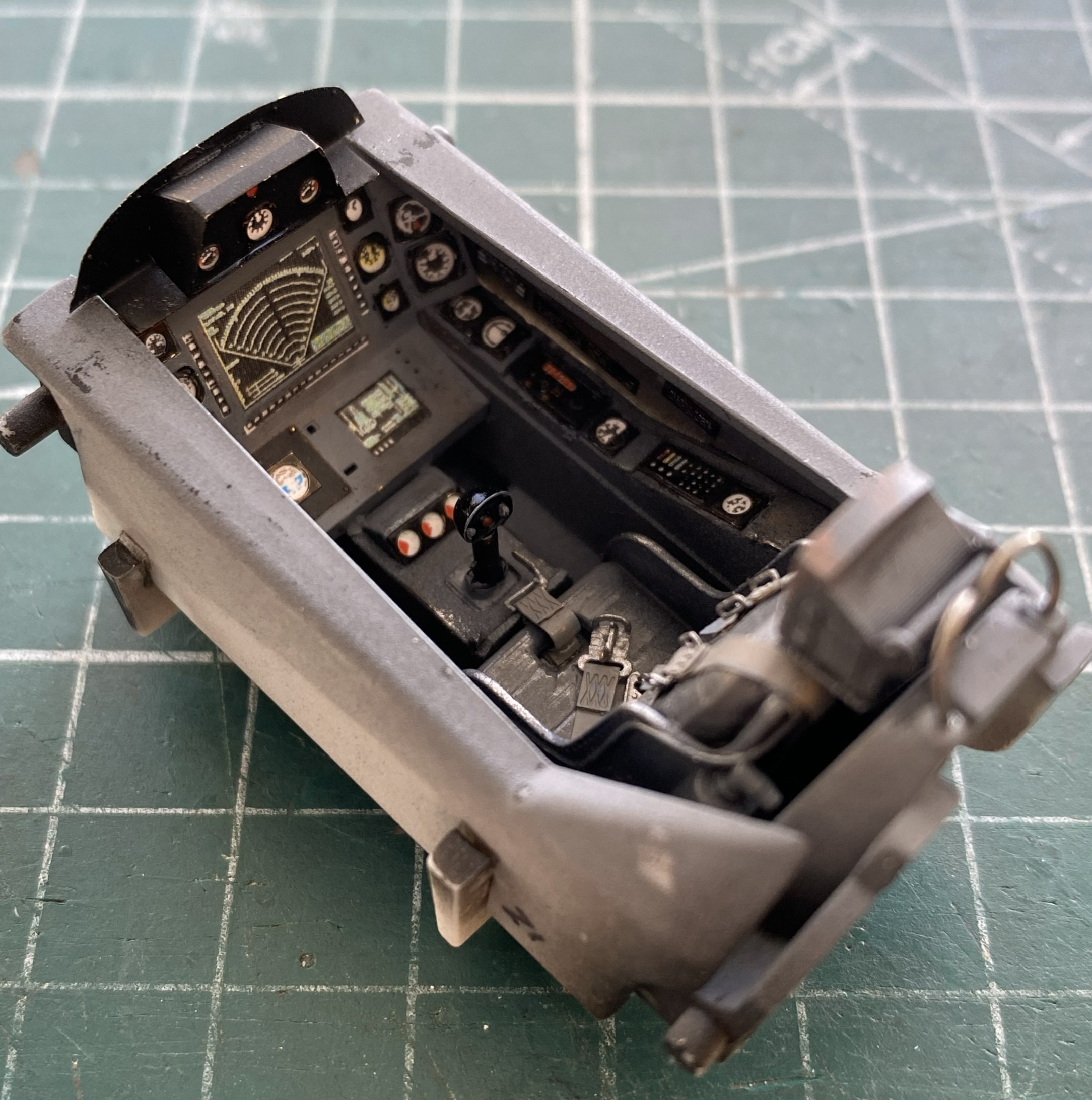
The belly of the fuselage is molded separately from the sides. Clever. It obviates most of the belly seam. To add the AM details, the main fuselage has to be cut away to allow the AM space (more on that later, too) to socket in place:
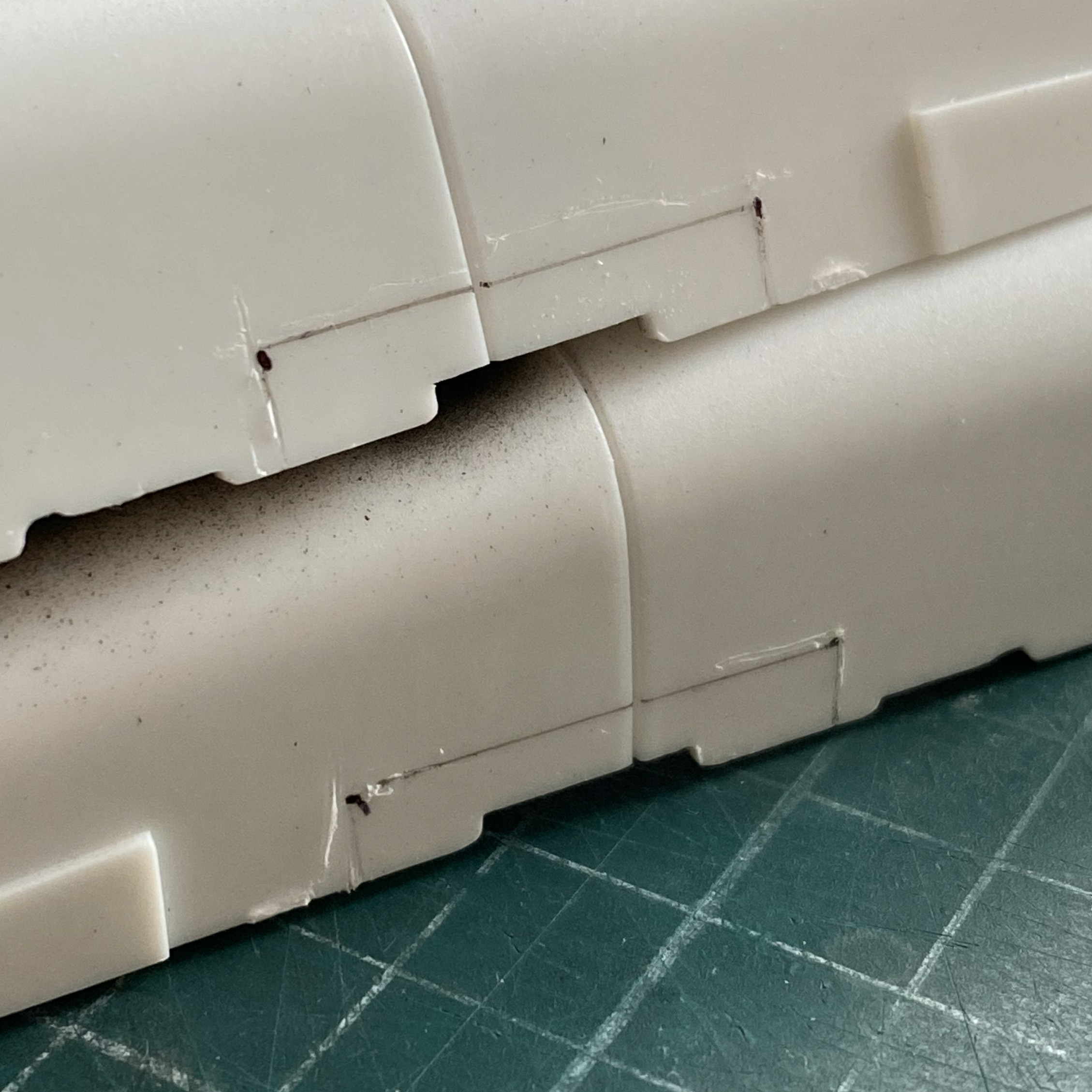
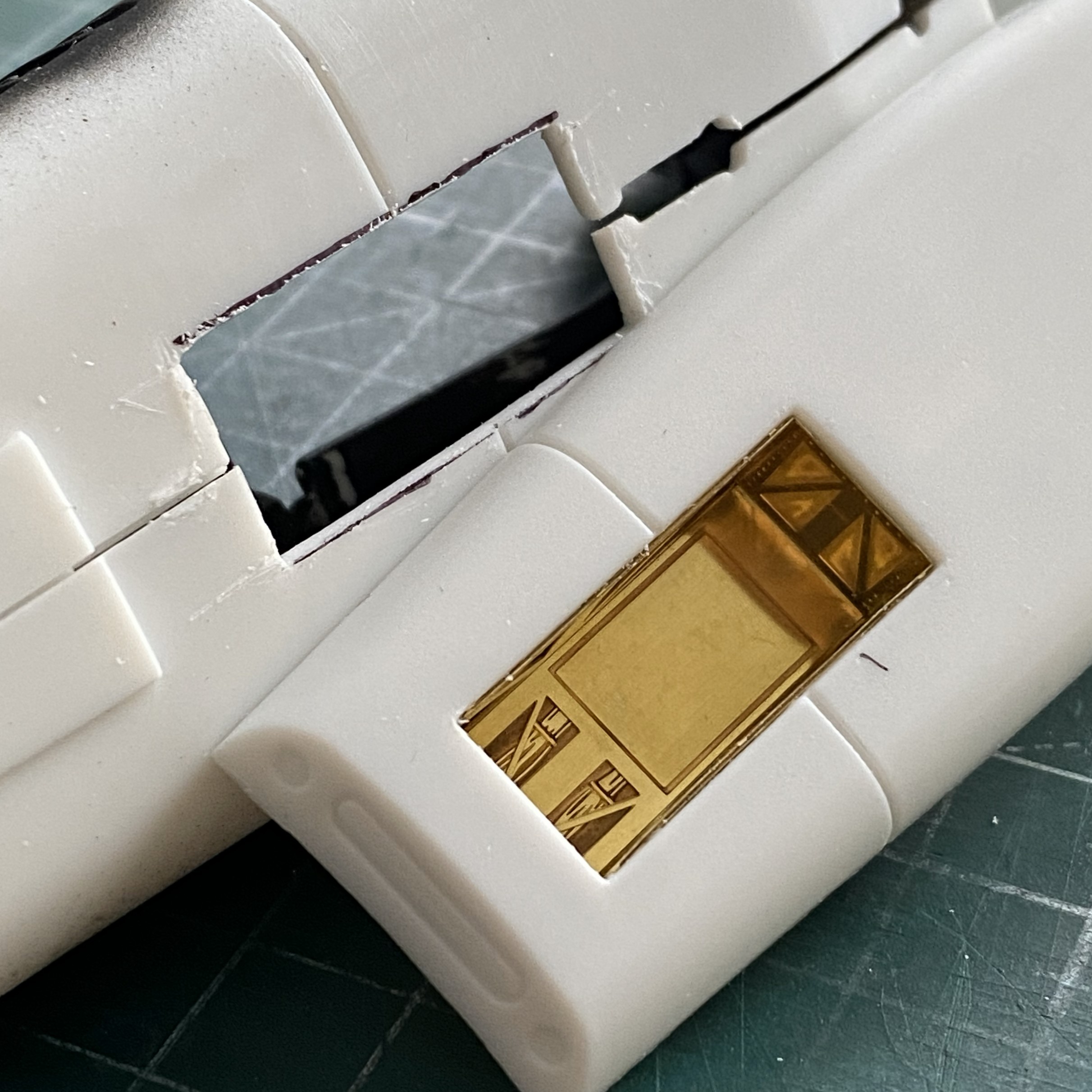
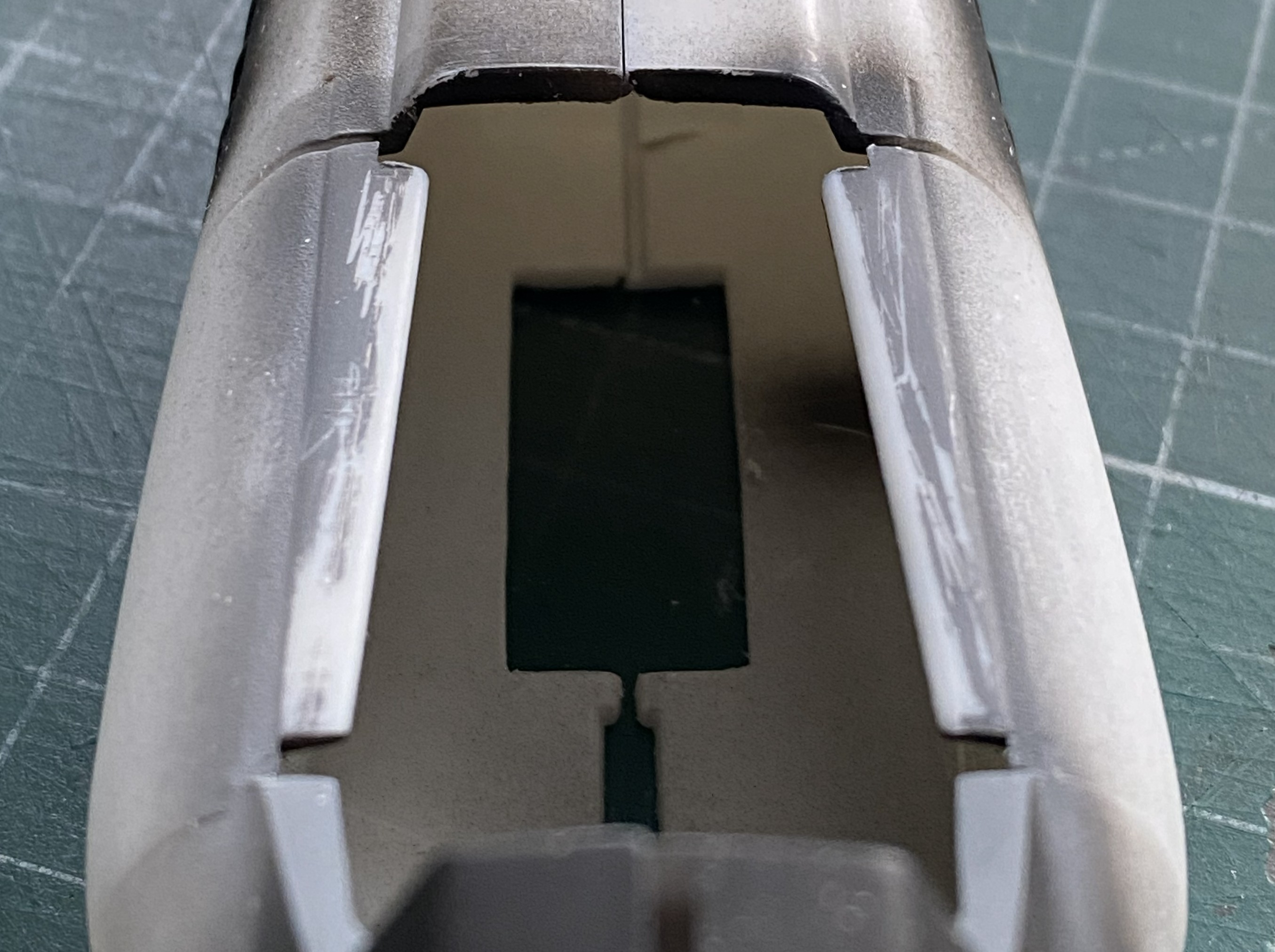
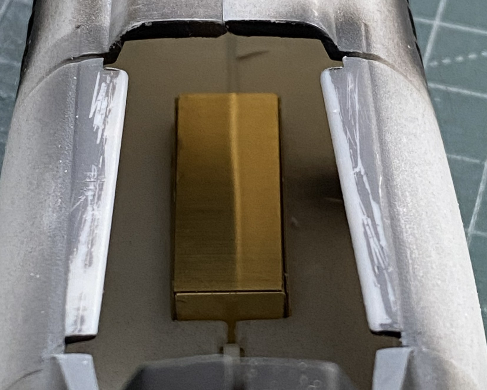
Since the cockpit was done, all detailed, painted, worn, and dirtied, I added it to the fuselage and glued the fuselage halves together:
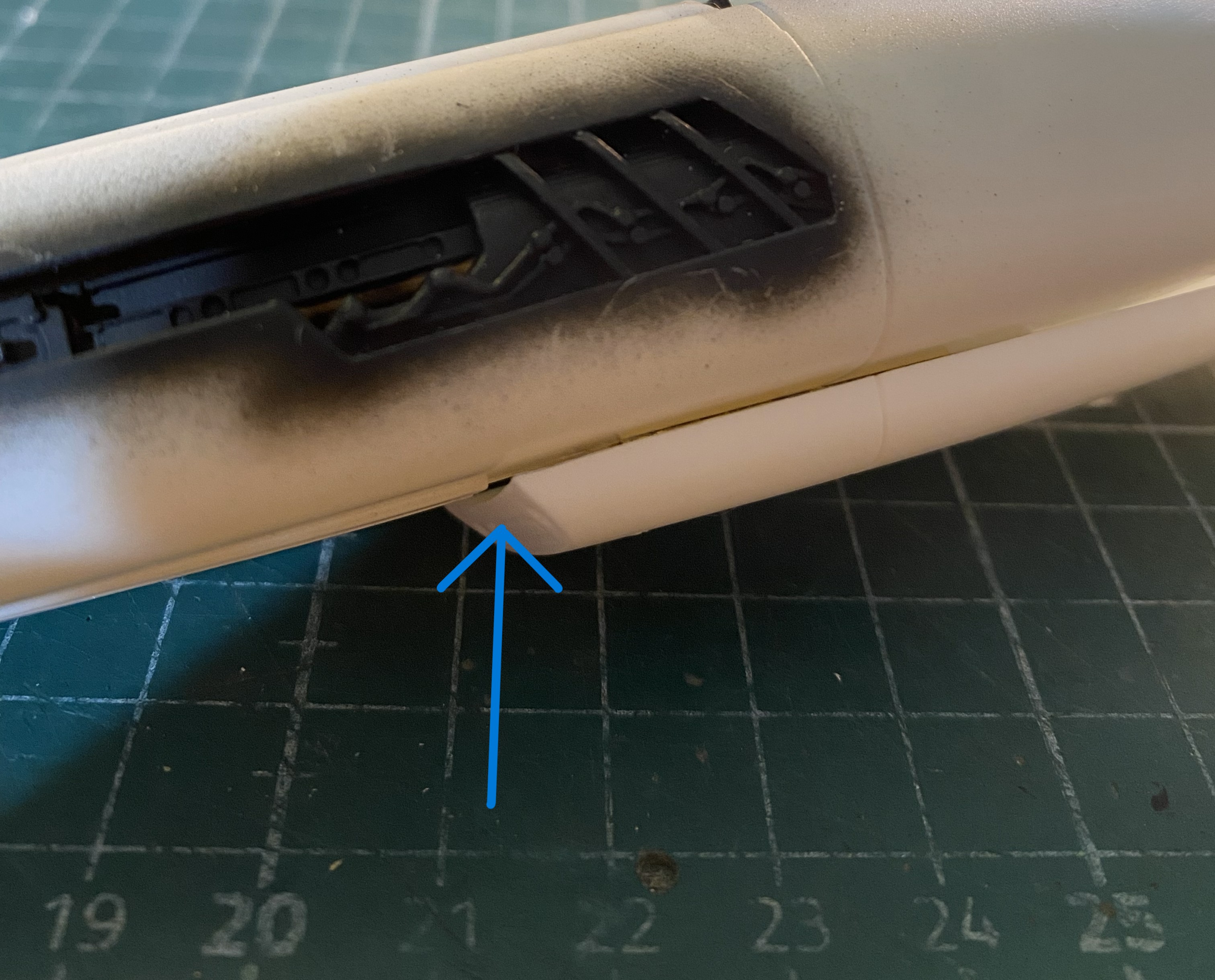
Then I put the belly in place (almost) and noticed that the top of the gear bay impacts the front floor of the cockpit (which is also an AM part from the same manufacturer for the same kit…guess nobody checked to see if it would fit) (again, check the blue arrow):
And speaking of fit, force will be required here (again torpedoing the notion that force never solves anything) to get these two parts to meet:
And while I was checking the fit of things, I took that beautifully cast canopy, put it in place, and realized that it didn’t fit well, either:

While I’m here and looking at the lousy join of this seam, I clamped it most puissantly:
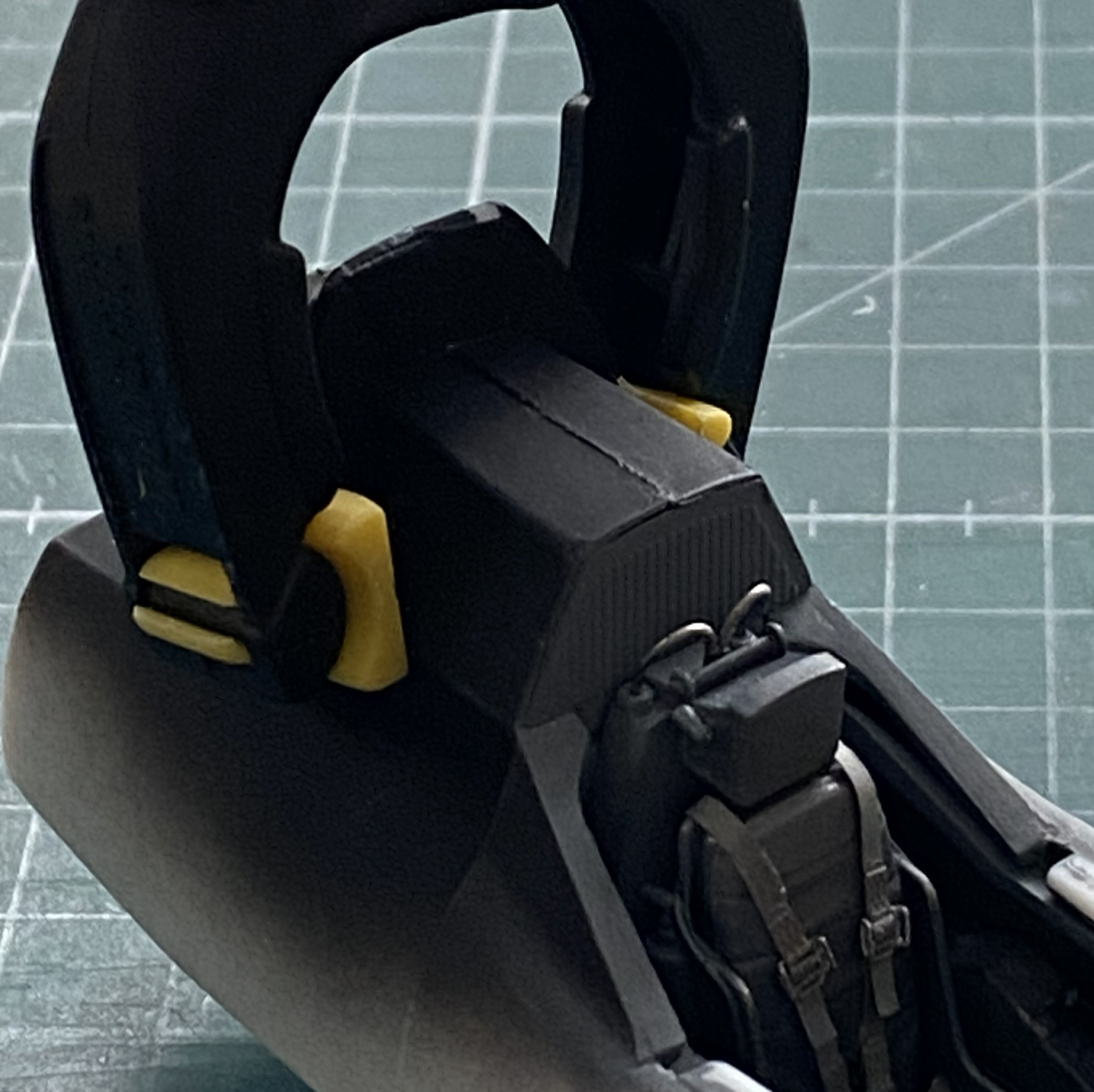
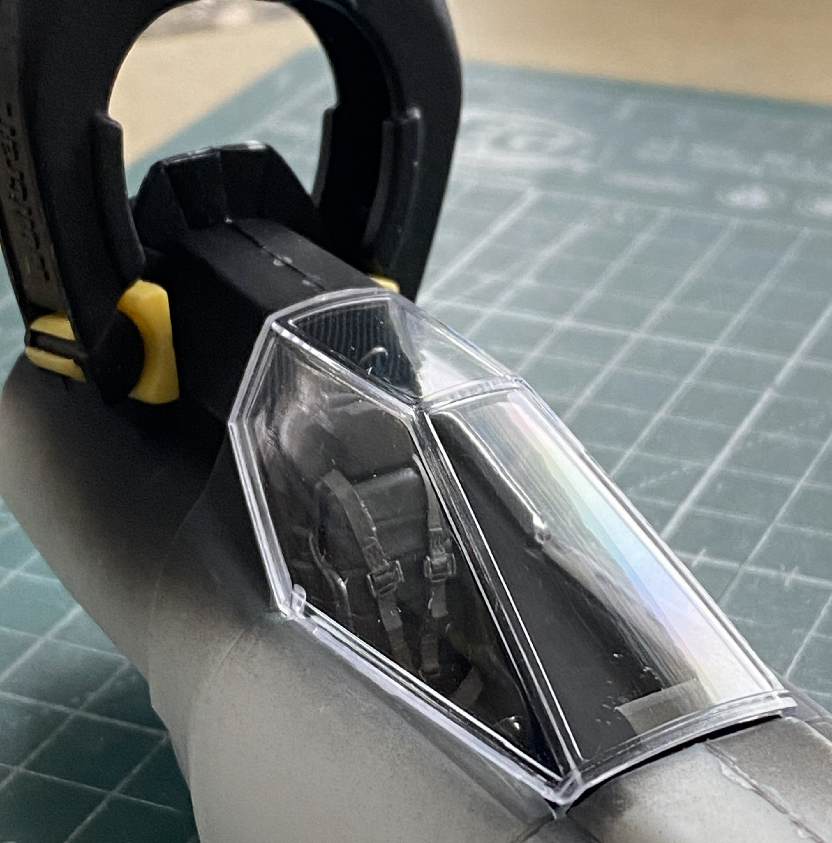
The sides don’t fit either. They’re supposed to seal the cockpit, which will require the surfaces of the canopy to touch the places of the fuselage it should touch:
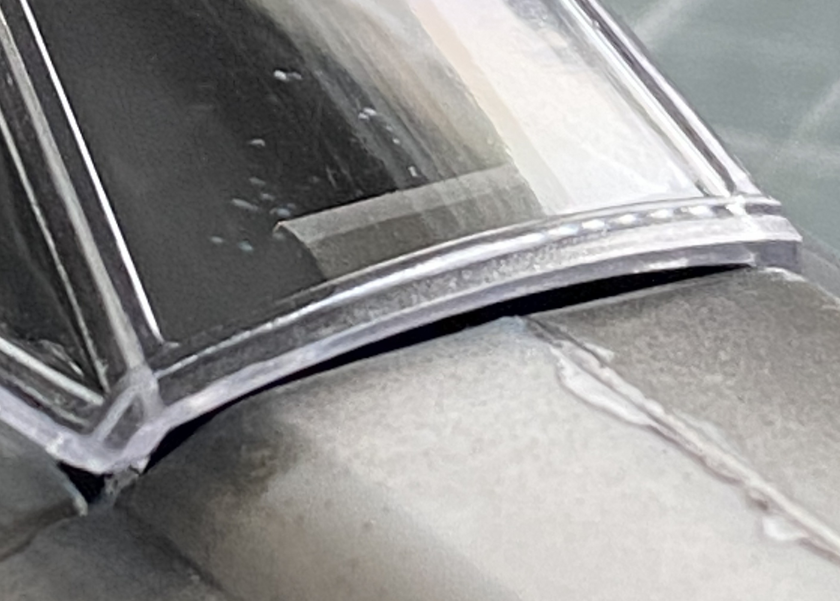
And note how well the leading contact edge of the canopy meets the fuselage:
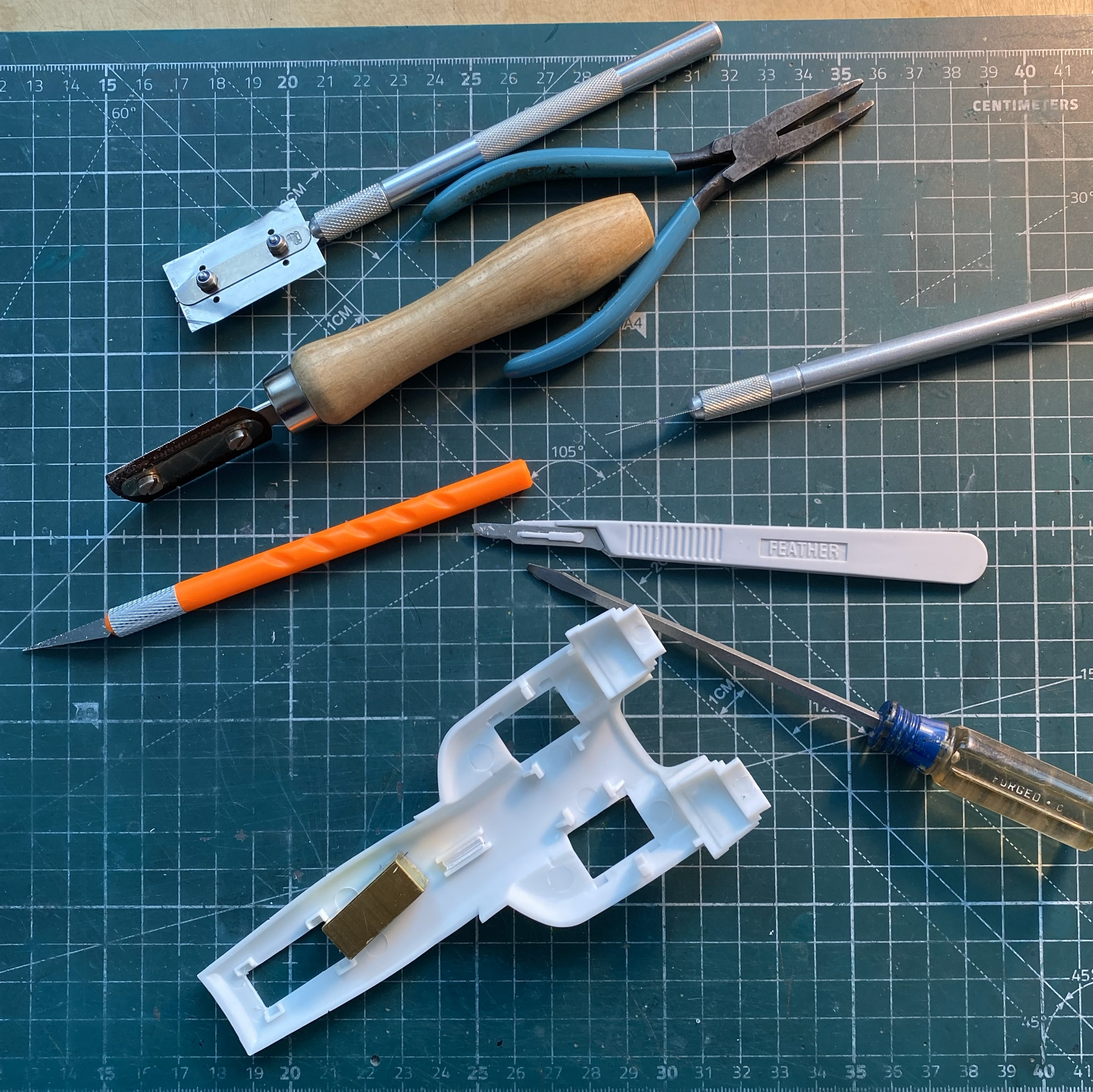
I decided to make the nose gear and belly pan fit first. That required me to cut free the PE part from all the glue I used to hold it there (because, since the nose landing gear attaches to the PE part, it had to be securely glued), which took the better part of an hour (didn’t want to damage the delicate PE, y’know). It also took a few tools to accomplish as well:
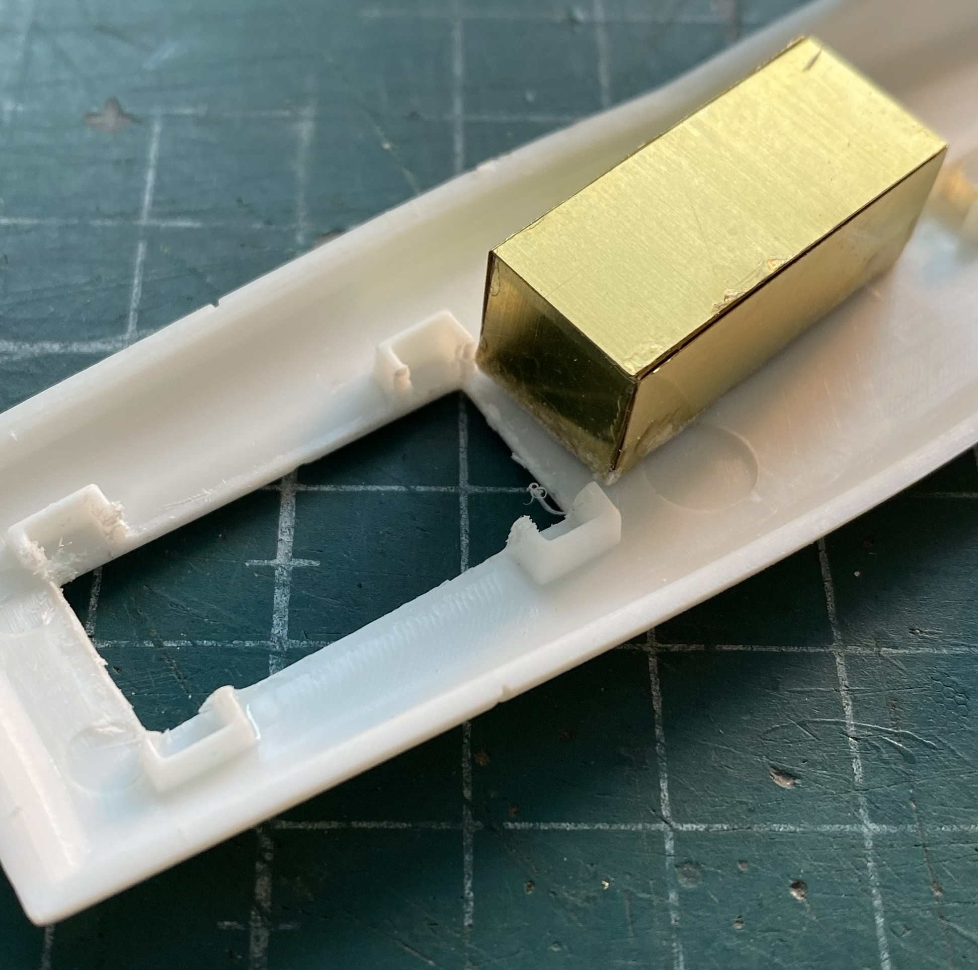
After cleaning the dead glue off of surfaces, it was time to refit it only this time accounting for the intrusion of the cockpit floor. The belly was taped in place and then the gear bay stuffed into the hole until it would go no further:

Since there was going to be cutting and filing of the exposed areas, I glued that PE part in securely and started work until the edges were flush with the fuselage:

Having put the sword o’ Damocles back into its sheath, I turned my attention to fixing the canopy’s fit. What do I fix? All references show that the upper fuselage in front of the canopy is flat. Do I rework the canopy to fit? Or… The canopy is clear and fairly delicate. Could I rework the clear part? Yep. (The Goose build taught me that.) Do I want to do significant surgery on a part I can’t replace? (Okay, sure. I could replace it. But what a freaking job that would be and the canopy would be at risk throughout the process.) No. So that means that I have to build up the nose to match it and do it in such a manner as to be unnoticed. Okay, that seems like a grand idea!
That grand idea started with me laying down strips of styrene from 0.040″ (1.016mm) to 0.020″ (.508mm) with liberal applications of glue:
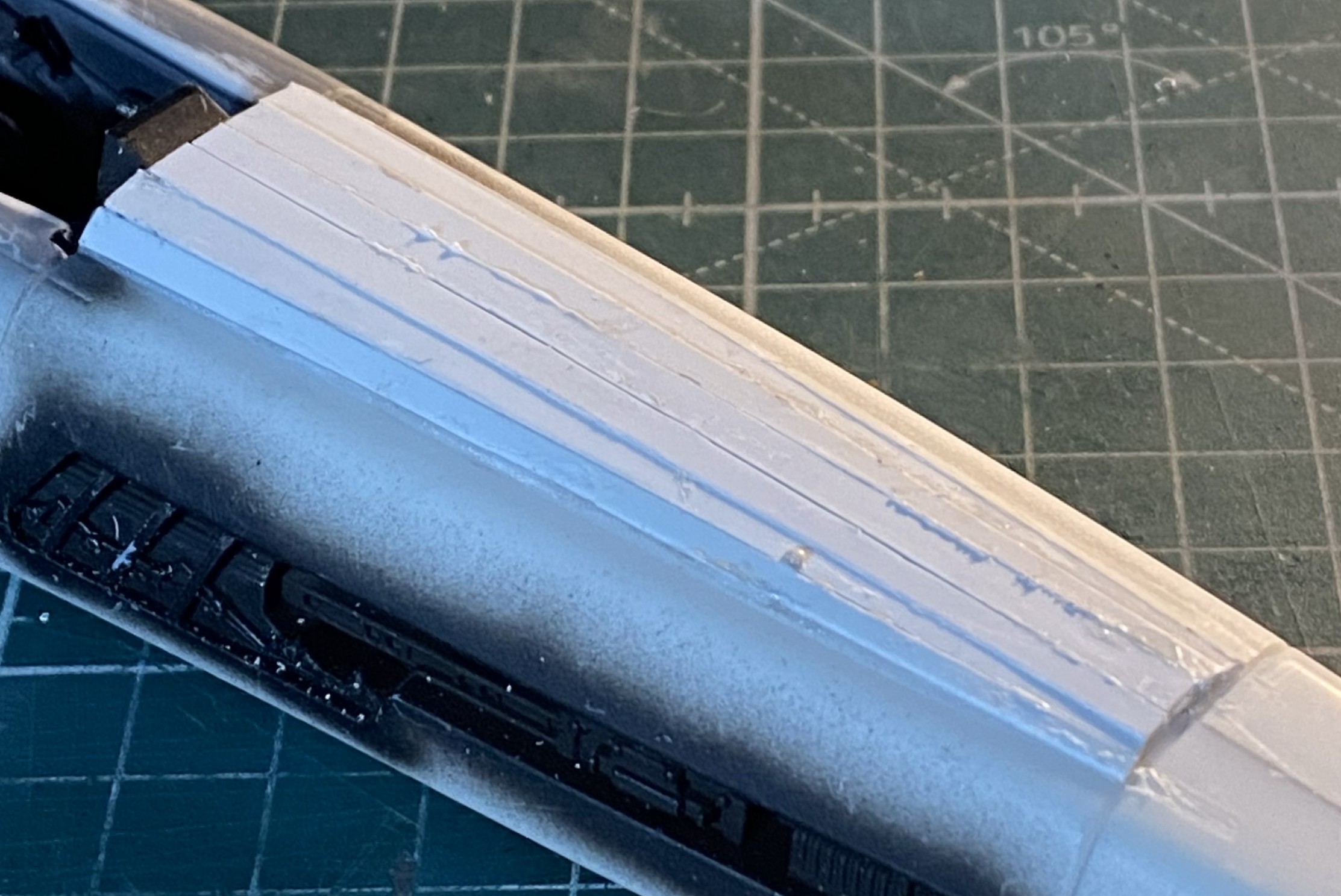
I let it sit overnight before starting to shape it. I started with 50 grit and worked my way past 100 grit and down to 220 grit, at which point gaps started to open up. Stretched sprue to the rescue:
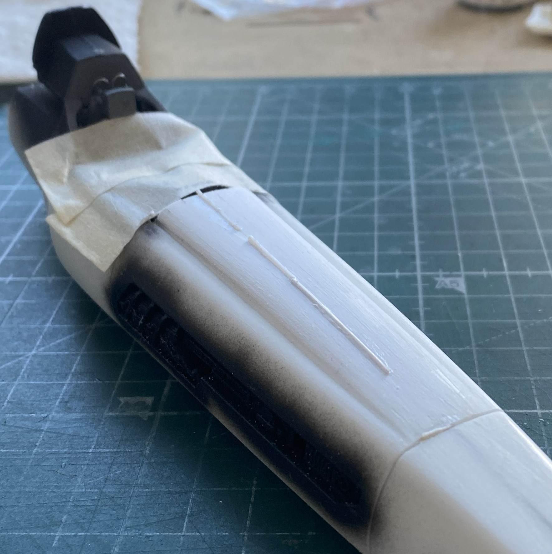
Making a curved surface with flat panels means that each panel will be thicker in the center than at the edges (arcs, y’know). As the surface is removed and shaped correctly, the thin edges of those flat panels start showing gaps. That’s okay. I knew it would most likely happen and I have a lot of sprue I can stretch:
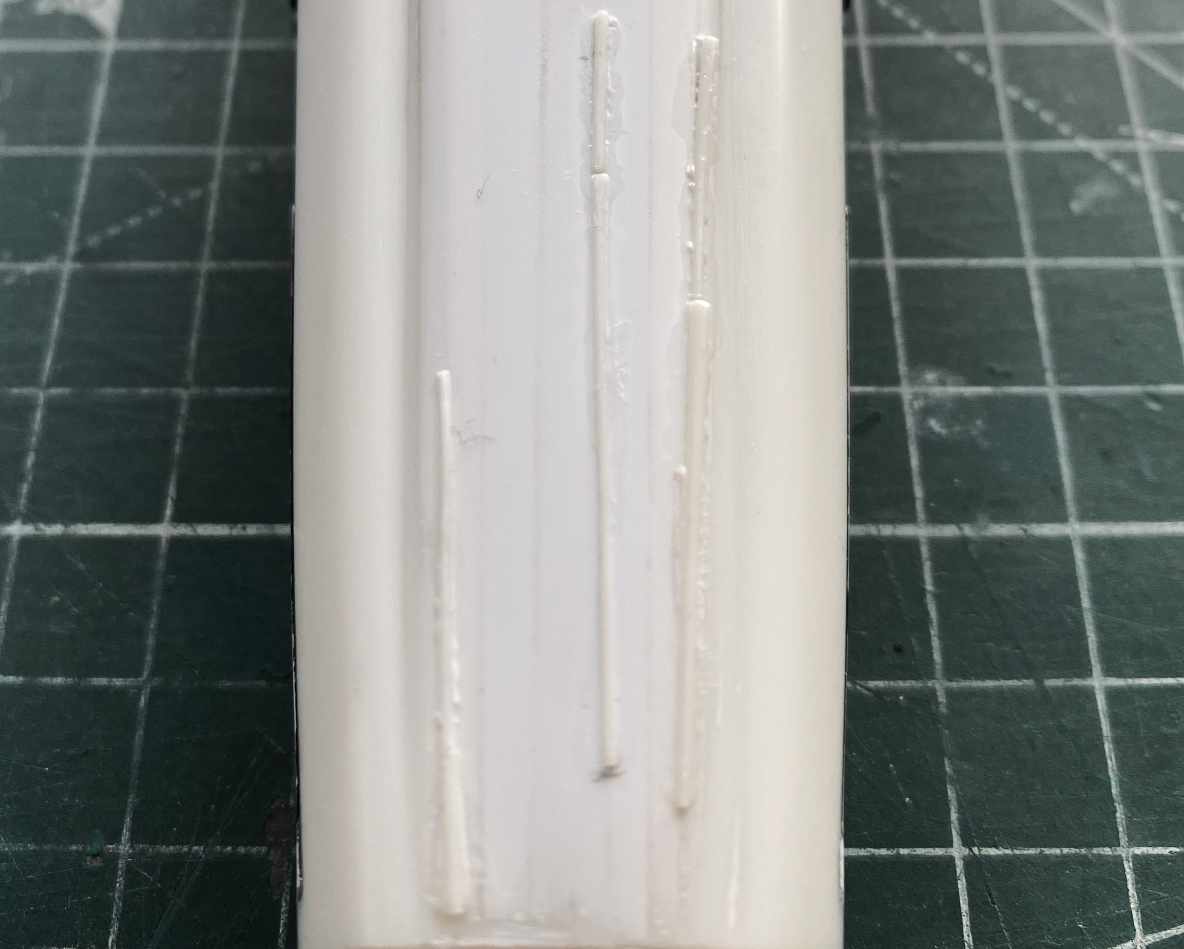
While those were curing, I started fitting the canopy. I added small bits of scrap plastic, putties, and got the two edges to meet at the front:
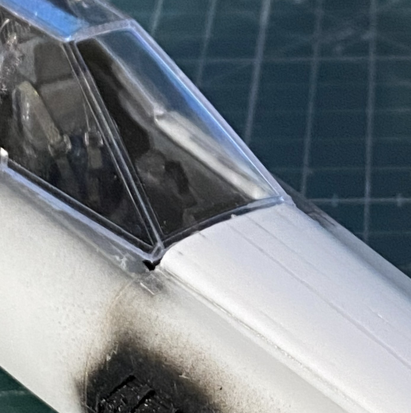
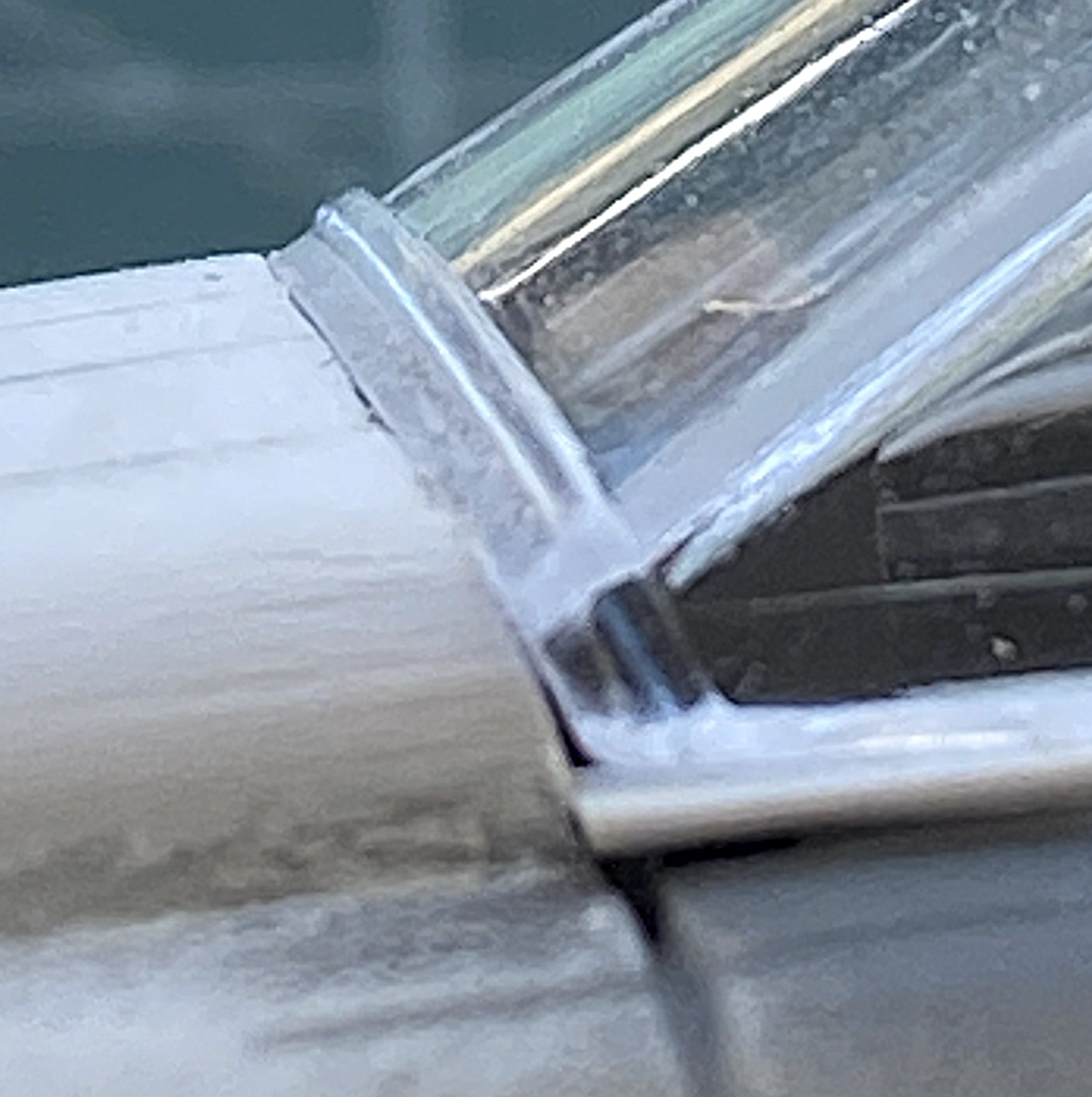
In the above photo, at the lower edge where the canopy meets the fuselage, you can see a 0.020″ (.205mm) spacer that I’m using to start filling the gaps at the sides of the canopy. Once the gaps are established, it’s just the sometimes-tedious job of filling them with scrap (mostly 0.010″ .254mm) and a bit of 0.020″ (.205mm)):
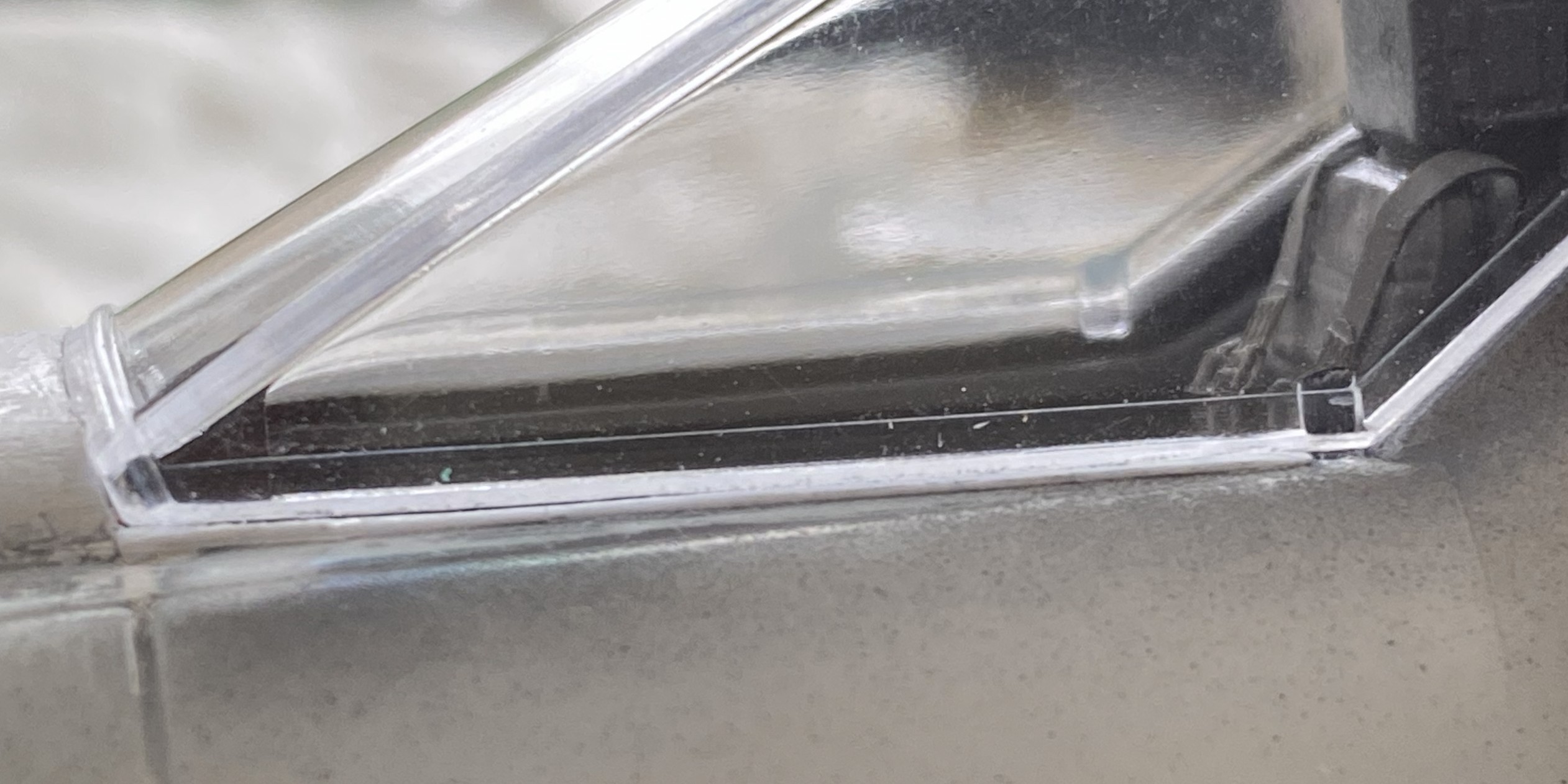
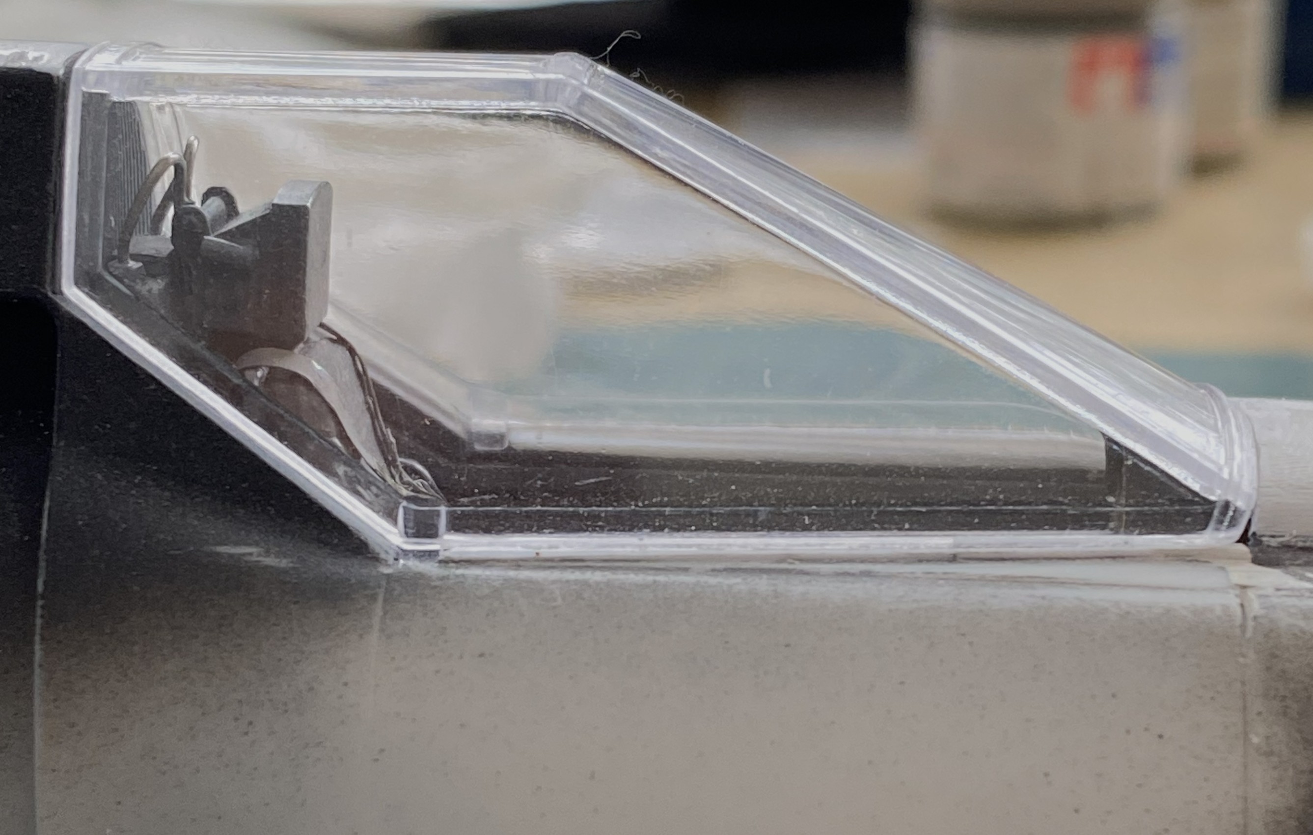
This post surprised me. It wasn’t until I started working on this post that I realized how much work I’ve done on this; it certainly didn’t feel like it. Anyway, I’m going to stop here. Yes, there’s more. I think I’ve already stuffed enough into one post. I’ll finish this one up (edit checks) and start the next one tomorrow.
 Scale Modeling Mania