SR-71A Blackbird (Testors) Build #16 – Fuselage Gets Tedious Attention
I ended the previous post with “whew.” I was premature. Putting all the parts together was one (very small) step of a long walk. Now that the parts (sort of) fit, I have to make the parts fit. And I also have to get everything to look integrated, smooth, and have all the gaps filled.
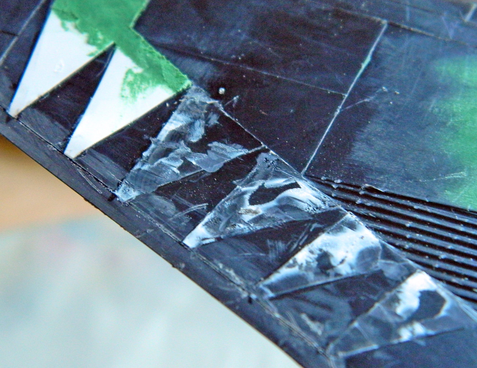
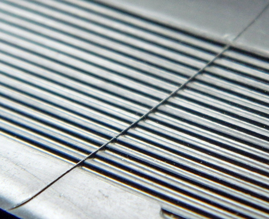
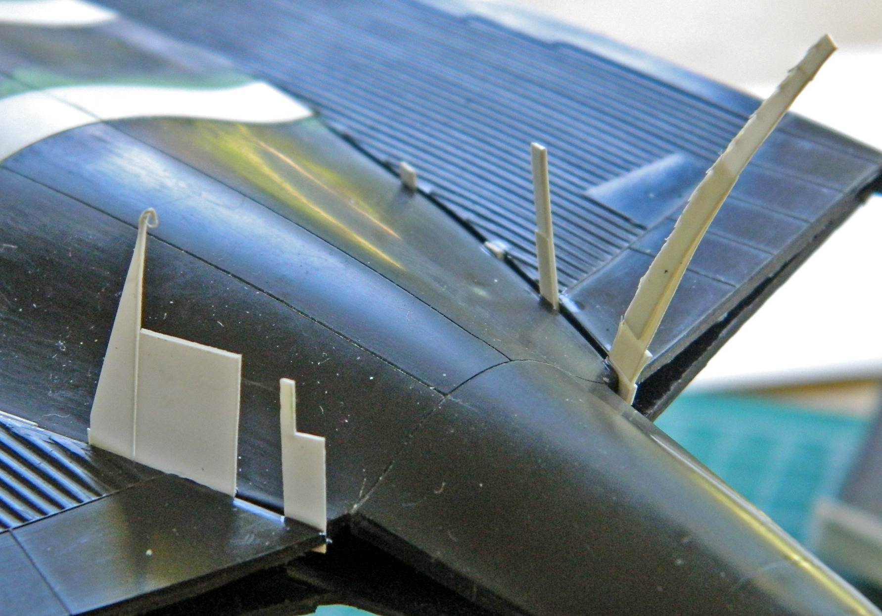
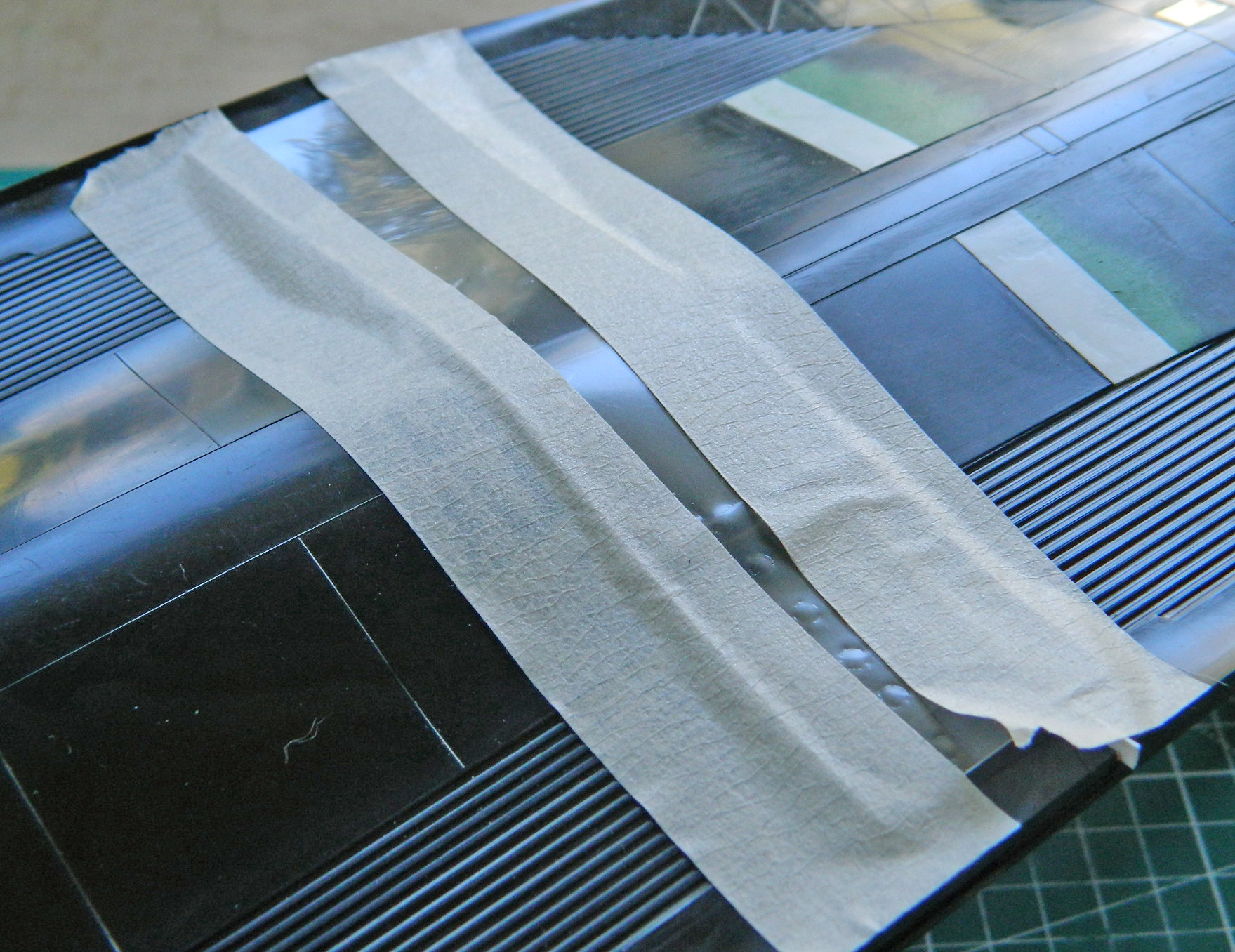
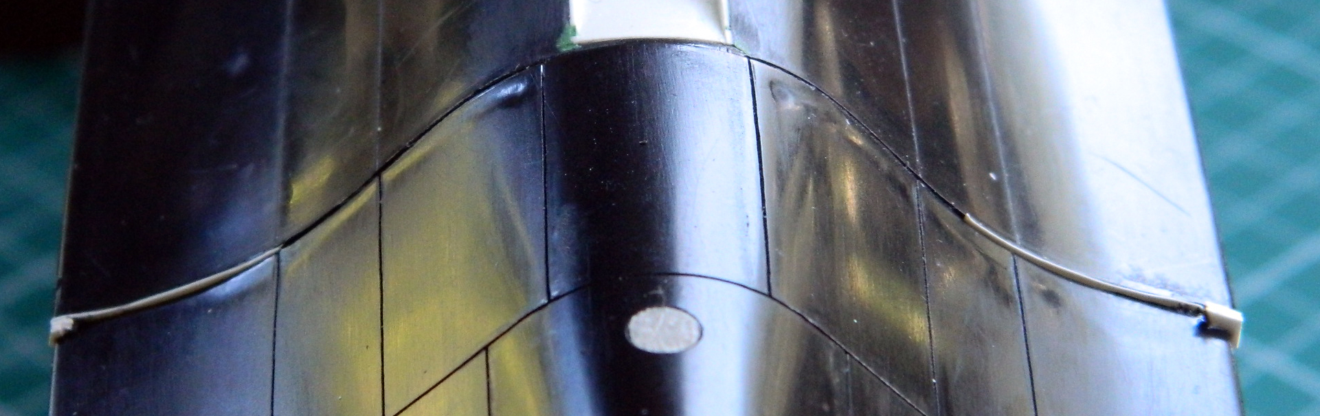
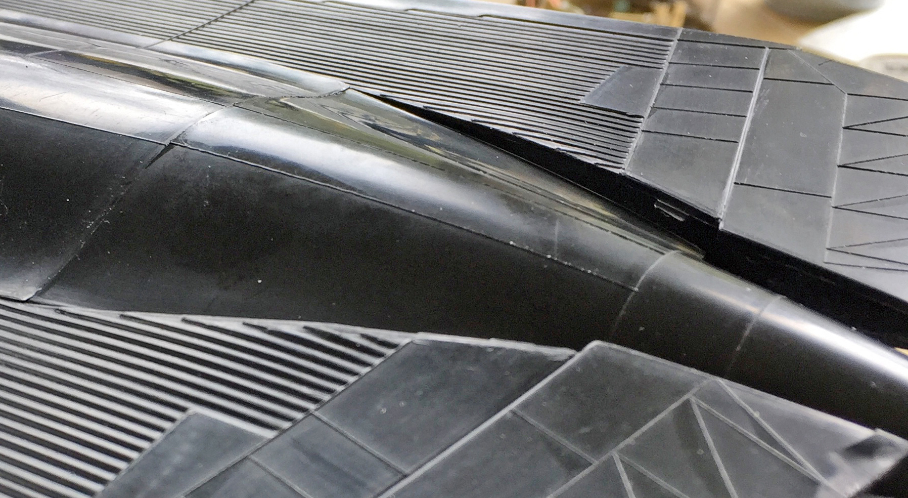
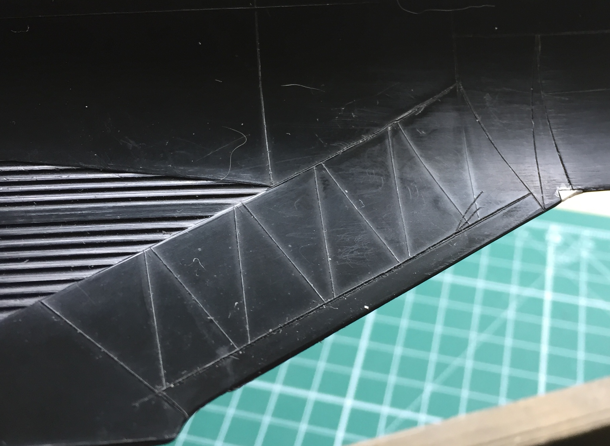
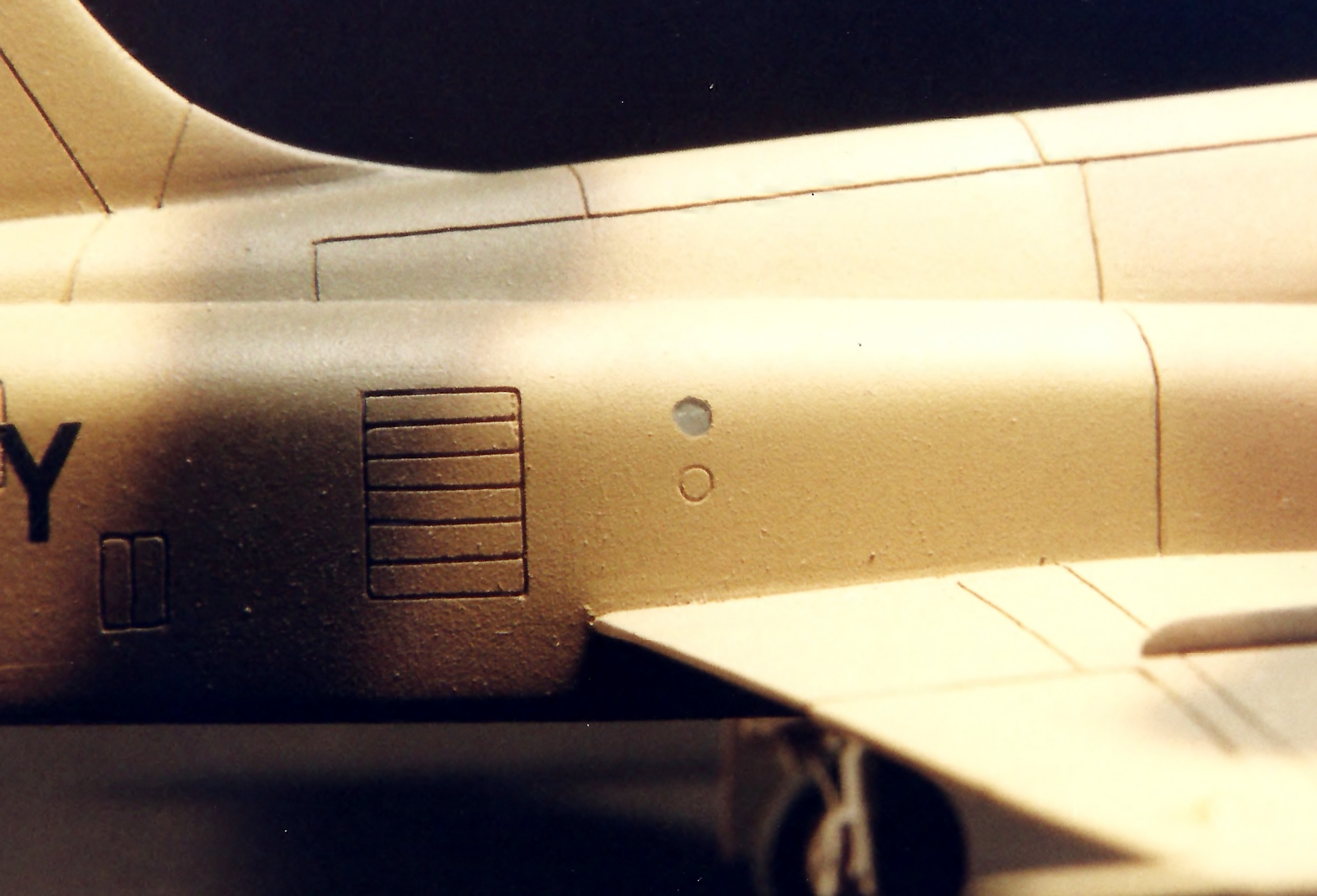
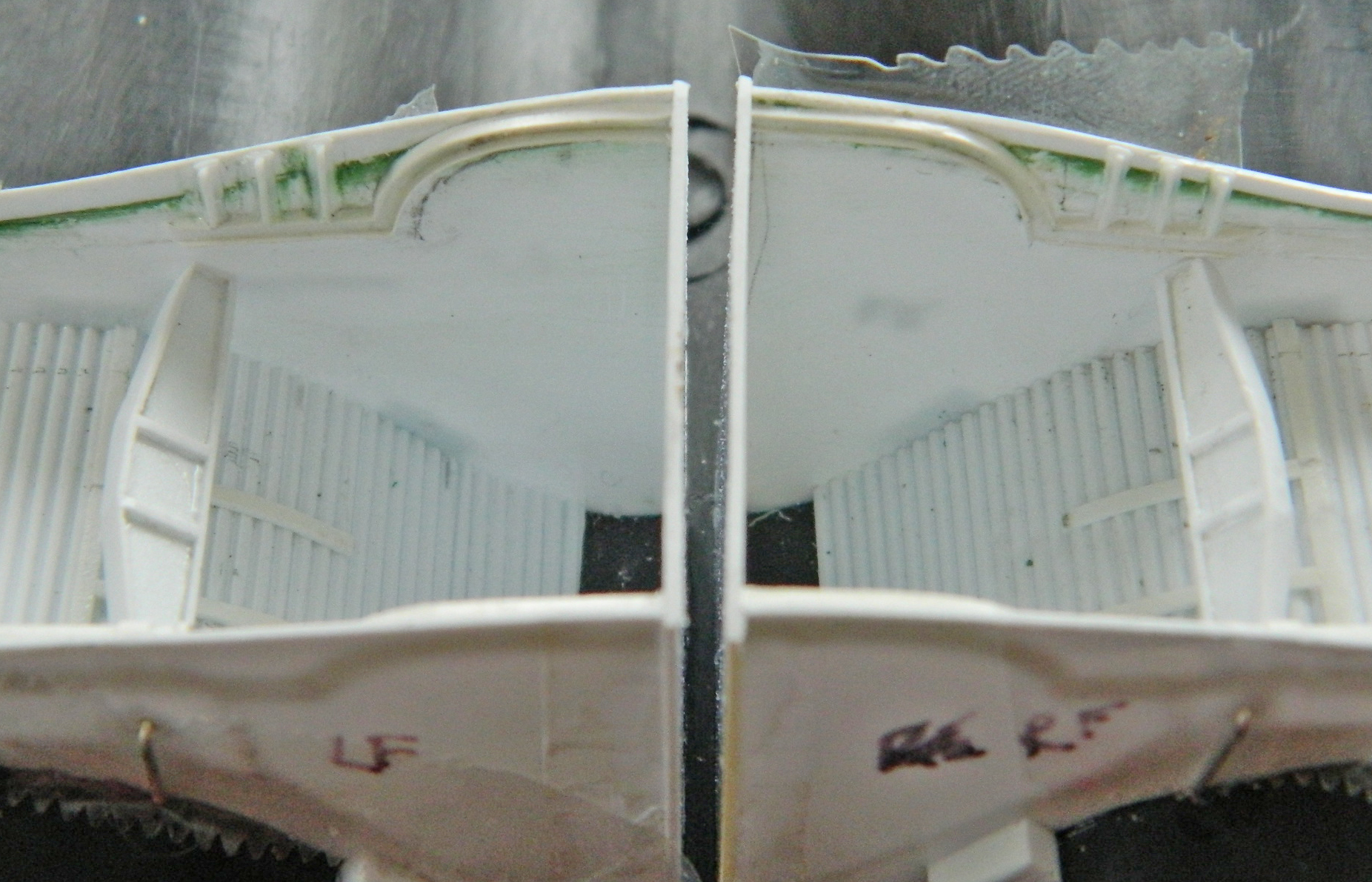
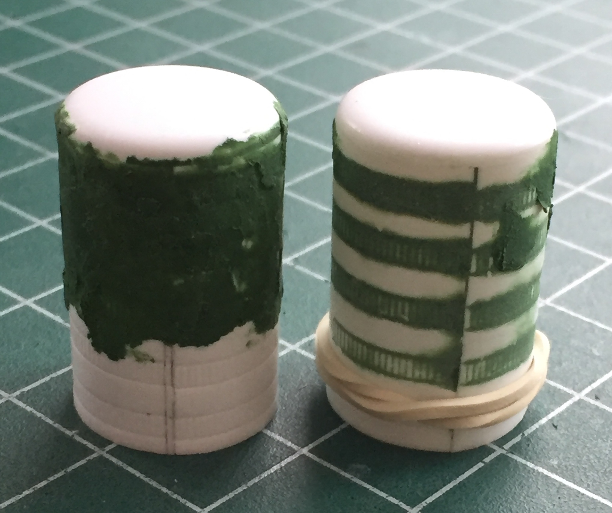
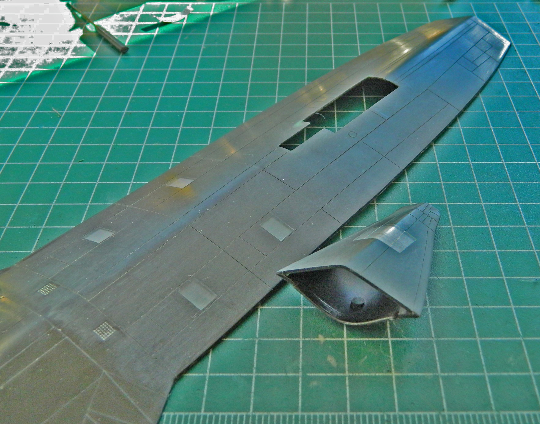
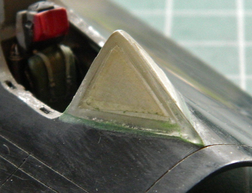
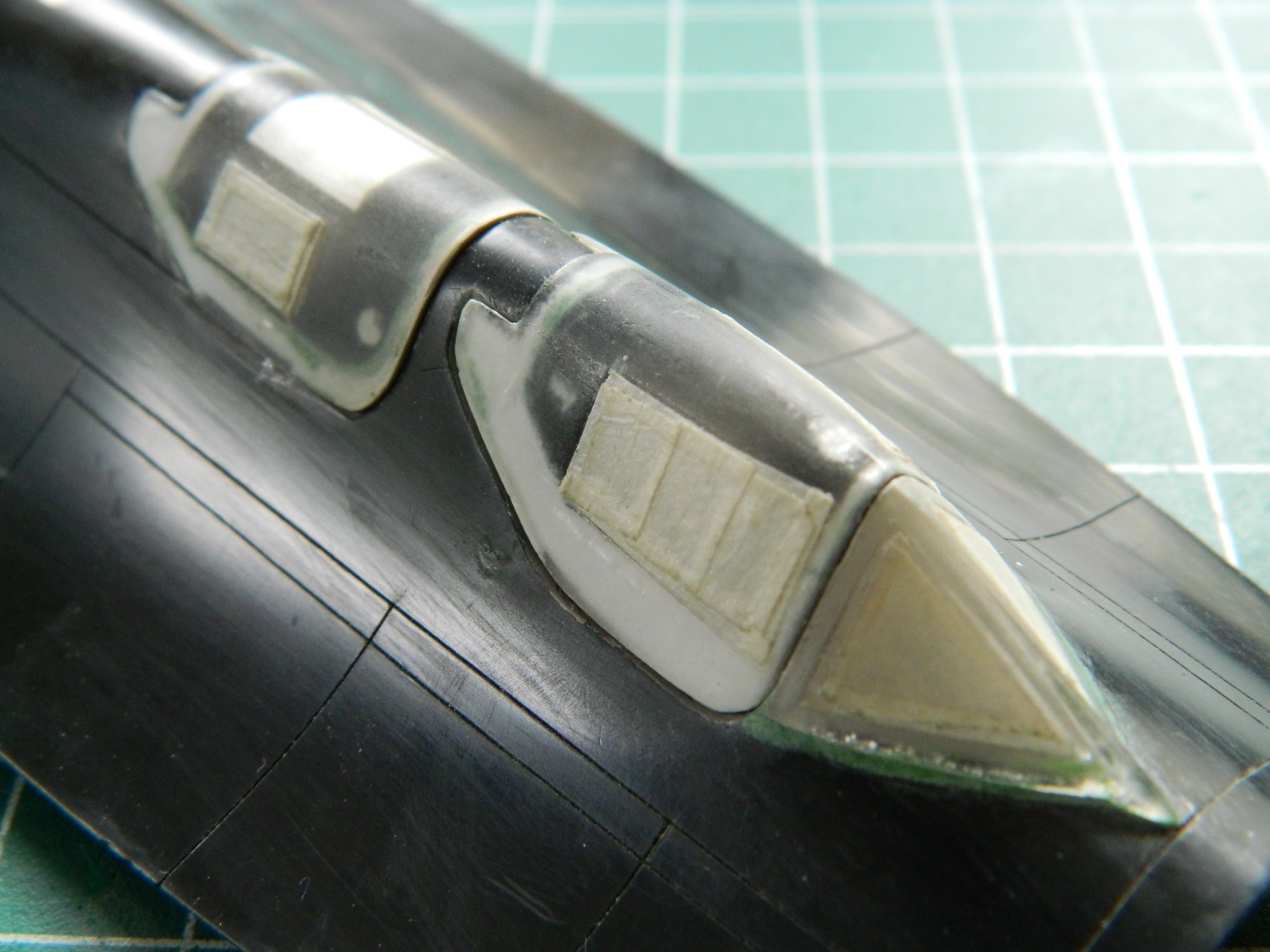
One of the things I noticed when I was at the NASM was that the triangular sections of the wings were actually raised, so .005″ (.127mm) sheet was fitted and putty used to blend the ones that need to be blended:

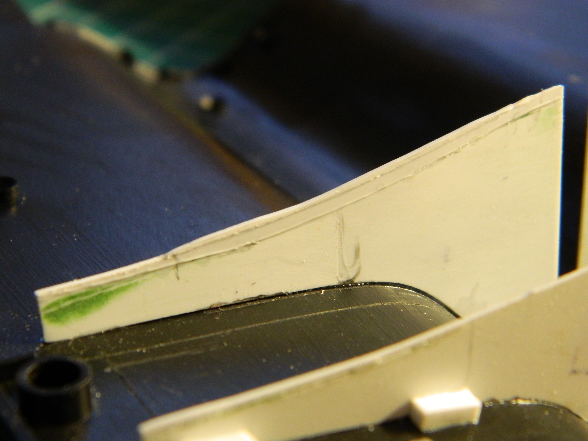
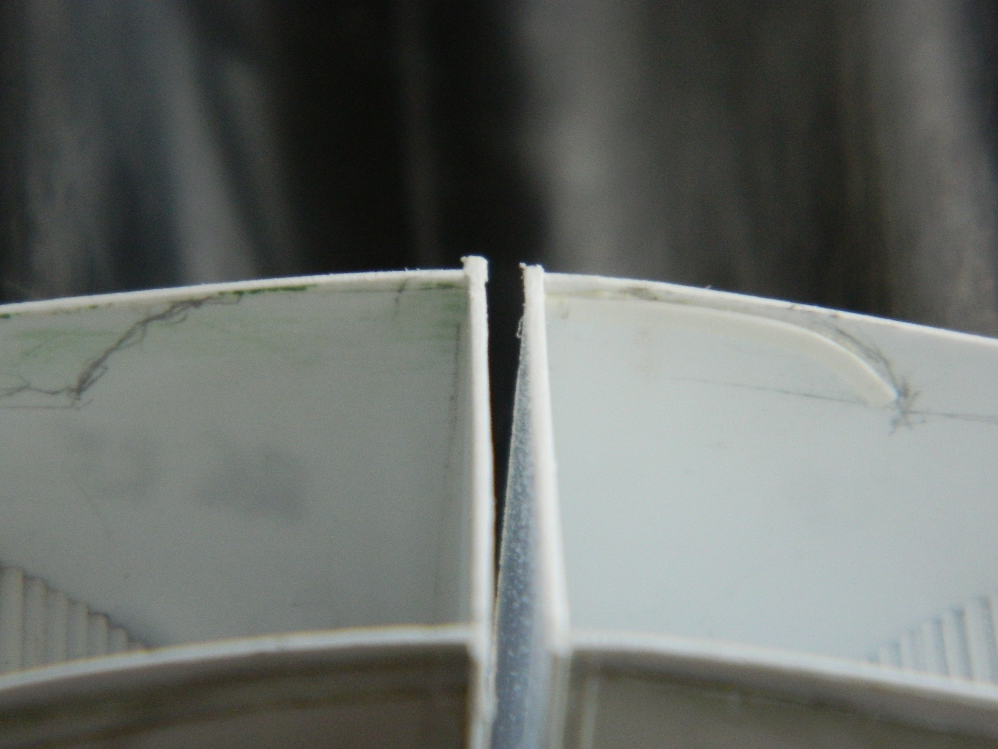
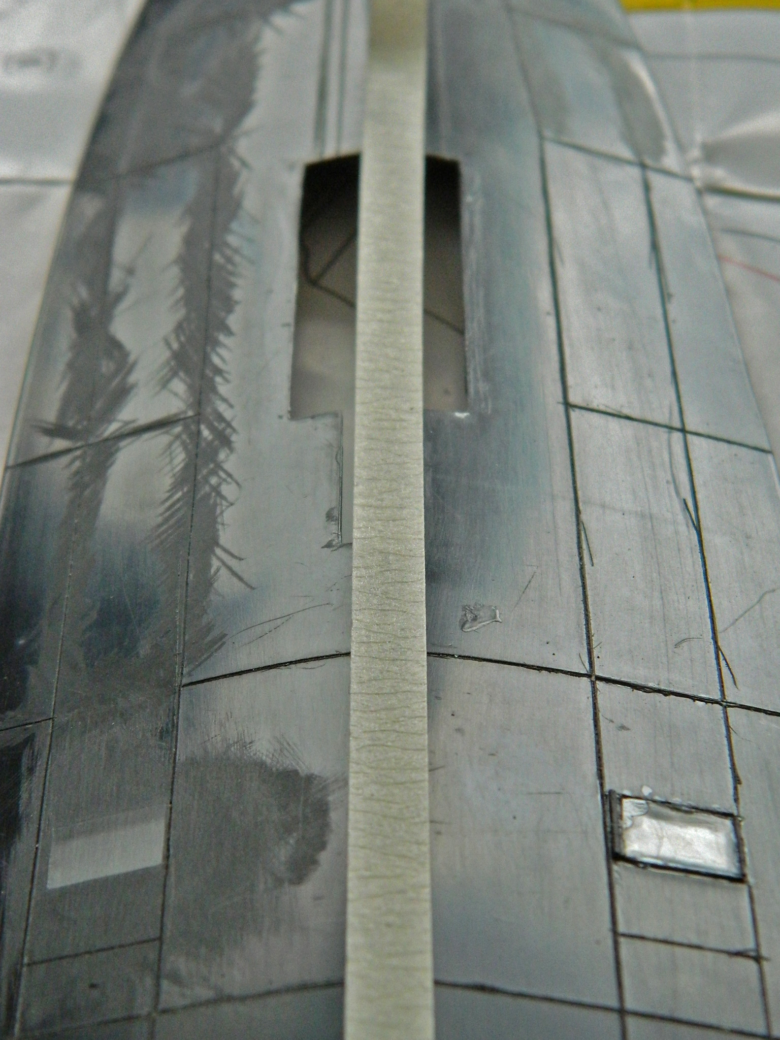
Naively, I followed the raised lines on both sides of the wing. The problem with that is that the alignment of the lines on top did not match the lines underneath. Of course I didn’t notice this until I’d glued the plastic to the bottom, so I removed the panels on the underside and made sure to align them to the panels on the upper side:
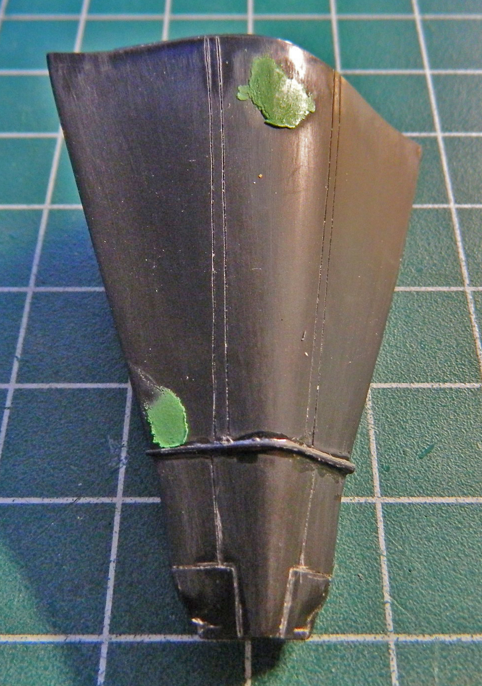
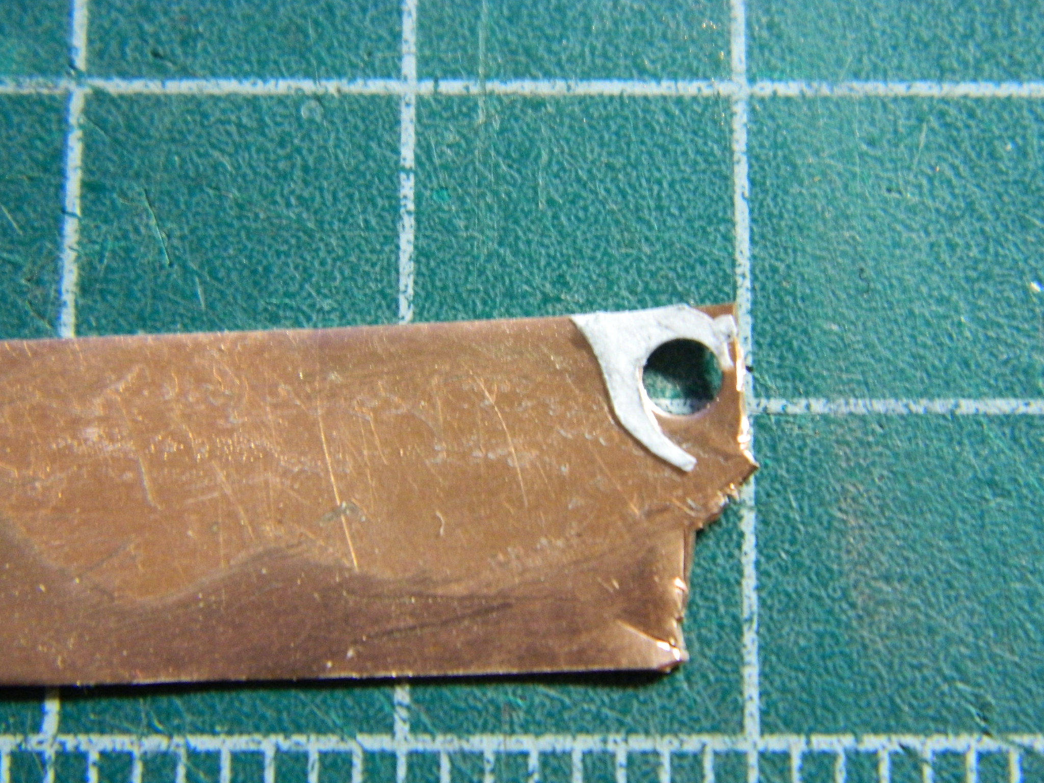
When I separated the upper fuselage from the lower, a section of the elevator ripped out. That needed to be repaired and adding new plastic was the easiest path:

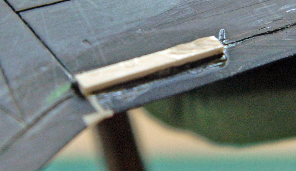
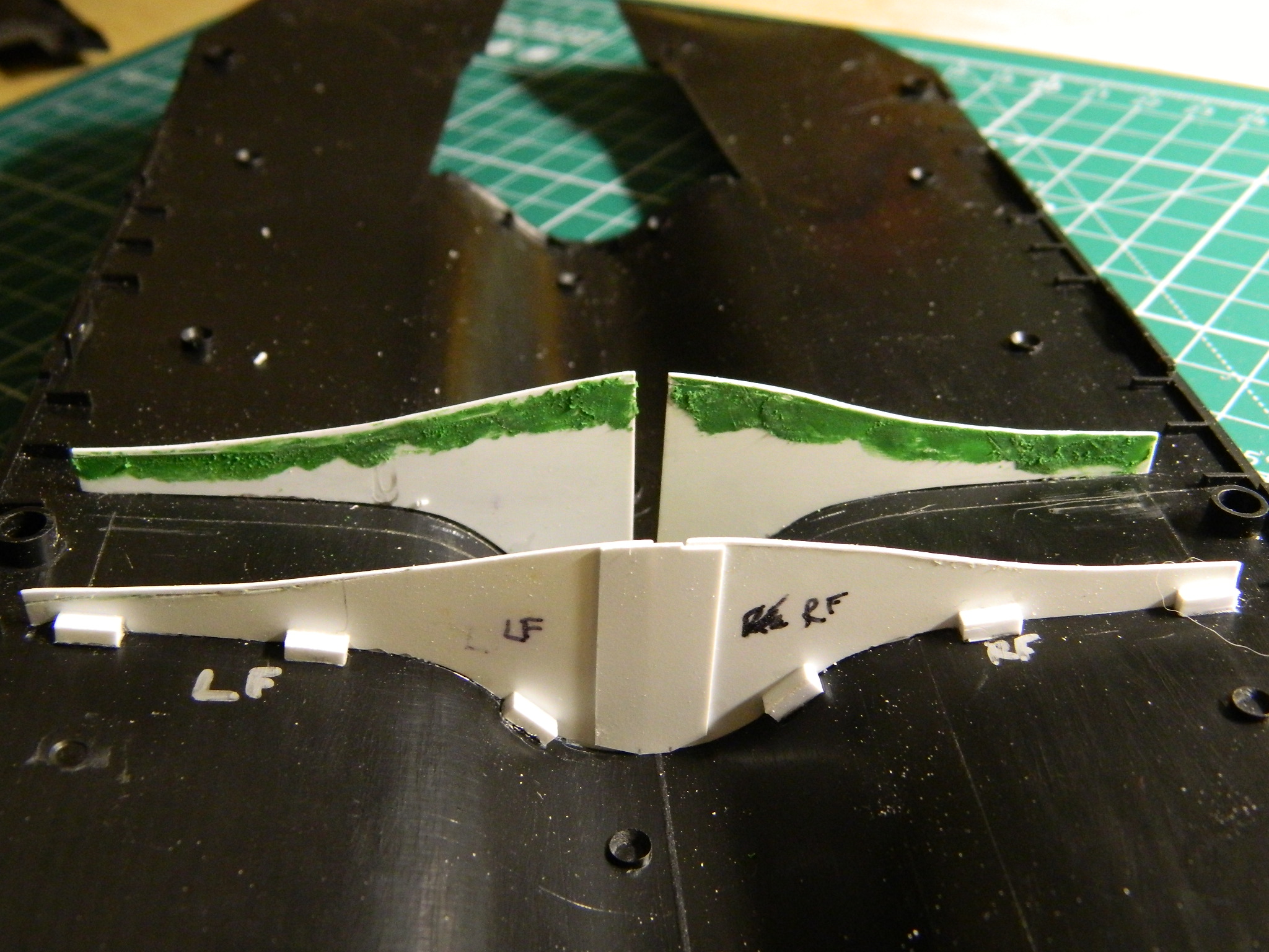
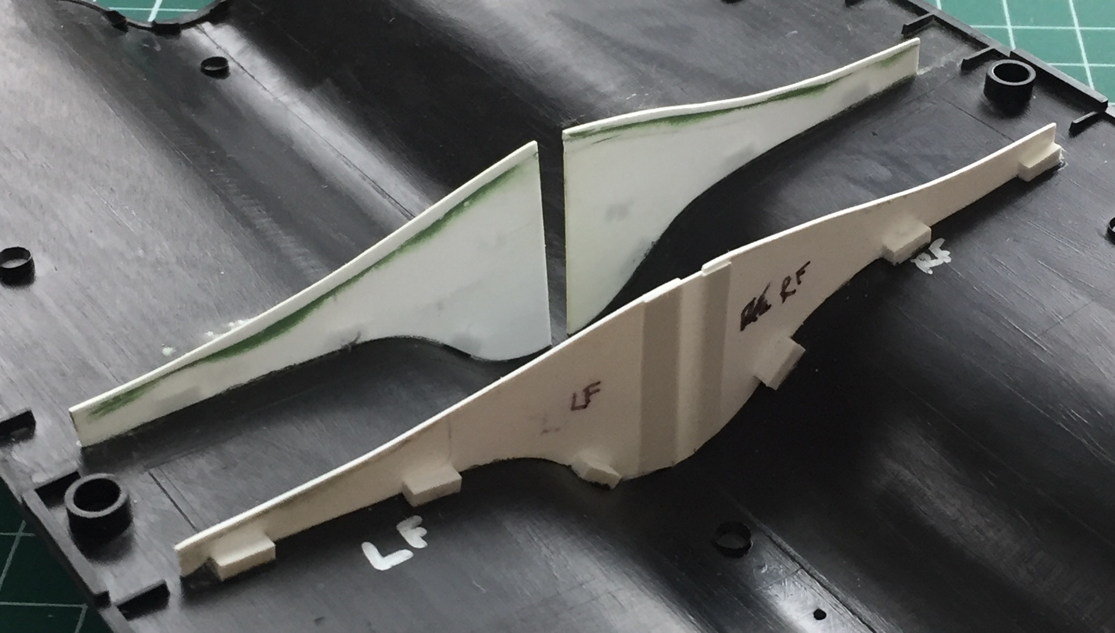
At this point I started scribing panel lines. Though I still don’t figure I’m good at scribing panel lines, I have gotten better at it (and this is good because I have SO much room for improvement!). One of the things I’ve learned with this build is that yes…adding sprue to fill large gaps can be good, and it can also be bad. Unless otherwise shaped, the sprue is round. This isn’t a problem as long as the removal process doesn’t remove more than half the diameter of the sprue. If it does remove more than half the diameter of the sprue, a gap is revealed (hopefully it’s obvious – there’s only supposed to be one line here). I cut away the dodgy section and replaced it with scrap sheet styrene:
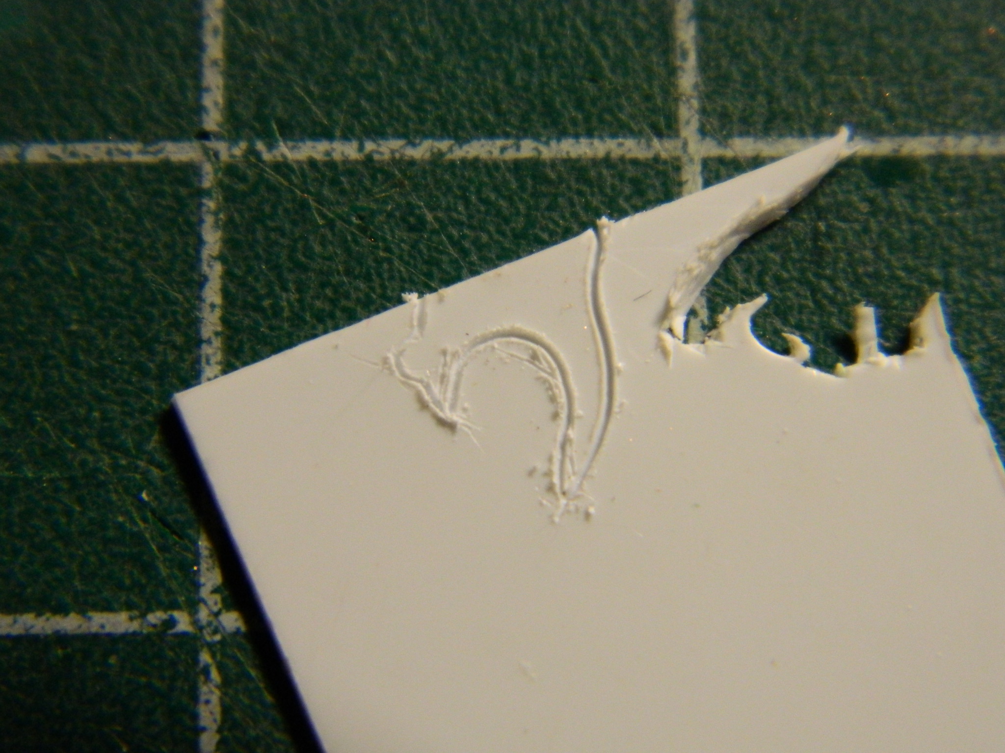
Something I didn’t realize at the time is something I will now draw your attention to. Look in the middle photo of the three previous. See that dark, short, line in the area I’d cut flat? That’s a void; there’s nothing there. As I later found out, leaving a void in an area that is going to be both thin and scribed won’t work well. The scribing breaks through the thin plastic and has to be filled. Again.
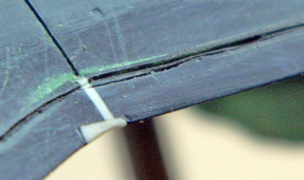
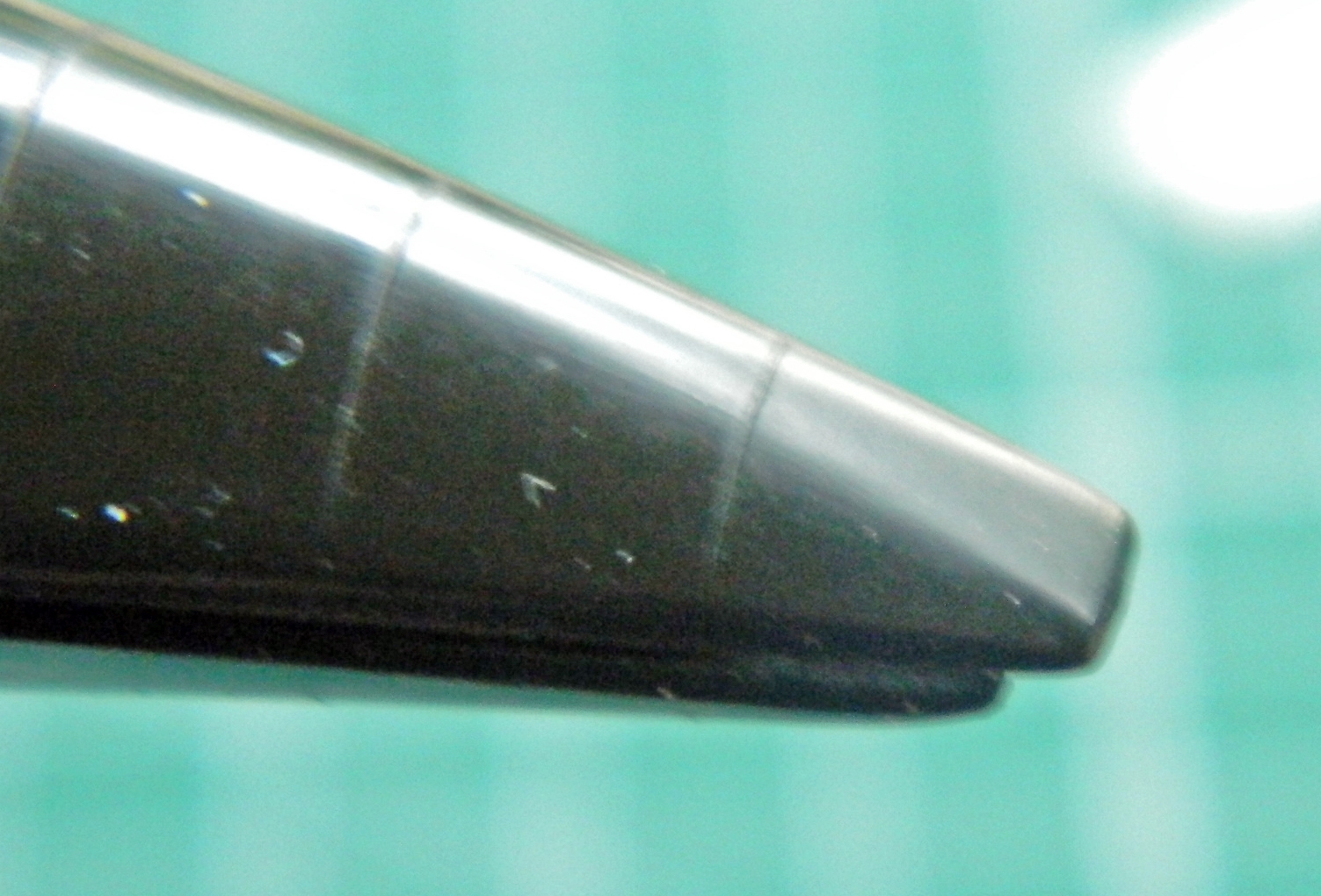
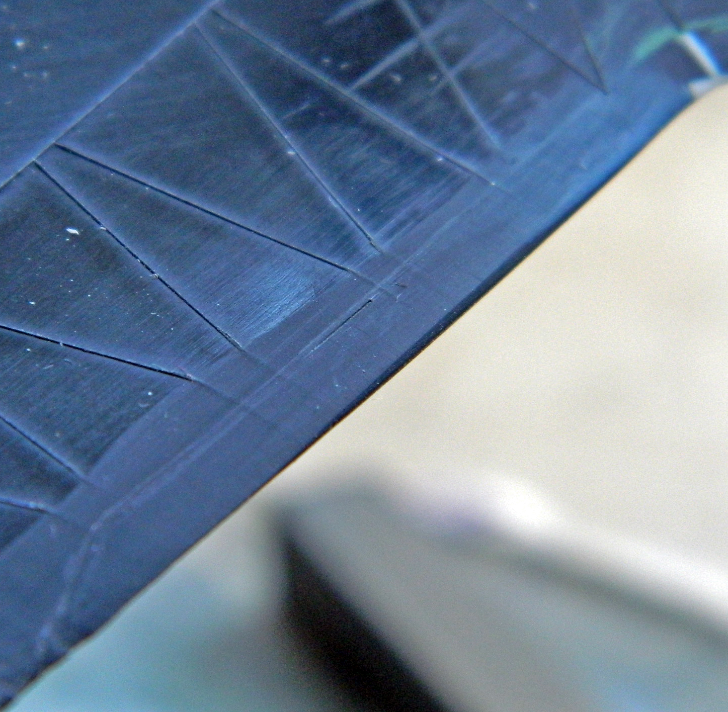
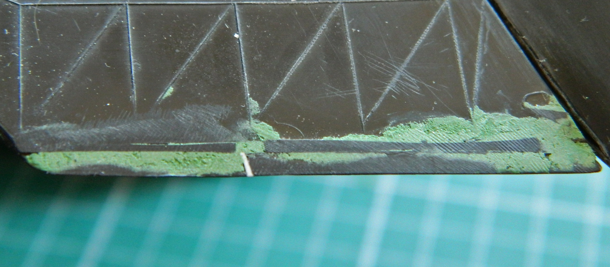
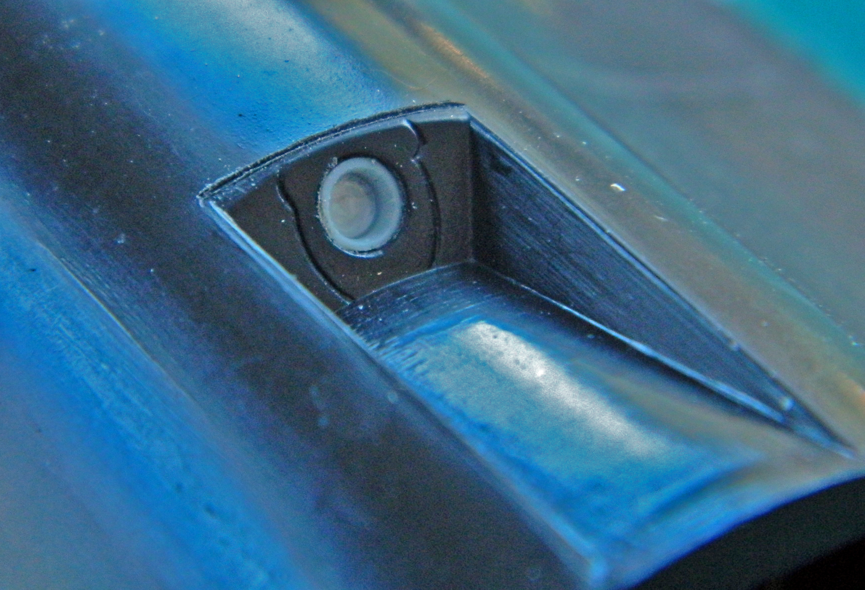
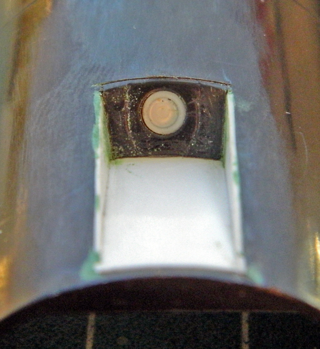
Sometimes scribing panel lines can be interesting. This is a raised panel line in an interesting place:
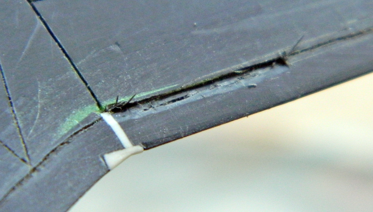
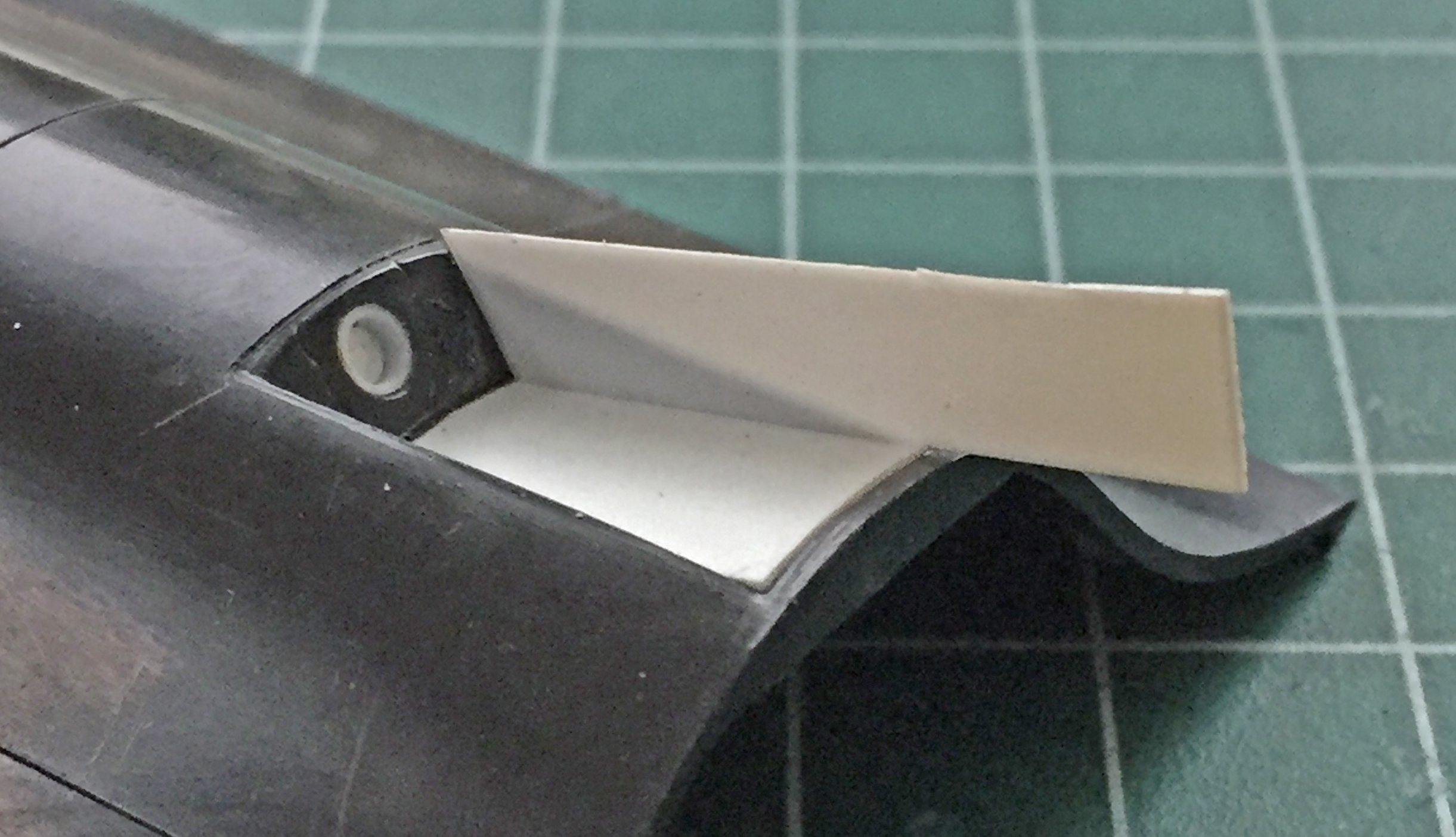
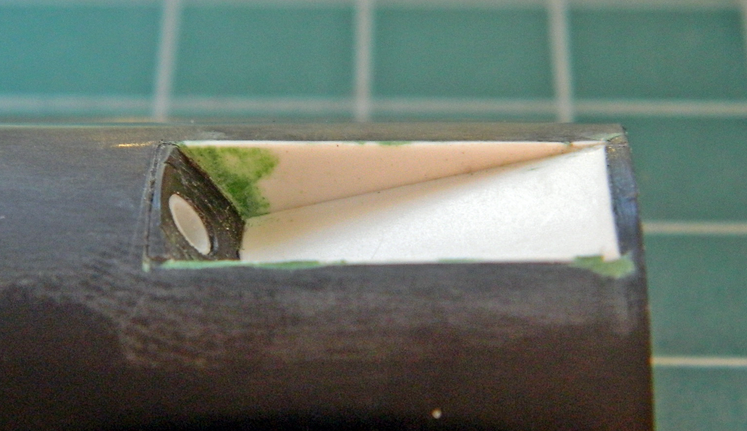
That line need to be recessed. To do that, I had to remove the line so that I could scribe the area:

That had to be done again on the other side.
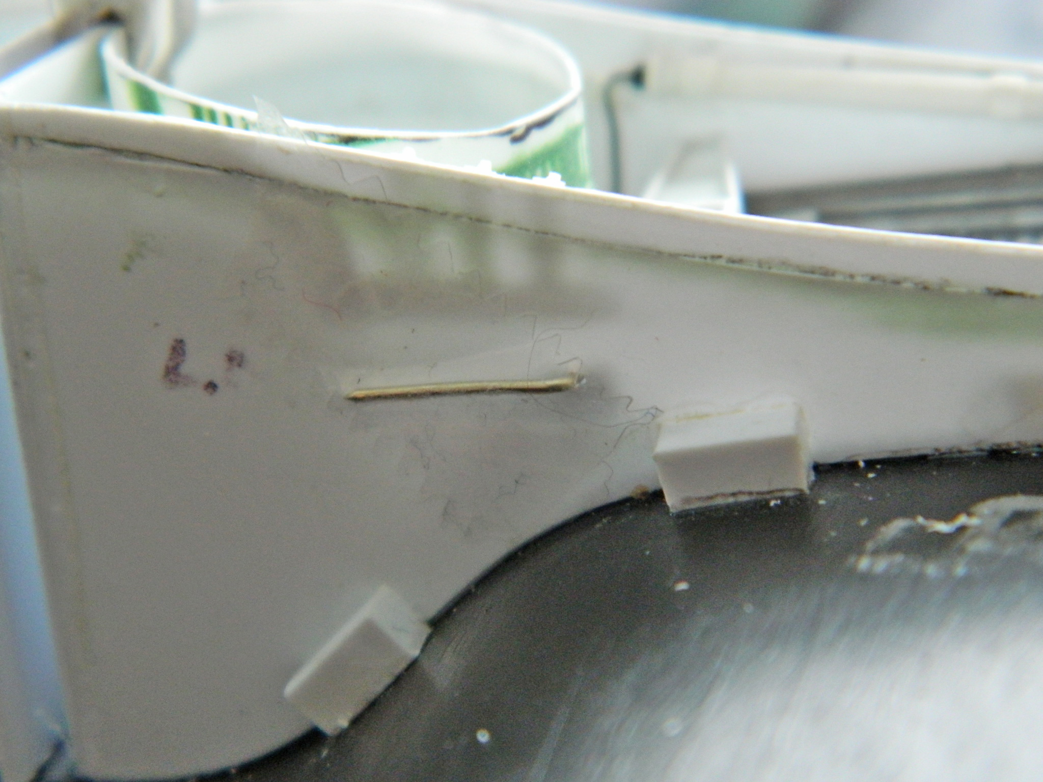
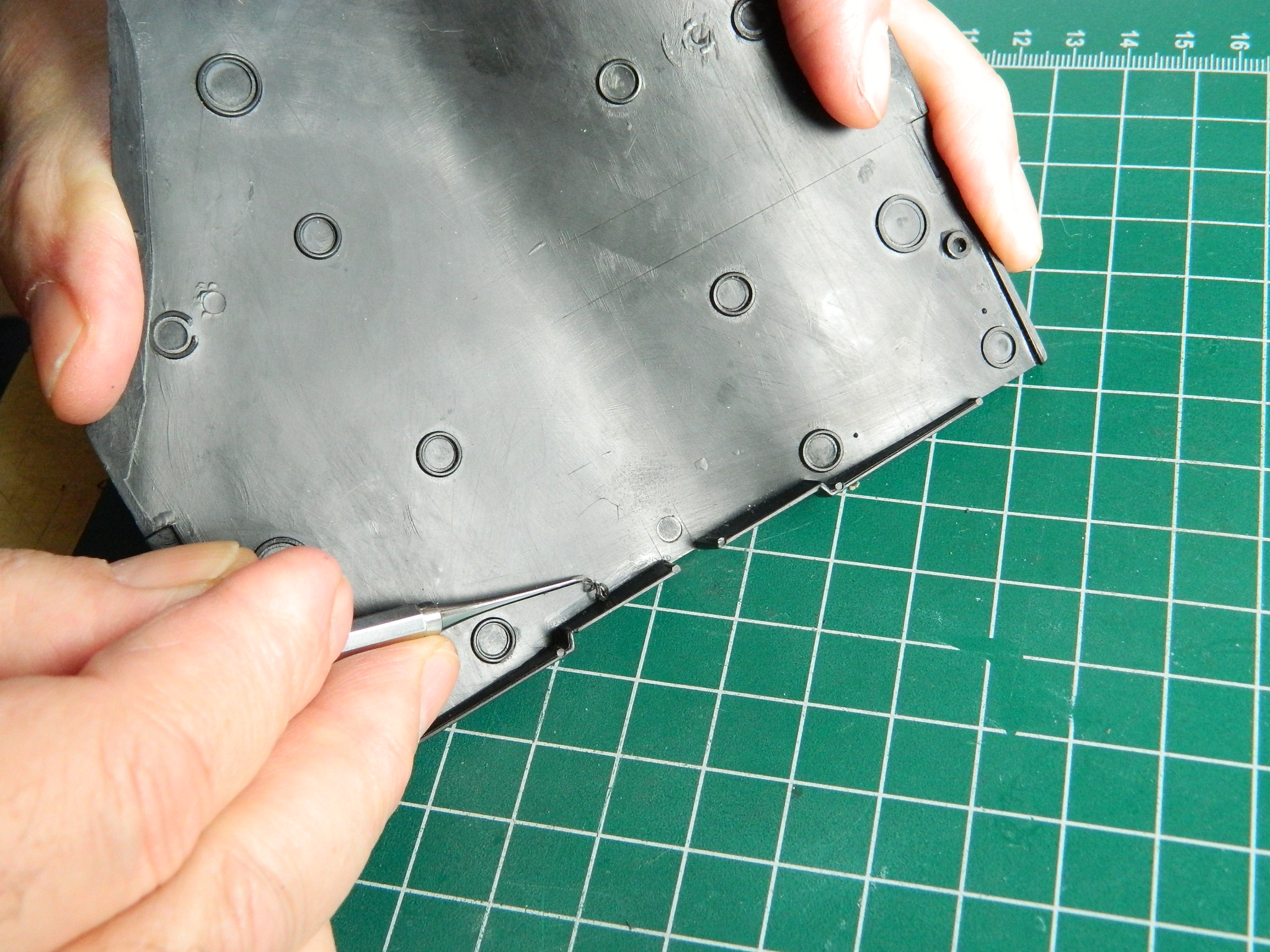
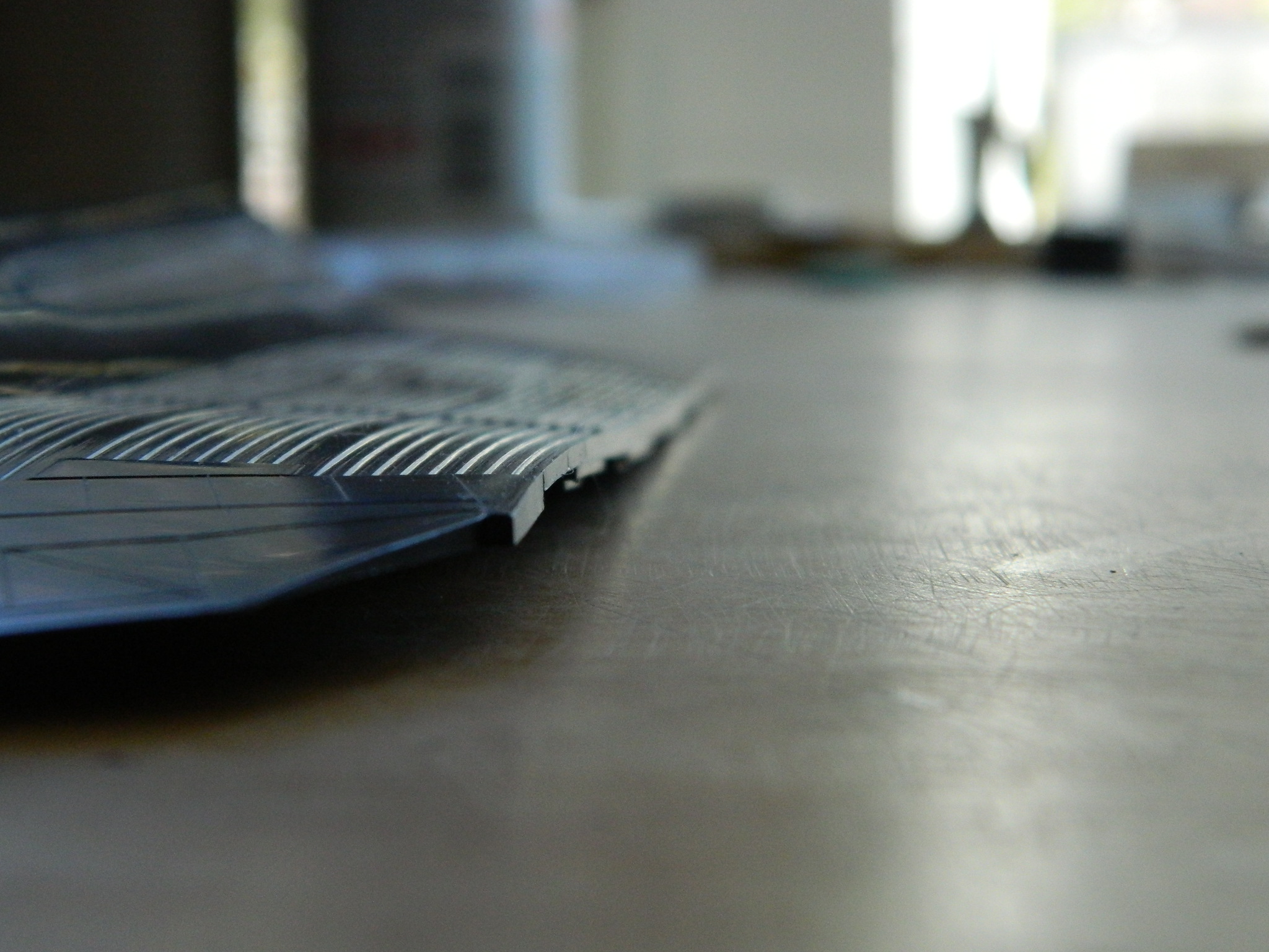
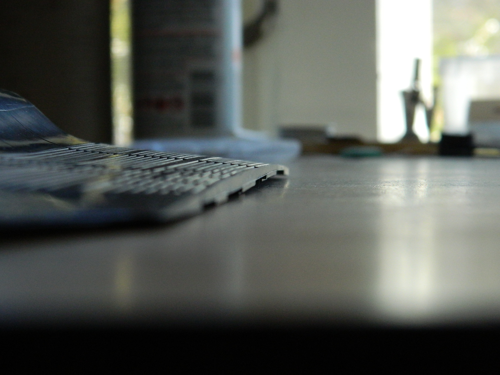
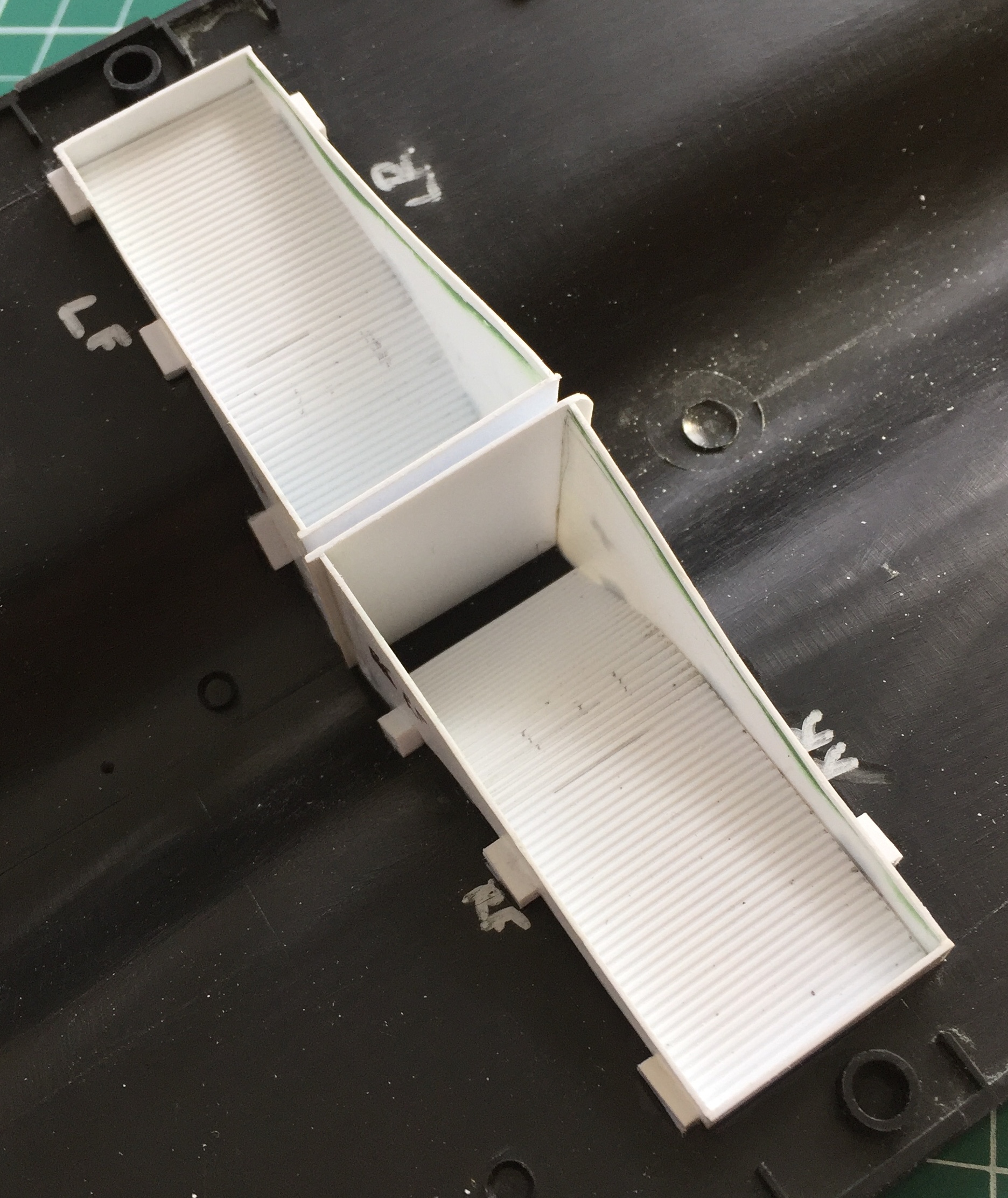
I thought I had already addressed a fit problem but where things actually went after assembly required me to rework the fuselage between the main landing gear openings (the added plastic was filed/sanded to fit smoothly):


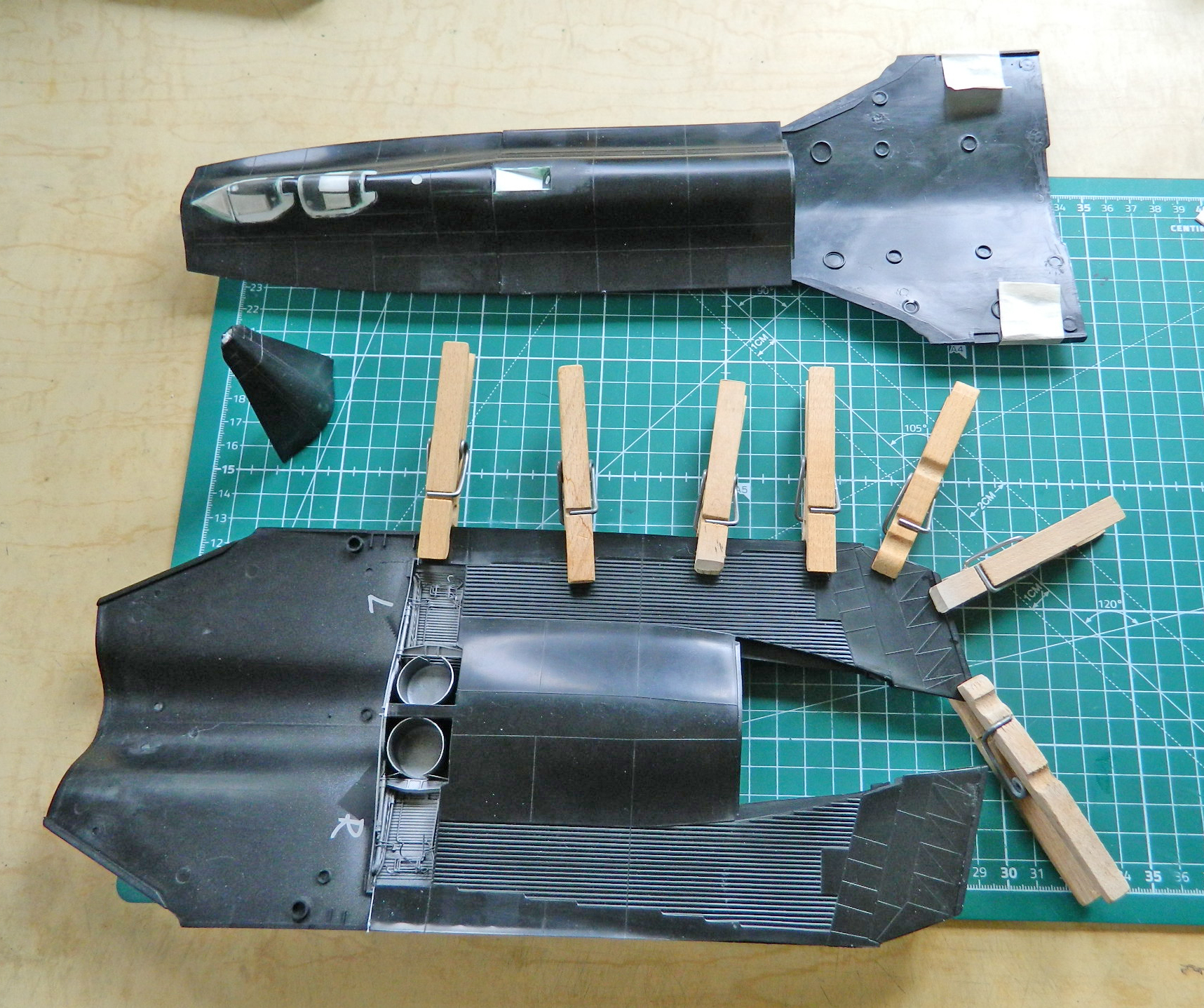
One thing I noticed when I got the ill-fitting fuselage section to fit was that there were gaps. The procedure for this build is fill with plastic, shave plastic down, fill smaller gaps with putty. But this time to get access and to rework the elevators and fuselage, removing the elevators (something that was on the to-do list since the elevators droop as #972 is displayed) was called for:

These photos show how far from meeting the surfaces that are supposed to meet are:

Scrap styrene acts as both wedges to keep surfaces aligned and fill for the gap (a file was used as a wedge to hold the surface in alignment):
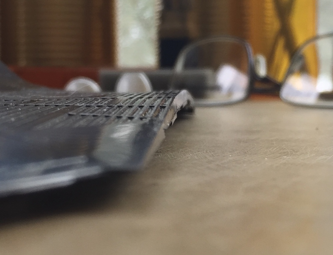
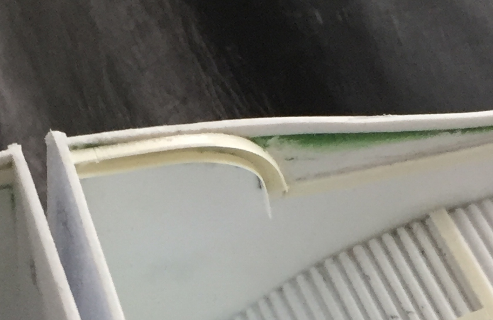
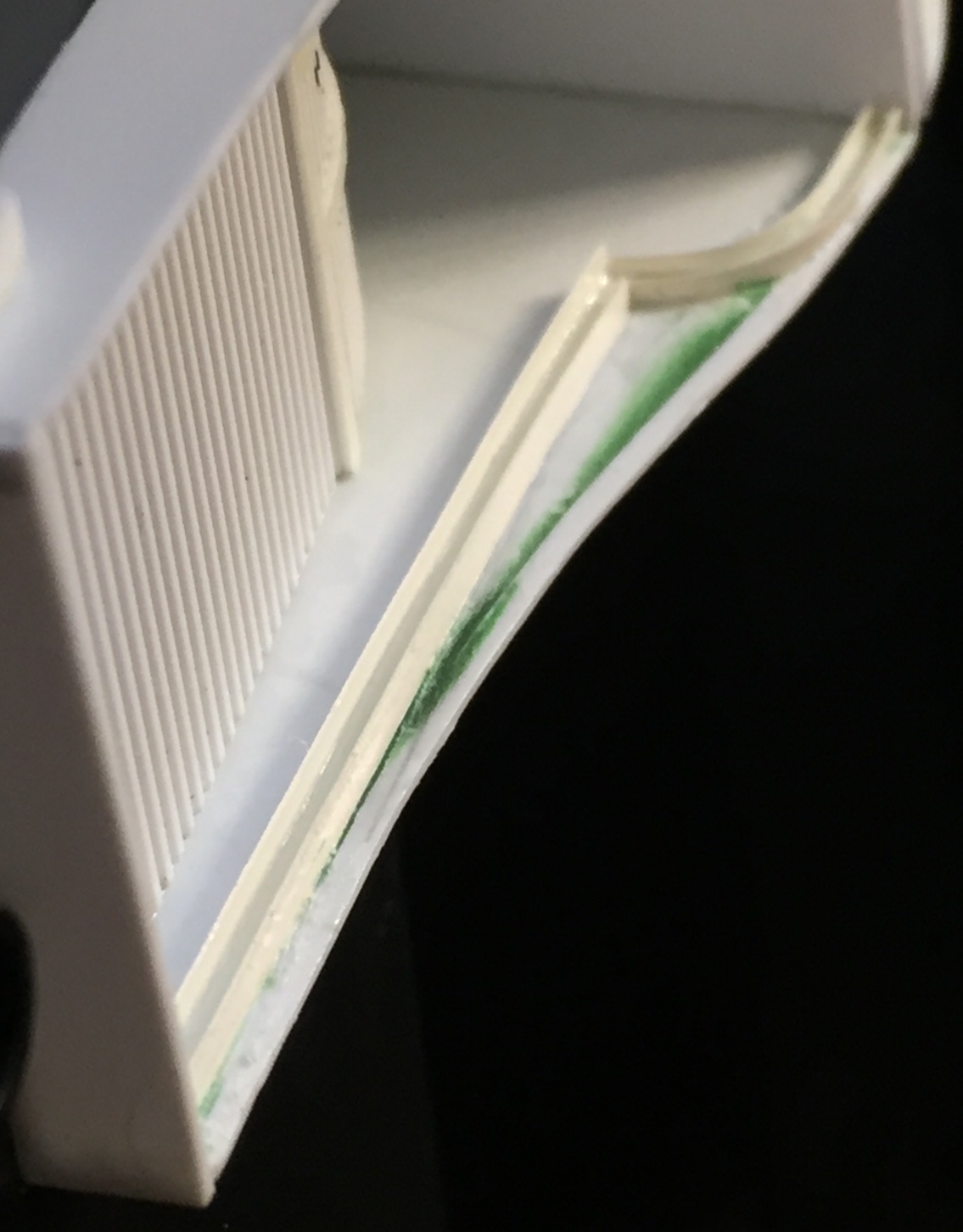
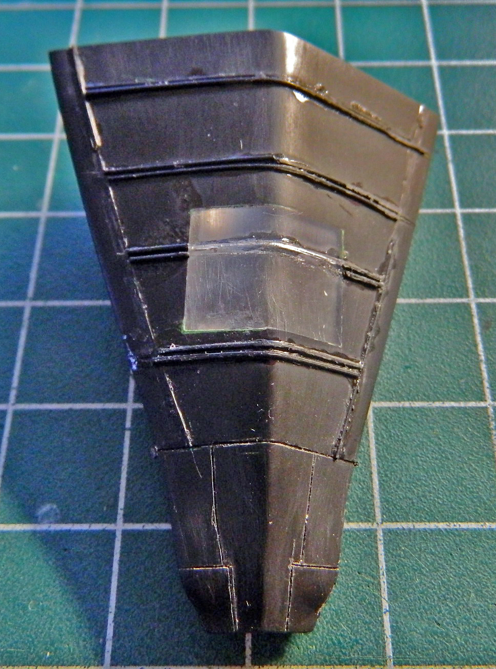
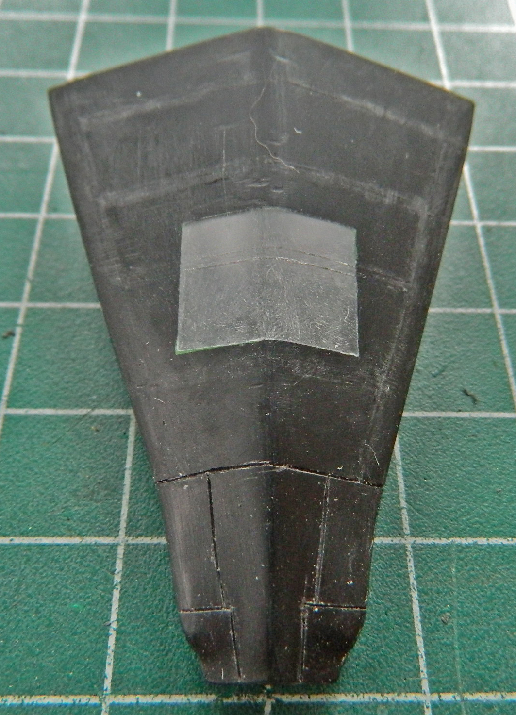
I also added flat styrene to the elevators to close the ends since they’ll be visible once in place:

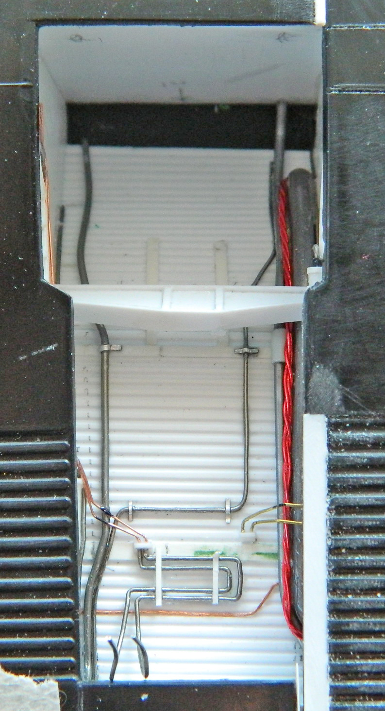
Lots of plastic needed to be added and then puttied over:

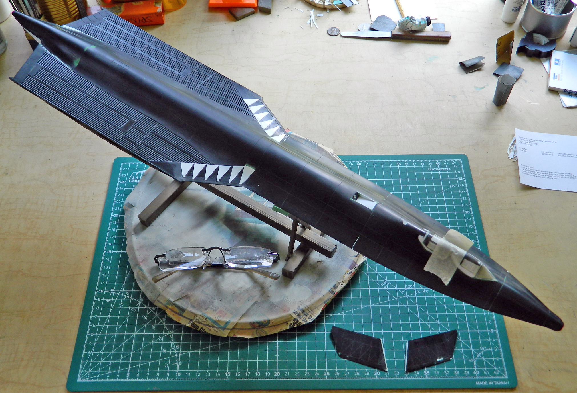
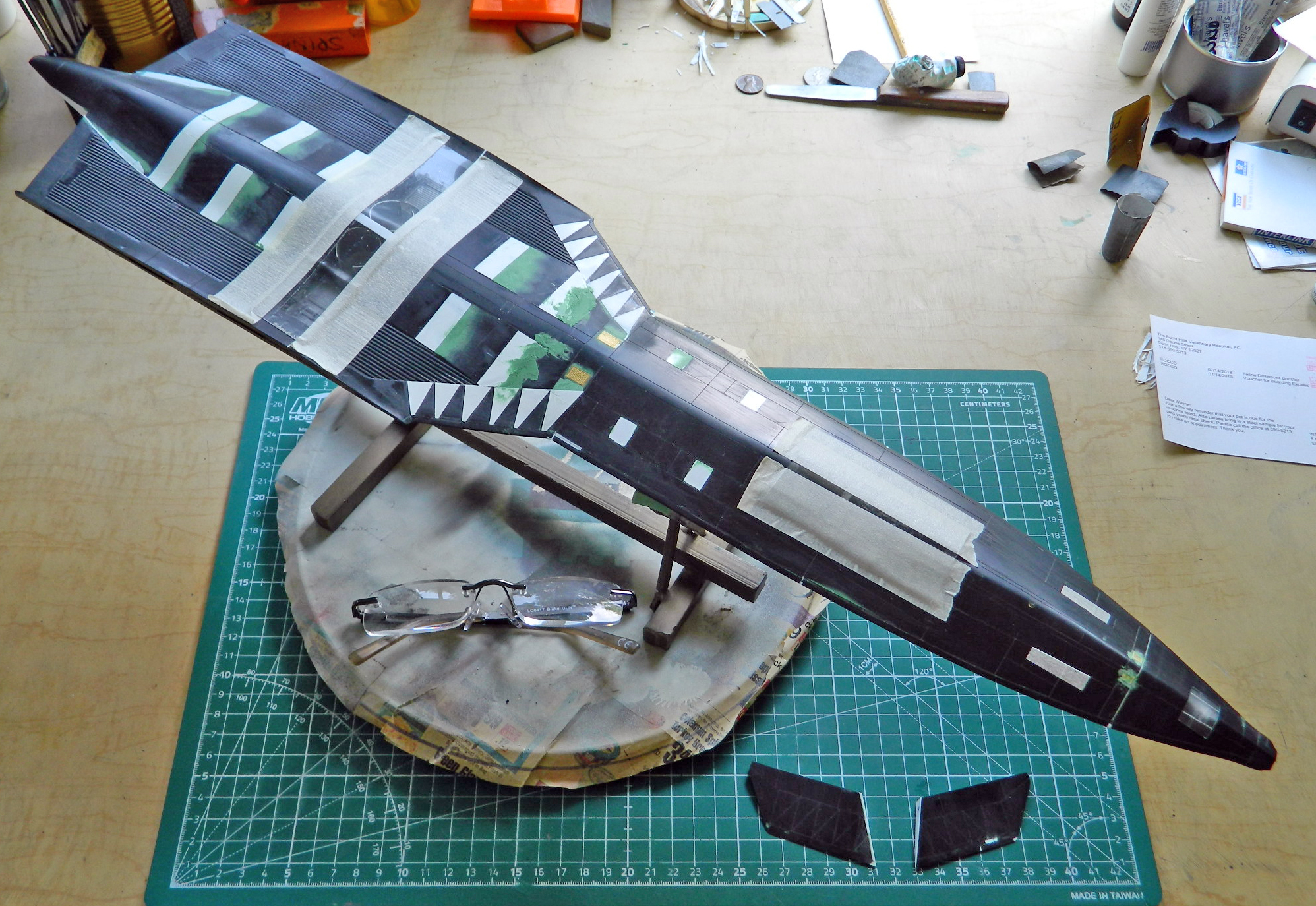
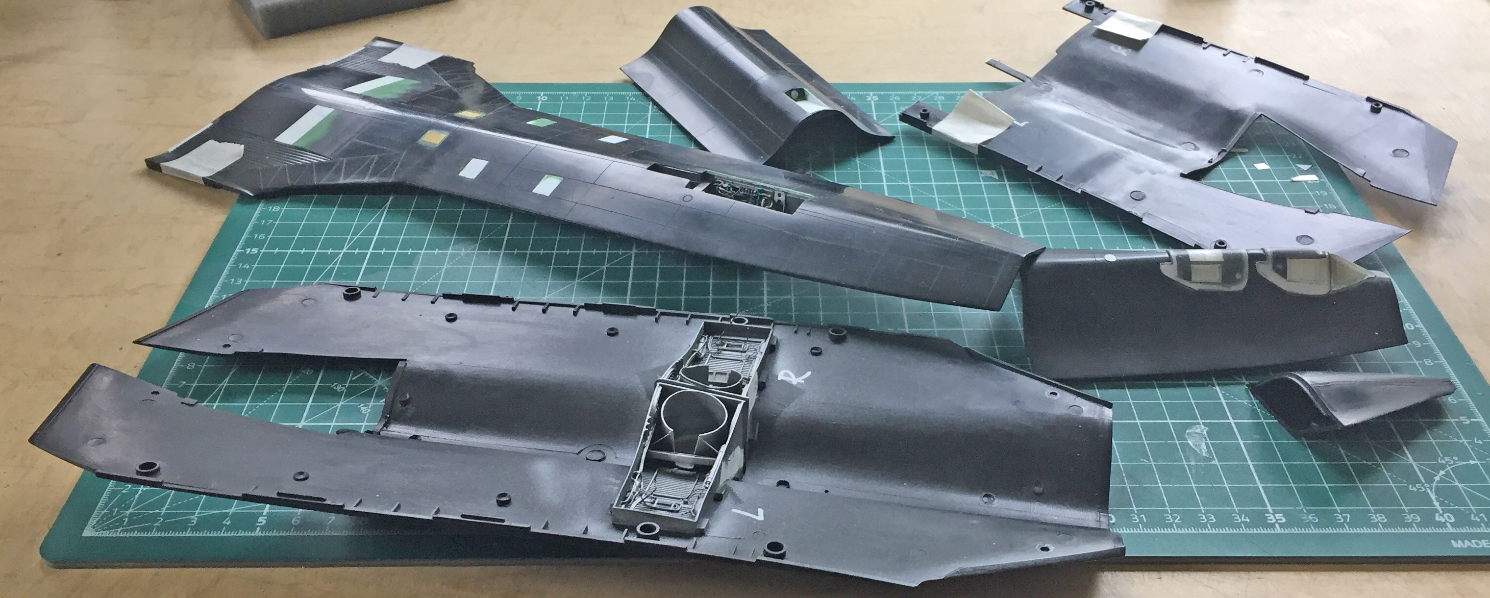
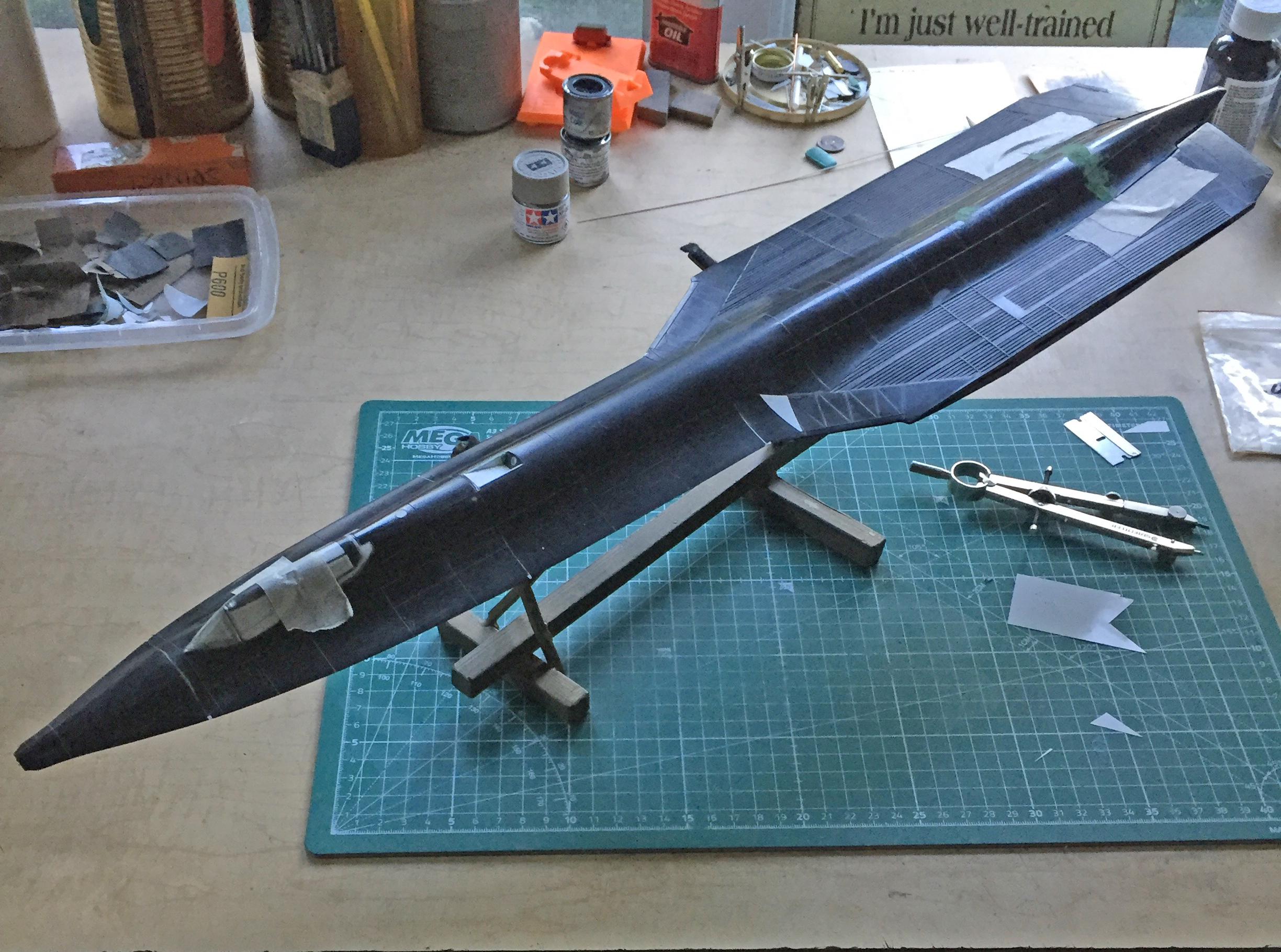
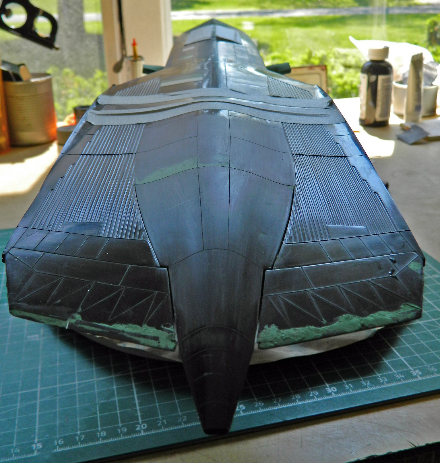
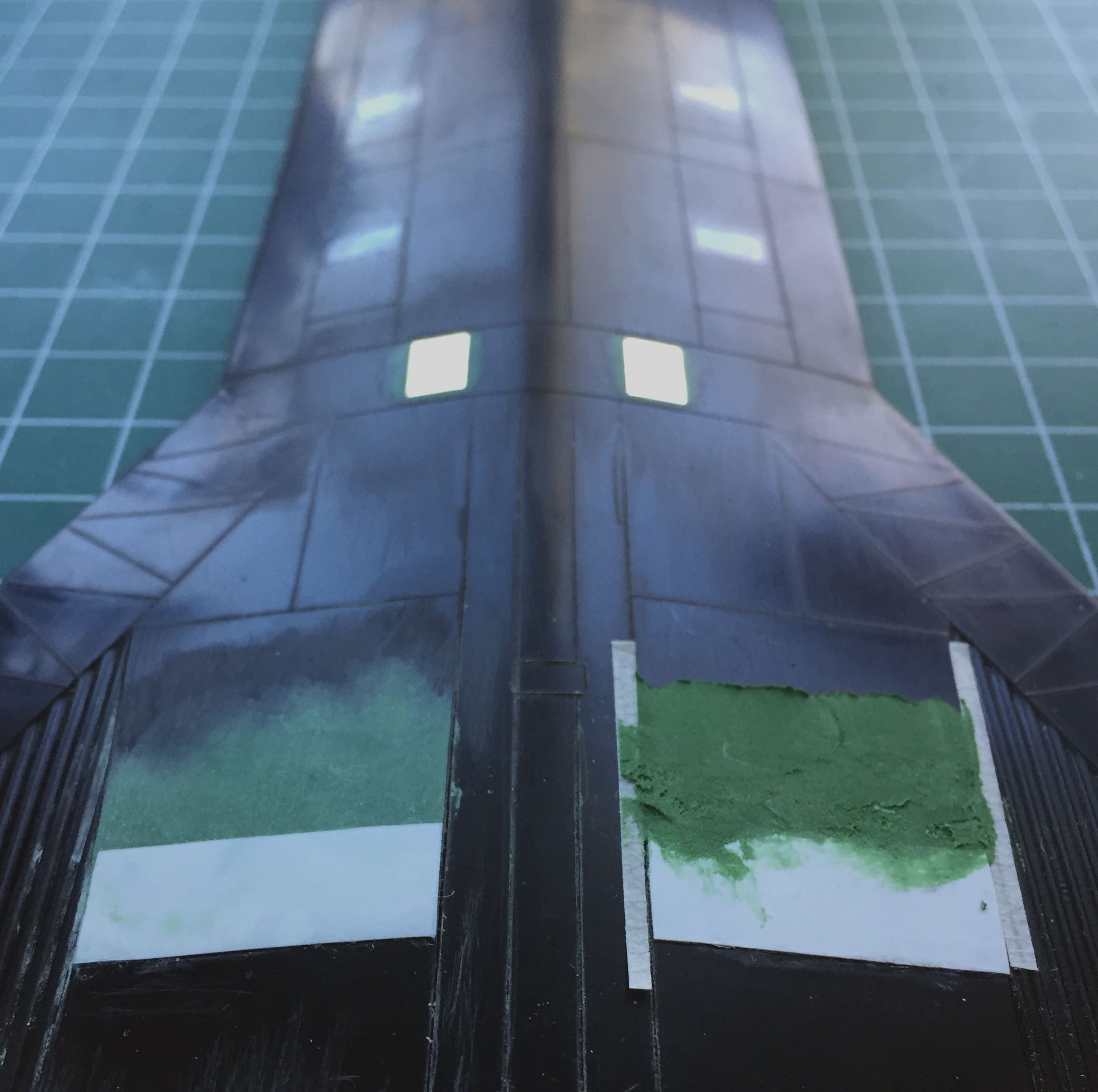
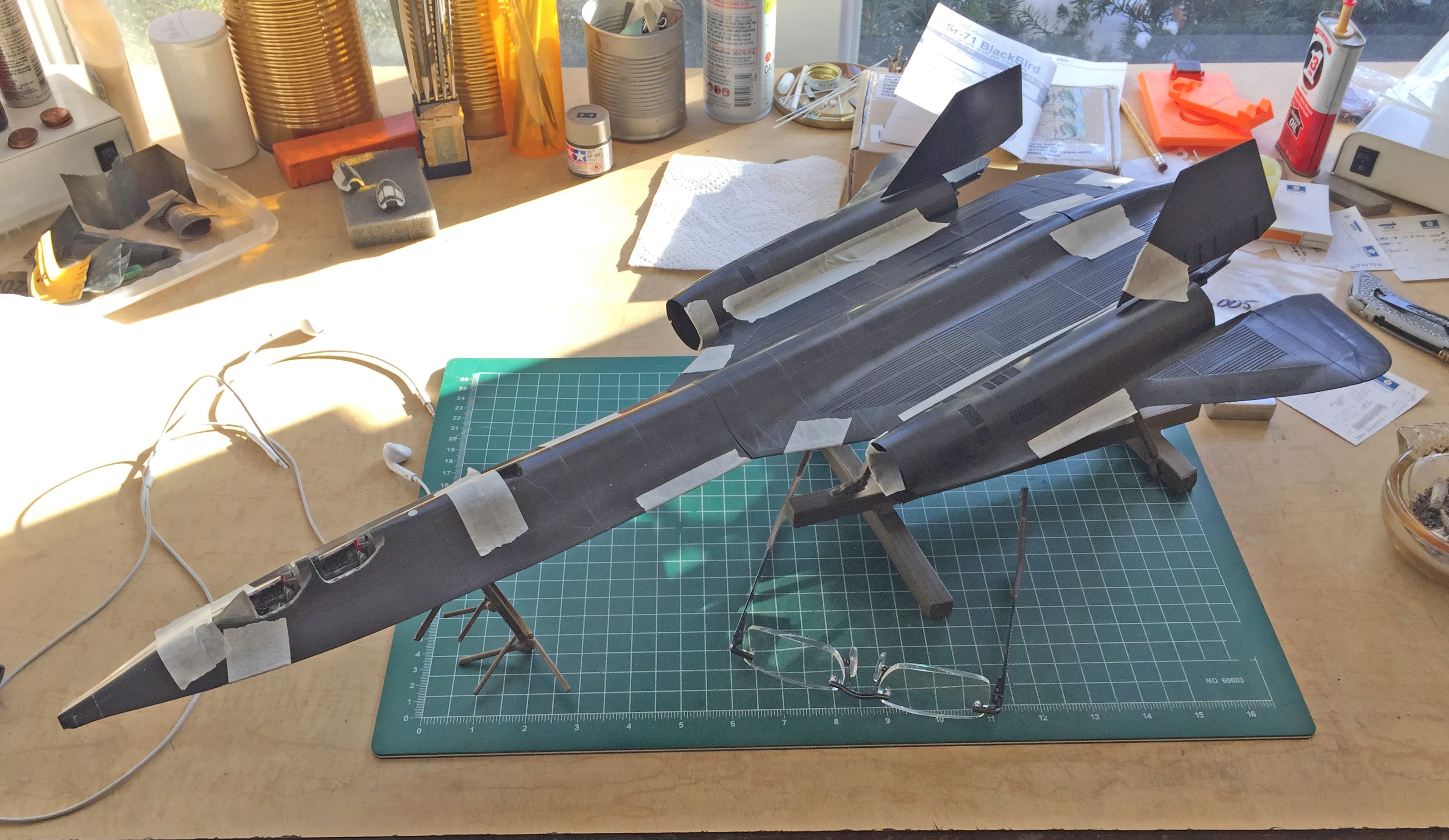
After these steps, days and days of sanding, adding putty, sanding, adding more putty, MORE sanding, ensued. I’m still not done yet and here is where things stand presently. All the white plastic areas are where I added plastic:
I haven’t even started on the engine nacelles and outer wingtips yet…
SR-71A Blackbird (Testors) Build #15 – Fuselage Gets Assembled and I Get a Right Proper Scare
Before I do something as “big” as assembling the fuselage, “big” because once that’s done, there isn’t any “going back inside and fixing something” that can happen easily…if at all, I’ll sometimes sit and stew (or ruminate, for those who are adults) for days. But unless that “big” something isn’t done, the model will never be, either. In short (finally), I started at the nose and put the sodding fuselage parts together.
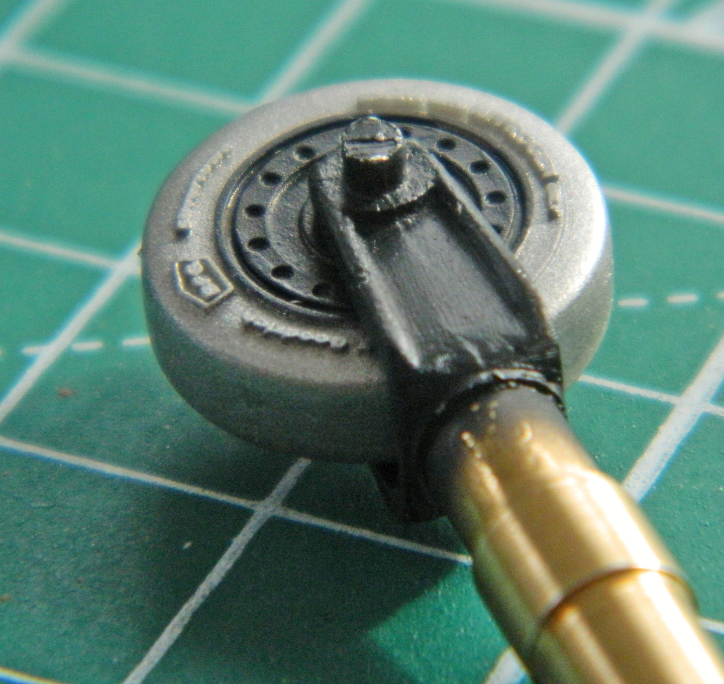
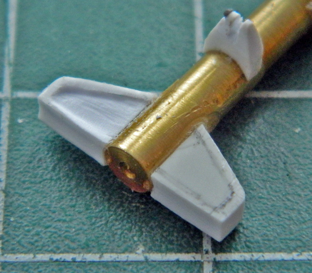
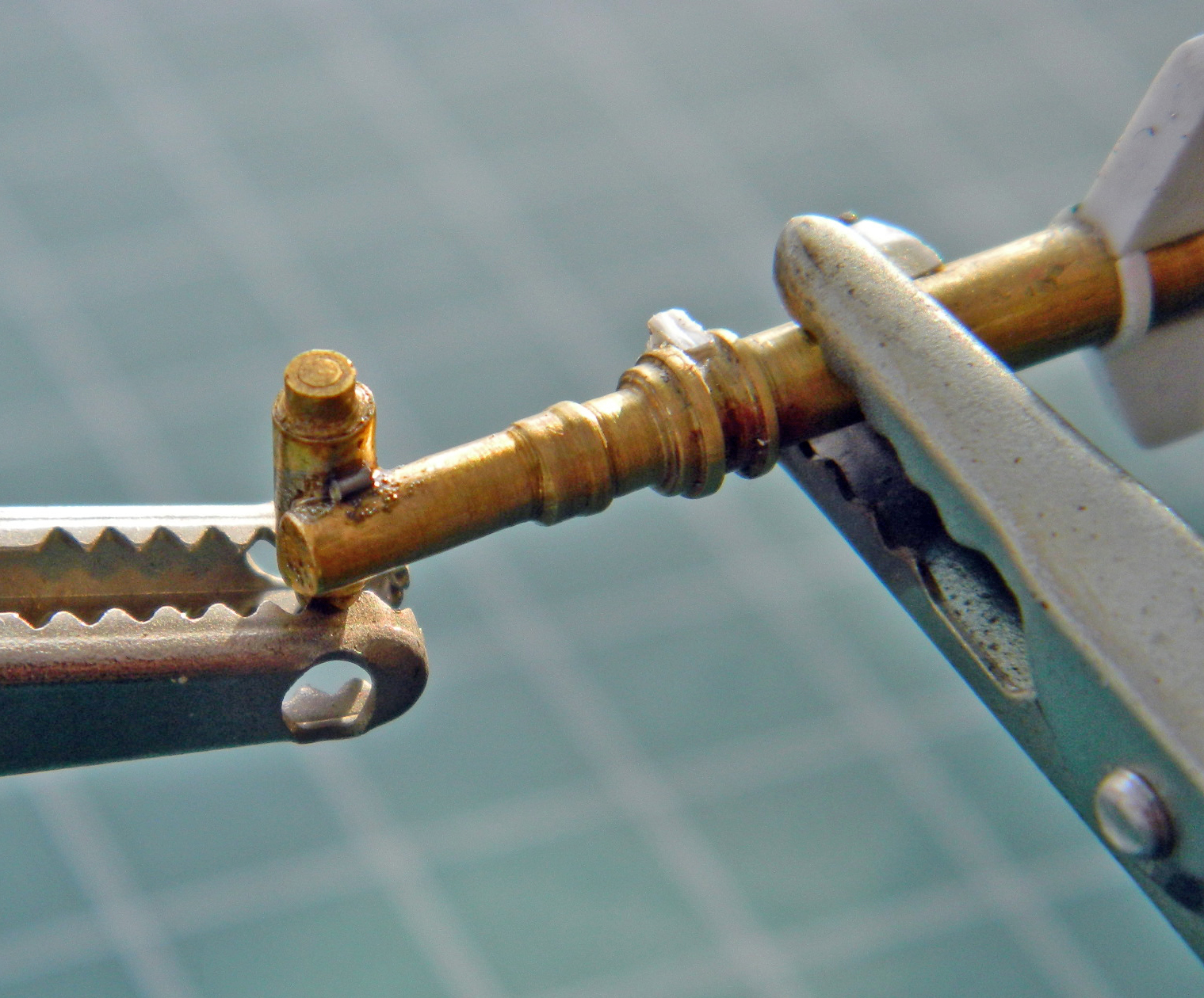
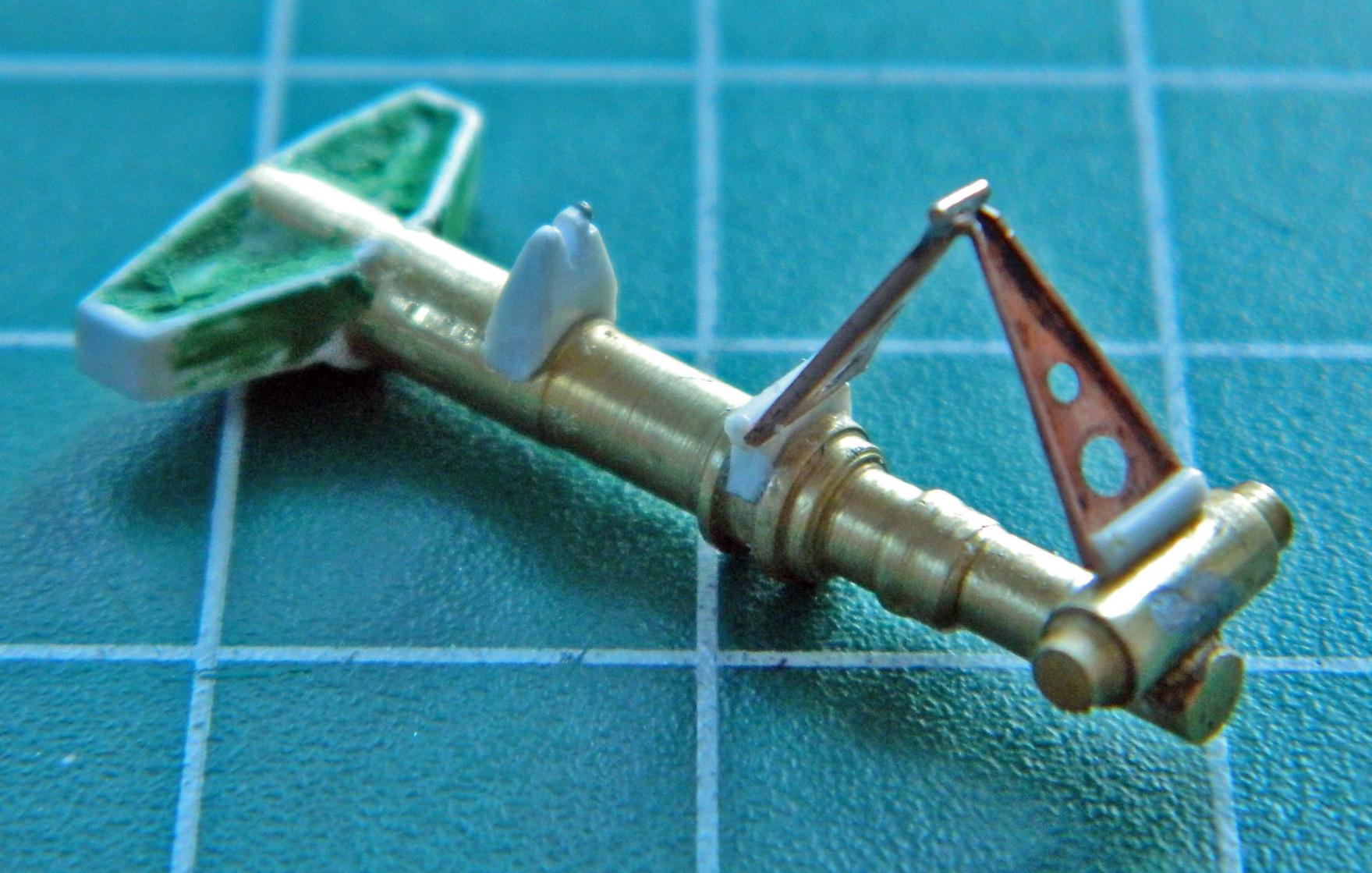
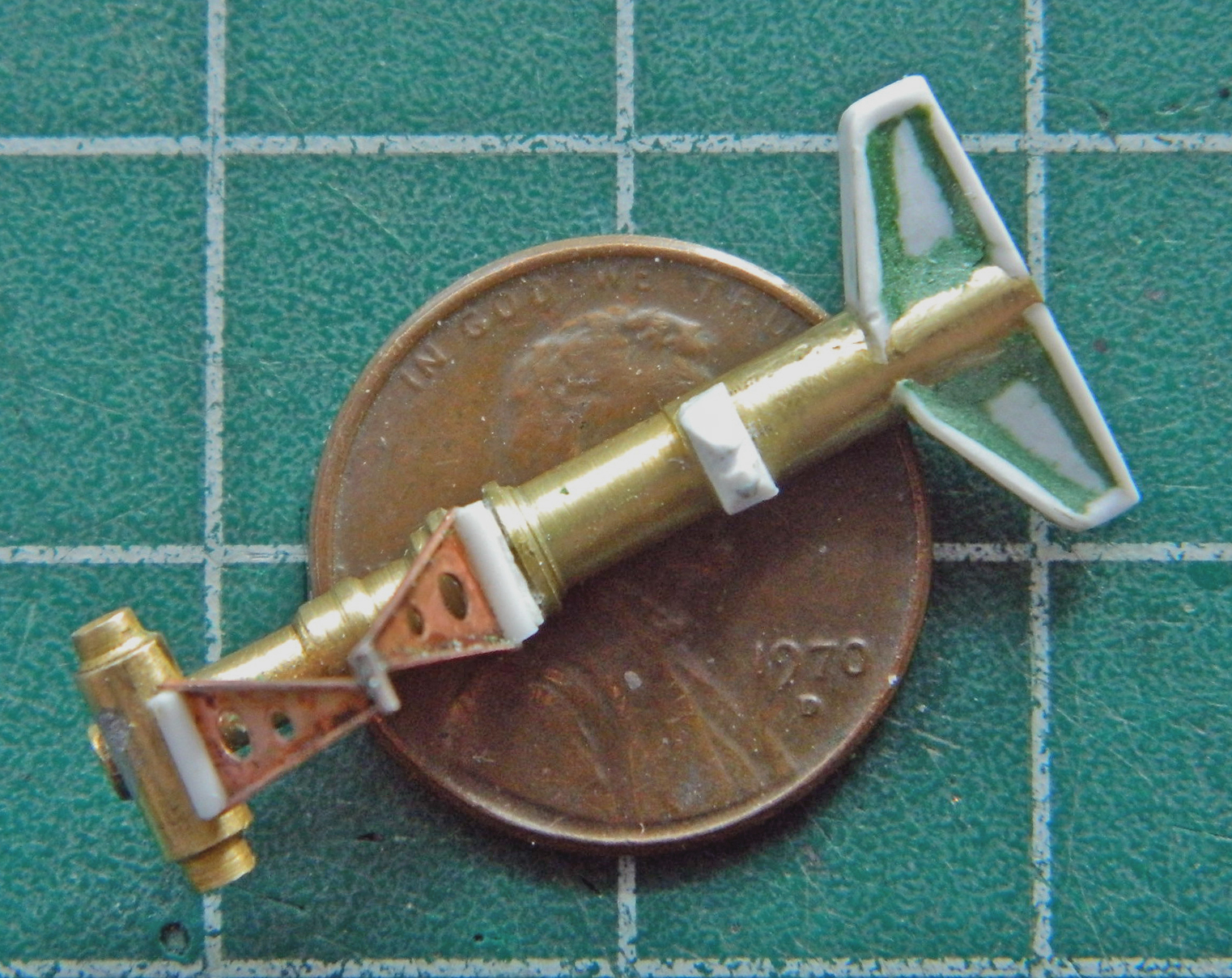
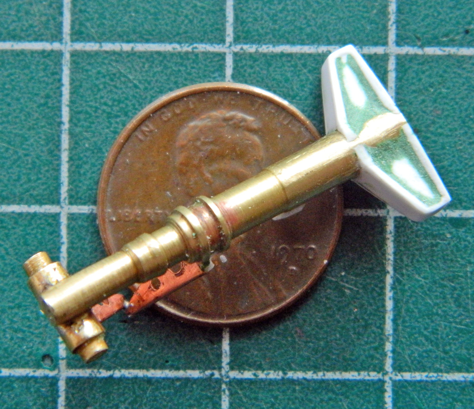
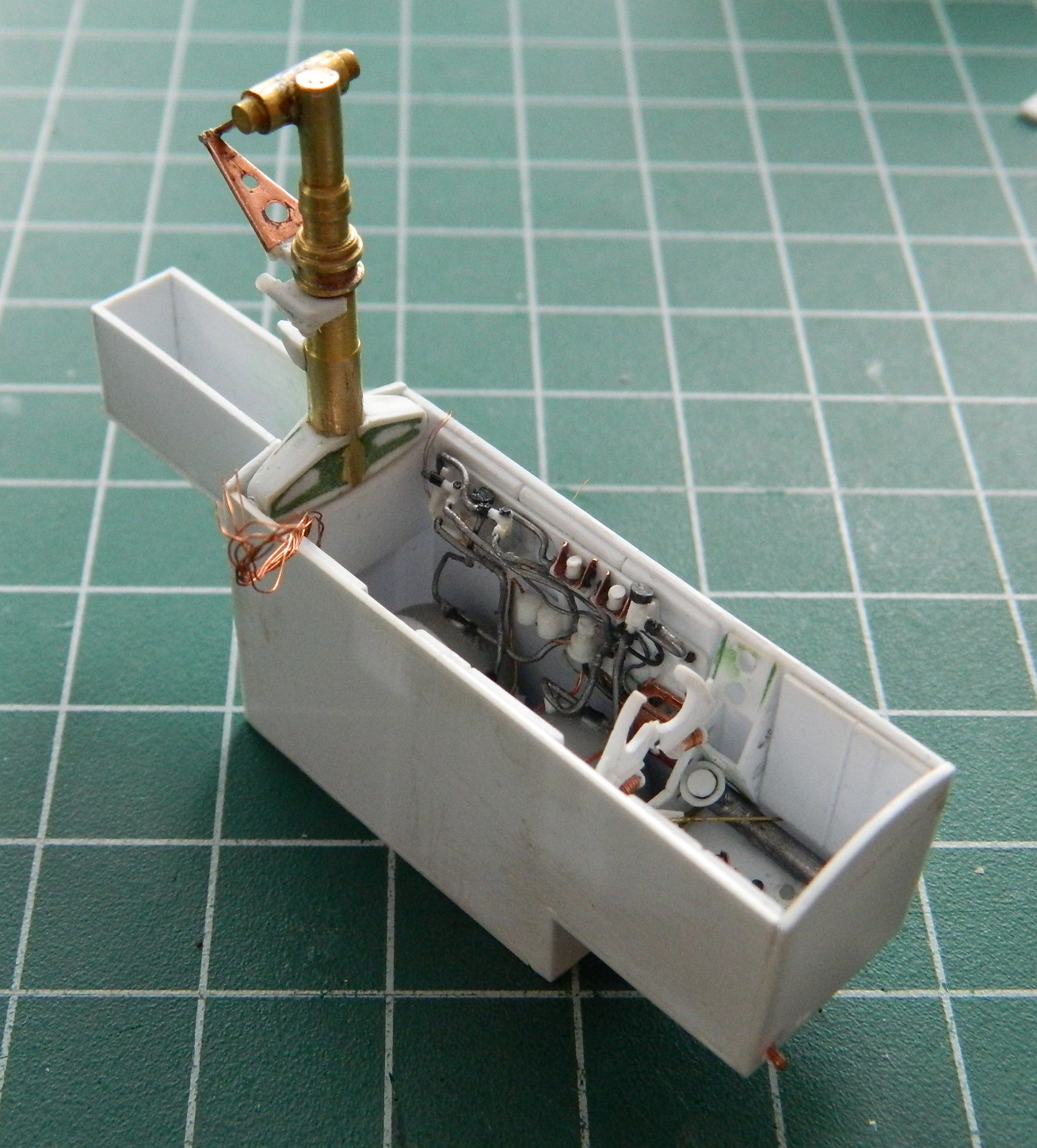
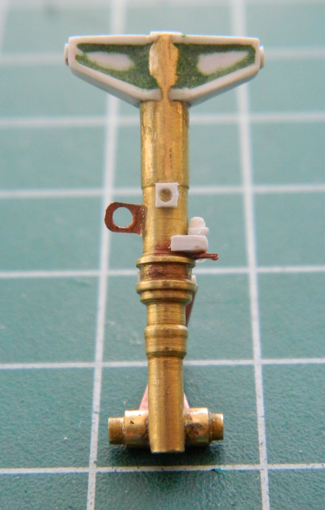
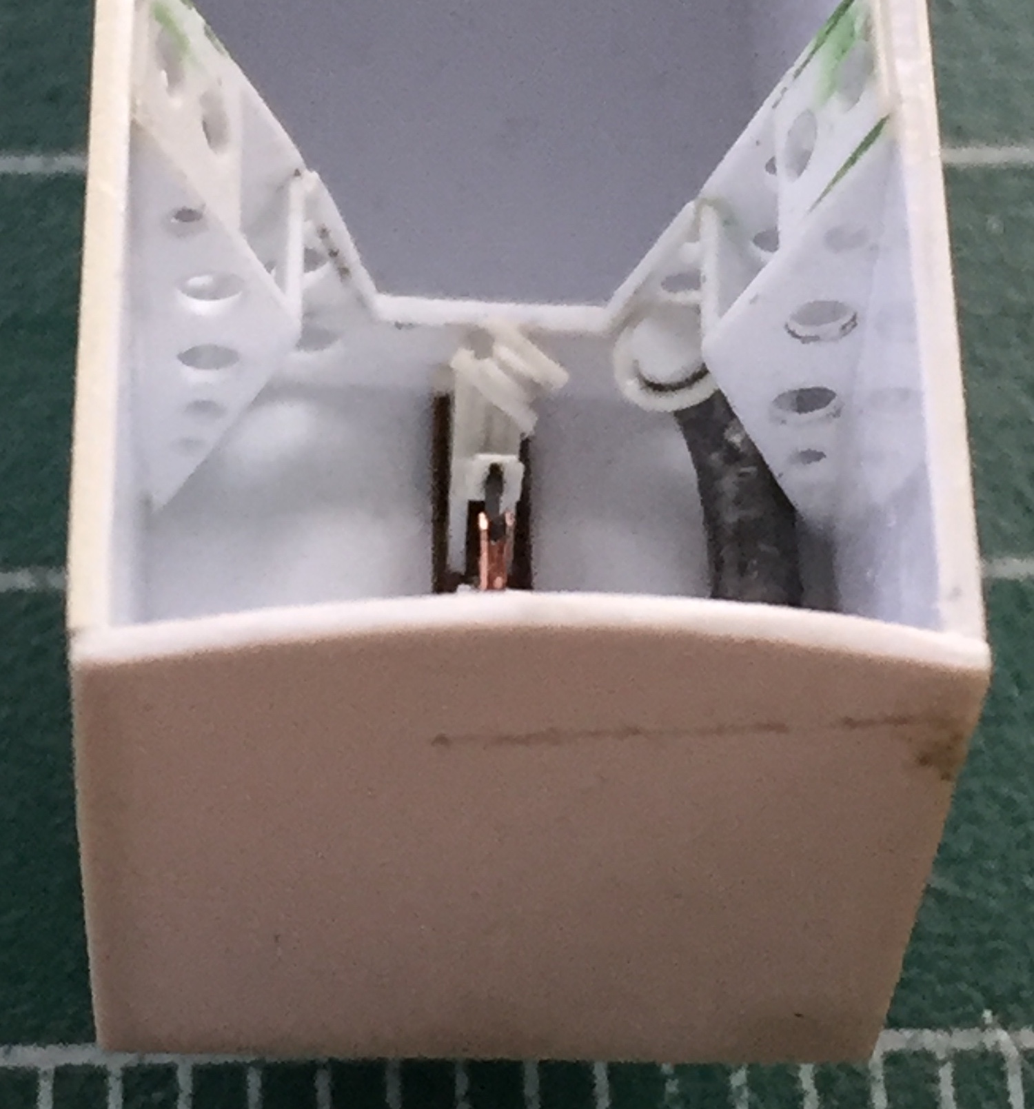
One (of many) thing that really does torque me out of true is when thin parts break off; it doesn’t matter if it’s during assembly or once it’s finished. I wanted something that would prevent that from happening with this one. What I came up with was to make the nose-probe (which on this bird was the pitot tube and a sensor) easily removable…as in, hit the thing hard enough to snap it and it’ll just fall off unbroken. I decided to hold the probe part on with magnets.
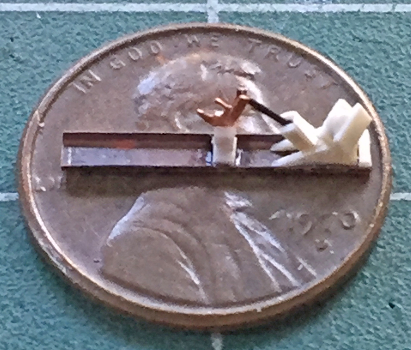
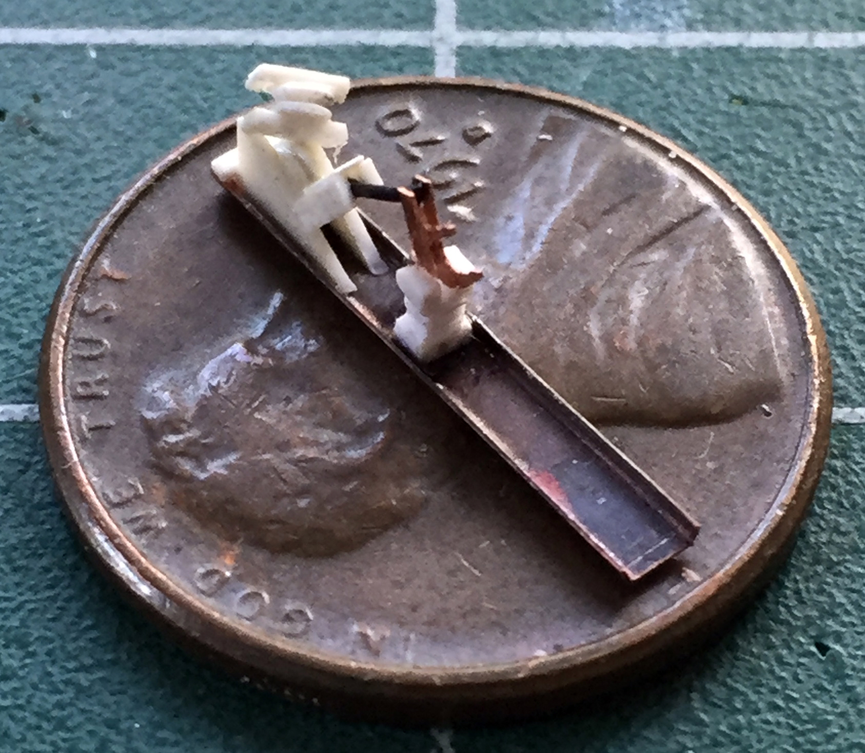
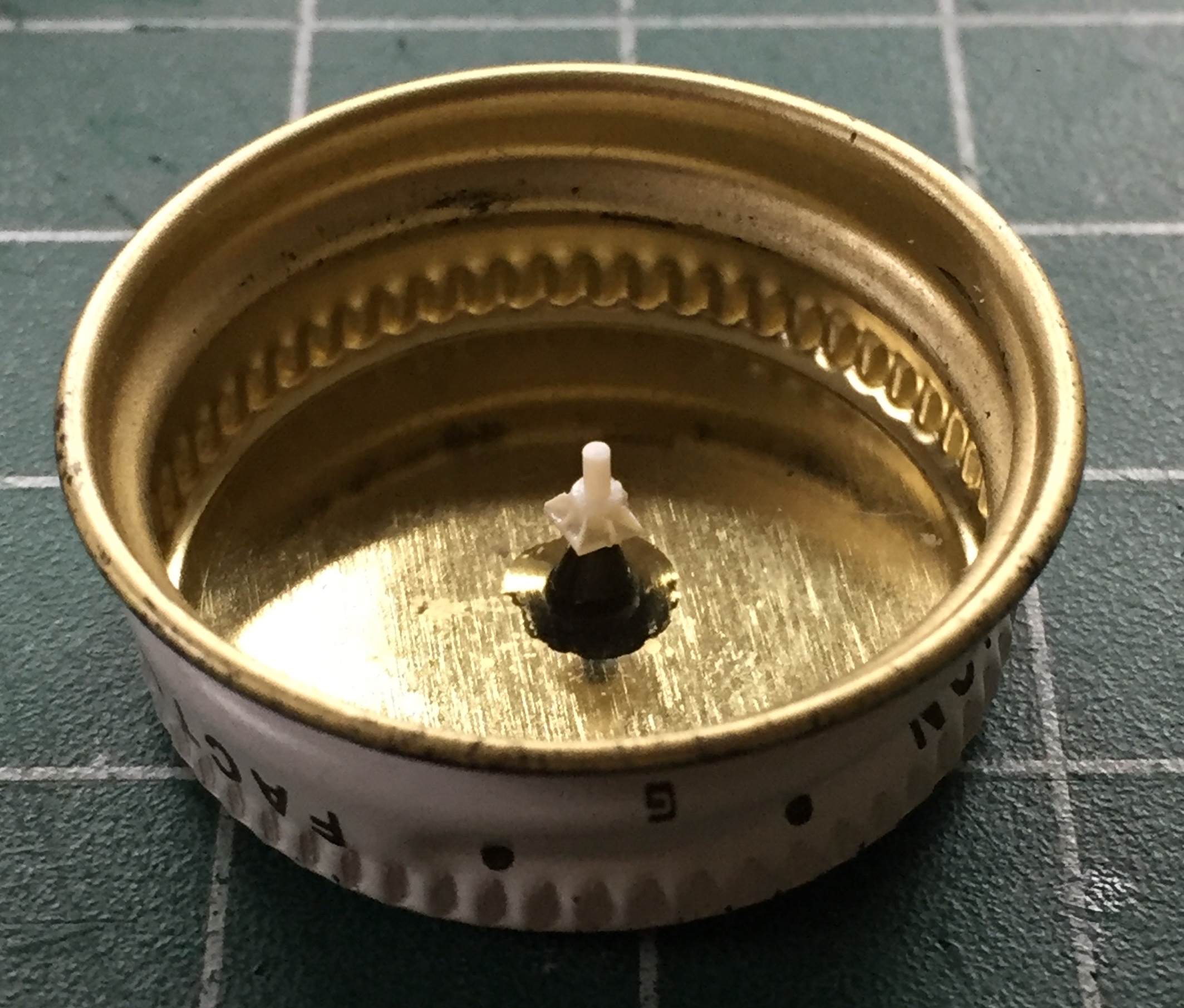
The first part of that involved getting the probe TO FIT tightly. Once that was taken care of, I wanted to socket a piece of steel sheet into the base of the probe. That started by cutting a piece from an old can, cutting the recess, then gluing the steel in place:
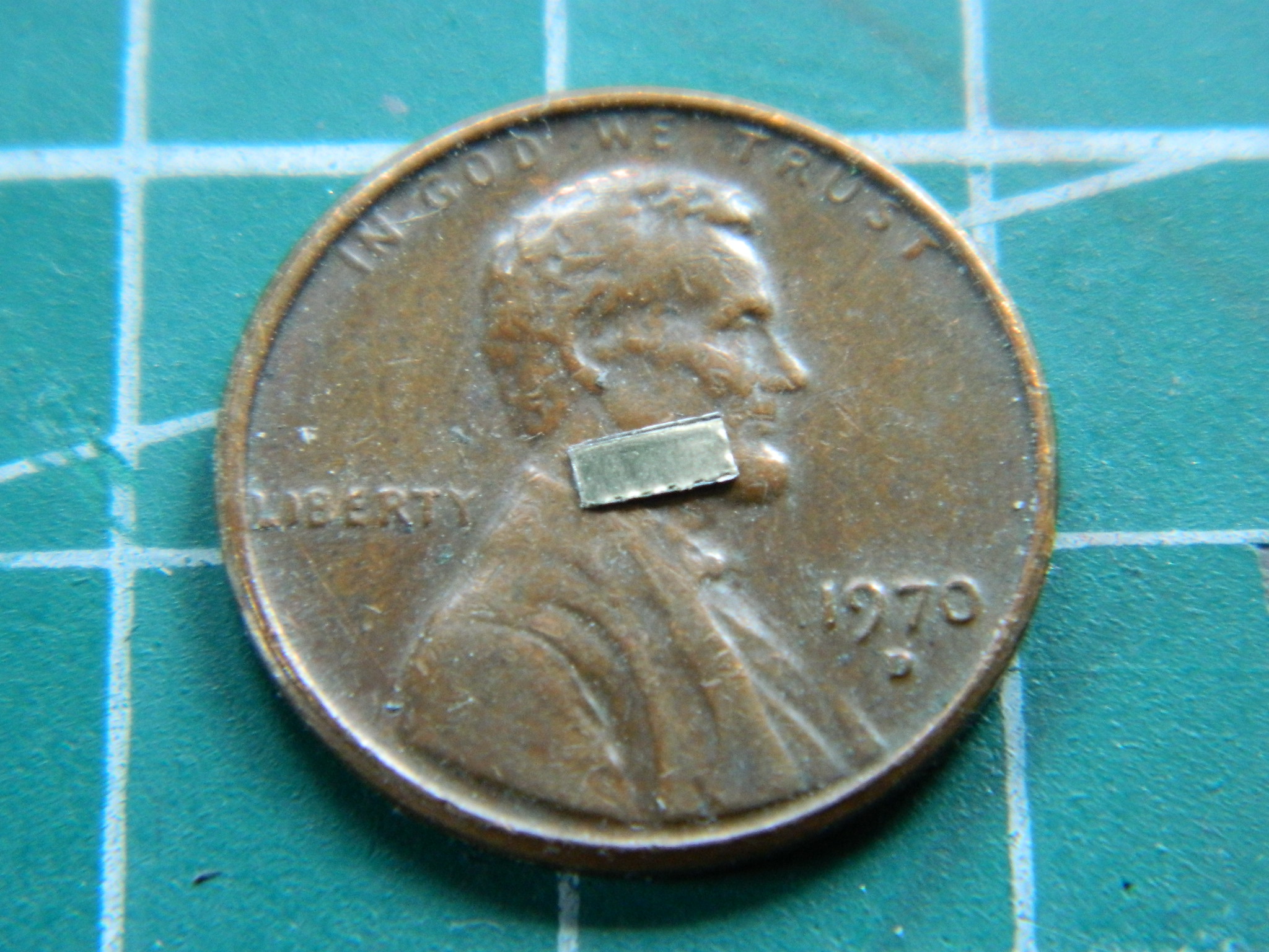


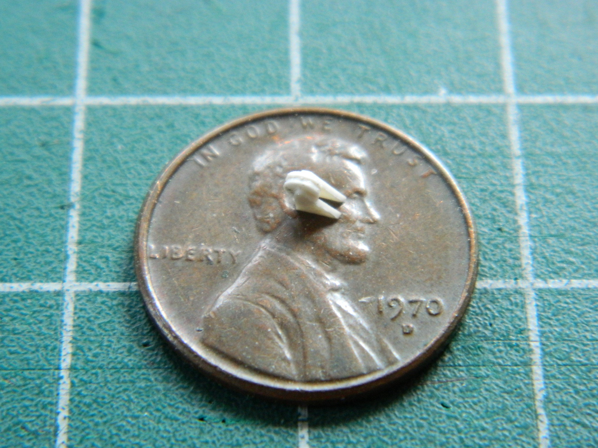
Next was to fill the socket where the (now removed) locating pin was to seat and then drill holes for the magnets to sit (kjmagnetics.com, part number ZD12, 1/16″ (1.28mm) x 1/8″ (3.18mm) rare earth magnets):
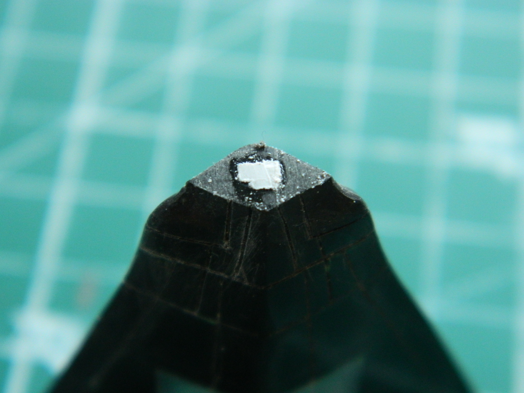
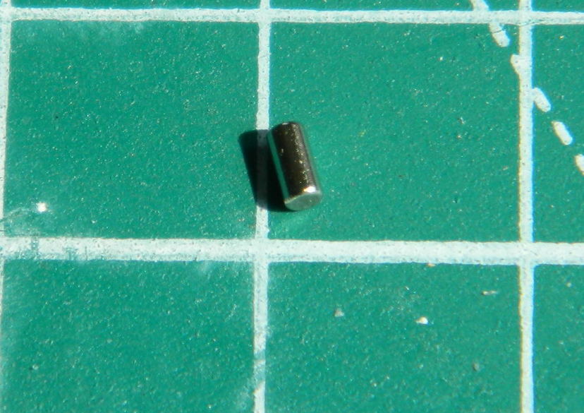
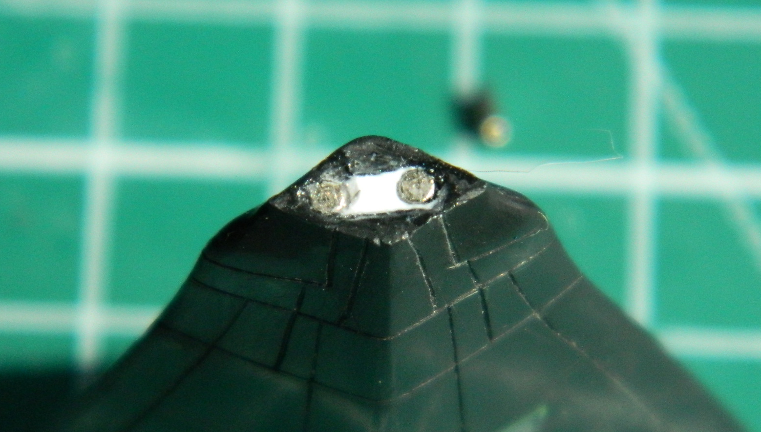
Works just fine (the clunky kit-supplied probe will be replaced with something much nicer):

Before I could start closing the fuselage, I needed to finish painting the landing gear bays and glue the nose bay into place. I misted Tamiya’s X-32 Titanium Silver over the flat black, and then touched a few connectors/caps on the spaghetti plumbing with Tamiya’s X-23 Clear Blue:


Okay, I liked how that came out, now to attach the nose gear bay. Since this model has some heft to it, I wanted to be certain I had enough surface area to support things. The first step was to get the bay in place. The vise on the right is supplying pressure to get a good bond in an area that wasn’t really fitting all that well (and there really wasn’t enough material left there to diddle around with):
I added some scrap .080″ (2.032mm) stock to both sides of the box to increase the surface area the glue could act on:

And then I noticed that the box was too narrow. If I knew how that happened, it would not have happened. The bottom edge in this photo doesn’t quite come out to the edge of the opening:
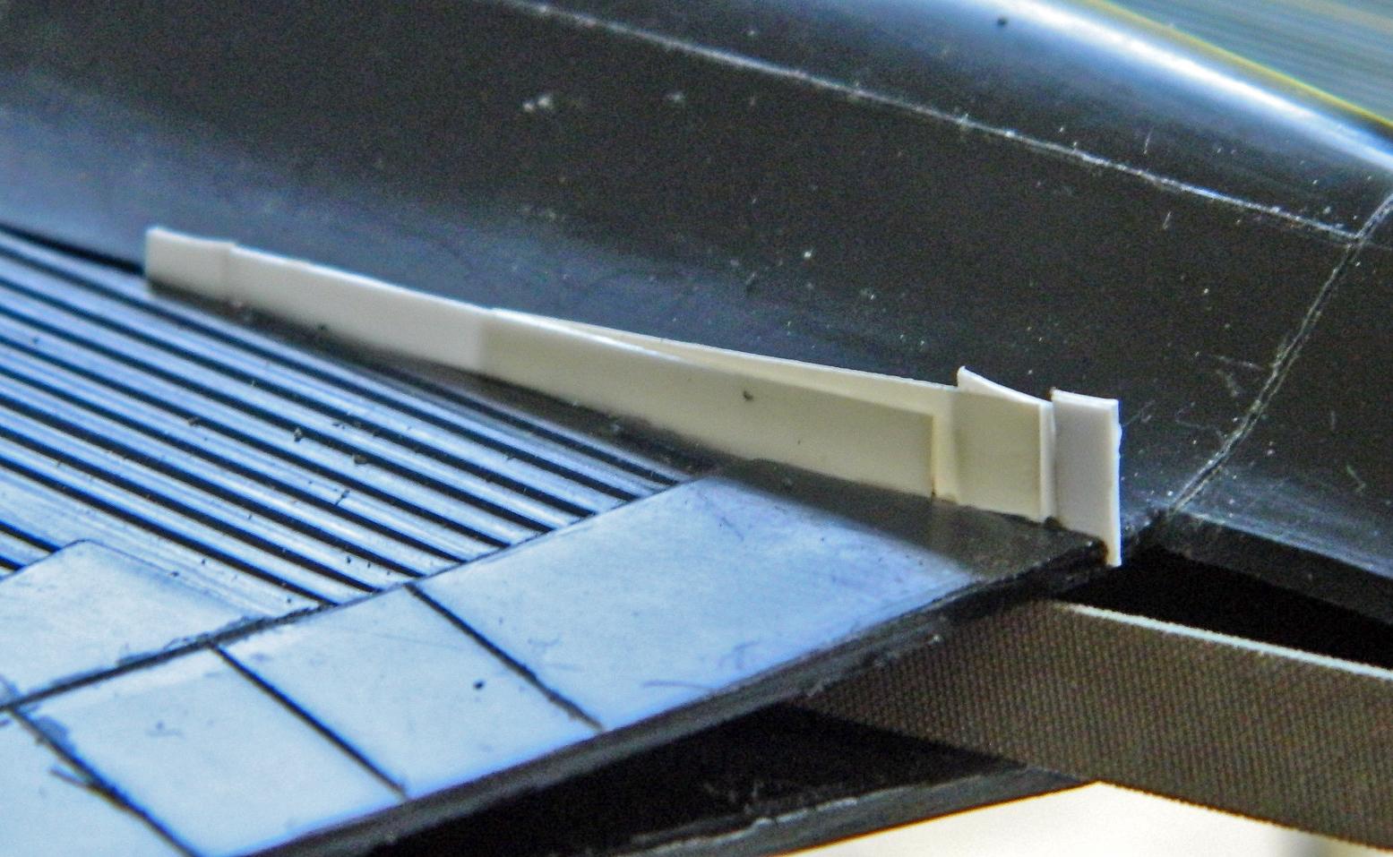
My “fix” was to add a strip of plastic to move the edge of the opening inward…and with how far out of true the underside of this nose is, that little strip of plastic isn’t the worst of it:

Time to put these parts together:
Putting these parts together required a bit of sincere persuasion:
About the time I got this far:

I noticed this broken part sitting on my cutting mat:

Those broken parts (because investigation showed more than one broke) came from here:

Not. Remotely. Pleased. The broken part was reassembled (almost completely…a very tiny part of it was never found) and glued back into place. NOT. FORNICATING. PLEASED.
To keep some moron (me) from blindly stuffing his finger into the bay again, I covered them all with excess plastic from a vacuforming session:
I also noticed the numerous places where “fit” would need work to FIT, in addition to numerous places where plastic needed to be added to fill gaps. Flat .010″ (.254mm) fitted into the gap found in underside of the nose:


And where the edges of the nose had gaps took some thicker scrap styrene:

Thicker stock filled gaps near the main landing gear bays:

And where fuselage sides met wing roots:

And where the fuselage met the fuselage…in other words, any place something with the fuselage met (or was supposed to) something else with the fuselage:
Some places I filled with sprue:

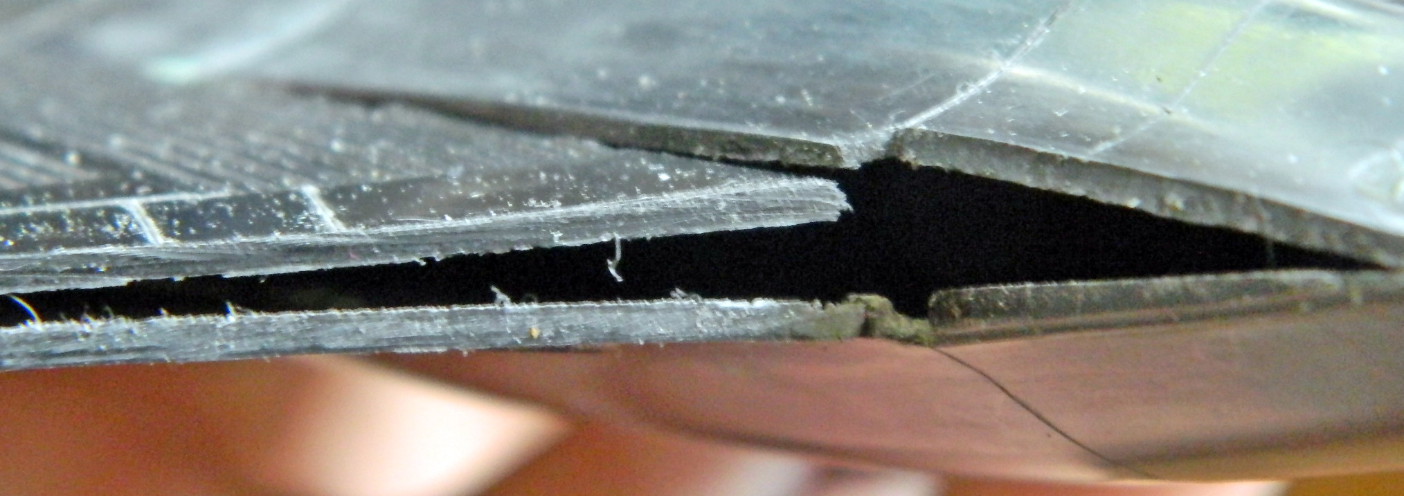
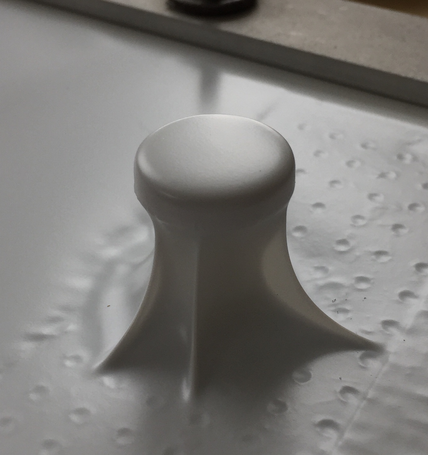
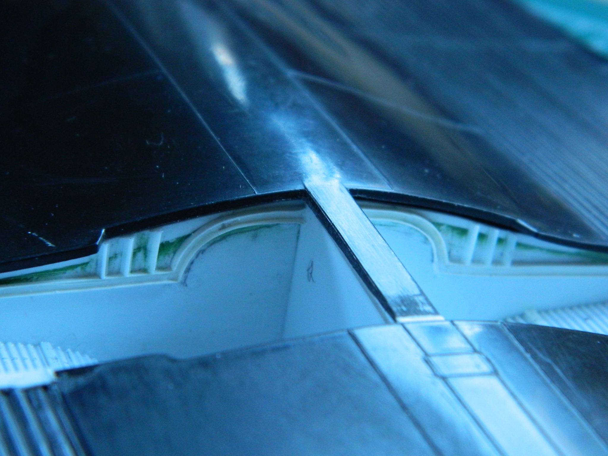
At this point you get to see the “Right Proper Scare” mentioned in the header. I turned the fuselage onto its back and discovered that THIS part doesn’t come anywhere near close to fitting:

Well. That did fascinating things to my blood pressure.
Yeah, that’s going to require some sort of magick or some sort of trick or some sort of SOMETHING SODDING CLEVER on my part because if that ISN’T made to fit, I either end up with a 3/16″ (4.76mm) step where there IS none:
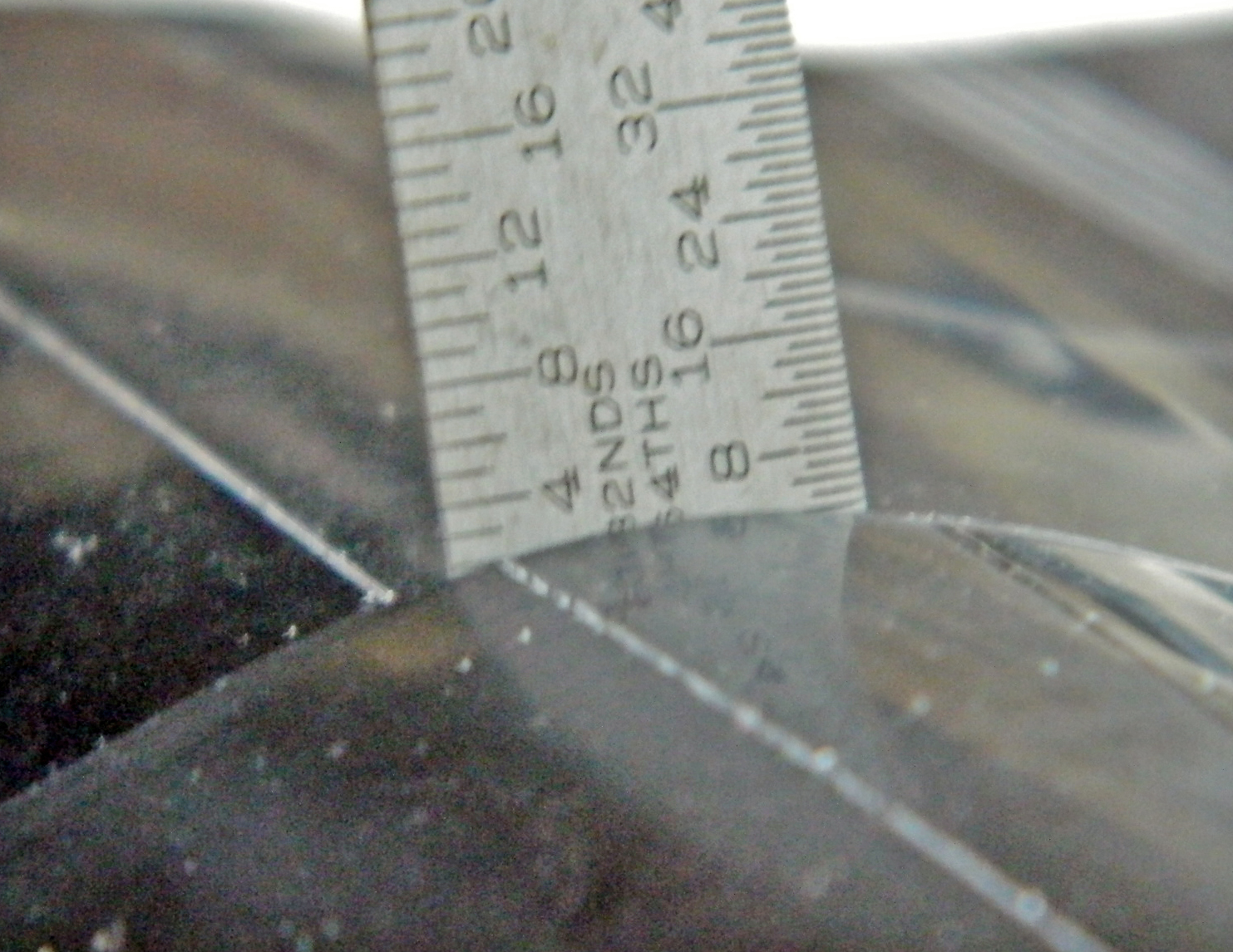
OR I end up with a small hole like this:

I spent a few days considering how I could explain to the person that this is being built for that he wasn’t going to (ever) get it. I also spent a few days considering how I could fix it. I realized that fixing it was going to be easier.
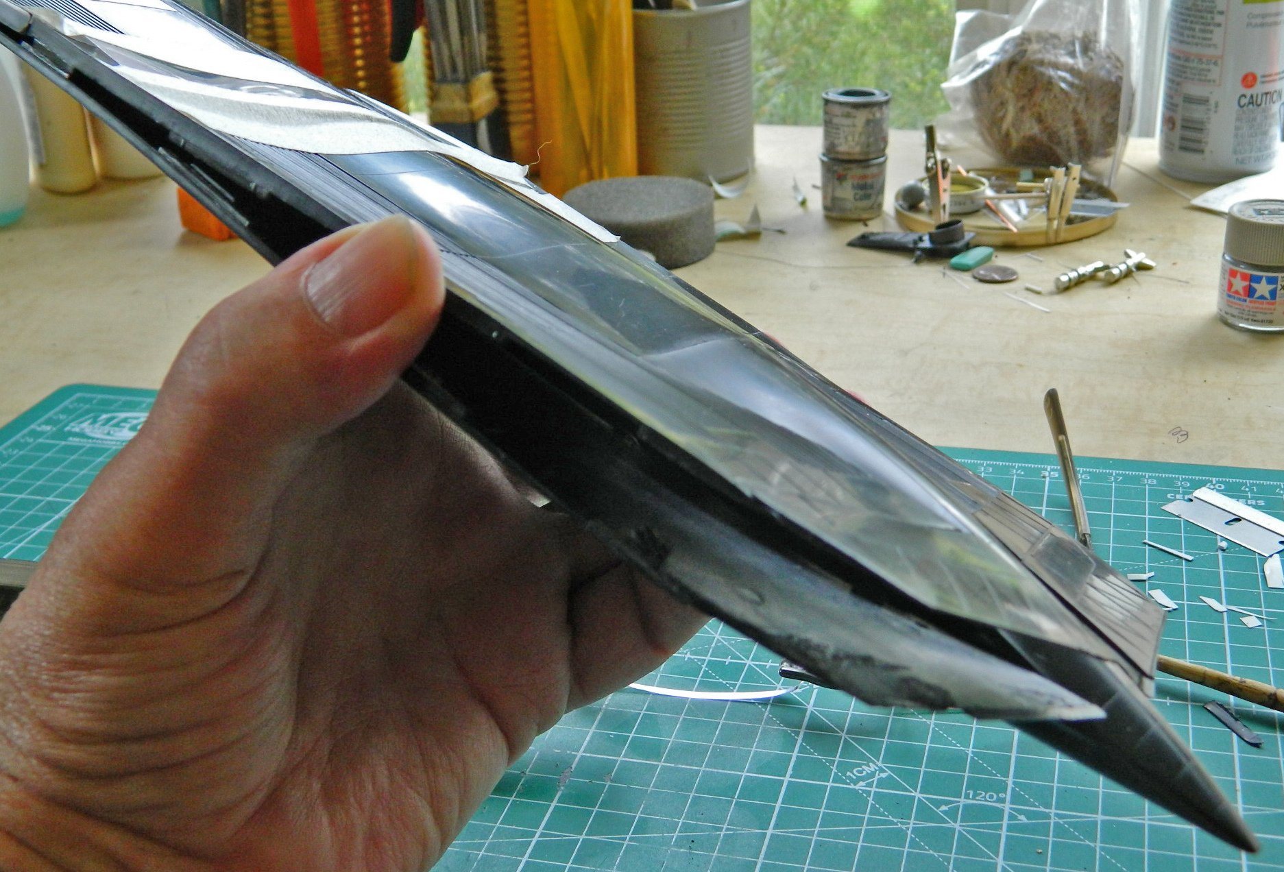
If you look at the lower left corner of the photo above, you’ll see there’s a section missing from the edge of what is the elevon (yes, that’s actually a word…it’s the combination of an elevator and an aileron). That’s because I split the fuselage parts aft of the main landing gear bays. The fuselage part that doesn’t fit was added to the underside (mostly because that’s where it’s supposed to go), the glue allowed to set up for a couple of days (because there’s going to be SOME FORCE applied here, dammit), and once I was satisfied that the part was as bonded as I could make it, I started bending things a bit (as well as more than a bit) (and in one place a lot), until things actually lined up.
That required me to hold the upper and lower fuselage sections apart while the glue set up enough for me to release it:
But I got it to fit:
“Fit” is a relative thing, sometimes… (And can be the difference between someone who assembles a kit and someone who builds a model. It’s only when things head for the crapper does it become an indicator of the builders’ skills. If it all goes correctly, it’s all easy.)
Now I had to reattach the bottom of the fuselage to the top and get all that to fit as well. As things turned out, this problem, even though it scared me to borderline incontinence, actually solved a different problem I had been concerned about. Having to bend and force things to fit the underside piece properly actually straightened out the warped fuselage parts and that will end up making it much easier to attach the engine nacelles:
Whew…recovered:
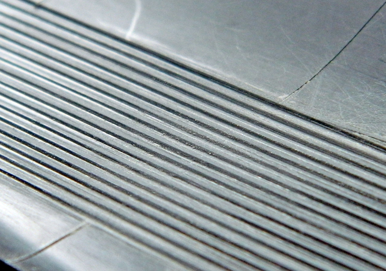
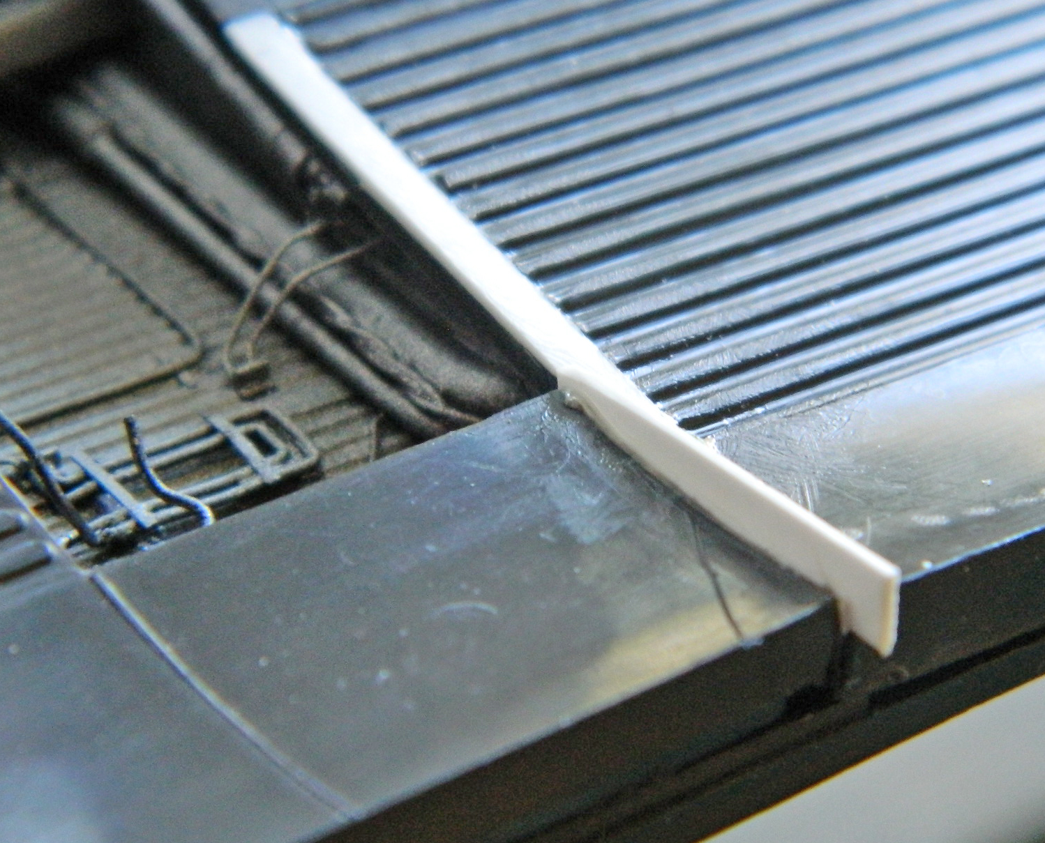
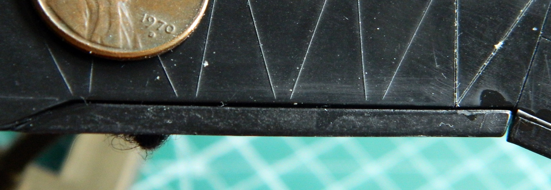
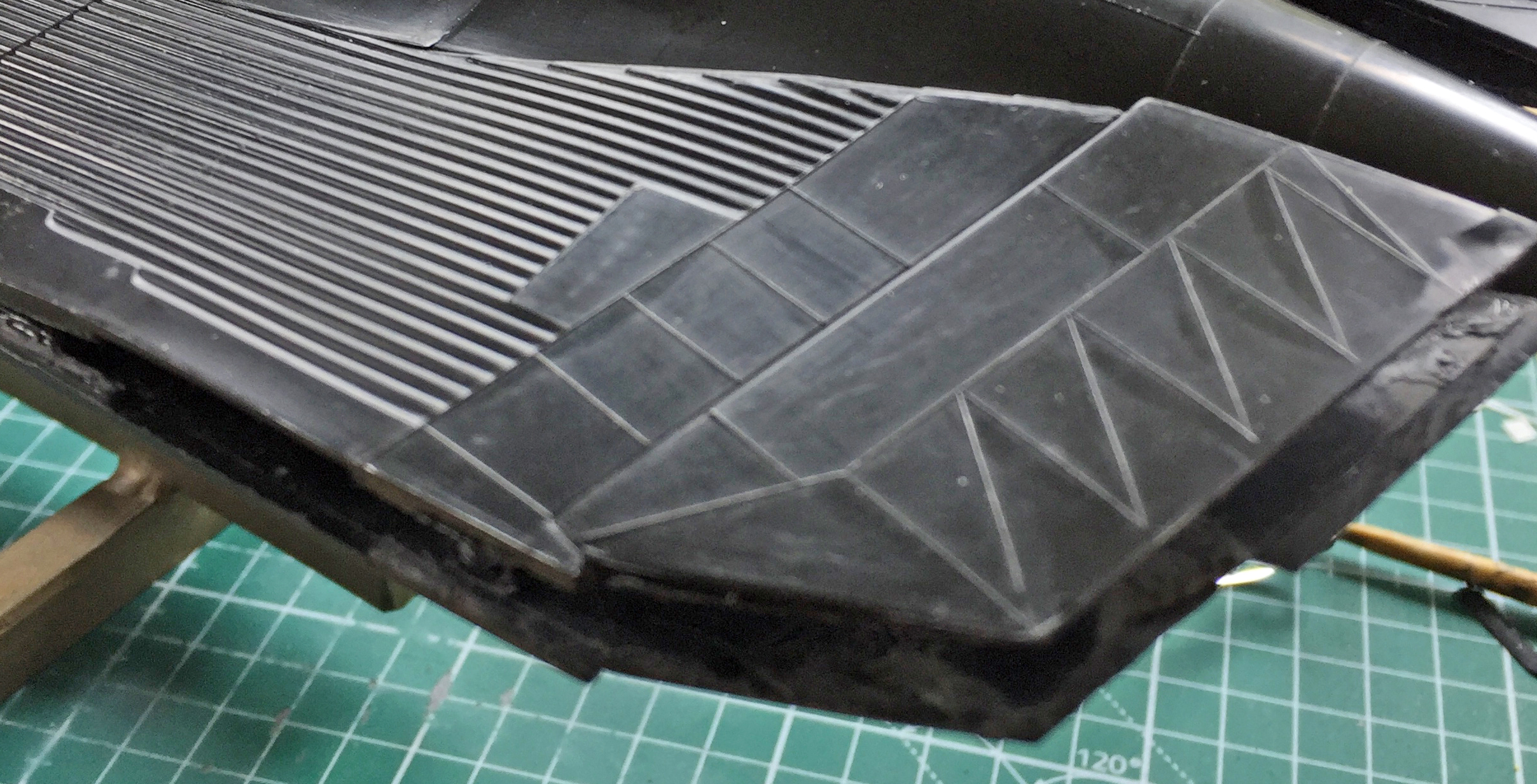
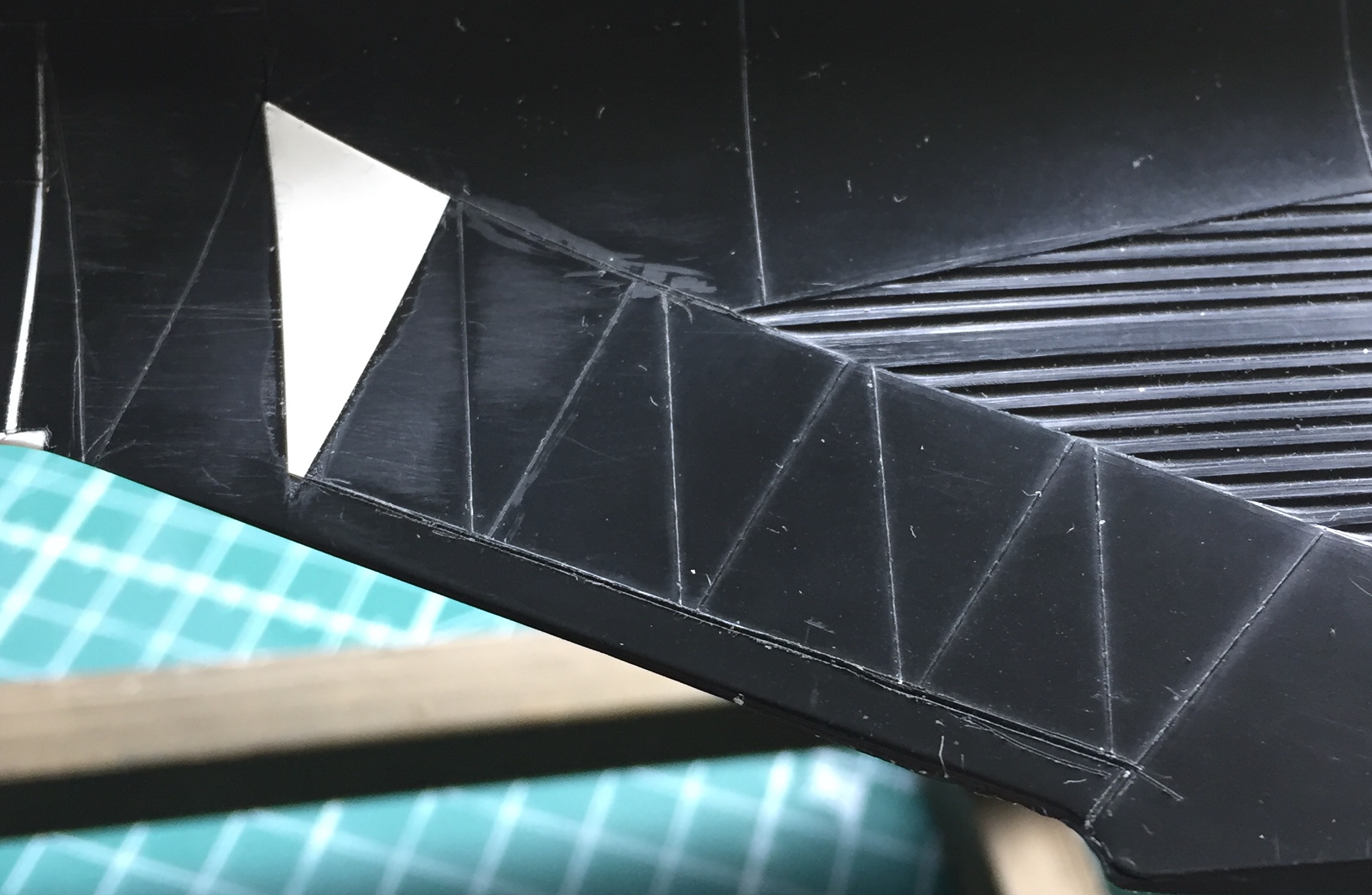
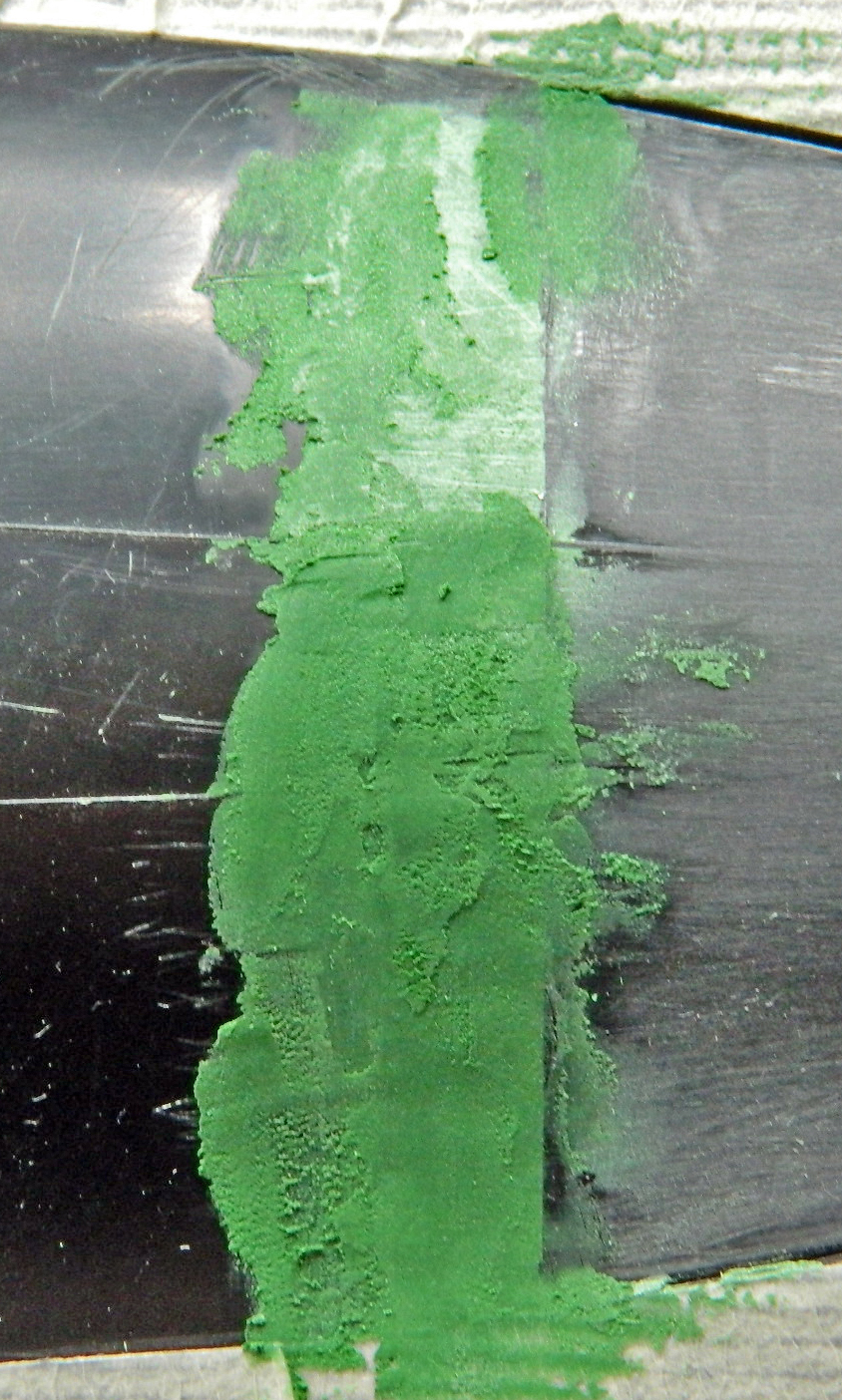
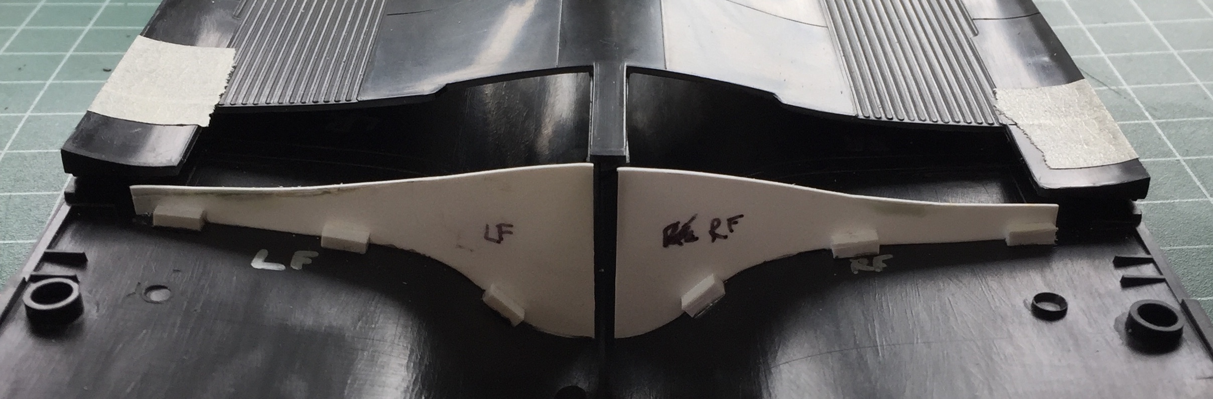
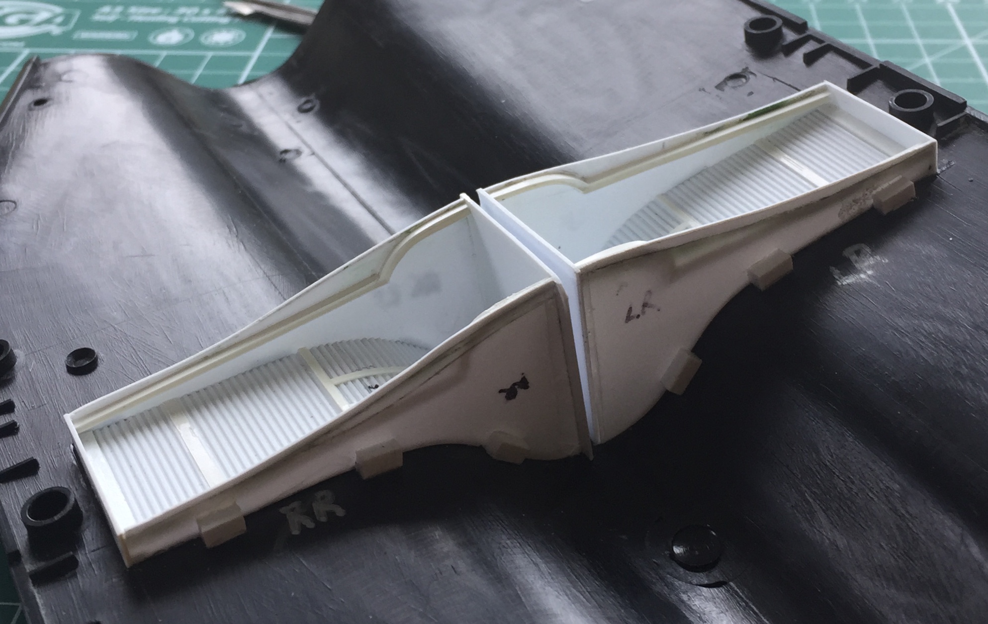
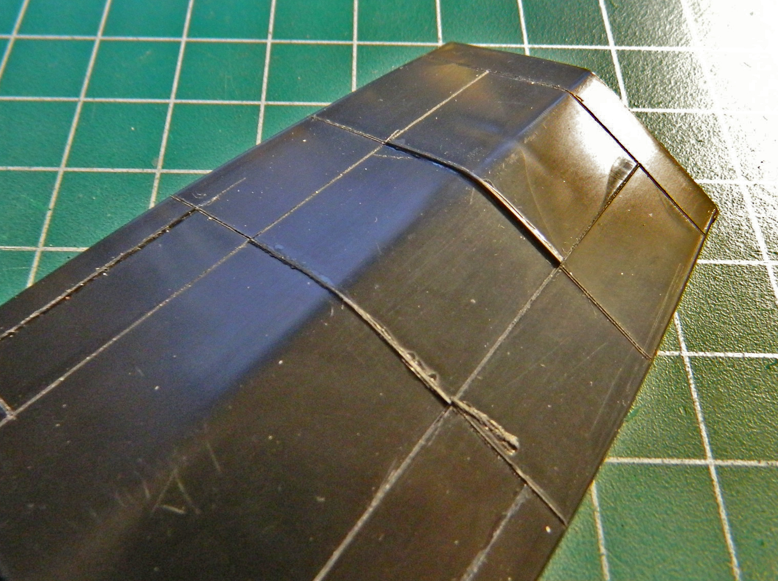
One of the things I noticed when I was at the NASM was that there were a number of fuselage panels that weren’t butt-fit but overlapped instead. The first place I noticed that was where these panels sat higher than the ones adjacent behind the leading edge of the wings:
I used .005″ (.127mm) sheet to raise them:
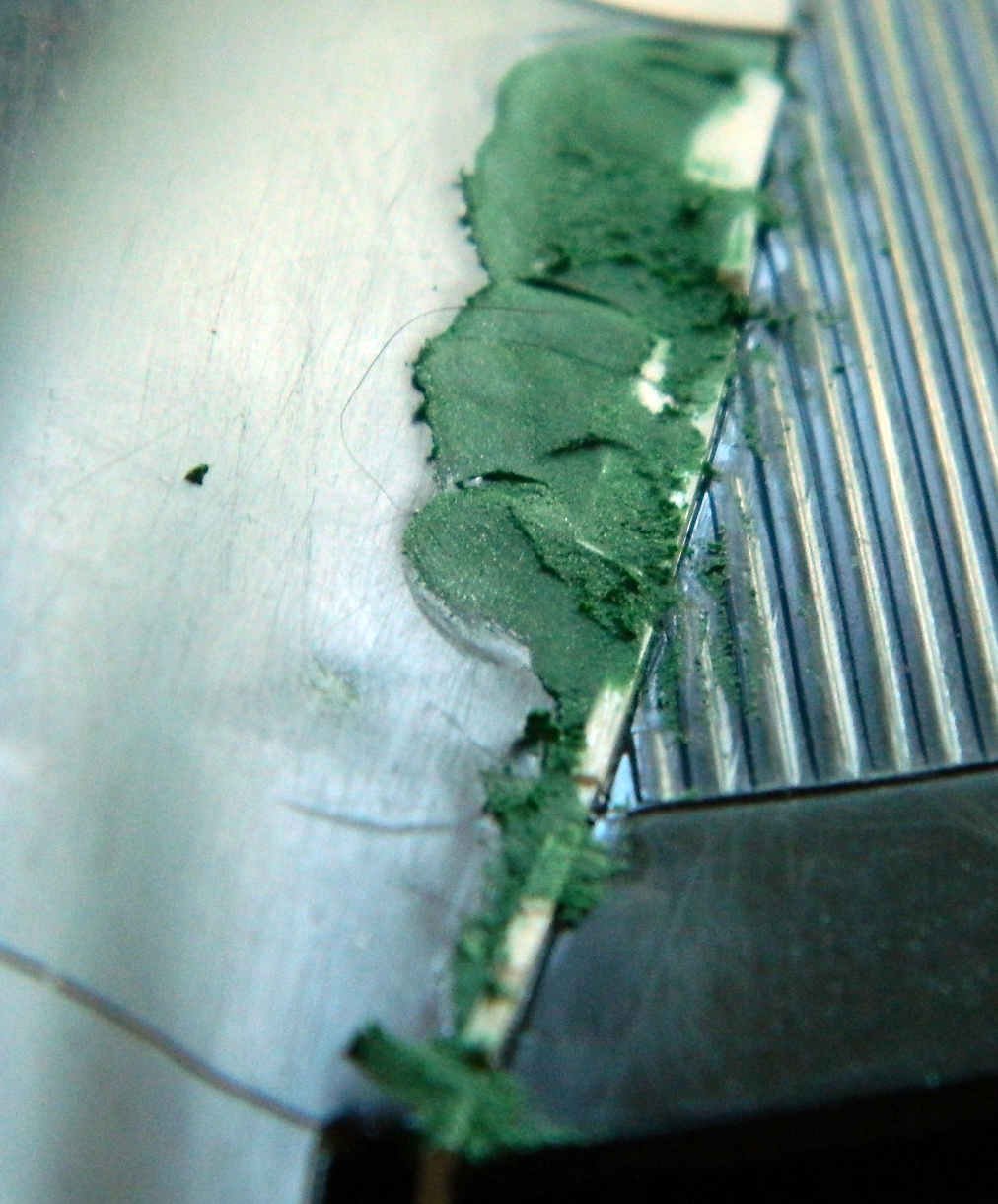
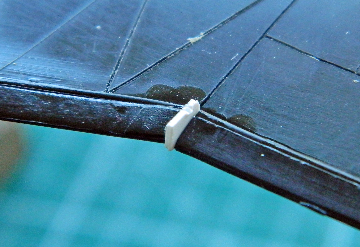
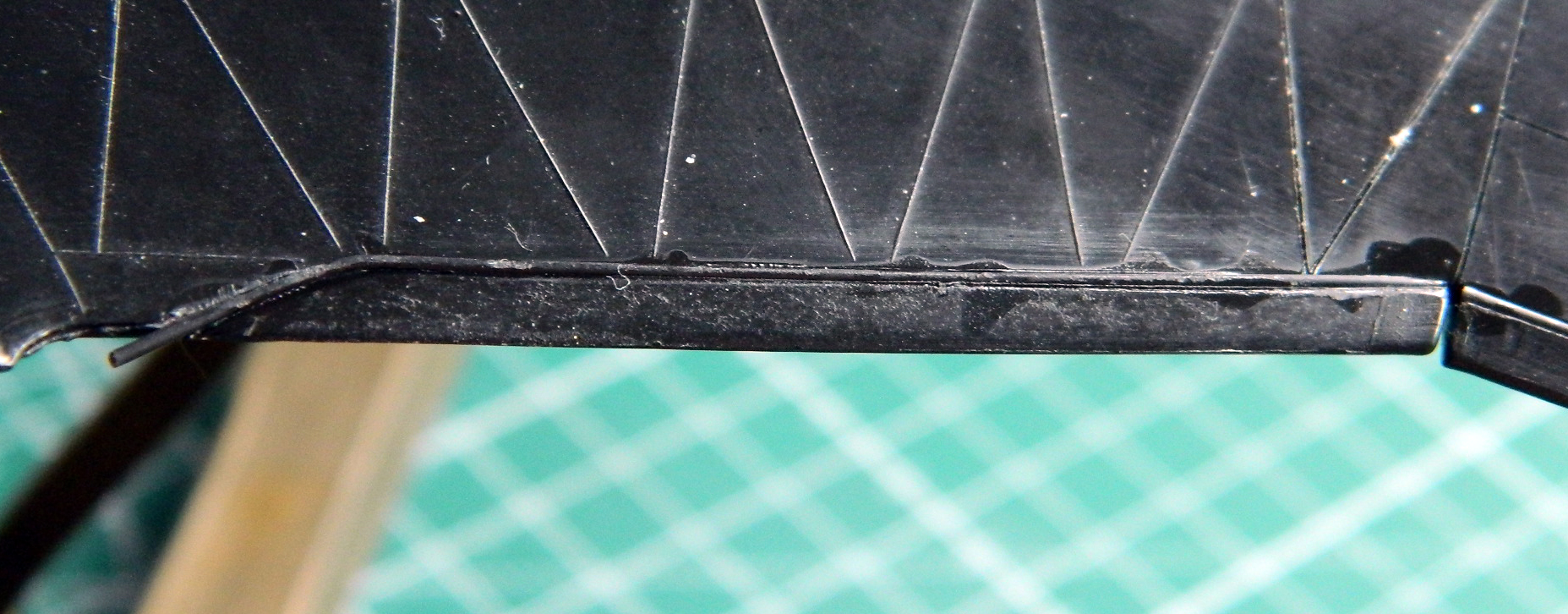
Once all the panels were added to the tops of the wing roots, I needed to blend one panel with putty:
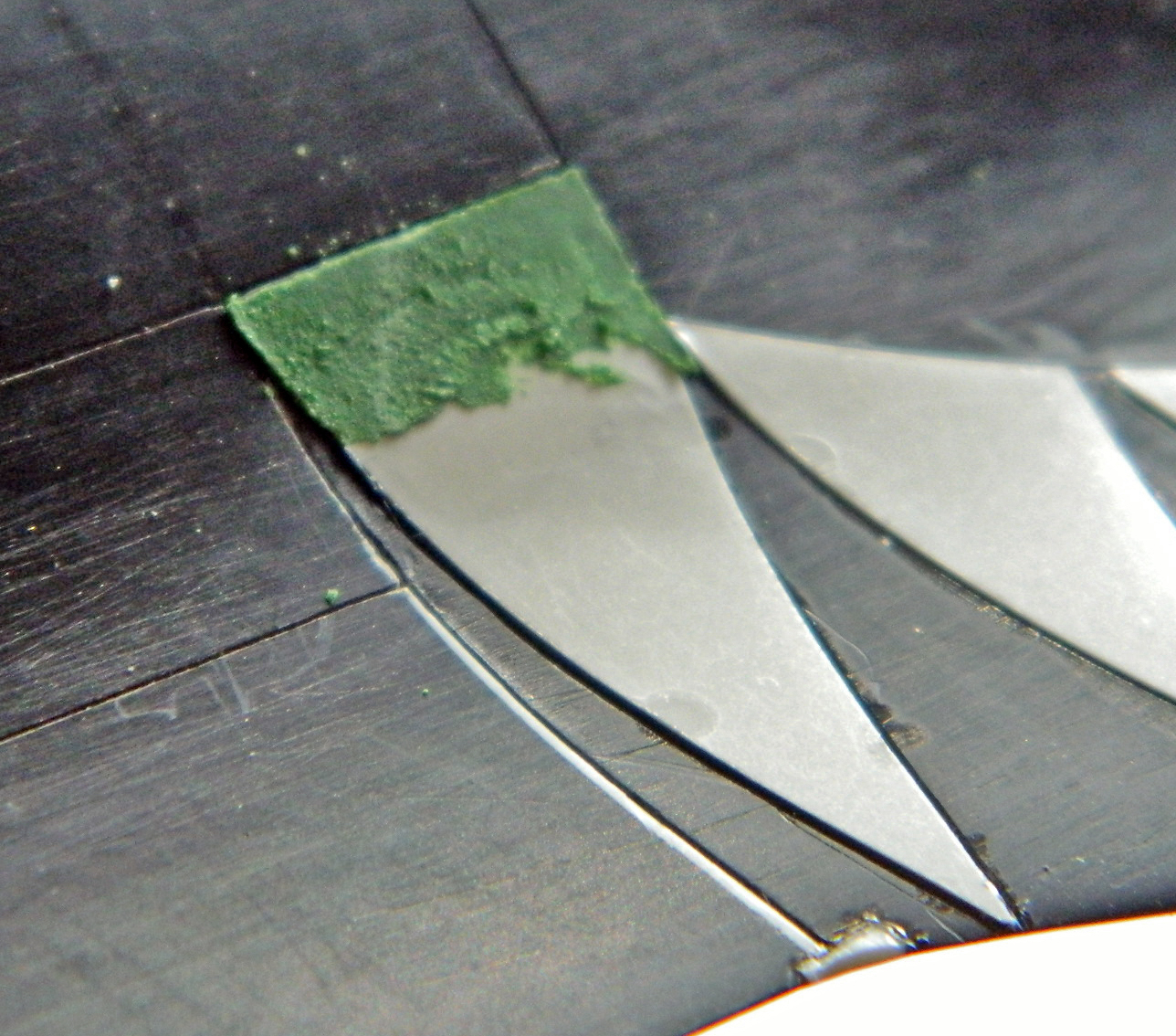
And since I had the putty out, I added it underneath to make the part I’d forced to fit blend without any ridge (and I did more panel scribing while I was under there):
When doing a large area like this, it’s not uncommon to need to add putty here and there. Several thin layers to achieve the desired result is better than trying it in one, thick, pass:

Unsurprisingly, most of that got filed, scraped, and sanded away.
There was a lot of filing and sanding to smooth surfaces where plastic was added. Actually, there is a lot more filing and sanding to do yet, but much of what has been added has been smoothed:


And there is more to do yet, such as this repair when a chunk of the elevator tore loose when I split the fuselage:
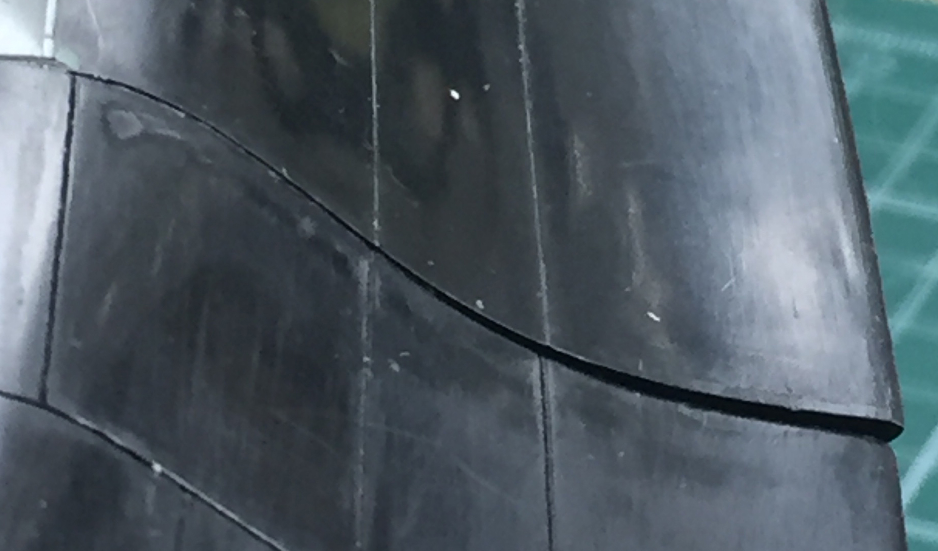
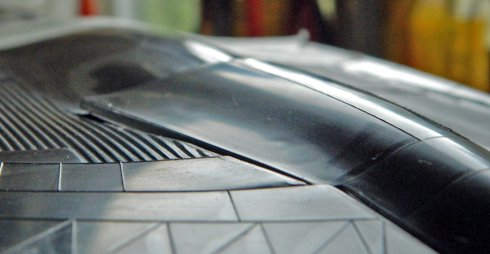
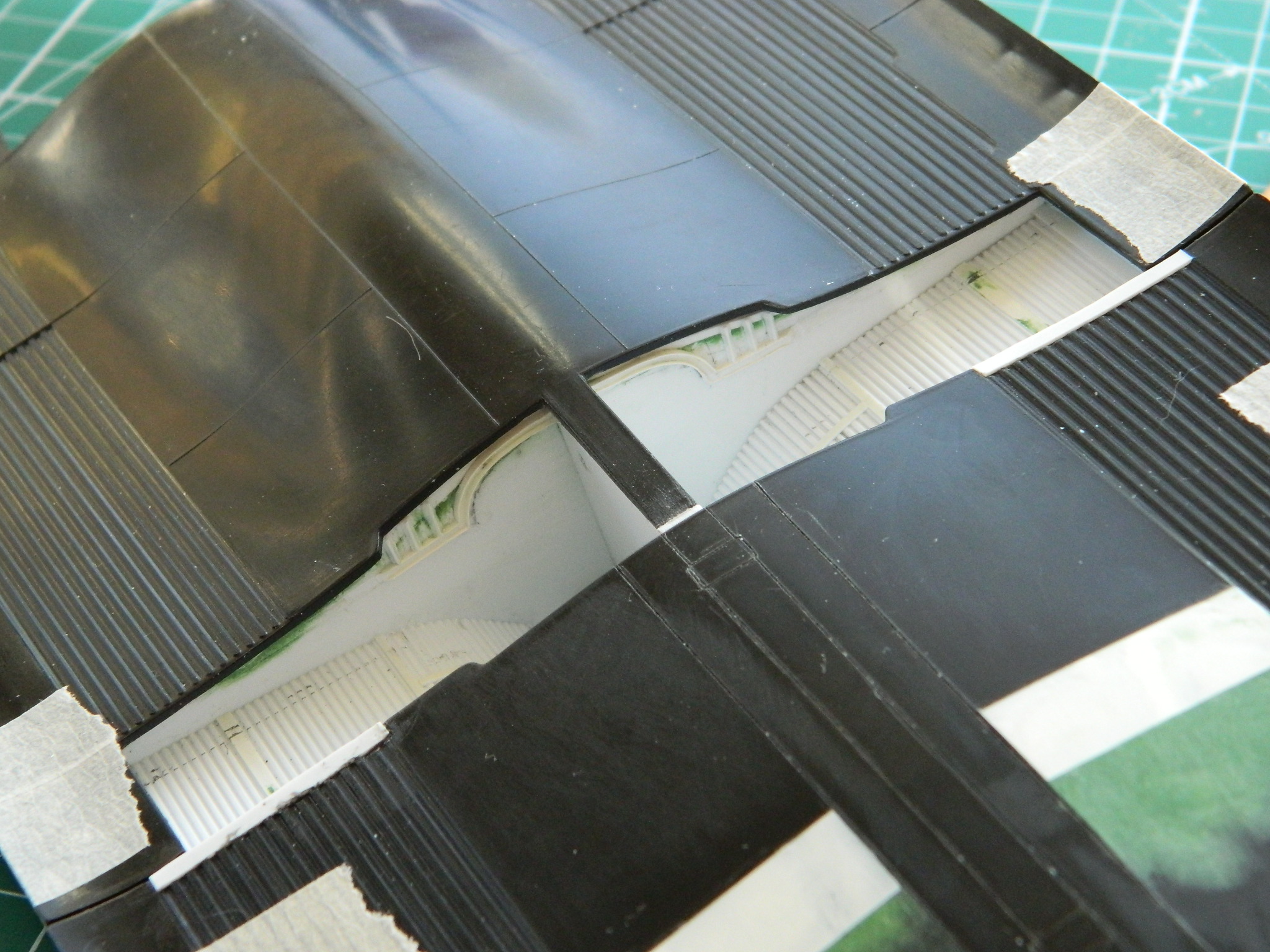
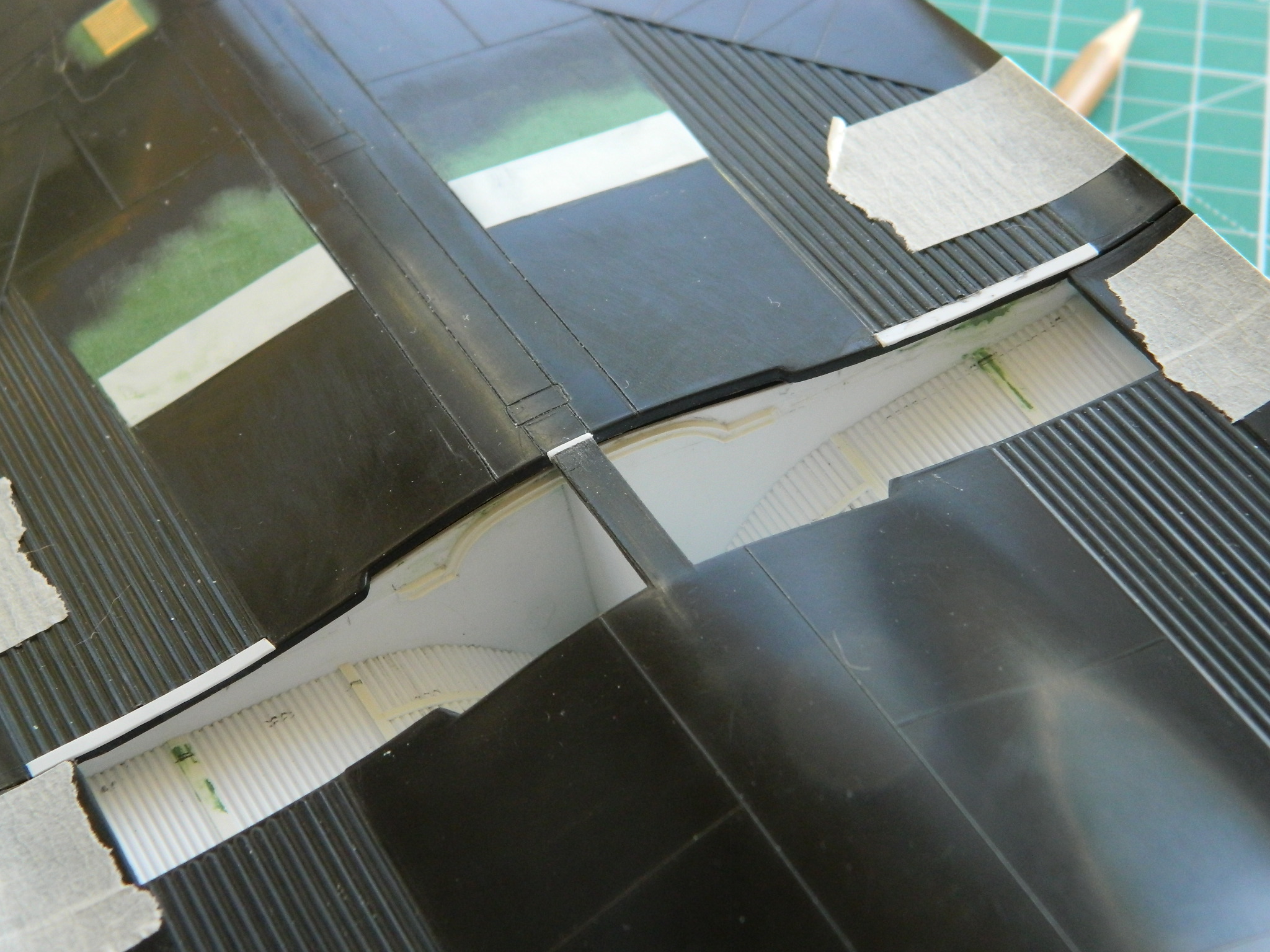
There are more .005″ (.127mm) plastic panels to add, more fit problems to fix, panel lines to be scribed, and no shortage of work left. This is the underside with that gaping hole cleverly (and laboriously) filled and some of the panel lines scribed:
Did I mention “whew” yet?
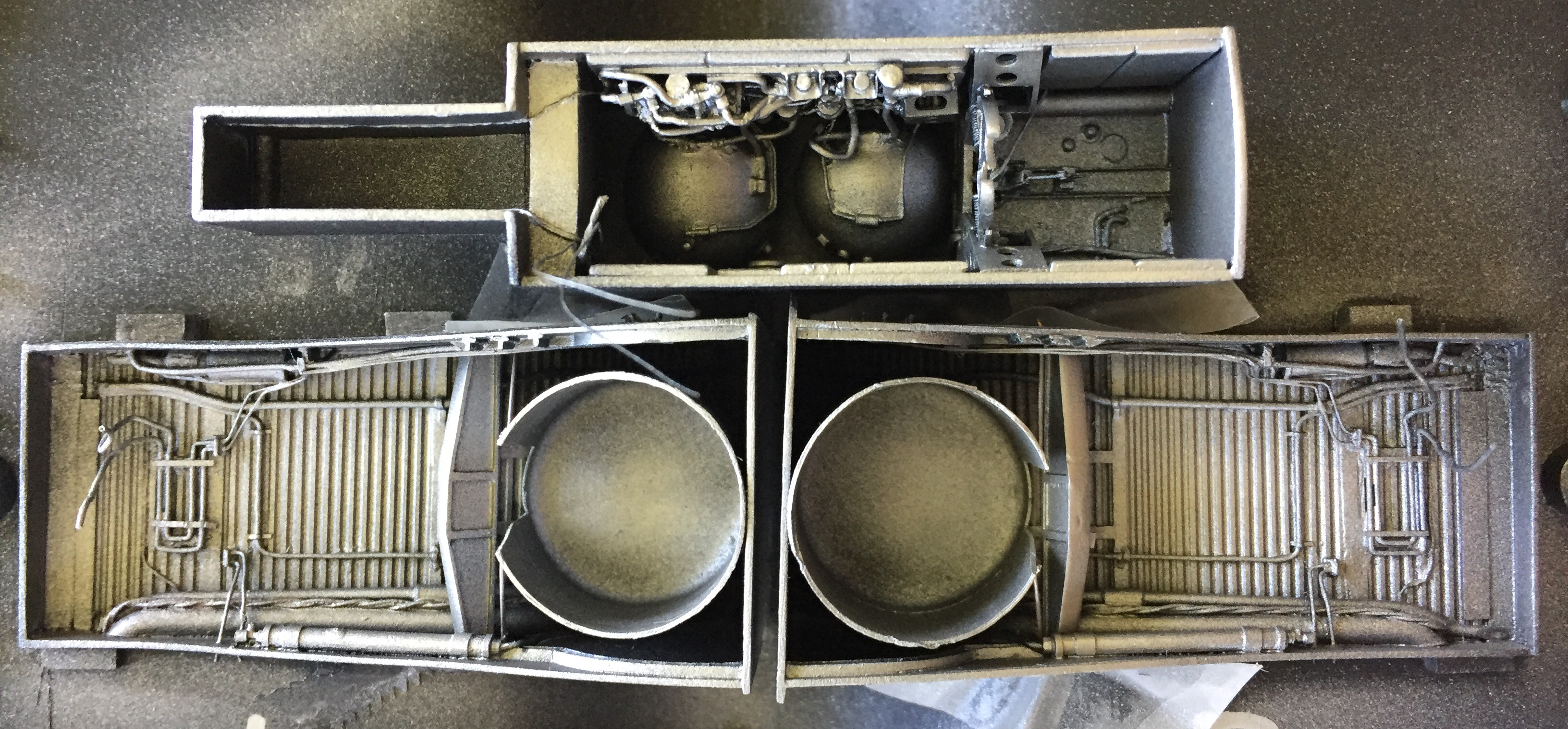
SR-71A Blackbird (Testors) Build #14 – Bays and Main Landing Gear Done For Now
For all the work that was done this month, I don’t have a lot to show. I have, however, gotten both the main landing gear bays AND the main landing gear completed! All pronouncements of “completed” come with the caveat, “for now.”
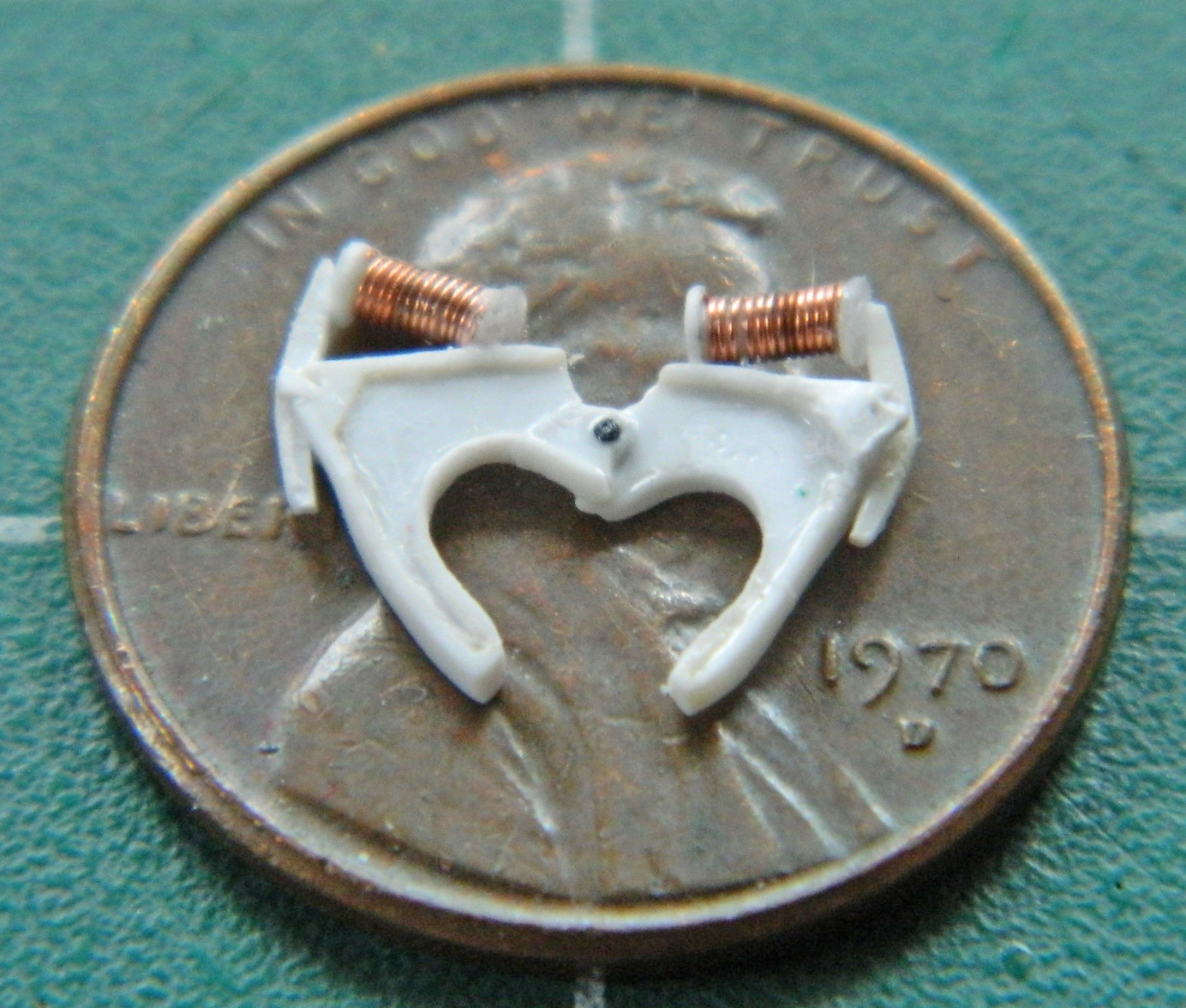
Having constructed the basic landing gear, it’s time to detail them. The first part of that was to make a bracket for Mystery Bits to attach to and I went to .005″ (.127mm) copper shim stock for that, cut out both pieces, and soldered them together into one bracket:

I don’t know why these lines are coiled, I just know that they are and they are visible, so, the coils get added to the bracket (I used solder for ease of manipulation) and the bracket as well as a junction block on the left side get added to the trunnion wings:
There is another Mystery Bit on each strut that evidently serves as some sort of distribution block for what I assume are hydraulic lines (they also provide mounting points for the linkages that the landing gear door attaches to, which I will deal with later on). Those had to be made and are comprised of about 10-12 pieces each:
Setting those aside, I wanted to paint the compressible section of the struts before I populated the parts with more details. I used Humbrol’s Metal Kote Steel, #27003, which is my go-to paint whenever I need something to look like steel and I can’t put steel in (and yes…I thought about it). It’s a buffing paint; once cured, it buffs to a very nice representation of shiny steel. (And I didn’t take any photos of that; you can find how #27003 looks after being buffed in the Sherman M4A3 build as I used it frequently.) But what I really need is anodized aluminum (and note how well the landing lights on the nose strut turned out!):


The NASM has #972 on display and they have it up on stands that attach to the landing gear. The stands keep the weight off the tires. To keep the oleos from compressing as the seals dry and stop sealing, collars are attached to the compressible sections. To my eye, they look like anodized aluminum. To replicate that, once the steel paint had been buffed and cured, I coated that with Tamiya’s X-27 Clear Red. It’s not aluminum, but the effect is close enough:

While the red is still easy to access, that area was masked.
[EDIT: Yeah, well, that red didn’t last very long. The initial plan was to model #972 as it’s displayed at the Smithsonian. That mean making the smooth cement floor, the stanchions, ropes, and lights (operational lights, of course) just they way they are at the Smithsonian. The person this was for was going to make a display table with a glass top to display #972 under. And then that plan changed at his end, meaning I didn’t have to make the Smithsonian display and probably saved me at least a hundred hours…perhaps…probably…more. I used acrylic thinner to remove the red and buffed the “steel” and that’s why in later photos you won’t see any read on the oleos.]
I started the pre-shading process by painting the inside of all the landing gear bays Tamiya’s XF-1 Flat Black:

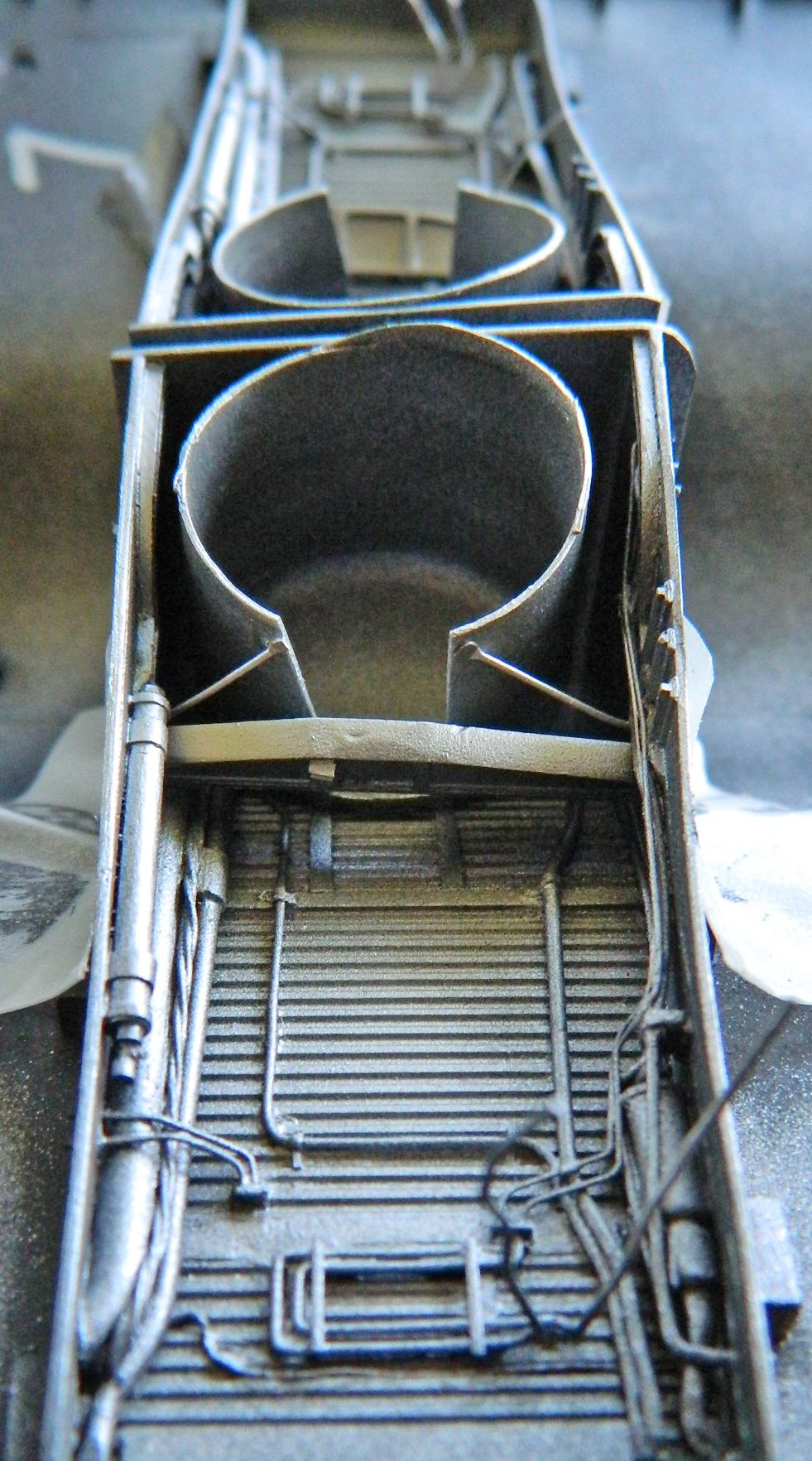
There are circular blast shields inside the main landing gear bays. Evidently the tires got hot enough to sometimes explode and given how many hydraulic lines and how much wiring is in the area, Lockheed’s engineers decided to protect them. Those were also painted flat black and then glued in place:
Then I added all the details I could to the main landing gear (the yokes are spread so that I can put the center tire in place once the landing gear has been painted):

My next task is to take a mental-health break while I figure out what the next step will be. I’m thinking it’s time to start putting the fuselage parts together. This will require me to glue the nose landing gear bay in place, fill MANY GAPS where the fuselage goes (relatively) together, and scribe panel lines…
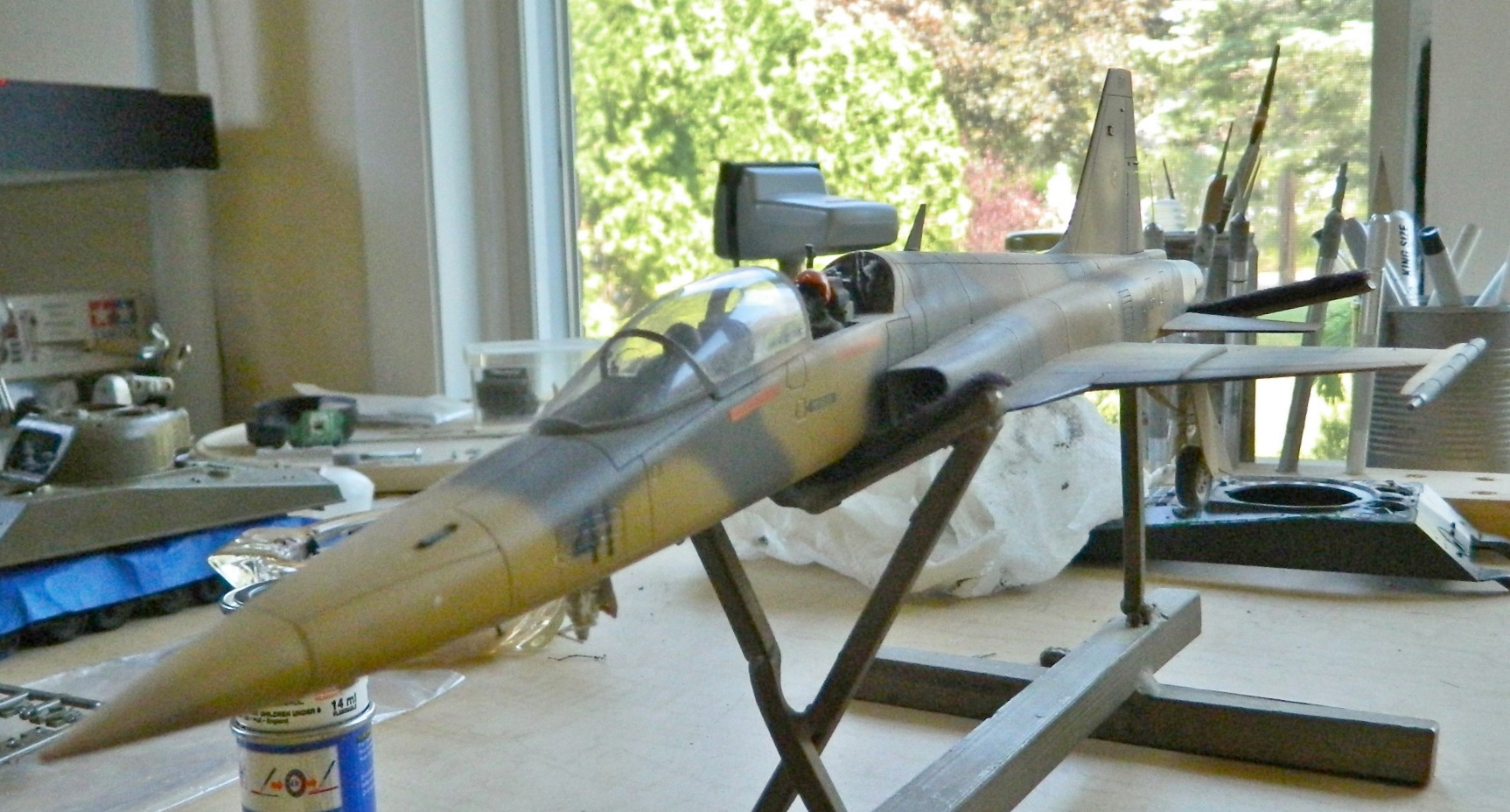
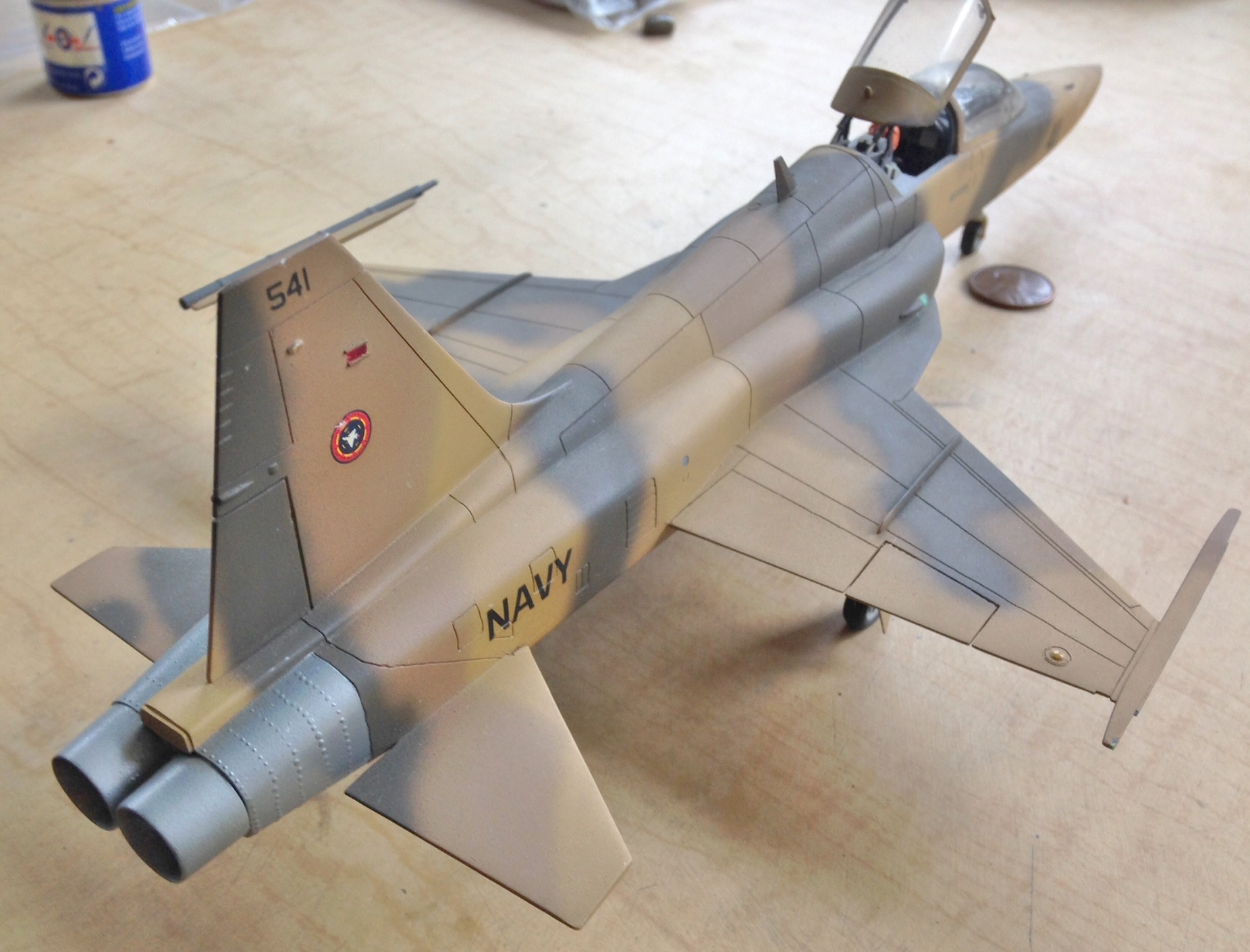
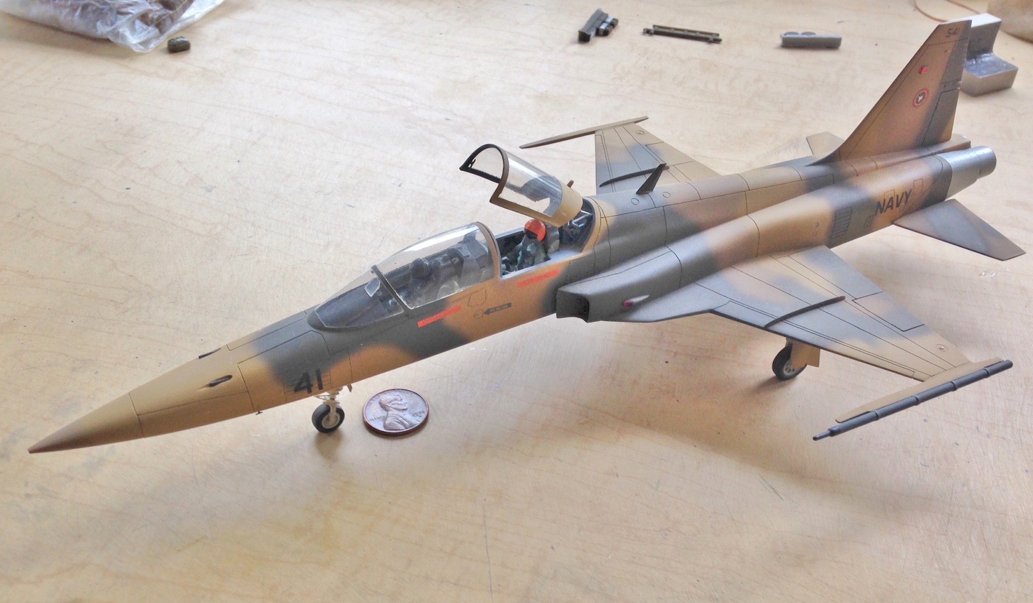
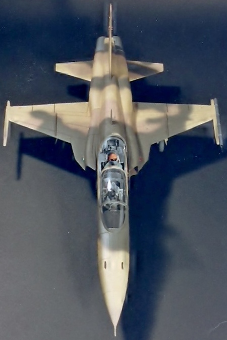
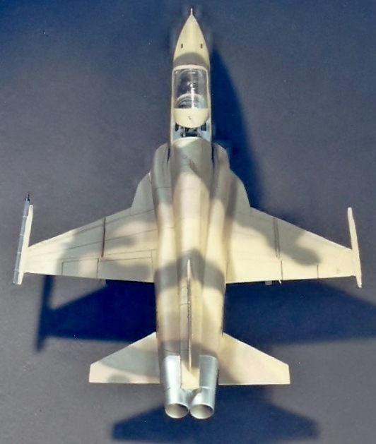
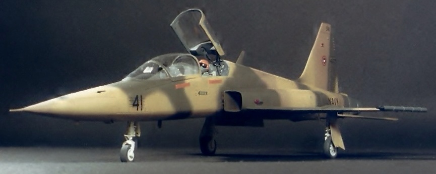
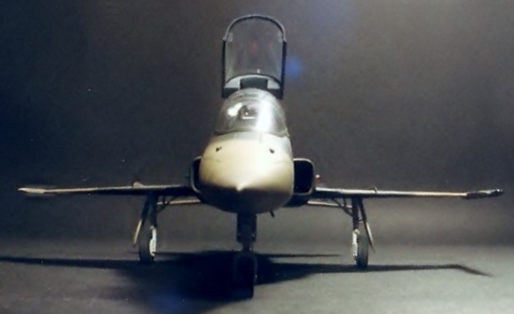
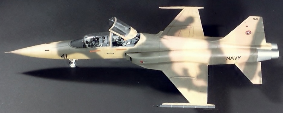
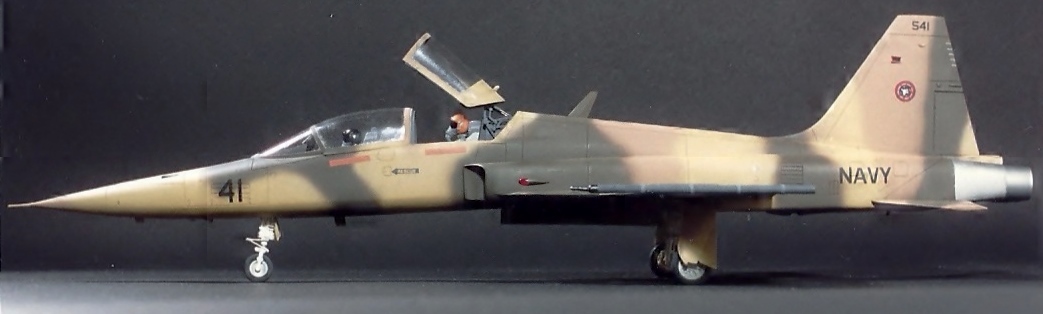
F-5F Tiger II (Monogram) 1/48; 527th Tactical Fighter Training Aggressor Squadron Markings
This was finished in ’91 and then boxed and stored shortly after it was finished…for about twenty-four years. I figured some bits would break off, which they did. I just thought more would have come off. For thirteen of those twenty-four years this was stored in an unheated and uncooled attic.
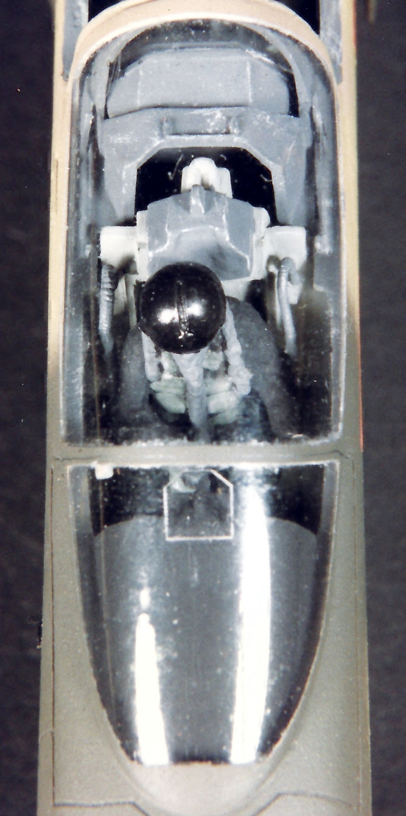
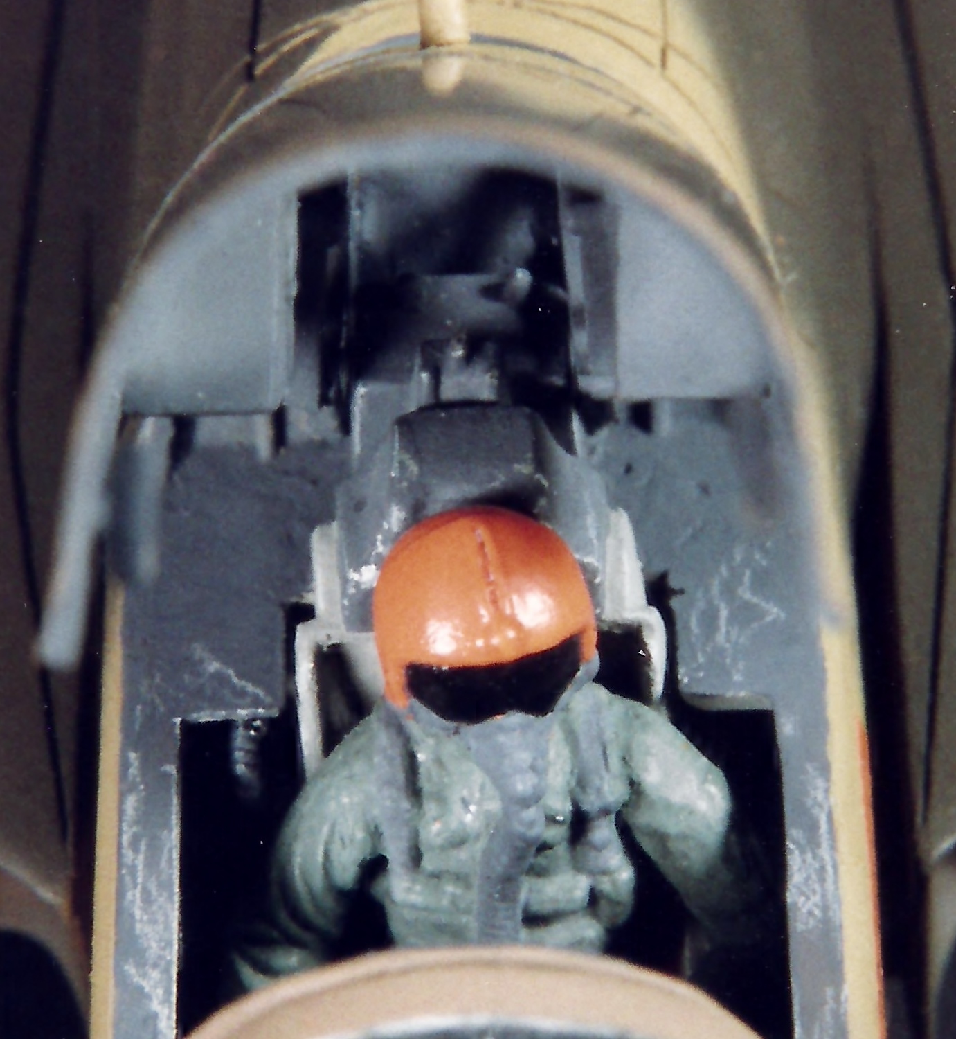
When it was built, I did a bit of detailing (not a lot). The canopies were vacu-formed (as were their inner frames), the pilot figures were modified from a Tamiya AM set, the oxygen and G-suit lines were made from guitar strings, some details were omitted from the cockpits (the Navy F-5s didn’t have on-board radar so I cut the radar screens off) and some were added (the hydraulic rams of the rear canopy hinge look like steel because they are – they’re straight pins), the formation lights were made from translucent toothbrush handles, hoses and lines were added to the landing gear (and the gear doors were scratch-built), and this was my first (somewhat poor) attempt at scribing panel lines.
Since I was taking it out of the box to display again, some fixing was called for:

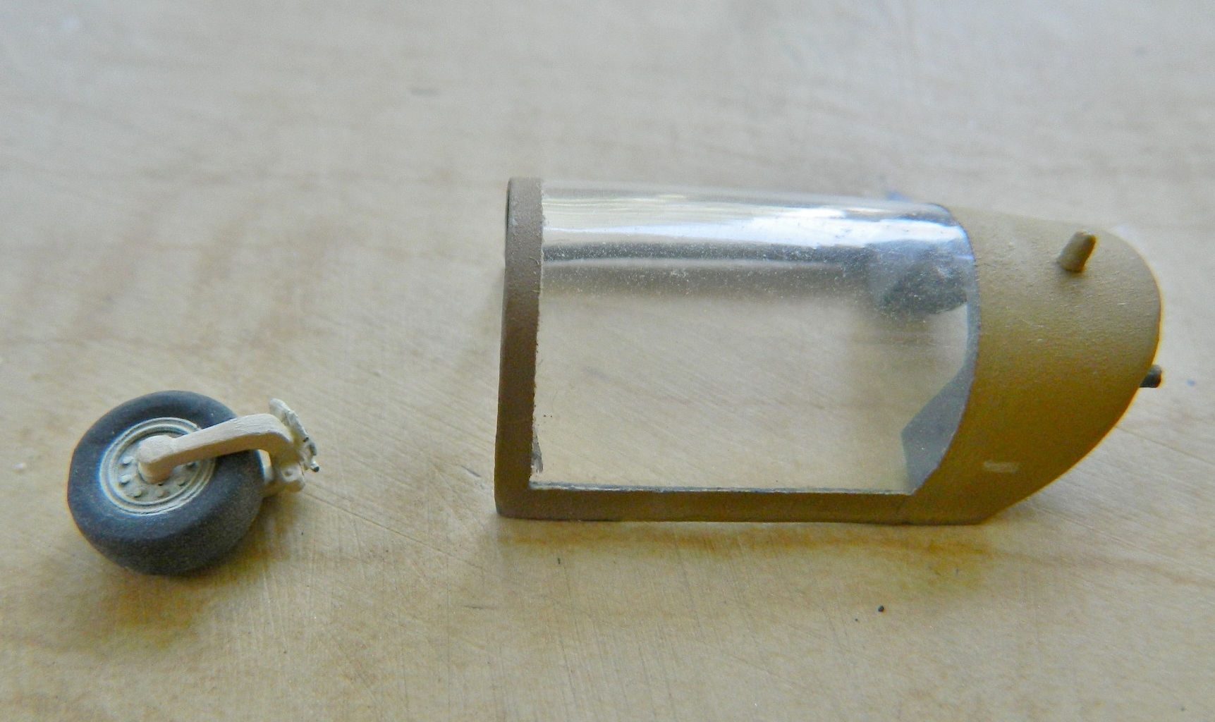
This isn’t the first time the front landing gear has snapped here, so this time I added a pin to help keep it where it belongs:
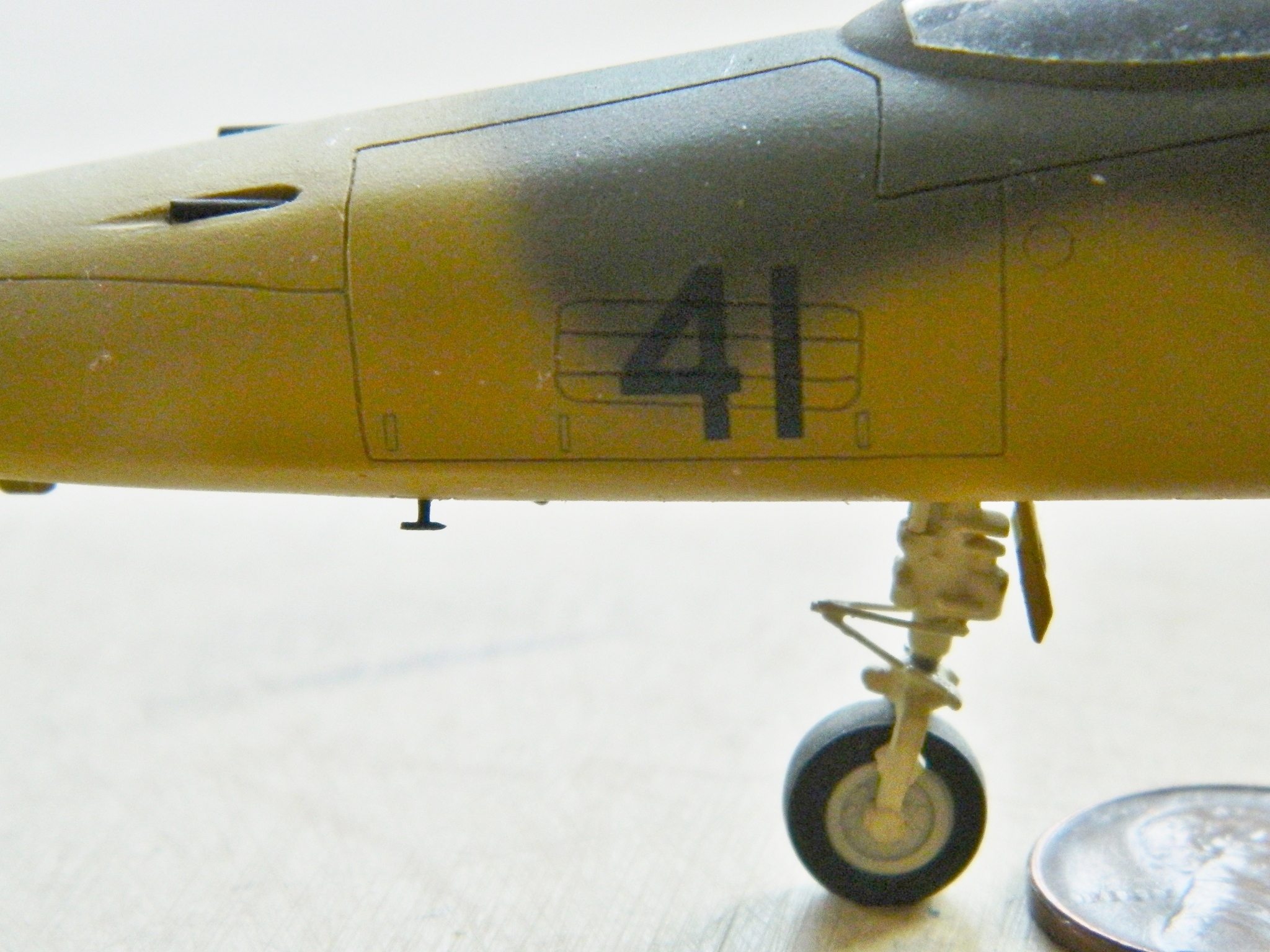
This will do for now. The nose probe is still MIA; the paint that I used in this area is no longer available. (I’ll have to do something about that at some point.) For now, it’s ready to display again:
Photos taken shortly after it was completed in ’91:
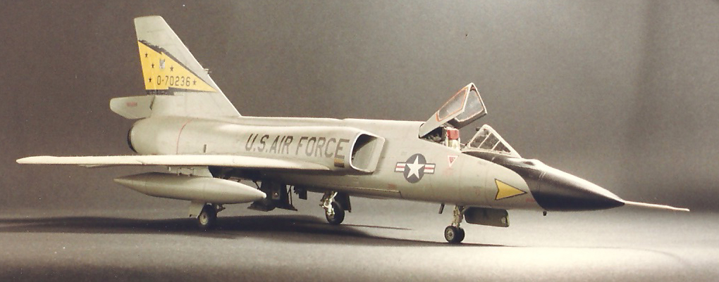
F-106A Delta Dart (Monogram) 1/48; 5th FIS Markings
Something that was done back in the late 80s, essentially OOB:


SR-71A Blackbird (Testors) Build #13 – Main Landing Gear Continues; Bays Get Stuff Stuffed
Every so often I get to a point where in order to do this, I need to do that first. Sometimes I find myself where in order to do either, I have to do the other one first. Since either approach has problems with it, it turns out not mattering; cut the knot, Gordon, and proceed…and that’s where I’m at presently with this.
With the landing gear started, I decided to start adding things to the bays. I have no idea what this Mystery Bit does, but it’s visually prominent so I copied it, one for each bay:
The hydraulic cylinder that extends and retracts the landing gear mounts on a cross brace which rotates to maintain alignment:

I made both of them and discovered during the trimming process that I’d made them too thick. I made them again, just more appropriately sized:

With the cross brace done, I needed to make the hydraulic cylinders. However, in order to make them to the correct length, I found myself far too short of hands. I had to brace the landing gear strut in place, and I had to hold the cross brace in position, and I had to align the cylinder. Right… Since I couldn’t think of a way to do all that with only the usual quantity of hands, I decided to make the cylinders so that I could adjust their lengths later when the landing gear was permanently attached, just the way I did for the hydraulic cylinders used with the canopies. That started by drilling out the plastic rod being used as the body of the cylinder to the diameter of the plastic rod being used as the ram:

This will allow the ram to slide and enable me to adjust length. Added a few details and here are the hydraulic cylinders next to the kit-supplied part:
Somehow, the trunion broke on one of the landing gear struts, so that will get fixed:

I started adding the various lines and as I was doing so, I realized that I was going to need to mount the cross brace about now because care would be needed so that I didn’t put things in that would prevent me from putting the cross brace where it should be. But I couldn’t do that because I only have two hands. What I needed was some way to mount the cross braces temporarily, but allow them to swivel so that they can be aligned relative to the angle (and length) the hydraulic cylinders need. My way around that particular problem was to hold the cross braces in position, drill through the side of the landing gear bay and the end of the cross brace, and that would allow me to put a pin (or wire…this isn’t that large) in there to hold the cross braces in place and allow them to swivel so that later on I can add the hydraulic cylinders with the alignment I want (and, hopefully, that’s correct). Once it was drilled and the wire pins in place, I used tape to keep the wires from falling out:

So yep…they swivel and by being in place, define where I can run lines and stuff:


And I ran lines and stuff:


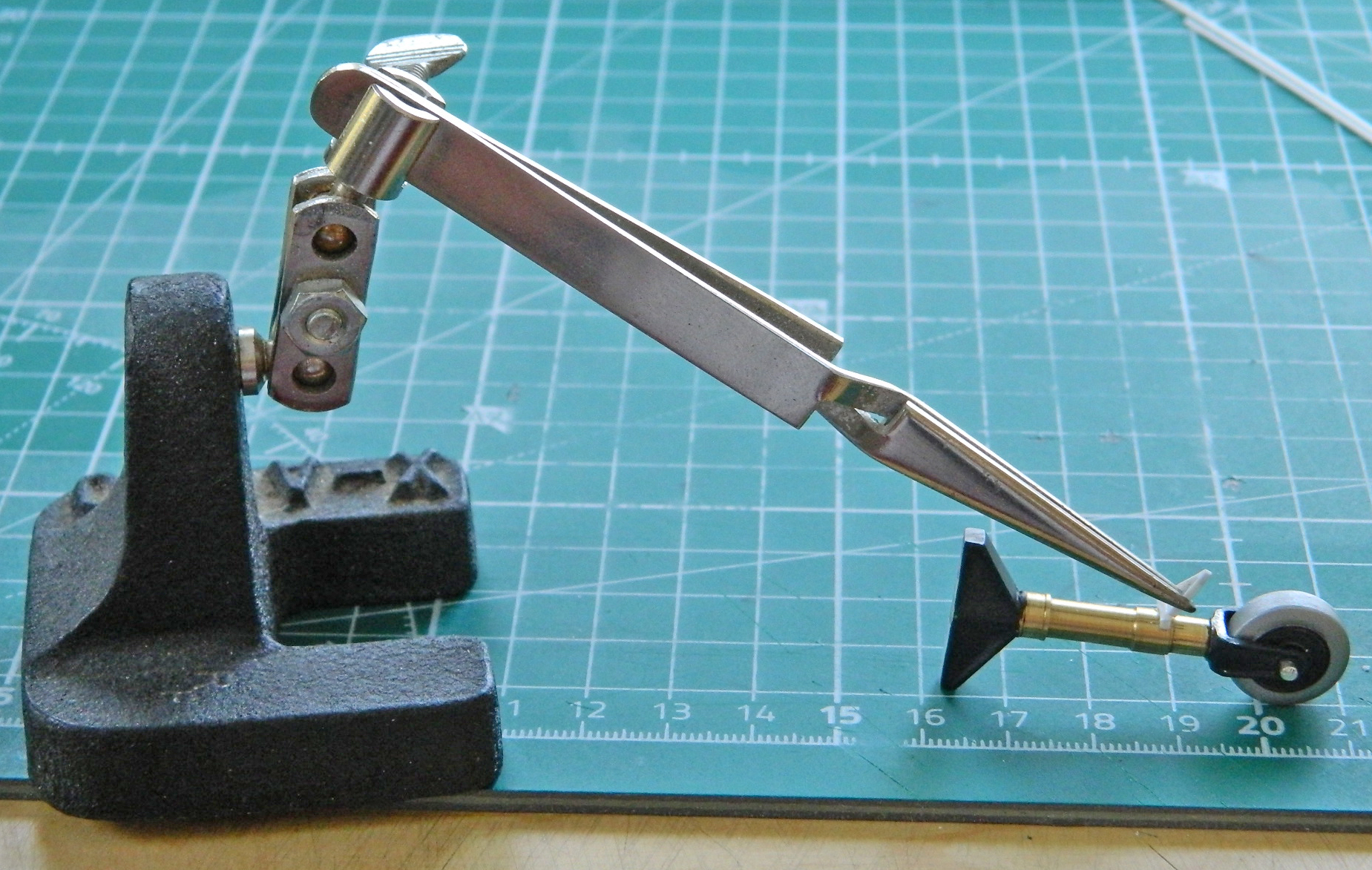
With the bays done for now (yeah…there’s more to do, just not quite as much), I started making the extension limiters for the landing gear. I got to make them a few times since it seemed my Eyecrometer was out of calibration:
Eventually, I got the parts sized correctly and started making the mounts to get them onto the struts:


During this part of things, I discovered that the epoxy I used to fasten the yokes to the struts didn’t really hold well. I used superglue to reattach the yokes and (so far) things seem to be attached.
Needing to take a break from this stuff for a bit (more like a week), I wanted to address something that’s been nagging me since I started.
Decals that could easily be forty years old. I looked for AM decal sets and the only one I found, though they look really good, aren’t what I need. I do NOT want to try to wet the kit’s decals, the kit’s forty-year-old decals, and have them come apart. There are no replacements so if these things don’t work, I’m [DELETED EXPLETIVE]. Proper [DELETED EXPLETIVE].
I read a suggestion online that seems to offer me a way out of this situation. Scan the decals into a BMP file, edit and clean them up, then print them myself onto decal paper.
Well. Let’s talk about pixel-by-pixel tedium. I started with this scan of the kit decals:
Note how IMPOSSIBLE it is to see the white ink. I made a copy of the file and diddled its contrast and brightness:

At least now I can see where the white ink is.
And a word about white ink. My printer (and most, excluding Alp) doesn’t print white ink, lazy git that it is thinks (because don’t all inanimate objects think?!) that white paper is enough when white is needed. Yeah, not this time. So when white ink is needed, I have to use white decal paper. I had to cut and paste the decals that need to be white into a separate file, and then surround the white part (after editing the hell out of them) with a contrasting color (black, in this case, since that’s going to be the color of the fuselage*) so I can see the sodding things:
Then I used the low-visibility markings that #972 sports and copied-pasted-edited them into another file that gets printed on clear decal paper:

Once I’d done all the markings #972 requires, I diddled around until I got the scaling correct so that when these things are printed out, they’ll be the correct size.
If this works as well as it’s looking it might, I think I have solved the “old decal” problem…and could end up with the capability of making my own decals!
*There will be some fiddling and color adjusting needed to make the decals’ black surrounds disappear. The black around the decals is BLACK; the black of the model will be color-corrected so it will actually be a dark gray. Should be “fun.”
SR-71A Blackbird (Testors) Build #12 – Starting the Main Landing Gear
At a certain point (and too often, an uncertain point) I get to the “chicken or the egg, and where do I start” point. I need this to do that, and I need that to do this. To start filling the bays with stuff, it would be handy to have the landing gear, or at least part of the landing gear, constructed. But, to build the landing gear, it would be equally handy to have the landing gear bays filled with stuff.
Hmm… I have a VERY worn 1926 Peace silver dollar in my wallet that I use when I get to a decision that’s evenly (and/or oddly) balanced between two choices; heads I do, tails I don’t. At the “chicken or the egg, and where do I start” point, it’s time to bring out the Morgan. This time, heads meant I start on the landing gear.
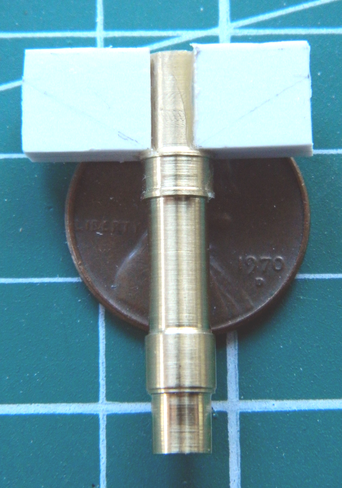
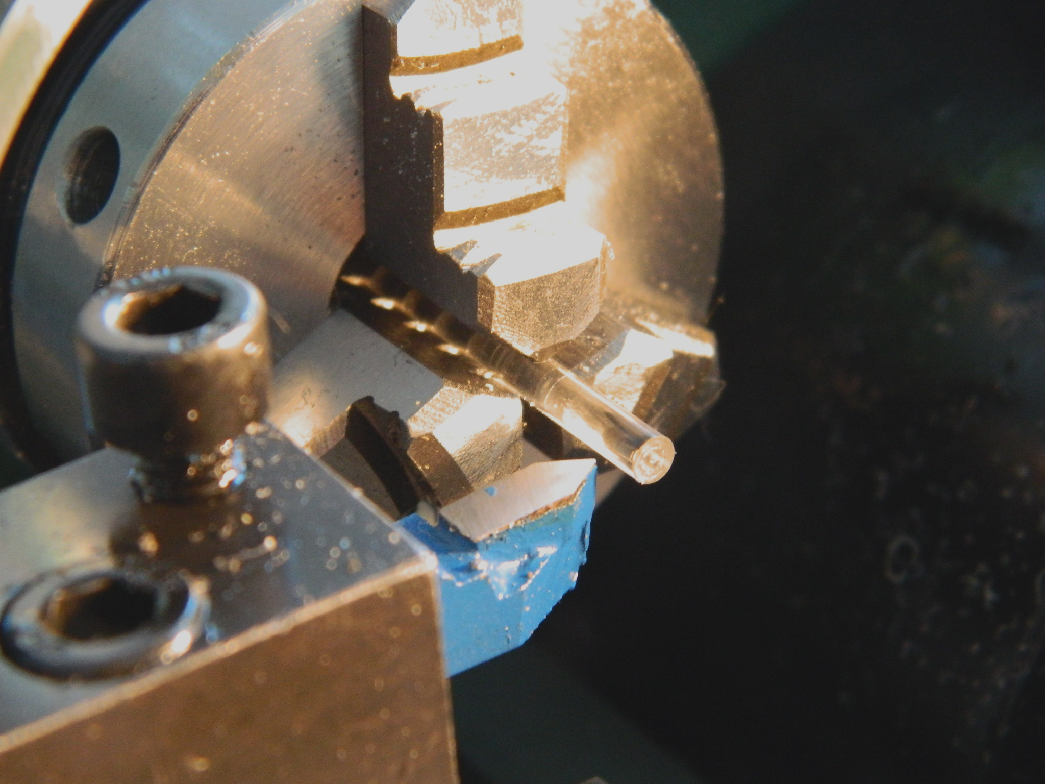
I cut a piece of quarter-inch (6.35mm) brass rod to an approximate length, leaving enough length to get the part as long as I want it and still enable the lathe’s chuck to firmly hold it without having to cut too closely to the chuck’s teeth to pose a hazard:
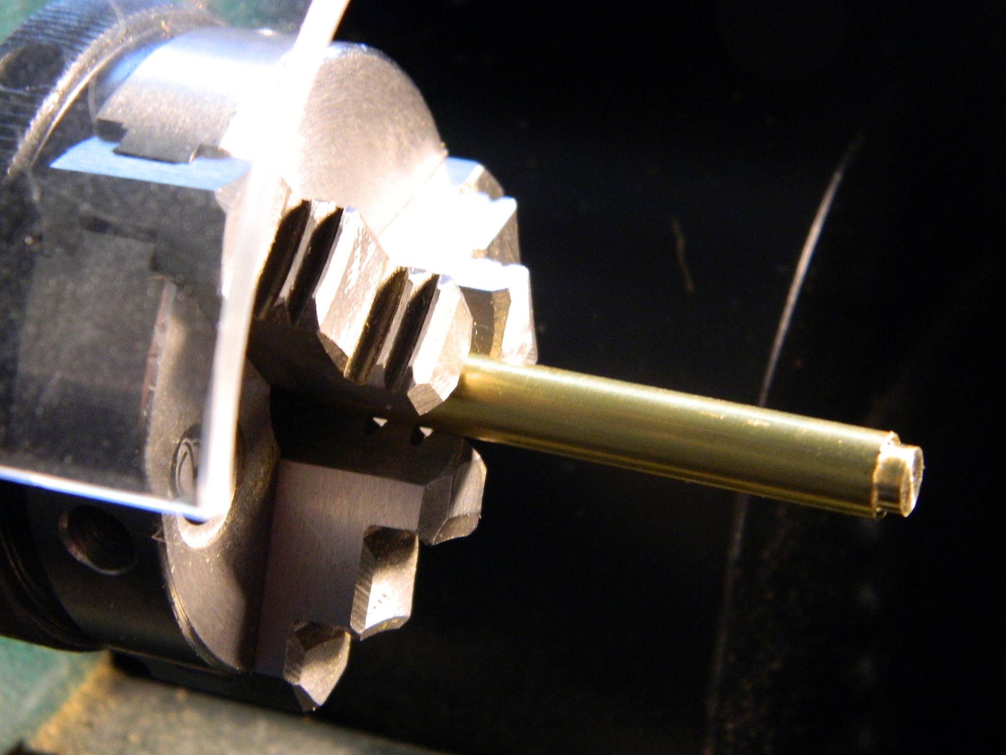
Lots of spinning and cutting as well as center-drilling the end for a pin I’ll need to install later and I ended up with this (which will be cut off at the shoulder on the left…I used the kit’s landing gear struts on all of the landing gear struts to establish the new parts’ overall length):

Okay, that’s what I want. Next trick is to do it again…and I did (sorry the photo is blurry…my vision was equally blurry and I didn’t notice at the time):

Originally I had purchased a set of metal landing gear from Scale Aircraft Conversions (#48067). All they do are landing gear sets from what seems to be a lead-based alloy. For a large and heavy model, it seems a good idea. Not faulting their process or business model, what I ended up with were copies of the kit part, only in metal. Great if the parts are accurate to being with…which they aren’t.
One of the things that have been nagging me is just how am I going to do the yoke where the center tire mounts? Any idea I came up with was either impractical or far too complicated. The idea I went with was the most simple (a concept that I need to keep in the forefront of my mind); cut the yoke off the SAC parts and glue it to the brass struts (that’s why I drilled the struts for pins). The nice thing about a lead-based alloy is that it can be easily cut with a razor saw (there are other benefits as you will see later):

As with the nose gear, the top of the main struts have cast trunnions. As with the nose gear, these have to be built. .080″ (2.032mm) styrene is about half as thin as I needed. I laminated two pieces together, curved the ends where they attach to the strut, and glued them in place (if you look closely, you’ll see the pencil lines where I have to cut away unneeded material):
Once the wings were cut to their basic shape, the inside of them had to be carved out:
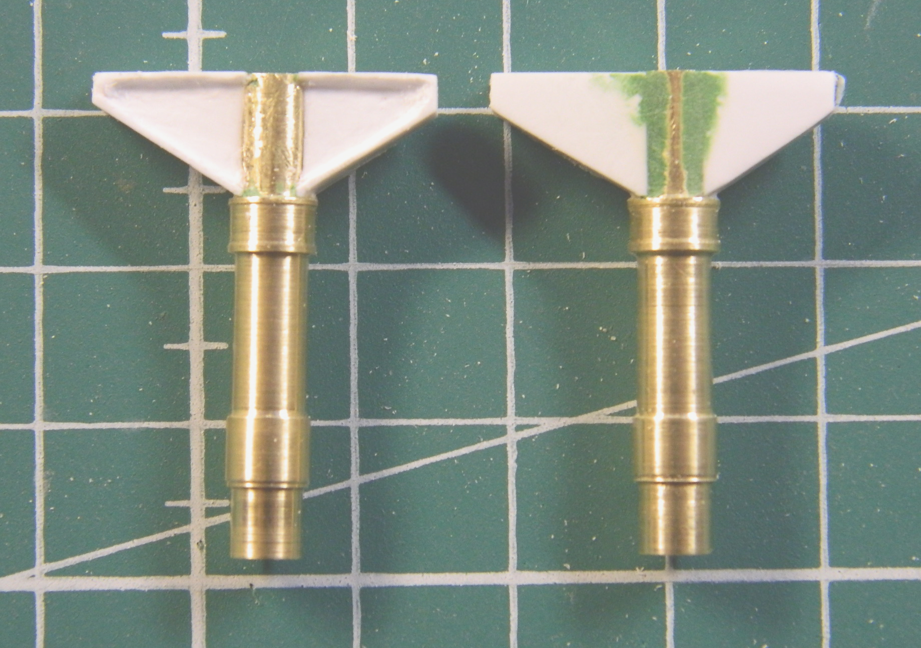
Some carving, some puttying, and I could add the pin. The size of this model called for the use of metal struts and I wanted to use a pin that was also strong. So I used a pin and then trimmed it:

Then there was carving and puttying on the next strut to do:
With the pin in place as the trunnions shaped, I center-drilled the yoke.
A word about that whole “center-drill” thing… It’s a genuine ass pain to do; ONE way to do it correctly, and an infinite amount of ways to get it wrong. Since my eyes (or pretty much any part of my decrepit body) aren’t what they once were, I’ve figured a way around my limitations. I drill the hole the pin will socket into slightly oversized. This way I have a built-in fudge factor in the likely event the hole isn’t PERFECTLY positioned. I countersunk the hole because there’s usually a slight bubble of glue where the pin meets the surface. Countersinking the hole (done at this size by using a larger bit than I need for the hole) allows the two parts to fit FLAT against each other:
Dry-fitting the strut and yoke show that they do indeed fit snugly. Satisfied with the fit, after this photo was taken, I used 5-minute epoxy (for strength) to join the two parts:
Some putty is needed to create the illusion that the top of the strut is one casting, not a part with two other parts added. I got a little carried away when I carved the one trunnion, so that got puttied while I was at it:
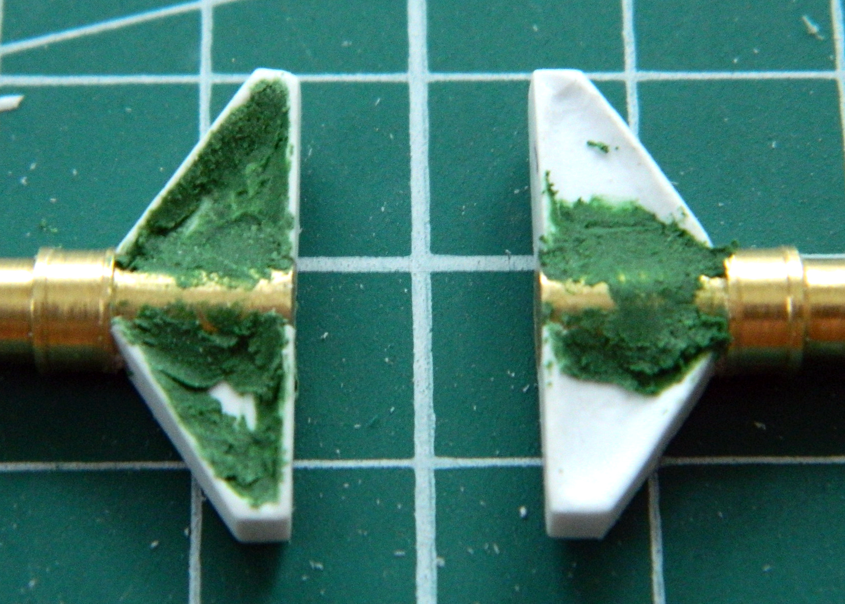
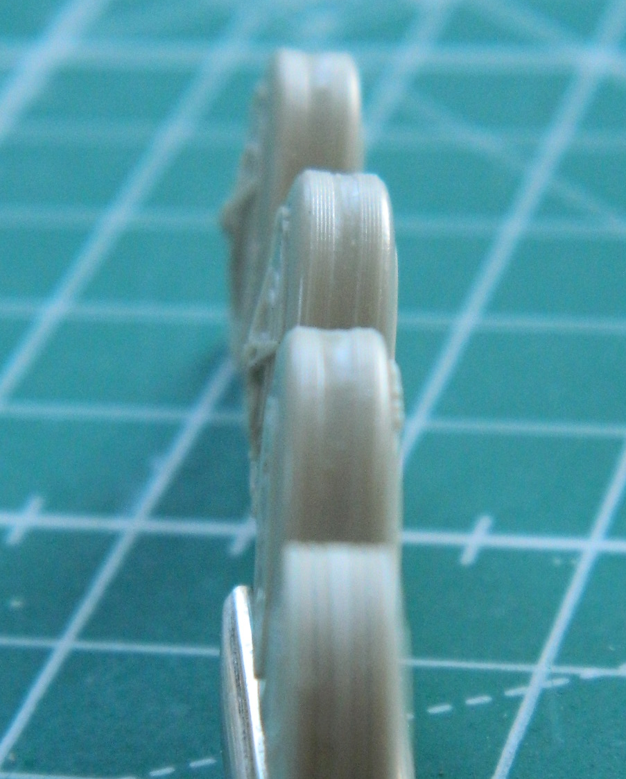
I’m using a set of resin wheels and tires from Fisher Model and Pattern (part #A-4806) for this build. The details of the hubs are far superior to the kit’s “details.” Even as nicely done as they are, they still need some attention. All of my reference photos show that the contact surfaces of the tires are smooth and don’t have the treads Fisher has modeled into the tires. The contact surfaces are also supposed to be slightly convex, not slightly concave:
I roughed the surfaces of the tires hoping that this would offer more bite for the putty added to round the contact surfaces. If the putty wouldn’t work, the alternative would be to sand the corners of the tires away completely. Well…it worked, sorta. The putty wasn’t entirely interested in sticking to the resin (yes…I washed the parting agent off). I managed to get the putty to stick by almost sanding the putty down to where I wanted it and then soaked the putty with superglue. Once the superglue cured, I finished sanding to shape and it all worked:
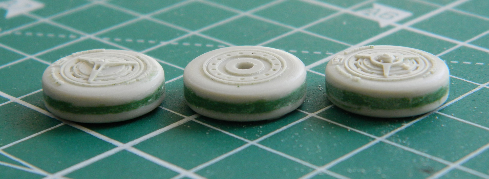
I encountered another problem with the nose wheels/tires. The profile of the tires is definitely rounded, not squared off. Files and sandpaper fixed that problem:

The last modification to the resin parts was to drill out the mounting holes so that they would fit onto the landing gear. The axle stubs of the yokes I’d added to the main struts also had to be trimmed down; initially, they were intended for hollow plastic parts.
With all the tires modified and fit, I wanted to get them under paint. The nose tires were painted with color-corrected Tamiya XF-85 Rubber Black. Then I LIGHTLY misted white onto the contact surface of the tires to replicate dirt and wear:
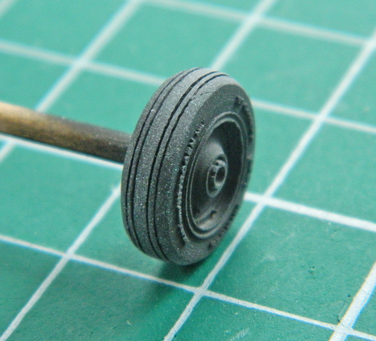
As they were curing, I mixed four parts Tamiya XF-16 Flat Aluminum with one part Tamiya X-18 Semi-Gloss Black. The tires of the Blackbird are impregnated with aluminum powder to facilitate heat dispersion and the flat aluminum alone looked too bright to my eyes so I added the semi-gloss black until it looked correct:

The hubs of all the tires were painted with a color-corrected coat of semi-gloss black. While I had the semi-gloss black in the airbrush, I had to check a couple of things and to do that I hit them with a coat of it. The first thing I wanted to check was how the trunnions turned out. Not quite perfect but certainly within 90-95%. I also have to spread the yokes to get them to accept the center tire (and there’s that other benefit to a lead-based part…it would bend easily). I didn’t know if I could bend them far enough without causing the paint to crack. Ideally, the acrylic paint would be flexible enough, I could get the tires in there, and I wouldn’t have to figure out how to paint the sodding yoke with the tires in place. Luck was with me and it worked:
For the rusted surfaces of the brake disks, I dry-brushed a mixture of two parts Heller Flat Rust (#9113) with Italeri Flat Rust (#4675AP). To my eye, the Heller flat rust was too brown and the Italeri flat rust was too red. The surfaces of the brake disks don’t appear to have an even layer of rust on the surfaces so I used a very small brush and dry-brushed the mixed paint onto the disks:

So…having decided which to start with, I’ve started with it. The next trick is to start making the stuff that goes into the landing gear bays and stuffing them with the stuff.
SR-71A Blackbird (Testors) Build #11 – Starting the Main Landing Gear Bays
This is what the kit provided for the main landing gear bays:
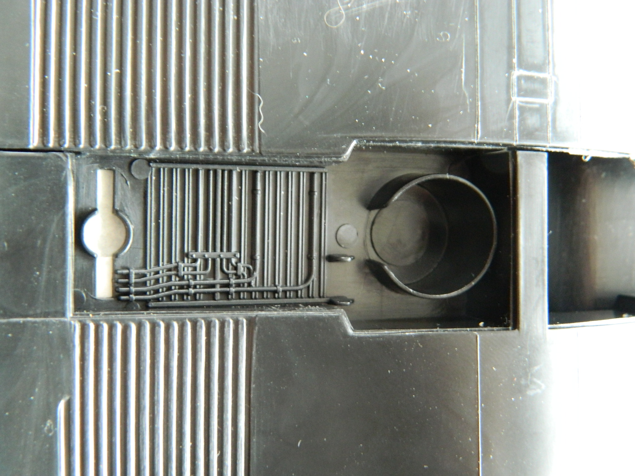
Yeah…it’s pretty sparse and not very accurate. I keep reminding myself that when the dies for this model were cut, the Blackbird was TOP SECRET. So rather than beat up the designers over what isn’t accurate, they deserve credit first for making it at all, and then for making it accurate enough that some maniac (me, obviously) 40+ years later has enough to work with.
As with many kits in this scale, there is a major difference between the provided landing gear bays and how they should be. Primary inaccuracy for the openings is that the bay is not defined by the openings; the bay is recessed back from the openings. The first step is to remove the inaccurate bay bulkheads. Multiple passes with the hooked scriber enables me to get a slot started that I can insinuate the edge of a razor saw into:
Once those are cut away, my favorite chore of making a perpendicular surface fit the inside curve of a surface is next. I roughed them in using 3″ (76.2mm) x 5″ (127mm) index cards for templates. There was MUCH fiddling and diddling to get them close (or at least I thought they were close at the time):


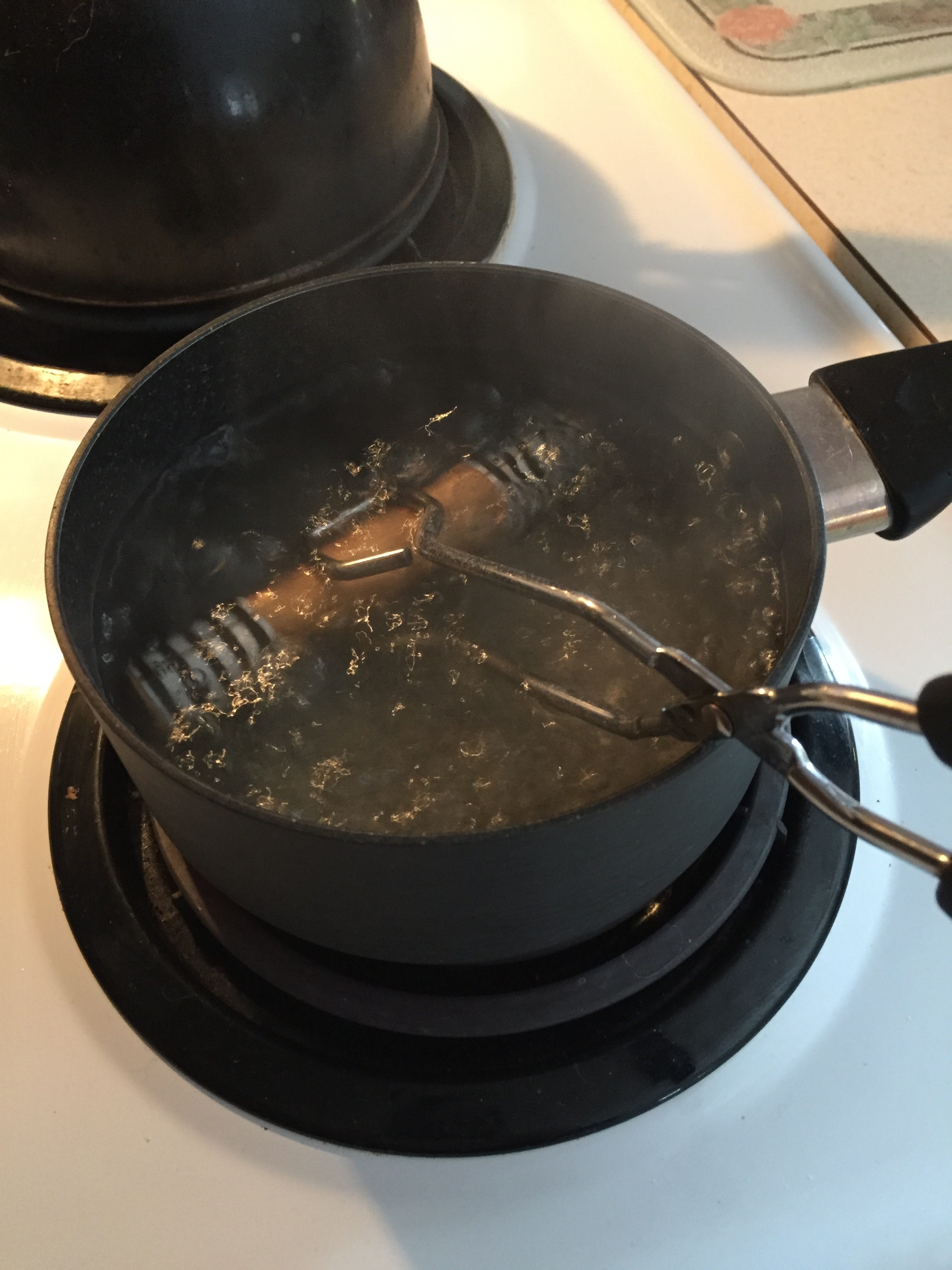
Large pieces of plastic stored snugly into a box and then left to sit for several decades doesn’t do good things for the dimensional integrity of the parts. Things are bent and because they stay bent, they stay bent. The curved surfaces aren’t supposed to be curved and since I wasn’t sure how the warped plastic would affect the build, I wanted to get the parts a bit straighter.:
I have some aluminum channel that I used as the straight edge and used clothespins to attach it. I’m hoping not to scald myself during the straightening process, getting my hands out of that process can only help with that:
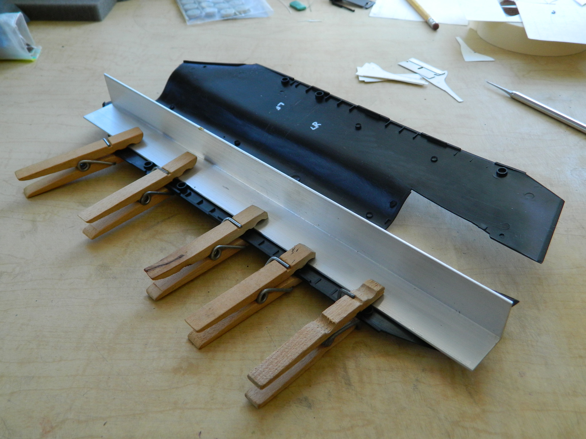
The hot water here is HOT. It’s certainly hot enough to make me whine like a five-year-old. But it’s not hot enough to enable me to get the parts straighter (a situation not improved by the sink itself acting as a cooling fin):

I filled a glass pan with water and ran it through the microwave. A lot. (I wasn’t sure the glass would hold up to being placed directly on an electric stove.):

Though I wasn’t able to get the water to boil, I was able to get it to about 190 degrees (87.77C). The parts were placed in the pan until the water temperature fell below 180 (82.22C), and then the process was repeated several times. And though not perfectly straight, they’re a lot better than they were when I started:

Having delayed and put off the tedium of fitting these bay bulkheads as long as I could, there was nothing to do but to fit the damned things. I had thought my cardstock templates were accurate, which wasn’t the case. So there was a lot of filing, sanding, cursing (never miss an opportunity for that) until things fit, then the first two bulkheads were glued on:

While the glue was curing, I decided to get another potentially fiddly task out of the way. Create the blast shields for the landing gear.
The tires on this aircraft GOT HOT. It was determined that taking off or landing with more than about half a load of fuel was too heavy for even aluminum impregnated tires to withstand and evidently they would blow up. These aren’t low-pressure tires and if they exploded in the bays, those large chunks of rubber moving at high speed did nothing to the hydraulic lines or wiring that anyone wanted to have done. The solution was to create circular blast containments that would surround the tires when the gear was retracted.
To make those, I staggered around the house, garage, and basement, looking for something the proper diameter that I could heat form cylinders around and use to make a buck to vacuform the caps over. Turns out that a 3/4″ (19.05mm) wooden dowel was just what I needed. To form the plastic, I needed to curve flat plastic (.010″ [.254mm]) around the surface and hold it as snugly as possible. Rubber bands didn’t hold it tightly enough, so I went with cable ties:

I left the dowel/plastic in boiling water for about five minutes (might have been able to get away with less time, one of these days I’ll have to experiment to see) before taking it out to let it cool. While those parts were cooling, I chucked another piece of 3/4″ (19.05mm) dowel into the lathe and turned the flattened dome of the top, then glued it onto a pedestal and attached it to my vacuum molder:
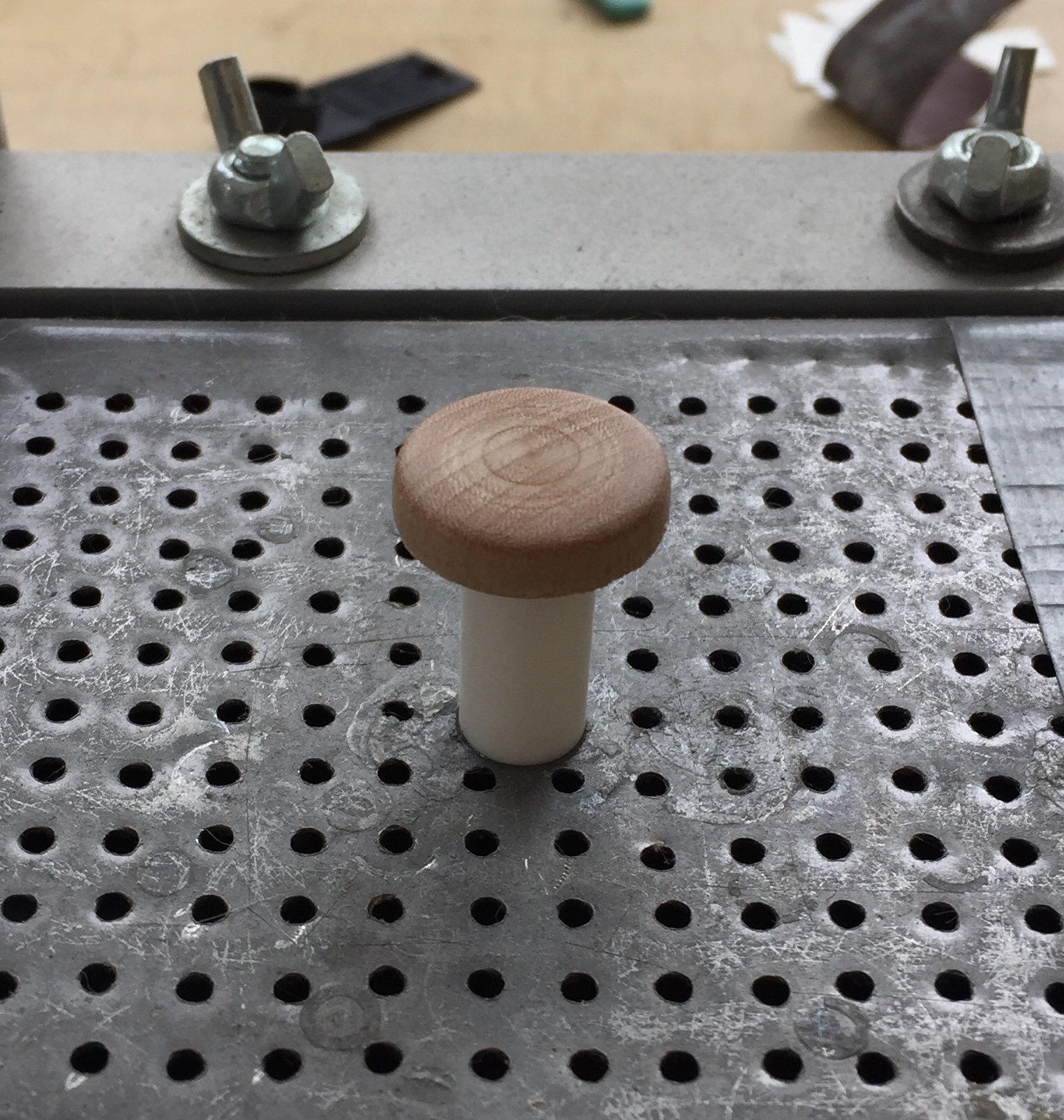
Done twice, I ended up with both the caps I needed:
When I snipped the cable ties, I found that they did indeed hold the plastic tight to the dowel…tight enough to impart cable tie impressions to the outside and wood grain to the inside (something I must remember…because I could use that texture to scratch-build ammo feed chutes with ammo or a corrugated surface texture!). Not ideal but also not a deal-breaker, either. The caps were trimmed and glued onto the cylinders, then the ends of the cylinders glued closed (later the openings in the blast shields will be cut into the cylinders and take away most of the seams):
A quick test fit showed that the dimensions work:

Time to putty the impressions of the cable ties:
Sanding putty on these parts was sort of like doing body work on an eggshell.
The first two bulkheads went in with some fitting. Yes…I got the tops and bottoms to match the interior curves of the upper and lower fuselage halves well enough. Getting the distance between the upper and lower fuselage halves required some more fitting. And then I tried doing the next two bulkheads. As it turned out, I failed to notice that the front of the landing gear bays is narrower top to bottom than the rear of the landing gear bays are. Once again, I found myself with a couple of parts that I couldn’t use as they turned out (he says as if these things made themselves). I needed to add plastic back to make them fit properly.
So I did (you will see that I had to add plastic back more than once):

Since the joints are visible, they were puttied and sanded:
My initial plan was to use the top of the fuselage from the spare kit as the inner top of the landing gear bays to make use of the details there (the top of the fuselage over the landing gear bays is also the inner top of said bays). When it was time to make this clever plan a reality, I realized that there would be A LOT of sanding and filing to thin these fuselage sections to a usable thickness. The company I buy my plastic stock from (Evergreen Scale Models) also offers corrugated flat stock. I checked the measurements of the corrugations and though I couldn’t find an exact dimensional match, I bought a sheet that came very close. I cut sections to fit and glued them in place:

With the basic boxes made and installed, it was time to add some of the structural details:
When I was looking for the corrugated plastic, I noticed that Evergreen also has preformed stock. Making the c-channels took a long time, mostly spent waiting for glue to cure so I could work the parts. There are some stiffening ribs I wanted to add and instead of taking a couple of days on a small detail, I decided to buy T-section extrusions and use those instead:
As I was readying myself to start adding more of the cylinders, lines, and wiring that goes in next, I noticed that the c-channels don’t extend all the way to the outsides of the bulkheads. ::sigh:: Okay…those get trimmed to the correct length:

It’s not necessary to sand the areas where the c-channels were removed to absolute flatness; most of those areas will be populated with cylinders, lines, and wiring which will obscure the surface. One last check with the fuselage panels in place to make sure I’ve gotten the look I want:
Yep…that’s about right (he says hoping he’s correct this time). Time to start filling these boxes and the major reference point is the landing gear.
Time to make the landing gear.
SR-71A Blackbird (Testors) Build #10 – Some Fuselage Details & the Nose Gear Gets Built
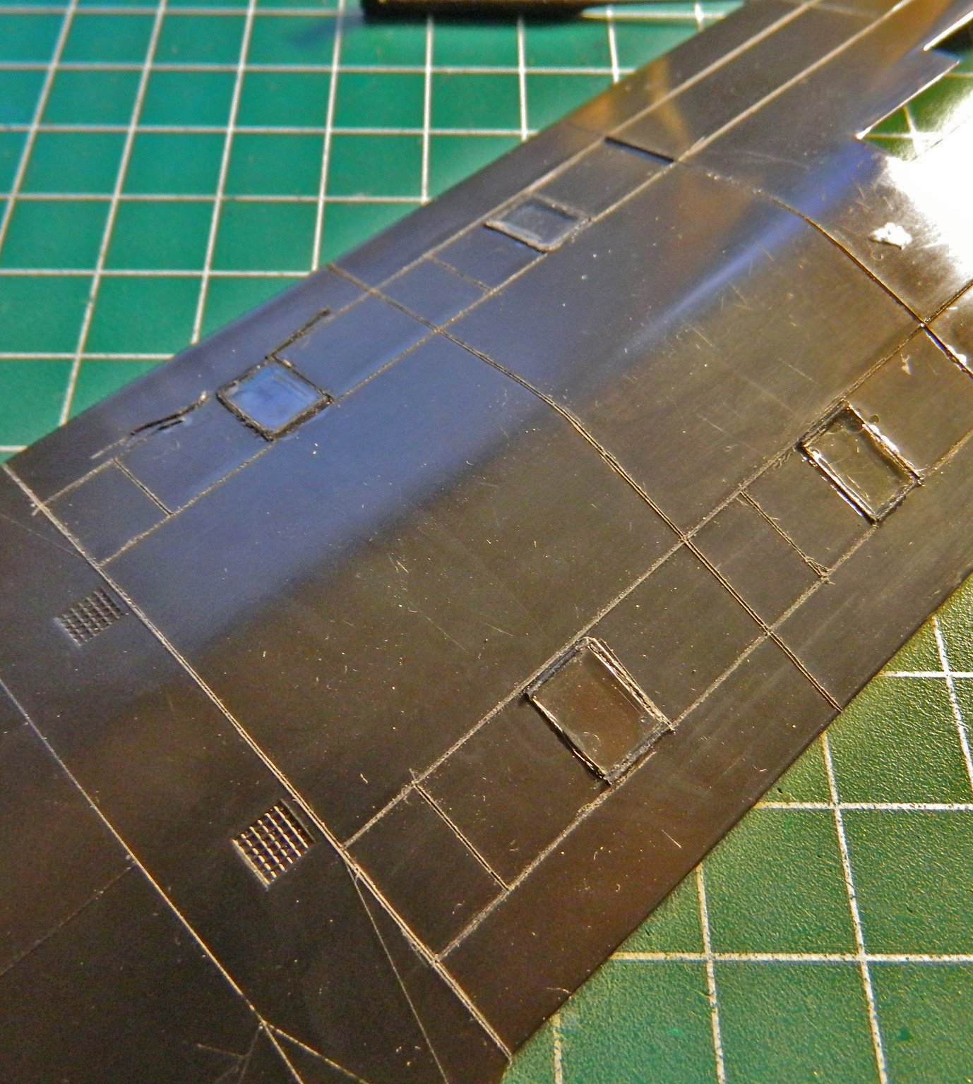
While waiting for the micro-lathe to arrive, and having no shortage of things to do, I attended to a couple of fuselage details that were annoying me. The PE details for various surface grates are very nice. Mistakenly, I took the two grates that most closely fit the molded on grates and installed them. The grates on the Blackbird are flush mounted (makes sense, considering drag slows an aircraft down and the Blackbird isn’t famous for going slow) which meant I had to align them, outline them, and then scrape away enough plastic to socket the grates flush:

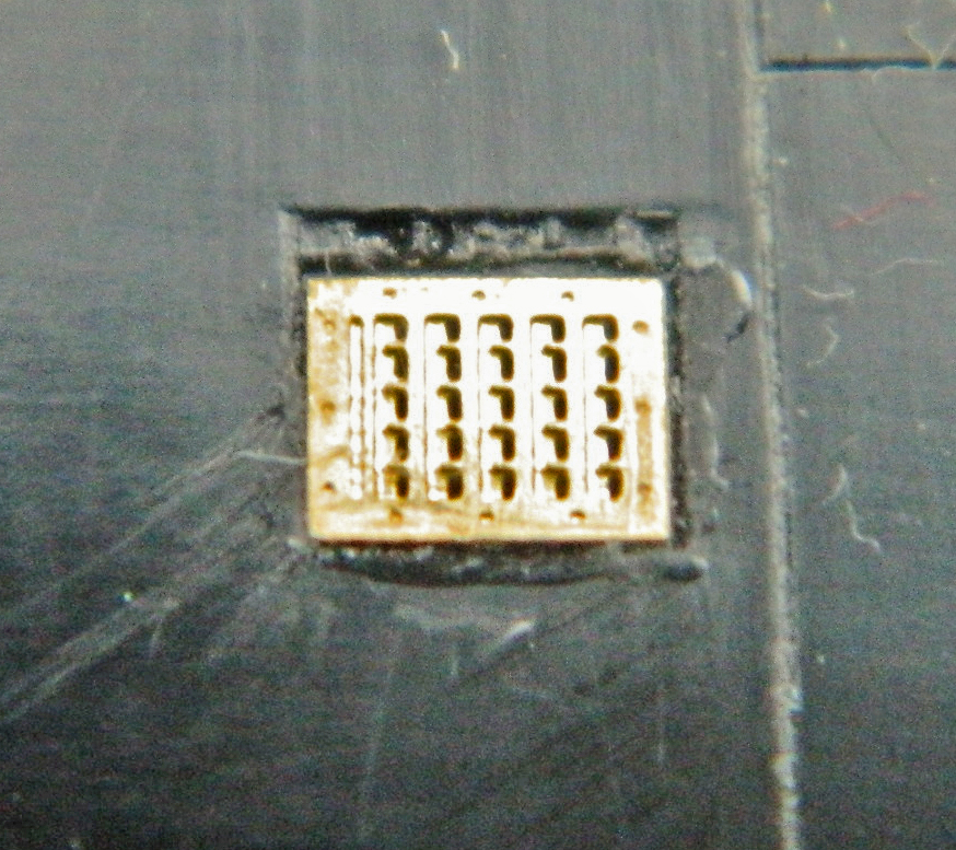

One of the interesting things I noted while at the NASM was that the fuselage panels on the belly of this beast aren’t butt-fit (meaning that the edge of one panel meets the edge of the next) but overlapped like shingles. To replicate that, I laid some .005″ (.127mm) sheet down to create the lip of the trailing edge:

While I was waiting for the cement to cure, I noticed that there are two grates that go towards the front of this belly section. Then I noticed that I’d already used those grates…in the wrong place. The grates I just socketed into place don’t go there, other larger grates go there. ::sighs:: With heart in mouth (which I’ve discovered makes breathing a bit difficult), I slipped the edge of a chisel blade under the edge to pry them away from the superglue and out of the putty. Damned if that didn’t work just fine. Not having a clear photo of this area, I made the decision to place them where I did. The larger grates were held in place and I scribed around their edges with a needle:

Satisfied that maybe now I was on the right path, I repeated the scrape, glue, and putty cycle with the correct grates in the (relatively, I hope) correct location (after one false start, evidenced by the lines at the left of the left grate below):


With that mistake recovered, the multiple thin layers of putty I laid down at the leading edge of the .005″ (.127mm) sheet had set up, allowing me to block-sand the putty flat:
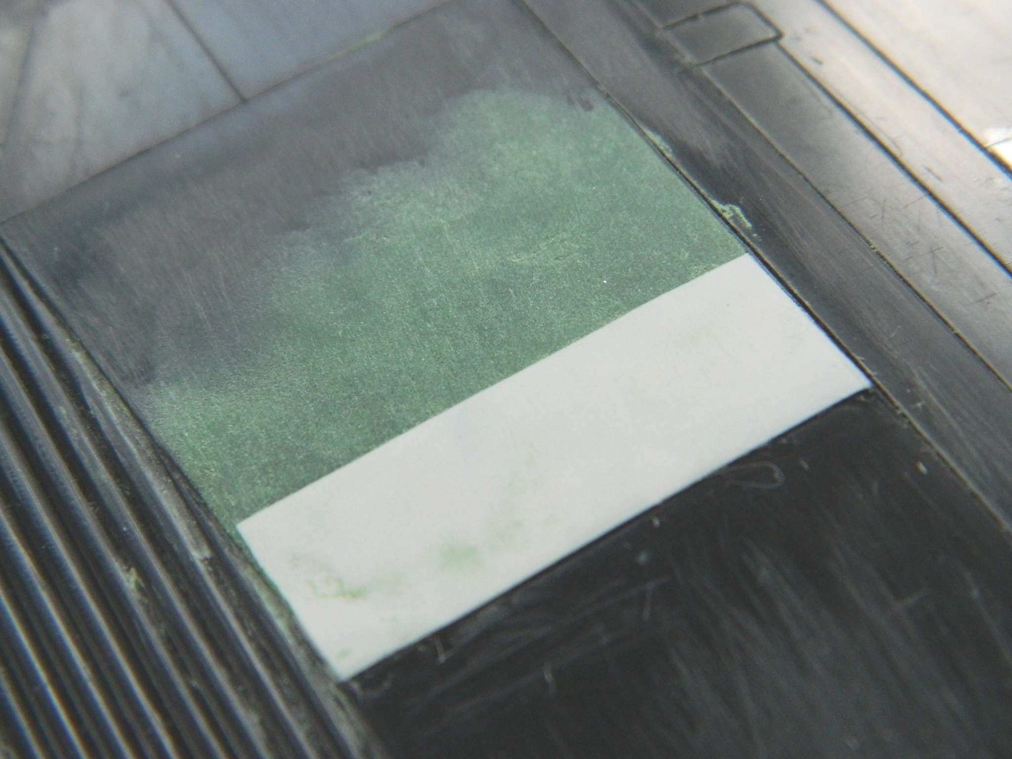
Satisfied with the outcome, I repeated the process on the other side, using thin strips of masking tape to keep the putty from getting into places I didn’t want it to get into:
Things occur to me when they do. With this blog, I can present things as if these things occur in a linear manner…but they don’t. The most recent example of this occurred the next morning, propped up in front of the bench, and when the coffee finally wet my neurotransmitters sufficiently for them to propagate a spark, I wondered, “Do I need to add nose weight for this thing to sit properly on its landing gear?” Rather than do useful work so soon after that initial daily spark, I taped all the major components together to see what the weight distribution looked like. I placed the supports directly under where the landing gear parts are going to mount:

Two things became evident. 1) No, I’m not going to need to add weight. 2) this is going to be a big model.
And then my new micro-lathe arrived! I spent the rest of that day unpacking, cleaning, lubricating, and getting to meet my new tool. It’s not as accurate as an old Unimat. It also cost about half of an old Unimat. Since I am not a watchmaker (or work in 1/72 scale), I don’t need the degree of accuracy an old Unimat provides; this one will work well enough for my purposes.
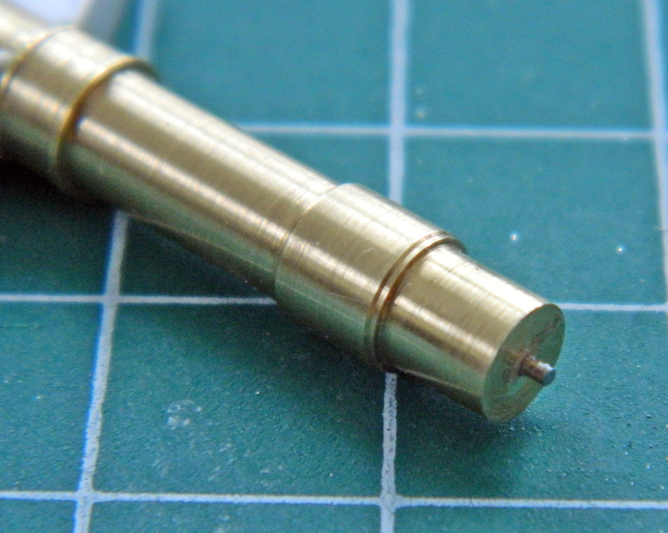
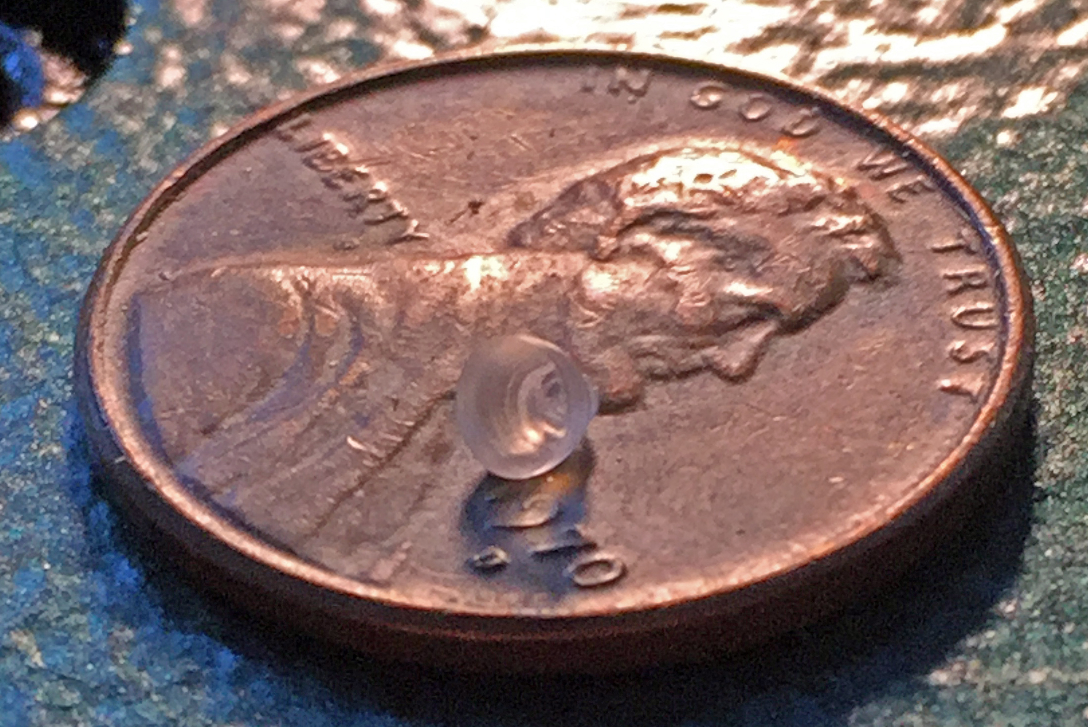
After getting comfortable with how the new lathe works, I turned the second landing light from a quarter-inch (6.35mm) clear acrylic rod:


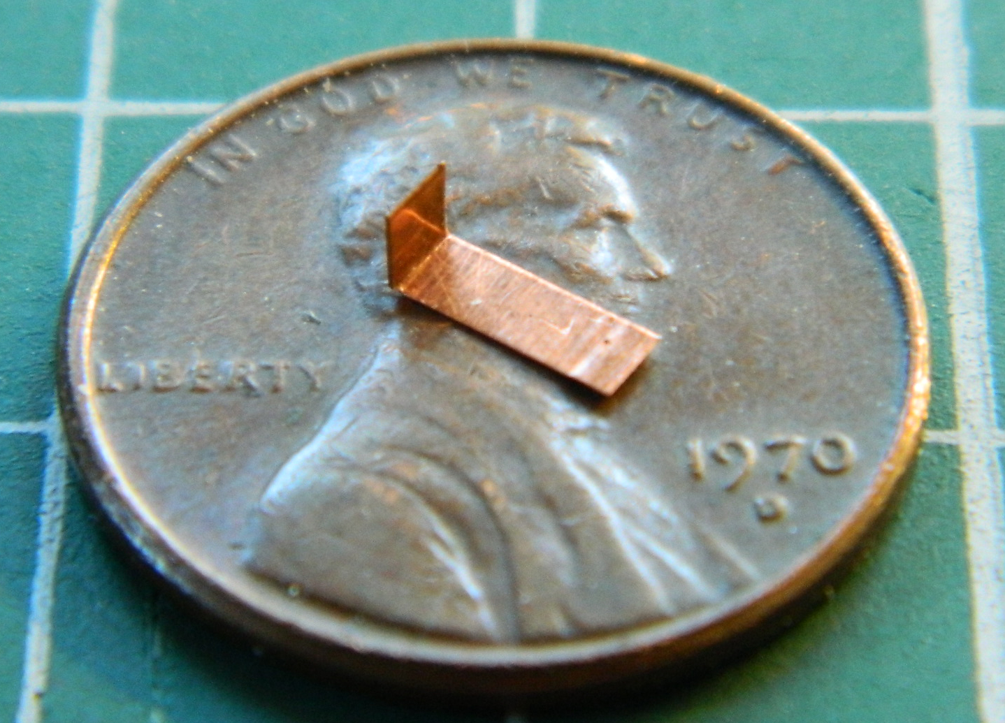
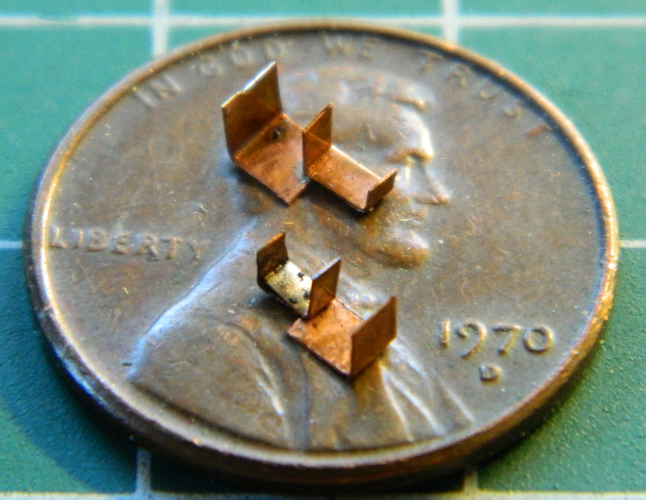
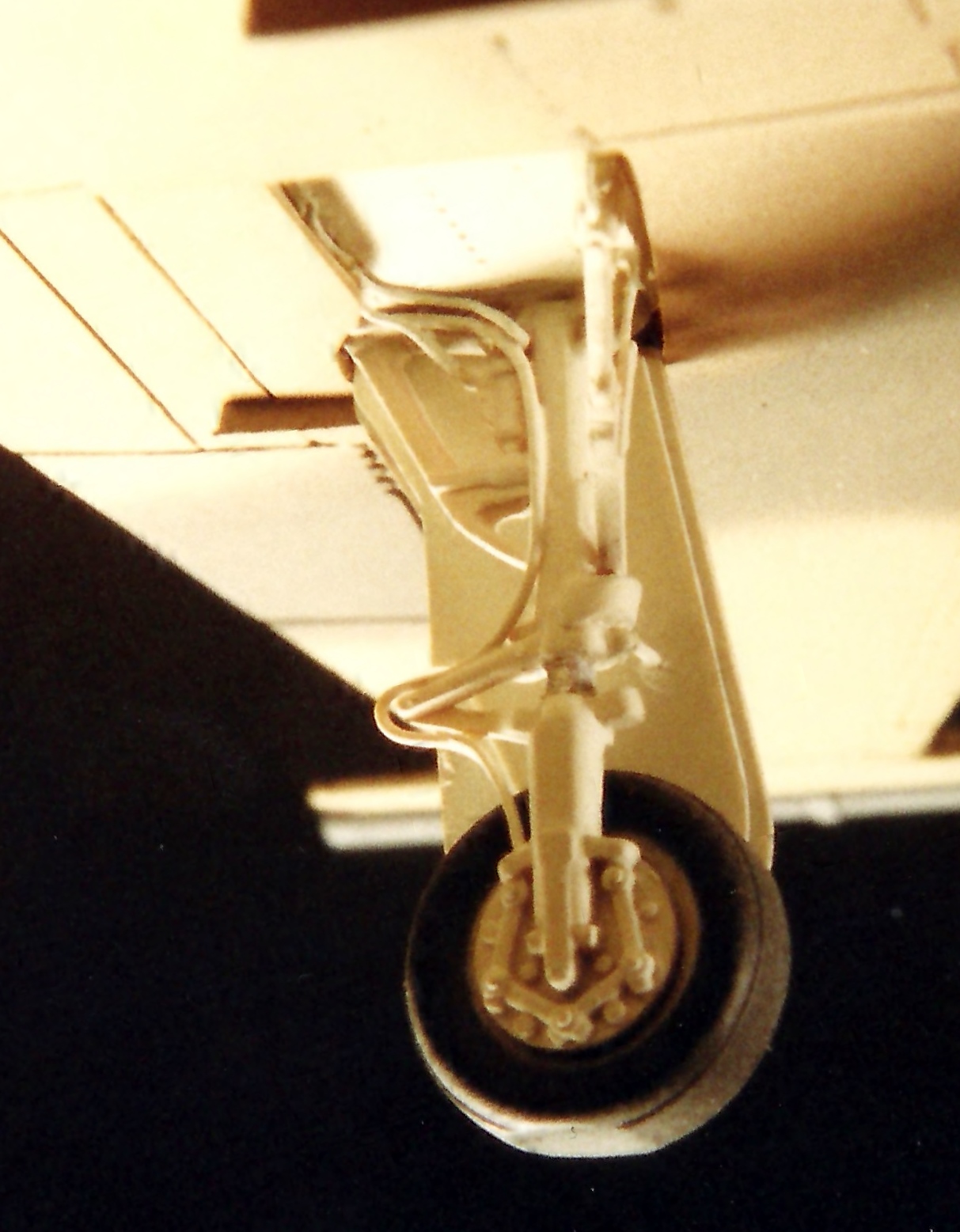
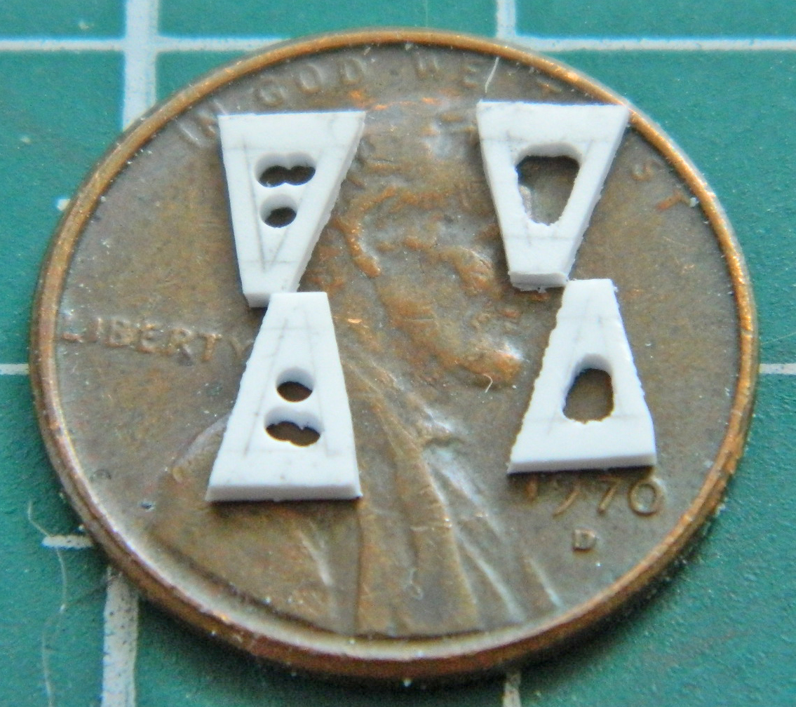
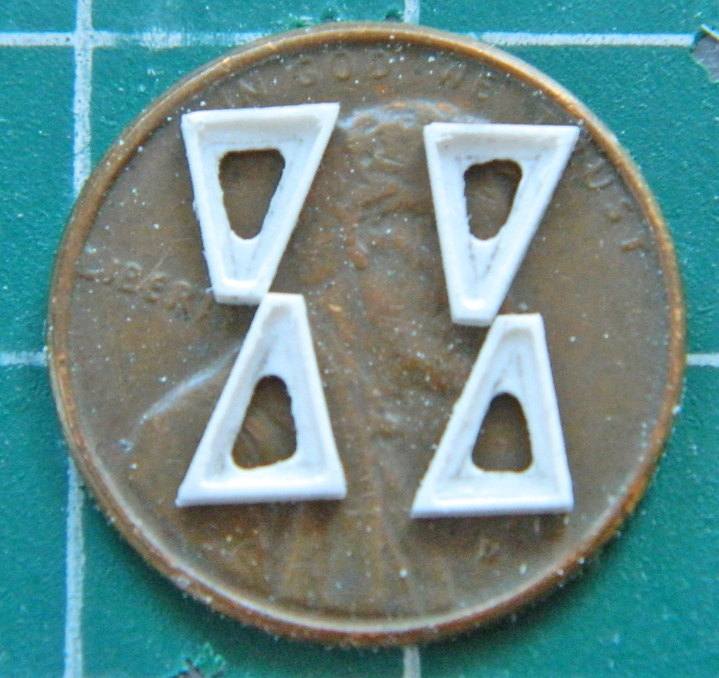
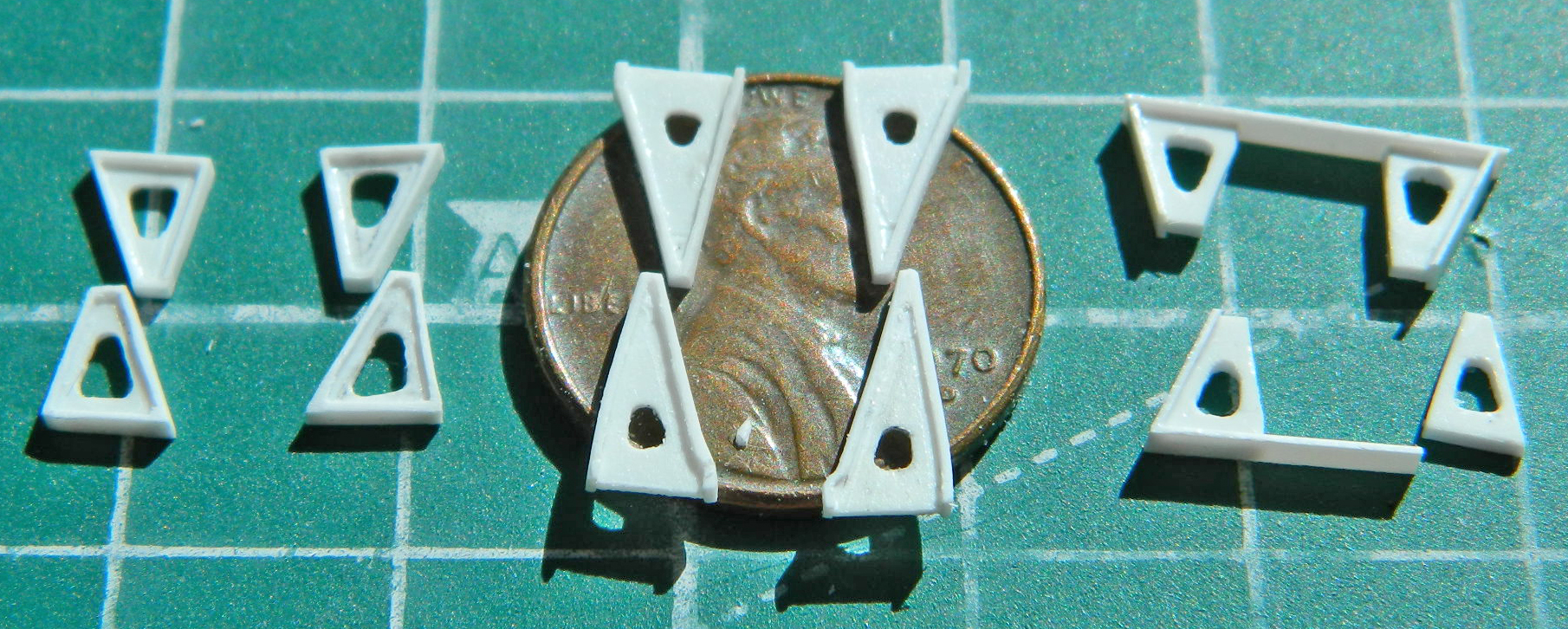
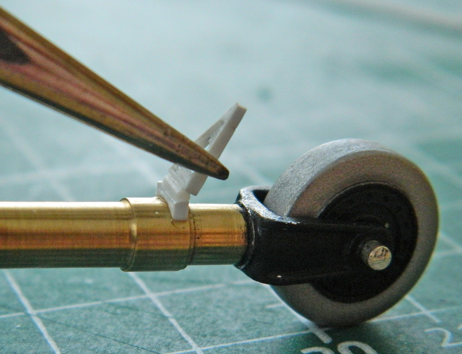
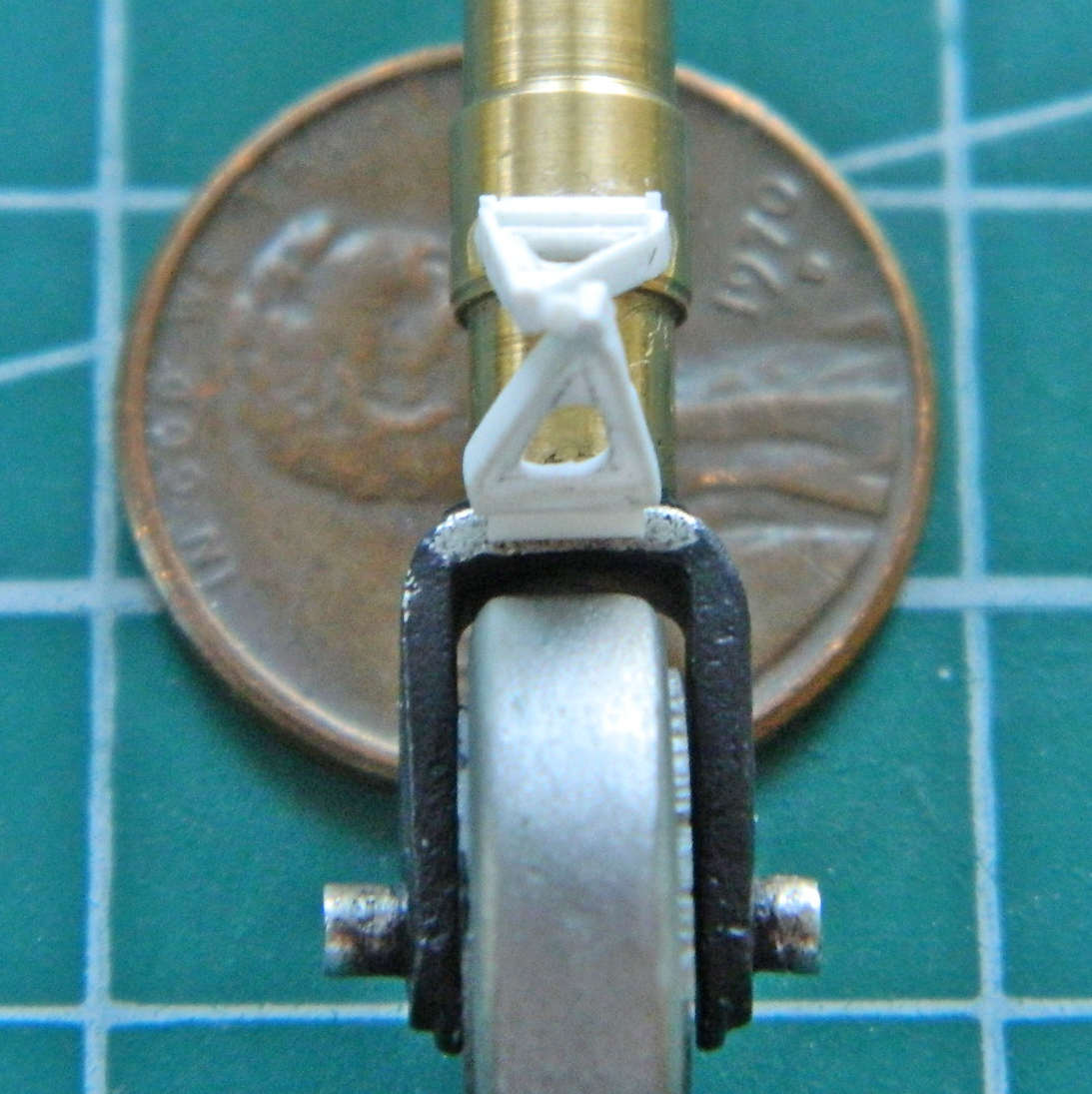
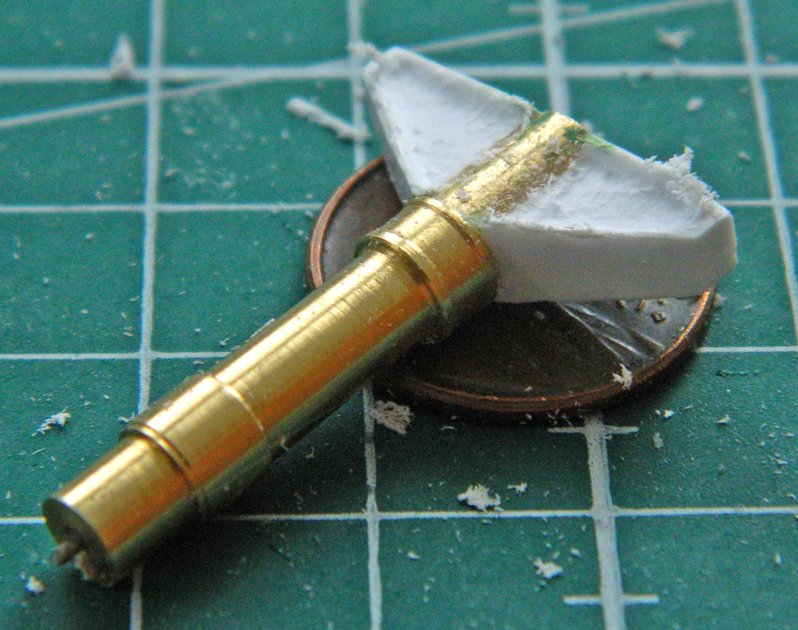
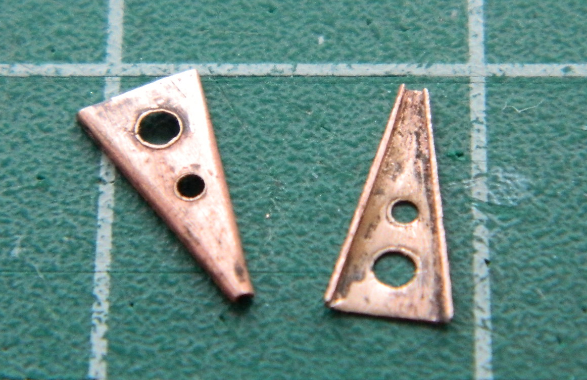
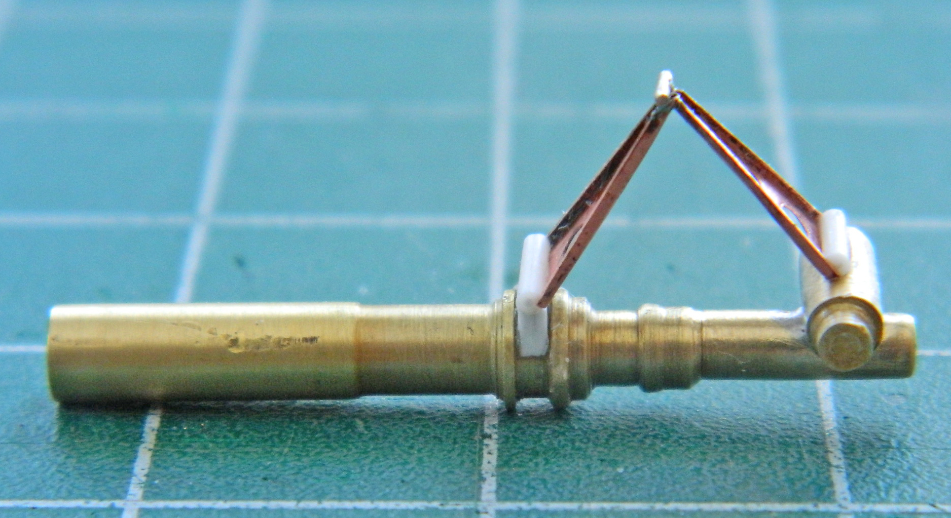
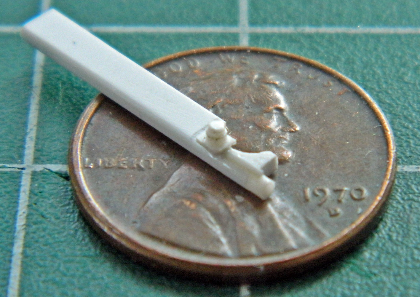
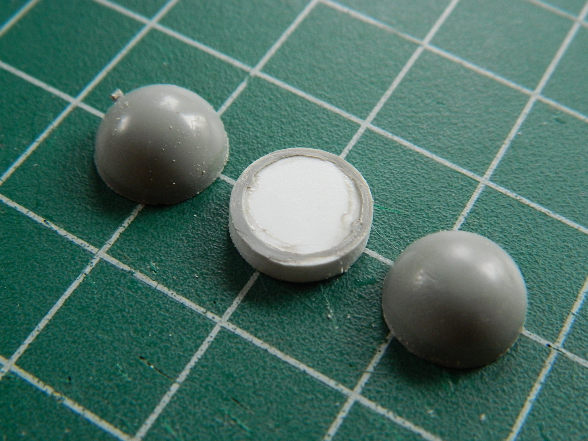
Landing gear on large aircraft is more like a very strong shock absorber and they’re called an “oleo”. They compress under load and extend when unloaded. Something has to be attached to keep the oleo from overextending and those extension limiters are triangular (generally). That’s the type used on this landing gear. I used .005″ (.127mm) copper shim stock to make them and that started by laying out their basic shape and punching two lightening holes in each part:
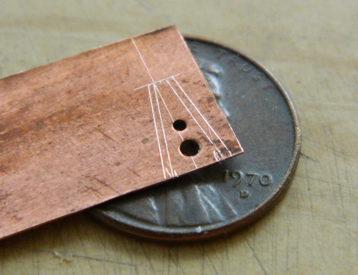
Once laid out, I cut the parts out using a sharp pair of scissors and then annealed the parts to make the bends easier and enable a smaller radius:
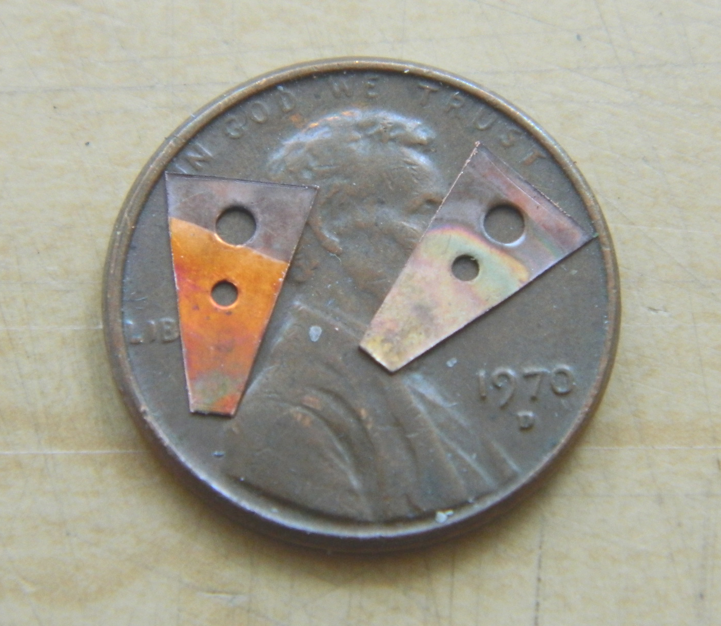
Naught left to do but bend them (he says as if it was easy…the first bend was easy…the second, well, not quite so much):
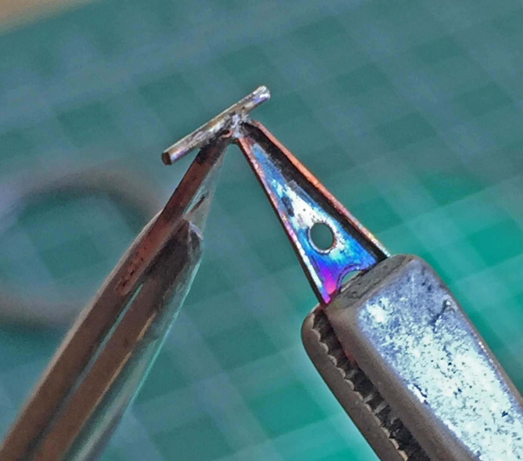
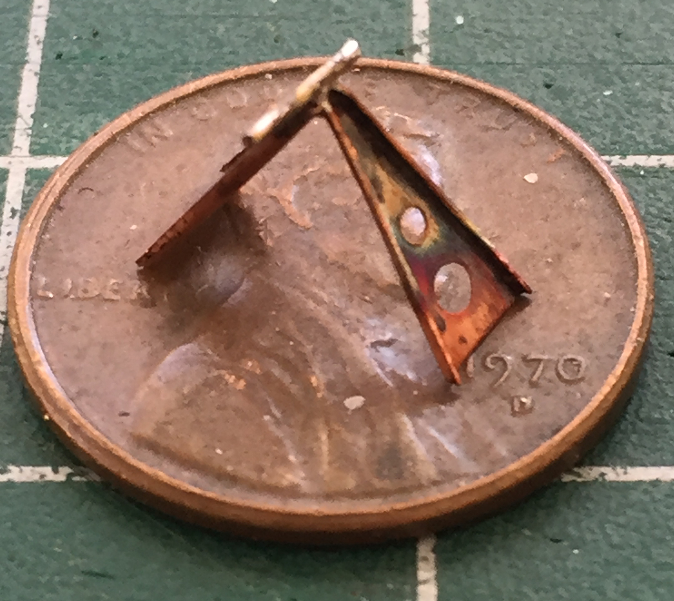
The extension limiters join at the small end. To replicate the hinge, I used a 22awg copper wire. The really interesting part of this was soldering them together. As most of the rest of the world, I only have two hands. To do this easily I would have needed at least three of them (or four, if you’re into bi-lateral symmetry) (I’m not judging). I used locking tweezers on stands to align and hold the two parts with just a little bit of overlap. This overlap created a “saddle” that I could place the wire on so that soldering it in place was at all possible. Using a butane torch would be challenging because the force of the torch’s gas flow could easily blow the wire across the workbench. To successfully solder this without causing the wire to go elsewhere, I approached the join from a fair distance away and worked the flame back and forth as I (SLOWLY) brought the flame closer. Once the flux melted, I knew I was close. Then the solder melted and I quickly moved the flame out of range. Whaddya know…it worked (I trimmed the wire to length once everything cooled):
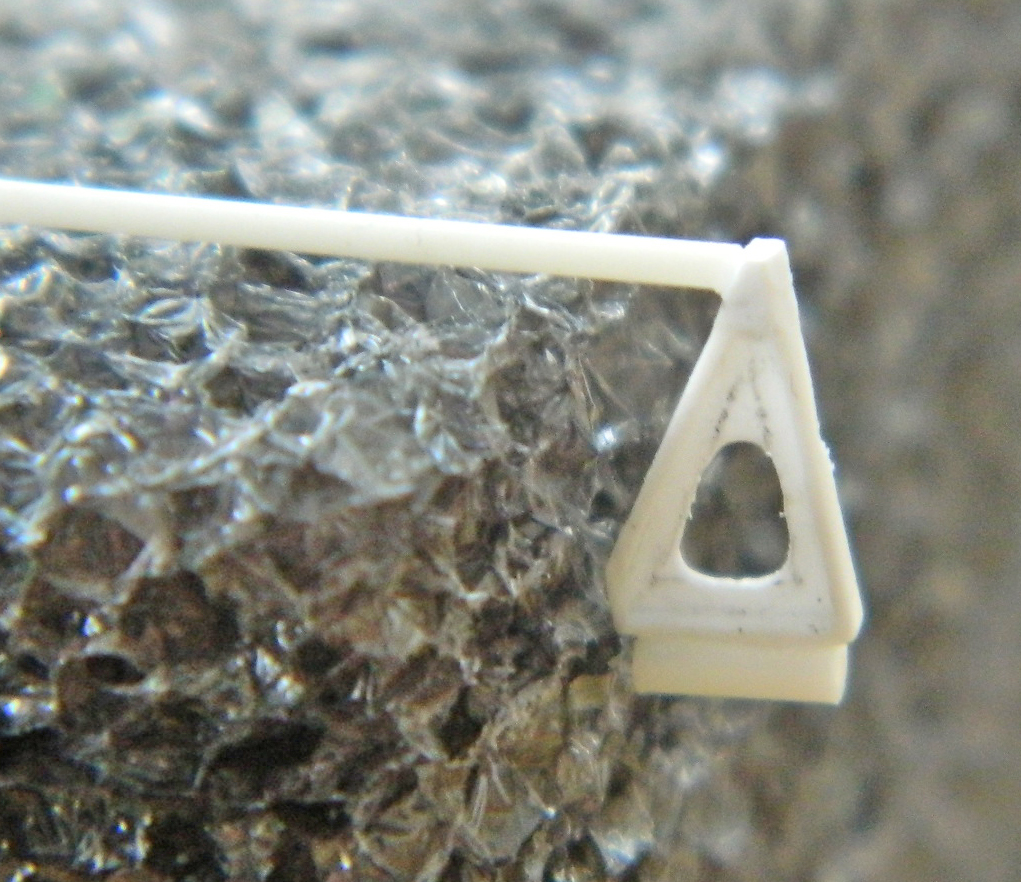
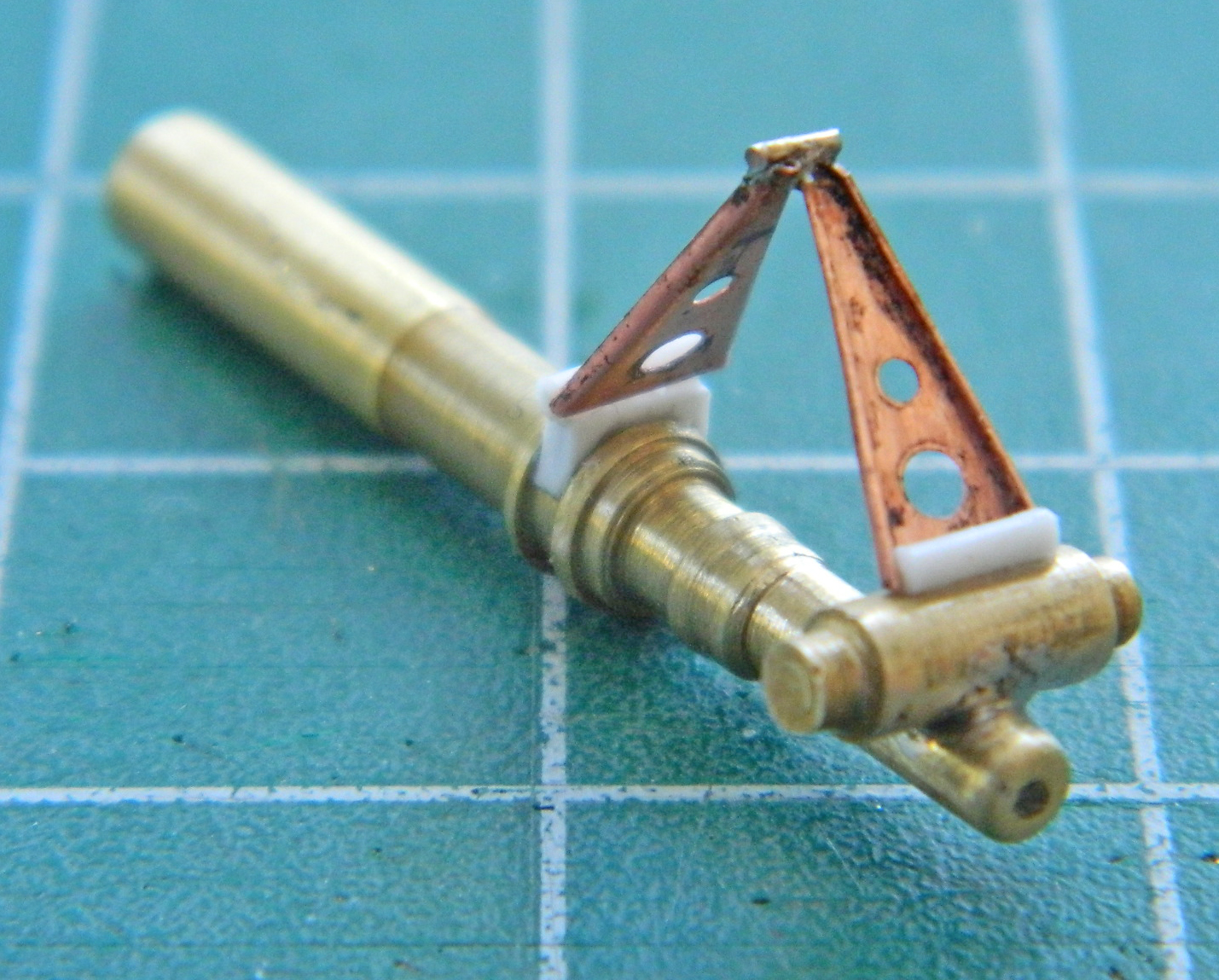
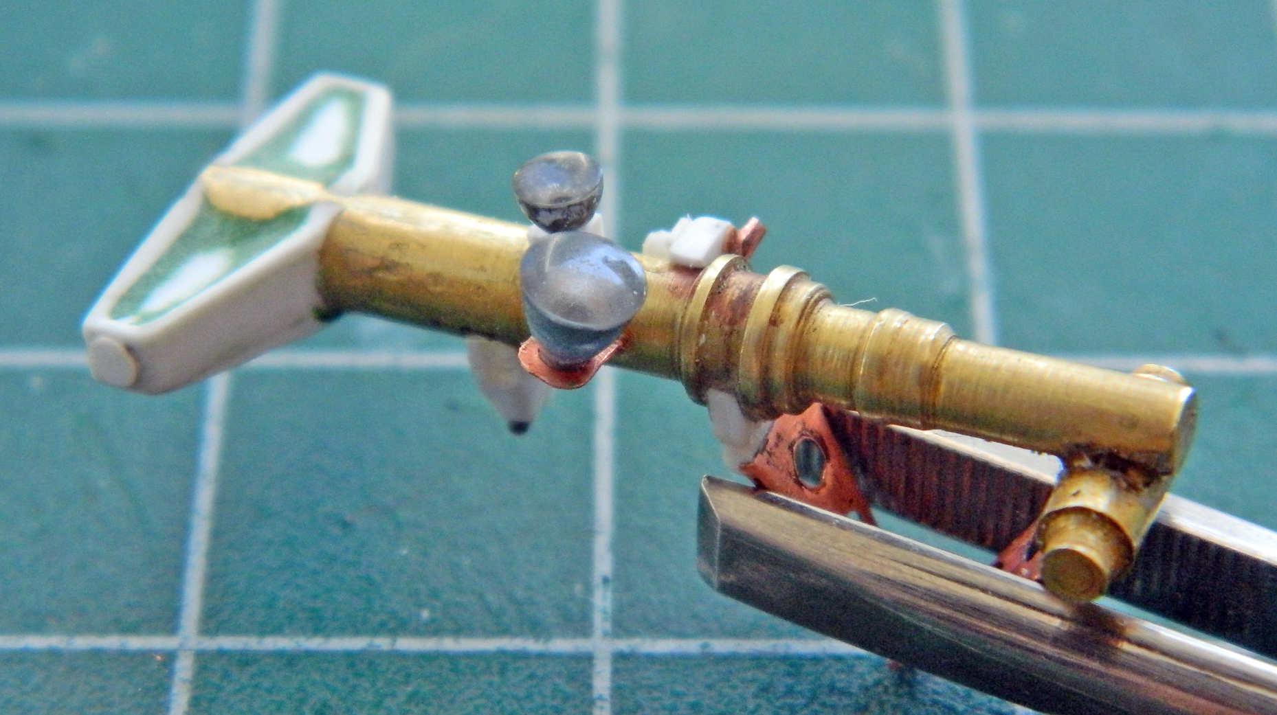
The extension limiters mount to the top and bottom sections of the front strut. I replicated that using small diameter styrene rod, superglued the rod across the wide end between the bent lips, and glued the extension limiter to the strut. (And where did that nice brass landing gear strut come from? I turned it on the lathe starting with quarter-inch [6.35mm] brass rod and without taking any photos of the process. Hopefully I don’t do that with the main landing gear struts):
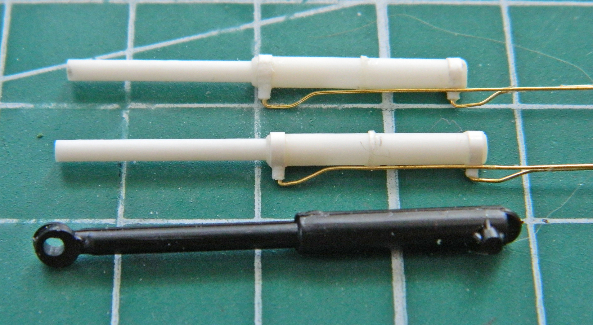
Flying if not high, at least off the ground, on my sense of accomplishment (that soldering job was very finicky and I did it successfully), I chucked a quarter-inch (6.35mm) brass rod into the lathe and turned the extension/retraction hydraulic cylinder, then added the hydraulic line. The restraining straps were made from aluminum duct tape, the line itself from 22awg wire. I amazed myself again by soldering the rounded mount at the left end of the cylinder in place (I filed the part round after soldering to ease the soldering process):

With the hydraulic cylinder done, I added its mount to the landing gear using .040″ (1.016mm) styrene and then checked its general fit:

Yeah…that gets it.
The front landing bay has three doors. The linkage for the rearmost of the three landing gear bay doors attached to the fuselage (wow, some surprise, there!) and to the nose gear strut. I constructed the door using .005″ (.127mm) sheet for the main section of the linkage, punched holes and connected them, and then added the connecting rods using 24awg wire, flattening the ends on my jeweler’s anvil with a hammer before gluing them into place (keeping in mind those will probably needed to be trimmed for correct fit later on):


I formed the landing gear door from .010″ (.254mm) sheet, curved it to match the curve of the fuselage, and then added the inner support structure using .040″ (1.016mm) styrene scrap. Once shaped, I blended the structure with putty. This may not be totally finished so if I need to add more detail later, later it will be added:
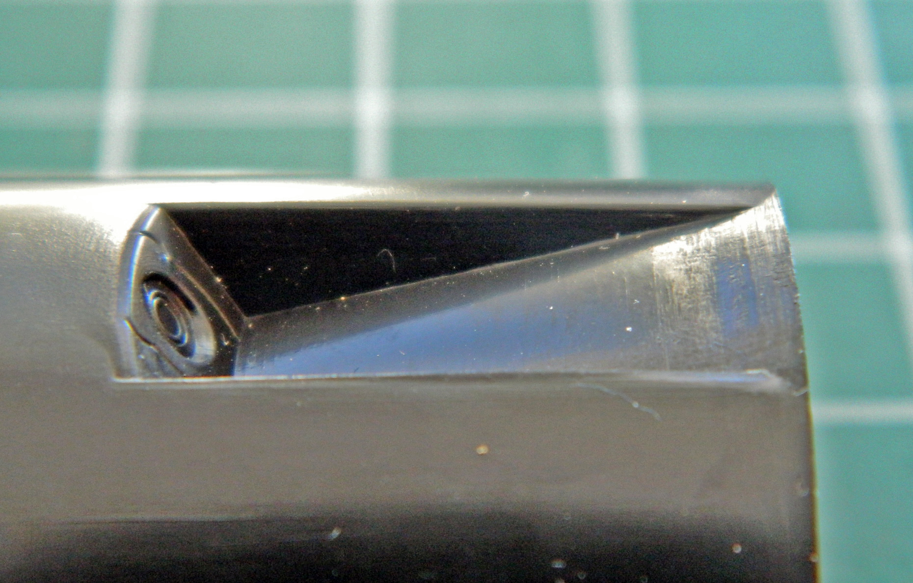
Stepping back from the landing gear construction, I fixed the errors of the mid-air refueling socket. The ramp that leads down into the fuselage is actually a hinged panel that swings up to close the port. The kit molded it incorrectly. It’s not supposed to be more narrow than the opening. The face where the refueling socket is looked correct to me, even if the socket itself wasn’t exactly a socket:
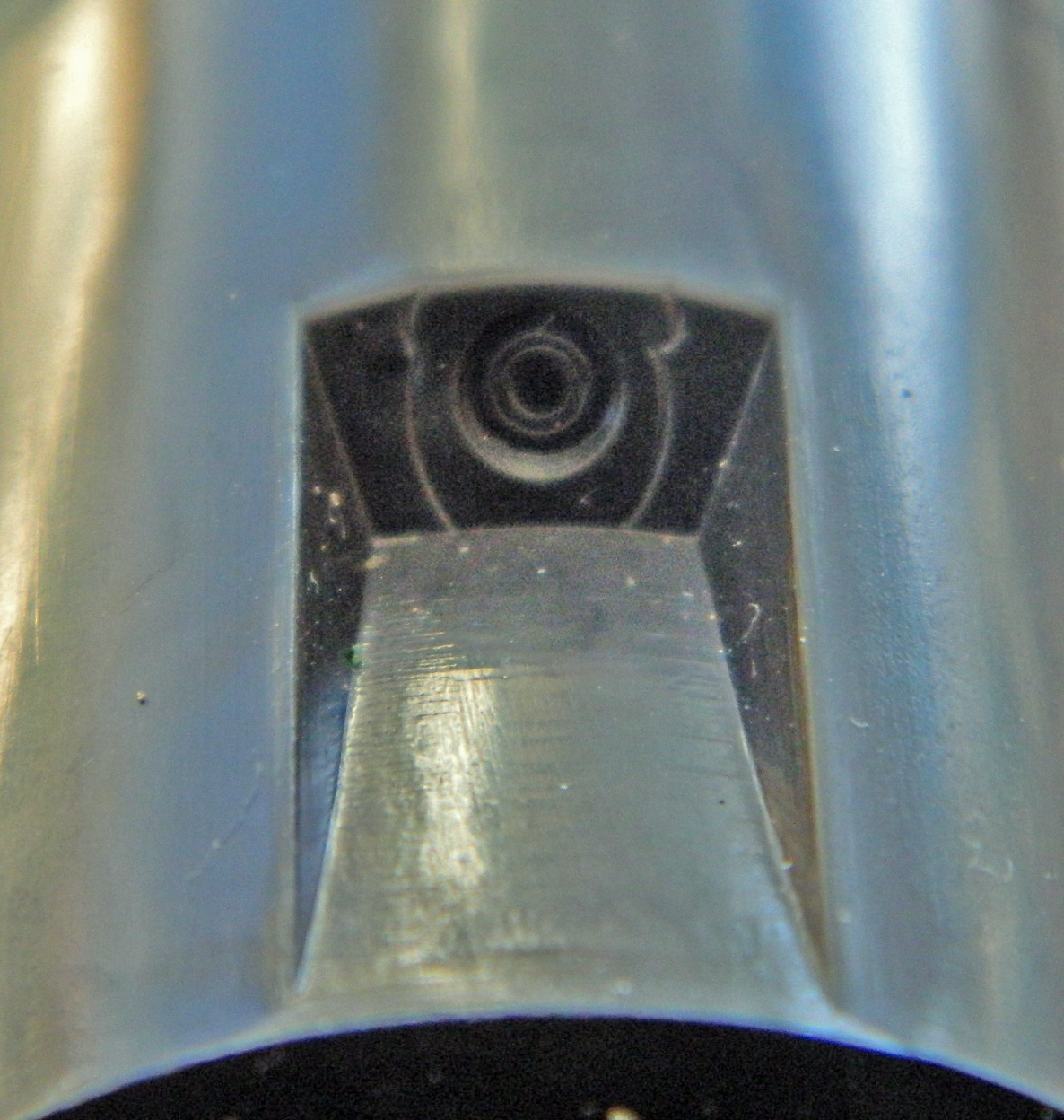
I drilled that out and widened the hole to the diameter I wanted with a rat-tail file. The closest styrene tube to that diameter was just a little bit too large in diameter and also needed to be drilled out to a correct inner diameter. I chucked it (GENTLY) into the lathe and turned it to diameter, and then drilled out the center. I cut a plug from .020″ (.508mm) styrene and inserted it into the drilled out center and glued it before gluing the whole thing into place:
I cut away the molded-in structure and added the new structure. I started with the hinged ramp using .020″ (.508mm) styrene. I cut it to the dimension of the now-open hole and used the top of the fuselage (and HOT water) to form the ramp/door to the correct curve. Once satisfied, that was glued into place. I used more .020″ (.508mm) styrene to form the sides:

A little bit of putty, a little bit of sanding, and the result looks much better, now:

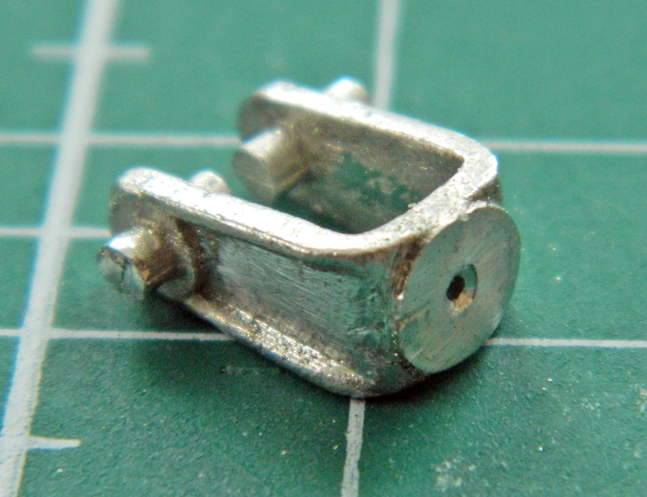
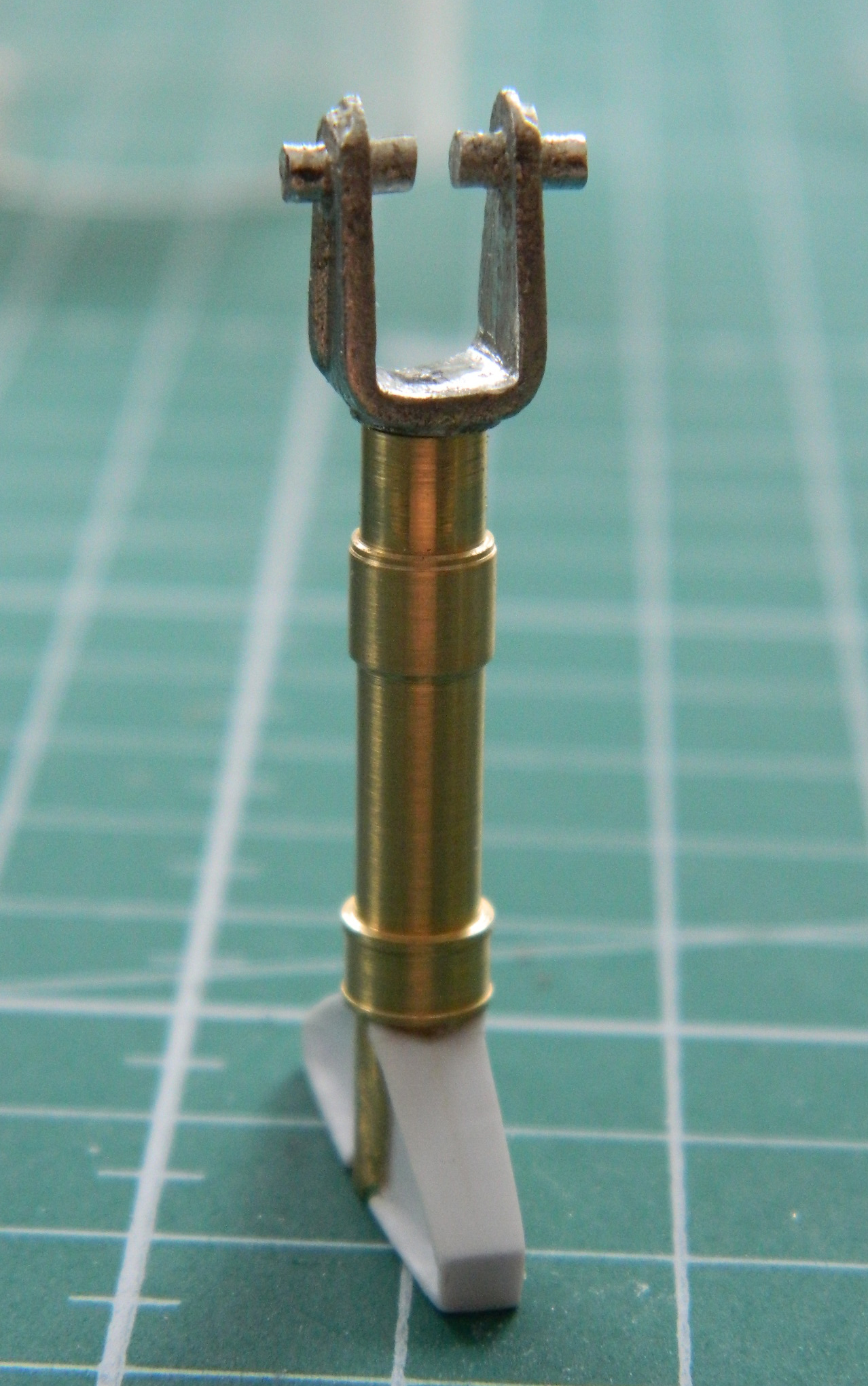
One prominent feature of the front landing gear is a large casting that forms the trunnion. I started with .060″ (1.524mm) styrene, shaped it, and then got to deal with the VERY FIDDLY alignment. I’m not sure I believe how long it took (over a couple of days, because sometimes stepping away to refresh the eye is a good idea) so I don’t expect you to. But eventually I got the parts aligned and (finally) glued:

The trunnion casting has a specific shape that I wanted to replicate. To do this, I started with an outline around the area I needed to carve a recess into and scraped the depression into the face:
I started adding the plastic that would give this part its shape:

Luck plays a factor in a build. If it’s bad luck, colorful invective is exercised, and if it’s good luck, well, I just take it and motor on. Funny (sometimes hysterical) thing about good luck is that sometimes it presents itself as bad luck. In the course of holding this assembly while I carved and scraped, the crossbar (that I spent HOURS getting aligned) snapped off.
In addition to all the colorful invective produced thereby, I also realized that this was probably a good thing. If that crossbar snapped off now, that meant it wasn’t soldered on well. That means if it didn’t snap off now, it would probably do so later after this thing was painted and finished. Fixing THAT would be…well…I don’t know as I have a pejorative foul enough. “Not easy to do” is a gross understatement. So my seeming bad luck turned out to be good luck.
That good luck was not quickly evident. Soldering, which is what I would need to do to get the crossbar reattached, involves heat. It involves enough heat to melt styrene. There is more than one piece of styrene on this part, one of which is much too close to where heat needs to be applied for my comfort. But without the crossbar attached, this piece is useless. If I screw up and melt plastic with the soldering job by using too much heat, then I’ll redo the plastic parts. Since it’s 100% useless as is, even with slim odds of soldering the part back on without melting anything, “slim odds” are better than “100% useless.” My journey into jeopardy started by snapping/cutting the extension limiter off.
This time I soldered the bitch on properly (twice, as the first attempt ended up with the crossbar misaligned) and didn’t melt anything! (I made sure of this by trying to wrench the thing off with pliers. Nope…it’s on there.):
There, just like it was never broken and repaired:

I added .040″ (1.016mm) strip around the upper and lower edges of the trunnion to complete the shape and filled out the surface with putty to replicate the casting:
The nose wheel steering is electrically operated and as such has a housing of a particular shape. That needed to be built (I left the “handle” attached so I could manipulate this bloody small part):
Once built, superglue attached it to the strut (well, I attached it to the strut…the superglue holds it there):

Now that I have the basic structure of what goes into the front landing gear bay…:
…maybe it’s time I should check to see if this thing fits in there:
Well, whaddya know…it fits like it was made for it!
Now that I’ve shown myself that I haven’t wasted the last two weeks, I can finish the nose wheel strut by adding all the other stuff that goes there (yes…there’s more). I started by making the landing light mounts. The mount for the larger light is on the right side of the strut and was made from .005″ (.127mm) shim stock. The smaller light is mounted centrally and was made from a drilled out piece of .030″ (.762mm) scrap:
I placed the lights in place to see how they line up. For the most part, they do, I just needed to snap the central mount off and move it further down on the strut:

I needed to add the wiring conduit and wires. I used 22 and 24awg wires as well as .015″ (.381mm) solder and a pair of 40awg wires. Then I placed the hydraulic cylinder in place and took the next photos to show the differences between the kit part and what I cobbled together:

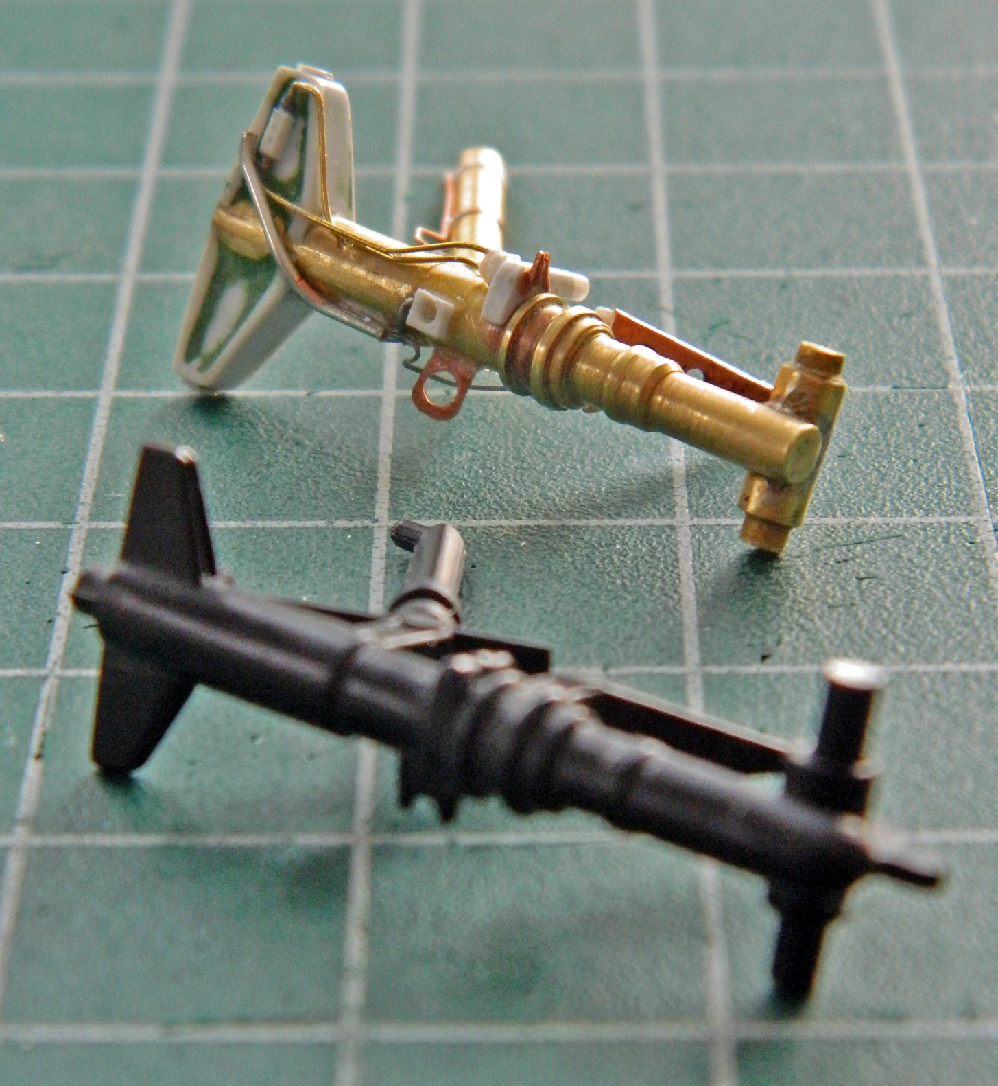
Clearly, though laborious and tedious (with a side order of frustrating), I think the improvement over the kit part was worth the time. Not counting the tires, of which there are two, this assembly required sixty-one separate parts to build.
One landing gear bay and landing gear is done, only two more to go. The “good” news is that I started with the more difficult assembly to make.
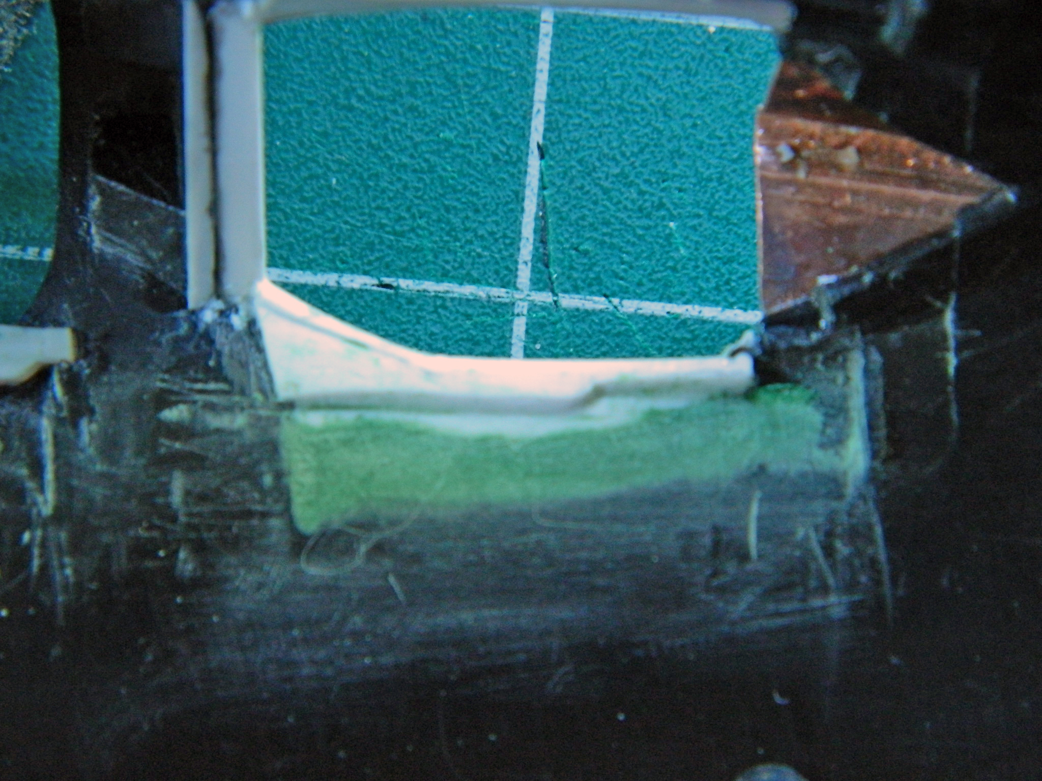
SR-71A Blackbird (Testors) Build #9 – Nose Gear Bay Gets Populated & Scribing “Fun”
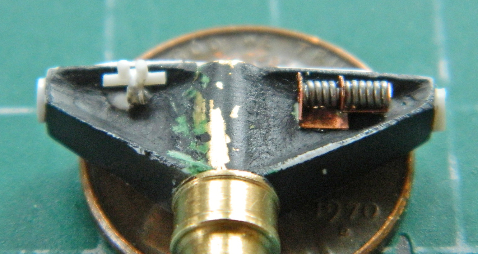
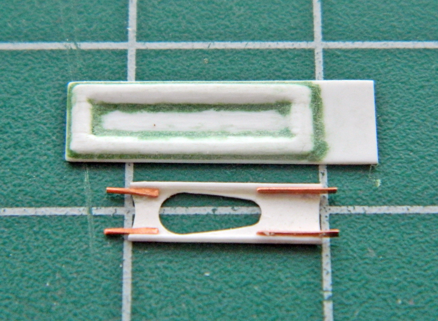
With the springs for the latches wound, I made a simplified version of the shock absorber that slides into them. I punched out a couple of discs, glued rod to one, then slid the spring down, trimmed the rod, and added the second disc:
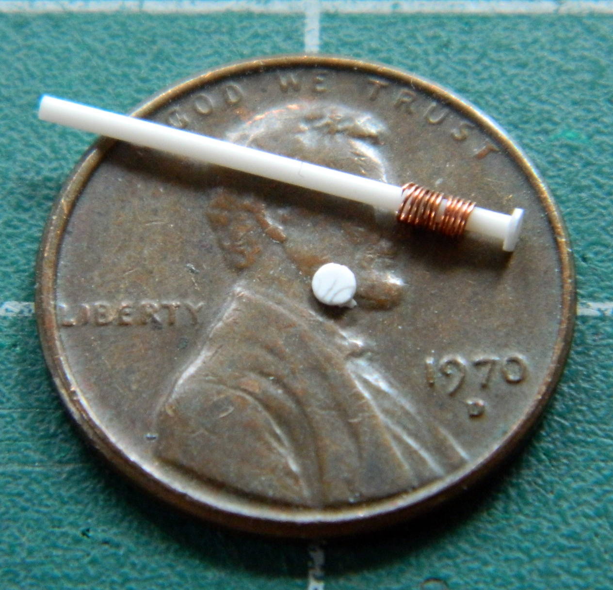
After wrestling with the alignment of the second disc, I realized these discs don’t have to be opaque…I can use clear styrene which will make for much easier alignment. And since these things are so small, I used a piece of rolled masking tape to hold ’em while I glued the second disc on:


There is a lever that attaches to the latch that one end of the spring is attached to. I made those and added the levers and the springs:

With both latches made, they were glued together:
Then I had me some fun. When I tried to fit the assembled latches into the nose gear box, they didn’t fit. They didn’t fit by a great deal, but not fitting is not fitting. Much scratching of head, kicking of cat, being clawed by cat, wandering around muttering ensued. Once that was out of my system (temporarily), I realized that rather than modify one area/section to enable this sodding thing to fit, if I took a little off each area it just might fit in there (the alternative was major surgery in a cramped space). So file, sand, pray, dodge lighting bolts created by praying (and thereby giving away my position), fit, file, sand (avoiding prayer…I can learn), and repeat several times until the bastid just fit…but fit it did:


Whew…
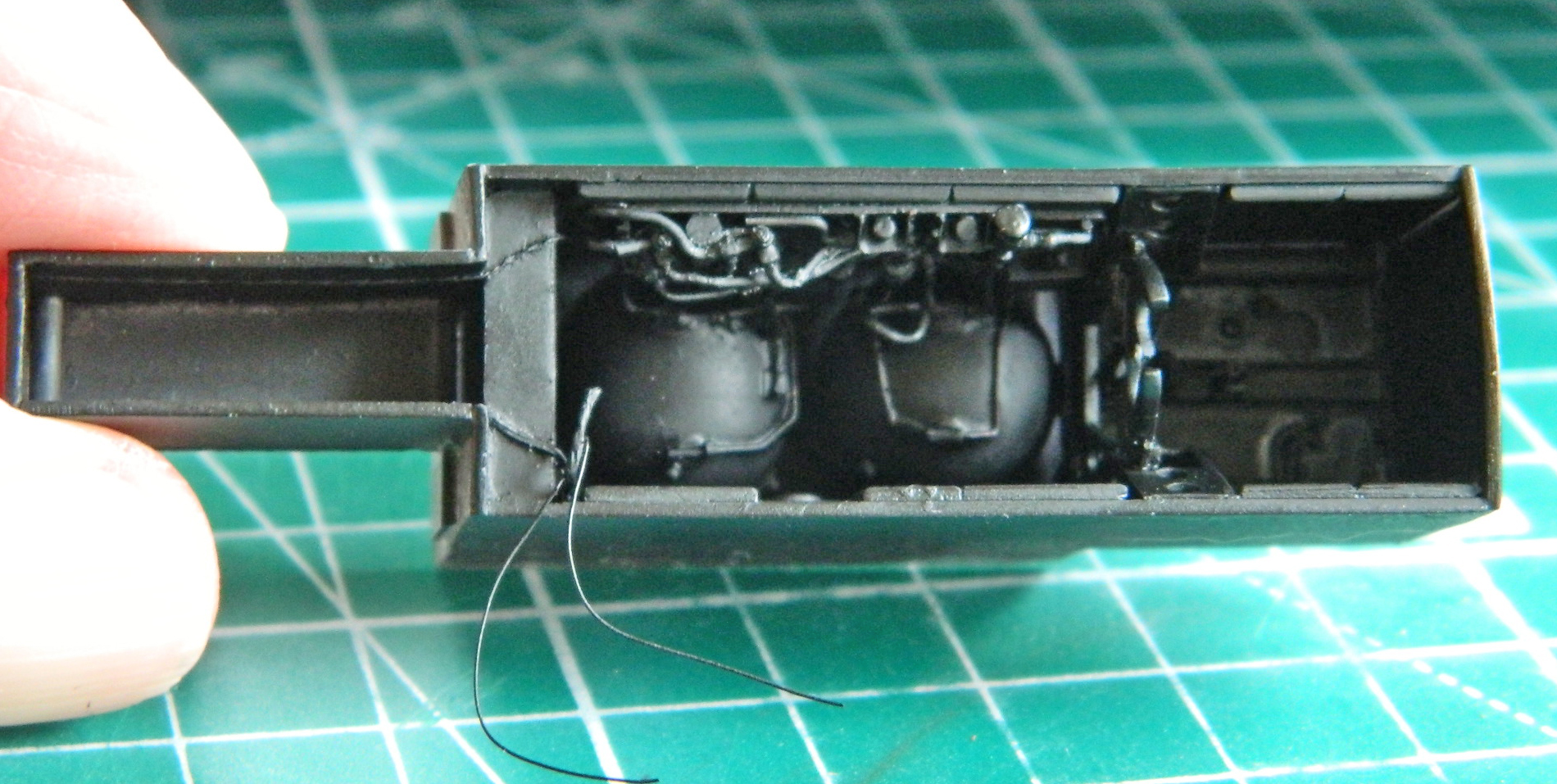
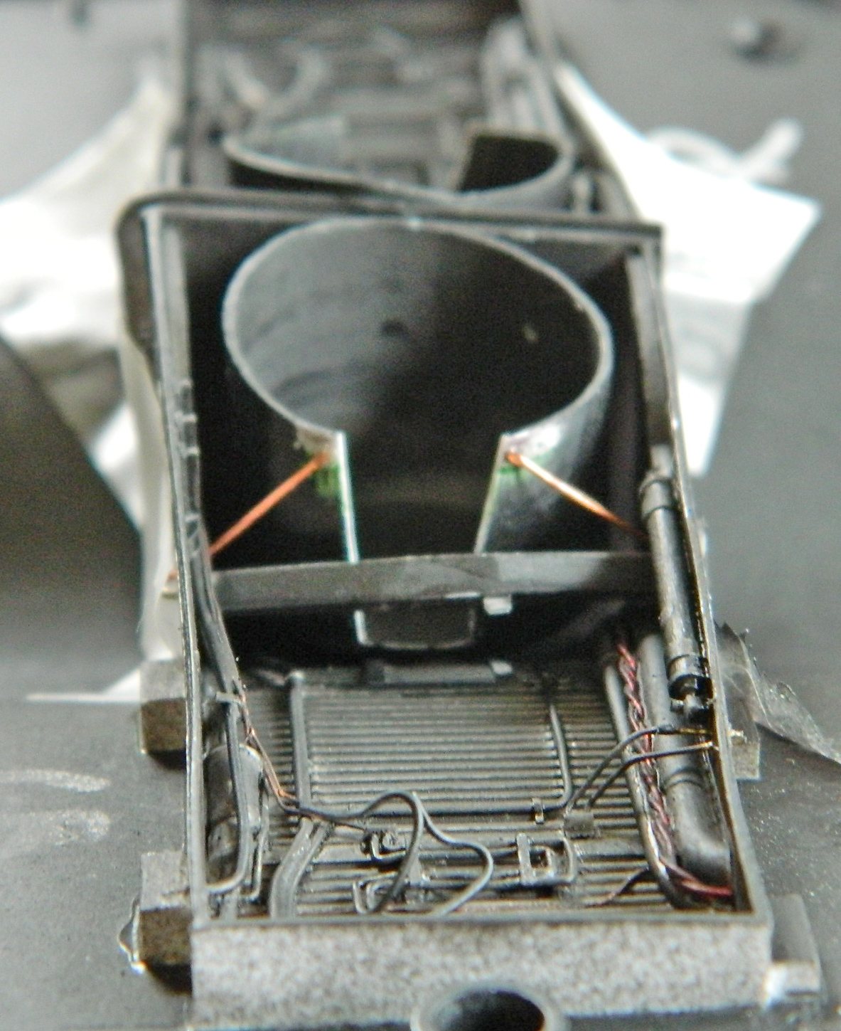
Now that I have all these bits, it’s time to stuff them into place. So that these things would go in at all, it was time to add the nitrogen tanks:
Then the spaghetti panel:
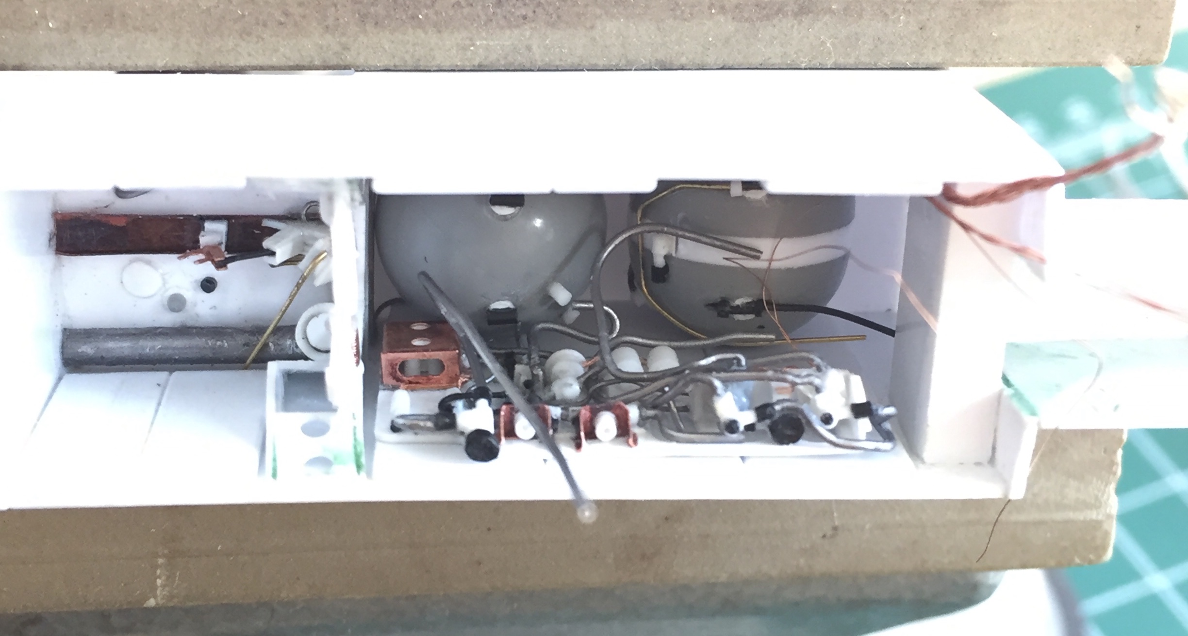
Then tie the spaghetti panel lines to the tanks:

The next step is to start scratch-building the front landing gear strut, but before I can do that, I have to wait for my new micro-lathe to arrive. Having NO shortage of things to do, I put this assembly to the side and did something else.
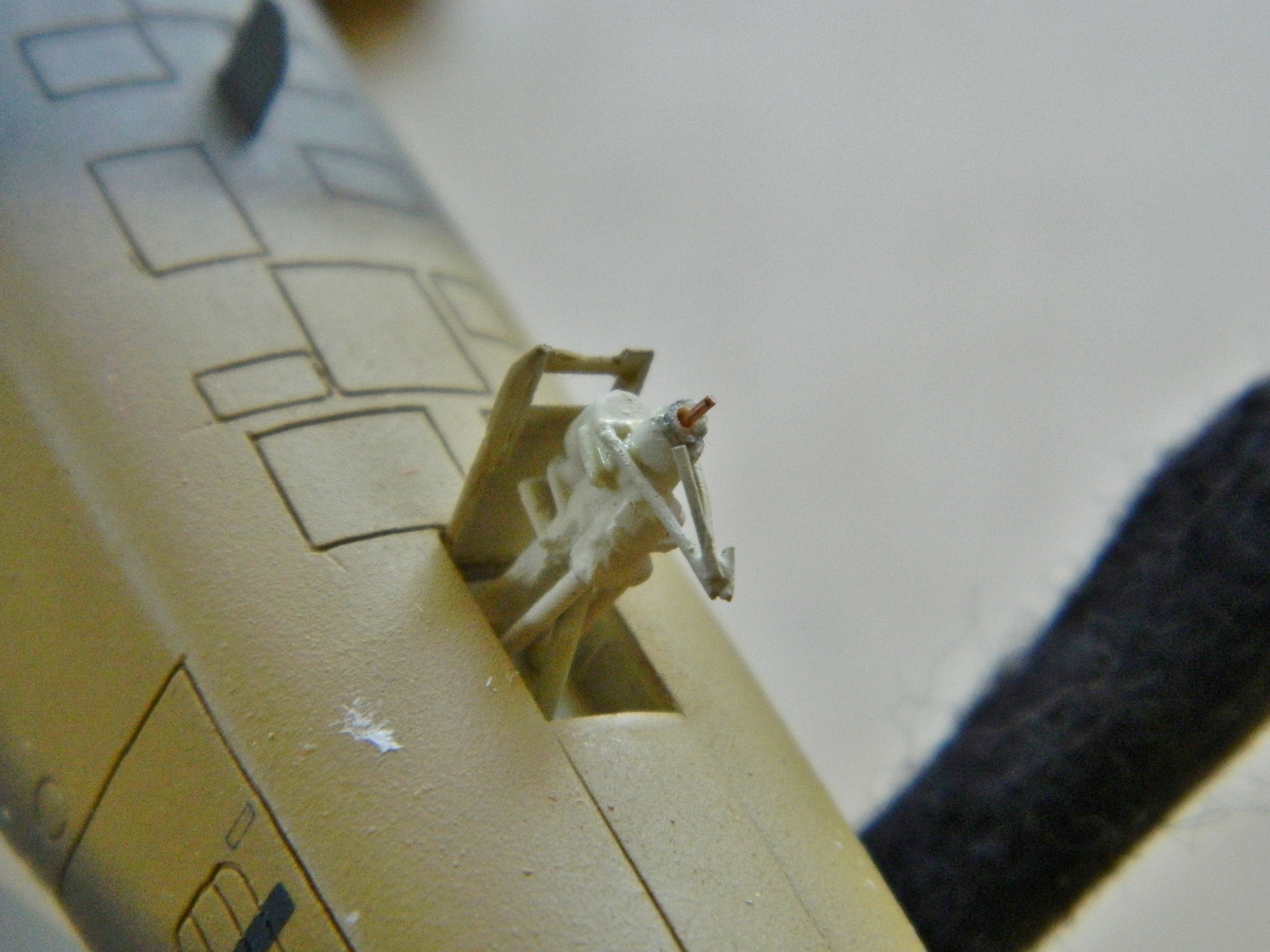
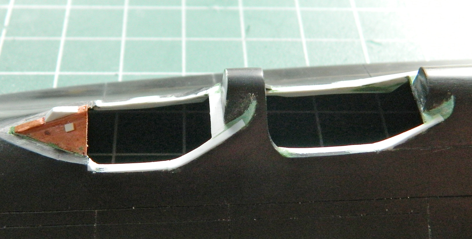
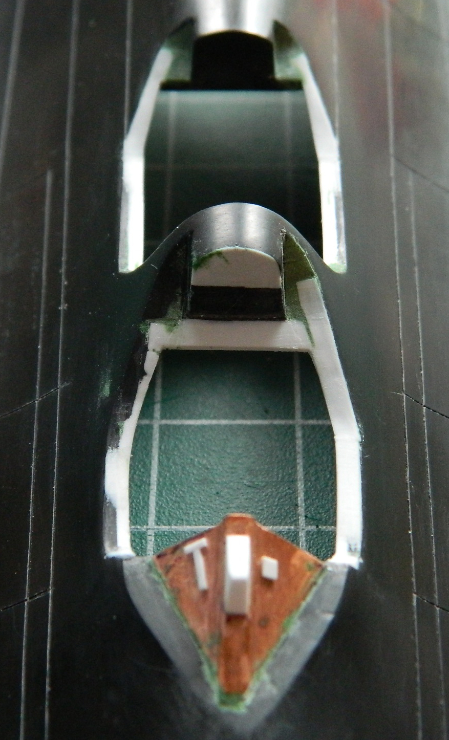
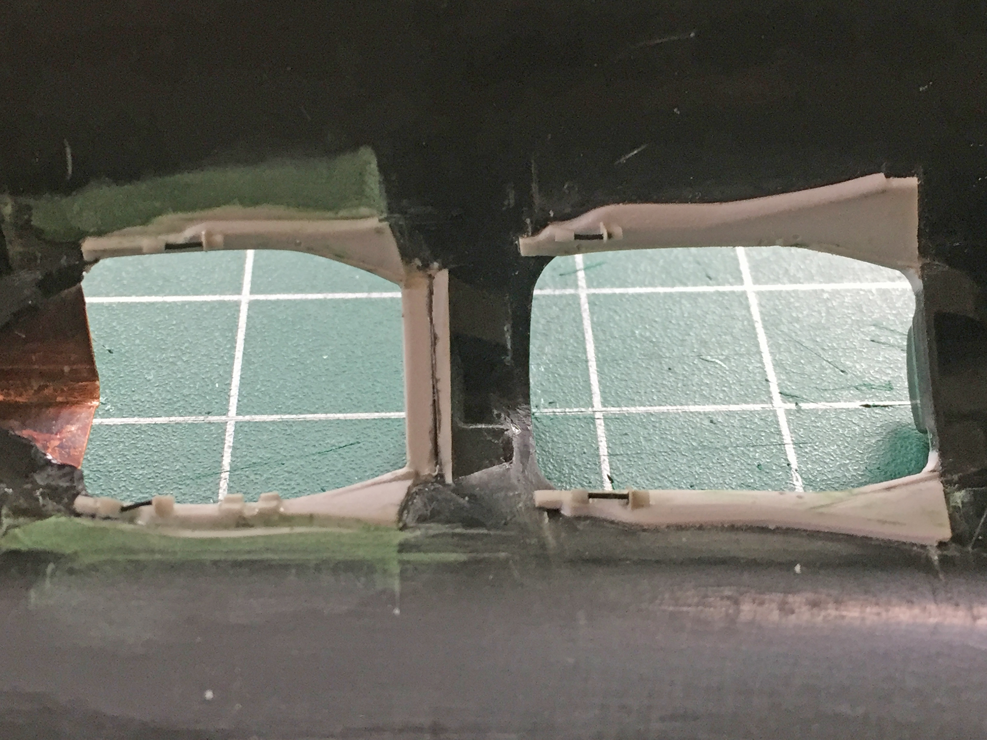
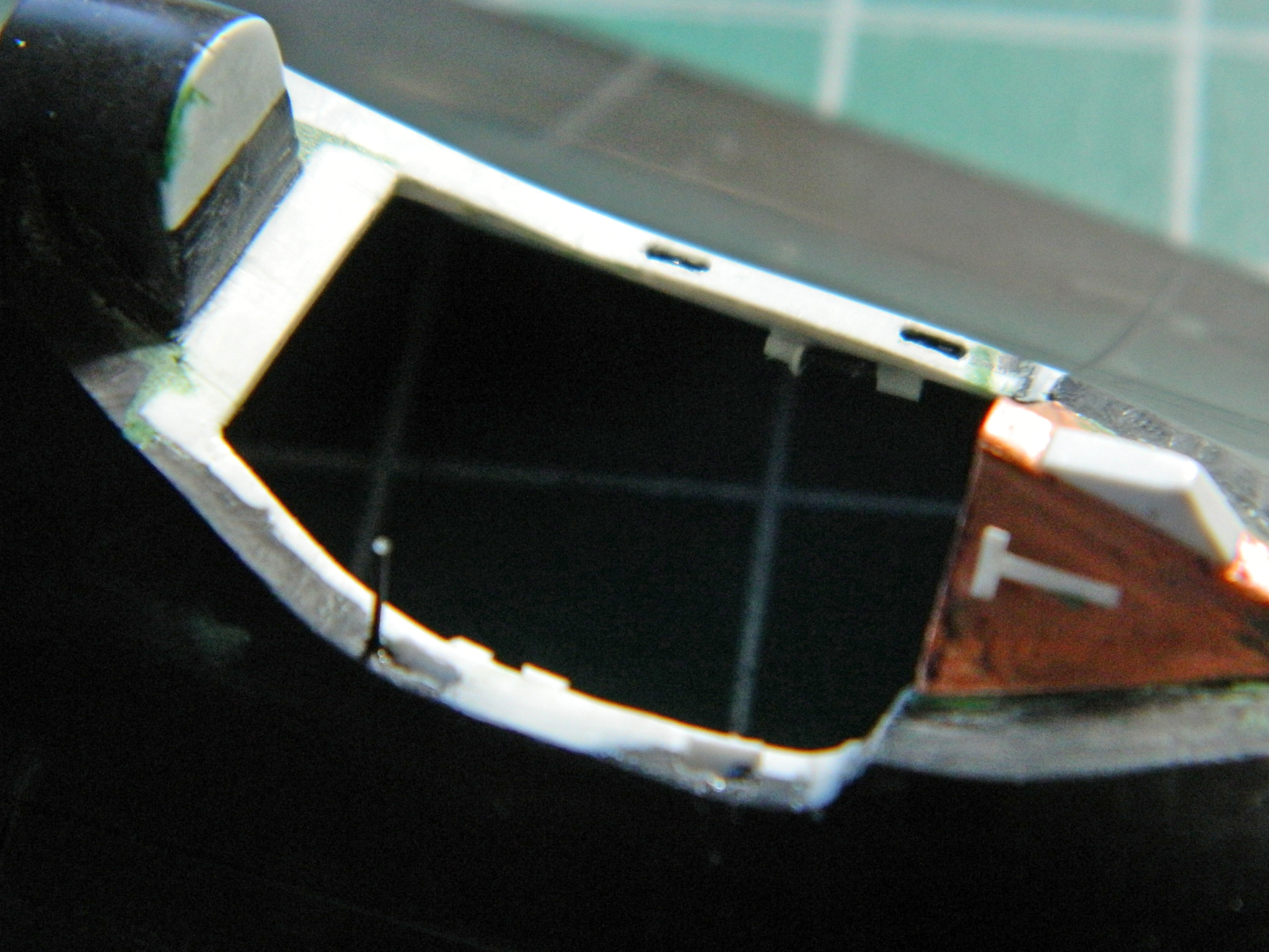
Tail #972 doesn’t have camera ports and the kit does. I used the clear ports as plugs which will get painted over. That started by gluing them into the openings and then gluing the nose halves together:
While the glue set up on the clear parts, I added sprue to the LARGE gaps between parts (evident on the right in the photo):
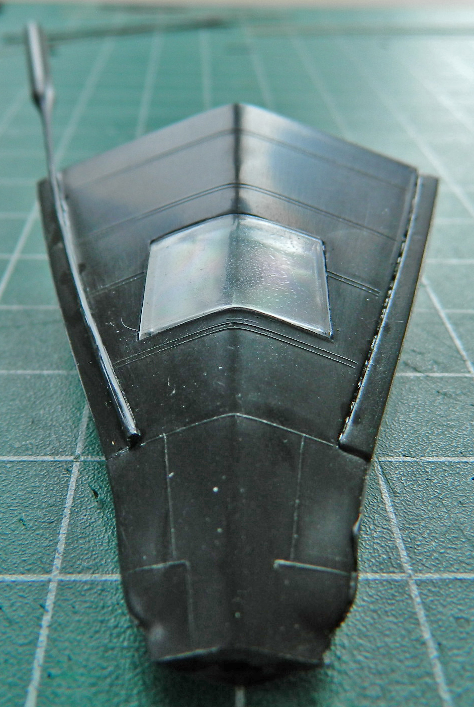
The rectangular ports are in the wrong position, even faired over. I scribed new panel lines to the left of where the kit put them:

Since there was to be a lot, A LOT, of sanding to this area, and I was going to have to do it anyway, I screwed up my courage (or the bravado that passes for courage) and started scribing panel lines:

There are probably those out there who just scribe, re-scribe, and add scribed panel lines as a matter of course. I ain’t one of ’em. Since I really am so poor at this aspect of modeling, I take my damned, sweet, time with it. And even THEN there are numerous oh-goddamit moments where the scriber (in this case usually needle) skips and adds a groove where I don’t want a groove…which then needs to be filled. If I get lucky, the oh-goddamit groove isn’t where I have to scribe over it. In that case, I can just add putty. If I do need to scribe over it, then I have to add sprue. Adding sprue means I have to let it sit overnight before trying to work it. Rushing it results in the scriber running into plastic that’s still gooey and that leads to more oh-goddamit moments…and tasks.
So there I am, merrily (merrily?!) scribing away. Pity I didn’t check references first. Some of the panel lines are in the wrong places (which of course I scribed in before noticing that). So I added sprue in several places as well as puttying the oh-goddamits and gaps between the clear part and the rest of the nose:

While that was all curing, I flipped the nose over and scribed lines and filled in large sink areas with putty (as well as filling a TOTALLY blown panel line with sprue):
Then I went and watched snow melt while the glued sprue cured.
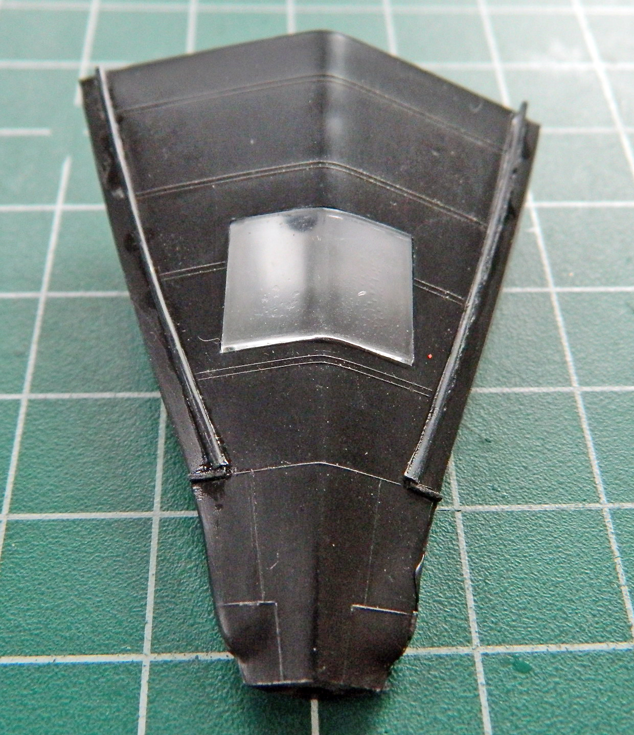
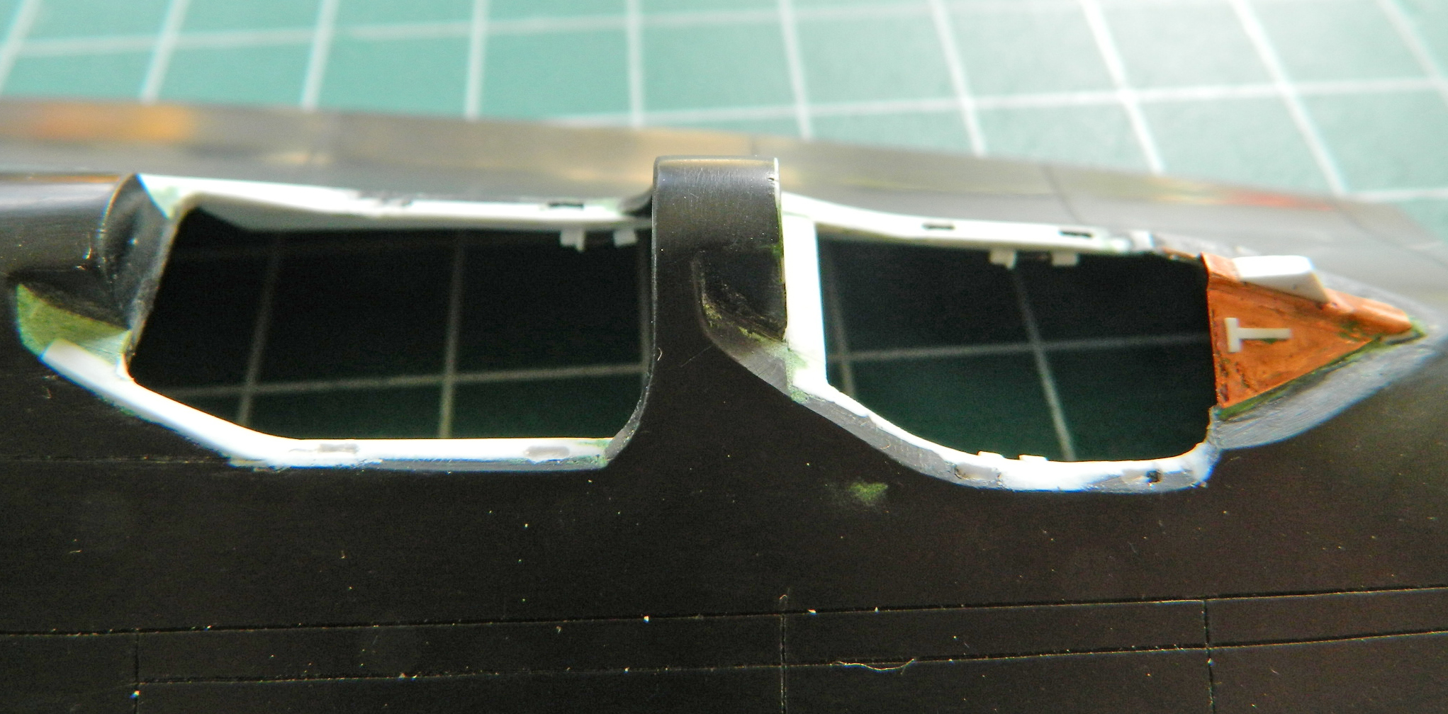
Back at it the next day, I noticed that the panel lines under the nose where the big camera window would be was flat out wrong. So all of that got filled with sprue:
While those areas were curing, I sanded the top of the nose:
Then next day I filed/sanded down the sprue:
Finally (which is actually a joke…”for now” is probably more accurate) checking references, I saw where missing panel lines had to be added, incorrect panel lines filled, so I started that and found a conundrum. Nothing is quite lining up! Yeah…these two lines go here. And they’re supposed to line up with this part of the nose gear bay opening. So why don’t they line up?!
They don’t line up because when the dies for these molds were cut, someone was either having a very bad day or the supervisor had an apprentice make the cuts. They don’t line up because the ENTIRE opening is about 1/8″ (3.18mm) to 3/16″ (4.76mm) of an inch TOO FAR TO THE RIGHT! The [DELETED INVECTIVE] is off center. The tape added to the fuselage section is centered to the wide end of the opening:
All sorts of depraved fantasies traipsed through my mind, not the least of which was to reposition the opening. Uhm…NO. No, no, NO, no, no!! The landing gear box I made is dimensioned to this opening in this position and to relocate the opening means making a new landing gear box! Y’know…I think I’ll pass on that one. It means I have to jigger a few things that come next, which means they won’t be entirely accurate, but I think my 90-95% mandate covers this.
One of the things that had to be jiggered is a sensor port in the belly that the kit didn’t model. It’s supposed to be centered between the panel lines I had to add, and sit right on the center line of the belly. Yeah. Well, it’s gonna be one or the other…unless I put this port just a little off center. I realized that if I centered the port, it would be off center of the scribed lines. That misalignment is more obvious than the port being off center of the fuselage. Right…centered to the lines it will be. Mostly.
It started by drilling a small pilot hole. I took a section of clear sprue and chucked it into a variable speed drill set on LOW speed, and used files, emery boards, and sandpaper to reduce the sprue’s diameter slightly. I decided which drill bit to use relative to the diameter of the sprue and widened the hole in the fuselage. While I still had the sprue in the drill, I used a smaller bit to replicate the detail in this area, then stuffed the sprue into the hole, glued it from the inside of the fuselage, and started trimming, filing, sanding, and polishing:


I back-painted the sensor using three parts Tamiya’s Chrome Silver (X-11) and one part Tamiya’s Flat Yellow (XF-3) for the surround and Tamiya’s Flat Black (XF-1) for the center:
Several days of chasing oh-goddamits, scribing, RE-scribing, deepening scribed lines, sanding, puttying, sanding some more, and finally this section is done (I think):
And as I was wrapping this up (I think), I got a notice that the micro-lathe I ordered from Grizzly Tools (part #G0745) arrived! Oh goodie…more insanity on the docket!
By popular demand…reference photos have been deleted
Nope…I’m not supplying references anymore.
SR-71A Blackbird (Testors) Build #8 – Back to the Nose Gear Bay
Sometimes I repeat myself often a lot over and over… Here comes another (again some more). The smaller the details, the longer they take me to do. With the cockpits done, I turned my attention and effort back to the nose gear bay…which will be full of very small details.
Sometimes instead of plastic sheet, I’ll make details from copper shim stock (.005″ (.127mm) and .010″ (.254mm) because that’s what I have on hand). There is a small “C” channel and rather than try styrene, I used .005 shim stock. To get tight bends, I’ve found that if I anneal the copper prior to bending, I can get much tighter and sharper bends. Once the copper cooled, I took out my PE bending brake. I used a needle to score my bend line (not because it actually scores it but because I need an alignment line to follow), fiddled with the copper until I had it correctly lined up, and then used the razor blade to make my ninety degree bend by slipping the edge of the blade under the copper that sticks out and lifting it up:

Worked well so I did it again and got this:

I had to make and add pulleys to one of the assemblies that populates the “C” channel. I used the punch and die set to knock out the inner part (.005″ (.127mm)), the outer parts (.010″ (.254mm)), and then assembled the pulleys and added them to the mount I made:
The “C” catch and its arms were also done with .005″ (.127mm) copper, its mounting done with little bits of scrap styrene, the pulley mount fleshed out, the connecting arm done with stretched sprue, the pulley added, and all of that added to the “C” channel:
So before I either dropped it and broke it, or just broke it without the optional drop, I glued that assembly into the nose wheel box (the capped vent tube was .093″ solder [2.38mm] added earlier):

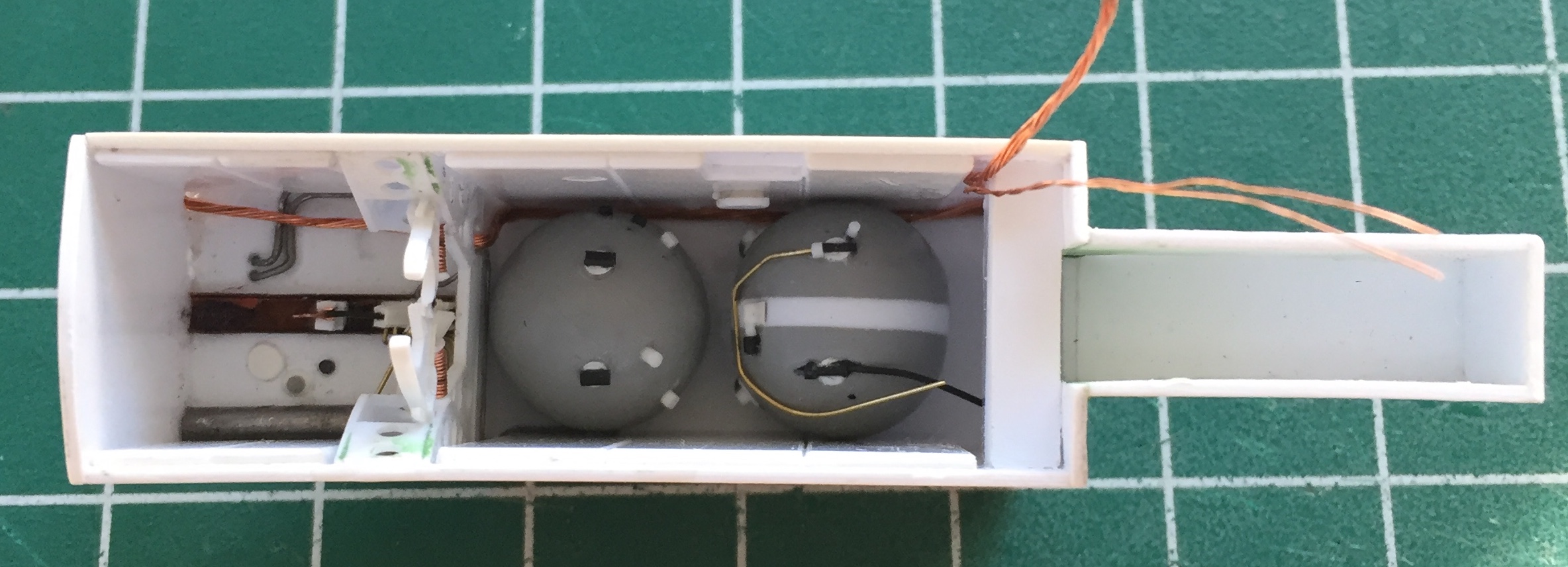
I had already built the liquid nitrogen tanks and was going to start adding lines to them. When I went to dry-fit them I realized that when I put them together, I didn’t have these sheets of insulation in place the way they are now:

Each sheet of insulation was made from .030″ (.762mm) styrene, which meant that the nitrogen tanks I built were .060″ (1.524mm) too wide, now. ::eye roll and forehead smack:: I had to saw them apart and put a thinner spacer between the ends. And just for the novelty of it, I checked reference photos. Some of the SR-71s have two oblong tanks, but the main references I’m using show only one tank being oblong; the other is round. Since I’m going to have to disassemble ’em anyway, I decided to do one oblong and one round just for the eye-candy aspect of it. I would rather do what tail number 972 has but I couldn’t get under the kite to see what’s in there so I decided to go with one round tank:
I added the various lines to the oblong tank using solder, copper wire, and stretched sprue. The discs were punched out with the punch and die set:

TOTALLY out of sequence (mine, of course), I decided to try an idea that had been rattling around under my (profoundly sparse) wig for a while…
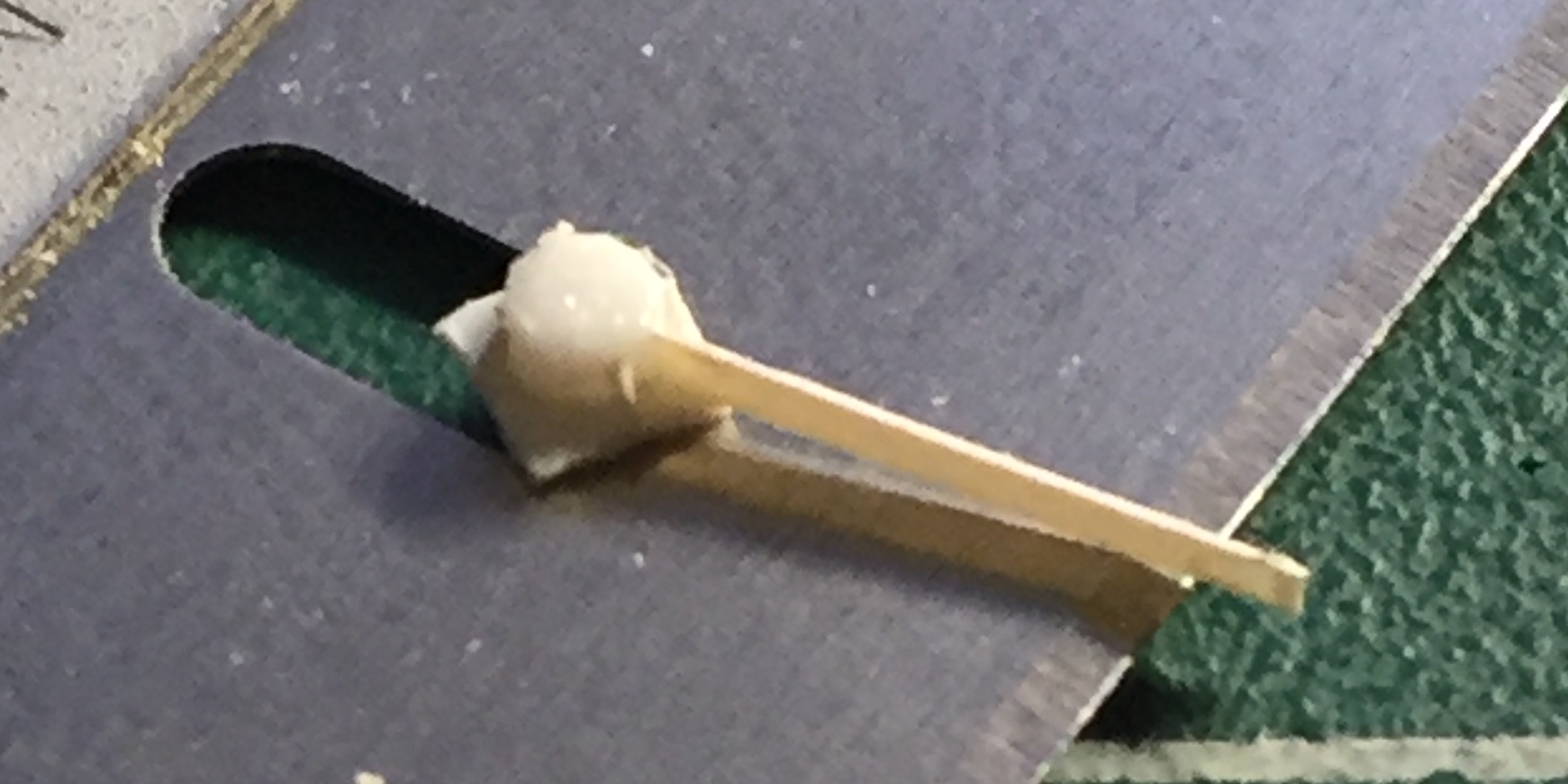
I do NOT like trying to replicate a clear item with opaque paints. (That’s sort of like getting drunk every night to promote sobriety.) There are two very prominent landing lights attached to the strut of the nose gear and the only parts on hand are opaque. Gah. I chucked a piece of clear acrylic rod into my lathe and turned a section down to the diameter and shape I wanted. Then I used progressively finer grit sandpaper to remove the steps left by the cutter and then polished out all the marks left by sanding paper. Once satisfied, I cut the work from the acrylic rod, which left a small stub on the end. Instead of cutting that off, I decided to use that to drill a SMALL hole (.0135″ [.343mm]) to replicate the bulb. I dipped the tip of a needle into black paint and stuck it in there, then used Molotow’s “Chrome” pen to create the reflector. So far I’m very pleased with the results (only time will show me how the “Chrome” accepts the black paint it has to have on the exterior):

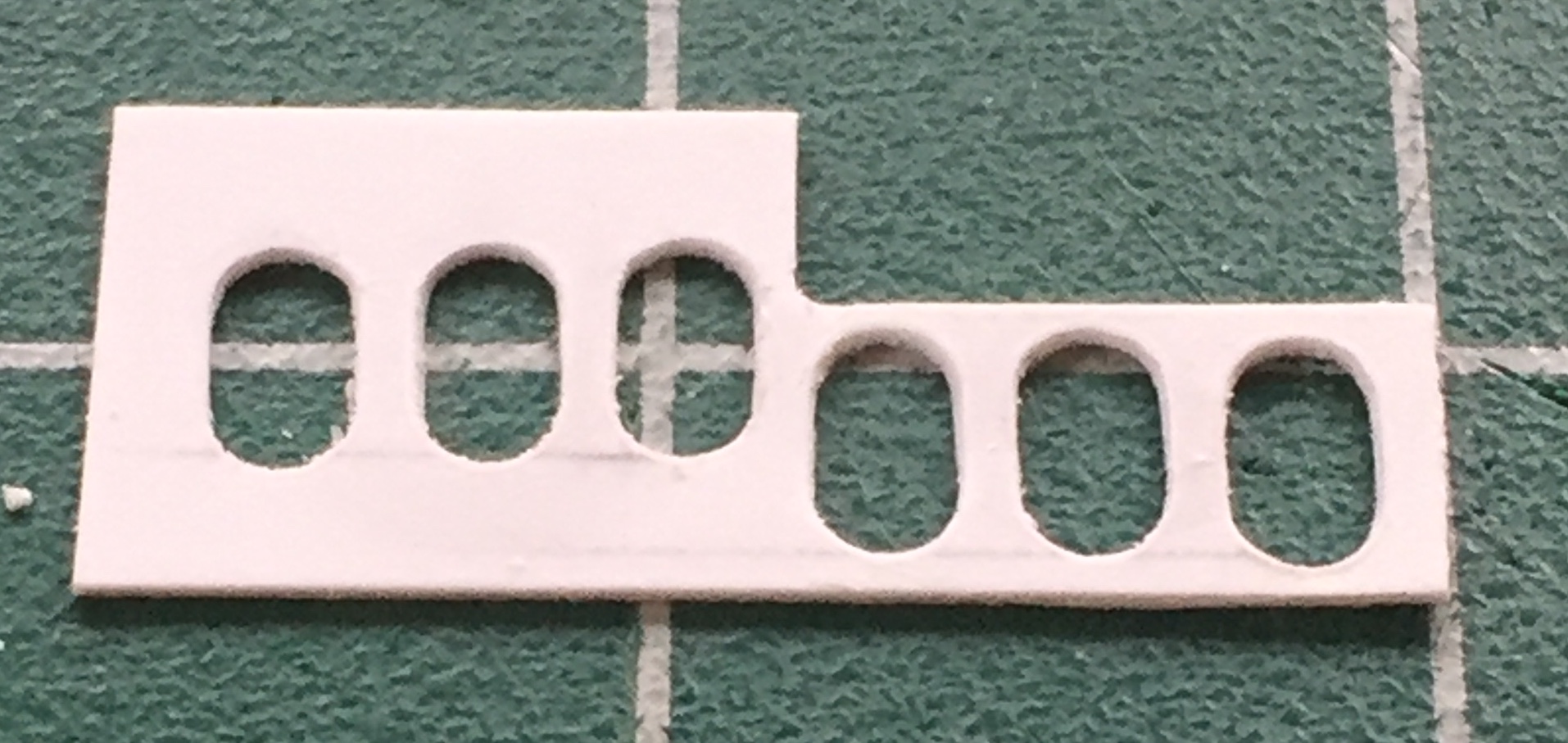
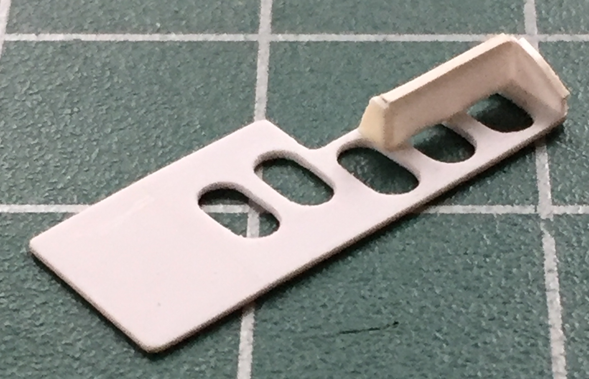
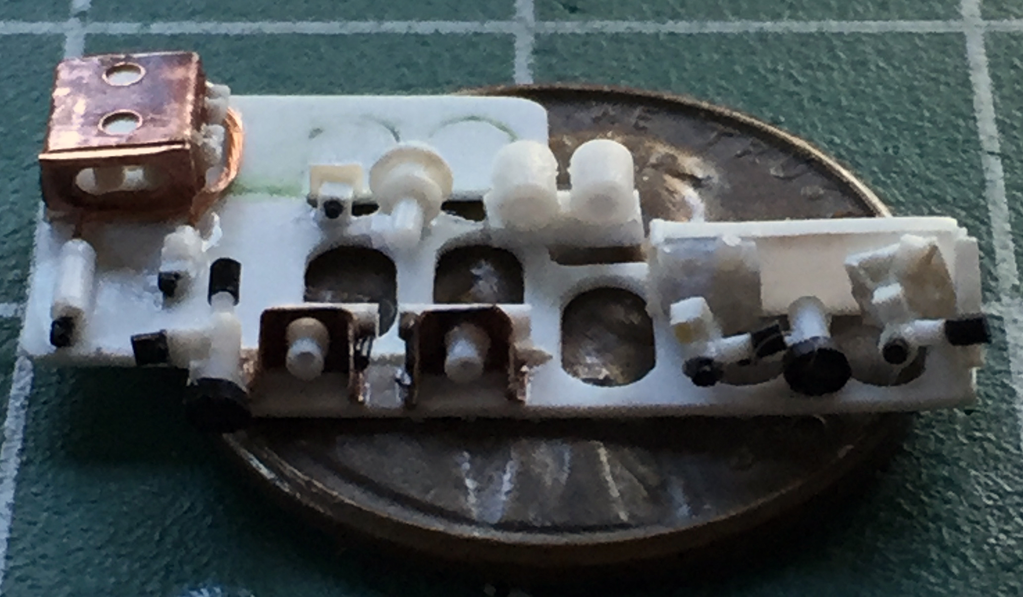
A very prominent feature on the starboard wall of the nose gear bay (that’s the right side, if I’m not trying to impress) is a panel full of plumbing, pressure regulators, and other varied Mysterious Bits and wiring. NObody makes this part, either*, so, I started by making the panel. I used a scribing template to be able to make consistent size/shape cuts. Well, not “cuts,” exactly…I used a needle to make repeated passes until I was able to cut through (as you can see below, I tried a couple of different techniques, starting with “outline, drill, connect the holes, pout, discard, try something else”):
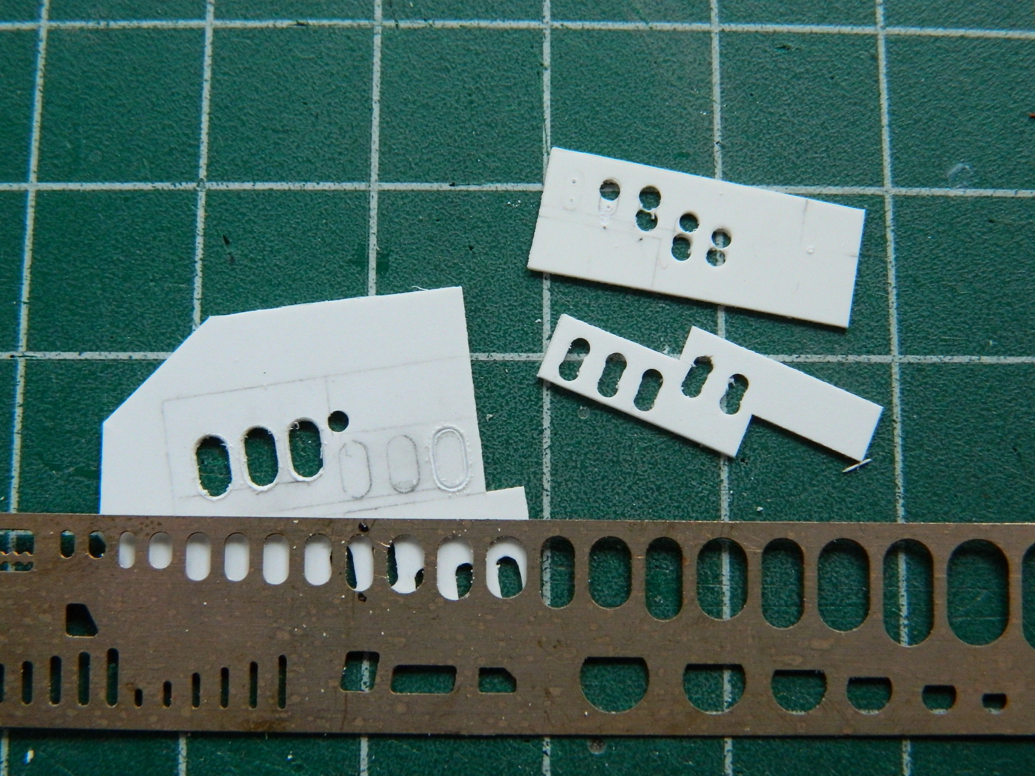
The scribing-through worked the best:
And…as that turned out I was a bit incorrect. There’s only two of the upper ovals, so I cut the offending hole off:
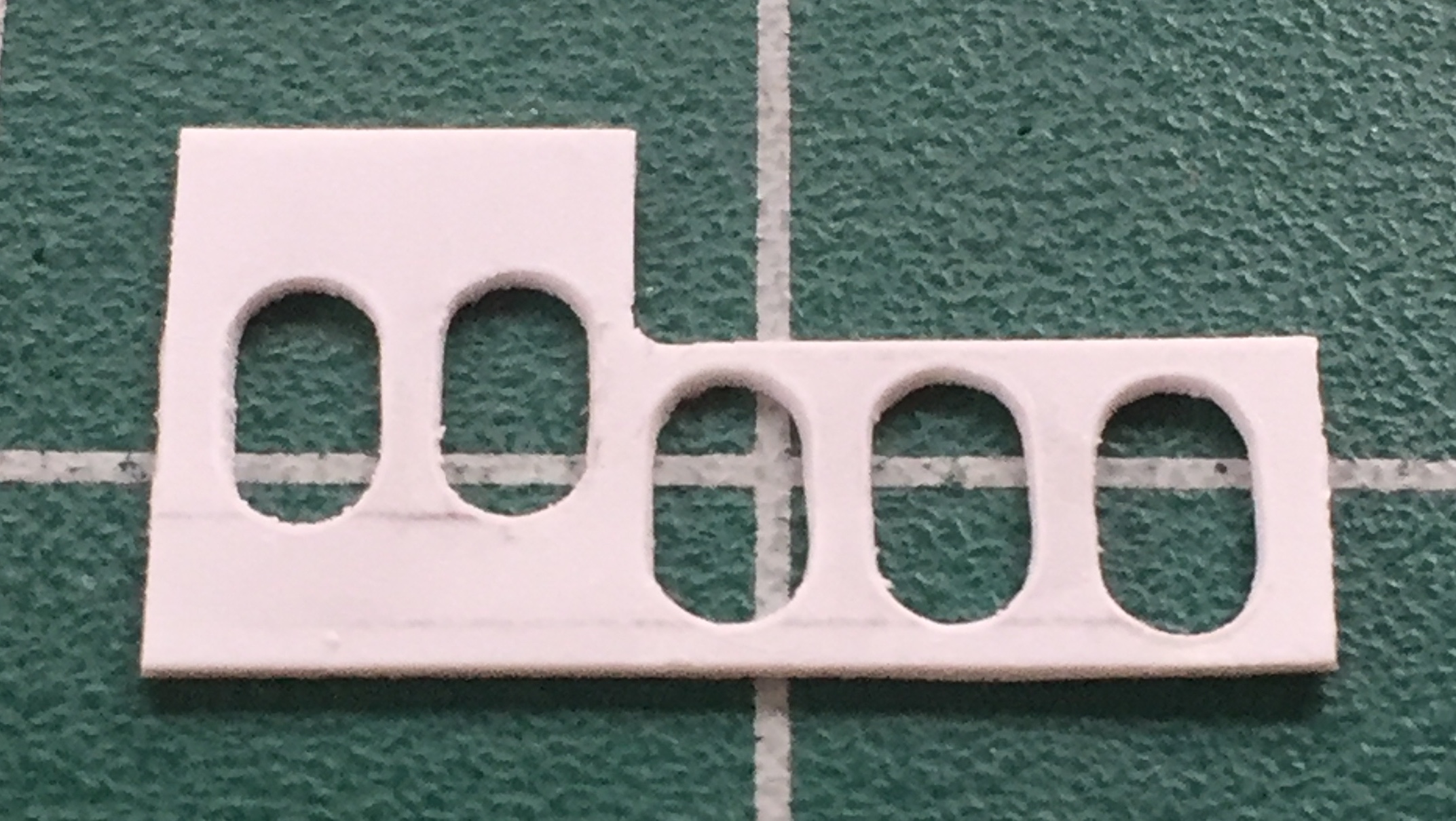
And now that this panel isn’t long enough, I added back what I had to remove:

Next was to start making the various parts that live on that panel. I started with a mounting bracket for what appear to be pressure regulators. I used .015″ (.381mm) styrene for the mounting bracket and .005″ (.127mm) styrene for the pronounced lip:

With it done, the bracket was glued to the plate:
Due to their shape and small size, rather than use styrene to make these mounts, I went with .005″ (.127mm) shim stock, annealed and bent as earlier, with holes punched out:
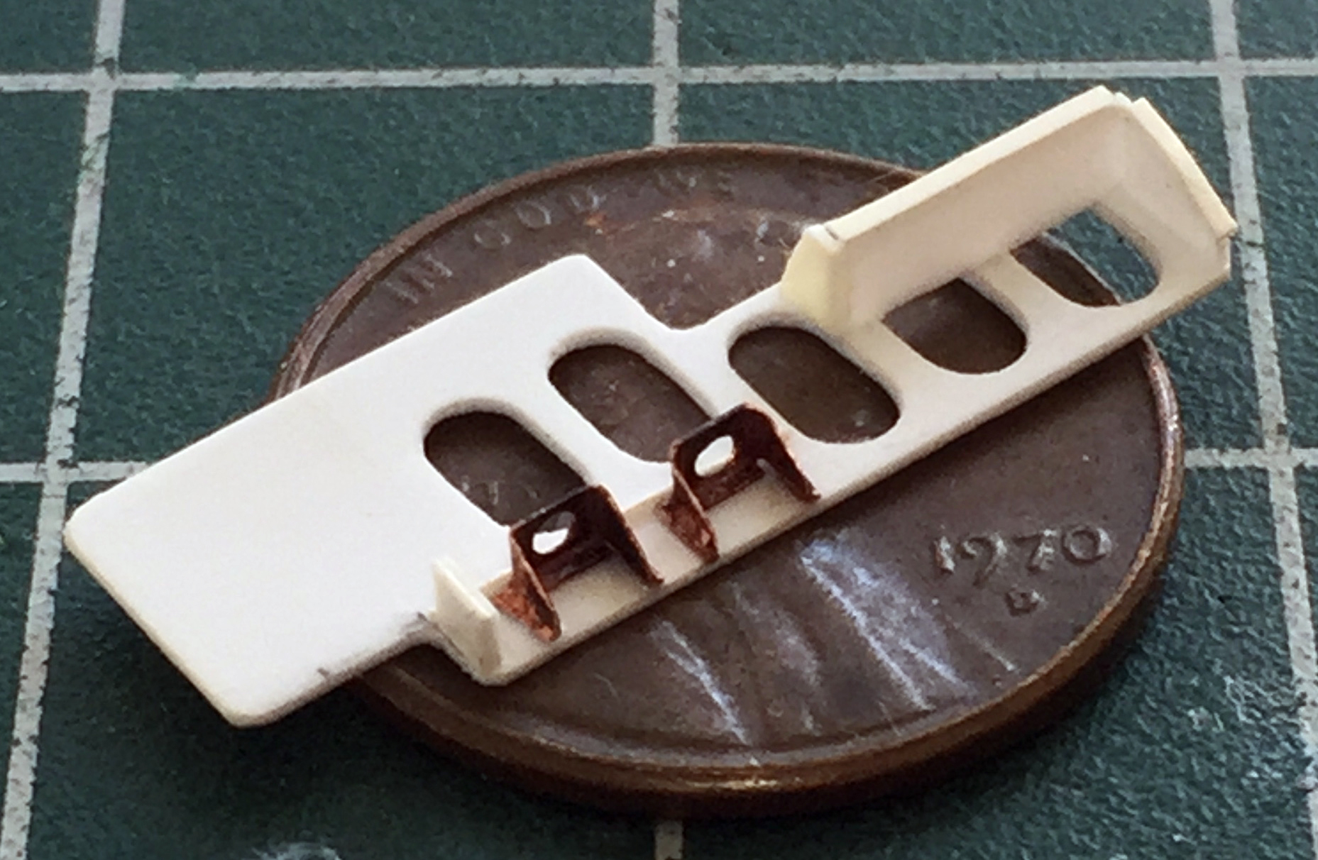
Now I need to populate the brackets. I started with (what I assume to be) the pressure regulators:
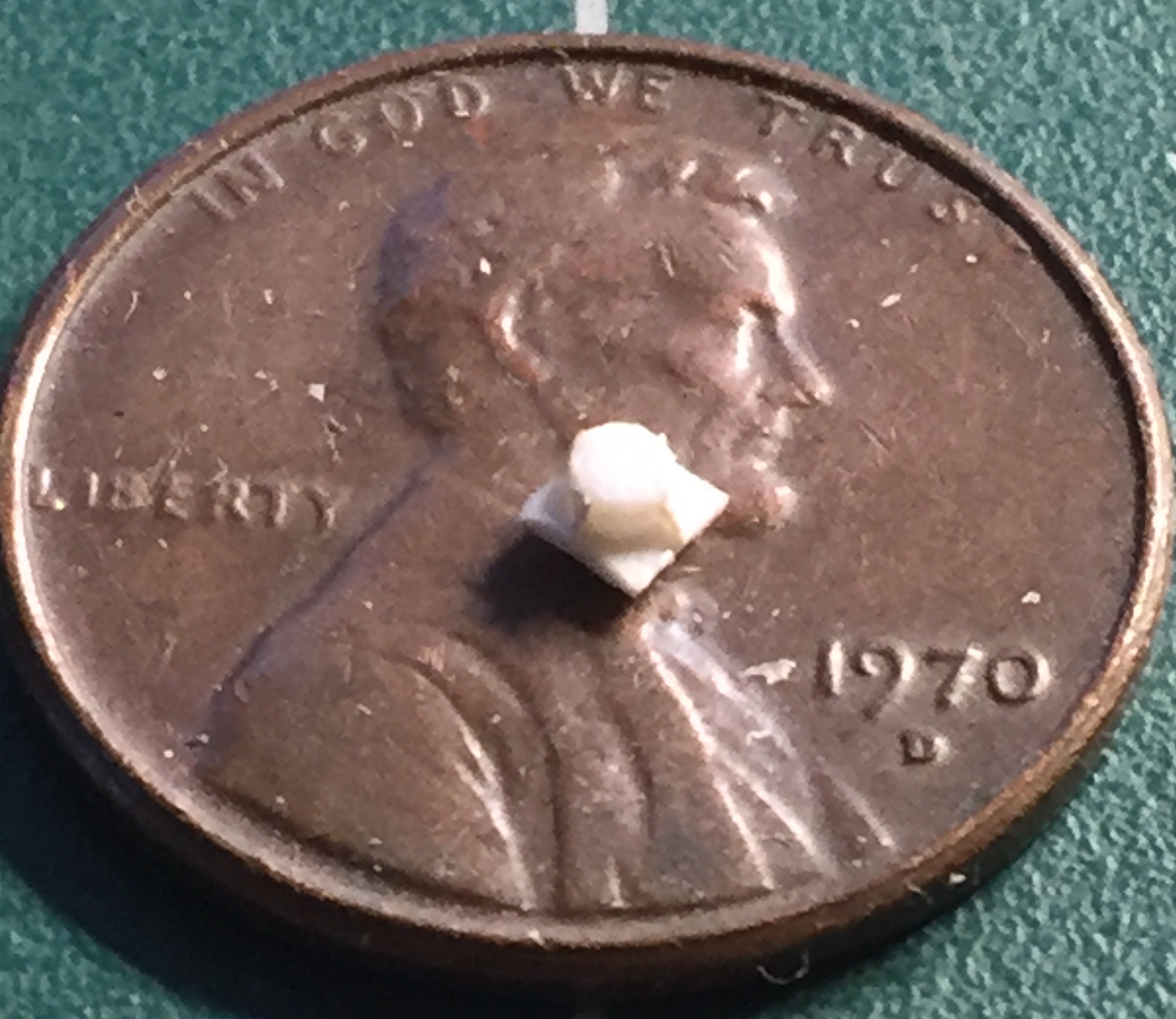

Since adding those fins to such a small piece was such a joy, I figured I’d use the thermo-mold compound to make molds and cast resin parts:
Yeah, well, no. I was reminded that the thermo-mold compound gets HOT. And styrene melts when things get HOT. Which is just what happened. Okay, so, I’m not going to be able to mold the entire part. But I can mold the hardest area to make which is the finned base, and that’s what I did. You’ll see below that one part is resin (the darker of the two), the other part the master that had the small details melted off and was fixed. You’ll also see where I added other Mystery Bits and had to add to the plate AND fill in most of the two oval cutouts in that addition:

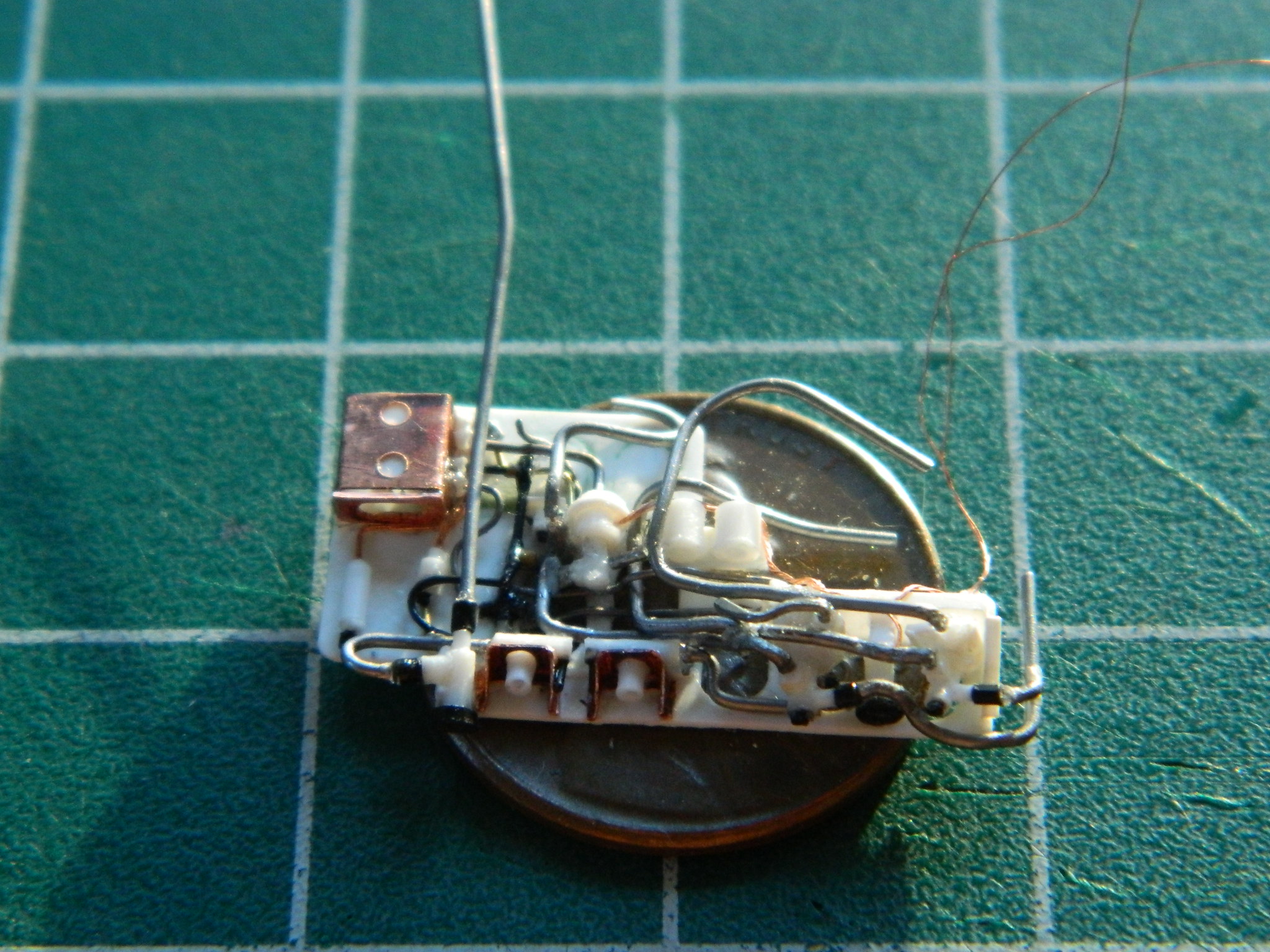
I added the copper colored box on the upper left of the plate (body is .005″ [.127mm] copper and the face with the oval cutout is .010″ [.254mm]), added wiring (eight strands of 48awg copper wire), wiring connector, and plumbing connections:
As I’m merrily (medications help) adding various lines, it occurred to me that maybe I should dry-fit this to see if it fits before I get carried away (further) with it…and yeah…it fits:


I kept at it, adding solder (.010″ [.254mm], .015″ [.381mm]), wire (26awg, 24awg, as well as more 48awg), and sprue (Eyecrometer-approved diameters), and figured that this will do (the lines that aren’t connected to anything will get connected to the nitrogen tanks):
And THAT all took some of October and all of November!
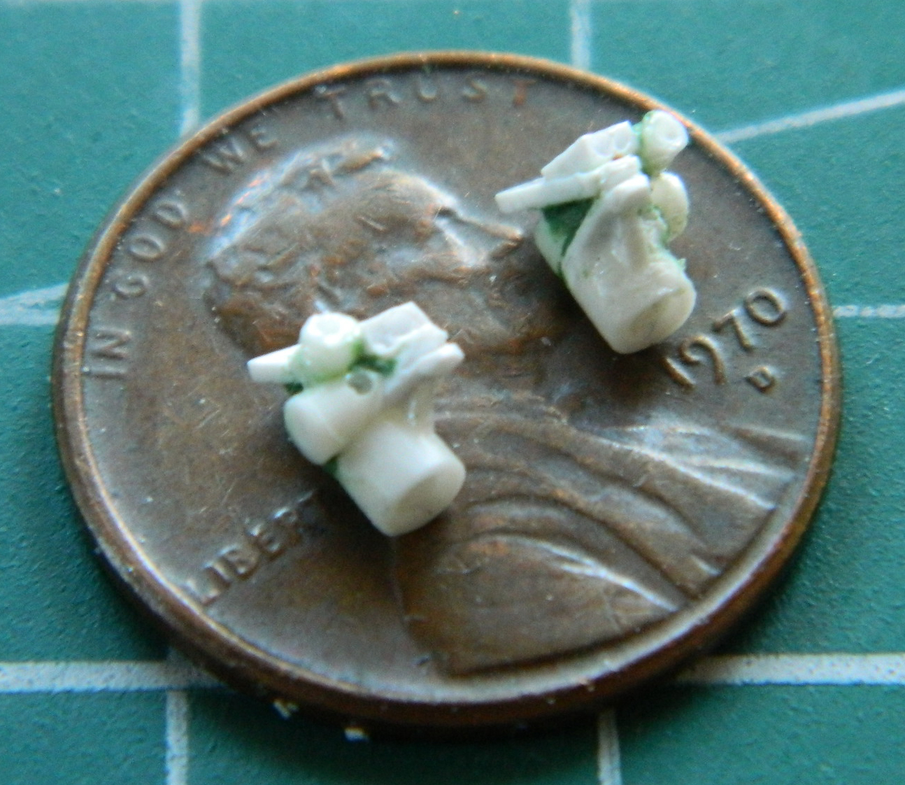
Inside the front landing gear bay are two large latches/supports that grab/support (which is what “supports” do, one supposes) the main strut of the nose gear. I copied the shape (and hopefully the size) to the adhesive strip of a Post-It pad. Doing it this way means I can trace around the template without the frustration of trying to hold something SO small and, well, paper thin, in place (a lot). Tracing onto the adhesive strip allows it to stick. I used a piece of .005″ (.127mm) copper as my working template (the hole was punched out):
Having the shape in copper made it easier to file the shape to its final dimensions:

Right after the above photo was taken, I picked the copper template up with my tweezers and PING…it vanished, never to be found again (of course, my cat will find it, eat it, and maybe I’ll see it again after the vet digs it out of whatever part of her alimentary canal it decides to puncture). So I made another one. Again, I traced around it with a needle until I worked through the .015″ (.381mm) styrene:

The original part on the aircraft is cast (probably titanium, but I’m not sure) and has an evident lip (sorta like I do) that goes around the periphery. I added that using a strip of scrap .015″ (.381mm) styrene:


I sanded the exterior lip and filed the interior lip to get the thickness I wanted. On parts this small, where things need to be filled, I don’t use putty (there really isn’t enough of it to hold to itself or the plastic). I add small scraps of styrene and cut, file, sand, them to shape once the glue completely cures:
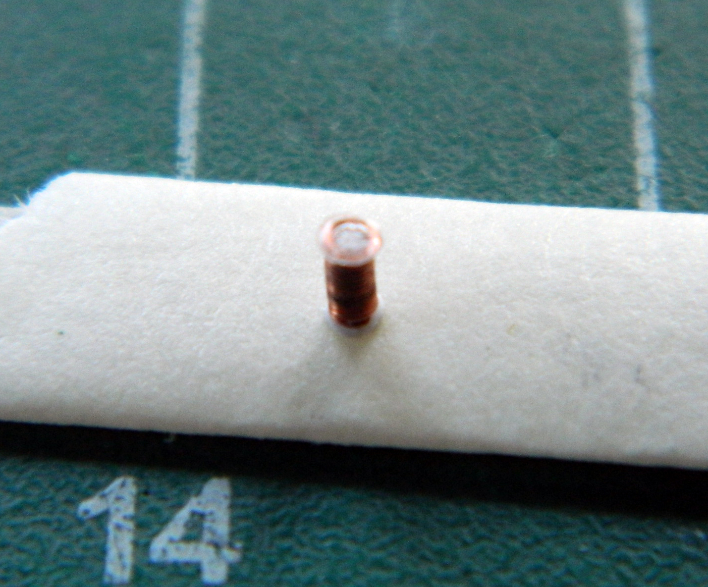
Right after the above photo was taken, I realized I put the lip around the round inner section of the right clamp/support on the wrong side of it. Yeahwellfine. I cut it off and redid it on the proper side…then I went and had more coffee. Once the coffee had calmed me down and made my approaching-ancient hands so much more steady, I took 28awg copper wire and wrapped it around a needle to make the springs that these latches will get:

I am SO looking forward to making the shock absorbers to fit inside those springs… (Remind me again why I don’t work in 1/72 scale?)
*Well, nobody made the parts when I started this build. Of course, once I had this section of the nosewheel bay built and installed, I discovered that Metallic Details (if memory serves) (yeah…like THAT ever happens) does make most of what I scratch-built in resin, now… ::eyeroll:: (Then again, I think what I made looks better.)
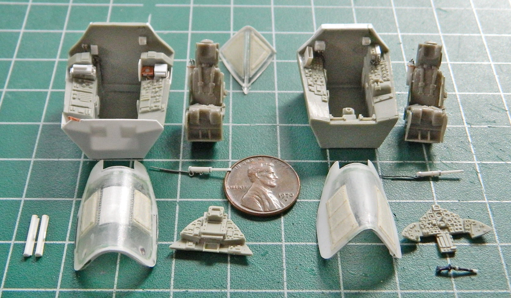
SR-71A Blackbird (Testors) Build #7 – Painting and Installing Cockpits
I like pre-shading things. It helps to make the view deeper and more realistic (I could go on about that; if you’ve any interest, drop me a note and I will). Pre-shading starts with painting the parts and assemblies flat black:

With the flat black “shadow” layer down, the color (in this case medium gray) gets misted over the surface. The objective is to not get complete coverage but to have the more recessed areas more black than gray and then establish a gradient from the darkest surfaces that don’t get as much light to the lightest surfaces that get the most light, being more gray than black. In the following photo, the shaded areas are not due to light but to the flat black base coat that wasn’t totally covered by gray. The masked areas are intended to stay black:

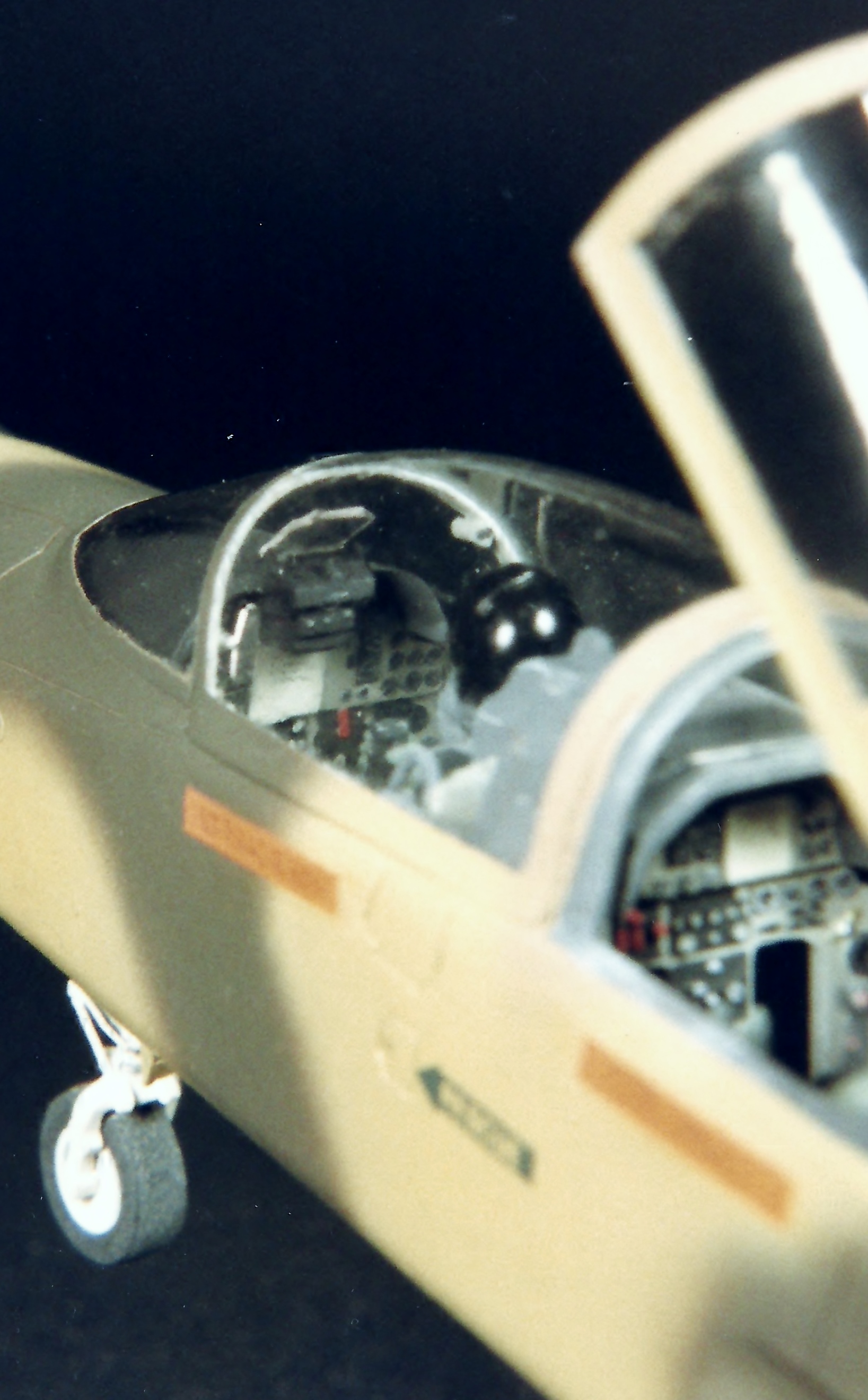
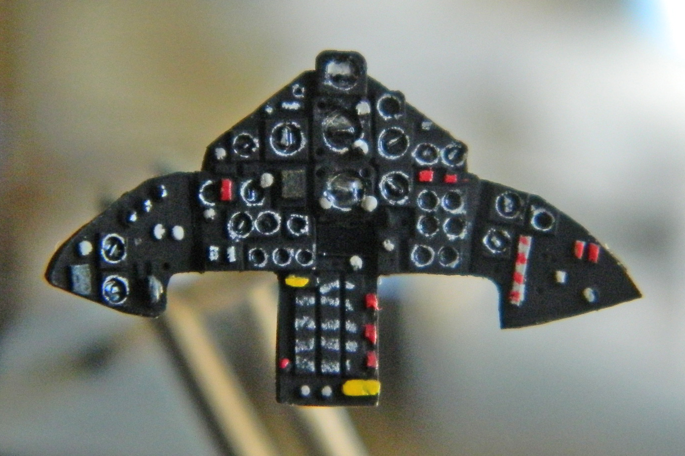
With the base coats down, the next step is to pick out the details with contrasting colors, some of which was done with paint and the really fine detail work was done with a white-colored pencil (SUCH a handy tool, that!):
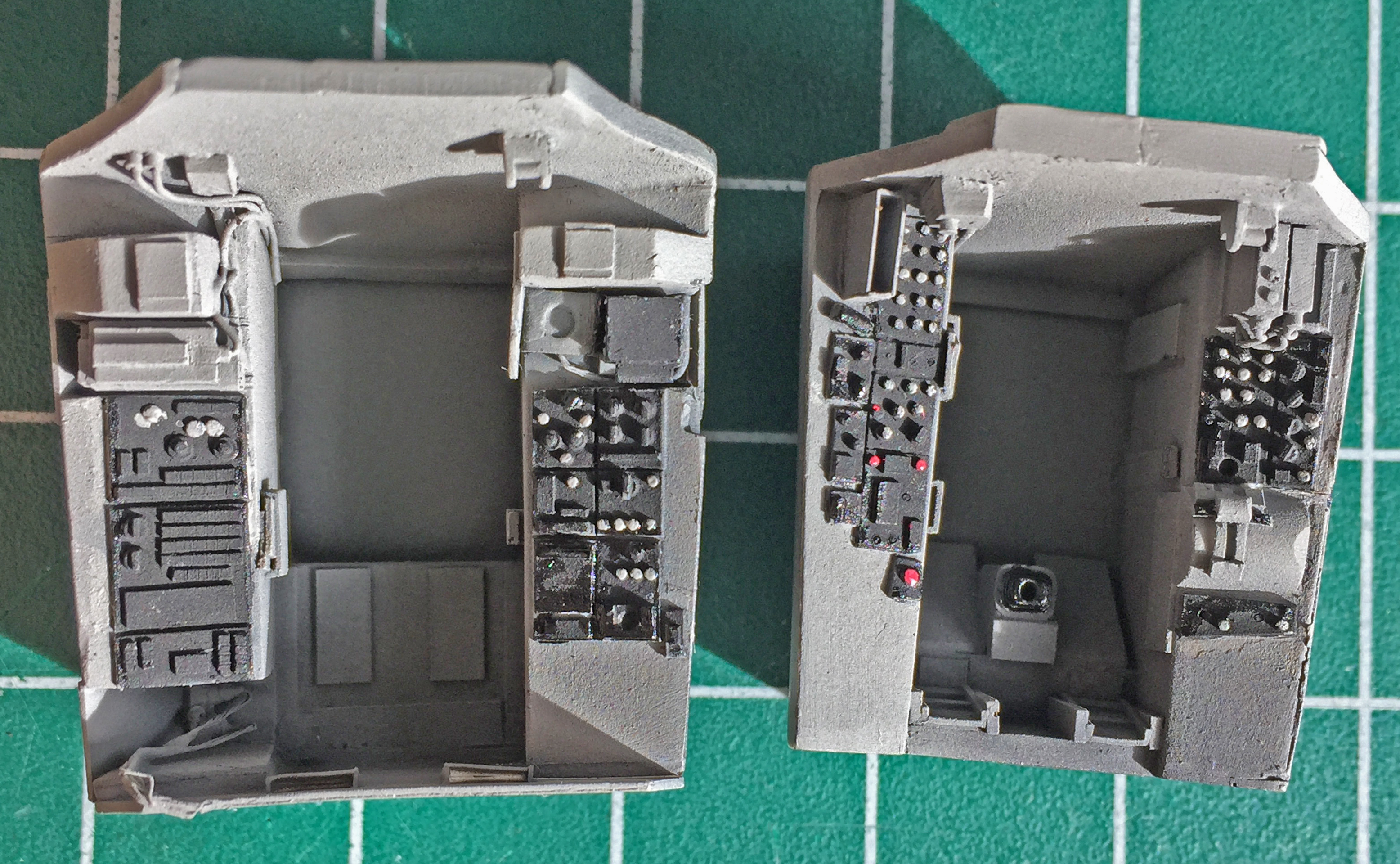
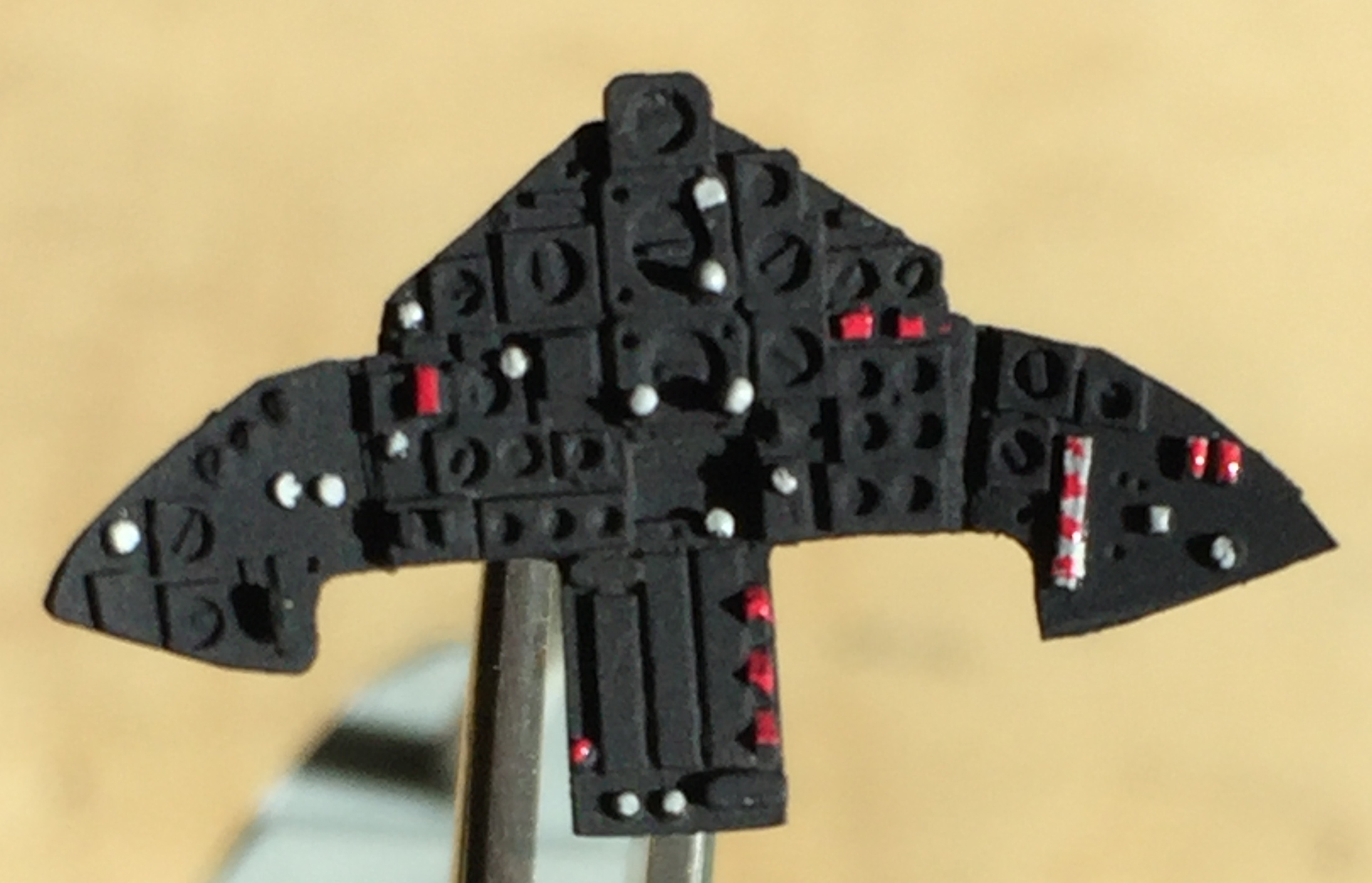


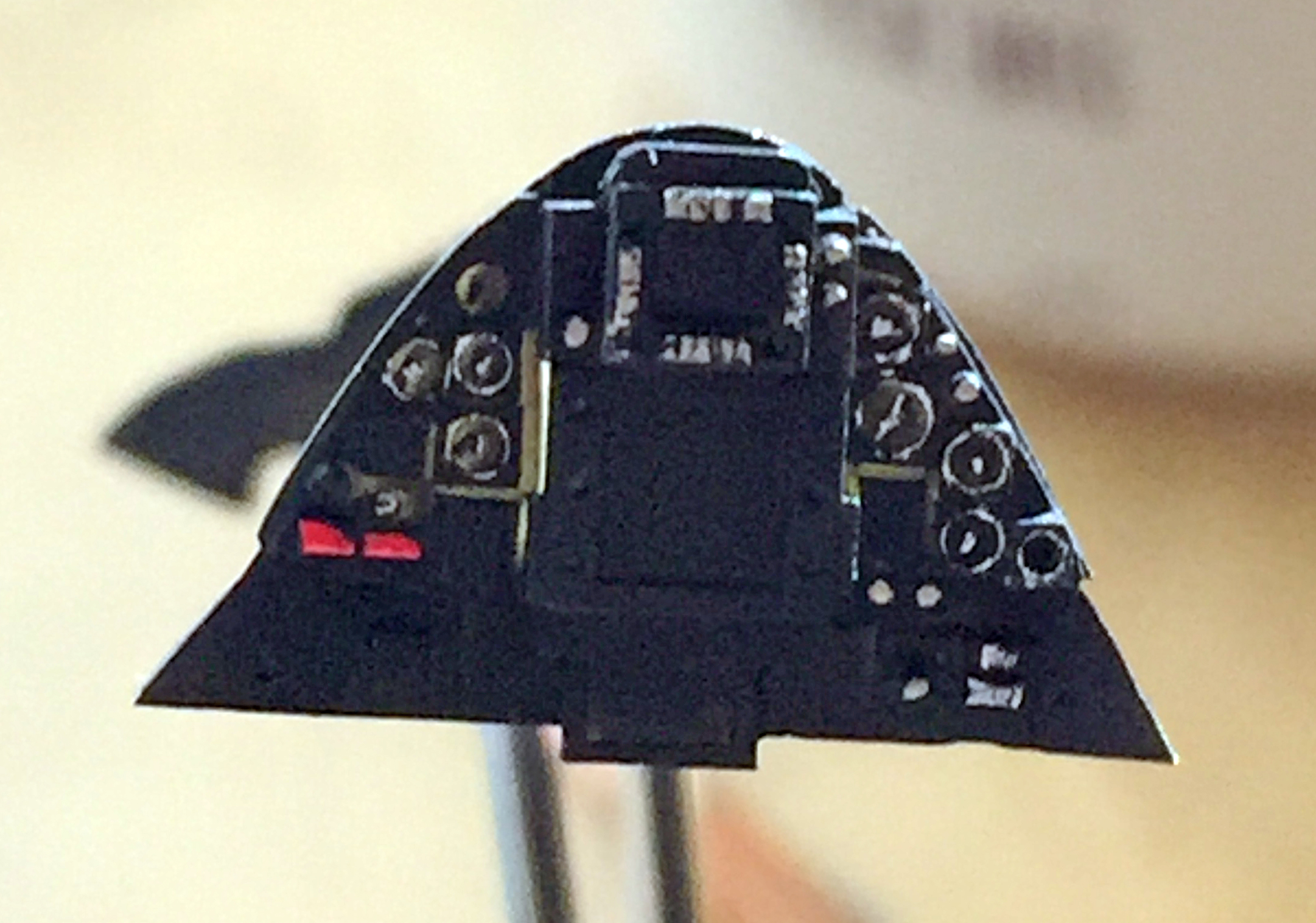
With the basics done, it was time to do the really fine stuff. For the pilot’s panel that meant I put a drop of clear gloss on each instrument. For the RSO’s panel, I glued the film I used for the CRT screens into place using diluted white glue (the pilot’s panel also has a small CRT screen under the three center gauges but it’s almost impossible to see) (almost):


The ejection seats get several different colors added (the green was misted over the flat black in the same manner the gray was done on the tubs). Red was used on headrests and ejection seat trigger covers, and aged white was used on the harnesses (as well as the “papers” in the in the trays in the cockpit tubs). Once that was done I used flat aluminum paint on the harness latches and to add chips and wear marks:
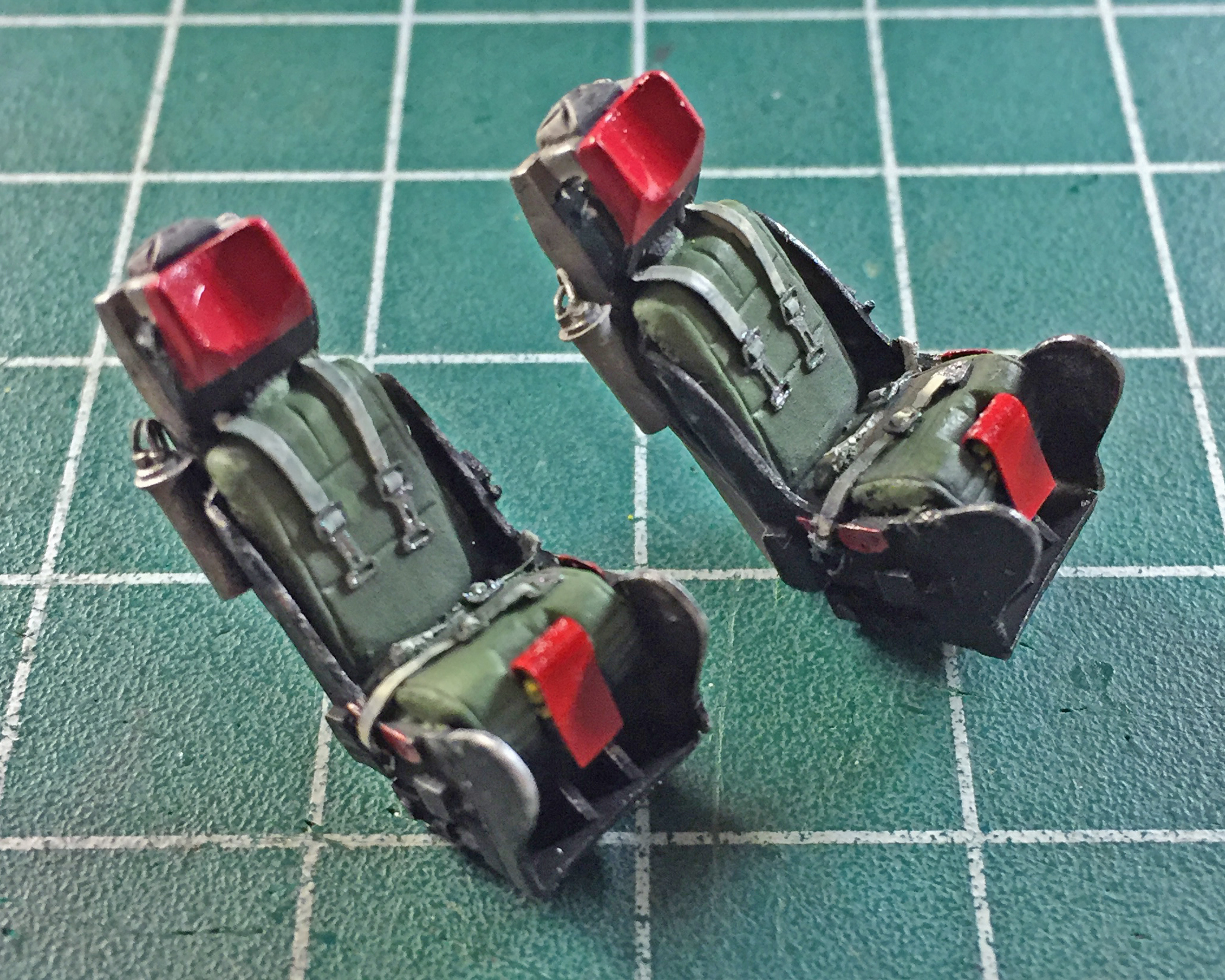
While I was in the mind of chipping and wear (really, because I had silver on the brush), I added the pilot’s joystick and then wear to the cockpit tubs (as well as painting a few of the details):


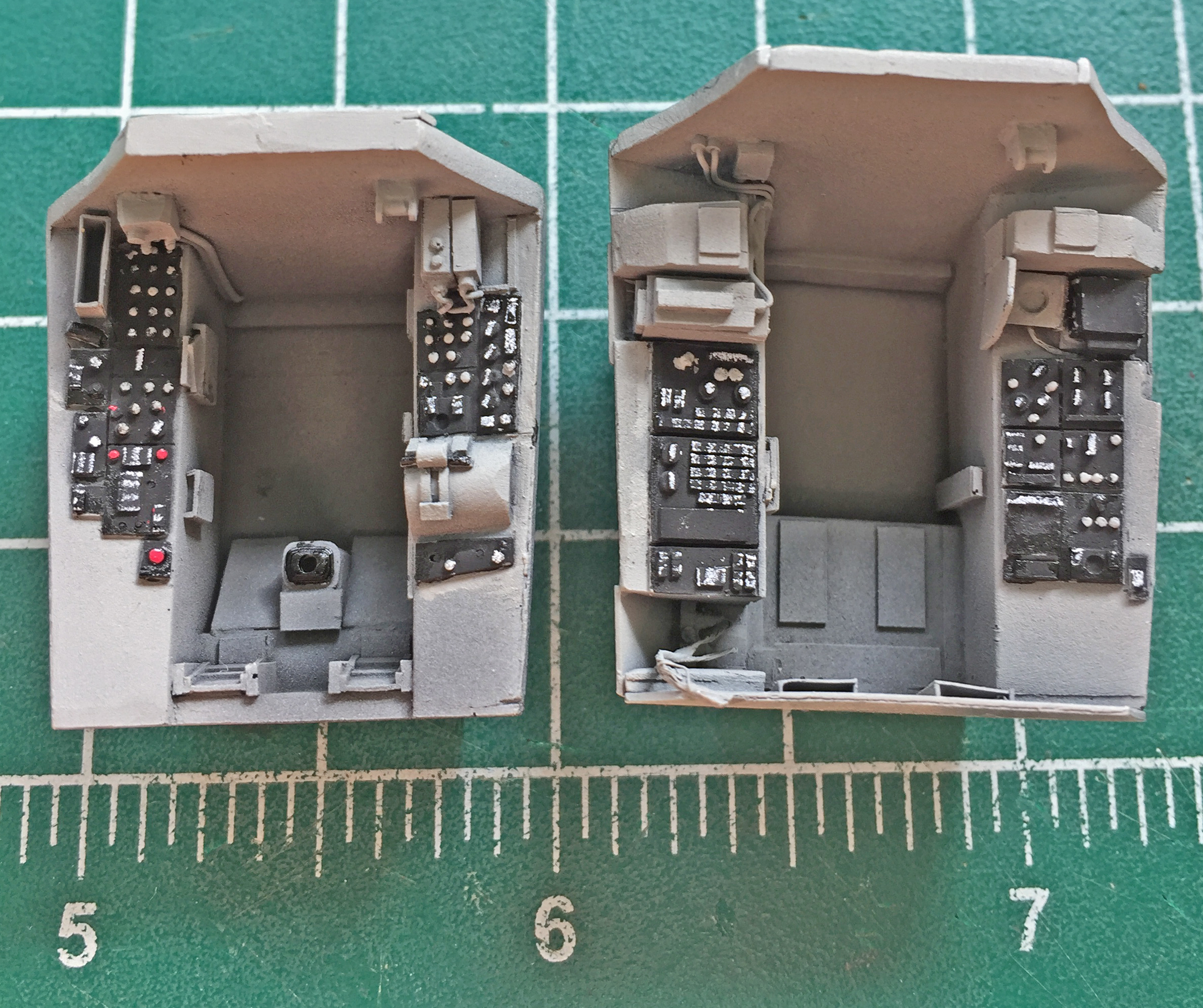
Nothing left now but to start putting things together. I glued the seats into the tubs using Contact cement. Normally I glue resin to resin with CA but there would be some positioning required that CA wouldn’t allow me the time to do. Being resin, the Contact cement wouldn’t attack the material the way it does styrene. Once assembled, I added generic use-dirt with pastels (no relation to sleep-dirt…the latter being more crusty in my experience) (unless it’s gooey):

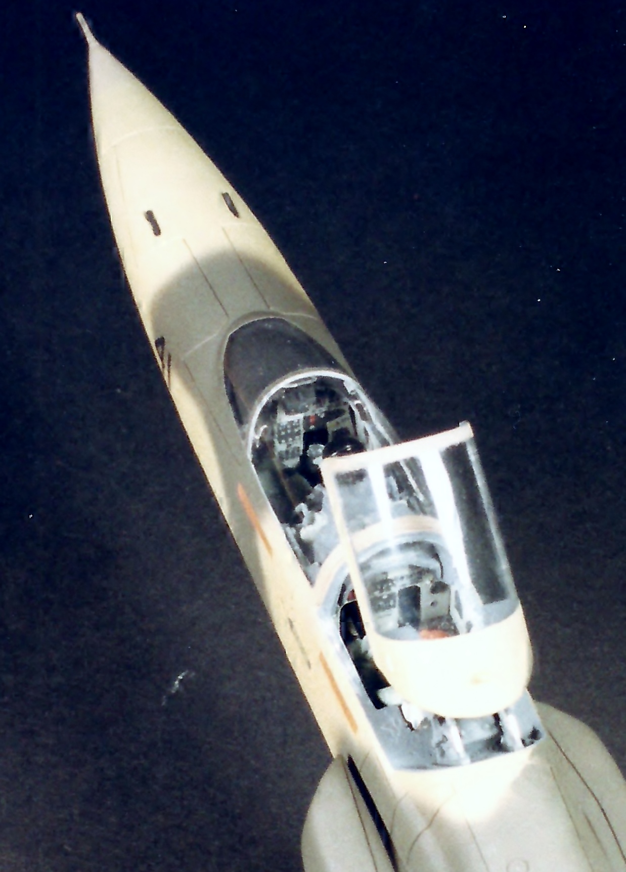
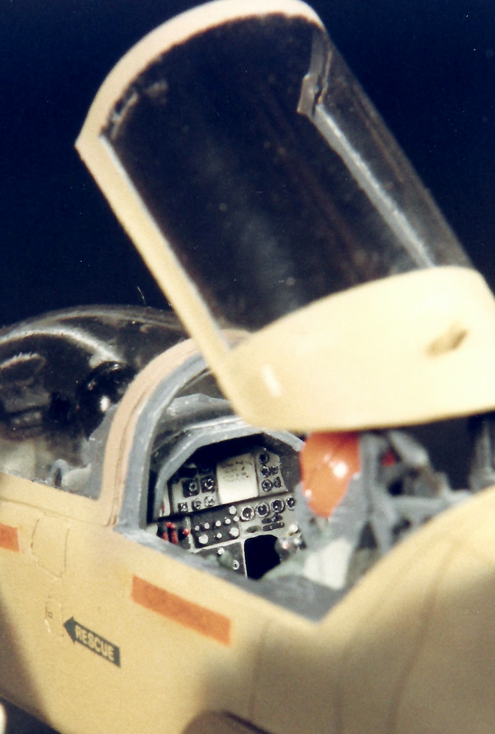
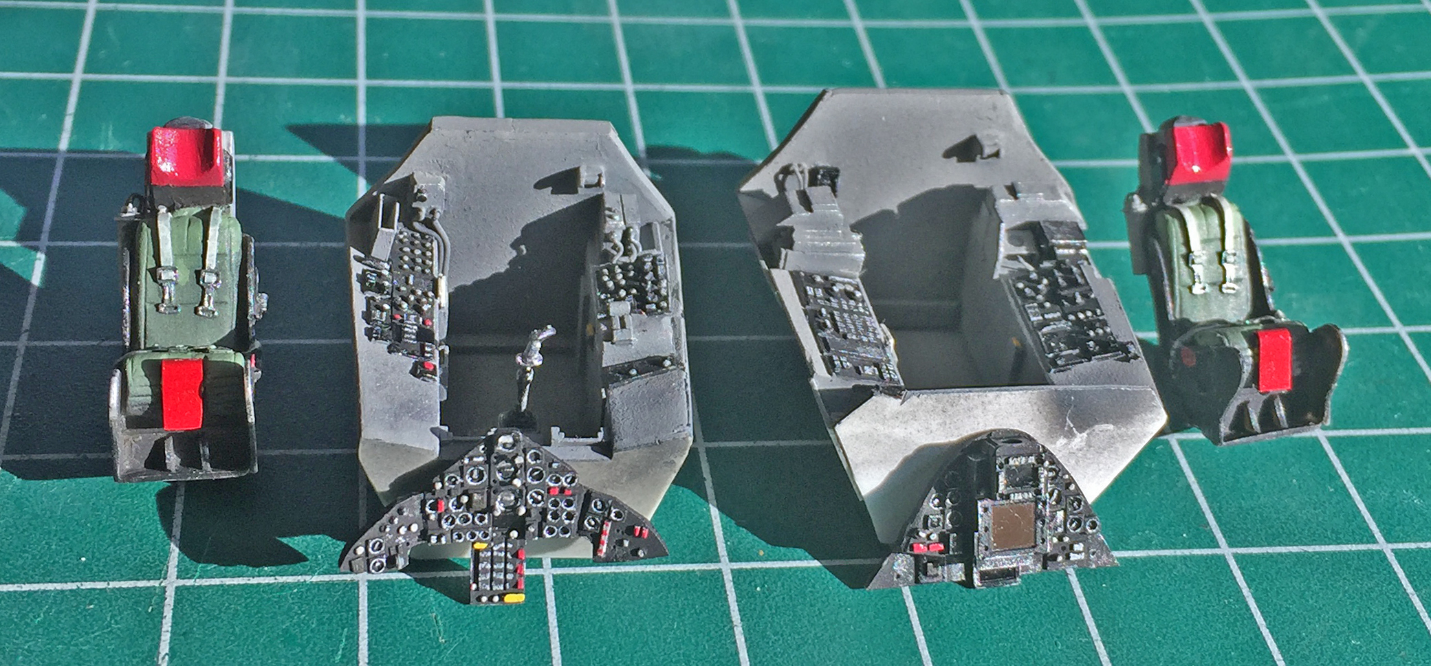
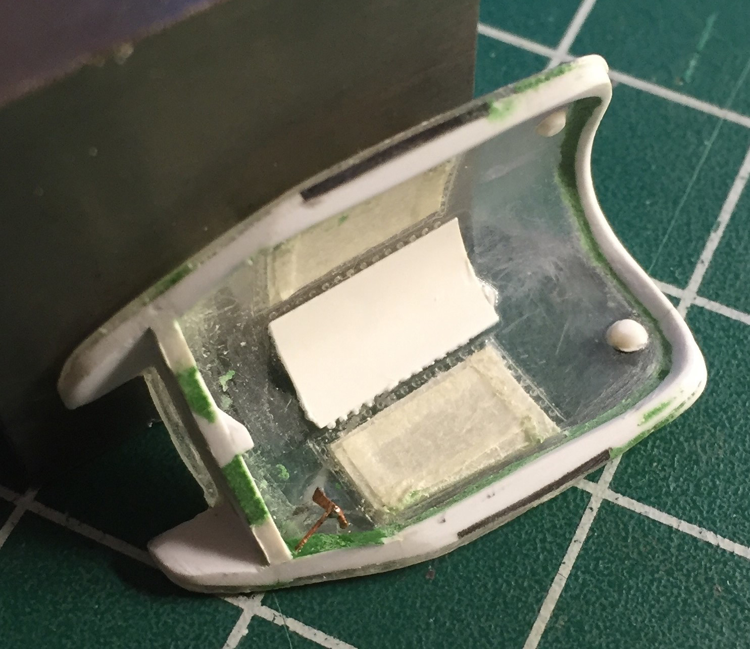
Time to attach these assemblies to the fuselage part. I added the instrument panels first, then the tubs, and then the windscreen:


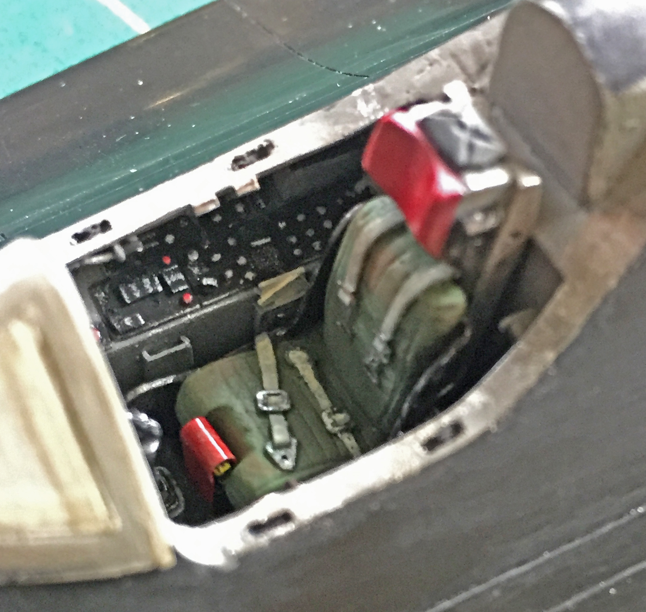
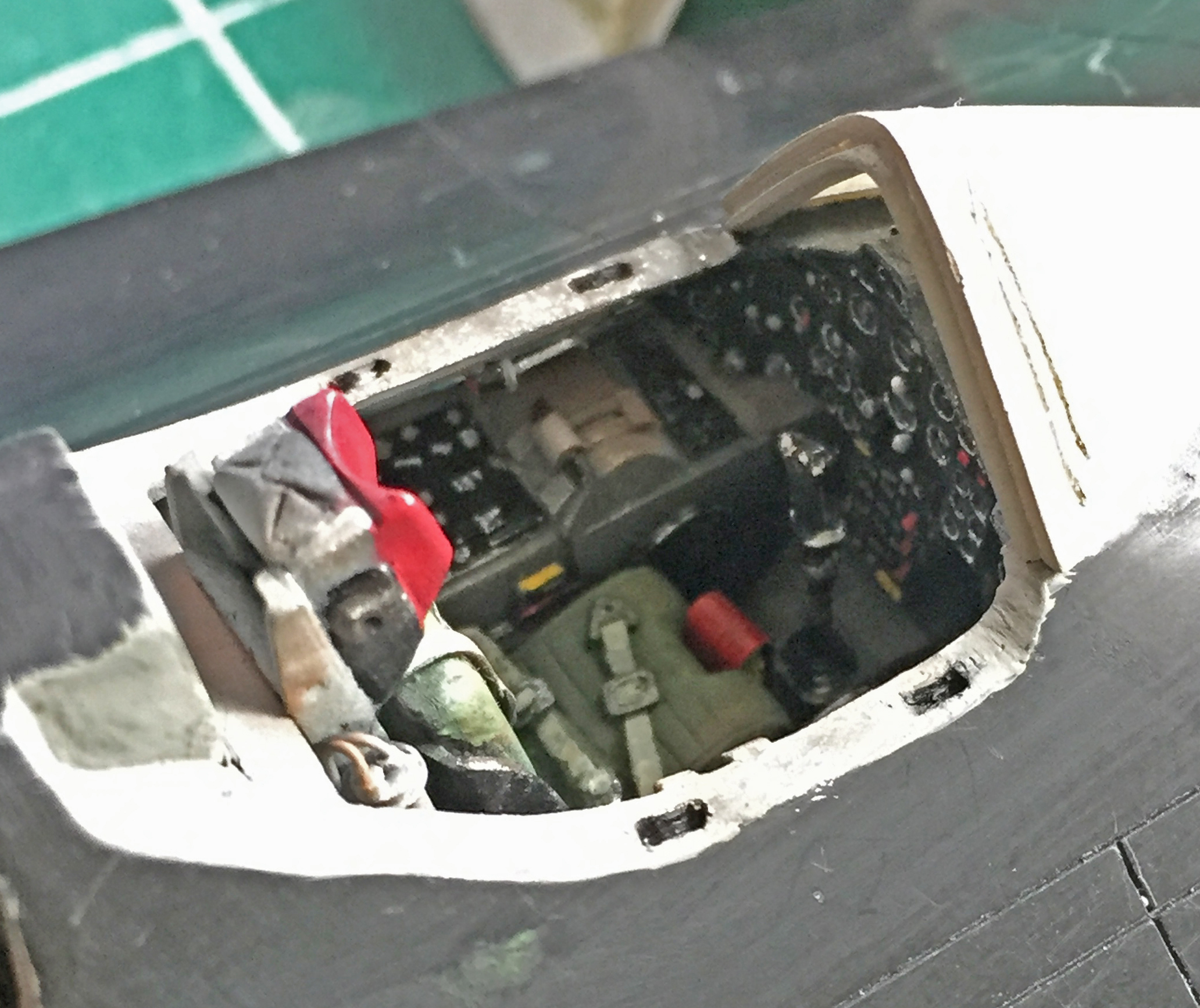


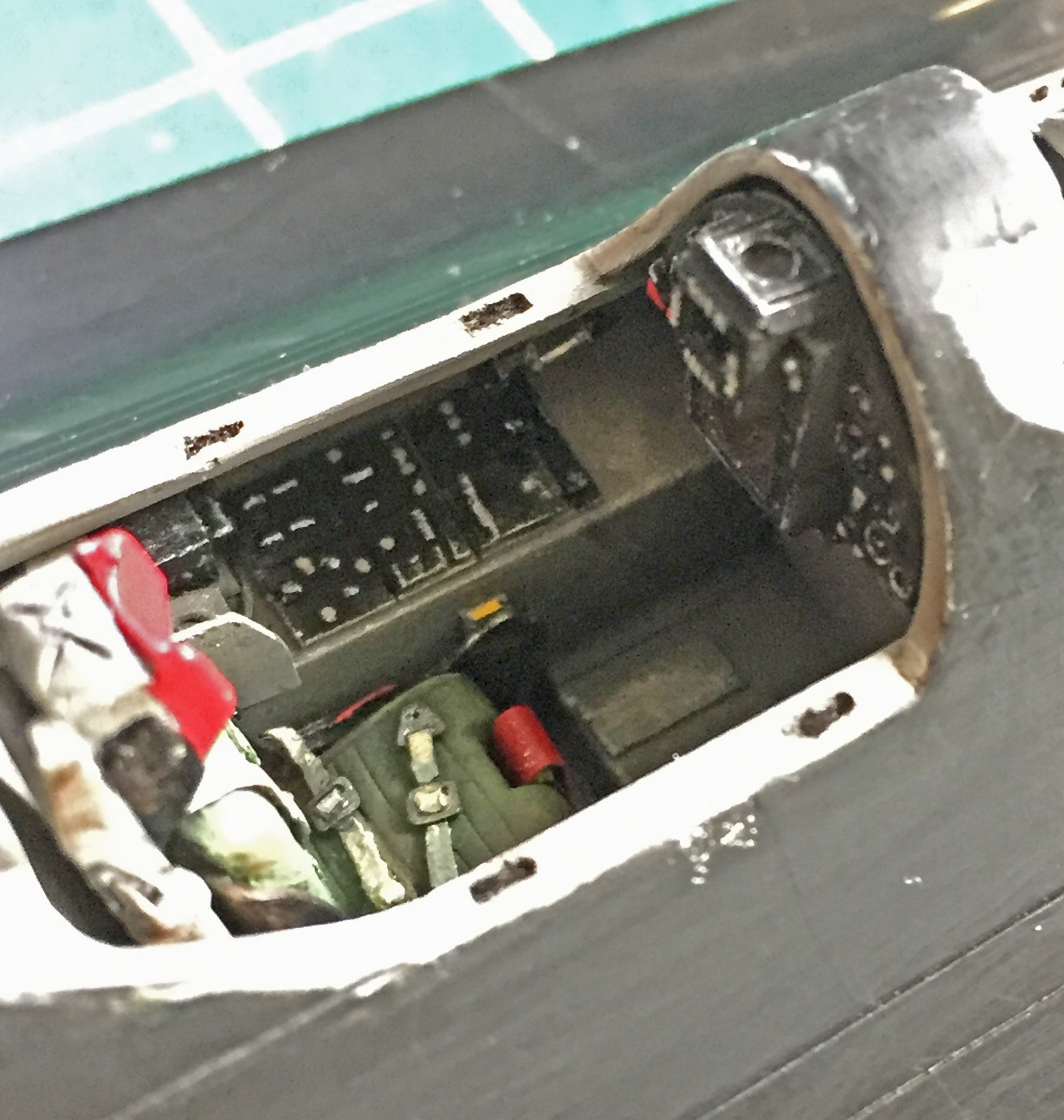
The windscreen was just slightly wider than the area it mounts to, due possibly to all the sanding I’ve already done on the fuselage. Regardless of why it’s larger, larger it is and putty was needed to make things fit:
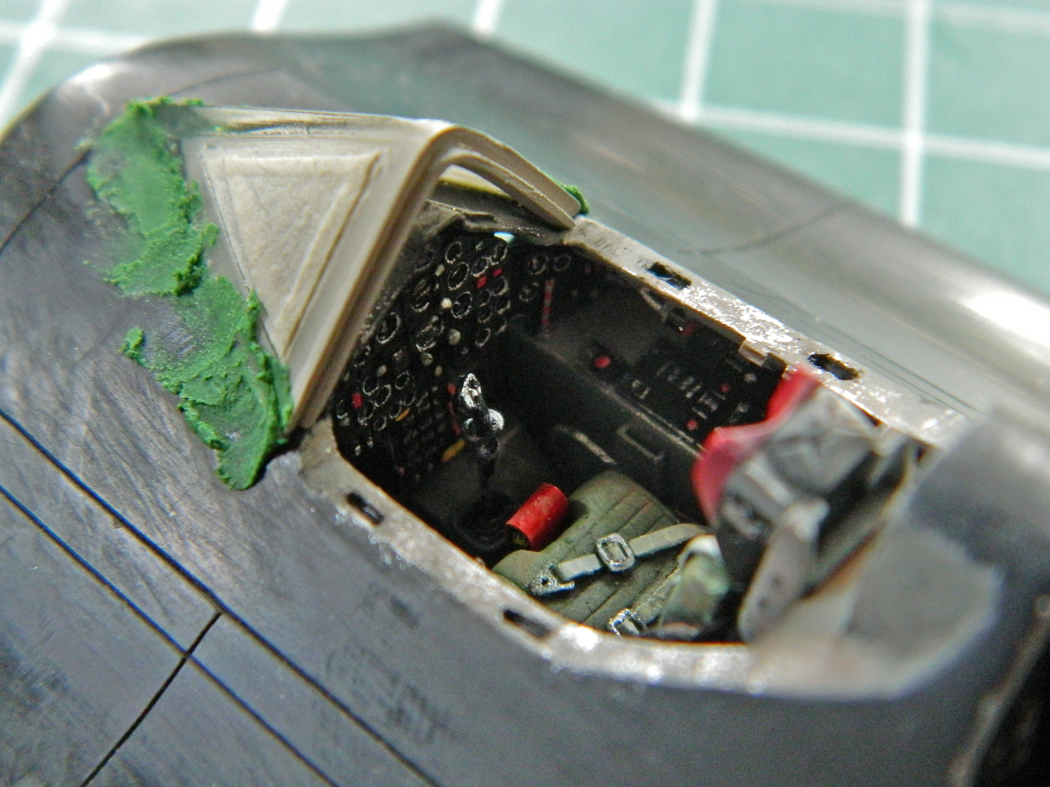


And with that, the cockpits are mostly done. There are a few minor details to add but those will come later. The cockpits will be held in place with white glue to seal the cockpits from the intrusion of paint:
SR-71A Blackbird (Testors) Build #6 – Wrapping Up the Cockpits
Whew. I think I now have the canopies and cockpits done. SO much work has been done on both the canopies that substantial care (and reconstruction) was required.
After adding the styrene to put back what I had removed, shaping them was the next step:
Then putty was added to blend in the additions:
Then details were added (the RSO’s cockpit was much simpler to shape than the pilot’s):
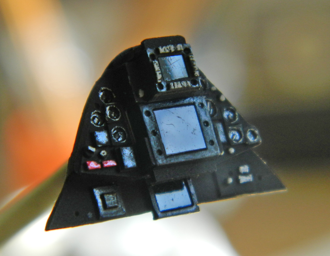
One of the (many) tips I ran across many years ago was a nifty one for replicating the screens used in “glass cockpits,” where the use of analog gauges have been replaced by MFDs (Multi-function Displays); in this case due to the technology extant at time of production, they were CRTs (cathode ray tubes like TVs used to have). To replicate the face of the screen, I cut the exposed section of filmstrip negatives (used before digital cameras) to shape and insert them where they go:
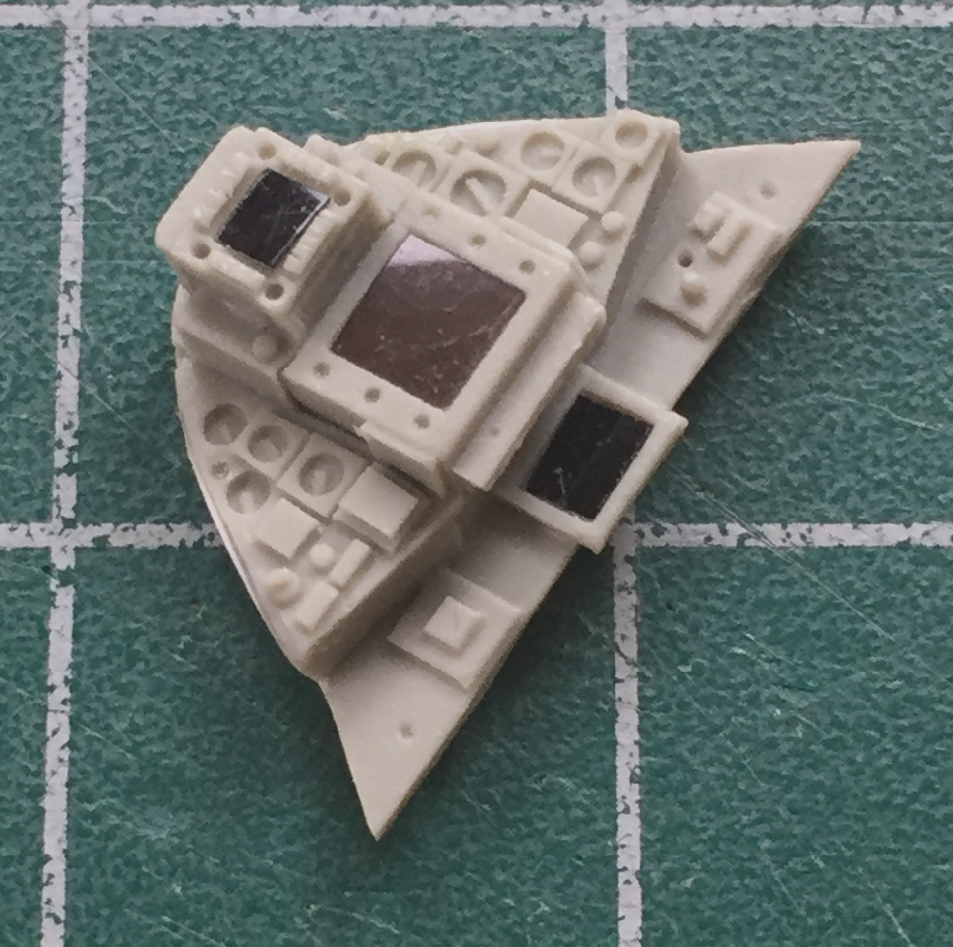
I like the result.
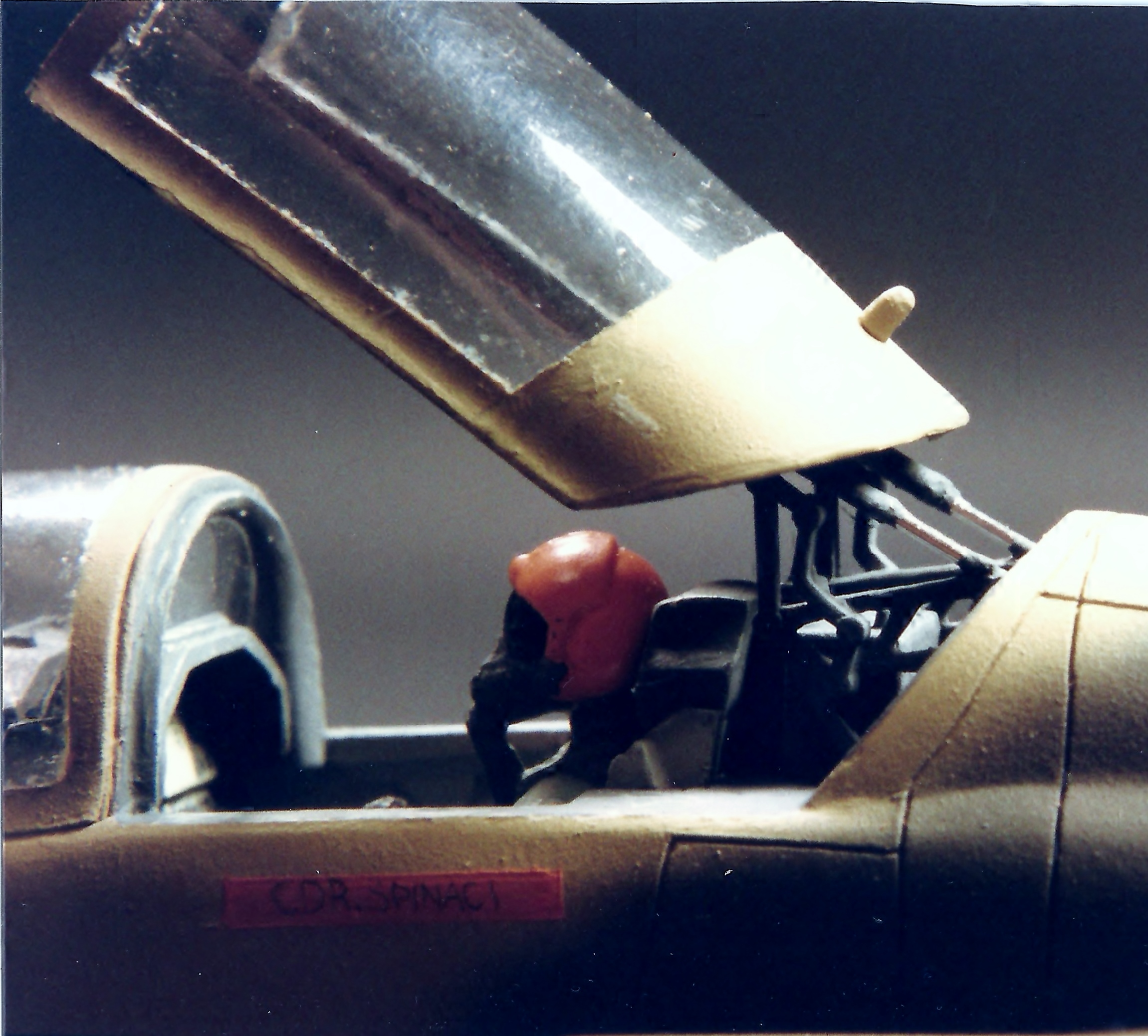
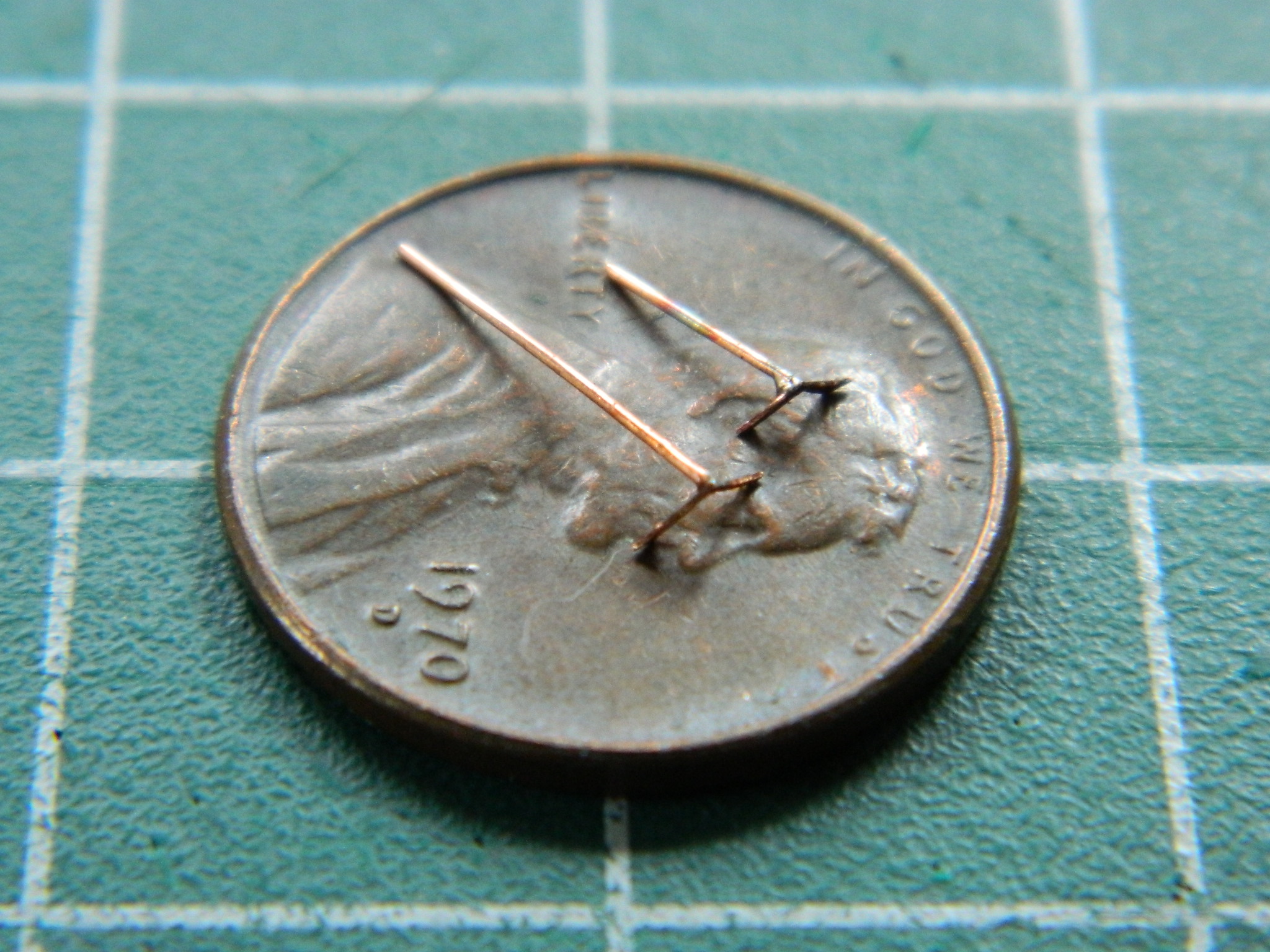
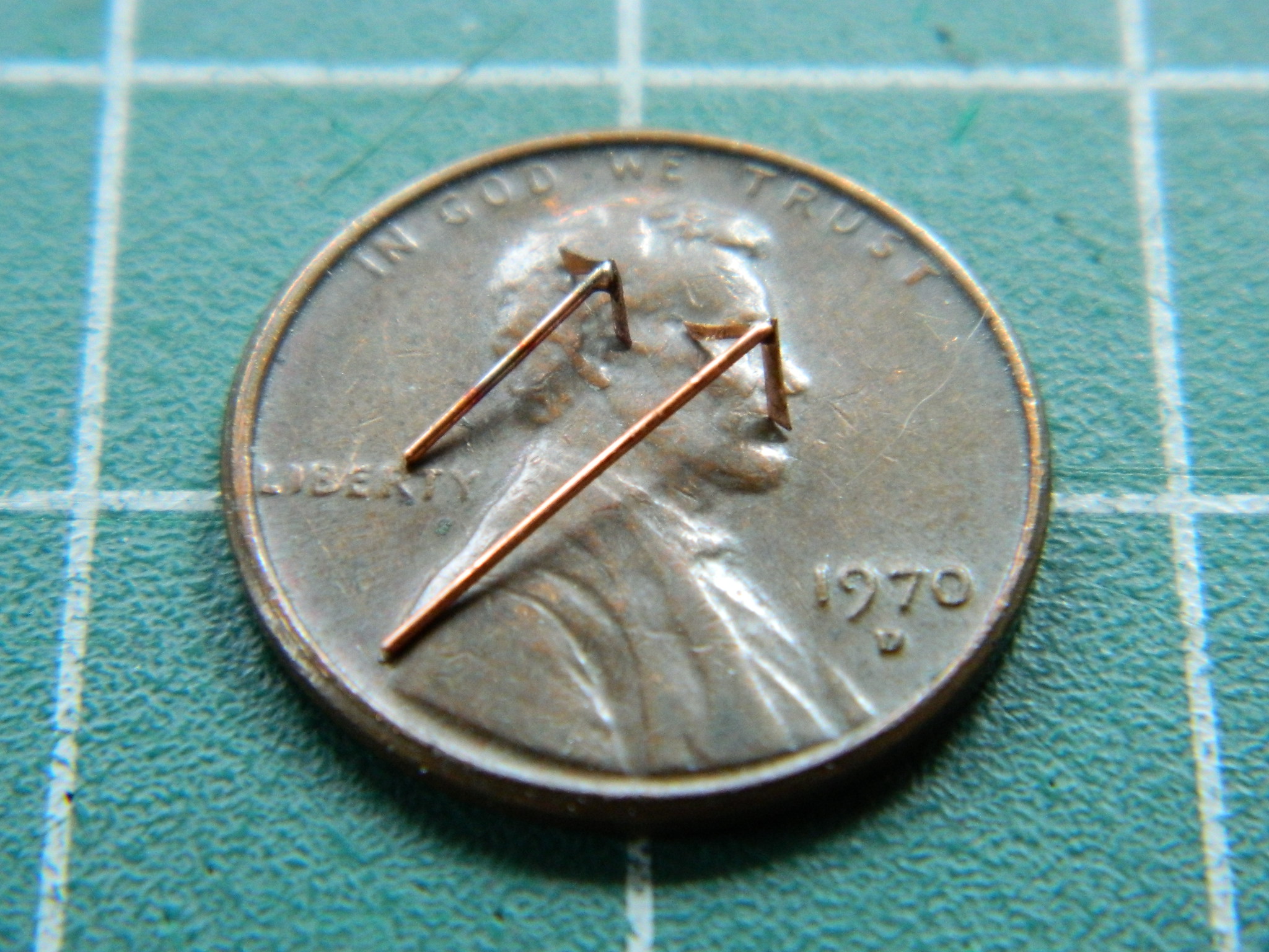
So with the sides of the cockpits done, time to finish up the details inside the canopies. One of those details is where the opening/closing hydraulic cylinders attach. Soldering…very, very, fine soldering was required. I used .010″ (.254mm) shim stock for the L-shaped section and 22awg wire for the support strut:
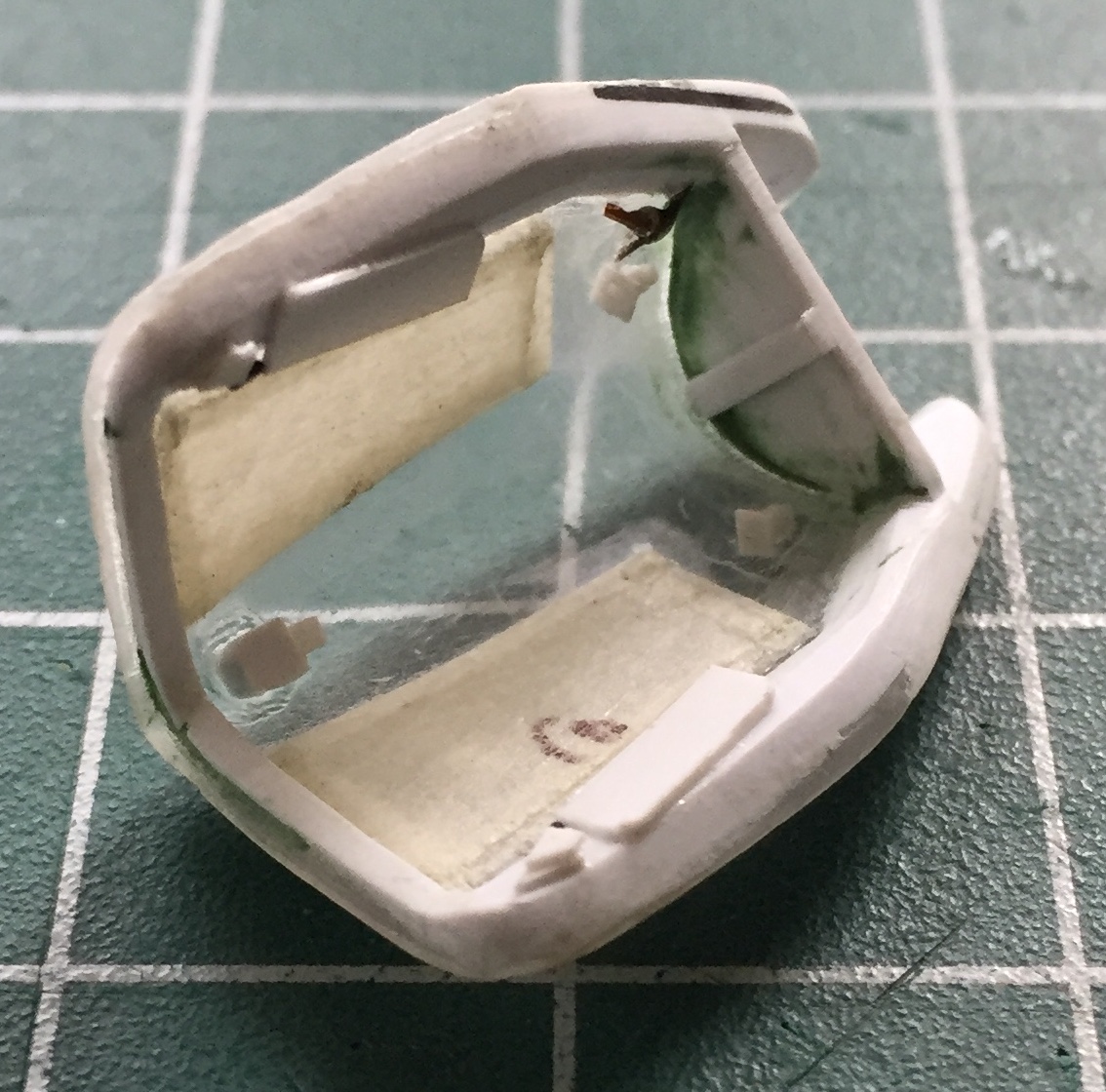
Once those were done, the wire was trimmed to fit and the mounts installed, as were a few other items. These aren’t the last details to add, but the ones still to add have to be added quite near the end of the build (the upper photo is the pilot’s canopy, the RSO’s canopy is below):
One of the details for the edges of the cockpits are slots where the locking lugs of the canopies insert. Well, it started okay…and then I punched through the plastic. ::sighs:: So I used a small section of stretched sprue to fill that punch-through:
But I got there:

No, I’m not entirely satisfied with the slots. I tried to make the ends of them rounded but several failed attempts to get them all that way showed me the limits of my building skill (again). Pouting, bitching, and stamping my feet, I left them as they are and made a note to not bring them to anyones’ attention (you see how well that worked).
At this point, I walked away for a couple of days. I had spent SO much time in SUCH a small area that my sense of objectivity went to the same place my hair went. (Elsewhere.) When I came back to it with, hopefully, a less subjective eye, I couldn’t think of anything to do next. That’s my version of, “I’m done here.”
Next step, paint all of the cockpit parts:
I will be very happy to work on something else for a while…and there is NO shortage of “something else.”
Build Philosophy and How To Learn

I don’t know about your experience but I’ve not found any place I can go to learn how to model; maybe these schools exist, maybe not. Dunno. But since I dunno, that means I’m going to have to teach myself how to build these things.
I’ve met those who are scared to borderline incontinence about learning things…and that’s if there is a school of whatever they’re trying to learn. I would imagine that if they had to teach this new thing to themselves that “borderline” could be removed from the equation. Well, as it turns out, most of what I know is self-taught. (I have other methods for keeping up on my regularity.)
So how does a person teach themselves something they don’t know?
Step one is deciding that they want to learn Something. Maybe that seems simplistic but it really is the first step because without it nothing else is going to happen.
Step two is to find out everything they can about Something…and that turns out to be an ongoing process. Important word that… Process. It appears to me that the culture in America focuses more on product than it does on process. I see that as a foundational error. Without process there is no product. I define and think about “process” as, what it is that I am doing and how I intend to do it. As was stated to me once (actually, it was stated to me A LOT…I’m not a quick starter) back in my white belt days, “Pay attention to what you are doing and how you are doing will take care of itself.”
And then the rest of it is much like swimming. Just jump into the water. Keep in mind that you’re going to jump into the water of your ignorance often. A lot. Frequently. CONTINUOUSLY. (Get the hint?)
My baseline is, “Other people can do [INSERT ACTIVITY HERE], and since we’re all born naked and hairless, why can’t I do it, too?” We aren’t born with any sort of abilities, y’know…
And a sidebar about ignorance, here. You, Dear Reader, are ignorant. I, Demented Author, am ignorant. We is ALL ignorant. We have our field of knowledge, self-taught generalists or long-lines-of-letters-after-our-name specialists. “Ignorant” means we don’t know something and I don’t care how much you know, generally or specifically, there’s a limit to what you know. There has to be. It’s a DAMNED big Universe (and it’s here, too…not just Out There) and we have DAMNED small skulls so there’s NO WAY any significant amount of what’s Out There will ever, ever, fit into our small noggins. On this side of the marker of our knowledge, we’re not ignorant. On the other side of that marker we are. So no matter how much you know about how many things, at some point you’ll encounter your ignorance. End of sidebar.
So if you take ignorance and divide it by process, the possibility for learning something new can occur. You have to multiply the result of that division with effort. Doing so increases the possibility for learning something and by so doing raises the likelihood of getting something useful out of it all.
And now we’re back to learning how to model.
Process is individual and any process that works is a good process…and it all starts with an Idea.
“Idea” is what you want to do. As in, “I really like the F-5 Tiger II and I want to build one.” There’s your idea. The next step is to figure out how and come up with a method. “How can I turn this box of parts into a completed model of the F-5?” How is the operant word and the place where ignorance/process/effort combine to produce a result. So your experiments to come up with a workable “how” are where your experience comes from. The more experience you have, the more you know, and ignorance diminishes.
Now that I’ve gotten all left-brain with this, it simply (can I do anything simply?!) means you’re going to make mistakes. You’re always going to make mistakes. Mistakes are the process in action. When I draw, my eraser is used at least as much as my pencil is.
So. Y’wanna start modeling? Keep in mind that even ladders have rungs on the bottom and they’re on the bottom for a reason. One has to start at a level that is attainable (just because you bought your first guitar and guitar lesson, doesn’t mean you’re going to play like Steve Vai tomorrow). So buy a kit that interests you. That interest will help you continue the process. Follow the directions and build the best kit you can build. Accept that you will make mistakes. How you deal with those mistakes will start creating the foundation for your modeling skills down the road. No matter how many years you model, no matter what lofty heights your skills attain, mistakes will always be made.
Trust me…perfection eludes us all. Sure…it’s okay to aim for perfection, but don’t let that drive the bus. Do you deal well with disappointment(s)? (I don’t, which is why my goal is to achieve a 90-95% accuracy in my builds. Not quite perfect but close enough that I’m usually the only observer of the finished item that notices it, they, ain’t perfect.) If you don’t, set your sights below perfection.
The best (and most important) part of being “good” is knowing when to quit.
With all that said, how do you, Dear Reader, learn how to teach yourself?
Start simple and easy. Build a kit, I don’t care of what, that by the time you’re finished with it doesn’t have any glue smears, no visible seams, a decent paint job devoid of runs and other errors, and decals that look like paint instead of something stuck onto the surface. If you haven’t done this before, those are all lofty enough goals for now. Once you can produce a clean model at will and every time you try, your next question is this:
Do I want more?
If the answer is “no,” then congratulations! This is A HOBBY and if that level of building pleases you, who else are you trying to please? You bought the thing, the tools, the materials, made a space to build in, and spent the time. Pleases you? EXCELLENT. Welcome to a very enjoyable hobby!
If the answer is “yes,” then how much more do you want? Did you happen to notice that the grab handles on the engine covers of an M-4 aren’t little molded on fins but are actually grab handles? Does that bother you and you want to change it? Excellent! Uhm…how do you do that?
“How do I do that?” is my FAVORITE question in modeling! It means that I don’t accept what I already have and want to change it, but I don’t know how to change it. “How do I do that?” is the mantra of the self-taught because, in order to answer it, the self-taught have to learn something new.
Learn something new. LOVE that phrase! I’m not an expert builder; I don’t get paid for it and it’s not my livelihood. I’m a hobbyist. But I have managed to decrease my ignorance on the matter (a process I’m not done with, FYI). There are things I really like to build. If I’m going to build it, I want it to fall within that 90-95% accuracy window. That means I gotta do research (and count yourself lucky, as I count myself, that the Interweb exists because in The Old Days research meant living in libraries and/or buying lots of books on the subject being researched) and that always teaches me something new. Do I want to correct what the kit got wrong? Do I want to put in what the kit left out? Do I want to build a specific variant of something that there’s no specific kit of? Do I want to build a kit of a new thing, a worn thing, a worn out thing, a destroyed thing? Answering these questions starts to narrow my focus to a specific result. (And it helps me fill up LOTS of disk space on my computer(s).) Answering these questions teaches me many, MANY, new things just in the process of answering the questions.
Once I have a picture in my mind of what my goal is, I have to figure out how to get there from here…and that’s usually not possible. Before I can, say, add dust to the top surfaces of a worn M-4, I have to add wear and stains. Before I can add wear and stains, I have to have a coat of matte clear to work on. Before I can lay down a coat of matte clear, I have to add decals. Before I can add decals, I have to have a coat of gloss clear (or its equivalent) to lay them onto. Before I can do that, I have to have the color coat laid down. Before I can do that…
You get the picture.
I keep building the model backward until I get to the point where I realize, “I can do that now.” What I’ve done in addition to setting a more accurate goal than merely, “I want to model an M-4 of the North African campaign that’s seen some use and action.” is to lay out the overall progress of the build, the steps I have to take, to get from this pile of parts to a finished and worn M-4 of the North African campaign.
Keep in mind that each step, regardless of what you’re building, has little surprises along the way. You’re going to have to figure out a solution to each of these surprises (and some of them ain’t gonna be “little”) if you want that picture in your head to be something sitting on your shelf (that you hope the cat doesn’t knock off).
It’s a rare problem that doesn’t have multiple solutions. The “right” solution is the one you can get to work the way you want it to (within whatever parameters of accuracy that you build to).
So the tagline I use when people ask me how I’ve learned to do this stuff is short and accurate. “I rarely start a build I know how to finish.”
Before I close this overlong tome I want to talk about AMS. “AMS” can stand for “Advanced Modeler Syndrome” and/or “After-Market Syndrome.” I’ve talked to people who liked my build until I told them I used an after-market set here, there, or wherever the intercourse I wanted to. The nose goes up slightly, the expression disdainful of varying degrees, and generally I hear, “Oh,” before they walk away in search of something more…I dunno…pure, I guess?
“Pure” my ass. Y’want “pure?” Then don’t start with a kit. Start with a pile of plastic (or whatever) and scratch-build the whole sodding thing; every damned part. There are those who do that and I admire (and am often in awe of) their skills and abilities. Sincerely. But that’s their hobby, it’s not mine. I bought a box of parts. I left out the parts that I decided won’t work for my goal. I fixed the parts that I decided are inaccurate for my goal. I bought parts that I decided I needed to so that what I have when I’m done (and at risk later on of being modified by the cat) matches to within 90-95% of what is in my head…which is my goal.
Stated a bit more directly, this is your hobby. Have at it to whatever level pleases you and get there by whatever means and methods please you. Nobody’s buying the damned thing for you, nobody’s building the damned thing for you, so do what you want in the manner you want and anyone who doesn’t like it is welcome to attempt an aerial intercourse through a rolling confection.
When someone looks at one of my finished models (and frequently during the build process) the phrase I hear most often is, “I don’t have the patience for that.” My standard reply is, “It only requires patience if you don’t like what you’re doing.”
Dear Reader, this is supposed to be fun. Go have fun. Send me a photo of what you’ve finished so I can appreciate it, too.
SR-71A Blackbird (Testors) Build #5 – Continuing Work on the Cockpits
Having decided to scratch-build the sides of the cockpits, I needed to know exactly how the cockpit tubs were going to fit into those spaces and have all the details added so I could get an accurate read on what needed to be where so it would all fit. This is what I started with:
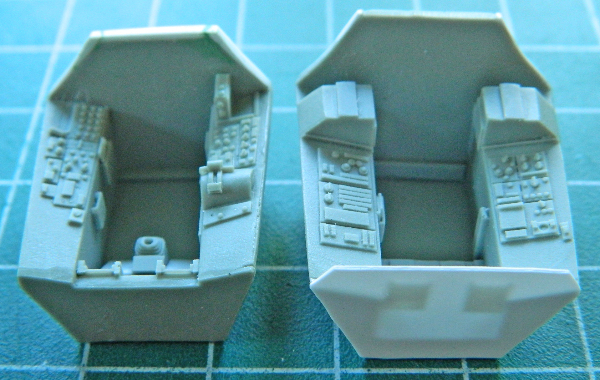
Neither tub is 100% accurate. Unless I wanted to entirely scratch-build these tubs, AND I DO NOT, it will do. Reference photos showed me that this section of the side needed to be removed so I could put less inaccurate stuff in there. First I went at the RSO’s cockpit and made vertical cuts to define the amount of resin that had to go:

Then I hogged it out with my Dremel:

With the bulk of it removed, I refined the shape with a sharp #11 and backed it with a scrap piece of .010″ (.254mm) styrene:

Then I removed the forward section of that pedestal to allow room for the bits that I want to put there:
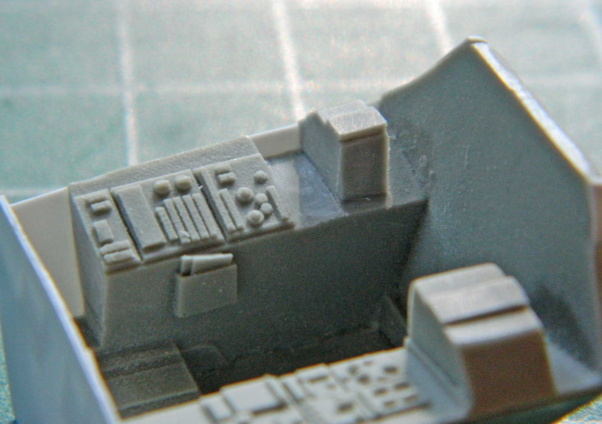
Now that there’s space, time to fill it. Using more scrap styrene I built the stack of Mysterious Bits that go there, detailed them, and then used the aluminum duct tape again to create the housing I needed for the stack:

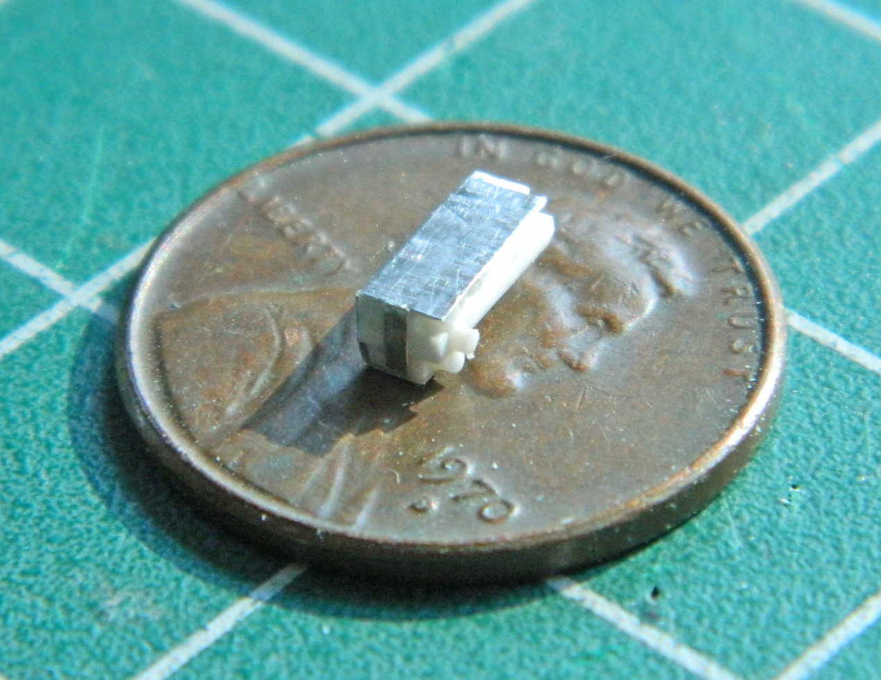
The completed bits get installed and wiring added. For the small part at the lower left I used 40awg wire to create the harness…then cut down the other pedestal to have a place to put more Mysterious Bits:
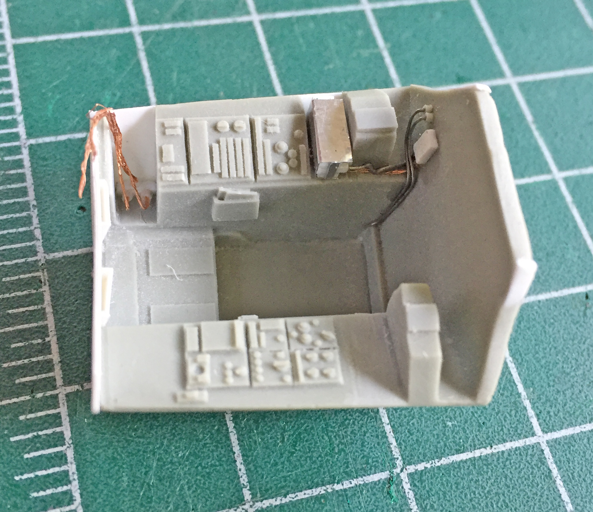
Then the Mysterious Bits were made. I used .010″ (.254mm) copper shim stock to make the housing for the one Mysterious Bit, using the punch/die set to create the round opening at its top and added more 40awg harness:
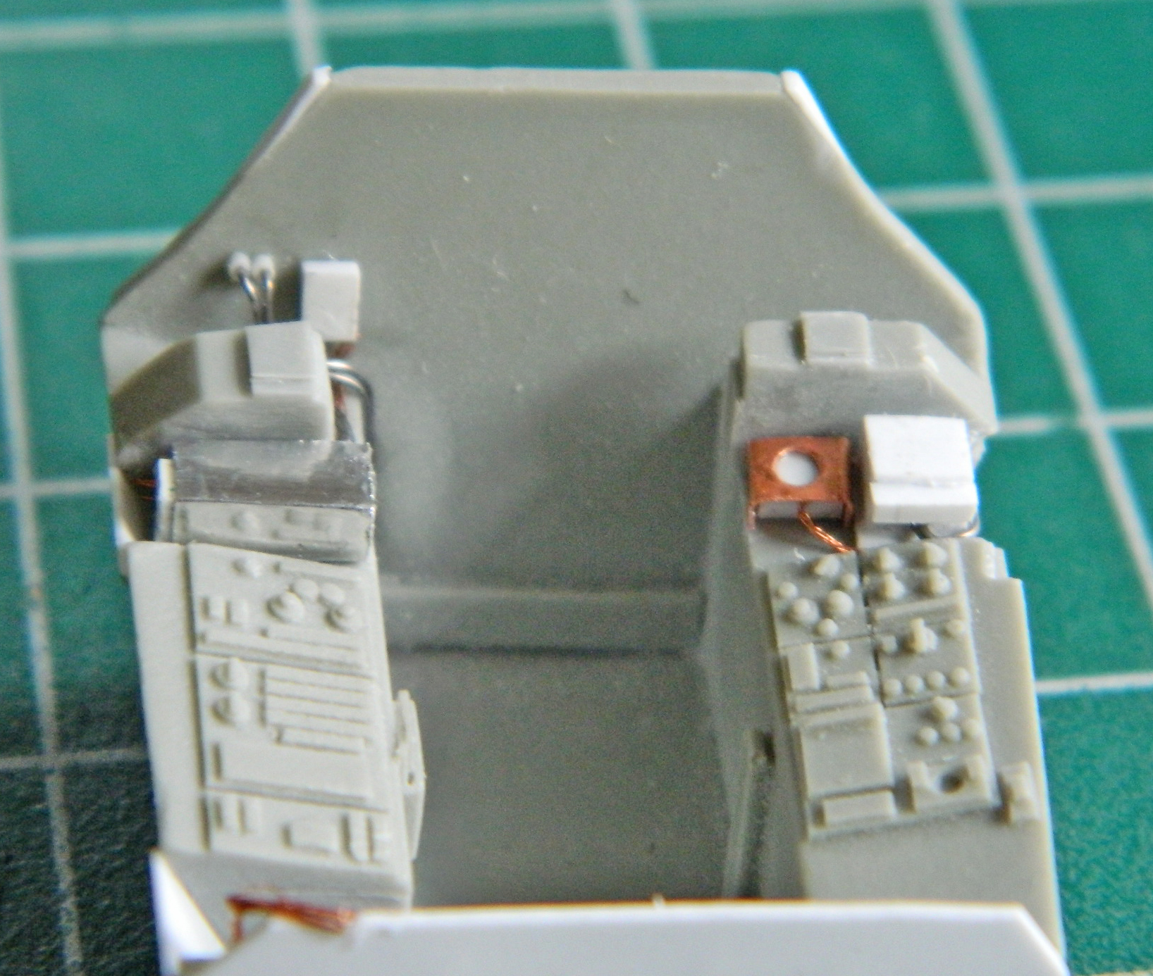
I repeated the process for the pilot’s cockpit…and didn’t take any photos until it was done. There will be a couple of more items added, such as the mount for the canopy opening cylinders, but this is the basic redone cockpit tubs (with the seats just placed in to see how it all fits…and it does) and how it looks:
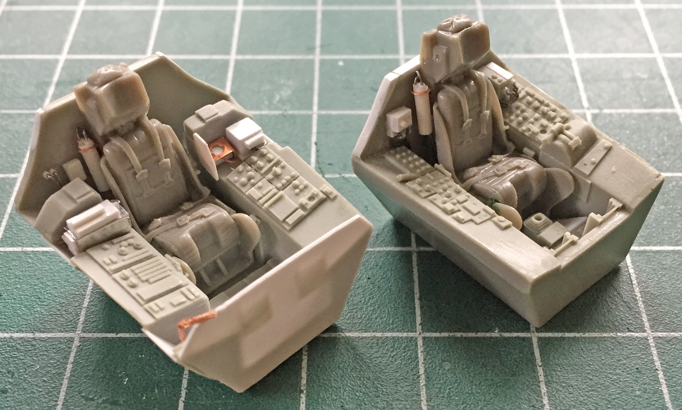
First I did the mounts that go on the rear bulkheads of the cockpits using scrap styrene:
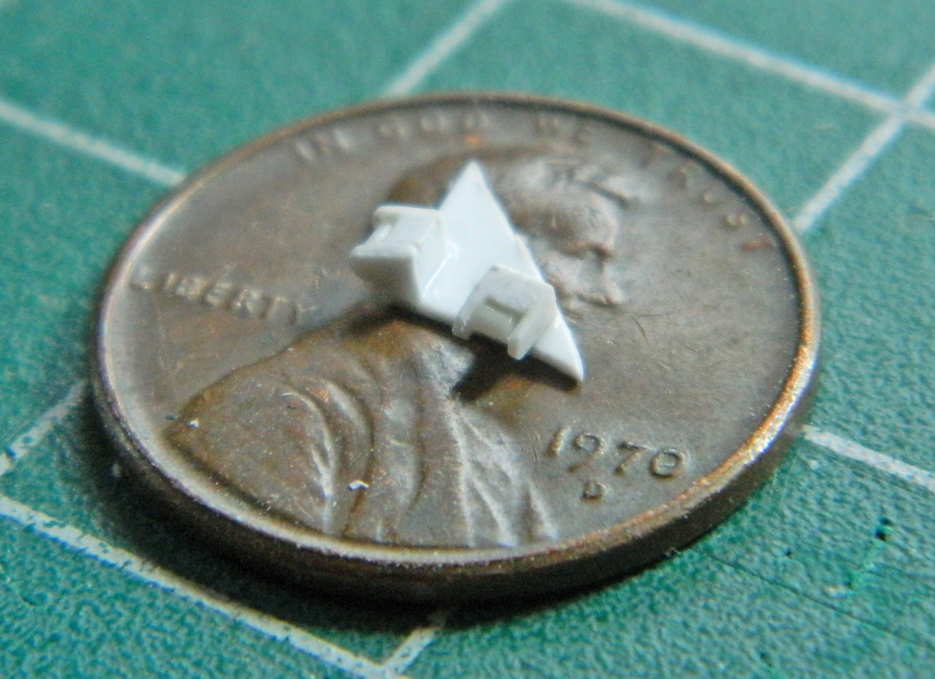
I used .062″ (1.57mm) styrene rod to make the cylinder and .035″ (.890mm) styrene rod to make the rams (the rod that moves in and out of the cylinder). The cylinders are a bit short so that I can adjust them later to fit into the available space. Fitting these things has the potential to be a bitch so I wanted to build in some adjustment. Until all the associated parts are actually mounted, I don’t know exactly how long the finished sub-assemblies will need to be. This started by center-drilling the .062″ (1.57mm) rods to accept the .035″ (.890mm) rods:
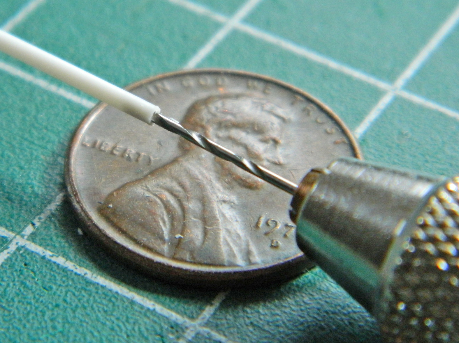
That will enable me to slide the .035″ (.890mm) rods out if the end parts are too short and I can always trim the .035″ (.890mm) rods if they’re too long.
I added the bands using the aluminum duct tape (love that stuff) and .010″ (.254mm) bits of lead wool to replicate the hydraulic lines:
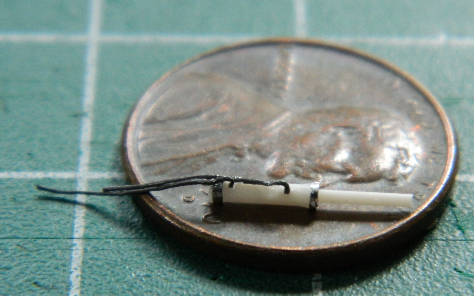
Then I did that all again for the other hydraulic unit and ended up with all of these (on the second unit I used .010″ (.254mm) solder to see which I like better…and the solder is the winner…it’s less fragile than the strand of lead wool is):
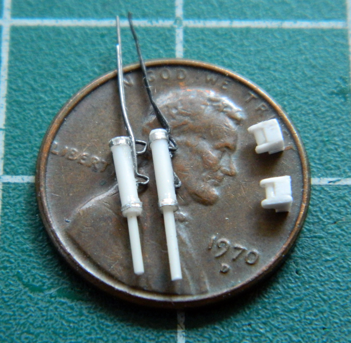
Now that I know what will fill the cockpits, it’s time to start by building up the cockpit walls (and I’m not unmindful of the irony of having to put back plastic to the areas I’d carved away to use resin parts I’m no longer using). These are the rough blanks for the RSO’s cockpit:
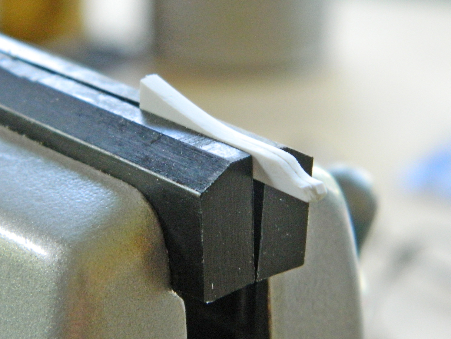
I started this process by making the main body of the side panels, gluing it into position, and then engaging in styrene mosaic to get mass built up in the areas I wanted it, starting with the RSO’s cockpit:
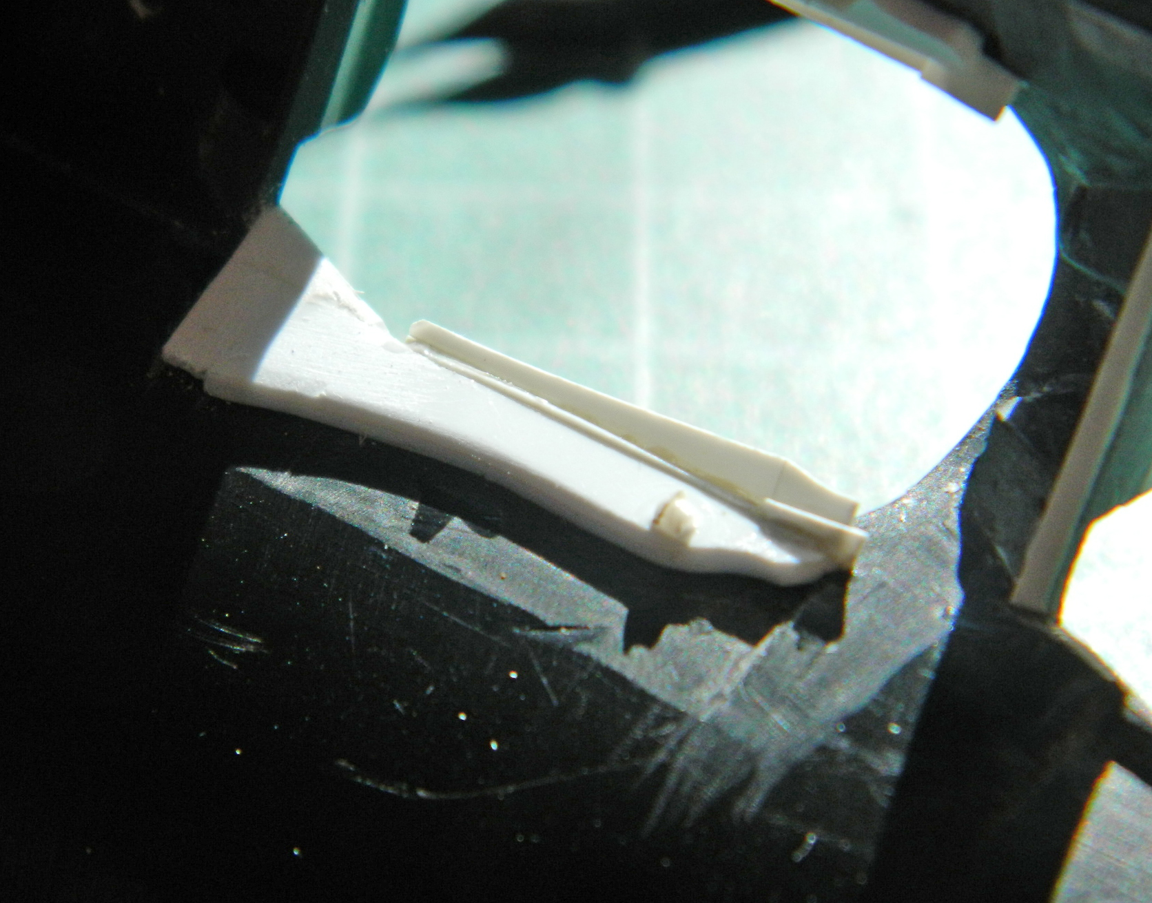

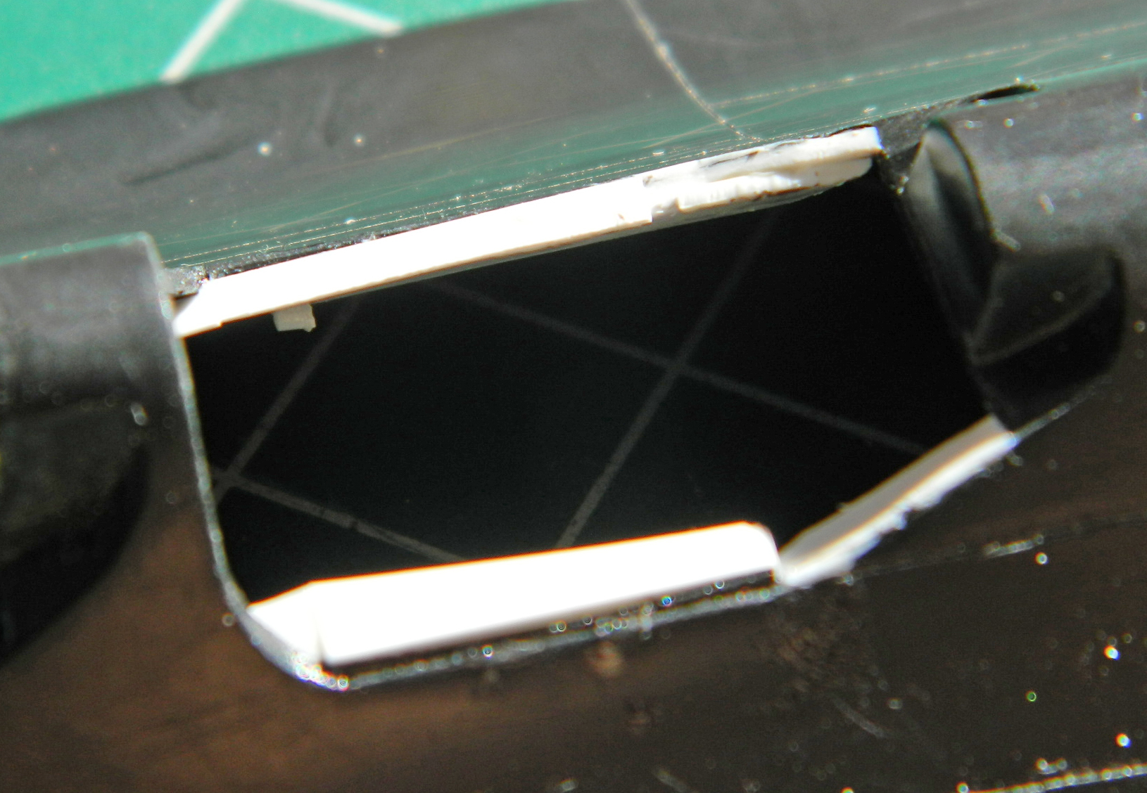
Next ensued much filing, sanding, scraping, and a little bit of putty:
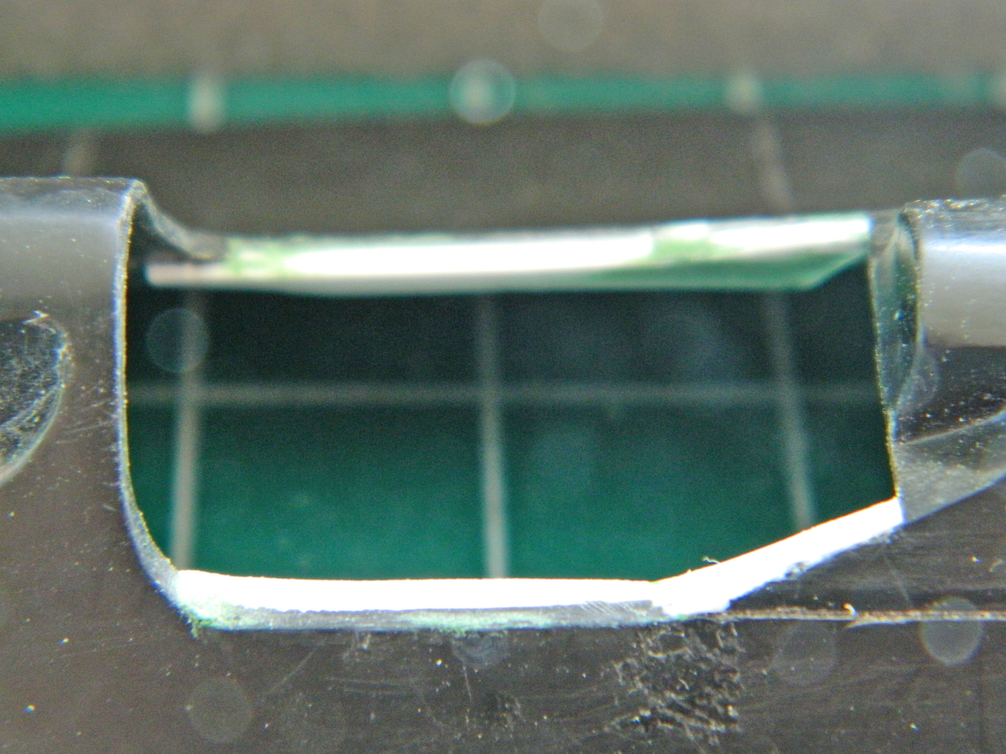

And then I did it again for the pilot’s cockpit:

One of the things I noticed about the True Detail cockpit parts was the “fit” between the pilot’s instrument panel and the coaming that goes over it. In short, they didn’t really fit with each other. At the top of the panel is a gauge with a square bezel and it’s supposed to fit up underneath the coaming…and the resin part does not. I decided to see if I could use the .010″ (.254mm) copper shim stock and make one.
I transferred dimensions from the resin part to the shim stock and roughly cut it out. Because I was going to have to make tight bends in a very small area, I decided to anneal the copper before trying to bend it and thereby remove its resistance to bending. I got it to work:


Satisfied with the result, I added the details with scrap styrene:

With that all done, I decided maybe it was time to see if things fit…and they do. Putty was added at the edges of where the coaming mounts:


Dry-fitting the cockpit tub showed me that I had to add more styrene to replace what I’d already removed. The result isn’t 100% accurate due to the a-bit-too-short overall length of the resin tub but it’s much better than not doing so:
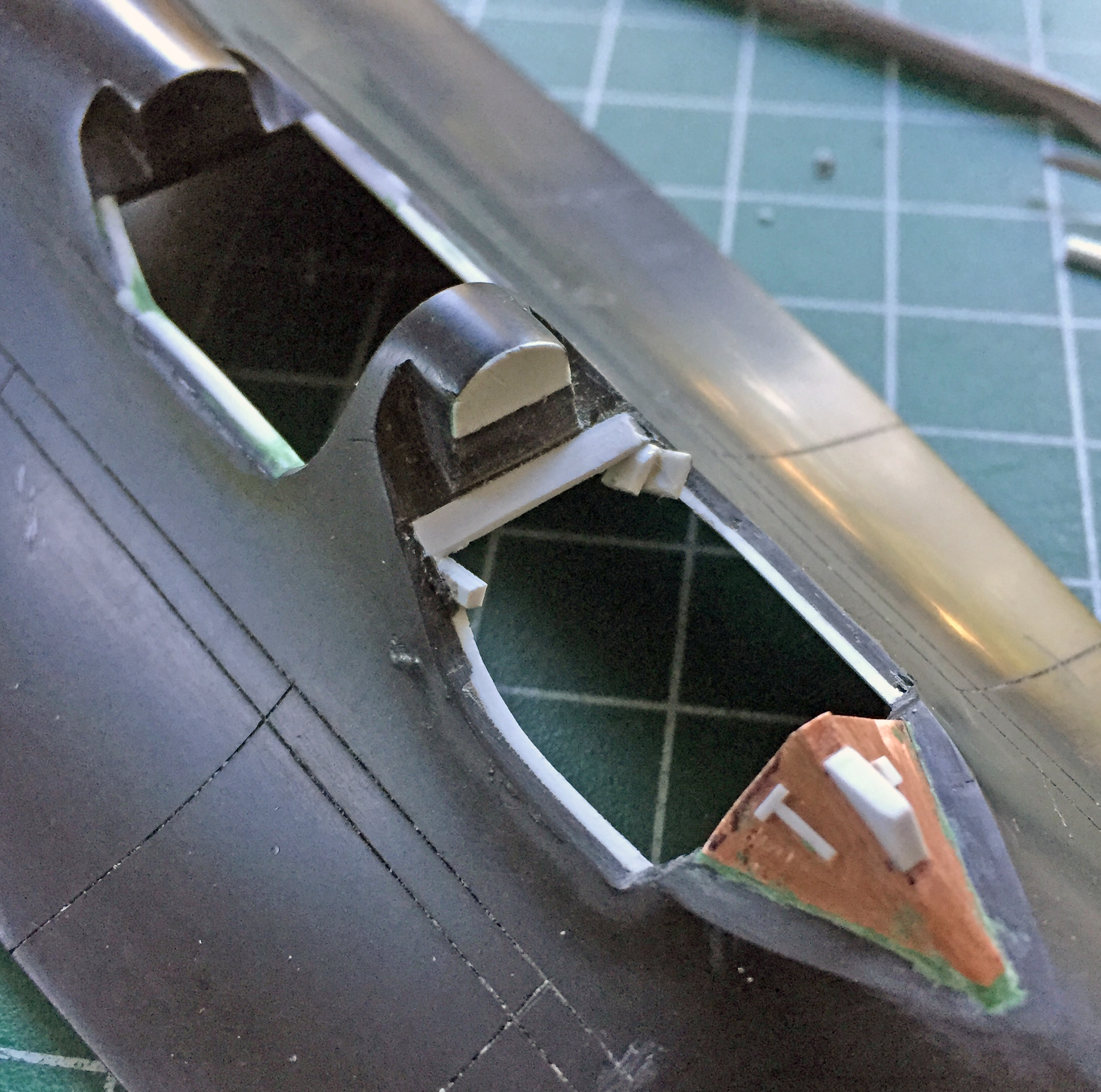
I started by penciling the outline of where the styrene has to be shaped to something less inaccurate:
With the styrene mosaic filed/scraped/sanded to dimension, next up is getting the added styrene to its final shape and adding the details needed:
SR-71A Blackbird (Testors) Build #4 – More Work on the Cockpits, Canopies, and Scribing Lines
With the (annoying) rear partition in place under both canopies, I started adding the structure, beginning with the rear canopy:

I kept adding plastic until the perimeter inside the canopy was covered, then there was A LOT of shaping to do. I’ve found it easier for me to scrape the plastic I don’t want there than sanding it away. I have much more control of where it comes off and how it comes off. With the basic structure of the canopy’s frame in place, I added putty to enable a smooth curve to replicate the actual framework:
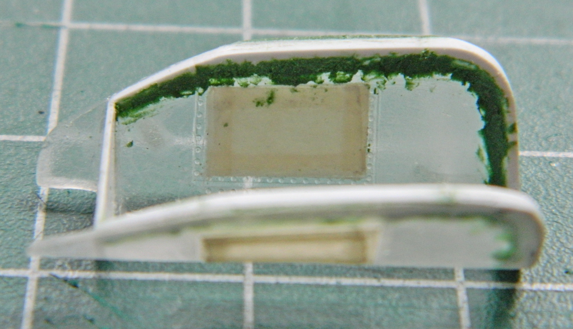
As the putty was curing, I started adding structure inside the front canopy:

And entirely out of sequence, I taped together the major components (which also allowed me to see if the fit of the parts is really as abysmal as its reputation would have it…and oh my isn’t its rep well deserved). I’m building this one for someone who needs its measurements to see where he can put it when it’s (eventually) done. It’s one thing knowing its going to be a big one, it’s another thing seeing how freaking big it’s going to be:

As with the rear canopy, once I’d added the plastic inside the canopy, many hours of scraping ensued. And then I noticed that the rear partition of the canopy was far too thin. ::sigh:: So that means I again get to fit plastic inside a curve (still my favorite) (spits). Once that was done I added more plastic inside the back “wings” on the canopies as the as-molded part was far too thin:
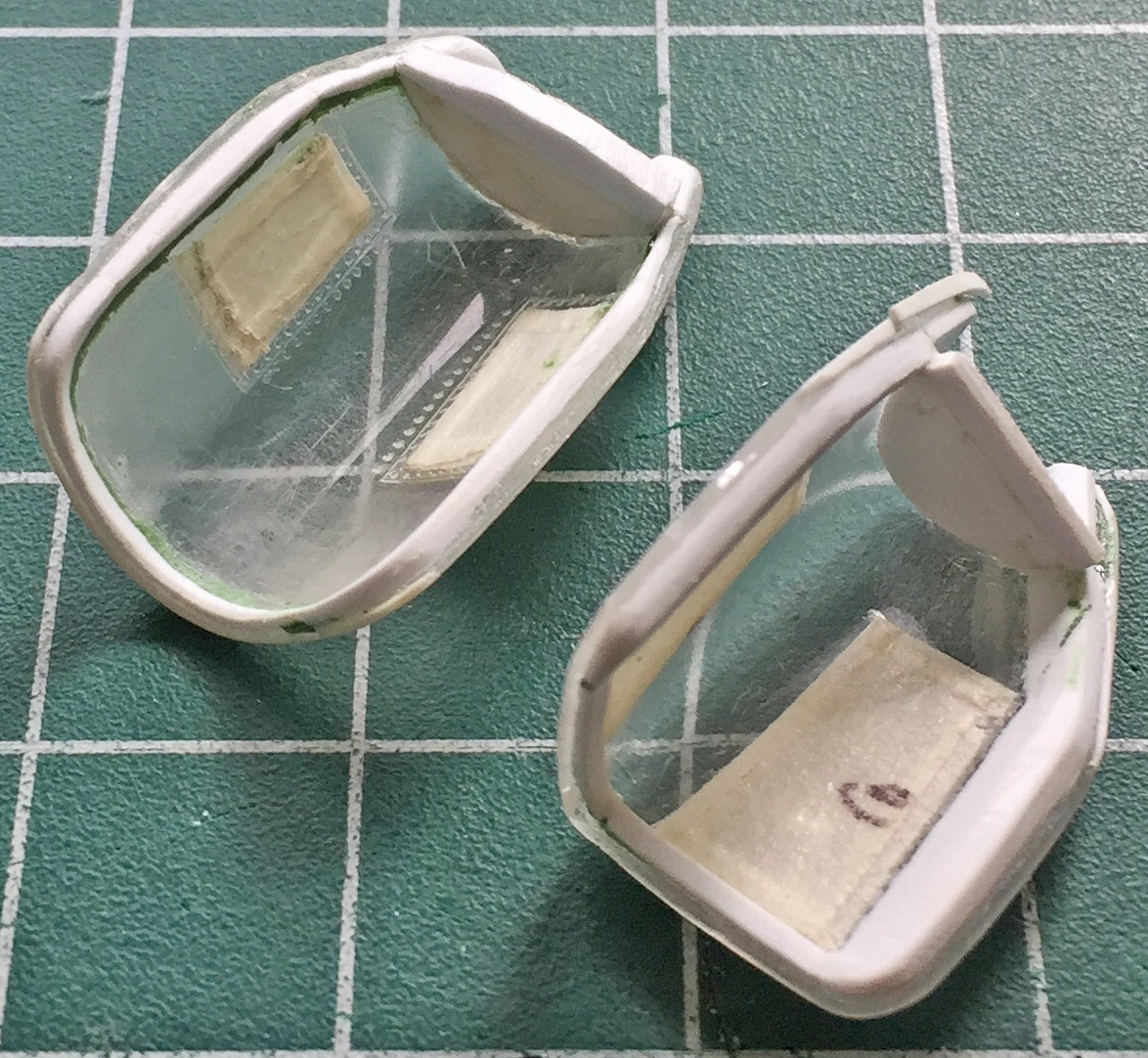
The rear canopy has roll-up glare shields (you and I would call them “shades”). I made a pair of those using .062″ (1.57mm) rod for the body and .005″ (.127mm) sheet for the end plates. These will be installed much later on; if they’re glued in now I won’t be able to get at the tape to remove it. I also added a few more details (with a few more to come) and did both canopies that way (the glare shields in the front canopy are entirely different and will also be done later):

Last was the front windscreen. The sharp tip is a bit too sharp and not correctly shaped. The point of the windscreen stops at the raised line (more about those shortly):

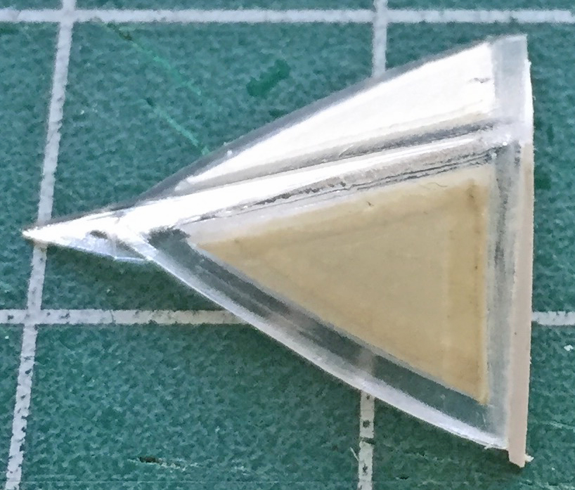
I cut the tip off and reshaped it to fit accurately, then I started on the inner framework of this part:
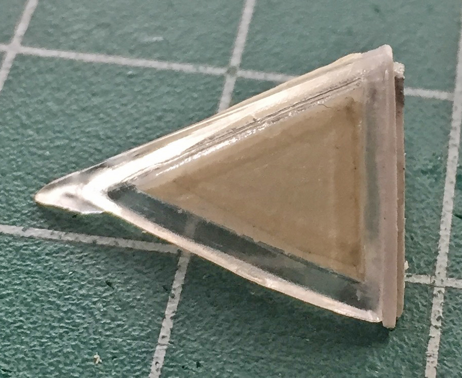
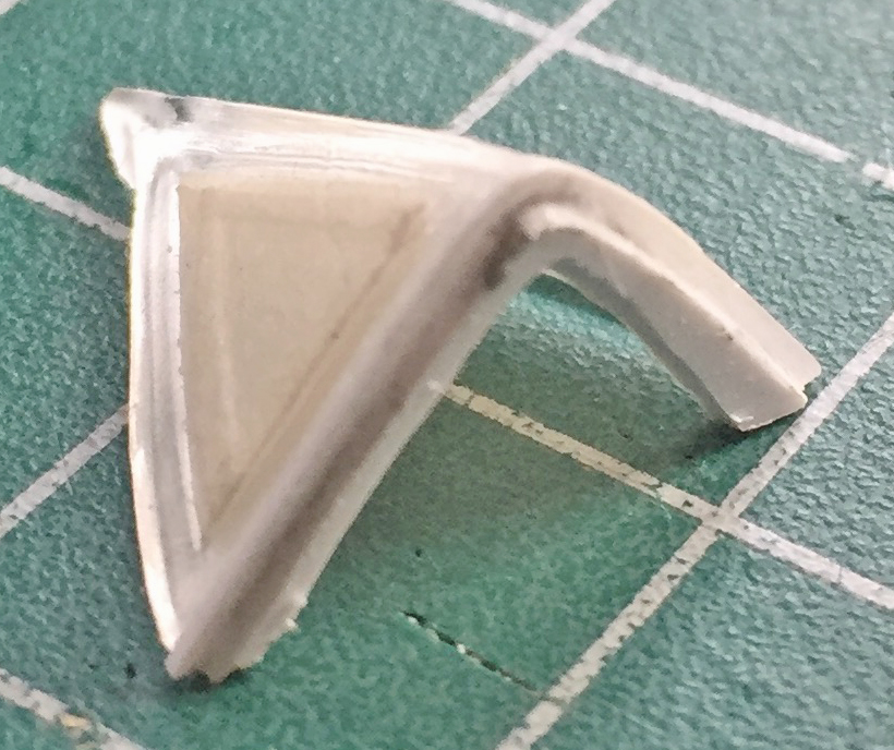
Yeah, so, the raised panel lines. Back in the mid-60s through the 70s, when the dies were cut it was a lot easier to create raised lines. One simply cuts them into the face of the molds. Recessed panel lines mean that the entire surface of the die that creates the surface shape(s) have to be recessed so that the panel lines can be raised in the mold and thereby create recessed panel lines on the finished part(s). That has to be much easier with CAD/CAM than cutting the dies manually. So all the lines shown below are raised and have to be scribed into the surface:
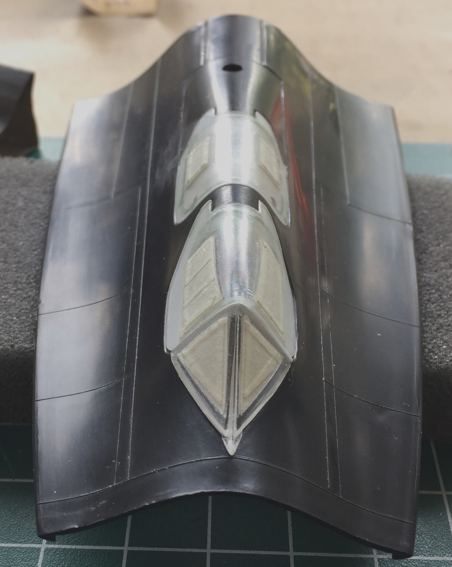
Well, I absosoddinglutely SUCK at inscribing panel lines. TOTALLY SUCK AT IT. I have two different types of scribers, mistakenly figuring that maybe one of the types I can get to freaking work (and now I have even more scribers…so many of them that if I had a wazoo, that’s what I’d be keeping them up into). Uhm…no. I can’t. One little bobble and the line is wrong. I really do not want to ruin whatever other work I’m doing on this build with lousy, irregular, not-quite-straight panel lines. After I screwed up two lines back to back, I stepped away (GLADLY) to reconsider Things…and to let my blood pressure drop back to normal.
Then something novel happened. I had a thought! Once the, well, novelty of that subsided, I decided to try it. (What’s the worst that could happen? I’d screw up a line or two? Already managed that.) What I tried was going back to an old-school technique. Instead of using dedicated panel scribers, I used a needle. AND I used Dymo label tape as my straight edge:
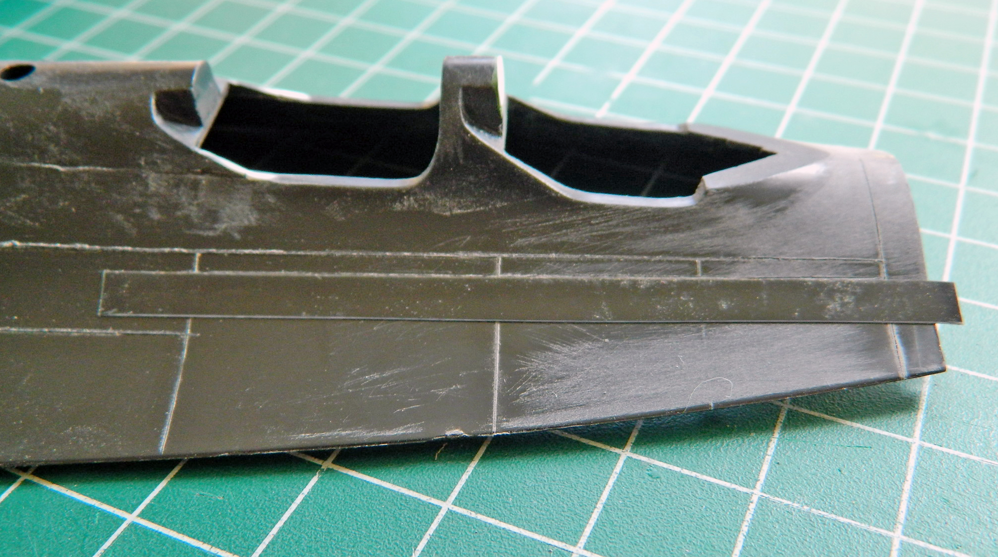
And gawDAM didn’t that work out just fine! The process is to lay the tape right next to the raised line then, holding the needle mostly vertical to the surface, lightly drag it along where the panel line goes. Several drags of the needle lightly result in a much better outcome than trying to do it in a pass or two…and if (when) the (old) hand bobbles, a light line is easier to sand out:
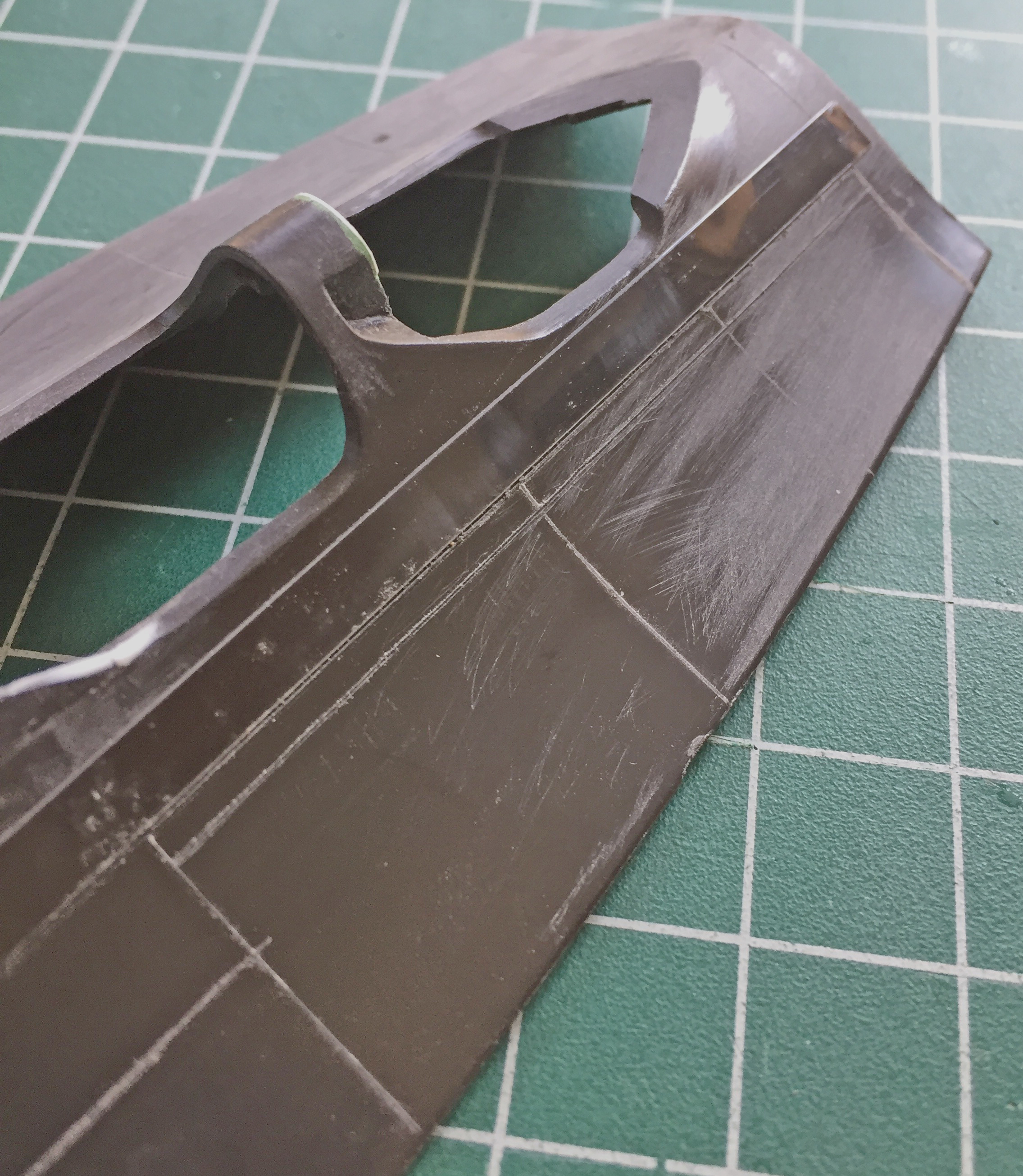

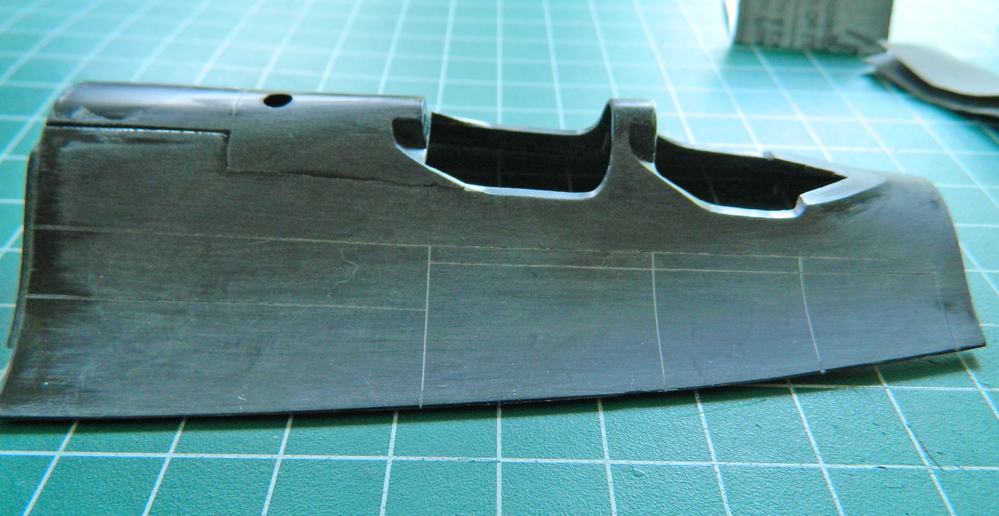

Then I had to fix the two uneven lines I’d scribed in. In dealing with plastic and putty, their physical properties are much different. For all its flexibility, plastic is a solid and putty is not. Even though the particles are small, putty is granular. Dragging a scriber or needle across putty results in it chipping and coming out unevenly. My way around it is to use stretched sprue to fill the lines that don’t pass muster. The sprue is laid along the section to be filled and styrene cement applied. I wait a minute or two and then press the raised sprue down firmly. The dissolved plastic then squidges out and downward, completely filling the space I want to be filled. The real trick to that is to wait until the cemented plastic is totally hardened. Not doing that results in blobs of it either pulling away or not scribing sharply. Each time I fill something this way, at least two hours needs to pass, more if the plastic applied is thicker. (I’ve since modified that procedure. I now let the work sit overnight before I go back at it so that the glue has cured totally.)
Once the cement had set, I re-scribed the filled areas and then sanded the surface progressively through 320, 400, 600, 1200, and 2000 grit paper. Use wet/dry paper wet. It keeps the dust down. The needle worked great. The lines are uniform in width and depth:

This is one of the better fitting panels I’ve encountered so far. No, I’m not being sarcastic (for a change…don’t get used to it). Because of the depth and width of the poor fit and the fact that these areas would get scribed, I decided I’d also fill these sections with stretched sprue:


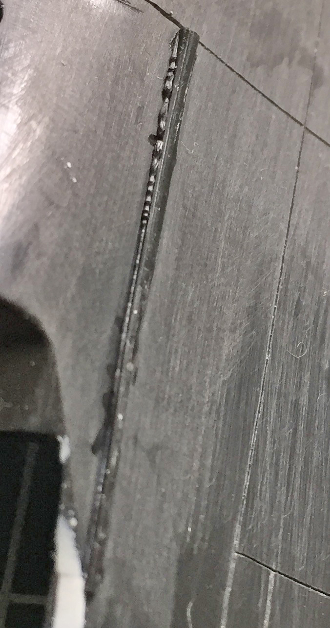
It turned out that because of the thickness of the applied sprue I had to wait overnight to remove the excess (and then go back and add more sprue in the section I dug out improperly because I only waited a couple of hours) and scribe the panel lines.
I added the cockpit sills from the AM resin detail set:

It’s common for resin parts to require fitting. If I just glued them in the result would have been cockpit sills that were far too thick:
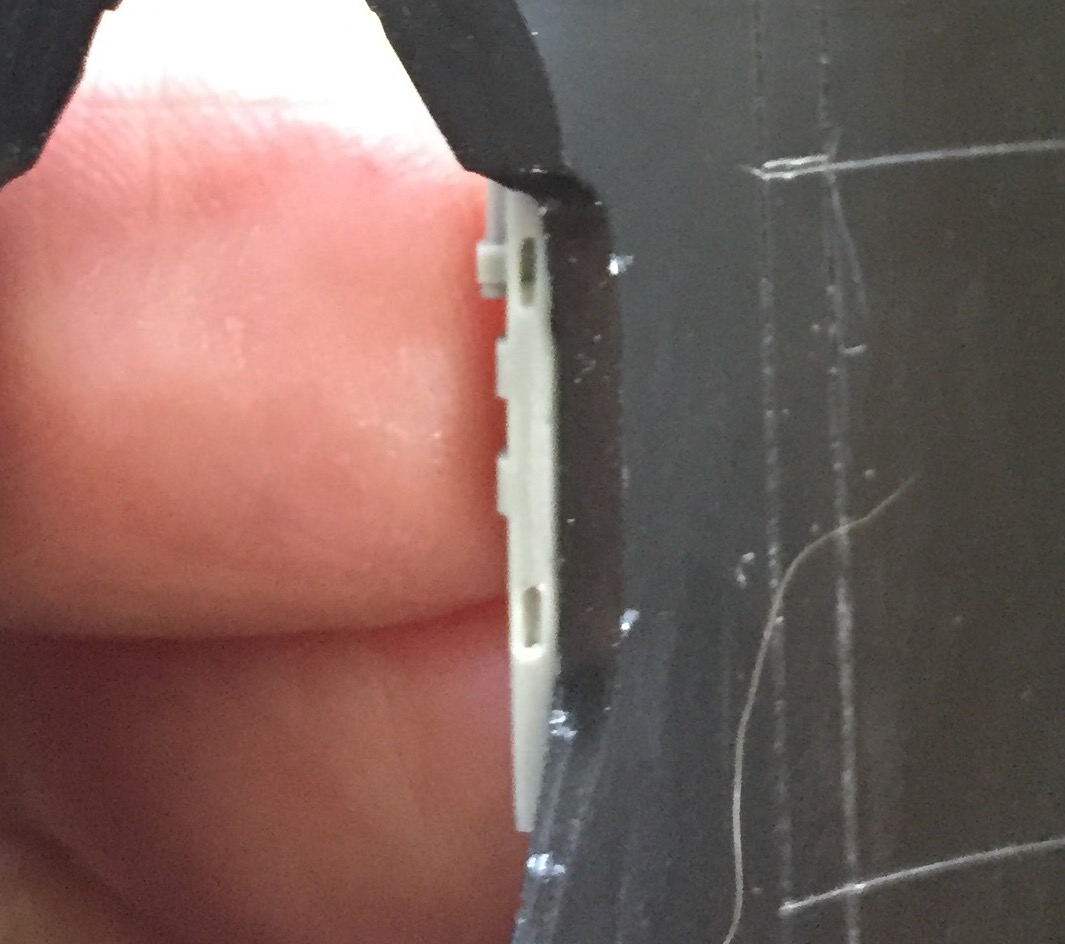
First I thinned the sills by scraping:

Then I had to “socket” the resin parts because though that above photo looks like it’s thin, it’s only the edge that is. Behind that edge the plastic is thick:
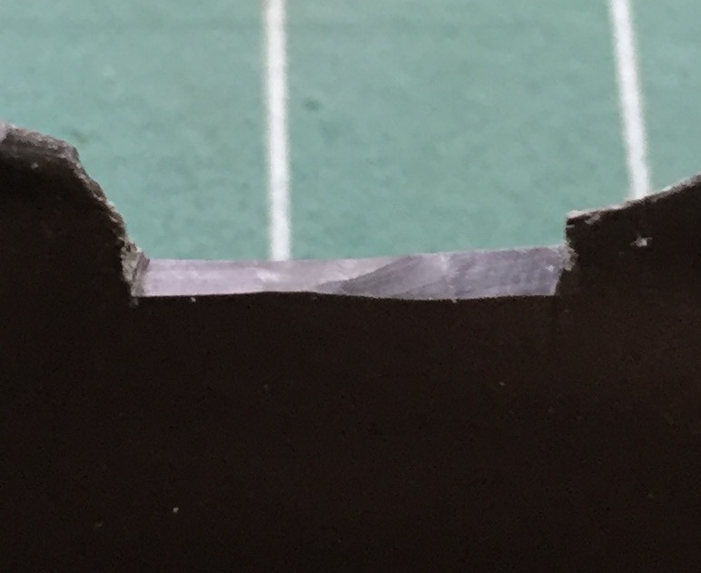
There was a lot of cutting scraping required to get the resin sills to (relatively) fit:
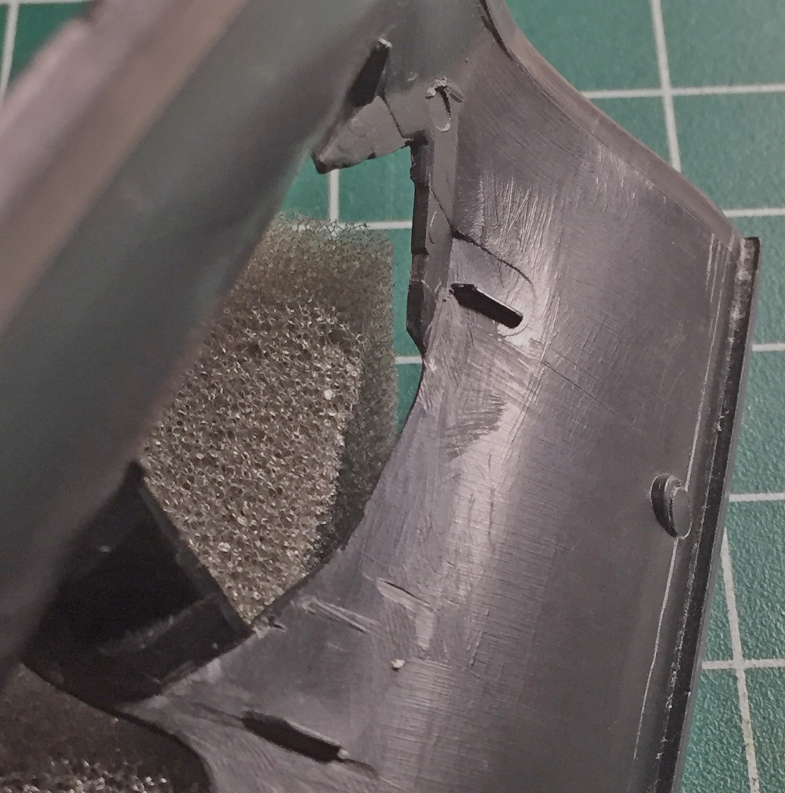
There was even more scraping and cutting to get the sills to nestle into position but the end result seemed to work (more on that later, too):
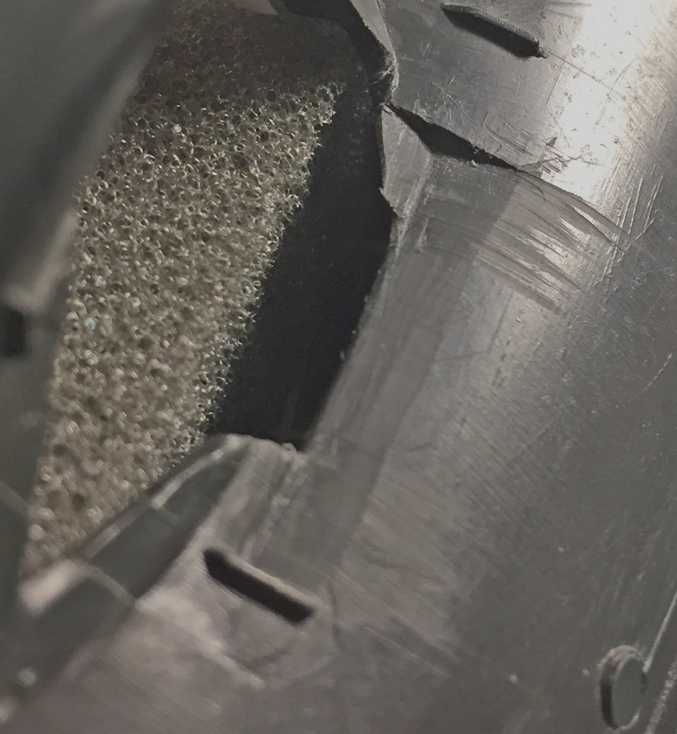
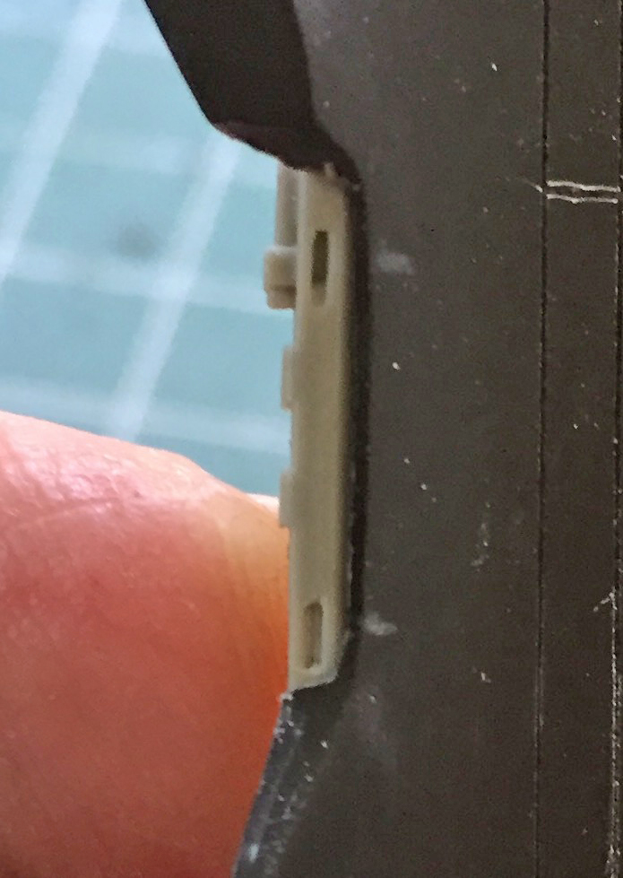
Having gotten all four sills to (relatively) fit, they were glued into position. There was a small gap at the edges of all the sills where they (relatively) met the side of the cockpits. That gap would need to be filled.
Some resin will bond with putty and some won’t. This formulation of resin just shrugged off the putty so that meant I’d have to find some other way of filling that gap. I tried gap-filling superglue. That stuff stays gooey for a long time so after it was applied I let it sit overnight…and then I tried to file it down. Tried to. I suppose I could have gotten it to work but it was a STONE BITCH to do and I simply did not like how it turned out. In order to get that gap completely gone, I would probably have to spend a week just on the sills. Oh. And another problem. The edges of the cockpit where they curve upwards was not working well with the superglue. There’s no seam there and no matter what I tried (short of spending a week on it) the seam was still visible.
And then I tried fitting the cockpit parts. In short, I had to remove substantial areas of resin so that the cockpits would fit, albeit poorly:
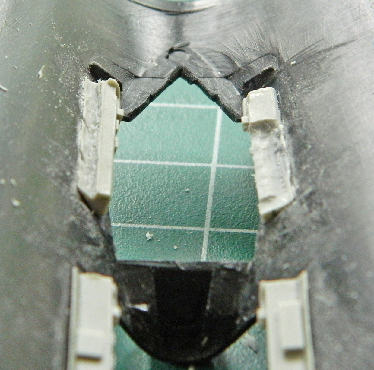
I decided there had to be a better way and as soon as I postulated that, I figured out a better way. Remove the resin sills entirely and scratch-build the things! That would solve all the blending problems. Using styrene would allow the putty to be effectively used and make blending the sills with the curved sections MUCH easier.
So I popped them out:
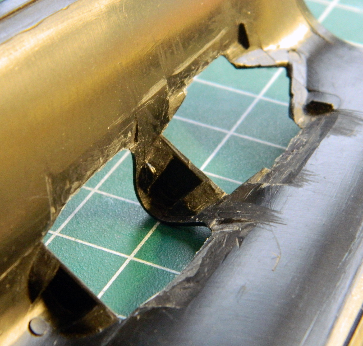
Since I was getting the cockpits ready for paint, I added the very small buttons and trigger to the joystick using stretched sprue and a small piece of .005″ (.127mm) for the trigger (can’t see it in these photos):
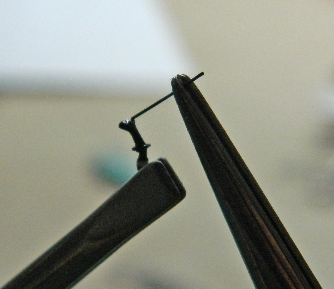

And right after these photos were taken of the joystick, during the final trimming of the buttons I managed to snap the grip off the stick. I reattached it and the glue is curing now.
::sigh::
SR-71A Blackbird (Testors) Build #3 – Work on the Cockpits and Canopies
My usual procedure is to start with the cockpit first so I turned my efforts in that direction.
I had purchased a cockpit detail set from True Details and, totally forgetting that I had, also purchased a pair of ejection seats from Pavla Models out of the Czech Republic. My oversight ended up offering me more options. Neither of the ejections seat sets was 100% accurate, each had something the other lacked. My choice became, which of the seats’ errors/omissions would be easiest to fix? As it turned out, I’m going to use the Pavla seats (the one on the left; part of what makes them look SO different in the photo is that the True Detail seat is still attached to the pouring block and the Pavla seat isn’t):
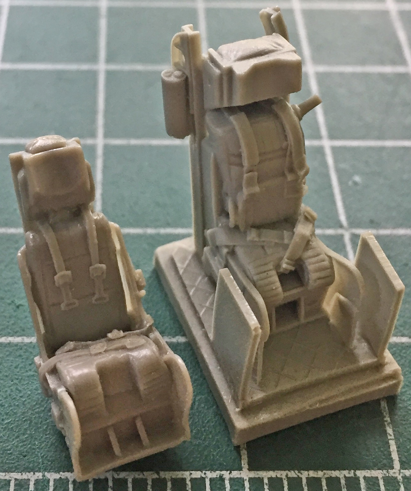
There are almost always casting flaws…it’s just the nature of the process. In this case, where the wings on the lower front portion of the seat attached were a bit off. It wasn’t well attached to the seat, as you can see by the gap:
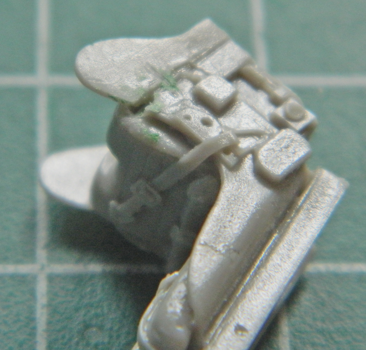
The seam where the wing attaches isn’t supposed to be there, either, but once the seats are installed in the cockpit tubs, those seams won’t be visible…but the gap at the top will be. I tried putty to see if it would adhere to this particular resin and it doesn’t. That meant I had to fill the gap with styrene and finish it to invisibility…so I did:
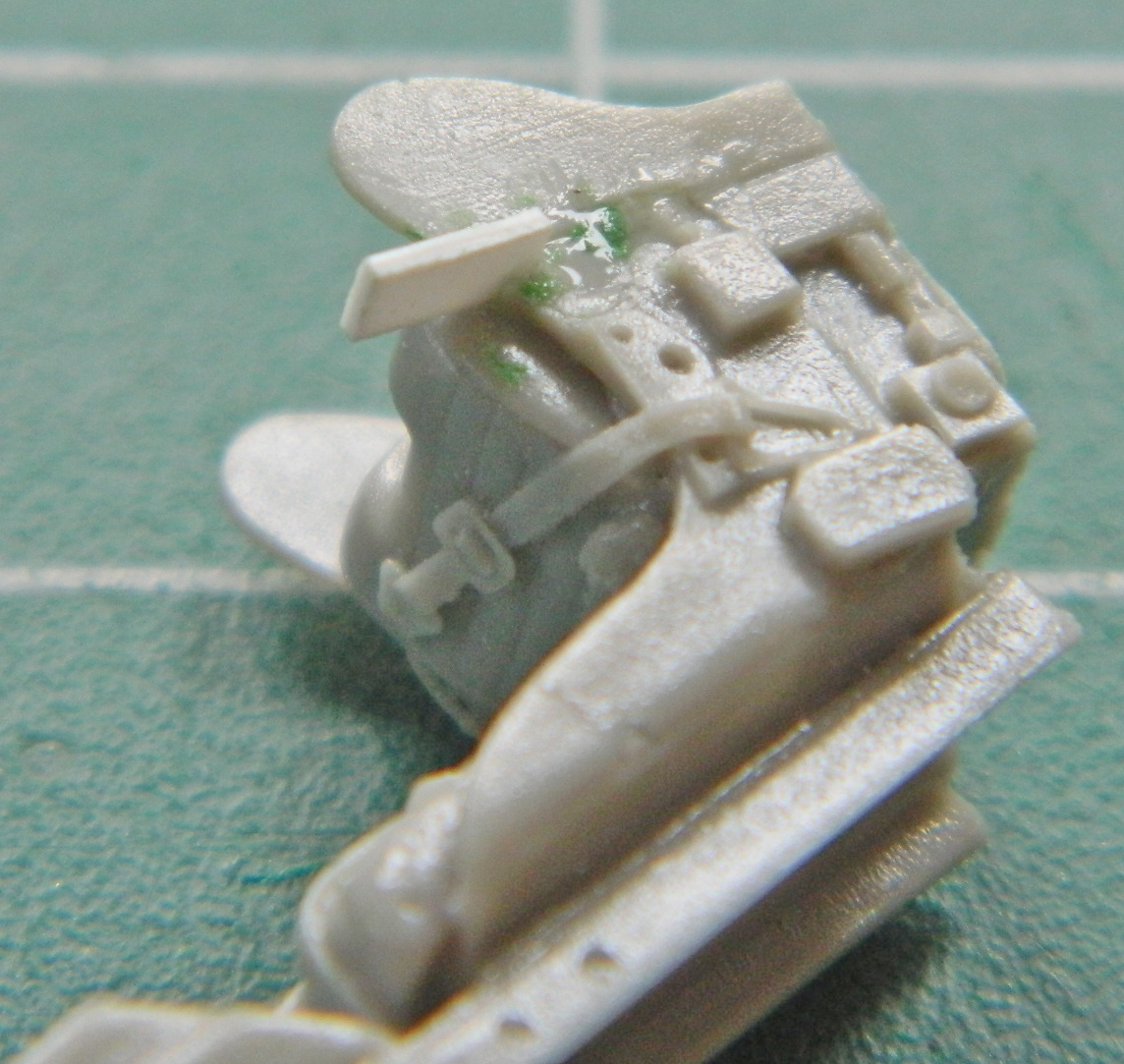
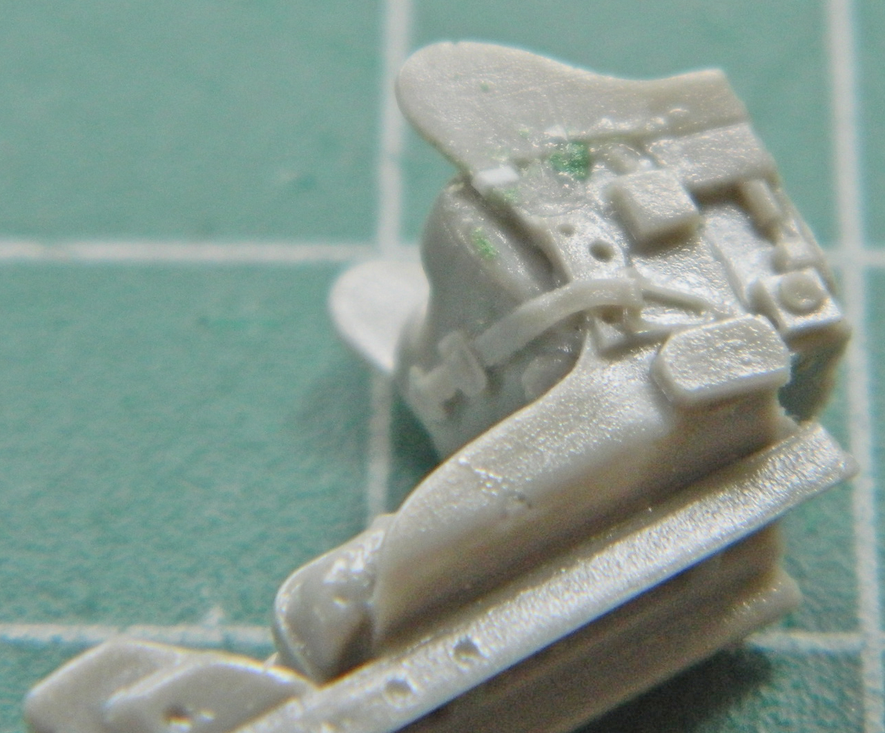
One the side near the top there is a cylindrical “thing” with two lines coming out of it. I used 1/16″ (.062″) (1.58mm) styrene rod for the body and .025″ (.635mm) styrene rod for the fittings. I used the True Details seat to determine the length of the body and then used locking tweezers on stands to align the rods and glued two pieces on:
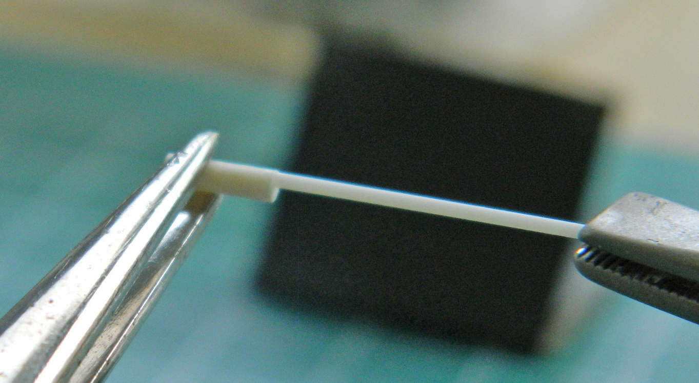
Once the glue had set, I trimmed the .025″ (.625mm) rods and center drilled them with a .0135″ (.343mm) bit:
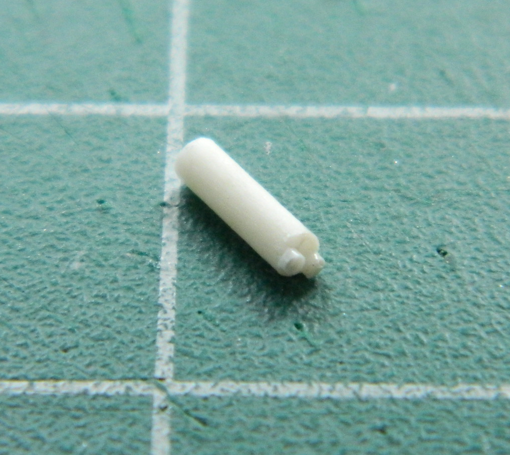
These cylinders aren’t just stuck to the frame of the seats, they have mounting brackets. I made them from .005″ (.127mm) copper shim stock and used the punch and die set to start the holes and a fine (very fine) rat-tail file to open the holes to the appropriate diameter. Tip: punch/drill the hole first, then cut to approximate size and use a file to bring the dimensions down to size:
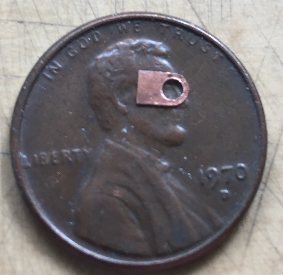
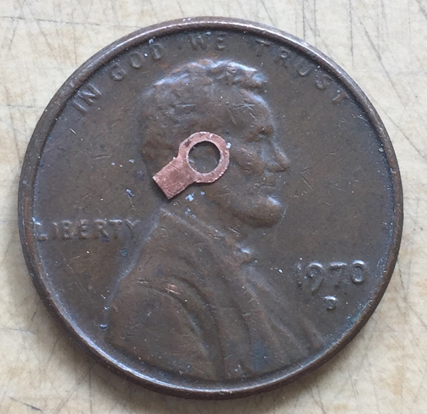
The flange is a little too large. I fixed that by holding the body of the bracket in the nose of small pliers and filed away the excess…and forgot to take pictures. (Perfection still eludes me.) With everything to their final size, I slid the bracket over the cylinder, glued it in place, and bent the mounting tab parallel to the cylinder’s body:
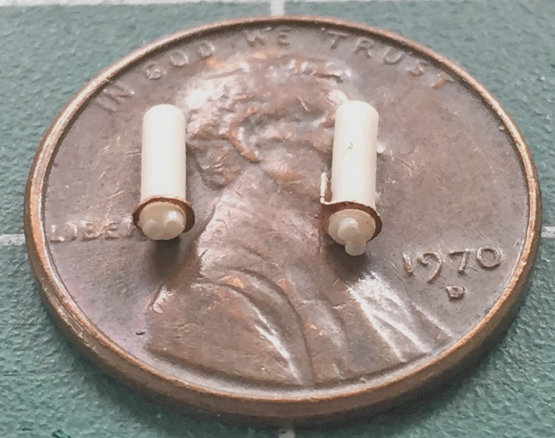
Even though once these parts are mounted in place and very unlikely to ever be stressed, “very unlikely” doesn’t even rhyme with “won’t ever.” I mean, it’s only .005″ (.127mm) copper! So I took a piece of .010″ (.254mm) styrene scrap and added additional support at the bottom of the cylinder:

Once glued in place, the .010″ (.254mm) styrene support isn’t easily visible and paint should make it even less visible. I didn’t use the True Detail seats to determine the location of these parts, I used reference photos. Once glued into position, I added .010″ (.254mm) solder lines, routed them down behind the seats, and ended up with two of this:

ONLY THEN did it occur to me that maybe I should perhaps check to see if the nose wheel bay EVEN FREAKING FIT into the fuselage! So I used white glue to hold the bay’s box in position and used the under fuselage section to see if maybe IT WOULD FREAKING FIT. In so doing, the first thing I noticed is the gap I’m going to have to deal with during assembly (that, of course, is on both sides and I sincerely doubt it’s the only gap):

I’ll pay the toll on that bridge when I get there. The reason I’m doing this is to see if the sodding box fits inside the fuselage…and I got lucky. It does:
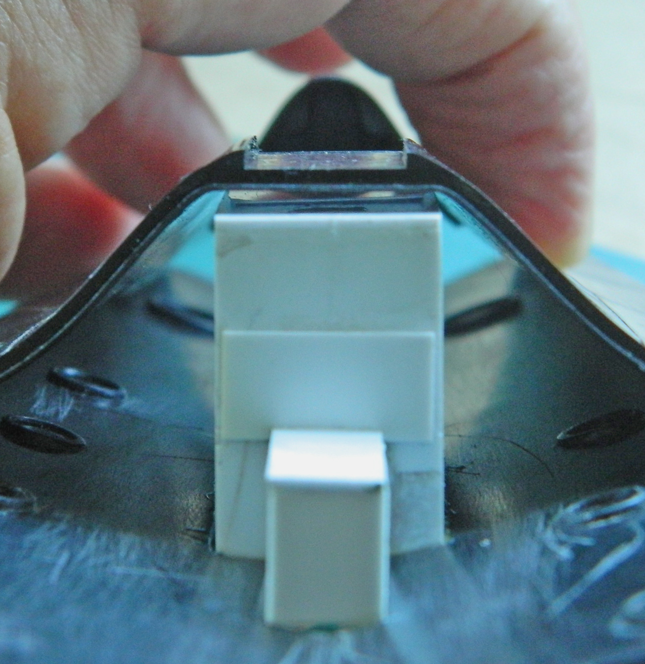
Okay…dodged that falling piano! So while I’m here, let’s see if the resin cockpit tubs FREAKING FIT:
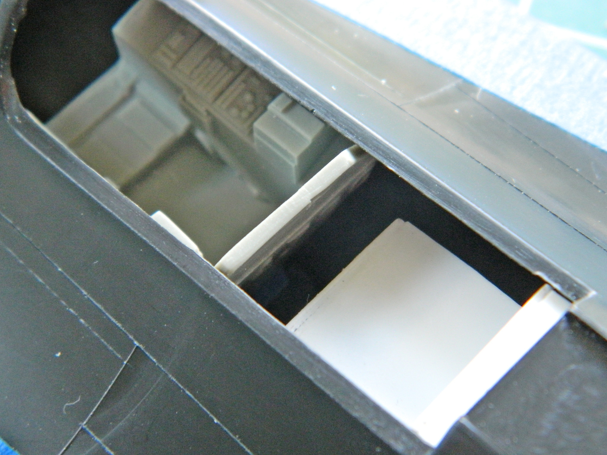
Whew…two for two.
Okay, since that fits, I checked the fit of the fuselage top behind the rear cockpit…and noticed that the fit problems seem to be consistent (and note the depression in the surface of the fuselage at the upper right…there’s several places where this happens and they’ll get filled with putty):
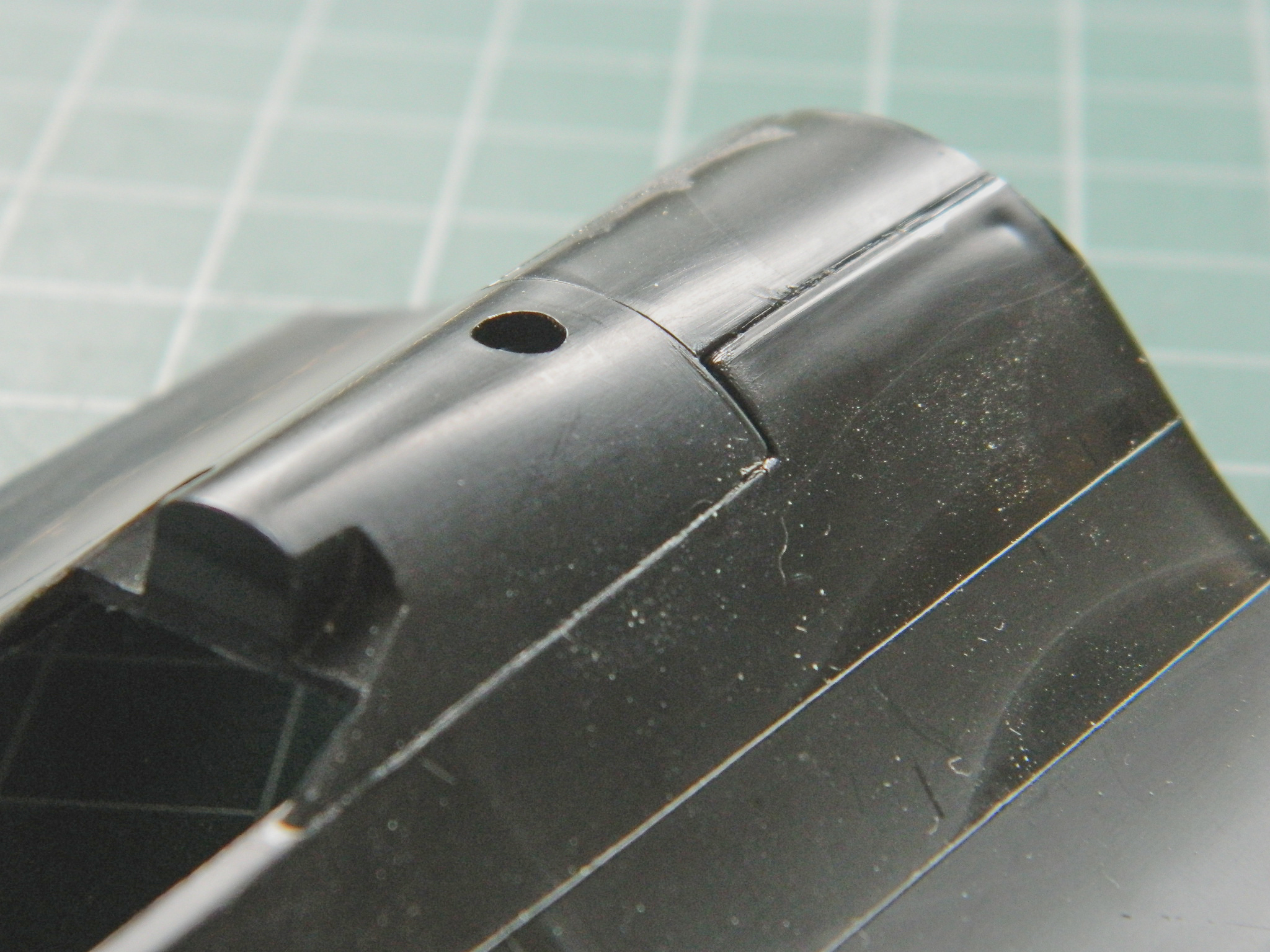
I knew I was going to have to trim the kit’s rear cockpit opening back a bit to fit the cockpit tub (you can see in the next photo where I have already started cutting it away) (and if you look at the above photo, it’s already been removed):
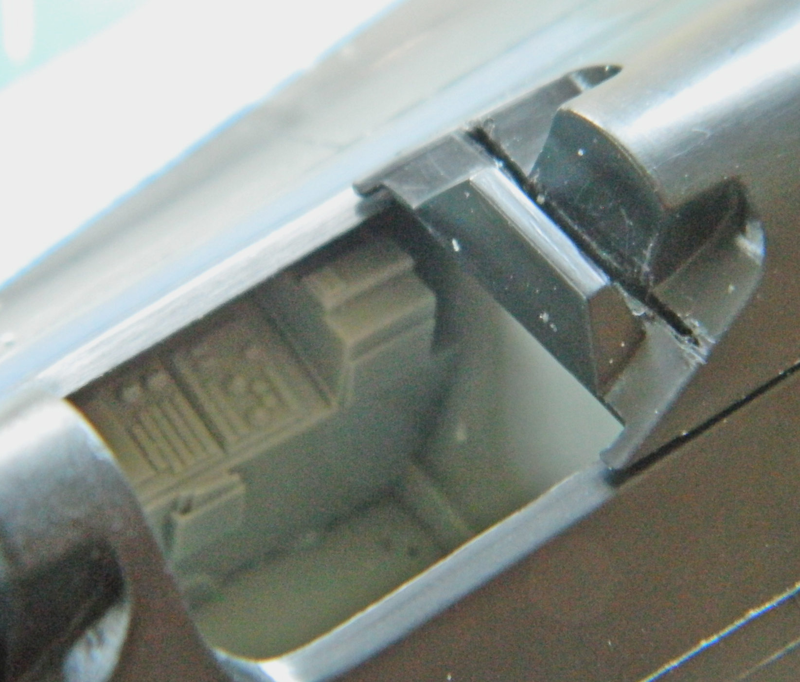
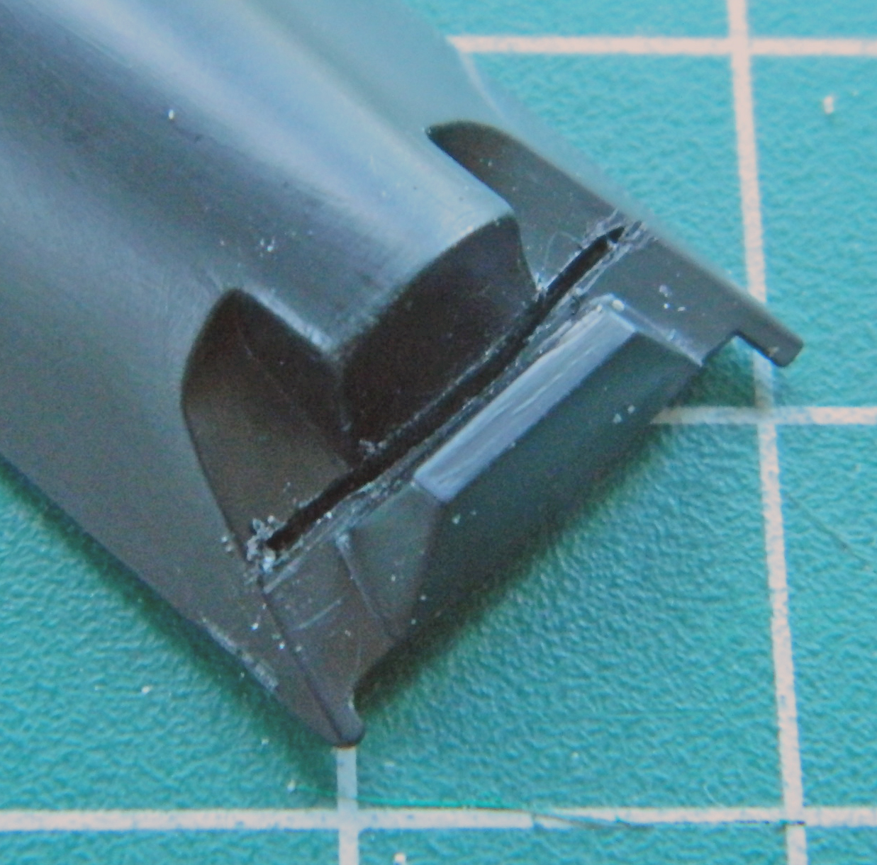
I treated the front cockpit the same way.
I checked the fit of the RSO’s instrument panel and saw that I needed to trim the plastic so that the panel fit better…or at all:

While I was checking fit, and not remotely expecting that anything would fit, I checked how the canopies fit the fuselage. They don’t very well:


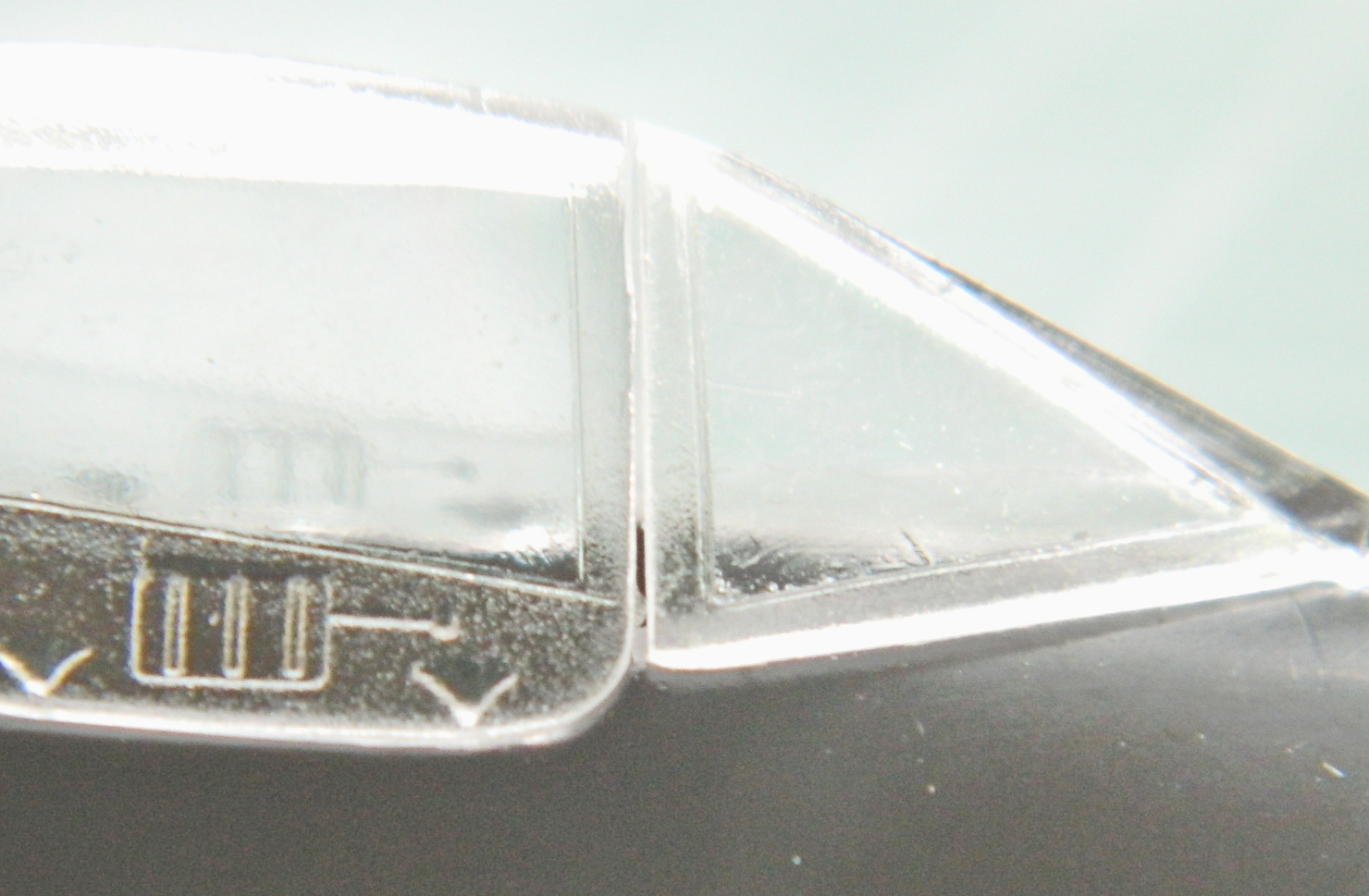
Even though the model with be displayed with the canopies open and fit isn’t really critical, I will be using the canopies to mask the cockpits when it comes time to throw paint onto this thing. I’ve learned that using large globs of white glue to seal things doesn’t do good things for the final paint job when they’re removed. It will take too much paint away with it. It makes more sense to put the time/effort into a good fit at the front of the job rather than try to recover a paint job at the back of the job.
So I added plastic to the fuselage and fiddled and sanded until the fit was better. I also added .020″ (.508mm) plastic to the canopies because the gap was SO large (I also added plastic to the fuselage and puttied the back of the area to sharpen the edge of the fuselage):
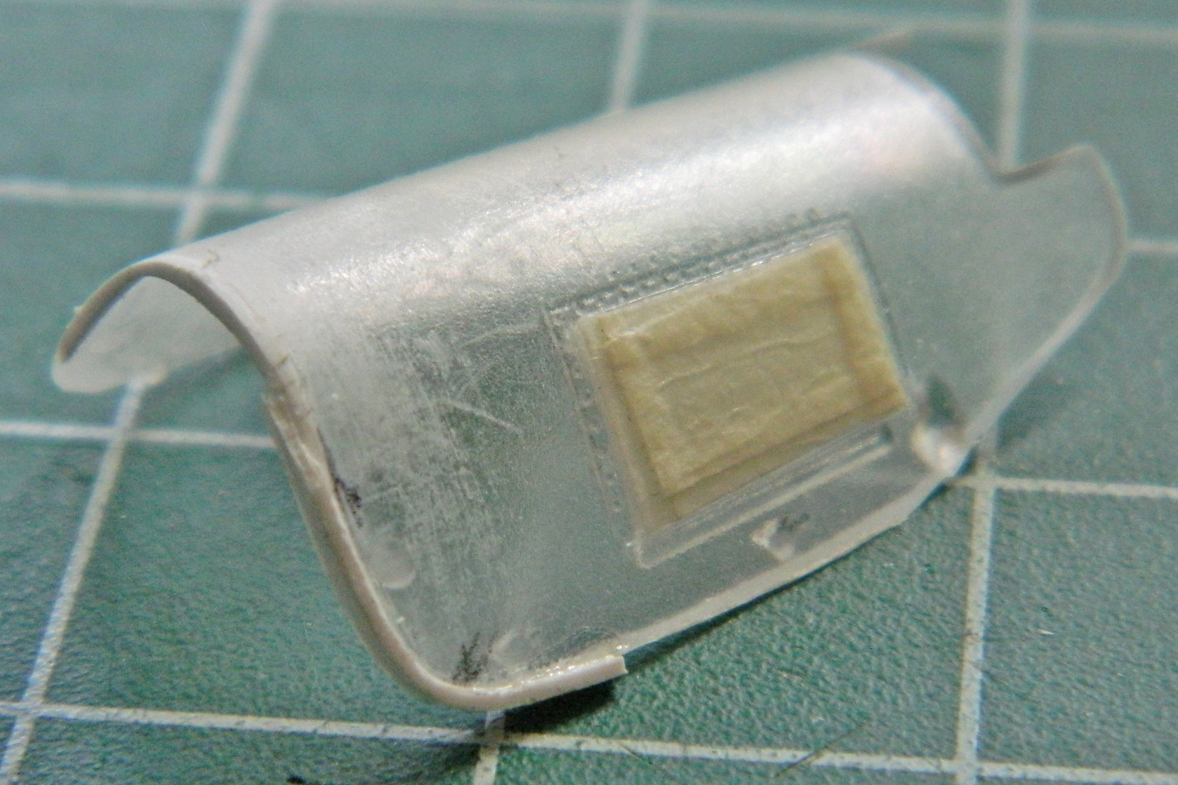

Yes…there are still gaps. If I were going to pose the canopies closed, I would have spent more time making the fit tighter. But I’m not and these gaps should easily fill with white glue and not rape the paint (too much) when they’re removed (the areas that have to remain clear were masked off to protect the surfaces from scratches):
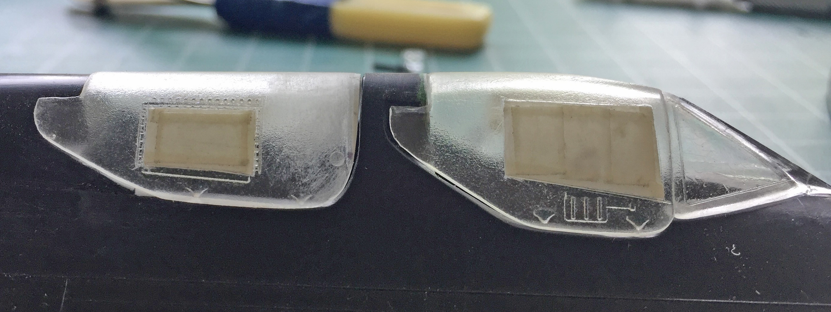
Keeping with the cockpits, I checked the kit’s pilot’s joystick against references:
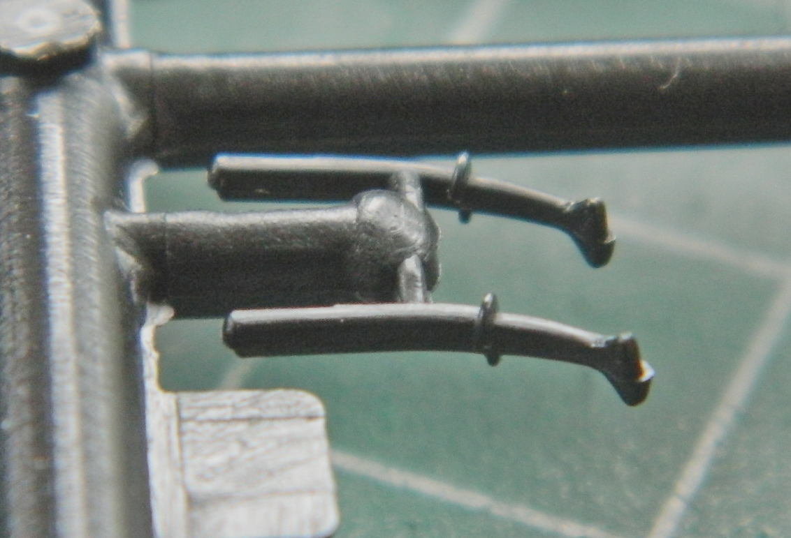
The ridge to the right isn’t supposed to be there; the mold was misaligned. The shaft of the joystick is too large, the grip area is too long, and there is a bulge just below the hand rest that’s missing. I started by taking out the misaligned parting lines:

The only thing left to do is to add the four buttons (three on the top facing the pilot, one on the other side), but I’ll do that when next I’m in the mood for extremely tiny things (right after my medications are adjusted). The grip has been shortened, the bulge added, and the main shaft replaced with styrene rod:
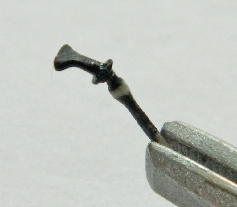
The rudder pedals are elevated onto a platform. References show that there are ramps in front of the platform that the resin part doesn’t have. Now it does:

There are pronounced structures inside the canopies that the kit’s parts don’t have. They’re necessary to have them so that started with a job that I REALLY can’t stand…putting a bulkhead inside a curve. Tedious. Tedious. Tedious. But they’re not going to add themselves, so:
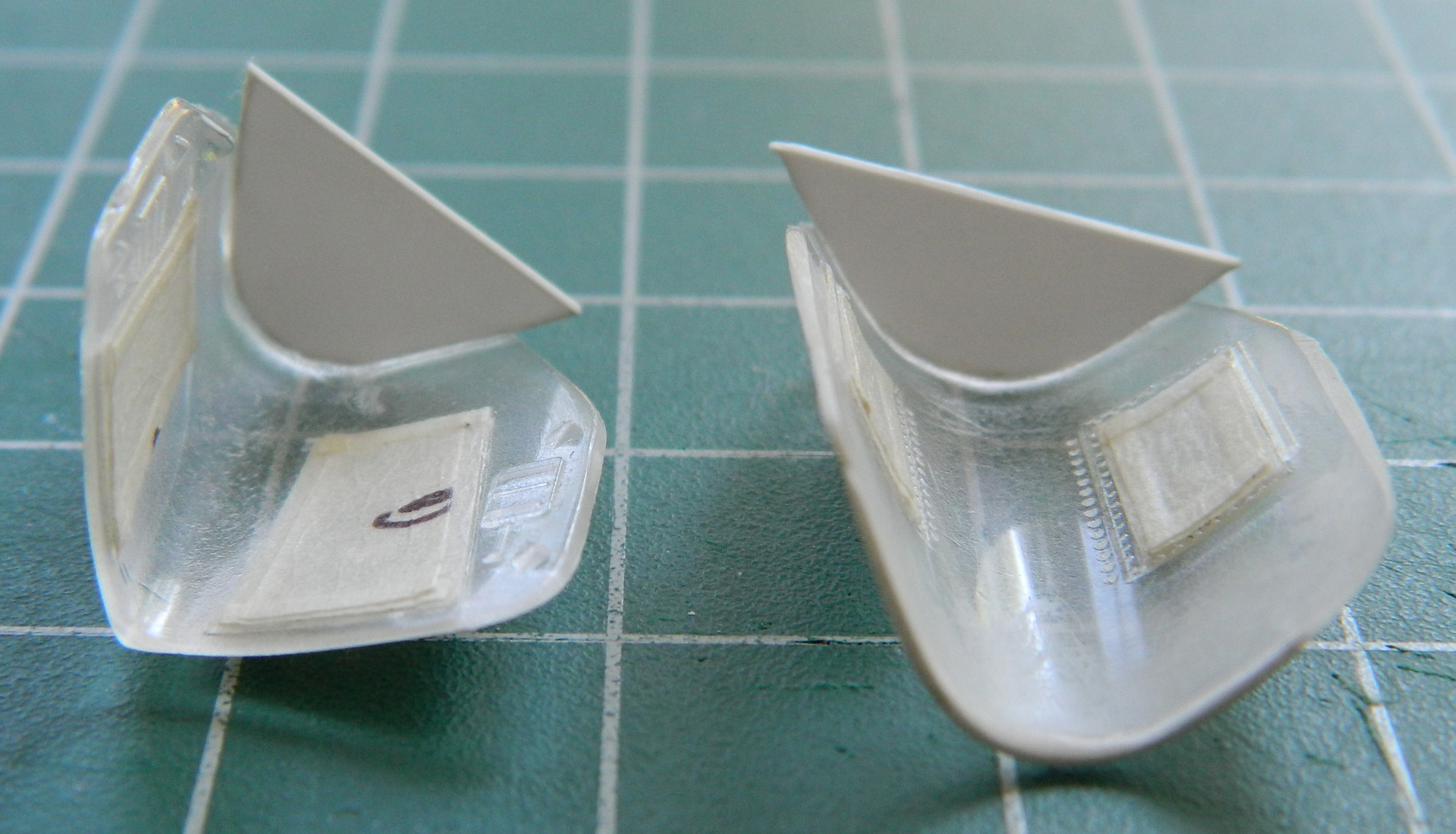
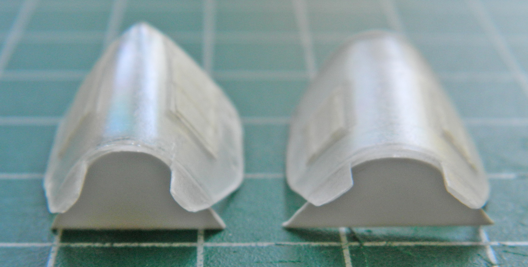
Once the glue cured overnight I removed the sections of the bulkheads that extend below the canopies’ edges.
The next trick is to add all the structure inside the canopies…
SR-71A Blackbird (Testors) Build #2 – Some Nose Gear Details
Entropy never sleeps…nor does Loki and Eris. Instead of going to Robins, GA, to see the Blackbird that’s on display there, that money went into my car to counter the effects of entropy. So I’m going to have to work with what references I have and can find to add the details to the landing gear bays. I decided to continue the build while the BitB work on the gear bay problem(s).
Tucked up at the top of the nose gear bay are two liquid nitrogen tanks (used for cooling…heat and how to deal with it was one of the major driving parameters of the SR-71’s design). They’re not precisely round. I went to one of the spares boxes which in this case was the 1/24 scale Gemini for the round parts. To elongate them, I sanded off the locating pins, measured the width of the gear bay and compared it to the width of the two round parts and added the difference with flat stock:
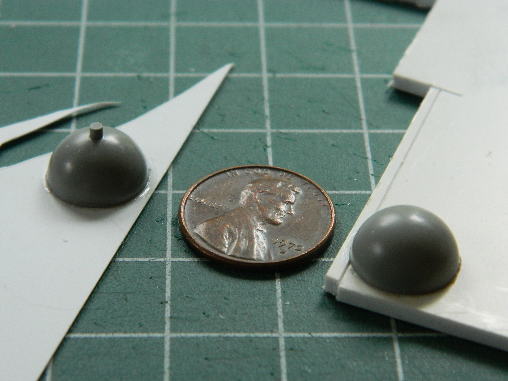
Then I glued the two halves together and removed the mounting pins and excess from the additions. Since there are two nitrogen tanks, this was done twice:

There is a band around the center of the tank that I replicated using high-temperature duct tape which is a heavy gauge, adhesive-backed, aluminum foil:
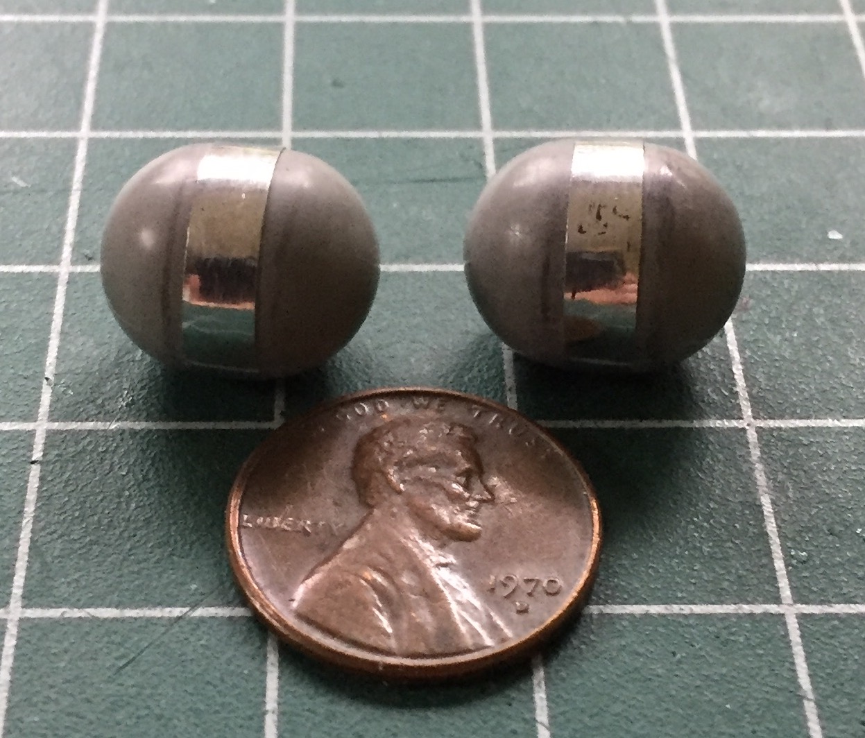
I added the tanks’ access lines’ terminus using 22awg copper wire and set the assemblies aside for now:
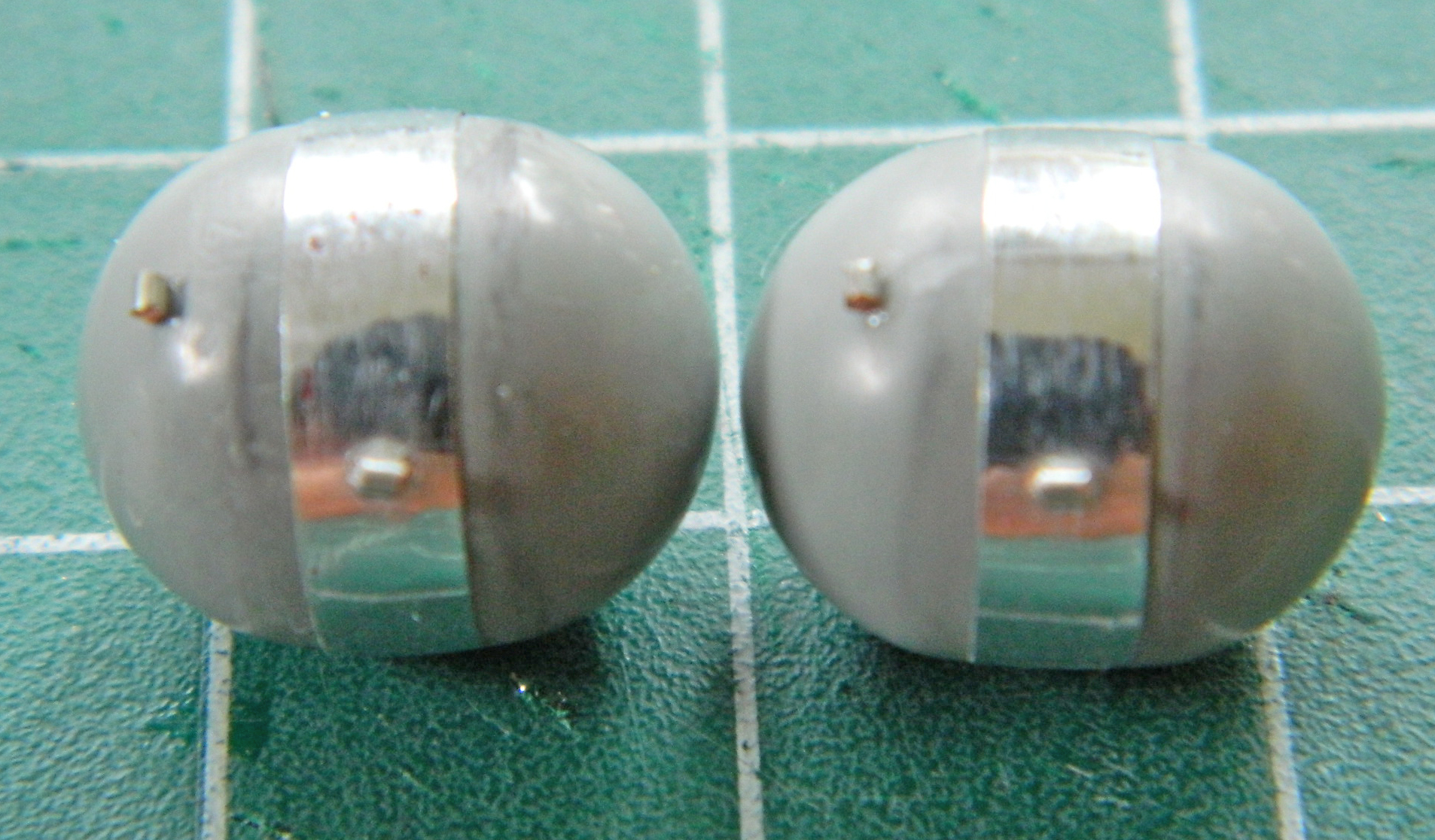
I used .010″ (.254mm) styrene sheet to fabricate mounting structure and used the punch and die set to create most of the lightening holes (drills did the holes I didn’t have a punch for), then started gluing the parts together, adding putty to make the joints disappear:


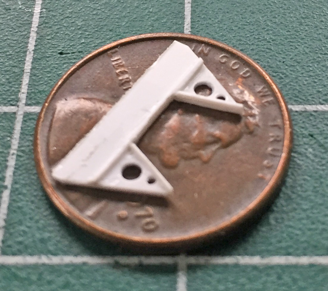
The structure was added to the landing gear bay:

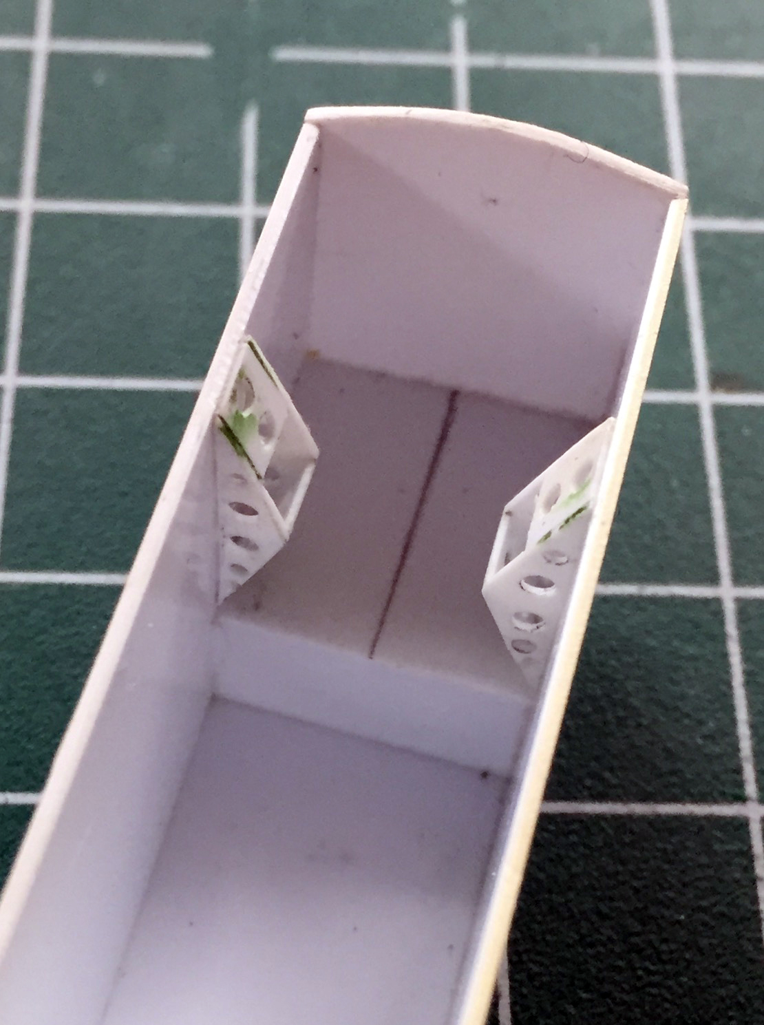
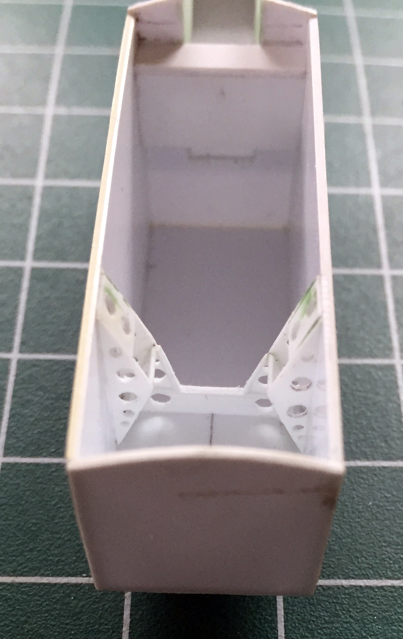
My initial plan (which rarely survives first contact with the work) was to use metal landing gear struts to better support the weight of what is (or will become…there’s that plan again) a large model. In looking at the metal parts, I see that they were produced by taking molds and making castings of the kit parts:

Okay, that’s fine as far as it goes but I’m taking this build as far as I can. The modifications I want to make to the nose gear strut will be easier on me if I do that part all in plastic. My thought (accurate or not) is that gluing the modifications to the strut will result in a stronger bond as the styrene cement melts the parts being joined together and superglue, which is what I’d have to use if I was going to use the metal part, would probably not be as strong (I still intend to make the main gear struts, which will support most of the completed model’s weight, from metal, but instead of using the parts I’d purchased, I’m going to scratch build them from brass or copper stock.):
With that decision made, as you can see in the above photo I cut off the extension strut so that I could more easily access the parting lines (they’re not well aligned as the next photo shows):
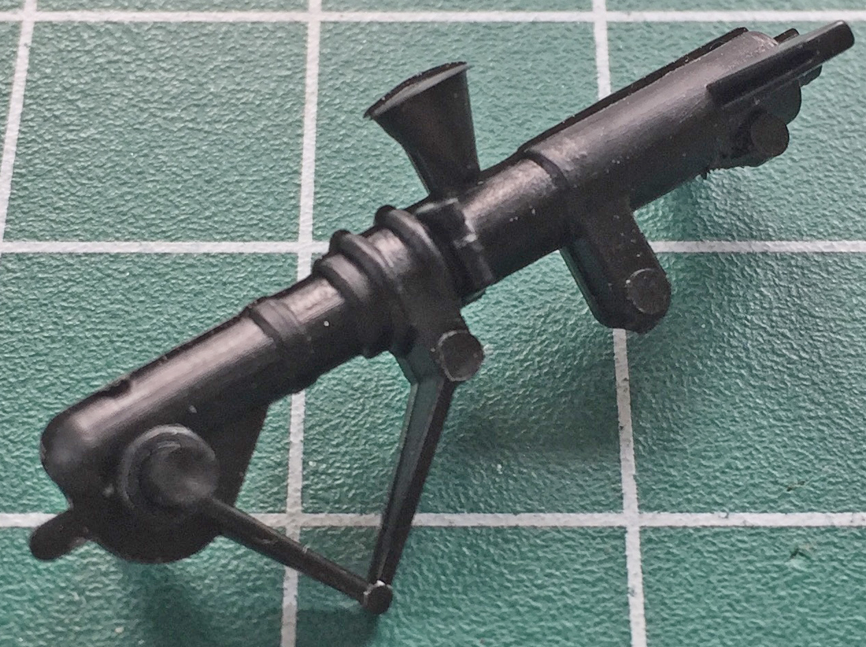
I also have a peculiarity (one of many); I don’t like trying to replicate clear parts using opaque paint. The conical structure in the above photo is one (of two…I have to make the other one) of the landing lights on the nose gear strut and as it is with lights, the lens is supposed to be clear. That means I gotta make the lights (I’ll try turning down clear acrylic rod for that/those) and the molded on “light” has to come off:
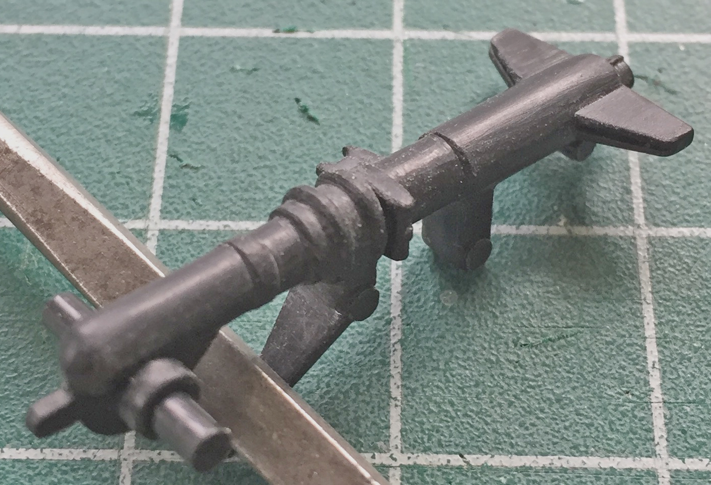
And while the BitB work on how I’m going to work the details inside the landing gear bays, I stop working on the nose gear parts and turn my efforts elsewhere. There’s no shortage of “elsewhere”…
SR-71A Blackbird (Testors) Build #1 – The Parts and the Nose Landing Gear Bay
I’m doing something a little different with this build; it’s a favor for a friend (who is due so much more). It’s also of a specific aircraft.
While I was planning this one in my head, I wanted to do a special aircraft (as if the SR-71 isn’t “special” because it exists). The last flight of a Blackbird in the Air Force inventory happened March 6, 1998. On that flight it broke four speed records over a measured distance (which are yet unbroken). The last AF Blackbird flight, tail number 972, was from Beale AFB, CA to Dulles International Airport, DC. Upon its arrival it was given to the Smithsonian National Air/Space Museum (NASM). It was refurbished and in 2003 (I think…I may have that incorrectly) placed in the new adjunct facility in VA, the Udvar-Hazy Center where it is presently displayed.
I’m going to model this specific aircraft as it’s displayed at the NASM and that all starts with the kit:

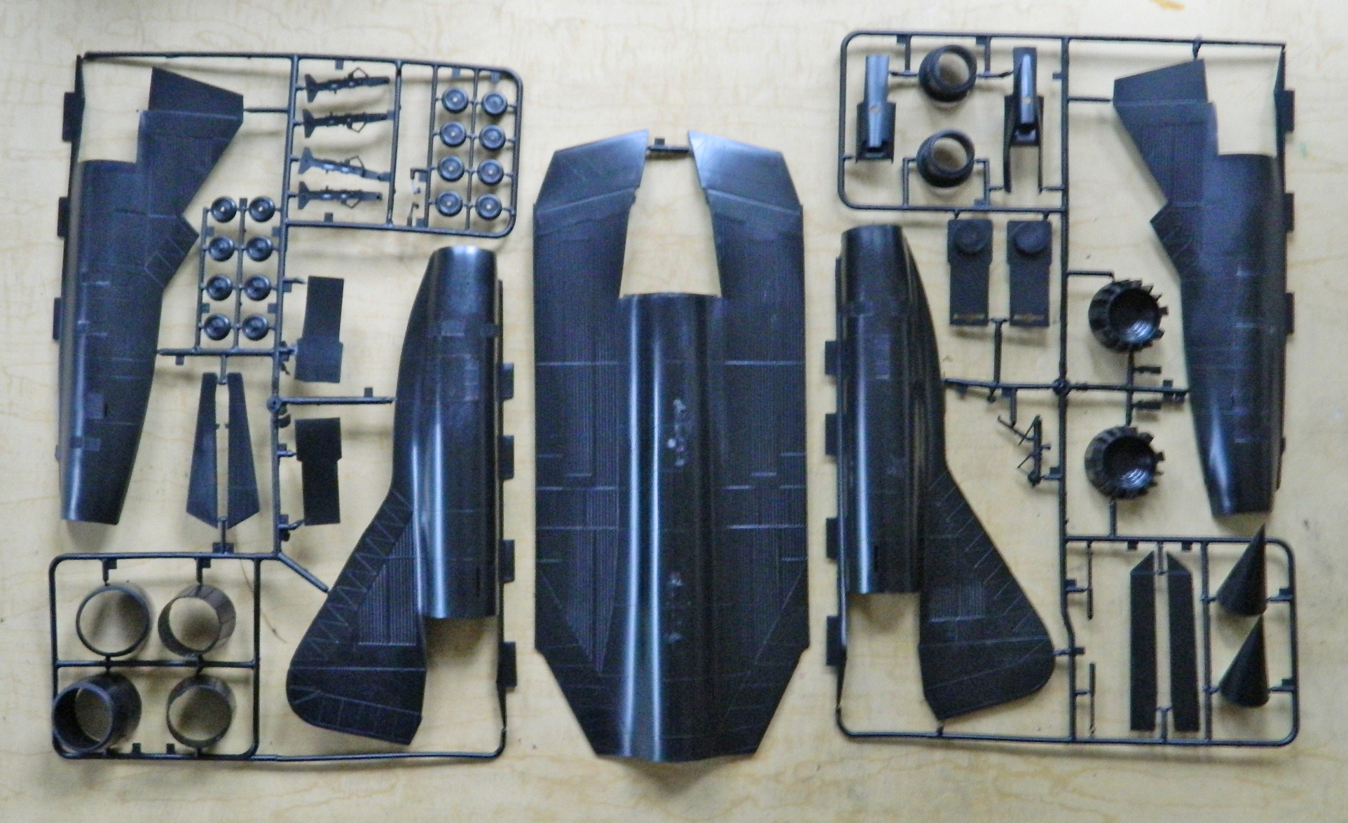
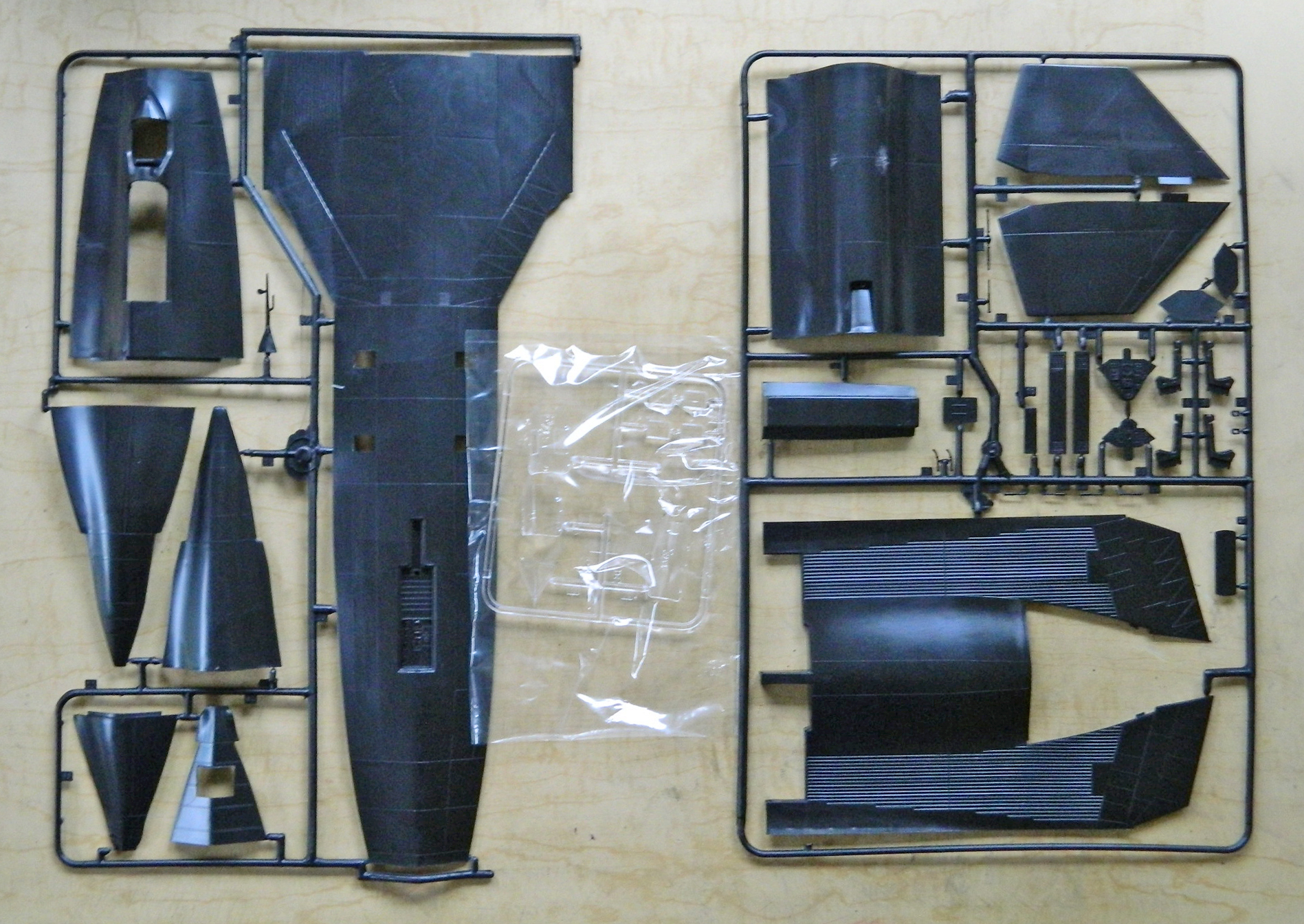
The AM parts I’ll be using are these:
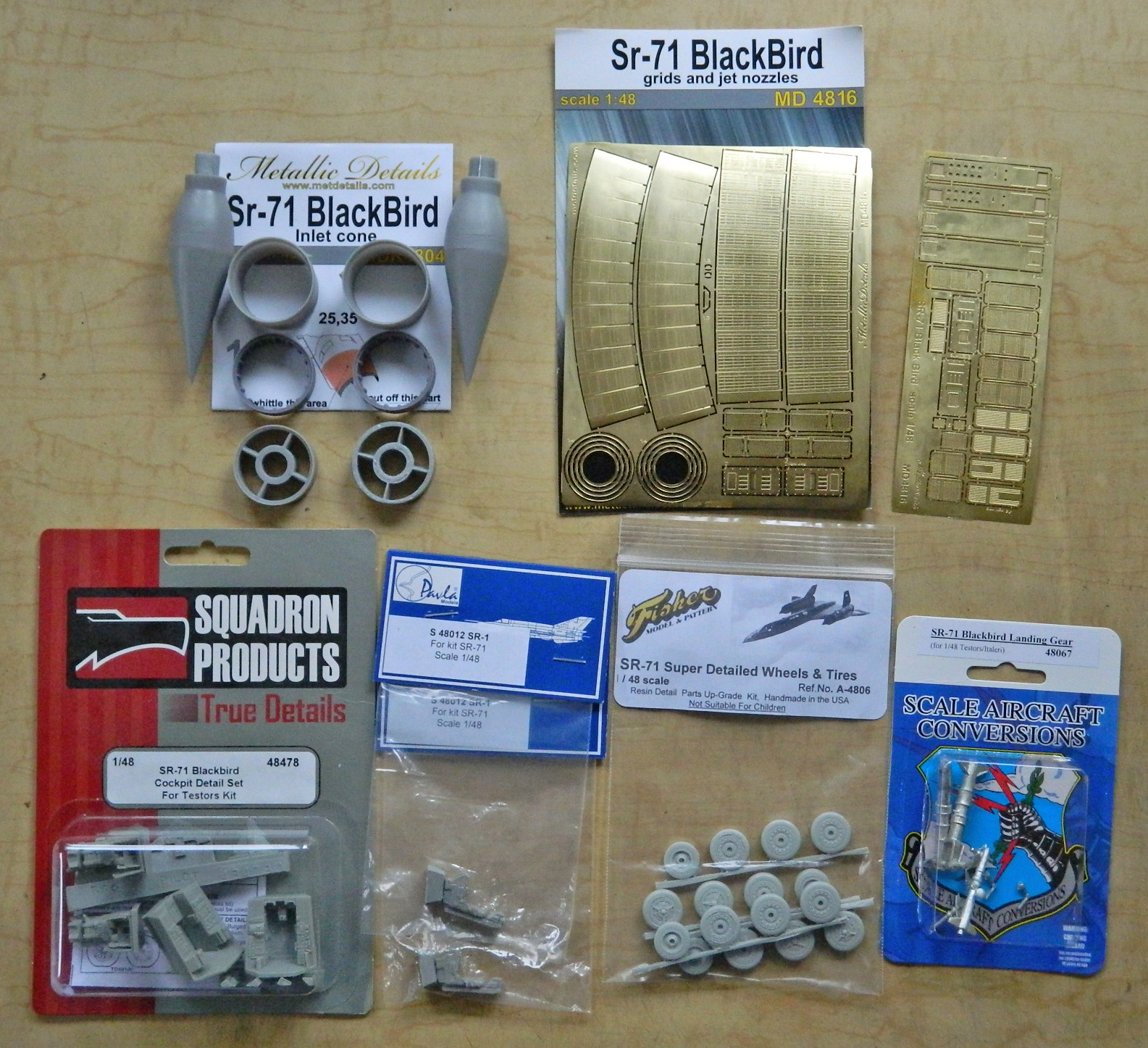
My usual method is to start with the cockpit so I can join fuselage halves and go from there. This time I’m going to start with the landing gear bays. These will be scratch-built so with that amount of work ahead of me, I wanted to do them while I was still fresh (I’m told I’m always fresh) and my enthusiasm is high.
Step one was to remove the molded-in nose gear bay “detail” (top photo is what the kit provided):
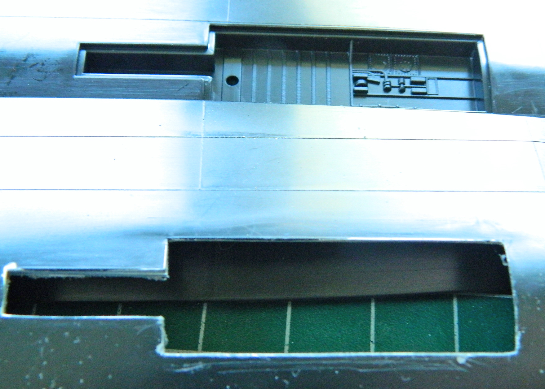
Then start dimensioning things…and here is where I made my first mistake. I used dimensions provided by someone else…a mistake I won’t make again. But at this point I thought the dimensions were accurate so…:

It wasn’t until I had the box about two-thirds constructed, enough to dry-fit, before I realized the provided dimensions were wrong:
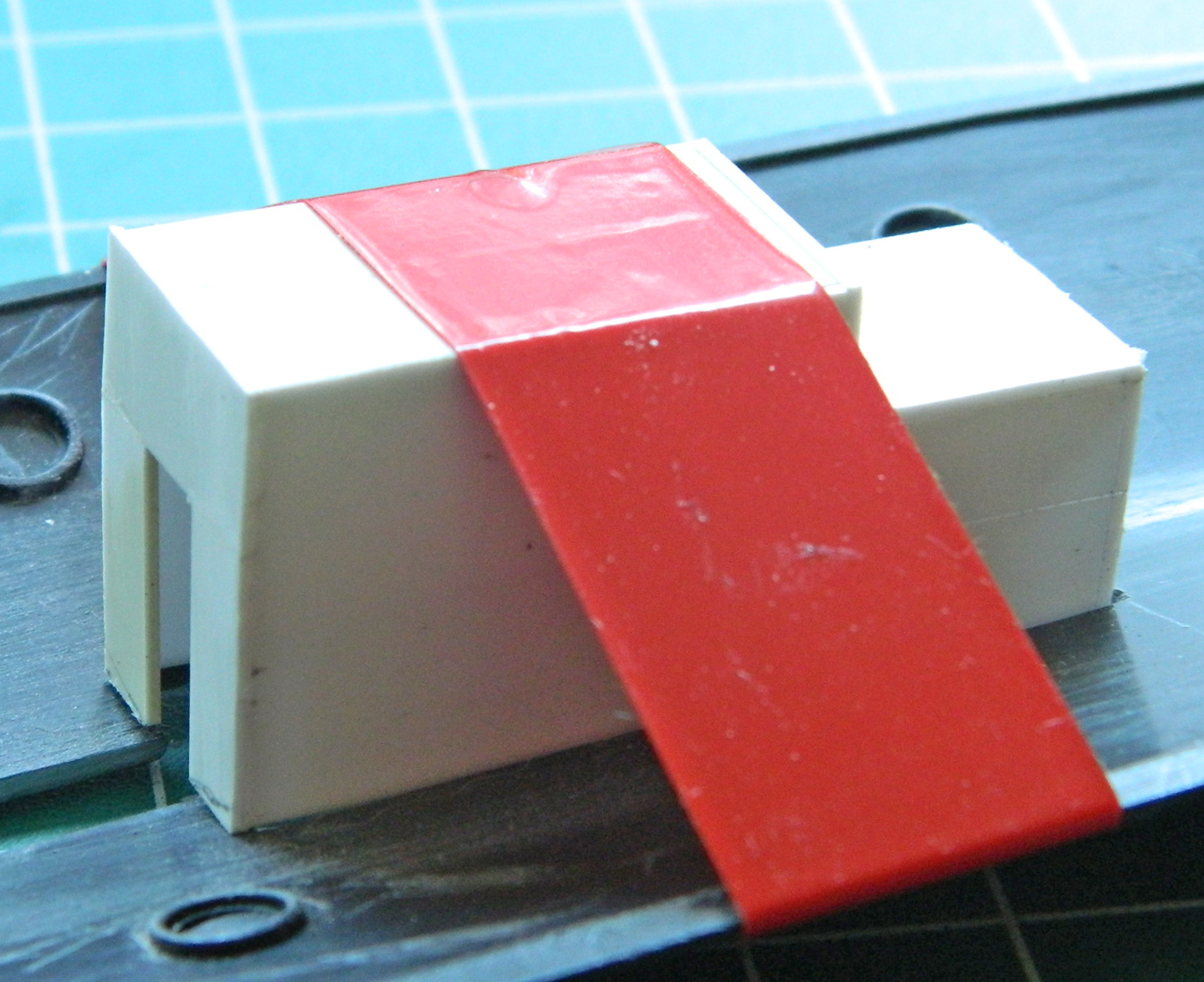
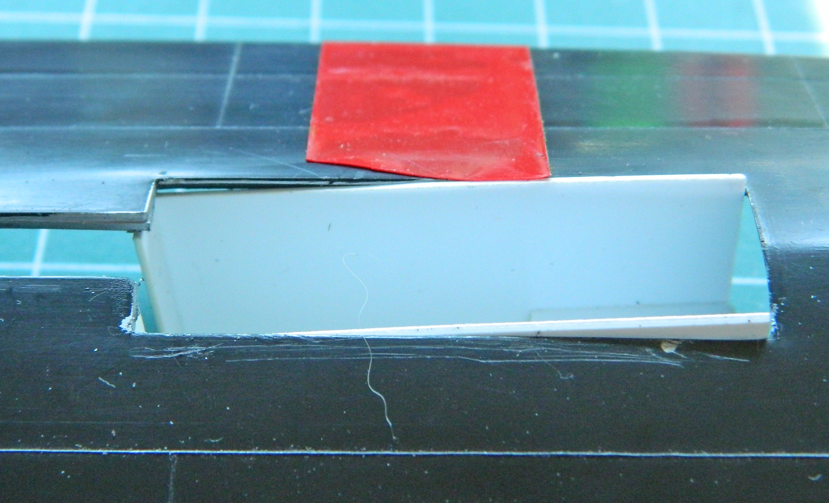
That got tossed in the scrap bin. Before I started cutting plastic (.030″ [.762mm]) again, I decided to create a socket for the new box to settle into. This is going to be a big model with some heft and I wanted to increase the surface area the glue would bond with:
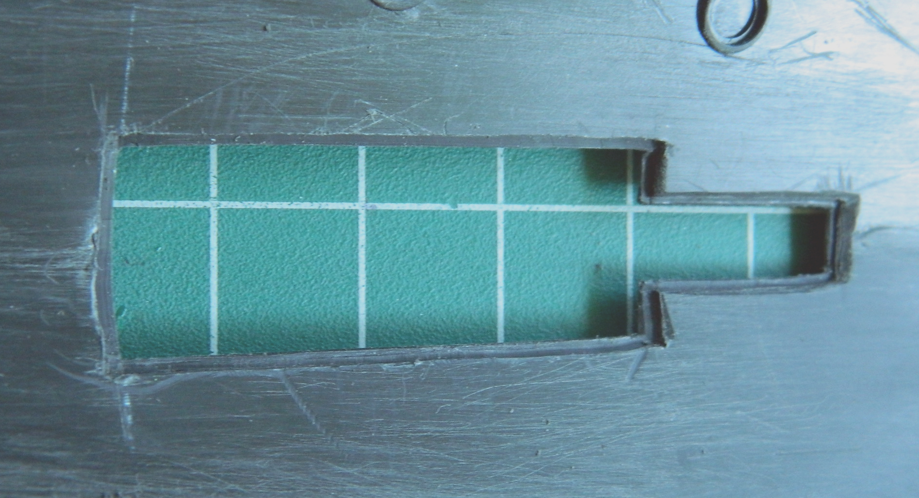
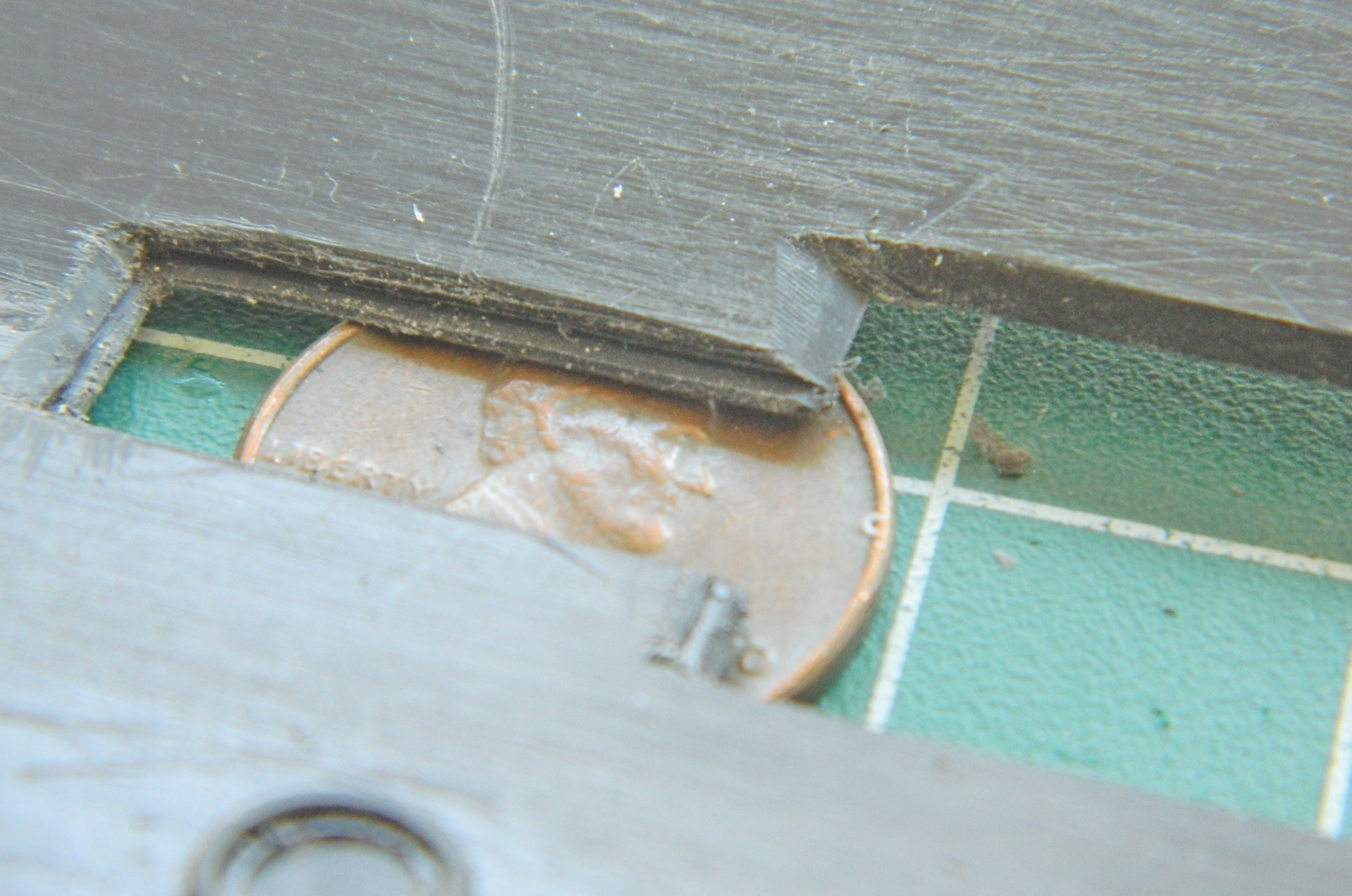
Then I used the opening to create the shape of the vertical bulkhead in the front, cut the side panels, and glued them together:
Dry-fitting shows a good fit:
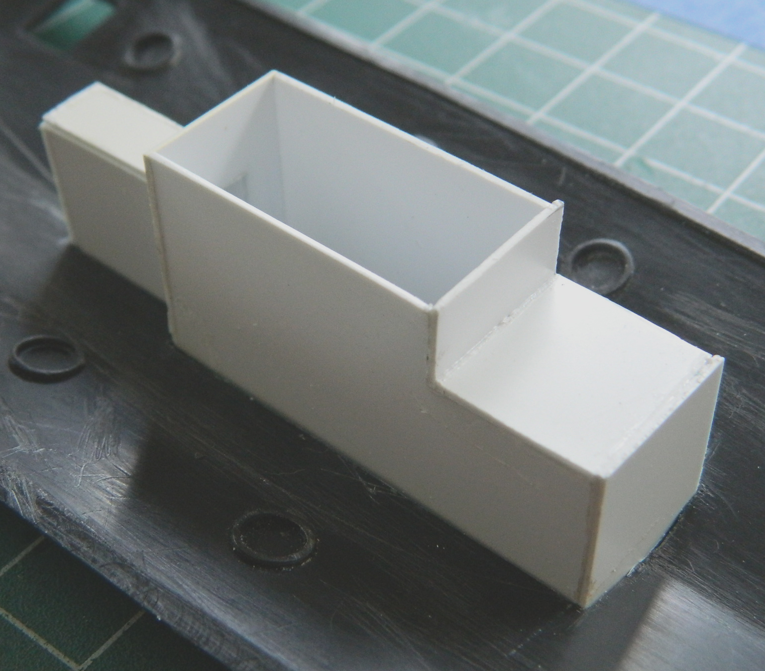
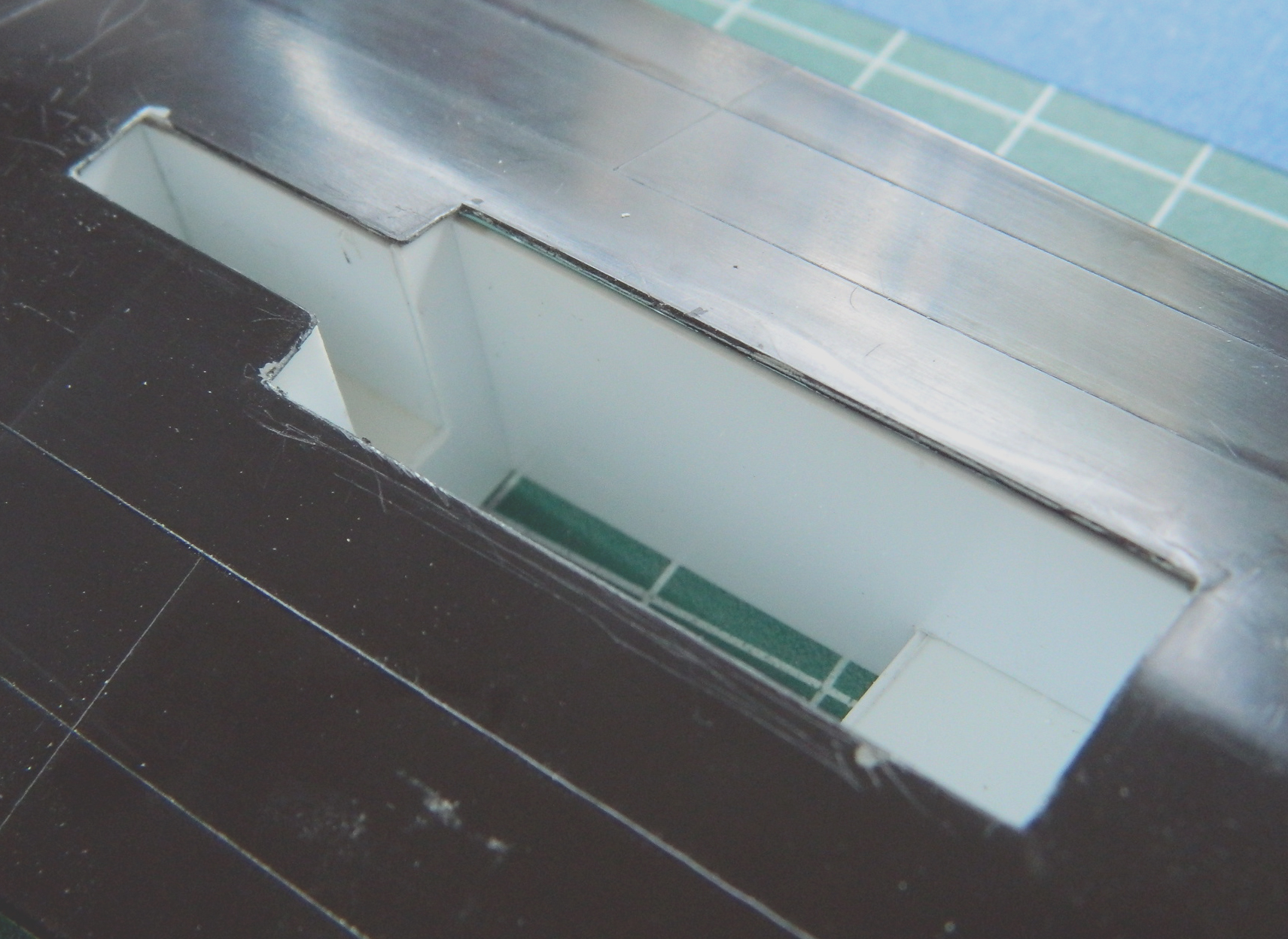
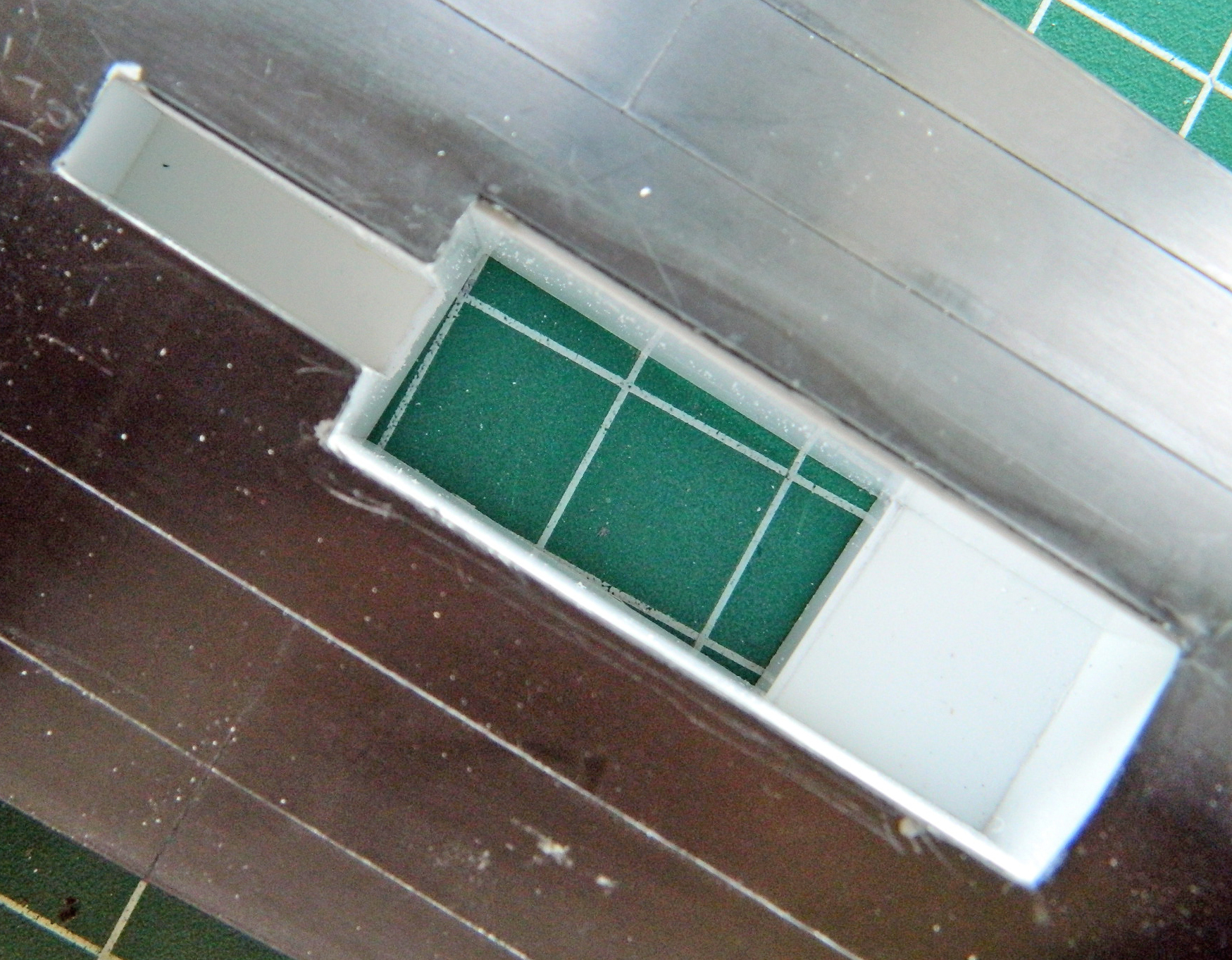
And then I noticed I’d gotten one of the dimensions incorrect. So I had to remove a section from the rear of the bay and rework it slightly:

Once that was done, a few more bits added and now the basic box is done:
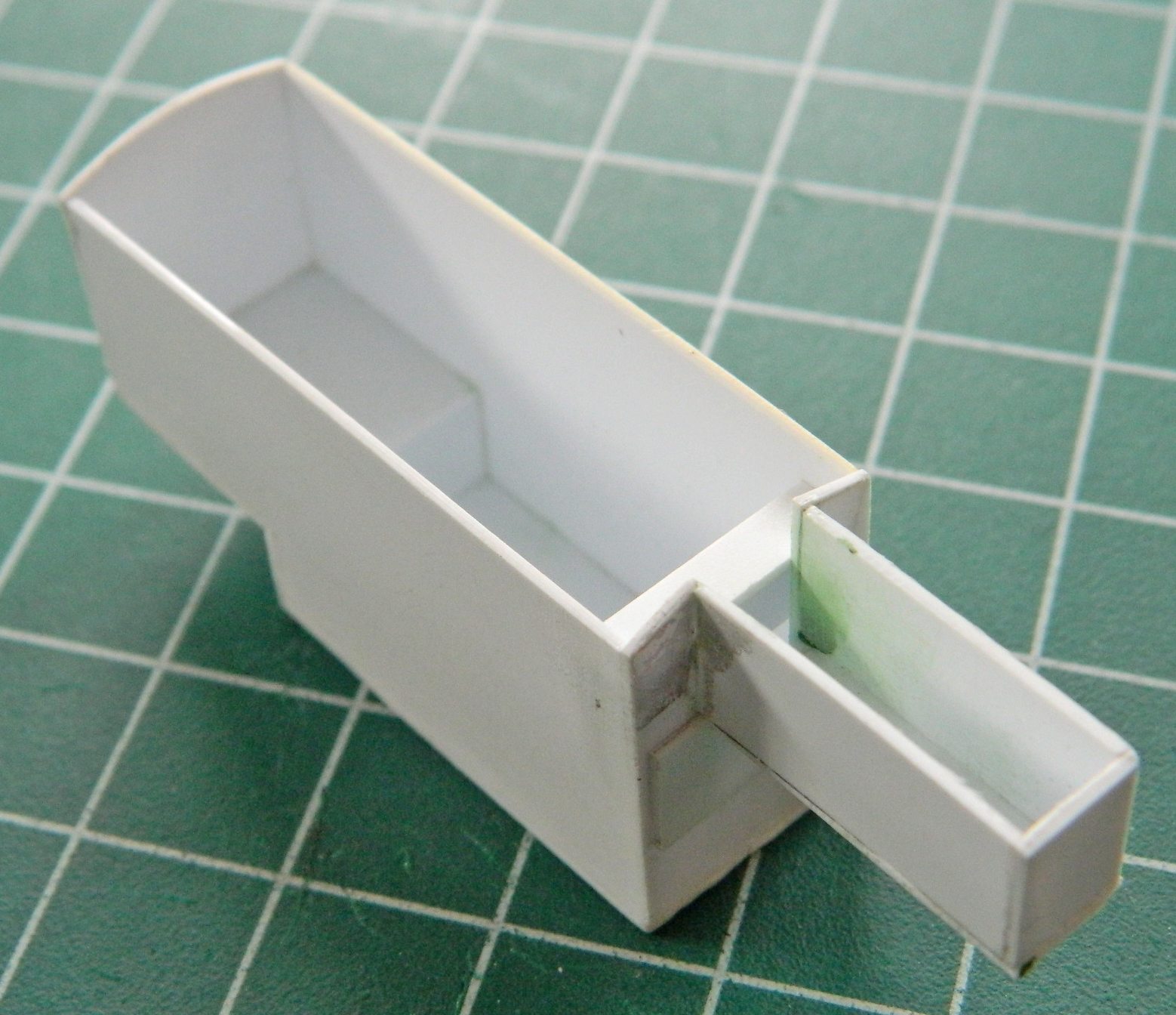
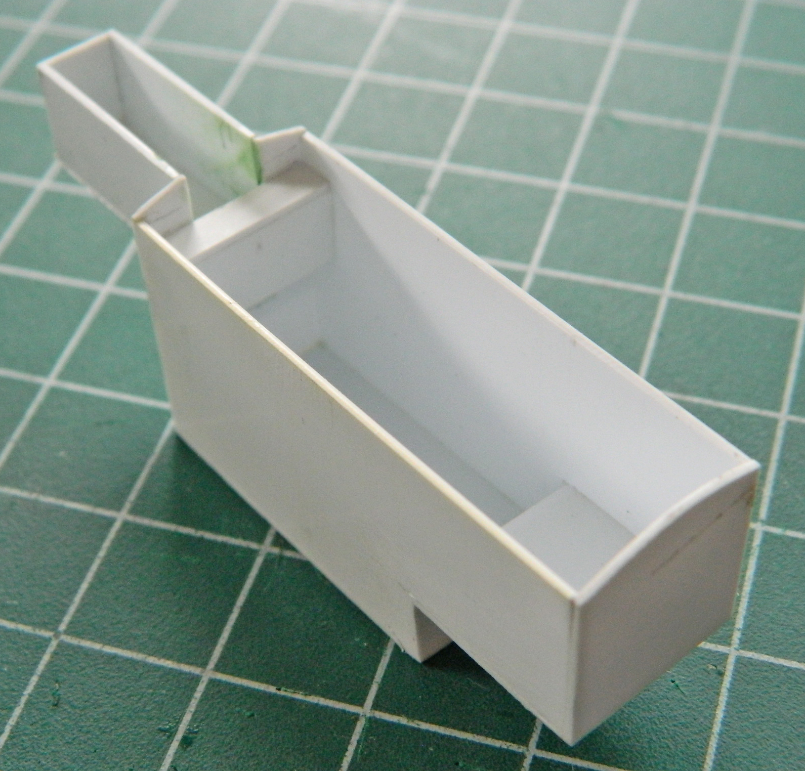
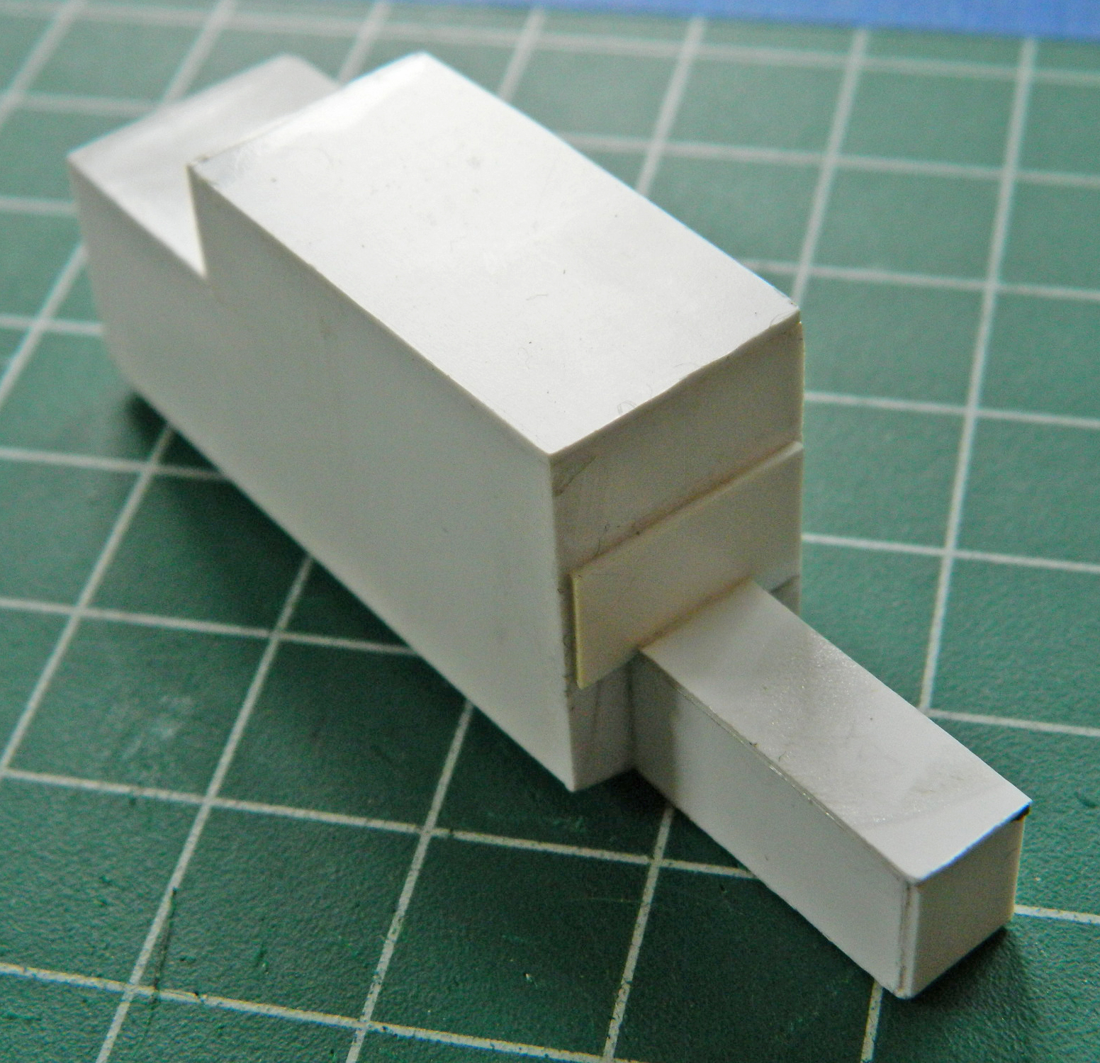

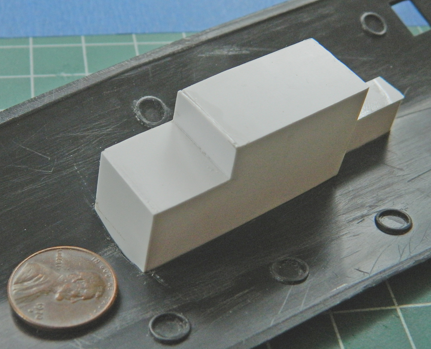
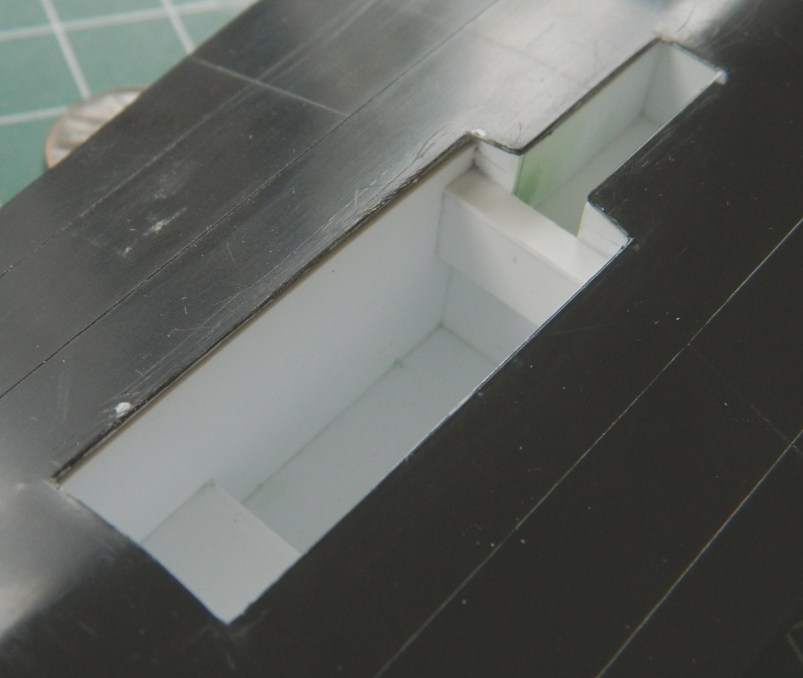
With the basic box of the landing gear bay built, it’s now time to fill that box.
