


Total time building 793.25 hours (that’s about 33.05 24 hour days, 19.833 work weeks).
Begin date July 15, 2017; end date September 20, 2019.
Vendors:
Testors
Giant Spy Plane Kit #984 1/48 scale
Having started on the engine bay, seemed to make sense to get the engines assembled and detailed. I quickly discovered that the carburetors wouldn’t stay glued on. There’s very little surface for the glue to adhere the parts to so the carburetors needed pins:

The most challenging of what the engines would need was to get eight TINY (.010″ (.254mm)) holes drilled into the distributor caps and then glue eight TINY lengths of .010″ (.254mm) solder into them:
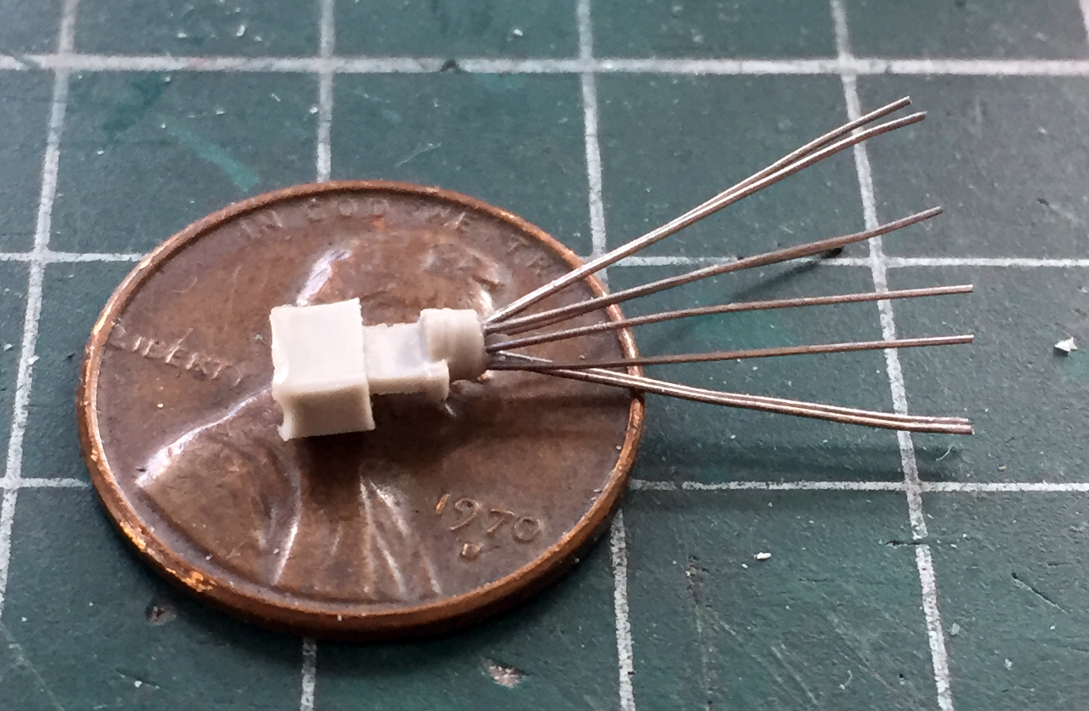
While the superglue cured a bit, I added the fuel lines to the carburetors’ float bowls:

Then I had to drill the distributor mounts to accept a pin; there’s NO WAY this solder and resin assembly could stay on with such a small surface to adhere to:
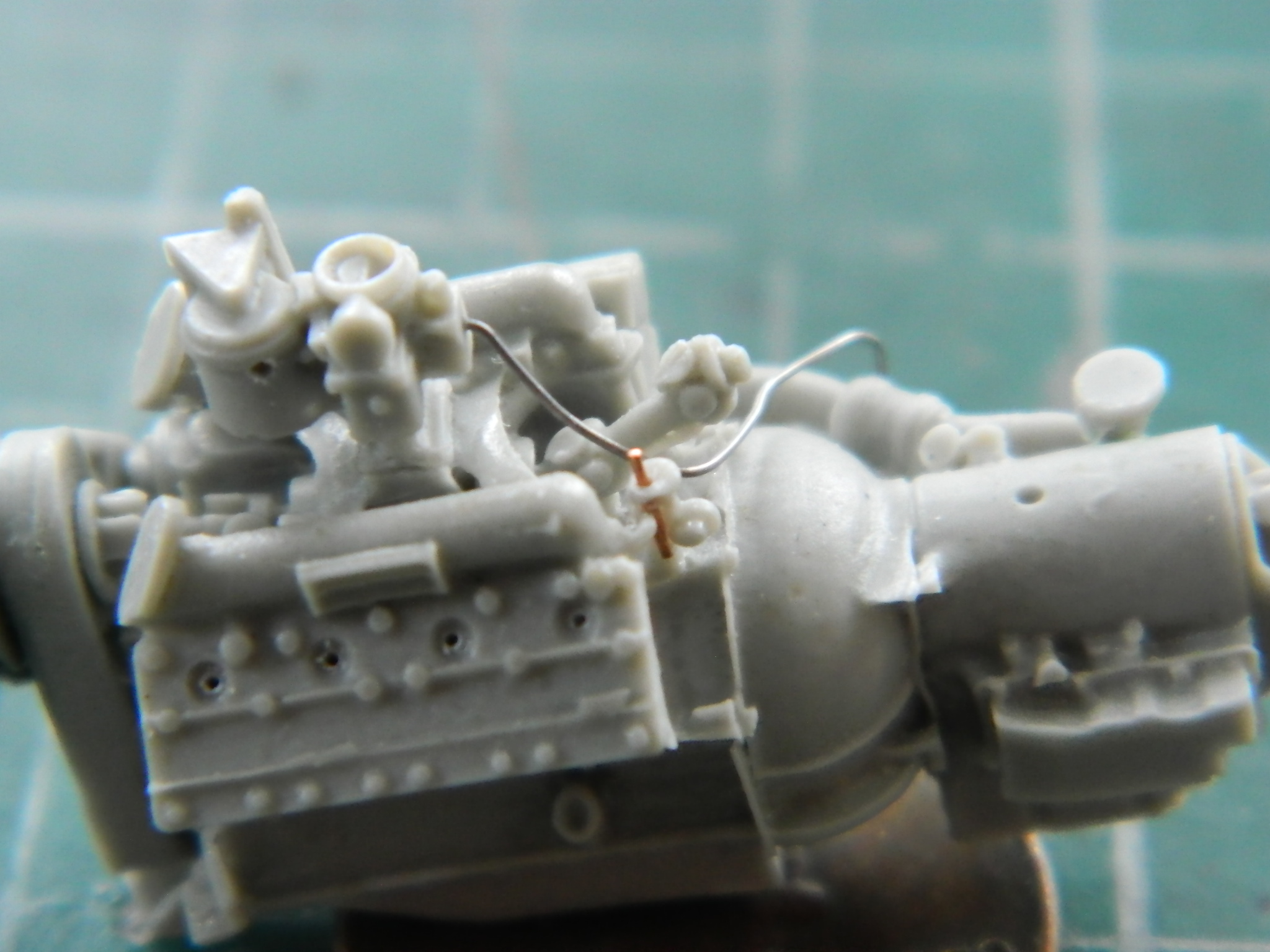
Okay…time to add the distributors:
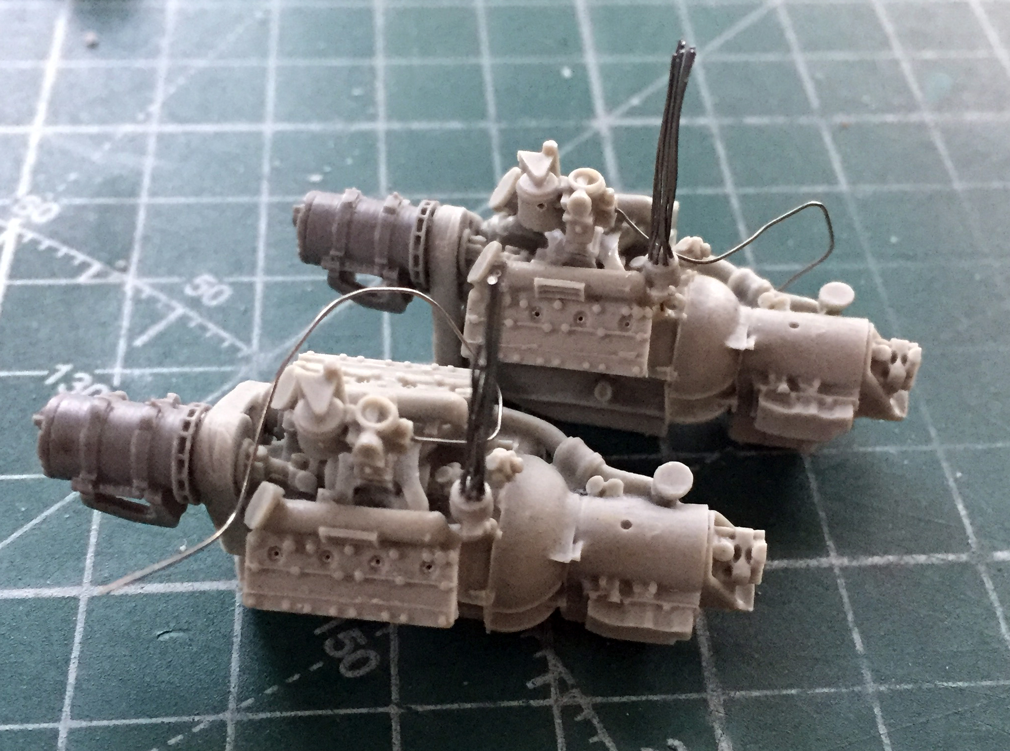
Of course, ignition wires (which I manage to get the firing order correct on) then get routed:
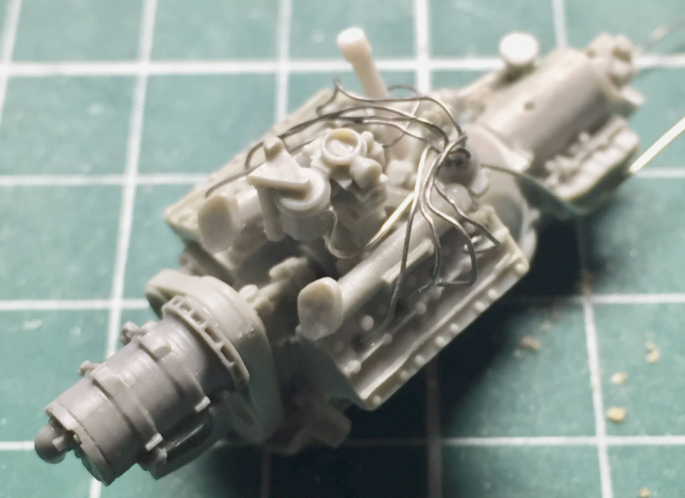
Each engine required the coil to step up the voltage for the spark(s). I used 1/16″ (.062) (1.58mm) plastic rod as the coils, drilled three holes for more .010″ (.254mm) solder, and then mounted them to their respective engines (as well as adding some lead foil for the wiring loom):
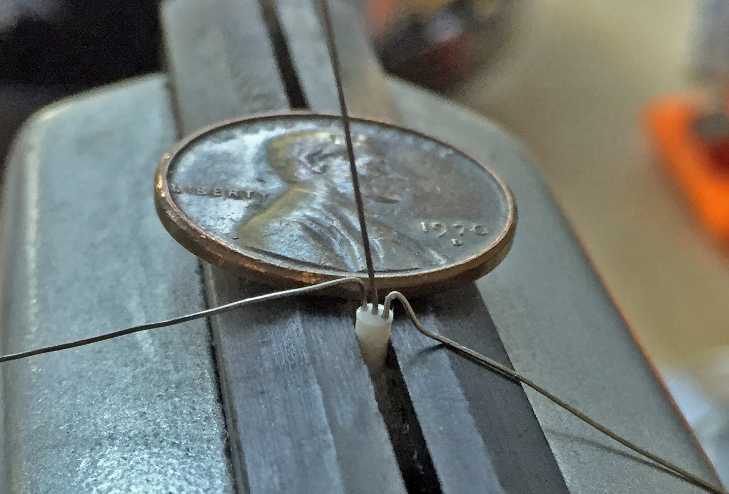
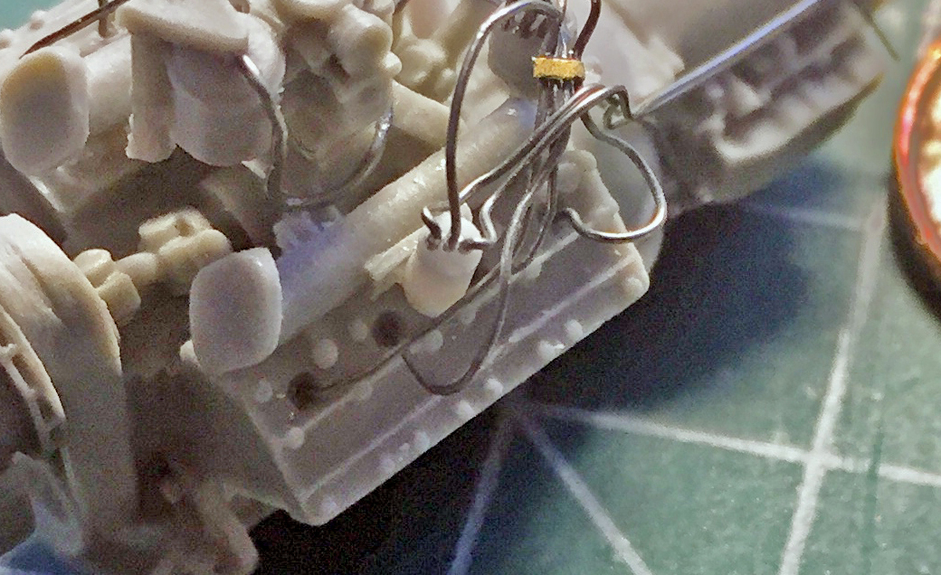
The hose/pipe arrangement needed details added as well as adding the oil filler tube and cap (the styrene rods that have a copper wire sticking out of them are part of the hoses; later those wires will be trimmed to fit):

Return lines were added to the crankcase vents, and the power leads were added to the generators:
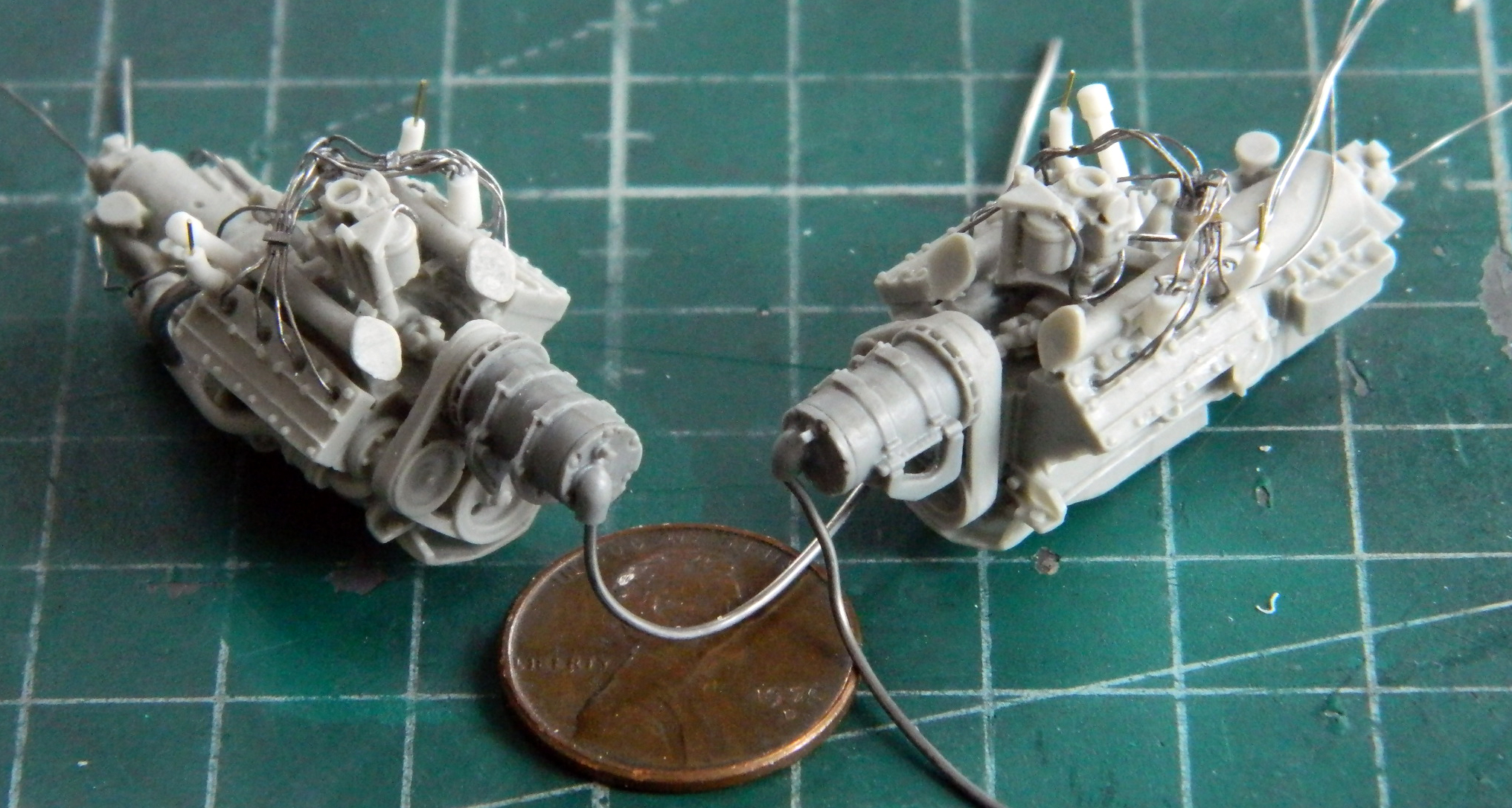
Somehow I failed to notice that one of the exhaust manifold parts had a large bubble in it. I cut the thinnest sections of the bubble away to see if I could fix it. The part as-is isn’t usable so I had nothing to lose by trying:
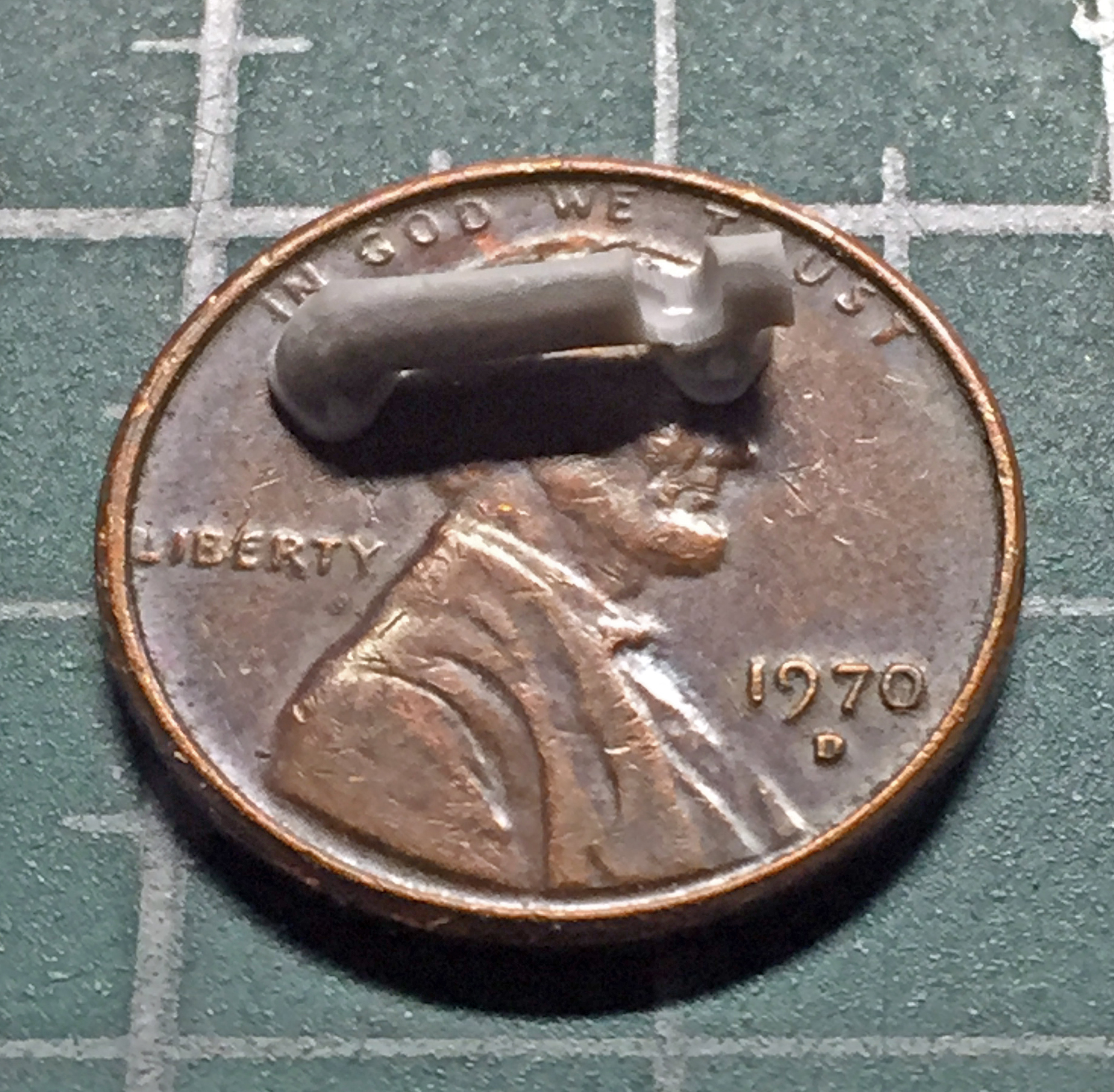
I squared the bottom of the gap and then added styrene scraps to fill and then glued the hell out of it all:
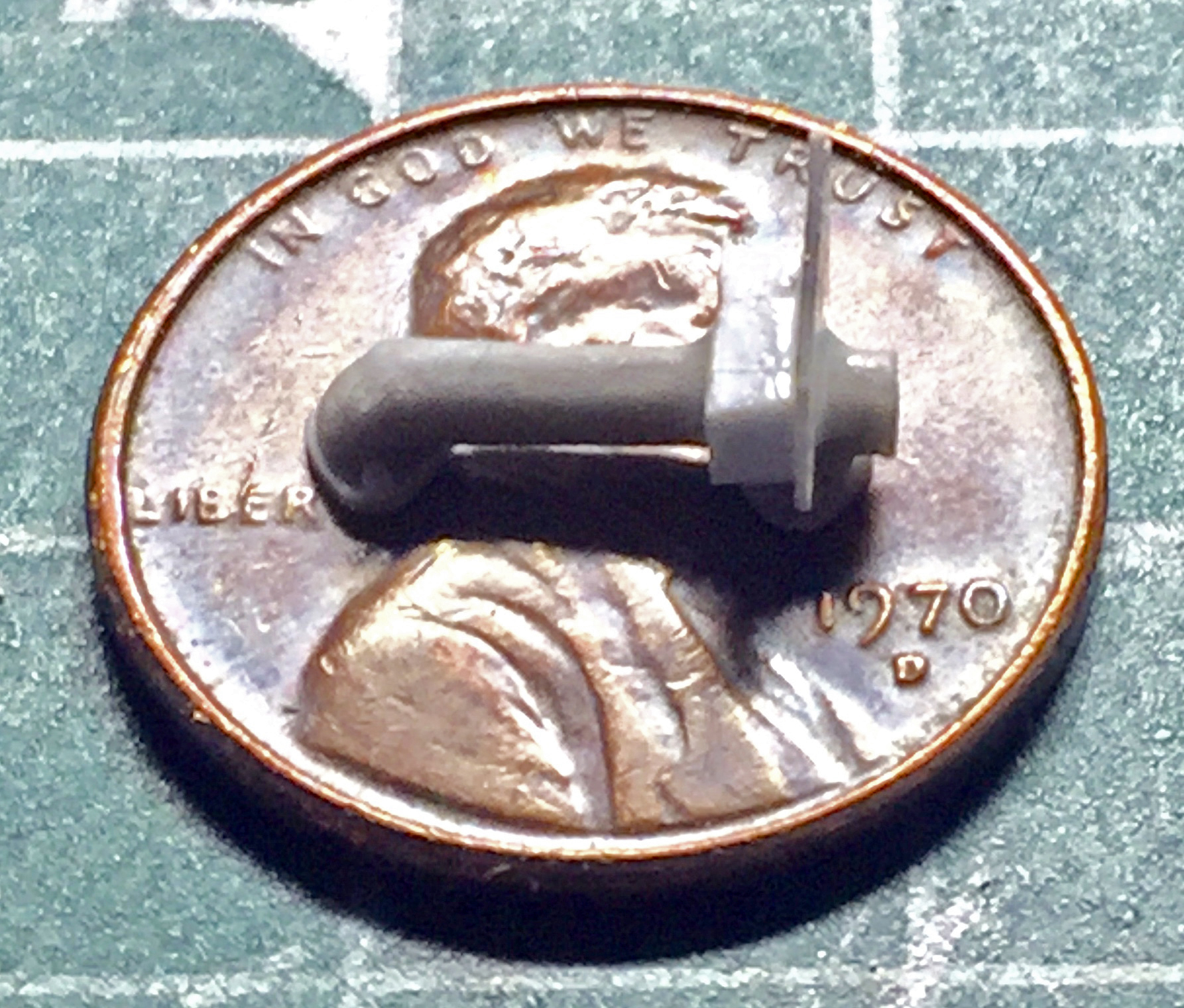
It worked:

A prominent feature on the engines is the lifting rings bolted to the top of each head. I didn’t consider using styrene at all as scale size dictates .005″ (.127mm) be used. Instead, I used .005″ (.127mm) copper shim stock. I was fortunate that the smallest punch of my punch and die set was just the size opening I needed. For ease of manipulating very small bits, I punched the holes first:

I used scissors to cut the strip from the stock and then LIGHTLY tapped the surface with a hammer to return it to a flat shape:

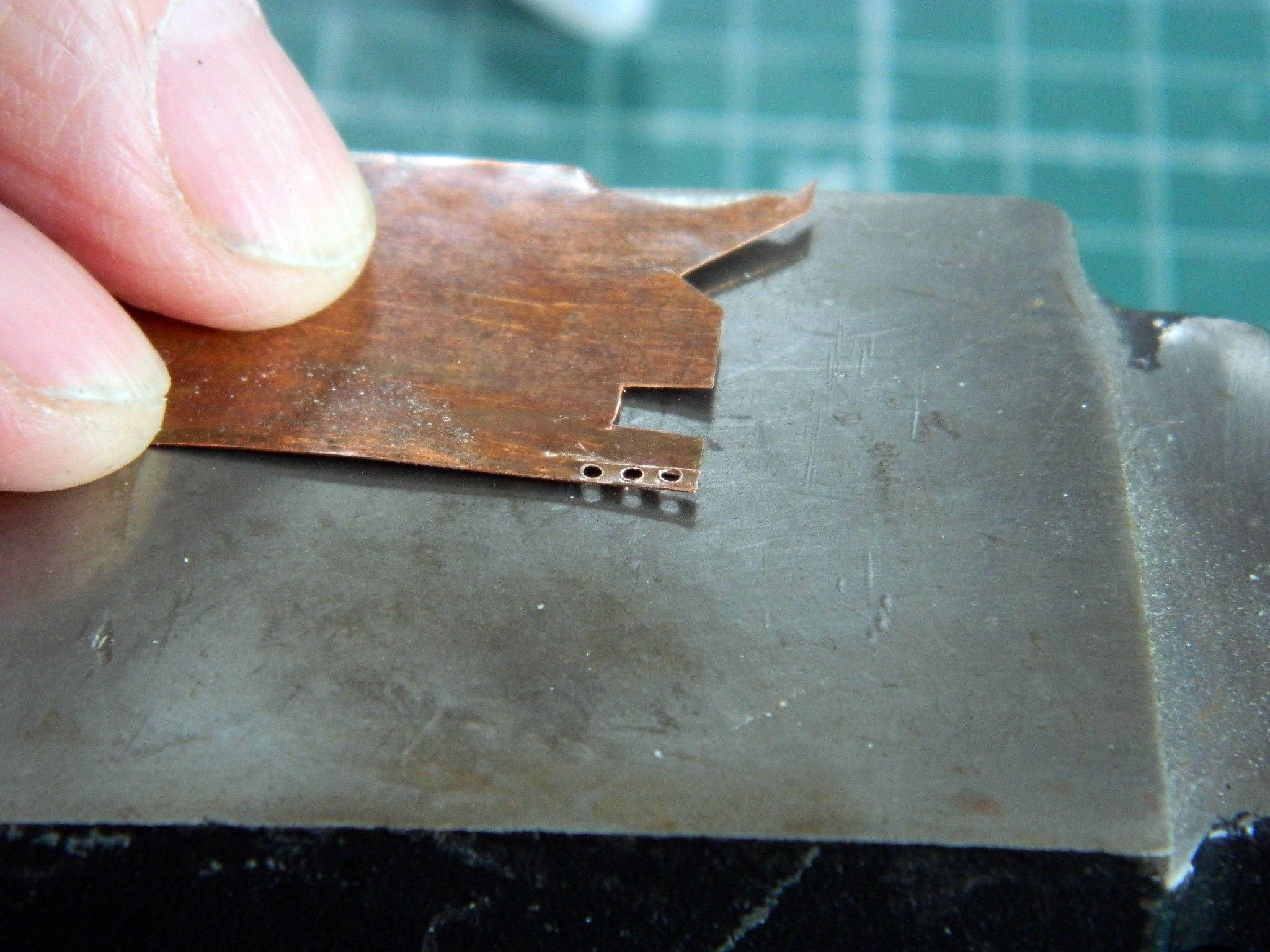
Hammering too hard will cause the soft copper to deform, so if you ever do this, softly with the hammer is required.
As it turned out, my first attempts were too small. There isn’t enough material left on one side to form the mount:
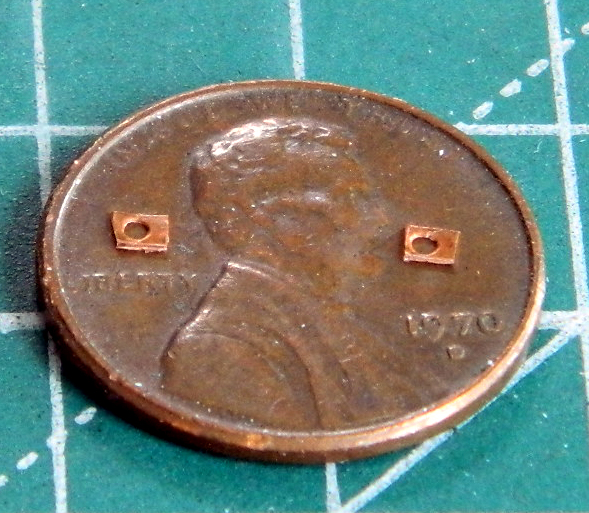
Then my brain caught up with events and informed me that IF I wanted a nice bend with a tight radius, maybe I’d better anneal the sodding copper…so I did:
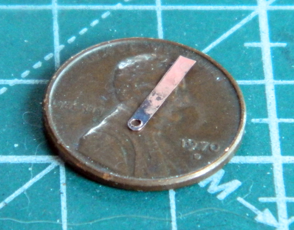
The first attempt (shown in the above photo) worked well. I needed three more. Then my pattern of the-first-is-easy-and-the-rest-anything-but-easy showed up. Again. I only needed another three, but it took me eight more sodding tries to get three that were acceptable.
::sigh::
With the lift rings finally done, all that needed to be done was to shave off the head bolts so the parts would fit flatly and then glue said parts in place:

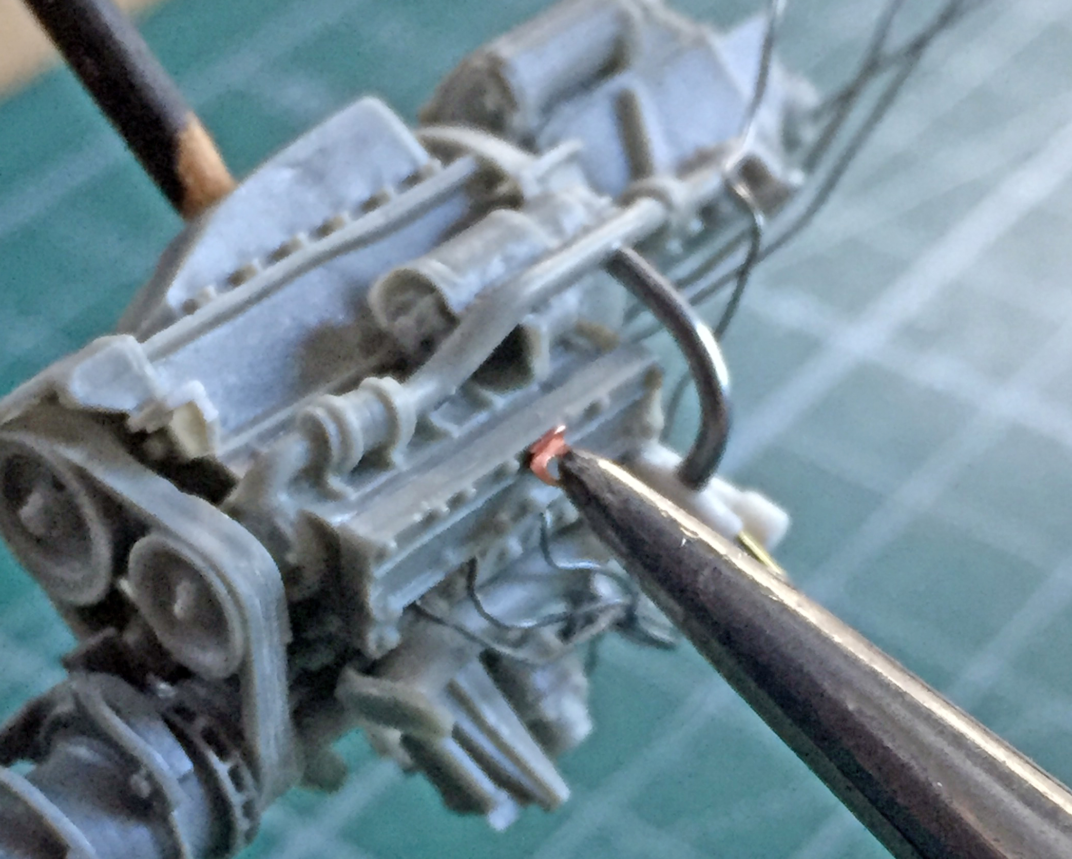
I was surprised that this part of the assembly was easy:

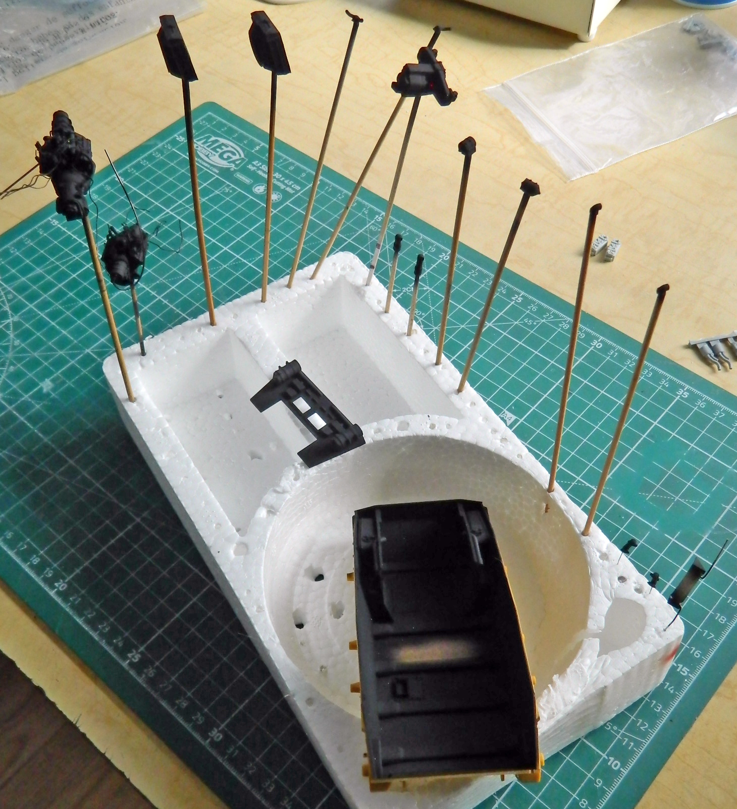
Whew. Tiny details. They take forever (it seems). Having done all that, the next step is to start painting while the parts and assemblies are out and accessible. I want to pre-shade the parts, assemblies, and engine bay, which meant that I had to spray them Tamiya XF-1 Flat Black:
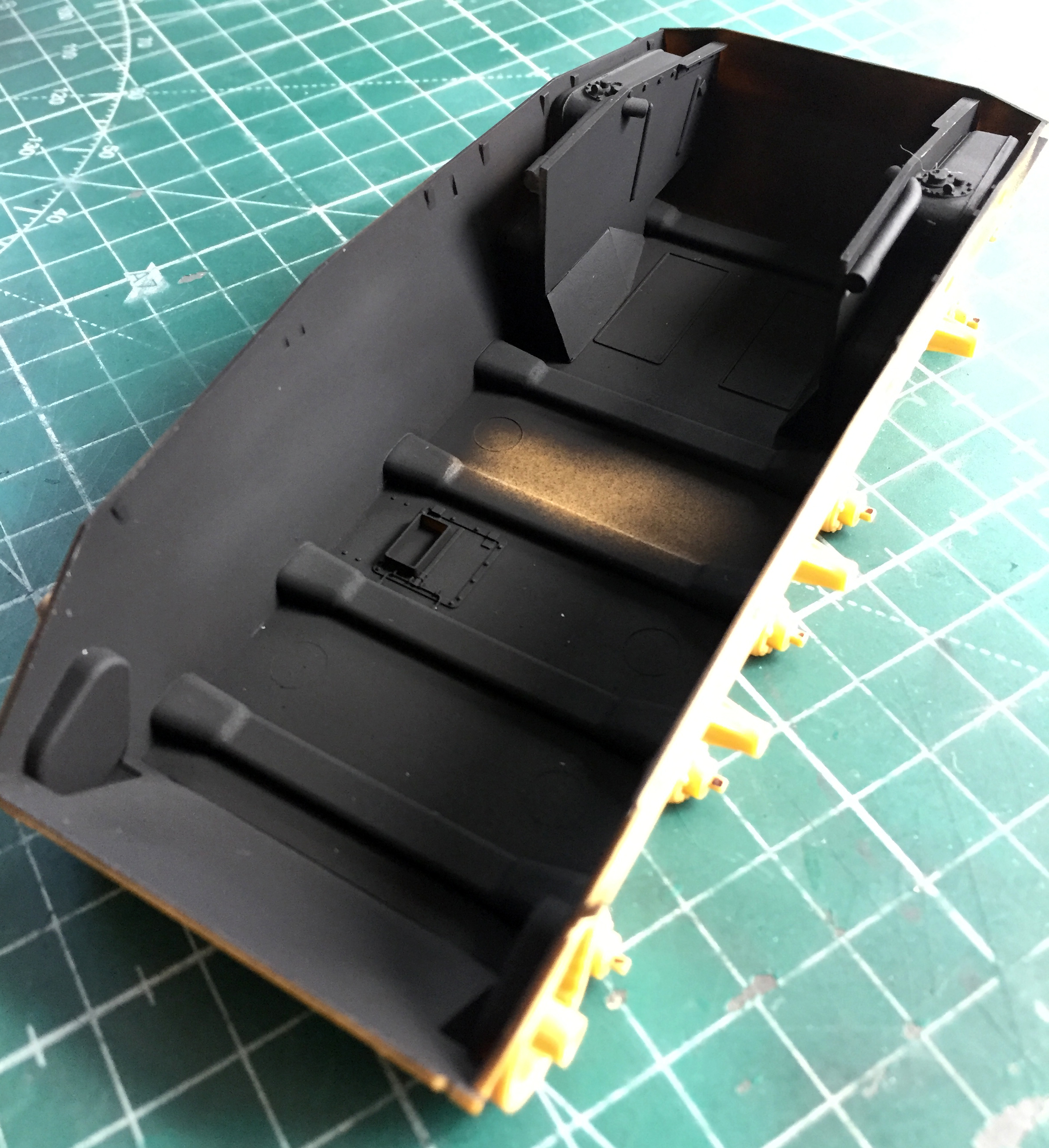
While I had the airbrush loaded with flat black, I did the inside of the lower hull:
That was the easy part of painting the engines and associated parts. What comes next could be challenging…
Thus far this build has been a little different. I usually sequester myself in the Mad Scientist’s Lair, and while cackling gleefully, immerse myself in my latest obsession…er…build. As those of you Out There who engage in this activity know, it’s mostly a solo activity, interrupted for bathroom breaks, refilling of the beverage of choice (with sharp things and potentially hazardous chemicals, I think alcohol consumption should not be part of that scenario…unless your local hospital ER has cute nurses and you’re more desperate than I am) (assuming that’s even possible), and sometimes sustenance to keep the vision from blurring. Okay, so maybe you don’t build that way, but I certainly do…or had until this build.
A dear friend of mine (for whom I had built the M3 Stuart) wants to see how I progress from a pile of parts and pieces through the Process of Modeling Glory (TM) and manage to end up with something that looks like [INSERT MODEL TYPE HERE]. Yes, this site is informative for her, but the process of Q&A can be rather cumbersome. So she’s been sitting next to me while I’ve been working. Being a simple-minded sod with limited multitasking capabilities, this has upset my routine of clip, scrape, diddle, and fit and then take pictures for inclusion here. So the beginning of this is a bit off from my usual form. That said…
Here are the parts:

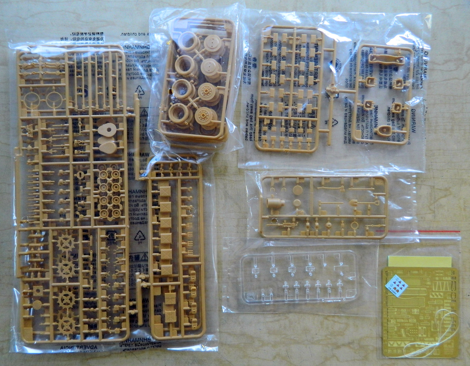
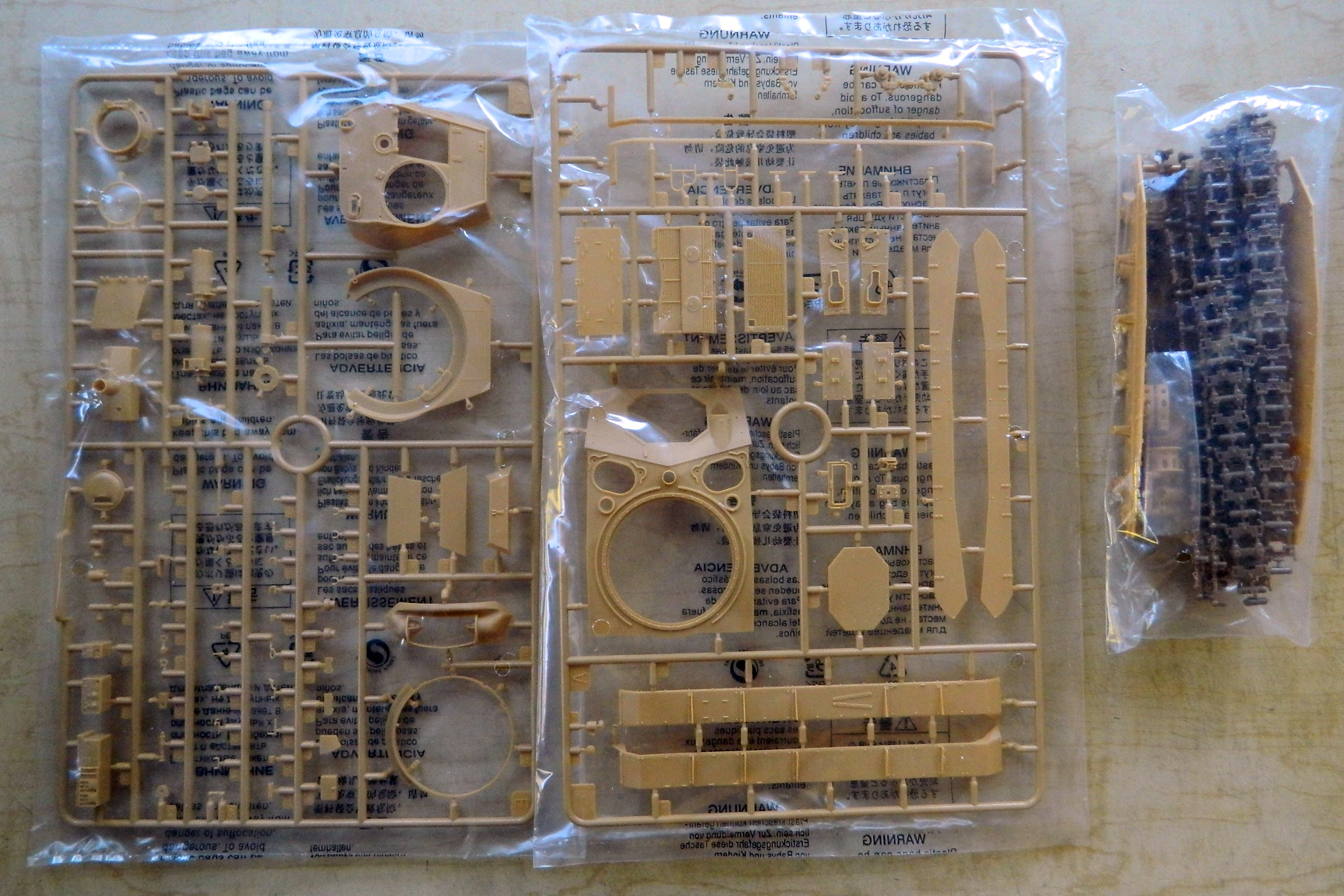
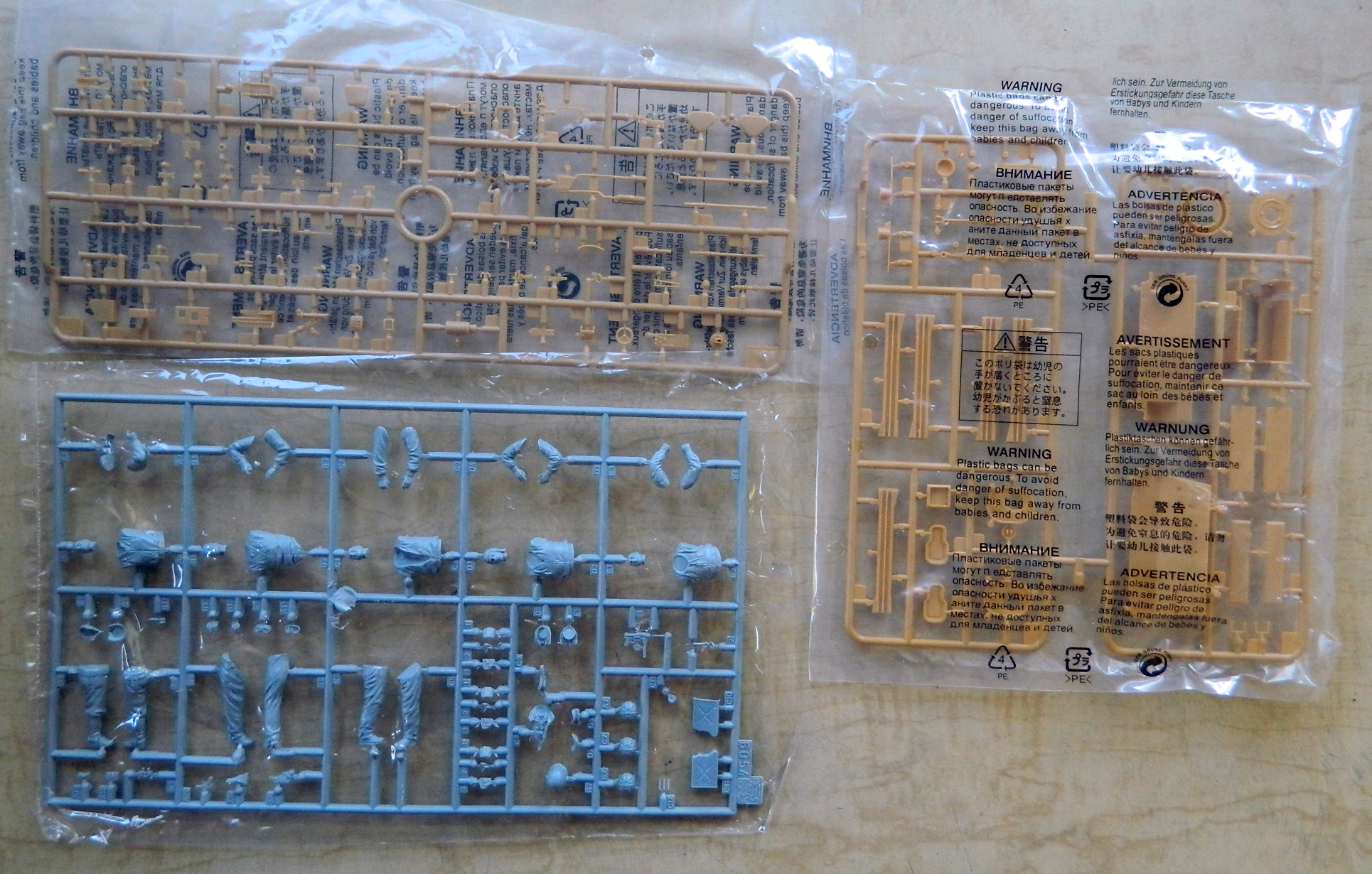
First look at the parts shows judicious use of slide molding. The main gun barrel was molded in one piece including the muzzle and rifling. I usually use metal barrels whenever possible but the kit’s plastic barrel seems good enough to use instead. Parts count is high but they all seem to be well molded without flash. I’ll see as I go along how the fitment of these parts works out.
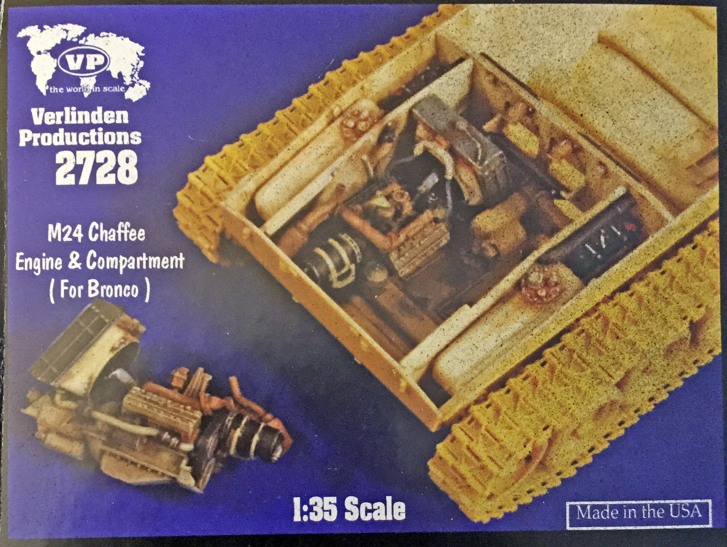
I intend to add an engine compartment and engines as well as a full interior. Verlinden made a resin detail set for both the engine compartment and interior (interesting note – if you look at the box for the interior set, you’ll see it was made for the Tasca model…except to my limited knowledge Tasca never made one):

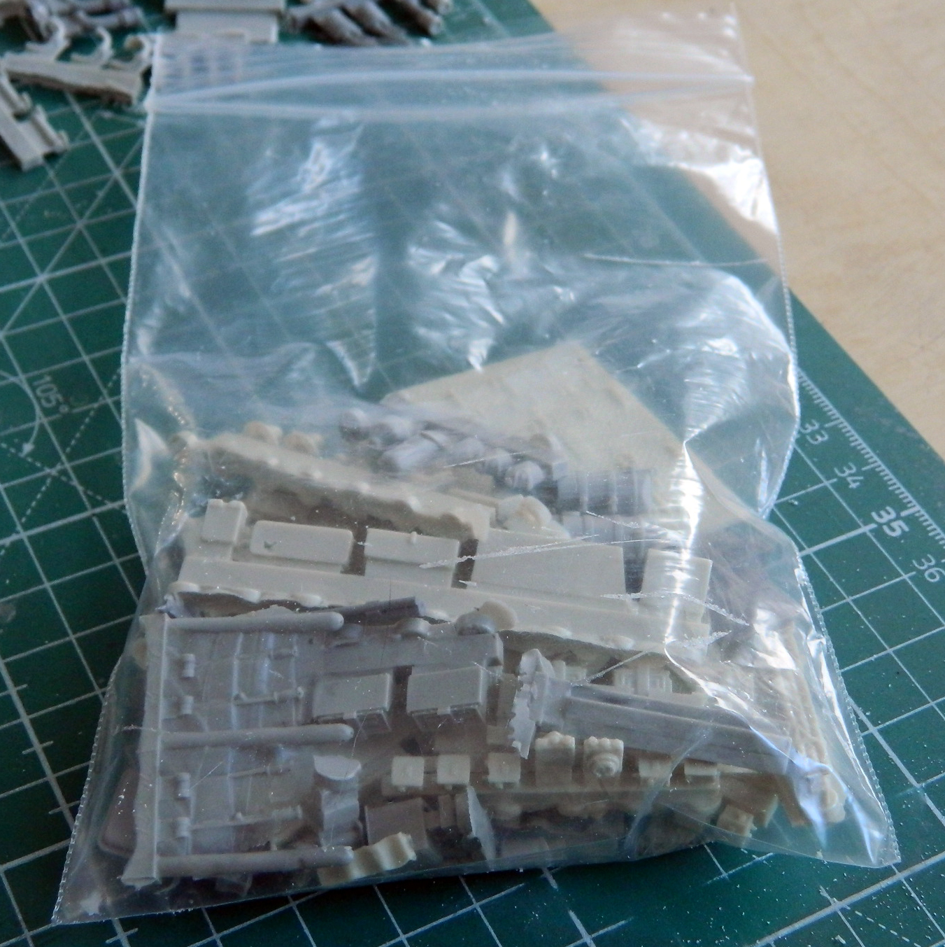
Since Verlinden parts will become more scarce, and thereby more expensive, as time passes, I’ve made a habit of copying Verlinden’s resin and using the copies instead of the actual Verlinden parts:
I started by constructing the lower hull. The bottom and sides are molded as one unit and show very nice surface details (including casting marks found on the actual M24). Once those were in place, I added the tow hook mounts at both ends. Since this is supposed to be an early production vehicle, the mounts for the flotation devices shouldn’t be there. The mounting pads aren’t on the front lower hull but there are mounting holes for the rear mounting pads that the kit supplied. Oops. Not supposed to be there. I filled the mounting holes with stretched sprue. Since both the interiors of the hull ends will be seen later on, I had to fill the places on the inside where the tow hook mounts showed through:
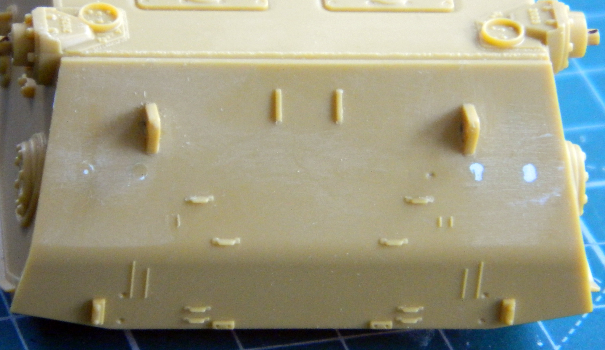

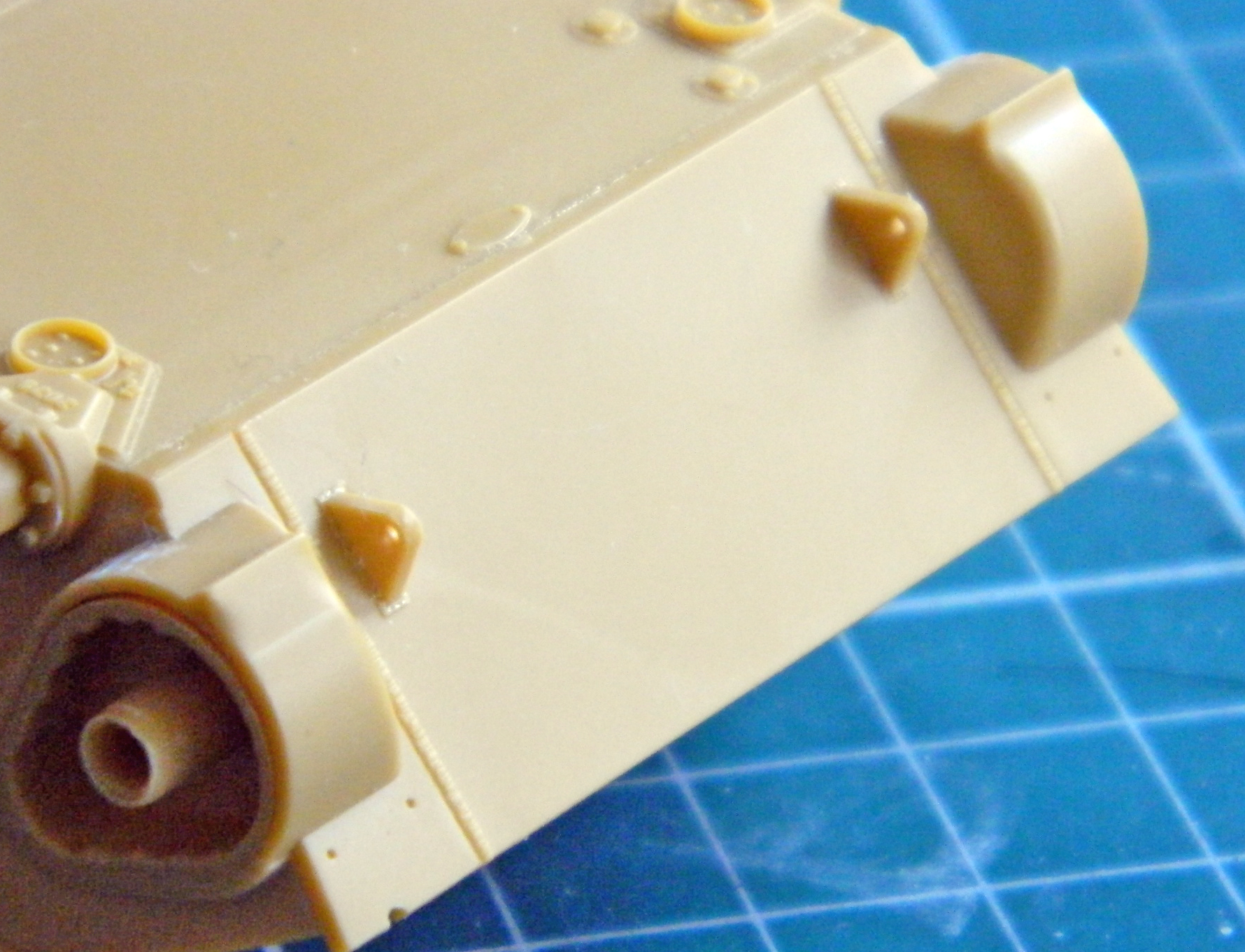
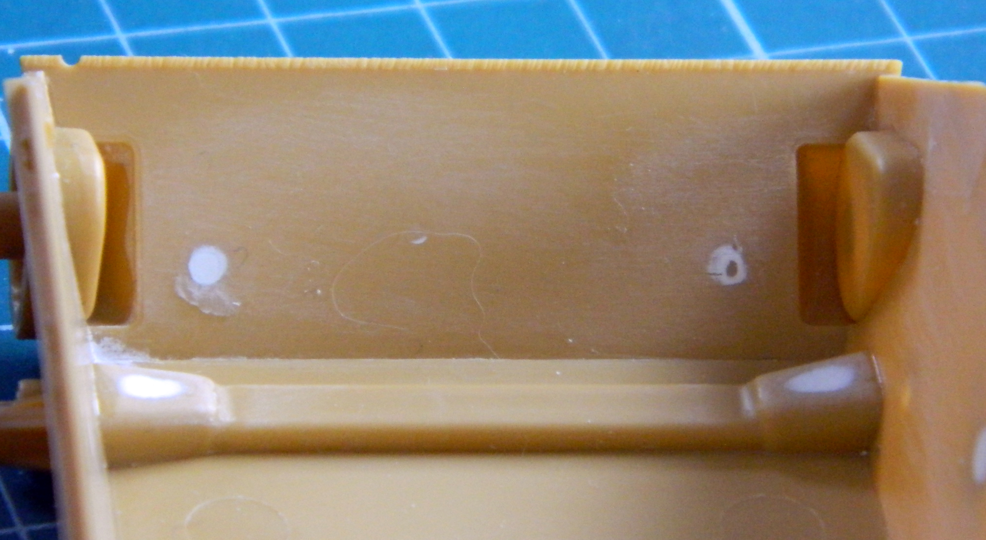
The first observation I made after mounting the front and rear lower hull is that the upper front hull doesn’t fit well with the lower (check the lower right of the next photo). Not a good start, Bronco:
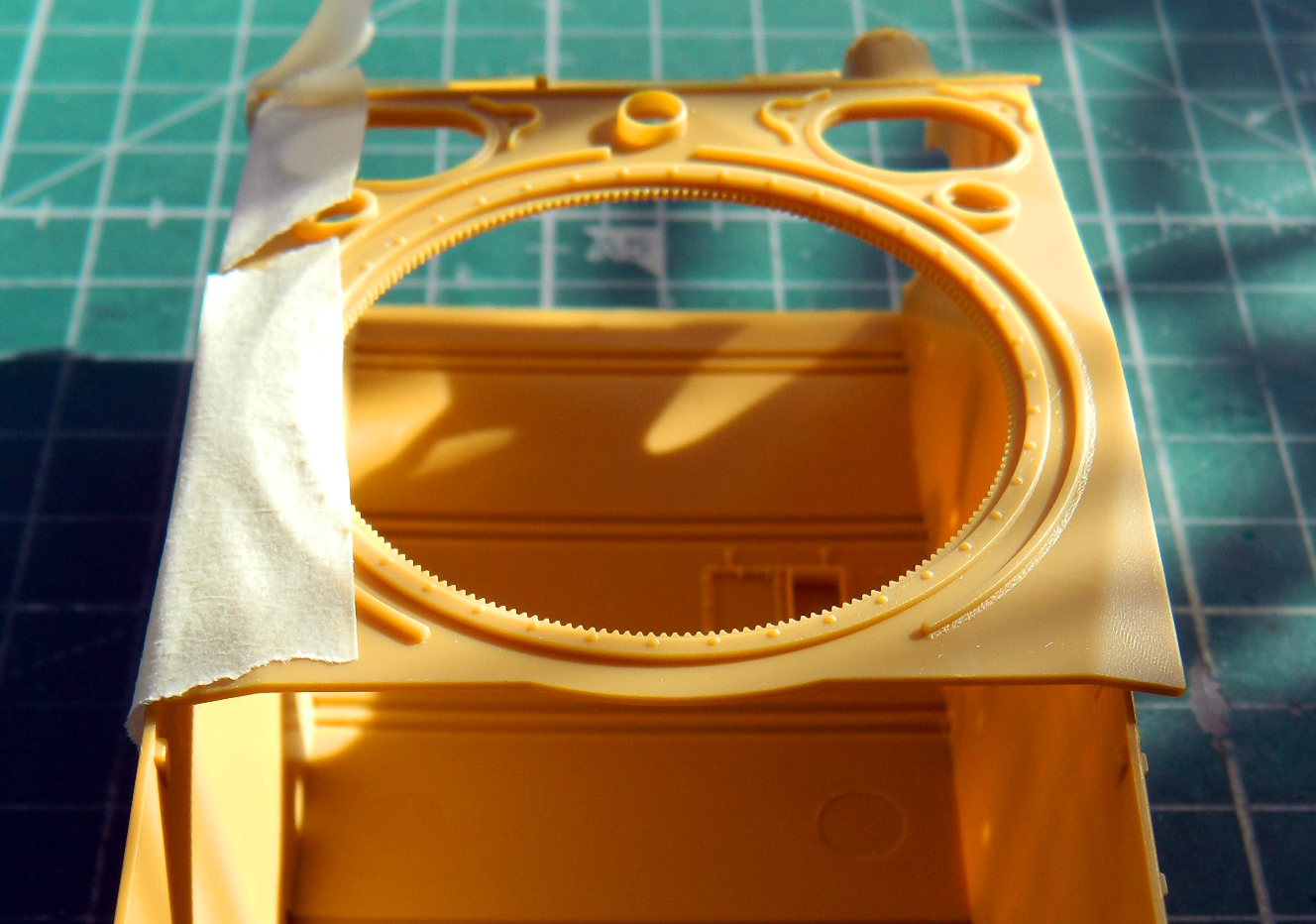
I pressed the sides out and settled the upper hull where it’s supposed to go, taped both sides to the upper hull, and immersed the whole thing into a sink of HOT water:
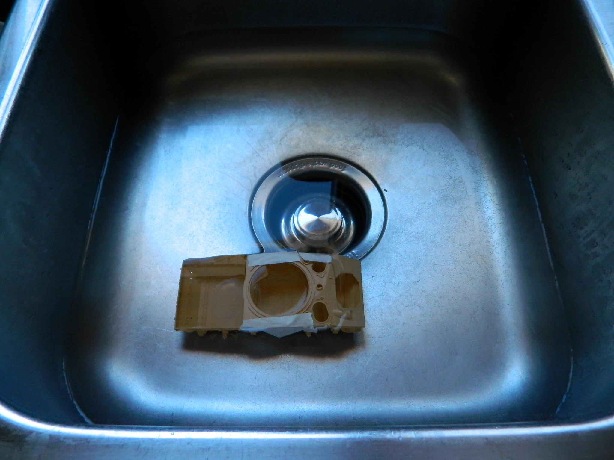
The result was better; about 75% of the misalignment was fixed. The remaining 25% will be dealt with as I add interior parts, particularly the bulkhead between engine and crew compartments.
There are things about this kit I find somewhat gimmicky. There is a spring inside the main gun’s receiver that allows the barrel to “recoil.” Why? And the suspension is clearly designed to be “workable.” It has separate torsion bars for each set of sprung road wheels. Again…why? I suppose having the suspension posable could make posing the tank on an uneven surfaced diorama possible, but posable is different from workable in my mind, leading again to the question of why. The days of models with “workable features” are over. I’m building a model, not a toy that I’m going to play with until it breaks. I added the torsion bar housings and torsion bars as well as the final drive covers that show inside the hull:

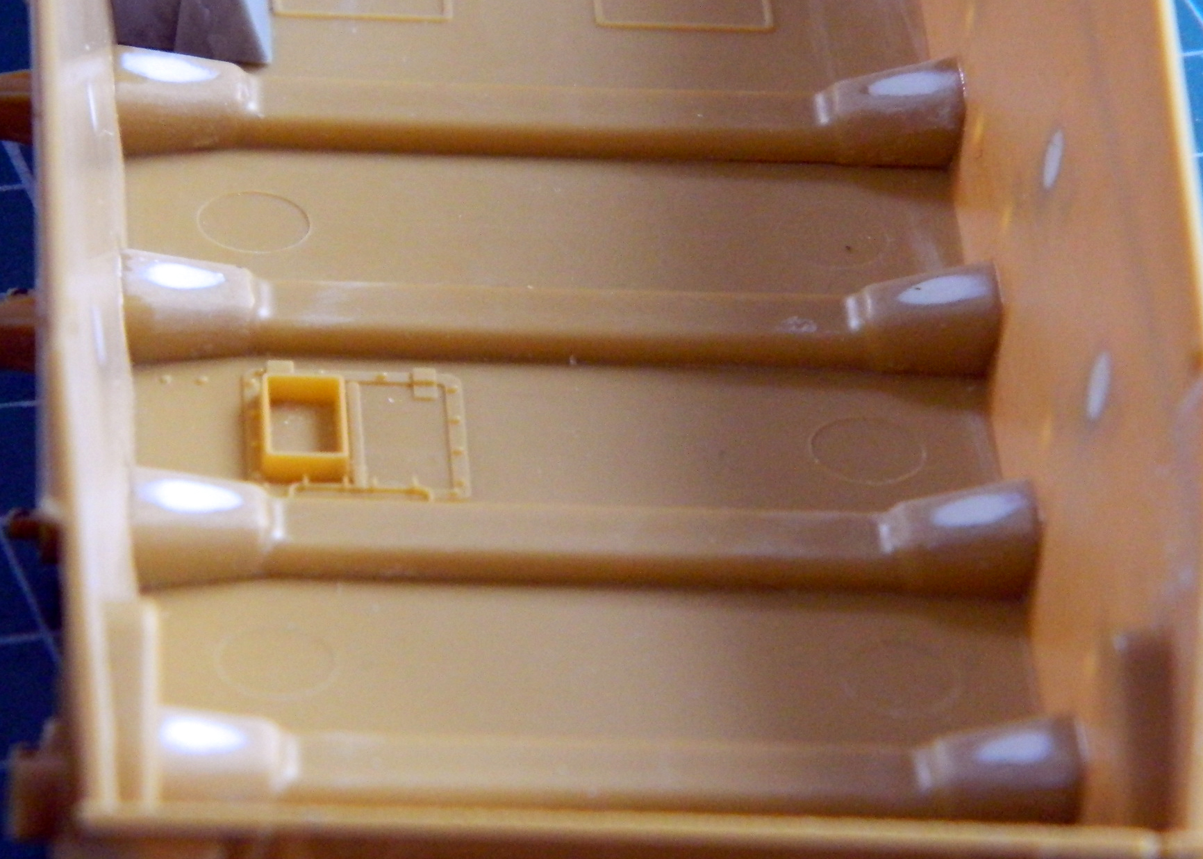
There aren’t many sinkholes in the parts, but I found that all the torsion bar housings had them on the flared ends:
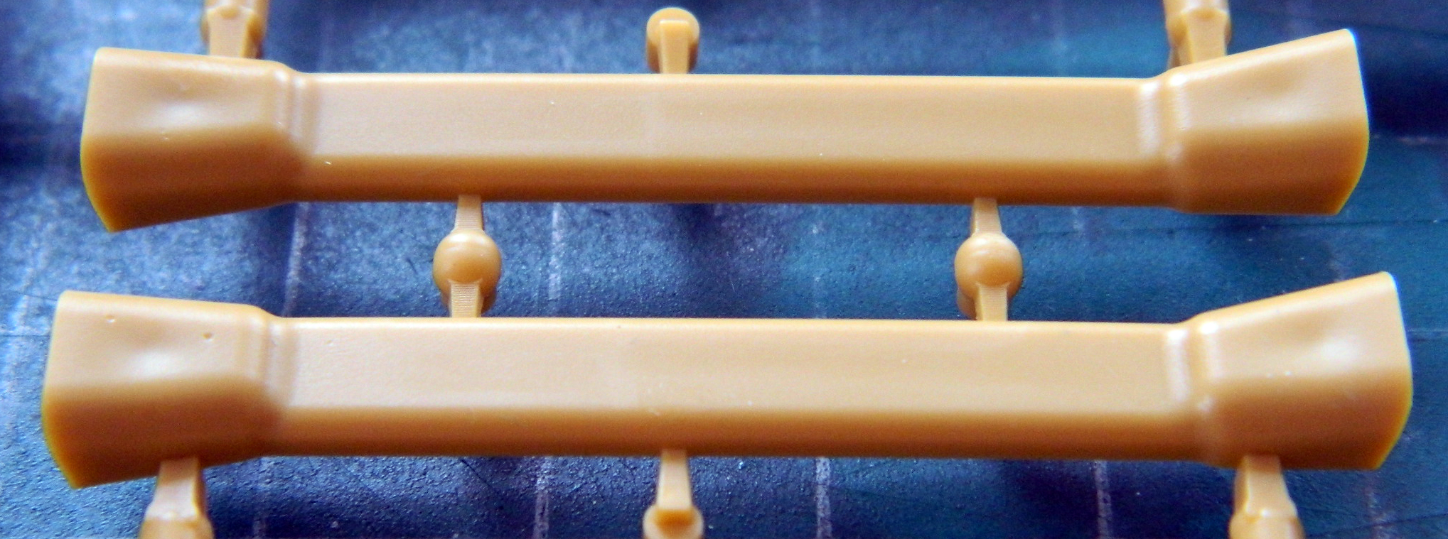
Not a big deal, just add putty:
Time to start populating the hull interior. Using an AM set will frequently result in me sitting there wondering where to start. There’s a lot of parts that have to fit inside this thing and not many definitive places for me to start at. In this case, though, there are two places that the parts can only go into the hull one way; the differential in the front and the sides of the engine compartment in the rear. I decided to start at the rear and installed the fuel tanks/compartment walls (molded as one piece):

With both fuel tanks/compartment walls in place, that gave me the position for the bulkhead. In this photo, the bulkhead is just taped into position to check how it affects its position relative to the sides of the hull, which according to the upper hull is too narrow:
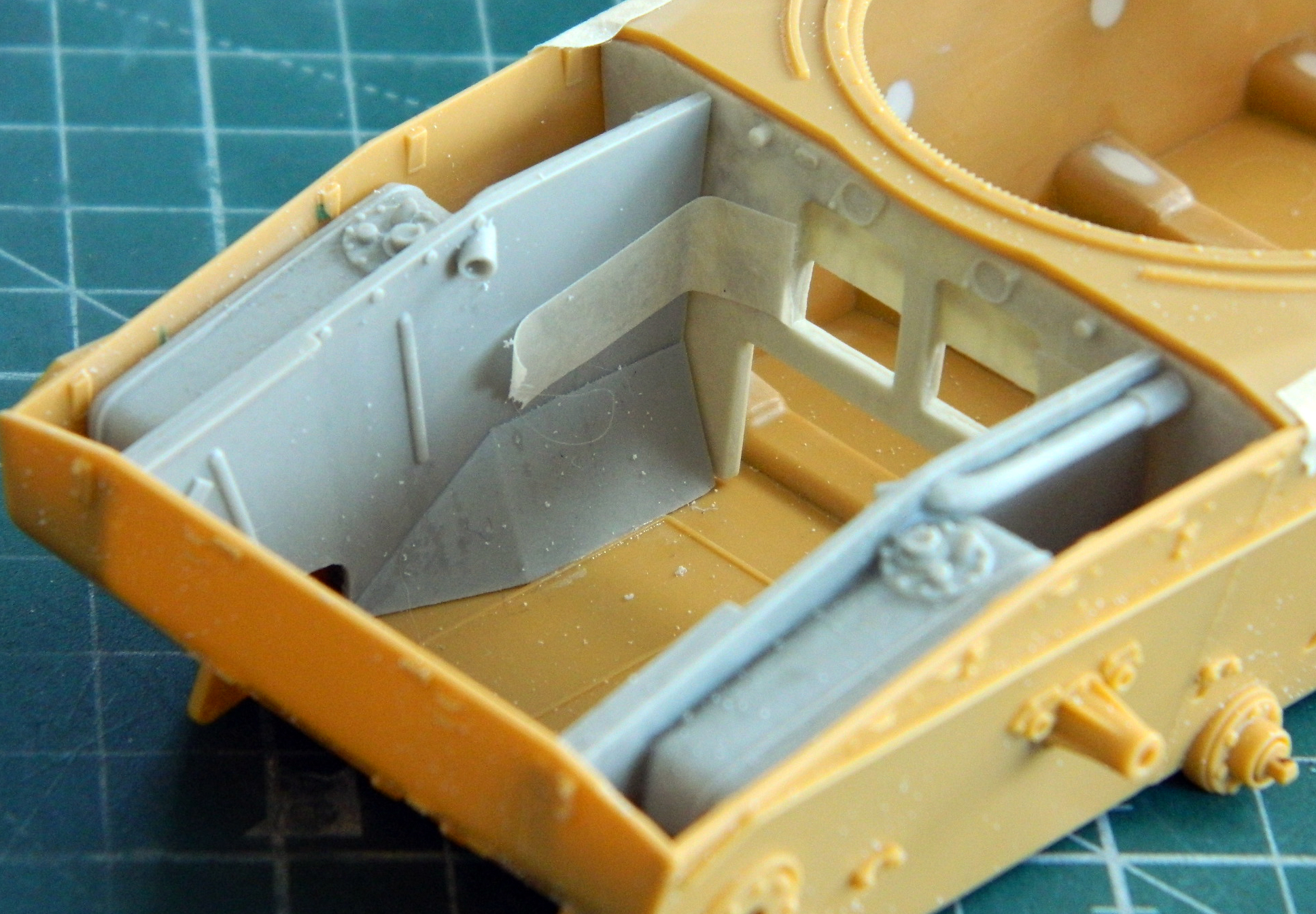
There are gaps on both sides and the top. I’ll add plastic strips to fix them later. Before I do that, there are more parts to add to the bulkhead which will be much easier to do with that part free.
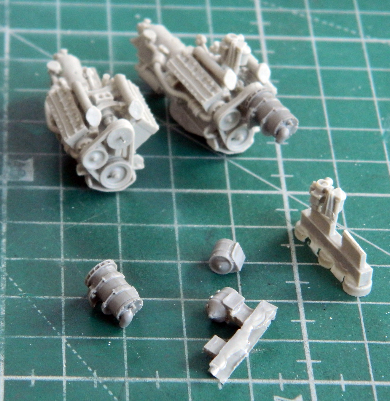
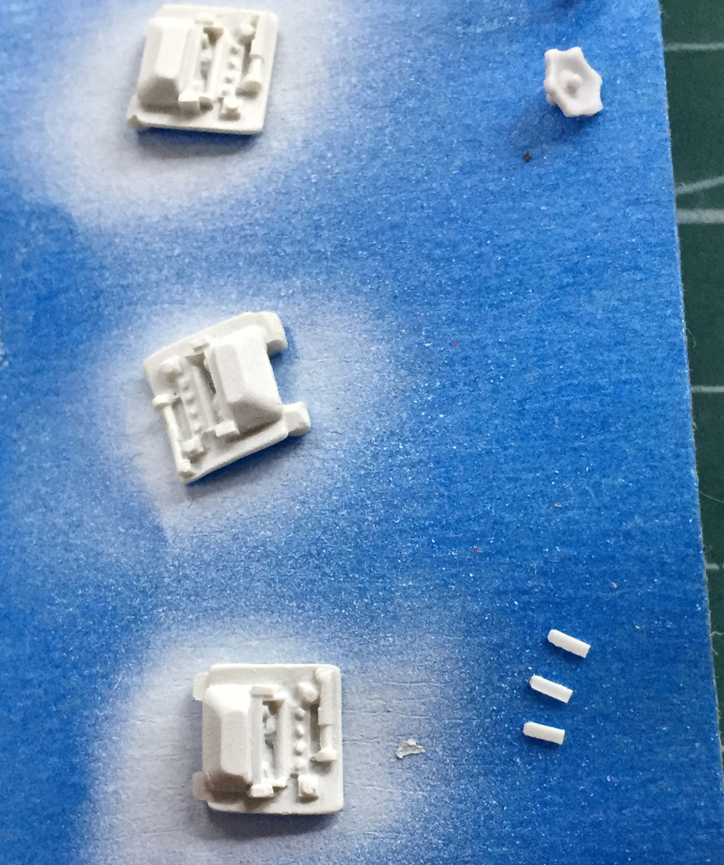
Since I now have a rudimentary engine compartment, it was time to start assembling the engines:
Here are more parts for the engine compartment that I will need to find permanent homes for in there:
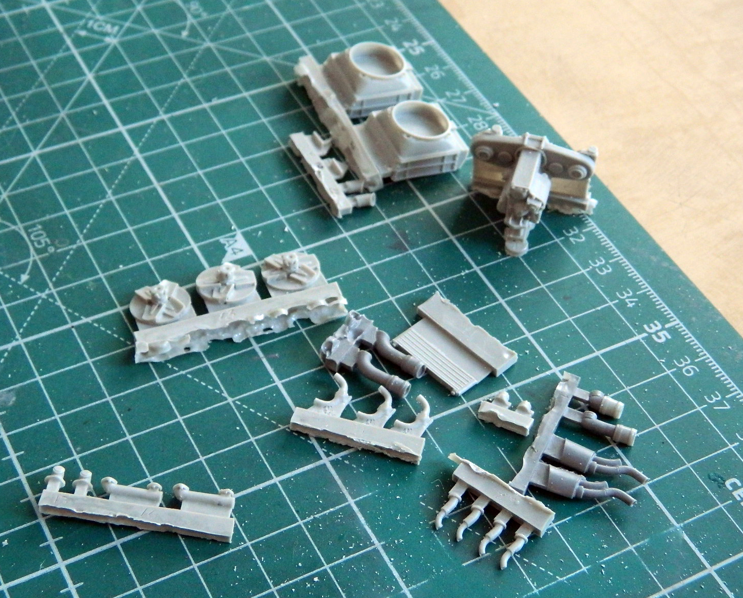
This kit contains a fret of PE parts. Among those parts are the casting marks for the lower front hull. They’re VERY TINY and so far I’ve managed not to launch any of them into oblivion. One side is done. Oh…and on that note, Bronco failed to photo-etch one of the “1” numerals…so it’s missing from the left side (there’s supposed to be a “10” next to the star, not a “0”):

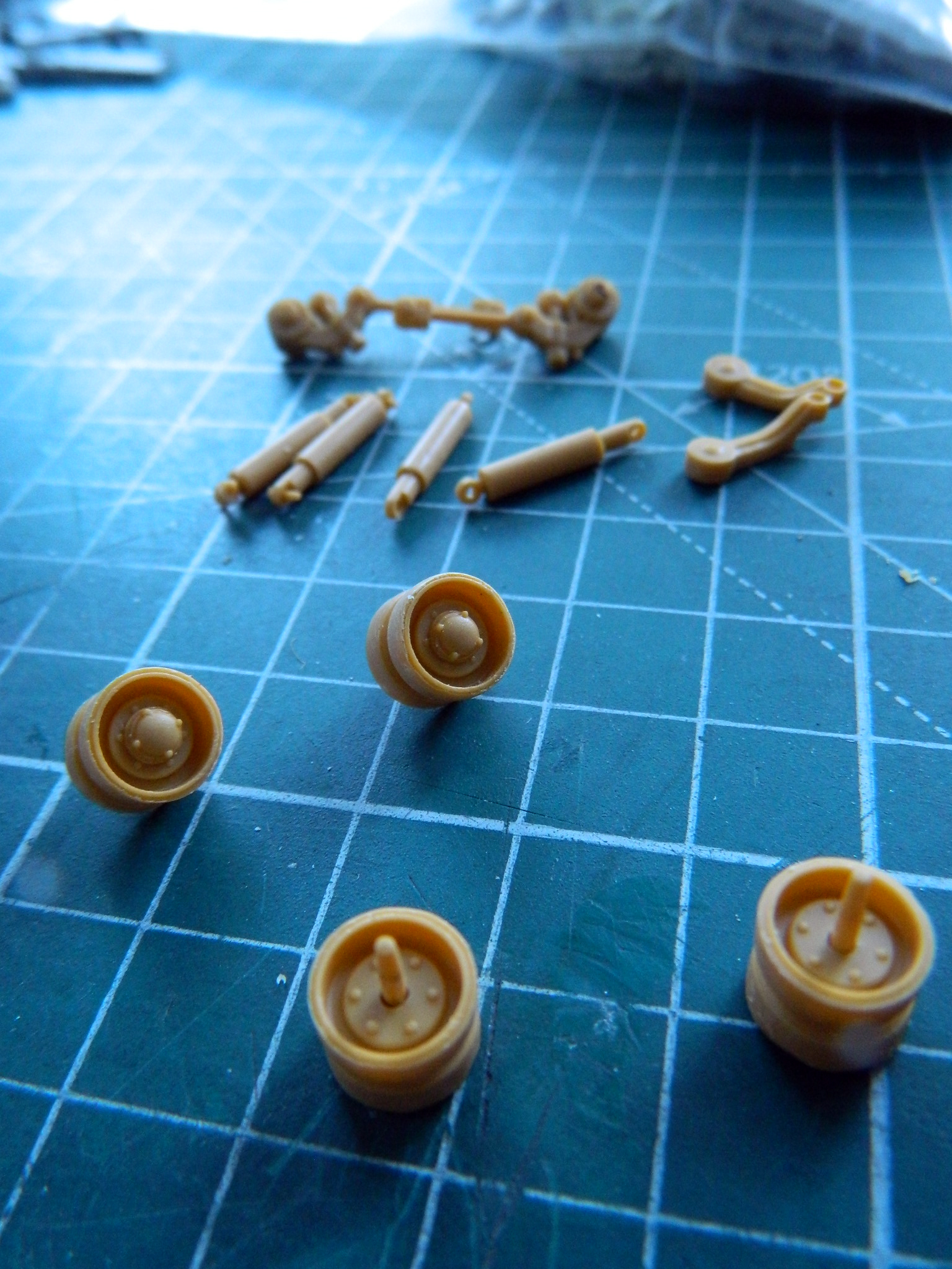
I also started assembling some of the suspension components. Each of these return rollers is comprised of four parts and the bolts that hold the shock absorbers in place are tiny and INCREDIBLY fragile:
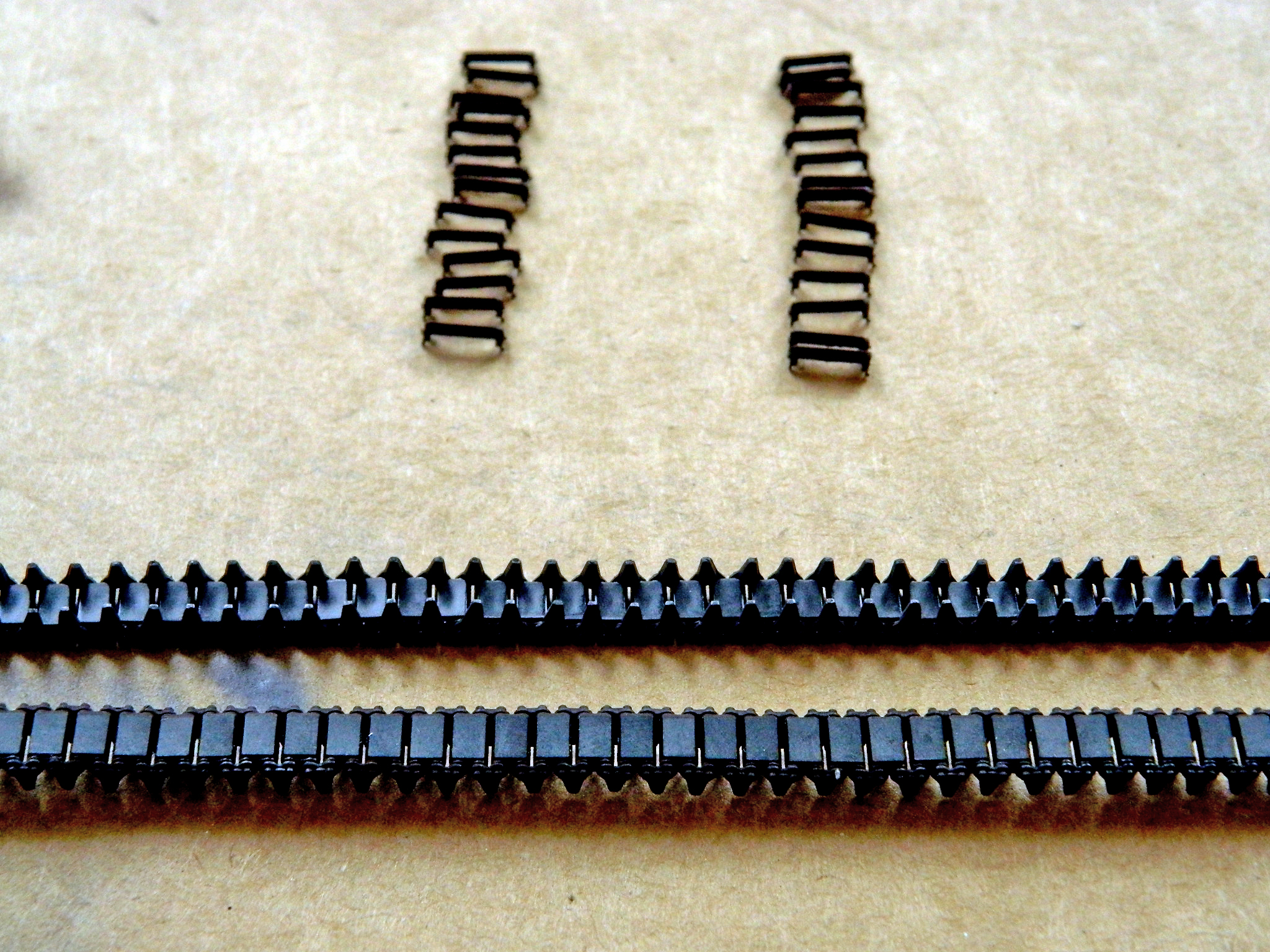
Once I started the build, I assembled the tracks, ten shoes a day while I sat at the workbench in the morning, having my tea and waiting for my dried up neurotransmitters to hydrate and begin transmitting sparks again:
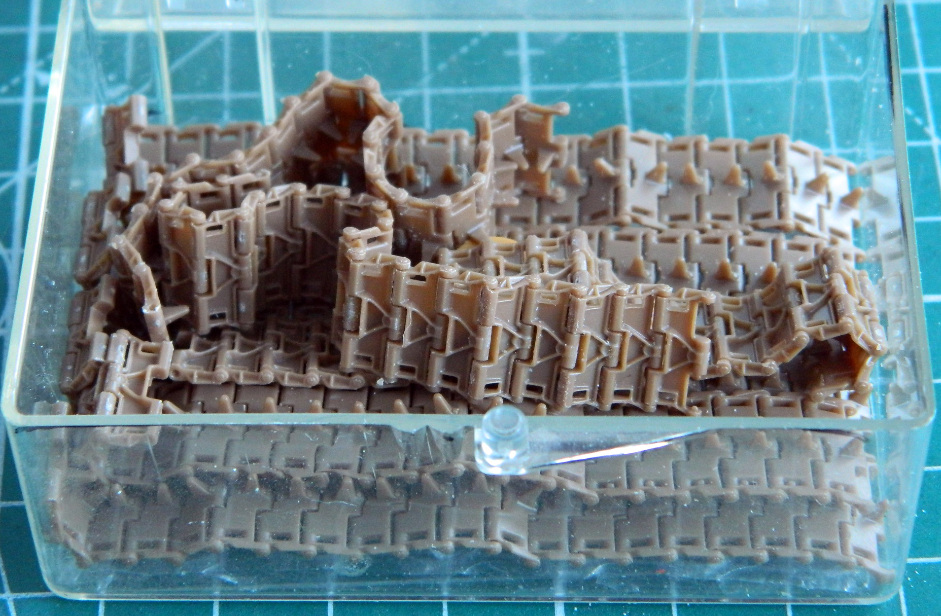
The tracks are finely molded. Perhaps they’re too finely molded. I managed to snap two into unsuitability while assembling them. Fortunately while perusing the ‘Net, I found a discounted set of metal T72 tracks that I will try using instead…which means I get to do this tedious task again.
Since the US deployment of light tanks in WWII, the M3 variants and the M5 variants, crews wanted something that offered more protection and had a larger gun. Being that both the M3 and M5 were essentially developed designs of a mid 30’s design, neither the M3 nor M5 could mount a larger gun. And seeing as the light tank doctrine had to be modified to fit the tanks’ capabilities, such as they were (or perhaps less inaccurately, deal with their shortcomings), the North African campaigns showed that any tank that relied on a 37mm main for defense would lose and that light tanks could not effectively be used in any other role than scouting. One “funny” person suggested that the only effective use of a light tank was to discover where anti-tank guns were situated, which, though I suppose offered a tactical utility, was rather rough on the crews.
For reasons I certainly don’t understand, the US Armored Force remained convinced that light tanks could be useful. (In addition to thin armor and a tiny gun, the armor of M3s and M5s wasn’t proof against any of the anti-tank guns.) So the M3 morphed into the M5 but shared with the M3 a high profile. A thinly armored tank with a high profile was easy to see and knock out. The M5, however, didn’t use a radial engine, which is why the M3 light tank, the M3 medium tank, and the M4s all shared the same flaw of being tall tanks. Instead of designing a new hull, the M5 used a variation of the M3’s basic hull design, even though the M5 used a pair of Cadillac V8s instead of a tall radial engine and could have benefited from a new hull design with a lower profile; they wouldn’t have had any greater firepower or thicker armor, at least they wouldn’t have been as tall.
Finally realizing that the M3 and any development of the M3’s basic hull design were tactically ill-advised, a new requirement was drawn up (1943, I believe). The requirement specified that the new light tank should not exceed 20 tons in weight and be capable of mounting a 75mm gun. The US Armored Force also decided that the four-man crew of existing light tanks was insufficient to combat efficiency and instead stipulated that a five-man crew was required, adding the additional crewmember to the turret crew.
With the pressures generated by an on-going war, as much of the M5 that could be used would be incorporated into the new design. The Armored Force remained convinced that a light tank would be useful for reconnaissance.
Cadillac had been working on an enlarged hull design intended for self-propelled artillery and incorporating as many of the M5A1 components as possible. Chrysler (then a part of GM) used the Cadillac-designed hull and offered a new design, the T24. It used a modified configuration of the M5A1’s Cadillac engines feeding a transfer case to combine the output of two engines into one drive shaft as the M5A1 had, feeding the M5A1’s transmission in the nose (the major difference from the M5A1 was that the new design used a manual transfer case instead of the M5A1’s automatic transfer case which turned out to have problems) as well as larger radiators for improved engine cooling. The original design required a larger turret ring to handle the 75mm gun and rather than make the body of the tank wider, instead the design employed sides that sloped outward at the top (and having an angle to the face of the side armor offered a slight improvement over a vertical side without increasing the vehicles overall weight of additional armor). The Armored Force also wanted wider tracks for decreased ground pressure (lessening the likelihood of the new tank becoming mired in muddy conditions) and designers moved away from the volute-style suspension of the 30s (which had become about as advanced as that archaic design could be) to the more modern torsion bar suspension used in more modern tanks of the Germans and Russians (torsion bar suspensions are still in use on tanks today). As a result, the track used on the M24 during WWII was the T72, a single-pin, center guide, metal shoe, track with a width of 16″. (Post-war track was changed to the rubber chevron, double-pin, T85E1 shoe with a width of 14″. Rubber tracks were easier on paved roads, a consideration of Occupation Forces in Japan.)
Even with the larger turret ring, using the 75mm of the M4 Sherman didn’t work as intended. However, a light-weight 75mm, the T13E1, with a different recuperator and shorter stroke design to absorb the recoil of the 75mm had been developed for the B25G and H models. Though the light-weight T13E1 of the B25 shot the same round as the 75mm of the Sherman, the barrel was shorter which resulted in an even lower velocity of the round, already considered a low-velocity shot. The initial gun, the T13E1, was taken from stores already produced for the B25 ground attack variants. Later on, a purpose-built gun for the M24 was produced and designated as the M5. The only way to tell the T13E1 from the M5 tube was that the former had a pair of rings around the barrel sleeve to engage the recoil mechanism of the B25 installation.
Initial trials of the new T24 went well and the Armored Force requested various changes in the prototypes, and once those changes were instituted, the T24 was standardized as the M24 in July 1944 and production began at the end of the M5 production in May 1944. Cadillac produced 3,592 M24s and Massey-Harris started production in July 1944 and produced 1,139. Total production was 4,731.
The M24’s combat debut was at Bastogne during the winter of 1944 (aka, the Battle of the Bulge) when a pair of M24s intended for 744th and 759th Tank Battalions were intercepted by the 740th Tank Battalion that had arrived in-theatre without any tanks. They were first deployed in Company D at Remouchamps on December 20, 1944, and saw action in the fighting for Stoumont and La Gleize.
The M24 was a profound improvement over the M5 and M5A1s that they replaced and the crews liked them. From what I can tell, the major complaint of the new tank (and probably every tank fielded) was its limited ammunition loadout (not at all uncommon for an M24 crew to go through the standard ammo load twice during an engagement…talk about awkward!). Mobility was praised as was its ability to get into (and most importantly, out of) places neither the M4 because of its size, and the M5 series because of their higher ground pressure, could. The first two tanks were pressed into service without the crews being trained in them. However, due to the mechanical similarities of the M5 series and the similar gun of the M4 75mm, they seemed to have no problem putting the new tank into service.
The M24 was thought to be the tank to use in the invasion of Japan because of its lighter weight (though a bit over the 20 tons initially specified) than the M4 series in consideration of the bridges found in Japan. Tests were conducted to see if the tank could be made to float, thereby decreasing the need for LSTs, and the flotation devices (including 28.5″ grousers bolted to the T72 track to increase propulsion in the water) developed for the M18 were successfully (all terms being relative) adapted and tested between late 1944 and early 1945.
The Enola Gay and Bock’s Car changed all that and the program was dropped. However, the mounting pads for the flotation devices on the nose and rear of the tank had been incorporated into the production lines and never dropped. I found one reference, “M24 Chaffee Walk Around, by David Doyle, ISBN 978-0-89747-592-1 that gives production numbers when the flotation mounts were added to the hull, the only problem being that different production numbers for the start of those additions. On page 12, he states that Cadillac-built M24s started adding the mounts at #1101, and then on the next page, 13, he states that Cadillac started adding the mounts at #713. So that is hardly informative! Either way, early production M24s, therefore, had the rings around the barrel of the T13E1 gun and no flotation mounts whereas late production M24s didn’t have rings around the barrel and had the float mounts. Some of the early M24s also had U-shaped stirrups added to the lower nose and rear plate and some did not. None of the M24s with the flotation mounts show these stirrups.
As mentioned earlier, M24s were used by US Occupation Forces in Japan (my father crewed, and later commanded one, and finally became a platoon commander).
Then Korea erupted.
The T34/85s that the North Koreas brought with them had been good enough to stop the Wehrmacht’s Panzer IVs, Panthers, and even Tigers. Encountering M24 light tanks, the only tanks we had on-hand that were close enough to throw at the North Korean invaders, posed no problem for the T34/85 crews (even as poorly trained as they were…which would significantly change when M4A3E8s and M26s arrived later). (The last tank my father had shot out from under him he was the only survivor of the experience, largely because he was standing in the open commander’s hatch when his tank was hit and destroyed. The explosion blew him clear of the flaming wreck.)
Post-WWII, France was the largest recipient of M24s and used them in Indo-China (Vietnam). The Vietnamese army also used them (too frequently in coups, which earned the M24 the nickname of “ballot boxes).
During its initial uses in WWII, the M24 was considered by some as America’s best tank (as if that determination can be made!). Side-stepping that debate, it was certainly the most advanced armor of the European Theater that the US fielded until the arrival of the M26.

M24 of the 18th Cavalry Squadron at Petit-Thier, Belgium February 1945

Total time building 270.5 hours.
Begin date March 21, 2019; end date* December 30, 2019. * Six-month hiatus during the build.
Vendors:
Academy
Kit #13269 – M3A1 Stuart
Tamiya
Kit #3542 – Stuart U.S. Light Tank M3
Kit #35360 – M3 Stuart Late Production
Kit #35250 – M4A3 Sherman
Tiger Model Designs (TMD)
Set #35-1039 M3 USMC Interior
Set #35-70023 – Tie-Down Cleats, Small
Verlinden
M3 details #1647 (just the vision block covers for the commander’s cupola)
AFV
Set #AF35056 U.S. Light Tank M3/M5/M8 Stuart Vertical Volute Spring Suspension
Archer Transfers
Set #AR35209B – Gauges and Interior Stencils
Set #AR88001 – Resin Rivets, Various Scales
M&Models
Set #35B24 (RB Models) – Turned Aluminum 37mm Barrel
Set #GM-34-004 – .30 Caliber Barrels (s), turned brass
The Scenic Factory Mud
Set #MK-02 – Ardennes Forest Kit “Dry”
Lots of solder, wire, lead foil, paint, and sprue
My opinion
Academy has a reputation for being soft on details and this kit would support that viewpoint. The kit is labeled as an M3A1 which it’s not. Depending on how you look at it, it’s either an M3 with an M3A1 interior (yes…the two interiors really are that different), or it’s an M3A1 with an M3 hull. So that’s the starting point.
The suspension has earned its reputation as a cock-up. It appears as if the engineers got the ground clearance incorrect with it and rather than start over and get it correct, they “drooped” the roadwheel arms much too far. If you’re concerned with accuracy, scrap the kit’s suspension and get the AFV suspension kit, which is MUCH better. I’d suggest getting that set if you’re doing any Academy M3 variant. The Academy drive cover (the lower nose) isn’t very accurate and the AFV drive cover is…and it’s included with the suspension. Yes…you’ll have to cut the Academy part off and graft on the AFV part. It’s worth it. If you decide to go with the AFV suspension, you’ll either have to use the AFV drive sprocket with their tracks or if you use the Academy tracks, you’ll have to use the Academy drive sprocket. The tracks are sufficiently different that you won’t be able to use the AFV drive sprockets with the Academy track and vice versa. (And each drive sprocket has inaccuracies.)
I was surprised (and somewhat disappointed) by Tiger Model Designs. Their Marine interior for the M3 didn’t really fit. It appeared that I needed more length in the lower hull to fit all the stuff that was supposed to go into the crew compartment, but when I extended the compartment, the driveshaft cover turned up too short (requiring me to lengthen it). I don’t know how that happened; I’m hoping that it was an as yet undiscovered mistake on my part as I really like the guy who runs TMD. And to be transparent, no…I didn’t complain or tell him about it (I think he’d needlessly beat himself up over it and I like the selection he has and the quality of his castings). I made the modifications required to get what I needed and just went on with things. So if you decide to use the Marine M3 interior set, be aware you may have fit problems.
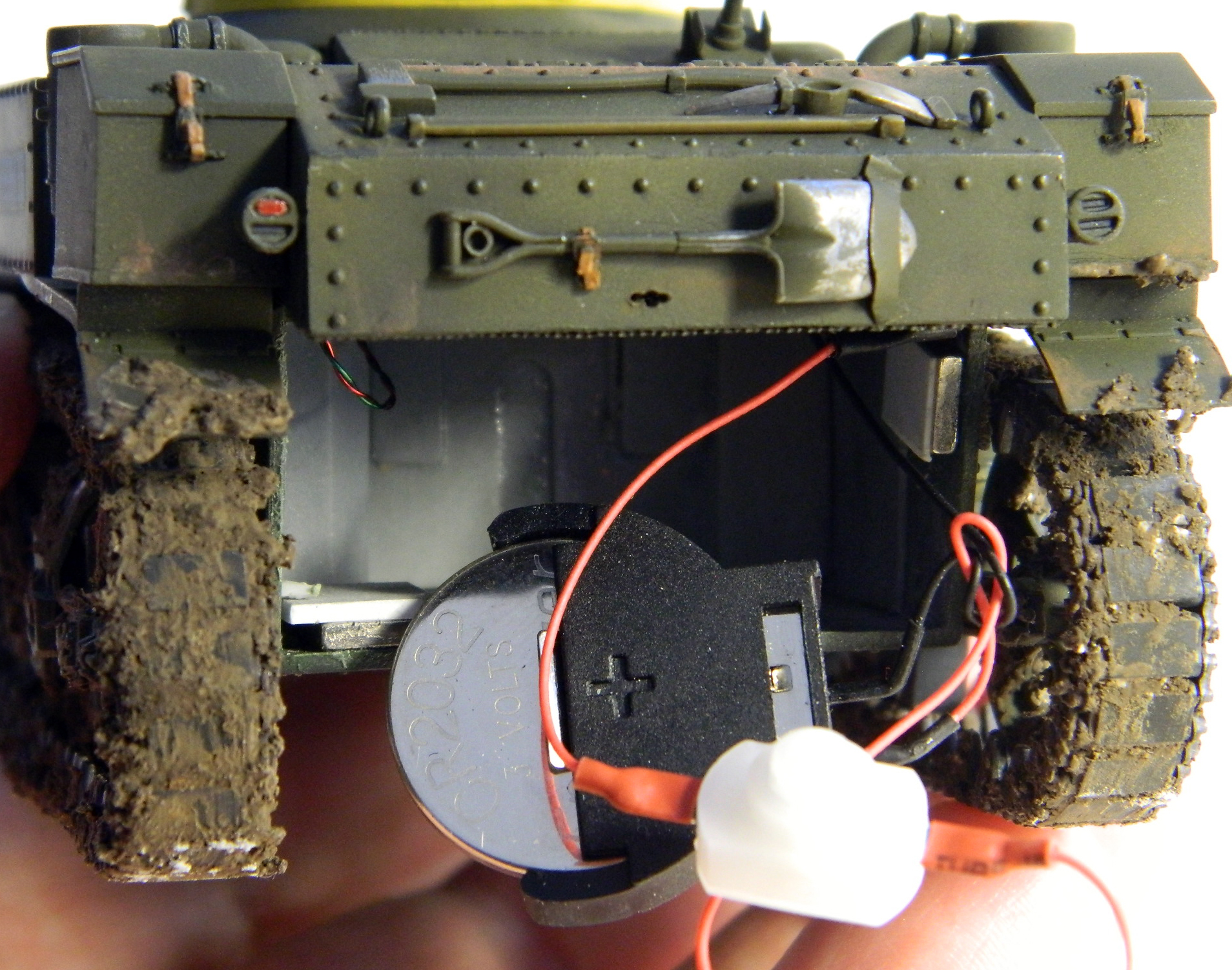
This was my first attempt at adding a light to a model. It was easy, limited more by my ignorance than any other factor, and I suspect I’ll be adding more LEDs in future builds. (And I was proud of myself for figuring out what to do with the battery and switch.)
I knew at the outset that I would be doing a tiny bit of kit-bashing as I wanted to backdate Academy’s turret from the kit-supplied D58101 turret to the more correct (for an earlier M3, not an M3A1) D39273 turret. The ancient Tamiya M3 #3542 has the rounded commander’s cupola that I wanted and that was my source for it. I didn’t expect to do as much kit-bashing as I ended up doing. Tamiya cupola, AFV suspension, and final drive cover, and then the new Tamiya M3, #35360. I’d originally intended to use just the headlights from the new Tamiya kit, but once I opened it up and started looking at what Tamiya’s engineers put in the box, I realized that a few other parts were much better than the (loosely) corresponding Academy parts. I used the air filter assemblies, sponson storage boxes, siren, headlights, and tail lights from the new Tamiya kit. The results were substantially better than if I’d used the Academy parts. (The next time I do an Academy M3, and I have two in the stash, I’ll source the same parts from Tamiya again.)
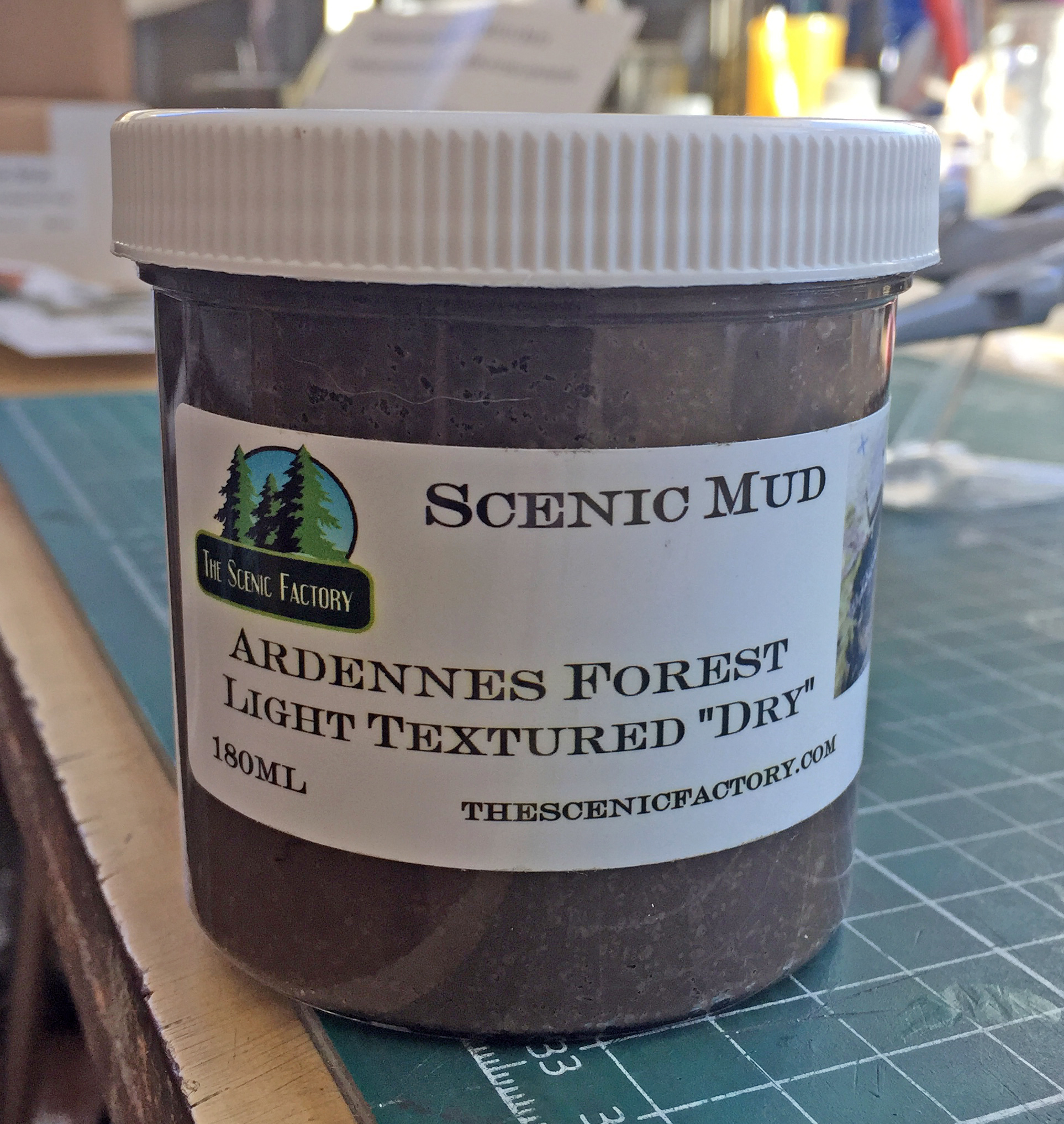
Another surprise was The Scenic Factory’s mud. GawDAYUM what a nifty product! Versatile and realistic, it’s easy to use and gives a great finish. If you need mud, check this stuff out.
I’m also surprised that this build was as short as it was. Then again, I suspect after the Blackbird, the heat death of the universe would seem quick to me.
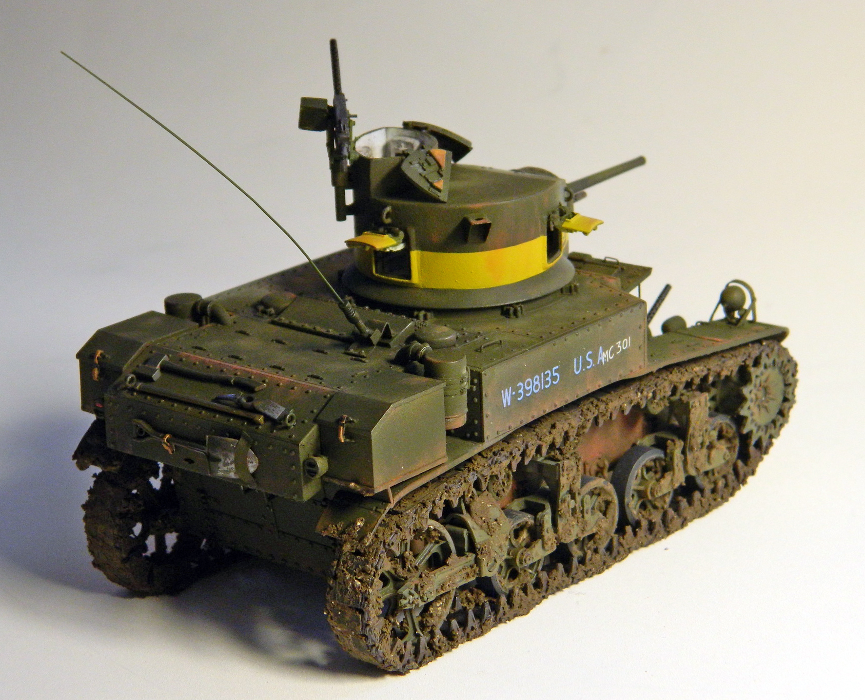
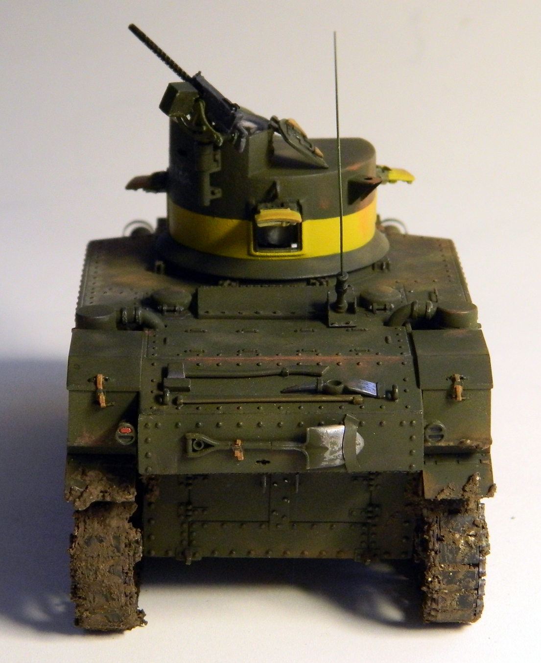
This kit was a secret build for someone. Actually, it was done for the wife of the friend I built the Blackbird for. He likes aircraft, she likes tanks…so I built one for her (I managed to be slick enough for her not to know what I was up to when I managed to get her to decide which tank I built!). I didn’t mention it before this because I wanted to keep the secret and surprise her with it (her name is Brenda and I figured her tank should have her name and I managed to forge her handwriting for the name). Mission accomplished. The tank was delivered to her on February 2:


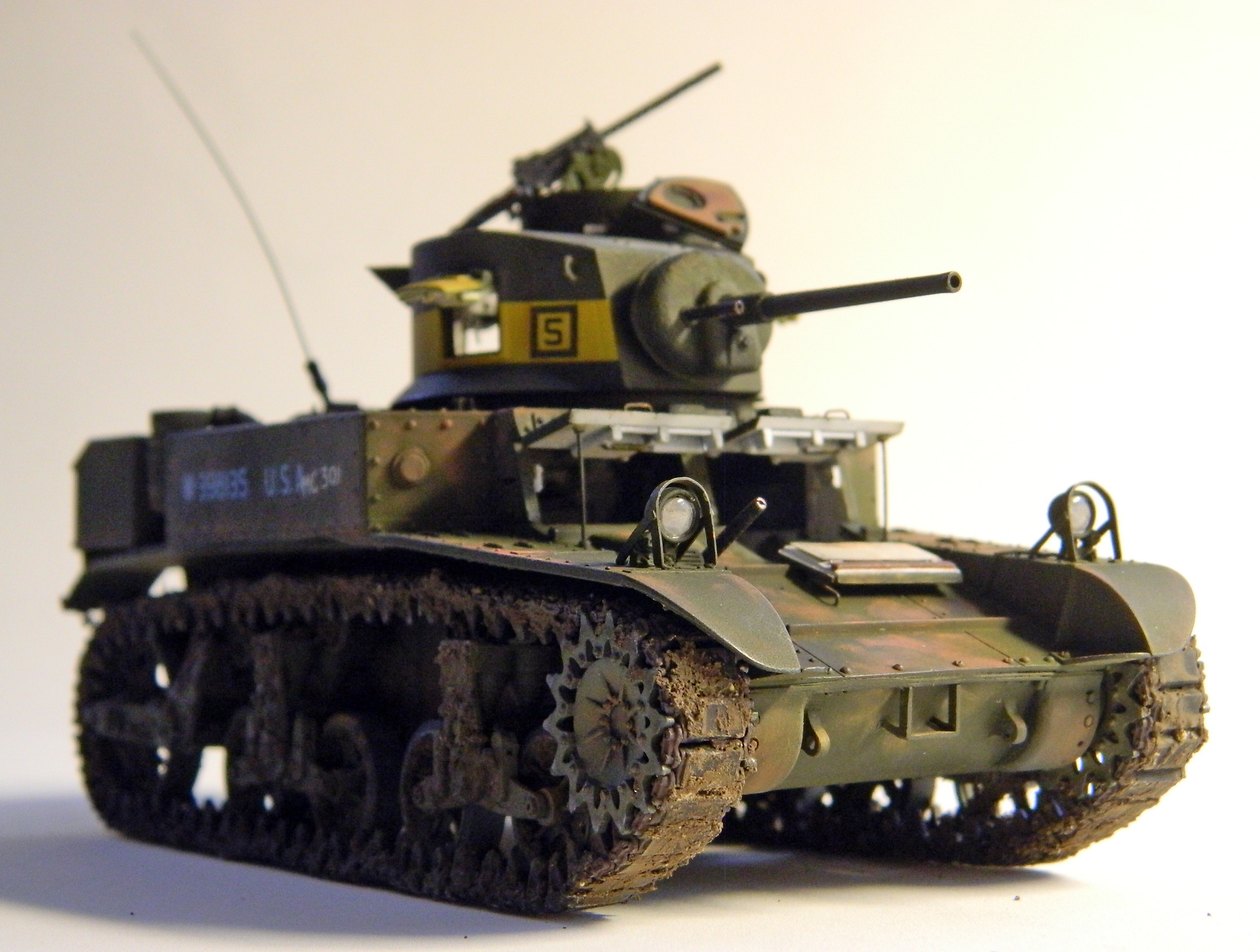
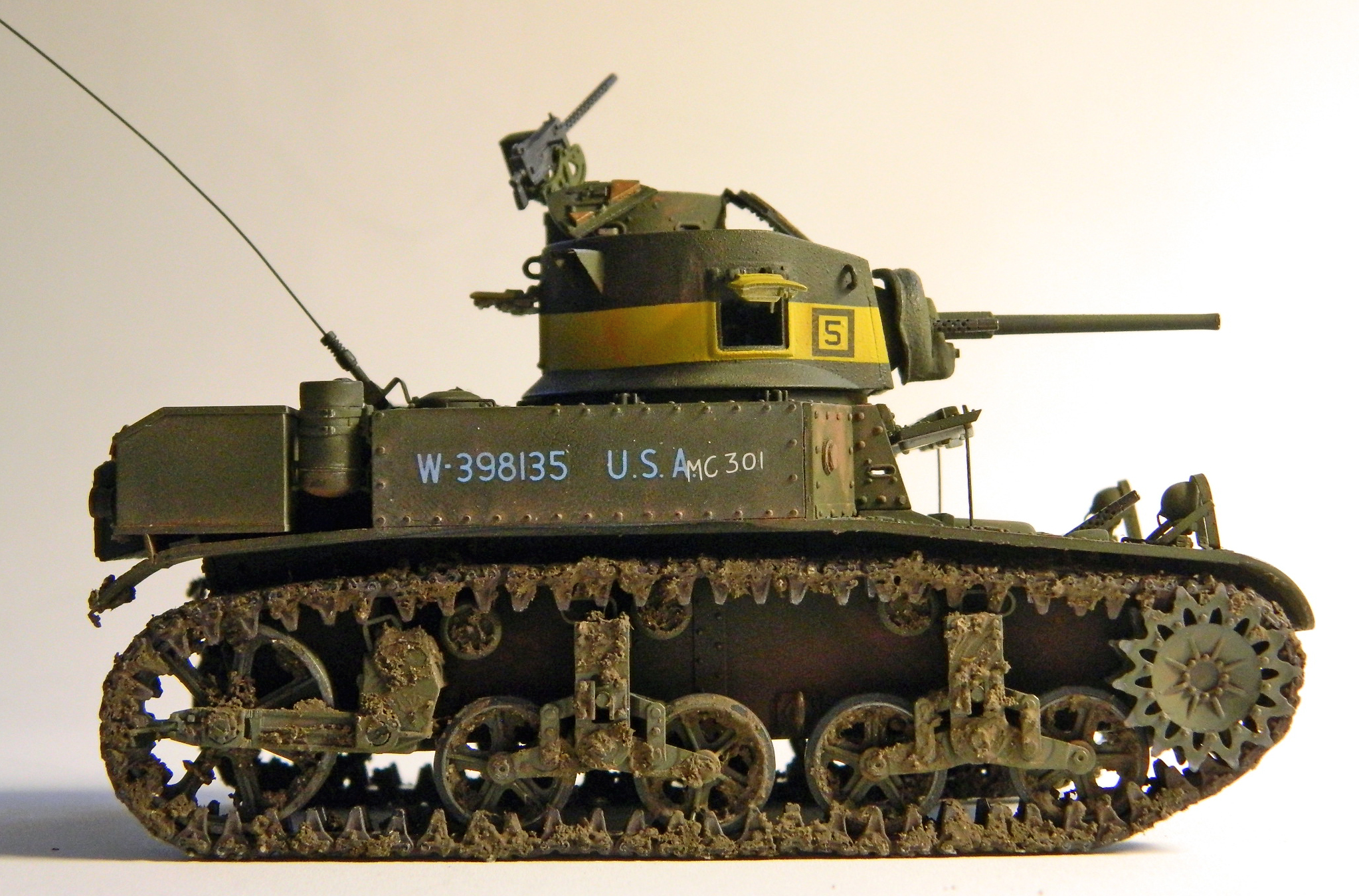

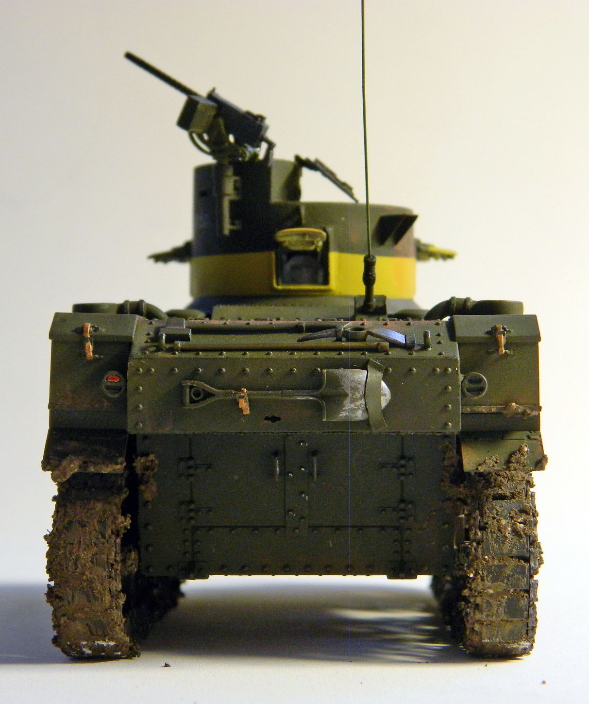
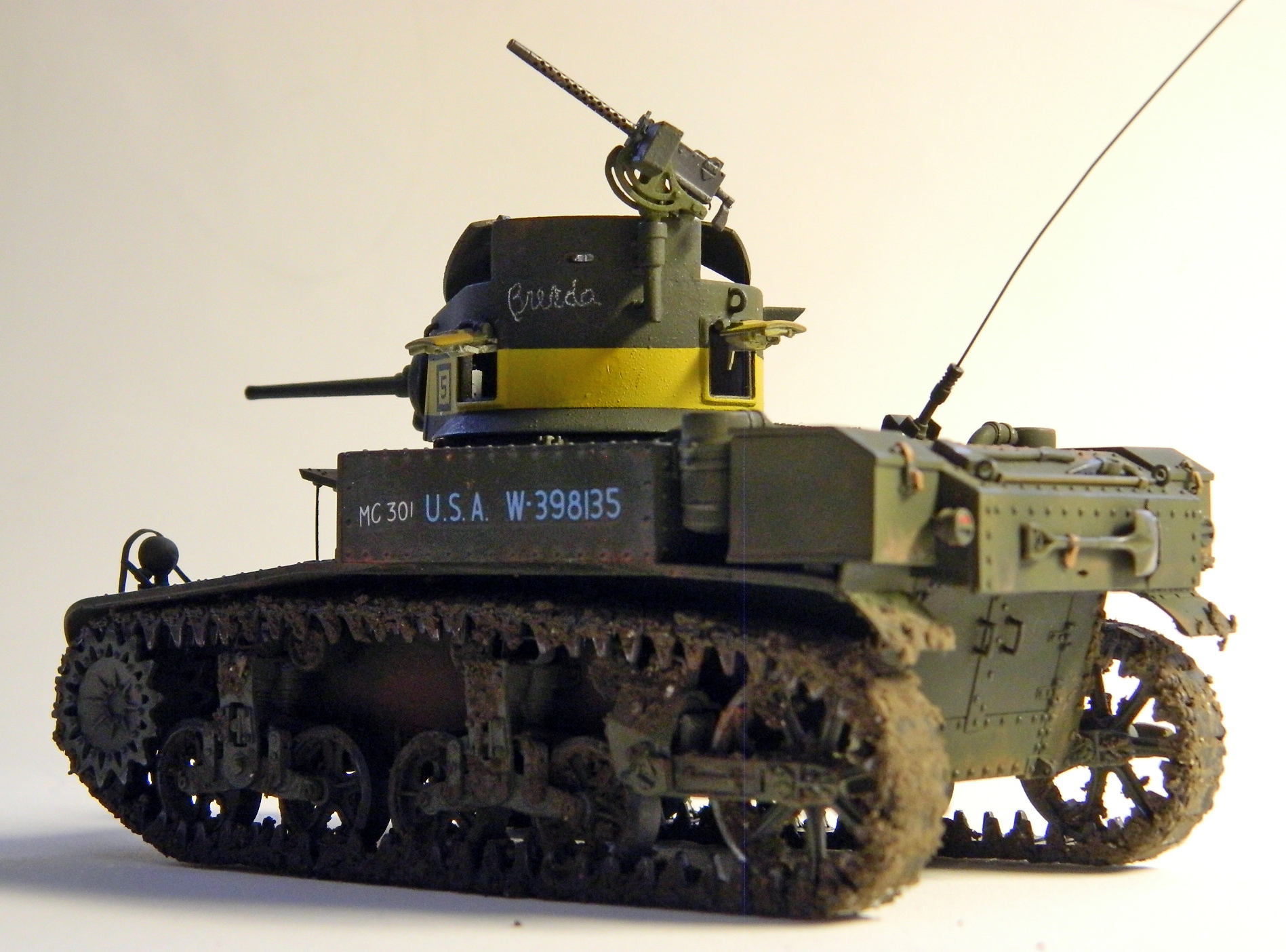


Then turn the light on:

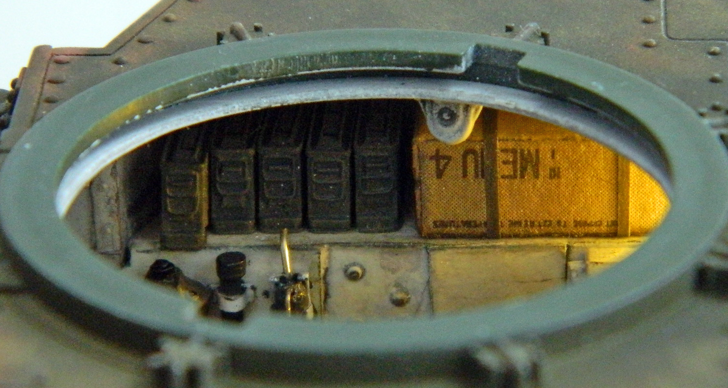
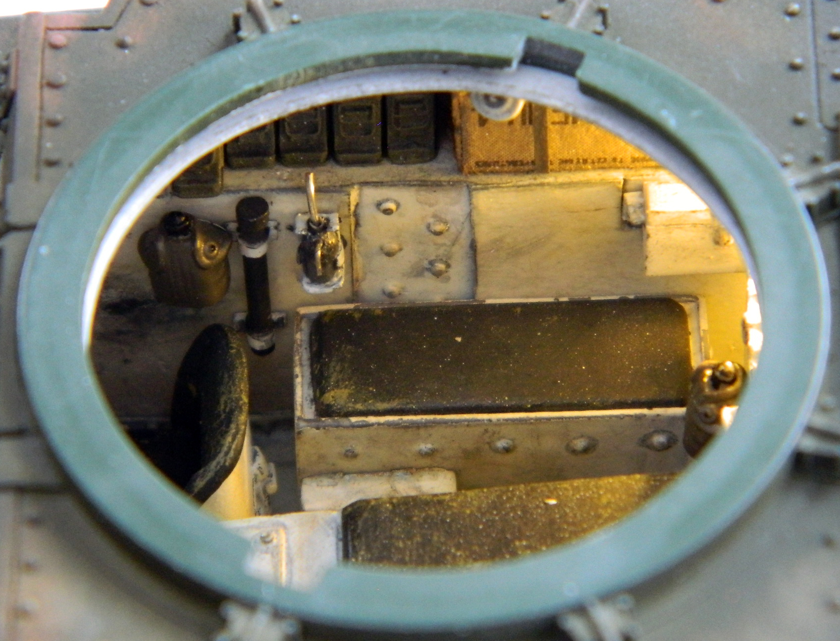


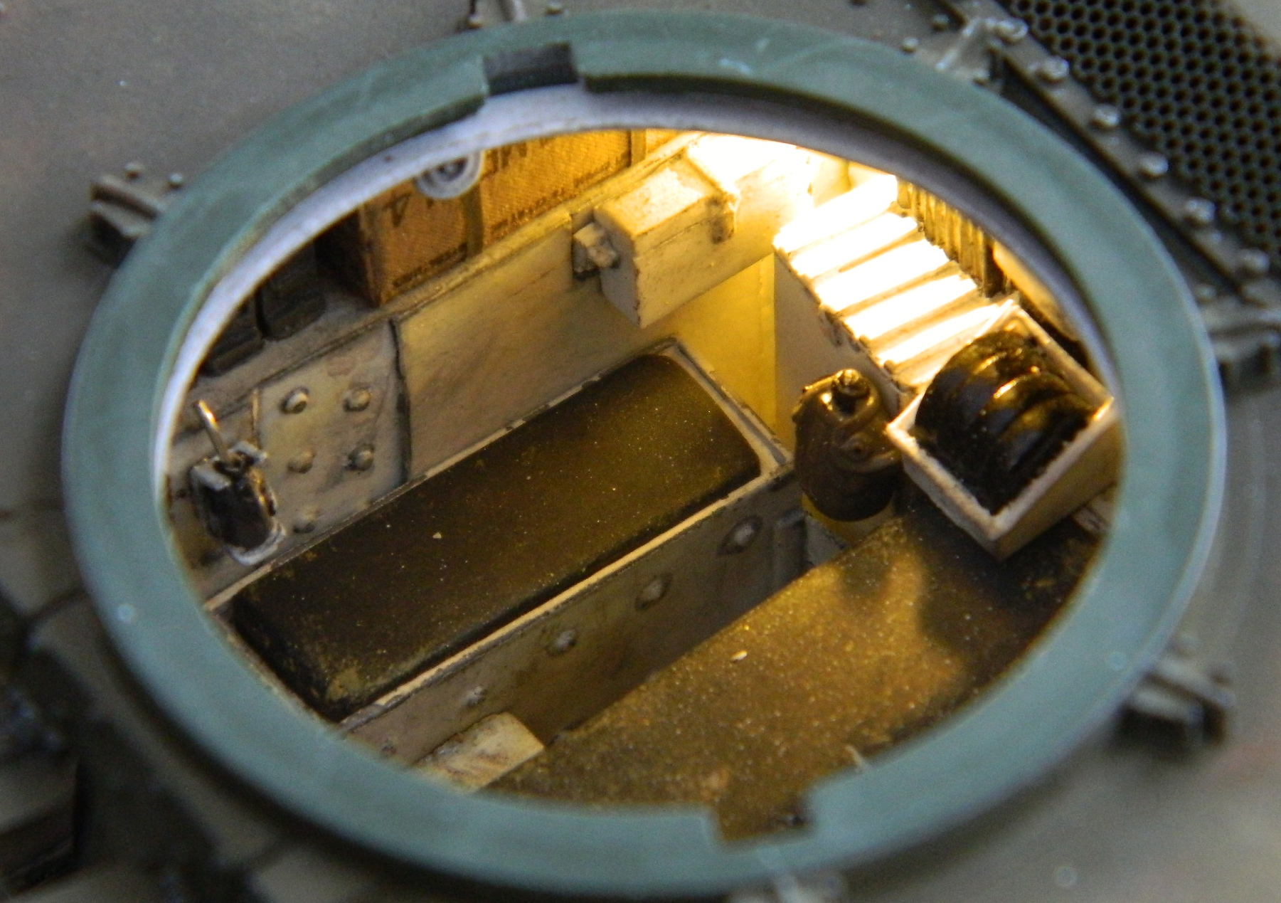
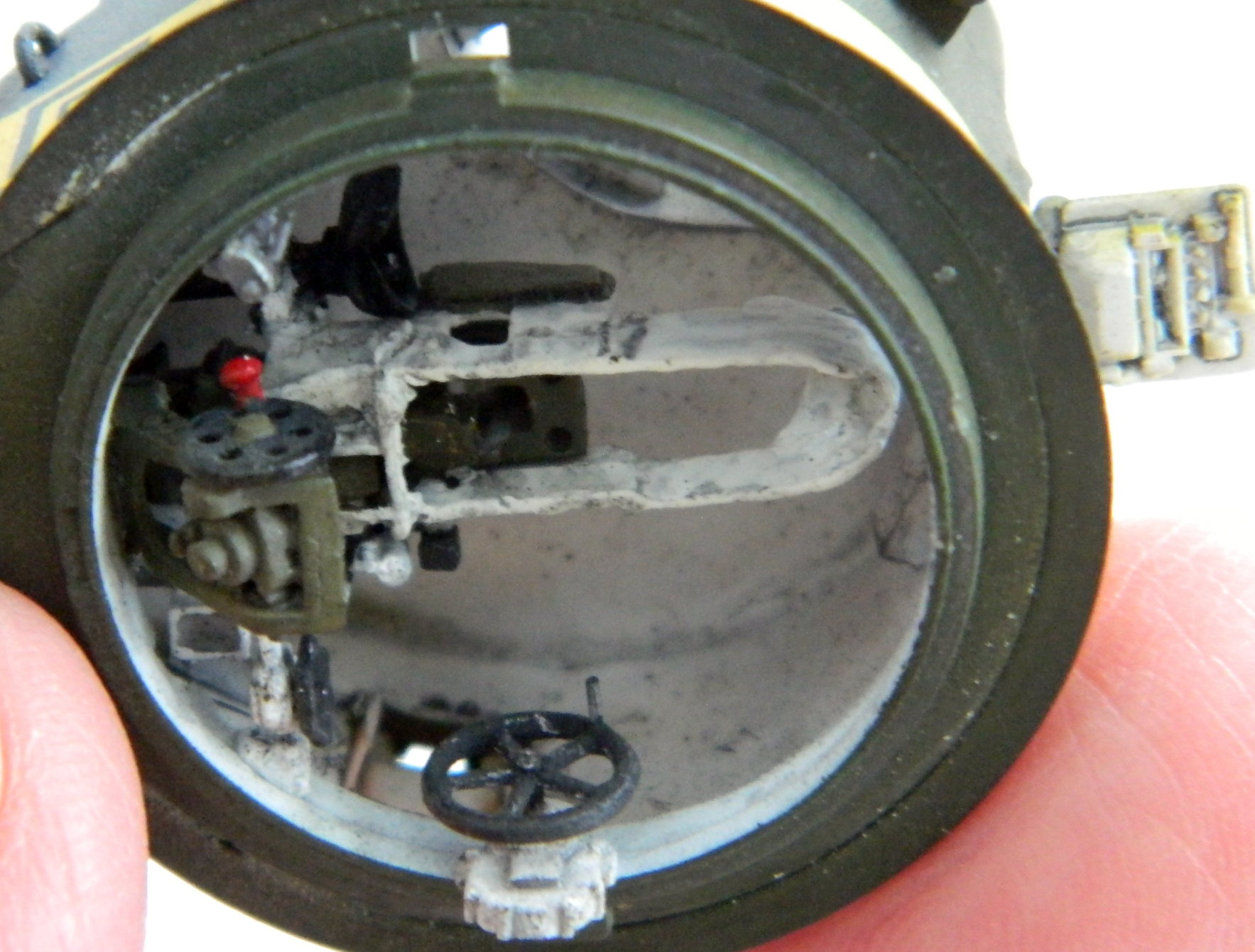


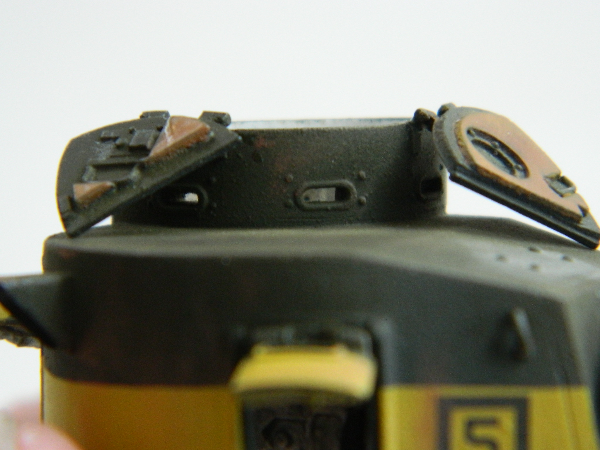
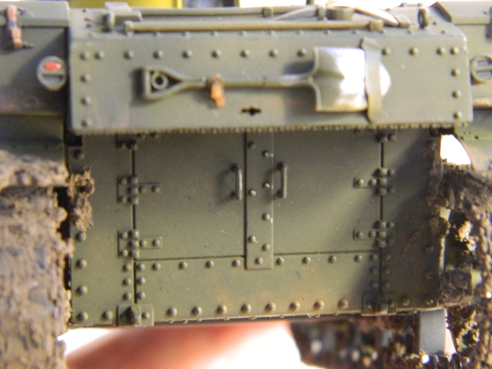
This will be a short post to wrap up this build. December, not my favorite month in general, was particularly crappy this year. A dear friend died and I had a very rare (THANKFULLY) heartburn incident that took over a week to get over. There wasn’t much left to do and once I could get back to it, it wrapped up quickly.
The decals arrived and they’re not bad, more like what I would expect from decals; neither too thick nor vanishingly thin, they did what I wanted them to. First I removed that hideous circle I’d painted onto the turret, repainted the OD, then did the yellow stripe around the turret using Tamiya XF-3 Yellow and XF-60 Dark Yellow. The yellow is YELLOW so I toned it down with the dark yellow by using three yellow to two dark yellow (which is more of a general buff to my eyes).
Once the yellow stripe dried overnight, I added the square markings with the numeral taken from a VERY OLD set of Microscale aircraft decals (which surprised me by going on as if they were new…I thought they’d shatter):
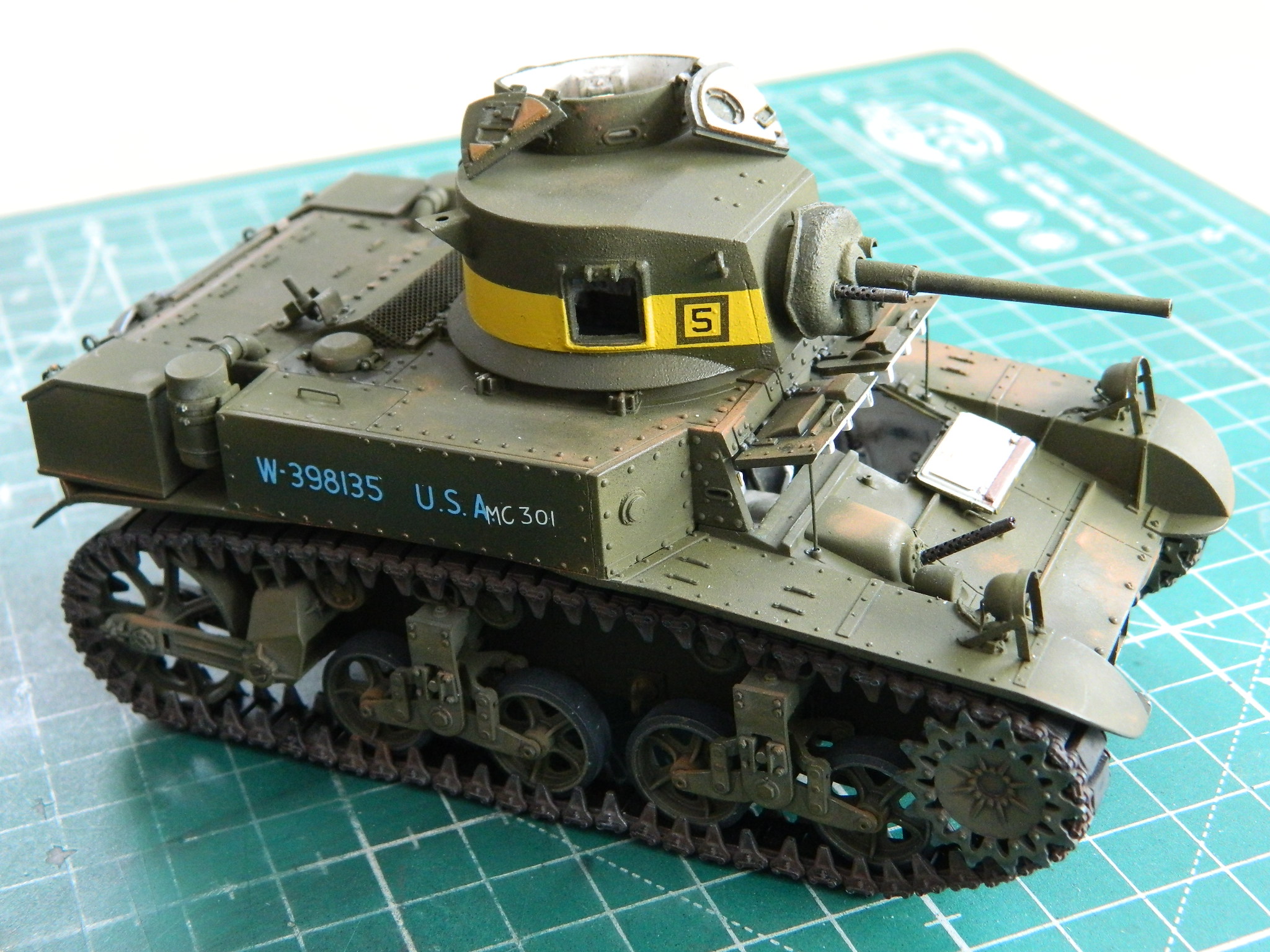

With the decals on, the only things left to do are apply mud to the tracks, then attach the hatches for the pistol ports, and then weather.
If you want mud and don’t want to make your own, The Scenic Factory makes a great product. The Scenic Factory has a YouTube channel for its products and I recommend you check it out. I’m using “Ardennes Mud” for this. It supplies the basic “mud,” which is acrylic-based, can be thinned with water, tinted with paint or pigments, doesn’t stink, and dries hard:
The kit also provides glycerine-stabilized (he says as if he knows what the intercourse that means, other than it doesn’t decompose) leaf and stick bits:
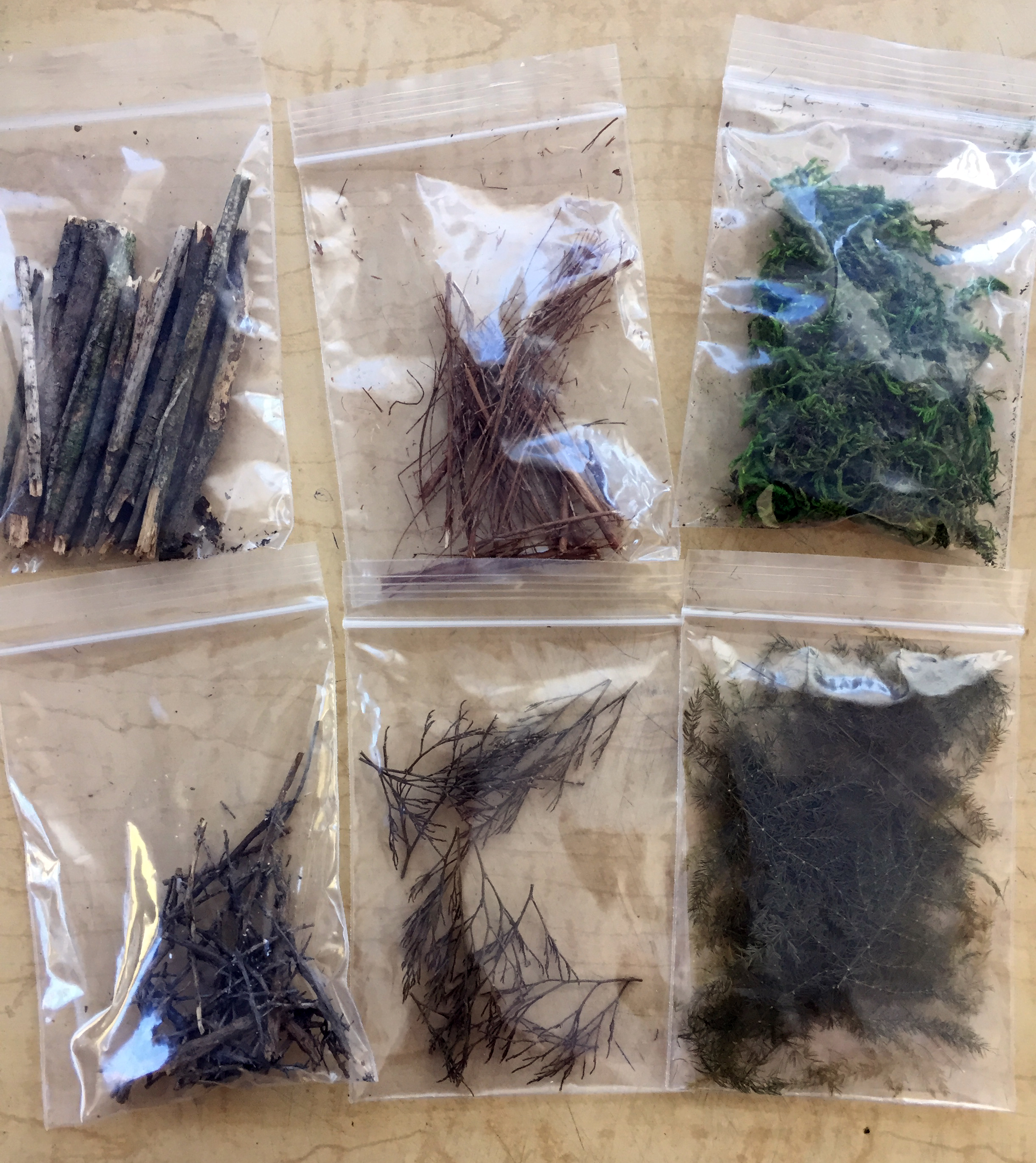
Okay. Enough free advertising. This is the mud on the tracks:

The last items to add were the pistol port hatches. Then the surface was worked over with a silver-colored pencil and a few different colored pastels…and like that, it’s done:

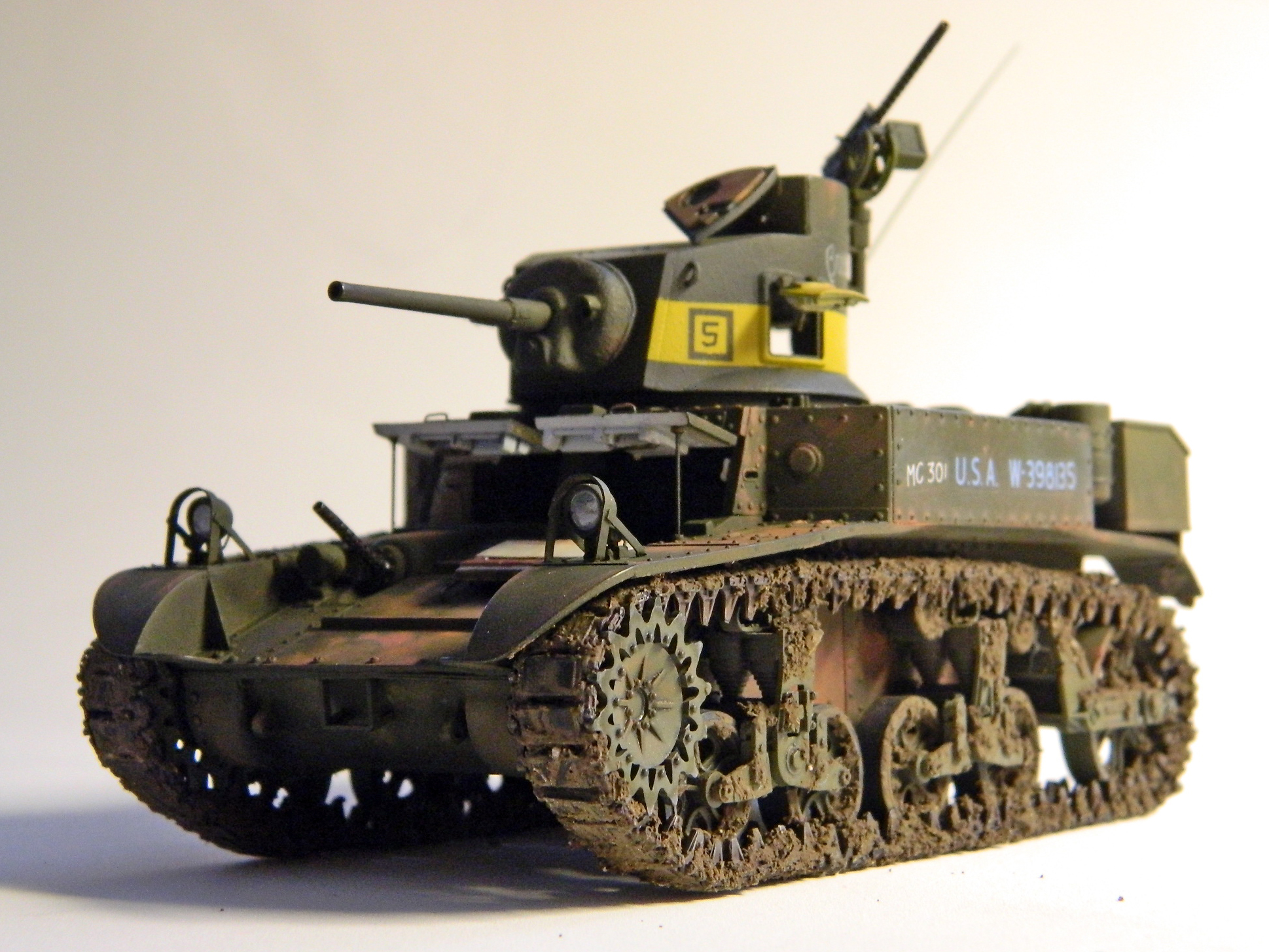
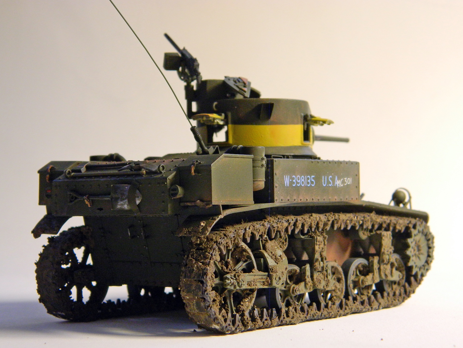
At the start of this build, I hadn’t really considered kitbashing. I figured that between the kit, an AM interior, and being able and willing to diddle really small details into the state/condition I wanted them, I’d end up where I wanted to get with this.
And then there are the headlights.
I did not like what Academy provided, and I spent several evenings lying in bed (waiting to get to sleep) wondering just how the intercourse I was going to be able to diddle the provided headlights into anything remotely acceptable…fruitlessly. One afternoon I was chasing M3 Stuart references all around the Internet and encountered a site that did a quick build of Tamiya’s new-tool M3 Stuart (kit #35360) (okay…so I lied about the porn). I noticed that the headlights Tamiya provided were SO much better and about 99.5% of what I wanted straight out of the box. Okay…so I bought one.
Once I had the Tamiya kit, I cut the headlights off the sprue and did the other .05%, making the bases thicker and more accurate, then adding bolt heads to the bases:
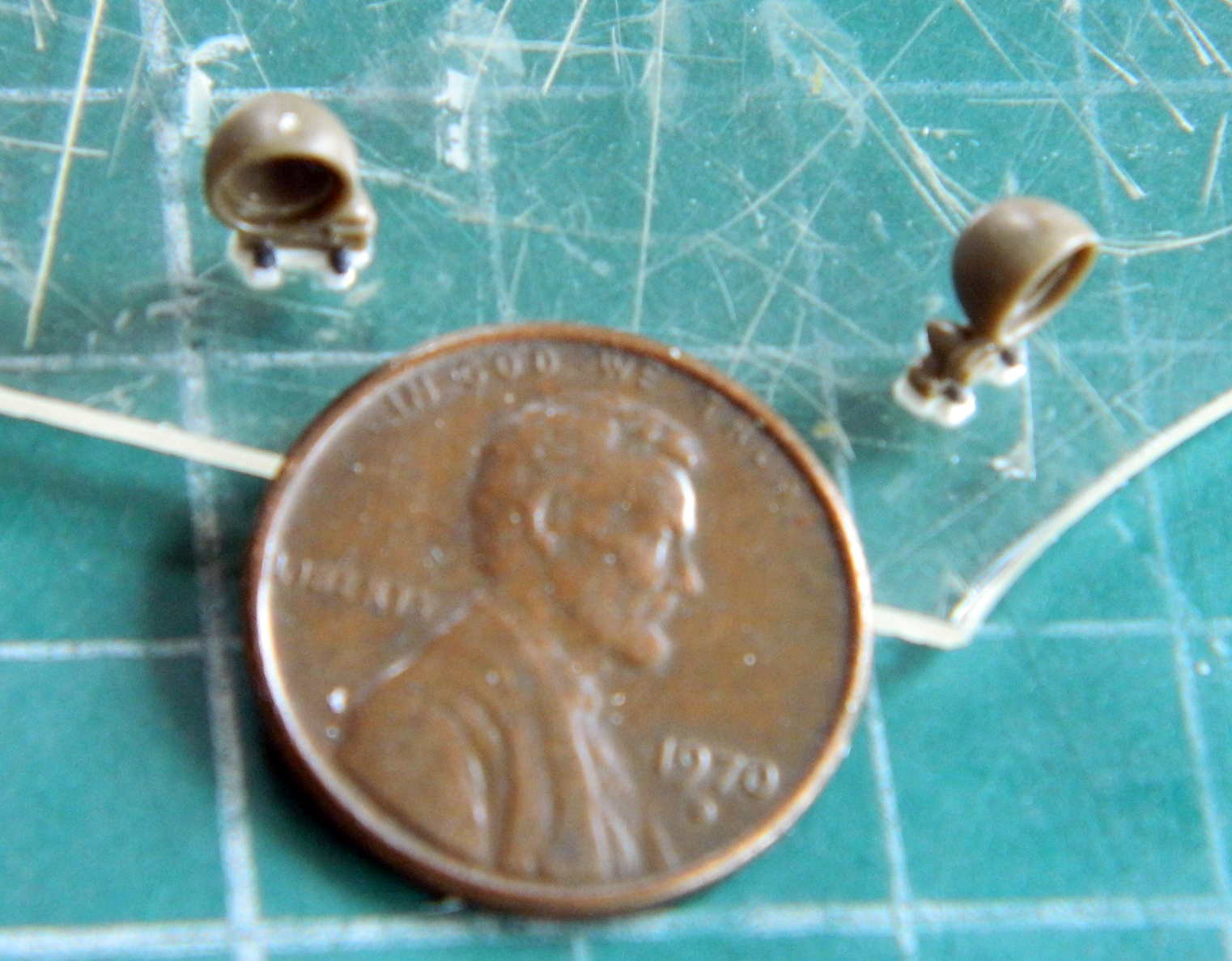
Checking fit, I can see that I’m already liking these bits MUCH more:
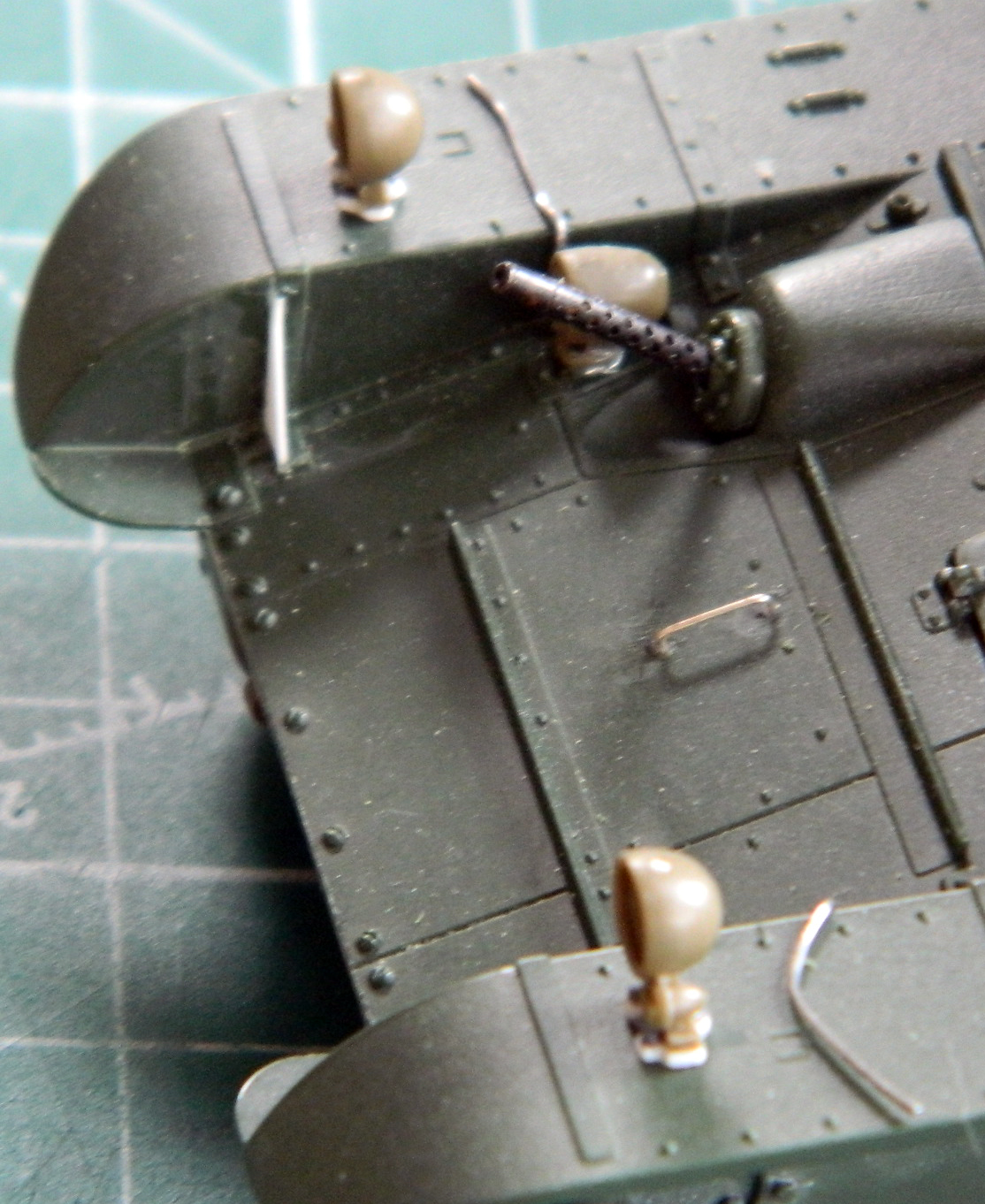
It made sense to me at the time (which is a different way of saying, “I have no idea what I was thinking* when I decided to make the headlight guards from styrene), so I cut a bit .015″ (.381mm) scrap to width and then tried (key word, that) to form them using hot water and something (small cable ties) to hold them to shape and set this aside to settle into the shape I was after:

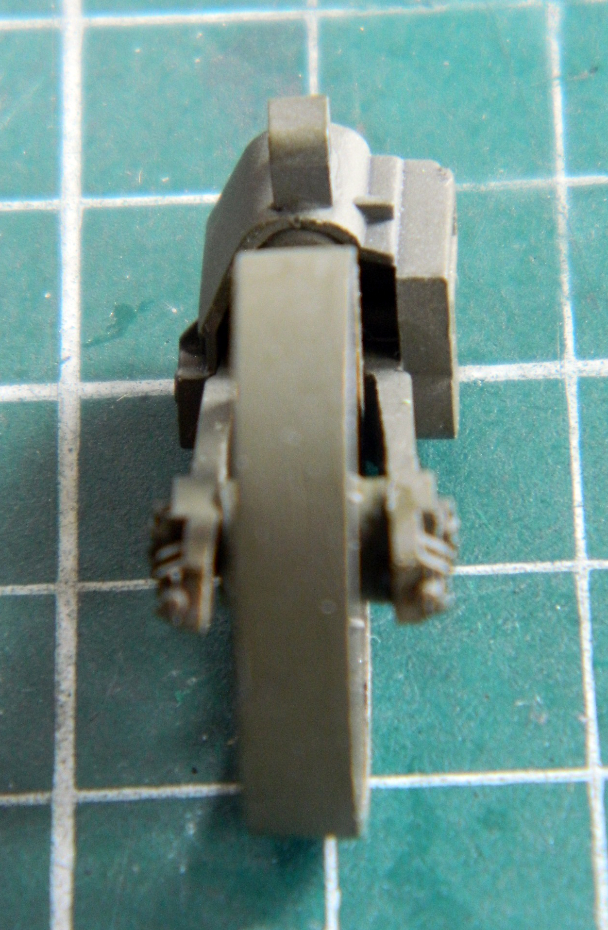
This wasn’t something I was looking for and checking. My eye chanced across the left rear idler wheel and discovered that it’s out of alignment with its mounting arm:
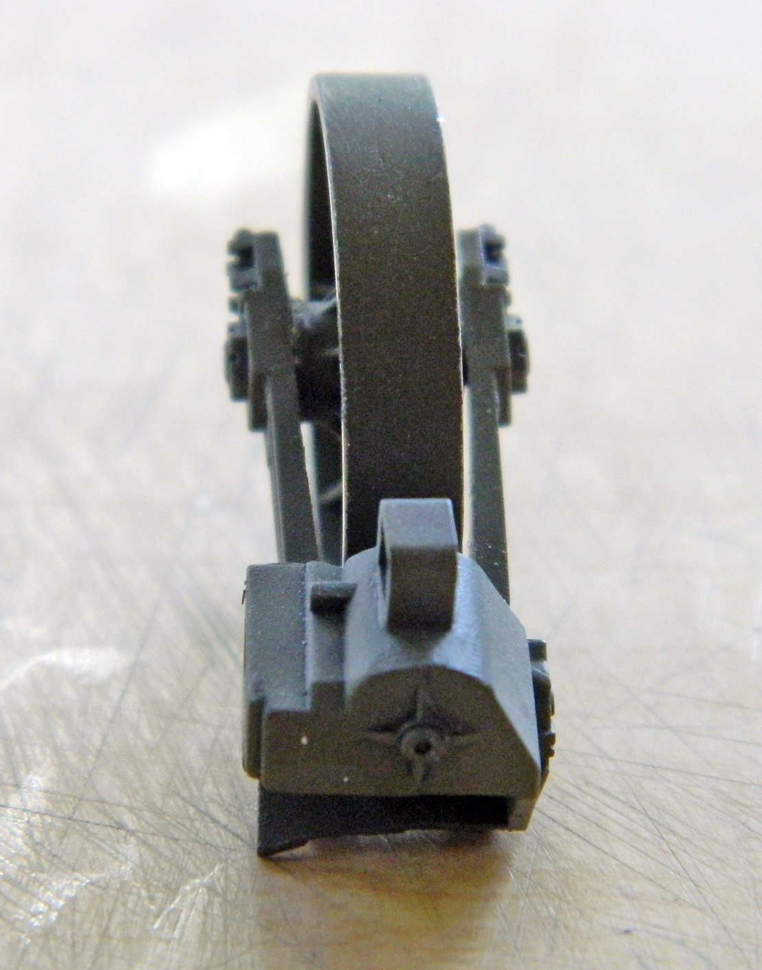
Blast and bugger. That has to be straightened and that puts the assembly at risk because I’m not shy about the application of adhesives. Nothing for it but to go for it and I used a chisel blade to get in there and break the wheel free:
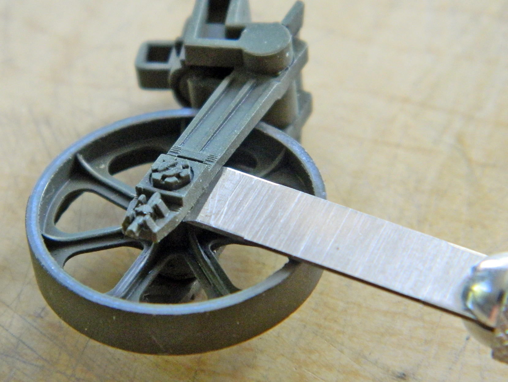
There was MUCH careful rocking of the edge back and forth to get the wheel loose and I managed to do that without destroying anything. After aligning the wheel better than it had been, more (and plentiful, of course) adhesive kept it there:
While opening the battery compartment, the hinge broke (and somehow the sodding muffler came loose while all this was going on):

I popped the screen off and reinstalled the muffler, considering how to fix the hinge:
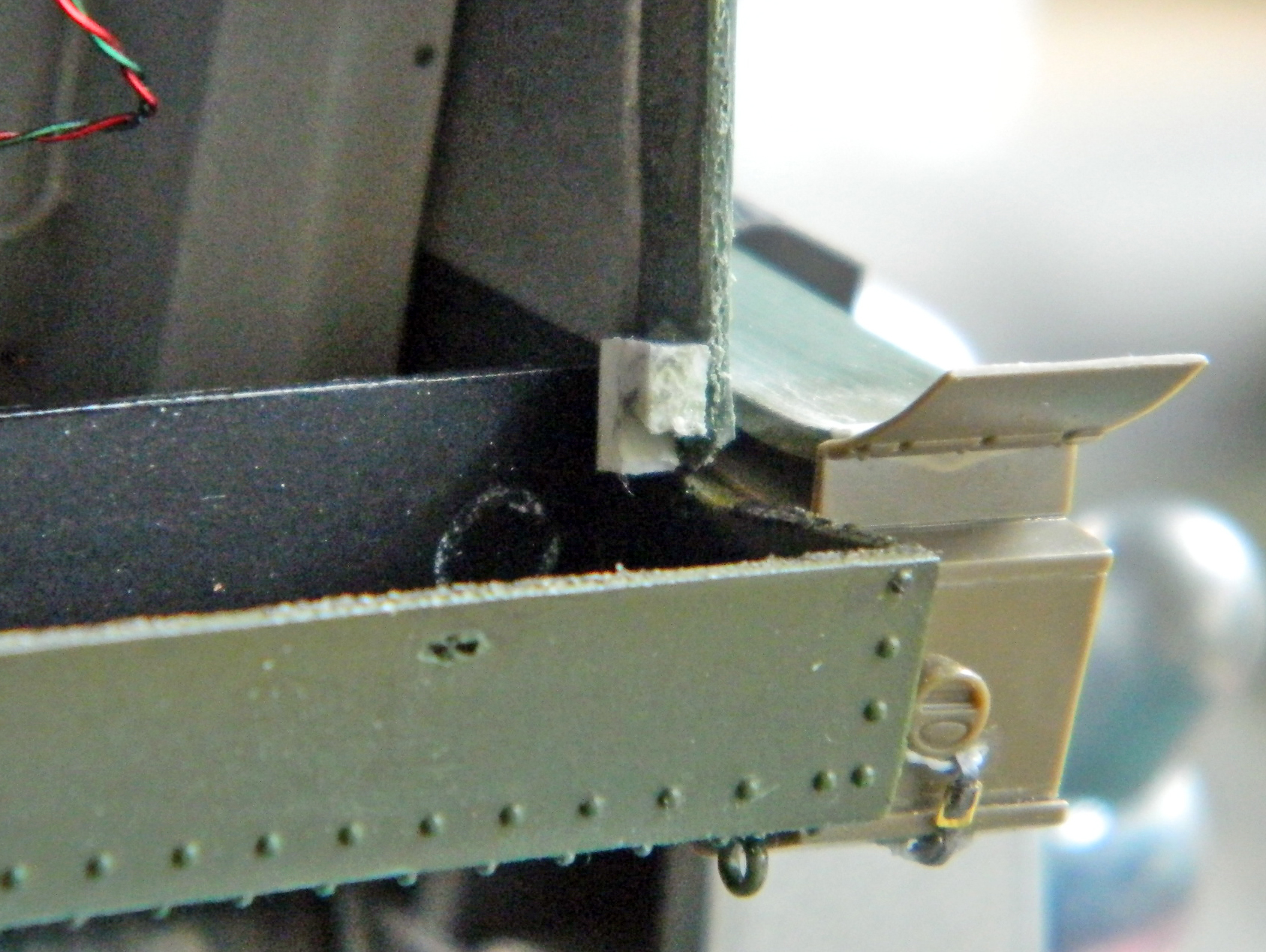
That consideration led me to the opinion that if I repaired the hinge, at some point down the line I would have to fix it again (and the further “down the line” this thing broke again, the worse the job of repair would be). So repairing this wouldn’t work long-term (doing things short-term only creates long-term problems), I would have to do something different. That’s when the Boys in the Back asked me if this had to be hinged…I just needed access.
Oh. Yeah. That.
Instead of repair, I removed the hinge completely and replaced it with another magnet/steel set up:

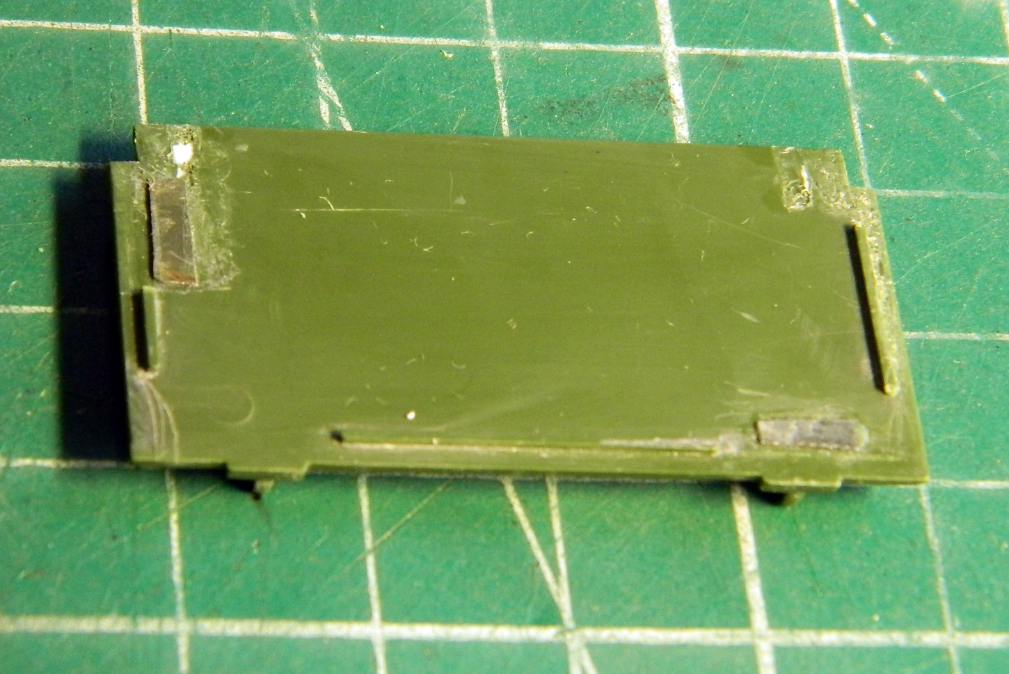
The result is certainly good enough and even more simple.
Having dealt with that, I went back to the headlight guards…realizing that using thin styrene was rather dumb of me. Where these parts sit, they’re exposed to various unintended contacts. Maybe making them out of sterner material would be a better idea.
About this time, I had someone ask me how involved the process was of using copper sheet for these. My response is, “About this involved.” These are the tools necessary:

The needle is to scribe the outlines of the parts I have to cut from the .010″ (.254mm) copper sheet. The scissors and chisel blade to make the cuts. The anvil (sorry, I forgot to pose the ball-peen hammer for the photo) to hammer the copper flat against after the scissors and chisel blade deform the copper. The smooth-jaw pliers to hold the copper while it’s annealed. The shaped wood to act as the form to curve the copper over. The tweezers to check fitment. (The small clamp was intended to hold the parts in place while being soldered, but instead, I used locking tweezers on bases for that.) The parts were cut out (the kit part in the background for comparison):

Then the parts were aligned and soldered:

The result was something more to scale and much sturdier:
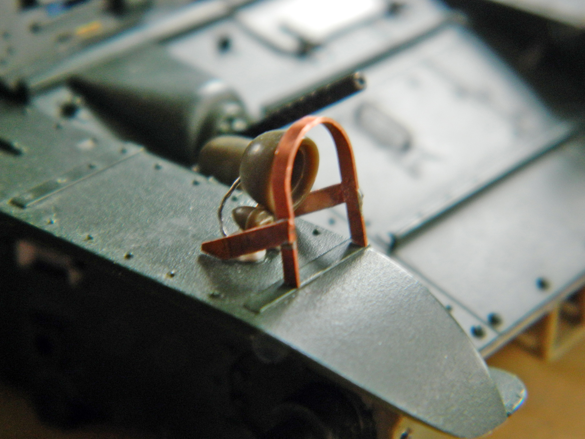
I let myself glow in the light of accomplishment a bit before I realized that I hadn’t gotten these things quite correctly. There are bends at the bottoms of all the flat sections that I had not either put in nor allowed extra length to put in.
So I redid them:
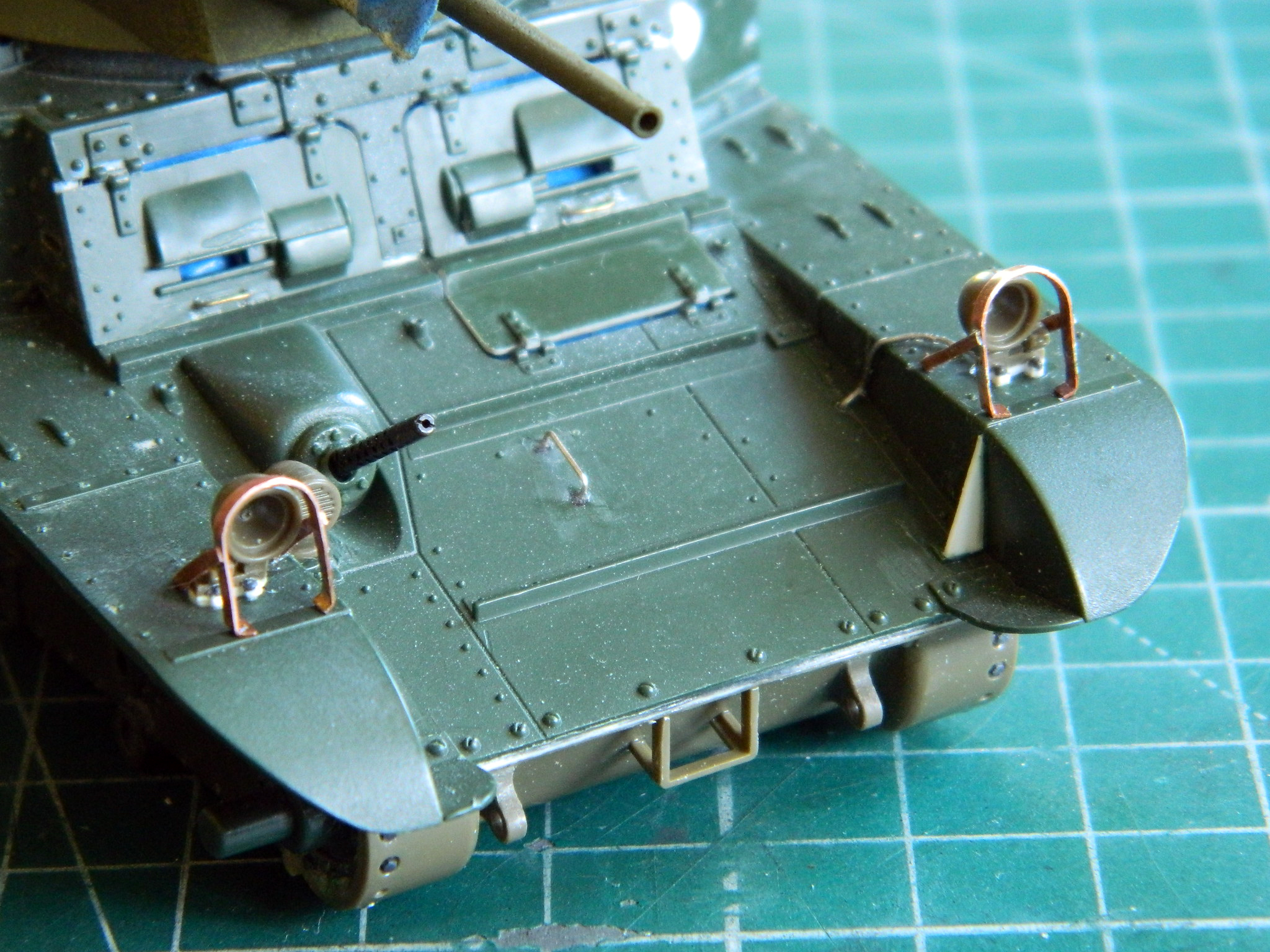
About this point, my brain decided it had other things to attend to*, leaving me sitting at the bench wondering what the hell I needed to do next (actually happens a lot) (stupid squirrels…). I knew I wanted to try a bit more in-depth pre-shading, so I had to paint this flat black. And I know once I did that, I’d find all the things I should have done before I painted it flat black.
Okay…let’s do this pre-shading thing:
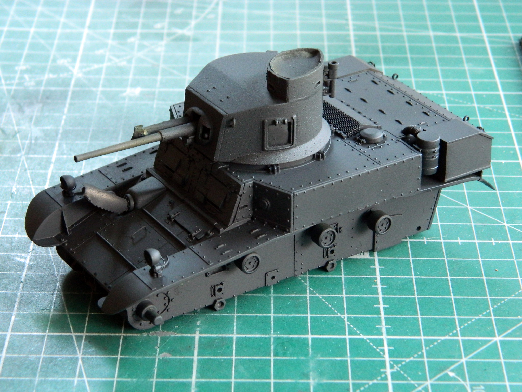
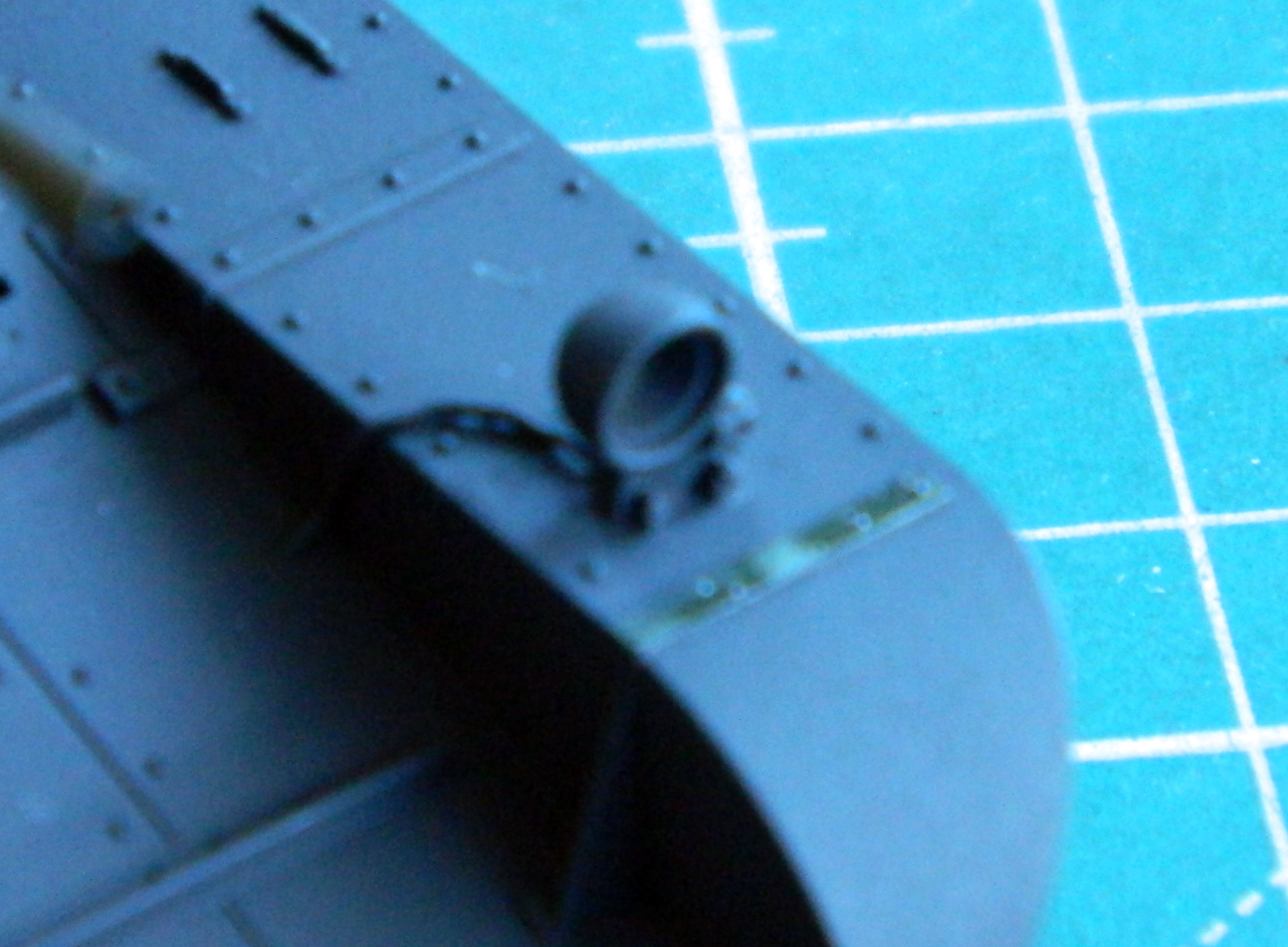
Huh. Whaddya know. I did forget to do a few things. I forgot to add the headlight guards I just spent all damned day on, forgot that I had to add rivets to the strap in front of the headlights (sorry about the blurred photo…I thought it had come out better than it did), and totally forgot to make the antenna mount (and then forgot to photograph the installed headlight guards):
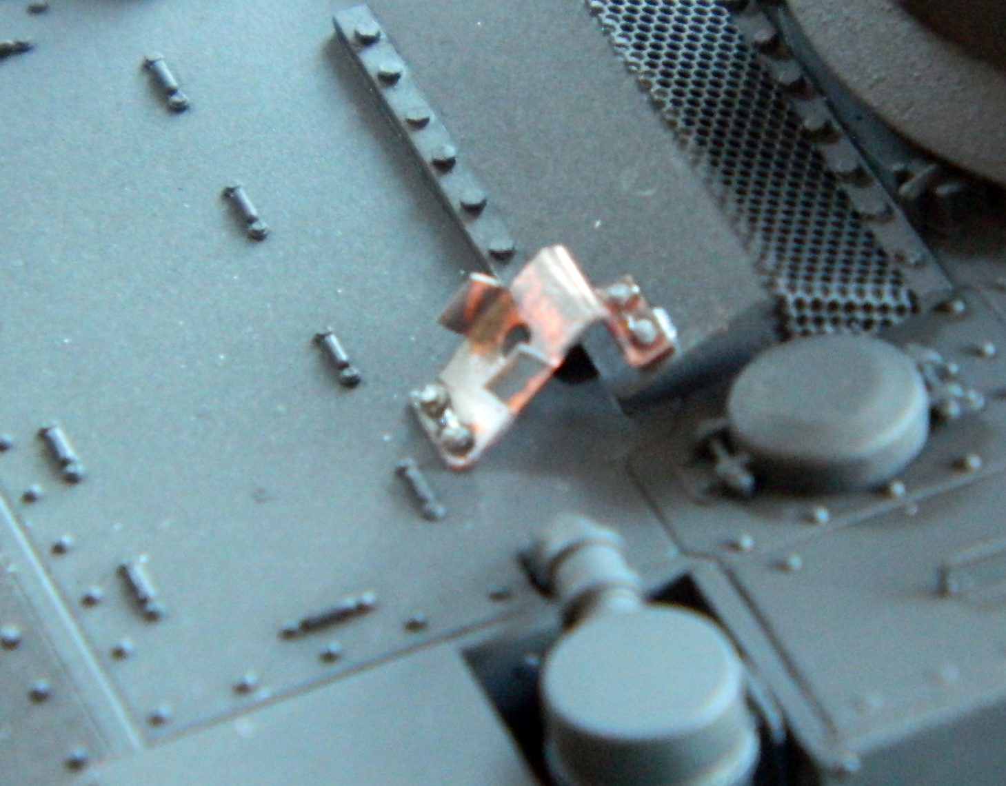
Once the .010″ (.254mm) copper was annealed and folded into the antenna mount, I added the bolt heads and glued it in place:
The next step in pre-shading is to paint all the areas I want lighter in appearance with flat white:
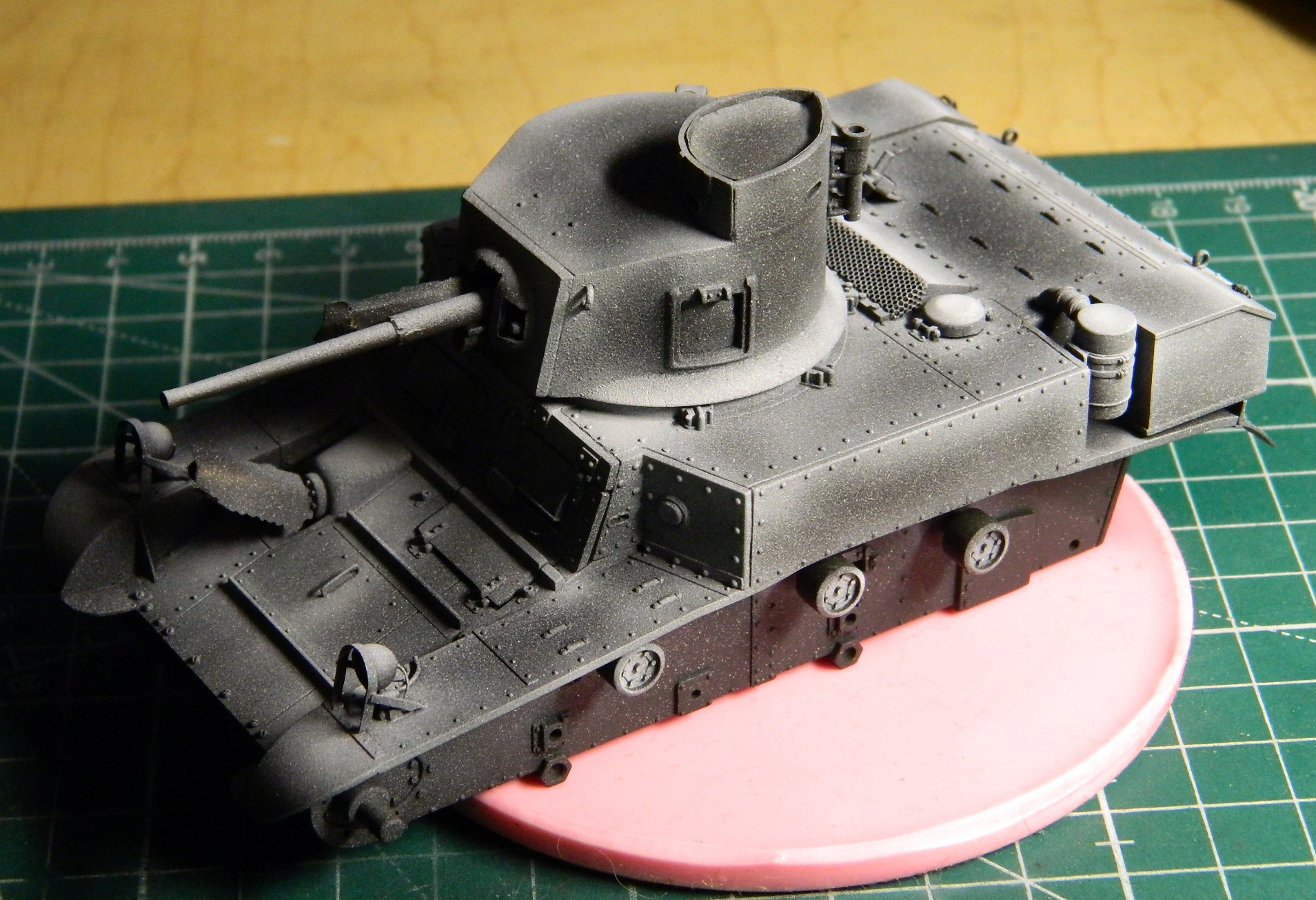

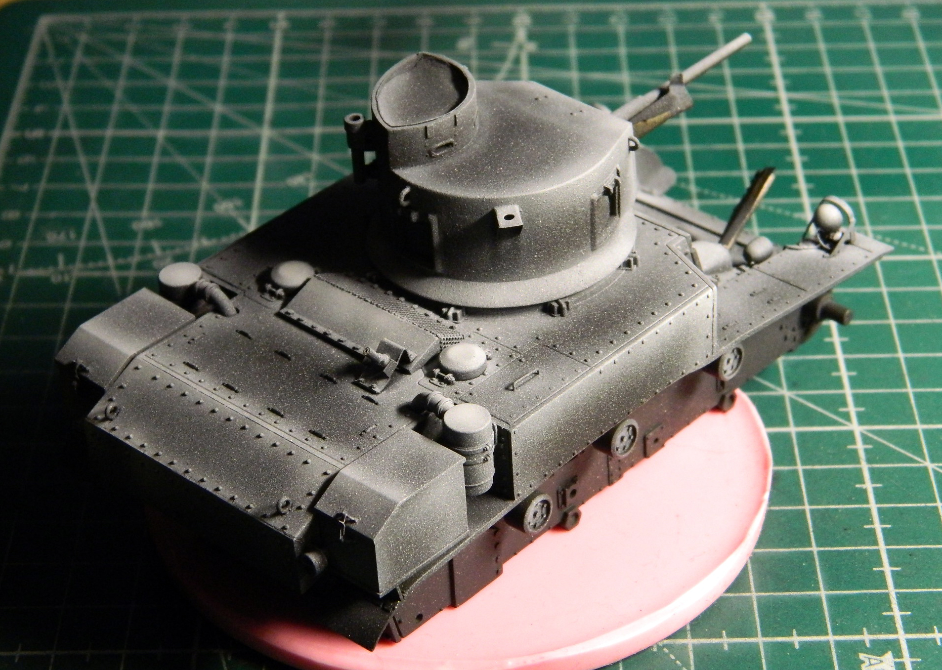
As things turned out later when I hit this with the color coat, I could have laid down a heavier amount of white in some areas. Lesson learned.
I set that aside for the paint to cure and went at some of the other small details. At present, I’m planning on using the track grousers that came with the AFV suspension upgrade. They were assembled and glued to a flat stick so that I could paint them without the airbrush blasting them into places I’ll probably never see again. I used a small dab of superglue:
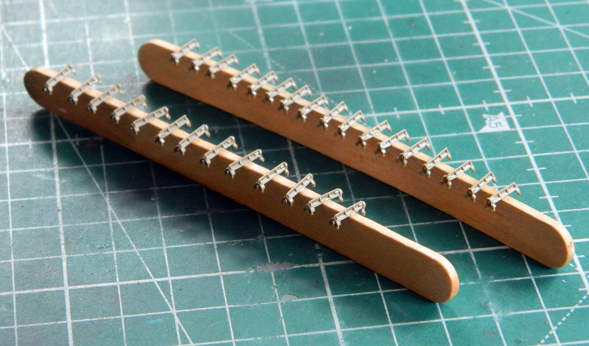
The first coat of paint was Humbrol’s “Steel”, #27003 (my FAVORITE when I need plastic to look like steel…you can see the grousers on the right have been buffed as have the tools). While I had the airbrush loaded with that paint, I also did the tools:
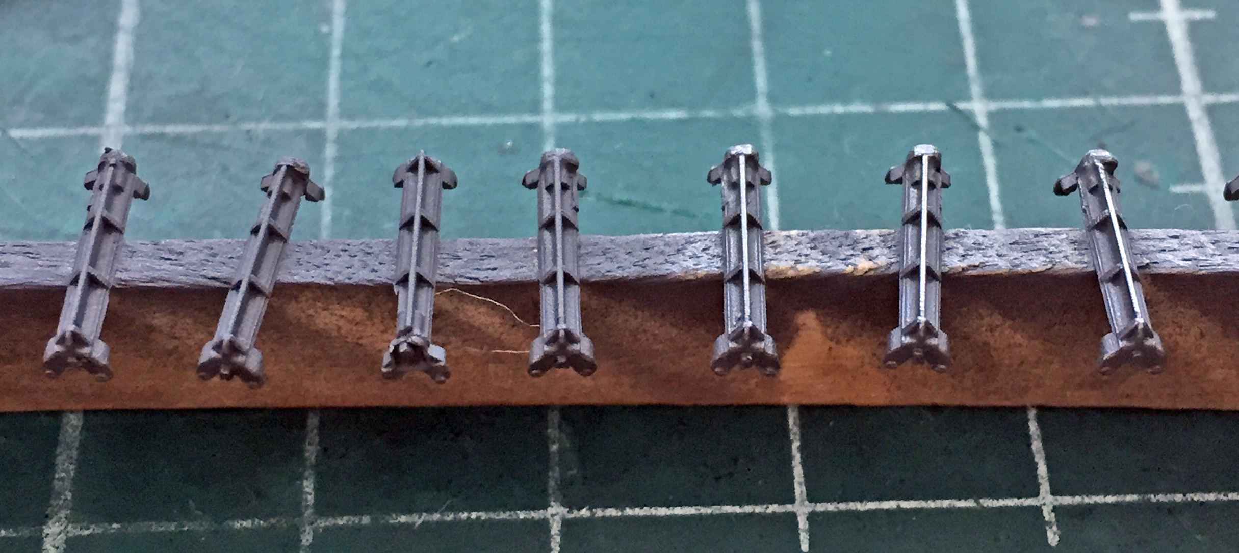

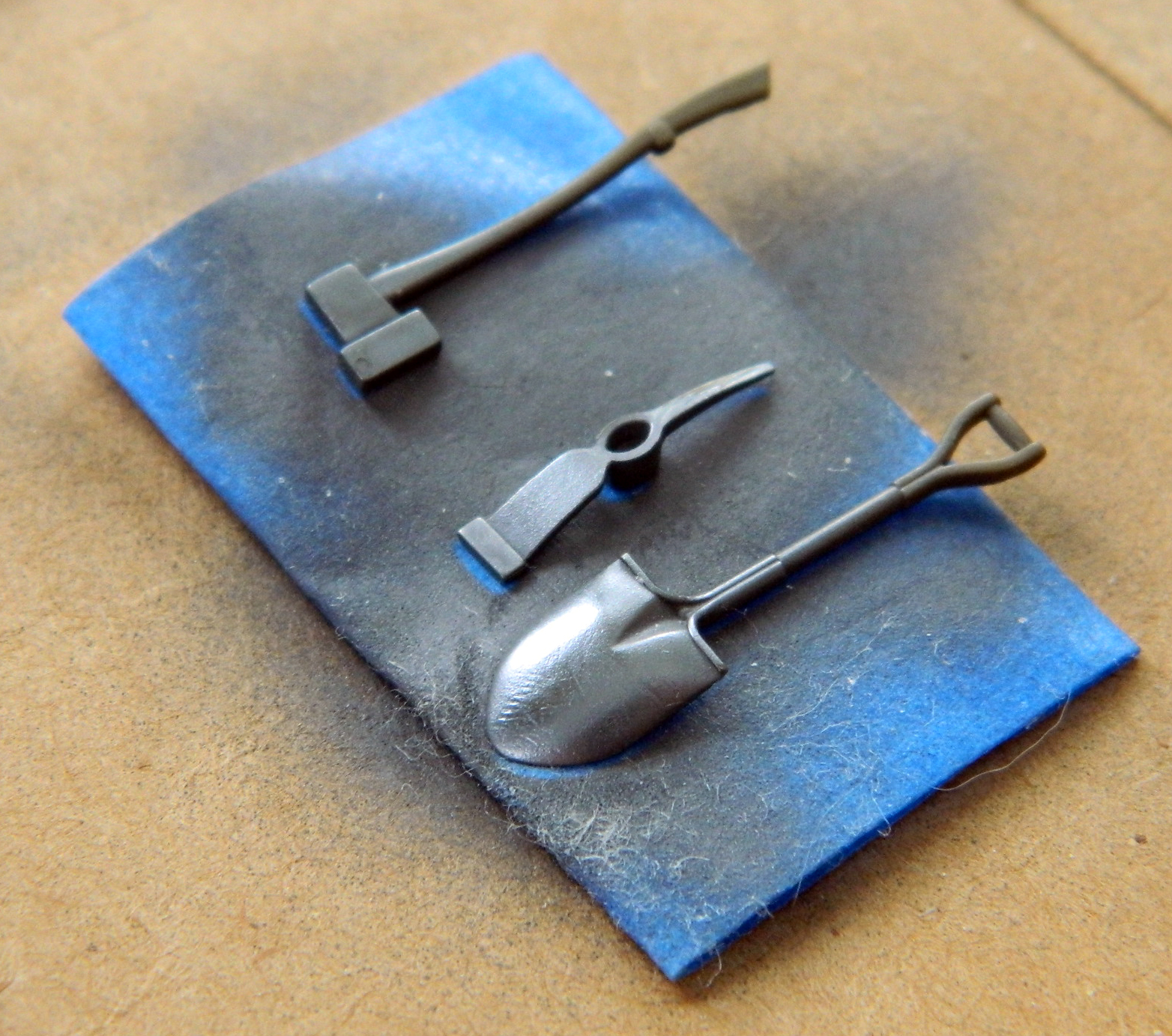
The grousers and track connectors were painted the track color (new formula I found online using Tamiya paints: 70% XF-68 Nato Brown, 25% XF-69 Nato Black, and 5% XF-7 Red) and the tools Tamiya XF-62 Olive Drab:
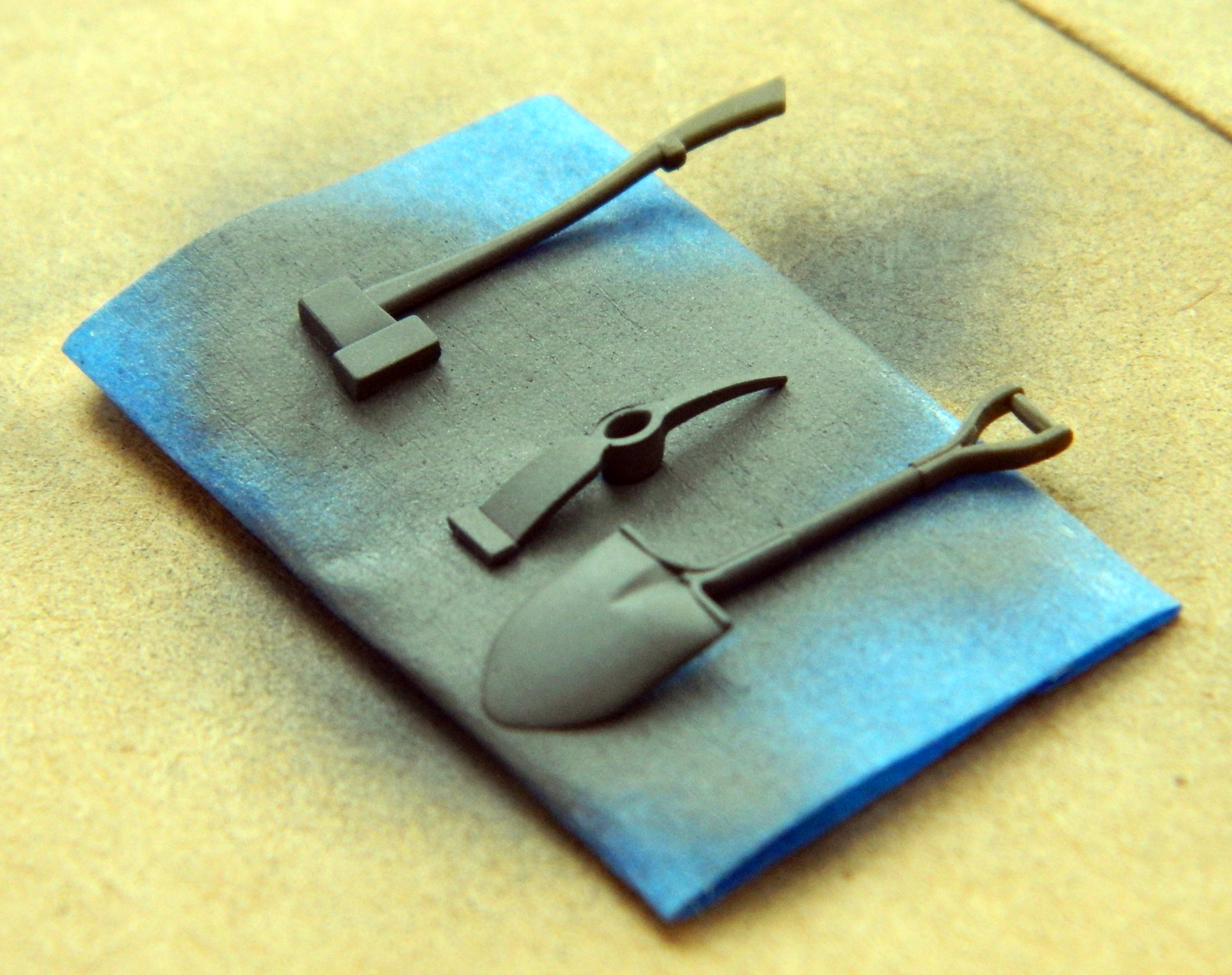
Before the OD set up for too long, I used a fine abrasive (nail polishing sticks from the beauty section of a drug store) (or apothecary, if you prefer) on the shovel and a toothpick on the pickax to replicate wear:


And while I had the OD in the airbrush, I tossed the first color coat at the tank:
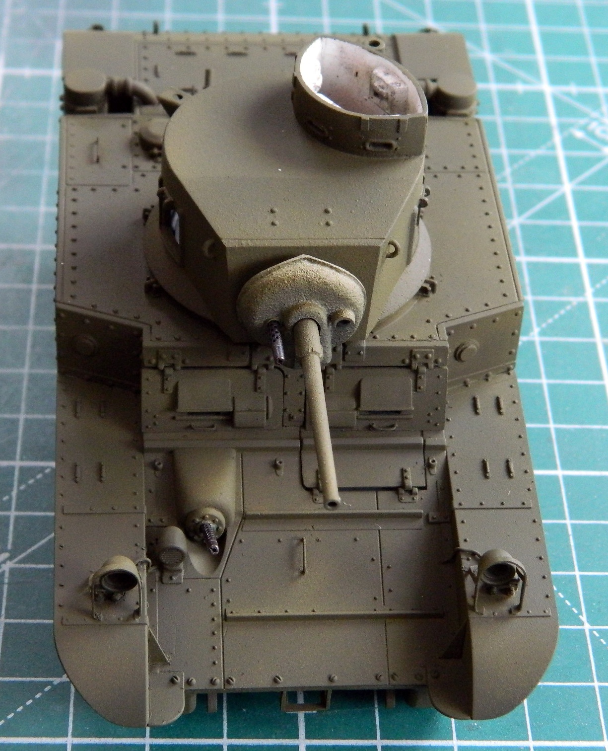
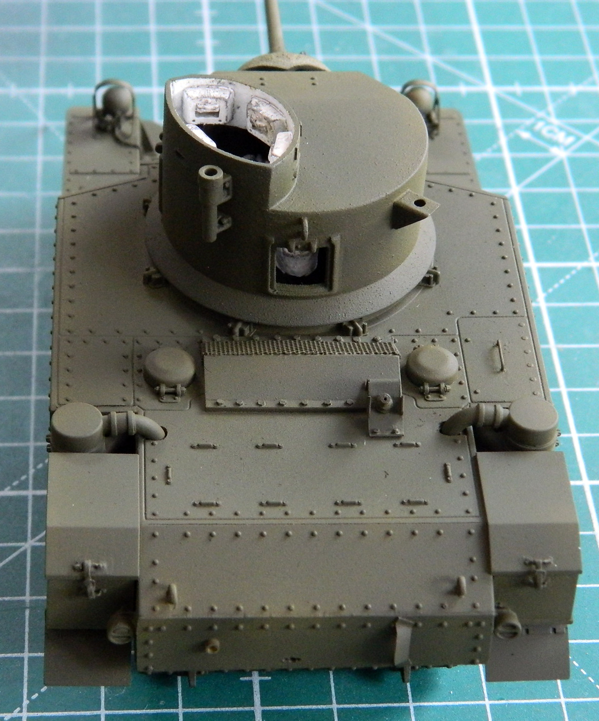
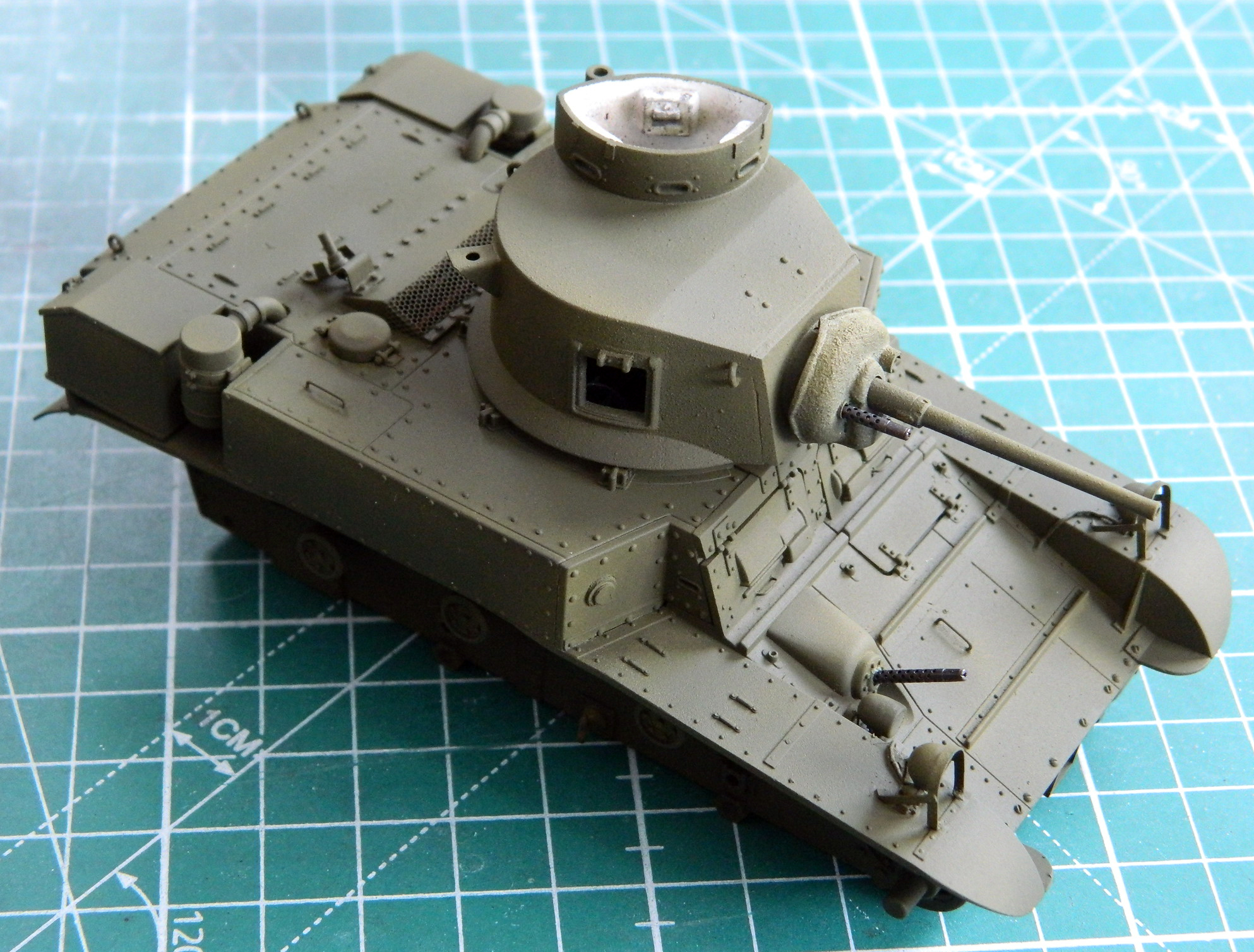
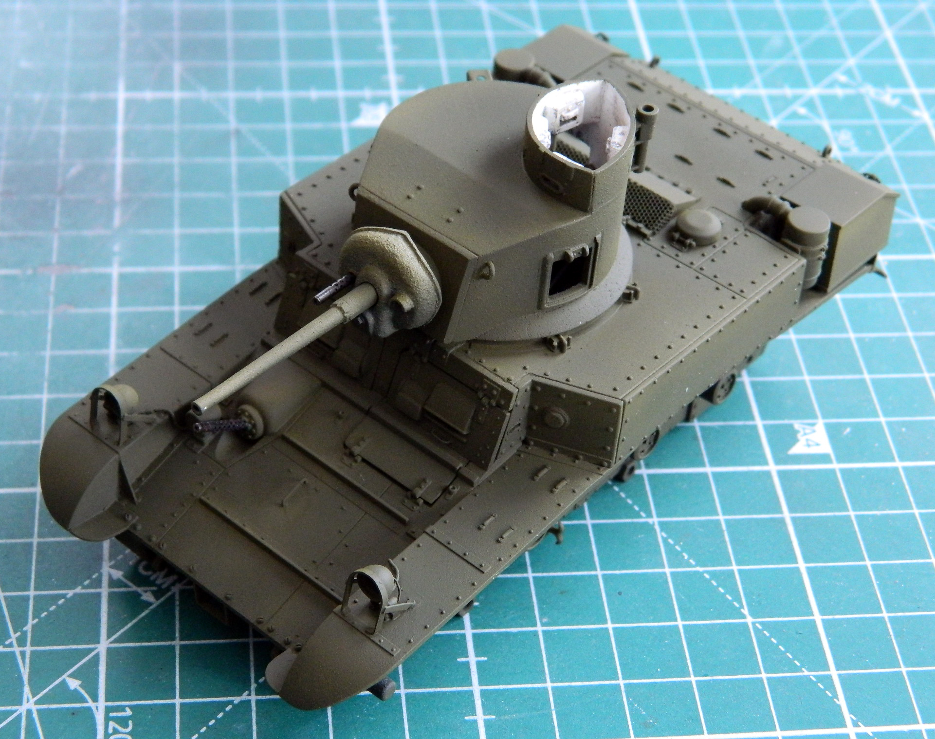
At this point is where I realized I could have been a bit heavier with the application of white. But, if I have to err, I’d prefer to err on the side of subtlety. I’ve often thought that some of the shading gets overdone, so if I have to adjust it, I’d prefer to adjust to more (pastels are my friend) than to attempt to tone it down.
What I’ve been working towards has been being able to attach the suspension and tracks…and now I’m at that point. The suspension did not come with the kit and the individual track links did. So before I could put the tracks on (not to mention the suspension), I needed to know how much track I needed to use. This would establish where the only variable left in the suspension goes; the idler wheel assembly. I thought I had the perfect meter, the rubber-band tracks that also came with the kit. I laid them down, placed the track I was going to use next to them, and ended up removing ten track shoes per side:
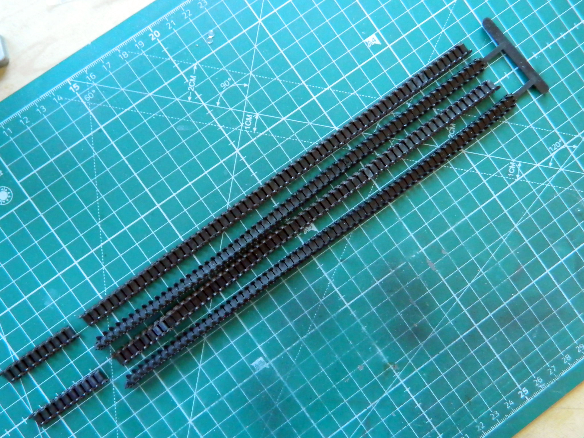
But once I tried to do that, hold the track in place while holding the idler wheel assembly in place while holding the tank, trying to get the sprocket wheel in place, AND snake the track over the return wheels, I discovered that just two hands made that all IMPOSSIBLE. If I had four hands it would have been difficult. I went back to reference photos, figuring that without the idler assembly in place, NO track gets mounted, so get the damned assembly properly in place, aligned to the ground, and then diddle with the tracks:
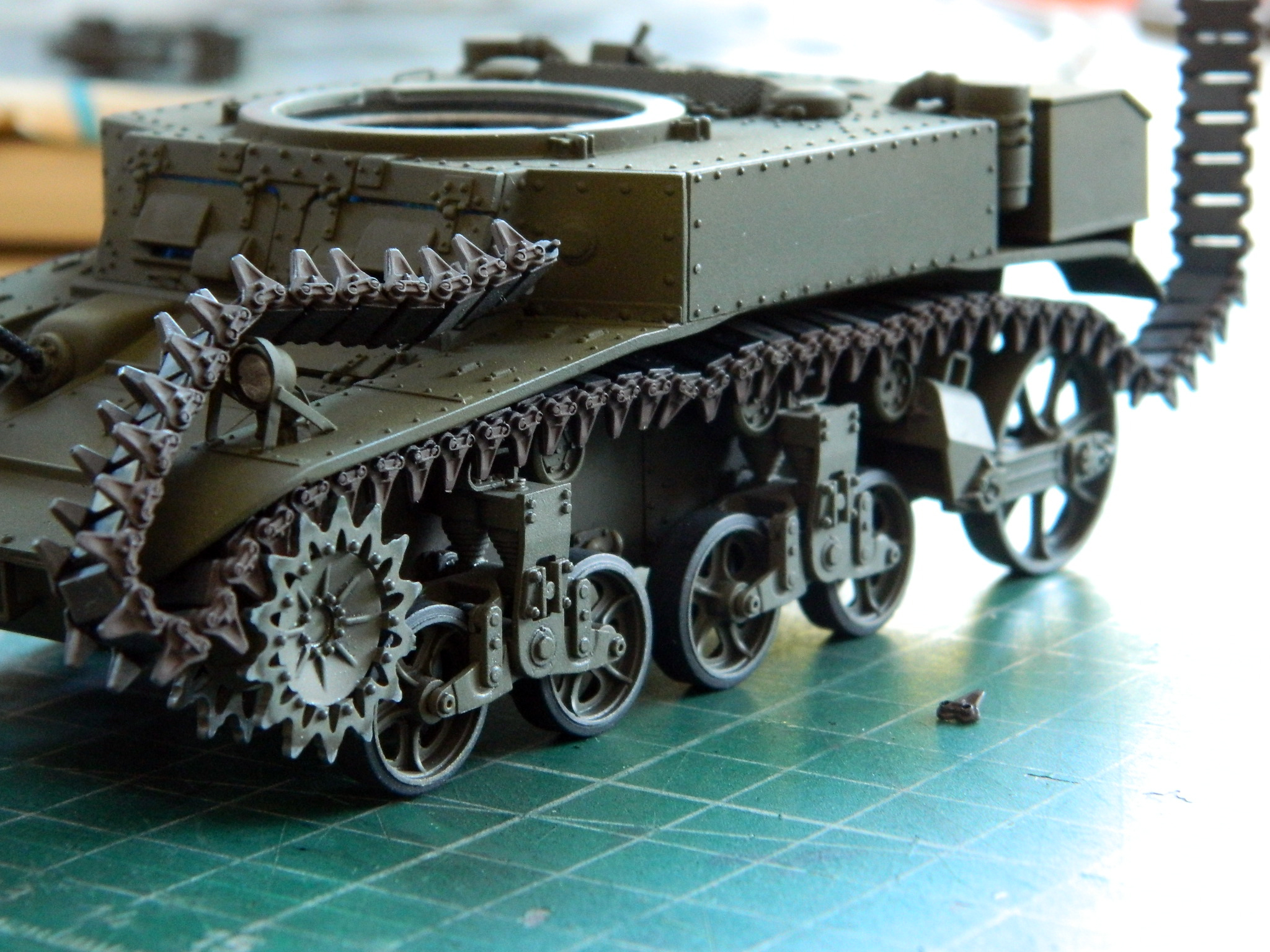
Trust me…MUCH colorful invective was abused getting the GODdamned…er…never mind. It was interesting. But as the above photo shows, not impossible and ultimately accomplished.
And when I tried to join the tracks, I discovered that the length as delineated by the kit’s tracks was just fornicating WRONG:
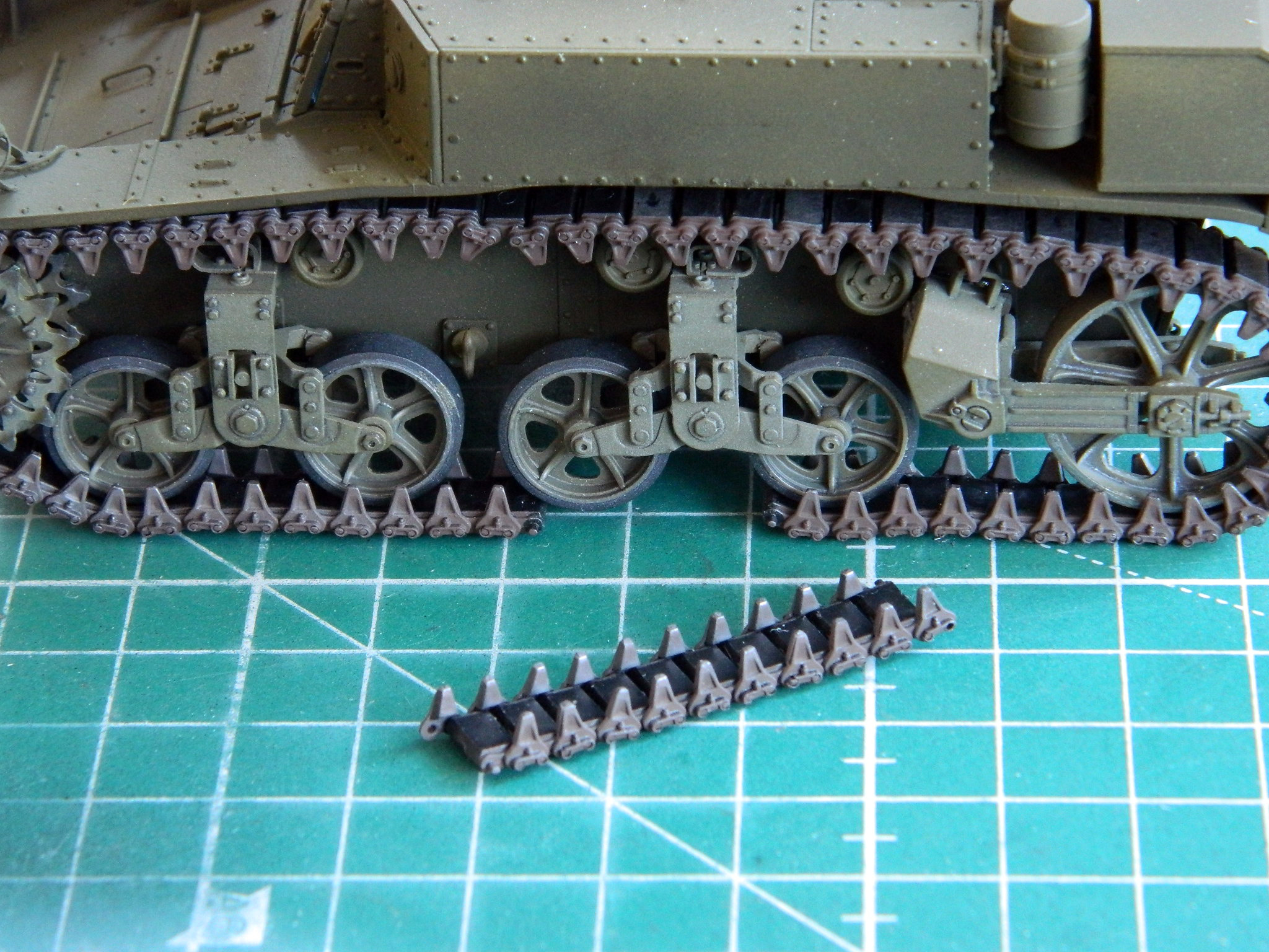
It was four track shoes wrong! Okay…I get that I’m using a different suspension. But I compared what I’m using to what the kit intended to be used and the difference should NOT be four track shoes!
::spits::
Getting the tracks to where they go is just annoying. It can be done with only two hands, though more would have made it easier:

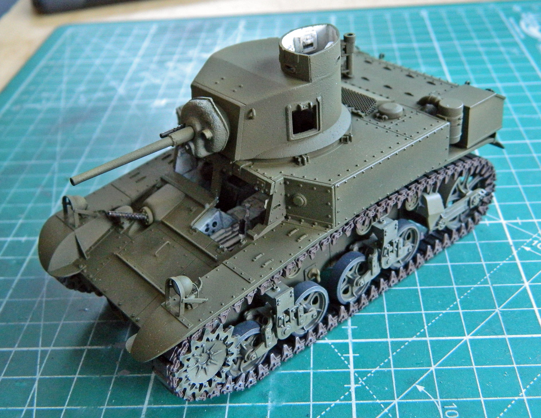
And then I turned the interior light on because after all the sodding tedium, I just wanted to see if it looked as good as I’d thought and hoped for:
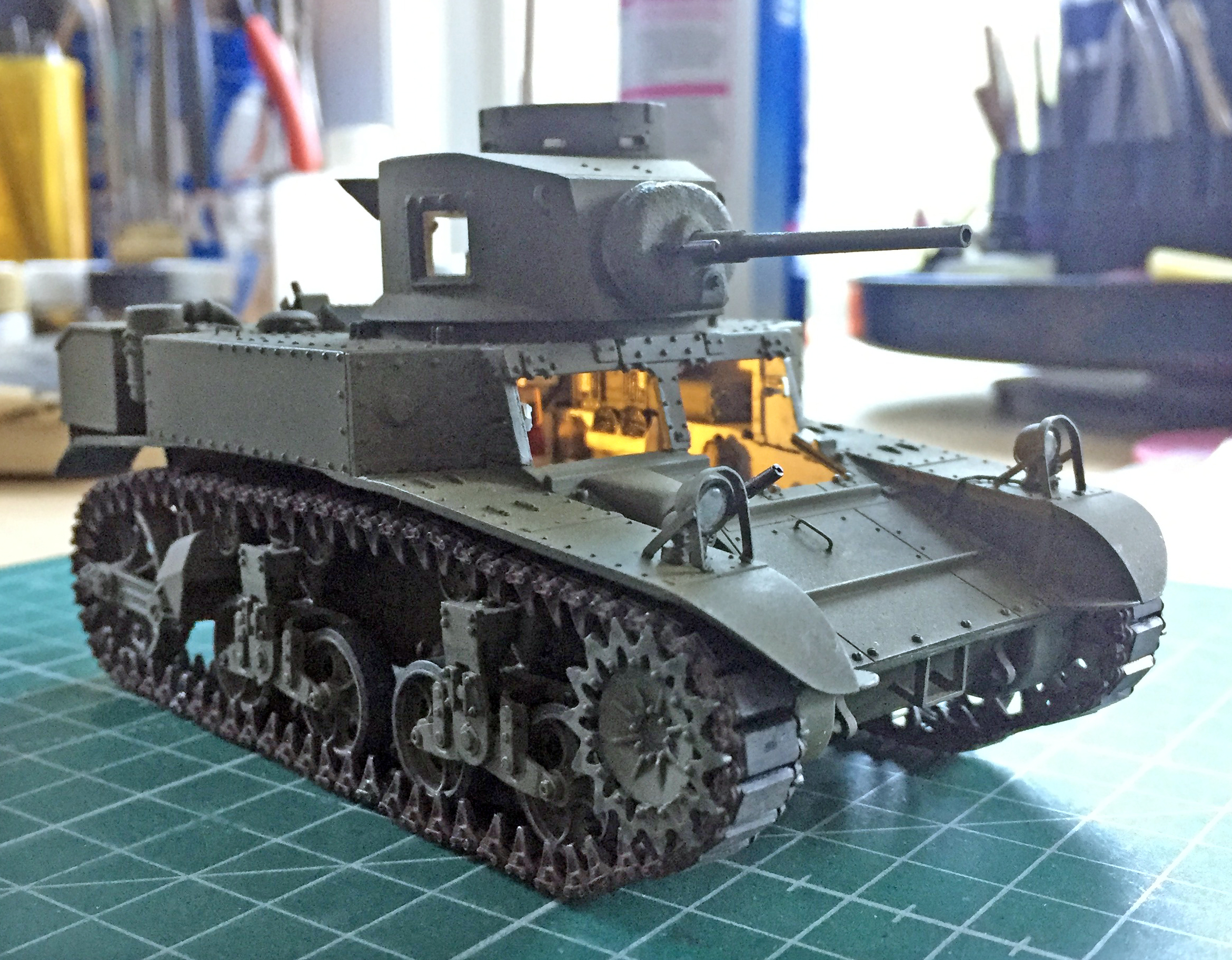
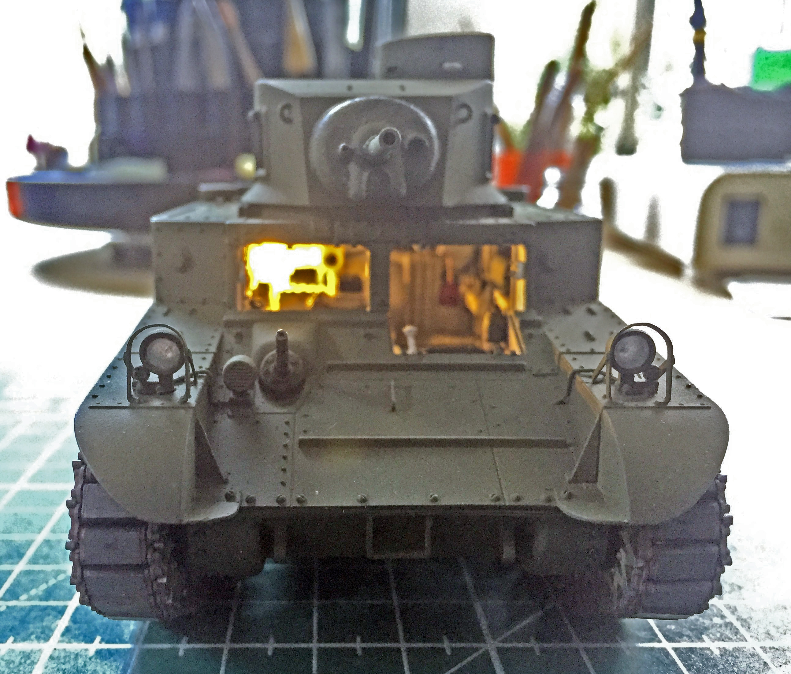
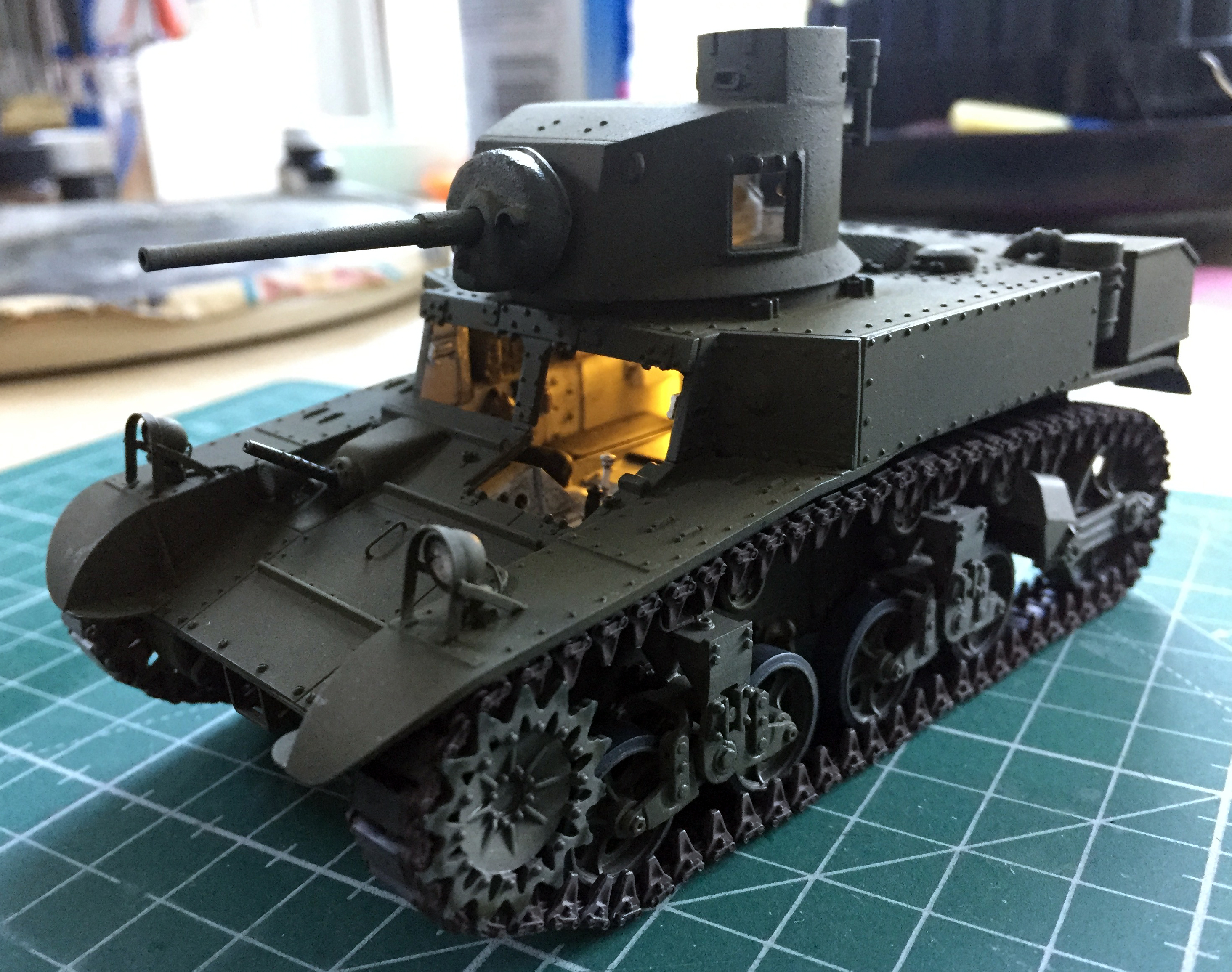
Yup.
Then I added on the front hatches and their support rods…and then all the parts I could dry-fit just because:
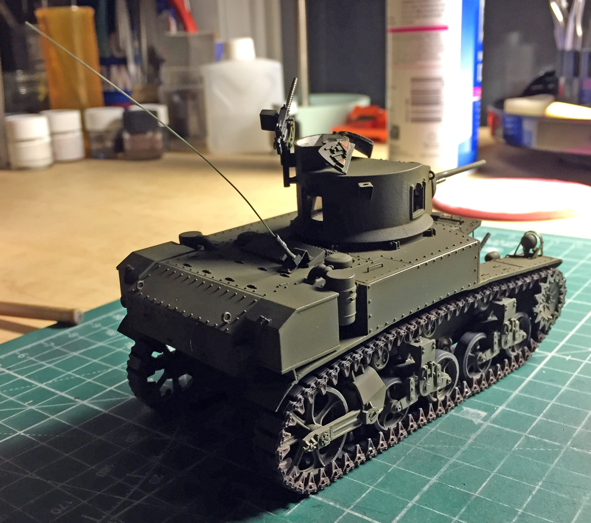
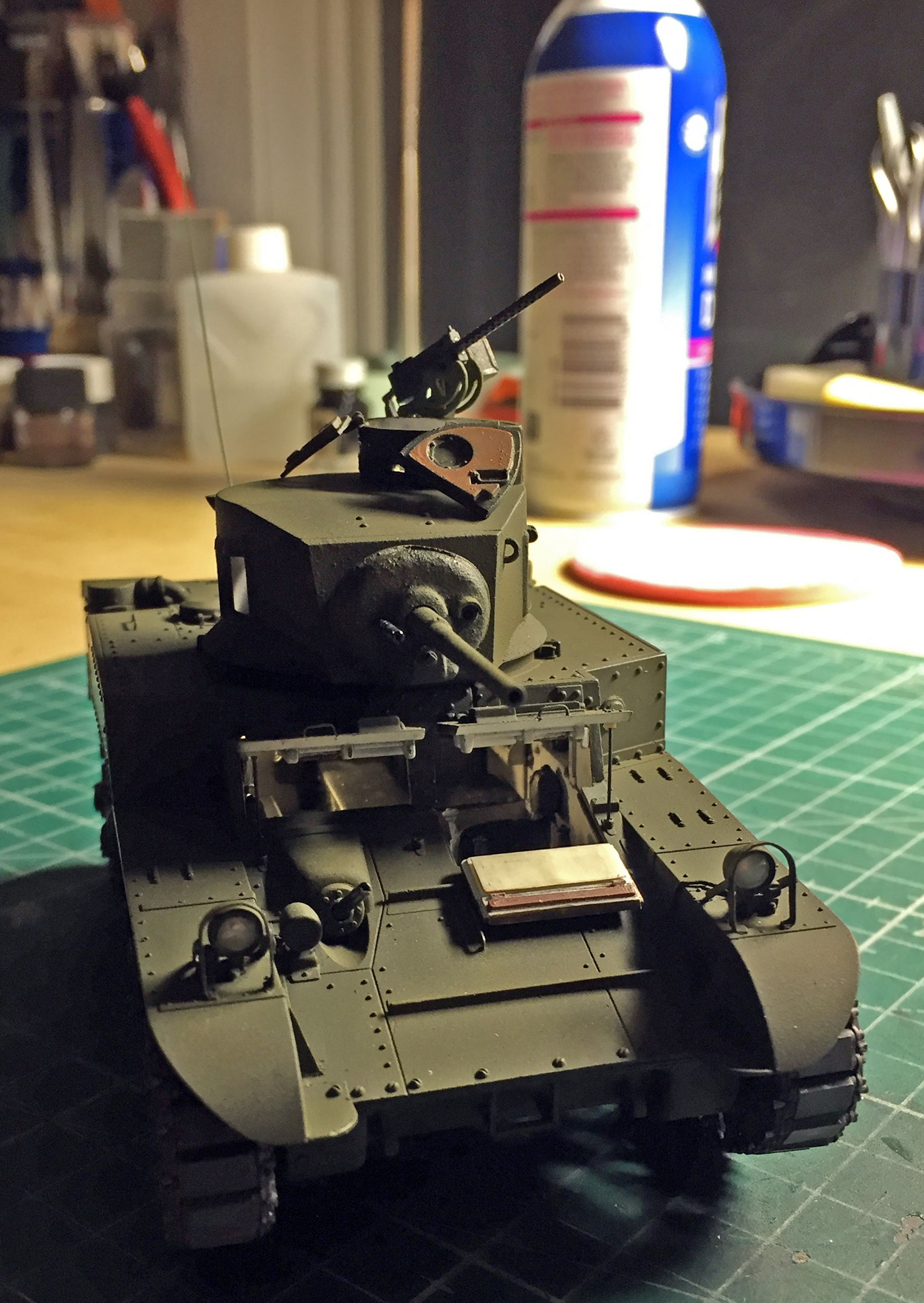
It’s getting there!
When I tried to start adding the markings is when I decided that maybe I’d better wait for the decals (that I just ordered) to arrive. This is what I have, I do NOT like it, and I will be stripping the paint off the turret and doing it over:

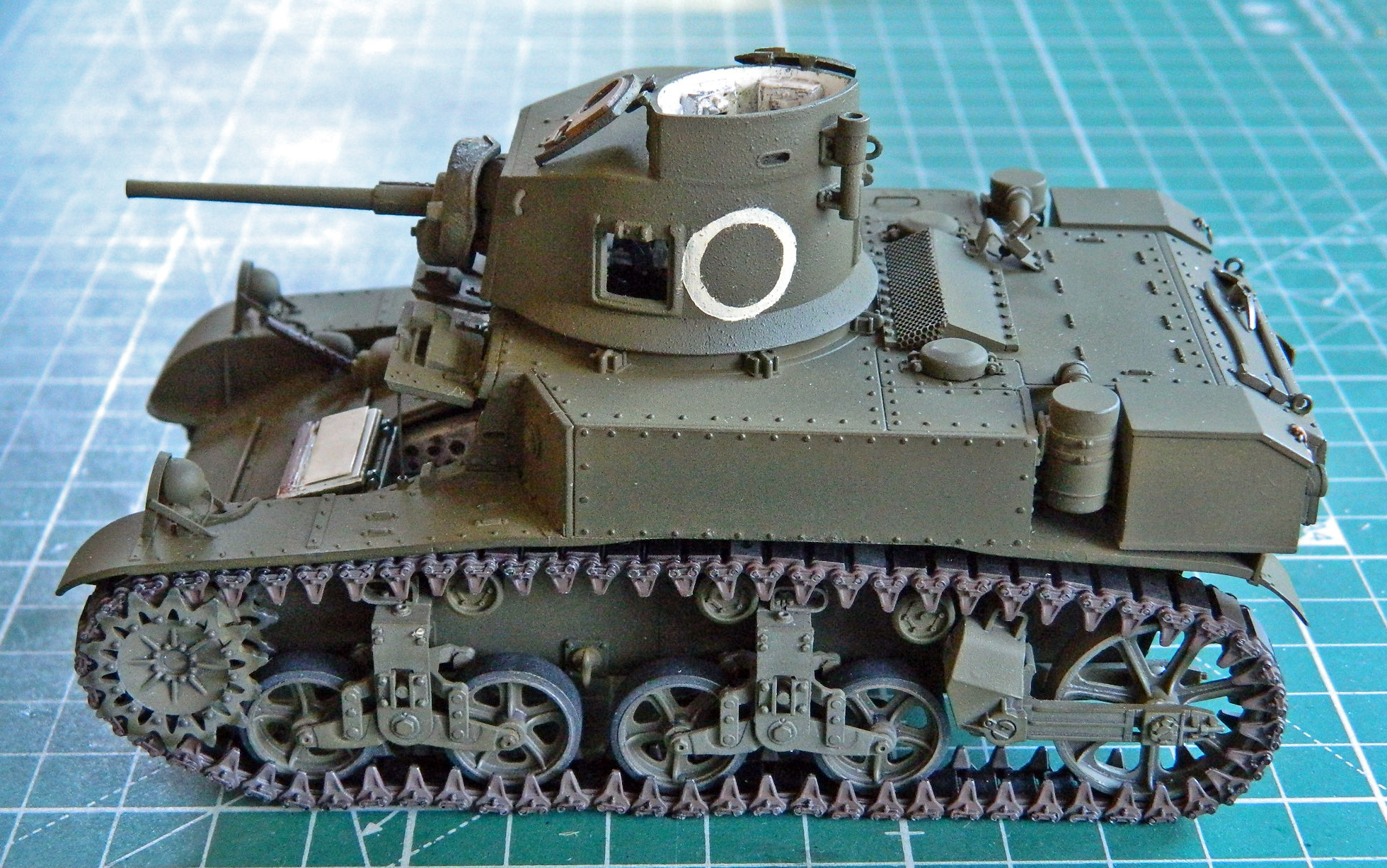
A lot of the early Marine markings were hand-painted over the Army markings (which is where their M3s were sourced), but even the most disinterested Misguided Child would have done a better job than I did.
*See “brain fade” in the glossary
With the crew compartment done, I moved attention and efforts up to the turret. I started putting the main gun, gunner sight, and coaxial .30 caliber (7.62mm) in place (the chipped paint on the gun barrel was from fitting the mantlet):
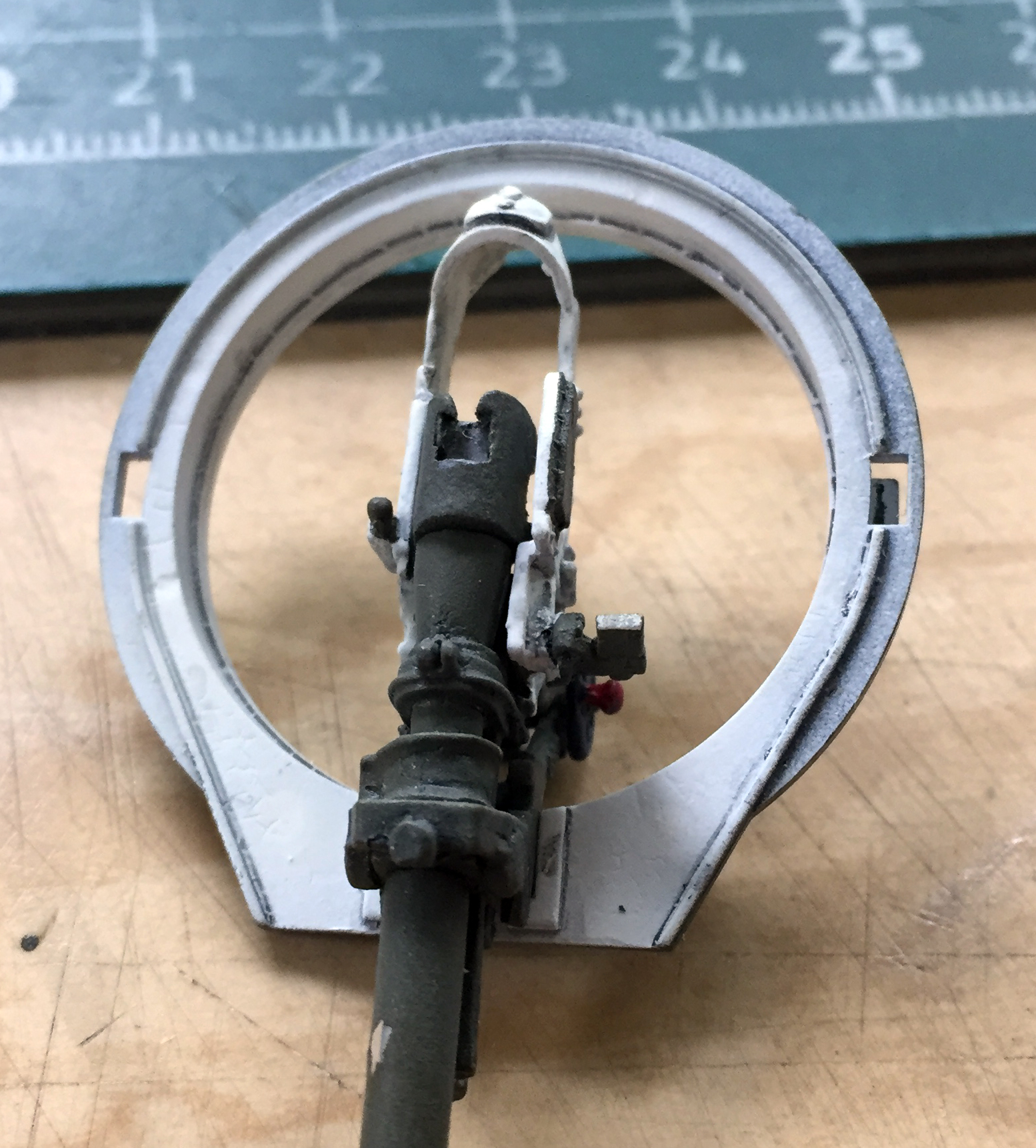
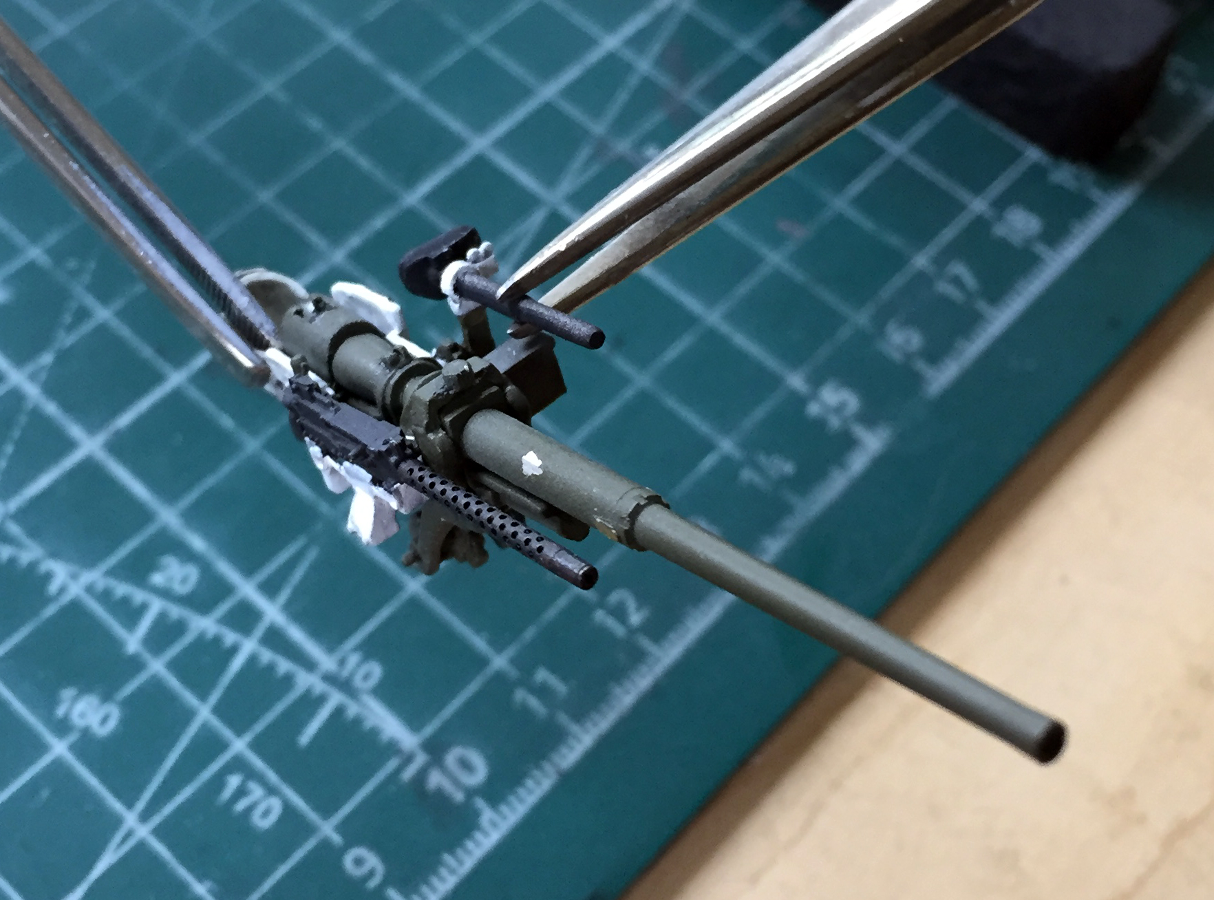
Then I dry-fit the turret bottom in place with the mantlet. I wasn’t quite pleased. The first thing I noticed was that the coaxial machine gun barrel isn’t parallel to the 37mm main gun; it’s closer at the machine gun’s muzzle:

Then I noticed that the resin turret front didn’t sit squarely, further exacerbating the misalignment of the gun mantlet. It’s all rotated slightly counter-clockwise:
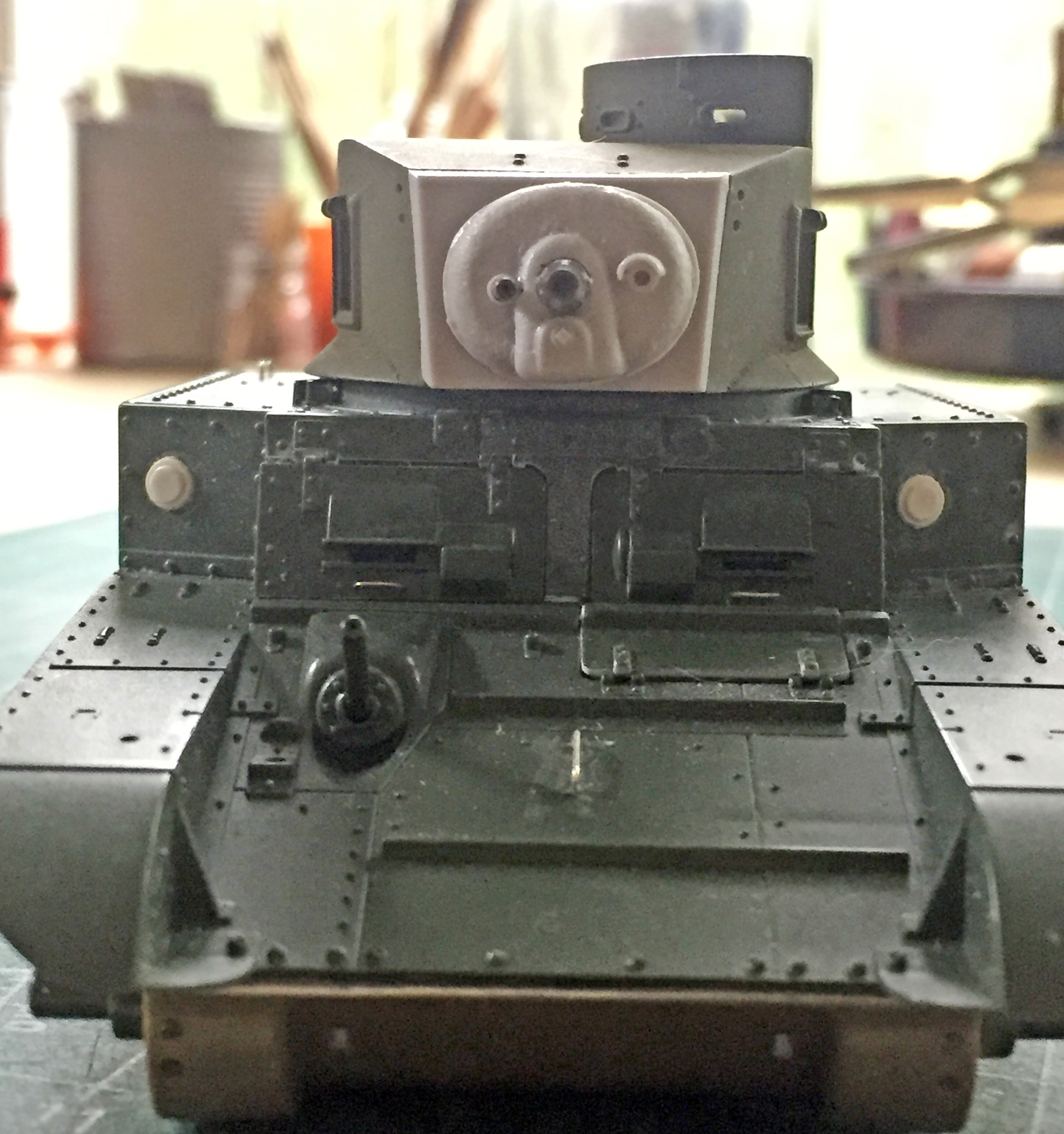
I decided the easiest way to fix that was to shave material off the gun’s receiver (the body of the machine gun for those of you who aren’t gun-savvy). That would allow the gun to rotate and move the muzzle outward from the main gun. I popped the resin turret front off and filed it to fit the turret better:
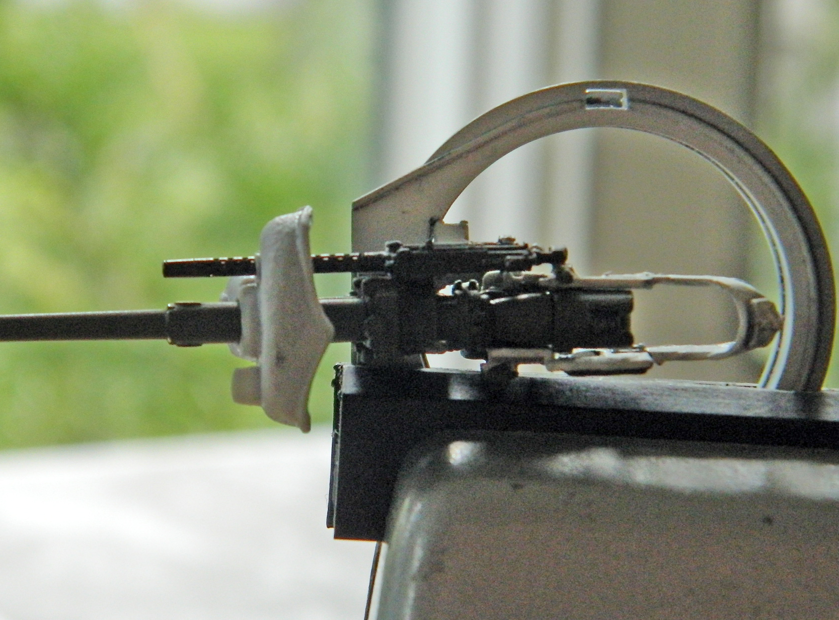
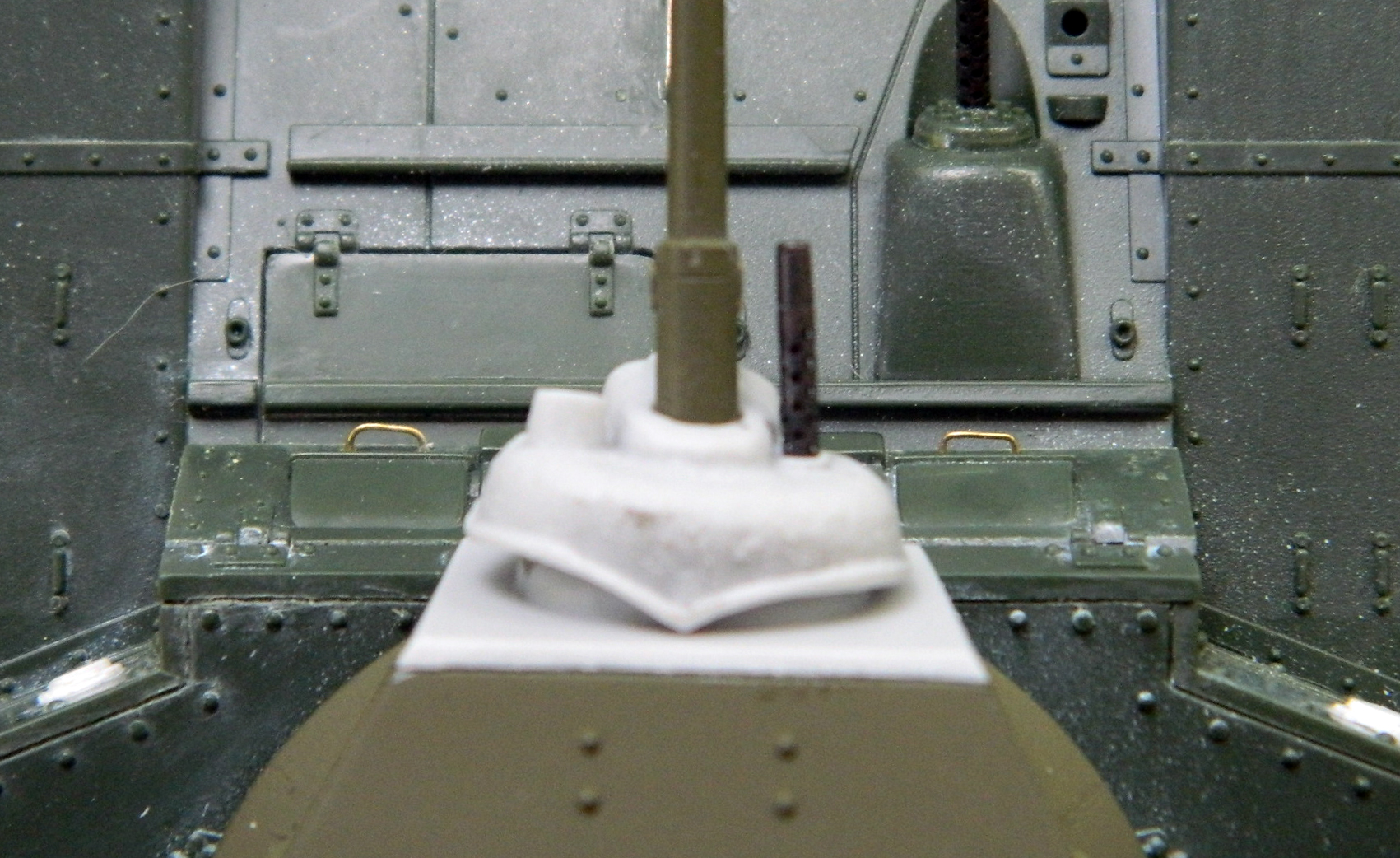
Not perfect but it will suffice.
During the dry-fitting, I noticed that the eyepiece of the gunsight wasn’t sitting correctly. I popped the assembly off, sawed the eyepiece off, and reattached the gun sight’s body:

While the superglue was setting up, I added bolt detail to the air intake assembly on the upper rear hull using Grandt Line bolts (it’s like taking parts of gnats off a sprue and reattaching them…eventually…somewhere else):
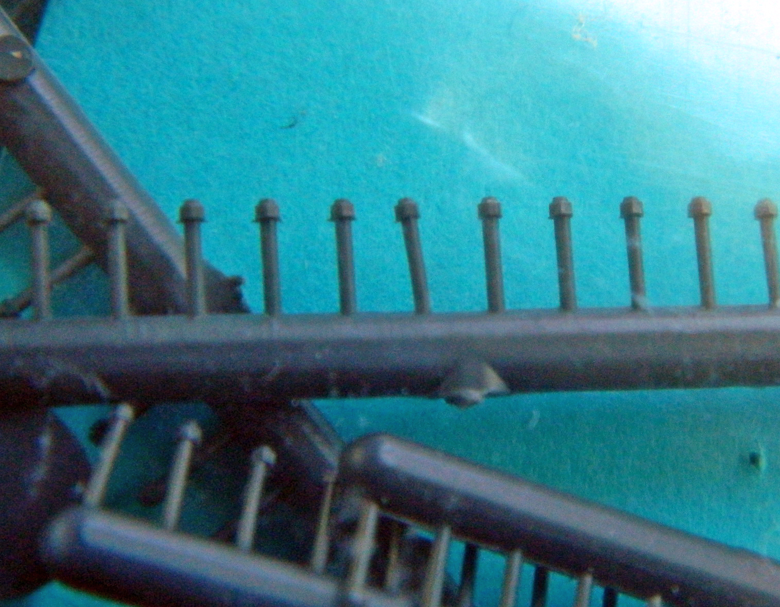
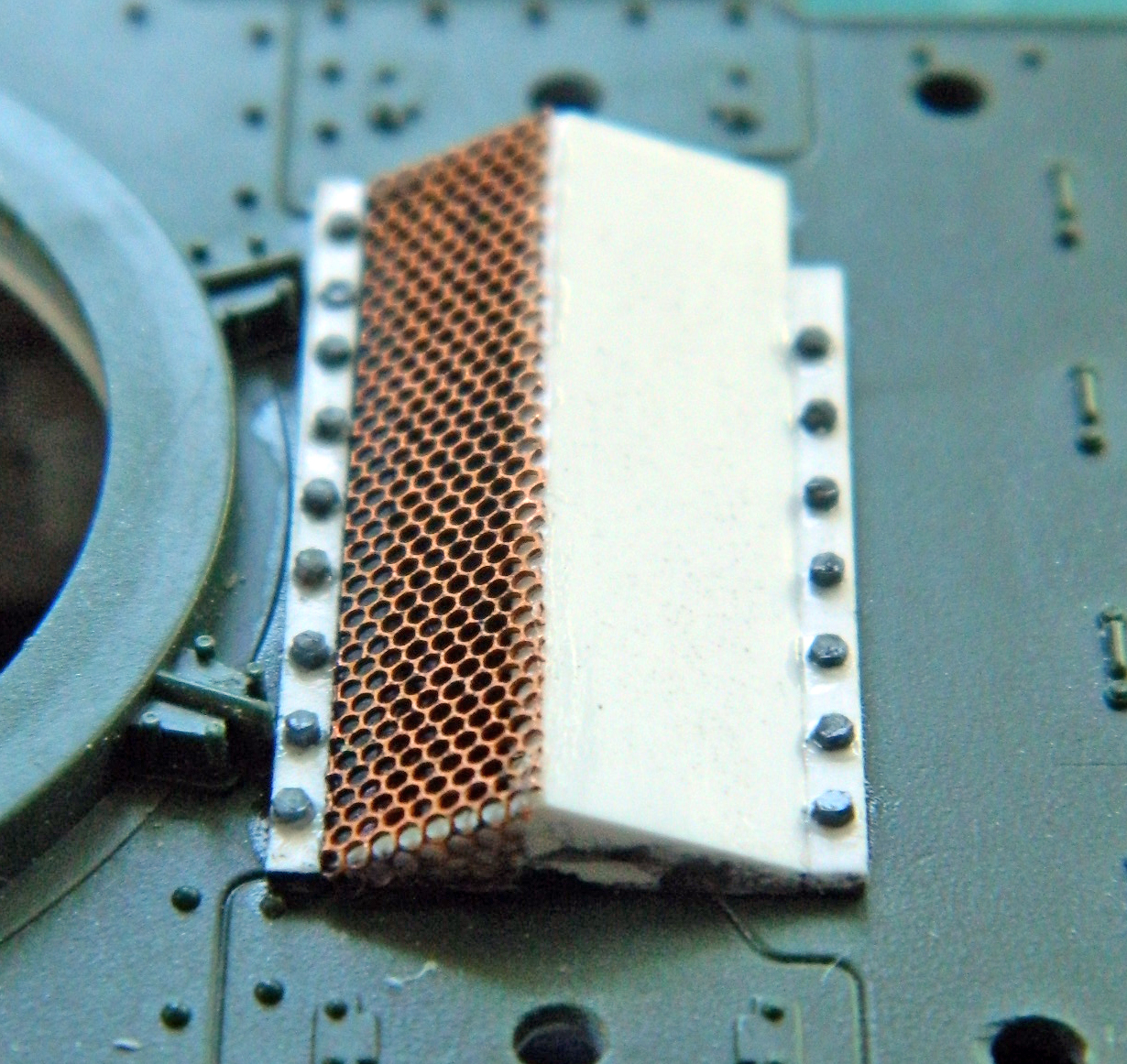
But they look great once they’re in place!
When I went back to dry-fit the mantlet to the gun assembly to make sure the gunsight lined up where it was supposed to, it wasn’t even close. On the inner face of the mantlet facing you, there’s a rounded projection. That’s where the gunsight is supposed to line up…and you can see how close it isn’t:
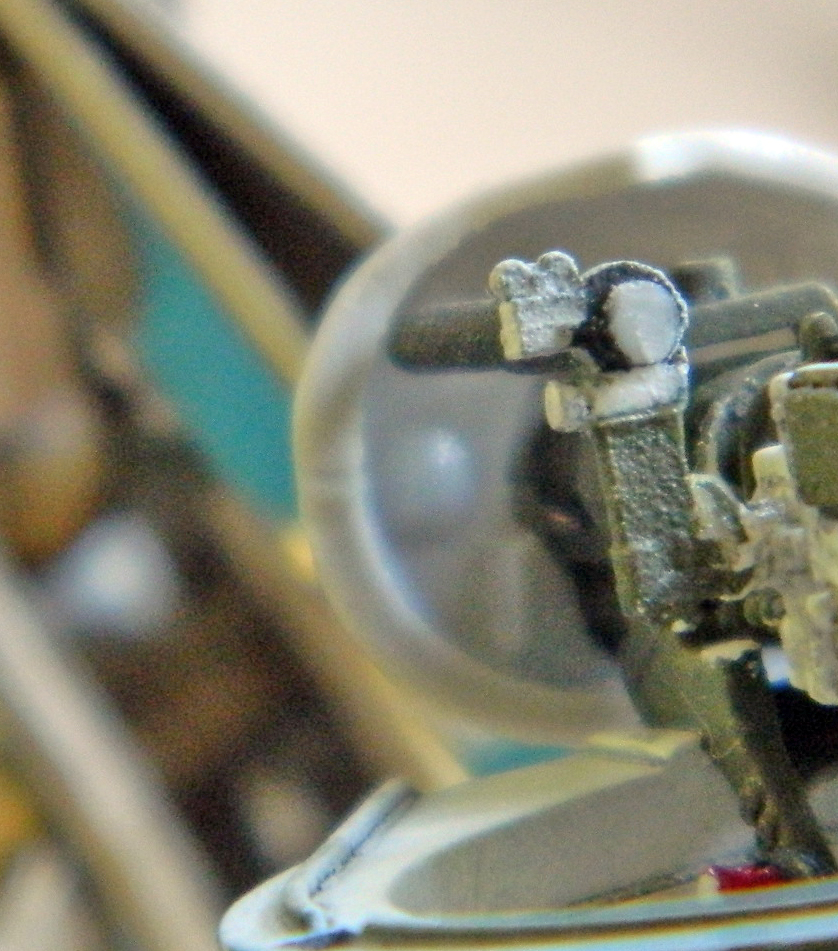
I had first considered that perhaps I’d erred and misaligned the parts as I assembled the gun parts. Nope. I checked the parts, I checked the alignment, and yet that’s where things ended up. (My respect for the person that mastered these parts took another solid hit.) I had to snap the gunsight free and trim the mount a few times before I got an alignment I could accept. That alignment required that the ammunition box for the .30 caliber (7.62mm), which was supposed to mount on the left side of the 37mm to instead be mounted on the turret ring next to the guns (unlike the .50 caliber (12.7mm) machine gun, the .30 caliber (7.62mm) can only be fed from the left side, requiring the ammo box to be mounted on the left side of the main gun with a chute above the 37mm to guide the belted ammo into the feed port).
No…that’s not in there correctly, but the cramped space inside the turret worked in my favor this time. Much of what had to be fudged and worked around cannot be clearly seen. Tight quarters and limited viewing angles can sometimes hide adaptations.
I discovered that the mantlet’s fit was a bit off. As it “fit,” the peak on the rear of the mantlet contacted the turret face while the barrel of the 37mm was mostly level. Well, that would certainly interfere with elevation:
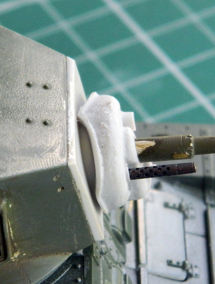
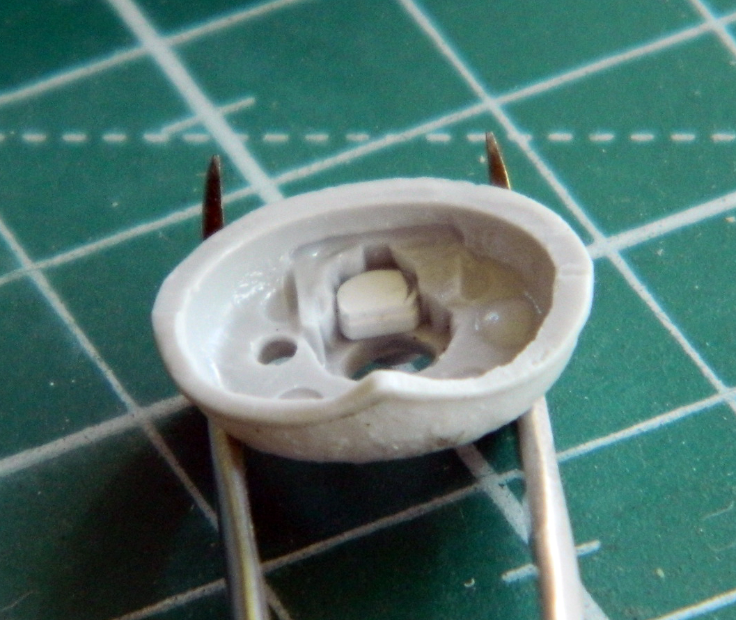
In order to move the mantlet away from the turret face, I needed to add a spacer (about .045″ (1.143mm) of scrap styrene) to its mounting point:
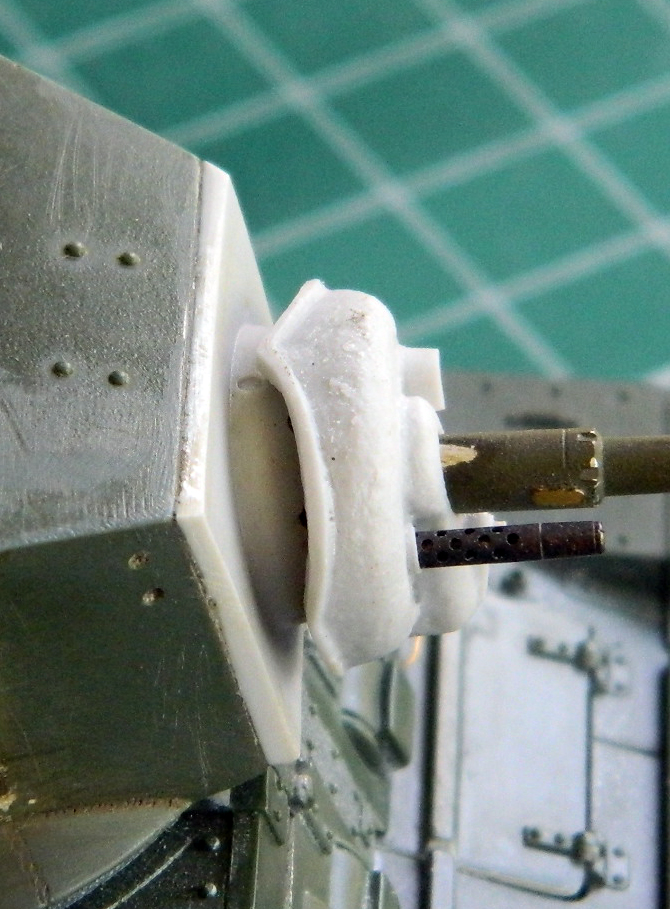
That solved the problem:
References show that the commander’s .30 caliber (7.62mm) was usually mounted in the Pacific (and at Guadalcanal, which is the locale I’m modeling this tank to represent). That gun is in the line of sight and I wanted to do something a bit more accurate than the kit’s part. I wasn’t especially satisfied with any of my options; the resin guns didn’t really fit the mount and the kit’s gun lacked detail. The easiest problem to fix was the absence of detail. Add some:
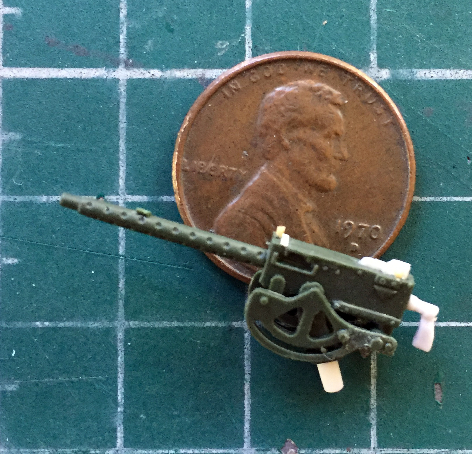
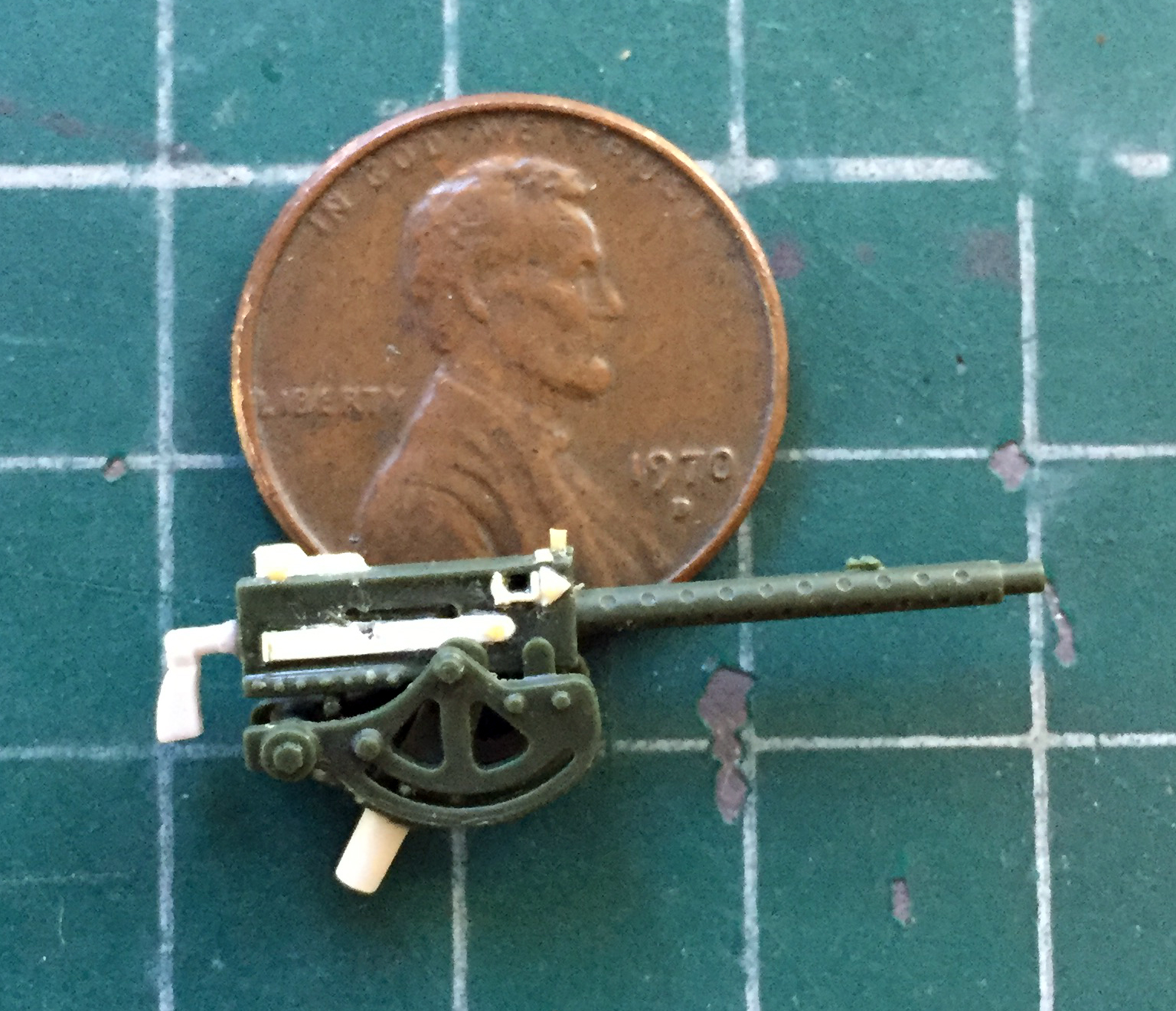


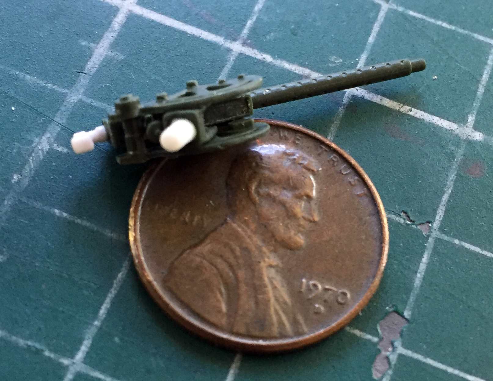
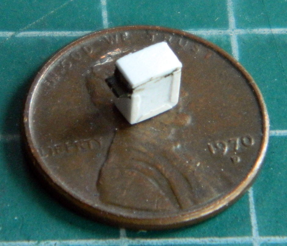
I’ve noticed that earlier in the war there was greater variation in gear than by the end of it. My assumption is that pre-war stock was used up and later in the war, equipment became more standardized for easier manufacture. I have plenty of what became the standard .30 caliber (7.62mm) ammo boxes on hand (500 rounds?), what I did not have was the 250 round box that was being used by the Marines in later summer of ’42. That required me to make one:
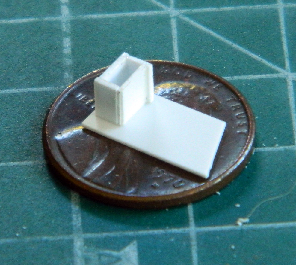
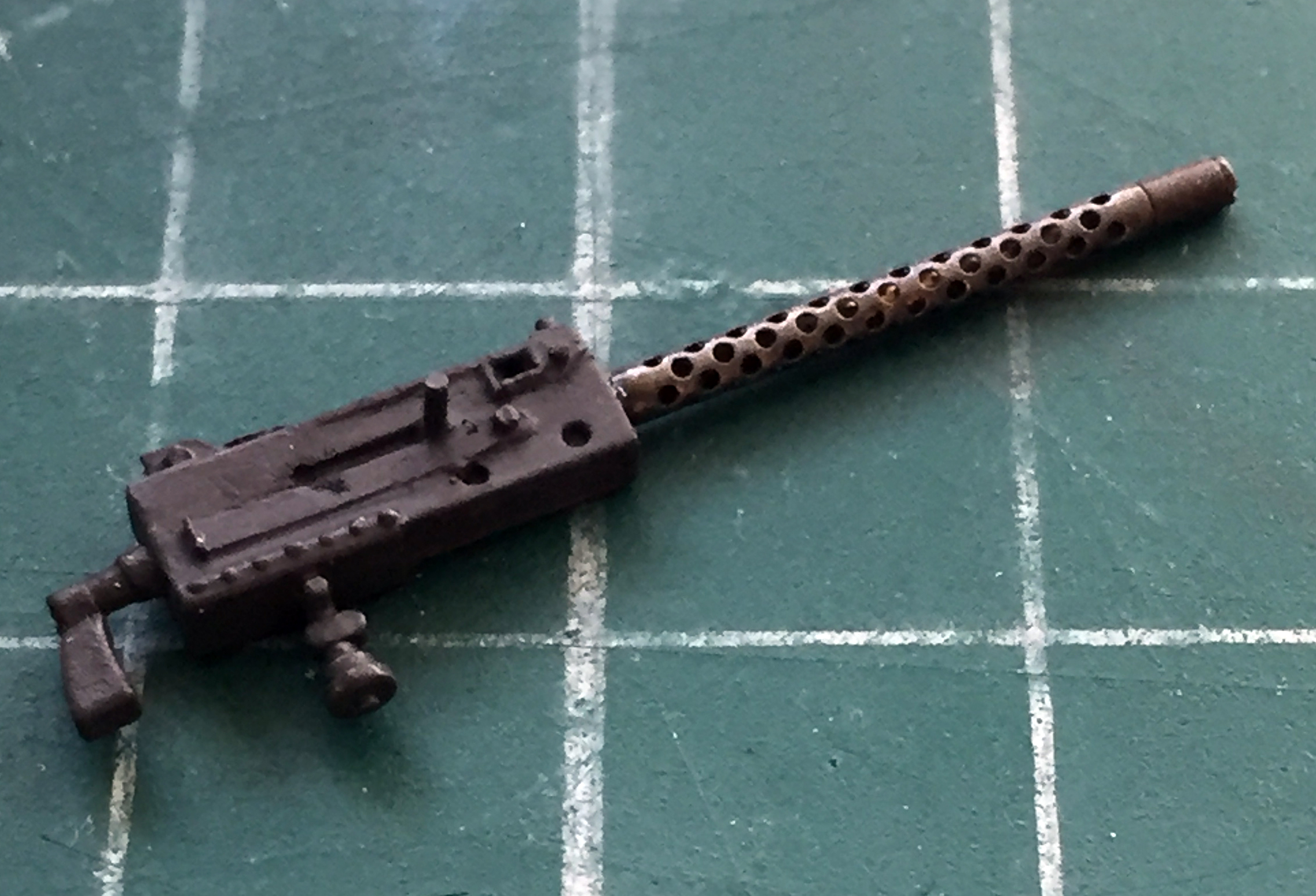
With the gun painted and the brass barrel installed, it just needs to be mounted in place:
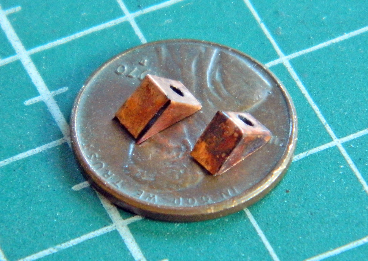
While I was wandering around the outside of the turret, I used .005″ (.127mm) copper shim stock to fold what looks like an unused antenna mount (because where would they put the second radio?!). As you can see, sometimes even something simple like this requires more than one attempt to get what you want:
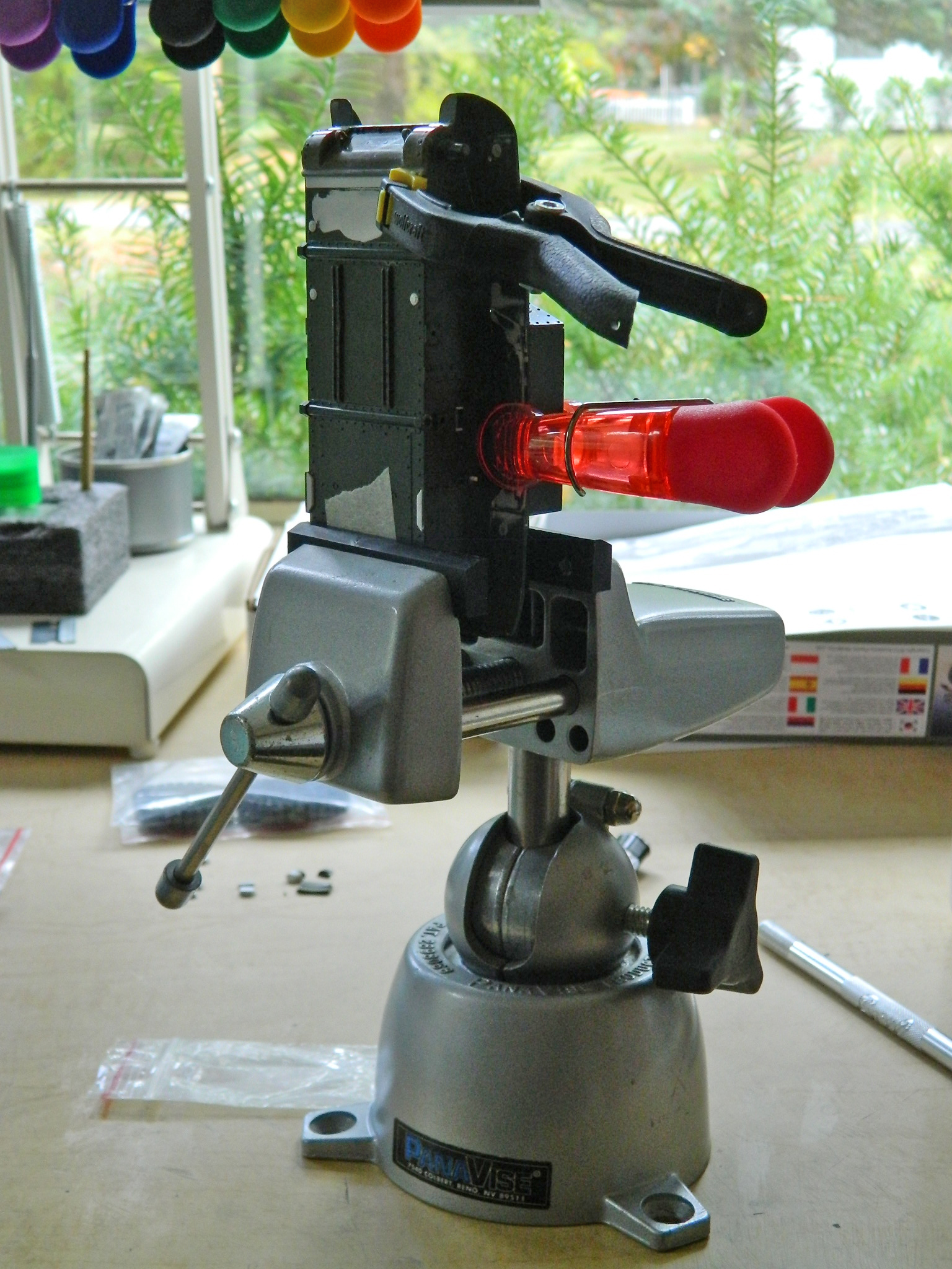
This time when I married the upper hull to the lower hull, I decided that IF I needed to vacuum the fornicating bench, it could sodding wait until it was ass-biting clear:
While the glue set up on the hull, I assembled the linkage that opened the pistol ports:
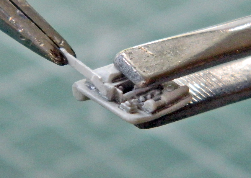

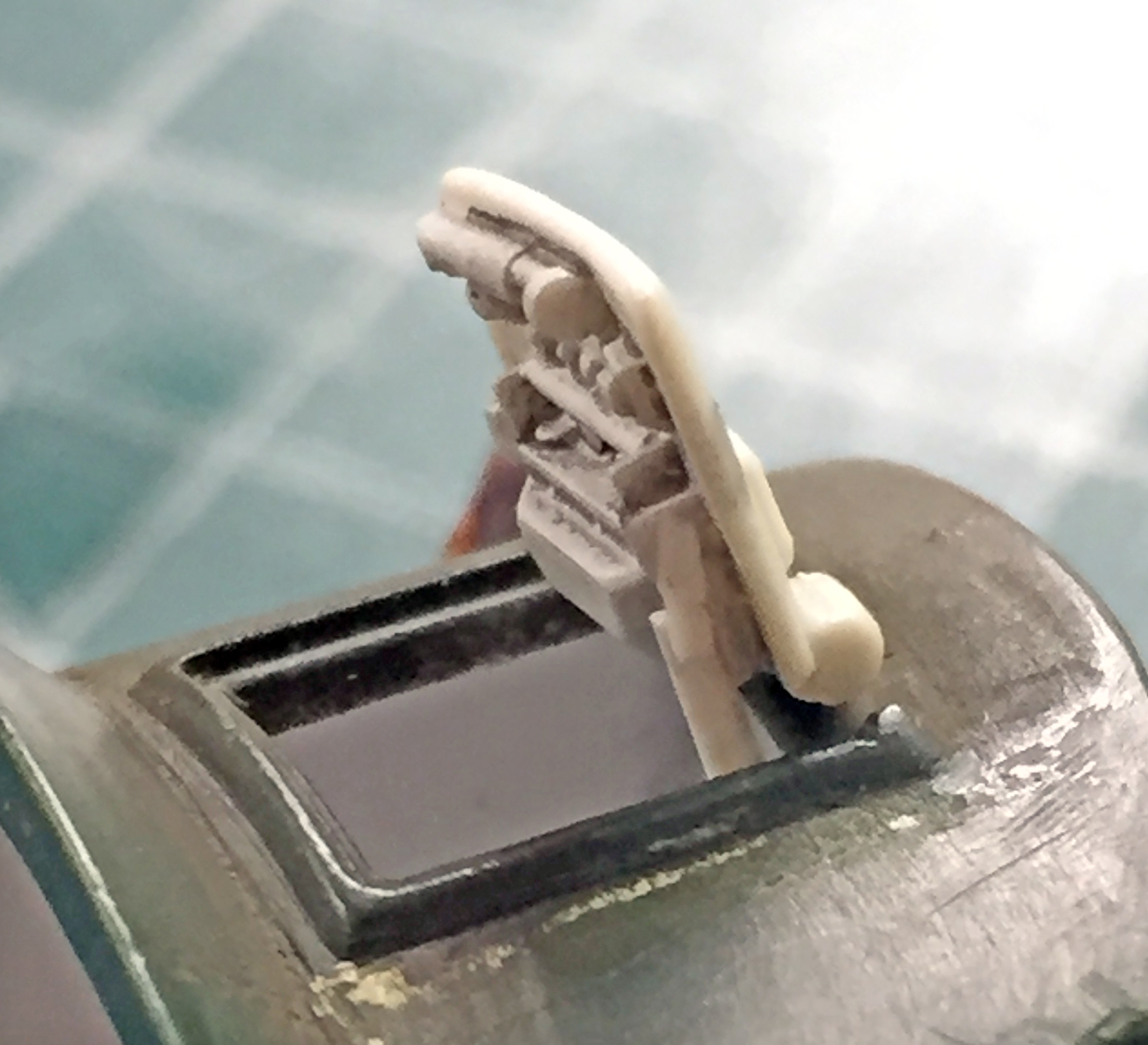
I also added more Grandt Line bolts because the mounts for the M3’s port hatches were bolted on unlike the Sherman’s, which were welded in place:
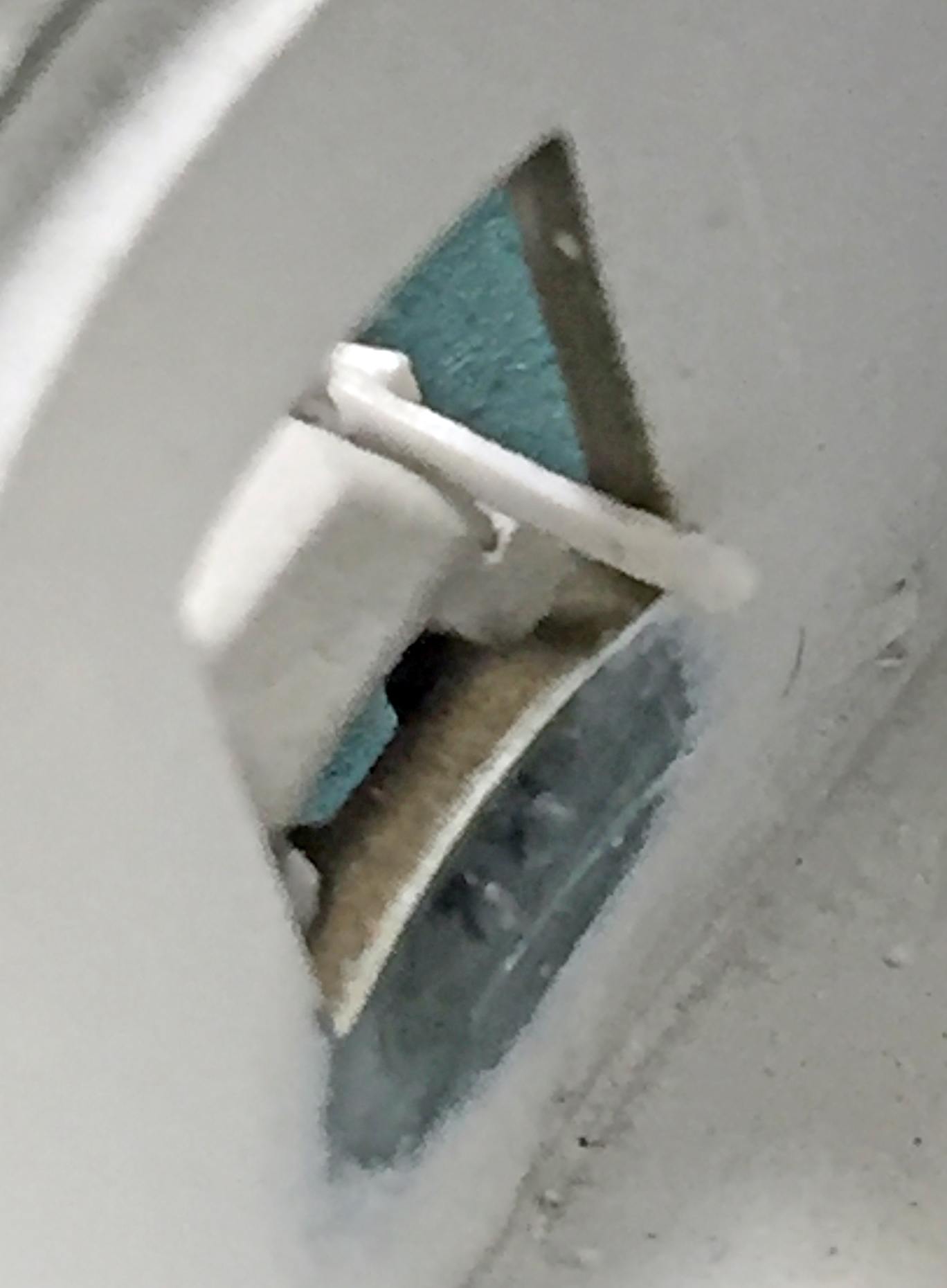
There will be more linkage added to the pistol port hatches later on.
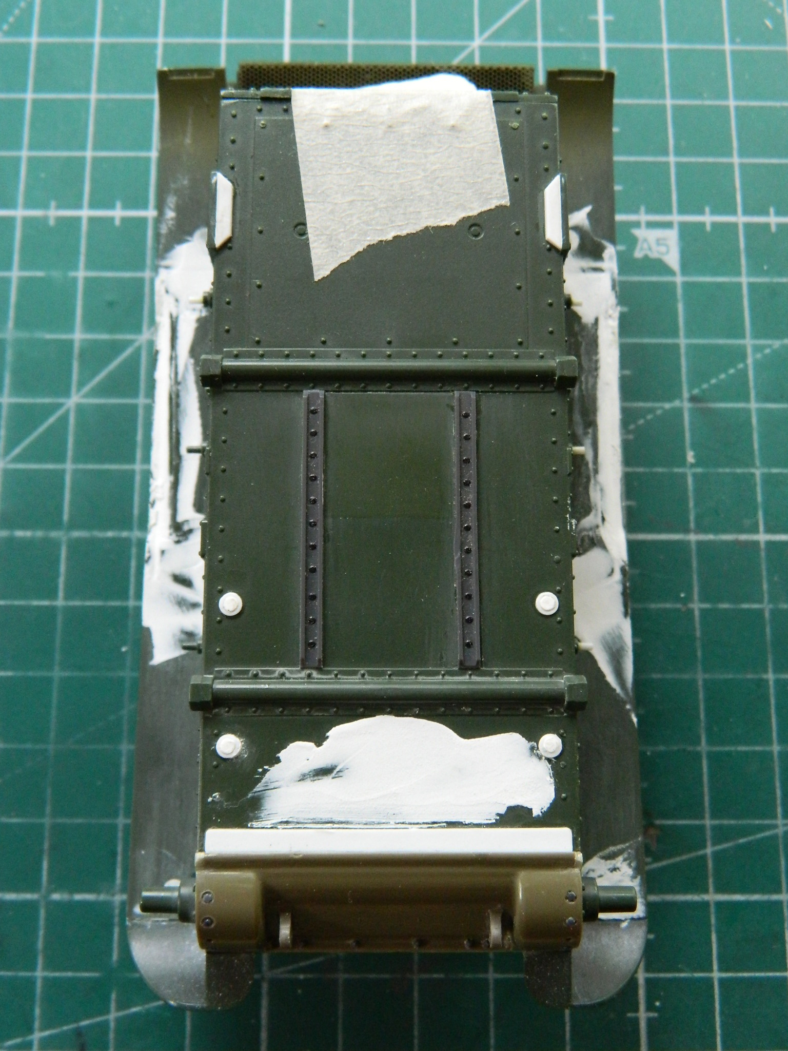
Since I had the upper hull in place finally, I puttied the underside of the sponsons to hide the gaps (again):
As I build, The Boys in the Back wrestle with various things that are problems in search of a solution. One of the (several) problems with this kit is certain details. It started with the headlight assemblies and then grew to encompass a few other things. The taillights were a bit off as were the air cleaner assemblies. While looking for something online that had nothing to do with modeling (yes…porn, again), somehow I ran across a video review of Tamiya’s new-tool M3 Stuart (because don’t all porn links take you to modeling websites?!). My take-away from that was that it’s a MUCH better kit than the hoary old beast from the early 70s and that due to how the parts were engineered, putting an interior in that kit would be a stone bitch. Fine if a silhouette model is the goal, though. Oh. And Tamiya’s headlights, taillights, and air cleaners were EVER so much nicer than Academy’s representations! In fact, they’re nice enough for me to have bought the kit as a donor kit. (Clearly, I need a life.) (Other than cruising porn.)
For instance… On the left is the mostly-assembled Tamiya air cleaner assembly, on the right is the Academy air cleaner:
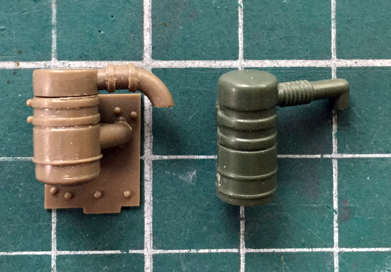
The Tamiya part is more accurate, intake ducting (the lower one on the right) is present whereas the Academy has none (and there’s no detail on the hull where this assembly goes in the Academy kit), the curve to the output ducting is accurate meaning I don’t have to fix the Academy ducts. Nice. But nothing is perfect (except maybe for stupidity) and Tamiya didn’t provide for the rods that keep the bottom of the air filter housing in place, so I added them:
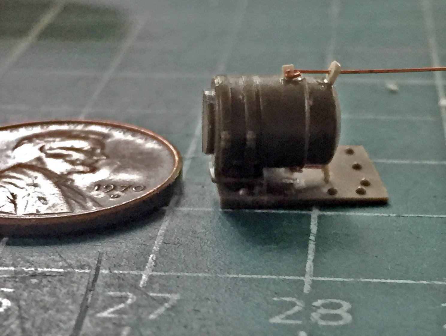
There was a fair amount of fiddling alignment, application of glue, and waiting for the glue to set up so that I could continue. So while that was curing and waiting, I went back to work on the turret.
With the nuts, resin turret face, and the mount for the opening linkages for the pistol ports in place, I repainted the inside, gave it a coat of clear gloss, a dark wash, and a sealing coat of clear flat:
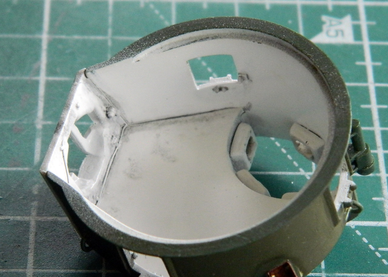
As that set up, I continued fiddling with the air cleaners:

Just those four small additions took enough time that while the glue on all of those additions set up, I populated the interior of the turret:
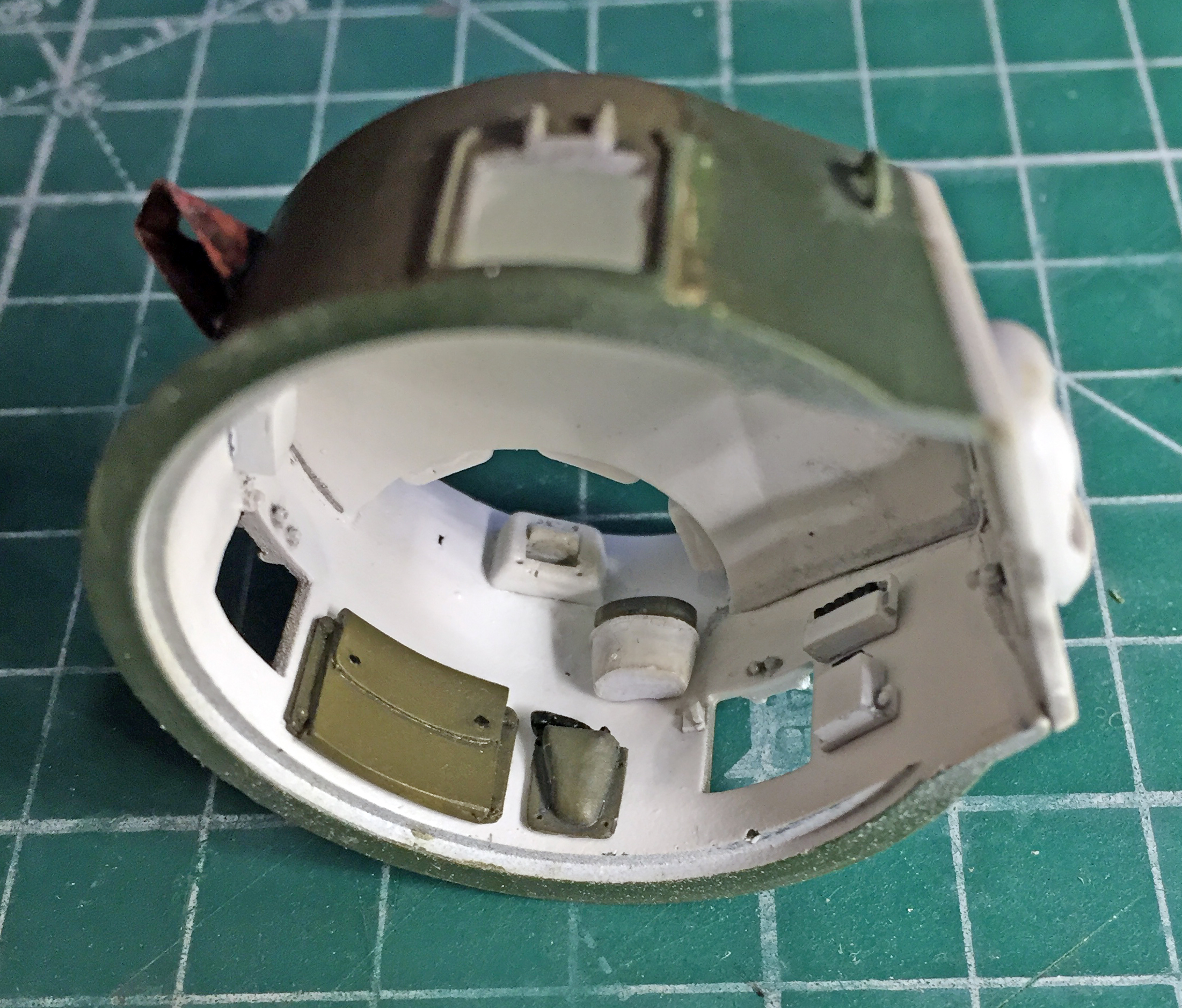
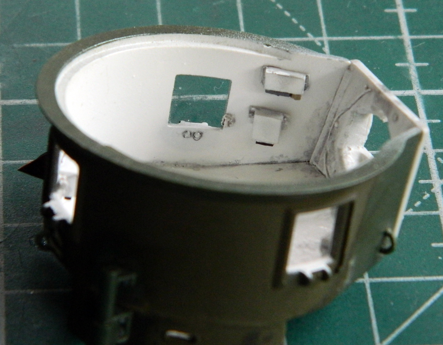
Adding more detailed air cleaners would take a bit of surgery. As you can see, just gluing them in place would result in this section of the hull being far too thick (and later on I would definitely need that missing space for something else):
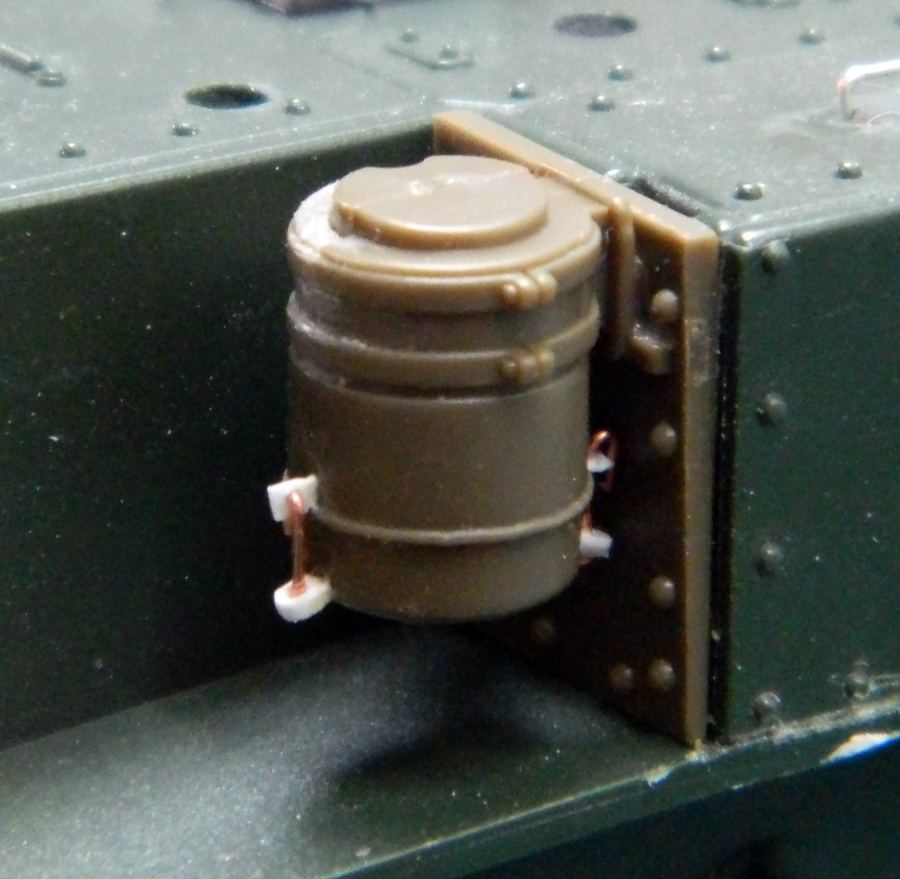
With that just held in place, I traced the edge of the new part on the kit to see how it could fit. If I could excise the plastic between the scribed line and the hull, I figured I could socket the new parts into place without losing the space I’d need to mount the sponson storage boxes (and this photo shows how bereft this area was of details):

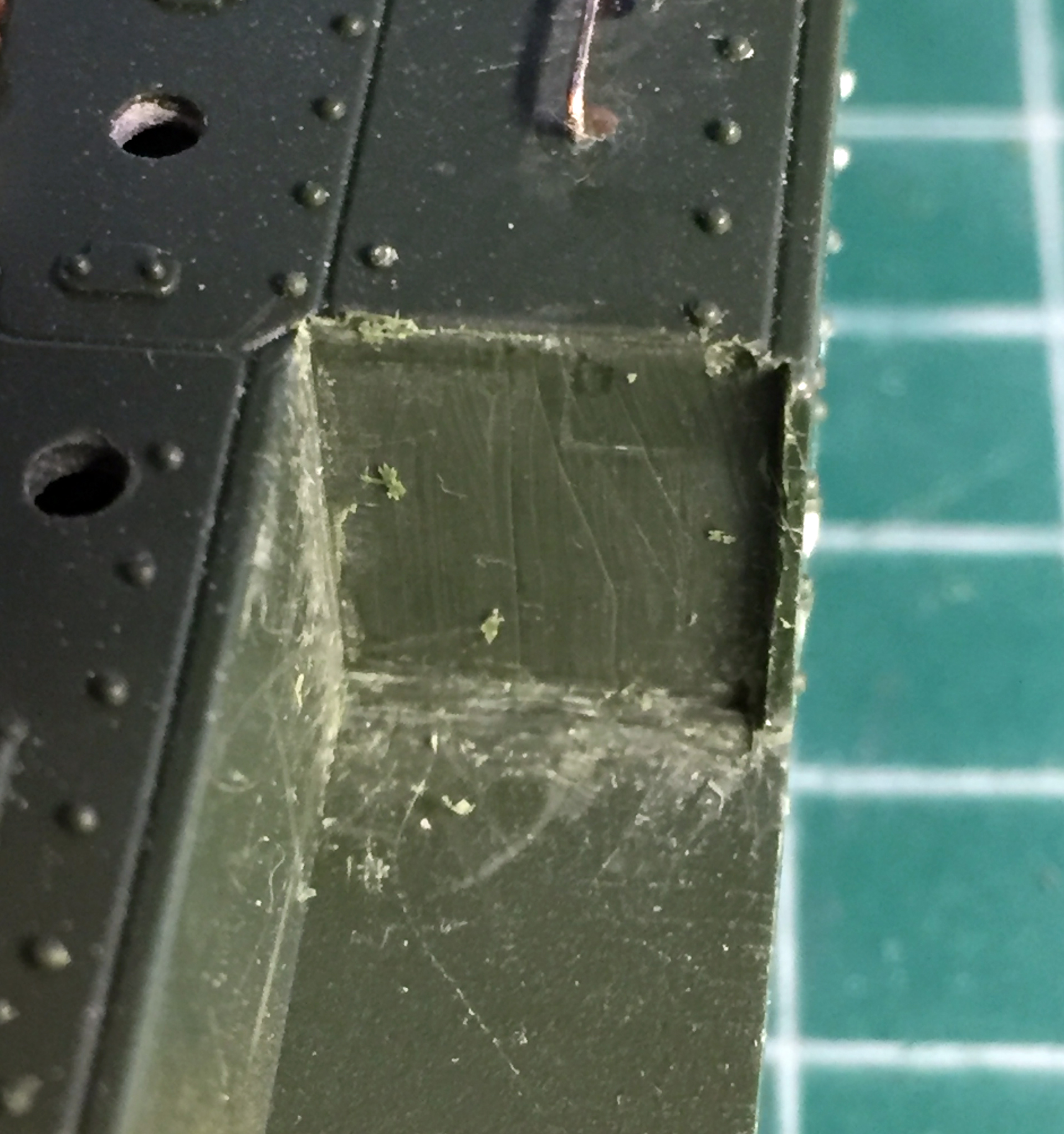
First I hogged out the plastic with my Dremel to get it close:

Then I used a freshly sharpened chisel blade to scrape things to a more accurate configuration:
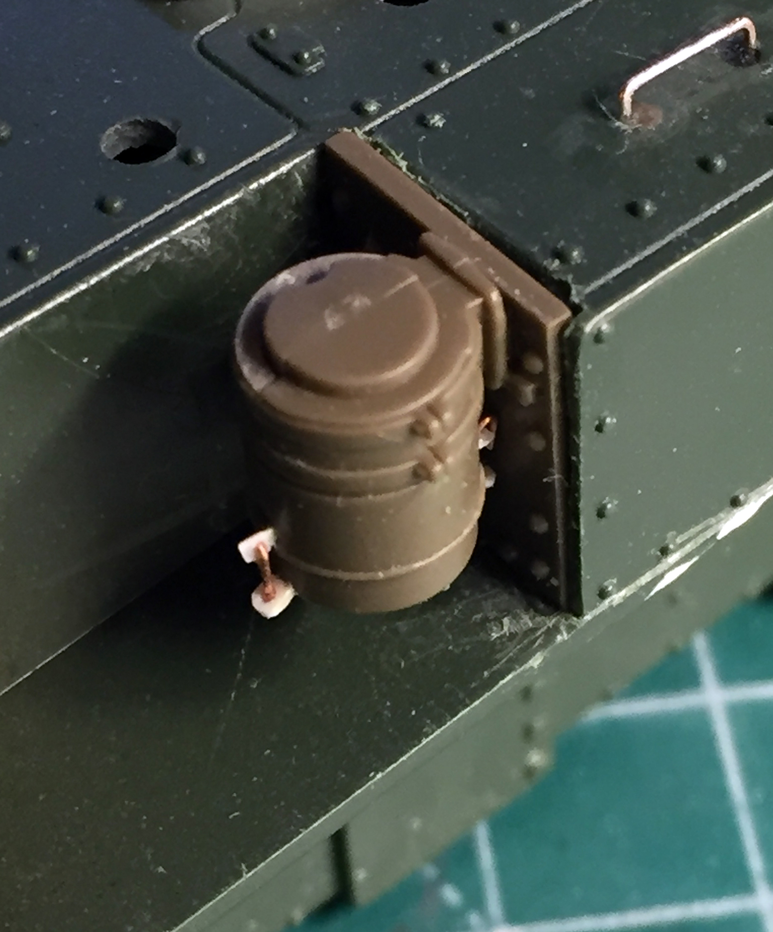
The new part was dry-fit several times with resulting adjustments until a pretty good fit was achieved:
I also checked to see how the new ducting would line up with the hole in the engine cover, which it does not:
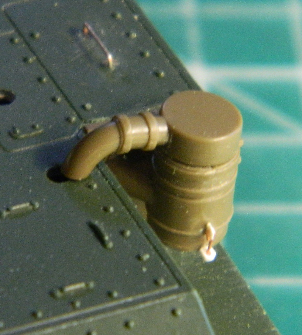
Right, so, that hole got filled. I chucked a piece of sprue into a variable-speed drill and used a file to taper it slightly and then stuffed it into the hole and glued it:

I didn’t know how much of the missing rivets would show so I added some Archer resin decals (great stuff, that!). I discovered later that most of these would never be seen:
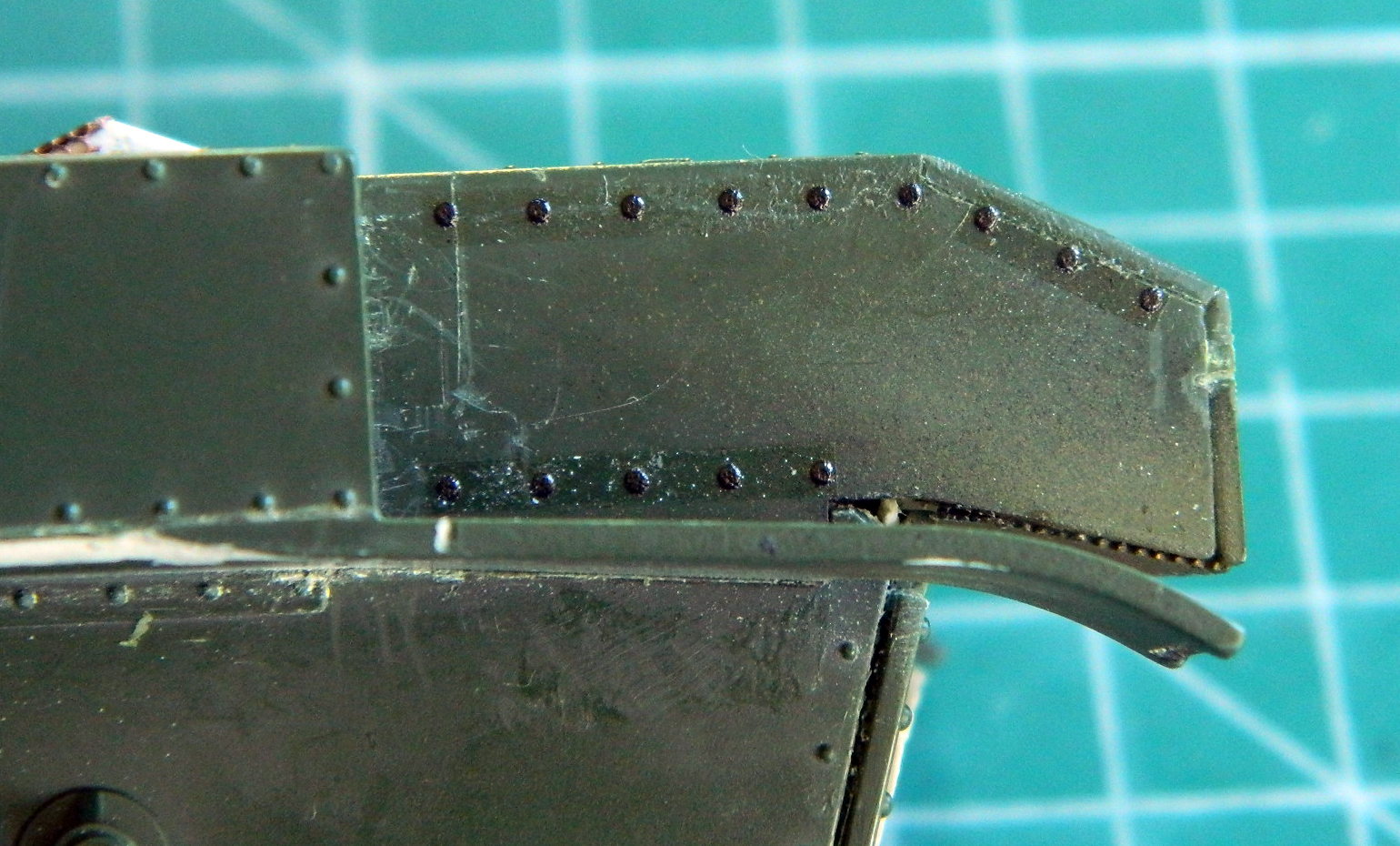
The detail for the mud flaps provided by Tamiya was better than Academy’s so I cut off the rear of the fender to add the Tamiya part:

I dry-fit the air cleaner assembly to determine where the new access holes had to be drilled and then checked alignment. Satisfied, right after this photo was taken I glued both air filters in place:
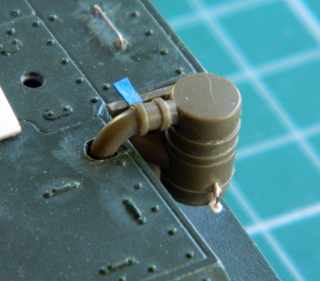
With those permanently attached, I added the sponson storage boxes and the mud flaps:
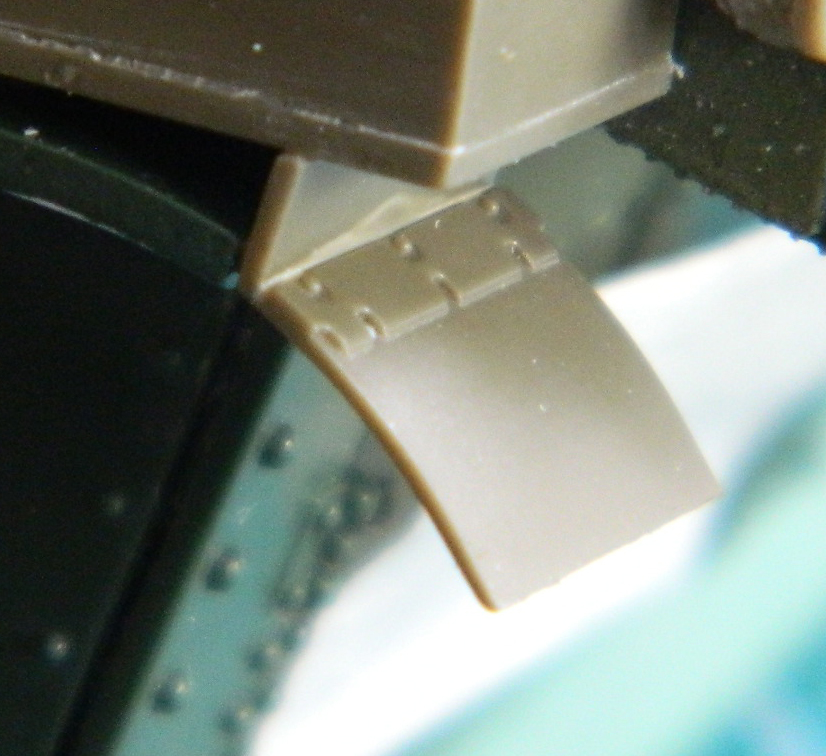
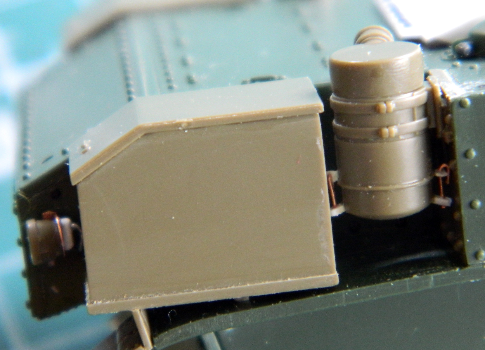
I also removed the kit’s taillights at this point. I used the Tamiya parts, made mounting brackets from .005″ (.157mm) copper shim stock, and added detail to the back of the light and used some .015″ (.381mm) solder as wiring conduit (which can also be seen in the above photo):
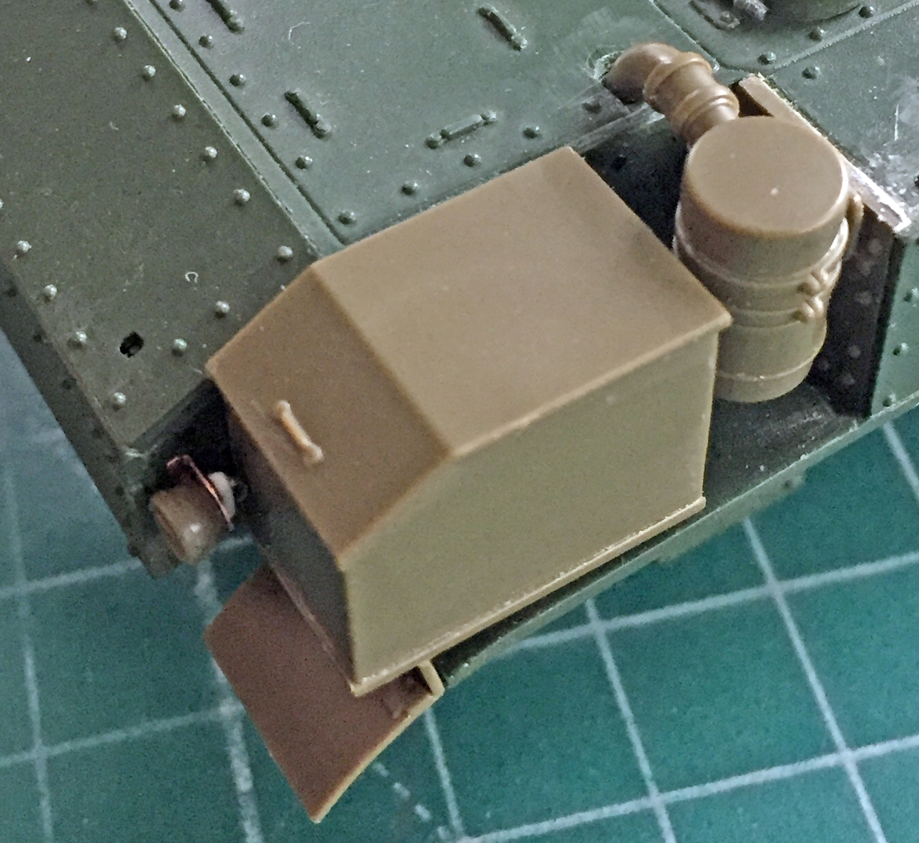
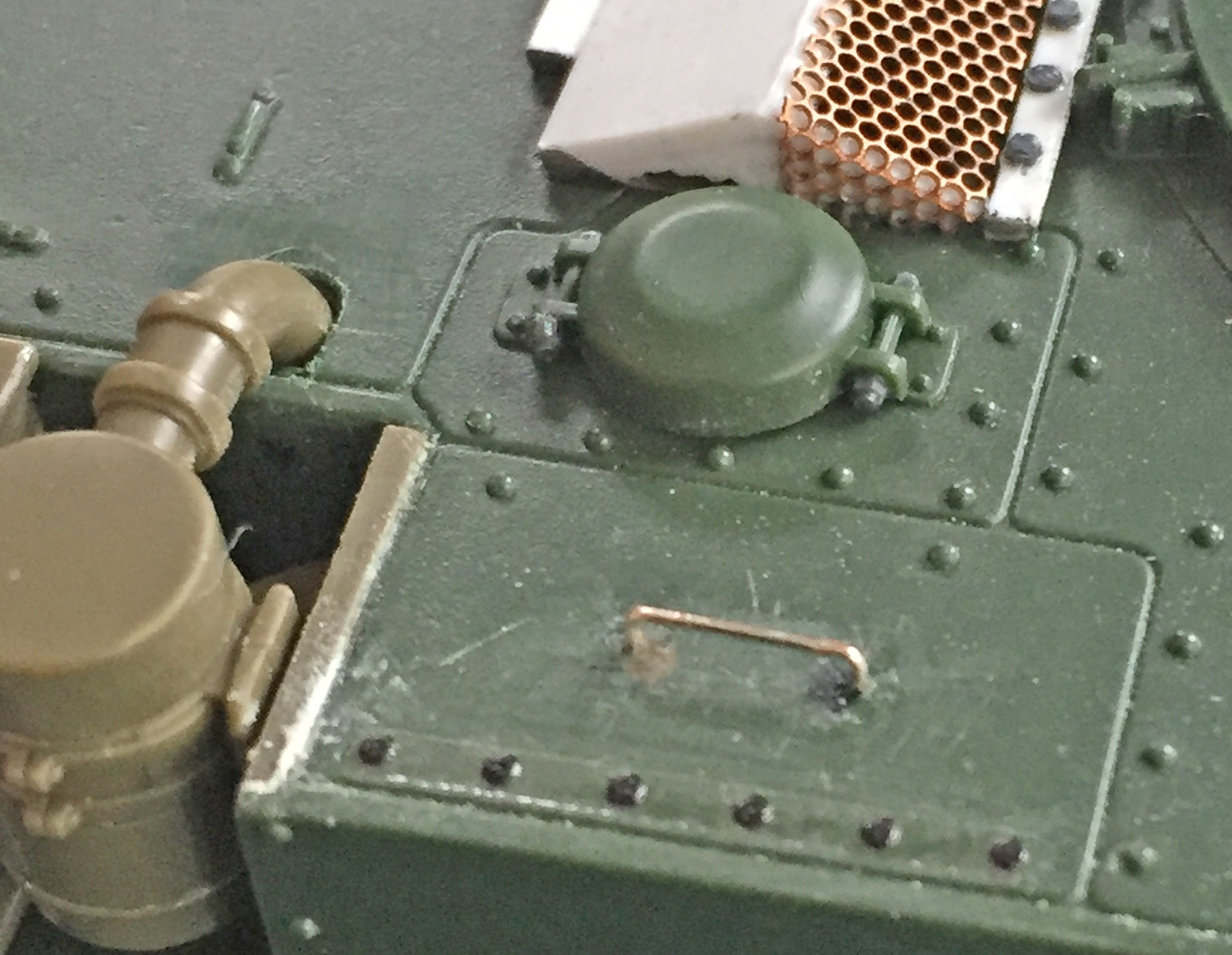
The armored fuel cap covers have distinctive and evident bolts holding them closed. The kit’s covers had the bolt length but no nuts. Once again, Grandt Line to the rescue:

I wanted to improve the detail of the sponson storage box closures. Modern restorations of the M3 seem to favor latches. I don’t know if later variant M3s had them but my references show the earlier ones used straps and buckles.
::sigh::
So I used a buckle from a Verlinden Sherman detail set (did I mention I’m gonna miss that guy yet?) and some lead foil to replicate (TEDIOUSLY) the buckle/strap arrangement. I cut away the molded-in cleats and used small cleats from TMD resin:
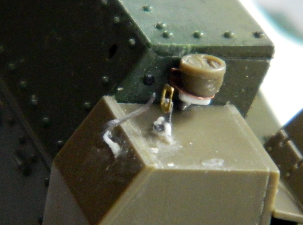
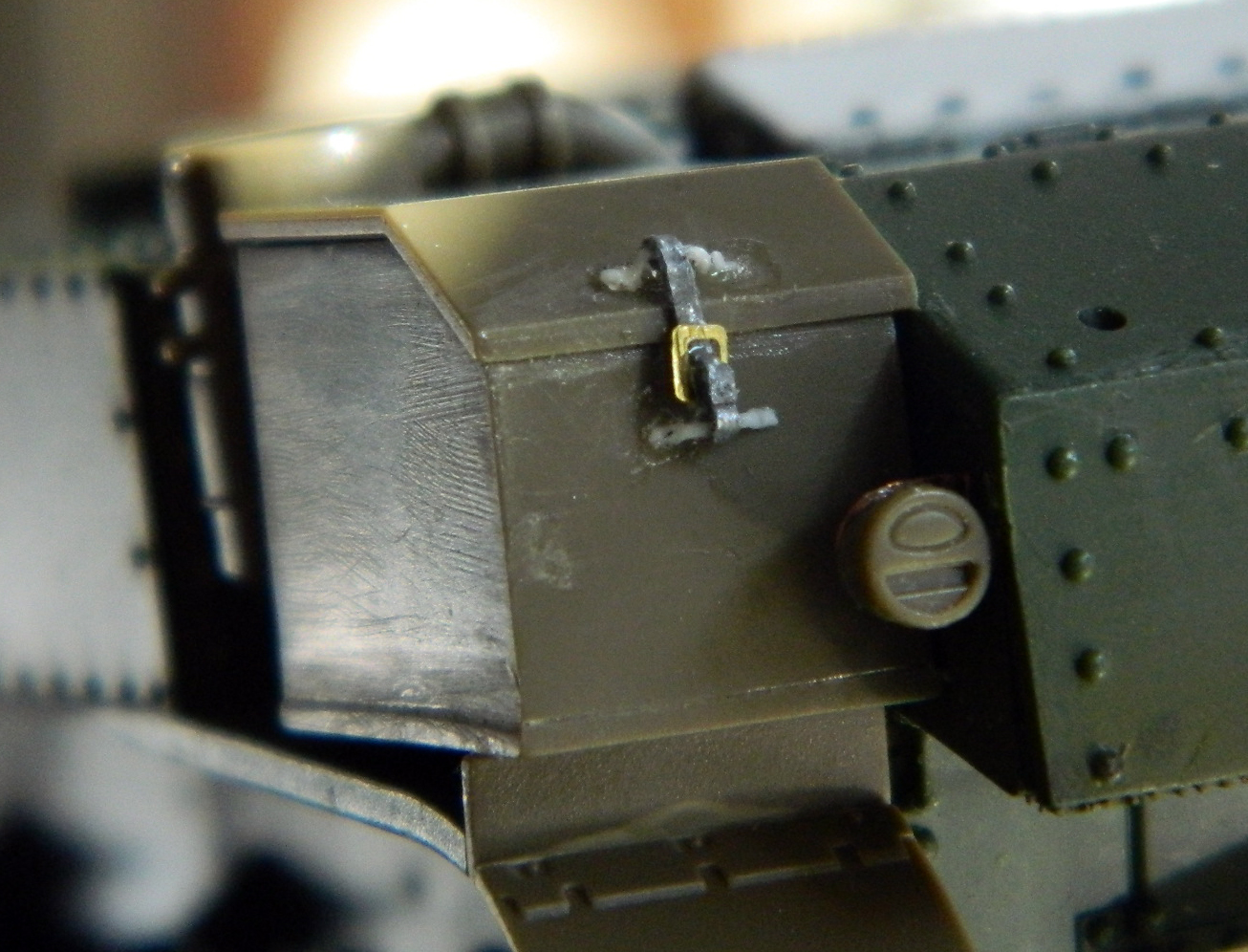
Though FREAKING TEDIOUS to do, I like the result. Now to do the other side…

Total time building 793.25 hours (that’s about 33.05 24 hour days, 19.833 work weeks).
Begin date July 15, 2017; end date September 20, 2019.
Vendors:
Testors
Giant Spy Plane Kit #984 1/48 scale
True Details
Resin Cockpits #48487
Pavla
Ejection Seats #S48012
Metallic Details
Engine inlets and shock cones #MDR4808
Grills and afterburner cones #MD4816
Lone Star Models
SR-71 Engines & Exhausts #10502
Fisher Model & Pattern
Wheels and tires #A-4806
K&J Magnetics
Rare earth magnets # ZD12, 1/16″ (1.28mm) x 1/8″ (3.18mm)
Caracal Models
Blackbird decals #CD48101
My Opinion
This kit was designed and produced back in the dark ages (Italeri, I think, cut the dies) and IT SHOWS. Gaps. OMFG, do we have gaps? Everywhere. And some of the gaps have gaps. Fit is foul. Sometimes knowing something sucks doesn’t help when it starts sucking.
The “detail” on this kit is equally notorious, which given that the Blackbird was TOP SECRET when the engineers went to take measurements (assuming they were allowed to take measurements) didn’t surprise me. It was obvious they weren’t allowed to get too close to the Blackbird. I knew going in that the details wouldn’t be there and that was damned correct.
True Details. What can I say about them… In general, they don’t impress me, and this time wasn’t an exception. I didn’t use the ejection seats they provided as they were incorrect. I used Pavla’s, which were also incorrect. I used the Pavla seats because those inaccuracies were easier to fix (relatively).
Metallic Details is interesting. Their PE parts are decent, I’m not especially impressed with their resin parts. After I had committed to scratchbuilding the landing gear bays, I saw that they’d come out with a resin set for that. Maybe they beat scratchbuilding the landing gear bays, though I like what I did better than what Metallic Details offer.
The build. It was a grind. Just under 800 hours spread over two years. GAH. And the further I got into this build, the more this thing fought me.
I had to modify the True Detail cockpits. Canopy details had to be scratchbuilt and some that didn’t fit just thrown out.
The landing gear and the landing gear bays were also scratchbuilt, and that took a lot of time.
Panel lines. Scribing panel lines on something that’s over 27″ long takes time. Rescribing takes more time. Rescribing the rescribed lines also takes time. Sanding wasn’t my friend. I’m beginning to rethink scribed panel lines. Are they better than raised lines? I figure both are equally inaccurate, just in different ways. I suspect that at some point in the future I’m going to end up filling recessed panel lines and sanding down raised panel lines, replacing them with lines that are drawn on. Sorry, but recessed panel lines are actually out-of-scale, y’know.
If a person has the skills and wants to invest the time, the finished product looks damned impressive (and in order to finish this thing, you will develop new skills); large, black, and sinister. It’s rumored that Hyperscale* is doing a new-tool kit of the ‘Bird in 1/48. If you really want one on your shelf (and ONLY one unless it’s a large shelf), wait for that one. This one takes a lot, A LOT, of time to build into something adequate.
This was also my first commission. I told him it was going to take a long time. His patience was definitely appreciated (and he seemed pleased with the result):

In closing, a shout-out to Bruce from New Zealand. About the time I was neck deep and sinking into the swamp of homemade decals, he informed me that Caracal was doing a new sheet of decals (the ONLY complete set of ALL BLACKBIRD MARKINGS in two different sets). That bit of information, without exaggeration, saved this build. My homemade decals were horrible. Thanks, Bruce…I owe you more than one! (For all the good that will do you!)
Its new home:

*Two years after posting this, Hyperscale still hasn’t released their new-tool kit of the ‘Bird, though they say they’re still working on it…and I get it that doing ANY sort of work on this subject takes time. However, it seems that perhaps they’ve waited a bit too long. Revell Germany has just released a new-tool kit of the SR-71 in 1/48 scale! I haven’t encountered any build reviews of RG’s kit so I can’t comment on it. (And NO. I will NOT be building one!!)
I know that I haven’t really been doing (or trying to be doing) the decals on this thing forever. It just feels like it sometimes. (The remainder of the time I’m asleep.)
I conferred with the person that I’m building this for about my inability to eliminate the step from the edges of the decals and he wondered if I’d lost my sanity. Odd…I thought it rather obvious that I had, well before he was even born. So if he’s okay with those steps around decals…no, I’m not ever going to be okay with that, but this is for him. It’s not for me. (And that is the only reason I’ve gotten this far with it instead of smashing it to atoms.)
Now that I have the clear gloss put down, let’s try putting down decals. Again. This time let’s do it on the underside…y’know…just in case:
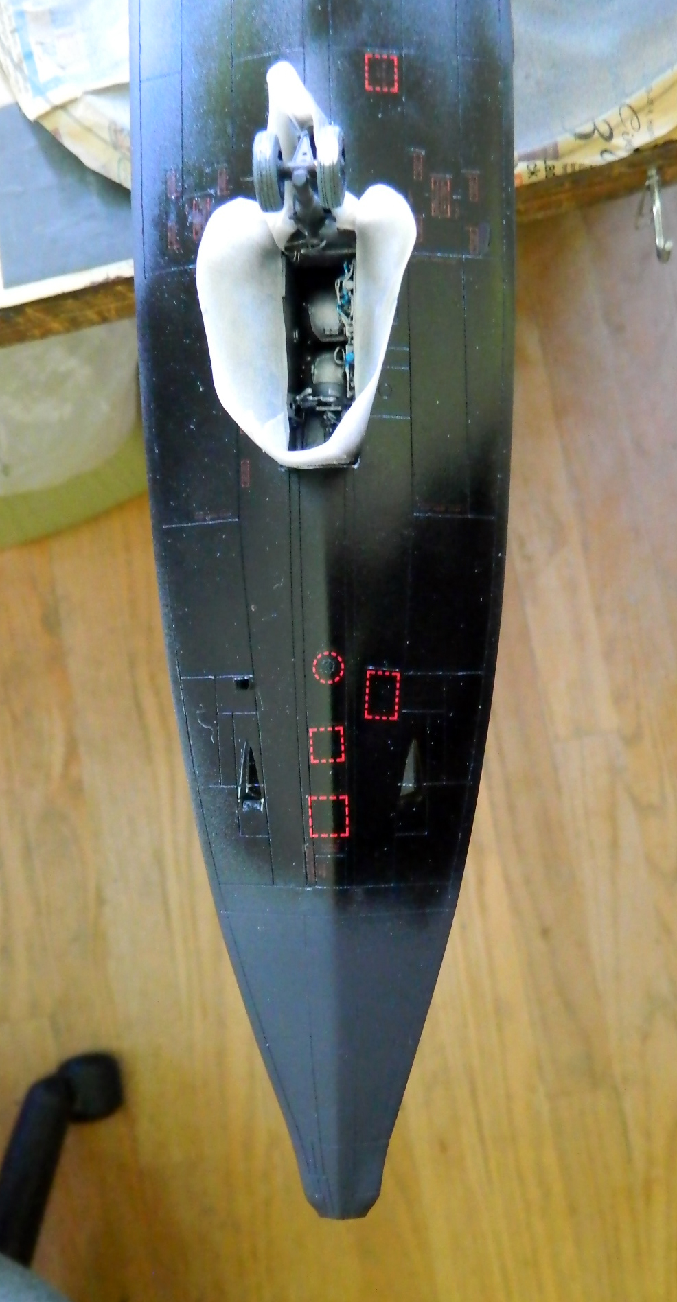
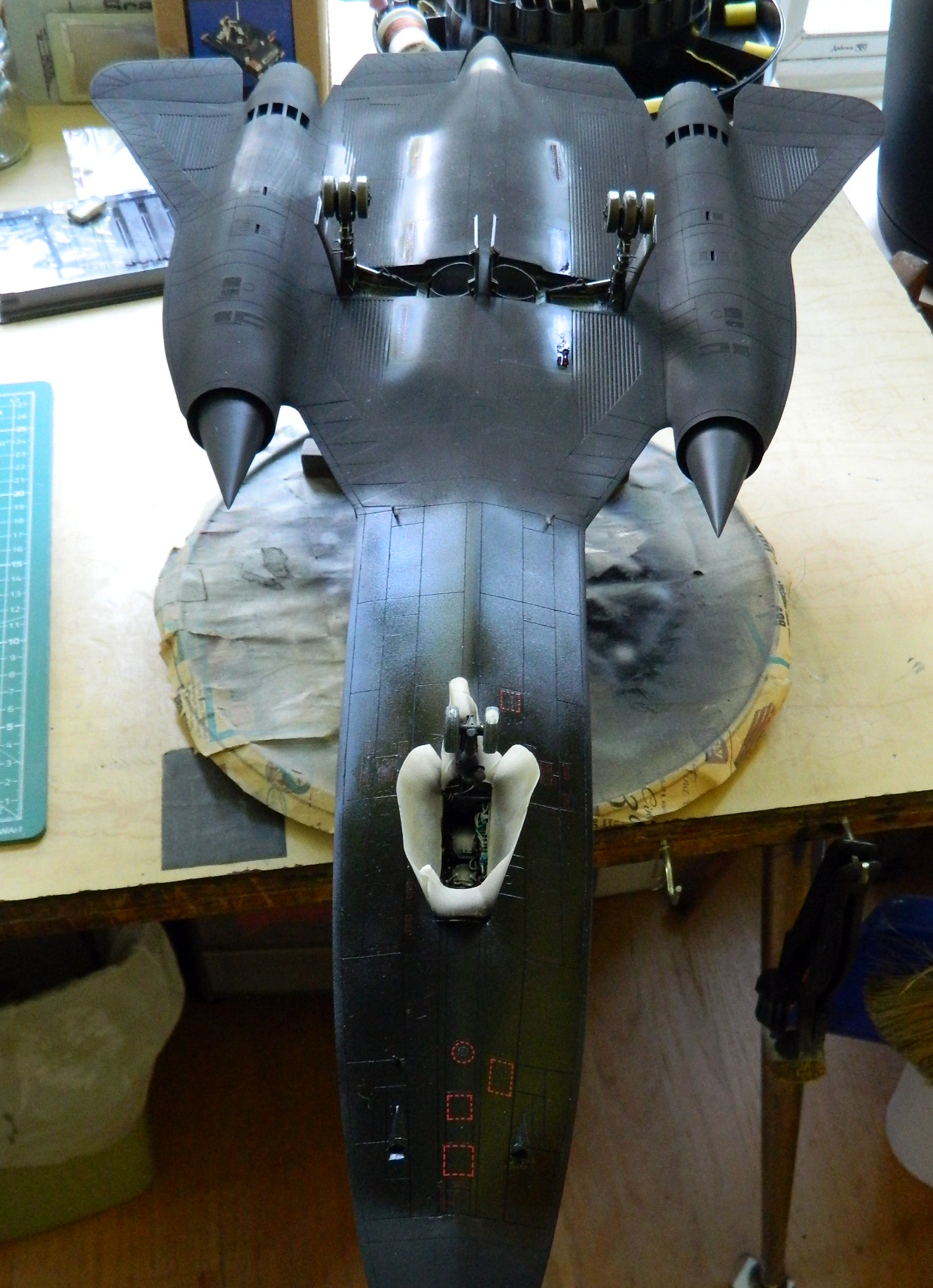
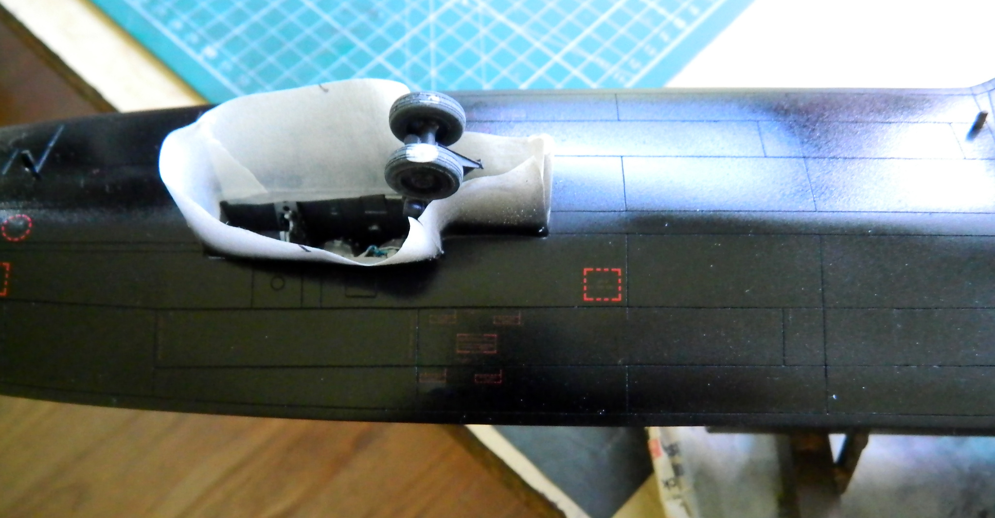

Once those were down, I put down clear matte over them. The results were acceptable…SO acceptable that I forgot to take photos. They were SO acceptable that I decided I’d try something so different for the top side that doing so felt like heresy.
I put these decals down over a matte surface without using clear gloss first. I put them down and then hit them hard with Walther’s Solvaset (the reason being that it’s the strongest decal solvent I’ve yet used):


I did both sides and then put down a coat of clear matte. Shocking myself to borderline incontinence, there was no silvering! Well…that’s what I thought initially. There was a bit of silvering, but very little. When that happened, I used a needle to prick the decals’ surfaces and reapplied Solvaset. The solvent knocked down the silvering to 99% gone, giving me the best results since I started trying to decal this styrene cunt.
Good enough. So I laid down the rest of the topside decals with similar results (and if you’re reading this before you build this bench whore, and you still want to build this bench whore, the long “No Step” stripes on top should NOT BE DONE IN ONE PIECE…cut them into MUCH EASIER to handle lengths) (no, don’t ask):

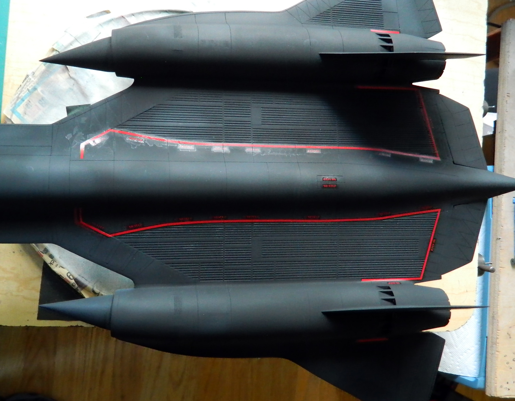

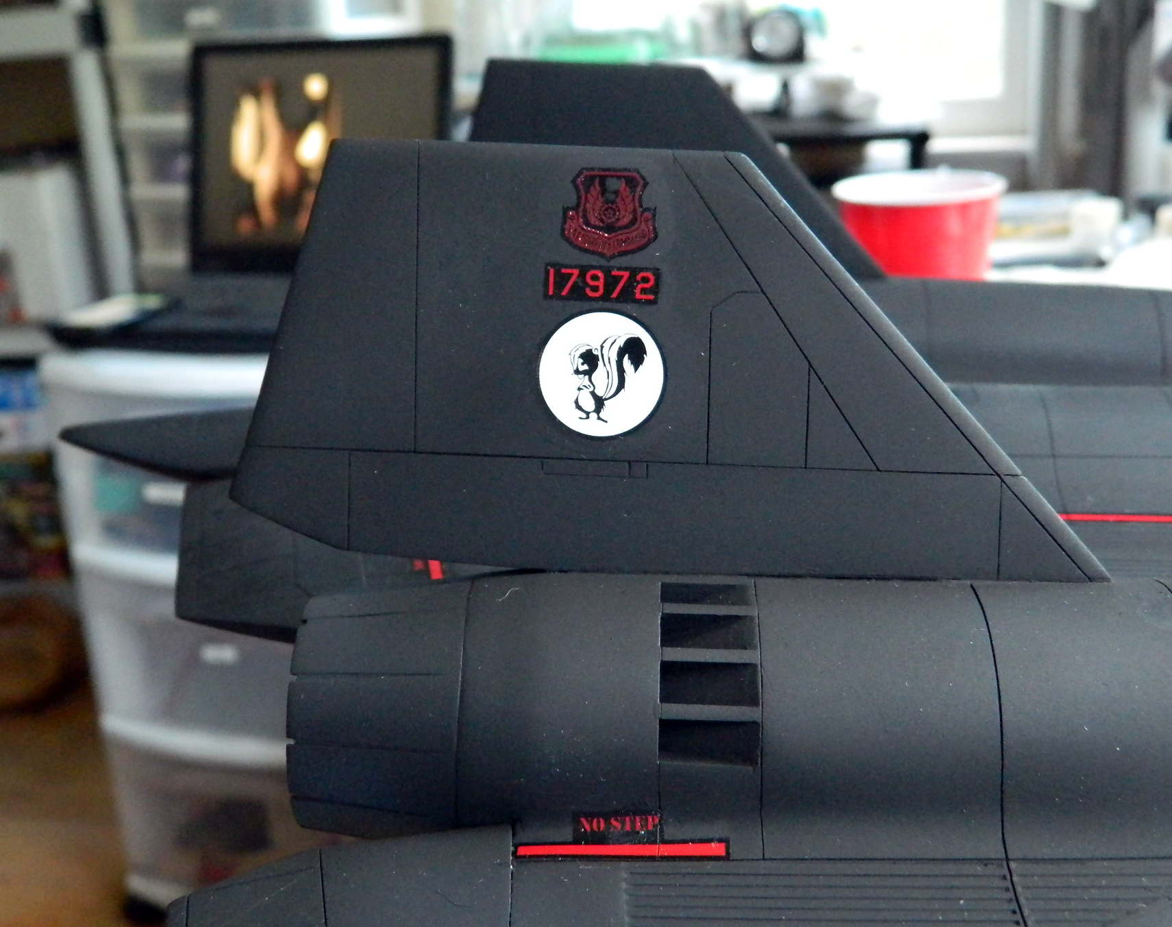
Then everything was treated to a coat of clear matte and the results were again good enough:
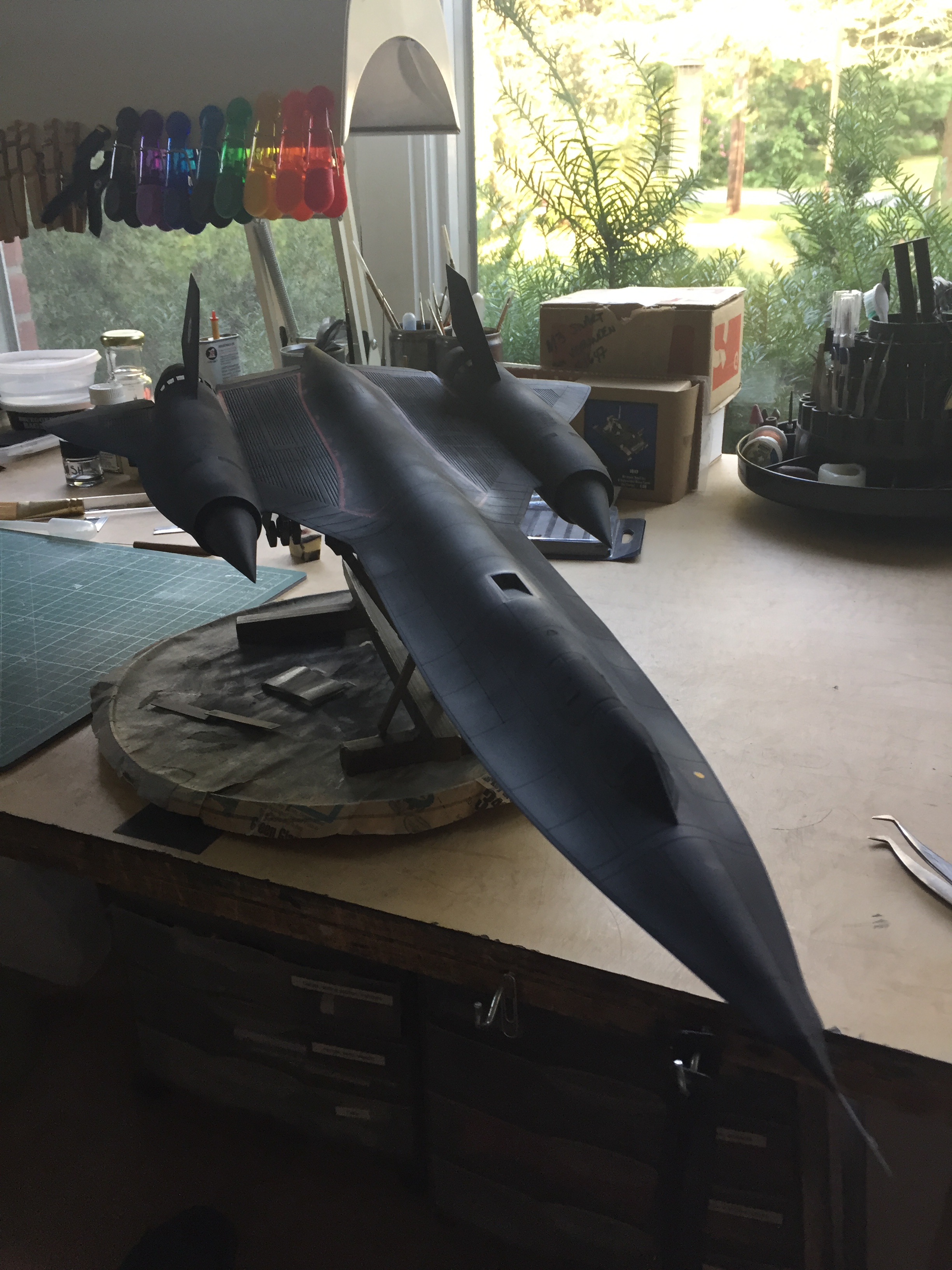


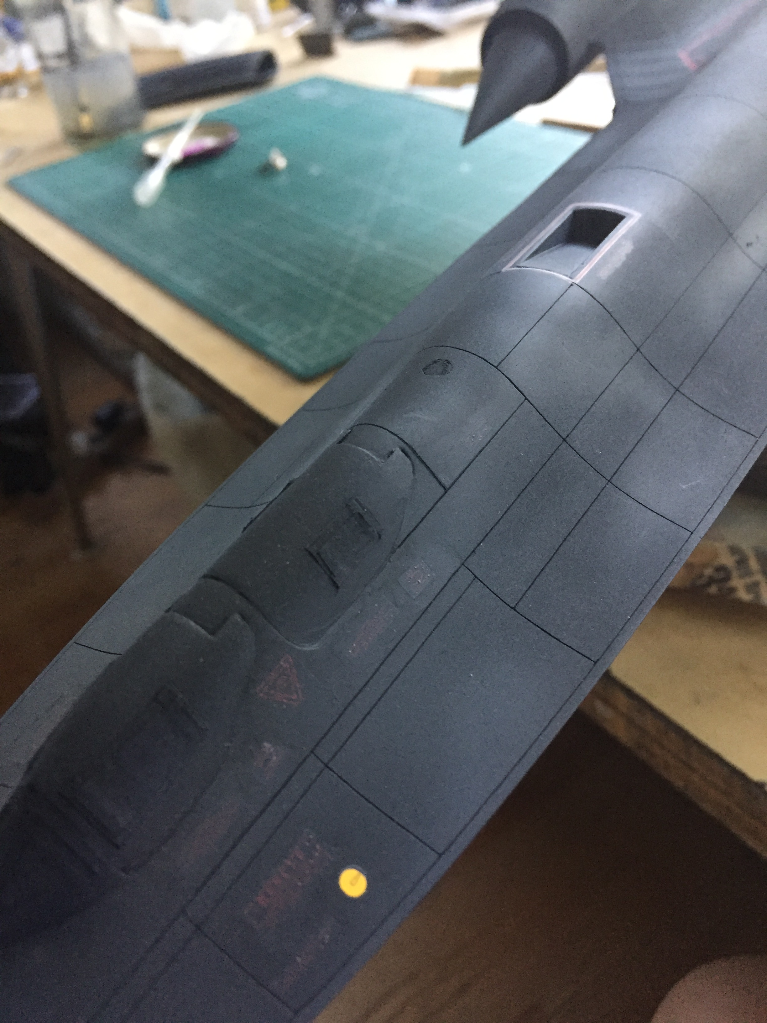

With the decals done (and the first time I had that thought I almost wet myself) and the (final!) coat of clear matte down, it was time to unmask and remove the canopies:

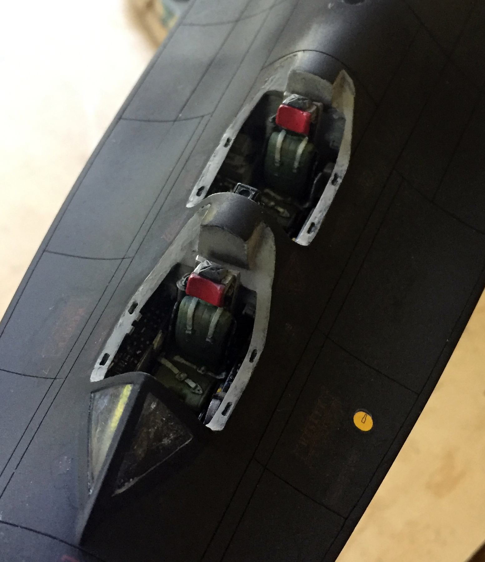
Some damage was done to the sill of the rear cockpit where the front canopy latch is. The fix was to VERY CAREFULLY cut away the side, insert a piece of .020″ (.508mm) styrene, putty it, sand it, and repaint it. I got lucky, it worked perfectly, and the minimal over spray on the decal was lifted off with a cotton swab soaked in denatured alcohol. Whew:
There was the requisite touch-up needed around the cockpit sills. I sanded back the paint with 1200 grit sandpaper to get a nice, smooth, transition. Then what I didn’t want painted was masked and the flat black was put down:


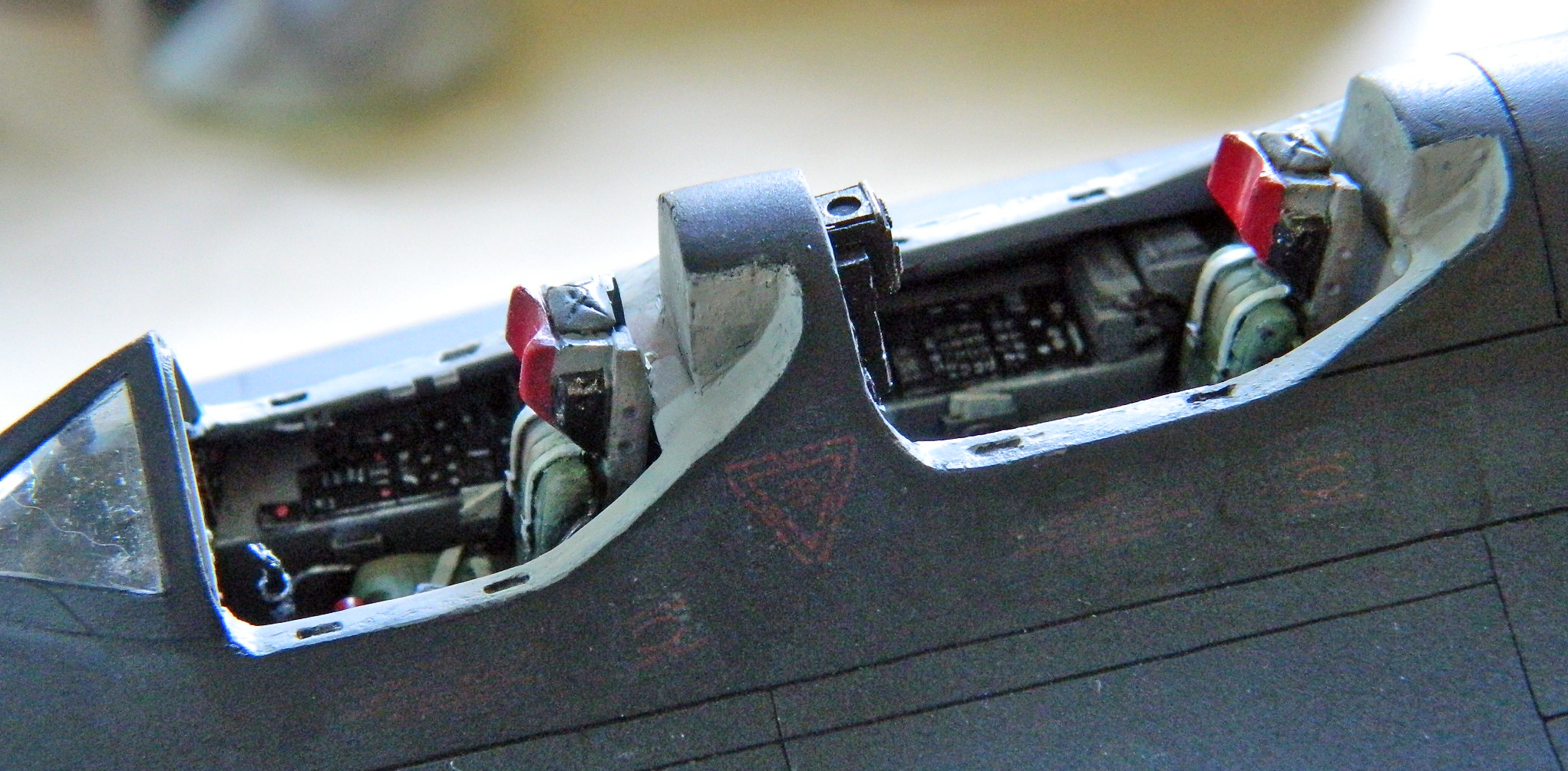
With the sills touched up, I did the same for the edges of both canopies. With that done, I used white glue to attach the roll-up window shades that are attached at the base of both rear canopy windows:
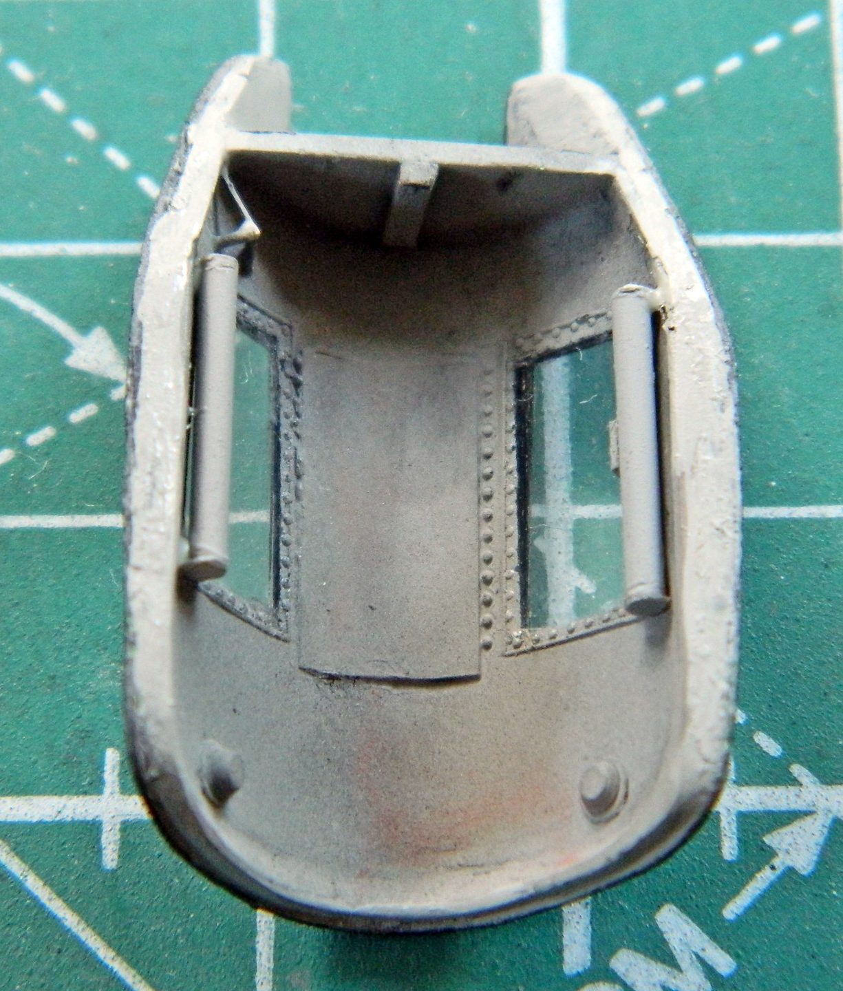
Before permanently attaching the canopies, I wanted to attend to the front landing gear doors. I started that with the rearmost (also note how much flatter the near tire is than the further tire is…that was was necessary to get both tires to touch the surface):
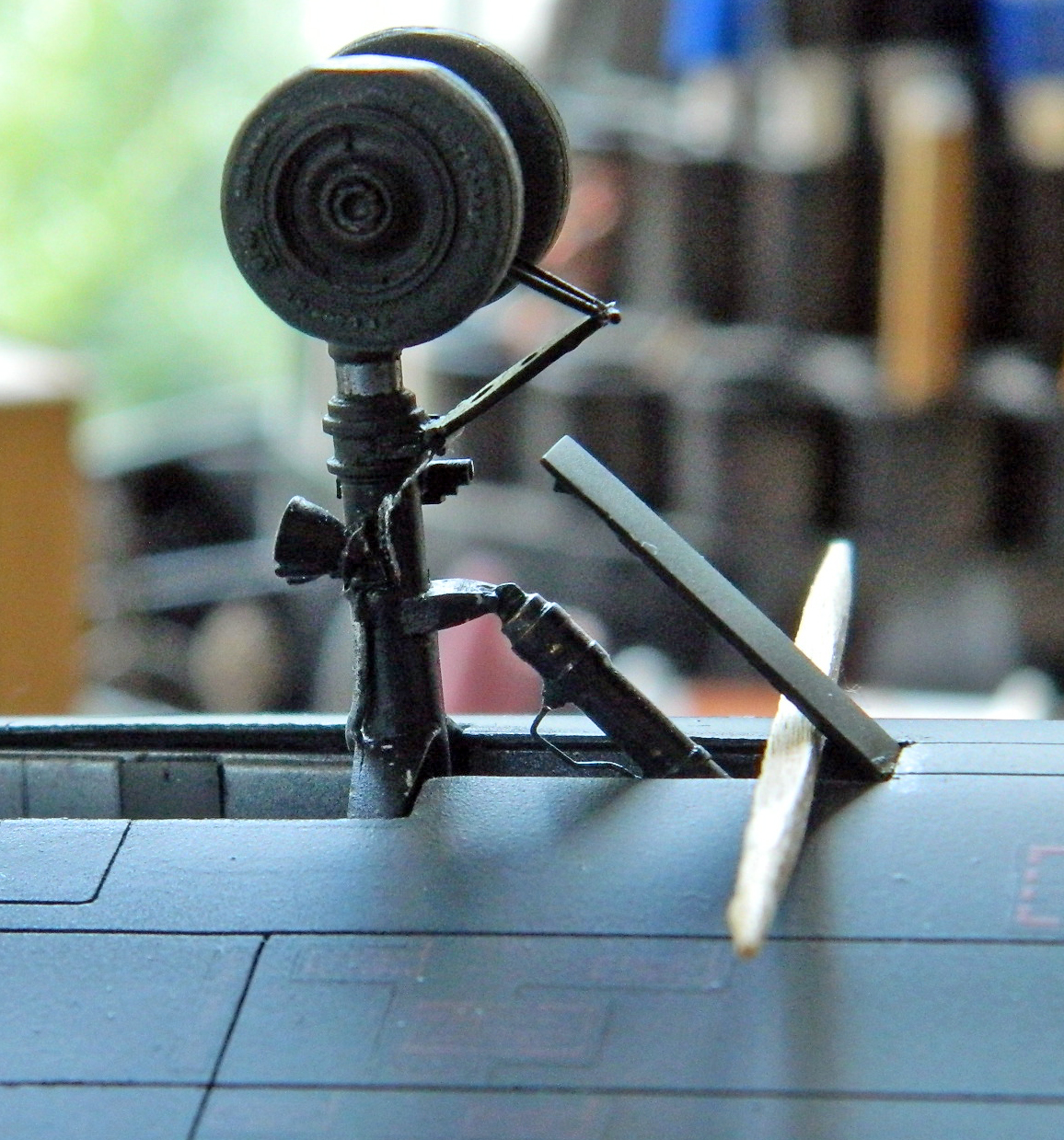
And continued with both side doors:
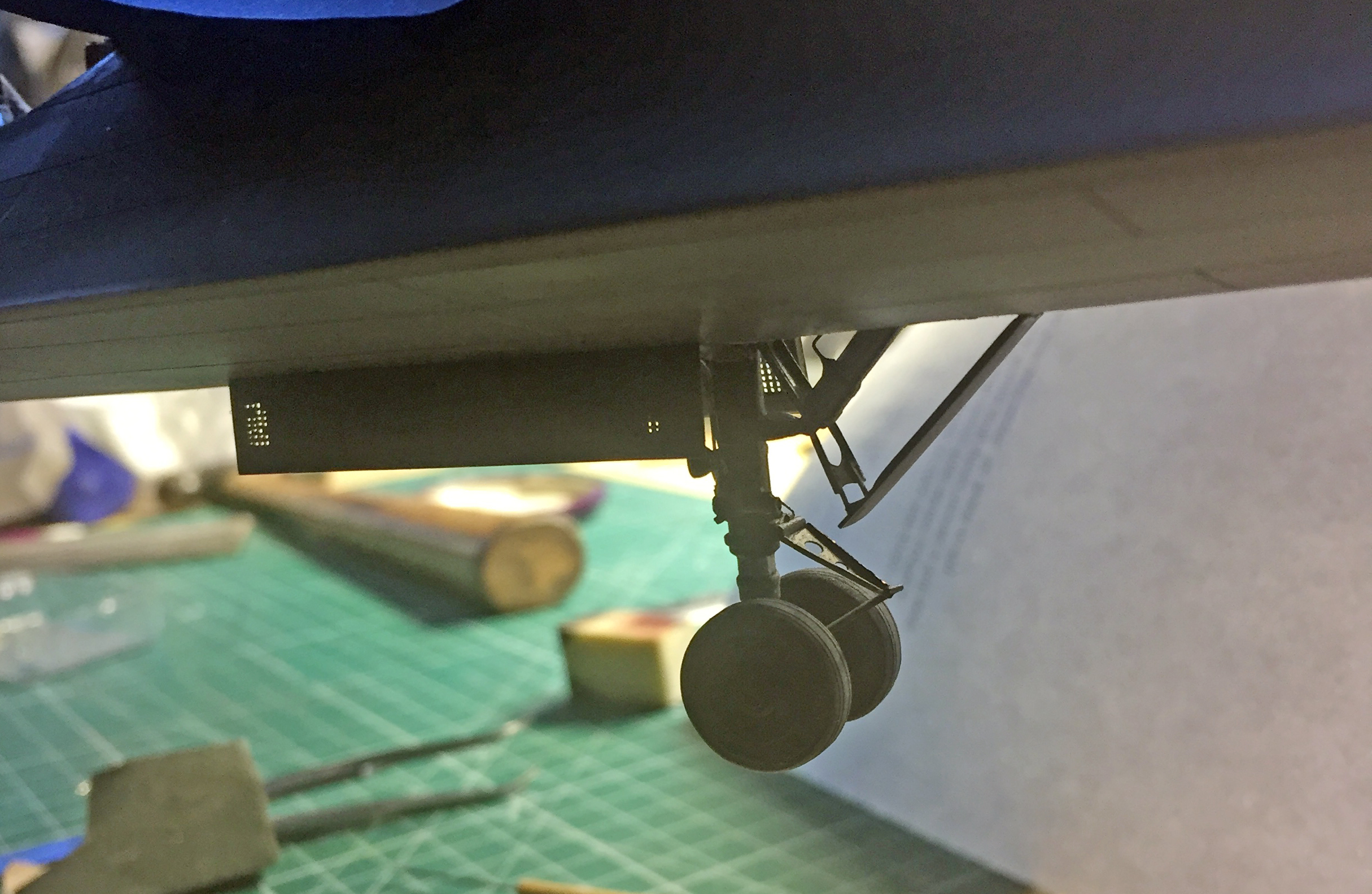
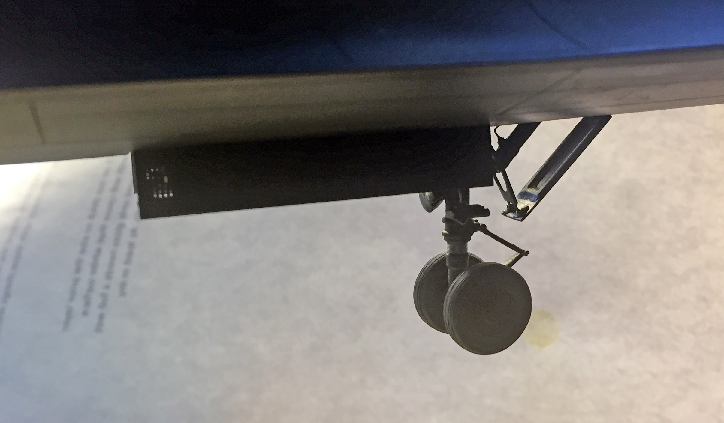
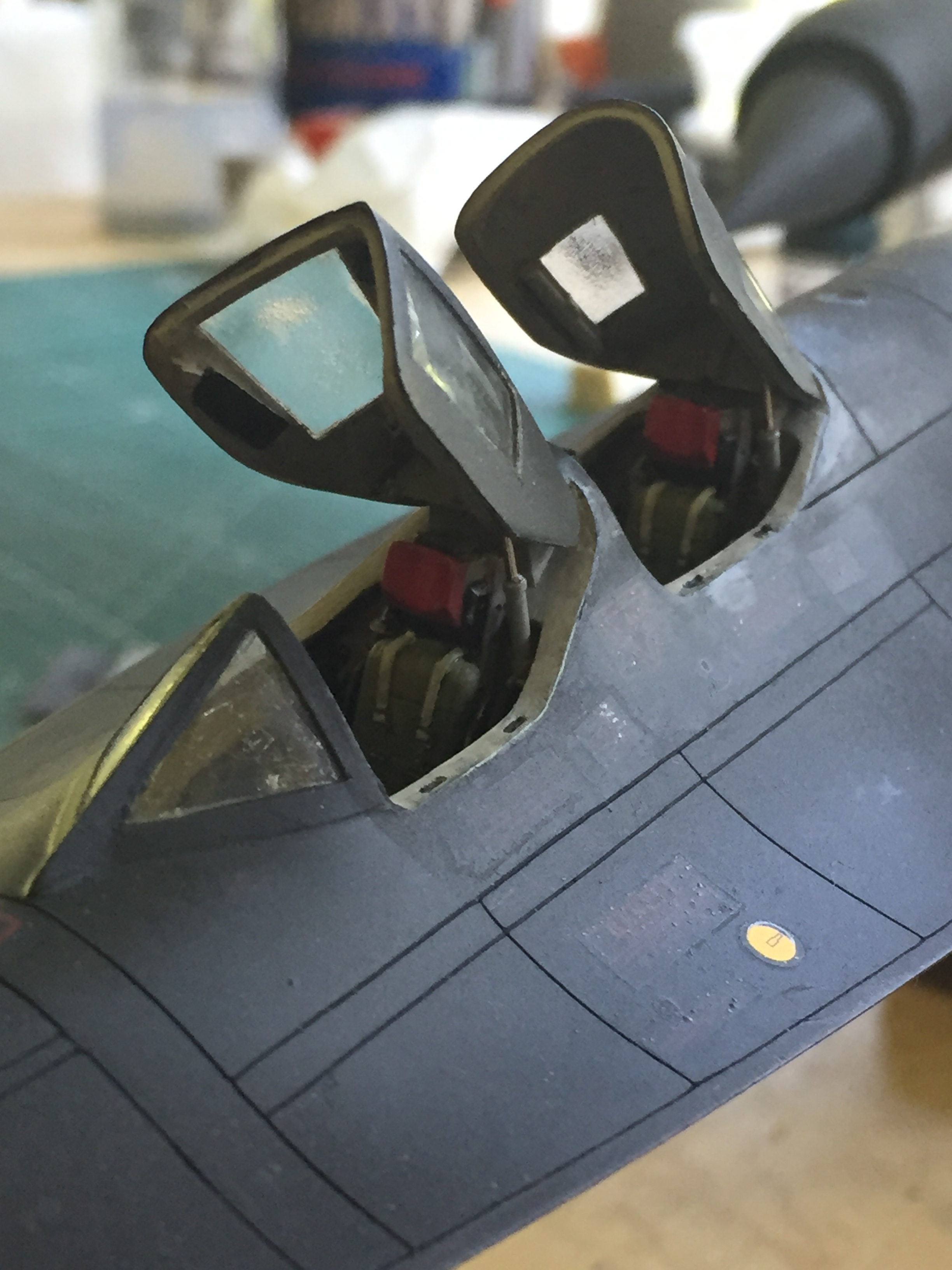
With those in place, it was time to add the hydraulic cylinders that close and open the canopies (the steel rams look like steel because they are steel…I used straight pins). I’m glad I had the foresight to make those parts with adjustability…it was “snug.” I did the rear canopy first as things were snug enough that had I done the front canopy first, I’d probably still be sitting at the bench and cursing my lack of foresight:
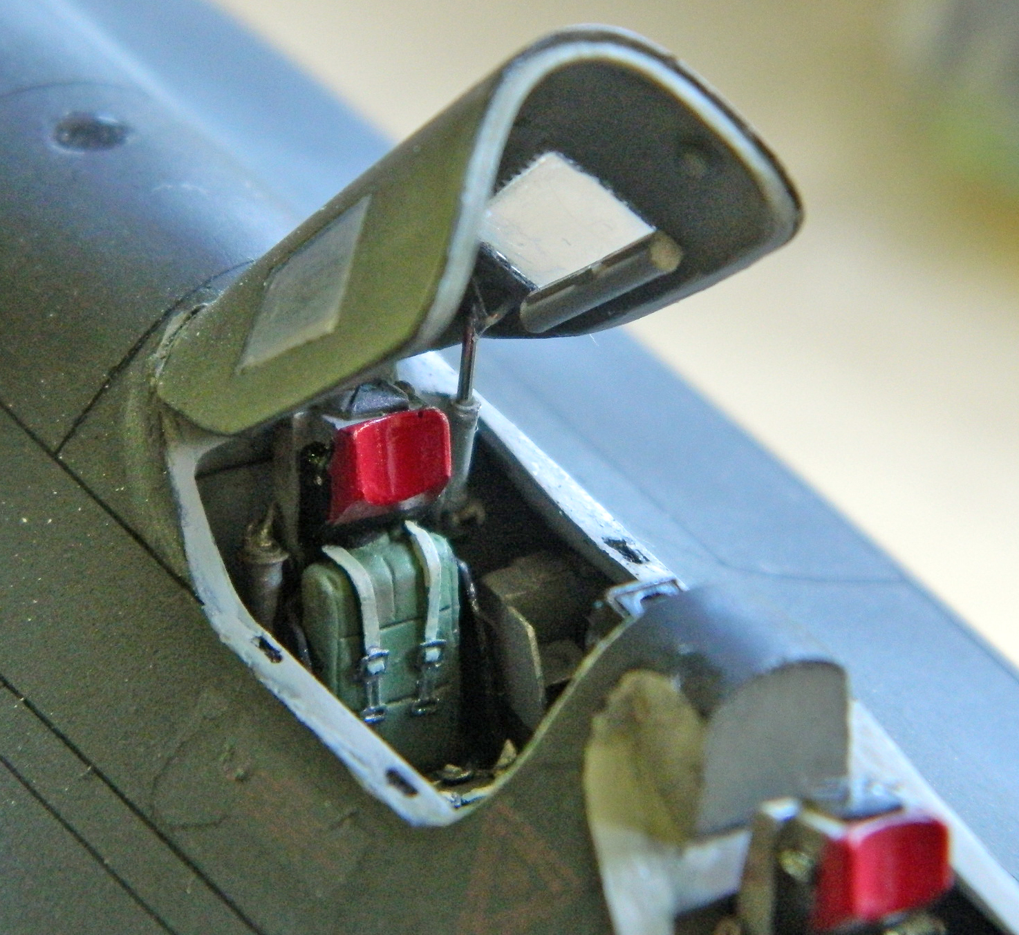
With that bullet successfully dodged, I did the front canopy’s cylinder:
So, this little box probably looks unimportant and therefore undistinguished. The reason I include it here is because that unimportant and therefore undistinguished appearing little box was where I was holding the last few parts I needed to add before construction was done.
AND IT’S EMPTY:

I don’t remember how long I sat there after taking that photo. It was several minutes. Then I took these photos:

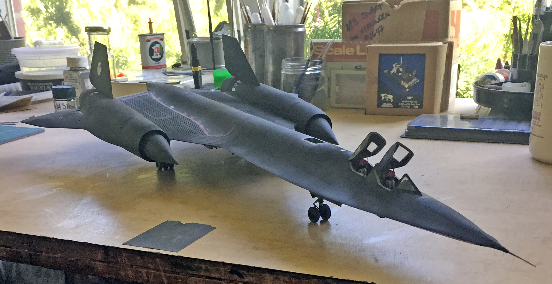
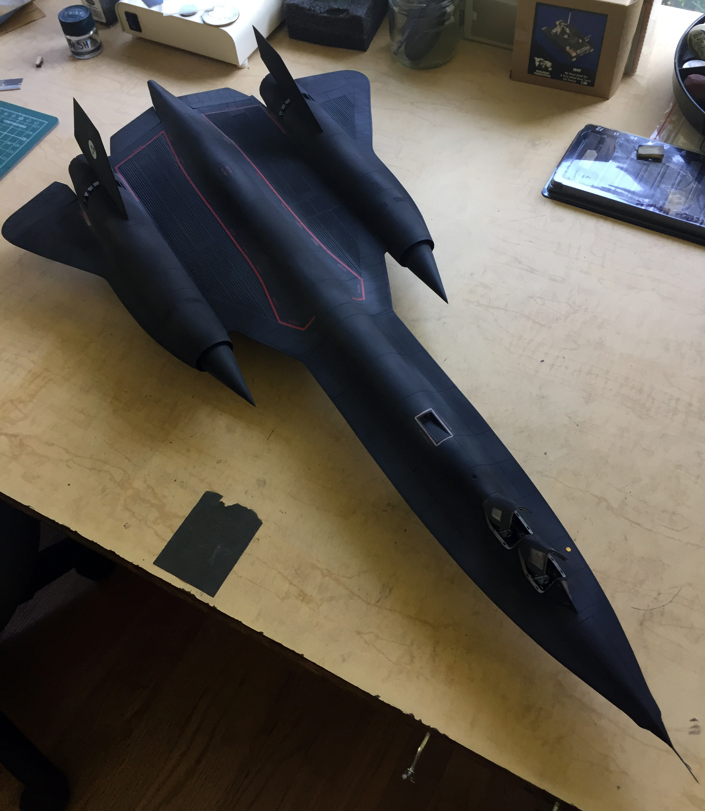
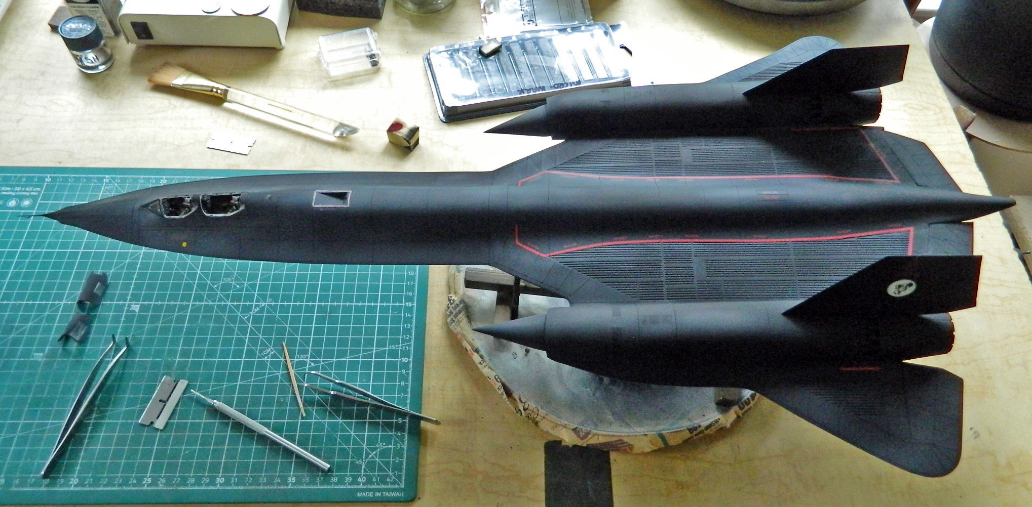
Oh my gawd…I think it’s done. I had intended to do some subtle weathering with pastels to accent panel lines. Sod that. I think this thing looks just fine nicely black and sinister.
Then I turned the shop lights off and went to bed. Giggling. Then the cat jumped up on the bed and gave me a Stern Look. It was time for sleep.
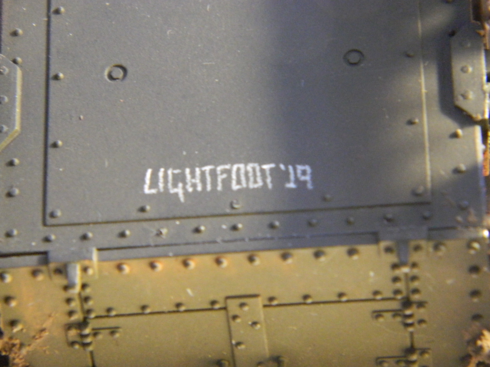
I awoke this morning and realized a couple of things (which seeing as I am NOT a morning person is miraculous all on their own). One was that since this is actually (technically) a commission, I have to sign it:
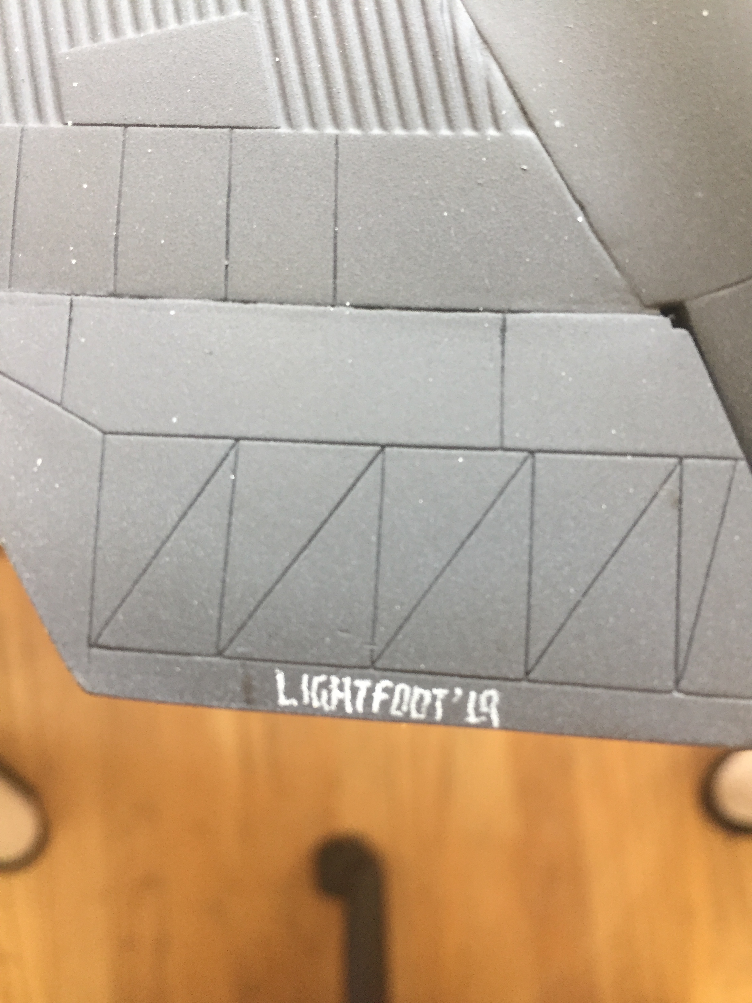
The other thing was that IT’S DONE.
For more photos, see Gallery.
If you’ll excuse me, it’s at this point that I need to go SERIOUSLY deplete my alcohol stock.
With the paint and decals stripped off and the canopies remasked, everything got hit with Tamiya’s XF-1 Flat Black:


I think even Minnie Mouse would look sinister painted flat black.
Then things were prepped for Tamiya’s X-22 Clear Gloss, which was then put down:


And here’s where I decided that maybe some paint testing would be in order. I am not going to strip this again. If I keep stripping it, eventually I’ll sand completely through the plastic (which is something I did many years ago with an F-104 I did) (my, wasn’t I surprised), and at 700+ hours, uhm…no. I have another Blackbird kit (actually a mislabeled A-12) that I can use as a paint mule. I grabbed one of the engine nacelles and threw rattlecan black at it:

Then I ordered about every matte and semi-gloss clear I could find.
Those who know me understand that leaving me unsupervised for any length of time is tactically ill-advised. This time that manifested as me trying to figure out exactly how I wanted to treat the panels. #972, as it’s displayed at the Smithsonian, shows very subtle shading where panel lines meet. Perhaps there are those who are proficient enough with an airbrush to be able to paint those subtleties. That ain’t me. And the way I’ve been going of late, I’d probably totally bitch it up. (Have I mentioned that I am not going to strip this again?)
I resorted to using pastels:

I like using pastels. I can get a degree of subtlety I struggle to achieve with an airbrush AND if I bitch it up, I don’t have to strip this thing. Again. Then I learned that my method of not sealing pastel effects with a clear coat was a good, albeit lucky, decision. Once the clear flat coat went down (rattle-can), the pastel effects vanished. Okay. Gotcha.
Then I sat around until the paints arrived:

Since I was going to be doing referenced testing, I didn’t want to go with water, isopropyl alcohol, or anything else not specifically intended as a thinner…and the Model Master thinner was back-ordered, so I had to wait for that to show up.
I worked with what I had on hand while I was waiting. Since my memory makes a sieve look vacuum-tight, I delineated zones with a white pencil and labeled what paint was in that zone:

Nothing left to do but paint it:

As a side note, I find it to be a good idea to have multiples things on hand that can stop a project cold. Things like a little Teflon ring that seals the tip of an airbrush. I dropped mine while cleaning it, rolled my chair back to find it, and evidently rolled right over it, rendering it garbage. Glad I had a spare:

And the results are in. I decided to go with Tamiya’s XF-86. It’s matte enough (I thought) and the manufacturer of the clear and flat are the same, so I figured they’d play well together. Though I liked MIG’s effect, the manufacturer calls for a 1.5 bar spray pressure (or about 17 psi). I discovered it’s VERY EASY for me to puddle paint at that pressure:

When the thinner for the Model Master paint arrived, I noticed this on the label:

Clearly, I misunderstood the definition of the word “universal.” That’s what I like about building models…I learn shit.
I also learned that I would probably need a spectrometer to see the difference between Model Master’s semi-gloss and matte because IF there’s a difference, I certainly couldn’t see it.
With that decision made, the mule was shot with clear gloss and the decals (I have extras, now) laid down (the snake graphic in the second photo is on there to do a decal solvent test):


I waited overnight for the decals to dry thoroughly (yeah…just a bit gun-shy at this point) and then whipped out the XF-86 at got this:

The edges of the decals are clearly visible.
And this is where I sit now…all of that and the edges of the decals are clearly visible. I have no FORNICATING IDEA of where to go from here. I mean, this is the process! I’ve done this before. What…suddenly I have to sacrifice a virgin to achieve the results I’ve been getting for far more years than I care to think about?!
Well, so much for those plans… Time to set this aside for a bit, CALM THE FUCK DOWN…er…regain my center, and decide what to do next or if there’s anything to do next. I may have to accept that this is the best I’m going to get. (I compromise SO well.) (spits)
After all this time, I am not going to start again, I am not going to strip this again, and I am not going to leave it unfinished. It may be that I’m just going to have to put my titties back into my training bra and cope (thank you, whatever screenwriter put those words into Margo from The Magicians mouth).
PS- At this point, I don’t know if I’m the mouse or the man.
The decals from Caracal were worth the waits (more on the use of plural later). They were produced by Cartograph and are freakin’ AWEsome:

So it was with shaky hands and misty eyes (and yes…no small amount of drool on the chin) (mine, this time) that I started getting the ‘Bird ready for its markings. First I had to strip the front landing gear doors (because I forgot to) and repaint them. Again:


This time I figured that maybe I should start with the underside this time, just in case, y’know, something goes awry, so I hit where the decals go with a coat of clear gloss:
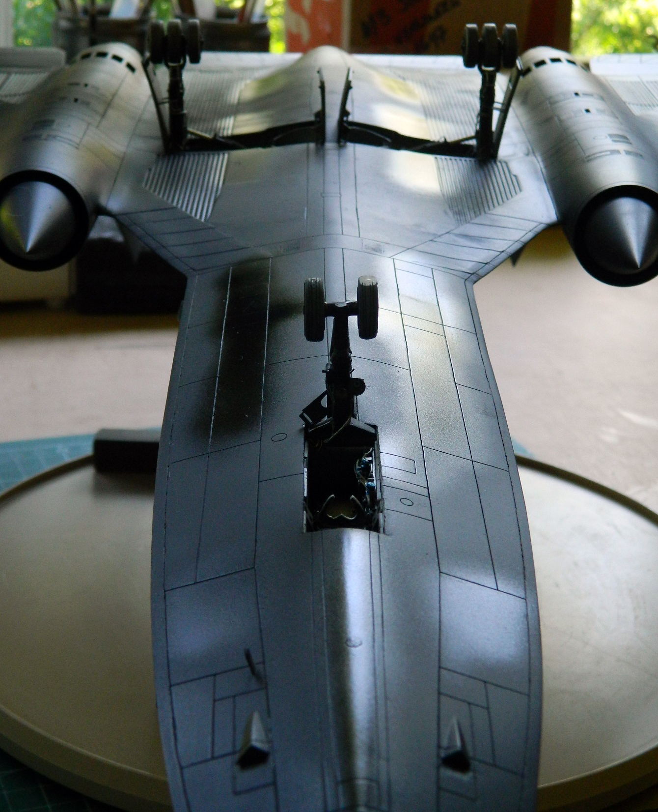
I decided that since I’d just repainted the front landing gear doors (again), I’d try the new decals there before moving up top:

Okay…so far so good! So I starting cutting, dipping, sliding, and setting and dissolving. “So far so good” continued! Had I heart, the process this time would have warmed it. And with all the decals I wanted on the underside laid down, it was time to lay down a coat of clear flat.
I now turn your attention to a phrase I’ve defined in the section, “What the Hell Does That Mean?” The phrase is “Brain Fade.” G’head. Look it up. I’ll wait.
::sound of ticking clock::
Glad you’re back. Now I can continue…
I got lazy and then I had a case of brain fade. The laziness came when I didn’t want to clean my freaking airbrush. I cannot overemphasize the lazy stupidity of that position. I could stand on the sodding roof and scream it until my throat bled and not emphasize it enough.
I didn’t want to clean my freaking airbrush.
Instead, I used a rattlecan of clear flat. A rattlecan only does one thing fairly well. It will cover an area with whatever the intercoursing can is filled with. What a rattlecan will not do is moderate how much paint is thrown at the target and the process cannot be remotely considered “fine.”
THIS lovely little finish is called “orange peel”:
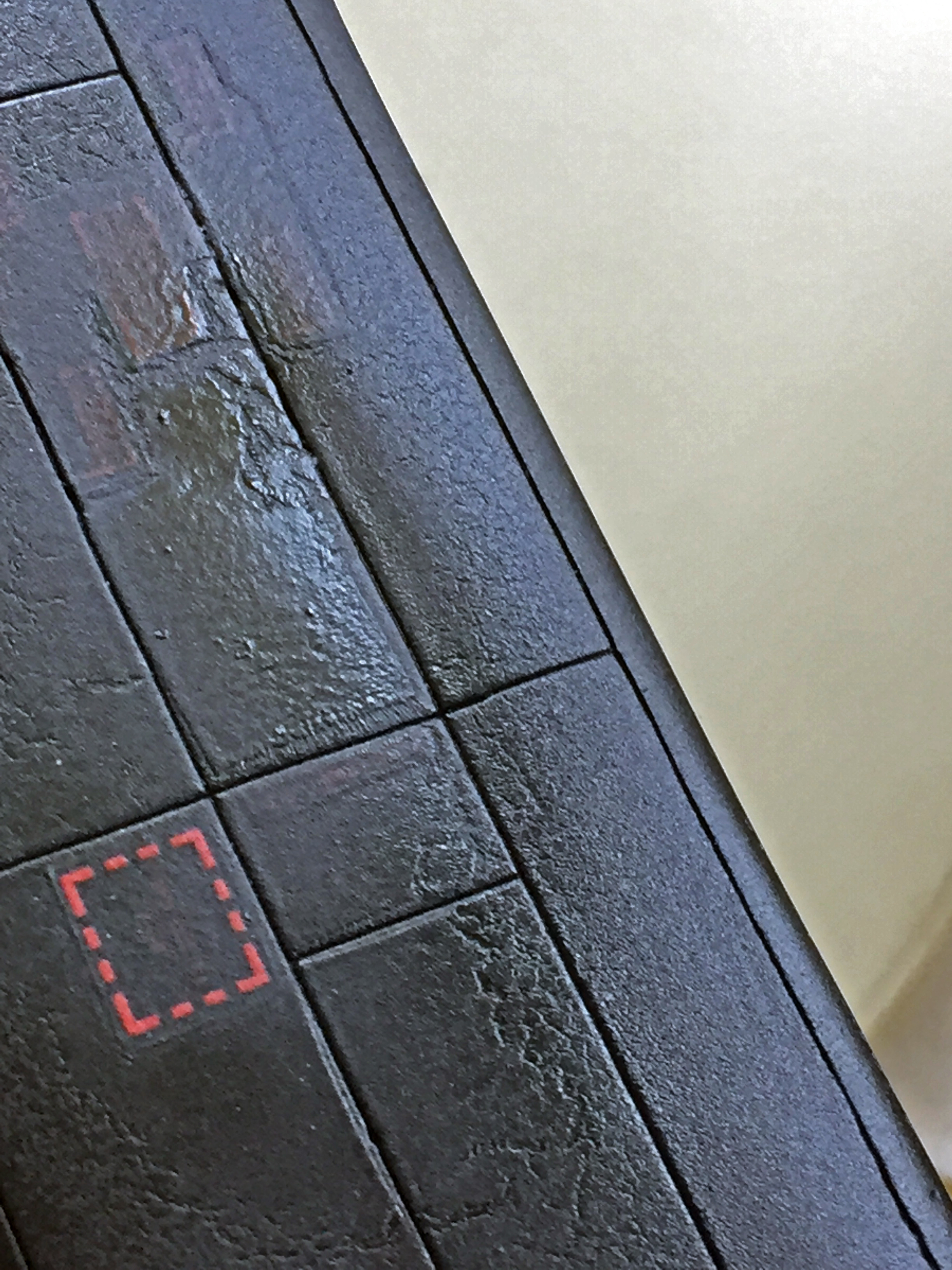
This results from too much paint being put down per pass…y’know…sorta what a rattlecan does. The brain fade part of all this is that I knew this before I popped the cap on the damned can.
How does one fix orange peel? There are a few ways. Smash the sodding thing with a big hammer. Burn it. Take out the shotgun, load it with birdshot, and keep firing until there’s nothing but powdered plastic left to shoot at. Sand the paint away and start over.
Surprising myself with the maturity of my response, I chose the last option. (This is also a testament to how much I admire and respect the guy I’m building this for. In short, he’ll get it…probably in one piece, but at this point I guarantee NOTHING beyond that.) The nice thing about the Internet (aside from the porn) is that no matter what time of day/week one discovers that the bullet hole in ones’ foot was placed there by one, things can be ordered (or porn looked at). I ordered another sheet of decals (which is why at the beginning of this post, “wait” was used plurally).
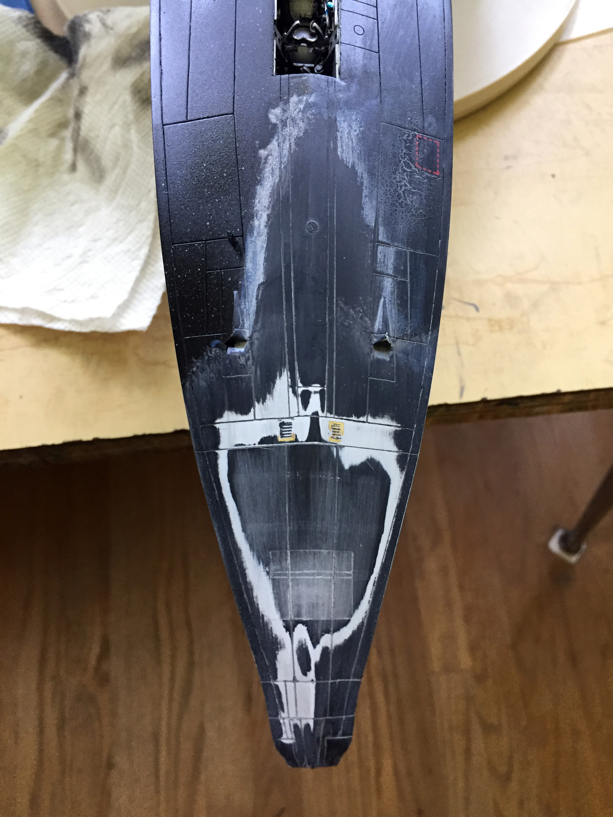
And so it began. AGAIN:
And continued. AGAIN:
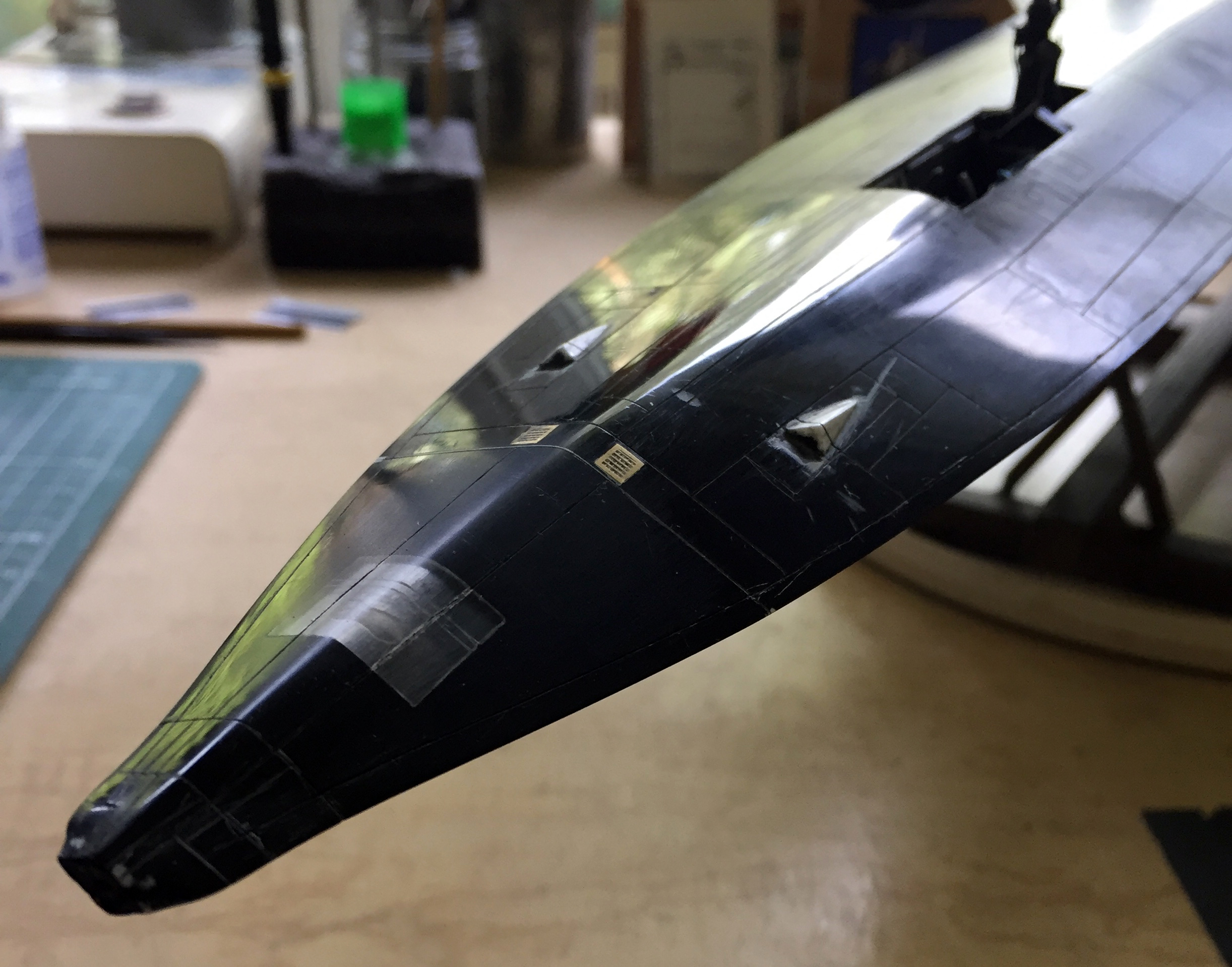
There was a lot of “and continued” (and a couple of oh-goddamn-it moments requiring parts I broke off to be reattached) until I got to this point:


I had started stripping the paint using denatured alcohol (I used plenty of alcohol, single malt and sour mash, to see if sorrows could be drowned…and they can…just not permanently) (assuming that the alcoholic stupor doesn’t kill the imbiber first). Then I realized that some of said denatured alcohol got on the top surface, removed paint, so that will also need the tender ministrations of the airbrush I was TOO FUCKING LAZY TO CLEAN TO BEGIN WITH. So from about the front landing gear bay back, I used sandpaper to get down to bare plastic. AGAIN.
At one point (which was about the time I realized that the alcohol had gotten on the top surface), I put the boarding platform next to the fuselage while it was sitting on its own feet and discovered that it was a colossal waste of money. It was out-of-scale and did NOT come near where it was supposed to rest…which is against the fuselage, even with the cockpits’ sills (and before you mention that maybe this problem is due to the scratch-built landing gear, it’s not; they’re the same length as the kit parts and if out of position, it’s not by more than 1/16th” [1.58mm], if even that much):


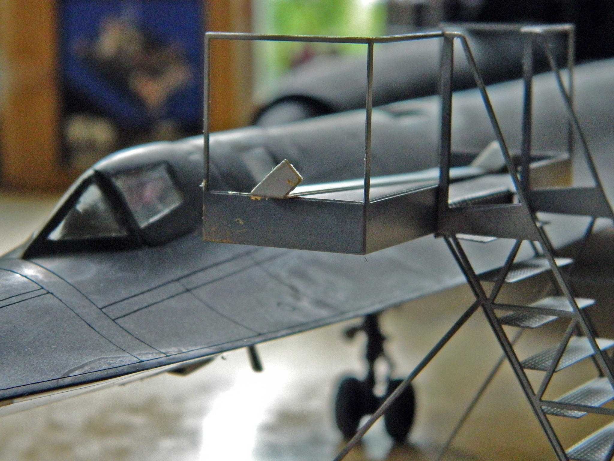
I have just the hammer for that.
There are a few spots where the paint needs to be feathered and reapplied:
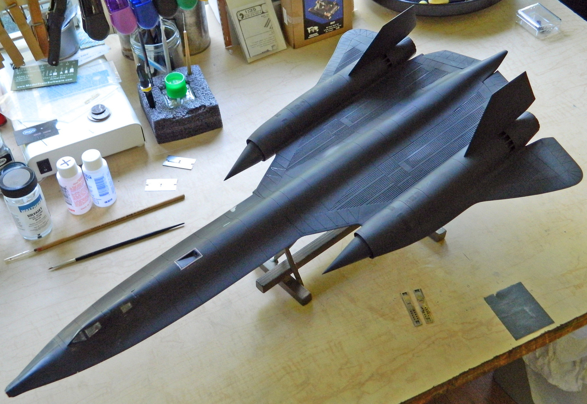
I had removed the masking from the clear areas of the canopy because leaving masking tape too long on a surface doesn’t do good things. The adhesive separates from the paper of the tape and marries itself to the surface being masked. Yeah…it’s removable. It’s just not easily removable. When I set this thing aside pending the arrival of the decals, I didn’t know how long they would take to get here, so I removed the masking. Therefore, step one to repainting this thing is to mask off the canopies again.
Yeah, well, no. Remember how I had trowled the clear flat on to try to get my homemade decals to work? That built up a lot of paint on the canopies…a fact I had overlooked when I stripped the paint off. That means it has to come off now:
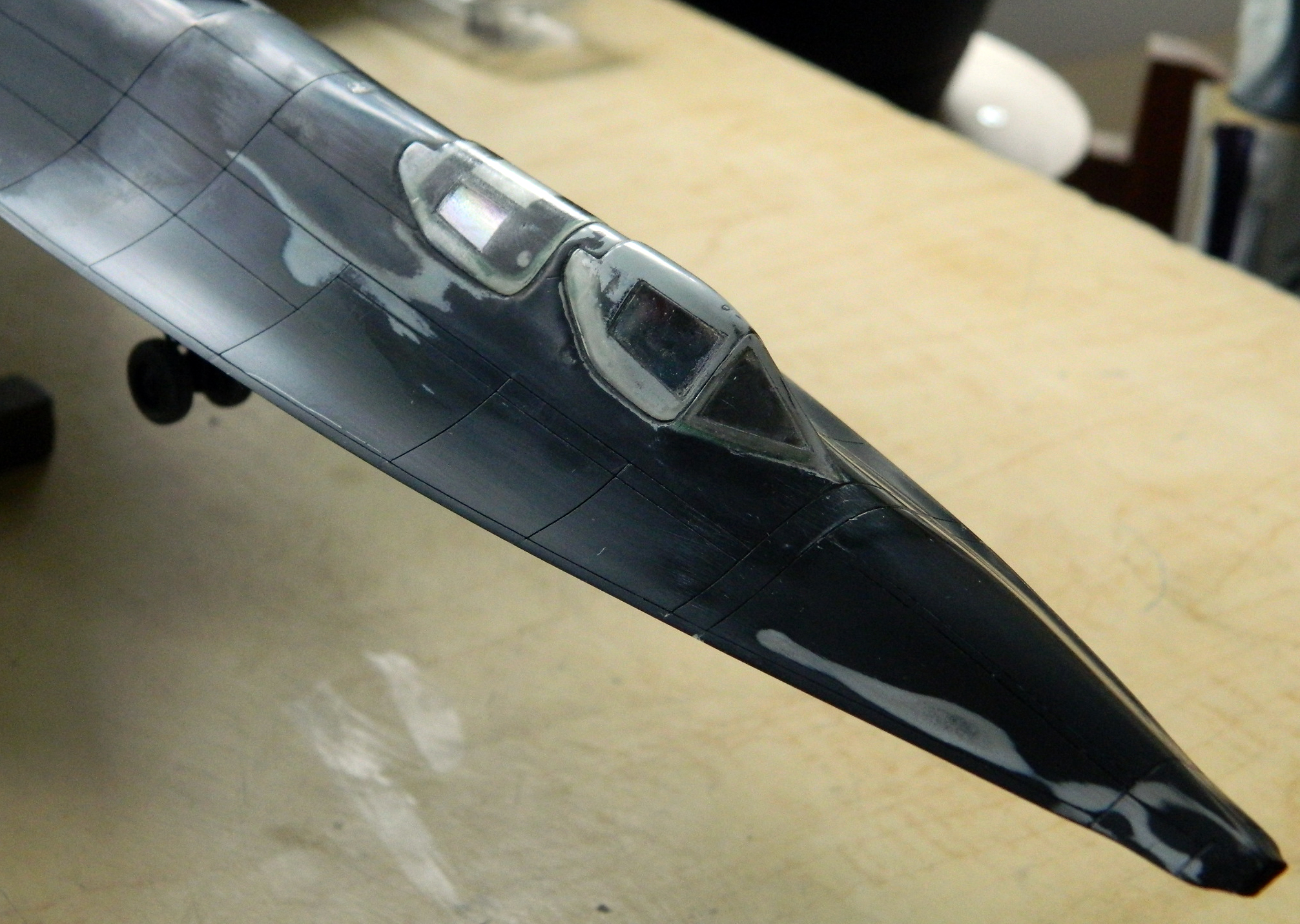


And off it has come.
Now to take my airbrush and paint both sides of this thing black, then lay down clear gloss for the decals.
AGAIN.
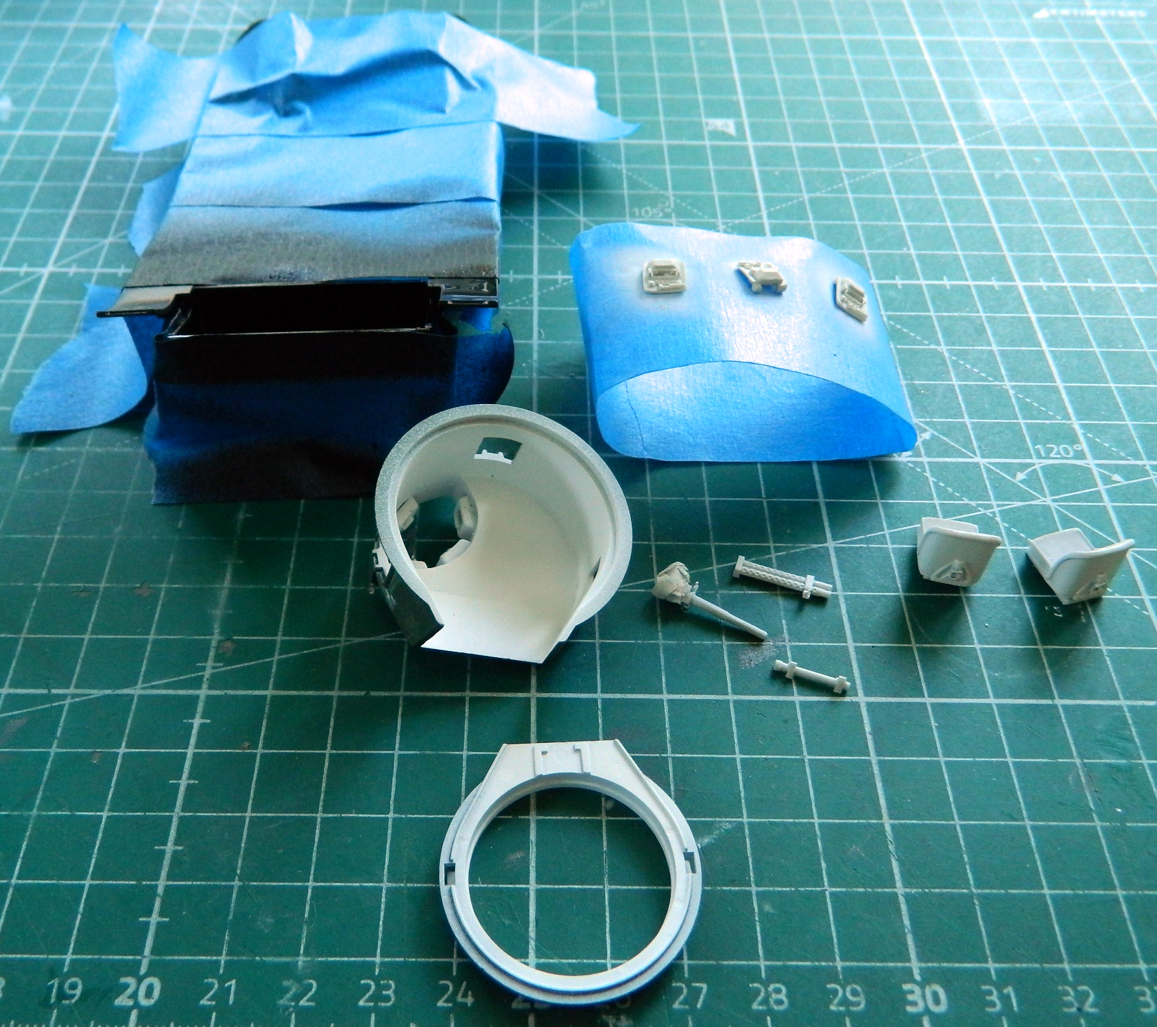
I installed a piece of plastic under the rear of the upper hull to block off the interior and then used Tamiya TS-6 Matte Black rattle-can to paint that section. I also painted some things that needed to be flat white:
The operating mechanism for the M3’s pistol port hatches needs to be built as well, so I started trimming some .010″ (.254mm) scrap for that:
These parts aren’t very big:

The aftermarket resin set was intended to be used with the earlier turrets that had flat sides either riveted (D37812) or welded (D38976). I’m using the “horseshoe” turret (D39273) that has curved sides. This means that some of the turret parts will need to be adjusted accordingly. This example is of the map case:
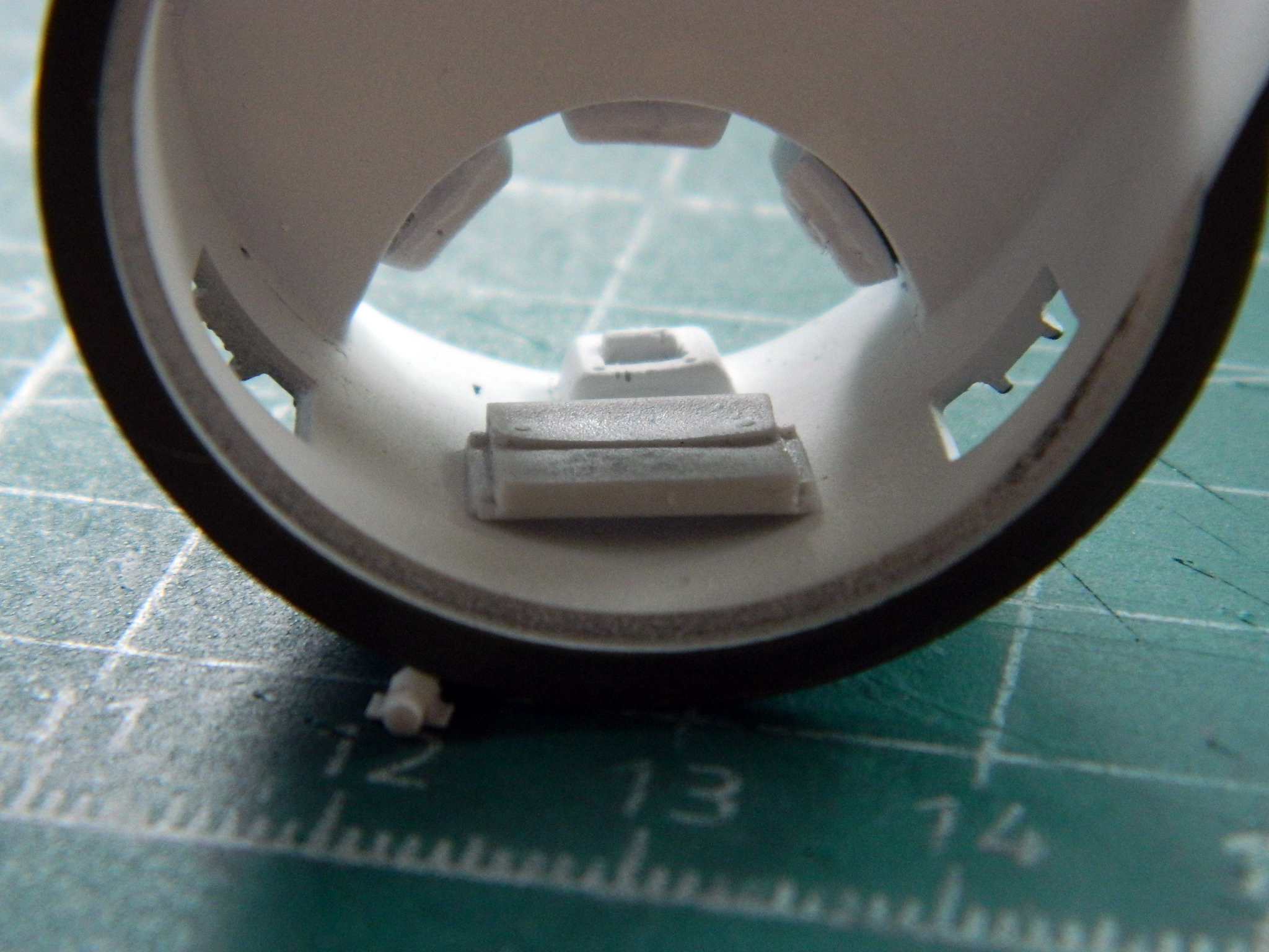
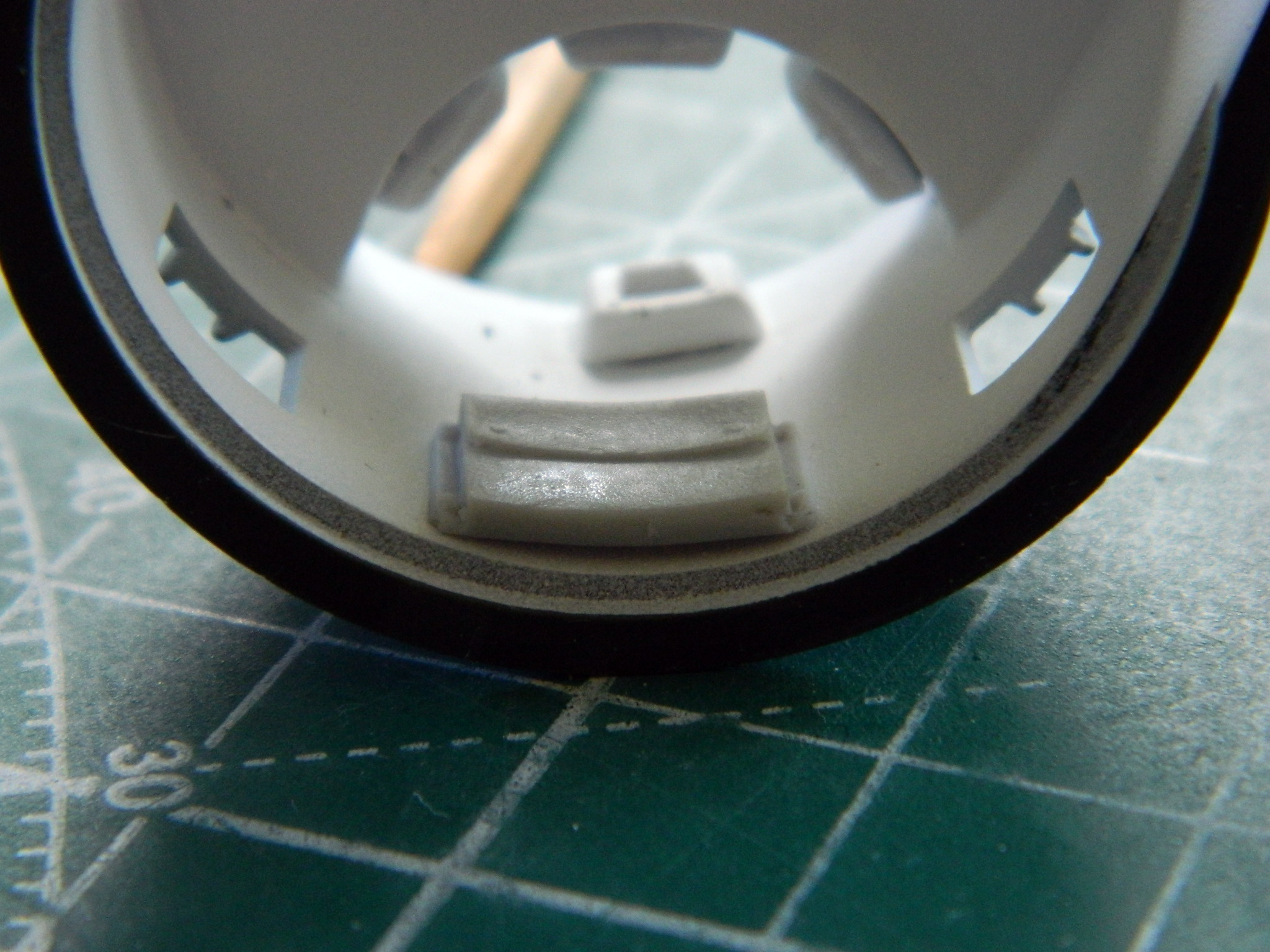
This isn’t the first time I’ve used Tiger Model Design’s (TMD) parts. They’re well made and nicely cast. What’s surprising me this time is the fit isn’t very good. This isn’t the first time during this build that I’ve found myself having to adjust things to make some sort of fit. This example is of the driveshaft cover. It’s simply too short. If I used it as it was produced, I would not have enough room to fit what must go in there (and forget what I’d like to put in there because those won’t fit). Note the gaps on either end of the cover; that’s how much more room I needed:

For this size/scale, that’s just too far off, which required me to add .060″ (1.524mm) styrene sheet to both ends of the cover:
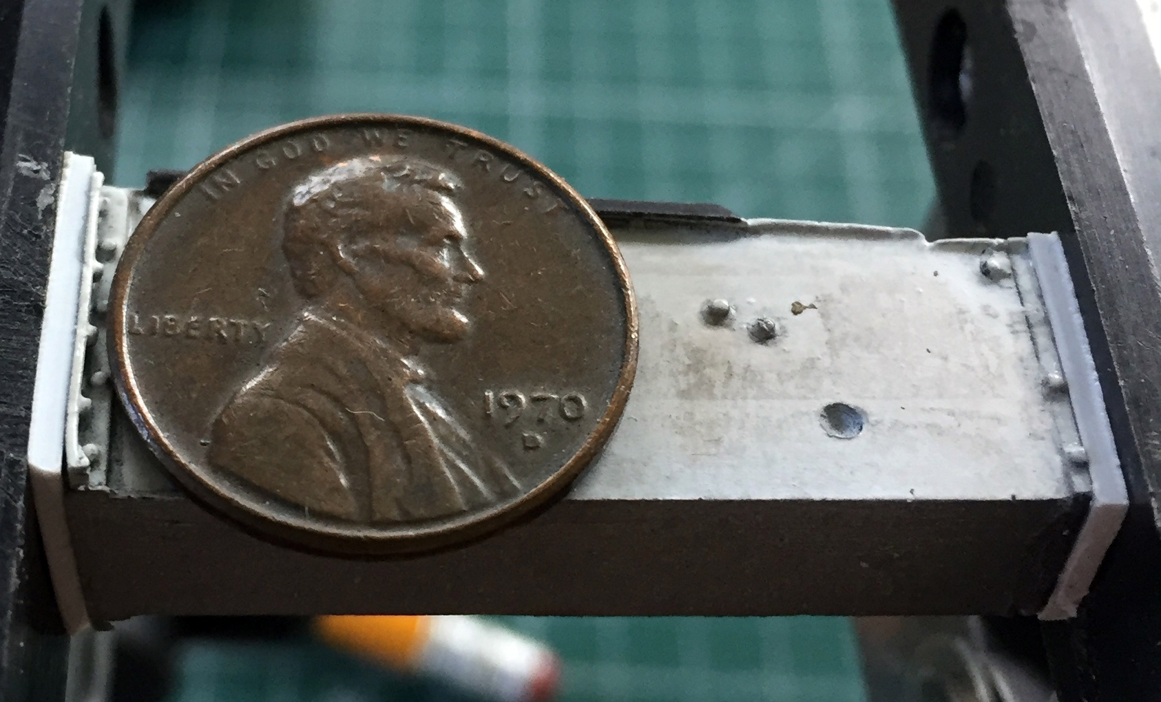
It fit better after that (the ammo stowage boxes are shown here without the pads that go on top of them to create the only seats the commander, on the right in the photo, and the gunner, on the left in the photo, have) as dry-fitting showed:
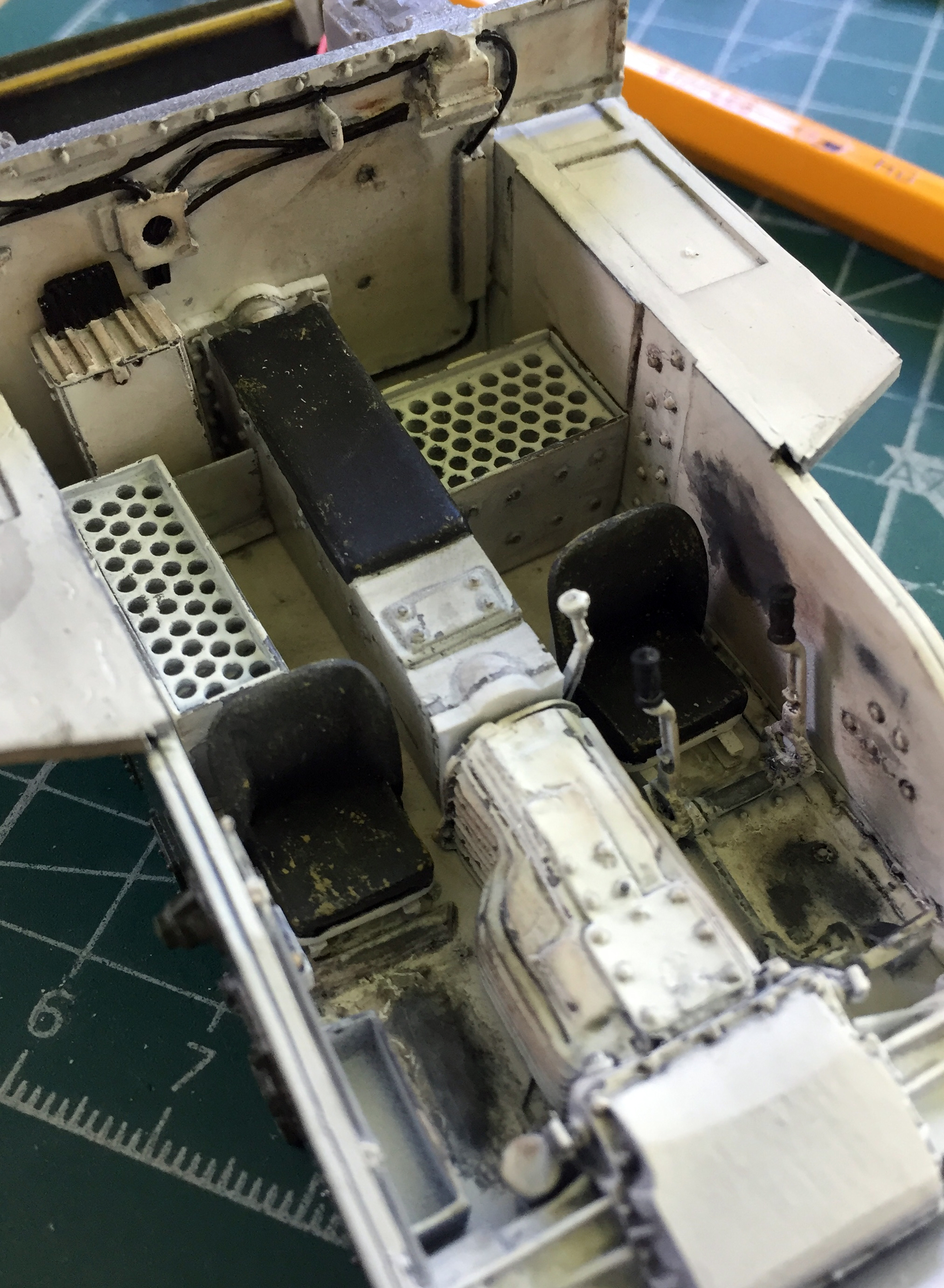
With the length of the driveshaft cover adjusted, putty was added to the additions. That needed to be sanded smooth and the paint and stains needed to be touched up:

While I had the airbrush loaded with flat white, I also did the instrument panels. Once the instrument panels were painted, I added the instrument faces using Archer’s “U.S. Gauges and Interior Stencils,” #AR352098. I just wish these old eyes, even with magnification, could see better so the transfers were more centered:
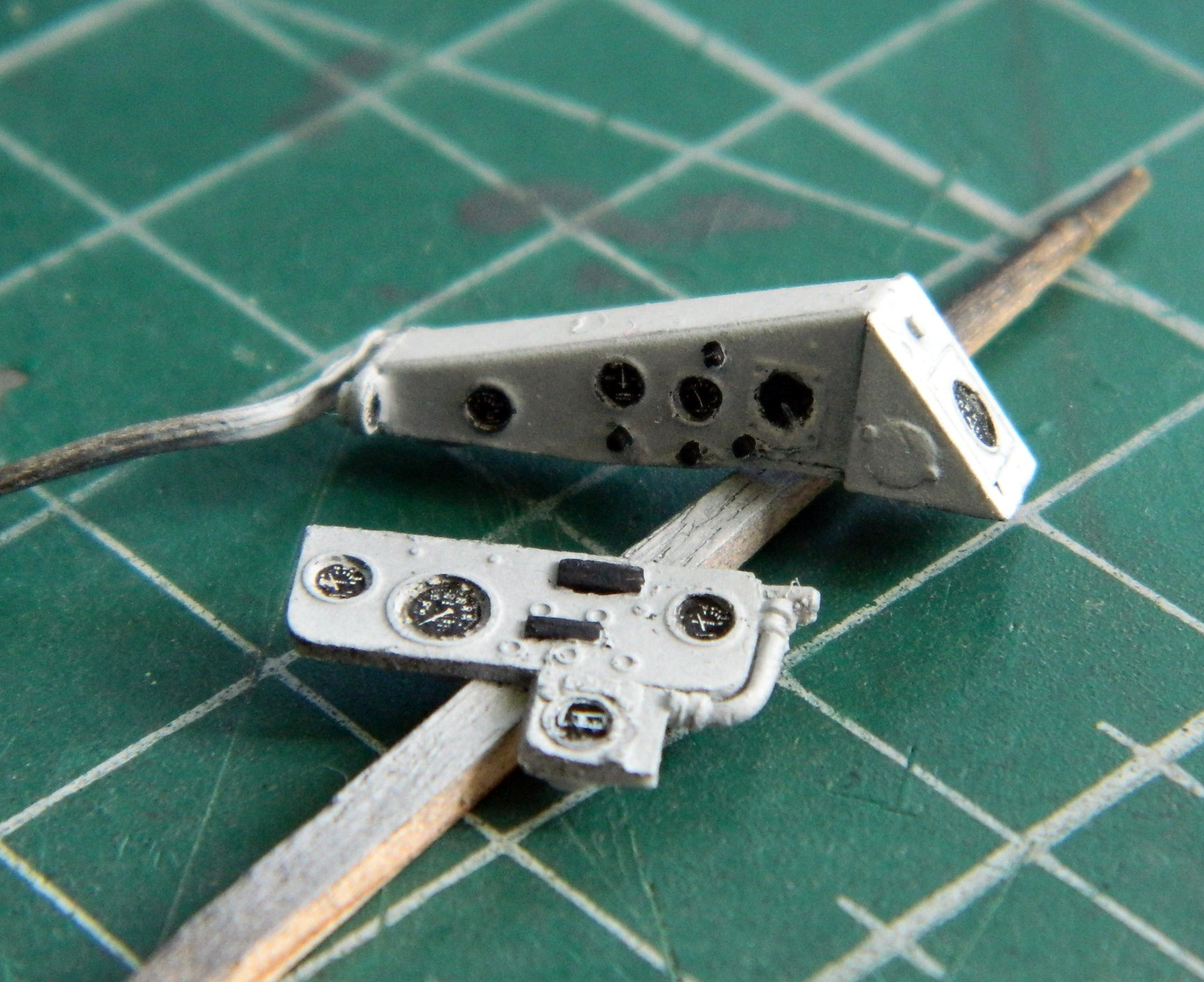
Having gotten the panels as well as I could, clear gloss was added for the dark wash to sit on, then clear matte was laid down:
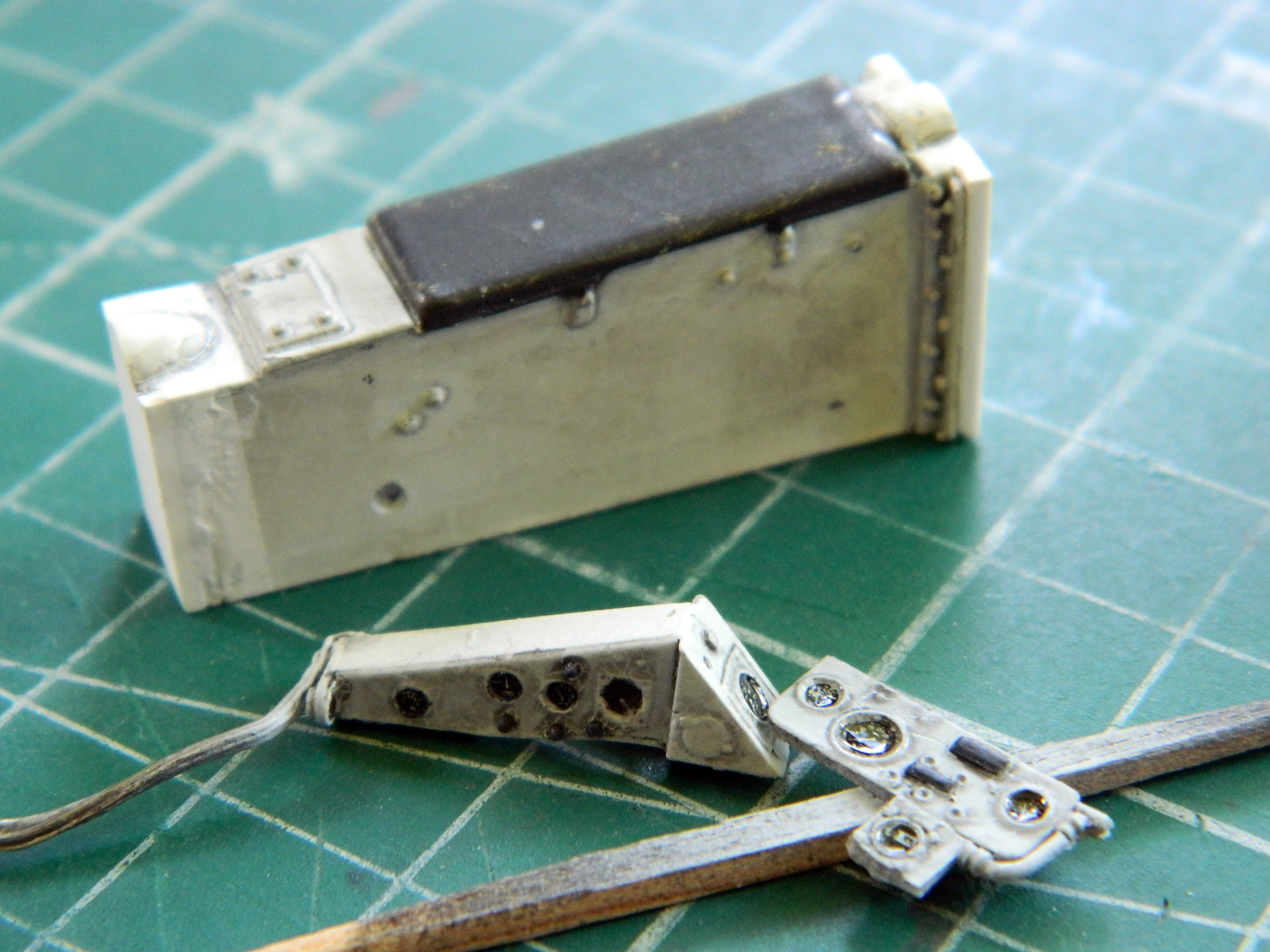
With the length of the driveshaft cover corrected, it was time to start populating the interior (note the cushions on top of the ammo stowage bins):
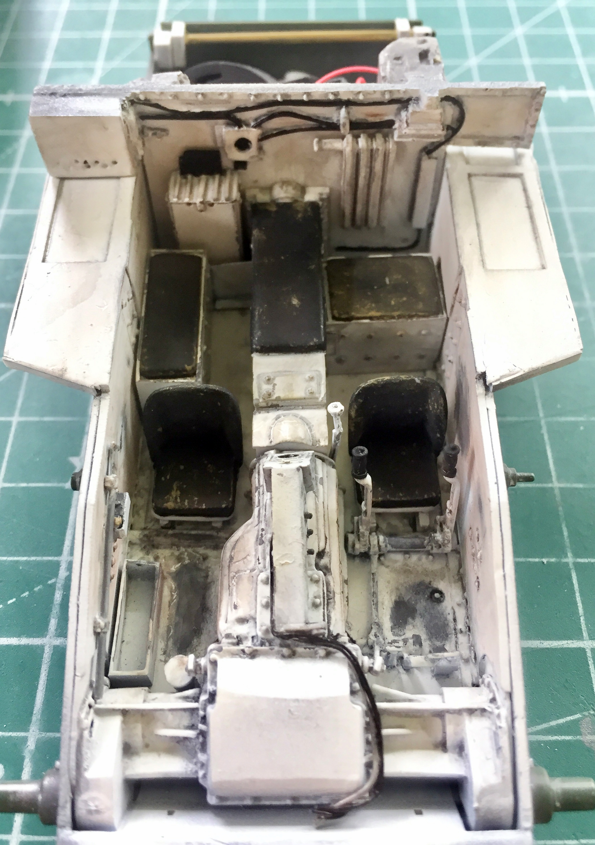
The rear bulkhead hasn’t been glued into place yet. The fire suppression system needed to be painted and added and the copper feed line (using copper wire) needed to be added:

With that in place, the bulkhead and center instrument panel were glued into position and other small items (Thompson submachine gun drum magazines, spare main gun sight behind the bow gunner, and spare .30 caliber (7.62mm) machine gun barrels behind the driver) were added and things were dirtied up and chipped:

More things were added including the radio, C-ration box (a Verlinden item…I’m gonna miss that guy), canteens, and so forth:
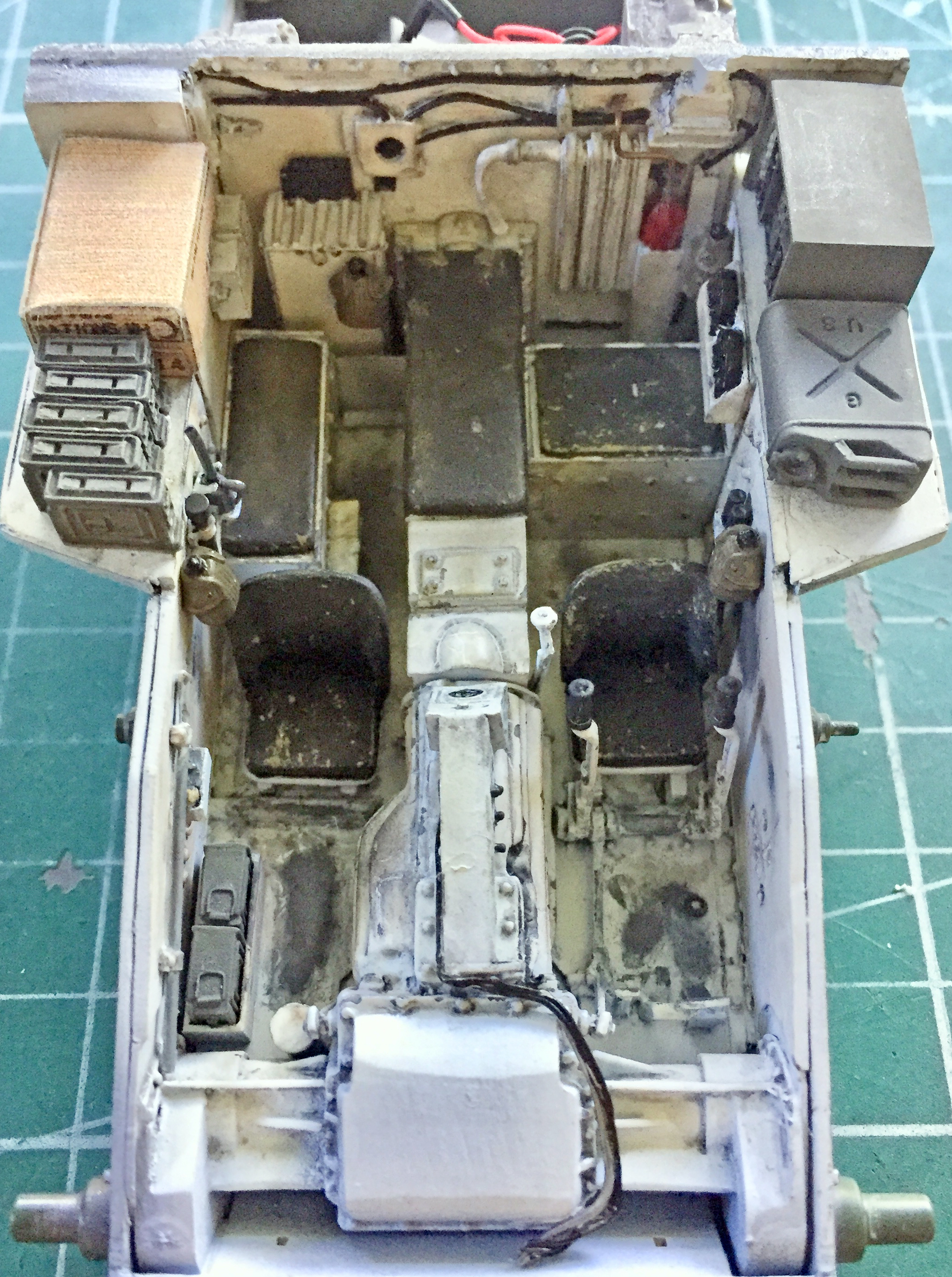
Something I’ve been itching to do was to check the LED light and see how it looks:

Yeah. That works just as I’d hoped it would.
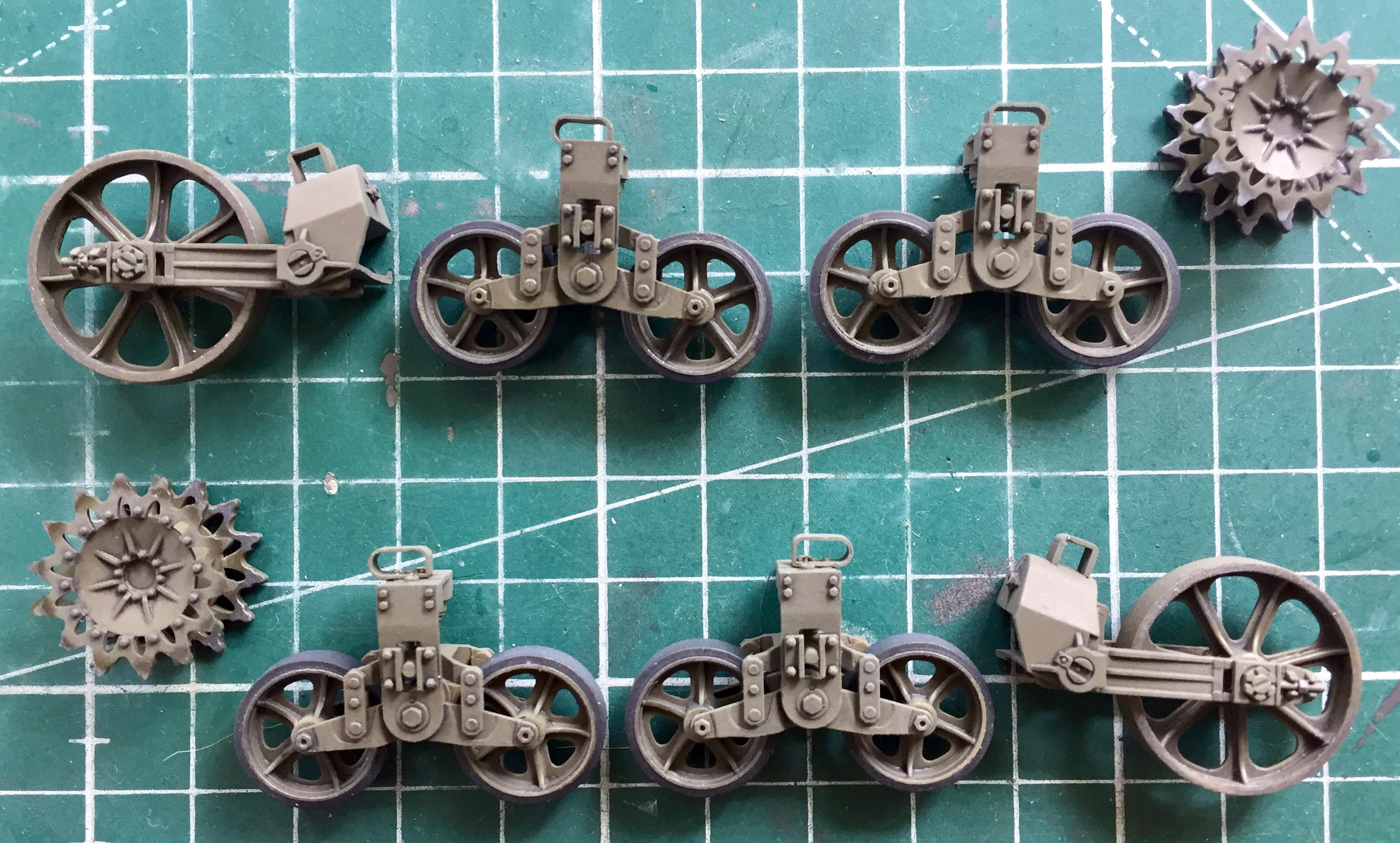
Then I assembled the AFV’s suspension, adding a little putty where needed:

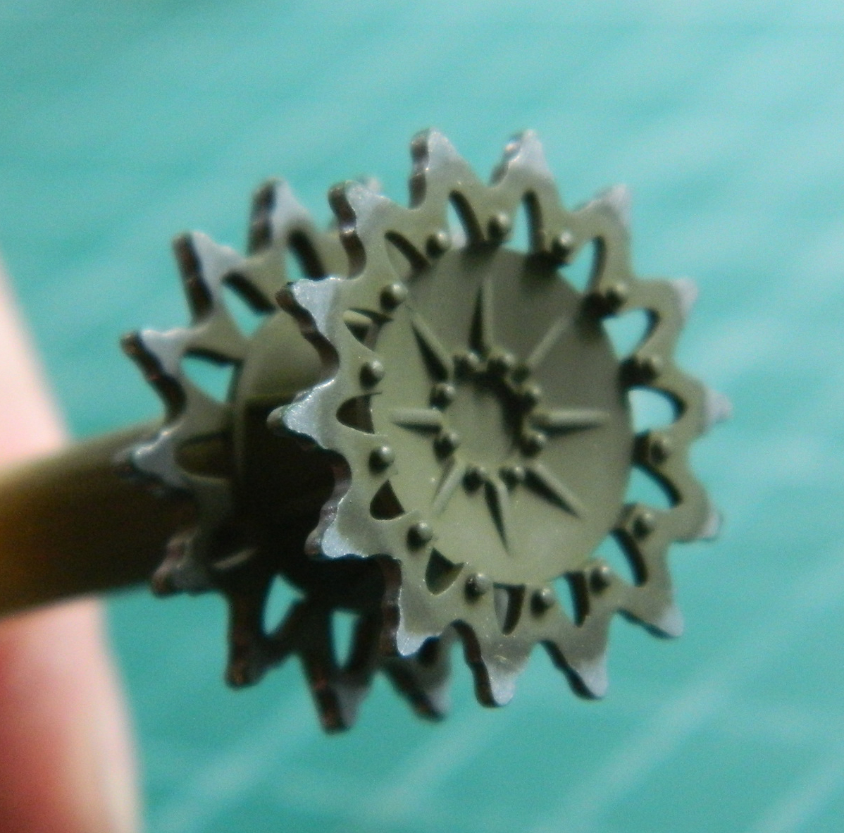
I don’t know why it was so, but I noticed that the M3s used in the invasion of Guadalcanal showed wear on the sides of the road wheels, leaving a shiny surface. So when I started painting the suspension, the first thing I did was to put down a coat of Humbrol’s steel paint. Once it dried, I painted over the steel with Tamiya’s XF-62 Olive Drab. With the OD dry, I used Tamiya’s thinner on a cotton swab to remove the green, starting with the drive sprocket’s teeth:
I masked the road wheels prior to shooting the suspension with the OD:
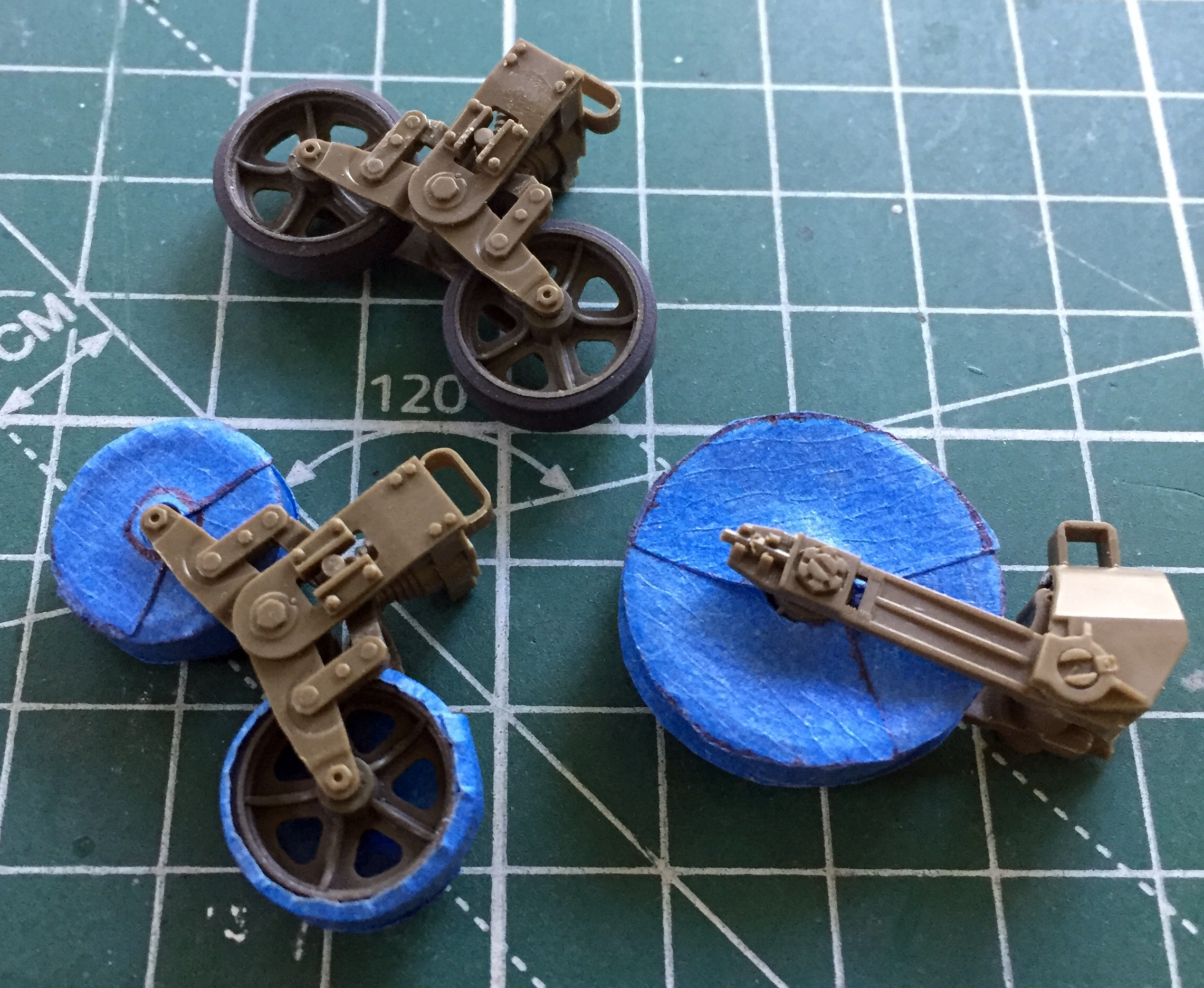
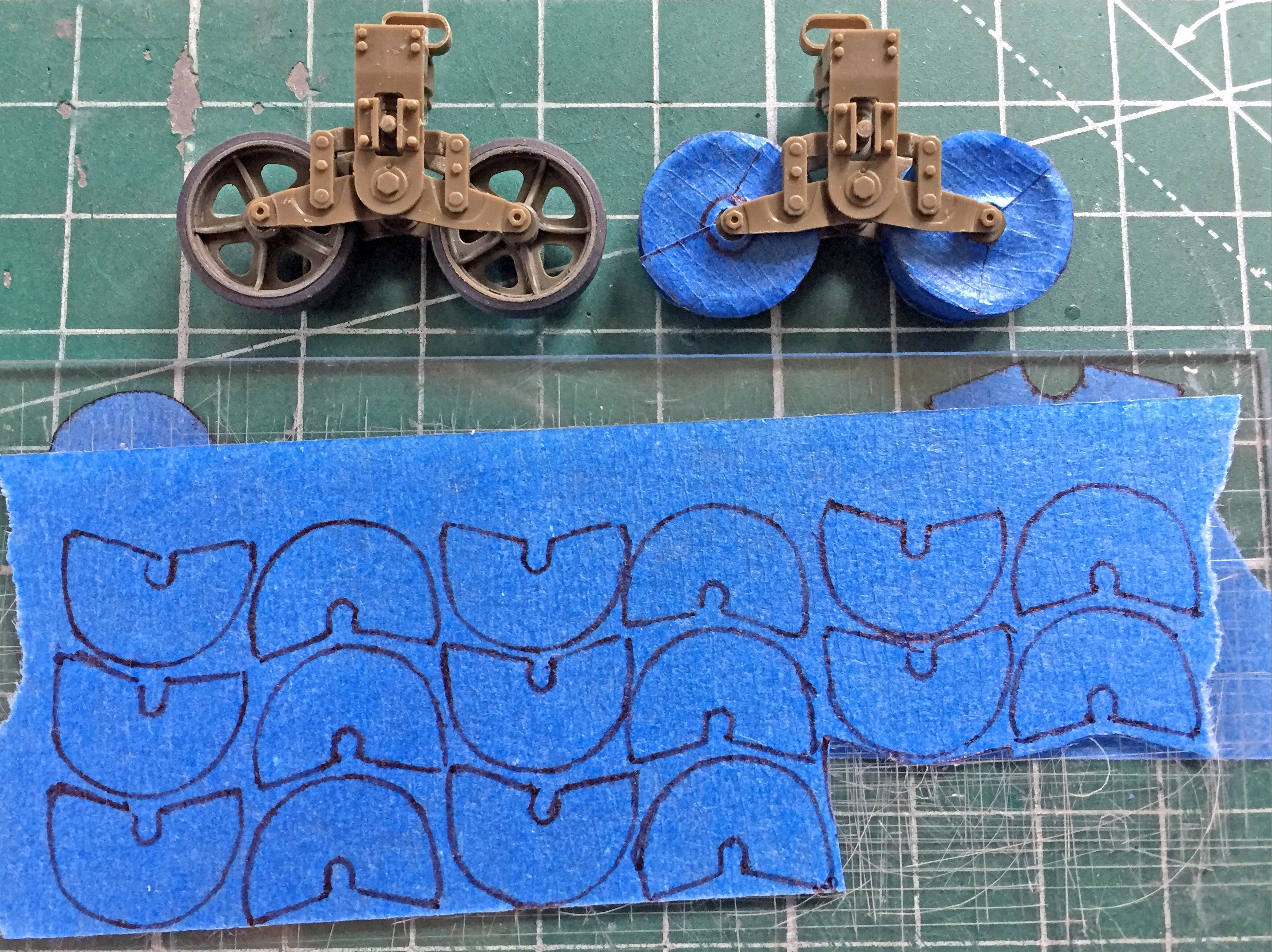
Once the suspension parts were painted, I laid down clear gloss and treated them to a wash. After an overnight wait, clear flat finished them:
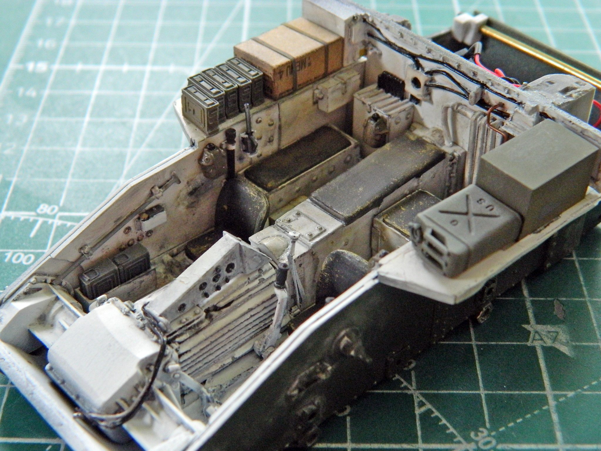
With the suspension done, I finished populating the inside of the crew compartment, and used dry brushing and pastels to wear, stain, and chip things:

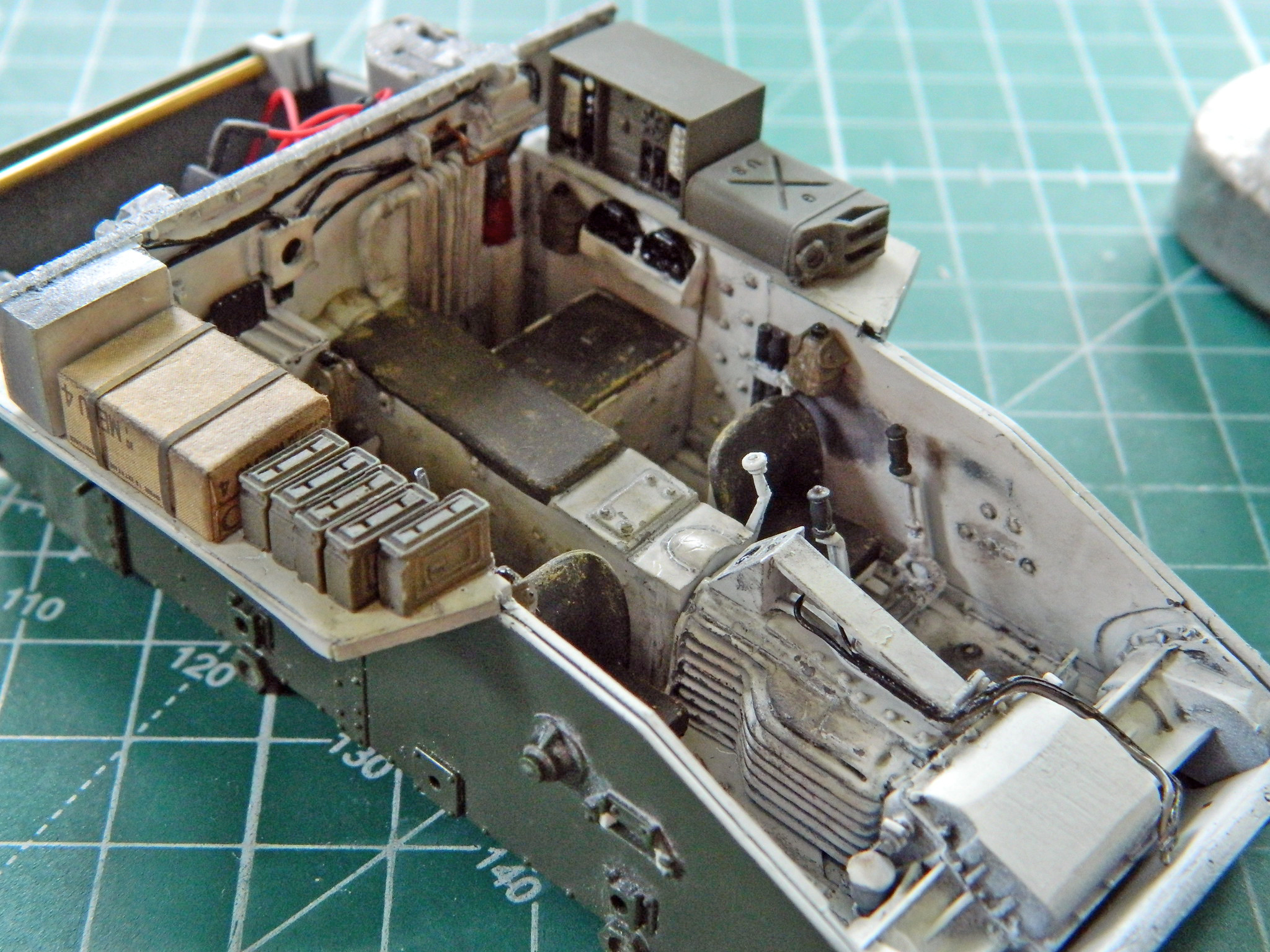
Dealing with the bow machine gun proved fiddly. That length of belted .30 caliber (7.62mm) ammo was a PAIN to heat, bend, snap, cut another section, heat, bend snap, and cut another section:
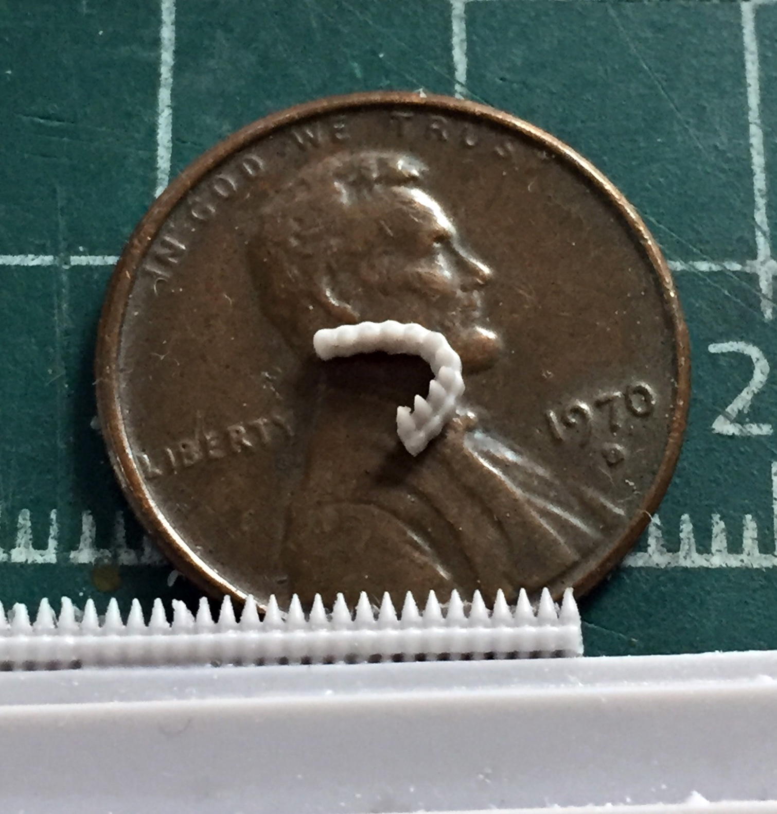
And I’ve decided that I don’t like Tamiya’s “gunmetal” paint. The paint itself is fine, I just think the color is off. I used a mix of five parts of Tamiya’s X-18 Semi-gloss Black and four parts of Tamiya’s XF-2 flat white to achieve something I think looks more realistic:

Painting and gluing it together was easy by comparison:

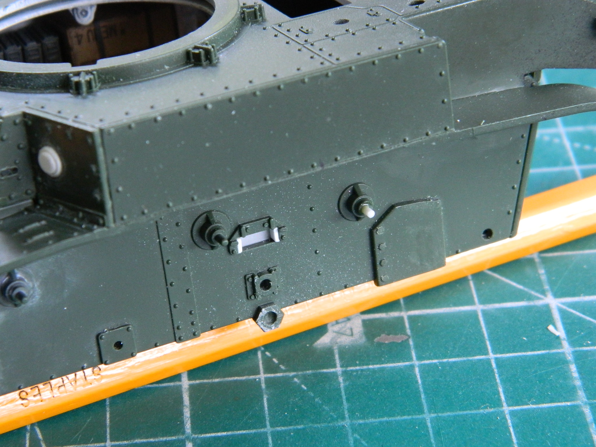
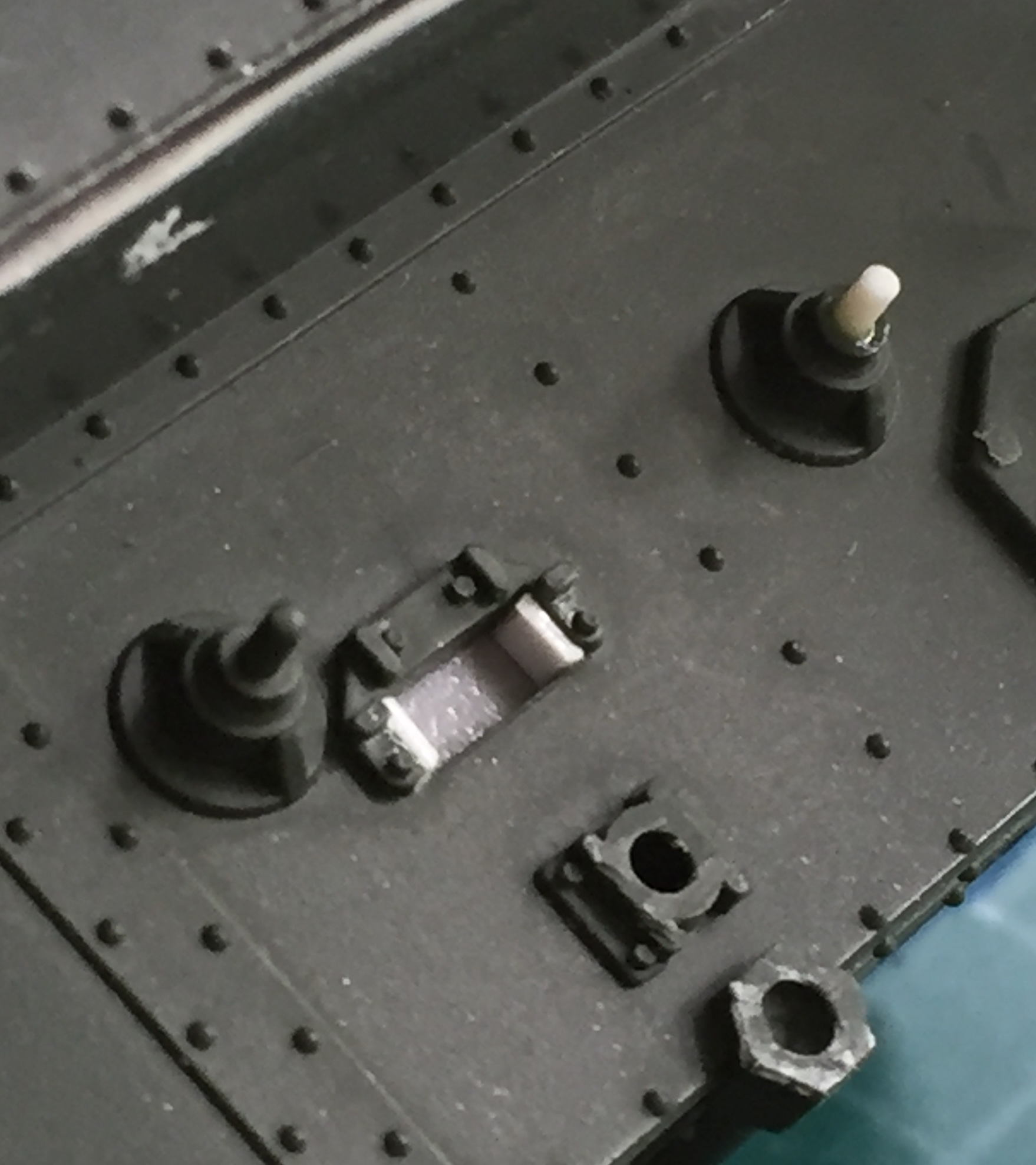
During handling and clamping things to the bottom hull, I managed to snap off four of the six little plastic pins that the return rollers attach to. As luck (good, this time) would have it, Evergreen’s styrene rod 3/64″ (.047) (1.19mm) was a perfect replacement. I drilled out where the rod went, glued them in place, then trimmed them. The white plastic in the rectangular holes was put in there to adapt the AFV suspension bogies to fit the Academy hull snugly:

Something else that had to be modified to fit was one of the commander’s hatch halves. These will be modeled open, but even so, to my eye something was off. I added a strip of .040″ (1.016mm) styrene to the offending hatch half:
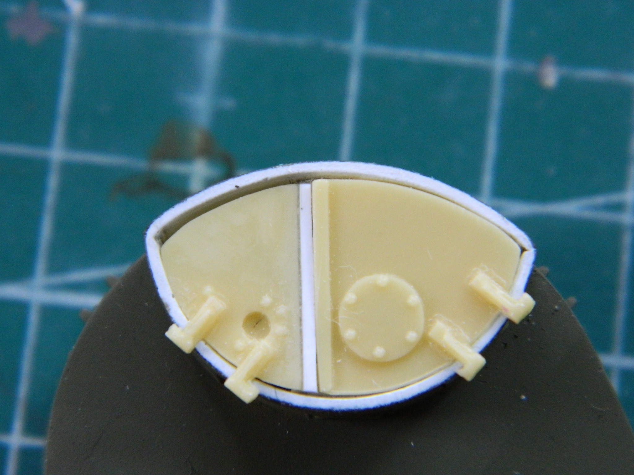
I added the bow gunner’s .30 caliber (7.62mm) to the front hull. And as it turns out, all the fiddling I did to get the belted ammo fitted and painted was largely a waste of time. It can’t be seen with the turret in place. And more fit problems showed up. Where the front instrument panel would fit isn’t close to where it’s supposed to go and the spare .30 caliber (7.62mm) ammo cans simply would not allow the gun (and therefore the whole damned front sodding HULL) to fit. It was easier to take the spare ammo cans out:
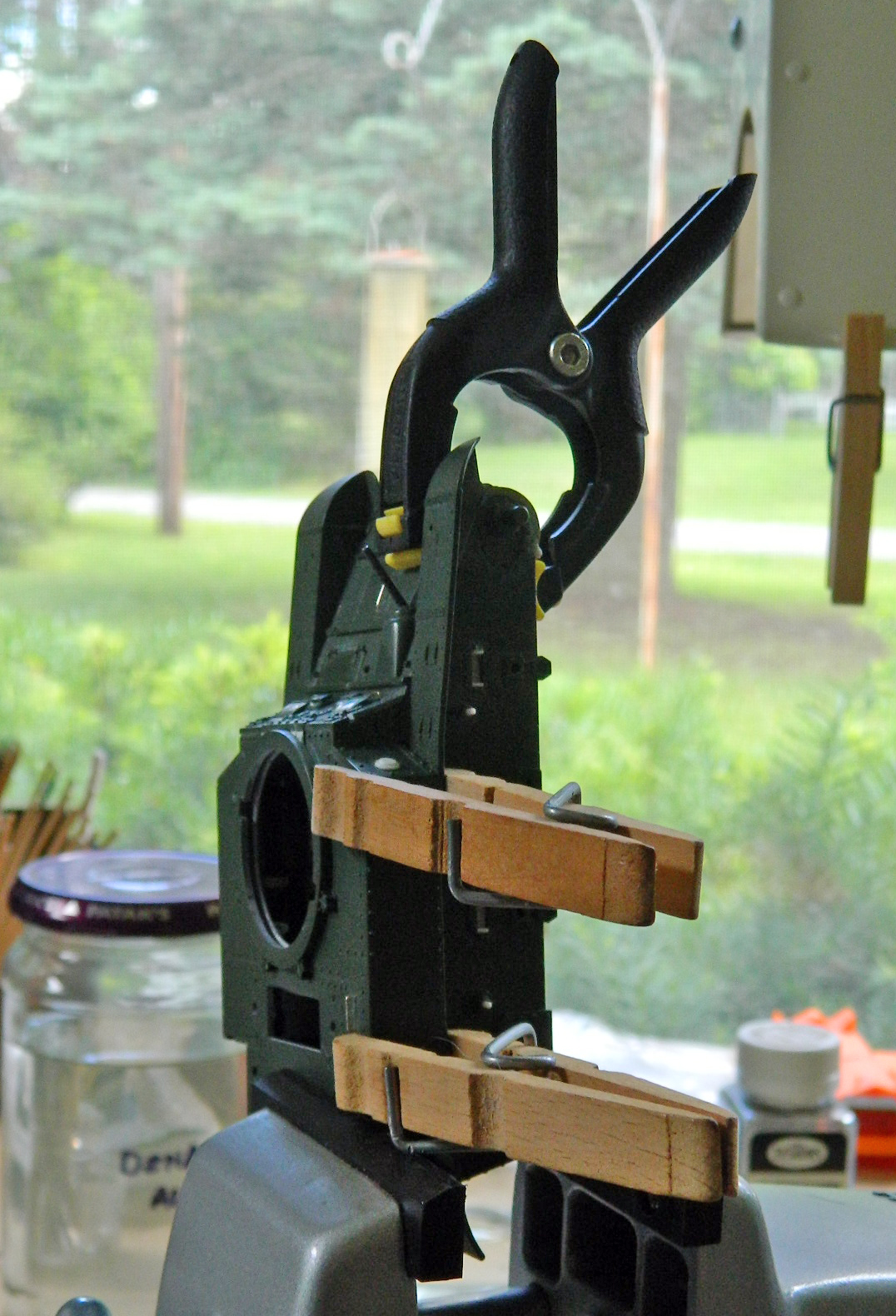
Okay. So that you understand why what happened next did happen, a bit of personal history…
I had spinal fusion surgery (L4-L5 and L5-S1, if that matters to you). It went about 50% correctly, meaning that it went about 50% incorrectly. In short, a nerve in my back is impinged, probably by scar tissue. Why this matters is because like a lousy wiring job, sometimes it shorts out. Sometimes that’s just a WHAM, a flash of white light, and it’s over, and sometimes I can be in bed for days. That said…
After gluing the upper hull to the lower and taking the above photo, I laid in the white acrylic putty to fill gaps in the sponson bottoms. As I was prepping to sand the putty, I noticed that previous sanding sessions had gotten putty dust all over the bench. Before adding more dust to the dust I already had, I figured I’d clean up a bit. I took the cordless vacuum, which weighs 2 lbs. and 15.5 oz. (1.345kg) and started vacuuming up the
WHAM
When the white light cleared, the cordless vacuum was on the cutting pad where the tank had been. The tank? I found it on the floor about five feet (1.524m) from where last I’d seen it:
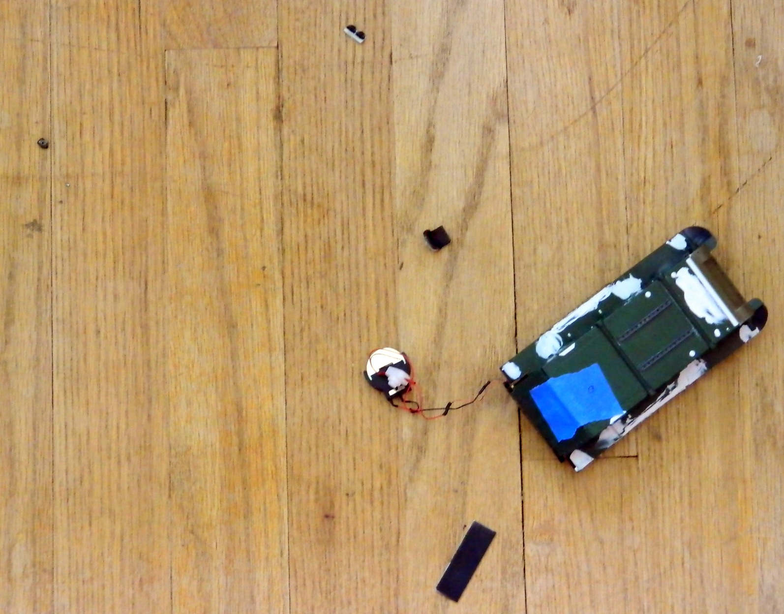
Yes. There are pieces lying on the floor next to it…pieces that, when last seen, I thought were attached. Then I picked the parts up and put them on the (now GODDAMNED CLEAN) bench.
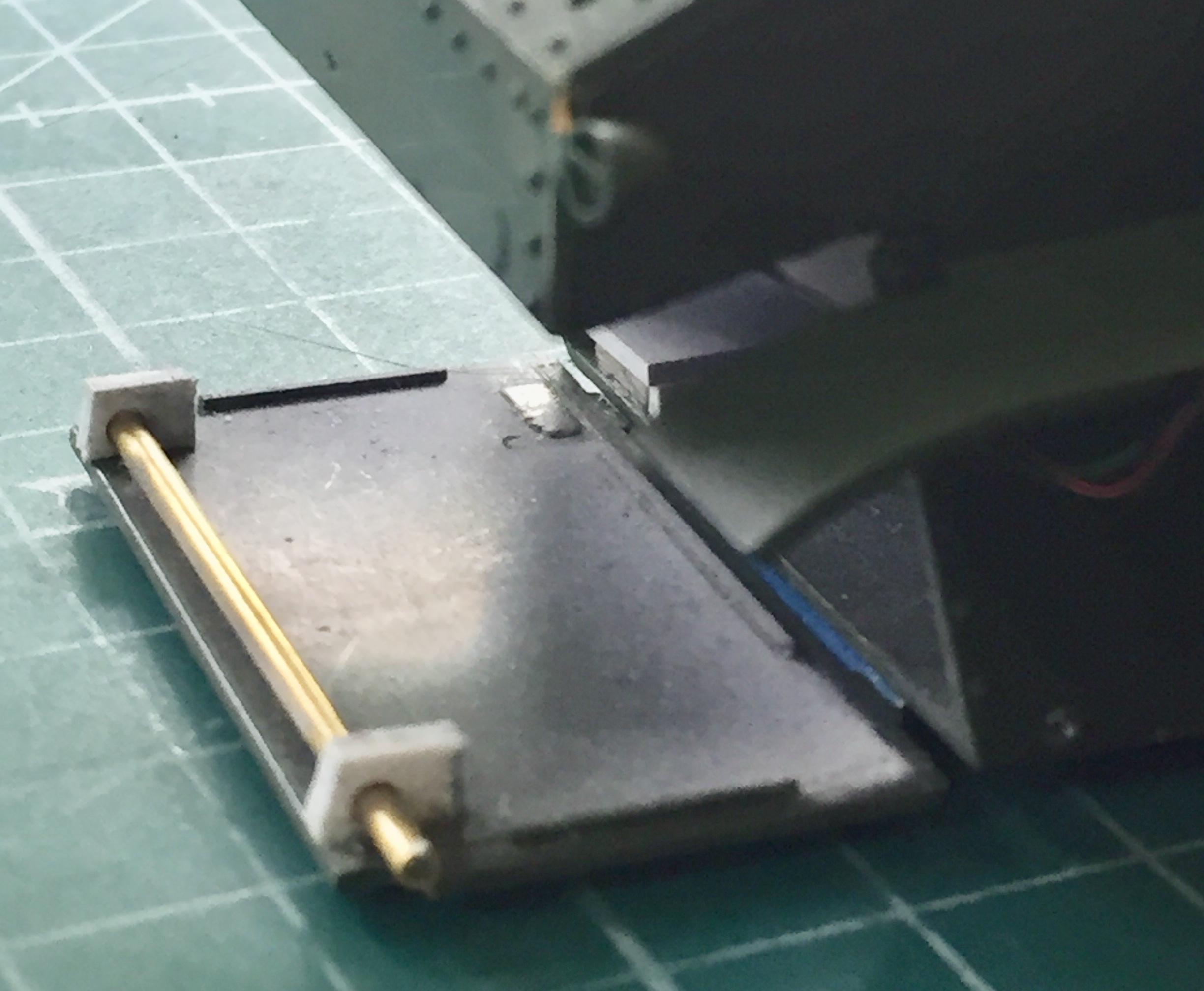
My cleverly hinged rear plate now sported a broken hinge:
The interior had been rearranged:

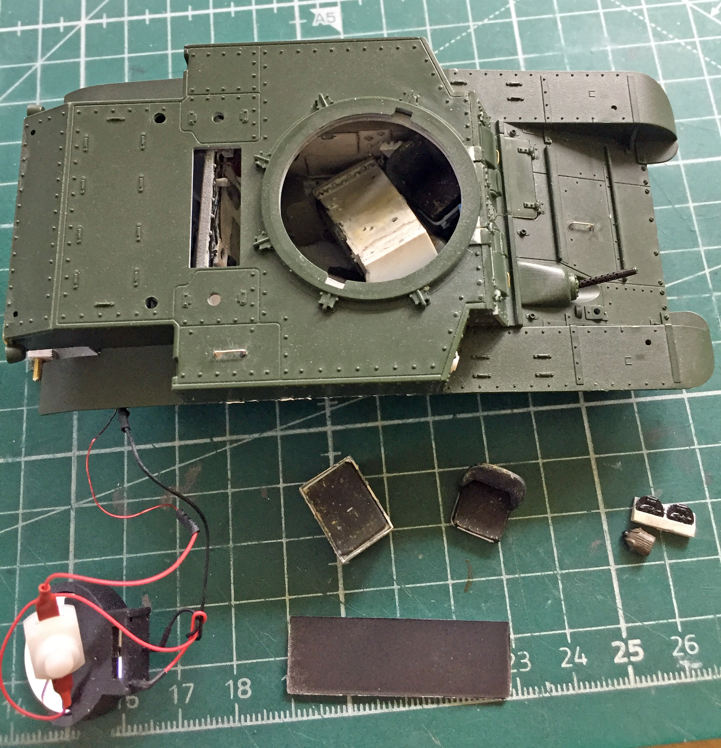

And these were the parts completely dislodged:
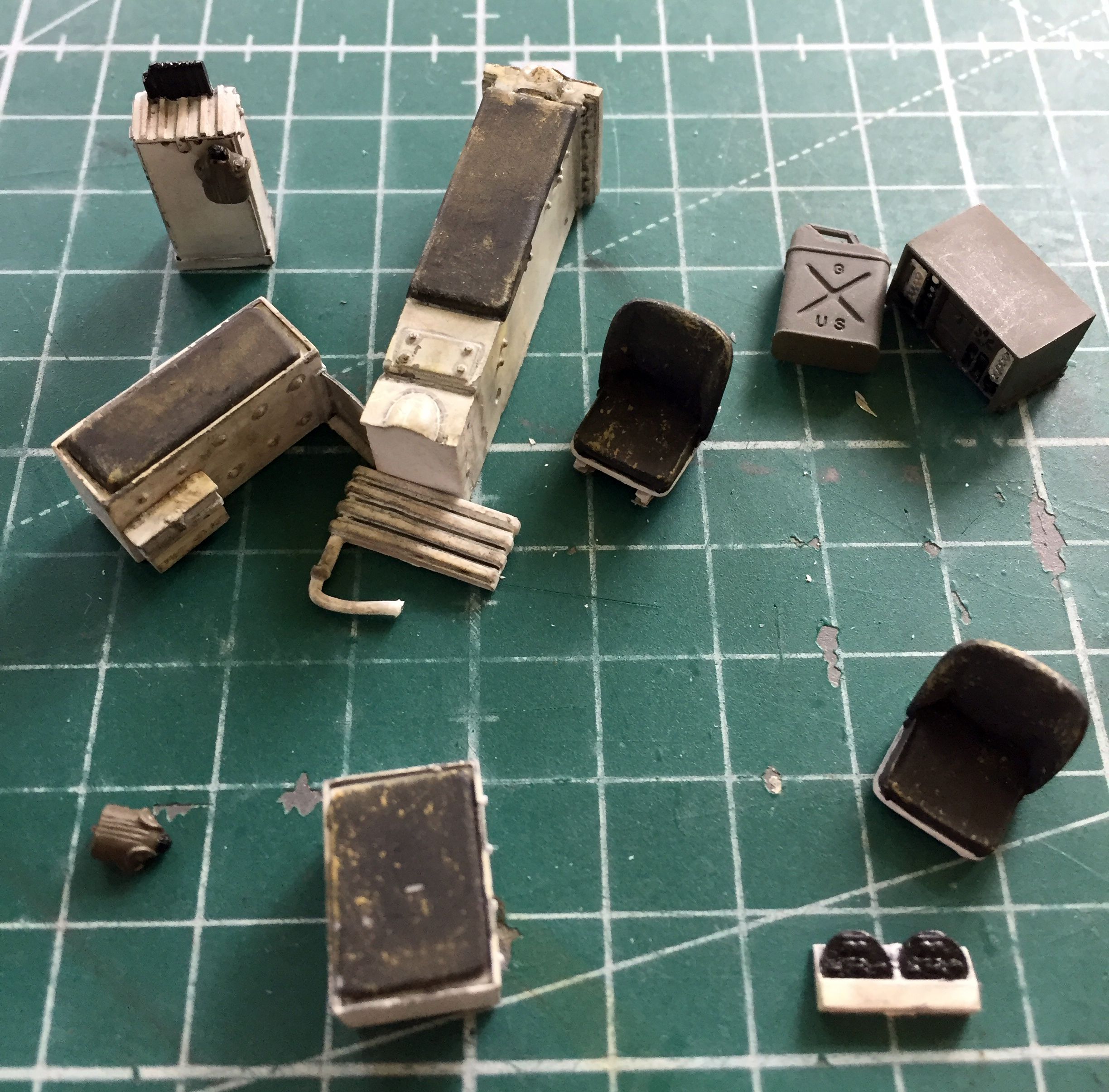
I dread having to take something apart after I’ve glued it together; I am NOT stingy with glue. For all these parts to have come loose, I’m surprised there was no damage to the plastic of the hull. Only one sponson had pulled free from where I glued it. However, in order to put back INside all the stuff I found OUTside, I was going to have to complete the job of removing the upper hull from the lower.
And I did. I felt like I was trying to defuse a bomb while blindfolded during the process, but before I went to bed that day, I’d recovered about 90% of what needed to be fixed:
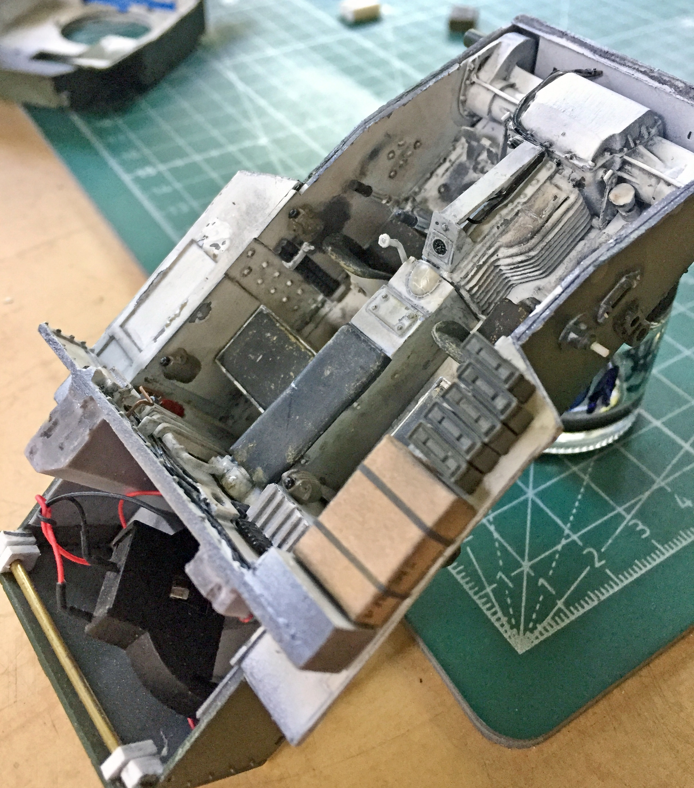
WHEW.
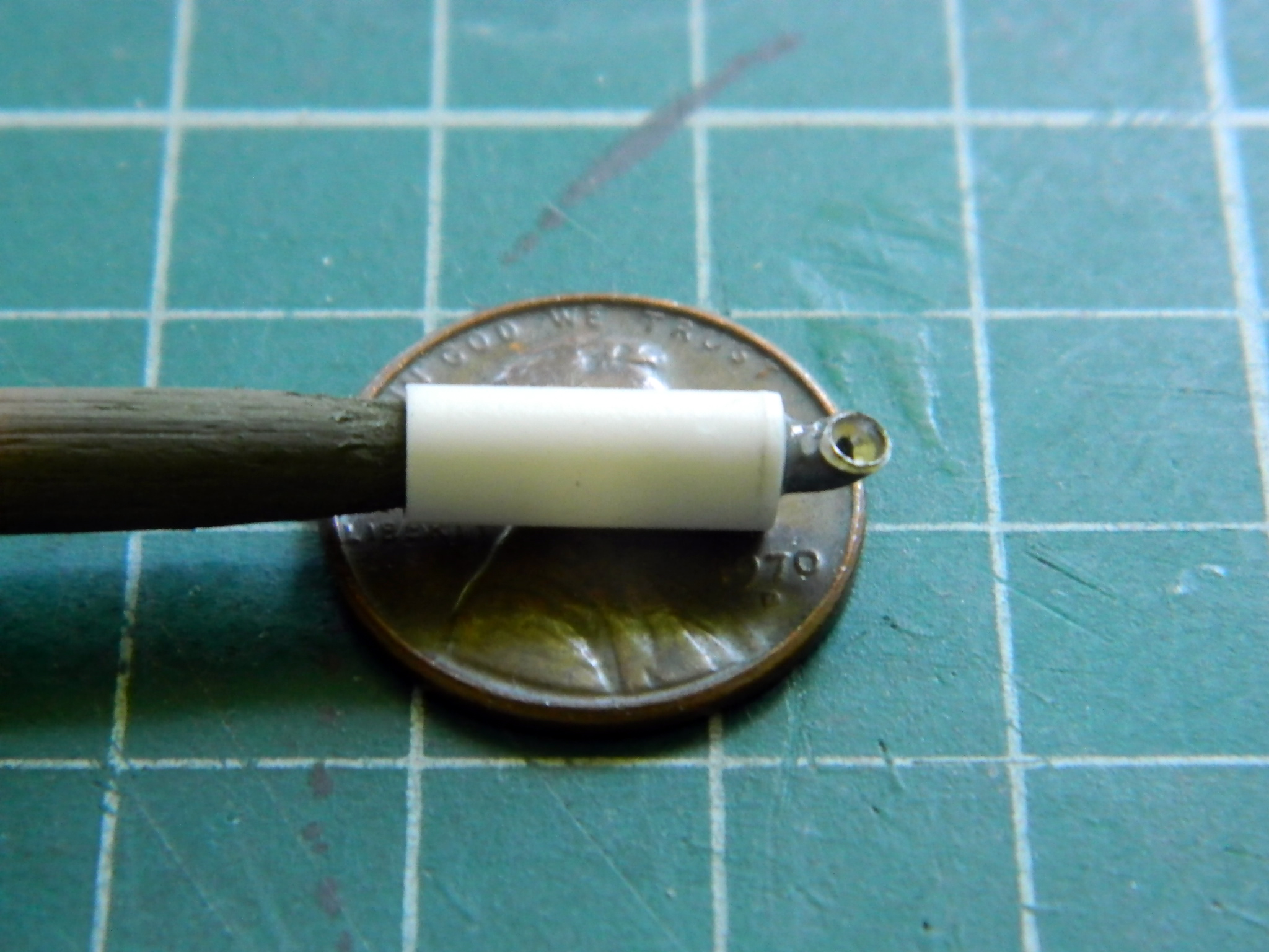
Moving right along, I made the mufflers and exhausts that live under the rear overhang of the upper hull. I used 1/4″ (6.35mm) styrene tube, capped it with .015″ (.381mm) scrap, and .093 (2.36mm) solder with drilled out ends:
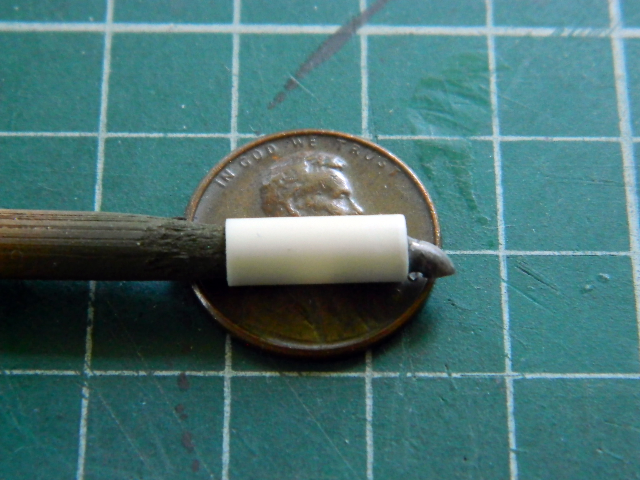
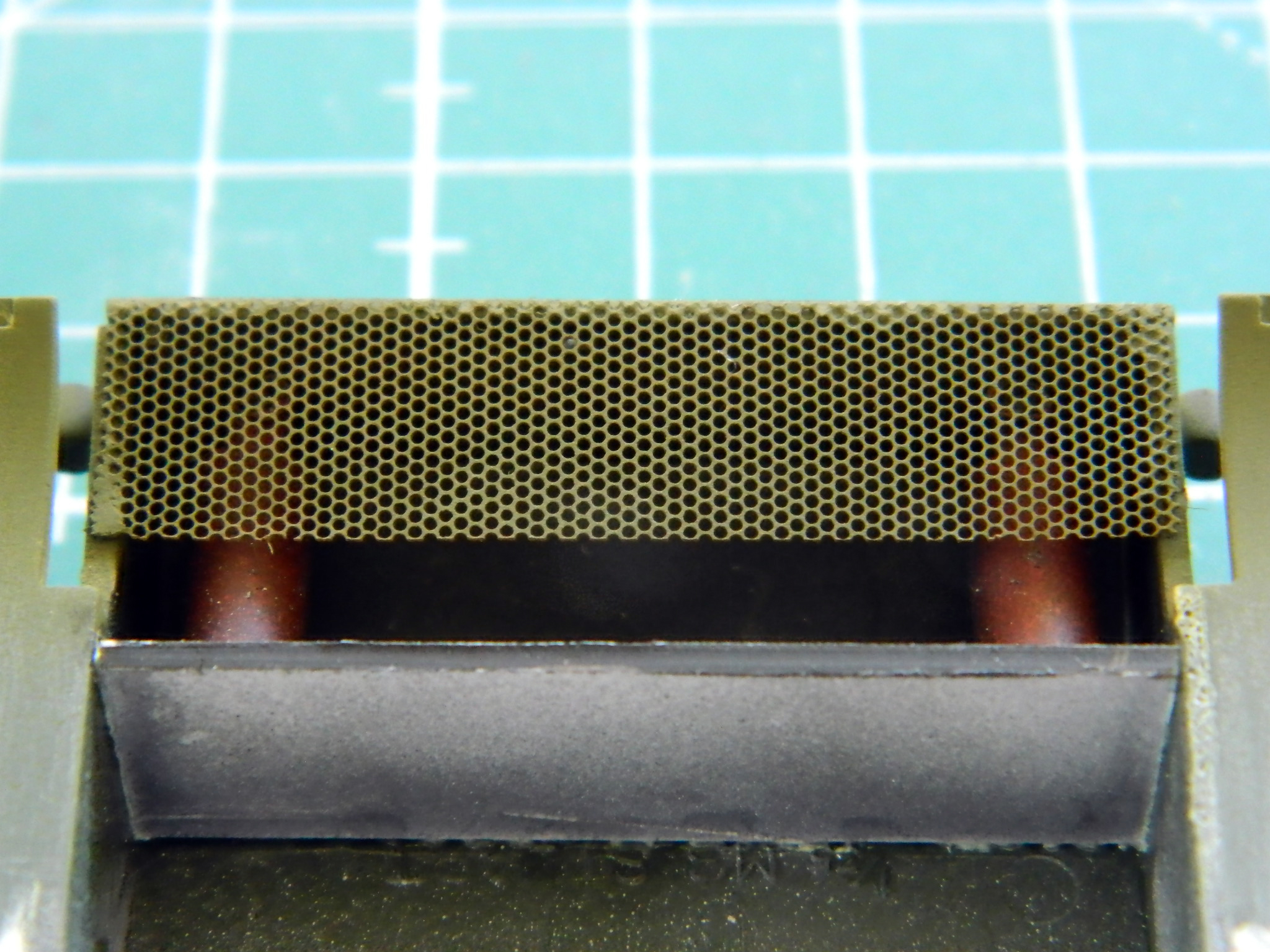
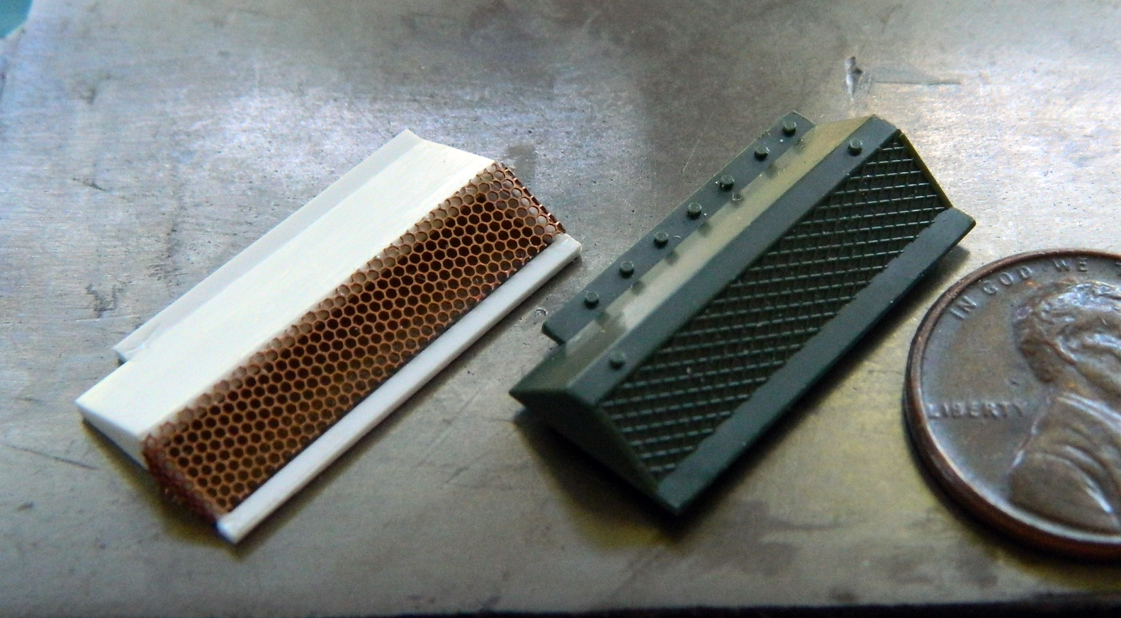
After painting them rusty brown, they were glued in place and PE mesh cut and glued in place and painted with Tamiya’s XF-62 Olive Drab:
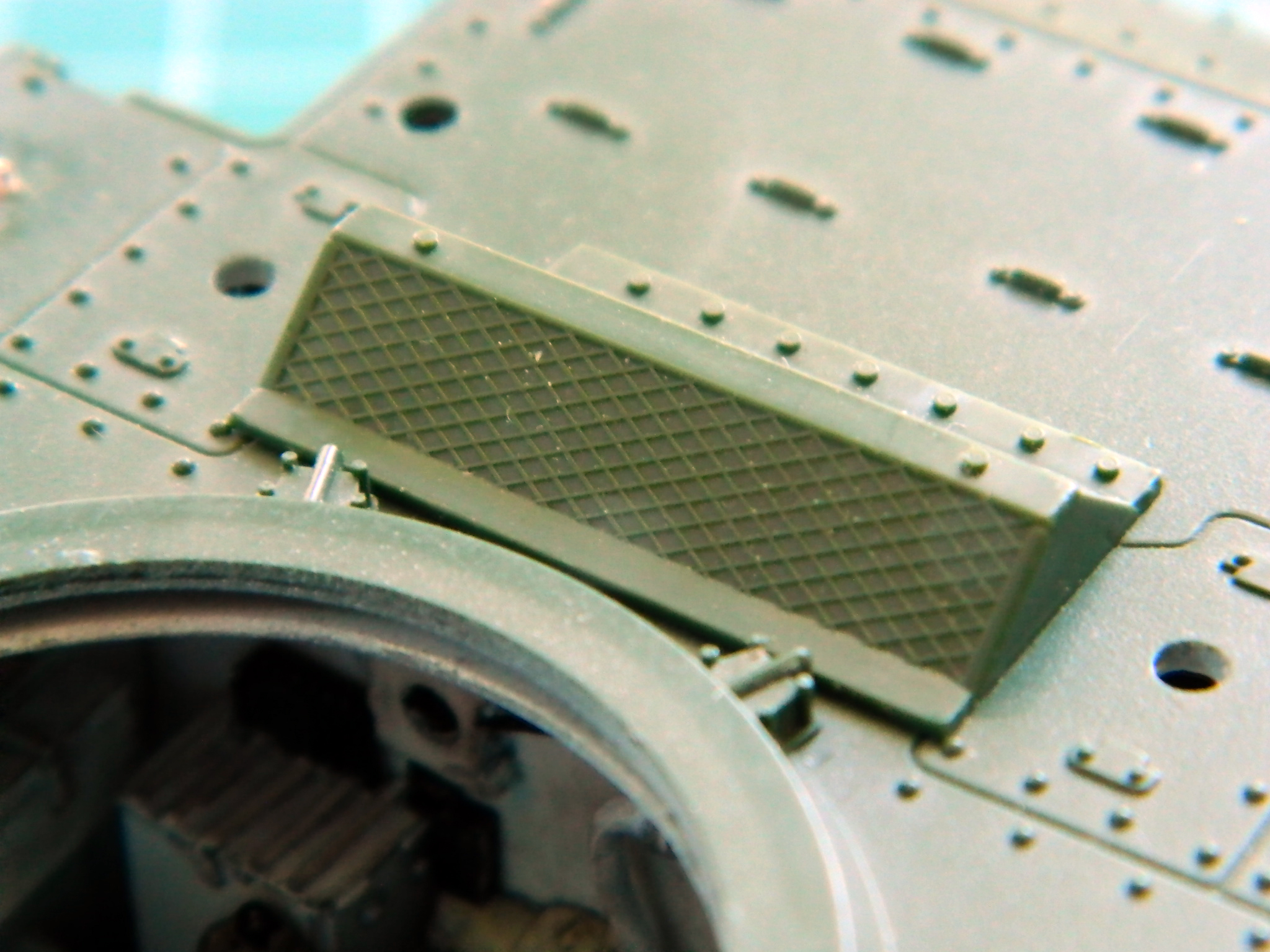
In checking references, the air intake over the engine was too tall, so I scratch built a correctly sized one:
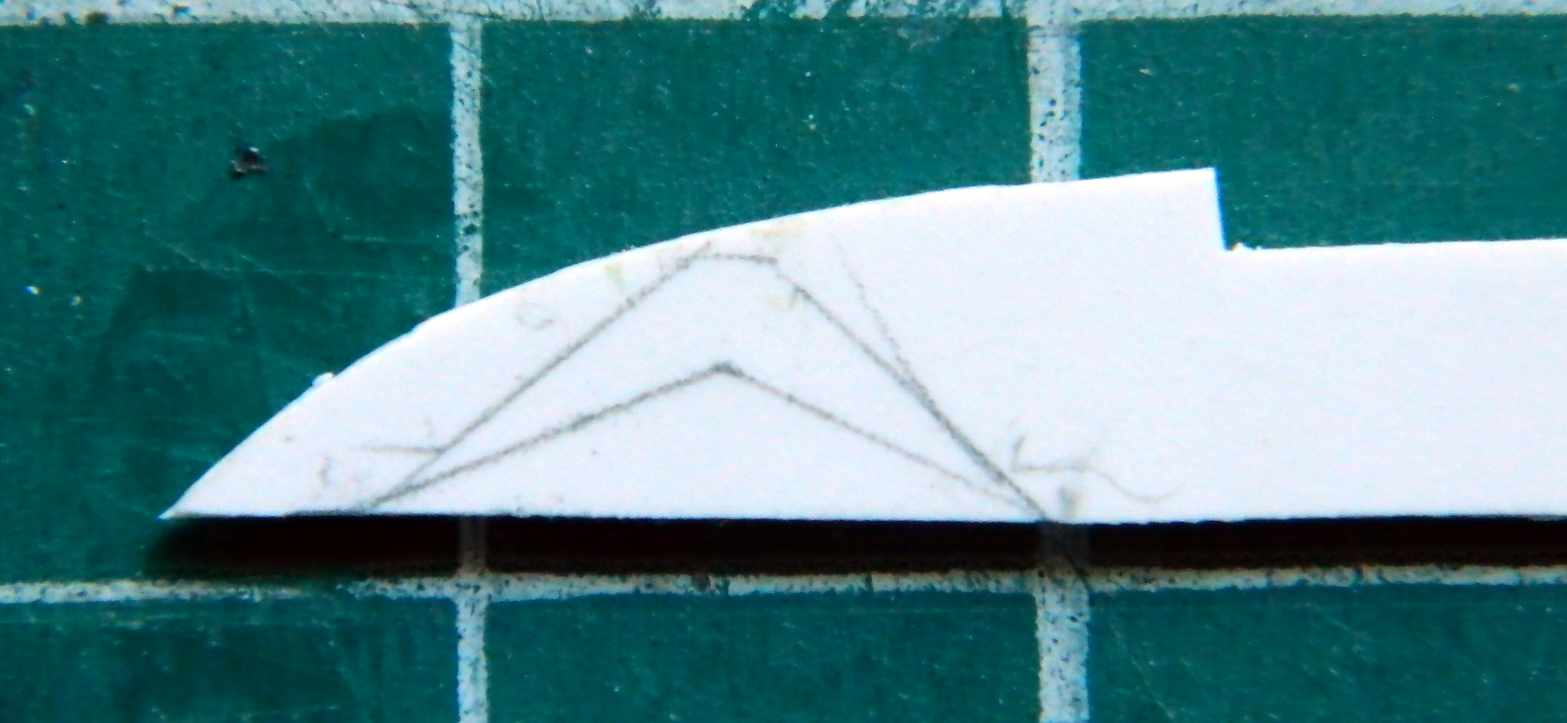
The end pieces were cut from .020″ (.508mm) scrap; the kit part was traced onto the plastic, which gave me the reference I needed to draw the replacements:
Adding more PE mesh, I ended up with something more accurately sized:


Did I mention, “whew”?
Back before Facebook disgusted me enough to leave it, I had been a member of a couple of modeler’s forums. There were the standard questions (“What is the best kit for the Super Belchfire GT in 1/32 scale?”), and then there was the question about airbrushes. It was a good question. Are they necessary? What’s the difference between a single-action and a double-action airbrush? Is one type of airbrush better than the other? Inadvertently, I started a flame war when I said I thought that for my purposes (emphasis added here), single-action was good enough.
So, IS an airbrush necessary for a good paint job? No, not really. To my way of thinking, having an airbrush makes a good paint job easier to achieve.
What’s the difference between a single-action and a double-action airbrush? In the former, pressing the button on top allows the air from the compressor to siphon the paint out of the cup/jar, into the body of the airbrush to mix, and then pushes it out of the airbrush, across the few inches from the surface, and down where the modeler wants it. To adjust the width of the spray pattern, there’s a knob at the back of it that will move the metering needle in and out of the aperture and thus control the width of that spray pattern. It’s a much simpler machine and, again to my way of thinking, is why I like the single-action better. I don’t need to vary the spray pattern very often…and when I do, adjusting the knob at the rear of the airbrush isn’t a hassle. But I DO need to clean the airbrush very often…so a simpler machine makes sense to me.
The double-action airbrush is a bit more complicated. The button on top still releases the compressed air to flow through the airbrush. However, it does something else, too. Pulling back on the button while pressing it down will make the spray pattern wider. One can adjust the width of the pattern on the fly. That’s a great feature to have if it’s needed…I just don’t happen to need it. So a more complicated and harder to clean machine doesn’t make sense to me.
Either tool takes time and practice to get good with. The double-action airbrush tends to take longer to figure out than the single-action airbrush. The double-action airbrush tends to be more expensive than the single-action airbrush, too.
And once the model is done, all painted, decaled, weathered, and on display, can a person tell just by looking at it which type of airbrush painted it? I certainly cannot!
Yes…I’ve simplified things here. I didn’t talk about internal mix and external mix airbrushes, or pretty much anything else about them other than which type of action they are.
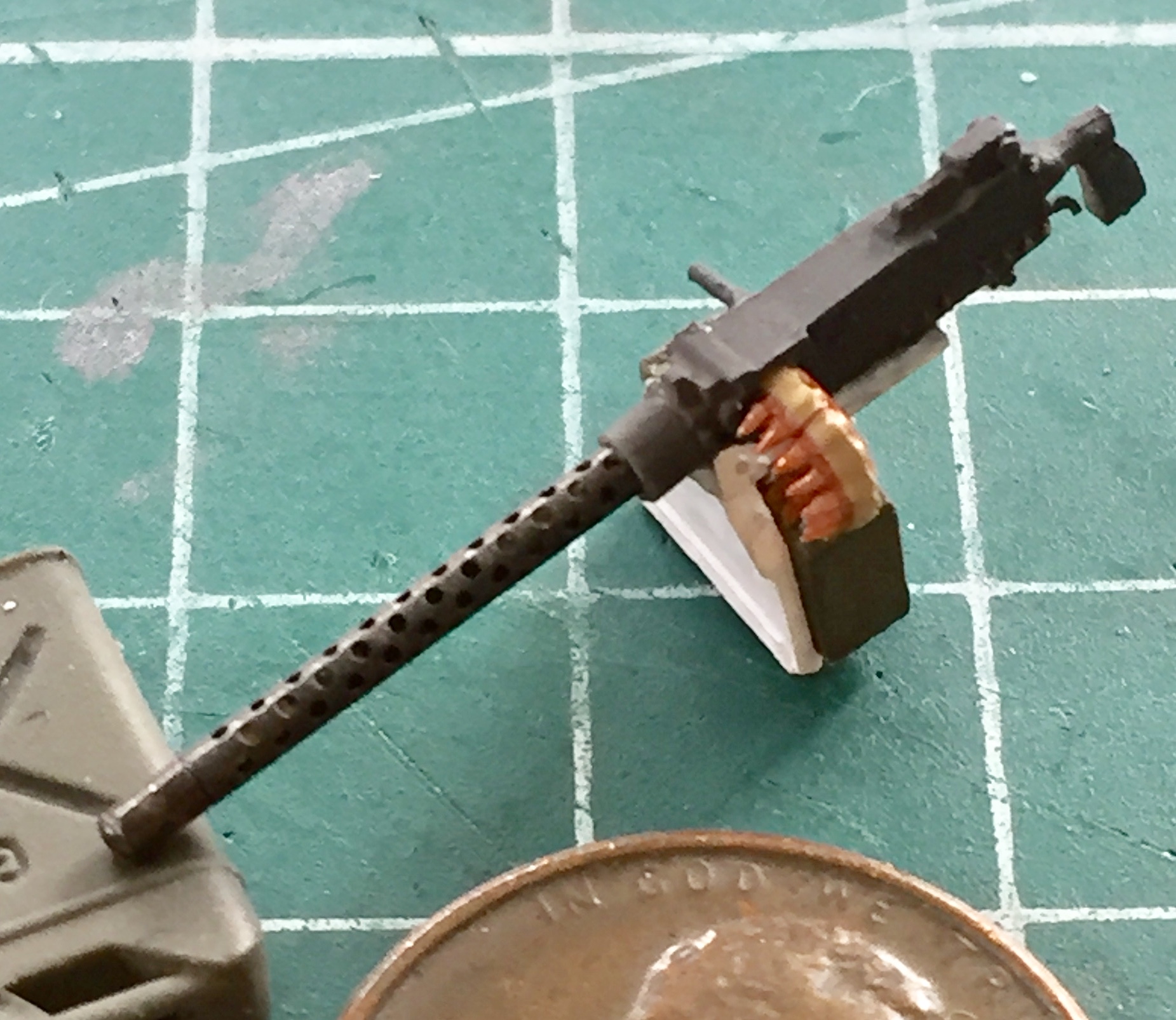
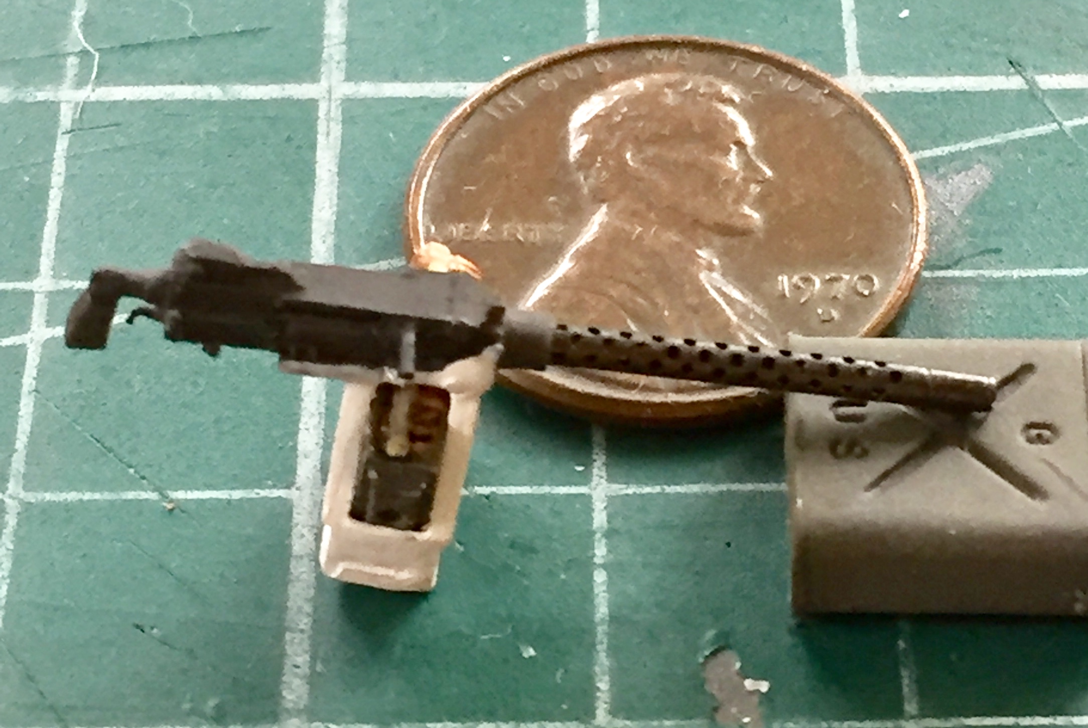
I discovered Master’s machine gun barrels (their Ground Master Series) when I did the M4A3. The .30 caliber (7.62mm) barrels are amazing pieces of work. The cooling shroud is a separate piece from the barrel. The last time I used Master’s barrels, I used superglue to hold the parts in place. This time I used solder, only soldering the parts where they attach to the machine guns’ receivers:

As fine as these parts are, I discovered the last time I used them that painting them doesn’t really show them very well. Yes, they’re better than the kit or resin barrels, but do not show as well once painted. While running around the ‘Net doing things (yes…porn), I encountered someone else who thought the same way about painting these beauties. His solution was to use a solution (ain’t I clever?) that ages brass! As with most solutions, there are problems and limitations with it, but the end result makes dealing with those problems and limitations SO worth it.
The aging compound was purchased from a firm that makes chemicals to treat firearms:

I made a little cup from aluminum foil and immersed the soldered parts in the solution and stirred it a bit. Then I discovered (because the solution leaked all over the bench) that this stuff dissolves aluminum:

The solution starts out relatively clear and as the brass takes on its color, the solution turns blue. The first attempt resulted in the chemicals not really getting inside the cooling jacket to color the barrel. The parts also came out looking rather sooty:
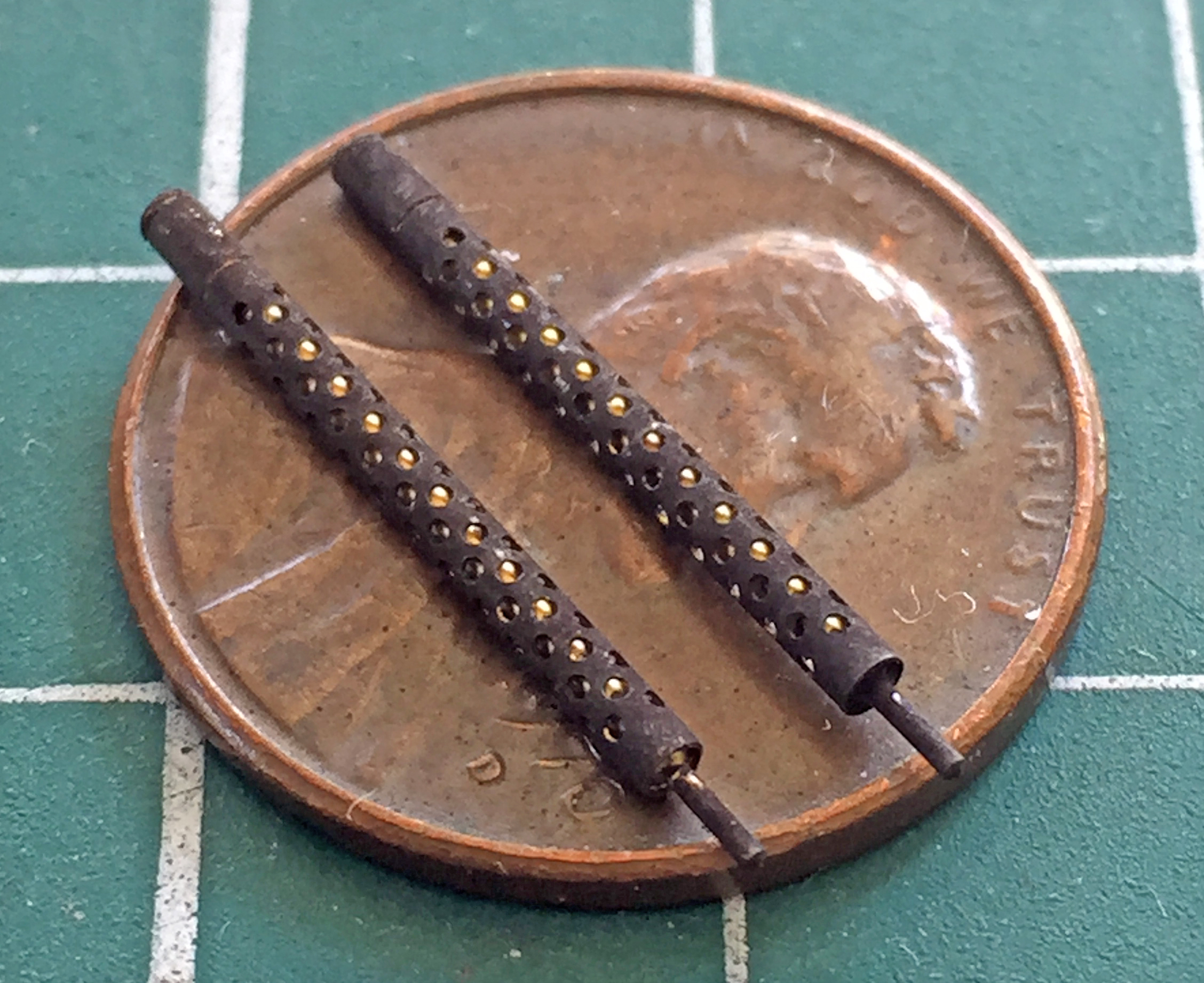
For the next immersion, I used an empty paint bottle (because, well, can you imagine the mess if it still had paint in it?) to hold the solution. The barrels were immersed again and if they had snot, I would have shaken it completely off of them. The result was better, though not perfect. I tried a few times and have come to realize that the next time I use the blackening solution, I’ll do so before assembly (and go back to superglue because I’m thinking that much heat to a treated surface will undo all the coloration). With the coating more comprehensive, I buffed off the sooty surface and really liked the results:

Another feature I wanted to add to this build is a LED inside the fighting compartment. I added that to the firewall and ran the wires into the area where the engine would go. The leads for the LED and battery/switch assembly were ample. They were ample enough to pretty much fill the damned space with just wires. So the wires were trimmed, soldered, and insulated:

Another of those things that had been hovering over my head was the question about how the battery and switch would be accessed. My initial thought was to cut open the inspection plate on the bottom of the hull under the engine compartment where these things were going to live (because that was the most complicated way to do it). Then I came out of my head and looked at what was sitting on the bench in front of me. The entire rear end of the lower hull is one piece. Hmmm… If I use that hull section as my access door, I’m not going to make work for myself but instead would use a feature of the kit to my purposes. Okay, so how do I make the entire back of the lower hull open? Well…I could make that entire back hinged. I already had the magnets I’d planned on using to keep the access door closed (wherever I put it), so keeping the access panel closed was already considered. Okay, then I guess I should make some sort of hinge.
I used a piece of 1/16″ (1.58mm) copper tubing as my hinge pin. .080″ (2.032mm) styrene scraps were used as the tubing sockets and were drilled to accept the ends of the tubing and glued to the sides of the hull. I drilled out .060″ (1.524mm) styrene scraps, slid them over the tubing, and then glued them to the rear plate:
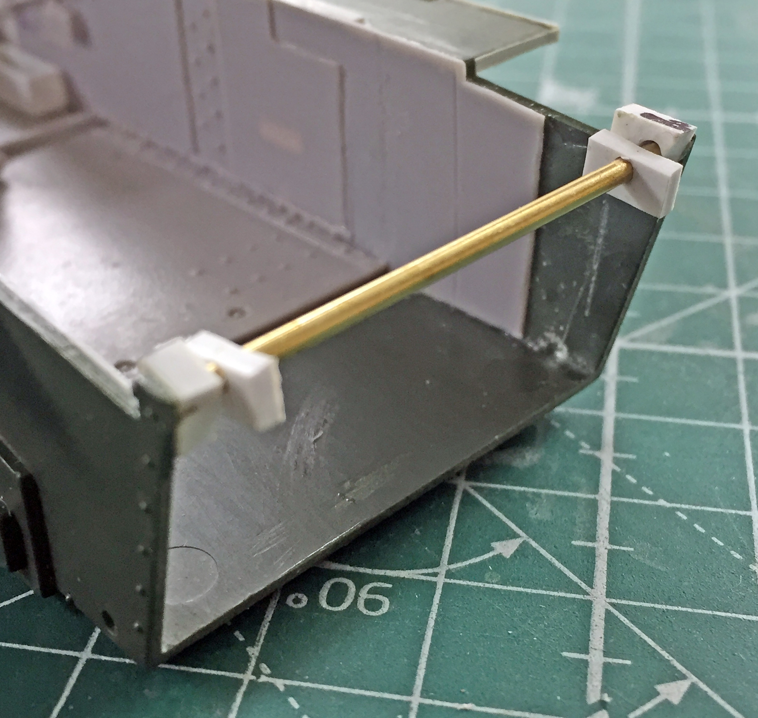

It closed snugly without giving away the fact that it was hinged and could open. However, the plastic blocks needed to have the tops of them radiused so that the door would open far enough to allow access so that the switch could be operated battery could be changed out.
This opening was how far it initially opened, which isn’t close to enough:

After cutting, scraping, and filing (and the requisite cursing and foul invective), this degree of opening will work:
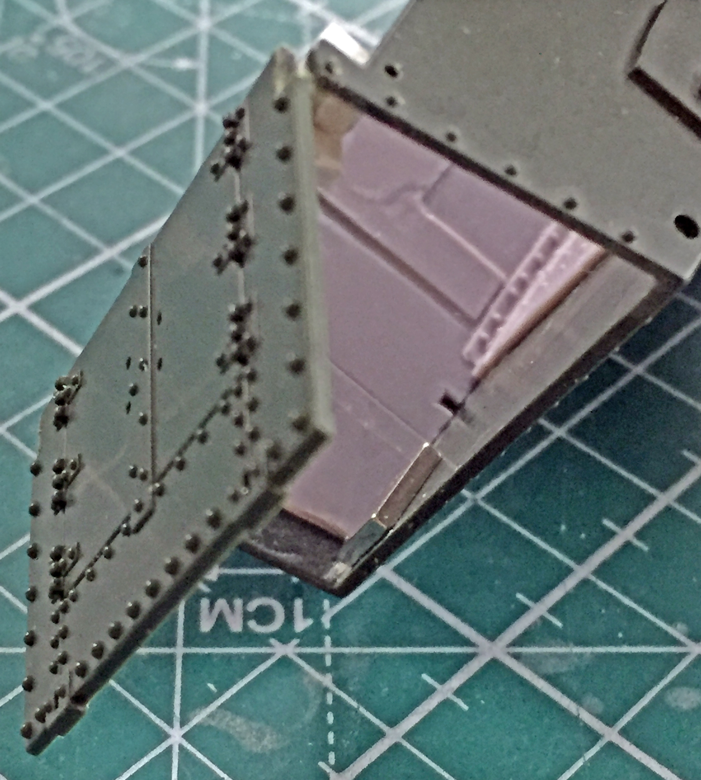
Now the magnet had to be installed. These are rare earth magnets and they’re damned powerful for their size. However, magnetism’s effect decreases with distance. After diddling around with it, I decided that a gap of .015″ (.381mm) between the magnet and the small piece of sheet metal I’d glued to the rear hull plate would hold it closed without excessive force (because this IS plastic…) needed to open it:

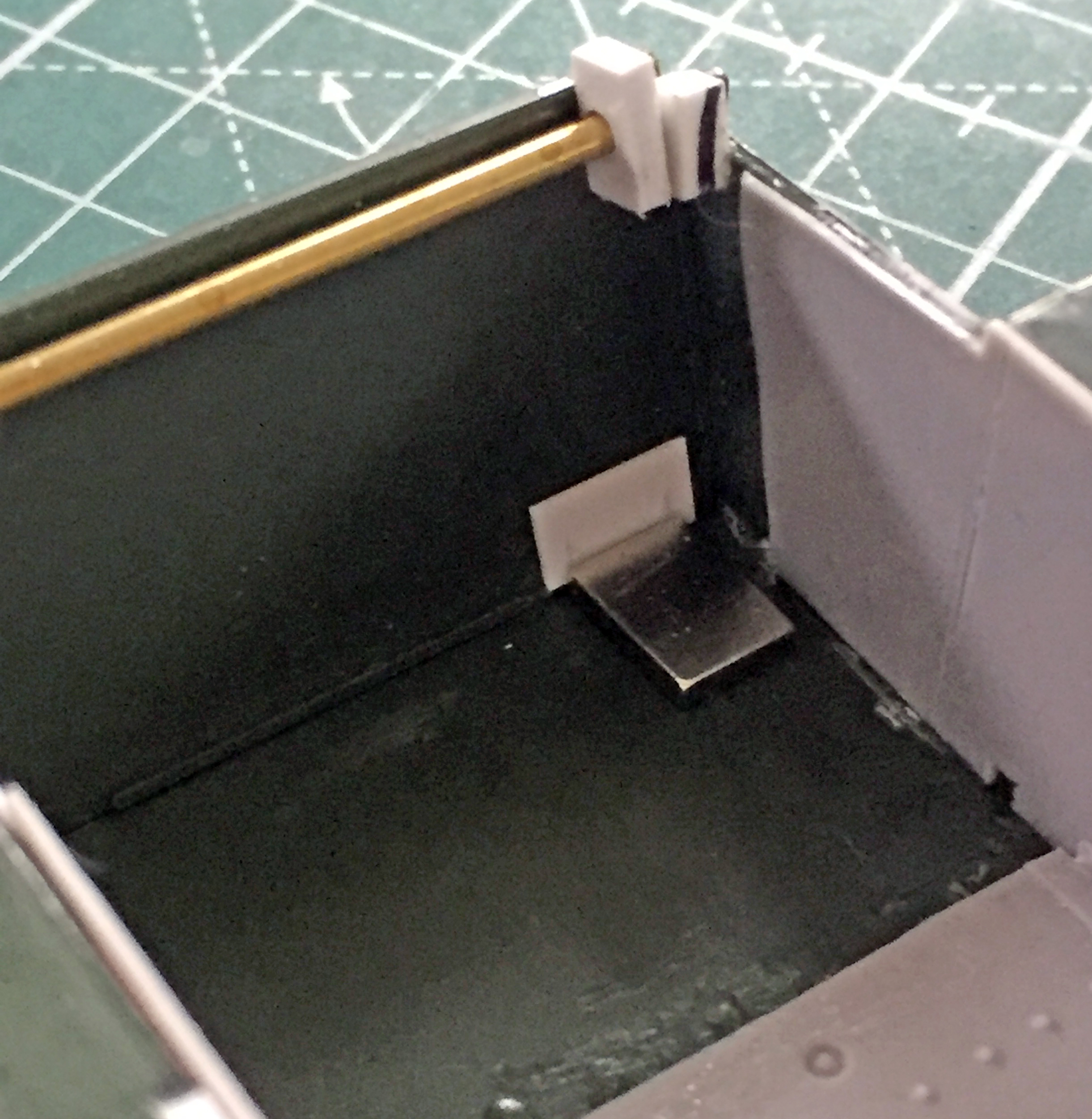
I was also unsure how the magnet and the battery would react with each other in a confined (or even wide open, for that matter) space. I used .060″ (1.524mm) styrene to box the magnet in and keep it from contacting the steel battery:


Then it was time to start getting the interior parts ready for paint. I replaced the 37mm gun barrel with an RB aluminum barrel. That process started with the removal of the resin barrel rear section and drilling the receiver to socket the aluminum barrel’s pin securely and then create the pivots for the trunnions:


I’ve had people ask me if all the hassle needed to replace gun barrels is worth it. Yeah…I’d say it is:
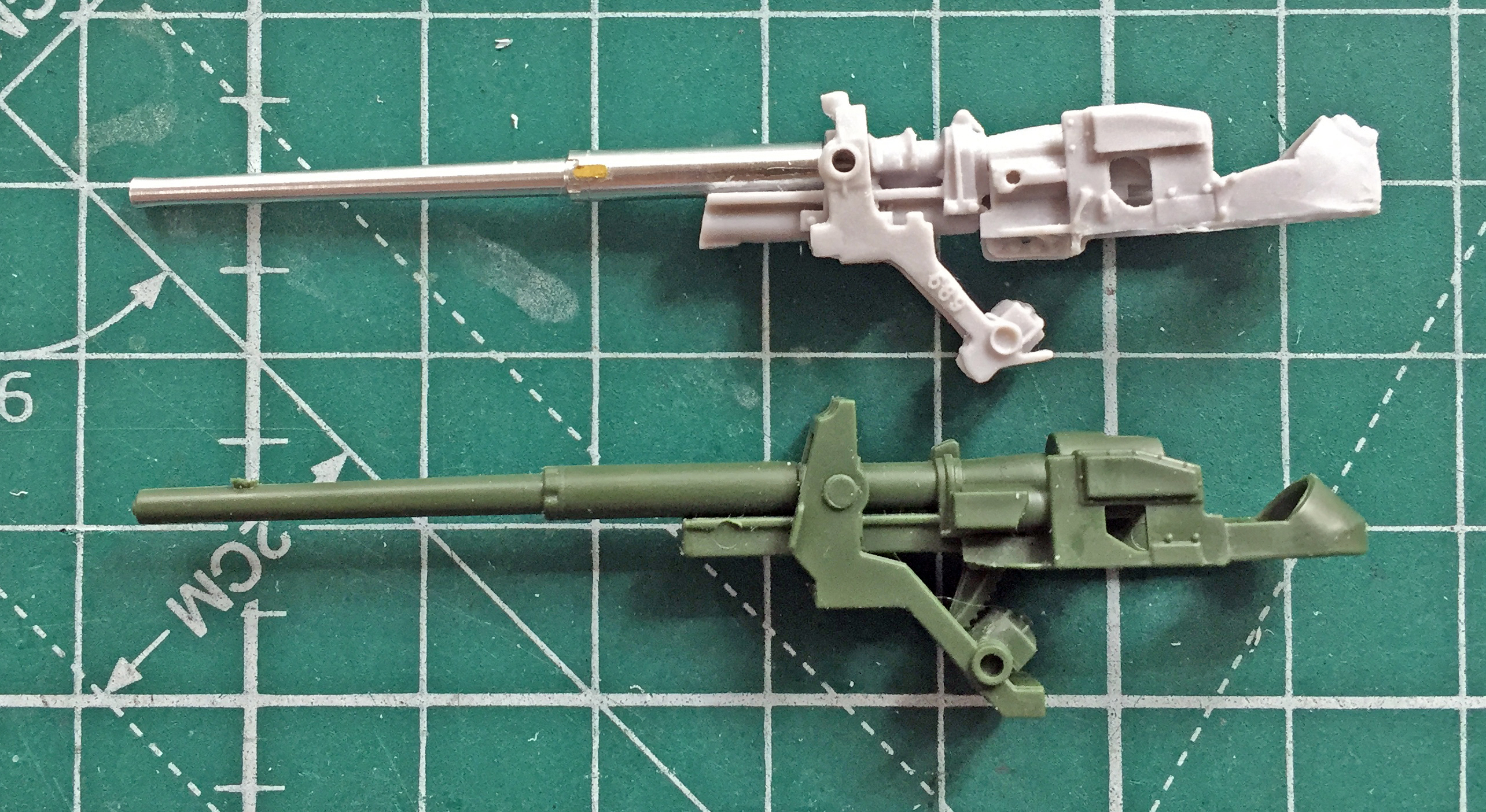
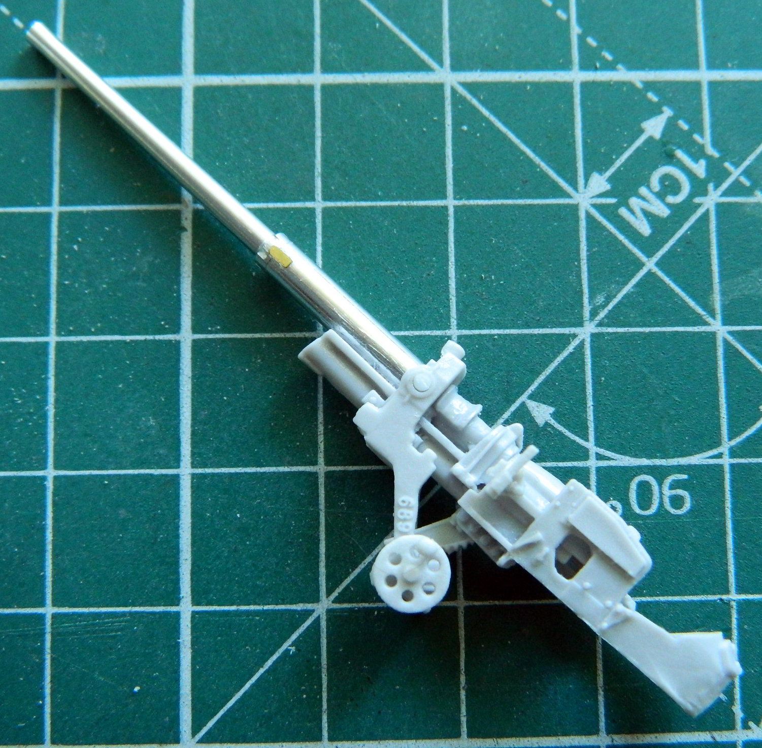
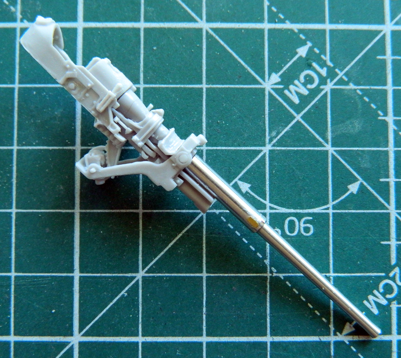

I’m using both the suspension and tracks from AFV. One would suppose that having tracks for an M3 Stuart and a suspension for an M3 Stuart from the same manufacturer would mean that the parts fit. Uhm…no. They do not. Note how the further the track wraps around the sprocket, the less the track fits…until it doesn’t fit at all:
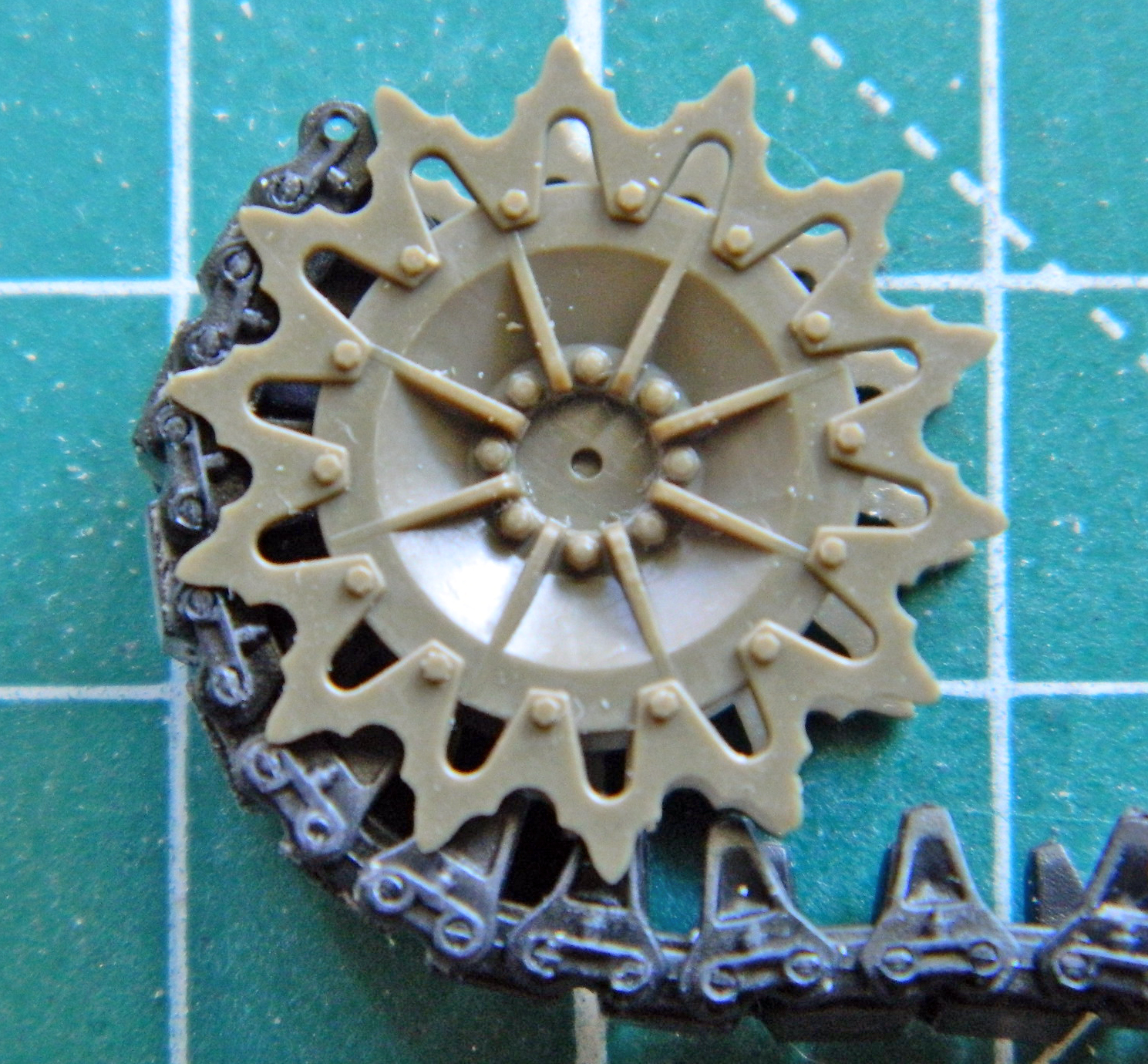
Well, THAT makes no sodding sense! And the AFV drive sprocket is more accurate than the one Academy provided (on the left):

But if it doesn’t fit, then its seeming accuracy is an illusion. So even though the kit part doesn’t appear to be as accurate as the AFV part, if it doesn’t fit, then it’s not accurate at all. The Academy sprocket fits fine:

Go figya…
Since I’ve had my bubble burst regarding fit, now wouldn’t be a bad time to check fit for the remainder of the suspension parts. Yes…there will be some fitting required. These are suspension parts for the bogies. The part on the upper right is the kit part. Note how much larger the block where the two different suspension parts are in contact. That’s how much wider the kit’s part is, which means there’s a larger socket where it’s supposed to mount to the hull:

There is also a pin on the bottom of the kit’s hull that has to be changed to a socket for the AFV suspension:
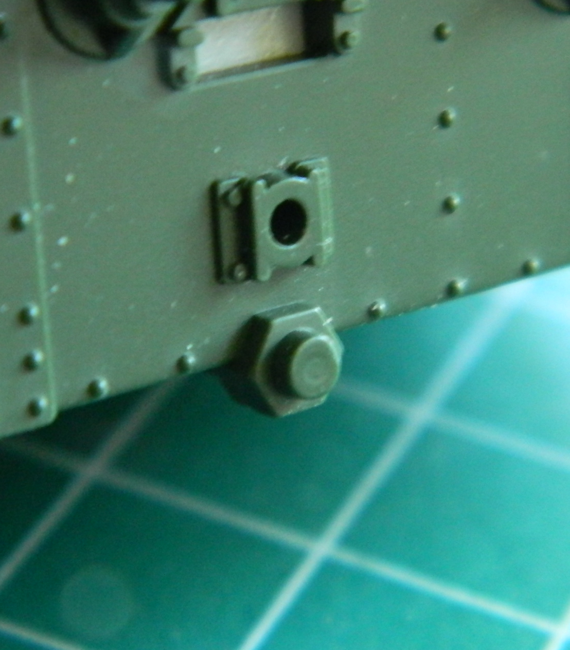
Okay, so I drilled out what needed to be drilled out:
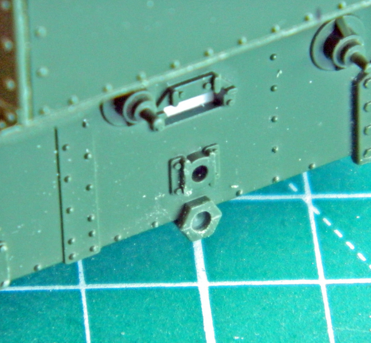
And I added .020″ (.508mm) styrene to both sides of the suspension mount (and I draw your attention to the mounts just inboard of the suspension mounts where a clamp slipped off and snapped off both mounting pins…which I will have to fix):
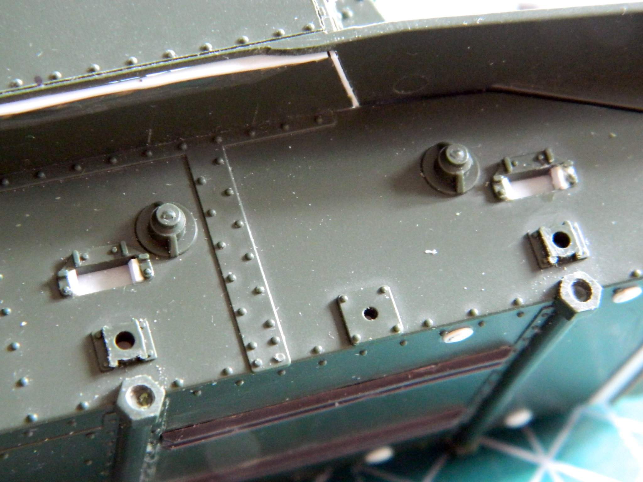
While getting parts prepped to paint, I dry-fitted the upper hull to the lower hull to see what I needed to do to make the switch/battery access work. The first thing I noticed is that I’m going to need a blocking plate under the upper hull so that there’s no chance of see-through happening:
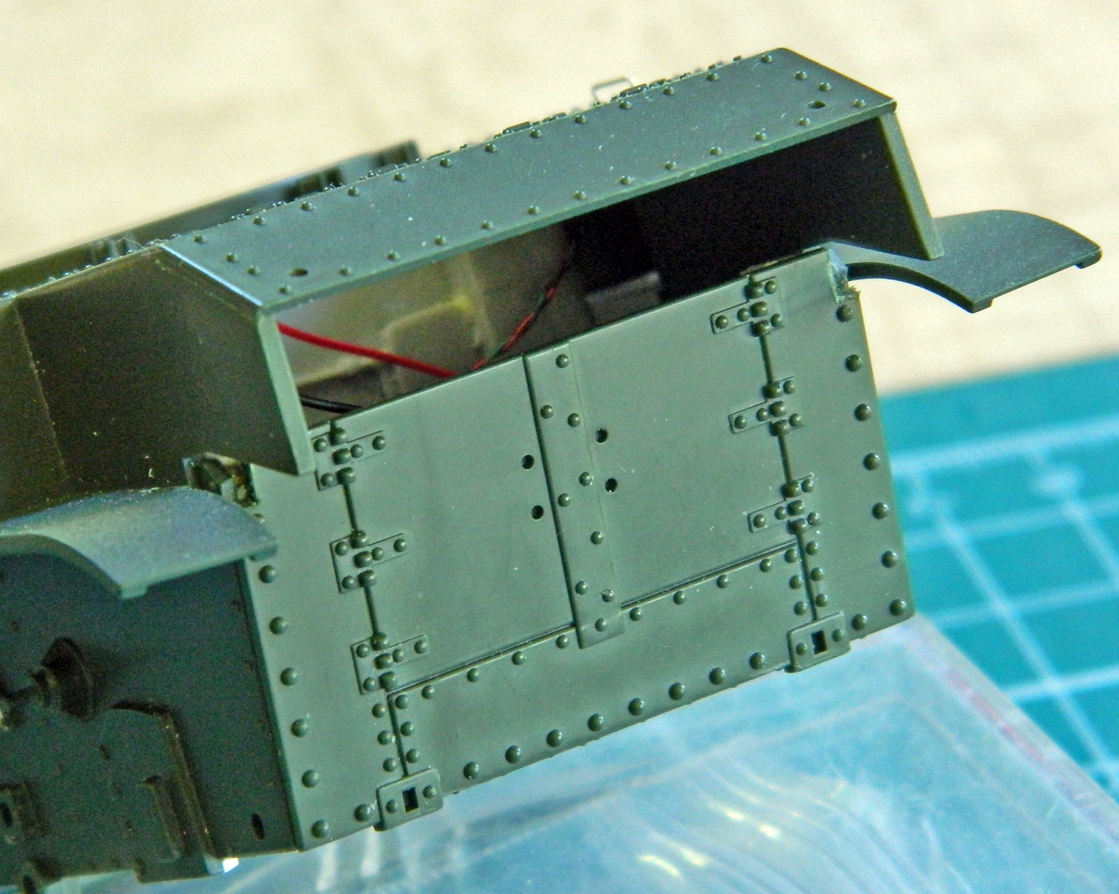
Then I checked (again) the ease of operating the access panel and the access to the things that need to be operated or eventually replaced:

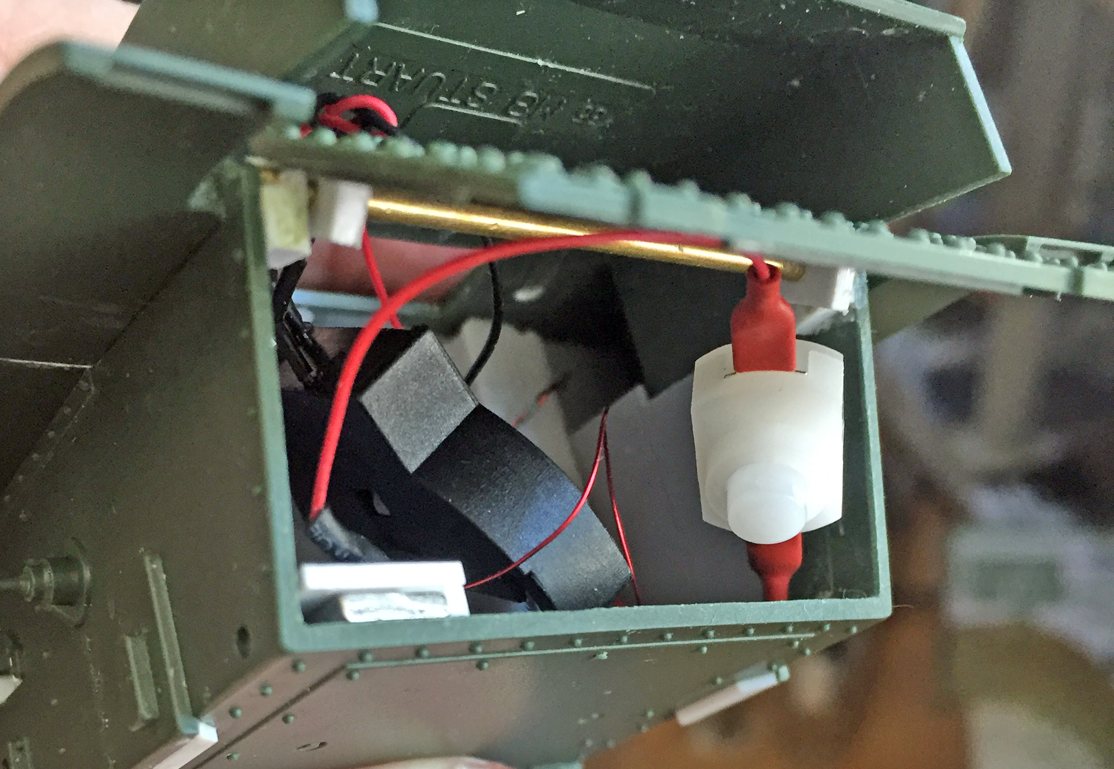
I also checked how well the electronics (such as they are) stow. I’m pleased with how this part all came out, particularly ease of access:
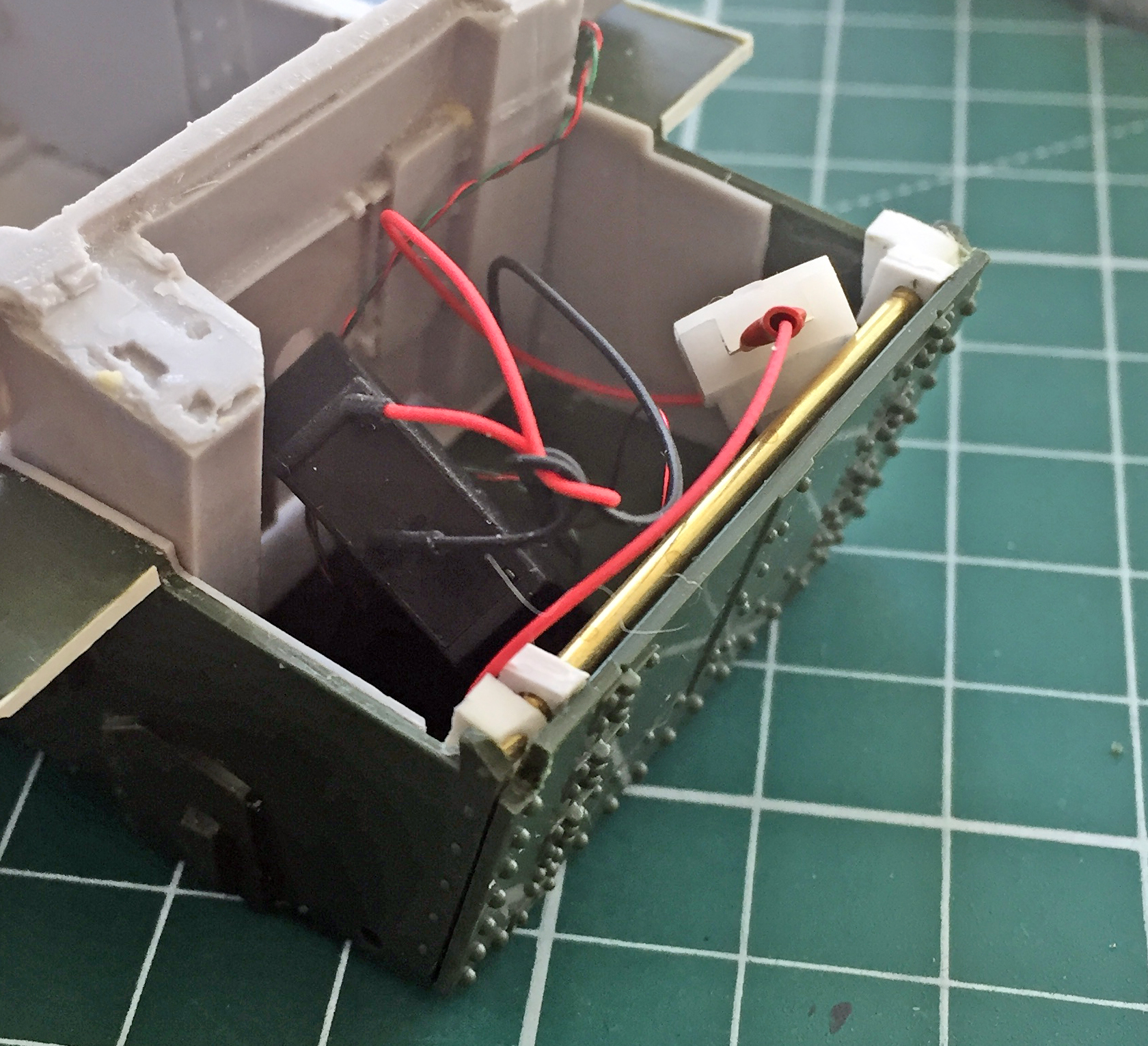
The driver’s lower hatch needed a little detailing. The top of it (to the right of the photo) is hinged so that it has the room to open and it also has a leather-covered pad (probably to keep the driver’s teeth inside his mouth). I scribed a line where the hinge should be and then used .010″ (.254mm) scrap and some stretched sprue to replicate the hinge (even though the hinged area has to be folded up to open the hatch, it’s always shown extended in my reference photos). I don’t know what the inner panel on the main body of the hatch is for, but I’ve seen it in references, so I used .010″ (.254mm) scrap to replicate it:

I filled the mounting holes (using sprue) for the plastic grab handles because, often even when using the plastic grab handles, the mounting holes tend to be too large. Replace the plastic handles with wire and those holes become WAY too large:
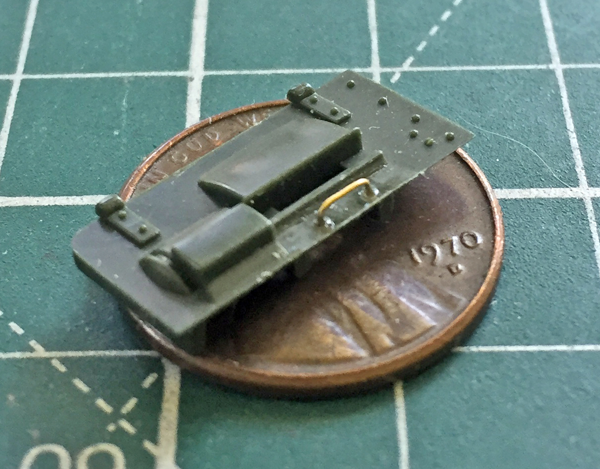
The transmission cover and battery cover were treated the same way:
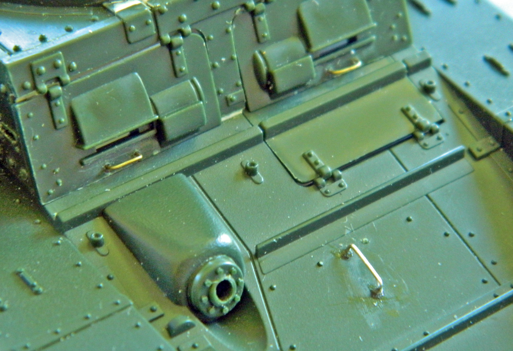

Seeing as I’m easily confused, I printed out a paint sheet to keep me from overlooking things (which of course I did anyway…):
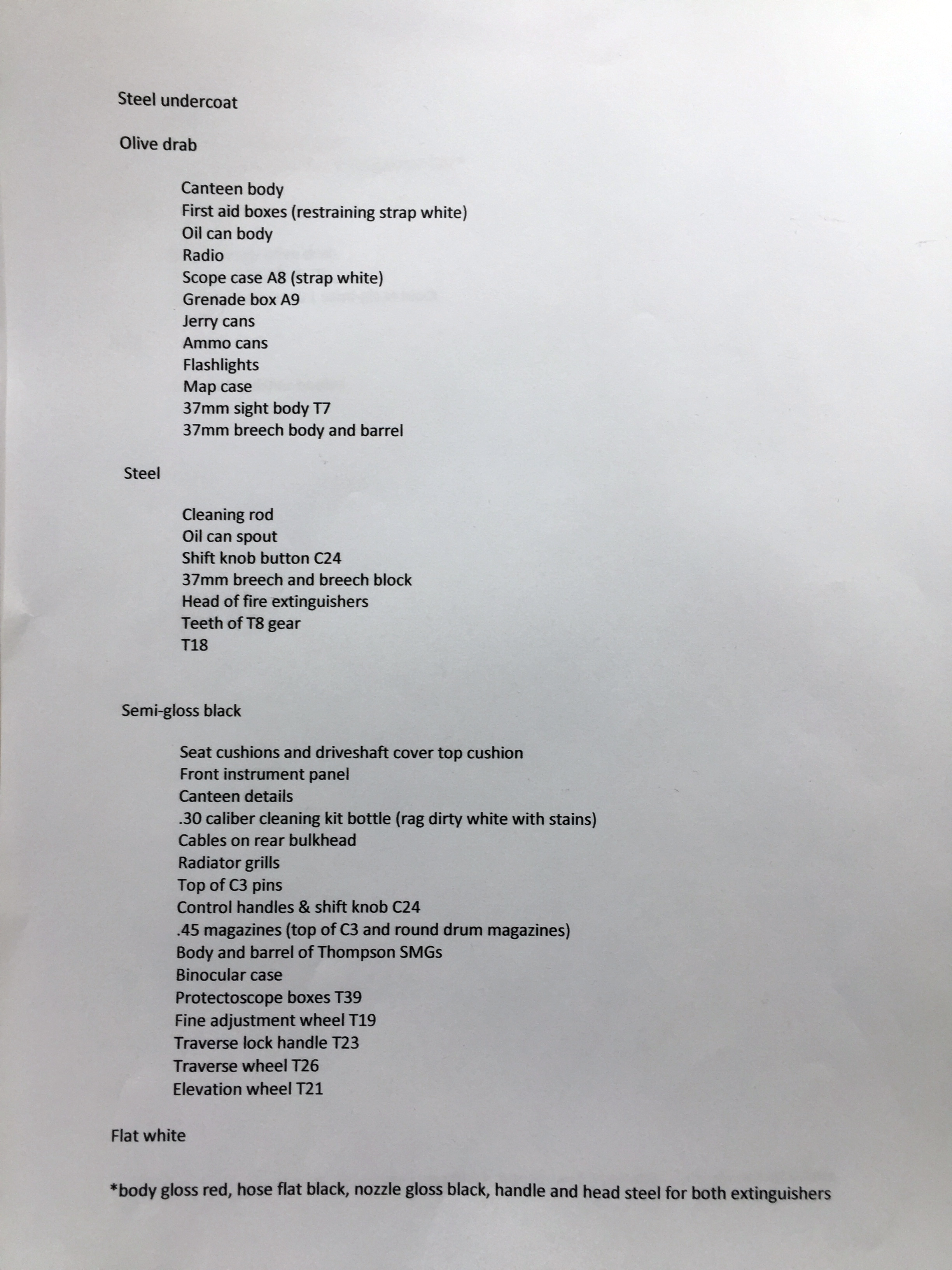
There are a LOT of small parts that need paint. Holding those with my sausage fingers has shown me that that doesn’t work well. I glued things (using superglue or PVA) to bamboo skewers so that I could get a grip on things (would that getting a grip were that easy in all things):
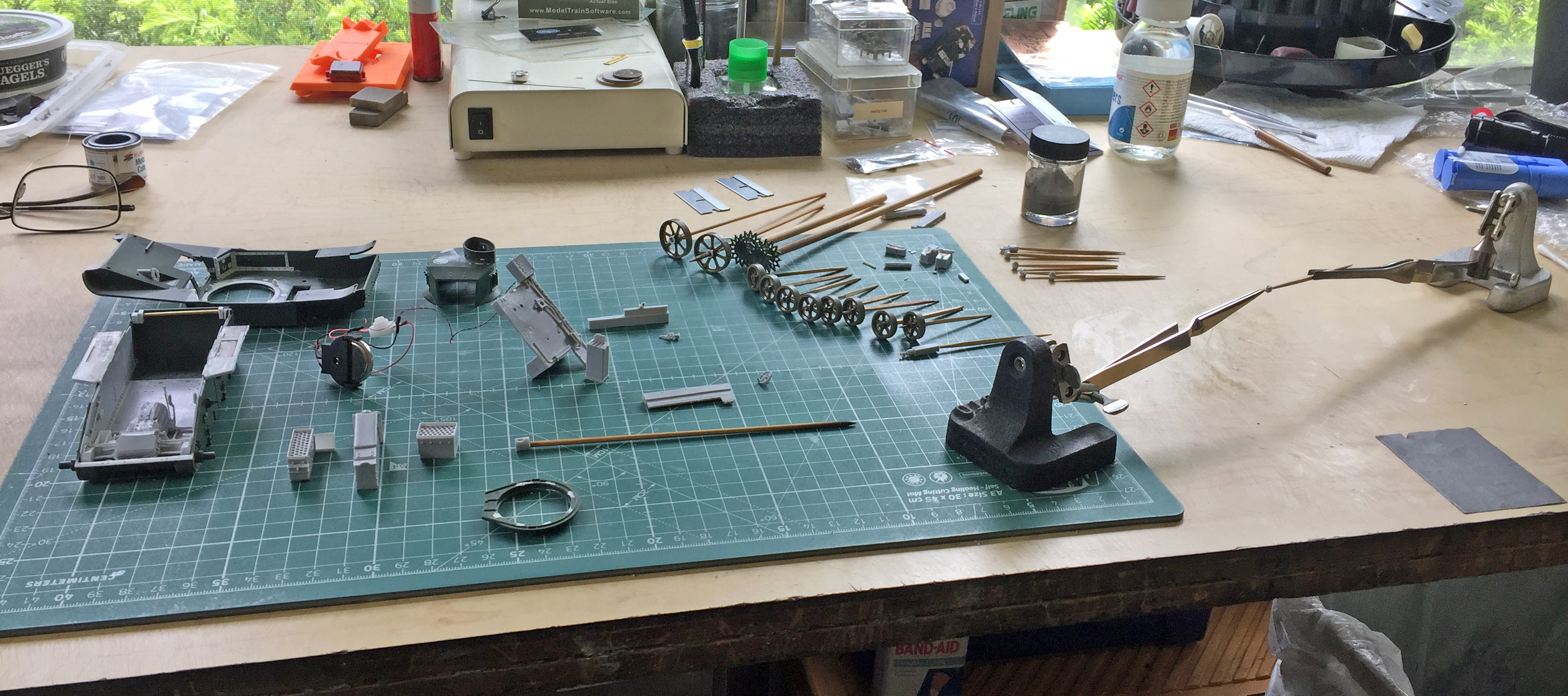

First I threw down the steel undercoat using Humbrol’s Metal Cote #27003 (my go-to paint anytime I need something to look like steel):
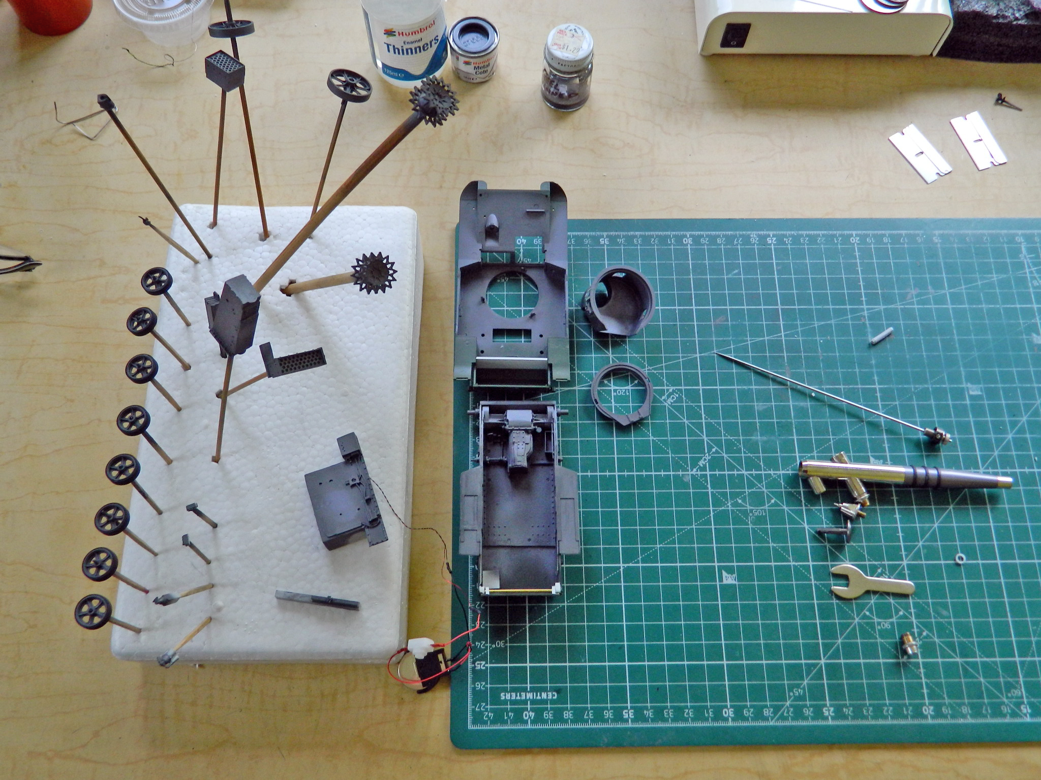
Then I tried an experiment. Normally my next coat would be of flat white. Some rubbing and chipping wear would be added, then it would all be hit with a coat of clear gloss so that I could enhance details with a dark wash. Well, maybe if I used gloss white instead, I could skip an entire step. After the wash would be time to hit things with clear flat. So I tried it:

All went well with the wash, and then was time to throw some clear flat over it all…and here’s where the wheels started to come off that wagon. It seems that a flat coat over a gloss coat has a problem. As the flat coat dries/cures, it fractures as the flat coat contracts and pulls apart. Seems the gloss undercoat doesn’t give enough tooth to the flat so that it will stay together.
Well, damn and bugger.
Luckily a strip and repaint drill wasn’t required. Where the clear flat pulled away from itself won’t be visible once the interior is assembled, weathered, chipped, and stained. Lesson learned.
At this point something that had been nagging at me, the ol’ “Have you forgotten something,” showed that yes…I had forgotten something. Inside the turret cupola are the armored covers for the direct-vision slots and I had neglected to put those in. Wonderful. I stripped out the steel and white paints (and interestingly, as I went after the acrylic paint with denatured alcohol, I discovered that it also lifted the enamel steel paint as well…so that requires further experimentation also, since turpentine STINKS) so that the resin parts would glue in securely.
The cupola is curved, as are the armored covers. However, the radius of the arcs between one side of the cupola and the other are different. The resin armored covers were fit to the rear of the cupola, not the front. Note the gap under the center of the cover (if you can…not the best photo of it, just the best I could get):
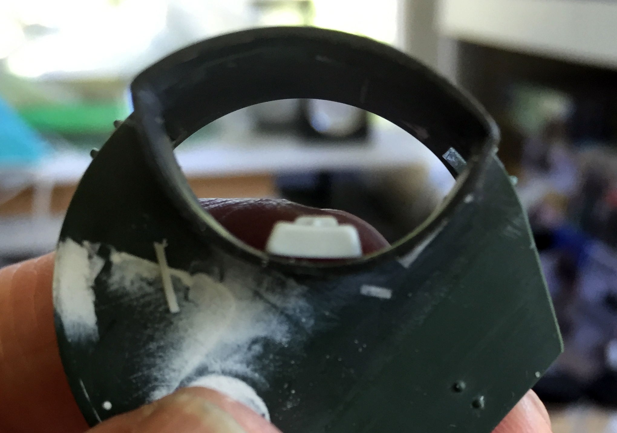
After filing and sanding all three front covers, they now fit as they should:

There is a very slight gap around the edges of all the armored covers so the 3M acrylic putty (LOVE that stuff!) and a chisel-tipped toothpick took care of that (and all the slots were cut open and the armored covers aligned with the openings):

The pistol ports with the kit were okay, but the aftermarket set from Verlinden has an even better set (which is where the armored covers came from…I copied them from the Verlinden resin parts):
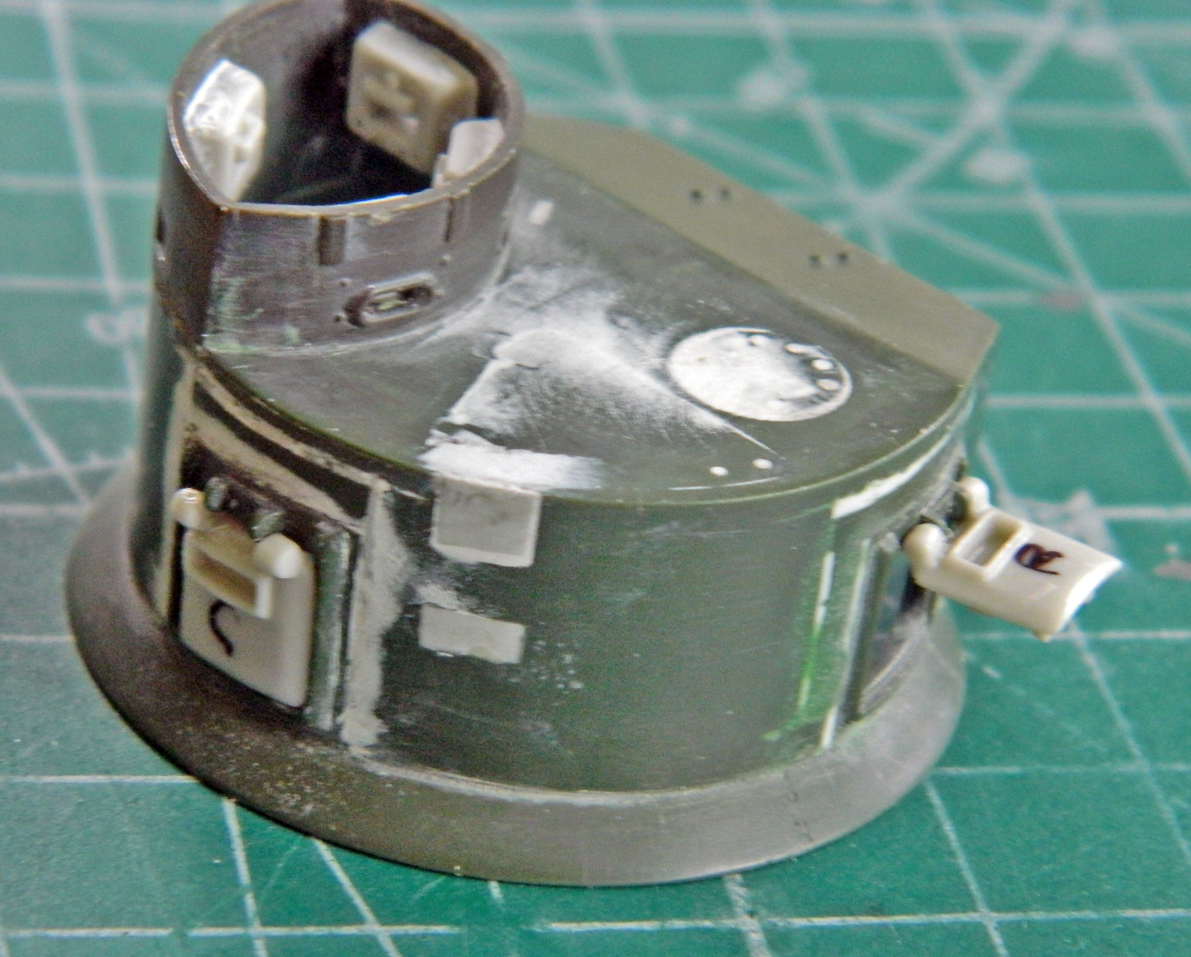
The two-part hatch for the cupola needed some work as well. When closed, there is a gap between the two hatches. I added .020″ (.508mm) styrene to the edge of one to fix that:

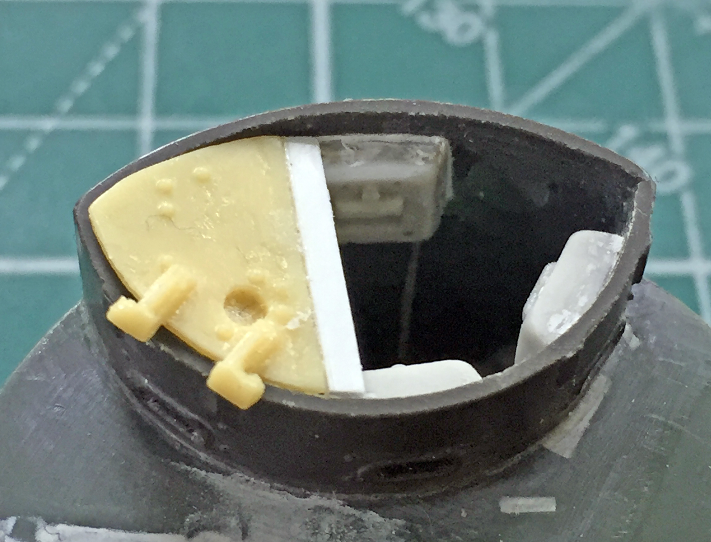
The hinges on the hatch halves doesn’t quite match the hinges on the cupola. Since fixing the hatches on the cupola are easier, that will come soon.
So the inside of the turret will get painted with steel again. And since I’ll have that paint in the airbrush, the guide horns of the tracks also need to be painted steel. So while this stuff is now ready for paint, I have to get the tracks ready for paint too:
Satisfied with how the .30 caliber (7.62mm) machine gun plugs came out, I glued the L-shaped parts to the upper hull:
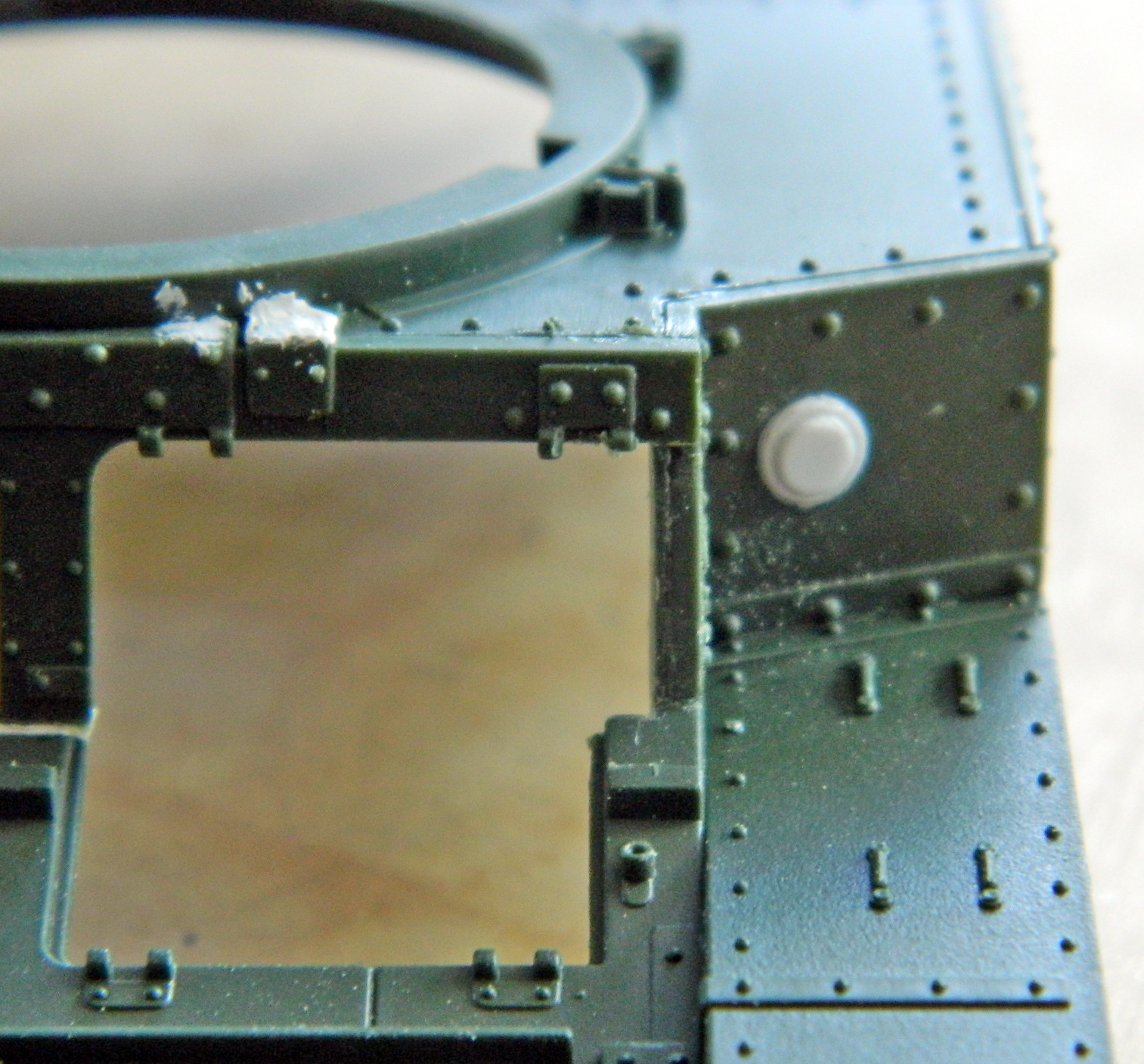
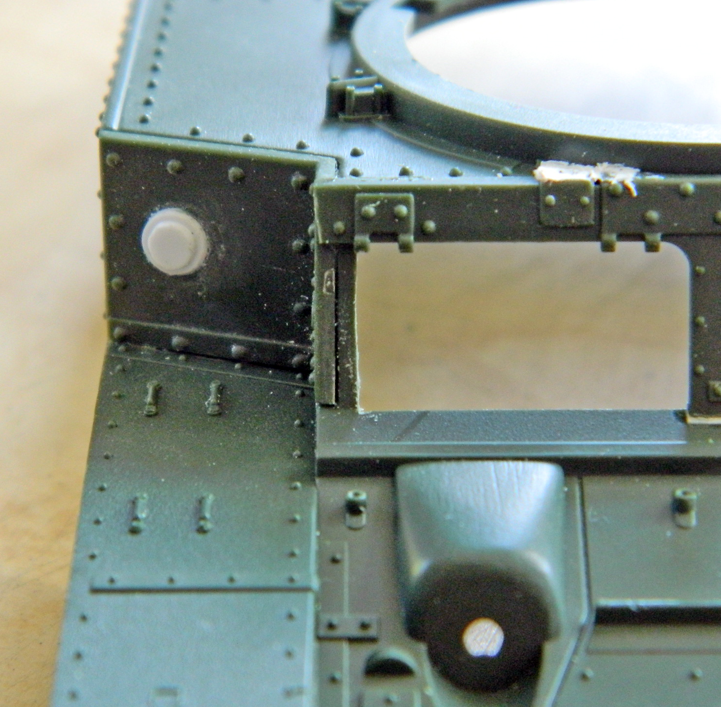
If you look at the photo above, you’ll see how the vertical side to the left of the opening is doubled. That’s way too thick, so I scraped the inner panel away, which resulted in a more scale thickness.
As more parts were cleaned up, pouring stubs removed, and parts dry-fitted, I came to the realization that somehow I managed to put the floor and walls in the wrong position; they were too far forward. The first step to fixing that was removing all three parts and then reattaching them correctly:
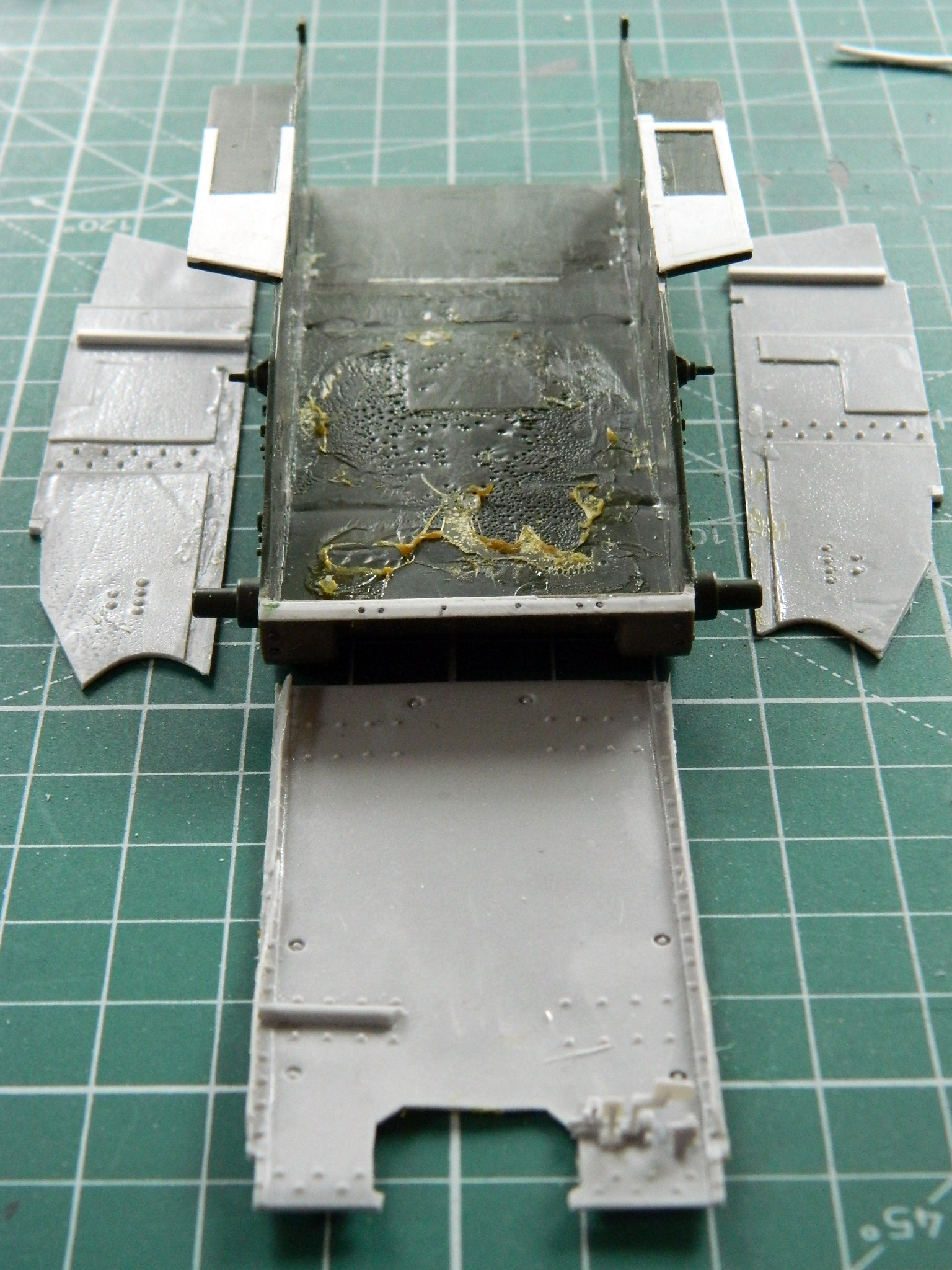
The idea of doing ten track links a day worked well. Most of that tedious task I wasn’t really aware of. I sat there, drinking coffee and drooling, while my fingers did a mindless task…and now that task is done (and I’m still mostly mindless):

The early M3s had riveted hulls (and turrets, but the turrets switched to all-welded construction before the hulls were switched) and the inside of the hull had straps of steel that supported the hull plates and gave the rivets something to attach things to. Since those sections can be easily seen through the front lift-up hatches, I cut .015″ (.381mm) styrene into strips and used Archer’s rivet decals to add that detail:
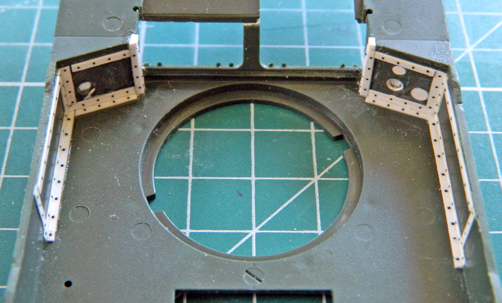
More rivets will be added to the exterior, but given how fragile they are once laid down, I’ll wait until later and as close to painting as can be.
One of the things I want to do with this build is to add a light to the interior. The battery and switch will go into the space where the engine would be, and the LED is going here, not finding any references as to where, or even if, the actual tank had a light, I put it at the upper right side rear bulkhead. That little yellow rectangle is the LED; I had the choice between cool white and warm white and I went with the warm white to replicate a 1940 light bulb:
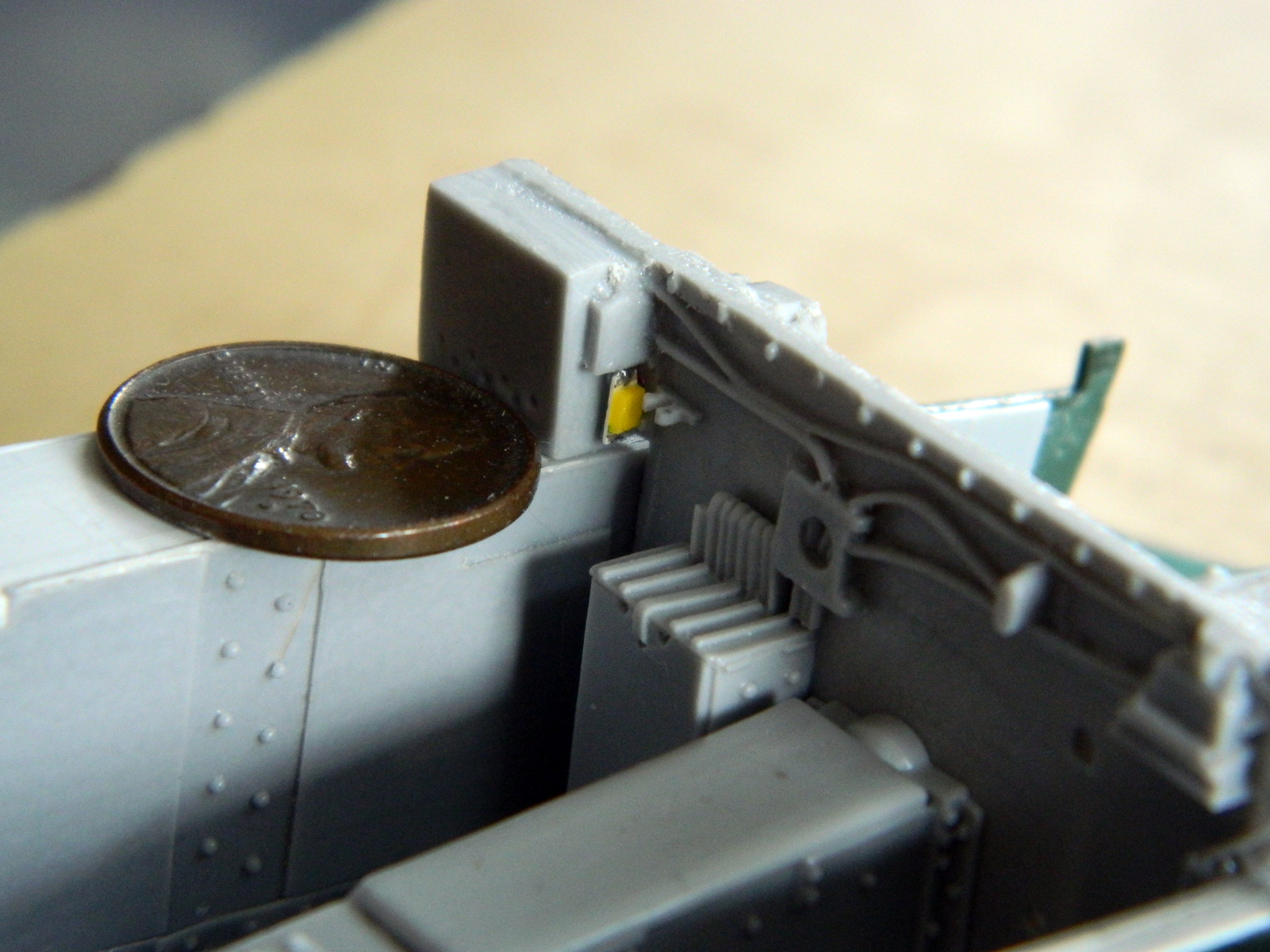
I tested the amount of light that TINY thing puts out (an impressive amount) and, once everything is painted white inside, that should be enough light without overdoing things:
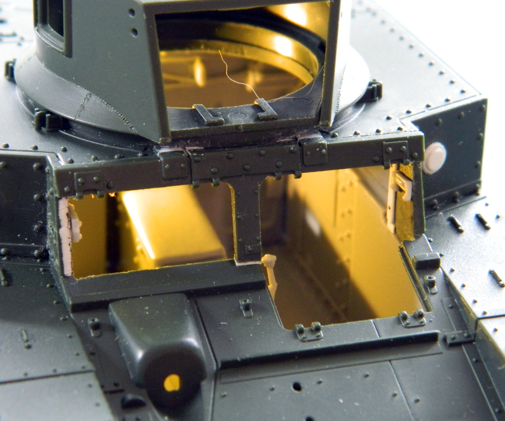
The tray on the floor next to the co-driver’s seat held two .30 caliber (7.62mm) ammo cans on end. The resin part was too small for the cans I’ll be using, so I made one from .015″ (.381mm) styrene scrap:
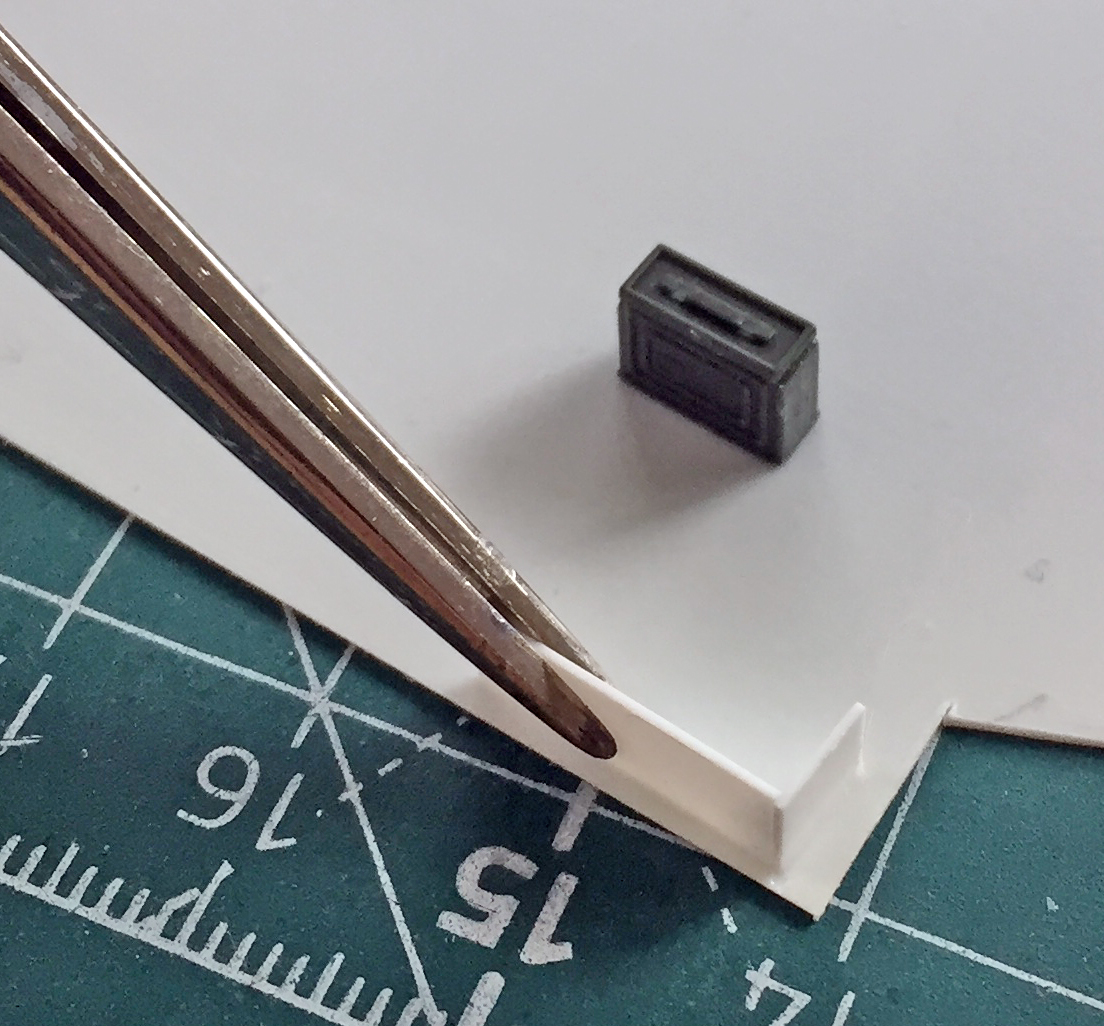
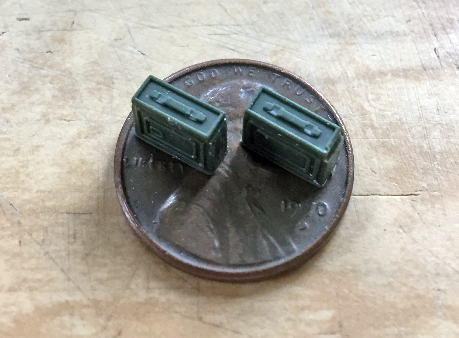
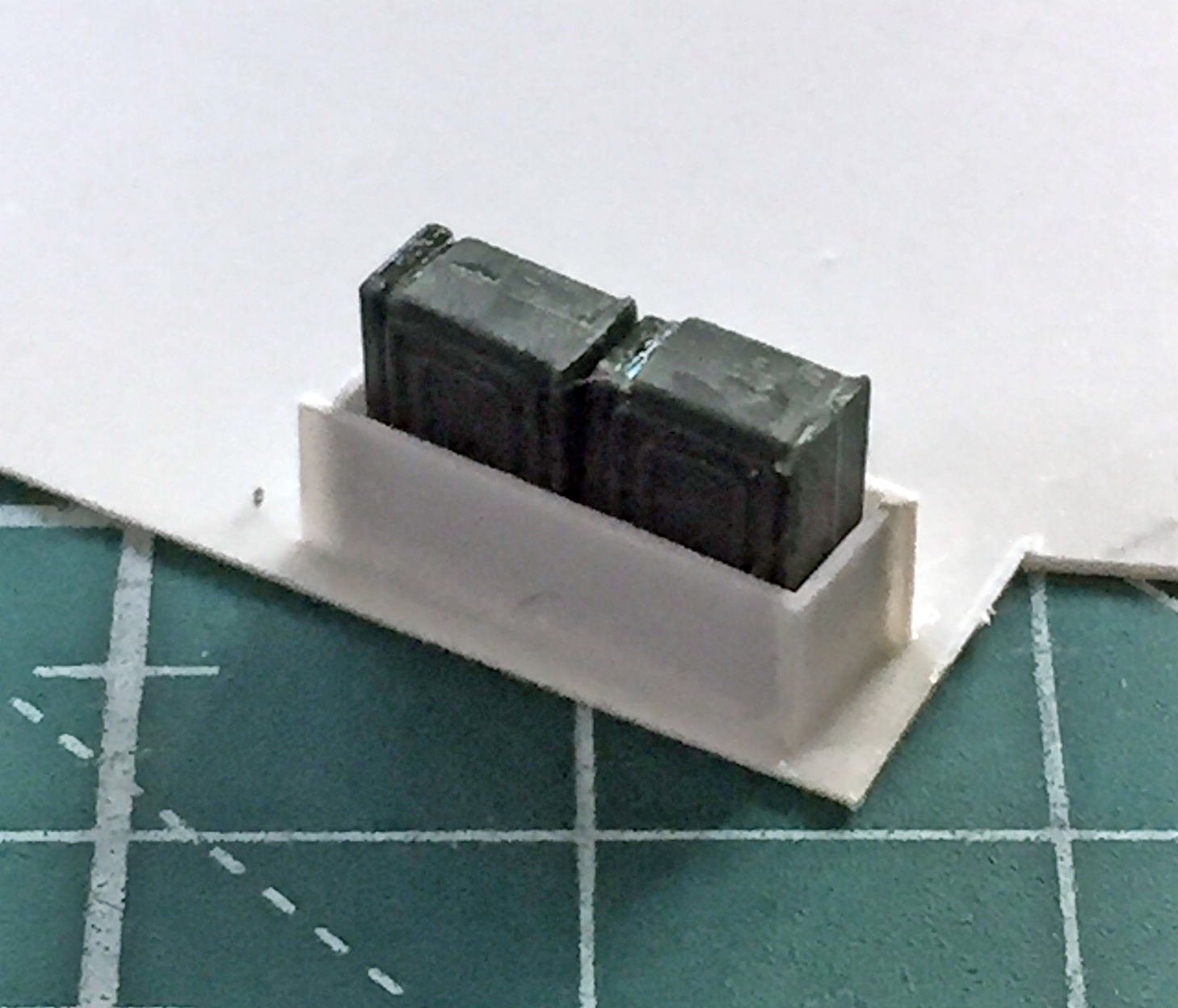
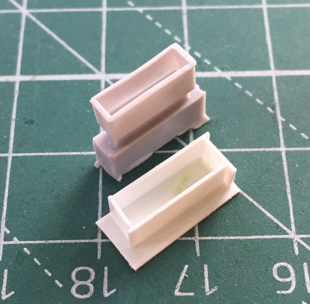
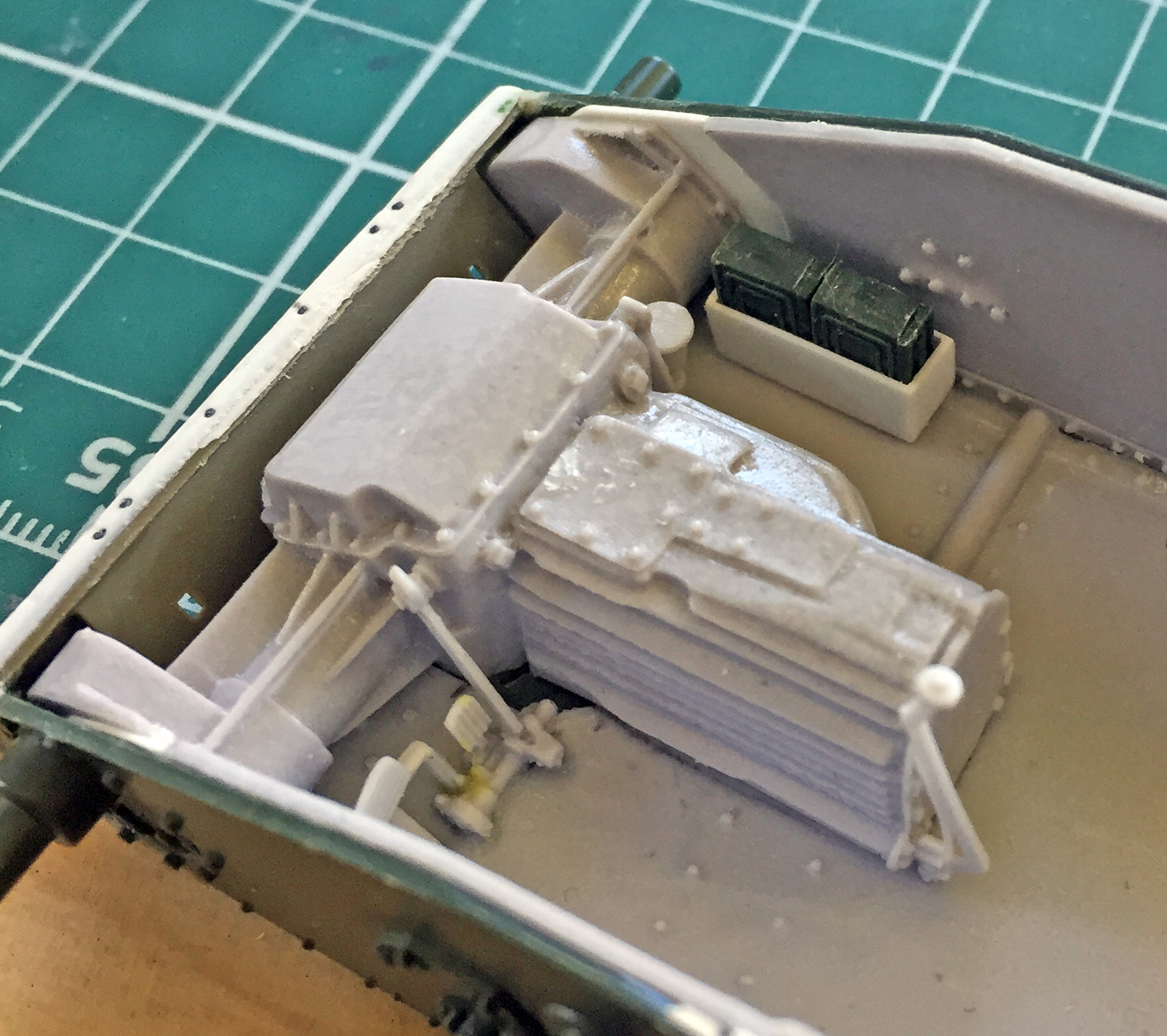
Frequently while I’m building things (usually what I know how to do), my mind ponders things I’ve yet to do (usually what I don’t know how to do). In this case, I want to backdate the turret from the D58101 turret that came with the kit which is more appropriate for an M3A1:
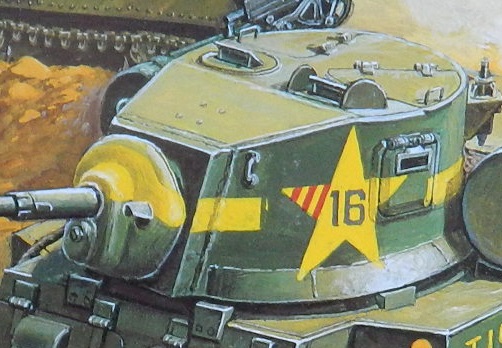
To the earlier D39273 turret which is more appropriate for an M3:
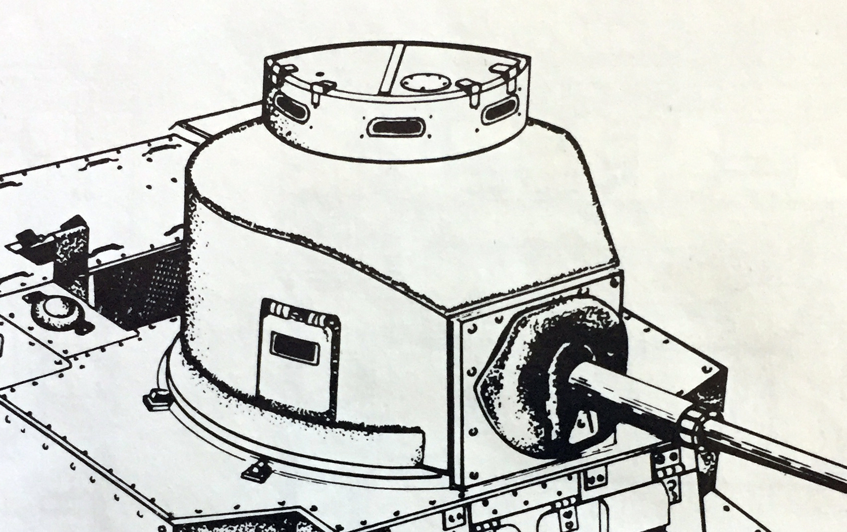
To do that, I’m using the turret from the old Tamiya M3 kit, #3542. I had intended on using the top of that turret to replace the top of the turret that came with the Academy kit. Then I realized that doing it that way would leave me with an internal seam that would need to be filled and sanded. Being an internal seam, doing that, though possible, would be an ass-pain. Instead, I decided to assemble the Tamiya turret to the extent where I could cut the commander’s cupola off as a unit and then graft it onto the Academy turret.
So the first step is to assemble the Tamiya turret. The mistake I made, though, was using a rubber band to hold the cupola sides together. The rubber band wicked the glue to places I didn’t want glue to be:
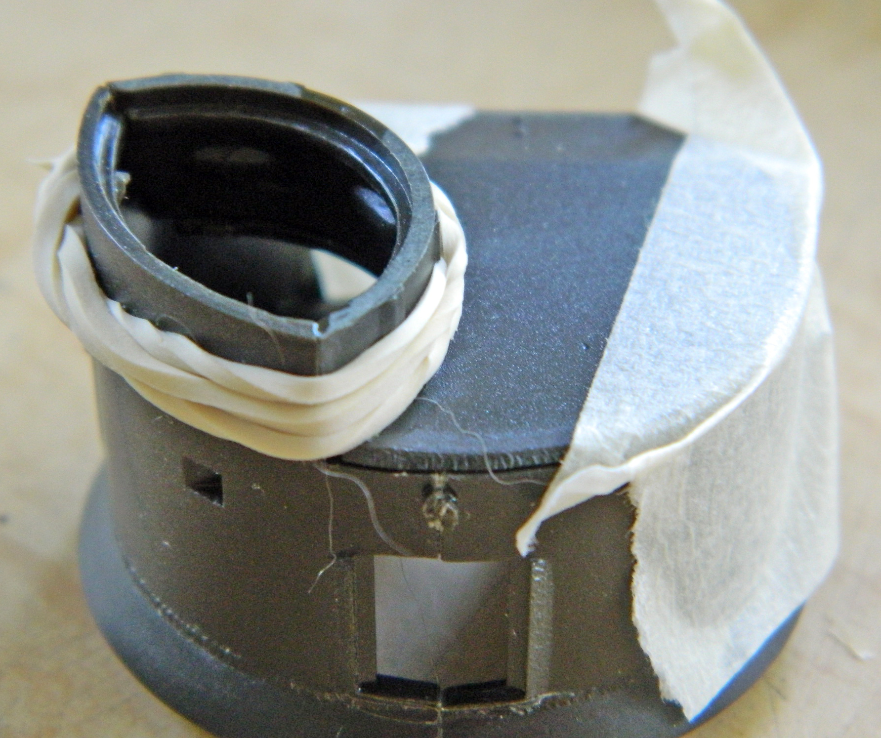

While the glue was curing, I checked the locations of the three pistol ports. One of the changes between the two turrets was that the later D58101 turret (on the right below) had the pistol ports higher than the earlier D39276 turret had them. (The D58101 turret also had the ports arranged asymmetrically and the D39276 had them evenly spaced between the two sides.):
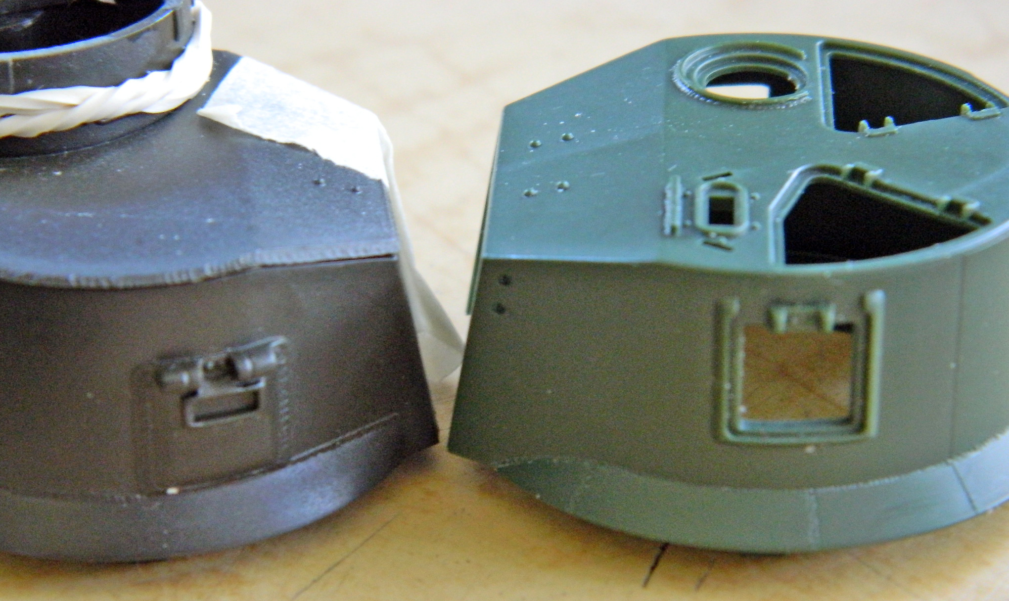
There are also openings in the turret top that need to be filled:
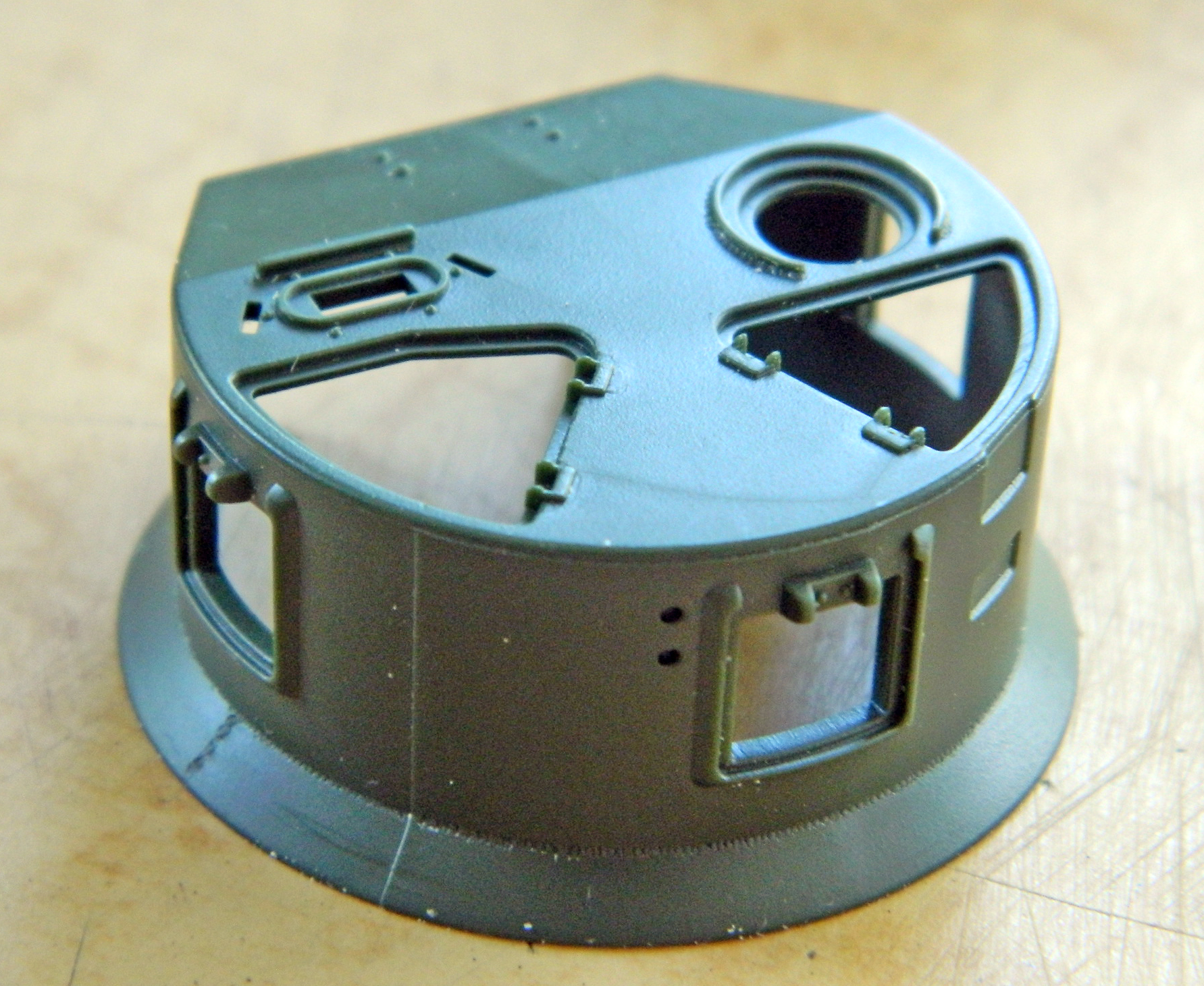
Scrap styrene does the deed for periscope locations and the loader’s hatch fills the hole it’s perfectly sized to fill:
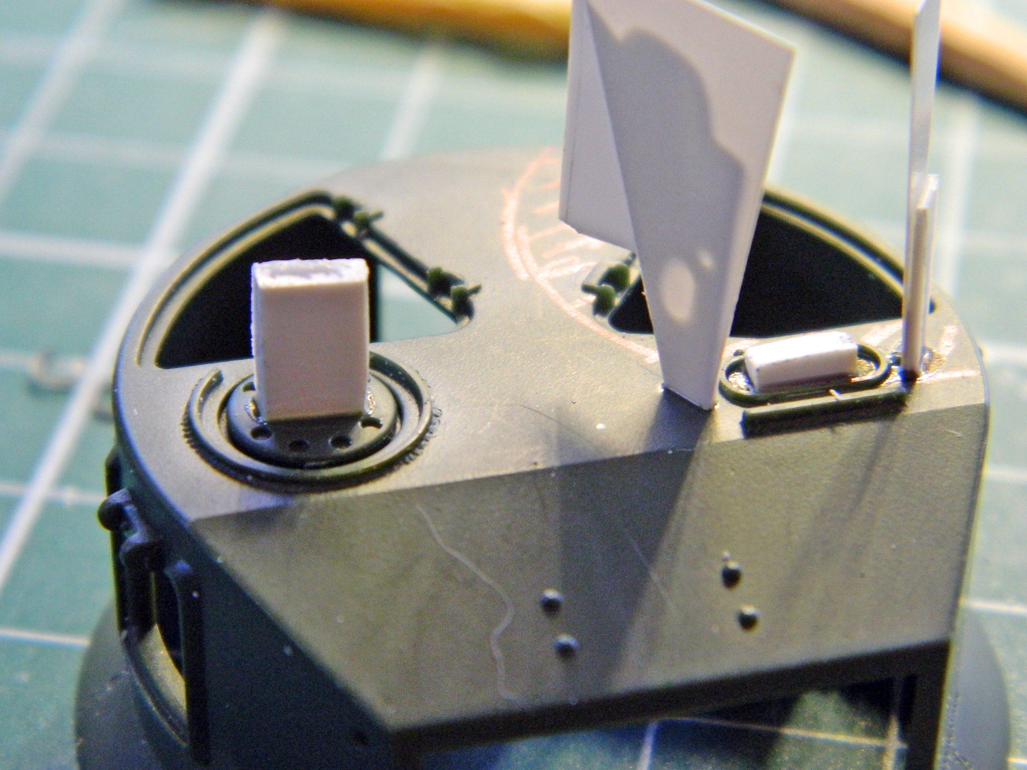
I also needed to see exactly (or within 90-95%) where that cupola sat on the curve of the turret’s side:
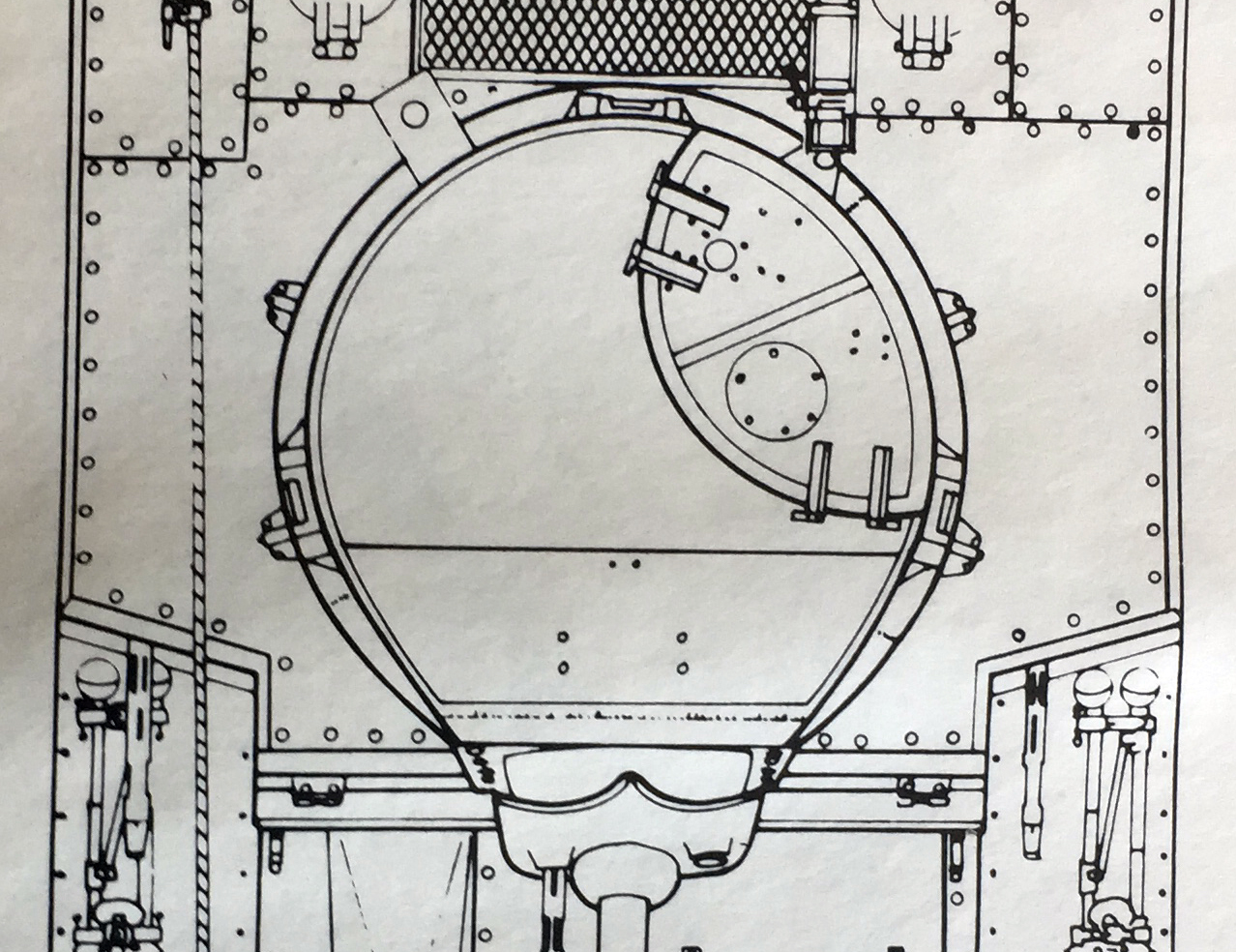
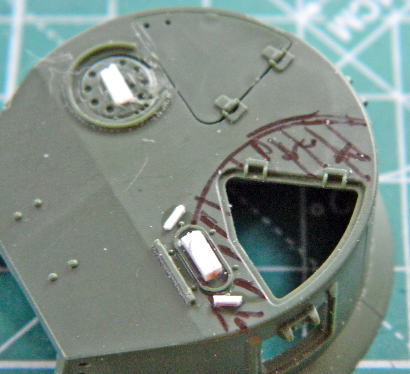
With the openings filled, things got smoothed flat:

Then started cutting away the first pistol port:
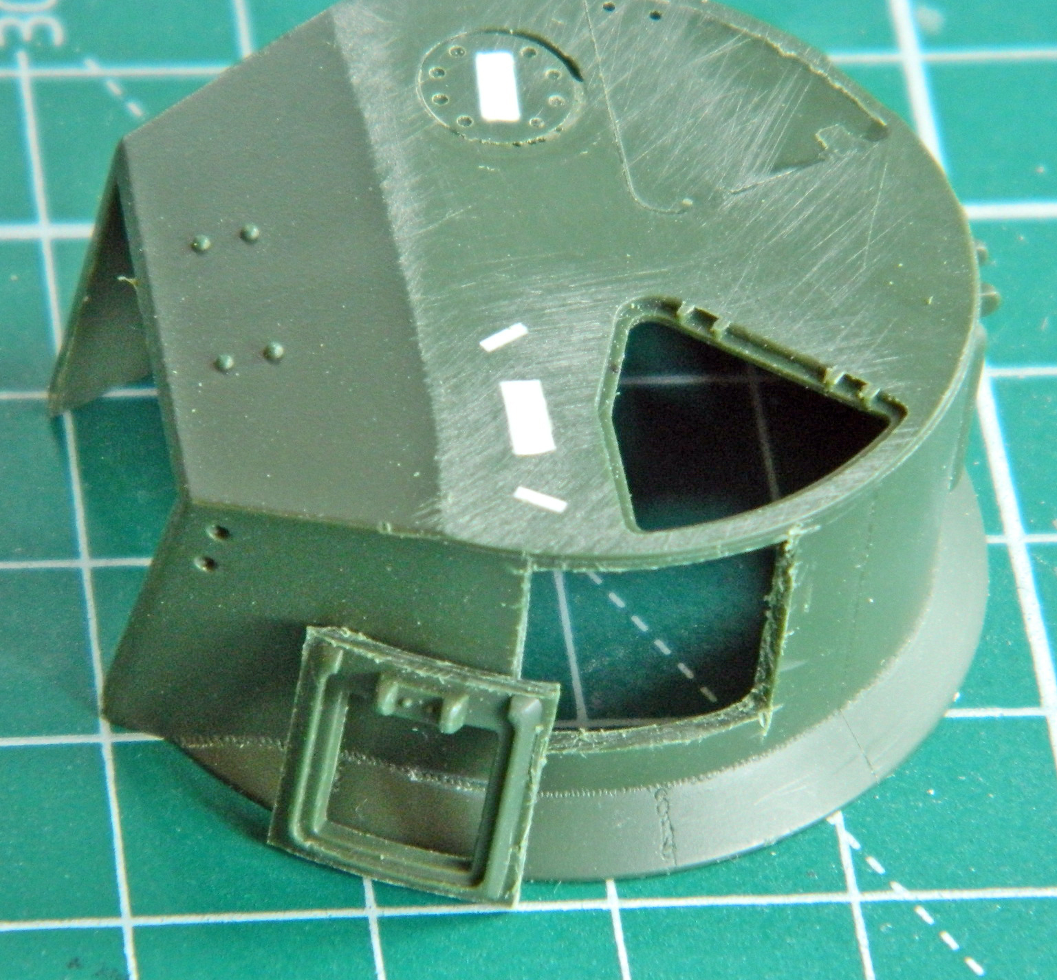
More plastic from the side of the turret had to be removed as this port not only needed to be moved down, it also needed to be moved forward:

I’d initially thought that I’d have to fill the space where the port came from with styrene…which meant getting the curve and thickness correct. Then I realized that I’d just cut away an L-shaped section of the turret so that I could move the pistol port to. I tacked the port in place and added scrap to fill the kerf and added the back-dated cupola:
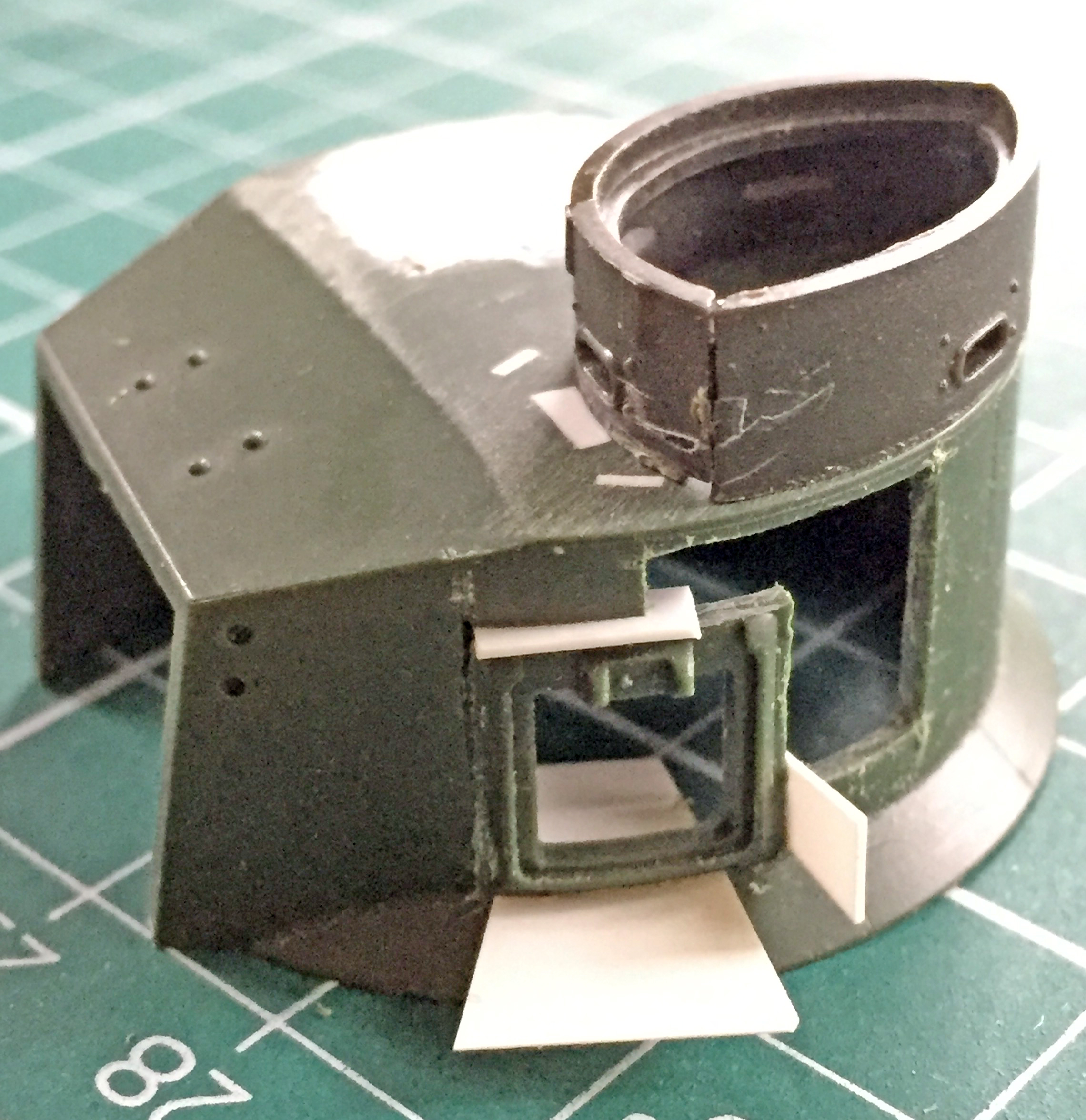
I added the section of the turret I’d cut away and puttied over the joints:
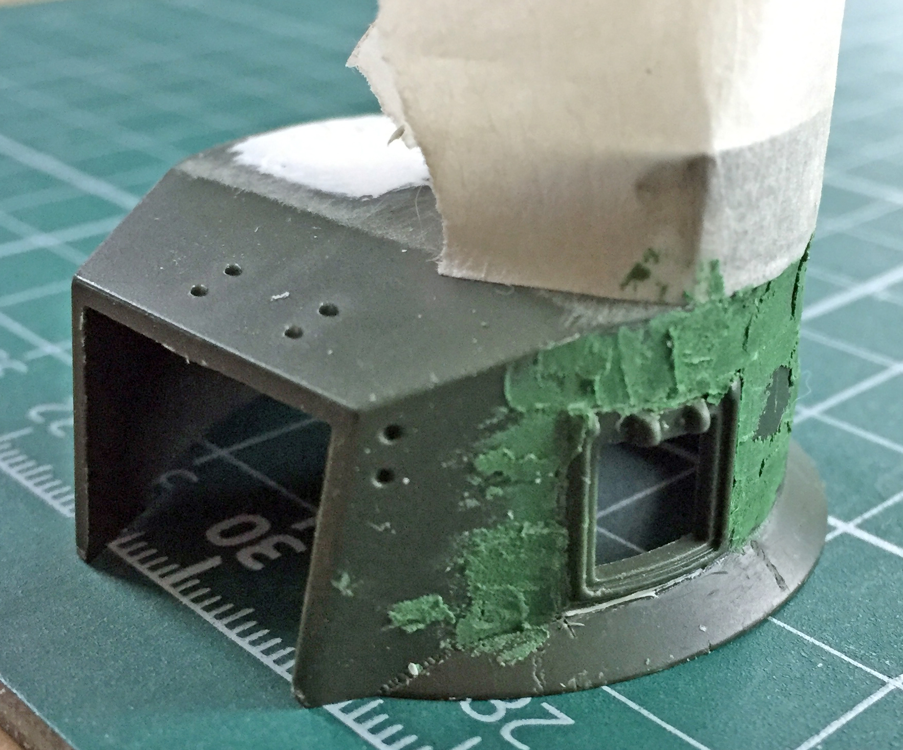
I puttied the top, cut out the turret top inside the new (old) cupola, then smoothed the putty:
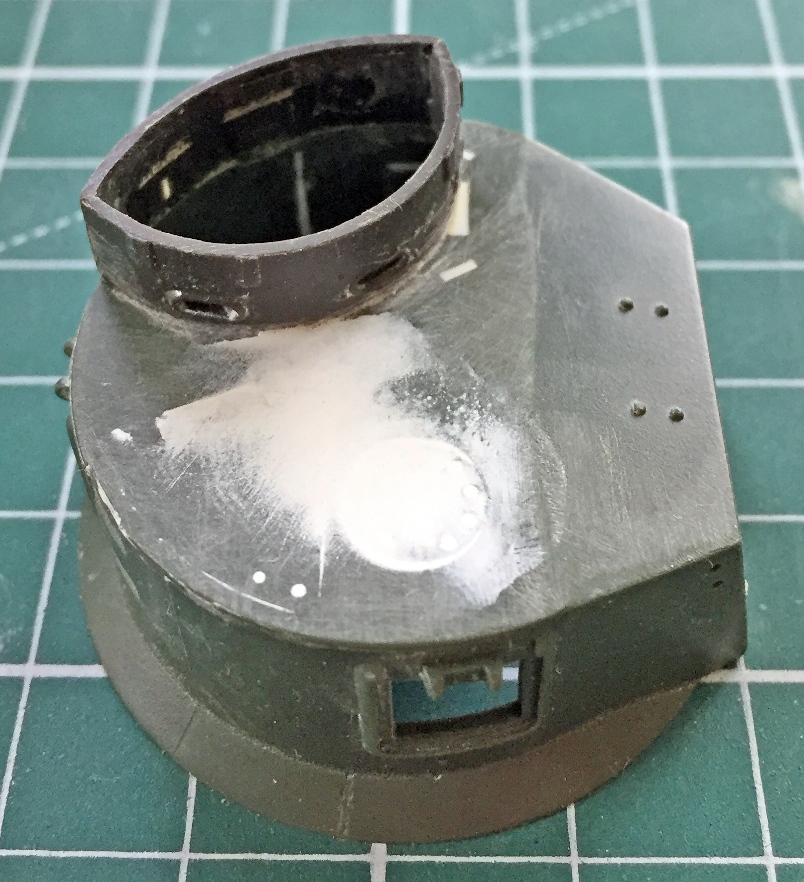
With the cupola added, the top smooth, and the gaps around the repositioned pistol port puttied and sanded, that all looks like this:
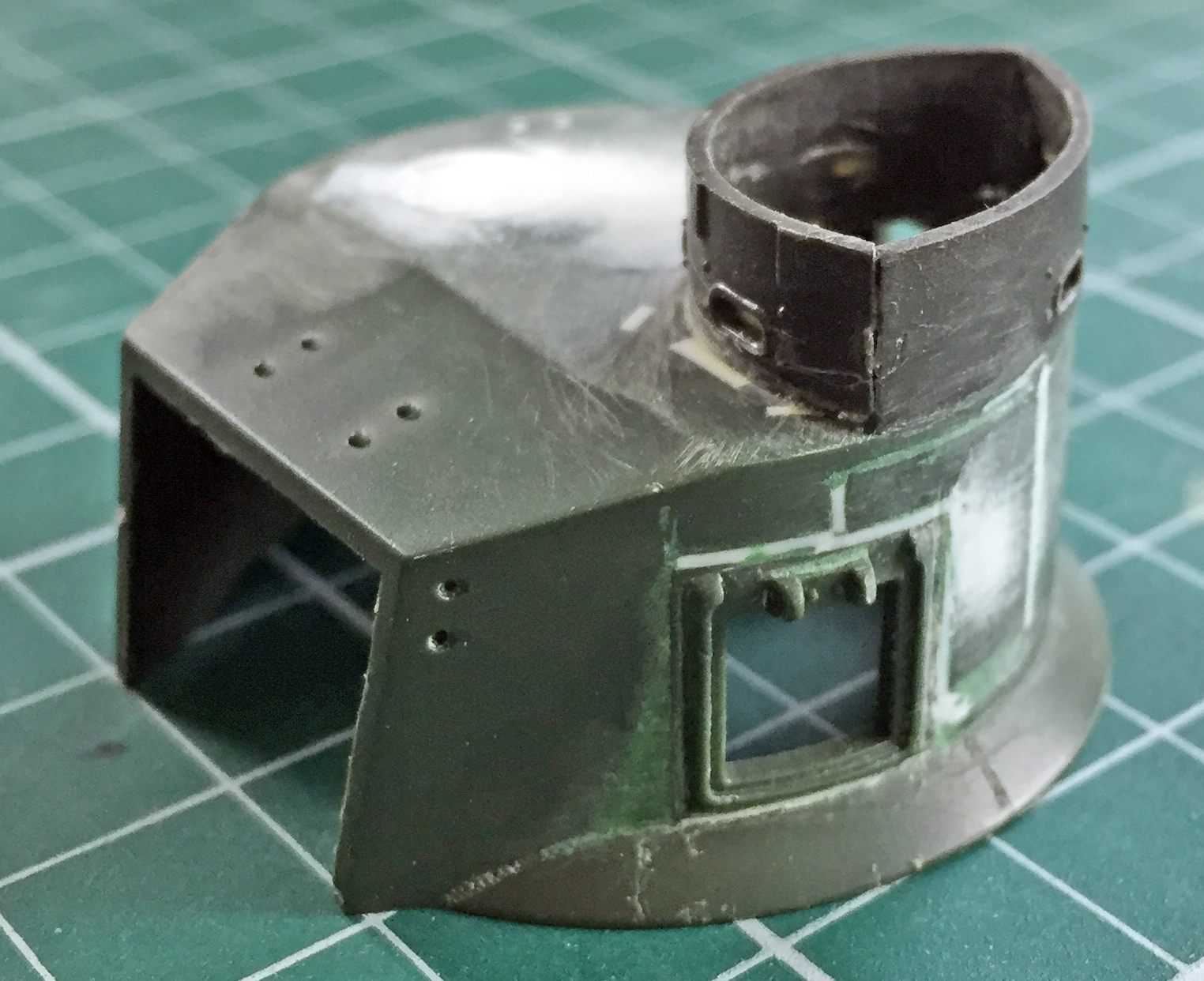
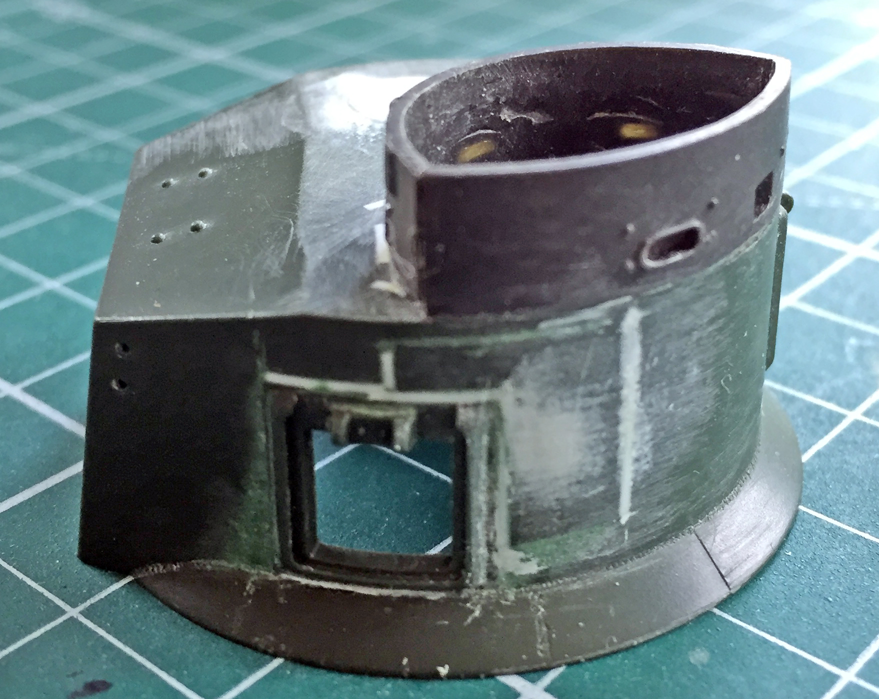
One down, two more to do. The right side pistol port, though needing to be moved down the same amount as the left side pistol port, wasn’t as far rearward. As with the other pistol port, I used the section of turret I had to cut away to move the port as the patch for the hole left behind. The kerf was stuffed with scrap styrene, everything puttied (at least three times), and then sanded:
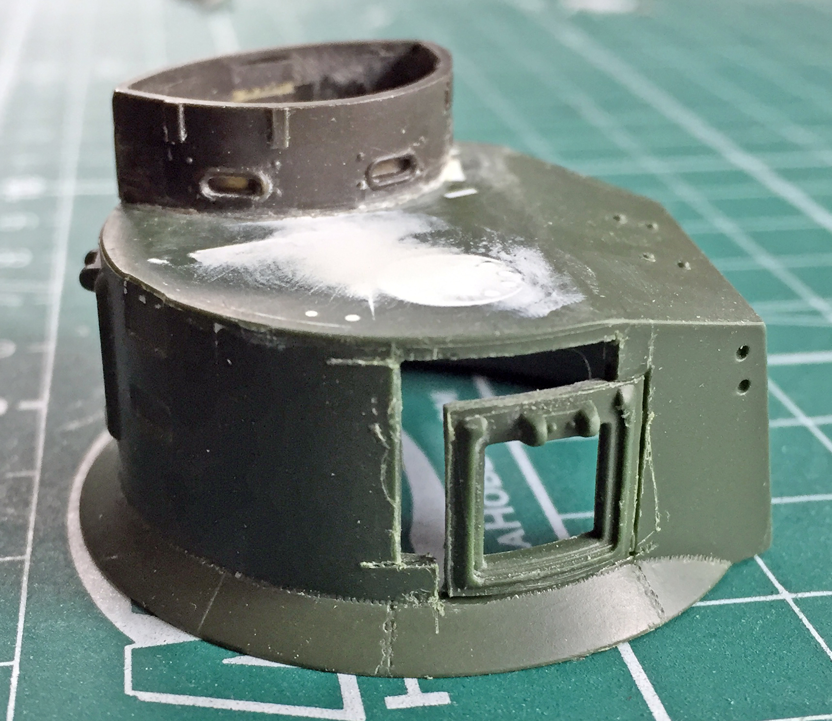

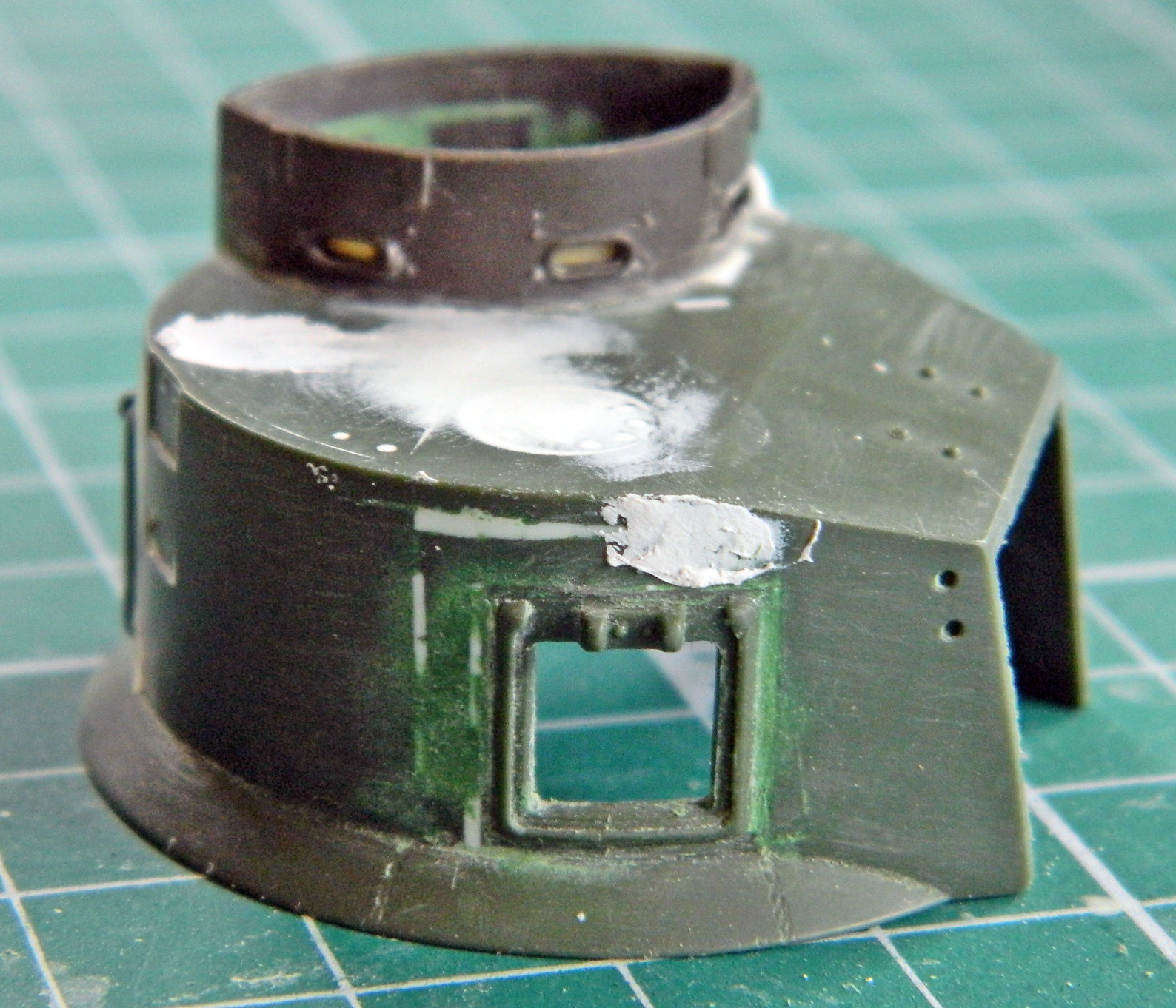
Two down, one more to do. This port was just moved down:

There are a few more details to do to complete the backdate transformation from a D58101 turret to the earlier D39273 turret. But, having this done, it’s now no longer hanging over my head and bugging me!
This is the kit:

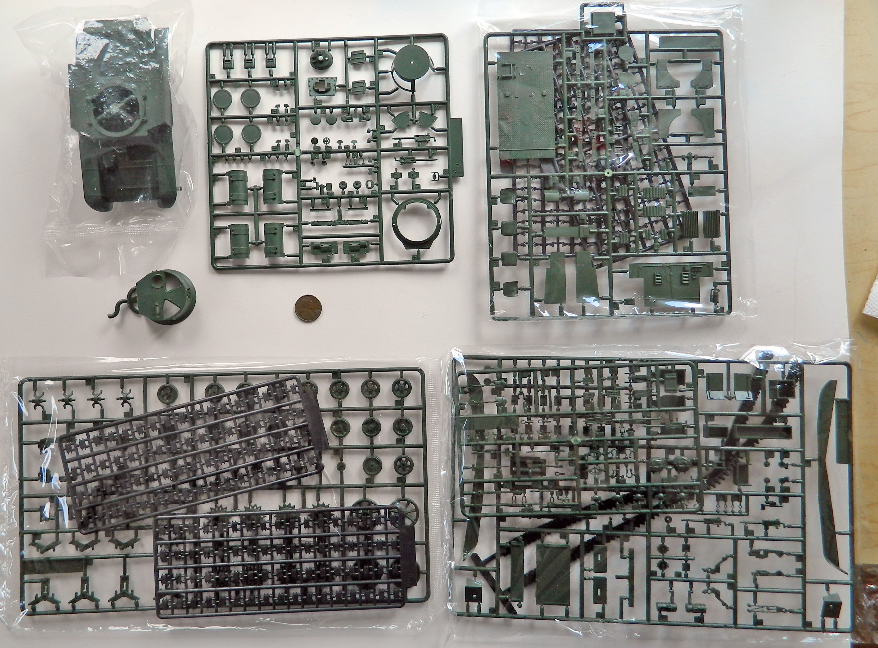

To start with, it’s not an M3A1. The back of the upper hull of the M3A1 has a curved section that M3s have angled the way this kit has it. So, literally, right out of the box, decisions have to be made about what I’m going to build. If I want to do an A1, then I have to replace the angled section with a rounded section. But mate…there’s war… The interior of the M3 is DRASTICALLY different from the M3A1. The kit has the M3A1 interior…complete with a turret basket that was not used in the M3. So, do I do an M3 and change the interior or do an M3A1, leave the interior as it is (or will be, it’s in parts presently) and change the outer hull?
Let’s do the M3…it needs more work to represent!
So presently, these are some of the items I’ll be adding to the kit.
The interior is done by Tiger Model Designs:

The tracks and suspension by AFV Club:

My intention is to build a representation of a mid to late production M3. That intention rules out two of the four possible turrets that had been fitted to the M3. That leaves two possible turret options to choose from. The different turrets have been referred to by their drawing numbers. The first two turret designs have flat-faced sides, extending up at the left rear corner to form the commander’s cupola (differing only in that the first turret was riveted and the second welded together). The “horseshoe” turrets, so called because instead of having a faceted side have curved sides, are what interest me. The question is do I use the kit’s part, the D58101 turret that has no cupola and two hatches (that’s what’s pictured on the cover of the kit’s box), or do I go with the earlier D39273 turret that has a rounded cupola only.
If I go with the D39273 turret, I’ll use a combination of the old Tamiya M3 kit’s turret by removing the top from it and grafting it onto the Academy turret. If I do this, I’ll use (some of) these parts from the Tamiya kit:
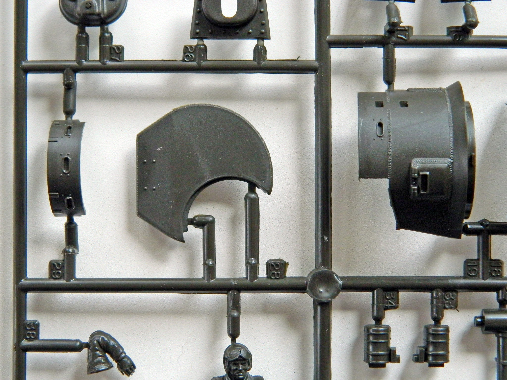
The first time I did individual link tracks was when I did Tamiya’s M4A3. Tedious. I try to learn from errors, so this time, instead of just sitting there for hours and hours putting little tiny track bits together, I’m going to do something different. I’ll do ten links a day:
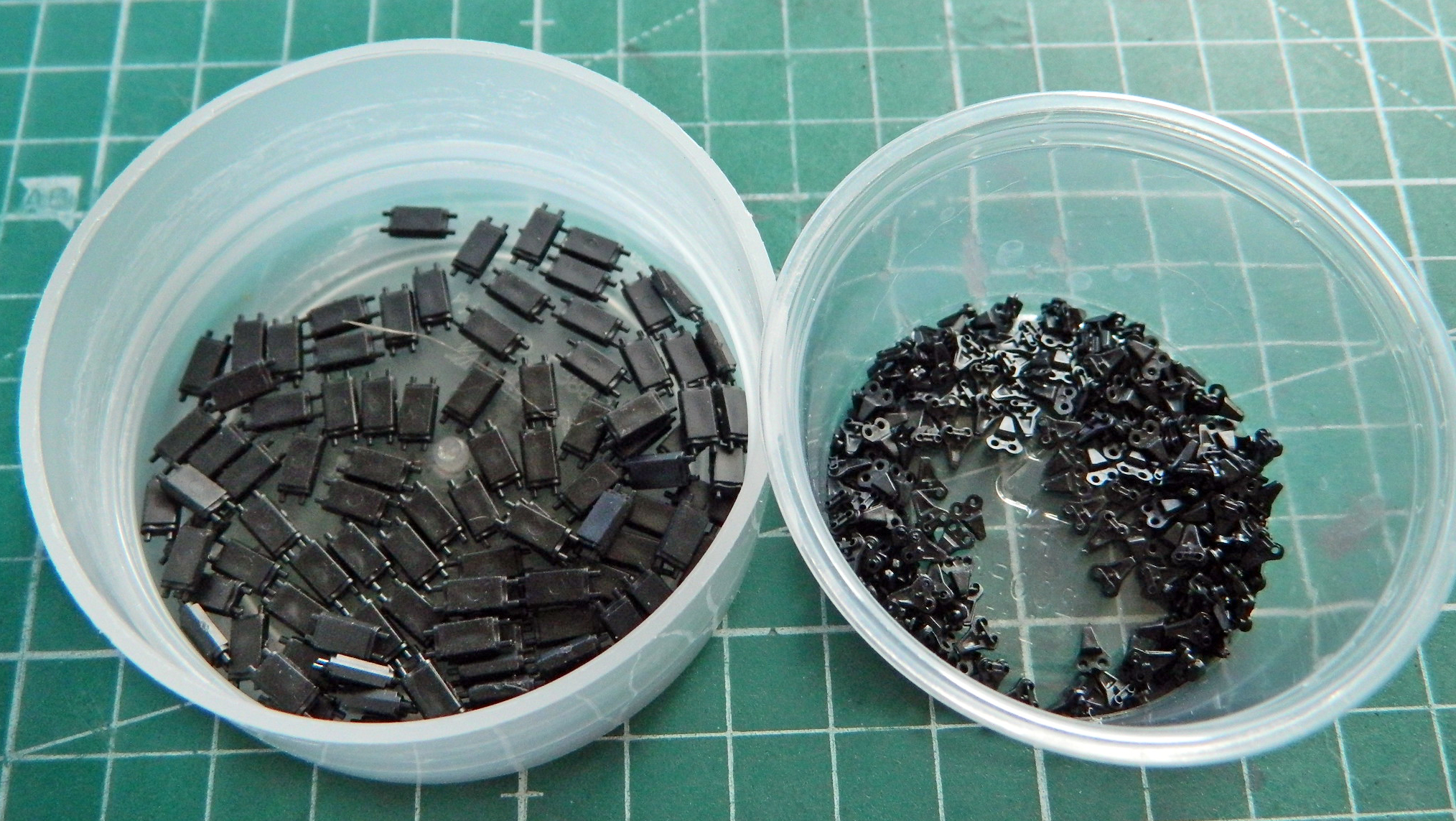
The first thing I noticed as I was removing parts from sprues is that there is a faint ejector pin mark on one face of every track shoe:

Will it show up after paint? Will it be obvious if I don’t remove them? Dunno. I do know that if I remove them, the answer to both questions will be “no.” I used double-sided tape to stick a piece of 400 grit to the bench and each side with the ejector pin mark is quickly sanded smooth:
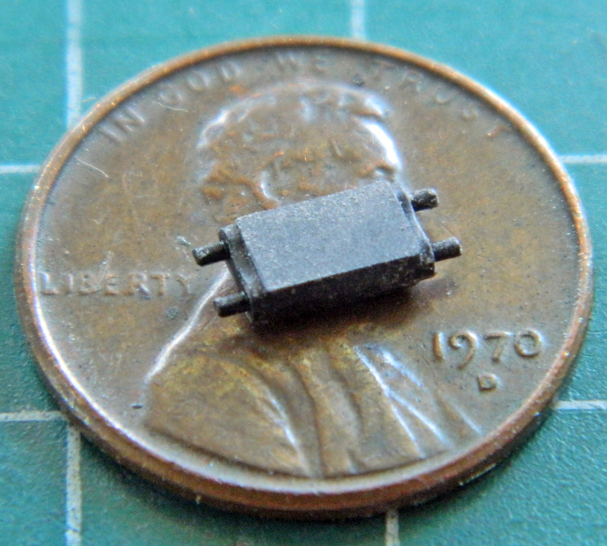
Then I noticed that the connectors fit the shoe pins a little too loosely…loosely enough that I had no idea how I could keep the parts assembled short of gluing them. Nope…made that mistake with the Sherman. Instead, I used a set of smooth-jawed pliers to press the pins SLIGHTLY, causing them to go out-of-round which allowed just enough friction (something I’m told I’m good at producing) for the connectors to stay on the pins. If you look closely at the pins in the below photo, you might be able to see where the tops of them have been SLIGHTLY flattened on the right side of the shoe:
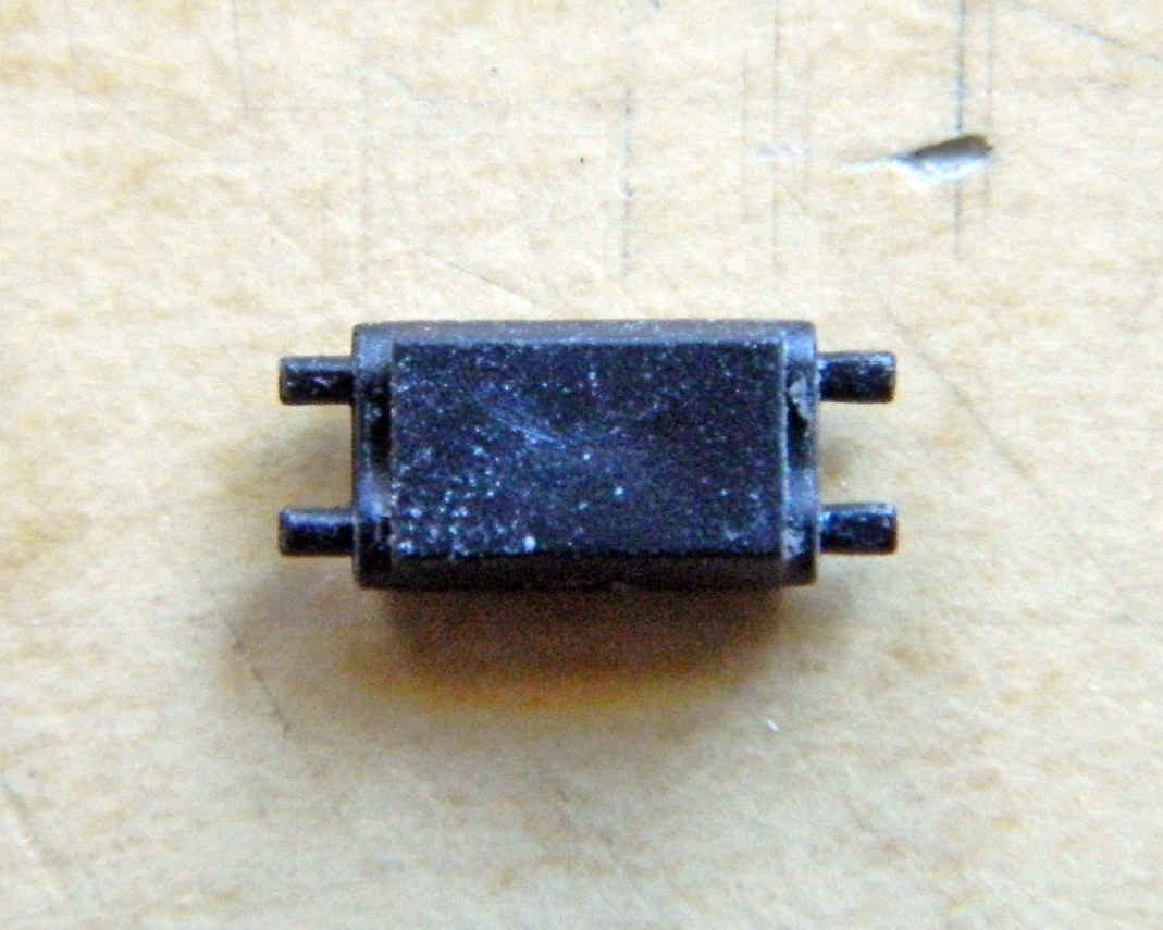
Doing the tracks a bit daily is SO MUCH BETTER:
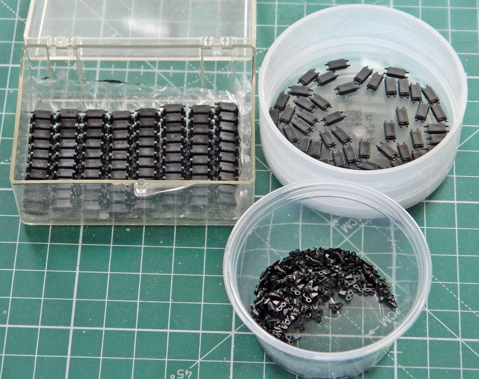
This is what the kit provided for the drive cover at the front of the lower hull:
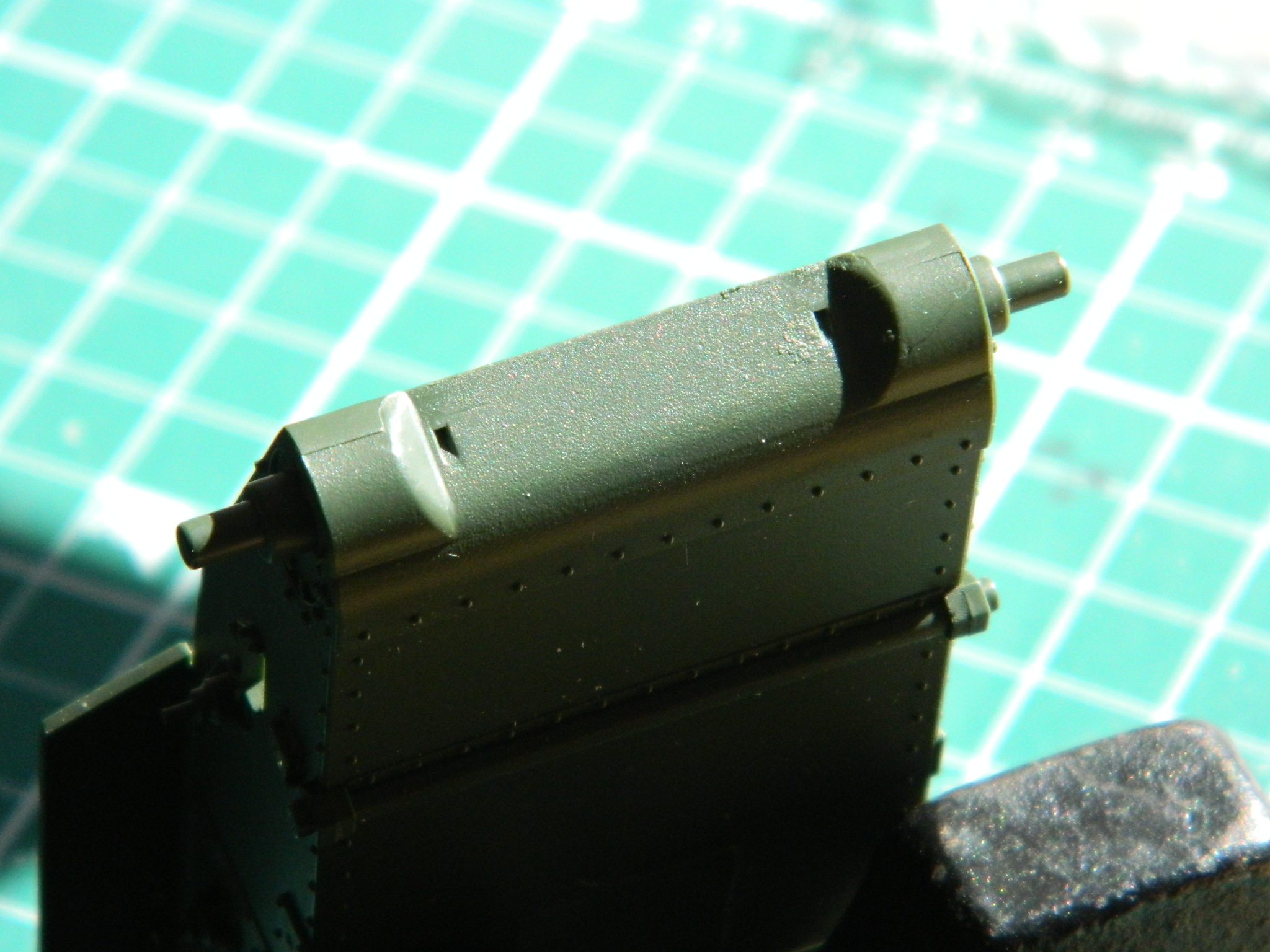
AFV’s suspension kit is obviously taken directly from their M3A3 kit (I think). They just produced the sprues that have the suspension parts, packaged them, and sold them (thankfully!) as an update set. What’s nice about that for me is that this drive cover came with the suspension parts (cat hairs were produced on-site):
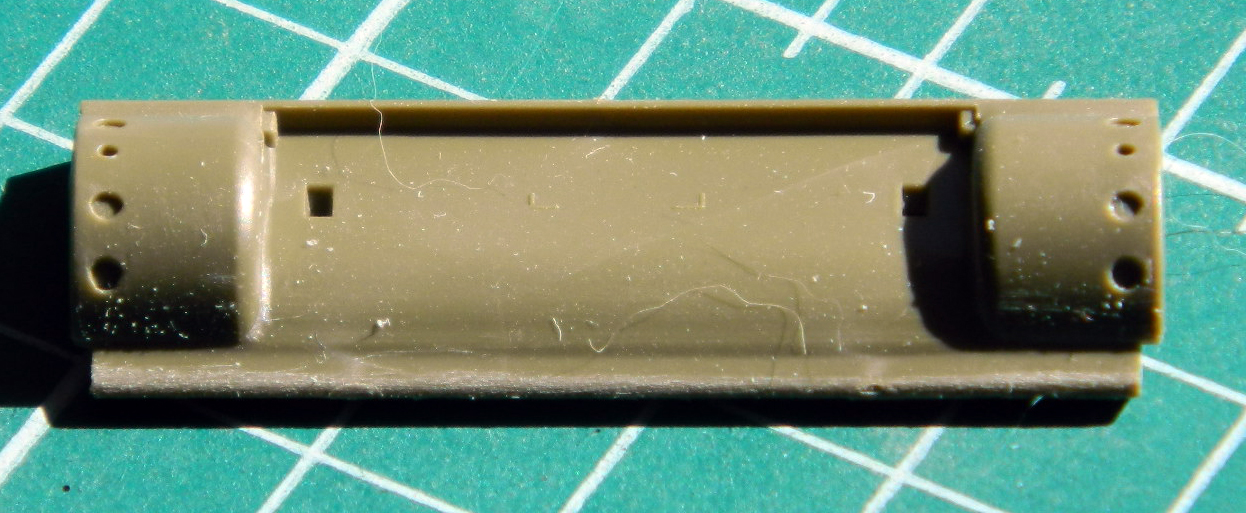
Now I just had to saw off the kit’s nose and graft that one on (later, I added Grandt Line bolts to the circular depressions):

Much more nice better!
Another inaccuracy to the Academy kit is the bottom of the sponsons. The fenders attach underneath them but no attempt was made to blend the fenders to the sponsons. Academy’s engineers missed that and did blend them, so that has to go. First, scribe a line to delineate the bottom of the armor, then cut away what should not be there:
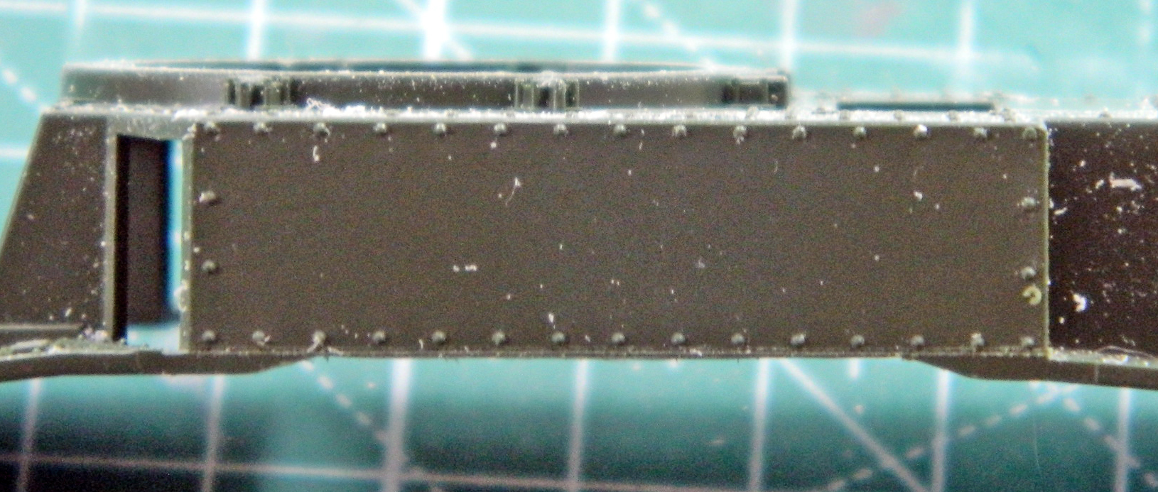
Having accomplished that, I needed to make the sponson bottoms fit the cutouts:
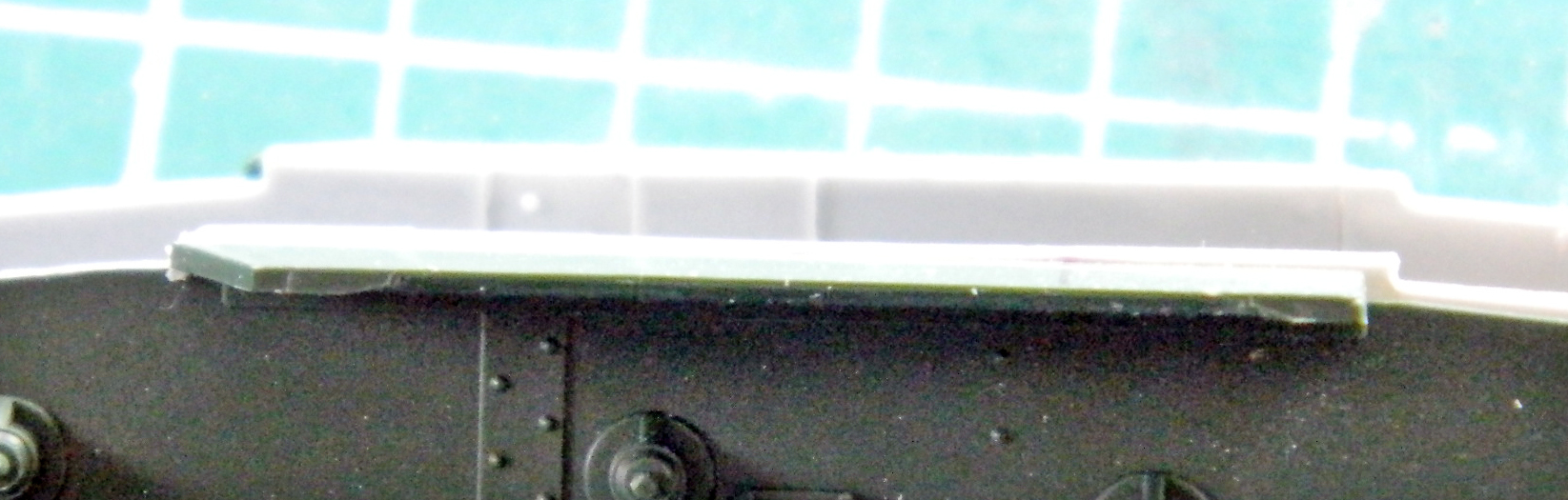
Just have to do the other side…
There is always fitting when using aftermarket parts. Sometimes is just a little tweak or two, sometimes it approaches re-engineering. So I fitted, sawed, filed, sanded and glued…first the sides and floor:
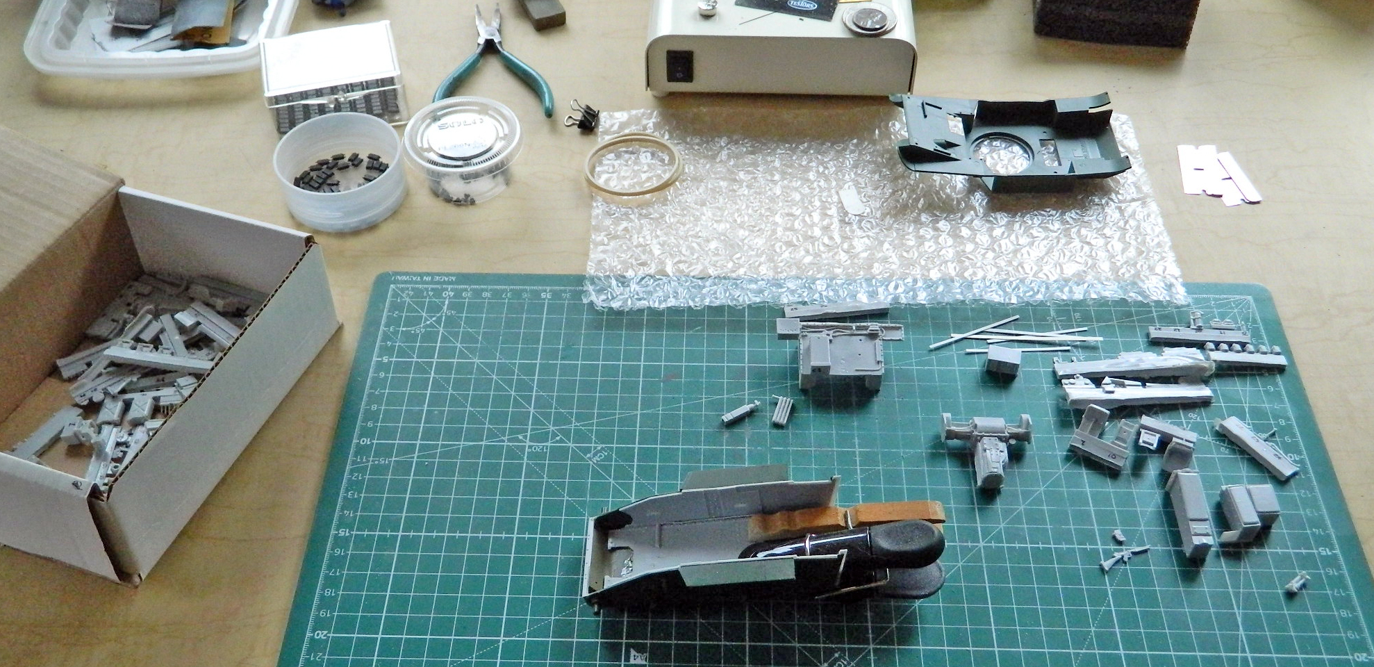
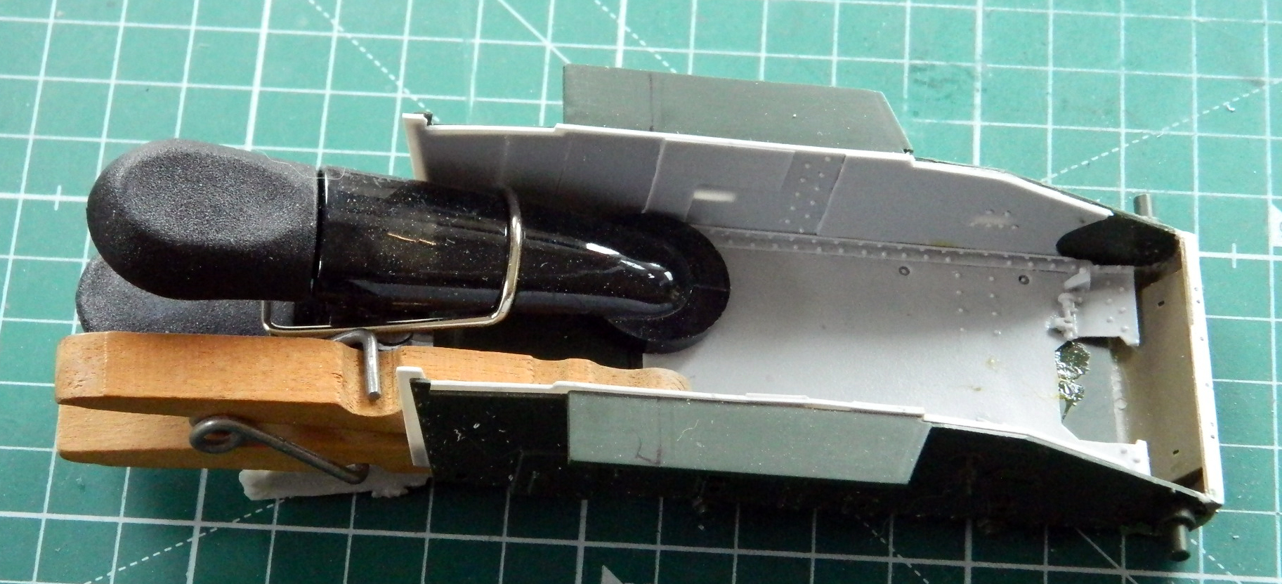
As produced from the factory, .30 caliber (7.62mm) machine guns were installed in the sponsons. As received in the field, those useless things were taken out. It’s pretty useless when it’s removed and empty space is more valuable. (Eventually the factories stopped putting the machine guns in there.) Armor plates were welded over the holes.
When I have to put plastic over something like this where its placement has to be aligned over something I won’t be able to see with the plastic in place, I use clear plastic (which turned out to be butyrate, so the styrene cement had no effect on them…but the ring left behind allowed me to align it anyway):
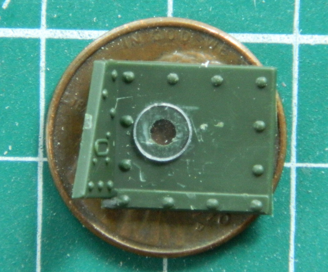
There are direct vision slots at the sides of each of the driver and bow gunner positions, so I drilled them out and trimmed them. Then I just put the panel in place to use as an alignment tool because those slots are supposed to go all the way through):


Yep…there’s gonna be LOTS of resin carving and fitting to come (and this is just the fighting compartment…there’s still the turret…whichever one I decide to go with):
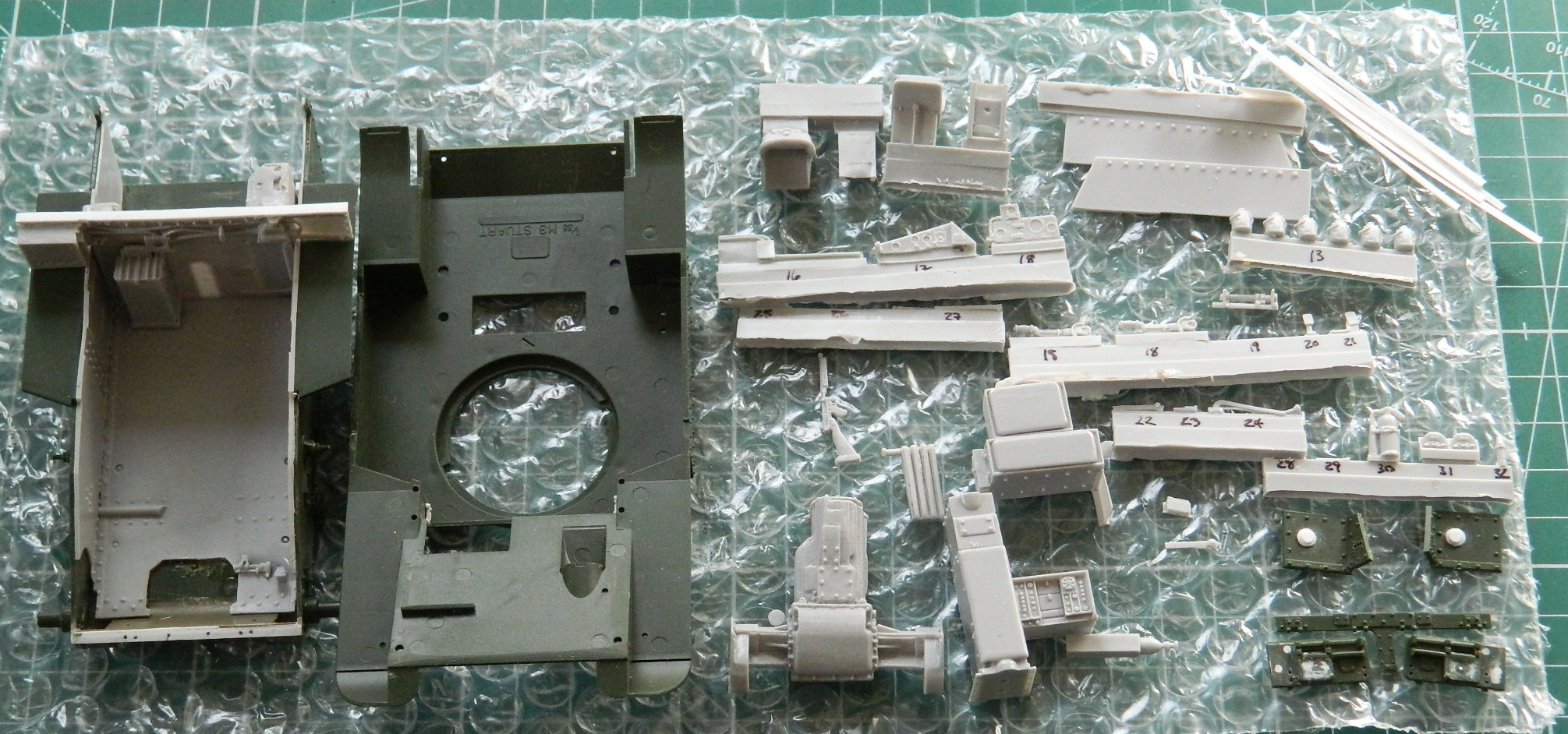
Until the advent of the M24, America’s armor was mired in WWI and the armor of the 20s and 30s showed that. The M3 wasn’t an inspired design, even though it was the culmination of US armor design of the 30s. The main inspiration at the beginning of US armor (not counting the license-built French FT17) was the British Vickers six-ton (which was actually closer to eight tons) export tank. The M3 evolved from the M1 Combat Car (no…not something found on the Long Island Expressway…though that’s not a bad idea) and the M2 Light Tank. For really convoluted thought processes and design considerations, because the Cavalry was, by law, forbidden to have tanks, the M1 was called a “Combat Car” and was used by the Cavalry. The almost identical M2 was called a “Light Tank” and was used by Army Infantry…and both the M1 and M2 were built at the Army’s Rock Island Arsenal. From my viewpoint, it seems that even from the outset, nobody could really decide who was getting what equipment or what it should be termed. As a base to this institutional indecision, all this was happening (the limited extent it was happening) without much funding (Congress was very parsimonious during the inter-war years and kept military spending VERY low.)
Both the M1 and M2 were armed with machine guns, not cannons; the M1 with a .30 and .50 caliber machine gun and the M2 with two .50 caliber machine guns. The reasoning for this armament was that the .50 caliber machine gun could penetrate most armor of the early to mid-30s.

M1

M2
And then came the Spanish Civil War. This war was a preview of what would and would not work for machines and tactics during WWII. One of the observations was that Soviet T-26, armed with a 45mm cannon, was a more effective war machine than the German PzKpfw I, armed with a pair of 7.92mm machine guns or the Italian CV.3/35 (being turretless, it’s actually more of what is now called a “tankette” and less a light tank) armed with a pair of 8mm machine guns.

T-26

PzKpfw I

L3-35
It was decided that the M2 (the M2A3, specifically) needed to be upgunned and, since at the time the 37mm anti-tank gun was effective, that would do.
Defensively, it was determined that sufficient armor to stop a 37mm from penetrating (even though the Soviet T-26 was armed with a 45mm tube) needed to be added. However, it wasn’t merely a matter of just bolting/riveting more armor on. With more and thicker armor came more weight and the hull lengthened to accommodate a larger turret. To be able to push more mass around the engine was also upgraded to the Continental W670-9 radial aircraft engine. To be able to handle all the additional weight, the suspension bogies (using vertical volute springs) were moved closer together and the rear idler wheel was greatly enlarged and became a direct part of the load-bearing suspension. Most of the improvements to the M2 line were also applied to the M1 line as well (specifically the M1A1).
And none of this, even while the US Army was beginning to develop medium tanks (like virtually every major combatant of WWII was doing, except the Japanese), addressed the role lightly armed and armored fighting vehicles had on a battlefield where medium tanks were starting to appear (though later in the war, light tanks were referred to as “anti-tank gun bait,” hardly complimentary).
For whatever reason, in 1940 the US Cavalry mostly ignored the lessons of the Spanish Civil War and continued to concentrate their efforts on the M1 series of combat cars.
The changes necessary to turn the M1/M2 line of vehicles into something that could handle the 37mm, its recoil, and mass, evolved into the M3 line.

M3
The first widespread use of the M3 was lend-lease vehicles with the Brits in northern Africa. Though the initial shipment of Lend-Lease tanks was of the M2A2 in the summer of 1941, once production lines started producing the M3, deliveries switched to the M3.
As a side note…
There are no period references indicating that the Brits actually called the M3 the “Honey.” It’s not a British phrase indicating anything other than a bee product. The US didn’t name the M3 the “Stuart.” The Brits did.
The November 1941 operations, Crusader, was the first time the M3 was committed to battle and they did not fare very well. The M3 never really fared that well again in battle…not counting the Pacific.
For whatever reason(s), the Japanese did not invest adequately in armor, armor tactics, or anti-armor tactics (the latter they devised as they went along). When the M3 encountered the light tanks (some of which were called “medium” tanks by the Japanese…pardon me while I giggle) they fared better. The Marines first used the M3 during the Guadalcanal campaign effectively (also learning on the go how to fight with them and how to protect them against a very determined and inventive foe). The 37mm gun had a cannister round that worked well against massed infantry charges.
The M3 matured into the M3A1, then evolved into the M3A3 (almost exclusively provided to allies) and finally the M5 series. It was obsolescent at its first deployment and rapidly obsolete shortly after. It was reliable but had a very limited range (75 miles on hard surfaces…roads…45 miles off roads, and numerous M3s were captured by Germans in northern Africa after they’d run out of fuel and abandoned). Neither its armor nor gun were sufficient when it was first deployed and time did not improve those situations, not being remotely remedied until the advent of an entirely new light tank was produced, the M24.
If you’ve been following this build, by now you know I’m not remotely thrilled with the decal situation I have to deal with. They’re too thick. Could I make them work? My Ego tells me “DEFINITELY.” However, it’s the very same Ego that on more than one occasion landed me in the ER telling the attending nurse/doctor, “Well, it seemed like a good idea…”
It wasn’t. Ever.
I’m NOT PLEASED with the results of my decal-making endeavor(s). I was just about to bite the bullet (where the hell did that phrase originate, anyway?) and continue when I heard a rumor that Caracal Models (manufactured by Cartograph!) is producing two new sheets for the SR-71 Blackbird! I contacted Caracal and the rumor is correct. Since this build isn’t for me, I discussed this new development with the person this build is for. Thankfully, he’s a craftsman (different mediums) and understands that the time “saved” now taking shortcuts results in something that’s never really correct…and every time the eye falls on it, the thought, “Why the intercourse didn’t I wait and do it properly?!” follows.
So I’m waiting and doing it properly.
At present, I have about 775 hours into this thing. What…like I should take a shortcut now?!
I’m going to put this thing (safely) away and covered for now. In the meantime, I’m going to start a different project.
See y’all here when the decals are in hand! (And hopefully at the next build as well.)

