Colonial Viper MkII (Moebius Models) 1/32 Scale Build #1, Part 1 – Parts Layout and the Start
This is going to be interesting (hopefully not in the Chinese sense). I’ve never done fictional spacecraft before. My initial intent was to model this as realistically as possible, but that balloon was popped almost immediately. Nothing about this is realistic, or as a friend of mine said, “Science by magic.” Okay, then what am I actually building here? It’s a movie prop that existed in two forms; digital (CGI) and practical (something real). That’s made the build easier and more difficult at the same time. The easier aspect is the availability of primary sources. Just watch the show and when a bit of detail flashes past, take screen captures of pertinent scenes. The difficult part is internal. As designed, this thing could never move under its own power and it irks a part of me. The rest of this thing should be fun!
Science by magic.
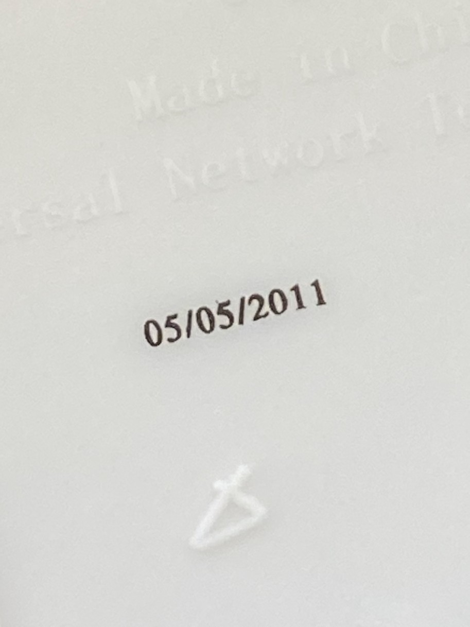
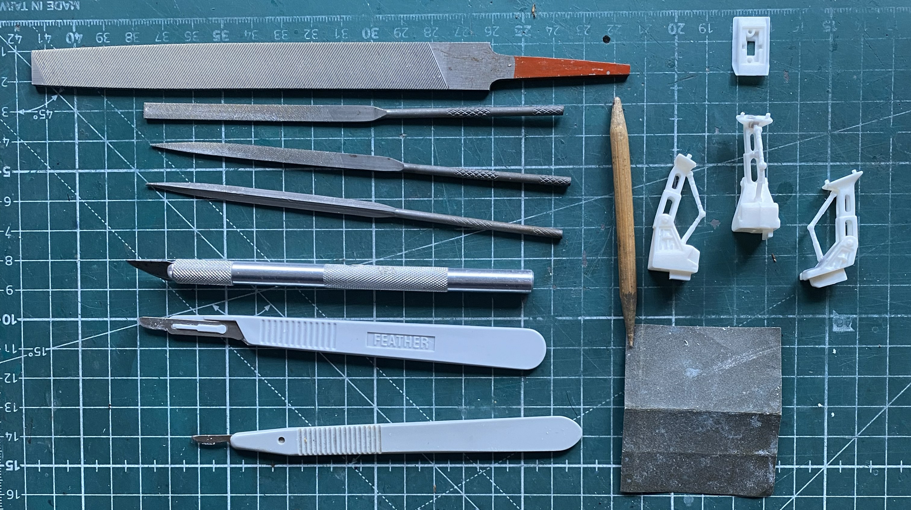
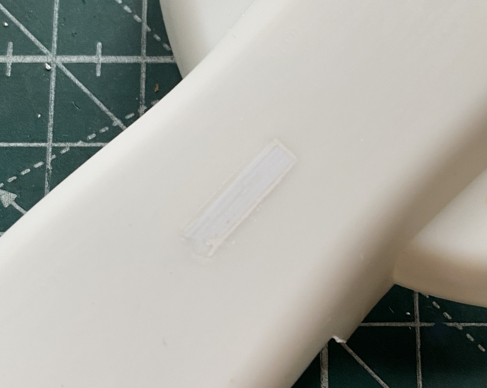
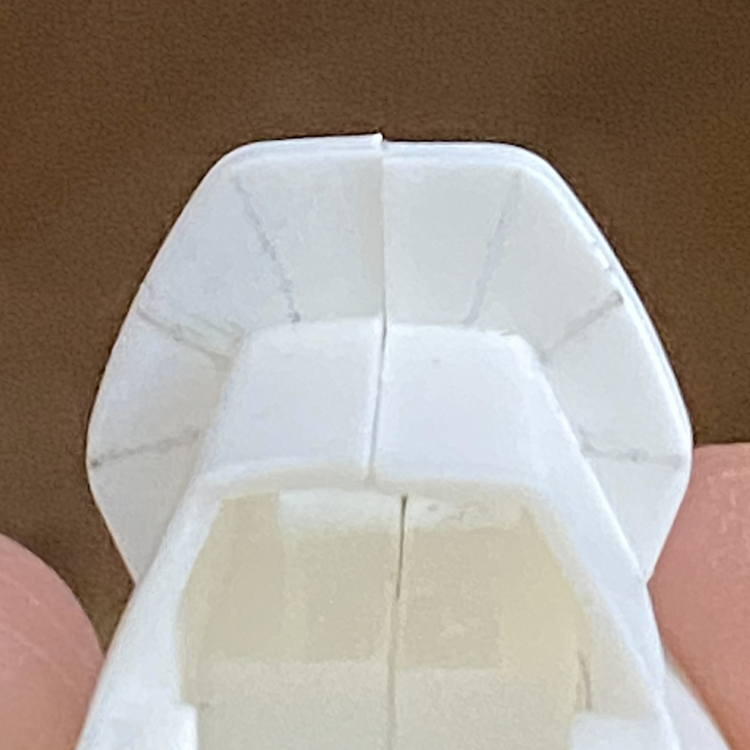
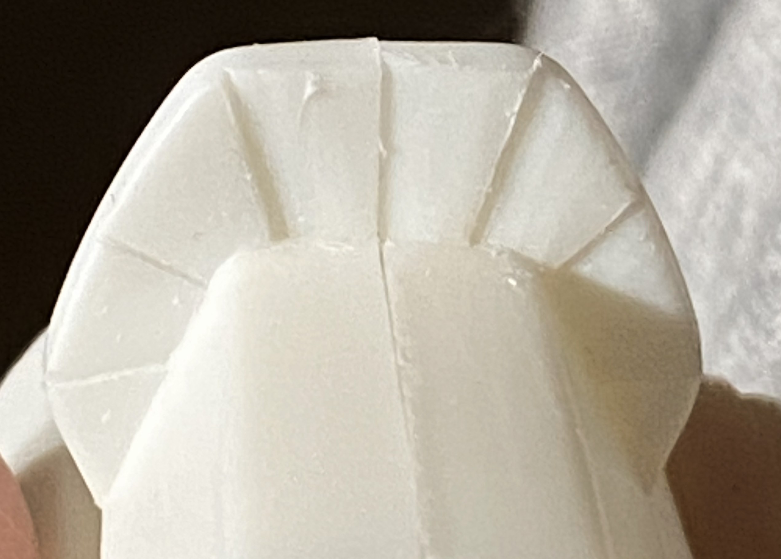
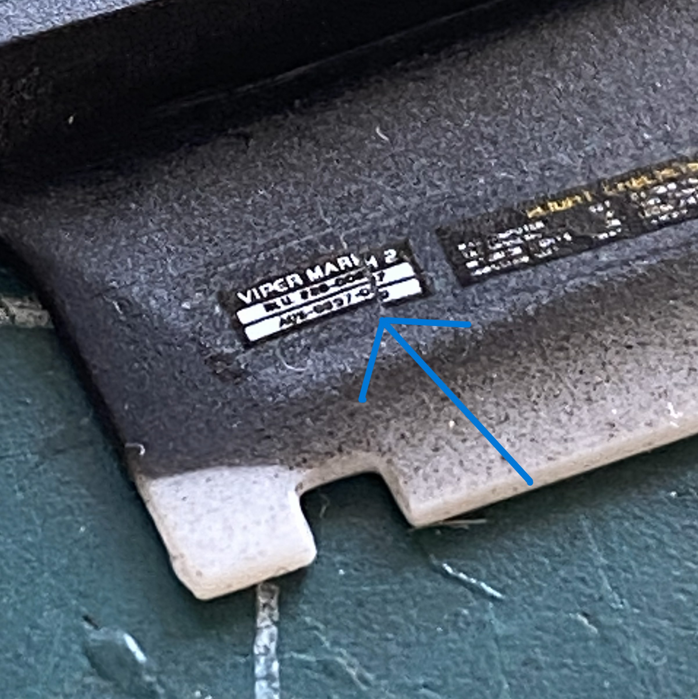
This is what I have to start with. This is the first time I’ve seen the manufacturing date (I assume, anyway) printed on kit parts (inside of the wing):
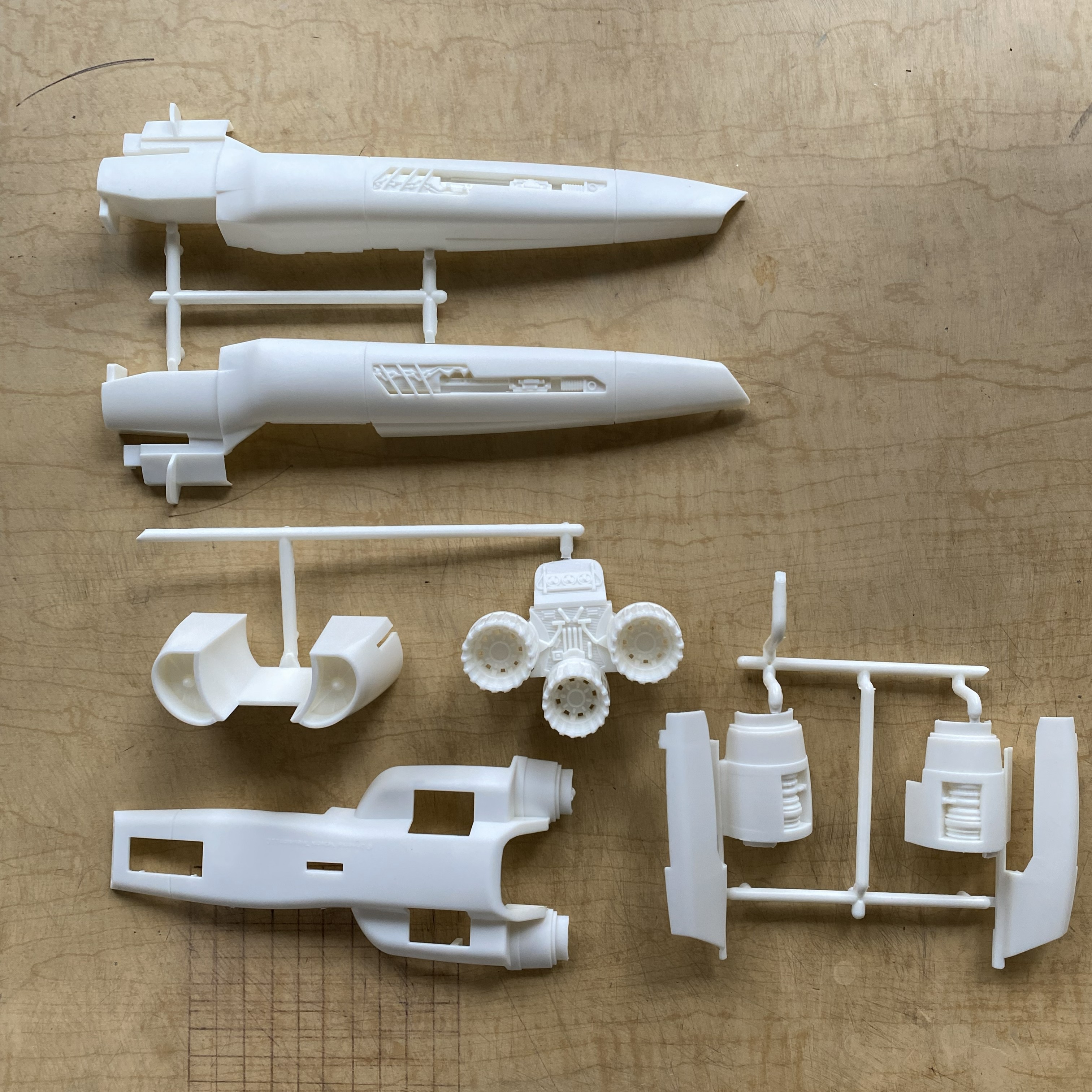
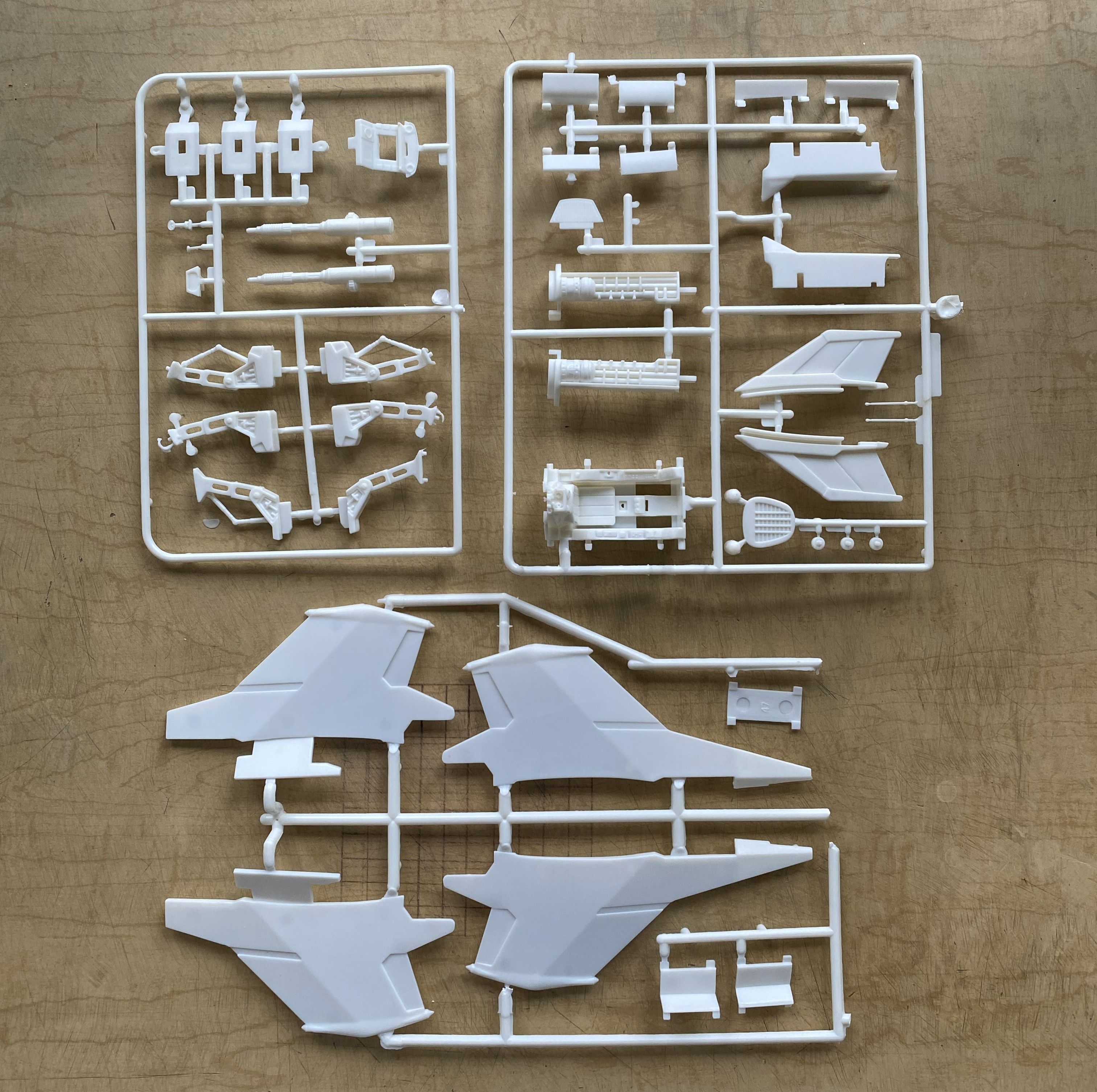
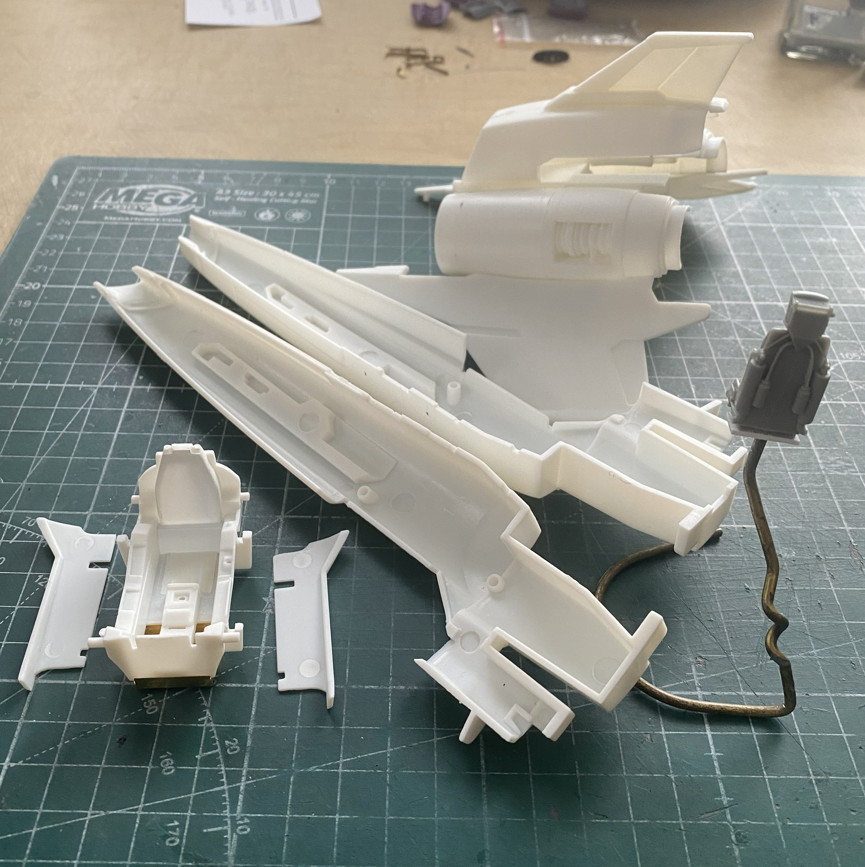
That noted, here’s what’s in the box:
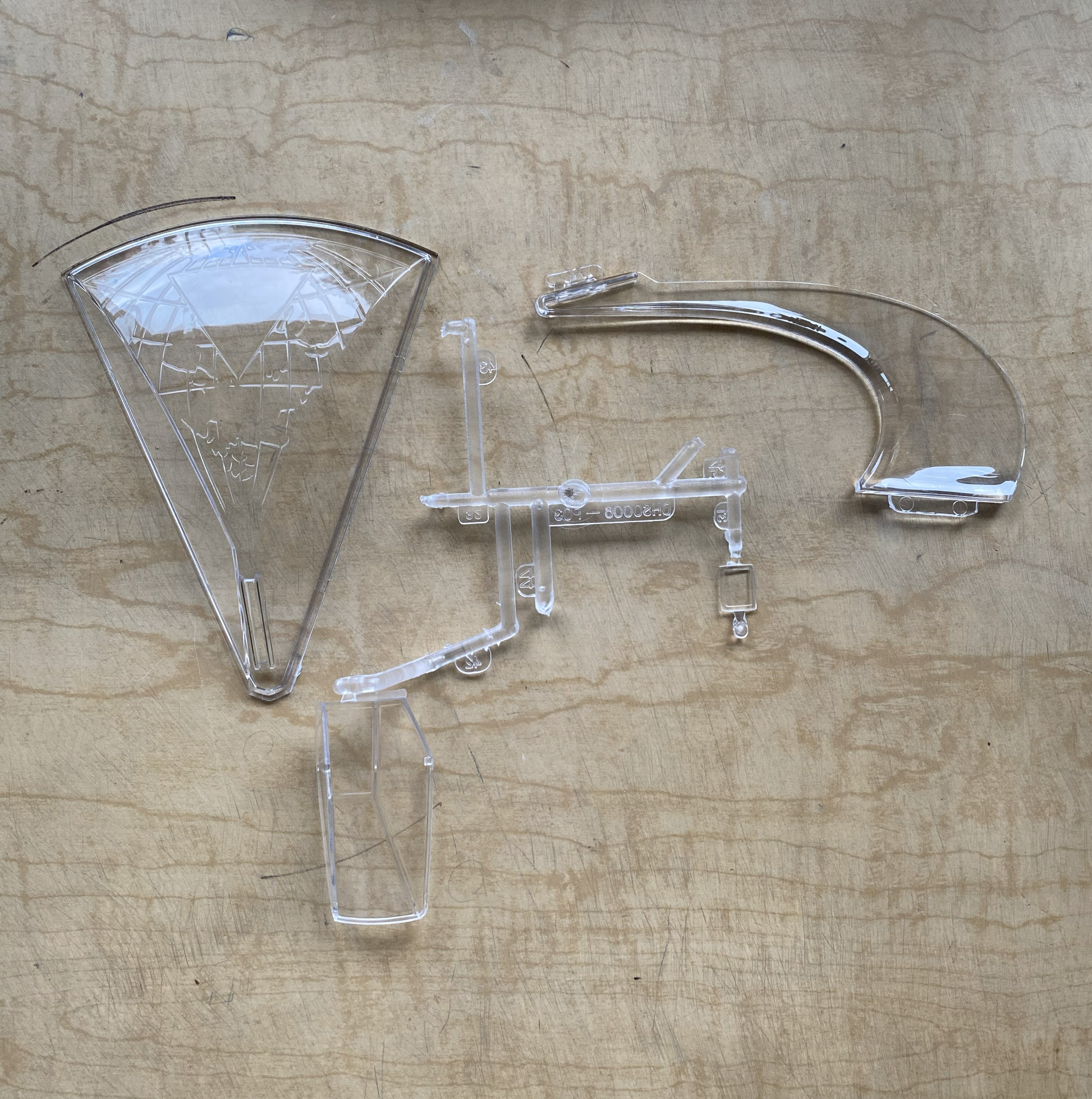

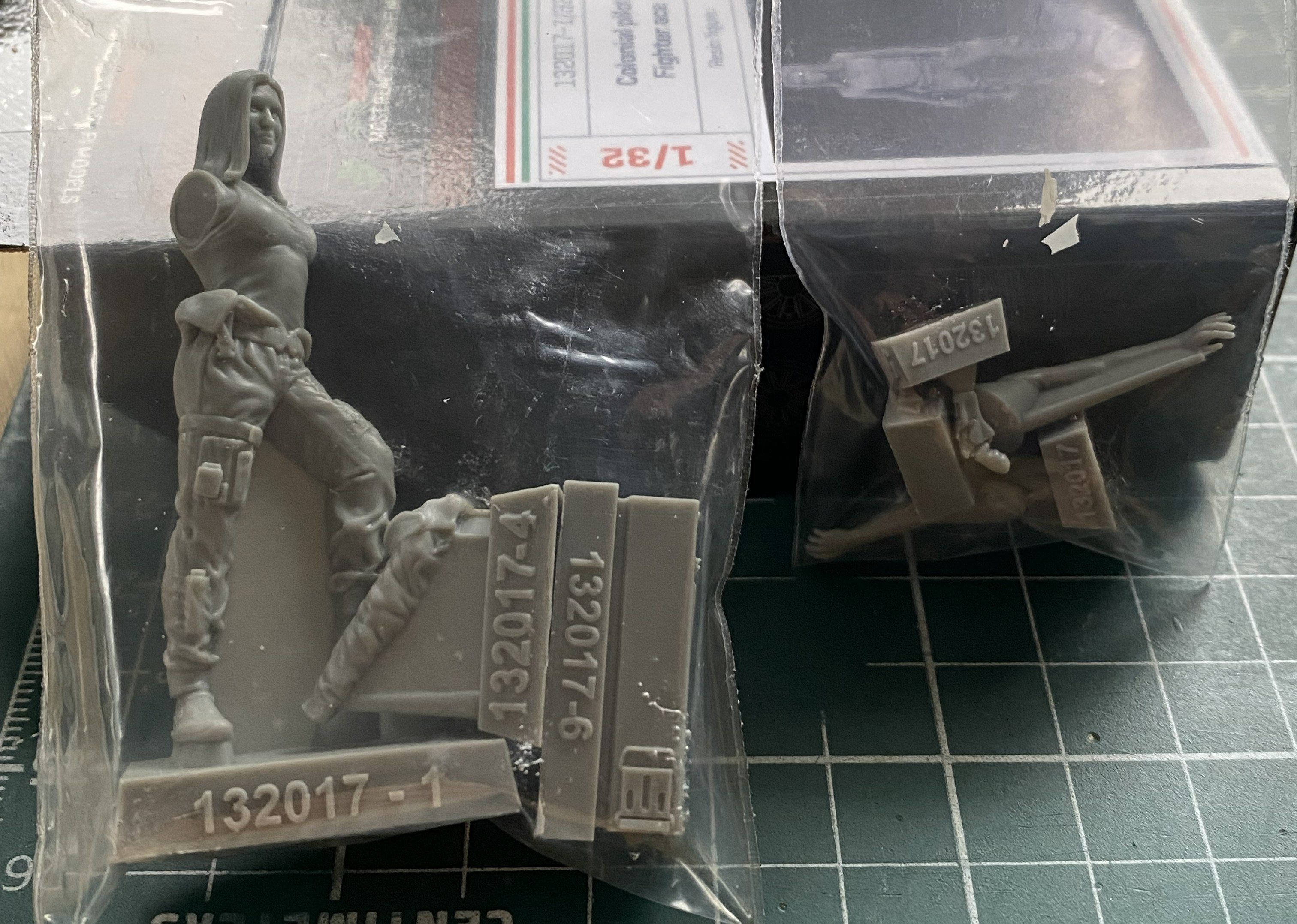
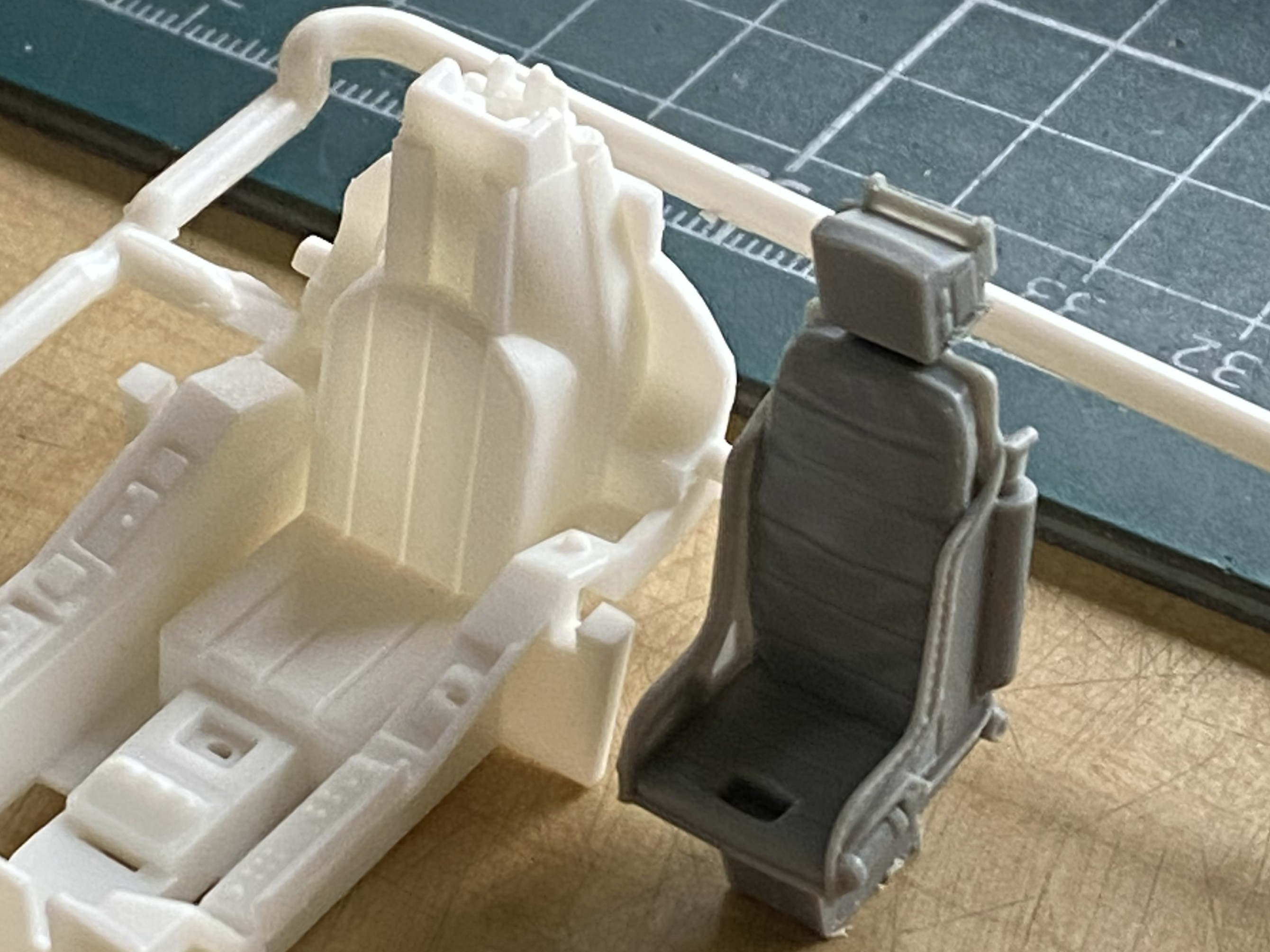
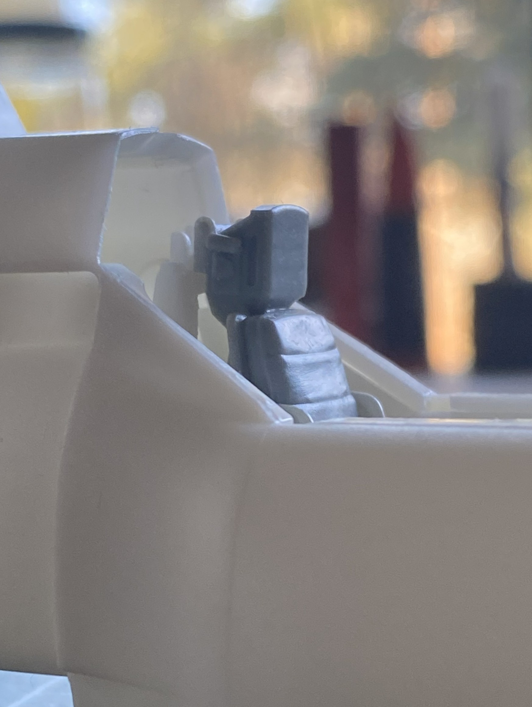
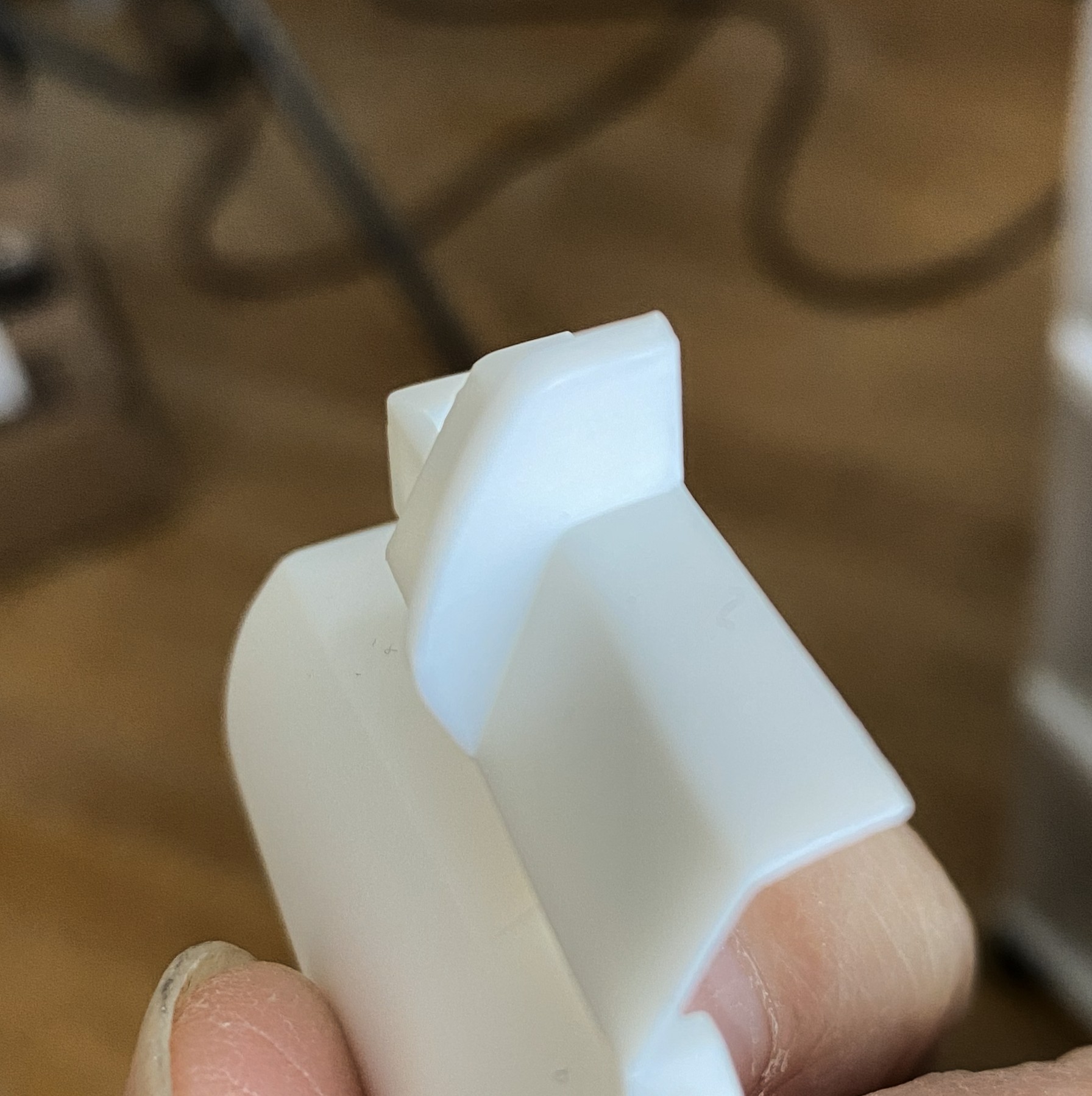
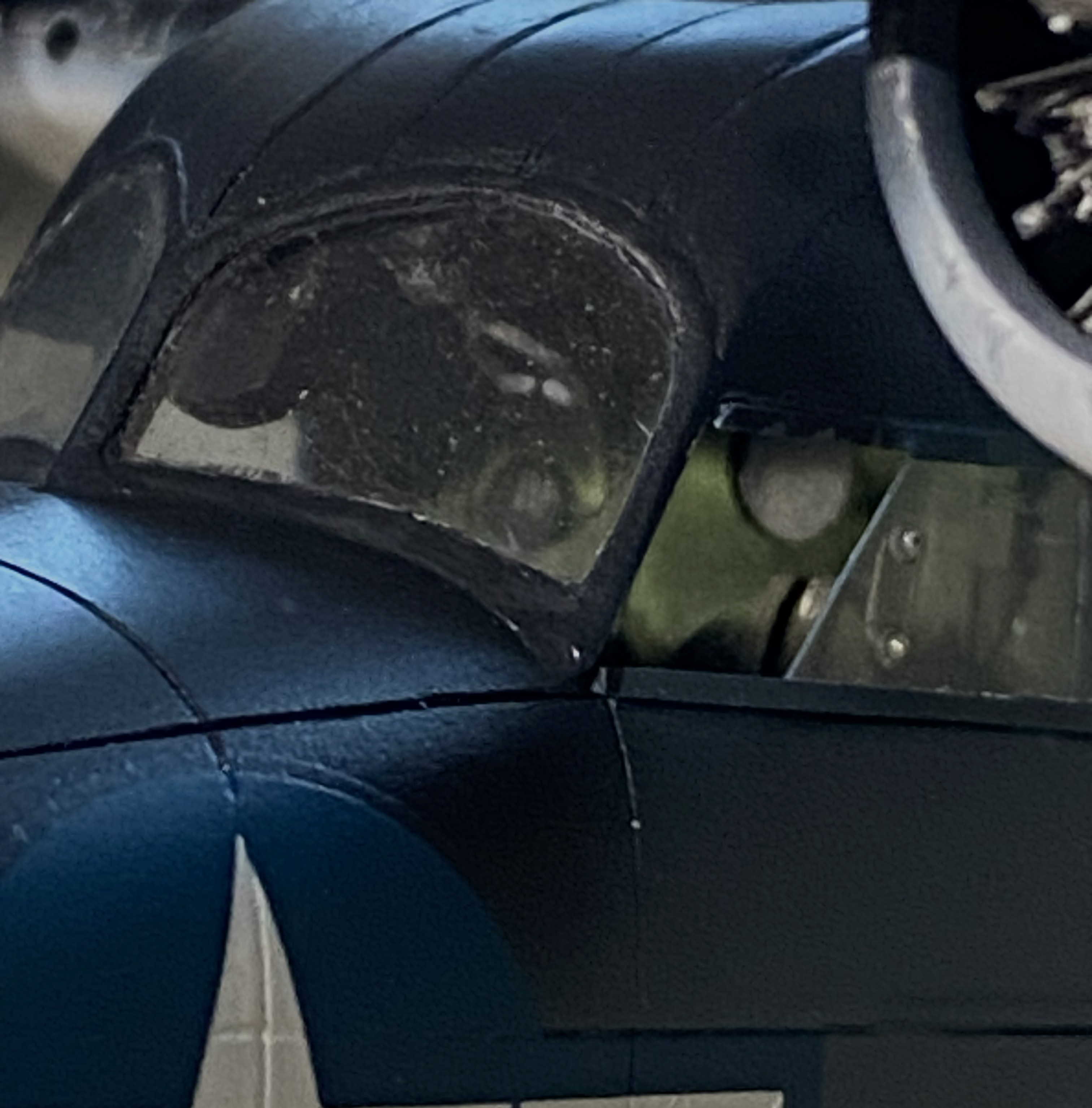
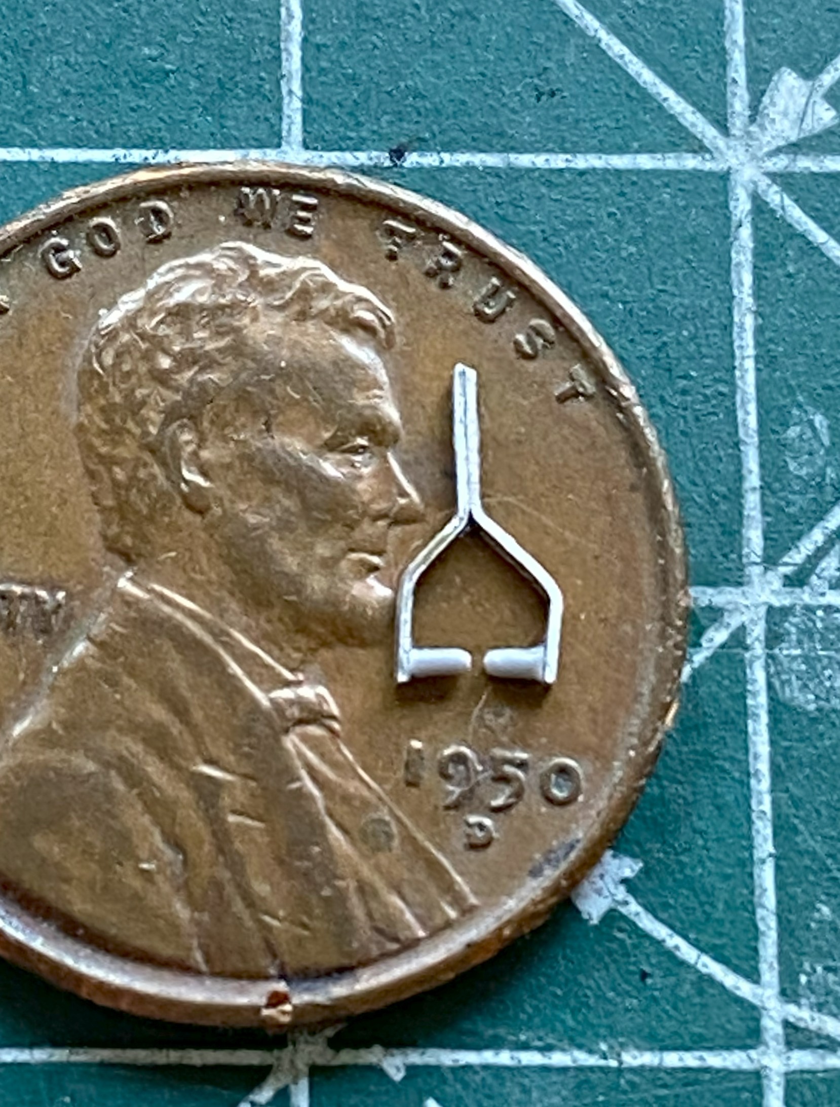
The first thing that caught my attention was the quality of the clear parts, in particular the canopy. Thin, clear, and mostly well done (more about that in more detail than you’d believe later). The second attention-getter was the resin figure. Overall, it’s nicely done. However. If you intend on using it, the joystick the right arm is holding (the unattached arm) is way too high. If you’re using the figure, you’ll have to deal with that (but since I’m not, I don’t have to deal with that).
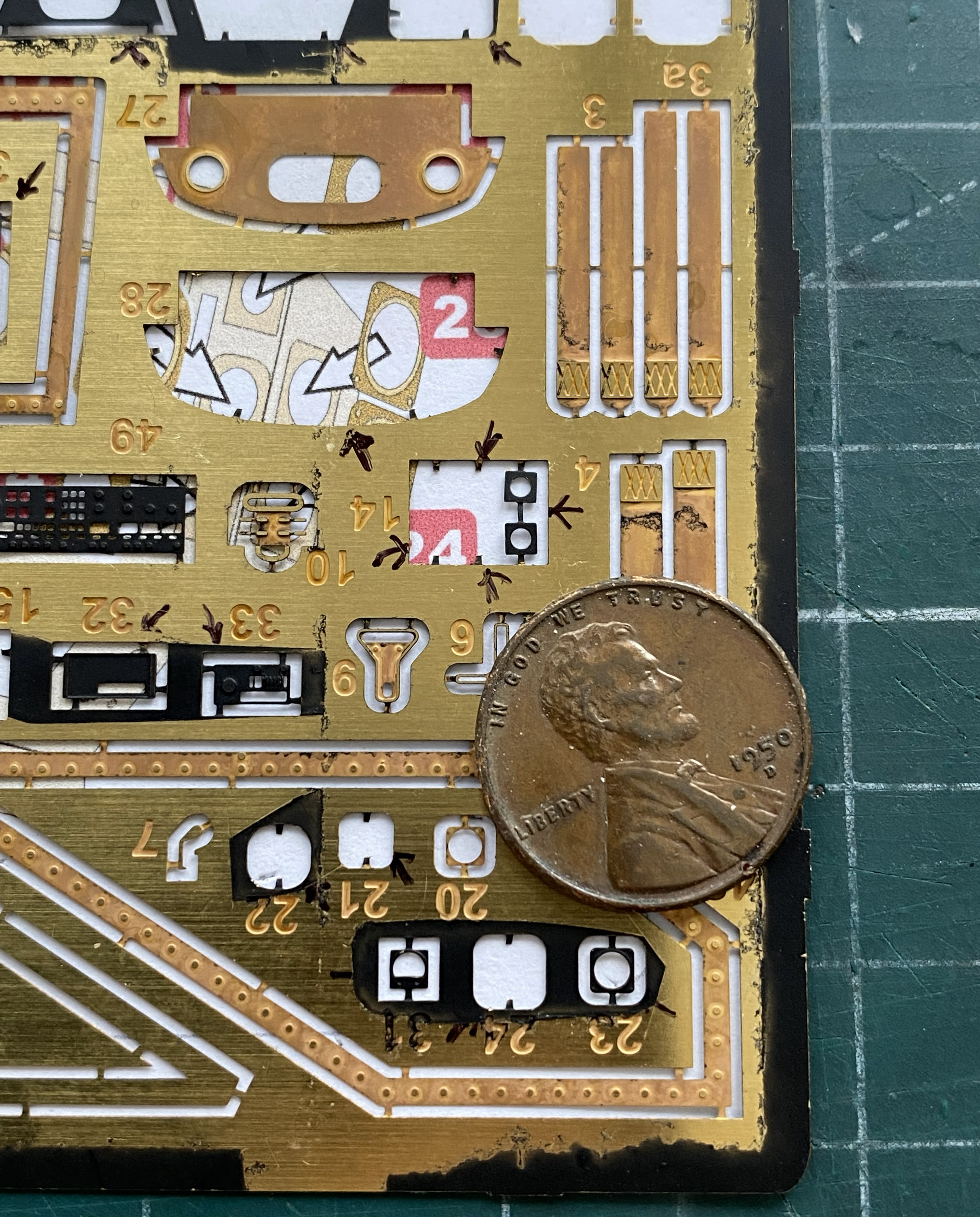
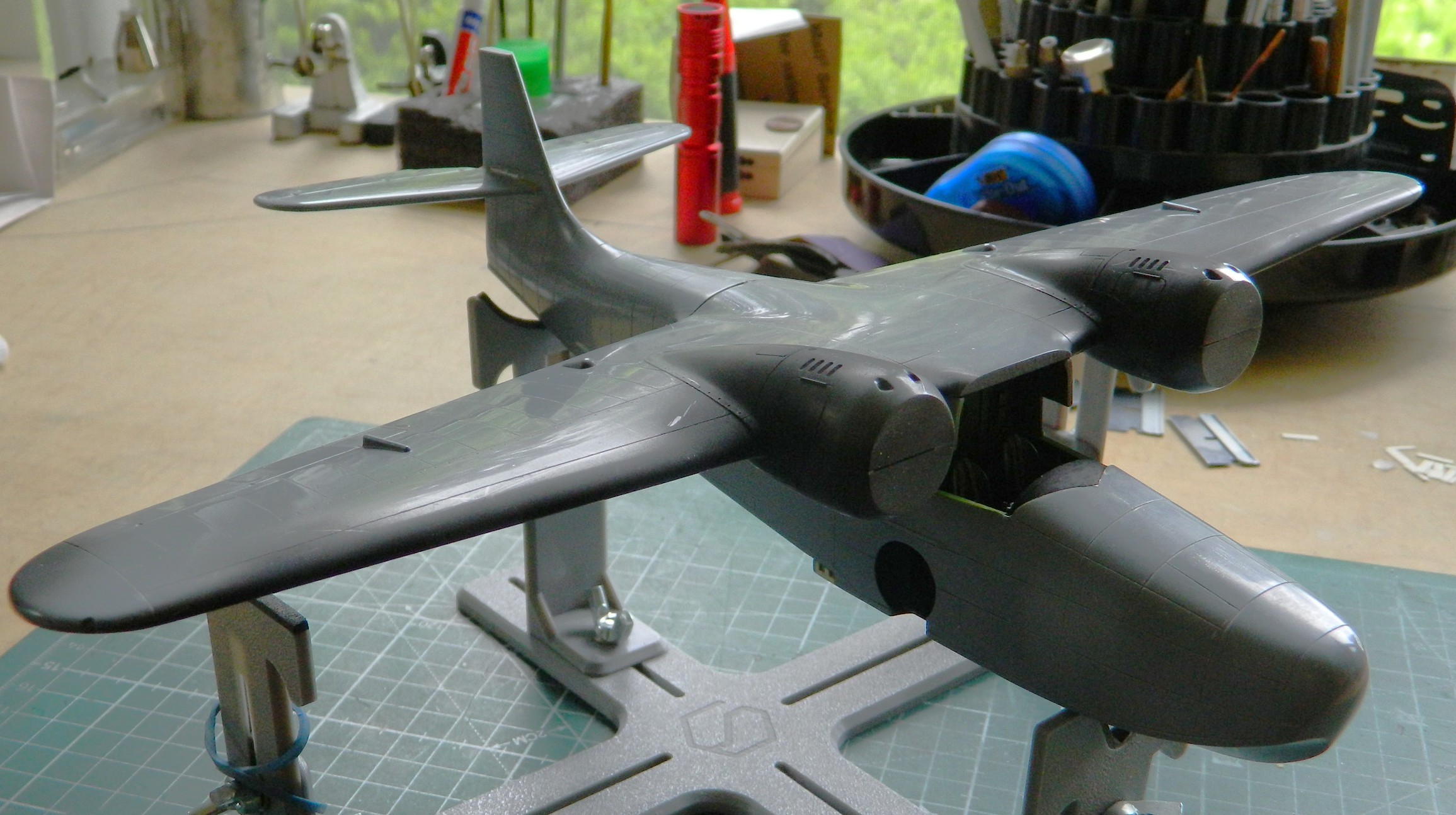
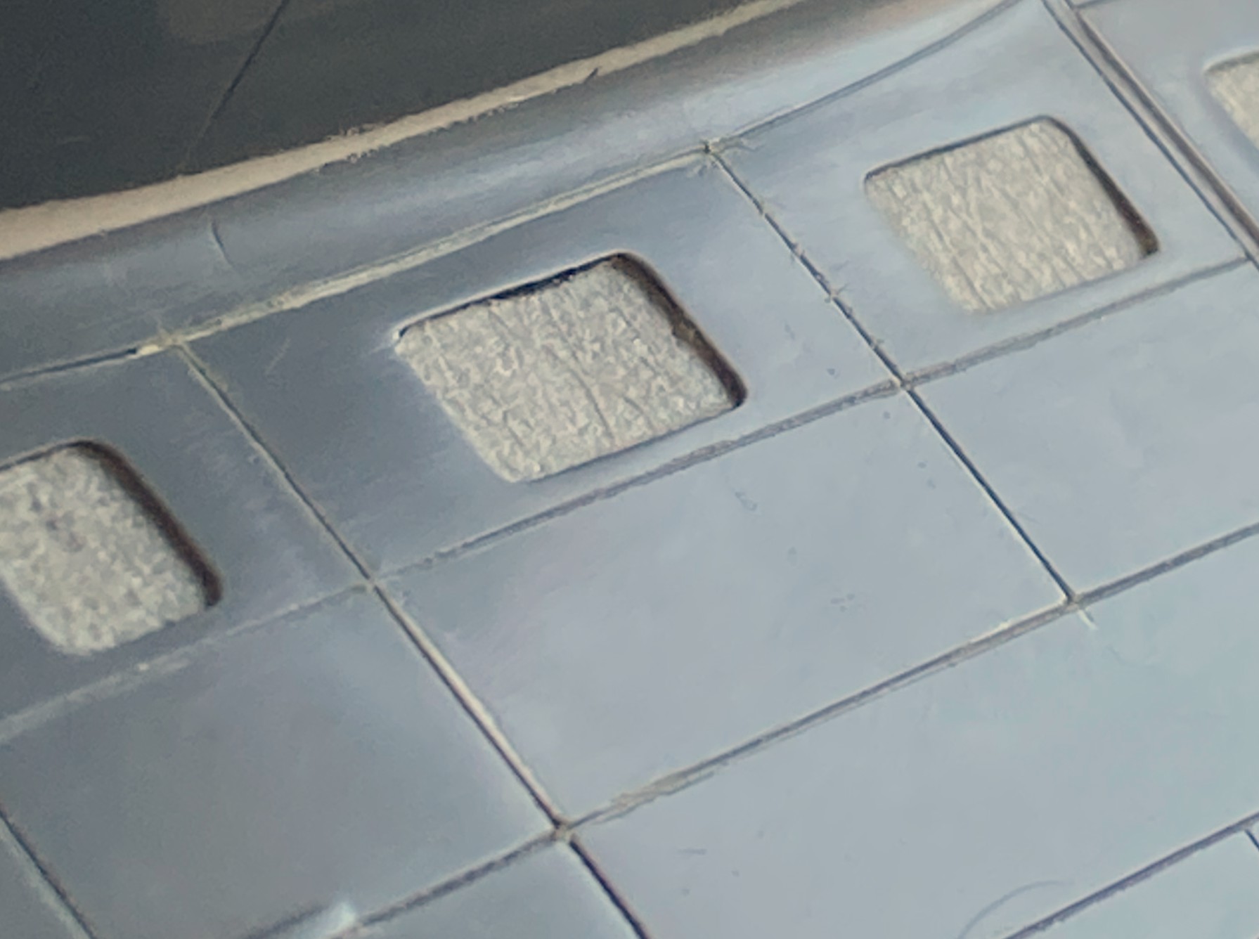
As you can see, it’s not a kit with a high parts count. It’s simple. Oh, yeah?! Well I can fix that. I’ll fix that by seeing how many of these bits I can shoehorn into it.
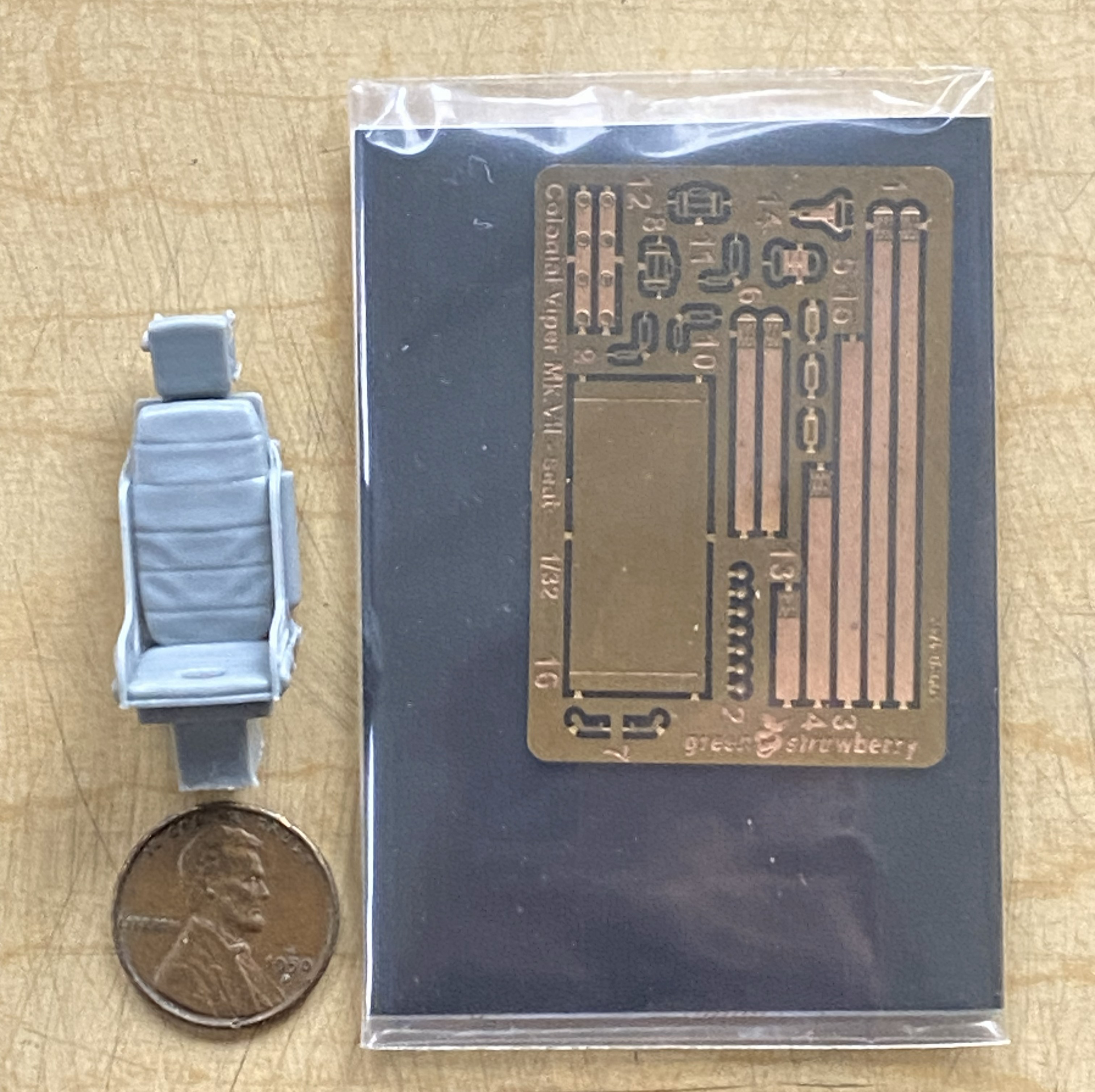
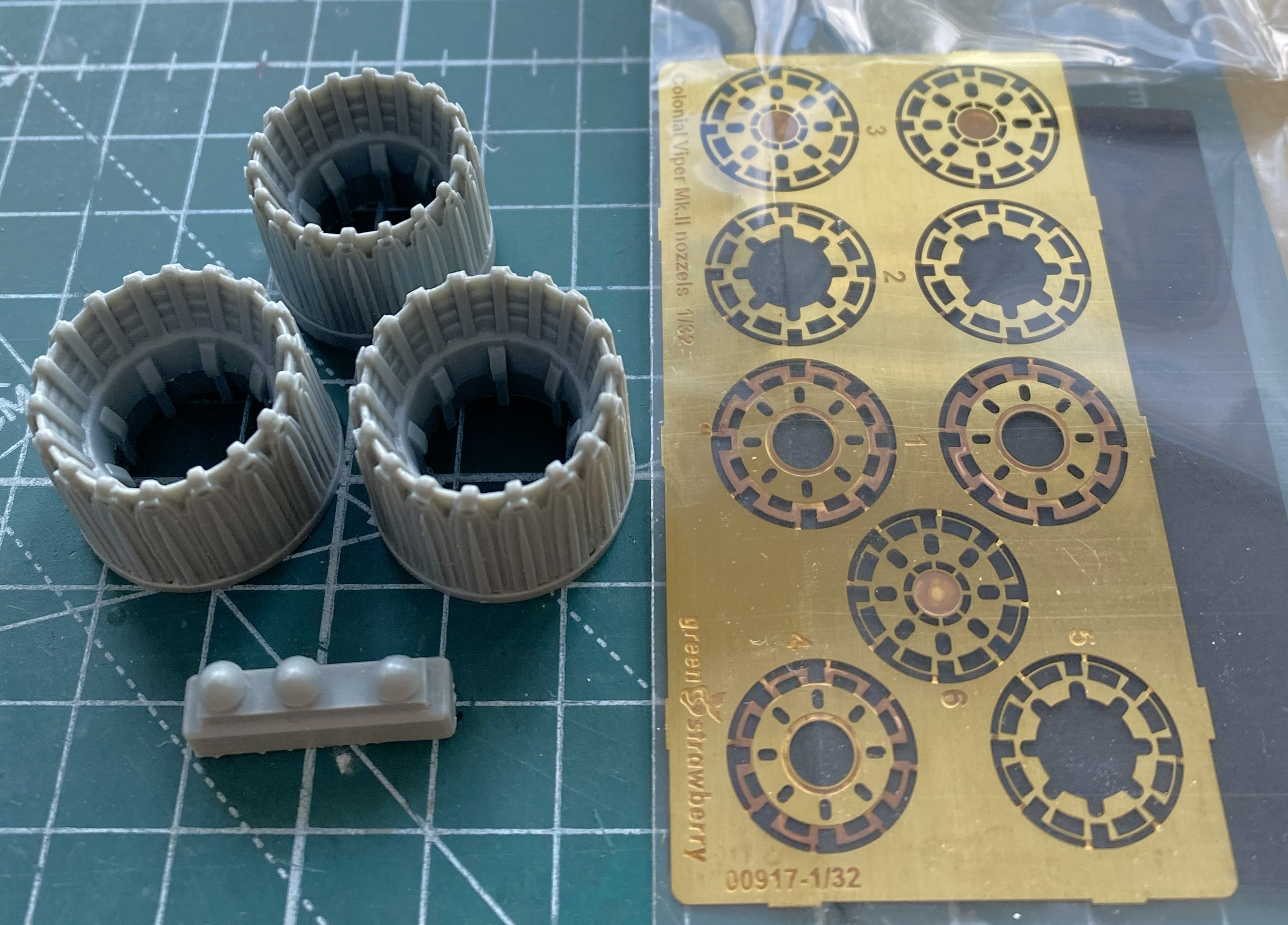
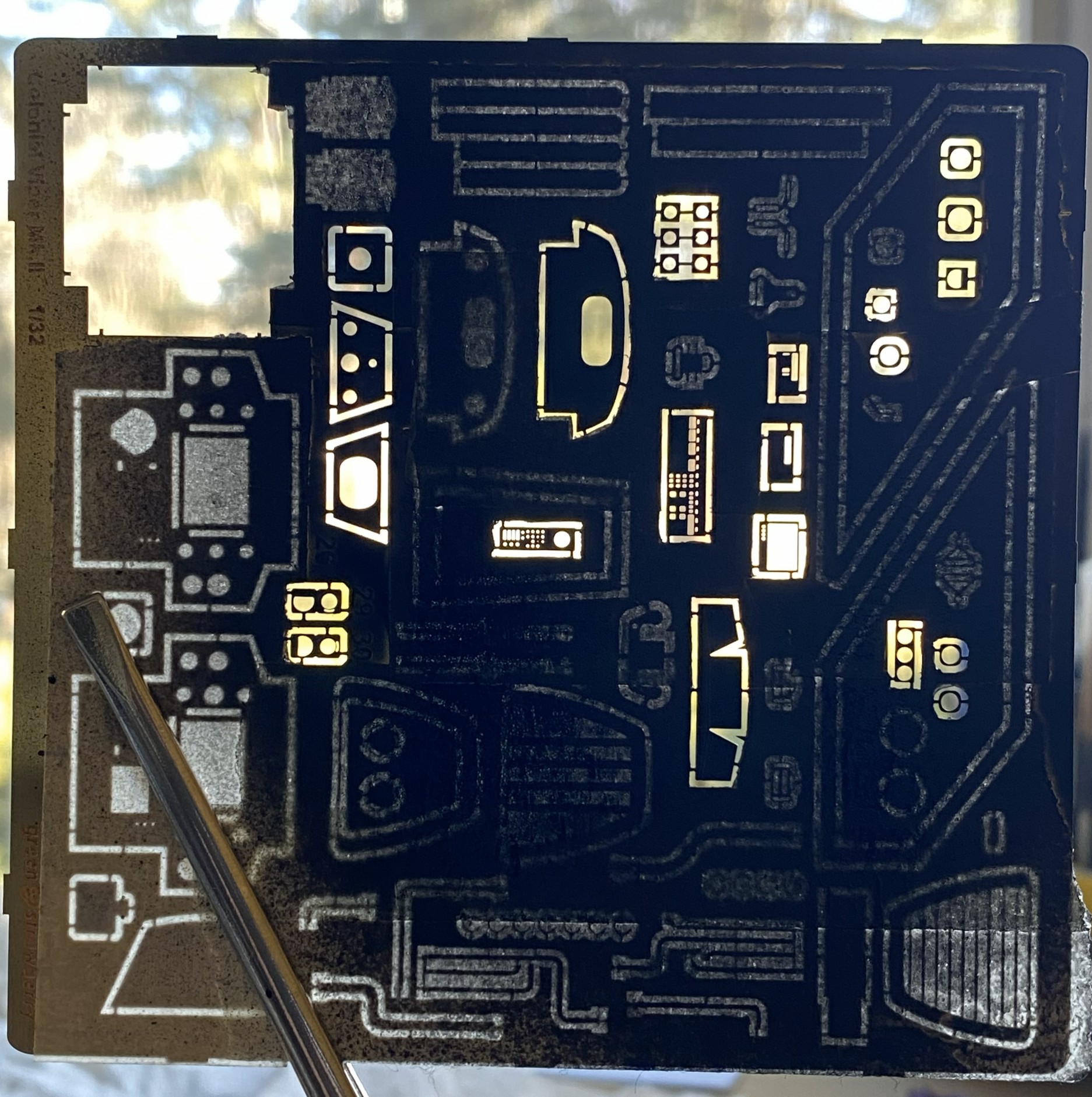
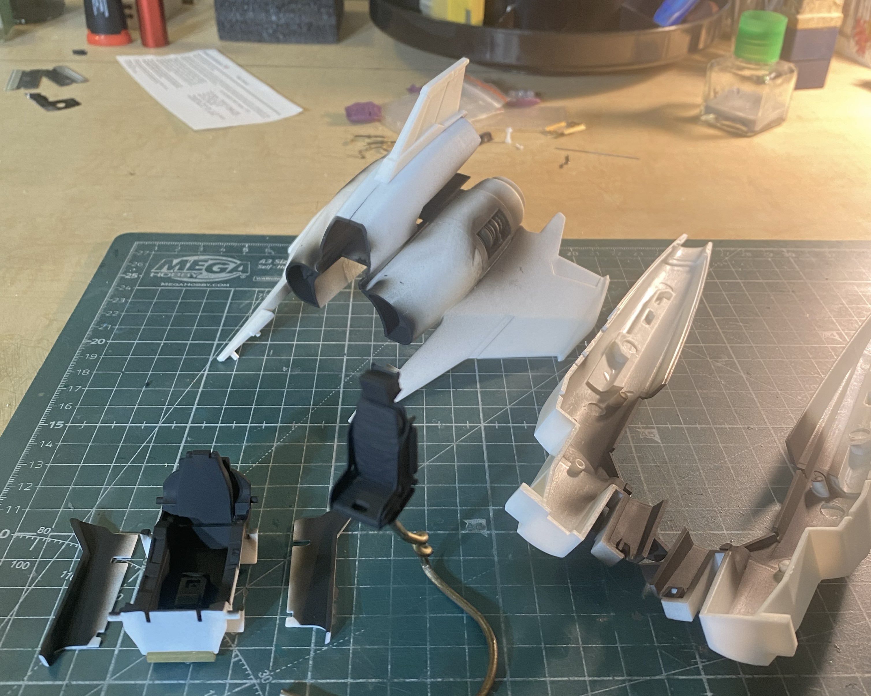
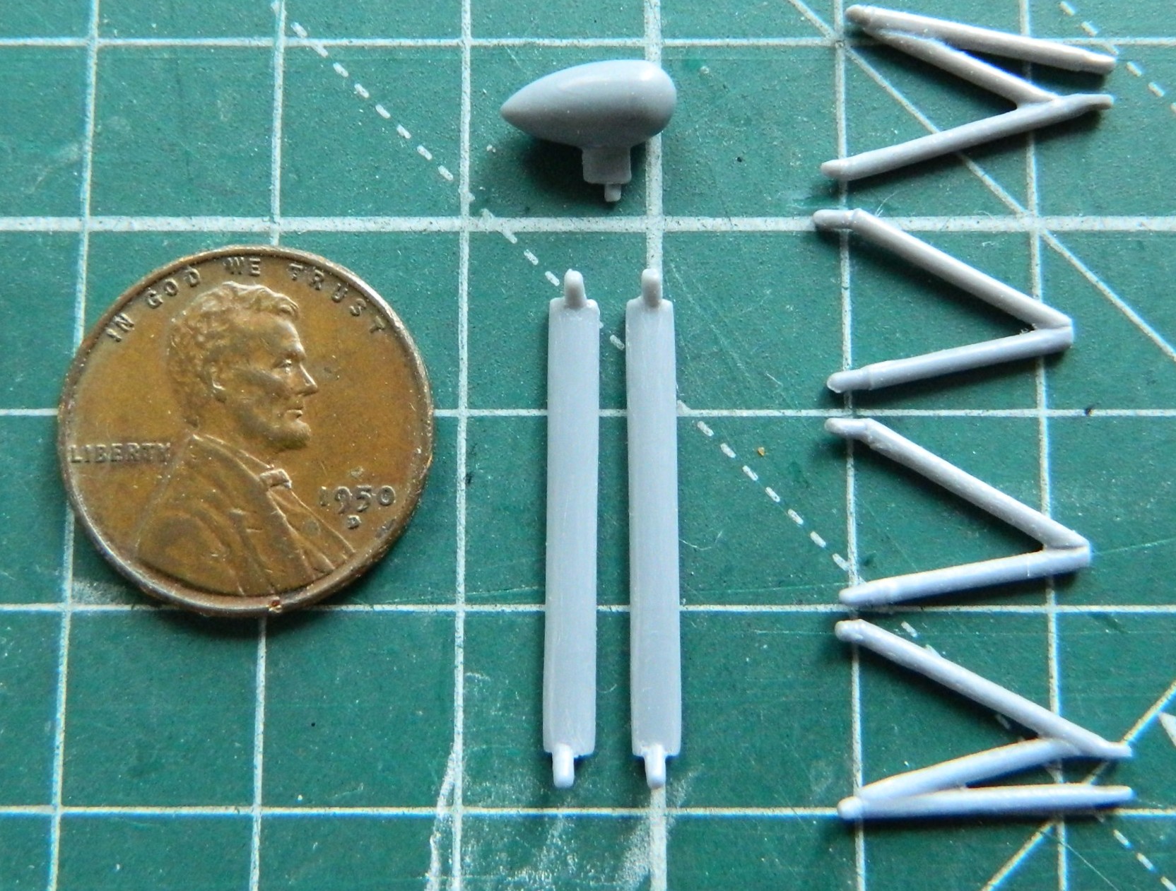
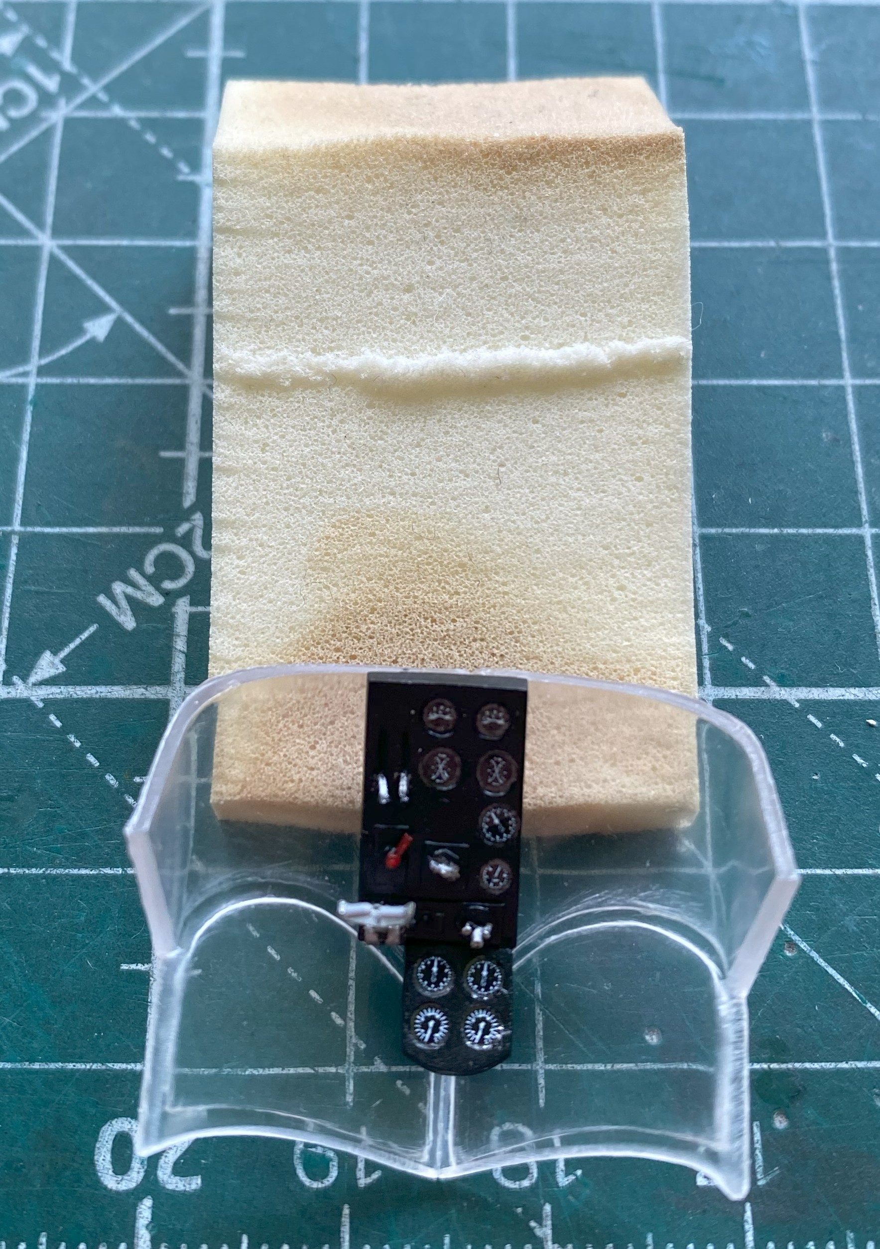
Green Strawberry (available from Moebius) makes all of the AM bits I’ll be using. One set supplies the resin seat, PE parts for the panels, etc., and photo-reduced images for all screens and instruments. And a word about that… The AM set for the cockpit offers two sets of gauge faces. One set is for a standard build, the other set is for those of you who like to add lighting. The kit is designed to allow the forward instrument panels to be back-lit. The set of gauge faces with a black surround are for illumination, the white (which are the ones I’m using since I’m not building this with lighting) are for a typical build. All of them are excellent and fit well. The other PE set is for landing gear bays. There is a resin/PE ejection seat, also nicely done. Since I have a profound appreciation for the character of Kara “Starbuck” Thrace, and the kit offers decals of her specific ship, I’ll also be adding Starbuck. Green Strawberry (or whomever did the sculpting) did a great job with this resin figure; it even looks like her. And since I just can’t seem to resist throwing everything at a kit, I’m also replacing the kit’s exhaust nozzles with resin/PE aftermarket parts:
It’s true…there isn’t anything that I can’t complicate. It’s a talent.
At this point of the build, all of the AM parts had yet to arrive and I was still thinking that I’d be able to make the engines more realistic. My intent was to open a panel on top of the engines (after creating one, but to fit canon, it would be an inspection panel, not an inspection cavern as the kit has them) and perhaps extend a bit at each end. Had I looked just a bit further, I’d have noticed that any attempt to expand on the engines wouldn’t work. There isn’t enough room to create engine extensions and fit canon. But I didn’t look further and I went down this empty rabbit hole.
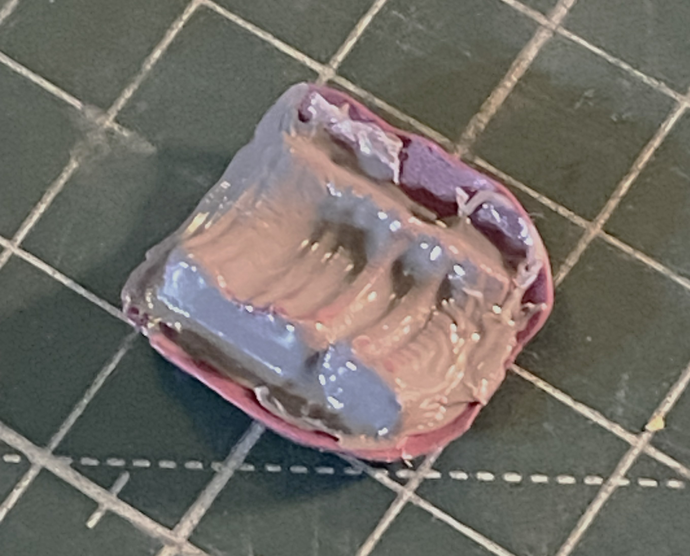
Rather than scratchbuild every addition, I’d thought that I could copy what detail was provided and then work it into an overall acceptable engine. To get molds, I used silicone molding putty:
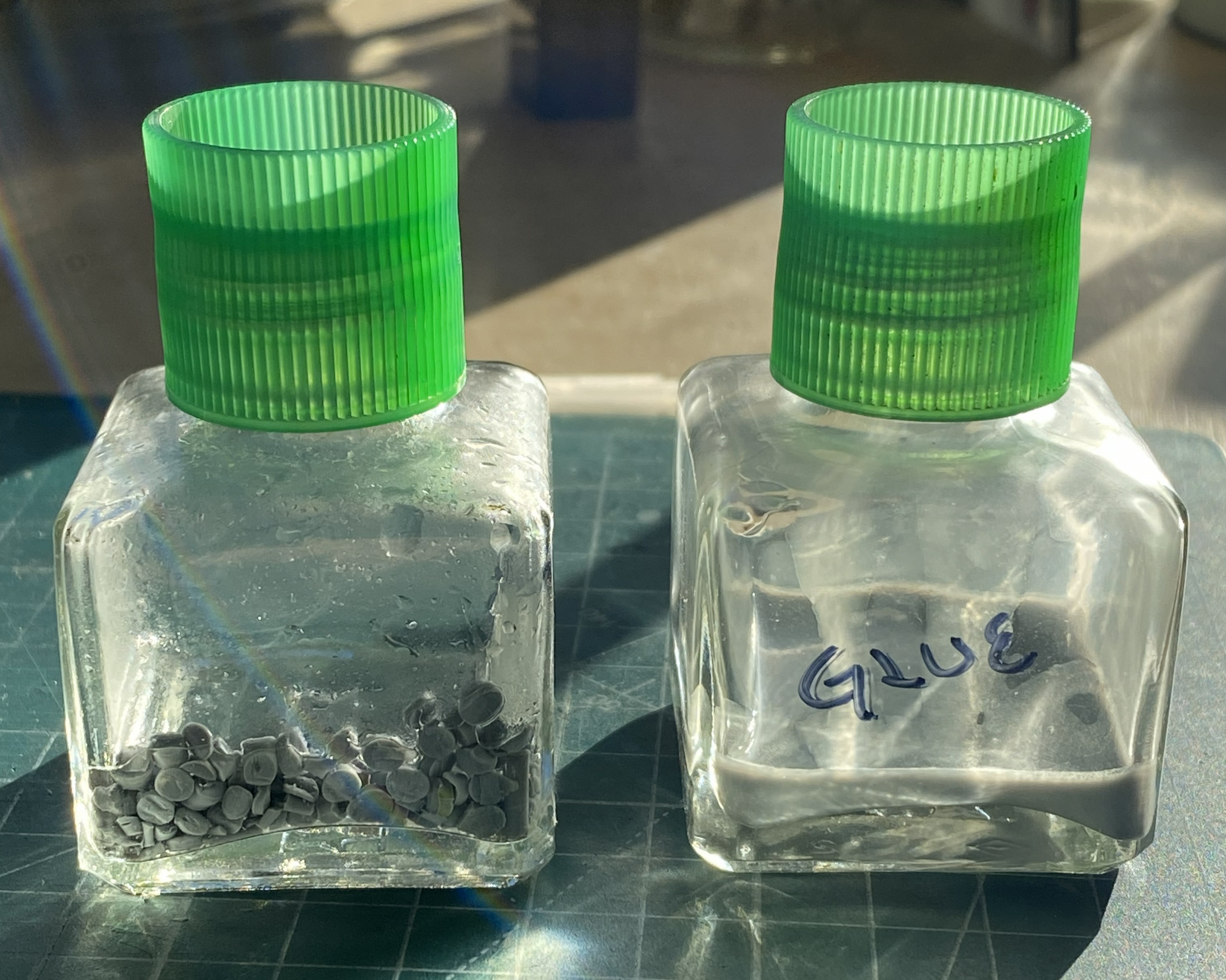
While the putty was curing, I investigated which would make “plue” (plastic and glue) to fill the molds. What would work better, acetone or Tamiya Extra Thin cement? I used two empty glue bottles, placing cut plastic pieces in each bottle and then putting enough acetone/glue in to cover the pieces. The tilted bottle has acetone (tilted so that the acetone would cover all the plastic) and the other has cement:
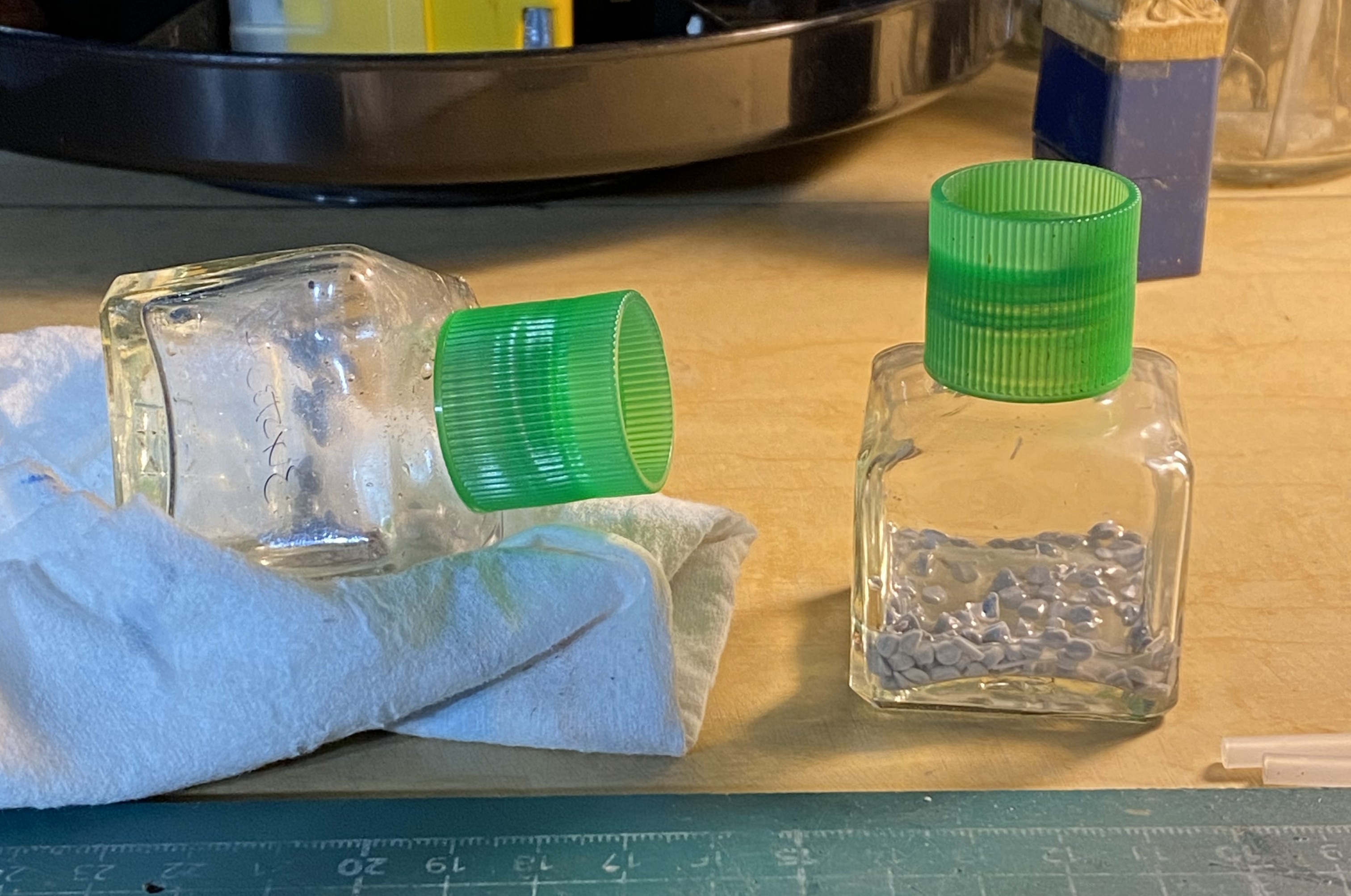
After sitting overnight, the clear winner is the glue. The only affect the acetone had on the styrene was to make the surfaces slightly tacky…that was it:
By then the mold was ready to fill:
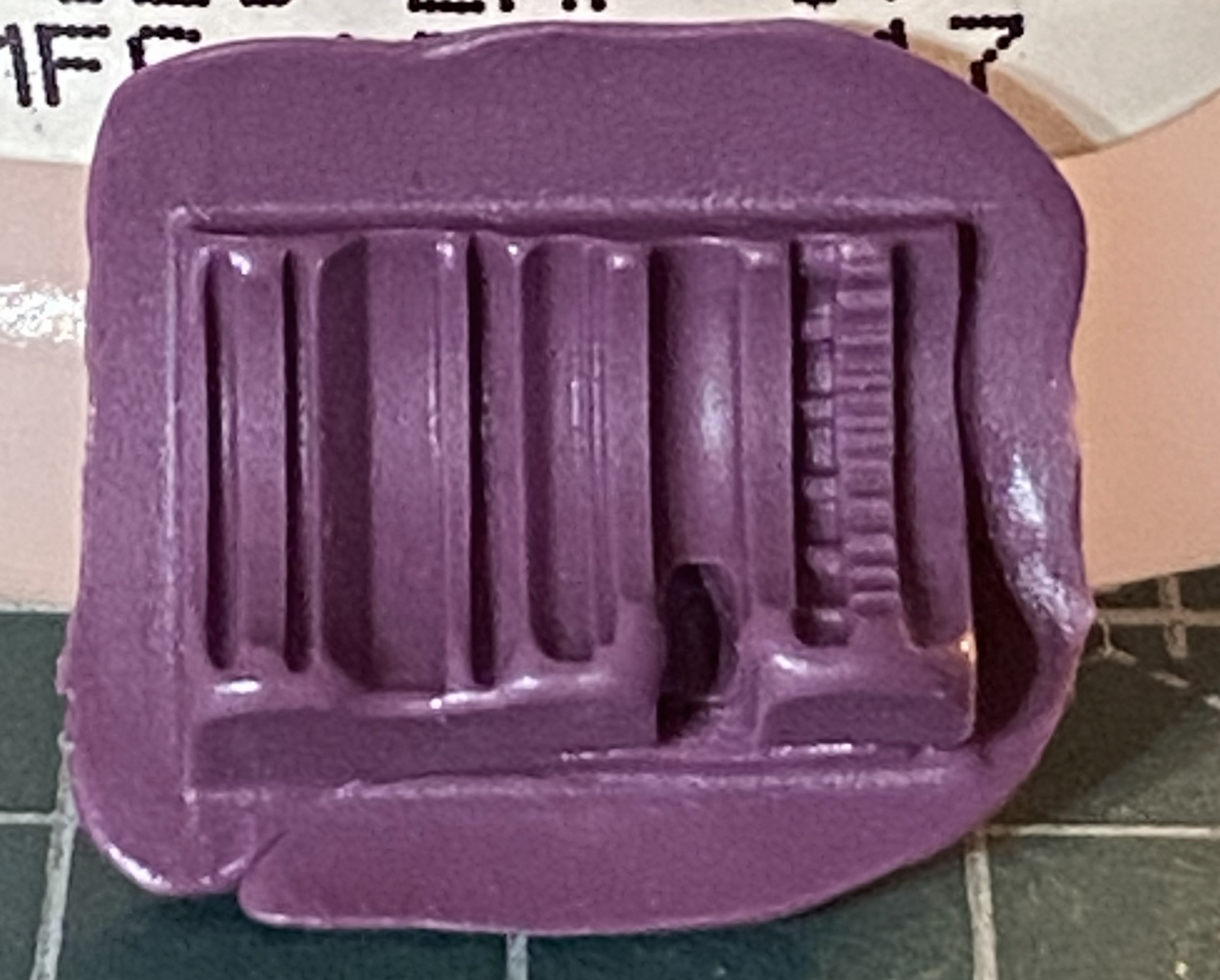
It’s been a while since I’ve used plue and the mold in the above photo shows it. I put on much heavier a coat than I needed to. Several thin coats works best. Another “interesting” trait is that the more the plue is manipulated in/on the mold, the more bubbles created, which this little lovely reminded me of:
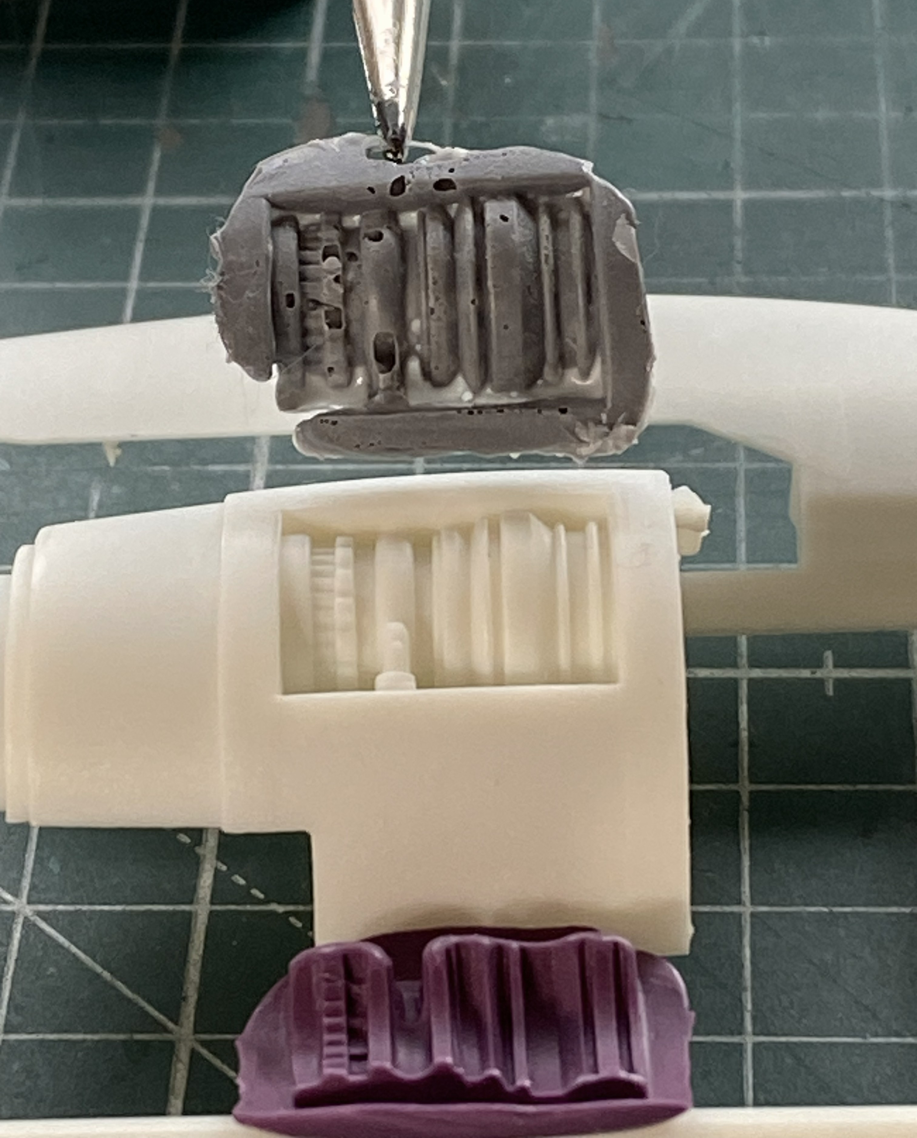
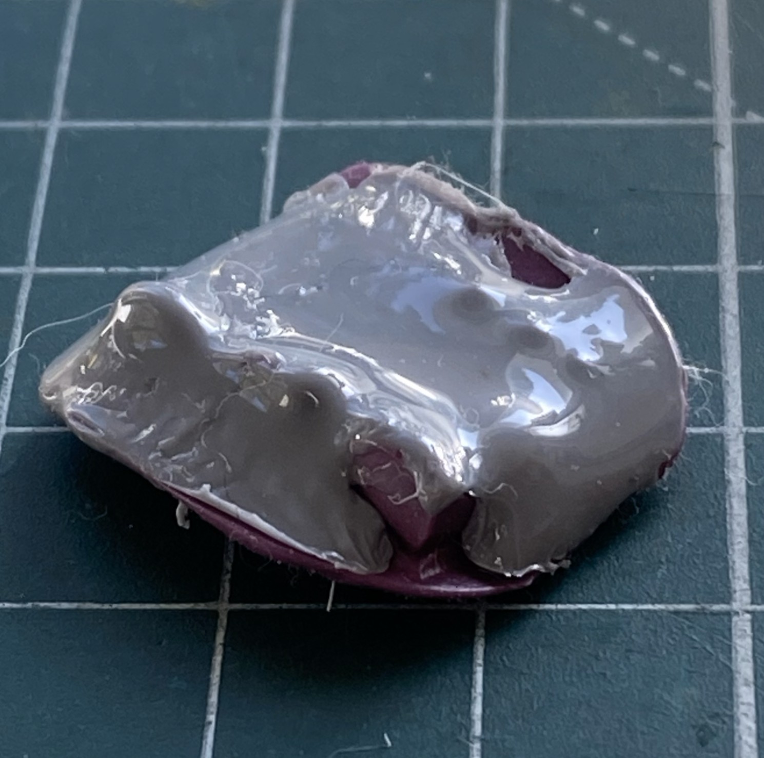
Next attempt using thinner coats worked better:
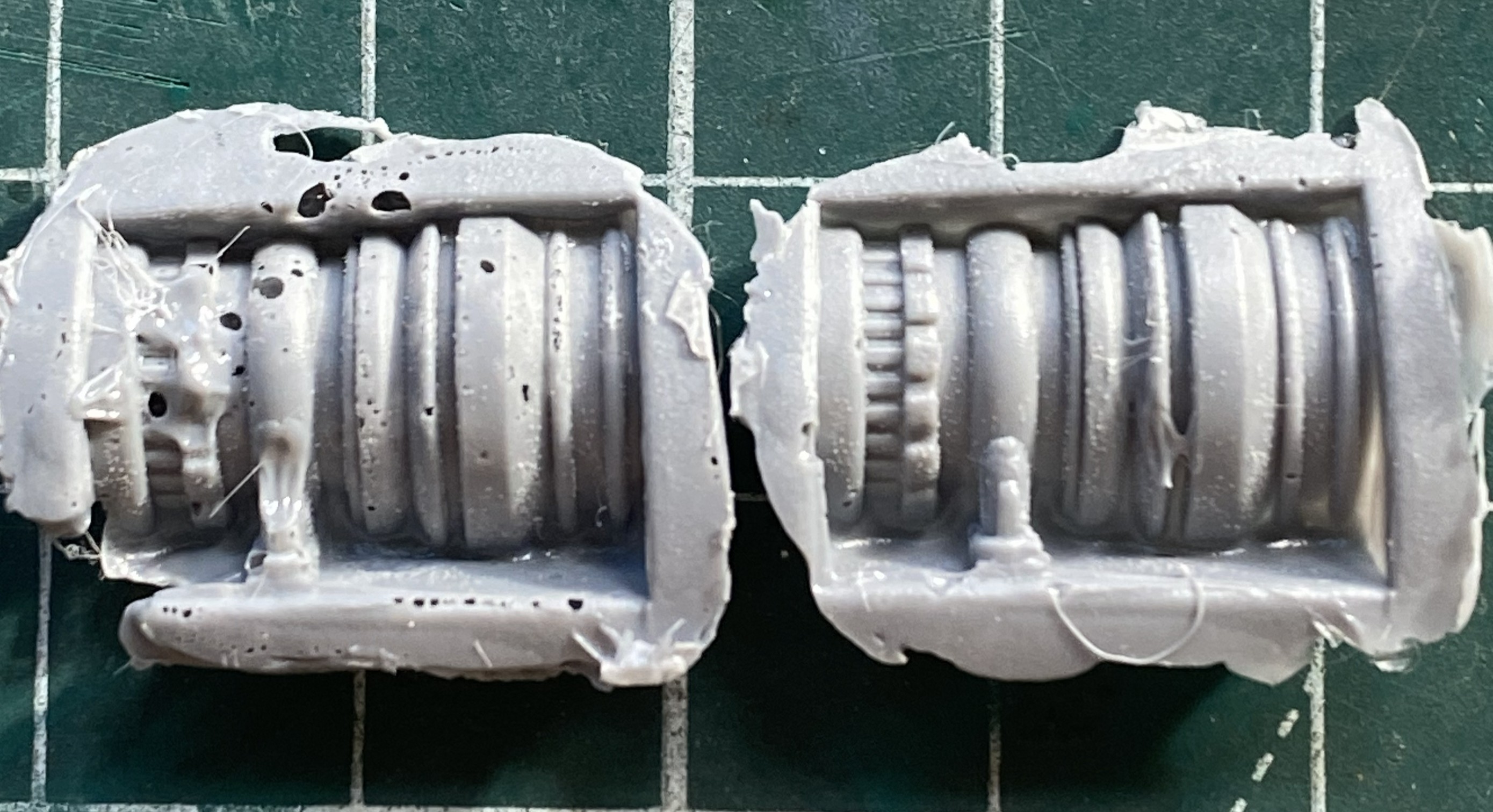
Of course I had to have a go at fixing the first casting (on the left above) but that solution created more problems than it solved. In fact, once I had acceptable castings for both sides is when I realized that the whole engine idea was a waste of time. They be what they is (relatively).
Since this was my first wake-up call (most of my builds have at least one), I decided to tape the major components together to check fit:
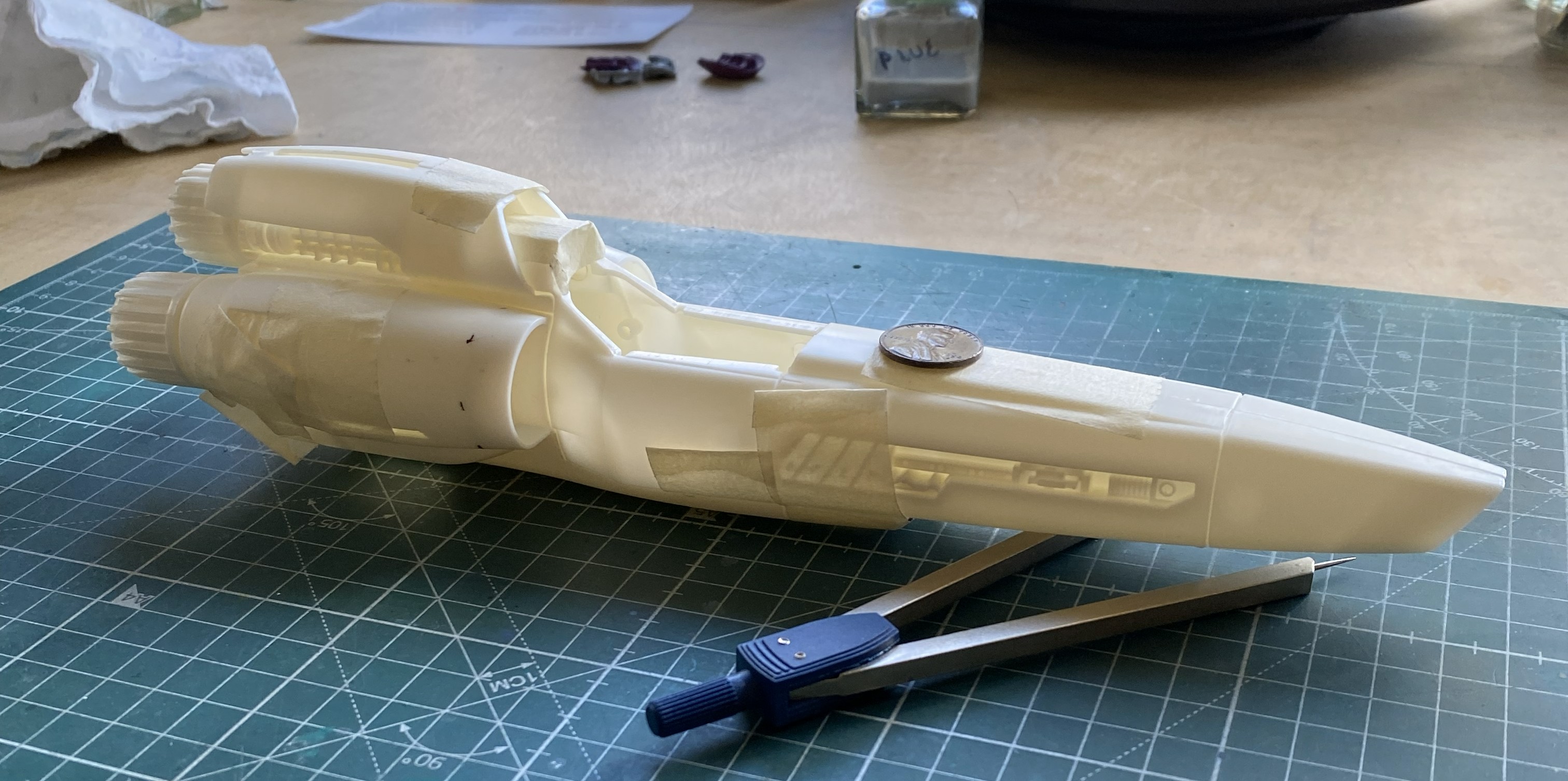
That will require some work. It’s not horrible, but it ain’t Tamiya, either.
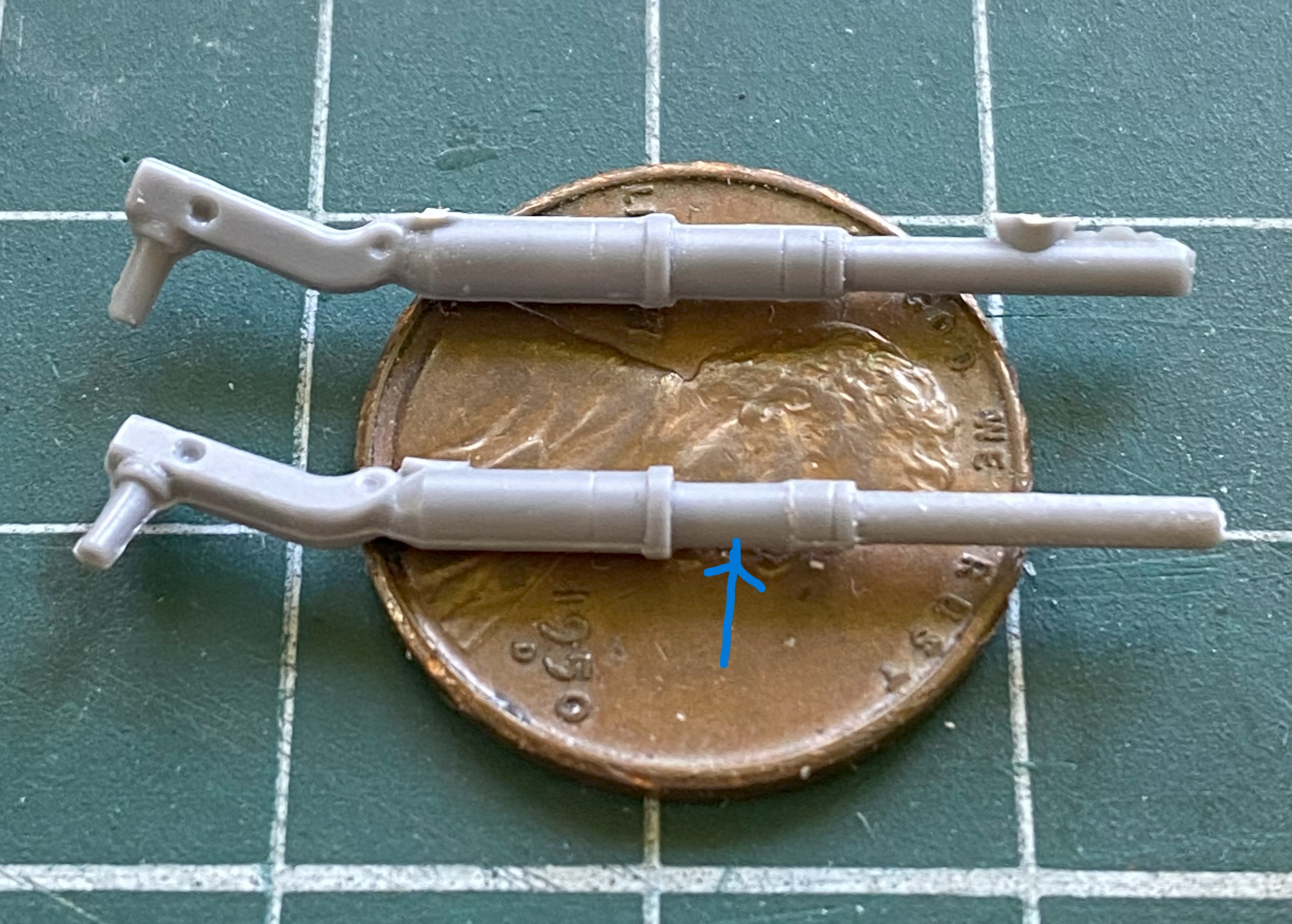
Since this thing doesn’t have a leg to stand on, I decided to start putting them together. Nose gear is on the right:
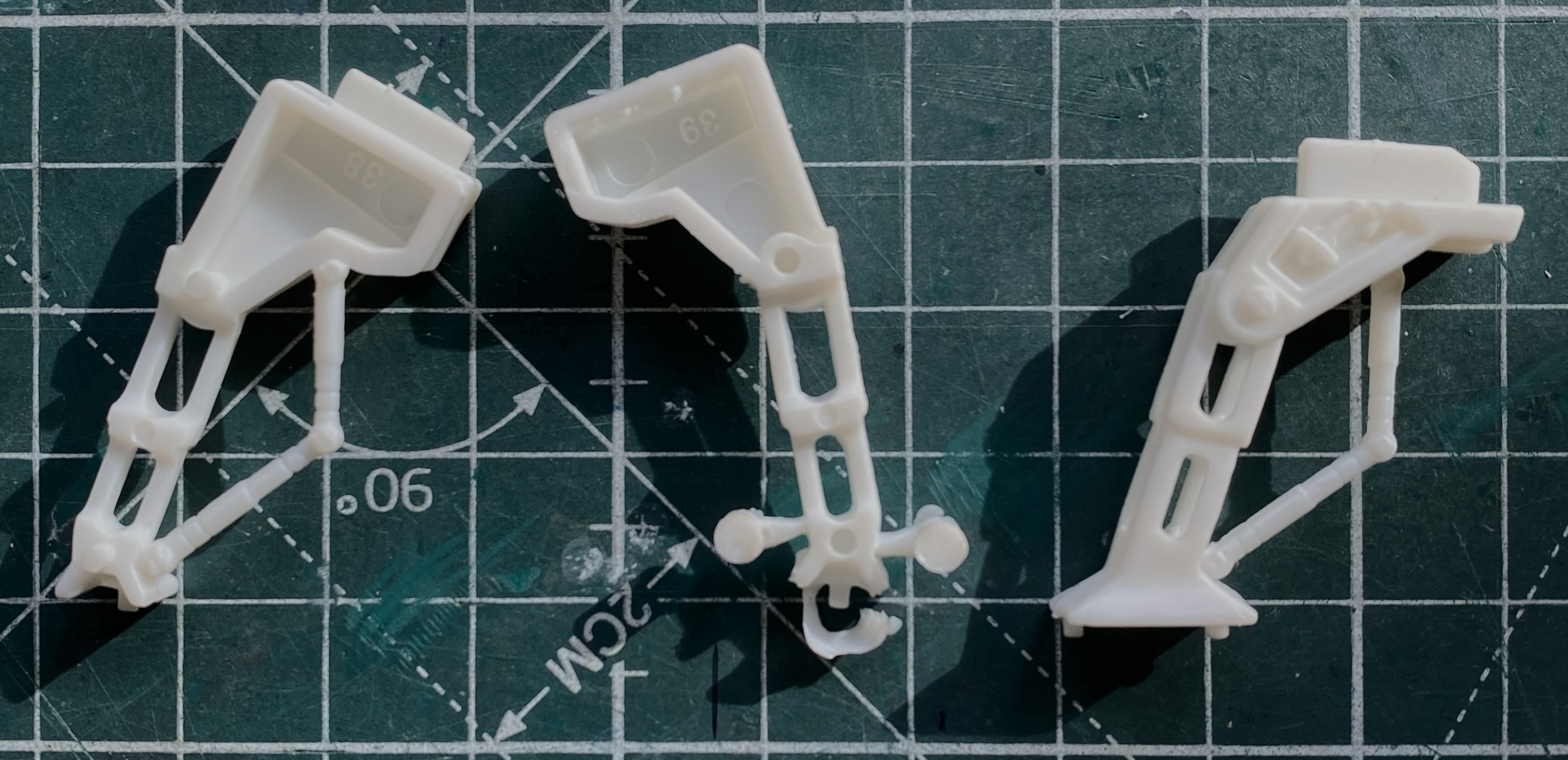
Seams are variable. Some good, some not good, some just freaking annoying. I’m moving away from putty as my default void filler towards scabbing in plastic instead. These landing struts/gear seams need it:
See what I mean:

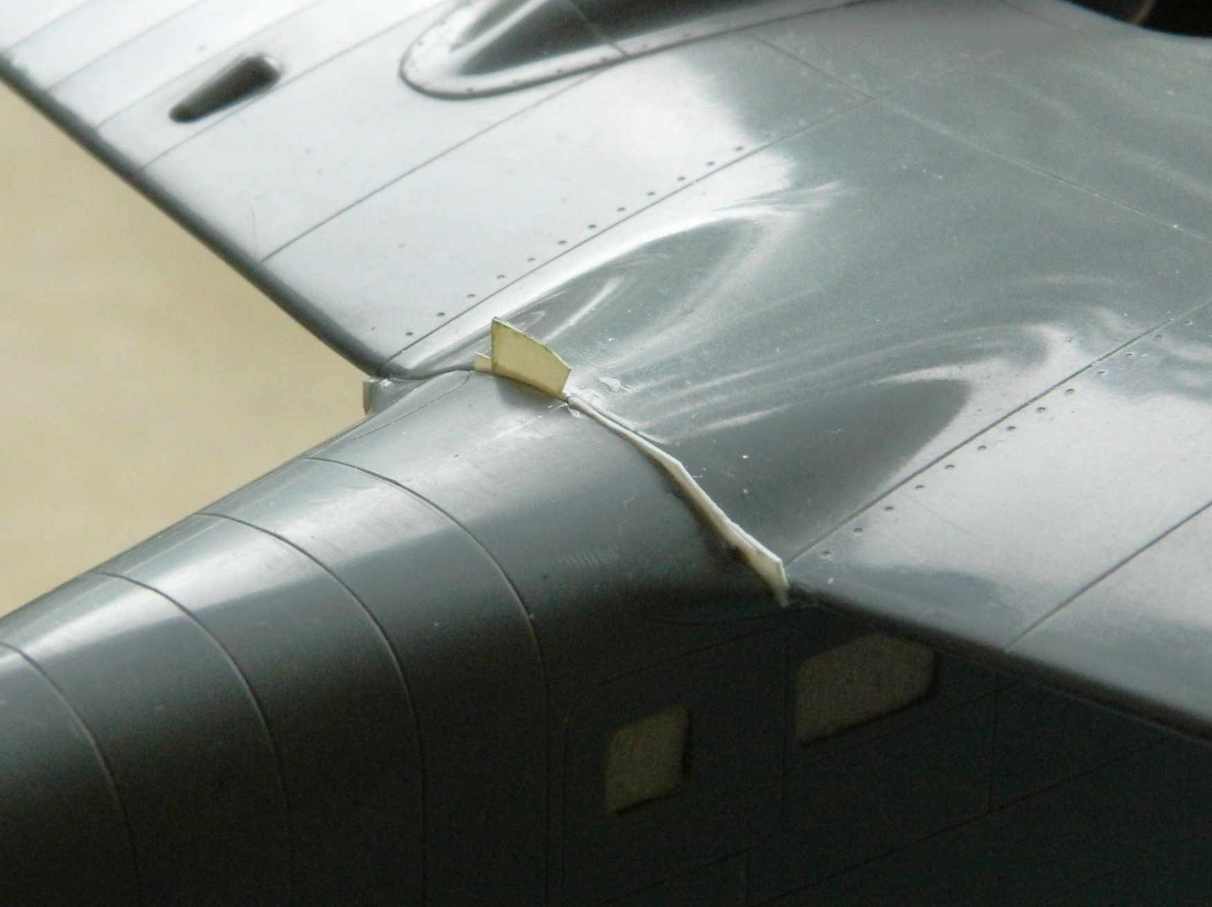
While all the added plastic was setting up, I started putting together wing halves. This was an area that needed help. So I helped it:
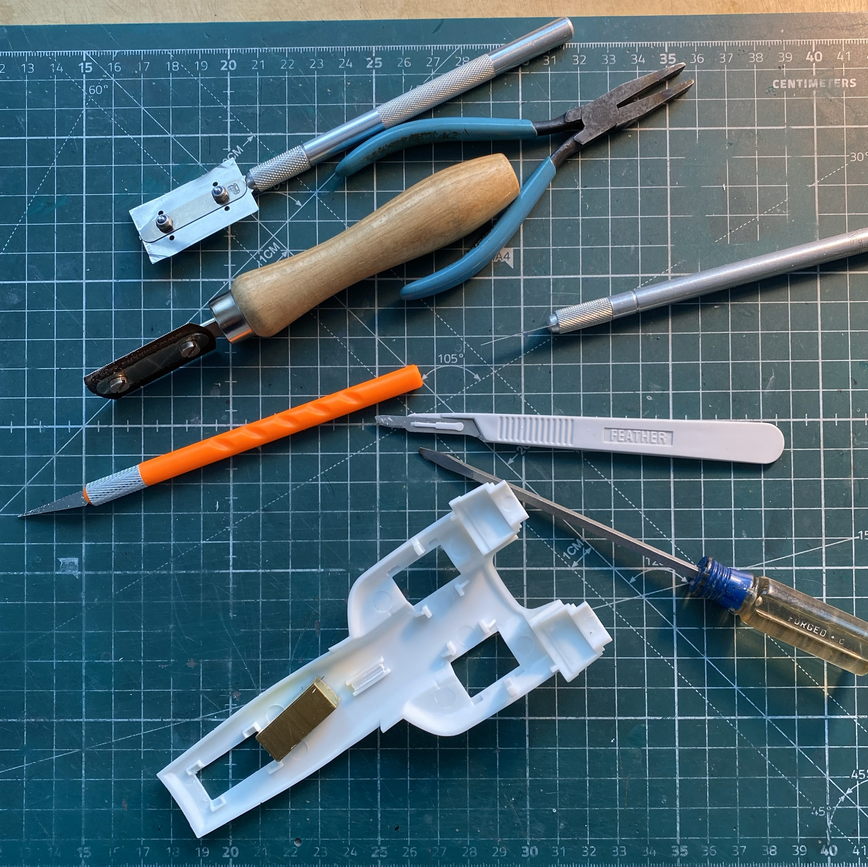
“Why is your work bench so cluttered and messy? Doesn’t that get in the way of working?” No, dear, it is working. These are the tools needed to clean up parts that are essentially simple:
Simple. Right?
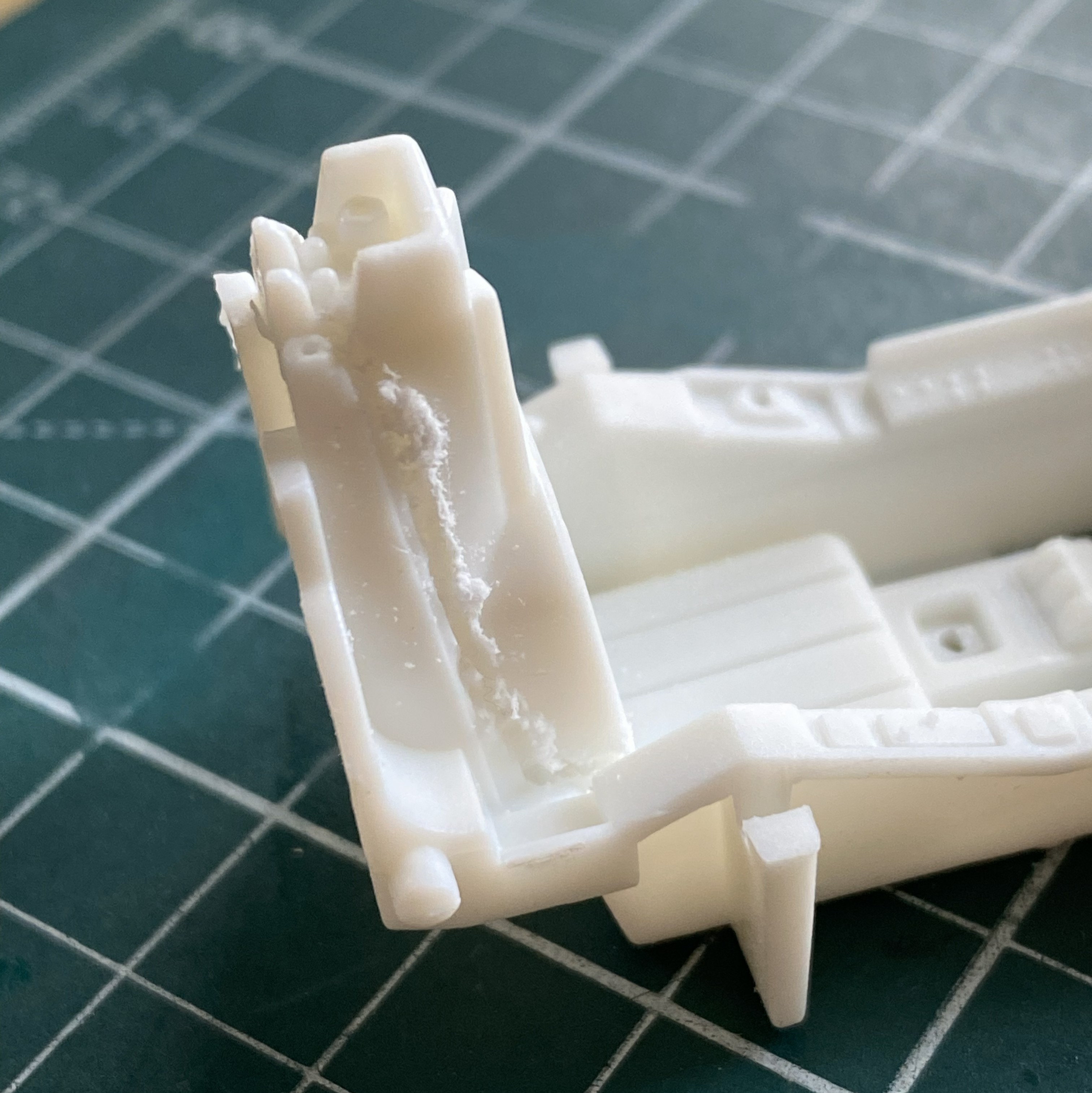
While removing the tape from where I’d dry-fit the major components together, an ohgoddammit moment arrived. The blue arrow shows you where a part came apart:
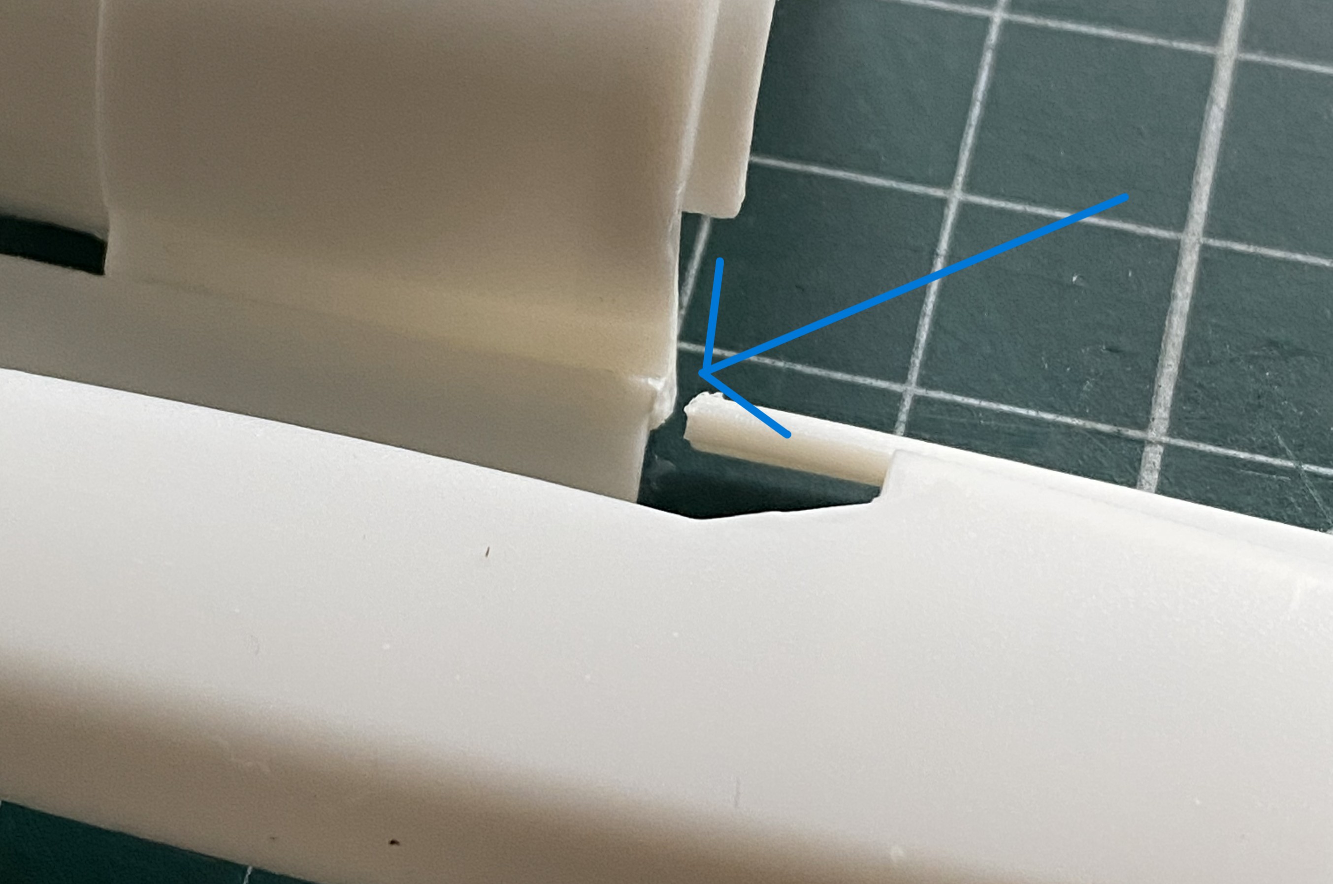
The way this is engineered, I decided that I’d use the model itself as a gluing jig (the break is on the left half of the engine area). The flat areas on either side of where the upper engine goes served well as an alignment guide:
Good illustration of fit, eh?

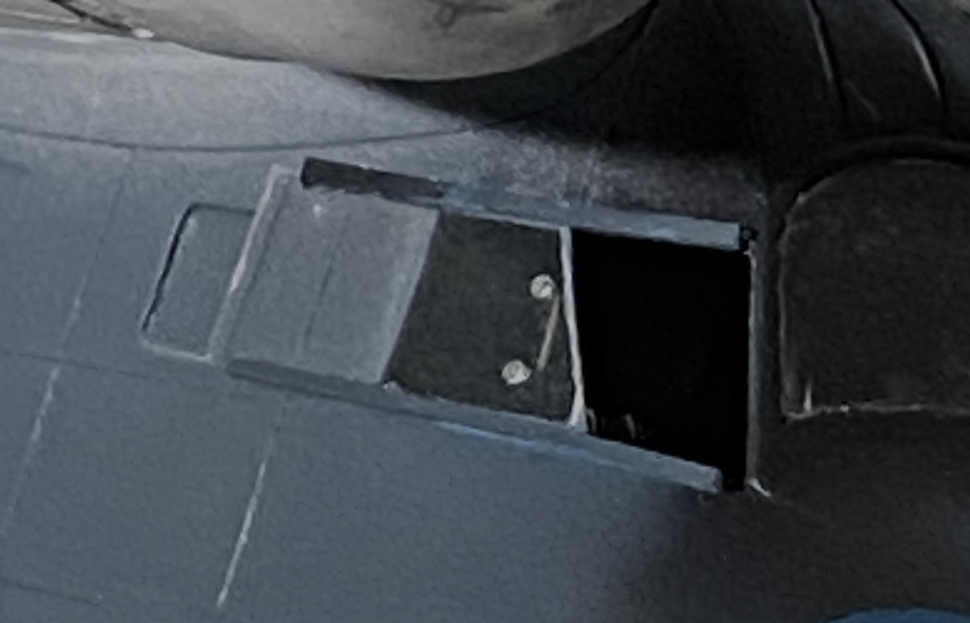
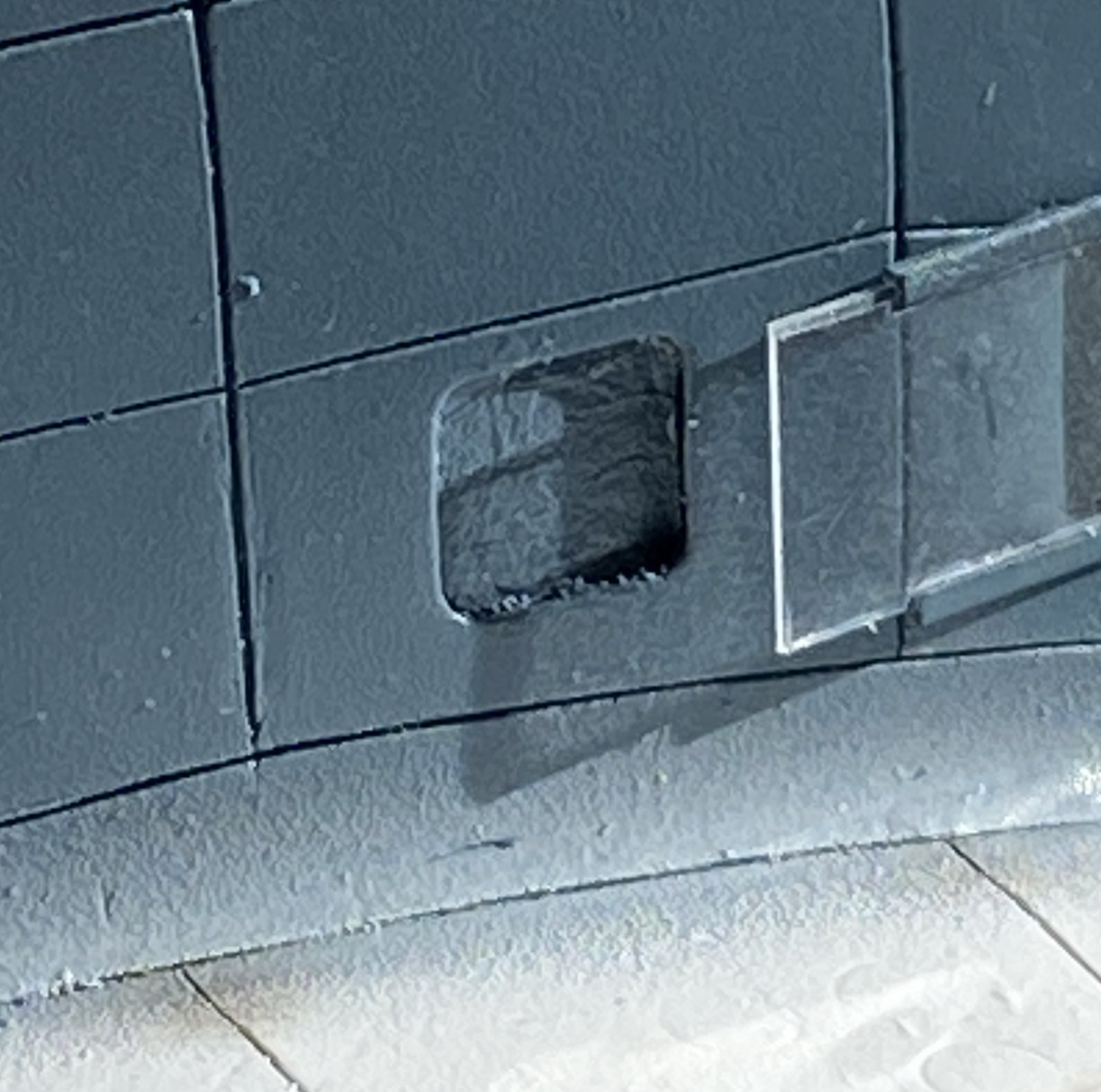
While I was there, I filled the slot for the supplied stand since I’m not going to use it:
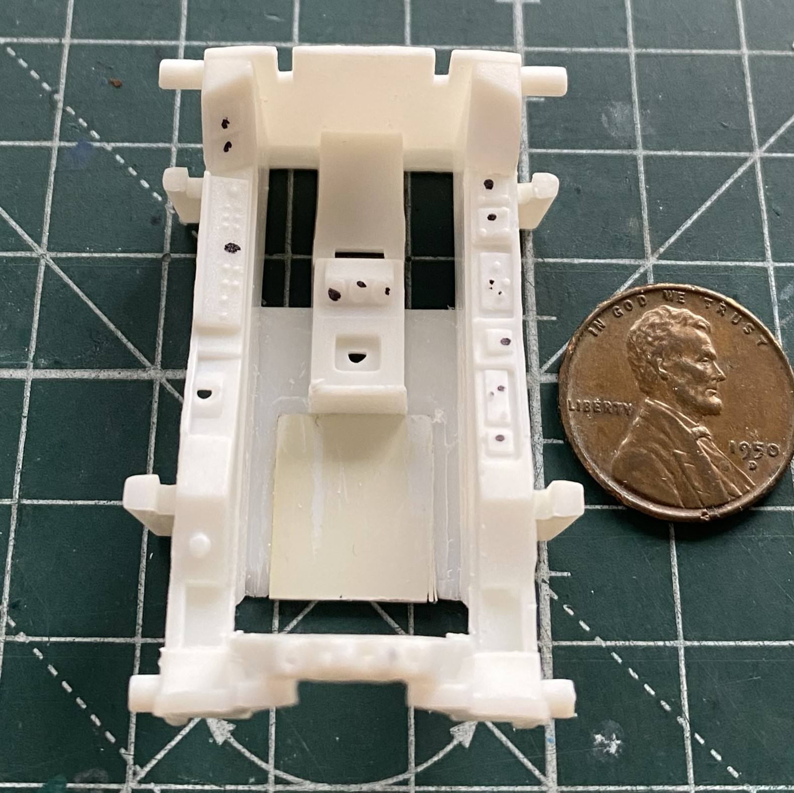
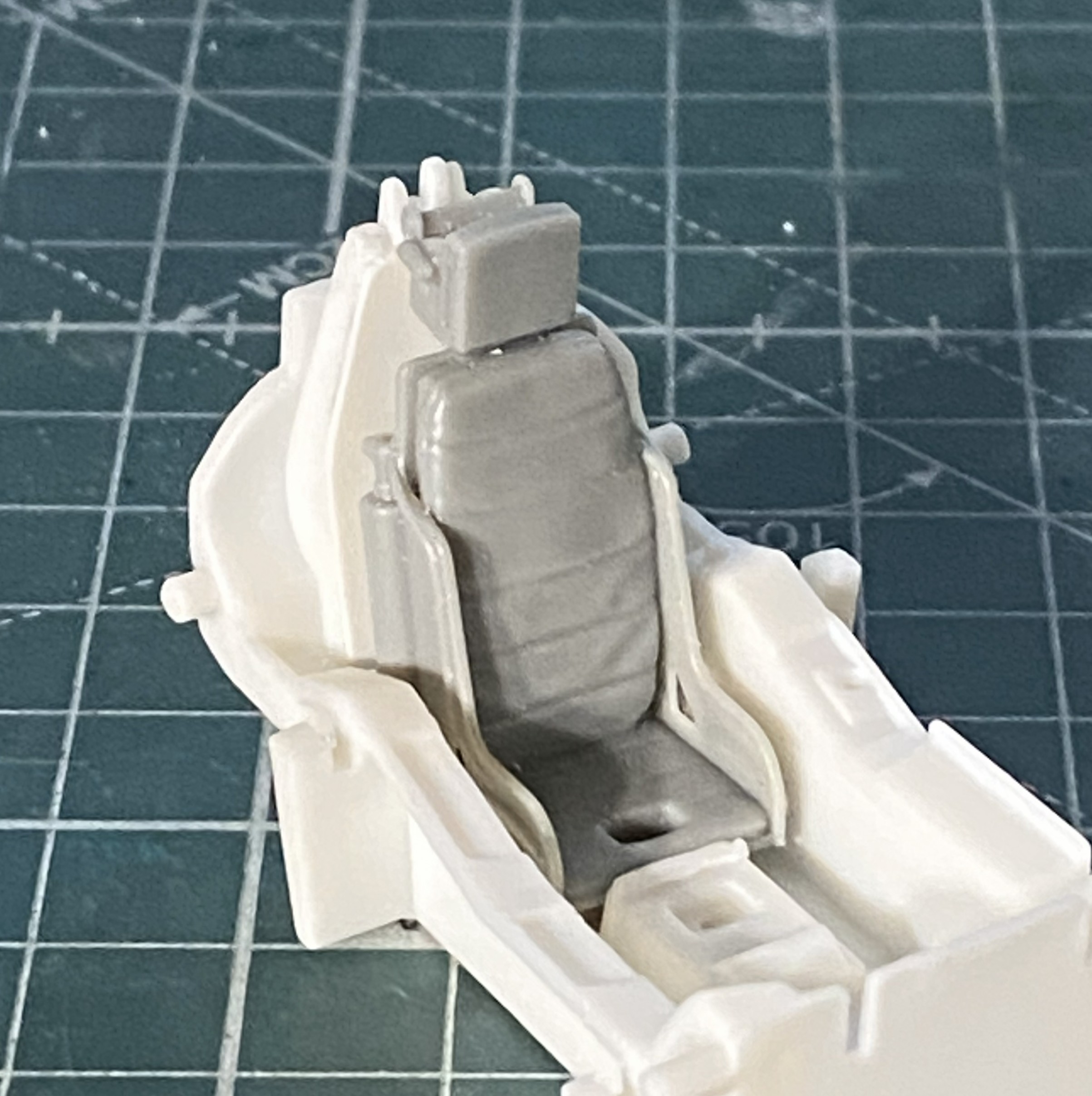
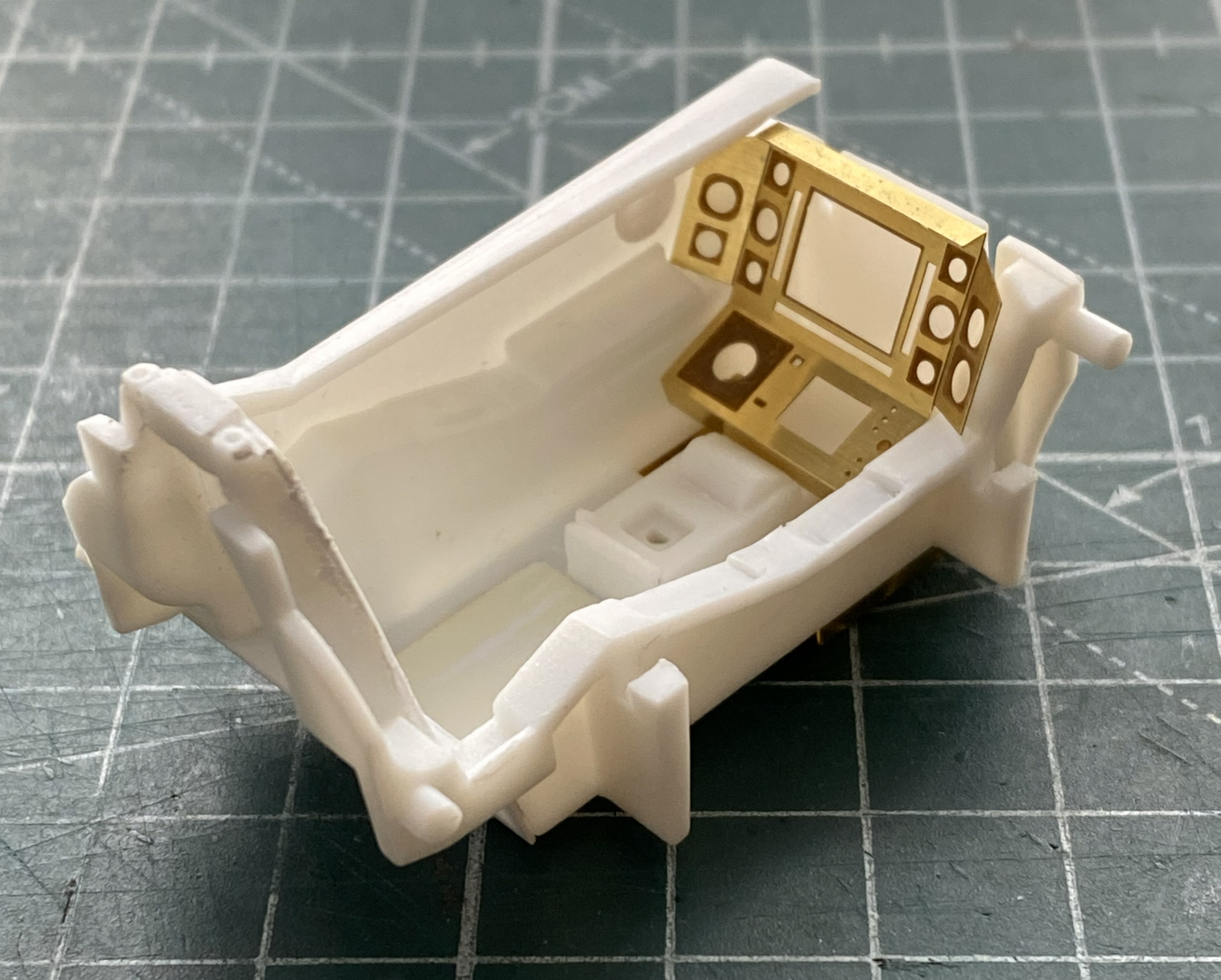
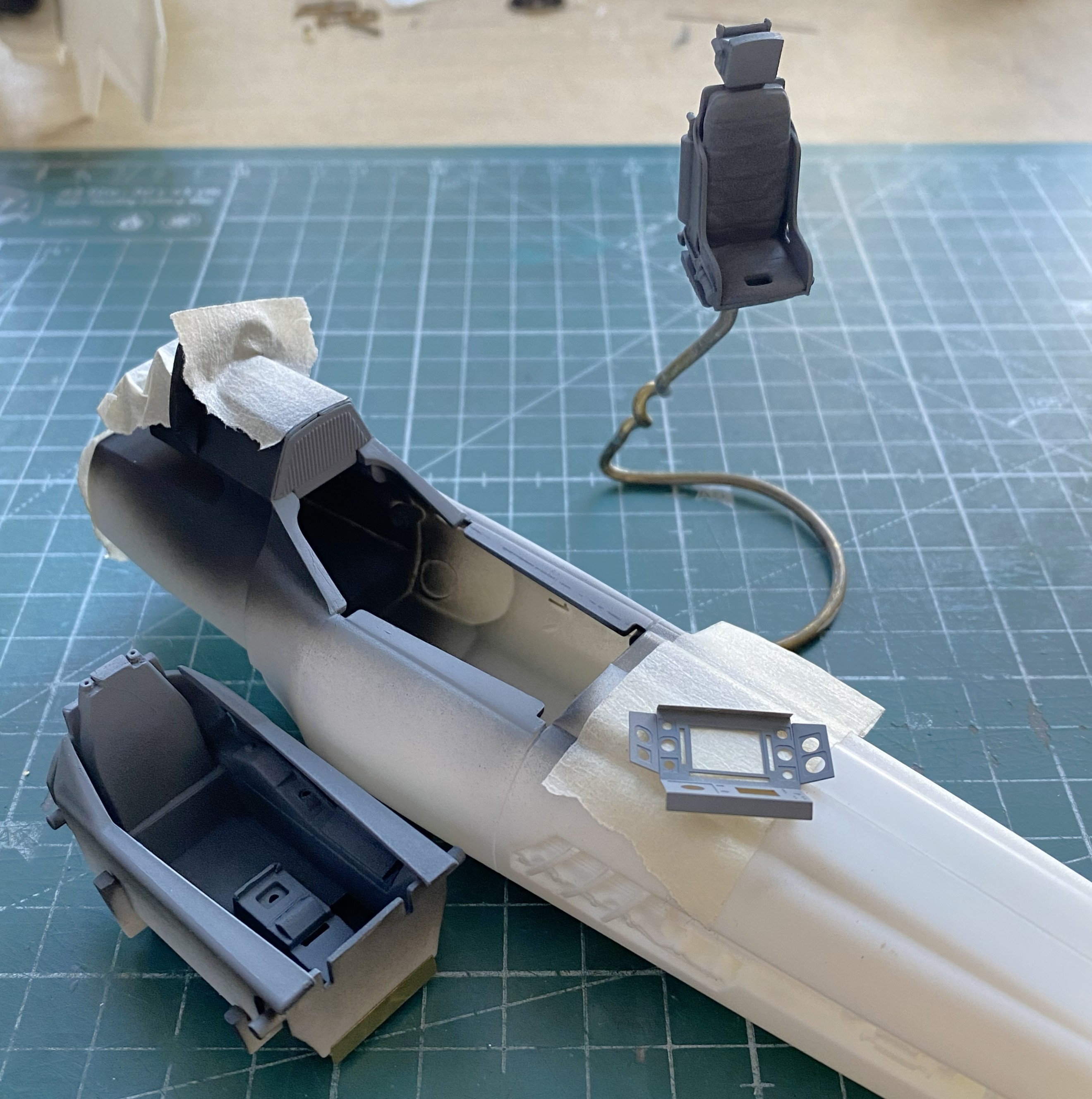
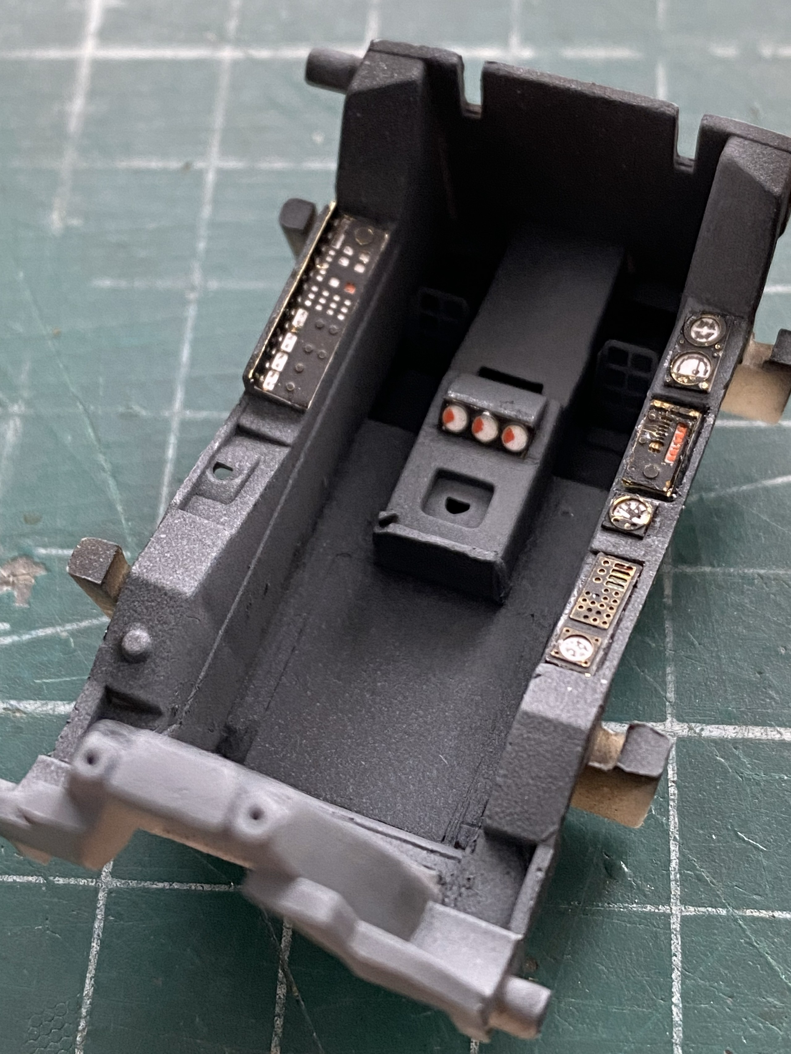
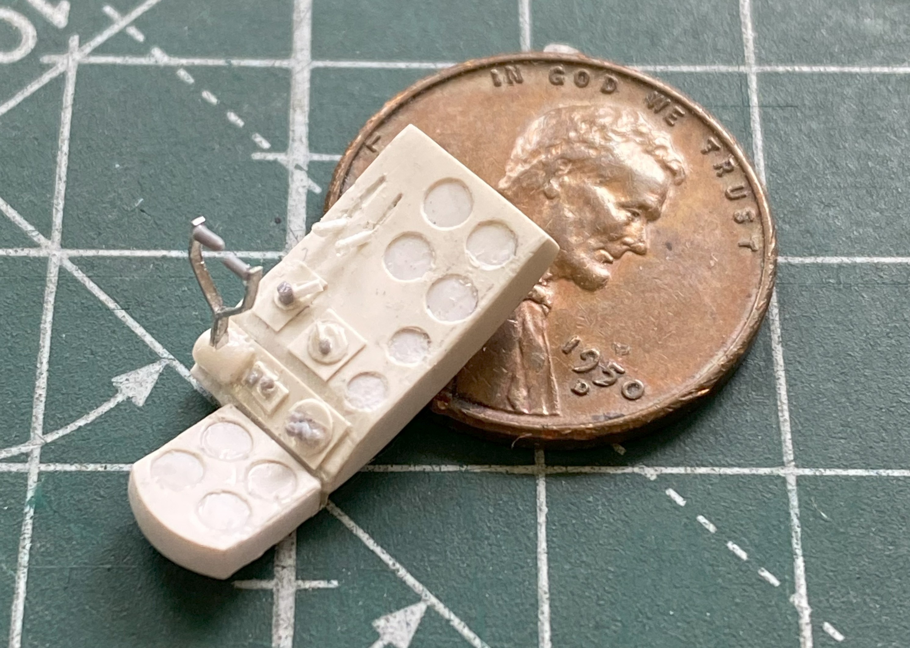
At this point the AM parts arrived so I changed focus to doing the cockpit. For the resin seat to fit, the molded-in seat has to come out:
Once the kit’s seat was gone, I assembled the pedestal for the seat:
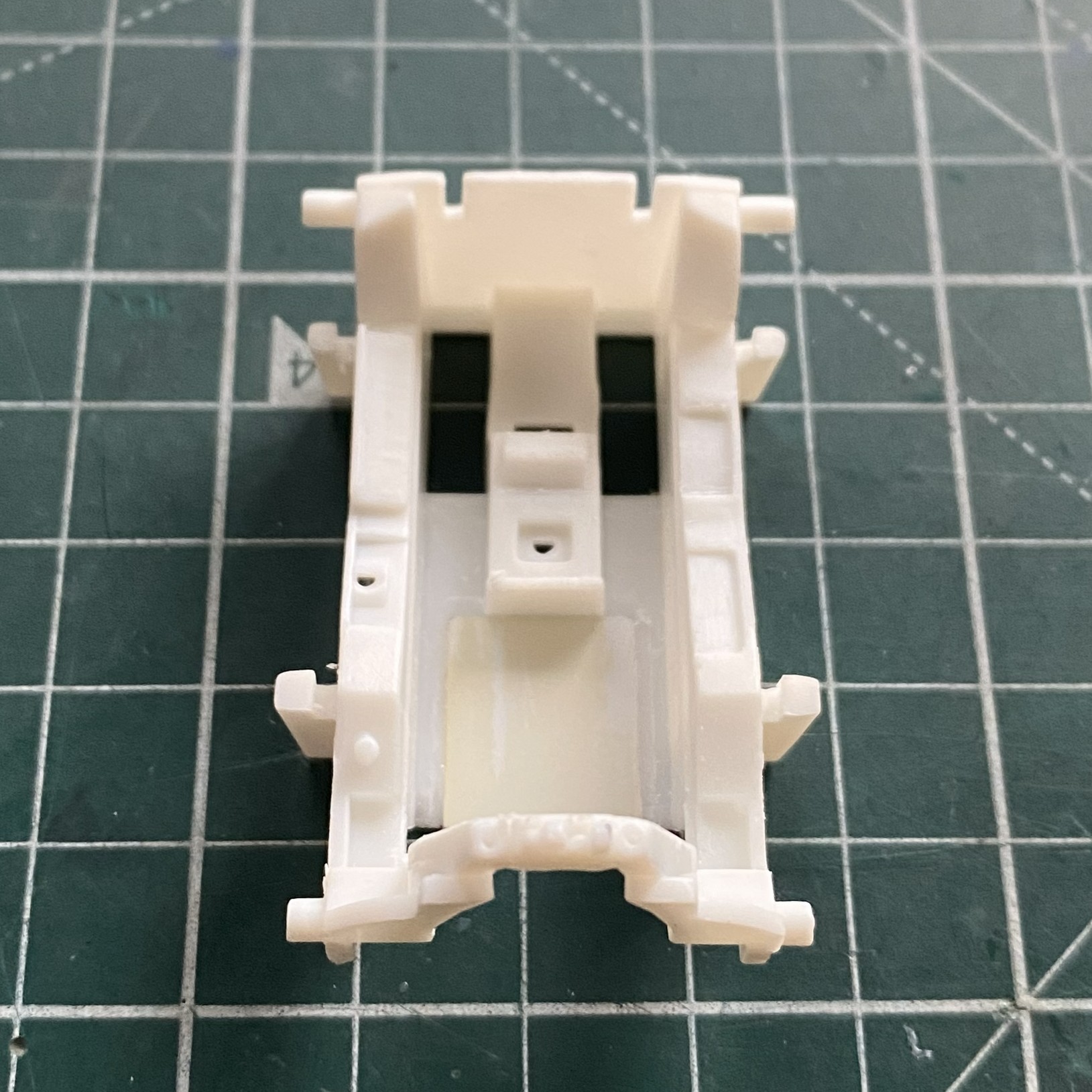
Then I checked the fit:


Nope. Sits too high. The fix was to remove the pedestal and glue the seat directly to the floor (you can see the fit of the fuselage behind the seat, which will require some inflexible persuasion on my part), which lowers the seat to the correct height:

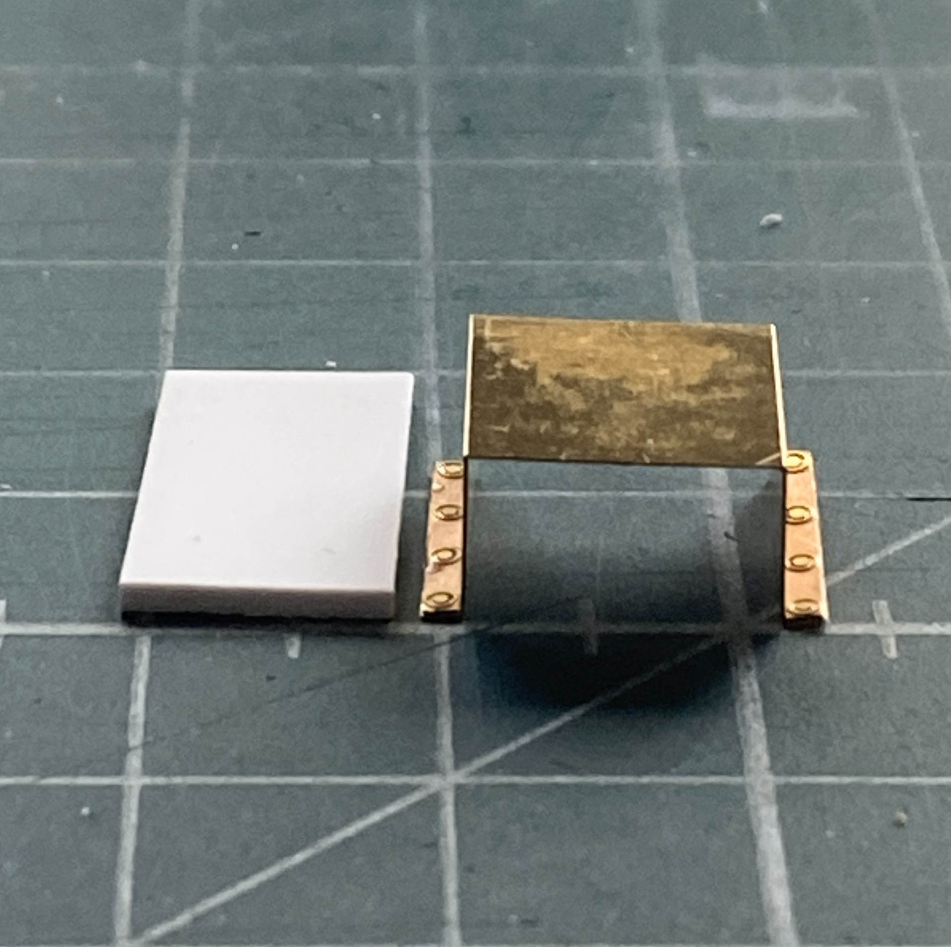
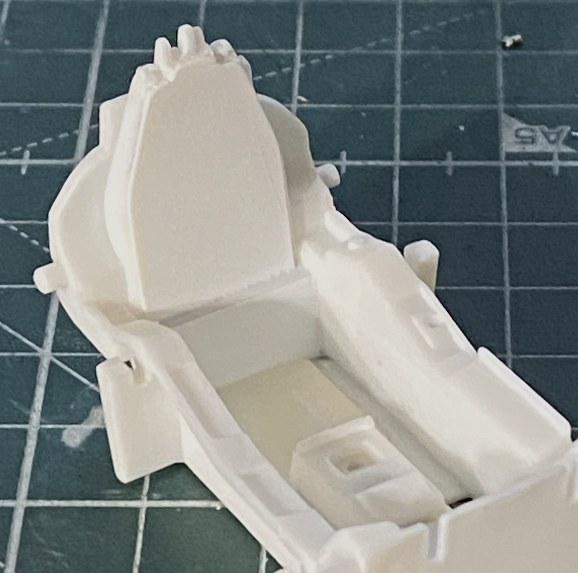
To apply the PE I have to remove the molded-on details. That with the round black dot has to be removed, the one on the left that looks like a D laying on its face is where the throttle goes. The insert in the floor is to fill the gap left after removing the molded seat (and to give me something to glue the resin seat to):
Done:
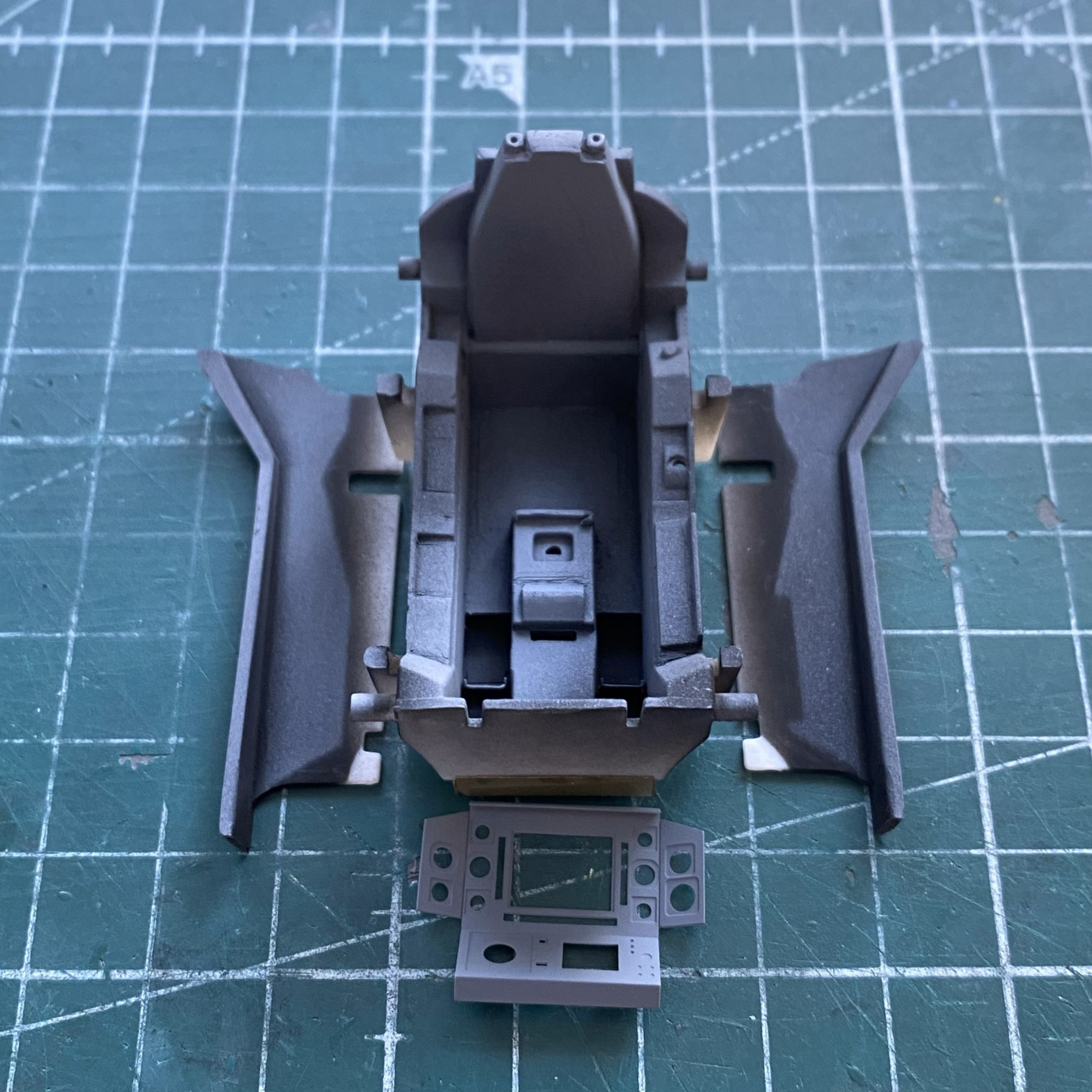
The structure behind the seat needs to be filled. I used 0.020″ (.508mm) for that:
Where the back joins the tub is evident at the edges. I used a little putty to make the added back look as if it belonged.
With unwanted details removed, PE moved to the front of the line. Surprising no one who’s worked with PE, acrylic paints don’t adhere well. They’re fine once painted if they aren’t stressed. I was curious to see if lacquer would hold up any better. I masked off what I didn’t want to paint and then sprayed the fret with Tamiya’s TS-6 Matt Black from a rattlecan and let it sit overnight:
The next day I used my MkIII Thumbnail to see if lacquer is more resistant to wear. It is. It still wore a bit as I was working things but NOwhere near as much as acrylic wears.
In general, I’m not a fan of PE harness straps. The PE fret has them so I decided to have another go at them. I started by annealing them so that they behave less like the strip of brass that they are:
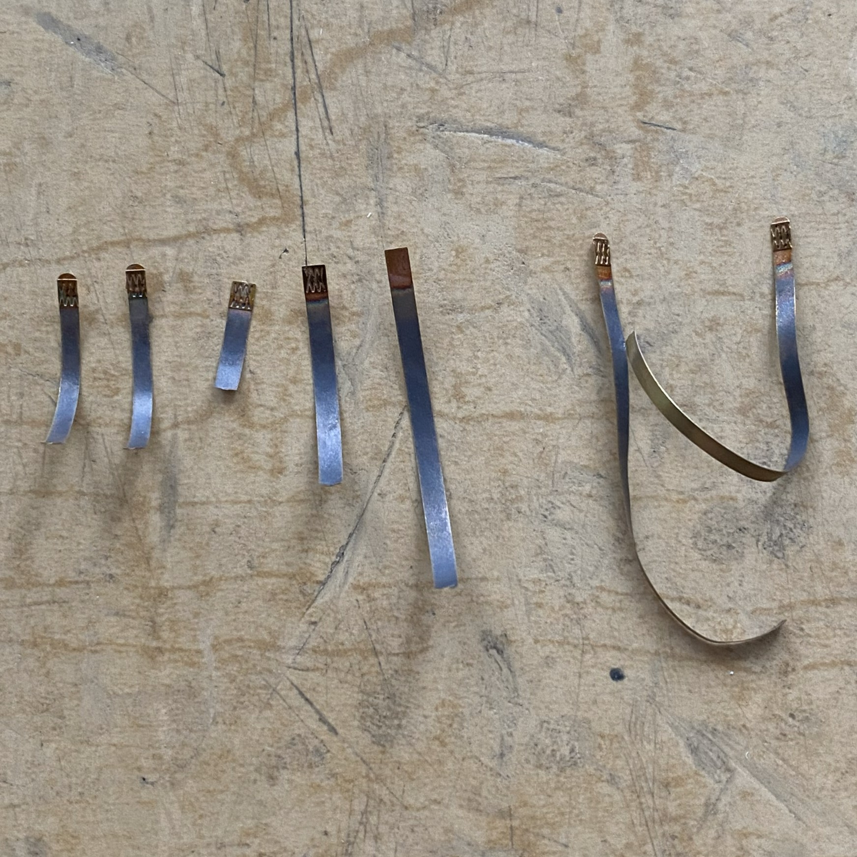
During annealing, I managed to scare myself. I use a butane torch to anneal. It’s hot. It’s hot enough to melt little brass strips! I came far too close to melting one of them, but since I’m not a grenadier…
Next I fed the straps through the hardware of sliders, tabs, and locks:
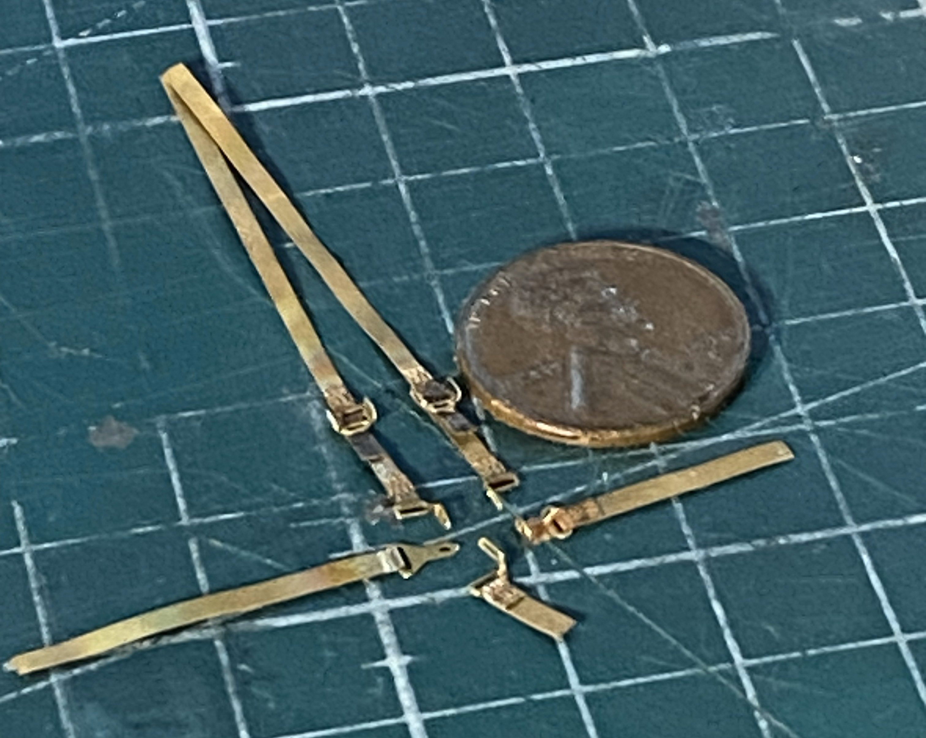
Annealing them made it magnitudes easier to feed the straps through the hardware! Now to see how they go on:
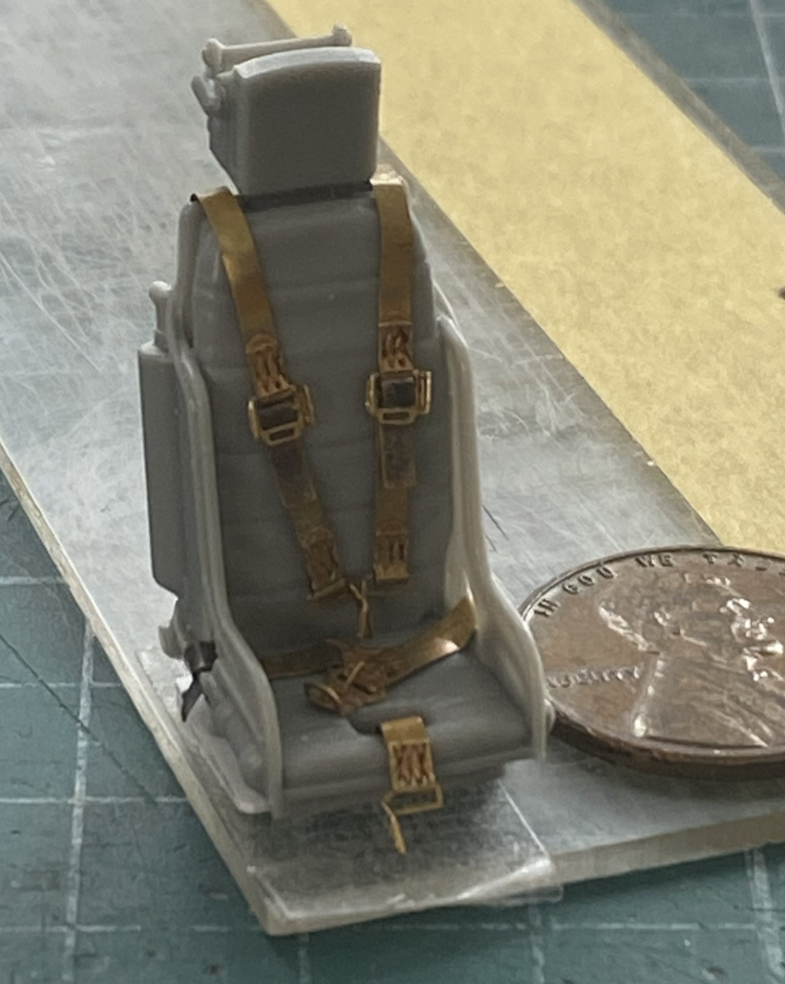
Annealing is definitely the way to go with PE harnesses.
I don’t know what this little panel is for, I just know it’s there so now was a good time (or even not a bad time) to see how the lacquer holds up to bending and gluing:
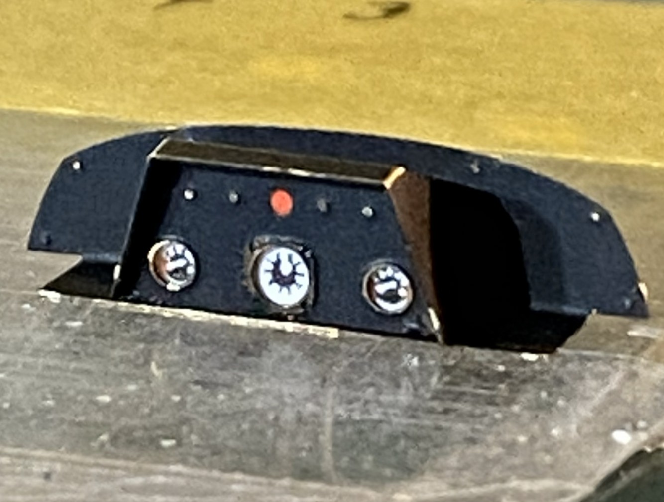
The lacquer holds up to being manipulated much better than acrylic does.
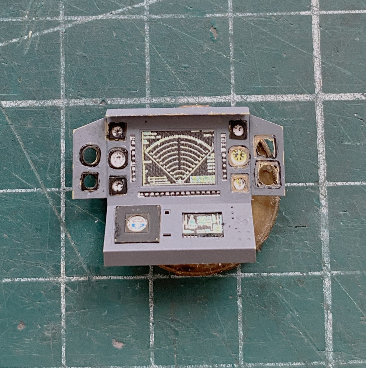
The main panel is basically formed, dry-fit, and checked for fit (good):
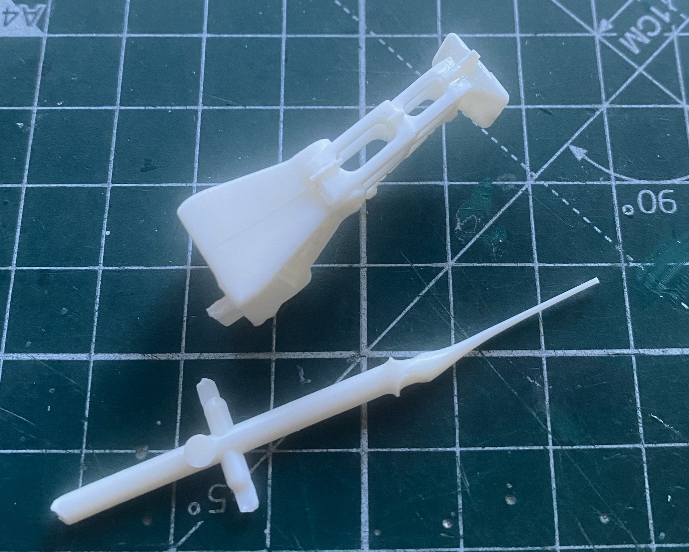
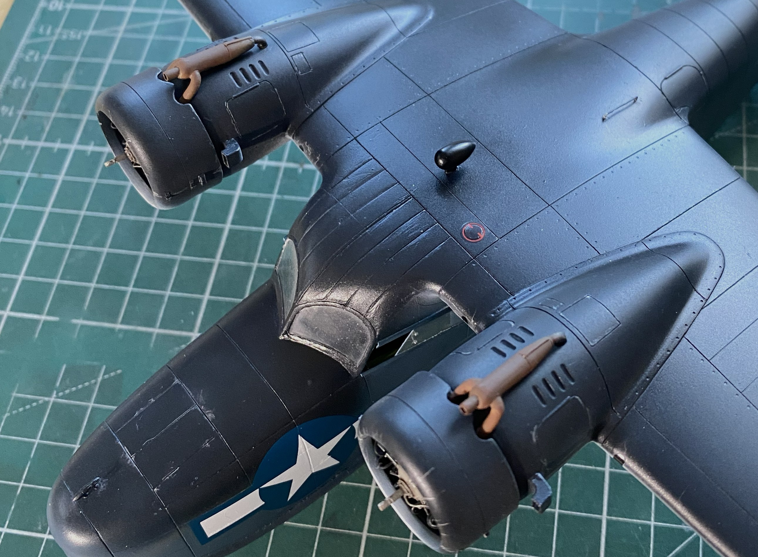
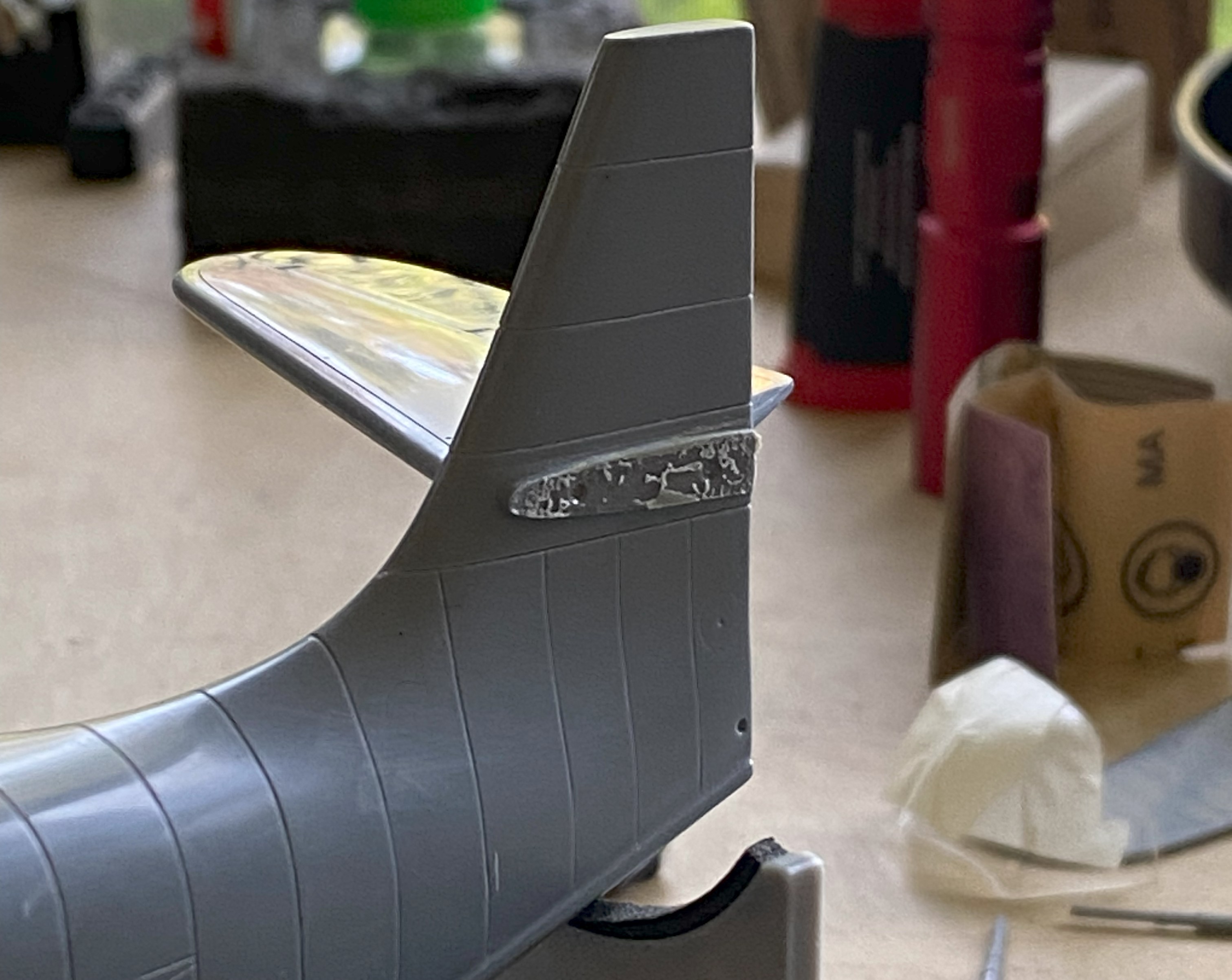
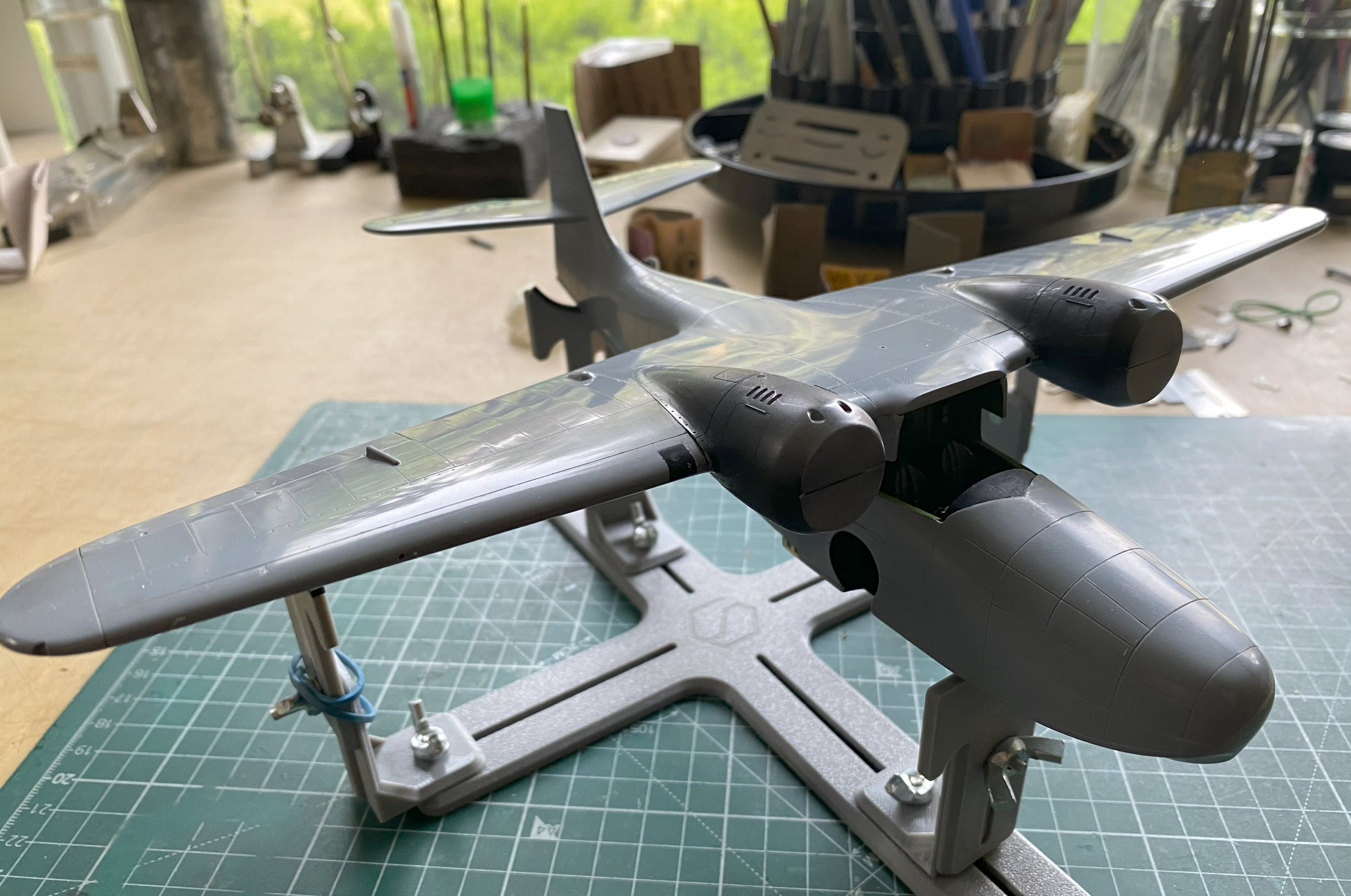
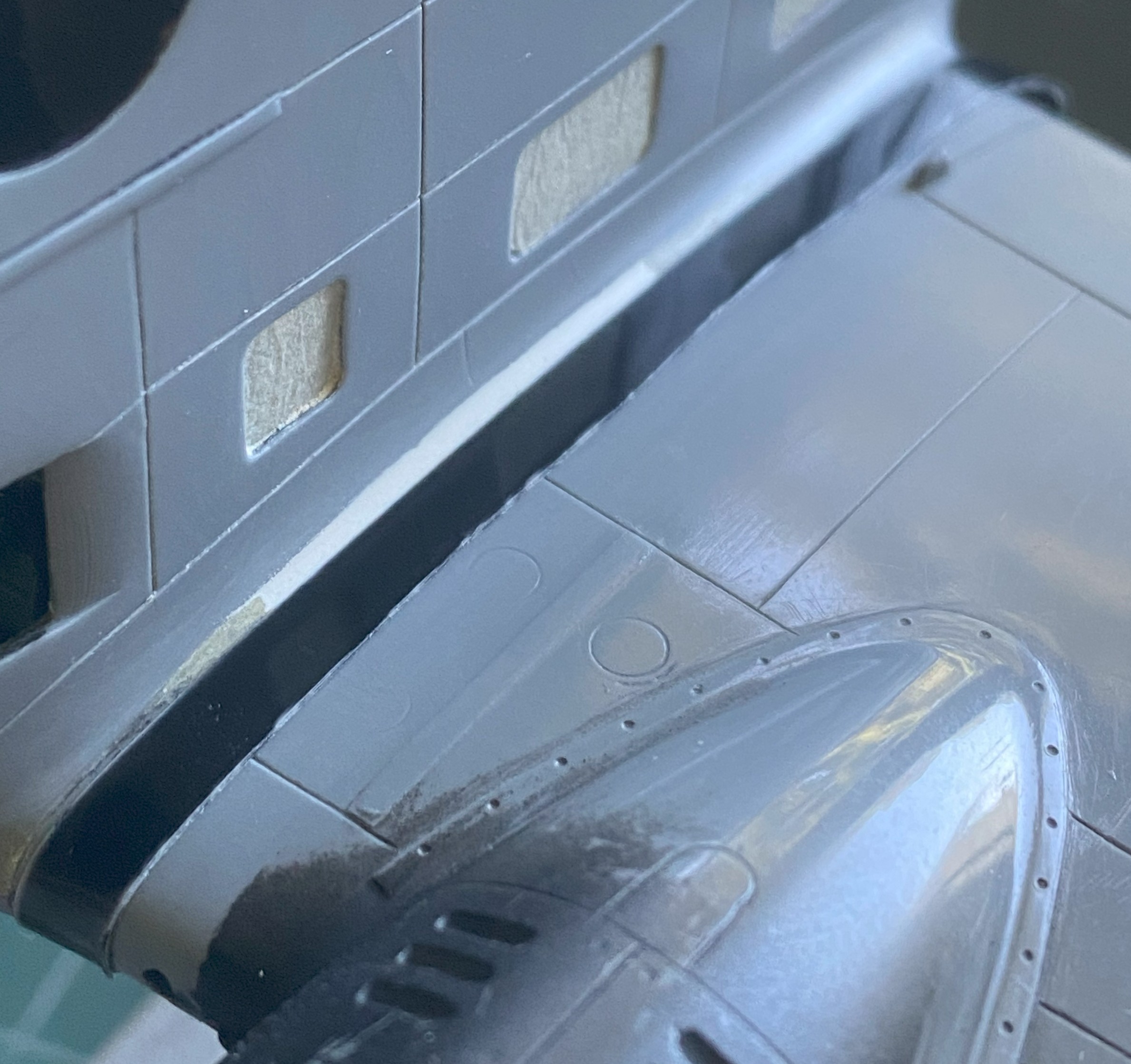
The engine intakes have blades for the intakes. Well, two out of three intakes. They look cool but are utterly unrealistic (and foundational theme for this build). The third intake is just a flat surface and of course it’s right up there in ones’ face(s), so I carved (another set of utterly unrealistic) fan blades into it. What the kit offers (one on both sides and the two of three intakes with fan blades):
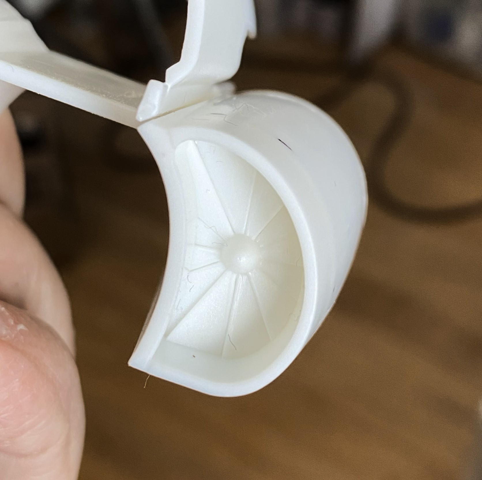
I started with this:
Drew the leading edges of the blades and checked appearance:

Then I sharpened all my scalpels and knives and started carving:

I cleaned up the edges/surfaces after taking the above photo.
First paint. These are the parts that get shot with Tamiya XF-1 Flat Black because I like the effects I get from pre-shading:
There:
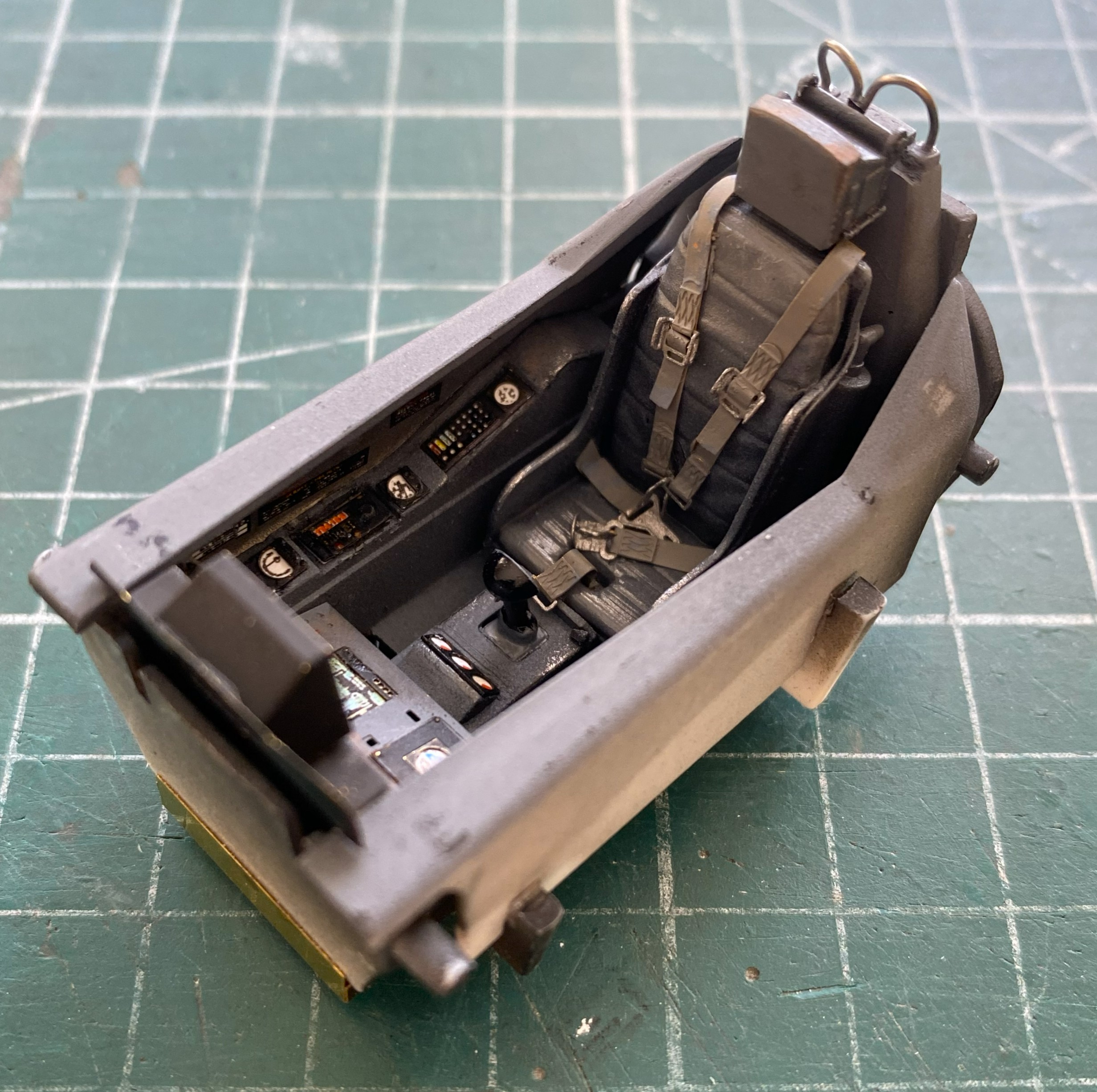
For the overall cockpit color I used Tamiya’s XF-53 Neutral Gray, no scale color correction, and just misted it on:
Set that to the side and started work on the main panel:

I continued to do the side panels of the cockpit:
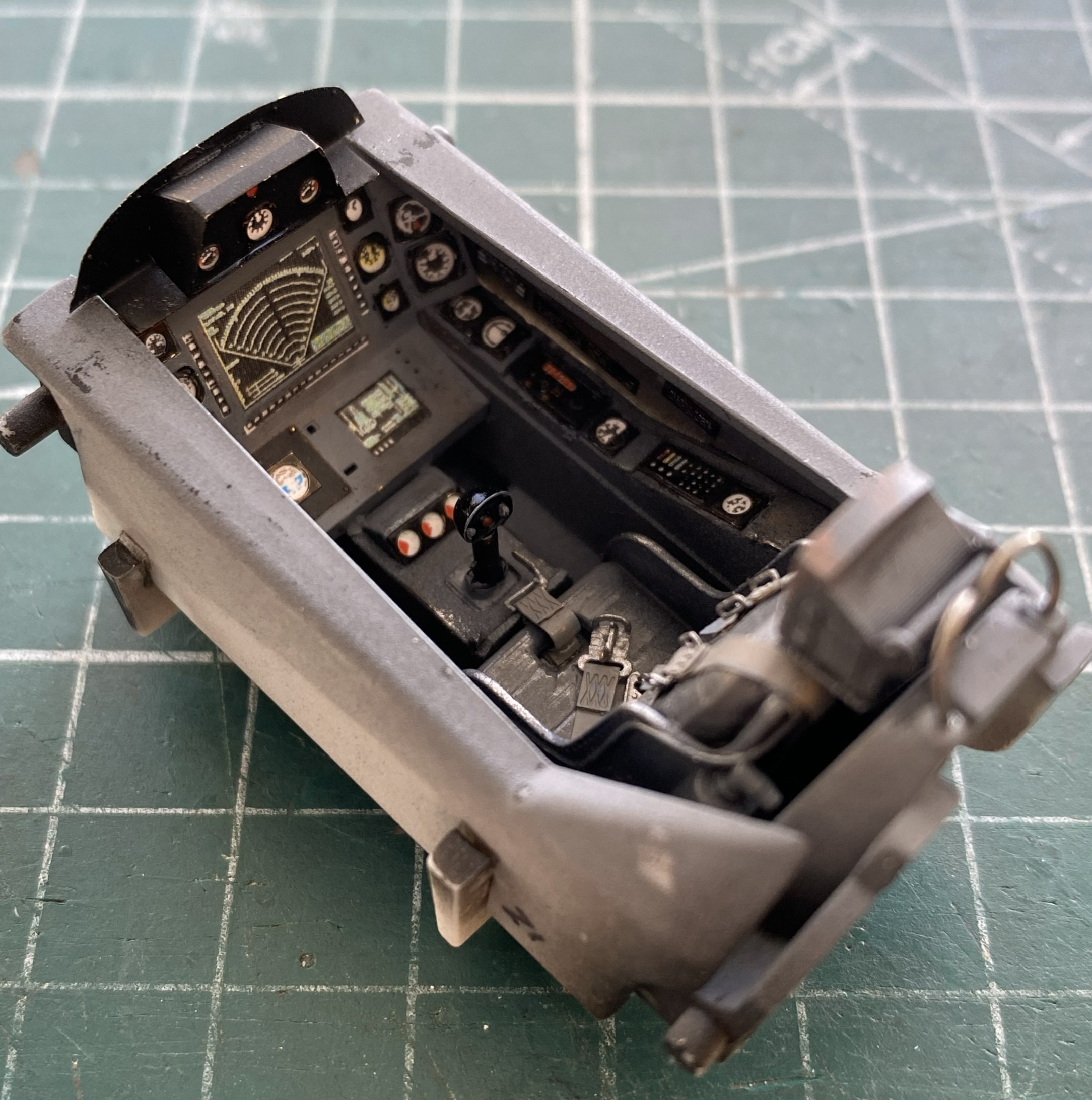
Preparatory to finishing the cockpit tub, I had to add decal data-plates to the sides and this is the first major uh-oh of the build. The first decal did not want to release from the backing paper. At. All. I let it sit in the (warm) water until the sodding thing just floated off. How I managed to fish it out of the water without folding it is one of Life’s Mysteries ™. Since I was pretty sure that whatever adhesive used to be on the decal was also floating in the water, I used Micro Set to convince them that this was their new home. That’s when I encountered the second uh-oh…the decal broke while I was trying to move it into a less inaccurate location (see the blue arrow):
Not only did it break, it broke because the left side of that decal, once it hit the surface, would not move at all. Instead, it tore. This isn’t boding well for the other decals. I hope I’m just being an alarmist.
I didn’t have any trouble at all painting and installing the harness:
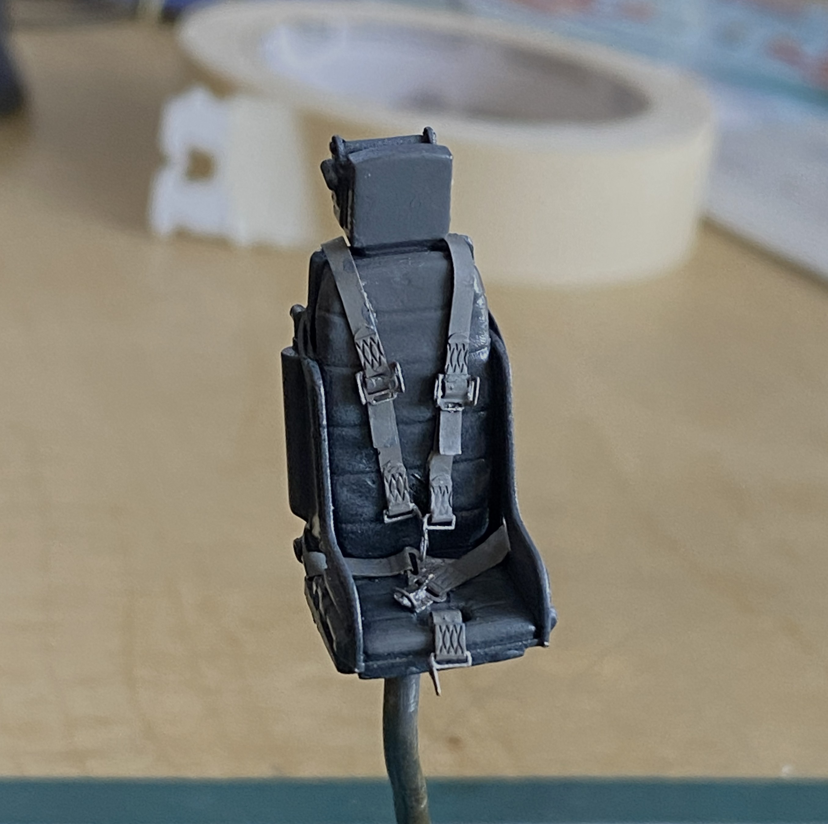
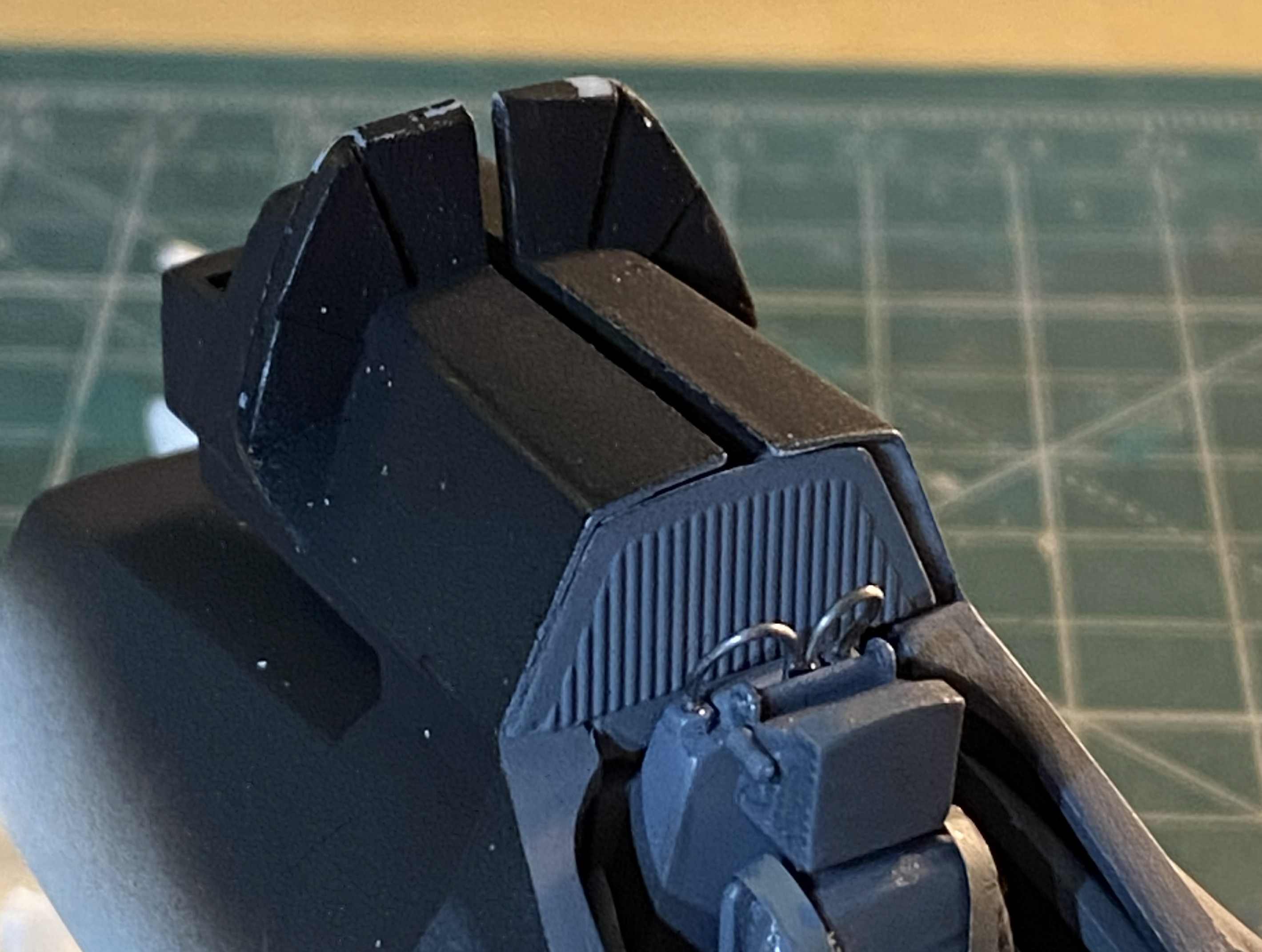
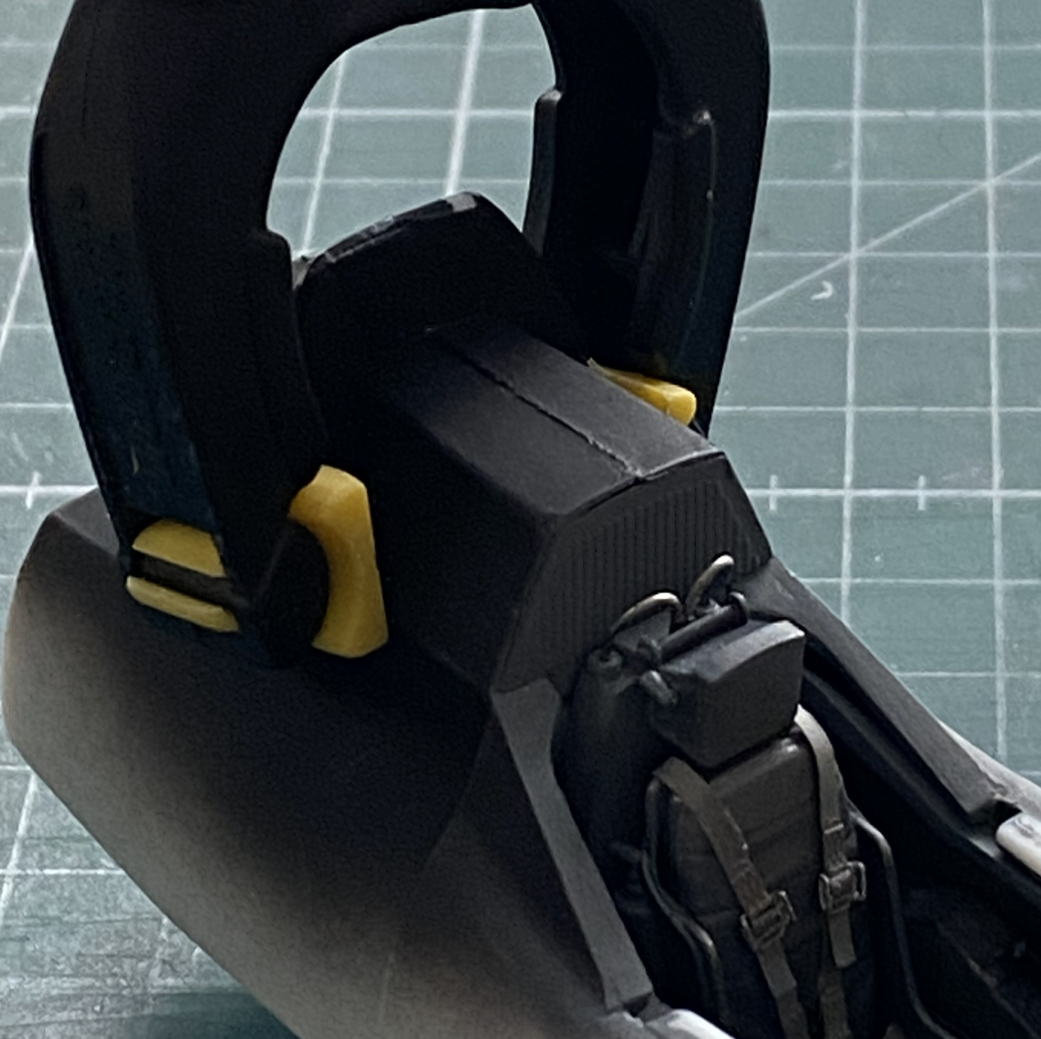
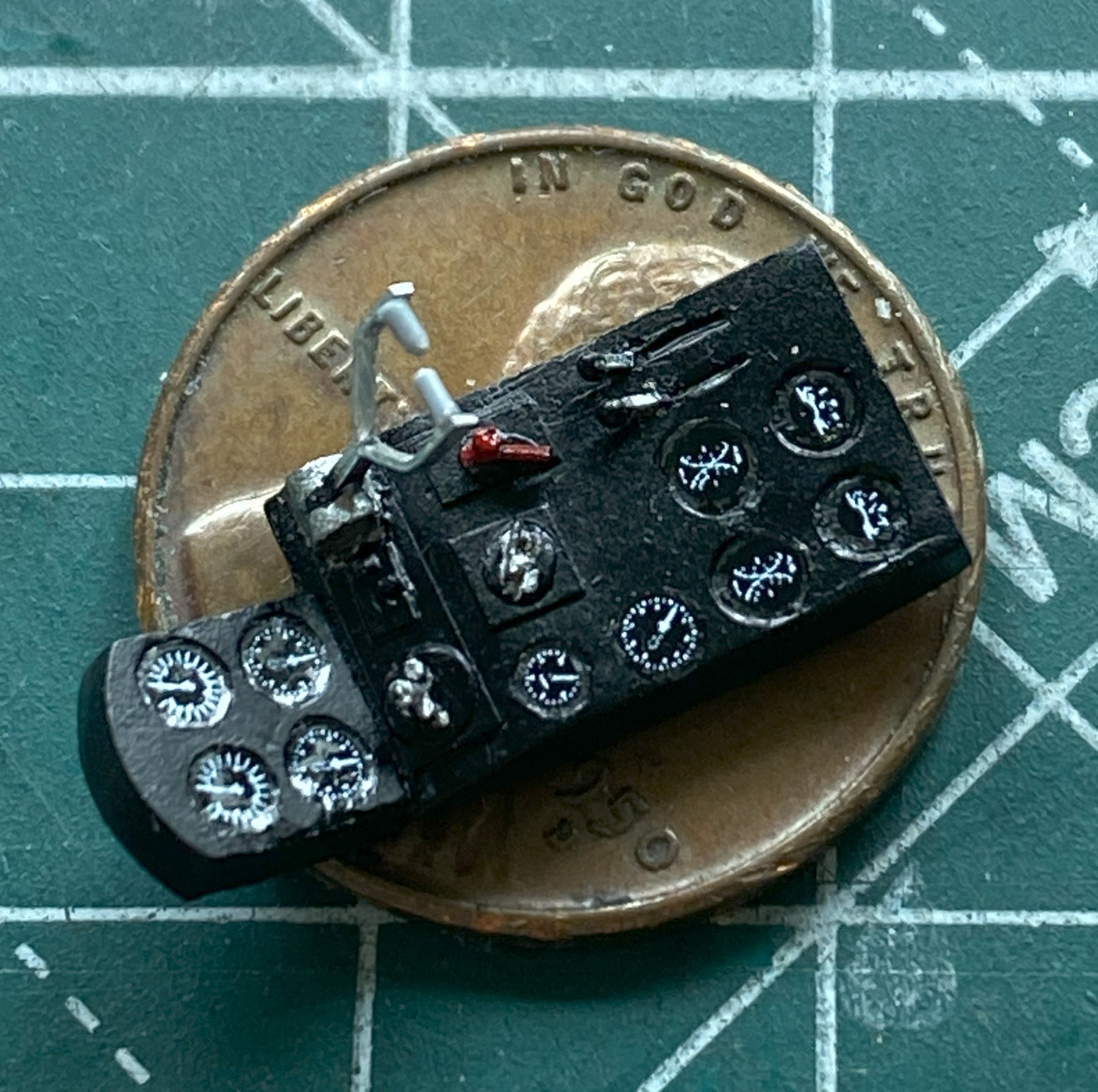
The first step to applying wear and staining was judicious use of the silver pencil. I added friction-wear (as opposed to impact-wear) marks as well as some pastels to make the office looked lived-in (and the sharper-eyed amongst you will note that I also affixed the throttle and joystick as well as the mystery loops behind the headrest, using 0.020″ (.508mm) solder) :
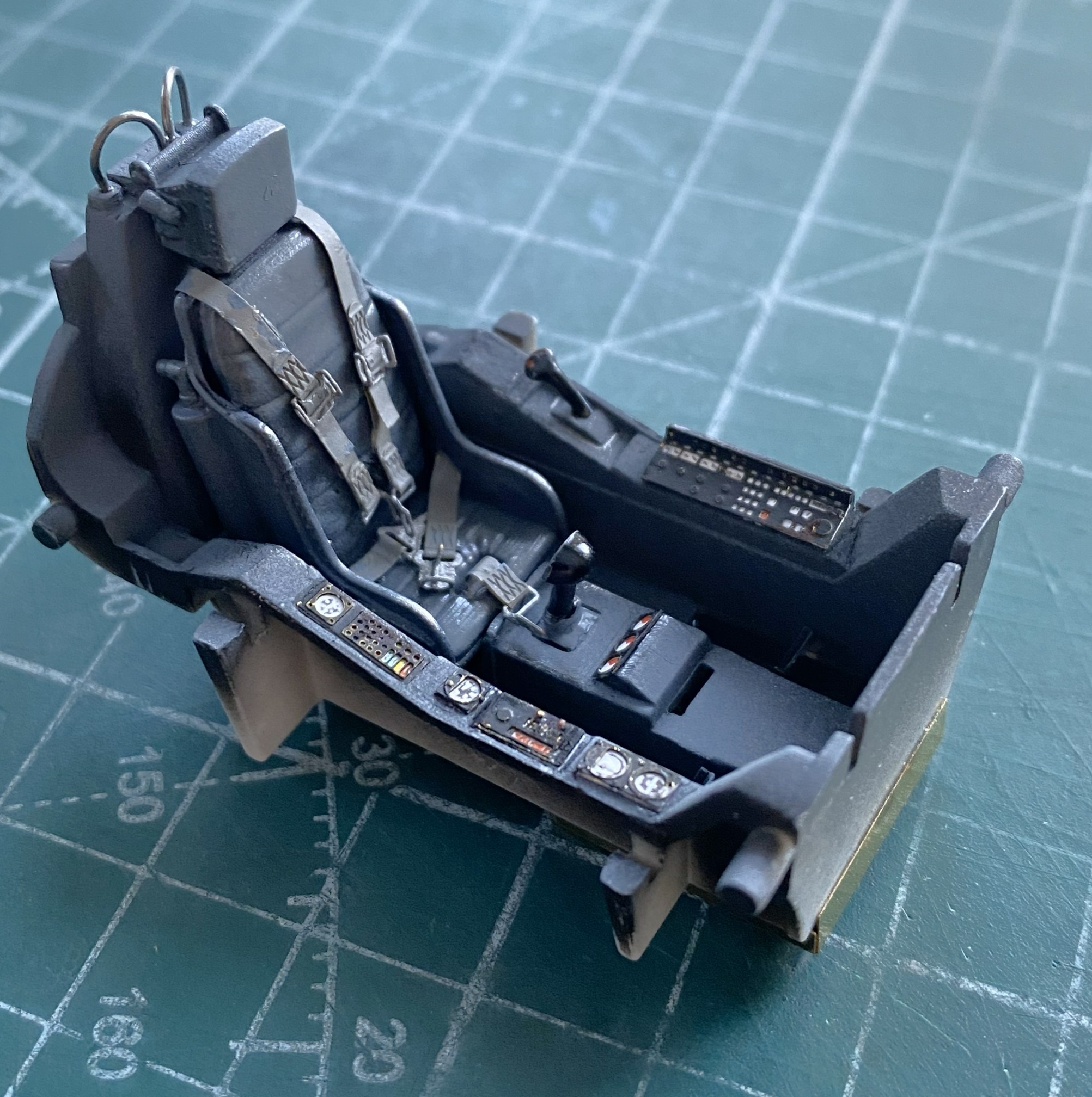

The side rails are just dry-fitted to get a sense of what stains show, where wear goes, and how much of it looks correct:
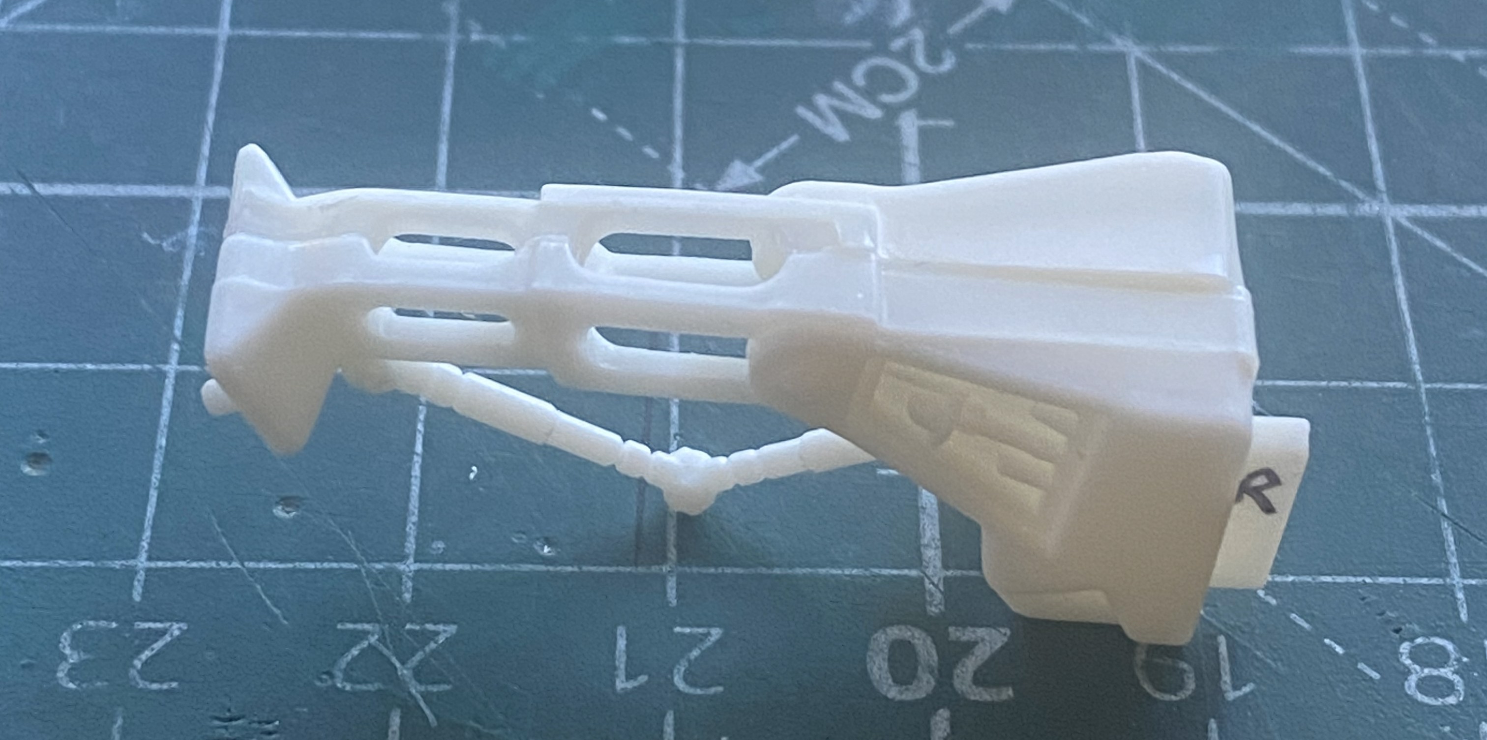
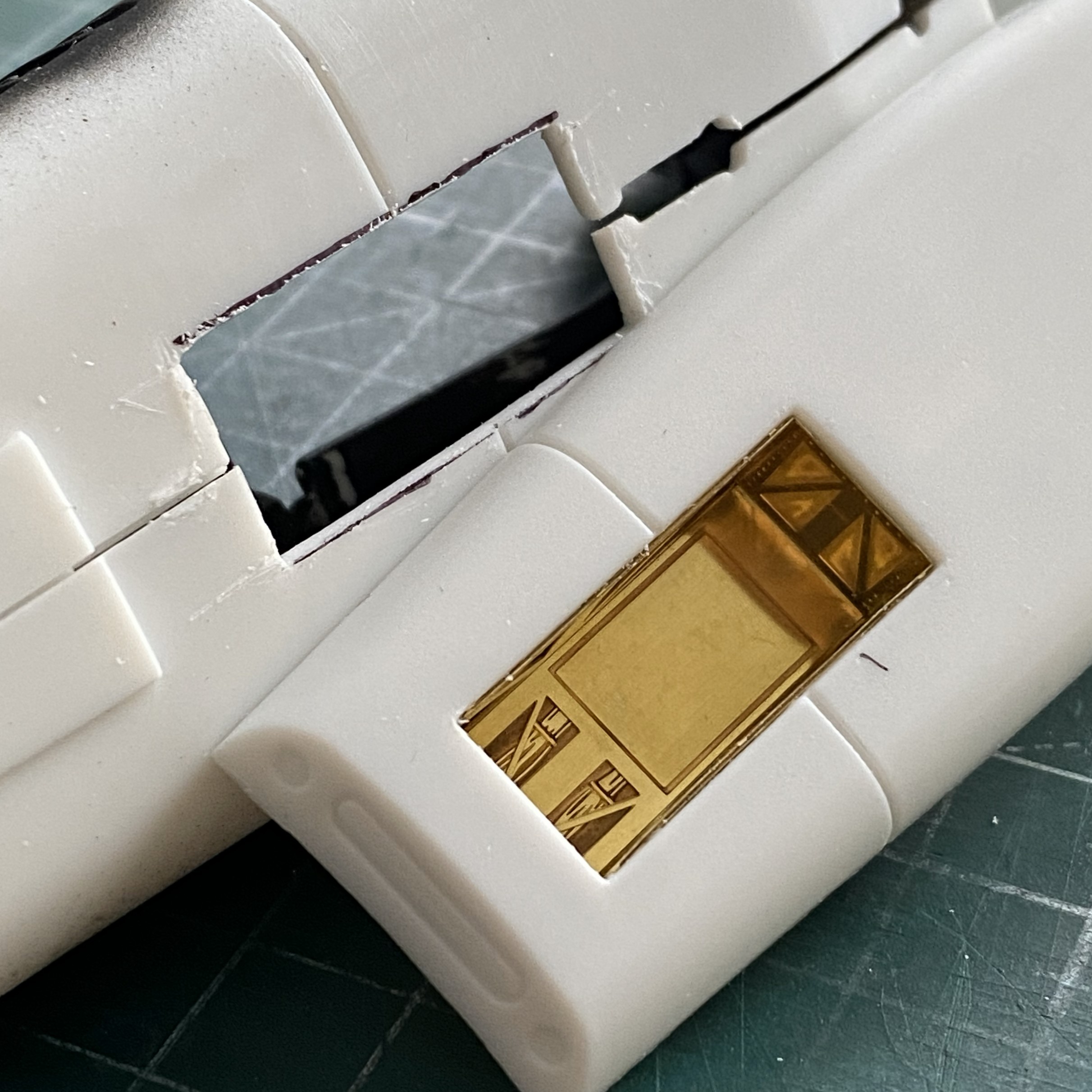
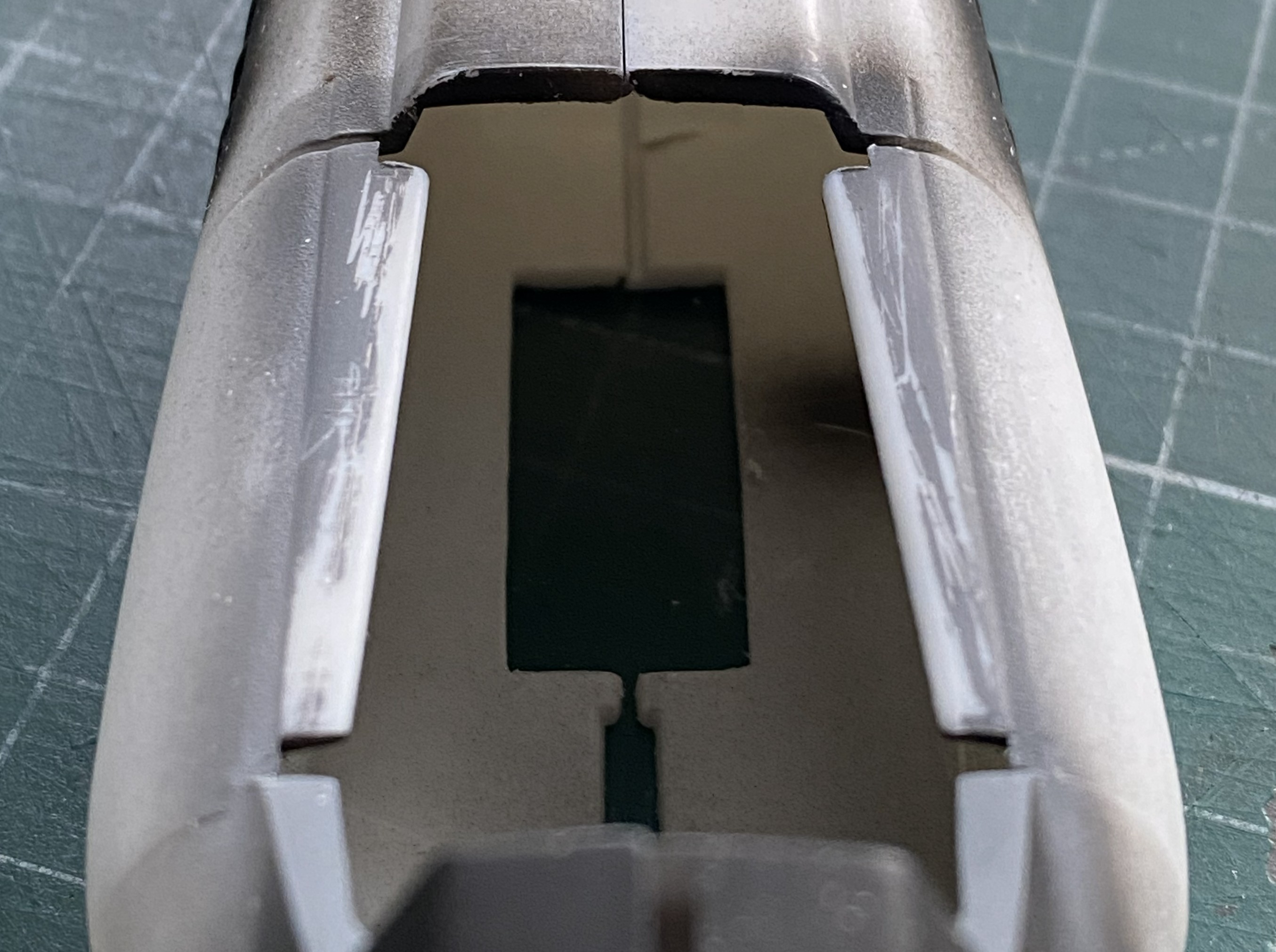
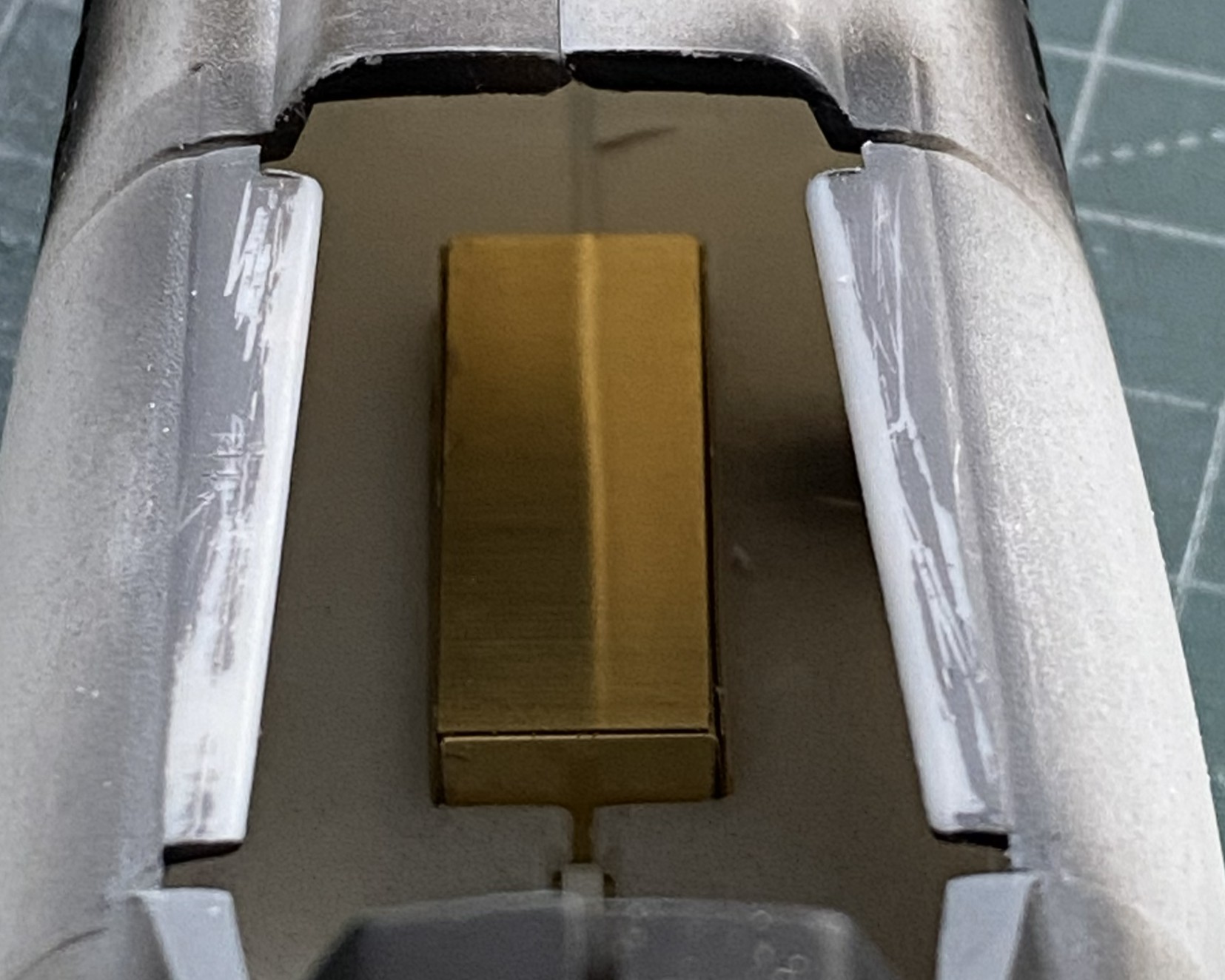
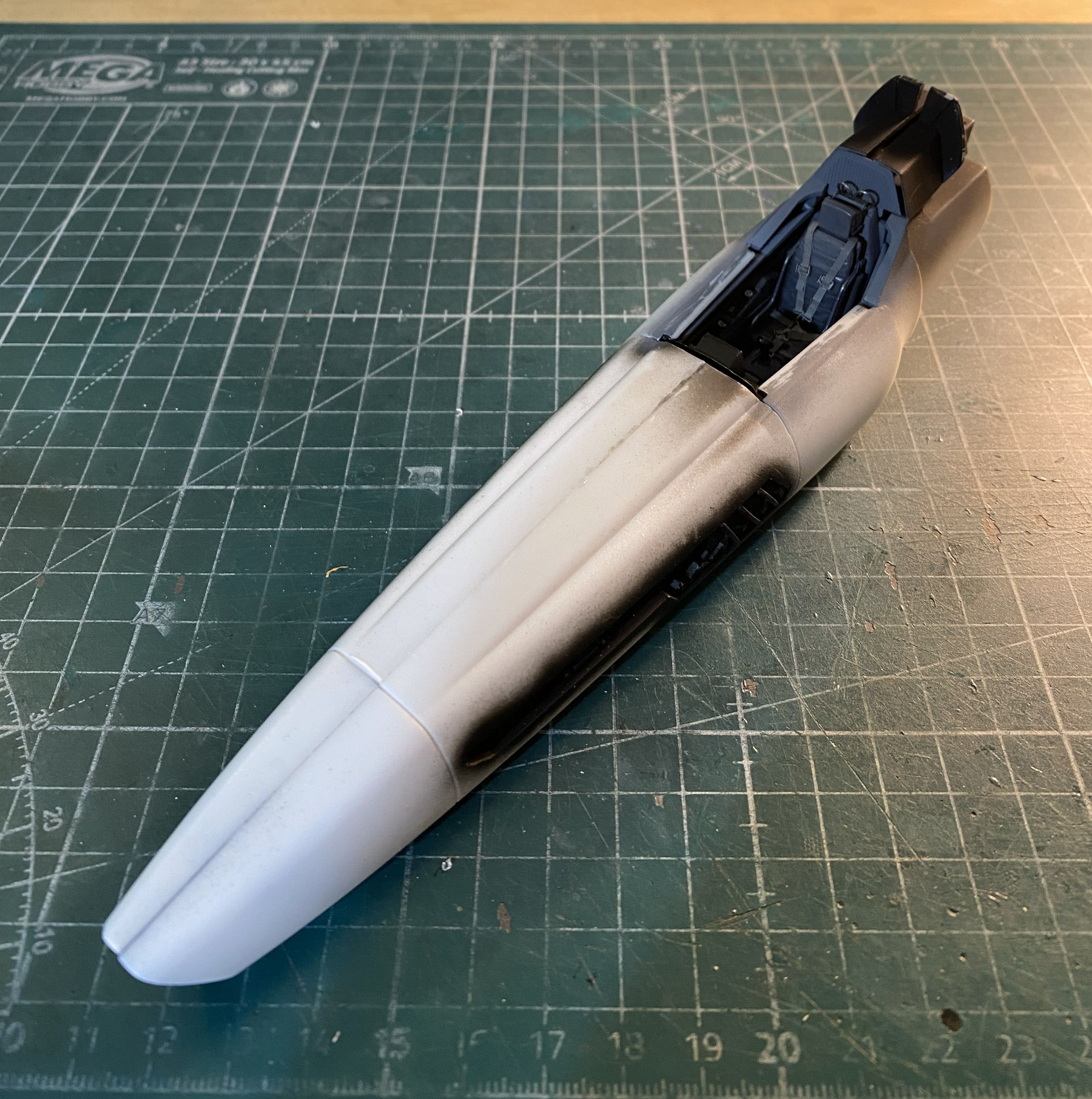
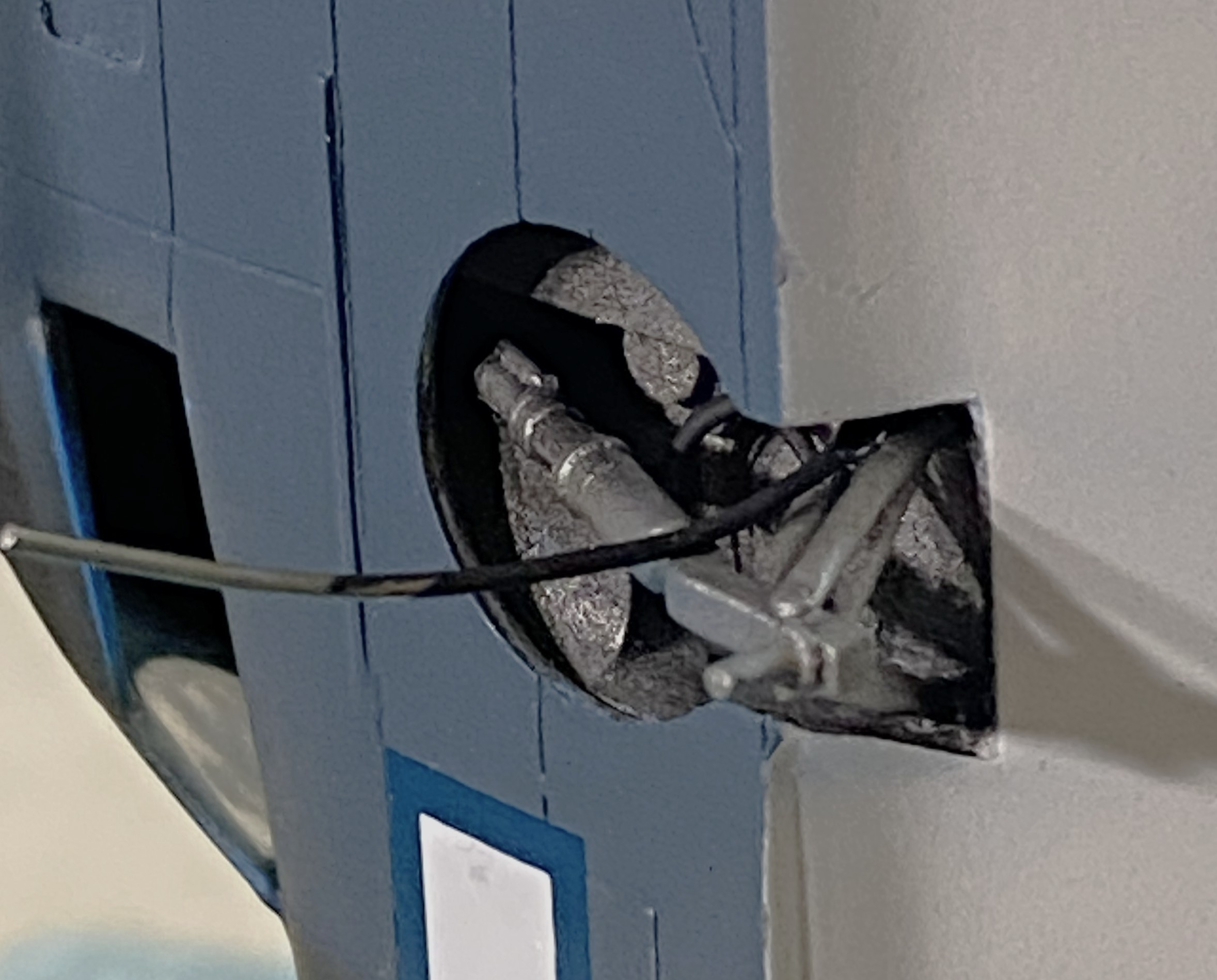
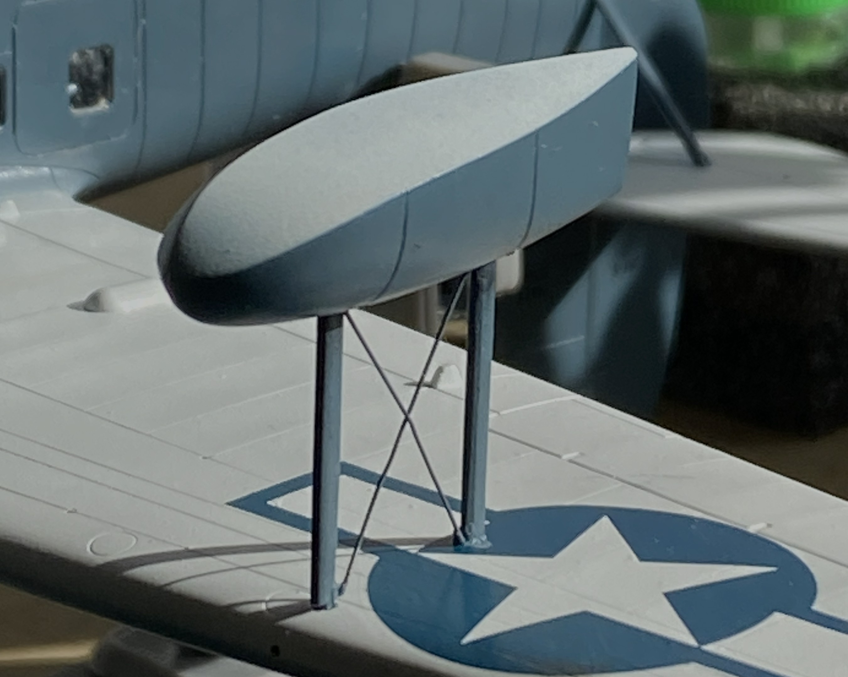
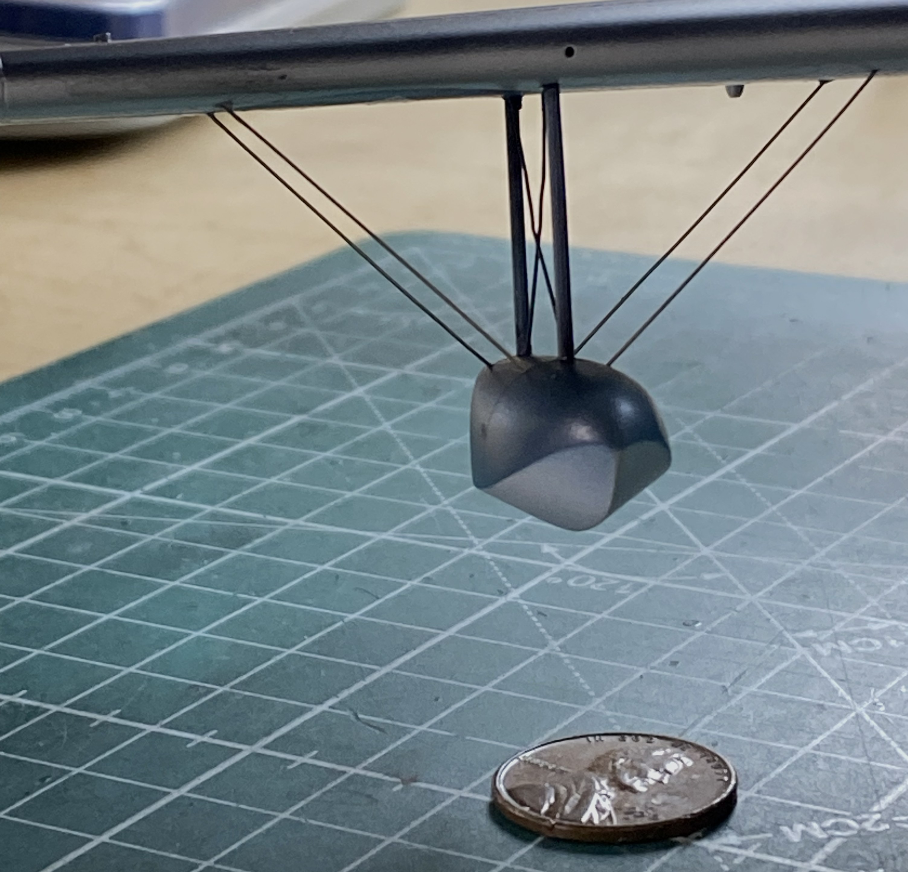
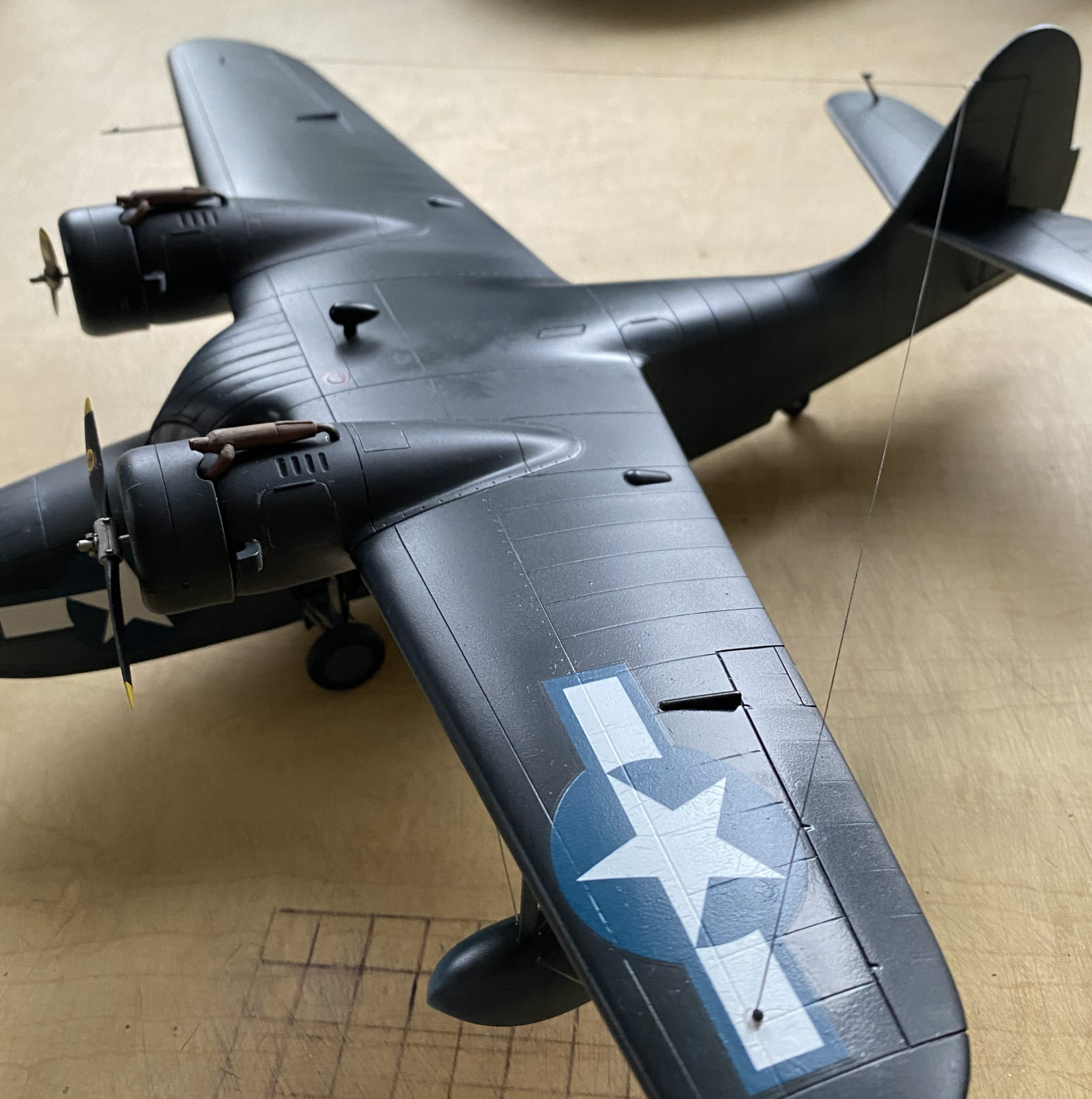
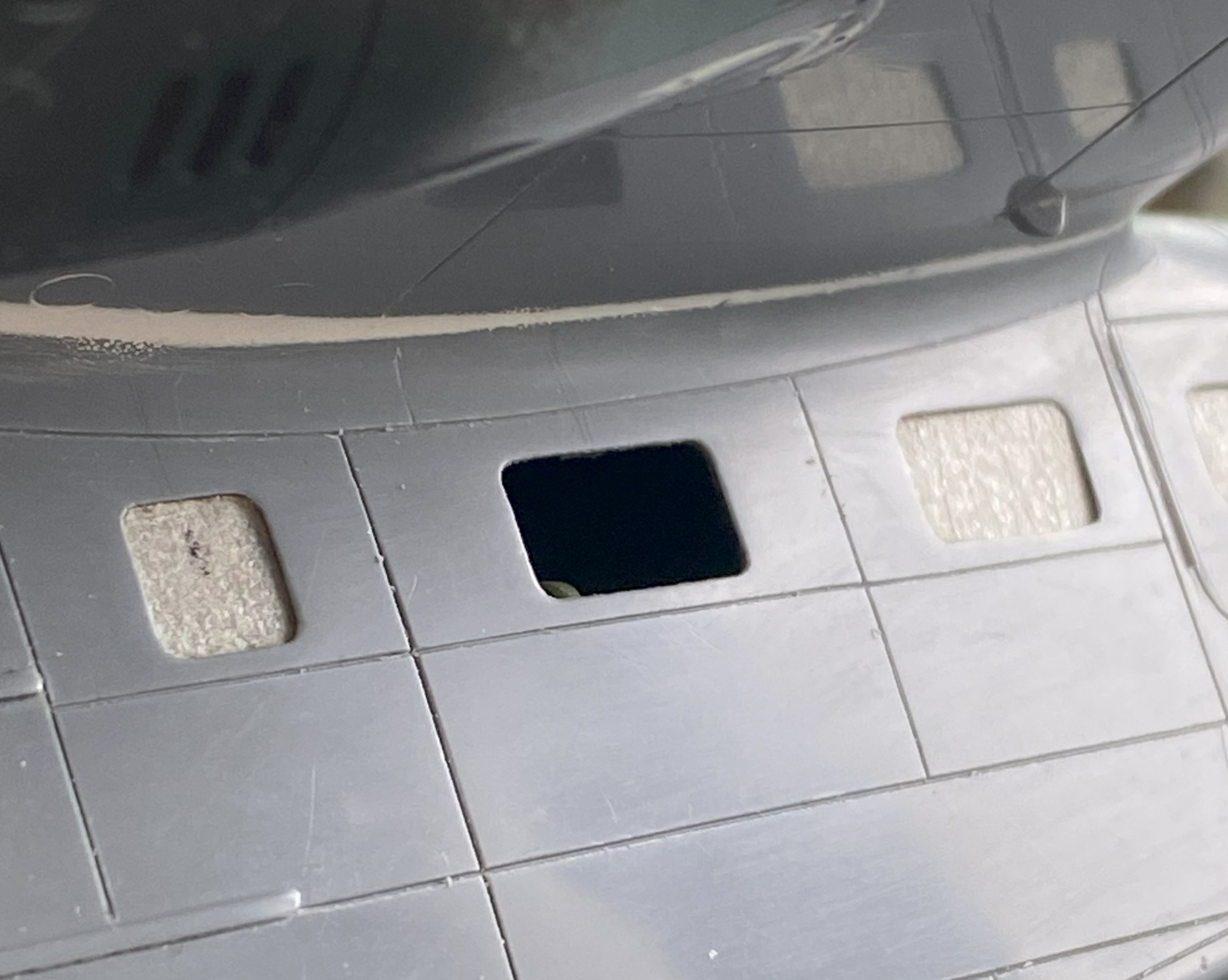
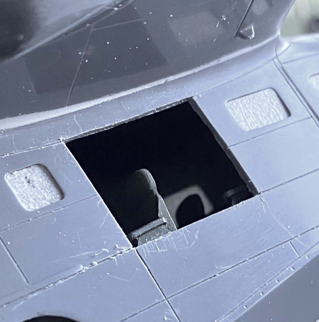
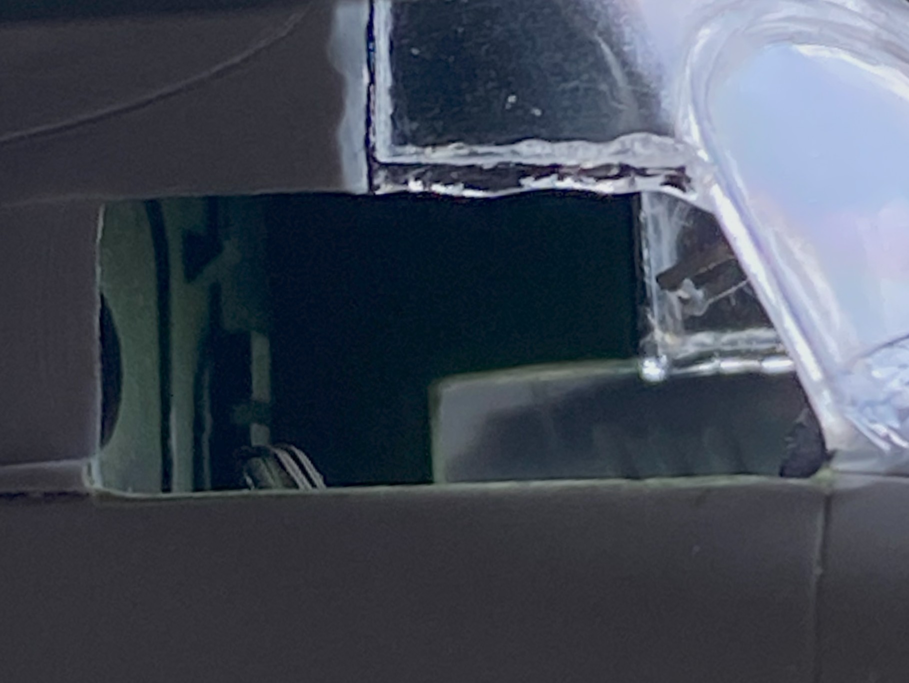
The belly of the fuselage is molded separately from the sides. Clever. It obviates most of the belly seam. To add the AM details, the main fuselage has to be cut away to allow the AM space (more on that later, too) to socket in place:
Since the cockpit was done, all detailed, painted, worn, and dirtied, I added it to the fuselage and glued the fuselage halves together:
Then I put the belly in place (almost) and noticed that the top of the gear bay impacts the front floor of the cockpit (which is also an AM part from the same manufacturer for the same kit…guess nobody checked to see if it would fit) (again, check the blue arrow):

And speaking of fit, force will be required here (again torpedoing the notion that force never solves anything) to get these two parts to meet:
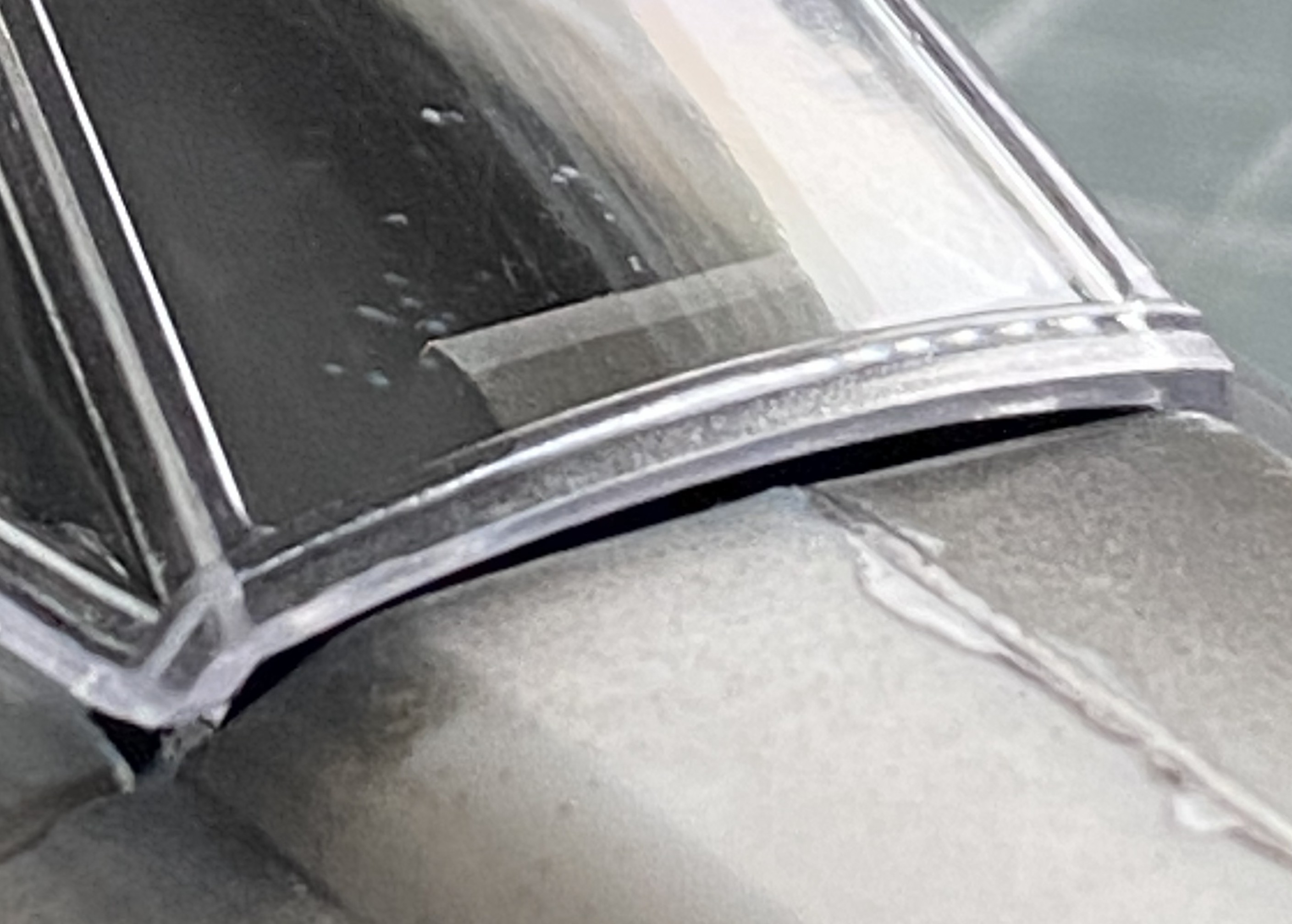
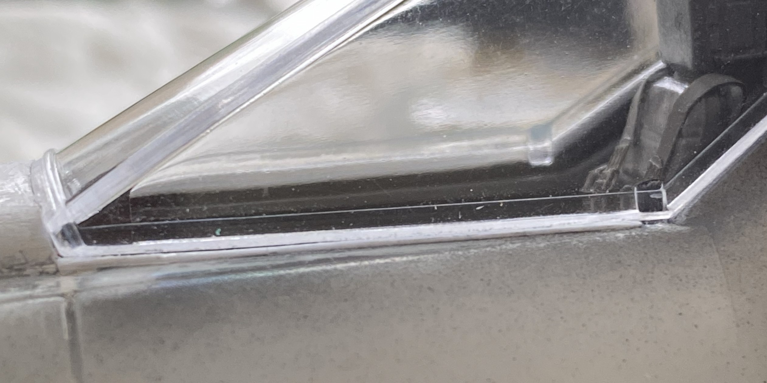
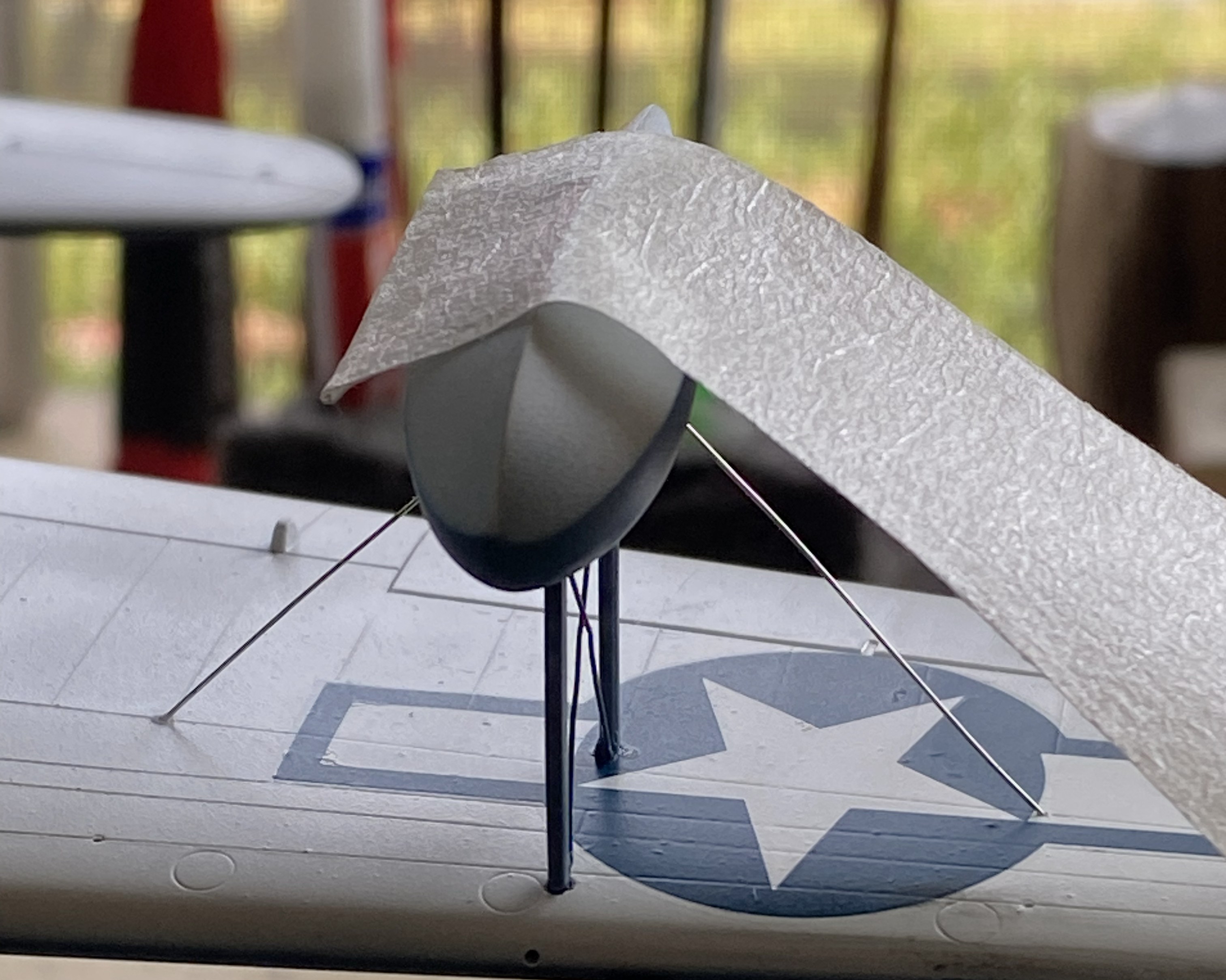
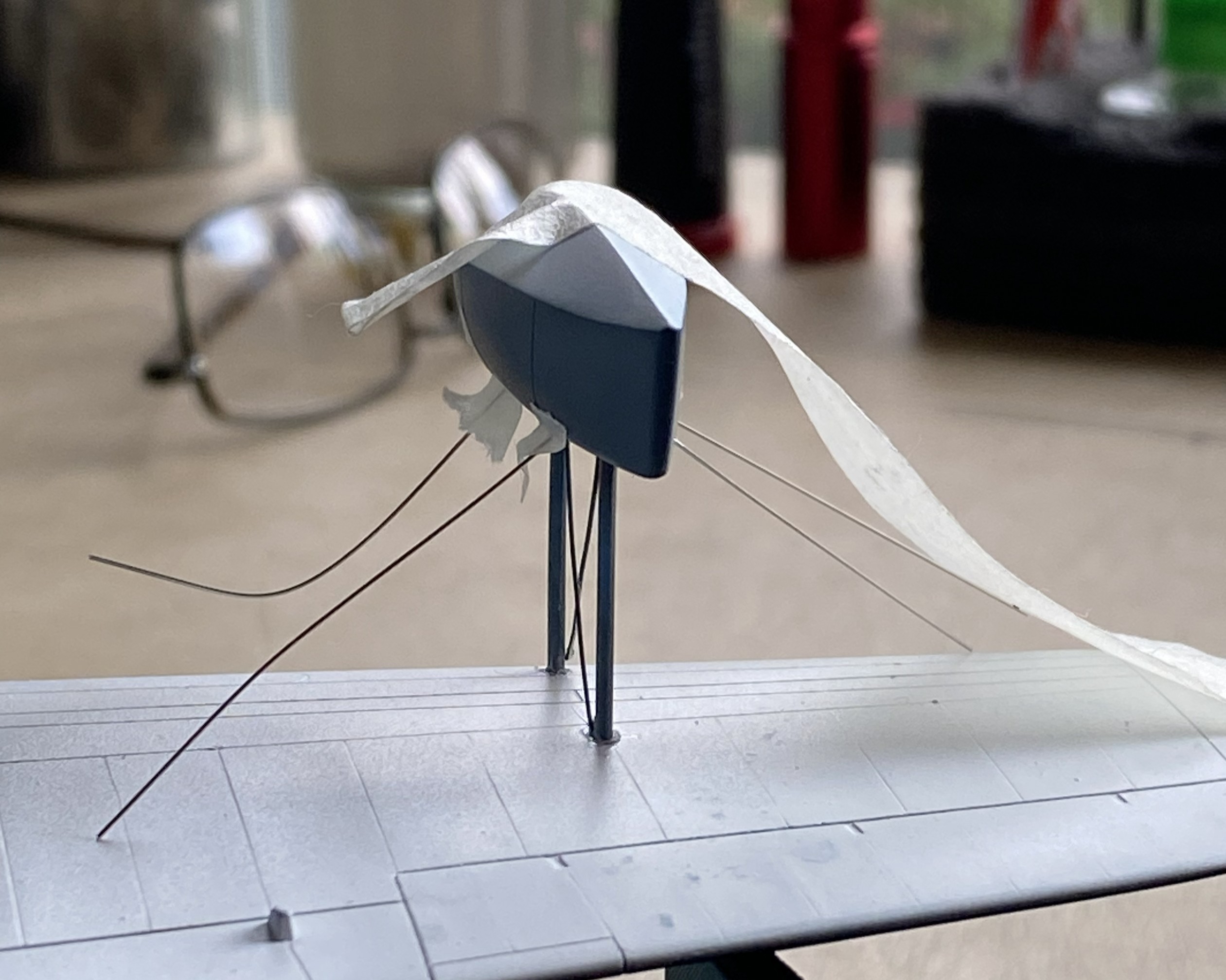
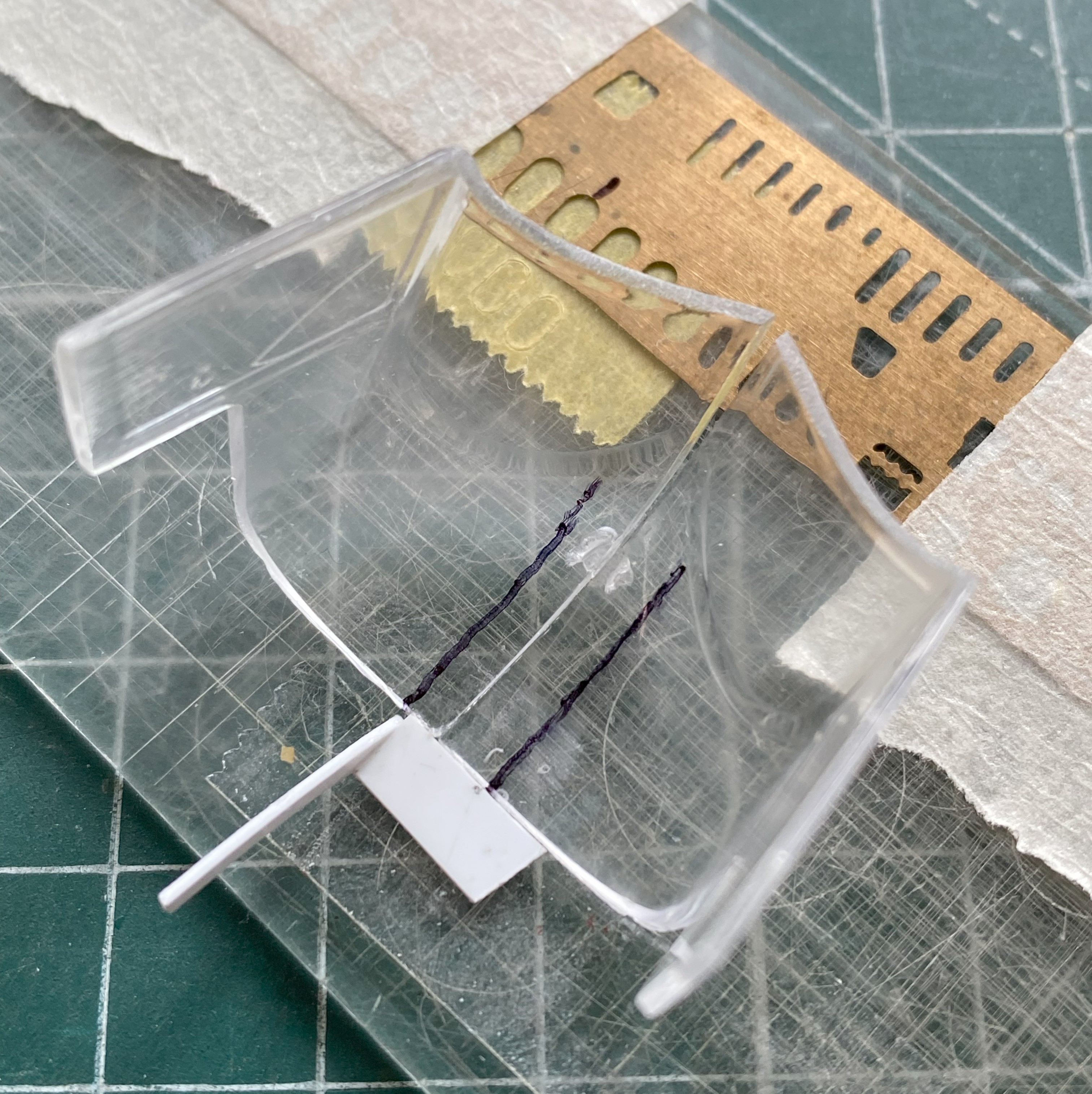
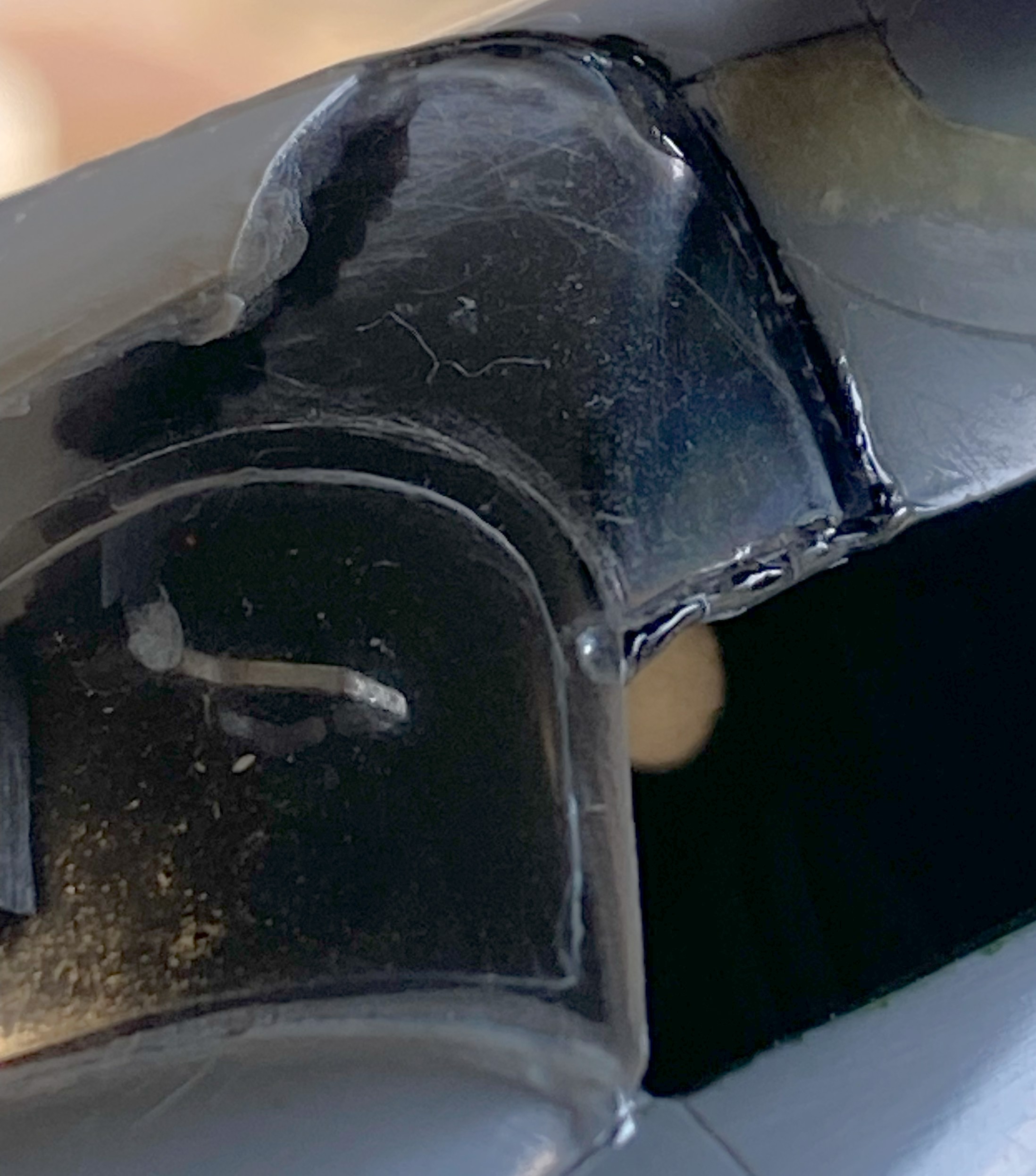
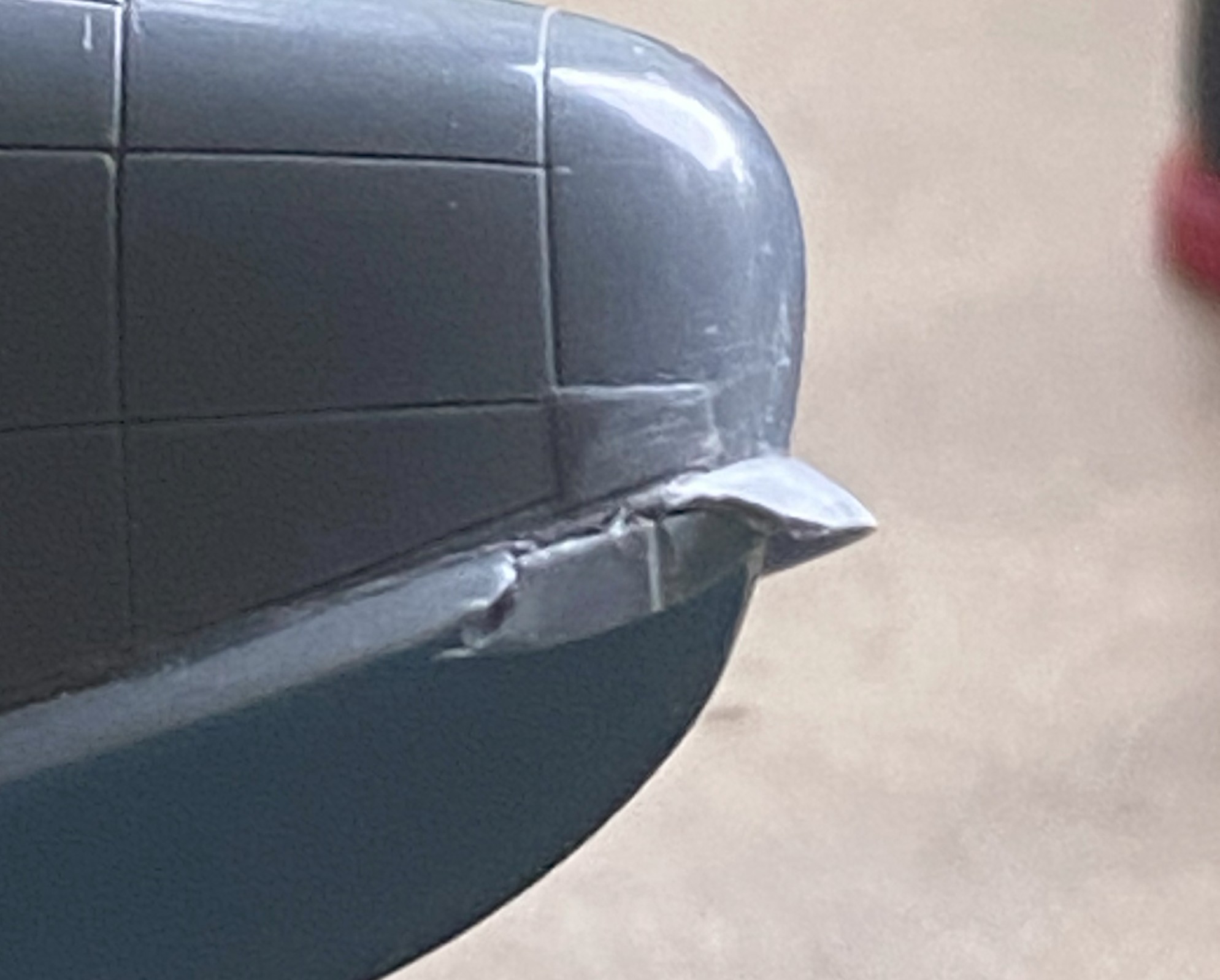
And while I was checking the fit of things, I took that beautifully cast canopy, put it in place, and realized that it didn’t fit well, either:

While I’m here and looking at the lousy join of this seam, I clamped it most puissantly:
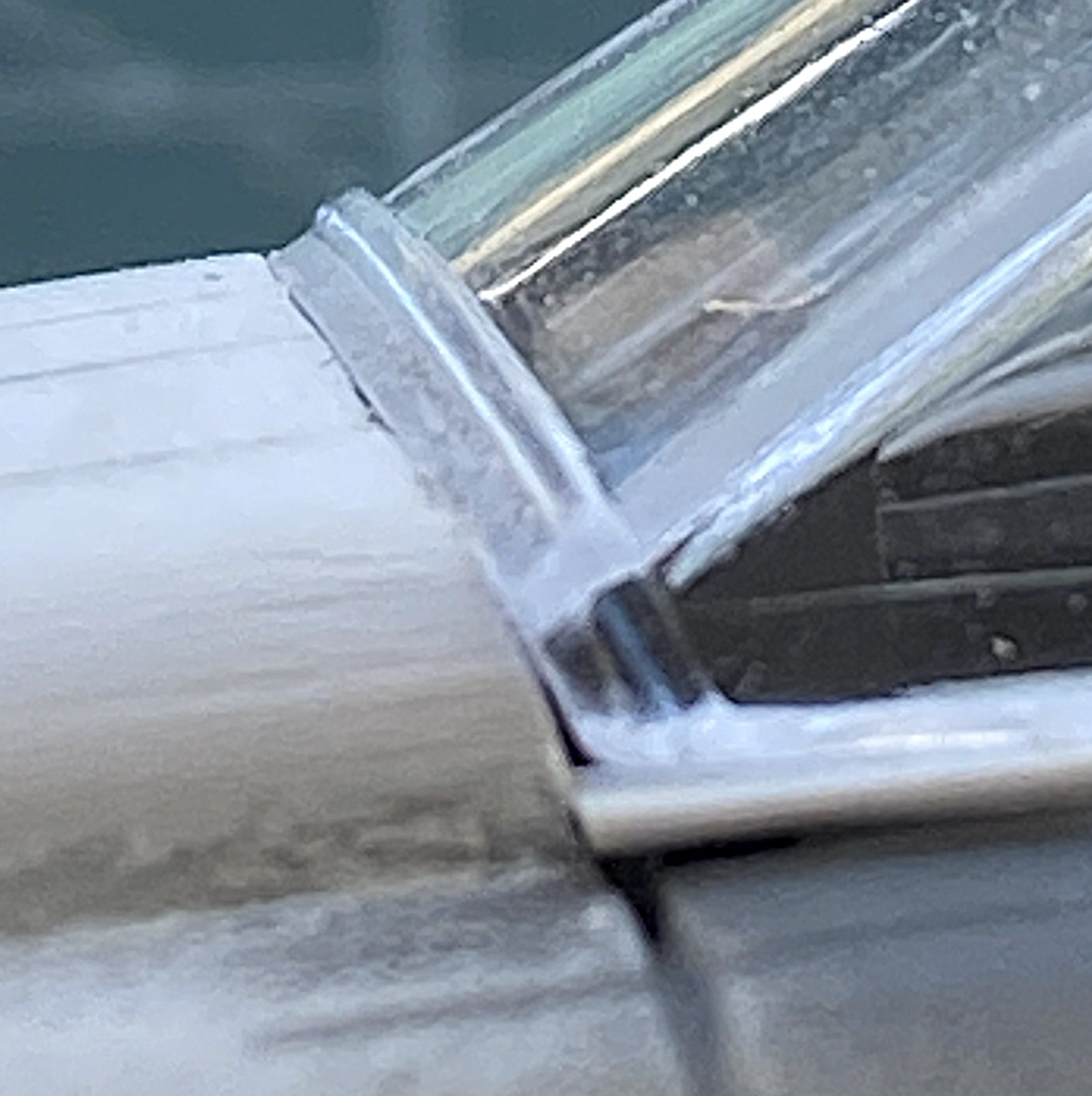
The sides don’t fit either. They’re supposed to seal the cockpit, which will require the surfaces of the canopy to touch the places of the fuselage it should touch:
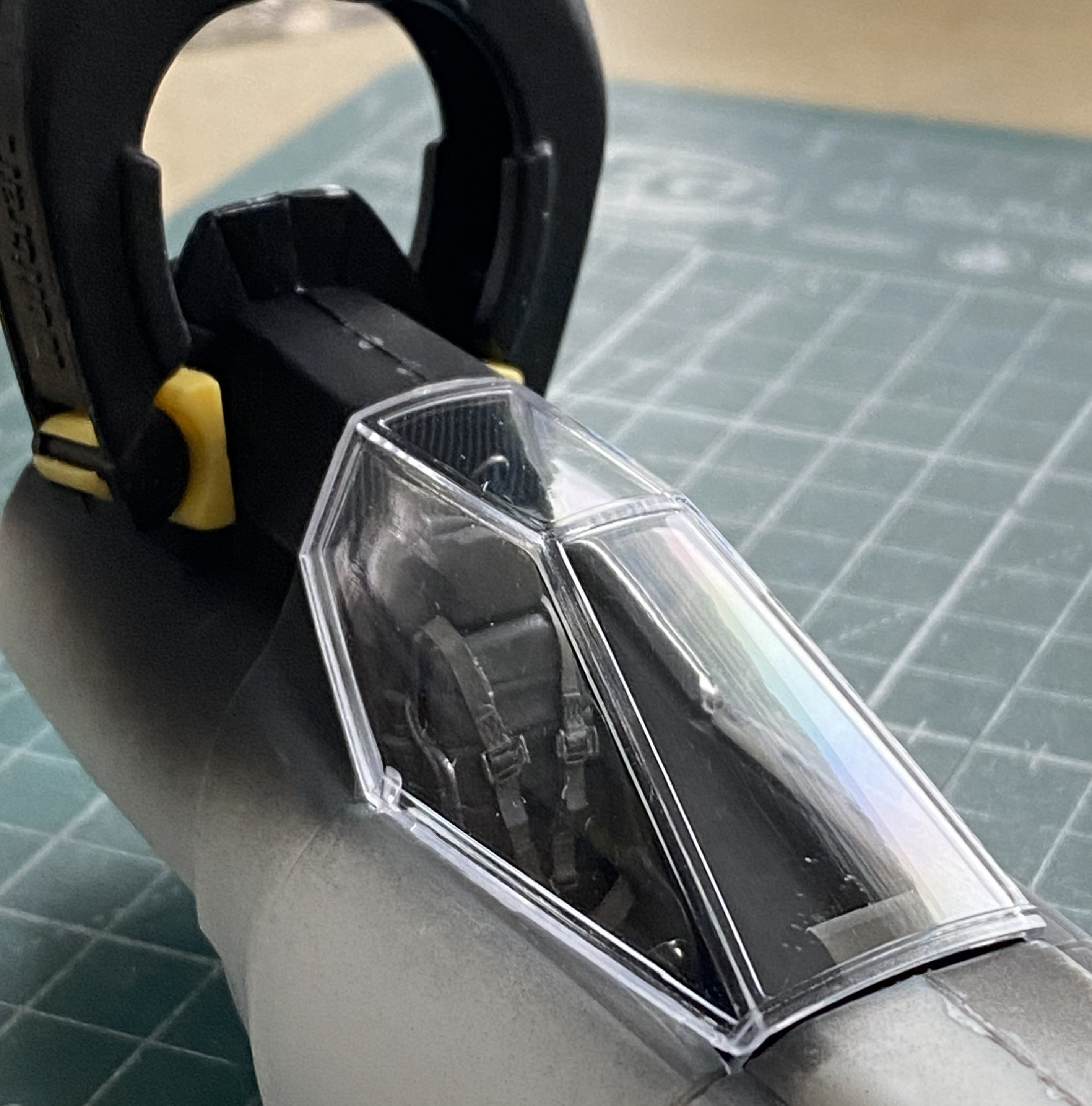
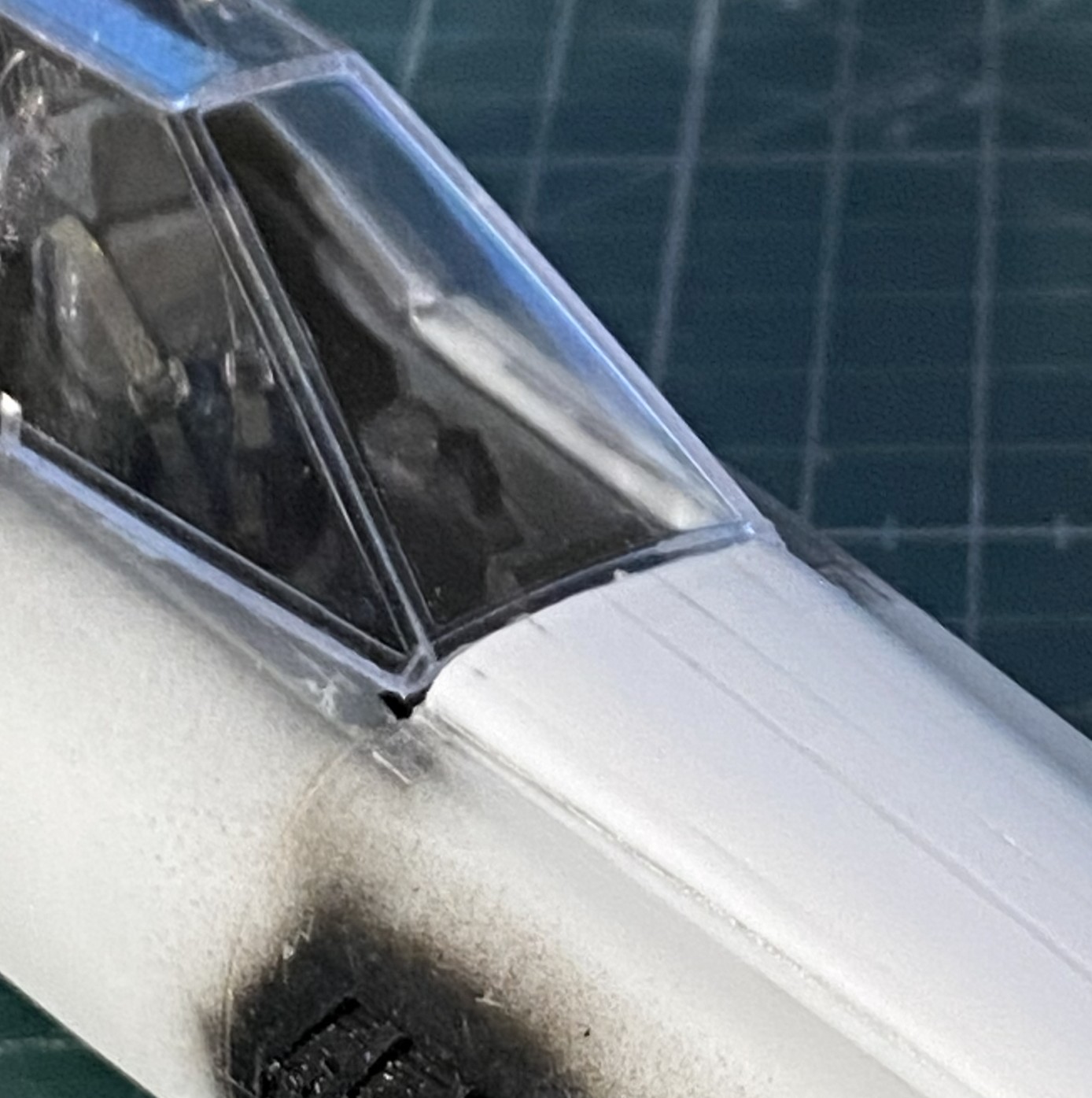
And note how well the leading contact edge of the canopy meets the fuselage:
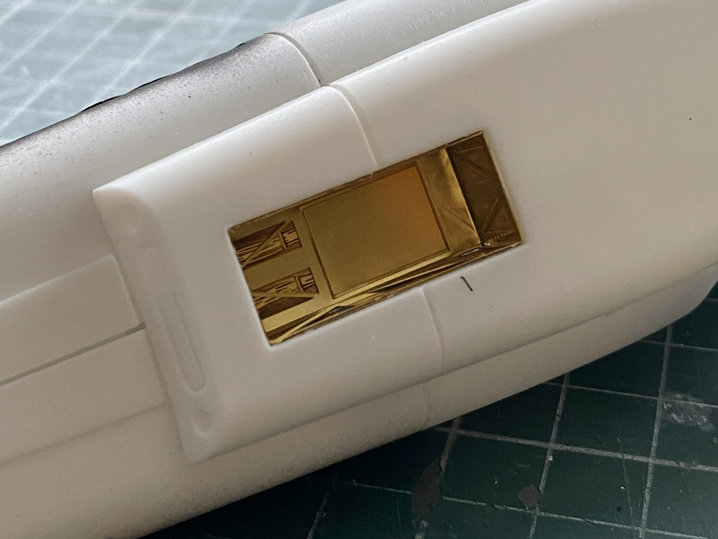
I decided to make the nose gear and belly pan fit first. That required me to cut free the PE part from all the glue I used to hold it there (because, since the nose landing gear attaches to the PE part, it had to be securely glued), which took the better part of an hour (didn’t want to damage the delicate PE, y’know). It also took a few tools to accomplish as well:
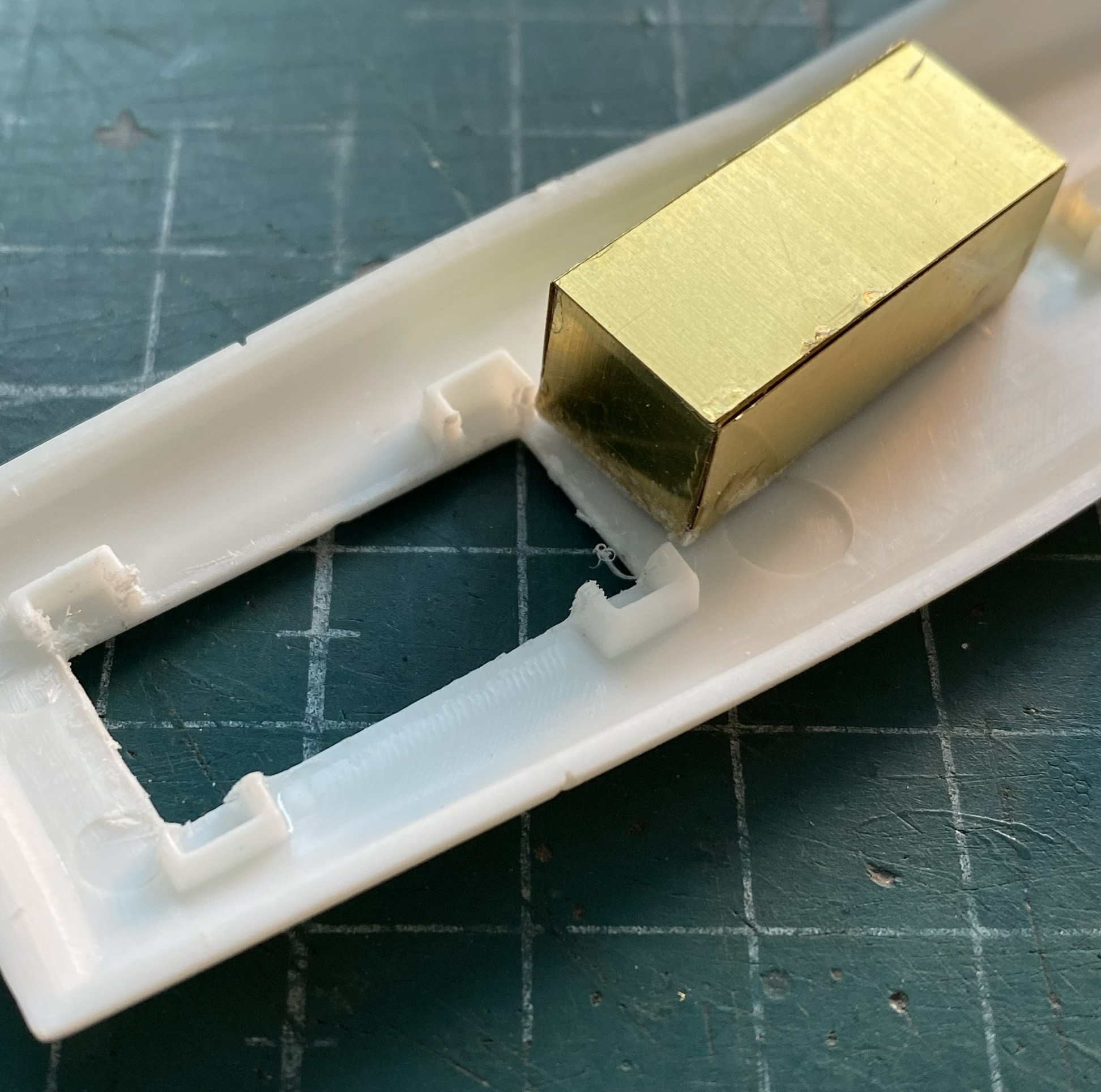
After cleaning the dead glue off of surfaces, it was time to refit it only this time accounting for the intrusion of the cockpit floor. The belly was taped in place and then the gear bay stuffed into the hole until it would go no further:

Since there was going to be cutting and filing of the exposed areas, I glued that PE part in securely and started work until the edges were flush with the fuselage:

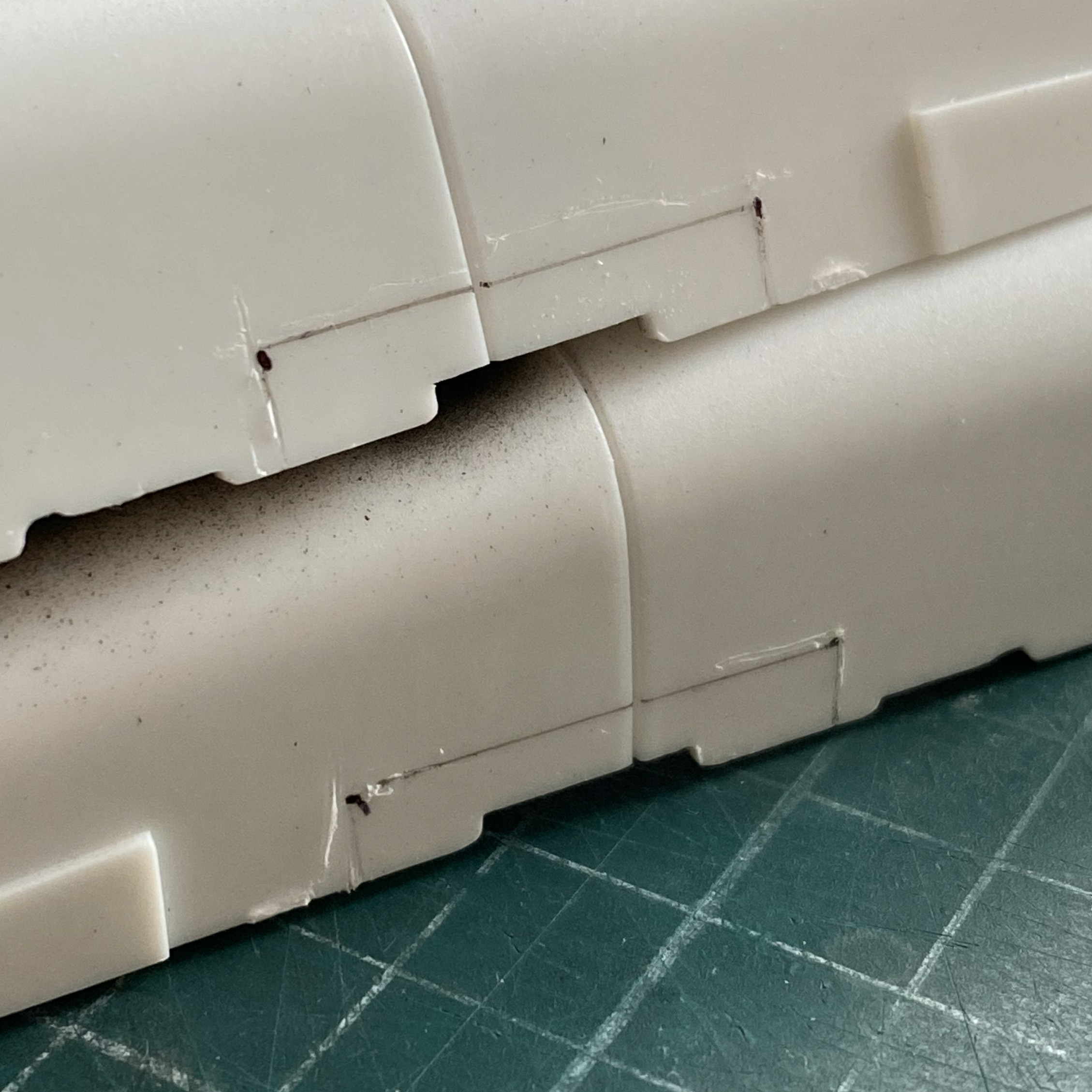
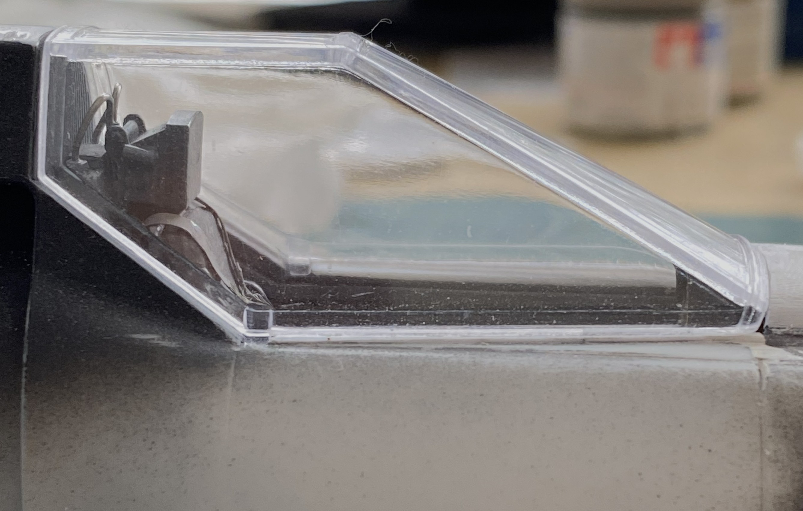
Having put the sword o’ Damocles back into its sheath, I turned my attention to fixing the canopy’s fit. What do I fix? All references show that the upper fuselage in front of the canopy is flat. Do I rework the canopy to fit? Or… The canopy is clear and fairly delicate. Could I rework the clear part? Yep. (The Goose build taught me that.) Do I want to do significant surgery on a part I can’t replace? (Okay, sure. I could replace it. But what a freaking job that would be and the canopy would be at risk throughout the process.) No. So that means that I have to build up the nose to match it and do it in such a manner as to be unnoticed. Okay, that seems like a grand idea!
That grand idea started with me laying down strips of styrene from 0.040″ (1.016mm) to 0.020″ (.508mm) with liberal applications of glue:
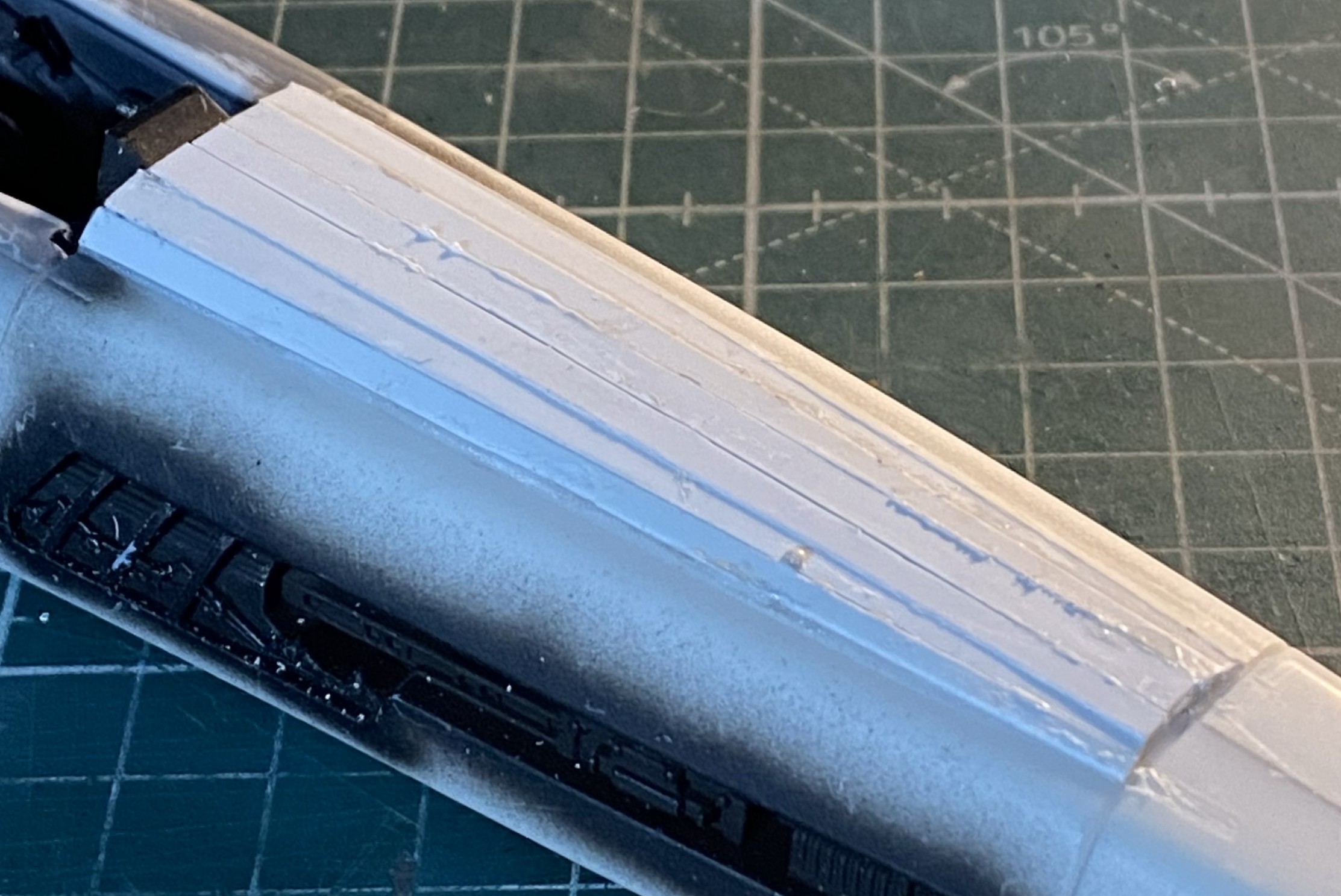
I let it sit overnight before starting to shape it. I started with 50 grit and worked my way past 100 grit and down to 220 grit, at which point gaps started to open up. Stretched sprue to the rescue:
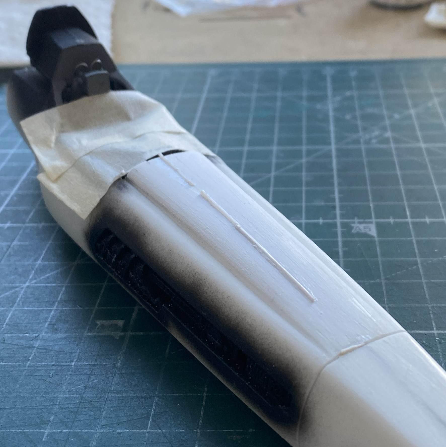
Making a curved surface with flat panels means that each panel will be thicker in the center than at the edges (arcs, y’know). As the surface is removed and shaped correctly, the thin edges of those flat panels start showing gaps. That’s okay. I knew it would most likely happen and I have a lot of sprue I can stretch:
While those were curing, I started fitting the canopy. I added small bits of scrap plastic, putties, and got the two edges to meet at the front:
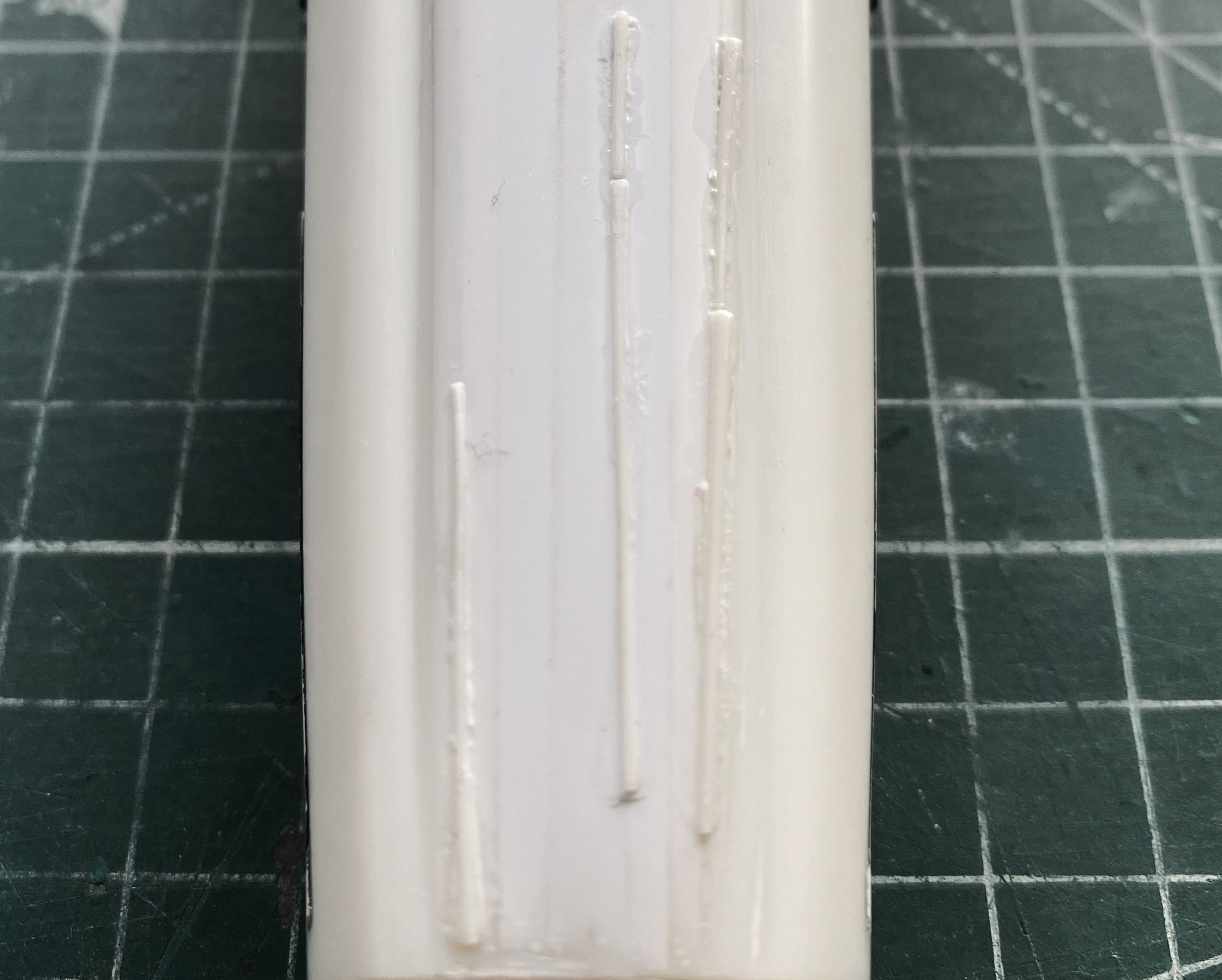
In the above photo, at the lower edge where the canopy meets the fuselage, you can see a 0.020″ (.205mm) spacer that I’m using to start filling the gaps at the sides of the canopy. Once the gaps are established, it’s just the sometimes-tedious job of filling them with scrap (mostly 0.010″ .254mm) and a bit of 0.020″ (.205mm)):
This post surprised me. It wasn’t until I started working on this post that I realized how much work I’ve done on this; it certainly didn’t feel like it. Anyway, I’m going to stop here. Yes, there’s more. I think I’ve already stuffed enough into one post. I’ll finish this one up (edit checks) and start the next one tomorrow.
Grumman JRF Goose (Czech Model) 1/48 Scale Build #7 – Staggering Towards the Finish…and Getting There
This is the danger-point for me, being so close to the end that I have to be careful not to rush things. Couple that with the reality that I despise this kit, I have to double the caution.
I started with what I perceived would be the biggest hassle and that was getting the wing level, and I wasn’t entirely incorrect. As it sits in this photo, the bubble indicates that the wing isn’t level:

At the center of the model, that bubble isn’t far off. At the wingtips it is. I bent my brain around several corners trying to figure out the best solution. I’m of the opinion that it is not uncommon for a given problem to have more than one solution, except that solutions to problems usually come with new problems (and the solution is enacted if the new problem is less than the old problem). And speaking of problems, here’s a short (I hope) examination as to what the problem is, not what I’d rather it be.
The struts of the landing gear fits into the top of the landing gear bay. The landing gear bays were not molded onto the fuselage sides. As I found out well after I’d added the landing gear bays, the sides of the fuselage do not match dimensionally. Yeah. Who knew that would be a problem. It certainly wasn’t Czech Models. However, with one landing gear bay higher from the bottom than the other, and the landing gear goes there, should I be surprised that once the aircraft is assembled that it doesn’t sit level? I was when I first found the dimensions (and shapes) did not match from side to side, but after I thought about it (a lot), I knew that by the time I got to this point of the build, I’d have this new problem to solve. ::facepalm::
Since I saw this problem as a geometry problem, I looked into the geometry of the landing gear. Being more than a little frustrated at this point, I dry-fit the wheels onto the landing gear and pressed firmly down on top of the model until the bubble was centered. Just as the bubble centered, I heard a soft crack as something broke loose…but the bubble was still level. Took a bit of investigation but I found what broke loose. The blue arrow in the photo below points to where the upper control arm snapped away from the strut leaving this gap:

Hmm. So, if I fit a spacer between the strut and control arm, will that make the wing level? The answer was, “mostly”, which I discovered once I’d cut a spacer from 0.030″ (.762mm) and checked:

I trimmed the spacer without gluing it in and checked again. This time I estimated that I needed another 0.005″ (.127mm) more:

And there it sodding is:

I think it’s the housing for an ADF head, but it needed to be painted semi-gloss black. So it was. I REALLY hate self-inflicted wounds, which is how I view overspray. When I aimed the airbrush at the football, NONE of the other painted surfaces were visible:
Success! Zero overspray:
I used 0.025″ (.635mm) as brake lines, painted them knowing full well that during the final bending process would cause paint to flake off. It was a lot easier to get at the parts that bent the paint away because there weren’t buried in the landing gear bay. I’ll get to these when touching up the paint happens (the photo’s on its side because I was using gravity to hold the solder where I wanted it to while the superglue set up):
And speaking of paint touch ups, I painted the frames of the cockpit windows off so that I could also paint under them. A solution that created a problem; paints don’t match once assembled. Okay, I’ll be doing touch-ups (with a small brush in these areas…the other side, though not as bad, is the same), just add this to the list:
You’ll also note that the cabin window just behind the flight deck is still masked. This was a problem I let sit as-is. When I tried to pry the masking tape away, three of the four sides of this window broke free. It was hanging on by paint. My memory isn’t what it once was (is anything?), but I DO remember what I had to go through to fix the one that came out already. Carve, fix, fill. Lots of fun when the plastic was unpainted, a no-go zone now that it has been painted. I supplemented the paint holding the window on with liberal applications of superglue. I’m pretty sure it’s going to stay there, now. It’s in a place where it will never be touched.
This one’s pushing the 90-95% accuracy I try to attain. I don’t care. A blocked off window is better than a sodding hole. Moving on…
Speaking of self-inflicted wounds, I noticed a week or so ago that there was blue overspray on the nose. ::adds to touch up list::

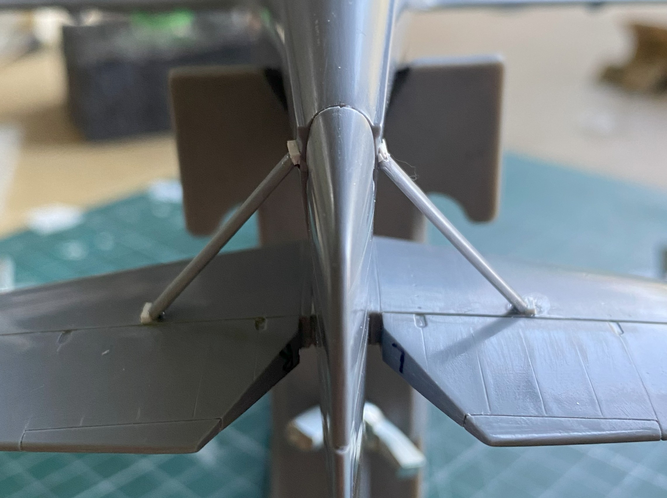
I added the heat exchangers (the brown things over the engine nacelles). Later on I’ll spiff them up a little bit with some pastels:
I added one of the landing gear “doors” just before beddy-bye so that the glue would set up; there’s not much gluing surface:

And while I was letting something sit overnight, I got ballsy (considering how late in the evening this happened) and added one of the floats to sit overnight as well:
Obviously, with only two small contact patches, this will be easy to knock flat laterally. I added tape to stabilize it while I fed the ends of the braces into the float and wing for gluing (superglue). l cut the wires overlong so that I could be certain I’d be able to adjust them if I needed to (a handy bit of foresight):
With all the guy wires in place, it looks pretty good:

Getting the guy wires into the pre-drilled holes of both the float and wing took some fiddling. For the next float, I tried inserting one end of the guy wires into the float without cement to see if that would be easier:

It wasn’t. If you look closely where the wires meets the float you can see small bits of masking tape holding them in place:
This didn’t work as well as I’d hoped.I was surprised at how difficult it was to just remove the tape. I had to diddle the tape so much that the float came free (in its defense, it hadn’t sat overnight for the plastic to harden fully at the glued points). After I reattached the float to the wing, when I turned the whole thing up side down, all the wires fell out:
I got that fixed:

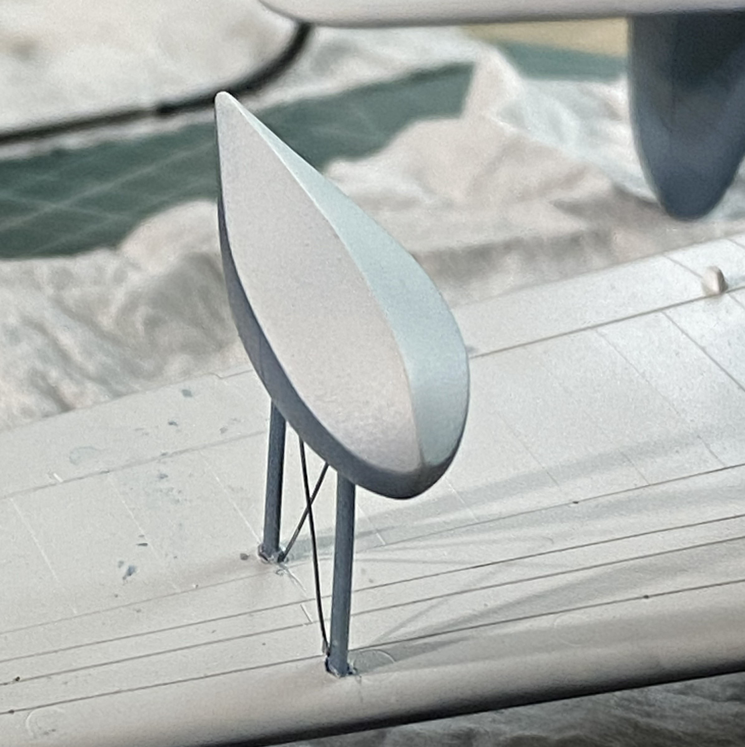
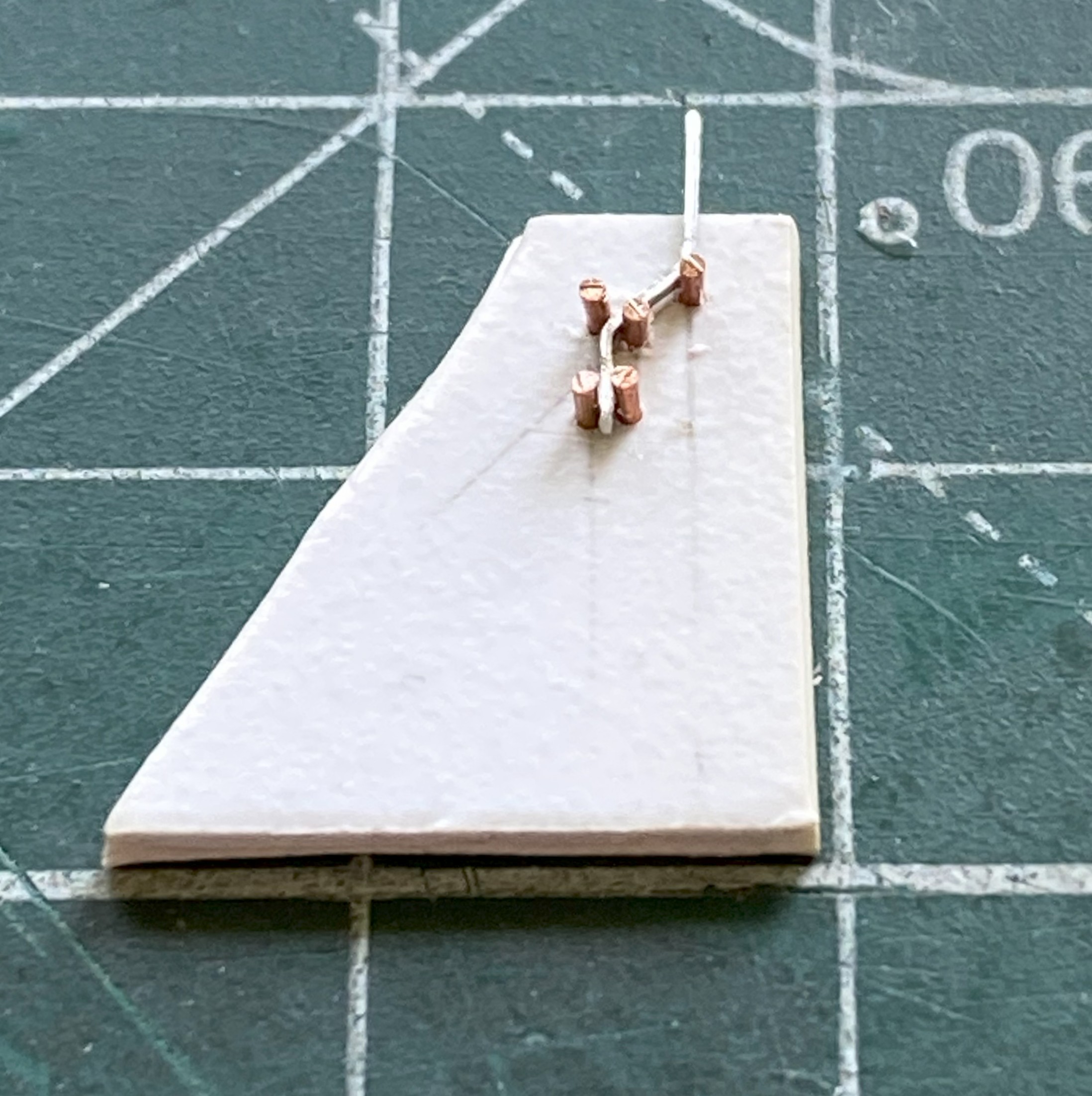
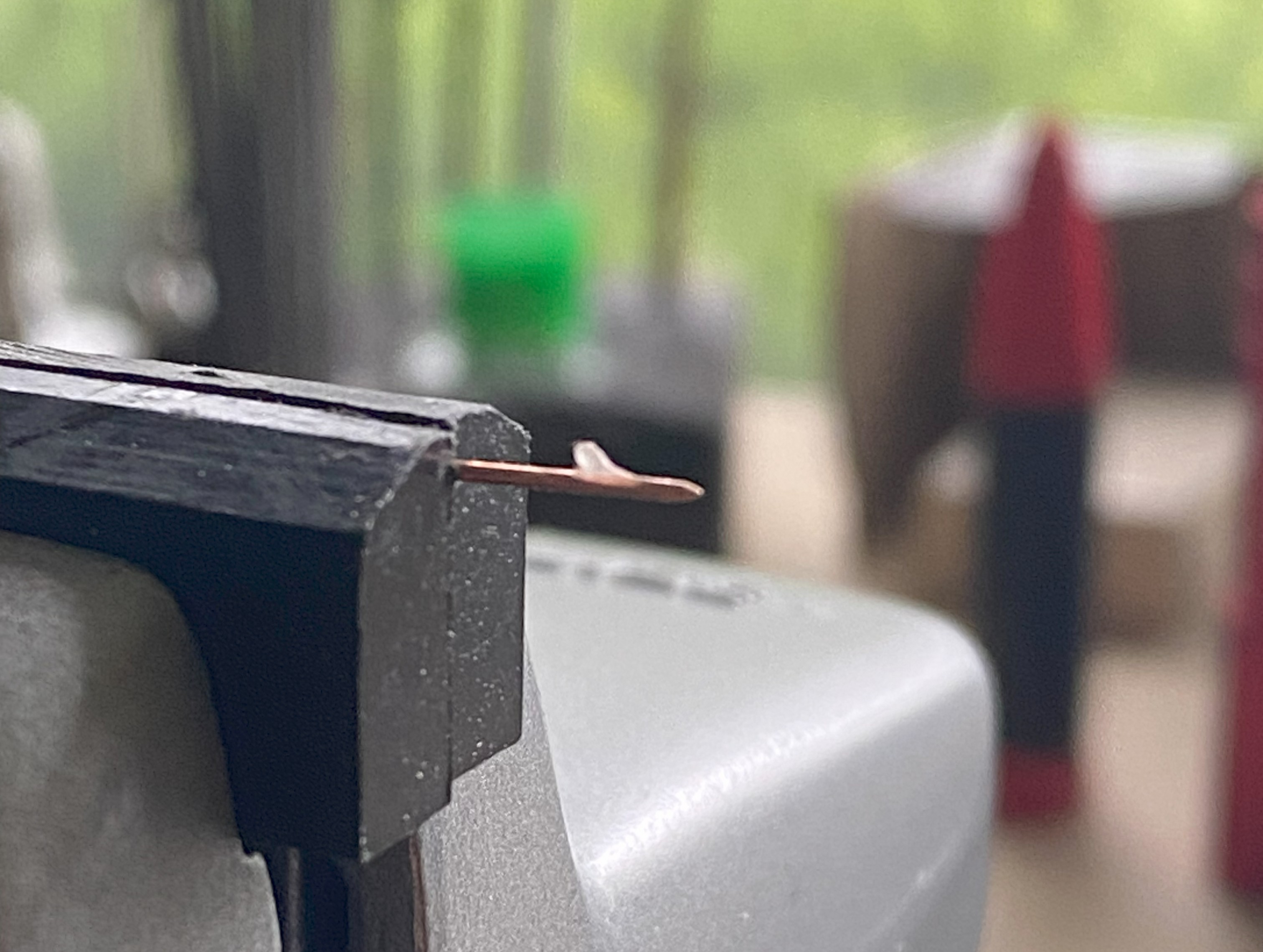
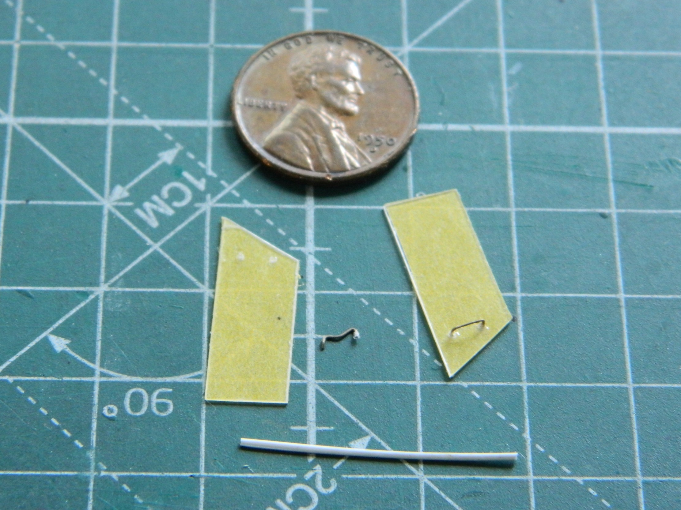
The radio aerials attach at both wing tips and the tip of the vertical stabilizer. I use this for aircraft aerials:
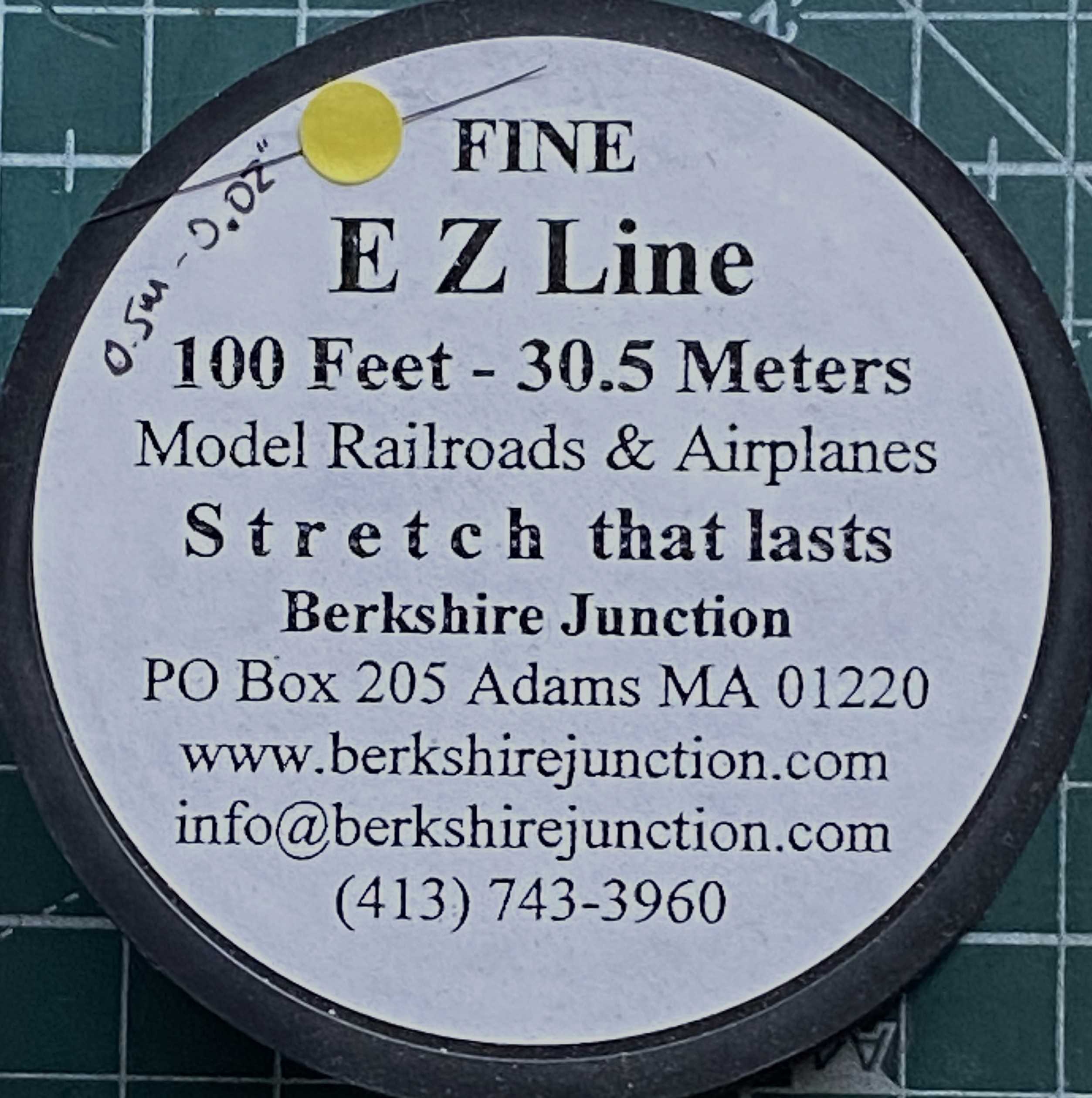
As I’ve been putting this together, obviously the more parts I add the less places I can hold it. For that reason (because these things get handled and transported) I wanted the aerials to be semi-removable; permanently attached at the wing tips, removable at the vertical stabilizer. What would make doing that simple would be to make the attachment point on the vertical stabilizer detachable. Or…I could mount the attachment point permanently and have it be J-shaped so that I can just lift the EZ-Line and let it drop. I like that idea, the major flaw is that even though the EZ-Line’s tension is adjustable, that J-hook has to be small. I didn’t have confidence in copper to hold up over the years. Instead I used the E-string from a guitar (thereby creating the moderately rare 5-string variant). Everything about its dimensions are printed on the pouch:

It’s certainly over-engineered for my purpose, which I think is great:
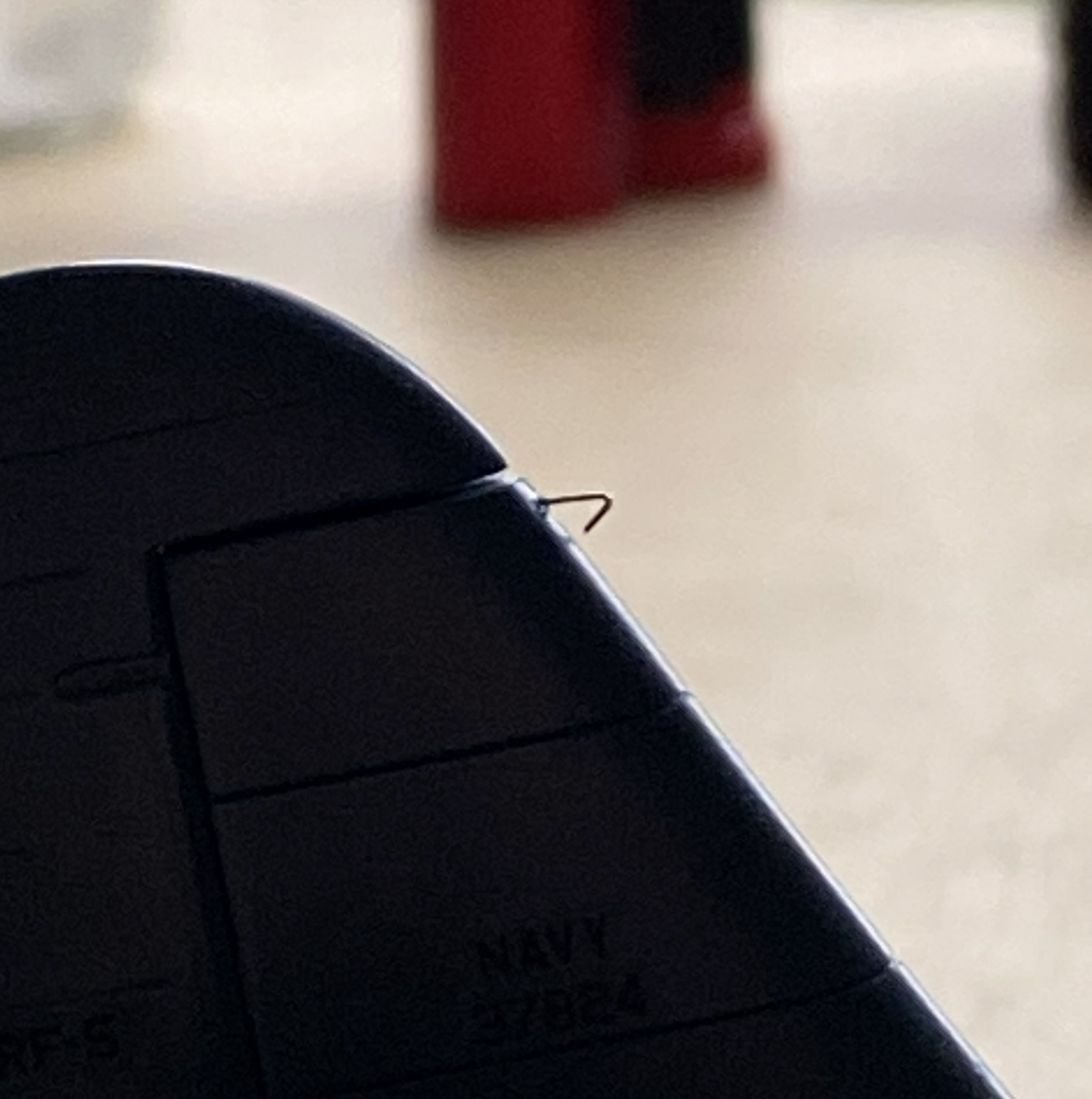
I’d attached little stubs of styrene rod where they belong and center-drilled them to socket the end of the EZ-Line into:

After gluing the other side in place, I tested the arrangement to see if it would function as desired. It function exactly as desired. Top photo below is with the aerials in place, the bottom photo is with the antennas dismounted (for these photos, I dry-fit all the parts yet to add and realized that none of those dry-fit parts need to be glued so I left them on):
I have one more thing to do (attach the brake lines to the wheels) and DONE!

Grumman JRF Goose (Czech Model) 1/48 Scale Build #4 – I Get to See Just How Poorly this All Fits Together
If you’ve been to this website before and checked out my building process, I’m confident you’ve noticed that I build subassemblies and once there aren’t any that I can build, I start putting them together (though there are those tasks that have to wait until later…think “small bits that want to snap off during normal handling”). In general, I’m usually surprised that once I get to the install-subassemblies stage, “suddenly” the build is done. It’s much like being an overnight success. There is rarely any sort of “suddenly” to the successful. There are usually years of perseverance, varied and continual emotional stress, and luck that support the “success” part. It’s not “suddenly” for the person who succeeds, and I think the same thing is true about my being surprised that it’s all coming together seemingly quickly. With my builds taking MONTHS to complete (or longer), “seemingly quickly” doesn’t seem very quick from where I’m sitting.
This month was much like that.
I ended last month’s post with cleaning up the empennage. So I started this month attaching the empennage. My. Goodness. It was very fiddly and easier to get incorrect than it was to get it correct:

It’s at this point that I state that the elevator bits were an utter ass-pain. They have a dihedral and the kit offers absolutely zero help in getting them aligned. After the above was glued on, I glued the other one on immediately, intending on using the mutability/movability property of freshly glued parts. What enabled me to get it done as well as I did (I hope) was using the support struts to achieve whatever degree of accuracy I managed to attain (they weren’t glued on at this point). This end of the strut goes here and the other end of the strut goes there. I hadn’t cleaned up the struts at this point, they were just used as jigs to at least get within sight of this thing called “accuracy”.
While the glued parts were sitting for the glue to set completely (more on that in a bit), I decided to pull another trigger and glue the wing on:

If you look at where the trailing edge of the wing crosses the top of the fuselage, you will see a gap. Since this gap is directly on top of the model and consequently easily seen, I decided that rather than putty the gap I would stuff it with scrap styrene (of various sizes):
Even though I had to squeeze the fuselage sides together in order for the wing to fit into place, there were still gaps at the wing-roots. More scrap styrene stuffed in to fill those gaps:

3M Acrylic Putty was laid down over all of these gaps and set aside to dry.
I was sort of dreading working on the landing gear. I think that whoever cut the dies for these parts did it from memory because they’re wrong. The main struts generally are also the main shock absorbers and as such have a certain look and, in the real kites, a definite purpose…and on this kit they’re just wrong. My initial thought (rare as those are) was to just scratchbuild the struts and move on. But once I had the part in my hand and my readers on, I realized that if I just could reduced the diameter of one section of the strut, that would suffice. No…it’s not 100% accurate. Yes…it does end up within the 90%-95% goal I’ve set for myself. In the next photo, the upper strut is a virgin (complete with parting lines). I used one strut as my trial, figuring that if I totally bitch it up, I can revert to my initial plan and “just” scratchbuild it. My goal, however, was to clean the part up well enough so that I could use the top of the struts (to the right in the lower photo) in my lathe if I managed to get the struts centered in the lathe chuck well enough then I’d be able to turn down the area I needed to. The blue arrow in the lower strut shows you where I managed that:
That machined area will be painted steel as it’s the section that compresses downward into the lower portion of the strut. I managed to get them both done without having to scratchbuild.
We’re at the “more in a bit” part. There was so little surface areas that could meet when I attached the empennage that, probably not surprisingly, during handling, one broke off:
Normally I used Tamiya Extra Thin to get these bits to stay attached. When I saw how poor the mating surfaces fit, I instead dropped back to an old standard, Tamiya Cement (white label, white cap), hoping that that would work in a poor-fit situation. The photo above is more proof that perfection continues to elude me. So that was reattached:

Back on the path, I spent A LOT of time blending the roots of the empennage to the fuselage, as well as bringing down the added styrene on top of the wing:

While I still had the wing on my mind, I decided which template I’ll use to cut the masks for the wing-mounted landing lights:
Which was then set aside because there’s a lot of work to do before the airbrush becomes the tool I need.
Having disappointed myself with how the paint job came out on the F7F-3 Tigercat, this time I decided that I would polish the surfaces to see if that resulted in something more satisfactory (as well as adding the rudder):


As I closed in on attaching the clear parts (normally I would call this “the canopy”, but most of it isn’t the “canopy” at all but structure of the fuselage over the cockpit. Hanging (okay, not hanging but attached) from the roof of the cockpit is a console with gauges, switches, and throttles. No way around it, I’ve got to build all that. And since I’m SO bad at matching interior curves (bad enough that comparing my…ahem…”skill” at scribing to matching interior curves makes my skill at scribing look decent), I decided that I would take advantage of the fact that the clear parts were molded in halves. I don’t have to match the interior curves, I can just trace them. Much inside the cockpit will never be seen. However, the throttle levers are quite visible, and if one turns the model just so, the face of the overhead can also be seen…so I have to build all that:
Having decided how wide I wanted the overhead, I used 0.020″ (.508mm) to fashion the sides and then 0.040″ (1.016mm) scrap as both ends:

While checking fit and keeping an eye on what needs to go on and into that overhead, I realized that maybe all those details would fit on an actual overhead console, there’s no way that the initial width of my construct would. I fixed that by adding 0.060″ (1.524mm) to both sides and added the face of the overhead with a piece of 1.010″ (.254mm) styrene:


After trimming everything to fit, I used a punch and die set to knock out the gauge locations on a bit of 0.005″ (.127mm) fascia:

Once I’d laid out the gauge locations, I glued the fascia on and added bits ‘n’ bobs to start filling in the details:


Yeah…a bit sloppy. What needed to be cleaned up was attended to.
While the glue was curing, I cleaned up landing gear arms, empennage struts, and the ADF (I think) antenna:
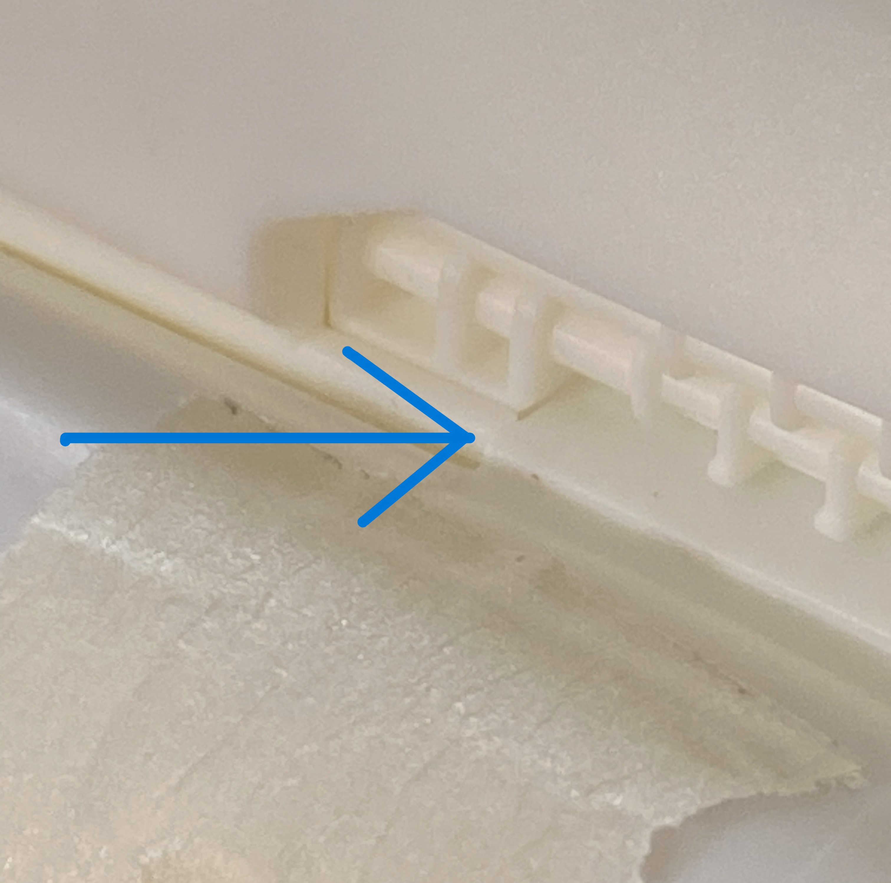
With the empennage struts all cured, this is the fit of them (note what the blue arrow is pointing at if you want a notion as to how ALL these parts so far have “fit”):

Of course that required filling, and though putty would be easier (all terms are relative), I didn’t know how it would hold up over time so instead of putty, I stuffed little bits of scrap styrene in to build up structure that later on I could trim to actually fit:

With the glue cured on the overhead console, I had to make the throttle levers. The body of them are made from 0.010″ (.254mm) aluminum for structural reasons. My first step was to lay out the angles on a scrap hunk of 0.040″ (1.016mm) styrene, drilled where the bends needed to be, and stuck 18awg wire into the holes:


Then a couple of tiny bits of stretched sprue for the grips:
Those were glued to the overhead as were a couple of other levers (UV-setting resin…great for making those infinitesimal knobs on the ends):
Time to paint it. The overall color is Tamiya X-18 Semi Gloss. Details were brought out by using red and silver paint on some of the switches and levers and Airscale “Instrument Dials, Generic WWII USAAF, item #AS48 USA”:
I don’t know if the dies were sloppily cut or if they’re old. Either way, at the windscreen area where the clear panel meets what will be opaque after painting, there is a radius. A soft corner. I didn’t want that. I know how to fix that with opaque plastic, but doing it that way will totally screw up the areas that need to be clear. I already had 1200 and 2000 grit sandpaper, but I didn’t think that would be enough to return the windscreens to unscratched clear. I went online and picked up 3000, 5000, and 8000 grit to fix this. The panel on the left has been sharpened but not sanded, the panel on the right is as-cast:
After doing left and right sides and then removing scratches with this progression: 320 grit, 400 grit, 600 grit, 1200 grit, 2000 grit, 3000 grit, 5000 grit, I polished with Novus #2 plastic polish. I was pleased with how clear and blemish-free that left the plastic:

Part of why this clear part fits SO poorly is because of the “wings” on either side. These are actually sliding panels that allow the side windows to slide open rearward. In order to fit this to the fuselage, those have to come off. I intend on making replacements for them (the prototype for which is at the bottom of the photo and covered in masking tape to minimize scratching):

With the overhead console done and the sliding windows removed, it was time to join the two clear parts. When I started that, I didn’t glue the entire join. I figured that since everything else fits so wonderfully (I sure hope you know that’s sarcasm), I wanted to leave enough room where the clear part attaches to the canopy just in case the fit was off (I know that it looks like the join has been completely glues…which it was…and then I realized that I was probably going to need to adjust the fit so I spread the two apart down to the post between the two windscreens before the glue could set up):

I am certainly glad that I made that allowance! The strip of plastic inserted at the rear of the clear piece(s) is 0.040″ (1.016mm) wide. Subsequent work showed me that I could have done with 0.020″ (.508mm) more:
I filled in the gap and sanded it down on both sides before I permanently attached the overhead console (the foam wedge is there to prop the clear part in the most supportive angle while the glue cure):
While I was yanking and cranking on the fit of the clear part, I heard an odd “click”. Investigation showed that I had pushed one of the passenger’s windows inside the fuselage:
This window can only be installed from the inside. ::face palm::
After much deliberation (read that as kicking, screaming, and threatening Dire Consequences), I decided that cutting out the section of the window between the panel lines would let me get at it to fix it:
I thought that I’d be able to get the window that popped out (or in) but I rattled that thing like it was a rattle can of rare paint that I hadn’t touched in a couple of years. Nope…not coming out. Okay, easy fix. Get another piece of clear…so I did:


Self-inflicted injuries are still injuries…only without anyone else to blame for it. Moving on.
With that delightful sidetrack, I got the clear part glued on. Note where the blue arrow is pointing. That’s the closest I could get it, mostly. Yes…I could have diddled it into a better fit, but the V shape of the windscreens has to match the V shape where it joins the fuselage. Fixing the poor fit on the sides was the easiest path:

I used UV-setting resin to build up the places I needed to so that the edges matched up:
As you’ve probably noticed, I also added a couple on panels of 0.005″ (.127mm) scrap to build up areas to meet the fuselage and wing. Sanding would have removed too much and altered the correct curve at the top. I also added more UV-setting resin to the top join to fill gaps and give me a firm surface to scribe a panel line into:

I also used UV-setting resin to attach the V at the front of the windscreens to the fuselage:

The additional UV-setting resin fixed the problem nicely:


Whew…and it gives me the look I wanted:

Now that painting this is driving the build, I started going over the surface to see what I’d missed. Little things like scribing the underside of the wing root. Dymo label tape is my go-to when I have to scribe a long, straight, scribe (and even then I can screw it up):
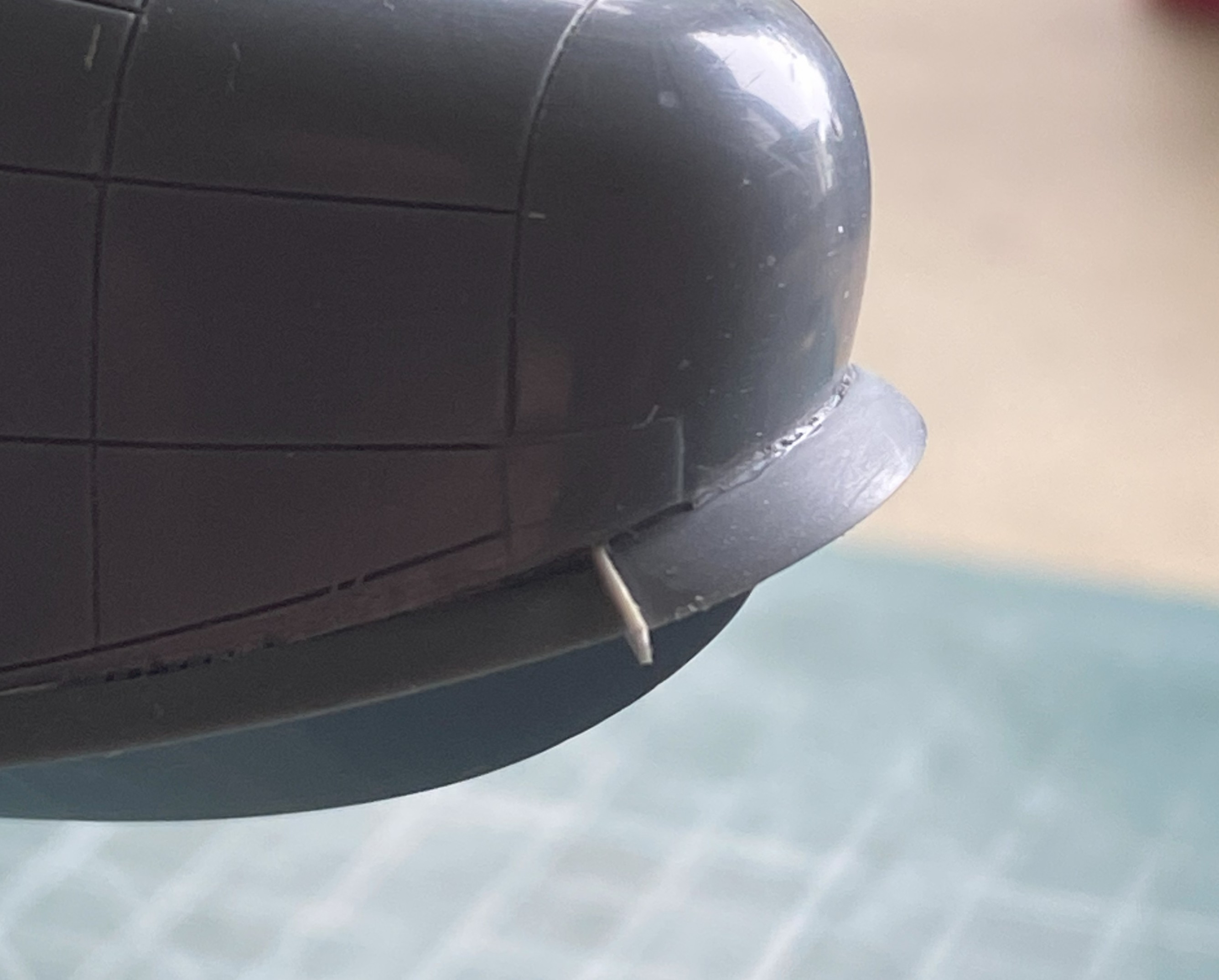
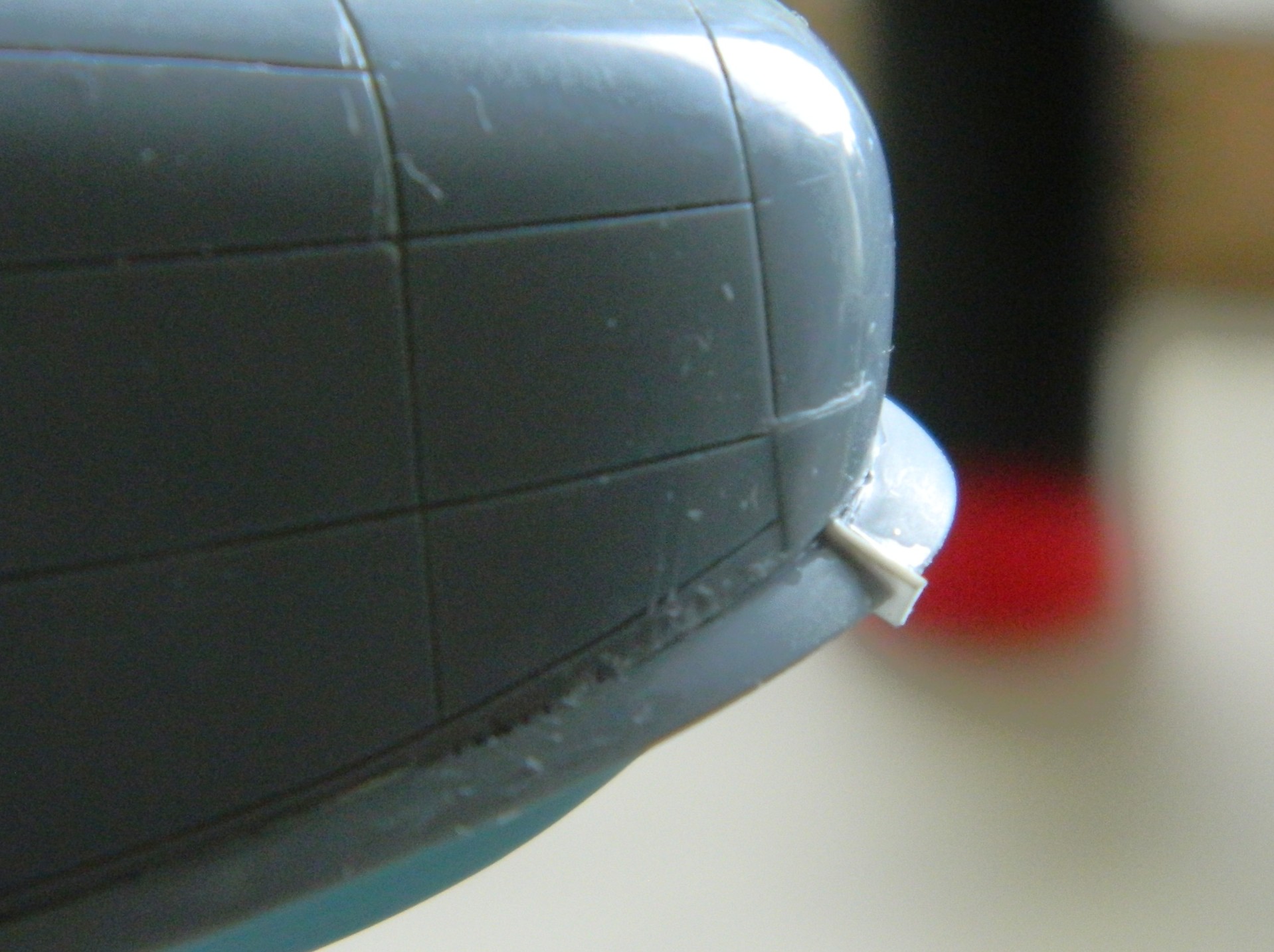
The kit provided no pitot tube (thankfully!) so I made one using 18awg wire and built up the fin that this one had using drops of UV-setting resin, curing it, adding more drops, curing that, until I had enough mass to shape correctly:

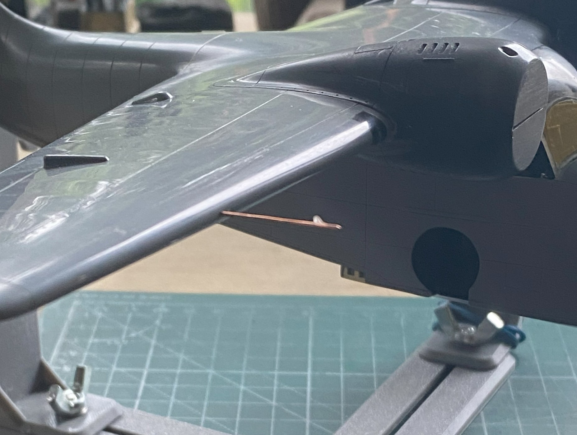
The pitot tube is removable so that I don’t have to make another one later on.
The Goose had a splash shield fitted around the nose and down the sides to the landing gear. This part was far too thick so I thinned it out, and it fit about as well as nothing else has fitted, resulting in me having to snap a section to allow curves to match and sides to extend backward:
While that glue was curing, I started going over the entire surface again, noting new scratches and the sort for near future attention(s), and then I dropped the whole sodding thing. Few things are so bad that things cannot get worse. This time, I dodged major reconstruction. This is the only damage that happened; the splash shield got dinged:
Fine, I’ll fix that too:

I started building the sliding windows for the cockpit. I was doing okay until, once again, I dropped one…and then stepped on it because a simple fix cannot be relied upon repeating itself. Thankfully, these are really simple parts and fixing them won’t present insurmountable obstacles:
But that’s for next month.
