Colonial Viper MkII (Moebius Models) 1/32 Scale Build #1, Part 1 – Parts Layout and the Start
This is going to be interesting (hopefully not in the Chinese sense). I’ve never done fictional spacecraft before. My initial intent was to model this as realistically as possible, but that balloon was popped almost immediately. Nothing about this is realistic, or as a friend of mine said, “Science by magic.” Okay, then what am I actually building here? It’s a movie prop that existed in two forms; digital (CGI) and practical (something real). That’s made the build easier and more difficult at the same time. The easier aspect is the availability of primary sources. Just watch the show and when a bit of detail flashes past, take screen captures of pertinent scenes. The difficult part is internal. As designed, this thing could never move under its own power and it irks a part of me. The rest of this thing should be fun!
Science by magic.
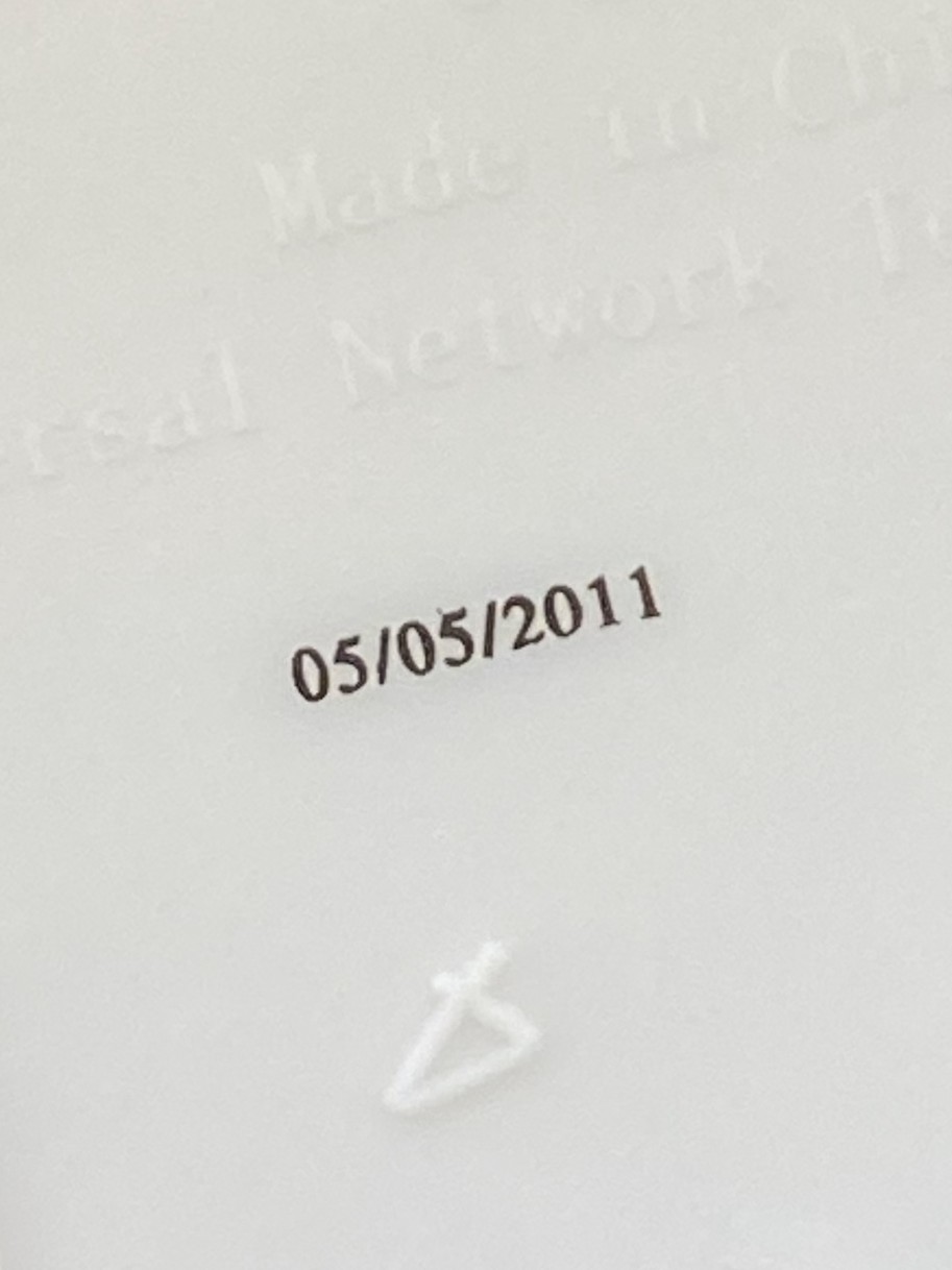
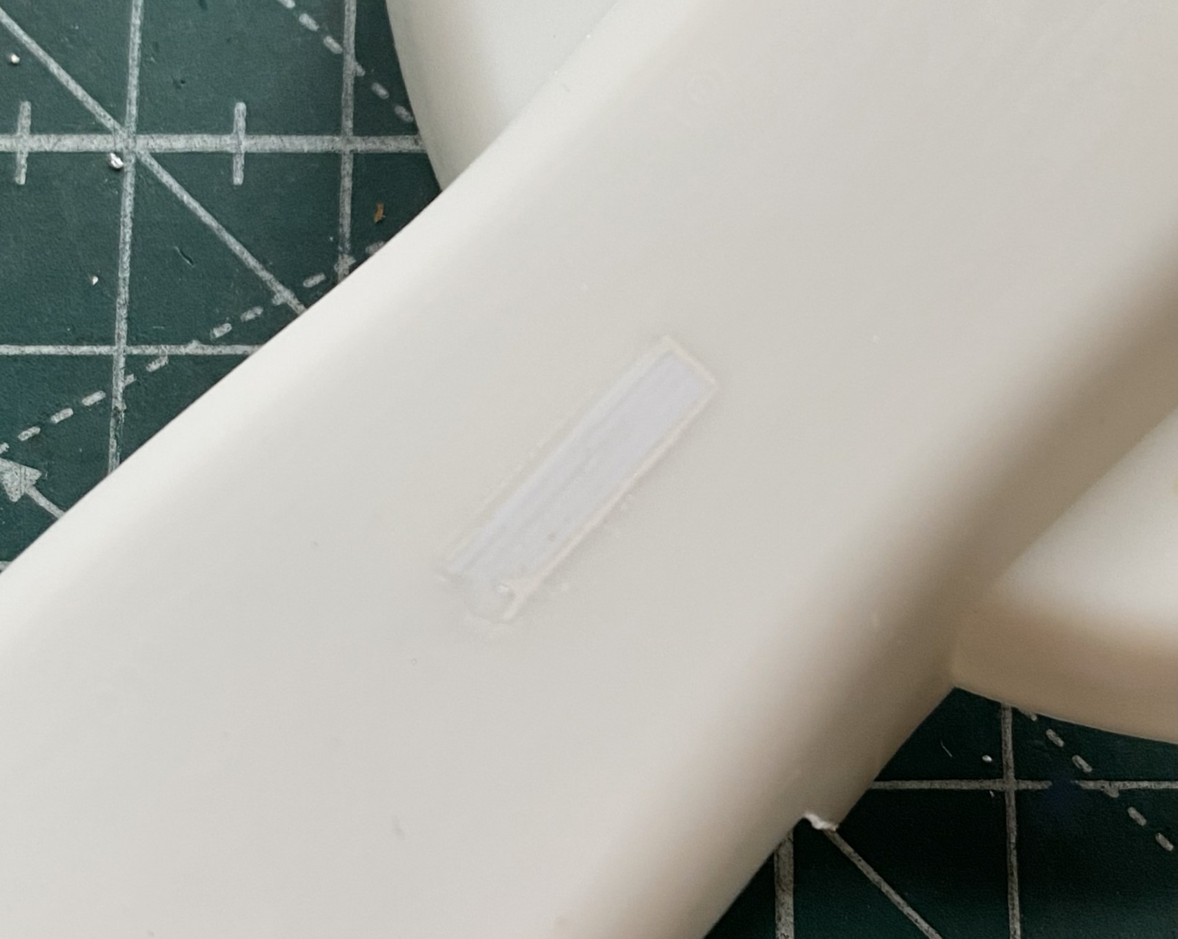
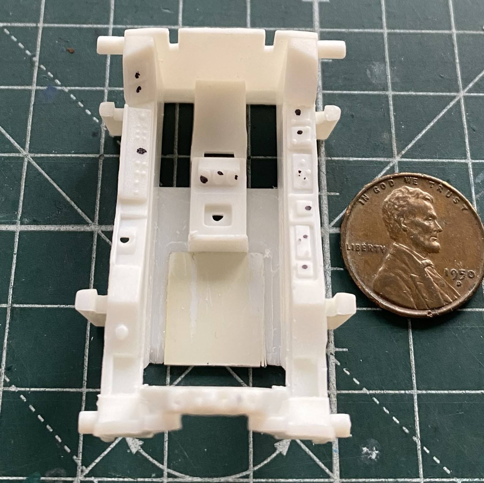
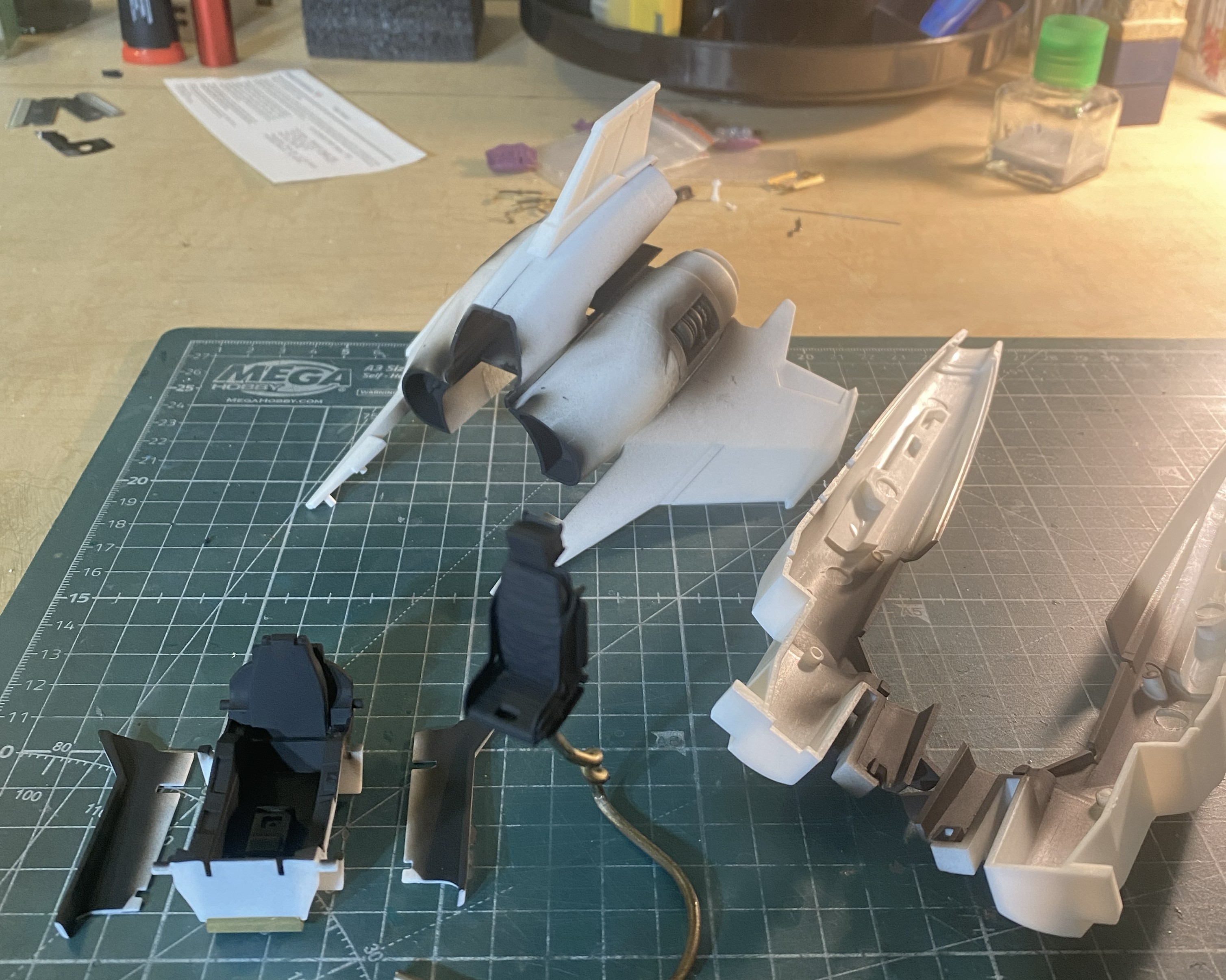
This is what I have to start with. This is the first time I’ve seen the manufacturing date (I assume, anyway) printed on kit parts (inside of the wing):
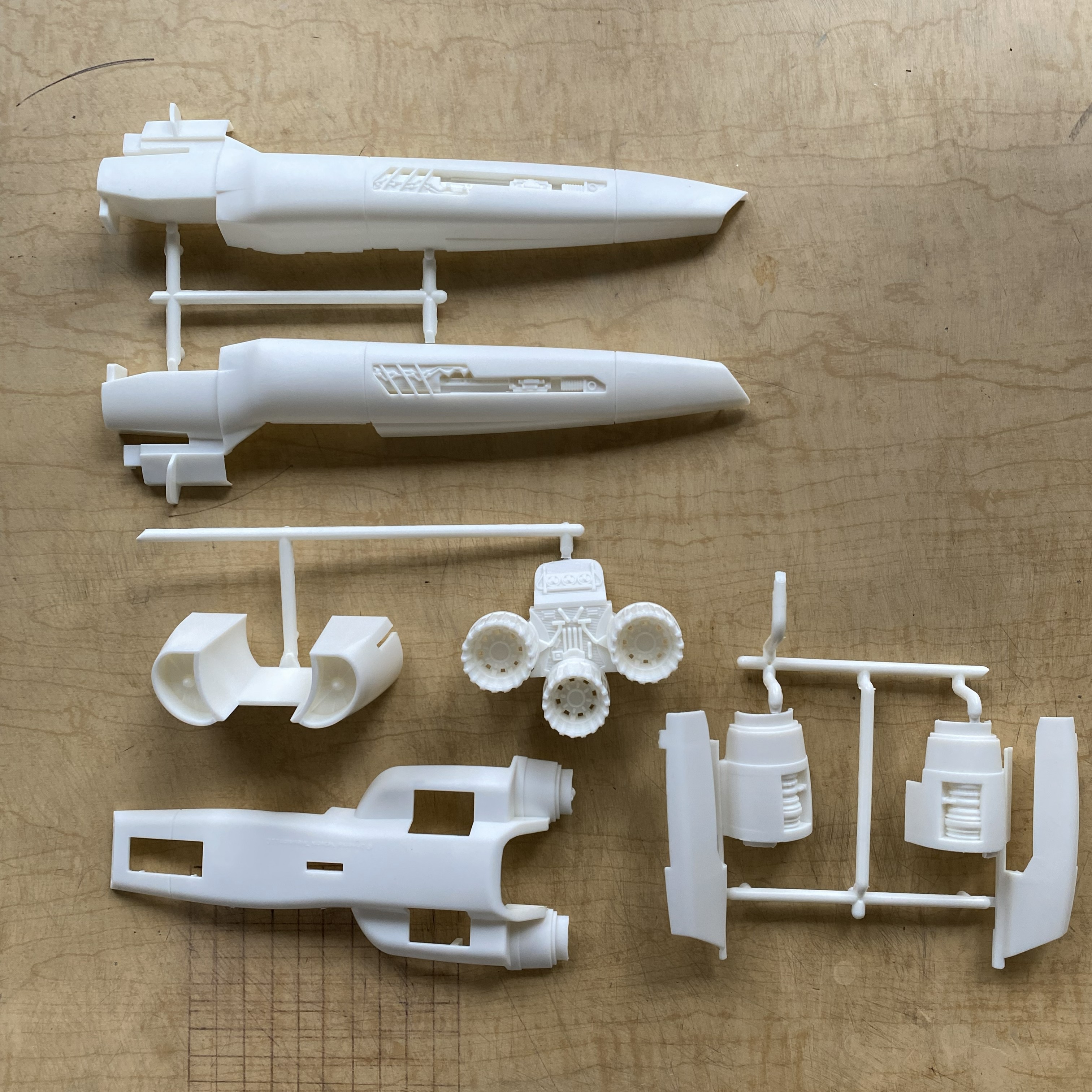
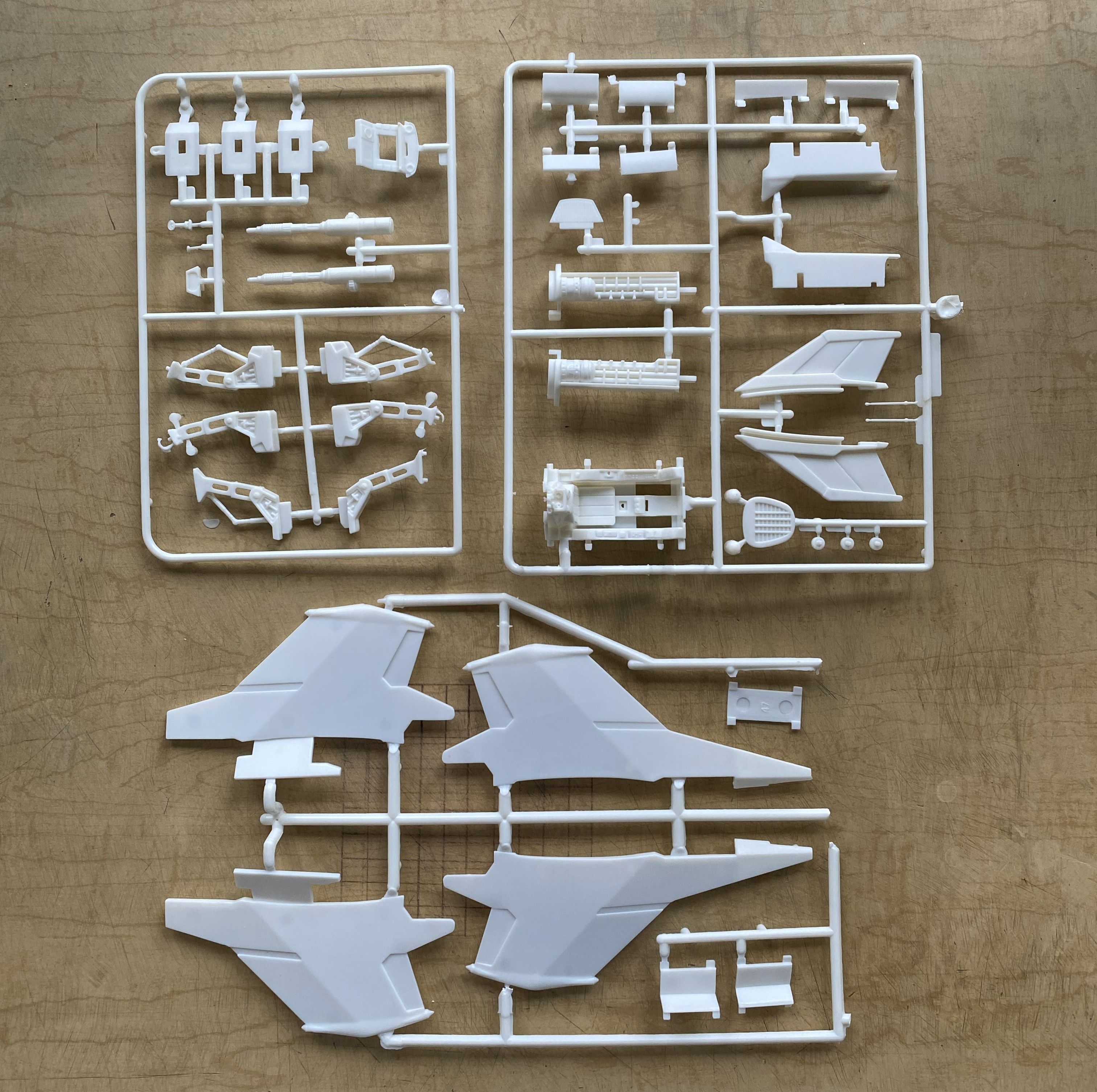
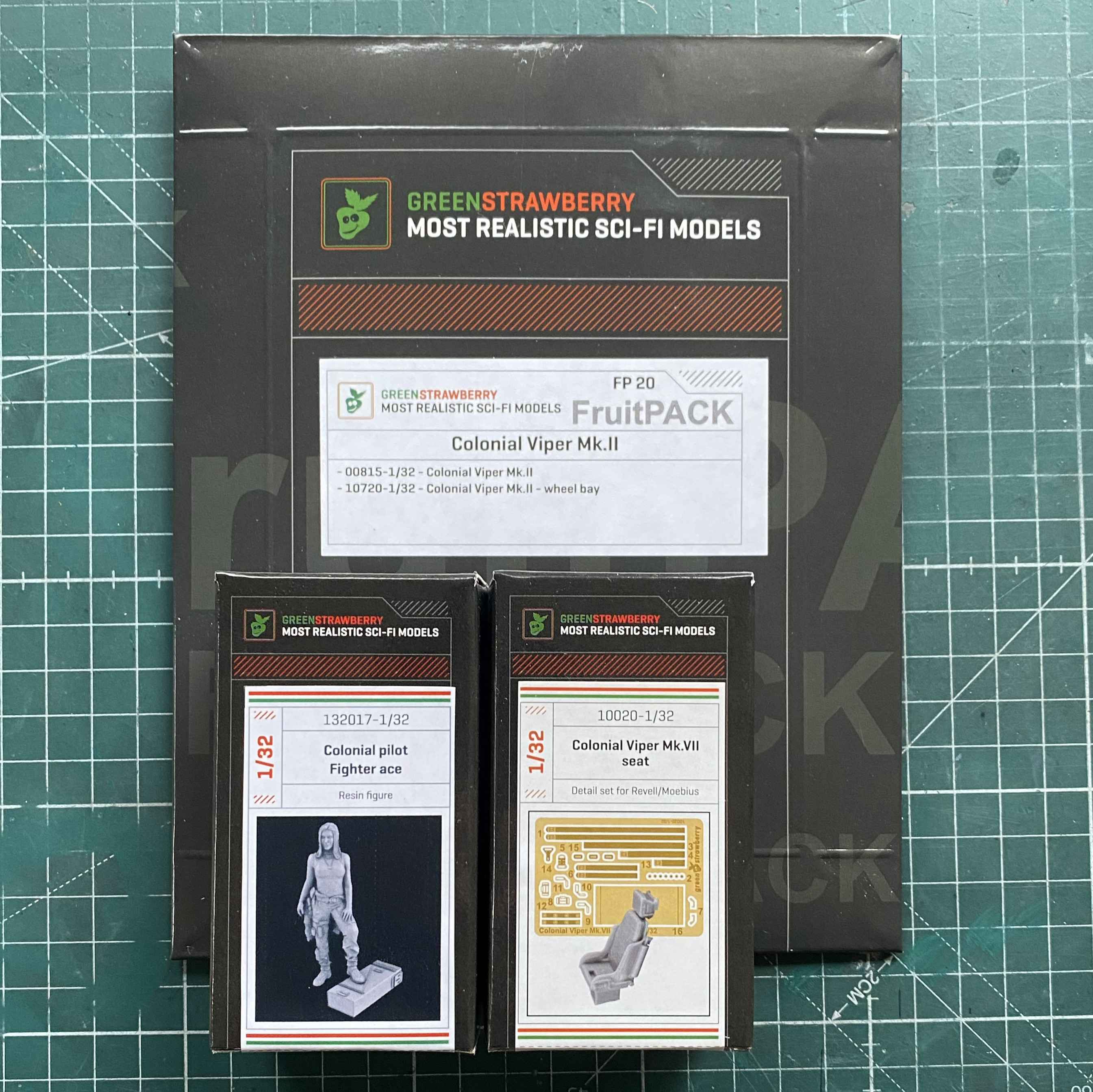
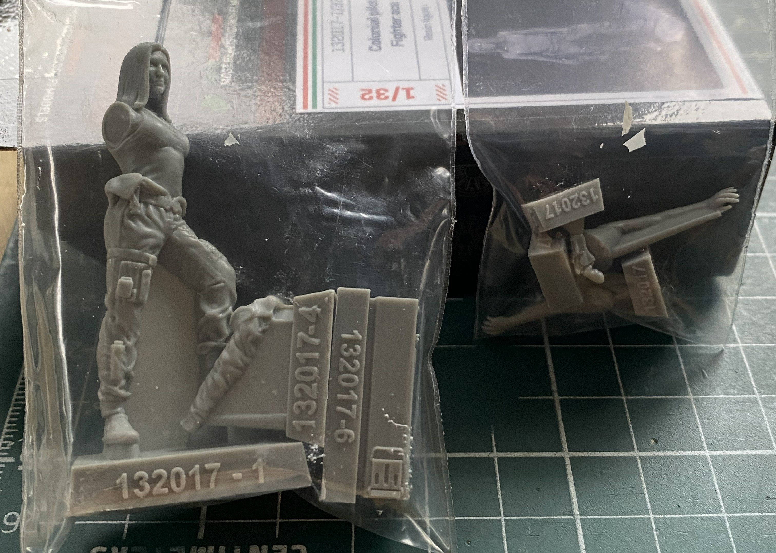
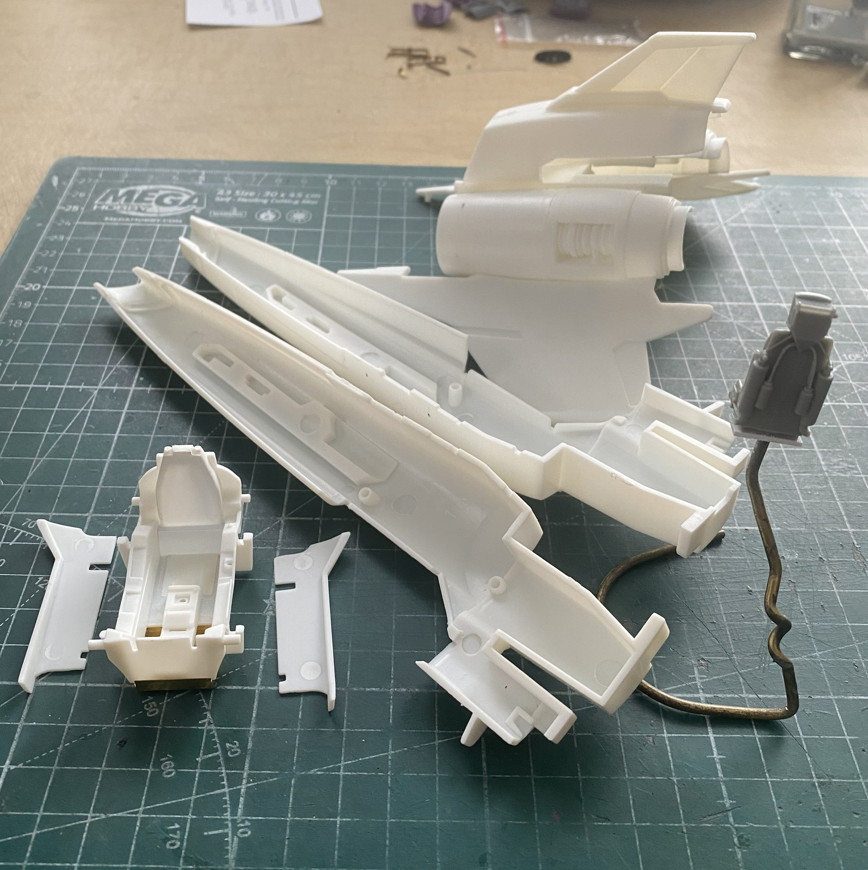
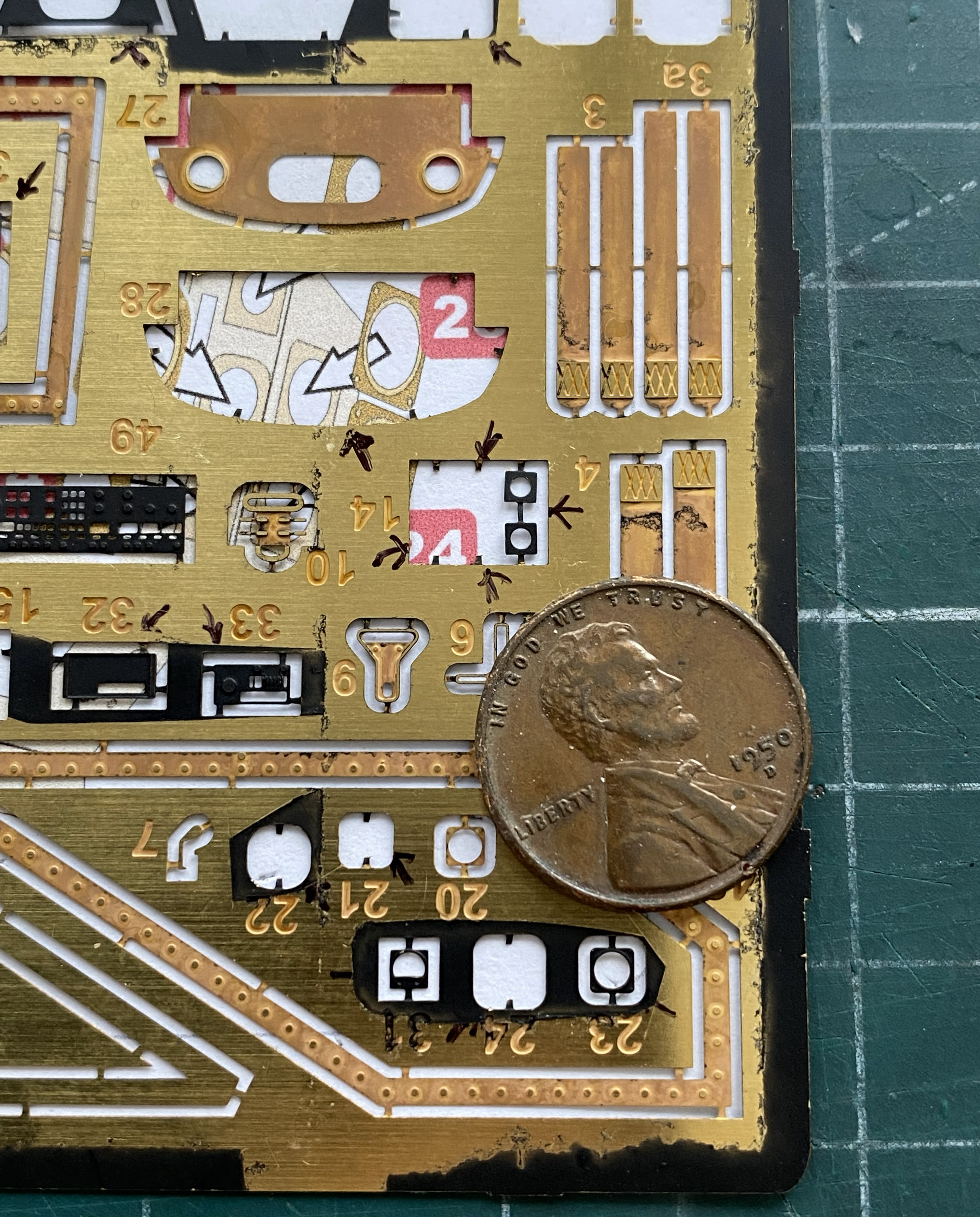
That noted, here’s what’s in the box:
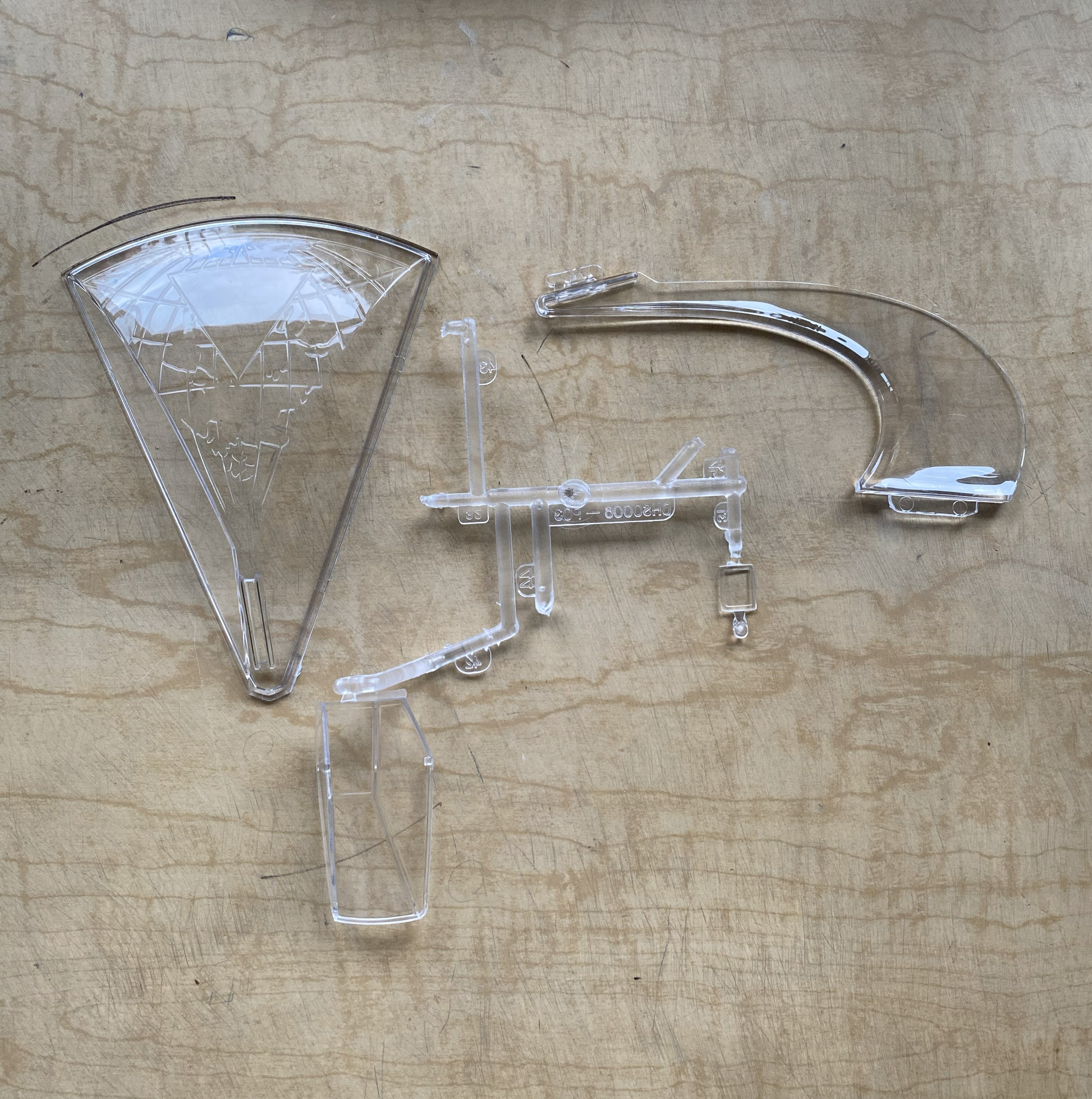

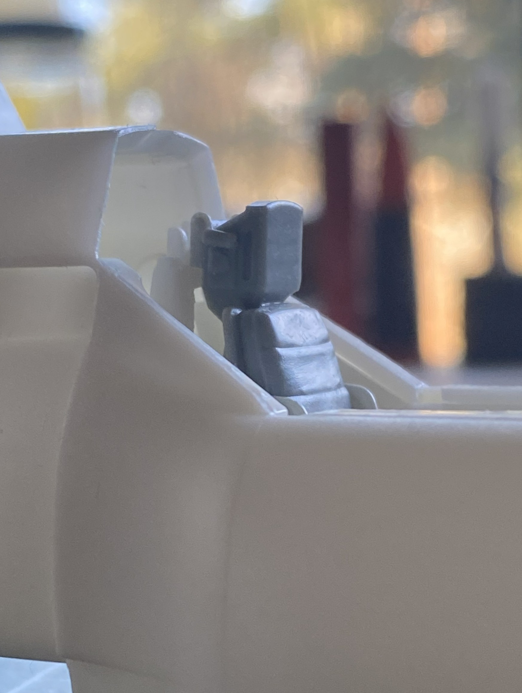
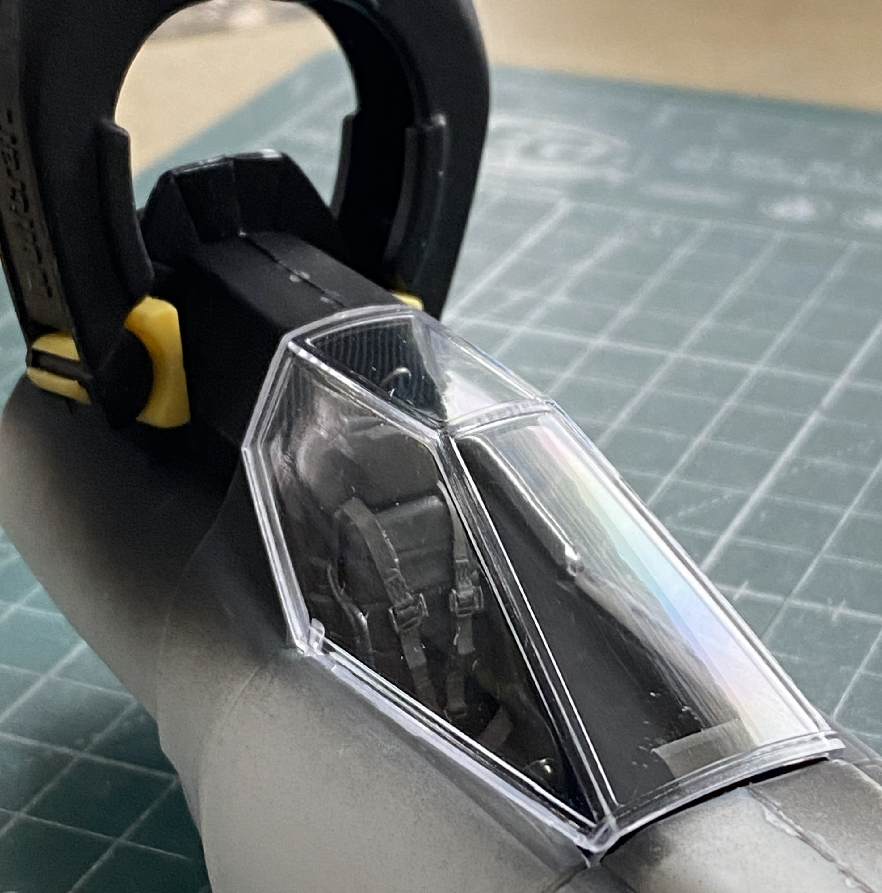
The first thing that caught my attention was the quality of the clear parts, in particular the canopy. Thin, clear, and mostly well done (more about that in more detail than you’d believe later). The second attention-getter was the resin figure. Overall, it’s nicely done. However. If you intend on using it, the joystick the right arm is holding (the unattached arm) is way too high. If you’re using the figure, you’ll have to deal with that (but since I’m not, I don’t have to deal with that).
As you can see, it’s not a kit with a high parts count. It’s simple. Oh, yeah?! Well I can fix that. I’ll fix that by seeing how many of these bits I can shoehorn into it.
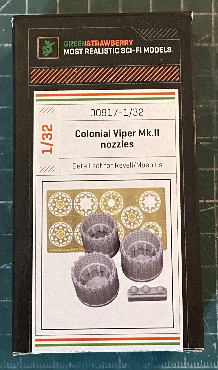
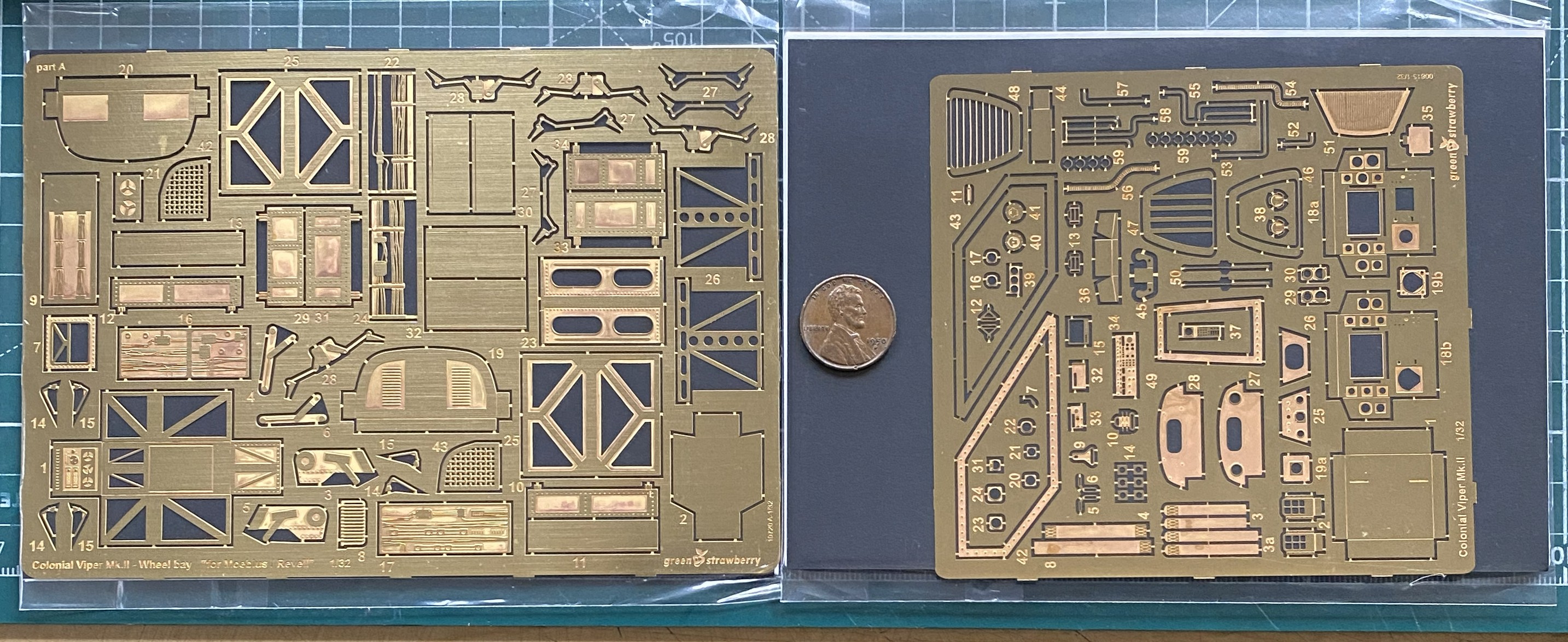
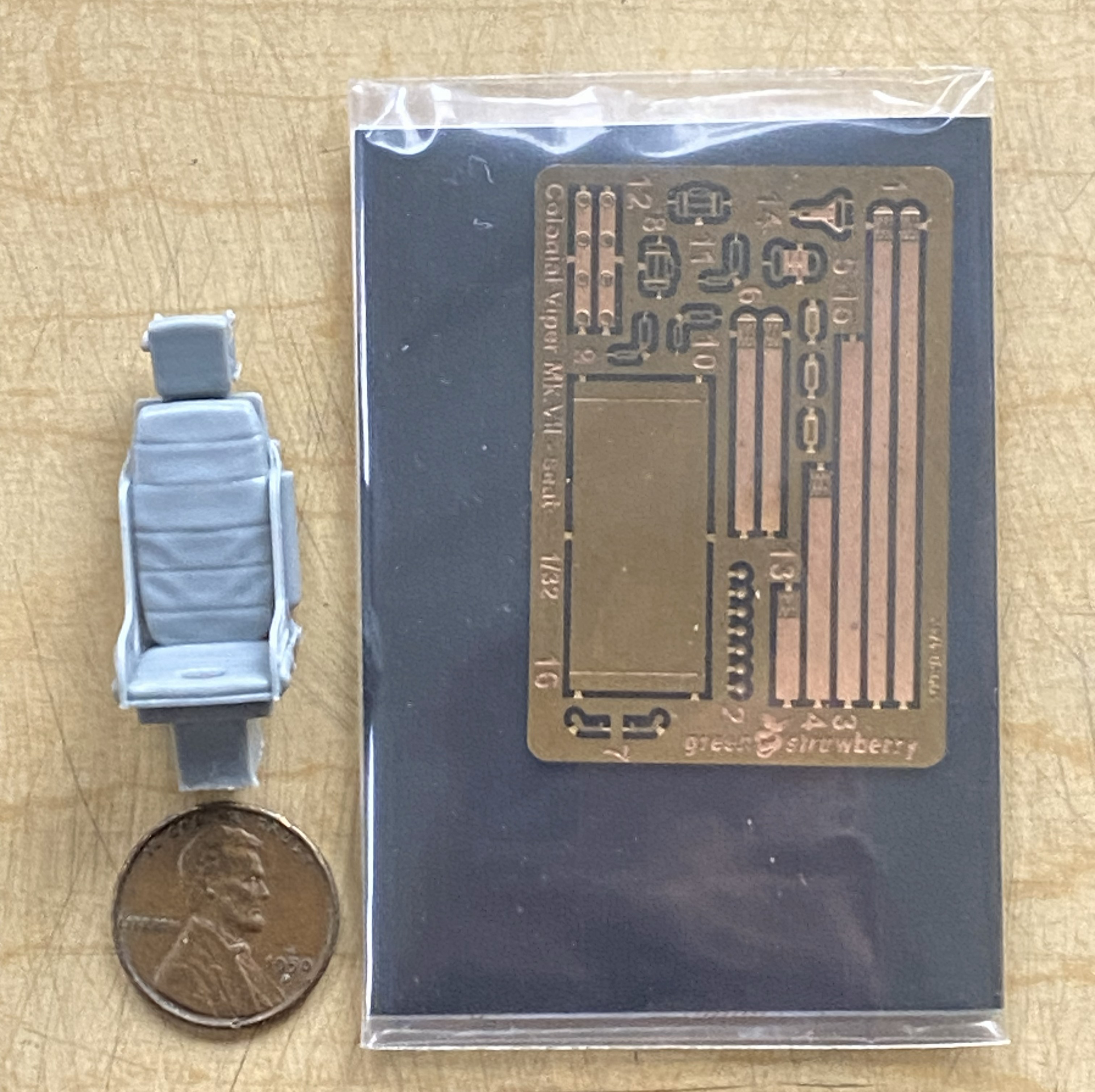
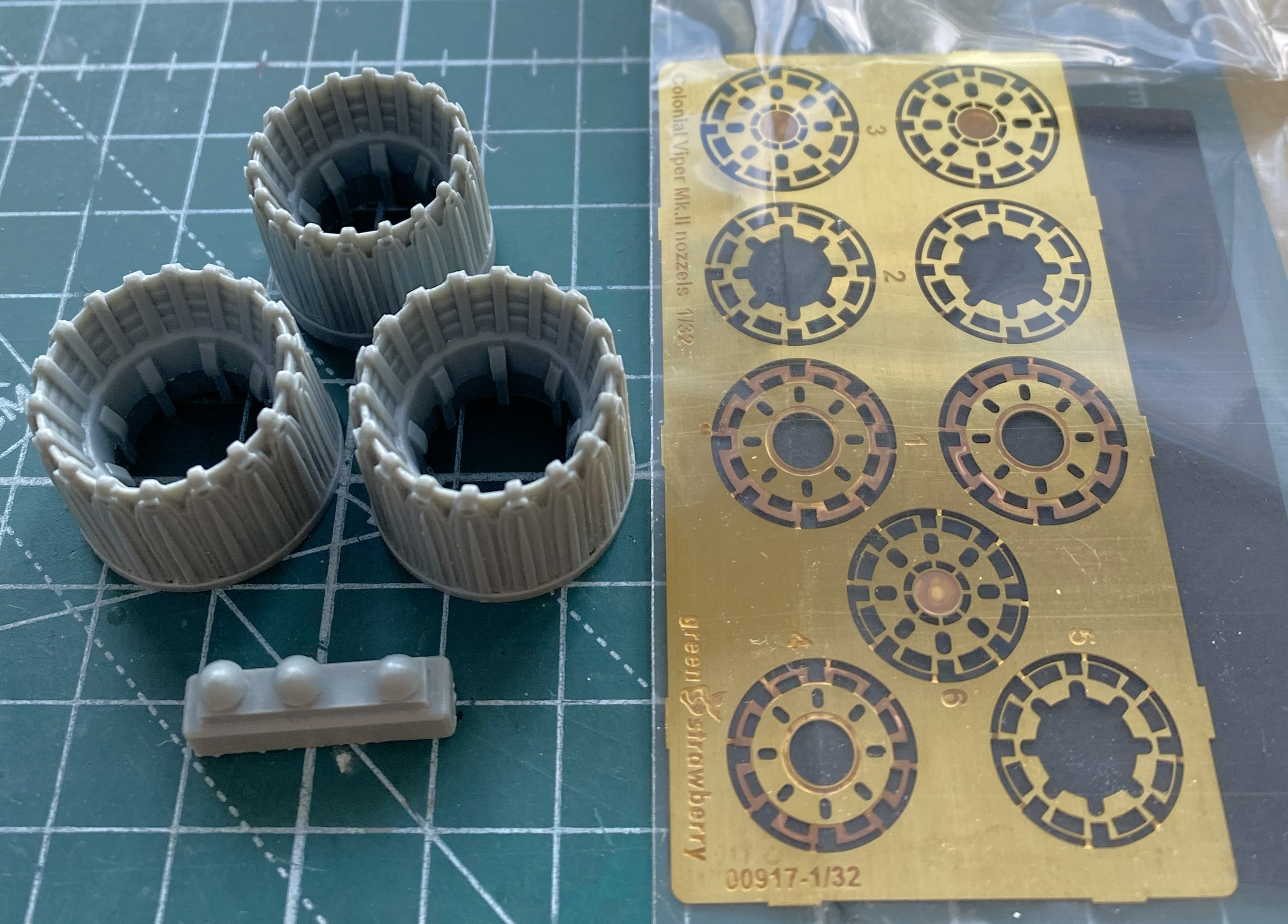
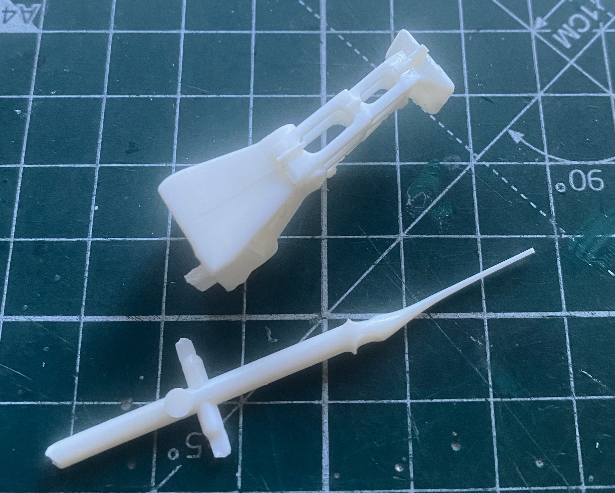
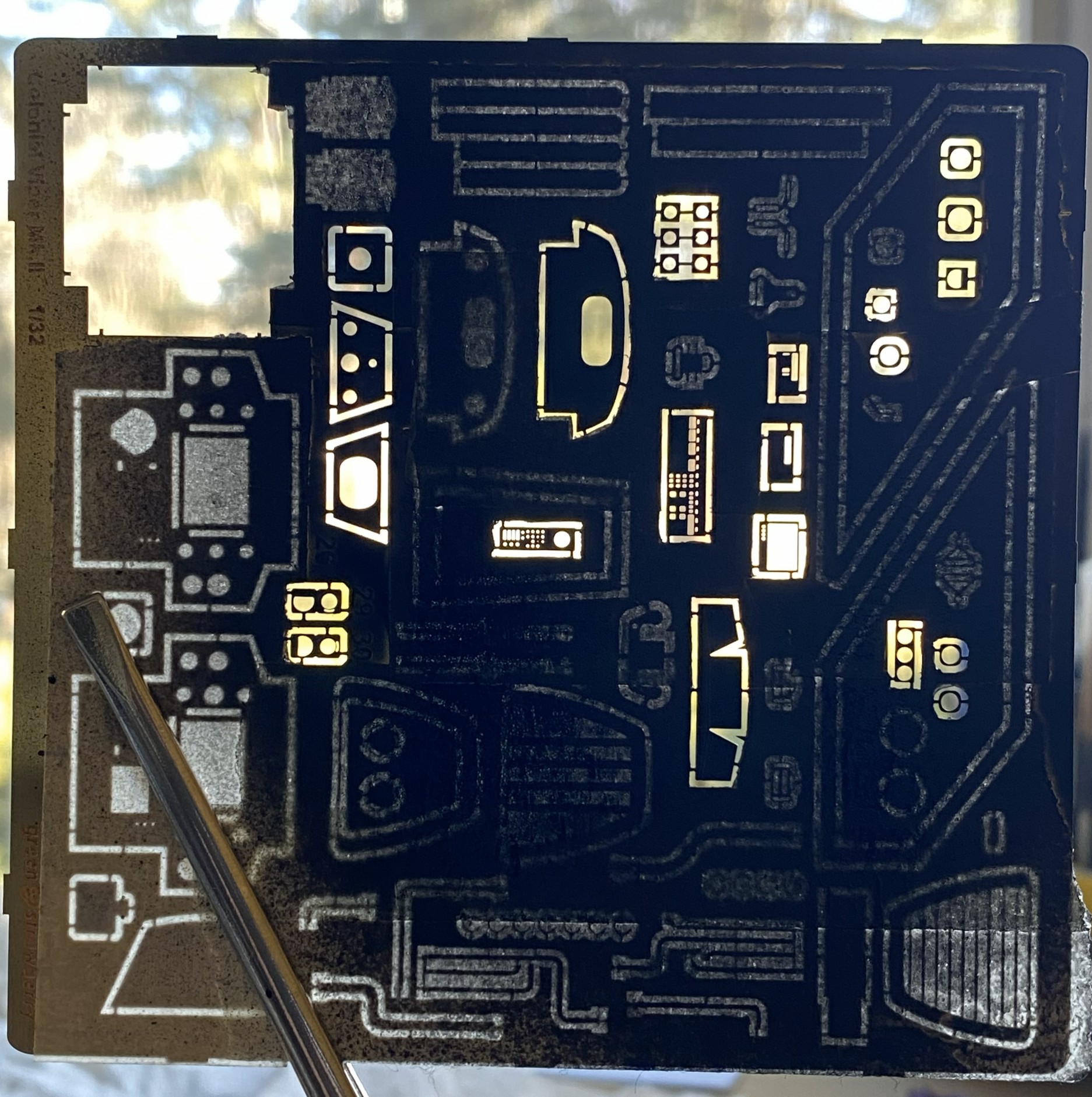
Green Strawberry (available from Moebius) makes all of the AM bits I’ll be using. One set supplies the resin seat, PE parts for the panels, etc., and photo-reduced images for all screens and instruments. And a word about that… The AM set for the cockpit offers two sets of gauge faces. One set is for a standard build, the other set is for those of you who like to add lighting. The kit is designed to allow the forward instrument panels to be back-lit. The set of gauge faces with a black surround are for illumination, the white (which are the ones I’m using since I’m not building this with lighting) are for a typical build. All of them are excellent and fit well. The other PE set is for landing gear bays. There is a resin/PE ejection seat, also nicely done. Since I have a profound appreciation for the character of Kara “Starbuck” Thrace, and the kit offers decals of her specific ship, I’ll also be adding Starbuck. Green Strawberry (or whomever did the sculpting) did a great job with this resin figure; it even looks like her. And since I just can’t seem to resist throwing everything at a kit, I’m also replacing the kit’s exhaust nozzles with resin/PE aftermarket parts:
It’s true…there isn’t anything that I can’t complicate. It’s a talent.
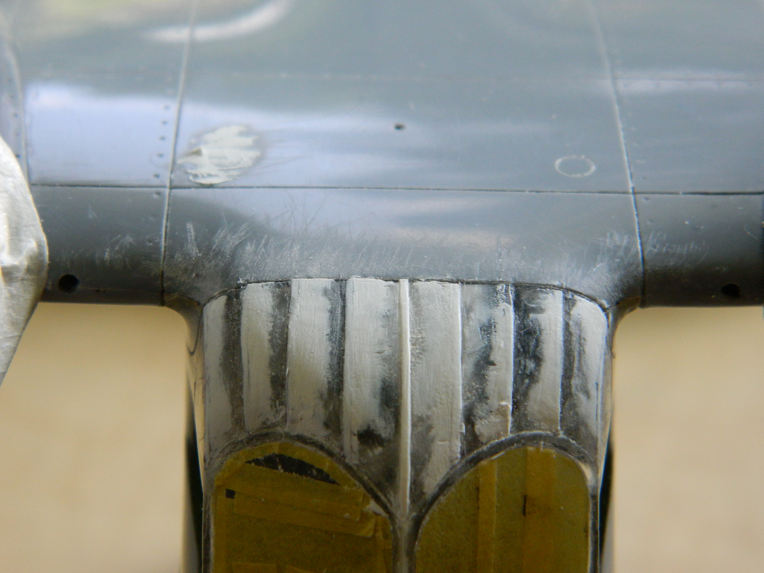
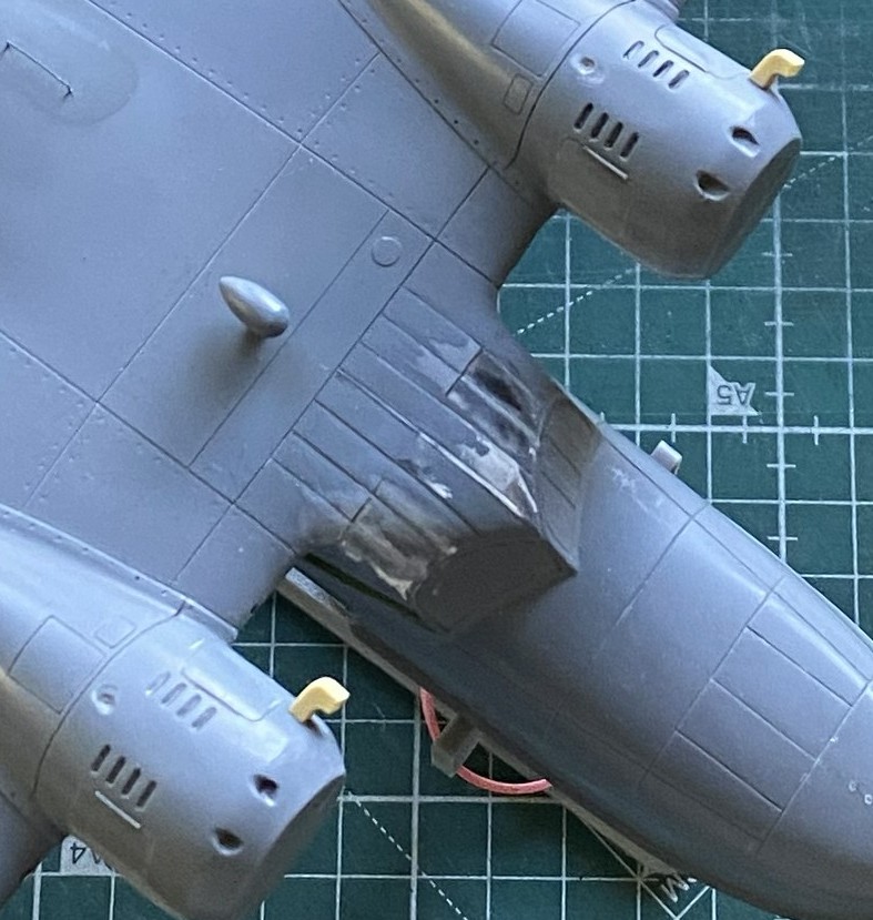
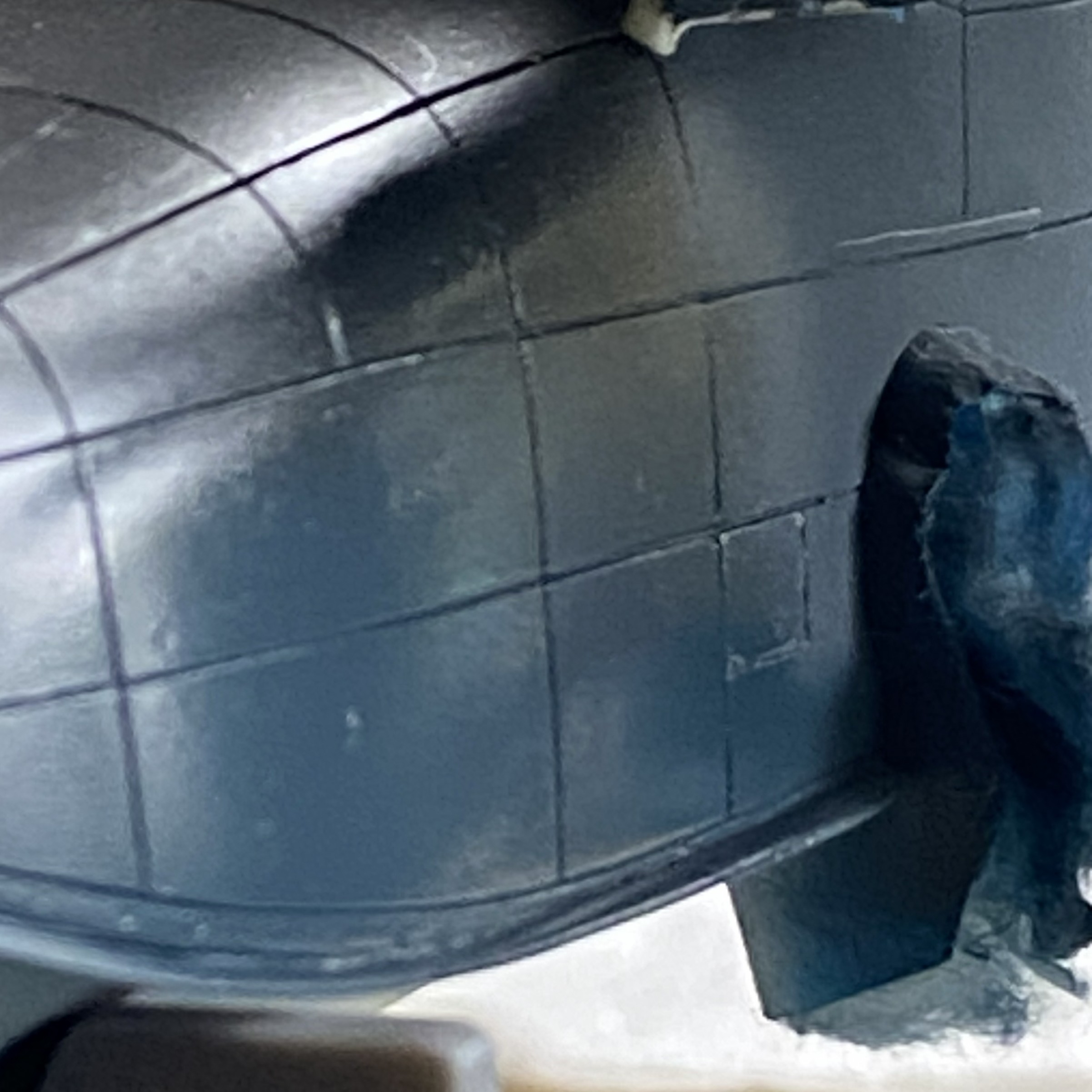
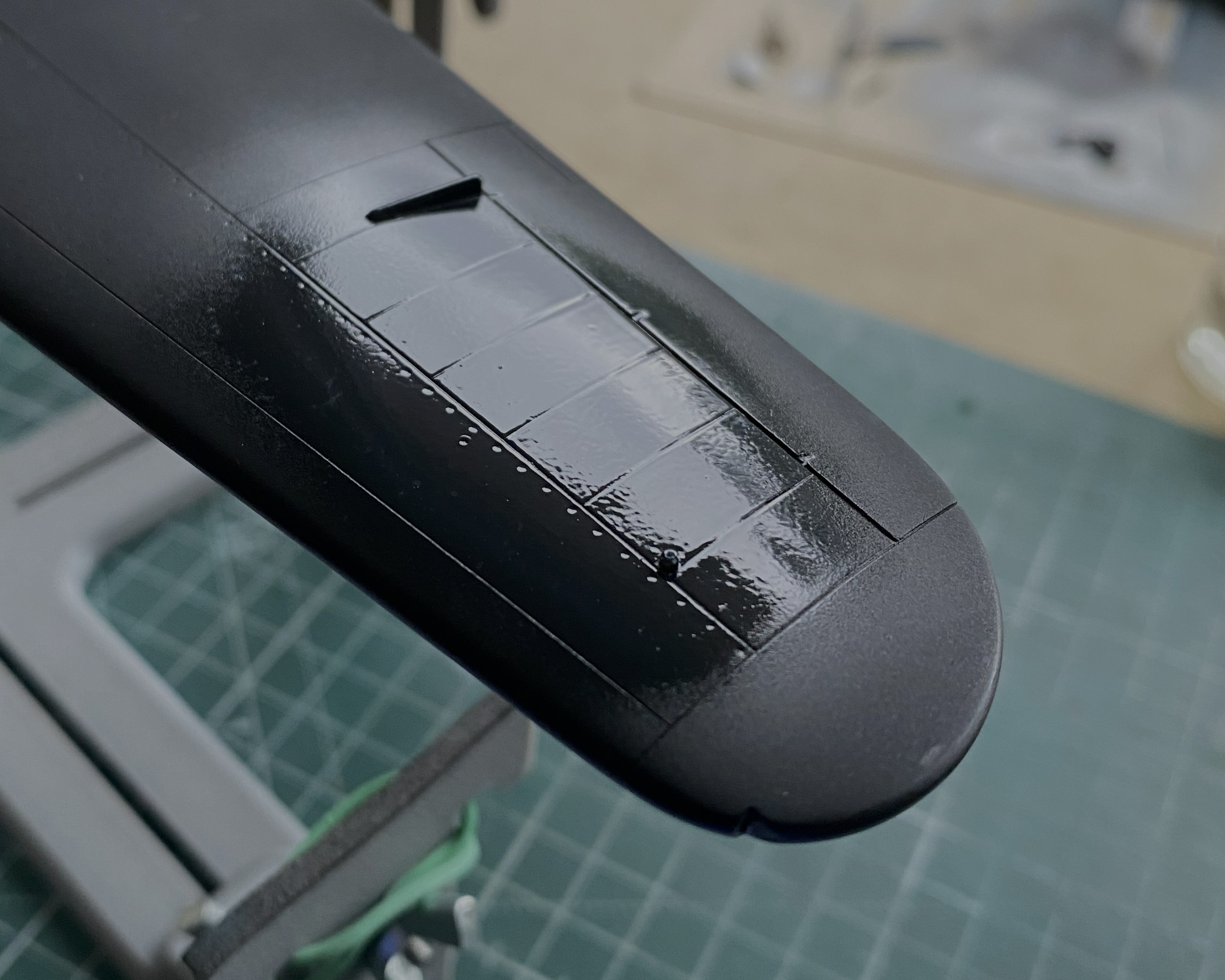
At this point of the build, all of the AM parts had yet to arrive and I was still thinking that I’d be able to make the engines more realistic. My intent was to open a panel on top of the engines (after creating one, but to fit canon, it would be an inspection panel, not an inspection cavern as the kit has them) and perhaps extend a bit at each end. Had I looked just a bit further, I’d have noticed that any attempt to expand on the engines wouldn’t work. There isn’t enough room to create engine extensions and fit canon. But I didn’t look further and I went down this empty rabbit hole.
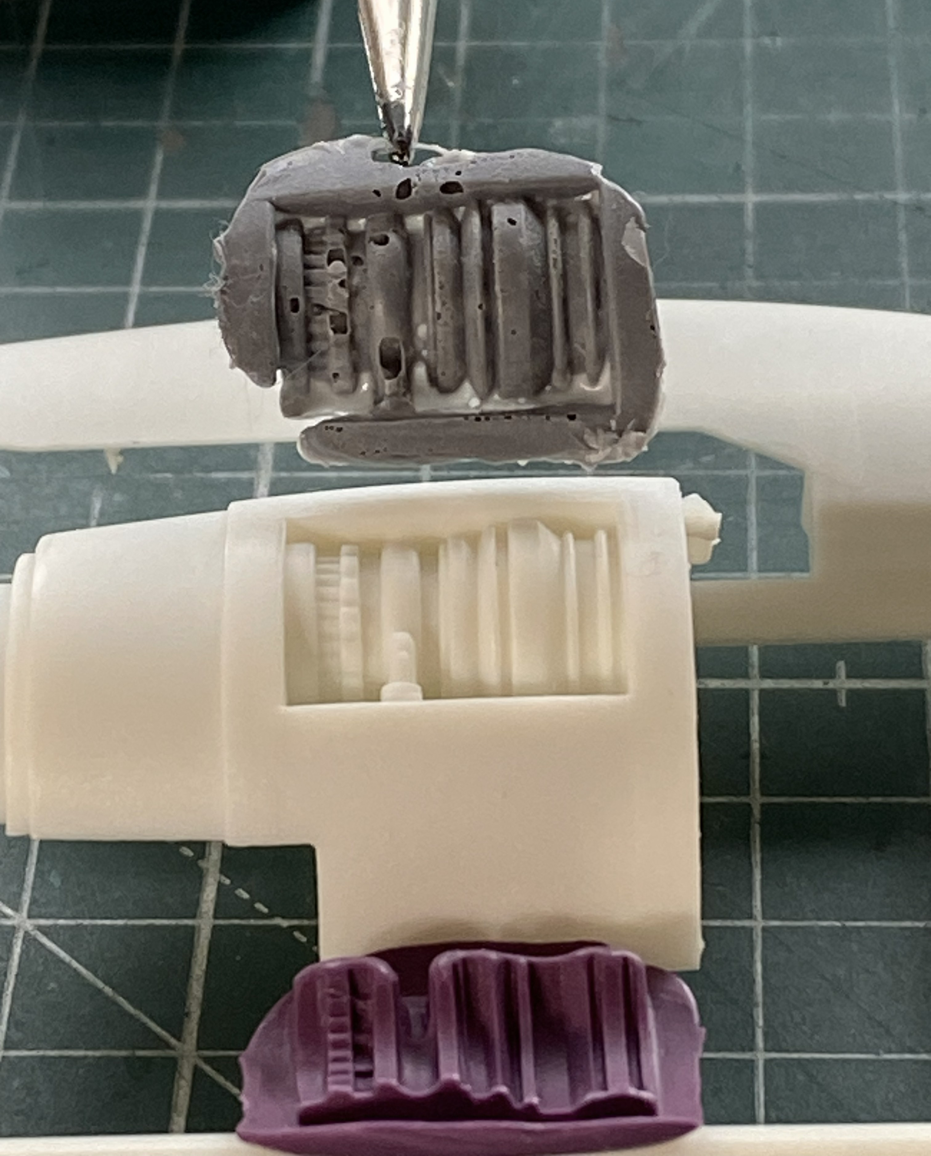
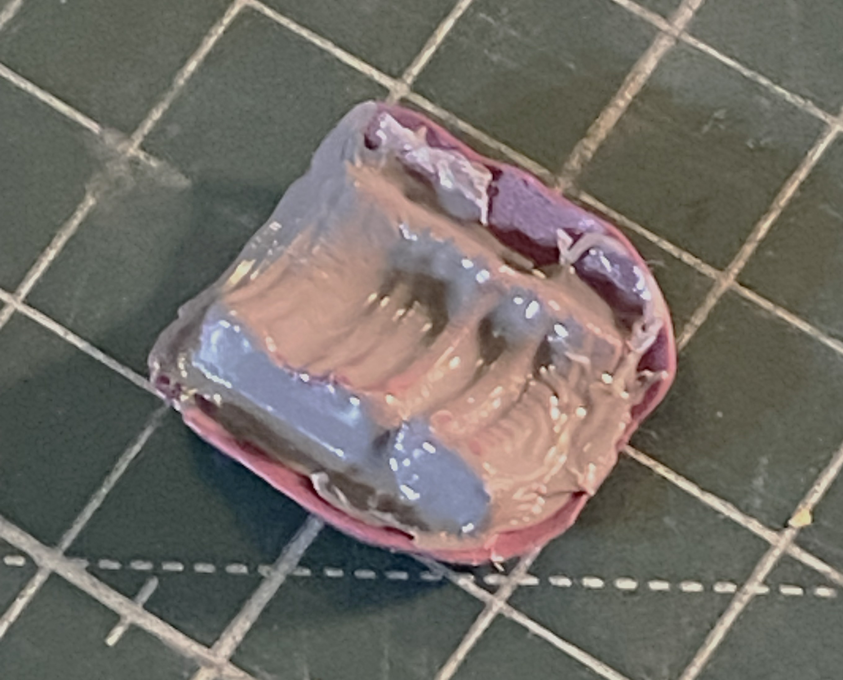
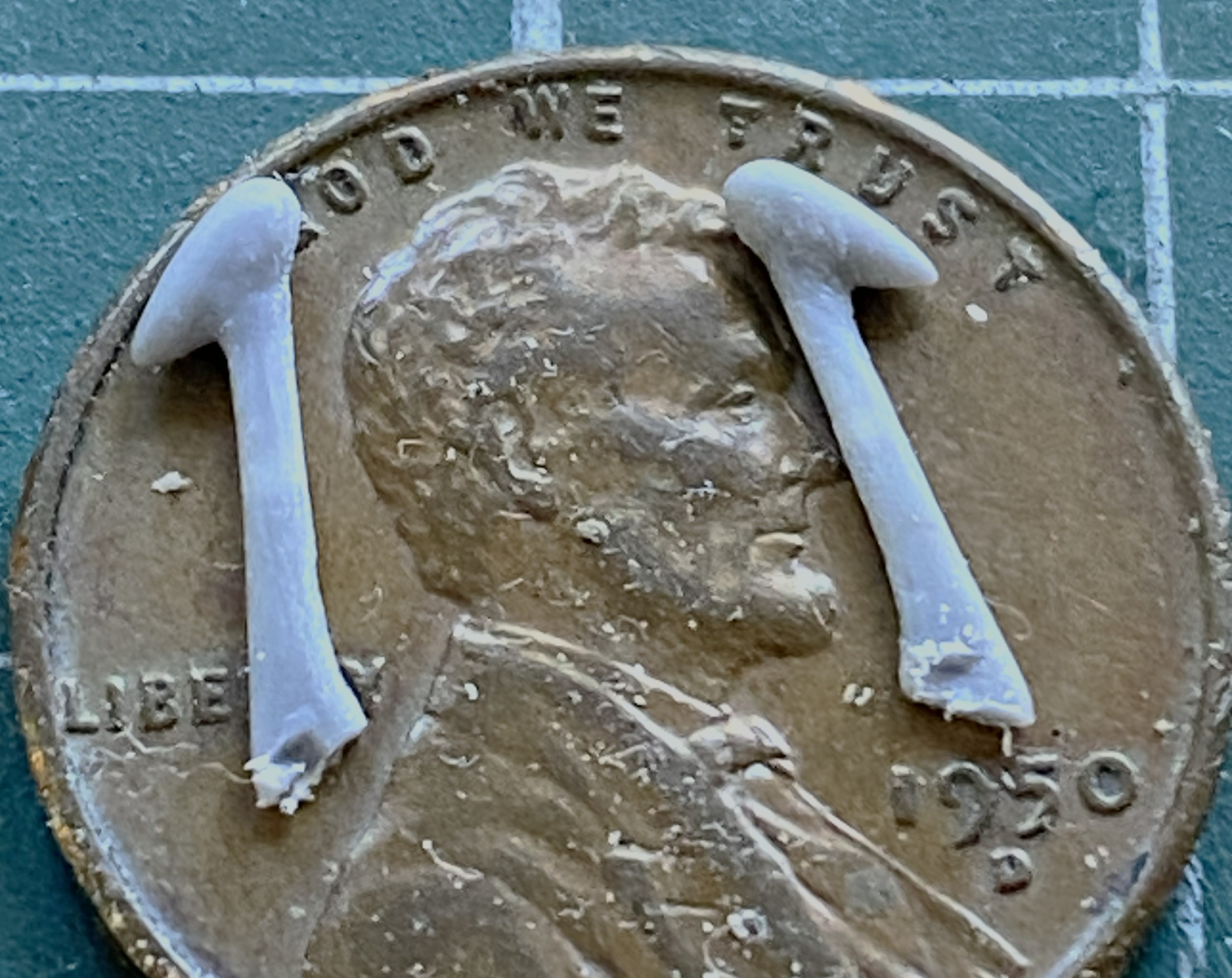
Rather than scratchbuild every addition, I’d thought that I could copy what detail was provided and then work it into an overall acceptable engine. To get molds, I used silicone molding putty:
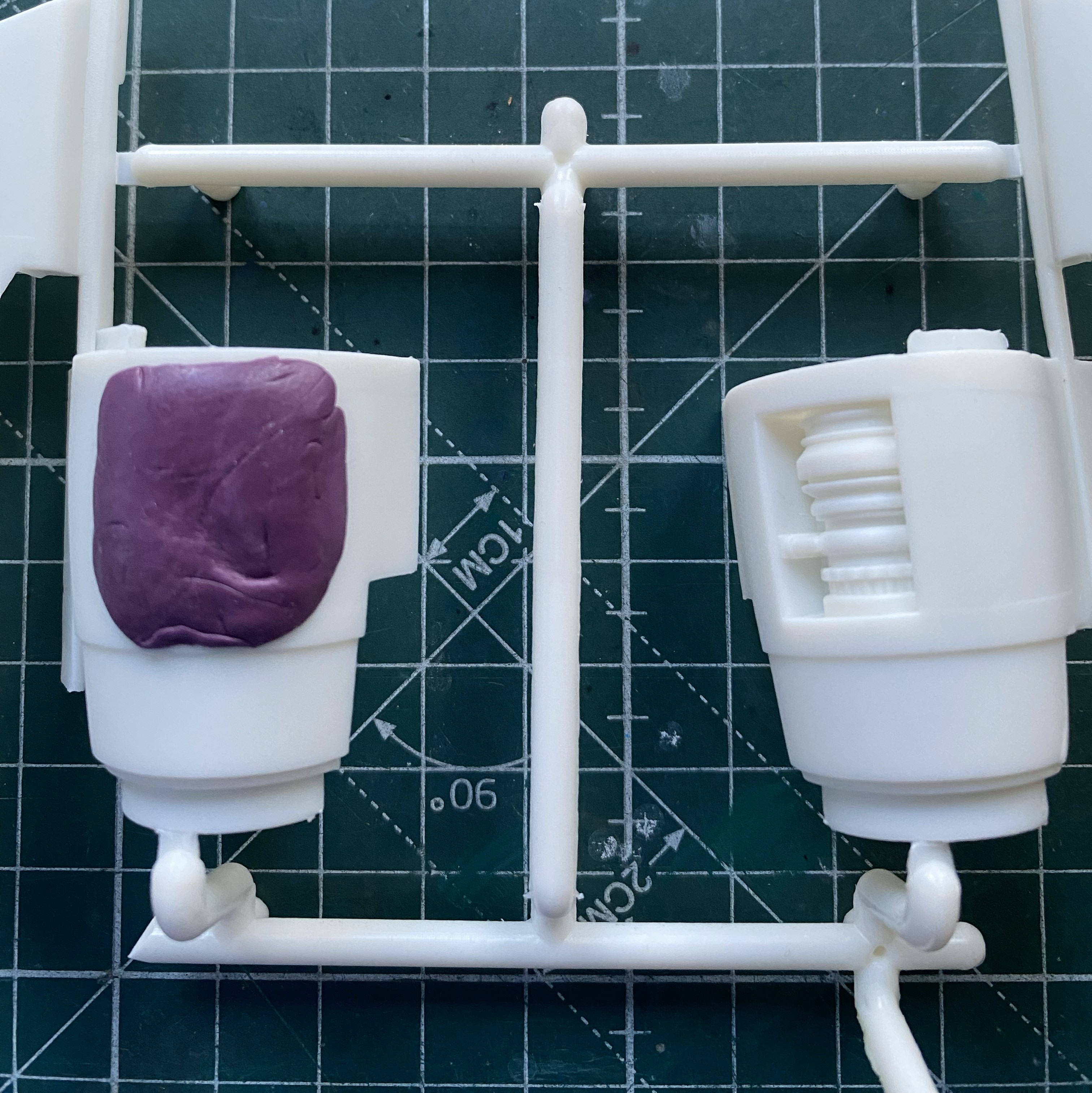
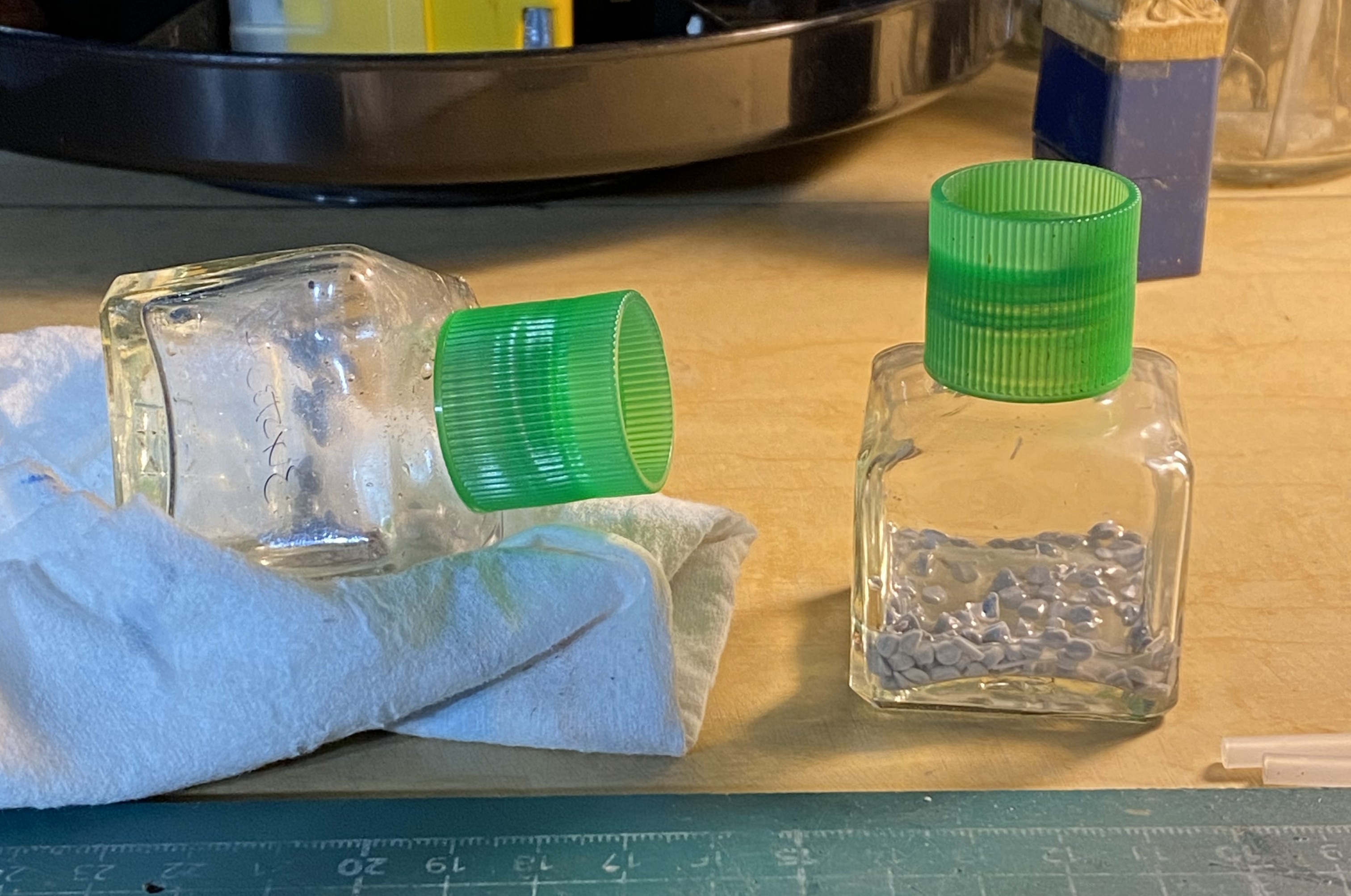
While the putty was curing, I investigated which would make “plue” (plastic and glue) to fill the molds. What would work better, acetone or Tamiya Extra Thin cement? I used two empty glue bottles, placing cut plastic pieces in each bottle and then putting enough acetone/glue in to cover the pieces. The tilted bottle has acetone (tilted so that the acetone would cover all the plastic) and the other has cement:
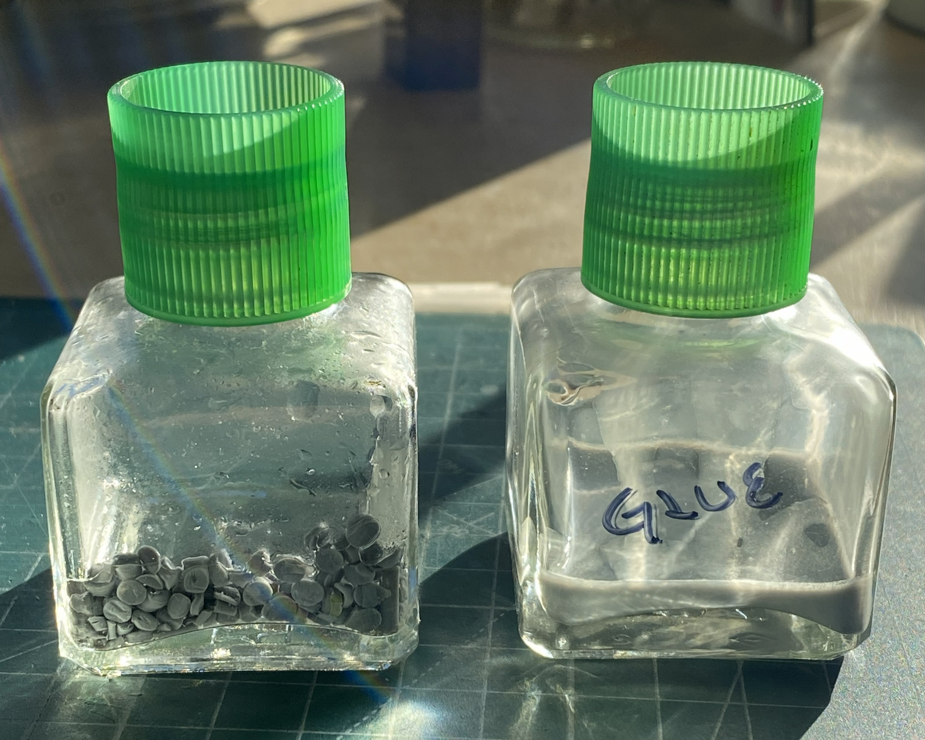
After sitting overnight, the clear winner is the glue. The only affect the acetone had on the styrene was to make the surfaces slightly tacky…that was it:
By then the mold was ready to fill:
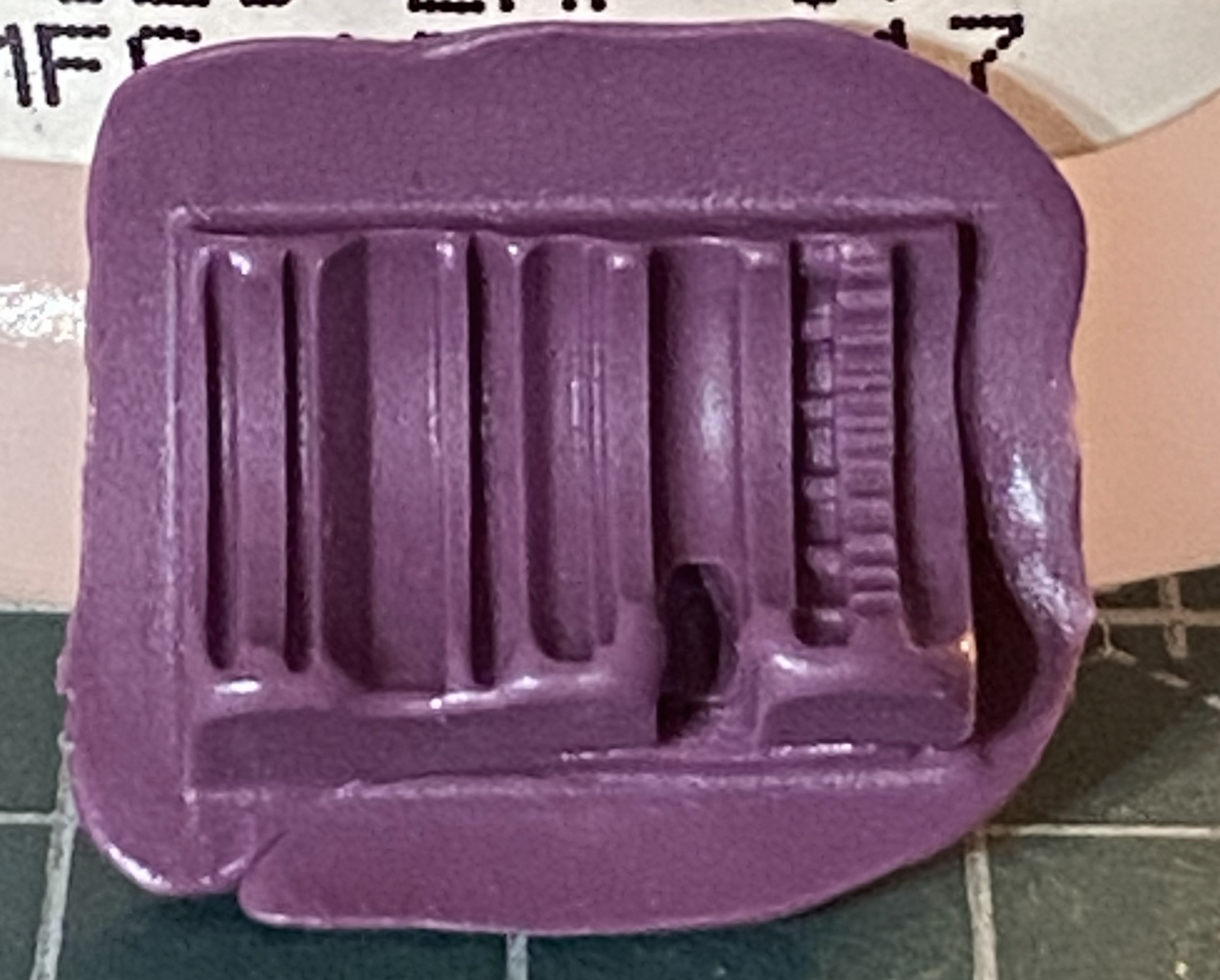
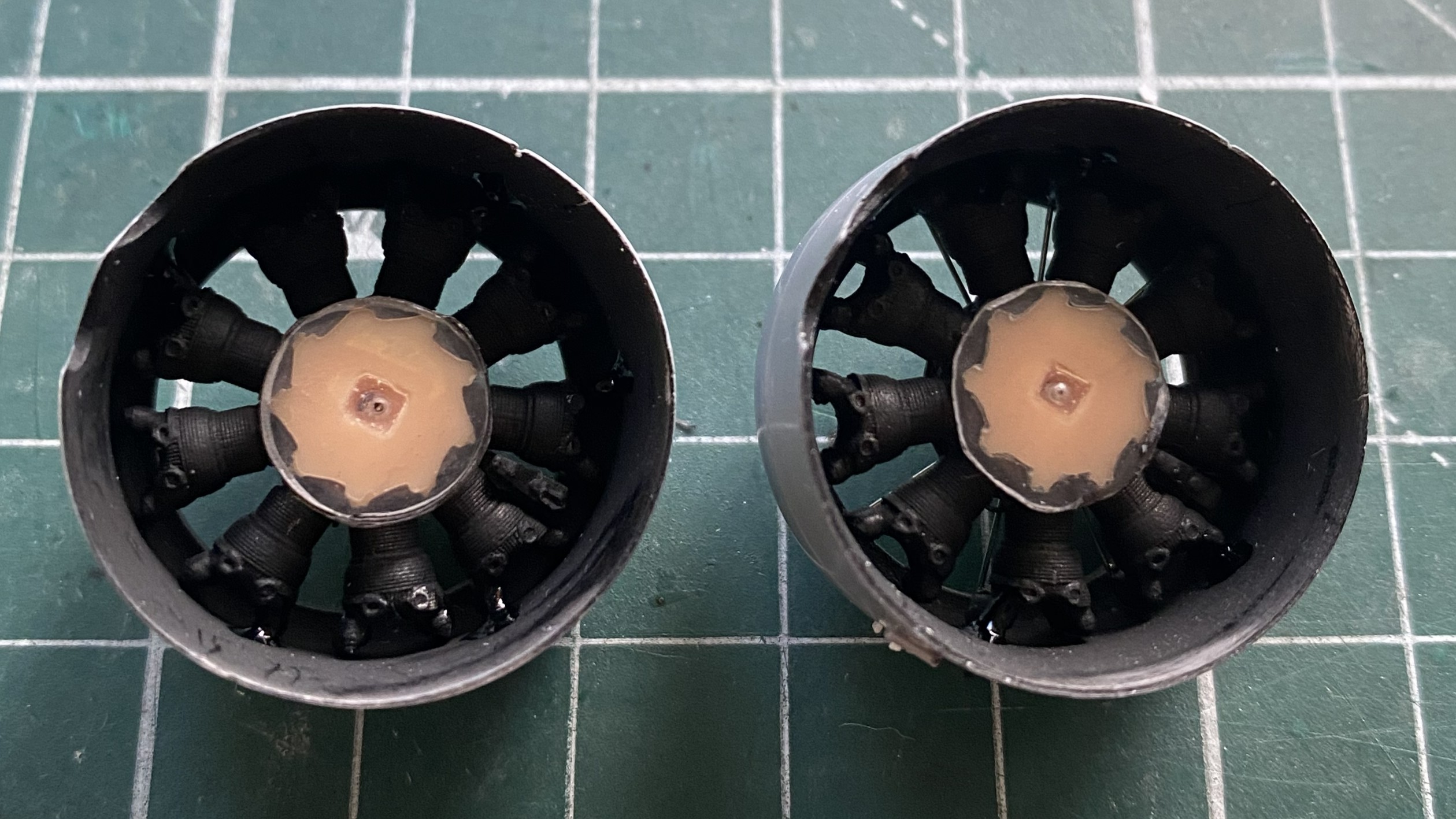
It’s been a while since I’ve used plue and the mold in the above photo shows it. I put on much heavier a coat than I needed to. Several thin coats works best. Another “interesting” trait is that the more the plue is manipulated in/on the mold, the more bubbles created, which this little lovely reminded me of:
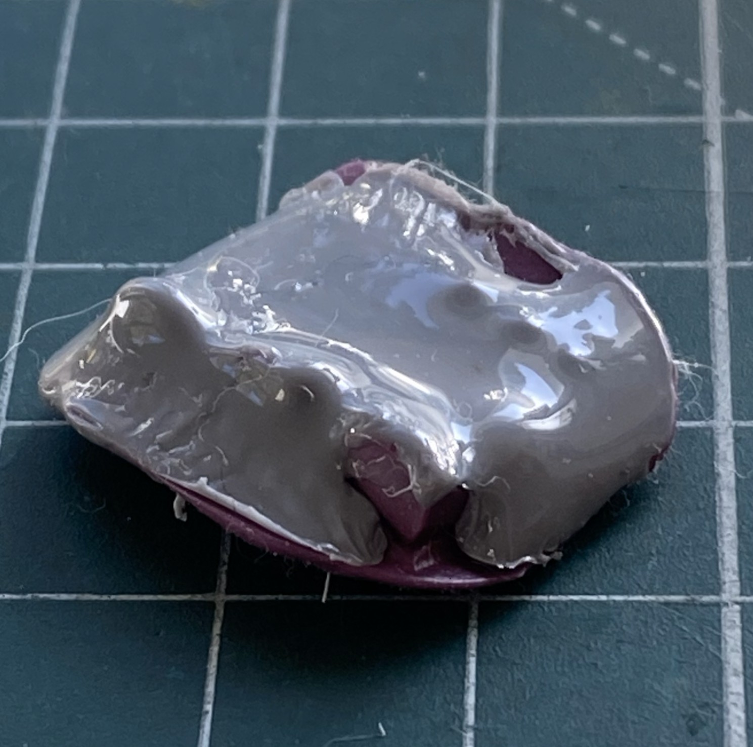
Next attempt using thinner coats worked better:
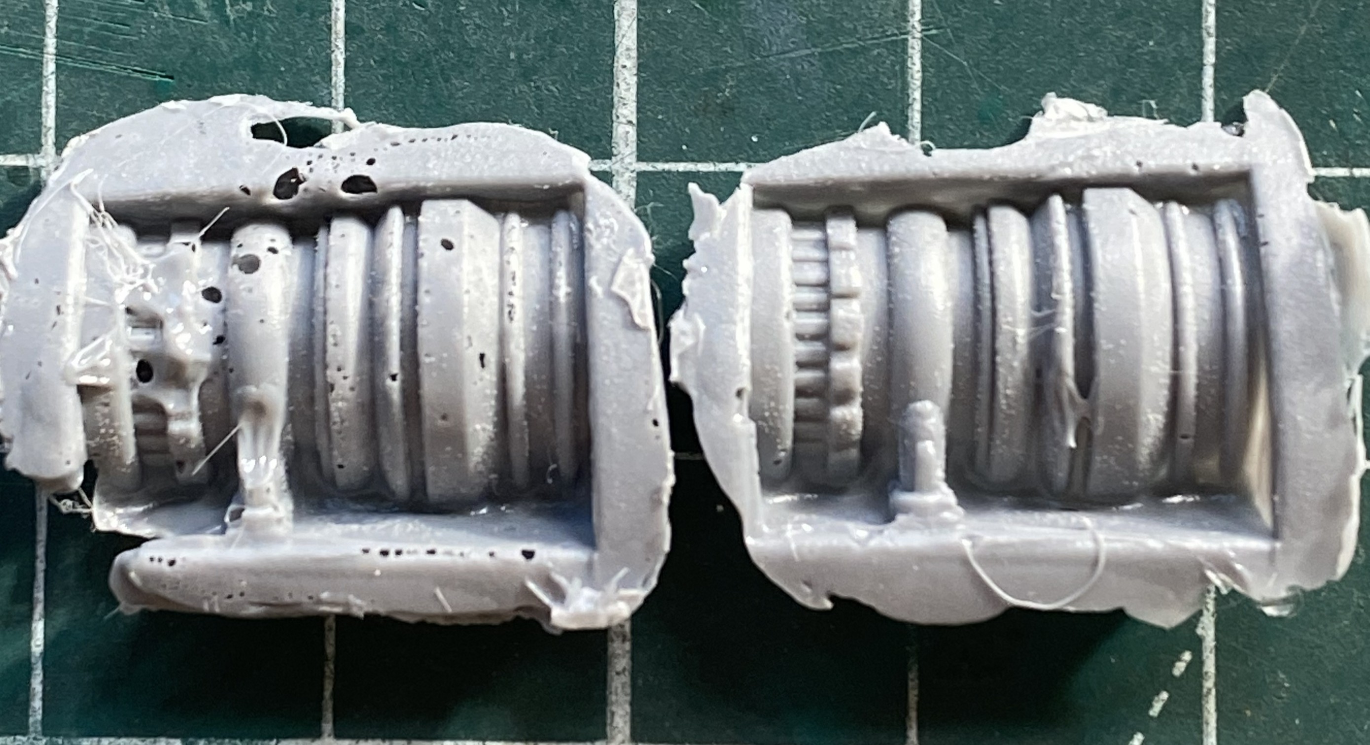
Of course I had to have a go at fixing the first casting (on the left above) but that solution created more problems than it solved. In fact, once I had acceptable castings for both sides is when I realized that the whole engine idea was a waste of time. They be what they is (relatively).
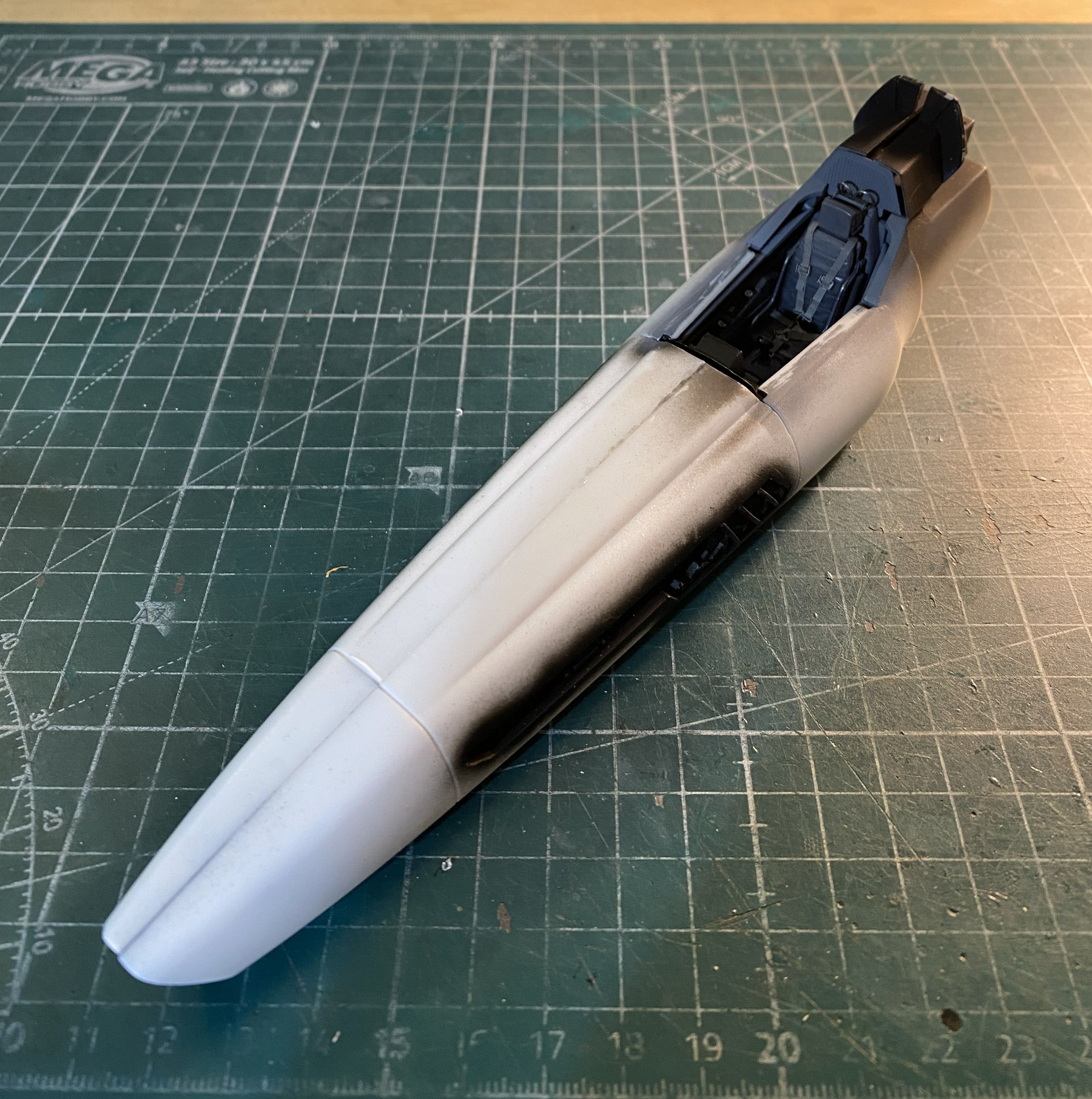
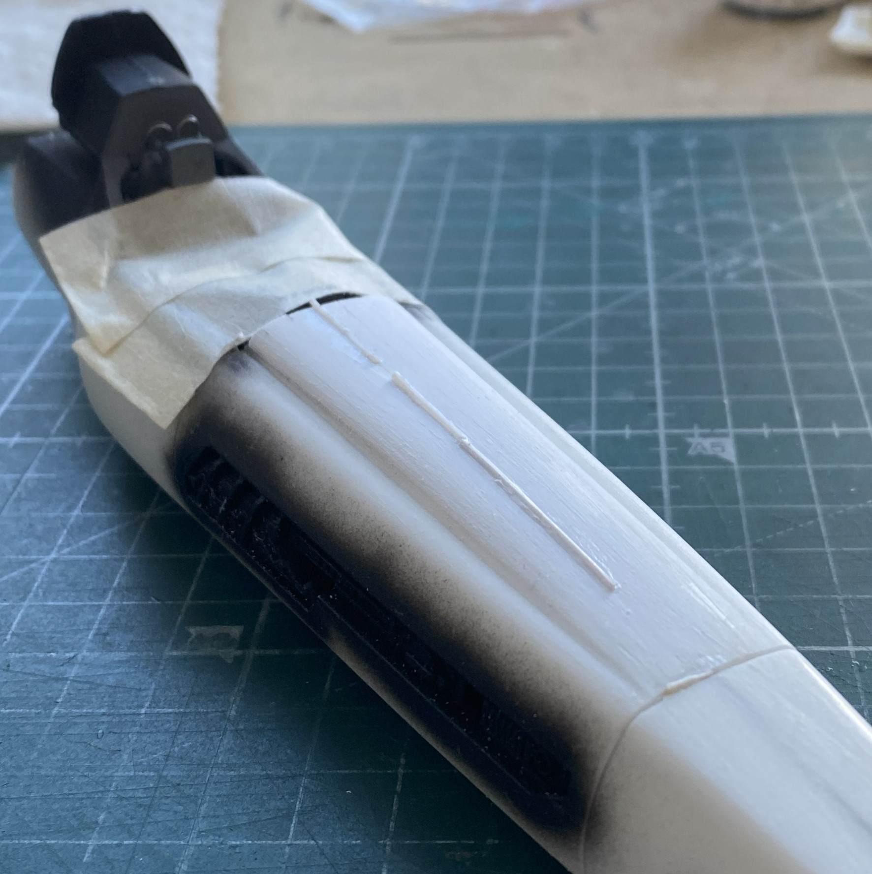
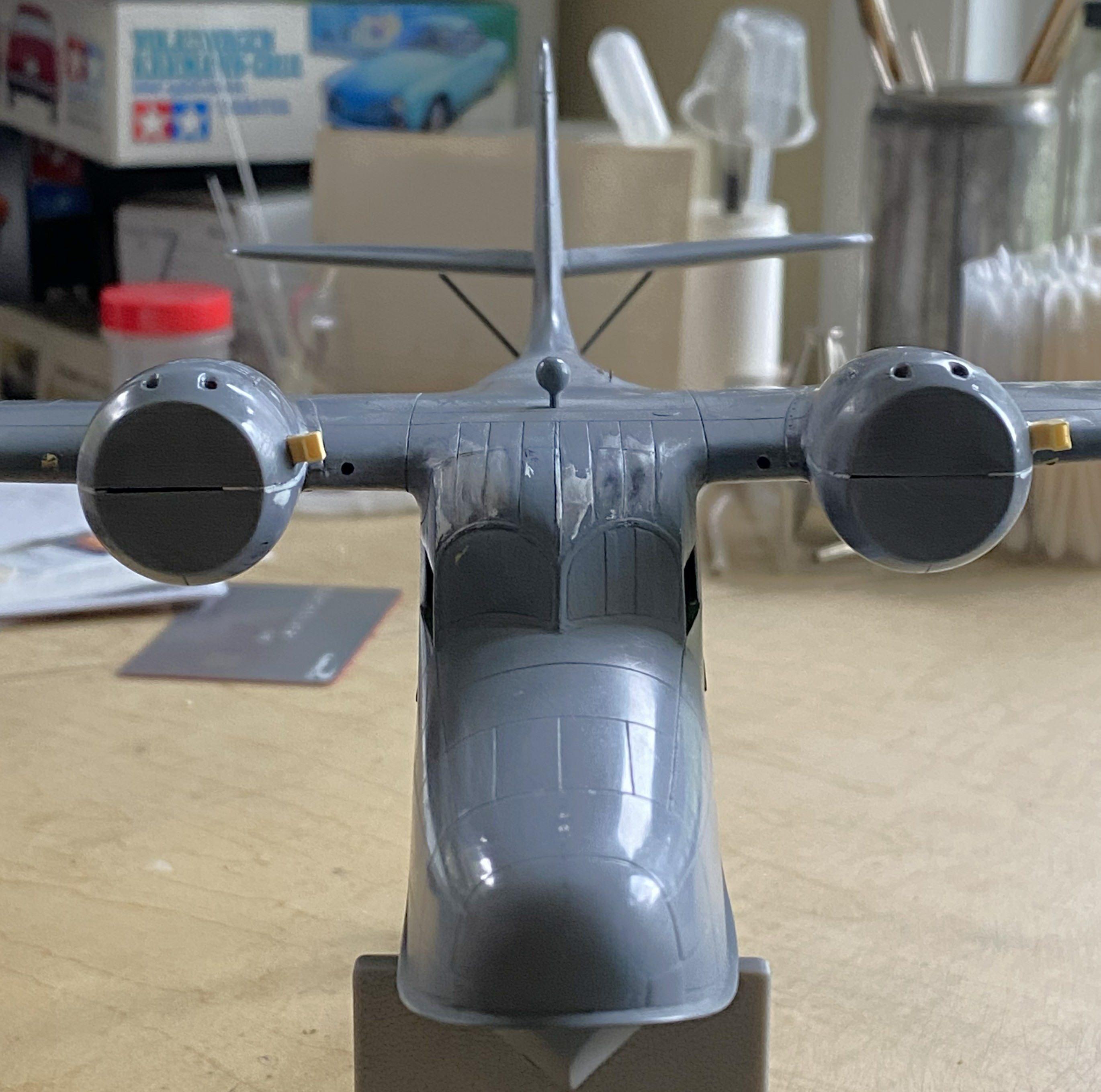
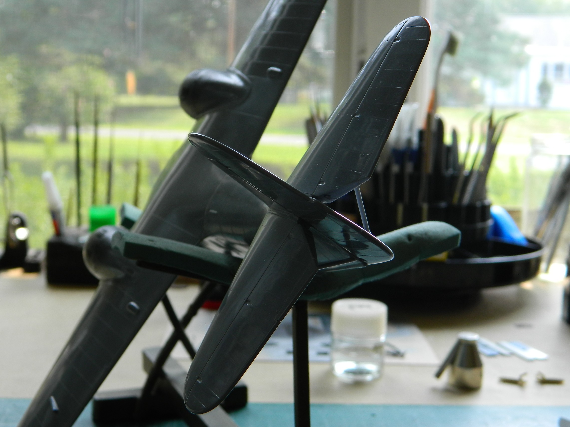
Since this was my first wake-up call (most of my builds have at least one), I decided to tape the major components together to check fit:
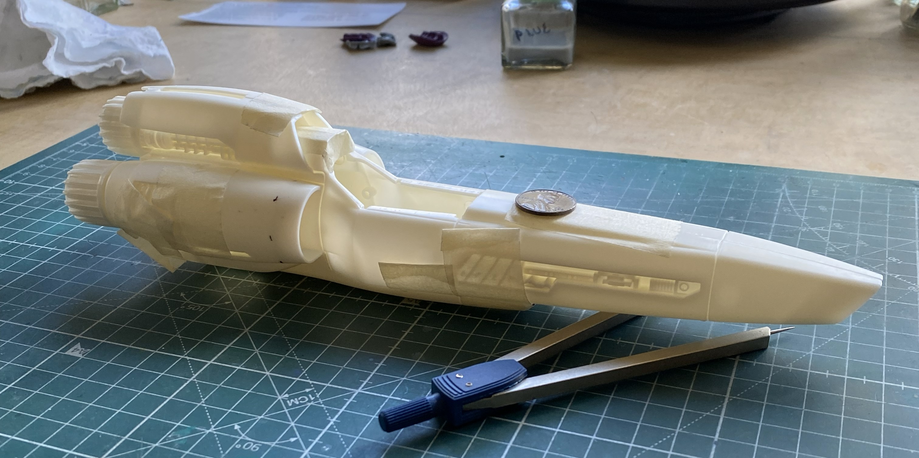
That will require some work. It’s not horrible, but it ain’t Tamiya, either.
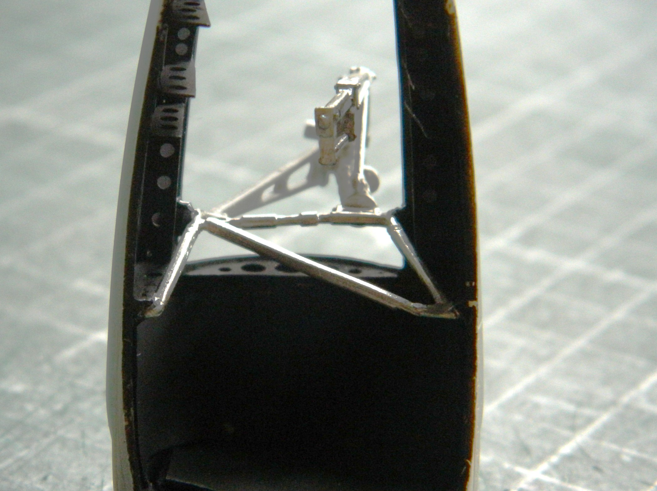
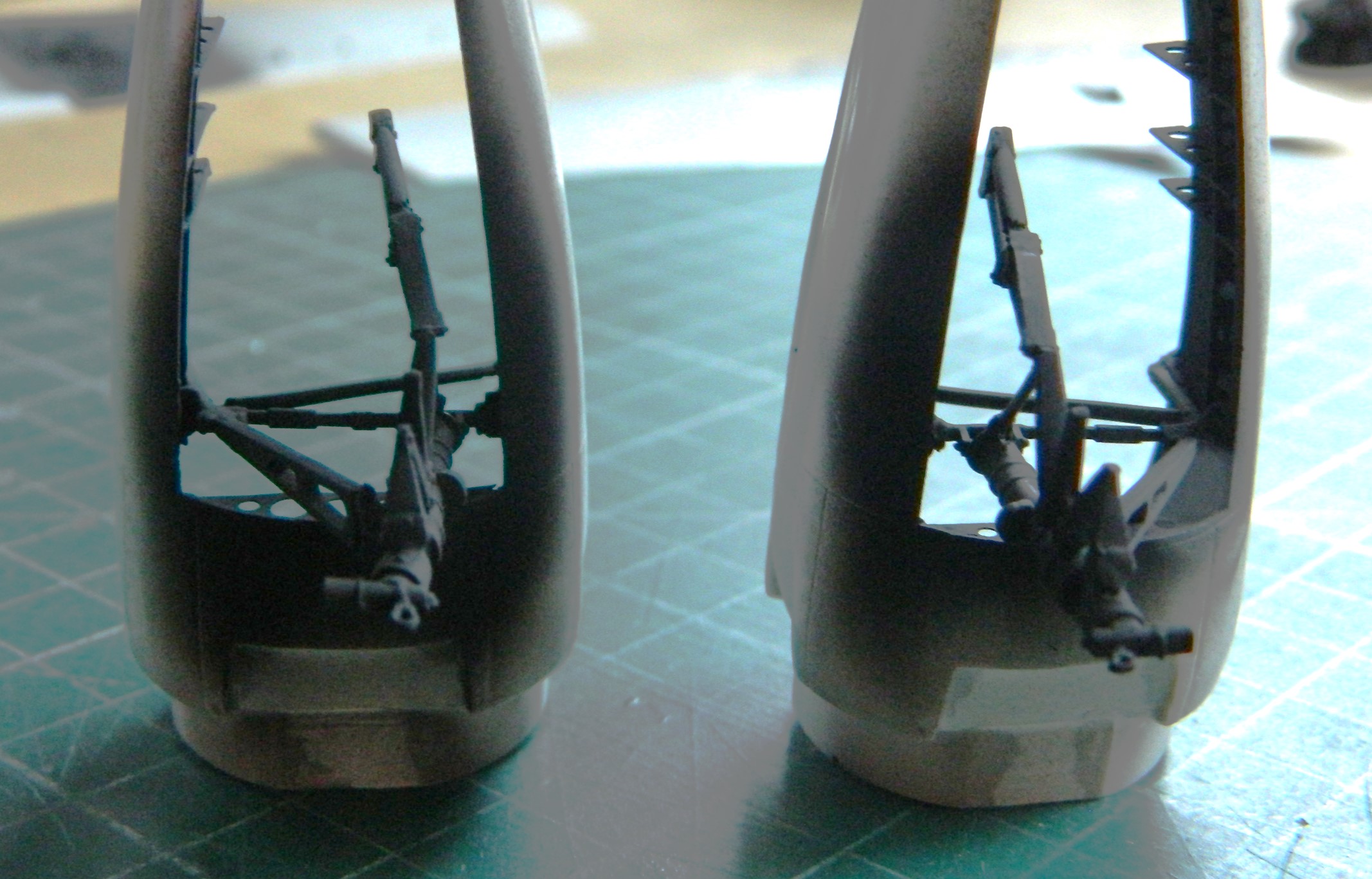
Since this thing doesn’t have a leg to stand on, I decided to start putting them together. Nose gear is on the right:
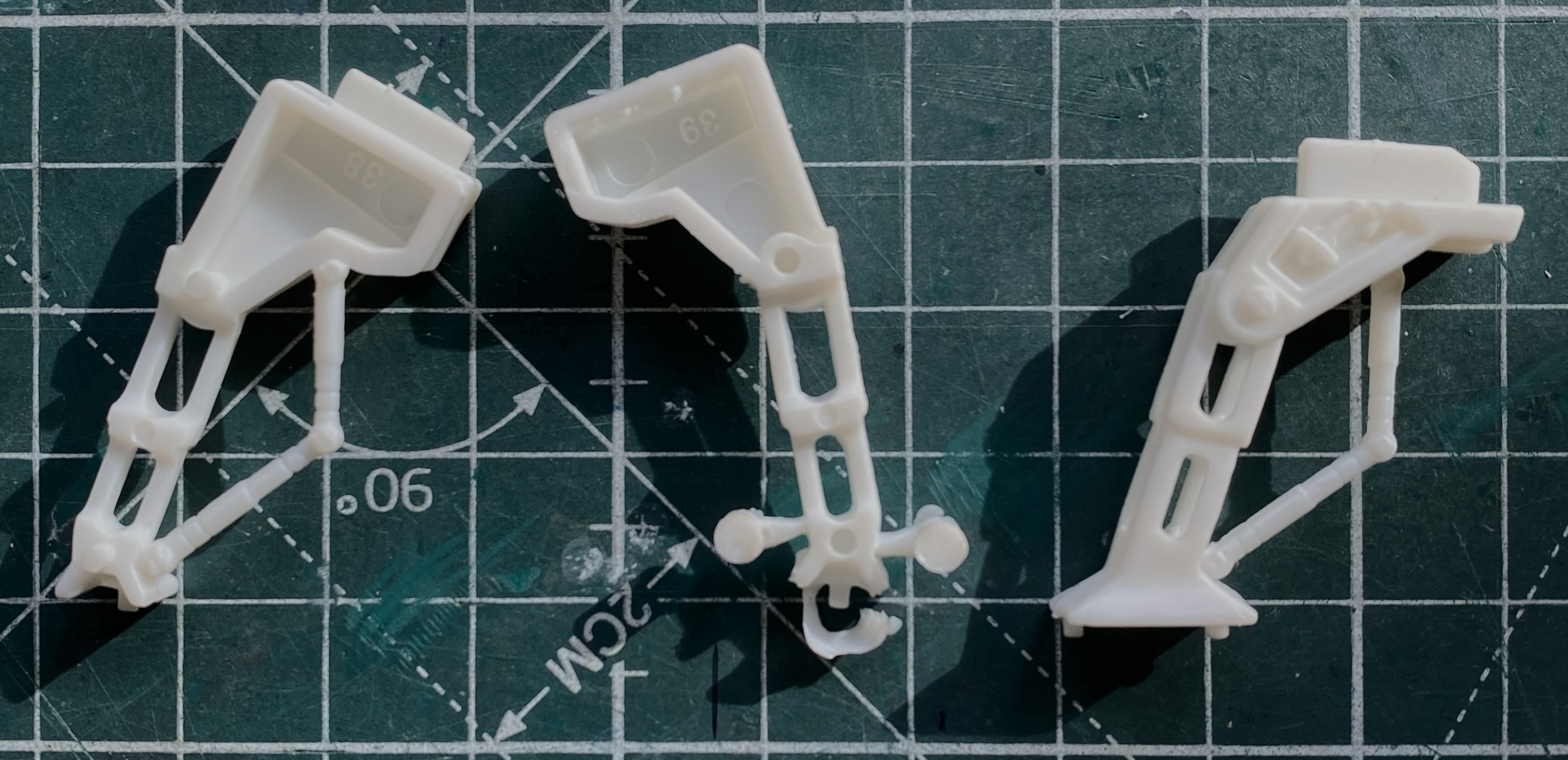
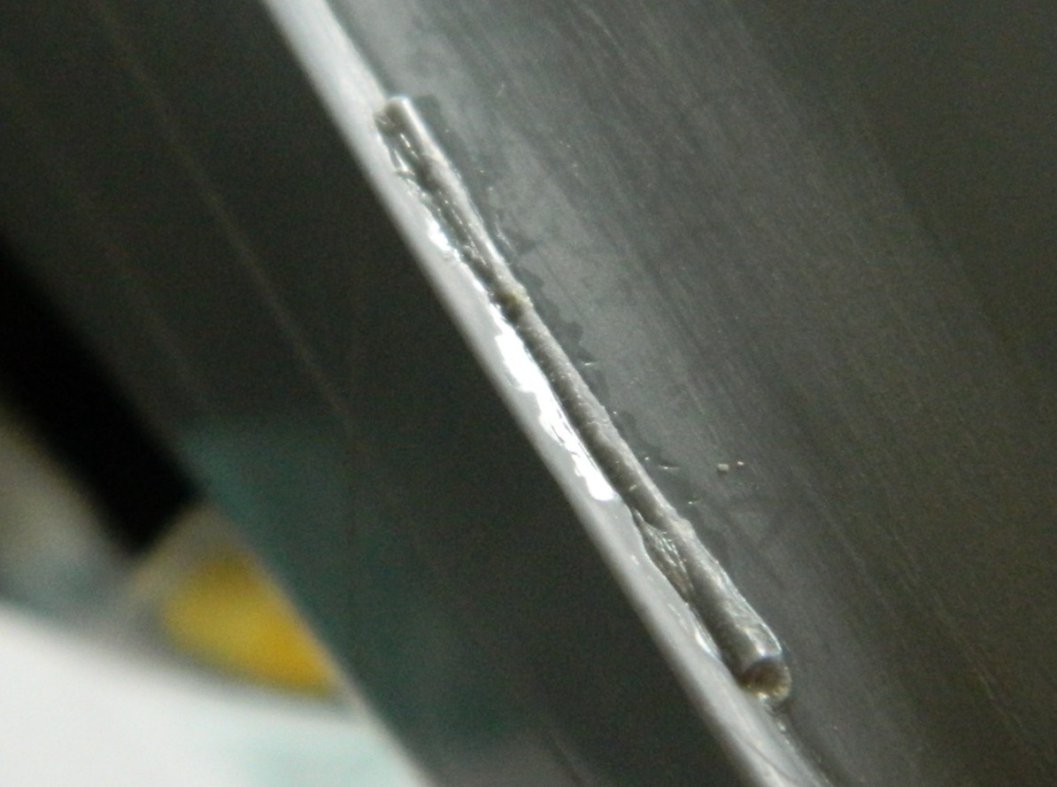
Seams are variable. Some good, some not good, some just freaking annoying. I’m moving away from putty as my default void filler towards scabbing in plastic instead. These landing struts/gear seams need it:
See what I mean:

While all the added plastic was setting up, I started putting together wing halves. This was an area that needed help. So I helped it:
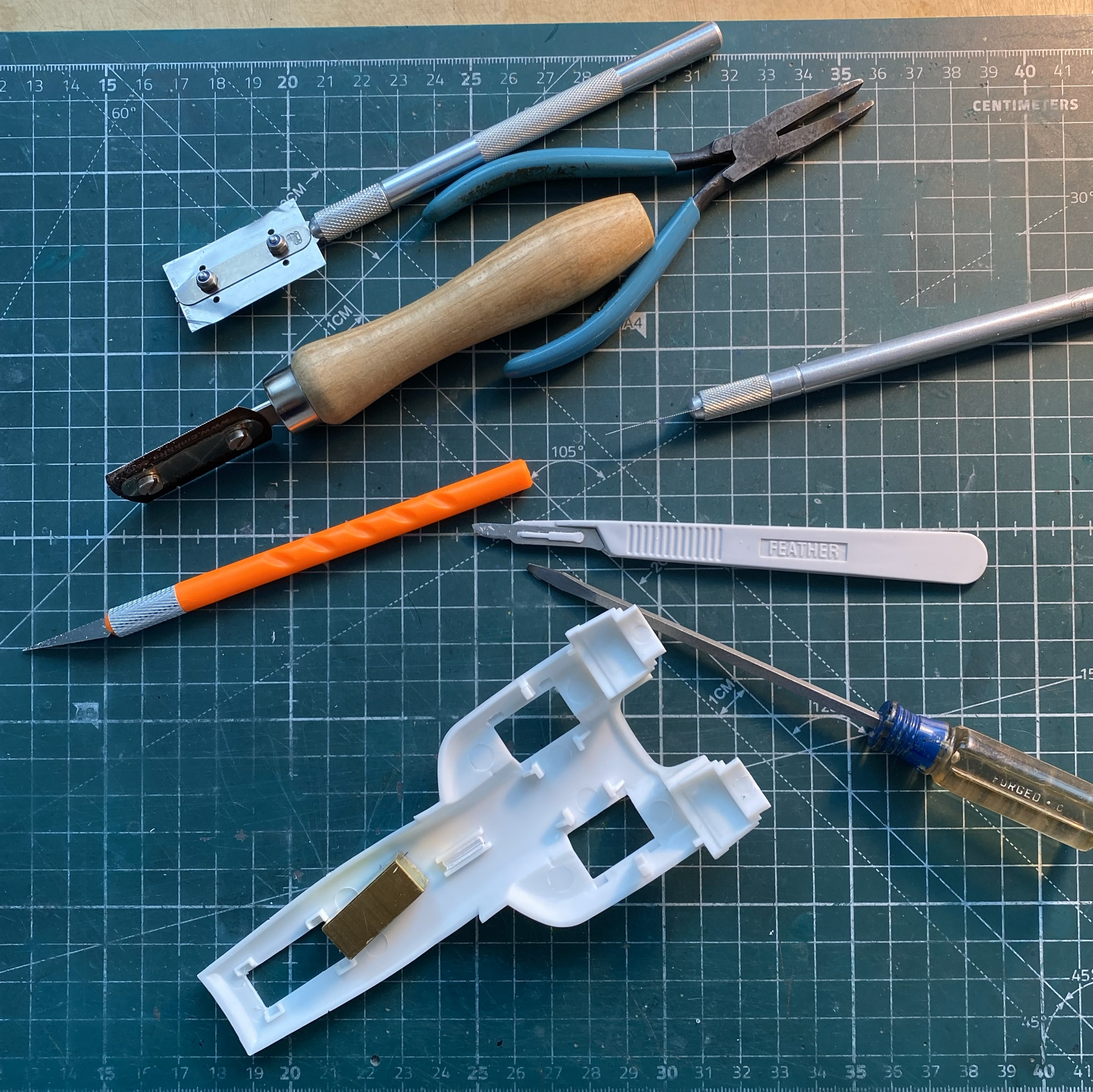
“Why is your work bench so cluttered and messy? Doesn’t that get in the way of working?” No, dear, it is working. These are the tools needed to clean up parts that are essentially simple:
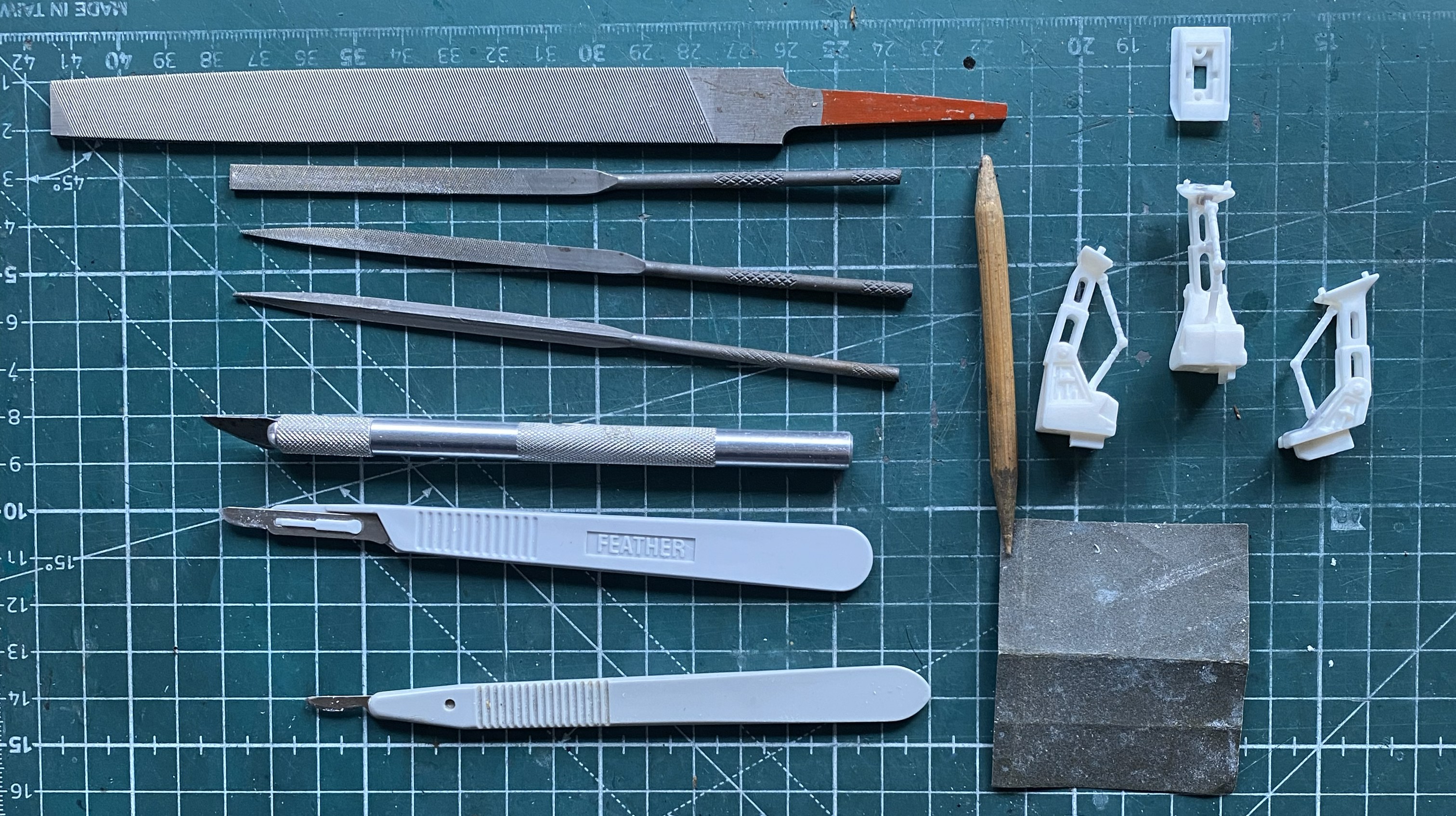
Simple. Right?
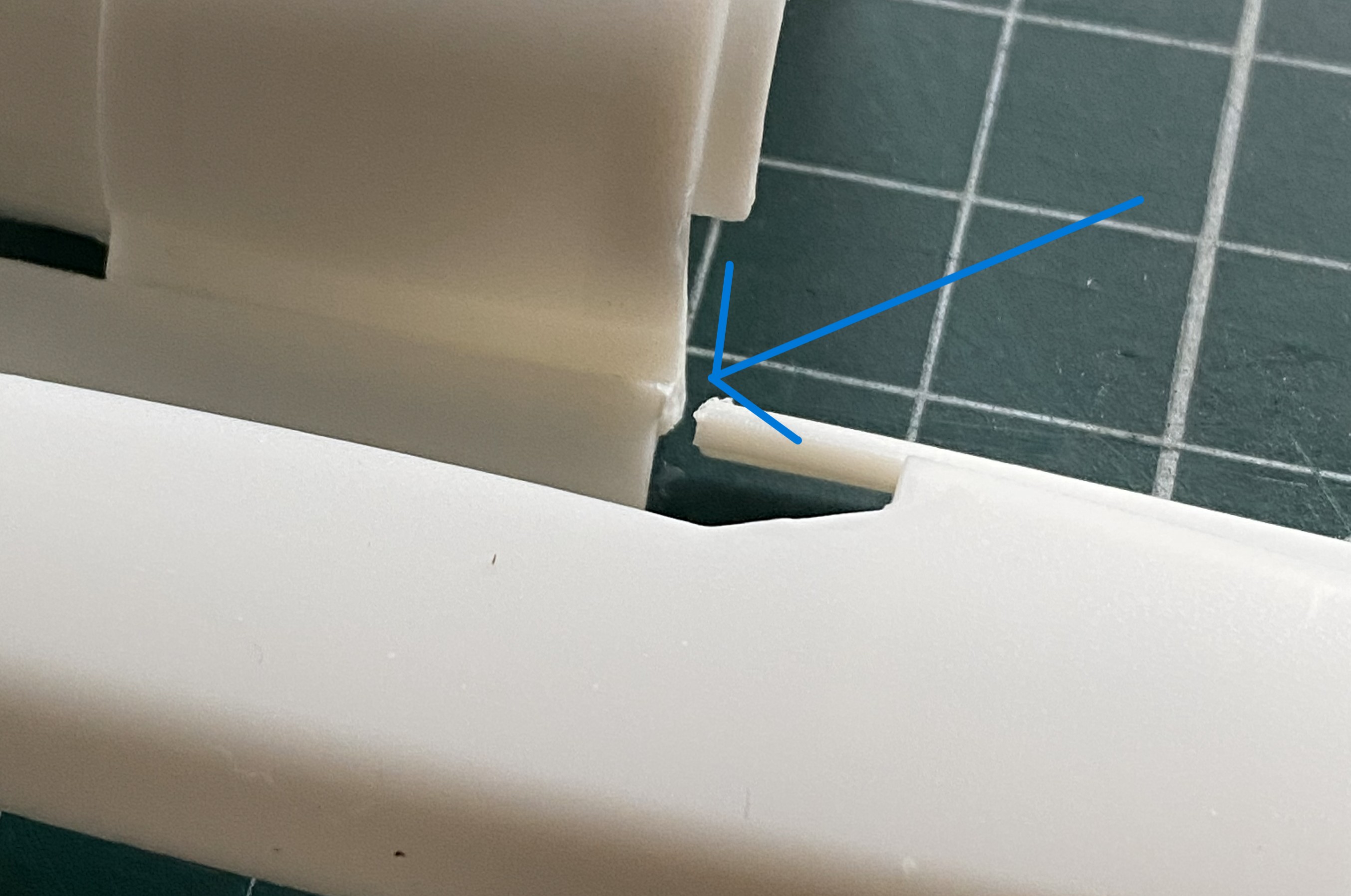
While removing the tape from where I’d dry-fit the major components together, an ohgoddammit moment arrived. The blue arrow shows you where a part came apart:
The way this is engineered, I decided that I’d use the model itself as a gluing jig (the break is on the left half of the engine area). The flat areas on either side of where the upper engine goes served well as an alignment guide:
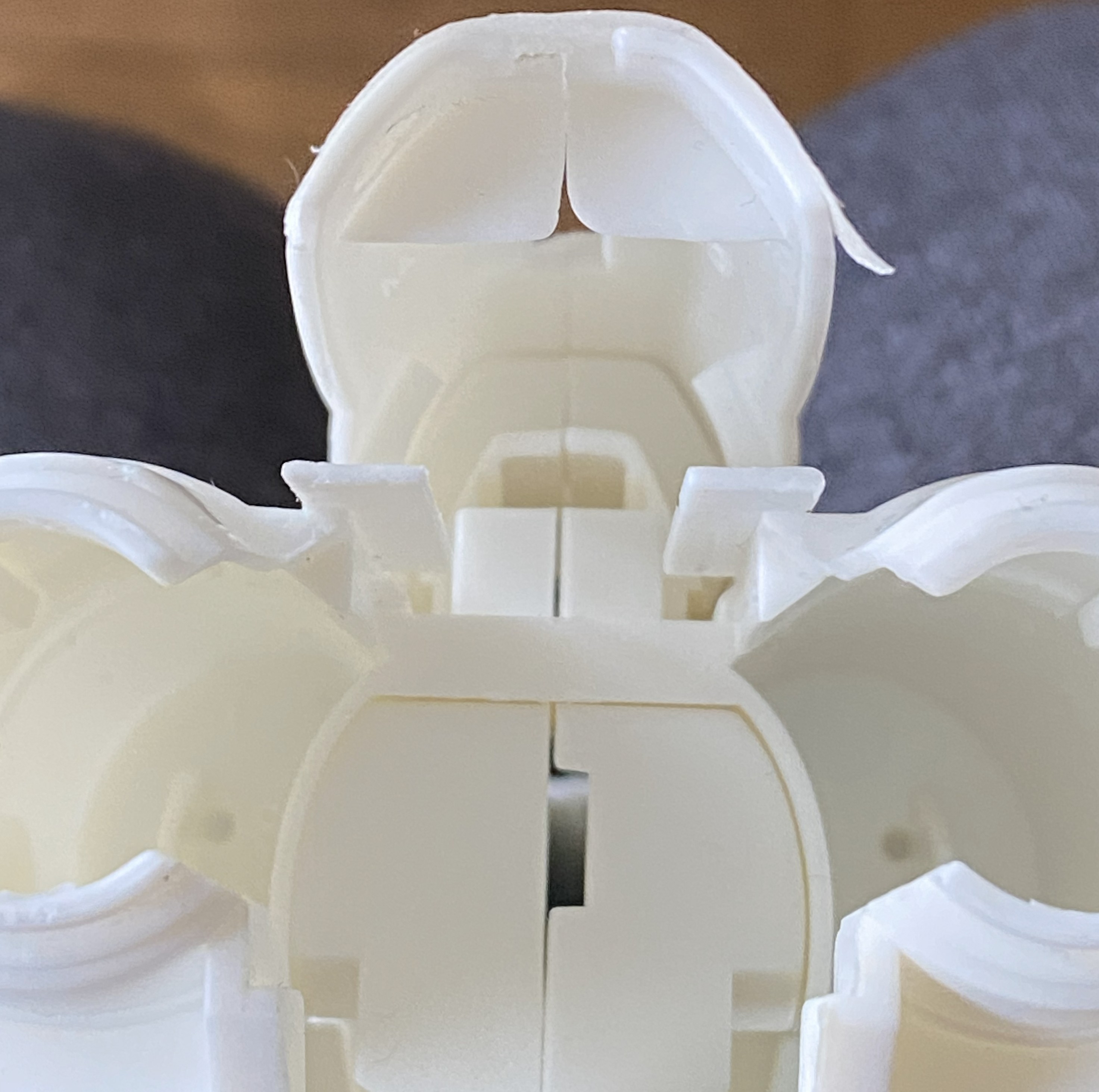
Good illustration of fit, eh?

While I was there, I filled the slot for the supplied stand since I’m not going to use it:
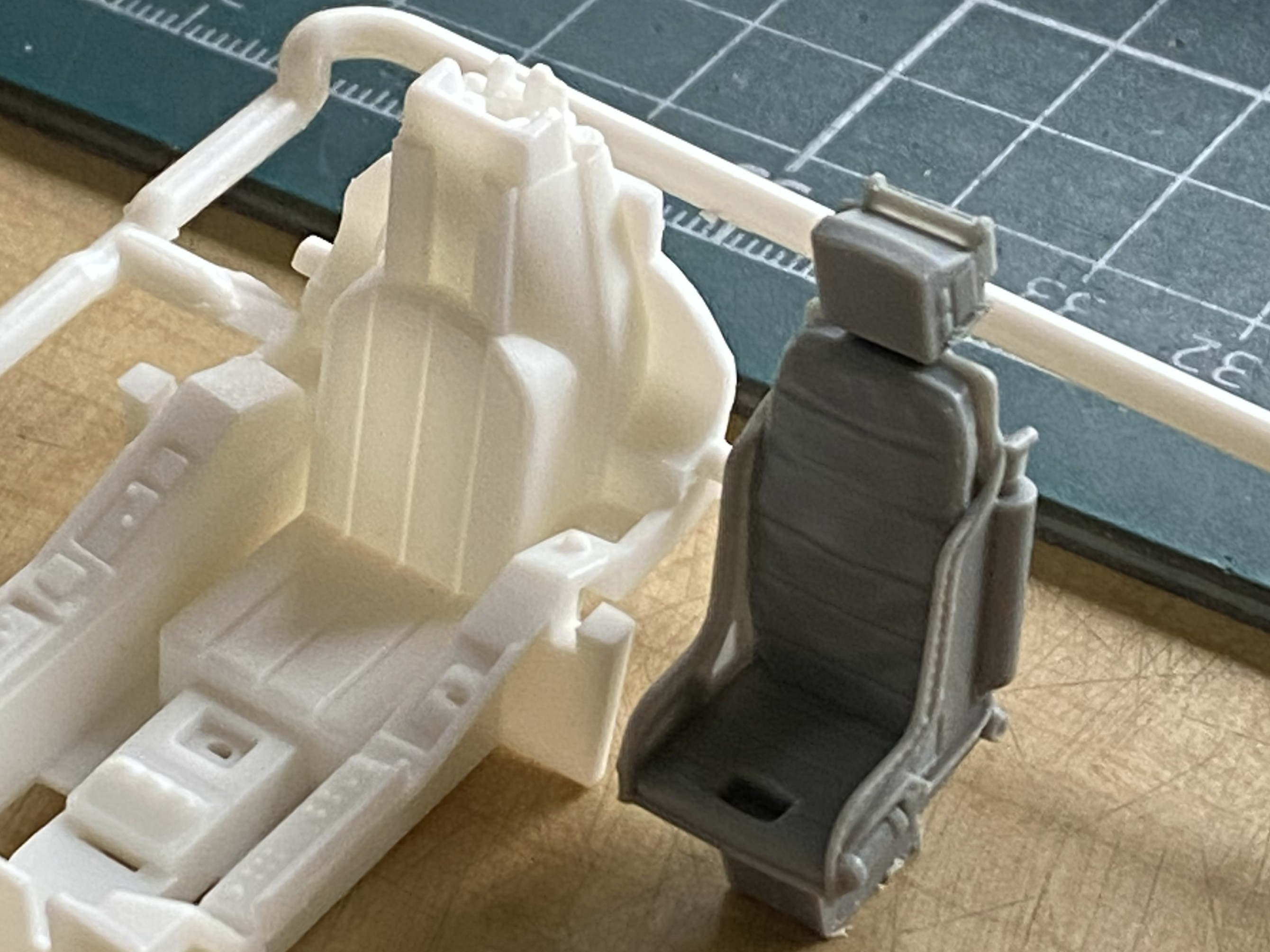
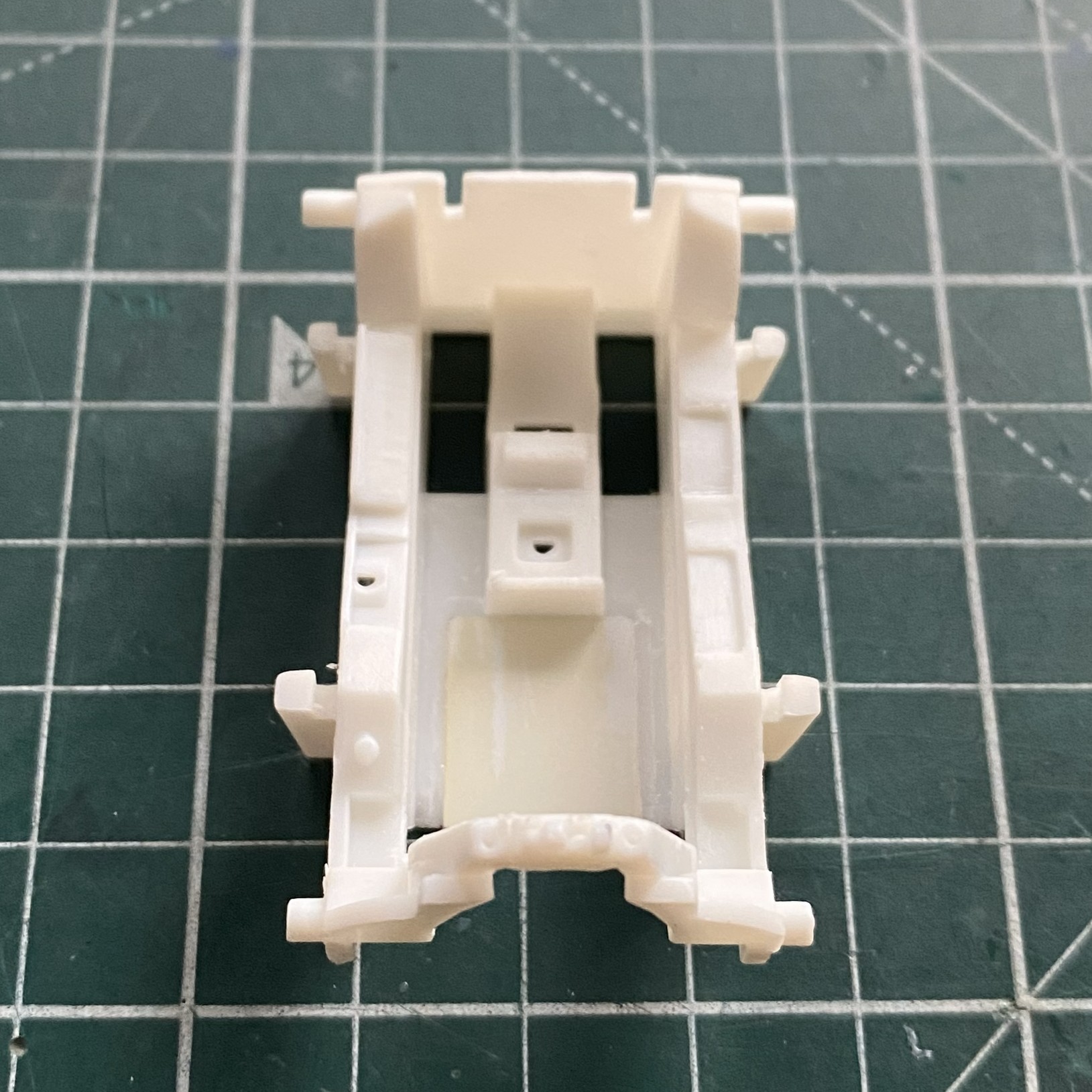
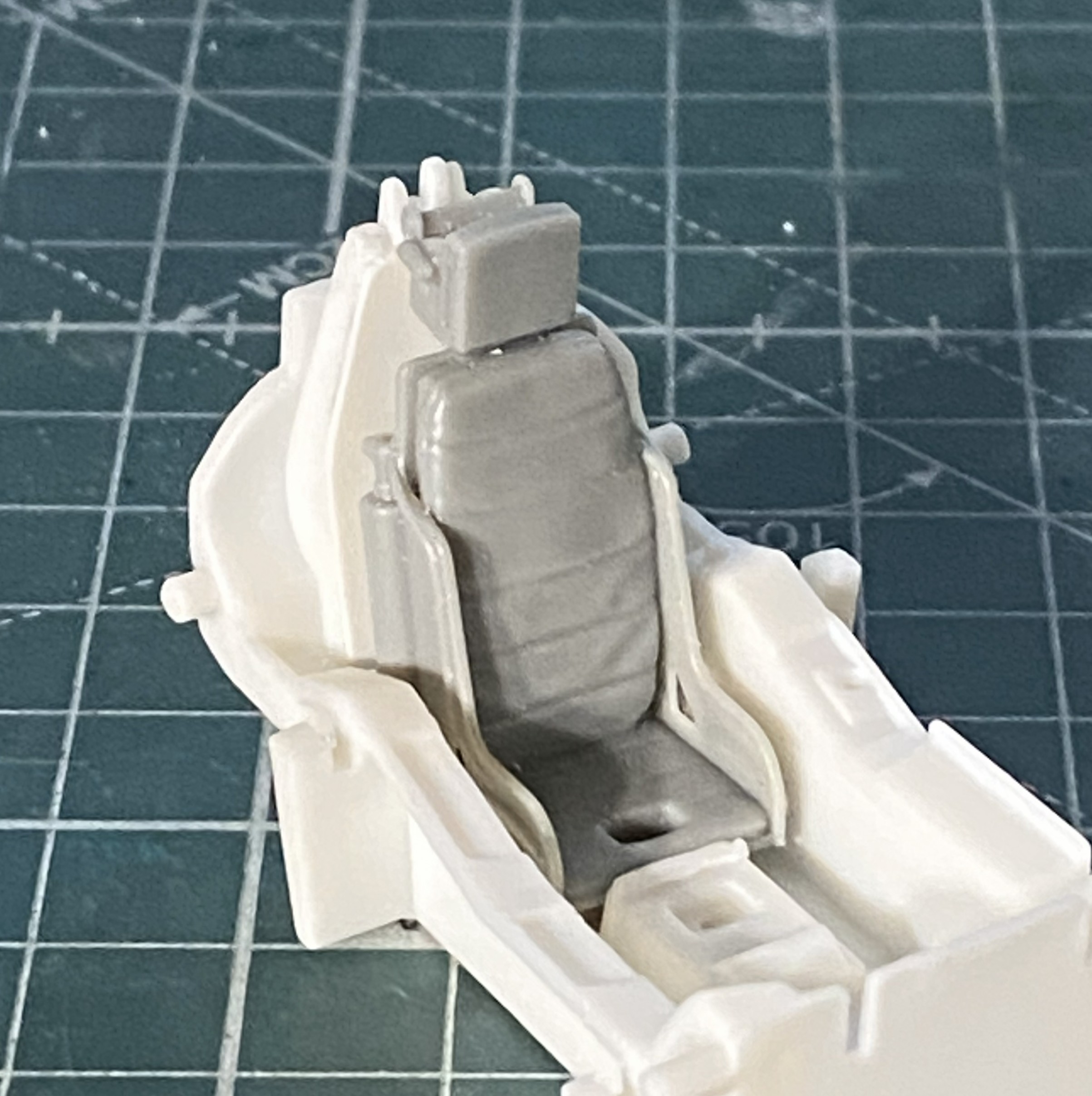
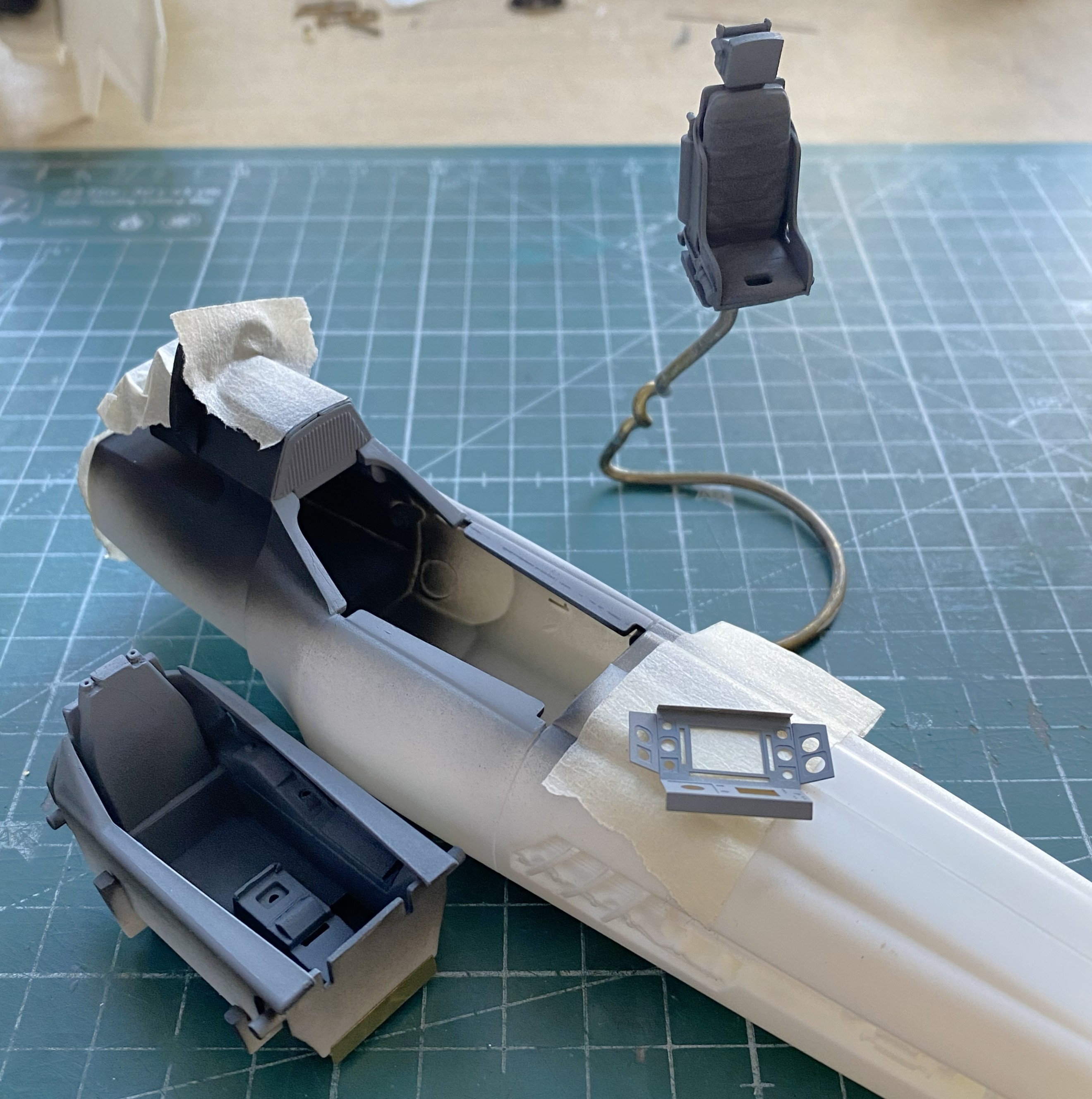
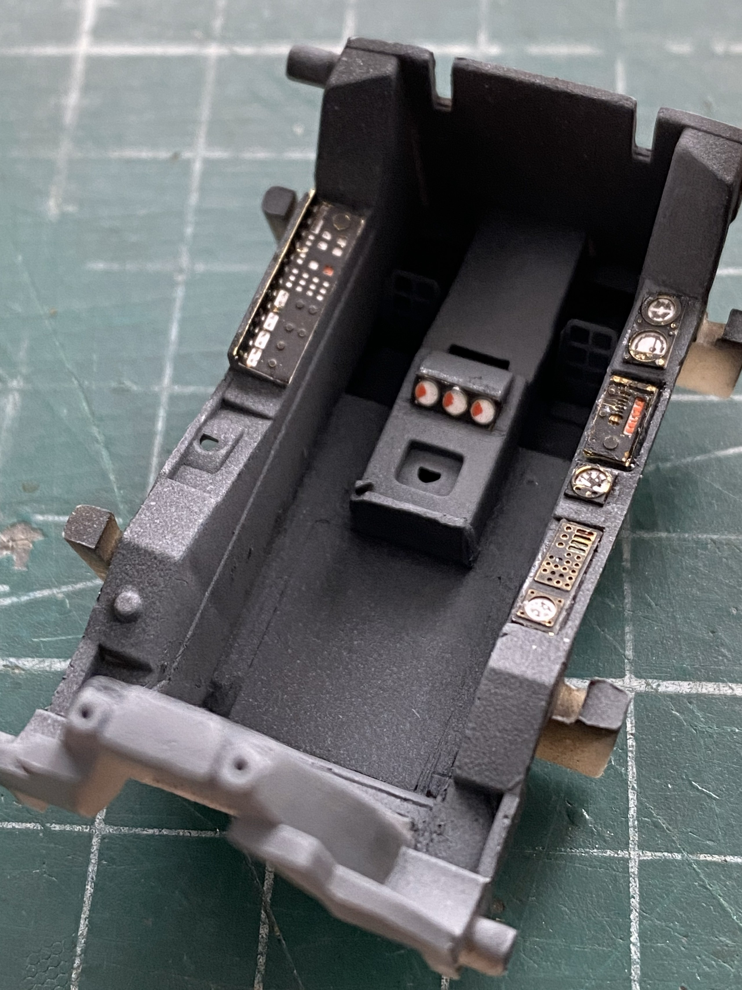
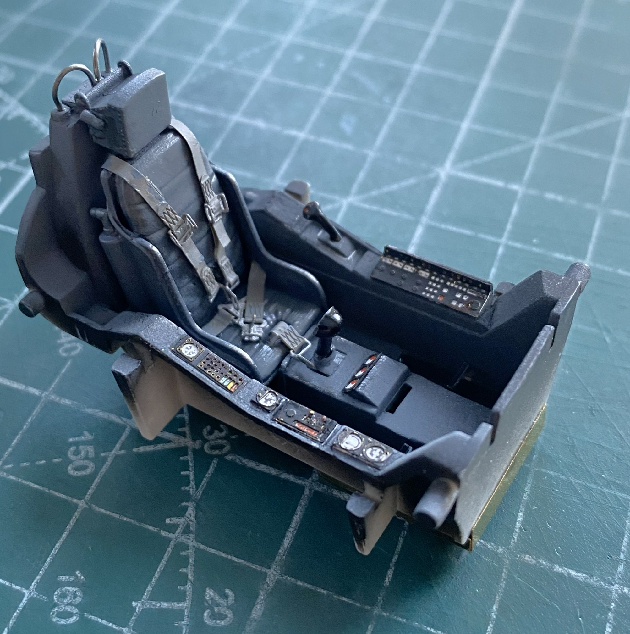
At this point the AM parts arrived so I changed focus to doing the cockpit. For the resin seat to fit, the molded-in seat has to come out:
Once the kit’s seat was gone, I assembled the pedestal for the seat:
Then I checked the fit:


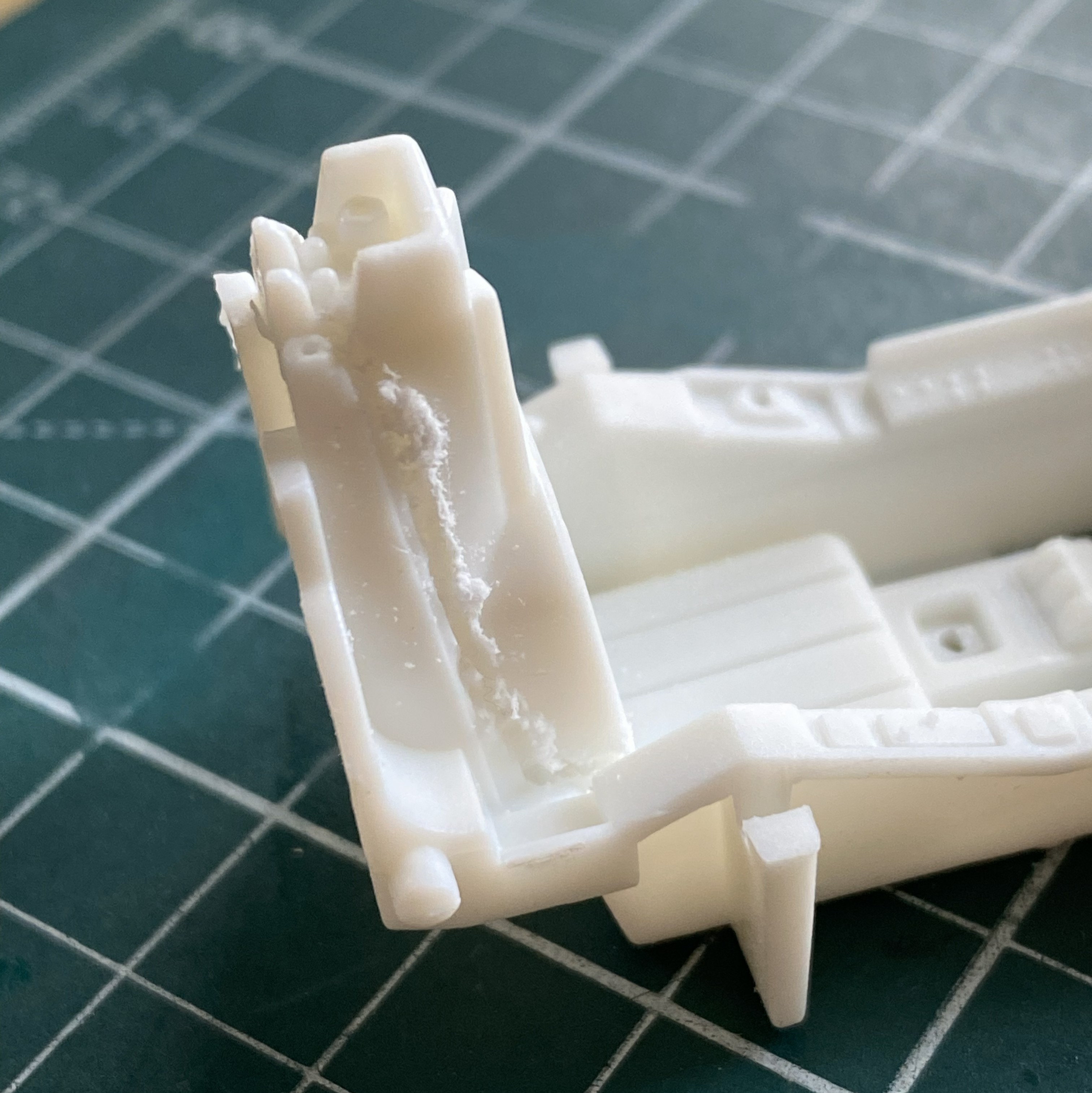
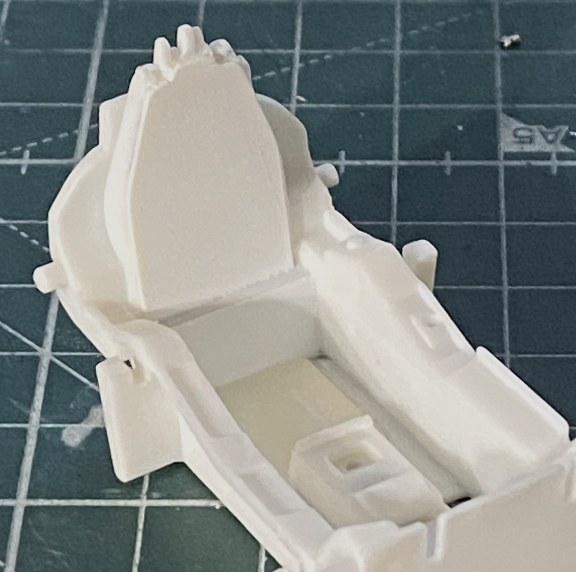
Nope. Sits too high. The fix was to remove the pedestal and glue the seat directly to the floor (you can see the fit of the fuselage behind the seat, which will require some inflexible persuasion on my part), which lowers the seat to the correct height:

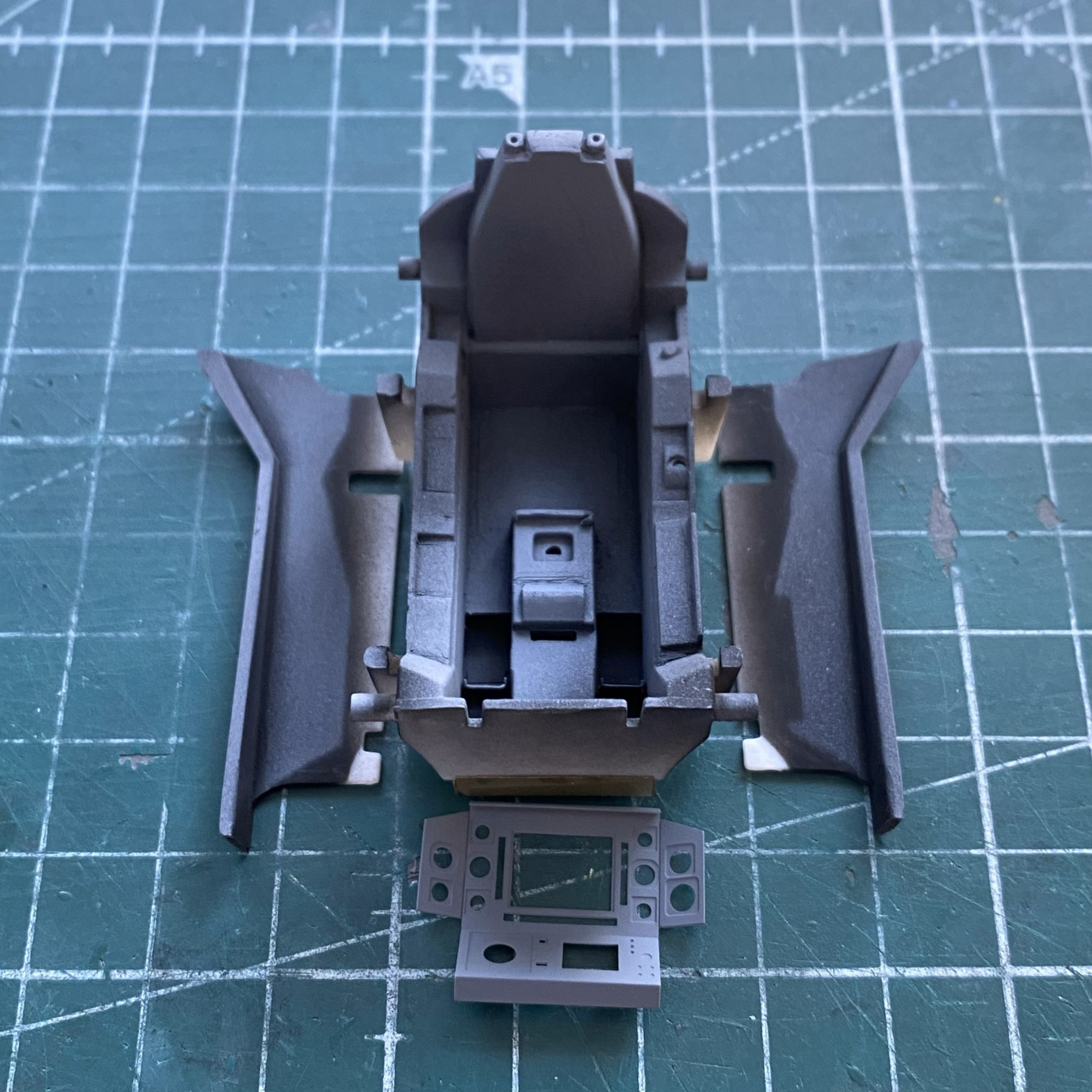
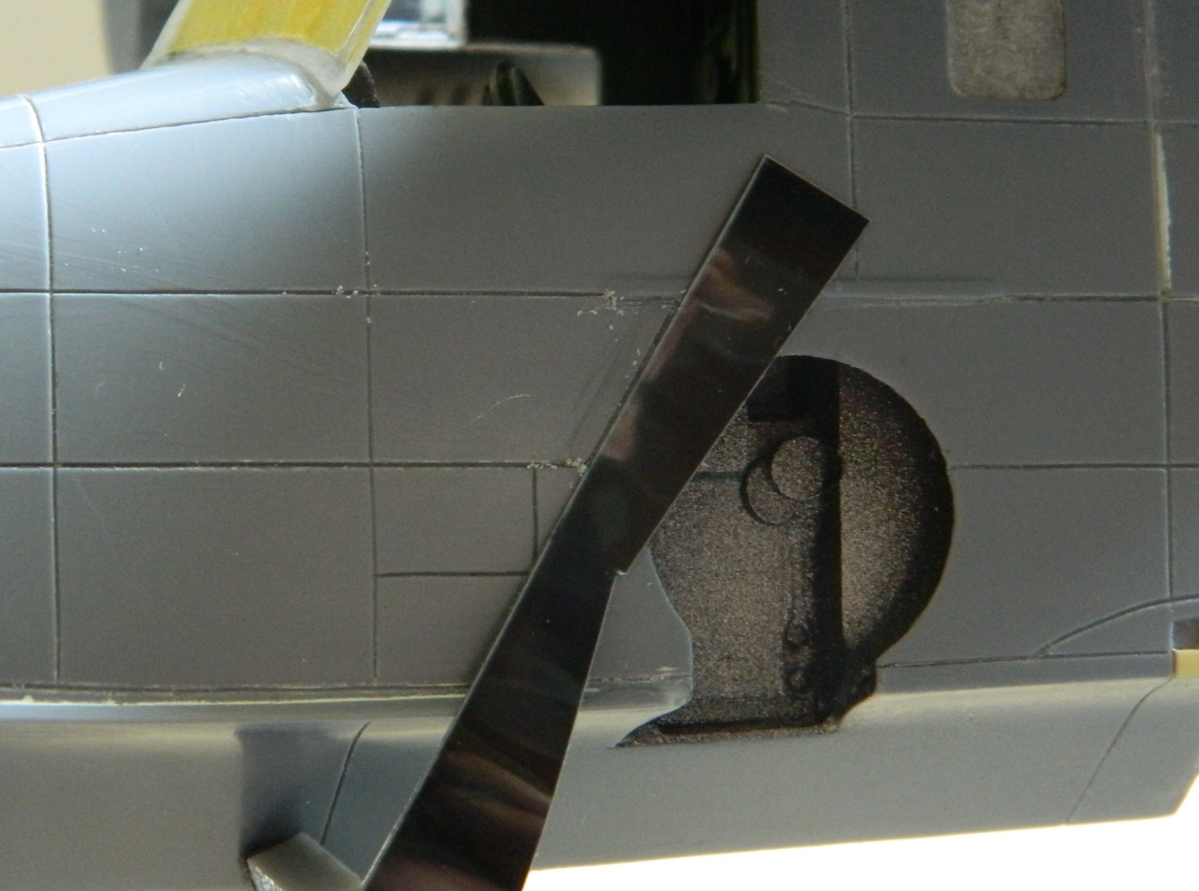
To apply the PE I have to remove the molded-on details. That with the round black dot has to be removed, the one on the left that looks like a D laying on its face is where the throttle goes. The insert in the floor is to fill the gap left after removing the molded seat (and to give me something to glue the resin seat to):
Done:
The structure behind the seat needs to be filled. I used 0.020″ (.508mm) for that:
Where the back joins the tub is evident at the edges. I used a little putty to make the added back look as if it belonged.
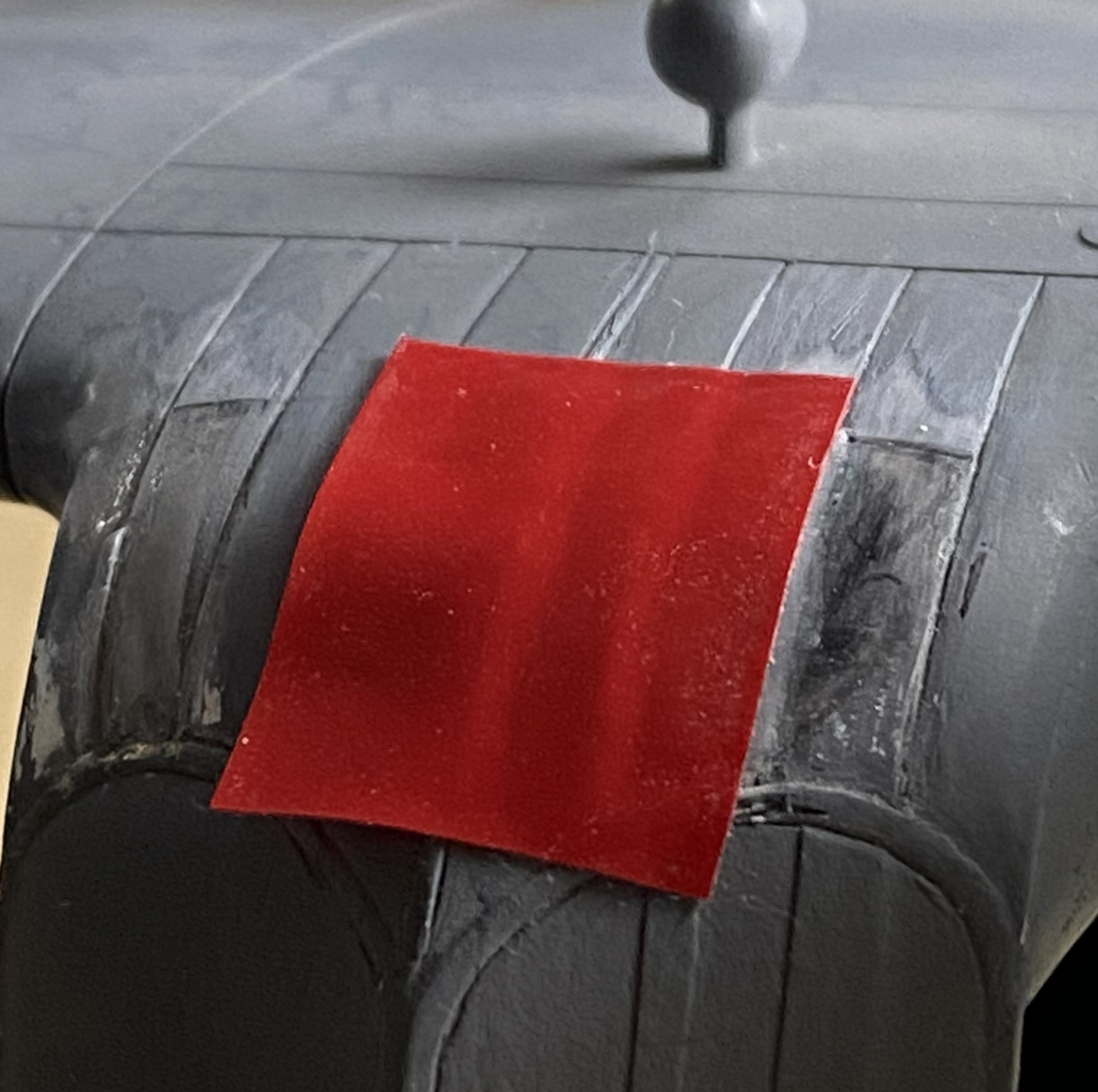
With unwanted details removed, PE moved to the front of the line. Surprising no one who’s worked with PE, acrylic paints don’t adhere well. They’re fine once painted if they aren’t stressed. I was curious to see if lacquer would hold up any better. I masked off what I didn’t want to paint and then sprayed the fret with Tamiya’s TS-6 Matt Black from a rattlecan and let it sit overnight:
The next day I used my MkIII Thumbnail to see if lacquer is more resistant to wear. It is. It still wore a bit as I was working things but NOwhere near as much as acrylic wears.
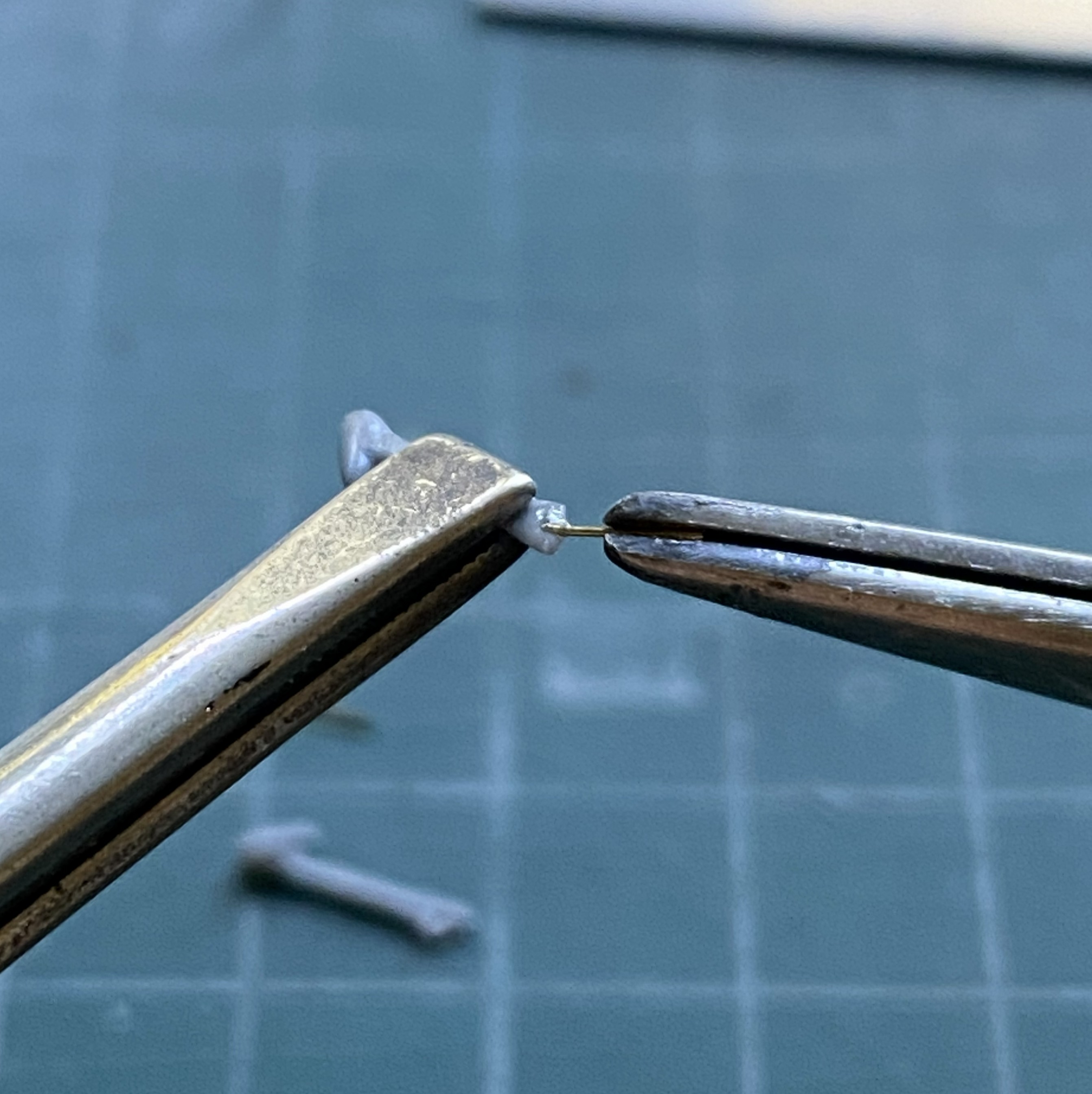
In general, I’m not a fan of PE harness straps. The PE fret has them so I decided to have another go at them. I started by annealing them so that they behave less like the strip of brass that they are:
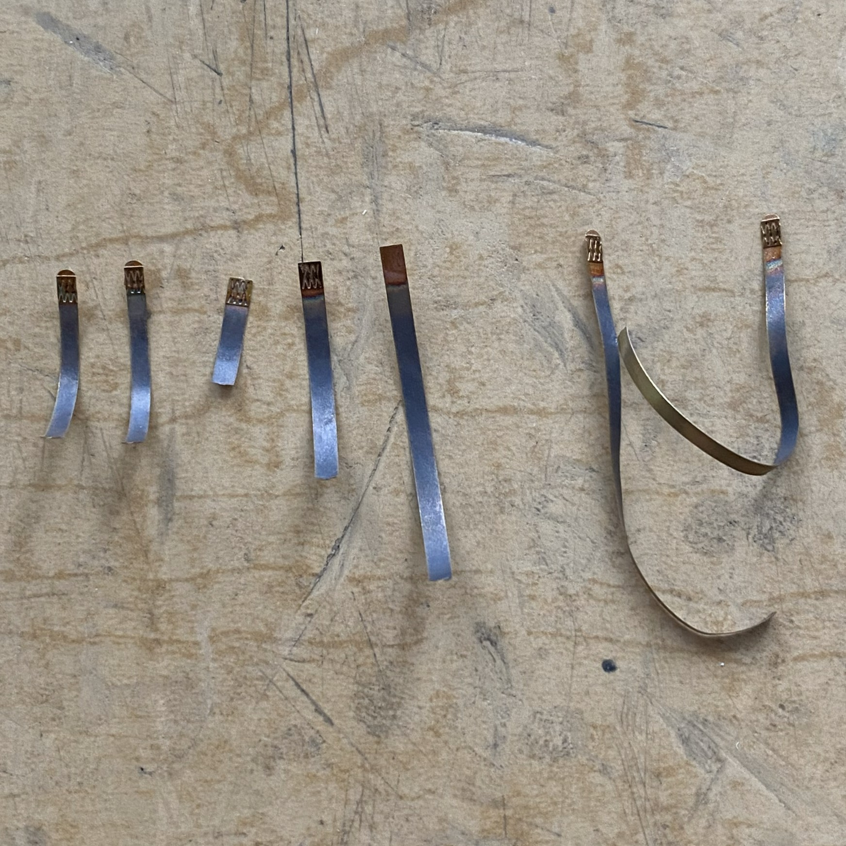
During annealing, I managed to scare myself. I use a butane torch to anneal. It’s hot. It’s hot enough to melt little brass strips! I came far too close to melting one of them, but since I’m not a grenadier…
Next I fed the straps through the hardware of sliders, tabs, and locks:
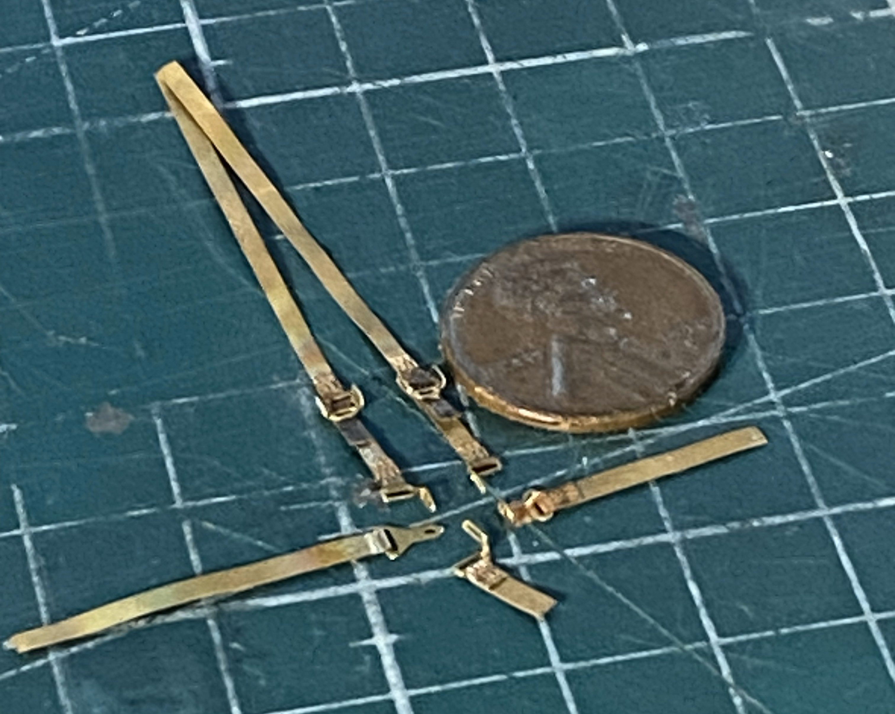
Annealing them made it magnitudes easier to feed the straps through the hardware! Now to see how they go on:
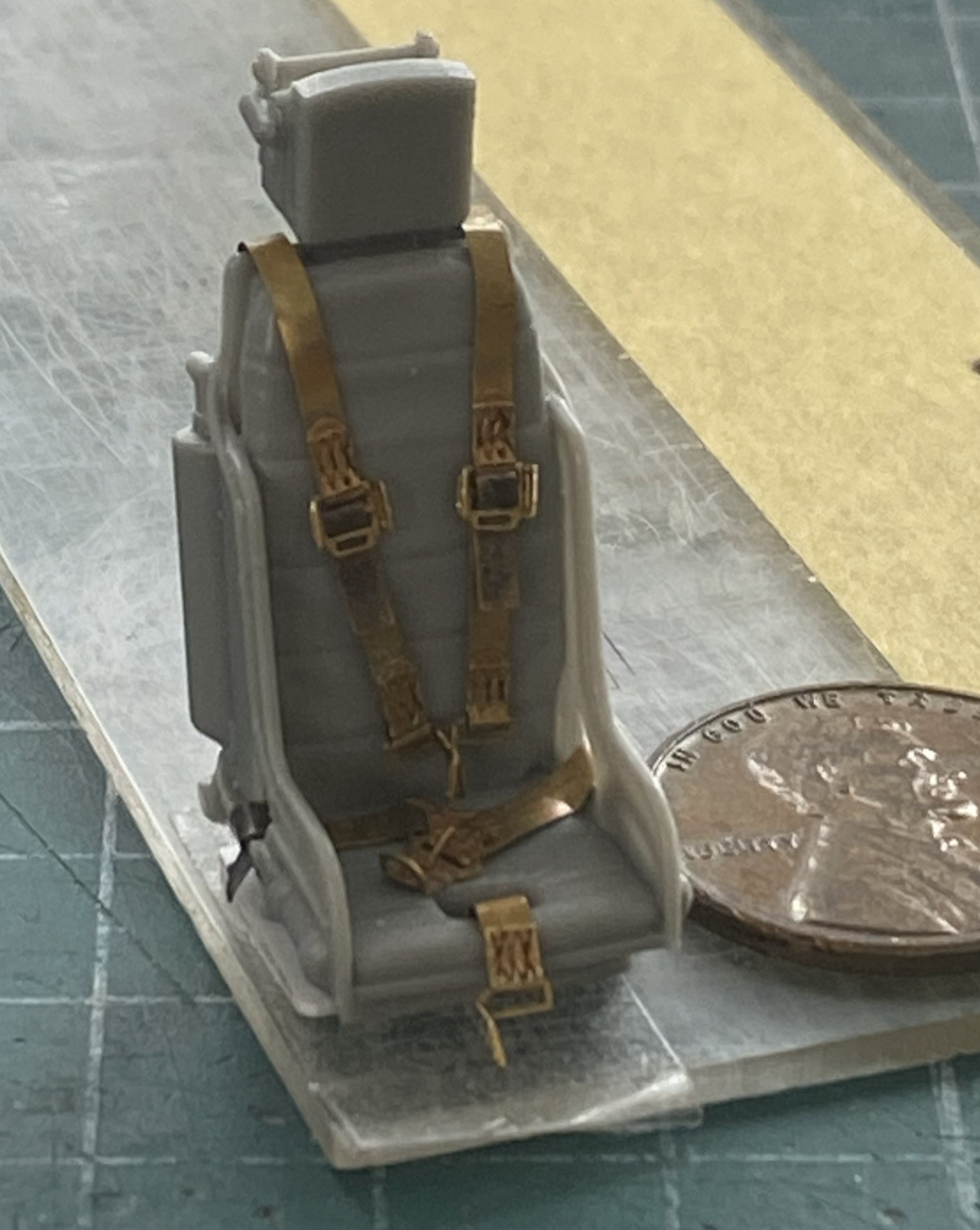
Annealing is definitely the way to go with PE harnesses.
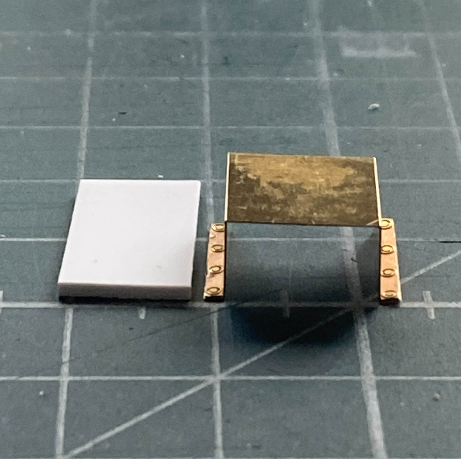
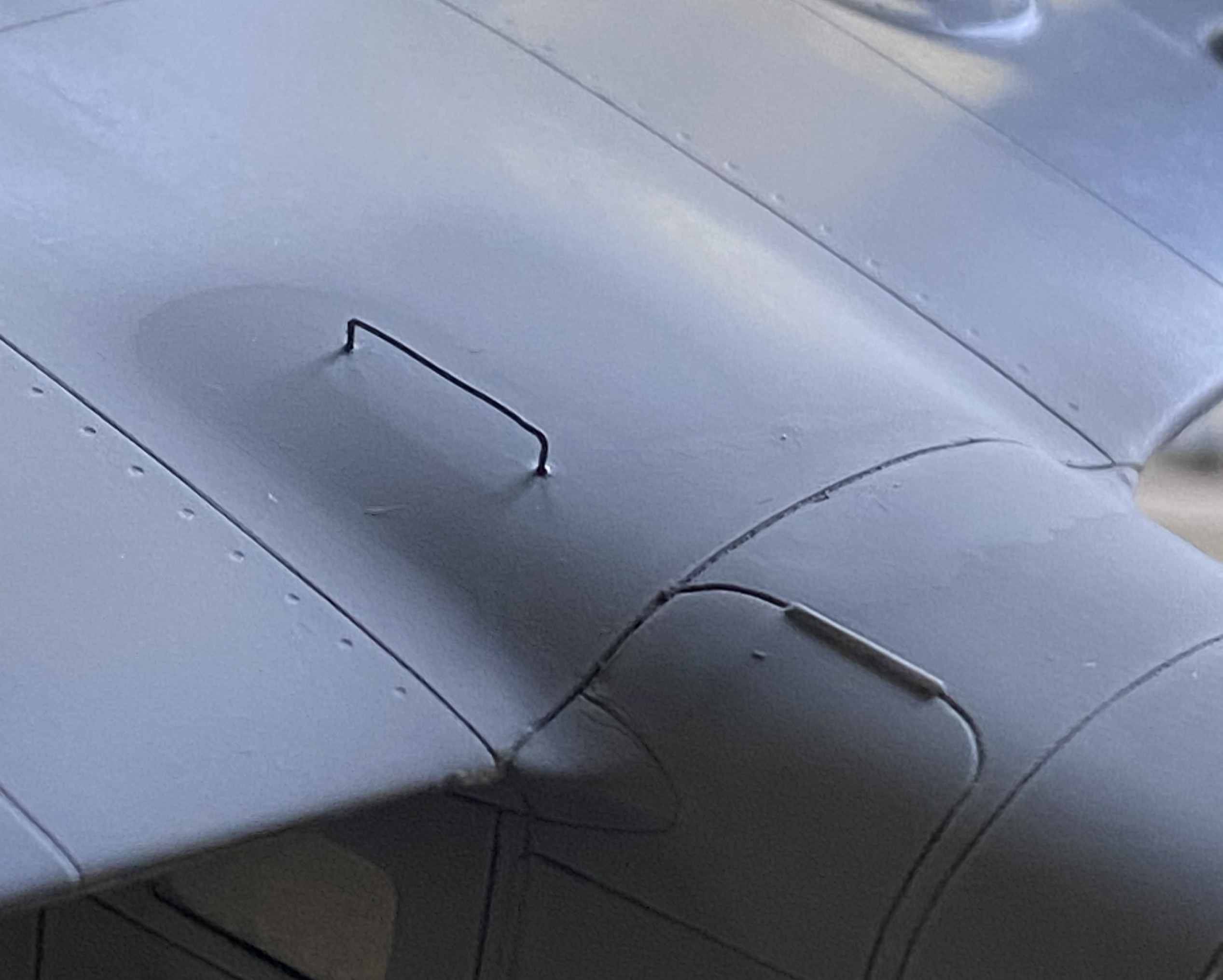
I don’t know what this little panel is for, I just know it’s there so now was a good time (or even not a bad time) to see how the lacquer holds up to bending and gluing:
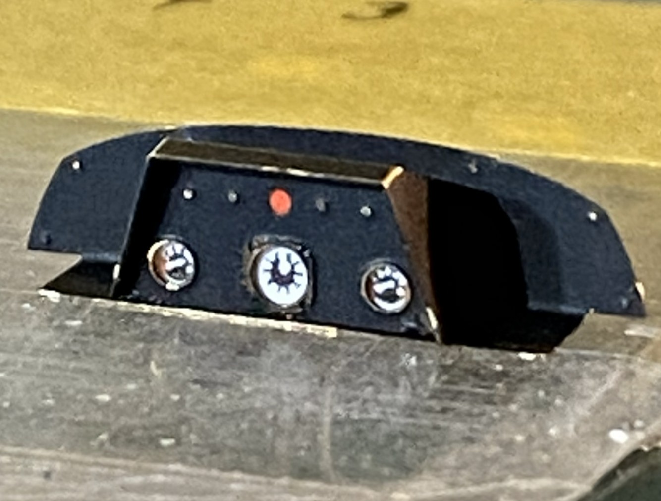
The lacquer holds up to being manipulated much better than acrylic does.
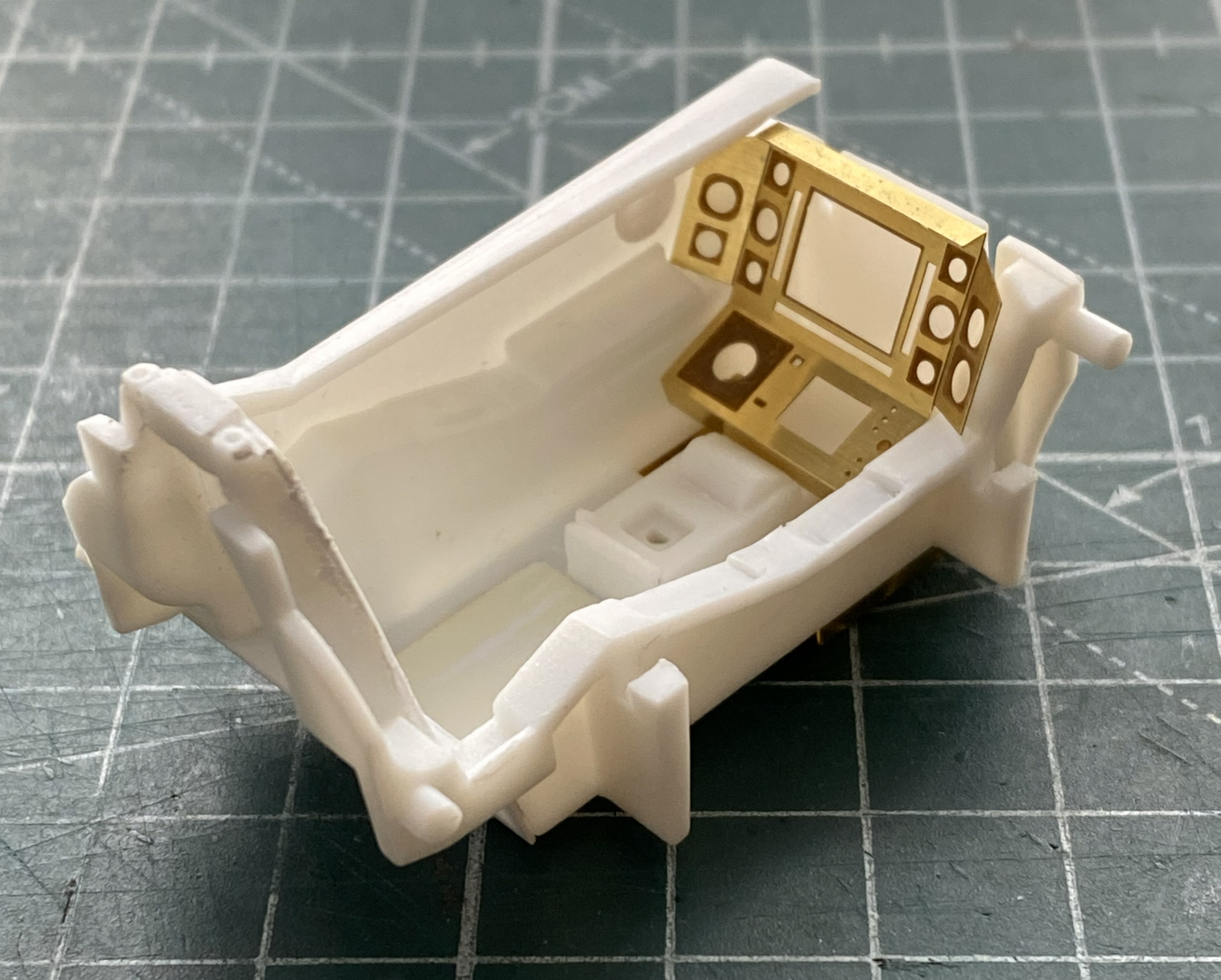
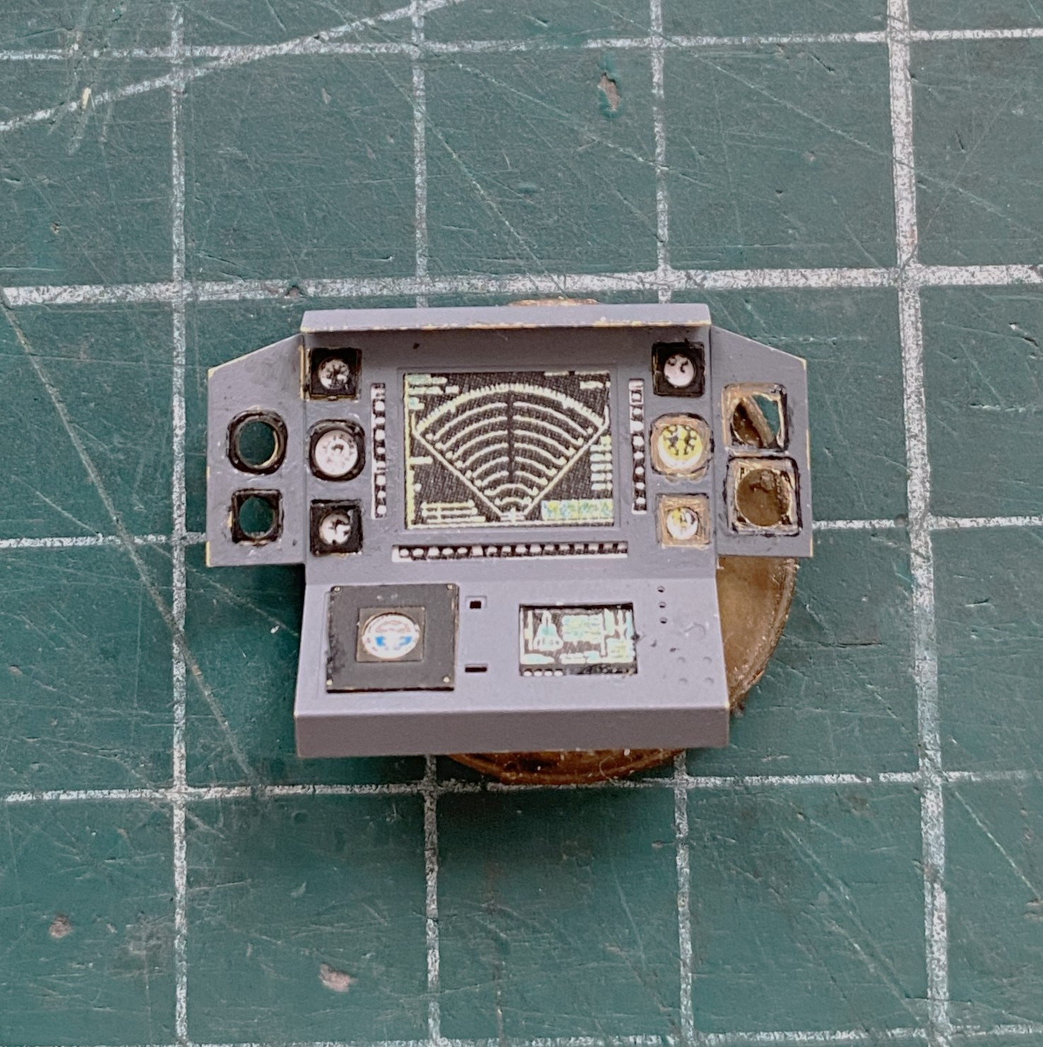
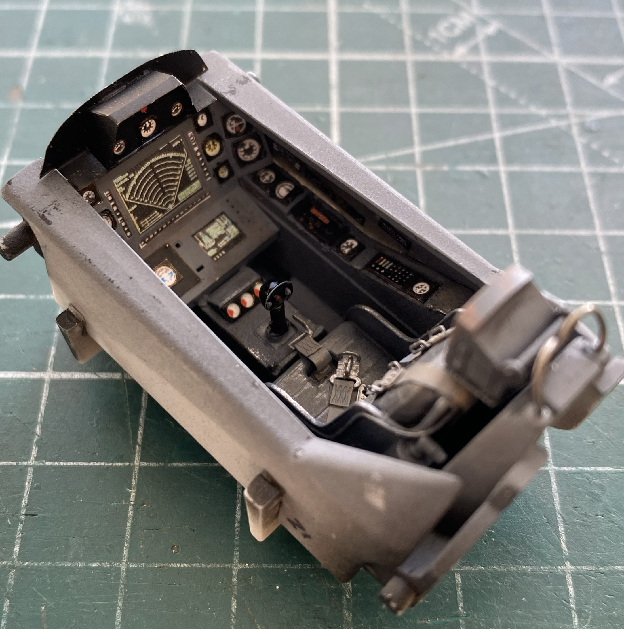
The main panel is basically formed, dry-fit, and checked for fit (good):
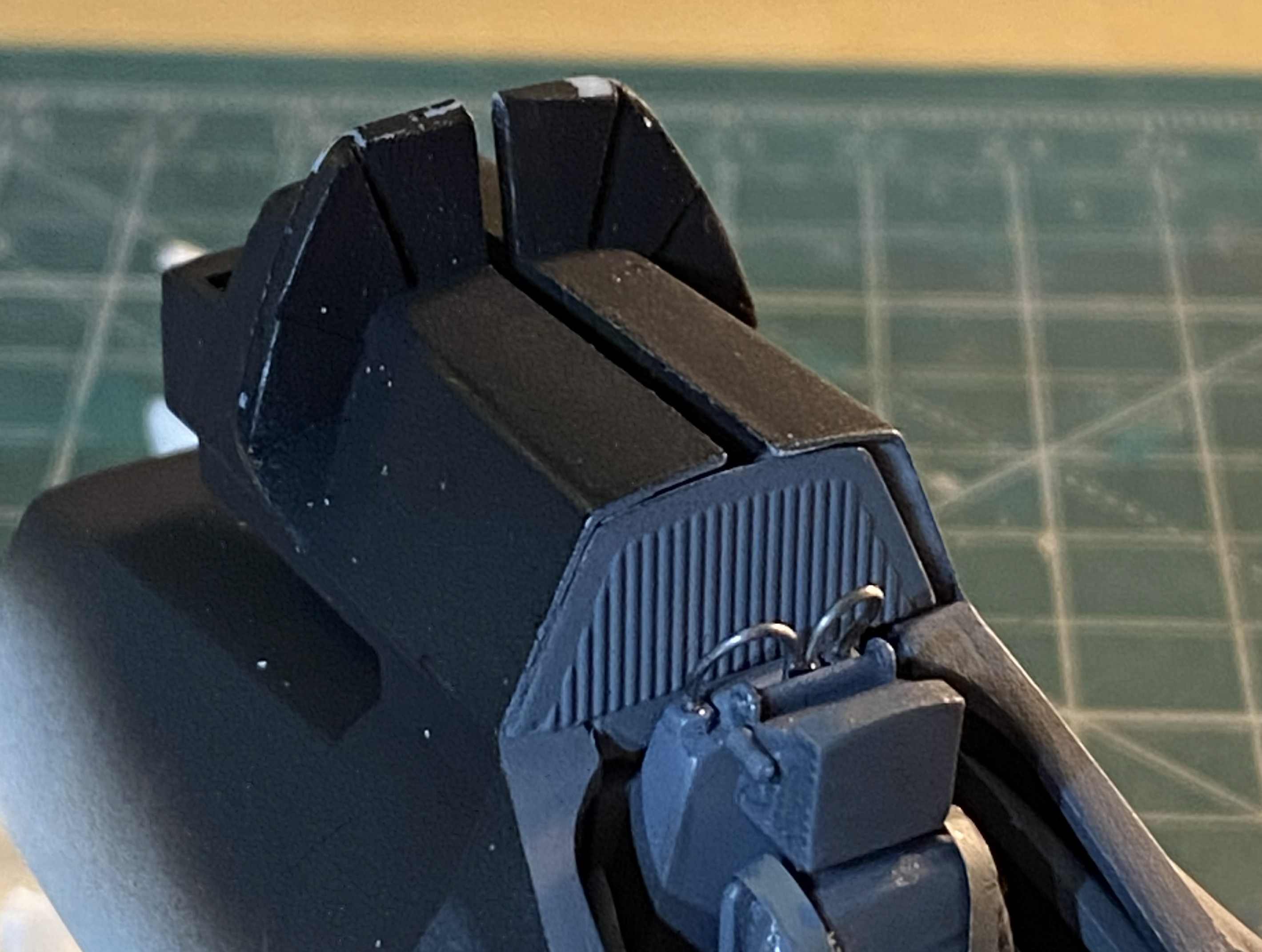
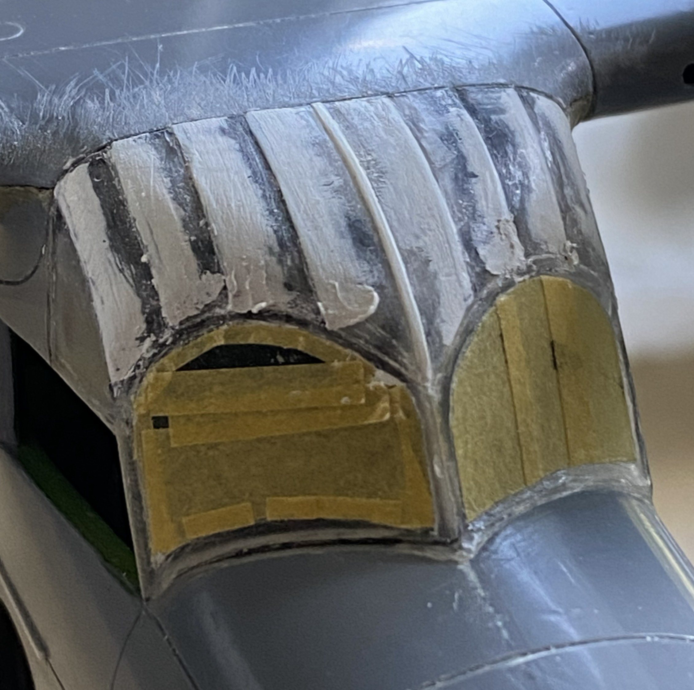
The engine intakes have blades for the intakes. Well, two out of three intakes. They look cool but are utterly unrealistic (and foundational theme for this build). The third intake is just a flat surface and of course it’s right up there in ones’ face(s), so I carved (another set of utterly unrealistic) fan blades into it. What the kit offers (one on both sides and the two of three intakes with fan blades):
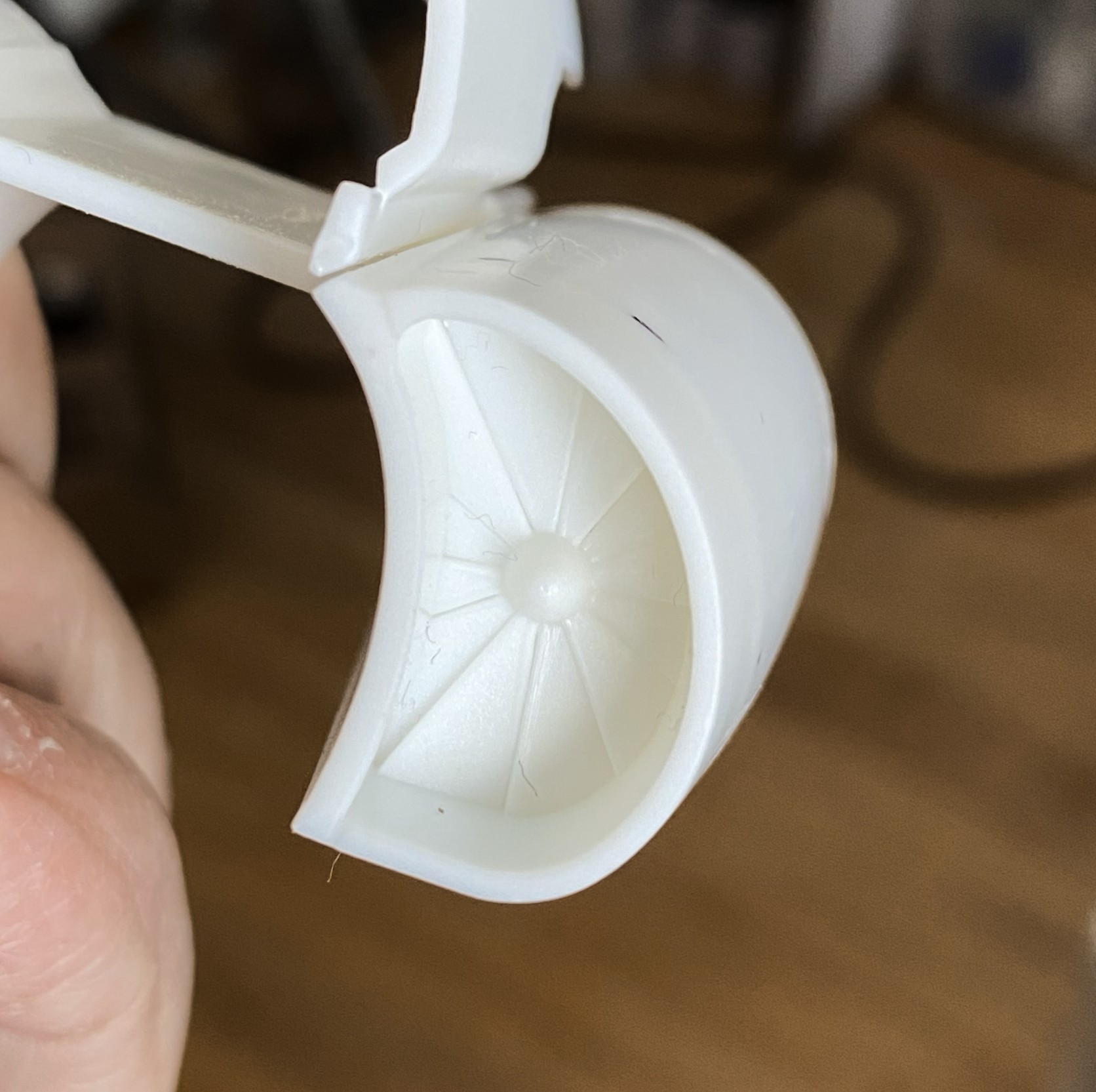
I started with this:
Drew the leading edges of the blades and checked appearance:

Then I sharpened all my scalpels and knives and started carving:

I cleaned up the edges/surfaces after taking the above photo.
First paint. These are the parts that get shot with Tamiya XF-1 Flat Black because I like the effects I get from pre-shading:
There:
For the overall cockpit color I used Tamiya’s XF-53 Neutral Gray, no scale color correction, and just misted it on:
Set that to the side and started work on the main panel:

I continued to do the side panels of the cockpit:
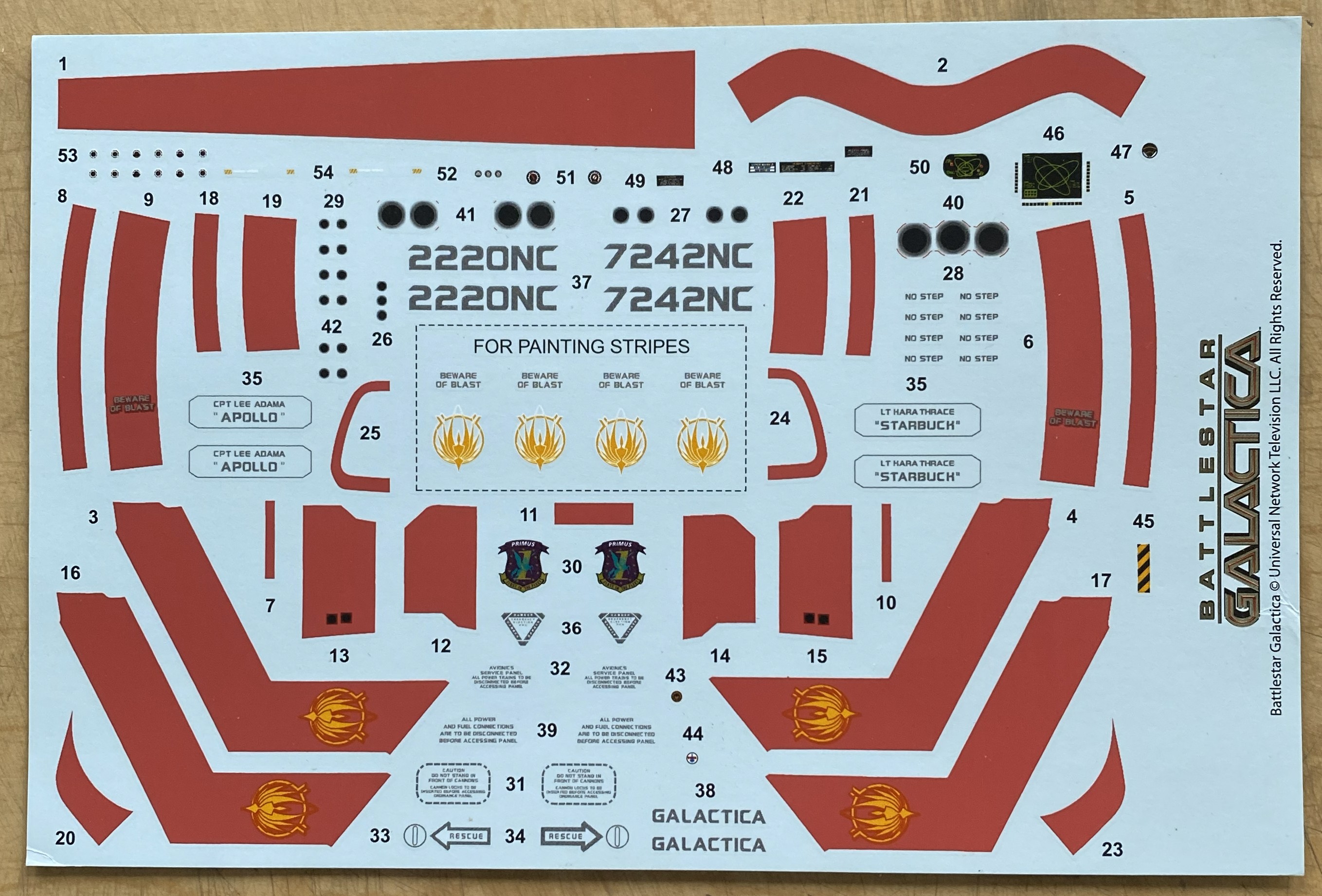
Preparatory to finishing the cockpit tub, I had to add decal data-plates to the sides and this is the first major uh-oh of the build. The first decal did not want to release from the backing paper. At. All. I let it sit in the (warm) water until the sodding thing just floated off. How I managed to fish it out of the water without folding it is one of Life’s Mysteries ™. Since I was pretty sure that whatever adhesive used to be on the decal was also floating in the water, I used Micro Set to convince them that this was their new home. That’s when I encountered the second uh-oh…the decal broke while I was trying to move it into a less inaccurate location (see the blue arrow):
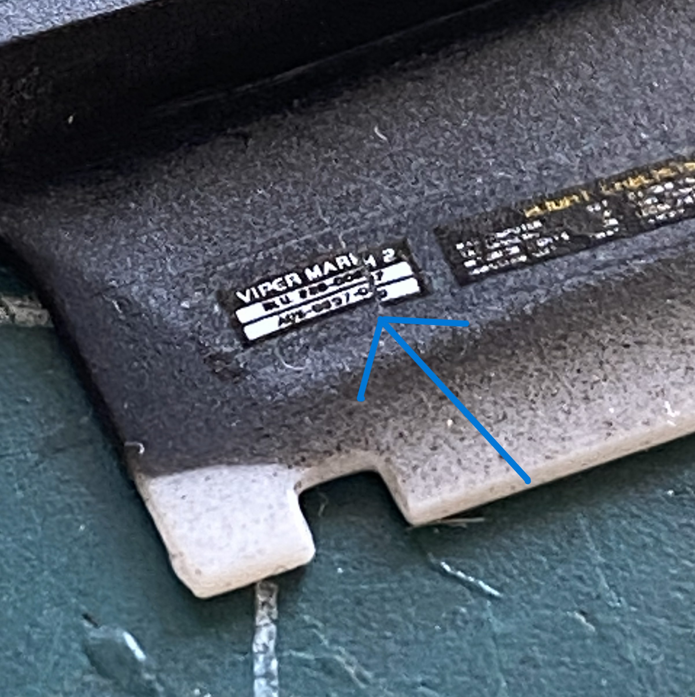
Not only did it break, it broke because the left side of that decal, once it hit the surface, would not move at all. Instead, it tore. This isn’t boding well for the other decals. I hope I’m just being an alarmist.
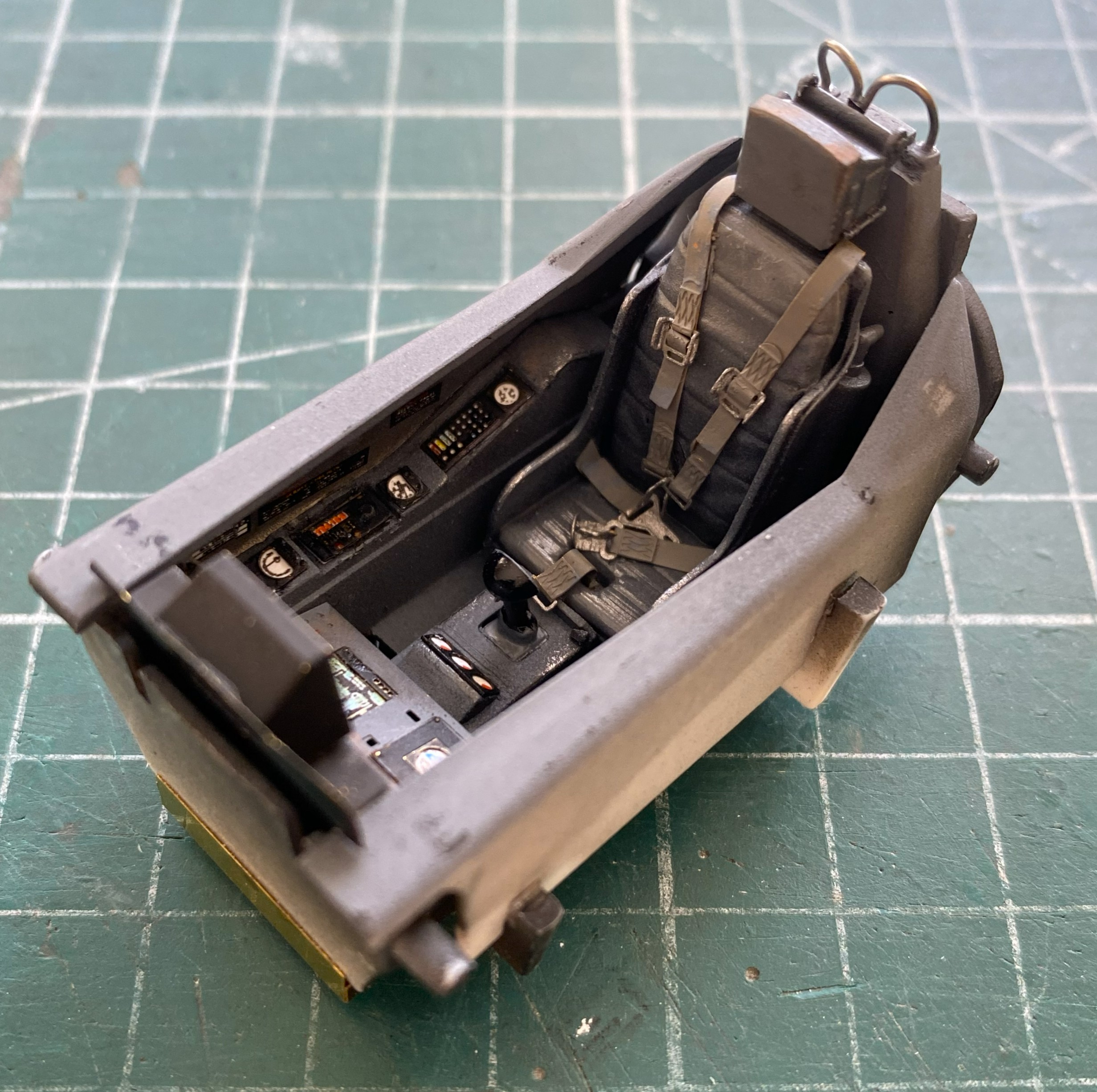
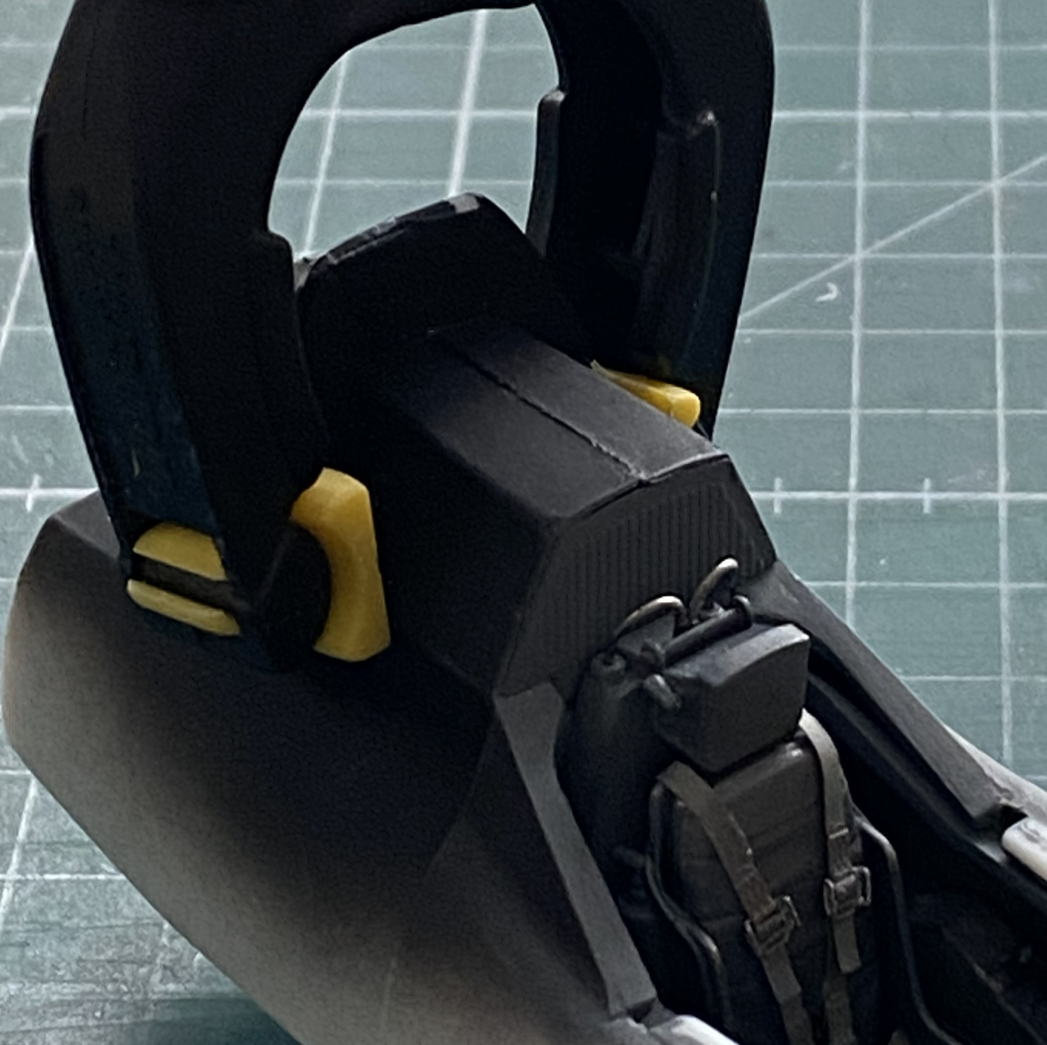
I didn’t have any trouble at all painting and installing the harness:
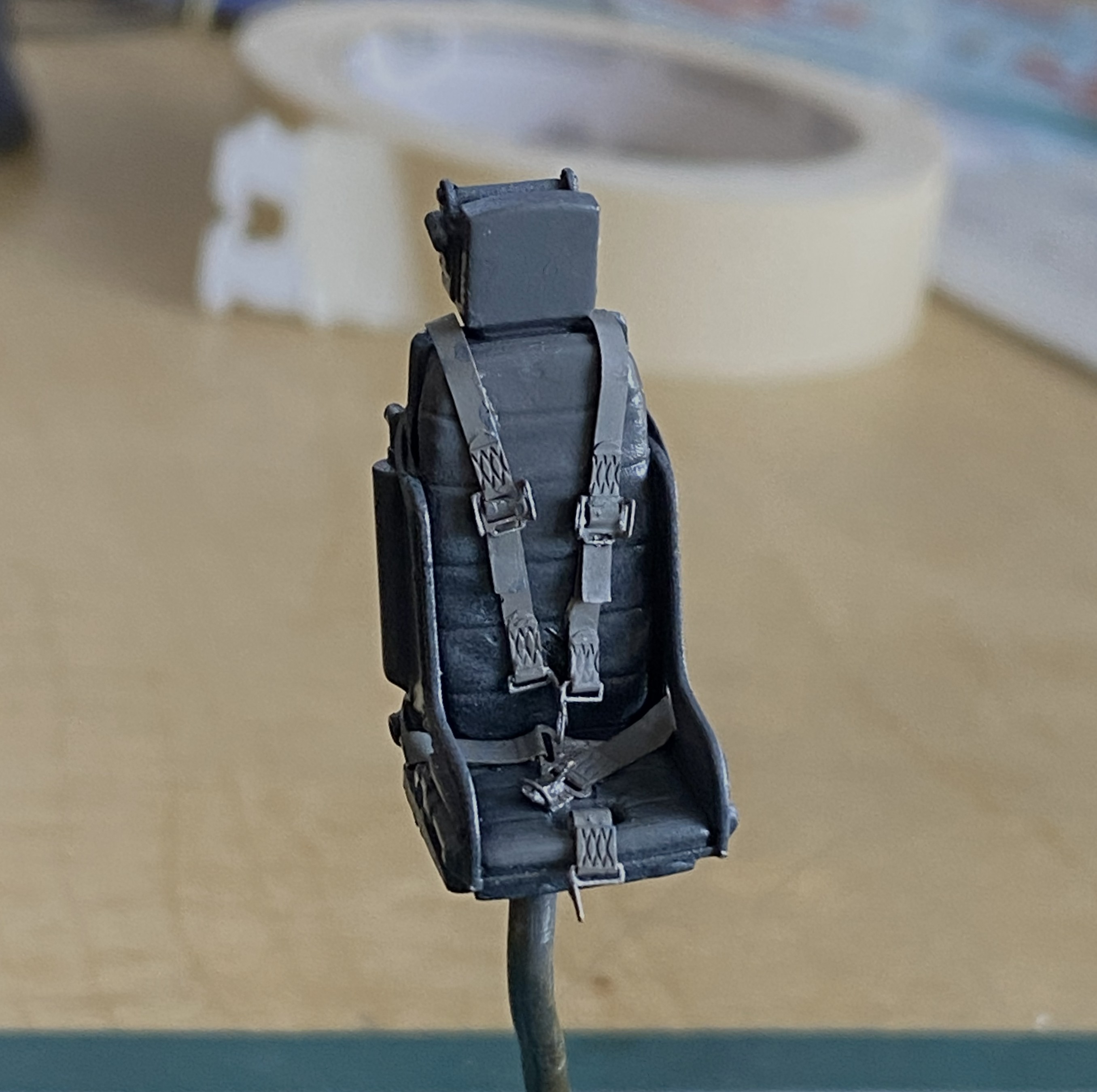
The first step to applying wear and staining was judicious use of the silver pencil. I added friction-wear (as opposed to impact-wear) marks as well as some pastels to make the office looked lived-in (and the sharper-eyed amongst you will note that I also affixed the throttle and joystick as well as the mystery loops behind the headrest, using 0.020″ (.508mm) solder) :

The side rails are just dry-fitted to get a sense of what stains show, where wear goes, and how much of it looks correct:
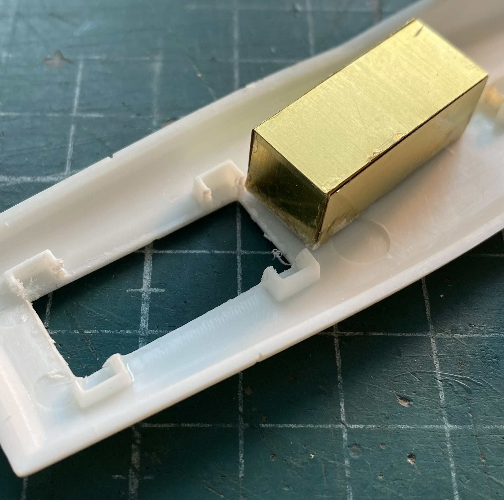
The belly of the fuselage is molded separately from the sides. Clever. It obviates most of the belly seam. To add the AM details, the main fuselage has to be cut away to allow the AM space (more on that later, too) to socket in place:
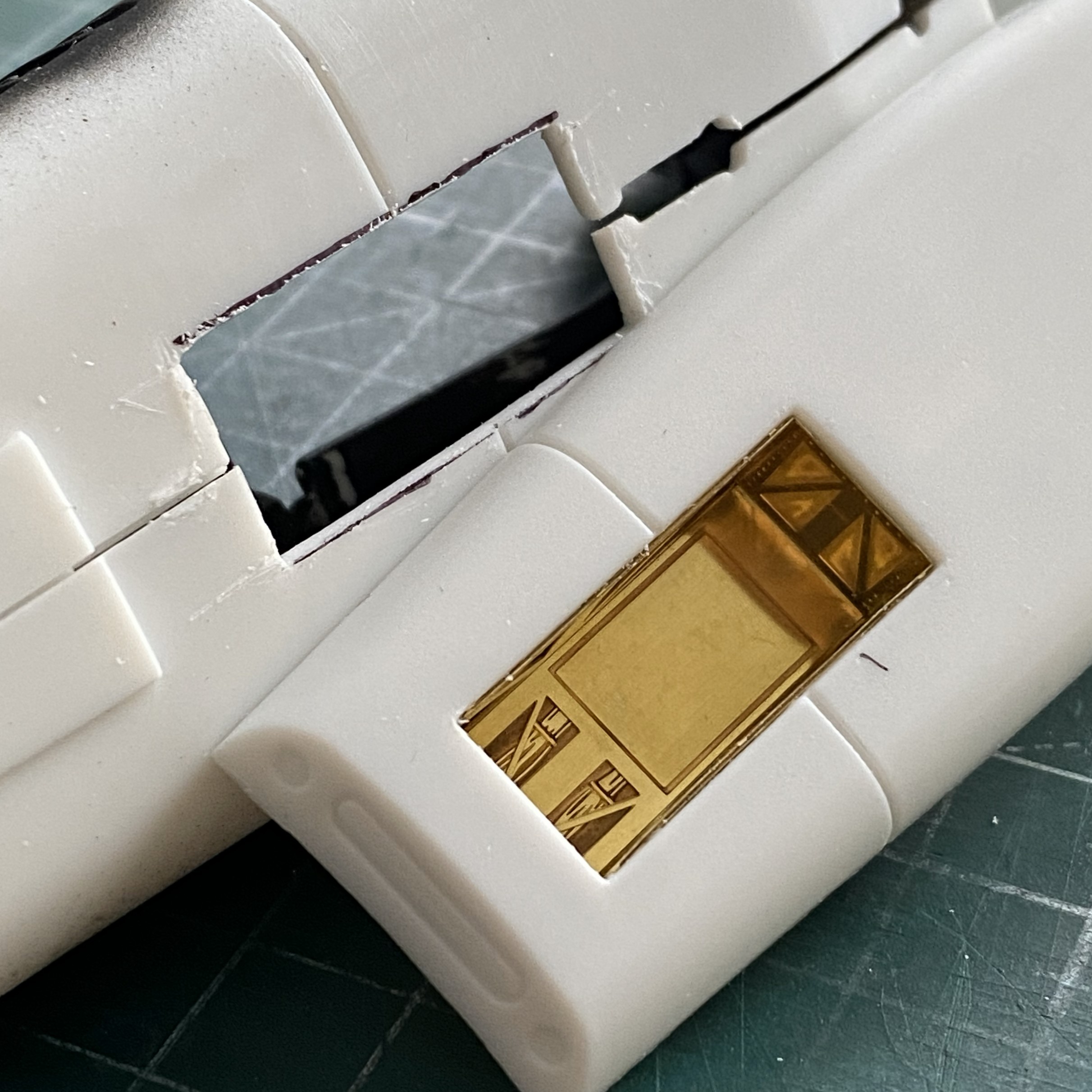
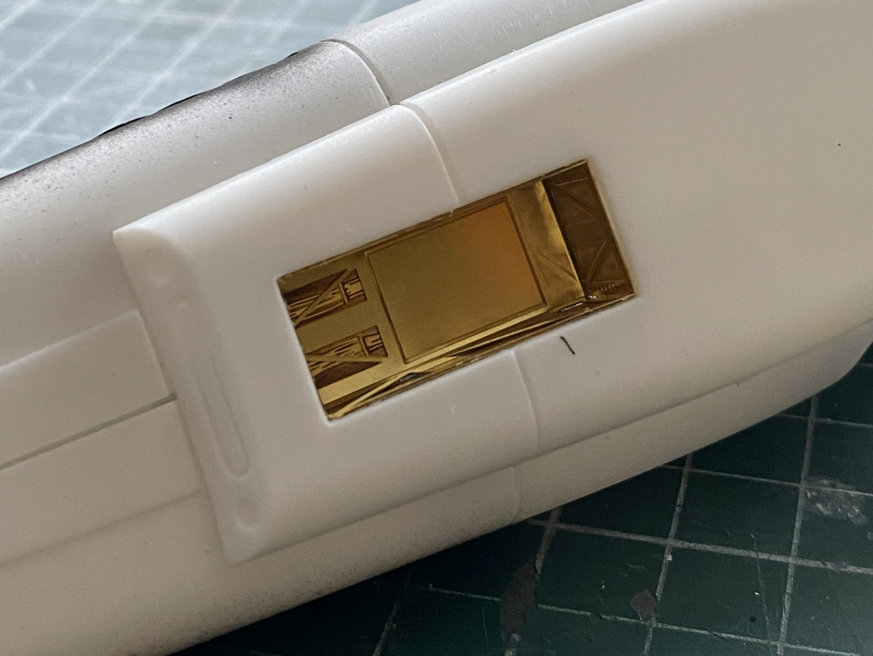
Since the cockpit was done, all detailed, painted, worn, and dirtied, I added it to the fuselage and glued the fuselage halves together:
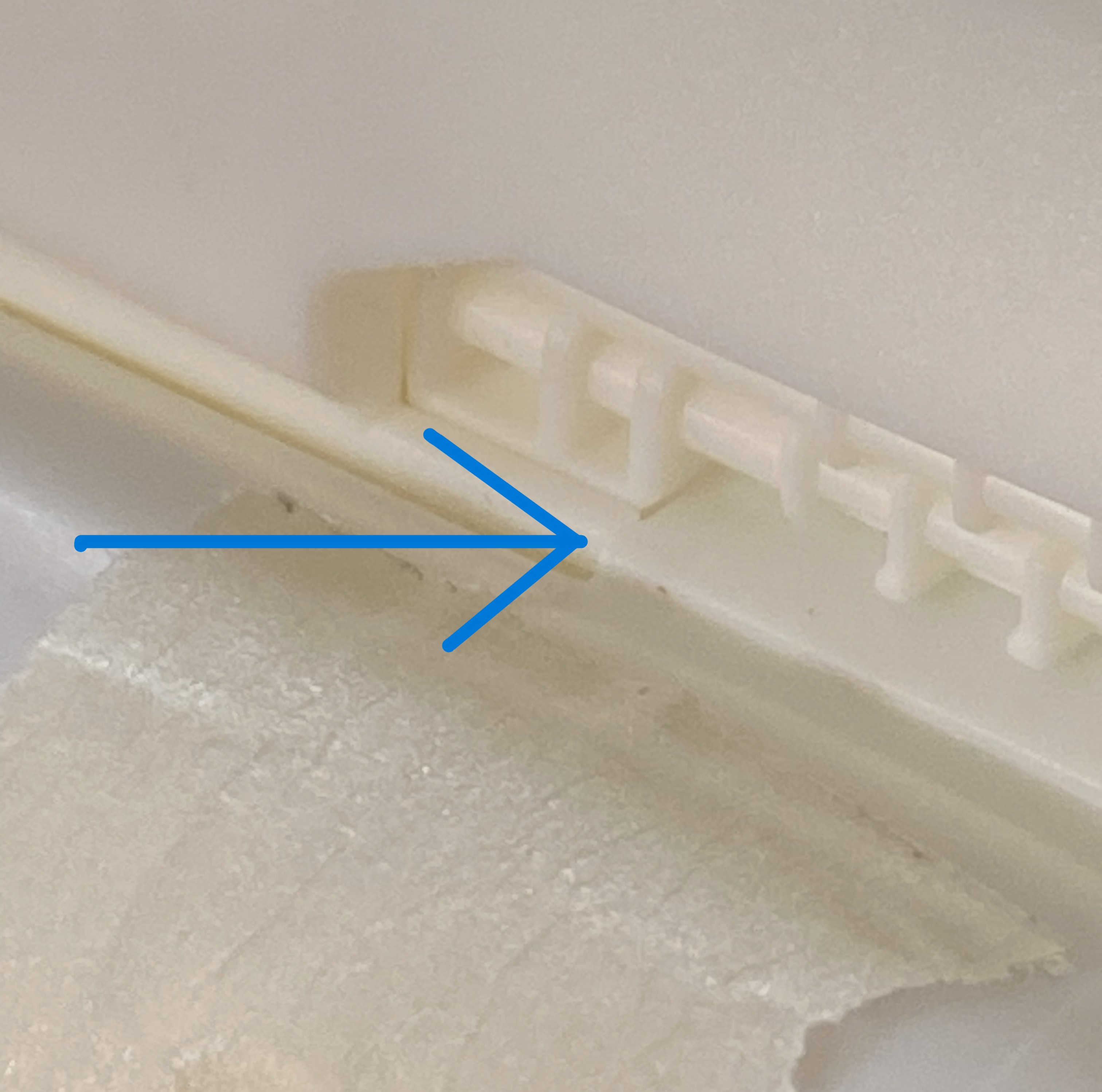
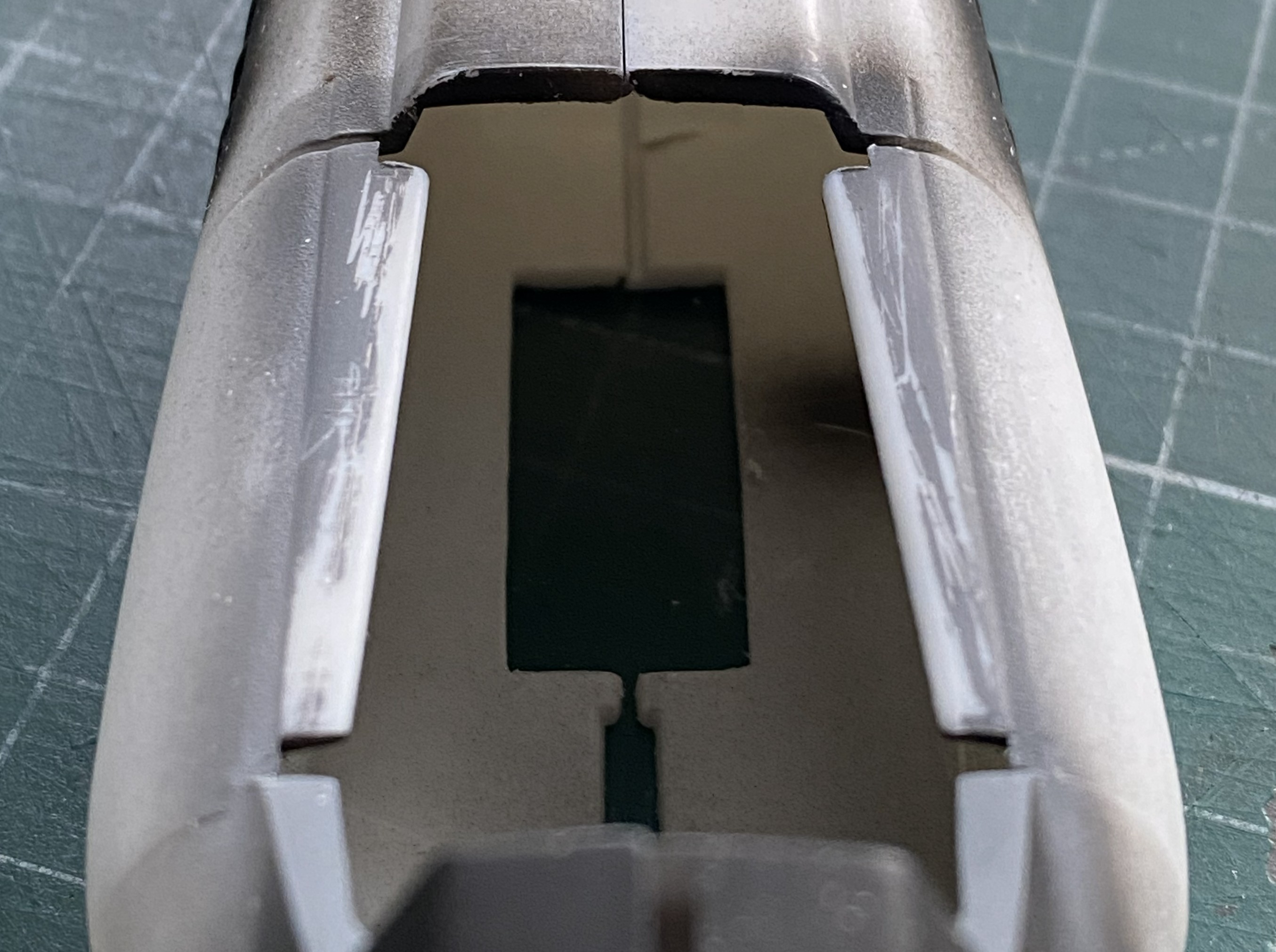
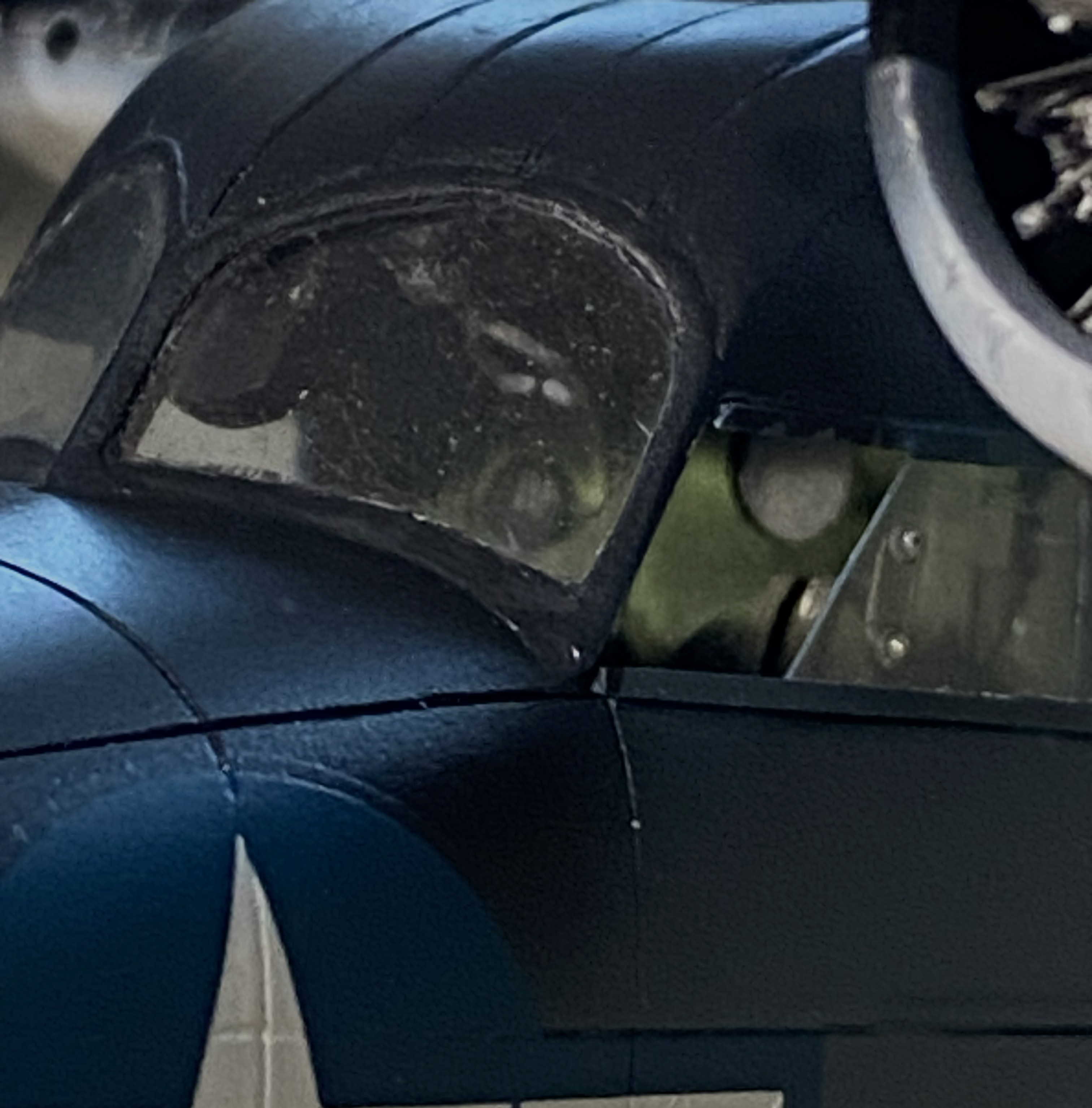
Then I put the belly in place (almost) and noticed that the top of the gear bay impacts the front floor of the cockpit (which is also an AM part from the same manufacturer for the same kit…guess nobody checked to see if it would fit) (again, check the blue arrow):

And speaking of fit, force will be required here (again torpedoing the notion that force never solves anything) to get these two parts to meet:
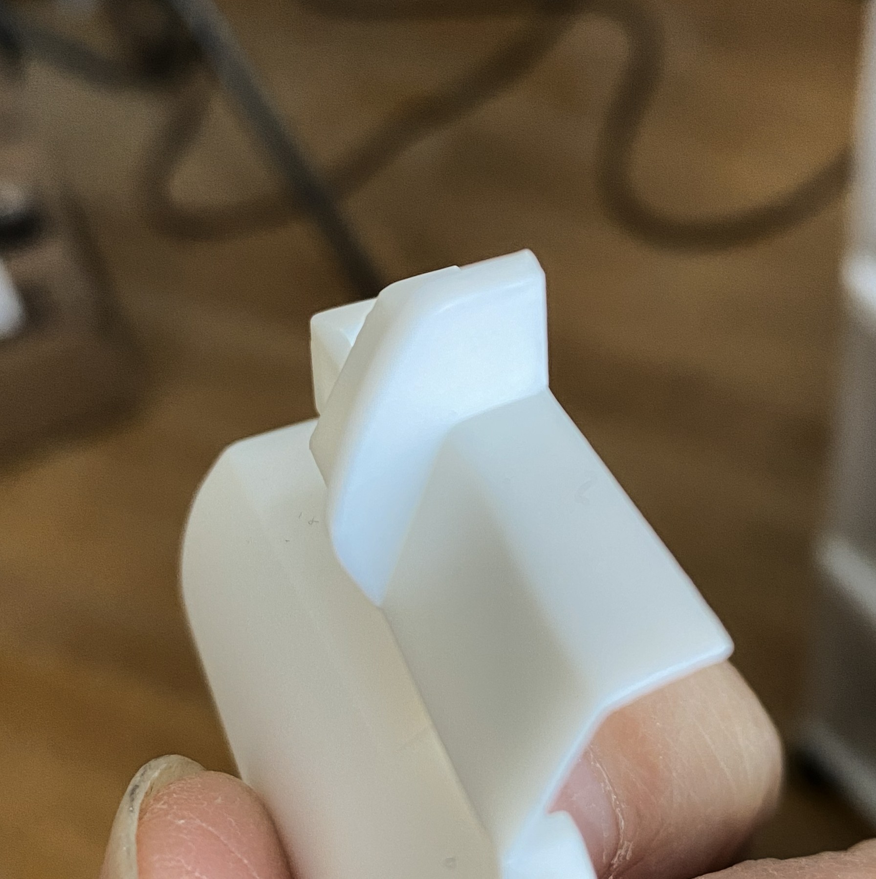
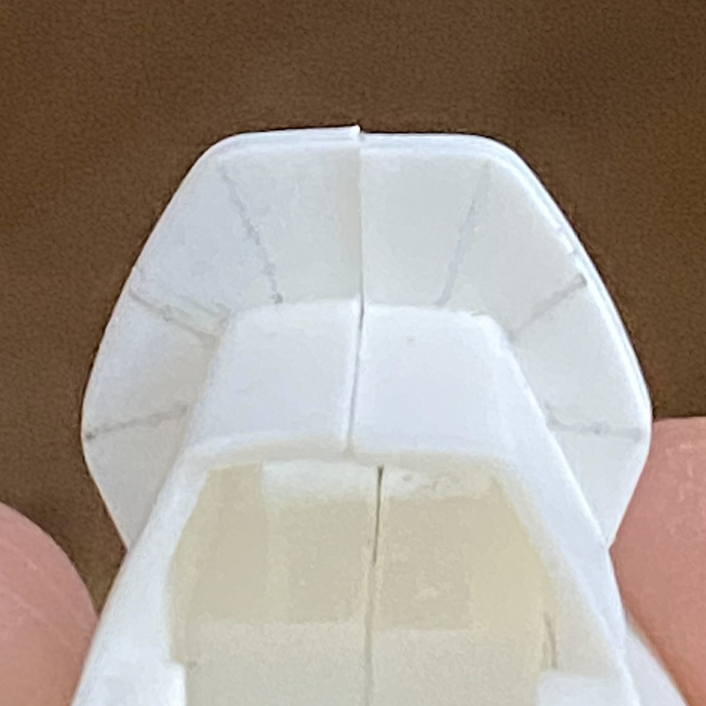
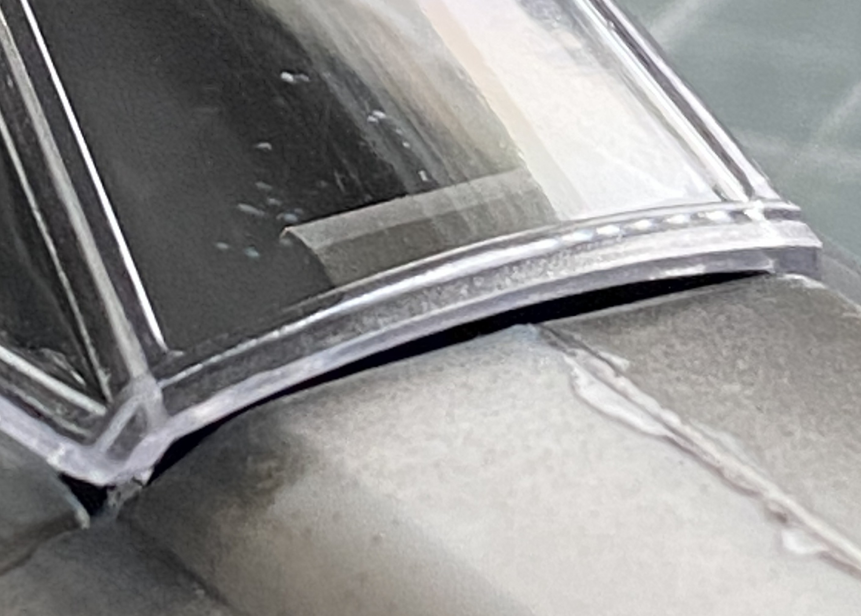
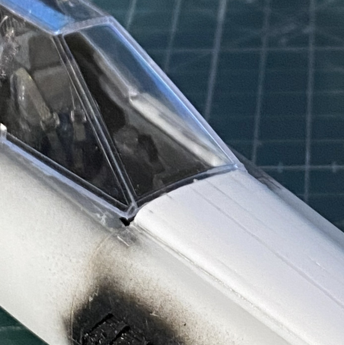
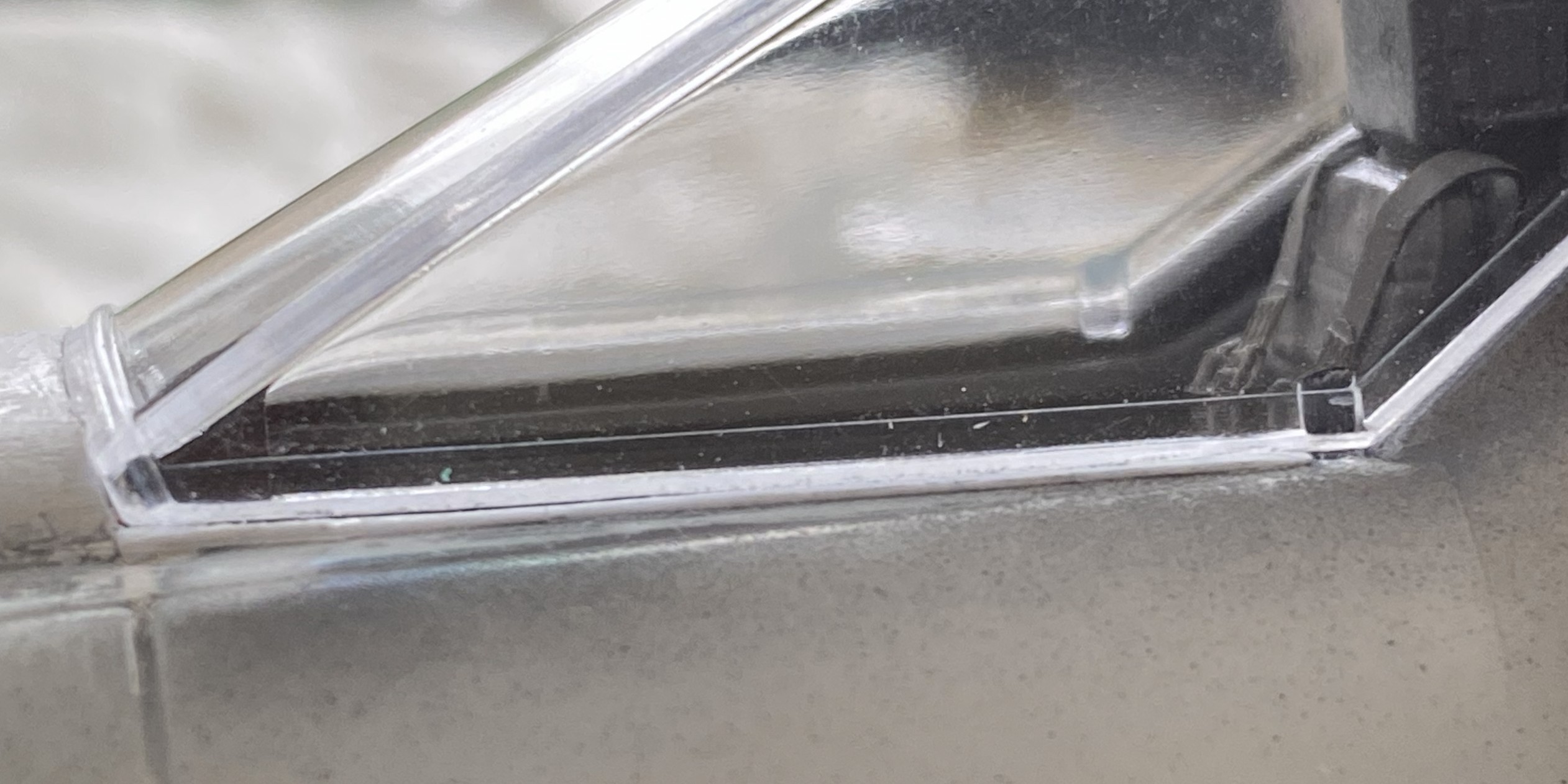
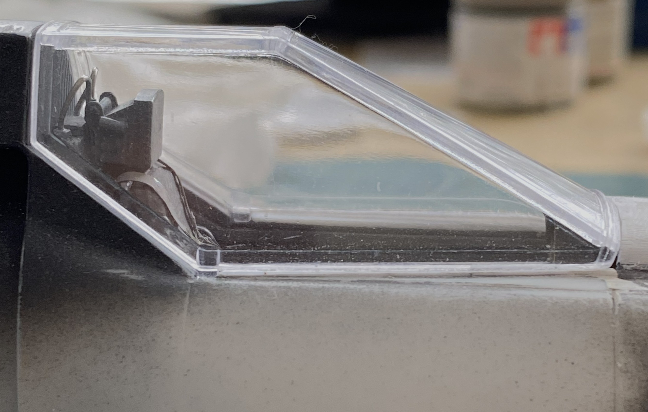
And while I was checking the fit of things, I took that beautifully cast canopy, put it in place, and realized that it didn’t fit well, either:

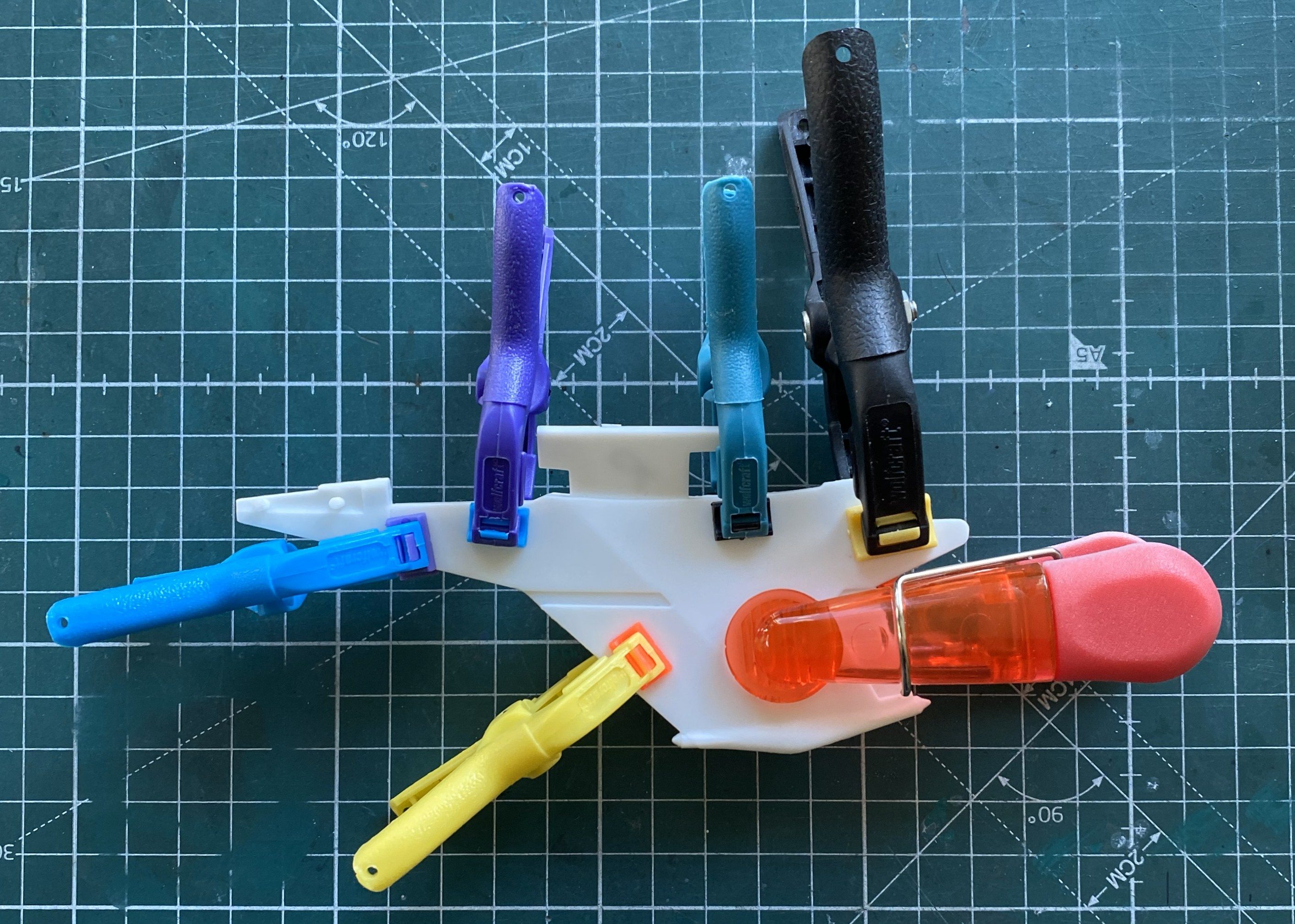
While I’m here and looking at the lousy join of this seam, I clamped it most puissantly:
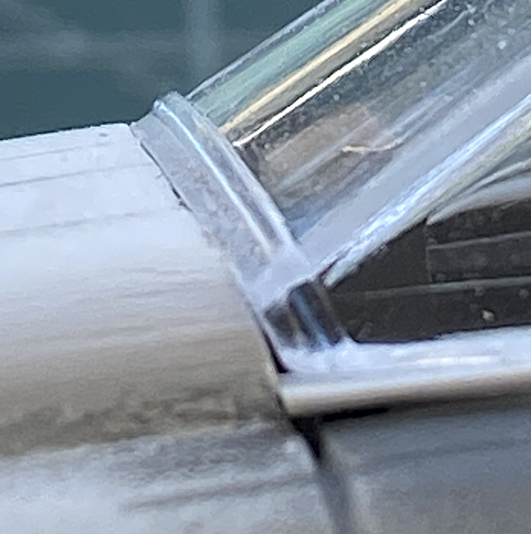
The sides don’t fit either. They’re supposed to seal the cockpit, which will require the surfaces of the canopy to touch the places of the fuselage it should touch:
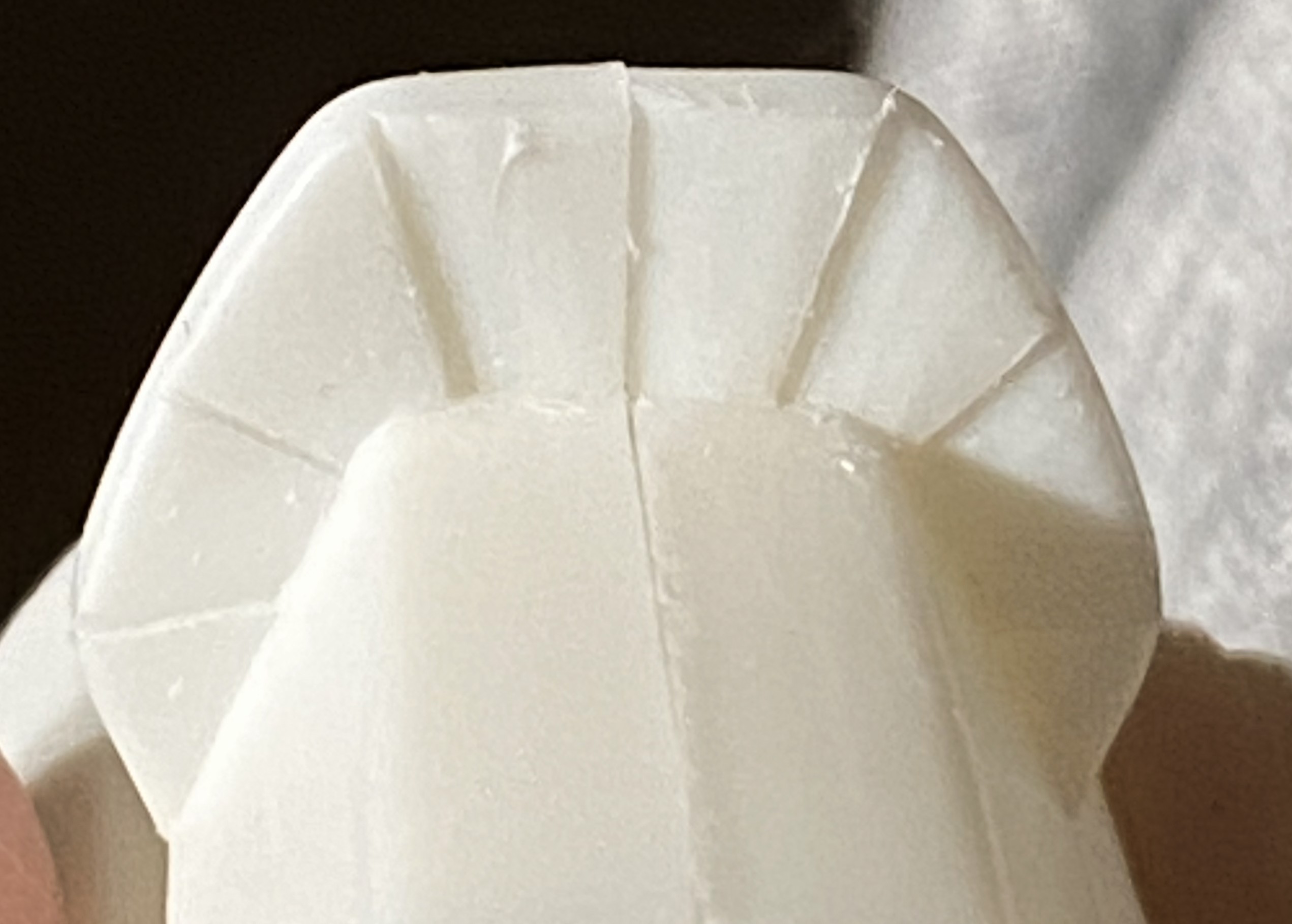
And note how well the leading contact edge of the canopy meets the fuselage:
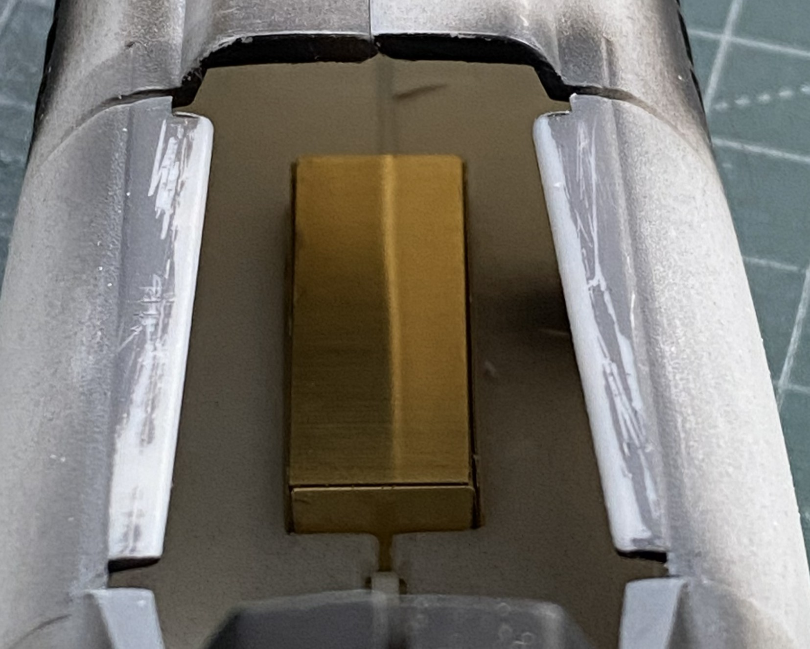
I decided to make the nose gear and belly pan fit first. That required me to cut free the PE part from all the glue I used to hold it there (because, since the nose landing gear attaches to the PE part, it had to be securely glued), which took the better part of an hour (didn’t want to damage the delicate PE, y’know). It also took a few tools to accomplish as well:
After cleaning the dead glue off of surfaces, it was time to refit it only this time accounting for the intrusion of the cockpit floor. The belly was taped in place and then the gear bay stuffed into the hole until it would go no further:

Since there was going to be cutting and filing of the exposed areas, I glued that PE part in securely and started work until the edges were flush with the fuselage:

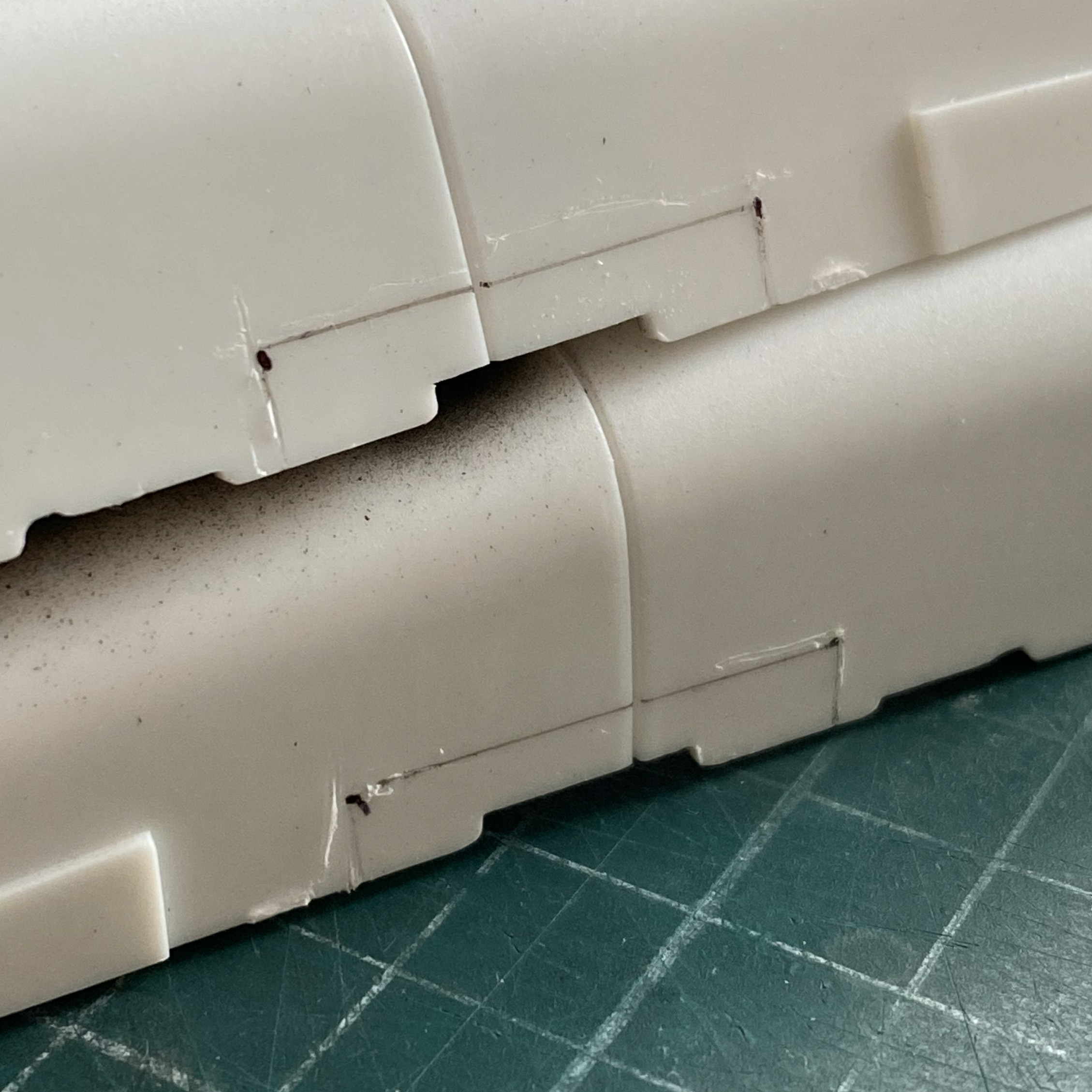
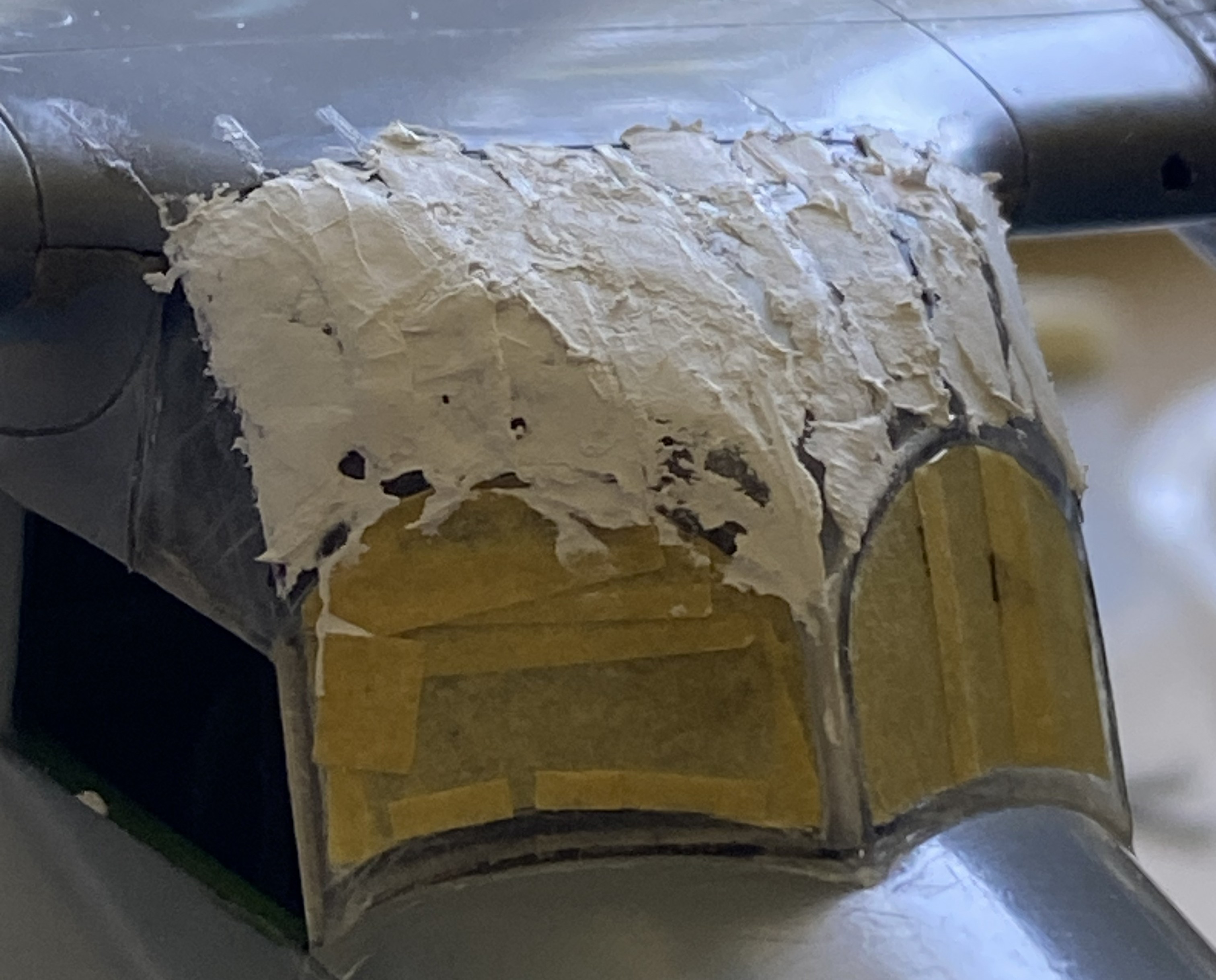
Having put the sword o’ Damocles back into its sheath, I turned my attention to fixing the canopy’s fit. What do I fix? All references show that the upper fuselage in front of the canopy is flat. Do I rework the canopy to fit? Or… The canopy is clear and fairly delicate. Could I rework the clear part? Yep. (The Goose build taught me that.) Do I want to do significant surgery on a part I can’t replace? (Okay, sure. I could replace it. But what a freaking job that would be and the canopy would be at risk throughout the process.) No. So that means that I have to build up the nose to match it and do it in such a manner as to be unnoticed. Okay, that seems like a grand idea!
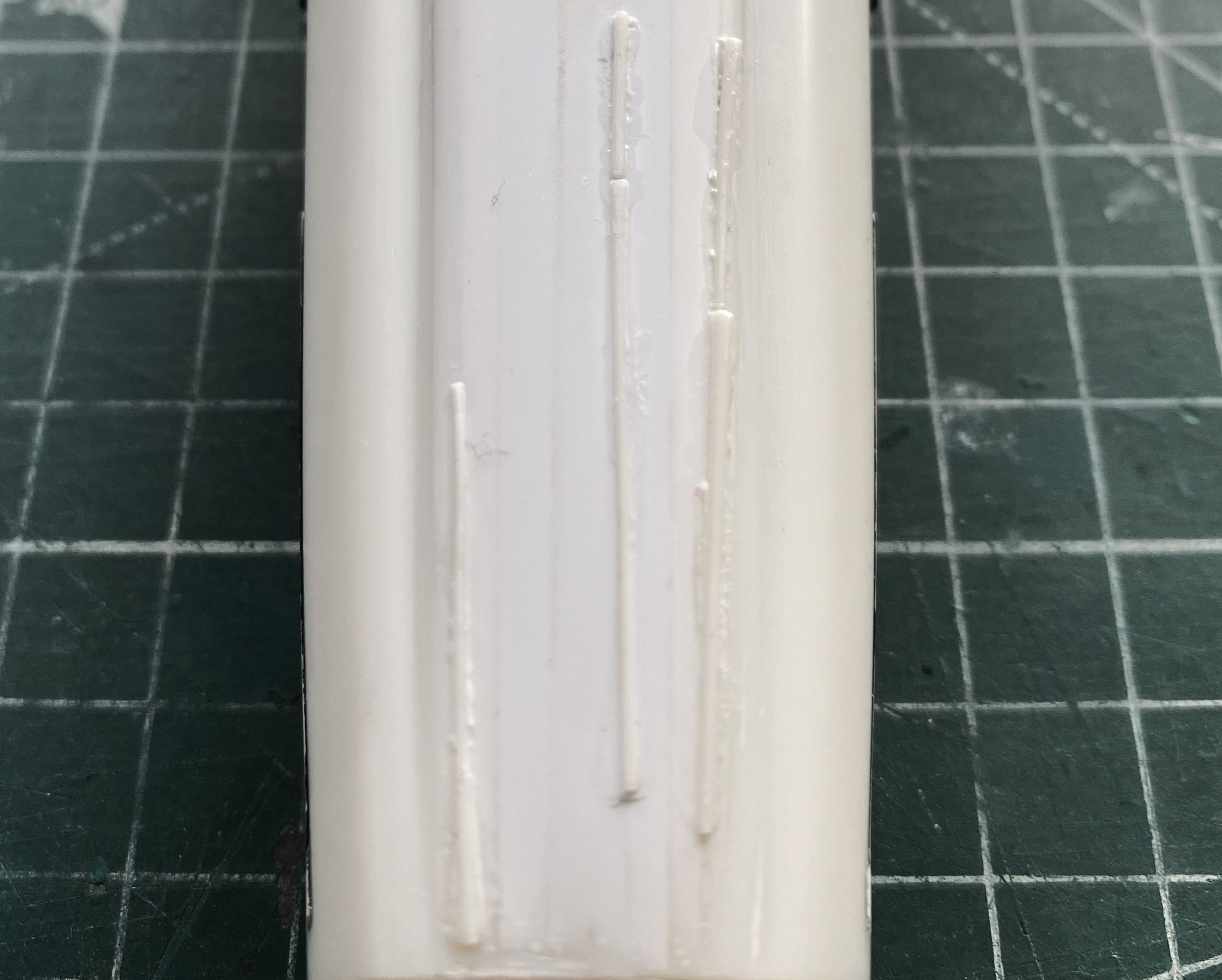
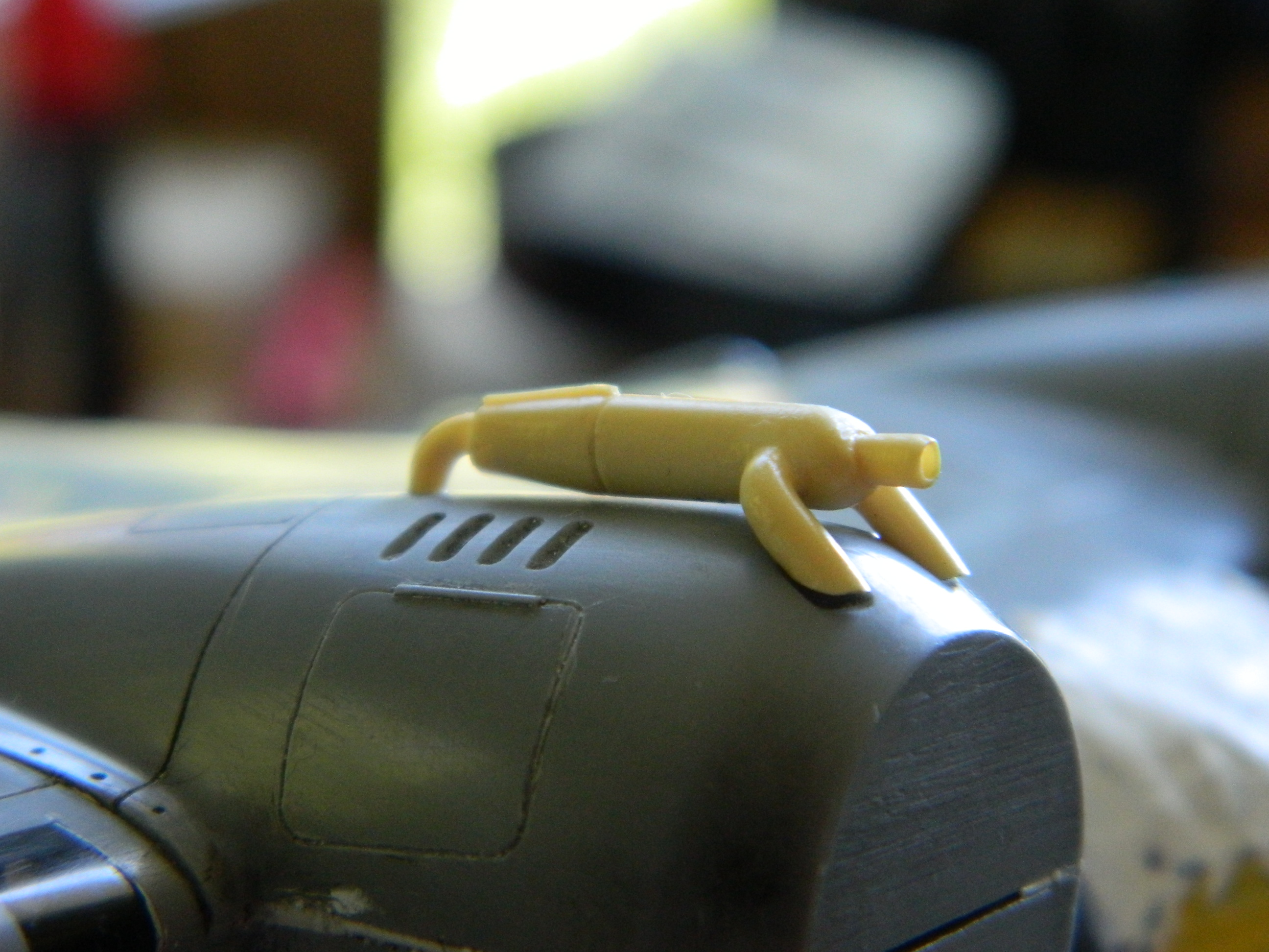
That grand idea started with me laying down strips of styrene from 0.040″ (1.016mm) to 0.020″ (.508mm) with liberal applications of glue:
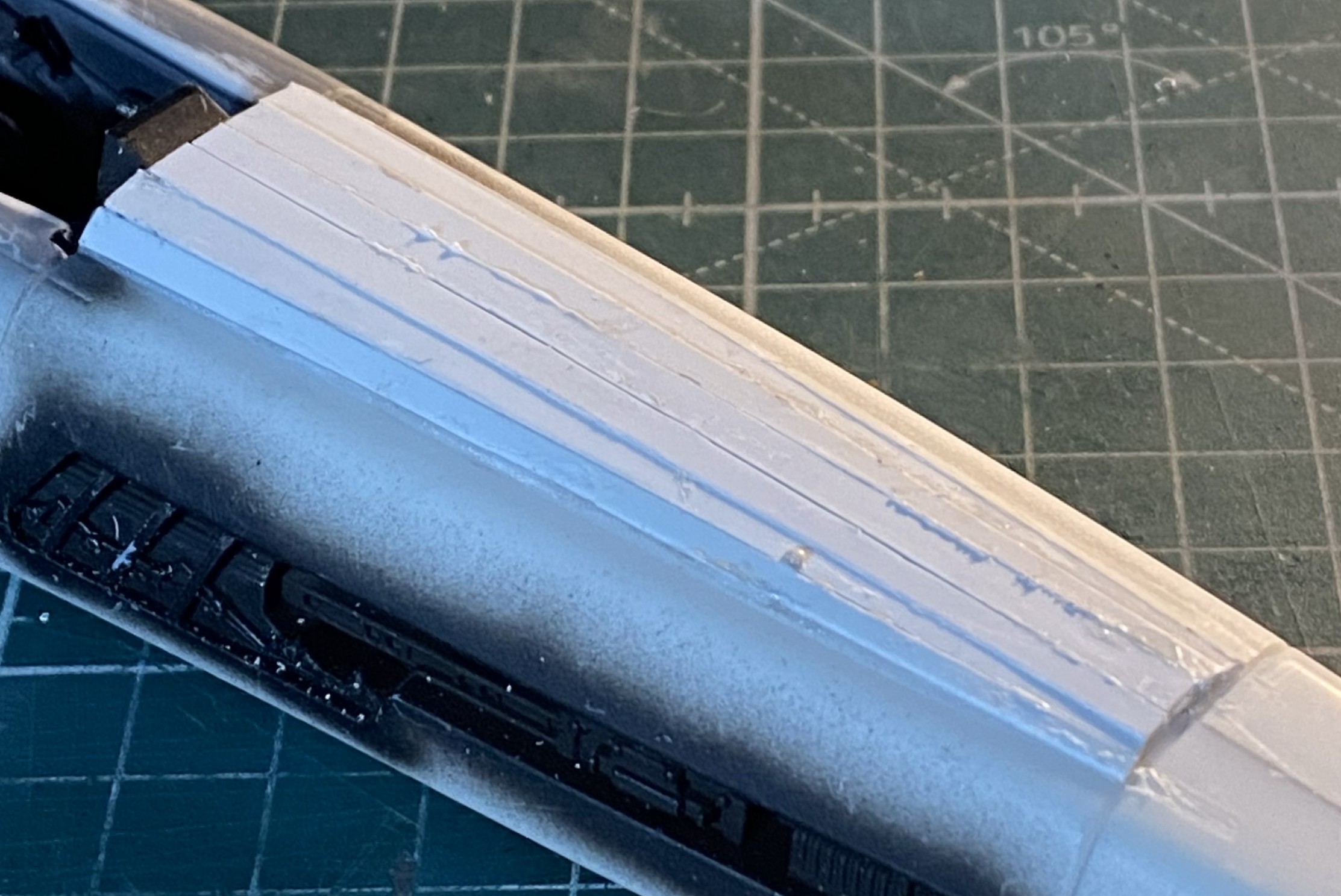
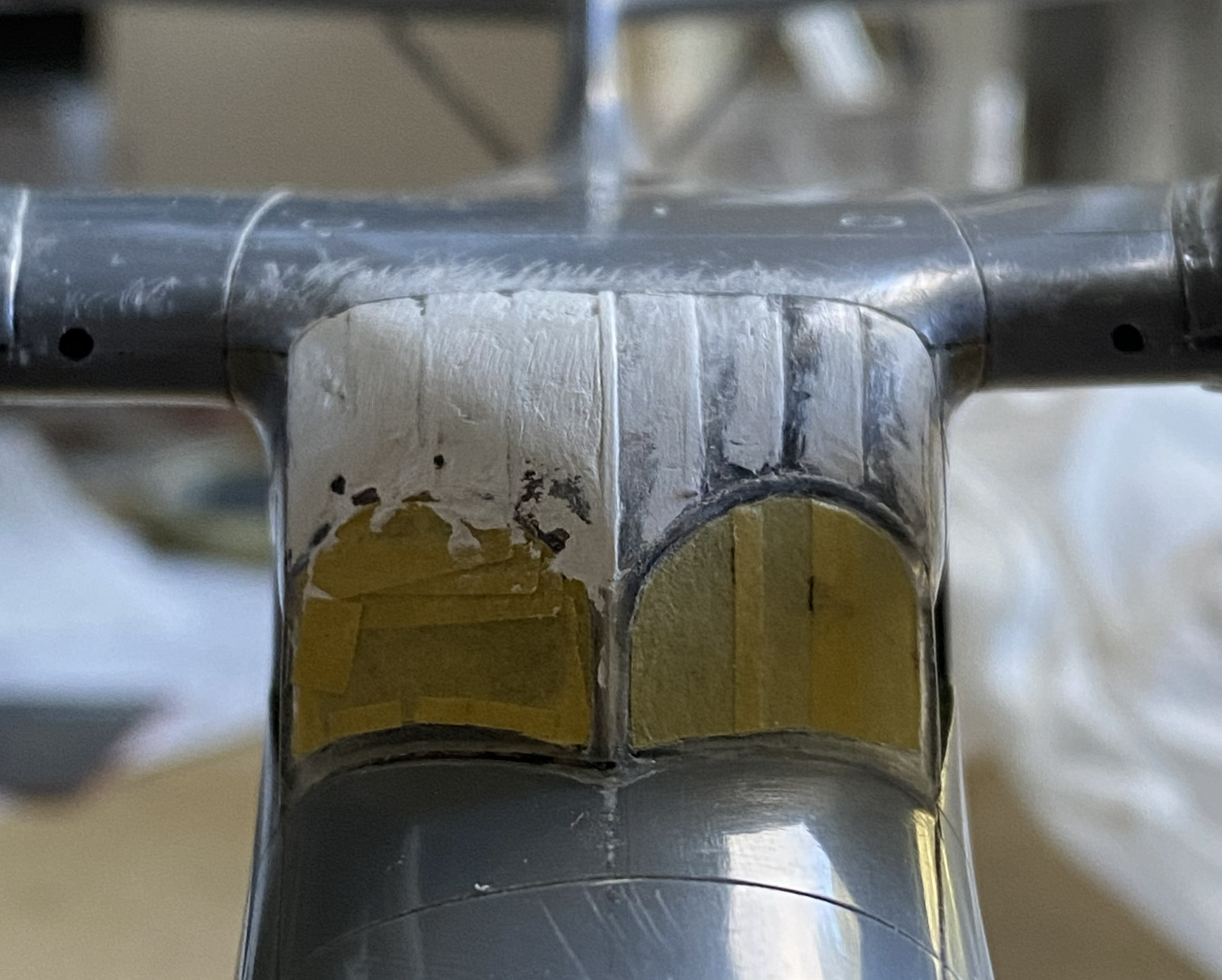
I let it sit overnight before starting to shape it. I started with 50 grit and worked my way past 100 grit and down to 220 grit, at which point gaps started to open up. Stretched sprue to the rescue:
Making a curved surface with flat panels means that each panel will be thicker in the center than at the edges (arcs, y’know). As the surface is removed and shaped correctly, the thin edges of those flat panels start showing gaps. That’s okay. I knew it would most likely happen and I have a lot of sprue I can stretch:
While those were curing, I started fitting the canopy. I added small bits of scrap plastic, putties, and got the two edges to meet at the front:
In the above photo, at the lower edge where the canopy meets the fuselage, you can see a 0.020″ (.205mm) spacer that I’m using to start filling the gaps at the sides of the canopy. Once the gaps are established, it’s just the sometimes-tedious job of filling them with scrap (mostly 0.010″ .254mm) and a bit of 0.020″ (.205mm)):
This post surprised me. It wasn’t until I started working on this post that I realized how much work I’ve done on this; it certainly didn’t feel like it. Anyway, I’m going to stop here. Yes, there’s more. I think I’ve already stuffed enough into one post. I’ll finish this one up (edit checks) and start the next one tomorrow.
Grumman JRF Goose (Czech Model) 1/48 Scale Build #7 – Staggering Towards the Finish…and Getting There
This is the danger-point for me, being so close to the end that I have to be careful not to rush things. Couple that with the reality that I despise this kit, I have to double the caution.
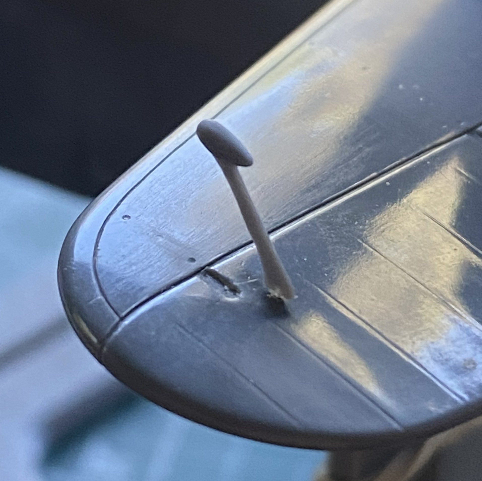
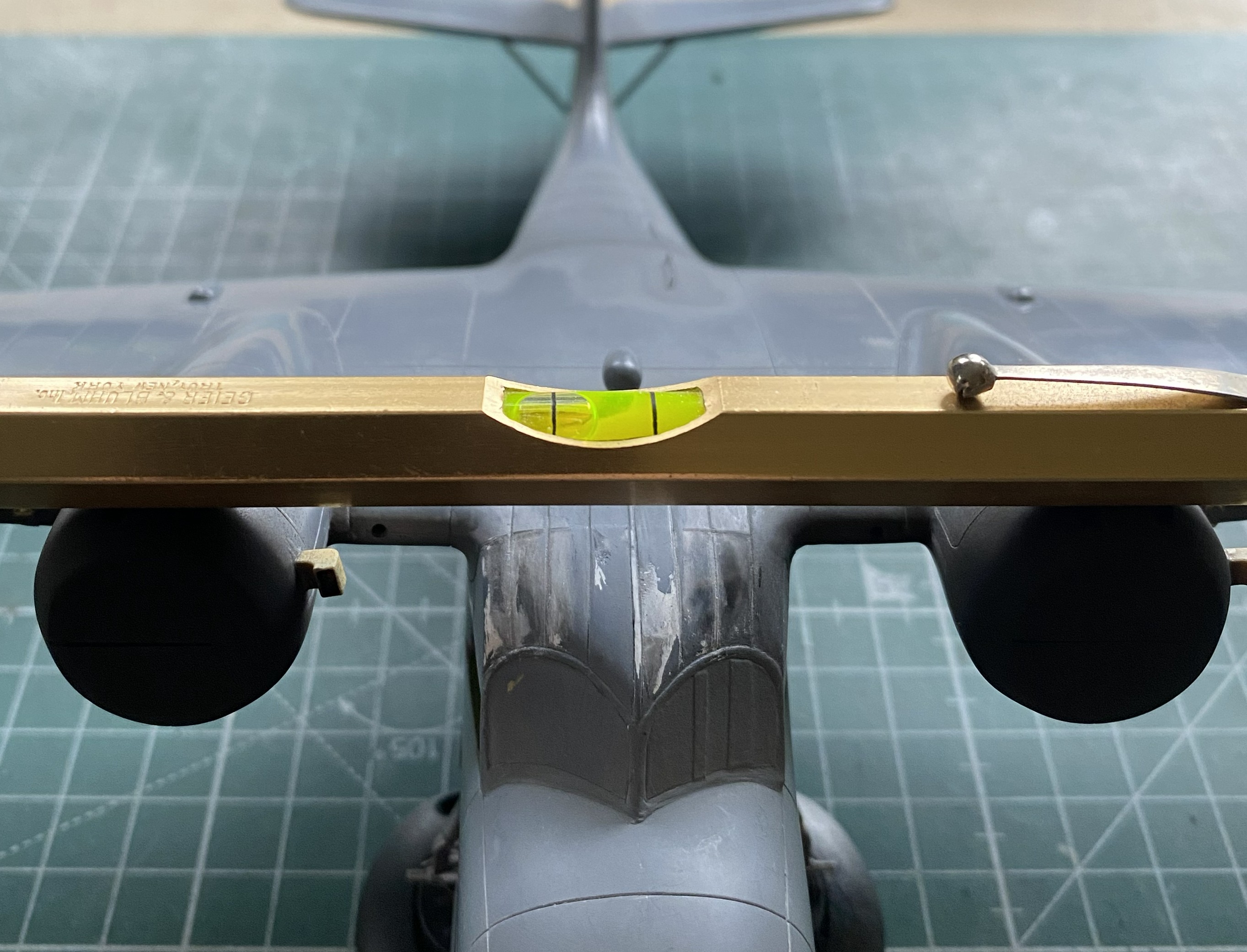
I started with what I perceived would be the biggest hassle and that was getting the wing level, and I wasn’t entirely incorrect. As it sits in this photo, the bubble indicates that the wing isn’t level:

At the center of the model, that bubble isn’t far off. At the wingtips it is. I bent my brain around several corners trying to figure out the best solution. I’m of the opinion that it is not uncommon for a given problem to have more than one solution, except that solutions to problems usually come with new problems (and the solution is enacted if the new problem is less than the old problem). And speaking of problems, here’s a short (I hope) examination as to what the problem is, not what I’d rather it be.
The struts of the landing gear fits into the top of the landing gear bay. The landing gear bays were not molded onto the fuselage sides. As I found out well after I’d added the landing gear bays, the sides of the fuselage do not match dimensionally. Yeah. Who knew that would be a problem. It certainly wasn’t Czech Models. However, with one landing gear bay higher from the bottom than the other, and the landing gear goes there, should I be surprised that once the aircraft is assembled that it doesn’t sit level? I was when I first found the dimensions (and shapes) did not match from side to side, but after I thought about it (a lot), I knew that by the time I got to this point of the build, I’d have this new problem to solve. ::facepalm::
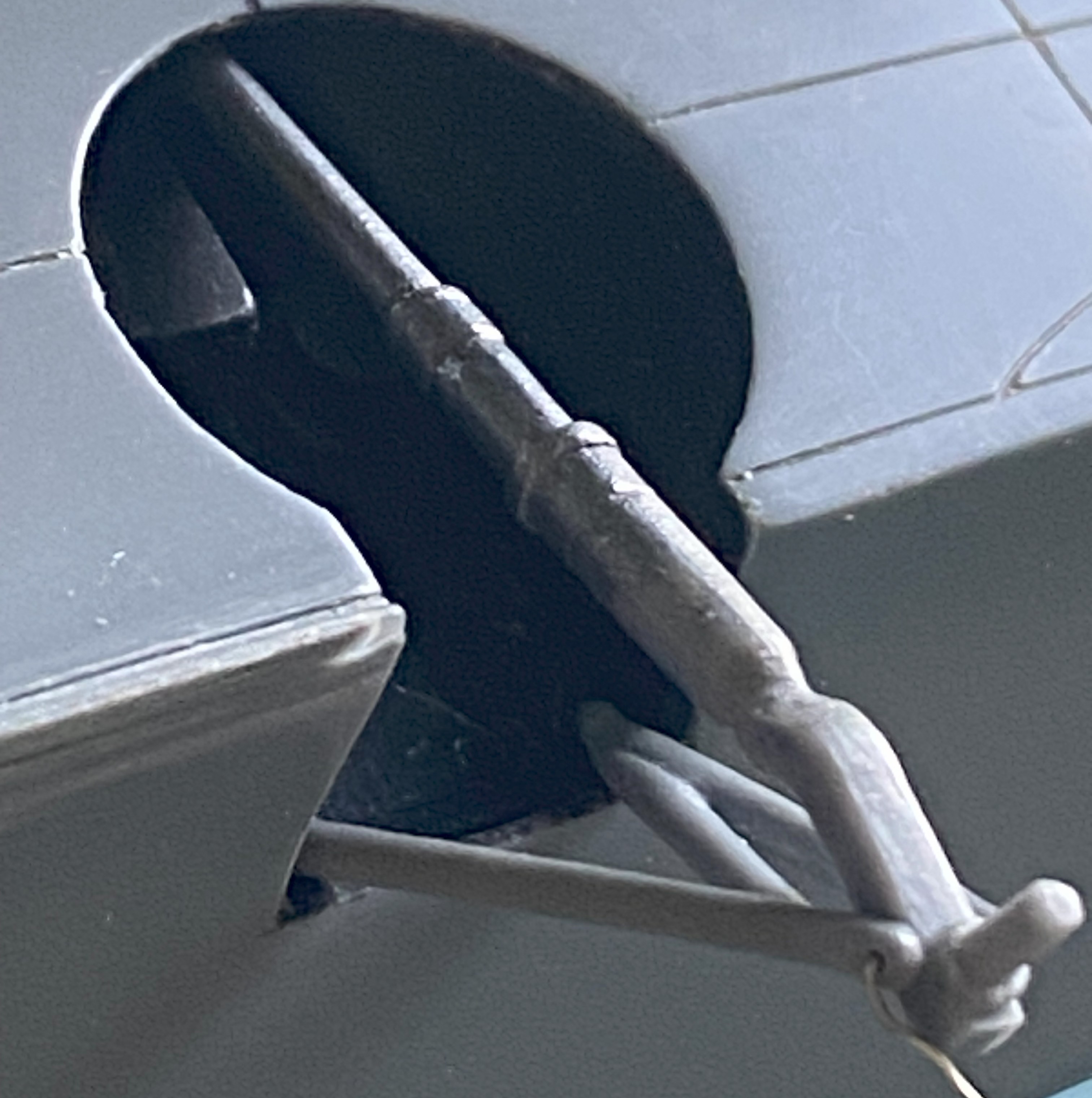
Since I saw this problem as a geometry problem, I looked into the geometry of the landing gear. Being more than a little frustrated at this point, I dry-fit the wheels onto the landing gear and pressed firmly down on top of the model until the bubble was centered. Just as the bubble centered, I heard a soft crack as something broke loose…but the bubble was still level. Took a bit of investigation but I found what broke loose. The blue arrow in the photo below points to where the upper control arm snapped away from the strut leaving this gap:

Hmm. So, if I fit a spacer between the strut and control arm, will that make the wing level? The answer was, “mostly”, which I discovered once I’d cut a spacer from 0.030″ (.762mm) and checked:

I trimmed the spacer without gluing it in and checked again. This time I estimated that I needed another 0.005″ (.127mm) more:

And there it sodding is:

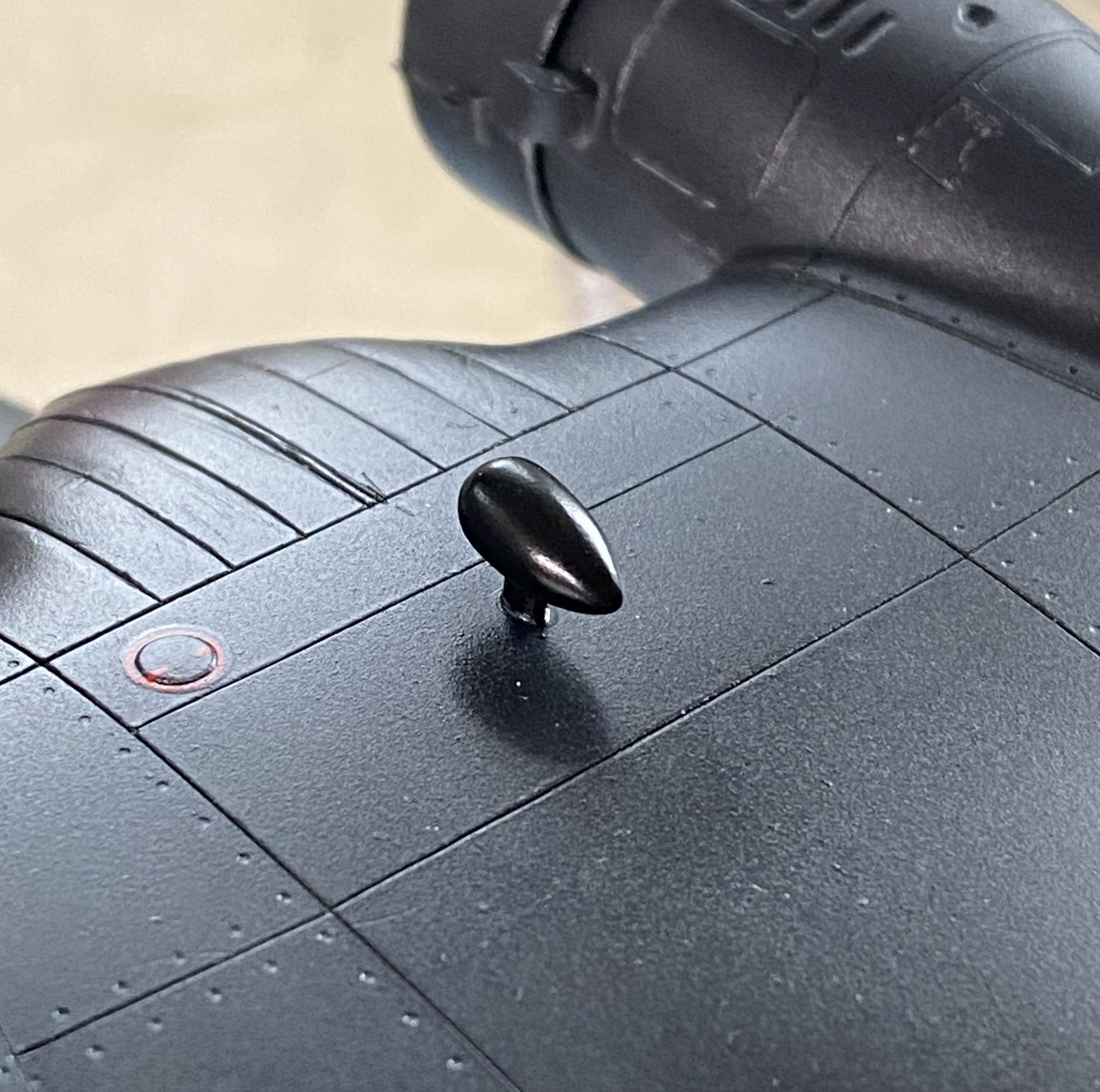
I think it’s the housing for an ADF head, but it needed to be painted semi-gloss black. So it was. I REALLY hate self-inflicted wounds, which is how I view overspray. When I aimed the airbrush at the football, NONE of the other painted surfaces were visible:
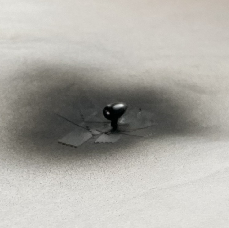
Success! Zero overspray:
I used 0.025″ (.635mm) as brake lines, painted them knowing full well that during the final bending process would cause paint to flake off. It was a lot easier to get at the parts that bent the paint away because there weren’t buried in the landing gear bay. I’ll get to these when touching up the paint happens (the photo’s on its side because I was using gravity to hold the solder where I wanted it to while the superglue set up):
And speaking of paint touch ups, I painted the frames of the cockpit windows off so that I could also paint under them. A solution that created a problem; paints don’t match once assembled. Okay, I’ll be doing touch-ups (with a small brush in these areas…the other side, though not as bad, is the same), just add this to the list:
You’ll also note that the cabin window just behind the flight deck is still masked. This was a problem I let sit as-is. When I tried to pry the masking tape away, three of the four sides of this window broke free. It was hanging on by paint. My memory isn’t what it once was (is anything?), but I DO remember what I had to go through to fix the one that came out already. Carve, fix, fill. Lots of fun when the plastic was unpainted, a no-go zone now that it has been painted. I supplemented the paint holding the window on with liberal applications of superglue. I’m pretty sure it’s going to stay there, now. It’s in a place where it will never be touched.
This one’s pushing the 90-95% accuracy I try to attain. I don’t care. A blocked off window is better than a sodding hole. Moving on…
Speaking of self-inflicted wounds, I noticed a week or so ago that there was blue overspray on the nose. ::adds to touch up list::

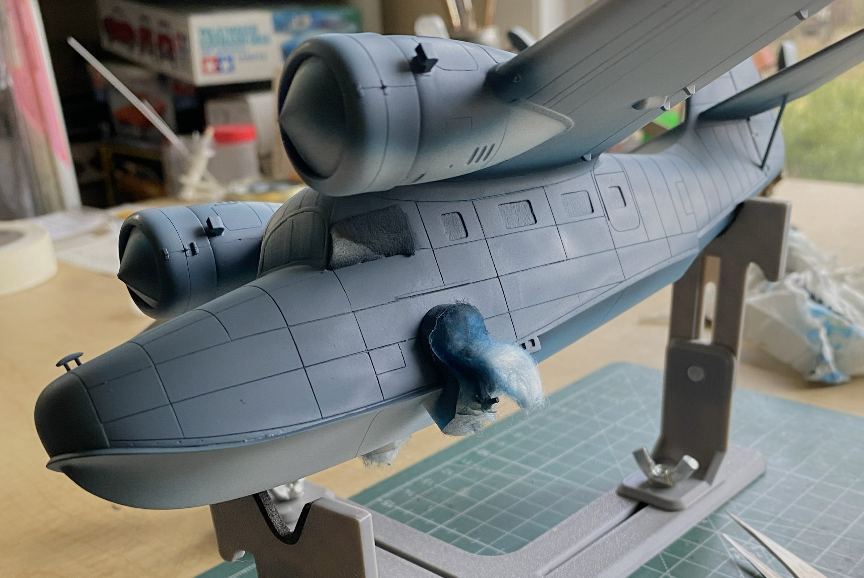
I added the heat exchangers (the brown things over the engine nacelles). Later on I’ll spiff them up a little bit with some pastels:
I added one of the landing gear “doors” just before beddy-bye so that the glue would set up; there’s not much gluing surface:

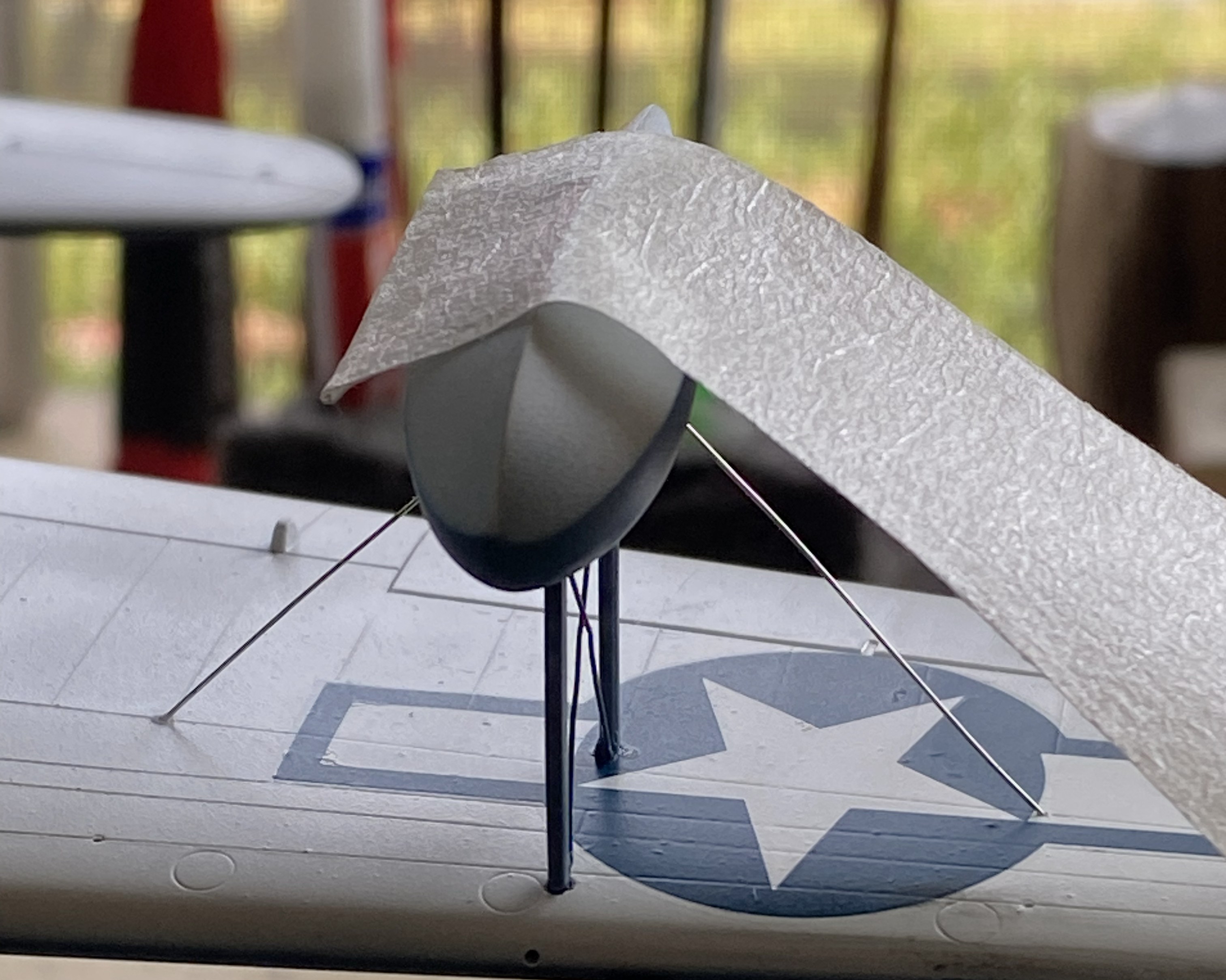
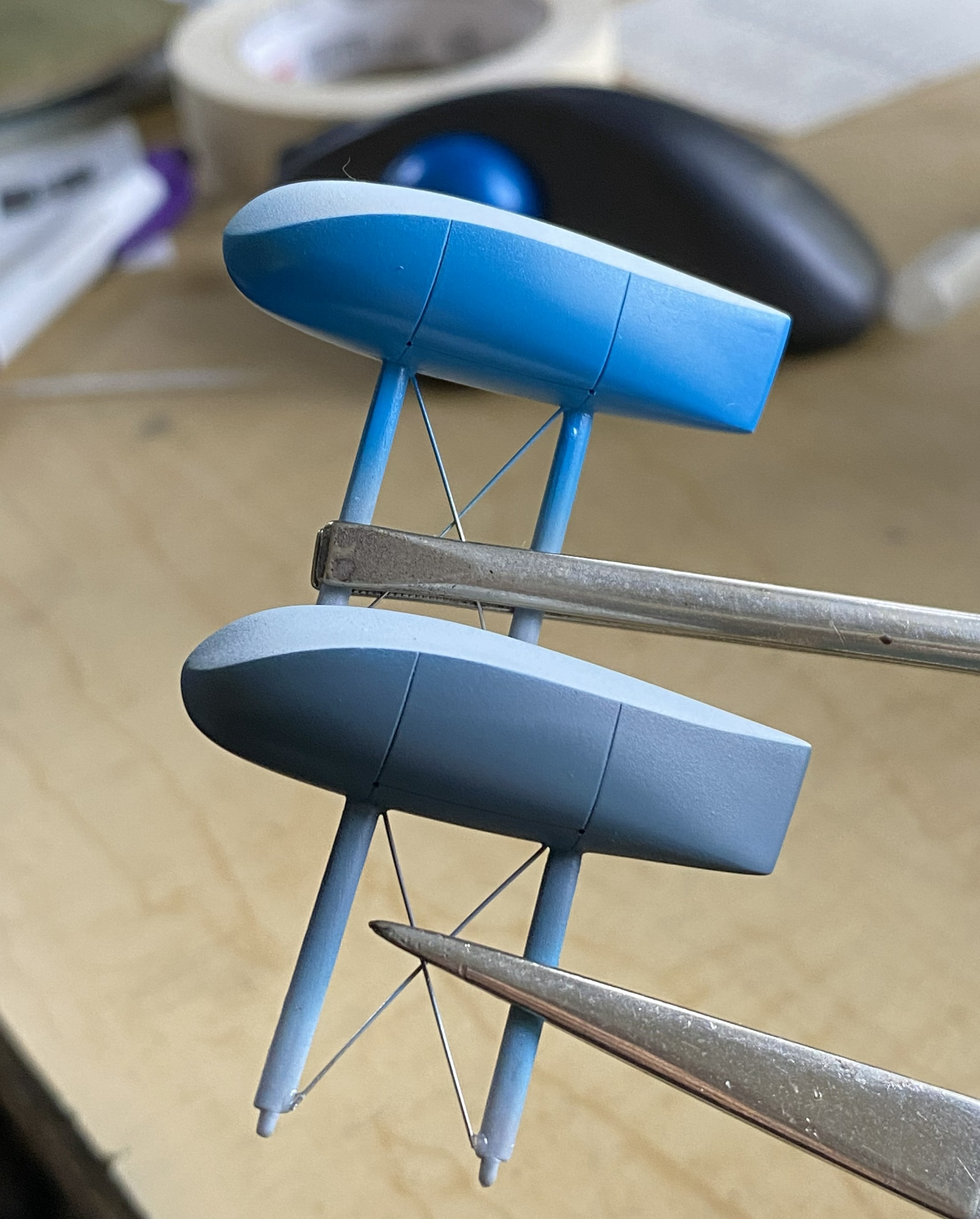
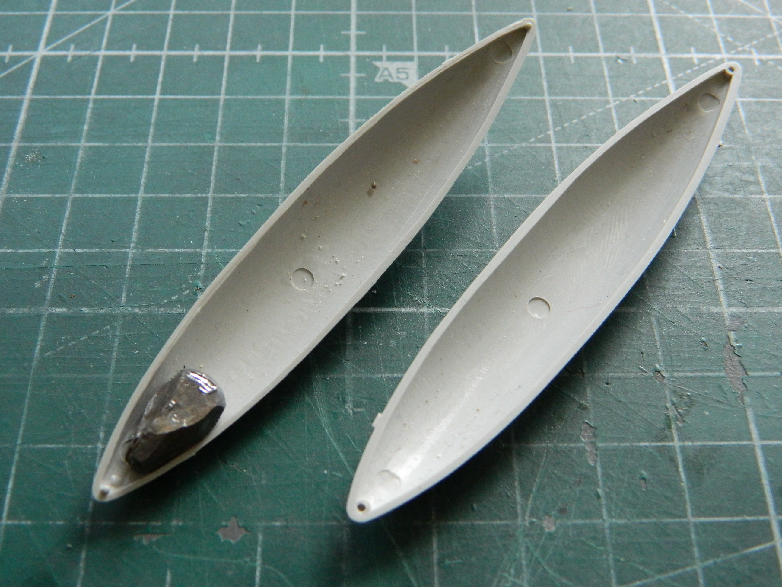
And while I was letting something sit overnight, I got ballsy (considering how late in the evening this happened) and added one of the floats to sit overnight as well:
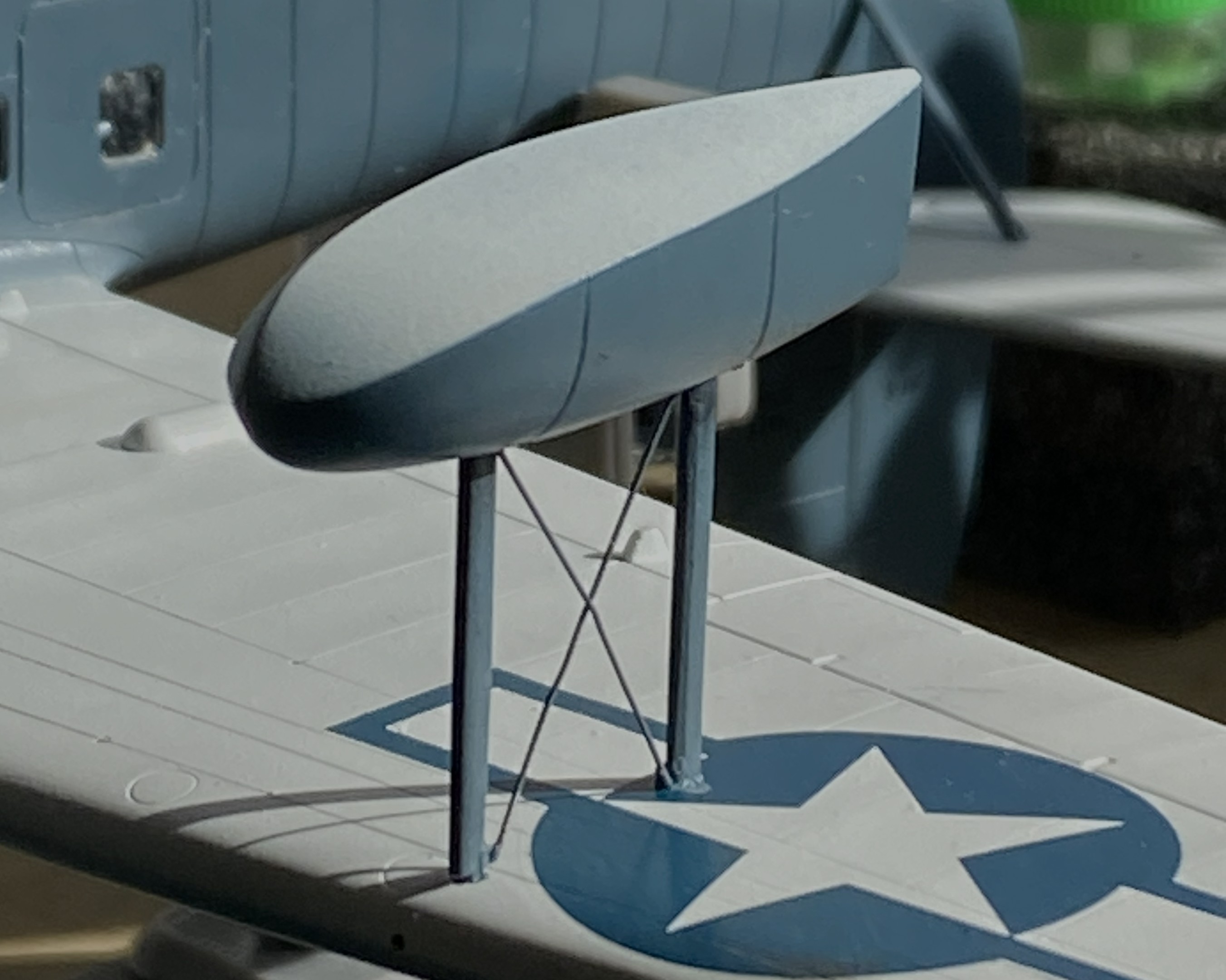
Obviously, with only two small contact patches, this will be easy to knock flat laterally. I added tape to stabilize it while I fed the ends of the braces into the float and wing for gluing (superglue). l cut the wires overlong so that I could be certain I’d be able to adjust them if I needed to (a handy bit of foresight):
With all the guy wires in place, it looks pretty good:
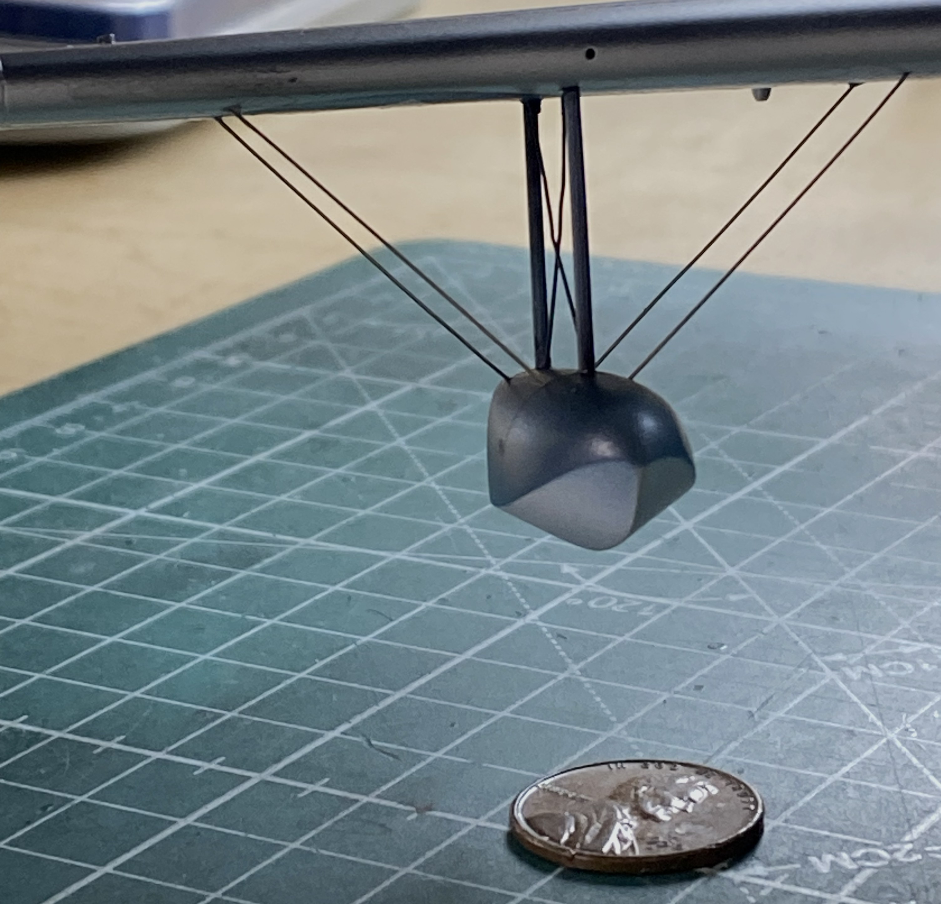

Getting the guy wires into the pre-drilled holes of both the float and wing took some fiddling. For the next float, I tried inserting one end of the guy wires into the float without cement to see if that would be easier:

It wasn’t. If you look closely where the wires meets the float you can see small bits of masking tape holding them in place:
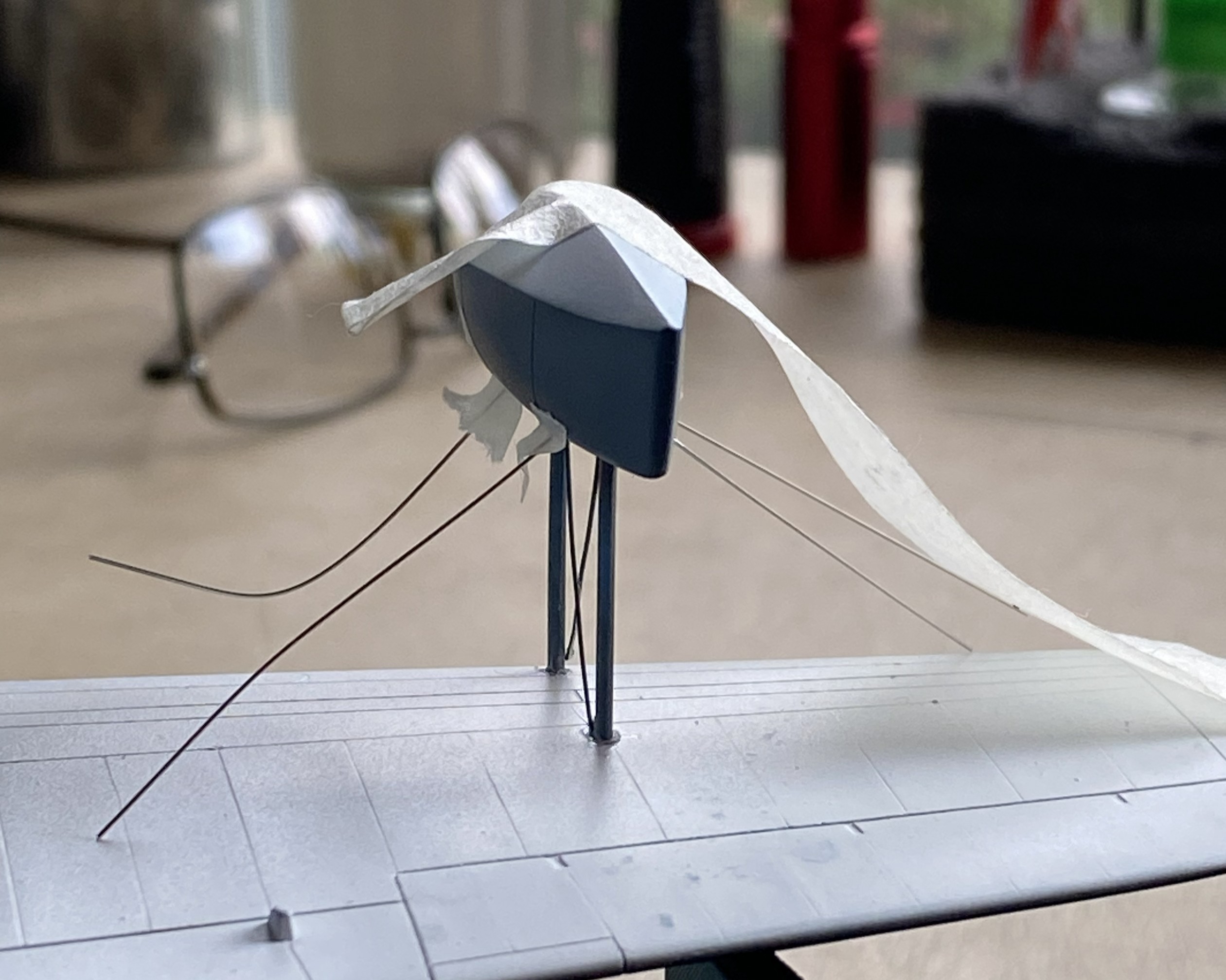
This didn’t work as well as I’d hoped.I was surprised at how difficult it was to just remove the tape. I had to diddle the tape so much that the float came free (in its defense, it hadn’t sat overnight for the plastic to harden fully at the glued points). After I reattached the float to the wing, when I turned the whole thing up side down, all the wires fell out:
I got that fixed:

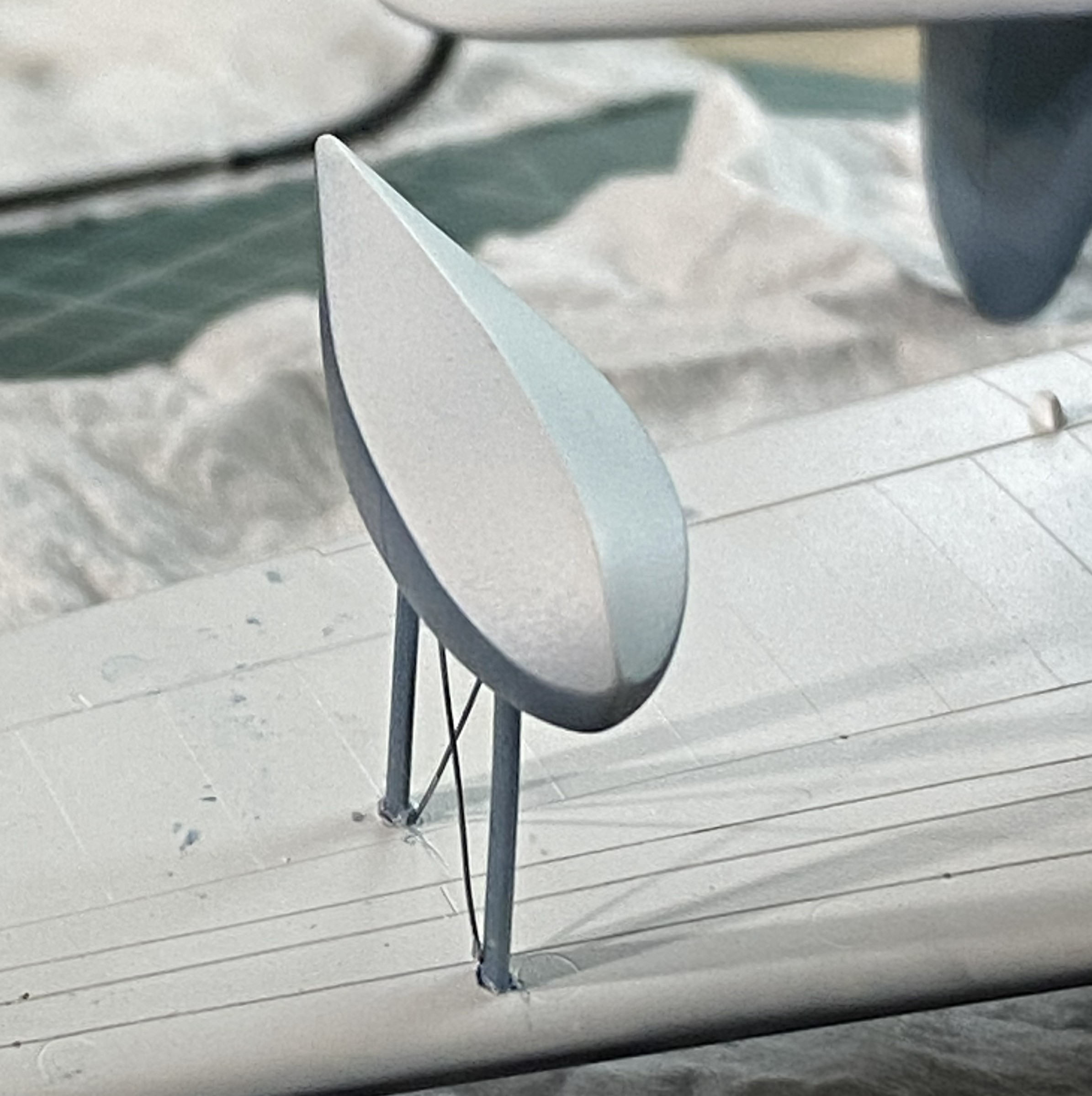
The radio aerials attach at both wing tips and the tip of the vertical stabilizer. I use this for aircraft aerials:
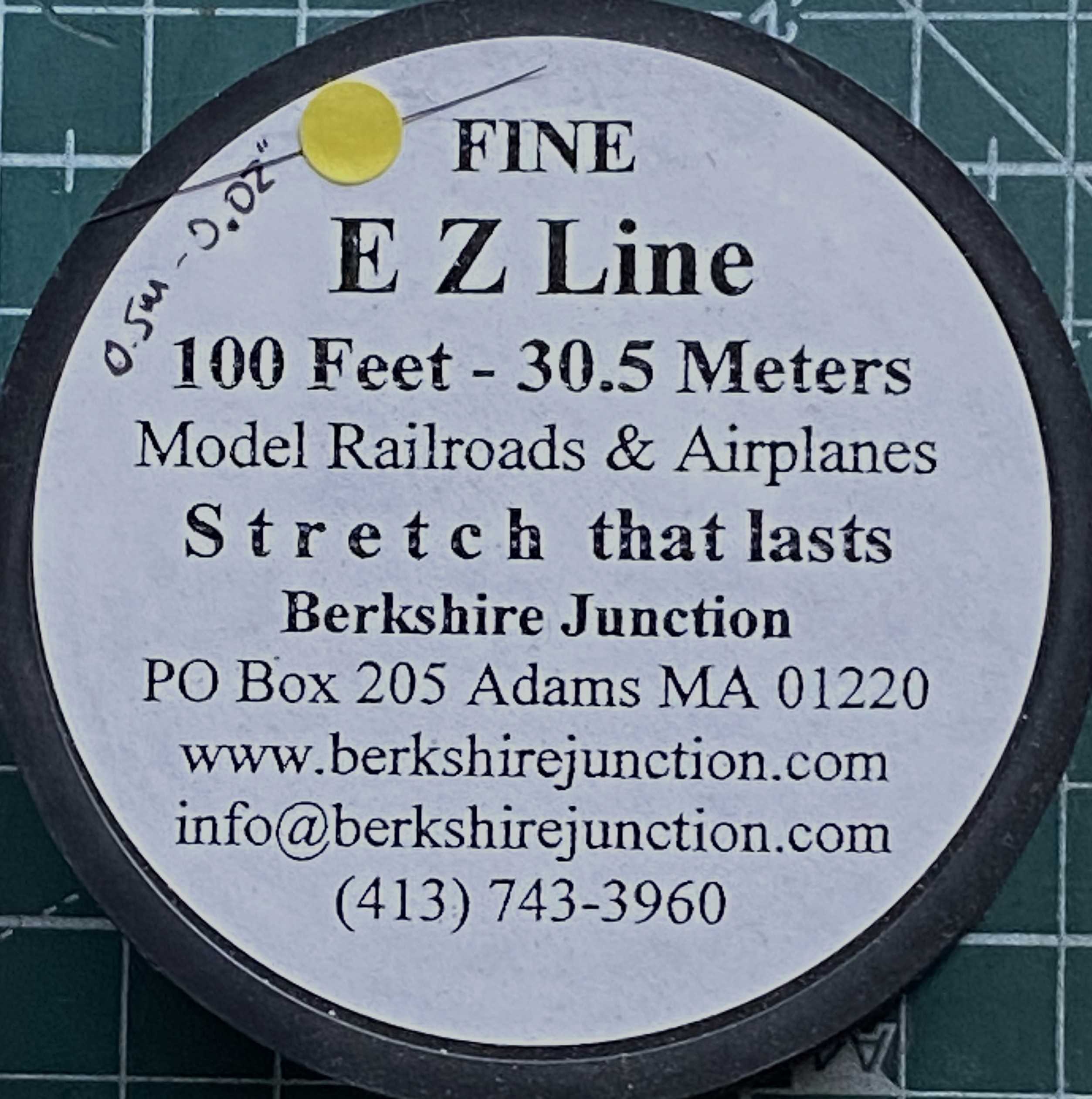
As I’ve been putting this together, obviously the more parts I add the less places I can hold it. For that reason (because these things get handled and transported) I wanted the aerials to be semi-removable; permanently attached at the wing tips, removable at the vertical stabilizer. What would make doing that simple would be to make the attachment point on the vertical stabilizer detachable. Or…I could mount the attachment point permanently and have it be J-shaped so that I can just lift the EZ-Line and let it drop. I like that idea, the major flaw is that even though the EZ-Line’s tension is adjustable, that J-hook has to be small. I didn’t have confidence in copper to hold up over the years. Instead I used the E-string from a guitar (thereby creating the moderately rare 5-string variant). Everything about its dimensions are printed on the pouch:

It’s certainly over-engineered for my purpose, which I think is great:
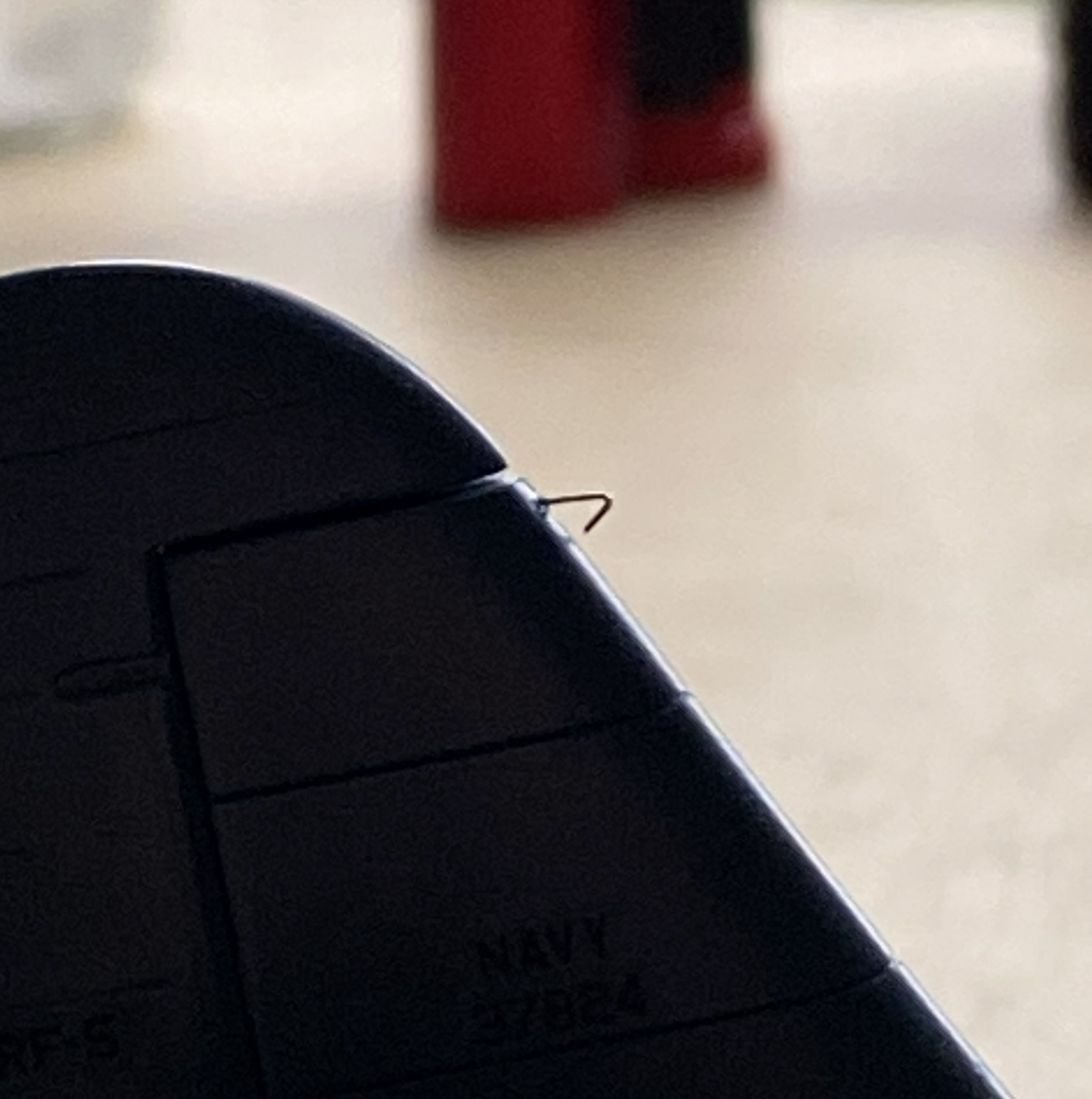
I’d attached little stubs of styrene rod where they belong and center-drilled them to socket the end of the EZ-Line into:

After gluing the other side in place, I tested the arrangement to see if it would function as desired. It function exactly as desired. Top photo below is with the aerials in place, the bottom photo is with the antennas dismounted (for these photos, I dry-fit all the parts yet to add and realized that none of those dry-fit parts need to be glued so I left them on):
I have one more thing to do (attach the brake lines to the wheels) and DONE!

Grumman JRF Goose (Czech Model) 1/48 Scale Build #6 – And This is When Tedium Really Sets In
I generally try to post new material here around the end of the month. Not having posted since August, that seems to have broken down. Seems to. It’s this build of this particular kit. I don’t want to work on it anymore. I recognize that this is an emotional response, not intellectual, so I have pressed on, albeit intermittently. But…here we are!
The fuselage over the flight deck (or cockpit, you choose) has a prominent feature. The curved shape is created on the actual aircraft by using flat panels. In some photos the panels appear to be butt-joined (the edge of each panel abutting the next), in some photos they seem to be scaled (where one side of the panel overlaps the next, sitting on top of it), and none of them are definitive. I made my guess (several guesses, really) and decided I’d go with the scaled (overlapped) presentation. I laid down strips of .005″ (.127mm) and then faired them in with 3M Acrylic Putty:
While the putty is drying, I fitted the heat exchangers on top of the engine nacelles. Originally it looked like a small, resin, cat standing on a hot griddle. Way too high off the nacelles. Fiddle, file, sand, cut at they now sit correctly:
EDIT
While I was doing this update, it was at this point in it that I sat here confused (easy place to get to due to how often I go there). I thought I’d taken more photos of the work over the flight deck. I certainly know that a lot of time was spent on it. About an hour ago the mystery (and confusion) dissipated when I found the photos I thought that I’d taken misfiled in a folder that, of course, has nothing to do with modeling (there are minor aspects of my life that have nothing to do with modeling) (honest). It’s at this place in this post that I surreptitiously add them in a manner that I think few will notice my oversight. ::giggles::
With the putty dry, I went back to the fuselage over the flight deck. ::sighs:: Where to begin… A lot of work ensued. Almost all the putty was sanded away to see if I could (I couldn’t) refine the shapes and lines of this area. As so often happens, once I’ve decided on a method to accomplish whatever oddball thing I’m trying to do, often I have to invent a way to do it (and frequently that is not a hurried process, regardless of how it may look). While doing the work of that invention on the model, it is quite common for me to figure out a different (and hypothetically better) way of accomplishing the task. It’s also not uncommon for that epiphany to come too late to use on what I got the idea from. This was one of those. While removing putty and trying to refine the shapes into something I want, I realized that what I should have done was not add the strips and putty at all. The panel lines should have been scribed and cut away to create the lapped effect. And then I noticed that the lines aren’t just on the clear part, they extend rearward to the pencil line on the main wing, which is how I came to the realization that adding the strips and putty was a total waste of time/effort (and I added the resin scoops to the left sides of the nacelles):
Putty was immediately added whenever I found a void that needed filling:


About this point I realized that I had too many different colors/shades reflecting light and I had lost the surface (visually…if I’m that bad off, I stay in bed). I used Tamiya XF-20 Medium Gray as it most closely matched the plastic’s color so that reflectance would be uniform:

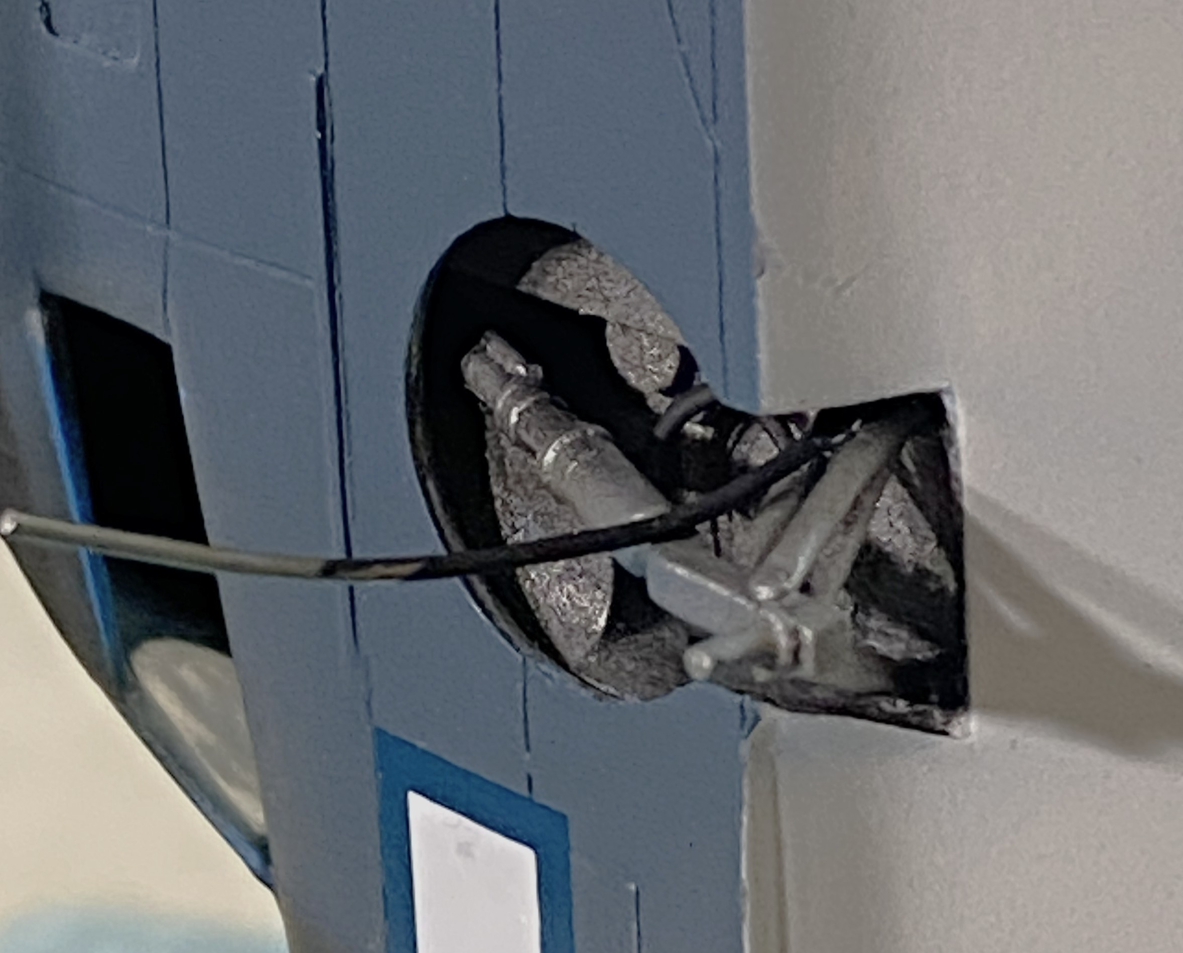
I’ve seen a number of field-expedient grab handles added to aid refueling. The filler port is on top of the wing on the left side. Access was achieved by opening the portside entry and crawling up onto the wing. Then the fueler had to scoot towards the filler port while dragging the fuel hose. (I’m not sure that “ergonomics” was even a word 80 someodd years ago, doesn’t look like “convenience” figure prominently, either.) I picked a photo to replicate and used some 22awg wire and added one setup that appealed to my eye:
Ain’t nuthin quite like applying primer to show you what still needs work. Plenty:


It seems I got too frisky with cutting in the lap lines and took too much off (though, for a change, it was before I’d carved through it) so I used stretched sprue to fill what had been mistakenly removed.
As an aside, if you need preshaped sprue to stretch, shaping the sprue before stretching it will keep the shaped you’ve established (this was shaped triangularly to better stuff the gaps I created):
Jeweler’s files. The self-locking tweezers that are attached to stands. If you don’t have any, get two. They are so useful in getting pissy parts aligned, and keep them aligned, while glue sets. I use my pair on every build at some point and it’s time to use them again to keep the stretched sprue in place while the glue sets up:

I’ll generally wait 2-3 minutes after applying the glue before I press the sprue into what I’m filling with it:


Still more work to do straightening out the lines. I spent over a week working on that section and ended up needing a break from that particular task. Since the added sprue needs to sit overnight before it could be worked, I attended to THE most fragile parts off all the fragile parts.
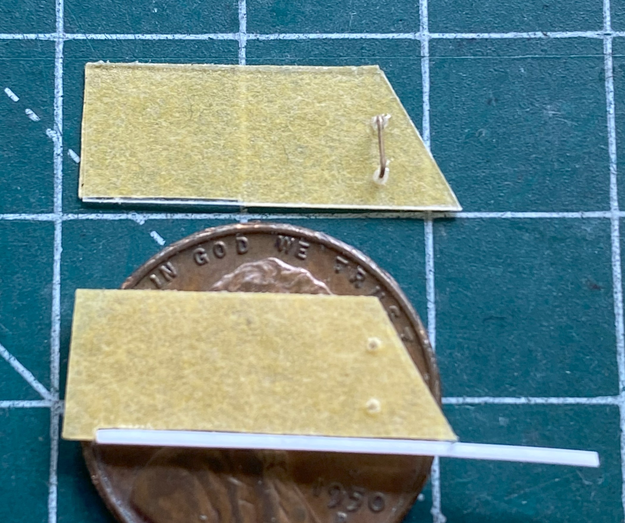
The mass balancers on the elevators. They’re so small that I left them attached to the sprue runners while I cleaned them up. I knew that I was going to make them removable using 22awg wire as pins. I didn’t need magnification to see that the bases are too small. 22awg was the smallest wire I was willing to use (anything smaller would be too flexible), so instead of even trying to get the notch I’d have to cut for the wires centered on the bases, I excised a slot slightly less than halfway through the base to recess the wire into. No…not accurate. Yes…practical:
And to think that I won’t work on anything smaller than 1/48 scale because “it’s too small” is getting really funny.
With those ready to paint, it’s back in on my head. My eyecrometer seems to be in need of recalibration. Since eyeballing it wasn’t working, maybe tool use will. The tape is so that the next line is freaking straight:

Next up will be mounting the engines.
While doing initial (hopefully final) fitting of cowls and engines, I realized that the engines are intended to mount to the cowlings! (No mention of that made in the directions. I guess if Czech Models figured if the builder has managed to get this far, they’ve realized that for most of whatever this kit needs, the builder will have to figure it out for themselves.) Okay…I’ll glue them to the cowlings:

I’m glad I had the foresight to remember that however the cowling mounted, where the engines mount would be important. But, seeing as the engines are resin and mounting to plastic, superglue won’t allow me enough time to align them correctly. To get around that limitation, I superglued 0.010″(.254mm) clear styrene to the backs of the engines. This will allow me the to join styrene to styrene and fiddle them into alignment (I used clear plastic so that the added disks would be easier to center over the engines):
Now for the task I’ve been dreading this entire time. It’s time to attach the landing gear.
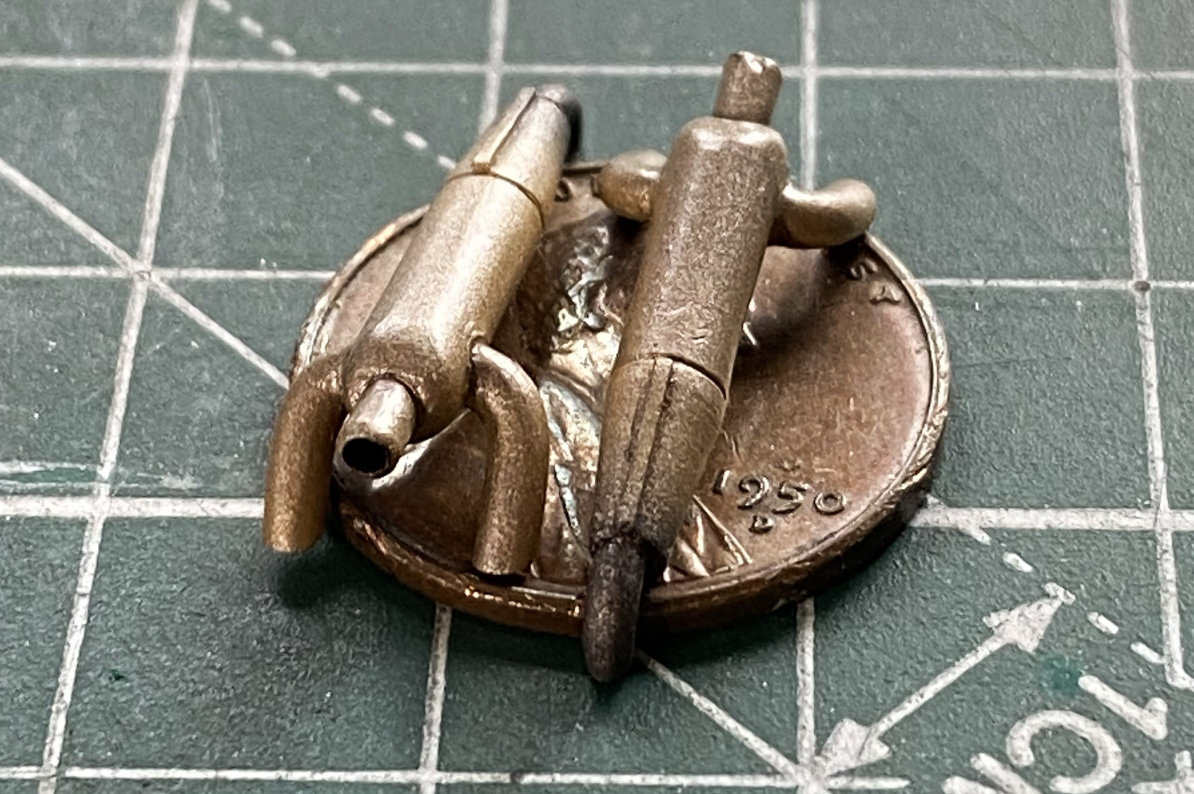
The kit offers three pieces for each landing gear; the main strut, the upper control arms, and the lower control arms. Three pieces, two hands, and minimal space to work in. I cut down on the parts count by aligning the lower control arms on each strut, then drilled through them and put a wire in there to act as a hinge. Had I not done that, I’ve NO idea how I’d have gotten these things on at all. Even with the parts reduction, the four-letter word I want to use to describe that process isn’t “easy”. Move this into position, attempt to move something else into position and the first piece moves out of position. I’ve seen this kit online where others have built it. They could get the landing gear on, so that means that I can get the fornicating landing gear on. I finally got the strut and lower control arm glued in:

After repeating this lovely task on one side, I did it again on the other side.
If I thought getting this strut/arm assembly in place was a delight (it wasn’t), then there’s the upper control arm to wiggle into position and trying to align it while making the aircraft sit level was a pleasure that defies description (or sense). I persevered (the process of which was akin to getting a colonoscopy without anesthesia):

Did I get the bird to sit level? Nope:
It’s not time to fix it yet. I’ll pay the toll on that bridge when I get to it.
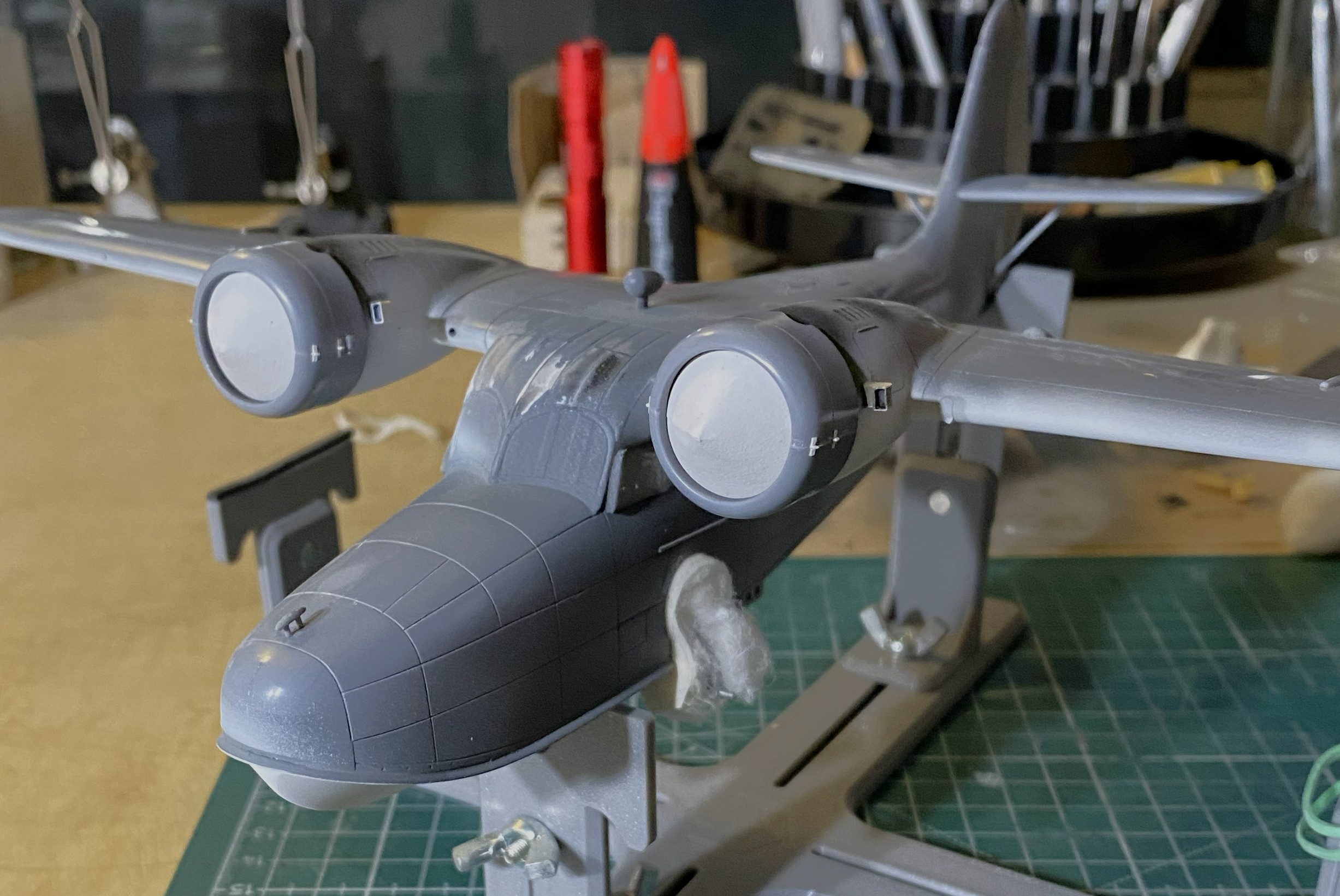
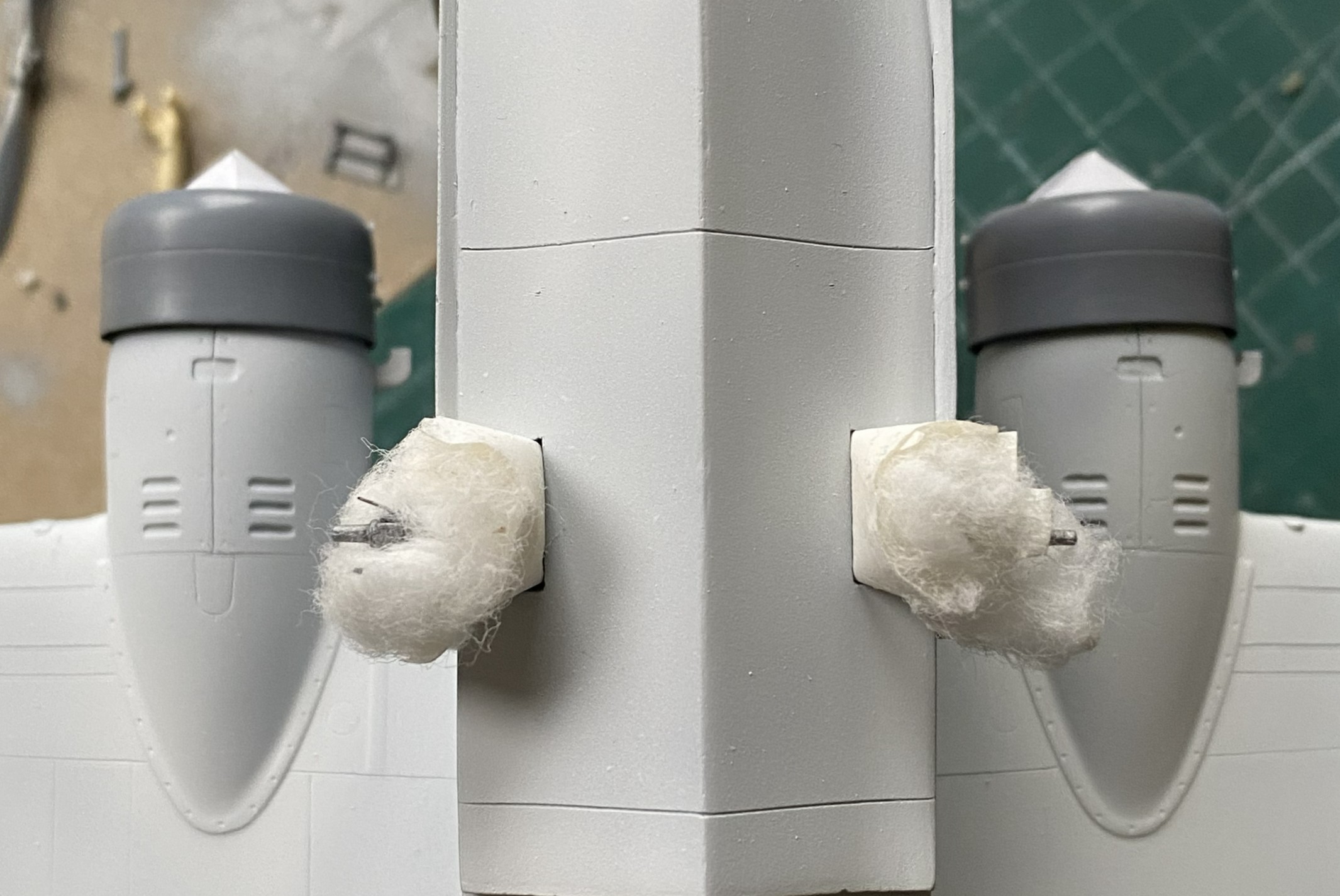
My next task was to start throwing paint at this. Of course I started with the light colors and worked darker, but where I started was figuring out how to mask this using cotton balls for the landing gear, front and rear. For the cockpits, I took foam wedges (nail care section of the drugstore/apothecary) and cut them oversized so that they would hold themselves in position (usually):
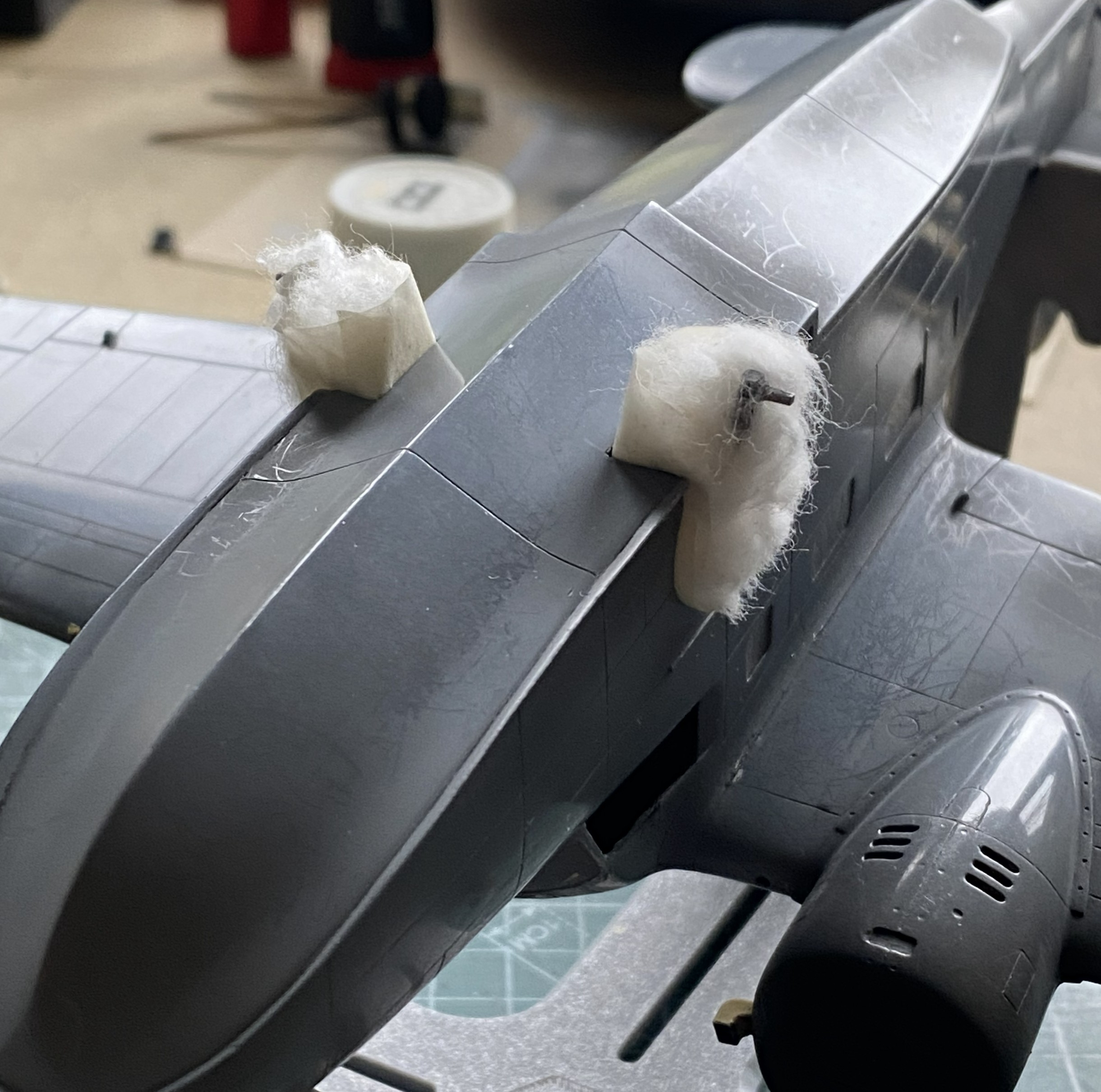
That worked:

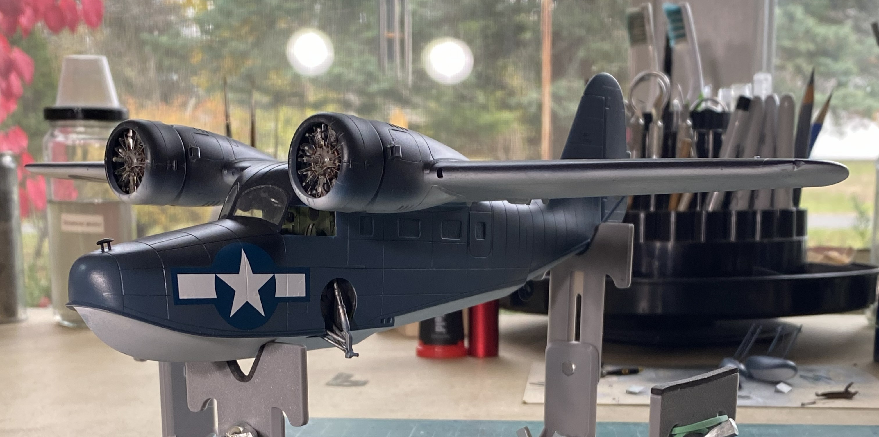
As this will have a three-color paint job, and the nacelles are definitely part of that paint job, I decided that adding the engines now would make all the color demarcations line up later. Before I added the engines, I traced the back of the cowl on paper, traced two circles (one for each engine), and after determining the center of the circles, cut from the center to the edge. This would give me paper cones that would fit in the cowling openings and mask the engines from the incipient painting (and if you look closely behind the engine that’s on the right in the photo, you can see the trimmed foam in the cockpit’s window behind it). With that done, I glued the engine/cowling assemblies in place (shortly after these photos were taken, I painted the undersides of the cowlings white as well):
Figuring that I was on a bagel (which is very similar to being on a roll, just a firmer seat), I got the paints ready. The XF-18 Medium Blue was the correct color, not the XF-8 Flat Blue you see below:

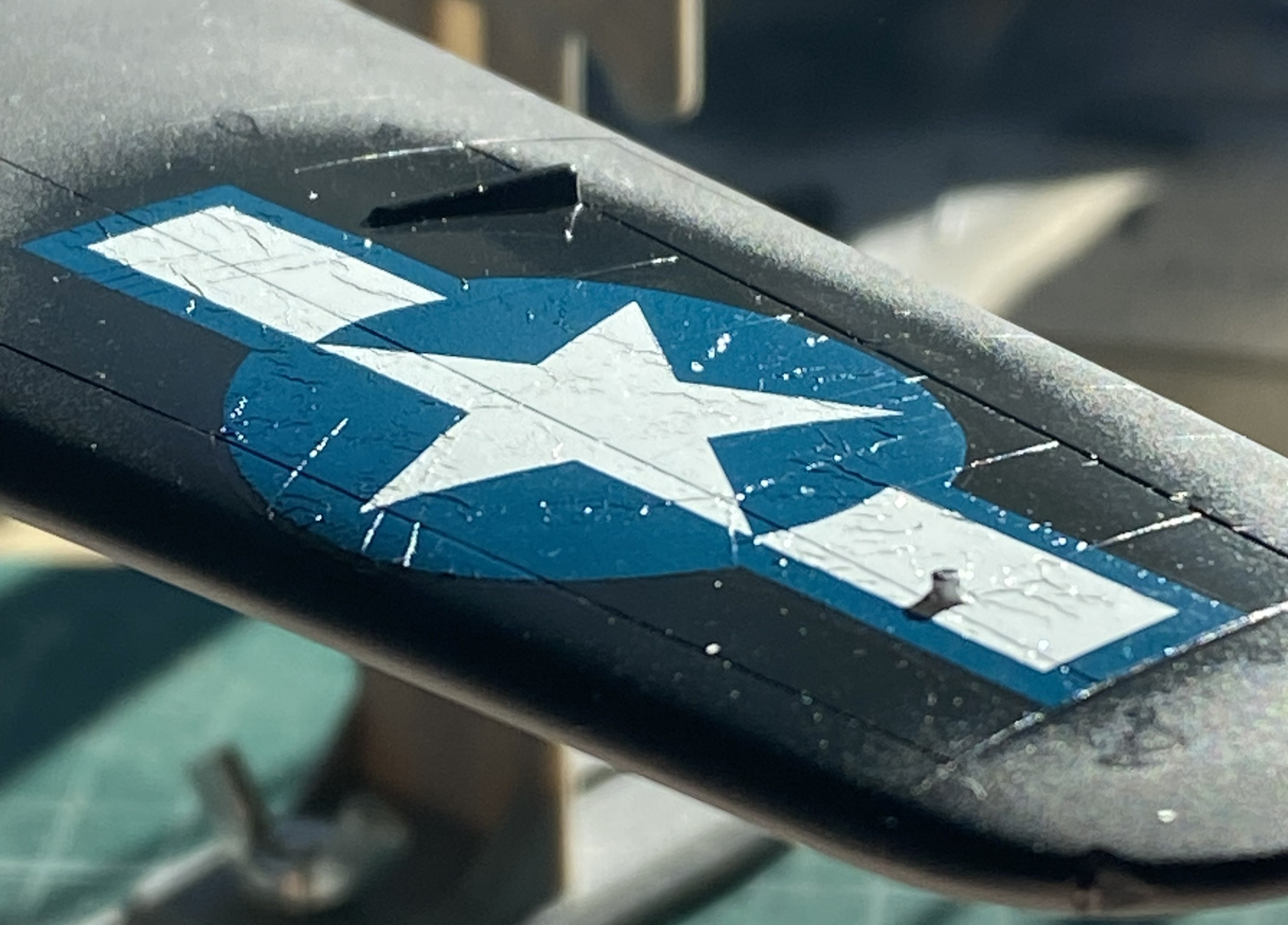
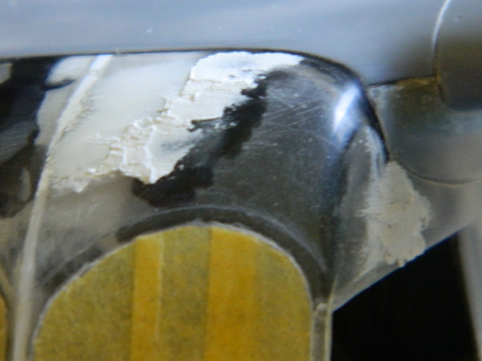
Yeah…wrong color. But…before I had to repaint the sides, I found that Thumbnut McFumbles, here, did not monitor the position of one of those thumbs and did this (hint…check the area that’s not blue…lightly sanded thumb mark on wet acrylic):

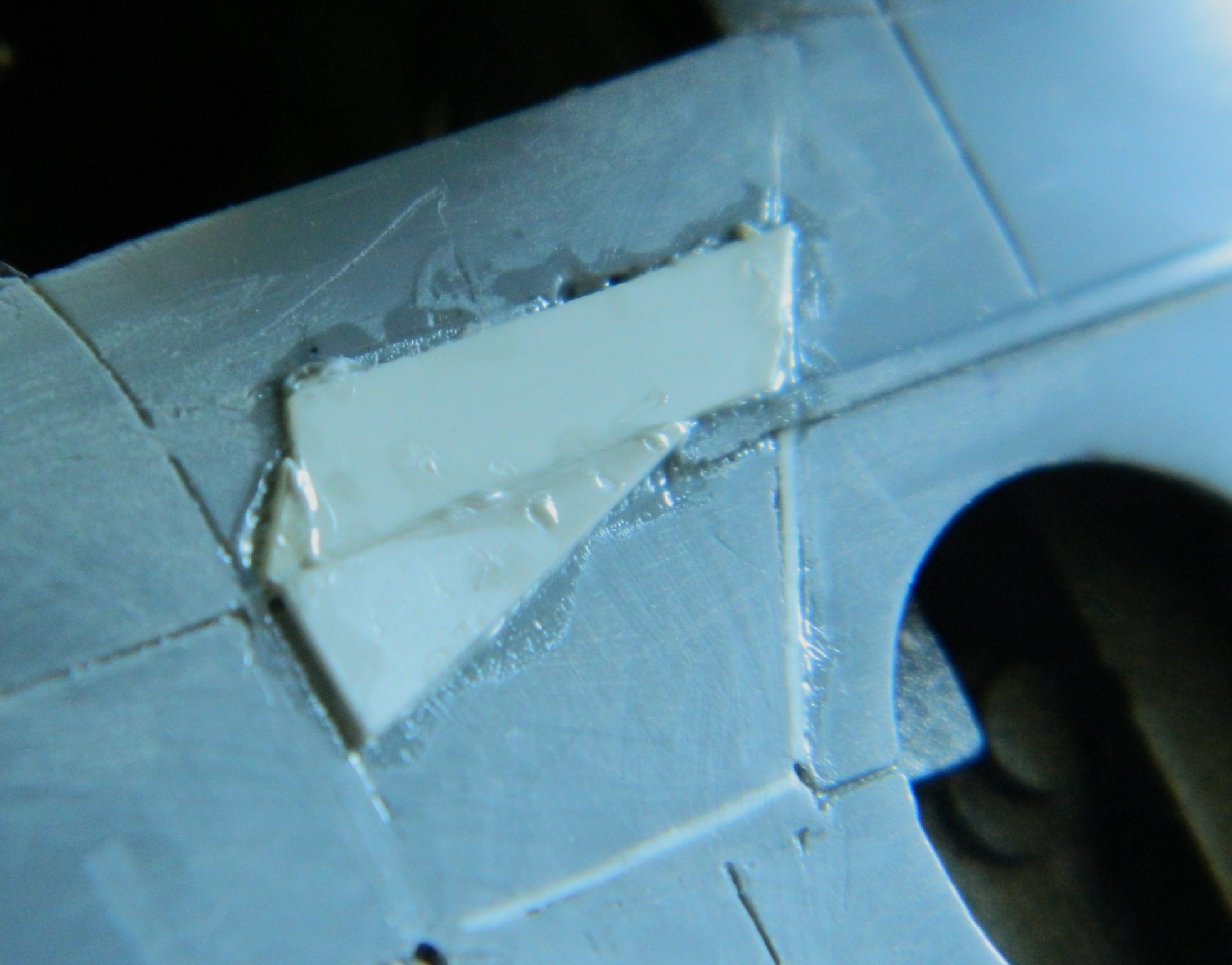
Though not precisely pleased, there was something else that fell short of pleasing. When I cut the access open to fix the pilot’s seat, I had to replace the part cut out once I’d fixed the seat. At this point of the build, I was reminded that if I’m not careful (giggle), when the cement finally out-gasses, there can be a visible shrinkage caused by A LOT of glue being used. I used A LOT of glue because there was A LOT of plastic used to fill the edges. This resulted in a clearly evident depression around the patch’s edge once the disco-blue was on. Since I was going to have to repaint the sides (once the correct color arrived), okay…so I’ll fill it in again, only this time I’ll use the UV-setting resin:


Just on a whim, I decided that the heat exchangers could use painting:
Pity…that paint job didn’t last very long as you’ll see later. Too bad. I liked it.
Seeing as I clearly can’t keep track of where my fingers go, I needed a method that would enable me to handle the model as it was being painted. Since I was starting with the bottom, next I would do the sides, and then finally the color on top of the aircraft. And since I want to finish this in a semi-gloss finish, I would also need a painting order for that as well. I let that rattle around inside my wig for now and set about getting that wrong blue covered.
When the paint arrived, XF-18 Medium Blue, I started the repainting with the floats. I’m sure you can figure out which was the before and which is the after:
Much better:
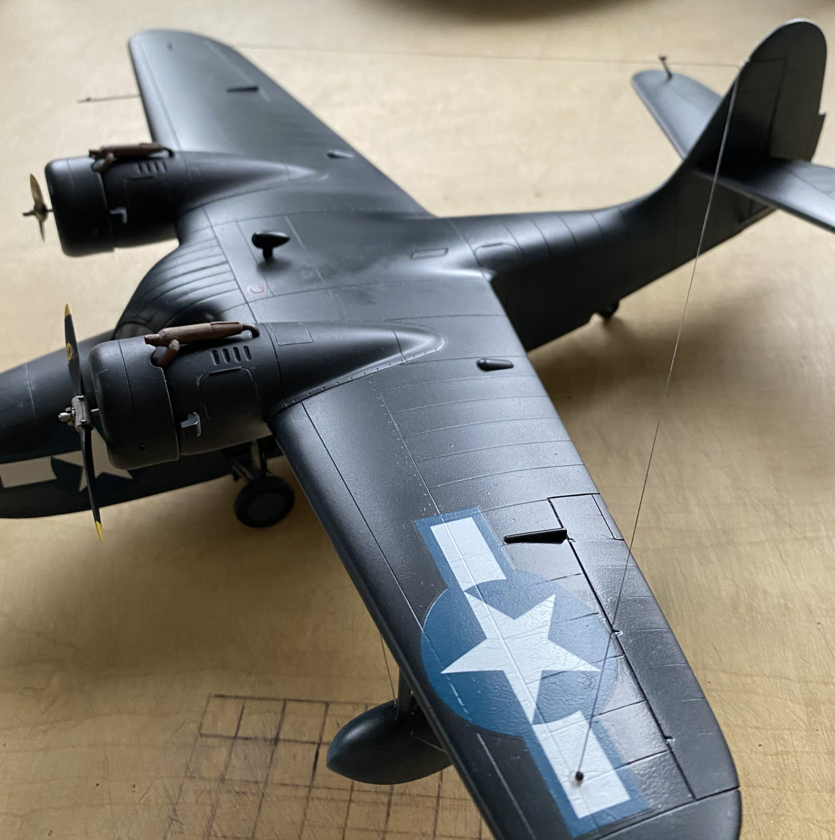
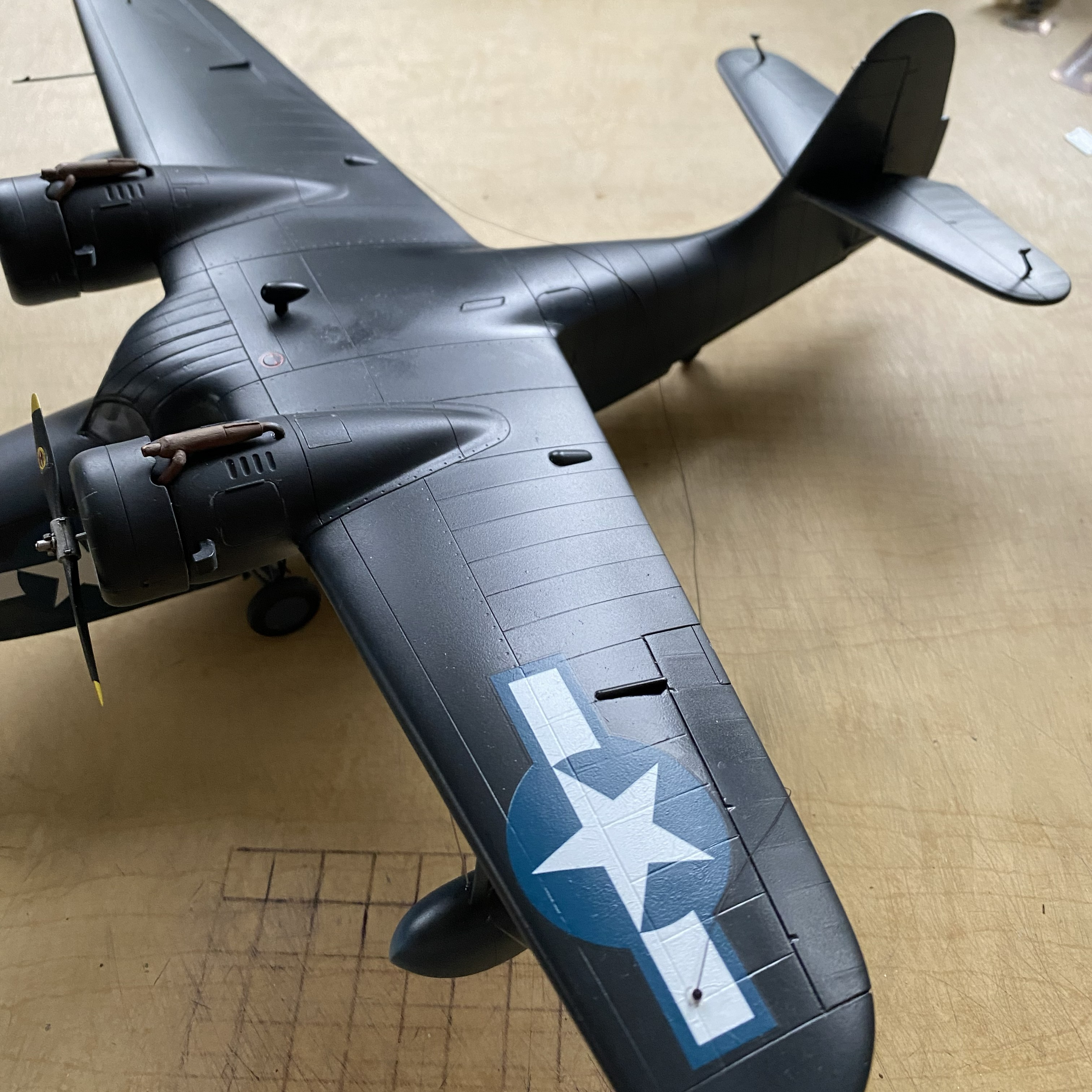
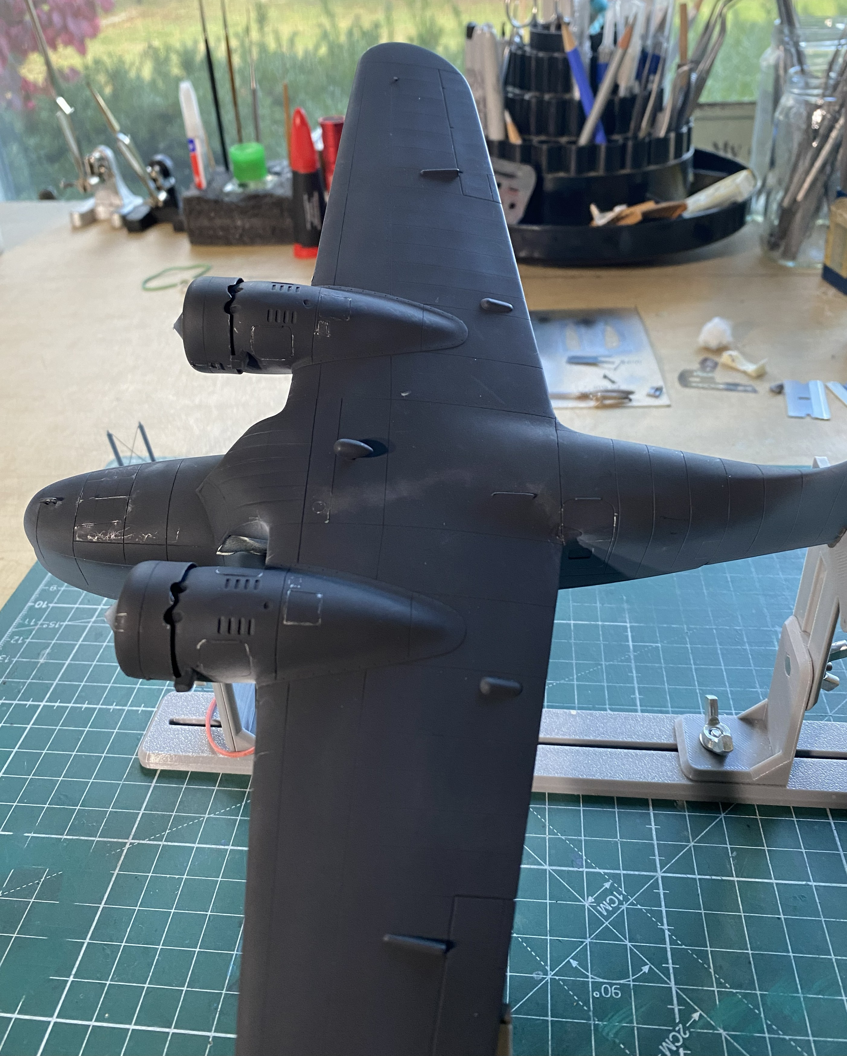
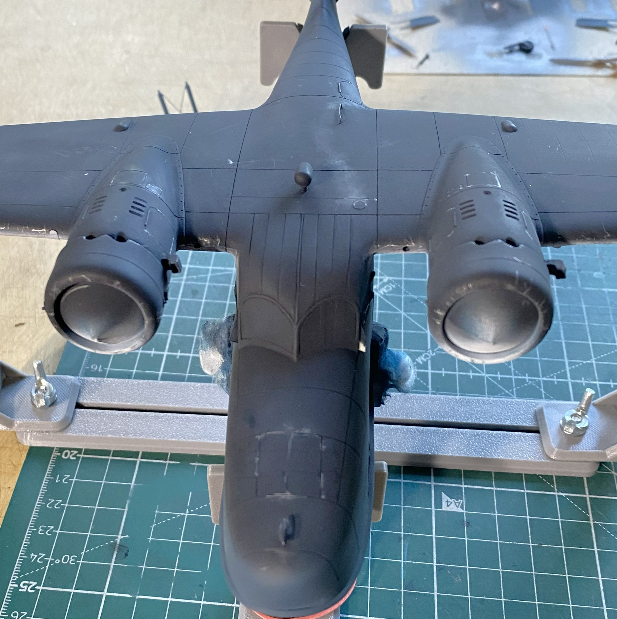
Next up, XF-17 Sea Blue for the upper surfaces:


The overspray of the wings and tail-planes white are how they were painted in WWII.
It was at this point I could take off my polarized sunglasses and resume work.
I like using pencils for some things. At the top of that list is Prismacolor’s PC949 Argent. It’s silver and in small-area applications, it looks enough like aluminum for me. As I’ve discovered, if the surface is slightly rough, the pencil not only goes down easier, amazing things can be done with subtle wear patterns. With the build now under paint, I sharpened my PC949 and went at it. Gently. The Navy doesn’t let its kit get shabby:


With the paint on, the next thing that goes on are decals, so I hit the spots where the minimal decals go with Tamiya’s X-22 Clear Gloss:
Yes, that looks like a lot of paint. However, this paint does self-level:

I had painted the white undersides (Tamiya XF-2 Flat White) a few days before the color and had shot it with clear gloss (Tamiya X-22 Clear Gloss) to prepare it for a wash which meant it was ready for the wash. I figured since the wash was going down over white, I could get away with a more nuanced wash. Pratt and Whitneys leaked oil. The skin panels were not oil tight. Oil leaked on the ground and once the bird was in the air, the oil that had leaked onto the skin streaked back in the airflow. That’s what I was after. I didn’t think an enamel wash would give me the subtlety I thought would work so I broke out the oils:
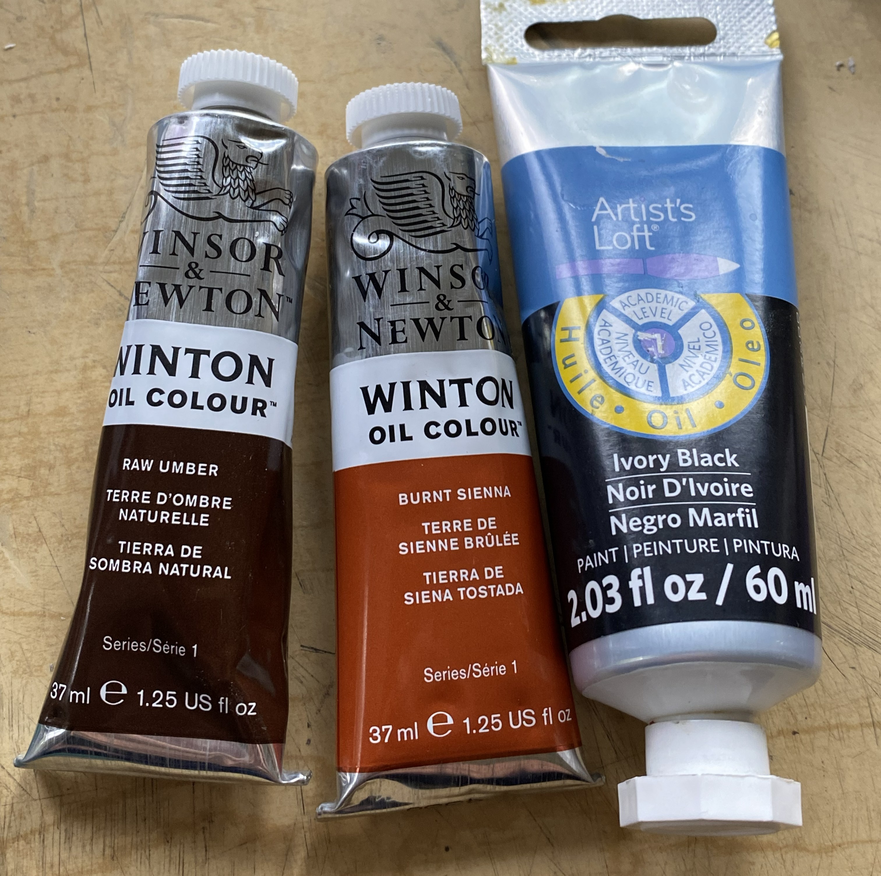
The last time I did a wash using oil paints (on the engines), I’d used Turpenoid as the base (roommate hates the smell of enamels and turpentine). It took a week to dry. For this wash, I tried using Gamsol as the thinner instead. It was dry the next day.
Yep…looks like engine oil:

Yep…it looks a lot like oil:
At this point, these are all the parts I have yet to add:
A couple of days later with full knowledge that the clear gloss had set sufficiently for decals, well then…let’s do the decals. And then there were these:


Well, well. Old decals. I decided to see if I could get them off the backing with few enough shards for me to piece them back together on the surfaces (because I’m that kind of nuts). Results were…well…predictable.
This one went on in “only” two-ish pieces and was acceptable:
The one for the upper wing, however, was a cockup:
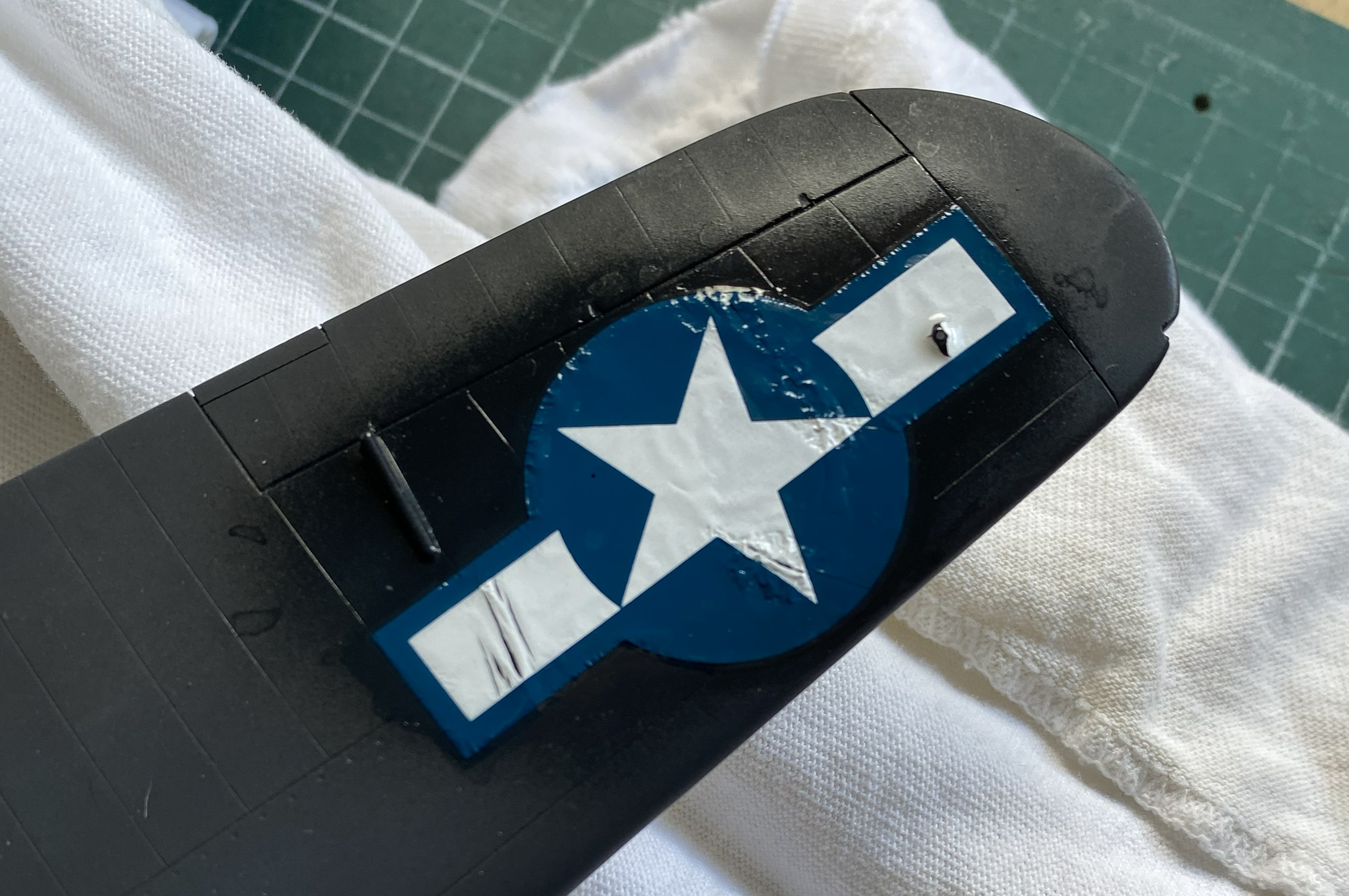
I broke out Walther’s Solvaset in the hope (another four-letter word) all the shards would play nice with each other. They didn’t. I used more Solvaset to see if perhaps multiple applications would smooth things out. In some spots it worked. However, there was a cost. NO amount of further Solvaset got rid of the wrinkles:

The second photo above was the best Solvaset could manage. Not acceptable. I only know of one way to remove blown decals. Sand them off, reapply paint, and start over:
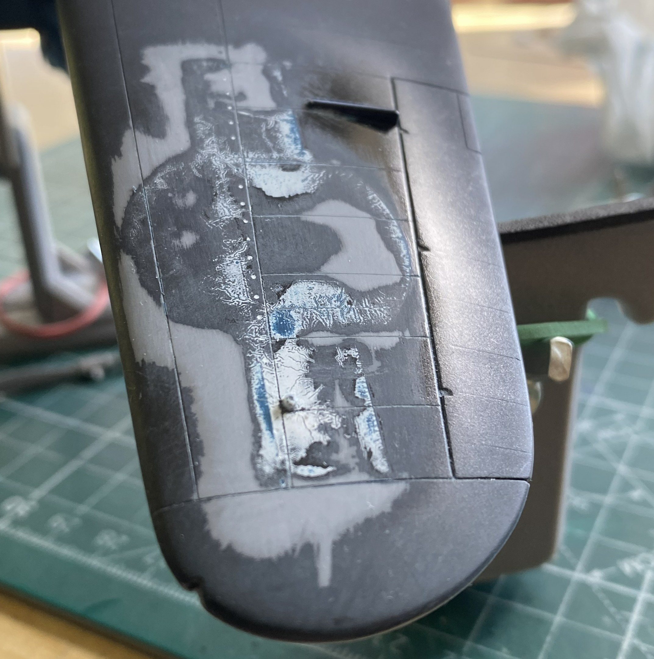


Yes, even through the new paint, the faint outline of the decal’s remnants shows up. Since the new decal would sit right there, I didn’t bother sanding it out.
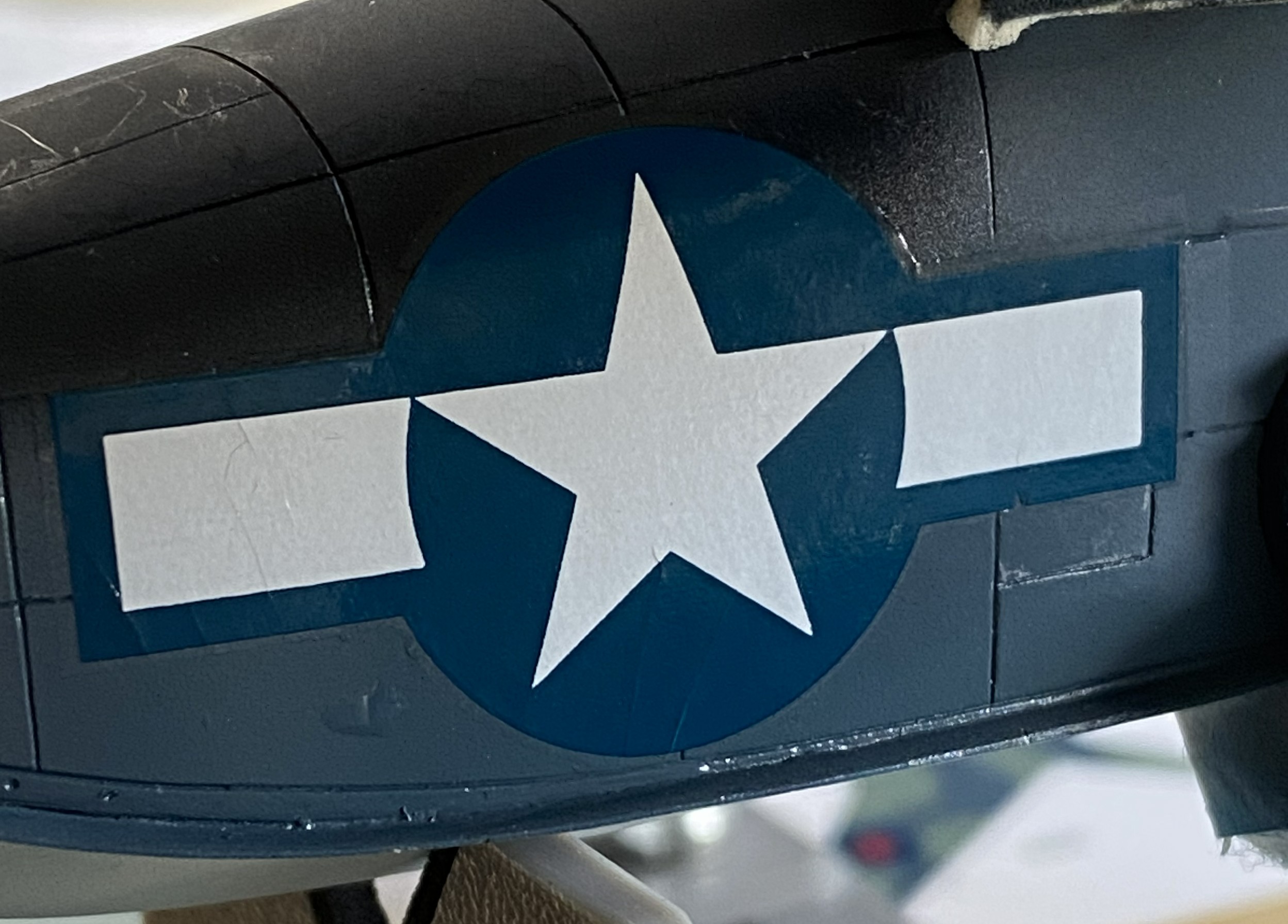
Solvaset worked well (though not perfect, it’s close enough) on the left nose decal:
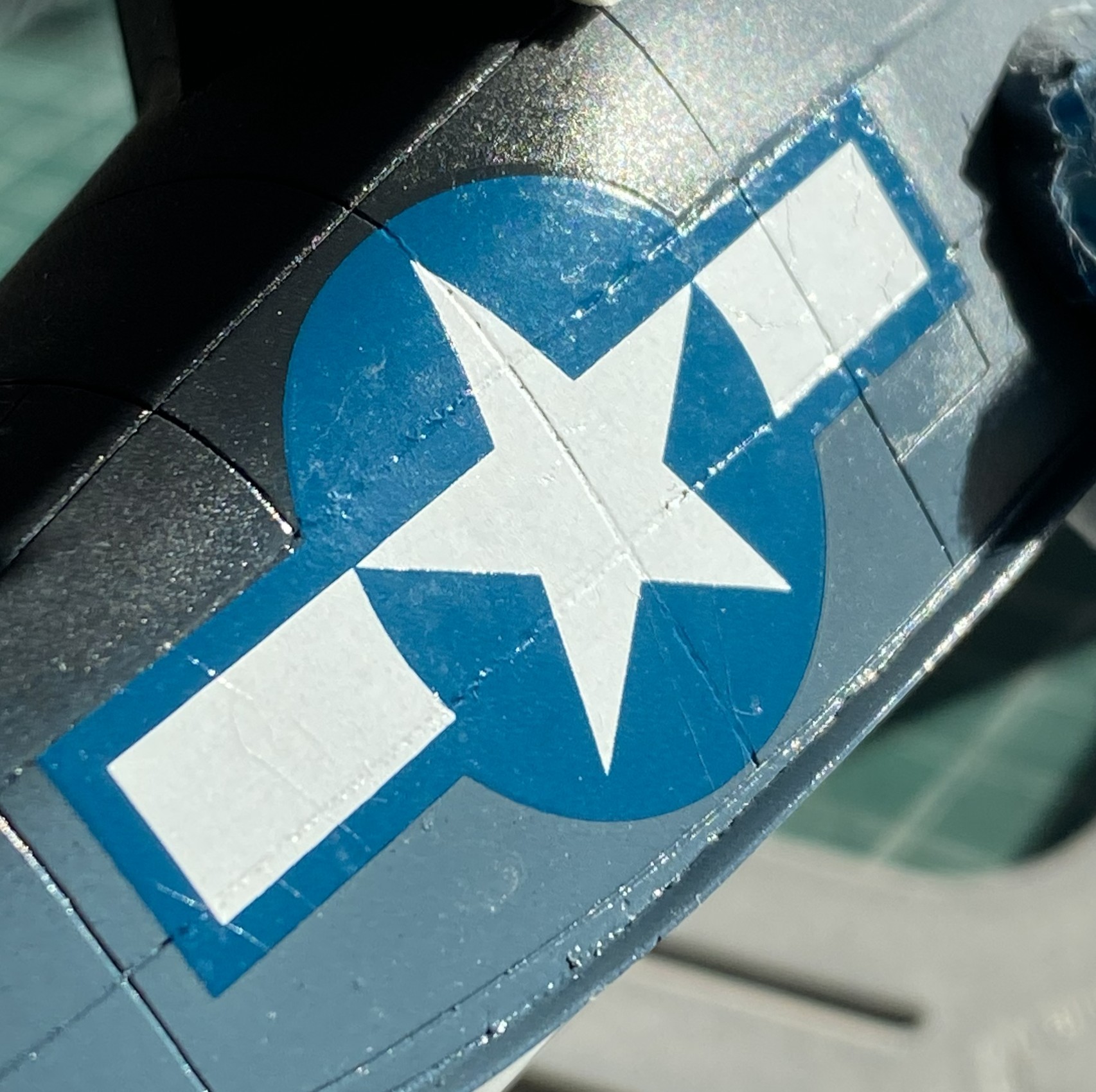
At this point I discovered that I’d salvaged the only two decals from that sheet that could be salvaged; all the rest were garbage. Oh great. This is a limited run kit so the odds of me finding suitable decals weren’t good. Okay, so it’s star ‘n’ bars…I probably have dozens of them on hand. When I went through the decal stash, I discovered that yes…I had lots of star ‘n’ bars. I just don’t have any even approximately properly sized. The big surprise was finding another sheet of the exact same decals for the exact same model. How I managed that, I’ve no idea. But with stars in my eyes, sweat on my forehead, my shaky hands cut out a decal from that sheet to test and it was FINE.
Whew…
Here’s the nose decal from the second sheet, and this time I wondered if Solvaset was too hot for these decals. So, who doesn’t have Micro Sol? I used that instead and though the old decals WERE OLD and shattered, perhaps part of my problem with the upper wing decal was the Solvaset. Micro Sol did the job (in-process in the lower photo):

While I’m fiddle-farting around with sodding decals, I neglected to notice that I’d knocked both heat exchangers off the bench and then stepped on one. I never heard the crunch. I did notice that neither exchanger was on the bench. Found one intact. Whew. Found one sitting in a small pile of resin dust (avec chunks):
::facepalm::
Okay, so I get to reattach the tail and make new arms. I didn’t have the exact diameter styrene rod, but I had styrene rod that was maybe 0.005″ (.127mm) less in diameter and that was close enough. Plastic has a memory so if I wanted a 90-degree bend, I’d have to over-bend them and let them sit overnight to attain their new memory:
At this point, a regular occurrence occurred. I dropped something and realized that the floor between my feet was CRUDDY. Okay, pick up the dropped tool and sweep the floor. Once the detritus was in the dust pan, there was one of the two arms sitting right there. Okay…let’s attach that NOW so I did using UV-setting resin:
That’s good news! I only have to make one arm using the UV-setting resin again:
It’s at this point that I got to see what happens when I get interrupted in the middle of something. I’ll forget the second half of something. I had one propeller all painted and ready. The other? Well, I got the hub painted and washed… Yeah. Let’s fix that before somebody notices:


I’m going to be facepalming so much that my forehead will be calloused and the tendons in my hand will be inflamed.
With the paint curing on the prop, I checked the repaired exchanger for fit. Just right:

With that all fixed, I got back to applying decals:

With all that applied, it sits overnight.
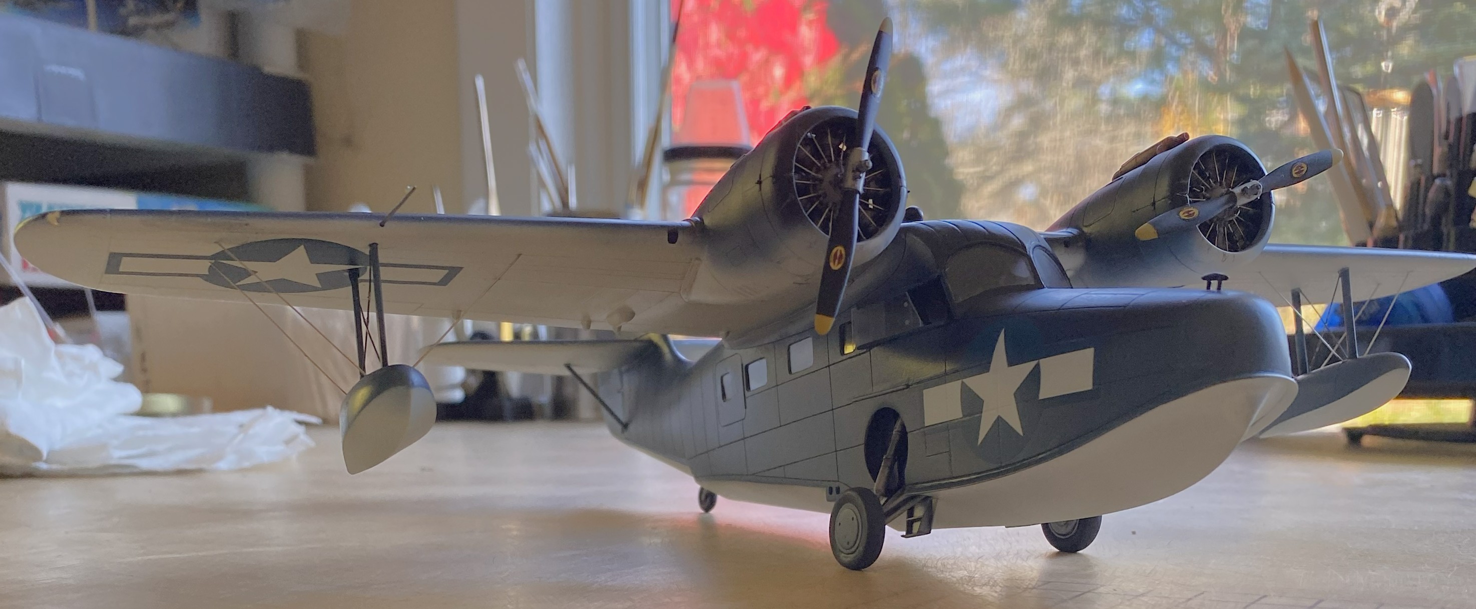
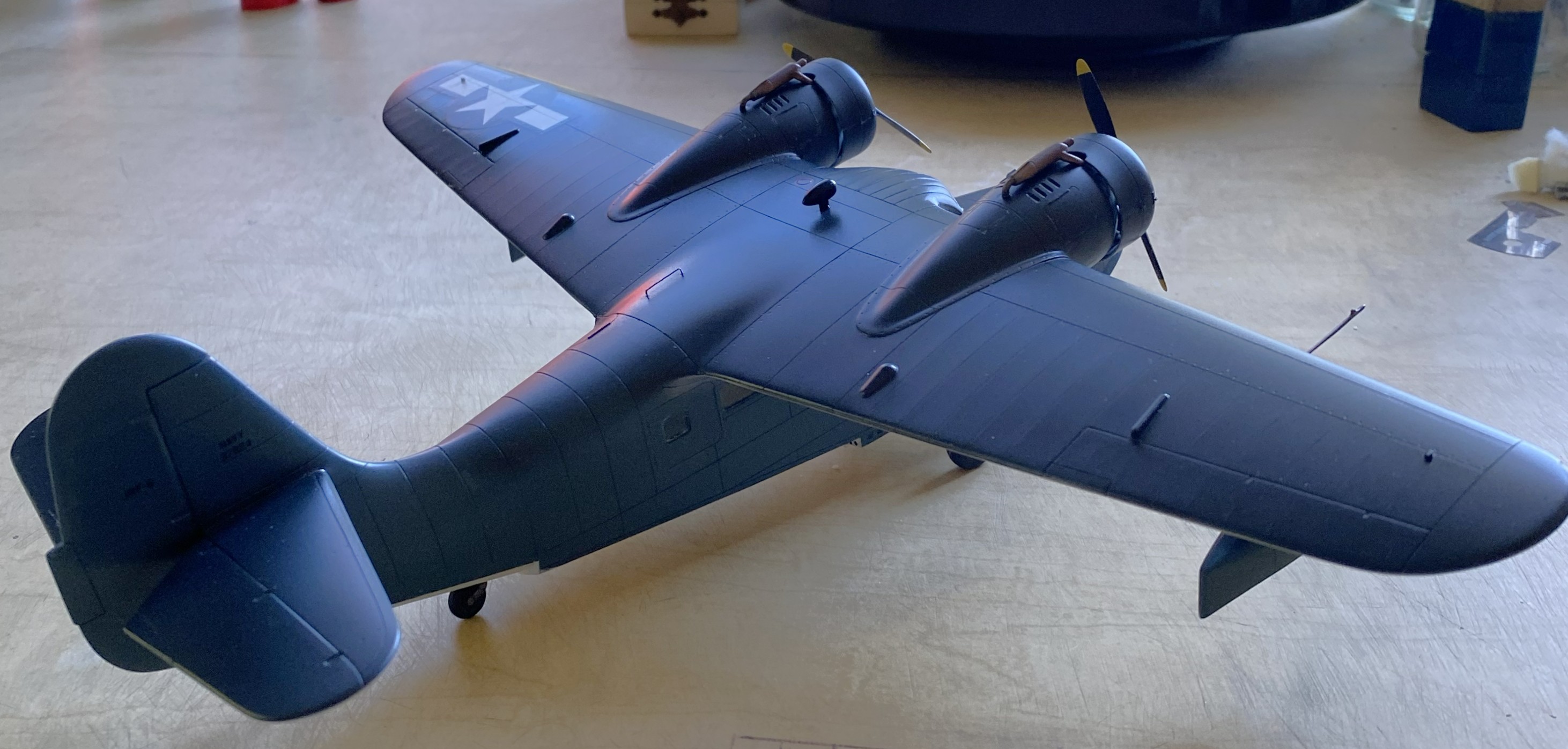
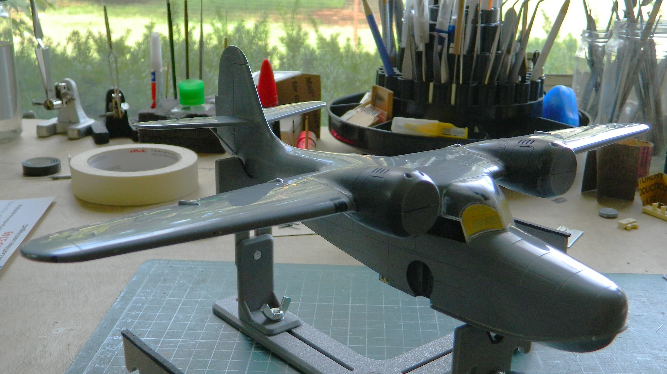
Increasingly, flat finishes on WWII aircraft are looking wrong to my eye. This time, I decided I’d do a semi-gloss (Tamiya X-35 Semi Gloss Clear) instead. This is where painting order becomes important. I have three basic areas to paint (not counting all the smaller details that haven’t been added yet, such as the floats in the photo below), top, bottom, and sides. I held the build by the sides and shot the top with semi-gloss. Once that set overnight, I did the bottom the same way. Doing it in this order meant that I’d have the wings to hold and manipulate the model during painting. The last thing to paint was the sides because now I can hold it by the wings:


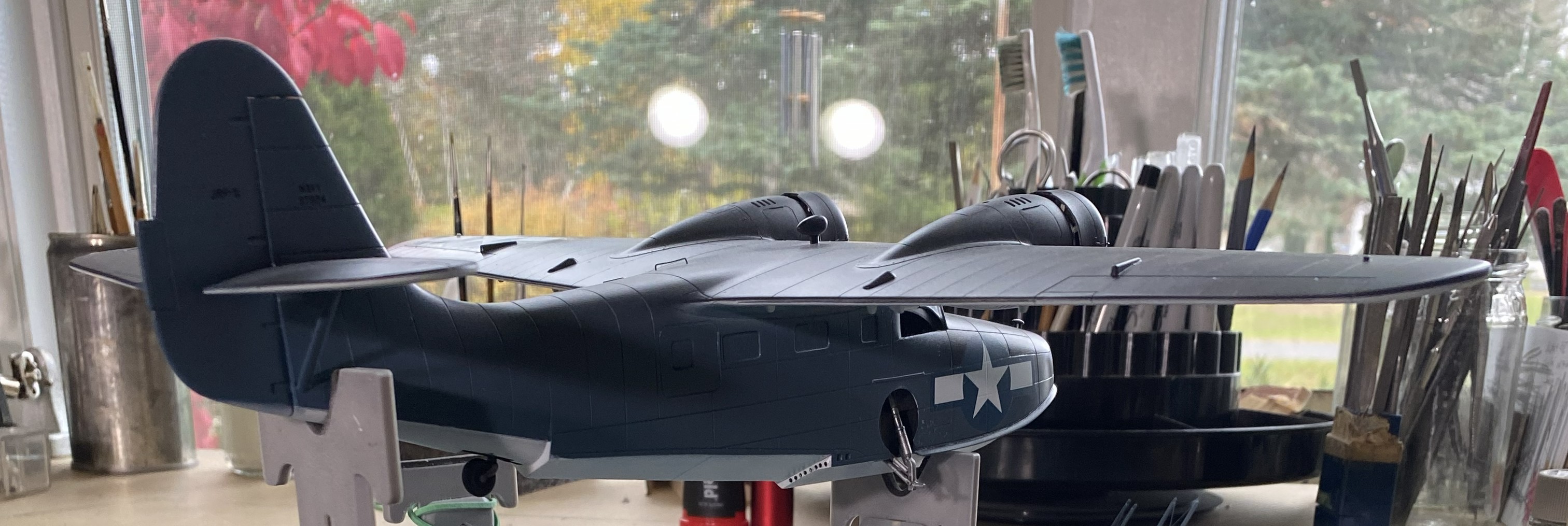


The next drill is going to be figuring out how to get this to sit level. It’s about 1/32″ (a little more than 1.5mm) off from side to side. This will be fun to fix. But to get that measurement, I had to have this build standing on its feet. While I had the wheels on, I decided to stick the props on as well to get a notion as to how it will display:

Not badly, methinks. Hopefully next month sees me to the end of this.
Grumman JRF Goose (Czech Model) 1/48 Scale Build #5 – I Pick Up Where I Left Off
There was no real update here since June. July was miserable on the personal front and having to deal with the profoundly rotten fit of everything was just enough to put me to redline. I needed to walk away from this for a bit, and the kit needed me to walk away for it to survive.
[I am also starting to bore myself with continually carping about how lousy this kit is. So take it as a baseline that this kit is a turd…a large and foul-smelling turd. More than enough said about that.]
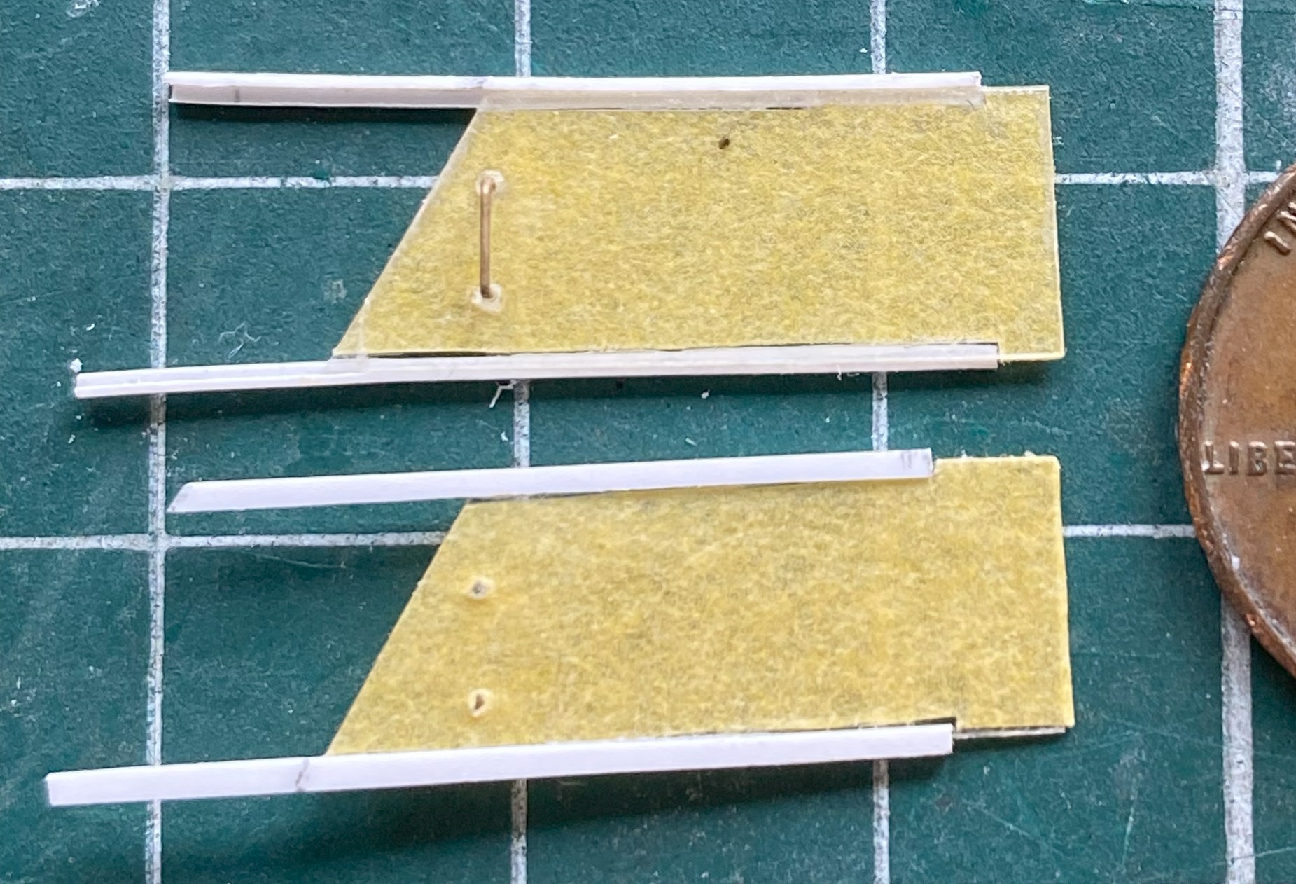
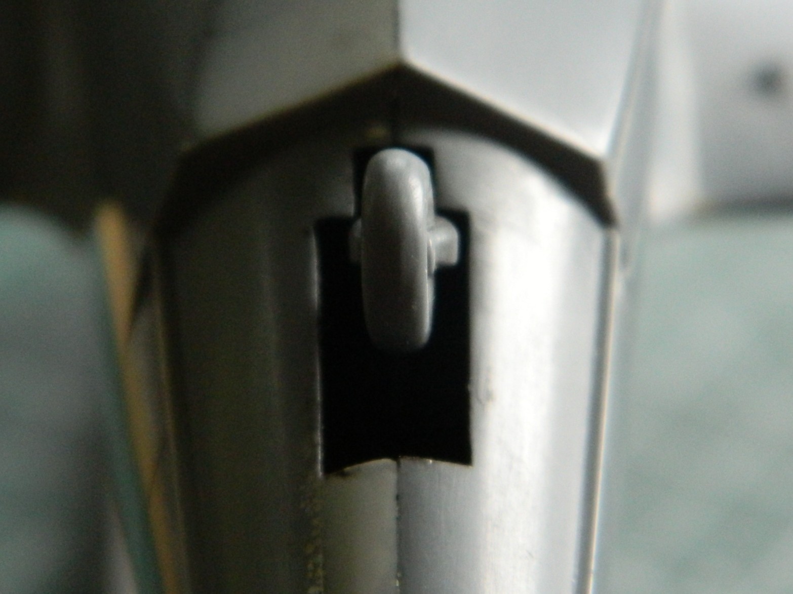
After cutting away the side windows of the clear part, I needed to make something more accurate. I used 0.010″ (.25mm) flat clear styrene. The side windows of the cockpit on the actual aircraft are flat and slide in L-shaped tracks (one of which is at the bottom of the following photo) with handholds inside. To keep from scratching the clear plastic, it was covered in masking tape, and the handholds were made from 24awg wire:

This is how I made the L-channels. I used scrap 0.010″ (254mm), aligned them to be perpendicular, and then glued the hell out of the join. After letting it sit for a few days, I started by cutting the plastic (and it’s made from so much plastic to enable me to grab hold of it) back and then using an emery board to straighten out the sides of it:

Instead of mounting the tracks and figuring out how to paint everything and then get the windows into place without scratching paint, I decided instead to figure out how far back the sliding windows were on the actual aircraft, trim the length of the tracks appropriately, and then trim the masking tape from the outside of the windows and then glue the tracks in place (one is shown above):
I’d played around with the floats earlier on and now it’s time to start adding the braces. (The stainless steel wire was sourced from a closed dental practice and it’s come in quite handy!) I drilled holes where the struts meet the tanks and UV-setting resin was used to attach the wires:


Then I started dealing with the nightmarish landing gear. In order to have even a slight chance of having enough hands to hold three parts in very specific locations, I aligned the major control arms to the suspension upright and then drilled through control arm and strut so that I could use a bit of wire to hold them in place and yet still allow enough movement to align everything without scattering parts by dropping them frequently:

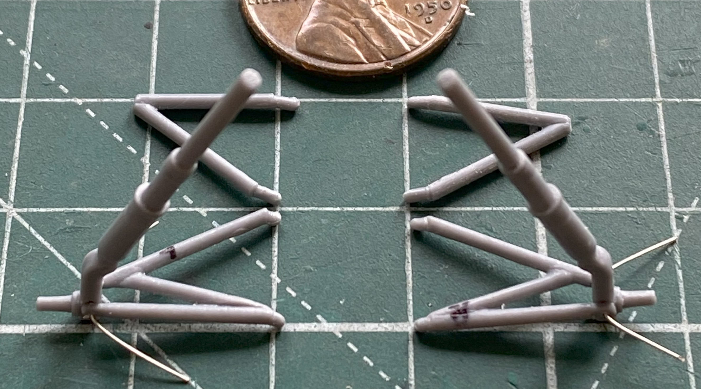
Getting all the landing gear parts to align was SO frustrating that I came within a hair of hanging this model from a tree so that I can see how many shots of 00 buckshot it would take to powderize this styrene cunt. It took several days to figure out how all these parts will fit (or, made to fit) and I think I finally have. I don’t think it’s time to add these frail things, but install now or later, I’ll figure out exactly how to do this. Stay tune for colorful (if anatomically impossible) invective when that process starts.
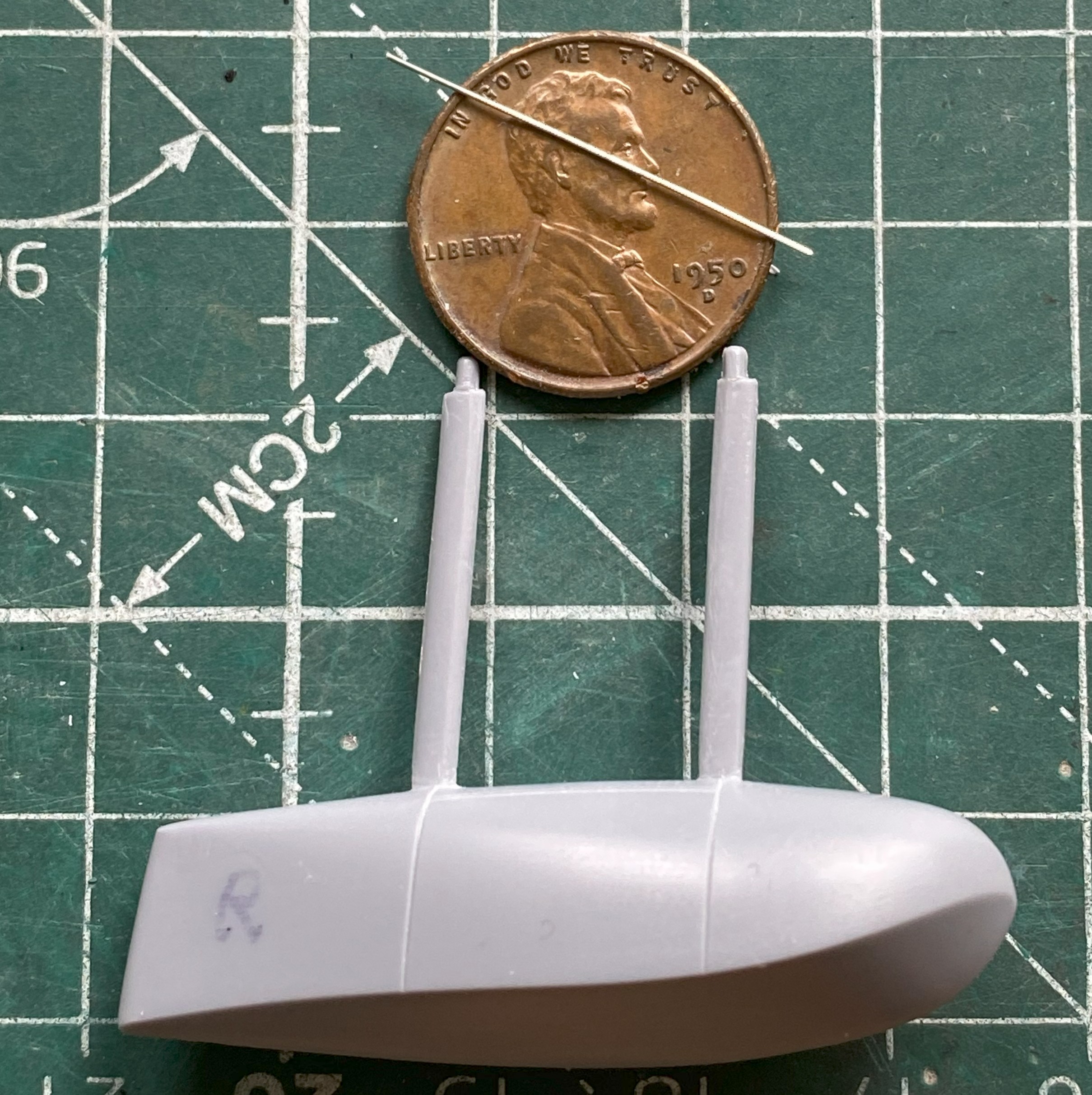
One part of the strut assembly is the oleo. It’s the part of the landing gear that functions as an oscillation damper (or, as we mistakenly call it in the States, a “shock” absorber). I’ve so HAD IT with this build that I didn’t even consider replacing the styrene rod with steel. Fuck it, in other words. But since it’s steel, I used Humbrol’s Metal Cote Steel #27003. While the airbrush was loaded with this paint, I also painted the pitot tube as well:
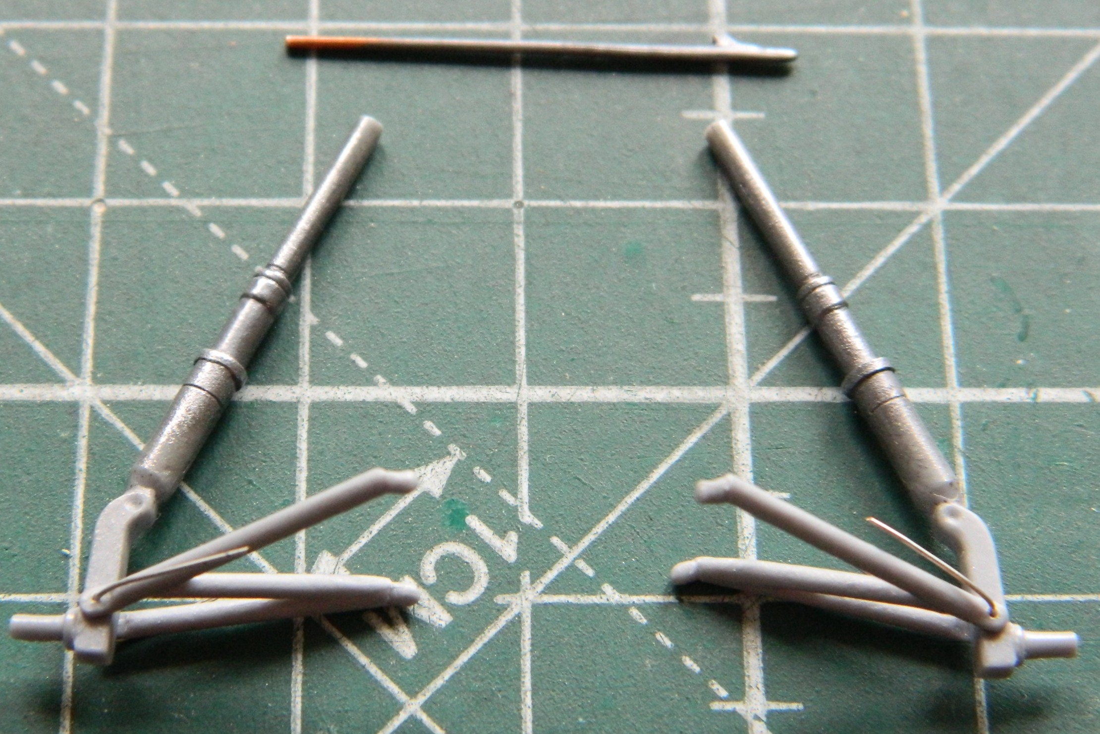
Since I was working with landing gear, I went back to the tail wheel. The next thing I’m going to load the air brush with will be aluminum, so I wanted to get all the parts that I need painted aluminum (at least right now) ready to paint. And then I encountered a surprise…
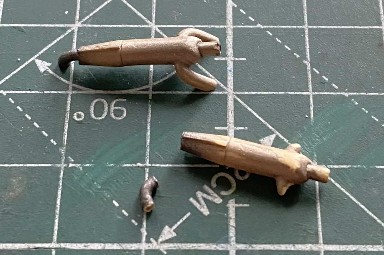
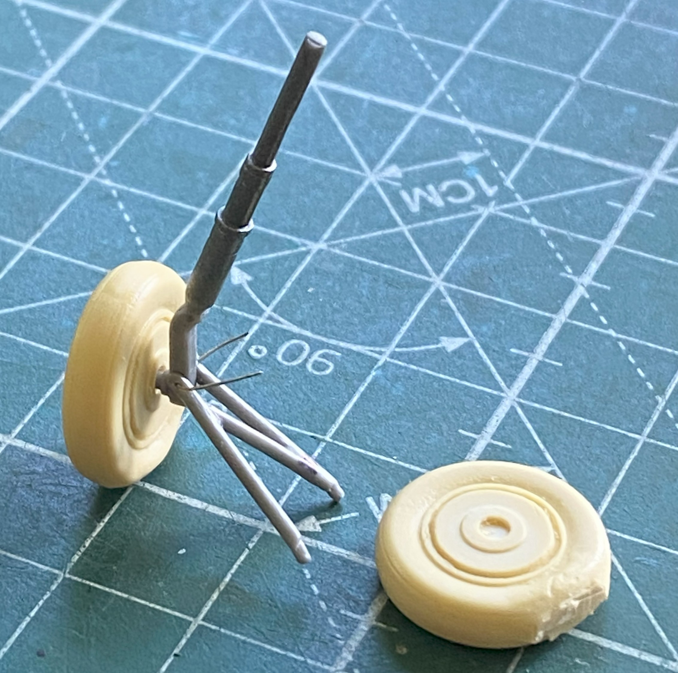
I worked this little part over for a while. Unsurprisingly, it was poorly molded, which was why I’d done some delicate knife-work to clean up the part. It was glaringly obvious that the wheel and strut were molded one piece…and not very well molded. What surprised me was discovering that the part, as molded, is twisted. The mounting pin is vertical to the camera. The yoke is bent to the right, and the tire is also bent to the right as well as being twisted:

After overcomplicating things but only in my head this time, I decided to see if I could diddle how it’s mounted sufficiently enough for the bent and twisted tail wheel assembly to appear as if it’s in there straight, which it is not. The bulk of the model combined with how close to the ground the tail will be combine to make this cheap fix possible. I’ll spend more time when it’s mounted to get this seeming as close to correct as I can without spending a week of surgery on it to correct it (modeling…it just has to look correct):

I’ve made no secret of the fact that I really dislike True Details’ items. Characteristic of that firm, their “flattened” tires look more like “underinflated” tires…and that’s only on their (relatively) “good” examples. The tires with this kit aren’t in that class. Even for True Details, these things look hastily done. Note how pitted the surface of the right wheel/tire are…and some of those pits are bubbles in the resin (of which I’m NOT a fan). The one on the left has been worked a bit to reduce the bulges on the side and I’m considering working them more before black paint is shot at them:
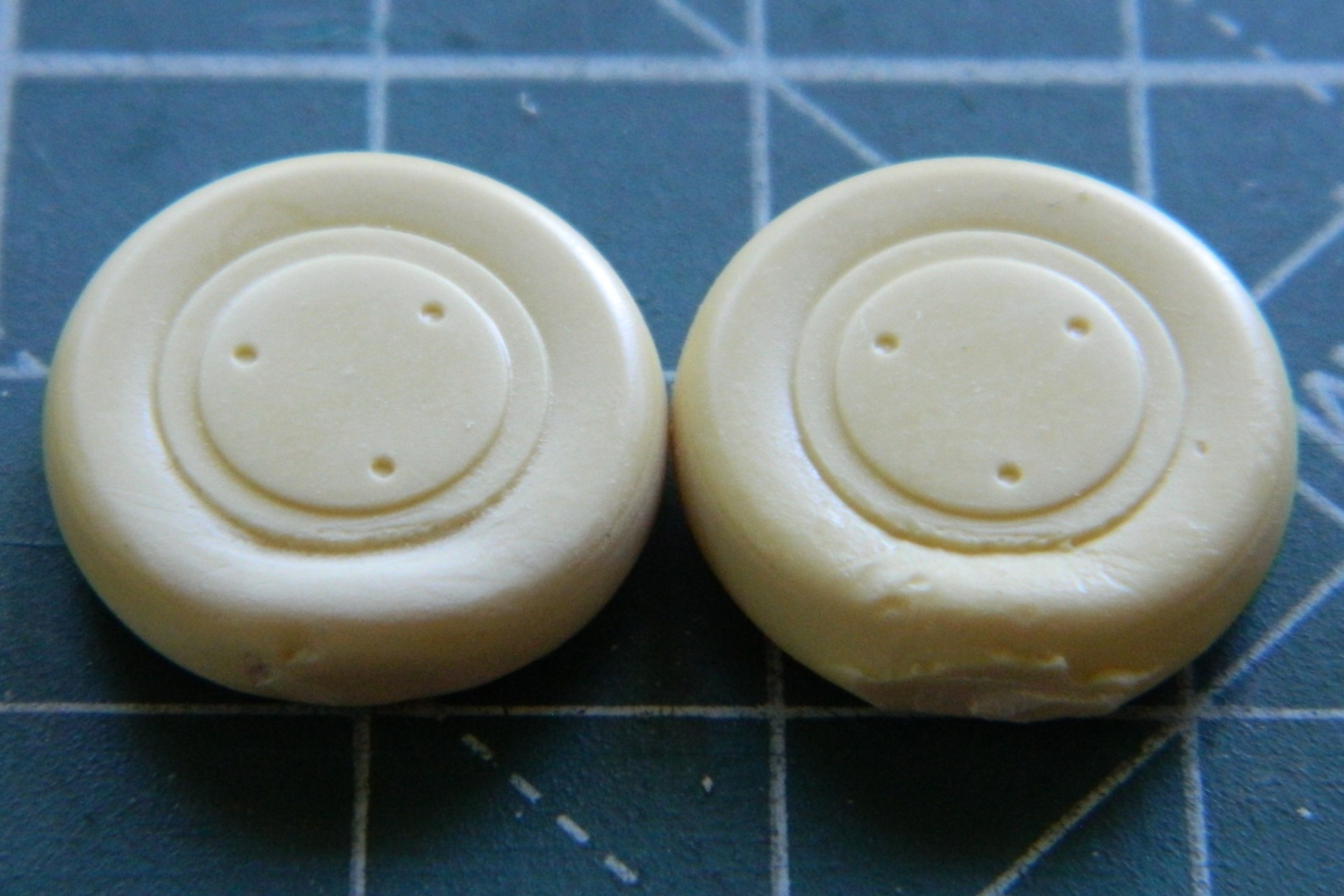
The backs had to be drilled to accept the mounting stub and since this bird had drum brakes, I used a tiny piece of styrene scrap to (not shown in this photo) replicate the mounting lug for the brake lines I’ll be adding later:
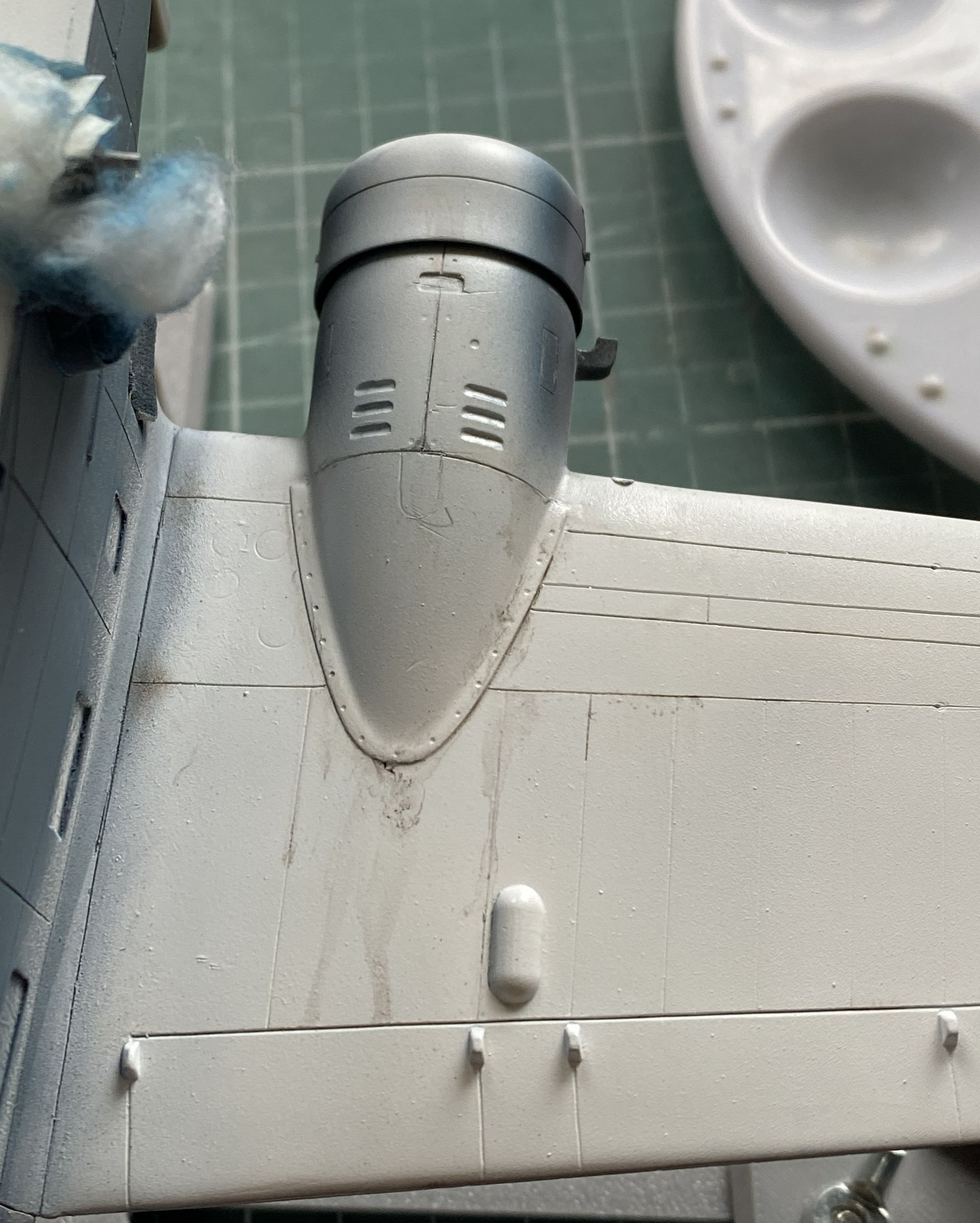
There are prominent heat-exchangers (for cabin heating) that mount externally on top of the engine nacelles. What’s provided is another True Detail bit of (disappointing) resin. I worked the one in the bottom of the next photo, the top part is as it came off the pouring block (they’re upside down in the photo):

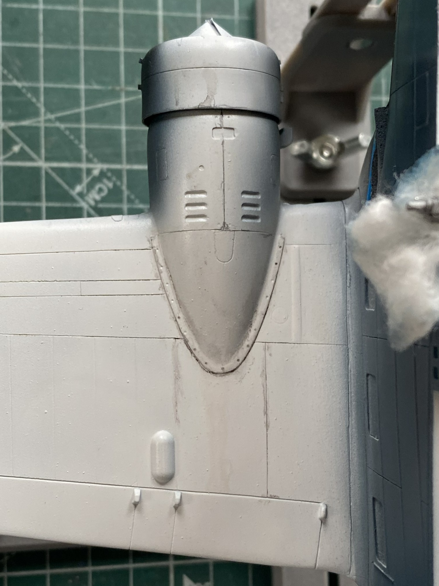
My next adventure in annoyance was the splash shield on the nose. It was too thick and too wide. It was also very fragile, so I put off thinning and shaping it until it was glued in place. Of course it didn’t fit and I had to add a little piece of scrap to enable it to fit:

I set that aside for the glue to thoroughly set and started fitting the landing gear into the space provided. It was during this process that I almost lost my shit and, again, had to walk away for a few days. It doesn’t fit where the spot that was provided for it is. That’s, “wrong mount locations”, the long form. Once I calmed down, I decided that where they would fit is where I’m going to put them. From my efforts so far, SO much work is going to be required to get the entire landing gear in place that I will probably forego my usual practice of adding landing gear as late as possible. If I do that, I suspect that I’m really going to damage the color coats, so I’m thinking that the landing gear will get added prior to painting because I’m really quite tired of redoing and redoing and redoing to get the damned thing as accurate as I can. In the following photo, whereas the lower control arms are where they’re supposed to go, the strut is not. And I have less than no idea how the upper control arms are going to mount:
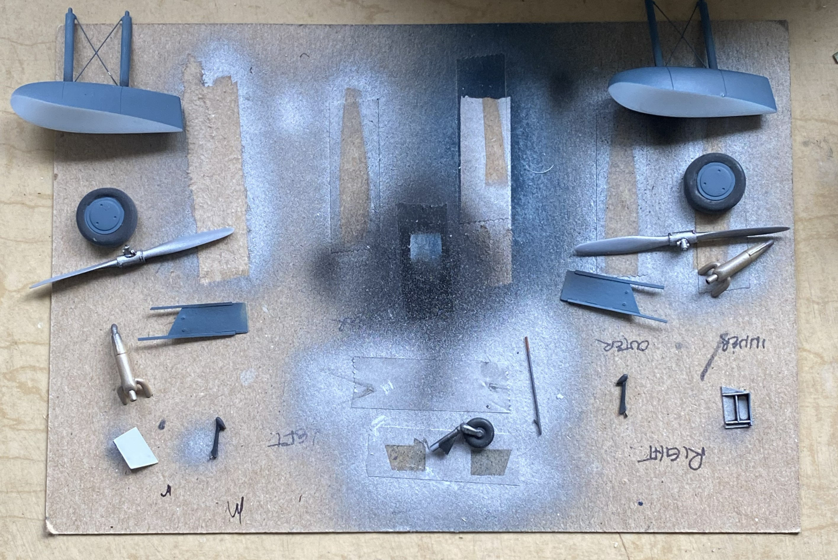
So with that set of problems hovering just out of sight, it was time to throw some aluminum paint (Tamiya XF-16 Flat Aluminum) onto these parts which are main and tail landing gear parts, the backs of the wheels, and the inside of the lower landing gear doors (the parts that the airbrush would launch into the next county are held down with double-sided tape):

And while I had the airbrush loaded with aluminum, I misted some into the landing gear bays:

And of course I had to touch up a fair amount of scribing and when tools skated across the surfaces:


There were more than just the two above.
The clear part over the flight deck wasn’t cooperating. I kept having to add more putty, more plastic, MORE putty, and more plastic:
Going back to the splash shield on the nose, the fin was thinned out and narrowed, and it looks much better. There was a gap in places where the shield attaches that needed to go away. More (and frequently added to) putty:


The splash shield is so thin that I ended up having to reinforce a spot using sprue; I didn’t have enough contact surface of the fin-to-fuselage join for it to stay attached:
And then I dropped the damned thing. I had to reattach the pilot’s seat, put the tail-planes back on, and hit a few spots where the sides of the V of the hull meet to form the apex of the V.
::sighs::
The tail-planes went back on easily:
And at this point, it was the only damage I’d seen. As I was rolling the fuselage around to align each tail-plane correctly, I heard a very, very, faint rattle from the cockpit. Investigation showed me that the pilot’s seat was 95% dislodged. It’s the seat in the next photo that looks like it’s tilted forward (because it’s tilted forward):

There are no words that will adequately express how I reacted. “Not well” doesn’t begin to cover it.
Okay, so I have to get in there to reattach it. No, in my wildest fantasy (and it’s pretty wild) can I access the base of that seat through the open windows. No, cutting open the top won’t work either. I’d put that seat in with the entire clear part absent and you see what that got me. I let it sit for a few days (or more) while I figured out the least-bad way to get at the base of that seat.
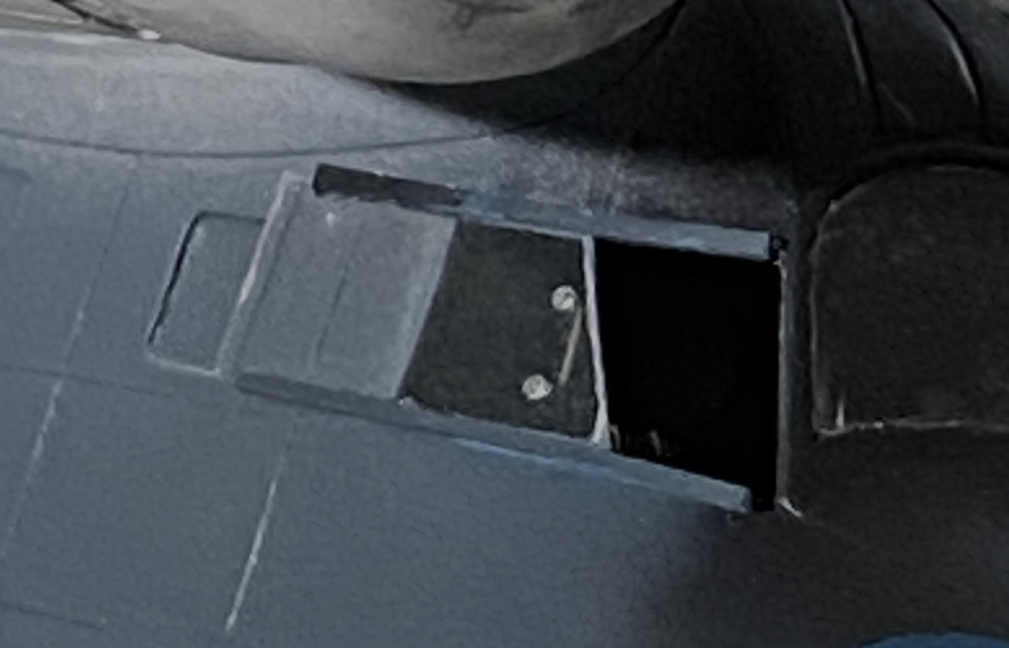
I have to cut the side open to get at it. As a guide for the scriber(s) that start the cut, I used a piece of Dymo label tape as a guide:
I kept the cuts along the panel lines whenever possible. The speckles on the seat are plastic and resin bits (because by going through the side, I also went through the resin detail panel attached to the side (the arrow points to one of the legs that has to be reattached):

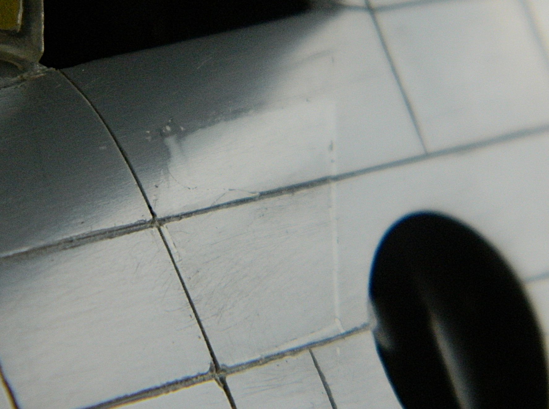
But the cutaway allowed me access to three of the four attachment points, all of which were glued THOROUGHLY to the floor. The fix probably took 3-4 minutes, then the excised panel had to go back. In most places, I added 0.010″ (.254mm) scrap to replace the kerf, and most of the cut areas also received stretched sprue over the top of the styrene:

However. It seems that before the glue had cured completely, I’d pressed on the top of the excision and failed to notice. When I started removing excess plastic is when I saw that the top and top-left corner needed to be raised up. I used 0.010″ (.254mm) instead of putty to do that:
By this point I’ve noticed that the edge of the V hull had cracked. I stretched some sprue with the intent of filling in the fix while the filler plastic next to the cockpit cured:


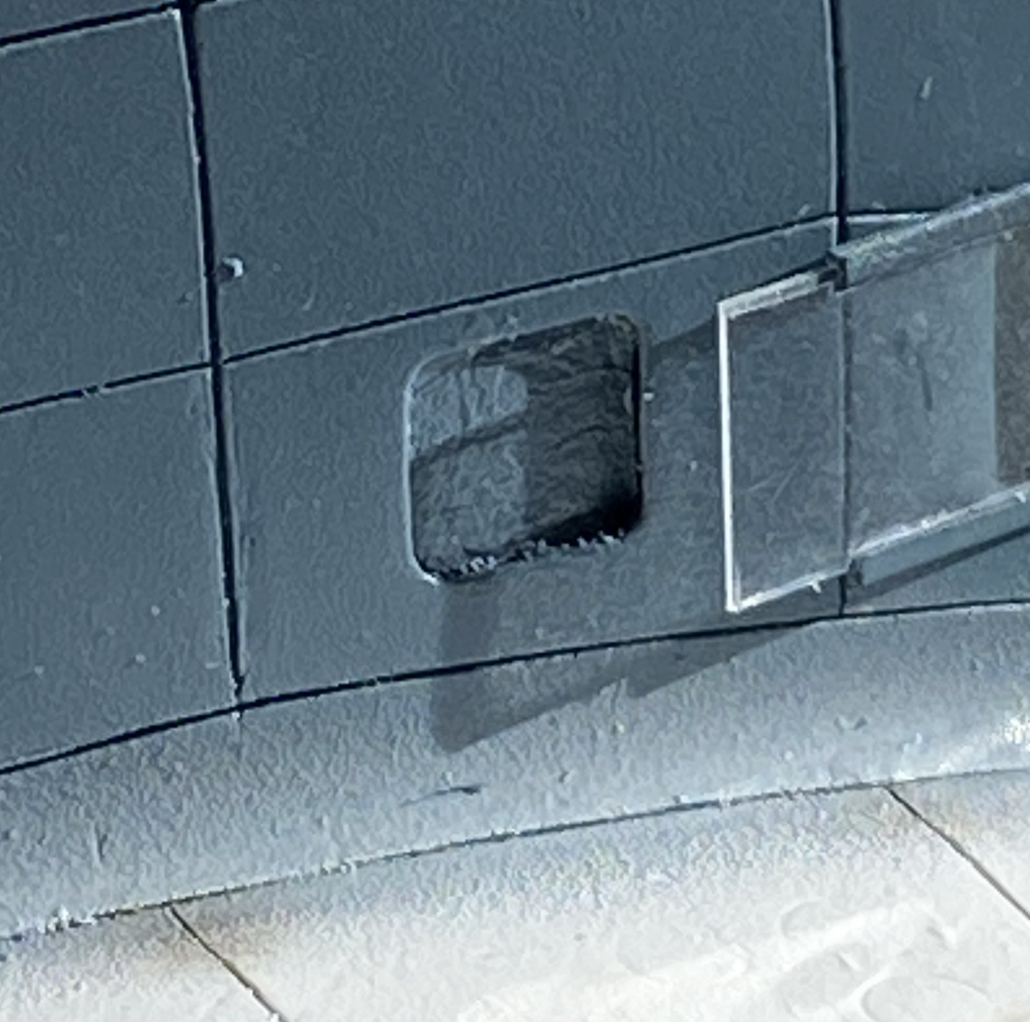
So with that repaired, I finished off (mostly…there’s a detail I have to add back) the excision:
And now that I’m at the middle of this month, I’ve spent most of the past two and a half weeks getting back to where I was when the month started:
Unless I drop the model…again…next month should see me get this thing under paint and on the way with attaching all the stuff that is too fragile to attach sooner.
F7F-3 (AMT/Italeri) 1/48 Scale Build #4 –Engines Get Painted, the Landing Gear Bays and Landing Gear are Pre-shaded, and the Landing Gear is Installed
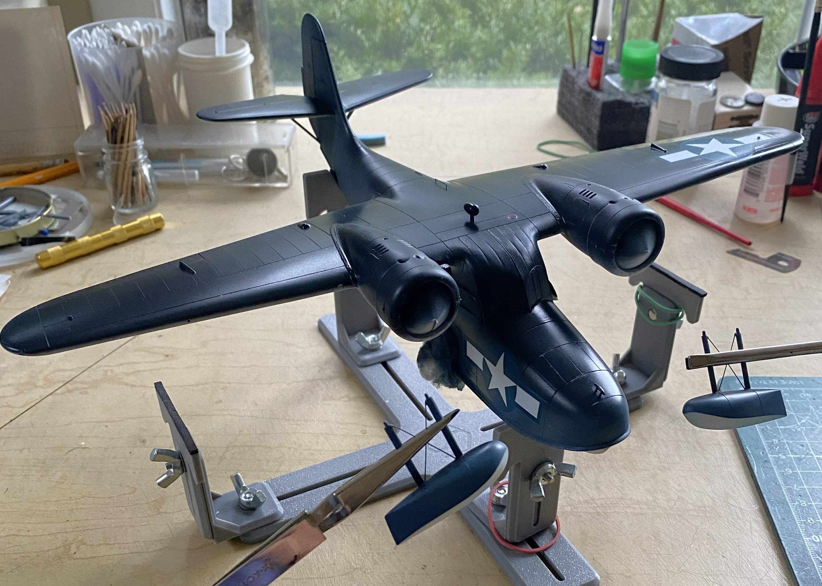
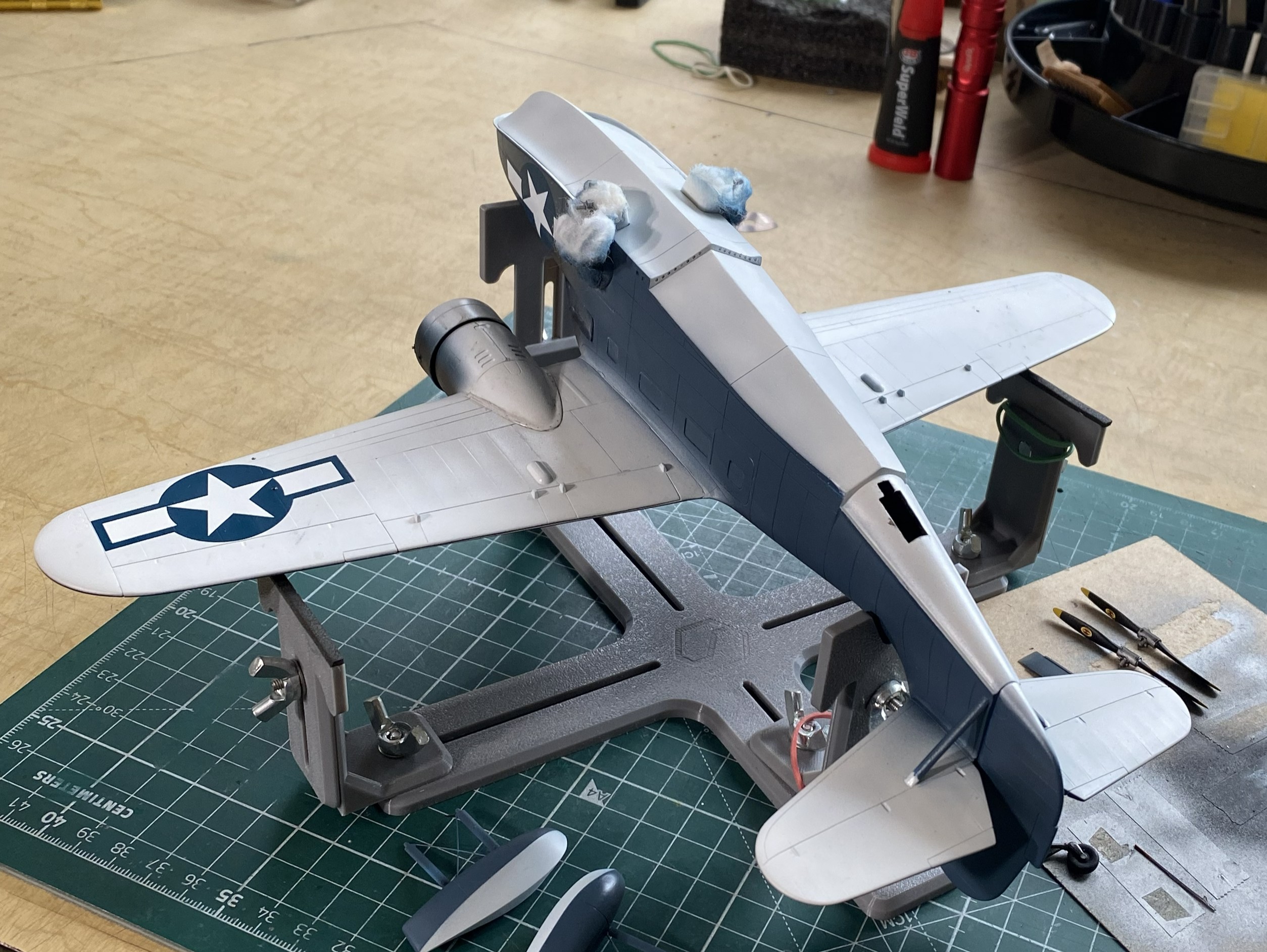
I started this month by asking (and getting an answer) to the question that has been obvious to me. Will this thing sit on its landing gear or will I be another modeler who needs to use something under the tail to keep it off the table. By this point, I’ve stuffed lead and tungsten into any space they’ll fit, so I taped all the major components together to see if I’m even close. I placed the taped-together parts on my fuselage stand with the horizontal supports in touch with the model in line with where the landing gear struts mount:

Yes! It will indeed sit on all three of its tires, though the balance as the nose tire resting ever so gently on the surface. And this is done with zero weight in the nose (not much space but lead will obey the hammer and can be coerced into the shape I need), so since I will be adding more weight to the nose and the forward section of the drop tank (because it extends forward of where the main tires touch the surface). I don’t want an errant breeze having this thing squat like a dog having a slash.
Hammer time:
With the Big Question answered, hammer time segued into airbrush time. The engines were pre-shaded with Tamiya XF-1 Flat Black. The crankcase and its bits were brush-painted Tamiya XF-53 Neutral Grey, the ignition tube surrounding the crankcase was painted a mixture of Tamiya XF-6 Copper (two parts) and XF-1 Flat Black (one part), and the wires were done with a mix of Tamiya XF-57 Buff (three parts), and XF-10 Flat Brown (one part). The front of the rocker arm covers were lightly dry-brushed with Tamiya XF-16 Flat Aluminum. The cooling fins were lightly touched with a silver pencil. Then I took a round toothpick with a chisel tip cut onto it to scrape the flat black off the pushrod shrouds:

The kit’s pins to mount the propellers didn’t come close to fitting the engines, so I drilled the engines out to accept sections of 0.062″ (1.57mm) instead. (Pain in the thing I’m sitting on that isn’t a chair getting them perpendicular to the crankcases!):
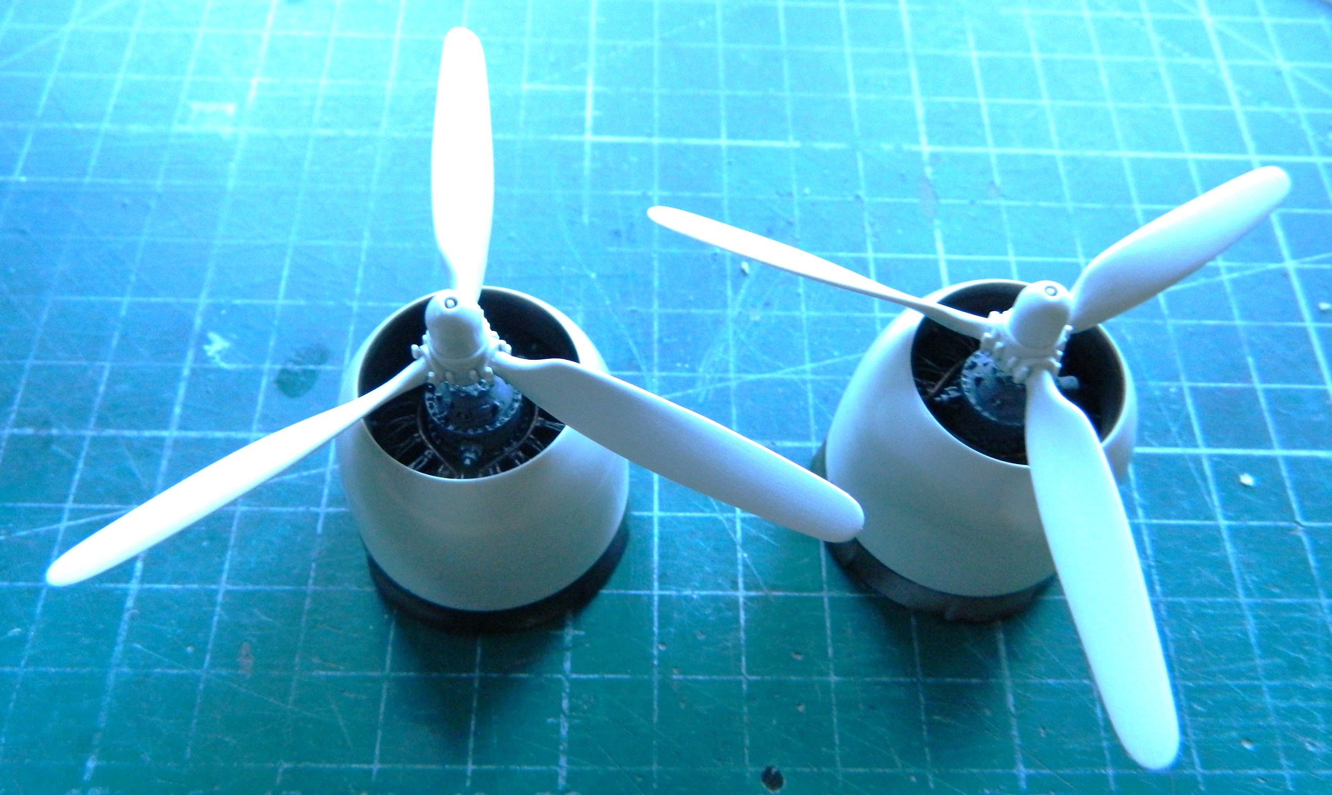

Not a lot showing but that’s as it’s supposed to be.
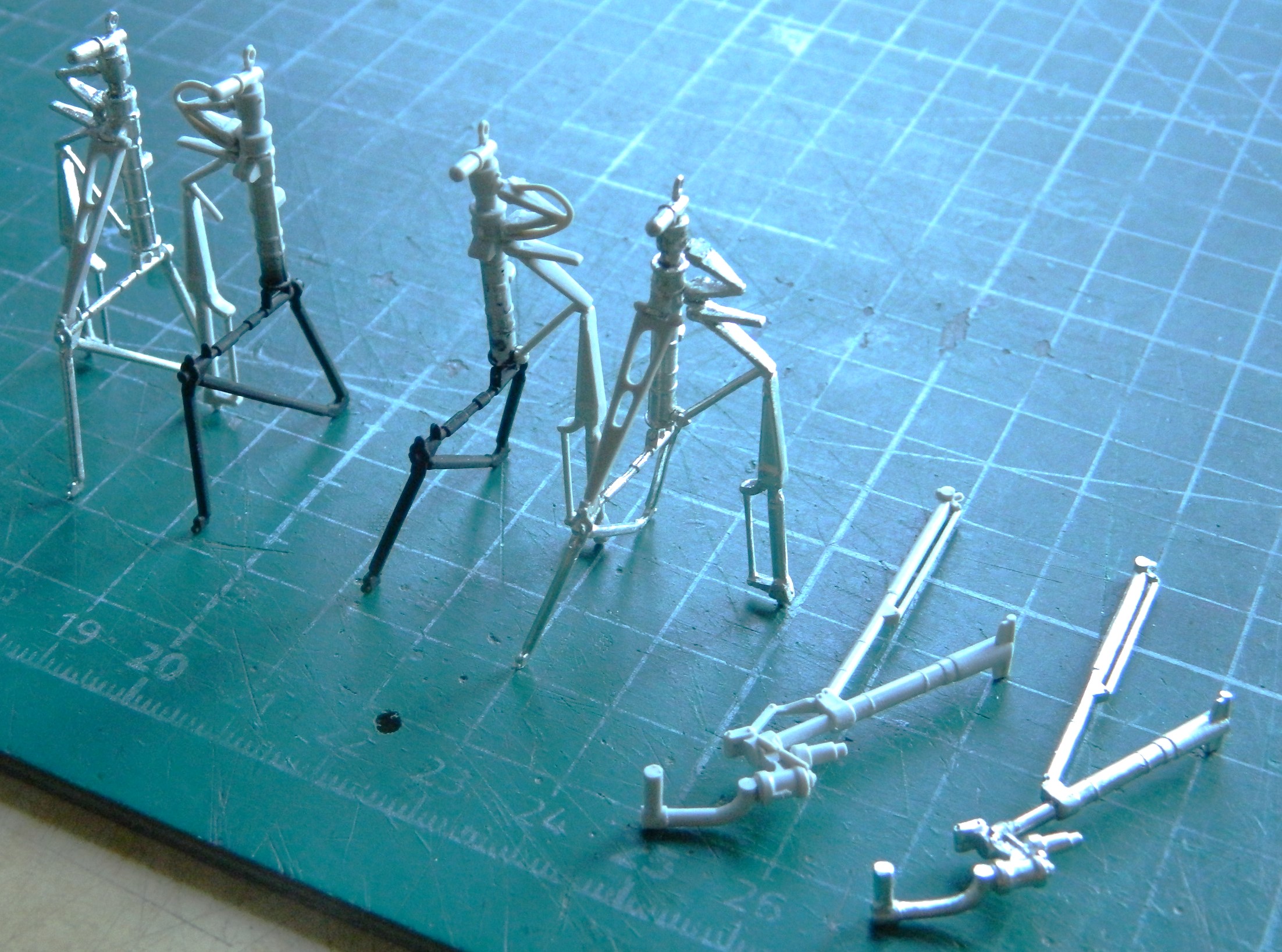
Then it was time to fart around…forever…with the landing gear. My initial notion of using the metal parts was set aside because the alloy is so malleable that working them was akin to trying to work the surface of cooked spaghetti (okay…maybe not that flexible, but after far too many times having to straighten something out I considered going to get tomato sauce and grated cheese) (couldn’t find the cheese and by the time I had, I’d sobered up, so…). I still had the plastic parts from the kit (which I’d assembled to act as a form so that I knew how far to bend the spag…er…metal parts), so I decided to use them instead and hope that this thing didn’t squat over time. I finished off almost all the parts when I found this:

Most of you probably knows what a “short shot” is (and no…it doesn’t mean that). For those of you who don’t (or think it does mean that), it’s when the liquid plastic pumped into the molds doesn’t fill the void completely. That’s what happened (or didn’t happen) to the lower part in the above photo.
Fine. I’ll use the damned metal parts, then. (And yes…I pouted.) (Probably more because I did sober up but some of the lower lip extension was because I had to change my mind back.):

I can be pretty funny sometimes. When I took the above photo, I thought I had everything finally aligned.
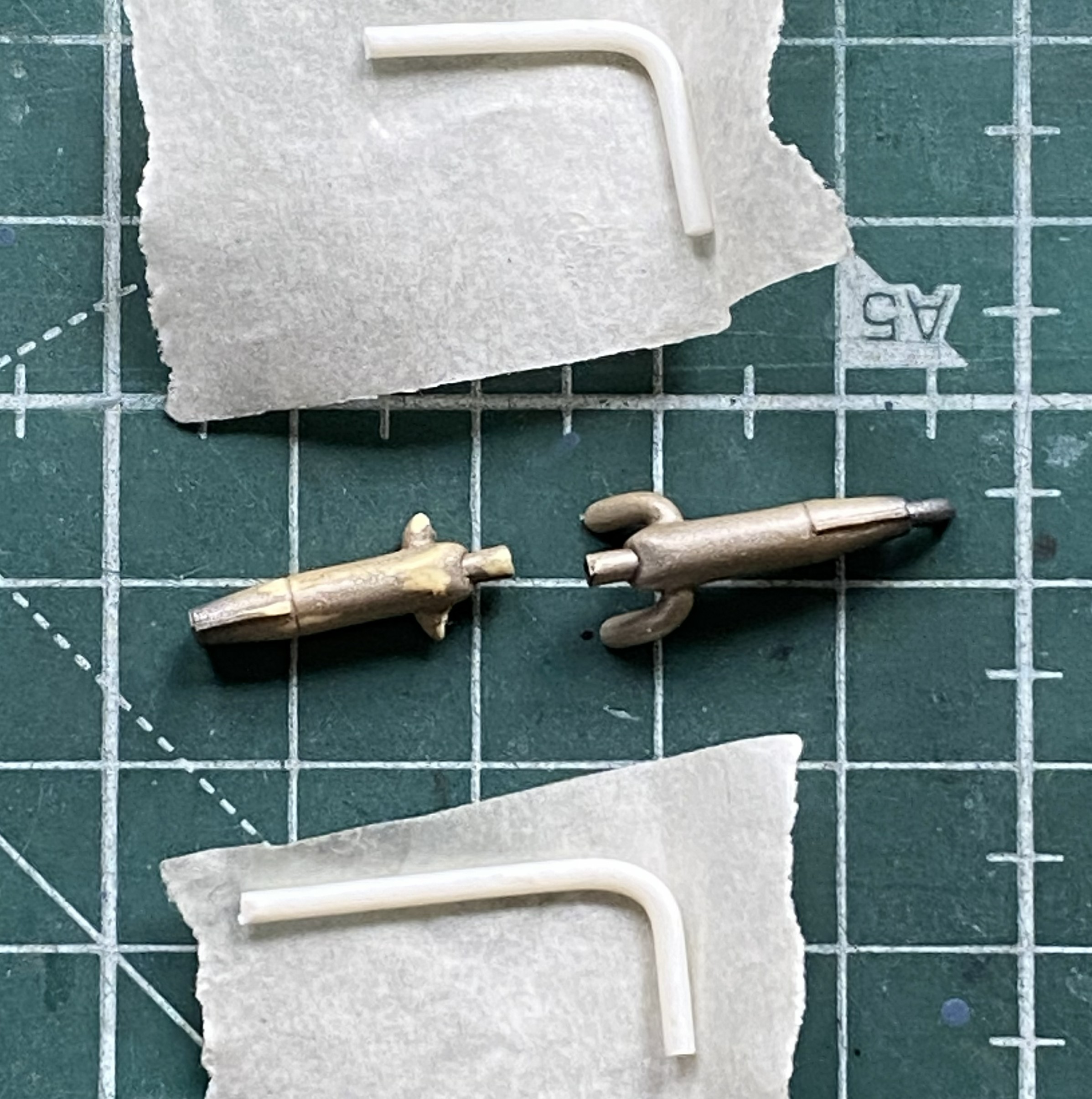
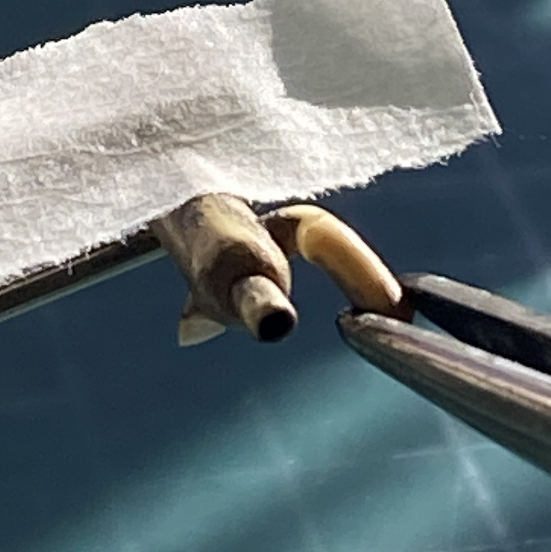
I used the kit’s oleo extension arms on the main gear, but used the arms from the PE set for the nose landing gear (that’s the brass-colored part):

And just as an aside (and because I don’t have a lot to show here for this month, so it’s filler), a few years ago I heard about these, bought a set (which comprises four separate sets of what’s pictured below), and plan to use them on this build (which, with my typical aplomb, I totally forgot that I had until I was looking for something else):
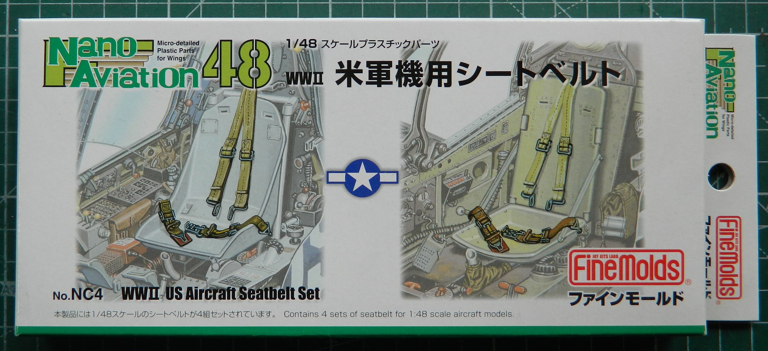

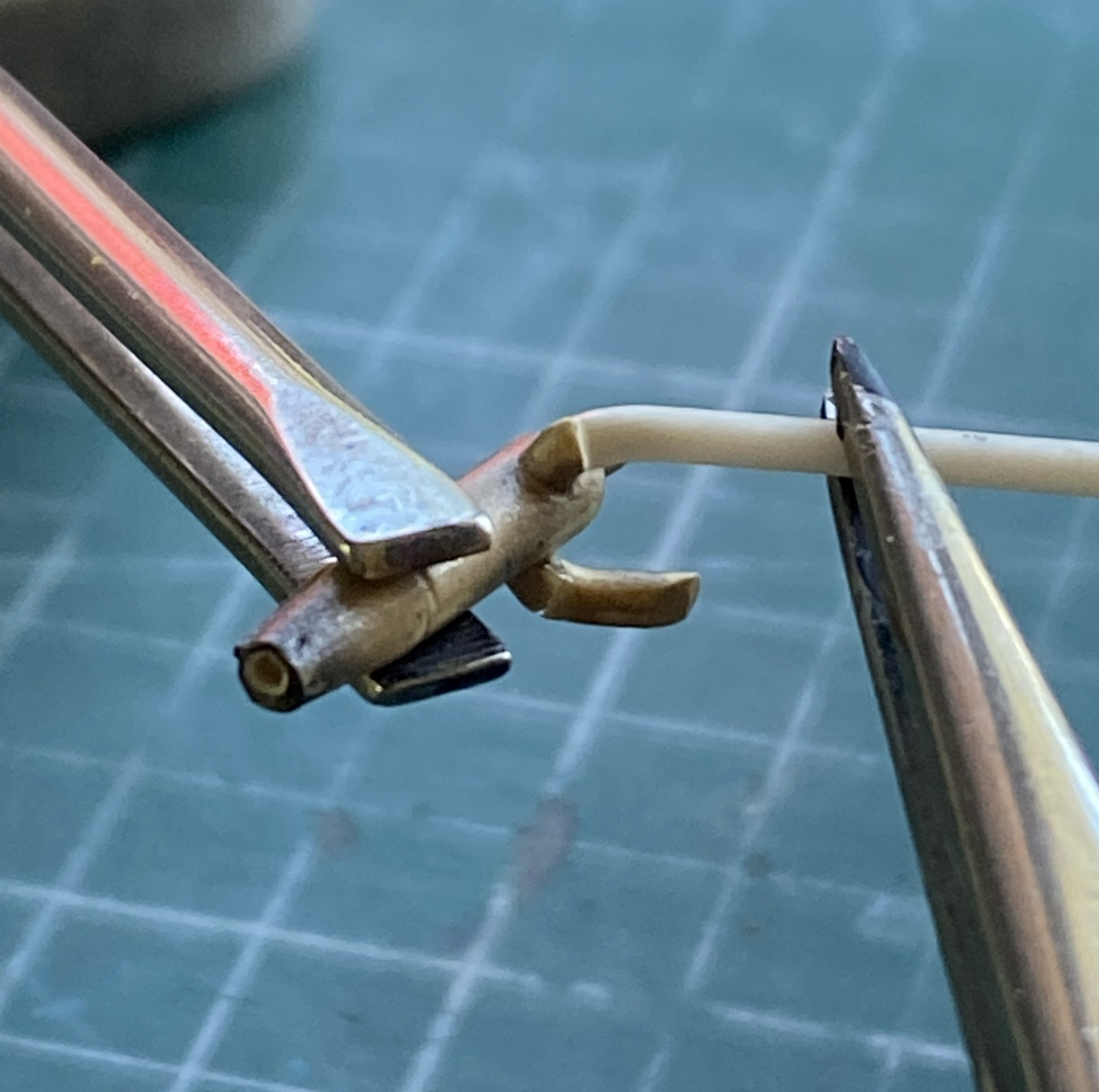
They’re nicely molded with good detail. I’m probably going to have so much fun bending and shaping what needs to be bent and shaped. We’ll see if the effort is worth the result.
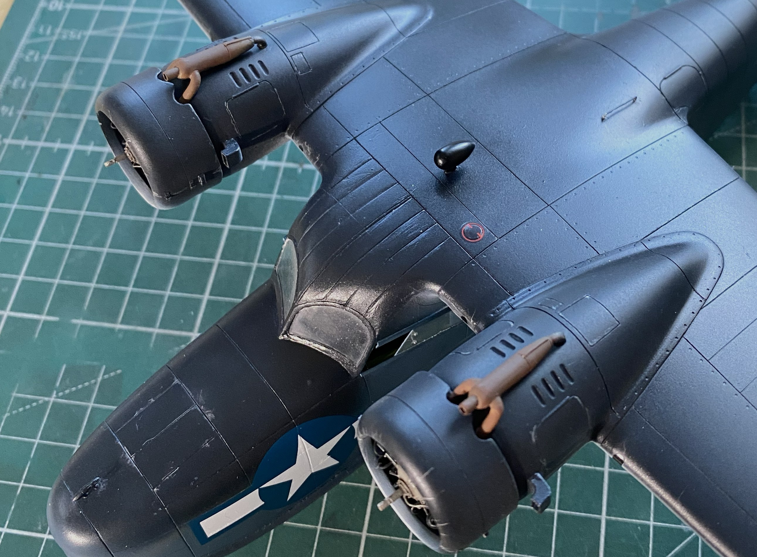
There are outlets for the oil coolers and the covers for the outlets are variable. The PE set offered replacements for what’s molded onto the wing tops but I decided to see if I could thin out what’s there sufficiently:
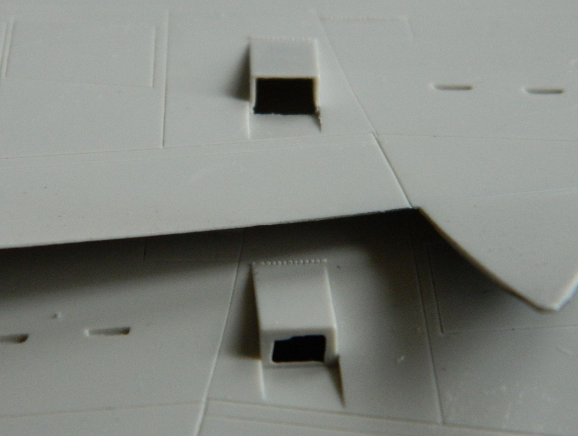
Yeah. That’s sufficient.
While doing the skull sweat regarding when the landing gear is permanently attached, I realized that trying to get the stupidly flexible metal landing gear inside the bays, things were going to be bent and badly so. Though I prefer to add things as delicate as these are as close to the end of the build as I can, that’s not going to work this time. Initially I thought it was because they’re so sodding bendable. Then when I tried to feed them into the bays from underneath, which is how they’d get attached later on, I discovered that they didn’t fit through the opening. ::sighs:: Okay, I’ll add them now:

Firmly glued in, out came the flat black again to pre-shade everything:

Next month these will all be painted aluminum. Who knows…I might even do other things as well.
