P-51 (Accurate Miniatures) Build #5 – Cockpit Work
My initial intention was to scratch-build the instrument panel. I don’t think either the kit-supplied part or the resin AM replacement offered anywhere near enough (accurate) details. There’s a company in Poland, Elementy Do Waloryzacii Modeli Plastikowiych, that makes a very nice photo-etched detail set for the P-51A (#S48-111). Since the differences between the P-51 and the P-51A cockpits are minor (no bomb/drop tank release, as the P-51 had provisions for neither), I picked up a set. I like PE parts for some things and I don’t like them for other things. The determining factor is the thickness of the metal being used. Sometimes it’s spot-on, other times it’s too thin. But since it was my intention to scratch-build the instrument panel anyway (using the Waldron instrument faces), I didn’t really think that would be a consideration. I used the PE part as the template and used my (freshly sharpened) panel scriber to cut closely around the PE template to create the panel’s frame and inner panel (they’re separate on Mustangs). To keep things from moving around, I taped the PE sheet to the plastic sheet and had at it:


Waldron’s punch and die set was a bit more than my wallet would bear, but Micro-Mark offered a cheaper set which I bought. I checked as closely as these 66-year-old eyes would allow seeing if the punch sizes worked with the gauge diameters (and they do) and then started punching holes in the plastic panel:

“I didn’t really think” is the operative phrase, there. The short-form of the problem is scale thicknesses. I came up just short of the room required to make an accurate representation of the locations of the gauges. I needed a few scale inches more width than reality provided to get everything to fit that I didn’t have. I briefly considered thinning the plastic on the fuselage sides to get those inches back and then realized that that would be SUBSTANTIALLY more hassle than simply using the PE set’s instrument panels (and beautifully reproduced gauge faces) and create other problems that I needed like I need a third buttock.
In looking at the brass and gauges, I realized I have no idea how to paint it and put it all together, the problem is in masking the three freakin’ tiny gauges that are located in the panel’s outer frame. Well, while (what’s left of) my brain worked on that conundrum, I started work on getting the rest of the cockpit to play well with each other and fit inside the fuselage.
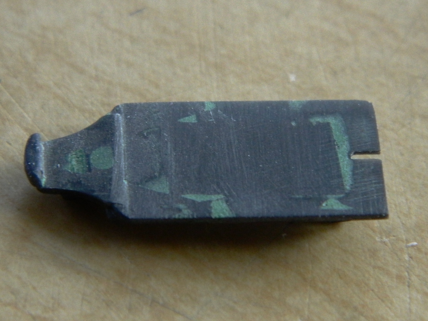
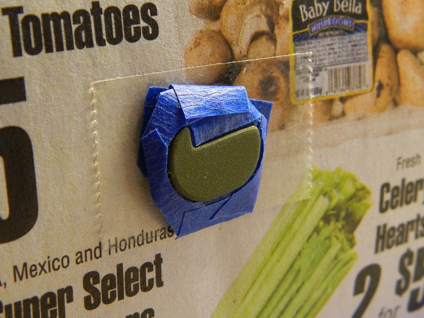
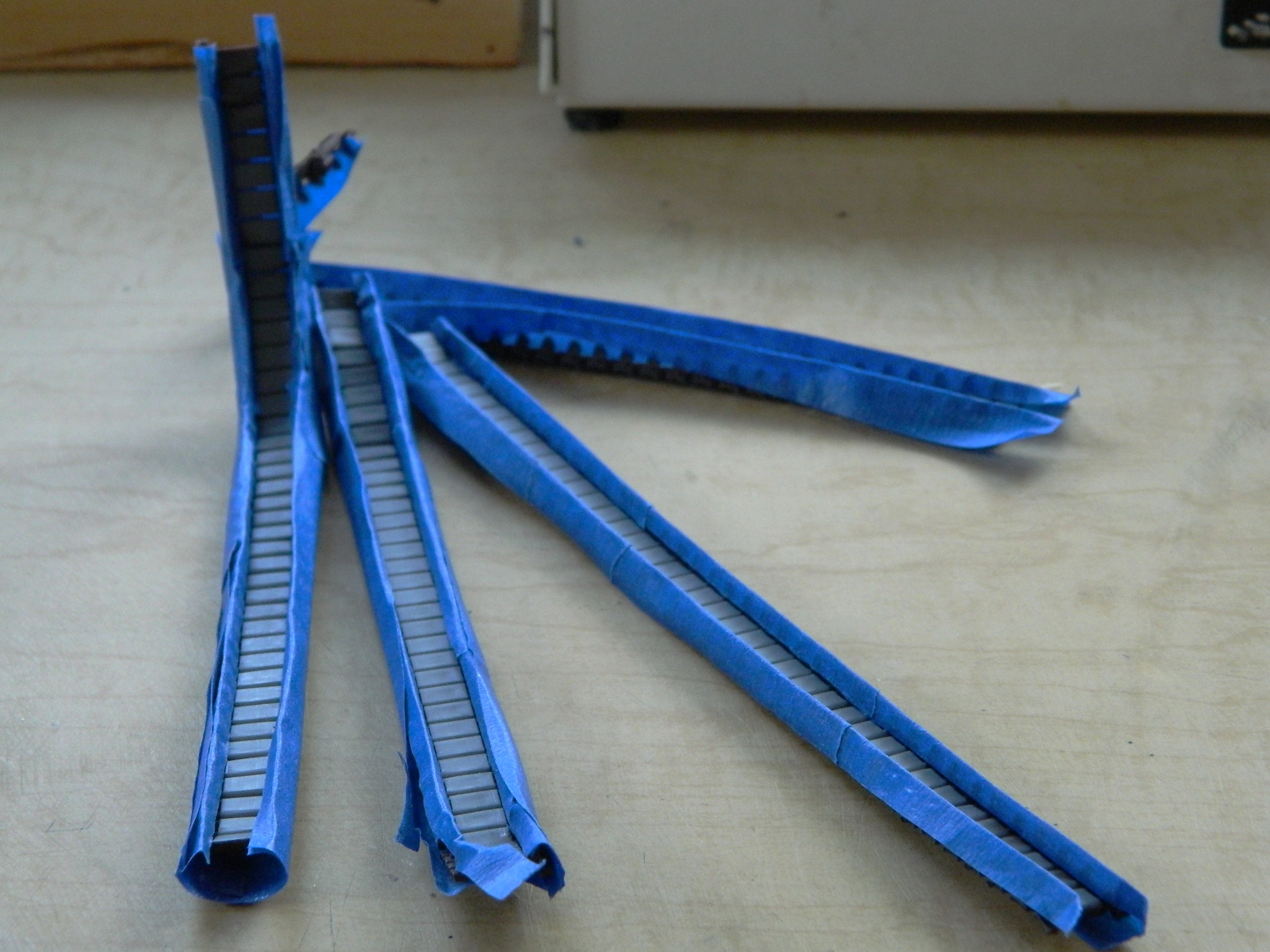
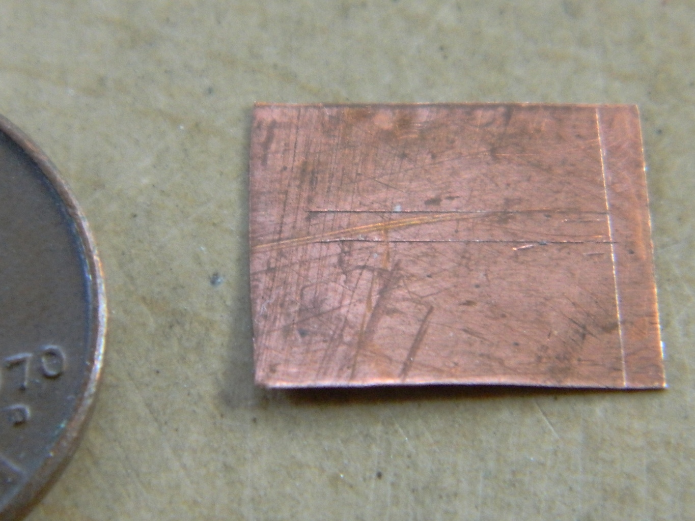
As stated in other places, I use copper wire, solder, and lead wool to replicate lines and conduits. Copper wire, solder, and certainly lead wool are not provided in straight sections, which are much more handy to work with and are often required to be straight. So how do I get from this:

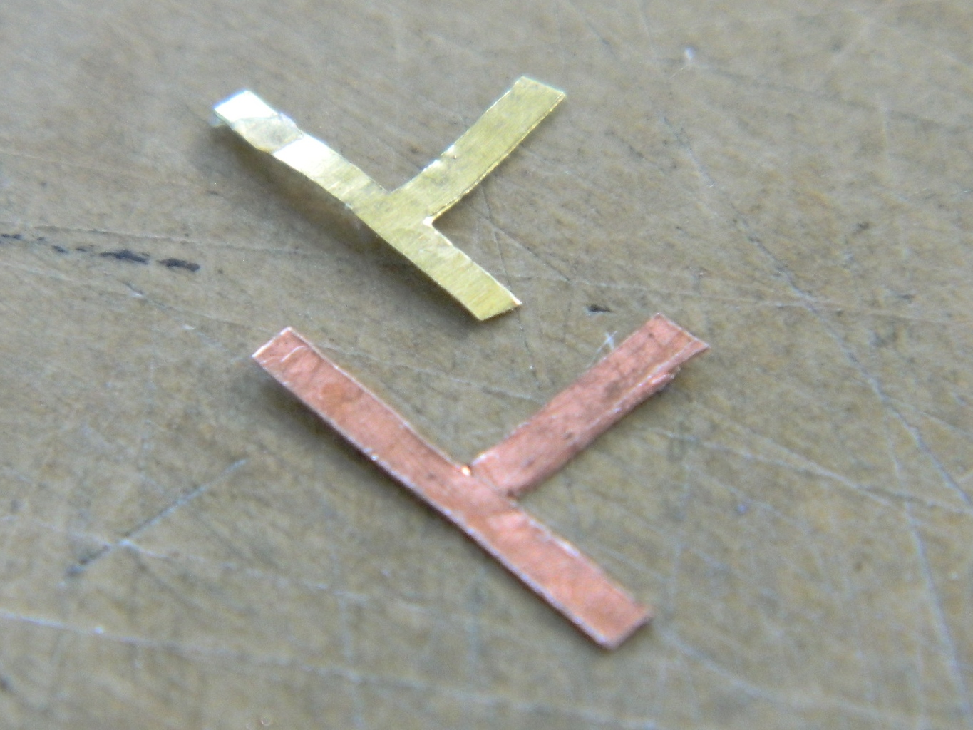
To this:
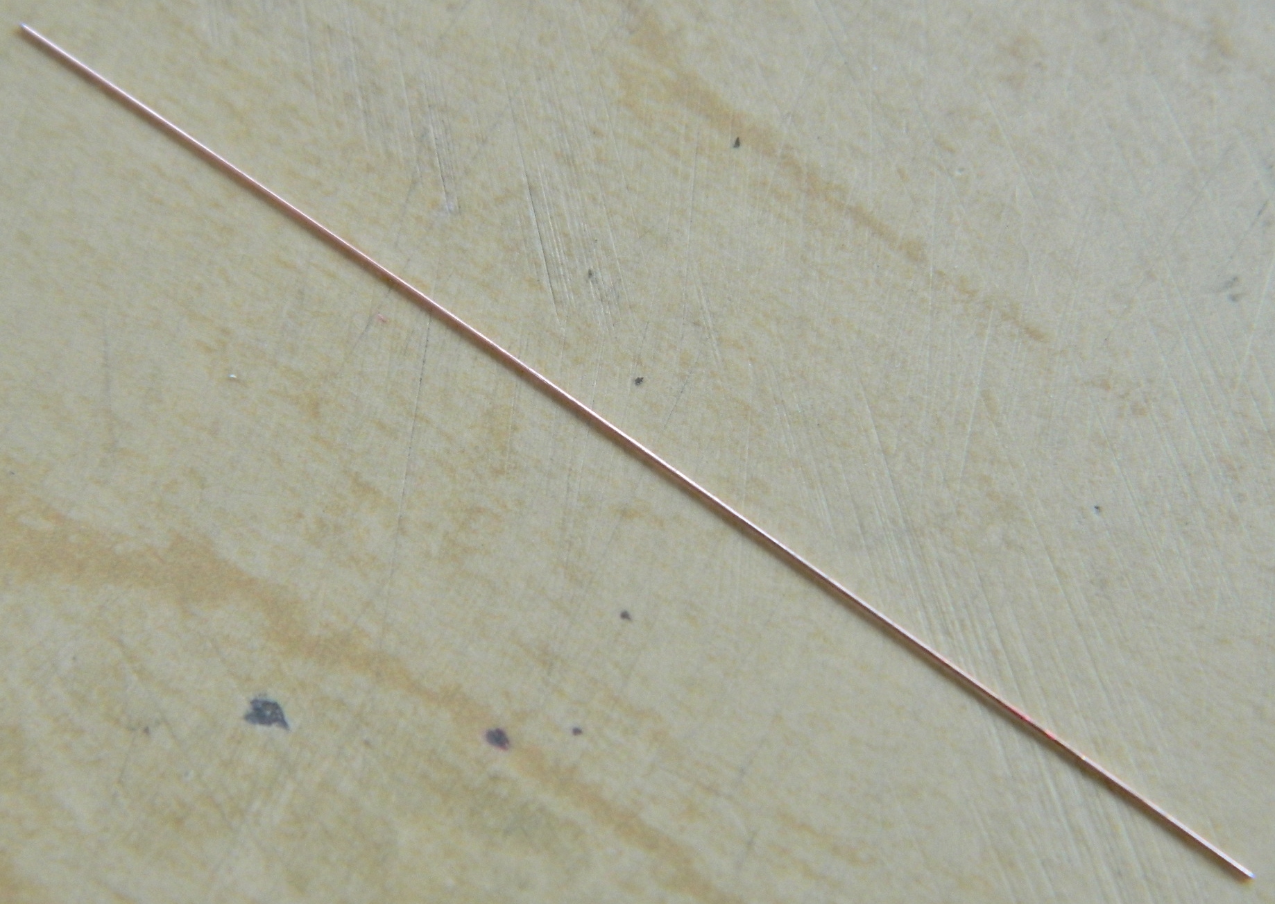
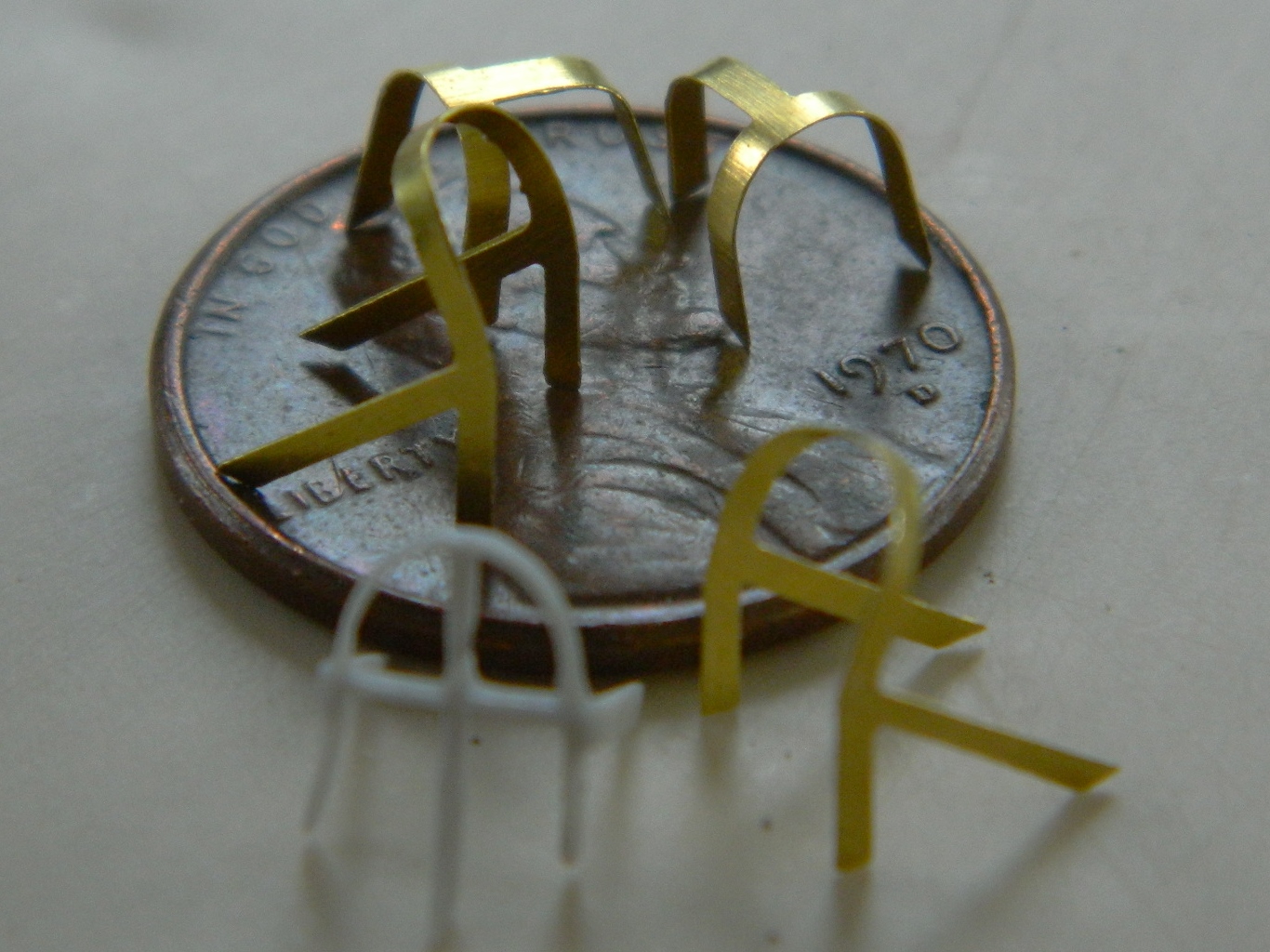
By using these. The clear pieces are old acrylic covers to welding masks (the type that doesn’t auto-darken). I tease the wire, solder, lead wool, into roughly a straight section, then I lay the piece I need straightened on one surface (usually the acrylic plates for solder and lead wool and the metal plates for copper, though I will use the metal plates for thick solder and the acrylic plates for thin copper) and gently rub the two plates against each other:

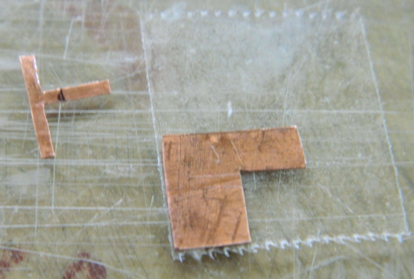
Once I had the copper wire straight, I folded it in half and twisted it:


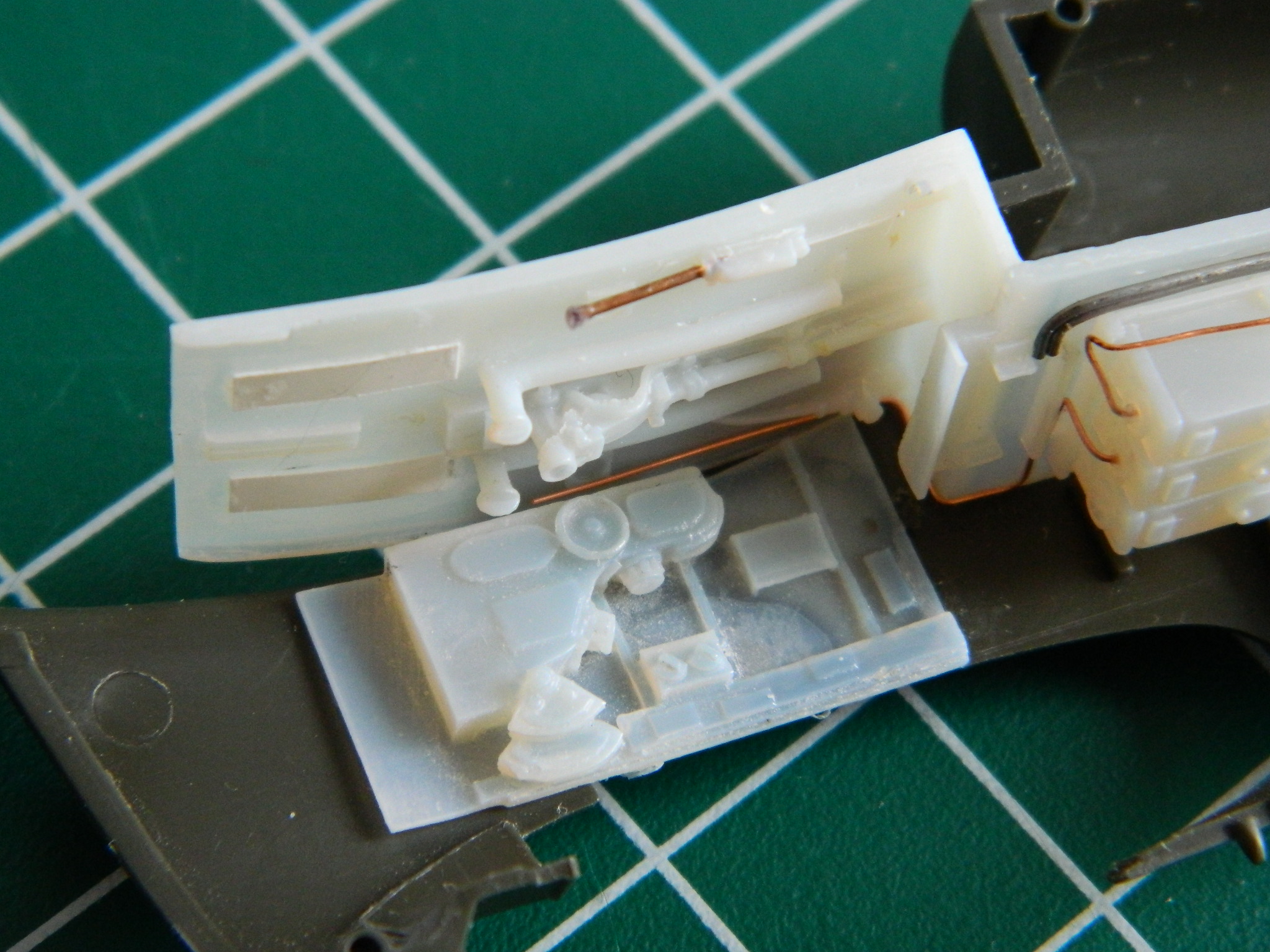
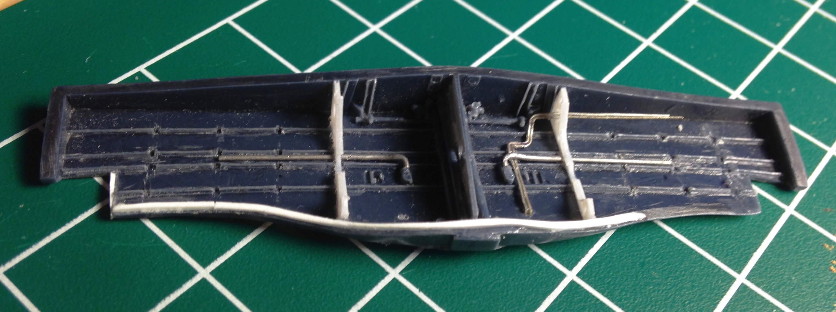
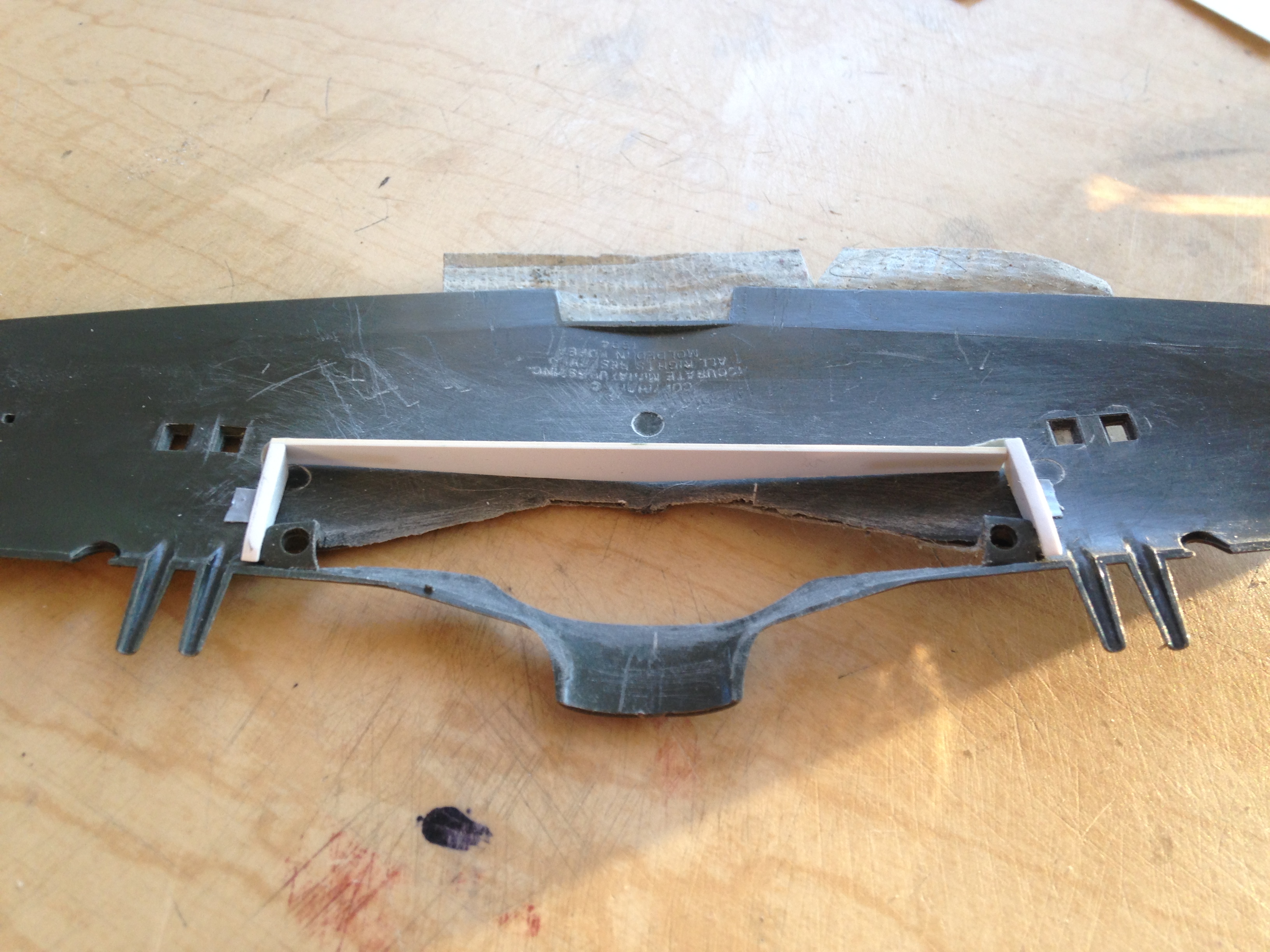
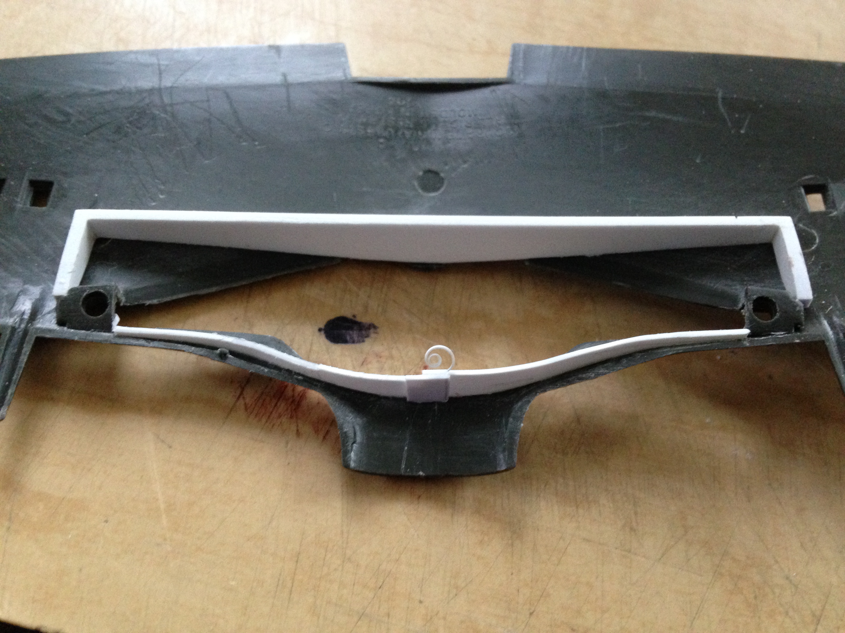
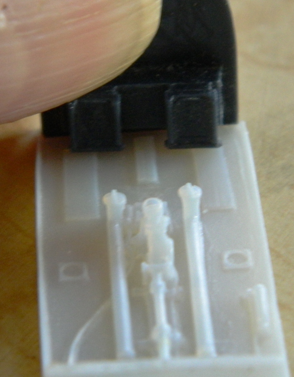
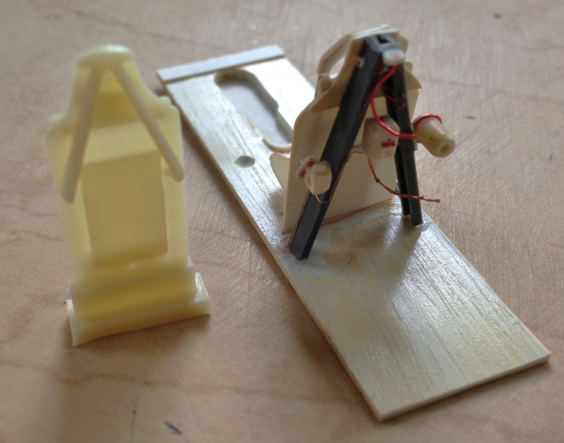
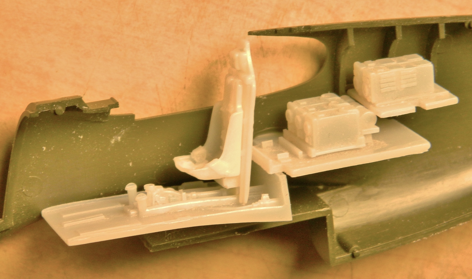
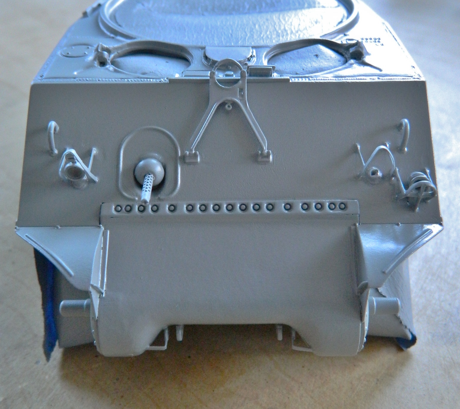
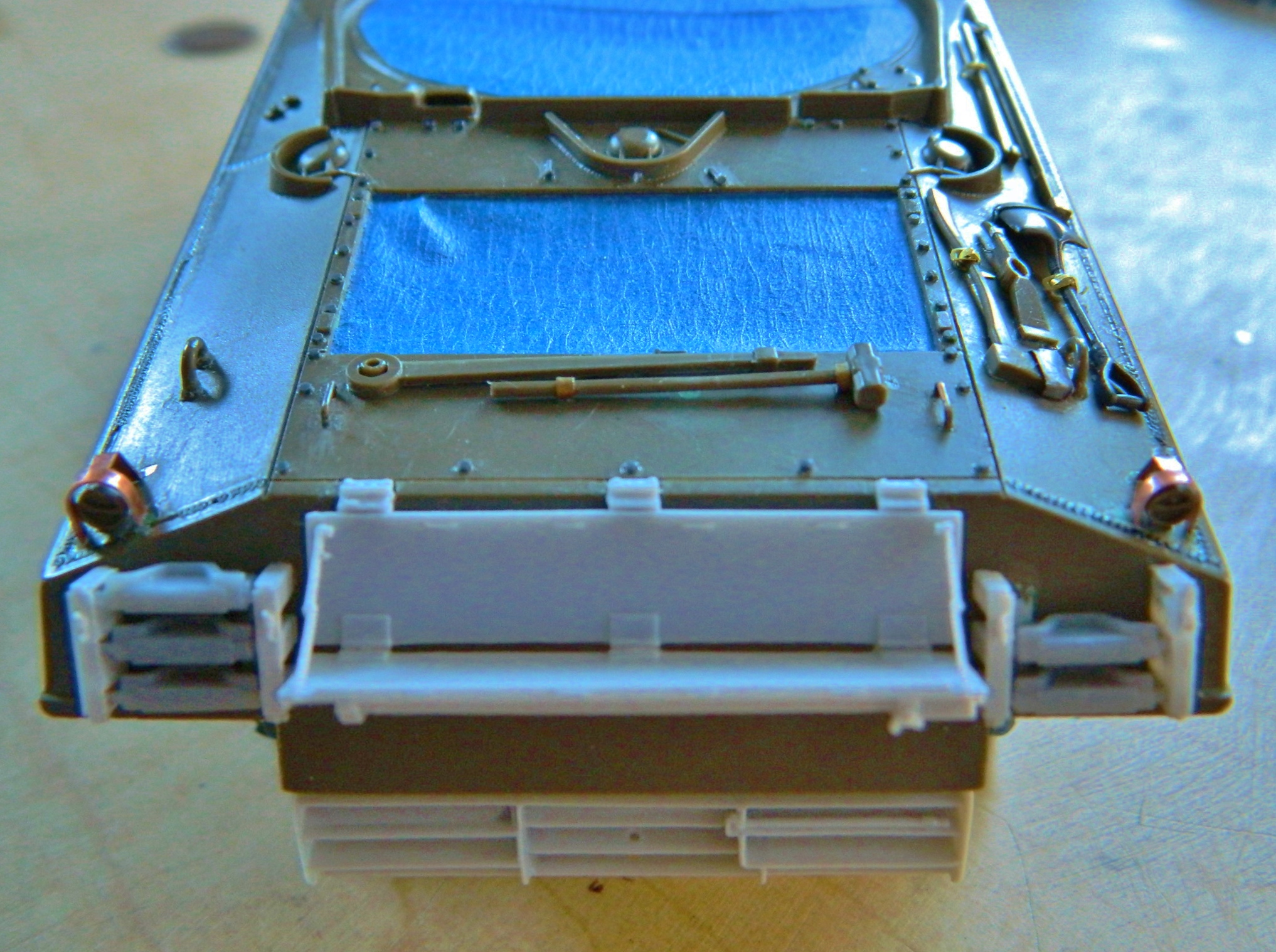
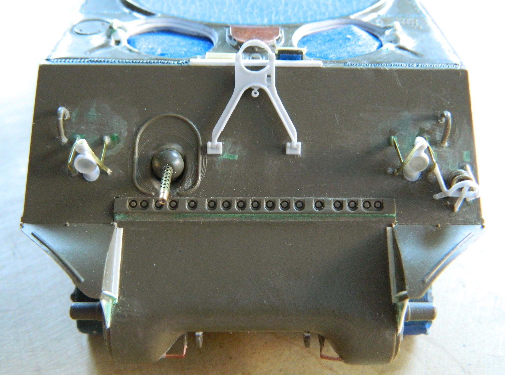
The lower radio shelf was glued to the floor section and conduits of copper wire and solder were added as well as adding the rollover brace to the armor plate, adding the junction box (the white part) to the brace, and then wiring them up:
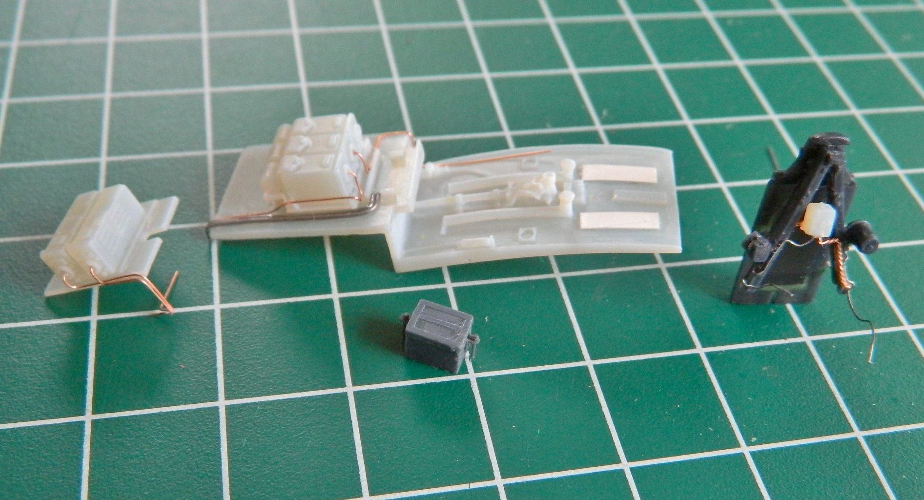

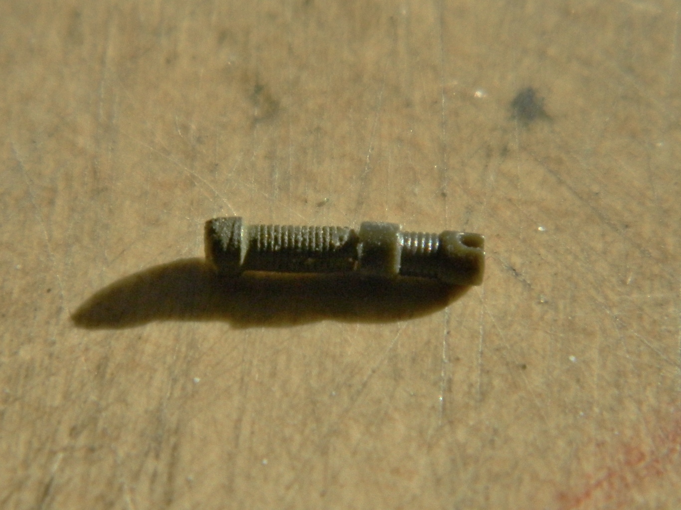
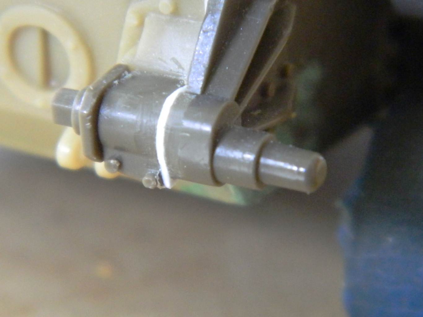
The cylinder on the floor to the right of where the pilot’s seat goes is the emergency hydraulic pump and as such it gets a handle. I drilled it out to accept a copper wire (cleverly straightened out as mentioned above) and then needed to make a knob for the end of it. Often white glue is used to make knobs of this sort, but the actual knob has a flat end which I could not replicate with the white glue. So I dipped the end of the wire in a small puddle of superglue. One of the interesting things about superglue is that when not used to bond things together (hides scarred fingertips behind back), it takes a while to harden and goes through a semi-hard stage. When the blob of superglue became milky, it wasn’t hard yet but had gone past the liquid state. At that point, I pressed the end of the blob against a flat surface and the result was a knob with a flat end just as I wanted:

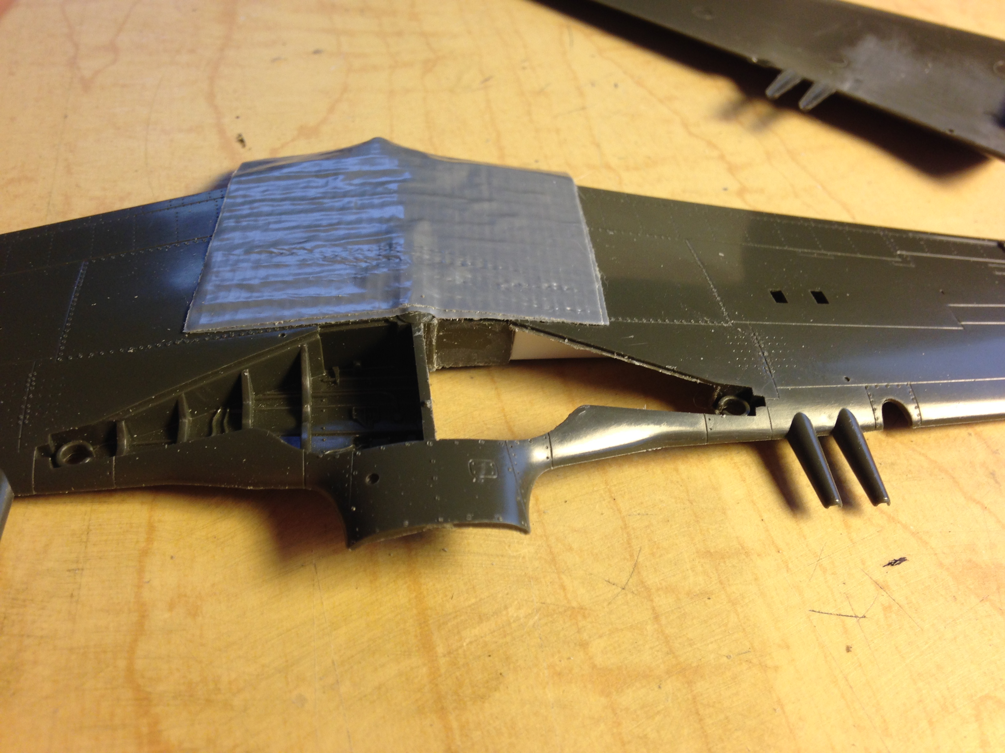
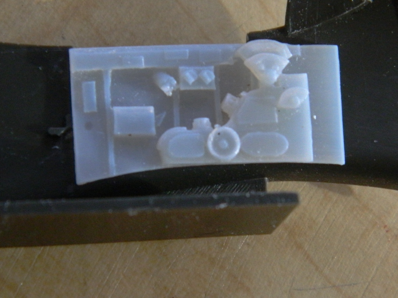
Sometimes not having four hands (or more) to dry-fit parts is a genuine annoyance. The work-around is to tack things in place with an adhesive that allows easy removal of parts only temporarily in place. If I’m dry-fitting resin, Contact Cement is good for that. But the solvent in Contact Cement will attack and dissolve styrene (don’t ask how I found that out) so when tacking styrene parts together, I use white glue, which is how I attached the two side panels of the cockpit to the fuselage halves:
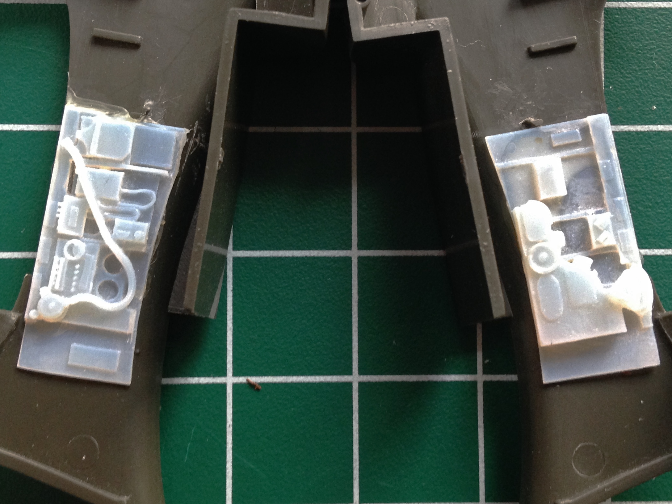
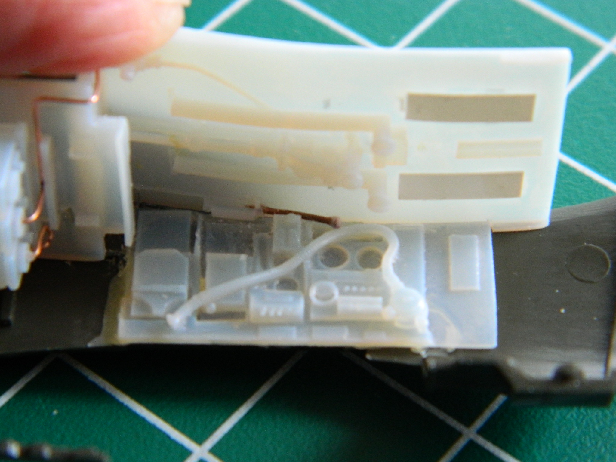
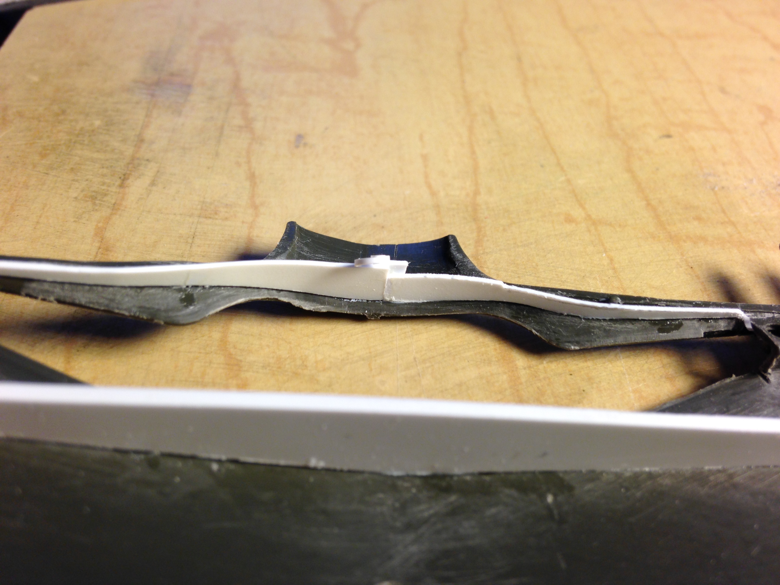
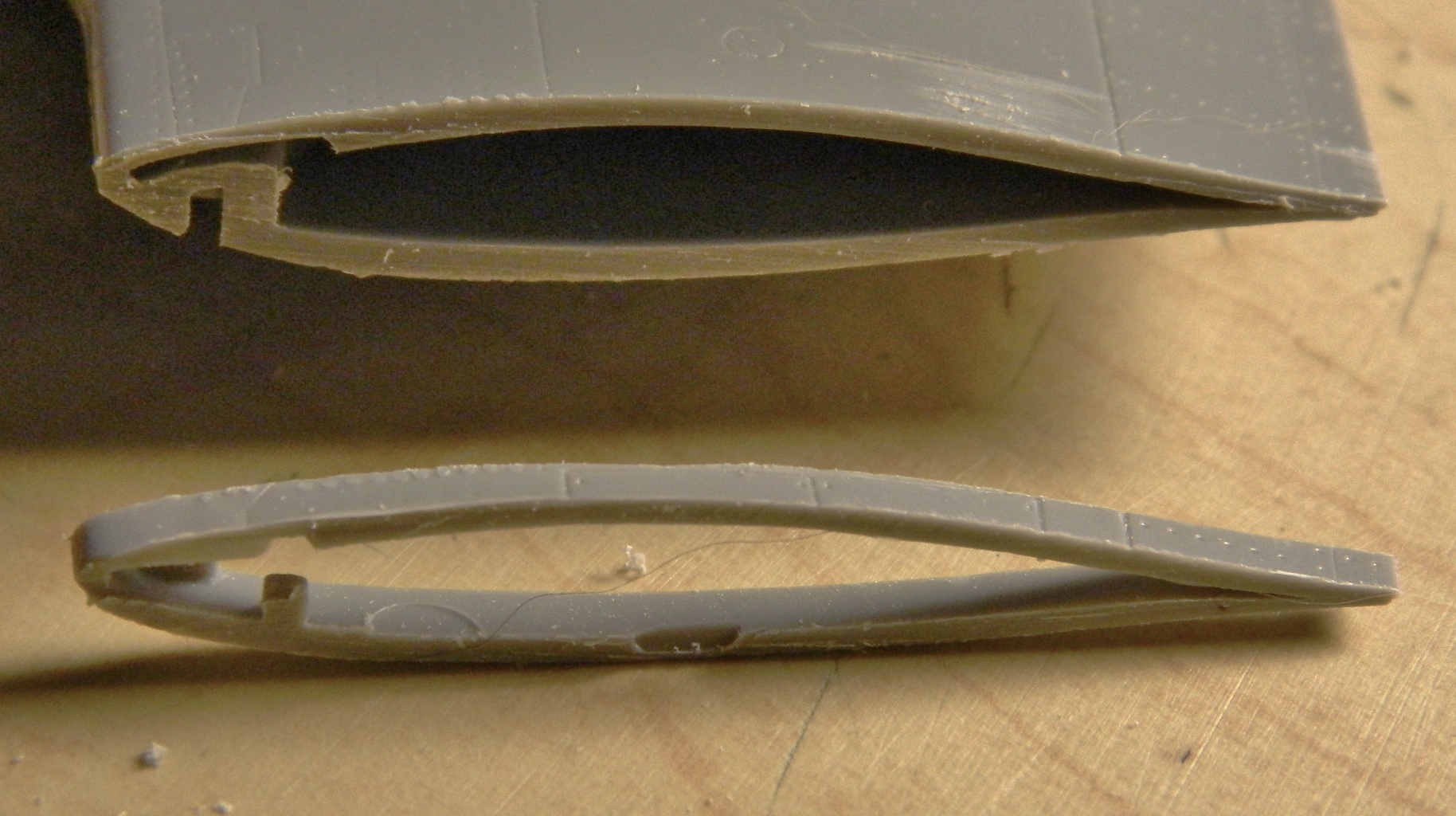
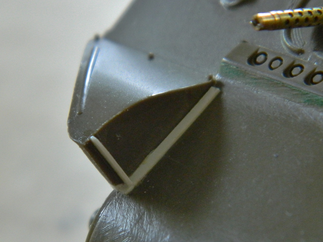
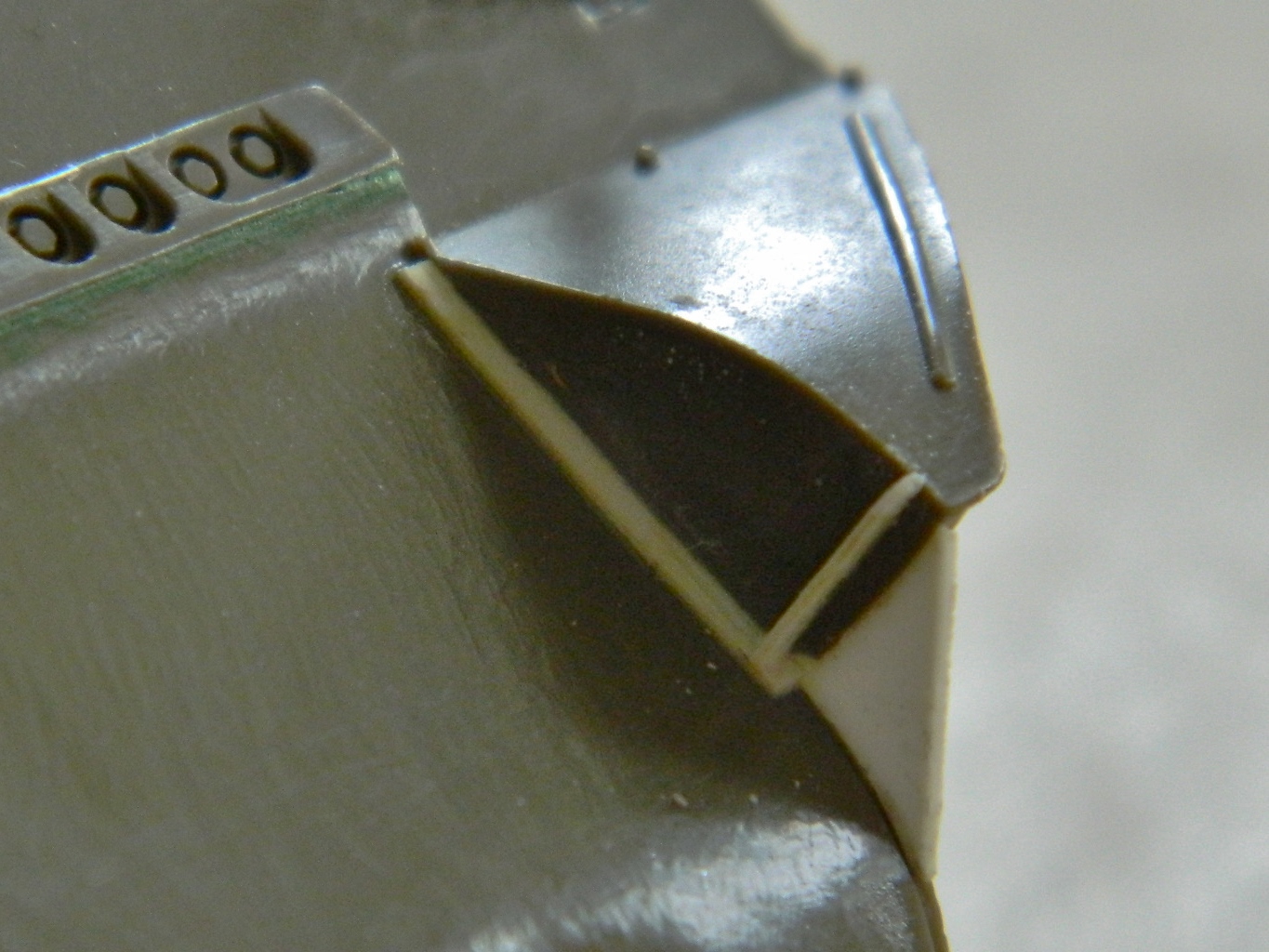
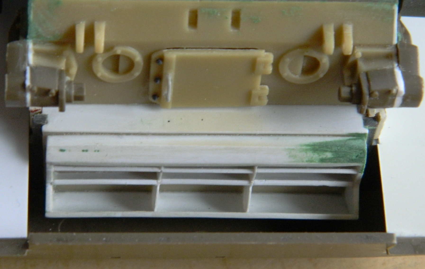
It didn’t take long for fit problems to show up. You’ll note that the bottom of the side console is straight and flat. But the floor section it’s to meet with isn’t flat and straight. And in the lower right photo, you’ll see that there is a substantial gap at the front (to the left in the photo) where things are supposed to meet:

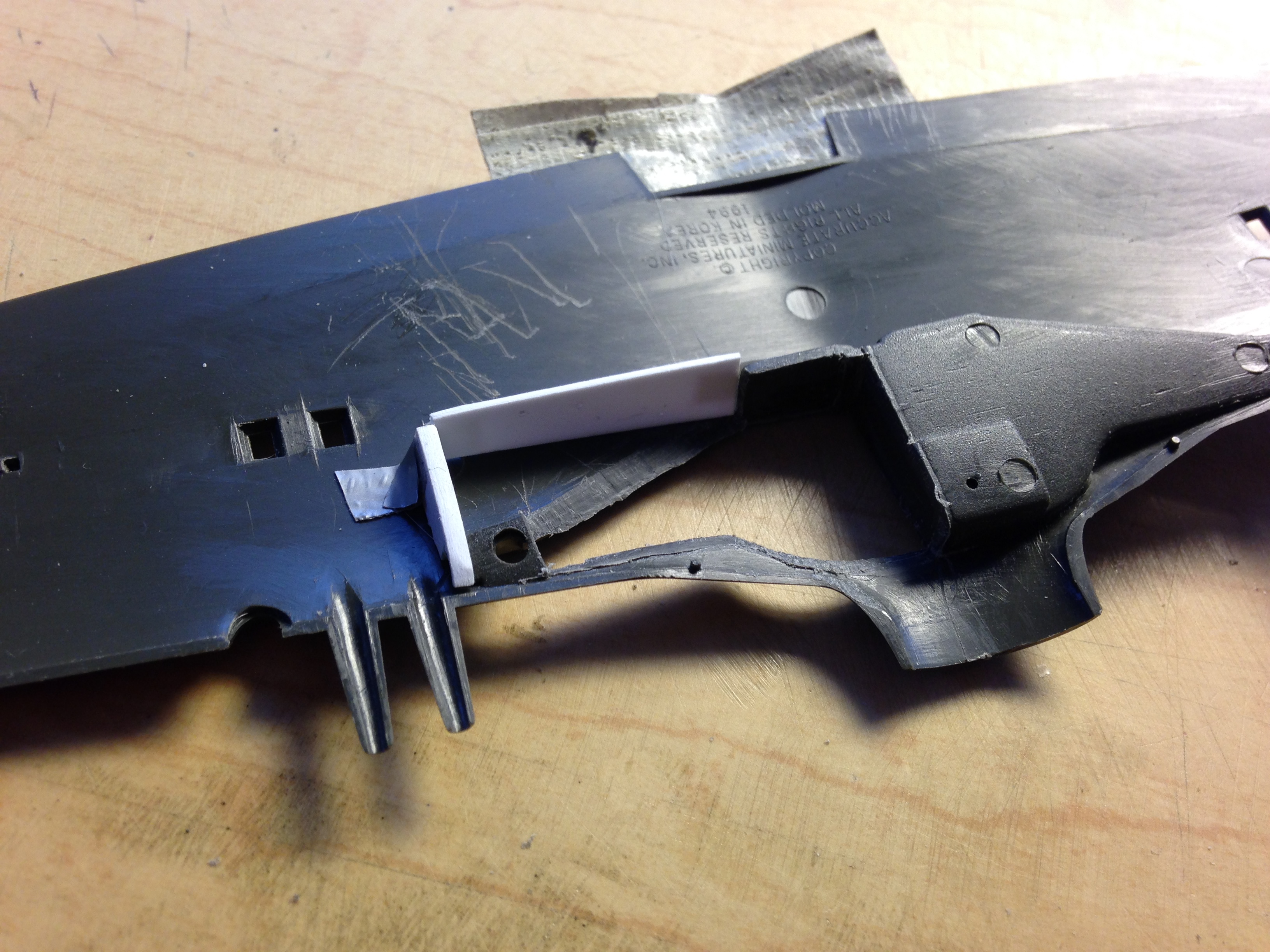
And not only that but the bottom of the side console also doesn’t match the face of the floor across its surface, as evidenced here (I drew a pencil line, only barely visible in the photo, at the bottom to show what needs to be removed):

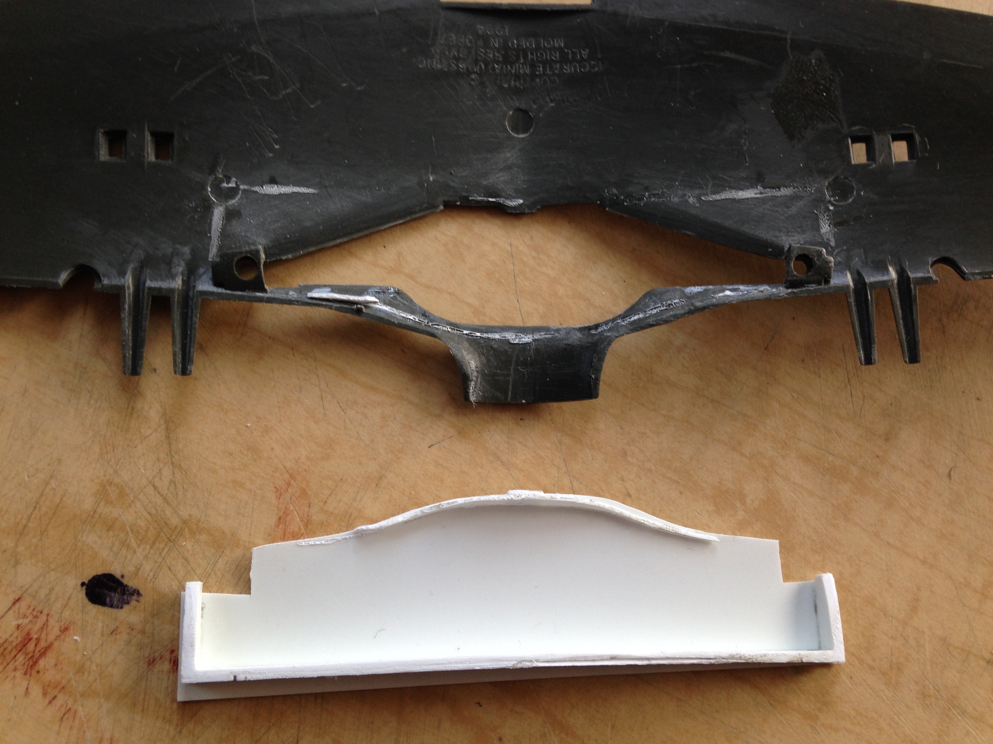
And yes, I have the same problem on the other side, too. And in addition to that, there’s NO WAY the carefully constructed pump handle will fit, either:

So much hilarity, gaiety (and invective) ensued as I trimmed, sanded, filed, heated, and bent various resin bits to play well with each other:

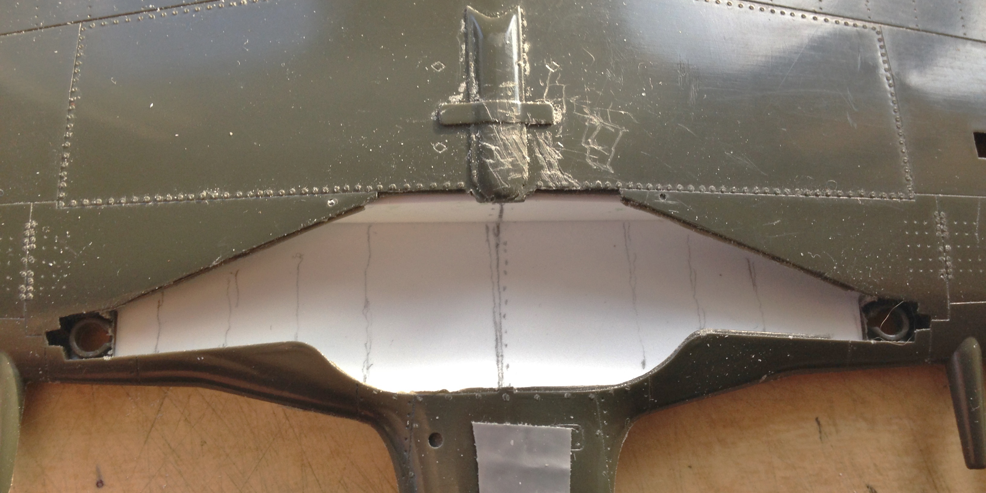
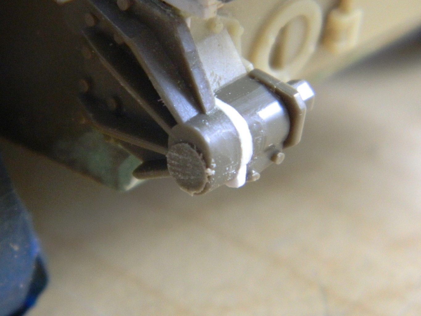
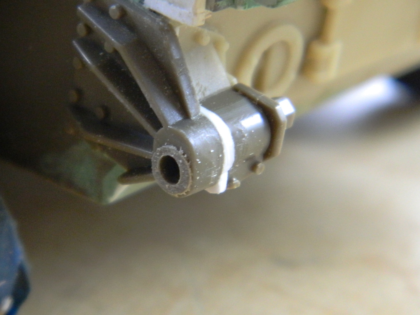
And I also had to get creative to get the pump handle to fit around the box on the cockpit side. No, the original handle isn’t bent. Then again, the original handle doesn’t have to fit inside something a half inch wide by three-quarters of an inch long, either:

Another fit problem was created by the molded-on oxygen hose, so that had to be carefully removed:

I found a great replacement, it’s actually a rubber-like material, and will conform to the space it has to occupy:

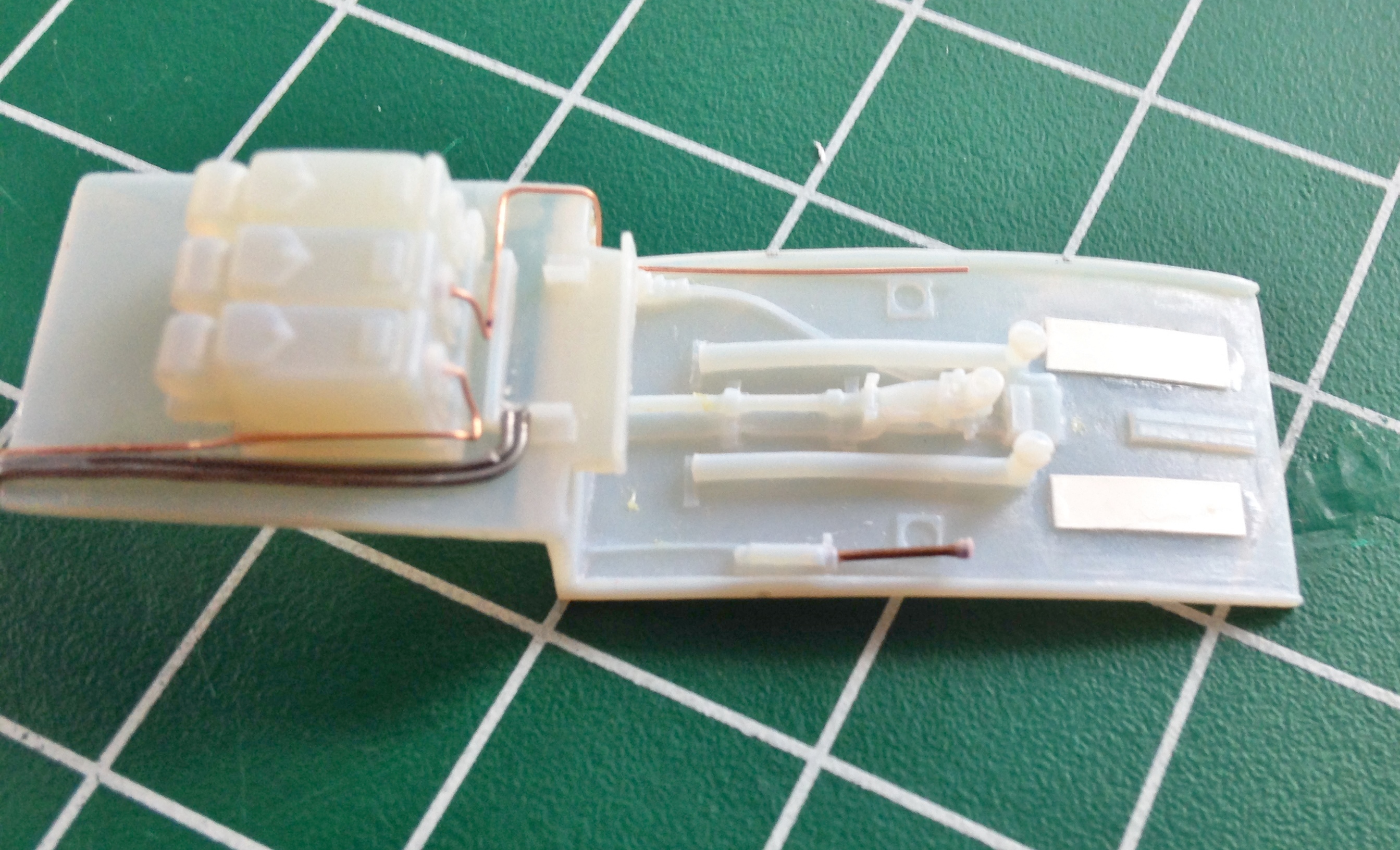
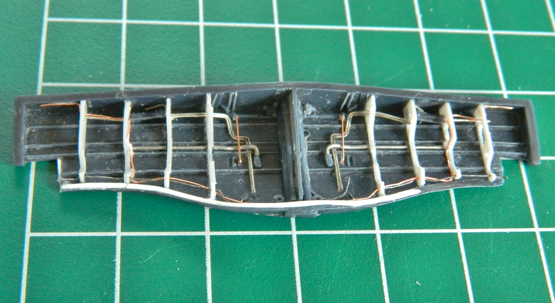
Looking at reference photos (something I did merely for the novelty of it), I see that the wiring looms/harnesses are quite evident as well as being absent from the resin part. I have a spool of 40 gauge magnet wire that I’m using to create the wiring. And 40 gauge is REALLY small stuff:

By folding the wire, I created two lengths of eight wires each and twisted them into one cable:

An eight-wire cable is attached to the electrical breaker panel:

The other eight-wire cable was split into two four-wire cables and attached to the radio control panel (on the left) and the microphone panel (on the right). The oxygen hose will be attached later:


P-51 (Accurate Miniatures) Build #4 – Casting Landing Gear Bay in Resin, Fixing Errors, Adding Details
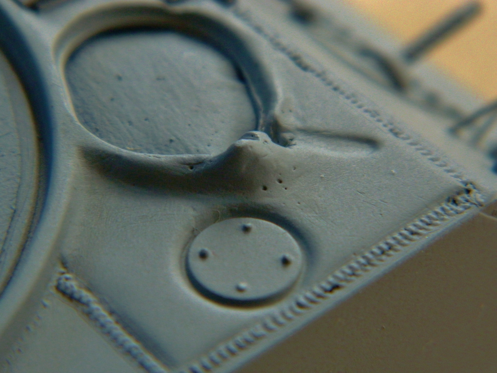
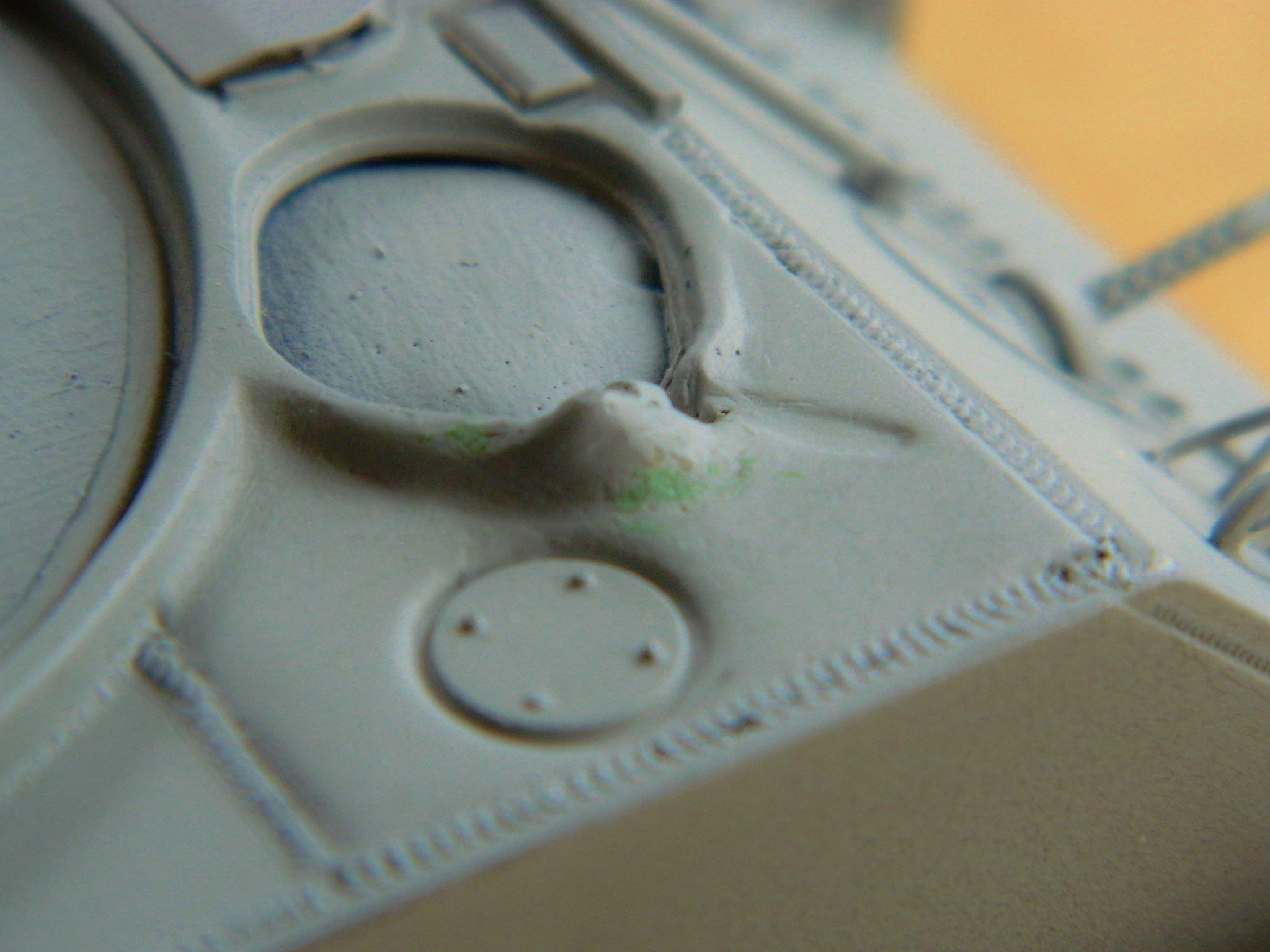
Well, I know I’ve mentioned before that one should refer back to references often. Evidently, I don’t listen to myself (hardly surprising; I’m already nuts and listening to that maniac can only exacerbate a bad situation). I’m sure you’ll notice (more quickly than I did) that the notch in the rib does not line up with the mount for the landing gear leg…and it’s supposed to:
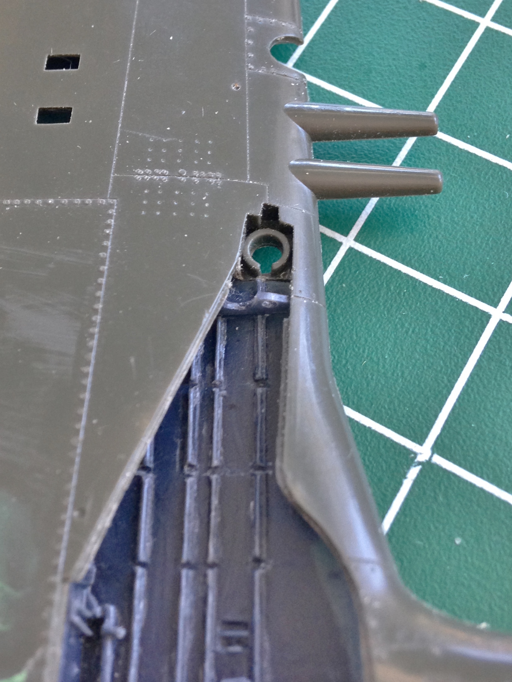
And the problem with that is that all the other notches don’t line up, either. The fix is to remake the ribs. And then make another mold. And THEN cast the sodding things again (I’m getting a great deal of practice with colorful invective).
Since the notches in the ribs are to allow clearance for the landing gear strut/tire to fit inside the wing, maybe using the landing gear/strut to establish that location might be a good idea:


With the proper alignment of the notches established, the whole process of cutting, drilling, and adding the lips got done. Again. After these were done the molding/casting process got done. Again:


There are lots of things about getting old I am not especially thrilled by (it’s a long list, which I have to make because I’m too old to remember), but one of the things that seem to work in my favor (sometimes) is understanding my short-comings (talk about a list) and figuring out ways to work around them. Sometimes I will sit at the bench for many hours and in so doing can remember what I did on one side so that I can do it again on the other. Sometimes I don’t sit at the bench for very long and sometimes days will pass before I get back to it. In that case, I can’t remember how I did what I did (or where the hell I put that damned list). My work-around is when I do something on one side, immediately do it on the other:

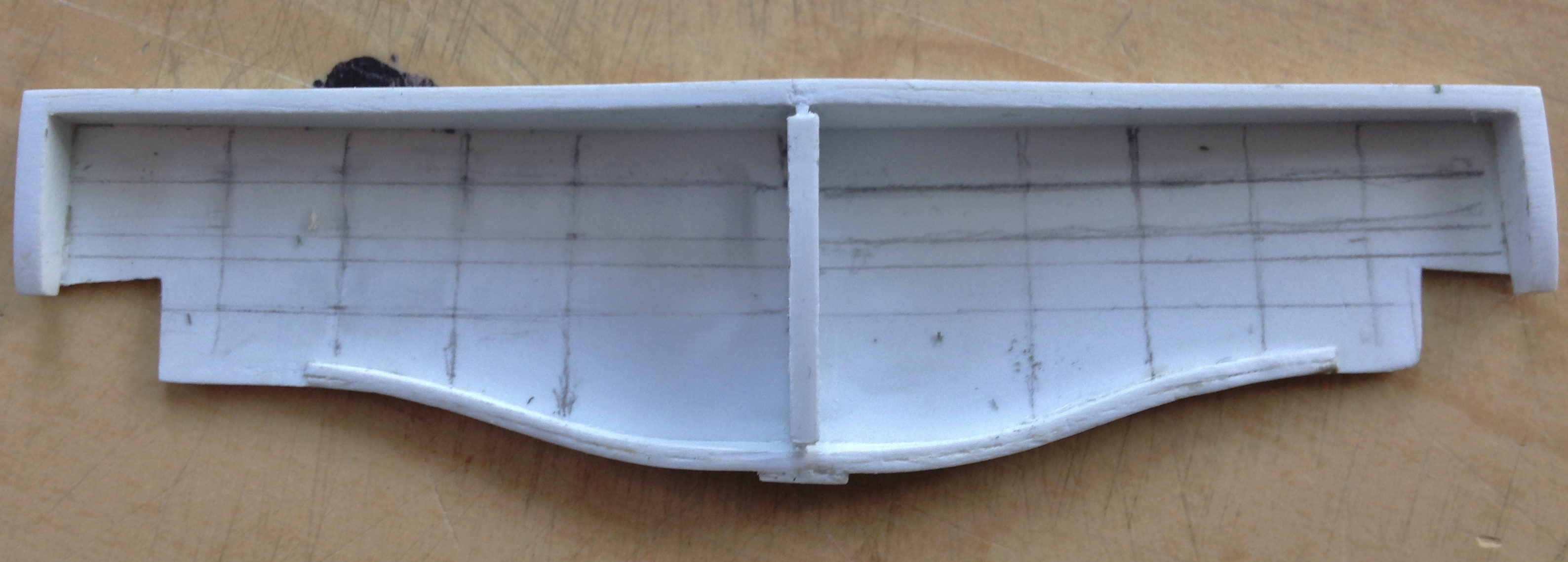
And that’s how I detailed the wells. The sections to the inside of the first ribs (as figured from the center) will not be seen once everything is in place:


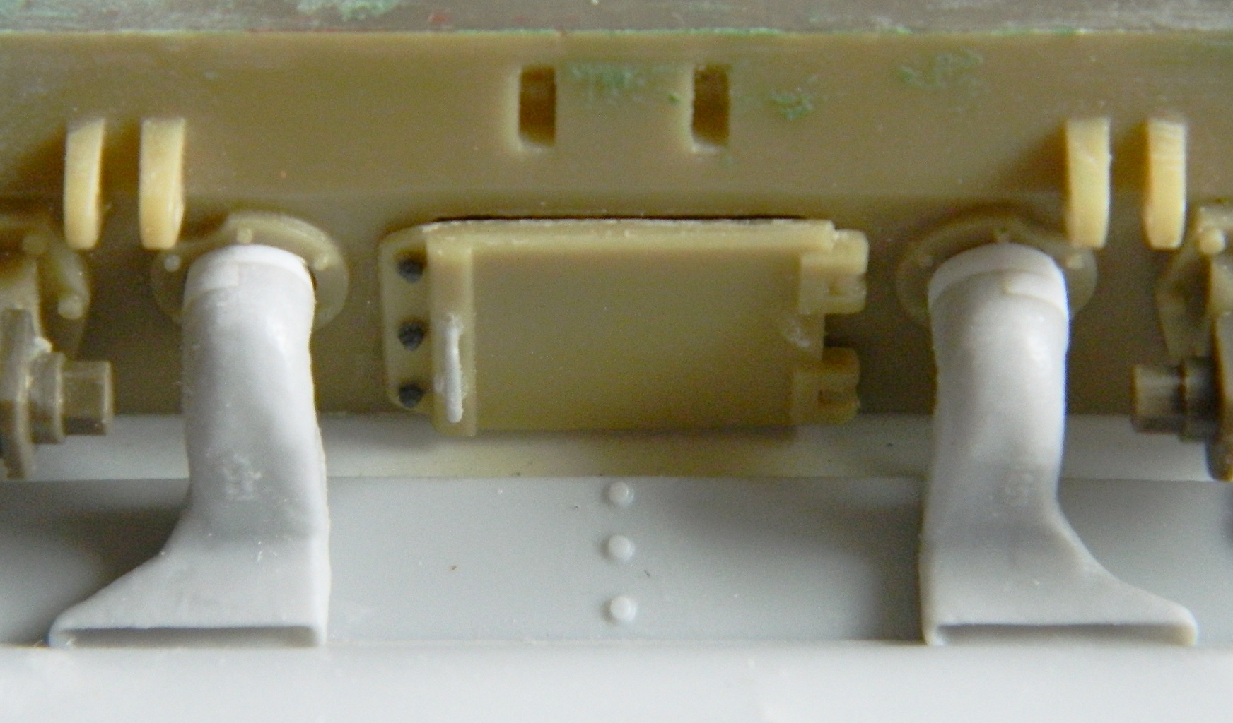
In reading the Mustang pilot manual, one of the shut-down procedures for the pilot was to release the hydraulic pressure in the system (this would cause the flaps to drop which in turn kept people from walking on them). Evidently, the later “D” models, didn’t have latches inside the gear wells to hold the clam-shell doors up which the Allison Mustangs did have. When the pressure dropped, the latches would keep the clam-shell doors closed and from what I can tell from reference photos, they stayed closed unless the ground crew needed to get in there.
So why am I putting details in that won’t be seen?
Practice and reference, both of which I need, one of which I don’t refer to often enough. And in adding the lines and wiring (copper wire, solder, and lead wool), I see that once again I got the ribs less than correct; some of the holes are wrong, some unneeded, and some in the wrong place. So here is where I get sloppy…
I AIN’T REDOING THE SODDING RIBS/MOLDS/CASTINGS AGAIN. At least, not for this build; before I do another Allison Mustang I will.
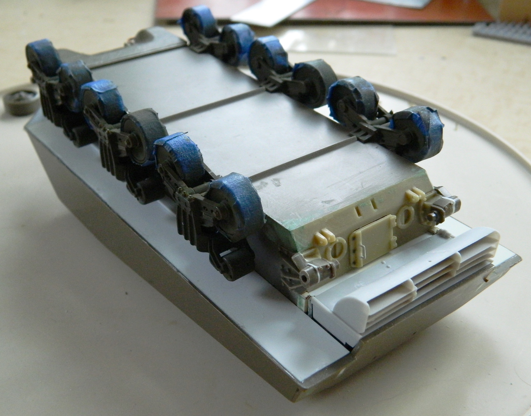
So, sloppily, this is where I got, adding the hydraulic cylinders, wiring, lines, etc.:

With this aspect of the build done, it’s time to put this aside (while I figure out how to paint it) and get back to working the cockpit parts.
P-51 (Accurate Miniatures) Build #3 – Scratchbuilding Landing Gear Bays and Readying Them for Molding
Since the delivery time from Roll Models was quite long, while I was waiting I figured I’d get after the landing gear wells. That started by sawing out the molded box and start getting what will replicate the main wing spar dimensioned and built. Since I wanted to keep the one accurate detail of the molded-in wells as my dimensional reference, I ended up cutting each well away separately (probably complicating the job).
I used the one correct section of the molded-in landing gear wells as my reference. Once I had access to that section, I used card stock to create a relative template (so-called because I’m going to have to fit this fabrication inside the wing and I’ll do that once I have it in plastic as that’s more rigid and easier to work) and then transferred that shape to plastic and taped it in place:

With the plastic cut, I checked it for fit using the rib as the terminus:

I started by using duct tape (upon which modern civilization is built) as my guide and used a panel-scribe to start laying out where I need to cut:


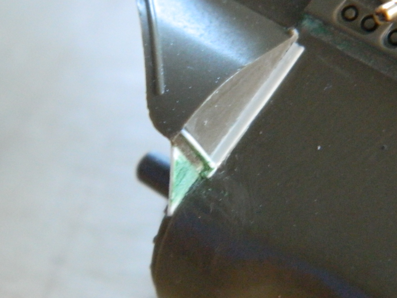
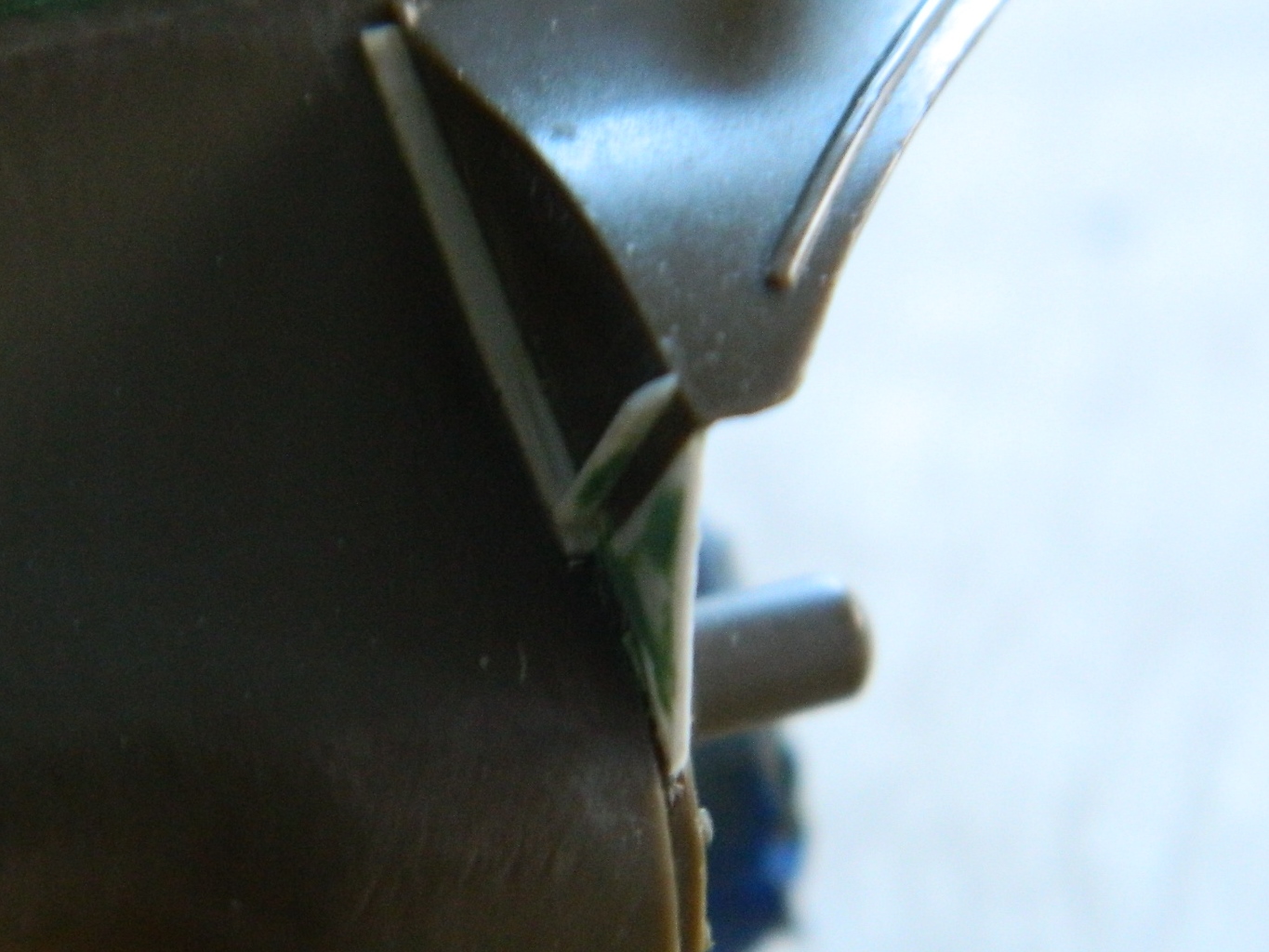
I neglected to take photos of the first removal but the coffee finally kicked in, neurotransmitters started conducting a current, and I remembered to take photos of the second removal which shows how I did the first removal. I started with many passes using a panel scribe and once I had broken through the plastic, used the small #11 saw to finish the job (note the proximity of the knurled collar of the knife to the belly of the wings, which I didn’t notice during the first cutting…and that oversight created more work for me, as I’ll show you shortly):


I left the molded-on landing gear attachment on both sides for structural strength when it comes time to add the landing gear legs:


Once I had cut away both of the molded-in wells, I had access to the width of the gear wells and made a template for the main wing spar and transferred that to .020″ (.508mm) sheet styrene:

That got taped into position and much sanding ensued to fit it:
With the spar laid out, it was time to fit it into the wings, which started by shaving down the lip on the inside surface of the upper wing sections that have to encapsulate the spar:
With the main spar (mostly) fabricated, I checked fit. Yeah…that’s what it’s supposed to look like:
I used the molded ribs as templates for the ribs I’ll fabricate to replace them. The kit’s ribs were sawed free of the boxed landing gear well and the rough (very rough, as it turned out) shape of the ribs was transferred to card stock to create rough (same caveat as above) templates:


Since I plan on molding and casting this assembly, I added another layer of plastic sheet to the wing spar for ease of pouring later on, and then I started fitting the front of the well. At this point dry-fitting was getting into the realm where even having four hands would have been challenging so I tacked the spar/ribs in place with glue and started adding the front of the wells:
Once I had things about where I wanted them, I added a sheet of .020″ (.508mm) to close the top of the box and then pried the “tacked on” sections off (it was…challenging), only breaking a small piece off the front area which I glued back into place:

I added more sheet to the front of the wells, also to facilitate pouring resin later on:

I placed the landing gear wells onto the wing to lay out where the ribs need to go.
You’ll note how chewed up the underside center of the wing is. This is what can happen when one (me, particularly) focuses on one area being worked without paying attention to adjacent areas that could be (and in this case was) affected by the tool. That area got chewed up because I was so focused on the area I was sawing away that I failed to notice that the knurled handle of the Exacto knife saw was rubbing on the wing. So that’s going to need fixing:
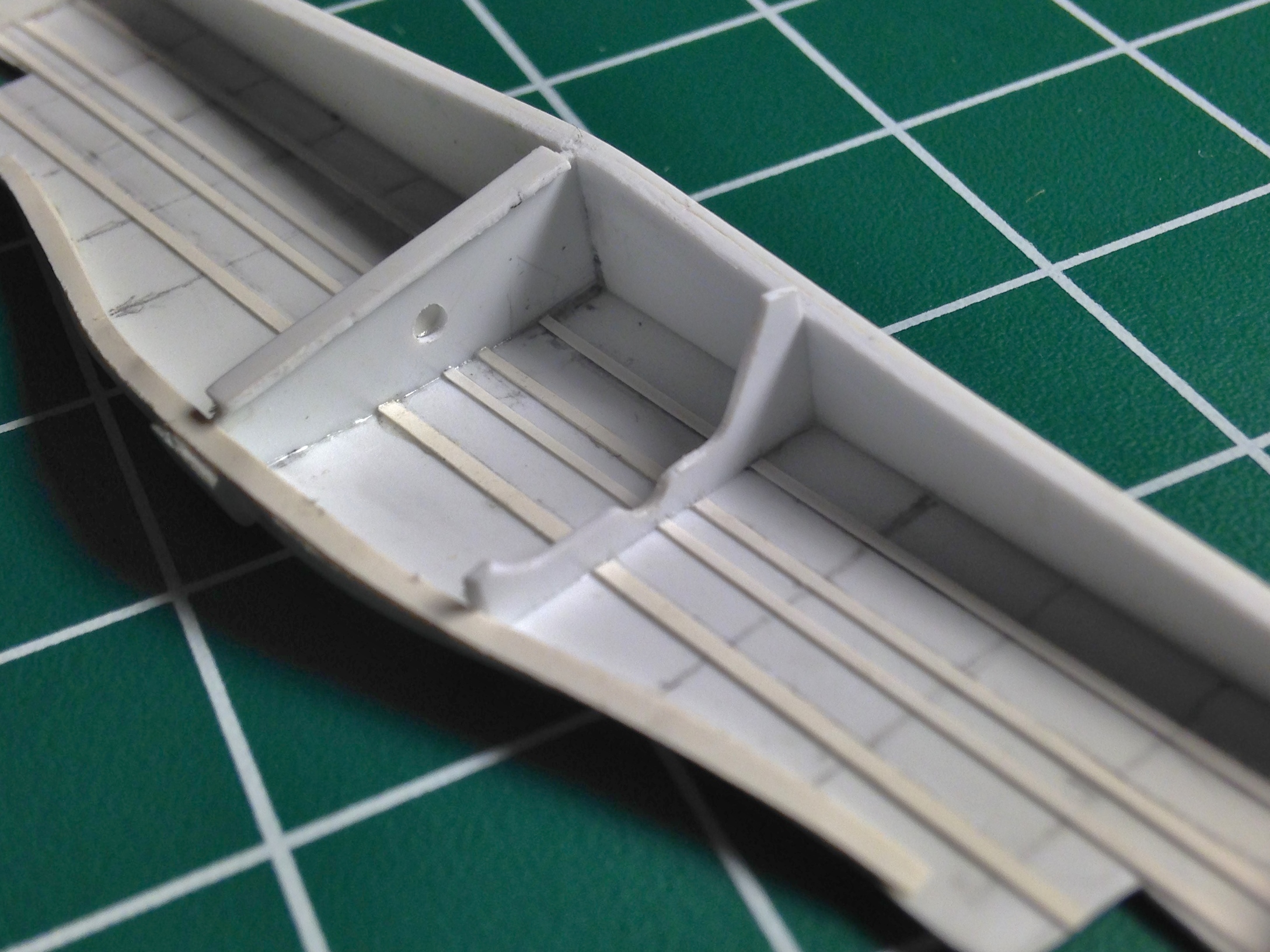
An easy way to transfer measurements from one side to the other is by using a compass. I used the pivot point to follow the center line to get the spacing correct (or at least consistent) for the ribs:


From what I can tell, each wing of the Mustang was built separately and then bolted together at the center, leaving a partition between the two wings. I added that:
I used 005 styrene strip for the stringers:

The center partition has a prominent hole in it so I drilled one. However, when I make a mold of this assembly, that hole will keep the part (and the master, too) trapped in the silicone. An easy fix was a “plate” covering the hole of .005″ (.127mm), something easy to sand off once this is replicated in resin:


I debated notching the ribs to fit over the stringers and then realized it’s a LOT less work to notch the stringers:
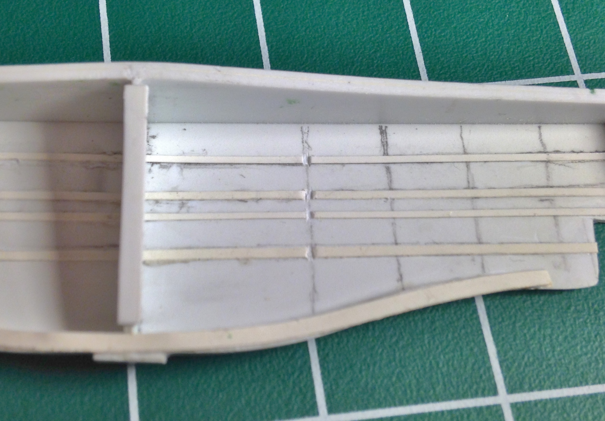
I cut the ribs out of .015″ (.381mm) (still too thick, scale-wise, but more realistic in terms of getting that space to fill with resin later) and checked how it works…which it does:
The stringers on the Mustang have ridges and I replicated them using lead wool:

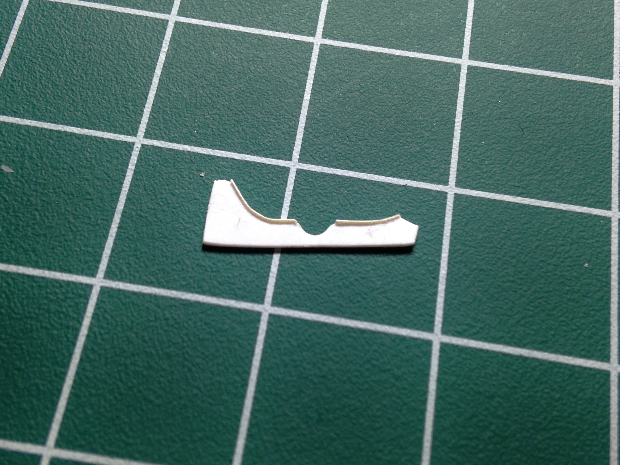
With the rib form finalized, I used .005″ (.127mm) to add the lip (after sticking the rib to double-sided tape for ease of working). Once the glue had cured, I sanded the lip down:

Then all the ribs had to be fit and that’s when I discovered how rough the templates were. There were many mistakes made during the fitting of the ribs including holes drilled in incorrect locations (and sizes) which had to be plugged and re-drilled, thin sections of the styrene breaking under handling which had to be reattached, but after much invective (both colorful and anatomically impossible), I finally had them finished (and hopefully correct):

They were then glued to a sheet of .040″ (1.016mm) styrene for ease of molding and casting:

The next step was to build (what I think are) the hydraulic cylinders that operate the landing gear (As an indication as to how small these things are, the squares of the cutting pad underneath it are half inch squares). Once I had those done, they got added to scrap styrene to create the pouring blocks for molding and casting:

Tiny details consume large blocks of time…
And speaking of consumption of time, I added the various details to the wells that I could. The hydraulic lines, wiring, and cables that run through this area can’t be added now because they’re free-standing from the surface. If I add them now they will be captured by the molding rubber, not that I think I could cast those sections in resin anyway because of their small diameter:

P-51 (Accurate Miniatures) Build #2 – Working Cockpit Parts, Adding Details
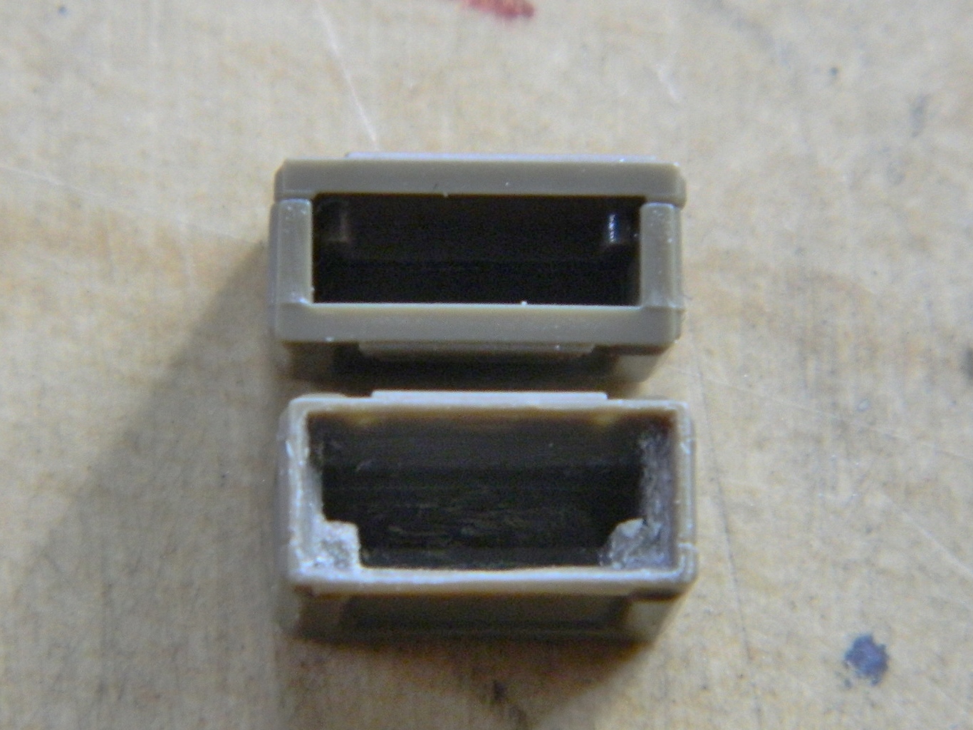
Once I demolded the resin parts, I noticed that there’s a battery that sits on the shelf in front of the radio. It’s a prominent feature that wasn’t supplied with the detail set so I made one (and took a mold of it):

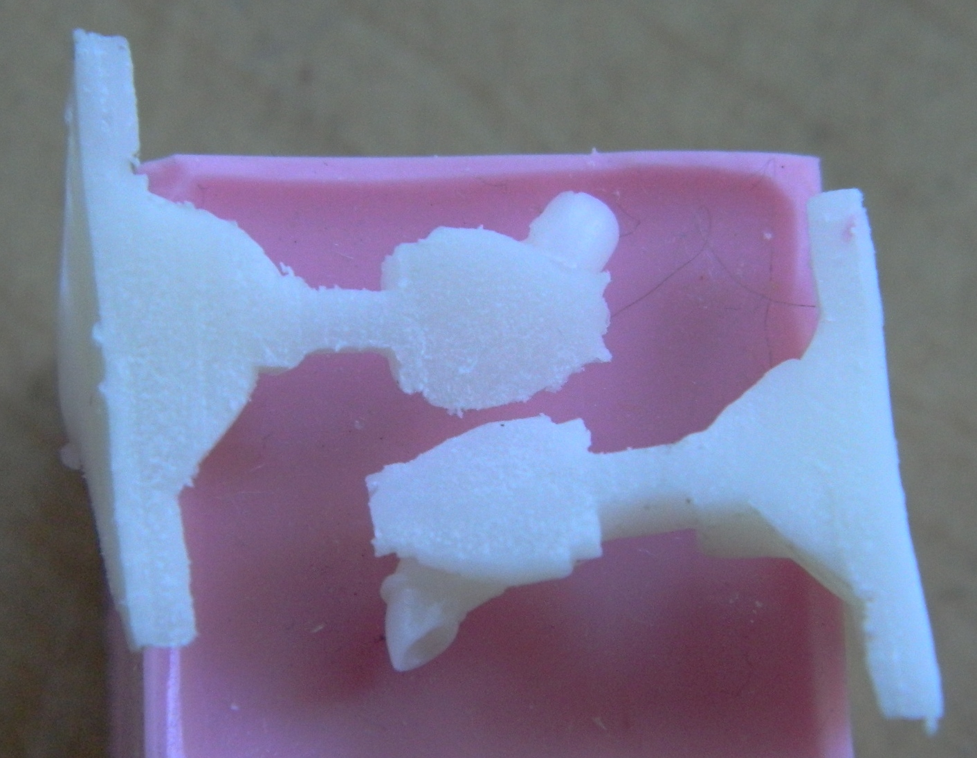
I’ve noticed that my (old) eyes are having difficulty with seeing the surfaces of the resin I’m using so I picked up some black resin dye. I was cautioned that it was highly concentrated so I tried adding a little bit. The effect, though better, wasn’t what I was looking for so I added a lot more. Below you can see the three pours; undyed on the left, lightly dyed in the center, and black on the right:

With the parts produced I want to use, it became time to start checking fit. The rudder pedals are a bit tight to the lower panel of the instrument panel but not so much that I’m willing to jump (crawl and stagger) through the hoops necessary to fix it. But the raised rectangles on the cockpit floor are skid plates for the pilot’s heels and as such should line up with the rudders…which they don’t, so that will need fixing:

In checking the resin seat against photographs of actual seats, the depression at the top of the seat where the shoulder harnesses are isn’t there. That’s an easy fix…just take down the corners:

Since I’m going to be using my rollover brace I carved/sanded/filed the brace molded to the armor plate off as well as removing the raised area on the back (from what I can tell from photos, that’s supposed to be flat). Once the molded-on details were removed, I applied a coat of putty to remove depressions:
Not only should one always check fit, one should check often. Evidently the resin I’m using is very sensitive to heat, even the heat generated by warm hands (of which I have two). The photo on the left below shows that the curve of the “floor” (in quotes because the actual floor of the Allison P-51s is the top of the main fuel tanks) has flattened out. The part I’m holding (with my warm hand) over it is the side panel. The floor is supposed to follow the curve of that panel so I checked one of the side panels of the cockpit to make sure it was supposed to be curved that much…and it is. A quick session under hot water put the curve back that the floor is supposed to have:

I’ve decided to scratch-build an instrument panel instead of using the resin part. Any “detail” on the resin part is rudimentary and I want to kick that detail up. Since I don’t have quite all the gauge faces I’m going to need with the old Waldron set (pity they’re out of business), I ordered another set of gauge faces from Roll Model (I’m told they bought the rights to Waldron so it will be interesting to see what they have available).
Working Resin Aftermarket Sets
There are a few things to keep in mind when you’re using aftermarket detail sets…
The first is to check to see which model kit the particular set you’re interested in was built for. Sure, you can adapt a detail set to a different kit (if I can do it, so can you), and it will probably save you time over scratch-building the details. But you’ll probably (probably, not definitely) get a better fit if you’re working the kit that the person who did the masters worked from.
Second… Keep in mind that the person that did the masters the molds were taken from most likely did NOT use CAD/CAM to build the master(s) (though I’m sure it’s just a matter of time before 3D printers start being employed). There’s a talented person somewhere who scratch-built the masters using the kit (that I’m hoping you’re using) for dimensions and shape. Talent, as you’ve probably suspected by now, is a massive variable; some have more than others do. As a result, the degree of accurate fit to the resin parts is also going to be variable. Some sets are really works of art, others your 12 year old nephew could do better. Unfortunately until you have the set on hand, you can’t tell how good it’s going to be. Certain aftermarket suppliers have better (and deserved) reputations than others and as you go along you’ll develop your own internal database as to whose parts are worth the cost of acquisition and whose are not.
Third… CHECK YOUR REFERENCES. Check them frequently. Sometimes people get things wrong (yeah, ain’t that news…) and that includes the person who did the masters. In my limited experience, there’s a WIDE range of accuracy problems.
If you expect to buy an aftermarket set that will just drop into your model, you’re going to be very disappointed. There will be a lot of fitting and adapting to do. And don’t expect that the aftermarket set will include all the details you want. Aftermarket sets will save you tons of time scratch-building but my experience has been that they’re not complete and require me to add things…and sometimes remove things…from them to get what I’m after.
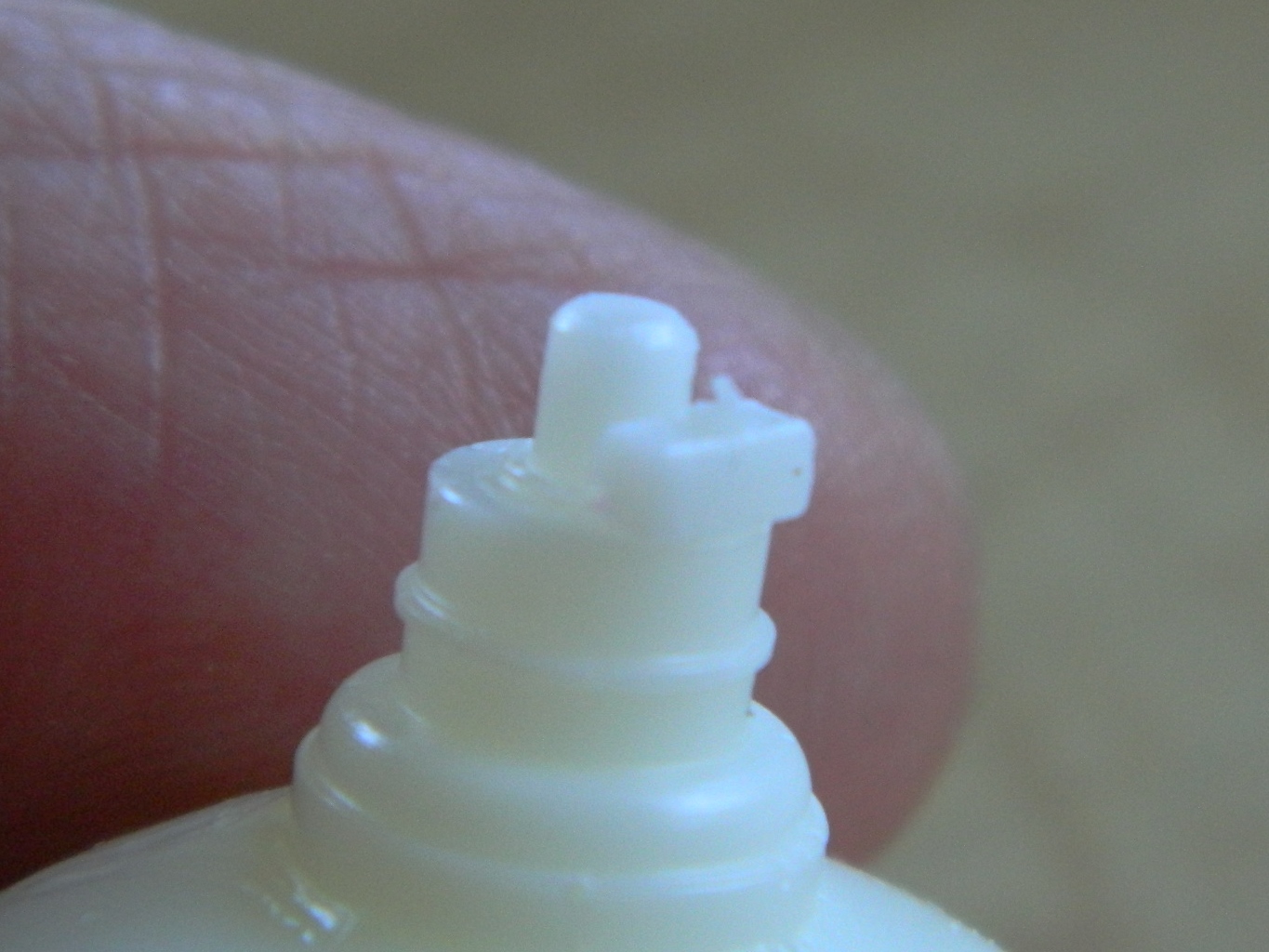
Resin parts are unaffected by styrene cement for reasons I hope are obvious…THEY AREN’T STYRENE, they’re resin. Depending on how “fine” the join is, you’ll need either epoxy or cynoacrylate glue – superglue – to do those tiny joins. The problem is that the tip of the superglue tube is NOT small enough and if you try to use it straight from the tube you’ll end up with a massive blob of glue that eradicates details. My method is to make a small puddle of glue on a piece of aluminum foil. Then I will dip something small into that puddle to transfer the glue to the area of the part(s) I want to marry.
There’s a few ways I can do that. If it’s a SMALL part (like freakin’ tiny brackets mounted to the side of a tank’s turret that rucksacks and gear hang off of), I’ll use the tip of a needle or a straight pin to transfer the glue. I have fingers that are much larger than I want them to be sometimes so instead of wrestling with just the pin or needle, I’ve mounted them onto convenient-to-hold things like a wine cork (for the needle) or an old chopstick (for the pin). When I have two parts that have to be touching before being glued, Micro-Mark sells a handy glue applicator (it’s in the middle of the photo):
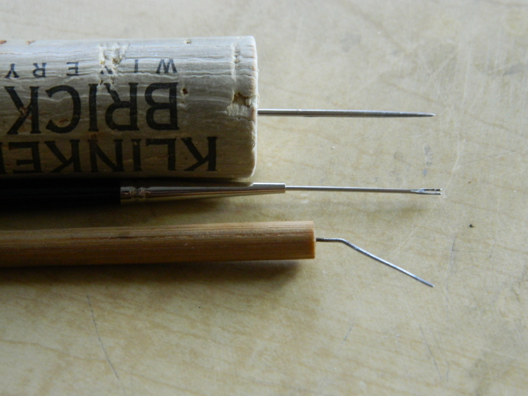
Okay, that applicator is nice. But once I was looking at it, it reminded me of something and it didn’t take me long to figure out what. It reminded me of the head of a needle that had had the tip of ground off. I checked Micro-Mark’s applicator against a needle and damned if I wasn’t correct. So. If you want a similar applicator (and having one like this is VERY SODDING NICE), make your own applicator. Grind the head of a needle off until you have an open-ended fork and then mount the needle into the handy…well…handle of your choice. And by making your own applicator(s), you can tailor the size of the applicator to the size of the job, only being limited by how small a needle you can get.
So these aftermarket sets will save you a lot of time. They will rarely just drop in and expect to add things that you’re going to want included.
Mustang – A Brief Overview
P51 Mustang! What a fighter. Just the name brings to mind George Preddy, Don Gentile, Bud Anderson, and John Landers…to name only a very few. But as it seems to be with many legends, the facts as they were are not the story that they became…
It all started with the Brits (as so much has). In 1940 they were having a rough go of things (which would get much worse shortly when France fell and they lost a LOT of equipment left behind at Dunkirk). They needed fighter aircraft desperately and in more numbers than they could produce. They approached the Curtiss corporation to see if they could get their hands on some P-40s, but Curtiss didn’t have the production capability to meet their contractual demands and the British demands. The Brits contacted North American Aviation (NAA) with the idea that NAA could build the P-40 under license from Curtiss. NAA had a counter-proposal. NAA wasn’t at all interested in producing a Curtiss product and suggested to the Brits that they could design a better fighter using the same engine that the P-40 was using (the Allison V12 liquid cooled V-1710). Legend has it that they promised the first prototype in 120 days and, though it’s a nice legend, it’s just a legend and that was never promised. Facts, as they often are, are more interesting…
I’m sure you’ve all heard of Eisenhower, Patton, and so on. Have you ever heard of 1st Lt. Benjamin Kelsey? Kelsey was an aeronautical engineer trained at M.I.T. and worked at Wright Patterson as the America’s chief fighter projects officer. To quote from P-51 Mustang in Detail and Scale, Volume 50 by Bert Kinsey (published by Squadron/Signal Publications):
On 4 May, 1940, when North American obtained release to sell the NA-73 [NAA’s internal designation for the new design] to the British [the British variant had different armament and exhaust tips and was called NAA-83], Kelsey had included the stipulation that two aircraft from the first production batch would be turned over to Wright Field for testing. This meant that the British would buy the U.S. Army two aircraft which it did not then have the funds to purchase for itself.
Kelsey was also aware of studies done on a new wing design, “laminar flow,” which decreased drag substantially by moving the thickest portion of the wing from the front where conventional design had placed it more towards the rear. Curtiss had also been ordered to turn over design studies that included a new design for a belly scoop for the radiator, also moving it back from the nose, where it produced drag, more rearwards towards the middle of the aircraft. (How much of Curtiss’ design studies were used seems to be up for debate and varies by who is asked.)
102 days after the contract was signed, NA-73 was rolled out, complete except for engine. When the 1120 hp V12 showed up a couple of weeks later, engine and taxi tests started. The first of what would be called the P-51 Mustang (named by the Brits, BTW) took to the air on October 26, 1940.
Another part of the Mustang legend revolves around that Allison engine. Legend has it that the Brits really liked the Mustang’s low and mid altitude performance but the engine ran out of beans at about 15,000 feet. The Allison engine had a single-stage supercharger and didn’t produce its rated 1120 hp above 15,000 feet, so somebody decided to put the Merlin V12, with a two-stage supercharger that the Spitfire used, in a P51…and the legend was born.
Not quite. Well, not at all. The Brits wanted the P-40 which was known to be a low and mid altitude fighter. Engineers, the most clever of clever monkeys, also knew that any air-frame that used an engine with a single-stage supercharger would be a low to mid altitude aircraft. The fact that two air-frames of the original production batch of the P-51, ordered even before the first flight of an XP-51 (which is what the Army called NA-73), had been set aside to be fitted with the Merlin engine (being built under license by Packard) showed that engineers were well aware of the Allison’s performance capabilities and were going to “fix” that by using an engine with a two-stage supercharger.
Something else not widely known was that at 10-12,000 feet, Mustangs with the Allison engine were faster than Mustangs with the Packard/Merlin engine.
Once the Packard/Merlin engine was installed, the Mustang was given the nomenclature P-51B. The radiator scoop was redesigned, making it simpler to build and operate as well as improving cooling (and the design of the scoop actually used the escaping hot air, heated by cooling the radiator, as additional thrust, which overcame any drag the newer scoop created), the carburetor intake was moved from above the engine to below it, and the three blade Curtiss Electric prop was replaced by a Hamilton Standard four blade cuffed prop.
As Kinsey states, both aircraft were very good at the altitudes they were designed to operate at.
One thing that pilots didn’t like about the early Mustangs was the canopy. The canopy opened in two places; the top was hinged at the right and opened to the right and the left side was hinged at the bottom and opened to the left, and when it was closed did not offer very much room. As if that wasn’t annoying enough, it wasn’t easy to see out of and bloody impossible to see rearward very well. B variants were fitted in the field with what’s been termed the “Malcolm” canopy. The Malcolm canopy, very similar to the canopy of the Spitfire, was a blown canopy of a single sheet of plexiglass (“perspex” as it was called in the ’40s) that did away with both sides and the top as well as all the framing for them, opening by sliding to the rear and making getting in and out of the cockpit much easier (a welcome feature to a pilot who had to get out in a hurry). Some of the B variants were fitted with it (there weren’t really a lot of the blown canopy to go around), but the real improvement in view came with the introduction of the bubble canopy. It had been tested (along with other improvements) on a late-production P-51B and introduced into production with the advent of the P-51D.
Shortly after the P-51B was deployed, it was given something else that turned the aircraft into a real game-changer. An 85 gallon fuel tank was installed in the fuselage behind the pilot.
An interesting thing about Mustangs and fuel…
THE definitive Mustang was the P-51D. With 184 gallons of fuel inside the wing’s fuel tanks, and 85 gallons of the fuselage tank, it could also carry up to 110 gallons in each drop tank. With a full fuel load of 489 gallons, I’ve read that the P-51D was 50% over maximum designed weight. (This may be part of The Legend, though…do your own research.) Carrying that much fuel did bad things to the carefully calculated center of gravity. When initiating roll maneuvers with a full load of fuel, it was nigh onto impossible to keep the Mustang from flipping over onto its back. I’ve read that recovery of stable flight was also nigh onto impossible. In practice, the fuselage tank was limited to 60 gallons, and even with less weight behind the pilot, roll maneuvers had to be initiated with a fair amount of forward stick to maintain control of where the aircraft went (and how it went there).
The first P-51, the Mustang Mk I, was built for the British and was armed with four .50 caliber (two of which were mounted in the “cheeks” of the engine cowling) and four .303 caliber machine guns. The first 51 for US use was armed with four 20mm Hispano Suiza cannons. The 51A and B used four Browning M2 .50 caliber machine guns, two in each wing, and the P-51D had six, three in each wing.
Three different types of belly scoops, two different designs of wings, three different styles of canopies… Oh. Did you know that there was a dive bombing version of the P-51? It was called the A-36…and it was armed with six .50 caliber machine guns (two in each wing, two in the nose in the same manner that British Mustang was) and had dive brakes above and below the wings.
Pretty legendary, huh?*
A36

Mustang MkI
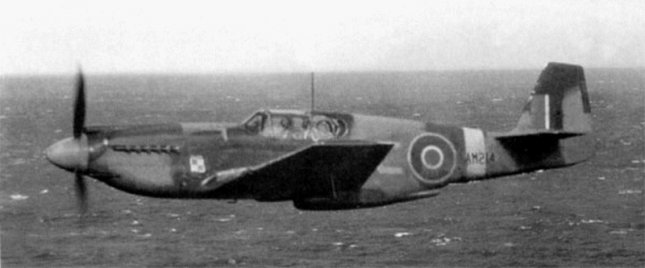
P-51

P-51A (With a P-40 in background; modern photo)

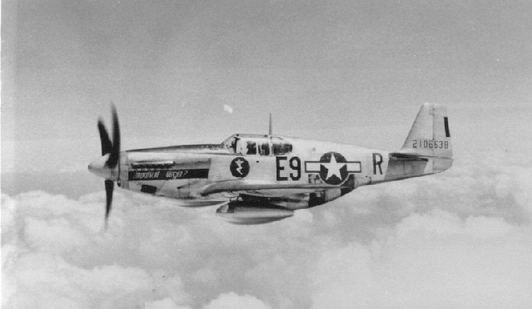
P-51B
P-51B (Malcolm canopy; modern photo)

P-51D

*Another bit of the Mustang legend that’s not exactly as told…
The Legend has it that with the addition of the fuselage fuel tank to the P-51B, the US now had a fighter that could escort bombers all the way to and from their target. Well, the US already had a fighter that could do that with the P-38 Lightning (a project also initiated by 1st Lt. Ben Kelsey). So why wasn’t the P-38 used for bomber escort? General Ira Eaker didn’t believe the bombers needed fighter escort and that their defensive armament would be enough to protect them. And in spite of the high rate of bomber losses, Eaker didn’t change his mind (he sent the P-38s in England to North Africa). I wonder how much that decision affected his being relieved of command…
In order of production, this is how many Allison-engined Mustangs were built:
US designation XP-51; British designation Mustang I; 4 .50 cal. machine guns, 4 .303 machine guns; 620 built (2 taken by US for evaluation)
US designation P-51; British designation Mustang IA; 4 20mm cannons; 150 built (93 to British, 55 to USAAF, 2 for Merlin engine tests as XP-51B)
US designation A-36; no British designation; 6 .50 caliber machine guns; 500 built (one was shipped to England for evaluation, none were ordered)
US designation P-51A; British designation Mustang II; 4 .50 caliber machine guns; 310 (50 to England)
Pressure Casting
Degassing the silicone molding rubber worked great, so I thought it would be equally great degassing the casting resin. Well…no.
Degassing the mixed resin turned the compound into a froth that quickly overflowed the pour cup and made a mess inside the vacuum chamber; I was just lucky I’d put a paper plate down under the cup! I mixed another batch of resin in a larger cup and degassed it. More froth and it was quickly obvious that the larger pouring cup wasn’t large enough. Rather than let it overflow again, I played with the valve I use to release the vacuum, cracking it just enough to keep the froth inside the container…barely. The resin has a 20 minute pot life, so I degassed it for about 7 minutes, poured it into the molds, and degassed again for another 10 minutes, playing with the valve again to keep it from frothing entirely out of the molds.
24 hours later I demolded the parts and was quite taken aback with how many bubbles were in the castings; enough so that the castings got tossed.
Hmmm…back to the Internet and more research. That’s when I heard about pressure casting. Instead of degassing to get rid of bubbles, the resin-filled molds are exposed to pressure. A pressure pot is used for application of liquids, most often paint, using a spray gun. With some minor modifications, it can also be used to pressure cast resins.
Pressure pots can be expensive. Once again, Harbor Freight had something reasonably priced that looked like it would do the job; their item number is 66839 and purchase of it will get you one of these:
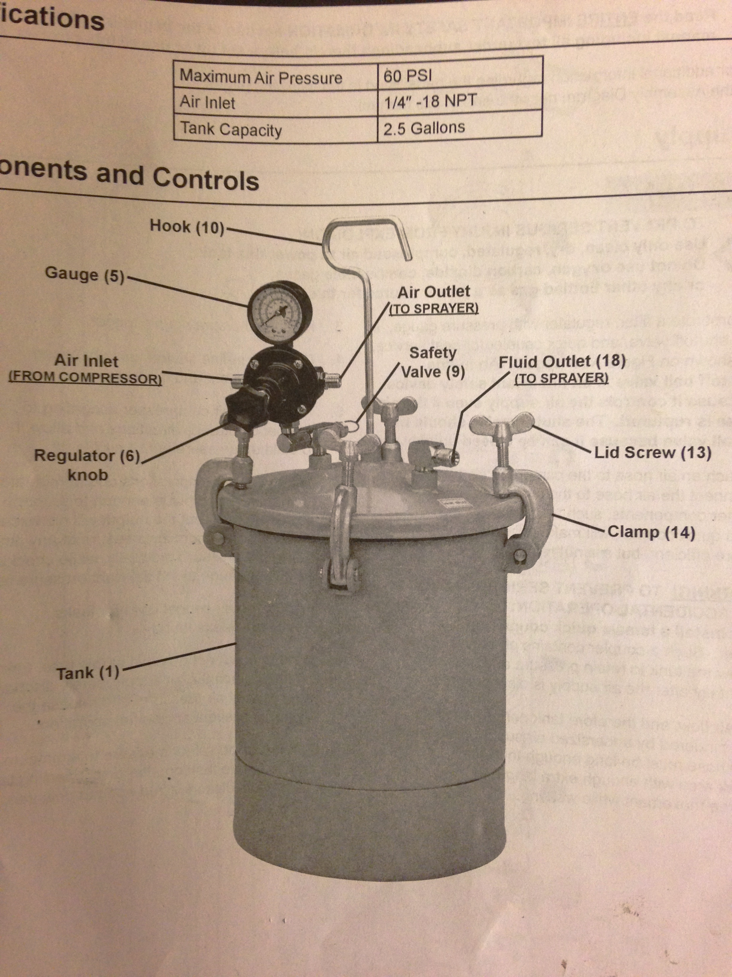
It’s a 2.5 gallon unit that’s rated for a maximum pressure of 60 psi.
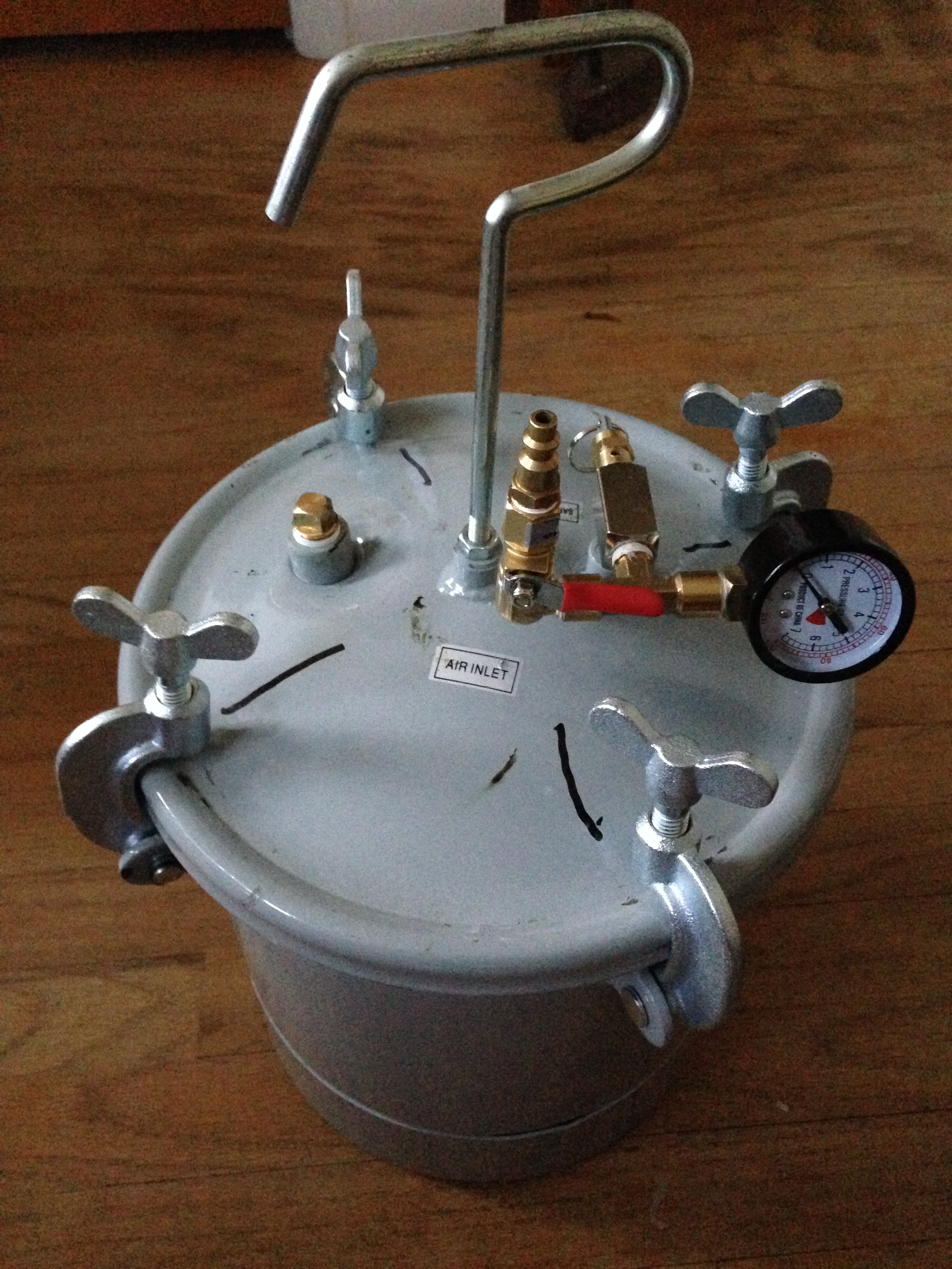
Since I’m not going to be spraying anything, there were some parts to remove. The siphon tube inside the lid screws out easily and a 1/2″ NPT plug plugs the hole. I don’t need the pressure regulator that’s supplied. Instead I added a brass T-fitting threaded 1/4″ NPT. I added a 90 degree elbow to one end of the T, then a valve, and then a hose coupler to the valve. To the other end of the T I added the supplied pressure gauge. To keep things from leaking, all fittings were sealed using Teflon tape intended for that purpose:
Before I ran a casting through it, I wanted to test it first. I fired up my compressor and adjusted the regulator to 50 psi. With the valve on the pressure pot’s top closed, the hose got attached to the coupler. Per instructions (yes…I read them), I put the lid in place (I ended up adding alignment marks to the lid) and tightened the clamping screws hand tight and then slowly opened the valve. Nothing hissed or exploded but the safety valve let go at about 30 psi. I increased the pressure coming from the compressor’s regulator to 60 psi and adjusted the release valve on the pressure pot until it let go (that’s done by tightening the collar by the release ring if you need more pressure to make it pop, loosening it if you need less pressure). I closed the valve, removed the hose, and bled off the pressure coming from the compressor before readjusting the regulator back to 50 psi and hooked things back up and applied pressure. Once fully pressurized, I closed the valve, removed the hose, and brought the pot inside to see how many pounds of pressure it would lose over an hour’s time, which turned out to be about 14 psi/hour, so that meant when I used it to cast I would leave the pot connected to the compressor overnight making sure the compressor stayed turned on.
That’s what I did when I ran the first set of molds through the pressure casting process. (Put something flat on the bottom inside the pot because it’s dished and trying to get several molds to sit flat would be impossible without it.) I let the pot sit in the garage connected to the compressor overnight and under pressure. When I demolded the parts 99% of the bubbles were gone. Well, not gone but compressed so small that they can’t be seen…which is the intent of pressure casting.
Good enough!
Getting a Better Pump
The vacuum pump I made from PVC pipe and fittings worked okay. Pumping myself into a frenzy only got me slightly over 25″ of vacuum, which was acceptable for my uses. However, it was the “frenzy” part of using it that got to be expensive. My back is made from glass rods and broken promises and it does not respond well to anything that has “frenzy” attached to it.
While I was researching vacuum pumps, I ran across a vacuum pump that is intended to be used to evacuate automotive air conditioning systems. And then I found a YouTube video where someone had used that type of pump for purposes of degassing. Harbor Freight has it; their item number is 98076 at $100. It’s a 2.5 CFM (cubic feet/minute) pump with a 1/6 hp 110V motor. The only modification I needed to make was to unscrew the fitting for a/c systems and screw in a 1/4″ barb for the vacuum hose:

It’s a LOT easier on my back to flick a switch! It takes very little time to generate 29.5″ of vacuum and that makes a noticeable difference. If you’re going to be doing little degassing then the PVC manual pump would probably suffice. If you’re going to be doing more than a little degassing, I recommend getting something like this.
P-51 (Accurate Miniatures) Build #1 – Parts Layout, Copying Parts, and Wing Modification
This build will be an early P51 with the Allison engine (though I won’t be adding an engine to the build).
I’ve seen a number of Accurate Miniatures’ P-51 models online and if there’s an exception it’s escaped my notice, but they’re all done with the kit decals that shows a P-51 of the 154th Reconnaissance Squadron out of Tunisia in 1943 with the name, Mah Sweet. As it turns out, there aren’t a lot of decals for the P-51 in 1/48 scale. (Yes, yes…I can hear y’all jumping up and down; of COURSE there are lots of P-51 decals available in that scale, but most of those are for P-51B and P-51D kites. I’m doing a P-51 with no suffix. Different bird.) I did manage to find an out-of-production decal set for early P-51s from AeroMaster (Early Mustangs #48-106). As it turns out it has markings for another P-51 from the same unit, the 154th, but with different numbers and name. That’s the set I’ll use for this build.
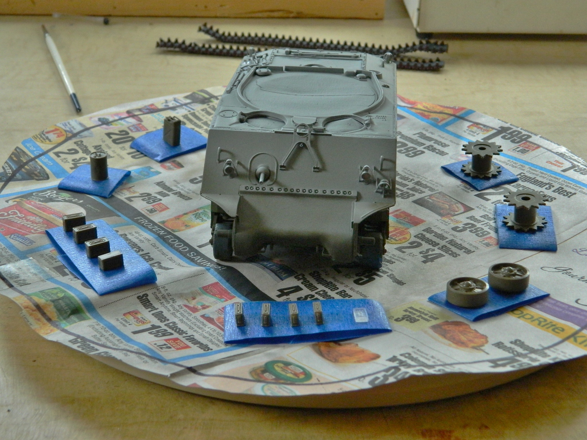
This is what I’m starting with:


This is where I want to go with it, which is another P-51 from the 154th (decals from AeroMaster Details set #48-106 “Early Mustangs” and the photo is from P-51 Mustang in Action from Squadron/Signals Publications, Aircraft #45, page 12):

And these parts are what I plan on adding to the build:

Back in the early ’90s, P-51D kits were made by seemingly everyone in many different scales; there were a few P-51B kits, but nobody was making any Allison-engine P-51s. So of course I wanted to build one. I found a resin conversion kit that replaced the fuselage halves of Monogram’s P-51B and started work. But just before I had to move and lost shop space, I noticed that the sides of the nose had a different cross-section between the Merlin engine and Allison engine Mustangs. Construction stopped while I figured out a way around that problem, and then moving really stopped construction. However, some of what I had done I would be able to use with this build.
The Verlinden set offered me the resin armor plate and A-brace but I don’t think it goes quite far down enough. I pulled my scratch-built piece out and compared them:
I decided to use the A-brace and its assorted bits. But since I’m going to be doing a few Allison Mustangs, I didn’t want to have to scratch-build that assembly again which meant making a mold of it to cast those parts in resin. It was heartening to note that when I glue something together, I glue something together. It was more heartening to not break anything while separating the parts for the molding process:

Once separated, the parts needed to be gated so that I could pour them. I also added plastic to the back of the instrument panel so that it would pour easier:


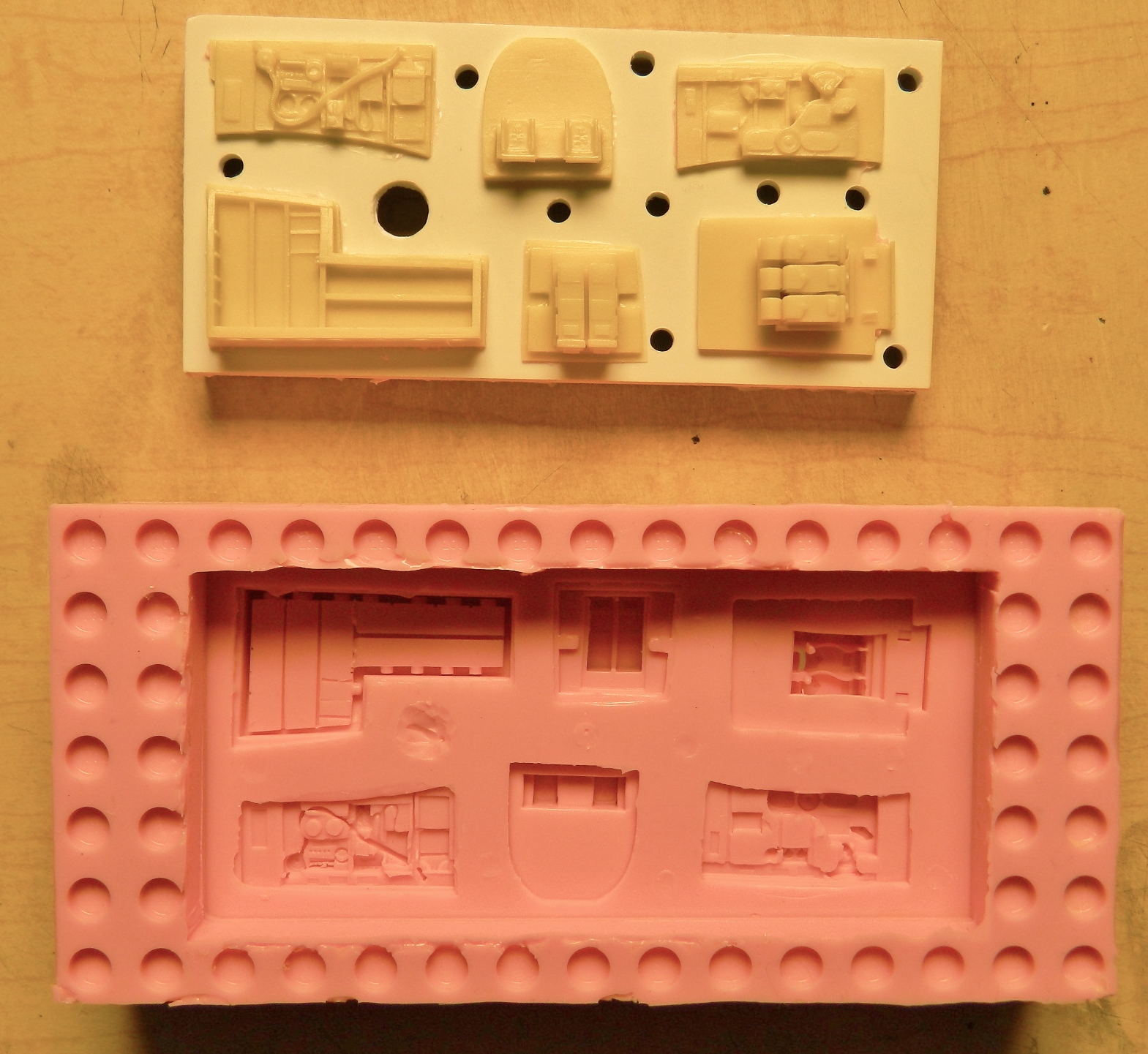
I also took molds of the other parts in the set:

I think it’s safe to say that pretty much all kits have something wrong with them. In this situation, I’m encountering the commercial balancing act between engineering and producing an accurate kit and yet still keep the final cost of the kit reasonable, and the Accurate Miniatures kit, though quite a leap forward at the time (the early ’90s), was no exception.
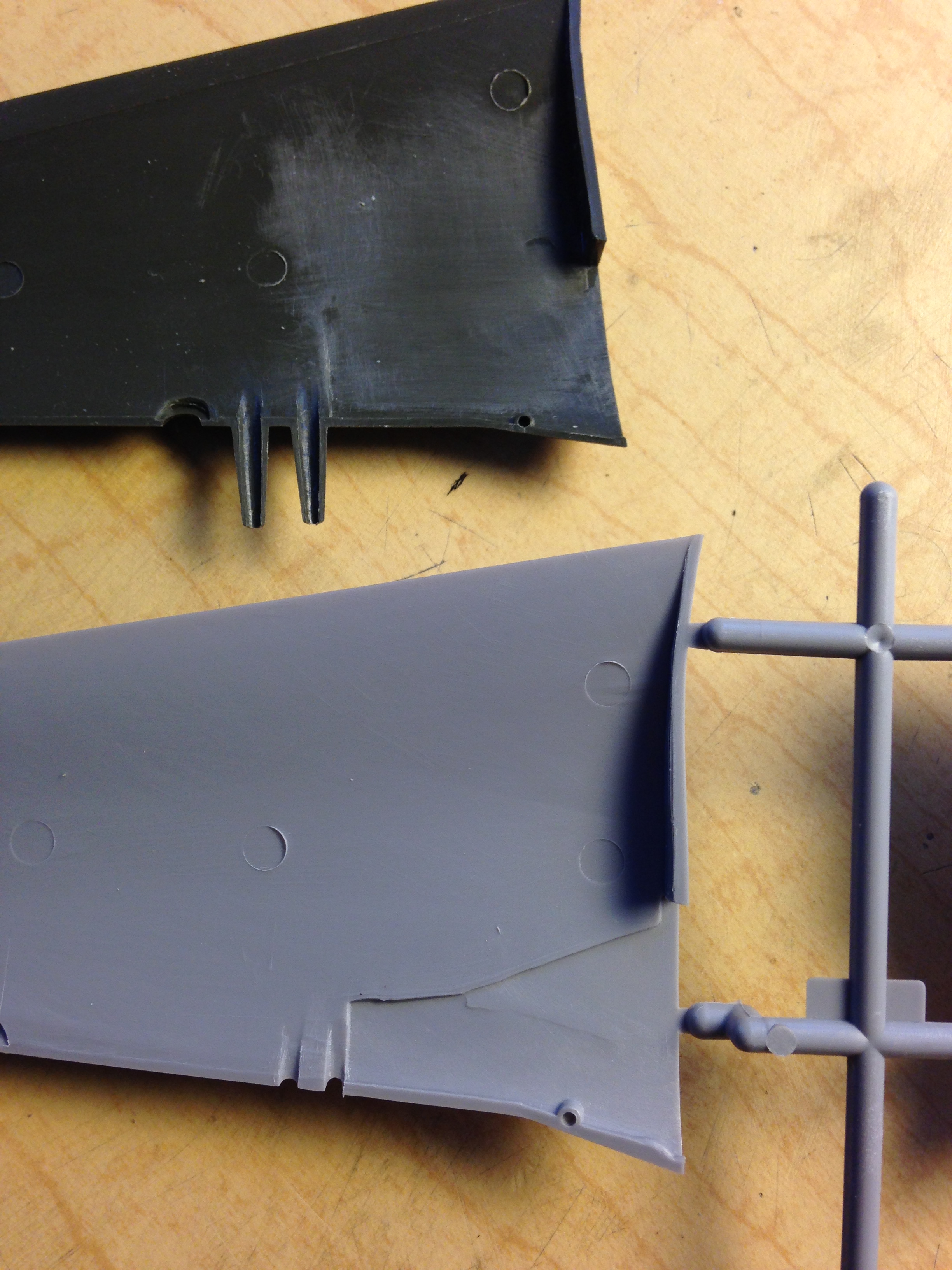
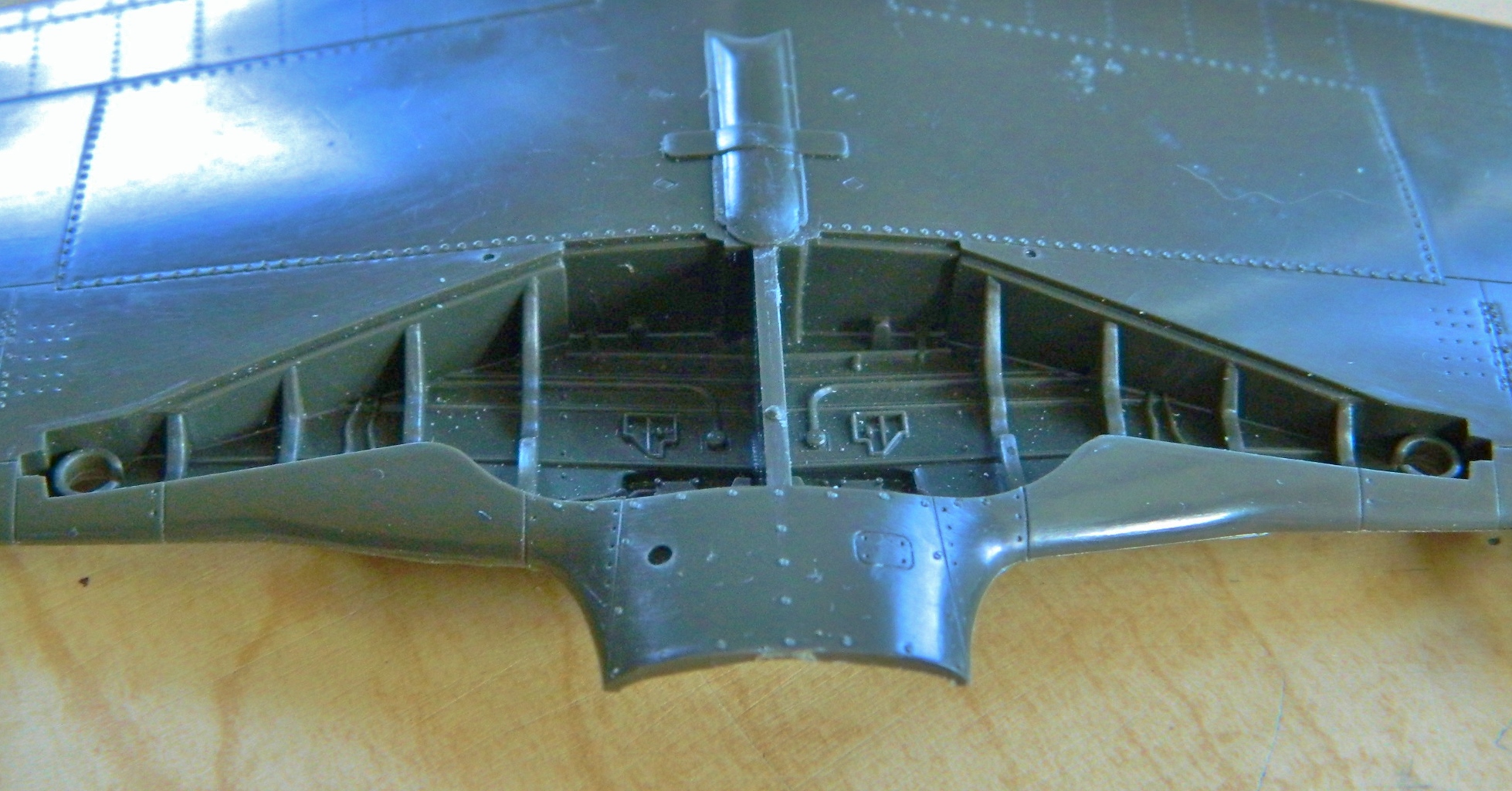
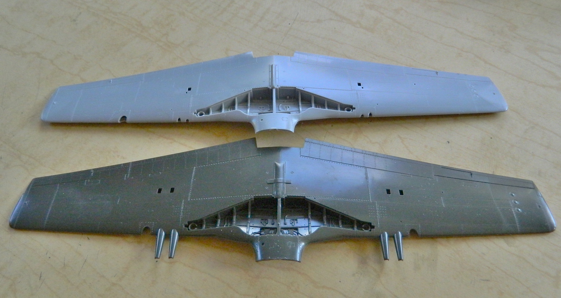
The first thing I noticed is that the landing gear wells are going to need to be reconstructed (and yes, once they have been, I’ll take molds of them and use resin castings in the builds). The rear of the landing gear wells is molded pretty much the way everyone else at the time molded them in this scale. And pretty much like everyone else producing these kits, they’re wrong. The rear of the wells doesn’t follow the openings in the wing surface the way the kit parts do. If you look into the landing gear well of a P-51 (which I have), you’ll see (like I did) that the rear of the well isn’t V-shaped as it’s been molded but is open all the way back to the main spar. And the ribs are not only not that thick (they’re aluminum stampings), they have lips around their edges for rigidity. The kit has none of those features so most of the molded-in wells are going to be cut away and replaced:

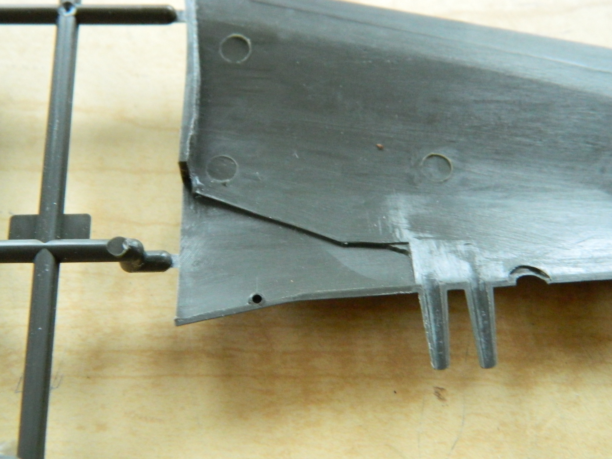
The top of the wells (or bottom, as you look at the above-left photo) are actually the underside of the upper wing surface of the actual Mustang. That means I have to blend the lip below into obscurity:
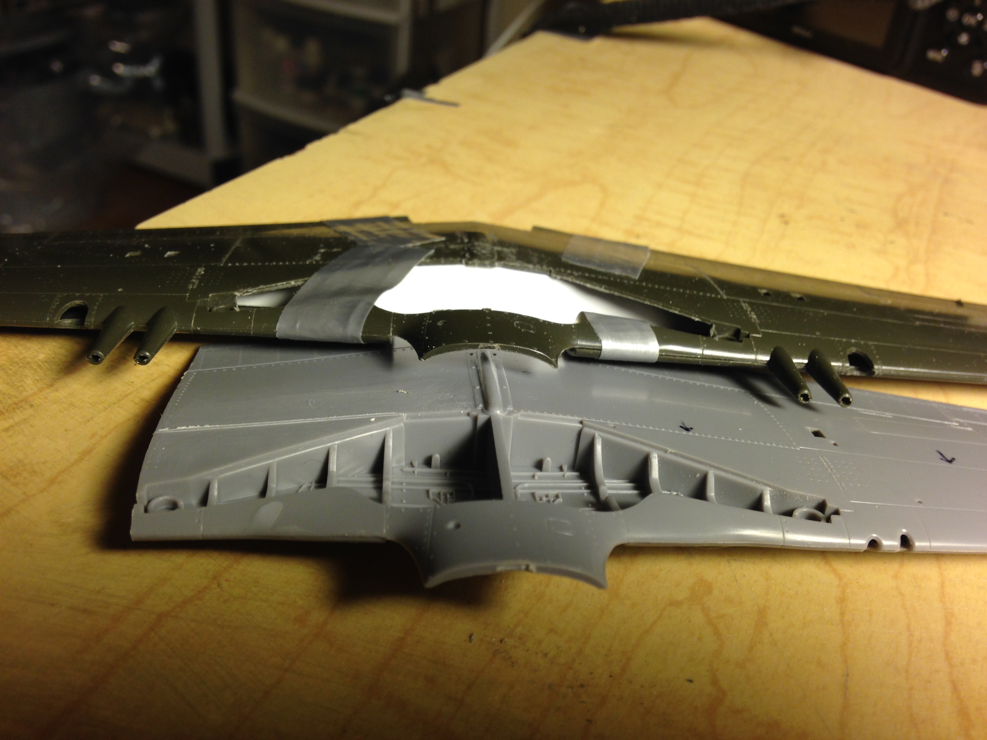
To do that, I’m going to need to follow the inner curves of the wing so that the parts fit. But to get that inner curve, I’m going to have to assemble a wing and then section it so that I can trace the inner shape. I only have one P-51 kit, but I have a few P-51A kits, and though the armament of the two variants was different, the wing is the same. So one of my P-51A kits has become the donor kit:
The lower-right photo has arrows pointing to the rib I’m going to want the shape of:

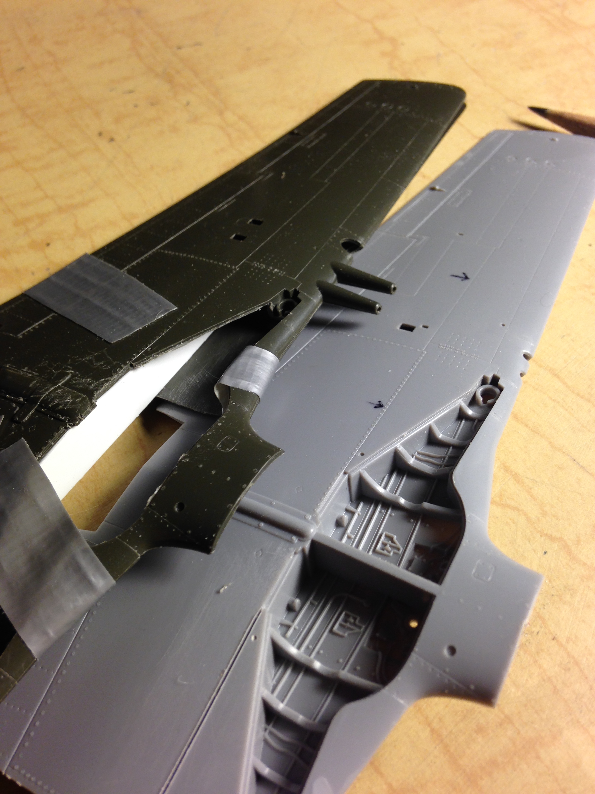
The wing was cut just short of the rib so that I could get in there with a pencil. The inner protrusion is part of the section where the landing gear leg attaches and I’m going to want to keep that for structural strength when the landing gear is attached, so the rib has to be built around that protrusion. Once I had the section I wanted cut free of the rest of the wing, it got taped to a sheet of .040″ (1.016mm) styrene and the inner shape traced:

Once I had the rough shape outlined, I cut, carved, cursed, filed, cursed some more until I finally got an adequate fit. This piece will form the outer end of the well:

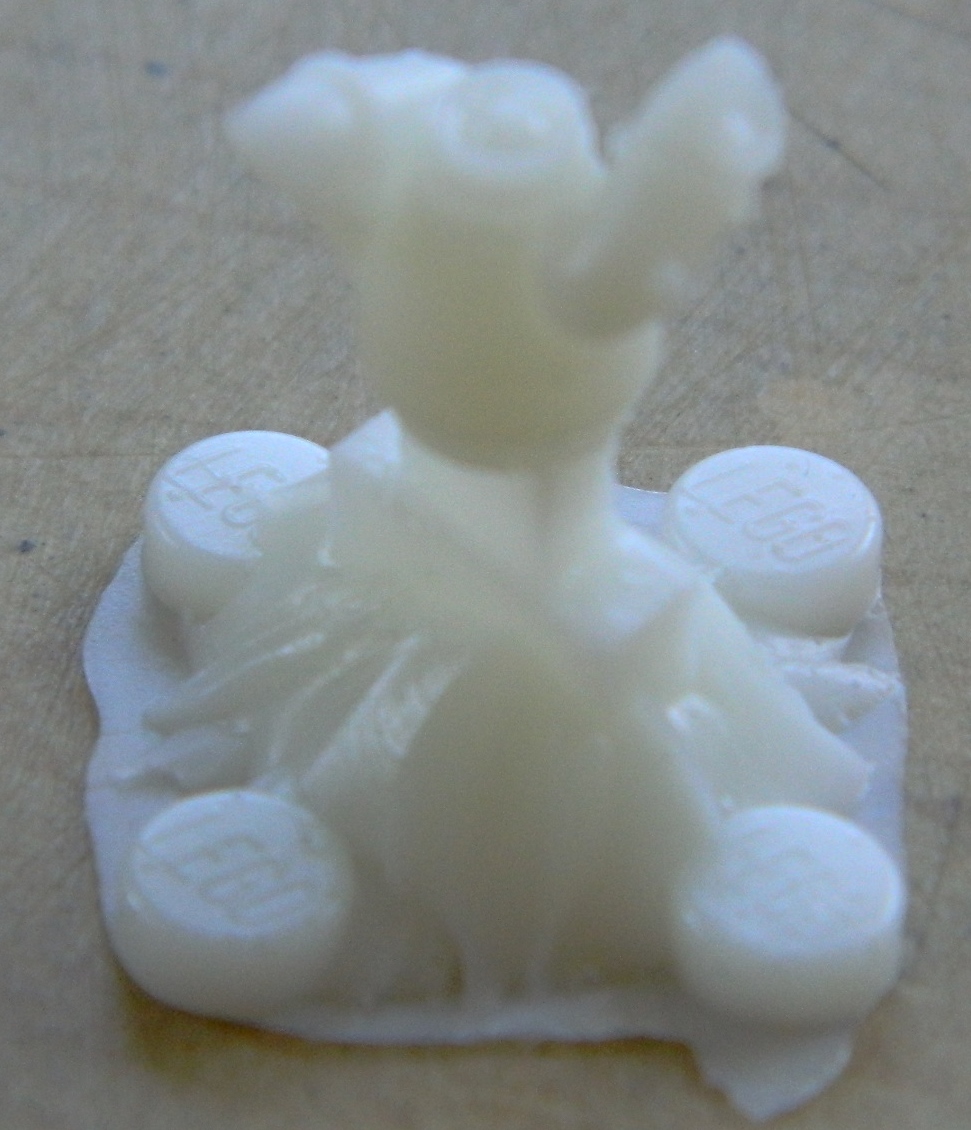
While I was working on that, I was also pouring resin into my new molds (the Lego blocks were taped to the edges of the molds to see if I could get a better reservoir for the resin and though I did, the “benefit” of that reservoir wasn’t worth the hassle of it all):
With the parts out of the molds, trimmed, sanded, filed, and cursed at (really, I’ll take any excuse to exercise my ability with colorful invective), the dry-fitting began by tacking things together with white glue and contact cement:

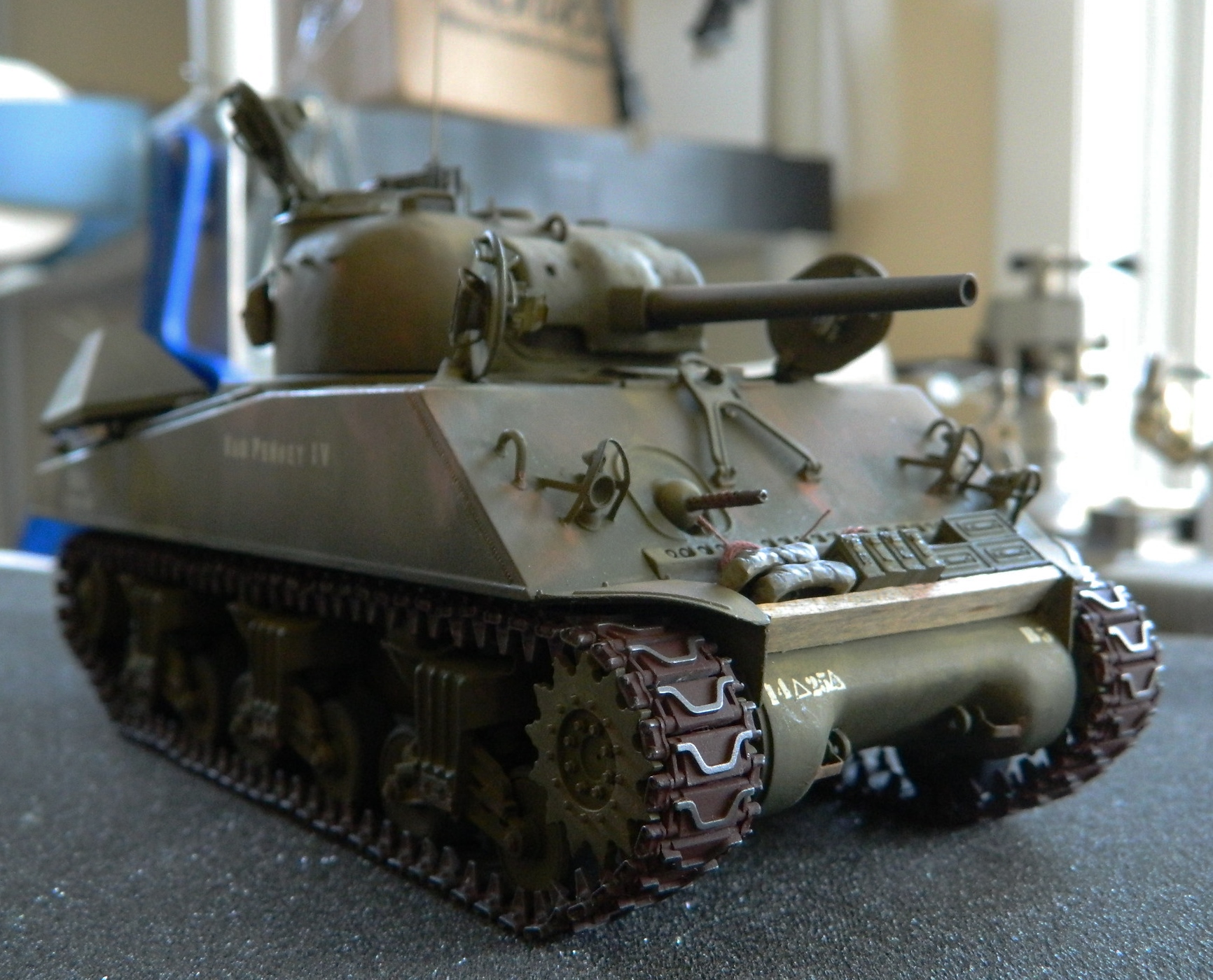
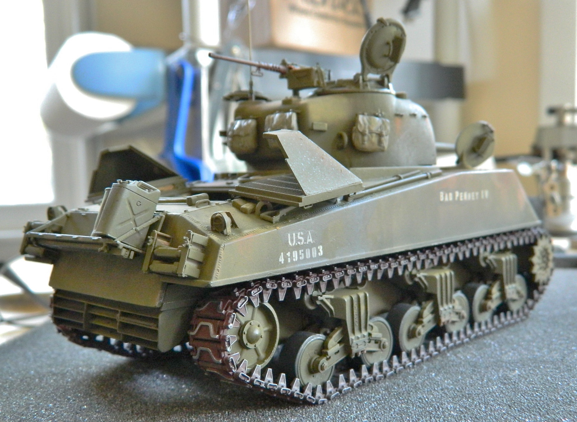
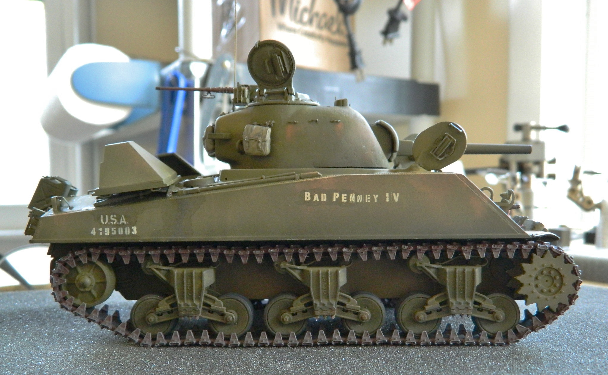
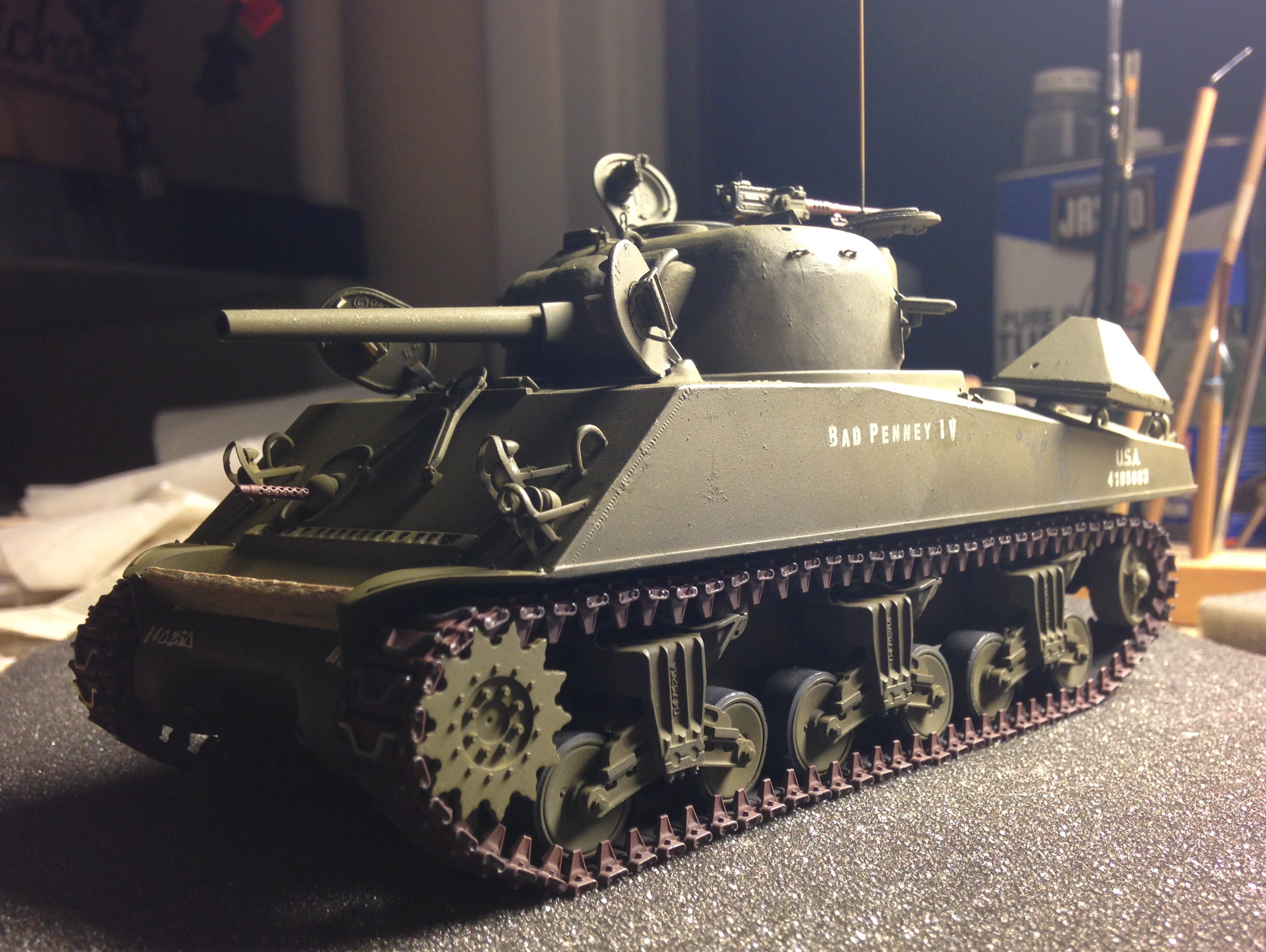
M4A3 (Tamiya) Build #29 – Final Details added and Completion
One last thing I want to do is to add rolled up tarps. I looked at AM resin sets but that’s just what they look like…resin. I decided to try something I’d read about. Taking paper towels or tissues (without texture), cut them to size and fold and roll them, and then soak them in diluted white glue. Tie them as desired, drape over the vehicle as desired, then set them aside to dry. Once thoroughly dry, paint and install. I placed plastic wrap between the soggy tissues and the model and draped as desired:
It took a couple of days for them to dry completely, but once dried they were painted, pastels added, and then the rope was also put on that would have held things in place:


The pastels came out for dusting things up a bit and I added more fuel spills…and DONE:

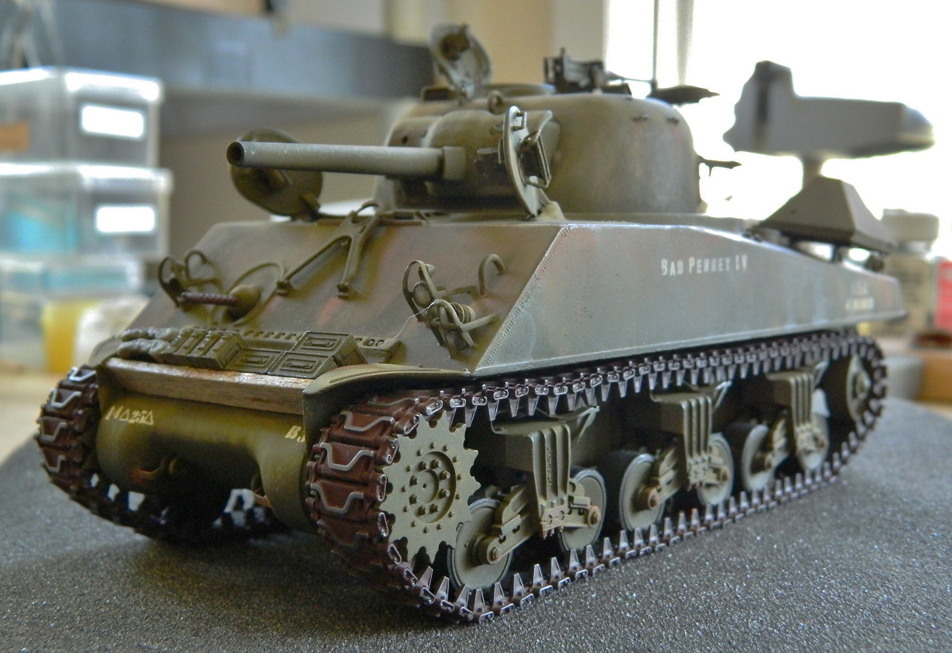

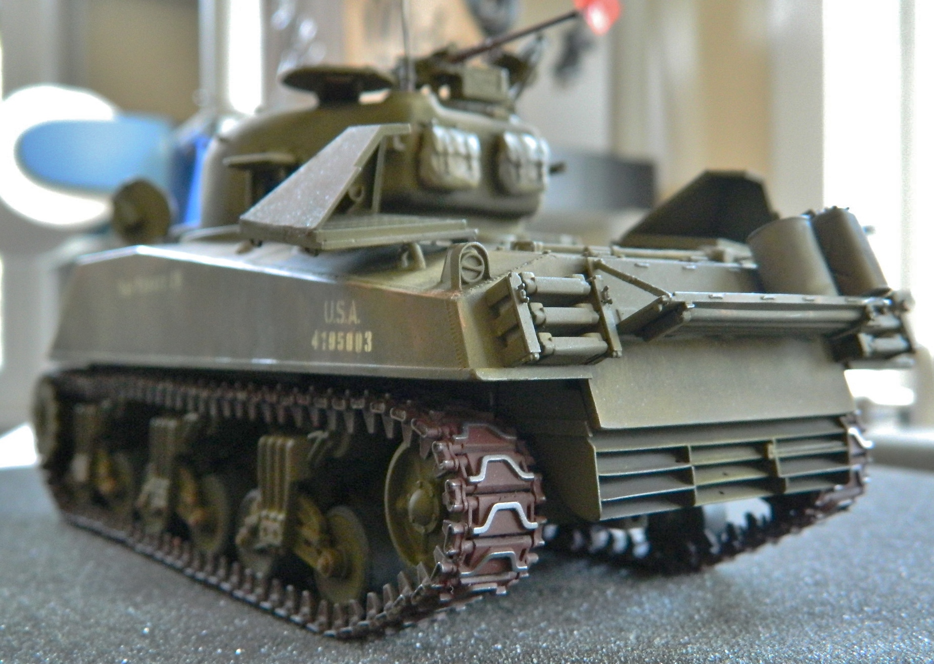


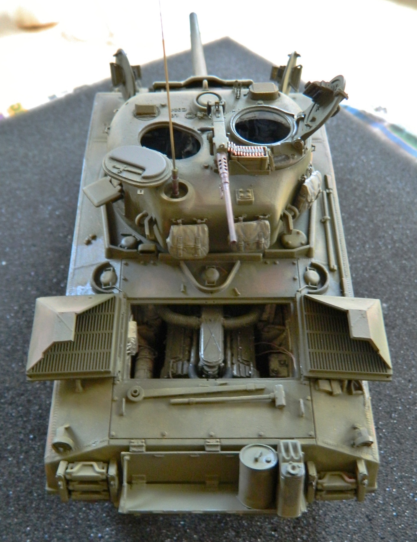
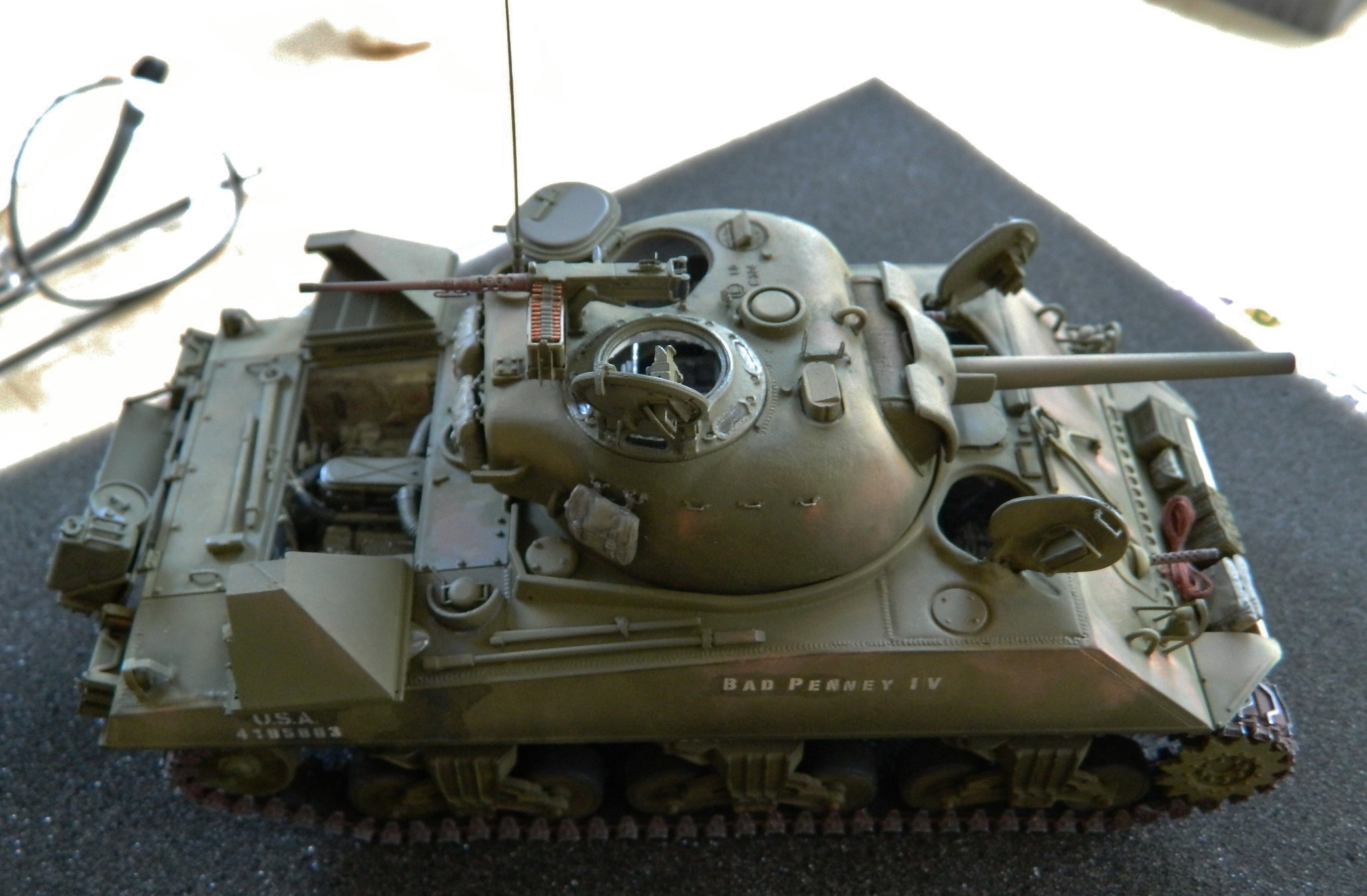
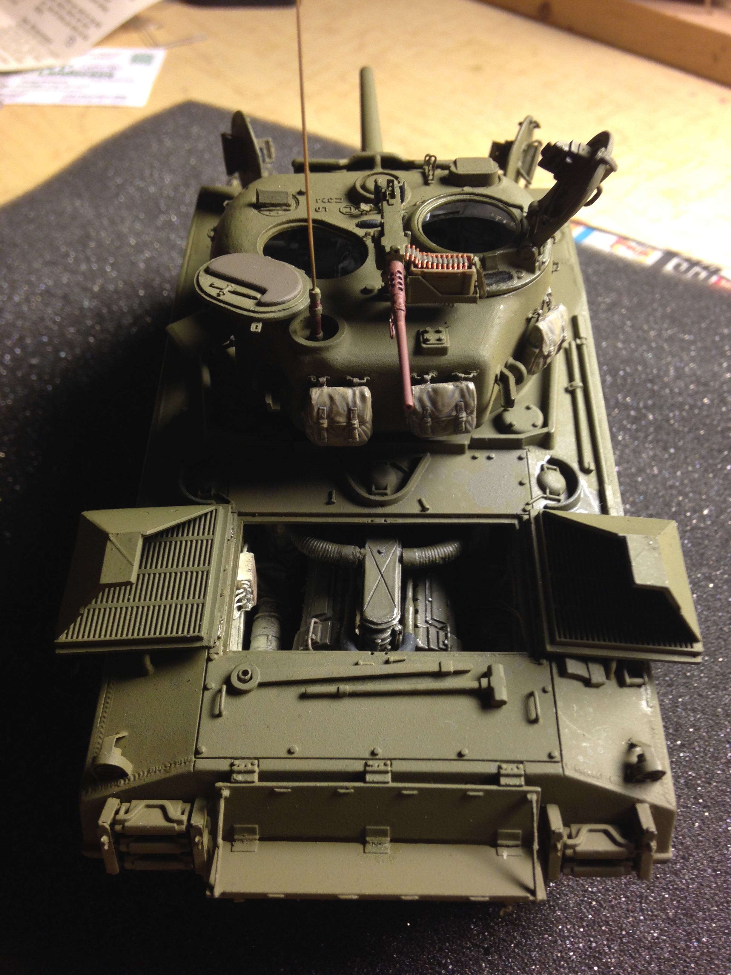
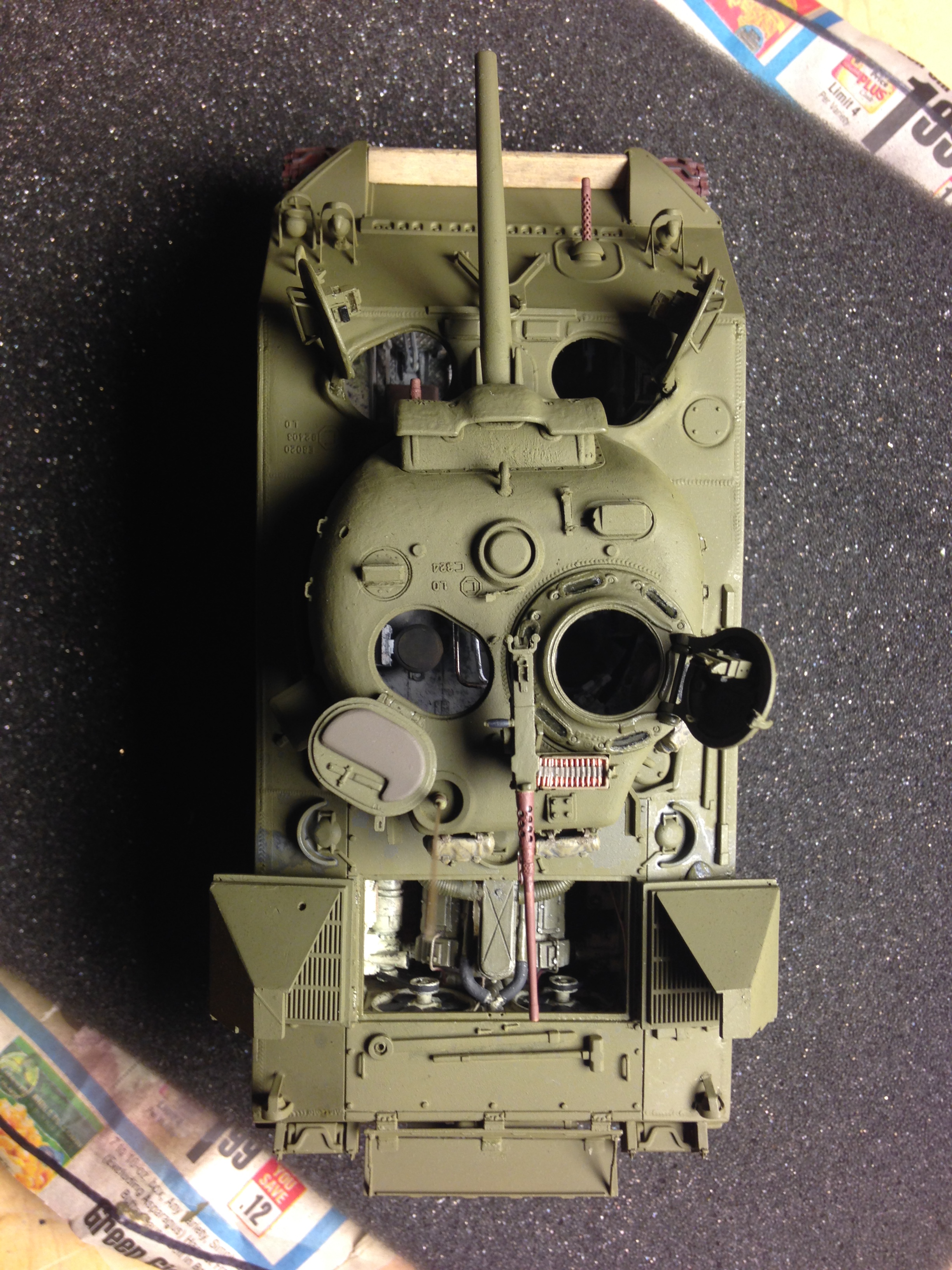
M4A3 (Tamiya) Build #28 – Weathering and Staining
Short on words, long on pictures, the only thing left to do now is to weather, stain, and dirty it up a bit and add some stowage:


M4A3 (Tamiya) Build #27 – Tracks Finally Installed and Markings are Added
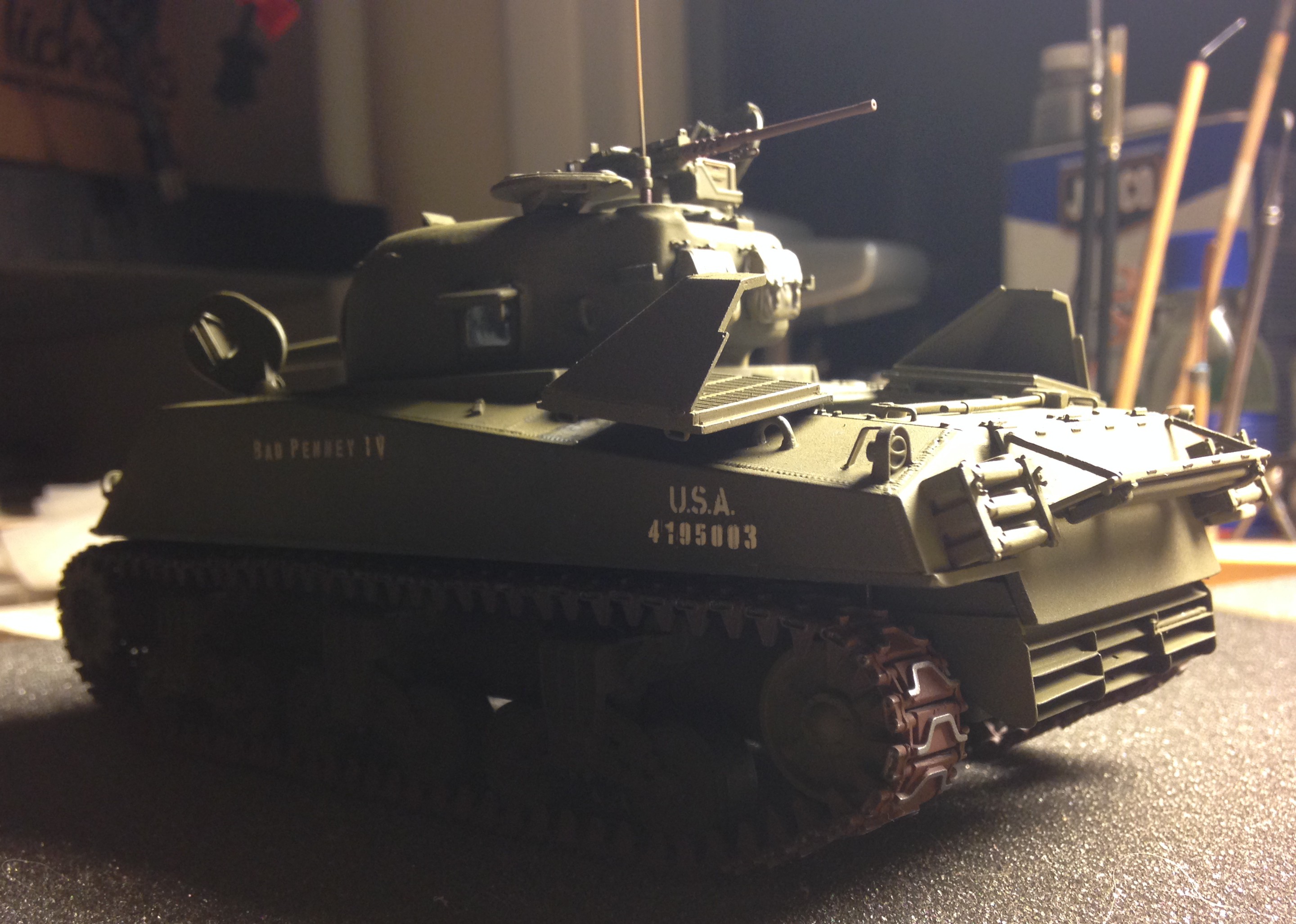
With the tracks assembled (but NOT glued) and painted, it’s time to put them on the tank. The first go-round with the pre-glued tracks was such an ass-pain that I approached the second go-round with a bit of trepidation. Needless. They went on like…well…they belonged there. So that’s the way to go with individual tracks; assemble but hold off on the glue:
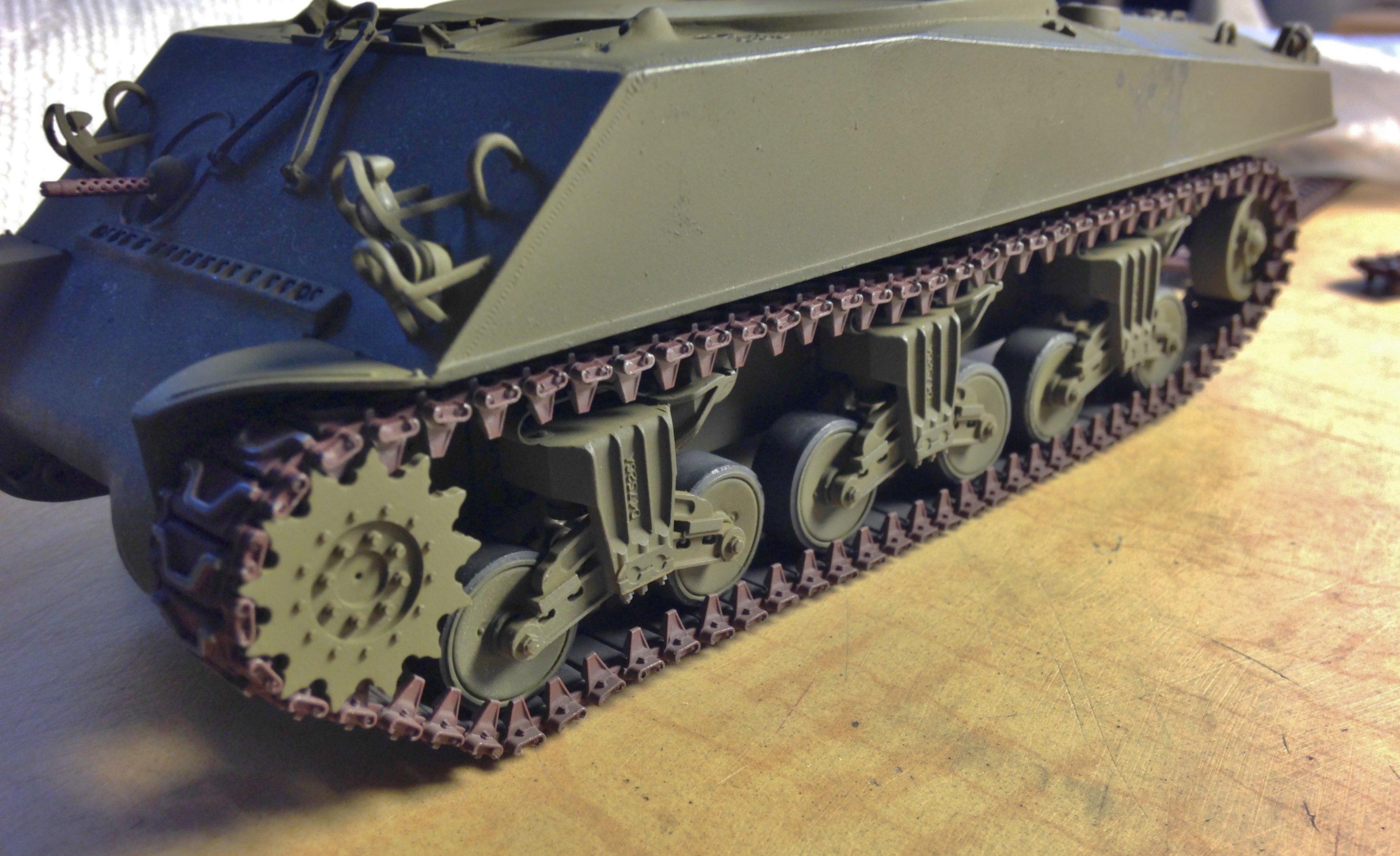

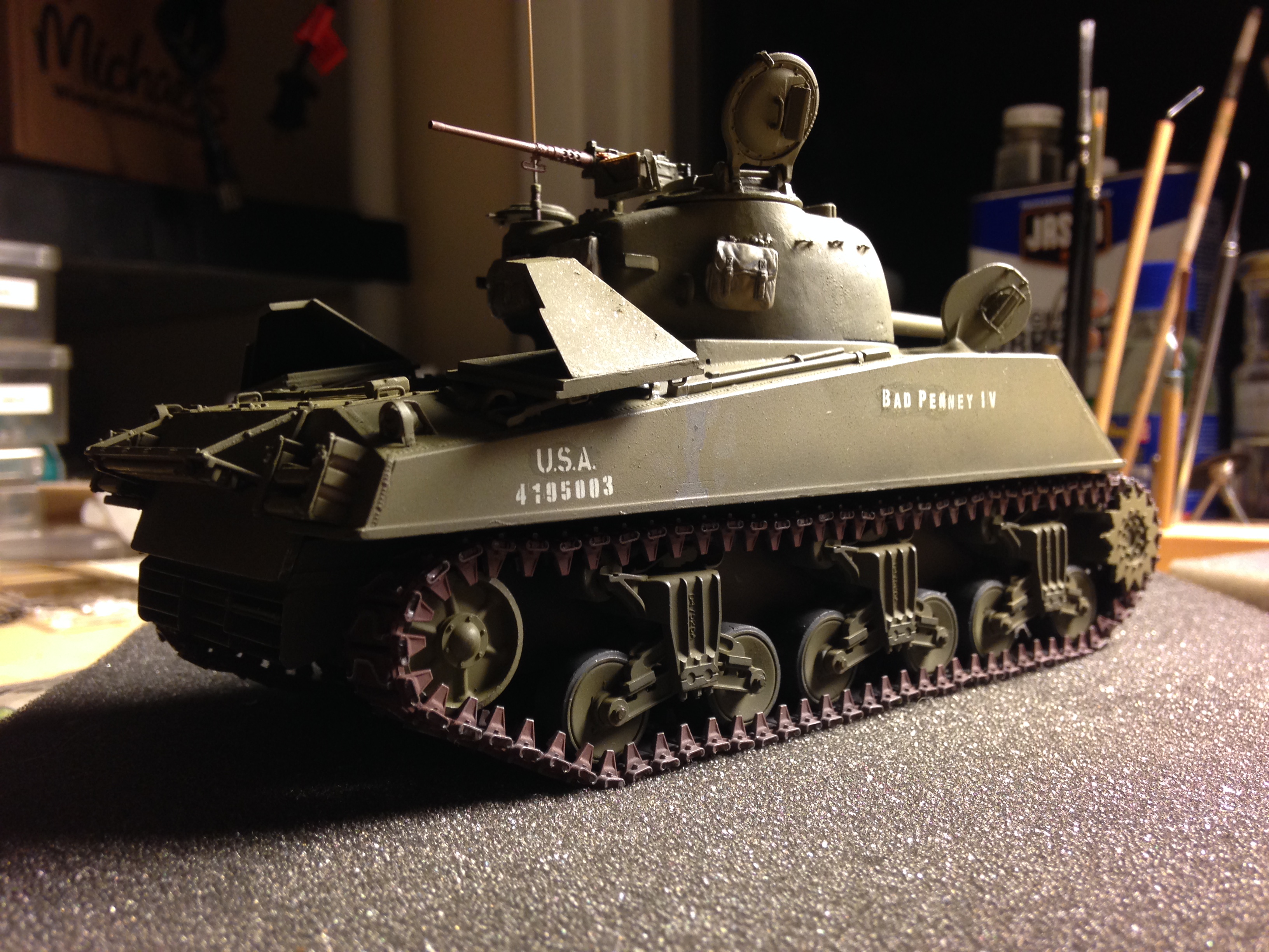
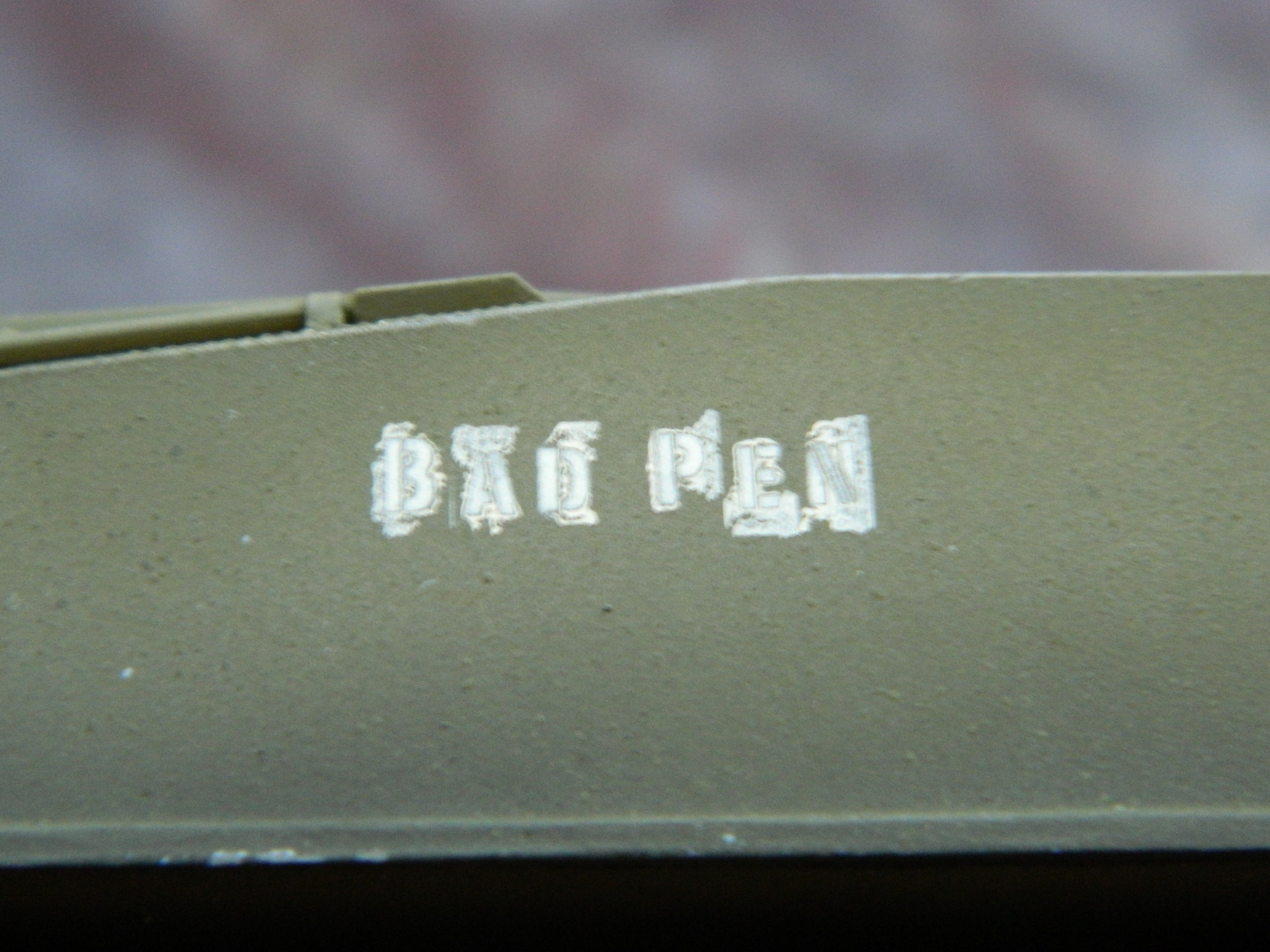
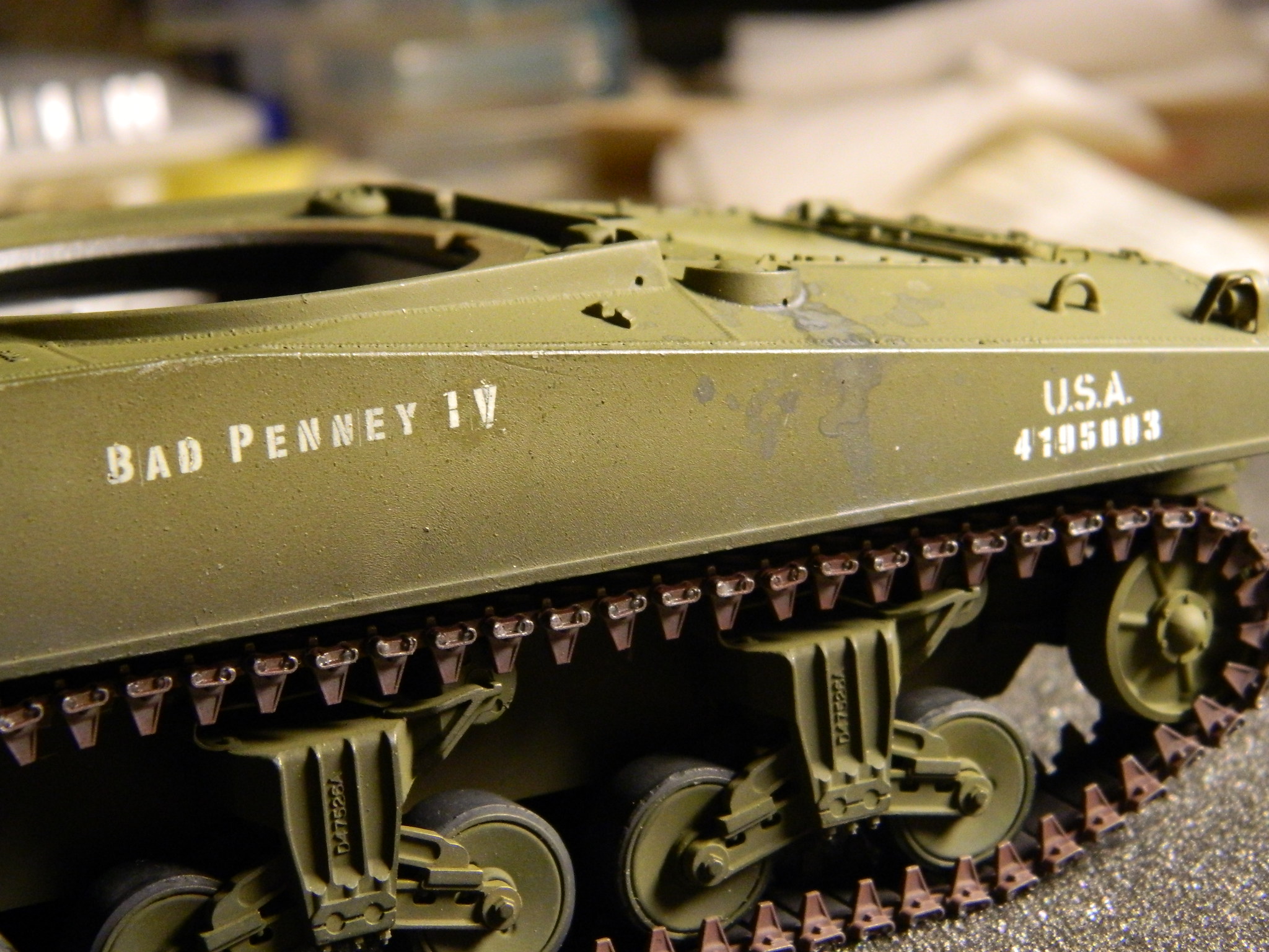
And with the tracks finally on, there really isn’t anything left to do but to start the final paint! I’m modeling a fictitious tank, so I cobbled together a serial number. I had intended on either doing dry-transfers or cutting up decals but instead found some really nice stainless steel PE stencils so decided to go that route:

I used the same “aged white” for exterior numbers and letters that I used in the engine bay; it isn’t quite as glaringly white and I like the effect:

However, when using acrylic paints, it’s best to be sure the airbrush doesn’t have any water left in it from the previous cleaning, otherwise, the paint is far too thin and you’ll end up with what I did:
So that got painted out and I tried again. Yeah…that does what I want it to, not look like it was done by a professional:
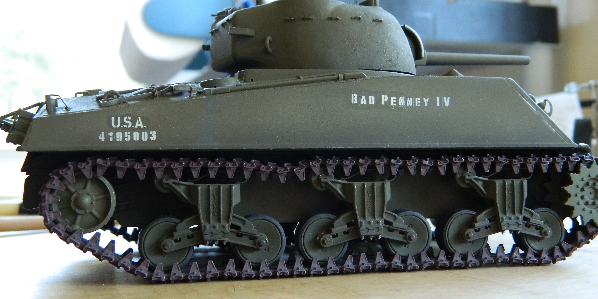
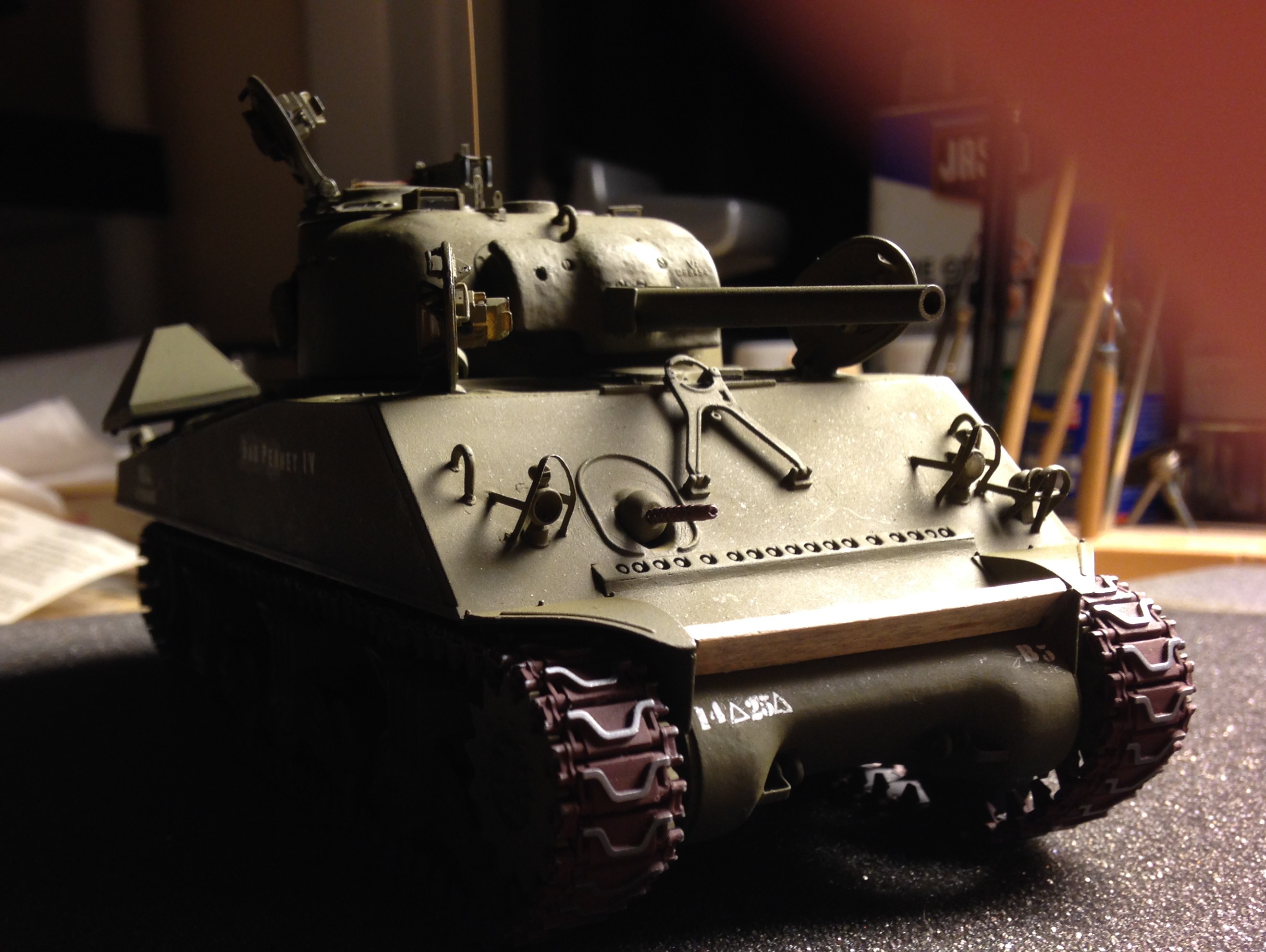
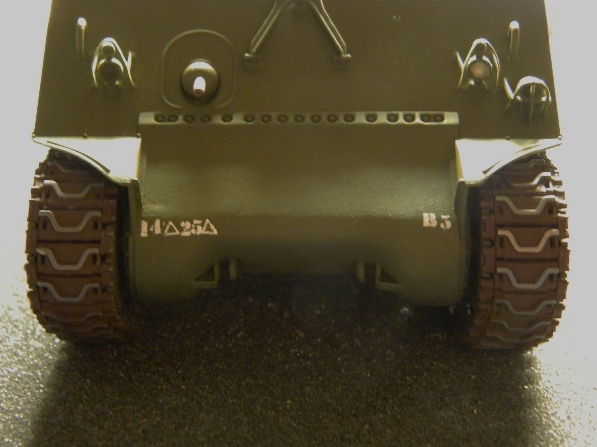
I did the vehicle markings using dry-transfers. Believe it or else…er…not, when very tiny transfers are combined with a curved surface, this was the best my 65-year-old hands could manage. I went through a lot of transfers to get this. No, I’m not 100% satisfied with them, and perhaps tomorrow (or the next day), I’ll peel them off (cellophane tape does it nicely) and try one more time:
And with that, there’s nothing left to do but the final assembly.
M4A3 (Tamiya) Build #26 – Fun with Tracks (Part 2), Painting Exterior Details
There was a hold placed on this build, which is obviously now over. The problem was with the tracks. Having never used individual track shoes before, I thought I was being “clever” by gluing the sections that would be flat in the thought that doing so would make the tracks easier to install. Such was not the case. When it came time to install the tracks on the model, the pins of the track shoes kept snapping. I tried drilling out the connectors and the shoes, inserting styrene rod to replace the snapped pins, and as far as that went it worked. Unfortunately, as I fixed one shoe, the one next to it would snap…and the one next to that…and having done five or six that way, I sorta figured that I would end up drilling and pinning ALL the shoes on BOTH tracks:

Time to cut my loss, order a set of new tracks, and start the whole tedious process again. [Insert industrial-grade whining here] And that’s what I did.
It seems as if even a little bit of experience is a good thing. I figured out a new way to clean up all the connectors and shoes. The first run-through with individual track links took me about 40 hours to clean up 158 track shoes and 316 connectors. The second time it took me about 15 hours to do the same thing (my shoulder is still sore from all the back-patting I did):


During that 15 hours (spread over three days), I spent a lot of time trying to figure out why those pins kept snapping. I mean, I only dry fit each track on both sides a half-dozen times… So the first determination was that I would only fit this set of tracks once per side and then glue them in place. And something about gluing kept nagging me. The pins on the track shoes ARE SMALL. They are also plastic. Hmmm…
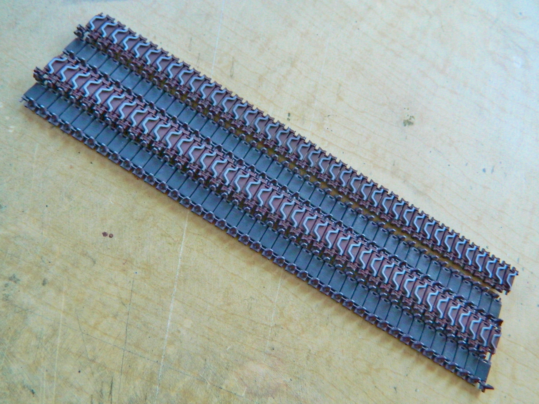
With sections glued, the torque stress of putting them on and taking them off showed the weakest part of the tracks; the little plastic pins. I’m figuring that by not gluing them prior to fitting them onto the model, those stresses won’t be concentrated on those little bits of plastic. Yes, with the connectors only pressed on the tracks will droop and twist. But each time they droop and twist that force will not go to twisting the pins. Okay, now I have two runs of tracks put together but not glued at all:
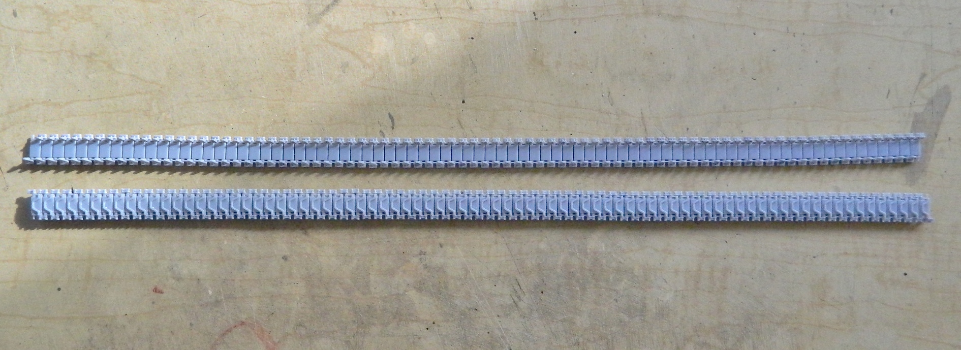
Next, they get painted the same way the last set did; steel, rusty brown, and rubber black. I start with steel and buffed the track faces (and do please note that this time I got all the chevrons aligned in the same direction):

I was not looking forward to the masking process. So much so that instead of masking the tracks and airbrushing the rubber paint after doing the rusty brown, I brushed the rubber on before the rusty brown, then shot the rusty brown on the faces and connectors, using acrylic thinner to clean the chevrons:

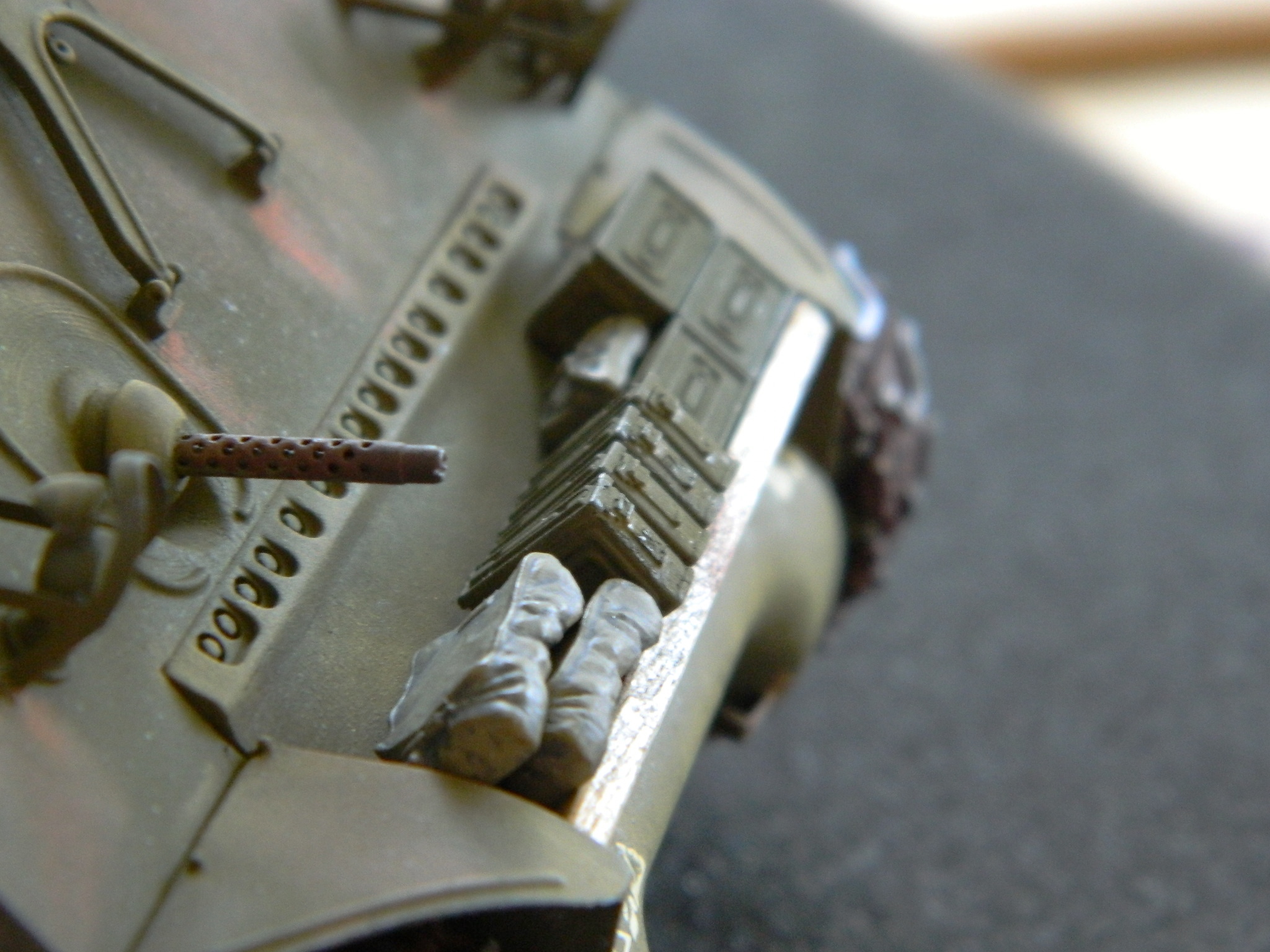
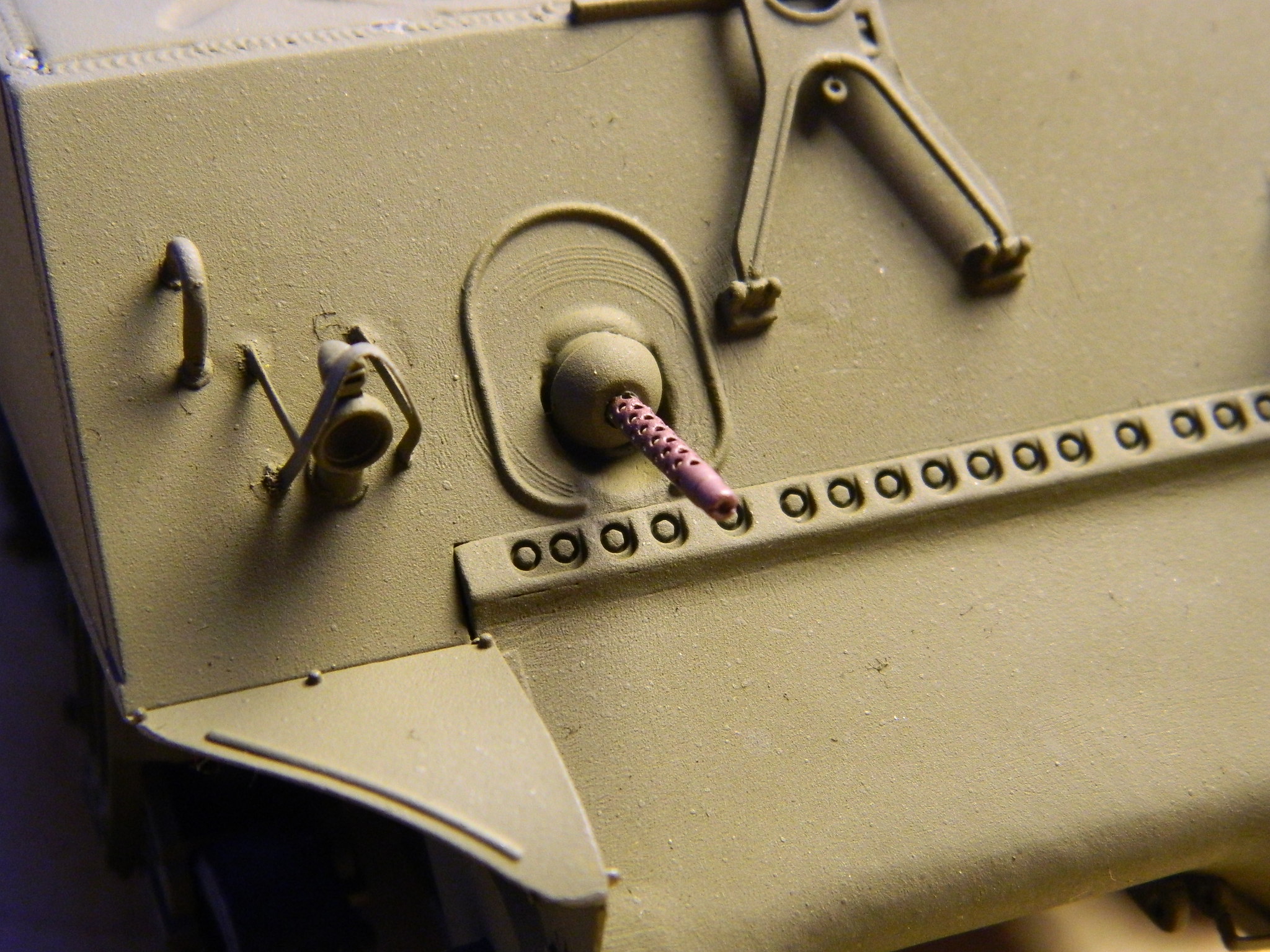
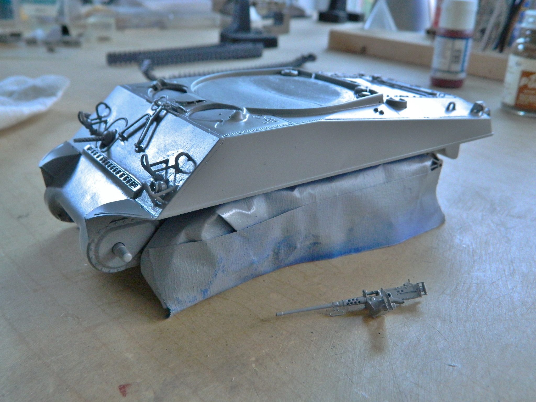
I set them aside to let the paint set up a bit more and turned my attention to other items that need paint. First I did the .50 caliber (1.47mm) and added the ammo box and belt:

I painted the coaxial .30 caliber (7.62mm) and then added the mantlet:

And then I painted the bow-mounted. 30 caliber (7.62mm):
I won’t be surprised if touching up needs to be done after final assembly, but I’ll bridge that cross when I get there. First I have to get the tracks mounted…
HOLD
Just a place marker in case you’ve been following this to let you know the build is on hold pending the arrival of new parts. I’ve been chasing my tail (an ugly sight at best) trying to mount the tracks. Links keep snapping. I drill both the track and the connectors out, set new styrene pins, and the next link breaks off. Okay…I see the pattern. Time out is called, new parts are on order, and I get to do all that fun stuff that cleaning 152 tracks and 304 connectors entails.
Experience. I just earned some.
M4A3 (Tamiya) Build #25 – Final Painting Begins
A long-term project is interesting. When I start I don’t really think much about the end. That’s not to say that I don’t have a direction, intention, and goal, because I do. But I don’t think about its completion because with something long-term, if I spend too much time thinking about the finish I can overwhelm myself with all that needs to be done, and really…during the project, I’m not at the finish. I focus on whichever step towards completion I’m presently working on. I figure if I do that, the finish will mostly attend to itself.
And then one day I realize, sacred excrement! I’m almost FINISHED! That awareness always seems so sudden. Well…
I’M ALMOST FINISHED!
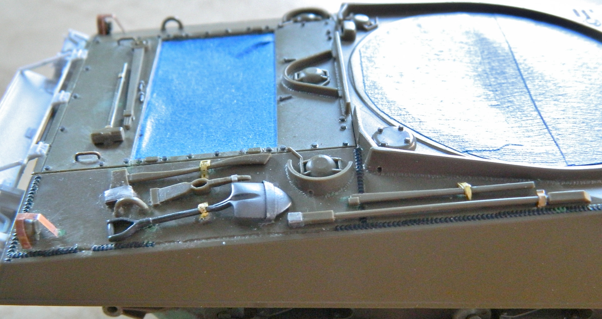
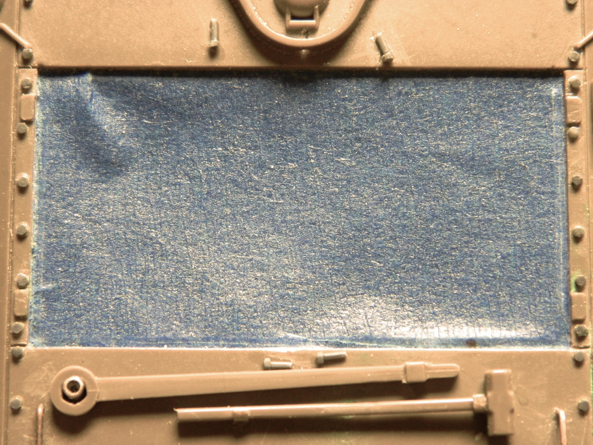
When using an airbrush, the force of the air coming out of the brush can blow small items off the bench. My way around that is to use double-sided tape to hold the piece in place, in this case it’s the loader’s hatch because I need to paint the pad on the underside of the hatch:
The blue masking tape works very well if I’m painting a room. IT ABSOLUTELY SUCKS FOR MODELING! To paint the rubber sections of the tracks (rubber black again), I had to mask off everything else. Well. There are about five hours invested in just getting the intercoursing tracks masked. No, I didn’t think it was particularly complex to mask because it shouldn’t be. However…the fornicating, sodomizing, tape refused to stick to anything other than what I did not want it to stick to. I spent hours pressing the tape back down. Hours. And even then, once I had the track paint mixed, again I had to press the tape back down. But I persevered and got them painted:
Below you will see two end connectors that I did not want the tape to stick to. This time the tape really stuck and when I gently pulled the tape off, I gently pulled the end connectors off, too. Not an insurmountable problem, but annoying anyway:
The underside of the hull, exhaust ducts, and areas where the sponsons meet the hull were painted flat black. Later I will mist Tamiya’s XF-62 Olive Drab over these areas:

Areas that I want to appear darker were then hit with Olive Drab:
I’ve discovered a fool-proof way to discover which small detail parts you still need to add. Paint the area where they need to go first. Shortly after you do, you’ll remember what you still need to add. In this case it was the commander’s gunsight (in front of his hatch opening) and the travel lock for the .50 caliber (1.27mm) (behind the roof vent). They’re easy to spot; they’re not painted:
Since I’m going to have to paint pretty much everything else with my custom mixed Olive Drab, I’ll hit those brass parts, too. Before I do that, I need to fill in the small bubbles that were left in the puttied co-driver’s hatch area that I didn’t see until I had it in primer:
With that taken care of, I misted the custom Olive Drab onto the bottom, the sponsons, and the back:
To keep from handling paint before it’s set, I mounted the small parts on the (INTERCOURSING) blue tape instead of the double-sided tape. I did the loader’s hatch with the double-sided tape because the Olive Drab has had months to cure and I wasn’t worried about leaving paint behind when I removed it. Such won’t be the case this time. And since the SODDING blue tape has (repeatedly) shown it doesn’t hold firmly, that will make getting the freshly painted parts off, reversed, and the other sides painted easier. Because I wasn’t going to be able to handle things, yet I would still need to move them so I could get complete paint coverage, I painted them on a turntable:
For all the difficulties and problems I encountered in this build, right now is the biggest problem. Leaving things alone until the paint cures! Because with a few minor exceptions (machine gun barrels, for example), the next step is to assemble all the parts:

Must.
Not.
Rush.
M4A3 (Tamiya) Build #24 – Adding Details and the First Coat of Primer
It seems I wasn’t quite as ready for prime time as I thought I was yesterday. Evidently, my mind works (assuming that’s not an oxymoron) better earlier in the day than later. When I wrapped up last night, I really did think I was ready to throw paint first thing today…and then I sat down at the bench today. That’s when I saw all the things I wanted to prime, which is when I saw how few of those were ready to prime. Fine. Let’s get them ready! I mean really…how long could it take?
The answer to that question was about four hours.
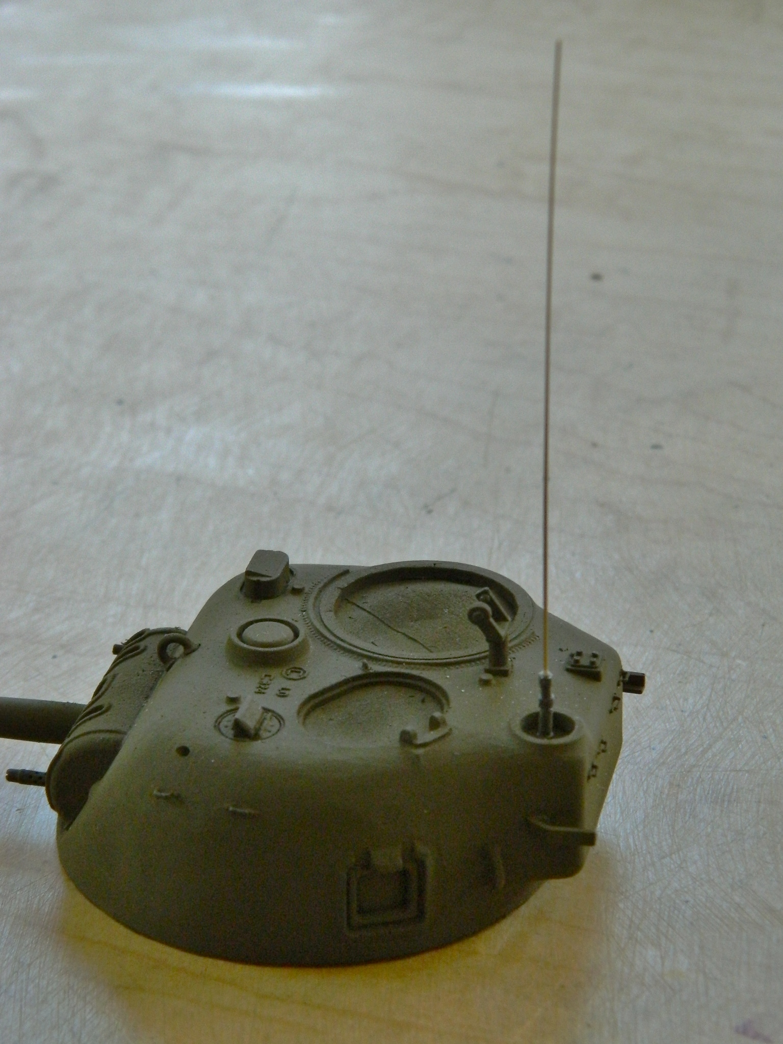
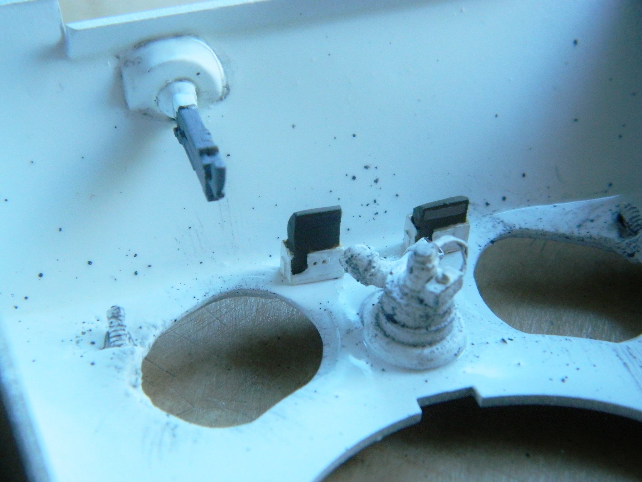
But I wasn’t aware it was going to take that long, so the first thing I did was to prepare the radio antenna. No kit I’m aware of supplies one; they supply the antenna base and expect the builder to supply their own antenna. Okay, no problem. I’ll just stretch some sprue…uhm…how long a piece do I need?
My memory is a funny thing (mine is just hysterical). One of the bits it burped up was that in one of the Sherman kits, the length of the antenna is specified. There are four kits sitting on the shelves in the shop and of course it was the last one I looked in that had that information. 7cm.
Those of you who model know that the little tiny nose probes on a 1/48 scale aircraft are forever catching on things and breaking off. A 7cm antenna doesn’t exactly qualify as “tiny.” It didn’t require much imagination to realize that this aerial is probably going to break off frequently. What I needed was a way to dismount the antenna for those (RARE) times I’m going to transport this model.
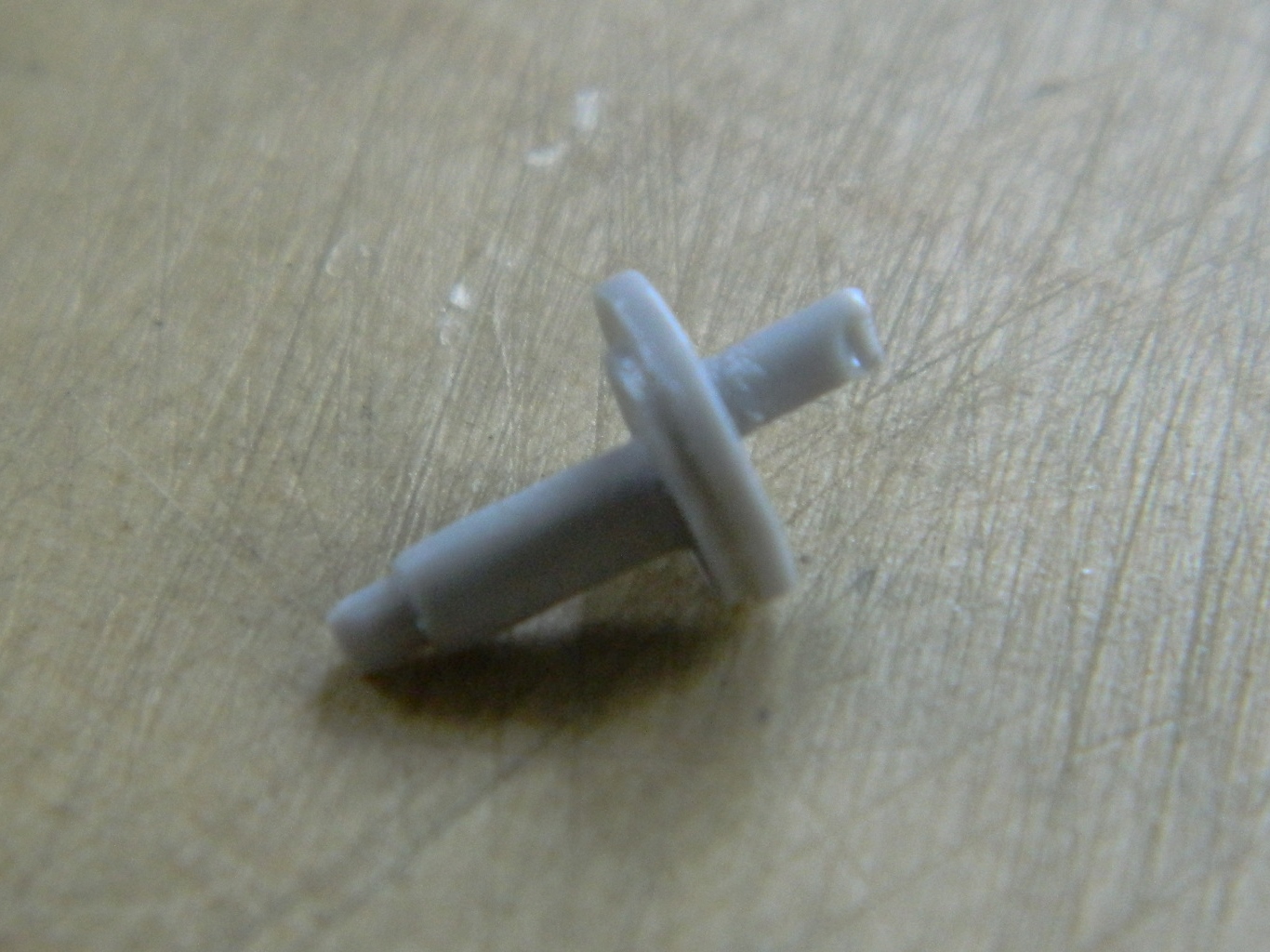
I really like having a spare kit of my build. I went to the spare and cut the top off the spare antenna mount, drilled it out, and inserted a pin. Then I cut the bottom off the mount I’m going to use, drilled that out, and ended up with a two-piece antenna mount:

Stretching sprue requires patience. Sometimes I can get the diameter I want in one pull. Sometimes it seems like it takes forever (as defined as a half hour) to get what I want. This time I was right in two. I cut the sprue and measured 7cm, cut it again, and glued it to the top of the mount. Because the plastic I stretched was already Olive Drab, I didn’t paint it:

Now the antenna can be safely removed and put back on:

At this point, I was still assuming that I’d be able to not only prime what I wanted to be primed, but also be able to use the airbrush to do some detail painting. I turned my attention to the .50 caliber (1.27mm) on the turret top.
I’d already thinned out a kit ammo box and laid in an ammo belt from my spares stash, now I needed to run another belt from the gun down and across the top of the belt already installed:


Handling small parts is rough on those parts. I spent considerable time reattaching things, more time waiting for the glue to cure, and then repeating that process several times (exacerbated by remembering I’d wanted to add the butterfly trigger to the .50 caliber (1.27mm), and wasn’t THAT an exercise that ate up time. Tempus fugit indeed.)
So after four hours of all of the above, I was finally ready to prime. I used a rattle can of Tamiya’s fine gray acrylic and hit everything that wasn’t styrene and much that is. Different materials and colors reflect light differently. Another reason to prime something that’s had parts added that the kit didn’t provide is to get one type of reflective surface. This way modifications, things that had to be made to fit, brass, lead, aluminum, resin, and styrene, will all reflect light the same way and will show you what doesn’t work, what needs more work, and the ego-stroke of seeing you got it right:
Now the primer will allow the subsequent paint layers some tooth. Tomorrow I’d like to get another detail or two added to the turret and then break out the airbrush to get some of the other details under paint, but that determination needs to wait for fresh brain and not be made with stale brain.
M4A3 (Tamiya) Build #23 – Readying the Exterior for Paint
With most (I think) of the major sub-assemblies done, it’s time to start getting the hull ready for paint. Because of all the different materials used, I want to prime the upper hull before I lay down color; experience has shown me that acrylic paint doesn’t adhere well to brass.
I masked off the off the crew compartment and engine bay:
I had considered waiting until very late in the build to put the detail parts in place on the hull. But because of the fairly involved paint scheme I have in mind, getting the details to fit with the color scheme would be substantially easier if they were painted along with everything else on the hull. That means details get added now. The first thing I did was to shorten the front lifting loops and while the glue was setting up, I trimmed and blended where I had shortened the rear lifting loops. That took so long that the glue on the front loops had set up by the time I was finished with the rear and then did those also.
Then I started bending PE parts for head and taillight guards from Verlinden’s Sherman detail set and I used TMD’s resin guard for the siren:
Doing lenses of any hue with paint doesn’t work for me – it just screams I’M A MODEL. I wanted to try something different for the headlights. The New Tiger Models Direct (TMD) makes a set of headlights and guards. I had originally intended to use the clear resin headlights that came with the set but decided to get daring. I used the opaque resin parts instead because clear lens covers also come with the set. For a little more visual impact, I decided to leave the lens off one headlight completely (I mean it’s a tank and the lights are glass, so no great stretch for one of the headlights to be broken). For the other headlight I decided to try and make the reflector out of thick aluminum. I used the headlight itself as my buck and sharpened and shaped a bamboo chopstick to use as my form and very gently pressed the stick into the aluminum while it was in place over the headlight:
Using small scissors I cut away most of the excess:
After pressing and gluing the aluminum reflector into the headlight bucket, I did the fine trimming with a round-tip hobby knife then placed the lens over the reflector. I liked it, so I glued the lens in place and then used white glue to hold both headlights to see how they work. I liked that, too:
Moving to the back of the tank, I added the spare track links to the racks. Reference photos showed that the spare links were over-painted OD green (as was everything else on the tank when it got a coat of paint, including dirt, spare tracks, and whatever else was strapped to it), so I added them to the racks and then added the fold-down shelf:
I successfully glued one of the taillight protectors in place, but when I was doing the second one, evidently I had another brain fade. I thought I had the knife positioned properly but something shifted, I didn’t notice it had, and I ended up cutting a quarter of an inch off the protector instead of a profoundly thin piece as I’d intended to do.
[Insert colorful invective here]
Turn off the lights, walk away, get a good night’s sleep (for a change, surprisingly), and the next morning while having life’s blood coffee and just ruminating on my options, I remembered (for a change, surprisingly) that I have .005″ (.127mm) copper shim stock on hand. Okay, using the ruined guard as a basic template, I traced the shape onto the shim stock and using the small scissors again, cut out a new piece:
I liked the replacement so much better than the PE part that I snapped the “good” guard off and made another one:
Back at the front, I needed to add the front fender mounts where they attach to the differential cover. But something didn’t look right. I went to my reference photos and realized that Tamiya hadn’t molded the front fenders correctly. On most of the late-model M4A3s in the photos, the sheet metal doesn’t form a 90-degree angle with the line where the fender meets the differential casting (that seems to be more common on earlier variants), it runs vertically down from the corner of the fender. I added .020″ (.508mm) sheet:
I applied putty to hide the seam and let that sit to cure.
Tools don’t just sit there. Sherman tanks bounced a fair bit (saw a photo of one named, “Bouncing Bitch”), so anything not secured to the tank wouldn’t stay in place. What the kit has molded to the tools as “attachments” were unacceptable. The brass straps and buckles came from the Verlinden PE set, brackets and sockets were made from lead foil:
The engine covers are bolted closed and to open them they have to be unbolted. So where do the bolts go? I would imagine they’d just be set on top of the rear plates until it was time to close the covers. I modified four Grandt Line bolts, trimmed them to length, and glued them in place:
With the putty cured, I went back to the front and smoothed away the excess putty. Since I used .020″ (.508mm) sheet to add the missing fender sections, the edges needed to be thinned to replicate sheet metal (yeah, it’s still too thick for scale accuracy, but making them as thin as they should be would result in them being too thin for reality):
Okay, that looks much better:
Since the goal is to get this under a coat of primer, and all of the fiddling with the top surface is done (I HOPE), I replaced the resin weld beads that had gotten knocked off during handling (lots and lots of handling):
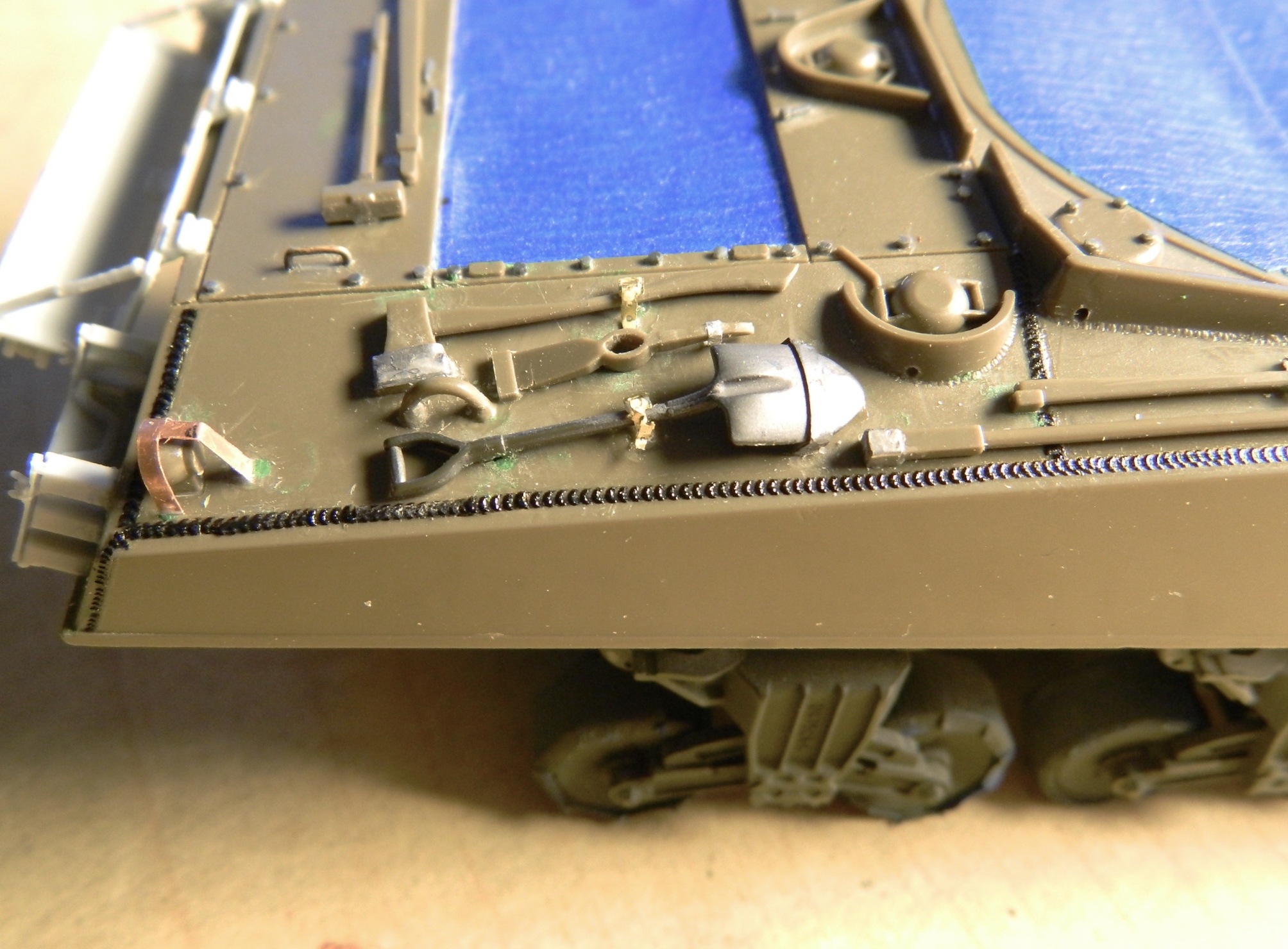
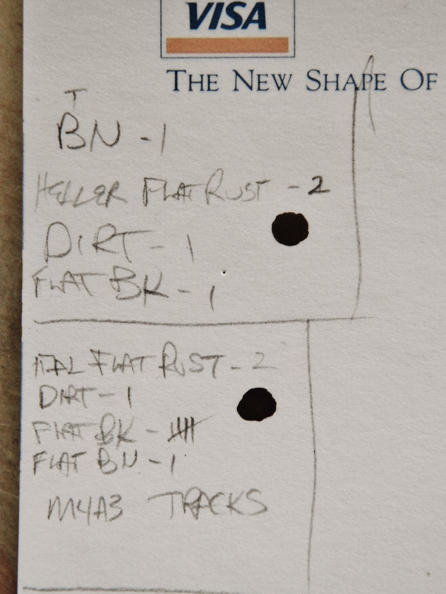
Another part I want to paint while I’m in painting-mode is the tracks. I have the buffed-out steel already on them as my undercoat. For it to be an “undercoat,” there needs to be a topcoat. For all the wear a tank in the field is subjected to, the tracks get the worst of it. I wanted something that combined generic crud with old rust, so that means I have to break one of my rules and mix paints from different manufacturers to get the color I’m after.
Heller’s Flat Rust is good if you’re after a reddish rust. But, like stupidity, rust comes in an almost infinite palette of colors. The first combined Tamiya’s XF-10 Flat Brown and XF-1 Flat Black, Polly-S Dirt (after twenty-four years it’s still good!), and Heller’s Flat Rust.
The second formula again used Tamiya’s XF-1 Flat Black and XF-10 Flat Brown and Polly-S Dirt, but this time I used Italeri’s Flat Rust which is browner than Heller’s version.
I don’t think the photo shows the colors well at all; I liked the second formula better than the first, so that’s what I’ll be using on the tracks for the topcoat.
The numbers or hash marks after the color indicates how many parts of which particular color are in the mix, so the first formula is one part each of brown, dirt, and black, and two parts flat rust. The second formula is one part each of dirt and brown, two parts flat rust, and five parts black:
Never one to miss a pun, it’s prime time!
M4A3 (Tamiya) Build #21
Before I can permanently attach the upper hull to the lower, there’s just a few of things left to do; attach the .30 caliber, shoot the surfaces with clear matte, and then apply pastels to grunge it up a bit. First the .30 caliber:
Then clear matte and pastels:

And then the hull gets glued into place:

Now I can redress Tamiya’s oversight regarding lack of sponson bottoms. Archer Dry Transfers has this template on their site:

However, its length is a bit off:

Unlike some things, adding a bit of length is easy:

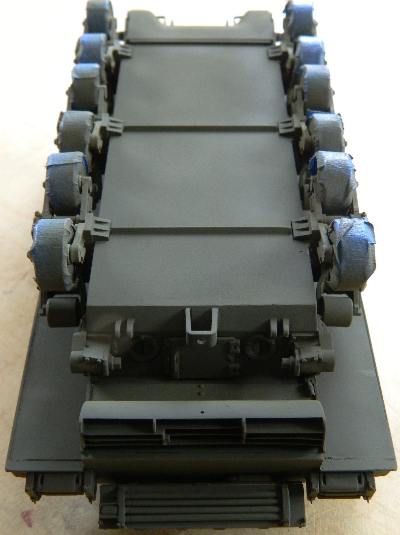
When I assembled the tracks, I tried dry-fitting them to the spare kit and in addition to realizing that I was about two hands short of what I needed to easily add them, they were a tight fit. NTMD has a simple solution that I availed myself of. These mounts are eccentric (unlike your humble Narrator, who is merely “colorful”) and thereby can adjust where the rear idler wheel sits and allowing for easier (I HOPE) fit and tensioning of the tracks:
First the molded on mount gets removed:
Then a hole of the proper diameter to mount the eccentric is drilled:
And then adjustability is possible:


I cut the sponson bottoms from 010 styrene and glued them into position. Yes, the template suggests 040. The reason I went with lighter stock was because due to the resin AM parts, the thin stock would be well supported.
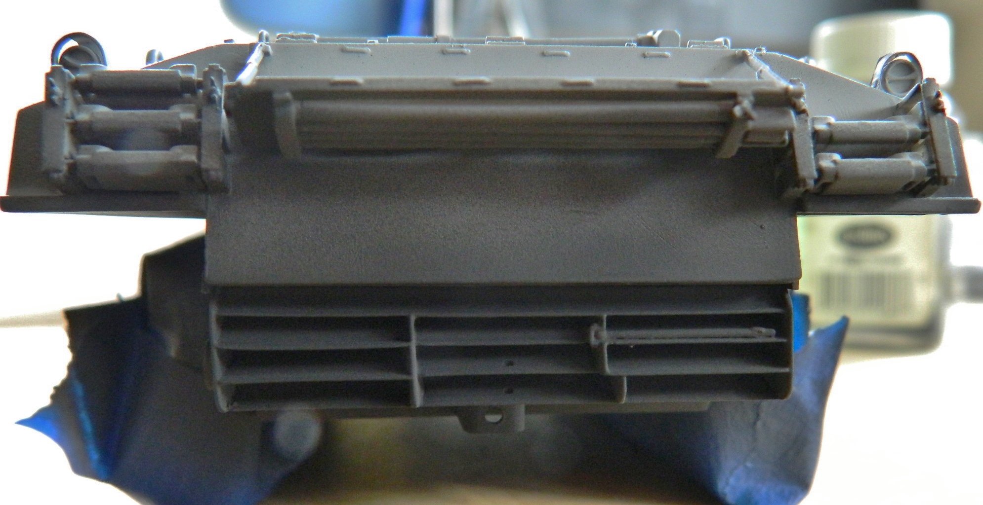
I checked the fit of the exhaust deflectors and though not quite as precise a fit as I would hope for, it certainly falls within the 90-95% tolerance:

And perfectly hides the radiator ducting I’d made (oh well):
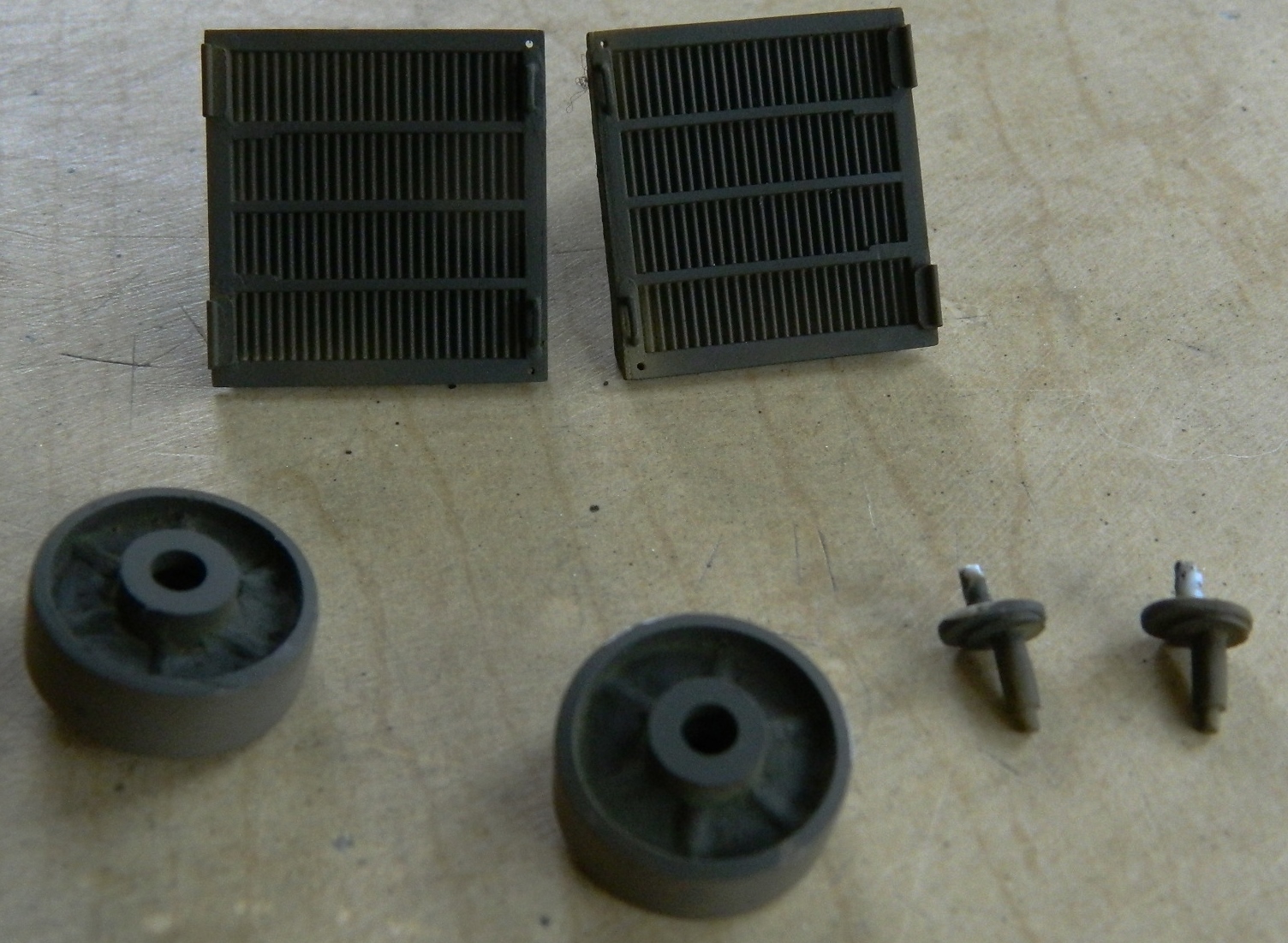
Okay, pay attention. This is a test. Aside from the fact that one part is resin and the other injection-molded styrene, what’s different between these two parts? (Hint: Look at the round depressions on either side of the engine access door, particularly to where the “D” shaped depressions are and are not.):


In case you didn’t see it, because I didn’t see it until I figured out why the exhaust tips did not fit, the depressions are reversed. Yes, the AM set got it wrong. When you look at this photo you will see the styrene I had to add (the white areas) to get the tips to (mostly) fit:
I inserted “mostly” next to “fit” because the tips are supposed to fit into the slots of the deflectors and this is the closest I can get them:

But given how hidden area is from casual view (because anybody picking this model up to look at it will have other things to concern themselves with, namely a “colorful” and irate builder), this is what I’m going to stay with:
M4A3 (Tamiya) Build #19
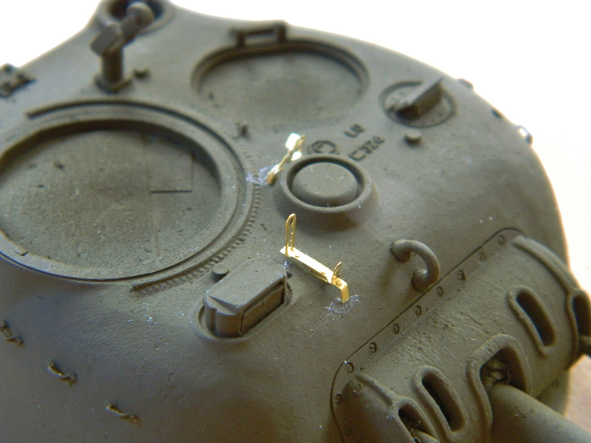
I’m going to add some PE details. They’re thinner than the kit parts and often more accurate to scale (but sometimes they’re thinner than they should be, so, obviously, check), but they’re flat and will need to be bent.
I’ve bent PE details before and that process can sometimes be quite annoying. Bend, it’s wrong; unbend to get it flat, bend it again to get it right, and so on. The problem with bending metal is that it will only bend so many times before it fatigues and separates (I’ve heard that sometimes marriages also have this problem). The obvious remedy to this is to bend the part only once (not sure that would apply to marriage).
Micro-Mark makes a useful bending brake for folding and bending PE parts (though sometimes you will still need to make your bends using jeweler’s pliers). The “fingers” allow multiple bends and if you need to bend one long piece, the finger-plate can be reversed and acts like a traditional bending brake (albeit a small one):

The part is aligned to the appropriately-sized finger and the clamp tightened. Then a straight-edged razor blade is used to lift the part and create the bend. After that, it’s a matter of loosening the clamp and moving the part for its next bend. In this case, I’m using a Verlinden PE set for the Sherman and bending the ammo box holder that attaches to the side of the .50 caliber:


The end result, though it looks nice, seems just a little too thin for my eye and at this point reserve judgement as to whether or not I’ll use it.
But the ammo box itself (kit part) wasn’t intended to be modeled open. As such, the sides are WAY too thick and needed to be thinned enough for a scale ammo belt to sit in the box properly:

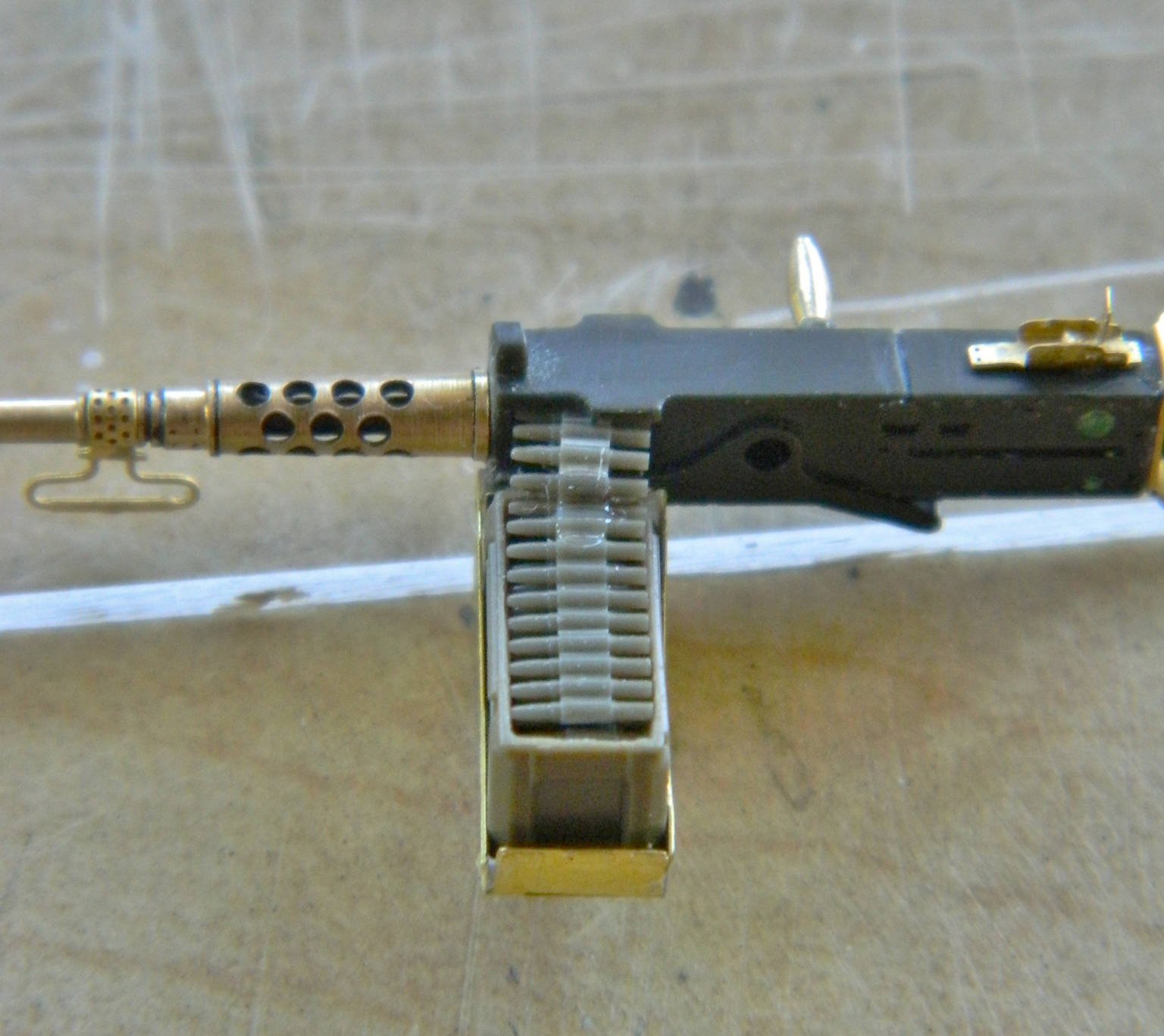
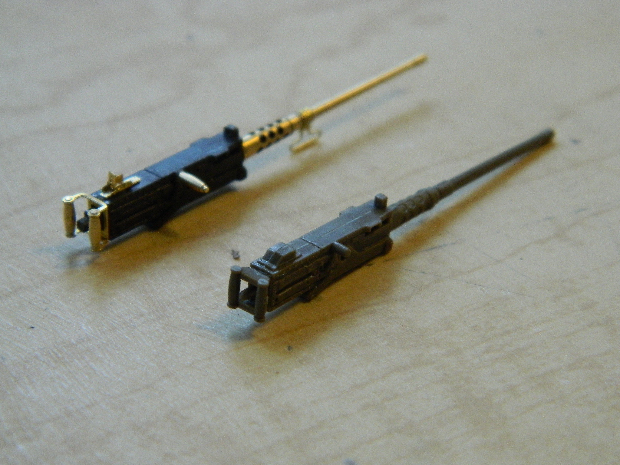
The vendor (M&M Models) who provided the .30 caliber barrels also provided this nice little detail set to upgrade the .50 caliber:

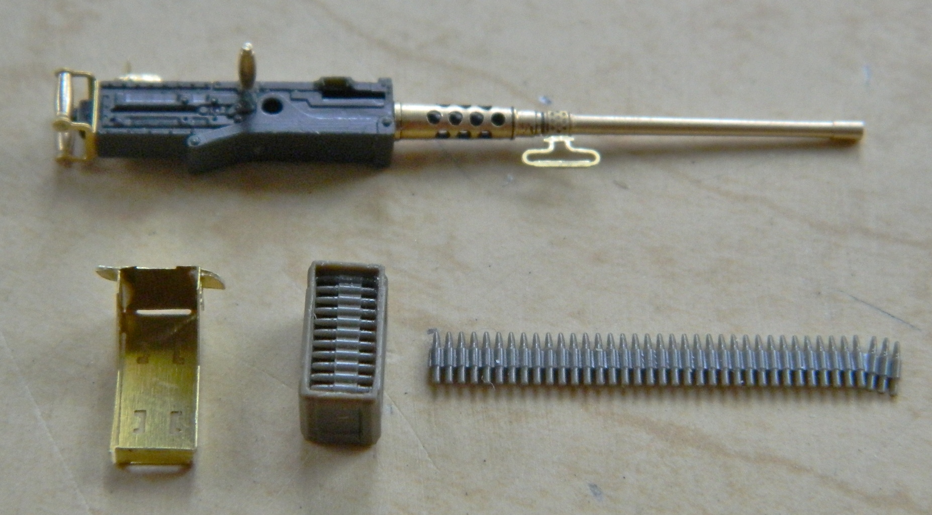
Just so you have an idea as to the difference this makes, lookit this:
By this time I had finished making the vacuum pump and chamber and it was time to pour some molds and make some copies.
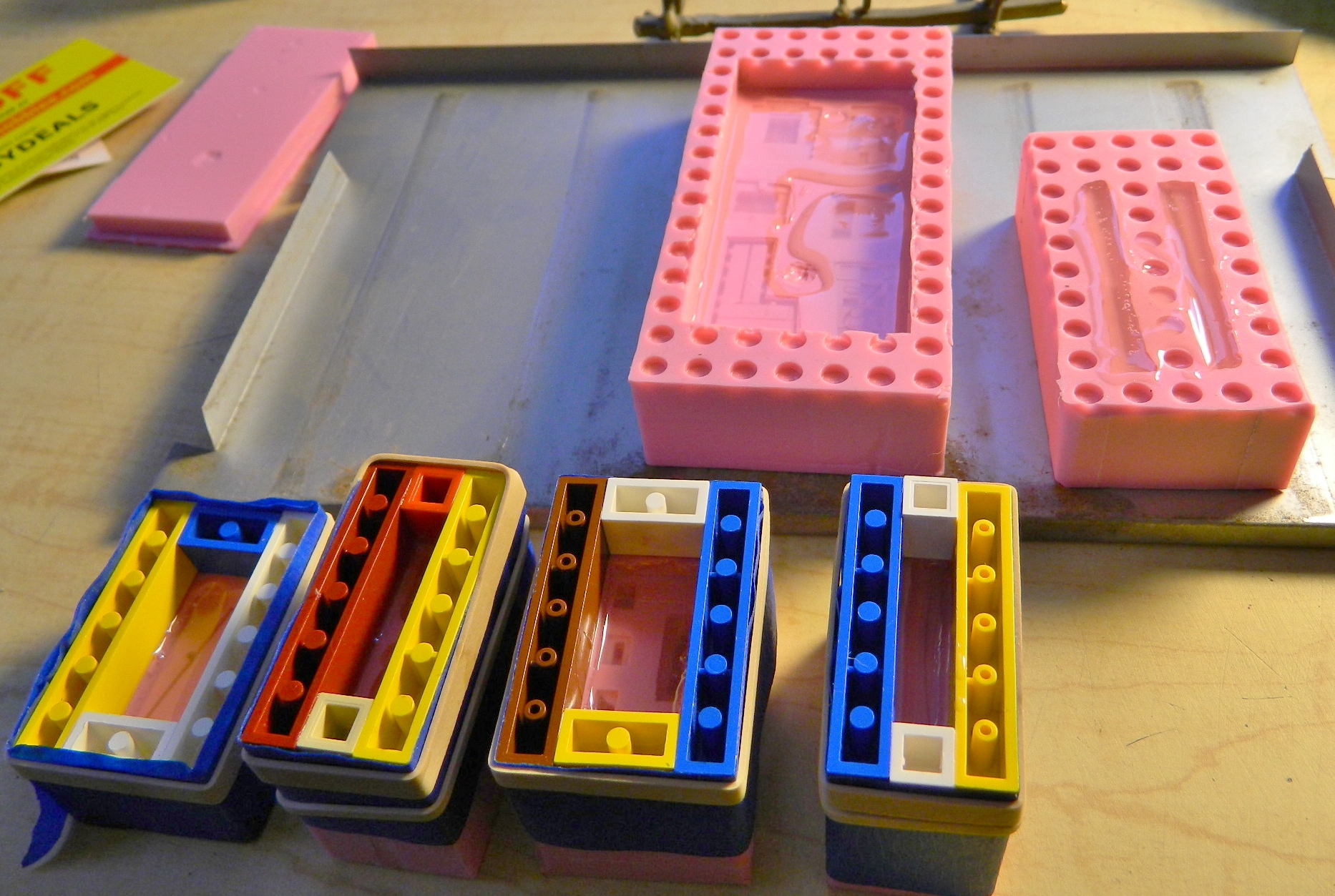
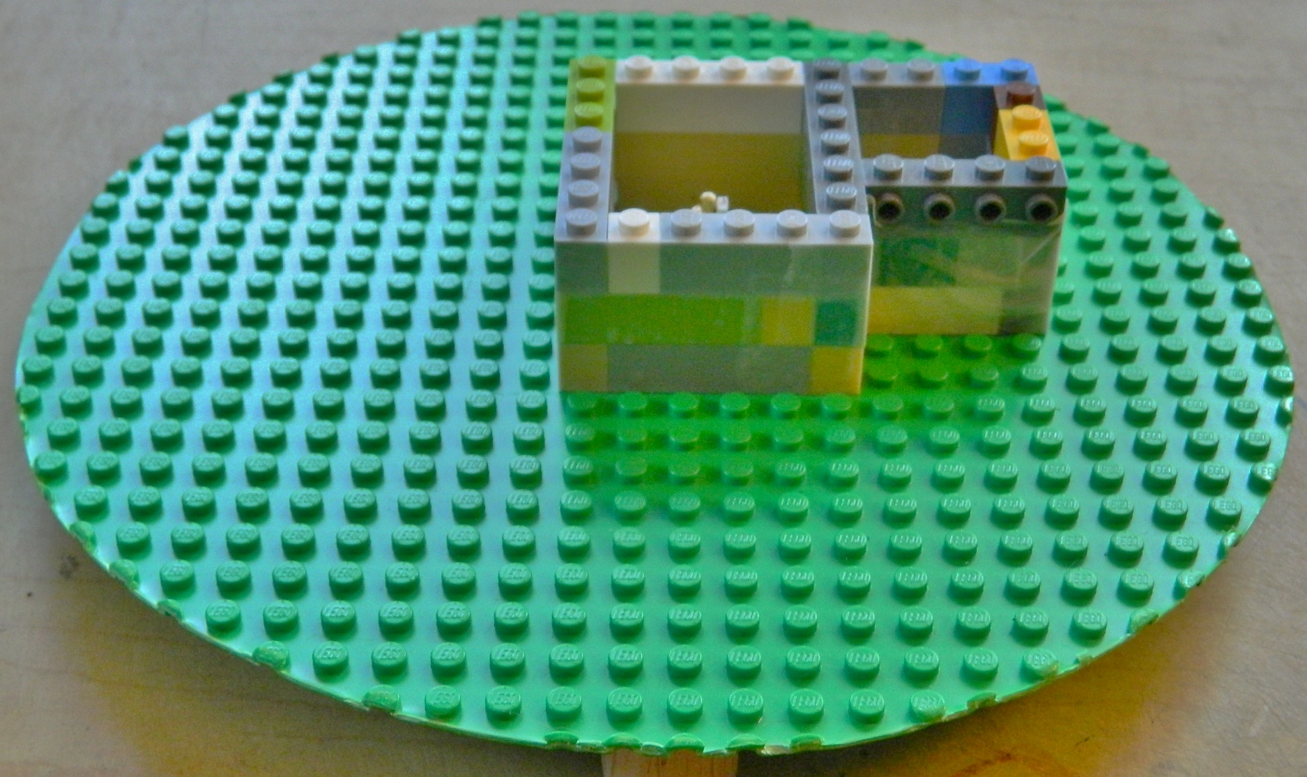
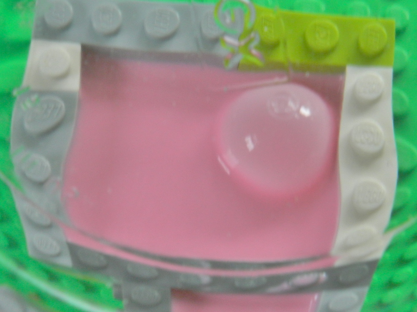
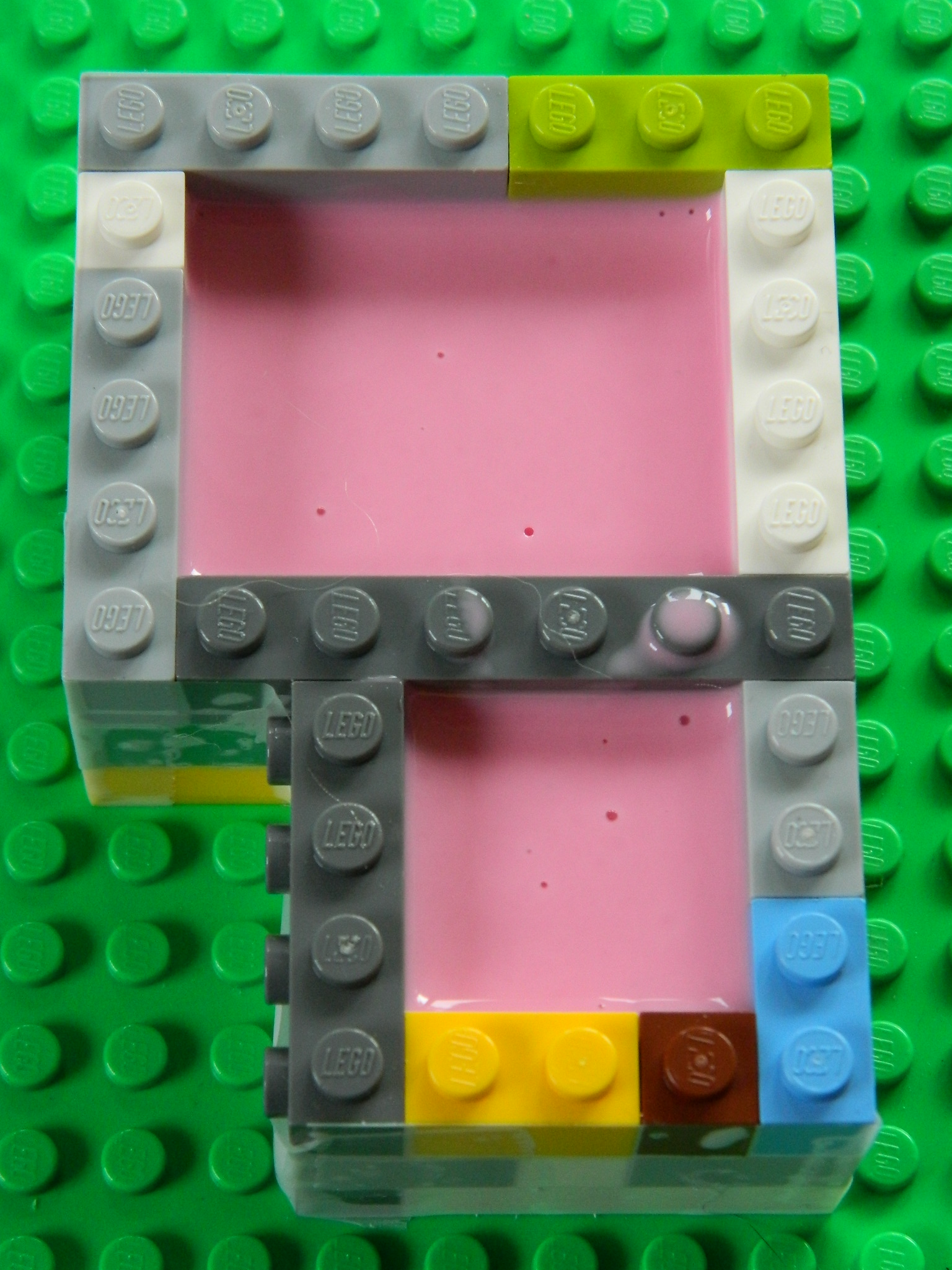
While thrashing around the ‘Net looking for information about vacuum pumps, I ran a cross a YouTube video that showed a modeler using Lego parts to make mold boxes. Well, I thought that was rather clever and got me some (and I had NO idea Legos were so damned expensive!).
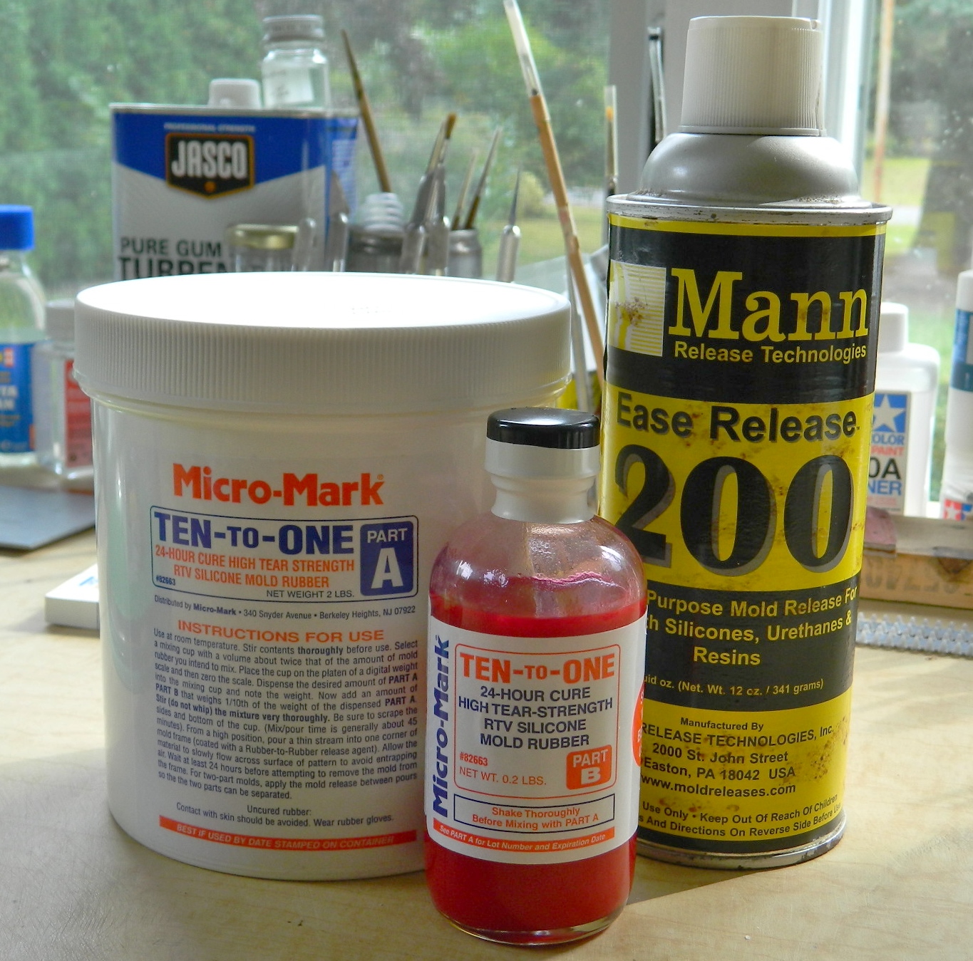
Micro-Mark supplied the two-part mold making rubber as well as the parting agent. The parting agent is sprayed wherever you don’t want the silicone molding rubber to adhere (and there is a parting agent specifically for silicone molding rubber to keep it from bonding to itself, which is necessary when making a multi-part mold so you can open the mold up):
I attached the brass master I’d made for the blower assembly to a resin pouring cup I’d made with the reusable molding compound and used white glue to fix it in place to the Lego base and then built the mold boxes. The other part I’m taking a mold from is a piece from Verlinden’s detail set for the M3-M5 light tanks (just to see if it’s possible at my skill level and to have a sacrificial casting I can cut in half so that I can check for the propagation bubbles):

The two-part molding compound has a hardening agent that’s mixed into the rubber compound so air bubbles also get mixed into the compound. For both the molding rubber and resin, I selected items that had the longest pot life. This allowed me the time I needed to degas the compounds. Here you think you can see the bubbles:
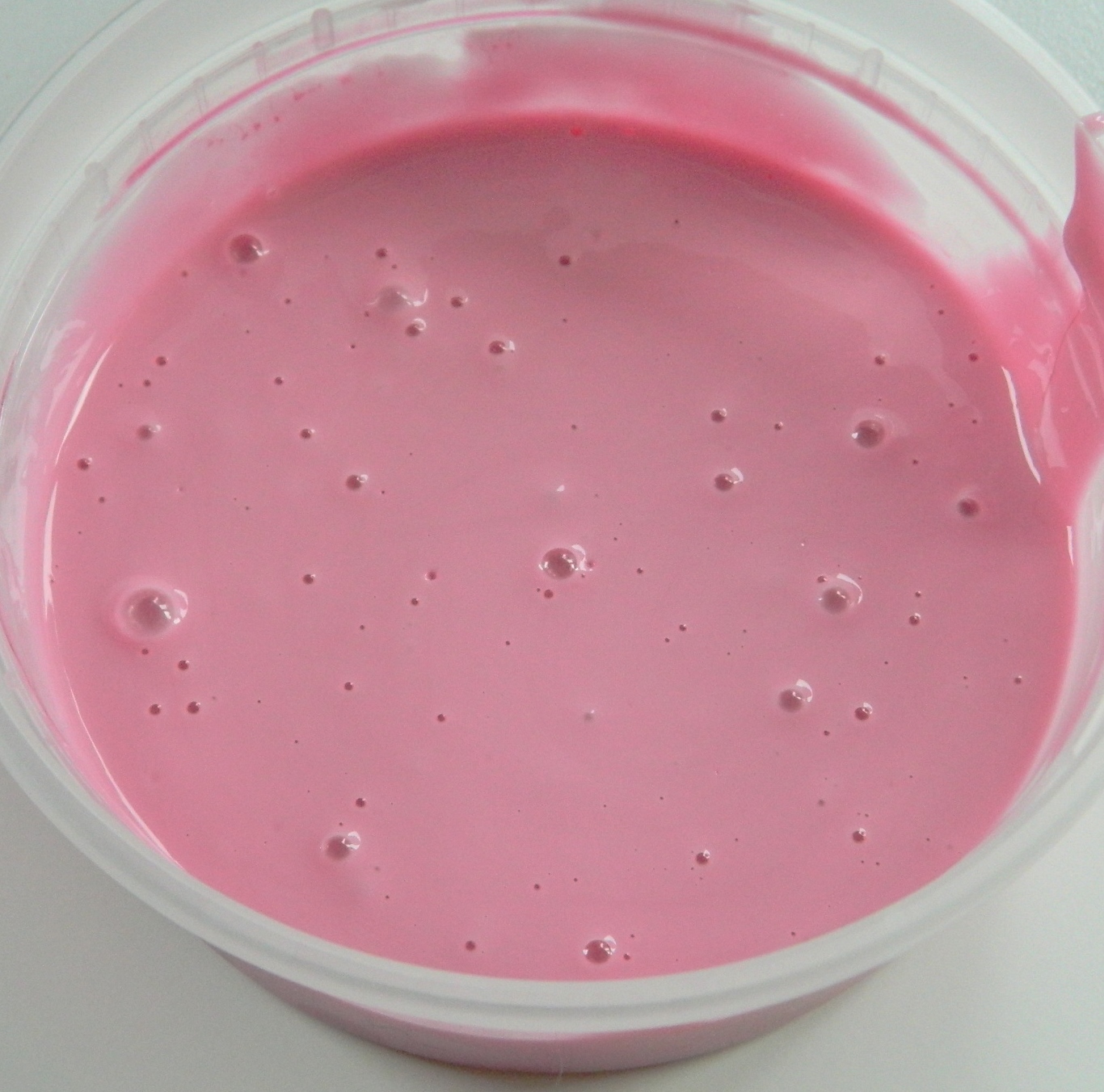
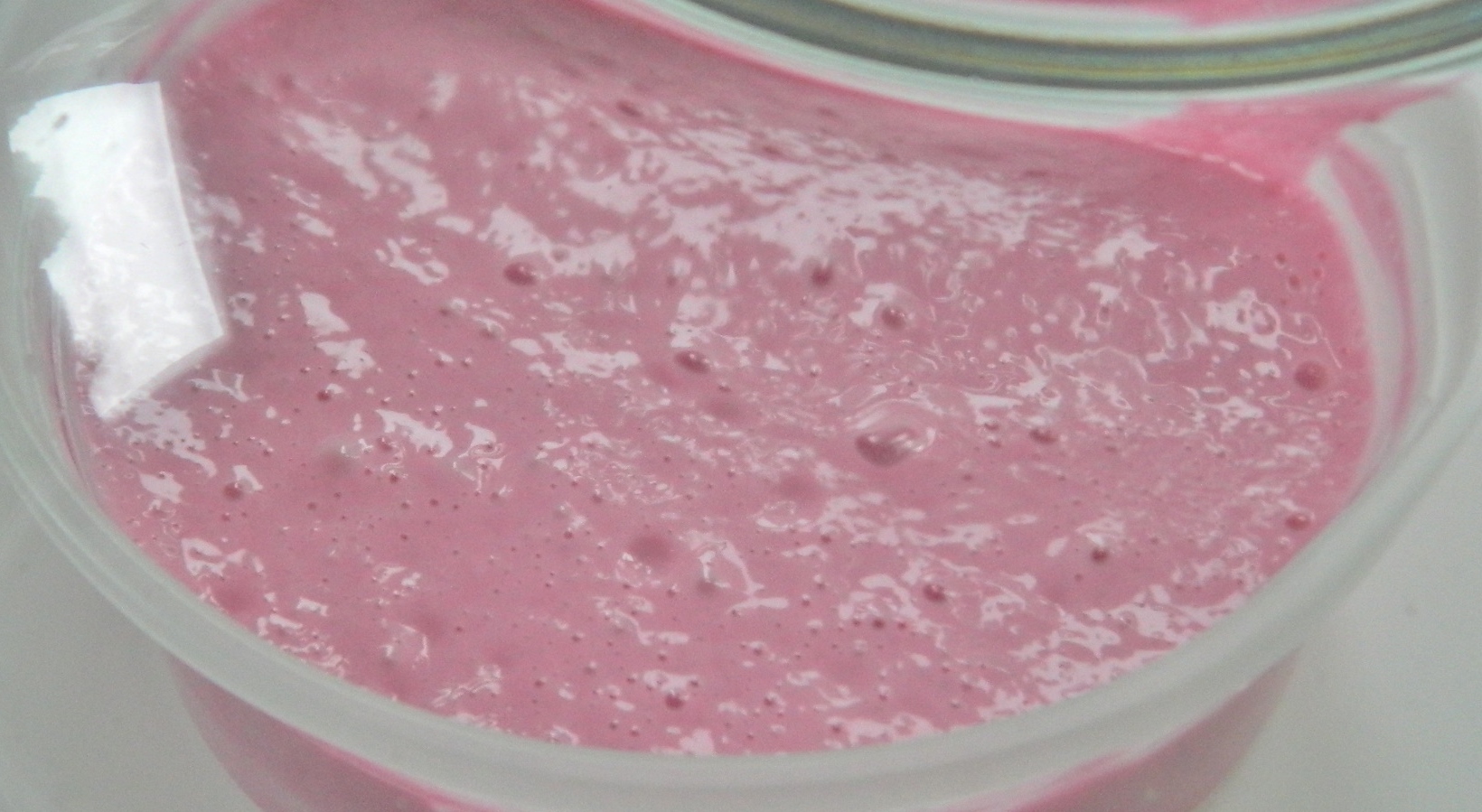
When the compound is exposed to a vacuum, this is what’s actually in the compound (and all those little nubbins are bubbles that haven’t made it to the surface yet):
A hint about molding. Before you start mixing compounds, molding or resin, have what you need the compounds for ready before you start mixing.
The molding compound has a 45 minute pot life, so I mixed it, degassed it for 20 minutes, and since the mold box had already been sprayed with release agent, I poured the molding compound into the box and degassed them for another 20 minutes:

With only a partial vacuum (the best my pump will manage is about 28″ of vacuum) and a time limit (pot life, y’know), there’s no way to get all the bubbles out. But I can get the large bubbles out, and when the vacuum is released, normal air pressure causes the small bubbles to compress to the point where they can’t be seen or screw up the part you cast in the mold.
The mold is taken out of the vacuum chamber and allowed to sit until the molding compound sets up and cures (for this compound, 24 hours):
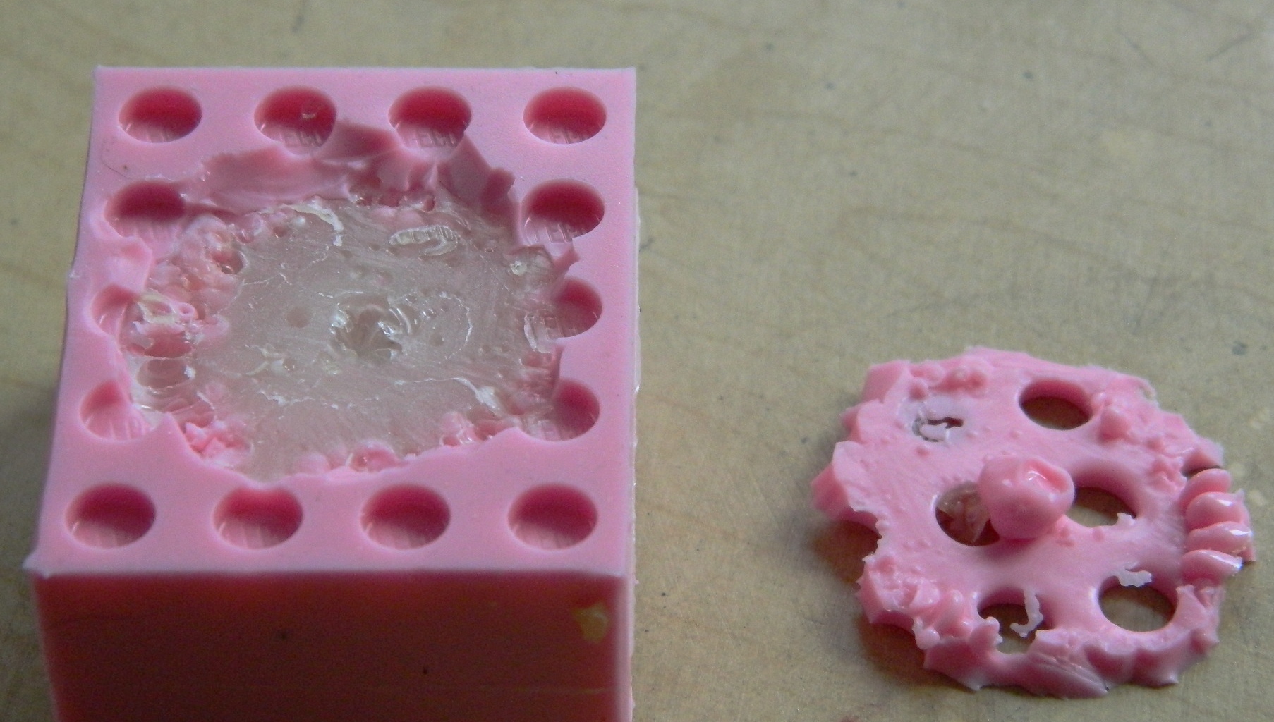
The next day I popped the excess molding rubber out of the mixing container and cut it in half to check for bubbles. Whatever bubbles are there, I don’t have the microscope to see. Good enough:

When I was assembling the molding boxes, I noticed there are small gaps between the blocks. Having not used this molding rubber before, I didn’t know the extent to which the rubber would insinuate itself between those cracks. To eliminate that insinuation, I used scotch tape to cover the cracks…and it seems that was a good idea. Taking the blocks away showed me there was a degree of insinuation:
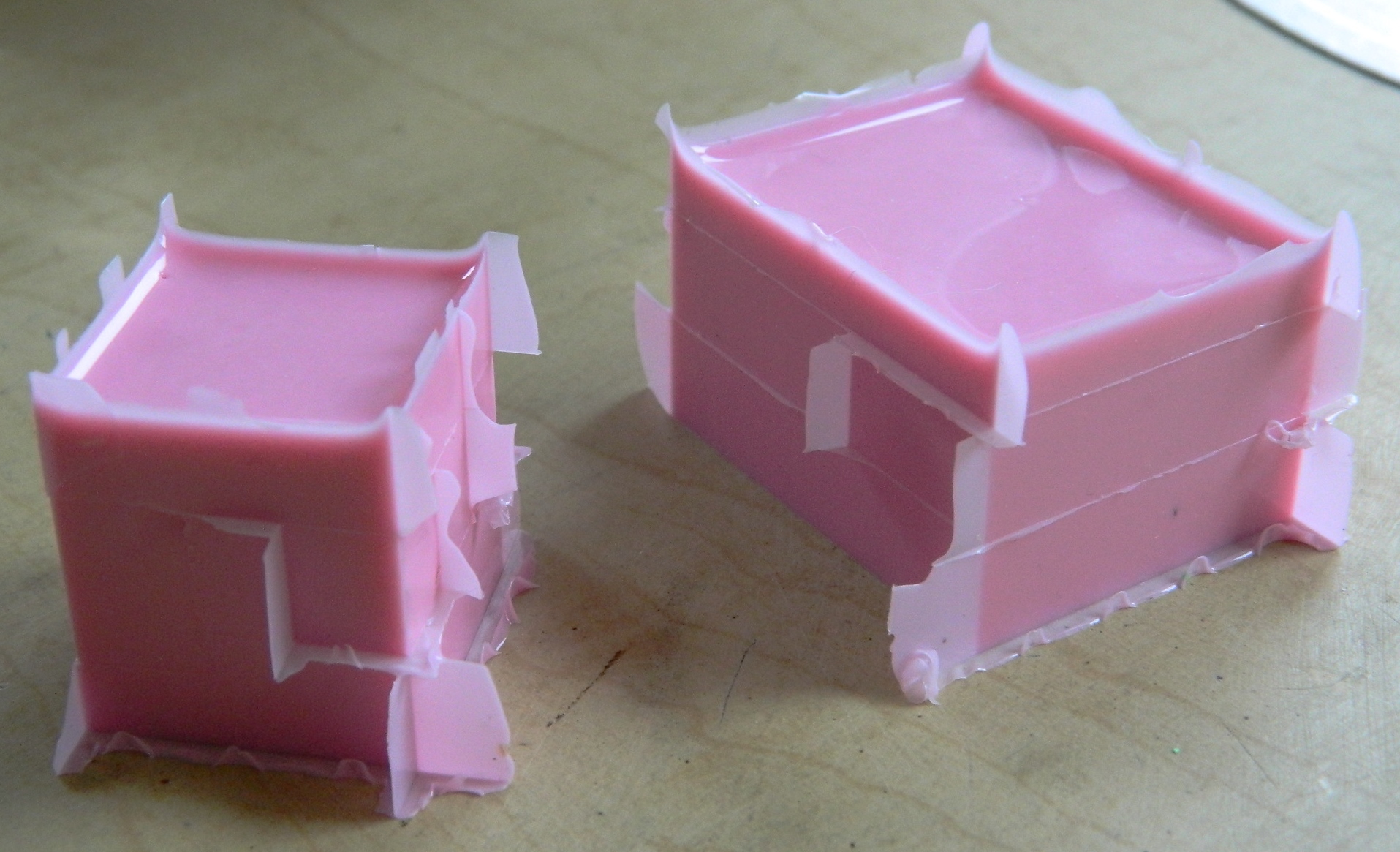
With the rubber out of the boxes, it was time to get the masters out of the rubber. With the smaller mold, its shape acted like an anchor which required me to cut the mold down the sides to release the master:

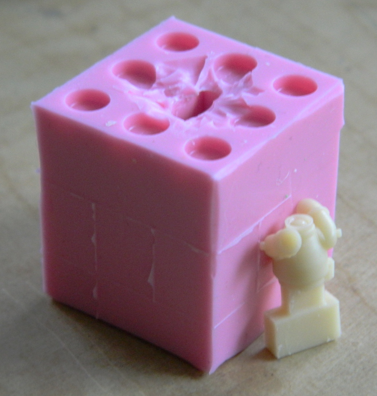
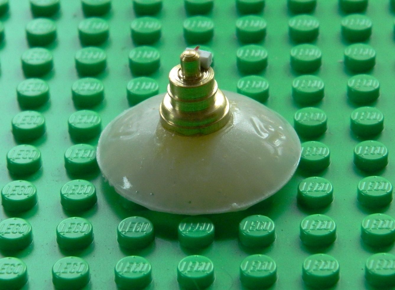
To get the blower assembly out, all I had to do was to cut away the rubber to get at the master, flex the rubber, and pop the master out (the switch box came out separately as the process of popping the master out caused it to detach):

THANKFULLY the resin is mixed by volume and not by weight. I used a cut down plastic cup as my mixing bowl. I expected a degree of froth from the mixed resin during degassing but I didn’t know how much, so I wanted to leave enough volume in my mixing cup to keep from having to clean up (another) mess:
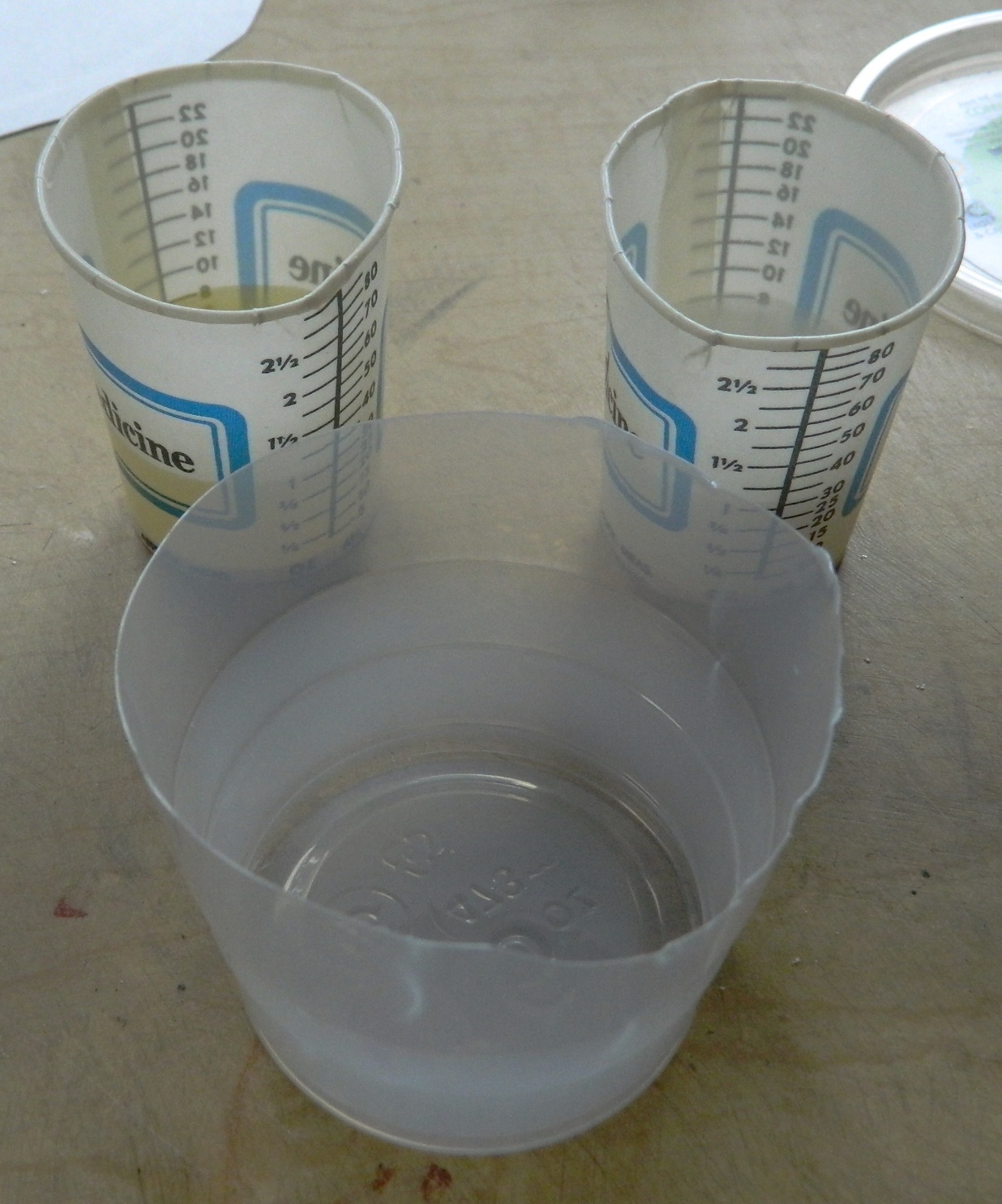
As with the molding rubber, the resin compound was mixed and degassed. Since the resin compound only has a pot life of 20 minutes, I degassed the mixed compound for about 7 minutes, poured it into the molds, and then degassed for another 10 minutes. After degassing, I wanted to leave enough time for the very small bubbles to be re-compressed by atmospheric pressure so as to become invisible:


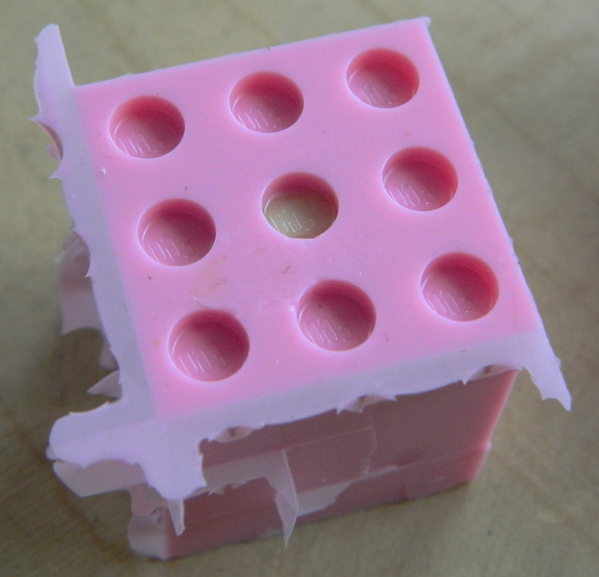
This is another 24 hour cure, so I let it sit overnight before removing the castings:
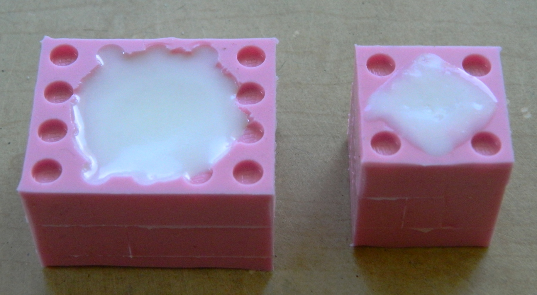
In addition to seeing if I could use a commercially available part as a master, I also wanted a sacrificial part that I could saw in half so that I could see just how many bubbles (or not) were produced during the curing process of the resin. It looks like I ended up with a nice, dense, casting:
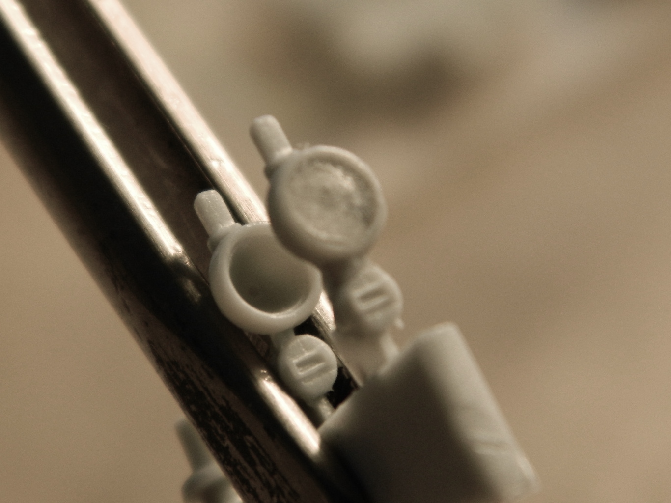
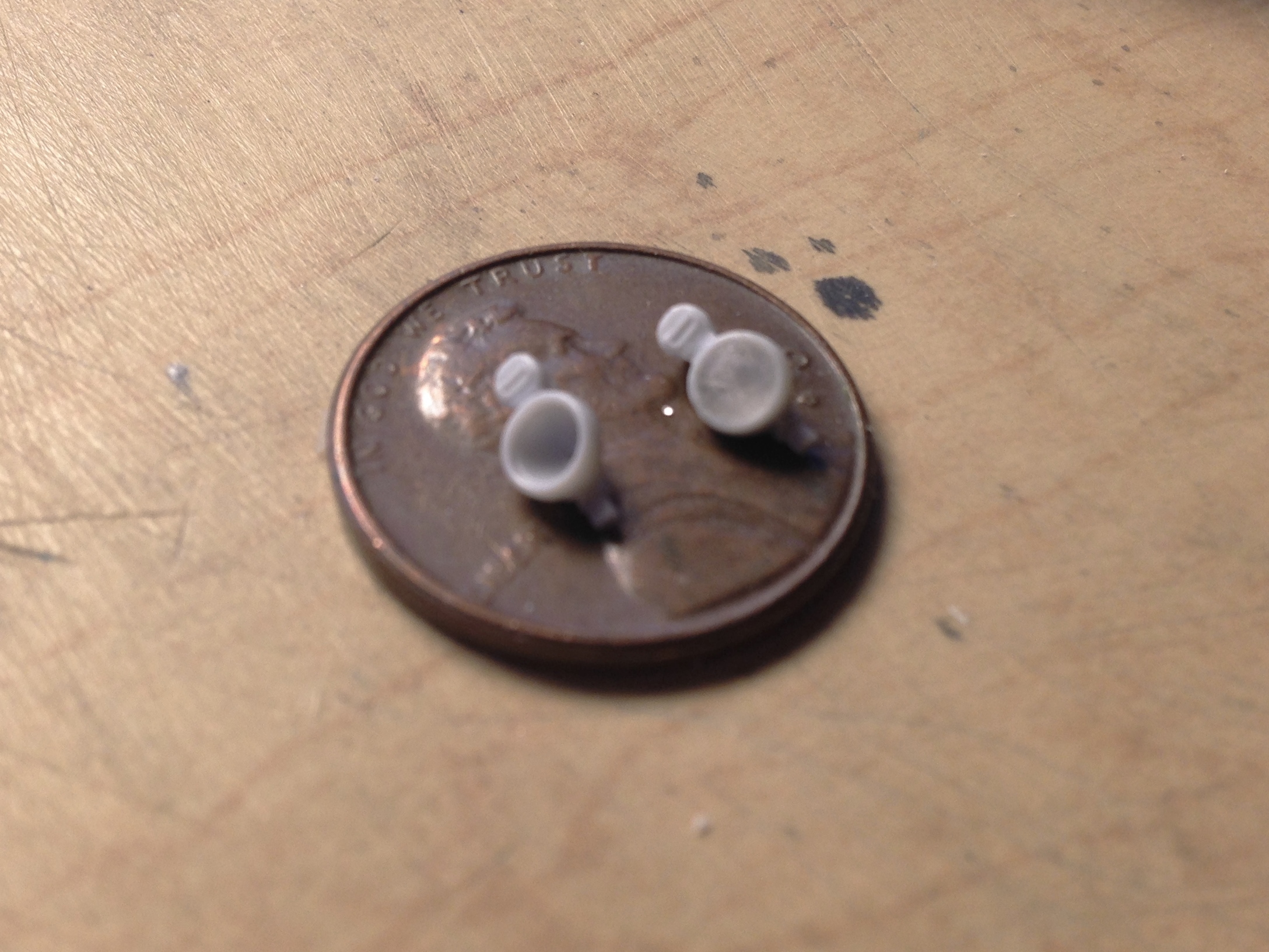
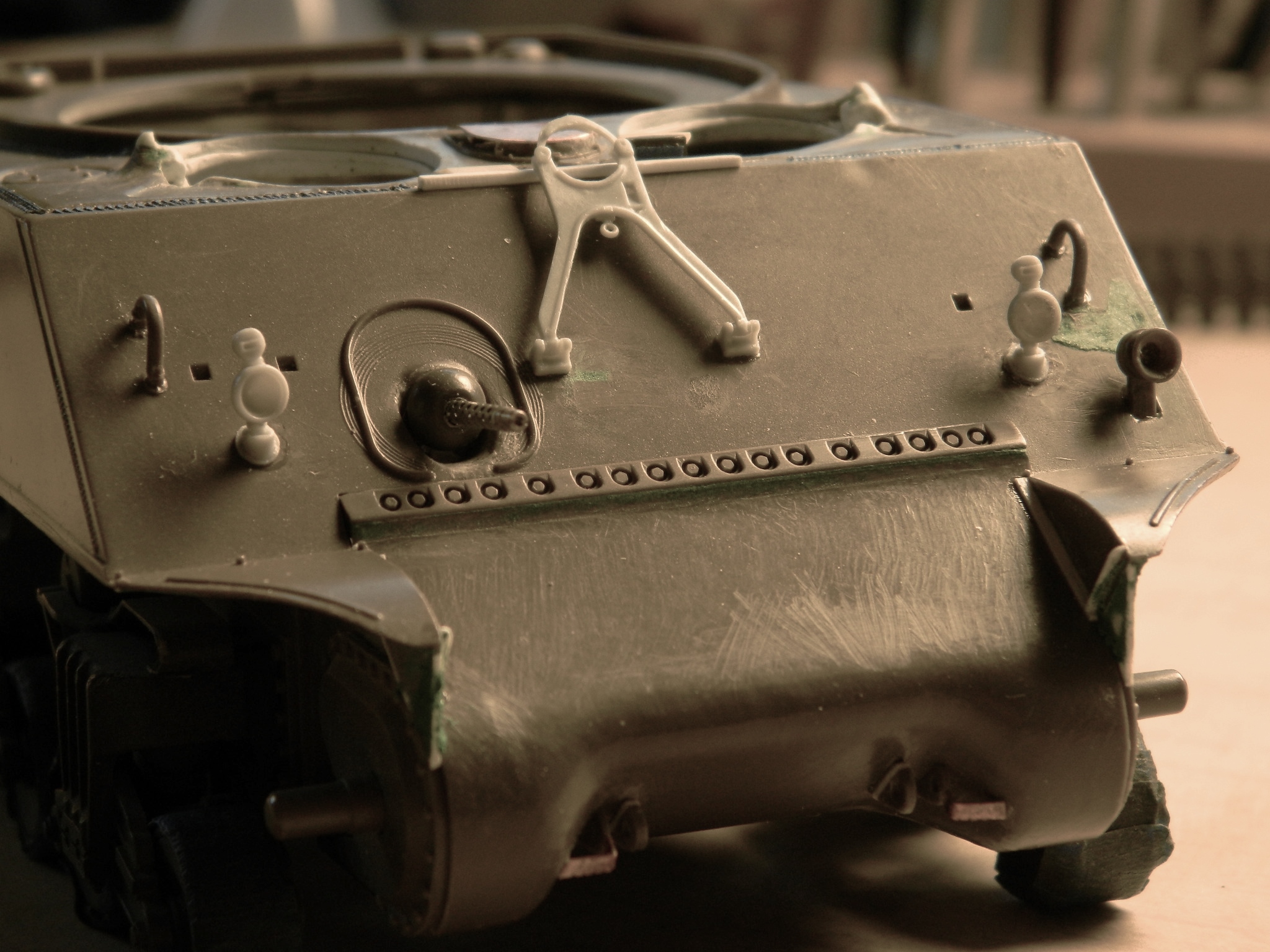
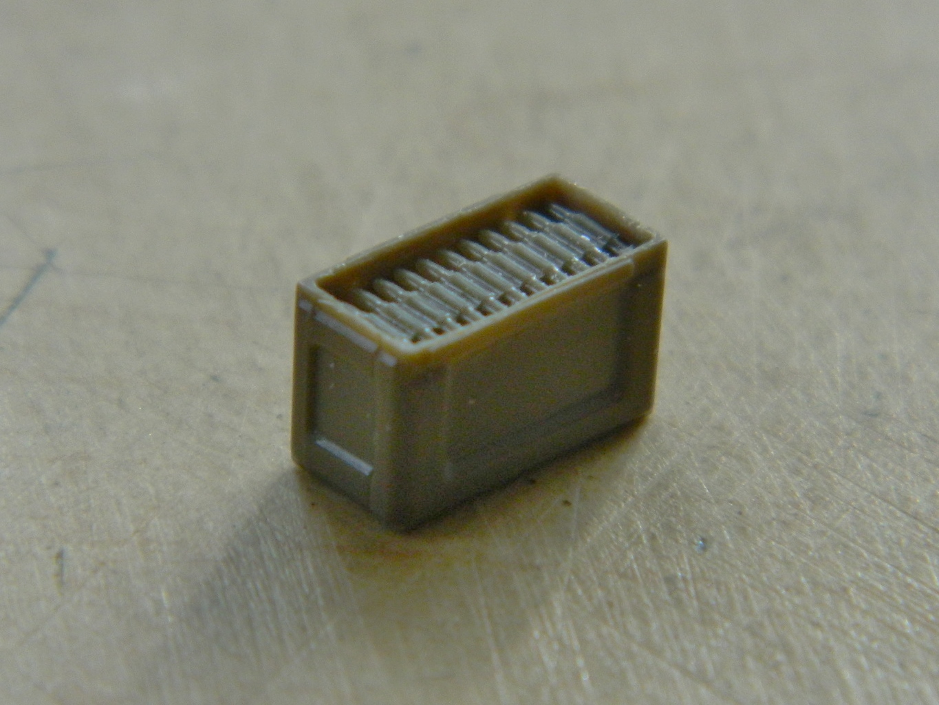
And here’s the part I was really after, the ventilation blower assembly that I can use on this build and any subsequent build based on the M4A3 hull. In the picture to the right, you can see that this process is fine enough to replicate the switch, which was made from 24 gauge wire:

Glossary of Terms
AM – Aftermarket
Molding rubber – A two-part compound comprised of the rubber, usually silicone, and a hardening agent
Parting agent – A thin lubricant, sprayed on or brushed, that keeps things from sticking
PE – Photo-etched
Pot life – How long a mixed compound can be worked before it starts to set up and cure and varies from compound to compound
Resin – Essentially a task-specific epoxy. Resins come in enough varieties to require a separate, in depth, article to cover them all (presently I’m using a urethane resin). Resin is what gets poured into a mold to create multiple and identical pieces
Sprue – That’s the “tree” that kit parts are attached to. What it really is is a channel that brings the molten plastic into the hollow cavity that, once filled, becomes the part. Sprue is really handy stuff! Heating it (GENTLY) over a candle allows it to be stretched, and if you shape the sprue first (like for a bolt head you need), it retains that shape when it’s stretched.
