P-51 (Accurate Miniatures) Build #2 – Working Cockpit Parts, Adding Details
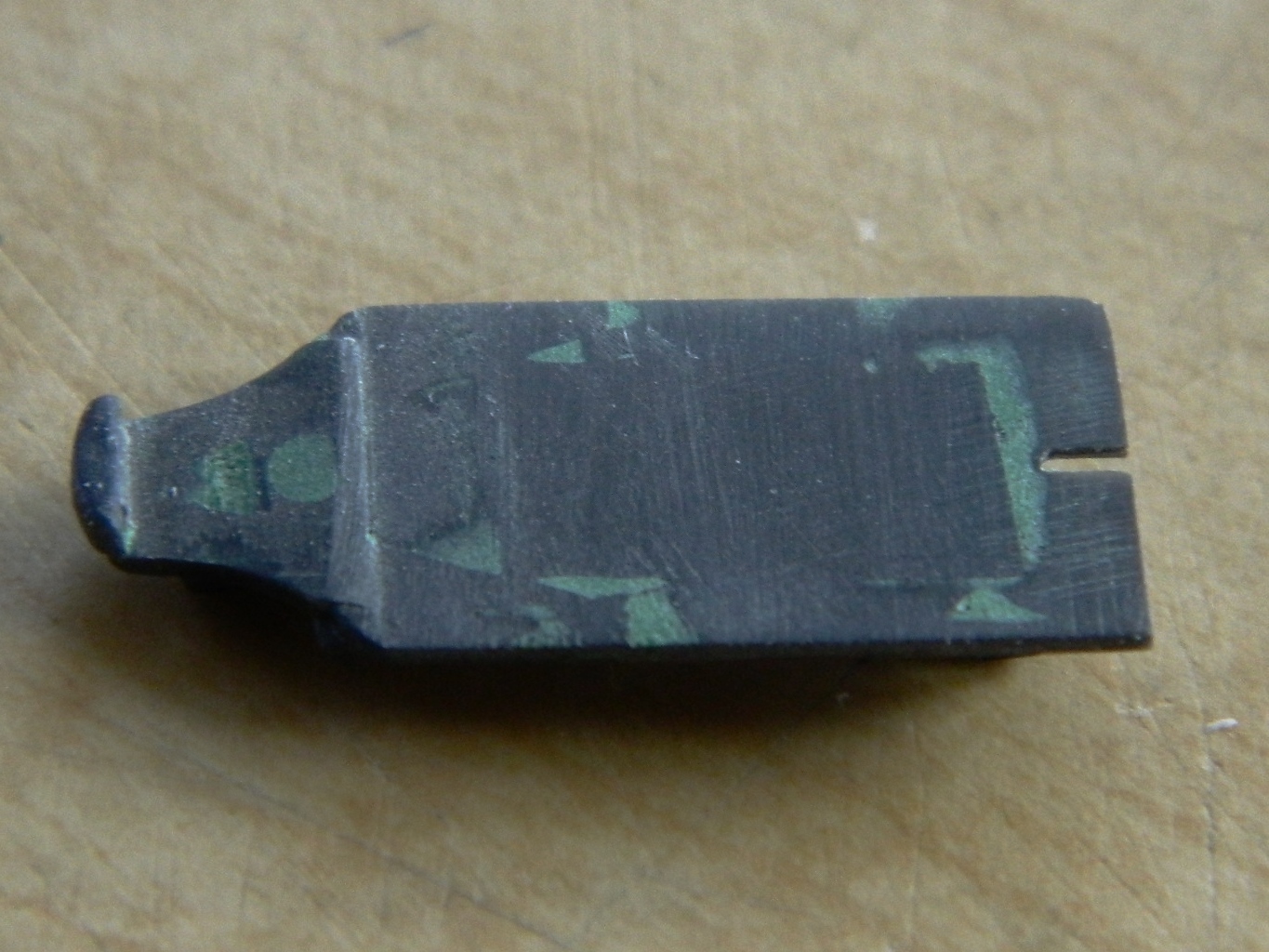
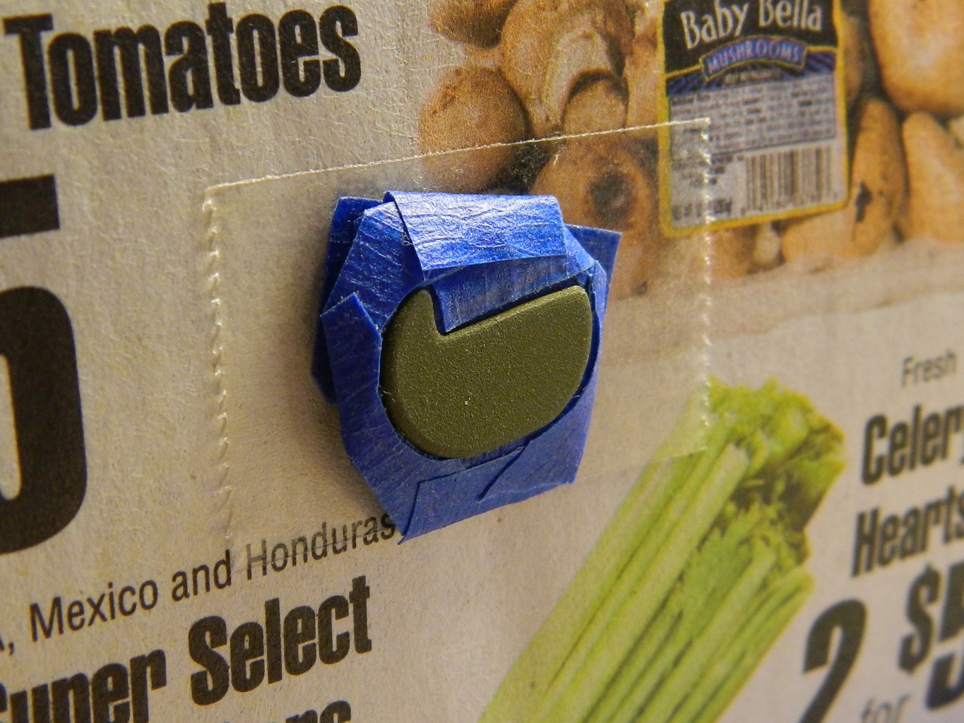
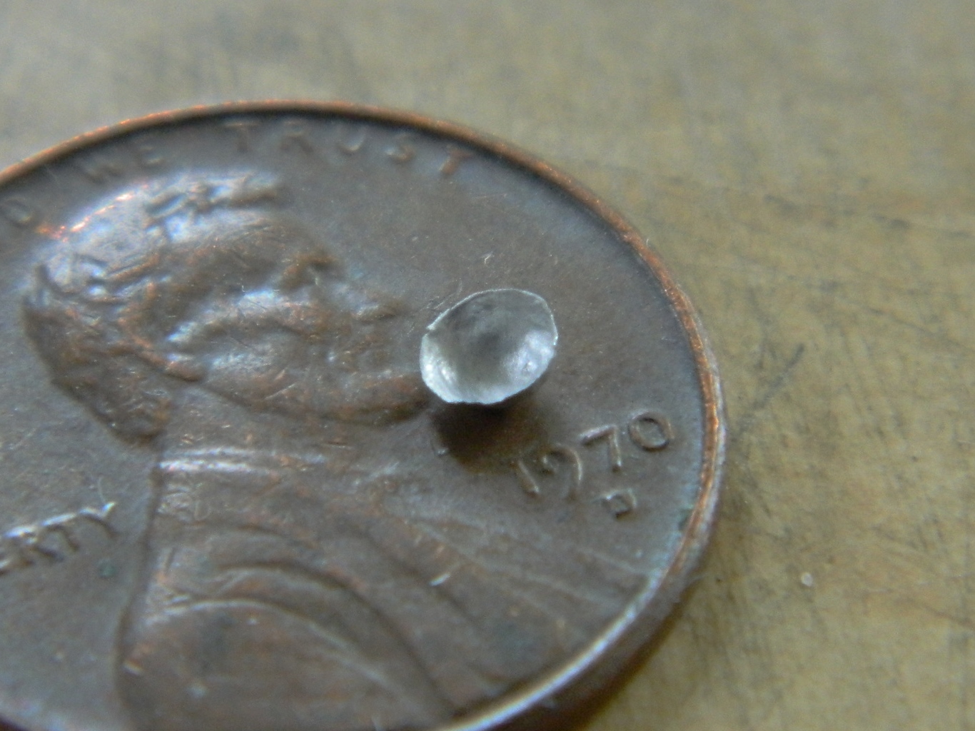
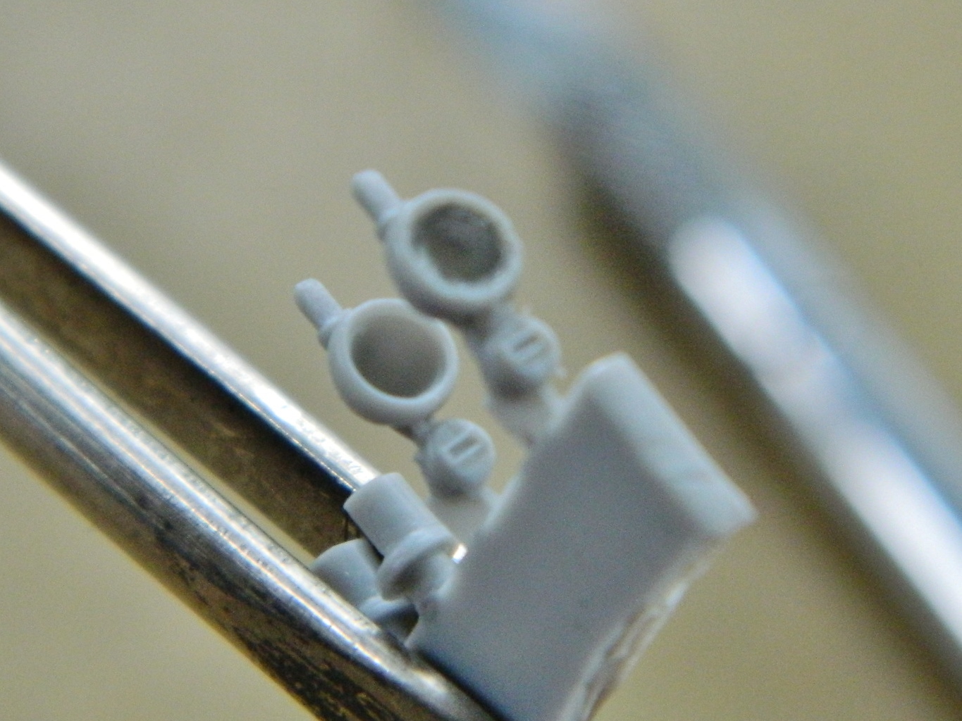
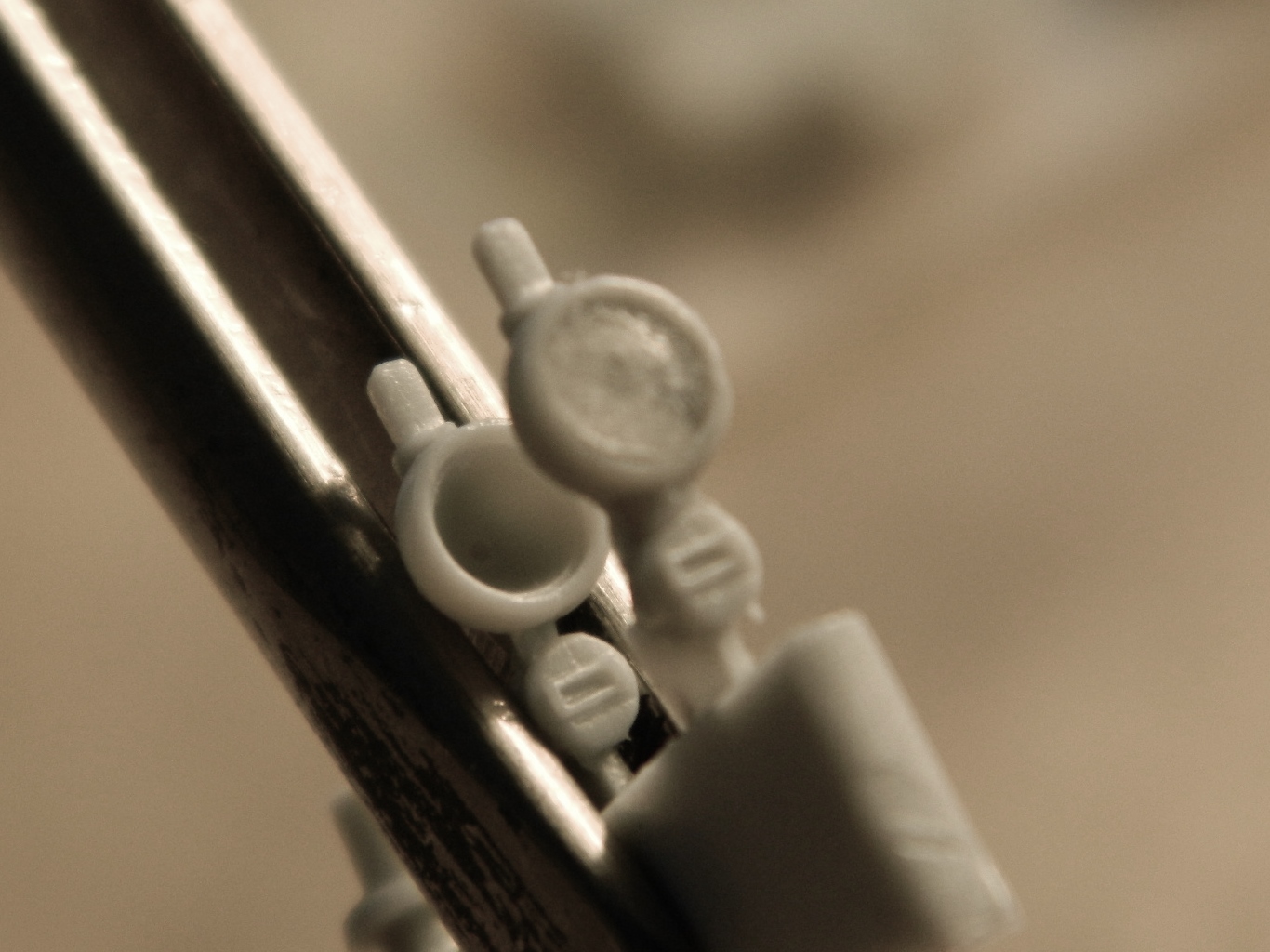
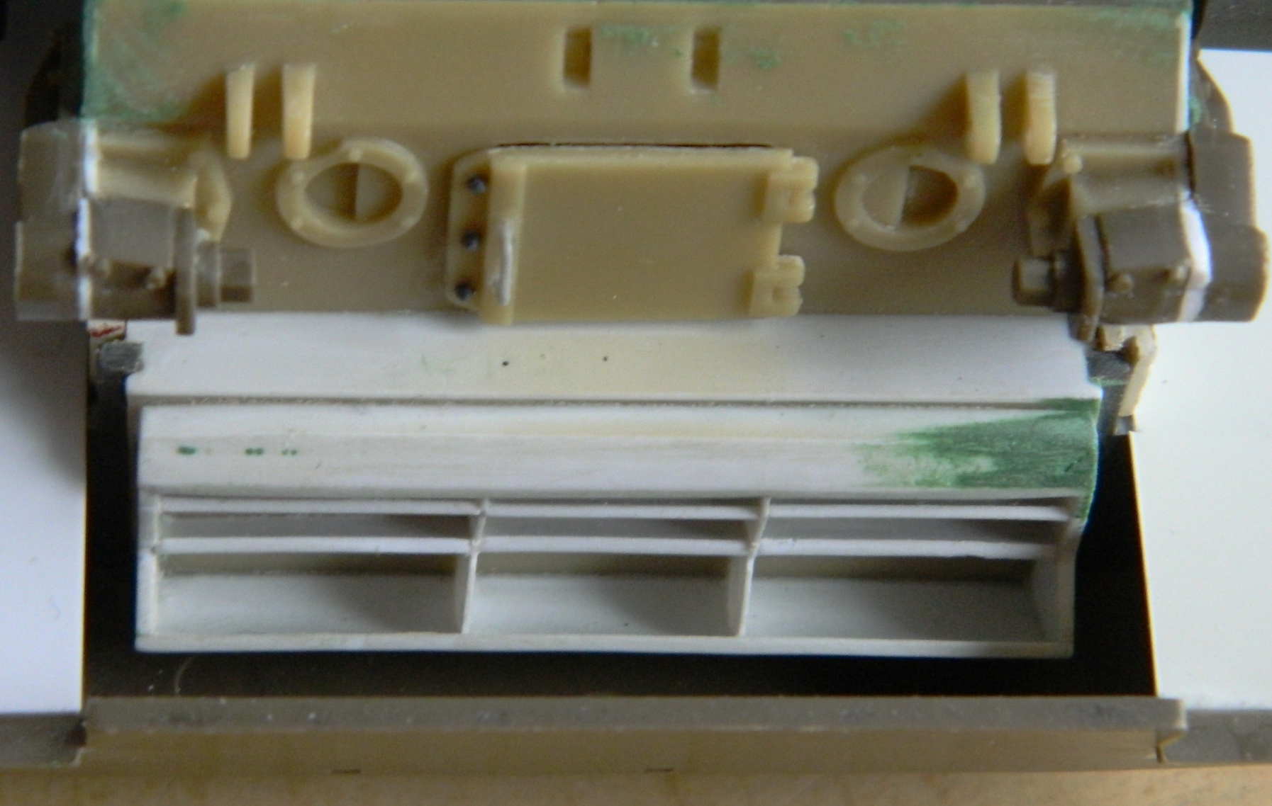
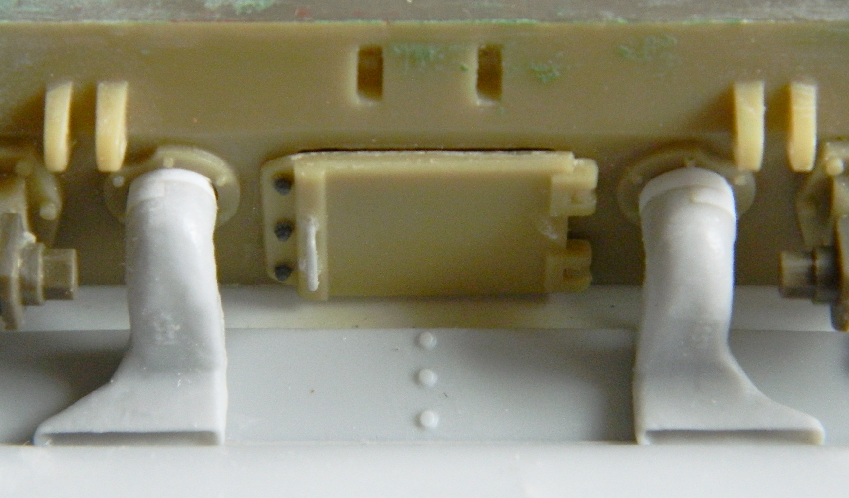
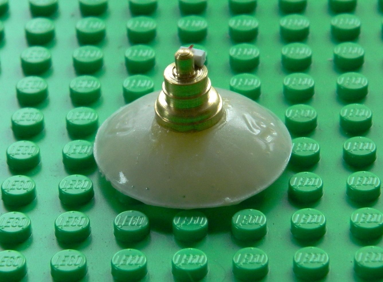
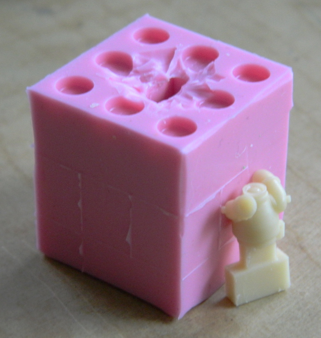
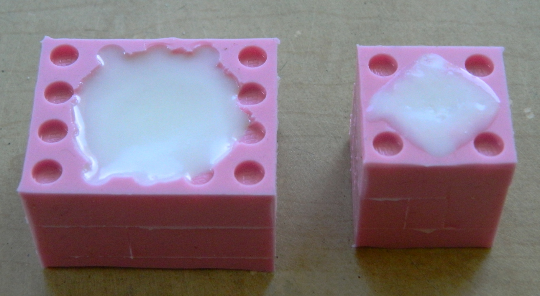
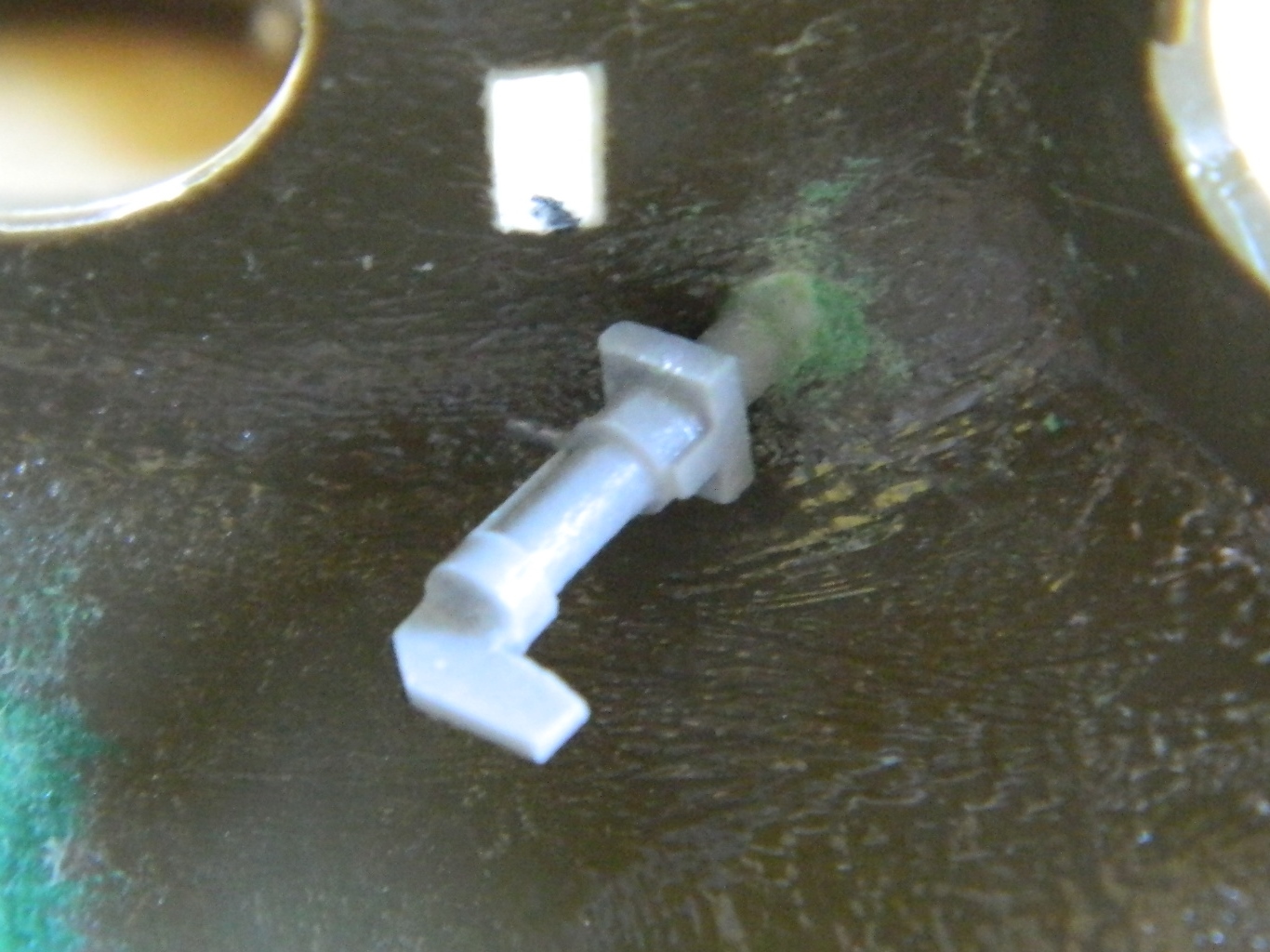
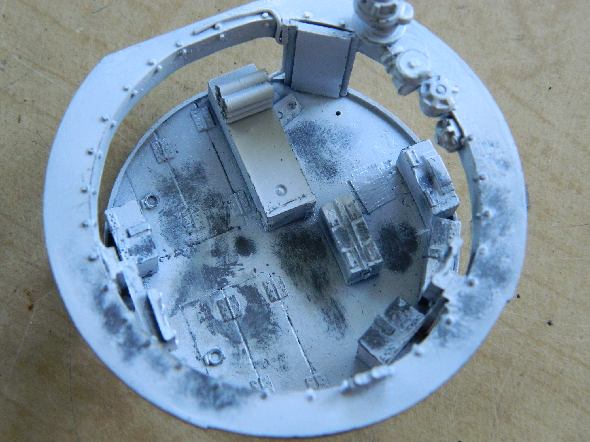
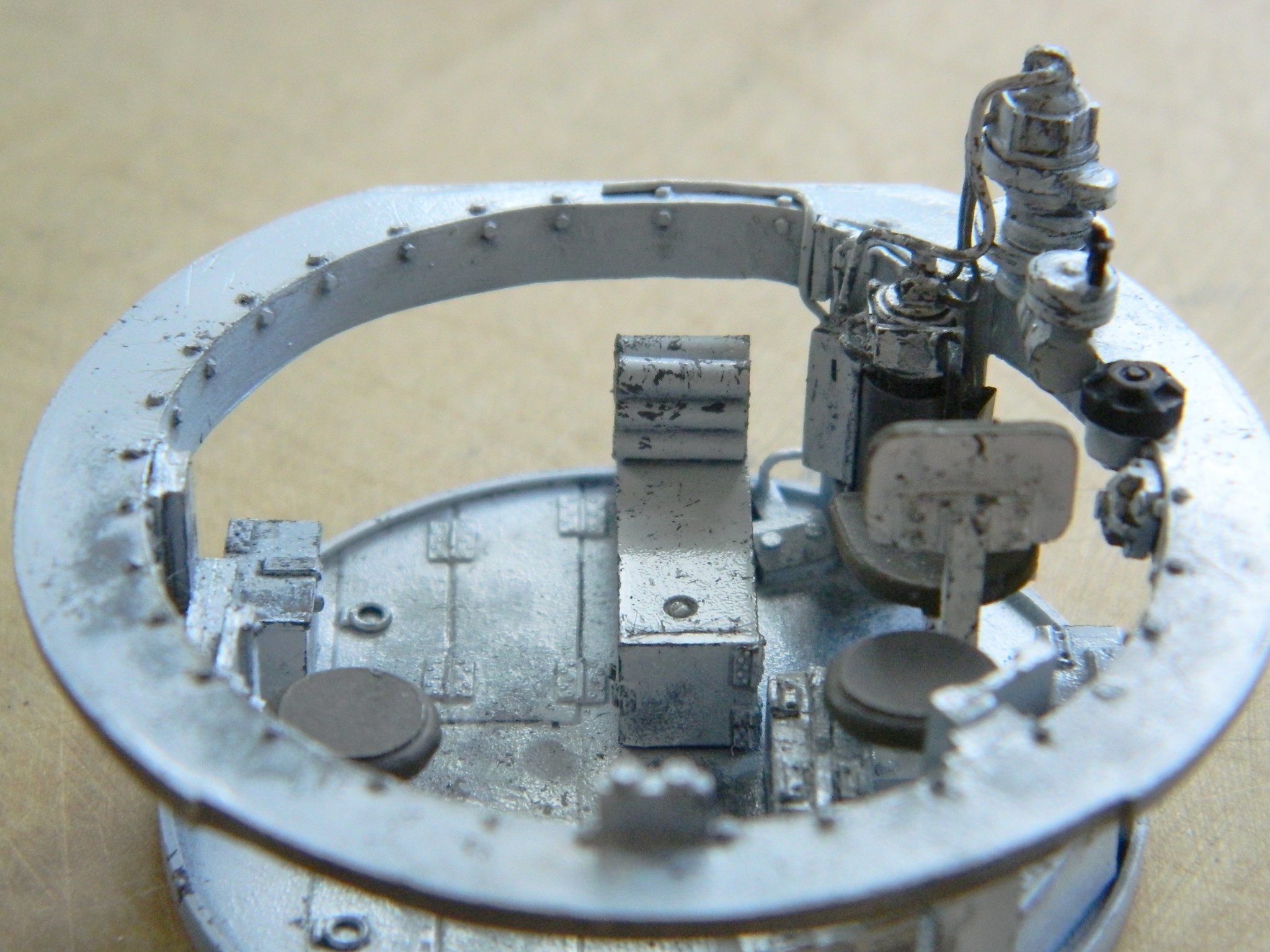
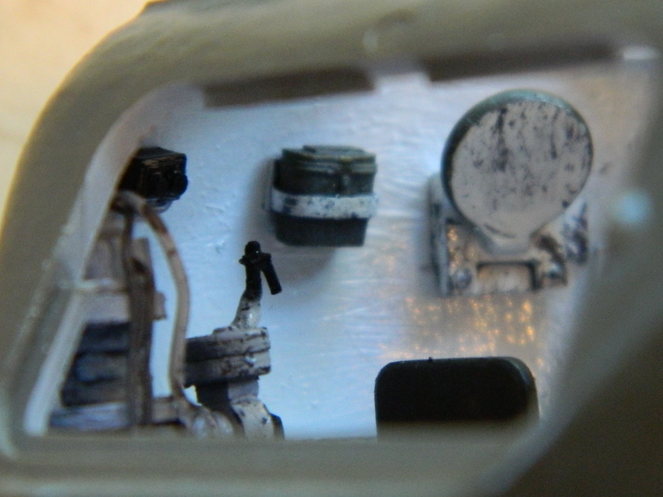
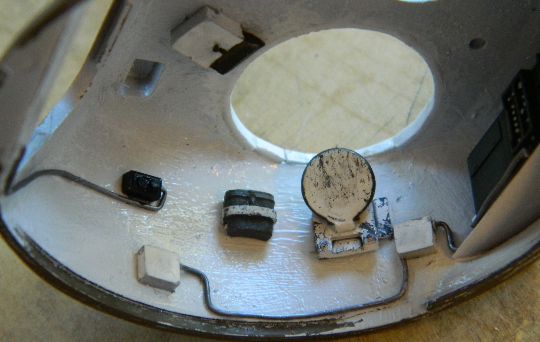
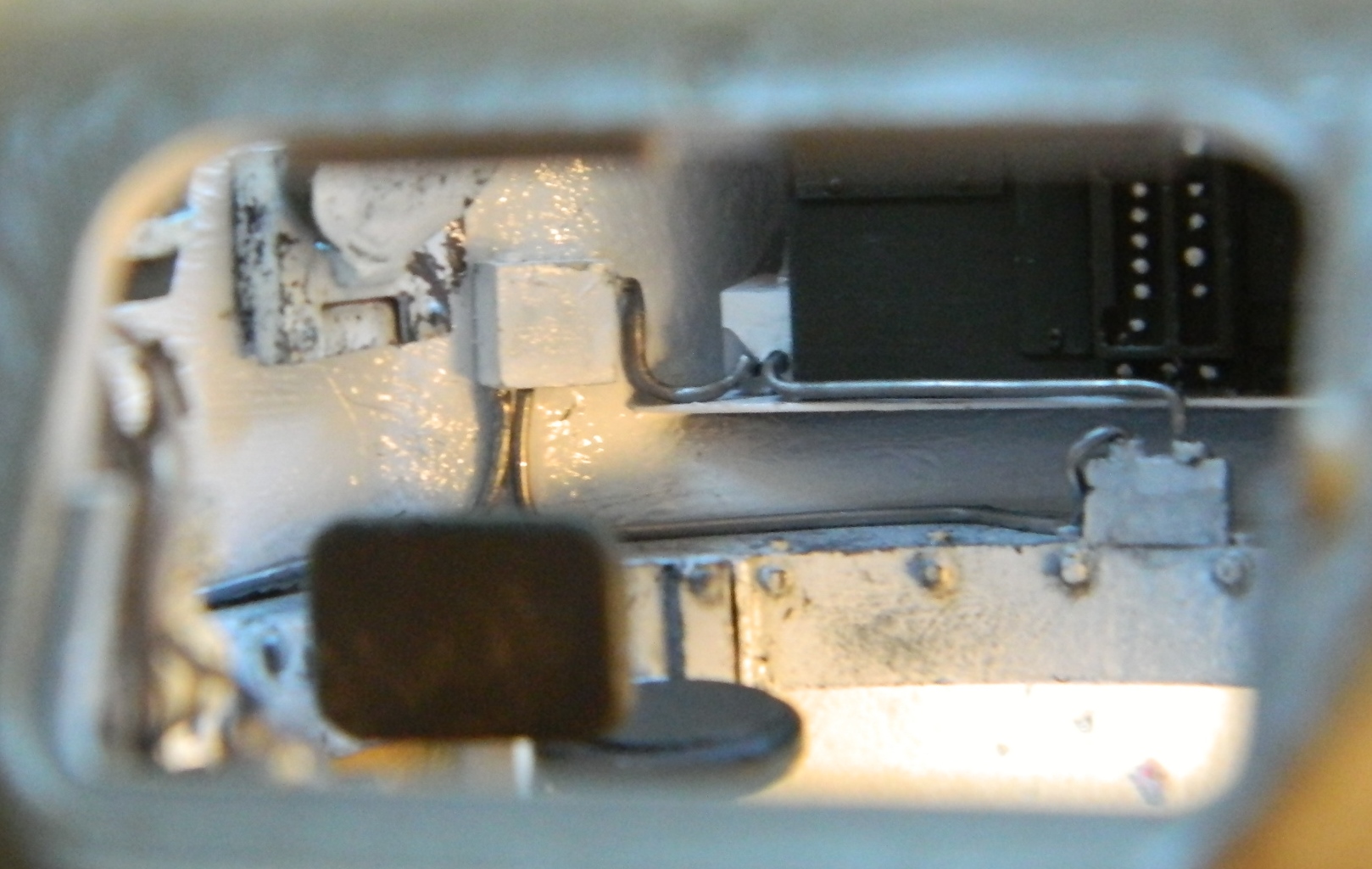
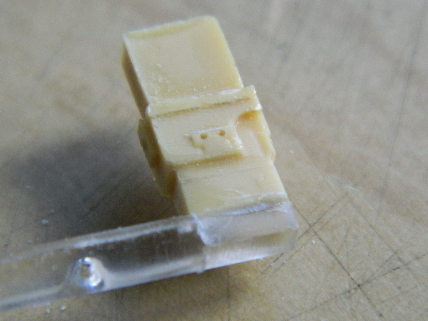
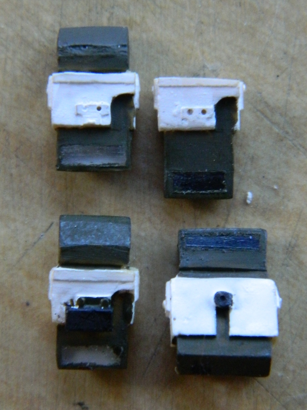
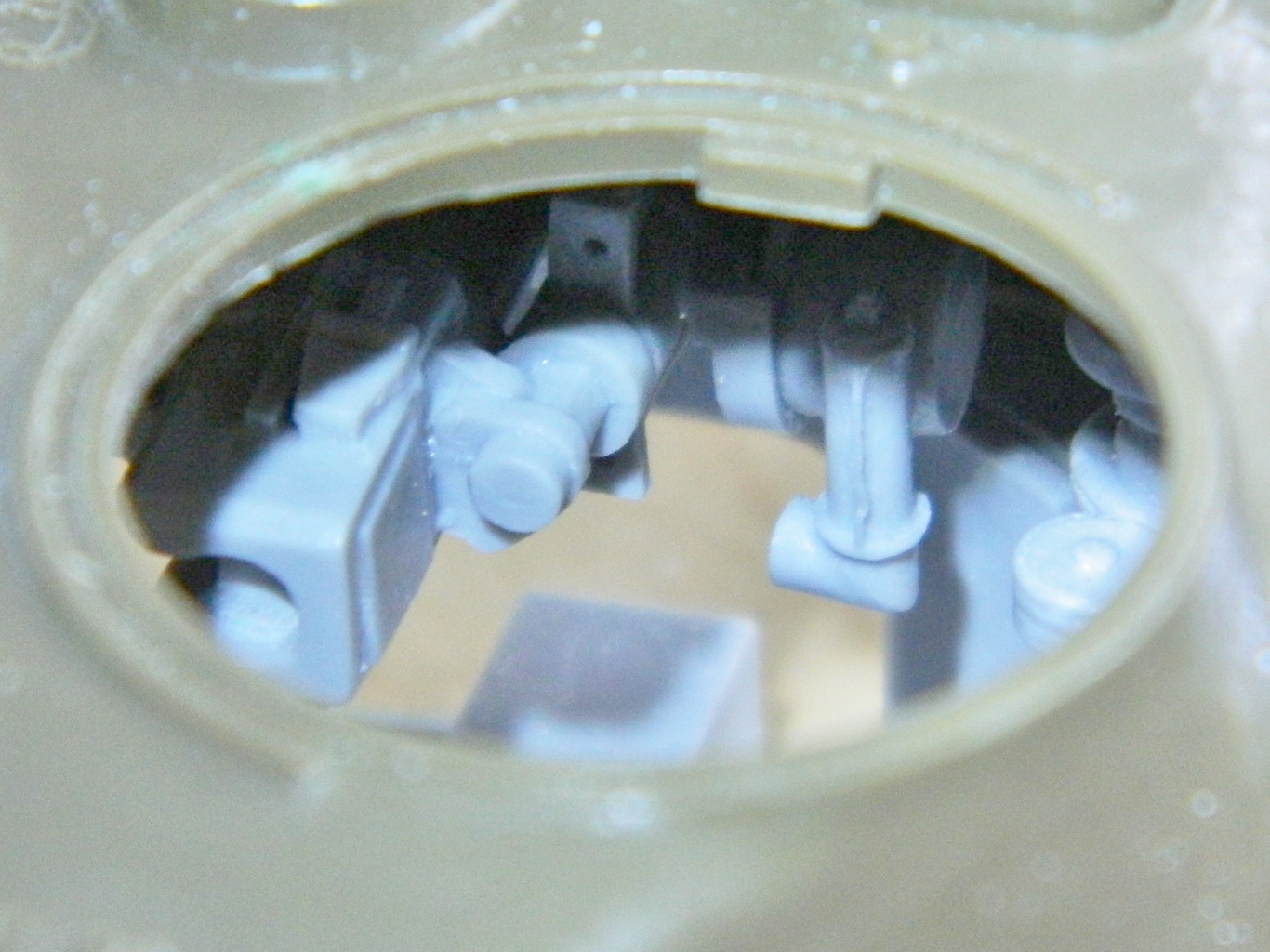
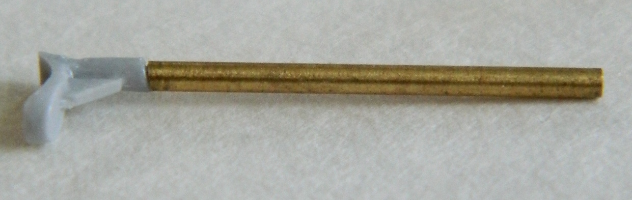
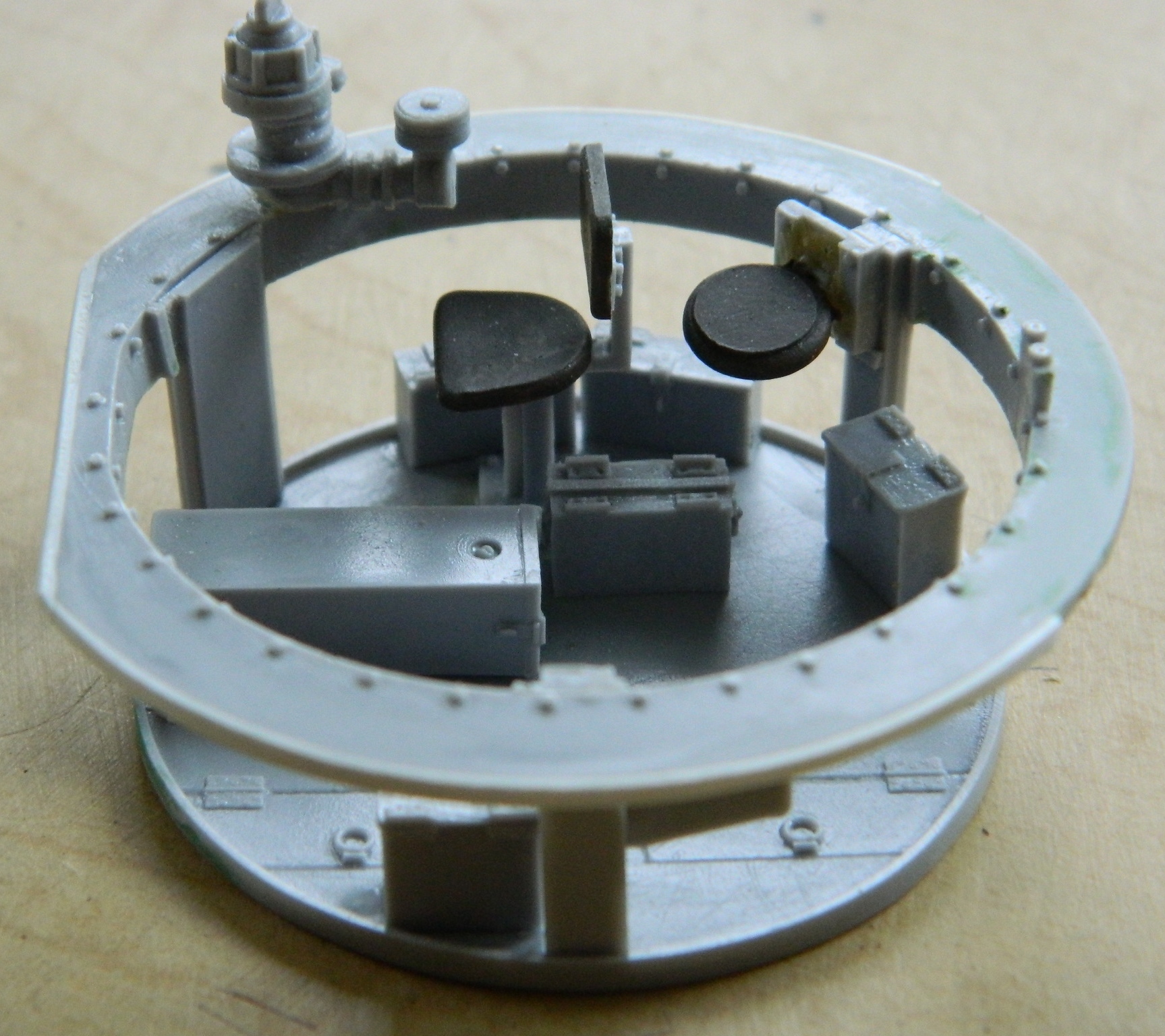
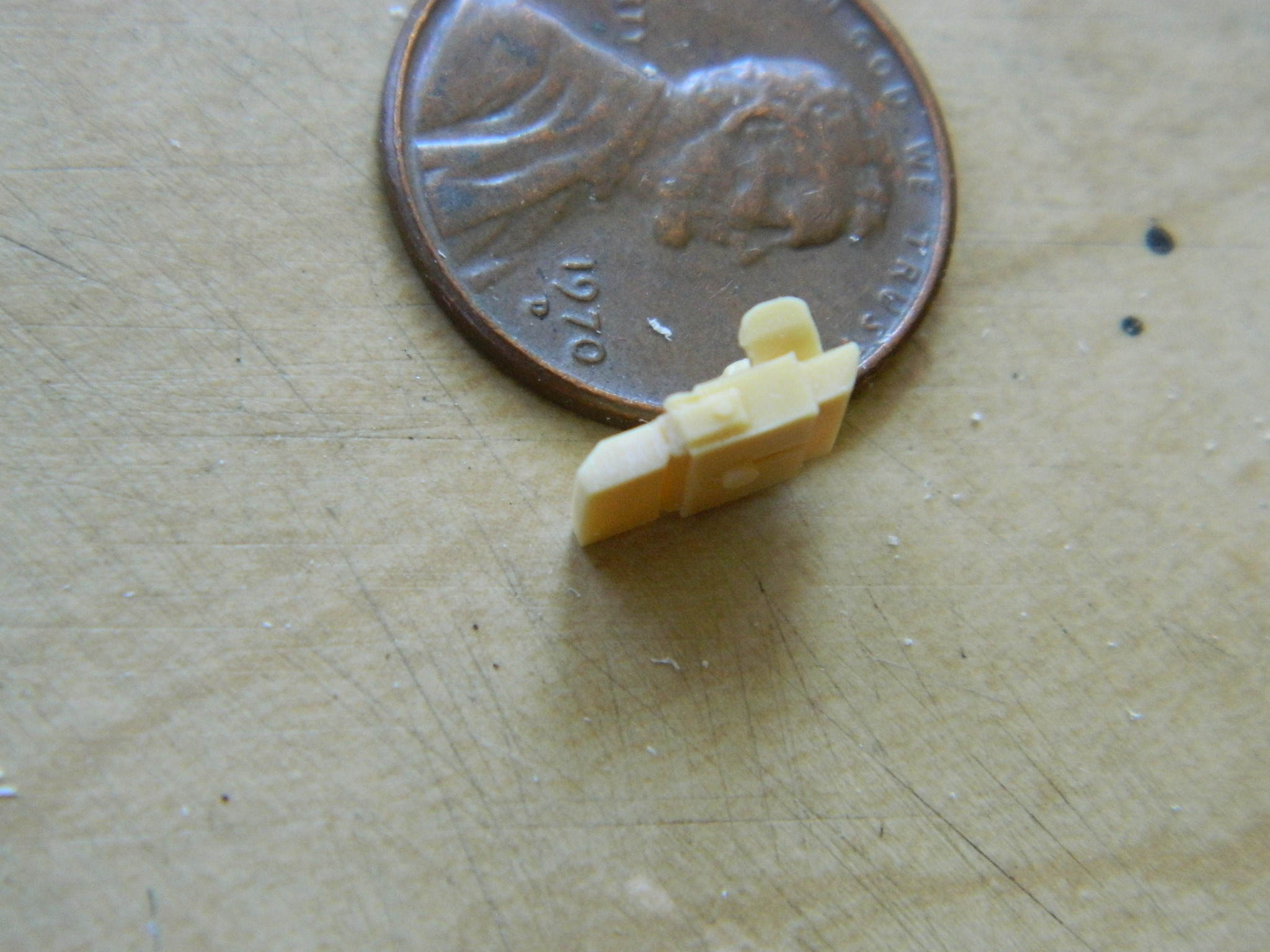
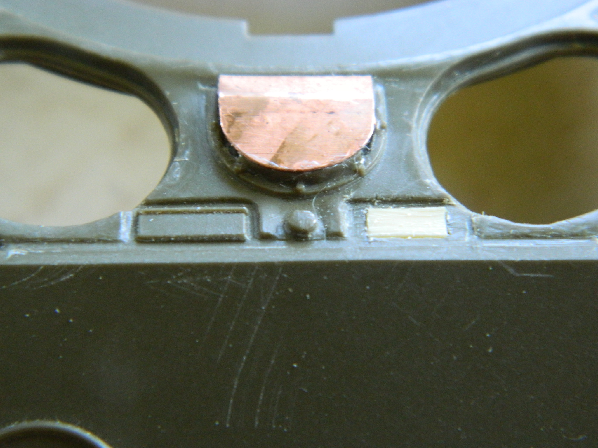
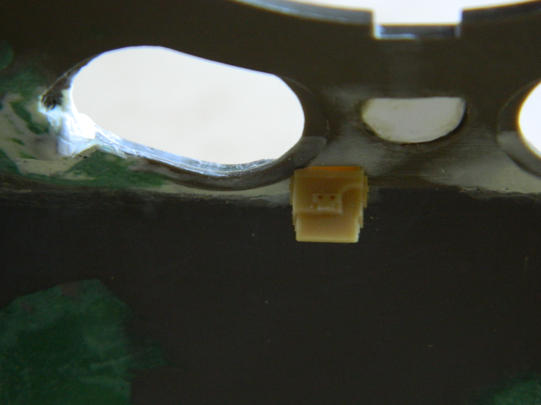
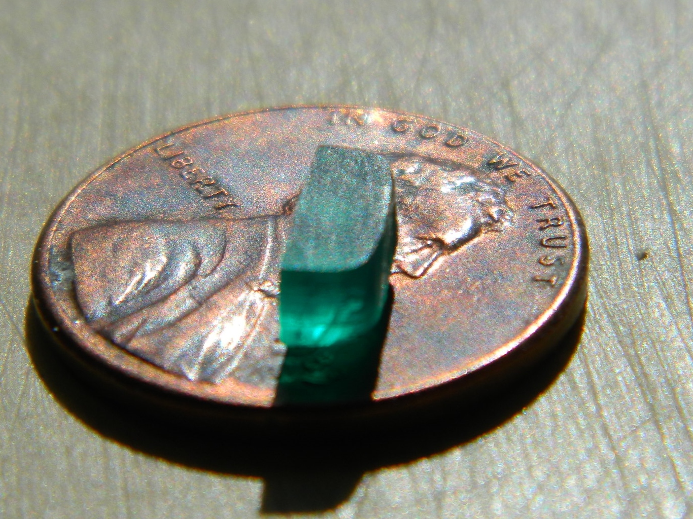
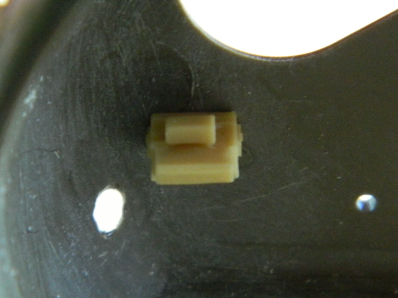
Once I demolded the resin parts, I noticed that there’s a battery that sits on the shelf in front of the radio. It’s a prominent feature that wasn’t supplied with the detail set so I made one (and took a mold of it):

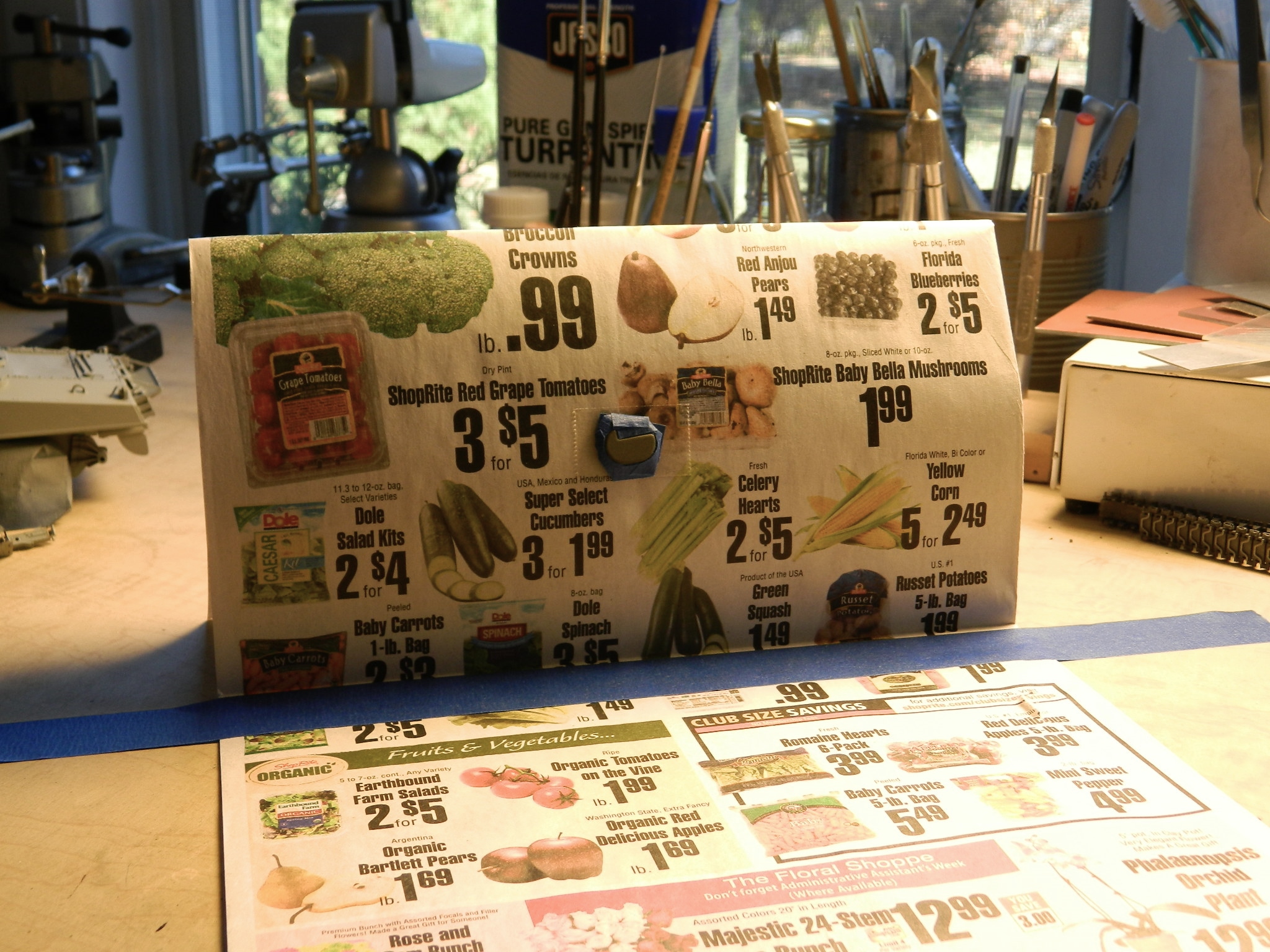
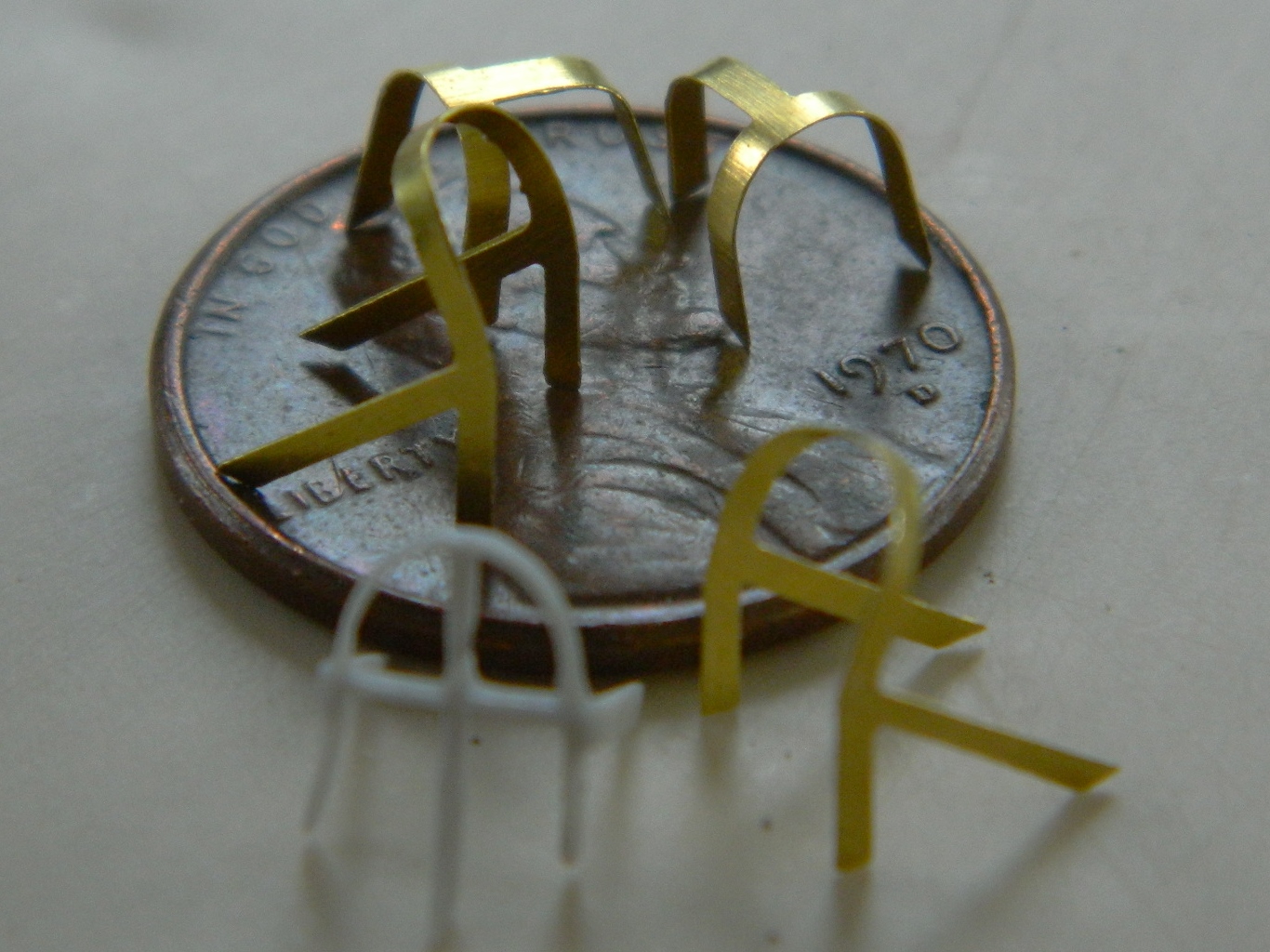
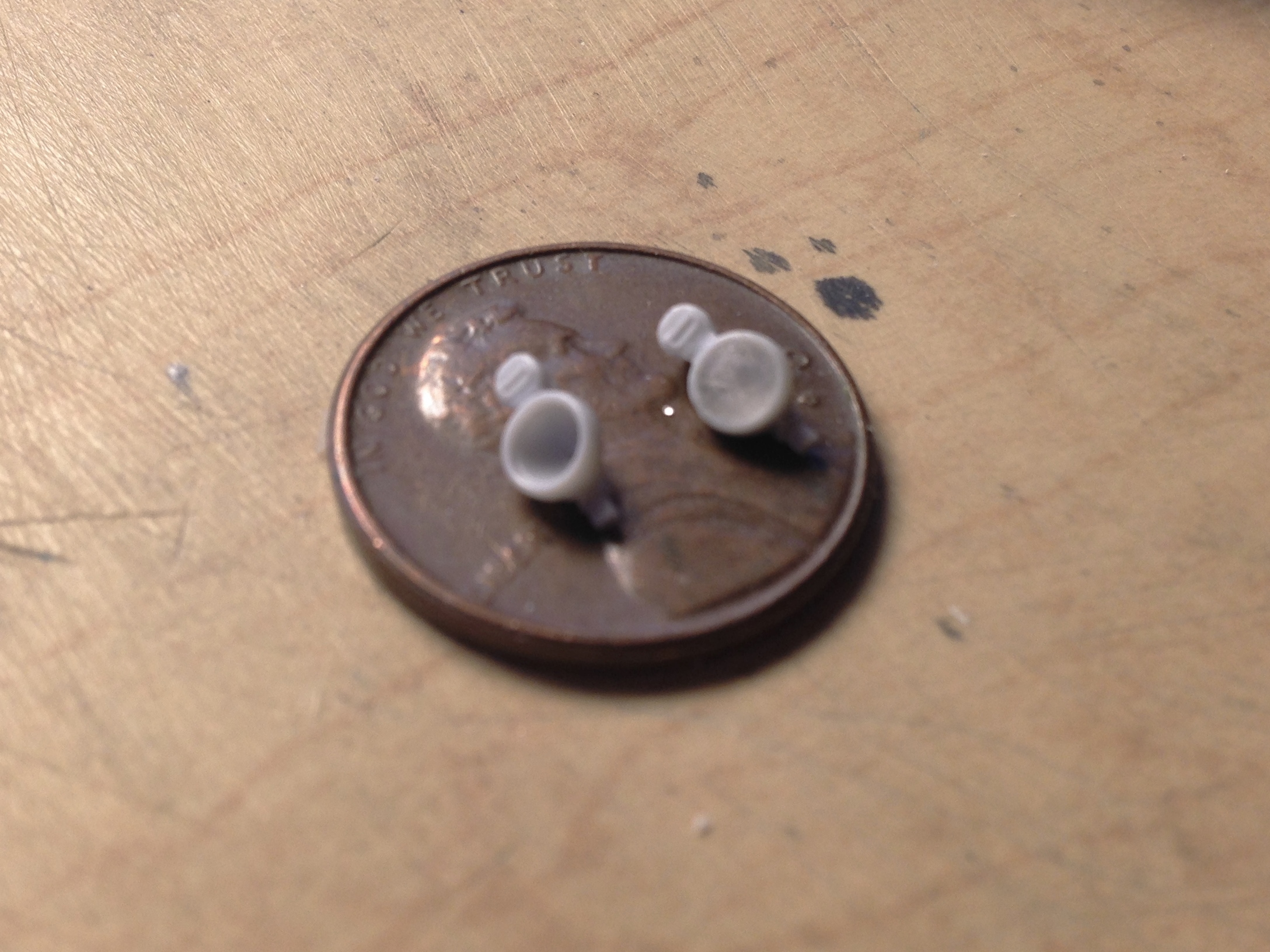
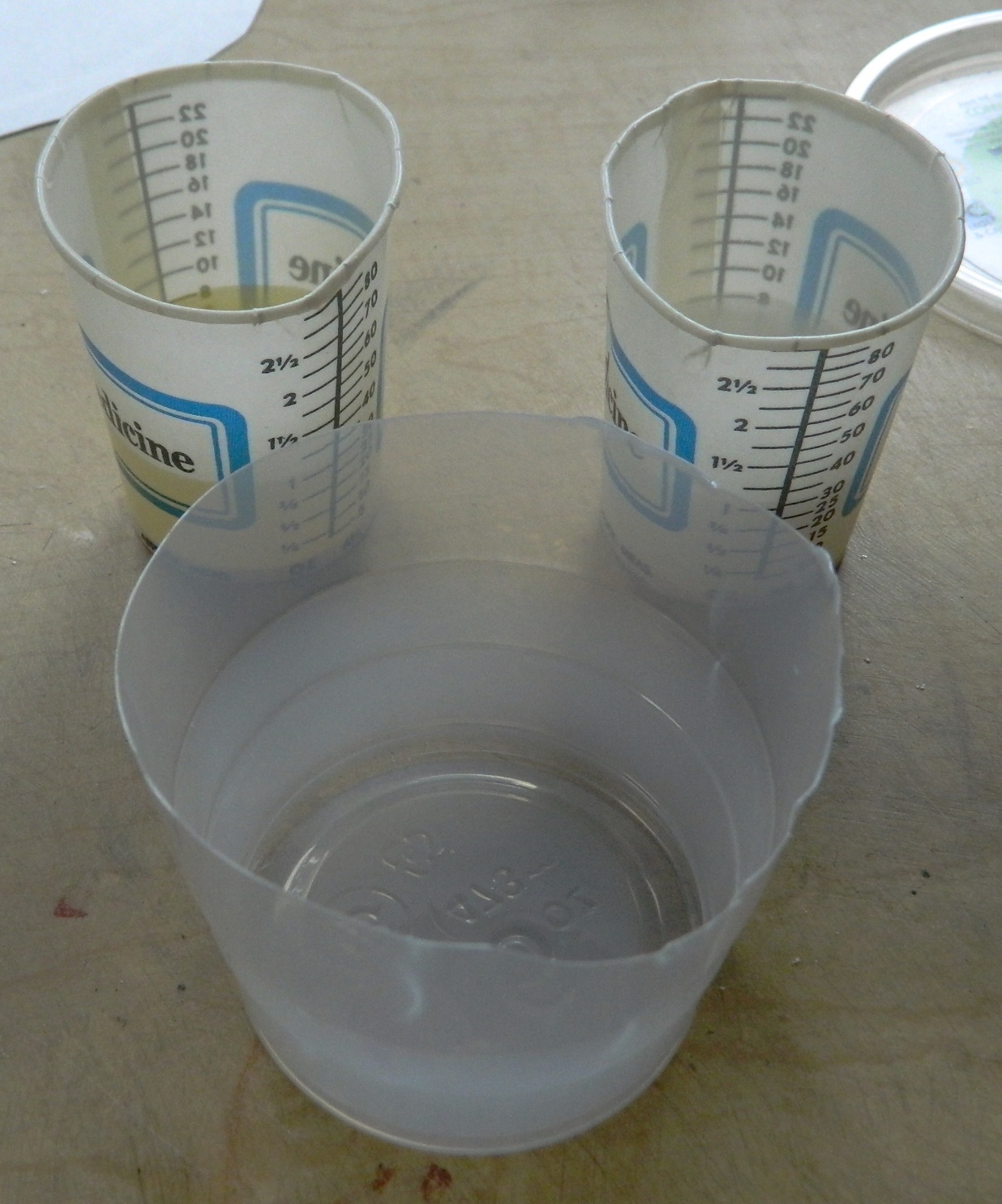
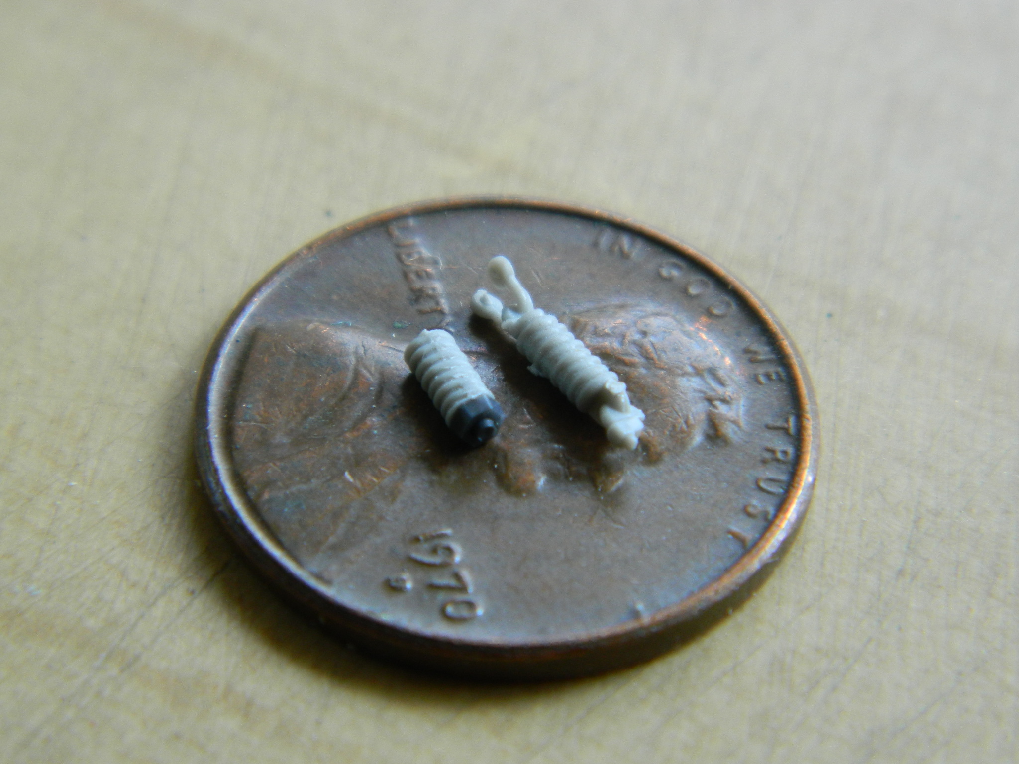
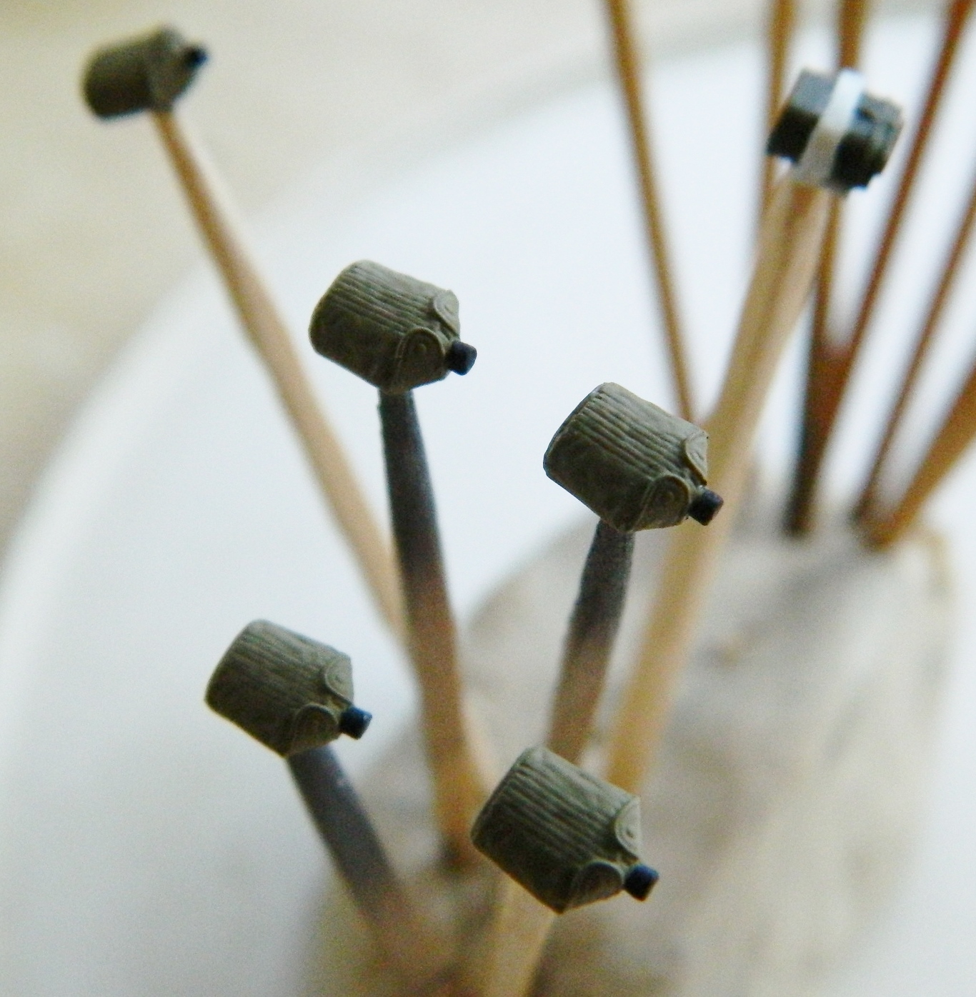
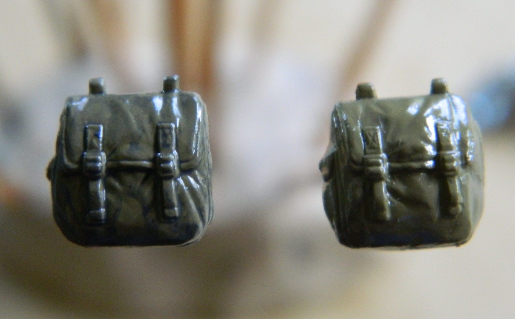
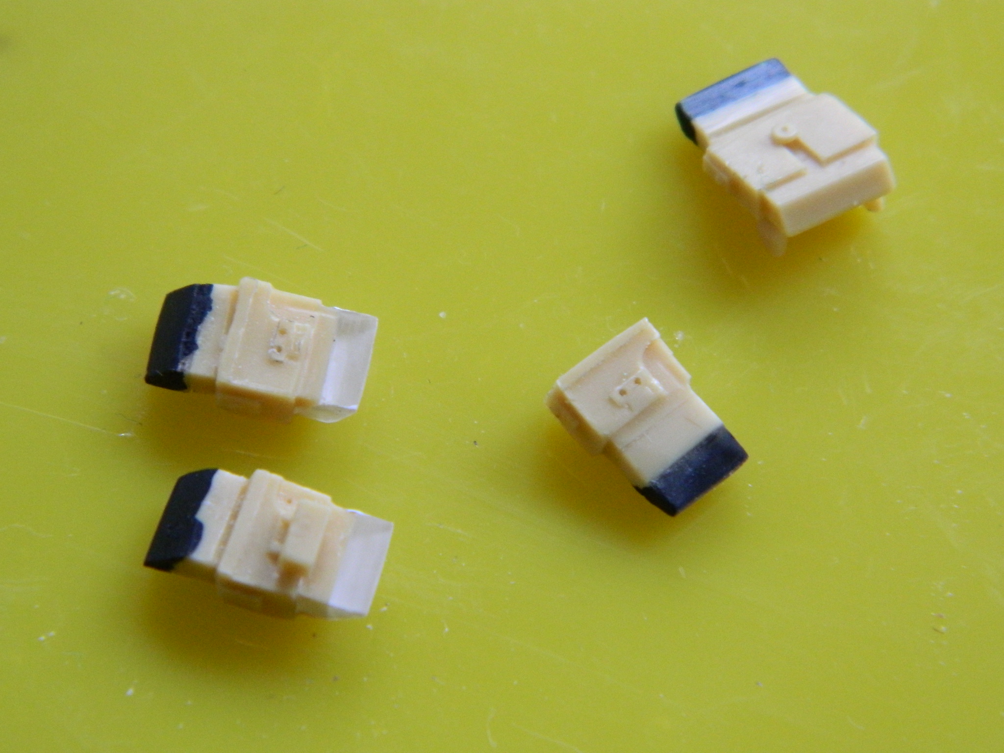
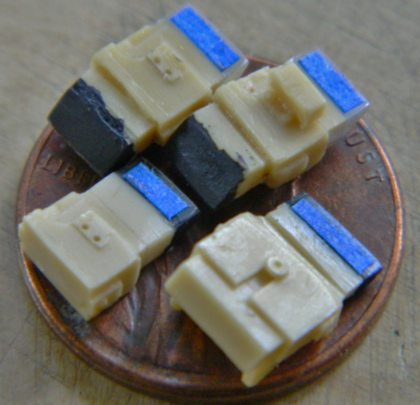
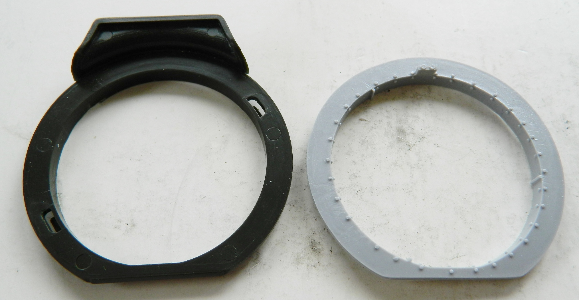
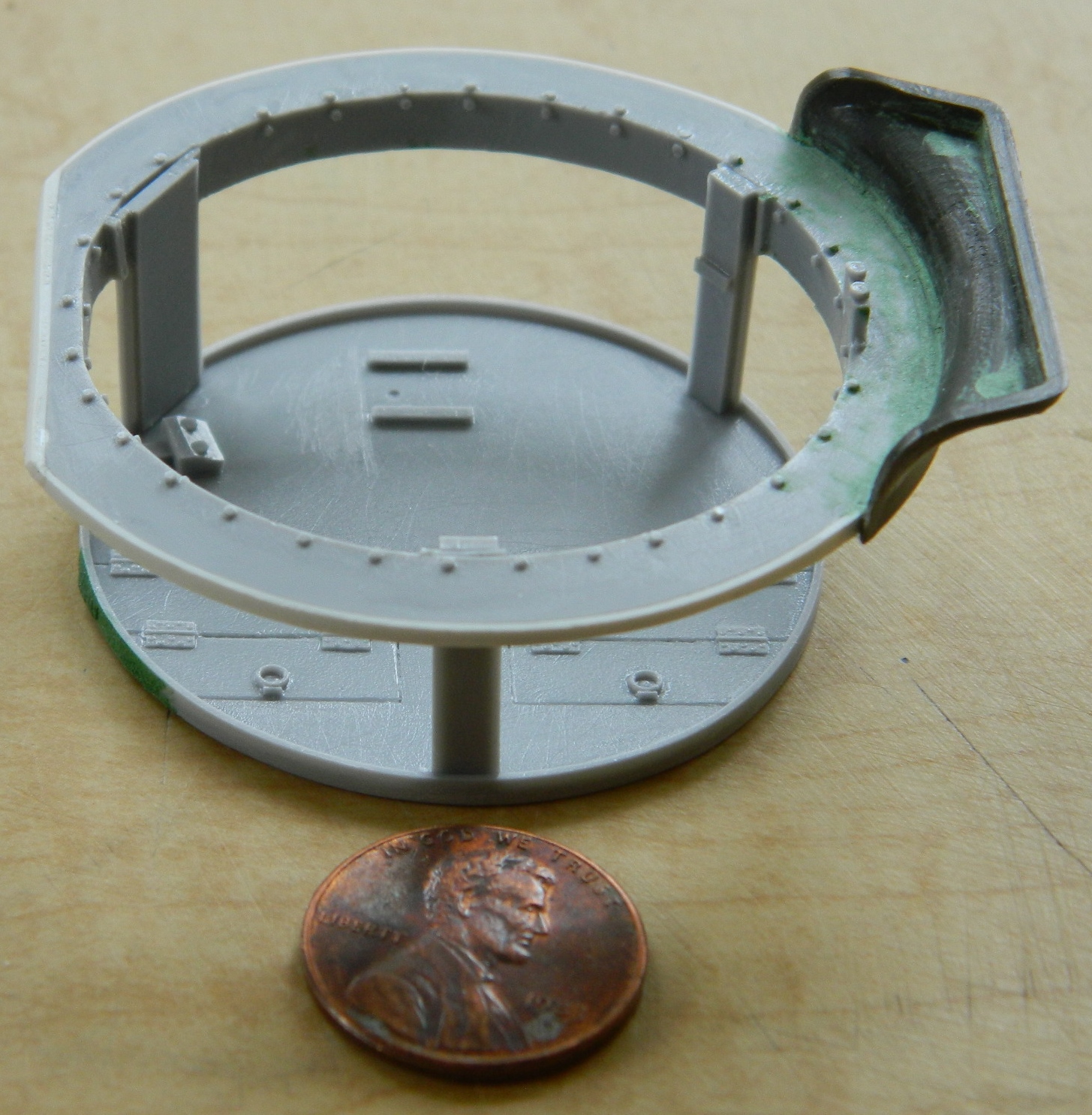
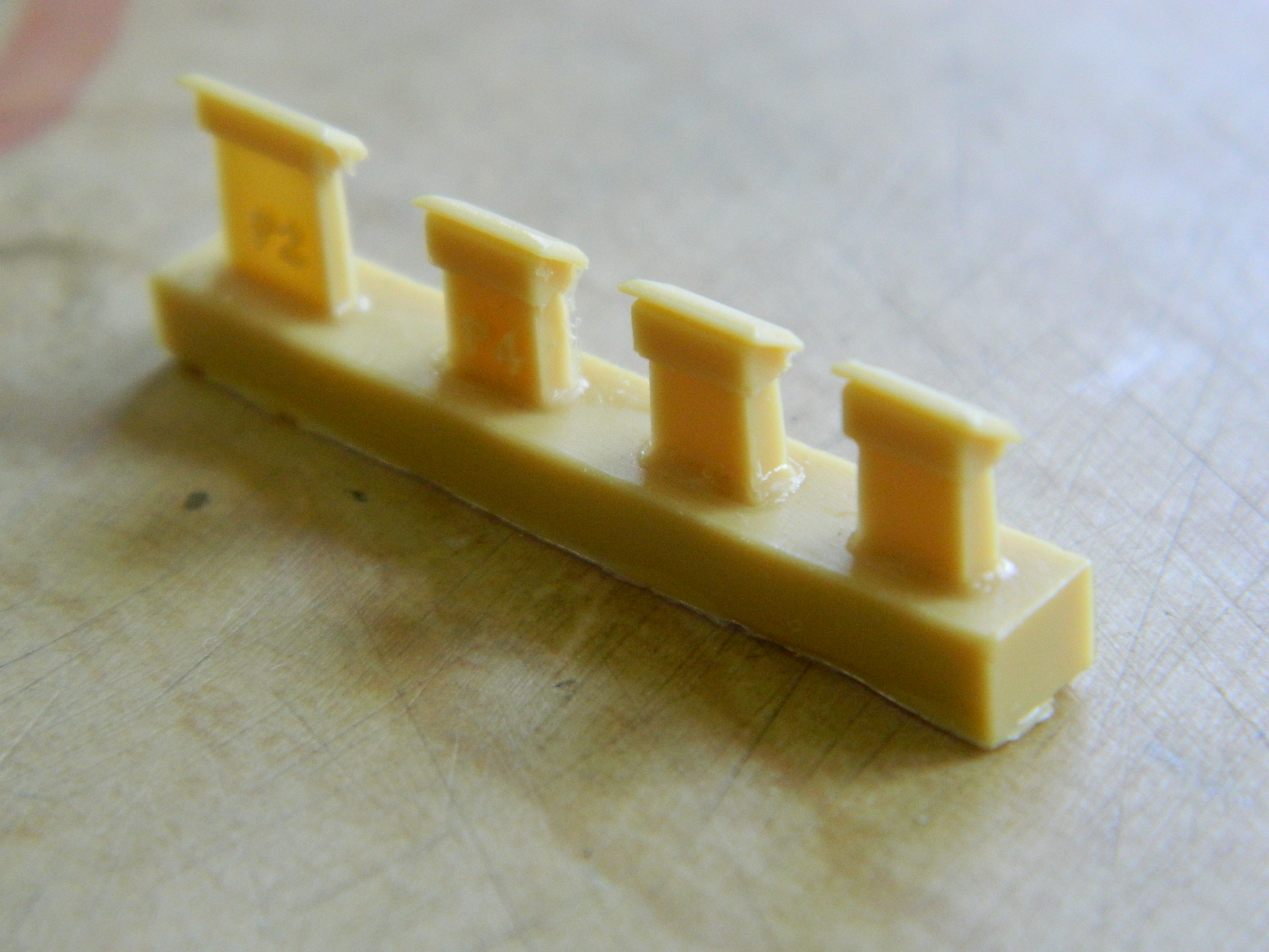
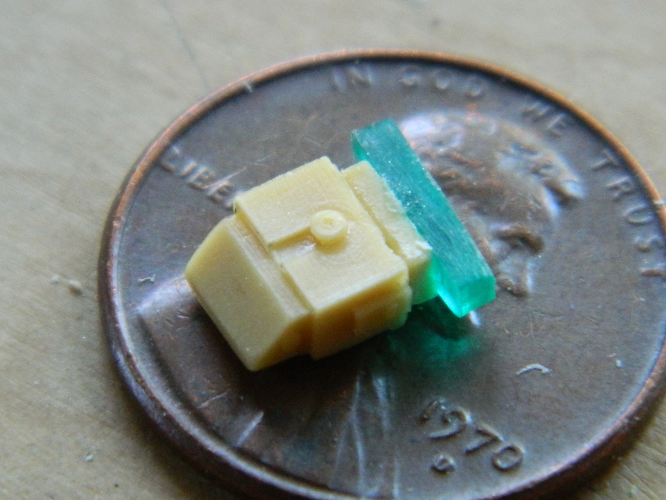
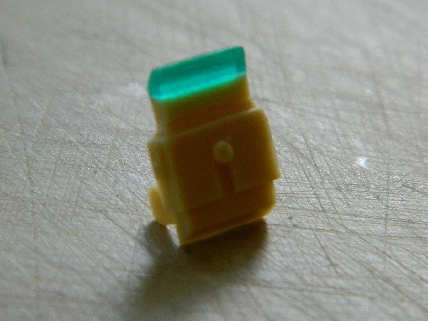
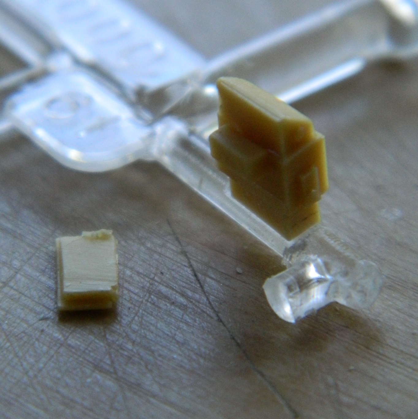
I’ve noticed that my (old) eyes are having difficulty with seeing the surfaces of the resin I’m using so I picked up some black resin dye. I was cautioned that it was highly concentrated so I tried adding a little bit. The effect, though better, wasn’t what I was looking for so I added a lot more. Below you can see the three pours; undyed on the left, lightly dyed in the center, and black on the right:

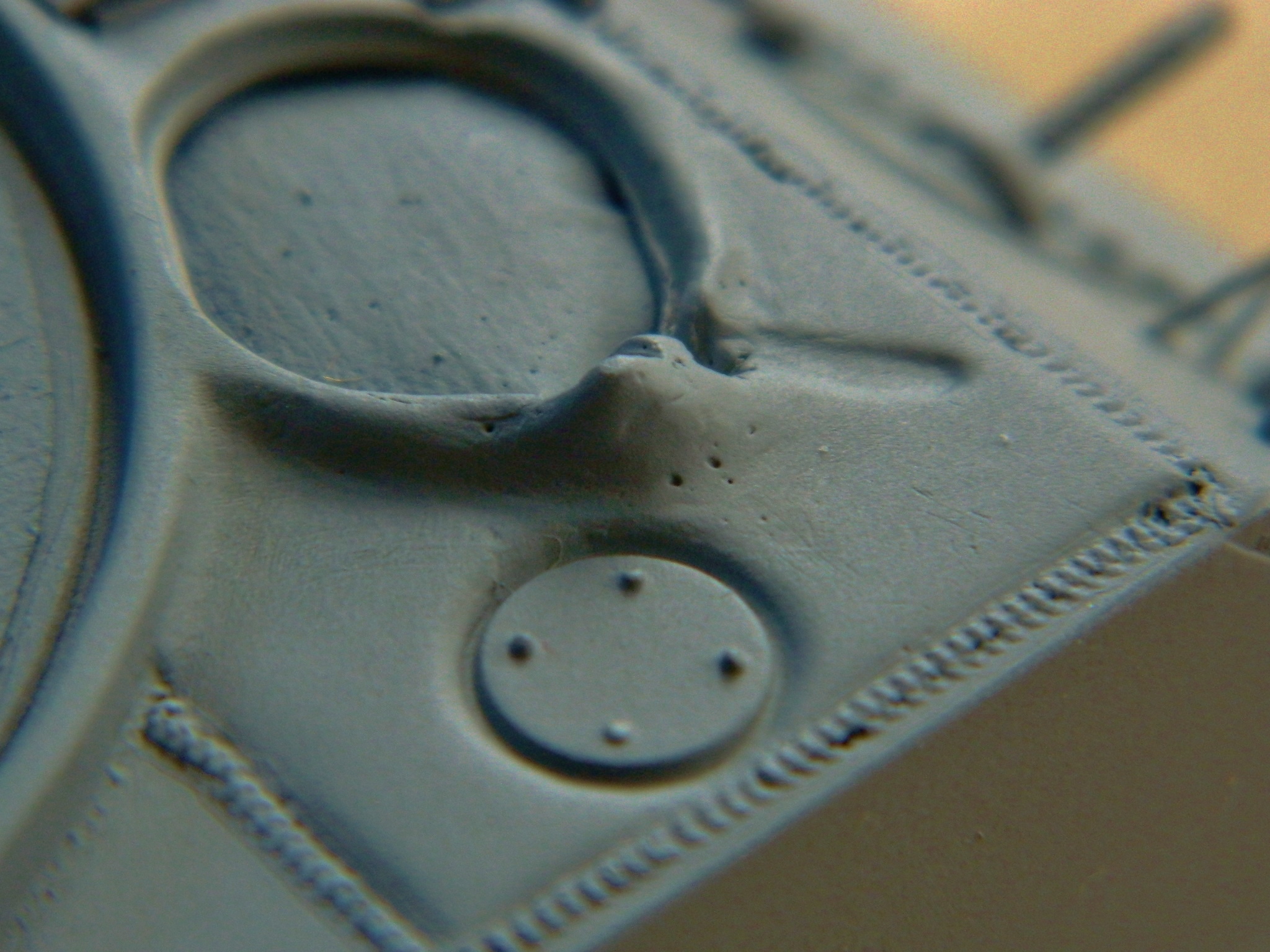
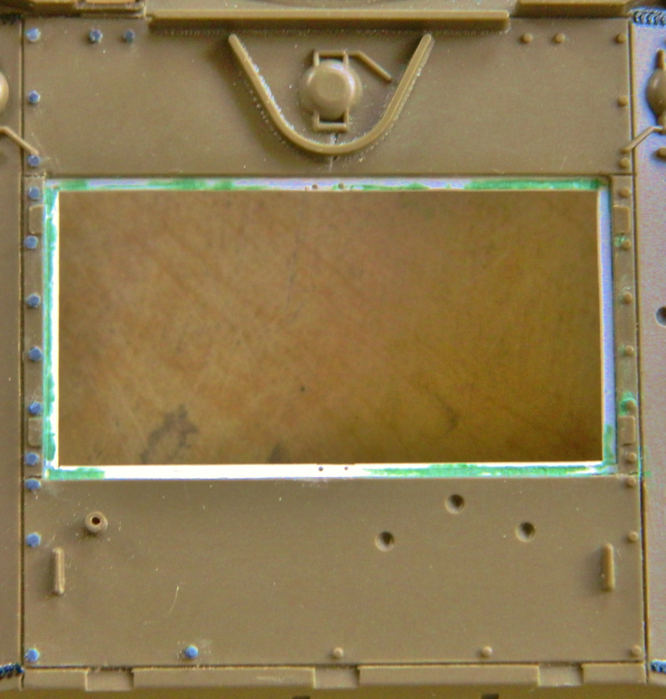
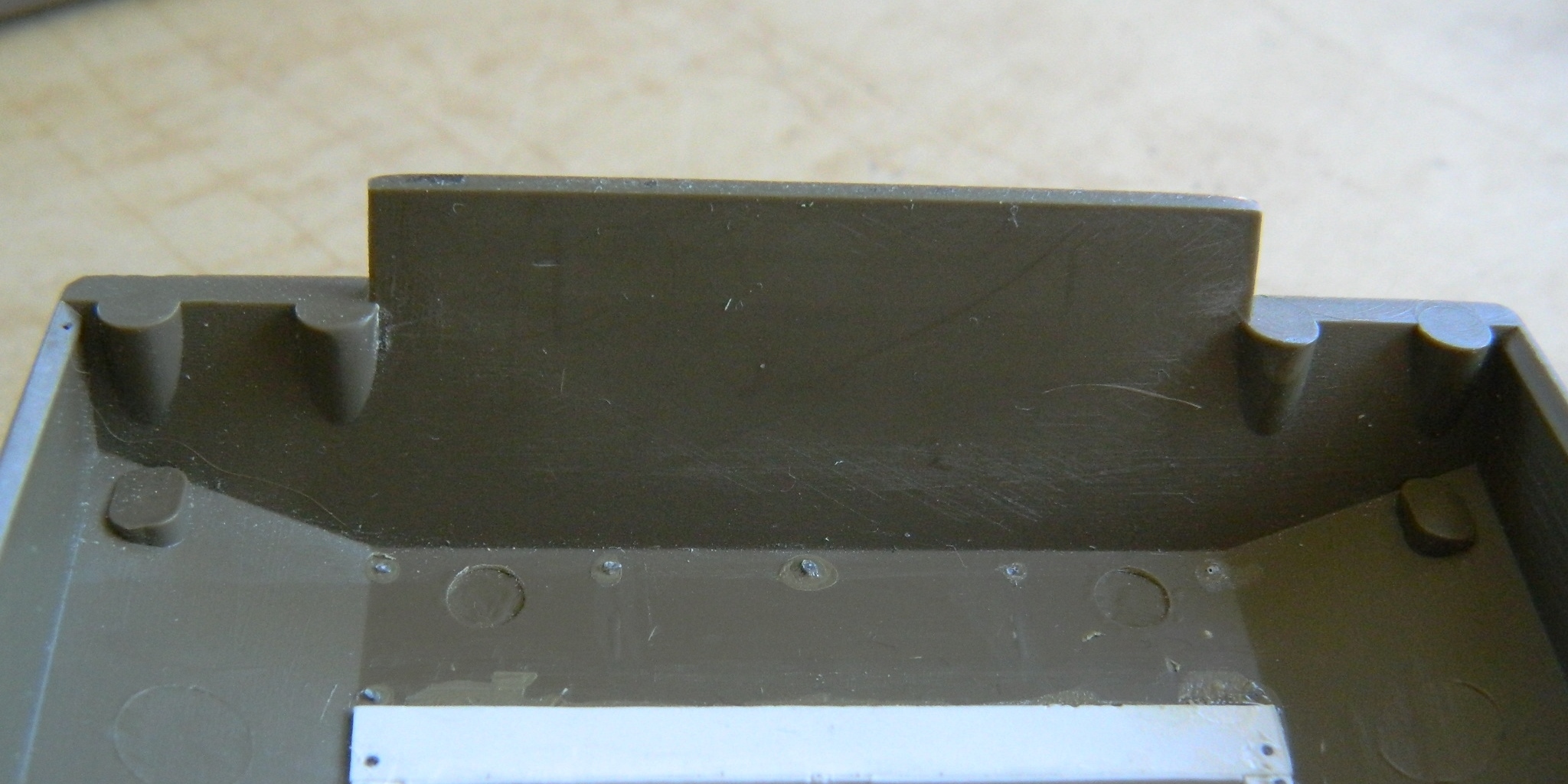
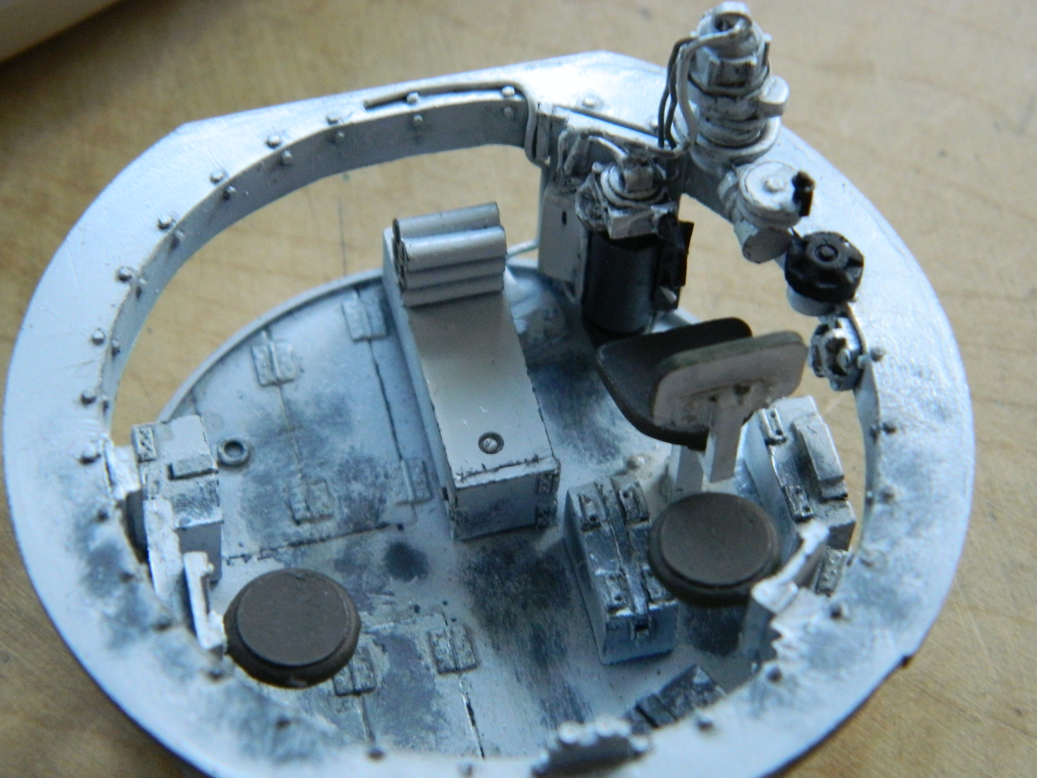
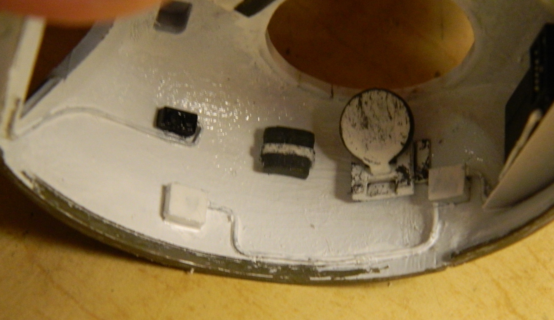
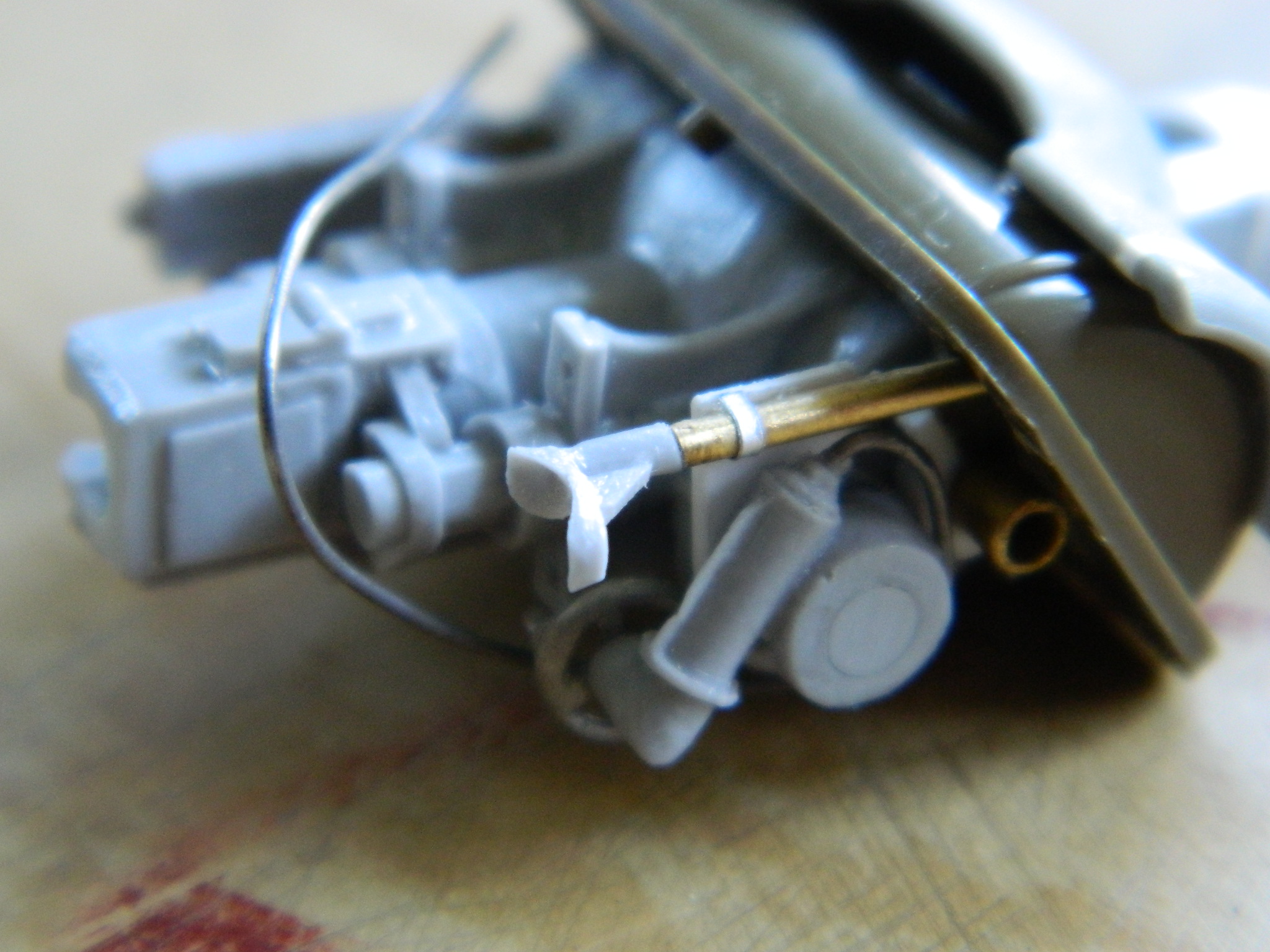
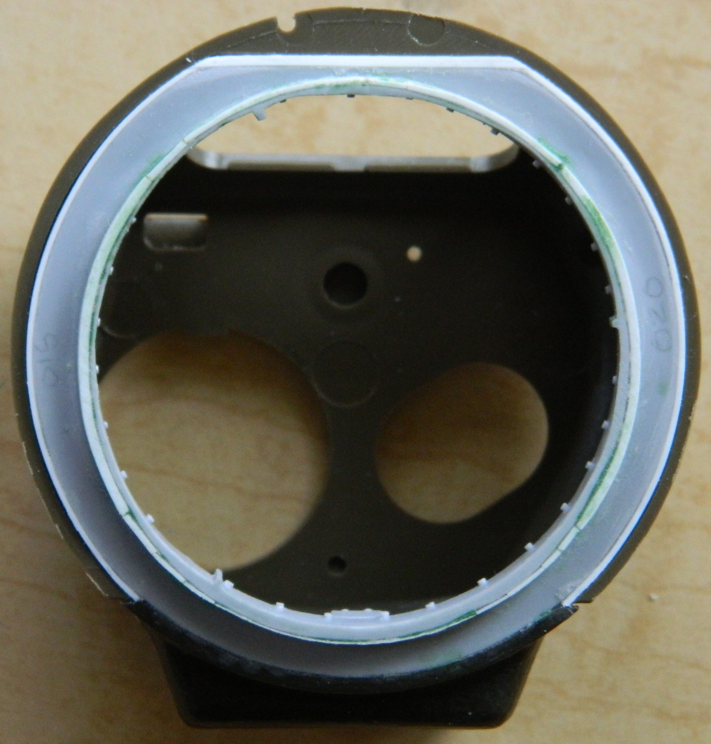
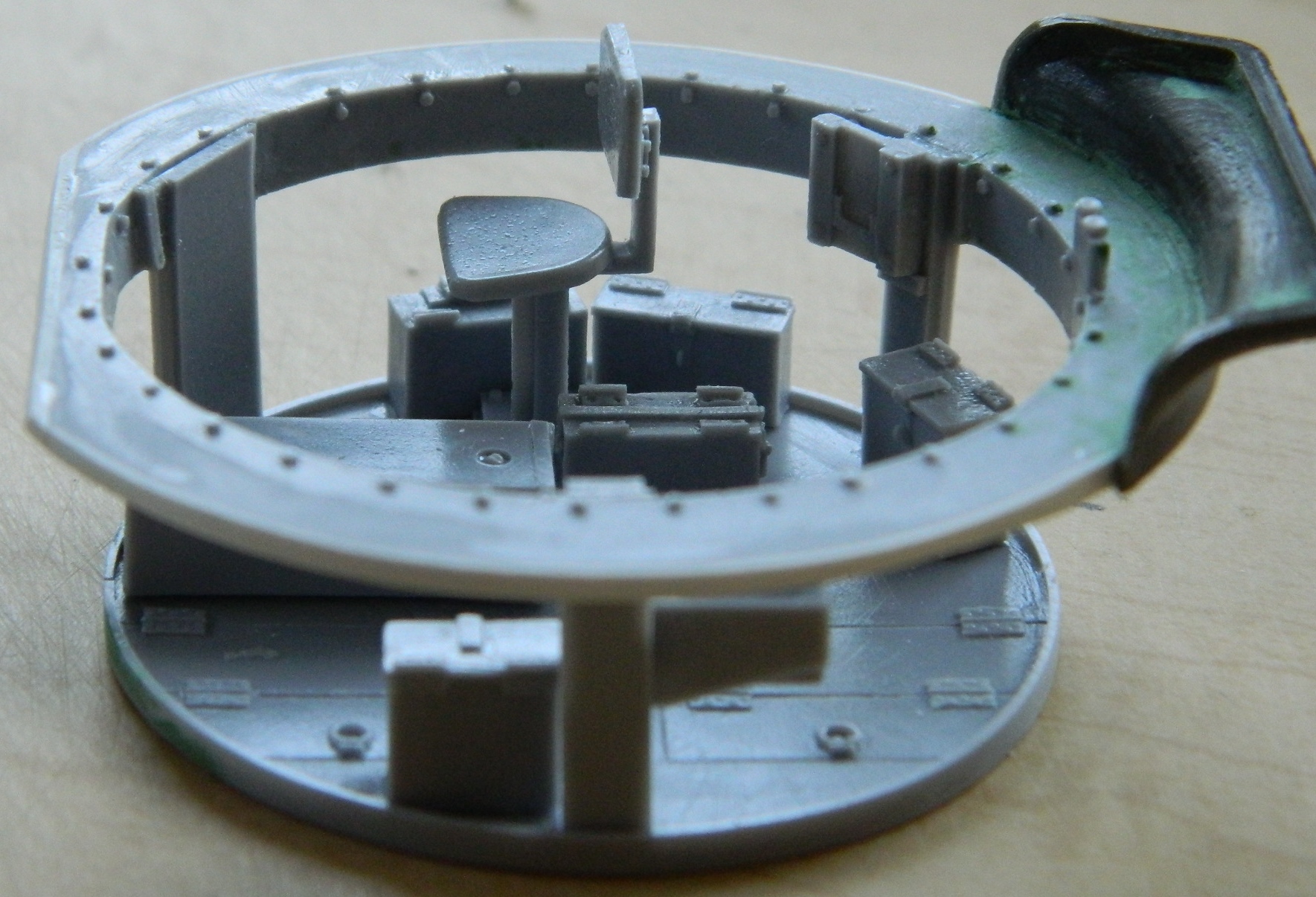
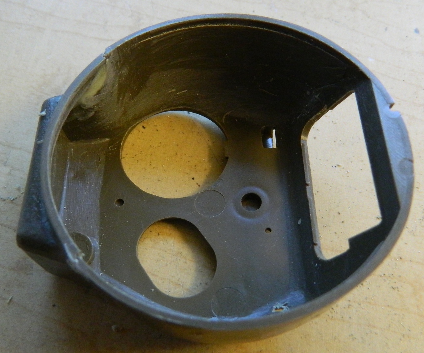
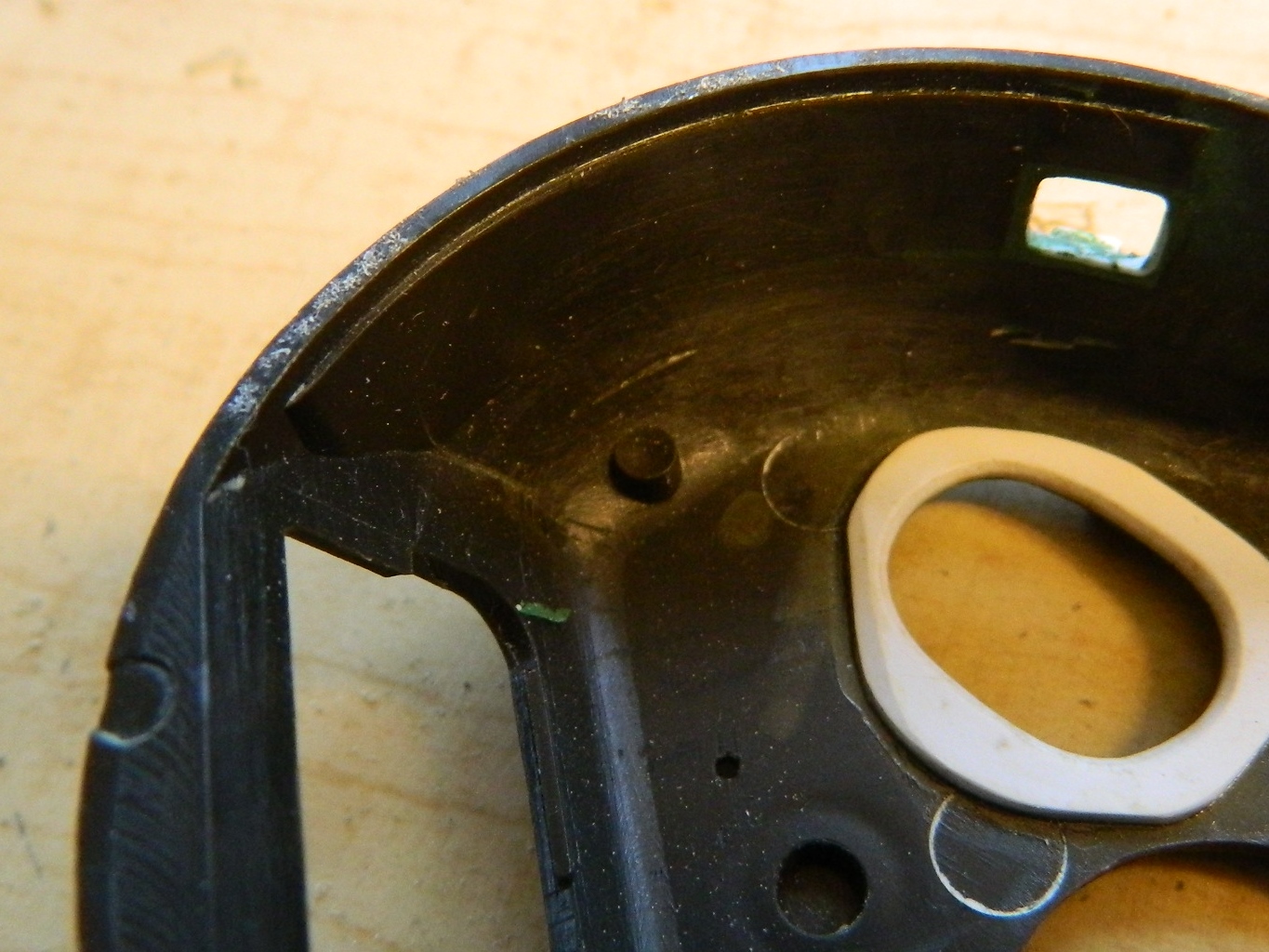
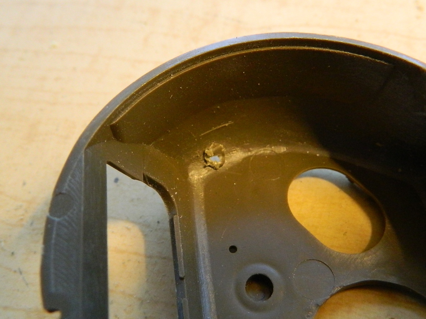
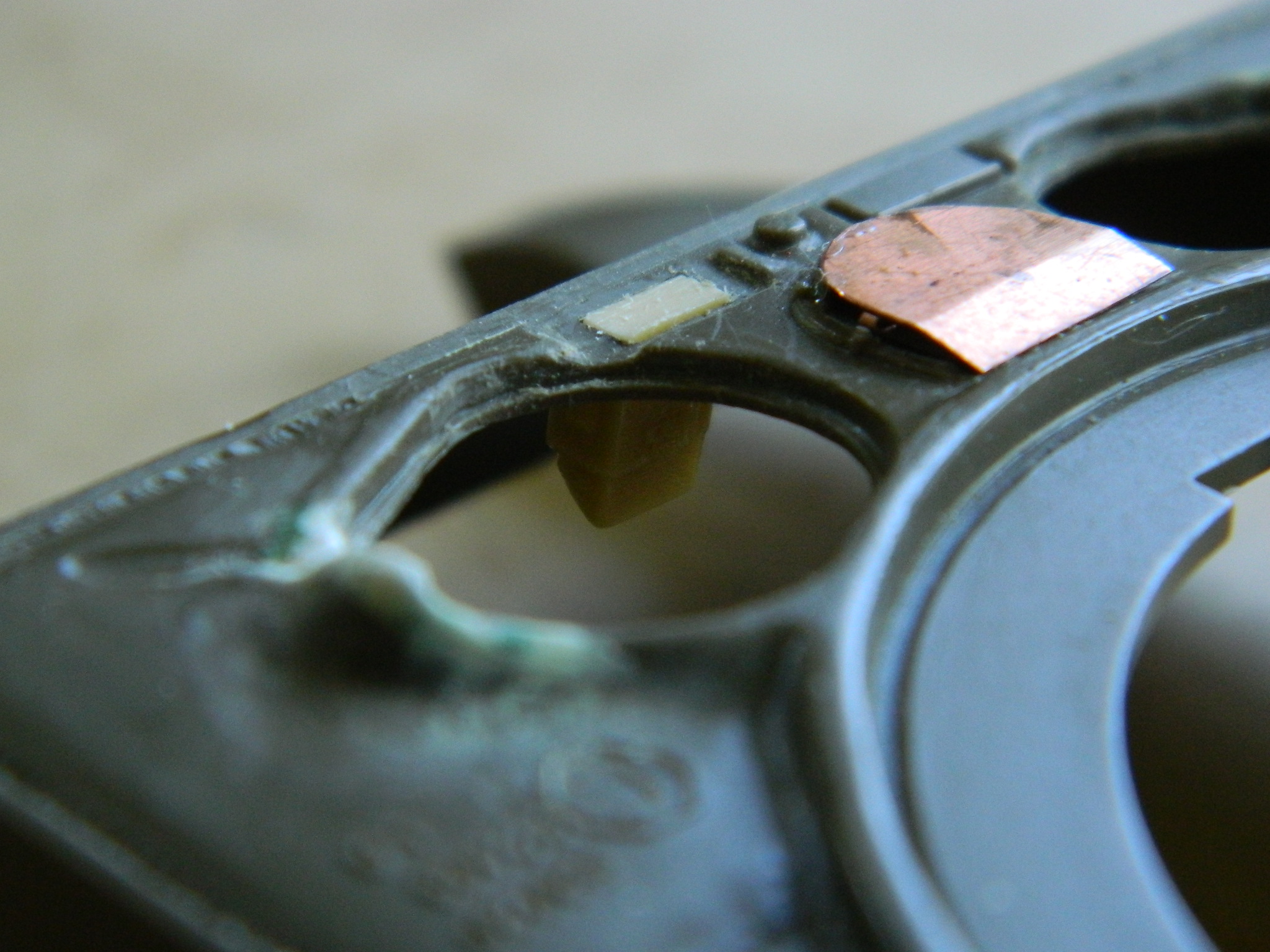
With the parts produced I want to use, it became time to start checking fit. The rudder pedals are a bit tight to the lower panel of the instrument panel but not so much that I’m willing to jump (crawl and stagger) through the hoops necessary to fix it. But the raised rectangles on the cockpit floor are skid plates for the pilot’s heels and as such should line up with the rudders…which they don’t, so that will need fixing:

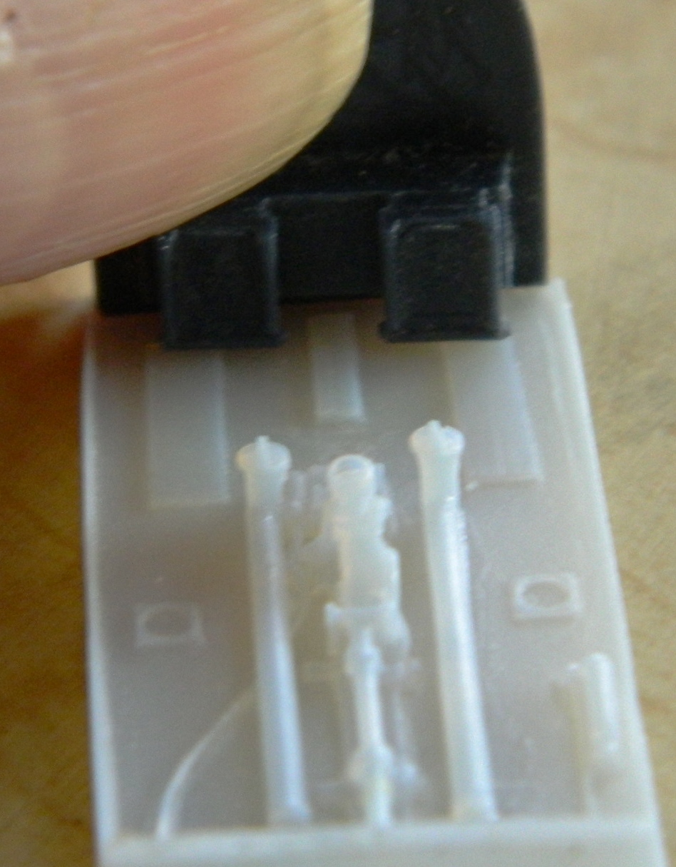
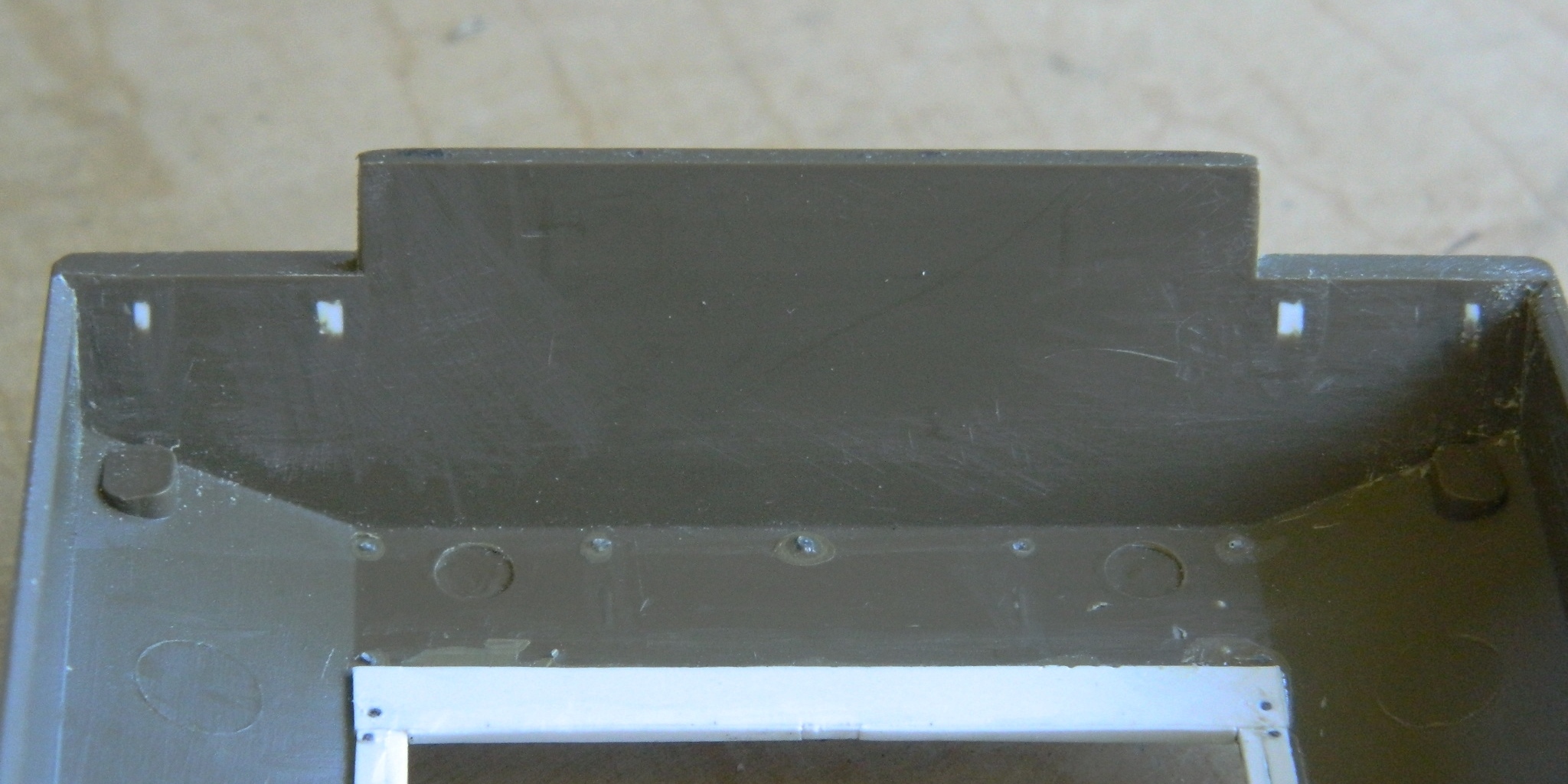
In checking the resin seat against photographs of actual seats, the depression at the top of the seat where the shoulder harnesses are isn’t there. That’s an easy fix…just take down the corners:

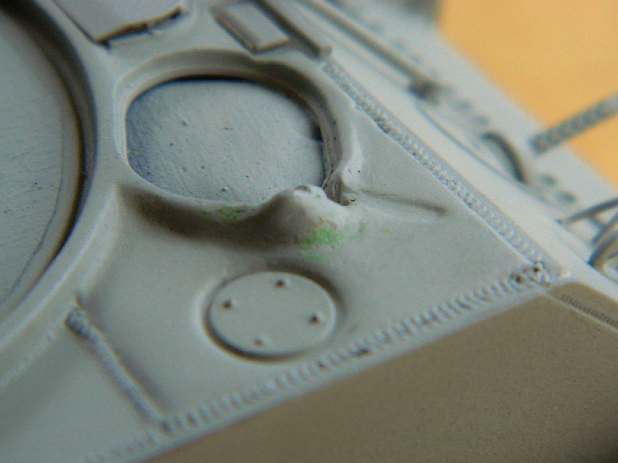
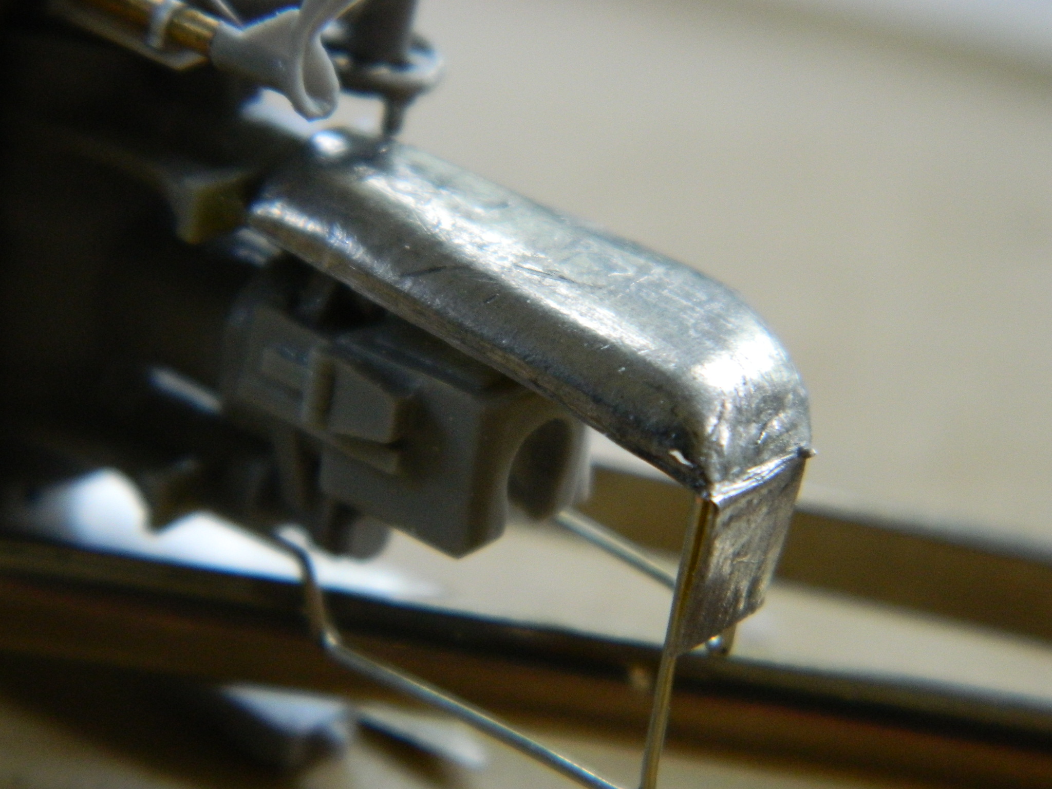
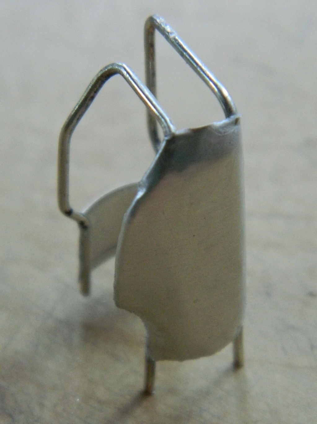
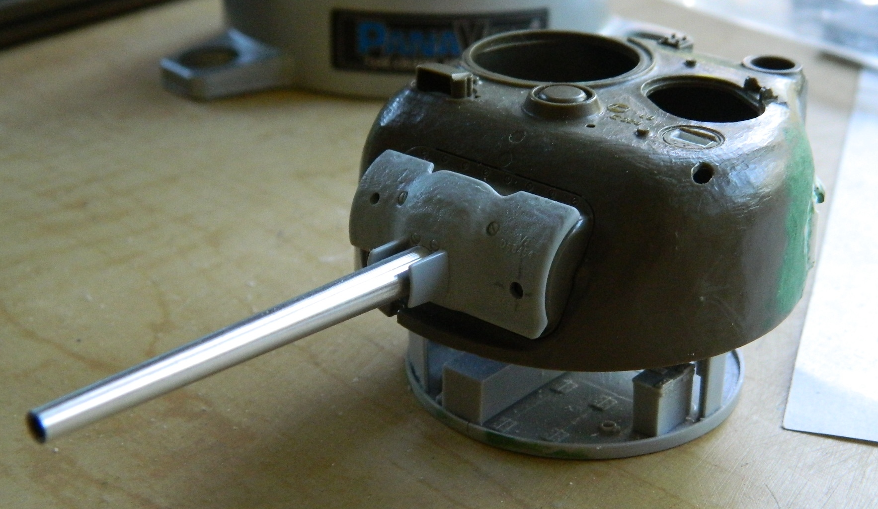
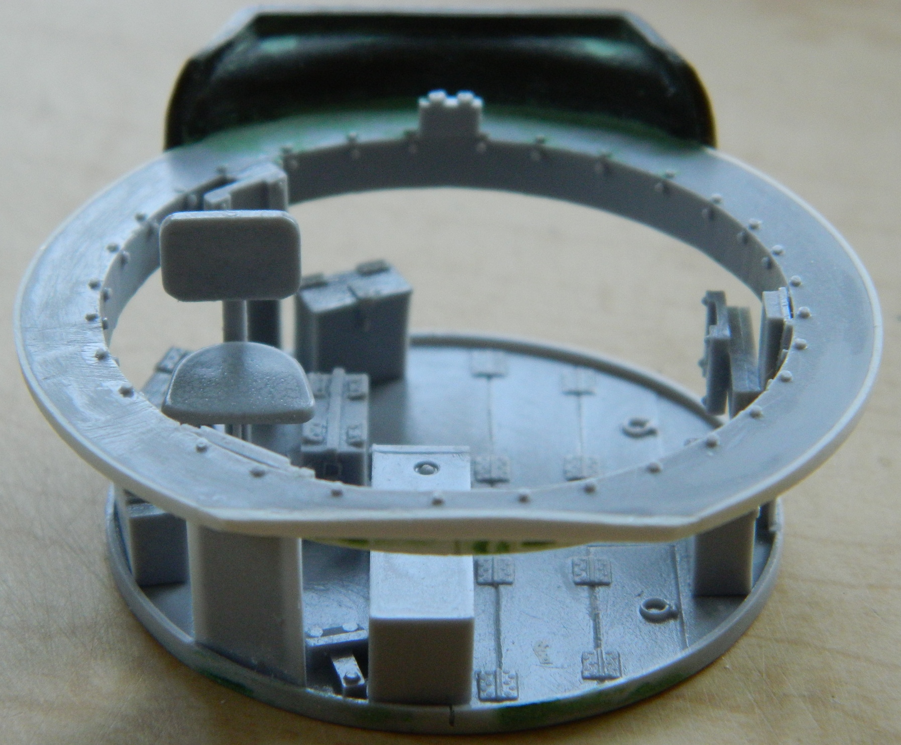
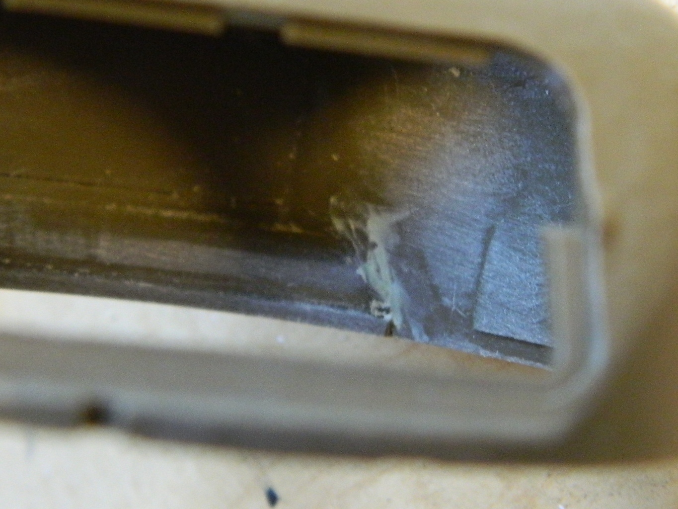
Since I’m going to be using my rollover brace I carved/sanded/filed the brace molded to the armor plate off as well as removing the raised area on the back (from what I can tell from photos, that’s supposed to be flat). Once the molded-on details were removed, I applied a coat of putty to remove depressions:
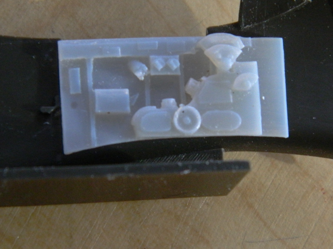
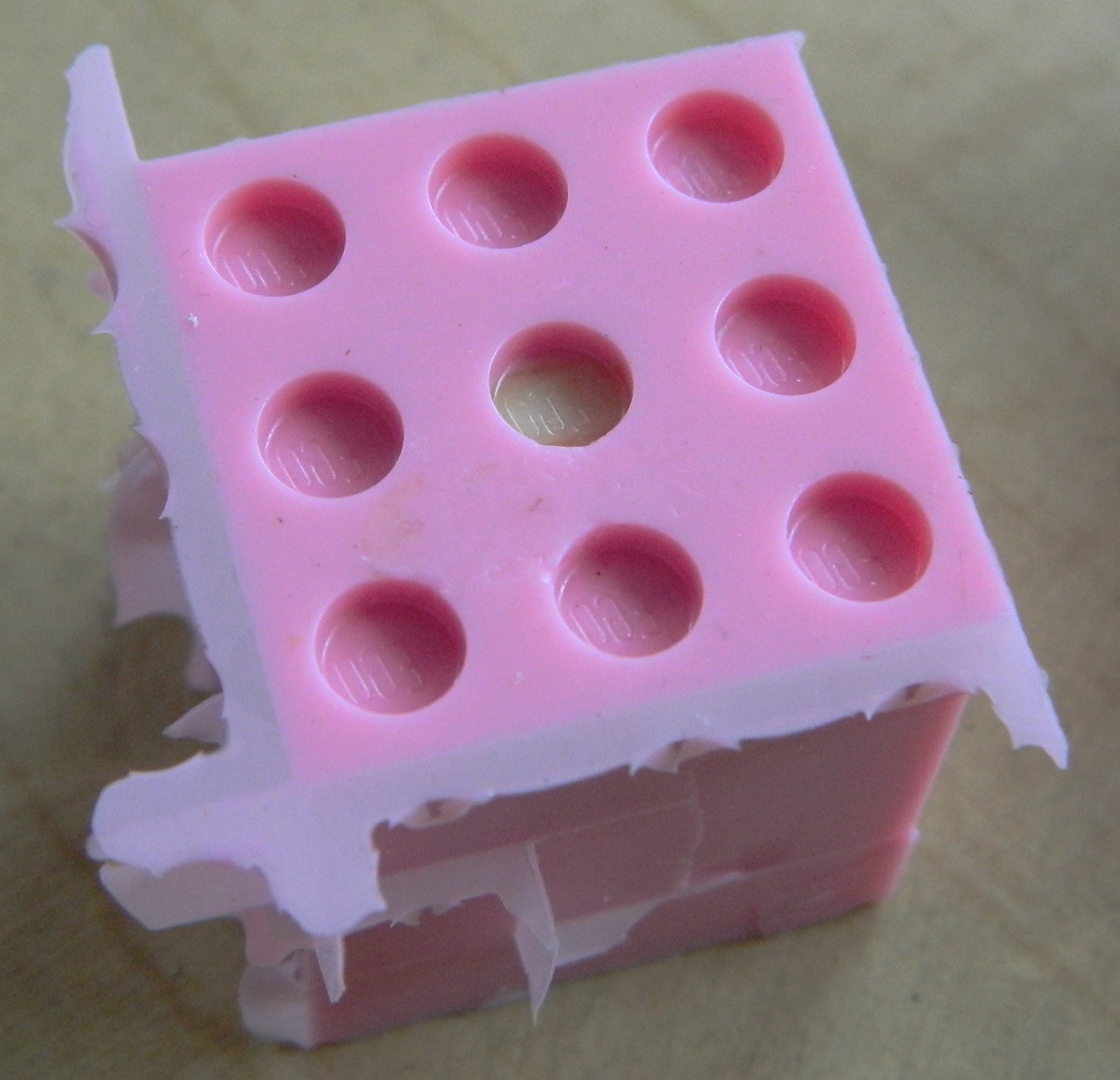
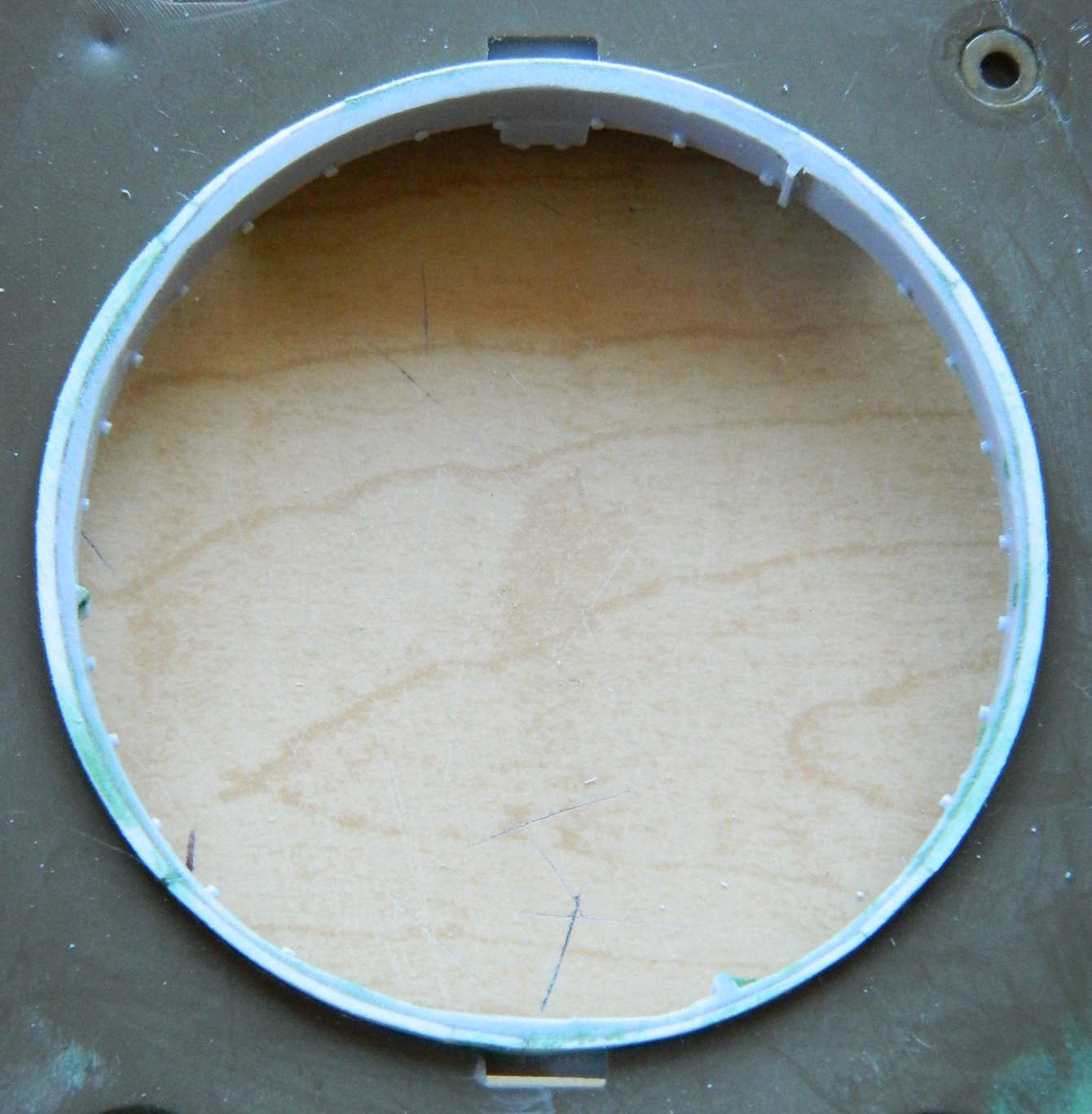
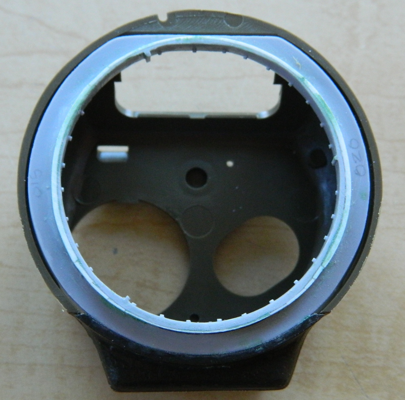
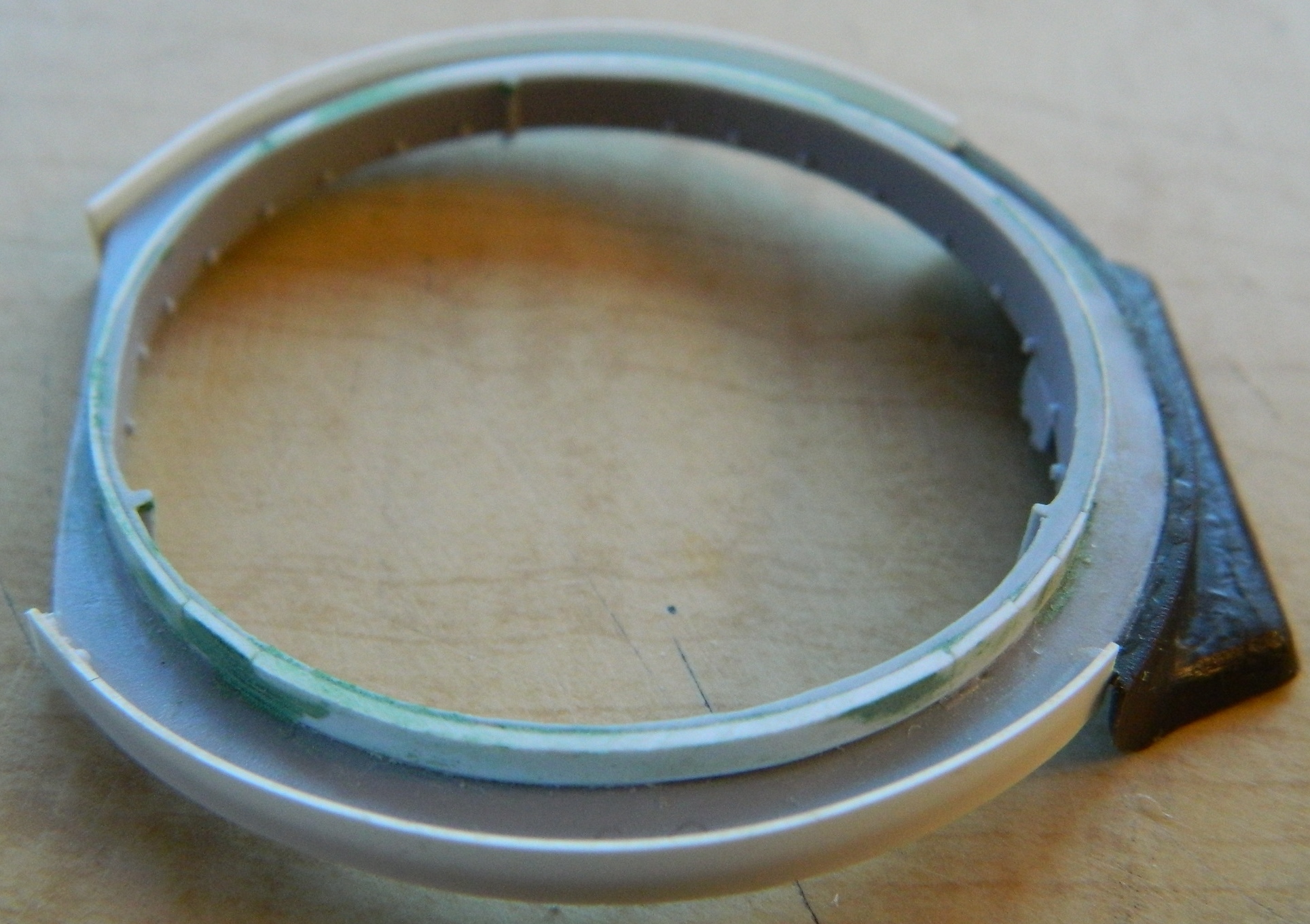
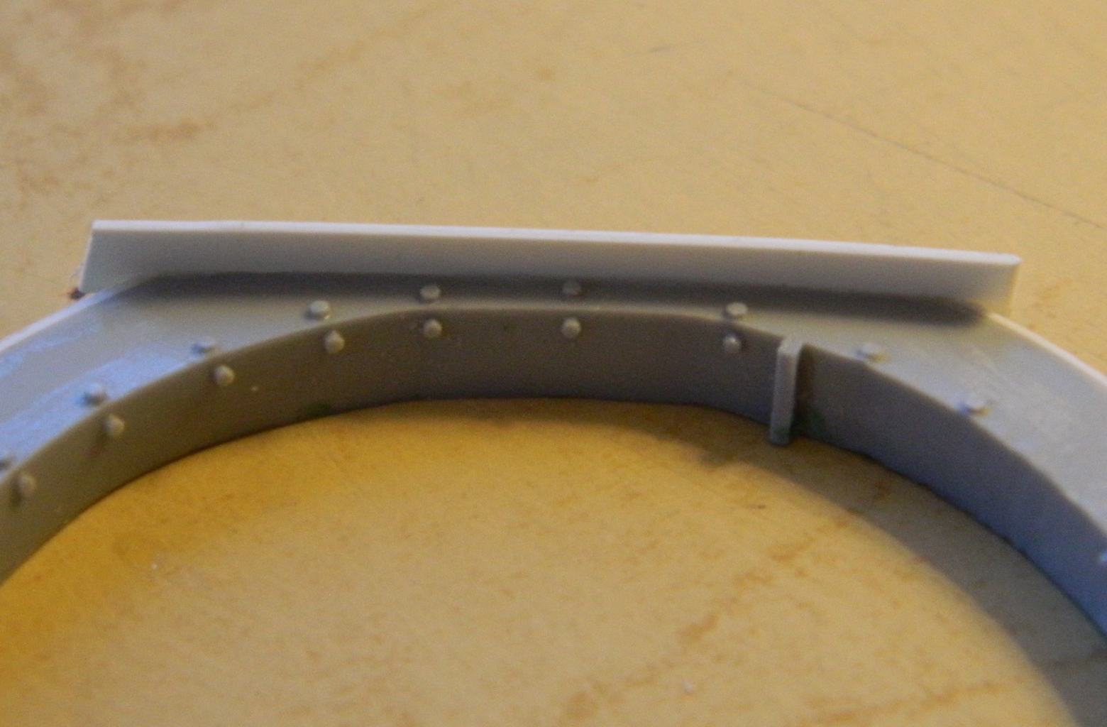
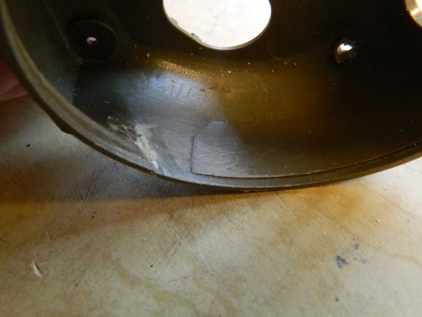
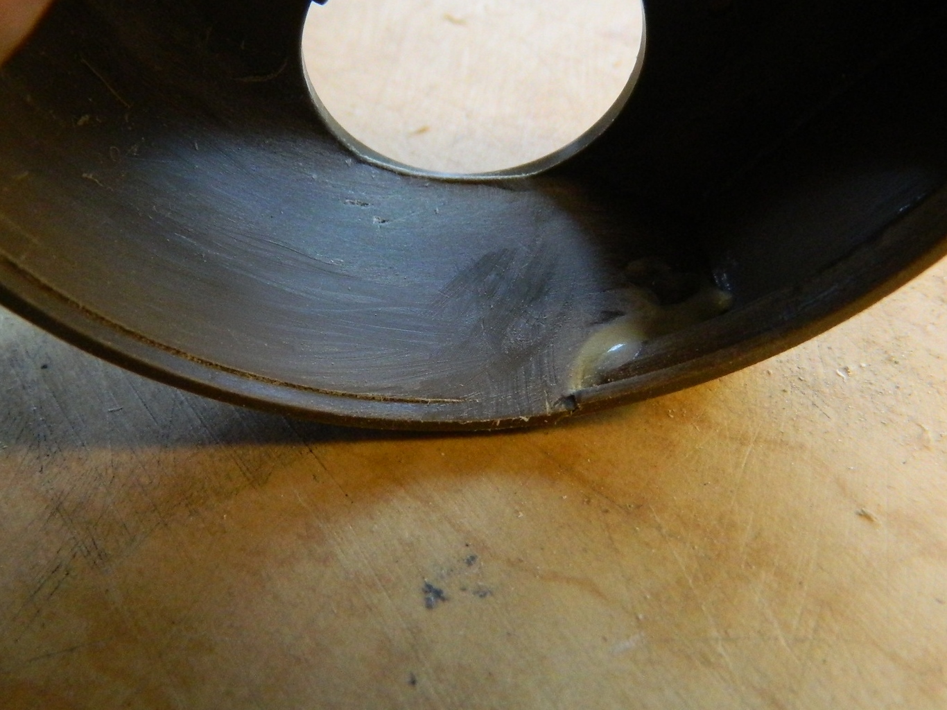
Not only should one always check fit, one should check often. Evidently the resin I’m using is very sensitive to heat, even the heat generated by warm hands (of which I have two). The photo on the left below shows that the curve of the “floor” (in quotes because the actual floor of the Allison P-51s is the top of the main fuel tanks) has flattened out. The part I’m holding (with my warm hand) over it is the side panel. The floor is supposed to follow the curve of that panel so I checked one of the side panels of the cockpit to make sure it was supposed to be curved that much…and it is. A quick session under hot water put the curve back that the floor is supposed to have:

I’ve decided to scratch-build an instrument panel instead of using the resin part. Any “detail” on the resin part is rudimentary and I want to kick that detail up. Since I don’t have quite all the gauge faces I’m going to need with the old Waldron set (pity they’re out of business), I ordered another set of gauge faces from Roll Model (I’m told they bought the rights to Waldron so it will be interesting to see what they have available).
Working Resin Aftermarket Sets
There are a few things to keep in mind when you’re using aftermarket detail sets…
The first is to check to see which model kit the particular set you’re interested in was built for. Sure, you can adapt a detail set to a different kit (if I can do it, so can you), and it will probably save you time over scratch-building the details. But you’ll probably (probably, not definitely) get a better fit if you’re working the kit that the person who did the masters worked from.
Second… Keep in mind that the person that did the masters the molds were taken from most likely did NOT use CAD/CAM to build the master(s) (though I’m sure it’s just a matter of time before 3D printers start being employed). There’s a talented person somewhere who scratch-built the masters using the kit (that I’m hoping you’re using) for dimensions and shape. Talent, as you’ve probably suspected by now, is a massive variable; some have more than others do. As a result, the degree of accurate fit to the resin parts is also going to be variable. Some sets are really works of art, others your 12 year old nephew could do better. Unfortunately until you have the set on hand, you can’t tell how good it’s going to be. Certain aftermarket suppliers have better (and deserved) reputations than others and as you go along you’ll develop your own internal database as to whose parts are worth the cost of acquisition and whose are not.
Third… CHECK YOUR REFERENCES. Check them frequently. Sometimes people get things wrong (yeah, ain’t that news…) and that includes the person who did the masters. In my limited experience, there’s a WIDE range of accuracy problems.
If you expect to buy an aftermarket set that will just drop into your model, you’re going to be very disappointed. There will be a lot of fitting and adapting to do. And don’t expect that the aftermarket set will include all the details you want. Aftermarket sets will save you tons of time scratch-building but my experience has been that they’re not complete and require me to add things…and sometimes remove things…from them to get what I’m after.
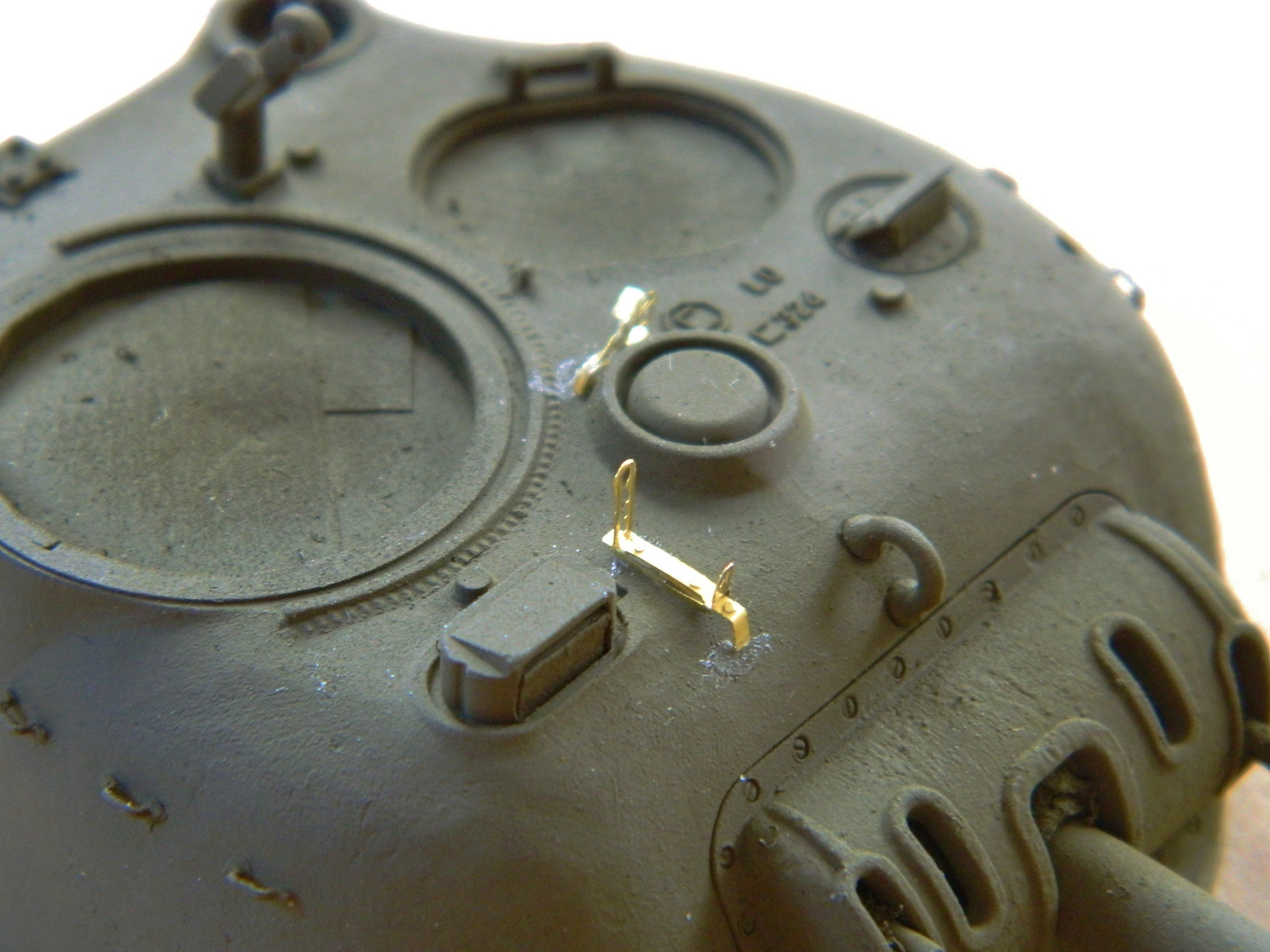
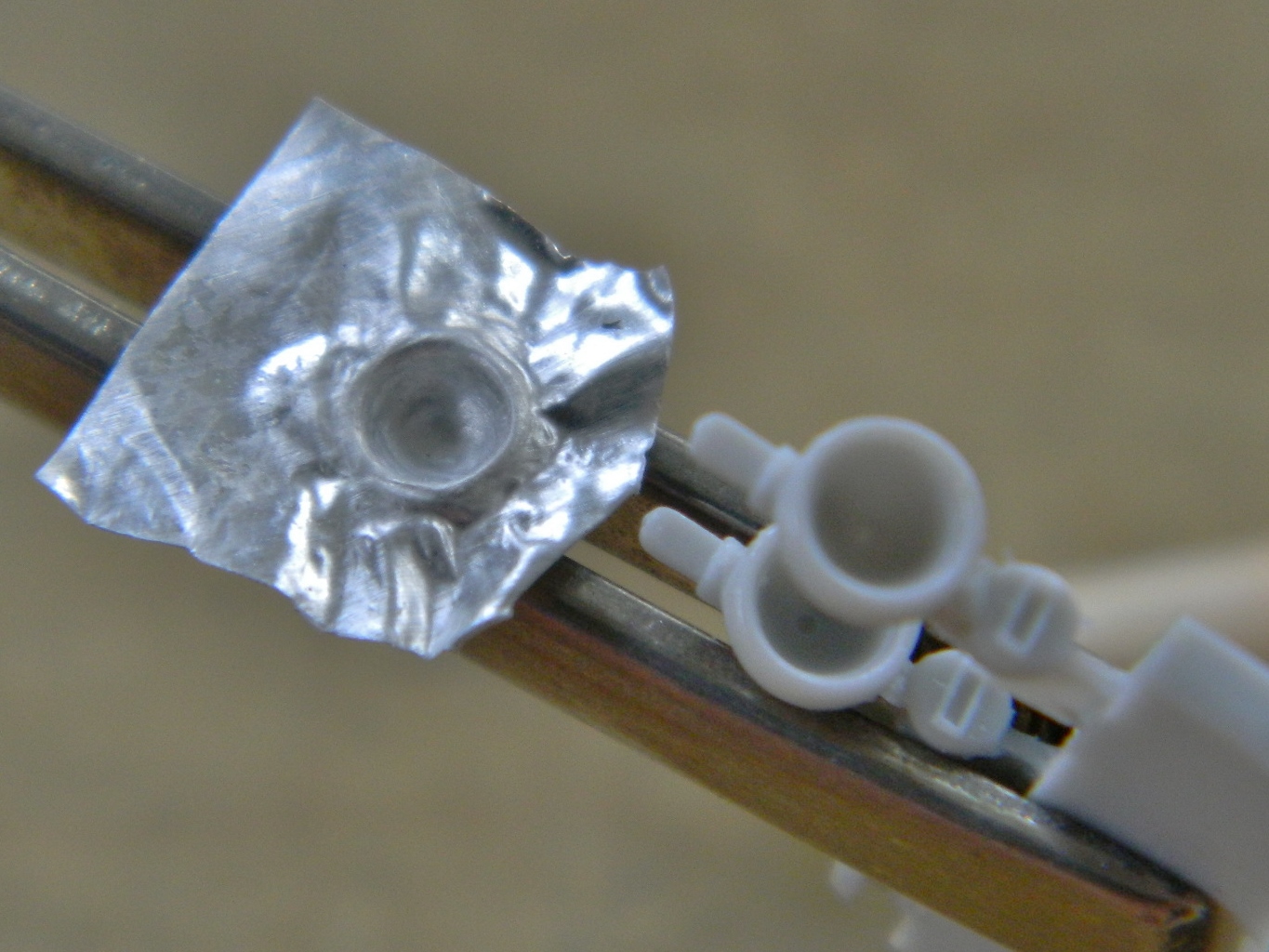
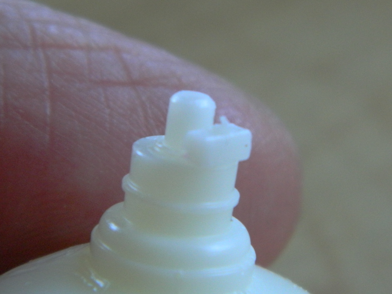
Resin parts are unaffected by styrene cement for reasons I hope are obvious…THEY AREN’T STYRENE, they’re resin. Depending on how “fine” the join is, you’ll need either epoxy or cynoacrylate glue – superglue – to do those tiny joins. The problem is that the tip of the superglue tube is NOT small enough and if you try to use it straight from the tube you’ll end up with a massive blob of glue that eradicates details. My method is to make a small puddle of glue on a piece of aluminum foil. Then I will dip something small into that puddle to transfer the glue to the area of the part(s) I want to marry.
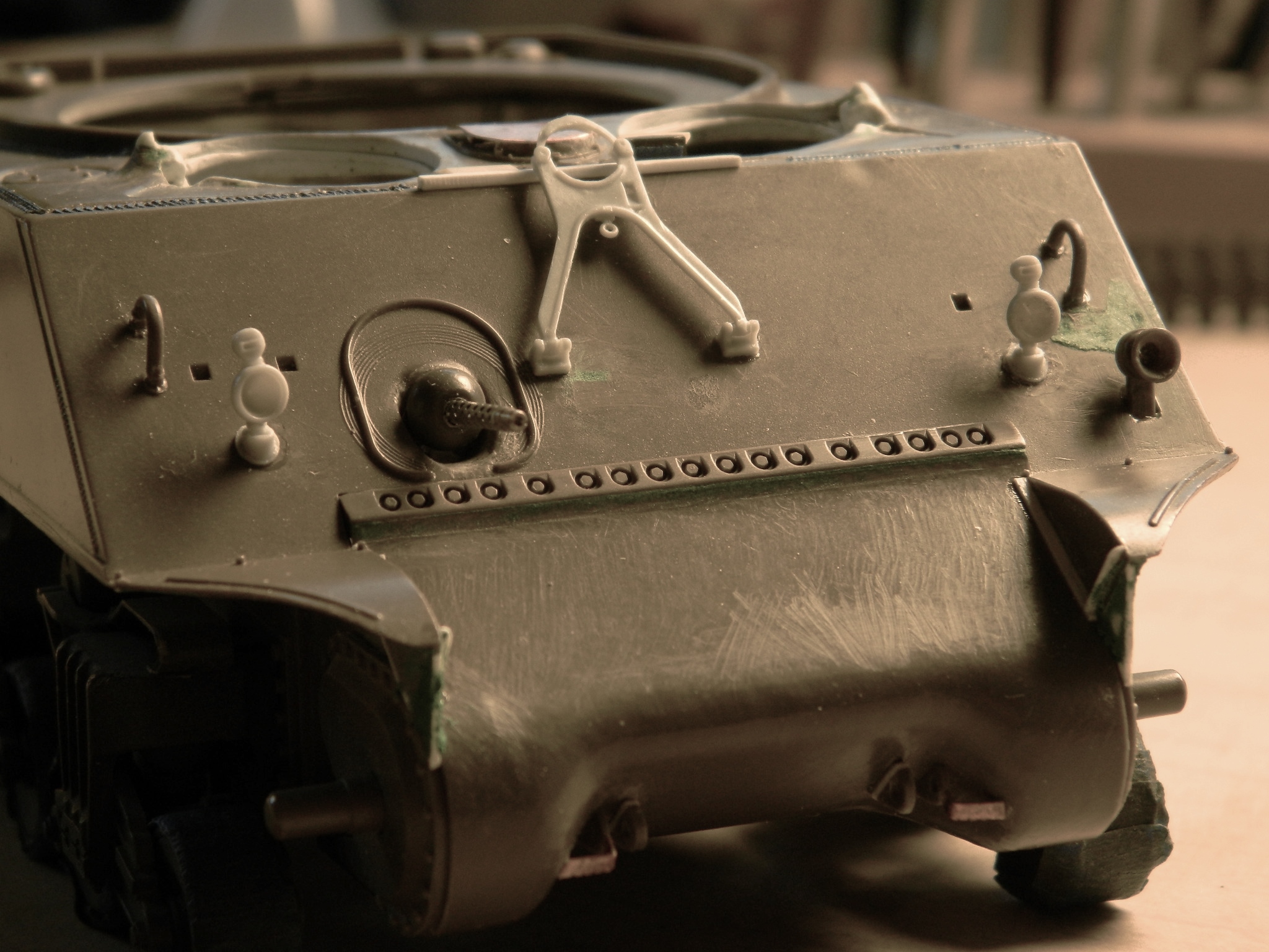
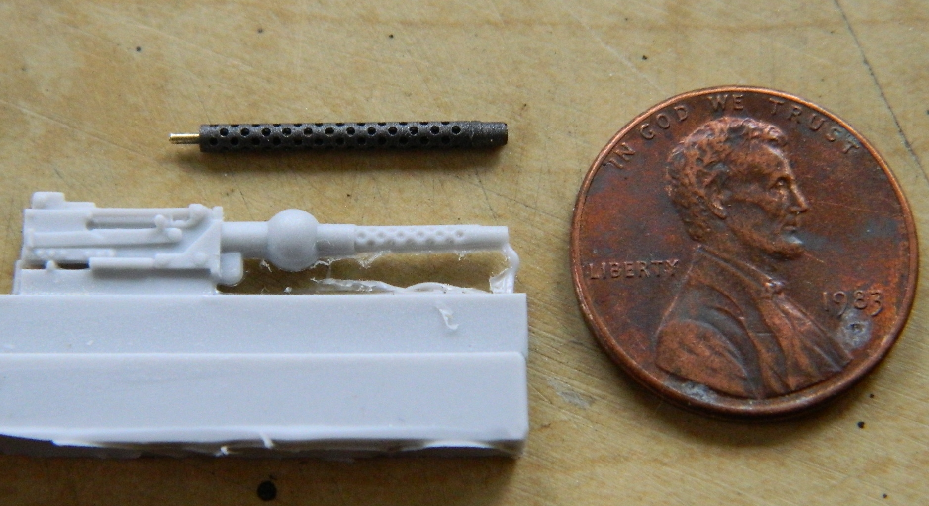
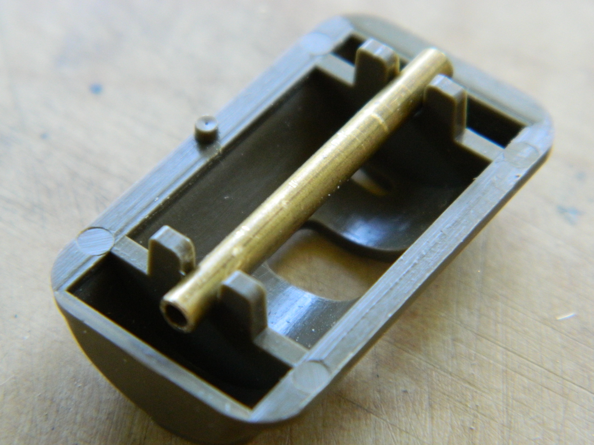
There’s a few ways I can do that. If it’s a SMALL part (like freakin’ tiny brackets mounted to the side of a tank’s turret that rucksacks and gear hang off of), I’ll use the tip of a needle or a straight pin to transfer the glue. I have fingers that are much larger than I want them to be sometimes so instead of wrestling with just the pin or needle, I’ve mounted them onto convenient-to-hold things like a wine cork (for the needle) or an old chopstick (for the pin). When I have two parts that have to be touching before being glued, Micro-Mark sells a handy glue applicator (it’s in the middle of the photo):
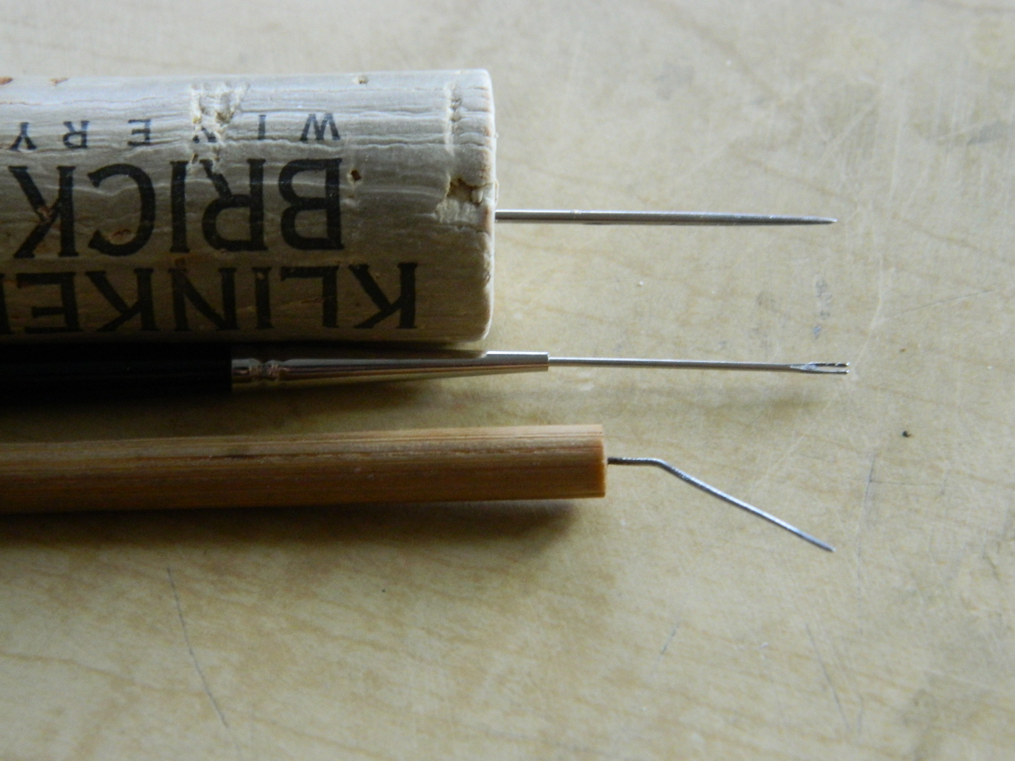
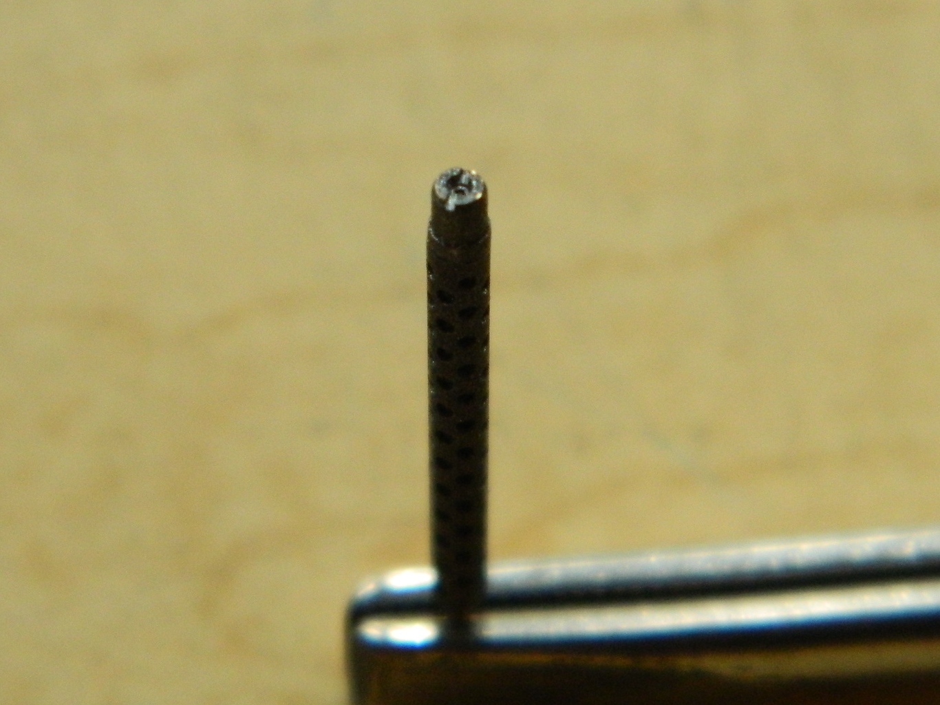
Okay, that applicator is nice. But once I was looking at it, it reminded me of something and it didn’t take me long to figure out what. It reminded me of the head of a needle that had had the tip of ground off. I checked Micro-Mark’s applicator against a needle and damned if I wasn’t correct. So. If you want a similar applicator (and having one like this is VERY SODDING NICE), make your own applicator. Grind the head of a needle off until you have an open-ended fork and then mount the needle into the handy…well…handle of your choice. And by making your own applicator(s), you can tailor the size of the applicator to the size of the job, only being limited by how small a needle you can get.
So these aftermarket sets will save you a lot of time. They will rarely just drop in and expect to add things that you’re going to want included.
Mustang – A Brief Overview
P51 Mustang! What a fighter. Just the name brings to mind George Preddy, Don Gentile, Bud Anderson, and John Landers…to name only a very few. But as it seems to be with many legends, the facts as they were are not the story that they became…
It all started with the Brits (as so much has). In 1940 they were having a rough go of things (which would get much worse shortly when France fell and they lost a LOT of equipment left behind at Dunkirk). They needed fighter aircraft desperately and in more numbers than they could produce. They approached the Curtiss corporation to see if they could get their hands on some P-40s, but Curtiss didn’t have the production capability to meet their contractual demands and the British demands. The Brits contacted North American Aviation (NAA) with the idea that NAA could build the P-40 under license from Curtiss. NAA had a counter-proposal. NAA wasn’t at all interested in producing a Curtiss product and suggested to the Brits that they could design a better fighter using the same engine that the P-40 was using (the Allison V12 liquid cooled V-1710). Legend has it that they promised the first prototype in 120 days and, though it’s a nice legend, it’s just a legend and that was never promised. Facts, as they often are, are more interesting…
I’m sure you’ve all heard of Eisenhower, Patton, and so on. Have you ever heard of 1st Lt. Benjamin Kelsey? Kelsey was an aeronautical engineer trained at M.I.T. and worked at Wright Patterson as the America’s chief fighter projects officer. To quote from P-51 Mustang in Detail and Scale, Volume 50 by Bert Kinsey (published by Squadron/Signal Publications):
On 4 May, 1940, when North American obtained release to sell the NA-73 [NAA’s internal designation for the new design] to the British [the British variant had different armament and exhaust tips and was called NAA-83], Kelsey had included the stipulation that two aircraft from the first production batch would be turned over to Wright Field for testing. This meant that the British would buy the U.S. Army two aircraft which it did not then have the funds to purchase for itself.
Kelsey was also aware of studies done on a new wing design, “laminar flow,” which decreased drag substantially by moving the thickest portion of the wing from the front where conventional design had placed it more towards the rear. Curtiss had also been ordered to turn over design studies that included a new design for a belly scoop for the radiator, also moving it back from the nose, where it produced drag, more rearwards towards the middle of the aircraft. (How much of Curtiss’ design studies were used seems to be up for debate and varies by who is asked.)
102 days after the contract was signed, NA-73 was rolled out, complete except for engine. When the 1120 hp V12 showed up a couple of weeks later, engine and taxi tests started. The first of what would be called the P-51 Mustang (named by the Brits, BTW) took to the air on October 26, 1940.
Another part of the Mustang legend revolves around that Allison engine. Legend has it that the Brits really liked the Mustang’s low and mid altitude performance but the engine ran out of beans at about 15,000 feet. The Allison engine had a single-stage supercharger and didn’t produce its rated 1120 hp above 15,000 feet, so somebody decided to put the Merlin V12, with a two-stage supercharger that the Spitfire used, in a P51…and the legend was born.
Not quite. Well, not at all. The Brits wanted the P-40 which was known to be a low and mid altitude fighter. Engineers, the most clever of clever monkeys, also knew that any air-frame that used an engine with a single-stage supercharger would be a low to mid altitude aircraft. The fact that two air-frames of the original production batch of the P-51, ordered even before the first flight of an XP-51 (which is what the Army called NA-73), had been set aside to be fitted with the Merlin engine (being built under license by Packard) showed that engineers were well aware of the Allison’s performance capabilities and were going to “fix” that by using an engine with a two-stage supercharger.
Something else not widely known was that at 10-12,000 feet, Mustangs with the Allison engine were faster than Mustangs with the Packard/Merlin engine.
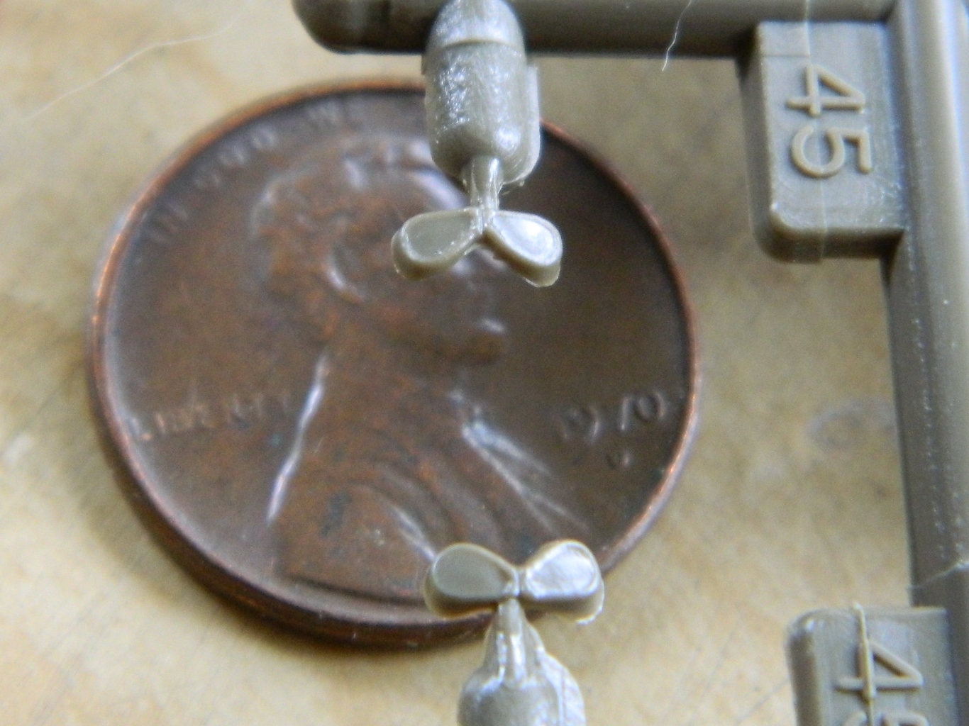
Once the Packard/Merlin engine was installed, the Mustang was given the nomenclature P-51B. The radiator scoop was redesigned, making it simpler to build and operate as well as improving cooling (and the design of the scoop actually used the escaping hot air, heated by cooling the radiator, as additional thrust, which overcame any drag the newer scoop created), the carburetor intake was moved from above the engine to below it, and the three blade Curtiss Electric prop was replaced by a Hamilton Standard four blade cuffed prop.
As Kinsey states, both aircraft were very good at the altitudes they were designed to operate at.
One thing that pilots didn’t like about the early Mustangs was the canopy. The canopy opened in two places; the top was hinged at the right and opened to the right and the left side was hinged at the bottom and opened to the left, and when it was closed did not offer very much room. As if that wasn’t annoying enough, it wasn’t easy to see out of and bloody impossible to see rearward very well. B variants were fitted in the field with what’s been termed the “Malcolm” canopy. The Malcolm canopy, very similar to the canopy of the Spitfire, was a blown canopy of a single sheet of plexiglass (“perspex” as it was called in the ’40s) that did away with both sides and the top as well as all the framing for them, opening by sliding to the rear and making getting in and out of the cockpit much easier (a welcome feature to a pilot who had to get out in a hurry). Some of the B variants were fitted with it (there weren’t really a lot of the blown canopy to go around), but the real improvement in view came with the introduction of the bubble canopy. It had been tested (along with other improvements) on a late-production P-51B and introduced into production with the advent of the P-51D.
Shortly after the P-51B was deployed, it was given something else that turned the aircraft into a real game-changer. An 85 gallon fuel tank was installed in the fuselage behind the pilot.
An interesting thing about Mustangs and fuel…
THE definitive Mustang was the P-51D. With 184 gallons of fuel inside the wing’s fuel tanks, and 85 gallons of the fuselage tank, it could also carry up to 110 gallons in each drop tank. With a full fuel load of 489 gallons, I’ve read that the P-51D was 50% over maximum designed weight. (This may be part of The Legend, though…do your own research.) Carrying that much fuel did bad things to the carefully calculated center of gravity. When initiating roll maneuvers with a full load of fuel, it was nigh onto impossible to keep the Mustang from flipping over onto its back. I’ve read that recovery of stable flight was also nigh onto impossible. In practice, the fuselage tank was limited to 60 gallons, and even with less weight behind the pilot, roll maneuvers had to be initiated with a fair amount of forward stick to maintain control of where the aircraft went (and how it went there).
The first P-51, the Mustang Mk I, was built for the British and was armed with four .50 caliber (two of which were mounted in the “cheeks” of the engine cowling) and four .303 caliber machine guns. The first 51 for US use was armed with four 20mm Hispano Suiza cannons. The 51A and B used four Browning M2 .50 caliber machine guns, two in each wing, and the P-51D had six, three in each wing.
Three different types of belly scoops, two different designs of wings, three different styles of canopies… Oh. Did you know that there was a dive bombing version of the P-51? It was called the A-36…and it was armed with six .50 caliber machine guns (two in each wing, two in the nose in the same manner that British Mustang was) and had dive brakes above and below the wings.
Pretty legendary, huh?*
A36

Mustang MkI
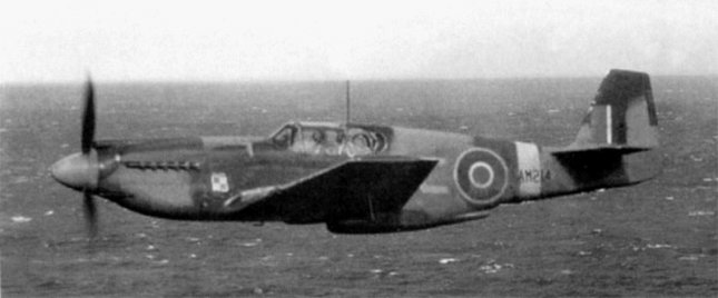
P-51

P-51A (With a P-40 in background; modern photo)

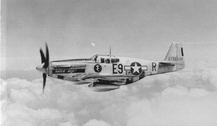
P-51B
P-51B (Malcolm canopy; modern photo)

P-51D

*Another bit of the Mustang legend that’s not exactly as told…
The Legend has it that with the addition of the fuselage fuel tank to the P-51B, the US now had a fighter that could escort bombers all the way to and from their target. Well, the US already had a fighter that could do that with the P-38 Lightning (a project also initiated by 1st Lt. Ben Kelsey). So why wasn’t the P-38 used for bomber escort? General Ira Eaker didn’t believe the bombers needed fighter escort and that their defensive armament would be enough to protect them. And in spite of the high rate of bomber losses, Eaker didn’t change his mind (he sent the P-38s in England to North Africa). I wonder how much that decision affected his being relieved of command…
In order of production, this is how many Allison-engined Mustangs were built:
US designation XP-51; British designation Mustang I; 4 .50 cal. machine guns, 4 .303 machine guns; 620 built (2 taken by US for evaluation)
US designation P-51; British designation Mustang IA; 4 20mm cannons; 150 built (93 to British, 55 to USAAF, 2 for Merlin engine tests as XP-51B)
US designation A-36; no British designation; 6 .50 caliber machine guns; 500 built (one was shipped to England for evaluation, none were ordered)
US designation P-51A; British designation Mustang II; 4 .50 caliber machine guns; 310 (50 to England)
Pressure Casting
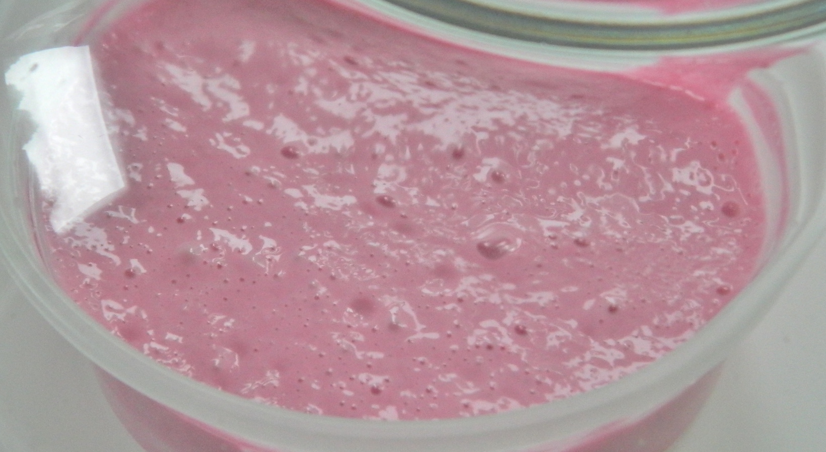
Degassing the silicone molding rubber worked great, so I thought it would be equally great degassing the casting resin. Well…no.
Degassing the mixed resin turned the compound into a froth that quickly overflowed the pour cup and made a mess inside the vacuum chamber; I was just lucky I’d put a paper plate down under the cup! I mixed another batch of resin in a larger cup and degassed it. More froth and it was quickly obvious that the larger pouring cup wasn’t large enough. Rather than let it overflow again, I played with the valve I use to release the vacuum, cracking it just enough to keep the froth inside the container…barely. The resin has a 20 minute pot life, so I degassed it for about 7 minutes, poured it into the molds, and degassed again for another 10 minutes, playing with the valve again to keep it from frothing entirely out of the molds.
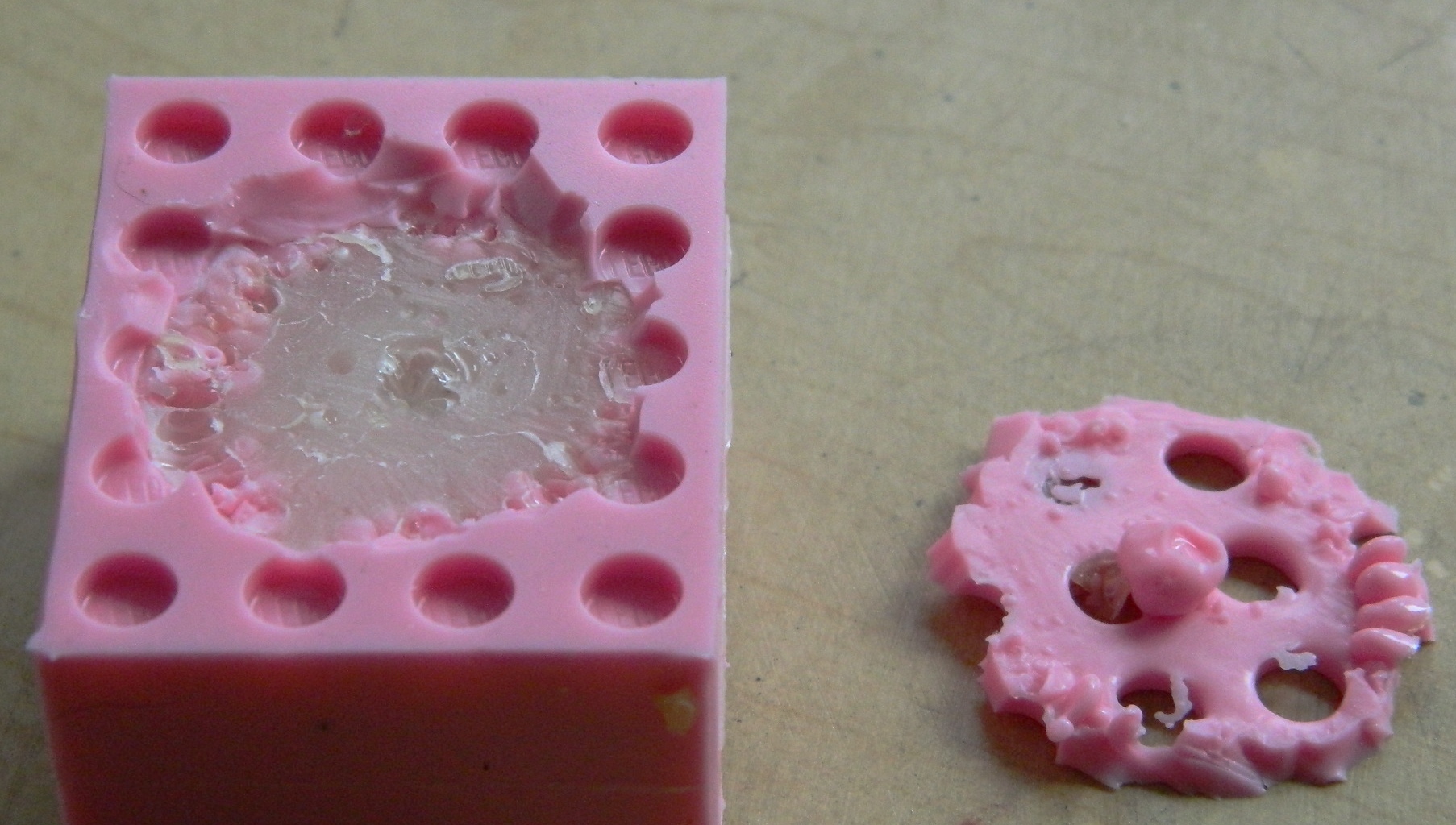
24 hours later I demolded the parts and was quite taken aback with how many bubbles were in the castings; enough so that the castings got tossed.
Hmmm…back to the Internet and more research. That’s when I heard about pressure casting. Instead of degassing to get rid of bubbles, the resin-filled molds are exposed to pressure. A pressure pot is used for application of liquids, most often paint, using a spray gun. With some minor modifications, it can also be used to pressure cast resins.
Pressure pots can be expensive. Once again, Harbor Freight had something reasonably priced that looked like it would do the job; their item number is 66839 and purchase of it will get you one of these:
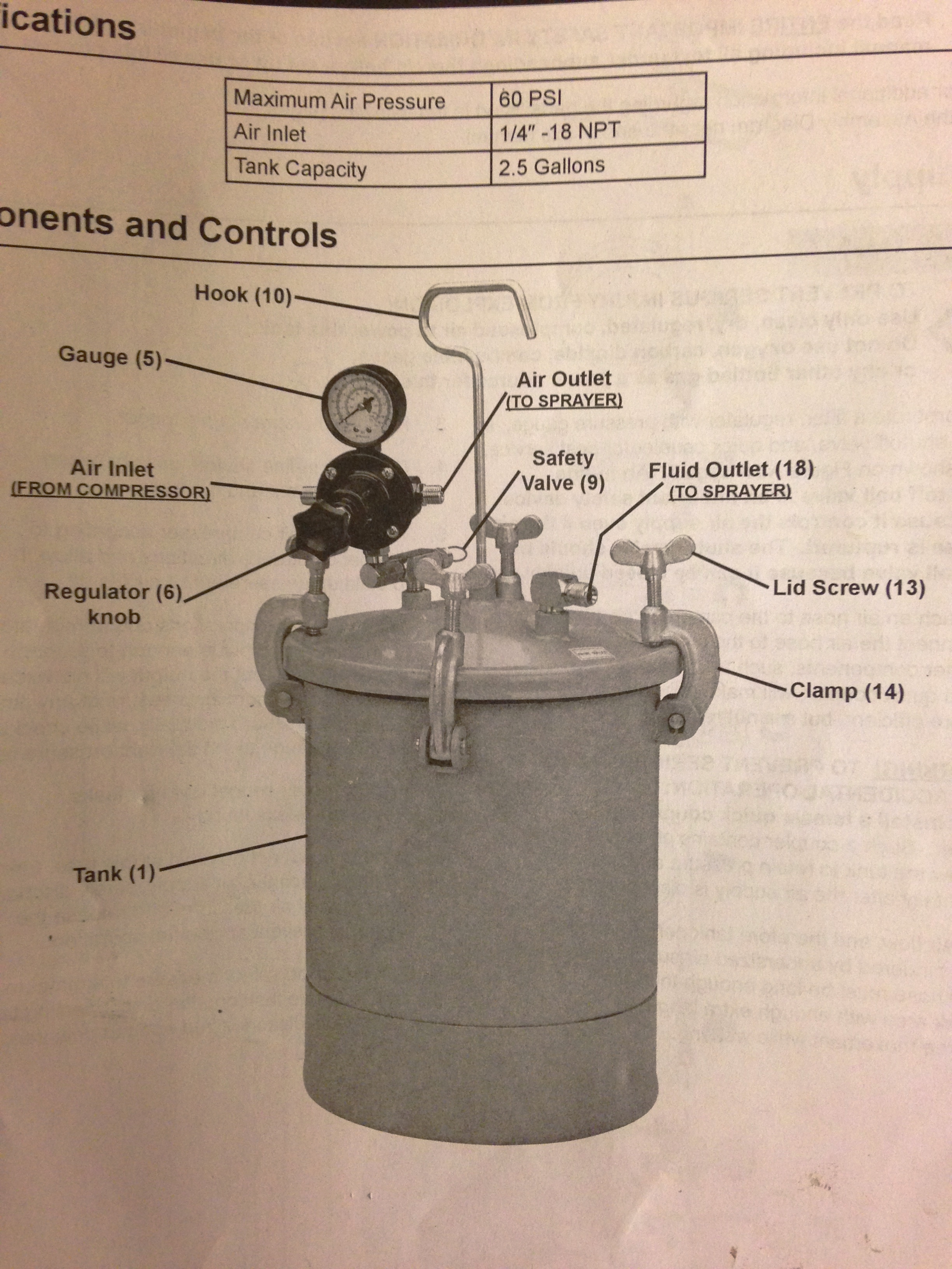
It’s a 2.5 gallon unit that’s rated for a maximum pressure of 60 psi.
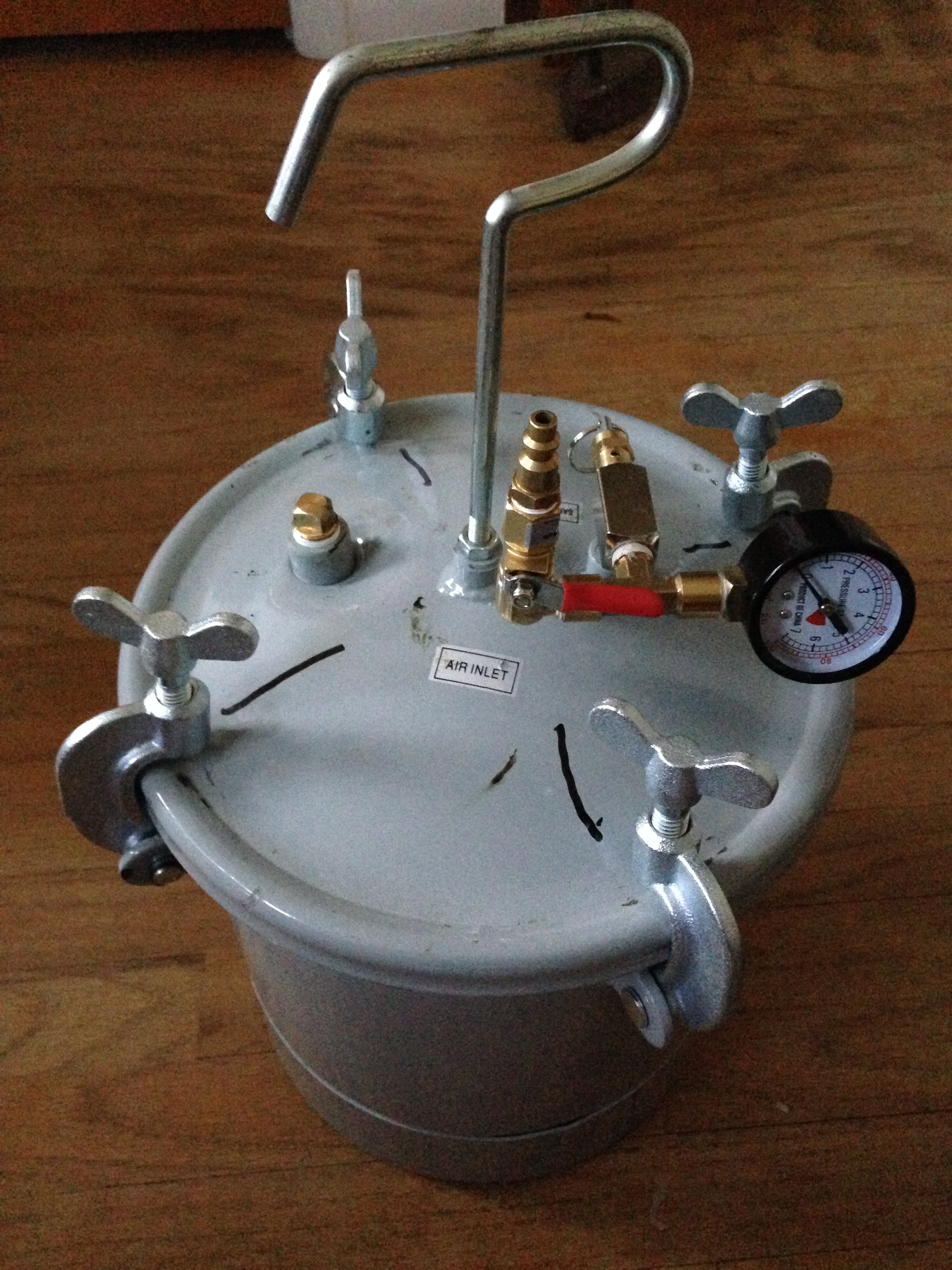
Since I’m not going to be spraying anything, there were some parts to remove. The siphon tube inside the lid screws out easily and a 1/2″ NPT plug plugs the hole. I don’t need the pressure regulator that’s supplied. Instead I added a brass T-fitting threaded 1/4″ NPT. I added a 90 degree elbow to one end of the T, then a valve, and then a hose coupler to the valve. To the other end of the T I added the supplied pressure gauge. To keep things from leaking, all fittings were sealed using Teflon tape intended for that purpose:
Before I ran a casting through it, I wanted to test it first. I fired up my compressor and adjusted the regulator to 50 psi. With the valve on the pressure pot’s top closed, the hose got attached to the coupler. Per instructions (yes…I read them), I put the lid in place (I ended up adding alignment marks to the lid) and tightened the clamping screws hand tight and then slowly opened the valve. Nothing hissed or exploded but the safety valve let go at about 30 psi. I increased the pressure coming from the compressor’s regulator to 60 psi and adjusted the release valve on the pressure pot until it let go (that’s done by tightening the collar by the release ring if you need more pressure to make it pop, loosening it if you need less pressure). I closed the valve, removed the hose, and bled off the pressure coming from the compressor before readjusting the regulator back to 50 psi and hooked things back up and applied pressure. Once fully pressurized, I closed the valve, removed the hose, and brought the pot inside to see how many pounds of pressure it would lose over an hour’s time, which turned out to be about 14 psi/hour, so that meant when I used it to cast I would leave the pot connected to the compressor overnight making sure the compressor stayed turned on.
That’s what I did when I ran the first set of molds through the pressure casting process. (Put something flat on the bottom inside the pot because it’s dished and trying to get several molds to sit flat would be impossible without it.) I let the pot sit in the garage connected to the compressor overnight and under pressure. When I demolded the parts 99% of the bubbles were gone. Well, not gone but compressed so small that they can’t be seen…which is the intent of pressure casting.
Good enough!
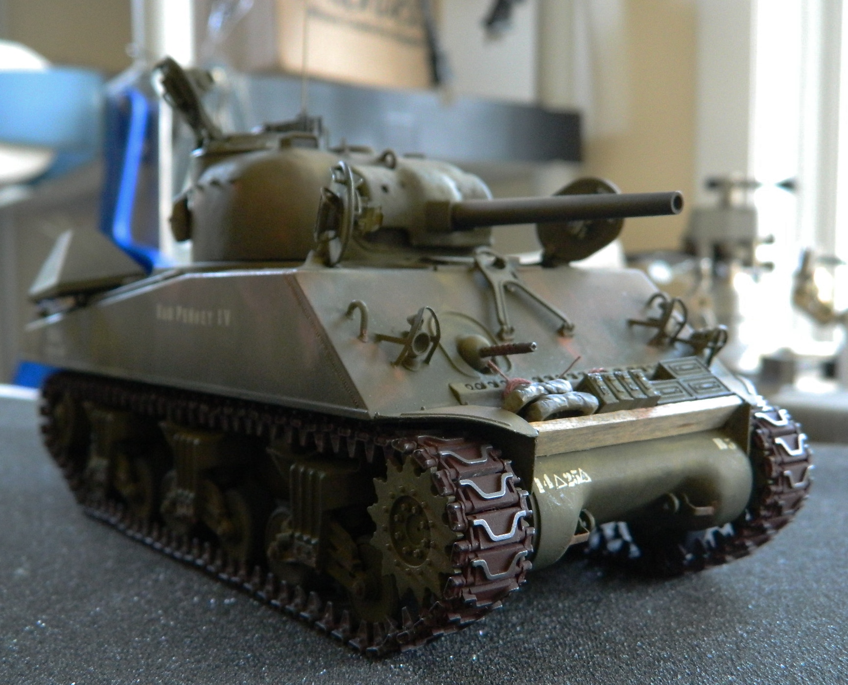
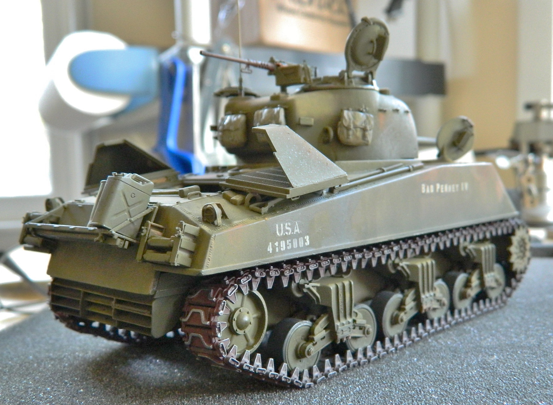
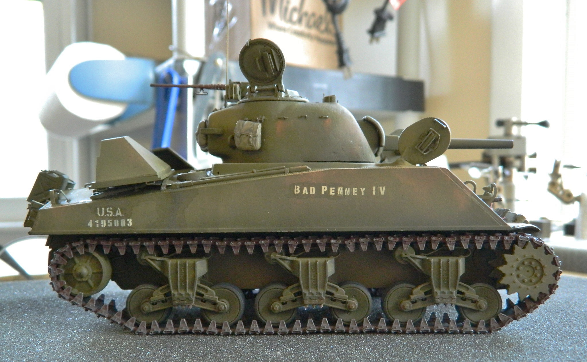
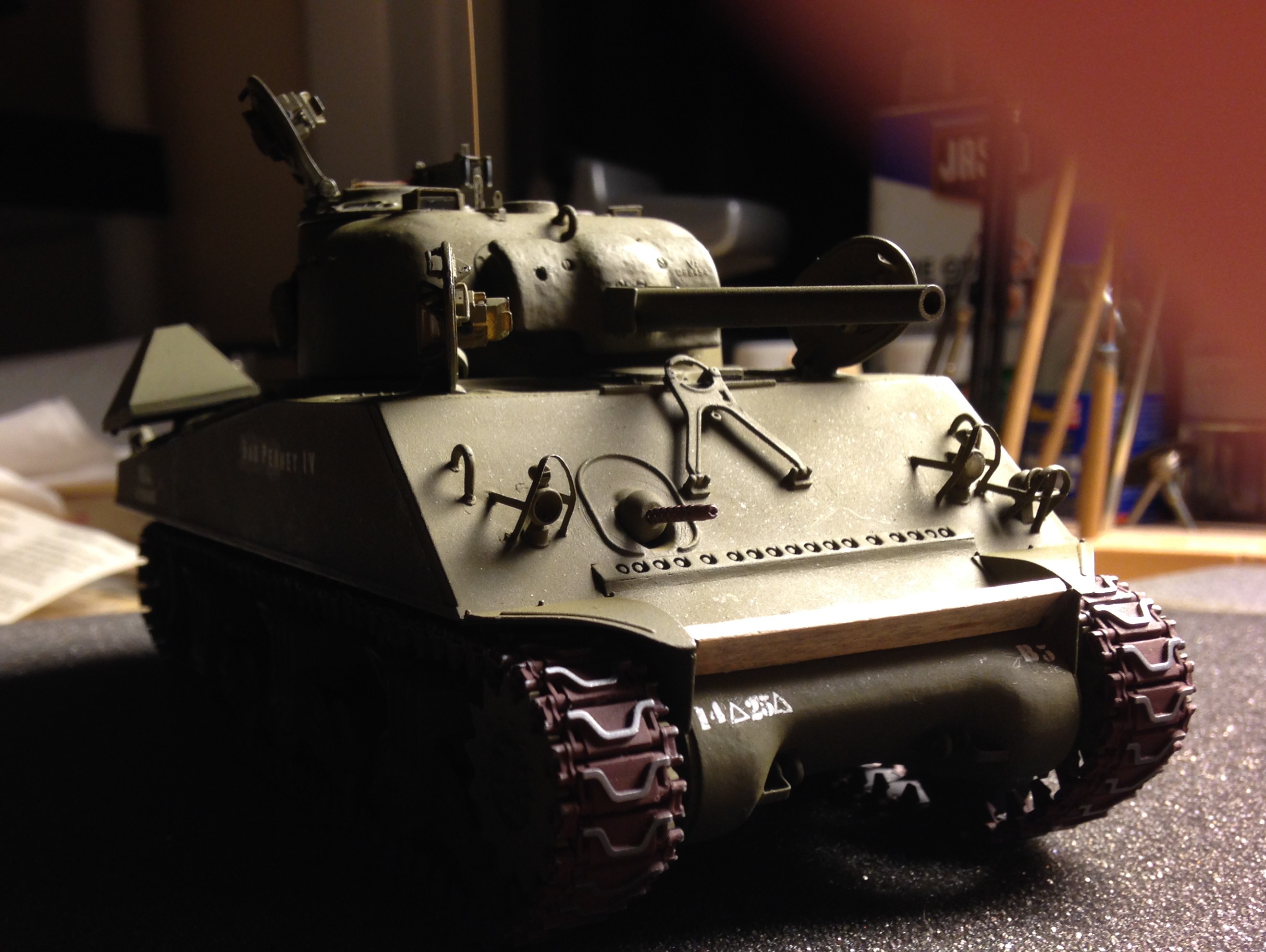
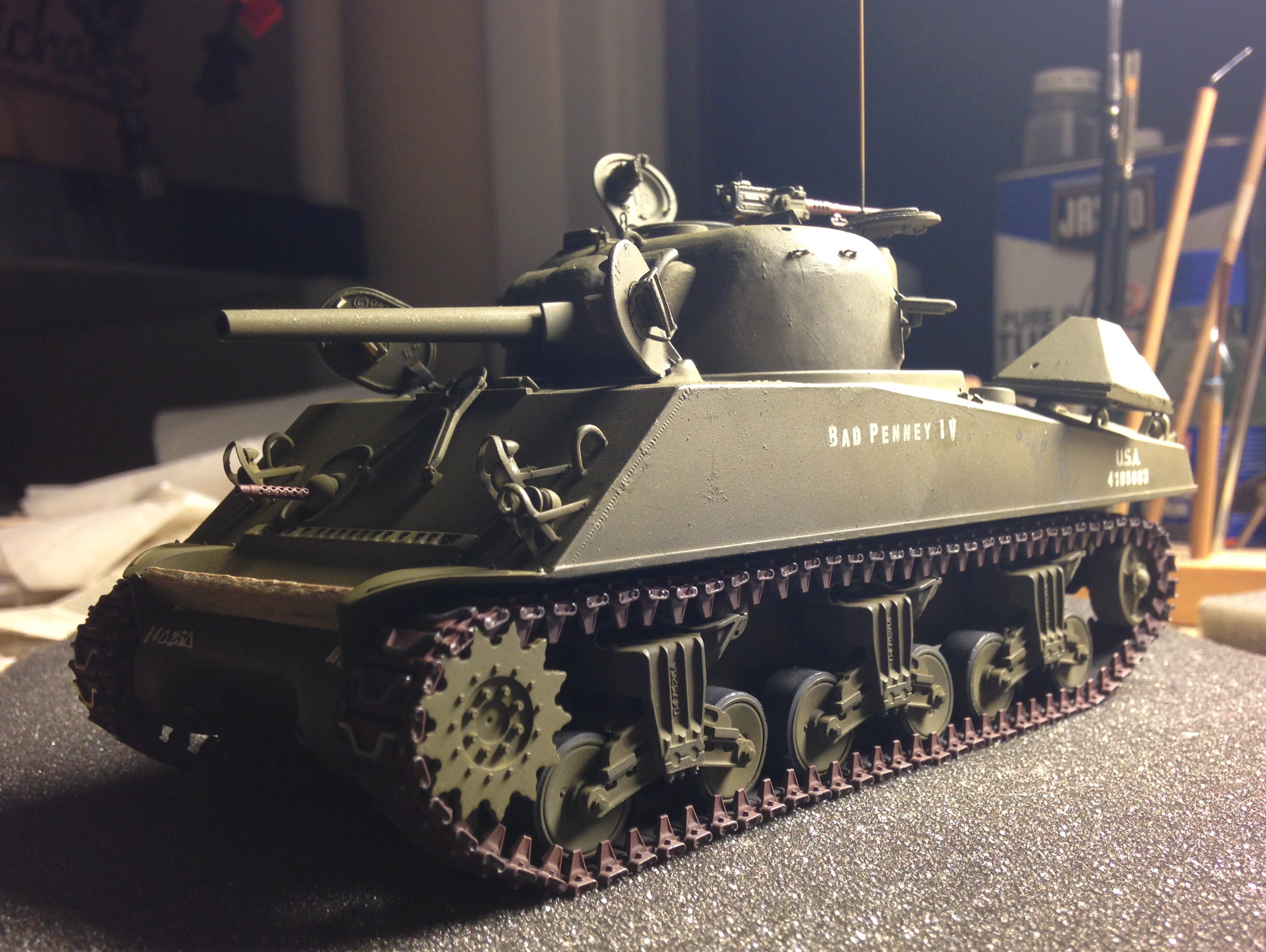
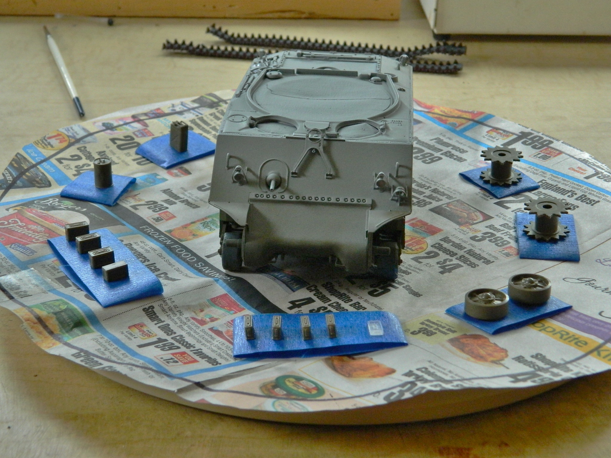
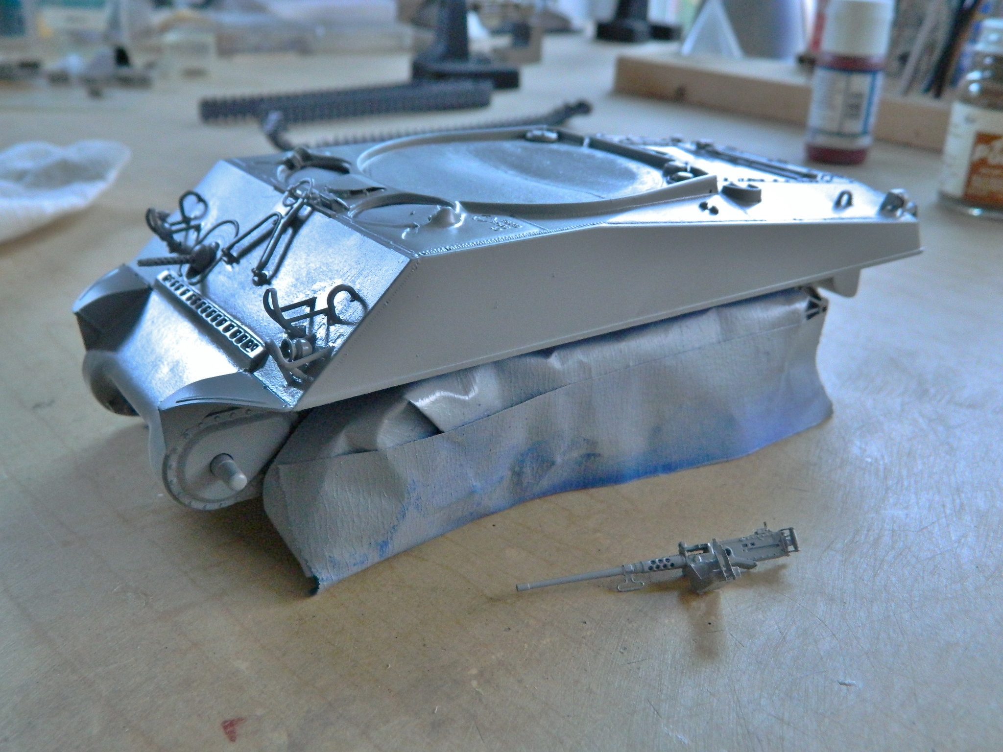
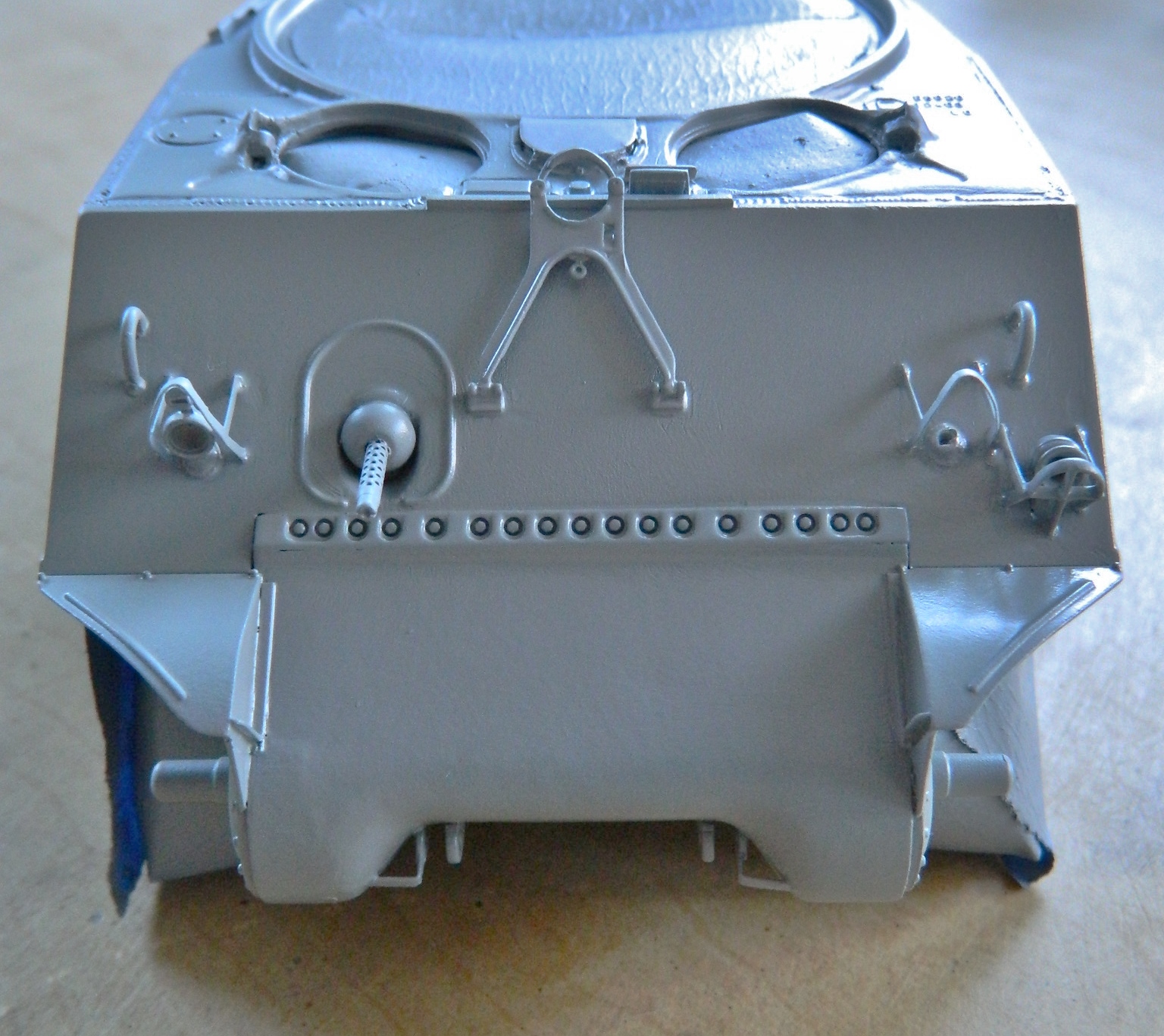
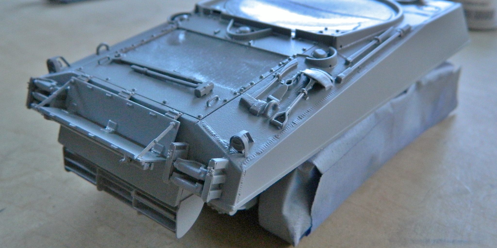
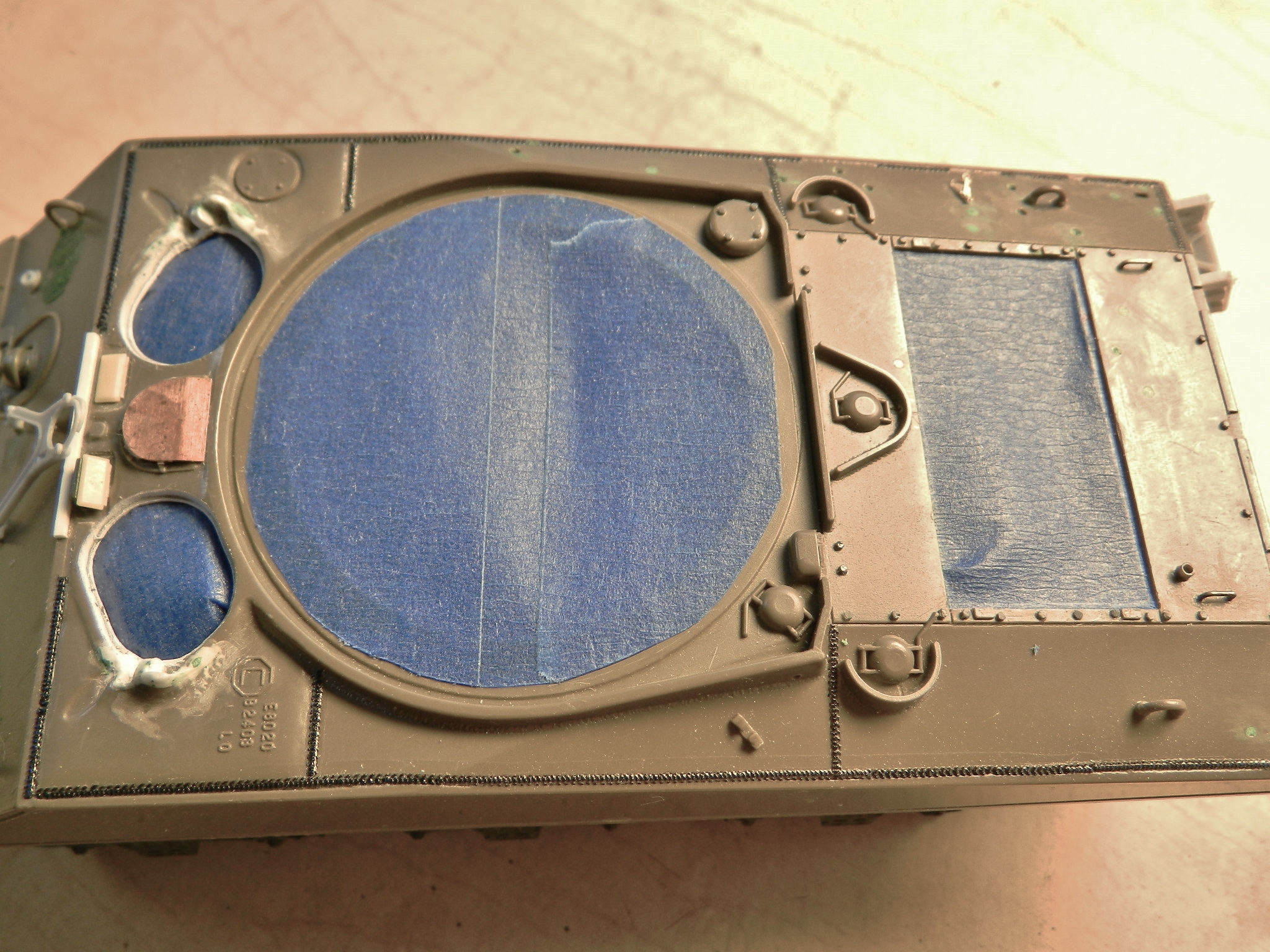
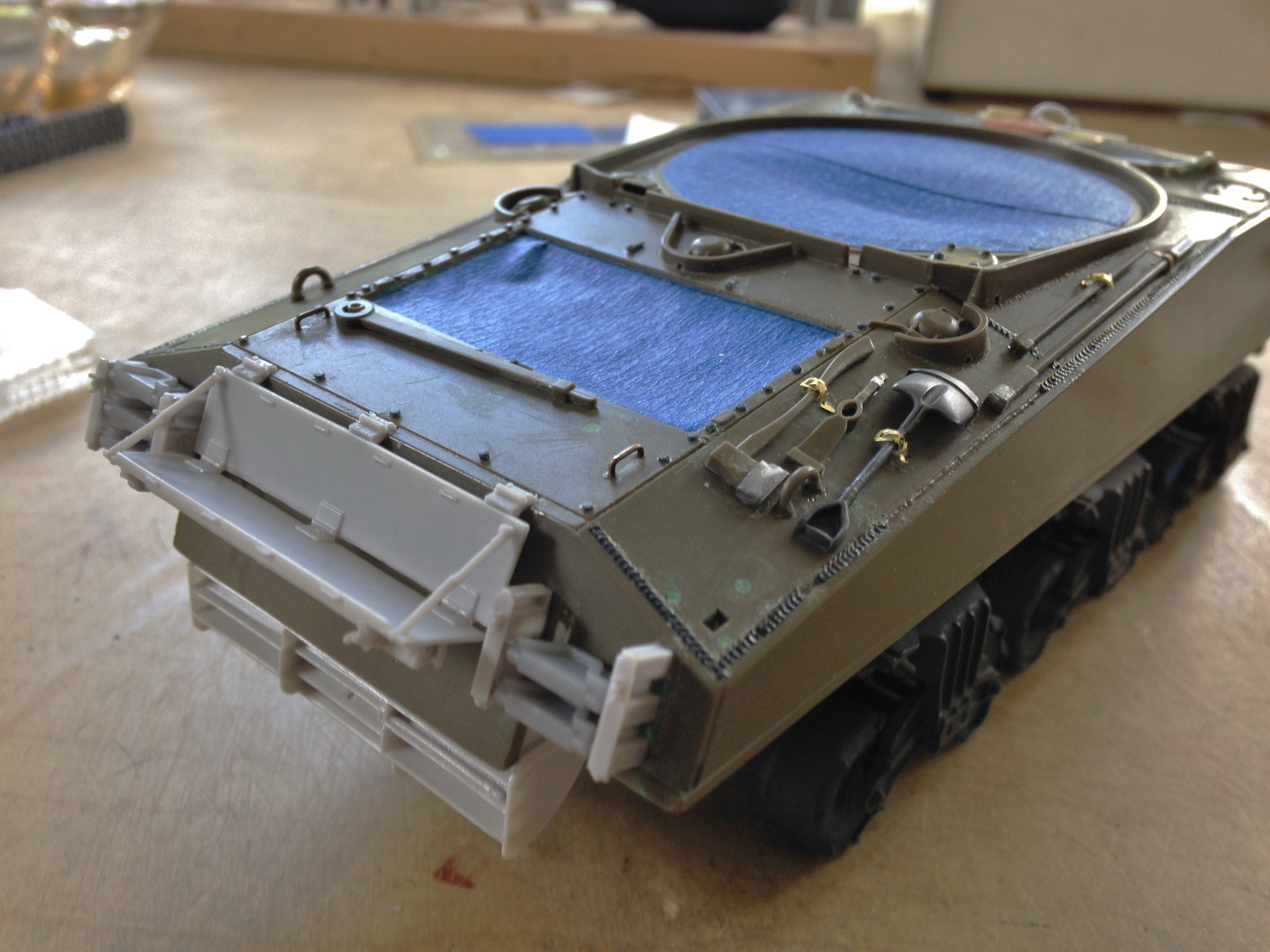
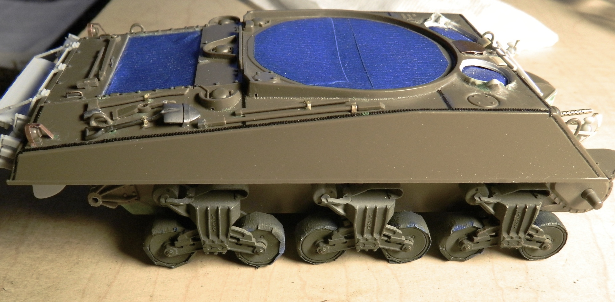
M4A3 (Tamiya) Build #29 – Final Details added and Completion
One last thing I want to do is to add rolled up tarps. I looked at AM resin sets but that’s just what they look like…resin. I decided to try something I’d read about. Taking paper towels or tissues (without texture), cut them to size and fold and roll them, and then soak them in diluted white glue. Tie them as desired, drape over the vehicle as desired, then set them aside to dry. Once thoroughly dry, paint and install. I placed plastic wrap between the soggy tissues and the model and draped as desired:
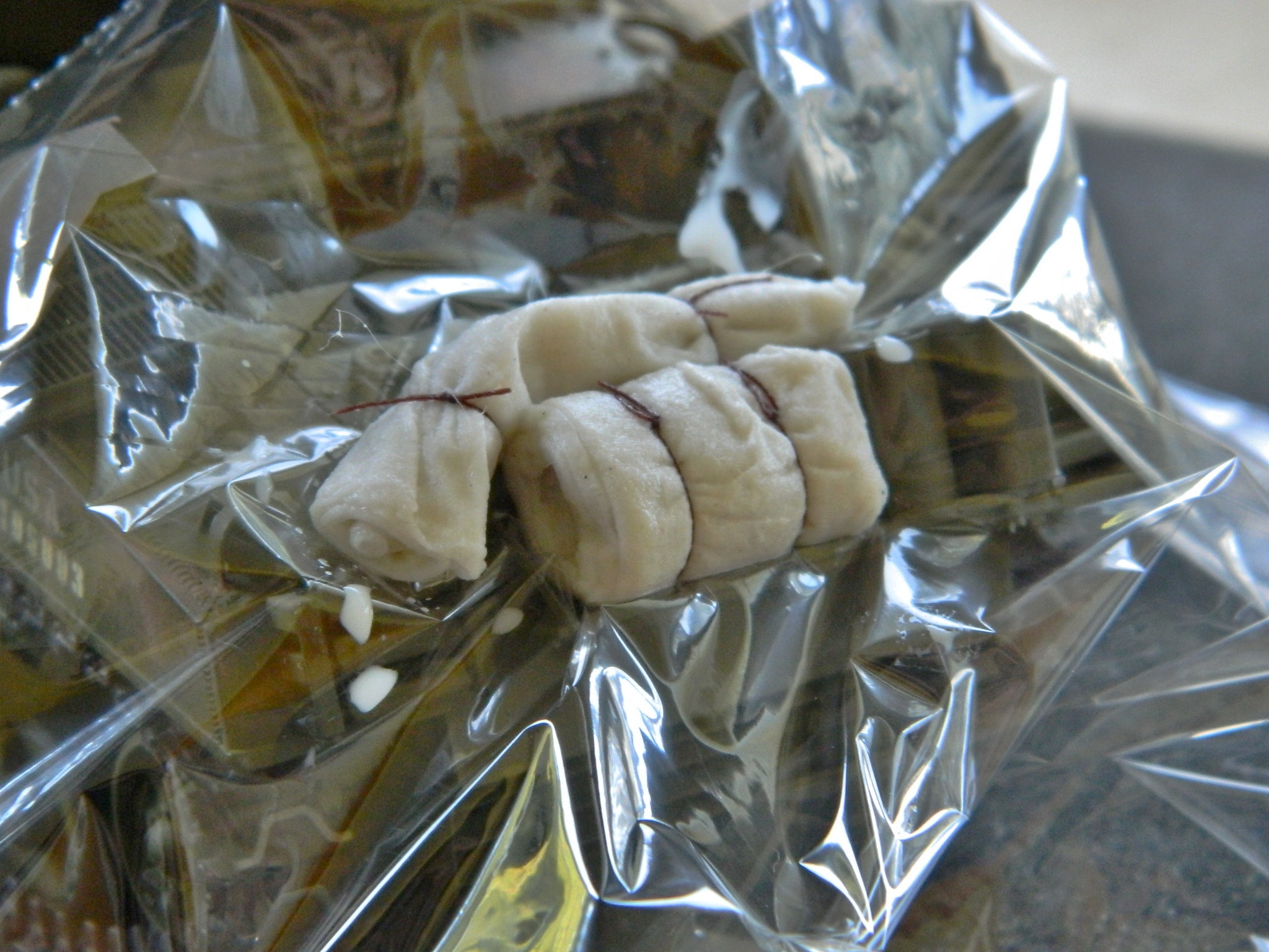
It took a couple of days for them to dry completely, but once dried they were painted, pastels added, and then the rope was also put on that would have held things in place:


The pastels came out for dusting things up a bit and I added more fuel spills…and DONE:

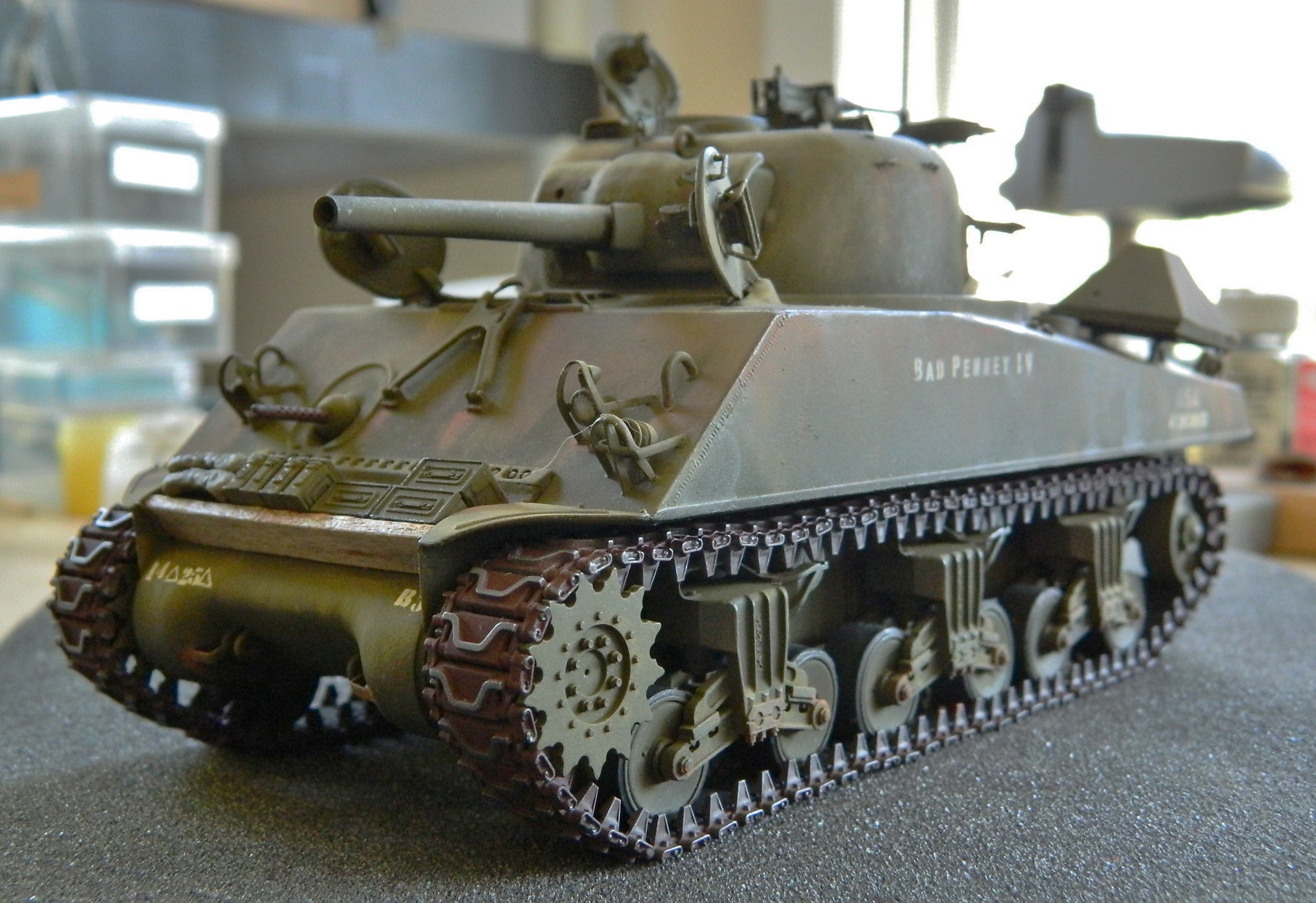

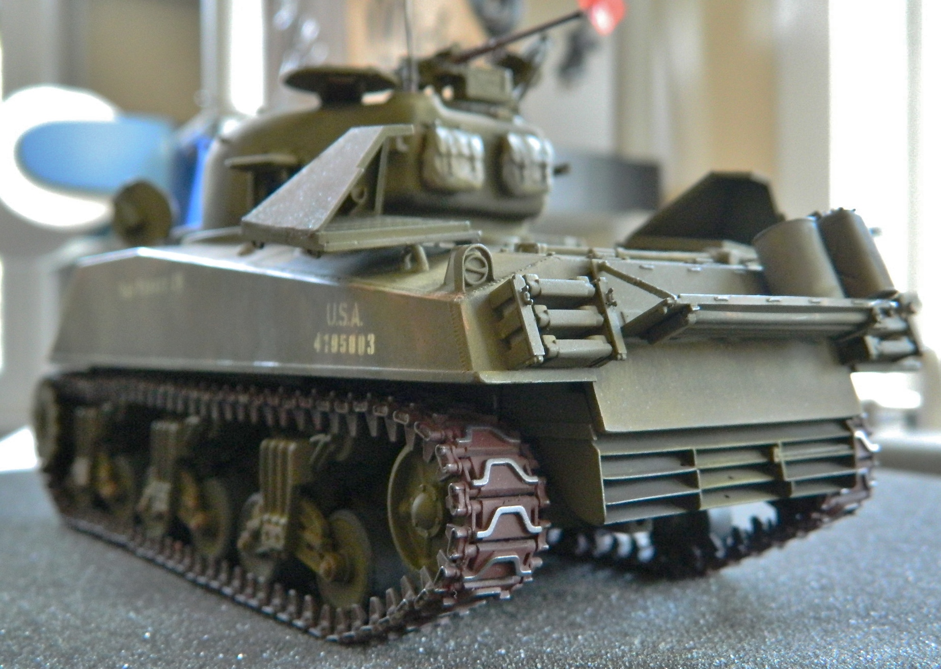


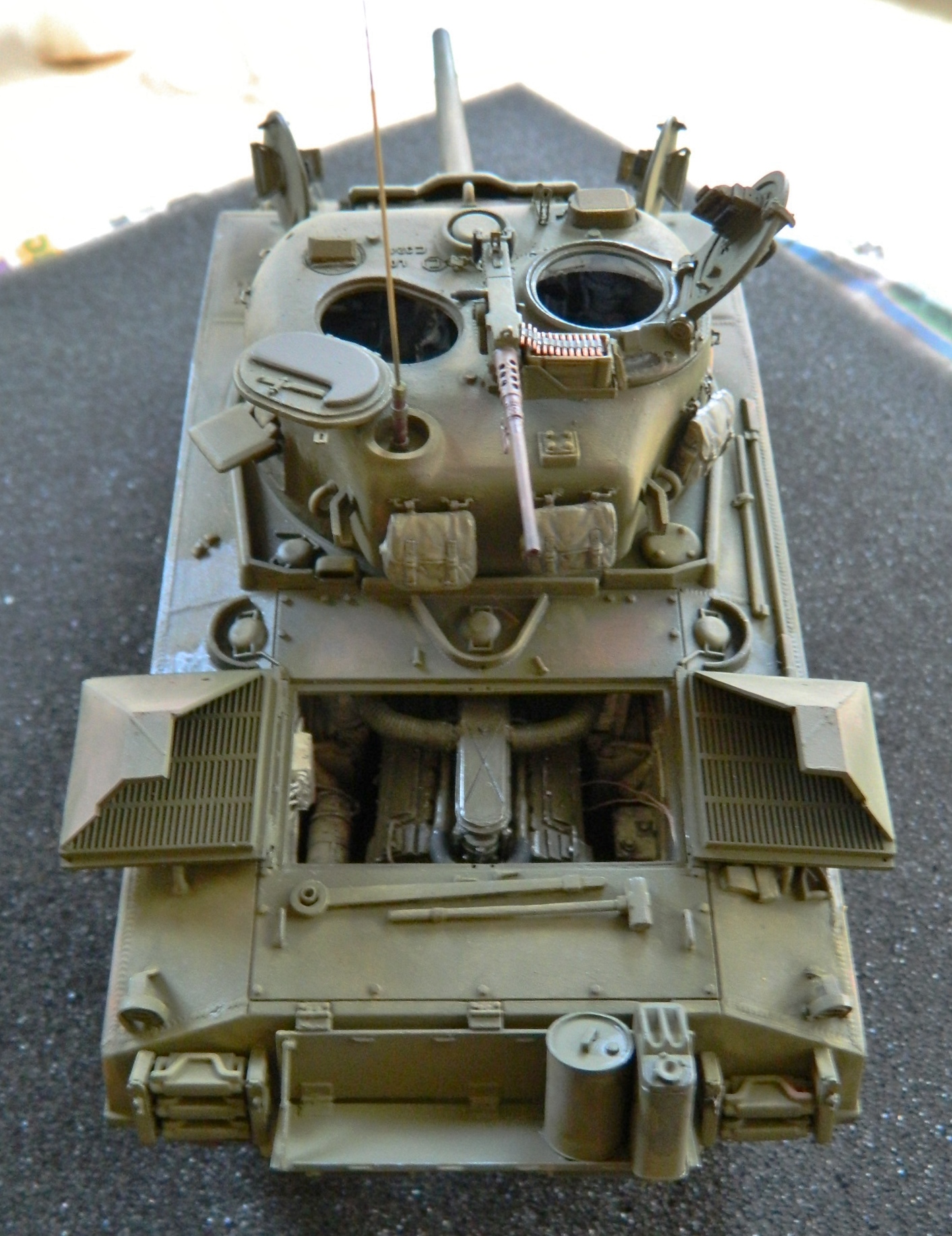
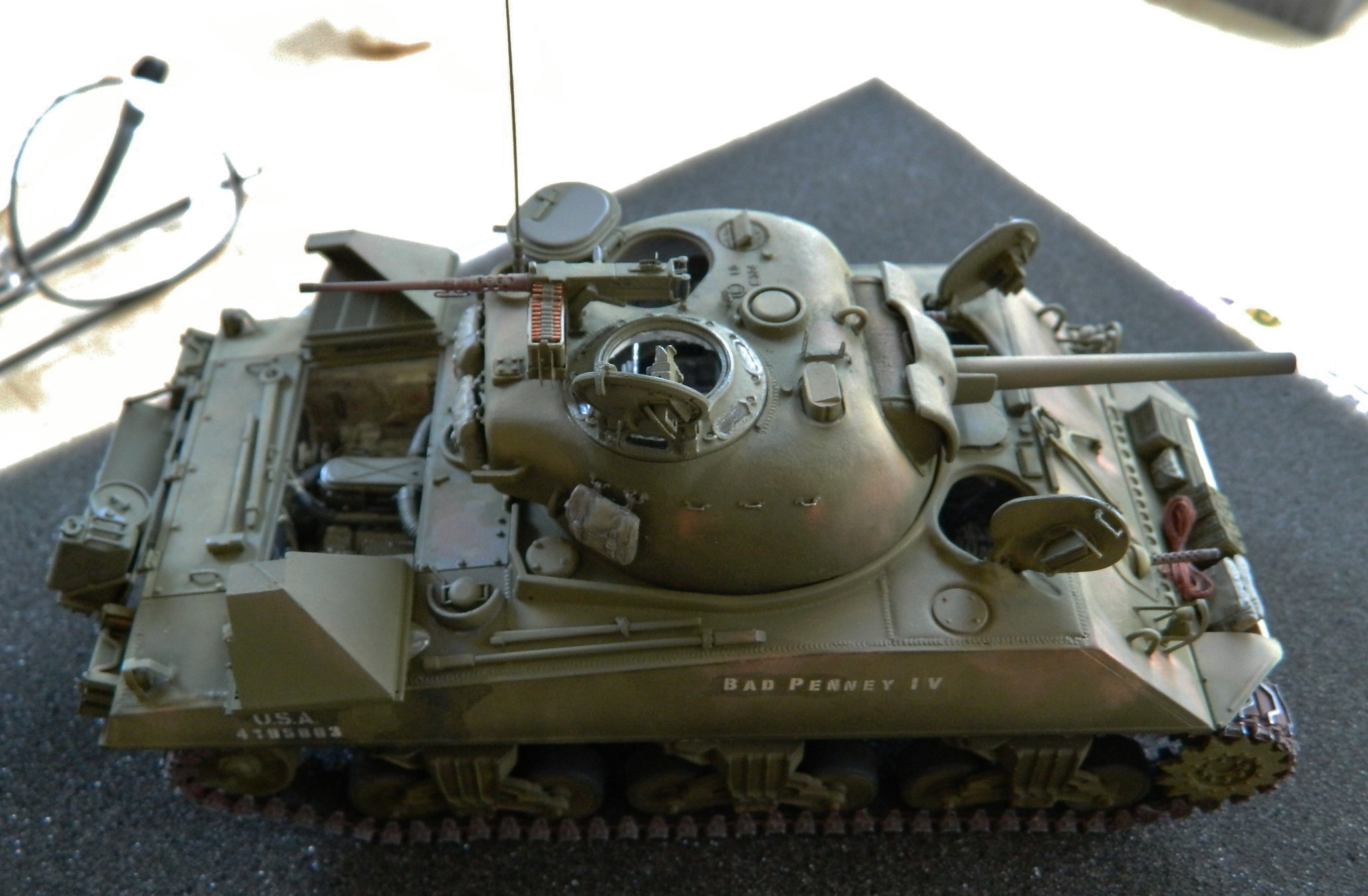
M4A3 (Tamiya) Build #28 – Weathering and Staining
Short on words, long on pictures, the only thing left to do now is to weather, stain, and dirty it up a bit and add some stowage:
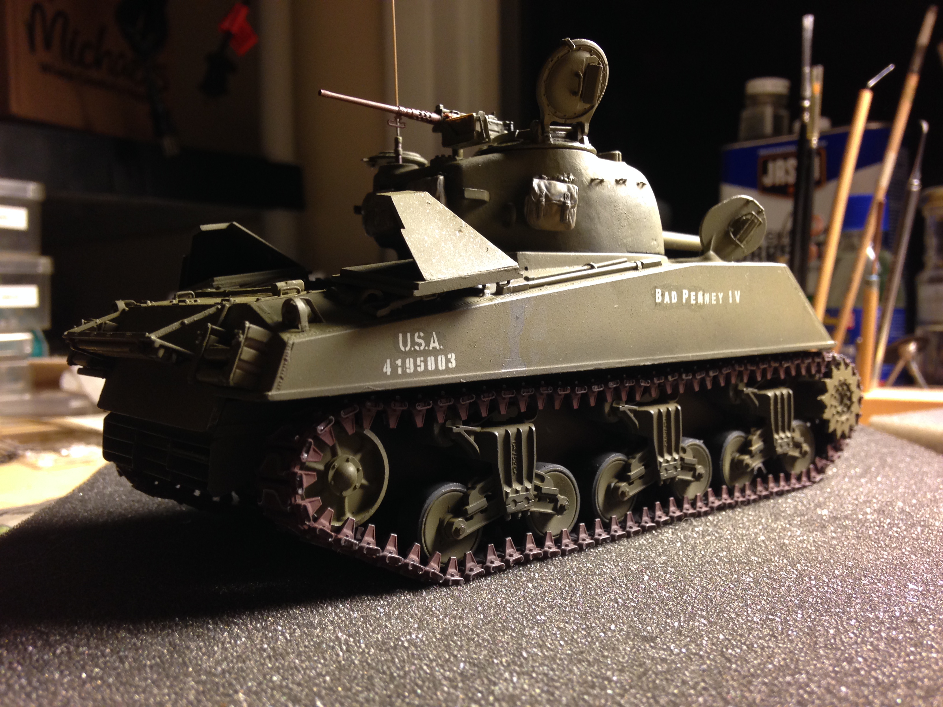

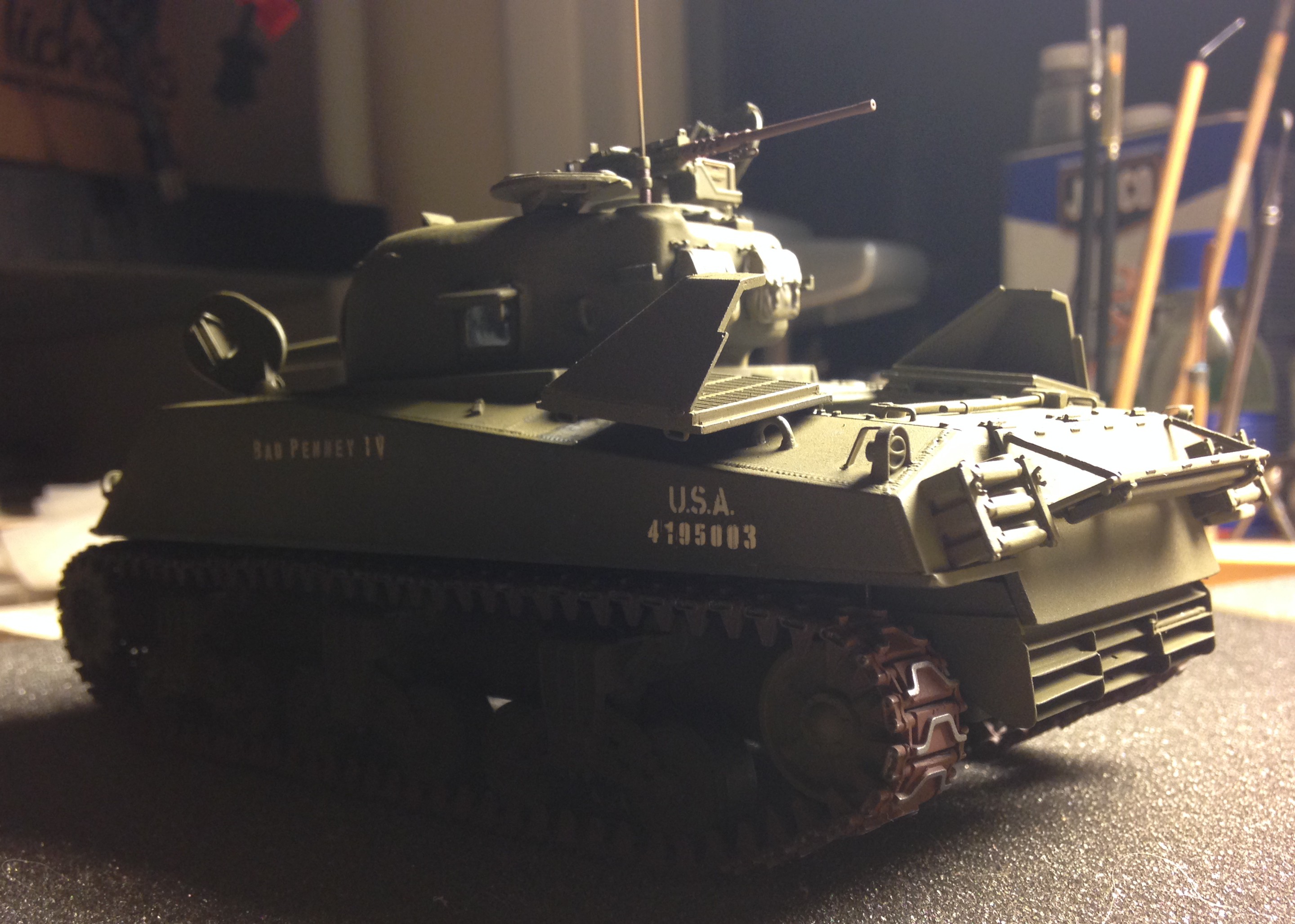

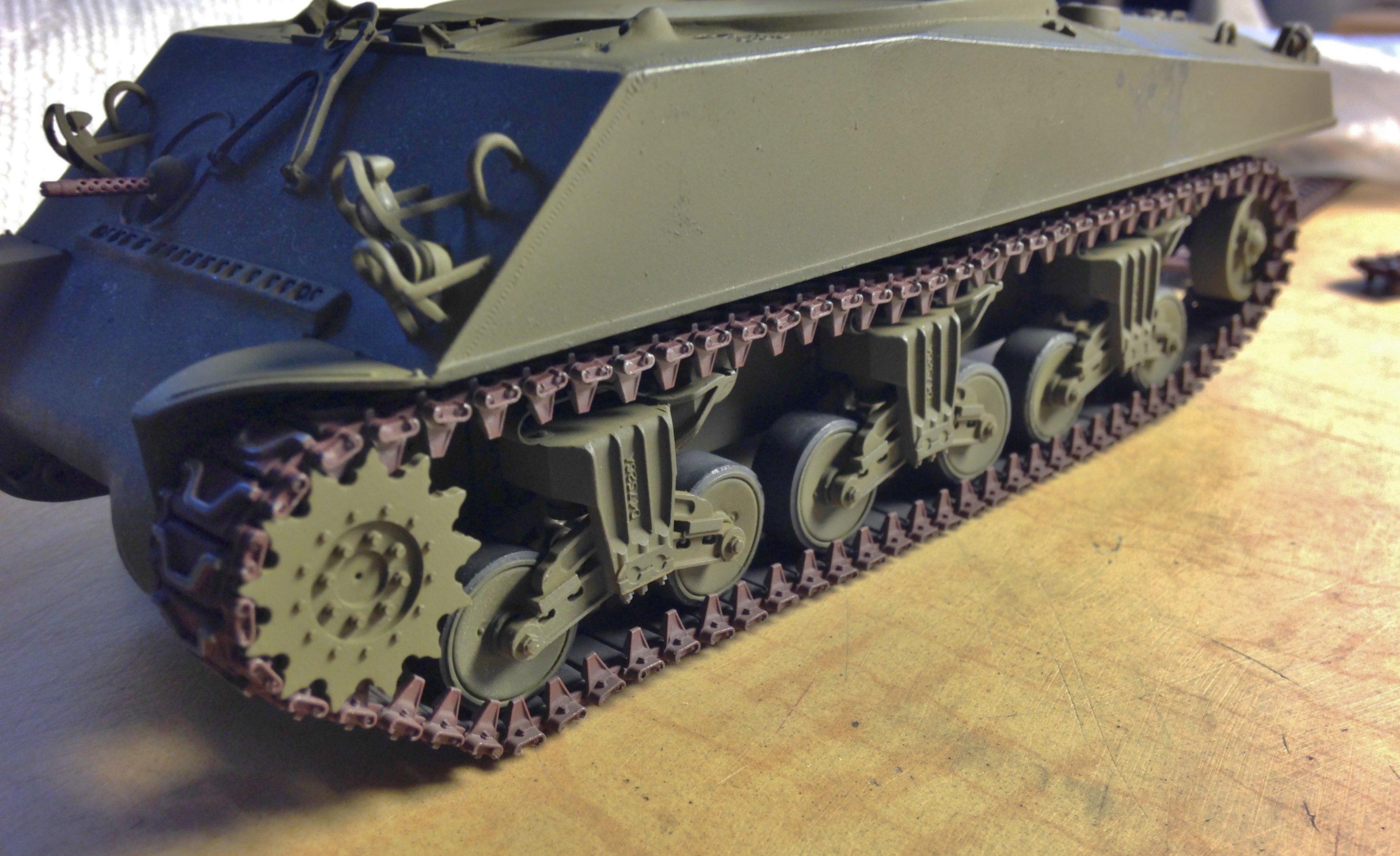
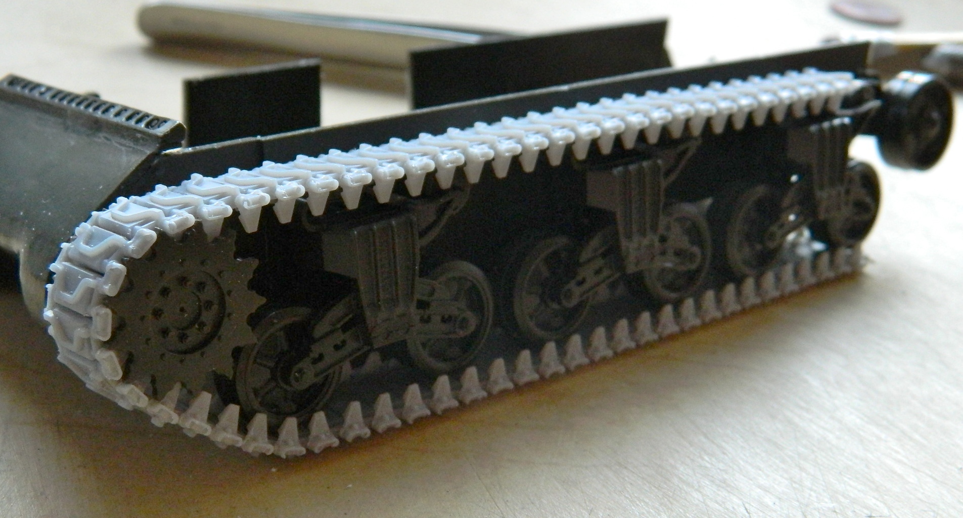
M4A3 (Tamiya) Build #27 – Tracks Finally Installed and Markings are Added
With the tracks assembled (but NOT glued) and painted, it’s time to put them on the tank. The first go-round with the pre-glued tracks was such an ass-pain that I approached the second go-round with a bit of trepidation. Needless. They went on like…well…they belonged there. So that’s the way to go with individual tracks; assemble but hold off on the glue:

And with the tracks finally on, there really isn’t anything left to do but to start the final paint! I’m modeling a fictitious tank, so I cobbled together a serial number. I had intended on either doing dry-transfers or cutting up decals but instead found some really nice stainless steel PE stencils so decided to go that route:

I used the same “aged white” for exterior numbers and letters that I used in the engine bay; it isn’t quite as glaringly white and I like the effect:

However, when using acrylic paints, it’s best to be sure the airbrush doesn’t have any water left in it from the previous cleaning, otherwise, the paint is far too thin and you’ll end up with what I did:
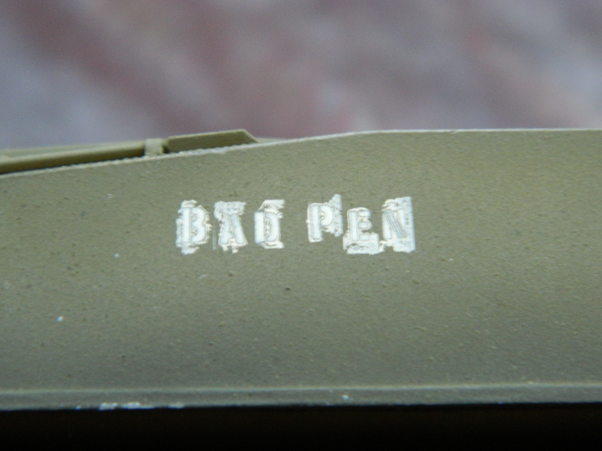
So that got painted out and I tried again. Yeah…that does what I want it to, not look like it was done by a professional:
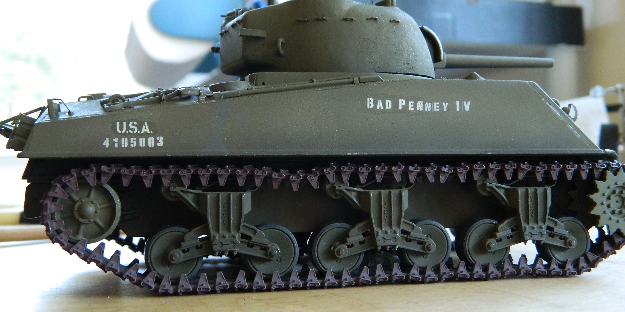
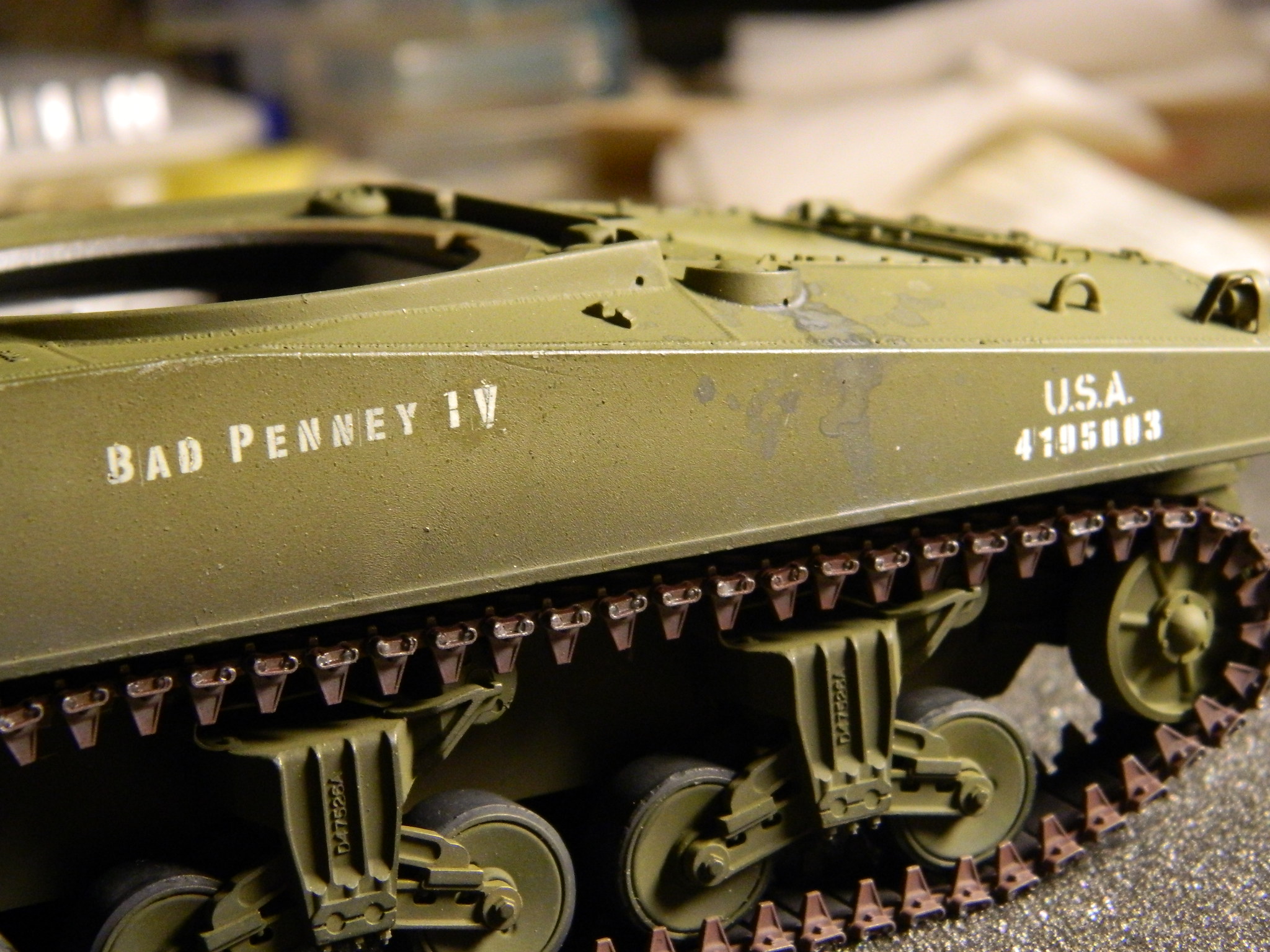
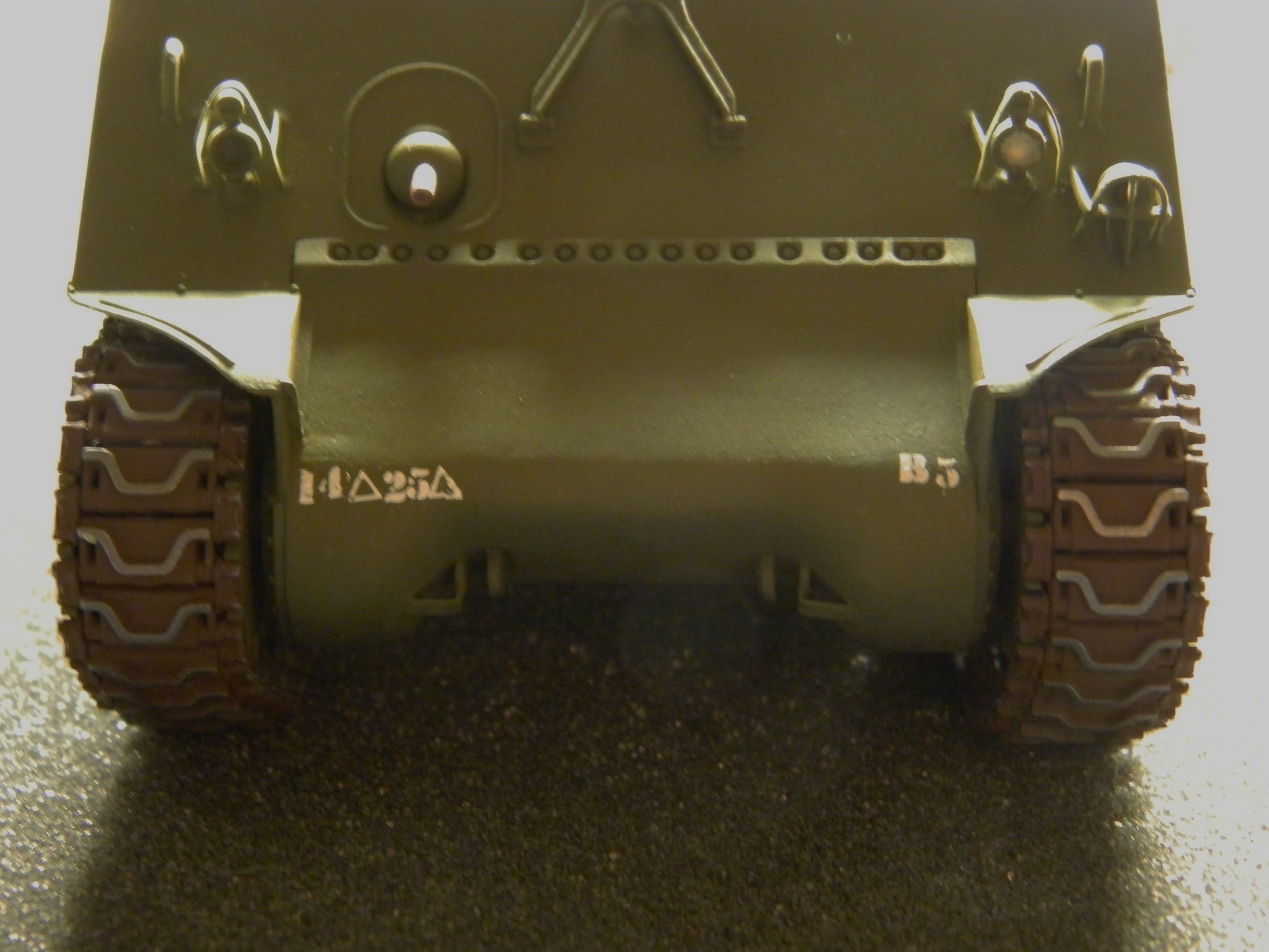
I did the vehicle markings using dry-transfers. Believe it or else…er…not, when very tiny transfers are combined with a curved surface, this was the best my 65-year-old hands could manage. I went through a lot of transfers to get this. No, I’m not 100% satisfied with them, and perhaps tomorrow (or the next day), I’ll peel them off (cellophane tape does it nicely) and try one more time:
And with that, there’s nothing left to do but the final assembly.
HOLD
Just a place marker in case you’ve been following this to let you know the build is on hold pending the arrival of new parts. I’ve been chasing my tail (an ugly sight at best) trying to mount the tracks. Links keep snapping. I drill both the track and the connectors out, set new styrene pins, and the next link breaks off. Okay…I see the pattern. Time out is called, new parts are on order, and I get to do all that fun stuff that cleaning 152 tracks and 304 connectors entails.
Experience. I just earned some.
M4A3 (Tamiya) Build #25 – Final Painting Begins
A long-term project is interesting. When I start I don’t really think much about the end. That’s not to say that I don’t have a direction, intention, and goal, because I do. But I don’t think about its completion because with something long-term, if I spend too much time thinking about the finish I can overwhelm myself with all that needs to be done, and really…during the project, I’m not at the finish. I focus on whichever step towards completion I’m presently working on. I figure if I do that, the finish will mostly attend to itself.
And then one day I realize, sacred excrement! I’m almost FINISHED! That awareness always seems so sudden. Well…
I’M ALMOST FINISHED!
When using an airbrush, the force of the air coming out of the brush can blow small items off the bench. My way around that is to use double-sided tape to hold the piece in place, in this case it’s the loader’s hatch because I need to paint the pad on the underside of the hatch:
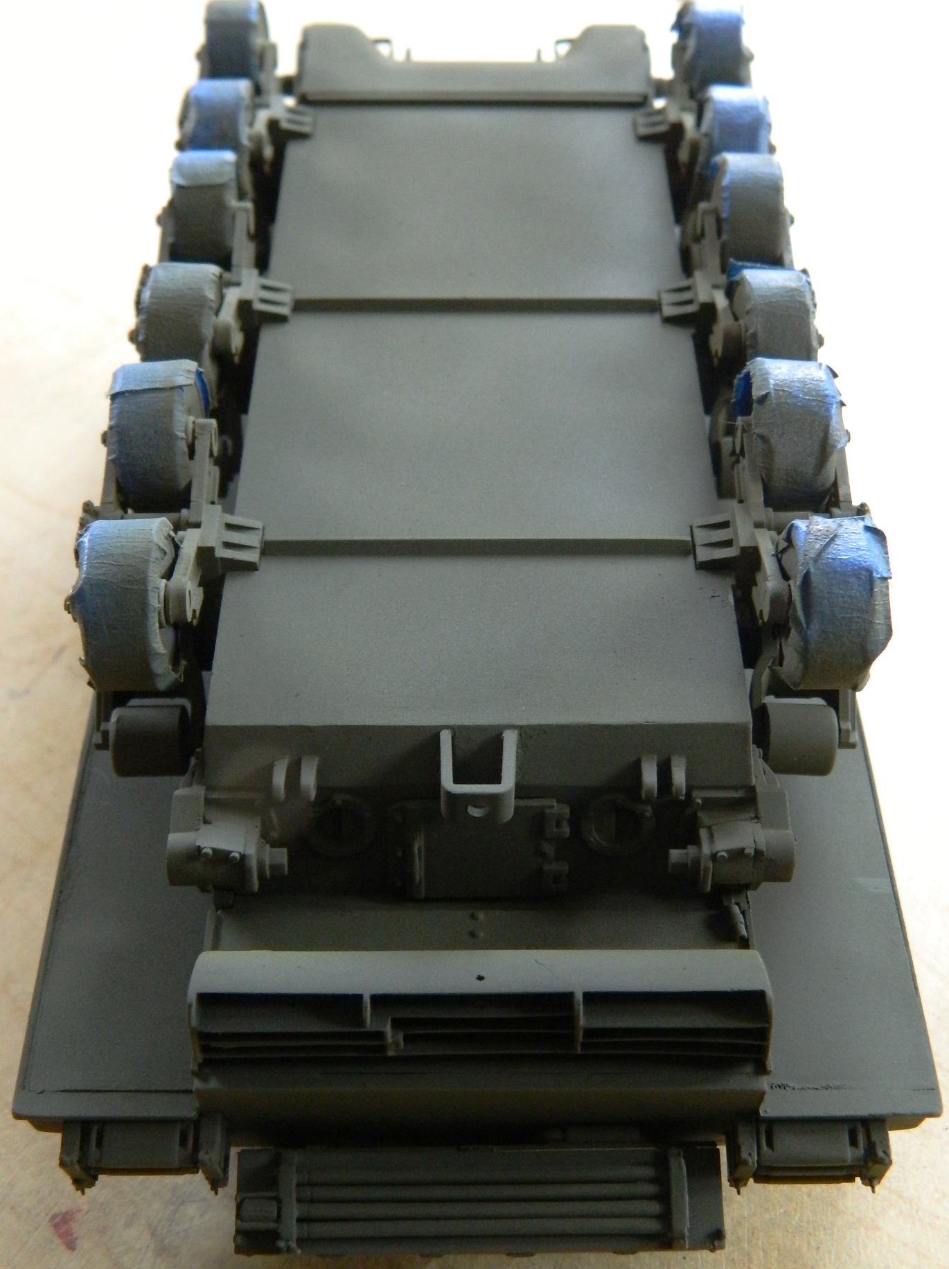
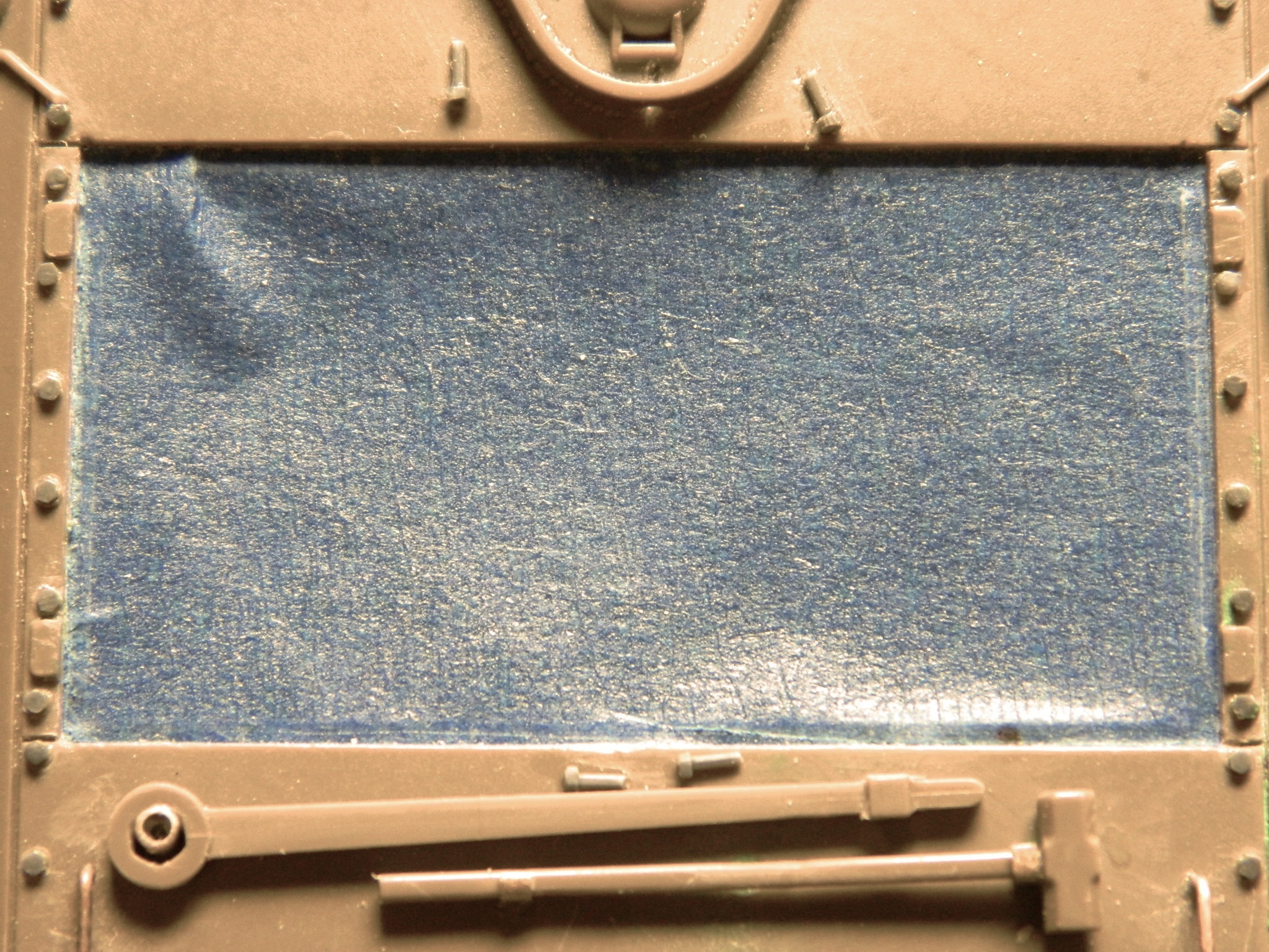
The blue masking tape works very well if I’m painting a room. IT ABSOLUTELY SUCKS FOR MODELING! To paint the rubber sections of the tracks (rubber black again), I had to mask off everything else. Well. There are about five hours invested in just getting the intercoursing tracks masked. No, I didn’t think it was particularly complex to mask because it shouldn’t be. However…the fornicating, sodomizing, tape refused to stick to anything other than what I did not want it to stick to. I spent hours pressing the tape back down. Hours. And even then, once I had the track paint mixed, again I had to press the tape back down. But I persevered and got them painted:
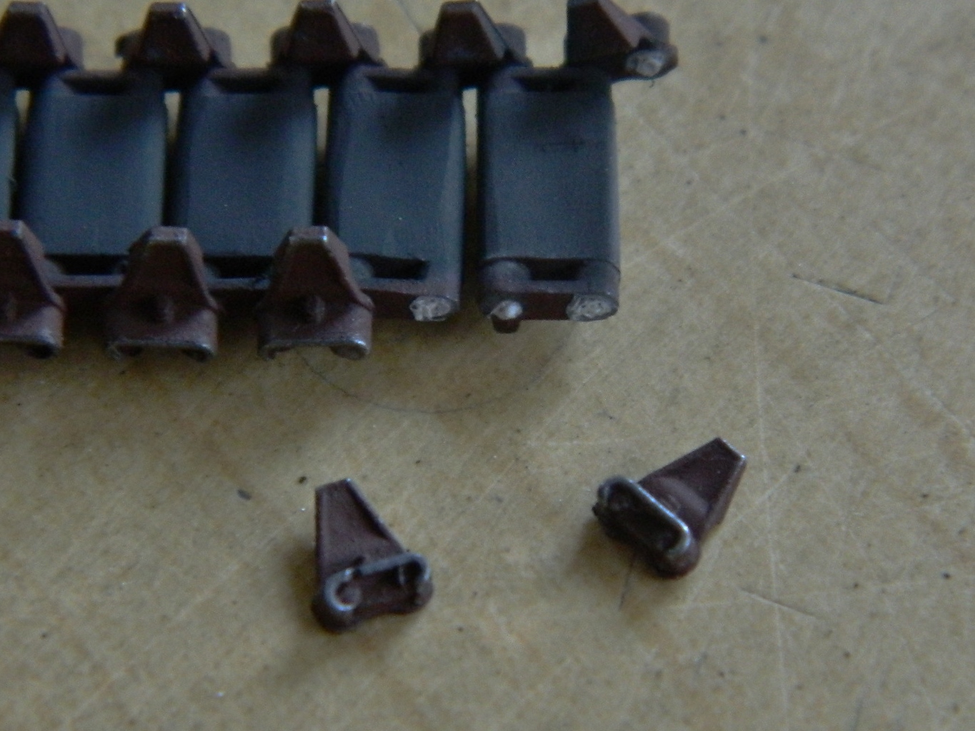
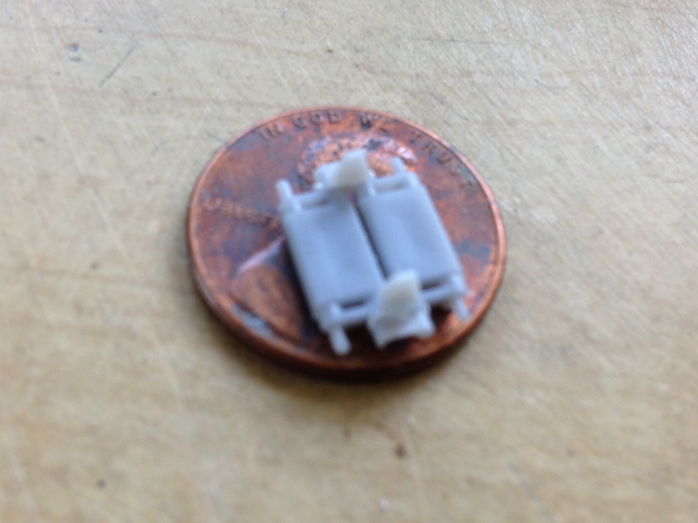
Below you will see two end connectors that I did not want the tape to stick to. This time the tape really stuck and when I gently pulled the tape off, I gently pulled the end connectors off, too. Not an insurmountable problem, but annoying anyway:
The underside of the hull, exhaust ducts, and areas where the sponsons meet the hull were painted flat black. Later I will mist Tamiya’s XF-62 Olive Drab over these areas:

Areas that I want to appear darker were then hit with Olive Drab:
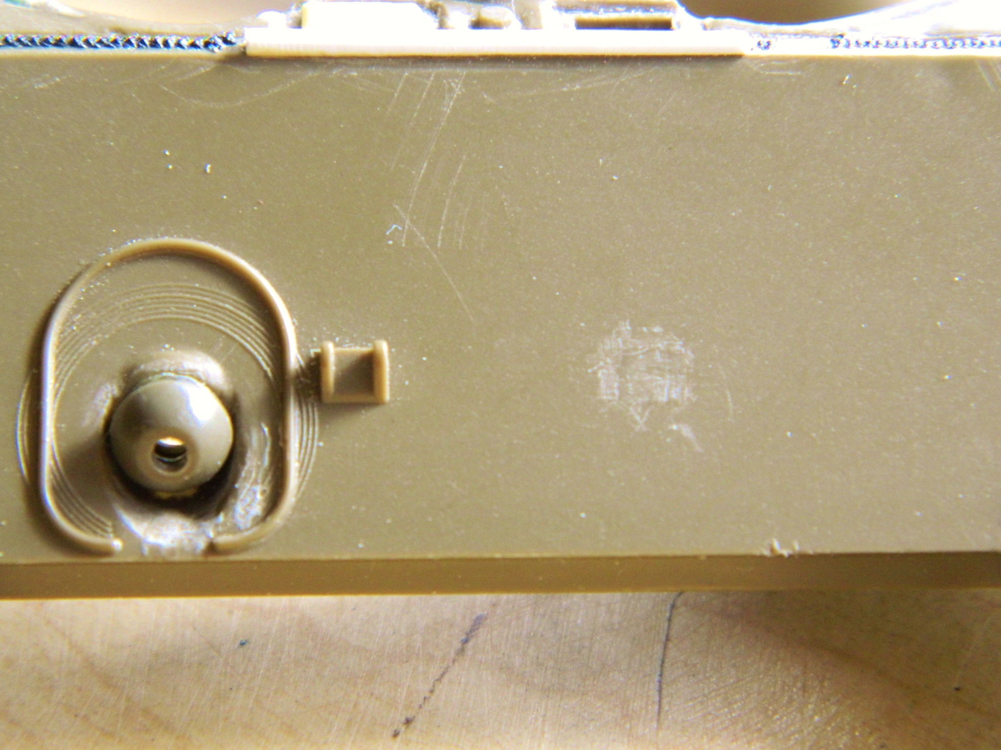
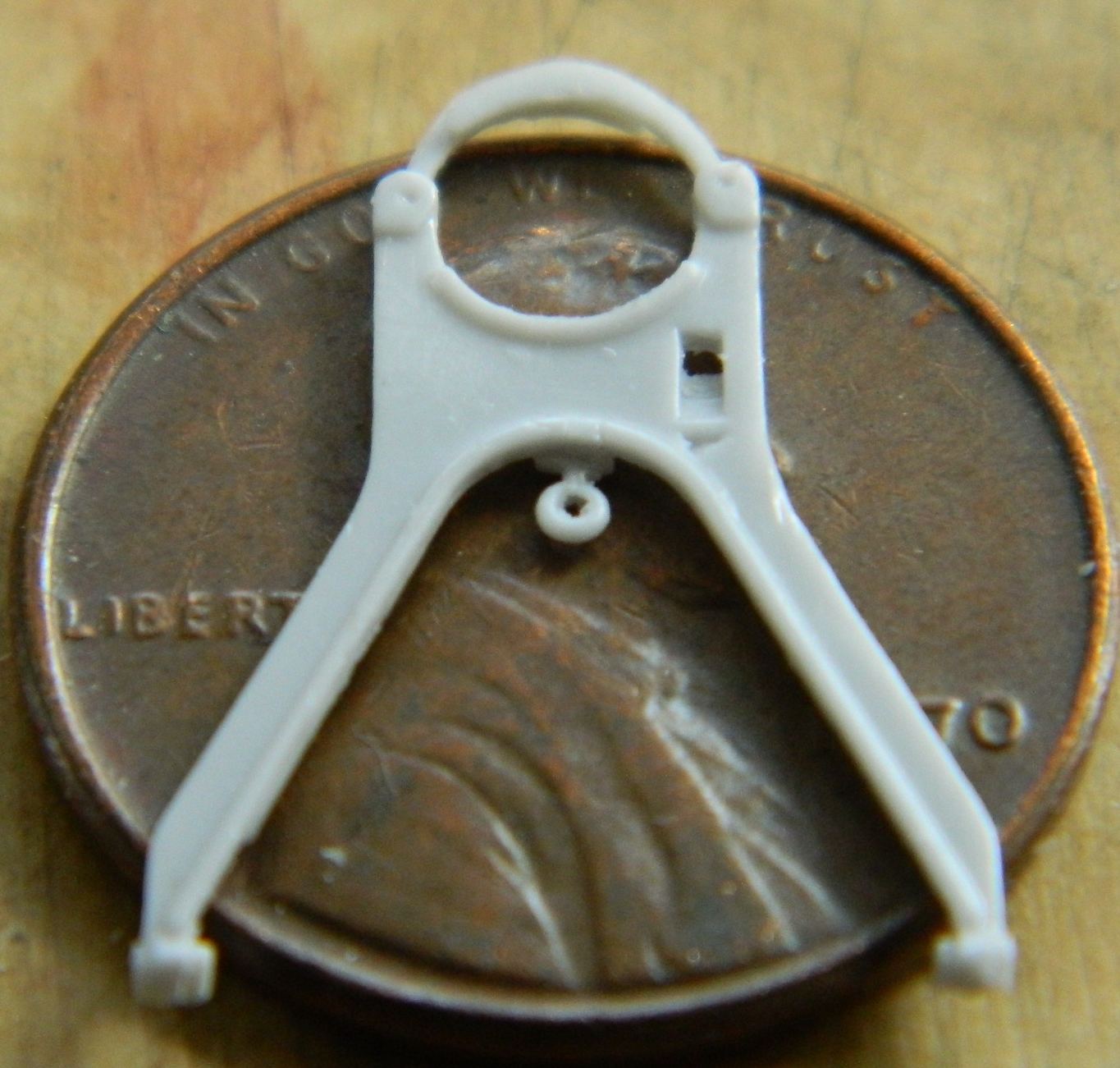
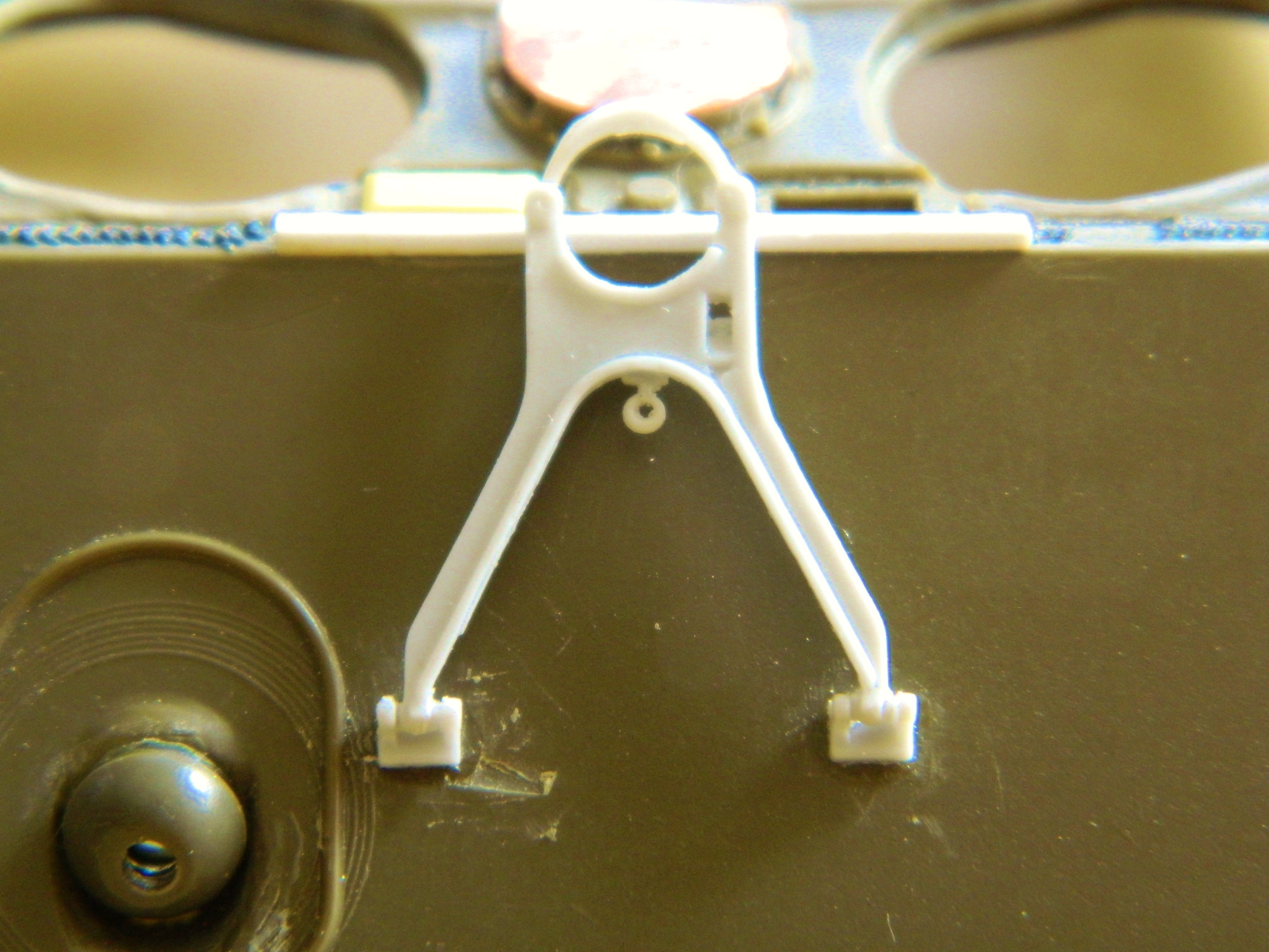
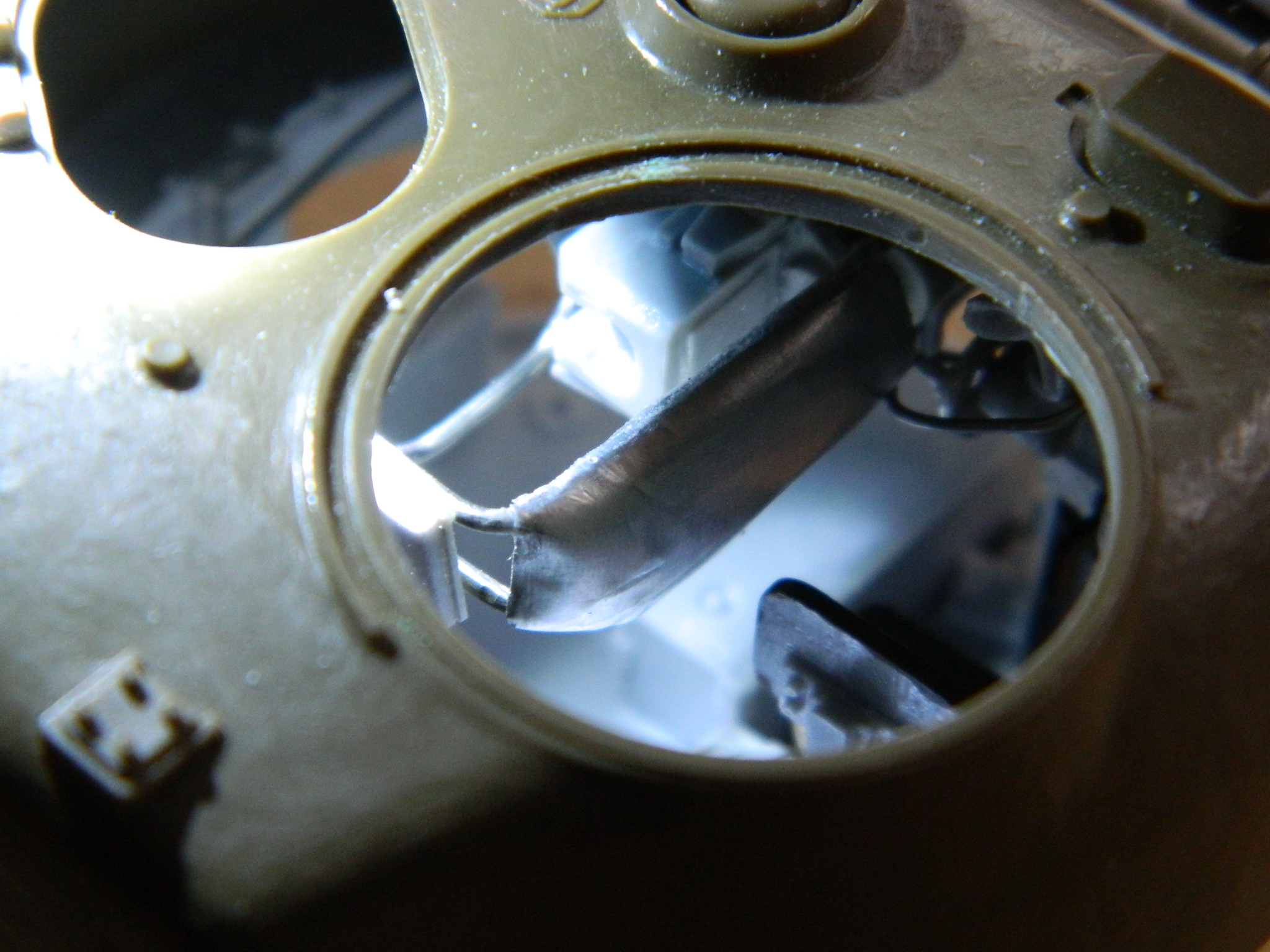
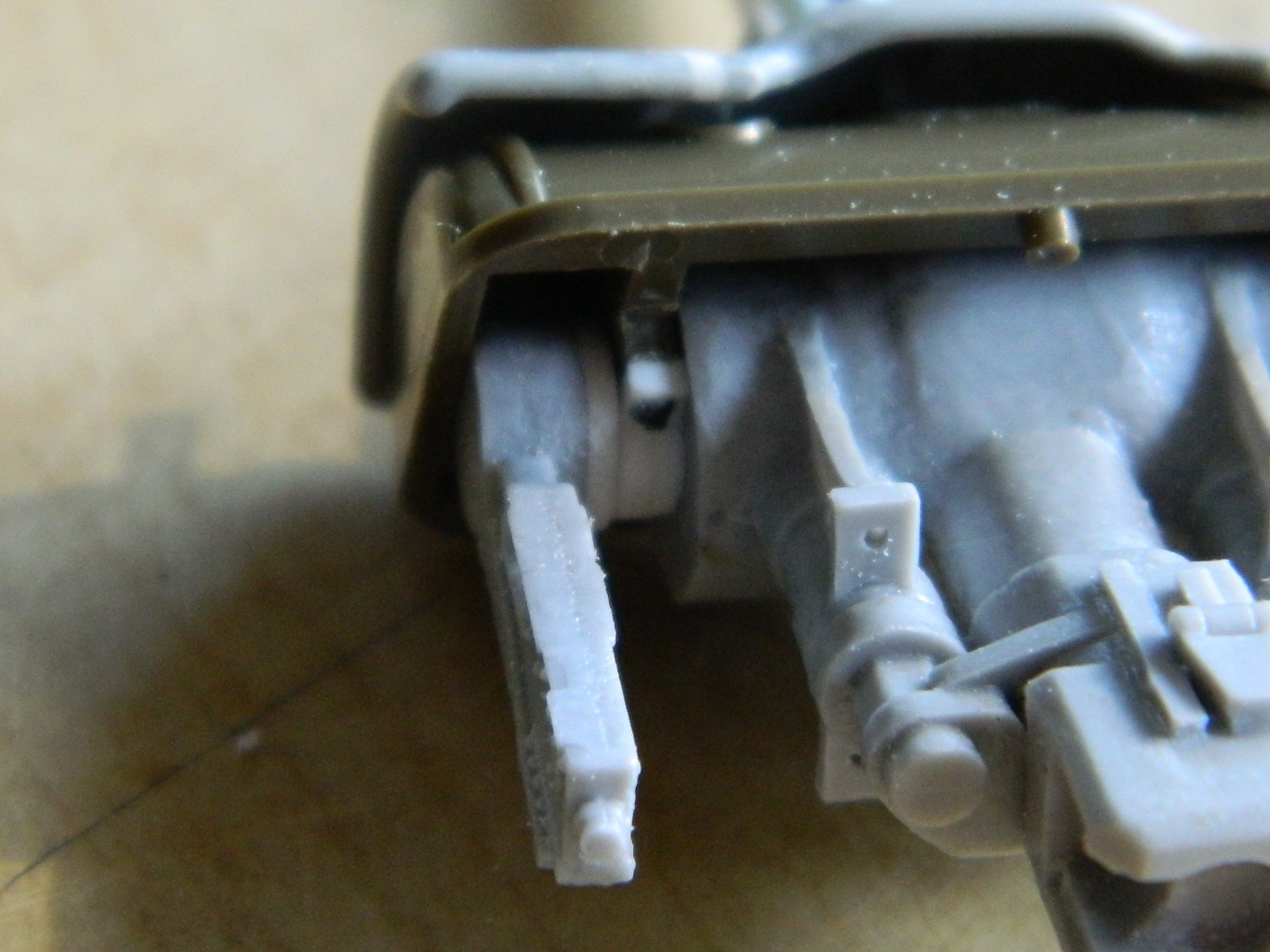
I’ve discovered a fool-proof way to discover which small detail parts you still need to add. Paint the area where they need to go first. Shortly after you do, you’ll remember what you still need to add. In this case it was the commander’s gunsight (in front of his hatch opening) and the travel lock for the .50 caliber (1.27mm) (behind the roof vent). They’re easy to spot; they’re not painted:
Since I’m going to have to paint pretty much everything else with my custom mixed Olive Drab, I’ll hit those brass parts, too. Before I do that, I need to fill in the small bubbles that were left in the puttied co-driver’s hatch area that I didn’t see until I had it in primer:
With that taken care of, I misted the custom Olive Drab onto the bottom, the sponsons, and the back:
To keep from handling paint before it’s set, I mounted the small parts on the (INTERCOURSING) blue tape instead of the double-sided tape. I did the loader’s hatch with the double-sided tape because the Olive Drab has had months to cure and I wasn’t worried about leaving paint behind when I removed it. Such won’t be the case this time. And since the SODDING blue tape has (repeatedly) shown it doesn’t hold firmly, that will make getting the freshly painted parts off, reversed, and the other sides painted easier. Because I wasn’t going to be able to handle things, yet I would still need to move them so I could get complete paint coverage, I painted them on a turntable:
For all the difficulties and problems I encountered in this build, right now is the biggest problem. Leaving things alone until the paint cures! Because with a few minor exceptions (machine gun barrels, for example), the next step is to assemble all the parts:

Must.
Not.
Rush.
M4A3 (Tamiya) Build #24 – Adding Details and the First Coat of Primer
It seems I wasn’t quite as ready for prime time as I thought I was yesterday. Evidently, my mind works (assuming that’s not an oxymoron) better earlier in the day than later. When I wrapped up last night, I really did think I was ready to throw paint first thing today…and then I sat down at the bench today. That’s when I saw all the things I wanted to prime, which is when I saw how few of those were ready to prime. Fine. Let’s get them ready! I mean really…how long could it take?
The answer to that question was about four hours.
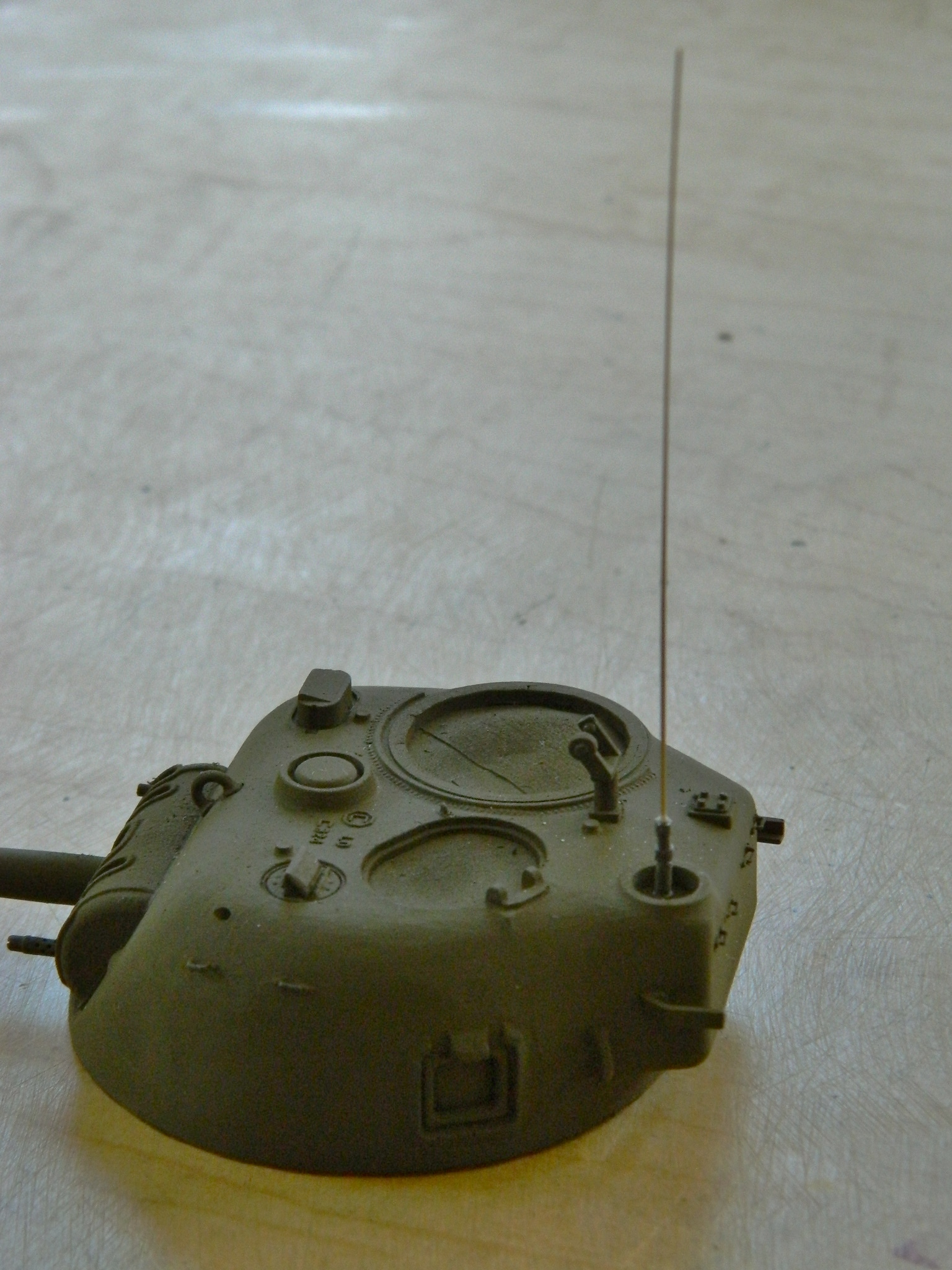
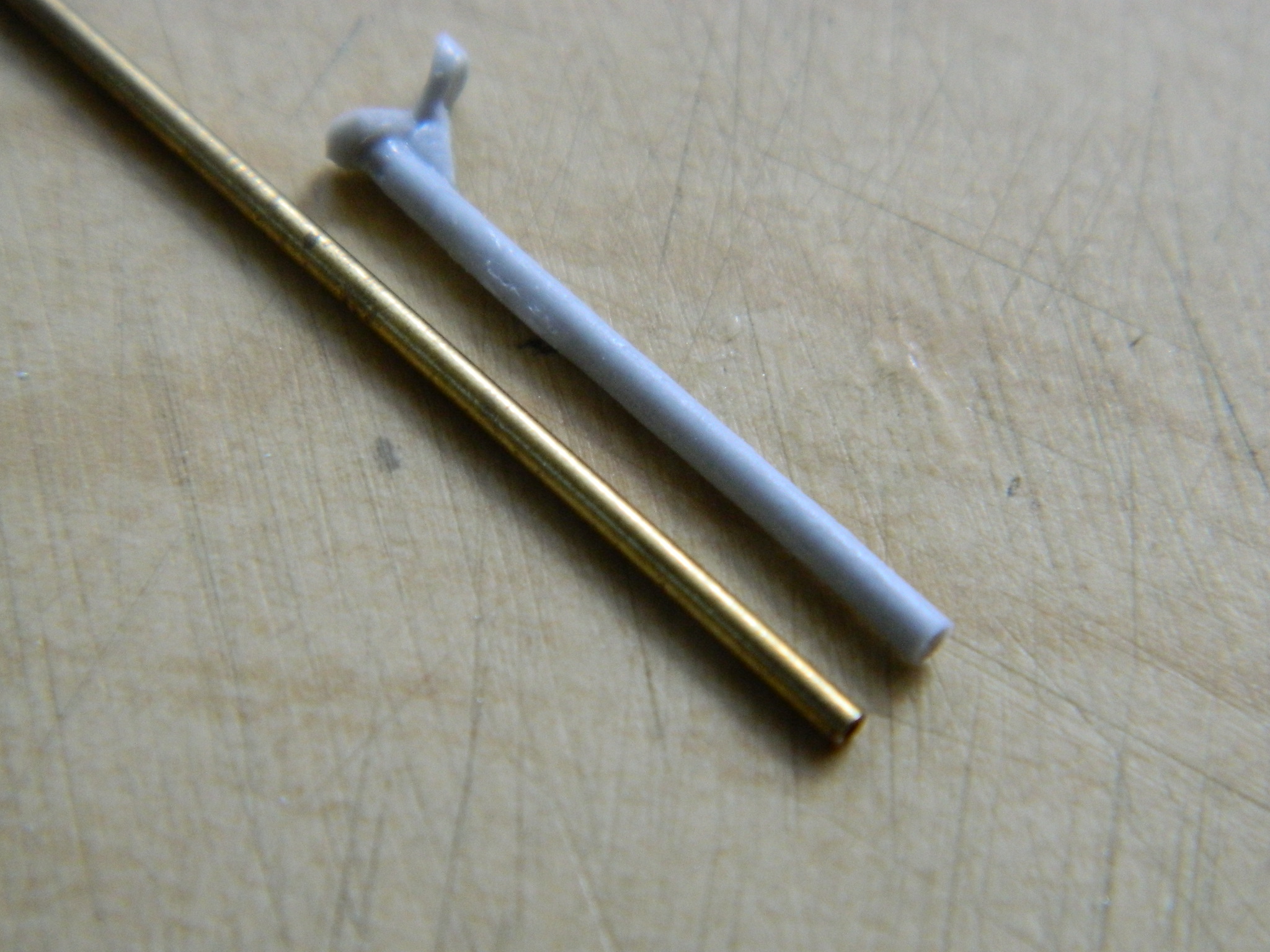
But I wasn’t aware it was going to take that long, so the first thing I did was to prepare the radio antenna. No kit I’m aware of supplies one; they supply the antenna base and expect the builder to supply their own antenna. Okay, no problem. I’ll just stretch some sprue…uhm…how long a piece do I need?
My memory is a funny thing (mine is just hysterical). One of the bits it burped up was that in one of the Sherman kits, the length of the antenna is specified. There are four kits sitting on the shelves in the shop and of course it was the last one I looked in that had that information. 7cm.
Those of you who model know that the little tiny nose probes on a 1/48 scale aircraft are forever catching on things and breaking off. A 7cm antenna doesn’t exactly qualify as “tiny.” It didn’t require much imagination to realize that this aerial is probably going to break off frequently. What I needed was a way to dismount the antenna for those (RARE) times I’m going to transport this model.
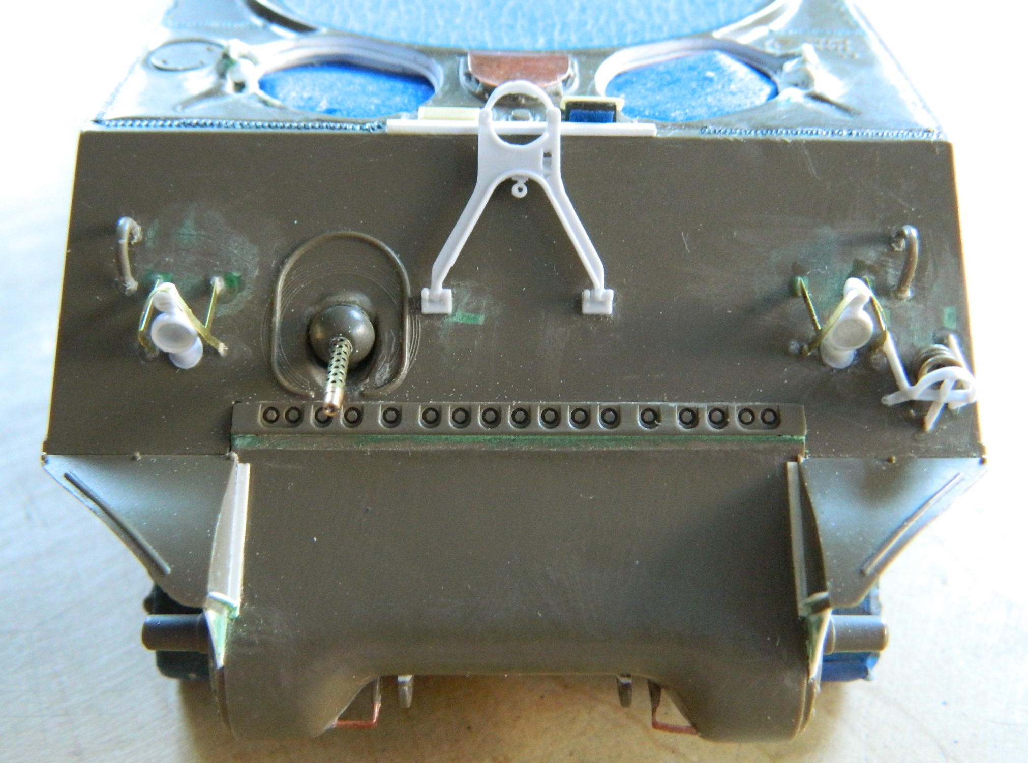
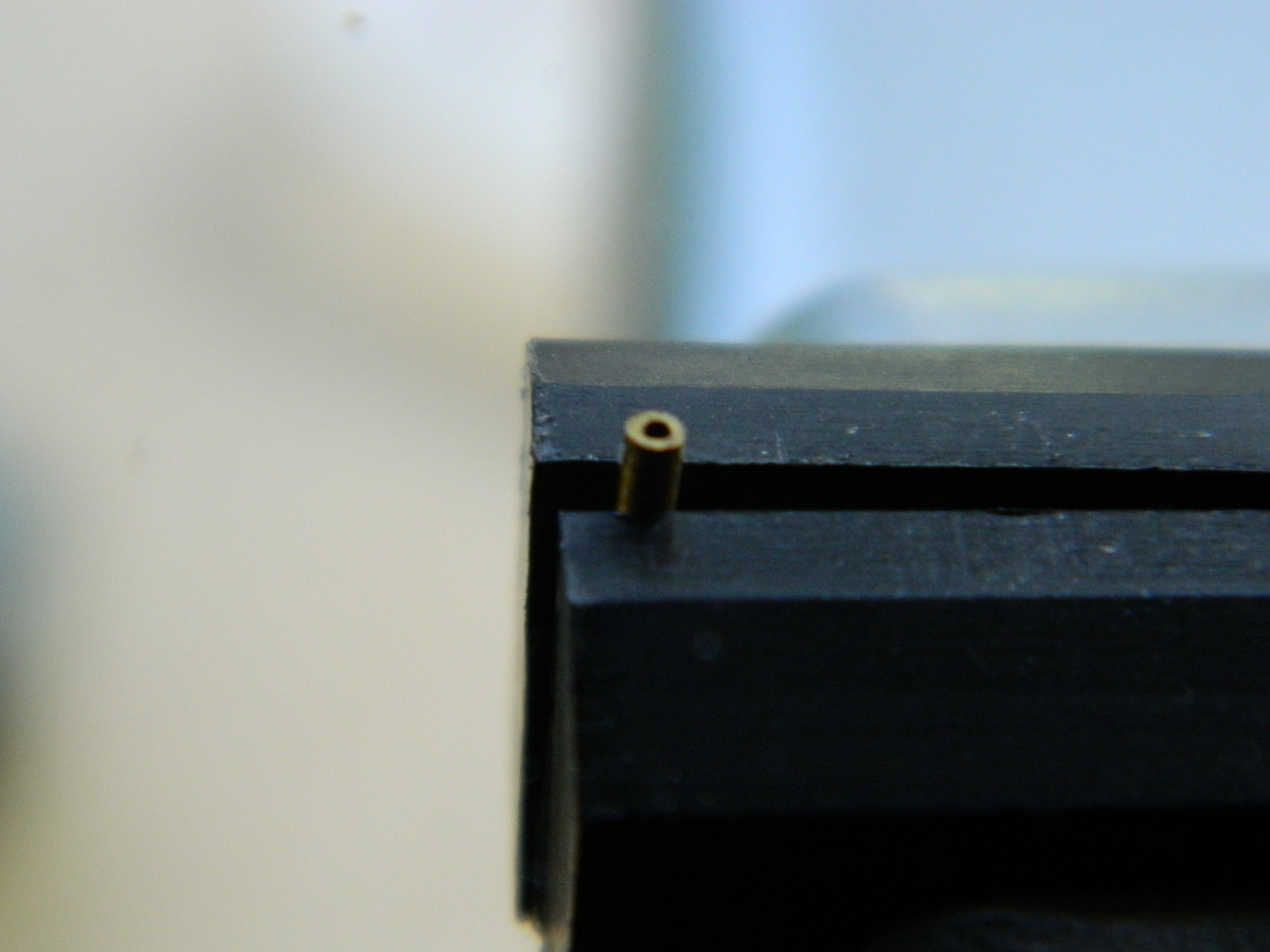
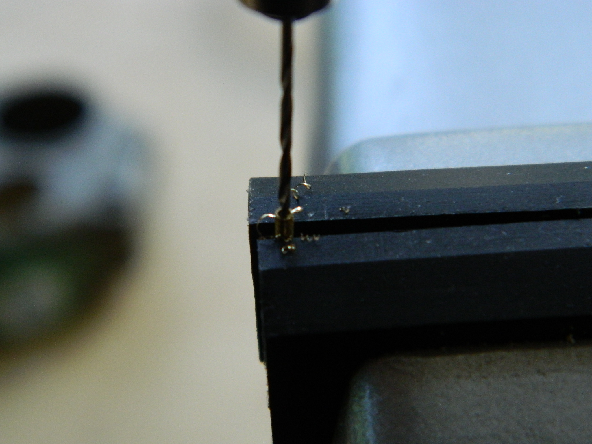
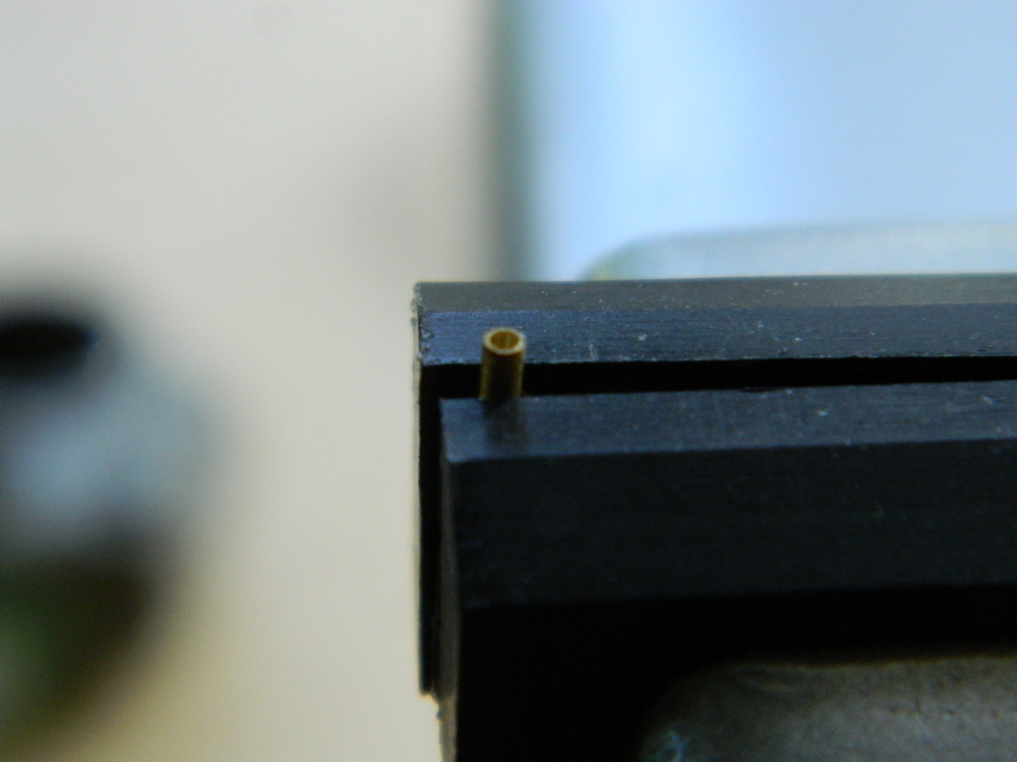
I really like having a spare kit of my build. I went to the spare and cut the top off the spare antenna mount, drilled it out, and inserted a pin. Then I cut the bottom off the mount I’m going to use, drilled that out, and ended up with a two-piece antenna mount:

Stretching sprue requires patience. Sometimes I can get the diameter I want in one pull. Sometimes it seems like it takes forever (as defined as a half hour) to get what I want. This time I was right in two. I cut the sprue and measured 7cm, cut it again, and glued it to the top of the mount. Because the plastic I stretched was already Olive Drab, I didn’t paint it:

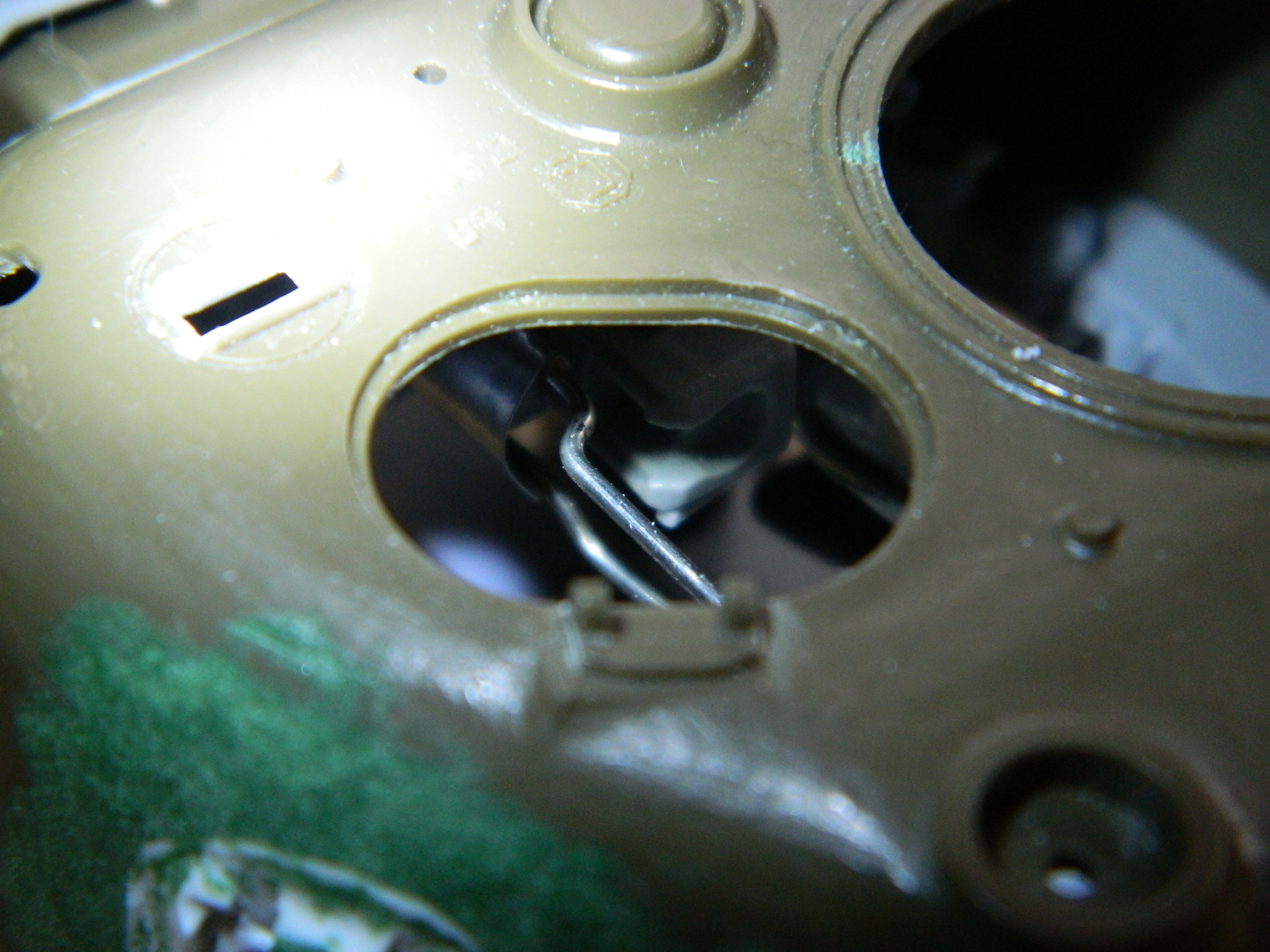
Now the antenna can be safely removed and put back on:

At this point, I was still assuming that I’d be able to not only prime what I wanted to be primed, but also be able to use the airbrush to do some detail painting. I turned my attention to the .50 caliber (1.27mm) on the turret top.
I’d already thinned out a kit ammo box and laid in an ammo belt from my spares stash, now I needed to run another belt from the gun down and across the top of the belt already installed:


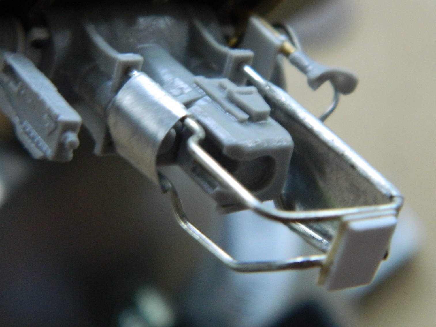
Handling small parts is rough on those parts. I spent considerable time reattaching things, more time waiting for the glue to cure, and then repeating that process several times (exacerbated by remembering I’d wanted to add the butterfly trigger to the .50 caliber (1.27mm), and wasn’t THAT an exercise that ate up time. Tempus fugit indeed.)
So after four hours of all of the above, I was finally ready to prime. I used a rattle can of Tamiya’s fine gray acrylic and hit everything that wasn’t styrene and much that is. Different materials and colors reflect light differently. Another reason to prime something that’s had parts added that the kit didn’t provide is to get one type of reflective surface. This way modifications, things that had to be made to fit, brass, lead, aluminum, resin, and styrene, will all reflect light the same way and will show you what doesn’t work, what needs more work, and the ego-stroke of seeing you got it right:
Now the primer will allow the subsequent paint layers some tooth. Tomorrow I’d like to get another detail or two added to the turret and then break out the airbrush to get some of the other details under paint, but that determination needs to wait for fresh brain and not be made with stale brain.
M4A3 (Tamiya) Build #23 – Readying the Exterior for Paint
With most (I think) of the major sub-assemblies done, it’s time to start getting the hull ready for paint. Because of all the different materials used, I want to prime the upper hull before I lay down color; experience has shown me that acrylic paint doesn’t adhere well to brass.
I masked off the off the crew compartment and engine bay:
I had considered waiting until very late in the build to put the detail parts in place on the hull. But because of the fairly involved paint scheme I have in mind, getting the details to fit with the color scheme would be substantially easier if they were painted along with everything else on the hull. That means details get added now. The first thing I did was to shorten the front lifting loops and while the glue was setting up, I trimmed and blended where I had shortened the rear lifting loops. That took so long that the glue on the front loops had set up by the time I was finished with the rear and then did those also.
Then I started bending PE parts for head and taillight guards from Verlinden’s Sherman detail set and I used TMD’s resin guard for the siren:
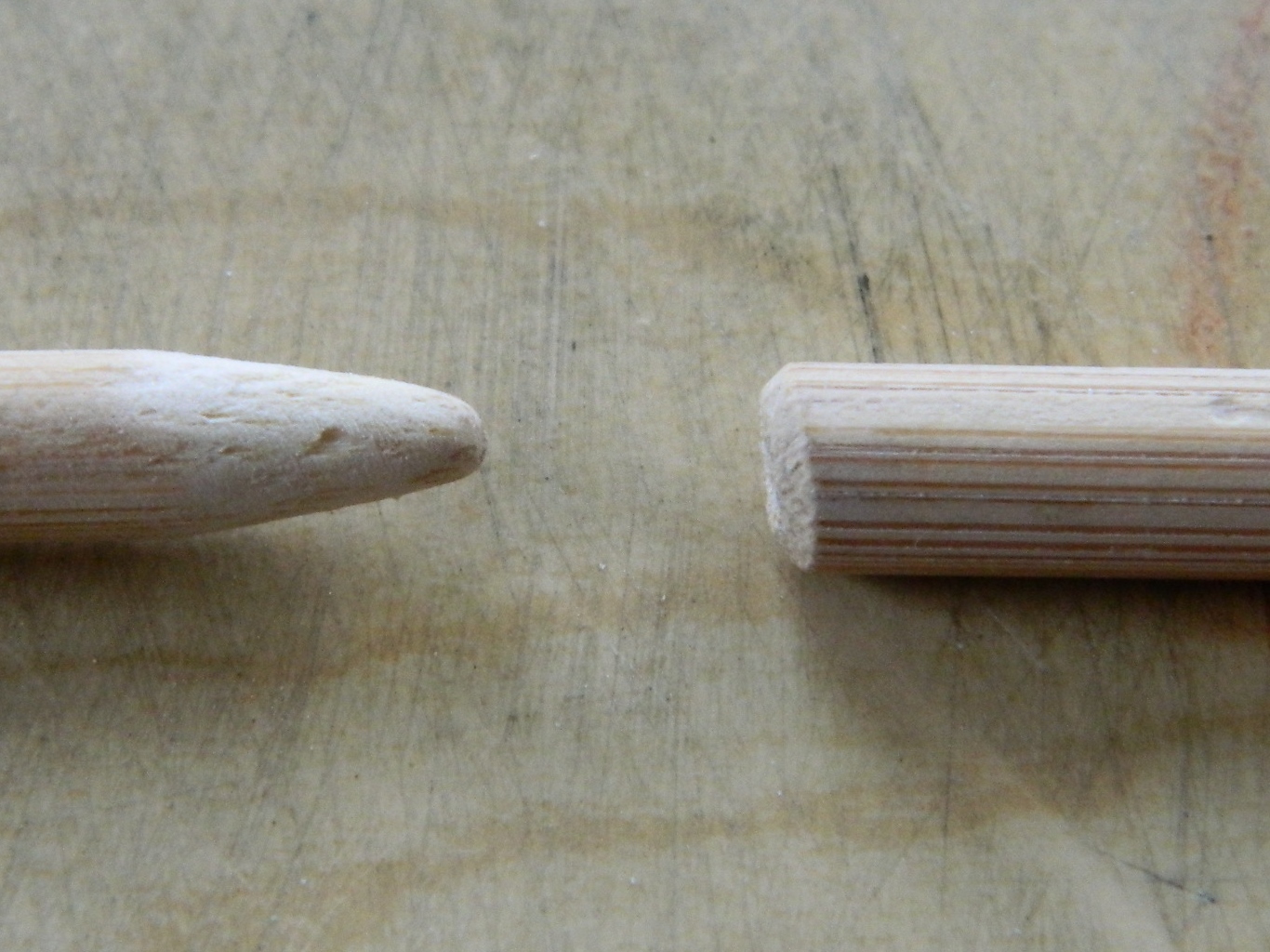
Doing lenses of any hue with paint doesn’t work for me – it just screams I’M A MODEL. I wanted to try something different for the headlights. The New Tiger Models Direct (TMD) makes a set of headlights and guards. I had originally intended to use the clear resin headlights that came with the set but decided to get daring. I used the opaque resin parts instead because clear lens covers also come with the set. For a little more visual impact, I decided to leave the lens off one headlight completely (I mean it’s a tank and the lights are glass, so no great stretch for one of the headlights to be broken). For the other headlight I decided to try and make the reflector out of thick aluminum. I used the headlight itself as my buck and sharpened and shaped a bamboo chopstick to use as my form and very gently pressed the stick into the aluminum while it was in place over the headlight:
Using small scissors I cut away most of the excess:
After pressing and gluing the aluminum reflector into the headlight bucket, I did the fine trimming with a round-tip hobby knife then placed the lens over the reflector. I liked it, so I glued the lens in place and then used white glue to hold both headlights to see how they work. I liked that, too:
Moving to the back of the tank, I added the spare track links to the racks. Reference photos showed that the spare links were over-painted OD green (as was everything else on the tank when it got a coat of paint, including dirt, spare tracks, and whatever else was strapped to it), so I added them to the racks and then added the fold-down shelf:
I successfully glued one of the taillight protectors in place, but when I was doing the second one, evidently I had another brain fade. I thought I had the knife positioned properly but something shifted, I didn’t notice it had, and I ended up cutting a quarter of an inch off the protector instead of a profoundly thin piece as I’d intended to do.
[Insert colorful invective here]
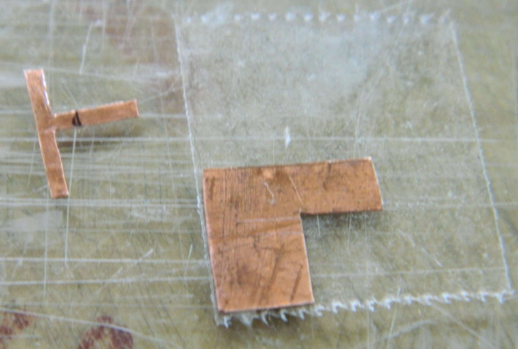
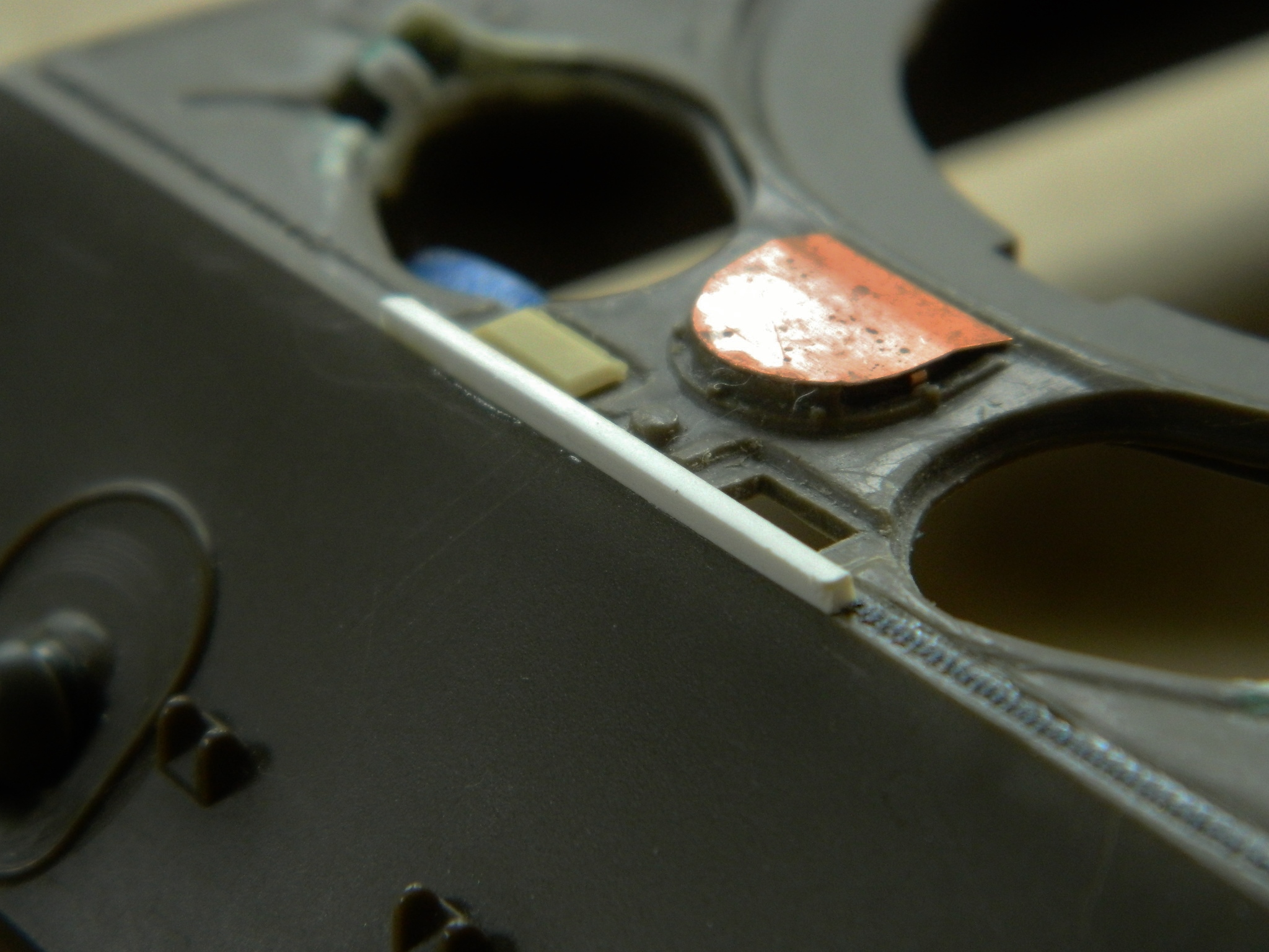
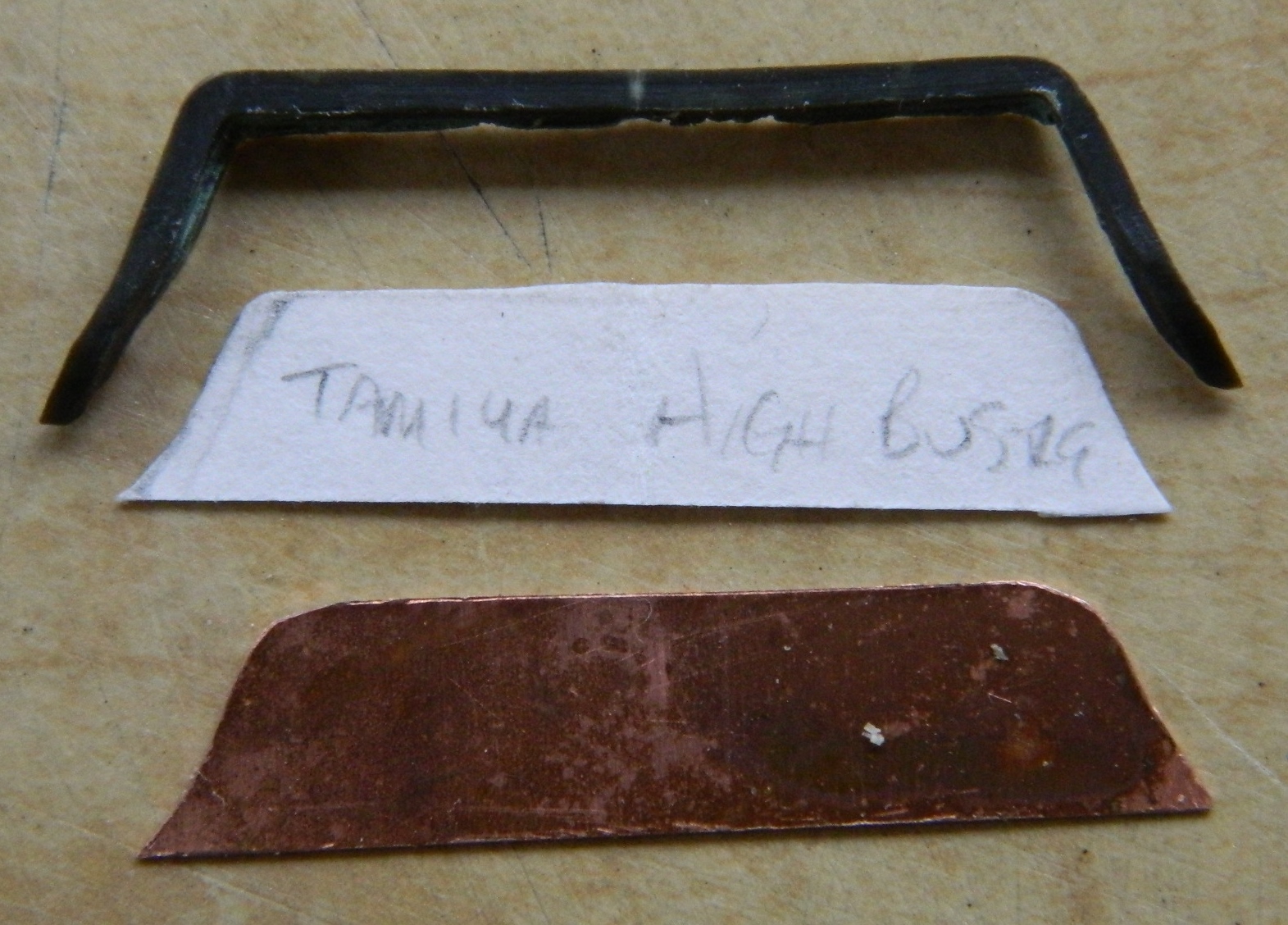
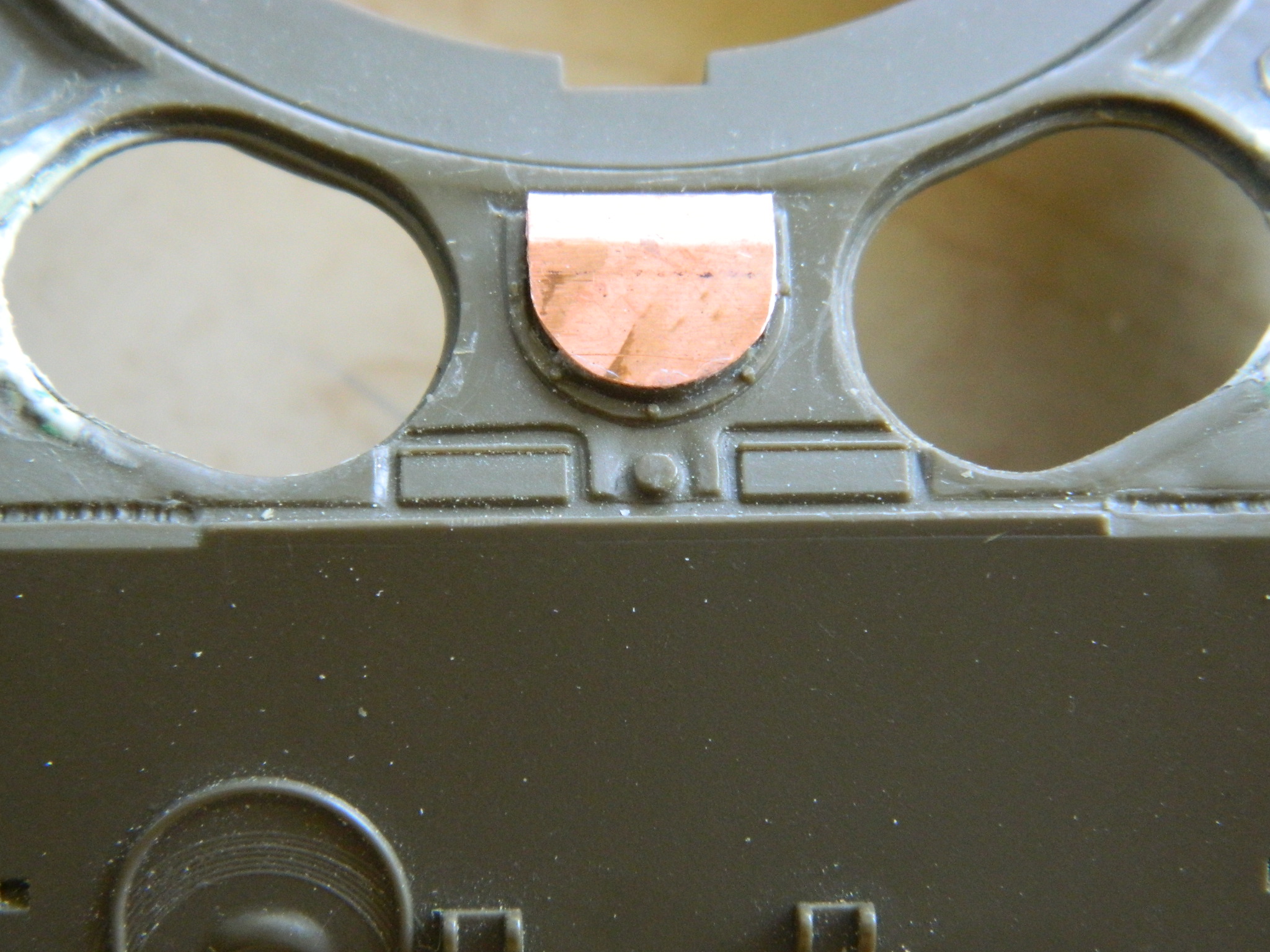
Turn off the lights, walk away, get a good night’s sleep (for a change, surprisingly), and the next morning while having life’s blood coffee and just ruminating on my options, I remembered (for a change, surprisingly) that I have .005″ (.127mm) copper shim stock on hand. Okay, using the ruined guard as a basic template, I traced the shape onto the shim stock and using the small scissors again, cut out a new piece:
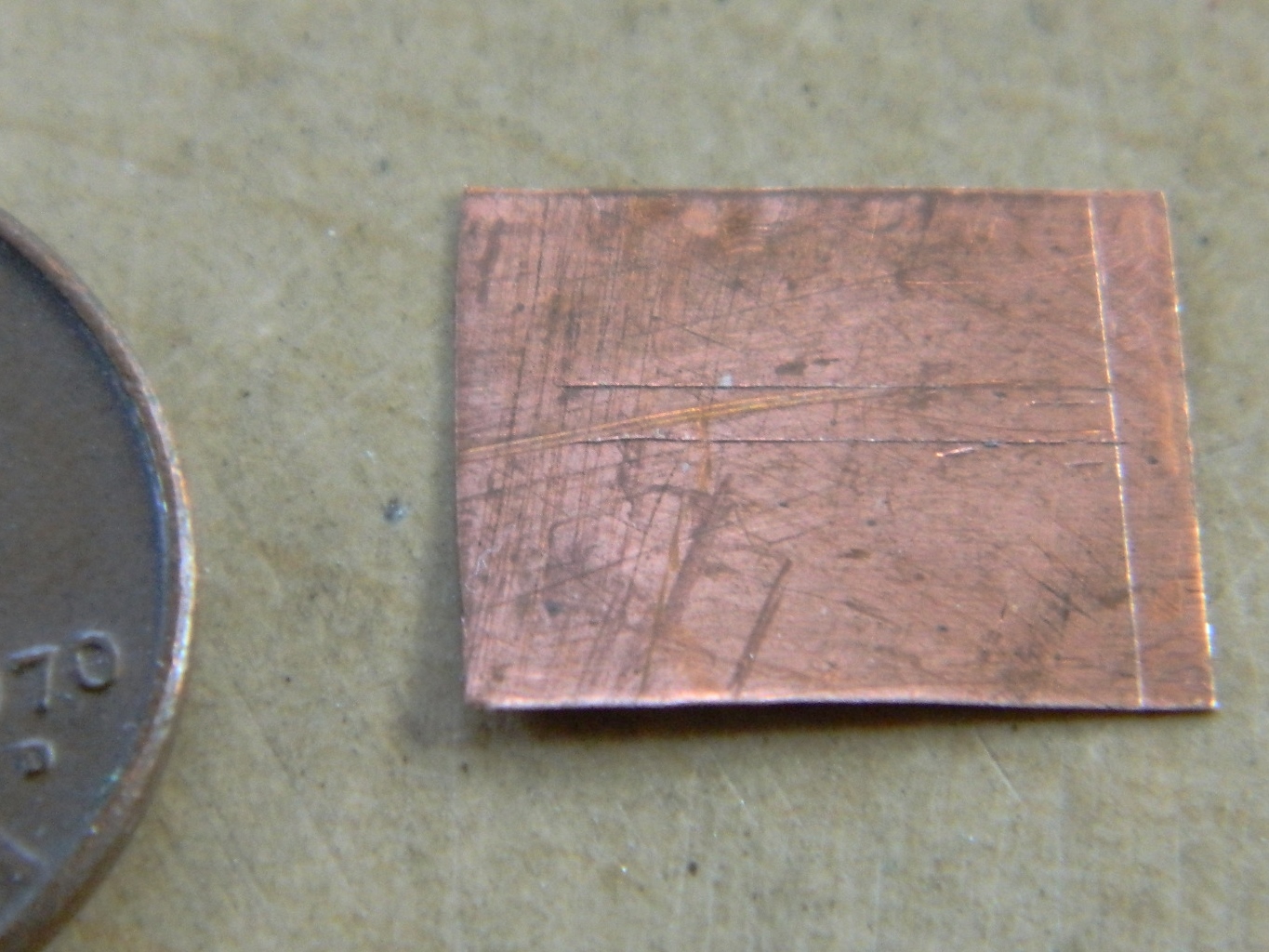
I liked the replacement so much better than the PE part that I snapped the “good” guard off and made another one:
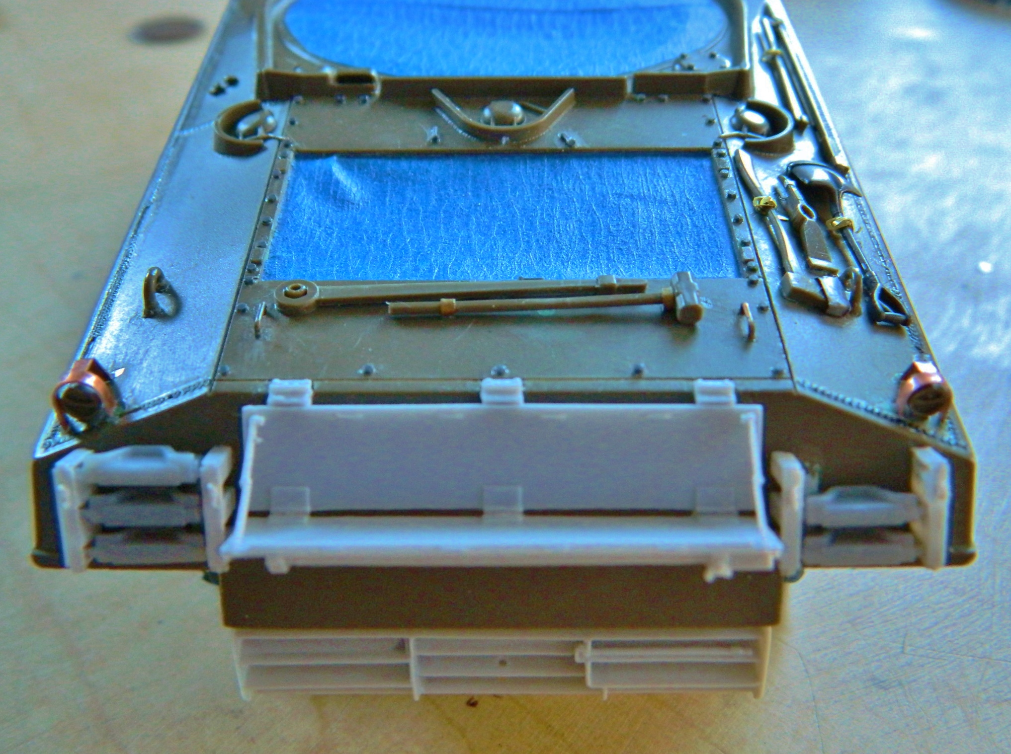
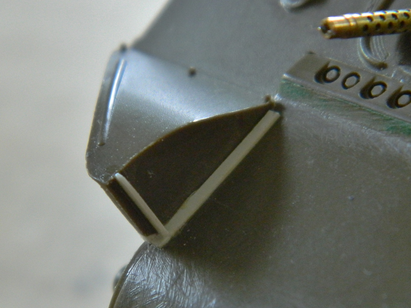
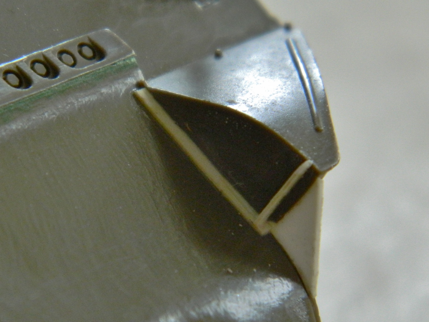
Back at the front, I needed to add the front fender mounts where they attach to the differential cover. But something didn’t look right. I went to my reference photos and realized that Tamiya hadn’t molded the front fenders correctly. On most of the late-model M4A3s in the photos, the sheet metal doesn’t form a 90-degree angle with the line where the fender meets the differential casting (that seems to be more common on earlier variants), it runs vertically down from the corner of the fender. I added .020″ (.508mm) sheet:
I applied putty to hide the seam and let that sit to cure.
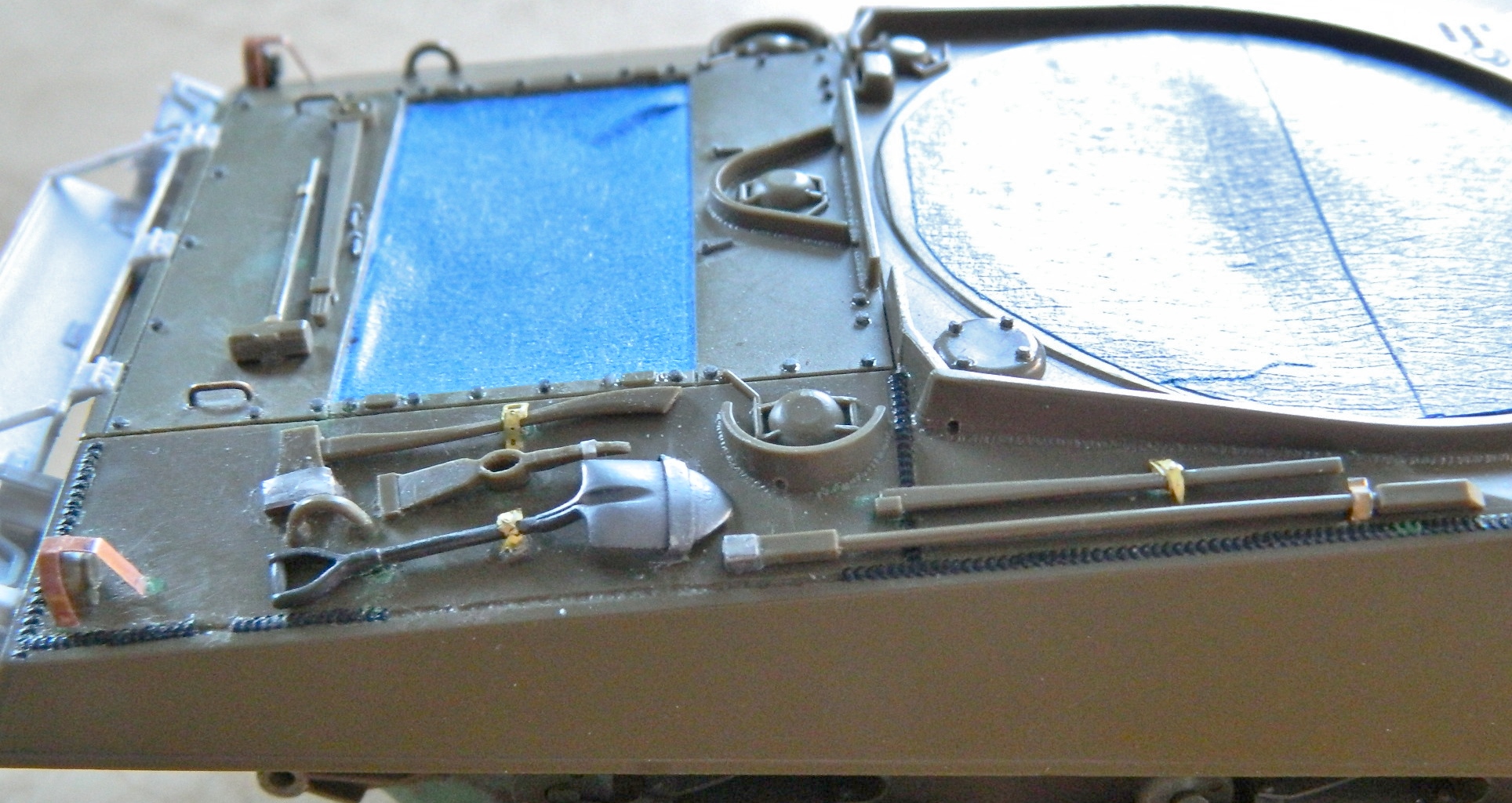
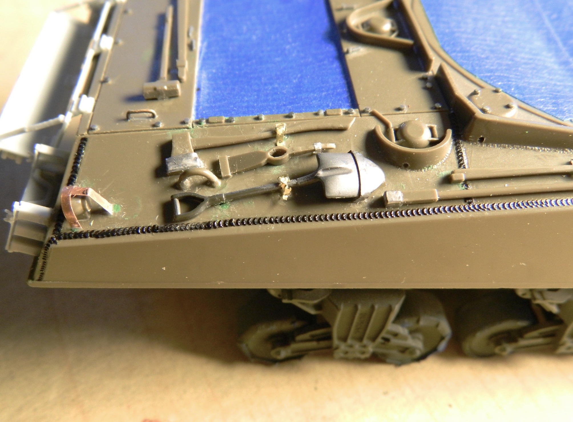
Tools don’t just sit there. Sherman tanks bounced a fair bit (saw a photo of one named, “Bouncing Bitch”), so anything not secured to the tank wouldn’t stay in place. What the kit has molded to the tools as “attachments” were unacceptable. The brass straps and buckles came from the Verlinden PE set, brackets and sockets were made from lead foil:
The engine covers are bolted closed and to open them they have to be unbolted. So where do the bolts go? I would imagine they’d just be set on top of the rear plates until it was time to close the covers. I modified four Grandt Line bolts, trimmed them to length, and glued them in place:
With the putty cured, I went back to the front and smoothed away the excess putty. Since I used .020″ (.508mm) sheet to add the missing fender sections, the edges needed to be thinned to replicate sheet metal (yeah, it’s still too thick for scale accuracy, but making them as thin as they should be would result in them being too thin for reality):
Okay, that looks much better:
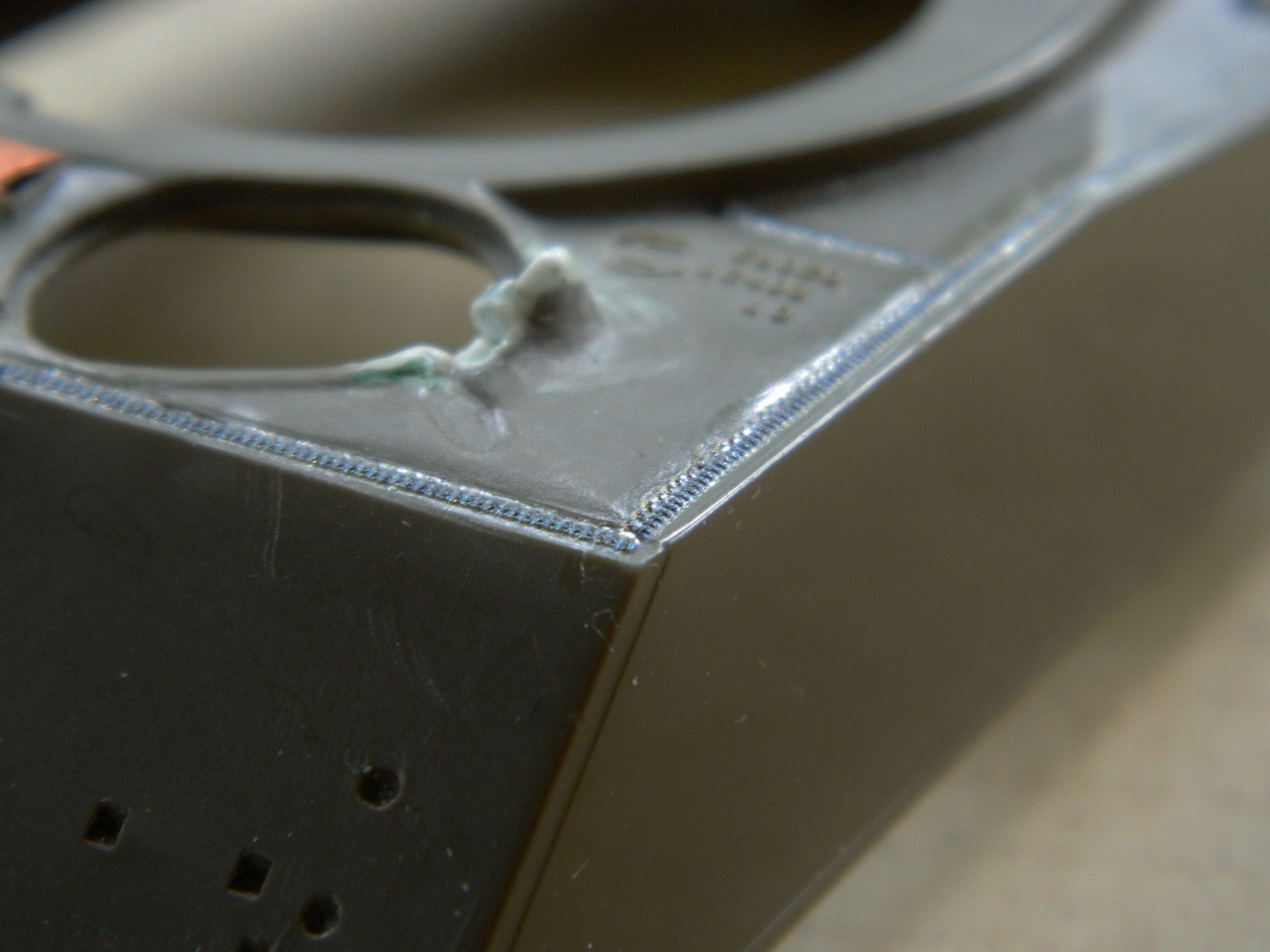
Since the goal is to get this under a coat of primer, and all of the fiddling with the top surface is done (I HOPE), I replaced the resin weld beads that had gotten knocked off during handling (lots and lots of handling):
Another part I want to paint while I’m in painting-mode is the tracks. I have the buffed-out steel already on them as my undercoat. For it to be an “undercoat,” there needs to be a topcoat. For all the wear a tank in the field is subjected to, the tracks get the worst of it. I wanted something that combined generic crud with old rust, so that means I have to break one of my rules and mix paints from different manufacturers to get the color I’m after.
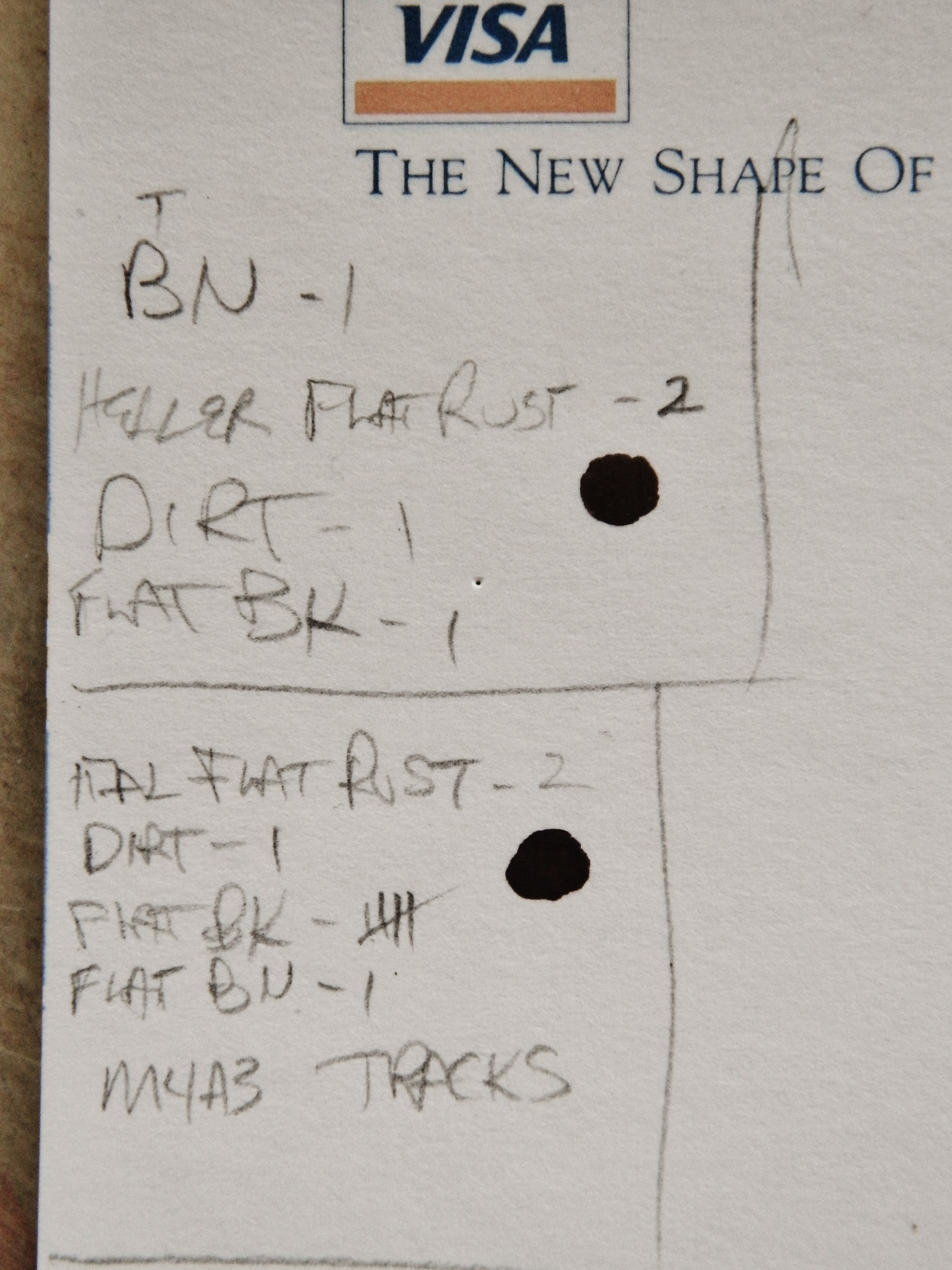
Heller’s Flat Rust is good if you’re after a reddish rust. But, like stupidity, rust comes in an almost infinite palette of colors. The first combined Tamiya’s XF-10 Flat Brown and XF-1 Flat Black, Polly-S Dirt (after twenty-four years it’s still good!), and Heller’s Flat Rust.
The second formula again used Tamiya’s XF-1 Flat Black and XF-10 Flat Brown and Polly-S Dirt, but this time I used Italeri’s Flat Rust which is browner than Heller’s version.
I don’t think the photo shows the colors well at all; I liked the second formula better than the first, so that’s what I’ll be using on the tracks for the topcoat.
The numbers or hash marks after the color indicates how many parts of which particular color are in the mix, so the first formula is one part each of brown, dirt, and black, and two parts flat rust. The second formula is one part each of dirt and brown, two parts flat rust, and five parts black:
Never one to miss a pun, it’s prime time!
M4A3 (Tamiya) Build #21
Before I can permanently attach the upper hull to the lower, there’s just a few of things left to do; attach the .30 caliber, shoot the surfaces with clear matte, and then apply pastels to grunge it up a bit. First the .30 caliber:
Then clear matte and pastels:

And then the hull gets glued into place:

Now I can redress Tamiya’s oversight regarding lack of sponson bottoms. Archer Dry Transfers has this template on their site:

However, its length is a bit off:

Unlike some things, adding a bit of length is easy:

When I assembled the tracks, I tried dry-fitting them to the spare kit and in addition to realizing that I was about two hands short of what I needed to easily add them, they were a tight fit. NTMD has a simple solution that I availed myself of. These mounts are eccentric (unlike your humble Narrator, who is merely “colorful”) and thereby can adjust where the rear idler wheel sits and allowing for easier (I HOPE) fit and tensioning of the tracks:
First the molded on mount gets removed:
Then a hole of the proper diameter to mount the eccentric is drilled:
And then adjustability is possible:


I cut the sponson bottoms from 010 styrene and glued them into position. Yes, the template suggests 040. The reason I went with lighter stock was because due to the resin AM parts, the thin stock would be well supported.
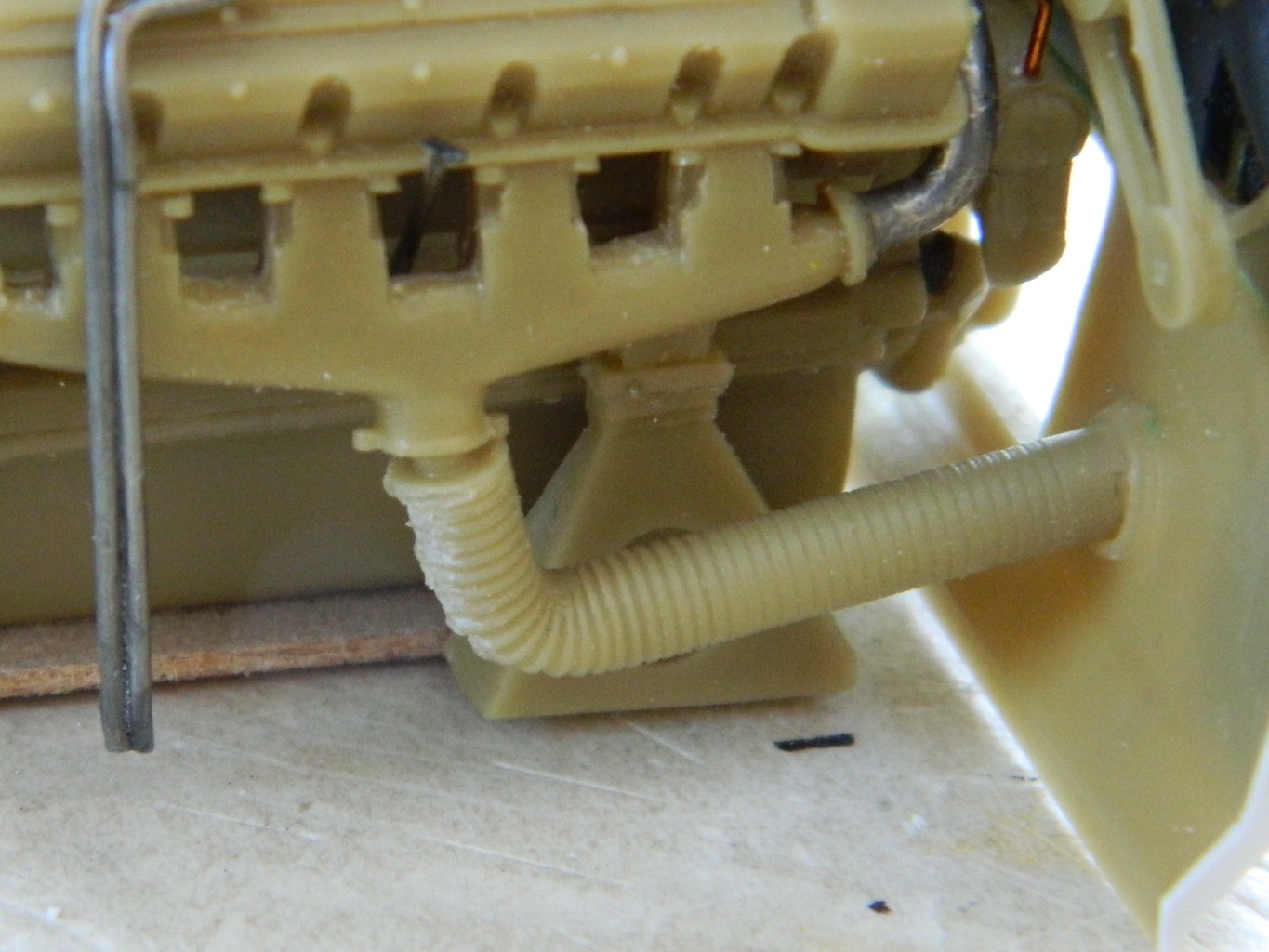
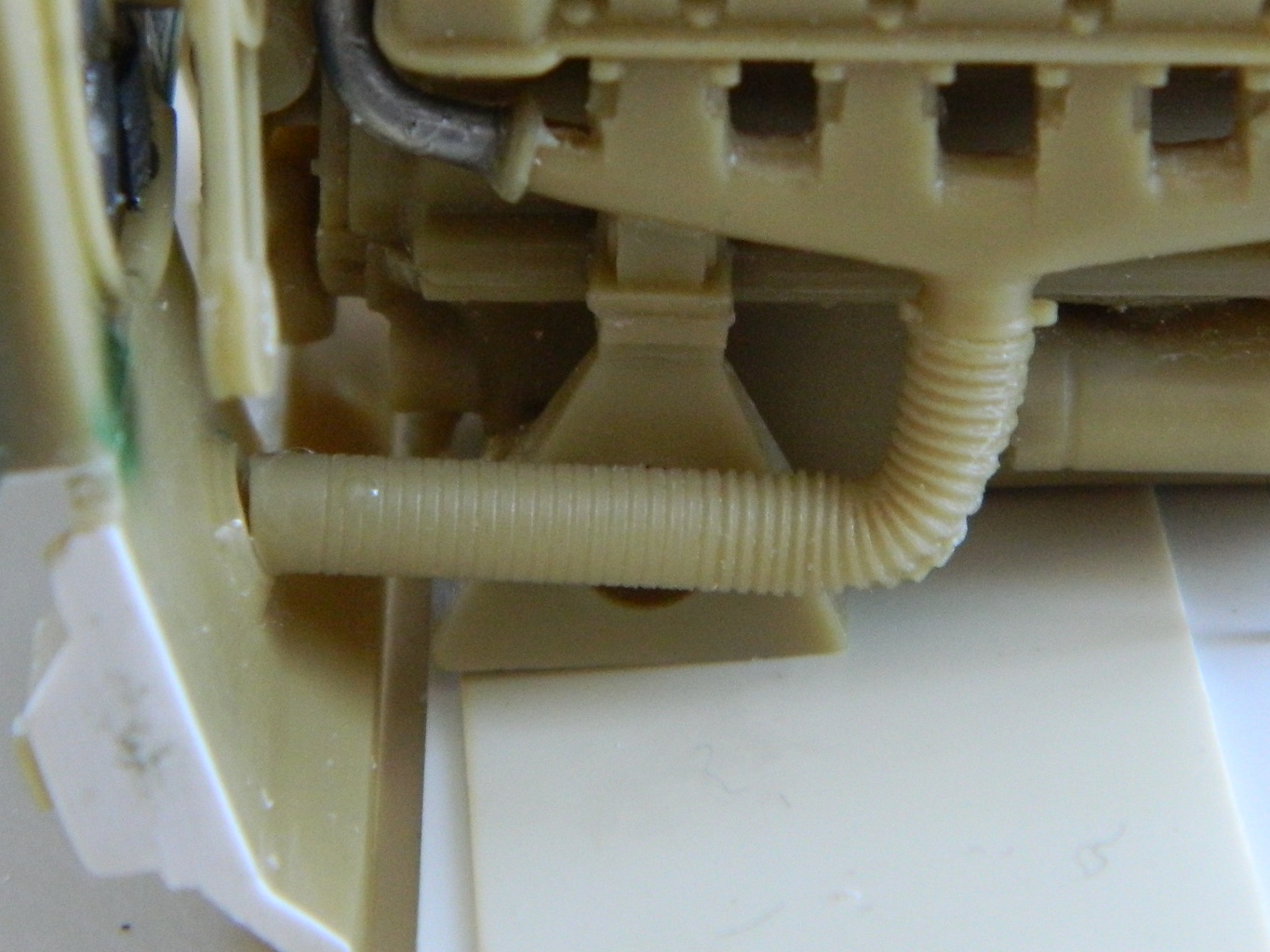
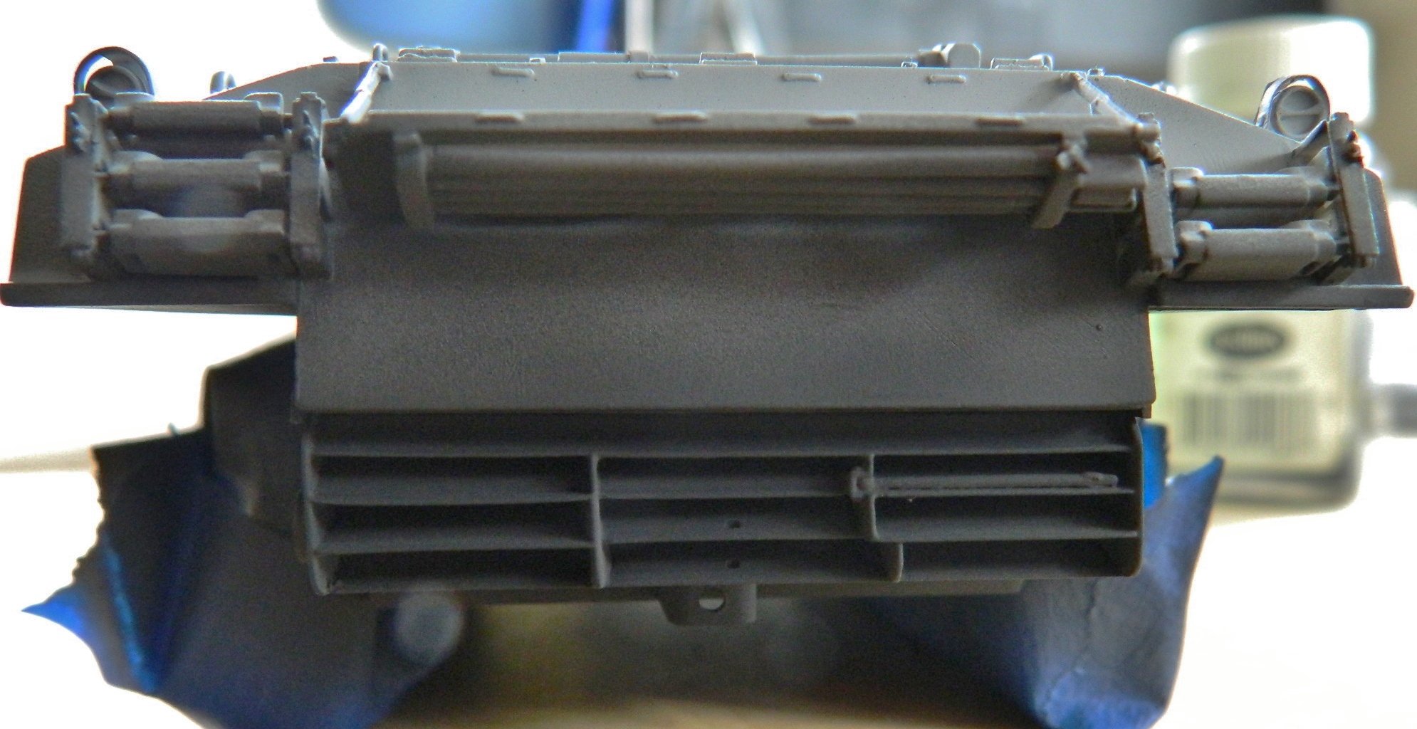
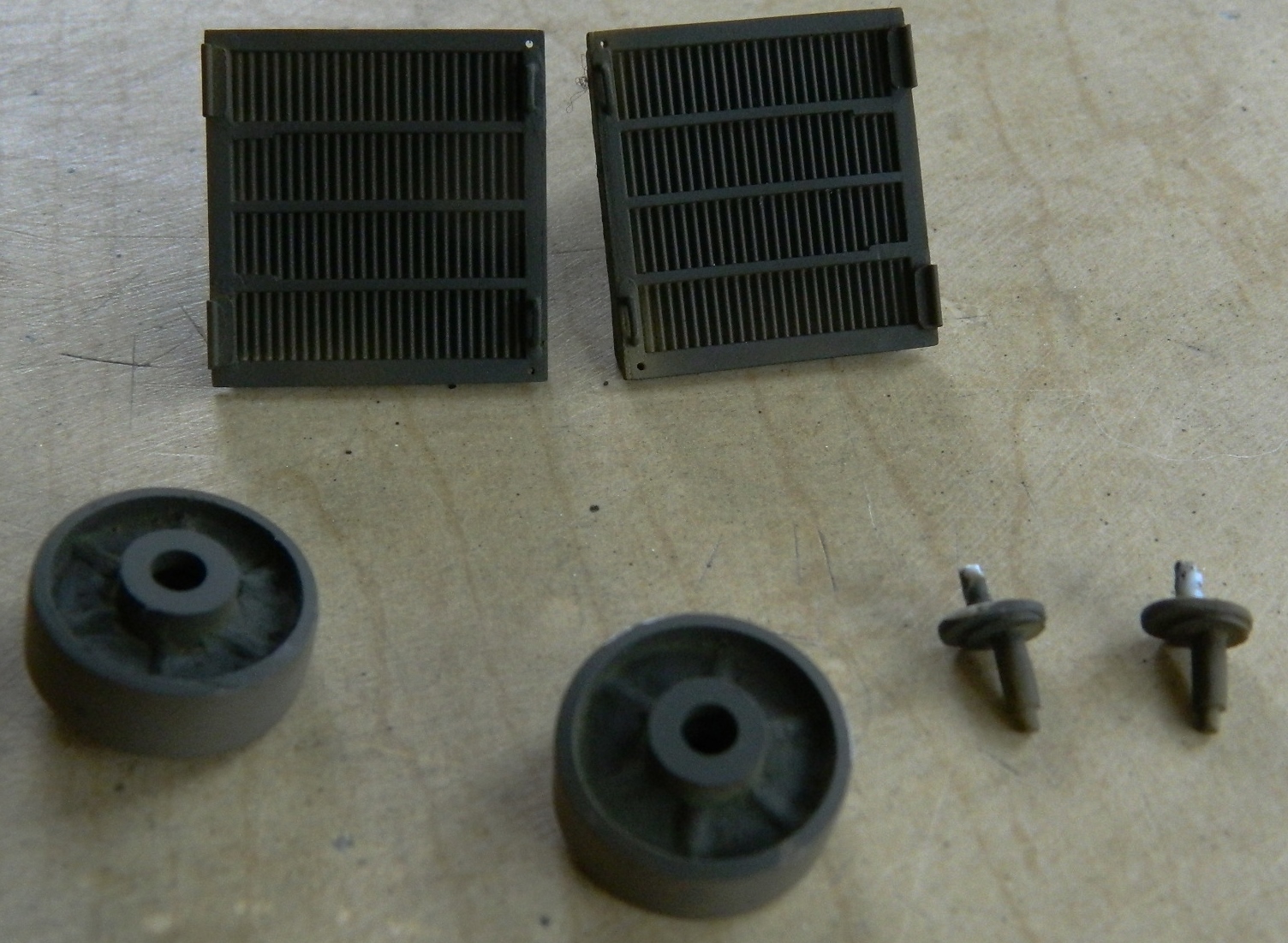
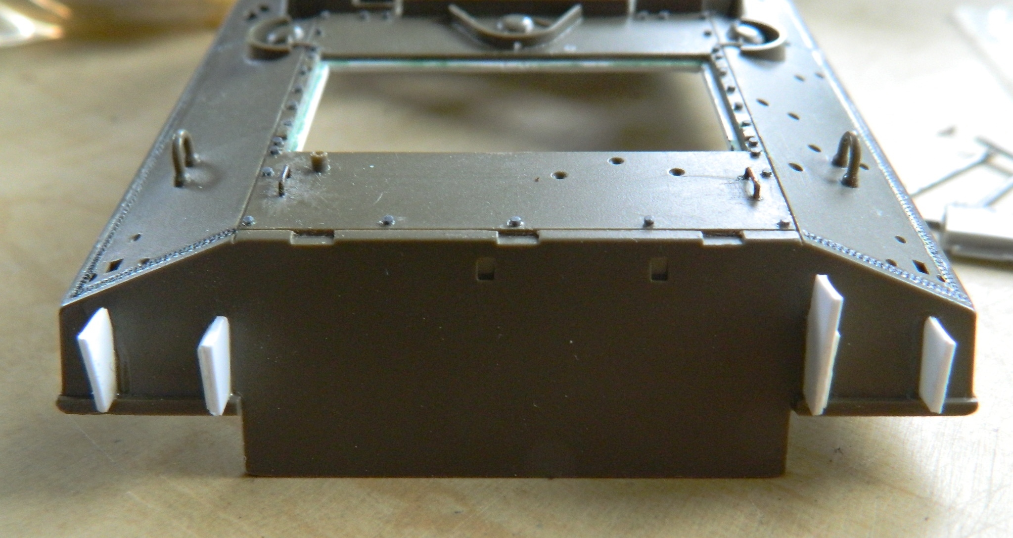
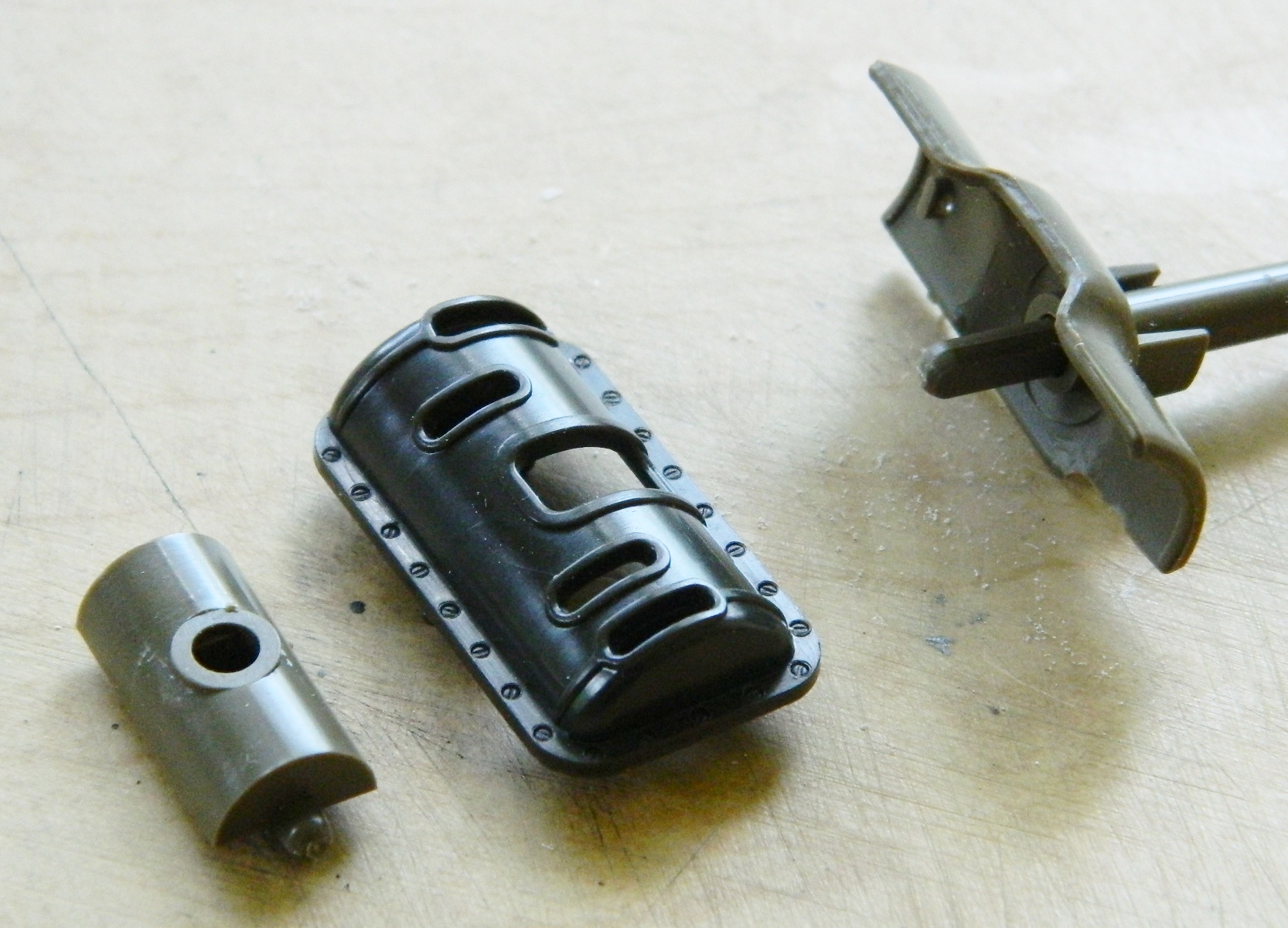
I checked the fit of the exhaust deflectors and though not quite as precise a fit as I would hope for, it certainly falls within the 90-95% tolerance:

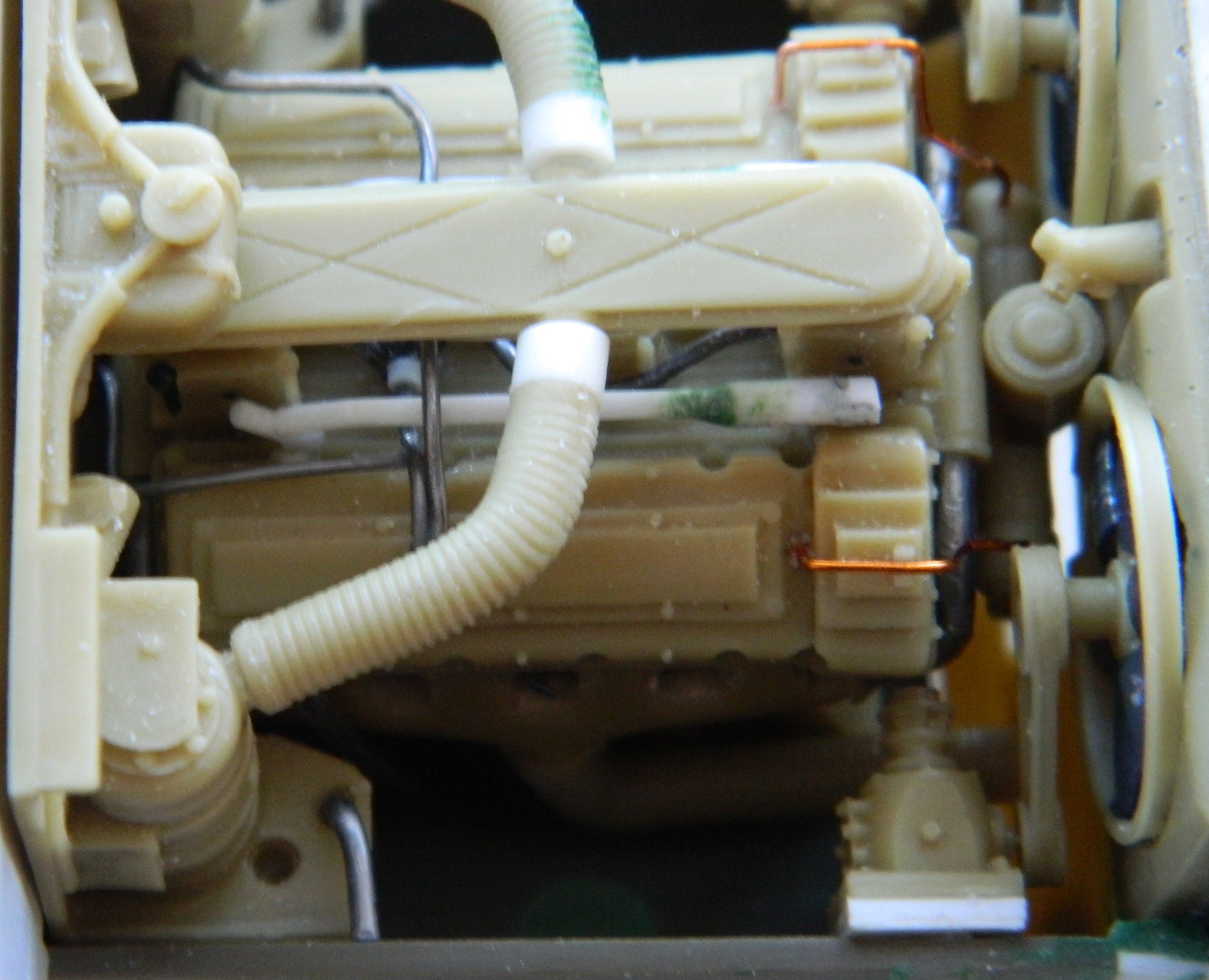
And perfectly hides the radiator ducting I’d made (oh well):
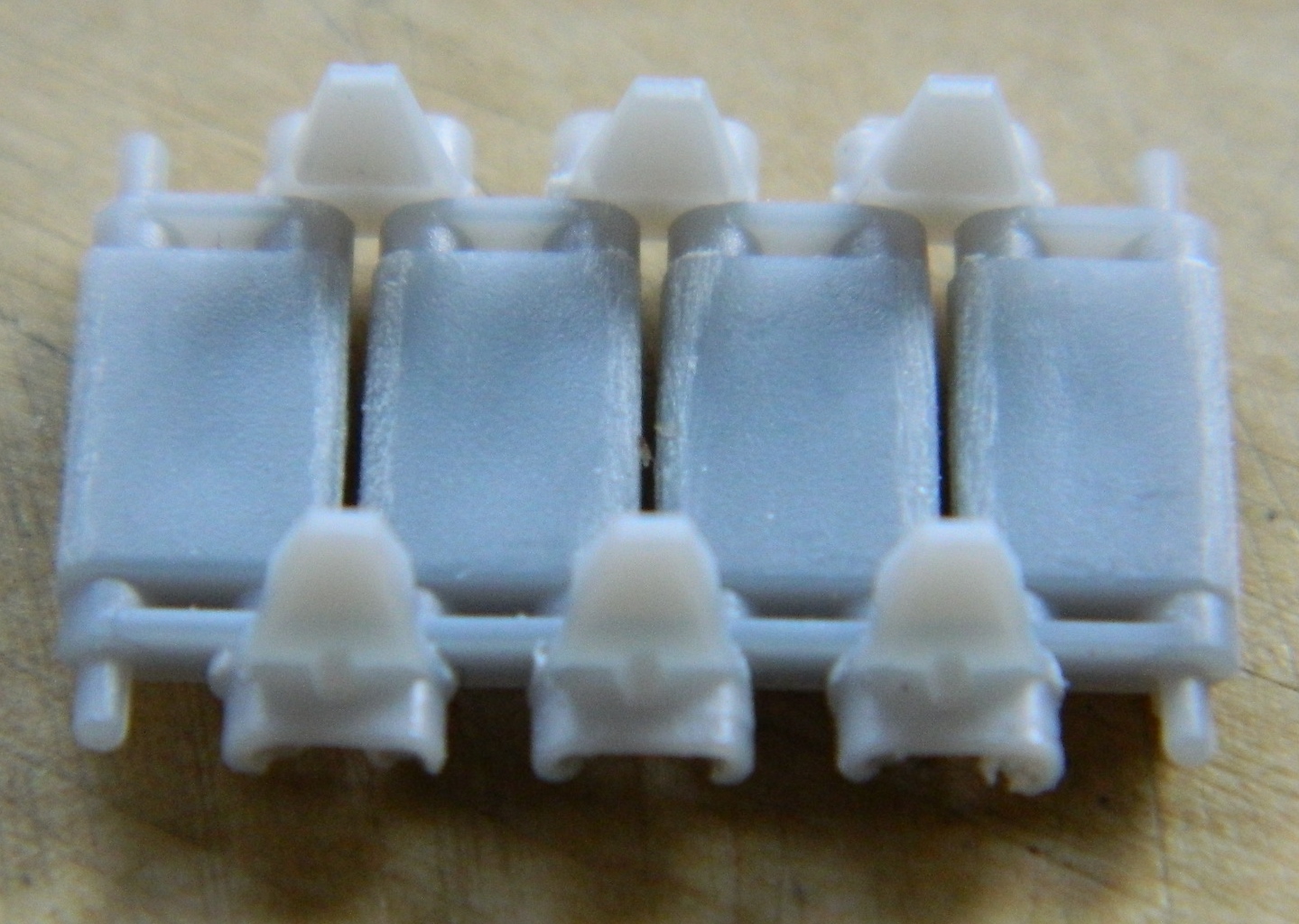
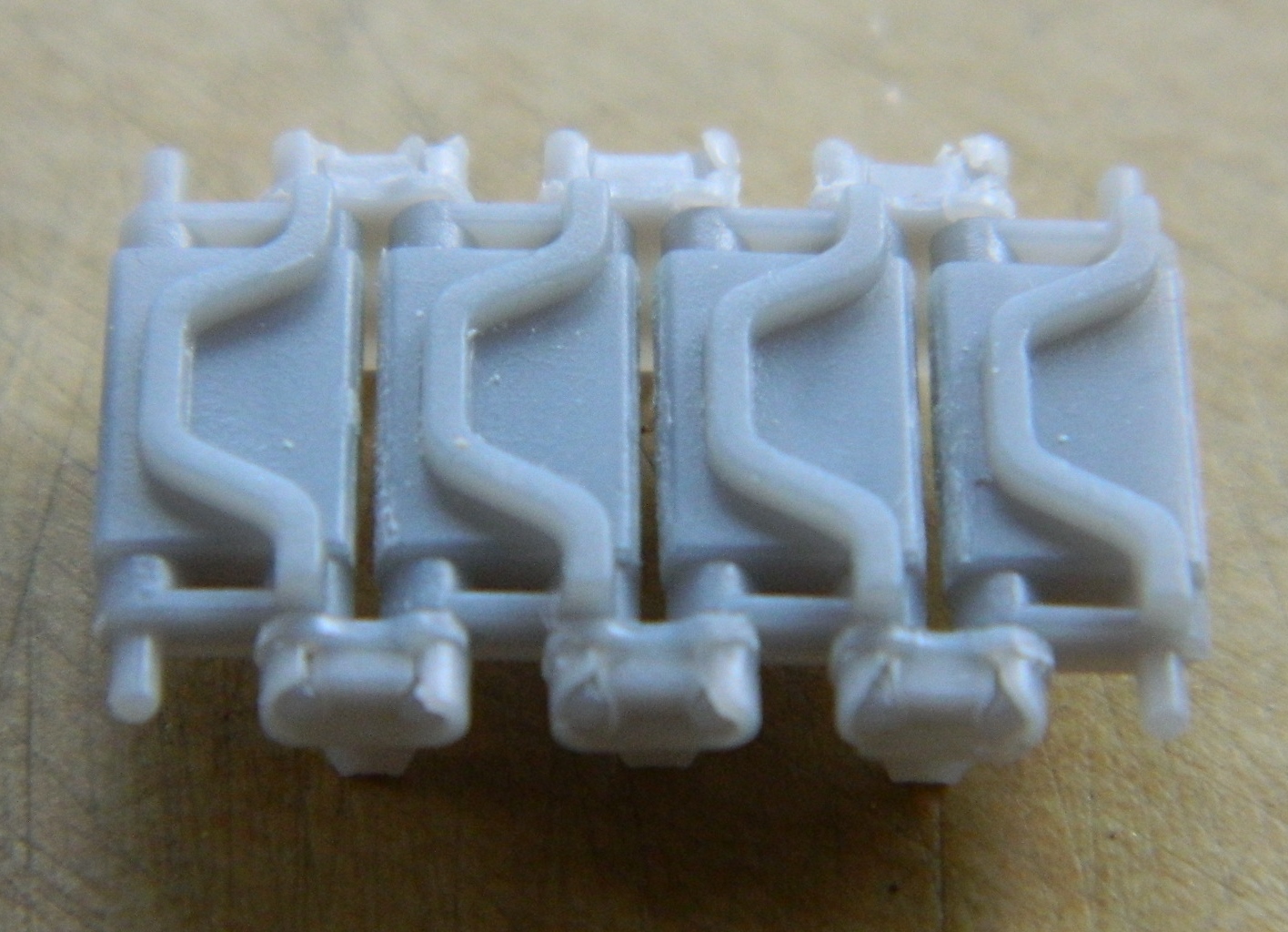
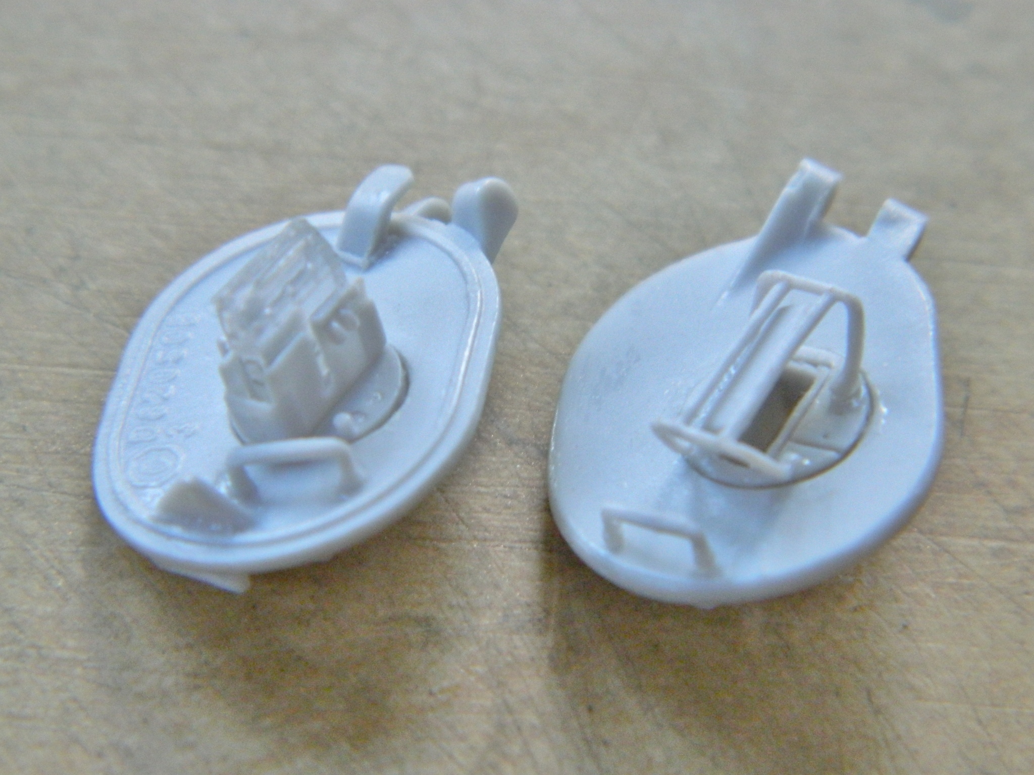
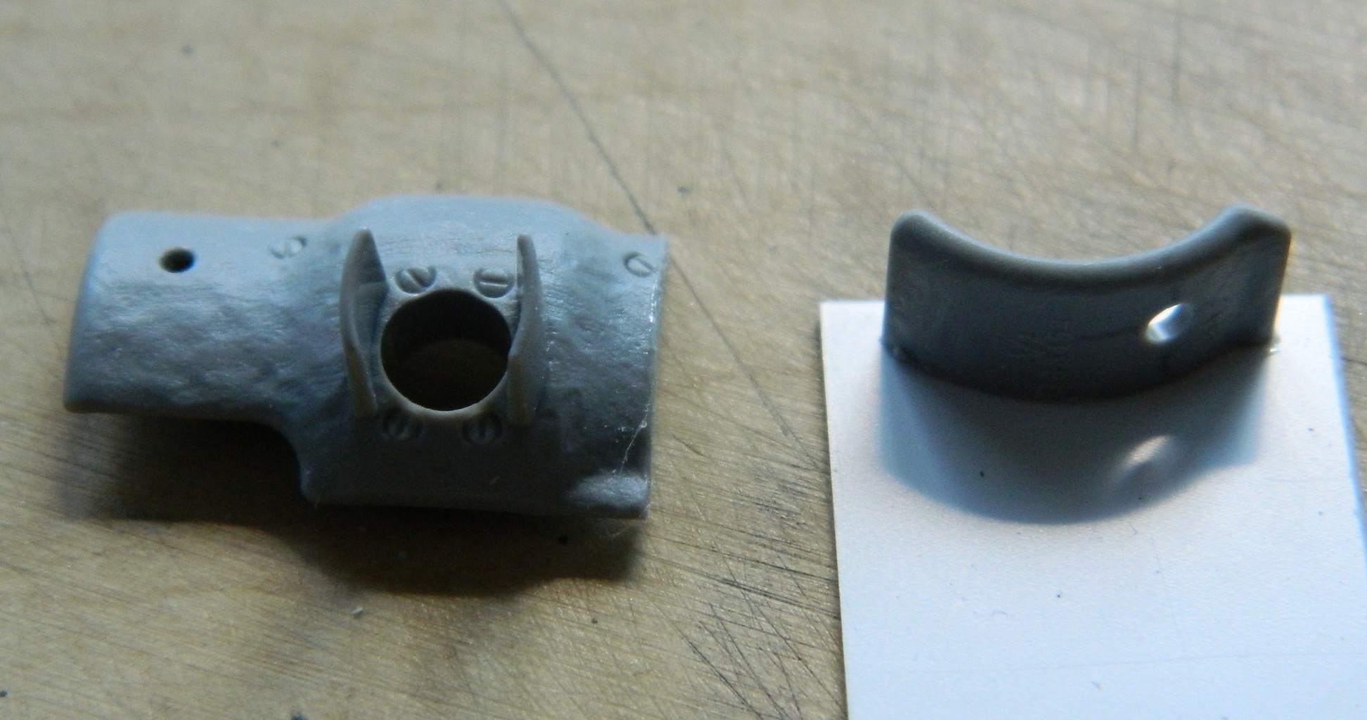
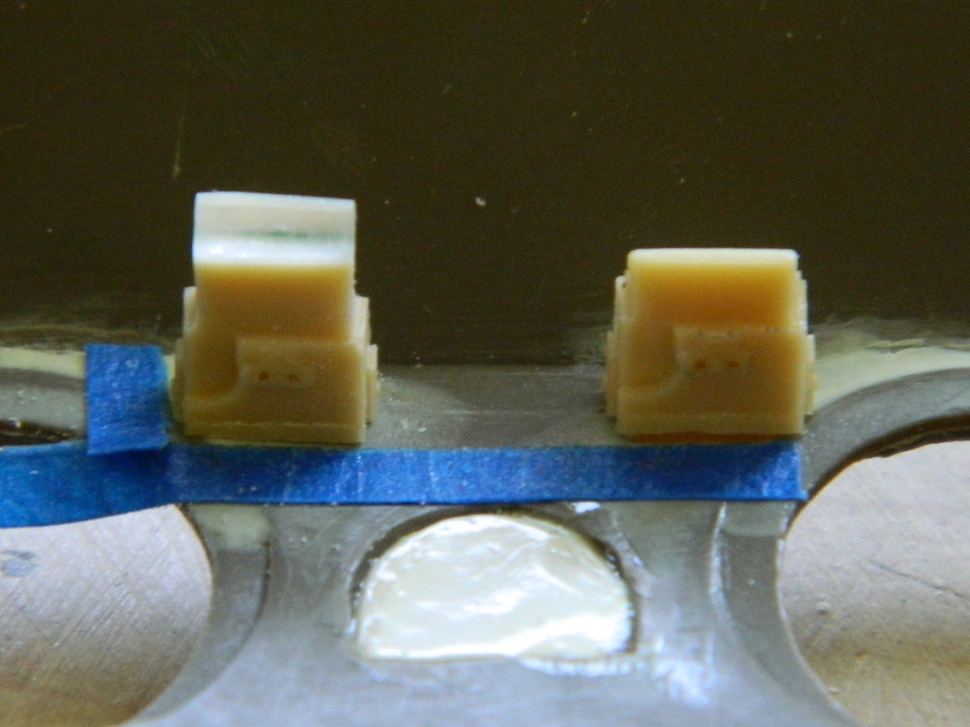
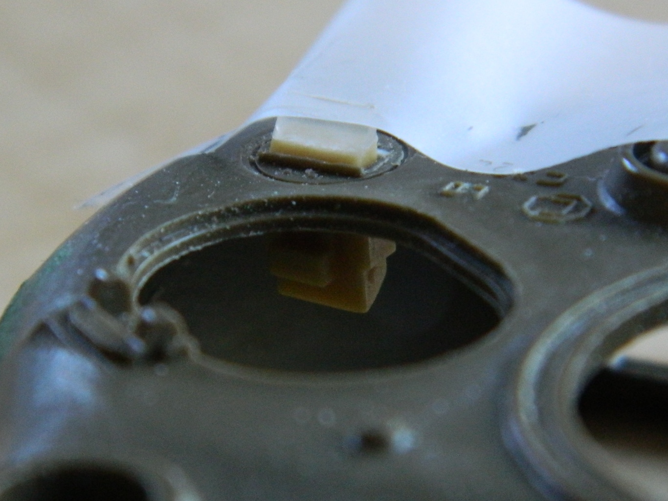
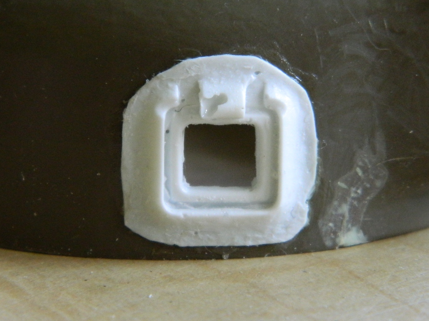
Okay, pay attention. This is a test. Aside from the fact that one part is resin and the other injection-molded styrene, what’s different between these two parts? (Hint: Look at the round depressions on either side of the engine access door, particularly to where the “D” shaped depressions are and are not.):


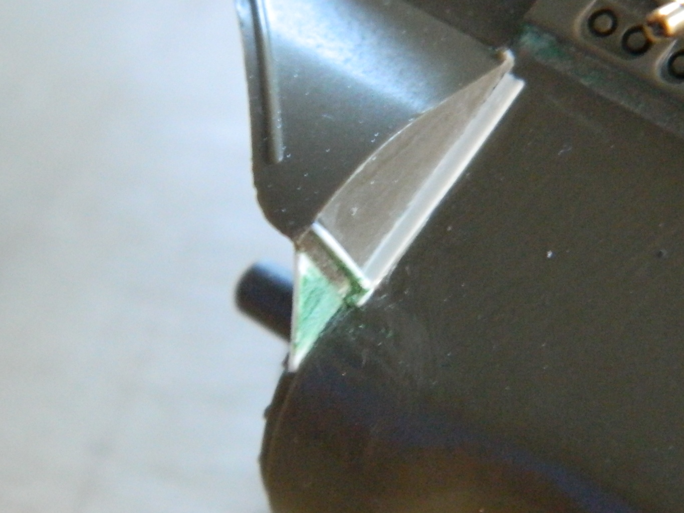
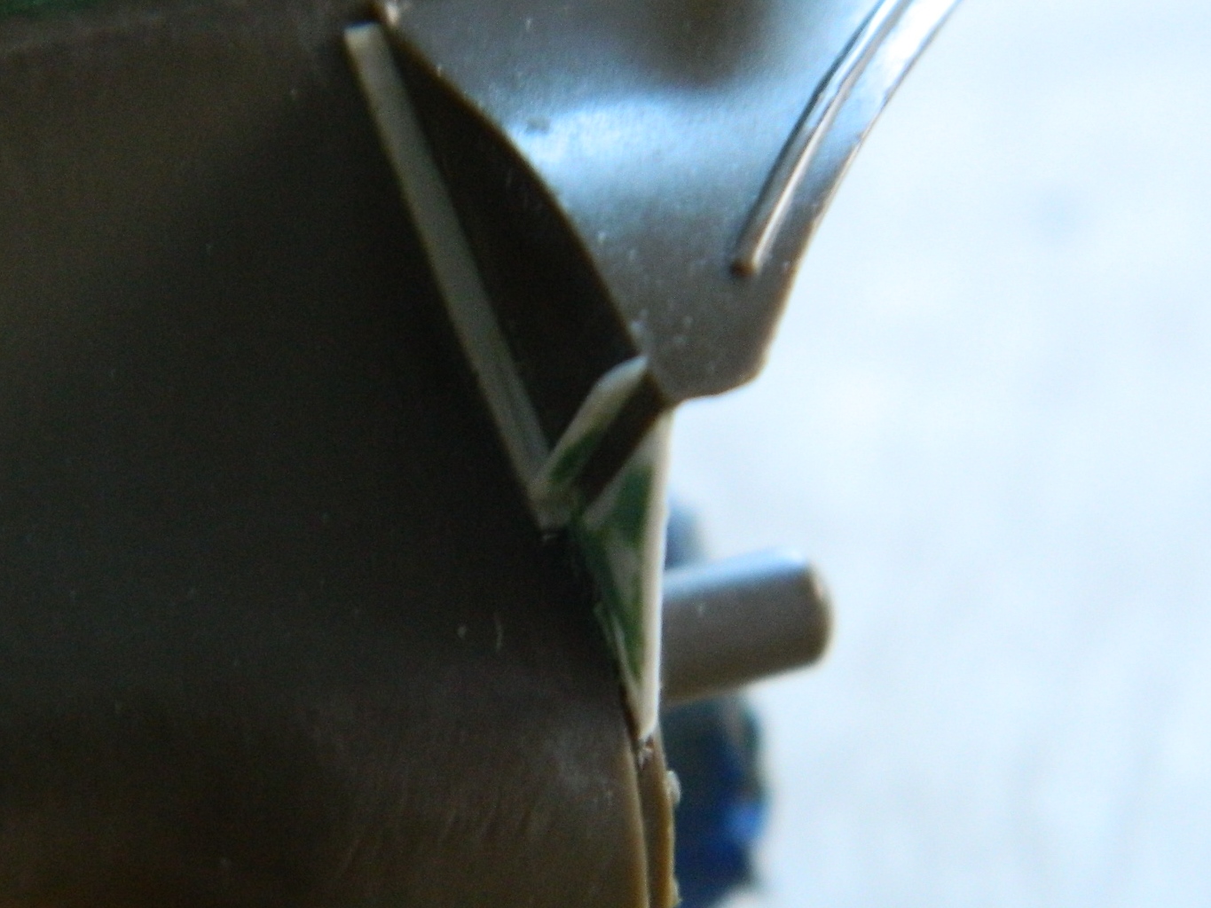
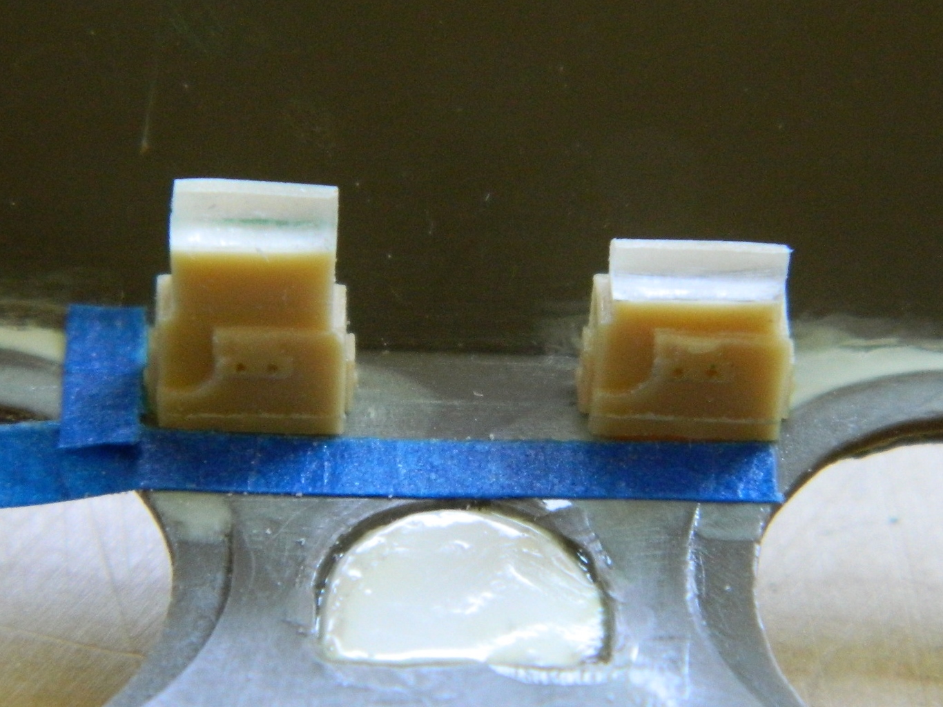
In case you didn’t see it, because I didn’t see it until I figured out why the exhaust tips did not fit, the depressions are reversed. Yes, the AM set got it wrong. When you look at this photo you will see the styrene I had to add (the white areas) to get the tips to (mostly) fit:
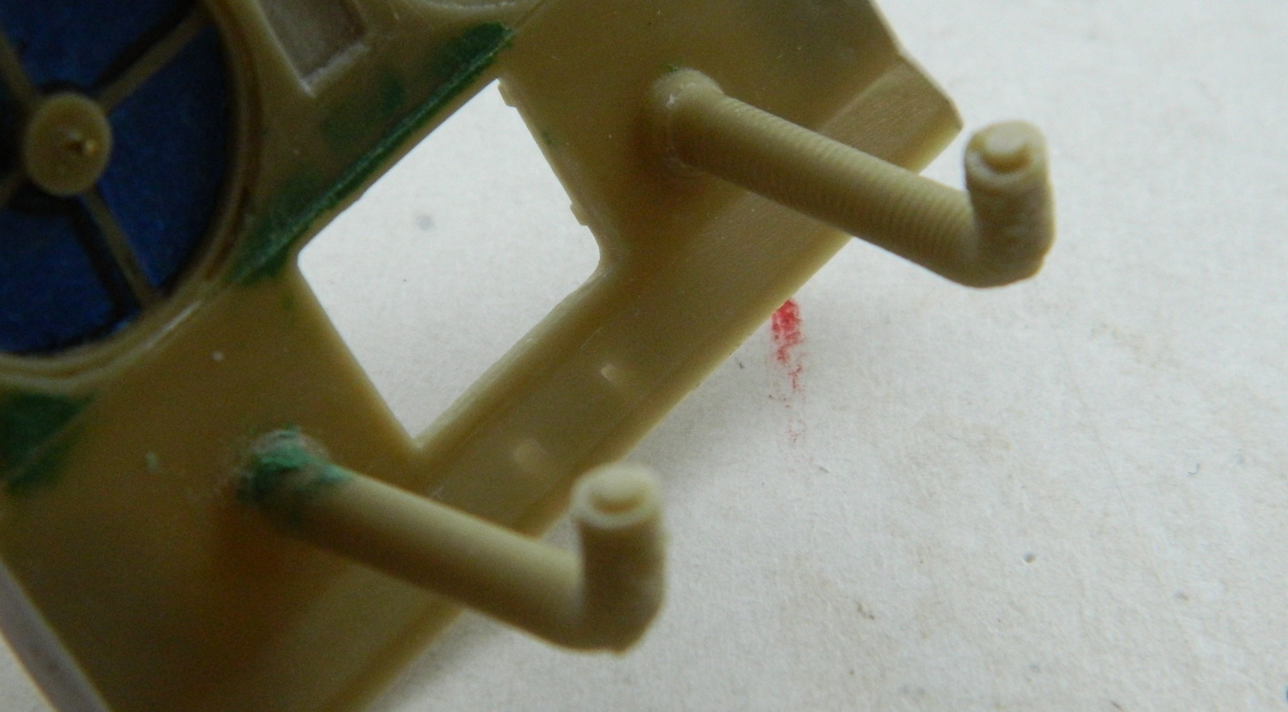
I inserted “mostly” next to “fit” because the tips are supposed to fit into the slots of the deflectors and this is the closest I can get them:

But given how hidden area is from casual view (because anybody picking this model up to look at it will have other things to concern themselves with, namely a “colorful” and irate builder), this is what I’m going to stay with:
M4A3 (Tamiya) Build #19
I’m going to add some PE details. They’re thinner than the kit parts and often more accurate to scale (but sometimes they’re thinner than they should be, so, obviously, check), but they’re flat and will need to be bent.
I’ve bent PE details before and that process can sometimes be quite annoying. Bend, it’s wrong; unbend to get it flat, bend it again to get it right, and so on. The problem with bending metal is that it will only bend so many times before it fatigues and separates (I’ve heard that sometimes marriages also have this problem). The obvious remedy to this is to bend the part only once (not sure that would apply to marriage).
Micro-Mark makes a useful bending brake for folding and bending PE parts (though sometimes you will still need to make your bends using jeweler’s pliers). The “fingers” allow multiple bends and if you need to bend one long piece, the finger-plate can be reversed and acts like a traditional bending brake (albeit a small one):

The part is aligned to the appropriately-sized finger and the clamp tightened. Then a straight-edged razor blade is used to lift the part and create the bend. After that, it’s a matter of loosening the clamp and moving the part for its next bend. In this case, I’m using a Verlinden PE set for the Sherman and bending the ammo box holder that attaches to the side of the .50 caliber:


The end result, though it looks nice, seems just a little too thin for my eye and at this point reserve judgement as to whether or not I’ll use it.
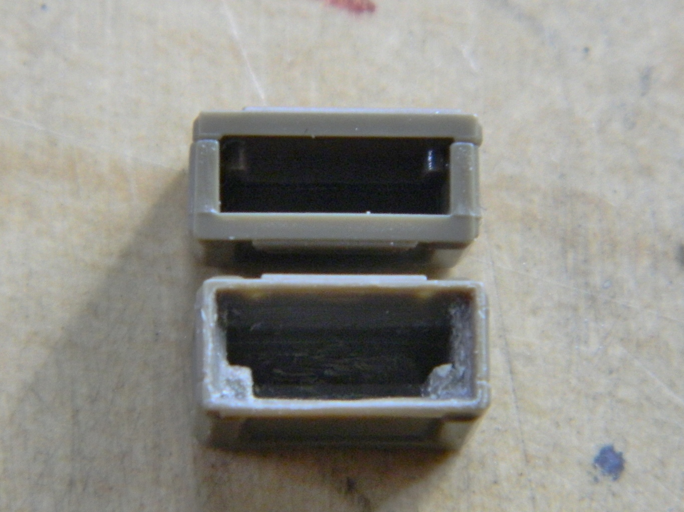
But the ammo box itself (kit part) wasn’t intended to be modeled open. As such, the sides are WAY too thick and needed to be thinned enough for a scale ammo belt to sit in the box properly:

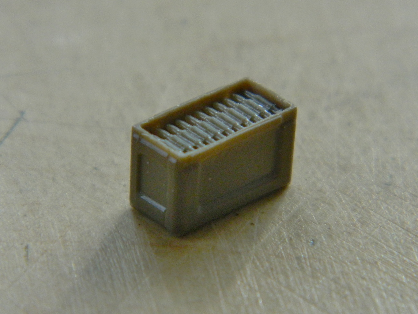
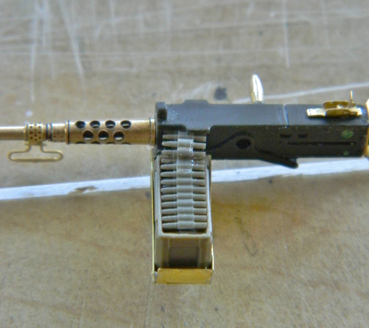
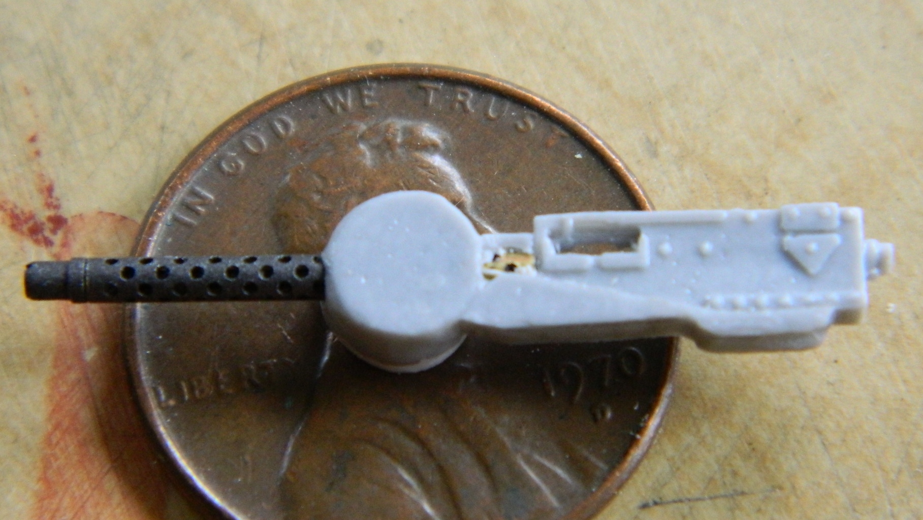
The vendor (M&M Models) who provided the .30 caliber barrels also provided this nice little detail set to upgrade the .50 caliber:

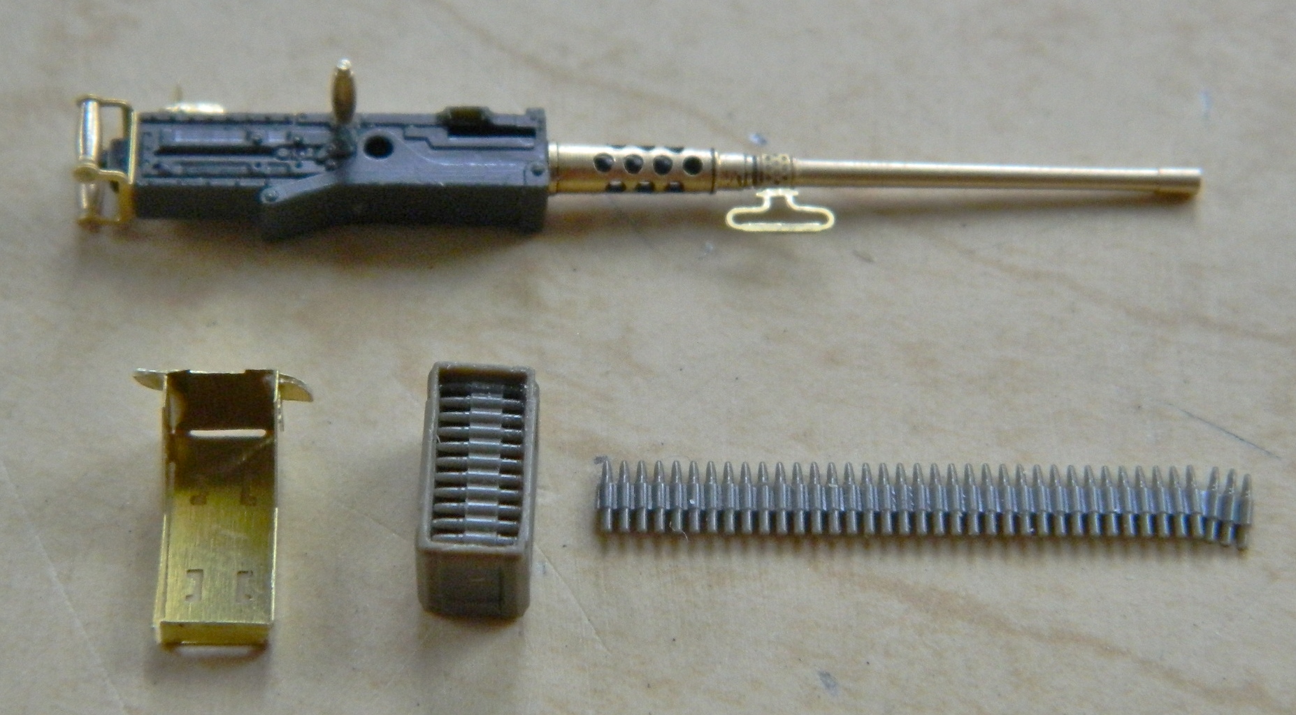
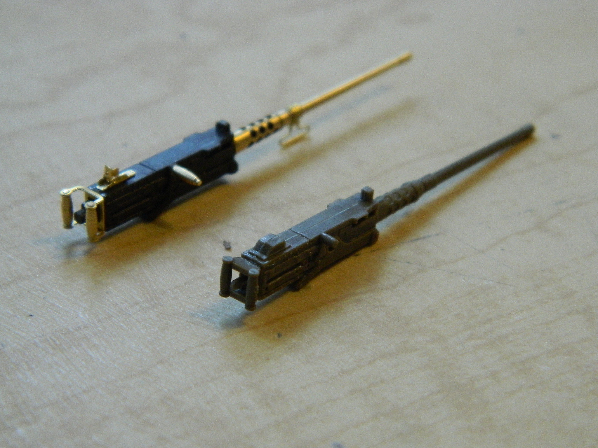
Just so you have an idea as to the difference this makes, lookit this:
By this time I had finished making the vacuum pump and chamber and it was time to pour some molds and make some copies.
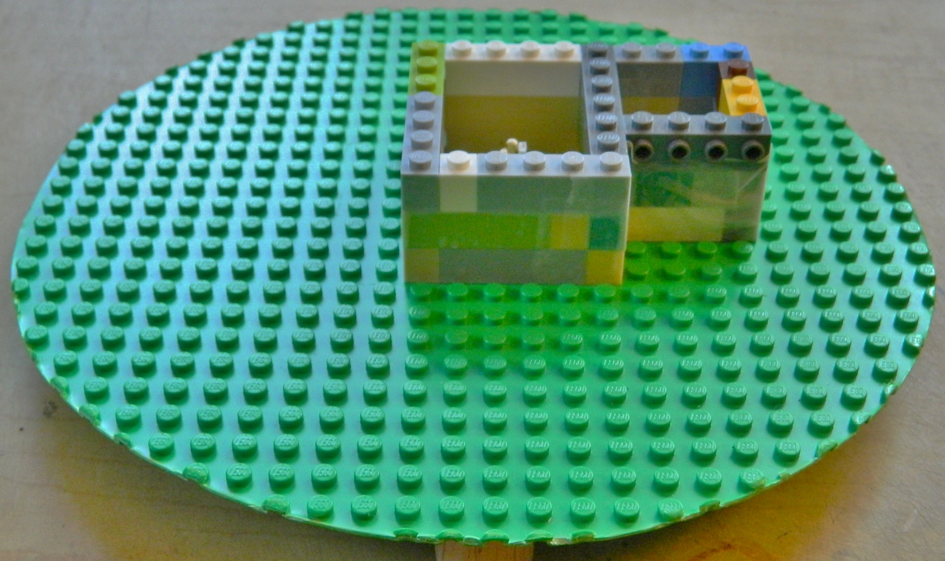
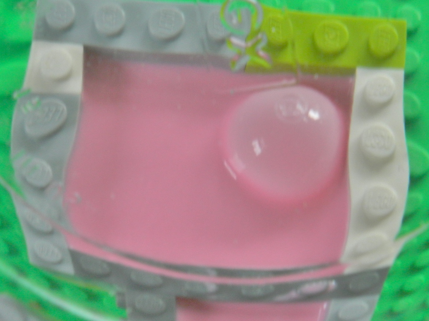
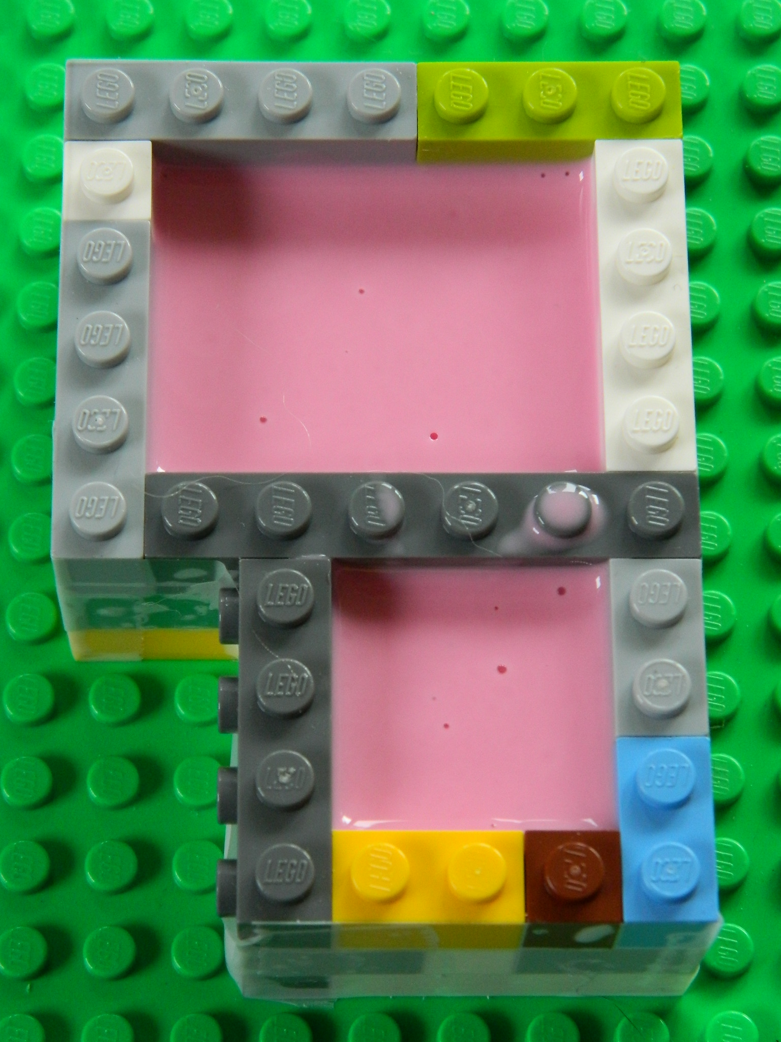
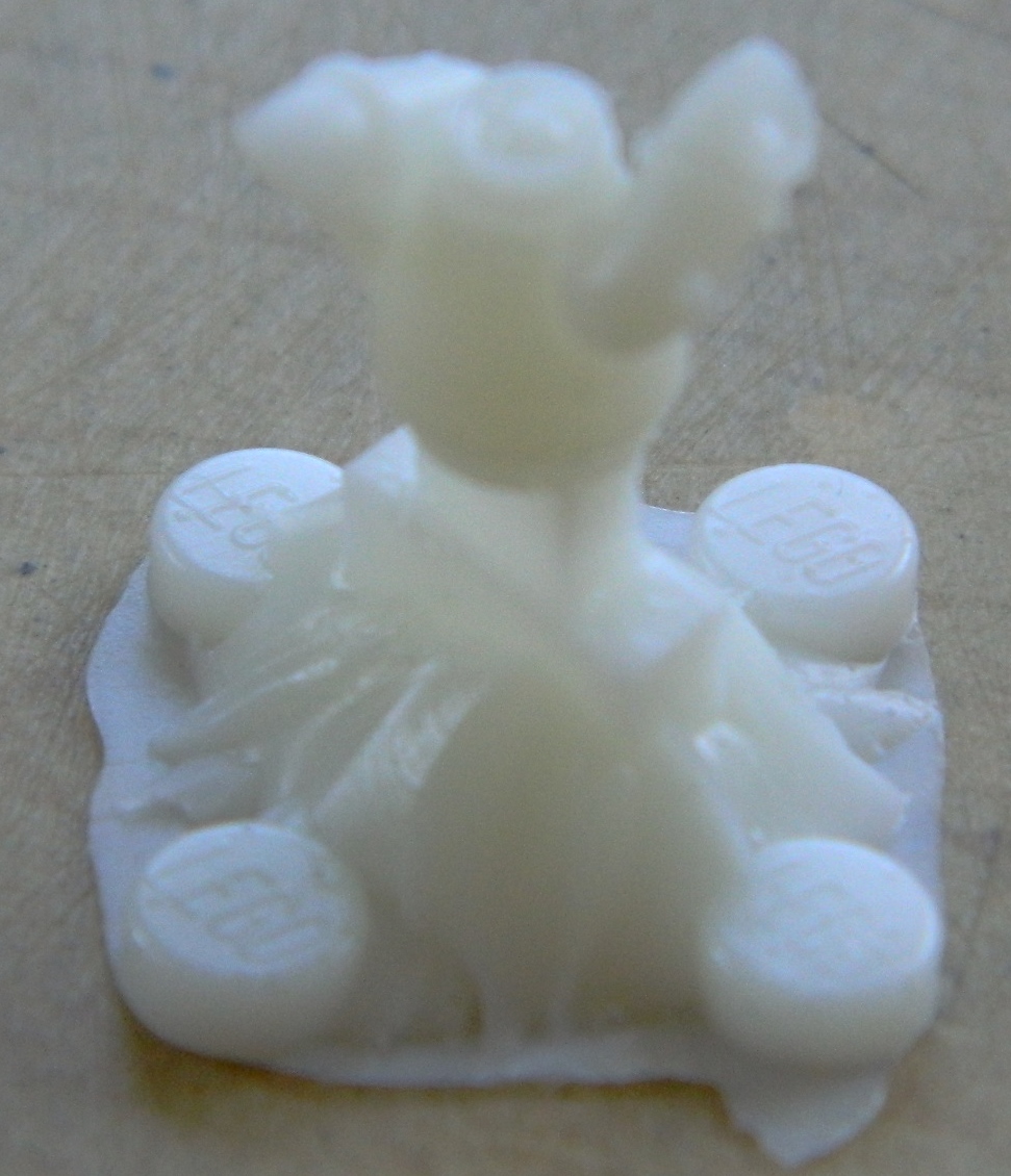
While thrashing around the ‘Net looking for information about vacuum pumps, I ran a cross a YouTube video that showed a modeler using Lego parts to make mold boxes. Well, I thought that was rather clever and got me some (and I had NO idea Legos were so damned expensive!).
Micro-Mark supplied the two-part mold making rubber as well as the parting agent. The parting agent is sprayed wherever you don’t want the silicone molding rubber to adhere (and there is a parting agent specifically for silicone molding rubber to keep it from bonding to itself, which is necessary when making a multi-part mold so you can open the mold up):
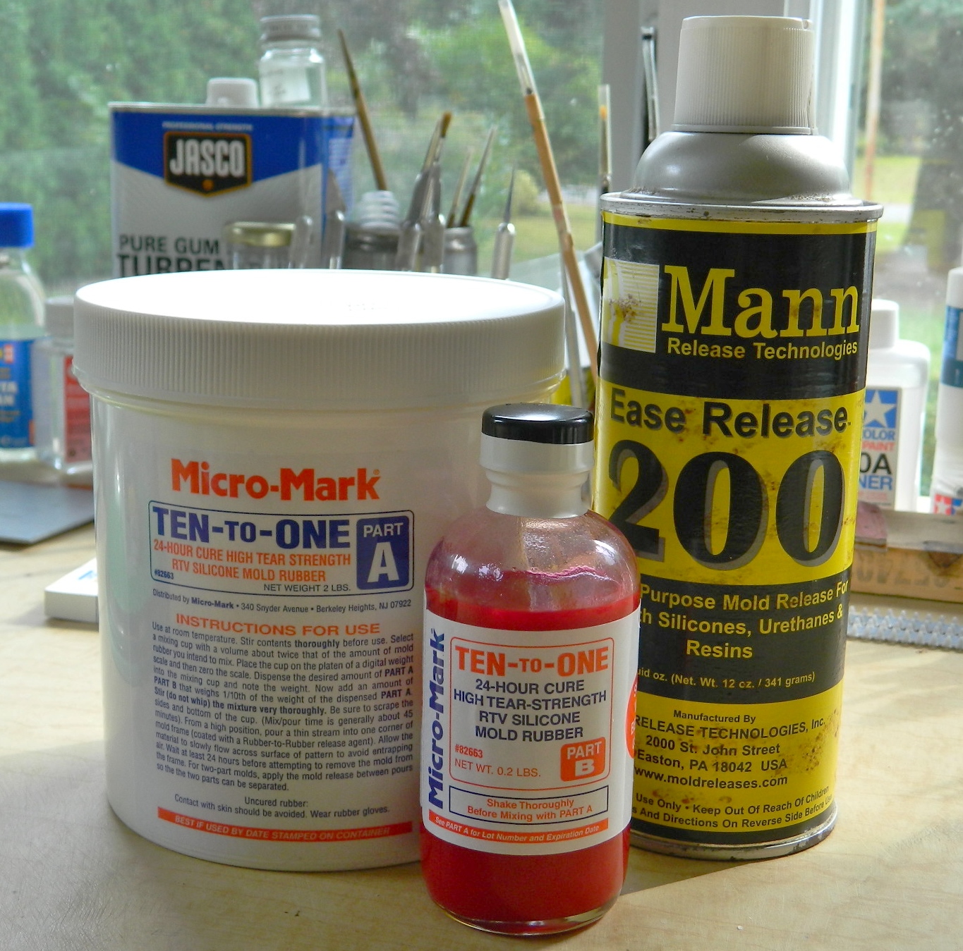
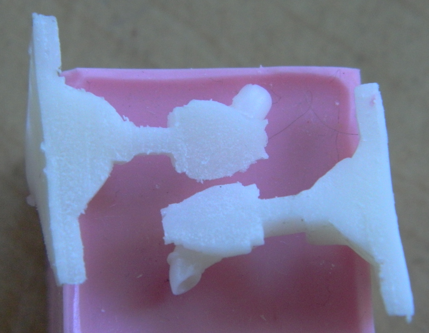
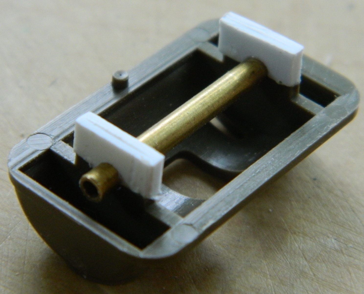
I attached the brass master I’d made for the blower assembly to a resin pouring cup I’d made with the reusable molding compound and used white glue to fix it in place to the Lego base and then built the mold boxes. The other part I’m taking a mold from is a piece from Verlinden’s detail set for the M3-M5 light tanks (just to see if it’s possible at my skill level and to have a sacrificial casting I can cut in half so that I can check for the propagation bubbles):

The two-part molding compound has a hardening agent that’s mixed into the rubber compound so air bubbles also get mixed into the compound. For both the molding rubber and resin, I selected items that had the longest pot life. This allowed me the time I needed to degas the compounds. Here you think you can see the bubbles:
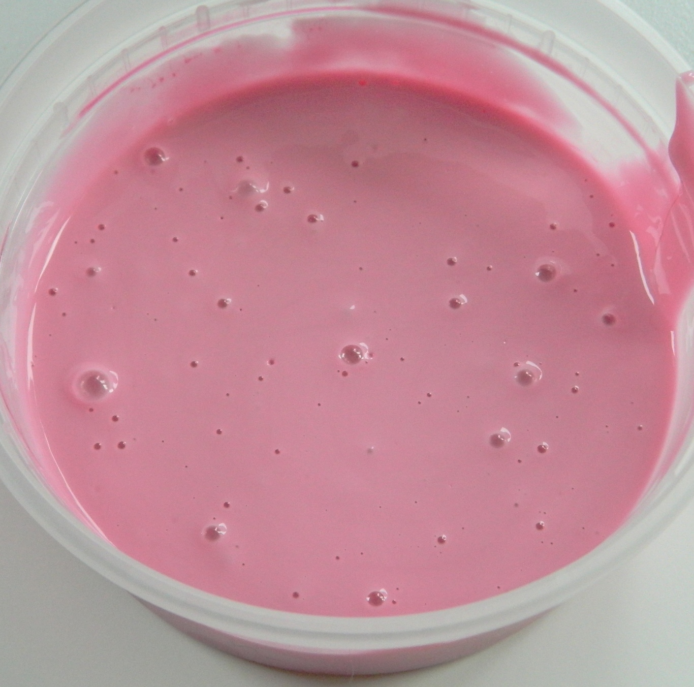
When the compound is exposed to a vacuum, this is what’s actually in the compound (and all those little nubbins are bubbles that haven’t made it to the surface yet):
A hint about molding. Before you start mixing compounds, molding or resin, have what you need the compounds for ready before you start mixing.
The molding compound has a 45 minute pot life, so I mixed it, degassed it for 20 minutes, and since the mold box had already been sprayed with release agent, I poured the molding compound into the box and degassed them for another 20 minutes:

With only a partial vacuum (the best my pump will manage is about 28″ of vacuum) and a time limit (pot life, y’know), there’s no way to get all the bubbles out. But I can get the large bubbles out, and when the vacuum is released, normal air pressure causes the small bubbles to compress to the point where they can’t be seen or screw up the part you cast in the mold.
The mold is taken out of the vacuum chamber and allowed to sit until the molding compound sets up and cures (for this compound, 24 hours):
The next day I popped the excess molding rubber out of the mixing container and cut it in half to check for bubbles. Whatever bubbles are there, I don’t have the microscope to see. Good enough:

When I was assembling the molding boxes, I noticed there are small gaps between the blocks. Having not used this molding rubber before, I didn’t know the extent to which the rubber would insinuate itself between those cracks. To eliminate that insinuation, I used scotch tape to cover the cracks…and it seems that was a good idea. Taking the blocks away showed me there was a degree of insinuation:
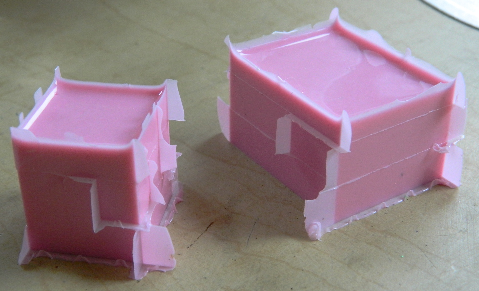
With the rubber out of the boxes, it was time to get the masters out of the rubber. With the smaller mold, its shape acted like an anchor which required me to cut the mold down the sides to release the master:

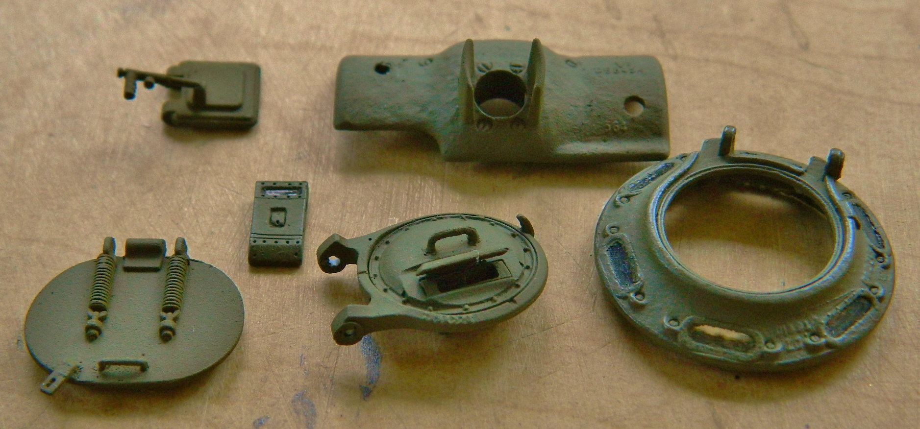
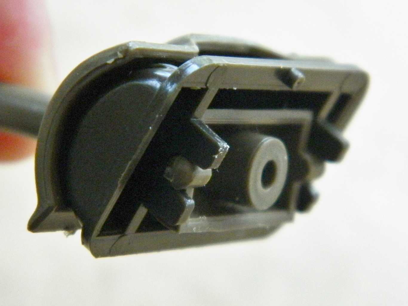
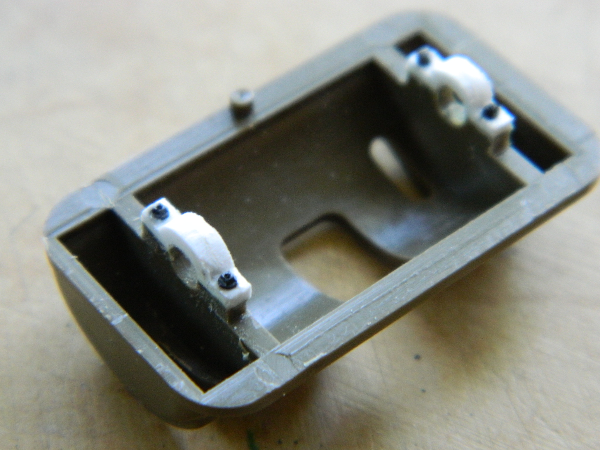
To get the blower assembly out, all I had to do was to cut away the rubber to get at the master, flex the rubber, and pop the master out (the switch box came out separately as the process of popping the master out caused it to detach):

THANKFULLY the resin is mixed by volume and not by weight. I used a cut down plastic cup as my mixing bowl. I expected a degree of froth from the mixed resin during degassing but I didn’t know how much, so I wanted to leave enough volume in my mixing cup to keep from having to clean up (another) mess:
As with the molding rubber, the resin compound was mixed and degassed. Since the resin compound only has a pot life of 20 minutes, I degassed the mixed compound for about 7 minutes, poured it into the molds, and then degassed for another 10 minutes. After degassing, I wanted to leave enough time for the very small bubbles to be re-compressed by atmospheric pressure so as to become invisible:


This is another 24 hour cure, so I let it sit overnight before removing the castings:
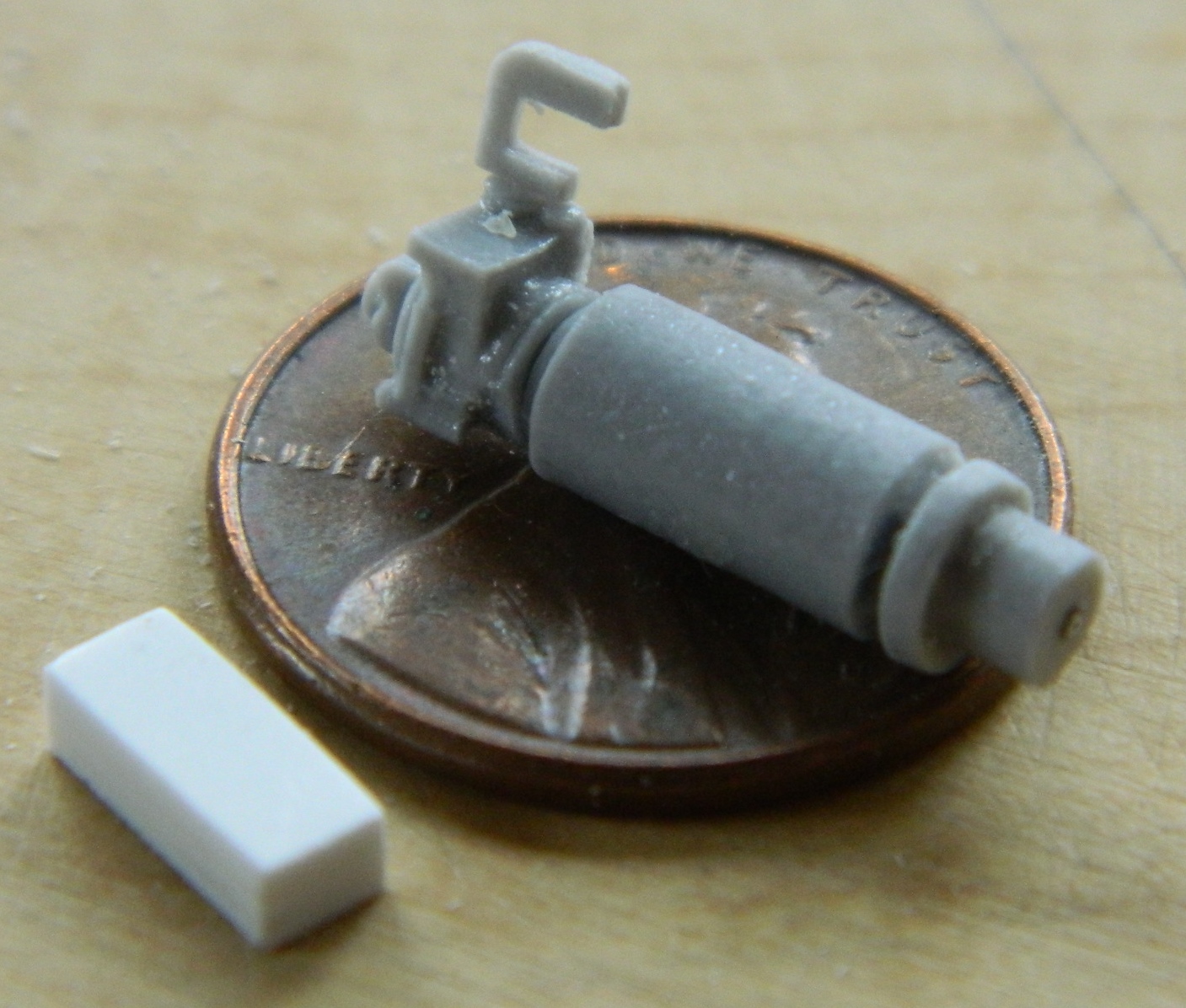
In addition to seeing if I could use a commercially available part as a master, I also wanted a sacrificial part that I could saw in half so that I could see just how many bubbles (or not) were produced during the curing process of the resin. It looks like I ended up with a nice, dense, casting:
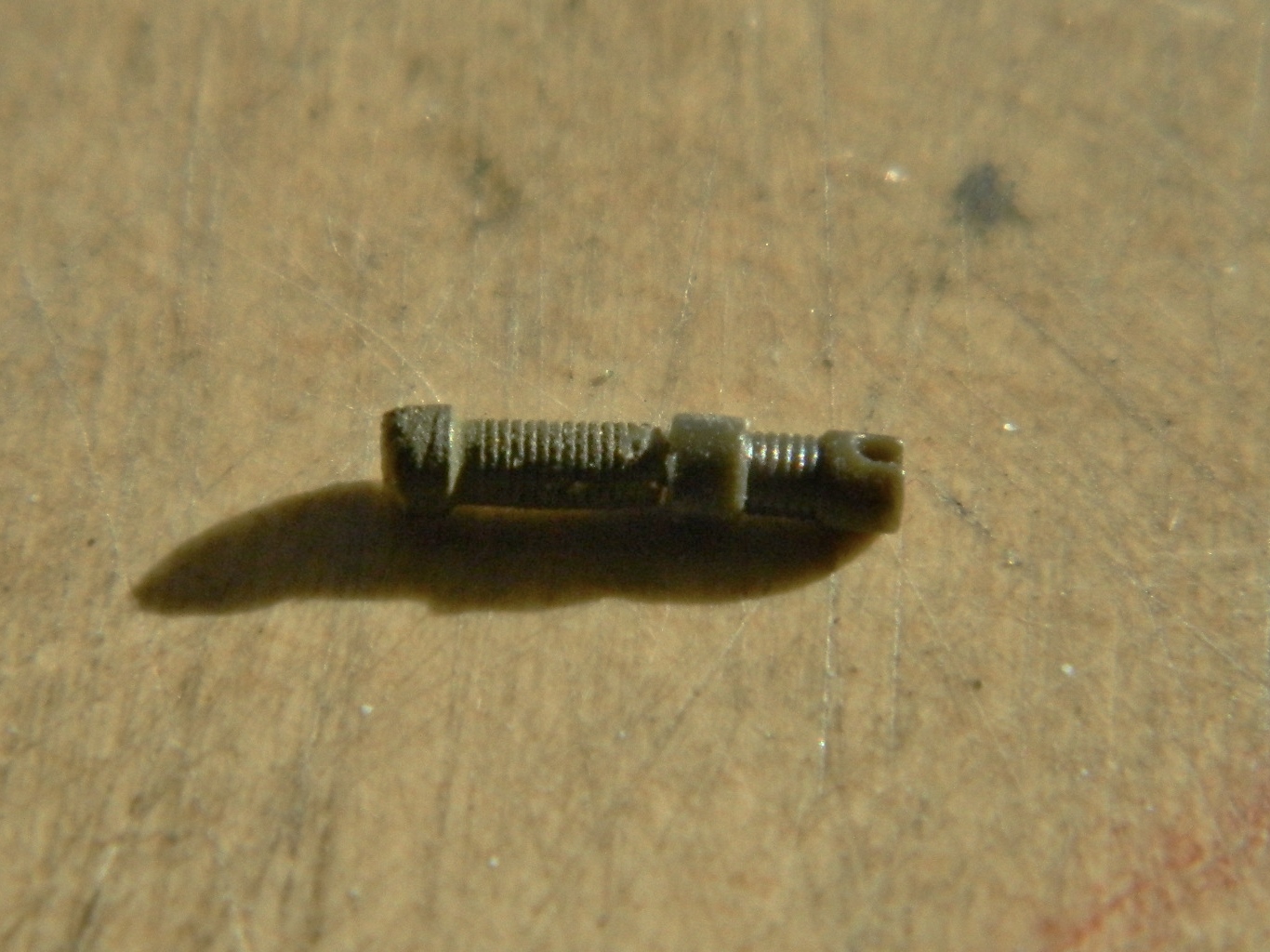
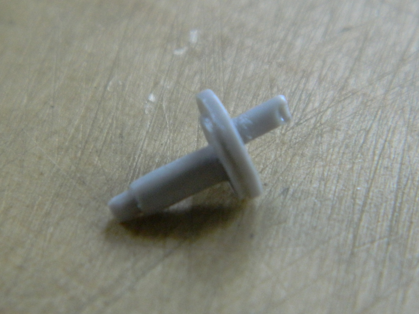
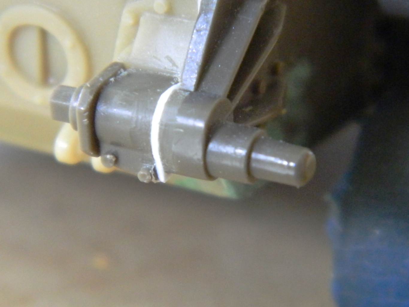
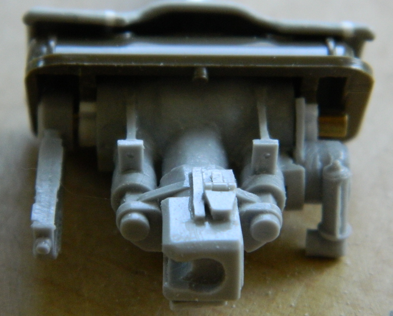
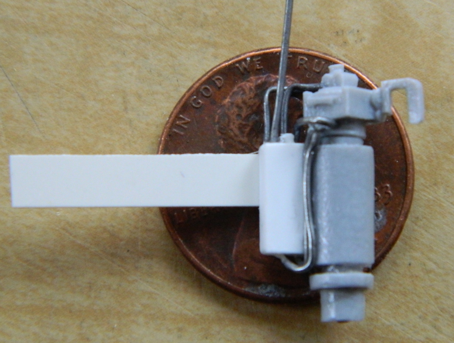
And here’s the part I was really after, the ventilation blower assembly that I can use on this build and any subsequent build based on the M4A3 hull. In the picture to the right, you can see that this process is fine enough to replicate the switch, which was made from 24 gauge wire:

Glossary of Terms
AM – Aftermarket
Molding rubber – A two-part compound comprised of the rubber, usually silicone, and a hardening agent
Parting agent – A thin lubricant, sprayed on or brushed, that keeps things from sticking
PE – Photo-etched
Pot life – How long a mixed compound can be worked before it starts to set up and cure and varies from compound to compound
Resin – Essentially a task-specific epoxy. Resins come in enough varieties to require a separate, in depth, article to cover them all (presently I’m using a urethane resin). Resin is what gets poured into a mold to create multiple and identical pieces
Sprue – That’s the “tree” that kit parts are attached to. What it really is is a channel that brings the molten plastic into the hollow cavity that, once filled, becomes the part. Sprue is really handy stuff! Heating it (GENTLY) over a candle allows it to be stretched, and if you shape the sprue first (like for a bolt head you need), it retains that shape when it’s stretched.
M4A3 (Tamiya) Build #18
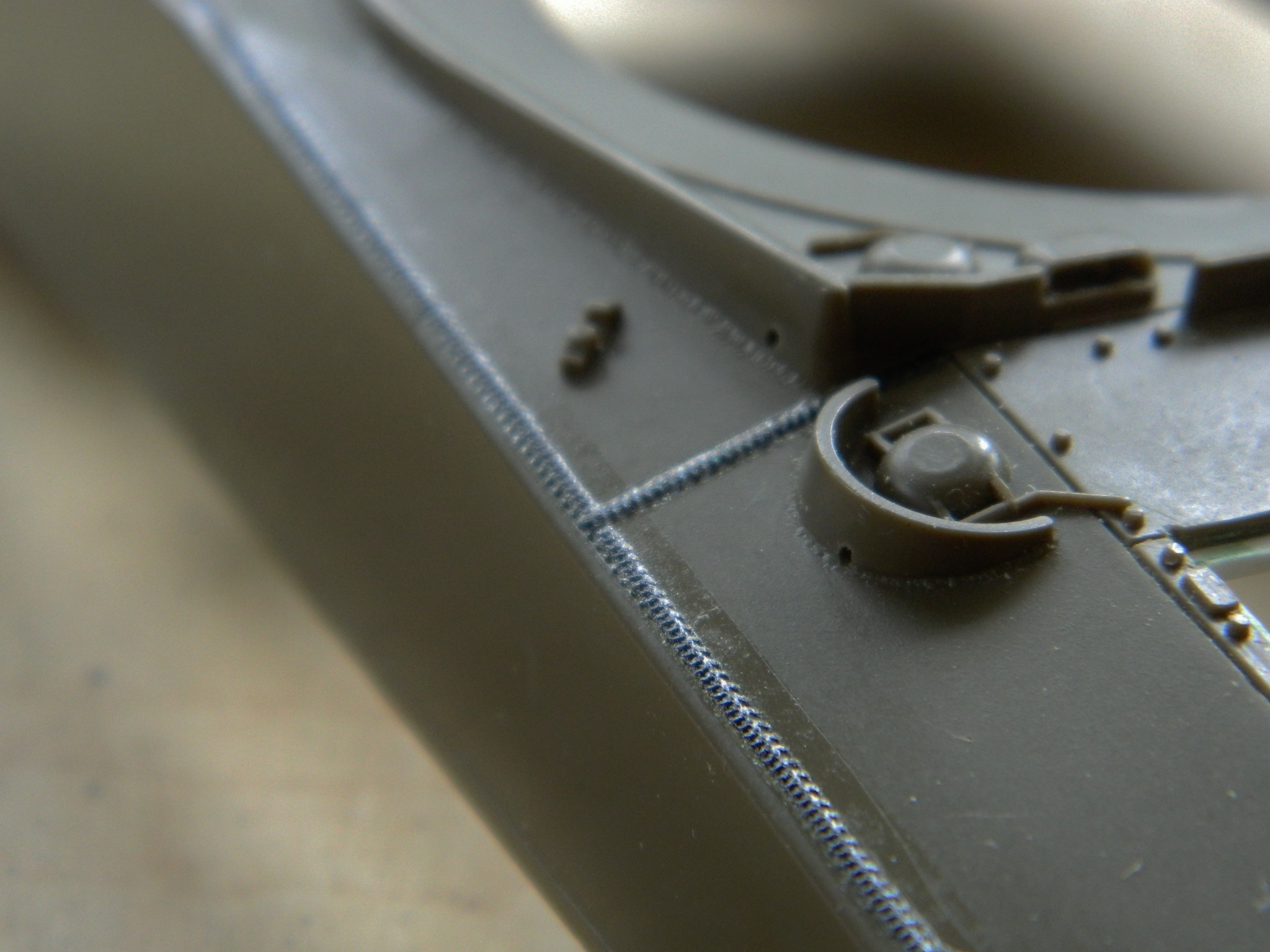
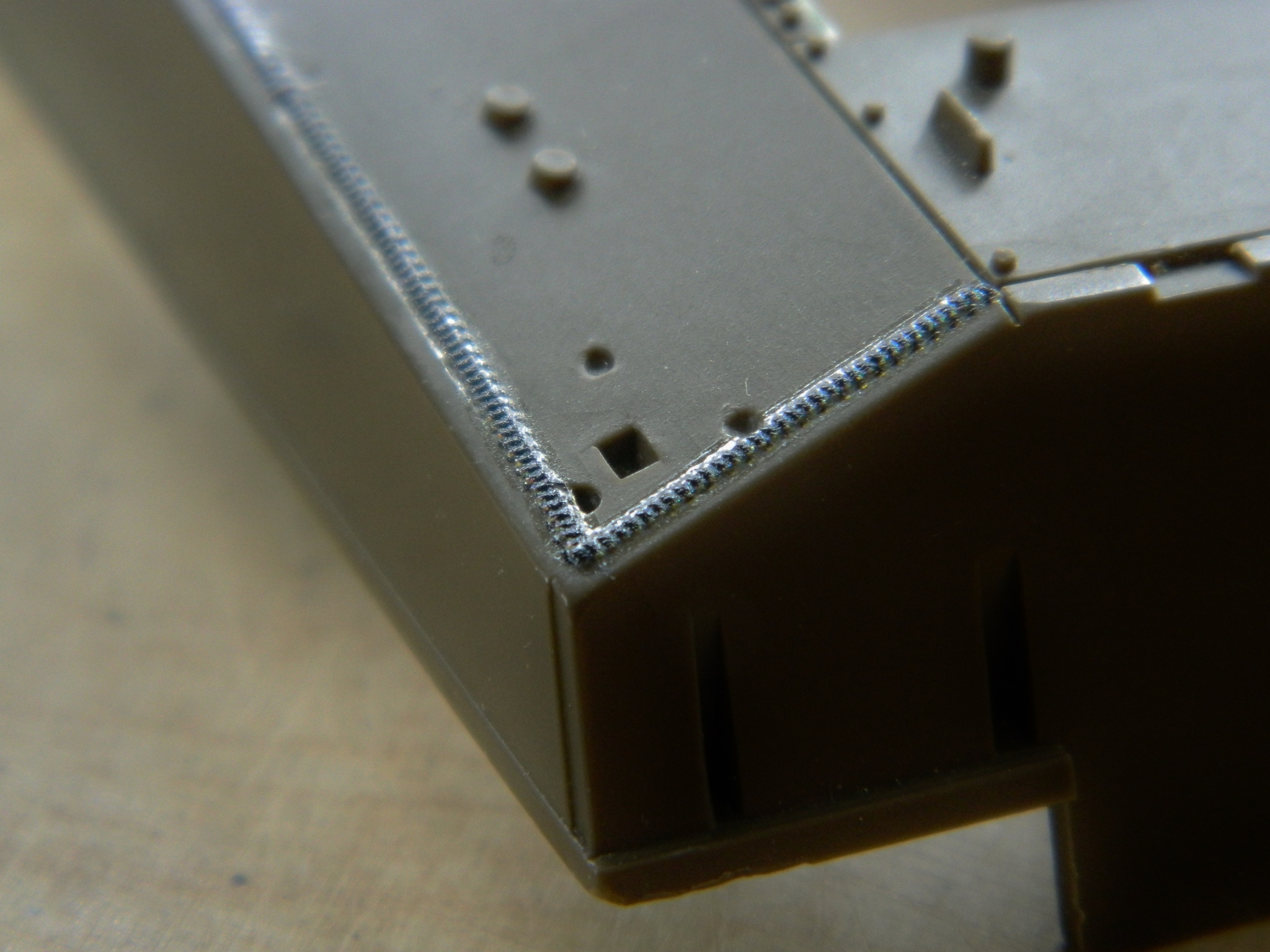
Tamiya got the weld beads wrong. On the kit they’re depressions and in reality they should sit above the surface. (This makes less than no sense to me. When cutting the dies, it would have been so much easier to cut the beads into the surface rather than to cut the surface down around the beads.) Archer Transfers makes 3D decals; resin details bonded to decal carrier film. They go on just like decals and though not perfect they’re a lot better. (As I worked around these beads, I discovered that I should have put them on later once I got to the point where I wouldn’t have to handle them much. They’re fragile and sections will easily pop off as things are added and the hull is handled). In order to more randomize the weld bead, I put down a wider bead first and then put a narrower bead on top of it:
I added the splash guard in front of the periscopes and will trim it to dimension later:
With those details taken care of, I threw a coat of paint onto the turret and other bits using Tamiya’s OD Green straight from the bottle (and if you look closely at the gun shield you’ll see I added casting texture to it using the same method I used inside the turret, though I should have waited before shooting paint; there are more details I have to add):


Once the paint had cured overnight, I decided that Tamiya’s OD Green wasn’t quite the WWII OD green. I did some experimenting and hit on a color I’m satisfied with. I used six parts Tamiya’s OD, one part yellow, and one part white (when mixing paints, I only mix paints of the same manufacturer together):
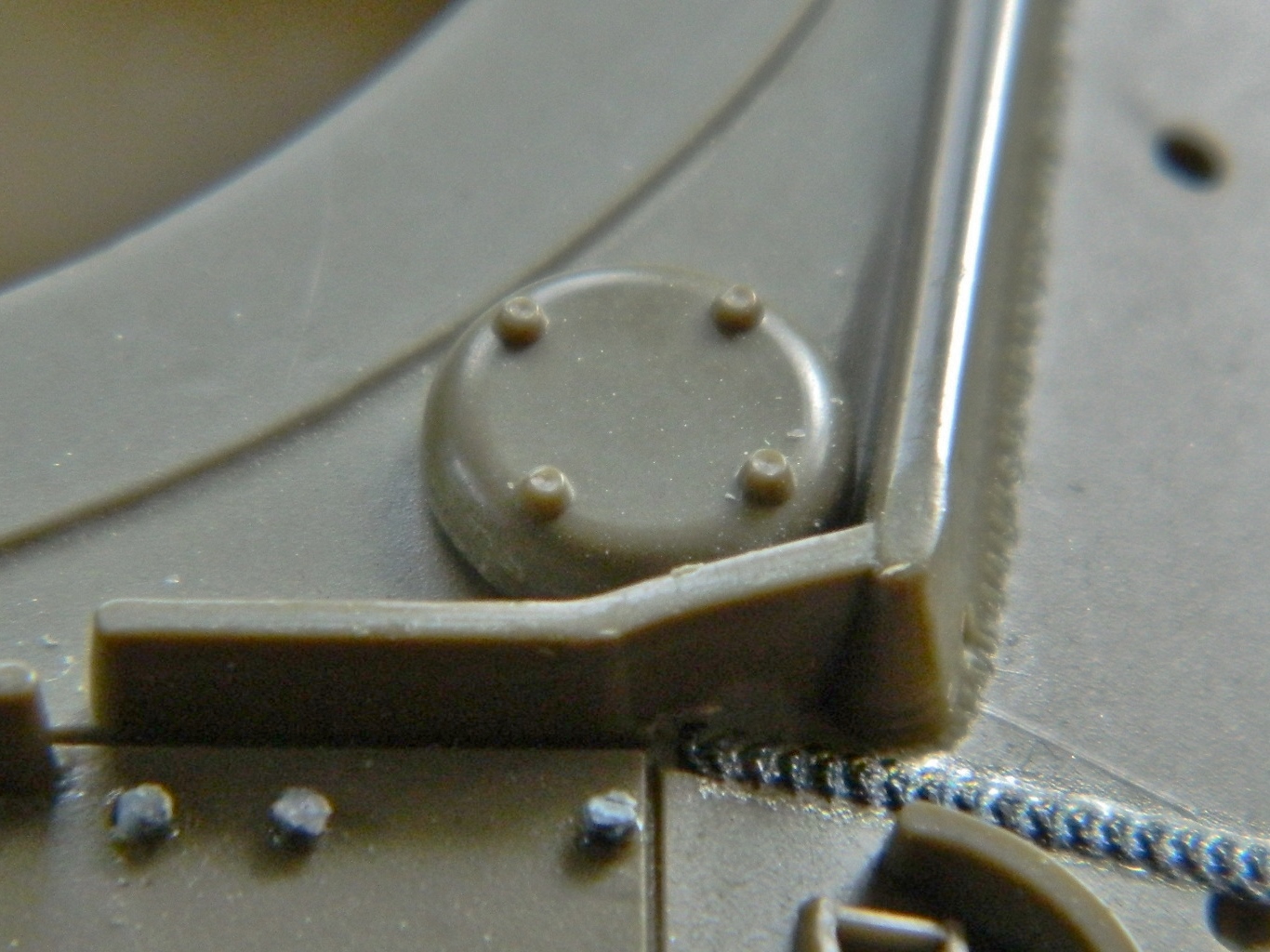
The rear deck plates of the hull are removable. But the “bolts” as cast on the model are round, not hex heads. Grandt Line bolts fixed that. If you look closely at the bottom-left photo, you’ll see that as cast, the “bolt” is actually a nut on a bolt. To get them to be bolt heads, I file off the bolt protrusion and end up with a “bolt”:

The rear ventilator cap suffered from the same problem with its bolts and got the same fix:

All the rear plates on top of the rear hull are removable and there are supposed to be grab handles where the kit has“fins.” Copper wire is cold-drawn which makes it hard and resistant to bending. I annealed the wire and replaced the fins with something more accurate:


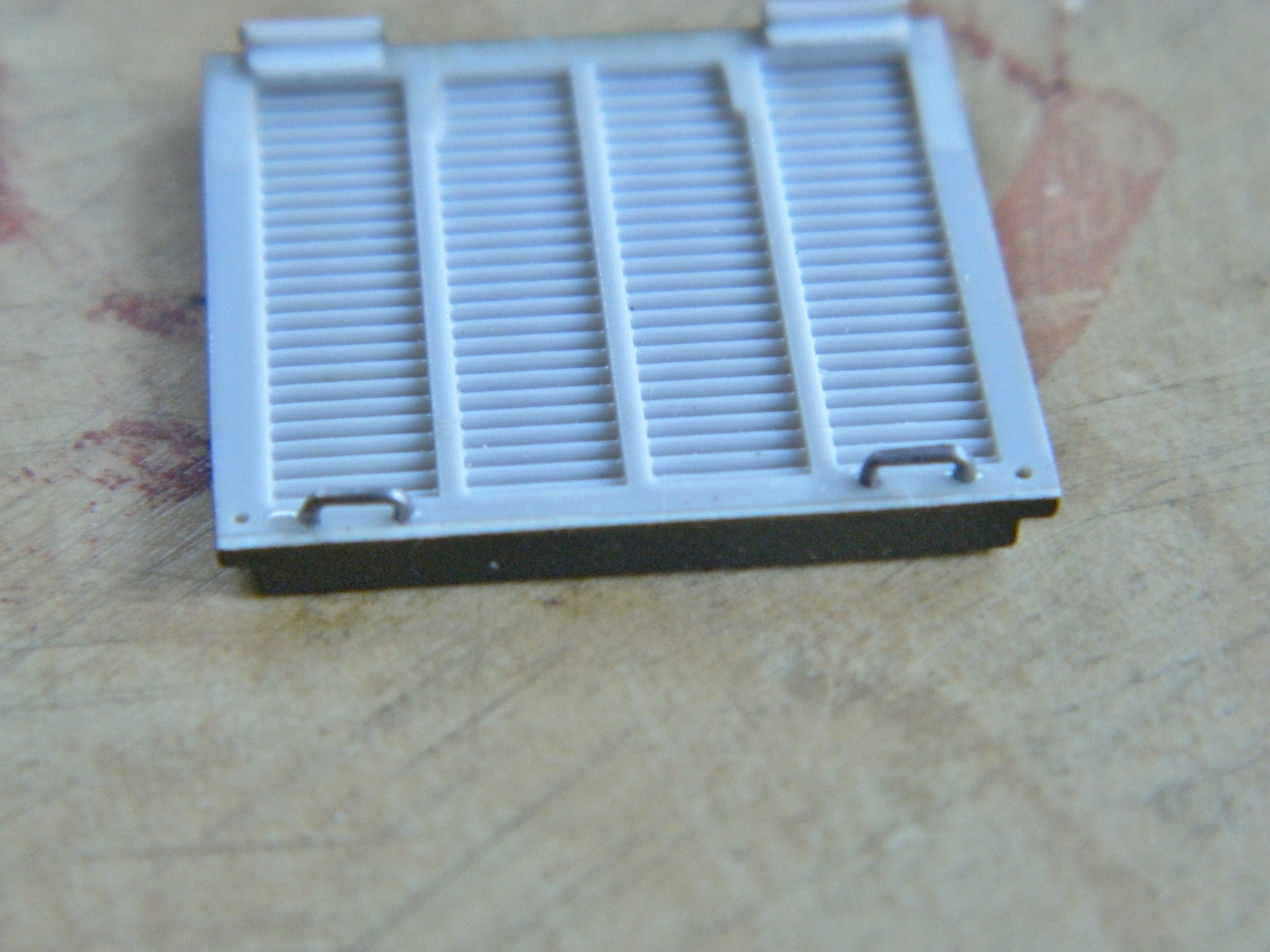
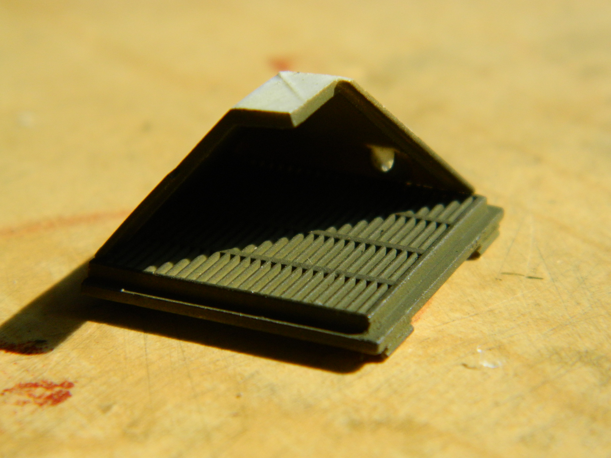
I tried doing the same thing for the grab handles of the engine covers, but even annealed the copper (successfully) resisted giving me the sharp bends I wanted so I used 020 solder instead. I also added the rain baffles to the inside surface of the engine covers:
The driver and co-driver hatches were spring assisted to make opening easier. As it turned out, the similar springs for the loader’s hatch from my parts box(es) are just the size I want. I cut off the attachments for the loader’s hatch, added a Grandt Line bolt, and after cutting the inside of the hull to the appropriate angle, glued them in:

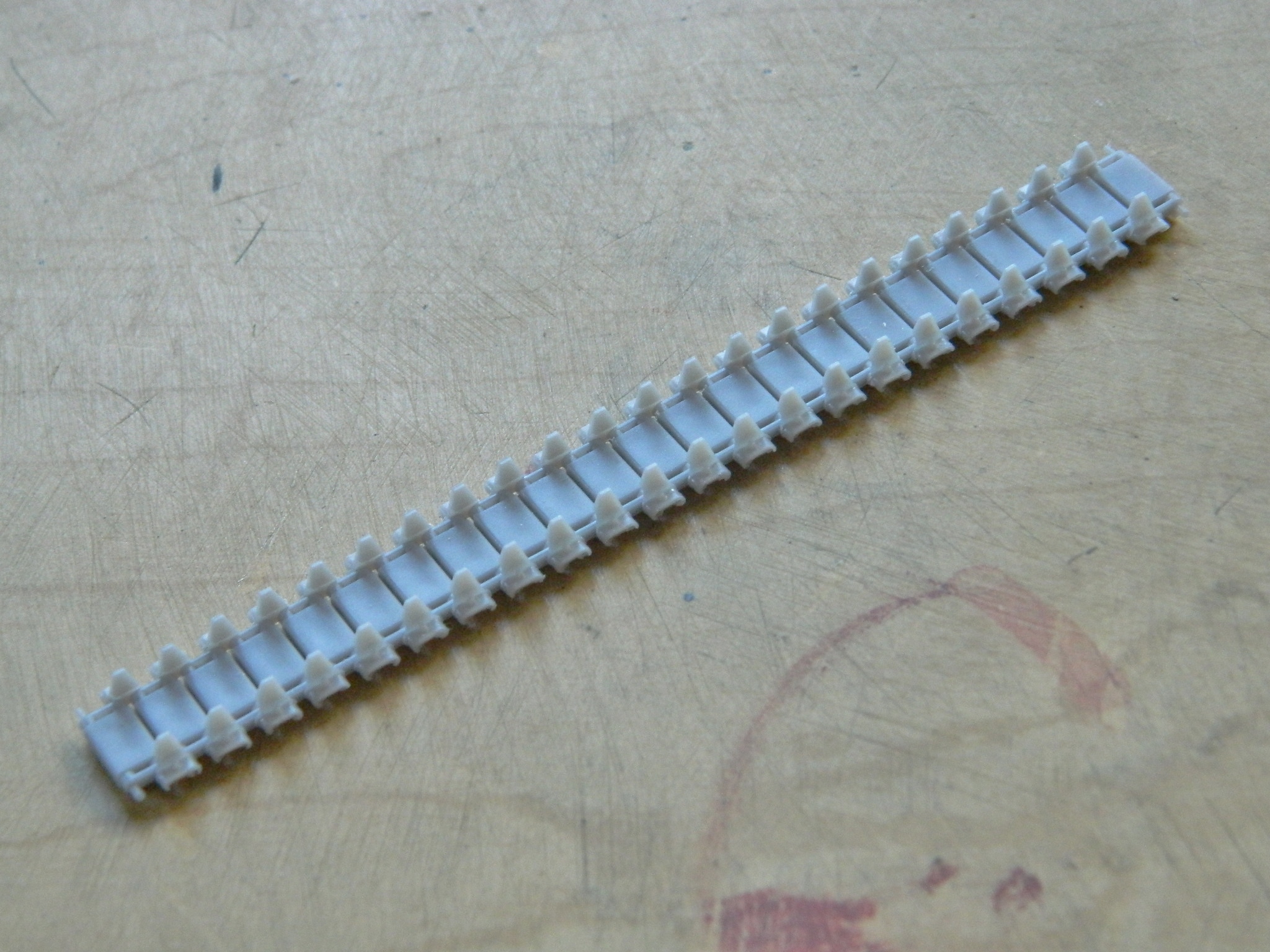
At this point I was waiting for parts and materials to arrive, so I decided to get after something tedious I wasn’t looking forward to. Assembling tracks one link at a time. This Sherman variant has 76 on each side. I timed it to take about 51 minutes per ten links assembled, so I’m looking at 16-20 hours to assemble both tracks.
Why am I doing individual link tracks? The “rubber band” tracks the kit supplies are vinyl and they don’t hold paint well. When flexed, the paint tends to flake off. The tracks I’m using are styrene and will keep the paint (not to mention look much better).
A quick note here about aftermarket tracks…
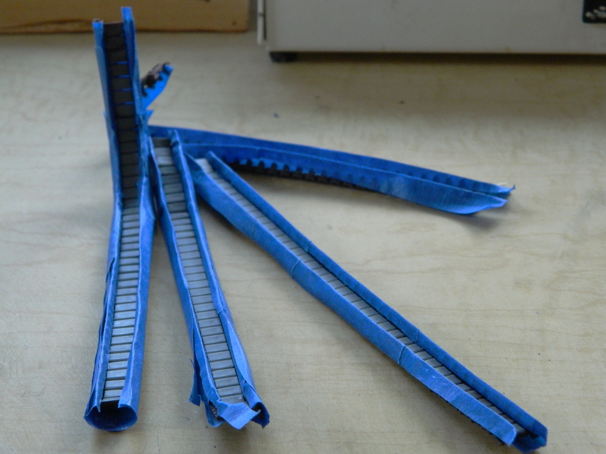
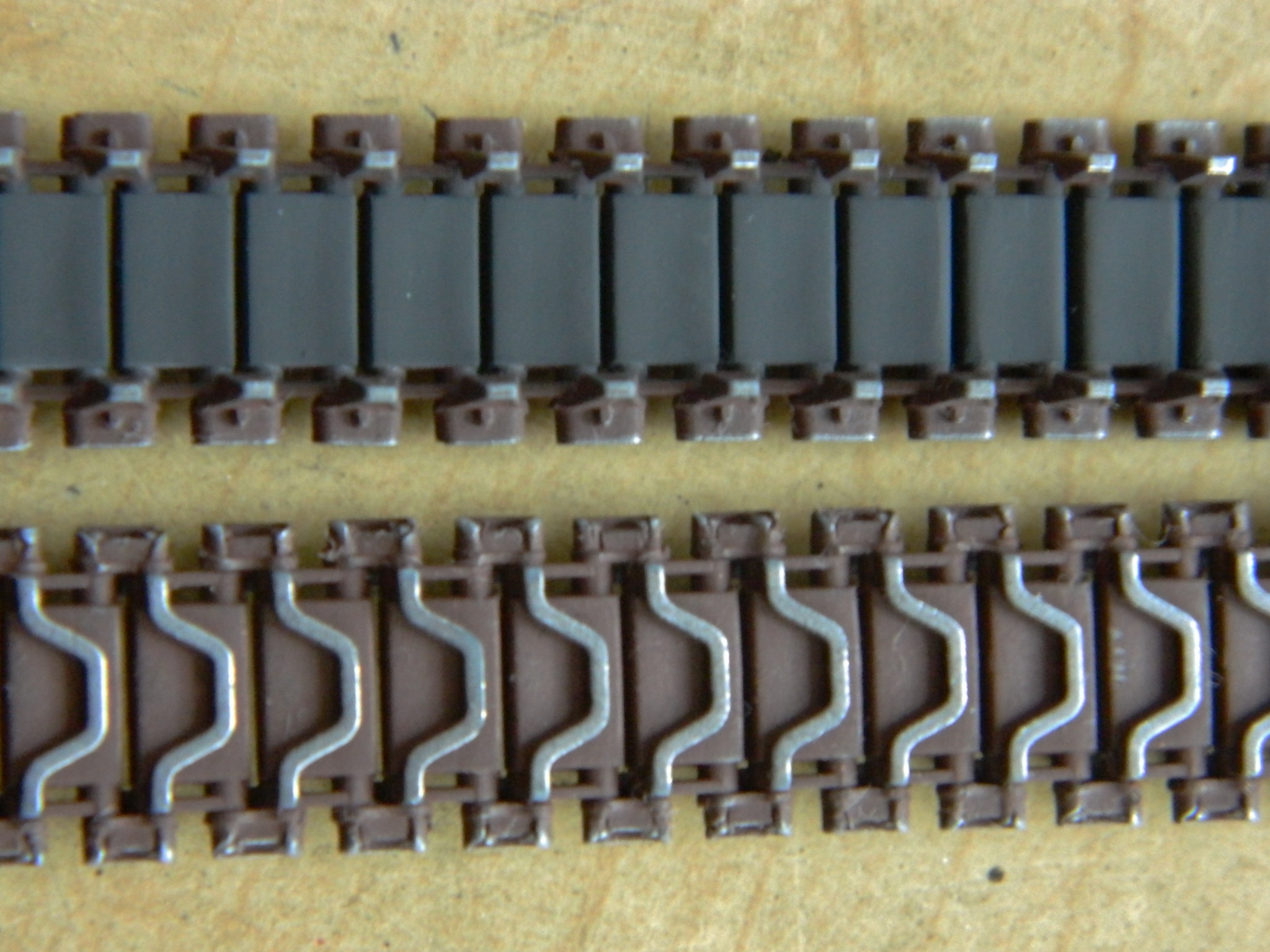
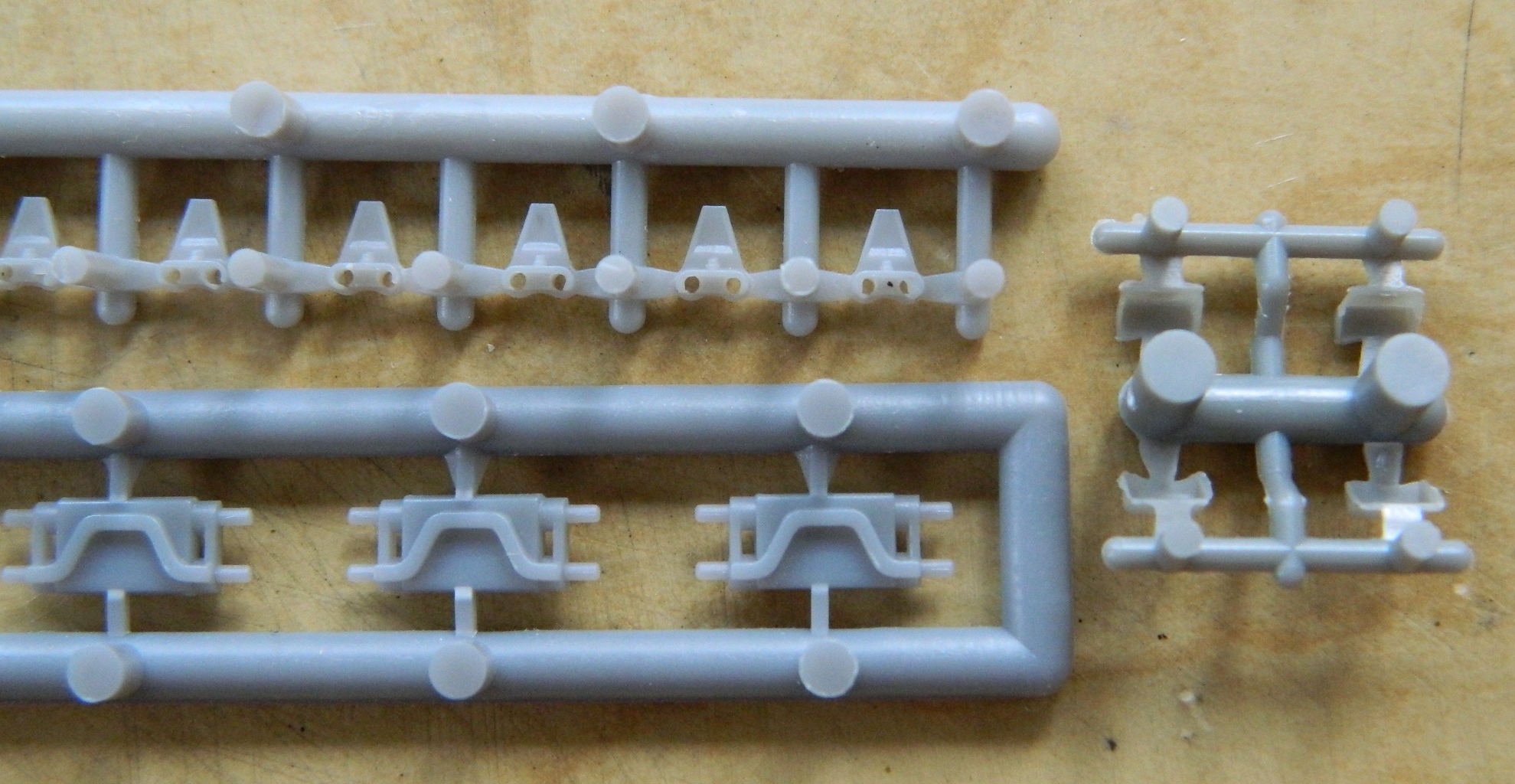
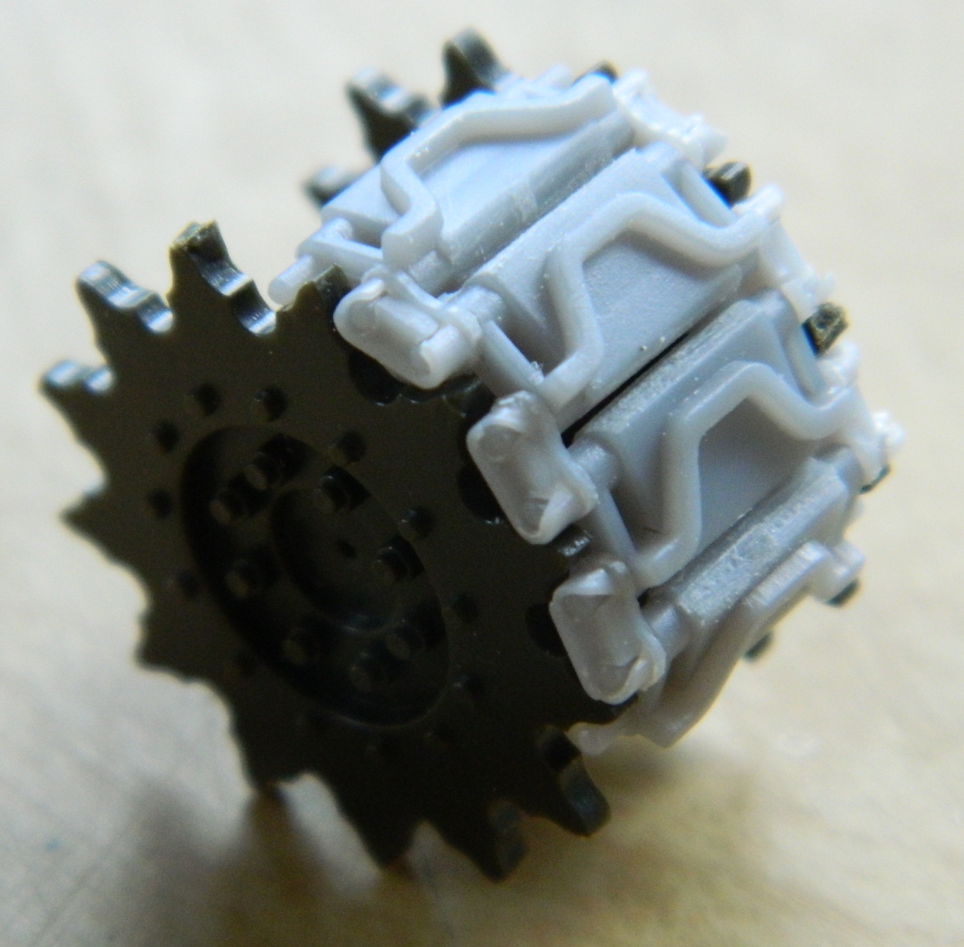
Before you buy tracks, look online for other modeling blogs and/or product reviews. Some tracks don’t fit accurately. From what I’ve been able to see, the place that tracks don’t fit seems to be the drive sprocket. Depending on which manufacturer you use, sometimes the drive sprocket wheel is too narrow for the width of the track to nestle between the sprockets. (Surprising me not at all, Tamiya seems to be more likely to have this problem, but it’s not exclusive to them.) But because of how the inner and outer Tamiya parts join together, it’s easy to widen the drive sprocket wheel by shimming the inside of the wheel. In this situation, I’m using the T51E, steel chevron tracks produced by Panda Plastics which happen to fit the Tamiya sprocket wheel perfectly. (In the first picture below, the sprue, or “tree,” on the right are “duckbill” track extenders and I tried to put them onto tracks but THAT level of tedium went beyond my patience to deal with so I’m not using them):
The good news is that I don’t have hair to pull out (anymore) over this.
I threw the suspension of the spare kit together to use as a jig for fitting the tracks:


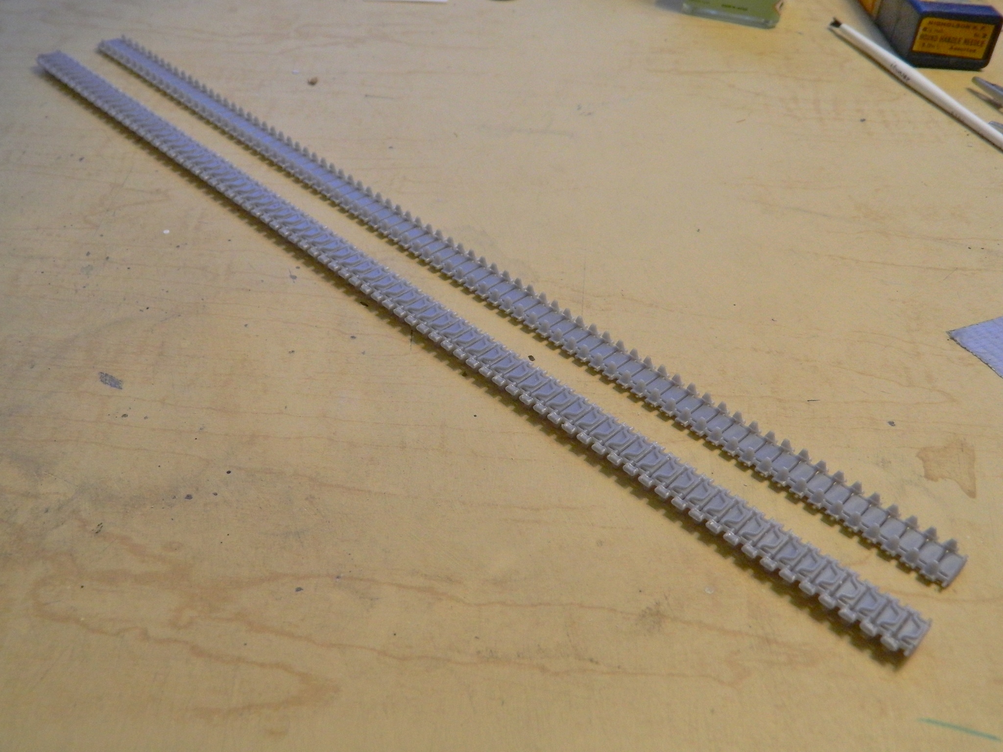
MANY hours later, I got both track runs assembled. Though Panda’s castings are clean with NO flash over the 152 separate pieces required to assemble the tracks, they are still cast pieces that have seams and each part needed those seams to be removed; it still took what seemed like forever to assemble them all. When I test-fit the tracks around the sprocket wheel, I noticed that the inner track face edges were just a little too square, so while I was removing seams, I also rounded the edges of each track so they would curve cleanly around the drive sprocket. (Hindsight has shown me that the next time I use individual track links that need edges rounded to round the edges of just the tracks that will bend around a wheel.)
Nothing is glued at this point (for reasons I hope are obvious). Test fitting shows me that I’m going to need at least three (preferably four) hands to put these things onto the suspension, but that’s a hair-puller for another time:
By this time I needed to do SOMETHING ELSE. During the many hours (did I mention many hours yet?) of track cleaning and assembly, I developed a case of what I call Craftsman’s Neck. That’s a lovely condition where your neck muscles PUNISH YOU for all the hours spent with your head hanging down working on something. So yeah…I needed to do something else.
I decided to work on the vent blower assembly.
Originally I had made the master out of styrene. I guess I should have known better because I tried to take a short cut (yeah, I know…) around replicating this assembly. I ordered a reusable mold making compound from Micro-Mark. It gets heated in the microwave to turn it liquid (or close to liquid; when molten it has the consistency of cool honey). As I found out, thin styrene doesn’t like heat and the styrene master I tried to use this molding compound with caused the master to deform the styrene slightly (by melting…how odd for something heat-related). So I made the blower assembly out of sterner stuff. Brass.
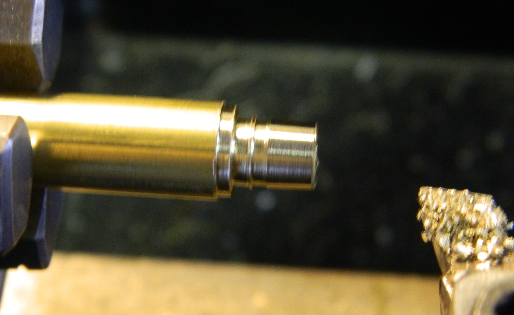
I purchased a 3/8″ brass rod from Online Metals, chucked it into my lathe, and turned the body:
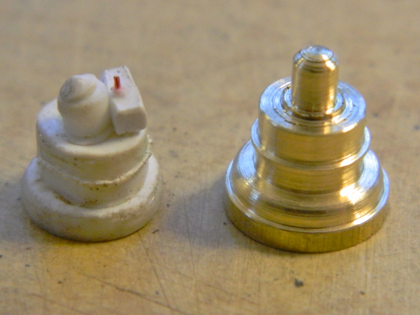
And because I’m essentially lazy, I snapped the switch box off the styrene “master” and glued it to my brass master:

So, since I’m going to be making molds, at this point I decided to go the route I should have gone to begin with and ordered two-part silicone molding rubber and to make a vacuum pump and chamber (an entirely different job and separate from this build, you can find details here Making the Pump and here Making the Vacuum Chamber). While I was waiting for materials to arrive, I decided to attend to a few other of the hull details, such as the crew hatches.
And again I turned to NTMD for these very nice parts, having resculpted the hinges again so they’d fit:

By this point in the build I have been at it for just over a year and am approaching 400 hours spent on the build.
Then I replaced the travel lock for the main gun with more NTMD parts:

Since I will be replacing the kit’s storage brackets for extra track links with resin parts (NTMD again), the slots in the rear hull face need to be filled and smoothed, inside and out (removing the provisions for the slots on the inside of the hull is going to make fitting sponsons later SO much easier):


M4A3 (Tamiya) Build #16
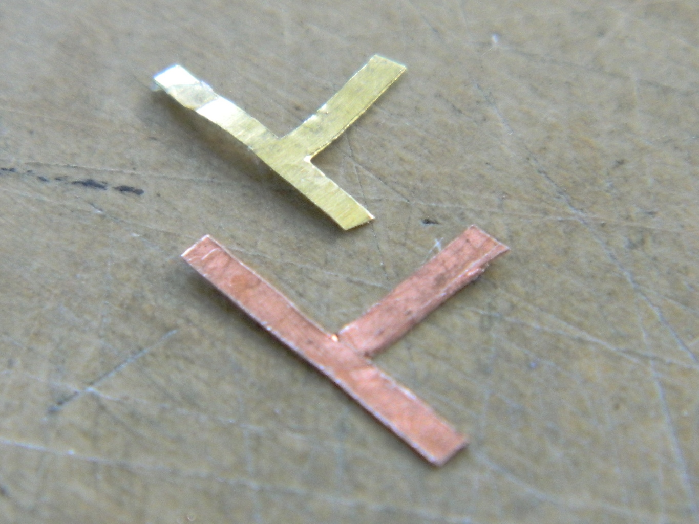
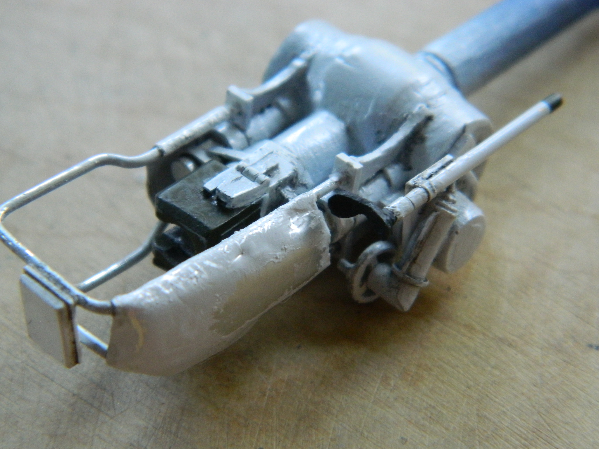
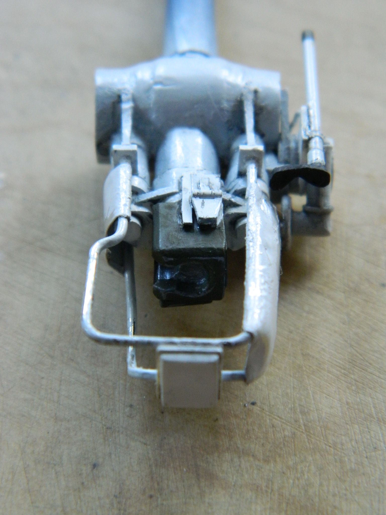
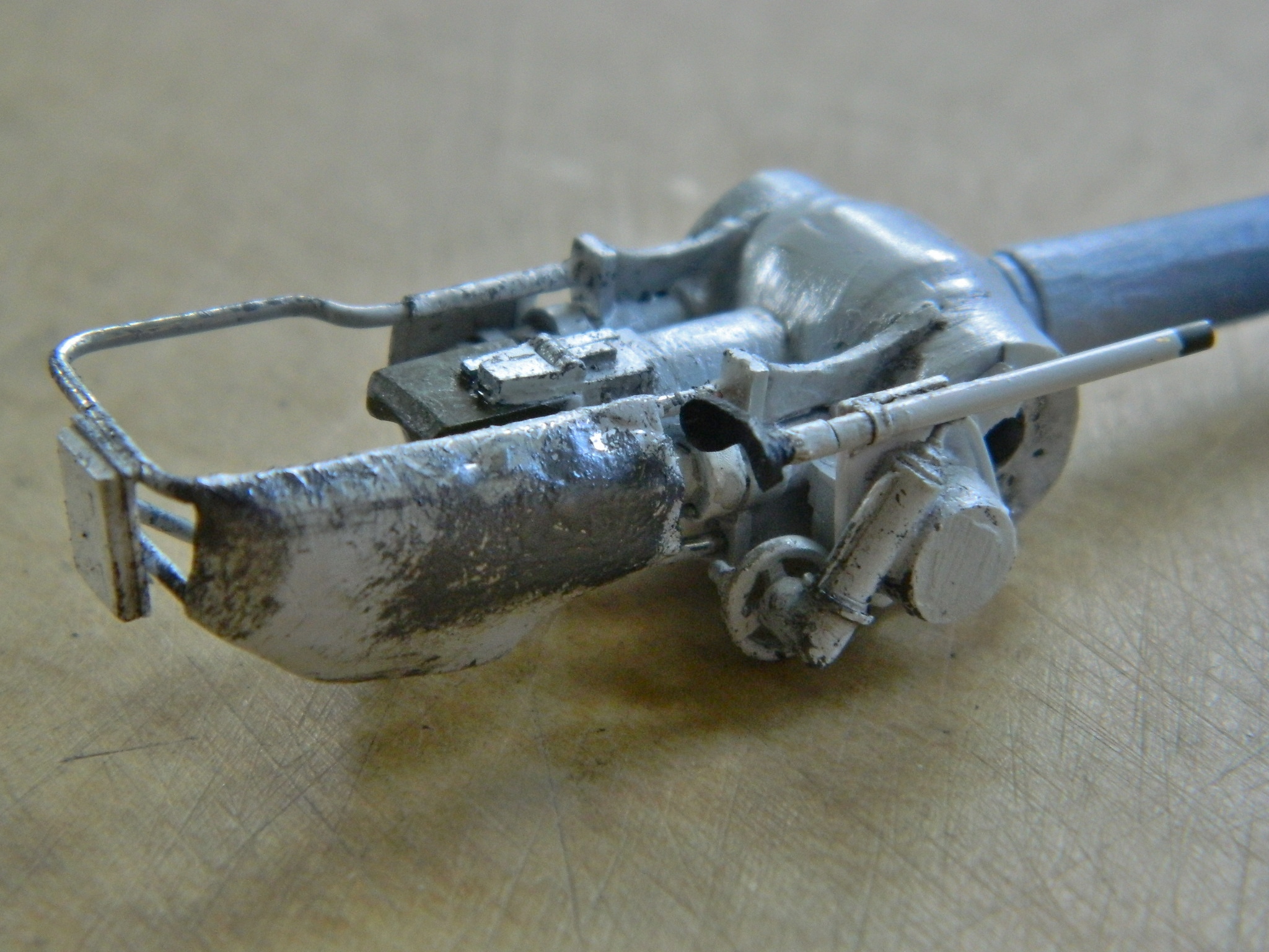
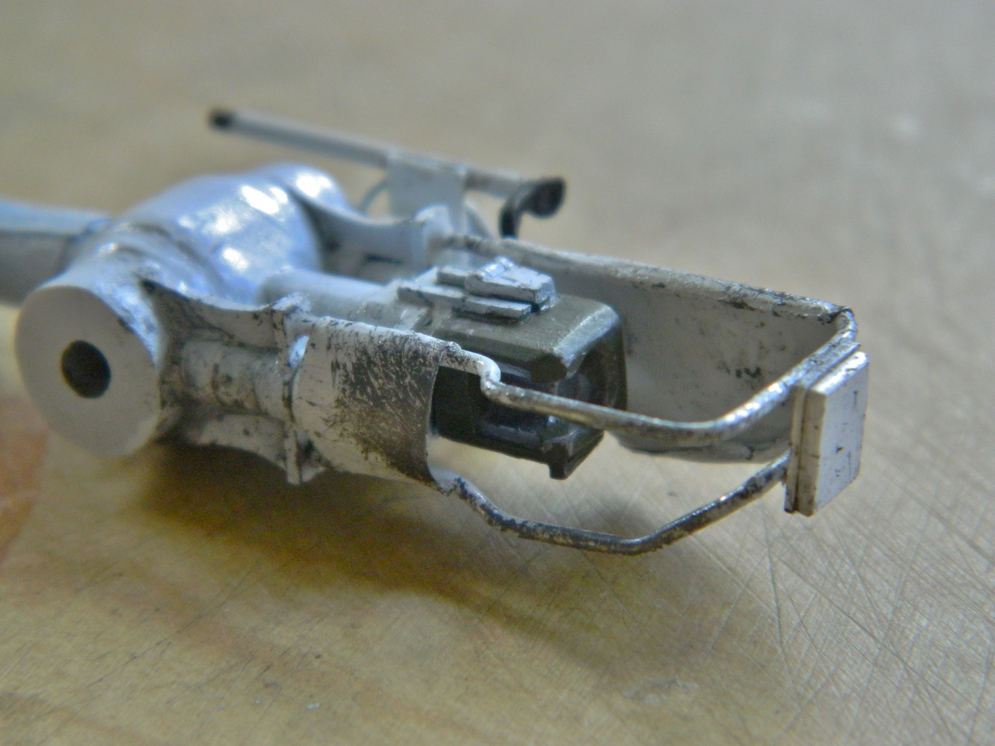
There is a guard that attaches to the breech mount to keep delicate body parts from getting crushed by the breech during the recoil from firing. The hard part to this particular assembly is that I have to make the guard detachable so that masking and painting it later doesn’t become a nightmare. The AM set provided a bending template and I used copper wire to make the frame:

There is a sheet metal barrier on the gunner’s side (the right). The AM set’s resin part is WAY too thick, so I used it as a buck and formed lead foil around it. Quite interesting in how far off it is:

So I made my own buck. I held the part as close to perfectly straight sideways as I could and traced the outline on a separate piece of 3×5 card and transferred the pattern to an old piece of plastic I had been laminating for a decades-defunct project:

I don’t know if it’s small parts and big fingers or if it’s big fingers and small parts, but sometimes just holding on to something I’m working gets “interesting.” This time I figured I’d add a handle to make forming over the buck, if not easier, at least (maybe, I hope) less difficult:

I made a copy from this buck and tried it against the guard. It’s close, but slightly off so I needed to shrink the buck slightly:

Yeah, the fit is better:
But I still wanted to tweak it a bit more. After several attempts to nail it, I did just that and glued it together and lo…it doth be removable. For the shape, size, and location, it turned out that using lead foil for these sheet metal parts was creating more problems than it was solving, so I went with heavy gauge aluminum foil instead:


Then I dry-fit the turret basket in place to make sure things, as they do, fit:

And then I checked my references again (and I really, really, should do that more often and NOT rely on whoever made any aftermarket set to have gotten it correct). This is when I noticed the eyepiece for the gun sight is incorrect. As supplied, the resin part would have the gunner using their left eye to lay the gun on target. Nope. The right eye was used to do that, so that means I have to (again) rework the sight. During the previous session reworking it, I realized that the person that mastered the mold used the goggles from Tamiya’s kit to fashion the eyepiece. Well. (That was done in my best Jack Benny voice.) (Which really isn’t very good.) I happen to have those pieces:
So I cut the resin eyepiece off, drilled out the Tamiya part, and attached it to the sight (and since the end of the sight’s tube protrudes slightly into the eyepiece, I was able to replicate that as well):
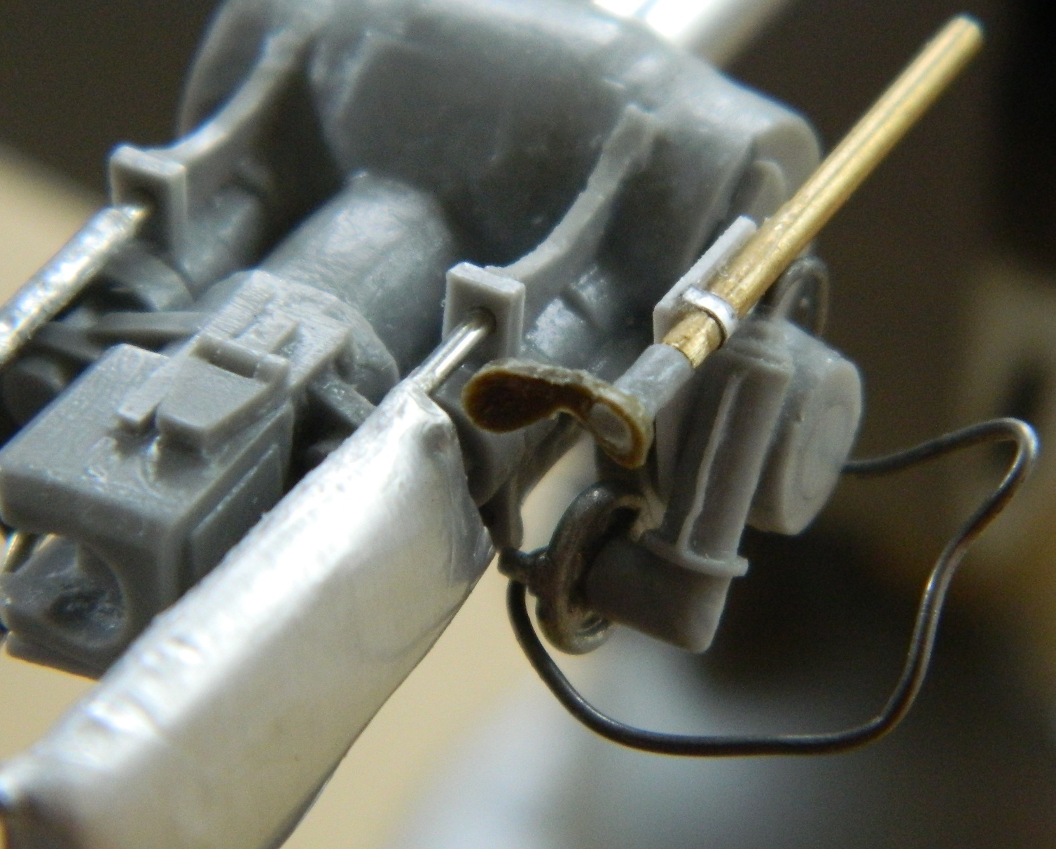
The .30 cal doesn’t have a grip or a trigger and it needs both, so now they’re there, as is the firing solenoid and the wiring for it:

While I was working in the turret, I (finally!) noticed that although the interior of an actual turret has an as-cast surface, which was pebbled as they were sand-cast, the kit’s part is smooth. I knew there was a “texturizer” out there but I was damned (he says, stating the obvious) if I could remember the name of the stuff which made finding it online not happen. Then I had an idea; liquid styrene cement works by dissolving the parts in contact and as the glue’s solvent evaporates, the dissolved styrene solidifies, bonding the parts together. Okay, basic stuff. But what I can work with is the “dissolve” aspect of all that.
I used Tamiya’s “Extra Thin” liquid cement, brushed it quickly onto the surface of the spare turret, and then used a cheap, coarse, nylon-bristled brush and tried to replicate the pebbled surface of a sand-cast casting:
And to my eye that worked just fine, so I treated the entire inner surface of the turret that way.
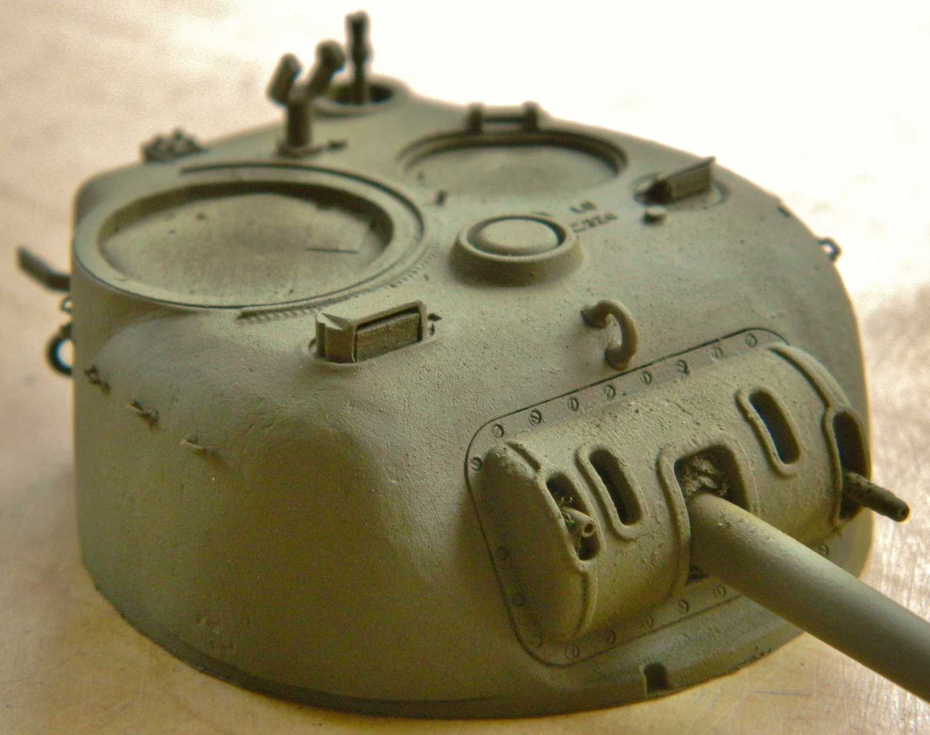
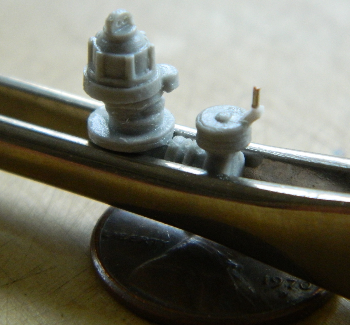
The later model Shermans had a mortar attached to the roof of the turret to lob smoke bombs (used to obscure the enemy’s ability to sight on the Sherman). Since this is a late-model M4A3, that’s got to be added (note added the sand cast texture) and then puttied the gap:
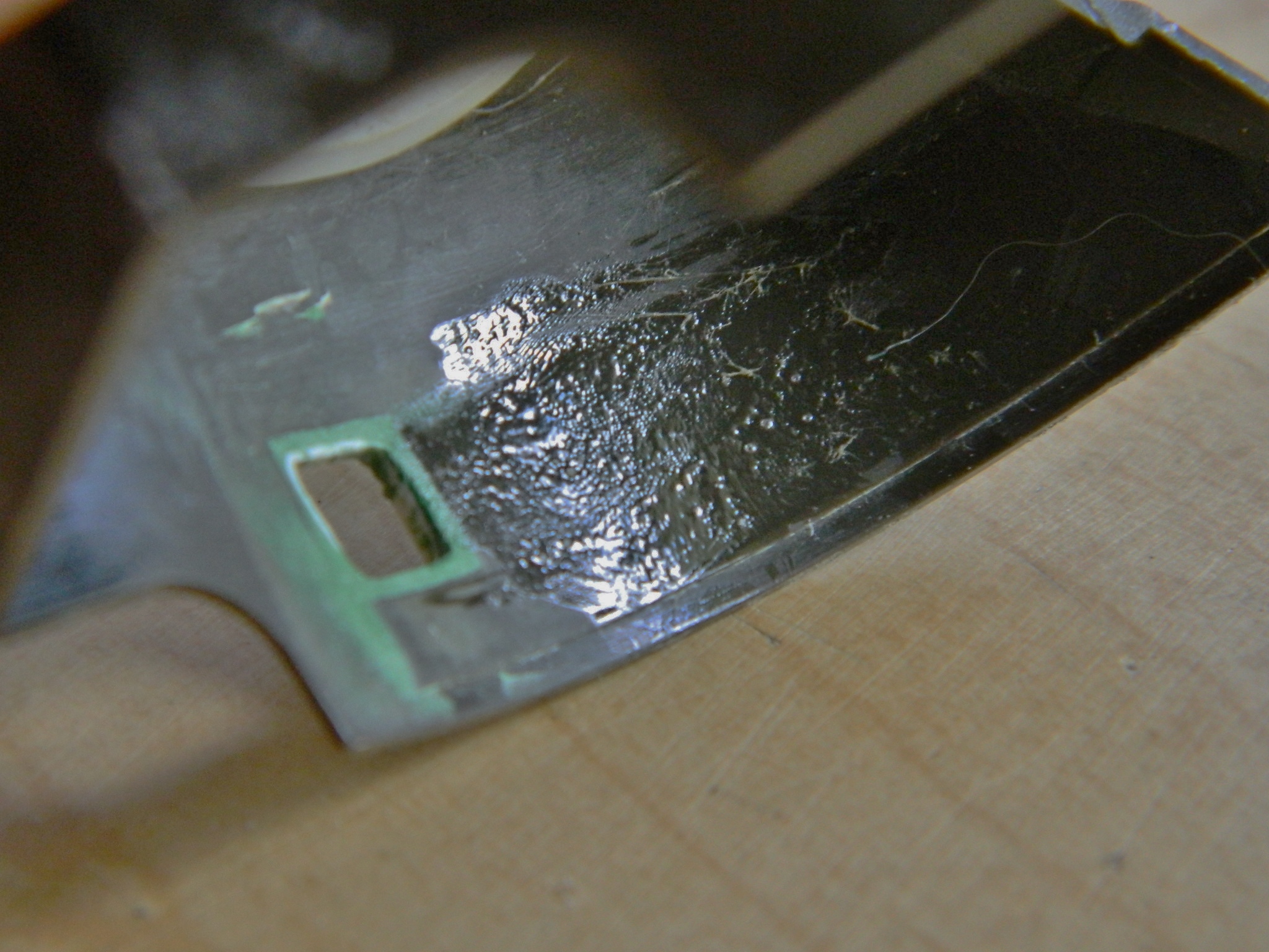
Time to throw paint! Again, the first step is to shoot a coat of “steel” paint. It sits overnight to cure and then will get buffed to the appropriate luster:

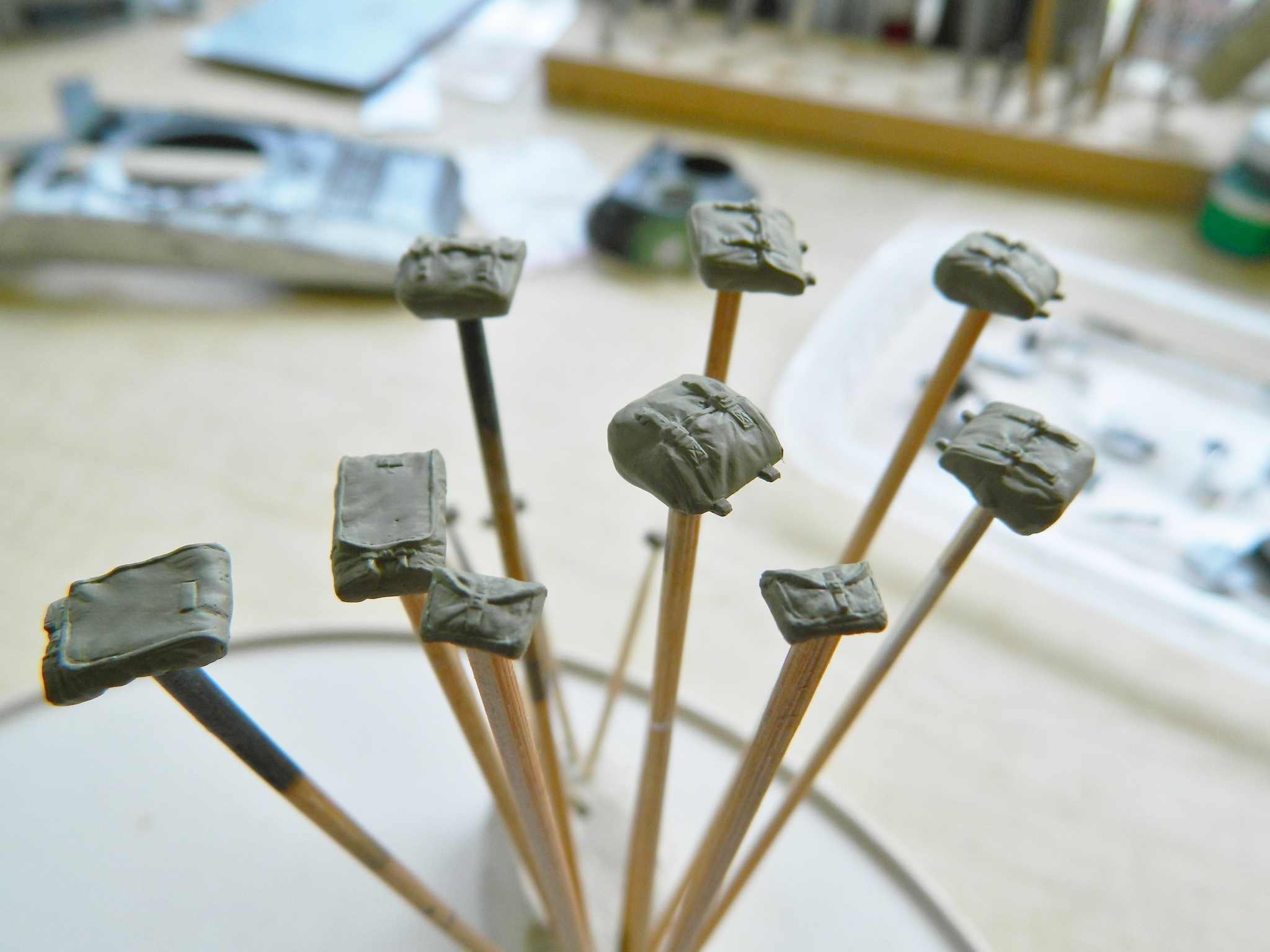
Some of the crew’s items will be added to the turret basket so while I had the airbrush out, I loaded it with khaki paint and did the items, too:

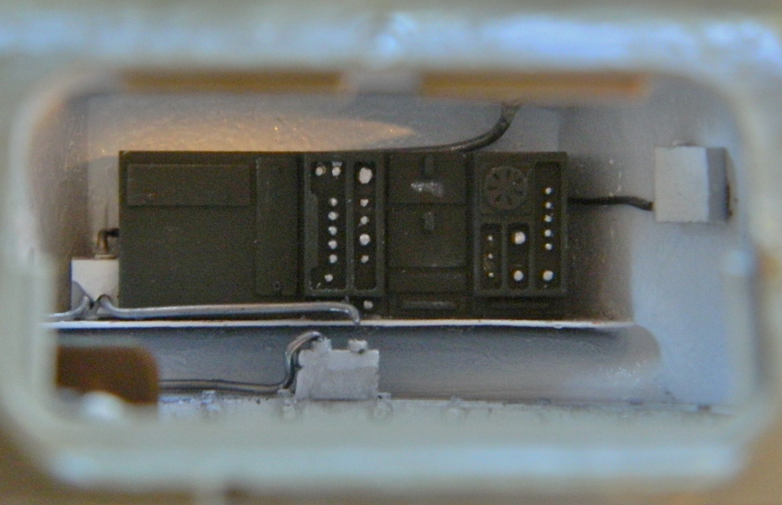
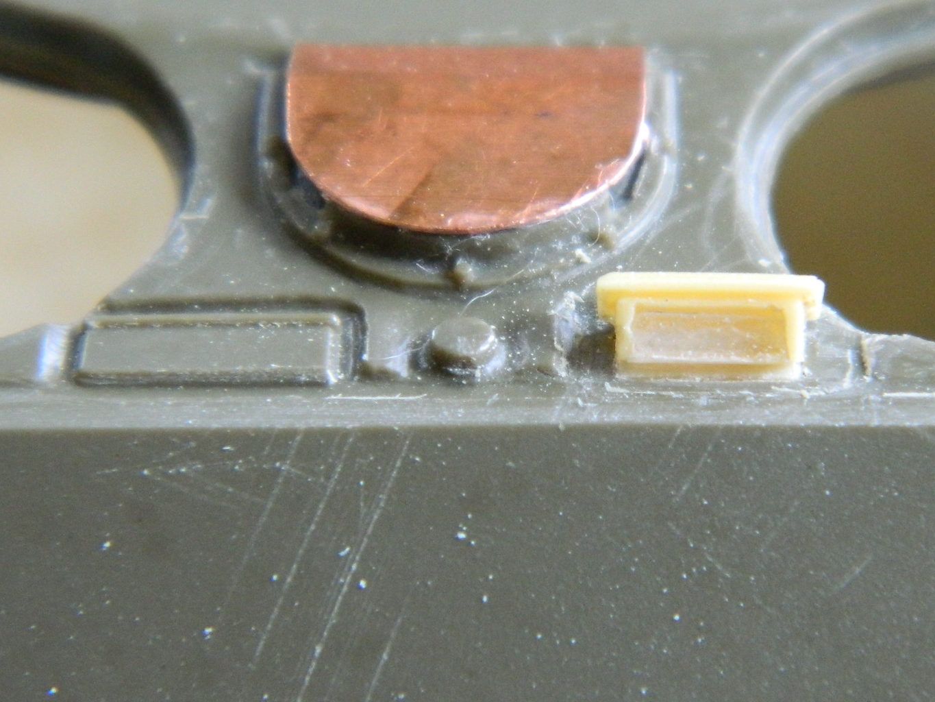
The radio sits on a shelf in the turret bustle and the AM set didn’t supply one. I used the photo-etched part from CMK’s dry-stowage interior as the template (because I liked it better than the one I’d already made), traced it onto card stock, then traced that onto 010 brass shim stock (which, unlike plastic, won’t sag over time), cut it out and filed it, and tacked it into the bustle (the radio is dry-fit for alignment):
With the matte khaki paint cured, I hit the parts with clear gloss and gave them a gray wash:
Then it all got coated with clear matte and set aside for later inclusion:


Since I’m working on turret components, I decided to work on the loader’s hatch while painted parts were drying. The loader’s hatch actually had a pad on its inner surface, one of the few padded things in the turret to keep the loader (or anyone else, for that matter) from getting bashed by hard and painful objects. The first part of that was to trace the outline of the hatch on 030” styrene, then trim and shape the piece to fit the hatch properly:


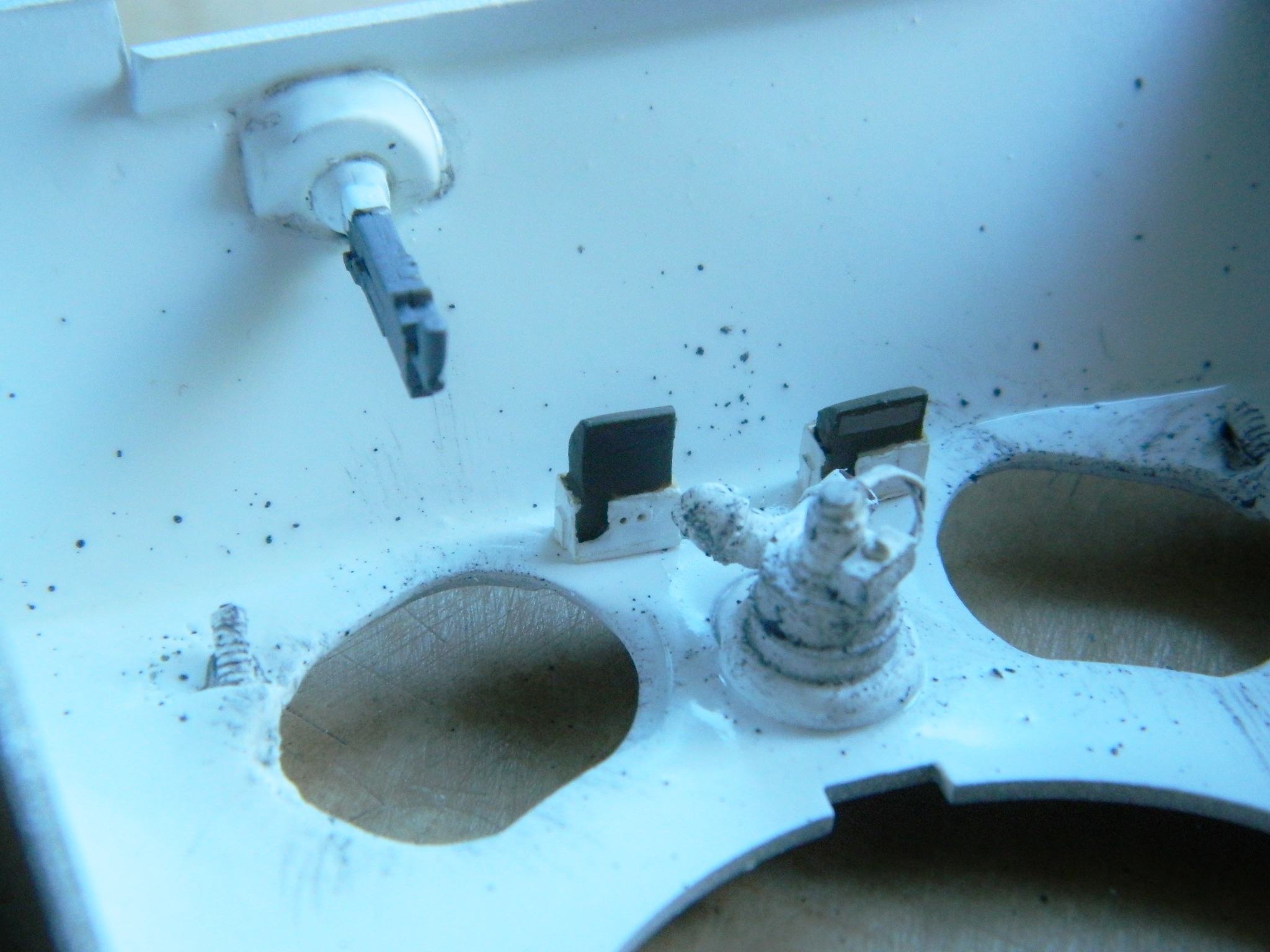
With the undercoat of steel paint well cured and selectively buffed, it was time to salt chip things. The items were treated as before and then overshot with matte white. As before, once the white had set up, I knocked off the salt crystals, rubbed the edges of the various boxes to wear the paint off, and dipped a cotton swab in acrylic thinner and applied the areas of rubbing wear:


When I rubbed the paint off the sheet metal breech guard, I exposed the aluminum underneath. And surprising no one (except me at the time), it looks like aluminum and not the steel it was supposed to be, so I will go back and coat that with steel:


But I did like how the breech area looked after I removed the masking (made SO much easier by having the breech guard removable):
And while I was in there, I also treated the mortar to a black wash, too:

The next step is to add some more chipping and scraping wear to the turret basket and associated parts (and to cover that damned aluminum):


Time to start putting things into the turret itself that are supposed to be there.
I started with the commander’s hatch, which in this case is the late-production vision block cupola. NTMD makes a nice set for this and it starts with a clear resin casting of the cupola (I was NOT looking forward to replacing those incredibly tiny vision blocks with clear plastic!):
But this part wasn’t designed for the Tamiya kit and the cupola was just slightly smaller in diameter than the opening it was going into, so I took some 010 styrene and shimmed the opening and the result was a nice snug fit:
I added the various items to the turret walls, installed the radio, added the electrical conduits (solder, of course), and then painted the conduits white:


M4A3 (Tamiya) Build #15
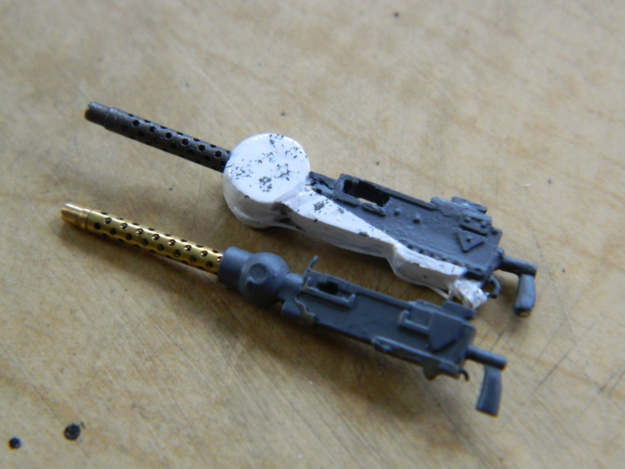
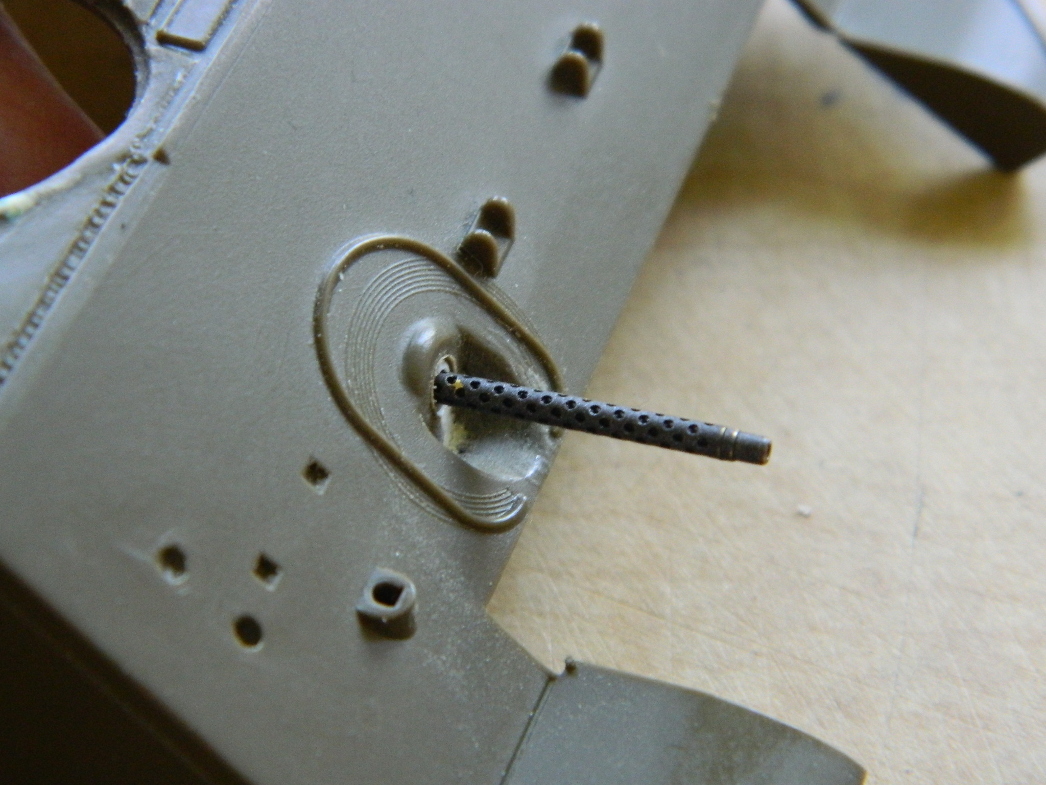
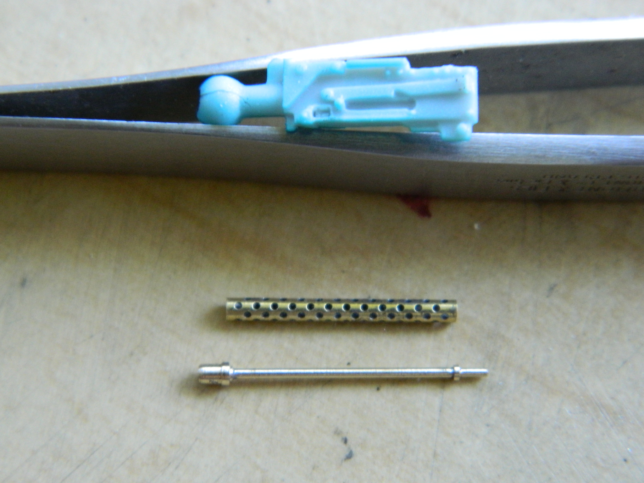
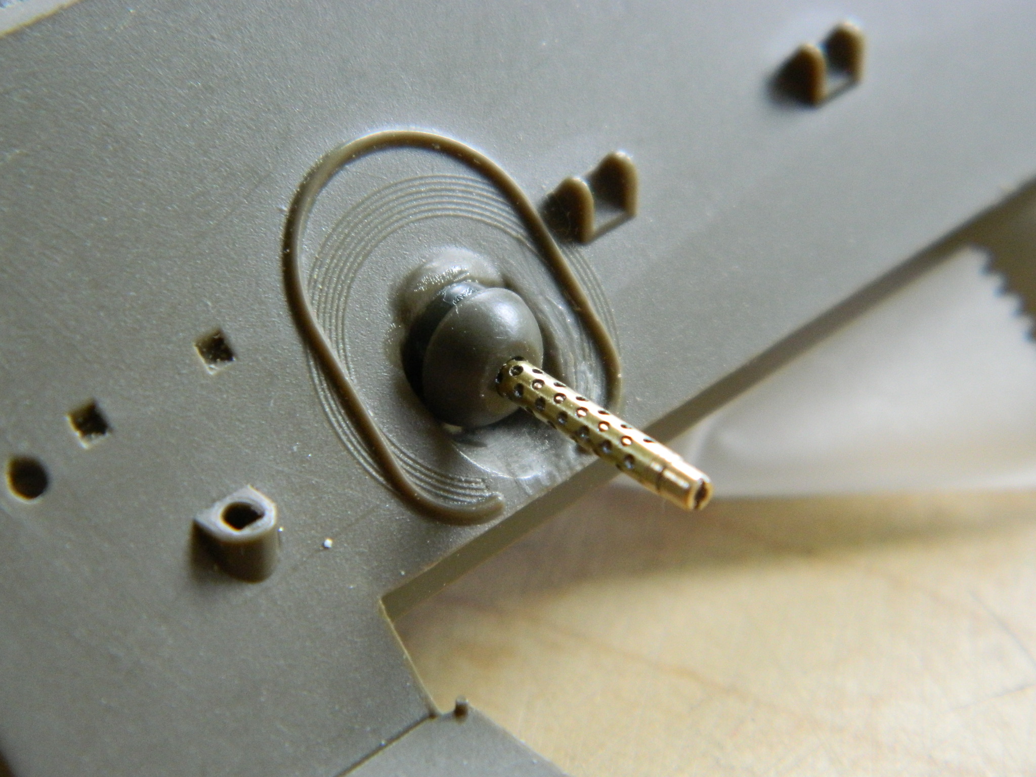
Going back to working on the upper hull interior, it was time to start working on the .30 caliber machine gun in the bow. I found exquisitely machined brass machine gun barrels for both the .30 and .50 caliber machine guns. I painted them prior to assembly:


I’m going to replace the bow gun. That means the barrel and jacket get assembled:
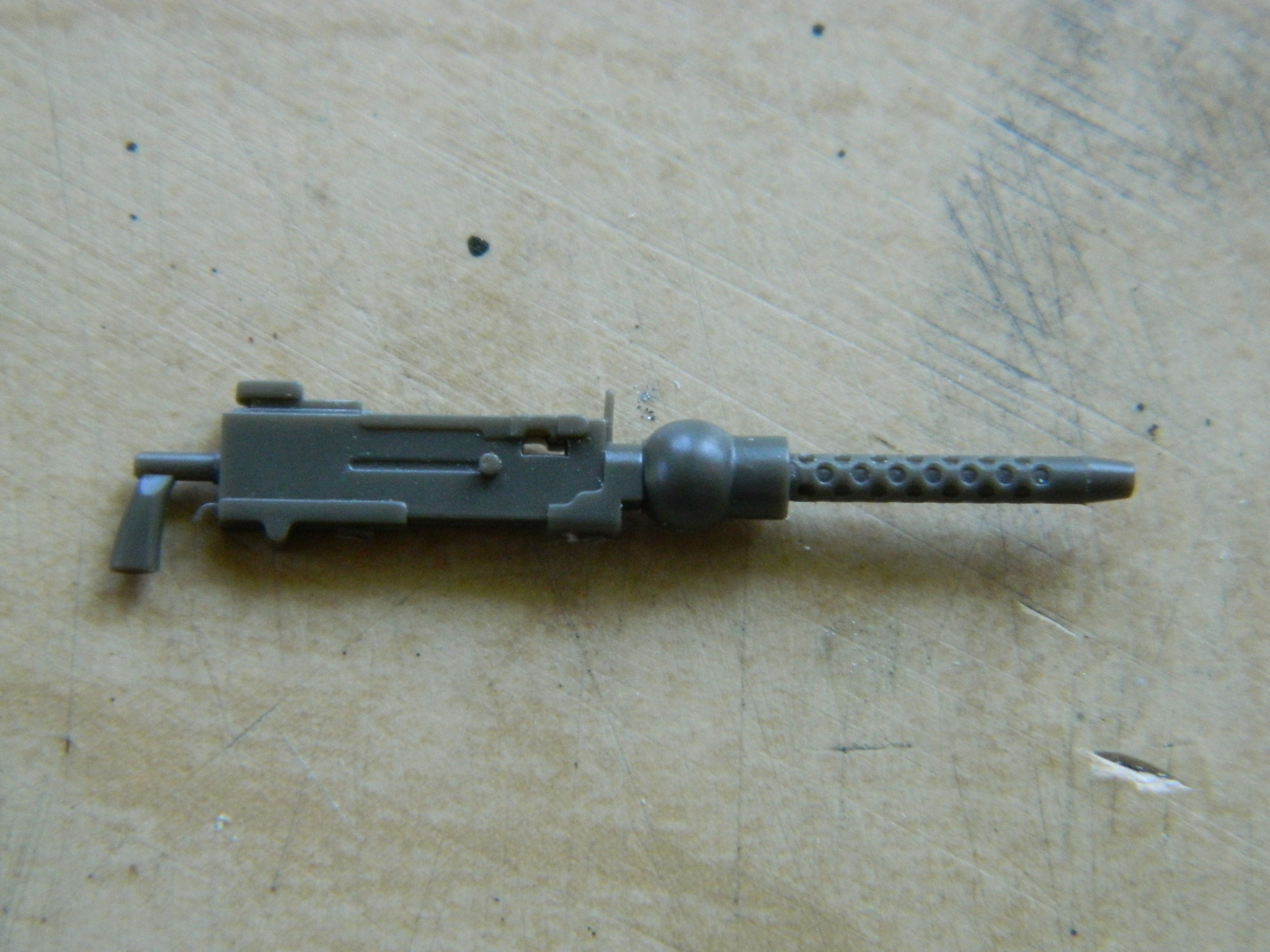
Next step is to cut off the resin barrel and drill a hole for the new barrel to seat into the receiver:

And that was another mistake. I didn’t check the overall length of the assembled gun and the barrel extends much further out than it should (much like my stomach does):
Since it’s superglued into the receiver, and since acetone softens superglue, I dropped the assembled gun/barrel into a jar of it and let it sit overnight. The next day I discovered a couple of things. First, the acetone did indeed loosen the superglue and the barrel/shroud slid right out:
What the above photo doesn’t show is that the receiver is no longer solid. It’s rubbery. Like thin rubber. Well, bugger…
I rattled around in my spares boxes and found the bow gun from an Asuka kit (or Tasca, as they’re calling themselves now):
And this time I certainly drilled it deep enough. If you click on the picture below and zoom in on it, you’ll see that just in front of the shell port where the bit has deformed the plastic outward (but given where this gun will reside, that won’t ever be evident):
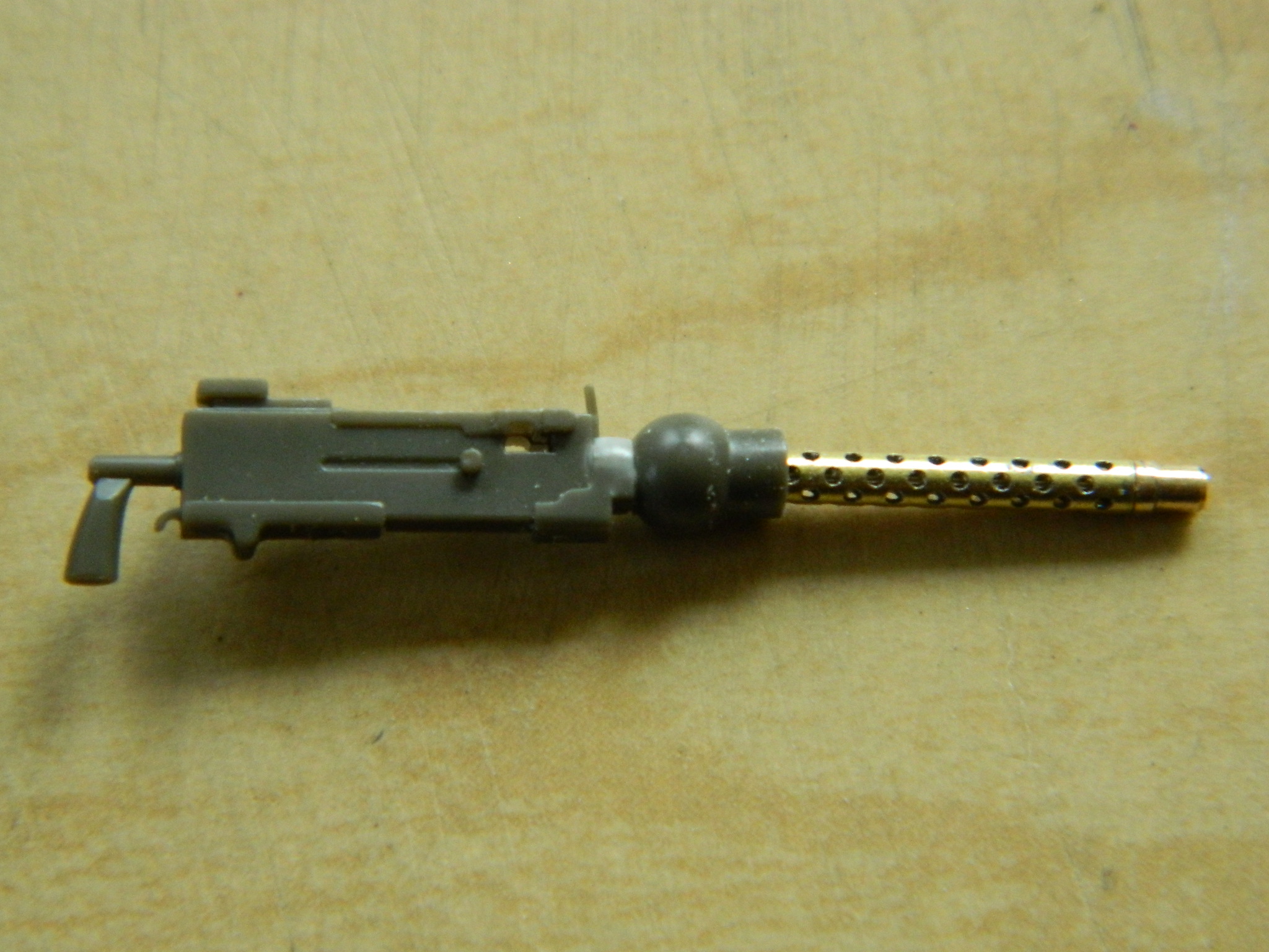
And now (unlike my stomach) the barrel doesn’t stick out too far:
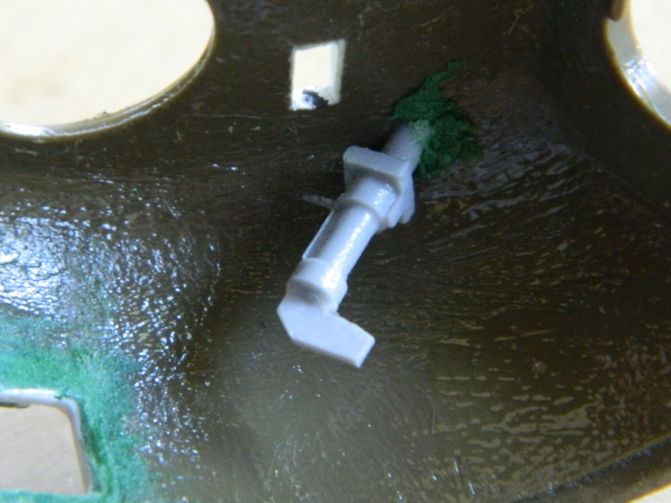
And since I’m replacing the periscopes and their flip-up covers, I had to remove the molded on cover and replace it with a resin cover of a size matching the cover of the driver’s periscope (after filing the head out from under it):

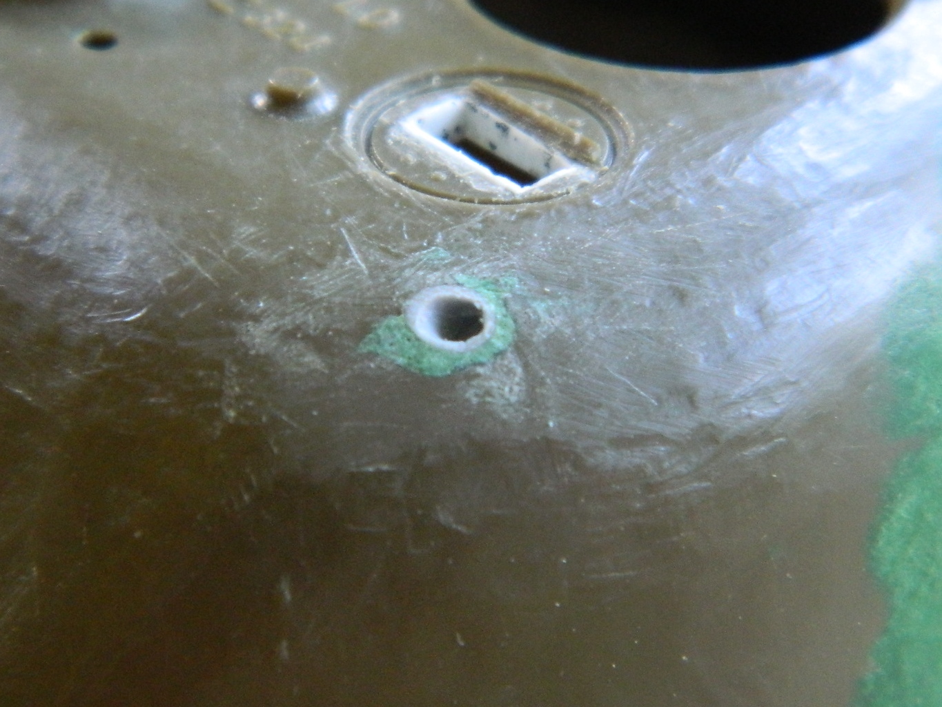
Since I realized that the vent blower is going to get in the way of the periscopes, the bow gunner’s periscope will be modeled retracted. The problem with that is that all the resin periscopes are molded open. That means I have to extend the bottom of the periscope and add clear sprue to the bottom where the view port is (and I had to add a little putty):


Since I was revisiting the periscopes, it seemed a good time to get some paint on them. I back painted the clear heads; internal heads that look out get back painted a light color, the external heads that look in get painted a dark color, and then they were masked off while they were still easy to get at:
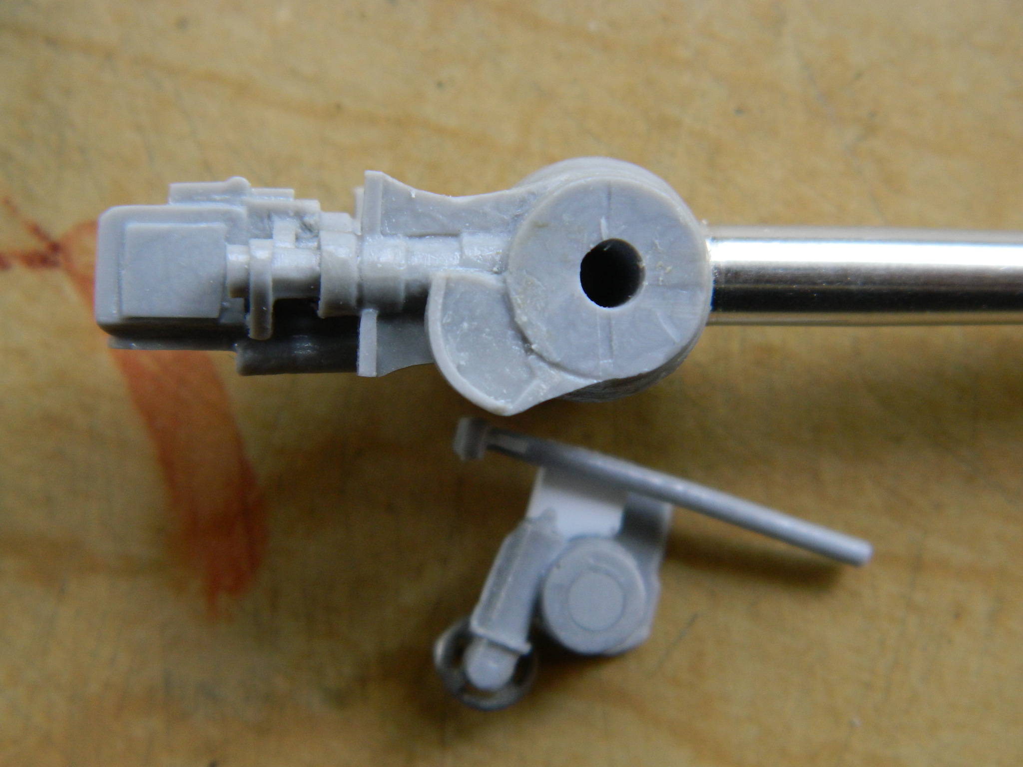
Getting back to the turret for a while, I started work on the main gun (75mm) assembly. I picked up a really nice turned aluminum barrel that even has rifling in it! Step one was to drill out the mount and socket the barrel into it:

What I found interesting is that the hole is so snug that the air behind it pressurized. The barrel came out (easily, in spite of superglue), I drilled a relief hole under the gun mount, and glued the barrel back in more securely.
Totally unsurprising at this point, there are fit problems. After doing some skull-sweat, I realized I would not be able to use the cast-on resin pivot (fit and structural considerations). As so happened, I just happened to have copper tubing of the correct diameter. I drilled…carefully…in from both sides of the gun mount towards the center and dayum if I wasn’t within .005 of being spot on:

Given that fit problems abound, it was time to dry-fit this next step and see how things were fitting (or not):

Things were fitting, mostly, but just like in an actual Sherman, “space” is only found outside.
So it turns out there’s fit problems. The mantlet I want to use is from a different kit (Dragon, because it has better surface detail) and does not quite line up with the gun shield behind it and that’s going to mean neither the coaxial .30 caliber machine gun nor the gun sight will line up properly, as they have to go through the shield and mantlet:


That means I have to widen the mantlet. It’s still not EXACTLY there, but I can work with this by widening the slots in the gun shield to pass the .30 and sight through:

To give you an idea of what modifications are really being done, this is what the kit provided for this whole section:
Yeah, it all lines up, but if the hatches in the turret are open…and they’re going to be…there ain’t jack to see in there.
Next step is the trunnion caps that hold the gun assembly to its mount. To do that, the molded on mounts have to be filed to about half their original length and caps fitted to the stubs:
After I shaped the trunnions and added bolts, the fit is checked again:
And yes…there are problems. There’s a gap between the .30 caliber mount (on the left of the above-right photo) and the rest of everything. Time to fix it. If you look closely, just to the inside of the .30 cal is a disc of plastic that takes up that now occupies that space:
And then I cut off the resin barrel and added the really nice two-piece brass set, only THIS time I made sure I’d drilled the part out far enough. All of this drilling I’m doing is done by eye and this particular piece was nice confirmation that my old eyes still work pretty good. I got this thing centered within minuscule variation as evidenced by the barrel protruding equally on both sides of the body of the gun (which won’t be seen after it’s installed, especially once it’s been painted):

On the Shermans, the turret was rotated electo-hydraulically, but there was also a manual crank in case the hydraulics failed (or were shot out). The AM part didn’t provide the handle so I have to add that:

Then while checking my references about something else, I noticed that I put the gun sight assembly in at the wrong angle, so that had to come out and be reworked. The part that’s off is the piece below the sight which is the elevation control. The picture shows the angle that control is supposed to be mounted at:
Due to the fragile nature of the resin and the very small diameter of the sight, I thought I would surely snap that bastid off…which I did not. However, while I was working the piece loose (sharp knives are OUR FRIENDS) and considering what options I might have when I did snap the resin sight, I came up with another method of making the sight that I liked a lot better. All I needed was copper tubing of the correct diameter…and it turns out I have that on hand:
The first step in using it was to drill out the end of it so that it doesn’t appear to be out of scale:
In order to mount it securely to the eyepiece, I drilled out the resin and glued a wire on, then I slid the tube over the wire and glued it securely in place:

With that taken care of, the elevation/sight assembly got glued back to the gun and its fit with the mantlet checked and I like this a lot better (I also added a mounting bracket – aluminum foil – and the control cable – solder – to the elevation crank housing):

I just wish I’d noticed at this point that the eyepiece on the site was incorrect. The way it’s set up in the above photos, the gunner would use his left eye to lay the gun on target, but in reality it was set up for him to use his right eye. But I didn’t notice…
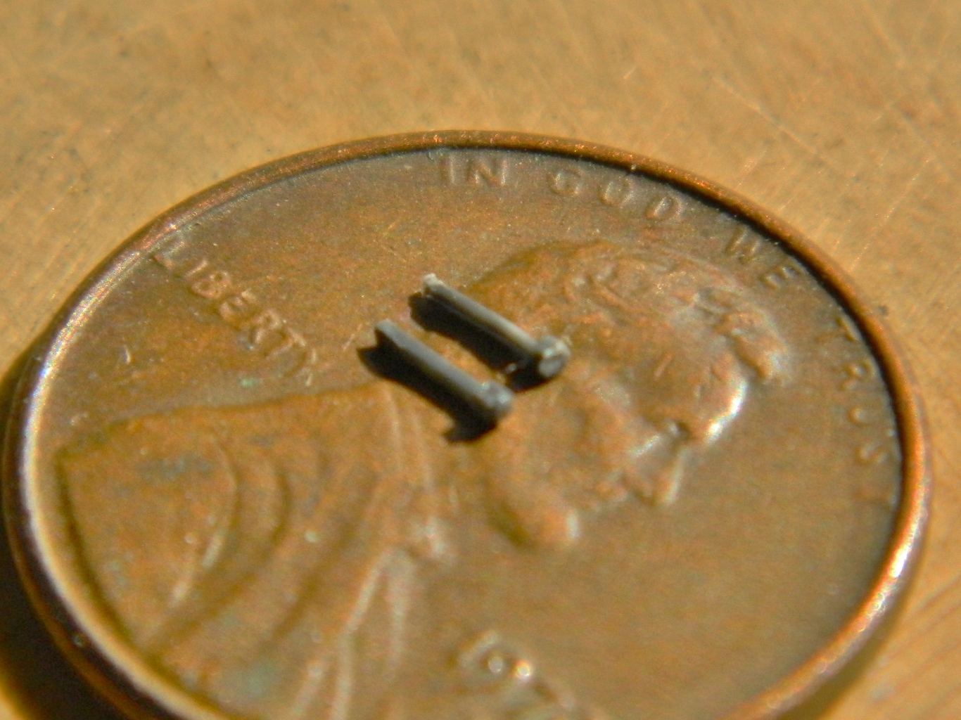
The ratchet-release for the manual turret traverse (aluminum foil again) got drilled, trimmed, and glued on (and then shortly thereafter the fragile handle snapped off; that will get added on later once I no longer have to manipulate that part):

M4A3 (Tamiya) Build #14
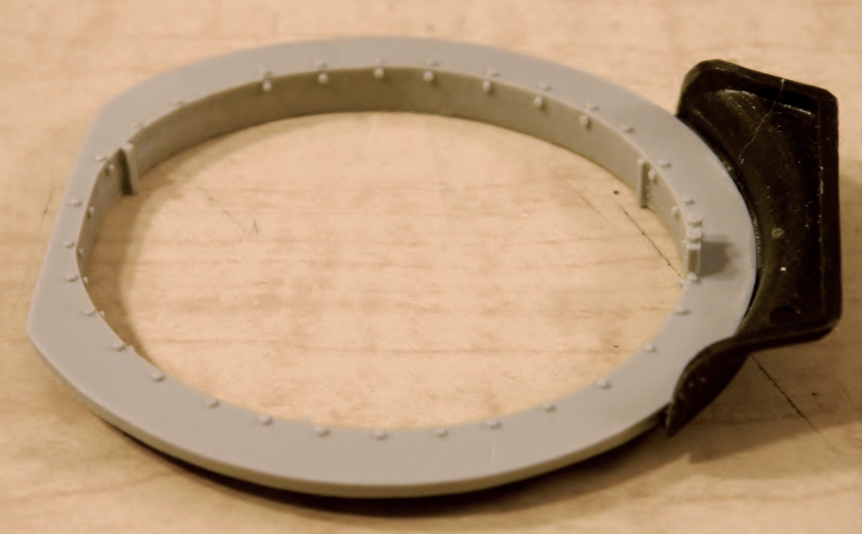
With the interior of the lower hull done, I’ve moved to the turret. I have to graft the turret bustle (dark plastic) to the resin turret ring (light resin):

I cut the kit’s turret ring off the bustle, used the spare turret as the jig and got the parts aligned:
Once I was satisfied, I glued the resin ring to the plastic bustle:
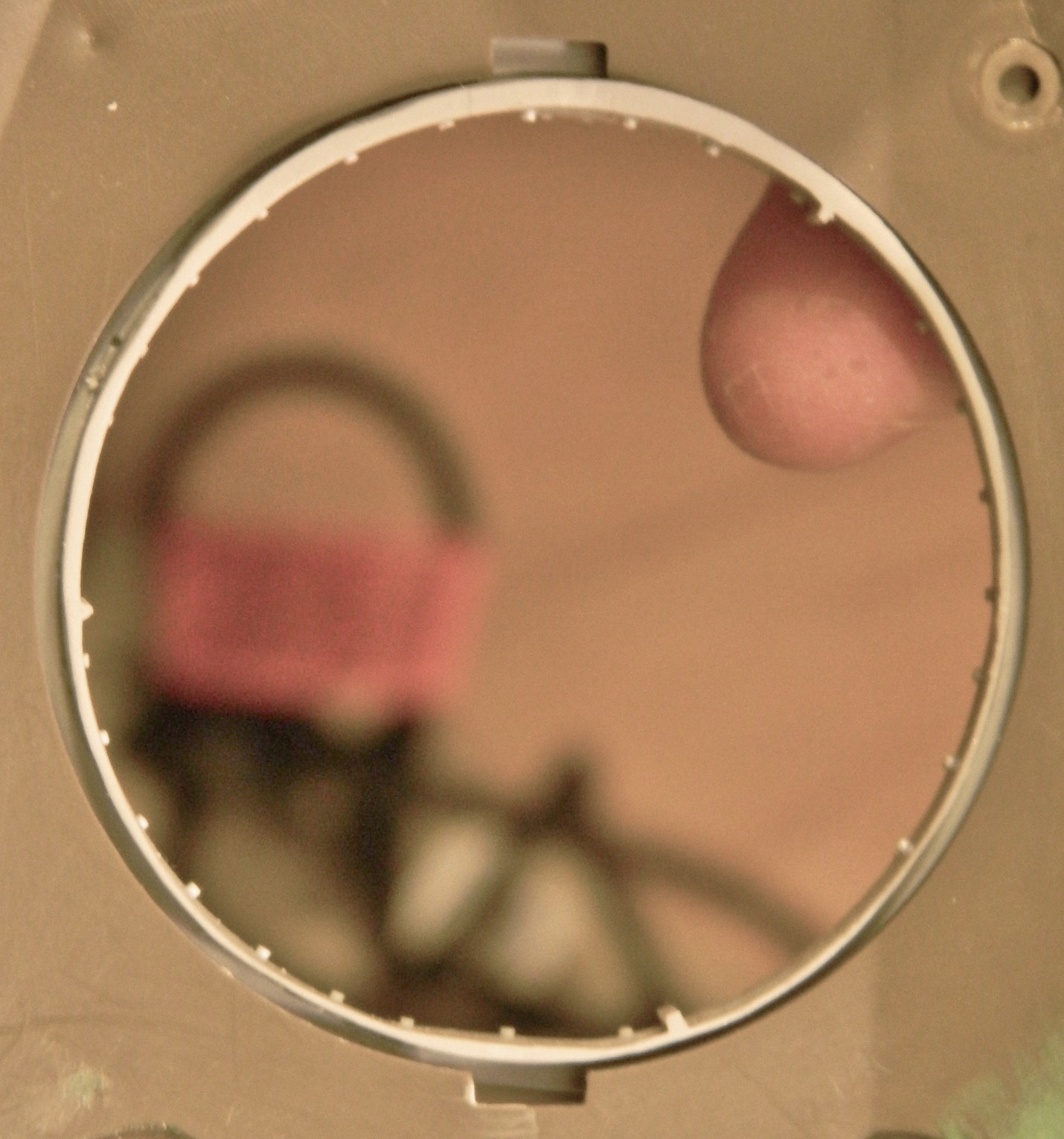
In fitting the ring to the upper hull, I see I have more work to do so that things fit better:
Taking the opening in the hull as my reference, I started shimming the gaps with styrene:
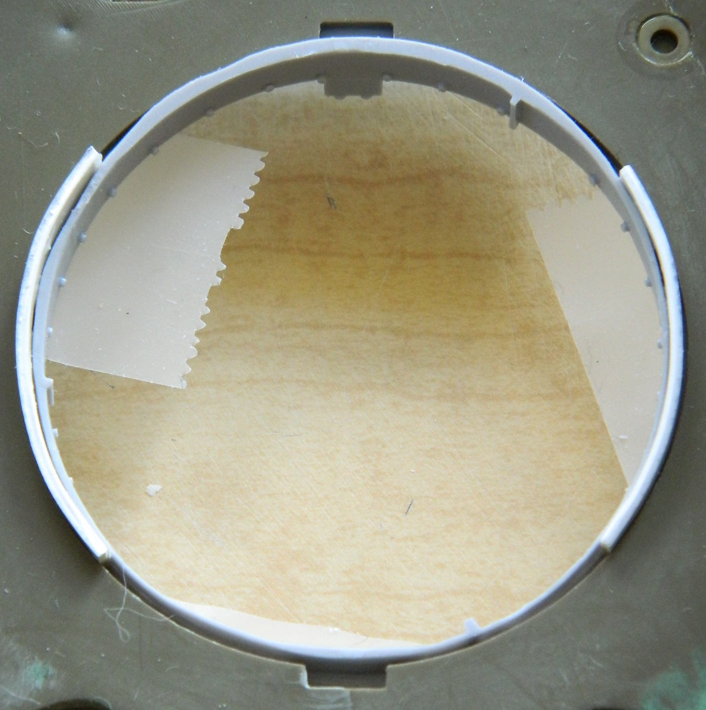
Now this gets trimmed and sanded into a rounder shape:

Okay…that’s better:
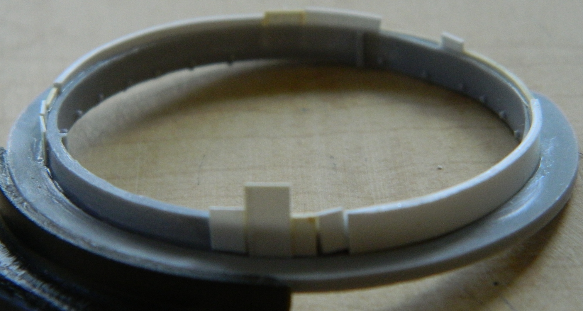
Then checking fit between the lip of the turret ring and the bottom of the turret shows there’s more shimming to do:
Shimmed, trimmed, and fit:

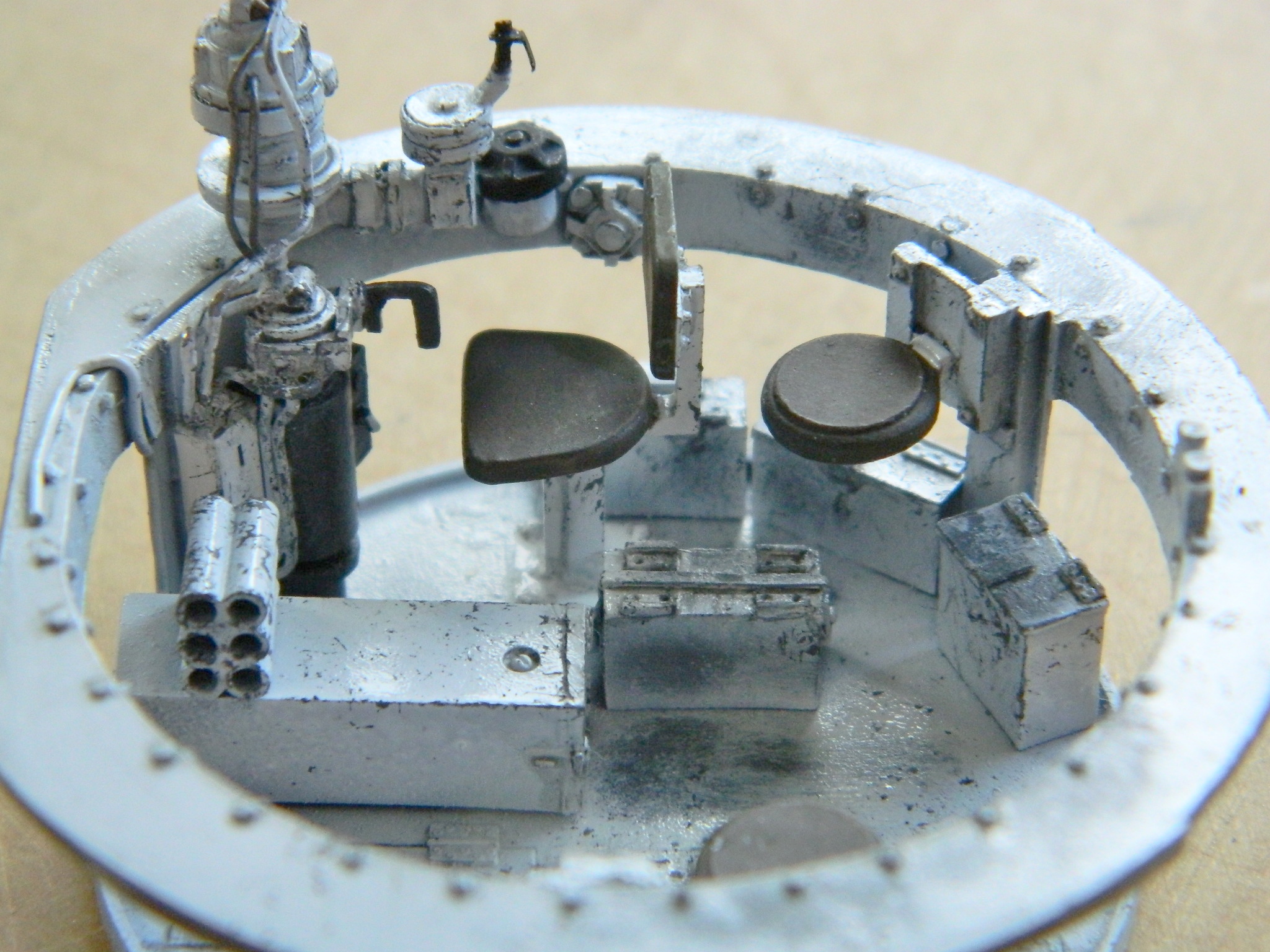
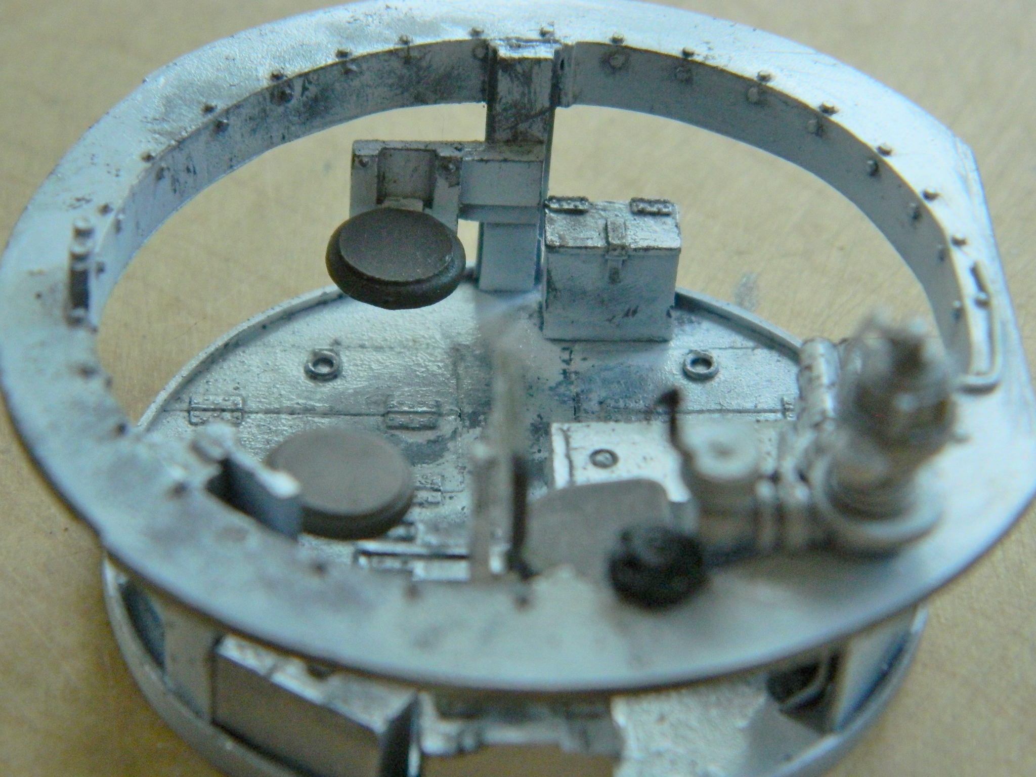
First the floor gets added to the ring:
Then the various boxes are added to the floor (the gunner’s seat is has to go in a specific place, the other boxes and things aren’t as critical, using the gunner’s seat as a reference point):
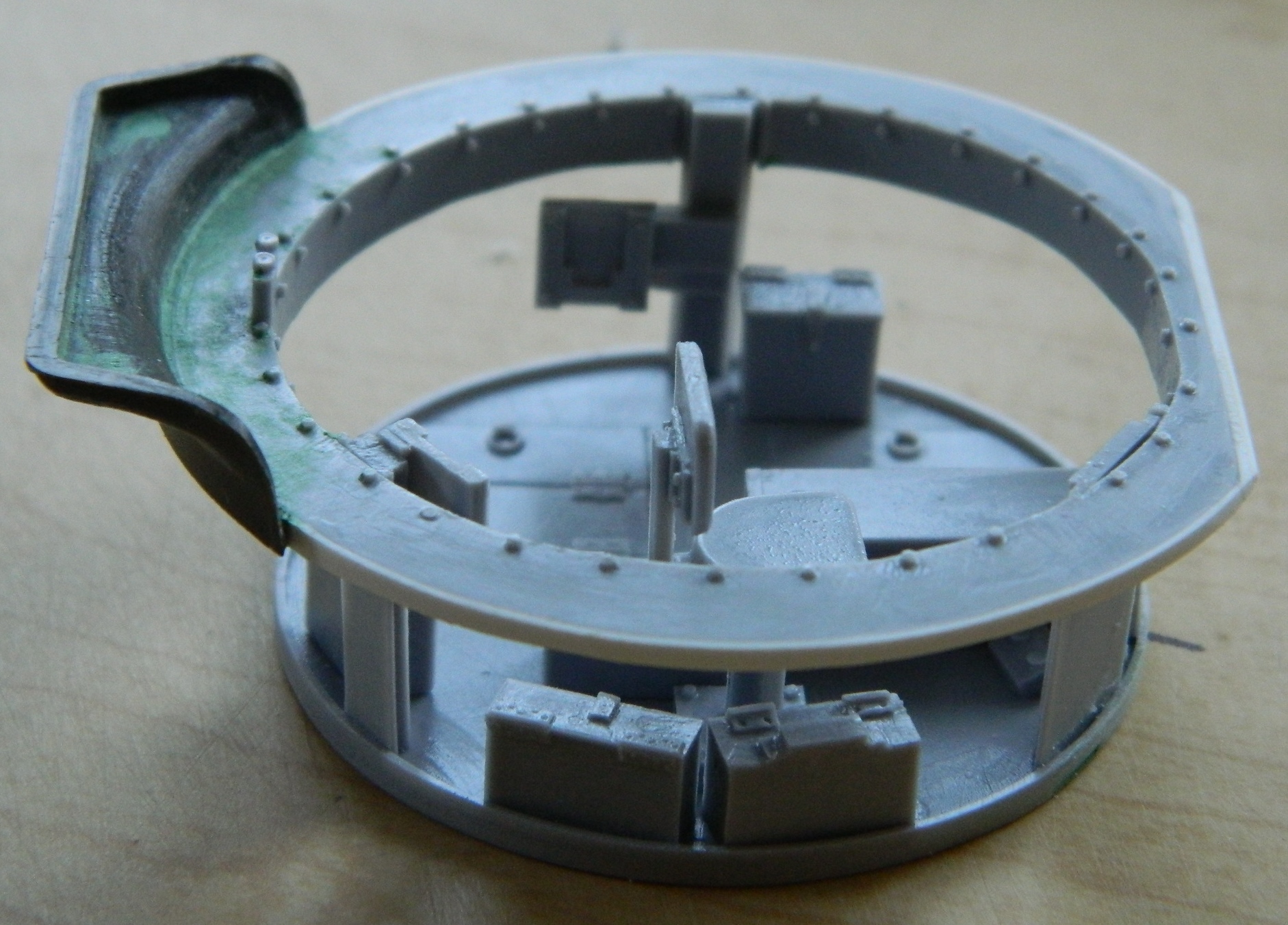
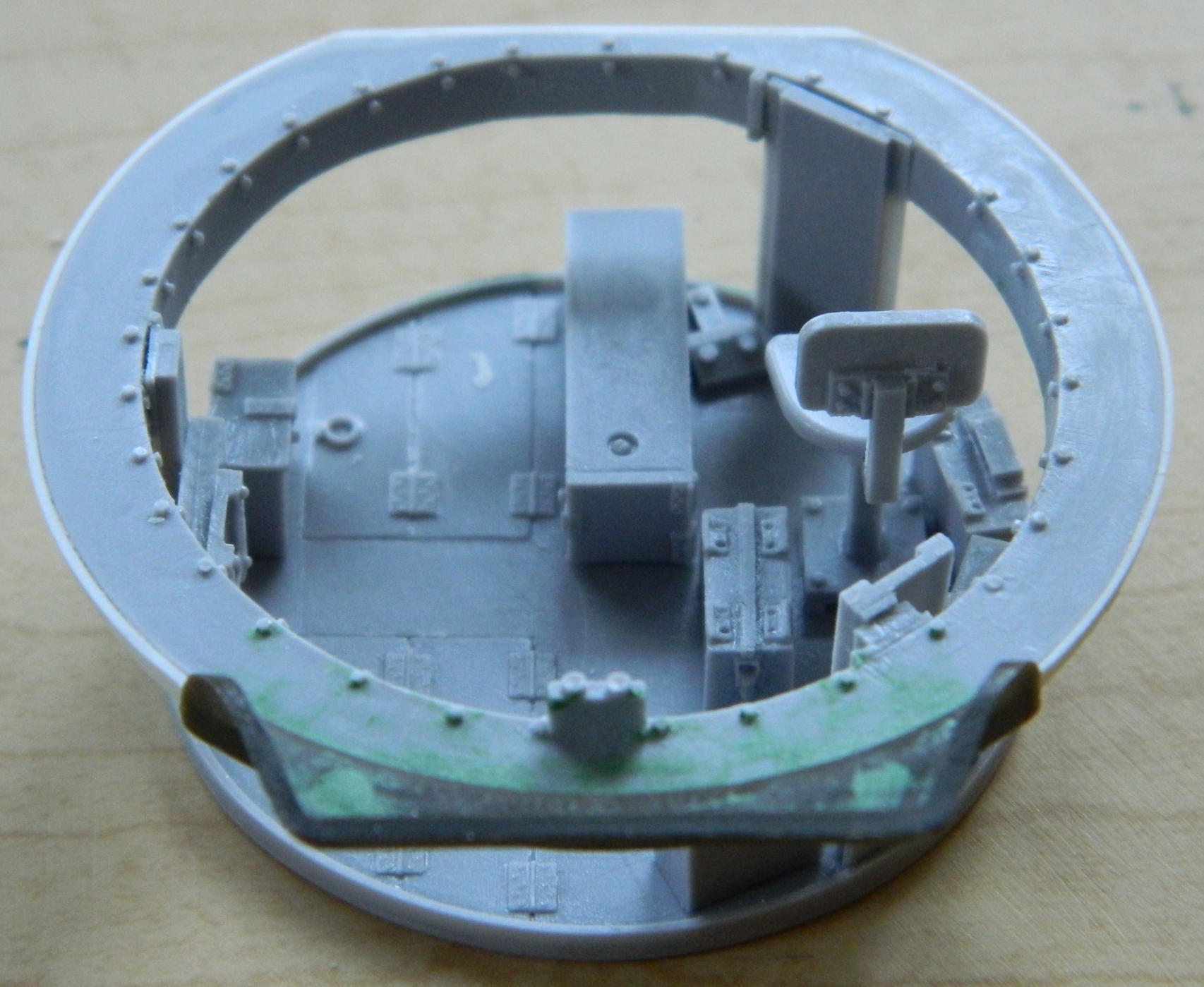
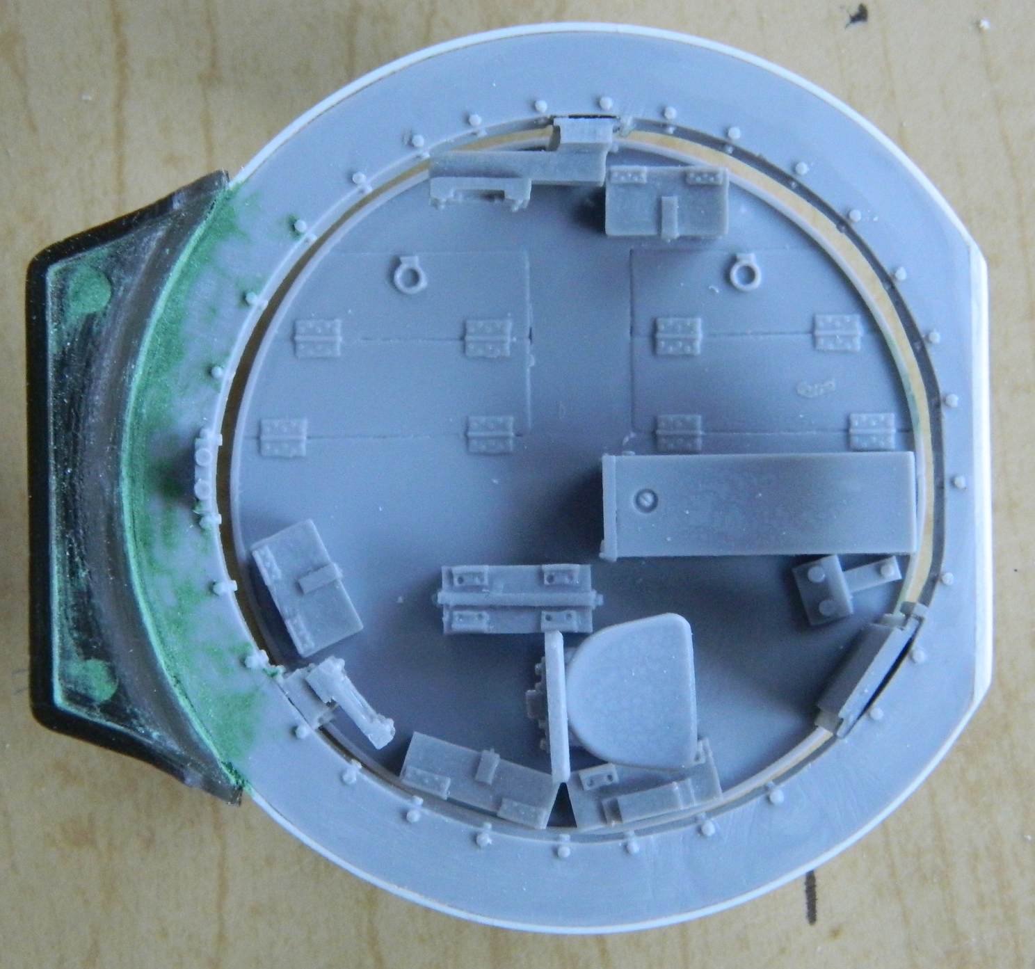
The gunner’s turret traverse controls are mounted on this panel in front of the seat:
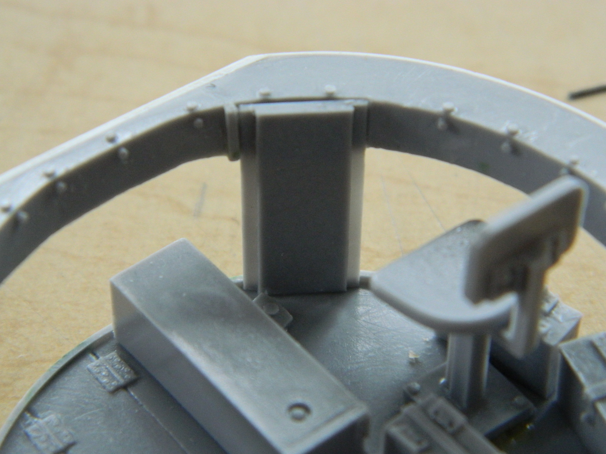
Because of the snug confines, other parts in the way, and having to paint most of this assembly white while sections of the turret controls would be different colors, I assembled the controls assembly on a sheet of .005 styrene so that I could move them as an assembly. For whatever reason (caffeine-deficient, perhaps), I couldn’t find the oil reservoir among the resin parts so I made one (the piece in white, and of course the resin part showed up months later). Once attached, I started adding the various hydraulic lines from different sized solder:
A quick dry-fit shows it should fit:
I painted the assembly, trimmed off the excess styrene, and put it aside for later inclusion:

As it turned out, I’d attached the bottom of the turret bustle to the turret ring prematurely. With the turret ring in place, there is NO way possible to get inside the turret to finish the seam of the bustle. That means the bustle has to come off the ring. Since I’d used the bustle bottom from the spare kit, I still had one perfectly good bustle to attach. Alignment, obviously, is important, so I’m using the kit itself as my alignment jig. First step to that is to attach just the bustle bottom and leave the ring unattached to the turret, then cut the ring off leaving the bustle attached. The gap is substantial so I glued where the parts touched and filled the gaps where they didn’t with my structural putty::


Even without the turret ring in place, getting in there to finish the seams was an “interesting” experience, but at least it was possible:

Then the bustle I’d attached to the turret ring had to be (CAREFULLY as resin can be delicate) removed:
This ledge and projection is on both sides of the turret’s interior, it’s not there on the actual tank, so they both have to go:
The late-production Shermans (and mostly all the British Shermans) had a 3” smoke mortar in the roof of the turret. On the spare turret, you can see the stub on the inside that keeps the hole from being just a hole (how unlike Tamiya!). That’s got to go so that I can mount the resin mortar later on:
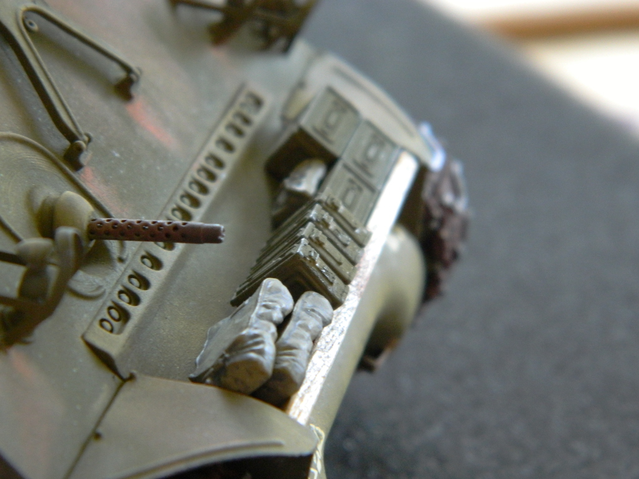
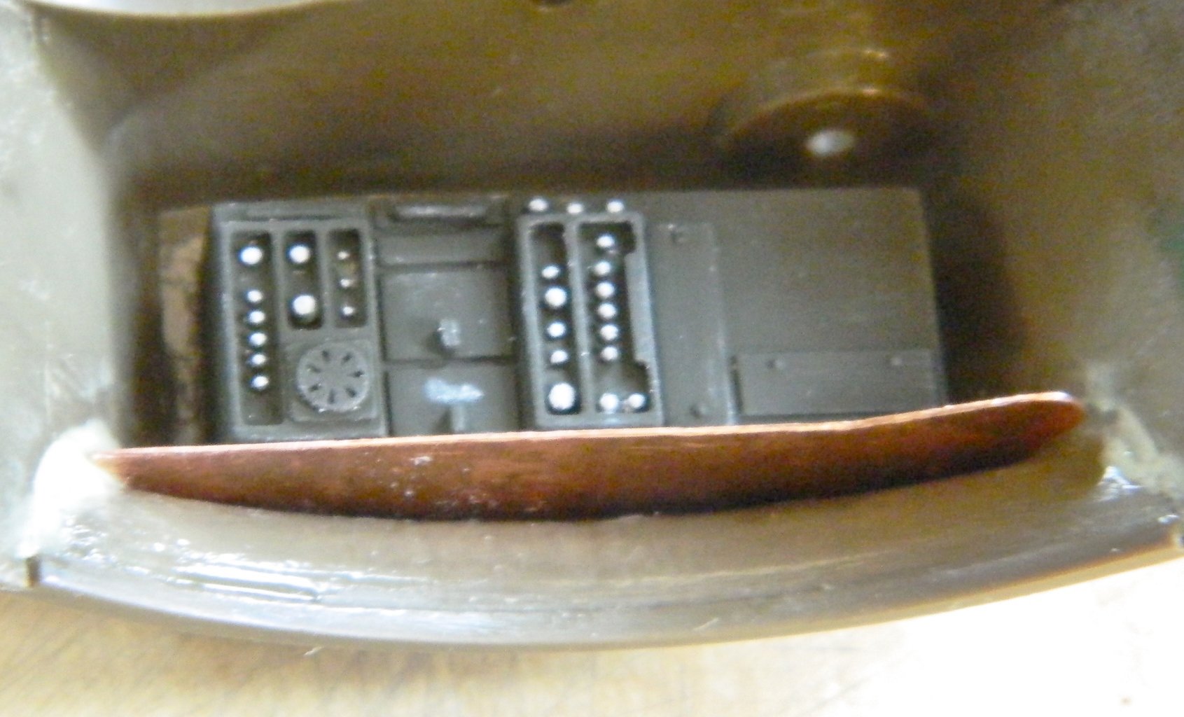
Another obvious feature inside the turret is the radio; it sits on a shelf in the bustle (and is probably the reason for the bustle). Of course, there’s no radio or shelf with the kit. The AM interior set provided the radio; it’s up to me to make the shelf. Again, I went with .010” brass shim stock. I took the bustle floor I removed from the turret basket and carved away the interior of it to use the profile of the bustle as the template for the shelf:
Periscopes. An exercise in tedium.
I started with the gunner’s periscope. It’s larger than all the other periscopes on the Sherman (all the others are the same and interchangeable with each other, with the exception of the periscope used in the commander’s hatch of the vision cupola), and often was used as the gunner’s gun sight. On later model Shermans, like the one I’m building, the gunner’s periscope had a lightly armored cover. Tamiya, for reasons only they know, modeled the armored cover but didn’t provide anything to fill the hole:
Time for the AM resin periscopes. The one on the right is the gunner’s periscope. The U-shaped part is actually a padded head rest. With the gunner’s face in close proximity to an inflexible object like that, recoil of the main gun (or maybe hitting a solid bump while peering through it) would smash his face without it:
When I cut the periscope off the pouring stub, rather than finish down the pouring gate and then later on having to add the periscope head and align it, I decided I’d use the pouring gate as the head and eliminate the need for alignment by shaping it accordingly:
While I was diddling about with these small periscopes, I decided I’d do all the other periscopes I needed at the same time.
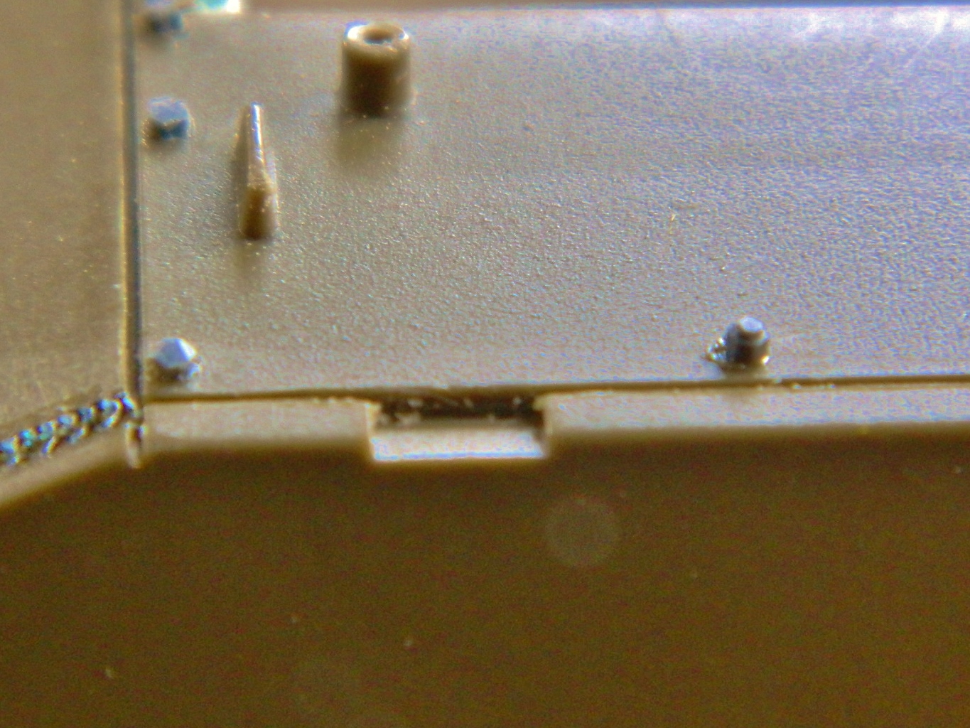
Early Shermans had direct vision slots (with covers) for both the driver and co-driver. It was learned early on that having a weak spot in the (already weak) armor directly in front of two crews’ faces was a bad idea, so they did away with the DV slots. They were replaced with another periscope in the hatch hoods directly in front of the hatches (seeing out of a buttoned up tank is LOUSY, especially WWII tanks). When the later model Shermans went with the larger hatches, redesigning the glacis plate to eliminate the old protrusions for the small hatches, those “extra” periscopes were moved inboard of the hatches, replicated in the photo below as those two rectangular protrusions (the lip in front of them is a “splash guard,” to prevent bullets that hit the glacis from ricocheting up into the periscope heads and taking them out; it’ll be replaced, too). Originally I had intend on adding both periscopes in these locations; I decided to do the driver’s side extended and the gunner’s side retracted. The molding on the model shows both as retracted and I’ll extend one:
With the cover shaved off, the splash guard removed, and the hole aligned and drilled, we get this:
The periscope heads are molded separately and the covers are the angled plates behind the faces:
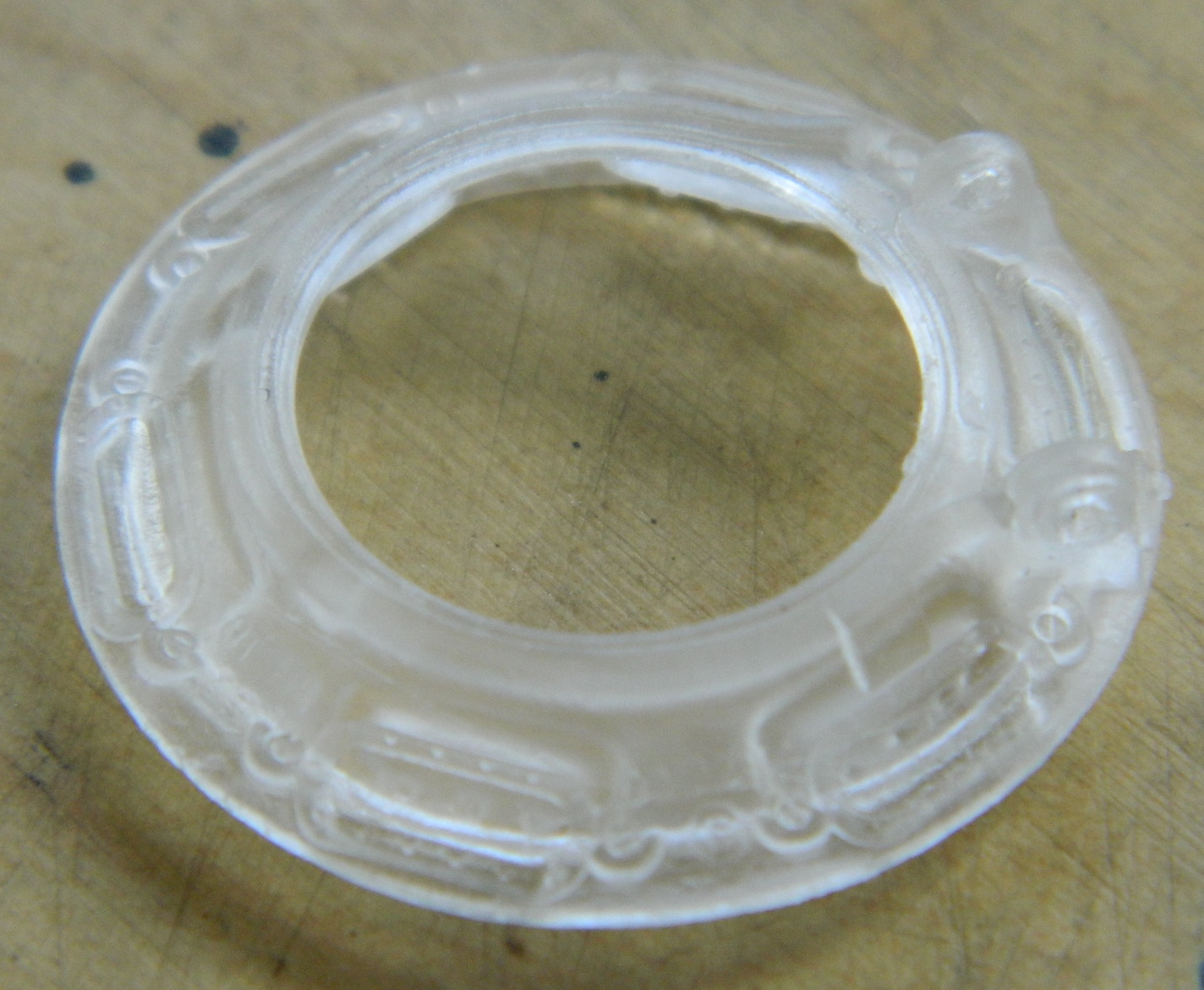
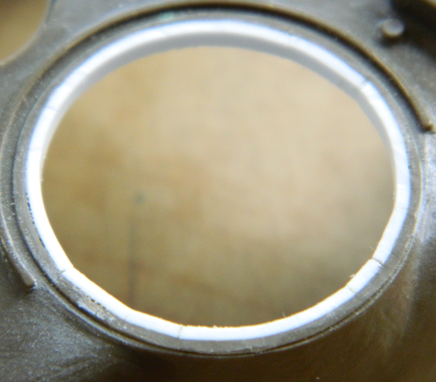
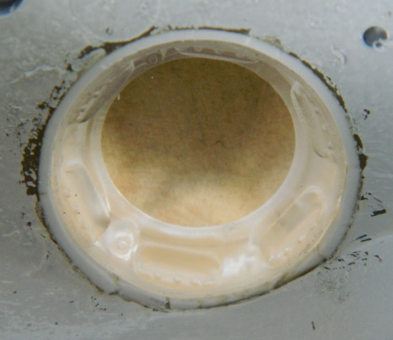
One of the things that always ruins the in-scale perspective for me is when I see something I know should be clear or translucent represented by opaque paint, so I wanted to try something else. I learned by doing aircraft position/formation lights that I could use acrylic toothbrush handles to make more representative lenses. I decided to see if that would work for periscope ports:


Yep…that seemed to work, so I’ll do the rest of the periscopes the same way, though I decided to use clear sprue from the spares box instead for the rest of them:


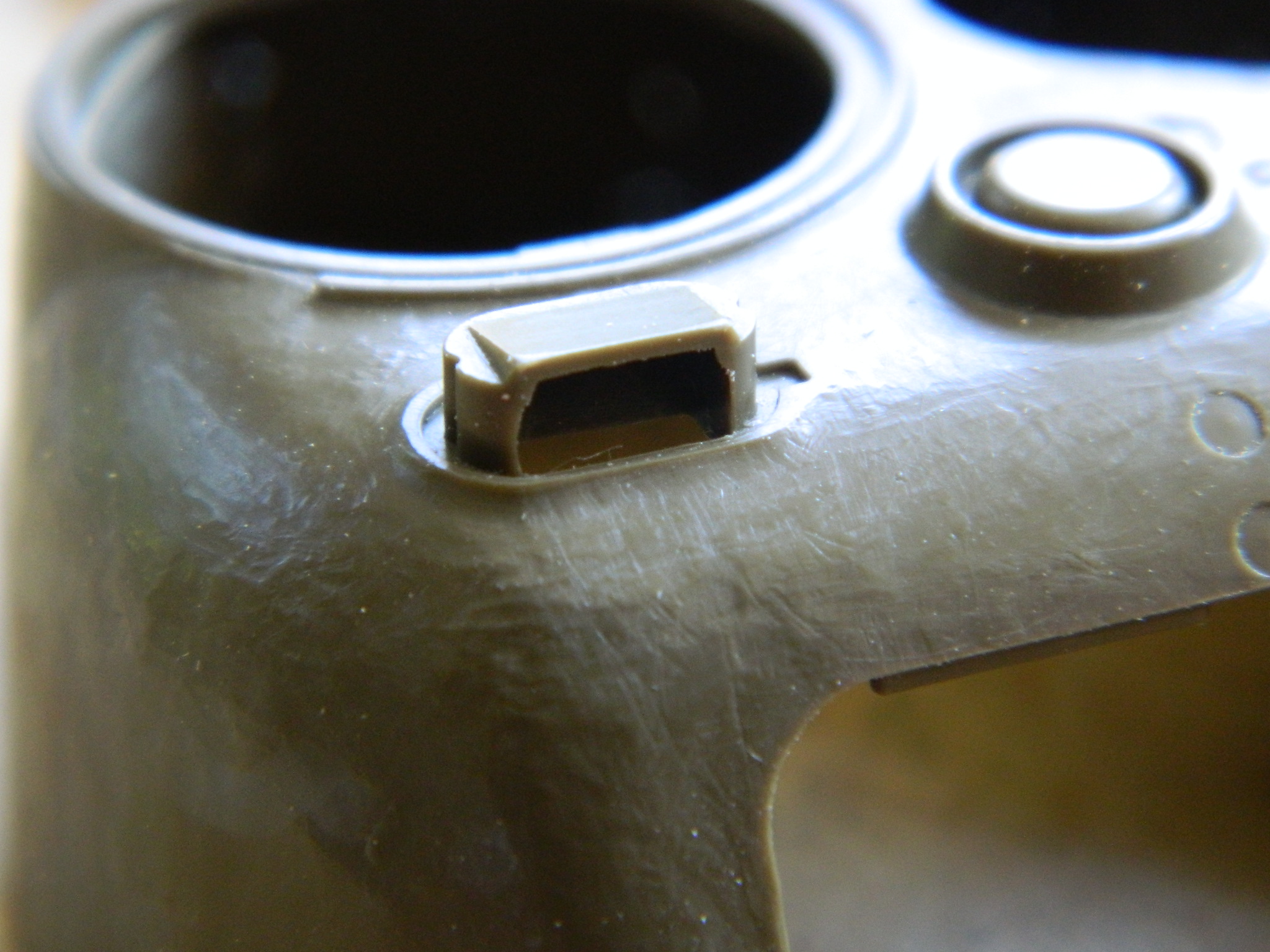
While I was working on turret-related things, I took out the pistol port I’d made, cut the hole in the turret, and grafted it on:

I set that aside to let the putty cure and went back to the hull.
M4A3 (Tamiya) Build #13
While cruising around online, one of the things I found was that New Tiger Models Direct makes nicely detailed hatches for the driver and co-driver. The bottom hatches are the kit-supplied part, the middle hatches are from another kit with better detail (and required me to resculpt the hinges on the bottom hull), and the top ones are the most accurate hatches I’ve found for the large-hatch Sherman courtesy of NTMD:
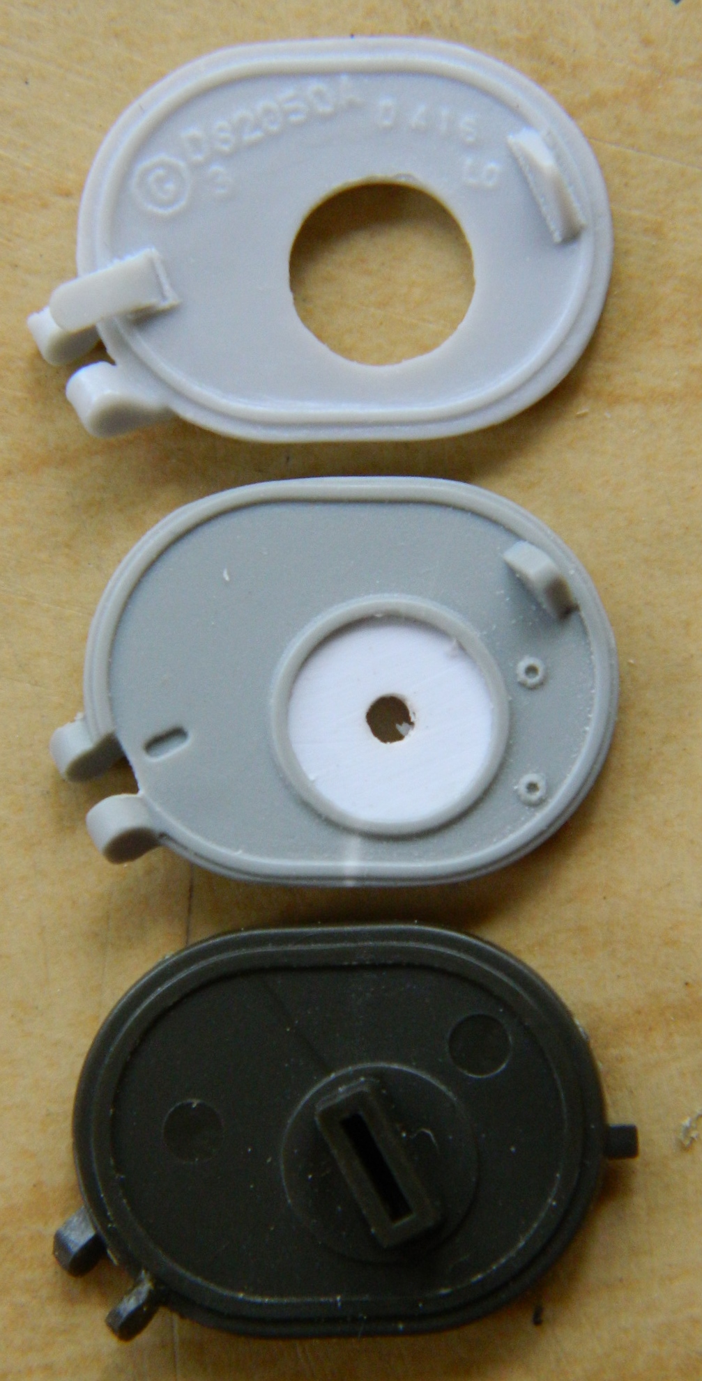

Of course, that means I had to resculpt the hinges on the hull again:
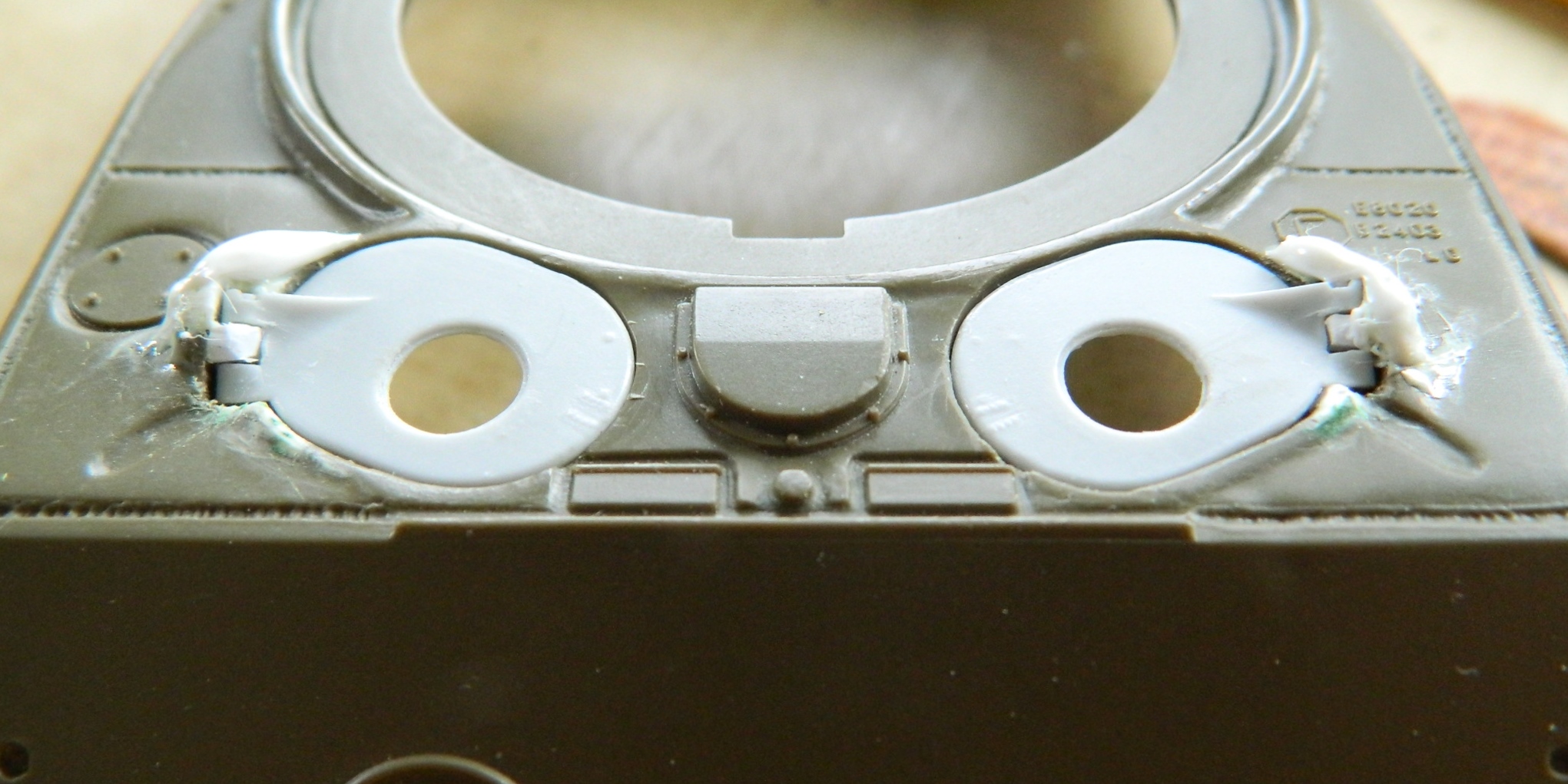
This is the external cap for the vent blower shown on an actual Sherman. It was discovered early on that the crew needed fresh air because carbon monoxide and the gases created by the 75mm’s breech opening after being fired weren’t very good for the efficiency of the crew (clearly in those days, “health” wasn’t very high on the list of Things to Fix):

This is how the kit has that modeled; solid with the bend of the top too far forward:
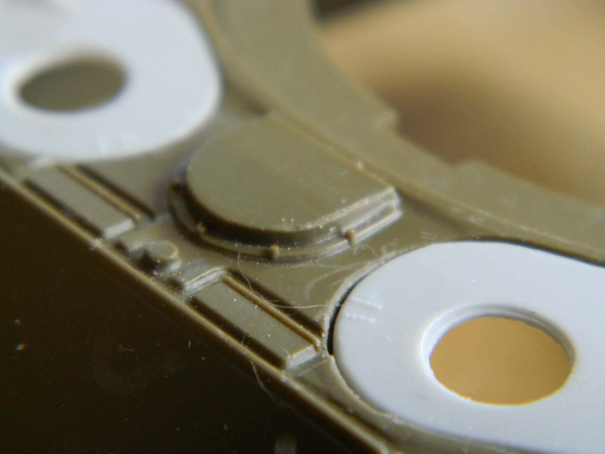
Once again I used .010 brass shim stock to make the replacement. I fumbled around trying to make a usable pattern to transfer the shape to the brass before realizing that this is one good reason I have an extra kit. I cut the section out of that kit and then trimmed it down:

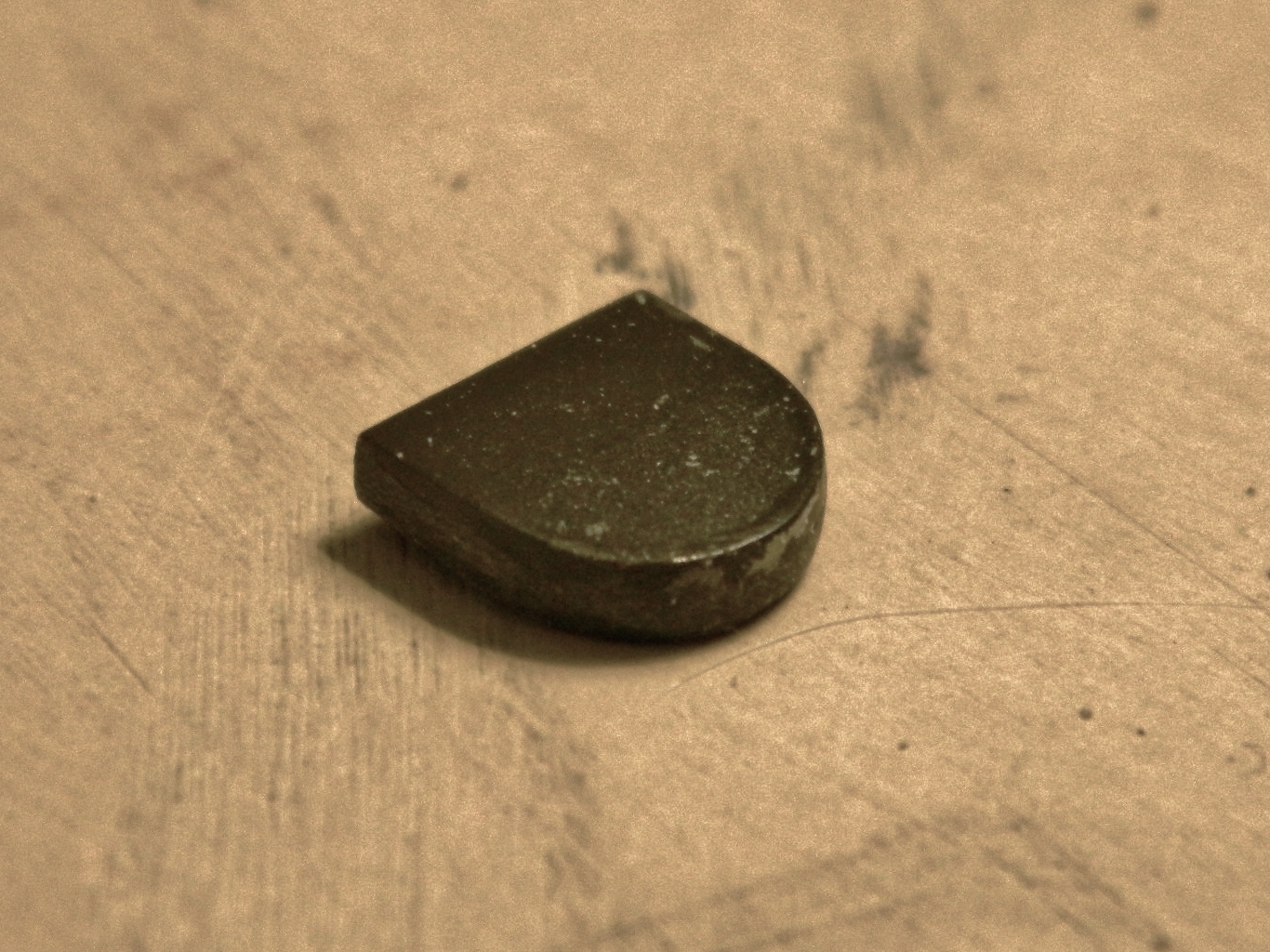
That made creating the pattern as simple as tracing:

I tried a few ways of making the new part but each of them had their own problems:

Then I looked more closely at the reference photo. The legs that hold this sheet metal cap up were actually under the cap, so okay…I’ll do it that way:

Before I could dry-fit the new part to check fit, I had to remove plastic from the hull and then I plugged the hole with sheet styrene:

Fit checked out well and I glued it into place:
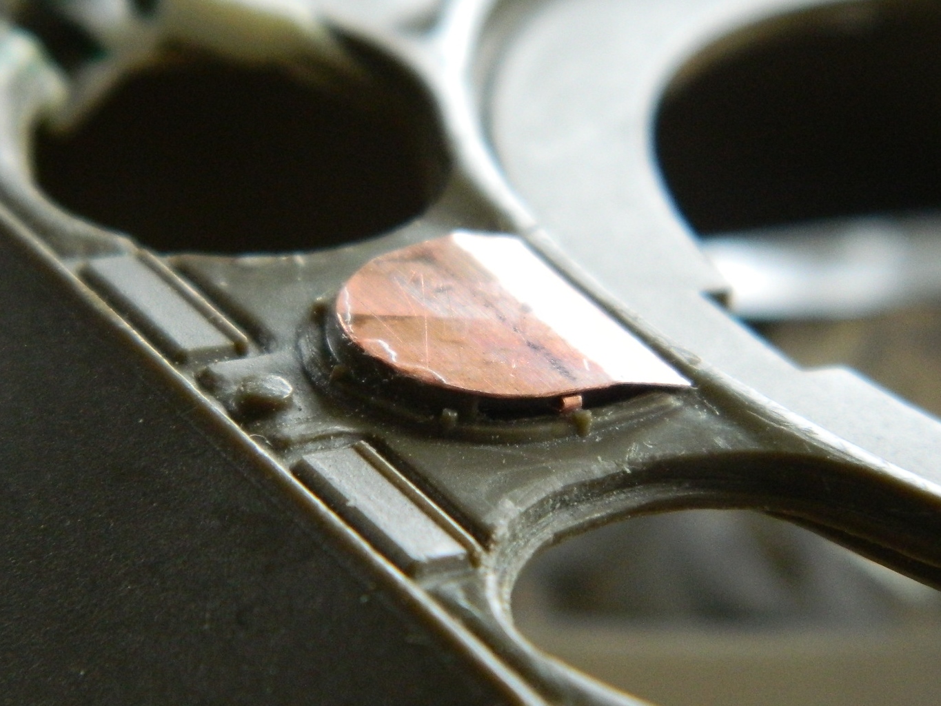
Before I went further with detailing the hull, I needed to make a vent blower assembly that was fitted between the hatches and under that brass cap I just made. However, I knew I was going to be using that blower assembly again (an M4A3E8), I wanted to be able to replicate it. For that I was going to need to be able to make a mold from the original (the “master”) and be able to pour resin into that mold. That was an entirely different direction and task, so while I was researching how to go about all that (see under “What the Hell Does That Mean” the topic, “Degassing – What it is and Why Do I Need it?”), I decided I’d work on the turret.
M4A4 (Tamiya) Build #9
And now the driver’s controls are all trimmed and glued. I added copper wire to run from the floor to the linkages (on the actual Sherman, the rods near the floor attached to the steering levers):
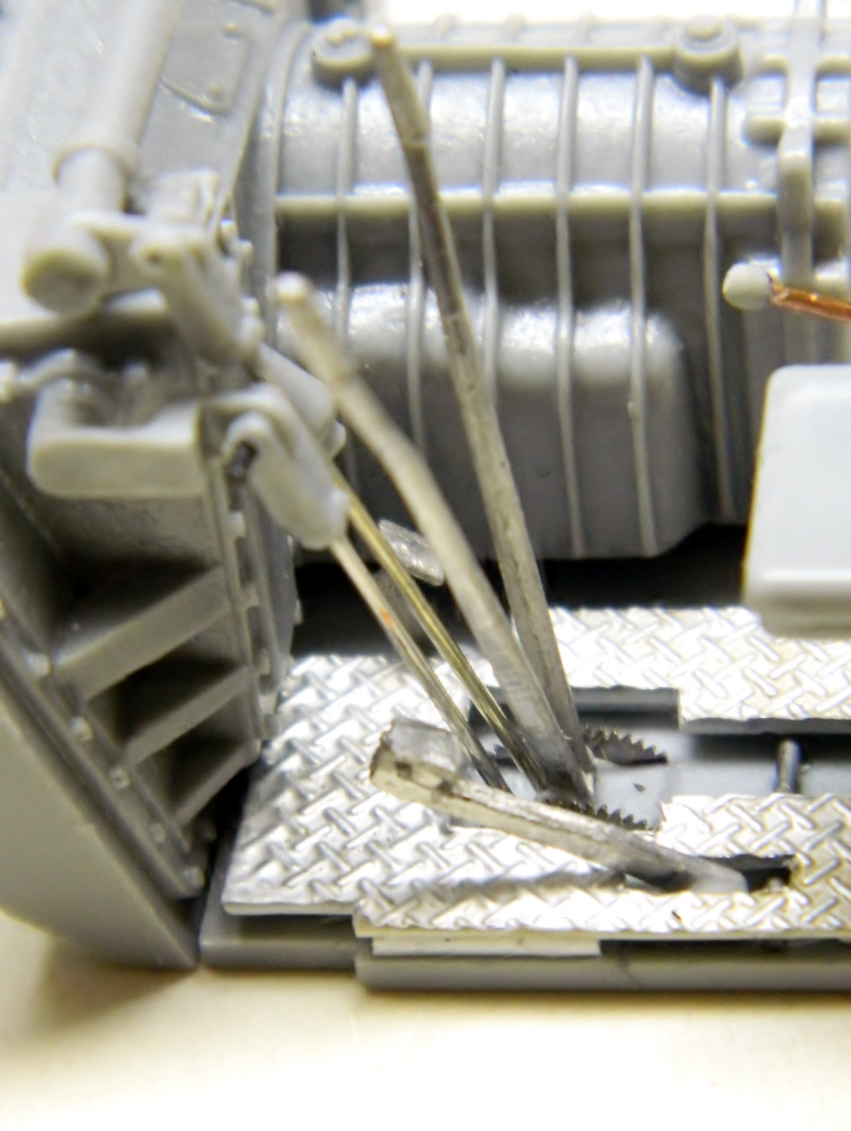
In the photo below, the kit hatch is on the left and fits, the one on the right is from a different kit. So of course I’m going to be using the hatch that doesn’t fit because it offers better details:
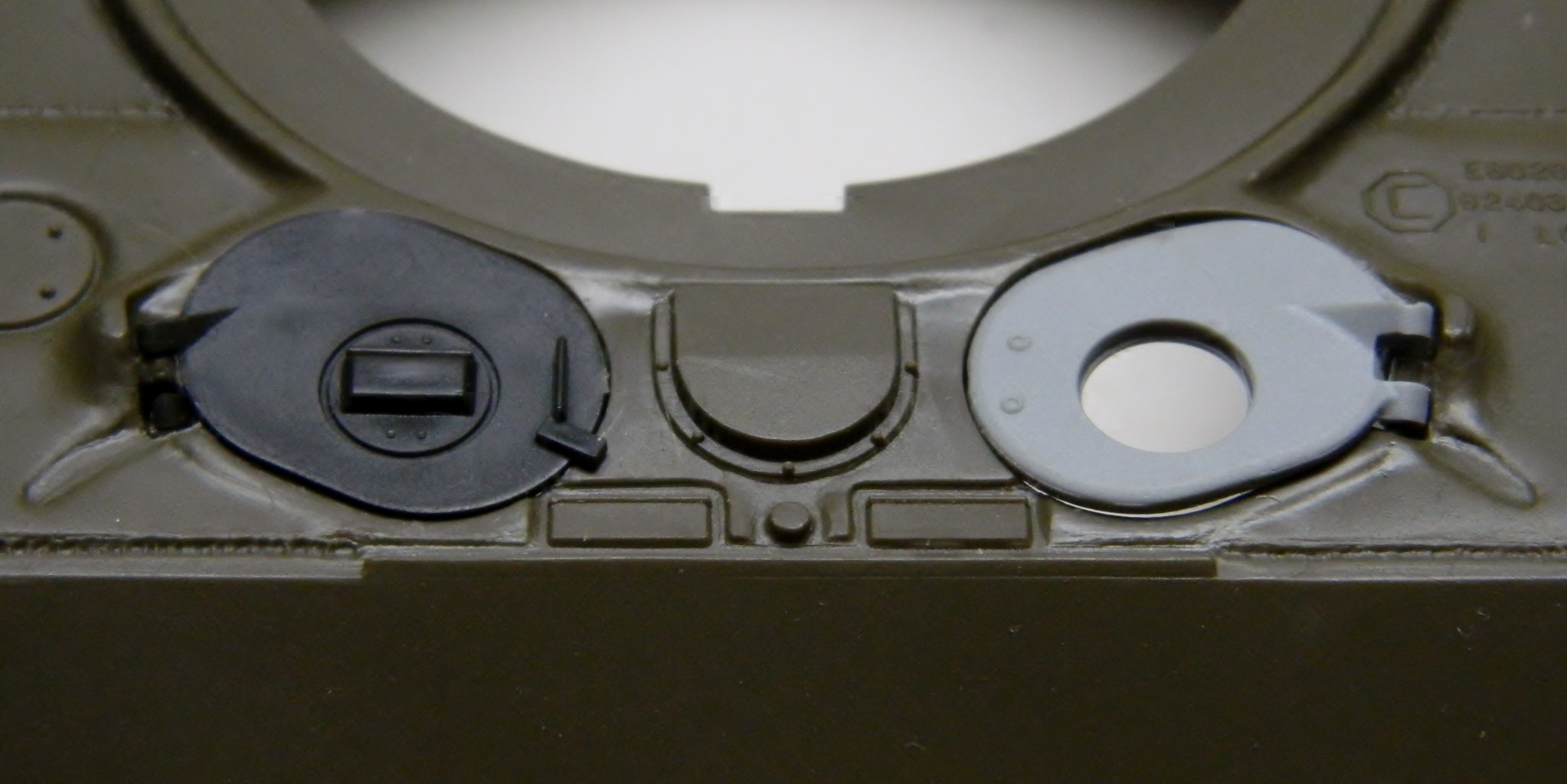
To make these hatches fit required reworking the hinges on the hull top, as you can see if you compare the hinge at left, using the kit hatch, with the hinge at right:
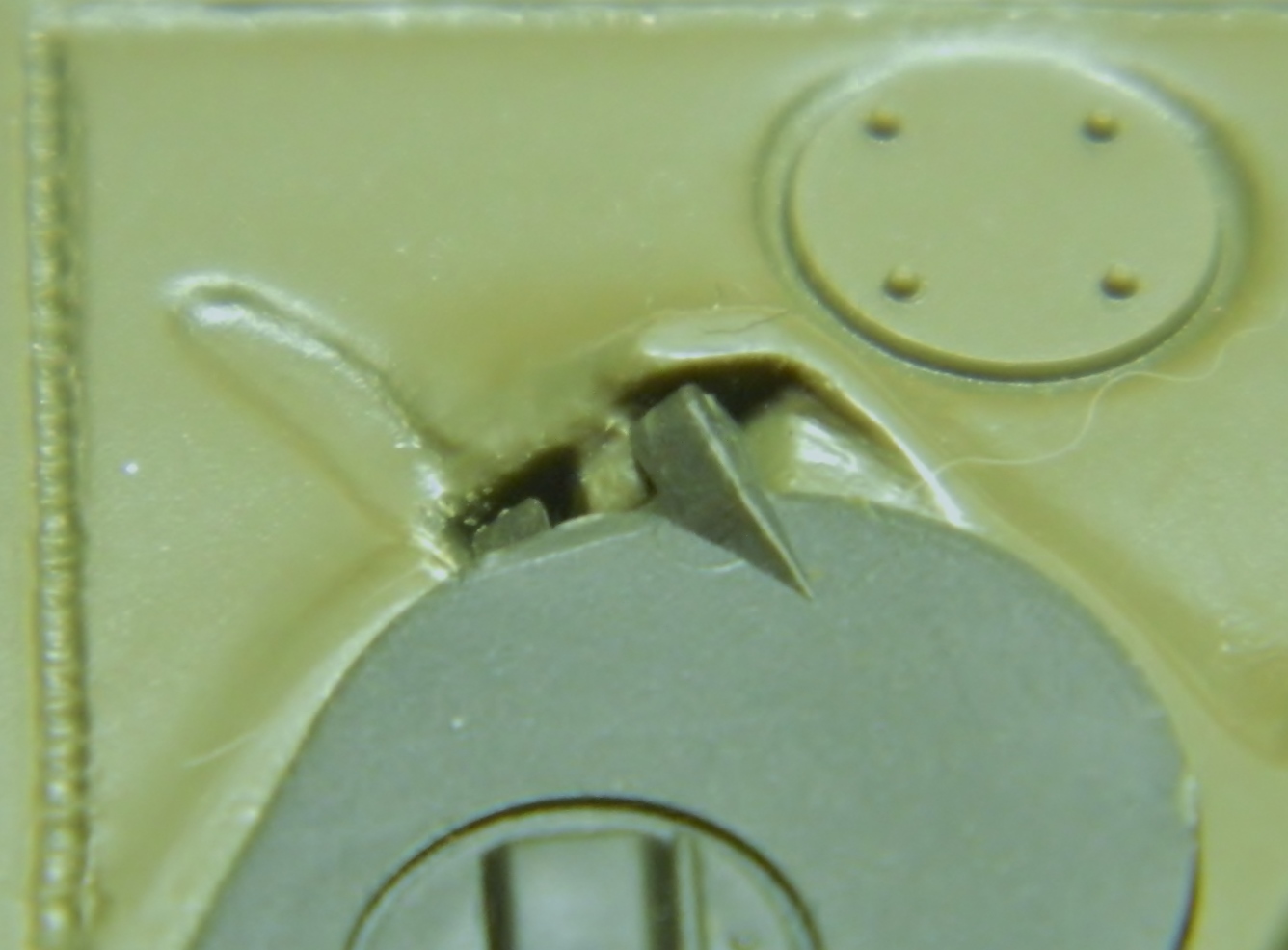
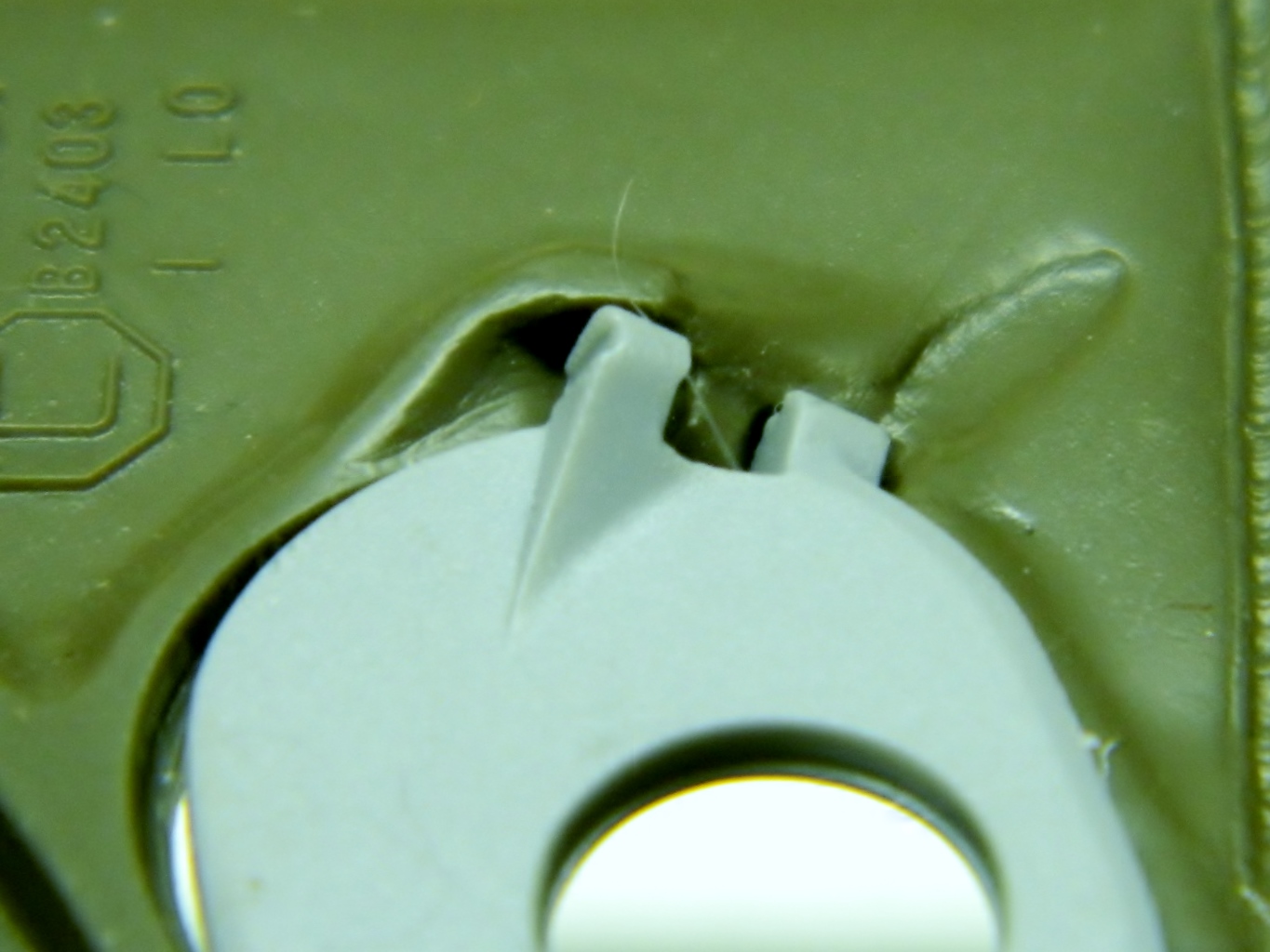
That starts by cutting away the kit’s hinges, adding styrene bits, and my structural putty:

The one on the right is done, now to finish the left:

The round holes in the hatches are where the periscopes’ mounts rotate, so I have to make those mounts. A piece of styrene chucked into my drill, turned to the proper diameter, and then filed/sanded to the correct thickness:

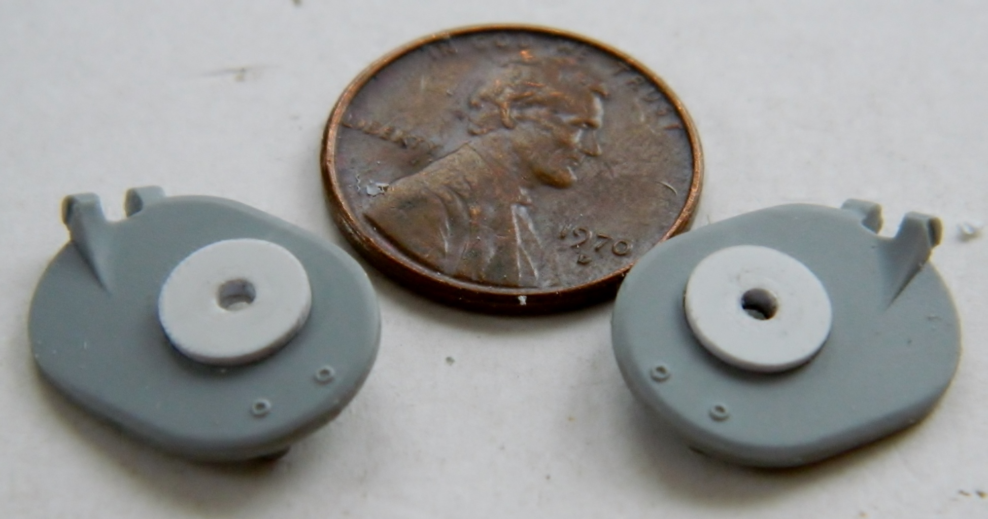

Feedback from Sherman crews in the field showed that the hatches for the driver and co-driver were too small and made un-assing the tank difficult if it got hit and/or started burning. When the hatches were redesigned to be larger, a couple of other design changes had to be made to accommodate the new hatches. One was changing the front glacis plate from a 60° angle to a 47° angle. The new glacis plate offered better protection (even though it was more vertical to incoming fire) because its design eliminated the protrusions of the hatch boxes (which had vertical faces) and was one piece, its face unbroken except for the bow machine gun. The new plate as also easier to produce because there was substantially less welding required to it.
The other change necessitated by the new hatches was to the bustle (the rear extension) of the turret. The larger hatches were hinged so that they opened forward and the bustle needed to be higher for clearance to allow the hatches to open.
The low bustle on the left, and high bustle on the right. Note the angle of the top of the bustle:
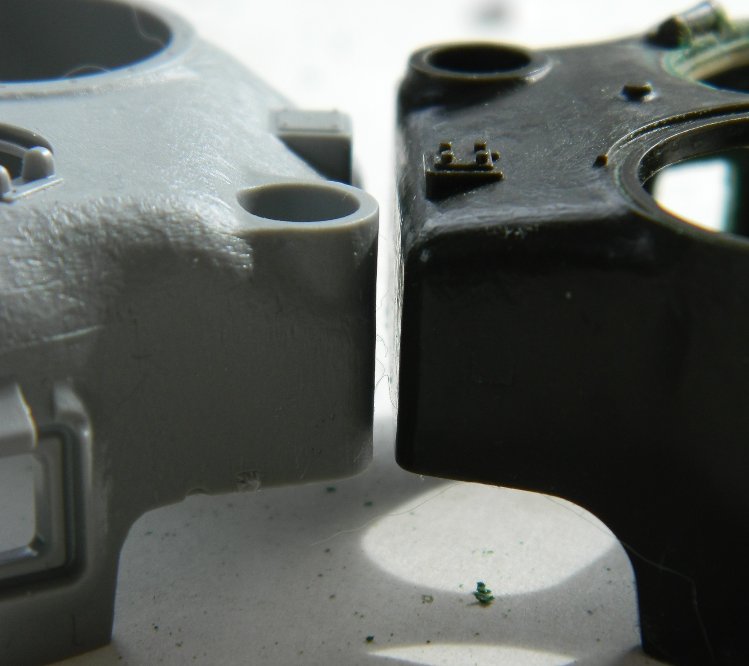
The square opening on the left turret is the “pistol” port (and I have no idea why they were called that because that wasn’t the function of the port – its purpose was for the loader to toss empty brass from the 75mm out). Tamiya had no intention of this port being open and I do. If the turret on the left had been a high bustle turret I would have used that instead. So I decided to use the port. I briefly considered cutting the ports out and grafting the open port (and its detail) to the high bustle turret, but that would sacrifice a part I may want to use later on. Instead, I decided to take a mold of it and cast a copy:


I used mold-making putty I have, combined the two parts, and took a mold of the gray turret’s port:
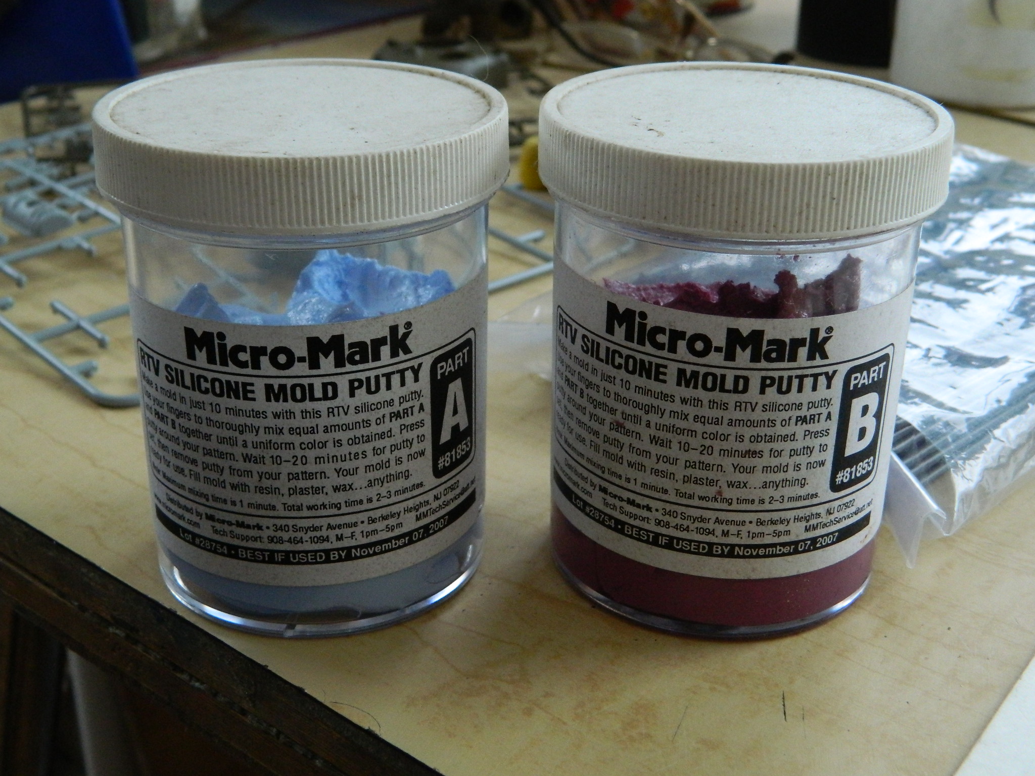
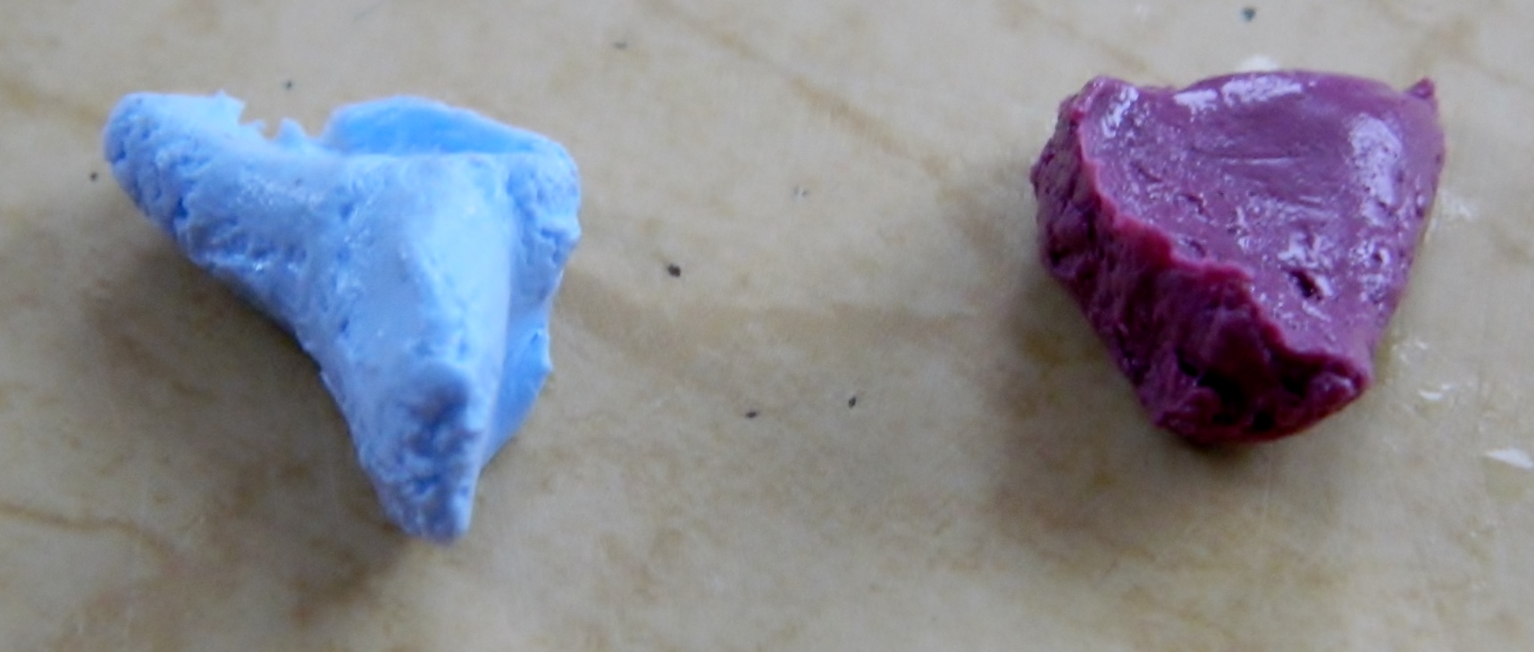
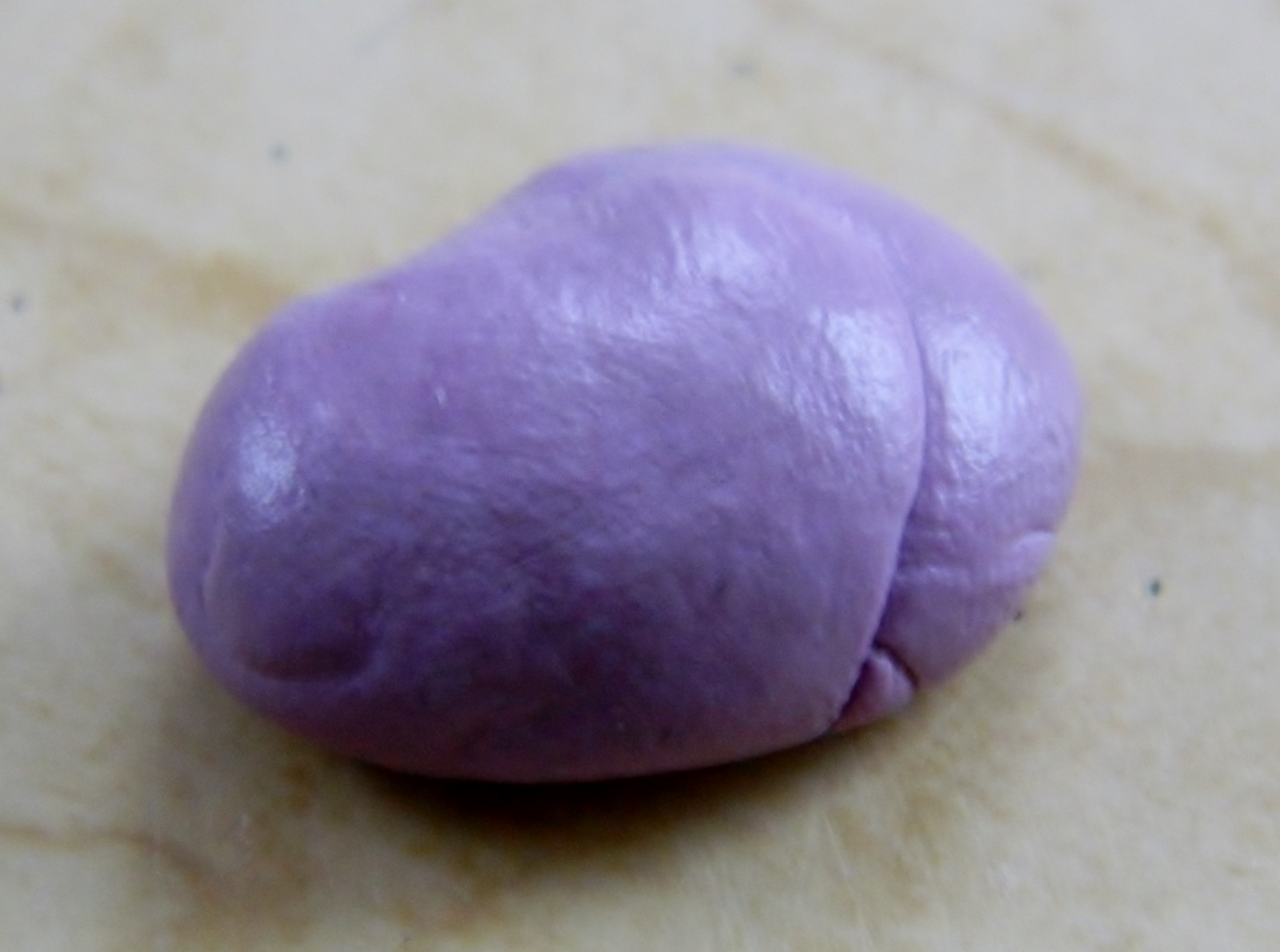
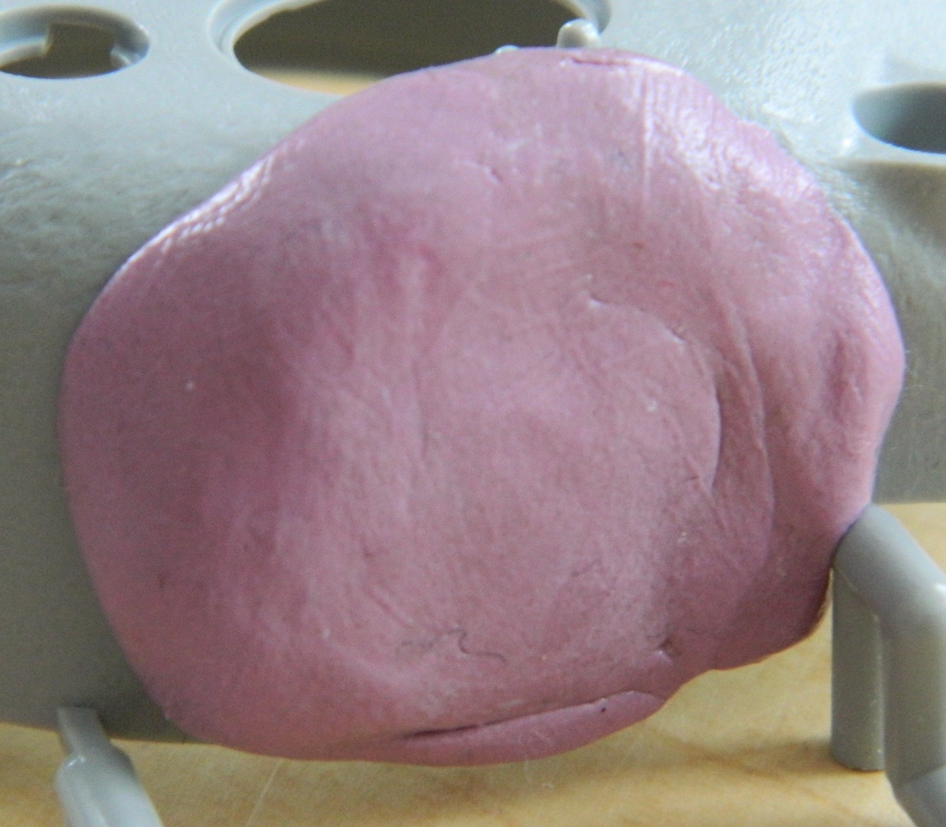
The next day after the molding putty cured, this is what I got which I then filled with my structural putty:
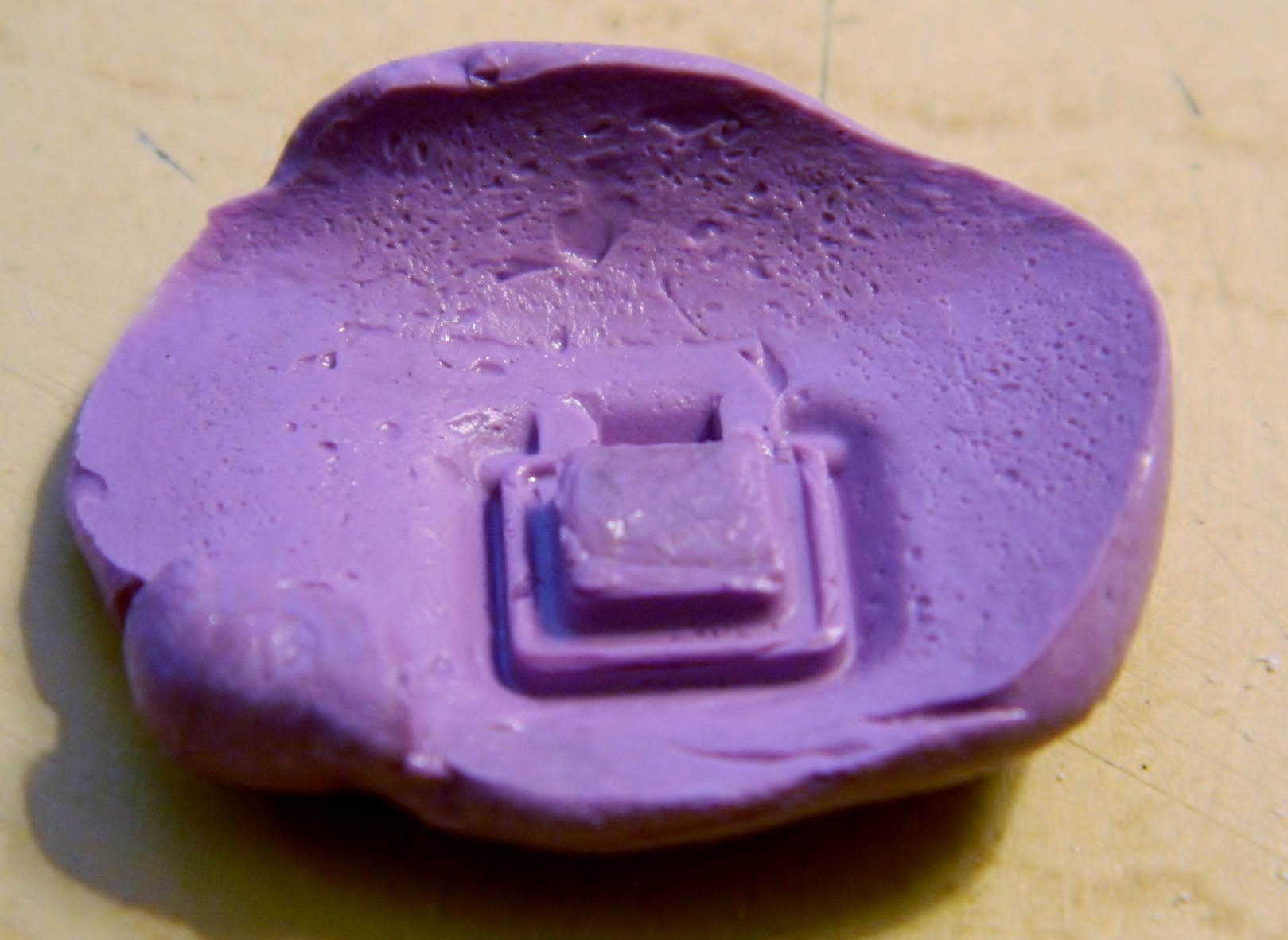

The next day I popped this out of the mold. In doing this, I discovered that if I move the putty around once it’s in place, it creates all these bubbles, but since this is a test, I didn’t much care:

Since this is an experiment, I used the spare turret from my mule and cut the hole for the port out, trimmed the back and edges of the molded piece, applied it, and puttied the edges:

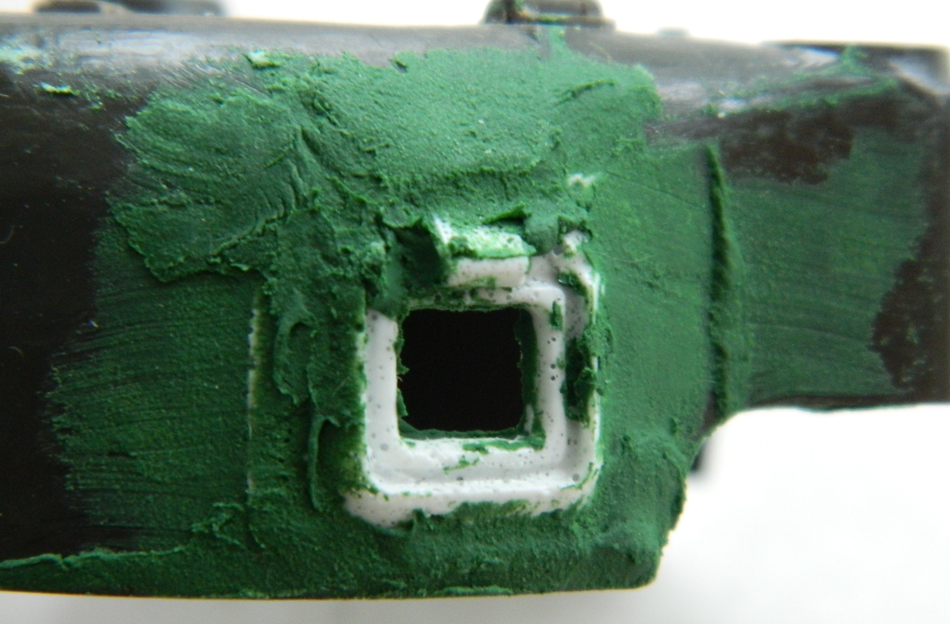

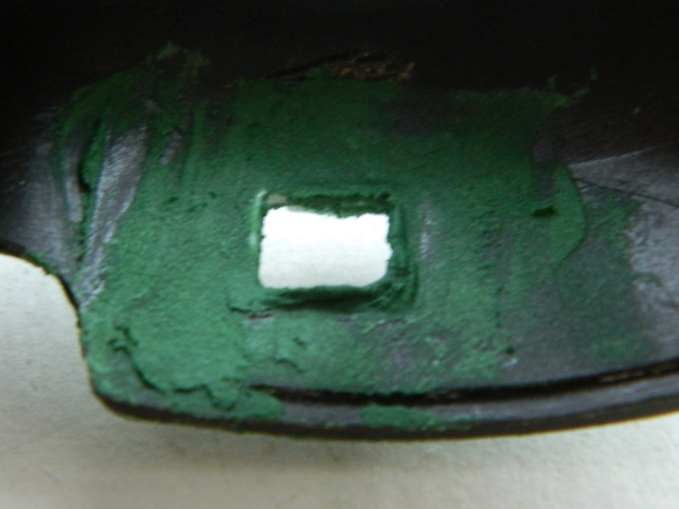
After letting the putty cure overnight, trimmed it, and was quite pleased with the results:
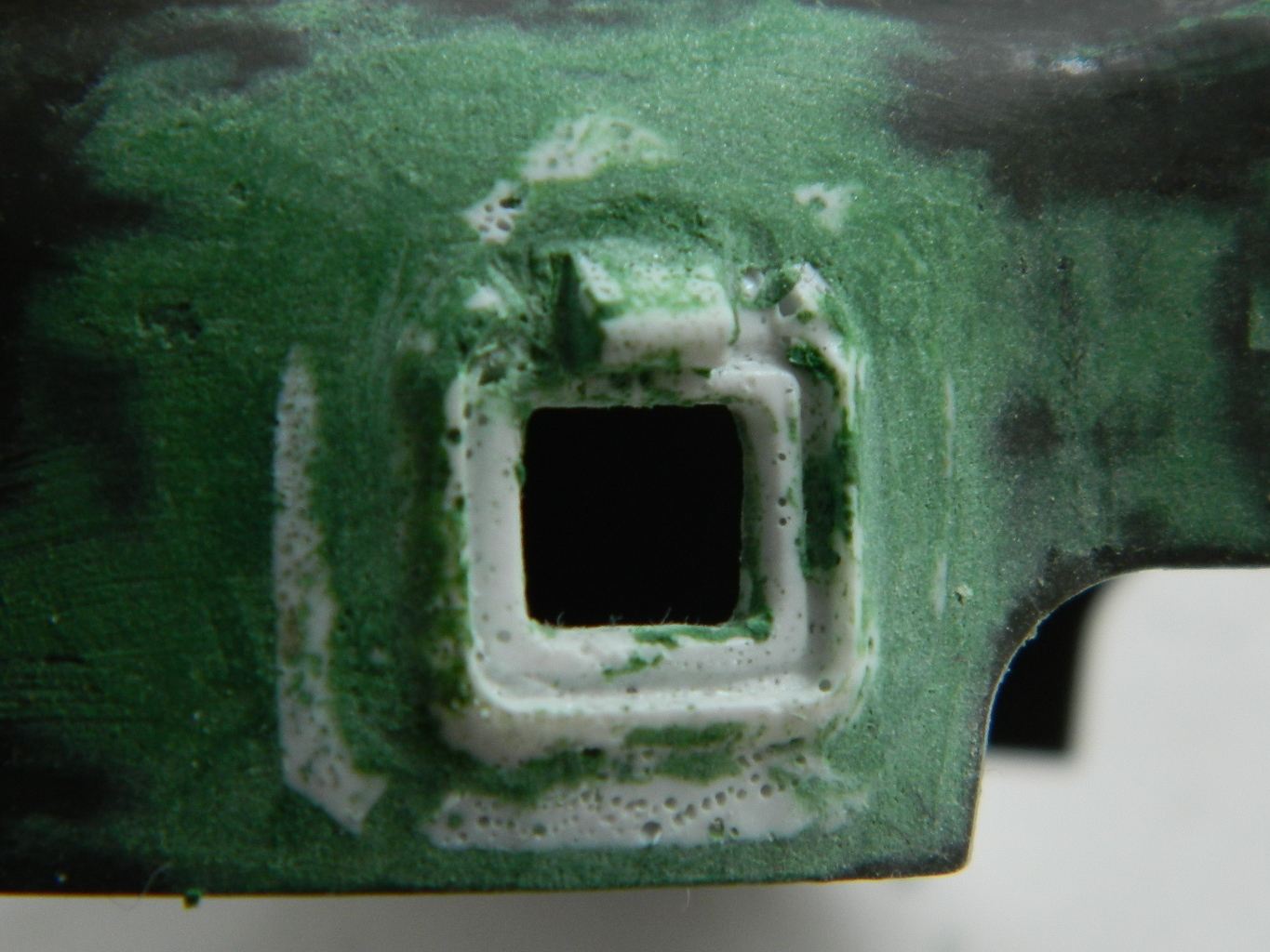
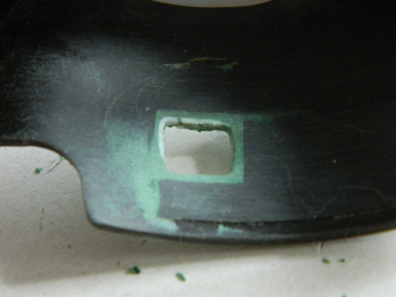
I’m putting an engine in this model and I want the engine covers to be open. The kit’s are molded in place so I have to cut out the opening. First, drill a hole, then take a small saw and cut to the inside of the opening:

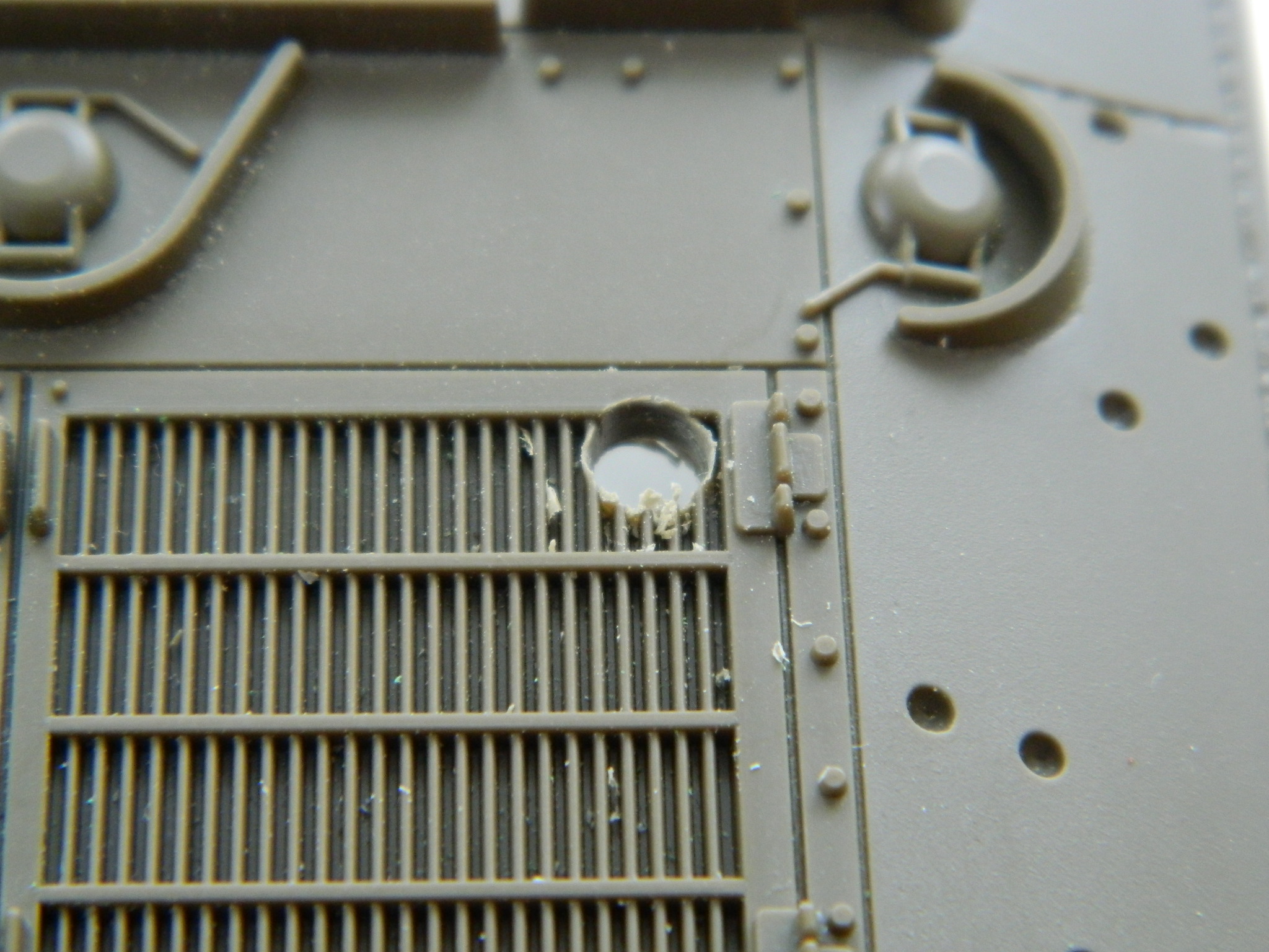

With the opening roughed in, the edges have to be cleaned up and the lip that the covers rest on (and are bolted to) has to be put in:
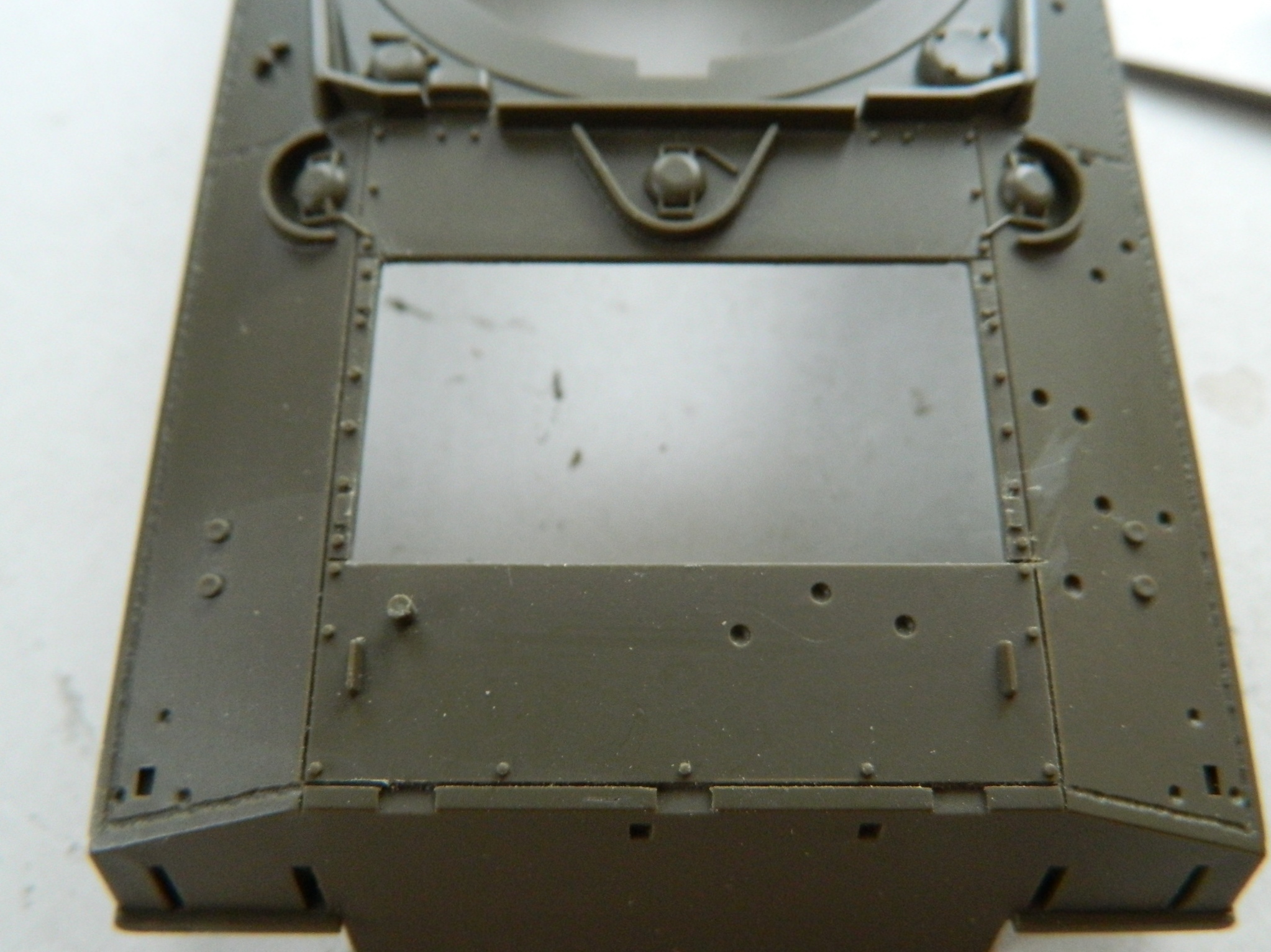
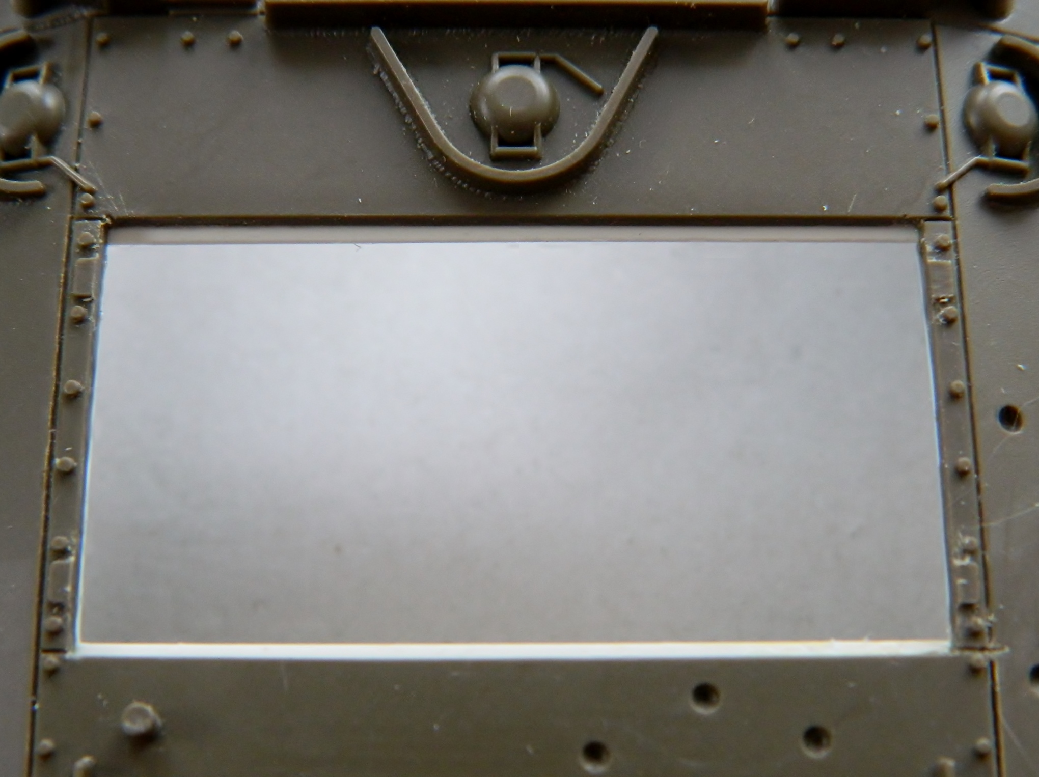
I wanted to do the engine covers next. I had initially thought to use the pair that came with the engine set but they’re inaccurate. Back to the Interwebs! I found a great manufacturer (The New Tiger Model Direct) who does beautiful resin castings for the engine covers:

The parts need to be modified because they (accurately!) replicate a post-WWII M4A3’s covers, but that was done relatively easily. The height of the covers fits but I had to add plastic strip to the edges, as well as remove the hinge-strengthening fins and make WWII-style hinges:
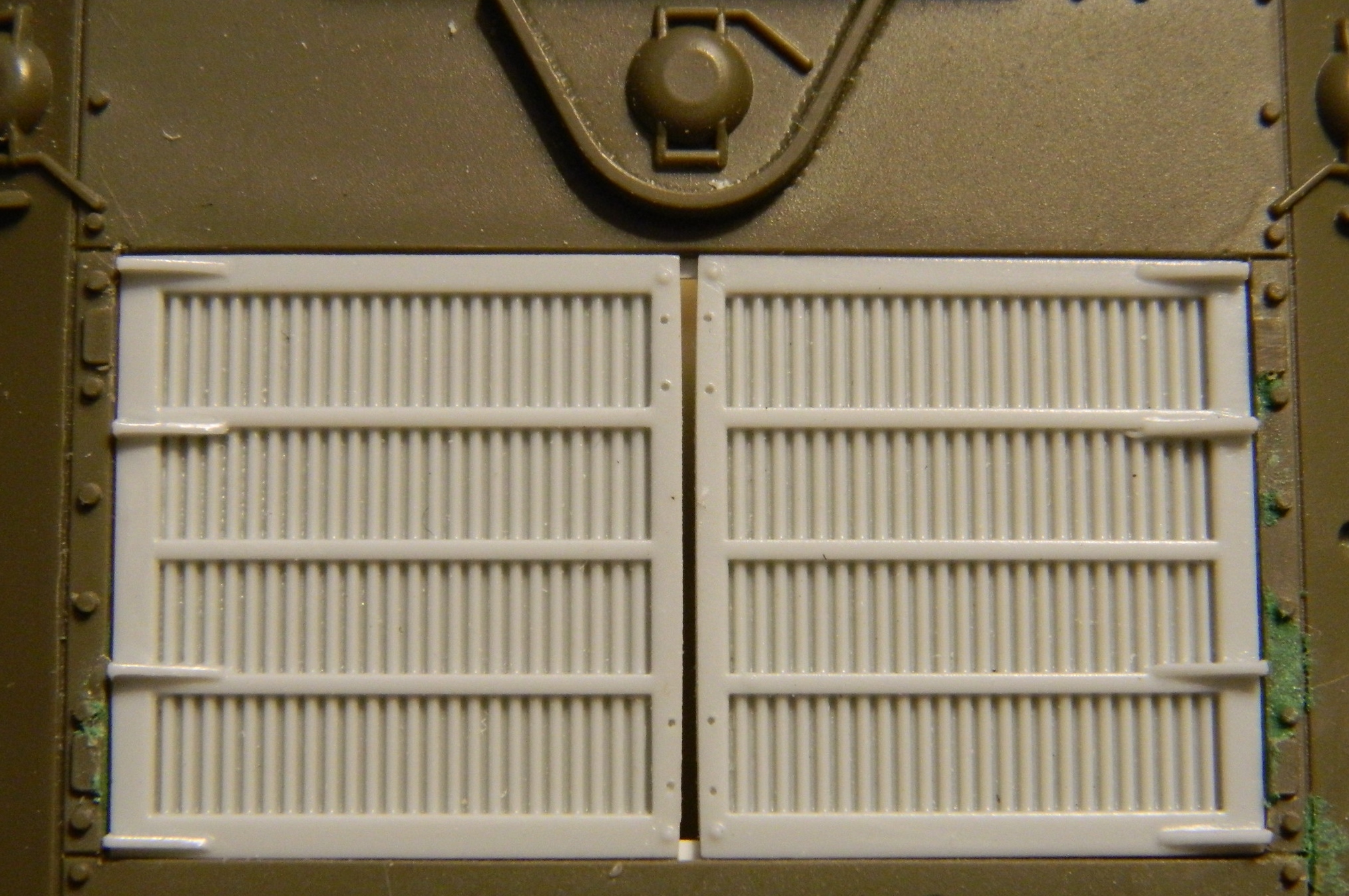
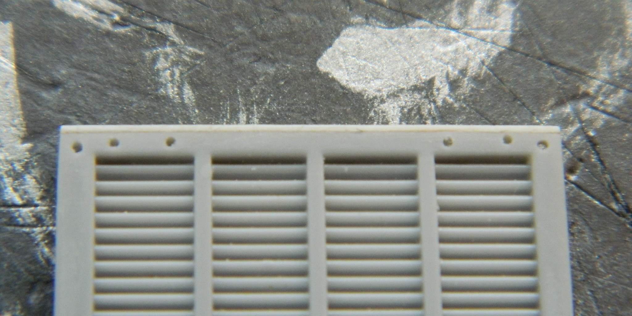


Back into the engine bay, before I put them together permanently, I needed to be able to get under the fans to paint the radiator faces as well as the fans themselves:

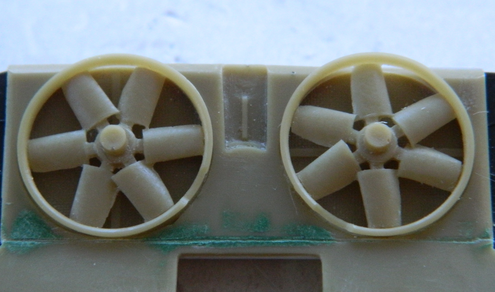
I hit the radiator faces with paint first and dry-brushed aluminum paint over the faces to bring out the detail:
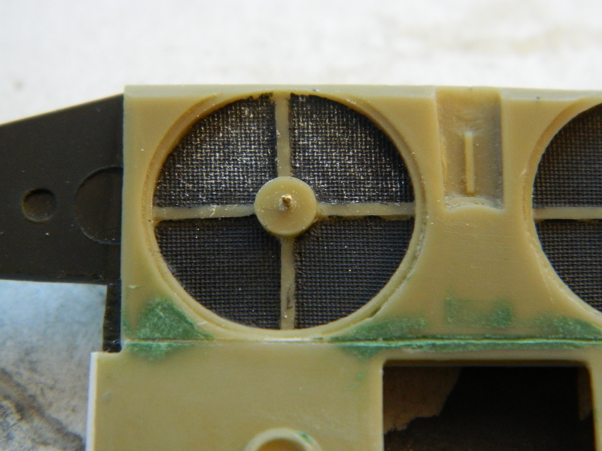
Then I painted the fan blades and added wear to the leading edges with more aluminum paint:
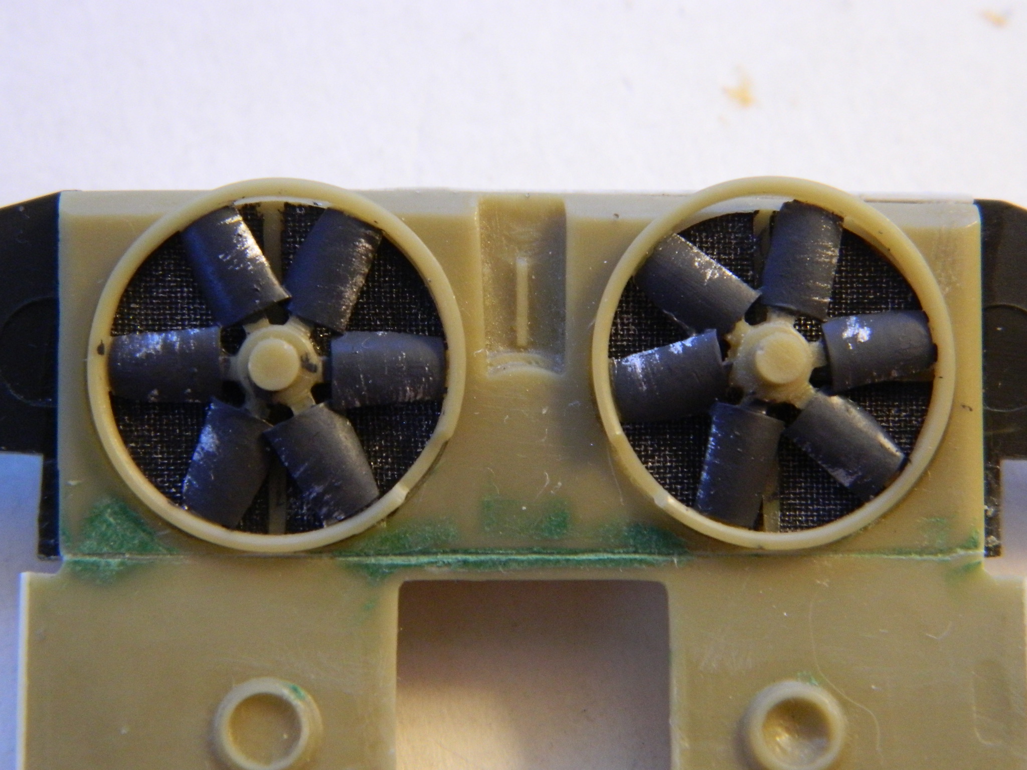
Since I knew I was going to be masking the radiators and fan blades, I wanted to fit the other things into the engine bay first. I didn’t know how far off the thickness of the tape would throw things so before I started masking, I had to get parts ready to dry-fit and the easiest way I knew was to drill out holes add pins, and since the fans were driven by PTO (power take off) units, I wanted to add styrene rod to make sure I had enough length to replicate that:
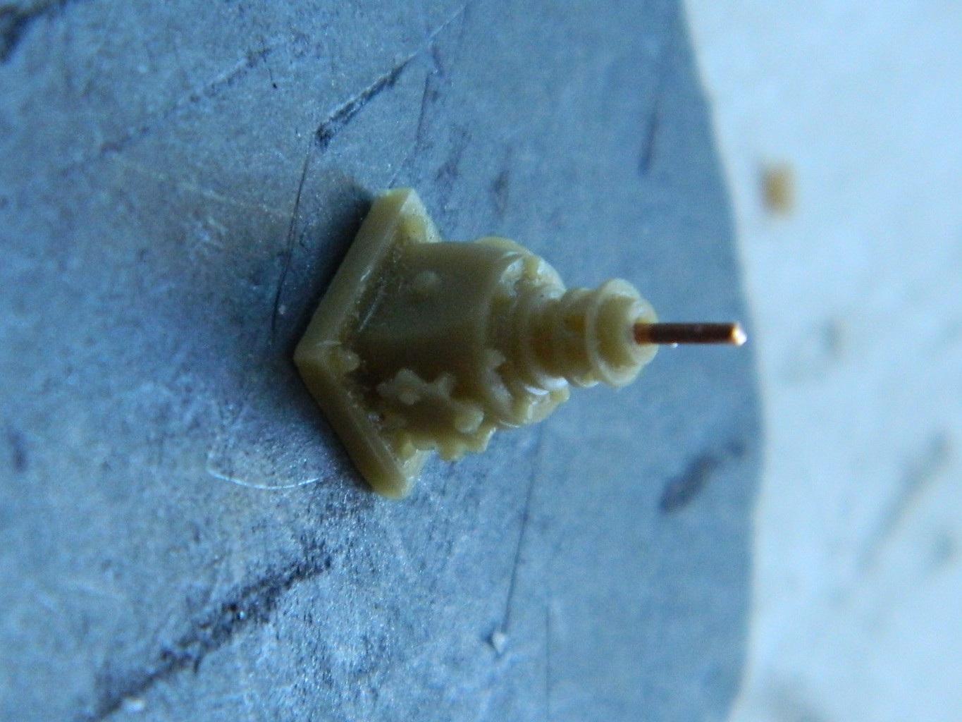


Then came the tedious process of dry-fitting (wherein once again I lamented the fact that I only have two hands; three or four would have made this so much easier). Once I had the engine placed in position, I added the ducts that route air from the air cleaners to the plenum:
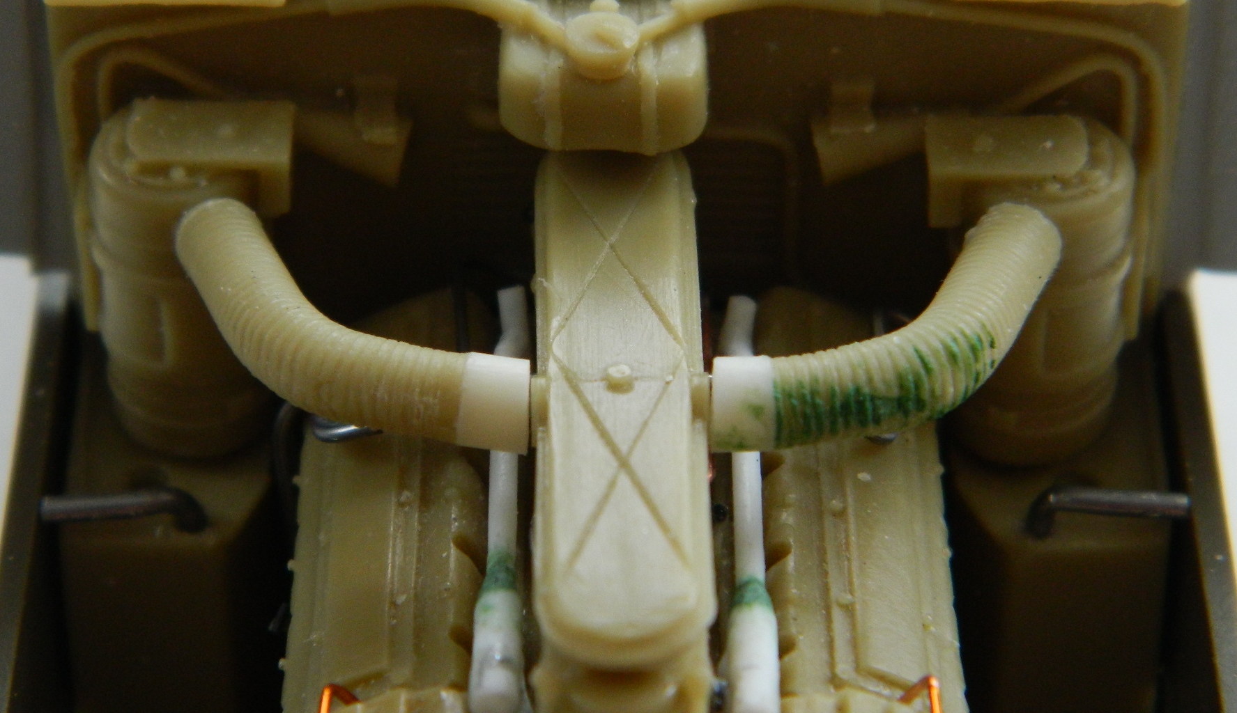
With those in place to establish the relatively exact engine location (and obviating the need for one extra hand), I dry-fit the PTO units, fan blades, and belt/pulleys into place:
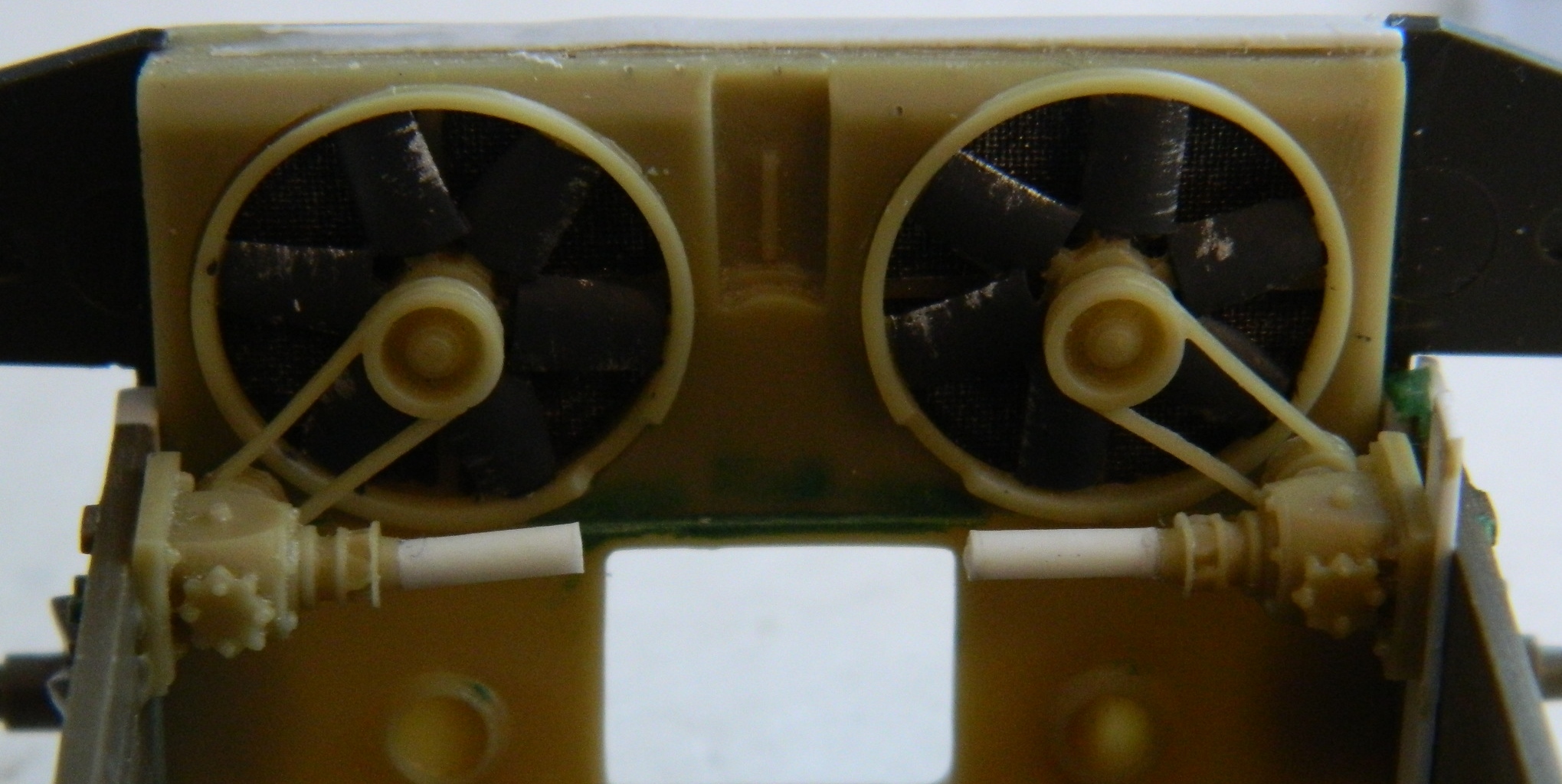
Putting the engine back in showed me that I needed very little of the styrene rod I’d added so those got trimmed and I adjusted the mounts for the PTO units so that they would align with both the fans and the engine (you can see what that needed by the thickness of the added styrene between the right PTO and the hull as opposed to what the left PTO needed):

The I put the engine in to see how it all fit:

Since that worked well enough, time to mask the fan blades and radiator faces:
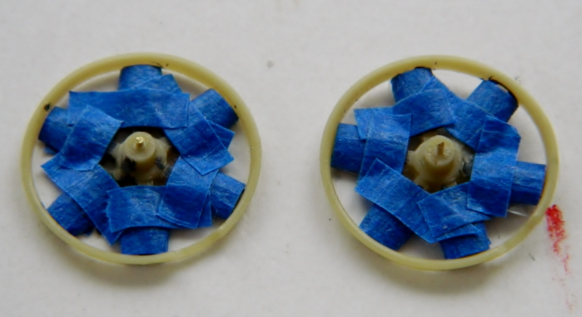

Then I attached the exhaust pipes to the rear bulkhead. I’m not 100% satisfied with the alignment but with the way things are packed into the engine bay, the gaps will not show: