(Vacuum Molder
When getting into modeling a bit deeper than Out Of Box (OOB), having the ability to make your own parts is quite handy.
An example is the canopy on a 1/48 scale (or any scale, really) aircraft. Sure, the kit part is clear, but if you measure its thickness and convert that to scale dimensions, you’ll realize that the real canopy isn’t six inches thick. Light does “interesting” things when it has to work through thick sections of plastic, and unless you replace that kit part with something closer to scale thickness, it’s going to look like what it is. A small plastic part. That’s when being able to vacu-form scale parts comes in handy.
I got the basic plans from FineScale Modeler back in the ’90s. It’s an easy set up to build and isn’t expensive. (I tweaked it a bit because that’s just what I do.)
To make one of these handy gizmos, you’ll need:
A bread pan, 1/4″ graph paper, sharp 3/32″ drill bit, epoxy putty, silicone sealant, plywood, a piece of pvc or plastic tubing about 4-5″ long, 1/2″ to 3/4″ wood screws, and something to make a split frame with (I used 3/16″ aluminum sheet), a hot place or access to an electric stove (and an understanding mate if you screw things up and drop molten plastic onto the burner) (or someplace else to sleep for a week or two should understanding not be in plentiful supply)
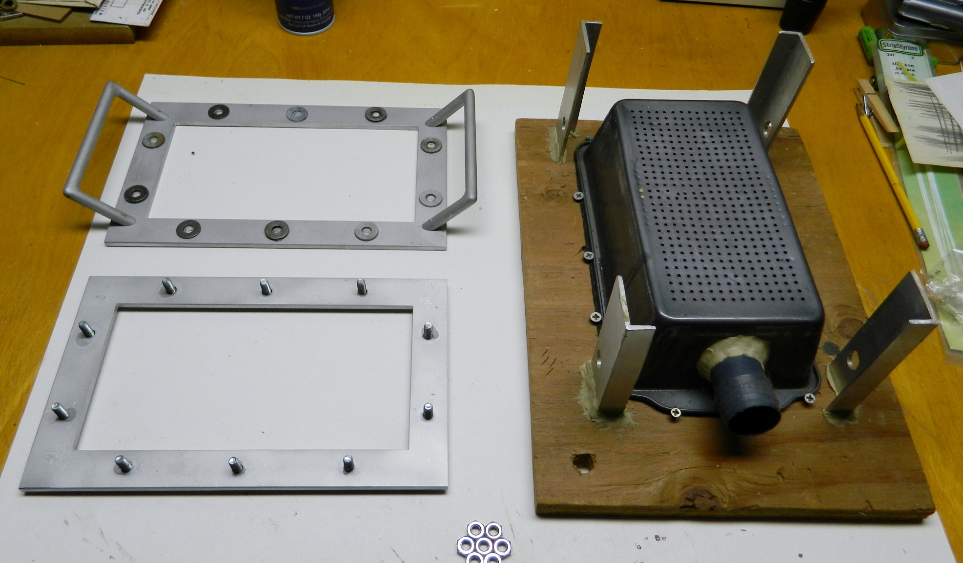
The main part is the plenum. This is the volume that traps the air you’re going to want to suck out. A standard-size, sheet metal bread pan, works great. I strongly suggest you get one that is stamped; it will have rounded edges at the bottom of the pan.
Get some graph 1/4″ paper, where the squares on the paper are a quarter inch square. Turn the pan over so the bottom is up, trim the paper to fit over it, and then tape it down. Take a sharp punch and tap firmly enough to leave a dimple in the metal without deforming it every place the lines intersect.
Use a sharp 3/32″ bit and drill a hole everywhere you made a dimple. Once you’re done, if you end up with what I did, you’re going to need to deburr the surface. For that I used a combination of a fine finishing file and sandpaper. (You don’t want sharp projections to puncture the plastic you’re going to be forming.)
Next you need to cut a hole in one end of the bread pan to attach the pvc or plastic tube to. This is where you’re going to hook up your vacuum cleaner (which is what will draw the plastic down around your form). Once you have the hole cut just large enough for the tube to fit, use the epoxy putty to build a flange on both sides where the tube goes through the hole in the bread pan. Put it aside until the putty has completely cured.
Size your plywood (I used a scrap of 3/4″) large enough to offer a stable base and place your bread pan, upside down, onto the plywood and outline it with a pencil. Run a bead of silicone sealant around the inside perimeter of your outline, settle the bread pan upside down (or with the bottom and all those holes up) and screw it down to the plywood. Let the silicone sealant cure.
The purpose of the frame is to hold sheet styrene (or butyrate) firmly over a heat source (I use an electric hotplate but an electric stove works also). Here’s where I got a little fancy. I had a friend who worked in a machine shop make a frame (two frames, actually) for me from 3/16″ aluminum plate (anything sturdy will do). I sized the inner opening to be just slightly larger than the bottom of the bread pan and the width of the frame to be an inch. I used bolts and wingnuts to hold the two frames together (once all the holes were drilled, obviously, I used superglue to hold the bolts in place), and I guess he was having a boring day at work because he also made me two nice handles for the frame (comes in handy when protecting the delicate fingers from holding this over heat).
Because I’m clumsy, I later added the aluminum L-stock to guide the frame to a centered landing on the platen (bottom of the bread pan with all those holes).
Place your form of what you want to replicate onto the platen. It can be anything of the desired shape that you can pull the plastic down over, things like canopies, body panels, etc. Anything you need a thinner piece of. I’ve found that gluing the form onto a pedestal and getting the bottom of your form off the platen makes life SO much easier! I use a drop of superglue to hold the pedestal to the platen (if you don’t leave it there overnight, it will snap right off).
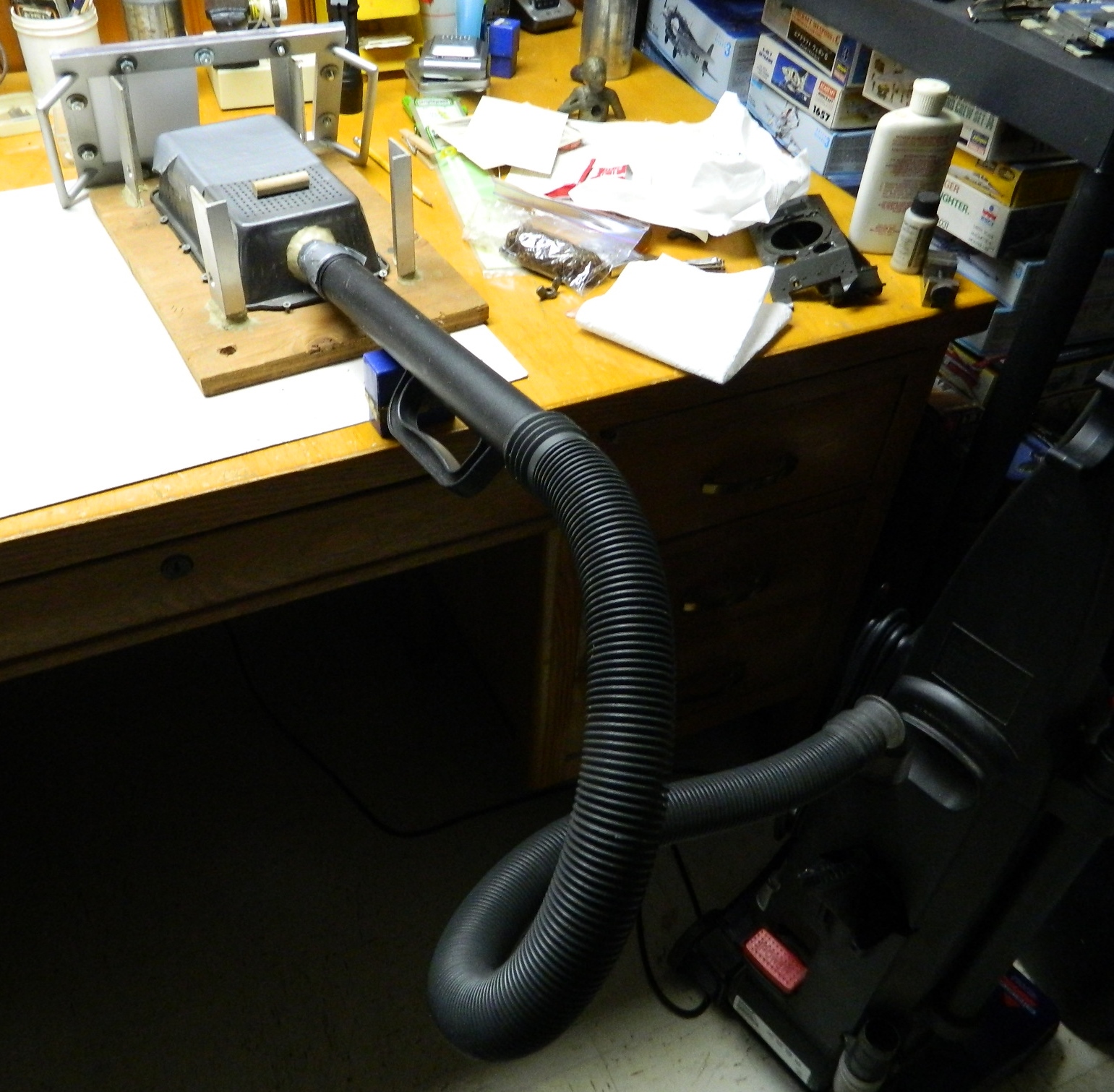
When you’re ready to have at it, attach the hose to a vacuum cleaner to the tube you epoxied to the bread pan. Put your form in place. Take a sheet of whatever you’re forming and fit it to your frame; once it fits, tighten the wingnuts securely, and then hold the plastic (or whatever) over your heat source and pay attention. You want to heat it until it’s flexible, but you do NOT want to heat it to the point where it falls out of the frame and onto your heat source, for reasons I sincerely hope are obvious. (Sure became obvious to me!)
Be prepared to waste plastic (or whatever). It takes a little, not much, experience for you to be able to tell when the plastic is soft enough to form, which will generally be once it starts to sag. Once you think it’s ready, turn the vacuum on and drop the frame over the platen, trapping your form underneath (don’t forget to turn off the vacuum…it doesn’t take long, just a few seconds) . Remember, this thing works on vacuum to suck the plastic around your form, so you’ll need to press down with the frame until the plastic seals against the platen, allowing the suction to pull the plastic down over the form (that’s why I made the inner opening of my frame just slightly larger than the bread pan). If you don’t heat it enough you can reheat it.

Home
So I’ll start by welcoming you.
Welcome.
Scale modeling is an interesting intersection of some things I really like doing; learning things, making things, figuring things out, research, and solving problems (lots of that in modeling). A few friends have been (and hopefully still are) interested in the stuff I make and I’ve been posting progress reports with pictures, explanations, and intentions and emailing them. This is starting to get top-heavy. Ever quick on the uptake, I decided to blog about it all and throw it onto the Interwebs should anyone else also be interested (and to make my life easier, of course).
And here we are! ::trumpet fanfare:: <- Copeland’s “Fanfare for the Common Man”.
The underlying theme should be, “I don’t really know what I’m doing but really enjoy figuring it out as I go”.
My main interests seem to be on equipment and machinery that people bet their lives on. That means I do aircraft (nothing smaller than 1/48 scale; I’m not a watchmaker) and armor (nothing smaller than 1/35 scale with the same caveat) primarily, but being a critter of mood and whimsy, will probably do the odd model here and there that are neither.
The really difficult part for me is knowing when enough really is ENOUGH. I see things in minute detail and unless I ride heard on my pre-conscious impulses, I might as well be a watchmaker. That means I try to maintain a 90-95% degree of accuracy.
Regarding this blog. I really don’t know what I’m doing! That means as things get figured out (trial and error with the emphasis on error) this…thing…you’re reading (and hopefully exploring) will change as I learn more about it.
If you like something, let me know. If you don’t like something, let me know that, too…though there’s no guarantees that any of what you don’t like will change, any more than there are guarantees that what you do like won’t change. I’m capricious. (I’m also crazy.)
What’s important to keep firmly in mind is that this is all just one maniac’s opinion. I’m no expert; if I was I would charge you money. What’s written here will be just my opinion and hopefully YMMV.
So, off the edge I step. I hope you enjoy what you find here. Time is a terrible thing to waste. That said, do please be patient will I get this…thing…formatted the way I want it to be.
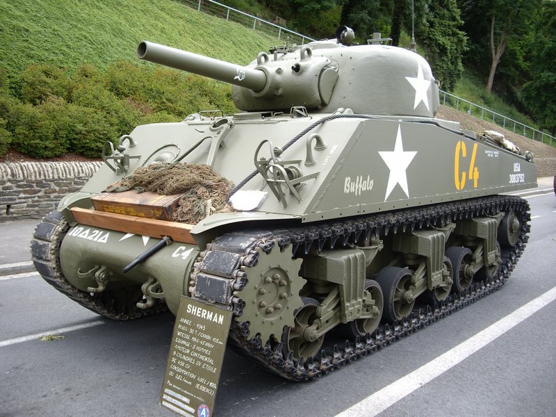
Sherman – A Brief Overview
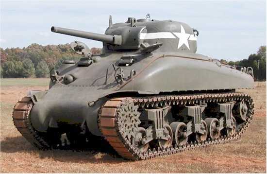
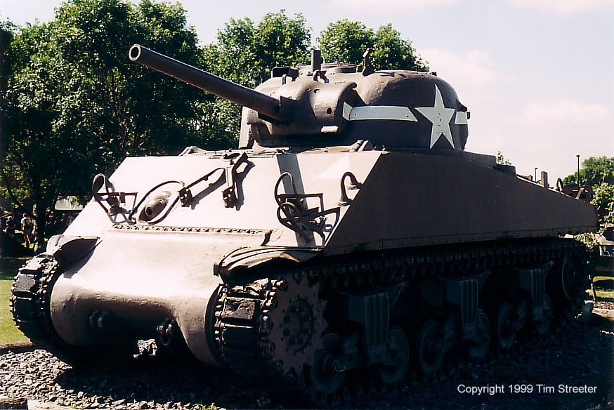
The M4 Sherman tank. Much loved, equally maligned, common wisdom states that it was not intended for the uses it was put to.
Yeah, most of them had low-velocity guns that couldn’t penetrate the armor of a Panther or Tiger tank at range, and yeah, the Panther and Tiger could light up (literally) a Sherman at ranges a Sherman could not reach. However, Panthers and Tigers combined only made up about 30% of the German armor the Allied tank crews faced after Normandy. The Sherman could go toe to toe with any German armor up to and including the Pkw. IV series (though the Pkw IV with the long-barreled 76mm did out range the Sherman’s 75mm).
Having said that over three years ago, subsequent research has shown that what follows and I had written back then is mostly inaccurate:
“But in line with the Armored Command’s battle doctrine, the Sherman was never intended for armor-on-armor engagements; that’s what tank destroyers were intended to do. The tactical application of the Sherman was a holdover from the WWI philosophy of using armor as infantry support like a mobile pillbox to break through enemy lines and create havoc and destruction behind the lines, or as a mobile fortification covering infantry on the advance.”
For an interesting look at the Sherman, its history and role, check out this YouTube video:
So it looks like I’m not the only to think the M4 series is a good tank! (And while you’re at YouTube, look for, “Oh bugger, the tank’s on fire.” QUITE fascinating.) The one major advantage the Sherman had over the Panther and Tiger (other than sheer numbers available in the field) was that it was reliable and a lot easier to work on. Panthers and Tigers were much more complicated machines and of all the terms tossed at the Sherman, “complicated” is not one I’ve encountered.
Being an evolutionary design, it carried over many traits of the M3 Lee…both bad (high profile, thin armor) and good (a well-developed drive train with robust components that are widely interchangeable). Its turret traverse would spin a turret faster than most German tanks; getting the first shot on target makes survival easier, and given that 70% of its armored adversaries weren’t Panthers (or Tigers which were MUCH rarer), that first shot stood a good chance of ending the encounter.
The major reason a Sherman would light up so easily and burn was not because it was gasoline-fueled, it was discovered to be the result of where the main gun ammunition was stored in the “dry-stowage” hulls where the ammo was stored high on the inside hull, leading to “wet-stowage,” where the ammo is encased in water jackets and stored on the floor of the hull. With dry-stowage hulls, any shot that penetrated would likely result in setting off the stowed ammo; wet-stowage hulls cut down on that happening drastically.
By the end of its production run with the M4A3E8, though the armor was still thinner than its adversaries, a great many of its problems were sorted out, it had an adequate gun, and the ride of the last suspension design was a lot smoother. The Army liked the A3 series enough to keep it in service after WWII and a number of them saw duty in Korea (and note the comment in the above video regarding the M-26 versus the M-4!).
There were about 50-55,000 of them made; as one clever sod once stated, “55,000 Shermans and 54,999 different from all the other ones.” That’s because parts interchangeability was profound. The transmission of a Sherman built in 1941 would fit a Sherman of an entirely different variant built in 1945 (as would many other major components). Disabled tanks would be scavenged for parts in the field to keep less damaged Shermans in service and fighting.
Some Shermans (M4 and M4A1) had a Cyclone radial engine (a holdover from the M3 line of medium tanks and was the reason the hull of the Sherman had such a high profile), some had the Chrysler “multi-bank” engine (M4A4) which was actually five engines built around a common crankshaft; go ahead, try routine maintenance on that one without pulling the power-plant, some had a 1000 cu. in. Ford V8 (M4A3 and M4A3E8), and though most Shermans were gasoline-fueled, a few were even diesel (M4A2 and a radial-engine diesel, the M4A6 of which only 75 were built).
Most had a low-velocity 75mm gun. Some were armed with a 105mm howitzer. Finally, a high-velocity 76mm gun was fitted (the 76mm, oddly enough, wasn’t as popular as the 75mm was, mainly due to the absence of a good high-explosive round). And all of that doesn’t take the British Shermans, called “Fireflies” into account with the 17 pounder gun. (And I haven’t even mentioned what the Israeli army did with them! Google M51.) There were even flamethrower variants the troops called “Zippos.” Some tanks had cast upper hulls, some had welded flat plates (of two varieties) and some had the forward upper cast hull welded to flat plate rear upper hulls. Most turrets had what’s called the “pistol port” (though it was actually intended to toss empty cannon brass out of) though many did not. Earlier turrets had a low bustle and no loader’s hatch; later ones had a high bustle with a loader’s hatch (and there were two variants of the loader’s hatch!). Early turrets had a flat, two-piece commander’s hatch, and later ones had a “vision block” cupola with a single hatch. Some turrets had applique armor over the gunner’s position, some had it cast in at the foundry. Two different gun mantles were fitted, early and late (of course) with an entirely different one for the 76mm gun. Early transmission casings were three-piece units bolted together (another M3 holdover), later ones had a one-piece cast casing and those could have rounded or pointed noses. And all of these parts were interchangeable!
And I haven’t even mentioned the assault variation of the Sherman M4A3E2 with a ton (actually, a couple of tons) of thickened armor or self-propelled artillery built on the Sherman chassis…
Three different types of suspensions, five different designs of tracks, some with applique armor over ammunition storage bins (dry-stowage, which had one design of engine air cleaners) some without (wet-stowage with different design and location of air cleaners), two different turrets, three different guns (75mm, 76mm, 105mm howitzer) and none of that takes into account individual crew modifications or field-expedient modifications (like the hedgerow cutters welded to the nose to keep them from hanging up on the Normandy hedgerows after the D-Day landings at Normandy) OR the specialized variants like the dual-drive Shermans intended for amphibious landings, tank retrievers (fitted with cranes), and on and on and on.
All the above just scratches the surface of what was done to the “basic” Sherman tank. So what the hell is a modeler to do? Model 54,999 tanks? (Even I’m not quite that crazy.)
I decided that I would do maybe five. An M4 (welded-plate upper hull), two M4A1s (cast upper hull armor), an early one with direct-vision slots and a later one without, all of these with low-bustle turrets and the Cyclone radial engine, the M4A3 which has different welded flat-plate armor from the M4 (less of an angle to the front glacis plate which was easier to build and had less places an incoming round would find a vertical surface to penetrate) and the V8 engine (made by Ford, 1000 cu. in., 500hp and 1100 lb/ft of torque from off-idle to 2500 rpm, aluminum, DOHC, four-valve per cylinder, twin carbs) and the high-bustle turret with the loader’s hatch, though there were also low-bustle turrets with loader’s hatches, too. And finally an M4A3E8 wet-stowage 76mm with the advanced suspension, considered by many to be the best of the Shermans (I may also do one of the British Firefly variants).
I decided to start with the M4A3… It was the variant the Army liked most and retained for use and upgrades after WWII.

Stepping Off the Edge
So I’ll start by welcoming you.
Welcome.
Scale modeling is an interesting intersection of some things I really like doing; learning things, making things, figuring things out, research, and solving problems (lots of that in modeling). A few friends have been (and hopefully still are) interested in the stuff I make and I’ve been posting progress reports with pictures, explanations, and intentions and emailing them. This is starting to get top-heavy. Ever quick on the uptake, I decided to blog about it all and throw it onto the Interwebs should anyone else also be interested (and to make my life easier, of course).
And here we are! ::trumpet fanfare:: <- Copeland’s “Fanfare for the Common Man”.
The underlying theme should be, “I don’t really know what I’m doing but really enjoy figuring it out as I go”.
My main interests seem to be on equipment and machinery that people bet their lives on. That means I do aircraft (nothing smaller than 1/48 scale; I’m not a watchmaker) and armor (nothing smaller than 1/35 scale with the same caveat) primarily, but being a critter of mood and whimsy, will probably do the odd model here and there that are neither.
The really difficult part for me is knowing when enough really is ENOUGH. I see things in minute detail and unless I ride heard on my pre-conscious impulses, I might as well be a watchmaker. That means I try to maintain a 90-95% degree of accuracy.
Regarding this blog. I really don’t know what I’m doing! That means as things get figured out (trial and error with the emphasis on error) this…thing…you’re reading (and hopefully exploring) will change as I learn more about it.
If you like something, let me know. If you don’t like something, let me know that, too…though there’s no guarantees that any of what you don’t like will change, any more than there are guarantees that what you do like won’t change. I’m capricious. (I’m also crazy.)
What’s important to keep firmly in mind is that this is all just one maniac’s opinion. I’m no expert; if I was I would charge you money. What’s written here will be just my opinion and hopefully YMMV.
So, off the edge I step. I hope you enjoy what you find here. Time is a terrible thing to waste. That said, do please be patient will I get this…thing…formatted the way I want it to be.
M4A3 (Tamiya) Build #1
Tamiya makes an adequate kit of the A3 and this is the base for this build:


Since I haven’t done a model since 1991 and I wanted to ease back into the pastime, I decided I would add a COMPLETE interior to a kit that was never designed to have one. This means adding an engine and engine bay, a crew compartment, and all the turret details, not any of which were engineered to work with each other. (Let’s start easy, eh?)
One (of many) things I discovered is that not only is the state of the art for after-market (AM) detail sets MUCH different than it was 24 years ago, so is the Internet. I can find references (photographic and written) that were unavailable Back Then. So unlike Back Then, I don’t have to scratch build everything I want to add (as in, start with a pile of bits to make all the gizmos that a tank is full of).
So I started with the engine bay. There’s a Belgian company, Verlinden, that makes really beautifully-modeled AM sets for all sorts of models and one of them is the Ford engine. From the box art:
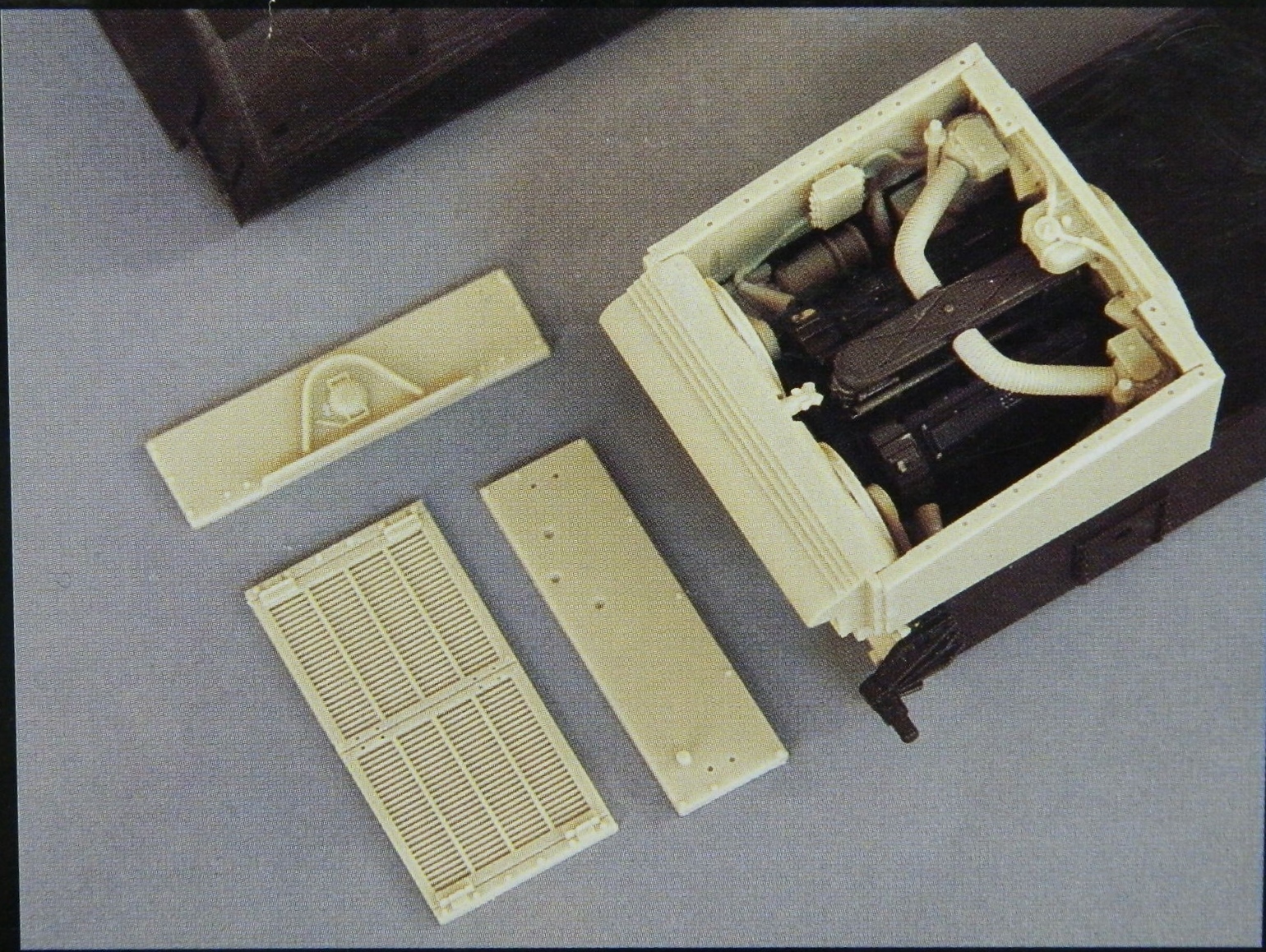
Most of the parts are resin (works about the same as fingernails) and this shows what the AM set includes:

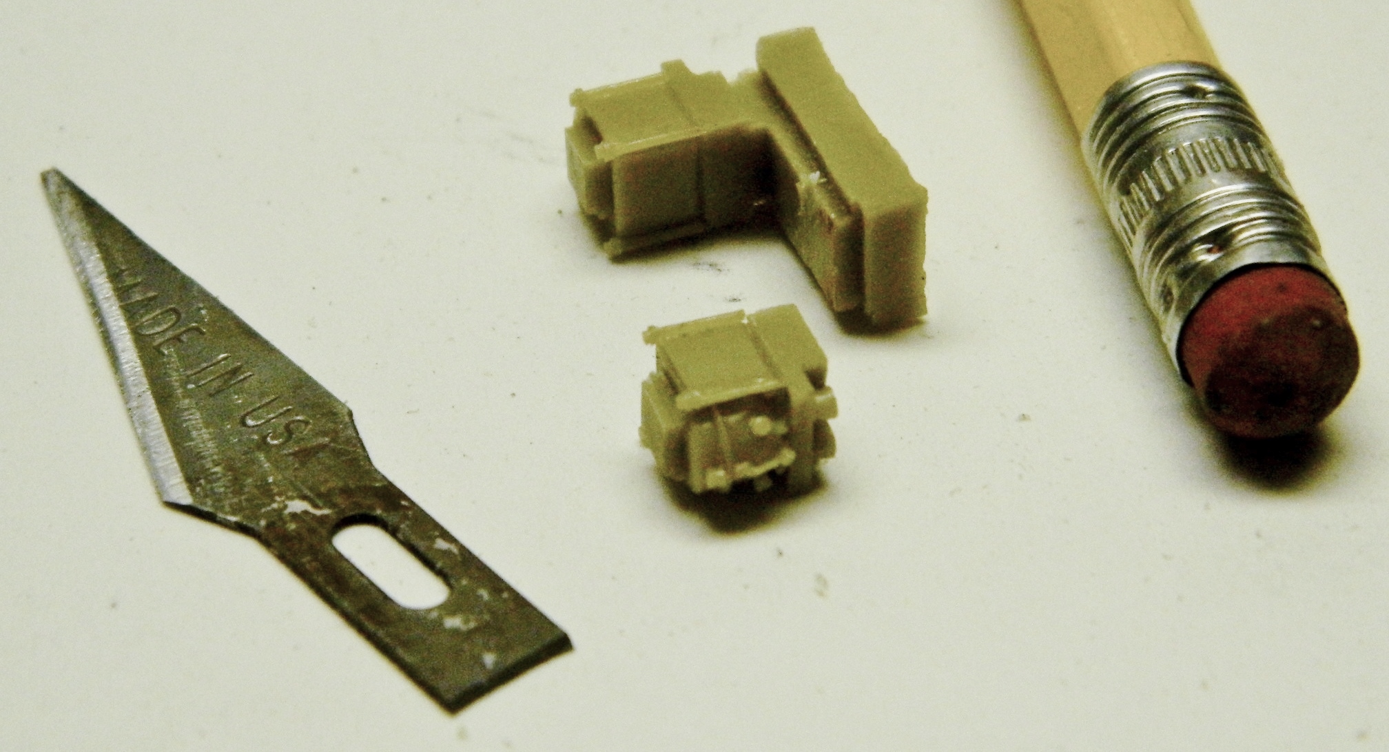
So I started assembling the engine. The first step is separating the parts from the casting blocks:

When dry-fitting pieces together, I saw that the starter motor didn’t quite reach the bell housing, so I added a piece of sprue from my bits-box using superglue:

While the glue was setting, I saw/filed/sanded the exhaust manifolds free:

Then I attached the modified sump (the added piece, dark-colored on the lower right, will get trimmed later):
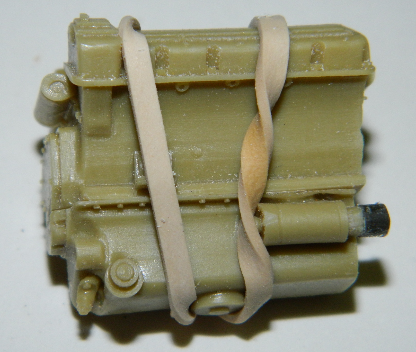
Dry fitting showed me that I’d trimmed one carb too closely so I had to add resin back (the tweezers are sitting on a lazy susan which makes aligning and gluing so much easier):


Fitted and trimmed the added plastic to discover that it doesn’t line up as it should. Short of remaking the entire starter, I realized that few would even see it much less realize it was “off” so I left it and glued the bell housing/clutch on:
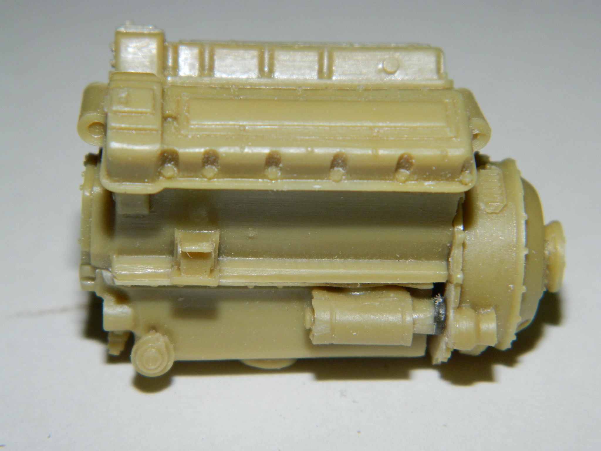
Then I saw that the water pump had a major part of the cooling system that did not actually reach the engine, so I took some sprue, heated it over a candle, and once it was…well…plastic, I pulled gently trusting my Mk I Eyecrometer to get the diameter close (larger is easier to fix than smaller).
Good ol’ Mk I Eyecrometer nailed it on the first pull, so that was glued and set aside to cure:

Trimmed the added resin on the carb with a razor saw:


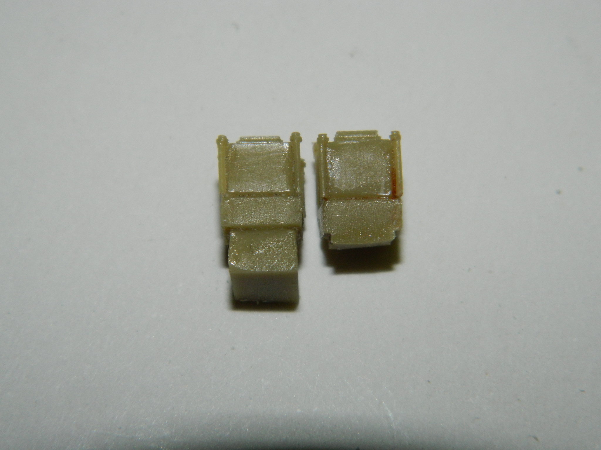
Then I added what looks like an air cleaner (it’s not, those are elsewhere in the engine bay, it’s actually a plenum chamber) and carbs to the engine as well as the modified water pump (later I had to snap the plenum off as I put it on backwards, lest you think this is one unbroken chain from a pile of parts to Modeling Glory):

In looking at reference photos, there is a fuel pump on top of the engine that the AM set didn’t provide. In the above photo, the round thing under the plenum is the oil filler; the fuel pump is just as obvious, so I decided I’d need to build one. I spent a few minutes whining that I’d sold my Unimat lathe because it was SO much more precise than the lathe I have now…and then I realized something. This is plastic, not metal. I didn’t need a lathe; I needed something that I could clamp a piece of sprue into and spin slowly (otherwise the plastic melts). Enter the variable speed drill:


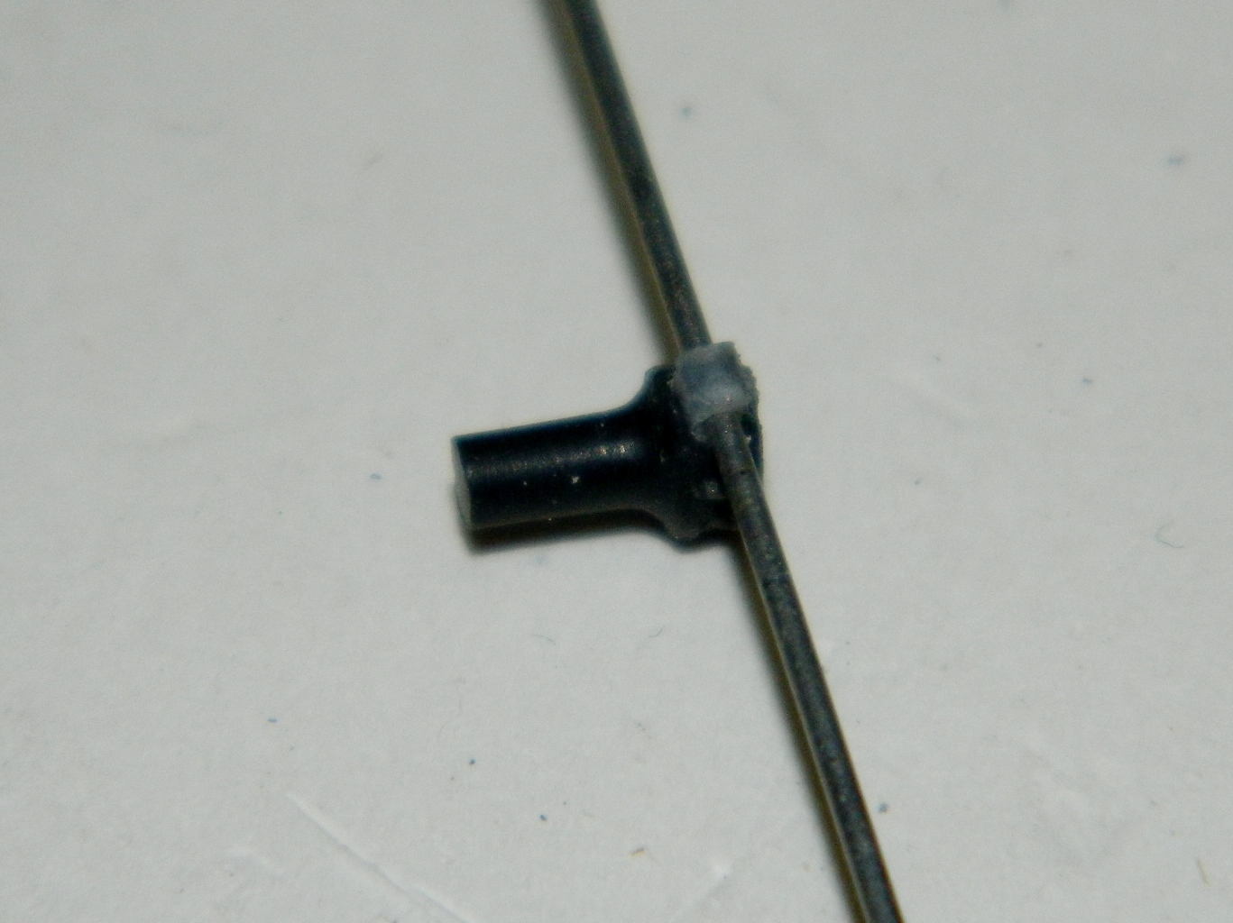
With the basic shape of the pump done, it was time to add the details. I added the shafts of the bolts using lead wool (just like steel wool only lead…how odd…available from plumbing supply and A LOT easier to work than copper…gah…or plastic…annoying). Then I glued a piece of plastic to the side where the fuel line from the pump goes to the carbs. I tried a couple of ways of adding the fuel line and it became quite evident that butt-gluing (don’t go there…like you just did) wouldn’t work (not enough surface area for a secure bond) (you’re still there…aren’t you) so I drilled it out and will use a length of solder of .032 diameter as the fuel line because it’s easy to bend, maintains that bend, and is structurally sound:

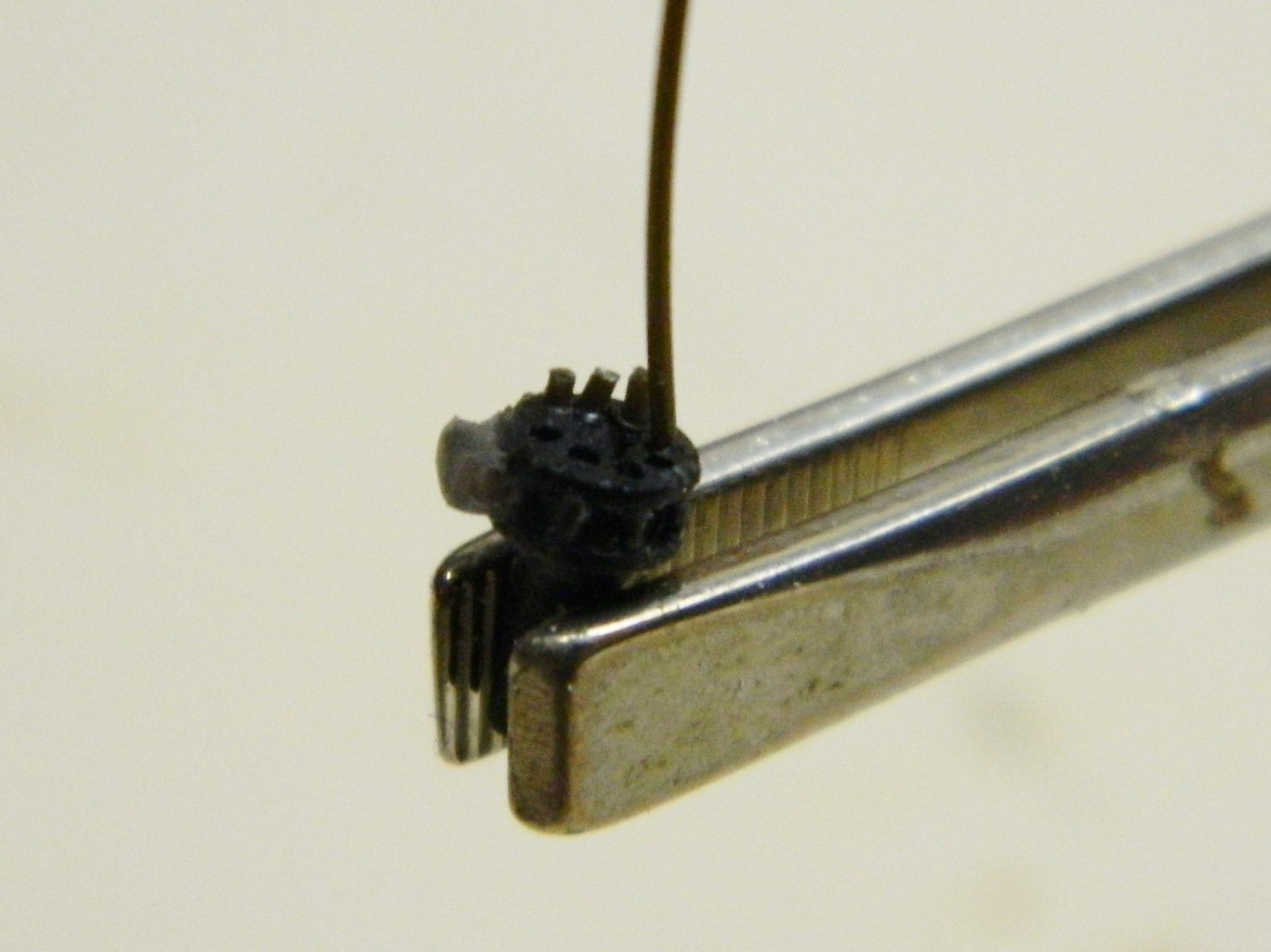
To replicate the bolts on top, I drilled the locating holes slightly, shaved sprue into an octagonal form (like the bolt heads I’m trying to replicate), and used the tweezers on stands to align and glue. I’ll trim them to size later (later on I would use Grandt Line styrene bolts for something like this but at the time I didn’t have them):
I wanted to add the magneto assembly next. I discovered that the back half of them weren’t modeled and since they would be easily seen needed to be. I used some of the cut off pouring stubs so make things easier to see:

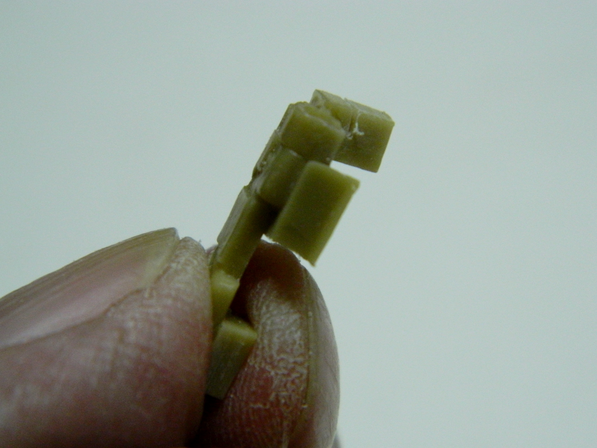
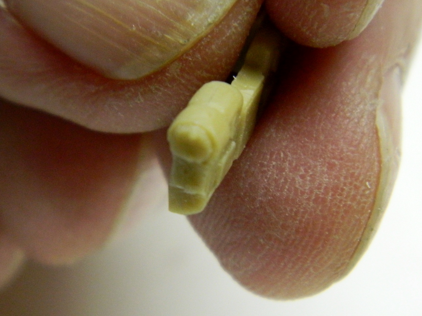
Since that worked well, I did the other side the same way.

